Embed Size (px)
Citation preview
Water Source Heat Pump
Axiom™High Efficiency Console — GEC
½ – 1 ½Tons — 60 Hz
April 2013 WSHP-PRC019-EN
Product Catalog
© 2013Trane All rights reserved WSHP-PRC019-EN
Introduction
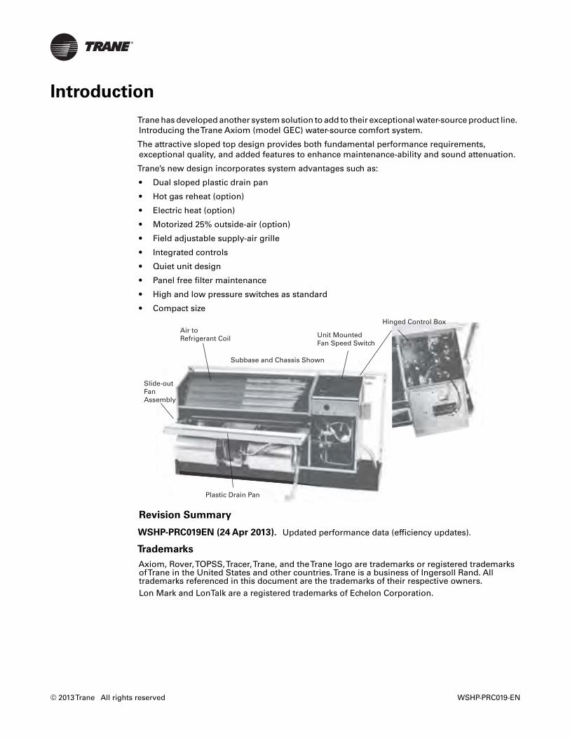
Trane has developed another system solution to add to their exceptional water-source product line.Introducing theTrane Axiom (model GEC) water-source comfort system.
The attractive sloped top design provides both fundamental performance requirements,exceptional quality, and added features to enhance maintenance-ability and sound attenuation.
Trane’s new design incorporates system advantages such as:
• Dual sloped plastic drain pan
• Hot gas reheat (option)
• Electric heat (option)
• Motorized 25% outside-air (option)
• Field adjustable supply-air grille
• Integrated controls
• Quiet unit design
• Panel free filter maintenance
• High and low pressure switches as standard
• Compact size
Revision Summary
WSHP-PRC019EN (24 Apr 2013). Updated performance data (efficiency updates).
Trademarks
Axiom, Rover,TOPSS,Tracer,Trane, and theTrane logo are trademarks or registered trademarksofTrane in the United States and other countries.Trane is a business of Ingersoll Rand. Alltrademarks referenced in this document are the trademarks of their respective owners.Lon Mark and LonTalk are a registered trademarks of Echelon Corporation.
Unit Mounted Fan Speed Switch
Subbase and Chassis Shown
Air toRefrigerant Coil
Slide-outFan Assembly
Plastic Drain Pan
Hinged Control Box
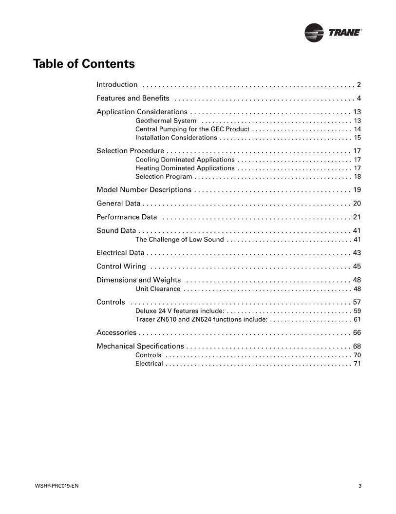
Table of Contents
WSHP-PRC019-EN 3
Introduction . . . . . . . . . . . . . . . . . . . . . . . . . . . . . . . . . . . . . . . . . . . . . . . . . . . . . . 2
Features and Benefits . . . . . . . . . . . . . . . . . . . . . . . . . . . . . . . . . . . . . . . . . . . . . . 4
Application Considerations . . . . . . . . . . . . . . . . . . . . . . . . . . . . . . . . . . . . . . . . . 13Geothermal System . . . . . . . . . . . . . . . . . . . . . . . . . . . . . . . . . . . . . . . . . . 13Central Pumping for the GEC Product . . . . . . . . . . . . . . . . . . . . . . . . . . . . 14Installation Considerations . . . . . . . . . . . . . . . . . . . . . . . . . . . . . . . . . . . . . 15
Selection Procedure . . . . . . . . . . . . . . . . . . . . . . . . . . . . . . . . . . . . . . . . . . . . . . . 17Cooling Dominated Applications . . . . . . . . . . . . . . . . . . . . . . . . . . . . . . . . 17Heating Dominated Applications . . . . . . . . . . . . . . . . . . . . . . . . . . . . . . . . 17Selection Program . . . . . . . . . . . . . . . . . . . . . . . . . . . . . . . . . . . . . . . . . . . . 18
Model Number Descriptions . . . . . . . . . . . . . . . . . . . . . . . . . . . . . . . . . . . . . . . . 19
General Data . . . . . . . . . . . . . . . . . . . . . . . . . . . . . . . . . . . . . . . . . . . . . . . . . . . . . 20
Performance Data . . . . . . . . . . . . . . . . . . . . . . . . . . . . . . . . . . . . . . . . . . . . . . . . 21
Sound Data . . . . . . . . . . . . . . . . . . . . . . . . . . . . . . . . . . . . . . . . . . . . . . . . . . . . . . 41The Challenge of Low Sound . . . . . . . . . . . . . . . . . . . . . . . . . . . . . . . . . . . 41
Electrical Data . . . . . . . . . . . . . . . . . . . . . . . . . . . . . . . . . . . . . . . . . . . . . . . . . . . . 43
Control Wiring . . . . . . . . . . . . . . . . . . . . . . . . . . . . . . . . . . . . . . . . . . . . . . . . . . . 45
Dimensions and Weights . . . . . . . . . . . . . . . . . . . . . . . . . . . . . . . . . . . . . . . . . . 48Unit Clearance . . . . . . . . . . . . . . . . . . . . . . . . . . . . . . . . . . . . . . . . . . . . . . . 48
Controls . . . . . . . . . . . . . . . . . . . . . . . . . . . . . . . . . . . . . . . . . . . . . . . . . . . . . . . . 57Deluxe 24 V features include: . . . . . . . . . . . . . . . . . . . . . . . . . . . . . . . . . . . 59Tracer ZN510 and ZN524 functions include: . . . . . . . . . . . . . . . . . . . . . . . 61
Accessories . . . . . . . . . . . . . . . . . . . . . . . . . . . . . . . . . . . . . . . . . . . . . . . . . . . . . . 66
Mechanical Specifications . . . . . . . . . . . . . . . . . . . . . . . . . . . . . . . . . . . . . . . . . . 68Controls . . . . . . . . . . . . . . . . . . . . . . . . . . . . . . . . . . . . . . . . . . . . . . . . . . . . 70Electrical . . . . . . . . . . . . . . . . . . . . . . . . . . . . . . . . . . . . . . . . . . . . . . . . . . . . 71

Features and Benefits
Building Block Design
The console configuration maintains a tri-building blockdesign. It includes
• Cabinet
• Chassis
• Subbase
These building blocks may be ordered in severalconfigurations.They include:
• Standard configuration (cabinet, chassis, andsubbase)
• Low height configuration (chassis, cabinet, andshort subbase)
• Extended length (cabinet, chassis, and subbase)
• Chassis ONLY
Design Advantages
The console configuration model GEC product offers a rangeof capacities ½ to 1½ tons supporting multiple applicationrequirements in the commercial conditioning industry.Thisincludes:
• Hotel rooms
• Offices
• Condominiums
• Assisted living facilities
• Dormitories
Cabinet
The cabinet is constructed of heavy gauge metal formaximum durability.The cabinet finish is pre-painted andavailable in the following colors:
• Deluxe beige
• Cameo white
• Soft dove
The cabinet design includes a hook-secure fit that allowscomplete access to piping and electrical hook-up for ease ofmaintenance and serviceability.The single cabinet assemblyis securely fastened into the wall sleeve with four 5/16” bolts.
4 WSHP-PRC019-EN
Features and Benefits
Field Flexibility
Piping and electrical connections to theconsole are made in either the left or righthand end pocket.The unit refrigerationplatform and the unit control box ismaintained in the same location whether leftor right hand piping, standard unit cabinet,extended unit cabinet, or low height unitcabinet has been specified.This clonedplatform poses a common look and feel tothe installer, as well as aids introubleshooting during service ormaintenance check-ups.
Right Hand Piping
Console units ordered with a right handpiping connection have the end pocketlocated on the right hand side of the unit.This end pocket provides room forconnecting field supply, return, andcondensate piping to the unit. It alsoprovides space for the high and low voltageconnections.
Left Hand Piping
Console units ordered with a left hand pipingconnection have the end pocket located onthe left hand side of the unit.This end pocketprovides room for the field supply, return,and condensate piping connection to theunit. Installation for the high voltageconnection is also made in the left hand endpocket. Installing the low voltage controls(thermostat/sensor hook-up) is ALWAYSmade on the right hand side of the unit.Thelow voltage termination for thermostat orsensor wires may be run along the back sideof the chassis to the right hand side of theunit for connection.
Note: Units containing the unit mountedcontrol option will ship from thefactory pre-wired. No low voltagehook-up is required.
WSHP-PRC019-EN 5
Features and Benefits
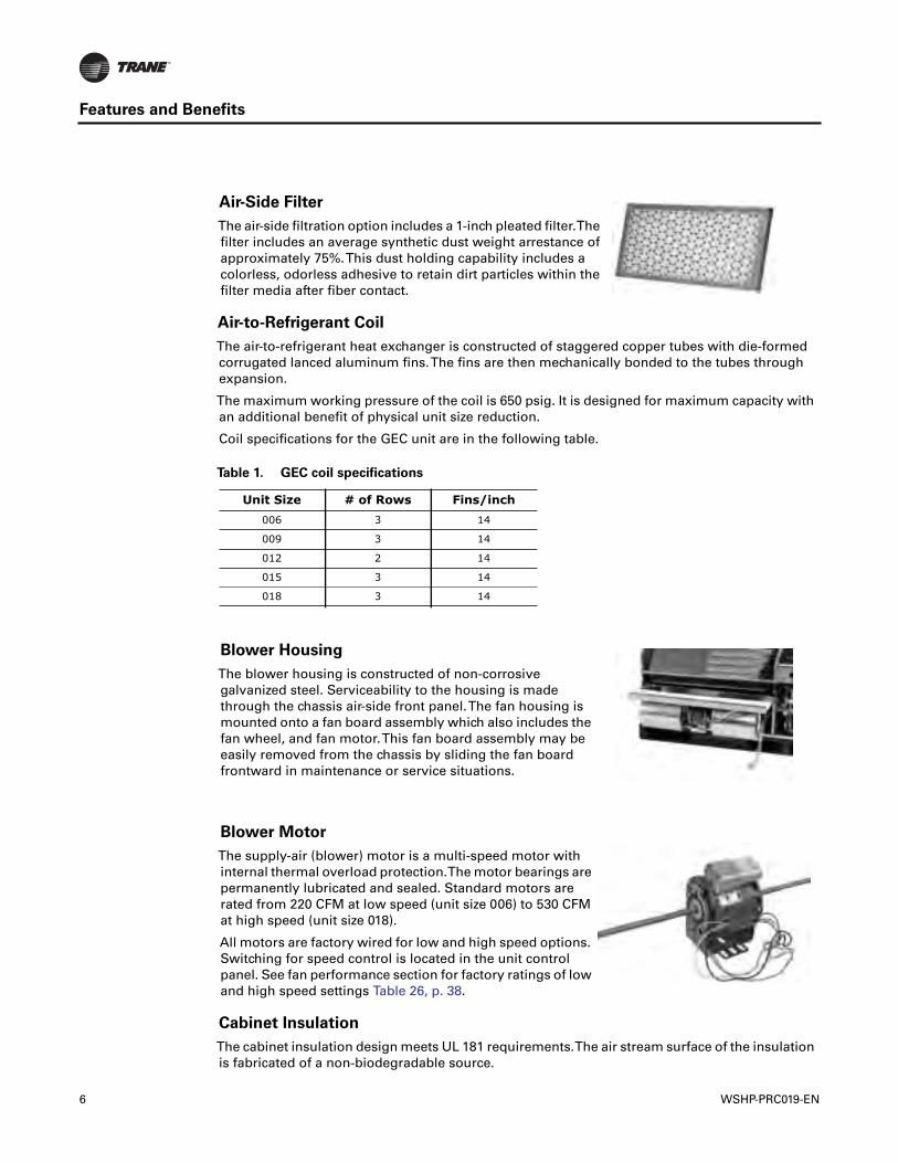
Air-to-Refrigerant Coil
The air-to-refrigerant heat exchanger is constructed of staggered copper tubes with die-formedcorrugated lanced aluminum fins.The fins are then mechanically bonded to the tubes throughexpansion.
The maximum working pressure of the coil is 650 psig. It is designed for maximum capacity withan additional benefit of physical unit size reduction.
Coil specifications for the GEC unit are in the following table.
Cabinet Insulation
The cabinet insulation design meets UL 181 requirements.The air stream surface of the insulationis fabricated of a non-biodegradable source.
Air-Side Filter
The air-side filtration option includes a 1-inch pleated filter.Thefilter includes an average synthetic dust weight arrestance ofapproximately 75%.This dust holding capability includes acolorless, odorless adhesive to retain dirt particles within thefilter media after fiber contact.
Table 1. GEC coil specifications
Unit Size # of Rows Fins/inch006 3 14
009 3 14
012 2 14
015 3 14
018 3 14
Blower Housing
The blower housing is constructed of non-corrosivegalvanized steel. Serviceability to the housing is madethrough the chassis air-side front panel.The fan housing ismounted onto a fan board assembly which also includes thefan wheel, and fan motor.This fan board assembly may beeasily removed from the chassis by sliding the fan boardfrontward in maintenance or service situations.
Blower Motor
The supply-air (blower) motor is a multi-speed motor withinternal thermal overload protection.The motor bearings arepermanently lubricated and sealed. Standard motors arerated from 220 CFM at low speed (unit size 006) to 530 CFMat high speed (unit size 018).
All motors are factory wired for low and high speed options.Switching for speed control is located in the unit controlpanel. See fan performance section for factory ratings of lowand high speed settings Table 26, p. 38.
6 WSHP-PRC019-EN
Features and Benefits
The insulation in the wet section of the cabinet complies with ASHRAE standard 62 toaccommodate (IAQ) indoor air quality standards.
Compressor and Co-axial Coil Isolation
Vibration isolation for the compressor and co-axial water coil is accomplished by increasing therigidity and stiffness at the base for the compressor, and at the back of the chassis for the co-axialwater coil.This platform includes double isolation to the compressor and single isolation to the co-axial water coil.
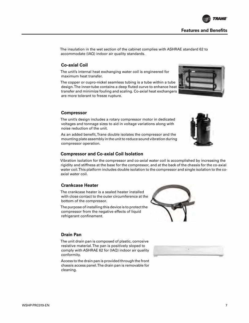
Co-axial Coil
The unit’s internal heat exchanging water coil is engineered formaximum heat transfer.
The copper or cupro-nickel seamless tubing is a tube within a tubedesign.The inner-tube contains a deep fluted curve to enhance heattransfer and minimize fouling and scaling. Co-axial heat exchangersare more tolerant to freeze rupture.
Compressor
The unit’s design includes a rotary compressor motor in dedicatedvoltages and tonnage sizes to aid in voltage variations along withnoise reduction of the unit.
As an added benefit,Trane double isolates the compressor and themounting plate assembly in the unit to reduce sound vibration duringcompressor operation.
Crankcase Heater
The crankcase heater is a sealed heater installedwith close contact to the outer circumference at thebottom of the compressor.
The purpose of installing this device is to protect thecompressor from the negative effects of liquidrefrigerant confinement.
Drain Pan
The unit drain pan is composed of plastic, corrosiveresistive material.The pan is positively sloped tocomply with ASHRAE 62 for (IAQ) indoor air qualityconformity.
Access to the drain pan is provided through the frontchassis access panel.The drain pan is removable forcleaning.
WSHP-PRC019-EN 7
Features and Benefits
Refrigeration Piping
The unit’s copper tubing is created from a 99% pure copper formation that conforms to theAmerican Society ofTesting (ASTM) B743 for seamless, light-annealed processing.
The unit’s copper refrigeration system is manufactured to be free from contaminants andconditions such as drilling fragments, dirt, or oil.This reduces the possibility of these contaminantsdamaging the compressor motor.
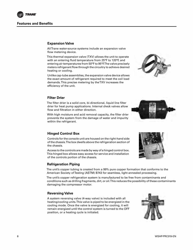
Expansion Valve
AllTrane water-source systems include an expansion valveflow metering device.
This thermal expansion valve (TXV) allows the unit to operatewith an entering fluid temperature from 25°F to 120°F, andentering air temperatures from 50°F to 95°F.The valve preciselymeters refrigerant flow through the circuitry to achieve desiredheating or cooling.
Unlike cap-tube assemblies, the expansion valve device allowsthe exact amount of refrigerant required to meet the coil loaddemands.This precise metering by theTXV increases theefficiency of the unit.
Filter Drier
The filter drier is a solid core, bi-directional, liquid line filterdrier for heat pump applications. Internal check valves allowflow and filtration in either direction.
With high moisture and acid removal capacity, the filter drierprevents the system from the damage of water and impuritywithin the refrigerant.
Hinged Control Box
Controls for the console unit are housed on the right-hand sideof the chassis.The box dwells above the refrigeration section ofthe chassis.
Access to the controls are made by way of a hinged control box.This hinged box allows easy access for service and installationof the controls portion of the chassis.
Reversing Valve
A system reversing valve (4-way valve) is included with allheating/cooling units.This valve is piped to be energized in thecooling mode. Once the valve is energized for cooling, it willremain energized until the control system is turned to the OFFposition, or a heating cycle is initiated.
8 WSHP-PRC019-EN

Features and Benefits
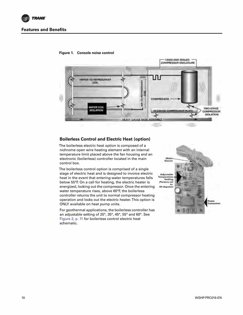
Sound Attenuation Package
The console equipment is designed to achieve the lowest noise levels possible. Extensive testinghas identified the major sound generating sources within the console unit package. Every effort hasbeen made to minimize the sound generation and transmission from the compressor, heatexchangers, and fan sources. Vibration transmission from the compressor and heat exchangershave been minimized by the use of isolation.The use of heavy metal gauges in critical areasenhance the unit acoustic performance. A patented two-stage compressor isolation system hasbeen specifically designed for the console unit. Acoustic lining has been used to quiet compressornoise.
The unit air side acoustic performance has been engineered to obtain the quietest acousticperformance through the fan, and fan housing selection.The fin tube (air-to-refrigerant) coil andfan discharge arrangement includes an additional acoustic lining in the fan compartment to furtherreduce the air side sound levels. See sound performance data on p. 41 and Figure 1, p. 10 forconsole noise control design.
The standard unit sound package for the console unit includes:
• Two stage compressor vibration isolation
• Water-to-refrigerant heat exchanger vibration isolation
• 12-gauge intermediate mounting plate for the compressor
• Lined compressor enclosure with ½” cabinet insulation
• Heavy gauge base assembly
• Maximum sized return-air opening and filter sizing
Supply-Air Registers
Supply-air registers for the GEC product are constructed of aplastic, corrosive resistive material.The registers include asnap-in deflection design to simplify installation, as well asfacilitate the ability to apply a bi-directional arrangementacross the register.
Wall Sleeve
The cabinets wall sleeve is attached to thewall by (4) four, #10 field provided screws.This rigid design allows for ease ofseparation from the cabinet assemblyduring service or installation situations.
The wall sleeve is painted the same coloras the cabinet for aesthetic purposes.
WSHP-PRC019-EN 9
Features and Benefits
Figure 1. Console noise control
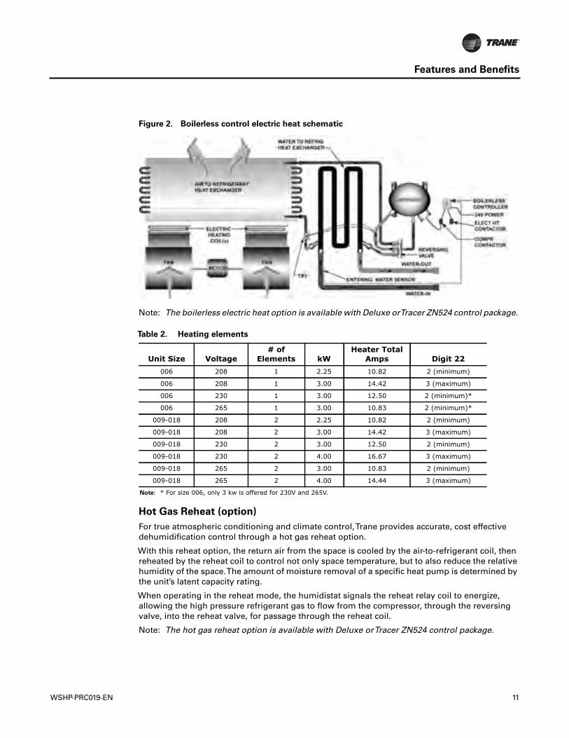
Boilerless Control and Electric Heat (option)
The boilerless electric heat option is composed of anichrome open wire heating element with an internaltemperature limit placed above the fan housing and anelectronic (boilerless) controller located in the maincontrol box.
The boilerless control option is comprised of a singlestage of electric heat and is designed to invoice electricheat in the event that entering-water temperatures fallsbelow 55°F. On a call for heating, the electric heater isenergized, locking out the compressor. Once the enteringwater temperature rises, above 60°F, the boilerlesscontroller returns the unit to normal compressor heatingoperation and locks out the electric heater.This option isONLY available on heat pump units.
For geothermal applications, the boilerless controller hasan adjustable setting of 25°, 35°, 45°, 55° and 60°. SeeFigure 2, p. 11 for boilerless control electric heatschematic.
10 WSHP-PRC019-EN
Features and Benefits
Note: The boilerless electric heat option is available with Deluxe orTracer ZN524 control package.
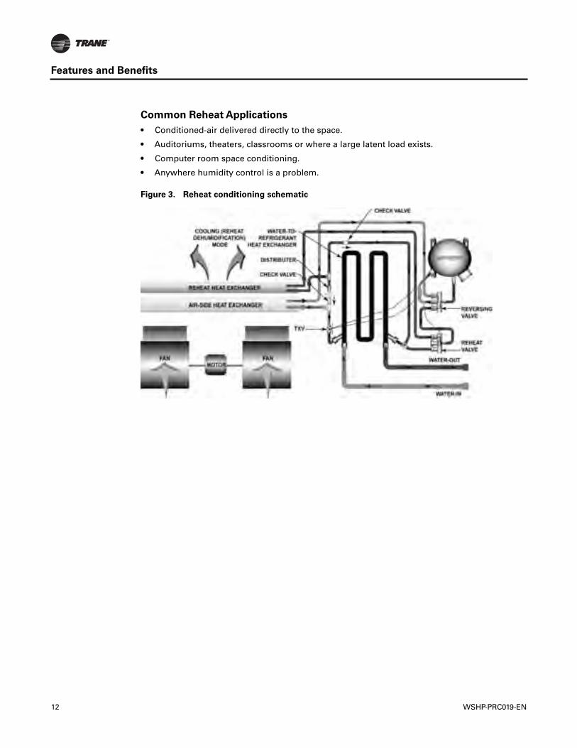
Hot Gas Reheat (option)
For true atmospheric conditioning and climate control,Trane provides accurate, cost effectivedehumidification control through a hot gas reheat option.
With this reheat option, the return air from the space is cooled by the air-to-refrigerant coil, thenreheated by the reheat coil to control not only space temperature, but to also reduce the relativehumidity of the space.The amount of moisture removal of a specific heat pump is determined bythe unit’s latent capacity rating.
When operating in the reheat mode, the humidistat signals the reheat relay coil to energize,allowing the high pressure refrigerant gas to flow from the compressor, through the reversingvalve, into the reheat valve, for passage through the reheat coil.
Note: The hot gas reheat option is available with Deluxe orTracer ZN524 control package.
Figure 2. Boilerless control electric heat schematic
Table 2. Heating elements
Unit Size Voltage# of
Elements kWHeater Total
Amps Digit 22006 208 1 2.25 10.82 2 (minimum)
006 208 1 3.00 14.42 3 (maximum)
006 230 1 3.00 12.50 2 (minimum)*
006 265 1 3.00 10.83 2 (minimum)*
009-018 208 2 2.25 10.82 2 (minimum)
009-018 208 2 3.00 14.42 3 (maximum)
009-018 230 2 3.00 12.50 2 (minimum)
009-018 230 2 4.00 16.67 3 (maximum)
009-018 265 2 3.00 10.83 2 (minimum)
009-018 265 2 4.00 14.44 3 (maximum)
Note: * For size 006, only 3 kw is offered for 230V and 265V.
WSHP-PRC019-EN 11
Features and Benefits
Common Reheat Applications
• Conditioned-air delivered directly to the space.
• Auditoriums, theaters, classrooms or where a large latent load exists.
• Computer room space conditioning.
• Anywhere humidity control is a problem.
Figure 3. Reheat conditioning schematic
12 WSHP-PRC019-EN
Application Considerations
Geothermal System
Closed-loop systems (both ground source and surface water) provide heat rejection and heataddition to maintain proper water-source temperatures.The choice of vertical, horizontal, or lakeloop earth coupling, should be based on the characteristics of each application.
Horizontal and vertical systems can be designed to provide the same fluid temperatures under agiven set of conditions.The surface (lake) loop system may see a greater variance of fluidtemperatures, but the reduced installation cost may compensate for any minor reduction inperformance.The three earth coupling methods should be considered at each application, with themost cost effective method chosen after all have been evaluated.
Operating and maintenance cost are low because an auxiliary electric/fossil fuel boiler and coolingtower are not required to maintain the loop temperature in a properly designed system.
The technology has advanced to the point where many electric utilities and rural electriccooperatives are offering incentives for the installation of geothermal systems.These incentivesare offered because of savings to the utilities due to reduced peak loads and flatten out the systemdemand curve over time.
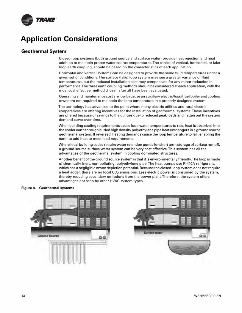
When building cooling requirements cause loop water temperatures to rise, heat is absorbed intothe cooler earth through buried high density polyethylene pipe heat exchangers in a ground sourcegeothermal system. If reversed, heating demands cause the loop temperature to fall, enabling theearth to add heat to meet load requirements.
Where local building codes require water retention ponds for short term storage of surface run-off,a ground source surface water system can be very cost effective.This system has all theadvantages of the geothermal system in cooling dominated structures.
Another benefit of the ground source system is that it is environmentally friendly.The loop is madeof chemically inert, non-polluting, polyethylene pipe.The heat pumps use R-410A refrigerant,which has a negligible ozone depletion potential. Because the closed-loop system does not requirea heat adder, there are no local CO2 emissions. Less electric power is consumed by the system,thereby reducing secondary emissions from the power plant.Therefore, the system offersadvantages not seen by other HVAC system types.
Figure 4. Geothermal systems
13 WSHP-PRC019-EN
Application Considerations
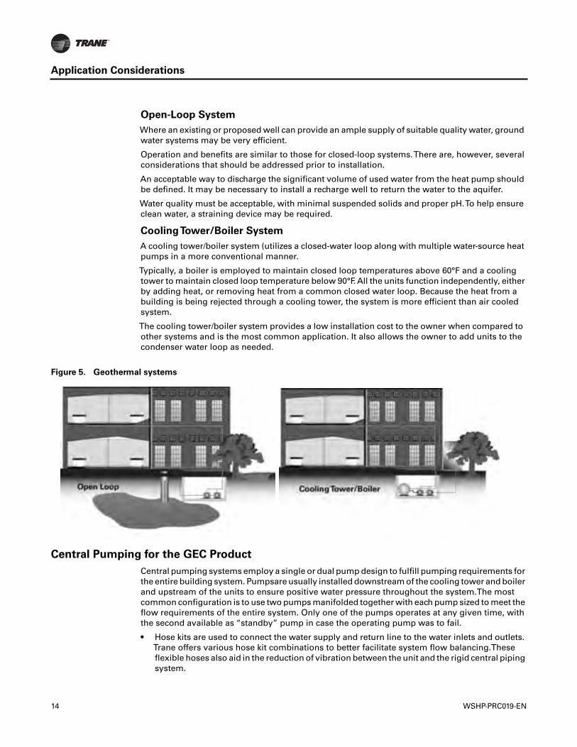
Open-Loop System
Where an existing or proposed well can provide an ample supply of suitable quality water, groundwater systems may be very efficient.
Operation and benefits are similar to those for closed-loop systems.There are, however, severalconsiderations that should be addressed prior to installation.
An acceptable way to discharge the significant volume of used water from the heat pump shouldbe defined. It may be necessary to install a recharge well to return the water to the aquifer.
Water quality must be acceptable, with minimal suspended solids and proper pH.To help ensureclean water, a straining device may be required.
CoolingTower/Boiler System
A cooling tower/boiler system (utilizes a closed-water loop along with multiple water-source heatpumps in a more conventional manner.
Typically, a boiler is employed to maintain closed loop temperatures above 60°F and a coolingtower to maintain closed loop temperature below 90°F. All the units function independently, eitherby adding heat, or removing heat from a common closed water loop. Because the heat from abuilding is being rejected through a cooling tower, the system is more efficient than air cooledsystem.
The cooling tower/boiler system provides a low installation cost to the owner when compared toother systems and is the most common application. It also allows the owner to add units to thecondenser water loop as needed.
Central Pumping for the GEC Product
Central pumping systems employ a single or dual pump design to fulfill pumping requirements forthe entire building system. Pumpsare usually installed downstream of the cooling tower and boilerand upstream of the units to ensure positive water pressure throughout the system.The mostcommon configuration is to use two pumps manifolded together with each pump sized to meet theflow requirements of the entire system. Only one of the pumps operates at any given time, withthe second available as “standby” pump in case the operating pump was to fail.
• Hose kits are used to connect the water supply and return line to the water inlets and outlets.Trane offers various hose kit combinations to better facilitate system flow balancing.Theseflexible hoses also aid in the reduction of vibration between the unit and the rigid central pipingsystem.
Figure 5. Geothermal systems
14 WSHP-PRC019-EN
Application Considerations
• A two position isolation valve is often applied to systems which incorporate variable frequencypumping.This valve is capable of stopping/startingwater flow to the unit, which in turn reducesthe pumping requirements for the entire system.
• The central system supply and return lines should be sized to handle the required flow with aminimum pressure drop.
Note: Pipe will sweat if low temperature water is below the dew point of the surrounding space.Trane recommends that these lines be insulated to prevent damage from condensationwhen condenser loop is designed to be below 60°F. Equipment installed in attic/crawl spacetemperatures below 40°F may require antifreeze in the water loop.
Installation Considerations
1. The field supplied line voltage disconnect with circuit breaker should be installed for branchcircuit protection.
2. The units (2) high voltage connection is located in the right or left hand end pocket.The fieldconnection may be made to the factory ordered disconnect, or hard wired via the factorymounted 2 x 4 handy box.
3. The (3) low voltage connections are made on the right hand side of the unit for units orderedwith the wall mounted thermostat or sensor options.The low voltage connection is factorymade if unit mounted controls are specified.
4. Because of the units blow-through design, no condensate trapping is necessary. However, it isnecessary for the condensate to run in a downward motion to allow gravity to produce aconstant outflow.
5. Hose kits are used to connect the water supply and return lines to the water inlet and outlets.Trane can provide various hose kit combinations to better facilitate system flow balancing.These flexible hoses, reduce vibration between the unit and the rigid piping system. For moreinformation on the types of hose kitsTrane recommends, review the WSHP-PRC025-ENmanual.
6. The console design includes a factory provided wall sleeve to facilitate installation of the unitin it’s establishment.
7. The grilles are made of a durable plastic symmetrical design. The design constitutes the abilityof a multi-directional supply-air from the units top.
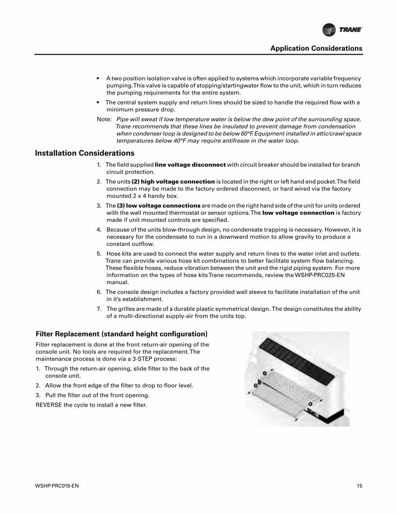
Filter Replacement (standard height configuration)
Filter replacement is done at the front return-air opening of theconsole unit. No tools are required for the replacement.Themaintenance process is done via a 3-STEP process:
1. Through the return-air opening, slide filter to the back of theconsole unit.
2. Allow the front edge of the filter to drop to floor level.
3. Pull the filter out of the front opening.
REVERSE the cycle to install a new filter.
WSHP-PRC019-EN 15
Application Considerations
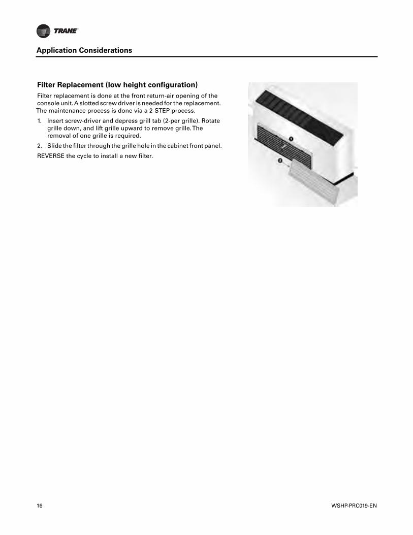
Filter Replacement (low height configuration)
Filter replacement is done at the front return-air opening of theconsole unit.A slotted screw driver is needed for the replacement.The maintenance process is done via a 2-STEP process.
1. Insert screw-driver and depress grill tab (2-per grille). Rotategrille down, and lift grille upward to remove grille.Theremoval of one grille is required.
2. Slide the filter through the grille hole in the cabinet front panel.
REVERSE the cycle to install a new filter.
16 WSHP-PRC019-EN
Selection Procedure
The performance standard AHRI/ISO 13256-1 became effective Jan. 1, 2000. It replaces AHRIstandards 320, 325 and 330.This new standard has three major categories:Water Loop (AHRI 320),GroundWater (AHRI 325), Ground Loop (AHRI 330). Although these standards are similar there aresome differences.
The cooling efficiency is measured in EER but includes a Watt-per-Watt unit of measure similar tothe traditional COP measurement.
The entering water temperature has changed to reflect the centigrade temperature scale. Forinstance the water loop heating test is performed with 68°F (20°C) water instead of 70°F.The coolingtests are performed with 80.6°F (27°C) dry bulb and 66.2°F (19°C) wet bulb entering air instead ofthe traditional 80°F dry bulb, and 67°F wet bulb entering air temperatures.This data (80.6/66.2) maybe converted to 80/67 by using the entering air correction table.
A pump power correction has been added onto the existing power consumption. Within eachmodel, only one water flow rate is specified for each performance category, and pumping watts arecalculated utilizing the pump power correction formula: (gpm x 0.0631) x press drop x 2990) / 300.
Note: gpm relates to water flow, and press drop relates to the drop through the unit heatexchanger at rated water flow in feet of head.
The fan power is corrected to zero external static pressure.The nominal airflow is rated at a specificexternal static pressure.This effectively reduces the power consumption of the unit, and increasescooling capacity but decreases heating capacity.These watts are significant enough in most casesto increase EER and COP over AHRI 320, 325, and 330 ratings.
Cooling Dominated Applications
If humidity levels are moderate to high in a cooling dominated application, the heat pump shouldbe selected to meet or exceed the calculated sensible load.Also, the unit’s sensible capacity shouldbe no more than 115% of the total cooling load (sensible + latent), unless the calculated latent loadis less than the latent capacity of the unit.
The sensible-to-total cooling ratio can be adjusted with airflow. If the airflow is lowered, the unitlatent capacity will increase. When less air is pulled across the DX coil, more moisture willcondense from the air.
Heating Dominated Applications
Unit sizing in heating dominated applications is based upon humidity levels for the climate, andgoals for operating cost and installation costs.
If humidity levels are moderate, the heat pump should be selected with the heating capacity equalto 125% of the cooling load.
If humidity levels are low in the application and low operating cost is important, the heat pump andground loop should be sized for 90% to 100% of the heating load.
If humidity levels are low and lower initial cost is important, then the heat pump and ground loopshould be sized for 70% to 85% of the heating load, with the remaining load to be treated withelectric resistance heat.
Installation cost will be reduced in this approach because of the smaller heat pump selection andless loop materials.
In general, the system will not use enough electric heat to offset the higher installation costsassociated with a fully sized or oversized system.
Finally, a unit sized for the entire heating load in a heating dominated application will be oversizedin cooling. Comfort is reduced from increased room humidity caused by short-run times. Shortcycling will also shorten the life expectancy of the equipment and increase power consumption andoperating cost.
WSHP-PRC019-EN 17

Selection Procedure
Many rebate incentives require the heat pump and ground loop to be sized for the entire heatingload. Check with your local utility for their requirements.
Selection Program
All WSHP products should be selected through theTrane Official Product Selection System,TOPSS™.
If this program has not been made available, ask a localTrane sales engineer to supply the desiredselections or provide a copy of the program.
Required Fields
The first step in the selection is to determine either:
• Total cooling capacity
• Sensible capacity
• Heating capacity
The maximum allowable water pressure drop and selection ranges can also be identified.
18 WSHP-PRC019-EN
Model Number Descriptions
Digits 1-3 — Unit ConfigurationGEC= High Efficiency Console
Digit 4 — Unit ConfigurationE
Digits 5-7 — Nominal Capacity
006 = ½Ton009 = ¾Ton012 = 1Ton015 = 1¼Ton018 = 1½TontDigit 8 — Voltage
(Volts/Hz/Phase)0 = 115/60/11 = 208/60/12 = 230/60/16 = 220-240/50/17 = 265/60/1
Digit 9 — Heat Exchanger1 = Copper-Water Coil2 = Cupro-Nickel Water Coil
Digit 10 — Design SequenceB
Digit 11 — Refrigeration Circuit0 = Heating and Cooling Circuit2 = Heating and Cooling Circuit with
Hot Gas Reheat
Digit 12 — Blower Configuration1 = Standard Blower Motor
Digit 13 — Freeze Protection0 = None or StandardA = 20° FreezestatB = 35° Freezestat
Digit 14 — Open Digit0 = Open DigitS = Design Special
Digit 15 — Supply-AirArrangement
0 = Standard Supply-AirArrangement
Digit 16 — Return-AirArrangement
0 = Standard Return-AirArrangement
Digit 17 — ControlTypes0 = Basic 24V ControlsD = Deluxe 24V ControlsC = Tracer ZN510 ControlsB = Tracer ZN524 ControlsE = Deluxe 24V Control with Low
Temp Unoccupied Sensor &ProgrammableThermostat
WSHP-PRC019-EN
Digit 18 —Tstat/Sensor Location0 = Wall Mounted Location1 = Unit Mounted Location with
Standard Entry2 = Unit Mounted Location with
Key lock Entry
Digit 19 — Fault Sensors0 = No Fault Sensor1 = Condensate Overflow Sensor2 = Filter MaintenanceTimer3 = Condensate Overflow and Filter
MaintenanceTimer4 = Fan Status Sensor6 = Condensate Overflow and Fan
StatusH = Fan Status and Filter Maintenance
TimerJ = Fan Status, Filter Maintenance
Timer and Condensate OverflowSensor
Digit 20 —Temperature Sensor0 = No AdditionalTemperature
Sensor1 = Entering Water Sensor
Digit 21 — Open Digit0 = Open Digit
Digit 22 — Electric Heat0 = No Electric Heat2 = Boilerless Control Electric Heat
(minimum)3 = Boilerless Control Electric Heat
(maximum)
Digit 23 — Unit MountedDisconnect
0 = No Unit Mounted DisconnectA = Power Cord/Receptacle BoxB = Power Cord/Receptacle Box
with Circuit BreakerC = On/OffToggle Switch
Digit 24 — FilterType0 = No Filter; Chassis Only1 = 1"Throwaway FilterA = 1" Pleated Filter
Digit 25 — AcousticArrangement
0 = Enhanced Sound Attenuation
Digit 26 — Factory Configuration0 = Standard Factory Configuration
(Chassis, Cabinet and Subbase)1 = Chassis ONLY2 = Low Height Factory
Configuration (Chassis, Cabinetand Subbase)
3 = Extended Length FactoryConfiguration (Chassis, Cabinetand Subbase)
Digit 27 — Paint Color0 = No Paint Selection Available1 = Deluxe Beige2 = Cameo White3 = Soft Dove
Digit 28 — Outside Air0 = No Outside Air Option1 = Outside Air Opening2 = Motorized Outside Air
(2-position)
Digit 29 — Piping ArrangementL = Left Hand Piping ArrangementR = Right Hand Piping Arrangement
Digit 30-36 — Does Not Applyto GEC
0000000 = Digits 30-36 are notapplicable to the GEC product
19
20 WSHP-PRC019-EN
General Data
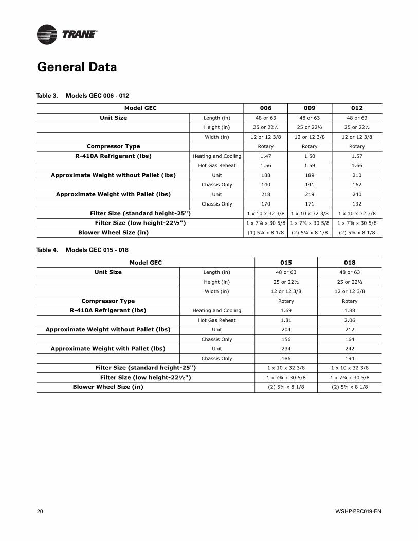
Table 3. Models GEC 006 - 012
Model GEC 006 009 012
Unit Size Length (in) 48 or 63 48 or 63 48 or 63
Height (in) 25 or 22½ 25 or 22½ 25 or 22½
Width (in) 12 or 12 3/8 12 or 12 3/8 12 or 12 3/8
Compressor Type Rotary Rotary Rotary
R-410A Refrigerant (lbs) Heating and Cooling 1.47 1.50 1.57
Hot Gas Reheat 1.56 1.59 1.66
Approximate Weight without Pallet (lbs) Unit 188 189 210
Chassis Only 140 141 162
Approximate Weight with Pallet (lbs) Unit 218 219 240
Chassis Only 170 171 192
Filter Size (standard height-25") 1 x 10 x 32 3/8 1 x 10 x 32 3/8 1 x 10 x 32 3/8
Filter Size (low height-22½") 1 x 7¾ x 30 5/8 1 x 7¾ x 30 5/8 1 x 7¾ x 30 5/8
Blower Wheel Size (in) (1) 5¼ x 8 1/8 (2) 5¼ x 8 1/8 (2) 5¼ x 8 1/8
Table 4. Models GEC 015 - 018
Model GEC 015 018
Unit Size Length (in) 48 or 63 48 or 63
Height (in) 25 or 22½ 25 or 22½
Width (in) 12 or 12 3/8 12 or 12 3/8
Compressor Type Rotary Rotary
R-410A Refrigerant (lbs) Heating and Cooling 1.69 1.88
Hot Gas Reheat 1.81 2.06
Approximate Weight without Pallet (lbs) Unit 204 212
Chassis Only 156 164
Approximate Weight with Pallet (lbs) Unit 234 242
Chassis Only 186 194
Filter Size (standard height-25") 1 x 10 x 32 3/8 1 x 10 x 32 3/8
Filter Size (low height-22½") 1 x 7¾ x 30 5/8 1 x 7¾ x 30 5/8
Blower Wheel Size (in) (2) 5¼ x 8 1/8 (2) 5¼ x 8 1/8
Performance Data
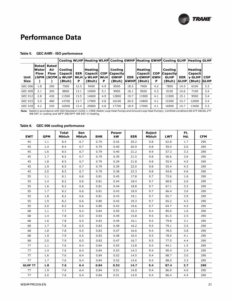
Table 5. GEC AHRI - ISO performance
Cooling WLHP Heating WLHP Cooling GWHP Heating GWHP Cooling GLHP Heating GLHP
Unit Size
Rated Water Flow (GPM
)
Rated Air
Flow (SCFM
)
Cooling Capacity WLHP (Btuh)
EER WLH
P
Heating Capacity WLHP (Btuh)
COP WLH
P
Cooling Capacity GWHP (Btuh)
EER GWHP
Heating Capacity GWHP (Btuh)
COP GWH
P
Cooling Capacity
GLHP (Btuh)
EER GLHP
Heating Capacity GLHP (Btuh)
COP GLHP
GEC 006 1.8 290 7500 12.5 9400 4.9 8500 18.5 7900 4.2 7800 14.5 6100 3.3
GEC 009 2.1 305 8800 13.1 10900 5.1 9900 18.1 9500 4.3 9100 14.6 7100 3.4
GEC 012 2.8 430 11500 13.5 14600 4.9 12800 19.7 11900 4.1 11900 15.1 9500 3.4
GEC 015 3.5 480 14700 13.7 17900 4.8 16100 20.0 14800 4.1 15300 15.7 12000 3.4
GEC 018 4.2 530 16500 13.4 20800 4.8 17700 18.9 17000 4.1 16900 14.7 13400 3.3
Note: Rated in accordance with ISO Standard 13256-1:1998 (Water Loop Heat Pumps and Ground Loop Heat Pumps). Certified conditions 80.6°F DB/66.2°F WB EAT in cooling and 68°F DB/59°F WB EAT in heating.
Table 6. GEC 006 cooling performance
EWT GPMTotal
MbtuhSen
Mbtuh SHRPower
kW EERRejectMbtuh LWT
Ft.Hd. CFM
45 1.1 8.4 6.7 0.79 0.42 20.2 9.8 62.8 1.7 290
45 1.4 8.4 6.7 0.79 0.40 20.9 9.8 59.0 2.6 290
45 1.6 8.5 6.7 0.79 0.40 21.2 9.9 57.3 3.3 290
45 1.7 8.5 6.7 0.79 0.39 21.5 9.8 56.6 3.6 290
45 1.8 8.5 6.7 0.79 0.39 21.8 9.8 55.9 4.0 290
45 1.9 8.5 6.7 0.79 0.39 22.0 9.8 55.4 4.3 290
45 2.0 8.5 6.7 0.79 0.38 22.3 9.8 54.8 4.6 290
55 1.1 8.1 6.6 0.81 0.45 17.8 9.7 72.6 1.6 290
55 1.4 8.2 6.6 0.81 0.44 18.4 9.7 68.8 2.6 290
55 1.6 8.2 6.6 0.81 0.44 18.8 9.7 67.1 3.2 290
55 1.7 8.2 6.6 0.81 0.43 18.9 9.7 66.4 3.6 290
55 1.8 8.2 6.6 0.81 0.43 19.1 9.7 65.7 3.9 290
55 1.9 8.2 6.6 0.80 0.43 19.3 9.7 65.2 4.2 290
55 2.0 8.2 6.6 0.80 0.42 19.6 9.7 64.7 4.5 290
68 1.1 7.7 6.4 0.84 0.50 15.3 9.4 85.0 1.6 290
68 1.4 7.8 6.5 0.83 0.49 15.8 9.5 81.5 2.5 290
68 1.6 7.8 6.5 0.83 0.49 16.1 9.5 79.8 3.1 290
68 1.7 7.8 6.5 0.83 0.48 16.2 9.5 79.1 3.5 290
68 1.8 7.8 6.5 0.83 0.47 16.6 9.4 78.5 3.8 290
68 1.9 7.9 6.5 0.83 0.48 16.5 9.5 78.0 4.1 290
68 2.0 7.9 6.5 0.83 0.47 16.7 9.5 77.5 4.4 290
77 1.1 7.6 6.4 0.84 0.55 13.8 9.4 94.1 1.5 290
77 1.4 7.6 6.4 0.84 0.53 14.3 9.4 90.4 2.4 290
77 1.6 7.6 6.4 0.84 0.52 14.5 9.4 88.7 3.0 290
77 1.7 7.6 6.4 0.84 0.52 14.6 9.4 88.0 3.3 290
GLHP 77 1.8 7.6 6.4 0.84 0.52 14.7 9.4 87.4 3.7 290
77 1.9 7.6 6.4 0.84 0.51 14.8 9.4 86.9 4.0 290
77 2.0 7.6 6.4 0.84 0.51 14.9 9.4 86.4 4.4 290
WSHP-PRC019-EN 21
Performance Data
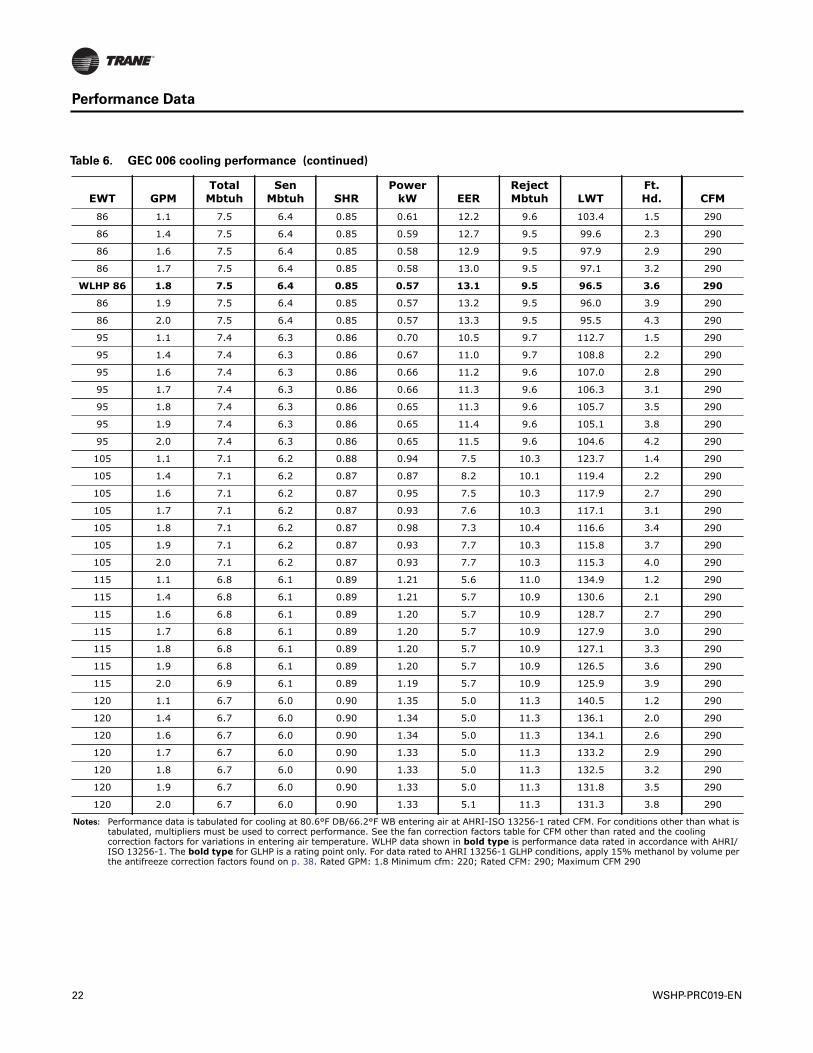
86 1.1 7.5 6.4 0.85 0.61 12.2 9.6 103.4 1.5 290
86 1.4 7.5 6.4 0.85 0.59 12.7 9.5 99.6 2.3 290
86 1.6 7.5 6.4 0.85 0.58 12.9 9.5 97.9 2.9 290
86 1.7 7.5 6.4 0.85 0.58 13.0 9.5 97.1 3.2 290
WLHP 86 1.8 7.5 6.4 0.85 0.57 13.1 9.5 96.5 3.6 290
86 1.9 7.5 6.4 0.85 0.57 13.2 9.5 96.0 3.9 290
86 2.0 7.5 6.4 0.85 0.57 13.3 9.5 95.5 4.3 290
95 1.1 7.4 6.3 0.86 0.70 10.5 9.7 112.7 1.5 290
95 1.4 7.4 6.3 0.86 0.67 11.0 9.7 108.8 2.2 290
95 1.6 7.4 6.3 0.86 0.66 11.2 9.6 107.0 2.8 290
95 1.7 7.4 6.3 0.86 0.66 11.3 9.6 106.3 3.1 290
95 1.8 7.4 6.3 0.86 0.65 11.3 9.6 105.7 3.5 290
95 1.9 7.4 6.3 0.86 0.65 11.4 9.6 105.1 3.8 290
95 2.0 7.4 6.3 0.86 0.65 11.5 9.6 104.6 4.2 290
105 1.1 7.1 6.2 0.88 0.94 7.5 10.3 123.7 1.4 290
105 1.4 7.1 6.2 0.87 0.87 8.2 10.1 119.4 2.2 290
105 1.6 7.1 6.2 0.87 0.95 7.5 10.3 117.9 2.7 290
105 1.7 7.1 6.2 0.87 0.93 7.6 10.3 117.1 3.1 290
105 1.8 7.1 6.2 0.87 0.98 7.3 10.4 116.6 3.4 290
105 1.9 7.1 6.2 0.87 0.93 7.7 10.3 115.8 3.7 290
105 2.0 7.1 6.2 0.87 0.93 7.7 10.3 115.3 4.0 290
115 1.1 6.8 6.1 0.89 1.21 5.6 11.0 134.9 1.2 290
115 1.4 6.8 6.1 0.89 1.21 5.7 10.9 130.6 2.1 290
115 1.6 6.8 6.1 0.89 1.20 5.7 10.9 128.7 2.7 290
115 1.7 6.8 6.1 0.89 1.20 5.7 10.9 127.9 3.0 290
115 1.8 6.8 6.1 0.89 1.20 5.7 10.9 127.1 3.3 290
115 1.9 6.8 6.1 0.89 1.20 5.7 10.9 126.5 3.6 290
115 2.0 6.9 6.1 0.89 1.19 5.7 10.9 125.9 3.9 290
120 1.1 6.7 6.0 0.90 1.35 5.0 11.3 140.5 1.2 290
120 1.4 6.7 6.0 0.90 1.34 5.0 11.3 136.1 2.0 290
120 1.6 6.7 6.0 0.90 1.34 5.0 11.3 134.1 2.6 290
120 1.7 6.7 6.0 0.90 1.33 5.0 11.3 133.2 2.9 290
120 1.8 6.7 6.0 0.90 1.33 5.0 11.3 132.5 3.2 290
120 1.9 6.7 6.0 0.90 1.33 5.0 11.3 131.8 3.5 290
120 2.0 6.7 6.0 0.90 1.33 5.1 11.3 131.3 3.8 290
Notes: Performance data is tabulated for cooling at 80.6°F DB/66.2°F WB entering air at AHRI-ISO 13256-1 rated CFM. For conditions other than what is tabulated, multipliers must be used to correct performance. See the fan correction factors table for CFM other than rated and the cooling correction factors for variations in entering air temperature. WLHP data shown in bold type is performance data rated in accordance with AHRI/ISO 13256-1. The bold type for GLHP is a rating point only. For data rated to AHRI 13256-1 GLHP conditions, apply 15% methanol by volume per the antifreeze correction factors found on p. 38. Rated GPM: 1.8 Minimum cfm: 220; Rated CFM: 290; Maximum CFM 290
Table 6. GEC 006 cooling performance (continued)
EWT GPMTotal
MbtuhSen
Mbtuh SHRPower
kW EERRejectMbtuh LWT
Ft.Hd. CFM
22 WSHP-PRC019-EN
Performance Data
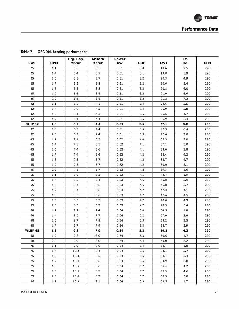
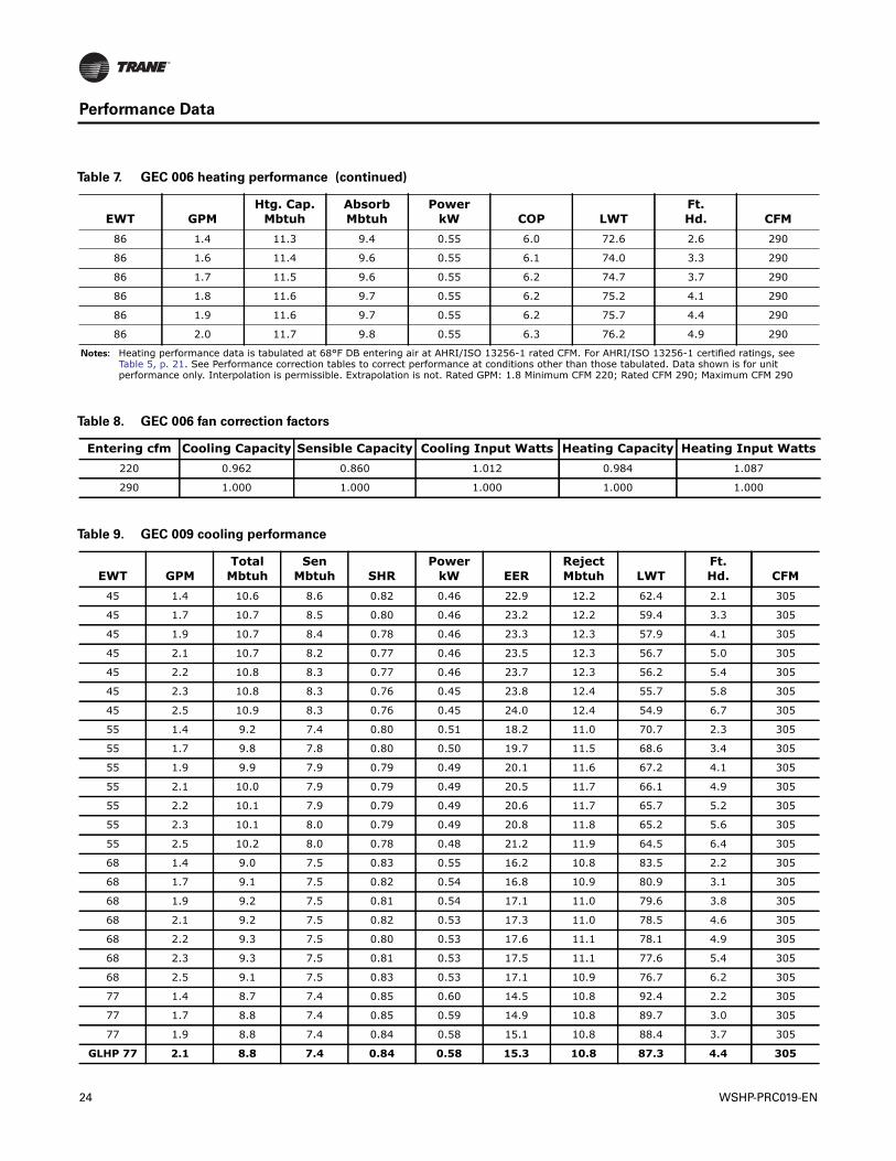
Table 7. GEC 006 heating performance
EWT GPMHtg. Cap.
MbtuhAbsorbMbtuh
PowerkW COP LWT
Ft.Hd. CFM
25 1.1 5.3 3.5 0.51 3.0 18.6 2.5 290
25 1.4 5.4 3.7 0.51 3.1 19.8 3.9 290
25 1.6 5.5 3.7 0.51 3.2 20.3 4.9 290
25 1.7 5.5 3.8 0.51 3.2 20.6 5.4 290
25 1.8 5.5 3.8 0.51 3.2 20.8 6.0 290
25 1.9 5.6 3.8 0.51 3.2 21.0 6.6 290
25 2.0 5.6 3.8 0.51 3.2 21.2 7.2 290
32 1.1 5.8 4.1 0.51 3.4 24.6 2.5 290
32 1.4 6.0 4.3 0.51 3.4 25.9 3.8 290
32 1.6 6.1 4.3 0.51 3.5 26.6 4.7 290
32 1.7 6.1 4.4 0.51 3.5 26.9 5.3 290
GLHP 32 1.8 6.2 4.4 0.51 3.5 27.1 5.8 290
32 1.9 6.2 4.4 0.51 3.5 27.3 6.4 290
32 2.0 6.2 4.4 0.51 3.5 27.6 7.0 290
45 1.1 7.1 5.3 0.52 4.0 35.3 2.0 290
45 1.4 7.3 5.5 0.52 4.1 37.1 3.0 290
45 1.6 7.4 5.6 0.52 4.1 38.0 3.8 290
45 1.7 7.4 5.6 0.52 4.2 38.4 4.2 290
45 1.8 7.5 5.7 0.52 4.2 38.7 4.7 290
45 1.9 7.5 5.7 0.52 4.2 39.0 5.1 290
45 2.0 7.5 5.7 0.52 4.2 39.3 5.6 290
55 1.1 8.0 6.2 0.53 4.5 43.7 1.9 290
55 1.4 8.2 6.4 0.53 4.6 45.8 2.9 290
55 1.6 8.4 6.6 0.53 4.6 46.8 3.7 290
55 1.7 8.4 6.6 0.53 4.7 47.3 4.1 290
55 1.8 8.5 6.6 0.53 4.7 47.6 4.5 290
55 1.9 8.5 6.7 0.53 4.7 48.0 4.9 290
55 2.0 8.5 6.7 0.53 4.7 48.3 5.4 290
68 1.1 9.2 7.4 0.54 5.0 54.5 1.8 290
68 1.4 9.5 7.7 0.54 5.2 57.0 2.8 290
68 1.6 9.7 7.8 0.54 5.3 58.2 3.5 290
68 1.7 9.7 7.9 0.54 5.3 58.7 3.9 290
WLHP 68 1.8 9.8 7.9 0.54 5.3 59.2 4.3 290
68 1.9 9.8 8.0 0.54 5.3 59.6 4.7 290
68 2.0 9.9 8.0 0.54 5.4 60.0 5.2 290
75 1.1 9.9 8.0 0.54 5.4 60.4 1.8 290
75 1.4 10.2 8.4 0.54 5.5 63.1 2.7 290
75 1.6 10.3 8.5 0.54 5.6 64.4 3.4 290
75 1.7 10.4 8.6 0.54 5.6 64.9 3.8 290
75 1.8 10.5 8.6 0.54 5.7 65.4 4.2 290
75 1.9 10.5 8.7 0.54 5.7 65.9 4.6 290
75 2.0 10.6 8.7 0.54 5.7 66.3 5.0 290
86 1.1 10.9 9.1 0.54 5.9 69.5 1.7 290
WSHP-PRC019-EN 23
Performance Data
86 1.4 11.3 9.4 0.55 6.0 72.6 2.6 290
86 1.6 11.4 9.6 0.55 6.1 74.0 3.3 290
86 1.7 11.5 9.6 0.55 6.2 74.7 3.7 290
86 1.8 11.6 9.7 0.55 6.2 75.2 4.1 290
86 1.9 11.6 9.7 0.55 6.2 75.7 4.4 290
86 2.0 11.7 9.8 0.55 6.3 76.2 4.9 290
Notes: Heating performance data is tabulated at 68°F DB entering air at AHRI/ISO 13256-1 rated CFM. For AHRI/ISO 13256-1 certified ratings, see Table 5, p. 21. See Performance correction tables to correct performance at conditions other than those tabulated. Data shown is for unit performance only. Interpolation is permissible. Extrapolation is not. Rated GPM: 1.8 Minimum CFM 220; Rated CFM 290; Maximum CFM 290
Table 7. GEC 006 heating performance (continued)
EWT GPMHtg. Cap.
MbtuhAbsorbMbtuh
PowerkW COP LWT
Ft.Hd. CFM
Table 8. GEC 006 fan correction factors
Entering cfm Cooling Capacity Sensible Capacity Cooling Input Watts Heating Capacity Heating Input Watts220 0.962 0.860 1.012 0.984 1.087
290 1.000 1.000 1.000 1.000 1.000
Table 9. GEC 009 cooling performance
EWT GPMTotal
MbtuhSen
Mbtuh SHRPower
kW EERRejectMbtuh LWT
Ft.Hd. CFM
45 1.4 10.6 8.6 0.82 0.46 22.9 12.2 62.4 2.1 305
45 1.7 10.7 8.5 0.80 0.46 23.2 12.2 59.4 3.3 305
45 1.9 10.7 8.4 0.78 0.46 23.3 12.3 57.9 4.1 305
45 2.1 10.7 8.2 0.77 0.46 23.5 12.3 56.7 5.0 305
45 2.2 10.8 8.3 0.77 0.46 23.7 12.3 56.2 5.4 305
45 2.3 10.8 8.3 0.76 0.45 23.8 12.4 55.7 5.8 305
45 2.5 10.9 8.3 0.76 0.45 24.0 12.4 54.9 6.7 305
55 1.4 9.2 7.4 0.80 0.51 18.2 11.0 70.7 2.3 305
55 1.7 9.8 7.8 0.80 0.50 19.7 11.5 68.6 3.4 305
55 1.9 9.9 7.9 0.79 0.49 20.1 11.6 67.2 4.1 305
55 2.1 10.0 7.9 0.79 0.49 20.5 11.7 66.1 4.9 305
55 2.2 10.1 7.9 0.79 0.49 20.6 11.7 65.7 5.2 305
55 2.3 10.1 8.0 0.79 0.49 20.8 11.8 65.2 5.6 305
55 2.5 10.2 8.0 0.78 0.48 21.2 11.9 64.5 6.4 305
68 1.4 9.0 7.5 0.83 0.55 16.2 10.8 83.5 2.2 305
68 1.7 9.1 7.5 0.82 0.54 16.8 10.9 80.9 3.1 305
68 1.9 9.2 7.5 0.81 0.54 17.1 11.0 79.6 3.8 305
68 2.1 9.2 7.5 0.82 0.53 17.3 11.0 78.5 4.6 305
68 2.2 9.3 7.5 0.80 0.53 17.6 11.1 78.1 4.9 305
68 2.3 9.3 7.5 0.81 0.53 17.5 11.1 77.6 5.4 305
68 2.5 9.1 7.5 0.83 0.53 17.1 10.9 76.7 6.2 305
77 1.4 8.7 7.4 0.85 0.60 14.5 10.8 92.4 2.2 305
77 1.7 8.8 7.4 0.85 0.59 14.9 10.8 89.7 3.0 305
77 1.9 8.8 7.4 0.84 0.58 15.1 10.8 88.4 3.7 305
GLHP 77 2.1 8.8 7.4 0.84 0.58 15.3 10.8 87.3 4.4 305
24 WSHP-PRC019-EN
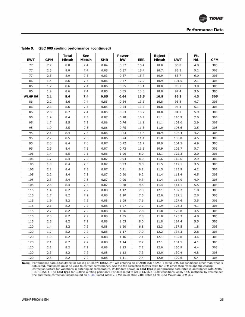
Performance Data
77 2.2 8.8 7.4 0.84 0.57 15.4 10.8 86.8 4.8 305
77 2.3 8.8 7.4 0.85 0.57 15.4 10.7 86.3 5.2 305
77 2.5 8.9 7.5 0.83 0.57 15.7 10.9 85.7 6.0 305
86 1.4 8.6 7.4 0.86 0.67 12.7 10.9 101.5 2.1 305
86 1.7 8.6 7.4 0.86 0.65 13.1 10.8 98.7 3.0 305
86 1.9 8.6 7.4 0.85 0.65 13.3 10.8 97.4 3.6 305
WLHP 86 2.1 8.6 7.4 0.85 0.64 13.5 10.8 96.3 4.3 305
86 2.2 8.6 7.4 0.85 0.64 13.6 10.8 95.8 4.7 305
86 2.3 8.6 7.4 0.85 0.64 13.6 10.8 95.4 5.1 305
86 2.5 8.7 7.4 0.85 0.63 13.7 10.8 94.7 5.9 305
95 1.4 8.4 7.3 0.87 0.78 10.9 11.1 110.9 2.0 305
95 1.7 8.5 7.3 0.86 0.76 11.1 11.1 108.0 2.9 305
95 1.9 8.5 7.3 0.86 0.75 11.3 11.0 106.6 3.5 305
95 2.1 8.4 7.3 0.86 0.73 11.5 10.9 105.4 4.2 305
95 2.2 8.5 7.3 0.86 0.74 11.4 11.0 105.0 4.5 305
95 2.3 8.4 7.3 0.87 0.72 11.7 10.9 104.5 4.9 305
95 2.5 8.4 7.3 0.87 0.72 11.8 10.9 103.7 5.7 305
105 1.4 8.5 7.3 0.86 1.06 8.0 12.1 122.3 2.0 305
105 1.7 8.4 7.3 0.87 0.94 8.9 11.6 118.6 2.9 305
105 1.9 8.4 7.3 0.87 0.93 9.0 11.5 117.1 3.5 305
105 2.1 8.4 7.3 0.87 0.91 9.2 11.5 115.9 4.2 305
105 2.2 8.4 7.3 0.87 0.90 9.2 11.4 115.4 4.5 305
105 2.3 8.4 7.3 0.87 0.90 9.3 11.4 114.9 4.9 305
105 2.5 8.4 7.3 0.87 0.88 9.5 11.4 114.1 5.5 305
115 1.4 8.2 7.2 0.88 1.12 7.3 12.1 132.2 1.8 305
115 1.7 8.2 7.2 0.88 1.10 7.5 12.0 129.1 2.8 305
115 1.9 8.2 7.2 0.88 1.08 7.6 11.9 127.6 3.5 305
115 2.1 8.2 7.2 0.88 1.07 7.7 11.9 126.3 4.1 305
115 2.2 8.2 7.2 0.88 1.06 7.8 11.8 125.8 4.5 305
115 2.3 8.2 7.2 0.88 1.05 7.8 11.8 125.3 4.8 305
115 2.5 8.2 7.2 0.88 1.03 8.0 11.8 124.4 5.5 305
120 1.4 8.2 7.2 0.88 1.20 6.8 12.3 137.5 1.8 305
120 1.7 8.2 7.2 0.88 1.17 7.0 12.2 134.3 2.8 305
120 1.9 8.2 7.2 0.88 1.16 7.1 12.1 132.8 3.4 305
120 2.1 8.2 7.2 0.88 1.14 7.2 12.1 131.5 4.1 305
120 2.2 8.2 7.2 0.88 1.13 7.2 12.0 130.9 4.4 305
120 2.3 8.2 7.2 0.88 1.13 7.3 12.0 130.4 4.8 305
120 2.5 8.2 7.2 0.88 1.11 7.4 12.0 129.6 5.4 305
Notes: Performance data is tabulated for cooling at 80.6°F DB/66.2°F WB entering air at AHRI-ISO 13256-1 rated CFM. For conditions other than what is tabulated, multipliers must be used to correct performance. See the fan correction factors table for CFM other than rated and the cooling correction factors for variations in entering air temperature. WLHP data shown in bold type is performance data rated in accordance with AHRI/ISO 13256-1. The bold type for GLHP is a rating point only. For data rated to AHRI 13256-1 GLHP conditions, apply 15% methanol by volume per the antifreeze correction factors found on p. 38. Rated GPM: 2.1 Minimum cfm: 240; Rated CFM: 305; Maximum CFM 305
Table 9. GEC 009 cooling performance (continued)
EWT GPMTotal
MbtuhSen
Mbtuh SHRPower
kW EERRejectMbtuh LWT
Ft.Hd. CFM
WSHP-PRC019-EN 25
Performance Data
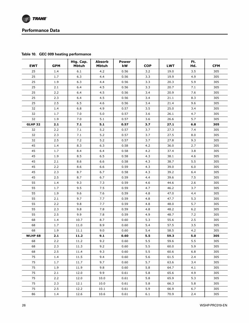
Table 10. GEC 009 heating performance
EWT GPMHtg. Cap.
MbtuhAbsorbMbtuh
PowerkW COP LWT
Ft.Hd. CFM
25 1.4 6.1 4.2 0.56 3.2 19.0 3.5 305
25 1.7 6.3 4.4 0.56 3.3 19.9 4.9 305
25 1.9 6.3 4.4 0.56 3.3 20.3 5.9 305
25 2.1 6.4 4.5 0.56 3.3 20.7 7.1 305
25 2.2 6.4 4.5 0.56 3.4 20.9 7.6 305
25 2.3 6.4 4.5 0.56 3.4 21.1 8.3 305
25 2.5 6.5 4.6 0.56 3.4 21.4 9.6 305
32 1.4 6.8 4.9 0.57 3.5 25.0 3.4 305
32 1.7 7.0 5.0 0.57 3.6 26.1 4.7 305
32 1.9 7.0 5.1 0.57 3.6 26.6 5.7 305
GLHP 32 2.1 7.1 5.1 0.57 3.7 27.1 6.8 305
32 2.2 7.1 5.2 0.57 3.7 27.3 7.4 305
32 2.3 7.1 5.2 0.57 3.7 27.5 8.0 305
32 2.5 7.2 5.2 0.57 3.7 27.8 9.3 305
45 1.4 8.3 6.3 0.58 4.2 36.0 2.7 305
45 1.7 8.4 6.4 0.58 4.2 37.4 3.8 305
45 1.9 8.5 6.5 0.58 4.3 38.1 4.6 305
45 2.1 8.6 6.6 0.58 4.3 38.7 5.5 305
45 2.2 8.6 6.6 0.59 4.3 39.0 6.0 305
45 2.3 8.7 6.7 0.58 4.3 39.2 6.4 305
45 2.5 8.7 6.7 0.59 4.4 39.6 7.5 305
55 1.4 9.3 7.3 0.59 4.6 44.6 2.6 305
55 1.7 9.5 7.5 0.59 4.7 46.2 3.7 305
55 1.9 9.6 7.6 0.59 4.8 47.0 4.4 305
55 2.1 9.7 7.7 0.59 4.8 47.7 5.3 305
55 2.2 9.8 7.7 0.59 4.8 48.0 5.7 305
55 2.3 9.8 7.8 0.59 4.8 48.2 6.2 305
55 2.5 9.9 7.8 0.59 4.9 48.7 7.2 305
68 1.4 10.7 8.7 0.60 5.3 55.6 2.5 305
68 1.7 11.0 8.9 0.60 5.4 57.5 3.5 305
68 1.9 11.1 9.0 0.60 5.4 58.5 4.2 305
WLHP 68 2.1 11.2 9.1 0.60 5.5 59.3 5.0 305
68 2.2 11.2 9.2 0.60 5.5 59.6 5.5 305
68 2.3 11.3 9.2 0.60 5.5 60.0 5.9 305
68 2.5 11.4 9.3 0.60 5.5 60.6 6.8 305
75 1.4 11.5 9.4 0.60 5.6 61.5 2.4 305
75 1.7 11.7 9.7 0.60 5.7 63.6 3.4 305
75 1.9 11.9 9.8 0.60 5.8 64.7 4.1 305
75 2.1 12.0 9.9 0.61 5.8 65.6 4.9 305
75 2.2 12.0 10.0 0.61 5.8 65.9 5.3 305
75 2.3 12.1 10.0 0.61 5.8 66.3 5.8 305
75 2.5 12.2 10.1 0.61 5.9 66.9 6.7 305
86 1.4 12.6 10.6 0.61 6.1 70.9 2.4 305
26 WSHP-PRC019-EN
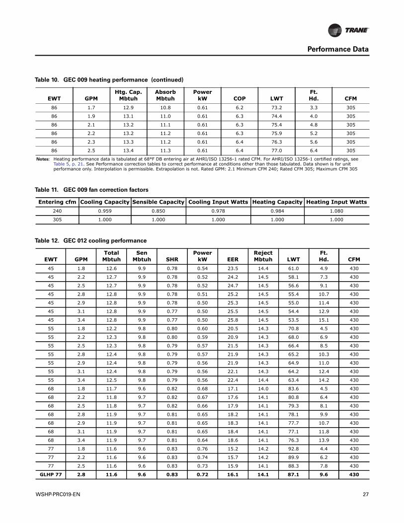
Performance Data
86 1.7 12.9 10.8 0.61 6.2 73.2 3.3 305
86 1.9 13.1 11.0 0.61 6.3 74.4 4.0 305
86 2.1 13.2 11.1 0.61 6.3 75.4 4.8 305
86 2.2 13.2 11.2 0.61 6.3 75.9 5.2 305
86 2.3 13.3 11.2 0.61 6.4 76.3 5.6 305
86 2.5 13.4 11.3 0.61 6.4 77.0 6.4 305
Notes: Heating performance data is tabulated at 68°F DB entering air at AHRI/ISO 13256-1 rated CFM. For AHRI/ISO 13256-1 certified ratings, see Table 5, p. 21. See Performance correction tables to correct performance at conditions other than those tabulated. Data shown is for unit performance only. Interpolation is permissible. Extrapolation is not. Rated GPM: 2.1 Minimum CFM 240; Rated CFM 305; Maximum CFM 305
Table 10. GEC 009 heating performance (continued)
EWT GPMHtg. Cap.
MbtuhAbsorbMbtuh
PowerkW COP LWT
Ft.Hd. CFM
Table 11. GEC 009 fan correction factors
Entering cfm Cooling Capacity Sensible Capacity Cooling Input Watts Heating Capacity Heating Input Watts240 0.959 0.850 0.978 0.984 1.080
305 1.000 1.000 1.000 1.000 1.000
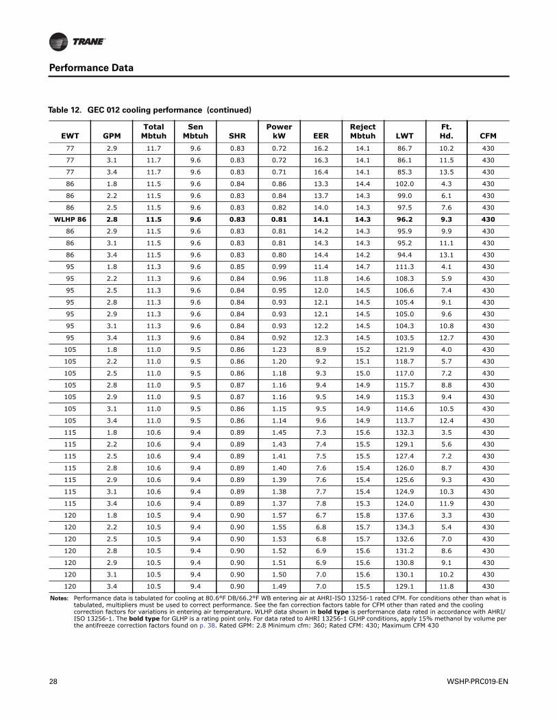
Table 12. GEC 012 cooling performance
EWT GPMTotal
MbtuhSen
Mbtuh SHRPower
kW EERRejectMbtuh LWT
Ft.Hd. CFM
45 1.8 12.6 9.9 0.78 0.54 23.5 14.4 61.0 4.9 430
45 2.2 12.7 9.9 0.78 0.52 24.2 14.5 58.1 7.3 430
45 2.5 12.7 9.9 0.78 0.52 24.7 14.5 56.6 9.1 430
45 2.8 12.8 9.9 0.78 0.51 25.2 14.5 55.4 10.7 430
45 2.9 12.8 9.9 0.78 0.50 25.3 14.5 55.0 11.4 430
45 3.1 12.8 9.9 0.77 0.50 25.5 14.5 54.4 12.9 430
45 3.4 12.8 9.9 0.77 0.50 25.8 14.5 53.5 15.1 430
55 1.8 12.2 9.8 0.80 0.60 20.5 14.3 70.8 4.5 430
55 2.2 12.3 9.8 0.80 0.59 20.9 14.3 68.0 6.9 430
55 2.5 12.3 9.8 0.79 0.57 21.5 14.3 66.4 8.5 430
55 2.8 12.4 9.8 0.79 0.57 21.9 14.3 65.2 10.3 430
55 2.9 12.4 9.8 0.79 0.56 21.9 14.3 64.9 11.0 430
55 3.1 12.4 9.8 0.79 0.56 22.1 14.3 64.2 12.4 430
55 3.4 12.5 9.8 0.79 0.56 22.4 14.4 63.4 14.2 430
68 1.8 11.7 9.6 0.82 0.68 17.1 14.0 83.6 4.5 430
68 2.2 11.8 9.7 0.82 0.67 17.6 14.1 80.8 6.4 430
68 2.5 11.8 9.7 0.82 0.66 17.9 14.1 79.3 8.1 430
68 2.8 11.9 9.7 0.81 0.65 18.2 14.1 78.1 9.9 430
68 2.9 11.9 9.7 0.81 0.65 18.3 14.1 77.7 10.7 430
68 3.1 11.9 9.7 0.81 0.65 18.4 14.1 77.1 11.8 430
68 3.4 11.9 9.7 0.81 0.64 18.6 14.1 76.3 13.9 430
77 1.8 11.6 9.6 0.83 0.76 15.2 14.2 92.8 4.4 430
77 2.2 11.6 9.6 0.83 0.74 15.7 14.2 89.9 6.2 430
77 2.5 11.6 9.6 0.83 0.73 15.9 14.1 88.3 7.8 430
GLHP 77 2.8 11.6 9.6 0.83 0.72 16.1 14.1 87.1 9.6 430
WSHP-PRC019-EN 27
Performance Data
77 2.9 11.7 9.6 0.83 0.72 16.2 14.1 86.7 10.2 430
77 3.1 11.7 9.6 0.83 0.72 16.3 14.1 86.1 11.5 430
77 3.4 11.7 9.6 0.83 0.71 16.4 14.1 85.3 13.5 430
86 1.8 11.5 9.6 0.84 0.86 13.3 14.4 102.0 4.3 430
86 2.2 11.5 9.6 0.83 0.84 13.7 14.3 99.0 6.1 430
86 2.5 11.5 9.6 0.83 0.82 14.0 14.3 97.5 7.6 430
WLHP 86 2.8 11.5 9.6 0.83 0.81 14.1 14.3 96.2 9.3 430
86 2.9 11.5 9.6 0.83 0.81 14.2 14.3 95.9 9.9 430
86 3.1 11.5 9.6 0.83 0.81 14.3 14.3 95.2 11.1 430
86 3.4 11.5 9.6 0.83 0.80 14.4 14.2 94.4 13.1 430
95 1.8 11.3 9.6 0.85 0.99 11.4 14.7 111.3 4.1 430
95 2.2 11.3 9.6 0.84 0.96 11.8 14.6 108.3 5.9 430
95 2.5 11.3 9.6 0.84 0.95 12.0 14.5 106.6 7.4 430
95 2.8 11.3 9.6 0.84 0.93 12.1 14.5 105.4 9.1 430
95 2.9 11.3 9.6 0.84 0.93 12.1 14.5 105.0 9.6 430
95 3.1 11.3 9.6 0.84 0.93 12.2 14.5 104.3 10.8 430
95 3.4 11.3 9.6 0.84 0.92 12.3 14.5 103.5 12.7 430
105 1.8 11.0 9.5 0.86 1.23 8.9 15.2 121.9 4.0 430
105 2.2 11.0 9.5 0.86 1.20 9.2 15.1 118.7 5.7 430
105 2.5 11.0 9.5 0.86 1.18 9.3 15.0 117.0 7.2 430
105 2.8 11.0 9.5 0.87 1.16 9.4 14.9 115.7 8.8 430
105 2.9 11.0 9.5 0.87 1.16 9.5 14.9 115.3 9.4 430
105 3.1 11.0 9.5 0.86 1.15 9.5 14.9 114.6 10.5 430
105 3.4 11.0 9.5 0.86 1.14 9.6 14.9 113.7 12.4 430
115 1.8 10.6 9.4 0.89 1.45 7.3 15.6 132.3 3.5 430
115 2.2 10.6 9.4 0.89 1.43 7.4 15.5 129.1 5.6 430
115 2.5 10.6 9.4 0.89 1.41 7.5 15.5 127.4 7.2 430
115 2.8 10.6 9.4 0.89 1.40 7.6 15.4 126.0 8.7 430
115 2.9 10.6 9.4 0.89 1.39 7.6 15.4 125.6 9.3 430
115 3.1 10.6 9.4 0.89 1.38 7.7 15.4 124.9 10.3 430
115 3.4 10.6 9.4 0.89 1.37 7.8 15.3 124.0 11.9 430
120 1.8 10.5 9.4 0.90 1.57 6.7 15.8 137.6 3.3 430
120 2.2 10.5 9.4 0.90 1.55 6.8 15.7 134.3 5.4 430
120 2.5 10.5 9.4 0.90 1.53 6.8 15.7 132.6 7.0 430
120 2.8 10.5 9.4 0.90 1.52 6.9 15.6 131.2 8.6 430
120 2.9 10.5 9.4 0.90 1.51 6.9 15.6 130.8 9.1 430
120 3.1 10.5 9.4 0.90 1.50 7.0 15.6 130.1 10.2 430
120 3.4 10.5 9.4 0.90 1.49 7.0 15.5 129.1 11.8 430
Notes: Performance data is tabulated for cooling at 80.6°F DB/66.2°F WB entering air at AHRI-ISO 13256-1 rated CFM. For conditions other than what is tabulated, multipliers must be used to correct performance. See the fan correction factors table for CFM other than rated and the cooling correction factors for variations in entering air temperature. WLHP data shown in bold type is performance data rated in accordance with AHRI/ISO 13256-1. The bold type for GLHP is a rating point only. For data rated to AHRI 13256-1 GLHP conditions, apply 15% methanol by volume per the antifreeze correction factors found on p. 38. Rated GPM: 2.8 Minimum cfm: 360; Rated CFM: 430; Maximum CFM 430
Table 12. GEC 012 cooling performance (continued)
EWT GPMTotal
MbtuhSen
Mbtuh SHRPower
kW EERRejectMbtuh LWT
Ft.Hd. CFM
28 WSHP-PRC019-EN
Performance Data
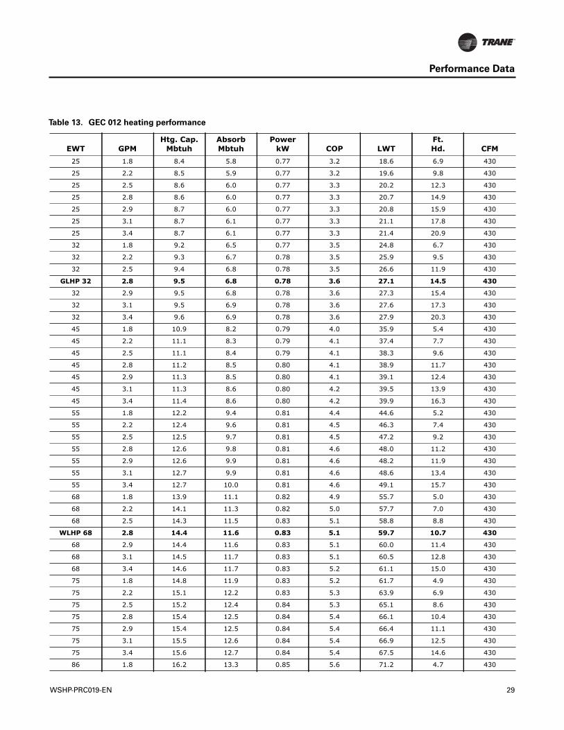
Table 13. GEC 012 heating performance
EWT GPMHtg. Cap.
MbtuhAbsorbMbtuh
PowerkW COP LWT
Ft.Hd. CFM
25 1.8 8.4 5.8 0.77 3.2 18.6 6.9 430
25 2.2 8.5 5.9 0.77 3.2 19.6 9.8 430
25 2.5 8.6 6.0 0.77 3.3 20.2 12.3 430
25 2.8 8.6 6.0 0.77 3.3 20.7 14.9 430
25 2.9 8.7 6.0 0.77 3.3 20.8 15.9 430
25 3.1 8.7 6.1 0.77 3.3 21.1 17.8 430
25 3.4 8.7 6.1 0.77 3.3 21.4 20.9 430
32 1.8 9.2 6.5 0.77 3.5 24.8 6.7 430
32 2.2 9.3 6.7 0.78 3.5 25.9 9.5 430
32 2.5 9.4 6.8 0.78 3.5 26.6 11.9 430
GLHP 32 2.8 9.5 6.8 0.78 3.6 27.1 14.5 430
32 2.9 9.5 6.8 0.78 3.6 27.3 15.4 430
32 3.1 9.5 6.9 0.78 3.6 27.6 17.3 430
32 3.4 9.6 6.9 0.78 3.6 27.9 20.3 430
45 1.8 10.9 8.2 0.79 4.0 35.9 5.4 430
45 2.2 11.1 8.3 0.79 4.1 37.4 7.7 430
45 2.5 11.1 8.4 0.79 4.1 38.3 9.6 430
45 2.8 11.2 8.5 0.80 4.1 38.9 11.7 430
45 2.9 11.3 8.5 0.80 4.1 39.1 12.4 430
45 3.1 11.3 8.6 0.80 4.2 39.5 13.9 430
45 3.4 11.4 8.6 0.80 4.2 39.9 16.3 430
55 1.8 12.2 9.4 0.81 4.4 44.6 5.2 430
55 2.2 12.4 9.6 0.81 4.5 46.3 7.4 430
55 2.5 12.5 9.7 0.81 4.5 47.2 9.2 430
55 2.8 12.6 9.8 0.81 4.6 48.0 11.2 430
55 2.9 12.6 9.9 0.81 4.6 48.2 11.9 430
55 3.1 12.7 9.9 0.81 4.6 48.6 13.4 430
55 3.4 12.7 10.0 0.81 4.6 49.1 15.7 430
68 1.8 13.9 11.1 0.82 4.9 55.7 5.0 430
68 2.2 14.1 11.3 0.82 5.0 57.7 7.0 430
68 2.5 14.3 11.5 0.83 5.1 58.8 8.8 430
WLHP 68 2.8 14.4 11.6 0.83 5.1 59.7 10.7 430
68 2.9 14.4 11.6 0.83 5.1 60.0 11.4 430
68 3.1 14.5 11.7 0.83 5.1 60.5 12.8 430
68 3.4 14.6 11.7 0.83 5.2 61.1 15.0 430
75 1.8 14.8 11.9 0.83 5.2 61.7 4.9 430
75 2.2 15.1 12.2 0.83 5.3 63.9 6.9 430
75 2.5 15.2 12.4 0.84 5.3 65.1 8.6 430
75 2.8 15.4 12.5 0.84 5.4 66.1 10.4 430
75 2.9 15.4 12.5 0.84 5.4 66.4 11.1 430
75 3.1 15.5 12.6 0.84 5.4 66.9 12.5 430
75 3.4 15.6 12.7 0.84 5.4 67.5 14.6 430
86 1.8 16.2 13.3 0.85 5.6 71.2 4.7 430
WSHP-PRC019-EN 29
Performance Data
86 2.2 16.6 13.6 0.86 5.7 73.6 6.6 430
86 2.5 16.7 13.8 0.86 5.7 75.0 8.3 430
86 2.8 16.9 13.9 0.86 5.7 76.0 10.1 430
86 2.9 16.9 14.0 0.86 5.8 76.4 10.7 430
86 3.1 17.0 14.1 0.86 5.8 76.9 12.0 430
86 3.4 17.1 14.1 0.87 5.8 77.7 14.1 430
86 1.8 8.4 5.8 0.77 3.2 18.6 6.9 430
Notes: Heating performance data is tabulated at 68°F DB entering air at AHRI/ISO 13256-1 rated CFM. For AHRI/ISO 13256-1 certified ratings, see Table 5, p. 21. See Performance correction tables to correct performance at conditions other than those tabulated. Data shown is for unit performance only. Interpolation is permissible. Extrapolation is not. Rated GPM: 2.8 Minimum CFM 360; Rated CFM 430; Maximum CFM 430
Table 13. GEC 012 heating performance (continued)
EWT GPMHtg. Cap.
MbtuhAbsorbMbtuh
PowerkW COP LWT
Ft.Hd. CFM
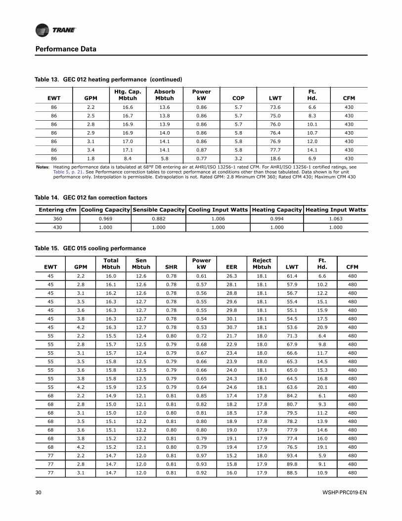
Table 14. GEC 012 fan correction factors
Entering cfm Cooling Capacity Sensible Capacity Cooling Input Watts Heating Capacity Heating Input Watts360 0.969 0.882 1.006 0.994 1.063
430 1.000 1.000 1.000 1.000 1.000
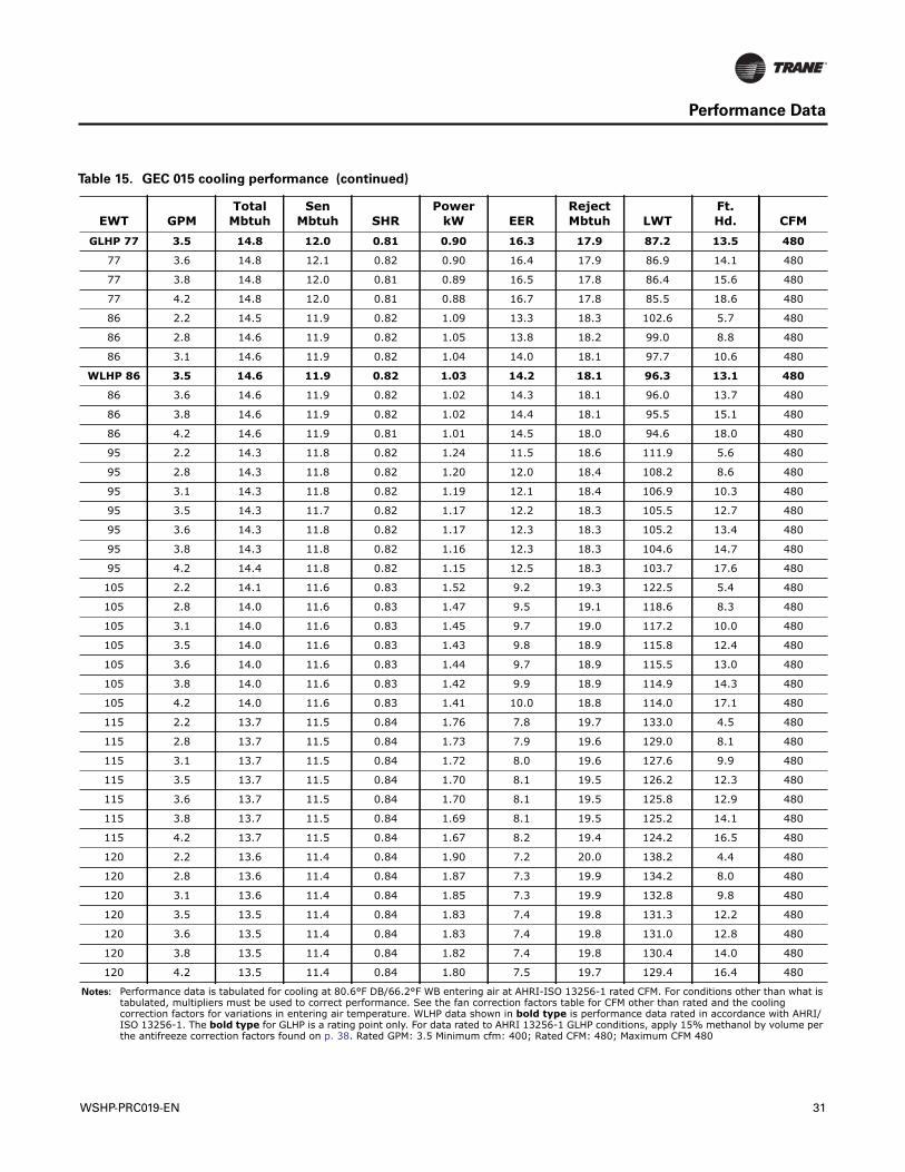
Table 15. GEC 015 cooling performance
EWT GPMTotal
MbtuhSen
Mbtuh SHRPower
kW EERRejectMbtuh LWT
Ft.Hd. CFM
45 2.2 16.0 12.6 0.78 0.61 26.3 18.1 61.4 6.6 480
45 2.8 16.1 12.6 0.78 0.57 28.1 18.1 57.9 10.2 480
45 3.1 16.2 12.6 0.78 0.56 28.8 18.1 56.7 12.2 480
45 3.5 16.3 12.7 0.78 0.55 29.6 18.1 55.4 15.1 480
45 3.6 16.3 12.7 0.78 0.55 29.8 18.1 55.1 15.9 480
45 3.8 16.3 12.7 0.78 0.54 30.1 18.1 54.5 17.5 480
45 4.2 16.3 12.7 0.78 0.53 30.7 18.1 53.6 20.9 480
55 2.2 15.5 12.4 0.80 0.72 21.7 18.0 71.3 6.4 480
55 2.8 15.7 12.5 0.79 0.68 22.9 18.0 67.9 9.8 480
55 3.1 15.7 12.4 0.79 0.67 23.4 18.0 66.6 11.7 480
55 3.5 15.8 12.5 0.79 0.66 23.9 18.0 65.3 14.5 480
55 3.6 15.8 12.5 0.79 0.66 24.0 18.1 65.0 15.3 480
55 3.8 15.8 12.5 0.79 0.65 24.3 18.0 64.5 16.8 480
55 4.2 15.9 12.5 0.79 0.64 24.6 18.1 63.6 20.1 480
68 2.2 14.9 12.1 0.81 0.85 17.4 17.8 84.2 6.1 480
68 2.8 15.0 12.1 0.81 0.82 18.2 17.8 80.7 9.3 480
68 3.1 15.0 12.0 0.80 0.81 18.5 17.8 79.5 11.2 480
68 3.5 15.1 12.2 0.81 0.80 18.9 17.8 78.2 13.9 480
68 3.6 15.1 12.2 0.80 0.80 19.0 17.9 77.9 14.6 480
68 3.8 15.2 12.2 0.81 0.79 19.1 17.9 77.4 16.0 480
68 4.2 15.2 12.1 0.80 0.79 19.4 17.9 76.5 19.1 480
77 2.2 14.7 12.0 0.81 0.97 15.2 18.0 93.4 5.9 480
77 2.8 14.7 12.0 0.81 0.93 15.8 17.9 89.8 9.1 480
77 3.1 14.7 12.0 0.81 0.92 16.0 17.9 88.5 10.9 480
30 WSHP-PRC019-EN
Performance Data
GLHP 77 3.5 14.8 12.0 0.81 0.90 16.3 17.9 87.2 13.5 480
77 3.6 14.8 12.1 0.82 0.90 16.4 17.9 86.9 14.1 480
77 3.8 14.8 12.0 0.81 0.89 16.5 17.8 86.4 15.6 480
77 4.2 14.8 12.0 0.81 0.88 16.7 17.8 85.5 18.6 480
86 2.2 14.5 11.9 0.82 1.09 13.3 18.3 102.6 5.7 480
86 2.8 14.6 11.9 0.82 1.05 13.8 18.2 99.0 8.8 480
86 3.1 14.6 11.9 0.82 1.04 14.0 18.1 97.7 10.6 480
WLHP 86 3.5 14.6 11.9 0.82 1.03 14.2 18.1 96.3 13.1 480
86 3.6 14.6 11.9 0.82 1.02 14.3 18.1 96.0 13.7 480
86 3.8 14.6 11.9 0.82 1.02 14.4 18.1 95.5 15.1 480
86 4.2 14.6 11.9 0.81 1.01 14.5 18.0 94.6 18.0 480
95 2.2 14.3 11.8 0.82 1.24 11.5 18.6 111.9 5.6 480
95 2.8 14.3 11.8 0.82 1.20 12.0 18.4 108.2 8.6 480
95 3.1 14.3 11.8 0.82 1.19 12.1 18.4 106.9 10.3 480
95 3.5 14.3 11.7 0.82 1.17 12.2 18.3 105.5 12.7 480
95 3.6 14.3 11.8 0.82 1.17 12.3 18.3 105.2 13.4 480
95 3.8 14.3 11.8 0.82 1.16 12.3 18.3 104.6 14.7 480
95 4.2 14.4 11.8 0.82 1.15 12.5 18.3 103.7 17.6 480
105 2.2 14.1 11.6 0.83 1.52 9.2 19.3 122.5 5.4 480
105 2.8 14.0 11.6 0.83 1.47 9.5 19.1 118.6 8.3 480
105 3.1 14.0 11.6 0.83 1.45 9.7 19.0 117.2 10.0 480
105 3.5 14.0 11.6 0.83 1.43 9.8 18.9 115.8 12.4 480
105 3.6 14.0 11.6 0.83 1.44 9.7 18.9 115.5 13.0 480
105 3.8 14.0 11.6 0.83 1.42 9.9 18.9 114.9 14.3 480
105 4.2 14.0 11.6 0.83 1.41 10.0 18.8 114.0 17.1 480
115 2.2 13.7 11.5 0.84 1.76 7.8 19.7 133.0 4.5 480
115 2.8 13.7 11.5 0.84 1.73 7.9 19.6 129.0 8.1 480
115 3.1 13.7 11.5 0.84 1.72 8.0 19.6 127.6 9.9 480
115 3.5 13.7 11.5 0.84 1.70 8.1 19.5 126.2 12.3 480
115 3.6 13.7 11.5 0.84 1.70 8.1 19.5 125.8 12.9 480
115 3.8 13.7 11.5 0.84 1.69 8.1 19.5 125.2 14.1 480
115 4.2 13.7 11.5 0.84 1.67 8.2 19.4 124.2 16.5 480
120 2.2 13.6 11.4 0.84 1.90 7.2 20.0 138.2 4.4 480
120 2.8 13.6 11.4 0.84 1.87 7.3 19.9 134.2 8.0 480
120 3.1 13.6 11.4 0.84 1.85 7.3 19.9 132.8 9.8 480
120 3.5 13.5 11.4 0.84 1.83 7.4 19.8 131.3 12.2 480
120 3.6 13.5 11.4 0.84 1.83 7.4 19.8 131.0 12.8 480
120 3.8 13.5 11.4 0.84 1.82 7.4 19.8 130.4 14.0 480
120 4.2 13.5 11.4 0.84 1.80 7.5 19.7 129.4 16.4 480
Notes: Performance data is tabulated for cooling at 80.6°F DB/66.2°F WB entering air at AHRI-ISO 13256-1 rated CFM. For conditions other than what is tabulated, multipliers must be used to correct performance. See the fan correction factors table for CFM other than rated and the cooling correction factors for variations in entering air temperature. WLHP data shown in bold type is performance data rated in accordance with AHRI/ISO 13256-1. The bold type for GLHP is a rating point only. For data rated to AHRI 13256-1 GLHP conditions, apply 15% methanol by volume per the antifreeze correction factors found on p. 38. Rated GPM: 3.5 Minimum cfm: 400; Rated CFM: 480; Maximum CFM 480
Table 15. GEC 015 cooling performance (continued)
EWT GPMTotal
MbtuhSen
Mbtuh SHRPower
kW EERRejectMbtuh LWT
Ft.Hd. CFM
WSHP-PRC019-EN 31
Performance Data
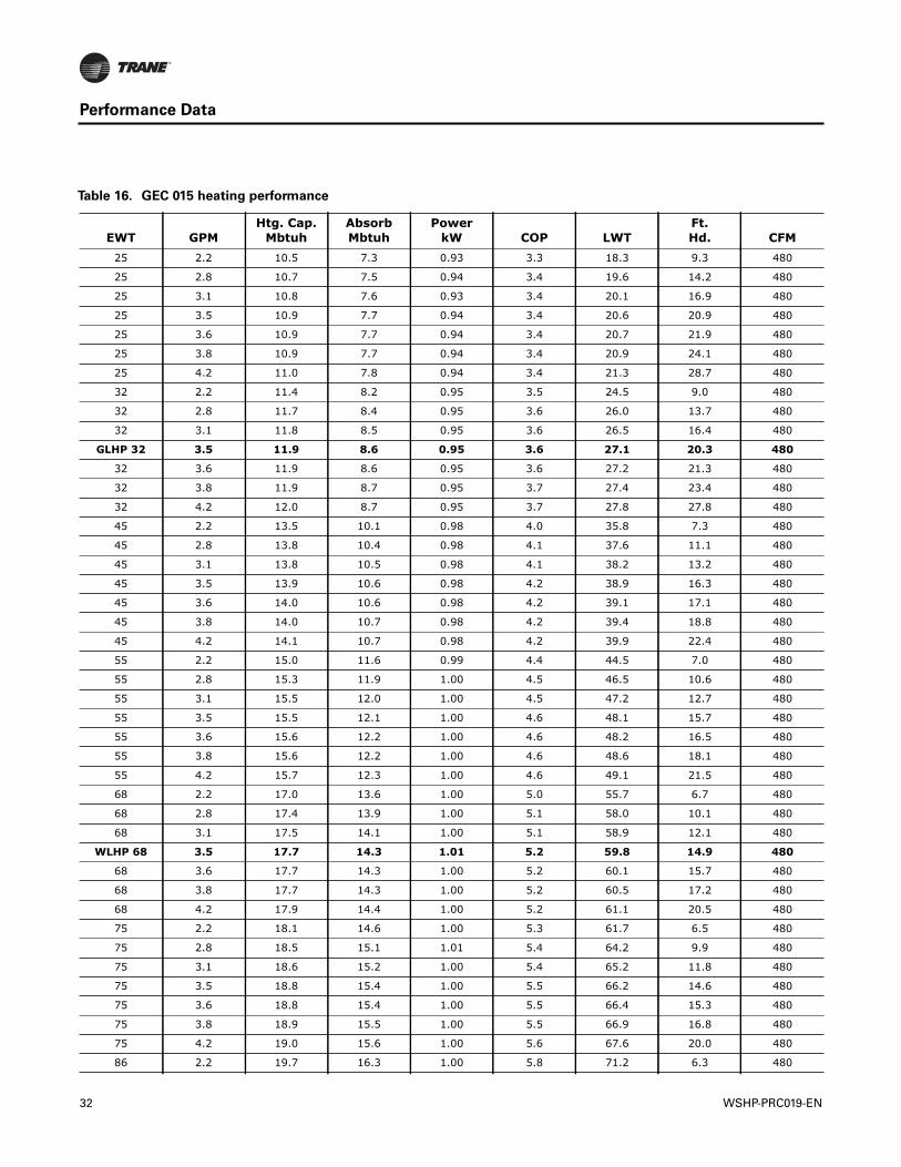
Table 16. GEC 015 heating performance
EWT GPMHtg. Cap.
MbtuhAbsorbMbtuh
PowerkW COP LWT
Ft.Hd. CFM
25 2.2 10.5 7.3 0.93 3.3 18.3 9.3 480
25 2.8 10.7 7.5 0.94 3.4 19.6 14.2 480
25 3.1 10.8 7.6 0.93 3.4 20.1 16.9 480
25 3.5 10.9 7.7 0.94 3.4 20.6 20.9 480
25 3.6 10.9 7.7 0.94 3.4 20.7 21.9 480
25 3.8 10.9 7.7 0.94 3.4 20.9 24.1 480
25 4.2 11.0 7.8 0.94 3.4 21.3 28.7 480
32 2.2 11.4 8.2 0.95 3.5 24.5 9.0 480
32 2.8 11.7 8.4 0.95 3.6 26.0 13.7 480
32 3.1 11.8 8.5 0.95 3.6 26.5 16.4 480
GLHP 32 3.5 11.9 8.6 0.95 3.6 27.1 20.3 480
32 3.6 11.9 8.6 0.95 3.6 27.2 21.3 480
32 3.8 11.9 8.7 0.95 3.7 27.4 23.4 480
32 4.2 12.0 8.7 0.95 3.7 27.8 27.8 480
45 2.2 13.5 10.1 0.98 4.0 35.8 7.3 480
45 2.8 13.8 10.4 0.98 4.1 37.6 11.1 480
45 3.1 13.8 10.5 0.98 4.1 38.2 13.2 480
45 3.5 13.9 10.6 0.98 4.2 38.9 16.3 480
45 3.6 14.0 10.6 0.98 4.2 39.1 17.1 480
45 3.8 14.0 10.7 0.98 4.2 39.4 18.8 480
45 4.2 14.1 10.7 0.98 4.2 39.9 22.4 480
55 2.2 15.0 11.6 0.99 4.4 44.5 7.0 480
55 2.8 15.3 11.9 1.00 4.5 46.5 10.6 480
55 3.1 15.5 12.0 1.00 4.5 47.2 12.7 480
55 3.5 15.5 12.1 1.00 4.6 48.1 15.7 480
55 3.6 15.6 12.2 1.00 4.6 48.2 16.5 480
55 3.8 15.6 12.2 1.00 4.6 48.6 18.1 480
55 4.2 15.7 12.3 1.00 4.6 49.1 21.5 480
68 2.2 17.0 13.6 1.00 5.0 55.7 6.7 480
68 2.8 17.4 13.9 1.00 5.1 58.0 10.1 480
68 3.1 17.5 14.1 1.00 5.1 58.9 12.1 480
WLHP 68 3.5 17.7 14.3 1.01 5.2 59.8 14.9 480
68 3.6 17.7 14.3 1.00 5.2 60.1 15.7 480
68 3.8 17.7 14.3 1.00 5.2 60.5 17.2 480
68 4.2 17.9 14.4 1.00 5.2 61.1 20.5 480
75 2.2 18.1 14.6 1.00 5.3 61.7 6.5 480
75 2.8 18.5 15.1 1.01 5.4 64.2 9.9 480
75 3.1 18.6 15.2 1.00 5.4 65.2 11.8 480
75 3.5 18.8 15.4 1.00 5.5 66.2 14.6 480
75 3.6 18.8 15.4 1.00 5.5 66.4 15.3 480
75 3.8 18.9 15.5 1.00 5.5 66.9 16.8 480
75 4.2 19.0 15.6 1.00 5.6 67.6 20.0 480
86 2.2 19.7 16.3 1.00 5.8 71.2 6.3 480
32 WSHP-PRC019-EN
Performance Data
86 2.8 20.2 16.8 0.99 6.0 74.0 9.6 480
86 3.1 20.3 17.0 0.99 6.0 75.1 11.4 480
86 3.5 20.5 17.2 0.99 6.1 76.2 14.1 480
86 3.6 20.5 17.1 0.99 6.1 76.5 14.8 480
86 3.8 20.6 17.2 0.98 6.1 76.9 16.2 480
86 4.2 20.8 17.4 0.98 6.2 77.7 19.3 480
Notes: Heating performance data is tabulated at 68°F DB entering air at AHRI/ISO 13256-1 rated CFM. For AHRI/ISO 13256-1 certified ratings, see Table 5, p. 21. See Performance correction tables to correct performance at conditions other than those tabulated. Data shown is for unit performance only. Interpolation is permissible. Extrapolation is not. Rated GPM: 3.5 Minimum CFM 400; Rated CFM 480; Maximum CFM 480
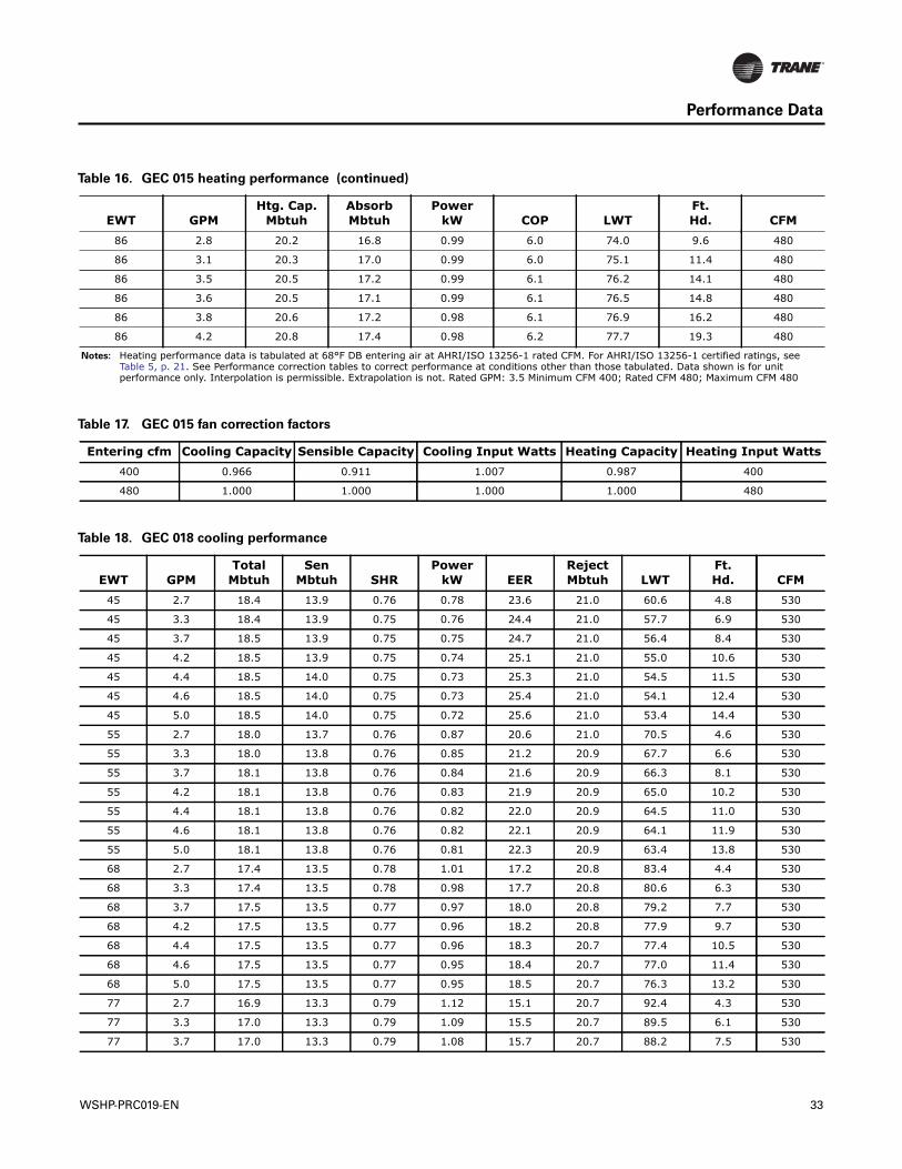
Table 16. GEC 015 heating performance (continued)
EWT GPMHtg. Cap.
MbtuhAbsorbMbtuh
PowerkW COP LWT
Ft.Hd. CFM
Table 17. GEC 015 fan correction factors
Entering cfm Cooling Capacity Sensible Capacity Cooling Input Watts Heating Capacity Heating Input Watts400 0.966 0.911 1.007 0.987 400
480 1.000 1.000 1.000 1.000 480
Table 18. GEC 018 cooling performance
EWT GPMTotal
MbtuhSen
Mbtuh SHRPower
kW EERRejectMbtuh LWT
Ft.Hd. CFM
45 2.7 18.4 13.9 0.76 0.78 23.6 21.0 60.6 4.8 530
45 3.3 18.4 13.9 0.75 0.76 24.4 21.0 57.7 6.9 530
45 3.7 18.5 13.9 0.75 0.75 24.7 21.0 56.4 8.4 530
45 4.2 18.5 13.9 0.75 0.74 25.1 21.0 55.0 10.6 530
45 4.4 18.5 14.0 0.75 0.73 25.3 21.0 54.5 11.5 530
45 4.6 18.5 14.0 0.75 0.73 25.4 21.0 54.1 12.4 530
45 5.0 18.5 14.0 0.75 0.72 25.6 21.0 53.4 14.4 530
55 2.7 18.0 13.7 0.76 0.87 20.6 21.0 70.5 4.6 530
55 3.3 18.0 13.8 0.76 0.85 21.2 20.9 67.7 6.6 530
55 3.7 18.1 13.8 0.76 0.84 21.6 20.9 66.3 8.1 530
55 4.2 18.1 13.8 0.76 0.83 21.9 20.9 65.0 10.2 530
55 4.4 18.1 13.8 0.76 0.82 22.0 20.9 64.5 11.0 530
55 4.6 18.1 13.8 0.76 0.82 22.1 20.9 64.1 11.9 530
55 5.0 18.1 13.8 0.76 0.81 22.3 20.9 63.4 13.8 530
68 2.7 17.4 13.5 0.78 1.01 17.2 20.8 83.4 4.4 530
68 3.3 17.4 13.5 0.78 0.98 17.7 20.8 80.6 6.3 530
68 3.7 17.5 13.5 0.77 0.97 18.0 20.8 79.2 7.7 530
68 4.2 17.5 13.5 0.77 0.96 18.2 20.8 77.9 9.7 530
68 4.4 17.5 13.5 0.77 0.96 18.3 20.7 77.4 10.5 530
68 4.6 17.5 13.5 0.77 0.95 18.4 20.7 77.0 11.4 530
68 5.0 17.5 13.5 0.77 0.95 18.5 20.7 76.3 13.2 530
77 2.7 16.9 13.3 0.79 1.12 15.1 20.7 92.4 4.3 530
77 3.3 17.0 13.3 0.79 1.09 15.5 20.7 89.5 6.1 530
77 3.7 17.0 13.3 0.79 1.08 15.7 20.7 88.2 7.5 530
WSHP-PRC019-EN 33
Performance Data
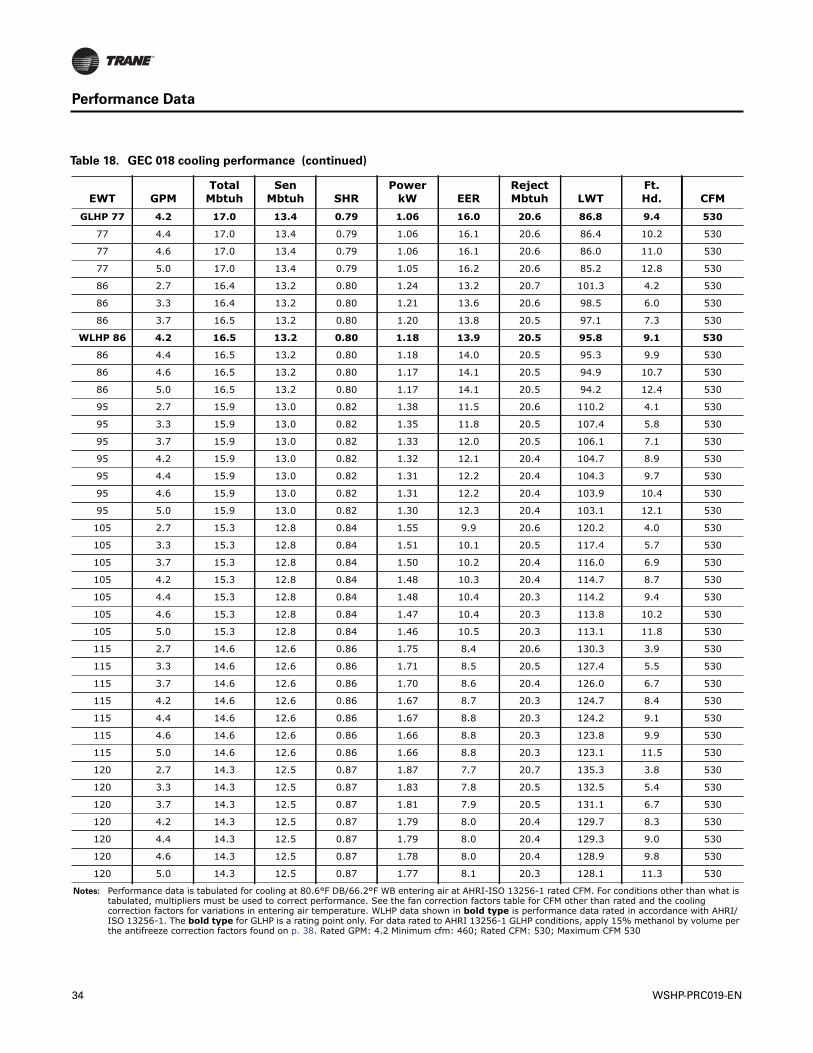
GLHP 77 4.2 17.0 13.4 0.79 1.06 16.0 20.6 86.8 9.4 530
77 4.4 17.0 13.4 0.79 1.06 16.1 20.6 86.4 10.2 530
77 4.6 17.0 13.4 0.79 1.06 16.1 20.6 86.0 11.0 530
77 5.0 17.0 13.4 0.79 1.05 16.2 20.6 85.2 12.8 530
86 2.7 16.4 13.2 0.80 1.24 13.2 20.7 101.3 4.2 530
86 3.3 16.4 13.2 0.80 1.21 13.6 20.6 98.5 6.0 530
86 3.7 16.5 13.2 0.80 1.20 13.8 20.5 97.1 7.3 530
WLHP 86 4.2 16.5 13.2 0.80 1.18 13.9 20.5 95.8 9.1 530
86 4.4 16.5 13.2 0.80 1.18 14.0 20.5 95.3 9.9 530
86 4.6 16.5 13.2 0.80 1.17 14.1 20.5 94.9 10.7 530
86 5.0 16.5 13.2 0.80 1.17 14.1 20.5 94.2 12.4 530
95 2.7 15.9 13.0 0.82 1.38 11.5 20.6 110.2 4.1 530
95 3.3 15.9 13.0 0.82 1.35 11.8 20.5 107.4 5.8 530
95 3.7 15.9 13.0 0.82 1.33 12.0 20.5 106.1 7.1 530
95 4.2 15.9 13.0 0.82 1.32 12.1 20.4 104.7 8.9 530
95 4.4 15.9 13.0 0.82 1.31 12.2 20.4 104.3 9.7 530
95 4.6 15.9 13.0 0.82 1.31 12.2 20.4 103.9 10.4 530
95 5.0 15.9 13.0 0.82 1.30 12.3 20.4 103.1 12.1 530
105 2.7 15.3 12.8 0.84 1.55 9.9 20.6 120.2 4.0 530
105 3.3 15.3 12.8 0.84 1.51 10.1 20.5 117.4 5.7 530
105 3.7 15.3 12.8 0.84 1.50 10.2 20.4 116.0 6.9 530
105 4.2 15.3 12.8 0.84 1.48 10.3 20.4 114.7 8.7 530
105 4.4 15.3 12.8 0.84 1.48 10.4 20.3 114.2 9.4 530
105 4.6 15.3 12.8 0.84 1.47 10.4 20.3 113.8 10.2 530
105 5.0 15.3 12.8 0.84 1.46 10.5 20.3 113.1 11.8 530
115 2.7 14.6 12.6 0.86 1.75 8.4 20.6 130.3 3.9 530
115 3.3 14.6 12.6 0.86 1.71 8.5 20.5 127.4 5.5 530
115 3.7 14.6 12.6 0.86 1.70 8.6 20.4 126.0 6.7 530
115 4.2 14.6 12.6 0.86 1.67 8.7 20.3 124.7 8.4 530
115 4.4 14.6 12.6 0.86 1.67 8.8 20.3 124.2 9.1 530
115 4.6 14.6 12.6 0.86 1.66 8.8 20.3 123.8 9.9 530
115 5.0 14.6 12.6 0.86 1.66 8.8 20.3 123.1 11.5 530
120 2.7 14.3 12.5 0.87 1.87 7.7 20.7 135.3 3.8 530
120 3.3 14.3 12.5 0.87 1.83 7.8 20.5 132.5 5.4 530
120 3.7 14.3 12.5 0.87 1.81 7.9 20.5 131.1 6.7 530
120 4.2 14.3 12.5 0.87 1.79 8.0 20.4 129.7 8.3 530
120 4.4 14.3 12.5 0.87 1.79 8.0 20.4 129.3 9.0 530
120 4.6 14.3 12.5 0.87 1.78 8.0 20.4 128.9 9.8 530
120 5.0 14.3 12.5 0.87 1.77 8.1 20.3 128.1 11.3 530
Notes: Performance data is tabulated for cooling at 80.6°F DB/66.2°F WB entering air at AHRI-ISO 13256-1 rated CFM. For conditions other than what is tabulated, multipliers must be used to correct performance. See the fan correction factors table for CFM other than rated and the cooling correction factors for variations in entering air temperature. WLHP data shown in bold type is performance data rated in accordance with AHRI/ISO 13256-1. The bold type for GLHP is a rating point only. For data rated to AHRI 13256-1 GLHP conditions, apply 15% methanol by volume per the antifreeze correction factors found on p. 38. Rated GPM: 4.2 Minimum cfm: 460; Rated CFM: 530; Maximum CFM 530
Table 18. GEC 018 cooling performance (continued)
EWT GPMTotal
MbtuhSen
Mbtuh SHRPower
kW EERRejectMbtuh LWT
Ft.Hd. CFM
34 WSHP-PRC019-EN

Performance Data
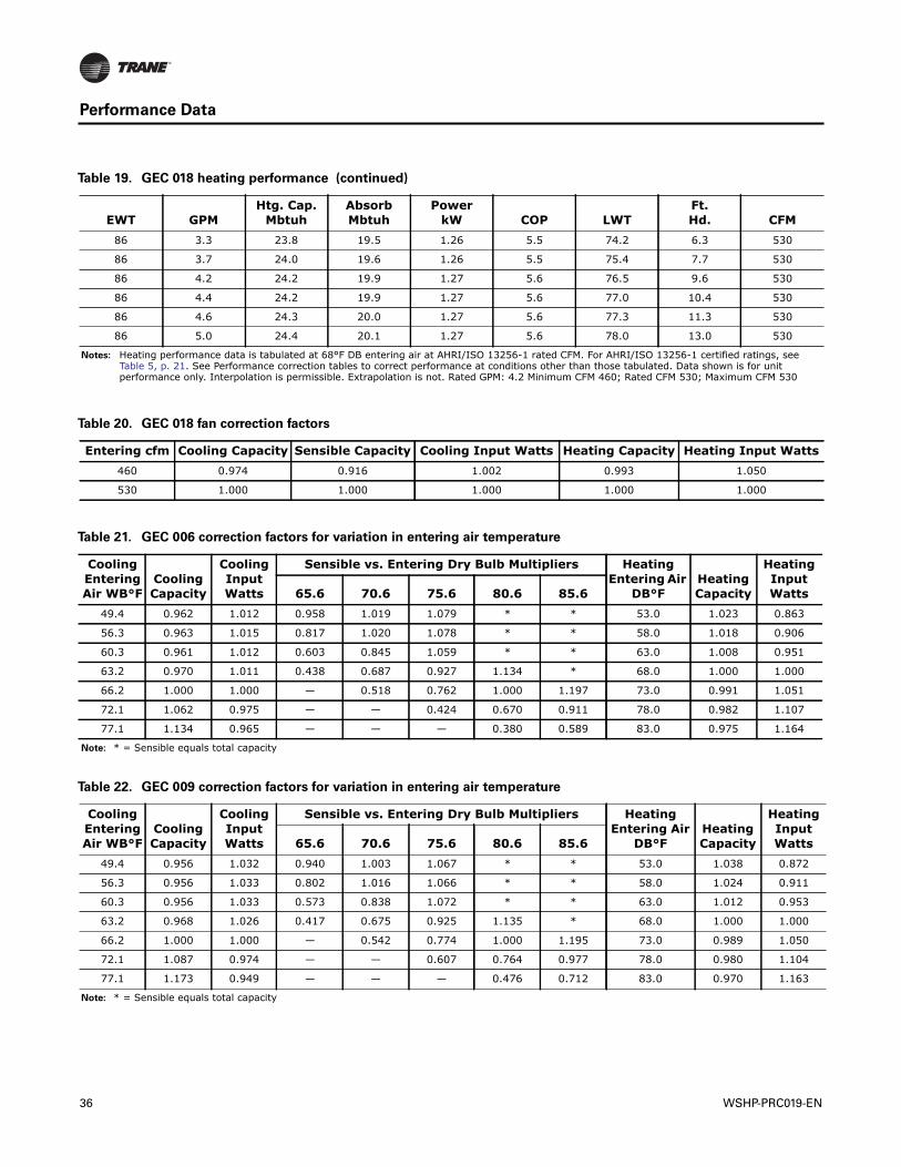
Table 19. GEC 018 heating performance
EWT GPMHtg. Cap.
MbtuhAbsorbMbtuh
PowerkW COP LWT
Ft.Hd. CFM
25 2.7 11.8 8.0 1.10 3.1 19.0 6.6 530
25 3.3 12.0 8.2 1.10 3.2 20.0 9.4 530
25 3.7 12.1 8.3 1.10 3.2 20.5 11.4 530
25 4.2 12.1 8.4 1.10 3.2 21.0 14.3 530
25 4.4 12.2 8.4 1.10 3.2 21.2 15.5 530
25 4.6 12.2 8.5 1.11 3.2 21.3 16.7 530
25 5.0 12.2 8.5 1.10 3.2 21.6 19.3 530
32 2.7 12.9 9.1 1.11 3.4 25.3 6.4 530
32 3.3 13.1 9.3 1.12 3.4 26.4 9.1 530
32 3.7 13.2 9.4 1.12 3.5 26.9 11.1 530
GLHP 32 4.2 13.3 9.5 1.12 3.5 27.5 13.8 530
32 4.4 13.3 9.5 1.12 3.5 27.7 15.0 530
32 4.6 13.3 9.5 1.12 3.5 27.9 16.2 530
32 5.0 13.4 9.6 1.12 3.5 28.2 18.7 530
45 2.7 15.3 11.4 1.14 3.9 36.5 5.2 530
45 3.3 15.6 11.7 1.15 4.0 37.9 7.3 530
45 3.7 15.7 11.8 1.15 4.0 38.6 8.9 530
45 4.2 15.8 11.9 1.15 4.0 39.3 11.1 530
45 4.4 15.8 11.9 1.15 4.0 39.6 12.1 530
45 4.6 15.8 11.9 1.15 4.0 39.8 13.0 530
45 5.0 15.9 12.0 1.15 4.1 40.2 15.1 530
55 2.7 17.2 13.2 1.17 4.3 45.2 5.0 530
55 3.3 17.4 13.4 1.17 4.4 46.9 7.0 530
55 3.7 17.6 13.6 1.17 4.4 47.7 8.6 530
55 4.2 17.8 13.8 1.18 4.4 48.4 10.7 530
55 4.4 17.8 13.8 1.18 4.4 48.7 11.6 530
55 4.6 17.8 13.8 1.17 4.5 49.0 12.5 530
55 5.0 17.9 13.9 1.17 4.5 49.4 14.5 530
68 2.7 19.7 15.6 1.20 4.8 56.4 4.7 530
68 3.3 20.1 16.0 1.20 4.9 58.3 6.7 530
68 3.7 20.2 16.1 1.20 4.9 59.3 8.2 530
WLHP 68 4.2 20.4 16.3 1.21 5.0 60.3 10.2 530
68 4.4 20.4 16.3 1.21 5.0 60.6 11.1 530
68 4.6 20.5 16.4 1.21 5.0 60.9 11.9 530
68 5.0 20.6 16.5 1.21 5.0 61.4 13.8 530
75 2.7 21.1 16.9 1.22 5.1 62.5 4.6 530
75 3.3 21.5 17.3 1.22 5.1 64.5 6.6 530
75 3.7 21.7 17.5 1.23 5.2 65.5 8.0 530
75 4.2 21.9 17.7 1.23 5.2 66.6 10.0 530
75 4.4 21.9 17.7 1.23 5.2 66.9 10.8 530
75 4.6 22.0 17.8 1.23 5.2 67.3 11.7 530
75 5.0 22.1 17.9 1.23 5.3 67.8 13.5 530
86 2.7 23.3 19.0 1.25 5.4 71.9 4.5 530
WSHP-PRC019-EN 35
Performance Data
86 3.3 23.8 19.5 1.26 5.5 74.2 6.3 530
86 3.7 24.0 19.6 1.26 5.5 75.4 7.7 530
86 4.2 24.2 19.9 1.27 5.6 76.5 9.6 530
86 4.4 24.2 19.9 1.27 5.6 77.0 10.4 530
86 4.6 24.3 20.0 1.27 5.6 77.3 11.3 530
86 5.0 24.4 20.1 1.27 5.6 78.0 13.0 530
Notes: Heating performance data is tabulated at 68°F DB entering air at AHRI/ISO 13256-1 rated CFM. For AHRI/ISO 13256-1 certified ratings, see Table 5, p. 21. See Performance correction tables to correct performance at conditions other than those tabulated. Data shown is for unit performance only. Interpolation is permissible. Extrapolation is not. Rated GPM: 4.2 Minimum CFM 460; Rated CFM 530; Maximum CFM 530
Table 19. GEC 018 heating performance (continued)
EWT GPMHtg. Cap.
MbtuhAbsorbMbtuh
PowerkW COP LWT
Ft.Hd. CFM
Table 20. GEC 018 fan correction factors
Entering cfm Cooling Capacity Sensible Capacity Cooling Input Watts Heating Capacity Heating Input Watts460 0.974 0.916 1.002 0.993 1.050
530 1.000 1.000 1.000 1.000 1.000
Table 21. GEC 006 correction factors for variation in entering air temperature
Cooling Entering Air WB°F
Cooling Capacity
Cooling Input Watts
Sensible vs. Entering Dry Bulb Multipliers Heating Entering Air
DB°FHeating Capacity
Heating Input Watts65.6 70.6 75.6 80.6 85.6
49.4 0.962 1.012 0.958 1.019 1.079 * * 53.0 1.023 0.863
56.3 0.963 1.015 0.817 1.020 1.078 * * 58.0 1.018 0.906
60.3 0.961 1.012 0.603 0.845 1.059 * * 63.0 1.008 0.951
63.2 0.970 1.011 0.438 0.687 0.927 1.134 * 68.0 1.000 1.000
66.2 1.000 1.000 — 0.518 0.762 1.000 1.197 73.0 0.991 1.051
72.1 1.062 0.975 — — 0.424 0.670 0.911 78.0 0.982 1.107
77.1 1.134 0.965 — — — 0.380 0.589 83.0 0.975 1.164
Note: * = Sensible equals total capacity
Table 22. GEC 009 correction factors for variation in entering air temperature
Cooling Entering Air WB°F
Cooling Capacity
Cooling Input Watts
Sensible vs. Entering Dry Bulb Multipliers Heating Entering Air
DB°FHeating Capacity
Heating Input Watts65.6 70.6 75.6 80.6 85.6
49.4 0.956 1.032 0.940 1.003 1.067 * * 53.0 1.038 0.872
56.3 0.956 1.033 0.802 1.016 1.066 * * 58.0 1.024 0.911
60.3 0.956 1.033 0.573 0.838 1.072 * * 63.0 1.012 0.953
63.2 0.968 1.026 0.417 0.675 0.925 1.135 * 68.0 1.000 1.000
66.2 1.000 1.000 — 0.542 0.774 1.000 1.195 73.0 0.989 1.050
72.1 1.087 0.974 — — 0.607 0.764 0.977 78.0 0.980 1.104
77.1 1.173 0.949 — — — 0.476 0.712 83.0 0.970 1.163
Note: * = Sensible equals total capacity
36 WSHP-PRC019-EN
Performance Data
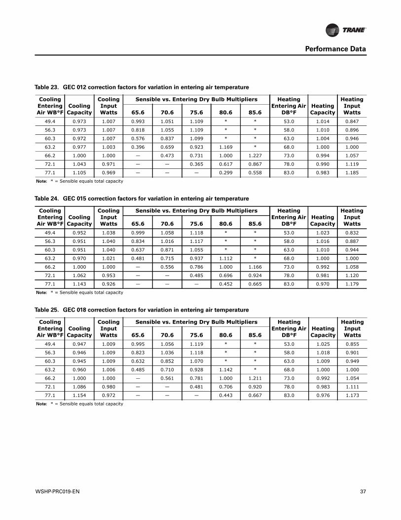
Table 23. GEC 012 correction factors for variation in entering air temperature
Cooling Entering Air WB°F
Cooling Capacity
Cooling Input Watts
Sensible vs. Entering Dry Bulb Multipliers Heating Entering Air
DB°FHeating Capacity
Heating Input Watts65.6 70.6 75.6 80.6 85.6
49.4 0.973 1.007 0.993 1.051 1.109 * * 53.0 1.014 0.847
56.3 0.973 1.007 0.818 1.055 1.109 * * 58.0 1.010 0.896
60.3 0.972 1.007 0.576 0.837 1.099 * * 63.0 1.004 0.946
63.2 0.977 1.003 0.396 0.659 0.923 1.169 * 68.0 1.000 1.000
66.2 1.000 1.000 — 0.473 0.731 1.000 1.227 73.0 0.994 1.057
72.1 1.043 0.971 — — 0.365 0.617 0.867 78.0 0.990 1.119
77.1 1.105 0.969 — — — 0.299 0.558 83.0 0.983 1.185
Note: * = Sensible equals total capacity
Table 24. GEC 015 correction factors for variation in entering air temperature
Cooling Entering Air WB°F
Cooling Capacity
Cooling Input Watts
Sensible vs. Entering Dry Bulb Multipliers Heating Entering Air
DB°FHeating Capacity
Heating Input Watts65.6 70.6 75.6 80.6 85.6
49.4 0.952 1.038 0.999 1.058 1.118 * * 53.0 1.023 0.832
56.3 0.951 1.040 0.834 1.016 1.117 * * 58.0 1.016 0.887
60.3 0.951 1.040 0.637 0.871 1.055 * * 63.0 1.010 0.944
63.2 0.970 1.021 0.481 0.715 0.937 1.112 * 68.0 1.000 1.000
66.2 1.000 1.000 — 0.556 0.786 1.000 1.166 73.0 0.992 1.058
72.1 1.062 0.953 — — 0.485 0.696 0.924 78.0 0.981 1.120
77.1 1.143 0.926 — — — 0.452 0.665 83.0 0.970 1.179
Note: * = Sensible equals total capacity
Table 25. GEC 018 correction factors for variation in entering air temperature
Cooling Entering Air WB°F
Cooling Capacity
Cooling Input Watts
Sensible vs. Entering Dry Bulb Multipliers Heating Entering Air
DB°FHeating Capacity
Heating Input Watts65.6 70.6 75.6 80.6 85.6
49.4 0.947 1.009 0.995 1.056 1.119 * * 53.0 1.025 0.855
56.3 0.946 1.009 0.823 1.036 1.118 * * 58.0 1.018 0.901
60.3 0.945 1.009 0.632 0.852 1.070 * * 63.0 1.009 0.949
63.2 0.960 1.006 0.485 0.710 0.928 1.142 * 68.0 1.000 1.000
66.2 1.000 1.000 — 0.561 0.781 1.000 1.211 73.0 0.992 1.054
72.1 1.086 0.980 — — 0.481 0.706 0.920 78.0 0.983 1.111
77.1 1.154 0.972 — — — 0.443 0.667 83.0 0.976 1.173
Note: * = Sensible equals total capacity
WSHP-PRC019-EN 37
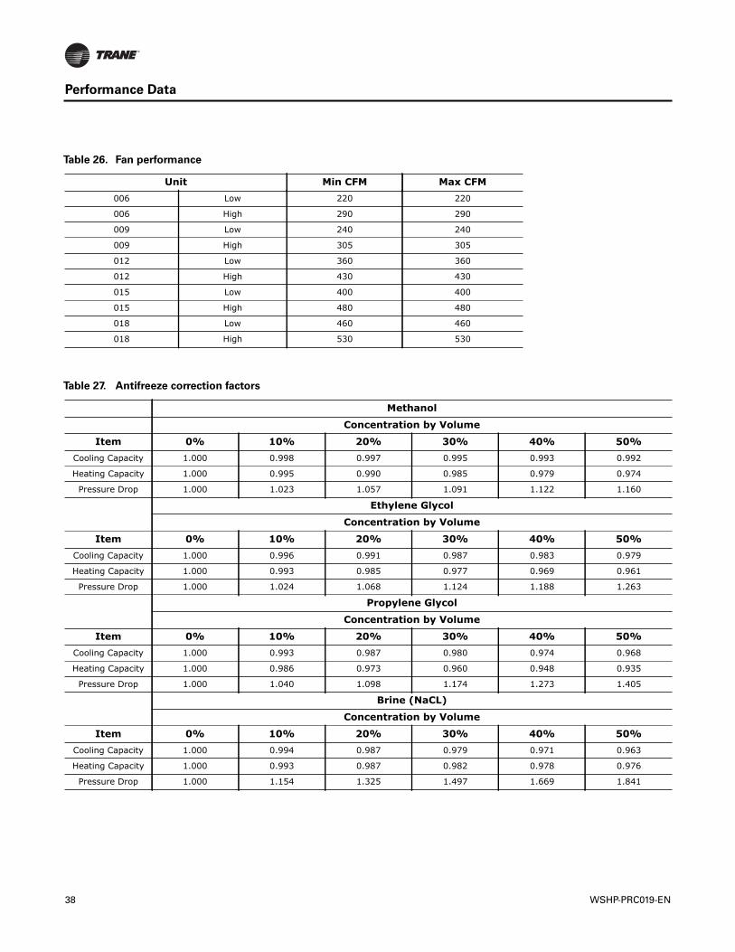
Performance Data
Table 26. Fan performance
Unit Min CFM Max CFM006 Low 220 220
006 High 290 290
009 Low 240 240
009 High 305 305
012 Low 360 360
012 High 430 430
015 Low 400 400
015 High 480 480
018 Low 460 460
018 High 530 530
Table 27. Antifreeze correction factors
Methanol
Concentration by Volume
Item 0% 10% 20% 30% 40% 50%Cooling Capacity 1.000 0.998 0.997 0.995 0.993 0.992
Heating Capacity 1.000 0.995 0.990 0.985 0.979 0.974
Pressure Drop 1.000 1.023 1.057 1.091 1.122 1.160
Ethylene Glycol
Concentration by Volume
Item 0% 10% 20% 30% 40% 50%Cooling Capacity 1.000 0.996 0.991 0.987 0.983 0.979
Heating Capacity 1.000 0.993 0.985 0.977 0.969 0.961
Pressure Drop 1.000 1.024 1.068 1.124 1.188 1.263
Propylene Glycol
Concentration by Volume
Item 0% 10% 20% 30% 40% 50%Cooling Capacity 1.000 0.993 0.987 0.980 0.974 0.968
Heating Capacity 1.000 0.986 0.973 0.960 0.948 0.935
Pressure Drop 1.000 1.040 1.098 1.174 1.273 1.405
Brine (NaCL)
Concentration by Volume
Item 0% 10% 20% 30% 40% 50%Cooling Capacity 1.000 0.994 0.987 0.979 0.971 0.963
Heating Capacity 1.000 0.993 0.987 0.982 0.978 0.976
Pressure Drop 1.000 1.154 1.325 1.497 1.669 1.841
38 WSHP-PRC019-EN
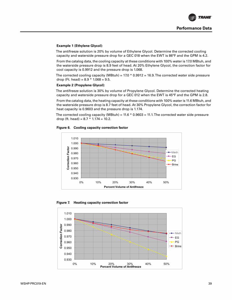
Performance Data
Example 1 (Ethylene Glycol):
The antifreeze solution is 20% by volume of Ethylene Glycol. Determine the corrected coolingcapacity and waterside pressure drop for a GEC 018 when the EWT is 86°F and the GPM is 4.2.
From the catalog data, the cooling capacity at these conditions with 100% water is 17.0 MBtuh, andthe waterside pressure drop is 8.9 feet of head. At 20% Ethylene Glycol, the correction factor forcool capacity is 0.9912 and the pressure drop is 1.068.
The corrected cooling capacity (MBtuh) = 17.0 * 0.9912 = 16.9.The corrected water side pressuredrop (Ft. head) = 8.9 * 1.068 = 9.5.
Example 2 (Propylene Glycol):
The antifreeze solution is 30% by volume of Propylene Glycol. Determine the corrected heatingcapacity and waterside pressure drop for a GEC 012 when the EWT is 45°F and the GPM is 2.8.
From the catalog data, the heating capacity at these conditions with 100% water is 11.6 MBtuh, andthe waterside pressure drop is 8.7 feet of head. At 30% Propylene Glycol, the correction factor forheat capacity is 0.9603 and the pressure drop is 1.174.
The corrected cooling capacity (MBtuh) = 11.6 * 0.9603 = 11.1.The corrected water side pressuredrop (ft. head) = 8.7 * 1.174 = 10.2.
Figure 6. Cooling capacity correction factor
Figure 7. Heating capacity correction factor
0.930
0.940
0.950
0.960
0.970
0.980
0.990
1.000
1.010
0% 10% 20% 30% 40% 50%Percent Volume of Antifreeze
Cor
rect
ion
Fact
or
MelthEGPGBrine
Meth
0.930
0.940
0.950
0.960
0.970
0.980
0.990
1.000
1.010
0% 10% 20% 30% 40% 50%Percent Volume of Antifreeze
Cor
rect
ion
Fact
or
MelthEGPGBrine
Meth
WSHP-PRC019-EN 39
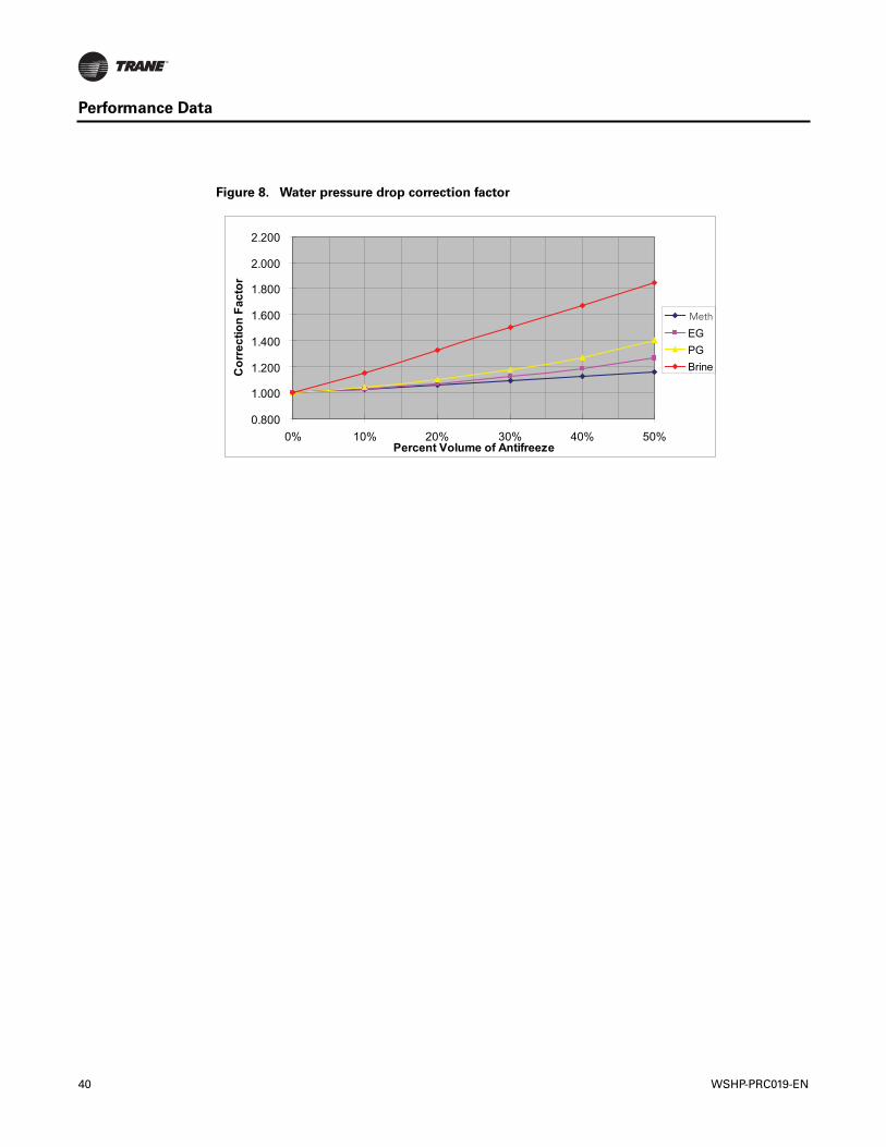
Performance Data
Figure 8. Water pressure drop correction factor
0.800
1.000
1.200
1.400
1.600
1.800
2.000
2.200
0% 10% 20% 30% 40% 50%Percent Volume of Antifreeze
Cor
rect
ion
Fact
or
MelthEGPGBrine
Meth
40 WSHP-PRC019-EN
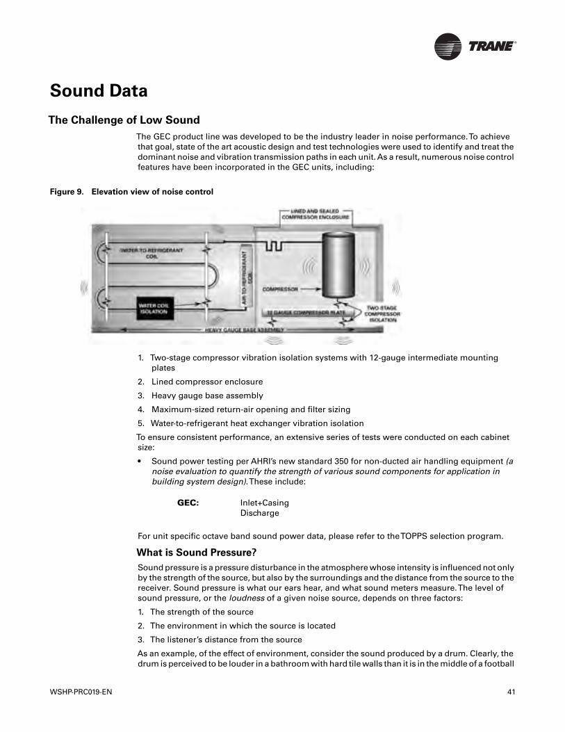
Sound Data
The Challenge of Low Sound
The GEC product line was developed to be the industry leader in noise performance.To achievethat goal, state of the art acoustic design and test technologies were used to identify and treat thedominant noise and vibration transmission paths in each unit. As a result, numerous noise controlfeatures have been incorporated in the GEC units, including:
1. Two-stage compressor vibration isolation systems with 12-gauge intermediate mountingplates
2. Lined compressor enclosure
3. Heavy gauge base assembly
4. Maximum-sized return-air opening and filter sizing
5. Water-to-refrigerant heat exchanger vibration isolation
To ensure consistent performance, an extensive series of tests were conducted on each cabinetsize:
• Sound power testing per AHRI’s new standard 350 for non-ducted air handling equipment (anoise evaluation to quantify the strength of various sound components for application inbuilding system design).These include:
Inlet+CasingDischarge
For unit specific octave band sound power data, please refer to theTOPPS selection program.
What is Sound Pressure?
Sound pressure is a pressure disturbance in the atmosphere whose intensity is influenced not onlyby the strength of the source, but also by the surroundings and the distance from the source to thereceiver. Sound pressure is what our ears hear, and what sound meters measure.The level ofsound pressure, or the loudness of a given noise source, depends on three factors:
1. The strength of the source
2. The environment in which the source is located
3. The listener’s distance from the source
As an example, of the effect of environment, consider the sound produced by a drum. Clearly, thedrum is perceived to be louder in a bathroom with hard tile walls than it is in the middle of a football
Figure 9. Elevation view of noise control
GEC:
WSHP-PRC019-EN 41
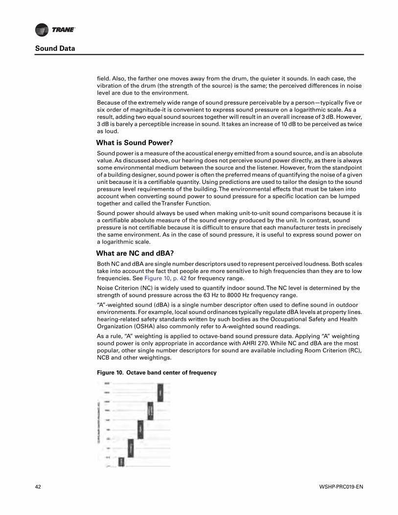
Sound Data
field. Also, the farther one moves away from the drum, the quieter it sounds. In each case, thevibration of the drum (the strength of the source) is the same; the perceived differences in noiselevel are due to the environment.
Because of the extremely wide range of sound pressure perceivable by a person—typically five orsix order of magnitude-it is convenient to express sound pressure on a logarithmic scale. As aresult, adding two equal sound sources together will result in an overall increase of 3 dB. However,3 dB is barely a perceptible increase in sound. It takes an increase of 10 dB to be perceived as twiceas loud.
What is Sound Power?
Sound power is a measure of the acoustical energy emitted from a sound source, and is an absolutevalue. As discussed above, our hearing does not perceive sound power directly, as there is alwayssome environmental medium between the source and the listener. However, from the standpointof a building designer, sound power is often the preferred means of quantifying the noise of a givenunit because it is a certifiable quantity. Using predictions are used to tailor the design to the soundpressure level requirements of the building.The environmental effects that must be taken intoaccount when converting sound power to sound pressure for a specific location can be lumpedtogether and called theTransfer Function.
Sound power should always be used when making unit-to-unit sound comparisons because it isa certifiable absolute measure of the sound energy produced by the unit. In contrast, soundpressure is not certifiable because it is difficult to ensure that each manufacturer tests in preciselythe same environment. As in the case of sound pressure, it is useful to express sound power ona logarithmic scale.
What are NC and dBA?
Both NC and dBA are single number descriptors used to represent perceived loudness. Both scalestake into account the fact that people are more sensitive to high frequencies than they are to lowfrequencies. See Figure 10, p. 42 for frequency range.
Noise Criterion (NC) is widely used to quantify indoor sound.The NC level is determined by thestrength of sound pressure across the 63 Hz to 8000 Hz frequency range.
“A”-weighted sound (dBA) is a single number descriptor often used to define sound in outdoorenvironments. For example, local sound ordinances typically regulate dBA levels at property lines.hearing-related safety standards written by such bodies as the Occupational Safety and HealthOrganization (OSHA) also commonly refer to A-weighted sound readings.
As a rule, “A” weighting is applied to octave-band sound pressure data. Applying “A” weightingsound power is only appropriate in accordance with AHRI 270. While NC and dBA are the mostpopular, other single number descriptors for sound are available including Room Criterion (RC),NCB and other weightings.
Figure 10. Octave band center of frequency
42 WSHP-PRC019-EN
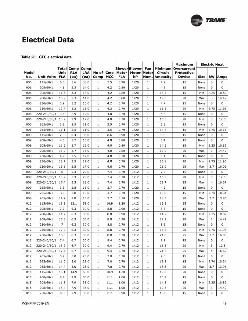
Electrical Data
Table 28. GEC electrical data
Model No. Unit Volts
Total Unit FLA
CompRLA(ea)
CompLRA(ea)
No ofComp
CmpMCC
BlowerMotorFLA
BlowerMotor
hP
Fan MotorNum.
Minimum Circuit
Ampacity
Maximum Overcurrent Protective
Device
Electric Heat
Size kW Amps006 115/60/1 6.5 5.6 30.0 1 7.5 0.90 1/20 1 7.9 15 None 0 0
006 208/60/1 4.1 3.3 14.0 1 4.2 0.80 1/20 1 4.9 15 None 0 0
006 208/60/1 11.6 3.3 14.0 1 4.2 0.80 1/20 1 14.5 15 Min 2.25 10.82
006 208/60/1 15.2 3.3 14.0 1 4.2 0.80 1/20 1 19.0 20 Max 3 14.42
006 230/60/1 3.9 3.2 15.0 1 4.2 0.70 1/20 1 4.7 15 None 0 0
006 230/60/1 12.7 3.2 15.0 1 4.2 0.70 1/20 1 15.8 20 Min 2.75 11.96
006 220-240/50/1 3.6 2.9 17.0 1 4.0 0.70 1/20 1 4.3 15 None 0 0
006 220-240/50/1 13.2 2.9 17.0 1 4.0 0.70 1/20 1 16.5 20 Min 3 12.5
006 265/60/1 3.2 2.5 11.0 1 3.5 0.70 1/20 1 3.8 15 None 0 0
006 265/60/1 11.1 2.5 11.0 1 3.5 0.70 1/20 1 14.4 15 Min 2.75 10.38
009 115/60/1 7.3 6.4 36.0 1 8.6 0.90 1/20 1 8.9 15 None 0 0
009 208/60/1 4.5 3.7 16.0 1 4.8 0.80 1/20 1 5.4 15 None 0 0
009 208/60/1 11.6 3.7 16.0 1 4.8 0.80 1/20 1 14.5 15 Min 2.25 10.82
009 208/60/1 15.2 3.7 16.0 1 4.8 0.80 1/20 1 19.0 20 Max 3 14.42
009 230/60/1 4.2 3.5 17.0 1 4.8 0.70 1/20 1 5.1 15 None 0 0
009 230/60/1 12.7 3.5 17.0 1 4.8 0.70 1/20 1 15.8 20 Min 2.75 11.96
009 230/60/1 16.8 3.5 17.0 1 4.8 0.70 1/20 1 21.0 25 Max 3.7 16.09
009 220-240/50/1 6 5.3 23.0 1 7.4 0.70 1/12 1 7.3 15 None 0 0
009 220-240/50/1 13.2 5.3 23.0 1 7.4 0.70 1/12 1 16.5 20 Min 3 12.5
009 220-240/50/1 17.4 5.3 23.0 1 7.4 0.70 1/12 1 21.7 25 Max 4 16.67
009 265/60/1 3.5 2.8 13.0 1 3.7 0.70 1/20 1 4.2 15 None 0 0
009 265/60/1 11 2.8 13.0 1 3.7 0.70 1/20 1 13.8 15 Min 2.74 10.34
009 265/60/1 14.7 2.8 13.0 1 3.7 0.70 1/20 1 18.3 20 Max 3.7 13.96
012 115/60/1 13.3 12.1 58.0 1 16.9 1.20 1/12 1 16.3 25 None 0 0
012 208/60/1 7.2 6.3 30.0 1 8.8 0.90 1/12 1 8.8 15 None 0 0
012 208/60/1 11.7 6.3 30.0 1 8.8 0.90 1/12 1 14.7 15 Min 2.25 10.82
012 208/60/1 15.3 6.3 30.0 1 8.8 0.90 1/12 1 19.2 20 Max 3 14.42
012 230/60/1 7 6.3 30.0 1 8.8 0.70 1/12 1 8.6 15 None 0 0
012 230/60/1 12.7 6.3 30.0 1 8.8 0.70 1/12 1 15.8 20 Min 2.75 11.96
012 230/60/1 16.8 6.3 30.0 1 8.8 0.70 1/12 1 21.0 25 Max 3.7 16.09
012 220-240/50/1 7.4 6.7 30.0 1 9.4 0.70 1/12 1 9.1 15 None 0 0
012 220-240/50/1 13.2 6.7 30.0 1 9.4 0.70 1/12 1 16.5 20 Min 3 12.5
012 220-240/50/1 17.4 6.7 30.0 1 9.4 0.70 1/12 1 21.7 25 Max 4 16.67
012 265/60/1 5.7 5.0 23.0 1 7.0 0.70 1/12 1 7.0 15 None 0 0
012 265/60/1 11.0 5.0 23.0 1 7.0 0.70 1/12 1 13.8 15 Min 2.74 10.34
012 265/60/1 14.7 5.0 23.0 1 7.0 0.70 1/12 1 18.3 20 Max 3.7 13.96
015 115/60/1 16.1 14.9 60.0 1 20.9 1.20 1/12 1 19.8 20 None 0 0
015 208/60/1 8.9 7.9 36.0 1 11.1 1.00 1/12 1 10.9 15 None 0 0
015 208/60/1 11.8 7.9 36.0 1 11.1 1.00 1/12 1 14.8 15 Min 2.25 10.82
015 208/60/1 15.4 7.9 36.0 1 11.1 1.00 1/12 1 19.3 20 Max 3 14.42
015 230/60/1 8.8 7.9 36.0 1 11.1 0.90 1/12 1 10.8 15 None 0 0
WSHP-PRC019-EN 43
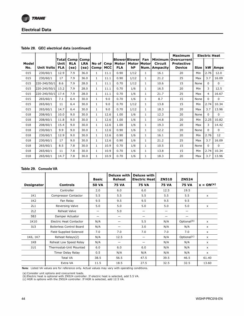
Electrical Data
015 230/60/1 12.9 7.9 36.0 1 11.1 0.90 1/12 1 16.1 20 Min 2.76 12.0
015 230/60/1 17 7.9 36.0 1 11.1 0.90 1/12 1 21.2 25 Max 3.7 16.09
015 220-240/50/1 8.6 7.9 28.0 1 11.1 0.70 1/12 1 10.6 15 None 0 0
015 220-240/50/1 13.2 7.9 28.0 1 11.1 0.70 1/6 1 16.5 20 Min 3 12.5
015 220-240/50/1 17.4 7.9 28.0 1 11.1 0.70 1/6 1 21.7 25 Max 4 16.67
015 265/60/1 7.1 6.4 30.0 1 9.0 0.70 1/6 1 8.7 15 None 0 0
015 265/60/1 11 6.4 30.0 1 9.0 0.70 1/12 1 13.8 15 Min 2.74 10.34
015 265/60/1 14.7 6.4 30.0 1 9.0 0.70 1/12 1 18.3 20 Max 3.7 13.96
018 208/60/1 10.0 9.0 30.0 1 12.6 1.00 1/6 1 12.3 20 None 0 0
018 208/60/1 11.8 9.0 30.0 1 12.6 1.00 1/6 1 14.8 20 Min 2.25 10.82
018 208/60/1 15.4 9.0 30.0 1 12.6 1.00 1/6 1 19.3 20 Max 3 14.42
018 230/60/1 9.9 9.0 30.0 1 12.6 0.90 1/6 1 12.2 20 None 0 0
018 230/60/1 12.9 9.0 30.0 1 12.6 0.90 1/6 1 16.1 20 Min 2.76 12
018 230/60/1 17 9.0 30.0 1 12.6 0.90 1/6 1 21.2 25 Max 3.7 16.09
018 265/60/1 8.5 7.8 30.0 1 10.9 0.70 1/6 1 10.5 15 None 0 0
018 265/60/1 11 7.8 30.0 1 10.9 0.70 1/6 1 13.8 15 Min 2.74 10.34
018 265/60/1 14.7 7.8 30.0 1 10.9 0.70 1/6 1 18.3 20 Max 3.7 13.96
Table 28. GEC electrical data (continued)
Model No. Unit Volts
Total Unit FLA
CompRLA(ea)
CompLRA(ea)
No ofComp
CmpMCC
BlowerMotorFLA
BlowerMotor
hP
Fan MotorNum.
Minimum Circuit
Ampacity
Maximum Overcurrent Protective
Device
Electric Heat
Size kW Amps
Table 29. Console VA
Designator Controls
BasicDeluxe with
ReheatDeluxe with Electric Heat ZN510 ZN524
x = ON(a)50 VA 75 VA 75 VA 75 VA 75 VAController 2.0 6.0 6.0 12.5 19.5
1K1 Compressor Contactor 5.5 5.5 5.5 5.5 5.5 x
1K2 Fan Relay 9.5 9.5 9.5 9.5 9.5
2L1 Reversing Valve 5.0 5.0 5.0 5.0 5.0 x
2L2 Reheat Valve — 5.0 — — —
5B3 Damper Actuator — — — — —
1K10 Electric Heat Contactor N/A — 5.5 N/A Optional(b) x
IU3 Boilerless Control Board N/A — 3.0 N/A N/A x
Field Supplied Solenoid 7.0 7.0 7.0 7.0 7.0 x
1K6, 1K7 Reheat Relays(2) N/A 12.5 — N/A Optional(c) x
1K8 Reheat Low Speed Relay N/A — — N/A N/A x
1U1 Thermostat-Unit Mounted 6.0 6.0 6.0 N/A N/A x
Timer Delay Relay 0.5 N/A N/A N/A N/A x
Total VA 38.5 56.5 47.5 39.5 46.5 61.40
Extra VA 11.5 18.5 27.5 32.5 32.5 13.60
Note: Listed VA values are for reference only. Actual values may vary with operating conditions.
(a) Consider unit options and concurrent loads.(b) Electric heat is optional with ZN524 controller. If electric heat is selected, add 5.5 VA.(c) HGR is options with the ZN524 controller. If HGR is selected, add 12.5 VA.
44 WSHP-PRC019-EN
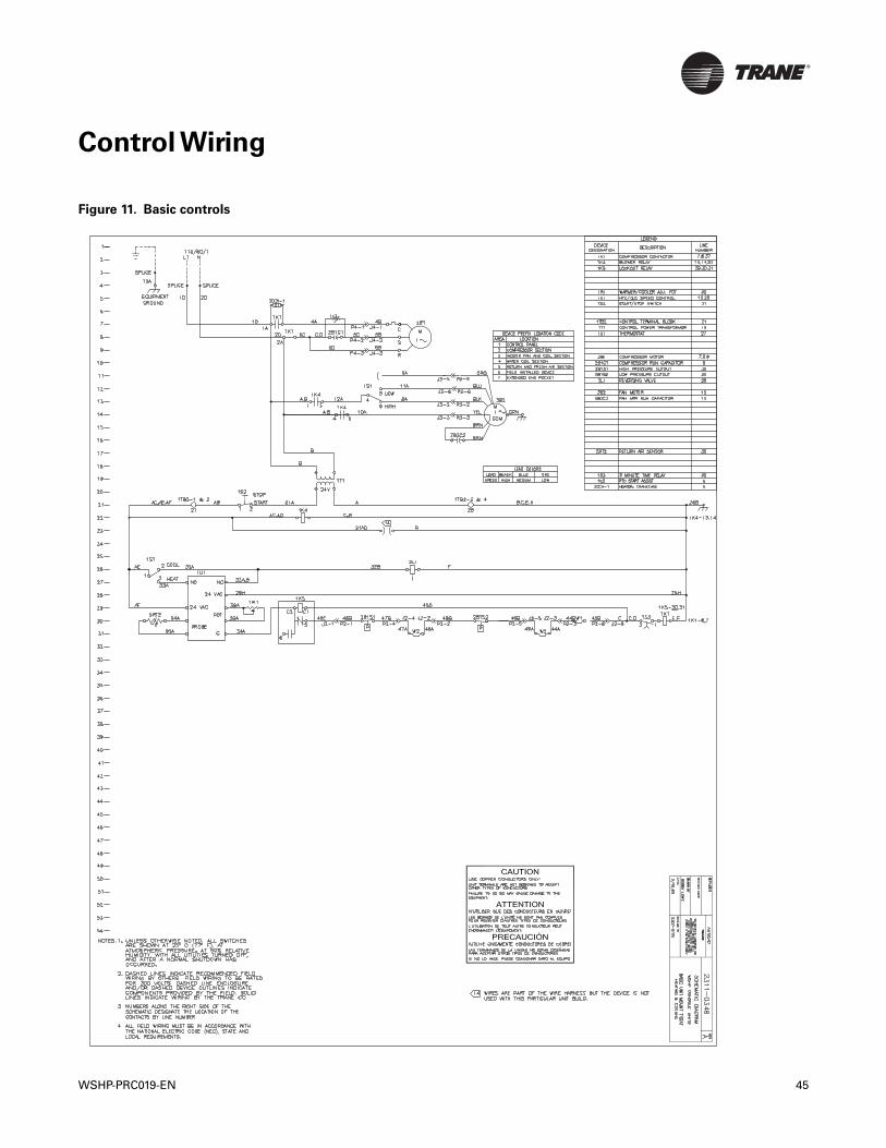
Control Wiring
Figure 11. Basic controls
WSHP-PRC019-EN 45
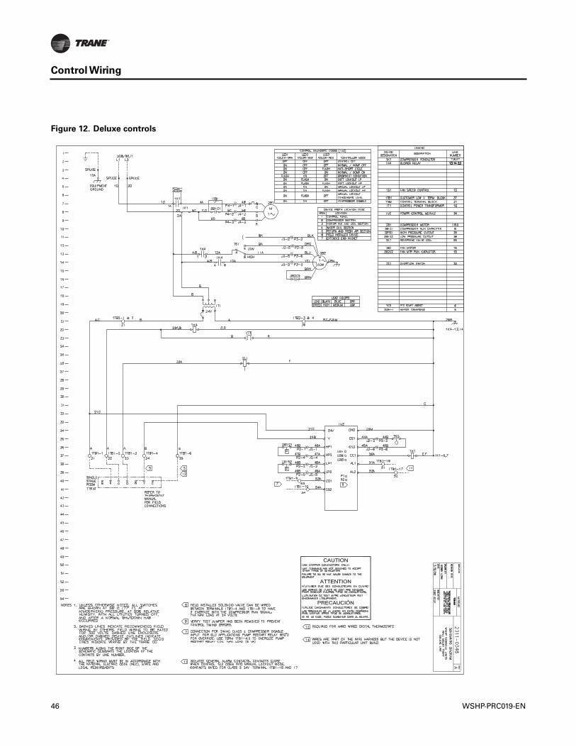
Control Wiring
Figure 12. Deluxe controls
46 WSHP-PRC019-EN
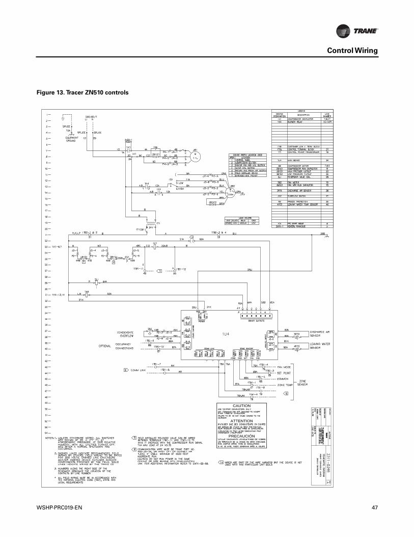
Control Wiring
Figure 13. Tracer ZN510 controls
WSHP-PRC019-EN 47
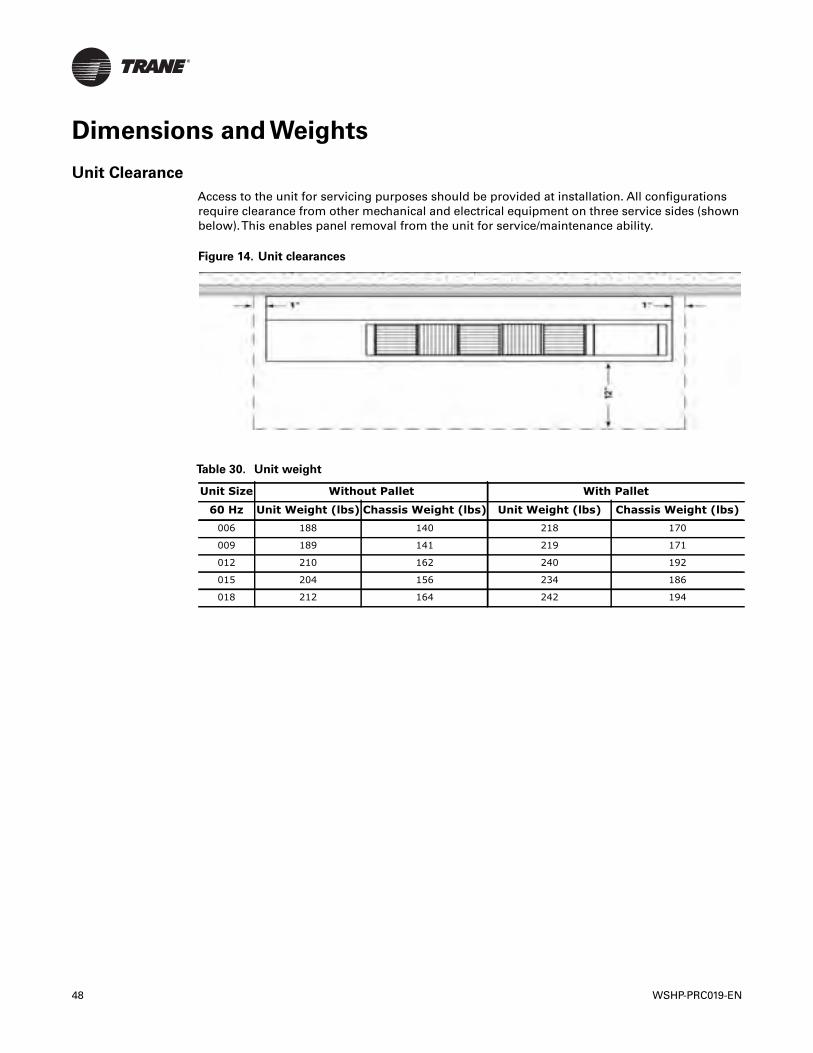
Dimensions and Weights
Unit Clearance
Access to the unit for servicing purposes should be provided at installation. All configurationsrequire clearance from other mechanical and electrical equipment on three service sides (shownbelow).This enables panel removal from the unit for service/maintenance ability.
Figure 14. Unit clearances
Table 30. Unit weight
Unit Size Without Pallet With Pallet
60 Hz Unit Weight (lbs) Chassis Weight (lbs) Unit Weight (lbs) Chassis Weight (lbs)006 188 140 218 170
009 189 141 219 171
012 210 162 240 192
015 204 156 234 186
018 212 164 242 194
48 WSHP-PRC019-EN
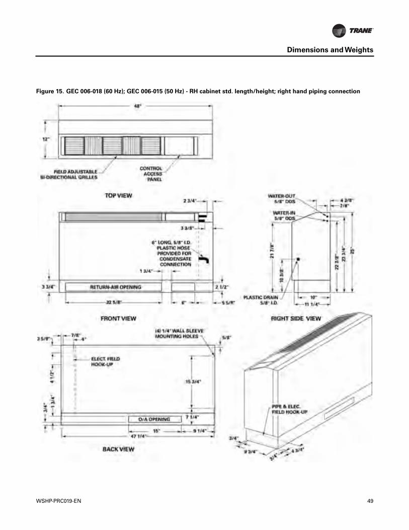
Dimensions and Weights
Figure 15. GEC 006-018 (60 Hz); GEC 006-015 (50 Hz) - RH cabinet std. length/height; right hand piping connection
WSHP-PRC019-EN 49
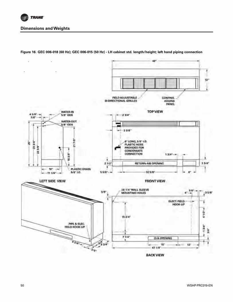
Dimensions and Weights
Figure 16. GEC 006-018 (60 Hz); GEC 006-015 (50 Hz) - LH cabinet std. length/height; left hand piping connection
50 WSHP-PRC019-EN
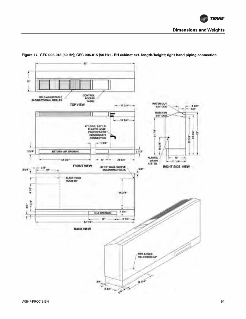
Dimensions and Weights
Figure 17. GEC 006-018 (60 Hz); GEC 006-015 (50 Hz) - RH cabinet ext. length/height; right hand piping connection
WSHP-PRC019-EN 51
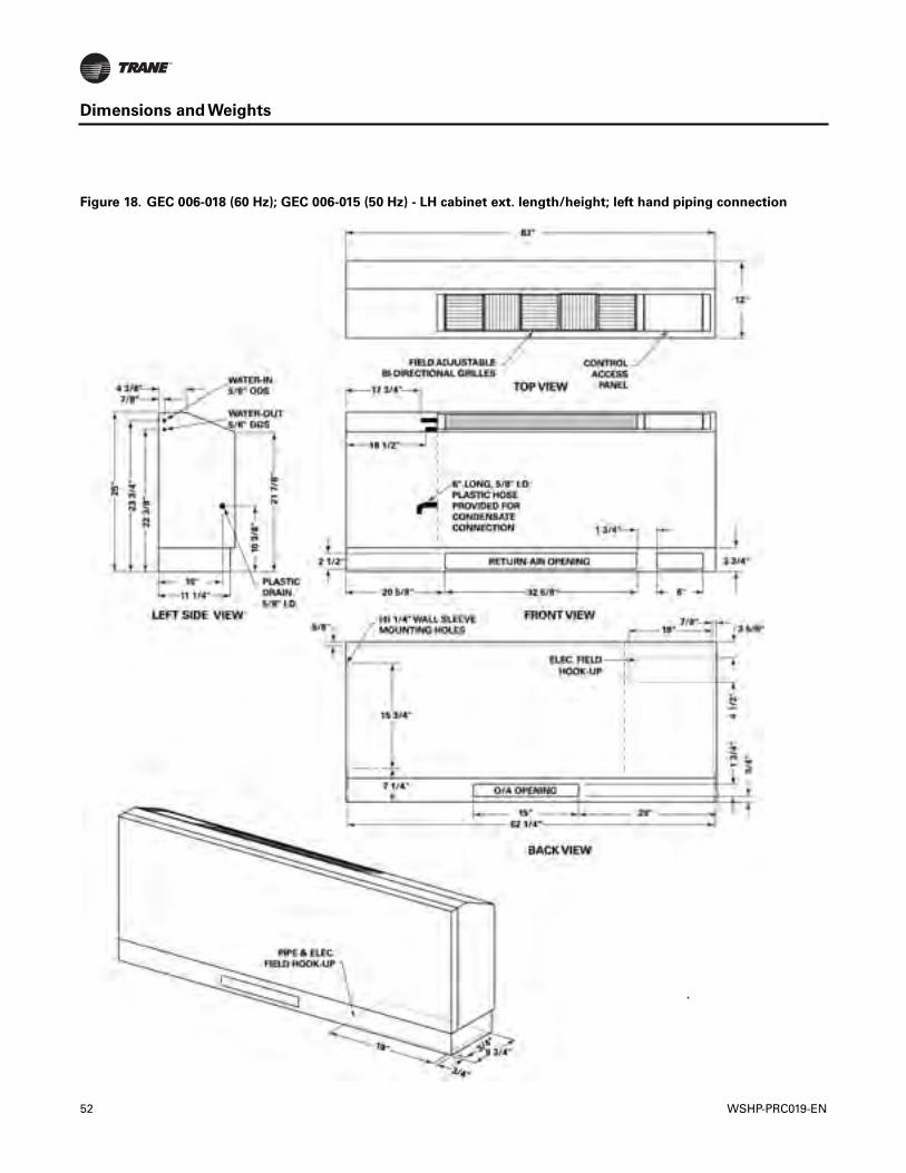
Dimensions and Weights
Figure 18. GEC 006-018 (60 Hz); GEC 006-015 (50 Hz) - LH cabinet ext. length/height; left hand piping connection
52 WSHP-PRC019-EN
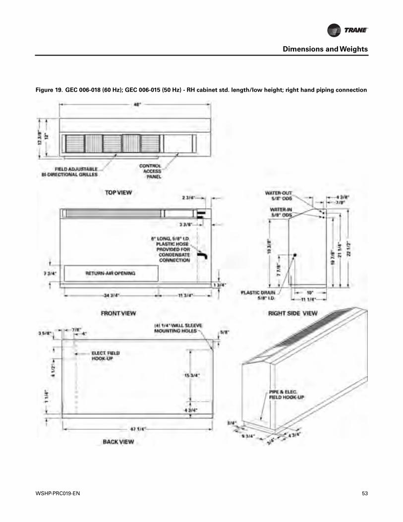
Dimensions and Weights
Figure 19. GEC 006-018 (60 Hz); GEC 006-015 (50 Hz) - RH cabinet std. length/low height; right hand piping connection
WSHP-PRC019-EN 53
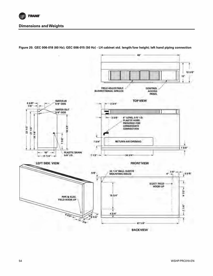
Dimensions and Weights
Figure 20. GEC 006-018 (60 Hz); GEC 006-015 (50 Hz) - LH cabinet std. length/low height; left hand piping connection
54 WSHP-PRC019-EN
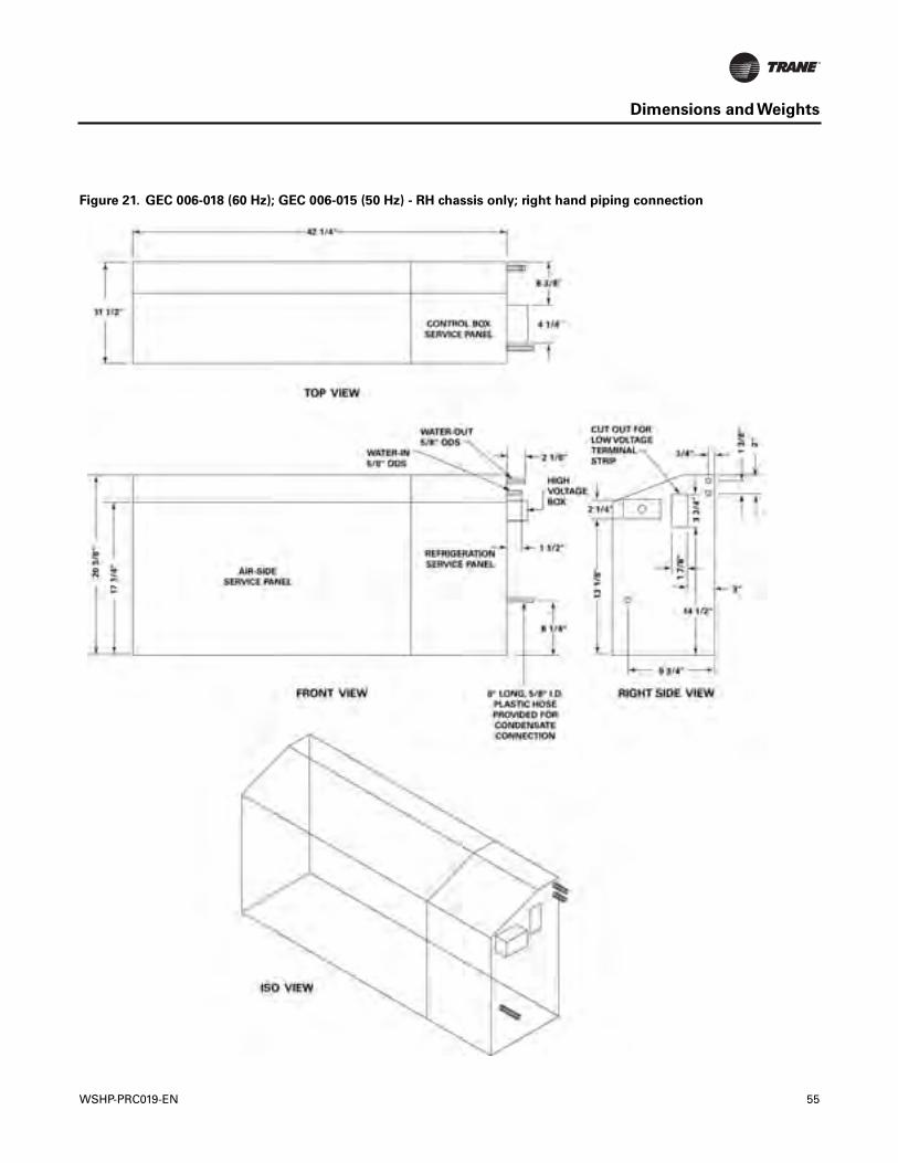
Dimensions and Weights
Figure 21. GEC 006-018 (60 Hz); GEC 006-015 (50 Hz) - RH chassis only; right hand piping connection
WSHP-PRC019-EN 55
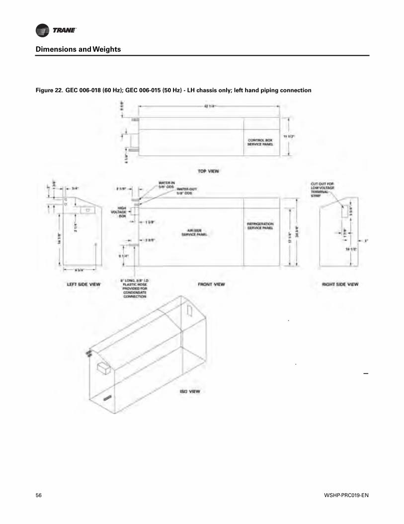
Dimensions and Weights
Figure 22. GEC 006-018 (60 Hz); GEC 006-015 (50 Hz) - LH chassis only; left hand piping connection
56 WSHP-PRC019-EN
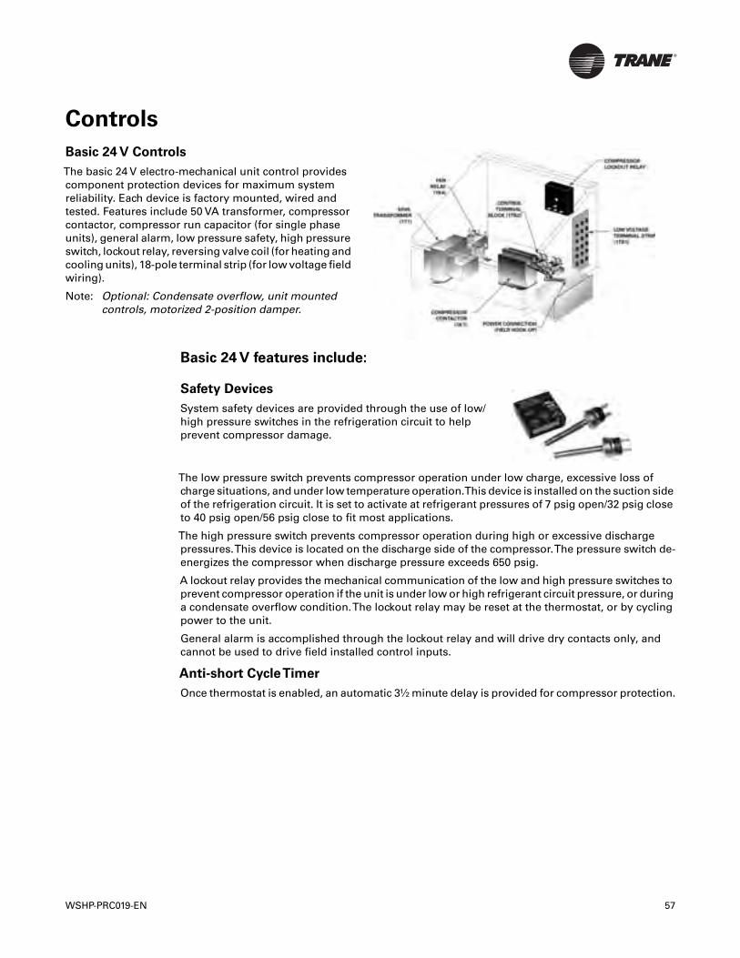
Controls
Basic 24 V features include:
The low pressure switch prevents compressor operation under low charge, excessive loss ofcharge situations, and under low temperature operation.This device is installed on the suction sideof the refrigeration circuit. It is set to activate at refrigerant pressures of 7 psig open/32 psig closeto 40 psig open/56 psig close to fit most applications.
The high pressure switch prevents compressor operation during high or excessive dischargepressures.This device is located on the discharge side of the compressor.The pressure switch de-energizes the compressor when discharge pressure exceeds 650 psig.
A lockout relay provides the mechanical communication of the low and high pressure switches toprevent compressor operation if the unit is under low or high refrigerant circuit pressure, or duringa condensate overflow condition.The lockout relay may be reset at the thermostat, or by cyclingpower to the unit.
General alarm is accomplished through the lockout relay and will drive dry contacts only, andcannot be used to drive field installed control inputs.
Anti-short CycleTimer
Once thermostat is enabled, an automatic 3½ minute delay is provided for compressor protection.
Basic 24 V Controls
The basic 24 V electro-mechanical unit control providescomponent protection devices for maximum systemreliability. Each device is factory mounted, wired andtested. Features include 50 VA transformer, compressorcontactor, compressor run capacitor (for single phaseunits), general alarm, low pressure safety, high pressureswitch, lockout relay, reversing valve coil (for heating andcooling units), 18-pole terminal strip (for low voltage fieldwiring).
Note: Optional: Condensate overflow, unit mountedcontrols, motorized 2-position damper.
Safety Devices
System safety devices are provided through the use of low/high pressure switches in the refrigeration circuit to helpprevent compressor damage.
WSHP-PRC019-EN 57
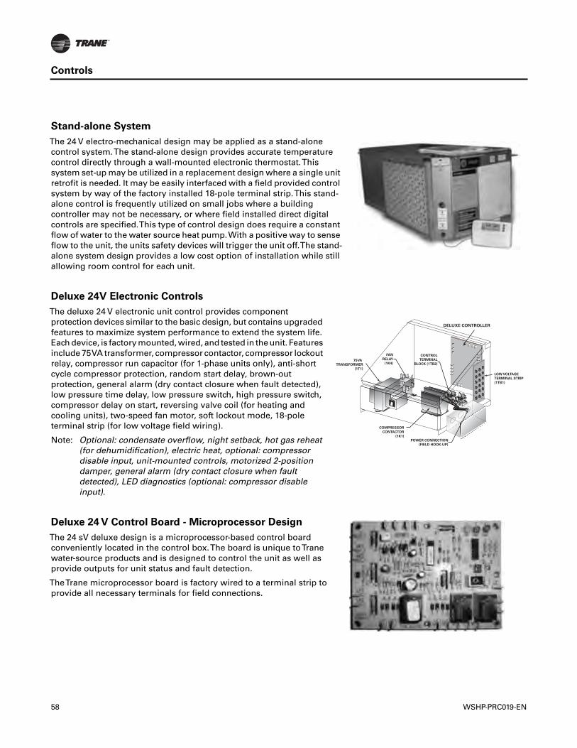
Controls
Stand-alone System
The 24 V electro-mechanical design may be applied as a stand-alonecontrol system.The stand-alone design provides accurate temperaturecontrol directly through a wall-mounted electronic thermostat.Thissystem set-up may be utilized in a replacement design where a single unitretrofit is needed. It may be easily interfaced with a field provided controlsystem by way of the factory installed 18-pole terminal strip.This stand-alone control is frequently utilized on small jobs where a buildingcontroller may not be necessary, or where field installed direct digitalcontrols are specified.This type of control design does require a constantflow of water to the water source heat pump.With a positive way to senseflow to the unit, the units safety devices will trigger the unit off.The stand-alone system design provides a low cost option of installation while stillallowing room control for each unit.
Deluxe 24V Electronic Controls
The deluxe 24 V electronic unit control provides componentprotection devices similar to the basic design, but contains upgradedfeatures to maximize system performance to extend the system life.Each device, is factory mounted, wired, and tested in the unit. Featuresinclude 75VA transformer, compressor contactor, compressor lockoutrelay, compressor run capacitor (for 1-phase units only), anti-shortcycle compressor protection, random start delay, brown-outprotection, general alarm (dry contact closure when fault detected),low pressure time delay, low pressure switch, high pressure switch,compressor delay on start, reversing valve coil (for heating andcooling units), two-speed fan motor, soft lockout mode, 18-poleterminal strip (for low voltage field wiring).
Note: Optional: condensate overflow, night setback, hot gas reheat(for dehumidification), electric heat, optional: compressordisable input, unit-mounted controls, motorized 2-positiondamper, general alarm (dry contact closure when faultdetected), LED diagnostics (optional: compressor disableinput).
75VA
TRANSFORMER
(1T1)
FAN
RELAY
(1K4)
COMPRESSOR
CONTACTOR
(1K1)
CONTROL
TERMINAL
BLOCK (1TB2)
POWER CONNECTION
(FIELD HOOK-UP)
LOW VOLTAGE
TERMINAL STRIP
(1TB1)
DELUXE CONTROLLER
Deluxe 24 V Control Board - Microprocessor Design
The 24 sV deluxe design is a microprocessor-based control boardconveniently located in the control box.The board is unique toTranewater-source products and is designed to control the unit as well asprovide outputs for unit status and fault detection.
TheTrane microprocessor board is factory wired to a terminal strip toprovide all necessary terminals for field connections.
58 WSHP-PRC019-EN

Controls
Deluxe 24 V features include:
Anti-short CycleTimer
The anti-short cycle timer provides a three minute time delay between compressor stop andcompressor restart. Once thermostat is enabled, an automatic 3 minute delay is provided forcompressor protection.
Brown-out Protection
The brown-out protection function measures the input voltage to the controller and halts thecompressor operation. Once a brown-out situation has occurred, the anti-short cycle timer willbecome energized.The general fault contact will not be affected by this condition.The voltage willcontinue to be monitored until the voltage increases.The compressors will be enabled at this timeif all start-up time delays have expired, and all safeties have been satisfied.
Compressor Disable
The compressor disable relay provides a temporary disable in compressor operation.The signalwould be provided from a water loop controller in the system. It would disable the compressorbecause of low water flow, peak limiting or if the unit goes into an unoccupied state. Once thecompressor has been disabled, the anti-short cycle time period will begin. Once the compressordisable signal is no longer present, and all safeties are satisfied, the control will allow thecompressor to restart.
Diagnostics
Component device connections to the microprocessor board are referenced in “Deluxe 24 VControl Board - Microprocessor Design,” p. 58.Three LEDs (light emitting diodes) are provided forindicating the operating mode of the controller. See the unit IOM for diagnostics or troubleshootingthrough the use of the LEDs.
Random Start
The random start relay provides a time delay start-up of the compressor when cycling in theoccupied mode. A new start delay time between 3 and 10 seconds is applied each time power isenabled to the unit.
Safety Control
The deluxe microprocessor receives separate input signals from the refrigerant high pressureswitch, low suction pressure switch and condensate overflow.
In a high pressure situation, the compressor contactor is de-energized, which suspendscompressor operation.The control will go into soft lockout mode initializing a three minute timedelay and a random start of 3 to 10 second time delays. Once these delays have expired, the unitwill be allowed to run. If a high pressure situation occurs within one hour of the first situation, thecontrol will be placed into a manual lockout mode, halting compressor operation, and initiating thegeneral alarm.
In a low temperature situation, the low pressure switch will transition open after the compressorstarts. If the switch is open for 45 seconds during compressor start, the unit will go into soft lockoutmode initializing a three minute time delay and a random start of 3 to 10 second time delays. Oncethese delays have expired, the unit will be allowed to run. If the low pressure situation occurs againwithin 30 minutes, and the device is open for more than 45 seconds, the control will be placed intoa manual lockout mode, halting compressor operation, and initiating the general alarm.
In a condensate overflow situation, the control will go into manual lockout mode, haltingcompressor operation, and initiating the general alarm.
The general alarm is initiated when the control goes into a manual lockout mode for either highpressure, low pressure or condensate overflow conditions.The alarm can be reset at thethermostat or by cycling power to the unit.
WSHP-PRC019-EN 59
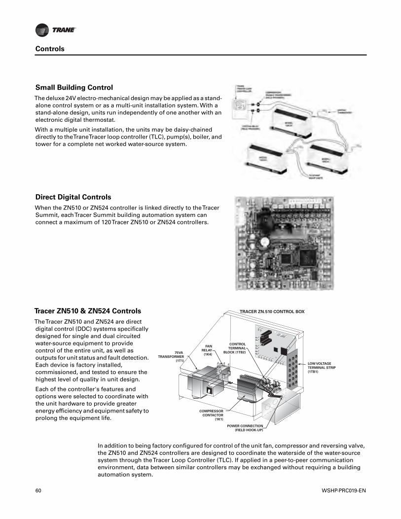
Controls
In addition to being factory configured for control of the unit fan, compressor and reversing valve,the ZN510 and ZN524 controllers are designed to coordinate the waterside of the water-sourcesystem through theTracer Loop Controller (TLC). If applied in a peer-to-peer communicationenvironment, data between similar controllers may be exchanged without requiring a buildingautomation system.
Small Building Control
The deluxe 24V electro-mechanical design may be applied as a stand-alone control system or as a multi-unit installation system. With astand-alone design, units run independently of one another with anelectronic digital thermostat.
With a multiple unit installation, the units may be daisy-chaineddirectly to theTraneTracer loop controller (TLC), pump(s), boiler, andtower for a complete net worked water-source system.
Direct Digital Controls
When the ZN510 or ZN524 controller is linked directly to theTracerSummit, eachTracer Summit building automation system canconnect a maximum of 120Tracer ZN510 or ZN524 controllers.
Tracer ZN510 & ZN524 Controls
TheTracer ZN510 and ZN524 are directdigital control (DDC) systems specificallydesigned for single and dual circuitedwater-source equipment to providecontrol of the entire unit, as well asoutputs for unit status and fault detection.Each device is factory installed,commissioned, and tested to ensure thehighest level of quality in unit design.
Each of the controller's features andoptions were selected to coordinate withthe unit hardware to provide greaterenergy efficiency and equipment safety toprolong the equipment life.
75VA
TRANSFORMER
(1T1)
FAN
RELAY
(1K4)
COMPRESSOR
CONTACTOR
(1K1)
POWER CONNECTION
(FIELD HOOK-UP)
LOW VOLTAGE
TERMINAL STRIP
(1TB1)
CONTROL
TERMINAL
BLOCK (1TB2)
TRACER ZN.510 CONTROL BOX
60 WSHP-PRC019-EN
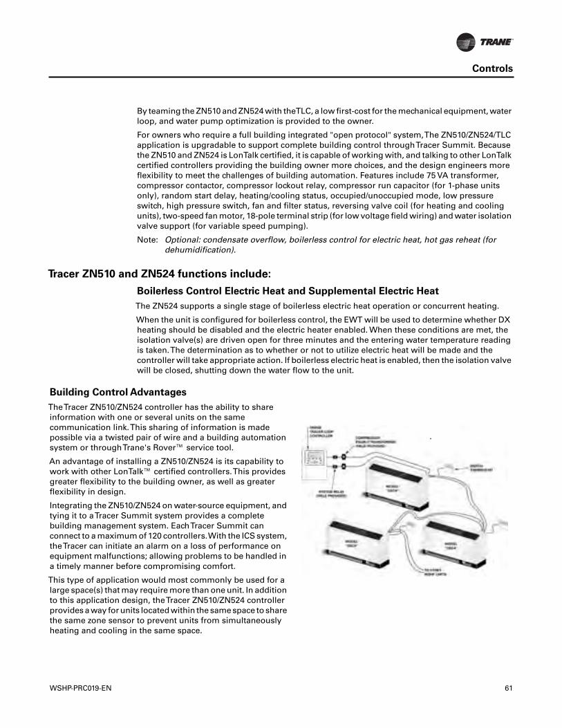
Controls
By teaming the ZN510 and ZN524 with theTLC, a low first-cost for the mechanical equipment, waterloop, and water pump optimization is provided to the owner.
For owners who require a full building integrated "open protocol" system,The ZN510/ZN524/TLCapplication is upgradable to support complete building control throughTracer Summit. Becausethe ZN510 and ZN524 is LonTalk certified, it is capable of working with, and talking to other LonTalkcertified controllers providing the building owner more choices, and the design engineers moreflexibility to meet the challenges of building automation. Features include 75 VA transformer,compressor contactor, compressor lockout relay, compressor run capacitor (for 1-phase unitsonly), random start delay, heating/cooling status, occupied/unoccupied mode, low pressureswitch, high pressure switch, fan and filter status, reversing valve coil (for heating and coolingunits), two-speed fan motor, 18-pole terminal strip (for low voltage field wiring) and water isolationvalve support (for variable speed pumping).
Note: Optional: condensate overflow, boilerless control for electric heat, hot gas reheat (fordehumidification).
Tracer ZN510 and ZN524 functions include:
Boilerless Control Electric Heat and Supplemental Electric Heat
The ZN524 supports a single stage of boilerless electric heat operation or concurrent heating.
When the unit is configured for boilerless control, the EWT will be used to determine whether DXheating should be disabled and the electric heater enabled. When these conditions are met, theisolation valve(s) are driven open for three minutes and the entering water temperature readingis taken.The determination as to whether or not to utilize electric heat will be made and thecontroller will take appropriate action. If boilerless electric heat is enabled, then the isolation valvewill be closed, shutting down the water flow to the unit.
Building Control Advantages
TheTracer ZN510/ZN524 controller has the ability to shareinformation with one or several units on the samecommunication link.This sharing of information is madepossible via a twisted pair of wire and a building automationsystem or throughTrane's Rover™ service tool.
An advantage of installing a ZN510/ZN524 is its capability towork with other LonTalk™ certified controllers.This providesgreater flexibility to the building owner, as well as greaterflexibility in design.
Integrating the ZN510/ZN524 on water-source equipment, andtying it to aTracer Summit system provides a completebuilding management system. EachTracer Summit canconnect to a maximum of 120 controllers.With the ICS system,theTracer can initiate an alarm on a loss of performance onequipment malfunctions; allowing problems to be handled ina timely manner before compromising comfort.
This type of application would most commonly be used for alarge space(s) that may require more than one unit. In additionto this application design, theTracer ZN510/ZN524 controllerprovides a way for units located within the same space to sharethe same zone sensor to prevent units from simultaneouslyheating and cooling in the same space.
WSHP-PRC019-EN 61
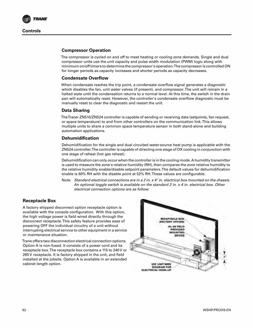
Controls
Compressor Operation
The compressor is cycled on and off to meet heating or cooling zone demands. Single and dualcompressor units use the unit capacity and pulse width modulation (PWM) logic along withminimum on/off timers to determine the compressor's operation.The compressor is controlled ONfor longer periods as capacity increases and shorter periods as capacity decreases.
Condensate Overflow
When condensate reaches the trip point, a condensate overflow signal generates a diagnosticwhich disables the fan, unit water valves (if present), and compressor.The unit will remain in ahalted state until the condensation returns to a normal level. At this time, the switch in the drainpan will automatically reset. However, the controller's condensate overflow diagnostic must bemanually reset to clear the diagnostic and restart the unit.
Data Sharing
TheTracer ZN510/ZN524 controller is capable of sending or receiving data (setpoints, fan request,or space temperature) to and from other controllers on the communication link.This allowsmultiple units to share a common space temperature sensor in both stand-alone and buildingautomation applications.
Dehumidification
Dehumidification for the single and dual circuited water-source heat pump is applicable with theZN524 controller.The controller is capable of directing one stage of DX cooling in conjunction withone stage of reheat (hot gas reheat).
Dehumidification can only occur when the controller is in the cooling mode.A humidity transmitteris used to measure the zone's relative humidity (RH), then compares the zone relative humidity tothe relative humidity enable/disable setpoint parameters.The default values for dehumidificationenable is 60% RH with the disable point at 52% RH.These values are configurable.
Note: Standard electrical connections are in a 2 in. x 4" in. electrical box mounted on the chassis.An optional toggle switch is available on the standard 2 in. x 4 in. electrical box. Otherelectrical connection options are as follow:
Receptacle Box
A factory shipped disconnect option receptacle option isavailable with the console configuration. With this option,the high voltage power is field wired directly through thedisconnect receptacle.This safety feature provides ease ofpowering OFF the individual circuitry of a unit withoutinterrupting electrical service to other equipment in a serviceor maintenance situation.
Trane offers two disconnection electrical connection options.Option A is non-fused. It consists of a power cord and itsreceptacle box.The receptacle box contains a 115 to 240V or265 V receptacle. It is factory shipped in the unit, and fieldinstalled at the jobsite. Option A is available in an extendedcabinet length option.
62 WSHP-PRC019-EN
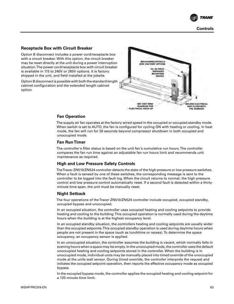
Controls
Fan Operation
The supply air fan operates at the factory wired speed in the occupied or occupied standby mode.When switch is set to AUTO, the fan is configured for cycling ON with heating or cooling. In heatmode, the fan will run for 30 seconds beyond compressor shutdown in both occupied andunoccupied mode.
Fan RunTimer
The controller's filter status is based on the unit fan's cumulative run hours.The controllercompares the fan run time against an adjustable fan run hours limit and recommends unitmaintenance as required.
High and Low Pressure Safety Controls
TheTracer ZN510/ZN524 controller detects the state of the high pressure or low pressure switches.When a fault is sensed by one of these switches, the corresponding message is sent to thecontroller to be logged into the fault log. When the circuit returns to normal, the high pressurecontrol and low pressure control automatically reset. If a second fault is detected within a thirty-minute time span, the unit must be manually reset.
Night Setback
The four operations of theTracer ZN510/ZN524 controller include occupied, occupied standby,occupied bypass and unoccupied.
In an occupied situation, the controller uses occupied heating and cooling setpoints to provideheating and cooling to the building.This occupied operation is normally used during the daytimehours when the building is at the highest occupancy level.
In an occupied standby situation, the controllers heating and cooling setpoints are usually widerthan the occupied setpoints.This occupied standby operation is used during daytime hours whenpeople are not present in the space (such as lunchtime or recess).To determine the spaceoccupancy, an occupancy sensor is applied.
In an unoccupied situation, the controller assumes the building is vacant, which normally falls inevening hours when a space may be empty. In the unoccupied mode, the controller uses the defaultunoccupied heating and cooling setpoints stored in the controller. When the building is inunoccupied mode, individual units may be manually placed into timed override of the unoccupiedmode at the units wall sensor. During timed override, the controller interprets the request andinitiates the occupied setpoint operation, then reports the effective occupancy mode as occupiedbypass.
In the occupied bypass mode, the controller applies the occupied heating and cooling setpoint fora 120 minute time limit.
Receptacle Box with Circuit Breaker
Option B disconnect includes a power cord/receptacle boxwith a circuit breaker. With this option, the circuit breakermay be reset directly at the unit during a power interruptionsituation.The power cord/receptacle box with circuit breakeris available in 115 to 240V or 265V options. It is factoryshipped in the unit, and field installed at the jobsite.
Option B disconnect is possible with both the standard lengthcabinet configuration and the extended length cabinetoption.
WSHP-PRC019-EN 63
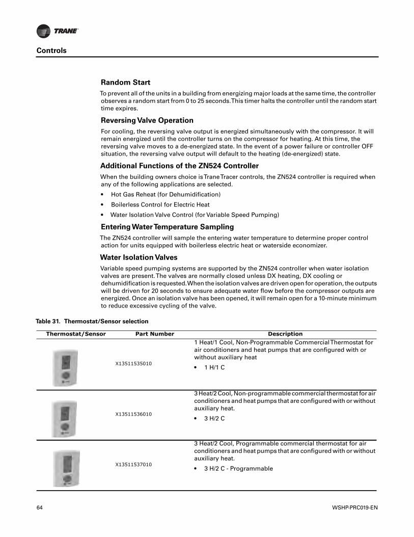
Controls
Random Start
To prevent all of the units in a building from energizing major loads at the same time, the controllerobserves a random start from 0 to 25 seconds.This timer halts the controller until the random starttime expires.
Reversing Valve Operation
For cooling, the reversing valve output is energized simultaneously with the compressor. It willremain energized until the controller turns on the compressor for heating. At this time, thereversing valve moves to a de-energized state. In the event of a power failure or controller OFFsituation, the reversing valve output will default to the heating (de-energized) state.
Additional Functions of the ZN524 Controller
When the building owners choice isTraneTracer controls, the ZN524 controller is required whenany of the following applications are selected.
• Hot Gas Reheat (for Dehumidification)
• Boilerless Control for Electric Heat
• Water Isolation Valve Control (for Variable Speed Pumping)
Entering WaterTemperature Sampling
The ZN524 controller will sample the entering water temperature to determine proper controlaction for units equipped with boilerless electric heat or waterside economizer.
Water Isolation Valves
Variable speed pumping systems are supported by the ZN524 controller when water isolationvalves are present.The valves are normally closed unless DX heating, DX cooling ordehumidification is requested.When the isolation valves are driven open for operation, the outputswill be driven for 20 seconds to ensure adequate water flow before the compressor outputs areenergized. Once an isolation valve has been opened, it will remain open for a 10-minute minimumto reduce excessive cycling of the valve.
Table 31. Thermostat/Sensor selection
Thermostat/Sensor Part Number Description
X13511535010
1 Heat/1 Cool, Non-Programmable CommercialThermostat forair conditioners and heat pumps that are configured with orwithout auxiliary heat
• 1 H/1 C
X13511536010
3 Heat/2 Cool, Non-programmable commercial thermostat for airconditioners and heat pumps that are configured with or withoutauxiliary heat.
• 3 H/2 C
X13511537010
3 Heat/2 Cool, Programmable commercial thermostat for airconditioners and heat pumps that are configured with or withoutauxiliary heat.
• 3 H/2 C - Programmable
64 WSHP-PRC019-EN
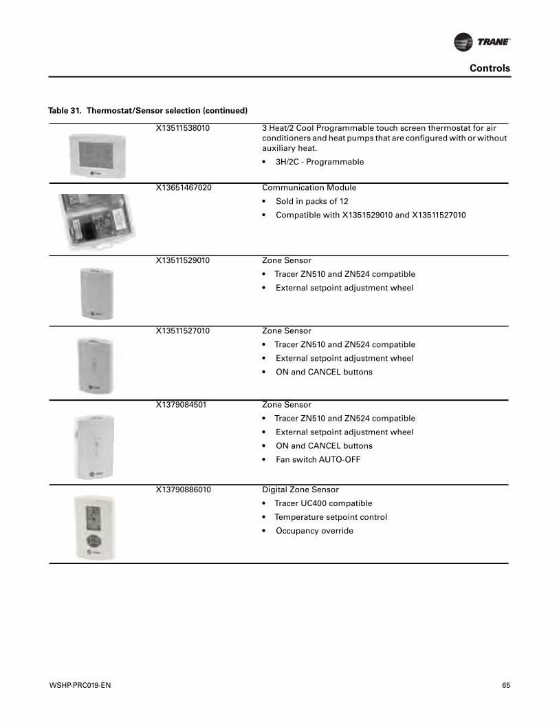
Controls
X13511538010 3 Heat/2 Cool Programmable touch screen thermostat for airconditioners and heat pumps that are configured with or withoutauxiliary heat.
• 3H/2C - Programmable
X13651467020 Communication Module
• Sold in packs of 12
• Compatible with X1351529010 and X13511527010
X13511529010 Zone Sensor
• Tracer ZN510 and ZN524 compatible
• External setpoint adjustment wheel
X13511527010 Zone Sensor
• Tracer ZN510 and ZN524 compatible
• External setpoint adjustment wheel
• ON and CANCEL buttons
X1379084501 Zone Sensor
• Tracer ZN510 and ZN524 compatible
• External setpoint adjustment wheel
• ON and CANCEL buttons
• Fan switch AUTO-OFF
X13790886010 Digital Zone Sensor
• Tracer UC400 compatible
• Temperature setpoint control
• Occupancy override
Table 31. Thermostat/Sensor selection (continued)
WSHP-PRC019-EN 65
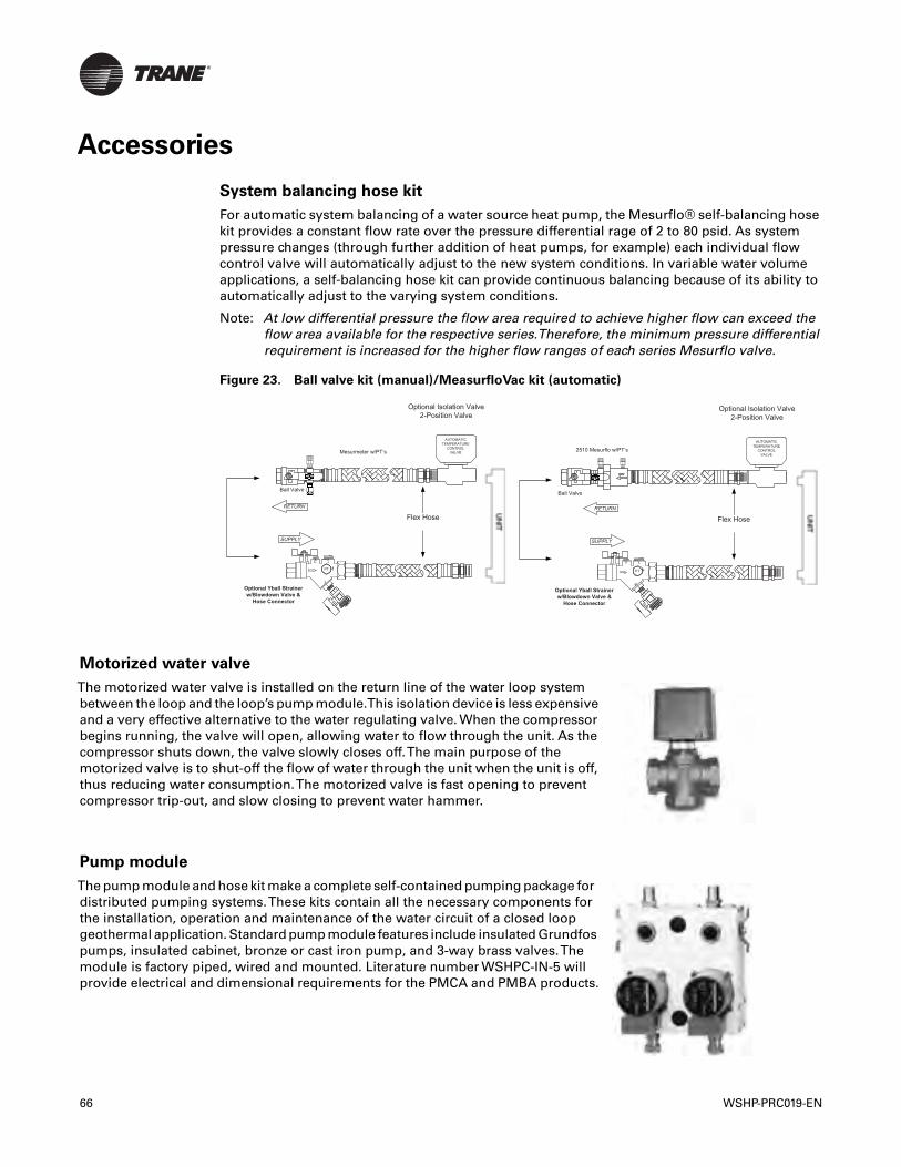
Accessories
System balancing hose kit
For automatic system balancing of a water source heat pump, the Mesurflo® self-balancing hosekit provides a constant flow rate over the pressure differential rage of 2 to 80 psid. As systempressure changes (through further addition of heat pumps, for example) each individual flowcontrol valve will automatically adjust to the new system conditions. In variable water volumeapplications, a self-balancing hose kit can provide continuous balancing because of its ability toautomatically adjust to the varying system conditions.
Note: At low differential pressure the flow area required to achieve higher flow can exceed theflow area available for the respective series.Therefore, the minimum pressure differentialrequirement is increased for the higher flow ranges of each series Mesurflo valve.
Figure 23. Ball valve kit (manual)/MeasurfloVac kit (automatic)
Flex Hose
Mesurmeter w/PT’s
Optional Yball Strainer w/Blowdown Valve &
Hose Connector
PTFLOW
Ball Valve
Optional Isolation Valve2-Position Valve
AUTOMATICTEMPERATURE
CONTROL VALVE
Flex Hose
Optional Yball Strainer w/Blowdown Valve &
Hose Connector
PTFLOW
Ball Valve
Optional Isolation Valve2-Position Valve
2510 Mesurflo w/PT’sAUTOMATIC
TEMPERATURECONTROL
VALVE
Motorized water valve
The motorized water valve is installed on the return line of the water loop systembetween the loop and the loop’s pump module.This isolation device is less expensiveand a very effective alternative to the water regulating valve. When the compressorbegins running, the valve will open, allowing water to flow through the unit. As thecompressor shuts down, the valve slowly closes off.The main purpose of themotorized valve is to shut-off the flow of water through the unit when the unit is off,thus reducing water consumption.The motorized valve is fast opening to preventcompressor trip-out, and slow closing to prevent water hammer.
Pump module
The pump module and hose kit make a complete self-contained pumping package fordistributed pumping systems.These kits contain all the necessary components forthe installation, operation and maintenance of the water circuit of a closed loopgeothermal application. Standard pump module features include insulated Grundfospumps, insulated cabinet, bronze or cast iron pump, and 3-way brass valves.Themodule is factory piped, wired and mounted. Literature number WSHPC-IN-5 willprovide electrical and dimensional requirements for the PMCA and PMBA products.
66 WSHP-PRC019-EN
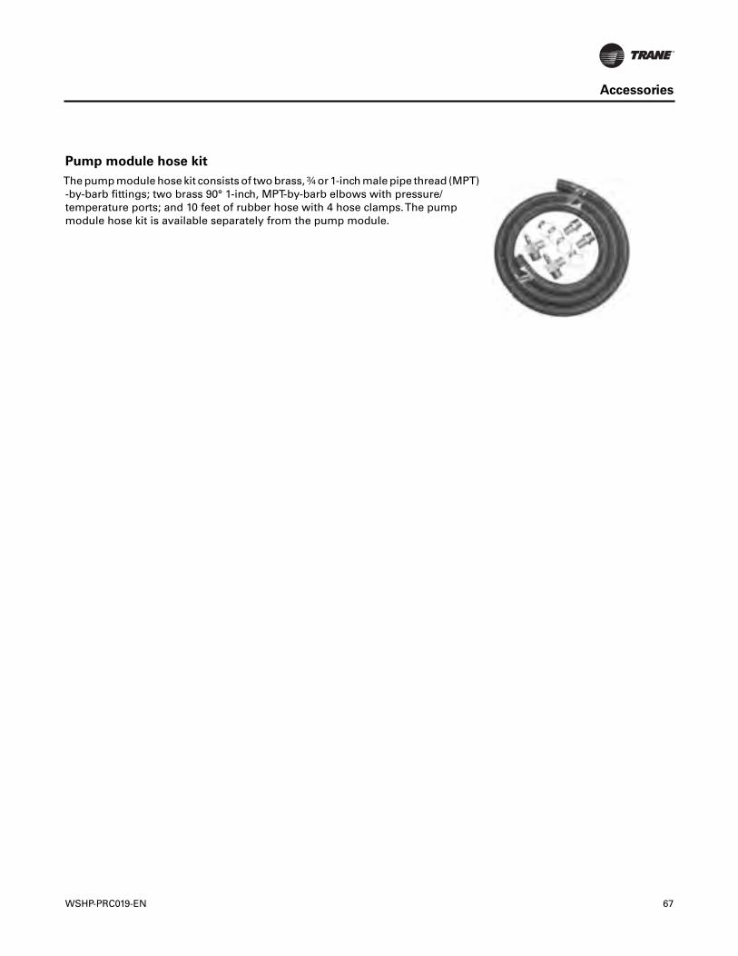
Accessories
Pump module hose kit
The pump module hose kit consists of two brass, ¾ or 1-inch male pipe thread (MPT)-by-barb fittings; two brass 90° 1-inch, MPT-by-barb elbows with pressure/temperature ports; and 10 feet of rubber hose with 4 hose clamps.The pumpmodule hose kit is available separately from the pump module.
WSHP-PRC019-EN 67
Mechanical Specifications
General
Equipment shall be completely assembled, piped, internally wired and test operated at the factory.It shall be both ETL and ISO-AHRI 13256-1 listed and labeled prior to leaving the factory. Serviceand caution area labels shall also be placed on the unit in their appropriate locations.
Air-to-Refrigerant Coil
The air-to-refrigerant coil shall contain copper tubes mechanically expanded into evenly spacedaluminum fins. All coils are to be leak tested.The proof must be performed at 650 psi operatingpressure and the leak test at 125 psi operating pressure with helium. In addition, the tubes are tobe completely evacuated of air prior to shipment.
The refrigerant coil distributor assembly shall be of orifice style with round copper distributortubes.The tubes shall be sized consistently with the capacity of the coil. Suction headers shall befabricated from rounded copper pipe.
A thermostatic expansion valve shall be factory selected and installed for a wide range of control.
Ball Valves (option)
Ball valves shall be field installed between the unit and the loop pump module, on both supply andreturn lines to the loop.
Cabinet
The cabinet shall be constructed of sturdy galvanized steel, with exposed edges rounded.The steelshall include electrostatic powder paint in three attractive colors for an appliance grade finish.Service to the refrigerant and controls shall be provided through a single access panel at the frontof the unit chassis. Insulation for the internal parts and surfaces exposed to the conditioned airstream shall be made of moisture resistant insulation.
The insulation shall be ½-inch thick dual density bonded glass fiber.The exposed side shall be ahigh density erosion proof material suitable for use in airstreams up to 4500 feet per minute (FPM).Insulation shall meet the Underwriters' Laboratories Fire Hazard Classification:
• Flame spread = 25
• Smoke developed = 50
Access for inspection and cleaning of the unit drain pan, coils and fan section shall be provided.The unit shall be installed for proper access. Procedures for proper access inspection and cleaningof the unit shall be included in the maintenance manual.
Drain Pan
The drain pan shall be constructed of corrosion resistant material and insulated to preventsweating.The bottom of the drain pan shall be sloped on two planes which pitches the condensateto the drain connection.
Electric Heat (option)
The electric heat option (boilerless for the heat pump version) shall be factory wired and tested.It shall be composed of a nichrome open wire coil designed for 2-kW per unit ton. It shall consistof a single stage of electric heat used as a primary heating source when compressor lockout hasoccurred due to the entering water temperature falling below 55°F in a boilerless situation.
Fans
The fans shall be placed in a blow-through configuration.They shall be constructed of corrosionresistant galvanized material.
68 WSHP-PRC019-EN
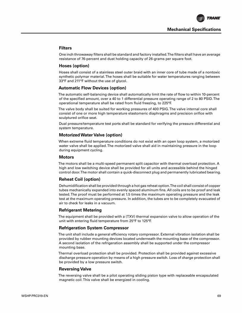
Mechanical Specifications
Filters
One inch throwaway filters shall be standard and factory installed.The filters shall have an averageresistance of 76-percent and dust holding capacity of 26-grams per square foot.
Hoses (option)
Hoses shall consist of a stainless steel outer braid with an inner core of tube made of a nontoxicsynthetic polymar material.The hoses shall be suitable for water temperatures ranging between33°F and 211°F without the use of glycol.
Automatic Flow Devices (option)
The automatic self-balancing device shall automatically limit the rate of flow to within 10-percentof the specified amount, over a 40 to 1 differential pressure operating range of 2 to 80 PSID.Theoperational temperature shall be rated from fluid freezing, to 225°F.
The valve body shall be suited for working pressures of 400 PSIG.The valve internal core shallconsist of one or more high temperature elastomeric diaphragms and precision orifice withsculptured orifice seat.
Dual pressure/temperature test ports shall be standard for verifying the pressure differential andsystem temperature.
Motorized Water Valve (option)
When extreme fluid temperature conditions do not exist with an open loop system, a motorizedwater valve shall be applied.The motorized valve shall aid in maintaining pressure in the loopduring equipment cycling.
Motors
The motors shall be a multi-speed permanent split capacitor with thermal overload protection. Ahigh and low switching device shall be provided for all units and accessible behind the hingedcontrol door.The motor shall contain a quick-disconnect plug and permanently lubricated bearing.
Reheat Coil (option)
Dehumidification shall be provided through a hot gas reheat option.The coil shall consist of coppertubes mechanically expanded into evenly spaced aluminum fins. All coils are to be proof and leaktested.The proof must be performed at 1.5 times the maximum operating pressure and the leaktest at the maximum operating pressure. In addition, the tubes are to be completely evacuated ofair to check for leaks in a vacuum.
Refrigerant Metering
The equipment shall be provided with a (TXV) thermal expansion valve to allow operation of theunit with entering fluid temperature from 25°F to 125°F.
Refrigeration System Compressor
The unit shall include a general efficiency rotary compressor. External vibration isolation shall beprovided by rubber mounting devices located underneath the mounting base of the compressor.A second isolation of the refrigeration assembly shall be supported under the compressormounting base.
Thermal overload protection shall be provided. Protection shall be provided against excessivedischarge pressure operation by means of a high pressure switch. Loss of charge protection shallbe provided by a low pressure switch.
Reversing Valve
The reversing valve shall be a pilot operating sliding piston type with replaceable encapsulatedmagnetic coil.This valve shall be energized in cooling.
WSHP-PRC019-EN 69
Mechanical Specifications
Schrader Connections
The refrigerant access ports shall be factory supplied on the high and low pressure sides for easyrefrigerant pressure or temperature testing.
Sound Attenuation
Sound attenuation shall be applied as a standard feature in the product design.
The sound reduction package shall include a vibration isolation to the compressor and water-to-refrigerant coil, a second stage of vibration isolation to the compressor base pan, heavy gauge baseassembly, insulated metal compressor enclosure, and maximum sized return-air opening and filtersizing.
The unit shall be tested and rated in accordance with AHRI 350.
Tubing
The refrigerant tubing shall be of 99% pure copper.This system shall be free from contaminantsand conditions such as drilling fragments, dirt and oil. All refrigerant and water lines shall beinsulated with an elastomeric insulation that has a 3/8-inch thick wall where ever air is introducedto the assembly.
Water Regulating Valve Assembly (option)
The water regulating valve assembly shall consist of a direct acting valve and a reverse actingvalve.The direct acting valve shall open in response to an increase in discharge pressure duringthe cooling cycle.The reverse acting valve shall open in response to a decrease in suction pressureduring the heating cycle.Water regulating valves shall be used where low flow, or low or high fluidtemperature conditions exist.This accessory shall be used with open-loop systems.
Water-to-Refrigerant Heat Exchanger
The water-to-refrigerant heat exchanger shall be of a high quality co-axial coil for maximum heattransfer.The copper or optional cupro-nickel coil shall be deeply fluted to enhance heat transfer andminimize fouling and scaling.The coil shall have a working pressure of 650 psig on both therefrigerant and water sides.The factory shall provide rubber isolation to the heat exchangingdevice to enhance sound attenuation.
Controls
Basic Controls (option)
The basic control package shall contain a low and high pressure switch along with a compressorlockout relay for control assistance. High voltage power connections shall be made at theequipment contactor. An optional condensate overflow detection device shall be made availablewith this control package. Each device shall be factory mounted, wired, and tested in theequipment.
Deluxe Controller (option)
The deluxe control package shall provide a 75VA transformer.The controller shall include a lockoutrelay, anti-short cycle compressor protection, random start delay, brown-out protection, lowpressure time delay, compressor delay on start and an open relay for night setback or pumprequest. Optional wiring from the factory for night setback, condensate overflow, hot gas reheat,electric heat and compressor enable shall also be provided.Three LEDs (light emitting diodes) shallalso be included for diagnostics of the equipment.
Tracer ZN510 Controller
This system shall utilize factory furnished and mounted DDC controls for operation of up to 100units on a LonMark (Comm 5) link.
70 WSHP-PRC019-EN
Mechanical Specifications
TheTracer ZN510 control package shall include a 75 VA transformer.The controller shall providerandom start delay, heating/cooling status, occupied/unoccupied mode, fan status and filtermaintenance options. Optional wiring from the factory for condensate overflow shall be available.Three LEDs (light emitting diodes) shall be included for diagnostics of the equipment.
The ZN510 shall be capable of a standalone application, or as applied to a full building automationinstallation.
Tracer ZN524 Controller (option)
The ZN524 controller shall utilize factory furnished and mounted DDC controls for operation of upto 120 units on a Comm 5 (LonMark™) link.
TheTracer™ ZN524 control package shall include a 75 VA (minimum) transformer.The controllershall provide random start delay, heating/cooling status, occupied/unoccupied mode, fan statusand filter maintenance options. Optional wiring from the factory for condensate overflow shall beavailable.Three LEDs (light emitting diodes) shall be included for diagnostics of the equipment.
The ZN524 shall be capable of a standalone application, or as applied to a full building automationinstallation.
With this controller, the unit shall be capable of a hot gas reheat (for dehumidification), boilerlesscontrol for electric heat and support of variable speed pump control applications.
Unit Mounted Controls
Factory wired unit mounted controls shall be available for both the basic and deluxe controlpackages.The units low voltage side shall be factory wired and require no external wiring in thefield.The unit mounted device shall include a temperature control thermostat knob, ON/OFFcontrol switch, manual changeover from COOL to HEAT, and fan speed control of HIGH and LOW.
The controls shall be accessible behind a durable plastic cover that shall be available with orwithout key-lock access.
Electrical
The factory tested and installed control box shall contain all necessary devices to allow heating andcooling operation of the equipment to occur from a remote wall thermostat or zone sensor.Thesedevices shall be as follows:
• 24VAC Energy Limiting Class II, 50VA breaker with external fuse or 75VA with a circuit breaker
• 24 VAC contactor for compressor control
• 18 pole terminal strip located inside the control box behind the service access panel.Thisterminal strip shall be used for low voltage (thermostat/zone sensor) connections.
• An electrically operated safety lockout relay shall help prevent cycling of the compressor duringadverse conditions of operation.This device shall be reset either at the remote thermostat/zonesensor, or by cycling power to the unit.
• A high pressure switch shall help protect the compressor against operation at refrigerantsystem pressure in excess of 650 psig.
• A low pressure switch shall help prevent compressor operation under low charge orcatastrophic loss of charge situations.
• Factory installed wire harness shall be available for the Basic, Deluxe,Tracer ZN510 andTerminal Unit Control packages.
WSHP-PRC019-EN 71

Trane optimizes the performance of homes and buildings around the world. A business of Ingersoll Rand, the leader increating and sustaining safe, comfortable and energy efficient environments,Trane offers a broad portfolio of advancedcontrols and HVAC systems, comprehensive building services, and parts. For more information, visit www.Trane.com.
Trane has a policy of continuous product and product data improvement and reserves the right to change design and specifications without notice.
We are committed to using environmentally
conscious print practices that reduce waste.
© 2013Trane All rights reserved
WSHP-PRC019-EN 24 Apr 2013
Supersedes WSHP-PRC019-EN (15 Dec 2011)


