Embed Size (px)
Citation preview
3745 Communication Controller All Models 3746 Nways Multiprotocol Controller Model 900
Console Setup Guide
--..- ------ -------- -. ---- - - -------------, -
SA33-0158-09
o
o
o
o
o
3745 Communication Controller All Models 3746 Nways Multiprotocol Controller Model 900
Console Setup Guide
--------- - ------- - ---- - - -----------,-
SA33-0158-09
Note! ----~~------------------------------------~---------------------------------,
Before Llsing this information and the product it supports, be sure to read the general information under "Notices" on page xi.
Tenth Edition (June 1998)
The information contained in this manual is subject to change from time to time. Any such changes will be reported in later revisions.
Order publications through your IBM* representative or the IBM branch office serving your locality. Publications are not stocked at the address given below.
A form for readers' comments appears at the back of this publication. If the form has been removed, address your comments to:
IBM France Centre d'Etudes et Recherches Service 0798 - BP 79 06610 La Gaude France
• FAX: 33 4 93 24 77 97 • IBM Internal Use: LGERCF at IBMFR • Internet: [email protected]
When you send information to IBM, you grant IBM a non-exclusive right to use or distribute the information in any way it believes appropriate without incurring any obligation to you.
© Copyright International Business Machines Corporation 1989, 1998. All rights reserved. Note to U.S. Government Users - Documentation related to restricted rights - Use, duplication or disclosure is subject to restrictions set forth in GSA ADP Schedule Contract with IBM Corp.
/
..
o Contents
o
o
c
"
o
Figures
Tab res
Notices ..... . European Union (EU) Statement Electronic Emission Notices ... Trademarks and Service Marks Safety ........ .
About this Guide Conventions Used in this Guide Who Should Use this Guide . How this Guide is Organized What is New in this Edition Where to Find More Information
World Wide Web ...... .
Part 1. 3745 Models A and 3746 Model 900
Chapter 1. Introduction to Remote Consoles and DCAF Consoles ........................... .
Diskettes with Example Configurations ........ . DCAF Logon Password and Service Processor Security Regaining Control of the Service Processor ..... . Minimum Workstation (Remote Console) Configuration
Programming Requirements ........... . Hardware Requirements and Recommendations
Chapter 2. DCAF Session Installation Summary of Procedures .. Preparation . . . . . . . . . . . . . Physical Insta"ation ...... .
Installing DCAF Upgrading DCAF .... . Installing TCP/IP ..... .
Customizing CS/2 and CM/2 Customizing a Remote Workstation
Loading Example Configurations ..... . Starting CS/2 and CM/2 Configuration
Configuring Data Link Control (DLC) for a Service Processor
Chapter 3. Using DCAF to Remotely Log On to· the Service Processor Starting a Session ........... . Closing a Session ........... .
From the Remote Workstation From the Target Service Processor
ix
ix
xi xi xi
xiii xiii
xv xv xvi xvi xvii xvii xvii
1-1 1-2 1-3 1-3 1-4 1-4 1-4 1-5
2-1 2-1 2-1 2-2 2-2 2-3 2-3 2-3 2-3 2-4 2-4 2-4
3-1 3-1 3-2 3-2 3-2
Chapter 4. TCPIIP LAN-Attached Remote Workstation Configuration 4-1
© Copyright IBM Corp. 1989, 1998 iii
Configuring a Target Service Processor ......... . Configuring a TCP/IP LAN-Attached Remote Workstation
Configuring DCAF for TCPIIP Configuring TCP/IP ................... .
4-1 4-4 4-4 4-6
Chapter 5. APPC LAN-Attached Remote Workstation Configuration 5-1 Configuring a Target Service Processor . . . . . . . 5-1
Parameter Values that Must Be the Same ....... 5-2 Configuring the Service Processor in MOSS-E 5-2
Configuring a APPC LAN-Attached Remote Workstation 5-5 Configuring CS/2 ....... 5-5 Configuring DCAF for APPC ............... 5-11
Chapter 6. Modem-Attached Remote Workstation Configuration 6-1 Configuring a Target Service Processor . . . . . . 6-1
Parameter Values that Must Be the Same ...... 6-2 Configuring the Service Processor in MOSS-E 6-2
Configuring Workstation Modems ........ 6-4 Configuring CS/2 and CM/2 in Workstations 6-6
Configuring Workstation for an IBM Modem ... 6-6 Procedures for Service Processors 9577 and 9585 6-7 Procedures for Service Processor 3172 ....... 6-8 Procedures for Service Processor 7585 ....... 6-9
Modem 7855 in Synchronous Mode to Service Processor 9577,9585, and 3172 via MPA Card in Synchronous Mode (17855SYN) ..... 6-10
Modem 7855 in Asynchronous Mode to Service Processor 9577, 9585, 3172, and 7585 via Serial Port (17855ASY) ............... 6-15
Modem 7857 in Synchronous Mode to Service Processor 9577, 9585, and 3172 via MPA Card in Synchronous Mode (17857SYN) ..... 6-20
Modem 7857 in Asynchronous Mode to Service Processor 9577, 9585, 3172, and 7585 via Serial Port (17857 ASY) ................. 6-25
Modem 7857 in AutoSync Mode to Service Processor 9577,9585, and 3172 via MPA Card in Sync Mode (17857AUT) .. . . . . . . . . . . .. 6-30
Hayes Modem in Asynchronous Mode to Service Processor 9577, 9585, 3172, and 7585 via Serial Port (HA YESASY) .............. 6-35
Hayes Modem in AutoSync Mode to Service Processor 9577,9585, and 3172 via MPA Card in Sync Mode (HAYESAUT) 6-40
Configuring DCAF for a Modem .......... 6-45
Chapter 7. SNA-Attached Remote Workstation Configuring a Target Service Processor ........ .
Parameter Values that Must Be the Same .... . Configuring the Service Processor in MOSS-E
Configuring a SNA-Attached Remote Workstation .. Configuring CS/2 ................... . Configuring DCAF for SNA . . .
NCP Definitions ........... . Remote Controlling Workstation .. Target Service Processor
VTAM Definitions . Start Definitions Logmode Table Major Node Definitions
Remote Workstation
iv All 3745 Models & the 3746-900: eSG
7-1 7-1 7-2 7-2 7-5 7-5
7-10 7-12 7-12 7-13 7-14 7-14 7-14 7-15 7-15
\,,- ... _/
()
o
o
o
o
o
Target Service Processor ........... .
Chapter 8. APPN-Attached Remote Workstation Configuring a Target Service Processor ..... .
Parameter Values that Must Be the Same ... . Configuring the Service Processor in MOSS-E
Configuring an APPN-Attached Remote Workstation Configuring CS/2 ...... . Configuring DCAF for APPN ........... .
Chapter 9. Telnet-attached Remote Workstation Introduction
Consoles ............ . Logon Password ........ . Programming Requirements .. Hardware Requirements and Recommendations
Installation ....................... . Using Telnet to Remotely Log On to the Network Node Processor
Starting a Session Closing a Session .......................... .
Part 2. 3745 Models 130 to 610
Chapter 10. Setting Up a Local or an Alternate Console General Information on Local or Alternate consoles 3151 in Native Mode (Local or Alternate) ..... 3151 in 3101 Emulation Mode (Local or Alternate) 3153 in 3151 Emulation Mode (Local or Alternate)
Recommended Settings ..... Starting the Console Configuration Leaving the Console Configuration
3161 or 3163 (Local or Alternate) IBM PS/2 (Local or Alternate) ..... MOSS Local or Alternate Console Emulation with CM/2 and Softerm 3727 ............................. . Testing a Connection with the Local or Alternate Console
Chapter 11. Setting Up a Remote Console General Information (Remote) ..... . 3151 in Native Mode (Remote) .... . 3151 in 3101 Emulation Mode (Remote) 3153 in 3151 Emulation Mode (Remote)
Recommended Settings ..... Starting the Console Configuration Closing the Console Configuration
3161 or 3163 (Remote) IBM PC ................ . IBM PS/2 (Remote) ......... . MOSS Remote Console Emulatioh with CM/2 and Softerm
Starting Custom Plus ........... . Defining a New Session ......... .
Defining the Terminal Emulation Profile Defining Connection Path Profile ....
7-15
8-1 8-1 8-2 8-2 8-4 8-4
8-10
9-1 9-1 9-1 9-2 9-2 9-2 9-2 9-2 9-2 9-2
10-1 10-1 10-2 10-3 10-5 10-5 10-5 10-6 10-6 10-6 10-9 10-9
10-10
11-1 11-1 11-2 11-3 11-5 11-5 11-5 11-6 11-6 11-6 11-7
11-10 11-10 11-10 11-10 11-12
Contents V
Ending Definition of a New Session ............ . Other Types of Consoles .................... . Testing the Modem· Connection to a· Remote Console
Chapter 12. Modem· Setup ...... . Modems for 3745· Models 130 to 160
Setting Up ........................ . Switch Settings for IBM Modems 5841, 5842, and 5853 "
IBM 5841 Modem ..................... . IBM 5842 Modem ..................... . IBM 5853 Modem ..................... .
Modems for 3745 Models A ... Setting the IBM 7855 Modem .................... . Setting the IBM 7857 Modem Connected to MPA Card (SYN) Setting the 7857 Modem Connected to COM1 (ASYN) ....... . Setting the 7857 Modem Connected to MPA Card on COM2 (ASYN) Setting the IBM 7858 Modem Connected to MPA Card (SYN) Setting the 7858 Modem Connected to COM 1 (ASYN) ....... . Setting the 7858 Modem Connected to MPA Card on COM2 (ASYN)
Chapter 13. RSF Modems IBM 5858 Modem ...... . IBM 7855 Modem ...... . IBM 7857 Modem ...... .
Part 3. Appendixes for 3745 Model A and 3746 Model 900
Appendix A. Configuration for a Two-Target Remote Workstation NCP Definitions .......... .................... . VTAM Definitions ........ .
Start List ........... . Logmode Table ........ . ........... . Switched Major Nodes .... .
DCAF Remote Workstation Configuration ...... .
Appendix B. Configuring DLC for DCAF ..... Create or Change the Token-Ring Network DLC Adapter Profile Create or Change the SOLC DLC Adapter Profile ......... .
Part 4. Appendixes for 3745 Models 130 to 610
Appendix C. Location of 3745 Console Connectors 3745 Communication Controller Models 130, 150, 160, and 170 3745 Communication Controller Models. 210, 310, 410, and 610
11-12 11-13 11-13
12-1 12-1 12-1 12-2 12-2 12-2 12-2 12-3 12-3 12-4 12-5 12-5 12-6 12-6 12-6
13-1 13-1 13-1 13-1
A-1 A-2 A-2 A-2 A-3 A-3 A-4
B-1 B-1 B-1
C-1 C-1 C-1
Appendix D. Console and RSF Interface Cables ... . . . . 0-1 Cable from the 3745 to a Local Console .................. 0-1
local Console Cable Assembly ....................... 0-1 Cable from the 3745 to an Alternate Console .................. 0-2
Alternate Console Cable Assembly ..................... 0-2 Cable Adapters for Local! Alternate Consoie ................... 0-2 Console Connection through the IBM 7427 Console Switching Unit ..... 0-3
vi All 3745 Models & the 3746-900: eSG
,/
o
o
c
o
o
Cable from the 3745 to the 7427 Switching Unit (A) Cable Assembly for Local Console ....... . Cable Assembly for Alternate Console ..... .
Cable from the 7427 to a 31xx, PS/2, or PC Console (8) Cable Assembly for 31 xx Console .... Cable Assembly for PS/2 or PC Console .. .
Cable from the 7427 to a 3727 Console (B) .. . Cable Assembly ........... .
Remote Console Cable .......... . Cable to Modem for Remote Console
Cable to Modem for RSF RSF Modem Cable ......... .
Part 5. Bibliography, Abbreviations, Glossary, and Index
0-3 0-3 0-3 0-3 0-3 0-3 0-3 0-3 0-4 0-4 0-4 0-4
Bibliography ..................................... X-1 Customer Documentation for the IBM 3745 (Models 210,310,410,610, 21A,
31A, 41A, and 61A), and 3746 (Model 900) .... . . . . . . . . . . . . . .. X-1 Additional Customer Documentation for the IBM 3745 Models 130, 150, 160,
170, and 17A ..... . . . .. ..... X-5
List of Abbreviations . X-1
Glossary X-3
Index . . X-7
Contents vi i

viii All 3745 Models & the 3746-900: CSG
o Figures
c
Tables
o
o
o
1-1. 4-1. 5-1. 5-2. 5-3. 6-1. 6-2. 6-3. 7-1. 7-2. 7-3. 8-1. 8-2. 9-1. A-1.
DCAF Console Attachments Types of TCP/IP Service LAN-Attached Remote Workstations APPC Service LAN-Attached Remote Workstation NetView Link/Reporting Customization DCAF Customization ........ . Modem-Attached Remote Workstation NetView Link/Reporting Customization DCAF Customization ........ . SNA-Attached Remote Workstation NetView Link/Reporting Customization DCAF Customization APPN Remote Workstation ... DCAF Customization Telnet Workstation Configuration A Two-Target Configuration
2-1. DCAF Session Installation Procedures 5-1. Identical Target and Controlling Parameters 6-1. Identical Target and Controlling Parameters 6-2. Recommended IBM Modems, their Settings, and CS/2 (or CM/2)
Configurations .......................... . 6-3. IBM Modems for Remote Workstations and Target Service
Processors 9577 and 9585 ................... . 6-4. IBM Modems for Remote Workstations and a Target Service
1-2 4-1 5-1 5-3 5-4 6-1 6-3 6-4 7-1 7-3 7-4 8-1 8-3 9-1 A-1
2-1 5-2 6-2
6-5
6-7
Processor 3172 .......................... 6-8 6-5. IBM Modems for Remote Workstations and a Target Service
Processor 7585 ............... . 6-9 7-1. Identical Target and Controlling Parameters .......... 7-2 8-1. Identical Target and Controlling Parameters .......... 8-2 X-1. Customer Documentation for the 3745 Models x10 and x1A, and
3746 Model 900 ............................ X-1 X-2. Additional Customer Documentation for the 3745 Models 1 xO and
17A .................................... X-5
© Copyright IBM Corp. 1989, 1998 ix

o
X All 3745 Models & the 3746-900: eSG
o Notices
o
o
c)
o
References in this publication to IBM products, programs, or services do not imply that IBM intends to make these available in all countries in which IBM operates. Any reference to an IBM product, program, or service is not intended to state or imply that only IBM's product, program, or service may be used. Any functionally equivalent product, program, or service that does not infringe any of IBM's intellectual property rights may be used instead of the IBM product, program, or service. Evaluation and verification of operation in conjunction with other products, except those expressly designated by IBM, is the user's responsibility.
IBM may have patents or pending patent applications covering subject matter in this document. The furnishing of this document does not give you any license to these patents. You can send license inquiries, in writing, to the IBM Director of Licensing, IBM Corporation, 500 Columbus Avenue, Thornwood, New York 10594, U.S.A.
European Union (EU) Statement This product is in conformity with the protection requirements of EU Council Directive 89/336/EEC on the approximation of the laws of the Member States relating to electromagnetic compatibility. IBM can not accept responsibrlity for any failure to satisfy the protection requirements resulting from a non-recommended modification of the product, including the fitting of non-IBM option cards.
Electronic Emission Notices
Federal Communications Commission (FCC) Statement Note: This equipment has been tested and found to· comply with the limits for a Class A digital device, pursuant to Part 15 of the FCC Rules. These limits are designed to provide reasonable protection against harmful interference when the equipment is operated in a commercial environment. This equipment generates, uses, and can radiate radio frequency energy and, if not installed and used in accordance with the instruction manual, may cause harmful interference to radio communications. Operation of this equipment in a residential area is likely to cause harmful interference, in which case the user will be required to correct the interference at his own expense.
Properly shielded and grounded cables and connectors must be used in order to meet FCC emission limits. IBM is not responsible for any radio or television interference caused by using other than recommended cables and connectors or by unauthorized changes or modifications to this equipment. Unauthorized changes or modifications could void the user's authority to operate the equipment.
This device complies with Part 15 of the FCC Rules. Operation is subject to the following two conditions: (1) this device may not cause harmful interference, and (2) this device must accept any interference received, including interference that may cause undesired operation.
© Copyright IBM Corp. 1989, 1998 xi
Industry Canada Compliance Statement
This Class A digital apparatus meets all requirements of the Canadian Interference-Causing Equipment Regulations.
Avis de conformiteaux normes d'lndustrie Canada
Cet appareil numerique de la classe A respecte toutes les exigences du Reglement sur Ie materiel brouilleur du Canada.
Japanese Voluntary Control Council For Interference (VCCI) Statement
This equipment is in the 1 st Class category (information equipment to be used in commercial and/or industrial areas) and conforms to the standards set by the Voluntary Control Council for Interference by Information Technology Equipment aimed at preventing radio interference in commercial and industrial areas.
Consequently, when used in a residential area or in an adjacent area thereto, radio interference may be caused to radios and TV receivers, and so on.
Read the instructions for correct handling.
Korean Communications Statement
Please note that this device has been approved for business purpose with regard to eJectromagnetic interference. If you find this is not suitable for your use, you may exchange it for a non-business one.
New Zealand Radiocommunications (Radio) Regulations
Attention: This is a Class A product. In a domestic environment this product may cause radio interference in which case the user may be required to take adequate measures.
xii All 3745 Models & the 3746-900: eSG
CT, ,\
,. ---
o
o
o
c
o
------ ----------------------------------------------------------- -------------
Trademarks and Service Marks
Safety
The following terms, denoted by an asterisk (*), used in this publication, are trademarks or service marks of IBM Corporation in the United States or other countries:
AIX APPN CM/2 CS/2 DeAF HPR fBM NetView Nways
OS/2 PC/AT PC/XT PS/2 RETAIN 5/390 Softerm VTAM
This product meets IBM Safety standards as referred to in Safety Information, GA33-0400.
Notices xi i i

c xiv All 3745 Models & the 3746-900: CSG
o About this Guide
o
o
o
o
This guide includes information:
• For the 3745 Communication Controller Models A (17A, 21A, 31A, 41A, and 61A) about:
- Installing and using the IBM Distributed Console Access Facility (DCAF*) program for remote consoles of the 3745 Models A. The service processor operates as a DCAF target workstation for the IBM 3745 Communication Controller Models A (and IBM 3726 Nways Multiprotocol Controller Model 900, if installed).
- Installing, upgrading, and customizing Communications Server (CS/2*) or Communications Manager/2 (CM/2*) for the Local Area Network (LAN) -Advanced Program-to-Program Communication (APPC), Modem, System Network Architecture (SNA), and Advanced Peer-to-Peer Networking (APPN*)I High Performance Routing (HPR*) links.
- Installing, upgrading, and customizing DCAF for LAN-APPC, LAN-TCP/IP, Modem, SNA, APPN/HPR , and Telnet links.
- Installing and using Telnet Client in remote consoles to access network node processors for Internet Protocol (IP) communications.
• For the 3745 Communication Controller Models 170 to 610 about installing local, alternate, and remote Maintenance and Operating Subsystem (MOSS) consoles.
Conventions Used in this Guide When used in this guide, the term:
3745 Refers to the IBM 3745 Models 130 to 170 and 210 to 610 with 3746 Expansion Unit Models A 11, A 12, L 13, L 14, and L 15.
3745 Model A Refers to the IBM 3745 Models 17A, 21A, 31A, 41A and 61A with a service processor.
3746-900 Refers to the IBM 3746 Nways Multiprotocol Model 900.
3746-900NN Refers to a function of the IBM 3746-900 operating as an APPN/HPR Network Node.
3746-9001P Refers to a function of the IBM 3746-900 operating as an IP router.
© Copyright IBM Corp. 1989, 1998 xv
Who Should Use this Guide This guide is intended for non-IBM personnel such as:
• Network engineers • System programmers • System service personnel.
These personnel would be responsible for configuring:
• Local, alternate, or remote MOSS operator consoles for the 3745.
• Remote consoles connected to the service processor for a 3745 Model A. The service processor runs the Maintenance and Operating Subsystem-Extended (MOSS-E).
The user should have an understanding of teleprocessing, modem operations, APPN/HPR, and IP networking. Teleprocessing specialists can also access online
~ \ ... i ~,,/
resources (help, guides and other materials) for information on: i-,
• MOSS-E // • Controller Configuration and Management (CCM) application • APPN/HPR and IP Control Point functions • DCAF • TCP/IP environment.
For more information, see the publications listed in "Bibliography" on page X-1.
How this Guide is Organized This guide has been divided into the following parts:
Part 1, "3745 Models A and 3746 Model 900" Describes how to configure remote consoles in DCAF as remote workstations for monitoring and controlling the service processor running MOSS-E. Example configurations are given of five types of link (LAN-APPC, LAN-TCP/lP, Modem, SNA, and APPN) via DCAF to a target service processor. /- .
Also describes how to configure a remote console as a Telnet remote workstation, with access to the Network Node Processor (NNP) for IP communications.
Part 2, "3745 Models 130 to 610" Describes how to configure the IBM 3151 and 3153 Display Station, IBM 3163 and IBM 3161 ASCII Display Station, IBM Personal System/2* (Models 30 286,50, 50Z, 60, 70, or 80), IBM Personal Computer (PC), IBM Personal Computer AT*, and IBM Personal Computer XT* Model 286, to function as a local, alternate, or remote MOSS console attached to an IBM 3745 Communication Controller.
Part 3, "Appendixes for 3745 Model A and 3746 Model 900" Contains the appendixes for Part 1.
Part 4, "Appendixes for 3745 Models 130 to 610" Contains the appendixes for Part 2.
Part 5, "Bibliography, Abbreviations, Glossary, and Index."
xvi All 3745 Models & the 3746-900: CSG
()
o
o
o
o
o
----~----------~-----------
What is New in this Edition This revised edition has been extensively restructured, especially the DeAF target service processor configuration procedures, to make it easier for you to access the information in this guide.
Where to Find More Information For more information, see the Bibliography on page X-1 and the additional publications listed below:
• DCAF: Installation and Configuration Guide, SH19-4068.
• IBM Redbooks:
- TCPIIP Tutorial and Technical Overview, GG24-3376
TCPIIP Implementation in an OS/2 Warp Environment, SG24-4730.
For OS/2*, consult the documents delivered as part of the OS/2 product package.
For the 3151,3153,3161, and 3163 display stations, refer to the terminal documentation. The following book should not normally be needed for setting up a PS/2 as a MOSS console; it does however contain supplementary information that you may find useful:
• IBM Operating System/2 Extended Edition: System Administrator's Guide for Communications, PIN 90X7908.
World Wide Web You can access the latest news and information about IBM network products, customer service and support, and microcode upgrade via Internet at the Uniform Resource Locator (URL):
http://www.networking.ibm.com.
About this Guide xvii

o
o xviii All 3745 Models & the 3746-900: eSG
o Part 1. 3745 Models A and 3746 Model 900
Chapter 1 to Chapter 8 refers to DCAF consoles.
Chapter 9 refers to Telnet consoles for IBM 3746-900 IP routers.
o
o
o
o
© Copyright IBM Corp. 1989, 1998

c
o
All 3745 Models & the 3746-900: eSG
o Chapter 1. Introduction to Remote Consoles and DCAF
c
10 I
o
o
PS/2 (or equivalent) workstations can be used to remotely access the service processor (and network node processor, if installed). These workstations access the service processor MOSS-E and Controller Configuration and Management (CCM) by using DCAF. The operator at a remote workstation using DCAF can either:
• Control the target service processor input in a DCAF active session, using the remote workstation keyboard and mouse to operate the service processor.
• Monitor the target service processor display in a DCAF monitor session via a remote workstation DCAF window.
The remote workstation operates as a DCAF controlling workstation and the service processor as a DCAF target workstation. When an active session connection is established between a remote workstation and the service processor, you can perform MOSS-E, CCM, APPN and IP functions as though seated in front of the service processor.
Chapter 1 to Chapter 8 and Part 3 of this guide include:
• Information about the parameters needed to configure consoles as remote (controlling) workstations
• Procedures for configuring remote (controlling) workstations.
Notes:
© Copyright IBM Corp. 1989, 1998
• In the parts of this guide that refer to the 3746 Models A, "console" means an "OS/2 workstation."
• When remotely controlled, the keyboard and mouse of the service processor cannot be used. However, you can regain control of the keyboard and mouse by using DCAF hot keys. The default hot keys are
pressing [[] m together.
Before reporting a service processor not working, check if it is under the control of a DCAF remote console.
• A service processor can be controlled by only one remote workstation at a time.
• A remote workstation can be configured to have access to more than one service processor.
• The service processor is shipped pre-configured as a DCAF target workstation.
• DCAF is a separate product from the IBM Communication Controllers. Installing DCAF on a PS/2 (or equivalent) workstation is the customer's responsibility. See Chapter 2, "DCAF Session Installation" for details.
1-1
~~---,------.. " ... ----.-.- . -----... -------.----.- .... -
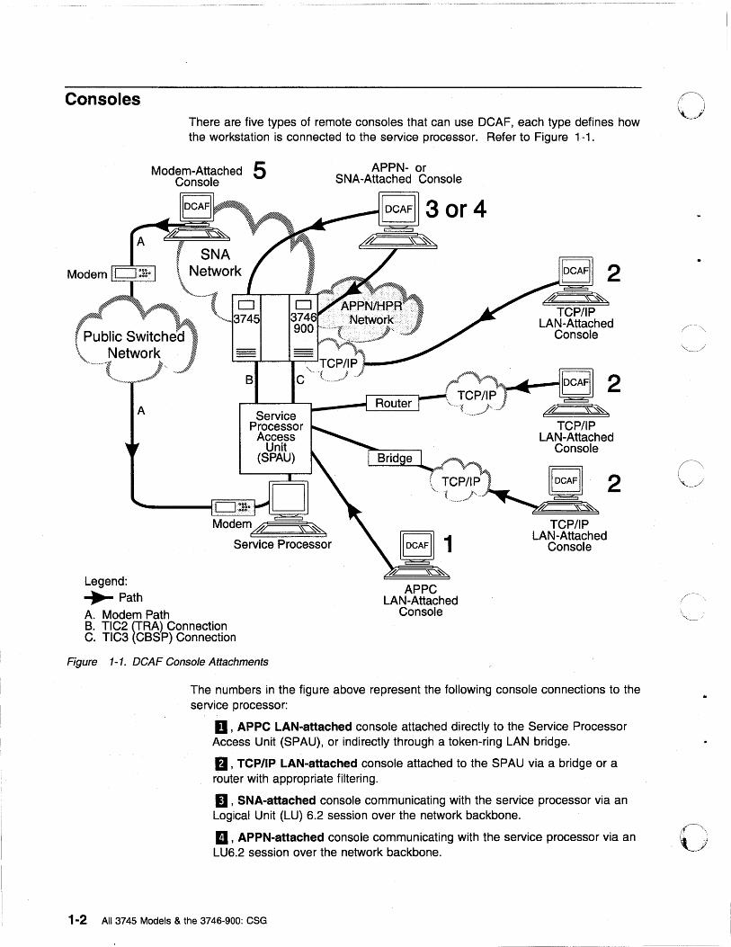
Consoles There are five types of remote consoles that can use DCAF, each type defines how the workstation is connected to the service processor. Refer to Figure 1-1.
Modem-Attached 5 Console
, SNA \ Network \,
'-'----'-d - ~ 0 "~ 3745
APPN- or SNA-Attached Console
2
, Public Switched \
d'r=:=\~~
TCP/IP LAN-Attached
Console
\, Network
Legend: ...... Path A. Modem Path
f.~" 1 IOCAFI I 2 r------..-_., TCP/IP ~
r:----:---~-------L~~~ '-.nnl __ n ........ }' __ .. l dr=:=\~~ Service
Processor TCP/IP Access LAN-Attached
Unit Console (SPAU) .. $''''''
C~CP~IP I IIDCAFII 2
Service Processor
{ j~ .. }~ ..... ---.. -........ - ~ ~~~~~:!::"'>~
TCP/IP e 1 LA~~~~~y~ed
APPC LAN-Attached
Console B. TIC2 (TRA) Connection C. TIC3 (CBSP) Connection
Figure 1-1. DCAF Console Attachments
The numbers in the figure above represent the following console connections to the service processor:
0, APPC LAN-attached console attached directly to the Service Processor Access Unit (SPAU), or indirectly through a token-ring LAN bridge.
D, TCP/IP LAN-attached console attached to the SPAU via a bridge or a router with appropriate filtering.
II ' SNA-attached console communicating with the service processor via an Logical Unit (LU) 6.2 session over the network backbone.
II ' APPN-attached console communicating with the service processor via an LU6.2 session over the network backbone.
1-2 All 3745 Models & the 3746-900: CSG
0:· -; I,
o
o
o
o
II, Modem-attached consoles that use the public switched telephone network to access the service processor via a Synchronous Data Link Control (SDLC) port and modem.
Note: The port and modem can also be used for Remote Support Facility (RSF), Remote Technical Assistance Information Network (RETAIN*), and Alert calls.
A remote console can be configured for all categories of access. This means that a single console at a central control site could be LAN-attached to a local service processor while providing APPN and modem access to other service processors.
Attention -------.---------------------,
Sending an alert to NetView via a service processor SDLC port or calling RSF has a higher priority for the MOSS-E than DCAF, SDLC, or SNA remote sessions.
Information on how to configure CS/2, CM/2, DCAF, and CCM, is contained in:
• Chapter 4, ''TCP/IP LAN-Attached Remote Workstation Configuration." • Chapter 5, "APPC LAN-Attached Remote Workstation Configuration." • Chapter 6, "Modem-Attached Remote Workstation Configuration." • Chapter 7, "SNA-Attached Remote Workstation." • Chapter 8, "APPN-Attached Remote Workstation."
A more complex two-target (two service processors) configuration is described in Appendix A, "Configuration for a Two-Target Remote Workstation." Each target uses a LAN, a Modem, and SNA to link to the remote workstation.
Diskettes with Example Configurations Included with this guide are diskettes 02L3825 for CS/2 and 02L3851 for CM/2. These diskettes contain example configurations that you can load into your CMUB directory. These configurations are primarily designed to help you with configuring modem attached workstations. However, if you are using another configuration for your workstation, (LAN-attached, for example) any of the configurations can help you. To load the configurations, see "Customizing CS/2 and CM/2" on page 2-3 for details.
DeAF Logon Password and Service Processor Security To access a target service processor using a remote workstation, you must first establish a DCAF link with certain parameters unique to the target service processor. This is explained later in this guide.
Passwords provide additional security for the service processor:
1. The DCAF target password establishes the link for accessing the target service processor. It can be unique for each target service processor.
There is no factory default password. Press ~Enterl] when you are asked for the password. To install or change a password, use Customize DCAF Target Settings on the service processor Configuration Management menu.
Chapter 1. Introduction to Remote Consoles and DCAF 1-3
2. You must enter a local MOSS-E password (controller or service processor password) to log onto the MOSS-E and remotely control the service processor. See the Planning Guide, GA33-0457 for more information on these passwords.
Note: By default, the security level of the DCAF sessions between a remote console and the service processor is non-secure (password-only).
The security administrator and authentication components of DCAF can be used with the service processor to increase the security of the DCAF link.
Regaining Control of the Service Processor During an active DCAF session, the remote workstation prevents the target service processor from responding to input from the keyboard or mouse.
However, the local service processor operator can use a hot key combination to override the controlling workstation and regain control of the service processor.
The default hot keys are ~ [!] pressed together.
Minimum Workstation (Remote Console) Configuration This section contains an overview of the system requirements for remote workstations. For detailed information, refer to the DCAF Installation and Configuration Guide, SH19~4068, provided with the DCAF installation diskettes.
Programming Requirements You need the following minimum program levels on your workstation to remotely access the service processor:
• DCAF, Version 1.3.3 (also known as TME10 Remote Control, PN 5697RCL).
• OS/2 Version 2.1 or higher with Warp 3.x and LAPS Version 5.10, or Warp 4.x, with Multiple Protocol Transport Services (MPTS) for OS/2 4.x.
• CM/2 Version 1.11 or higher.
• CS/2 Version 4.1, with OS/2 Warp, MPTS, and TCP/IP.
• MPTS Version 2.2 or higher for LAN-attached workstations.
• Transmission Control Protocol/Internet Protocol (TCP/IP) Version 2.0 or higher for TCP/IP-attached workstations.
1-4 All 3745 Models & the 3746-900: eSG
./
r-"\ U

o
c
o
o
o
The following additional program support is needed for specific types of console attachment:
• Network Transport Services/2 (NTS/2) for LAN-attached and SNA-attached consoles that connect to SNA networks via a LAN.
• To access the service processor via an SNA or APPN network backbone, check that the following programming support is available:
1. DCAF remote workstations and gateway workstations are configured as physical units (PUs) type 2.1. If the DCAF workstation is downstream from a 3174 control unit, then the 3174 must have either one of the following:
- Configuration Support B plus 8Q0800 Programming Request for Price Quotation (PRPQ).
- Configuration Support C (APPN feature).
2. NCP V5 R2, operating under Virtual Telecommunications Access Method (VTAM*) V3 R2 for 3720 and 3745 Communication Controllers on the network backbone.
3. NCP V4 R3, operating under VT AM V3 R2 for 3725 Communication Controllers on the network backbone.
Later releases of these programs may be used unless otherwise stated.
Hardware Requirements and Recommendations For remote workstations, IBM recommends using the following items:
• PS/2s (or equivalent) with at least a 80386 microprocessor and Video Graphics Adapter (VGA) display such as an IBM 8515 color display. A Pentium**-Ievel microprocesser is recommended.
• A hard disk of at least 80 MB and at least 10MB of RAM.
• A pointing device (usually a mouse).
To find the equivalent keys on IBM non-QWERTY keyboards, refer to OS/2 documentation for keyboard layouts or codes.
The following is recommended for different types of console attachments:
• LAN-attached console (APPC or TCP/IP type), an IBM Token-Ring Network Adapter/A operating at 16 Mbps.
• Modem-attached console, a synchronous modem (such as IBM 7857 or equivalent) and a multi-protocol adapter (MPA) card.
• SNA- or APPN-attached modem, an IBM token-ring network adapter with a MPA card.
Technical information on the service processor is provided in the Planning Guide.
Chapter 1. Introduction to Remote Consoles and DCAF 1-5

o
o 1-6 All 3745 Models & the 3746-900: CSG
o Chapter 2. DCAF Session Installation
o
o
o
..
o
Summary of Procedures
Preparation
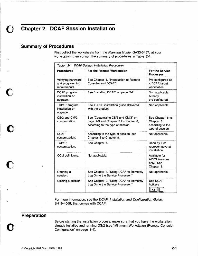
First collect the worksheets from the Planning Guide, GA33-0457, at your workstation, then consult the summary of procedures in Table 2-1.
Table 2-1. DeAF Session Installation Procedures
Procedures For the Remote Workstation For the Service Processor
Verifying hardware See Chapter 1, "Introduction to Remote Pre-configured as and programming Consoles and DCAF." a DCAF target requirements. workstation.
DCAF program See "Installing DCAF" on page 2-2. Non applicable. installation or Already upgrade. pre':configured.
TCP/IP program SeeTCP/IP installation guide delivered Non applicable. installation or with the product. upgrade.
CS/2 and CM/2 See "Customizing CS/2 and CM/2" on See Chapter 5 to customization. page 2-3 and Chapter 5 to Chapter 8, Chapter 8
according to the type of session. according to the type of session.
DCAF According to the type of session, see Not applicable. customization. Chapter 5 to Chapter 8.
TCP/IP See Chapter 4. Done by IBM customization. representative at
installation.
CCM definitions. Not applicable. Available for APPN sessions only. See Chapter 8.
Opening a See Chapter 3, "Using DCAF to Remotely Not applicable. session. Log On to the Service Processor."
Closing a session. See Chapter 3, "Using DCAF to Remotely Use DCAF Log On to the Service Processor." hotkeys
[G!][I] .
For more information, see the DCAF: Installation and Configuration Guide, SH19-4068, that comes with DCAF.
Before starting the installation process, make sure that you have the workstation already installed and running OS/2 (see "Minimum Workstation (Remote Console) Configuration" on page 1-4).
© Copyright IBM Corp. 1989, 1998 2-1
Use the OS/2 command SYSLEVEL to verify the programs you have already installed on the workstation and the Service Pak levels you are using. 0 Prepare the following:
• Installation diskettes for CS/2 Version 4.1 or higher or CM/2 Version 1.11 or higher.
• LAPS Version 2.2 or higher. • DCAF Version 1.3 or higher installation diskettes. • TCP/IP Version 2.0 or higher installation· diskettes. • Diskettes shipped with this Console Setup Guide. • Information from the Planning Guide worksheets.
Physical Installation Any remote console or associated modem is installed by using procedures in the documentation provided with the product. See "Configuring CSJ2 and CM/2 in Workstations" on page 6-6 for IBM 7855,7857,7858, or Hayes Modems.
Installing DCAF Important ----------------------------------------------~
DCAF is also known as TME10 Remote Control, PN 5697RCL.
The DCAFsecure (or password-only security) target component is automatically installed in the MOSS-E during delivery of the service processor.
The remote console is a DCAF controlling component. Follow the procedure below to install DCAF on the remote workstation:
Step 1. Insert the DCAF diskette 1 into drive A.
Step 2. Open an OS/2 full screen or window.
Step 3. Change to drive A.
Step 4. Type i nsta 11 and press Enter.
Step 5. Double-click Controller.
Step 6. Select Install with defaults, then click OK.
Step 7. Wait until Ready to install is displayed under Status field.
Step 8. In the Install pull-down menu, click Install included component{s).
Step 9. At this step you may define your own DCAF path and backup CONFIG.SYS file. Record this information, and click OK.
Step 10. Change the diskette and click OK when you are prompted.
Step 11. When a message displays saying that the installation was successful, click OK. A new Distributed Console Access Facility icon appears.
Step 12. Verify that there is no diskette in drive A.
Step 13. Shutdown and restart your workstation.
Step 14. Go to "Customizing CS/2 and CM/2" on page 2-3.
2-2 All 3745 Models & the 3746-900: CSG
..
o
o
o
o
o
o
Upgrading DCAF Attention --------------------------,
If the DCAF on your workstation is a level lower than 1.3, de-install it and then install DCAF 1.3.3. See "Installing DCAF" on page 2~2.
This section describes how to upgrade DCAF 1.3 with the CSD UB20924.
Step 1. Insert DCAF diskette 1 into drive A.
Step 2. Open an OS/2 full screen or window.
Step 3. Change to drive A.
Step 4. Type servi ce and press ENTER.
Step 5. Follow the prompts:
a. Insert DCAF diskette 1. b. Insert DCAF diskette 2. c. Insert DCAF diskette 3. (Also called CSD diskette 1) d. Click Service. e. Click OK. f. Insert DCAF diskette 4. (Also called CSD diskette 2)
Step 6. Click OK.
Step 7. Click No.
Step 8. Click Cancel.
Step 9. Click OK.
Step 10. Use Desktop Manager to shut down and restart the workstation. Important------------------------------------------------------------------------~
After upgrading DCAF, it is recommended that you access the following URL to download any required fixes and APARs:
ftp://ftp.software.ibm.com/ps/products/dcaf/fixes/v133/us-english/apar/
Installing TCP/IP Follow the procedures in the TCP/IP installation procedure that come with the product that you are using.
Customizing CS/2and CM/2 This procedure will help you navigate from a remote workstation to the service processor and complete the customization of DCAF. For more information, see the Planning Guide.
Customizing a Rel110te Workstation The procedures in this section apply to the following types of consoles:
• APPC LAN-attached • SNA-attached • APPN-attached • Modem-attached.
Chapter 2. DCAF Session Installation 2-3
Loading Example Configurations 0 .. -" ,~, The CS/2 and CM/2 example configurations on the diskette included with this guide include one example of each type of remote DCAF workstation. Using the diskette that corresponds to program (CS/2 or CM/2) installed on your workstation, copy the configurations onto your workstation hard disk. In an OS/2 window, use the command
XCOPY a:*.* e:\emlib Is
You can replace the default directory eml i b with another if you want to.
Starting CS/2 and CM/2 Configuration Important ------------------------------------------------~
The procedure below is the same in CM/2 unless otherwise indicated.
Step 1. From Desktop Manager, double-click the CS/2 icon.
Step 2. Double-click the
Step 3. Click Setup.
Communications Manager Setup icon.
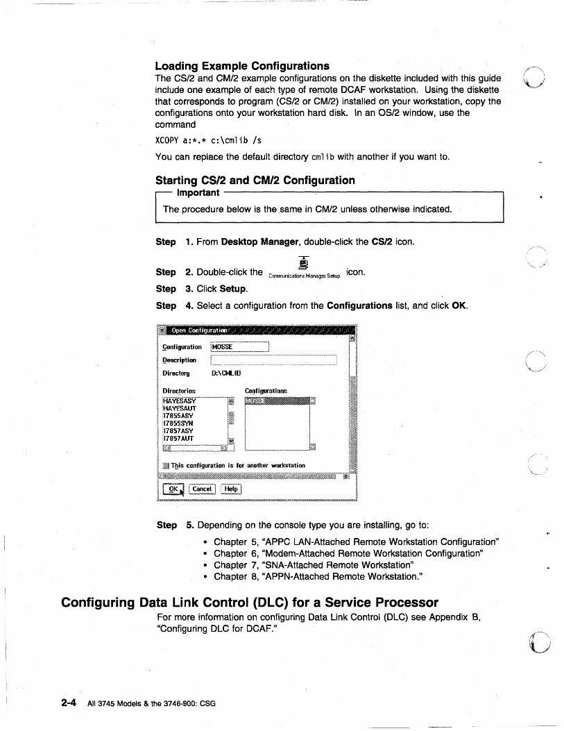
Step 4. Select a configuration from the Configurations list, and click OK.
~ §
I ~ooli_lion ~~==-'::=J rl ~ Qescription ! I N . ~ ! Directory D:\eMLIB LJ g • I • ~ Direc!ories Co~figurations il~ I HAy'EsASy··· .. ·· ........ · .. · .. · ...... II mJ~~ III ~ HAVESAUT i: : il~ ~ 'l7855AS'r' iiim i i il~ I :~ ! i ,II ,. 'I1855SYN ll'%1 1 ......... :· ....... :1:. i~1 ~ 17851 AS'r' i il~ ~, '!iw.a ~ 17851 AUT 1~: ,11~ I [~K~:.~:::::~:.~~:::.:~:~::::::.~~=::~: .... :i t ......................................................... l~ III ~ ~ This configuration is for another workstation II~ t~~_~~"·"·jiJ.!%11
11 QK ~ C~!~~~] [H!!~]I J////////fiW//////////////////////////////H'////////////////////u/////////////////////////////////////////////fi//////////////////////////////////////////////////////////////////3.
Step 5. Depending on the console type you are installing, go to:
• Chapter 5, "APPC LAN-Attached Remote Workstation Configuration" • Chapter 6, "Modem-Attached Remote Workstation Configuration" • Chapter 7, "SNA-Attached Remote Workstation" • Chapter 8, "APPN-Attached Remote Workstation."
Configuring Data Link Control (OLe) for a Service Processor For more information on configuring Data Link Control (DLC) see Appendix B, "Configuring DLC for DCAF."
2-4 All 3745 Models & the 3746-900: CSG
-----.-~--
o
o
0
o
Chapter 3. Using DCAF to Remotely Log On to the Service Processor
For more information about DCAF functions, including opening multiple concurrent sessions, switching between sessions, and keyboard shortcuts, see the DCAF: Installation and Configuration Guide, SH19-4068.
In this procedure, the service processor is the DCAF target workstation, and the remote console is the DCAF controlling workstation.
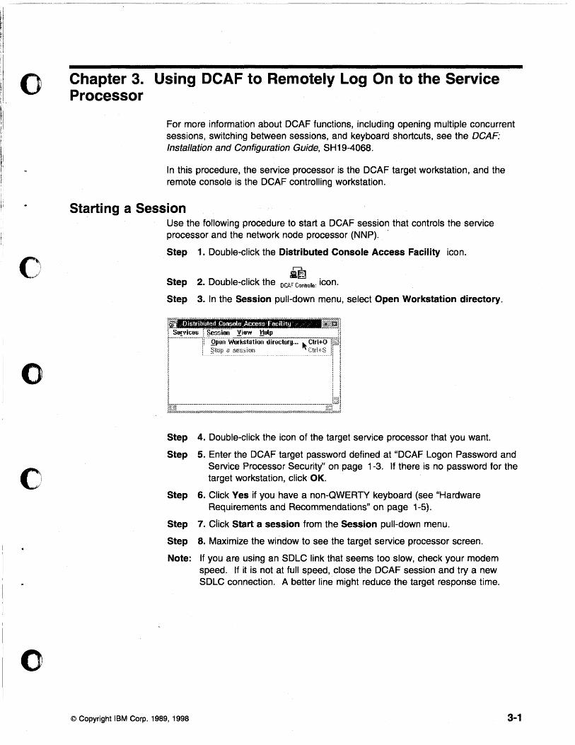
Starting a Session Use the following procedure to start a DCAF session that controls the service processor and the network node processor (NNP).
Step 1. Double-click the Distributed Console Access Facility icon.
r--<-
. .~. Step 2. Double-click the DCAF Controller Icon.
Step 3. In the Session pull-down menu, select Open Workstation directory.
Step 4. Double-click the icon of the target service processor that you want.
Step 5. Enter the DCAF target password defined at "DCAF Logon Password and Service Processor Security" on page 1-3. If there is no password for the target workstation, click OK.
Step
Step
Step
Note:
© Copyright IBM Corp_ 1989, 1998
6. Click Yes if you have a non-QWERTY keyboard (see "Hardware Requirements and Recommendations" on page 1-5).
7. Click Start a session from the Session pull-down menu.
S. Maximize the window to see the target service processor screen.
If you are using an SDLC link that seems too slow, check your modem speed. If it is not at full speed, close the DCAF session and try a new SDLC connection. A better line might reduce the target response time.
3-1
Closing a Session
From the Remote Workstation In the Session pull-down menu on the DeAF window action bar, click Stop a session.
Attention -------------------------,
Do not close the session by de-selecting "Enable DeAF Link/Operations" from the "SP Customization" function.
From the Target Service Processor To close the session of the target service processor, use the DCAF hot keys,
[I]D]{g] pressed together.
Note ----------------------------------------------------~
When your DCAF session is finished, make sure that SOLe link has ended. This frees SDLC resources for other tasks.
3-2 All 3745 Models & the 3746-900: eSG
o
/' .'"
('" ~,\
Y
o
o
o
o
o
Chapter 4. TCP/IP LAN-Attached Remote Workstation Configuration
i
i
TCP/IP
d? ~
o
LAN-Attached Workstation
I
TCP/IP
d? ~ LAN-Attached Workstation
I
CJ 3745
CJ 3746
900NN
TIC3 at 2080
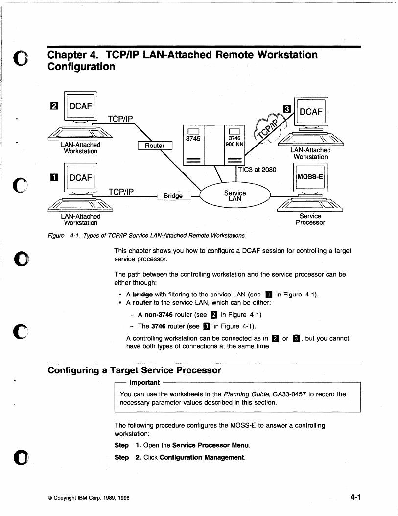
Figure 4-1. Types of TCPI/P Service LAN-Attached Remote Workstations
i
LAN-Attached Workstation
d?
!MOSS-E!
~ Service
Processor
I
This chapter shows you how to configure a DCAF session for controlling a target service processor.
The path between the controlling workstation and the service processor can be either through:
• A bridge with filtering to the service LAN (see D in Figure 4-1). • A router to the service LAN, which can be either:
- A non-3746 router (see fJ in Figure 4-1)
- The 3746 router (see II in Figure 4-1).
A controlling workstation can be connected as in fJ or II, but you cannot have both types of connections at the same time.
Configuring a Target Service Processor Important---------------------------------------------,
You can use the worksheets in the Planning Guide, GA33-0457 to record the necessary parameter values described in this section.
The following procedure configures the MOSS-E to answer a controlling workstation:
Step 1. Open the Service Processor Menu.
Step 2. Click Configuration Management.
© Copyright IBM Corp. 1989, 1998 4-1
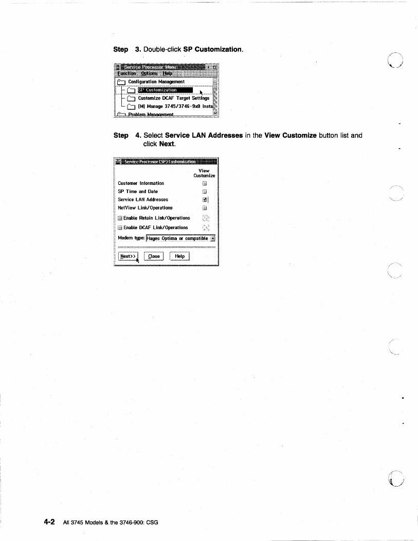
Step 3. Double-click SP Customization.
Step 4. Select Service LAN Addresses in the View Customize button list and click Next.
ii:11················································· ..................................................................... ,.
Customer Information
SP Time and Date
Service LAN Addresses
NetView Link/Operations
rw Enable Retain Link/Operations
id Enable DCAF Link/Operations
View: Customize:
Modem type: ItJ~yE!S. .. .9P.~i.~~ .. fl.r~~'!'pati~l~ .. LI·. , ....................... , , ...................... , , ....................... / i ~ext> > ~ I !;lose I i. Hel~
.......
4-2 All 3745 Models & the 3746-900: eSG
o
o
o
o
o
o
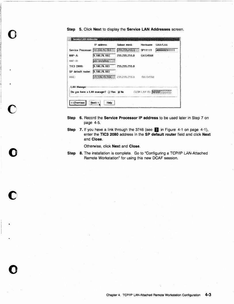
Step 5. Click Next to display the Service LAN Addresses screen.
IP address Subnet mask Hostname UAA/LAA
Service Processor: 111111 ••••••• SPll111 14~~~~~2~111ulu' NNP-A: 19~ 100.16~ 1021 255.255.255.0 CA134568
TIC] 2080: t9.:1~O~!S.:~~3u 255.255.255.0
SP default router: 19~100.16.103
,-LAN Manager .~--.-.~-.----.-----~-~.-~----.-~--.-~.-.-~-.--~--~-.~-----'~---~~---------~------', . .
: 00 you have a LAN manager? GJ Ves \i. No
'~"'--'~"-"~'-'"'-"""""''''''''-''--'-''-''-'''-'-_ ............. _._ .. _ .. _._._ ...... __ ...... __ .... _._ ..... __ ...... -...• -~.-.... -.-..... ~ ...•. -.... ~ ... --. _ ...... _ .. _ .......... ..
Step 6. Record the Service Processor IP address to be used later in Step 7 on page 4-5.
Step 7. If you have a link through the 3746 (see II in Figure 4-1 on page 4-1), enter the TIC3 2080 address in the SP default router field and click Next and Close.
Otherwise, click Next and Close.
Step 8. The installation is complete. Go to "Configuring a TCP/IP LAN-Attached Remote Workstation" for using this new DCAF session.
Chapter 4. TCPIIP LAN-Attached Remote Workstation Configuration 4-3
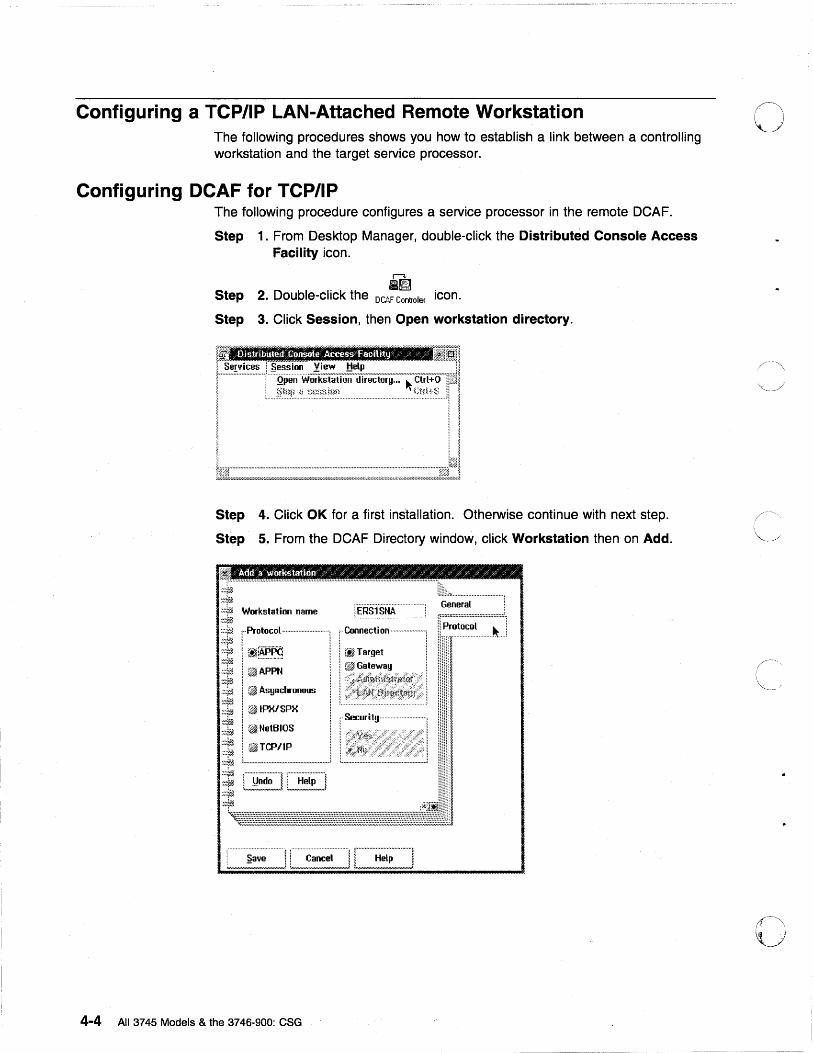
Configuring a TCP/IP LAN-Attached Remote Workstation The following procedures shows you how to establish a link between a controlling workstation and the target service processor.
Configuring DCAF for TCP/IP The following procedure configures a service processor in the remote DCAF.
Step 1. From Desktop Manager, double-click the Distributed Console Access Facility icon.
r--:l
a~ Step 2. Double-click the DC6.F Controller icon.
Step 3. Click Session, then Open workstation directory.
rf.'_'III!fi~!;1[1l'nftJ.,tI r fllllilii L~~~~~-!fIr~~~rl
i 1
~c-;.::======~::=.::;=:i:J Step 4. Click OK for a first installation. Otherwise continue with next step.
Step 5. From the DCAF Directory window, click Workstation then on Add.
~"""''''''''''''''''''''''''''''''''''''''''''''''''''''''''''''''''''''''''''''''''''''''''''''''''''''""."".""""""". .:::~ ~:.r~ .;;~# Workstation name
:;+..:l ",Protocol,,,,,,,,,,,,,,,,,,,,,,,,,,,,,, ;" Connecti on""",,,,,,,,,,,,,,,,,!,
;;t: ! (tifiiPPO i I,:, ~ Target :: I ~'~.~~' 1
~,: I ~ Asynchronous ... :.i .. :; .. ~.il ..... flh .... '.fi ... t1 ... ;\ .. if .. !.~ ... t ... ;w ... { ... % ...... >y .. '..1 ,,',' >;,~/..IPX/SPX :::~~ '$~
~:j;E1 i ;;~f;2 1 ~ NetBIOS
~:j!~ I ~ TCP/IP .:::~ . ::'::?~ t .......................................................... J ;::~#l ~hr~ ::::r~ ;~:j;%
4-4 All 3745 Models & the 3746-900: eSG
r Security·· . . ........... ,
c ___________ J
rniL~ ..... .,.,. .. ., ... ., .......... " .. ;
~\ I I ~
0''',' , ,
o
o
o
o
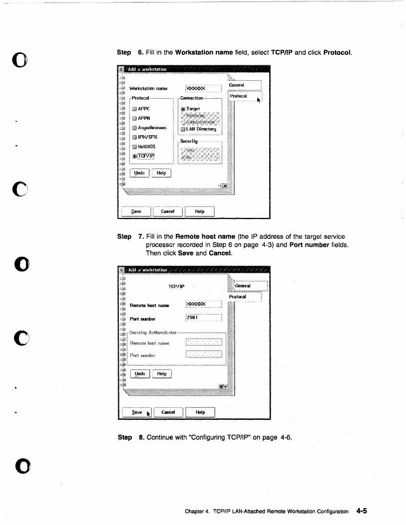
Step 6. Fill in the Workstation name field, select TCP/IP and click Protocol.
'Add a )ll'ockstation '/ / / / / / / , ••••••• u ••••• ,. ...................... ,. .............. ..
·-::}ff2
General r-:;;z:z:::::::;:::::::;:::::::::::;;::::'.
~:~» .:/tJ Workstation name
.........................................................
r1J.iL~ ................................. ~
11 Protocol :::"f(/J. , .. Protocol ............................. ] i .. Connection·······················: ,,~,!
::'1~ ~·:fia i.@1APPC ~~:~t~
:::r£1 i ~APPN ~:.v~ .~~~~ ~~i(.~ :::1iJ.
I ~l Asynchronous
! ~IPX/SPX ::~ ! ~ NetBIOS ;~14'~ ·:::rYJ ;'~~ I .... ~.~:~~~~~~ .................... ...J ;~; [i~,~~] C~~~~~,~~~~] ::-:'f1 :::j~
Step 7. Fill in the Remote host name (the IP address of the target service processor recorded in Step 6 on page 4-3) and Port number fields. Then click Save and Cancel.
Add a workstation ;/ '/ /' / 0' '/ / ' / / ,'/ '/ / "
:.:1?£ Remote host name :::ri'-~~1(i{ ,:::1£1 Port number ~:4?a
Prutocol
i?501
Step 8. Continue with "Configuring TCP/IP" on page 4-0.
Chapter 4. TCPIIP LAN-Attached Remote Workstation Configuration 4-5
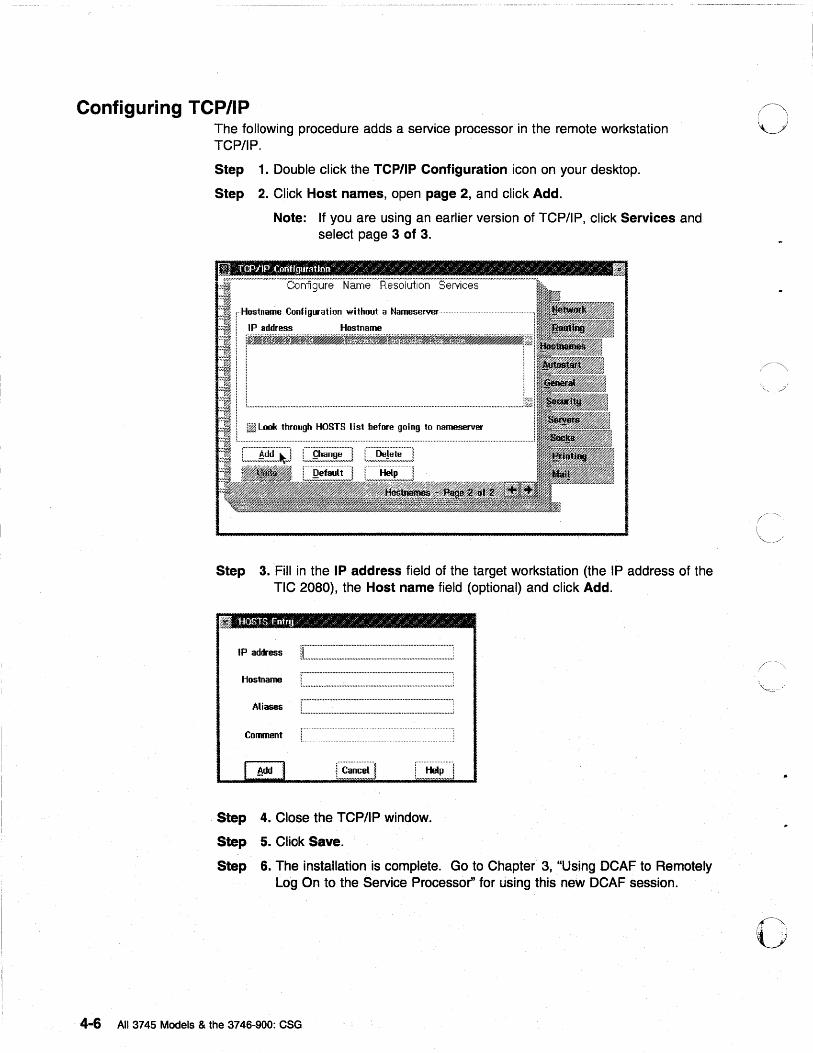
Configuring TCP/IP The following procedure adds a service processor in the remote workstation TCP/IP.
Step 1. Double click the TCP/IP Configuration icon on your desktop.
Step 2. Click Host names, open page 2, and click Add.
Note: If you are using an earlier version of TCP/IP, click Services and select page 3 of 3.
r·Hostname ConligW'ation without a Nameserver
i IP address Hostname
. I iW~~ftj~j~~'~~~%~.f~_t%~~f.ft#t.~!~1 " ! I
I L ......................................................................................................................................................................... j~!
~ L~ .. ~~~~~~~ ... ~~.T.~ ... ~.i.~~ ... ~.~.~:~ ... ~.oi.~.~ ... ~~ ... ~.~.::~.~.: ........................... ..1
Step 3. Fill in the IP address field of the target workstation (the IP address of the TIC 2080), the Host name field (optional) and click Add.
: •••••• ,. ••••• u ••••••••••••••••••••••••••••••••••• O# ••••••••••••••••••••••••••••••••••••••••••••
Hostnarne 1... ............................................................................................ ;
Comment
Step 4. Close the TCP/IP window.
StepS. Click Save.
Step 6. The instaliation is complete. Go to Chapter 3, "Us~ng DCAF to Remotely Log On to the Service Processor" for using this new DCAF sess~on.
4-6 All 3745 Models & the 3746-900: eSG
o
o
o
o
o
o
Chapter 5. APPC LAN-Attached Remote Workstation Configuration
D D 3745 3746
900
D d? ~ d? ~ j
LAN-Attached Workstation
i
Figure 5-1. APPC Service LAN-Attached Remote Workstation
j
Service Processor
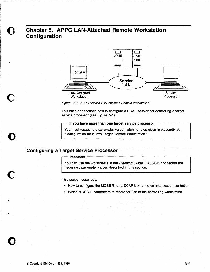
This chapter describes how to configure a DCAF session for controlling a target service processor (see Figure 5-1).
I
If you have more than one target service processor ---------,
You must respect the parameter value matching rules given in Appendix A, "Configuration for a Two-Target Remote Workstation."
Configuring a Target Service Processor Important----------------------~
You can use the worksheets in the Planning Guide, GA33-0457 to record the necessary parameter values described in this section.
This section describes:
• How to configure the MOSS-E for a DCAF link to the communication controller
• Which MOSS-E parameters to record for use in the controlling workstation.
© Copyright IBM Corp. 1989, 1998 5-1
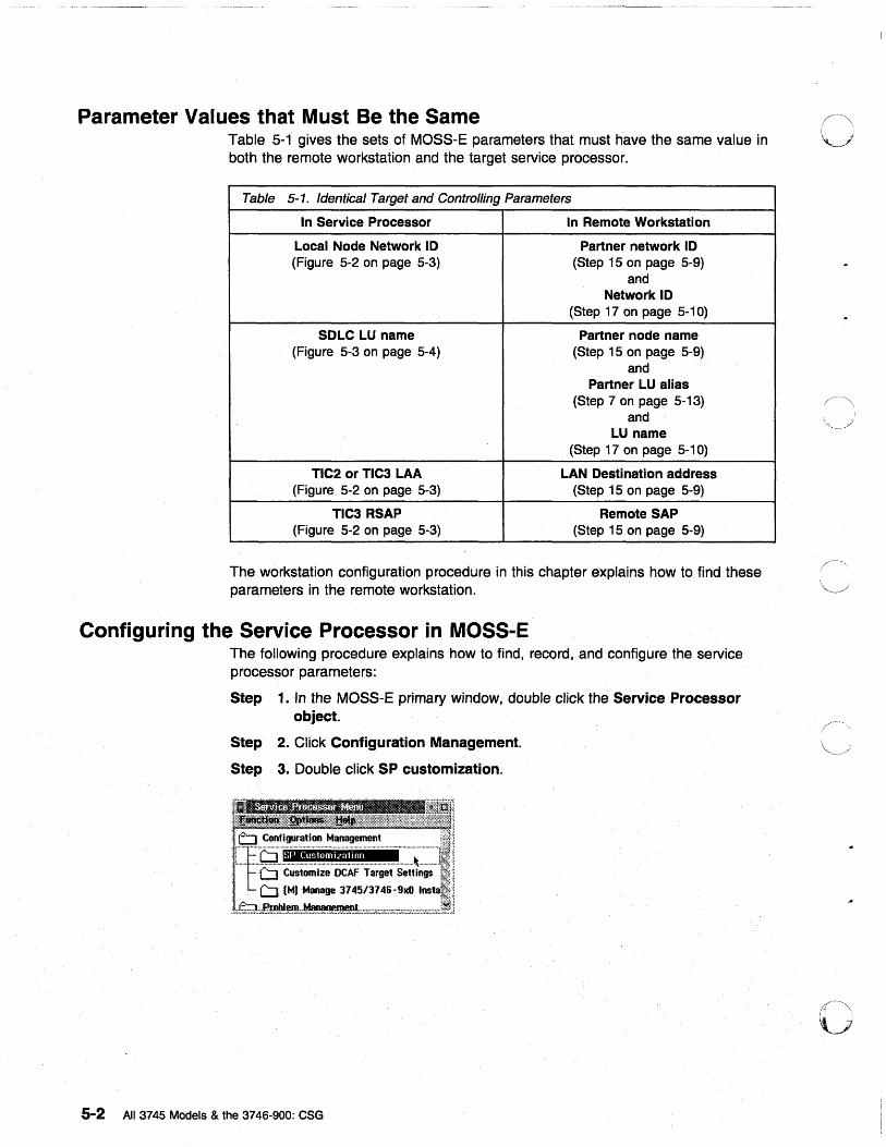
Parameter Values that Must Be the Same Table 5-1 gives the sets of MOSS-E parameters that must have the same value in both the remote workstation and the target service processor.
Table 5-1. Identical Target and ContrOlling Parameters
In Service Processor In Remote Workstation
Local Node Network 10 Partner network 10 (Figure 5-2 on page 5-3) (Step 15 on page 5-9)
and Network 10
(Step 17 on page 5-10)
SDLC LU name Partner node name (Figure 5-3 on page 5-4) (Step 15 on page 5-9)
and Partner LU alias
(Step 7 on page 5-13) and
LU name (Step 17 on page 5-10)
TIC2 or TIC3 LAA LAN Destination address (Figure 5-2 on page 5-3) (Step 15 on page 5-9)
TIC3 RSAP Remote SAP (Figure 5-2 on page 5-3) (Step 15 on page 5-9)
The workstation configuration procedure in this chapter explains how to find these parameters in the remote workstation.
Configuring the Service Processor in MOSS-E The following procedure explains how to find, record, and configure the service processor parameters:
Step 1.ln the MOSS-E primary window, double click the Service Processor object.
Step 2. Click Configuration Management.
Step 3. Double click SP customization.
5-2 All 3745 Models & the 3746-900: eSG
o
o
o
o
o
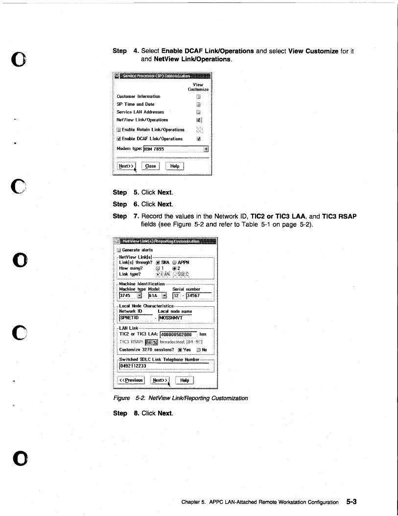
Step 4. Select Enable DCAF Link/Operations and select View Customize for it and NetView Link/Operations.
i· .. ·~.,§tmgJ'g'j;'j;"U;:Ui'jl't';!'ln:;cH;r;·· ..... ··· ................. .
Customer Information
SP Time and Date
Service LAN Addresses
NetView Link/Operations
[:ill Enable Retain Link/Operations
f~ Enable OCAF Link/Operations
Modem type: IIE:ltytJ~~~ ....
Step 5. Click Next.
Step 6. Click Next.
View Customize ••
. ....... UfJ:i
Step 7. Record the values in the Network ID, TIC2 or TIC3 LAA, and TIC3 RSAP fields (see Figure 5-2 and refer to Table 5-1 on page 5-2).
[·II\;~·I'I!l.!ffi! .. 'fflf:fmm:lr;Ir'='~""""""" lti Generate alerts
,·NetView Link[sJ··············.·.··· .......................... · ................................ , .' : Link( s} through? @ SNA eM APPN . . j How many? @1 @2 j link type? ·~'iAl"4·:~~f).tt . 1 .................................................. ; •.•• ~.:.: .::.:.~ ••• ~ ........ :.: •• ~';': •• "::' ••• :':':.::~ •••••••••••.••••••••••••••••••• J ;
c· Machine Identif icat ion ................ - ........................................... , .• : Machine type Model Serial number , ,
U~Z~~~~~~~~l~ ... m.~~~·~~~~~~ •• Jl3L~J~~~~~~~!~:~~~.: ... 00 ••• 00.
1 .
,··local Node Characteristics······································· ............ , . : Network 10 Local node name
II~Jl~~TIO . 't¥t0SSNM"T
, .. lAN l ink ····· .. ·· .. __ ........... ___ .moom ....... ____ ••• oo.oo •••• ••• .. • •• ••••• •••••••••• --........ , •
! TIC2 or TIC3 lAA: I~~~~~~~~~~~~.. hex
I TIC] m,t,p: H~@:.[if; b~xadHdmat UH· gel j :.
L~ __ ~~~~~~~:~~ ... ~~.::~.~~=-.. 00 ~~~ ..... ~~:!~~~ .... _.l .• ,·Switched SDlC link Telephone Number··--.. ····m
----., •
11~~~?~}~2.~~.. . :-~~~~~.---.~-~--~--.--.. --~ ...... --.-.-...... --.~.j '.
I""<'<e;;~i~~~] r!i~·;·t;:·;:~ r·····H~·····i •....... . ............................................................... , ........ .
Figure 5-2. NetView Link/Reporting Customization
Step 8. Click Next.
Chapter 5. APPC LAN-Attached Remote Workstation Configuration 5-3
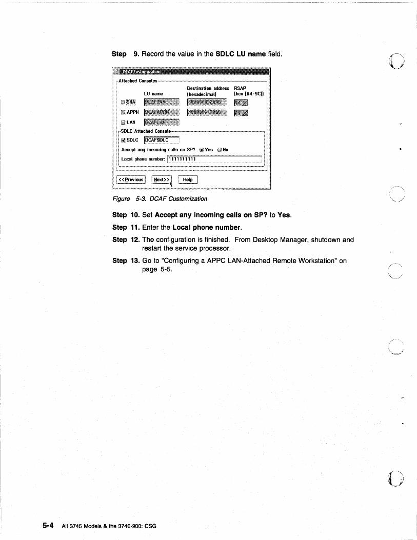
Step 9. Record the value in the SOLe LU name field.
i r-Attached Consoles--.-. i,
. . Destination address RSAP I • LU name (hexadecimal) (hex [04-9C)) ! :
.. iE [~.~~ I~~~~~t'~~~~:~$~:~~l':\' I.l~:li I i :: fii APPti 1~~I~imftf~~:::":,\::::::::::, 1~:~ll~~~~~~j::!R~:~~:j,:;::,;: Jl~::lil I : ... iELAN I: III r·SDLC Attached Console· .. · ........ · ............ · .. · .............. · ...................... · ...... ·· .. ·· .. ·· .. · .. · .. ··· .. · ........ ····· .. ·11 !
i: i : M SDLC IDCAFSDLC . ! I '
!: I ! Accept any incoming calls on SP? t!1 Yes ~i~ No I ! i :::: !!:
H i i Local phone number: 11111111111 ;: ! : i: 1t .......................................................... : .... : .. : ................................. : ...... : ........................ : ........ :: ......... :: ...................... ! I: 1~' L ..................................................................................................................................................................................... .1 ]
! ! «~revious I I Next» ~ ! Help i
Figure 5-3. DCAF Customization
Step 10. Set Accept any incoming calls on SP? to Yes.
Step 11. Enter the Local phone number.
Step 12. The configuration is finished. From Desktop Manager, shutdown and restart the service processor.
Step 13. Go to "Configuring a APPC LAN-Attached Remote Workstation" on page 5-5.
5-4 All 3745 Models & the 3746-900: eSG
o
o
o
C
o
o
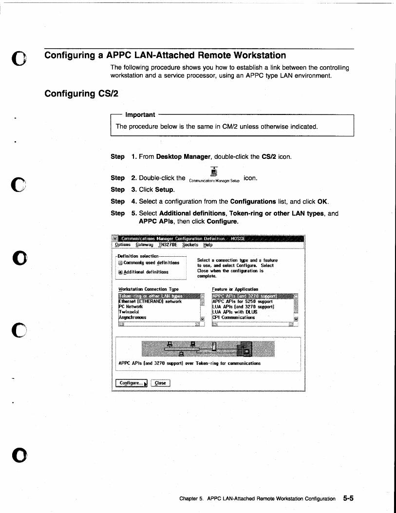
Configuring a APPC LAN-Attached Remote Workstation The following procedure shows you how to establish a link between the controlling workstation and a service processor, using an APPC type LAN environment.
Configuring CS/2
Important -------------------------------------------------,
The procedure below is the same in CM/2 unless otherwise indicated.
Step
Step
Step
Step
Step
1. From Desktop Manager, double-click the CS/2 icon.
2. Double-click the Comrnunicatior,s Manager Setup icon.
3. Click Setup.
4. Select a configuration from the Configurations list, and click OK.
5. Select Additional definitions, Token-ring or other LAN types, and APPC APls, then click Configure.
~ ~
~ Qptions §ateway IN3210E ~ockets !::!elp [I £ommunicatitlps Manager Configuration Definition ~ MOSSE ,
ri~=~::::~~;~~~~~-~~---;;~,~;;;:;~~~;;~---------l : ~Additional definitions Close when 1he contig .. ation is ~
'------------' complele. I ~orkstation Connection Type feature «Application ~
~m.~!&'SJJIS~ ~~. ~m-.i~ ~ ~ rne1 ETHERAND) network 11 1APPC APls tor 5250 support I PC Network 1"7. jLUA APls (and 3270 support) I 1 frwinaxial I lLUA APls with DLUS ~ ,
[As"';';;::/'~'f;"'" ync ..... ~ ..... -.h .. ~~.:~.-...... ~.-.. ~ .. ~ ... -.. -.:: ................. -........ _.:~ ..... ~.:=:.-.... -.. -.. _ .. _~ ... -.. ~:: ...... ~ .... ~.,;: .. :,:.::l.~ .. ";:,, !CPI Comnwnicatioos :~ I l!; - - - _ - _ _ _ __ ~ _ ~":::'===-_=::_=-...::.Ji!.j I I ~
! I :::s. ~~;:_~l -T_en-ri~ lor C~ICMloM I ~//////////////////////////.I///////I//,////////////;:;::;;;;;;///////////H///////II////////////////////////////1///////lhY/,QI/II///III/////h7////////////////////////////////////////11////////1/1////1//////1////////////////////1////1
Chapter 5. APPC LAN-Attached Remote Workstation Configuration 5-5
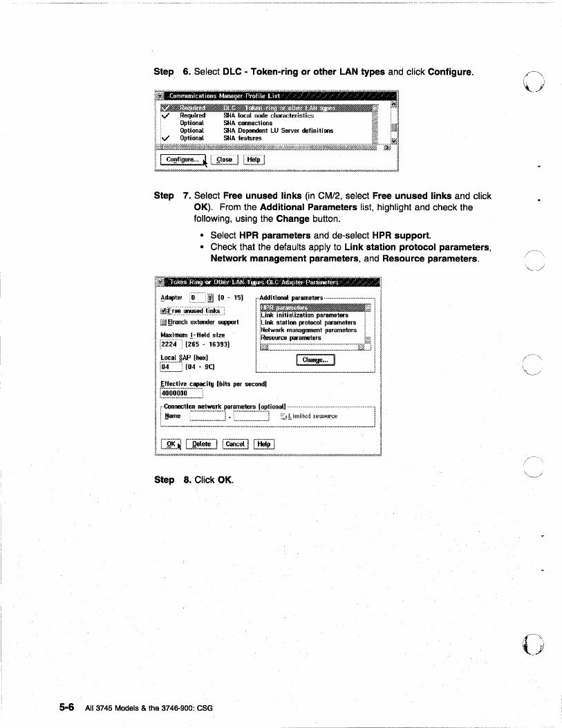
Step 6. Select OLC - Token-ring or other LAN types and click Configure.
~ i ~,"d SNA local node da""le,;.';", n
l~~ ~ I Co~flgure ... LI [_i~,!~~,~] !.~~B~~~] ~ Lw~((//"W""("'(((('//"'////"'(""~"';;;;;;~;;~;;;;;;;~;;;/////;;;~;;;:W///;///'M(////""//(/M///(/(//k//"W/4,(M""Y/////////////(//(/////(/////////////"Y//((,W/////"7/"W////////////..1
Step 7. Select Free unused links (in CM/2, select Free unused links and click OK). From the Additional Parameters list, highlight and check the following, using the Change button.
• Select HPR parameters and de-select HPR support. • Check that the defaults apply to Link station protocol parameters,
Network management parameters, and Resource parameters.
Step 8. CliCK OK.
5-6 All 3745 Models & the 3746-900: eSG
o
o
o
o
o
c
o
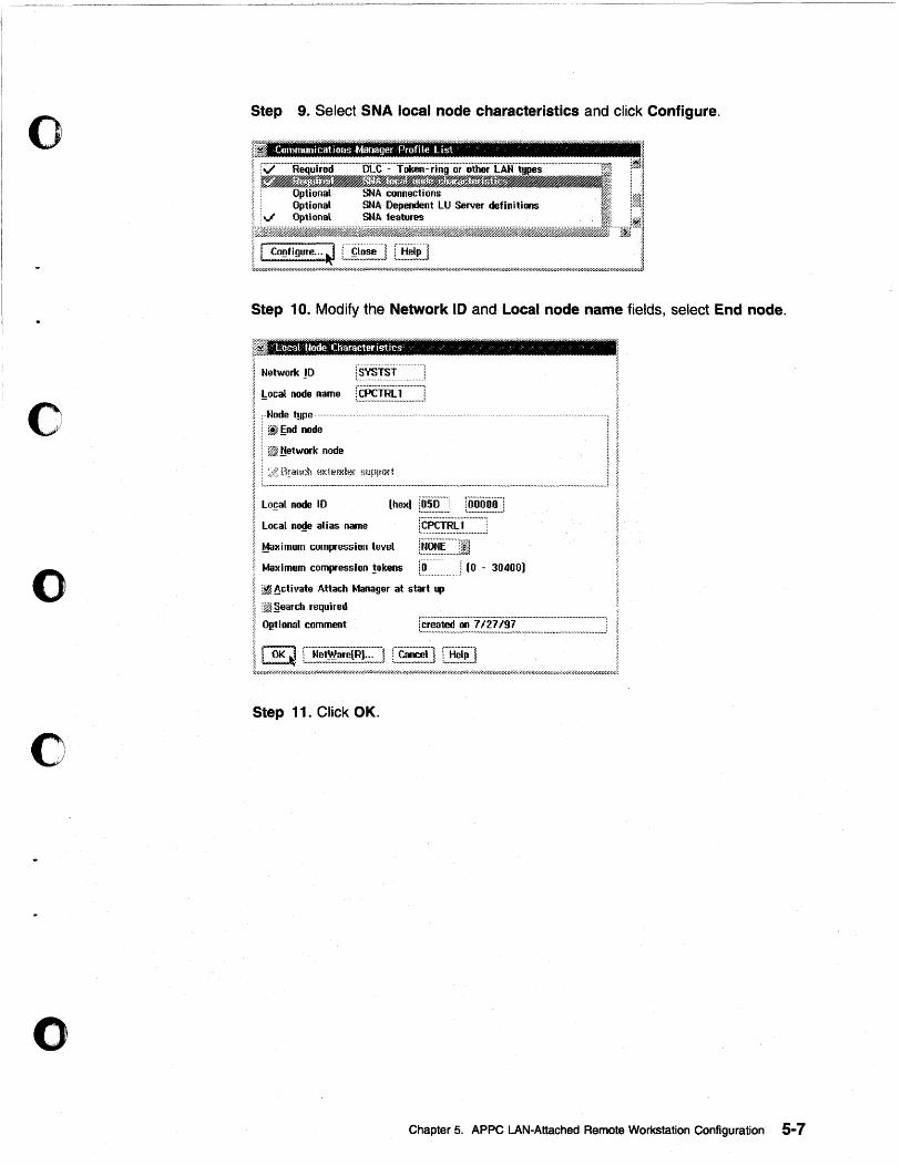
Step 9. Select SNA local node characteristics and click Configure.
Communications Manager Profile list c c 1 ~I 1 ~
SNA connections : ,~
''''' 5:::! ;: =-' LU Server deli.iti.... . .... "'. ;~:,,:: jkiff'@l%~~~_.M~.ifjj'jfAW~@!.~.~j:&,~.,,%;' r%f;:~f@Mti; T.~:, ;
t!""~:::~/~:::~~~,,~,,,,!;;;;E~~~~;;;;!"h~;';~;~;~;;!//h>////////////.w//////////////////////////////////////////////h»//////////////////////////////////////////////J Step 1 O. Modify the Network IDand Local node name fields, select End node.
r /uuool Hade Character istics ,"
Network !D
!:ocal node name [~~~.!.~.~T:::::::] fHNode type",
~~nd node
Lo!;al node ID 1'oifooo"'l :~n~._ • ..,._ . ..,,...,;
Local n~e alias name
Maximum Gompression level
r~~.s.!.~~X::::::::::J r~§.~.~.·:::.JI
Maximum compression !okens i~"'H] (0 .. 30400)
~ 8cti 'late Attach Manager at start up
:~ §ean;h required
O~tional comment
" """"1
I
I roK'"1 (""H~tW;~lRr"'''''t [~~~,~] C~~~] ~ ~~ L"""""="",,,,,,,,,,,,,::':mJ i 7/////////////////////////////////////////////////;W/////////'//////Q/////.W////hY.I/./fii///////////////////////.i////////////U//.I////////////////////////////////////.f/.l.0;';::-7//////////////////////////////.
Step 11. Click OK.
Chapter 5. APPC LAN-Attached Remote Workstation Configuration 5-7
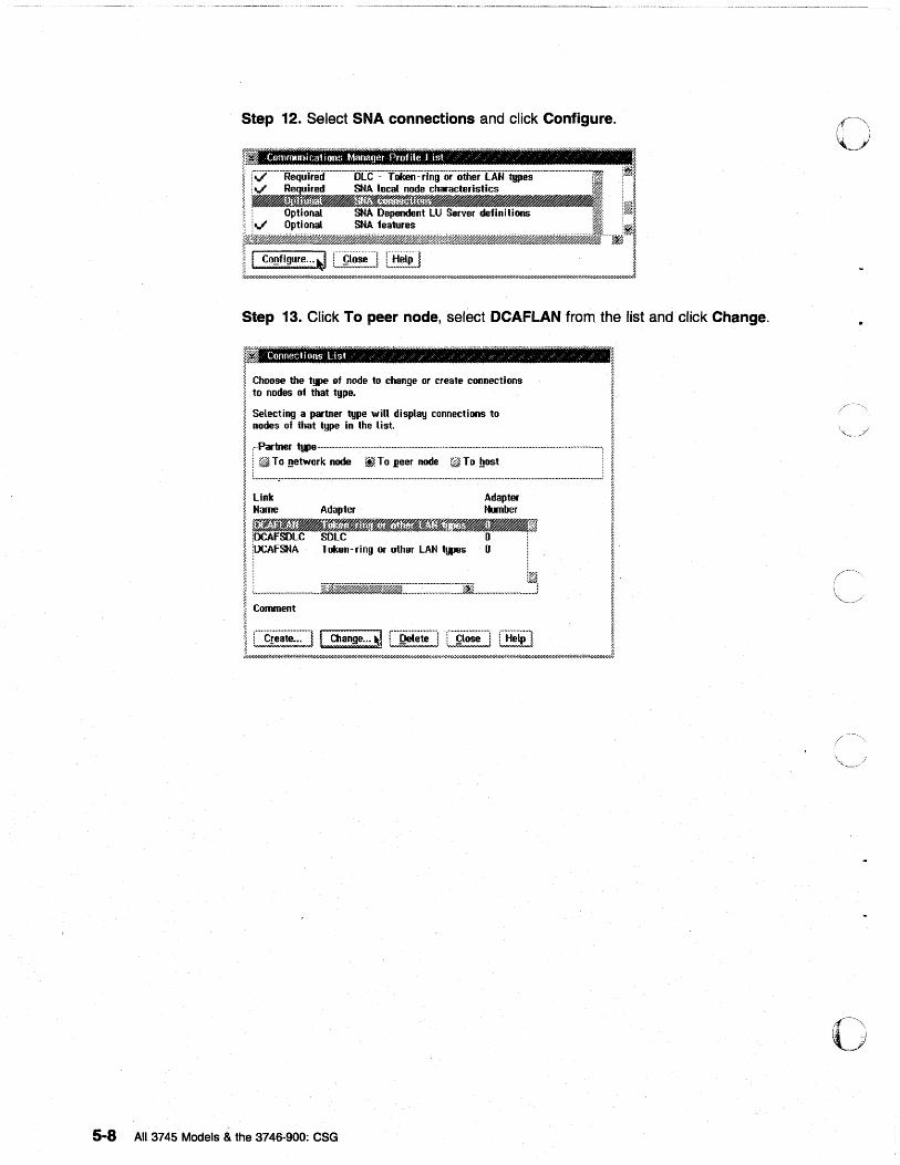
Step 12. Select SNA connections and click Configure.
r . ~ Communications Manager Profile List " z / / / / o
rV"· .. ·······Reqiiiied ........ ······ .. oU; .. ··:-··fOkeii·:·iing··o' .. ·iitfierT·Aift!ii8s .. · ..... ········ ... ···· .. ···· .. · iv" Required SNA local node characteristics
~~~~~~~: ~~~~~~~~I1~~~~IIII~~ . Optional SNA Dependent LU Server definitions i v" Opti ona1 SNA features
~ " ~///////////,'//,w///;/////.r//////////////////nw///u///////////h'////'/.I/,r////////////////////.//////,r.,///Mr4;W/ .. W//////////////////////////////////I'///////////////4'//fiY.l//U//////////////////hW/////.I////iW/j
Step 13. Click To peer node, select DCAFLAN from the list and click Change.
ConnecH ons Li st / / / / / / / / / / / / / / / "" .
! Choose the ""'" of node to ..... ge 01 cr .. te connectioos I to nodes of that fgpe. ,
Selecting a partner type will display connections to /
::::: :~_i:~~'~~"~_________ ___________________________ , I . ifj To network node ~ To .l!eer node 0» To !!ost . ~
~:---------------------:;.:w-----~ I Name Adapter Number I W;~JjE Jjff~1J1"4_Bj'If~~_ BIf <
iDCAFSOLC SDLe o· I
.. '.DC ....... A .... F. SII ....... A ............... := ... ~ .... r ......... L ..... A ....... N .......• ~ ..................... ~ ......... O .................... _.i.I.:..~; I ~:=-~--, -.-----'r-=---' ;--~~-: I i Create... ! I Change ... ~ i Qelete l i 90se I i Help ~ ~
lw/;///////~:///////:..::~////// .. :,;.,./,.,;~Y//////I'/"/li'IXI////::':rh}:///////hi'",,"mw/H::'~;''';::::~:::::::///4::=;~:r//////.t'//hY.l////////////////////////hwj
o 5-8 All 3745 Models & the 3746-900: eSG
o
c
o
o
o
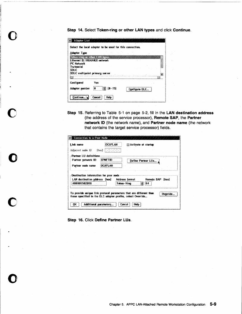
Step 14. Select Token-ring or other LAN types and click Continue.
fi Adapter Us, /
~ Select the local adapter to be used for this connection.
I ,Adapter Type
~ iI'.I1§1flJZJ1Js:fJIJr(lf~ ___ ~ i ~ Ethernet (ETHERAfoV) networkW/l i I i~i~7:.rkl . ~ iSOLC I !SOLC multipoint ~imar!J server . . .' II I i%i· .... ~:~~ ..... :~·.:::~·.:.:·.·.:· ....... :·.:· ... :~ .. :~~:~ ... :::: ..... :~ .. : .. ~ .. ::~:: .. ~: ...... :::~: .... : .. ::::: .. ~: ...... : .. ~ .. : ...... : .. ~: ... ~~:::~: .. : .. : ... :~.~::.~ ... : ......... : .... : .. :~.: .... : .... : ...... : .... ::.:.::: .... :: ........ : .... ~ ..... ~~] ..... . ~ Configured Ves ~
~ Adapter number [, .. ·0.·.·.·.·.·.·.·.·.·.·.·.·.·.·.·.·.1,. ~.i' .. ~. (0 - 15) ,·····C·········f··;······ .. ······D .. ··L .. ·C·············, ~ - :;a,. t",~!n IgU'!,,,~_,;:..:,,,J II cooiiOOL~l~ ~ [S] j .:r////////////// ... ),////////////////'l"u'////////////hr////////////////.'l'/.1"h;.:-r..;-'///////////.-r////////.1"//..;-·/.'l .... :~llj'////////'-;-:1"/////'-;1"///'-;-'////""'-""";';":1"/.-;..' ... 1 .. ;.-//.1"/'-;-'//// .. :1'//'>;-'//,'.W/////.~·;l"/ .. ~W//////.~'l»
Step 15. Referring to Table 5-1 on page 5-2, fill in the LAN destination address (the address of the service processor), Remote SAP, the Partner network 10 (the network name), and Partner node name (the network that contains the target service processor) fields.
~Ink name
Connecthm '0 -a Peer Node c /
jOCAFLAN l¥fJ Acti~ate at startup
n~('l'd ,."~ .. ,,, ... ,,, ... ,,, ... ,,, ... ,,,; ~ , .. Partner LU definitions· ............................... . r .. :.:' i.,' Partner _network 10 i.·.S.·.·.·.PN.·.·.·.·.·.·.E.·.·.T.-.. ·.·I.·.D.·.·.·.· ................... : .................. " , .................................................................. .
i, ' ......•.•.•.••....••••••.•.•.••••• ::.......... LJ~~!'!~!m~~!'!~m~~.!:::_.~ ~ , Partner node name ~.~.~.~~.~~ .................. .; I: ................................................................................................................................................. , ~ " Destination information for peer IDle .. ·
I : LAN destination ~ddress (hex) Address !ormat Remo!e SAP (hex) I Il~~!~!!~~~~~~ ____ ~~~~~~~~~~~_~~ _________________ J
l 1
I 1 1
1 ~
I ~ ~
J ~ To provide unique link protocol parameters that are different than r···O;;··:·d··········· .. , ~ ~ those specified in the DLC adapter prome, select Override... LININ"m,!,!",.!':;,;"",) ~
!~~~~ I ~////////h;l//////////////////////////////////////////I'/h;>'//////hl/.//////////////////////////////////////////.-r////'-:--////////////U///////////////////.'I'///////////////////////.4rh~·'/.I///////////////////////////////hr// .. r/////////////h
Step 16. Click Define Partner LUs.
Chapter 5. APPC LAN-Attached Remote Workstation Configuration 5-9
5-10
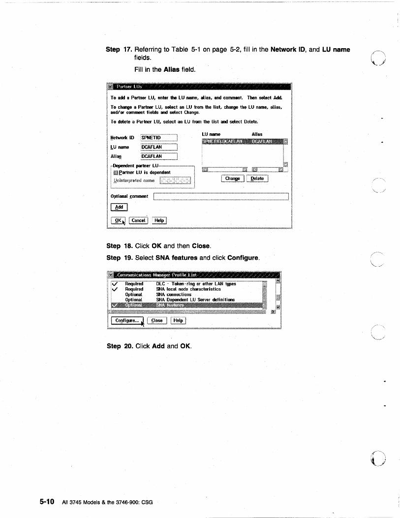
Step 17. Referring to Table 5-1 on page 5-2, fill in the Network 10, and LU name fields.
Fill in the Alias field.
~ Partner LUs / / / / / / / /
To add a Partner LU, enter the LU name, atlas, and comment. Then select Add.
To change a Partner LU, select an LU from the list, change the LU name, alias, and/or comment fields and select Change.
To delete a Partner LU .. select an LU from the list and select Delete.
~etwork 10 LU name All as
."~~~J!rm~~]~~l!~·!~·DI i l:U name
Alta~
rDependent partner LU·······-·····--·-----------·----i 1m:::::::::::::::::::::::::::::::::::::::::::Jt:J1 ...... ~::::::::::::::::::::::::::ffj!~ ! ~ ~artner L~iS dependent ! C~~.~~!J!] [.R~i!!i] L~:~:~~::~:~~~~_~:.~~.~_.~~~::::. __ . ____ ._ ... ____ ... _. ____ . .-.1
Optl .... 1 ~lIIIIIDI!IIt r=='::-:-==--=======--::J I.'
I Add I
I~~[§~:-~ , .:r .... uu///////////////// ... ///////////.·Xl///li· ... // ... "// ......... /UI" ... ,-'/.///////////////////,,.../,../,,...// ... /////////H/////// ... I'///1'////1'..-..... '/. .. /////1'/////////////////////////////////, .... /////////////I'////'///////h·///////// ......... //,.Y,· .. //I ..... //I'//////I'//I'////////'?'
Step 18. Click OK and then Close.
Step 19. Select SNA features and click Configure.
r;:;;··········Requ·ireir··············5CC'··::···fiikeii·::·ifng··or· .. otherTAN· .. types···-······· .. ··················T~ :~~ : v Required SNA local node characteristics I : ~ i g~!:~~:~ :: ~~~=~~sLU Server definitions I ____ ~'"'-----· ... ,.,:.I"'. ~ ~jf.1J1fW~~J~rm~#~~.mmmB.!~m~~ ... ;m~ ~~~~~.~@fi7~ ~ ~ II Configure ... J r"'~lo;e""l r"-H'eip"'~ I t/////////////////,w//////////////////////!!.h/;::;;'::::::;///~:::;":::;///////.l.W//h//'~/";W///'w///////////''l'/////////////////////////////////////////////////////////////////Q/////////J
Step 20. Click Add and OK.
All 3745 Models & the 3746-900: CSG
o
o
o
o
o
o
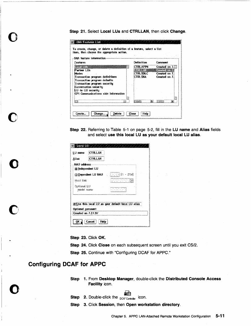
Step 21. Select Local LUs and CTRLLAN, then click Change.
! :1
I To create, change, or delete a delinition of a feature, select a list ~ ~ Item, then choose the appropriate actioo. i
I ~~·~~~~-~;~~~~l-;j, I ! Partner LUs ; ilf ~ : !Modes iCTRLSDlC Created on 7.1 1 : \Transactioo program definitions lCTRLSNA Created on 7'1,,' ~ : iTransacti ... program defaults 1,; ~ i lTransactiOIl program security i ~
1 ~~E~:I:~ s'de I~.,"urt'oo L . i I Il!=~==-=:::==-I~=.=~=~~J I , rc!;;;~~:-! I a.anDe. .. ~ r-Q;i;;t;;--I :-9;;;;-1 iHoiPl I ;/,~~:::'::;;:':;~::';;::':~W/'~hY.~/'~W////'W////'W/'//'~~';W~;;:;:::::;:;::':";>~':::::':::;;;//h:;:;::::::/.'l7/";';~~/.W////''/,W/,~/'W///'W//'~~XW/..r.M;';Wk,~;~~j
Step 22. Referring to Table 5-1 on page 5-2, fill in the LU name and Alias fields and select use this local LU as your default local LU alias.
Step 23. Click OK.
Step 24. Click Close on each subsequent screen until you exit CS/2.
Step 25. Continue with "Configuring DCAF for APPC."
Configuring DCAF for APPC
Step
Step
1. From Desktop Manager, double-click the Distributed Console Access Facility icon.
r"3
.~ 2. Double-click the DCAF Controller icon.
Step 3. Click Session, then Open workstation directory.
Chapter 5. APPC LAN-Attached Remote Workstation Configuration 5-11
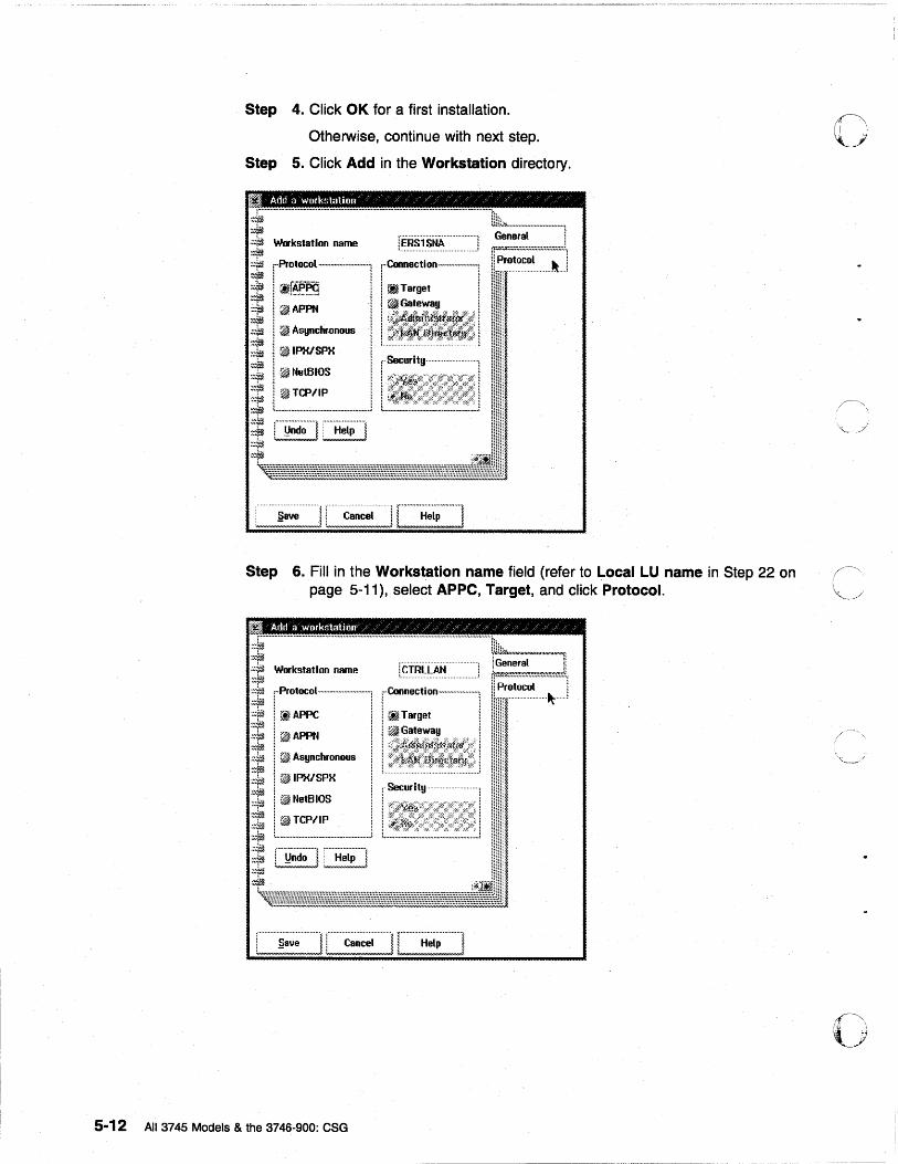
Step 4. Click OK for a first instalJation.
Otherwise, continue with next step.
Step 5. Click Add in the Workstation directory.
Add a workstation /' ;: / / / ;: ~ / / ~:''''''''''''''''''''''''''''''''''''''''''''''''''''''''''''''' ........................................................... ···· .. lnib~· ... · ...... ······· ... ······· .. ·l
t~~.~.1.~·~.·.·.· ... ·.·.·.·.· ............ 1 General Workstation name
r~~~--I ~ ~IPX/SPX I I ~NetBIOS I ~~~~ __ J
r:i~1 I ~~;4~~i' ' I t ................................................... J
[Security ......................... .
i I L ............................... _ ............. _.i
: .................................... ~ : ............ -......... -- .... -.- ..... ~ r .. .,· .. · .. · .... · .... ·"· .. "··· .. ···~ ! B8ve ! 1 Cancel I i Help ~ W"",,,,,,,",,,,,,,,,,,,,,,,,,,,A :",,,,,,,,,,,,,,,,,,,,,,,",_A ~/~N/~A«'Q.Q}.
Step 6. Fill in the Workstation name field (refer to Local LU name in Step 22 on page 5-11), select APpe, Target, and click Protocol.
Add a workstation";: / /. 7' / / Y /. /.)';: /. ;; /. '/ /.;: / / /
Workstation name
,··Protocol .. ····· .. ·· .. ················,
I ~APPC I
I:~;_us I 1 ~IPX/SPX I I ~NetBIOS I
l~~~~_.1 [~~d~"] [~~~~~~]
............... - ..................... ~ iCTRlLAN : ......................................... :
r:::~-i I ~Gatewa!l !
t~-l~1 1-.;ly···························1
t,." .... ,,.,,, .............. ,.,. ... ,., .... "u, ......... , ...................... ::
, .................................... j c··································j r· .. ••••••••••••·•··••··••·· .. ·•·• .. i l B8ve l ! Cancel 11 Help ! :.,_",,,,H'~',,,''',,,,,;. !,,,,',,,,NN,,,'N",,,,,,,""",;' ~'~_'N"''''''''NHJI'.ofW'"".«'l
5-12 All 3745 Models & the 3746-900: eSG
o
fl' ~\,
·'U
o
o
o
o
o
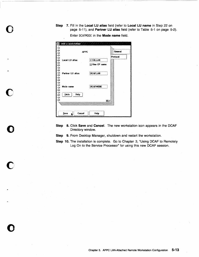
Step 7. Fill in the Local LU alias field (refer to Local LU name in Step 22 on page 5-11), and Partner LU alias field (refer to Table 5-1 on page 5-2).
Enter DCAFMODE in the Mode name field.
/A1:ld a workstation~ , /' /
::;}ifJ
~~~rE :~:~.,1
~:. Local LU alias
.:::;~
1:~~ ;;;::Jj Partner LU alias ~~~f~ :::fij ~:~iiJ, :.~:.r~
~~= Mode name ~7:;;l
APPC
·::~ttl : ....................... ~ f············ .. ····· .... -:;
~~irj L~~,~~,J :~~~!!J :::it1.
r.~f,~~~~.'~~~~~~~~~~~~~.] [@ Use CP name
Step 8. Click Save and Cancel. The new workstation icon appears in the DCAF Directory window.
Step 9. From Desktop Manager, shutdown and restart the workstation.
Step 10. The installation is complete. Go to Chapter 3, "Using DeAF to Remotely Log On to the Service Processor" for using this new DCAF session.
Chapter 5. APPC LAN-Attached Remote Workstation Configuration 5-13

o
o
5-14 All 3745 Models & the 3746-900: CSG
o
o
o
c
o
Chapter 6. Modem-Attached Remote Workstation Configuration
i A ~ i
Modem-Attached Workstation
A i
D ~ i
Service Processor
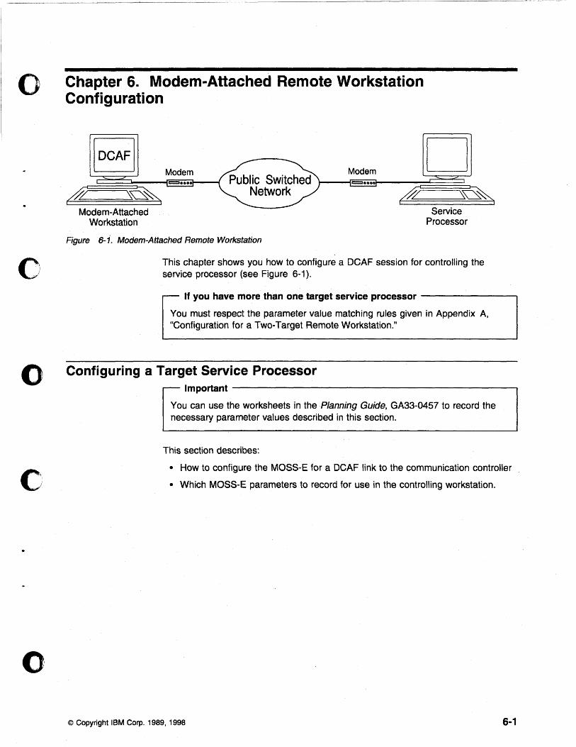
Figure 6- j. Modem-Attached Remote Workstation
This chapter shows you how to configure a DCAF session for controlling the service processor (see Figure 6-1).
If you have more than one target service processor -------....,
You must respect the parameter value matching rules given in Appendix A, "Configuration for a Two-Target Remote Workstation."
Configuring a Target Service Processor Important----------------------~
You can use the worksheets in the Planning Guide, GA33-0457 to record the necessary parameter values described in this section.
This section describes:
• How to configure the MOSS-E for a DeAF link to the communication controller
• Which MOSS-E parameters to record for use in the controlling workstation.
© Copyright IBM Corp. 1989, 1998 6-1
Parameter Values that Must Be the Same Table 6-1 gives the sets of MOSS-E parameters that must have the same value in both the remote workstation and the target service processor.
Table 6-1. Identical Target and Controlling Parameters
In Service Processor In Remote Workstation
Local Node Network 10 Partner network 10 (Figure 6-2 on page 6-3) (Step 19 in each configuration procedure)
SOLe LU name Partner node name (Figure 6-3 on page 6-4) (Step 19 in each configuration procedure)
and Partner LU alias
(Step 19 in each configuration procedure)
Each modem configuration procedure in this chapter explains how to find these parameters in the remote workstation.
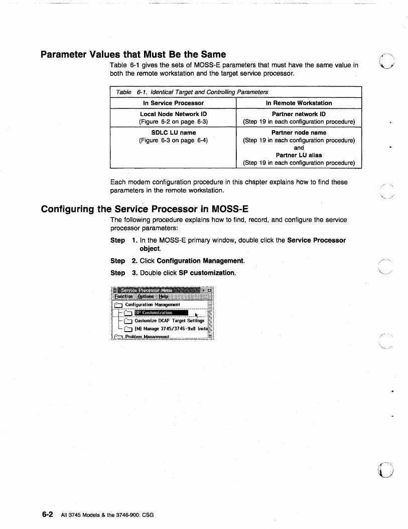
Configuring the Service Processor in MOSS-E The following procedure explains how to find, record, and configure the service processor parameters:
Step 1. In the MOSS-E primary window, double click the Service Processor object.
Step 2. Click Configuration Management.
Step 3. Double click SP customization.
6-2 All 3745 Models & the 3746-900: CSG
o
""', .. /
~- , I '
o
o
o
o
o
o
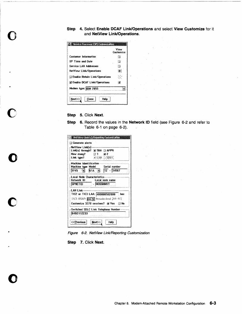
Step 4. Select Enable DCAF Link/Operations and select View Customize for it and NetView Link/Operations.
i!:·I.'EKfj'!!m'UFi!:t4XI(i"Plr;r;;'i~Er;I;rr':'i::'"
Customer Information
SP Time and Date
Service LAN Addresses
NetView Link/Operations
[.ill Enable Retain Link/Operations
Customize:
~ Enable DCAF Link/Operations r~
Modem type: 111::I .... ?~~~q qqliJ
........................ , ,······ .. ··············l ,.···················· .. 1 I ~ext» ~ L90se J : Help l
5. Click Next. Step
Step 6. Record the values in the Network 10 field (see Figure 6-2 and refer to Table 6-1 on page 6-2).
f.ill Generate alerts
;·NetView Link(s) .. · .. · .. · .. · .... · .. ······ ...... · .. ·· .. ·· .......... · ...... · .. ······ ............. ; : j Link{s) through? lt~SNA G' APPN : How many? 1 2
L~ .. i.~~ .. ~.~~~~ ............................................................................................ _ ,. Machine Identification ................................... . : Machine type Model Serial number
1..t~7~~····~~~~~1! .. J~~~~~:!!._ .. ~ .. ~ .. t~~.~.~~ .................... , ; .. Local Node Characteristics· .... · .. ·· .. · .. · .. · .. · .. _ .... · .. · .... · : Network 10 Local node name
i . ..!~:~~:~!~:?:::::: .................. · ... '-~~~~~~y.! ... : ............................ '. ~·LAN Link·--~--·-.. · .. ·-· .... - .... · .. - .. ·-...... · .... · .... · .... - .. ·, : I TIC2 or TIC3 LAA: /400000502080 hex :.
[ TIC] nSAP: Jl~~:ii k:l>:;dtdmai. UM·· qq
l .. ~~~~~~~.~.~ ... ~.~.!..~ ... =~:~.~.~~.~: ..... ~!.:.~= ........ ~~ .. ~~ ... . ,Switched SDLC Link Telephone Number ...... · .... ·_ .. ,
i 10492112233 .
I"<'<~;~~i~~ .........
Figure 6-2. NetView Link/Reporting Customization
Step 7. Click Next.
Chapter 6. Modem-Attached Remote Workstation Configuration 6-3
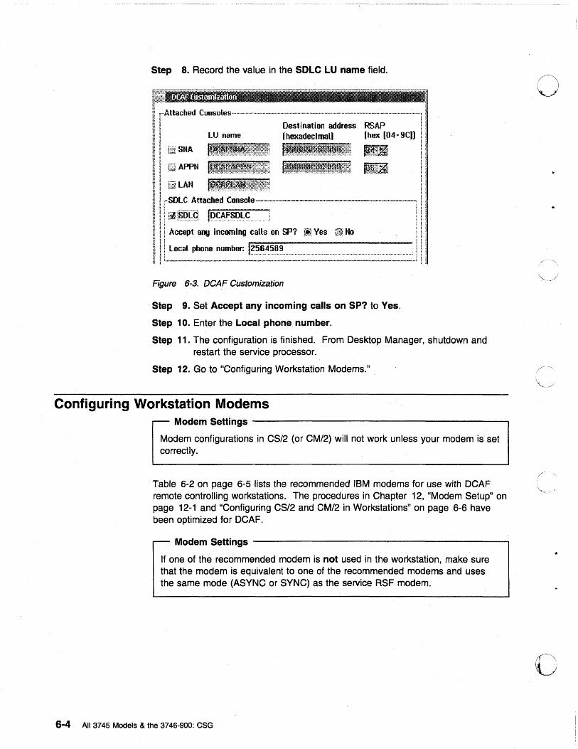
Step 8. Record the value in the SOLe LU name field.
~~~===.=~~ i! ! Destination address RSAP i: I! ! UJ name (hexadecimal) (hex [04- 9CIl !!
mi SNA I~tl~.i~~;ttl~:t~f:~~~:~~:;~:: li~[:~Ci
{ri." APPN Il~rfff1.i~i~t~~t~~~~;~t: l~iI'-m!gt~tJ.~!~;;:;;~;;~;: [~~JHi~
!l ! l Accept any Incoming caUs on SP? ~~Y: Ves C) No l j :
111~:~~~~~~~:======i Ii Figure 6-3. DCAF Customization
Step 9. Set Accept any incoming calls on SP? to Yes.
Step 10. Enter the Local phone number.
Step 11. The configuration is finished. From Desktop Manager, shutdown and restart the service processor.
Step 12. Go to "Configuring Workstation Modems."
Configuring Workstation Modems Modem Settings ------------------------------------------~
Modem configurations in CS/2 (or CM/2) will not work unless your modem is set correctly.
Table 6-2 on page 6-5 lists the recommended IBM modems for use with DCAF remote controlling workstations. The procedures in Chapter 12, "Modem Setup" on page 12-1 and "Configuring CS/2 and CM/2 in Workstations" on page 6-6 have been optimized for DCAF.
Modem Settings ------------------------------------------~
If one of the recommended modem is not used in the workstation, make sure that the modem is equivalent to one of the recommended modems and uses the same mode (ASYNC or SYNC) as the service RSF modem.
6-4 All 3745 Models & the 3746-900: CSG
o
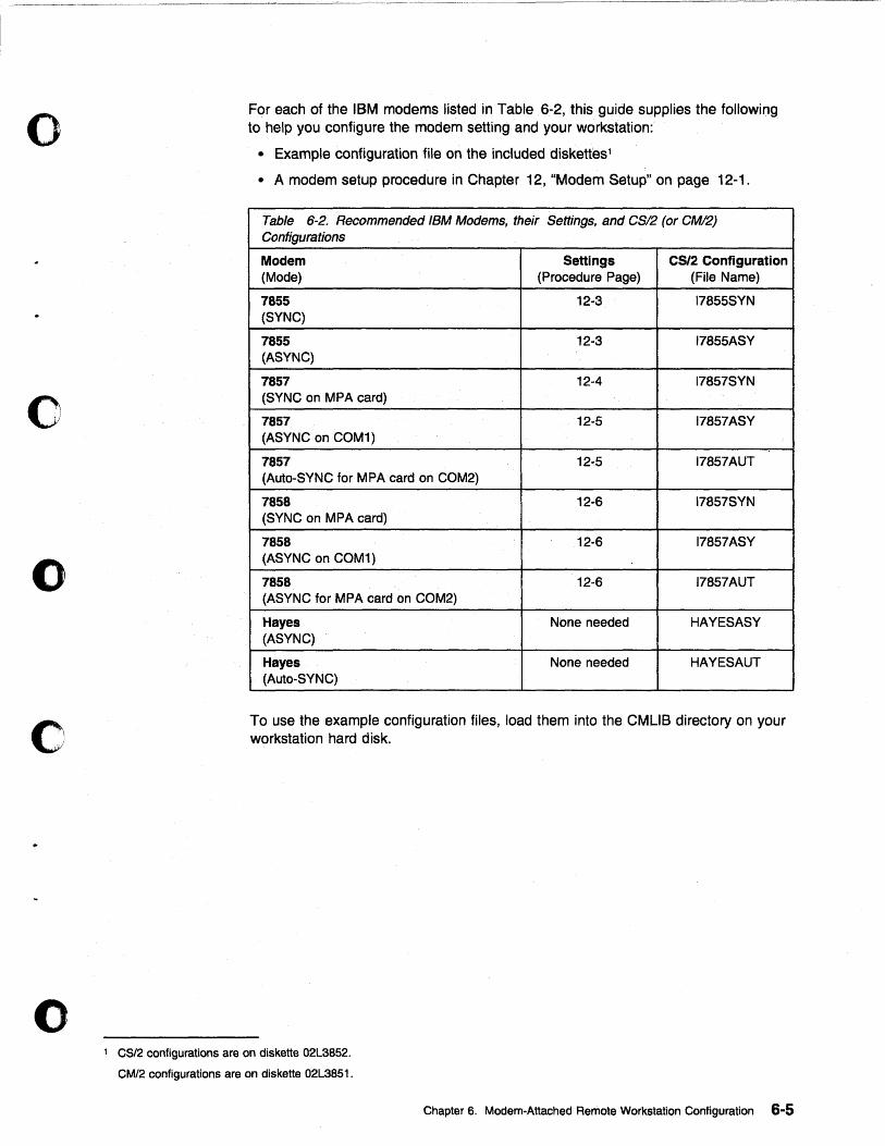
o
o
o
o
o
For each of the IBM modems listed in Table 6-2, this guide supplies the following to help you configure the modem setting and your workstation:
• Example configuration file on the included diskettes1
• A modem setup procedure in Chapter 12, "Modem Setup" on page 12-1.
Table 6-2. Recommended IBM Modems, their Settings, and CS/2 (or CM/2) Configurations
Modem Settings CS/2 Configuration (Mode) (Procedure Page) (File Name)
7855 12-3 17855SYN (SYNC)
7855 12-3 17855ASY (ASYNC)
7857 12-4 17857SYN (SYNC on MPA card)
7857 12-5 17857ASY (ASYNC on COM1)
7857 12-:5 17857AUT (Auto-SYNC for M PA card on COM2)
7858 12-6 17857SYN (SYNC on MPA card)
7858 12-6 17857ASY (ASYNC on COM1)
7858 12-6 17857AUT (ASYNC for MPA card on COM2)
Hayes None needed HAYESASY (ASYNC)
Hayes None needed HAYESAUT (Auto-SYNC)
To use the example configuration files, load them into the CMUS directory on your workstation hard disk.
1 CS/2 configurations are on diskette 02L3852.
CM/2 configurations are on diskette 02L3851 .
Chapter 6. Modem-Attached Remote Workstation Configuration 6-5
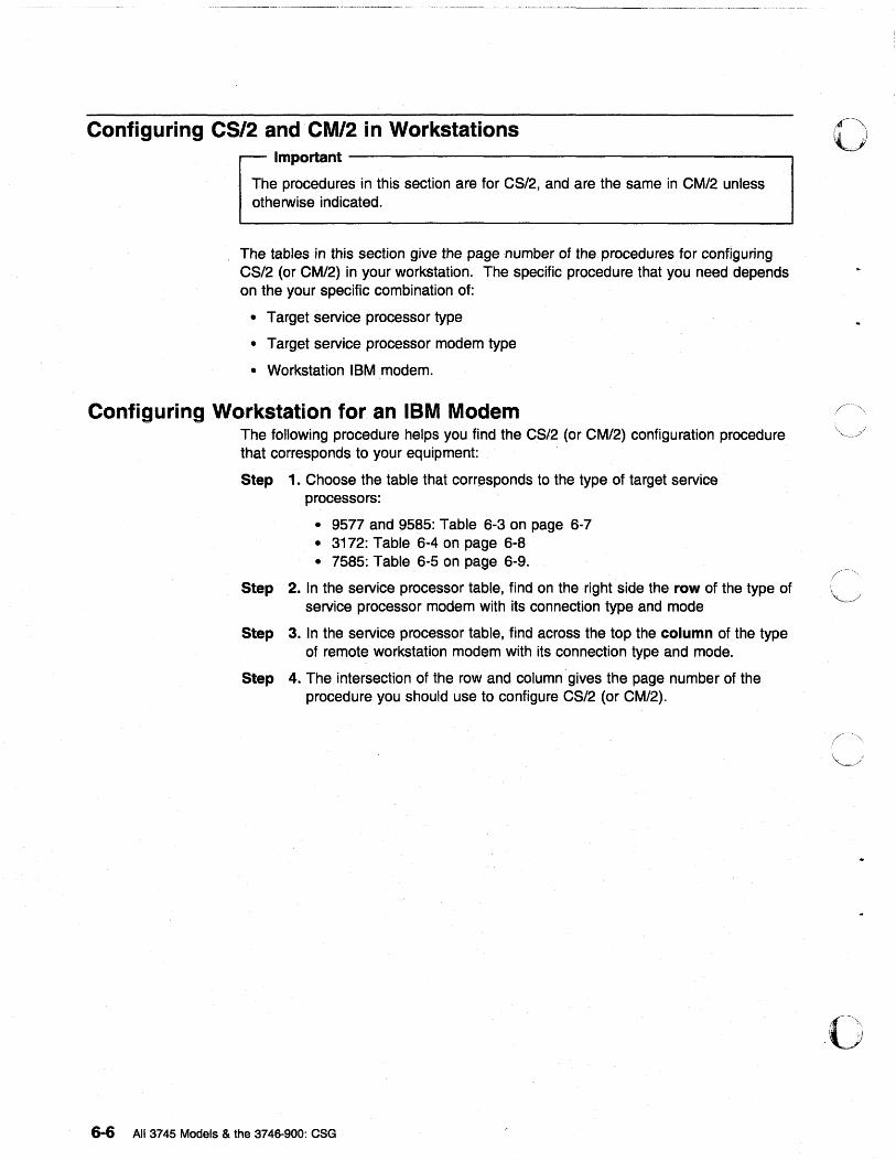
Configuring CS/2 and CM/2 in Workstations Important --------------------------------------------~
The procedures in this section are for CS/2, and are the same in CM/2 unless otherwise indicated.
The tables in this section give the page number of the procedures for configuring CS/2 (or CM/2) in your workstation. The specific procedure that you need depends on the your specific combination of:
• Target service processor type
• Target service processor modem type
• Workstation IBM modem.
Configuring Workstation for an IBM Modem The following procedure helps you find the CS/2 (or CM/2) configuration procedure that corresponds to your equipment:
Step 1. Choose the table that corresponds to the type of target service processors:
• 9577 and 9585: Table 6-3 on page 6-7 • 3172: Table 6-4 on page 6-8 • 7585: Table 6-5 on page 6-9.
Step 2. In the service processor table, find on the right side the row of the type of service processor modem with its connection type and mode
Step 3. In the service processor table, find across the top the column of the type of remote workstation modem with its connection type and mode.
Step 4. The intersection of the row and column· gives the page number of the procedure you should use to configure CS/2 (or CM/2).
6-6 AU 3745 Models & the 3746·900: eSG
o
O:·~.\ ,.
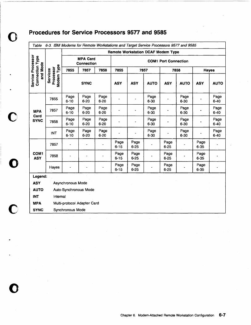
o Procedures for Service Processors 9577 and 9585
Table 6-3. IBM Modems for Remote Workstations and Target Service Processors 9577 and 9585
Remote Workstation DCAF Modem Type r... o cp
MPA Card tI) a. COM1 Port Connection ~~cp Connection
uc"C cp 000 cpoD. 7855 7857 7858 7855 7857 7858 Hayes Q:;;:i UtI)>-cpu"C UtI)~ U Cp C "> Cp E "> 2 '" r... U Cp
cp0"C r... 0 Cl)r...o SYNC ASY ASY AUTO ASY AUTO ASY AUTO ~o o..:i
7855 Page Page Page - - Page - Page - Page 6-10 6-20 6-20 6-30 6-30 6-40
o MPA 7857 Page Page Page - - Page - Page - Page 6-10 6-20 6-20 6-30 6-30 6-40
Card SYNC 7858
Page Page Page - - Page - Page - Page 6-10 6-20 6-20 6-30 6-30 6-40
INT Page Page Page - - Page - Page - Page 6-10 6-20 6-20 6-30 6-30 6-40
7857 - - - Page Page - Page - Page -6-15 6-25 6-25 6-35
o COM1
7858 Page Page Page Page
ASY - - -6-15 6-25 -
6-25 -
6-35 -
Hayes - - - Page Page - Page - Page -6-15 6-25 6-25 6-35
Legend:
ASY Asynchronous Mode
AUTO Auto-Synchronous Mode
INT Internal
c MPA Multi-protocol Adapter Card
SYNC Synchronous Mode
()
Chapter 6. Modem-Attached Remote Workstation Configuration 6-7
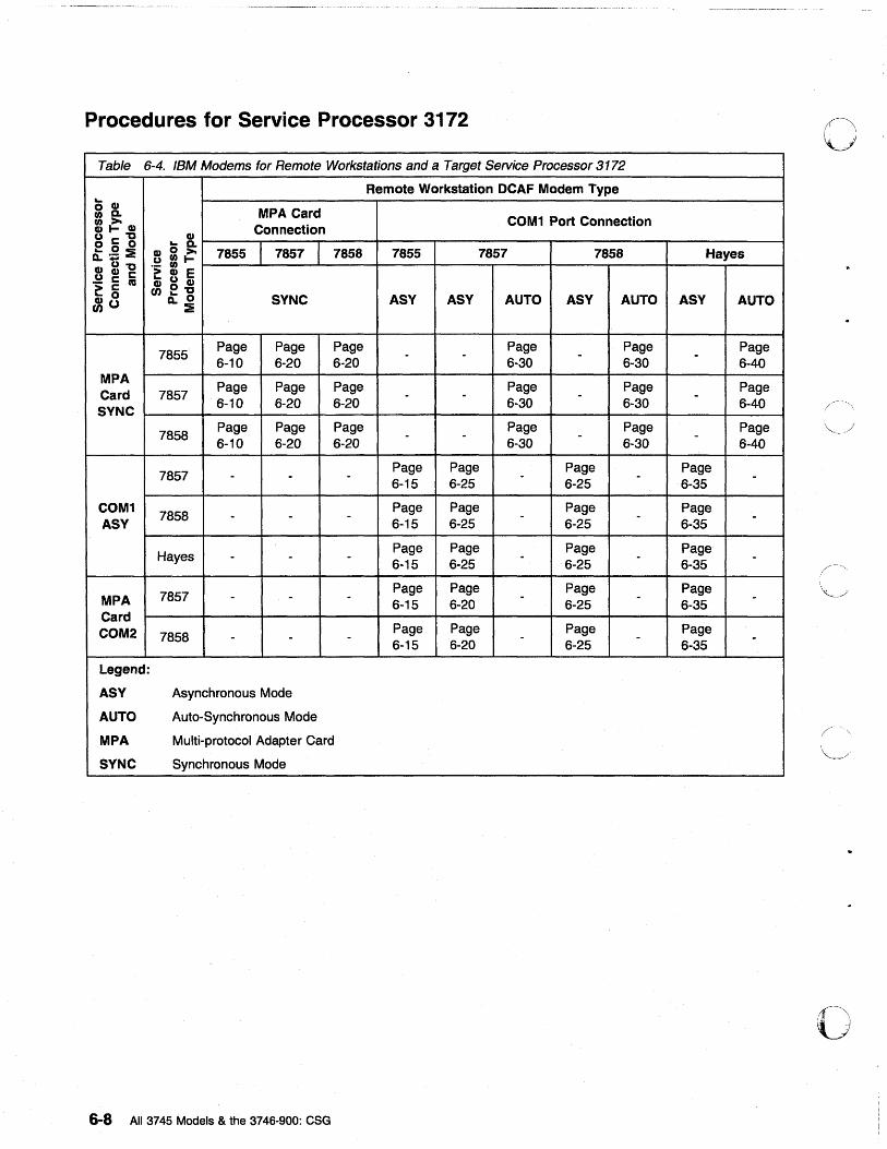
Procedures for Service Processor 3172
Table 6-4. IBM Modems for Remote Workstations and a Target Service Processor 3172
Remote Workstation DCAF Modem Type ~ o CI)
MPA Card U)D. COM1 Port Connection ~~CI) Connection
uc::;"D CI)
0 0 ° '- D. Q:;;:E C1) 0 >o 7855 7857 7858 7855 7857 7858 Hayes uU)1-Cl)u"D "- U) U CI) c::; > CI) E "; ~ as Gi u CI)
cn°"D ~ 0 '- ° SYNC ASY ASY AUTO ASY AUTO ASY AUTO ~o Q.:E
7855 Page Page Page - - Page - Page - Page 6-10 6-20 6-20 6-30 6-30 6-40
MPA Page Page Page Page Page Page
Card 7857 - - - -SYNC
6-10 6-20 6-20 6-30 6-30 6-40 /~"
7858 Page Page Page - - Page - Page - Page 6-10 6-20 6-20 6-30 6-30 6-40
~-j
7857 - - - Page Page - Page - Page -6-15 6-25 6-25 6-35
COM1 7858
Page Page Page Page ASY
- - -6-15 6-25 - 6-25 - 6-35 -
Hayes - - - Page Page - Page - Page -6-15 6-25 6-25 6-35
MPA 7857 - - - Page Page - Page - Page -6-15 6-20 6-25 6-35 Card COM2 7858 - - - Page Page - Page - Page -6-15 6-20 6-25 6-35
Legend:
ASY Asynchronous Mode
AUTO Auto-Synchronous Mode
MPA Multi-protocol Adapter Card
SYNC Synchronous Mode
o 6-8 All 3745 Models & the 3746-900: eSG
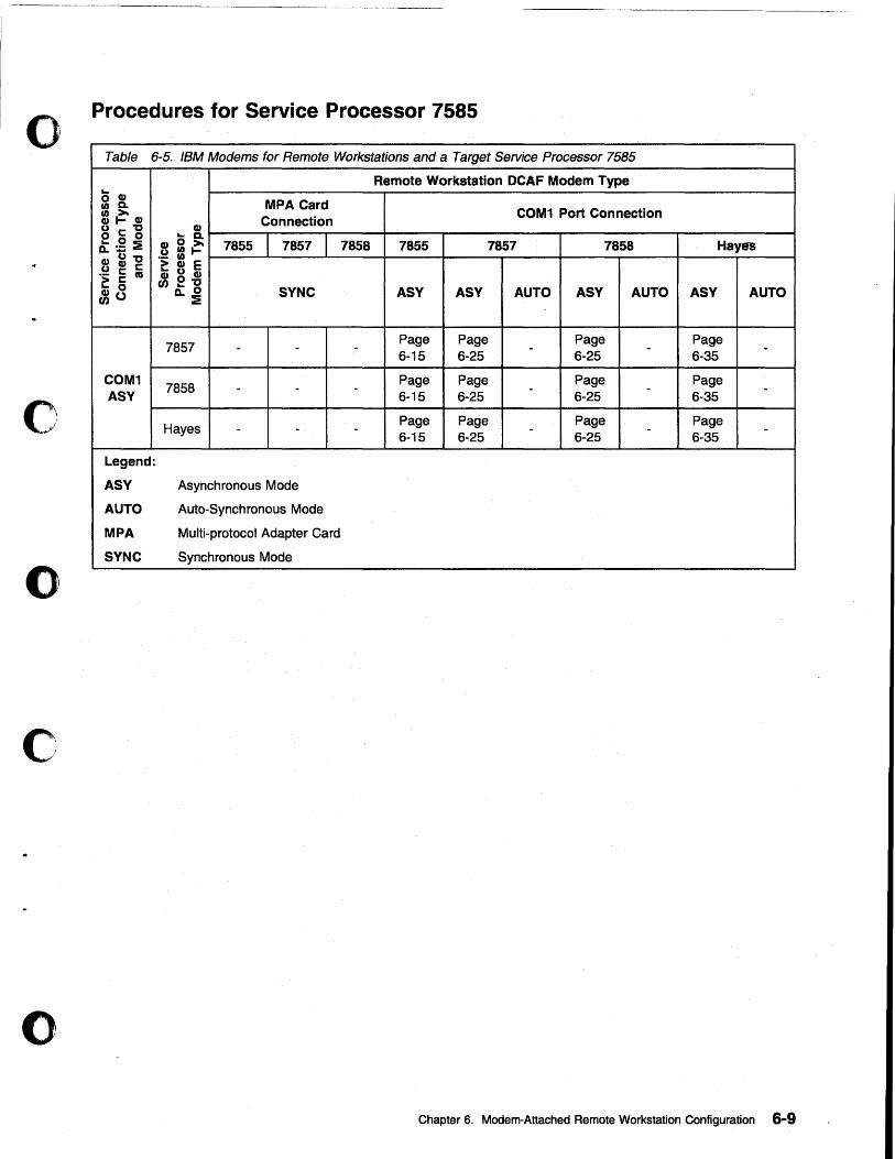
o
c
o
c
o
Procedures for Service Processor 7585
Table 6-5. IBM Modems for Remote Workstations and a Target Service Processor 7585
COM1 ASY
Legend:
ASY
AUTO
MPA
SYNC
Remote Workstation DCAF Modem Type
MPA Card COM1 Port Connection ~ ~~ ____ ~c-o-n-ne-c-t-io~n--__ --+-----~------------~ ____ ------~r---____ --__ ~
~ = ~~7_8_5_5~ __ 7_8_5_7~ __ 7_8_58 __ +-_78_5_5 __ ~ ____ 7~85-7 ____ -+-----7-8T5_8 ____ ~----H-a~y-~-s--~ .~ CI) E CI) u CI)
UJ °"D ~ ° D..:e
7857
7858
Hayes
SYNC
Asynchronous Mode
Auto-Synchronous Mode
Multi-protocol Adapter Card
Synchronous Mode
ASY
Page 6-15
Page 6-15
Page 6-15
ASY
Page 6-25
Page 6-25
Page 6-25
AUTO ASY
Page 6-25
Page 6-25
Page 6-25
AUTO ASY AUTO
Page 6-35
Page 6-35
Page 6-35
Chapter 6. Modern-Attached Remote Workstation Configuration 6-9
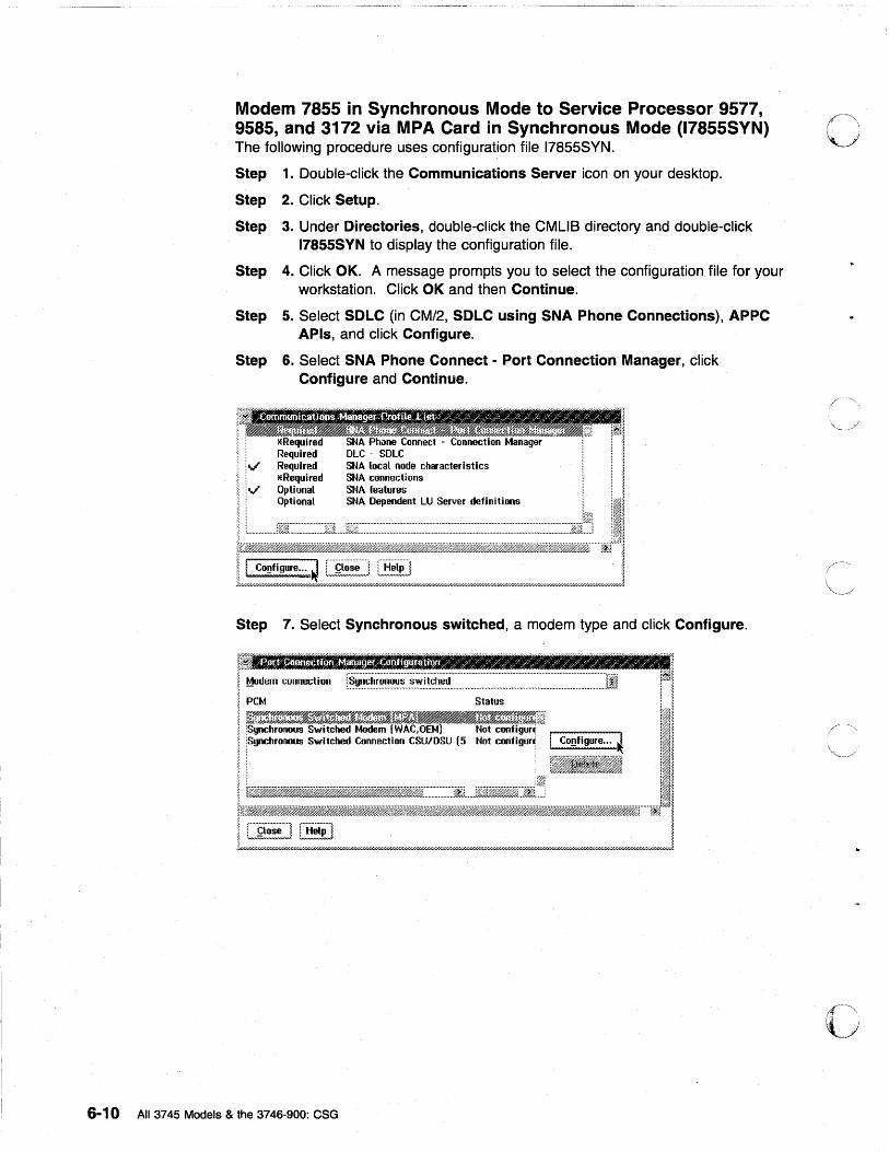
Modem 7855 in Synchronous Mode to Service Processor 9577, 9585, and 3172 via MPA Card in Synchronous Mode (17855SYN) The following procedure uses configuration file 17855SYN.
Step 1. Double-click the Communications Server icon on your desktop.
Step 2. Click Setup.
Step 3. Under Directories, double-click the CMUS directory and double-click 17855SYN to display the configuration file.
Step 4. Click OK. A message prompts you to select the configuration file for your workstation. Click OK and then Continue.
Step 5. Select SDLC (in CM/2, SDLC using SNA Phone Connections), APPC APls, and click Configure.
Step 6. Select SNA Phone Connect - Port Connection Manager, click Configure and Continue.
red Required Required lERequired Optional Optional
SNA local node characteristics sr.~A connections sr.~A features SNA Dependent LU Server definitions
Step 7. Select Synchronous switched, a modem type and click Configure.
6-10 All 3745 Models & the 3746-900: CSG
o
()
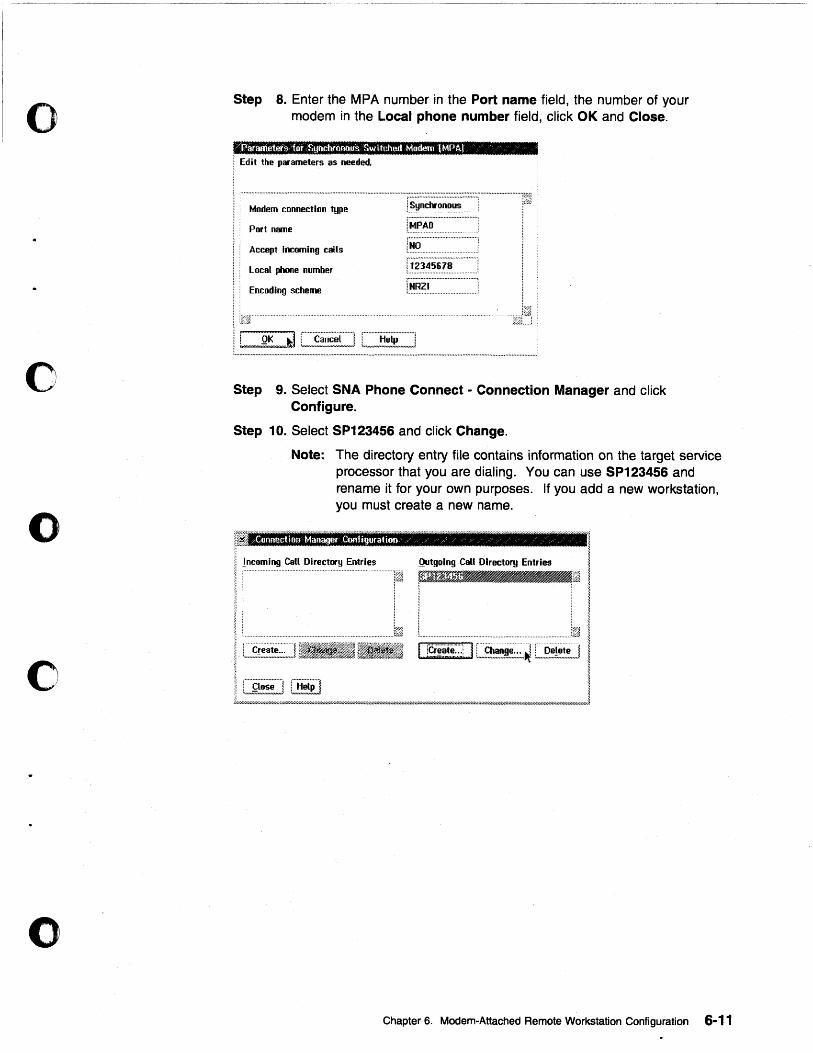
o
c
o
o
o
Step 8. Enter the MPA number in the Port name field, the number of your modem in the Local phone number field, click OK and Close.
"'Parameters "for Synchronous Switched Madero IMPA,J "
I Edit the parameters as needed.
Modem connection type
Accept Incoming calls
Local phooe number
Encoding scheme
.. " ........................................ .. l~R?1 .
Step 9. Select SNA Phone Connect - Connection Manager and click Configure.
Step 10. Select SP123456 and click Change.
Note: The directory entry file contains information on the target service processor that you are dialing. You can use SP123456 and rename it for your own purposes. If you add a new workstation, you must create a new name.
z£oonectitm Manager Confi!Wfation / /' / / ;-. "
; incoming Call Directory Entries ~
Qutgoing Call Directory Entries I '--I ! ~
L. .......................... .. ...... ..:f~ I I rti~ate~:·:; I C~,§~!~,:,~,~ l:,,~,~~!!!] I
• I ~ ::
I C:£i~~2] L~~i!] • ~ JL',//////UY/////////////h .. }r////hY////h;' .. 7//hWhY////hYhY/////h};.'//////h}jI///h-Yh:r////,t/////h;}W//////.r/////////fi7hY////hW/////////////.';"fi"//////////////hy/////// ... 7///UWhYh"'-////l'hY//h}7///h}W//hft.
Chapter 6. Modem-Attached Remote Workstation Configuration 6-11
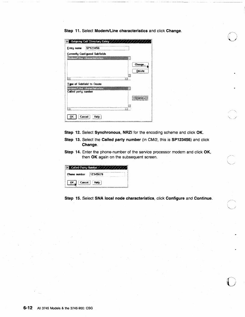
Step 11. Select Modem/Line characteristics and click Change.
Step 12. Select Synchronous, NRZI for the encoding scheme and click OK.
Step 13. Select the Called party number (in CM/2, this is SP123456) and click Change.
Step 14. Enter the phone-number of the service processor modem and click OK, then OK again on the subsequent screen.
%
i; ~hone number [~'~?456i8' . . ~
t/~'7.W~:"~,/u~;~~~E;~!~;;!///;;;;:~;~~;L////,////,,,/////////U7.w////////u,,,,,w/uJ
Step 15. Select SNA local node characteristics, click Configure and Continue.
6-12 All 3745 Models & the 3746-900: CSG
()
c
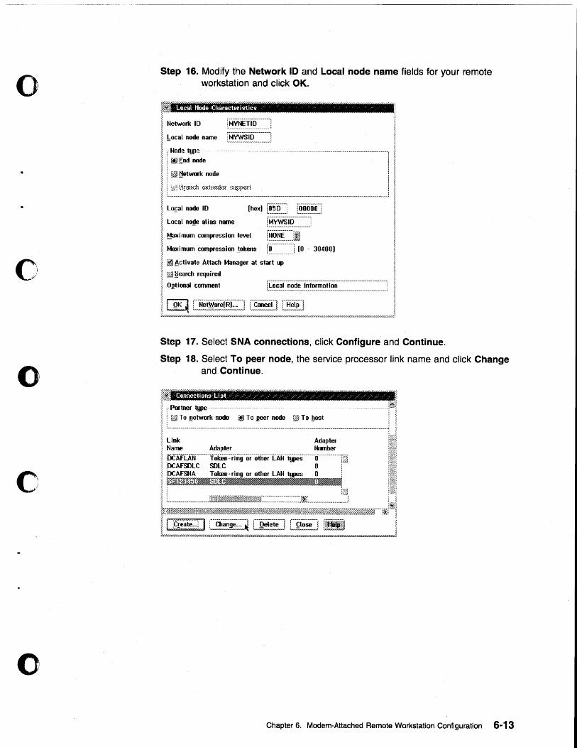
o
o
o
c
o
Step 16. Modify the Network 10 and Local node name fields for your remote workstation and click OK.
Local MOde Characteristics ........................... _----_ ..
Network !O : MV~!.IP ............ .
!:ocaL node name f~~.~~}.~~~~~~~~~~~~~] :··Node type··· ....................................................................................................................................•
: ~End node
• ~ !!etwork node
Flranch (~Khmde( ~>Hpp(lfi L~.n .. ., .. ., .... u ... ,. .. ,..,.,. ..................... ,. ..... I .................... _ • ............................... ,. ..... ,. ...... ,.." ................. ,. ......... ,. .......... ,.,. ... ## .......... .1
Lo~aL node 10
LocaL no~e alias name [~.~~~~.~~:::~~~ .. ~~::~J Maximum compression leveL [~~.~~~:~.·JI Maximum compression 10kens r~ ........... : ............. ] (0 - 30400)
~.Bctivate Attach Manager at start up
:~ .§earcl1 required
OI!tional comment
I QK ~ C.~~~~~.~~.~(~E:;~~] L~~~] [H!~~] . Ly/"""""""",/,/,.,.""",/////hW,////.Wh''''///",///////////hY///////hY////////////////////h,..'.'//.'//////////////4//hW////.W////////.;W/hY////////h'////.W//////////////////fi,,,,,j
Step 17. Select SNA connections, click Configure and Continue.
Step 18. Select To peer node, the service processor link name and click Change and Continue.
;:7"///.1,:
II ,Partner type 1m1:
i ... ~ .. ~.~ ... =:~:.~.~~ ... ~.~ ........ ~.~~ .. ~.~.~.~ ... :~ ...... ~ .. ~~ .. =.:~ ...................................................... J I Link Adapter 1m!'! Name Adapter NLmber i~fi~ fOCAFLAN ............ Token·::·rTilg .. or .. ·otherTAJrijpis .......... ·O ..................... [~J.. il~
~II
Chapter 6. Modem-Attached Remote Workstation Configuration 6-13
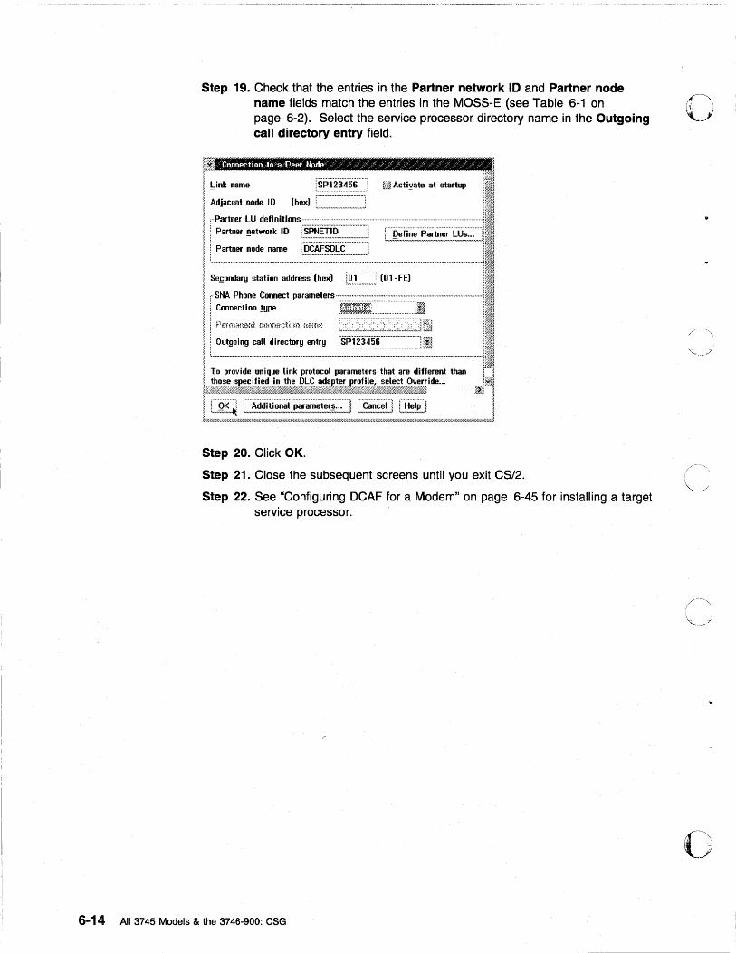
Step 19. Check that the entries in the Partner network 10 and Partner node name fields match the entries in the MOSS-E (see Table 6-1 on page 6-2). Select the service processor directory name in the Outgoing call directory entry field.
I J !oink name :.~.J=l.~.~.~.~.~.~. ff~ Actiyate at startup
Adjacent node ID (hex) ::::::::::::::~::::::::::::::::::; ;··Partner lU definitions······ ............................................................................................. .
Partner network 10 rSPNEiiii"·····,,···········! - : •• ,..,. ..................... ,.,.,.,.,.,..#0 •••• ;
Partner node name jjcAF·sDL:E·····"·····"i - : ............................................ ;
Sefondary station address (hex) f.~T:::::::::J [Ol-FE)
TD provide unique link protDcol parameters that are different than {~
i£D~~k~1itt~~j}1~j~~;~j~it~lt~d~#~~~1~1&~%}~t~;i~id~,", ··················I1;~1 ; ! QK i ~ Additional parameter~ ... l : Cancel! i Help 1 1 . 'm"''''''''''~ '"uuu"u",uu",,,u,,,u,,,uuuu,,,,,,u,,,,,,,,,u,,,,,,u,,,d "",,,,,,,,,u,,,,,,,,~ 'm",u"",uu/ ~
t/.4~~r,r/.~~:i";~~~~~»~X'7.4"W//;W.4~~w//;~w//..wu»;~r/.xz;.z;~~r,x~xw/////;~/////.~xr/.~"X-;-;-;w/.~7,0";:;~~n//;~~~:W///hr,~r,:r..z:'l"//;~:I//,~'i~~iliW/':;'ili~:x.r,;i.iWlili;i:w/////u;:;:W/;~ili;;
Step 20. Click OK.
Step 21. Close the subsequent screens until you exit CS/2.
Step 22. See "Configuring DCAF for a Modem" on page 6-45 for installing a target service processor.
6-14 All 3745 Models & the 3746-900: eSG
o
o
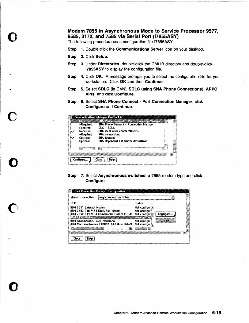
o
o
o
o
o
Modem 7855 in Asynchronous Mode to Service Processor 9577, 9585, 3172, and 7585 via Serial Port (17855ASY) The following procedure uses configuration file 17855ASY.
Step 1. Double-click the Communications Server icon on your desktop.
Step 2. Click Setup.
Step 3. Under Directories, double-click the CMUB directory and double-click 17855ASY to display the configuration file.
Step 4. Click OK. A message prompts you to select the configuration file for your workstation. Click OK and then Continue.
Step 5. Select SDLC (in CM/2, SDLC using SNA Phone Connections), APPC APls, and click Configure.
Step 6. Select SNA Phone Connect - Port Connection Manager, click Configure and Continue.
Configure... L_~~!~J L,!:!!~P'j ~ , ....................... , , .............. ,
Step 7. Select Asynchronous switched, a 7855 modem type and click Configure.
Port Cannection Manager -Configurt:ltion / ':' ,/ / / / / / / ~~
I. Modem connection ~~~ l i I !~~:'"i85'1 E~iernal Modem .............................. ·························~::~:Hgur{i III
; :IBM 7852 010 V.34 Data/Fax Modem Not configurE !ll;~!
; ~1~f~J.I~r~1~~~~~rr;i~~~~_a/~~~;~(;:;p;;~rJ I Co~figure ... ~ ill ~ ~/;#~~~JJ~A?)..w//h.#.J_ ~..?HA?~AW#~»:-~7/~ % :~~ j IBM AS'y'NC!SDLC V.32 Modem! A Not configurE 11 il@1 ~ IBM Microelectronics PCNCIA lt1.4Kbps Data/l Not configurE~ ~ ;'1 ~ 1~.~~:=:::::::::::::::::::::::::::::::.~:::::I ____ .D_.~]1i.~: !I ~f~_~~~.~M.i.A'iJ.······f#!::~~ I C~i!!~:] [~~] I, t'//6WUH///dd/aili'Y/hW////////U////U.6w/,.-.WP//////U/b'd/M".m-'/,Q////d/.&W/// .• Wb'////b'//////////b'//b'..m"/U/.6:U//U/UfiXI'U/fir///U/U/////.6W.6W////.Q'...;U'.6W/UJ:.iY/fir/M-,i/yhy/u.i:d//////':;:XW/////.6:».OW////.6~7////~
Chapter 6. Modem-Attached Remote Workstation Configuration 6-15
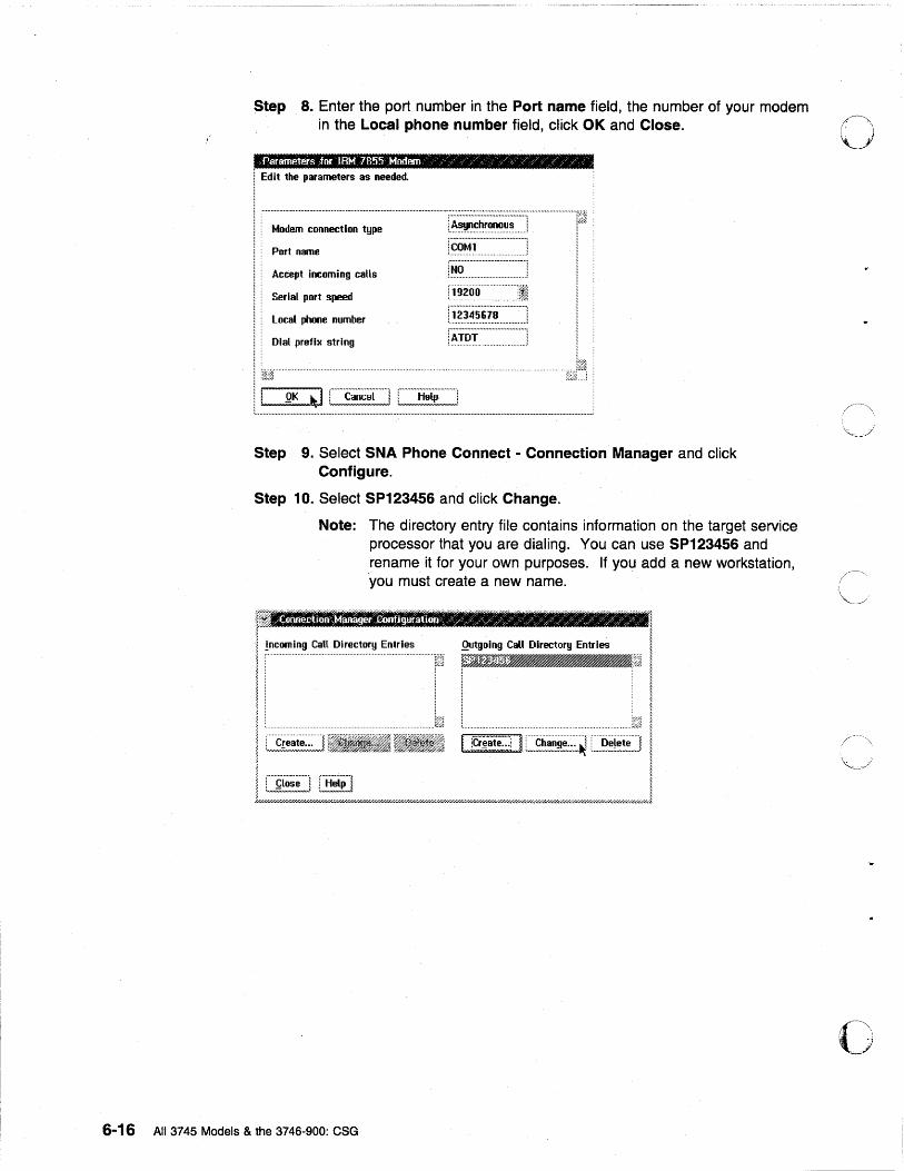
Step 8. Enter the port number in the Port name field, the number of your modem in the Local phone number field, click OK and Close. 0
! Edit the parameters as needed.
Modem connection type
Port name
Accept incoming calls
Serial port speed
local phooe number
:~.°t>.1~n ........... ' r~o..·::::::::::::::::·.·::::::::::::.·::·! :~.~200· .. · .. ··.··.··.·.Ii!
!X?:~.~:~.6.:i~::::::::::::·] Dial prefix string [~i"~!."':""""":""""']
II' OI(~~~ Step 9. Select SNA Phone Connect - Connection Manager and click
Configure.
Step 10. Select SP123456 and click Change.
Note: The directory entry file contains information on the target service processor that you are dialing. You can use SP123456 and rename it for your own purposes. If you add a new workstation, you must create a new name.
rili;!na~g.I';f:!~Wlmn!NlnHtll' r" ""l"n"[llIllll""'1 r I "Inrll rln ~ j
~ Incoming Call Directory Entries Qutgoing Call Directory Entries i !~rj ~J,igm_~j I
i ! I , .................................................................................................• !.~.".,j '. . ...... n .......... niM I
i C~~~~~!H~i~.;.~] I rcr~ai'e~:) I C.~~~~~~~~~ [~~~~~!i!!~~] I ~
; L,,~~~~_J L~,~~J j f///////////h7/////////////////////////////////.-Y////////////////////////////.i/////hY///.l.W//////fii'Y///dl//////fiY//////////////////47///////////////////////////////////////////////////////////////////////////,',W//.0
6-16 All 3745 Models & the 3746-900: CSG
(".\. I.)
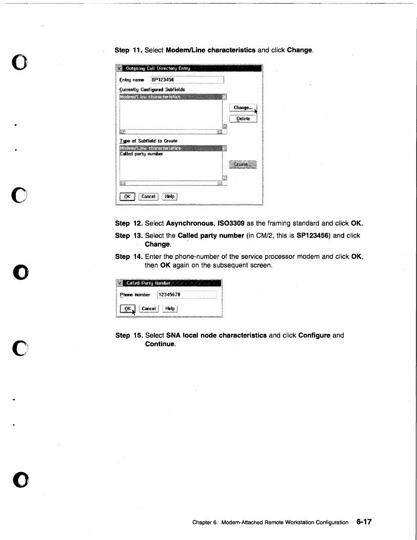
o
o
o
o
o
Step 11. Select Modem/Line characteristics and click Change.
Step 12. Select Asynchronous, IS03309 as the framing standard and click OK.
Step 13. SeleCt the Called party number (in CM/2, this is SP123456) and click Change. '
Step 14. Enter the phone-number of the service processor modem and click OK, then OK again on the subsequent screen.
I ~hone number <..1 .. 2 .... 3 ... 4 .... 5 .... 6 ... 7 .... 8 ............................................... .
~
L/!/////=u:r~/,/E;~;~~~iE///~;~~;~2"//,,,/,//,//,r/.'wh~'7////.W/M////.~7//u//.~
Step 15. Select SNA local node characteristics and click Configure and Continue.
Chapter 6. Modem-Attached Remote Workstation Configuration 6-17
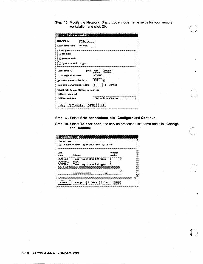
Step 16. Modify the Network 10 and Local node name fieJds for your remote workstation and click OK.
Local Hode Character istics / , ;:, %
Network !D : .. ~.X.~!..I.'? .......... bocaL node name [f.i~~~~!.~~~~~~~.~J .. ·Node type.................... ............................................ .. ..................................... ..
Il~~~~~~-~--~ ~: ( ................ : .................... 1
Local ~ alias name r~y.~:~.~::::::::::::J Ma~imum compression level r~§..~.~::::JI Maximum cOlllpression !okens [8'" ::.'::::.':] (0 - 30400)
~ ~ctivate Attach Manager at start up
:~ §earch required
O~tional comment
~.;~, ............................................ i. ( ..................... ~ , ................. , 1 §, ~~ l Net~are[R)... l i Cancel I l Help I i ~}"/////.II'/////////////////I~:~;::::;;;:;;;::.::;;:;;::////;::;..::~:;~:: .. ~~~;:::::;//////////////////////////////////J'// ...... ////////////////////////.r//h'///4'~W/" .... J.
Step 17. Select SNA connections, click Configure and Continue.
Step 18. Select To peer node, the service processor link name and click Change and Continue.
~ ~
Il~~~~:~_:~ __ ~_~:~:·:_:,: __ ~_~:_~~ ___________________ j' ~~~ Adapter =b: Iii [OCAFLAtf··········Token·:·,Tiig .. o,···otherTAtf'ijjes .. ··· .. ·· .. tf··· .. ············T~ 111
I~~~ tWffi.~,.~~$~~JMi_jj'fif.~·······1¥.J~1 II [f!:ate~~~ I [~~!~i~;;] [~R!i,!i!] [~,~!~J I J//h'/.i'///////////////////.v..w;PH$///&/ .. w..w////.6W//h'/.6~/fi'H//.fiY///Q'///hYU7////////////.6W/////$nYh7///////Y/////PY//////u7/////d////////uu//m;w//////////P,Q/,Q///fiW/////////J.
6-18 All 3745 Models & the 3746-900: CSG
o
0-------"-'I
: ..•. -. :'.:
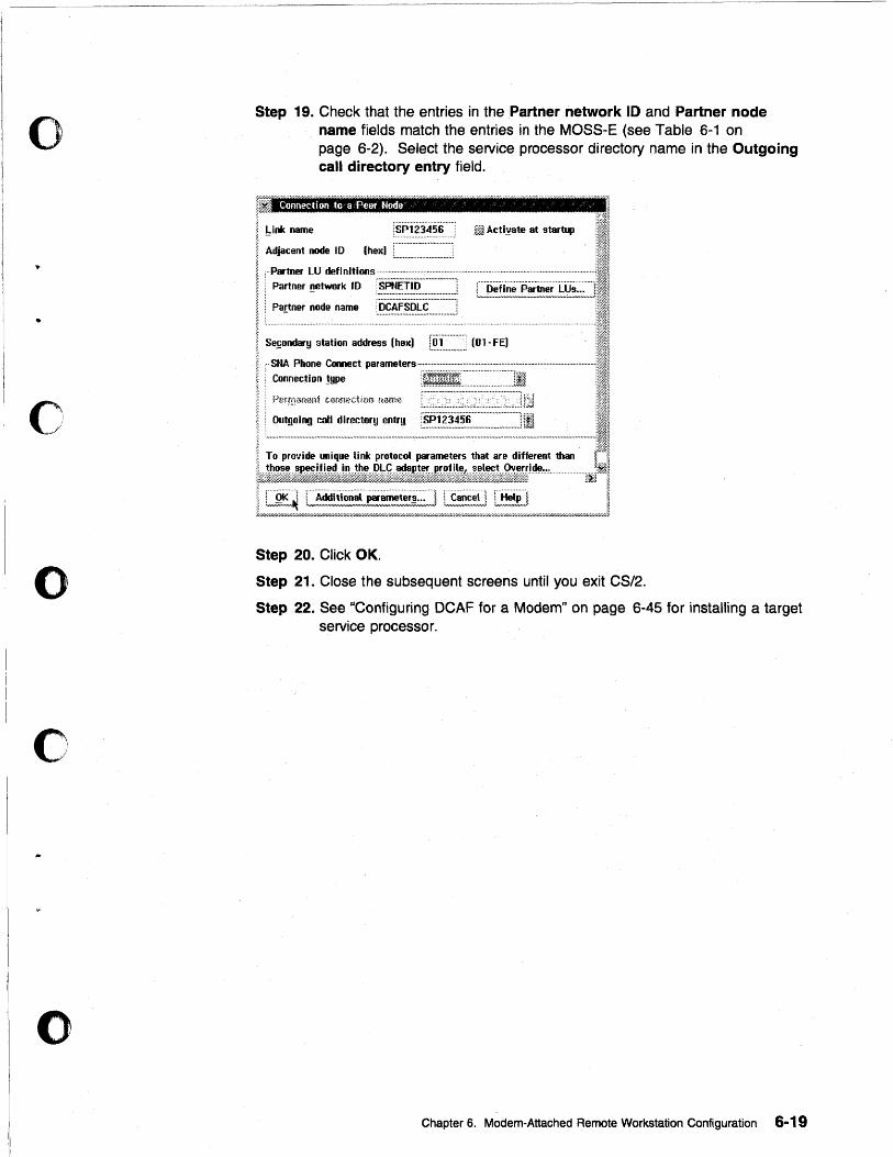
o
•
o
o
c
o
Step 19. Check that the entries in the Partner network 10 and Partner node name fields match the entries in the MOSS-E (see Table 6-1 on page 6-2). Select the service processor directory name in the Outgoing call directory entry field.
;Y-
J1 Connection .to a Peer Node ~, ~ /'
~ Link name % -
iSP123456 lMli Actiyate at startup
a Adjacent node 10 (hex)
Partner LU definitions···· . ~ : Partner !!etwork ID :SPNET .. O··""·· ... ·,,· ...... ,
I s:u:t:~::~:l~;:J (Ol-F~ PHrmHn(m~ c~mm:d;or.< nam~~
i I '; . Outgoing call directory entr!)
To prollide unique link protocol parameters that are different than r"~
~2}~it.;ff_i1jt~~;;iffi~i;;:IJ'rllg~j~jliill';®£~;iilji.~~'~~·· ... ············rf:i.f!J.J
L~!~~~dE~~~~~~;~~~:~;~~~~,r.~:~~~~~i:L.,,~:~::~/,w/.""'''W6"'.M6,.""W6M6"J Step 20. Click OK.
Step 21. Close the subsequent screens until you exit CS/2.
Step 22. See "Configuring DCAF for a Modem" on page 6-45 for installing a target service processor.
Chapter 6. Modem-Attached Remote Workstation Configuration 6-19
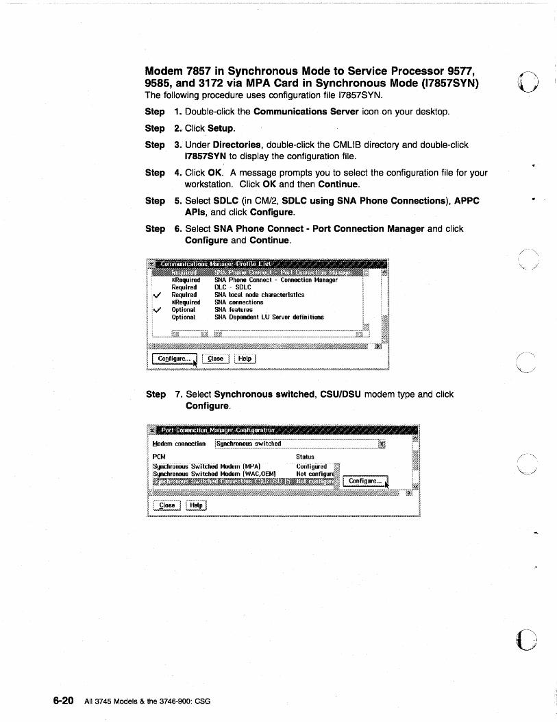
Modem 7857 in Synchronous Mode to Service Processor 9577, 9585, and 3172 via MPA Card in Synchronous Mode (17857SYN) The following procedure uses configuration file 17857SYN.
Step 1. Double-click the Communications Server icon on your desktop.
Step 2. Click Setup.
Step 3. Under Directories, double-click the eMUS directory and double-click 17857SYN to display the configuration file.
Step 4. Click OK. A message prompts you to select the configuration file for your workstation. Click OK and then Continue.
Step 5. Select SDLC (in CM/2, SDLC using SNA Phone Connections), APPC APls, and click Configure.
Step 6. Select SNA Phone Connect - Port Connection Manager and click Configure and Continue.
SMA local node characteristics SMA connections SMA features SNA Dependent LU Server definitions
Step 7. Select Synchronous switched, CSU/DSU modem type and click Configure.
6-20 Atl3745 Models & the 3746-900: eSG
o
o

o
o
c
o
Step 8. Enter theMPA number in the Port name field, the number of your modem in the Local phone number field, click OK and Close.
Parmneters for Synchronous SWitched MBdem lMPAJ ' /
I Edit the parameters as needed.
Modem connection type
Port name
Accept Incoming calls
Local phone number
Encoding scheme
i·.~M~ct.!~~~·~·········'"
r~PAO'''''''''''''''''''''''''''l
r~~''''''''''''''''''''''''''''''''''':
Step 9. Select SNA Phone Connect - Connection Manager and click Configure.
Step 10. Select SP123456 and click Change.
Note: The directory entry file contains information on the target servtce processor that you are dialing. You can use SP123456 and rename it for your own purposes. If you· add a new workstation, you must create a new name.
Chapter 6. Modem-Attached Remote Workstation Configuration 6-21
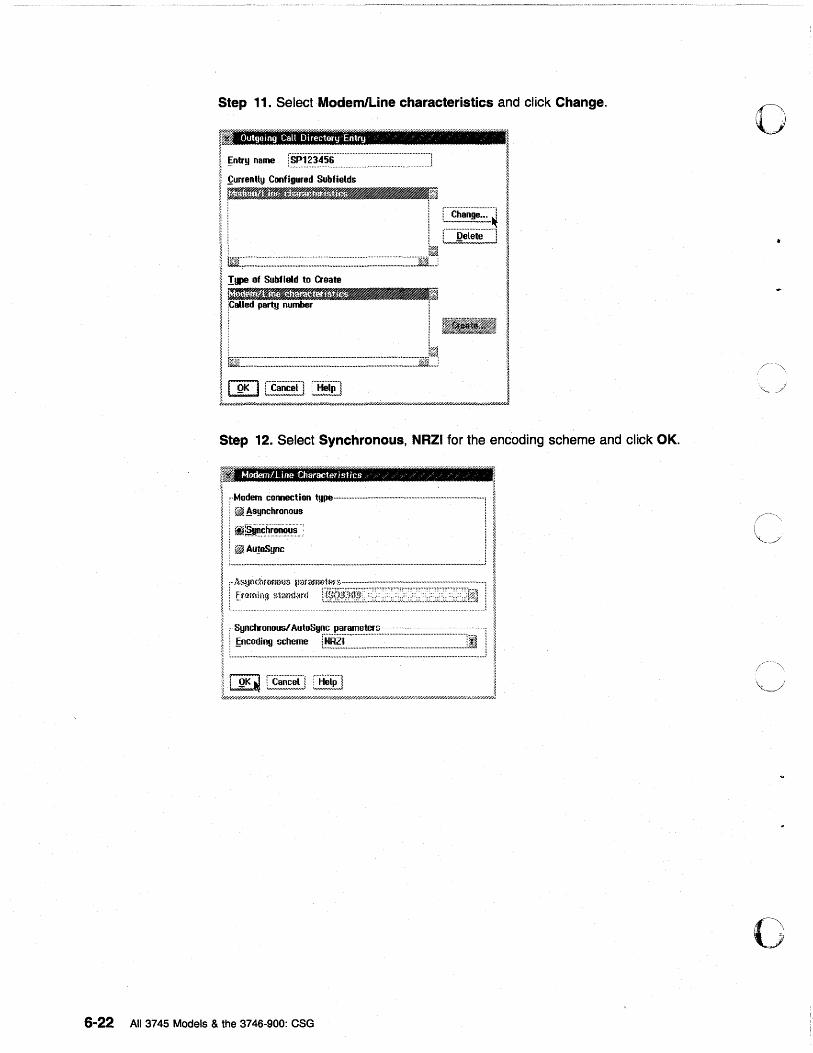
Step 11. Select Modem/Line characteristics and click Change.
. Outgoing CaU Directory Entry " c "
Step 12. Select Synchronous, NRZI for the encoding scheme and click OK.
ModemlLine Characteristit:s ,/ /;' ;/ / /
i::.,..=:=on --------------------.-... --l : ~~~.~r.~~.~_.: ! ~Au!oSync L,., .......... u_ ....................... -' ............. " ..................... ,.. ................ ,. ........................................................................ ,. ............................... ,.. .......... _ .. _ ... ~
, .. AS!..tn~:hfl)fIl)~I~) ~lar'~~lt~1~f~; ........................ _ ............................................................... ,
; ff~mlng ~>1and.:ml ! ........ :
, Synchronous! AutoSync parameters'" . . . ................. .... ".
i ~ncoding scheme [~~~:C:::::::::::::::::::::::::~:~::::::::::::::~:::~:~::~:::~~:::::::::::~::]I L ................................................................................. ,. ............................................................... " .................. ;
6-22 All 3745 Models & the 3746-900: eSG
o
c
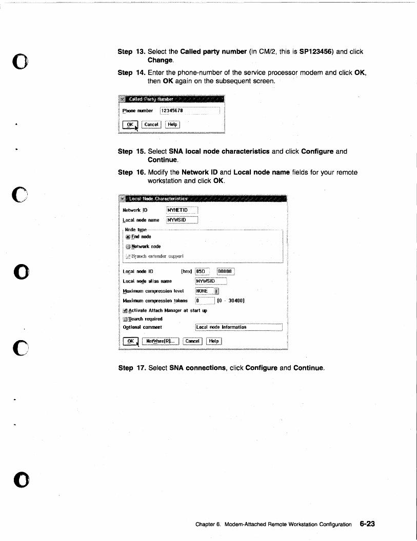
o
c
o
o
o
Step 13. Select the Called party number (in CM/2, this is SP123456) and click Change.
Step 14. Enter the phone-number of the service processor modem and click OK, then OK again on the subsequent screen.
Called Ptlrty Ntlllber c' r ~
I ~hone number [j2345678 .
IlllK~~1 ~I I ~.u/////////////////////////////////////u/////////.u////////////.I.~F//.l.W////////////////////<;';;'d///////////////////////.4~~1
Step 15. Select SNA local node characteristics and click Configure and Continue.
Step 16. Modify the Network 10 and Local node name fields for your remote workstation and click OK.
lit I Network 1D ;. : t.4.X~~!.I.I? ........... , ~ !:ocal node name ~ ~ i·Node t!Jpe
~ : iiJ !;nd node
I. i fu'ffi ~etwork node
I : iii: dr~HCh (~l<hmlkf {;upP(ld
; Lo~al node 10 ;:
~ local ~e alias name
I Maxinmm compression level
I Ivtaxinmm compression !okens ~
j"niiii"oo"'l :,. ............ UI#UJ
r~.~~:~.~::::::::::::J r~.~.~r:::J1
............................ __ .................. .
I ~
1'0.... .. ....... J 10 - 30400)
~ ~~ ~cti yate Attach Manager at start up
I :~ §earch required
I O.l!tional comment
~
LL"::",lE~f~!~i~~!=2""f~~~L~E~~/bil",M""",k,,kMMkbW///////,»,w//,,/.W/.W/hW/,W/.WJ Step 17. Select SNA connections, click Configure and Continue.
Chapter 6. Modem-Attached Remote Workstation Configuration 6-23
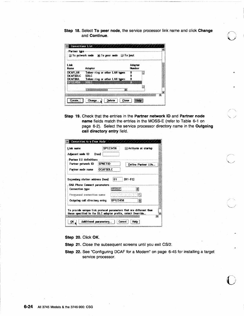
Step 18. Select To peer node, the service processor link name and click Change and Continue.
Gllnnecl!ons tAst "~/" / ~ /, /":f" z" in
I :·Pc.tner t!JIe·· ...................................... . ............................................................................................. .1~1 I i-~-~~:-'::~-~---~~:~~:~--~~~~----------------ll ! Link Adapter :I~ ~ Name Adapter Number il~ > " •••••••••••••••••••••••••••••••••••••••••••••••••••••••••••••••••••••••••••••••••••••••••••••••••••••••••••••••••••••••••••••••••••••••••••••••••••••••••• , .. ;x ,~~ ~ iOCAFLAN Token-ring or other LAN types 0 l~ il~ ~ :OCAFSOLC SOLC o· !~~ ~ iOCAFSNA Token-rinl or other L~.~ ... ~s 0 1~~ I. ~iJj'Jl~~1JJ~ • P'lIIAta;, III ~ j l~ 1~~
I~ __ =~~;;~······J~I ~~J Step 19. Check t~at the entries in the Partner networ.k iD and Partner node
name fields match the entries in the MOSS-E (refer to Table 6-1 on page 6-2). Select the service processor directory name in the Outgoing call directory entry field.
in
I Lt....... jSP123456 !:mAt:t1~..., at ...... II ~ - ................................... i~~ ~ Adjacent node 10 (hex) L .............................. .1 i~1
I : Partner LU definitions- ... -.. ~-.- ...... ·.··.-·-.-.. --... ·-· .. ·.-·..--~.---·I.J~.~ ~ j Partner _network 10 !SPNET'iO .. · .............. ·· .. · . '1ffi1' ~ ~ ~n .................. m.u • .,.m •• m .... .J l Define Partner LUs ~;~~
,;:~,,; .. :: .... :i: .............................................. , L"';;;; .... "'''' ................................ ''''''::,: .... .;;:.·.:II ; Partner node name :.~.~.~~.~~.~ ............... j I~ ;~1 ..... -..................... --............ --.- .. --..... -.......... --------------------.-------... ·11 I I I Se~ondary station address (hex) fi1'l .. · ...... · .. · (Ol-fE) 'I~ I • I r~:~: ~=ct p .. ame .... _~~:-:-::.:.i-----------II i i t·l~~r~:~~"n(?n~ t~lnm:GUOn nam~~ ill
Il~~~:~:~~~~~~~~~~~~ _________ 11 a To provide unique link protocol parameters that are different than ~ ~
~j~~SlW~~~,;~-!-~-~-~~~-··-------------·--~~1
I [ .. ~~.~~ L~~~~~.!.~~~~~~~~.~,~!~!!i:,:~,] L,~,~~~,~,~J L~!!r] I 7/////////////////////////////////////////////////////////////////////////////////////////U//////////////fiW////U//////////////////U//d/////////////b/U////U//////U//////fi///hW///.4~W/////H
Step 20. Click OK.
Step 21. Close the subsequent screens until you exit CS/2.
Step 22. See "Configuring DCAF for a Modem" on page 6-45 for installing a target service processor.
6-24 All 3745 Models & the 3746·900: eSG
c
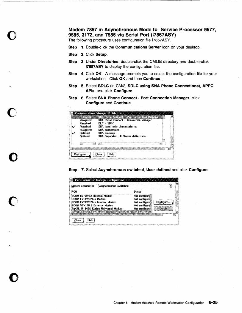
o
c
o
o
o
Modem 7857 in Asynchronous Mode to Service Processor 9577, 9585, 3172, and 7585 via Serial Port (17857 ASY) The following procedure uses configuration file 17857 ASY.
Step 1. Double-click the Communications Server icon on your desktop.
Step 2. Click Setup.
Step 3. Under Directories, double-click the CMUS directory and double-click 17857 ASY to display the configuration file.
Step 4. Click OK. A message prompts you to select the configuration file for your workstation. Click OK and then Continue.
Step 5. Select SOLC (in CM/2, SOLC using SNA Phone Connections), APPC APls, and click Configure.
Step 6. Select SNA Phone Connect - Port Connection Manager, click Configure and Continue.
Step 7. Select Asynchronous switched, User defined and click Configure.
Port C(lllllection ManagevC(jntigur~tfQR ;/ / " /;/ / / /;/ \ / ;/ ~)' / /" / /
Modem connection I.E~~~~~~~~~~~::.~.~~.!.~~:::::::.~::::.~::::::::::::::::::::~~~~~:::~:::~:~~~~~.~~~~:~~~~~~~~~~~~:::~::~~~~JI PCM
'EVrxVj2internaCModem EVFPV32bis Modem EVFPV32bis Internal Modem VFX 28.8 External Modem U-1496 Series Universal Modem
Chapter 6. Modem-Attached Remote Workstation Configuration 6-25
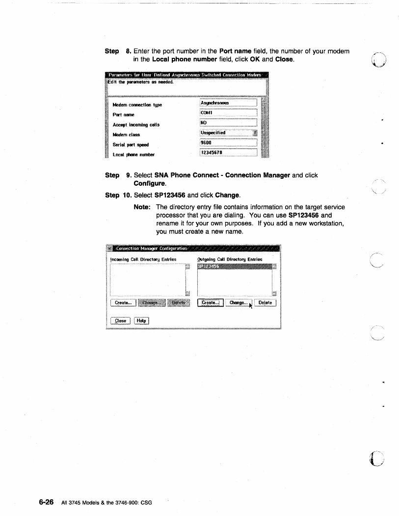
Step 8. Enter the port number in the Port name field, the number of your modem in the Local phone number field, click OK and Close. 0
Modem connection type
Port name
Accept incoming calls
Modem class
Serial port speed
local phone number
l~~~~~ ................................ . i'cOMl"·.-·········.-········· .. ·· .. · ...... ·· .. ····:··:·:::J ..................................................... u • ••••••••••••••••••
:.~9. .............................................................. ..l .~~.~.i'.(i.~.~'.'· .. •••••••••••••••••••••••••• u •••••••••••• n •••••••••••••••••••••••••••••• ':0
:9600 ! -........................................................................ ; :·12"i4·5ii·s .... ·· .... ····.-·················· ... ······l ............................. . .................... ;
Step 9. Select SNA Phone Connect - Connection Manager and click Configure.
Step 10. Select SP123456 and click Change.
Note: The directory entry file contains information on the target service processor that you are dialing. You can use SP123456 and rename it for your own purposes. If you add a new workstation, you must create a new name.
r ; ~ I ~ ~ ~ !ncomlng Call Directory Entries Qutgolng CaU Directory Entries I I ~,iI1~~ __ ~ I
I ~ :·I'i~iite::.! I ~:~ cJ I. ~ r.
} ~
L~!§~L.9~~!L_& ___ ~d~_d_J
6-26 All 3745 Models & the 3746-900: CSG
c
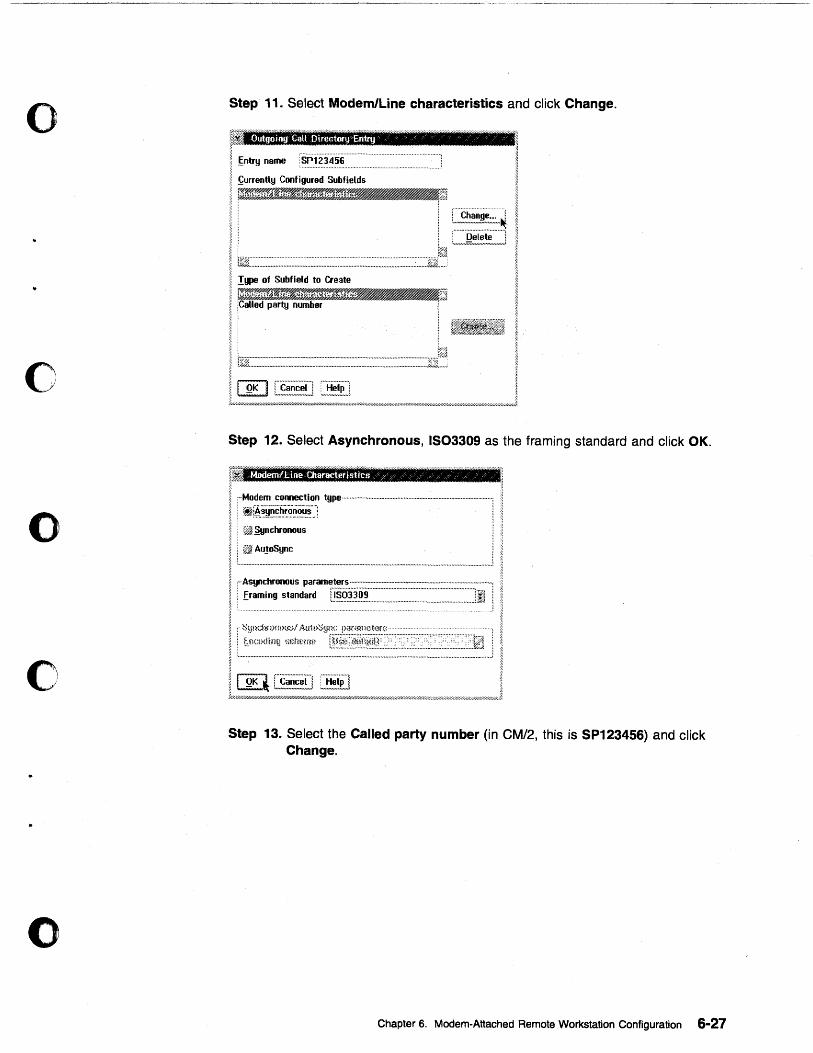
o
o
o
o
o
Step 11. Select Modem/Line characteristics and click Change.
Outgoing Call Oirectory~Eritry ~ / / / / /
I ~ntry name ·SP123456· ................................................ ]
I ~urrently Configured Subfields
; r~~-«~~~~e~~~~re:'~~f:fi ~ ~.w/##MJ$H»Mi--*U$Z)yH"'''')~''''#$~~~j;~},
I i :::,;.~~~~~~~~:.,,4 ~ • ,."''''!?,~,~!~~'''''J ~ ! .
11~£L:·,::·.:·.:·.::::·.::·.·.::·.·.:·.::::::::::::::: .... ::::: .. ::: ... ::::: .. ::.:: .. ::::::~.-.:::::.:::: .. :.:· .. :.:.:·.::::·.::·.::·.:·'-.Jji~!·
I ~
11%jL.-.~.-.-.-.-.-.-.-.-.-.-.-.-~.-.-.-.~.-.-.-.-.-.-.-.-.-.-.-.-.-.-.-.-.-.-~.-.-.-.-.-.-.-.-.. .-.-.-.-.-.-.-.-.-~.-.-.-.-.-.-.-.-.-.-.-.-.-.-.-.-.-.-.-.-.-.-.-.-.-.-.-.-.-.-.-.-.-.-.-.-.-.-.-.-.-.-.-'-'-'-J1jl:~j '1
II!!KI[~LJ~ I i"".I .... :i///''l"hW////////////////////////////////////////////////////''l"/'~'''~;·;';·''''h;'''»~Y ... /////h»Y/ ... Y//.tY/.'l;'''''ih-Yh:i/d/// ... Y// ...... h;.////.-y///,,;-'// ... ;t/h;t'/.~ ... Hi'///// ... ;.~r...h;~ ... /j~;.w ... J.J
Step 12. Select Asynchronous, IS03309 as the framing standard and click OK.
/Modem!l.:irn~ Characteristfcs ~)' )' '/" / /' / /
:··Modem connection t!lPe·················································· ..................................... " ... ".j
: ~fA.~·~.~~~r..~·~.~~~-J : ~ ~!JIlchronous
i ~Au.!oSync
I ~=~~~=i:i~~~~si= I :' ~t:,!:;:::i~l:~!)::~;~,~~:~0g[J~.-!~fr·~~~i~~fj1f:;?;::::;.::;;;.-::;l·.-::;;.-::;;;:-:.·;;::: .... .-::;;;.-::.; .. :::~j
t ............................................................................................................................................................... J ~
! W :c~;;c;;li rH;;jpl l t;.:w////:///////./7//d/:;~:~;::::/Uh':;;::::;~HY///H/h/;~;y)///U//H);;(//h7/h~:ij;-/./7h;-;-X.~~~~;i/#;~~WM~»»//h~;()/);~;i/h~h~YX.~J.~
Step 13. Select the Called party number (in CM/2, this is SP123456) and click Change.
Chapter 6. Modem-Attached Remote Workstation Configuration 6-27
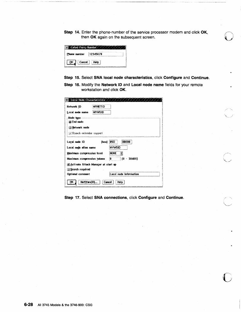
Step 14. Enter the phone-number of the service processor modem and click OK, then OK again on the subsequent screen.
i?! .~ ~ ;. I ~hone number 1_~-*~456i8----~
~~ Step 15. Select SNA local node characteristics, click Configure and Continue.
Step 16. Modify the Network 10 and Local node name fields for your remote workstation and click OK.
~ ~ Network!D
~ !:ocal node name ~
~ ;--Node tgpe-----
I : ~~nd node
I : ~ ,ttetwork node
~ >< Br{fll(;h (%hnnier ~mpp(Jft ~ ~ ....... n •• ,..u .... .,.,.." •• n ...... "".,. ..... ""._ •••••••• _,.., ....... " ... ,. • ., •••••• ,. •••• ,. ... ., .... ,. •• ,.." ... ,. ....... _ ....... ,. ........... __ • ., ............... ,. ...... ,.,. ......... ~
~ ~ Lo~al node ID ~ , LocaL no~e ~ias ~e
I Maximum compression level ~-
riiiiooo"'l ;. ............. ,. .. ,.;
j·Mvws·ii5·········_····: : ...................................... :
~ Maximum compression !okens t~ __ -- -- --j (0 - 30400) a.
~ ~ ~ct i vate Attach Manager at start up ~ ~ l~ §eardl required
I O~tional comment rf~~~~~.~:::~~:~:::.~~!~.~.~~.~:~.~~~~:::::::~:::::::::::::::::::::::::::::J
II!lK~~~[§J ~/////////////////////////////////////////////////////////////.t.:W/////////;r/////Q///////////////W///////I'/.'l'///;Wk///////k////u7////uF'//////Q////////////////////fiW////////.7//d,,::w//kr///////);
Step 17. Select SNA connections, click Configure and Continue.
6-28 All 3745 MOdels & the 3746-900: CSG
o
(~-~.'-
~j
u·-.'''.···· I •
'I
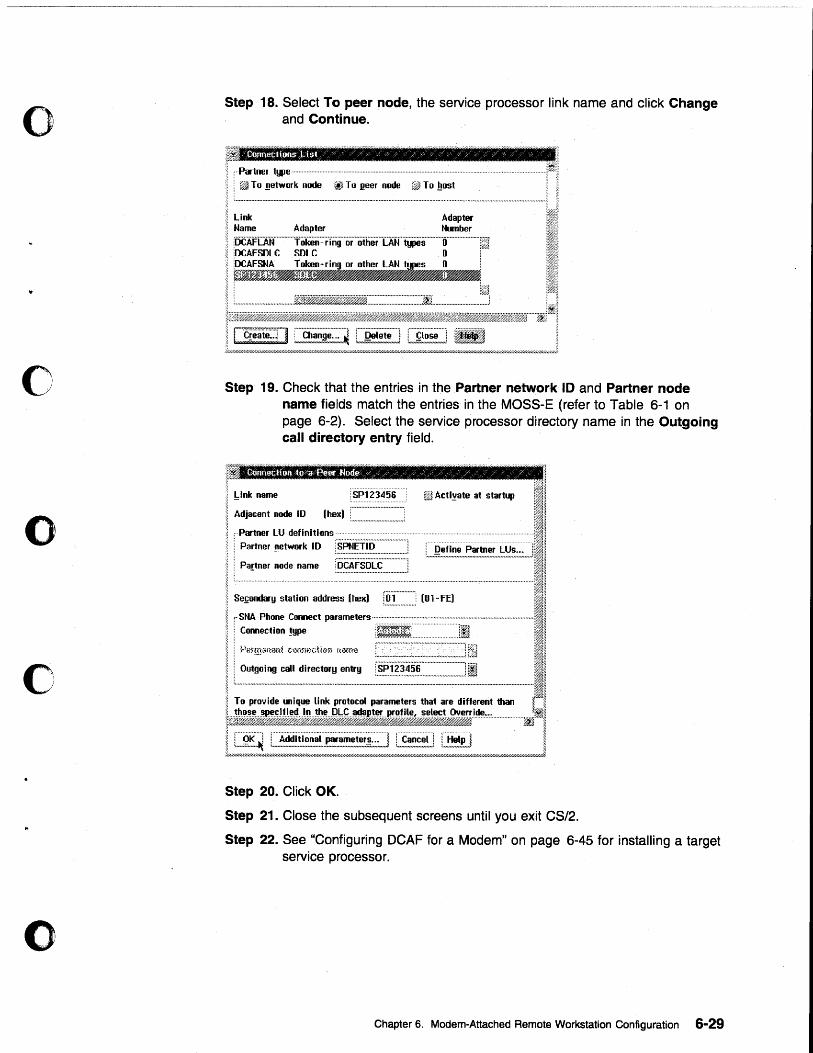
o
o
o
o
o
Step 18. Select To peer node, the service processor link name and click Change and Continue.
j " Partner type ................................................................................................................. ·························I~~
j ! ... ~ .. ~.~ ... ~:~:.~.~~ ... ~.~ ........ ~~.~~ .. ~.~.~.~ ... :~: ....... :~ .. ~~ .. =.:~ ......................................................... J I
~ .~~~//////////b//.4'/.d////H////.4~X.7//////h~/4 .. /.4r//LiW//////.4//.4r.4wH.i'//////.4w//////d.4'l"//.uu//..;:r..:l.4~///h///////.u/////////.4w////////...w//////.I.'l'////////U.fi//#hWfi/h~ .. h'l&/4:/.J
Step 19. Check that the entries in the Partner network 10 and Partner node name fields "match the entries in the MOSS-E (refer to Table 6-1 on page 6-2). Select the service processor directory name in the Outgoing call directory entry field.
r.l. ;. 1
j =:: ~~n't,~7" ~_~~~l ".WAct,Y.w.t .• s~ ••••.••.•. ii"I.I.!:. Partner !Ietwork ID ·sFitiEiiii····_········_···j Z;F : ~~n., oode:::e_~E~~~~~~~:~II!
I Sefondary station address (hex) L~.~ ............. ! [Ol-FE) :Ij
i c;;~~;;~~;~:~:::~::JI ~ To provide uniq~ link protocol parameters that are different than ~%iJ.1
l~j.~J~»~j~~~l~~$;~·'·~·"~·,····················~~1 i L.~~.~ I ..... ~~.~~!~~!"'~.~.~!~!!~:.:.:.J L~!~~.!~...l L.~~~J I ;'///////6:y////////////////HI'/////////////////////Q'//////////////U/.W//////6W//d .. W///////////////////./////////d///////d///////////d/dd/6Wd/4W/6'l//////////////h/////////////////////J.
Step 20. Click OK.
Step 21. Close the subsequent screens until you exit CS/2.
Step 22. See "Configuring DCAF for a Modem" on page 6-45 for installing a target service processor.
Chapter 6. Modem-Attached Remote Workstation Configuration 6-29
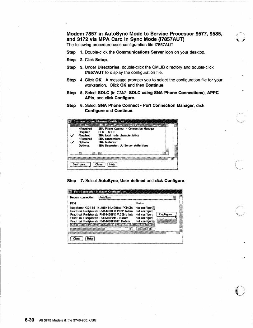
......... _. __ . __ ....... _-_ .. _. . . .----.--.... -.-- .. ---~ ... .
Modem 7857 in AutoSync Mode to Service Processor 9577, 9585, and 3172 via MPA Card in Sync Mode (17857AUT) The following procedure uses configuration file 17857AUT.
Step 1. Double-click the Communications Server icon on your desktop.
Step 2. Click Setup.
Step 3. Under Directories, double-click the CMUS directory and double-click 17857AUT to display the configuration fiJe.
Step 4. Click OK. A message prompts you to select the configuration file for your workstation. Click OK and then Continue.
Step 5. Select SDLC (in CM/2, SDLC using SNA Phone Connections), APPC APls, and click Configure.
Step 6. Select SNA Phone Connect - Port Connection Manager, click Configure and Continue.
V' SNA local node characteristics SNA connections
V SI~A features SNA Dependent LU Server definitions
Step 7. Select AutoSync, User defined and click Configure.
~ ~
P I
~ Modem connecti on r.~~!~~,~,~,~~:~~~::~~:~:~:~~~~::~~~~~~~~~~~:~~~~~~~~~~~~:~~~~~~~~~~~~~~~~~~~~~~~~~~~~~~~~~~~~~~~:~~~~~~~~~~~~~~~~~~~~~~~~~~~~~~~~~~~J·I I~I I PCM Status i 1
I fMegaher'tz"xJ2l~f4"'f4)fjjoTl'4)tO·jjbps·"PCMCfA"·"'Noi"coofigur~i III
t.i~~~~;~~::,=~~=L_=i~e-__ ~_11 iKffi._~~.~ii*j}%K@i@MBiillf1tJMfff.£@Jif~Jffi_'1¥ ... gi%}~J.W ~JJ ~
I, C~l~] [B~i.] I Jkw,///.I/////////////I'///I'/, .... /////////////////////,////hY///.I/.I////i'/hW////////////////h»..-... Y////hYh;.;-.... ;,;,;.y/////,;-'/.WHi'///h;,;,r.r////////////////////hW////I'/.I//h:'~////;'Q///hW////UhW/////////////////////////h7////n1
6-30 All 3745 Models & the 3746-900: CSG
o
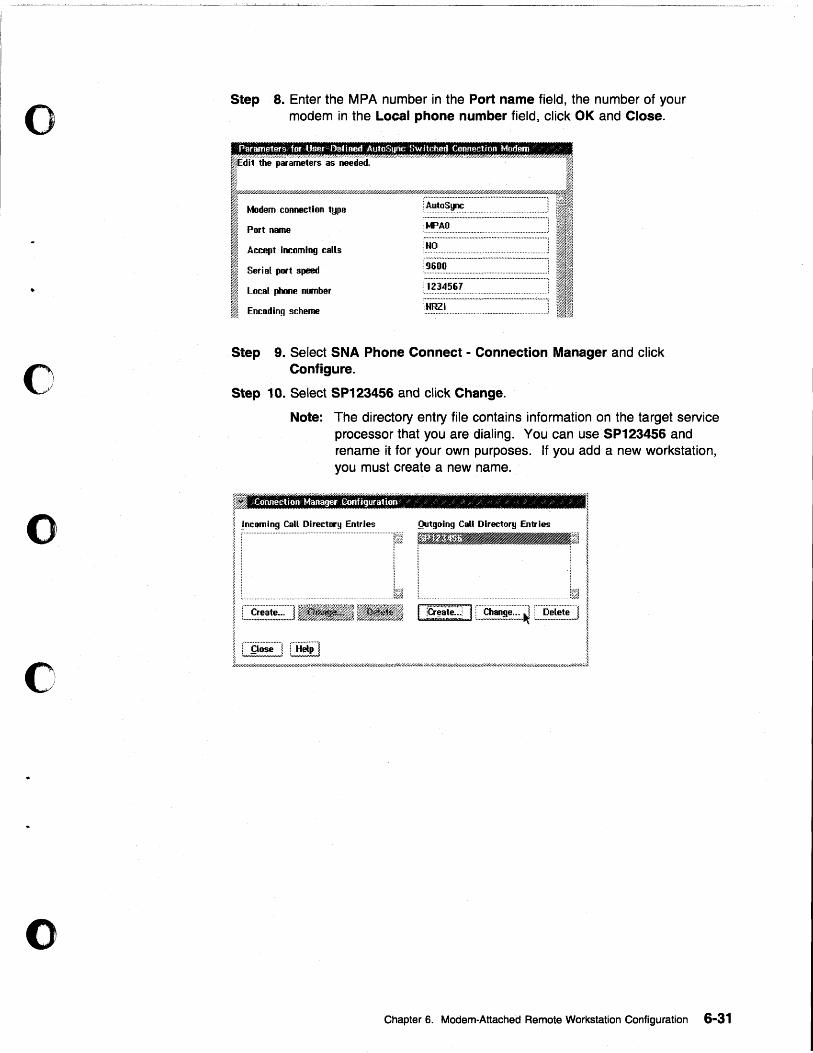
o
o
o
c
()
Step 8. Enter the MPA number in the Port name field, the number of your modem in the Local phone number field, click OK and Close .
Modem connection type
Port name
Accept incoming calls
Seri 81 port speed
Local phone number
Encoding scheme
••••••••••••••••••••••••••••••••••••••••••••••••• ,.#0 ••••• ,. •••••••••••• ,. •••••
l~.~~~~~. . .......................... . : ••• .,,. ... ,. •••••••••••• ,. ...... ~ ....... u ••• ,.,.,. ........................... :
'K>AO •• - ••••••••••••••••••••••••••••••••••••••••••••• - ••••• •••••••••••••••••• _.j
n •••••••••••••••••••••••••••••••••••••••••••••••••••••••••••••••••••••••••••••
!HO ............................... . ; •••••• ,. ••• #1.,.., ................... ,. • .,.,. •• " ••• ,.., ................... on;
9600 .........................................
1234561
HIll I
Step 9. Select SNA Phone Connect - Connection Manager and click Configure.
Step 10. Select SP123456 and click Change.
i0
I
Note: The directory entry file contains information on the target service processor that you are dialing. You can use SP123456 and rename it for your own purposes. If you add a new workstation, you must create a new name.
J ~ incoming Call Directory Entries Qutgolng Call Director!! Entries 1 ~ iftl W"J.m~- ~~ t
i! I II .. : .. ~ ~ i~"ie~~I~~··~1 ,. ~
I C~l~~~] [~~!] I ~/,r////.I///////////////////////4.,./////H/////////////////////fi/////fiY/////////////////////////~l'//fi//////HW.4W///..W///////.4rkhru////fiY///////.'iw////////////p7lY///////fifi'';-;7//.lfir////fihF//fil'///////4J.
Chapter 6. Modem-Attached Remote Workstation Configuration 6-31
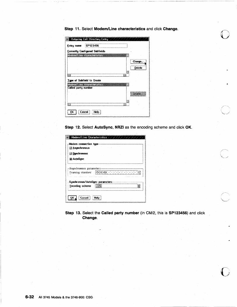
6-32
Step 11. Select Modem/Line characteristics and click Change.
Outgoing CaU Directory Entry 'l' "
~ntry name r~~.1.·.?~·~.~·~·.··············· .......................................... J
~urrently Configured Subfields ~1111 III':::.~ [~5!i!~~~~~
C"Q~l;t;"]
~ ..... :~ ..... ~ ....... :~ ... :::: .... ::: .. ~.: ............. : ... ~: ... : ...... : ...... : .... :.: ................. : .. : .... : .......... ::.:.: .. : ..... : ... ::.:.:.: .. : ..... : ...... :: ... :.:~.:'ffi.:
Step 12. Select AutoSync, NRZI as the encoding scheme and click OK.
fi Modemltille Characteristics "/" / / /';/ /', / /
[ .. Modem connection type·· .. ··· ...... · .. ·· .... · .. · .... · .... · .. · .. , .. ···· .... ·· .... ·· .. · .. · .. ·· .. · .......... · .. ·· .. · .... 1 . ~ ~synchronous 1
~~chronous
.1
I I ~
~ .. ,. ... ,. .... -"'-" ....................... " ............. -..... ., ..... ., ...•. ",.,. .... ,. .. ,.,.,..,. ... ,.,. ...... ,. ................................................. : ~
~. f .. As.~Jl,~:I<rI~Il)~}~> ~}()rarm?ll*~~; ...... · .......... · .. · .. · .... · .. · .................. · .... · .... .-...... · ........ · ........ · .. 1
. t·,,,mi.'il "",,,',"" ..... ... ..' ! f' ~~:i:o::~Syf~jI~~=:~~~=~~~~~~~ .. ~~~~~~~~~~~~~~~~~~~~~~~~~~~~~~~~~~~~~~~~~~~~~~jl····· ] , I--~:~-;;~~~~~;;-=~-------------------------.! I t~~'7.-;W///H7//////7///;;:;::;;;;;;;;;:WI7;;;;;:;::;//////&w//////hW/..1-Wu7u/.i:.W..z.W//u,;wj////hW/h~'WuYu.iy//.1/////,W/n7hW//////1
Step 13. Select the Called party number (in CM/2, this is SP123456) and click Change.
All 3745 Models & the 3746-900: CSG
o
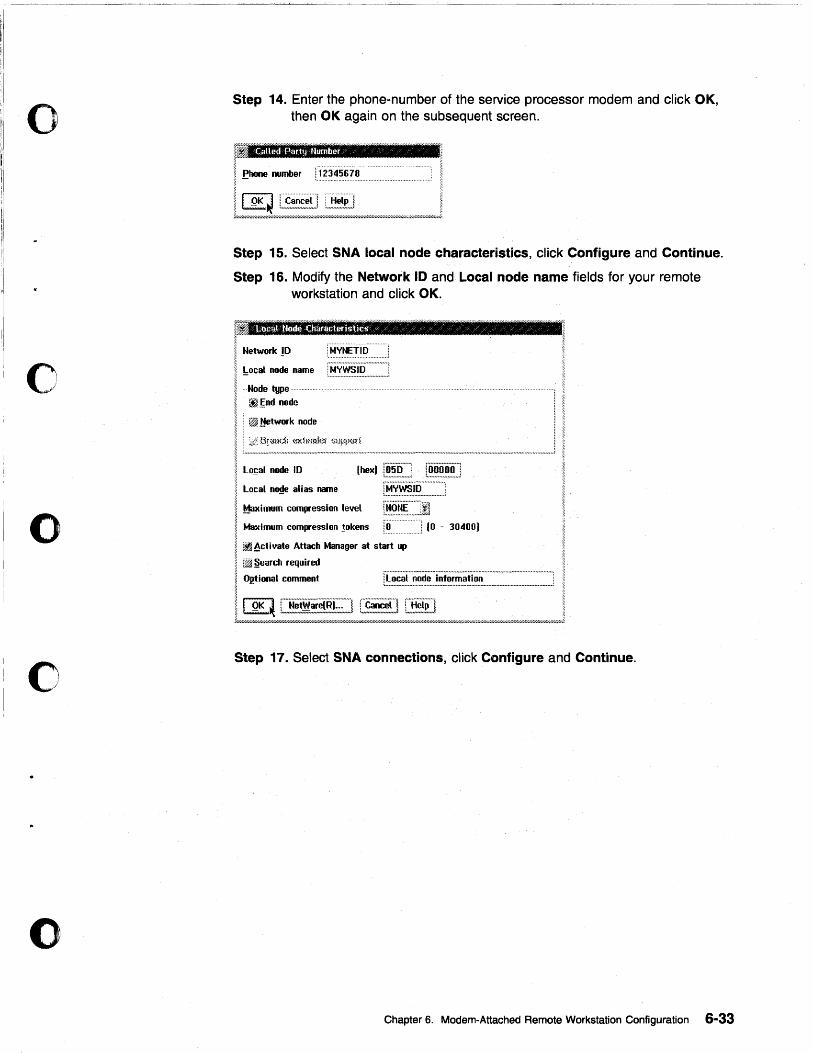
o
o
o
c
o
Step 14. Enter the phone-number of the service processor modem and click OK, then OK again on the subsequent screen.
, Called Party number " o
! I Phone number ff2345678 ~ -
Step 15. Select SNA local node characteristics, click Configure and Continue.
Step 16. Modify the Network 10 and Local node name fields for your remote workstation and click OK.
r: ~ I Network ID !MVtEiiii I !:ocal ~ name ;'Nyws'iri::':::::::::::'l ! ,Nod. type ~-----,
1 : ~~nd node
i : ~ Metwork node
! ~~~~:~~~~""-~-------------'--------' I Lo~al node ID [hex) [~,~!?:::::. r~~:~,~~J
Local RO!te alias name rB.,~~:~.~:::::::.·.·::::.·:i I Maximum compression level r~.~~.~::::::J1 I Maximum compression !okens !~ ...... 'J (0 - 30400) ~
~ ~~ctivate Attach Manager at start up
! :~ .§earch required
I Optional comment r.~~,~.~L~~~!::.!,~,!~,~.~.~.!:!.~~::::::::::::::~:::::.~::~:~:::::,~::::J
11Qt<4~~~ ! ~//////////////////////////////////////67///////Ul'////h-r///hYC///////////////.-r////////,f/////.I///////////.0-Y.lfiW//hW,I.I/.I///hF'///////d-w/ ..... /.;W/Uk'W//////."///////////,f//,f/////////////////////.d
Step 17. Select SNA connections, click Configure and Continue.
Chapter 6. Modem-Attached Remote Workstation Configuration 6-33
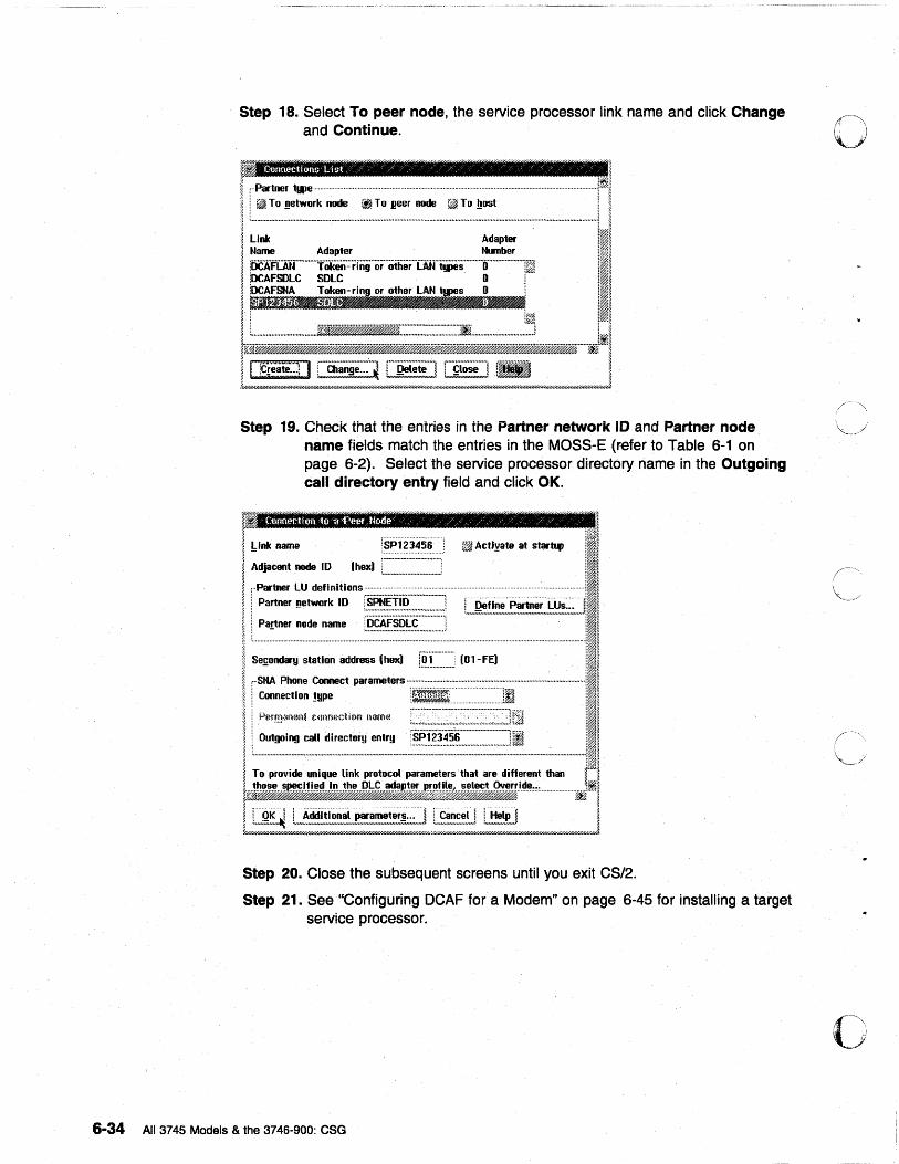
Step 18. Select To peer node, the service processor link name and click Change and Continue.
Step 19. Check that the entries in the Partner network 10 and Partner node name f1elds match the entries in the MOSS-E (refer to Table 6-1 on page 6-2). Select the service processor directory name in the Outgoing call directory entry field and click OK.
m 1
I ~ I !,Ink name rSPli3Jj-5i ~ Actlyate at star~ ;11 I Adjacent node ID I hex) C~~~~~~~~~~~~~~~~~~~~~~::~:] :11 I • ~ :-·Partner lU definitions ........ _.. . . :I@
11 Partner ~etwork ID r.~~~!I~:::~~~:.~~~~:~:=] f Define Partner lUs... ~I~ ~ : Partner node name rDCAFSDLC"··············l ...... ;;;; ........ m ........... m ..... m.mmm.m ... m.mJ:Ii. ~ ; , ............................................ ; 'I~ I L ................................................................................................................................................. ·············;I~ ~ _ ~i I Sefondary station address (helC) l.~ .. ~ ............ .! (Ol-FE) iii I • I i :':t~: ~::=t param.t.rs-iiii==-:-:::~ji-------------ill ~ i P.~rm;m(m~ c@miction !~3€'fIe il~
I L~_~,~~~~_:~_:~_i~~~~ _______ ~11 ~ To provide unique link protocol parameters that are different than fi1~ ,%~=~~JltibJl¥i~~~J.!t.~~~:··················· < :
~ . ;.
~ 1 OK i : Additional parameters... ~ ~ Cancel i : Help ! ~ ~ ' .. m-= .... ~ '.m ........ _ ............................... _ ........ ;;; .......... ~ , ...................... , : ................. ~ ~
~/////////.uu.Q////////////////////////////////////H/////d/.u/////////HH////H/////U/////////////.4~W.W.4'/////////////U///////////////////////////Q'///////.I/.(///4'////.I/////,'/////////;w////;~
Step 20. Close the subsequent screens until you exit CS/2.
Step 21. See "Configuring DCAF for a Modem" on page 6-45 for installing a target service processor.
6-34 All 3745 Models & the 3746-900: eSG
o
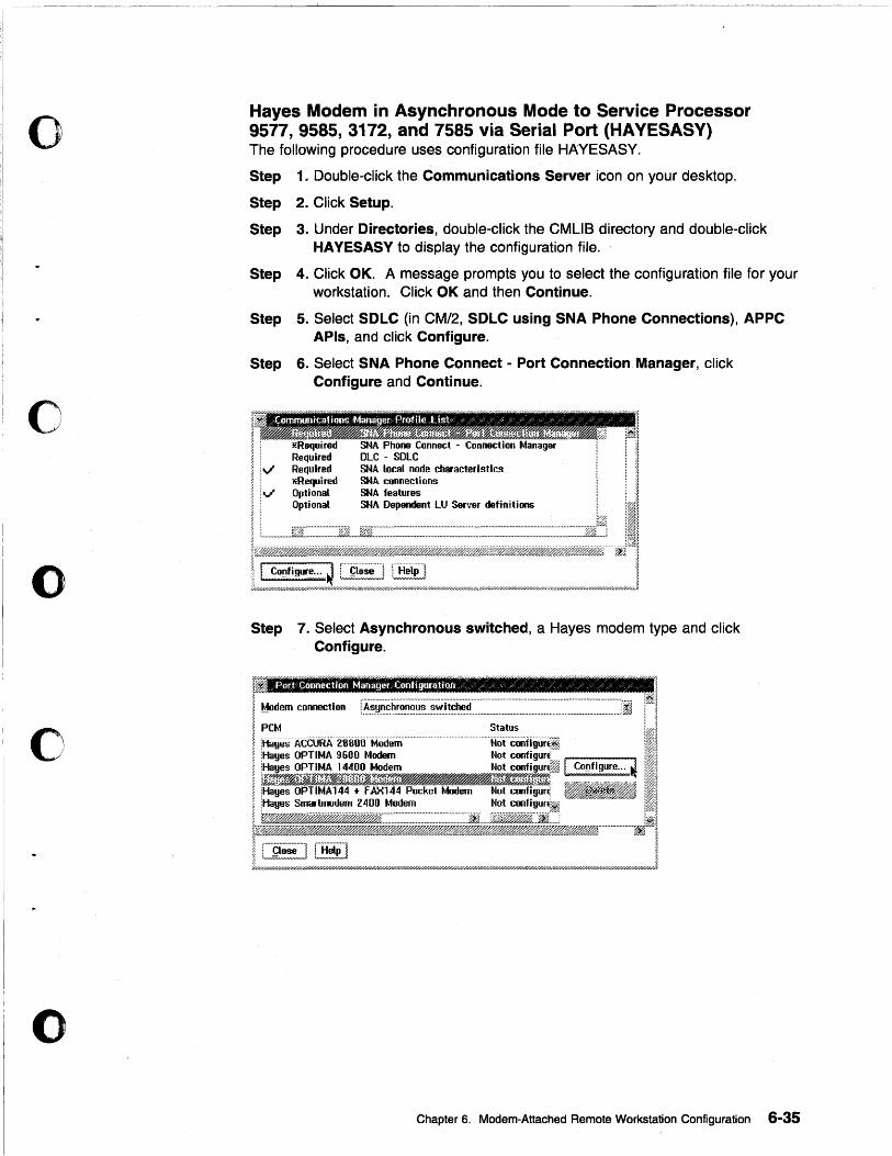
o
o
o
o
Hayes Modem in Asynchronous Mode to Service Processor 9577, 9585, 3172, and 7585 via Serial Port (HA YESASY) The following procedure uses configuration file HAYESASY.
Step 1. Double-click the Communications Server icon on your desktop.
Step 2. Click Setup.
Step 3. Under Directories, double-click the CMUB directory and double-click HA YESASY to display the configuration file.
Step 4. Click OK. A message prompts you to select the configuration file for your workstation. Click OK and then Continue.
Step 5. Select SDLC (in CM/2, SDLC using SNA Phone Connections), APPC APls, and click Configure.
Step 6. Select SNA Phone Connect - Port Connection Manager, click Configure and Continue.
SMA local node characteristics SMA connections SMA features SNA Dependent LU Server definitions
Step 7. Select Asynchronous switched, a Hayes modem type and click Configure.
~ 1
I Modem connection [~~~~~~~~~~~~~~.~.~.~.!~.~~~~~~~~~~~~~~~~'~~~~~~~~.~~~~~~~~~~~~~~~~~~~~~~~~~~~~~~~~~~~~~~~~~~~~~~~~~~~~~~~~~JI I~J I.' ;CM Status 1 ~ ;~1 I ;HayesACCURAZ0800Modem Not GOOf~gurii !I~ ~ iHayes OPTIMA 9600 Modem Not conhgurE~/" . ;~j ~ iHayes OPTIMA 14400 Modem Not configur~~ [ COflflgure ... J ;~~ ~ WP(?'(1'{r@~Yf.li'~rr.r:~Jrrirfrt~~r~~~~rtrf~rrff'(ff: - P{ 'W~ ;. ~H$.;..:I#J~~~k.&H"?~j»'H~.b/#~/,H#~/#»;'~_~..w;'»$..b#}~A;~7~ .,~ ~"'" .. "~~ ... ,, """h""~ i~~ ~ iHayes OPTIMA144 .. FAX144 Pocket Modem Not configur( ~ il~ ~ jli<lyes Smartmodem 2400 Modem Not configunil !~~
t~:~~~~I:~""""""""""~~1 ~ ___ ~_~ ___ d ___ J
Chapter 6. Modem-Attached Remote Workstation Configuration 6-35
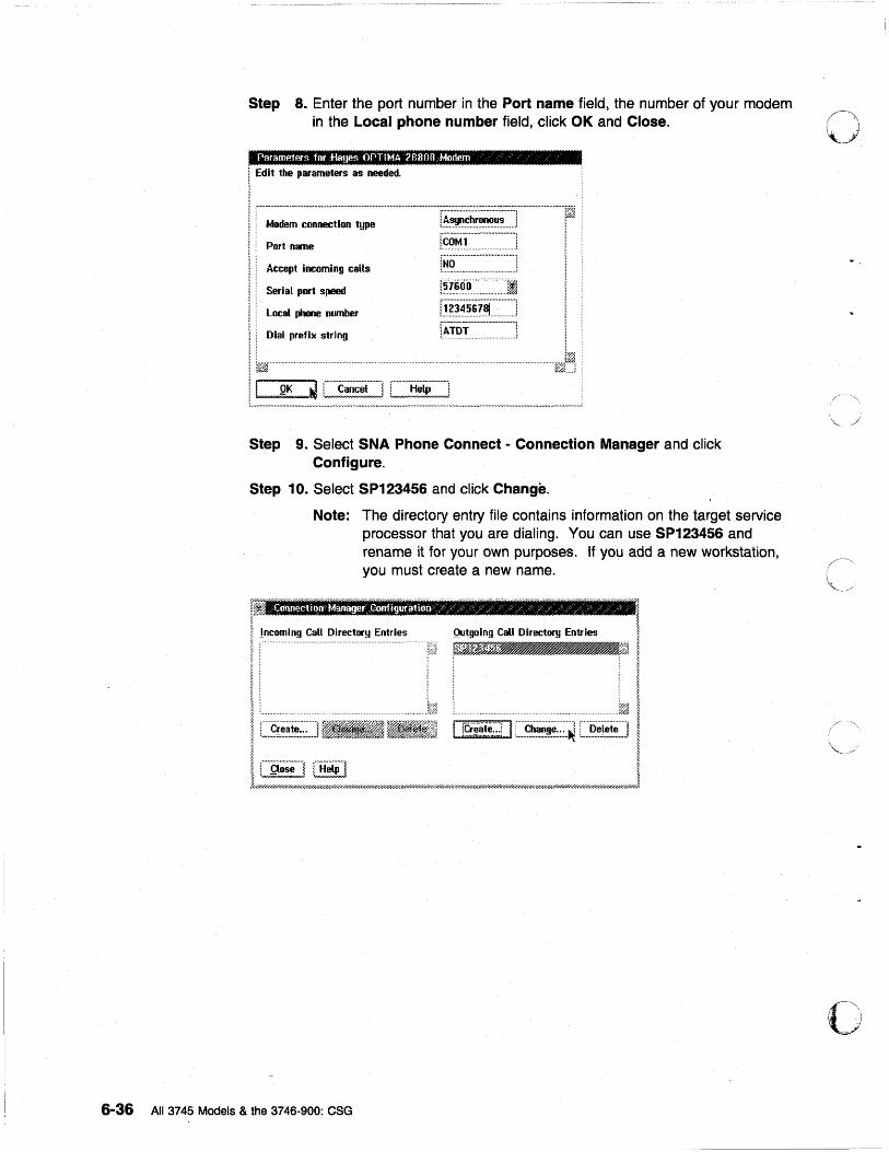
Step 8. Enter the port number in the Port name field, the number of your modem in the Local phone number field, click OK and Close.
Parame1P.1"s for fiatjes OPTIMA 28803 Modem /"
! Ed it the parameters as needed.
: ........ ,. ................................. ~ l.~~~~~~ .... .J r~.OM·l .. ···· .. ····~·····.~~·]
[~.~::::::::::::::::::::::::::::::::] [~.'16ri·O ···.···· .... ···.· .. ··]1
! Local phone number IX?:~.~:~.~:!.:~::::::::::::] I Dial prefix string [~Ti)T··· .... ~·::~···~:··:] I~~ ......................................... , ........................................................................................................... ~~~, . j
l!_~_J~ __ ~ _____ ~ Step 9. Select SNA Phone Connect - Connection Manager and click
Configure.
Step 10. Select SP123456 and click Change.
Note: The directory entry file contains information on the target service processor that you are dialing. You can use SP123456 and rename it for your own purposes. If you add a new workstation, you must create a new name.
o
i !ncomlng Call Directory Entries Qutgolng Call Dlrect.IlI Entries I i "' , I. ~ ~
I :i:1 I >:;: •... : .... ::.~ .. ~ .. ~C .. ~~! ... ~ .. :a .. ~:!.:~ ....... : ..... :1 ii:1 I ! _____ ......i I fti~e::.! I ~ ~iet;] I I C]X~,!!:] CE~~] I j//////////////////U'U"/////////////////////////////////////////////////////////////////1////////////////////61'/////////////////////////////////////////////////0' ......... ////////////////////////////////////////////////////////j
6-36 All 3745 Models & the 3746-900: eSG
o
o
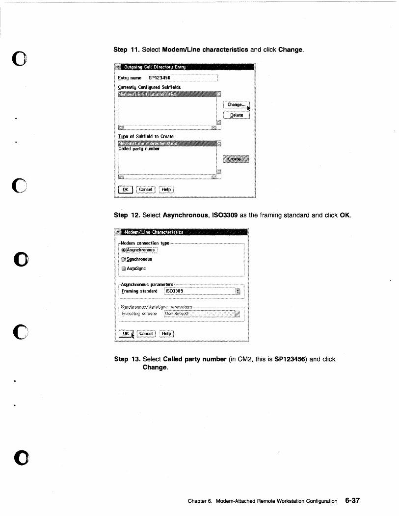
o
o
o
o
o
Step 11. Select Modem/Line characteristics and click Change.
. Outgoing Call Di rectory Entry
~ntry name
~urrently Configured Subfields
D"E6~.N'~%1 L~~~:~~~!~:.~~~
, : C~~9!.~!~!~~~] 1t2.::·.·.·.::::·.:::·.::::::·.::::::::·:.·.:·.:·.:·.:: .... ::: ... : ....... :.:.::: ... :::.:::: .. : .. :: .. : .... : .. :'.:::':.:::::'::.::'.::::'.:'.::'.:'.'j)~~!-; !!p! of Subfleld to Create
Step 12. Select Asynchronous, IS03309 as the framing standard and click OK.
Modem/t::ine "Characteristic,S "" /
,··Modem connection type··· .. ·· .. ··············································· .. ······ ... ··················· .. ·······1
! ~[A.~.~.~~~r..~.~.~~~J ! @f ~ynchronous
! @f Au!oSync
r" Asynchronous par8l1leters ............................................................. ······················· .. ····1
! framing standard IS03309 ;
Step 13. Select Called party number (in CM2, this is SP123456) and click Change.
Chapter 6. Modem-Attached Remote Workstation Configuration 6-37
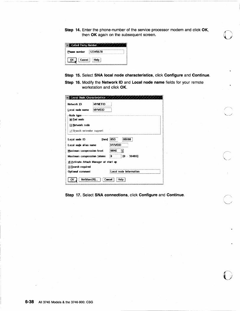
Step 14. Enter the phone-number of the service processor modem and click OK, then OK again on the subsequent screen.
;;;
~fi m Called fl.art1j HlJfIlber /
I p ........ number , ._"" l~~345618
IIQK~§G~ I ~//////////////////////////////////.u////////////////////////////////////////////////////////////////hW////.6-W//.l.w/U//hWh~
Step 15. Select SNA local node characteristics, click Configure and Continue.
Step 16. Modify the Network 10 and Local node name fields for your remote workstation and click OK.
f3 ~
I Network 10 i"MVNETio' ~ - . . ................ ~
~ !:ocal node name
I ;· •• ode type
~ : ~ !;nd node I i ~ !!etwork node
l! Hr,md. ~~Khnnh~f ~mpp(l,1 ~ ~ . ., . .,,. . .,.,., ......... .,.,. .. ., .. .,., ....... ,, ..... .,.,.., ...... ., .................... ., .................... " ... " ....................................................................... ., ........... .,;
I Lo~al node 10 [hexJ r~.~:~:~:::. [~~:~~~.~J ~
~ local no~e alias name >-
~ Maximum compression level ~-
~ Maximum compression !okens l~ .··h!IO - 30400)
I :~~cti ... ate Attach Manager at start up
@ @j~ §earth required
I O~tional comment ~
~ I QK ~ [~~!~~~!,~I~E;:] c~~n i::B~:~] ~ 7//////////////////////////////////////////////////////////////////6r//////.I///////////////////////////.~/.'l'//I'-:;'l'///////.W/////b7.1,4W//.W/////////unw///////////////////.Wfi7//////////////////////d
Step 17. Select SNA connections, click Configure and Continue.
6-38 All 3745 Models & the 3746-900: eSG
o
C' ,'. ,. \,
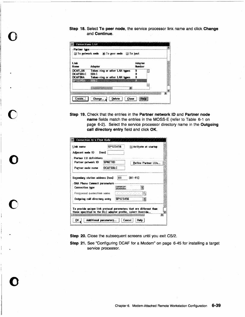
o
o
o
o
o
Step 18. Select To peer nodeJ the service processor link name and click Change and Continu$.
. Connections List
Step 19. Check that the entries in the Partner network 10 and Partner node name fields match the entries in the MOSS-E (refer to Table 6-1 on page 6-2). Select the service processor directory name in the Outgoing call directory entry field and click OK.
~ 1 I . I link name !SP"i"l345S' ~ Actl~ate at startup III ~ - , ........ .-...................... : ;I~
I Adjacent node ID Ihex) : ................................. 1 ..................... 1: .... :,.:.".:.:.1.;
~ (Partner LU definitions:::.. ... .-............ .-.................. , ..... ............. ..;!!; ~ : Partner !!etwork ID ~~~~~.~ ..................... : i Define Partner LUs... 1!~H ~ ••••••••••••••••••••••••••••••••••••••••• #0 •• : tU",;;;;"""",."#""",,,,,,.,,,,,.,,,,,,,,,,,,.,. •• ,,."n""""";~~~
~ . Partner node name .. ~.~.~~.~~.~ ............... ; :~j ~ ... . ... . ·11, ~ ,................... I@ ~ Se!;ondary station address (hex) [.~ .. ~ .............. (Ol-fE) I~
I :::: :::,,~,::~~~~~~~~~~------------I I, .• ;~~~-~~--=-~~-----I! ; .~J ~ To provide unique link protocol parameters that are different than [~~
ly;~i~»i~jJ.&JJ}~~·'·~~·~~=···················~~1 ~ : .. -.. -..... -.- .. ~ : ......... __ ............................................. -.- ... -.- ....... ~ r·····················~ : ................. ~ ~ ~ i OK 1 i Additional parameters ... ! i Cancel i i Help! a. ~ '''''=-''''~ , ....... "" ... _____ m .. m_m"' .. 'mmm'mm;;;."""mJ ' .. mm .. , ... ""." .. ' :m"m""m"~ ~ ~////HU////////////////u/////u////////////#/////u//////#///////H///////H//hW////U//////H/H/HU/U/U/U/U/A0W//////#/UhW//////$////////////////////////.IW///////////////////U]
Step 20. Close the subsequent screens until you exit CS/2.
Step 21. See "Configuring DCAF for a Modem" on page 6-45 for installing a target service processor.
Chapter 6. Modem-Attached Remote Workstation Configuration 6-39
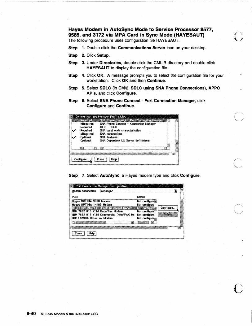
Hayes Modem in AutoSync Mode to Service Processor 9577, 9585, and 3172 via MPA Card in Sync Mode (HAYESAUT) The following procedure uses configuration file HAYESAUT.
Step 1. Double-click the Communications Server icon on your desktop.
Step 2. Click Setup.
Step 3. Under Directories, double-click the CMUS directory and double-click HAVESAUT to display the configuration file.
Step 4. Click OK. A message prompts you to select the configuration file for your workstation. Click OK and then Continue.
Step 5. Select SDLC (in CM/2, SDLC using SNA Phone Connections), APPC APls, and click Configure.
Step 6. Select SNA Phone Connect - Port Connection Manager, click Configure and Continue.
SI~A local node c"aracterlstlcs SNA connections SNA features SNA Dependent LU Server definitions
Co~figure ... ~ LI~!!!] L~~~]
Step 7. Select AutoSync, a Hayes modem type and click Configure.
Port Connection Manager ConfiguraUon / / / / / /
6-40 All 3745 Models & the 3746-900: CSG
o
o i ~
I
, ~.,i 'i
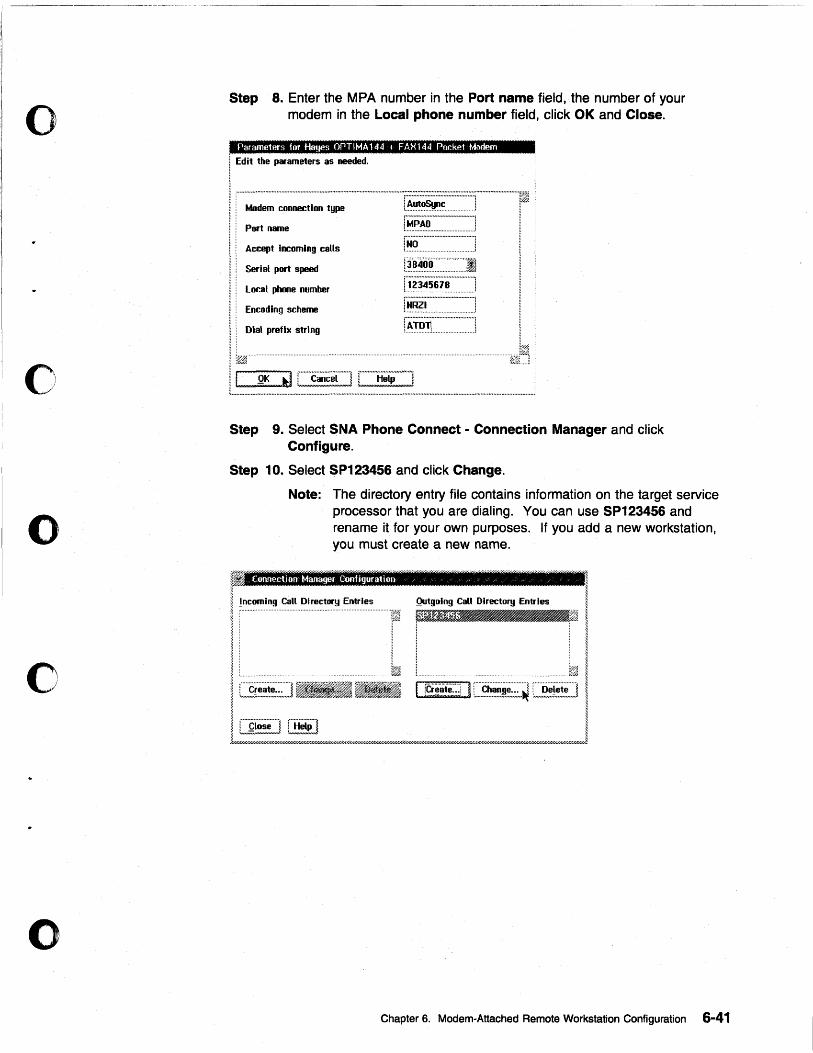
o
o
o
o
o
Step 8. Enter the MPA number in the Port name field, the number of your modem in the Local phone number field, click OK and Close.
Parameters for tifrnes OPTIMA144 I FAX144 Pocket Modem I Edit the param.- as needed,
Modem connection type
Port name
Accept Incoming calls
Serial port speed
Local phone number
Encoding scheme
Dial prefix string
[~.~.~.~:""':"::':.:"] rMPAO·-----·--··-·l t .................••...•................... ;
Step 9. Select SNA Phone Connect - Connection Manager and click Configure.
Step 10. Select SP123456 and click Change.
Note: The directory entry file contains information on the target service processor that you are dialing. You can use SP123456 and rename it for your own purposes. If you add a new workstation, you must create a new name.
r ~ I !ncomlng Call Directory Entries Qutgolng Call Directory Entries I ~ :~ i~fm~ _~ .~ I
~ : i
£.onnectiOfl t..taaager Configuration "
~
I =~ ~ ir~~e:'11~~~ I J/////////////////////////////////////////////////////////fiY/////D////////////////////////////////////////////////////////////bY/////////////////////.~/U////////////////////////////////////////////#/////////////////1
Chapter 6. Modem-Attached Remote Workstation Configuration 6-41
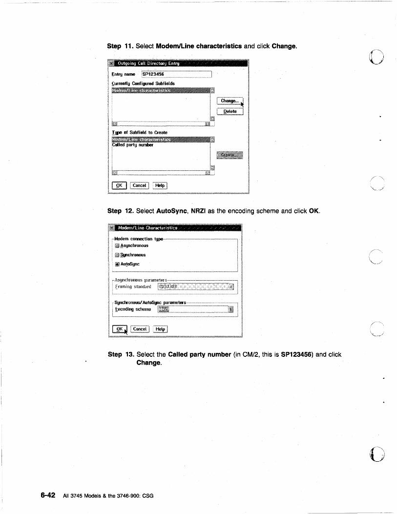
6-42
Step 11. Sel.ect Modem/Line characteristics and click Change.
Outgoing CaU Directory Entry
~ntry name
!;urrently Configured Subfields
~~~.$6'6ffJt~~ ~ ~:I:::~ [£~ii!~!~=~
: : []~~!=J !§j;j.:: .... ::: .. ::: .. ~.: .. ~:::.:.:.: .... ::~ ... : .. ::~.: .. :: .. ~:.:::~:.:.::.::.:::.::.:.:: .. :~ .. ::.:.:::::.: .... :: .... ::: .. :::::~ ..... ::::::: .. ]~~~: !IP! of Subf Ield to Create -, t§Jf:::::::::::::::::::::::::::::::.~::~~::::::::::::~::~:::::::::::::::::::::::::.~~~::::::::::::::::::::::::EJ~
>.
~ ~
~
I
I I I ~
I I ~
I QK J [~.~~~~.(J C~!~~] I t////////////hW//hy.l//////////// ..... //////////////////////////I"///h"-////'I'1'////////////////////.47/////////////////////////////.-1'////////////1'////////////////////////////////////1
Step 12. Select AutoSync, NRZI as the encoding scheme and click OK.
Modem/kine Characteristiu / % " ~ % ~ ~i I" ~ ; ,::"=~:on tgpe----------------------------I ! ;; ... : : ~ ~chronous *-
-c~~~ ________________ i I : .. i~~~.ll.~:hronml,> par<:!m.~t~~ " .......................................................................................... :: .. :: ~
~ : ff~m"llng ~>1<)f!d<mi "
I ~o;nKC~i::f.:; .. O.C.us/.S~ .. C~ .. h~.:u.~ .. rnl .. t.e,,:Os .. :: .. y .. Hn.[ .. k~~.~.!i~.~pr.~.~.~.:.:~::f====:==~=~=~~~=j' i:.::~.',',""', ..
l _____________ . _____________________________________ " ________________ .l i ~//U'/////://///#////Q';;:/Hd//////;,~/u~=:::.:;~/H'////&//////////.bw//////.¥./4~rU"///.¥//H///n7///////////H'#/////////$///d/6rH •. ~,j
Step 13. Select the Called party number (in CM/2, this is SP123456) and click Change.
All 3745 Models & the 3746-900: CSG
o
o
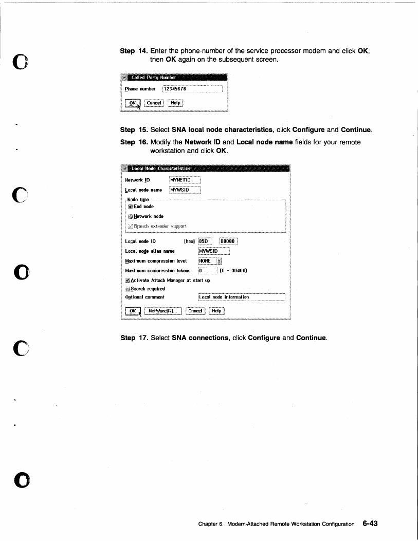
o
o
o
o
o
Step 14. Enter the phone-number of the service processor modem and click OK, then OK again on the subsequent screen.
Called Party HlJIl1ber ~
I Phone number 152345678 ~ -
t~1.~.J Step 15. Select SNA local node characteristics, click Configure and Continue.
Step 16. Modify the Network 10 and Local node name fields for your remote workstation and click OK.
~ " I Network!D !Mvt:ETio I local node name ~ -
..............
ltv1YWSID ~ ~ ,·Node tgpe·
: ~~nd node
: ~ !!etwork node
: >r:i drum;\< eKhmder ~'>lJppm1 I. l. ................................................................................................................................................................................................. .1
~ Local node ID [hexl l~.~.~...... rooii'oo'''l ~ -
~ local node alias name ~ -~ Ma)limum Gompression level ~
!.~.X~.~.~ .............. ': !.~g~.~ ........ ~~
~ Ma)llmum compression !okens (0 - 30400)
I ~~~ctivate Attach Manager at start up
1 :~ Sean;h required M ,~VJ_
I O~tional comment r.~~.~~.L~:~:~:~:::.~.~.!.~:~.~.~.~I~.~::::::::::::::::::::::::::::::::::::::::::::~
lL~~lf~~!~~~~L~~~_w~=. ___ ~_J Step 17. Select SNA connections, click Configure and Continue.
Chapter 6. Modem-Attached Remote Workstation Configuration 6-43
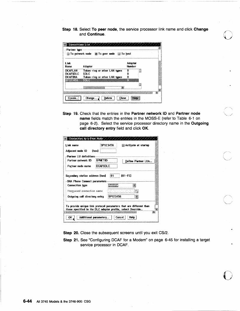
Step 18. Select To peer node, the service processor link name and click Change and Continue.
Step 19. Check that the entries in the Partner network iD and Partner node name fields match the entries in the MOSS-E (refer to Table 6-1 on page 6-2). Select the service processor directory name in the Outgoing call directory entry field and click OK.
P: ~ ~ ~
IUok name iSP123456!ii1 A<tl~.", at ...... II I ~djaCent node 10 (hex) f .... · .... · ... · .... ·· ..... ·•· .... ·i :I~ !,: L ................................ ! jl~ " i· Partner LU definitions· "'11
i Partner ~etwork ID ~.~~~i:~.~:::::::::::::::::] :.~ ... g!!.~~!"'~!!.~!~"'~~!:;.; .. J111 : Partner node name [.~.~.~.~.~~.~::::::::::::] ill
, ....................................................................... . ··· .............................................................. · .......... ····111 ~ Sefondary station address (hex) L~ .. ~ ............. ; (Ol-FE) :I~
Il;I~~;;~:~::::~~~~~~-:~:J1 !. To provide unique link protocol parameters that are different than ~ ~
k~~;);J~~jf~~.M&;;~·i.~4!.,,' ................. ~II
t!;;;~;~;/~",!;;;~;:;;;~i:;;;~f=;:~;;~;;;2,,//!;;;~:~~!i;;!",E~:i~;;!,//6W"",6"""""////"""""",,J Step 20. Close the subsequent screens until you exit CS/2.
Step 21. See "Configuring DCAF for a Modem" on page 6-45 for installing a target service processor in DCAF.
6-44 All 3745 Models & the 3746-900: eSG
o
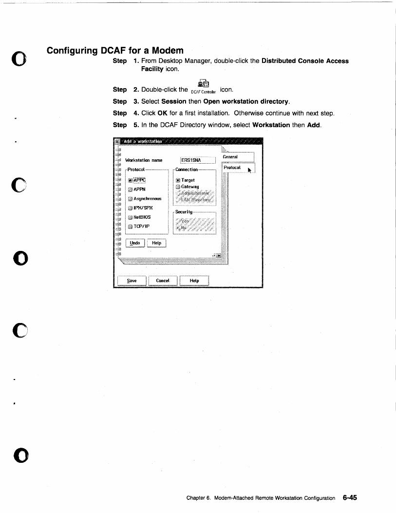
o
o
o
o
o
Configuring DCAF for a Modem Step 1. From Desktop Manager, double-click the Distributed Console Access
Facility icon.
r-... SI~
Step 2. Double-click the DC6.F Controller icon.
Step 3. Select Session then Open workstation directory.
Step 4. Click OK for a first installation. Otherwise continue with next step.
Step 5. In the DCAF Directory window, select Workstation then Add.
General ·:::1J1 Workstation name
r::;y.:z::::;;;:;:;::;::::;:;:;:;:;::;;::~:
%:ri1 :~:~~ :.:~
["Protocol· ... ··· ...................... ! rCoonection ...................... ! !I Protocol Jt.l
~::r$ ! i1j~.~'~ 1 (~Target ::~ra :::fJ1 i ~APPN ~~~~~ ,::~tJ1 ! ~ Asynchronous
~~~r~ l ~#~ IPX/SPX ~:~fh ! '/;m
,:~pA l.·. t~ NetB lOS [,Security ... , ........... :
··::f~ ;//#
i~¥~ ':::rj~ ~:~~ ·:::tJ ::1t~
! ~TCP/IP
§ave ........... ! r" Canc~i"""""! :"",,,,,,,,,,,,,,,,,,,,,,,,,,,,,,,,,,,,,,A.:,,,,,,,,,,,,,,,,,,,,, .. ,,,,,,,,,,""",,,,,,,!
Chapter 6. Modem-Attached Remote Workstation Configuration 6-45
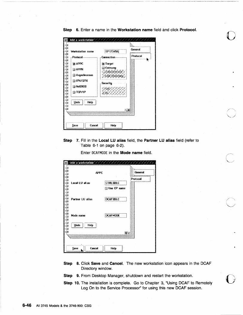
Step 6. Enter a name in the Workstation name field and click Protocol.
;f .............. · ........ ·· ...... ·· .................. · .. · .. ·· .. · .. · ...... · ...... ·· .. · .. · ...... · ...... · ........ · .......... · .. · .... 'tllL .................................. j
.;;~jjJ Workstation name i.~·~j#.~A~~J.. General
~::~ , .. Protocol ........ · ...... · ...... · .. · .... ·. '," Connect.' on· .... · .................. , rr~;;;:~;~::::::::::::::::!.! ~ , . -~--~
::?,; .. ~ i,,~ APPC ! '." T t : ::~::;; :.: ~J# i ~j. arge :.1 0ji Gale ..... a!l : ·~~~r~ . I~i
:,.: ;ii~APPN i:$A ';;f~ 1 ~ Asynchronous
~~~~ I, rf~ IPX/SPX ~!tf~ ;;;r~ 1 @j NetBIOS
;;;1(3. i" ~ TCPII P '~~~f~
r Securit!l" ! ,·,;'··· .. L··'.);{··· •.•. ,,,··· • ./···· .• ,""··,.,.,:····,.,.(··· ... x
i:1~ :.u •••• ,. ....... ., •••••••••••• ., ... ,..., •••• " ............. ;
Step 7. Fill in the Local LU alias field, the Partner LU alias field (refer to Table 6-1 on page 6-2).
Enter DCAFMODE in the Mode name field.
:,-:ltjj local lU alias
.:::~
i:~~ .;:-;~ Partner lU alias ~%r~ :::V,1 :::ltJ), :::T;j ::;i~ ,:::(~
:~:rA ':::7Ji ~:r~
Mode name
i'c·TRl·SDLc .... · .......... l ; .... ., ...................................... .: i1f~ Use CP name
; §ave l ! Cancel· ...... ·l 1"' .. " .... ·;:;;'[; .. "·"" ... 1 :"""""""""",,,,,,,,,,,. .,,J. :""",,,,,,,,,,,,,,,,,,,,,,,,,,,,,,,A ~,/",,,/-'/,,,/ ... /,...,/,,//,-',.,,,/,'-'/H/#/l
Step 8. Click Save and Cancel. The new workstation icon appears in the DCAF Directory window.
Step 9. From Desktop Manager, shutdown and restart the workstation.
Step 10. The installation is complete. Go to Chapter 3, "Using DCAF to Remotely Log On to the Service Processor" for using this new DCAF session.
6-46 All 3745 Models & the 3746-900: eSG
o
o
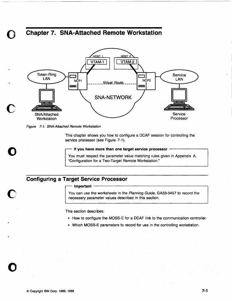
o Chapter 7. SNA-Attached Remote Workstation
o
o
o
SNAI Attached Workstation
_______ -'lirtlJ.alJ3Qutft _____ _
SNA-NETWORK
Service Processor
Figure 7-1. SNA-Attached Remote Workstation
This chapter shows you how to configure a DCAF session for controlling the service processor (see Figure 7-1).
If you have more than one target service processor ---------,
You must respect the parameter value matching rules given in Appendix A, "Configuration for a Two-Target Remote Workstation."
Configuring a Target Service Processor Important--------------------------------------------------~
You can use the worksheets in the Planning Guide, GA33-0457 to record the necessary parameter values described in this section.
This section describes:
• How to configure the MOSS-E for a DCAF link to the communication controller.
• Which MOSS-E parameters to record for use in the controlling workstation.
© Copyright IBM Corp. 1989, 1998 7-1
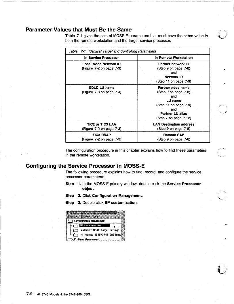
~ -. - ~ ~-- ~~--~~-~ .~.~ .~.~.~. ~ .~-- •. ~ _._-_. .-~. -~------.. -~-.-- --_. - ~
Parameter Values that Must Be the Same Table 7-1 gives the sets of MOSS-E parameters that must have the same value in both the remote workstation and the target service processor.
Table 7-1. Identical Target and Controlling Parameters
In Service Processor In Remote Workstation
Local Node Network ID Partner network 10 (Figure 7-2 on page 7-3) (Step 9 on page 7-8)
and Network ID
(Step 11 on page 7-9)
SDLC LU name Partner node name (Figure 7-3 on page 7-4) (Step 9 on page 7-8)
and LU name
(Step 11 on page 7-9) and
Partner LU alias (Step 7 on page 7-12)
TIC2 or TIC3 LAA LAN Destination address (Figure 7-2 on page 7-3) (Step 9 on page 7-8)
TIC3 RSAP Remote SAP (Figure 7-2 on page 7-3) (Step 9 on page 7-8)
The configuration procedure in this chapter explains how to find these parameters in the remote workstation.
Configuring the Service Processor in MOSS-E The following procedure explains how to find, record, and configure the service processor parameters:
Step 1. In the MOSS-E primary window, double click the Service Processor object.
Step 2. Click Configuration Management.
Step 3. Double click SP customization.
7-2 All 3745 Models & the 3746-900: CSG
o
c
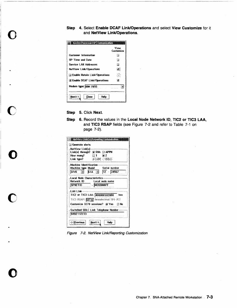
o
C·~ /
o
c
o
Step 4. Select Enable DCAF Link/Operations and select View Customize for it and NetView Link/Operations .
............................................................................. :.:: ... ::::::::::::::::::::::::::::::::::::::::: 1:::1 ............................ ..
Customer Information
SP Time and Date
Service LAt~ Addresses
NetView Link/Operations
[liM Enable Retain Link/Operations
View , Customize 'i
iii Enable OCAF Link/Operations :$
Modem type: II~fIotJ~~~.... . ............... L:ttl ••
r·····················j
1 Help 1
Step 5. Click Next.
Step 6. Record the values in the Local Node Network 10, TIC2 or TIC3 LAA, and TIC3 RSAP fields (see Figure 7-2 and refer to Table 7-1 on page 7-2).
iliJ Generate alerts
,..NetView Link(s)----------.-----, : Link( s) through? (t) SMA C) APPN : : How many? 1 ~~ 2 i Link type?>~qh\;
;··Machine Identification········································ ..... 1 Machine type Model Serial number
i 1~!~5... . Lif l~l~ .. L~ fi'2' -134567
~Local Node Characteristics----------, : Network 10 Local node name .
i 1:~~~?T:~:?::.:::.: .. :::_:.: .... : ... !:~~:7:~~:~:y:!::.::.:: ................................ . "LAN Link -.-.----.--...... --................. -...... -.-.................. -............. ,
1 Tle2 or TIC3 LAA: 1400000502080 . hex .
i TiO Pi:,AF~: HUttli h~~~a,h~dmat iH4·· :~C! • Customize 3270 sessions? @ Yes @ No
,Switched SOLC link Telephone Number .. -.. · .... · ... · .. :
! I0492112~3~ . :
f'«p~~-;'k;~;'l r~~-;;t>;'~ C"'H;tp"'''l .. ........ ... .... .. . ............. .
Figure 7-2. NetView Link/Reporting Customization
Chapter 7. SNA-Attached Remote Workstation 7-3
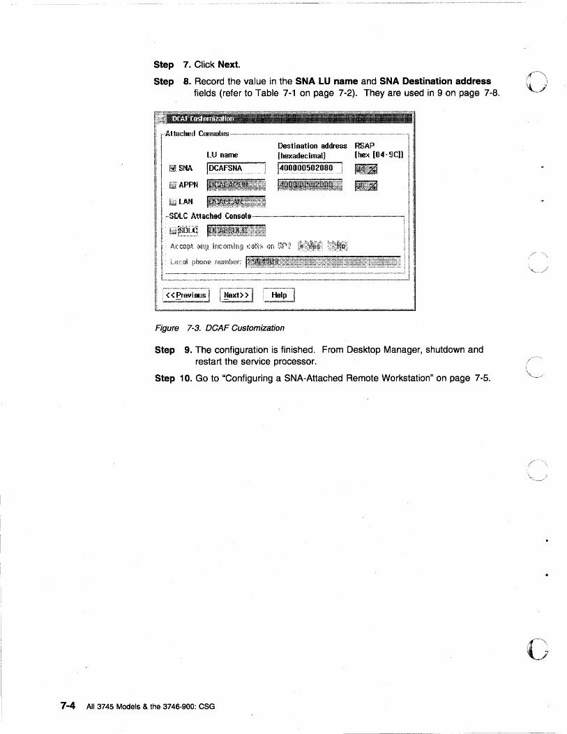
~~-----... """"""' .. '-" •...........•.•... - •....•.•.••..........
Step 7. Click Next.
Step 8. Record the value in the SNA LU name and SNA Destination address fields (refer to Table 7-1 on page 7-2). They are used in 9 on page 7-8.
~l!~l[I';'flrll:'tti'ff.ft:1:"·""'"''''''''''''''''''''''''''''''''''''''''''''"""".'''''''''''''''''''''.'''''''''''''''''''''''''<''''''''''''''''''''''''''''':.
I:: rAttached Consoles·············································· ...................................................... ·······················1 :.
i:: 1 Destination address RSAP ! :. 1:! l LU name (hexadecimal] (hex [1l4-9C]) ~:.
!::! ~. SNA f~~~~~.~.~. 4011000502080 : IHflli ! :
@J. APPN It.lilf~~l!rl~f:~~t~l~l I~l~[[i
Figure 7-3. DCAF Customization
Step 9. The configuration is finished. From Desktop Manager, shutdown and restart the service processor.
Step 10. Go to "Configuring a SNA-Attached Remote Workstation" on page 7-5.
7-4 All 3745 Models & the 3746-900: CSG
o
\,.
o
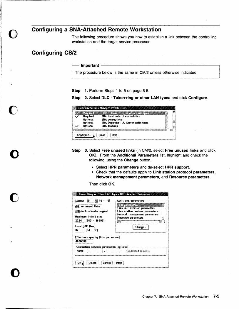
o
c
o
o
Configuring a SNA-Attached Remote Workstation The following procedure shows you how to establish a link between the controlling workstation and the target service processor.
Configuring CS/2
Important ------------------------------------------------~
The procedure below is the same in CM/2 unless otherwise indicated.
Step 1. Perform Steps 1 to 5 on page 5-5.
Step 2. Select OLC - Token-ring or other LAN types and click Configure.
t' 1 I I.~ I ~~ 6 \/ Required SNA local node characteristics r<1i i ~
I ! g~!::~:~ ~! ~:=~~~u Server definitions I ,~I 1~~~;;;~~_j2~.#t.~_%#~£tif~j~t~i_~' "~i~i, ,,~---...., ~ I Configure .... ~ 1 ~lose I 1 Help ~ I ~ . JIt' "uN;"'''' .... '"''',,,,,, ",,,,,_,,,, .. ,,,J J 7/////07///////////////.67///////////////////////////////////fil'////.I'fiW//////fi:-,//47///fi<"/////kl//////hJl///////////////////I///////.I.i'/.6'l////Jkh~~%'l'''';~;''kW/.-;Y/////.'l''':;W.i.///////''l'//'W/,i7///';''7/U.'l'//.'///"';;
Step 3. Select Free unused links (in CM/2, select Free unused links and click OK). From the Additional Parameters list, highlight and check the following, using the Change button.
• Select HPR parameters and de-select HPR support. • Check that the defaults apply to Link station protocol parameters,
Network management parameters, and Resource parameters.
Then click OK.
~ .... $.
~ Adapter :0 if~ (0 - 15) ,··Additional parameters ........................ · .... · ................ , a - L ....... ·:~ I r(~1t'r.~~~~1f~f%f I !.:. ~:.:.f~· .. rr··eea .. --n·-c··tn.sh··-e··--x·et-en~··'dJe··l.*r···ss"'~rl I rt:~r:itr:lt:;tion parameters ~!f0; I i ~ --rr-! jUnk station protocol parameters i i
I !~Di;:I~dl:~~3J Ii. ~Z="E~~~~;J~ ' ...... ,1.,1. :.:'.,:,':".' i Ej~!~!C] "_" __ "" __ J_~~~"_" ___ " ; ~: ~
I ~ffectiV'e capacity 'bits per second) I
I ~~~~~~~~~:~"~~~~~:_~_~J I W/////////////,#$//////////////////////////////////////////1"7///////.'/////////////////////////#///////////#///////////////////";'Y///fi'///////7/,@////n:1W//////.;7//////////////II/II/II////I!!!!!!!!R
Chapter 7. SNA-Attached Remote Workstation 7-5
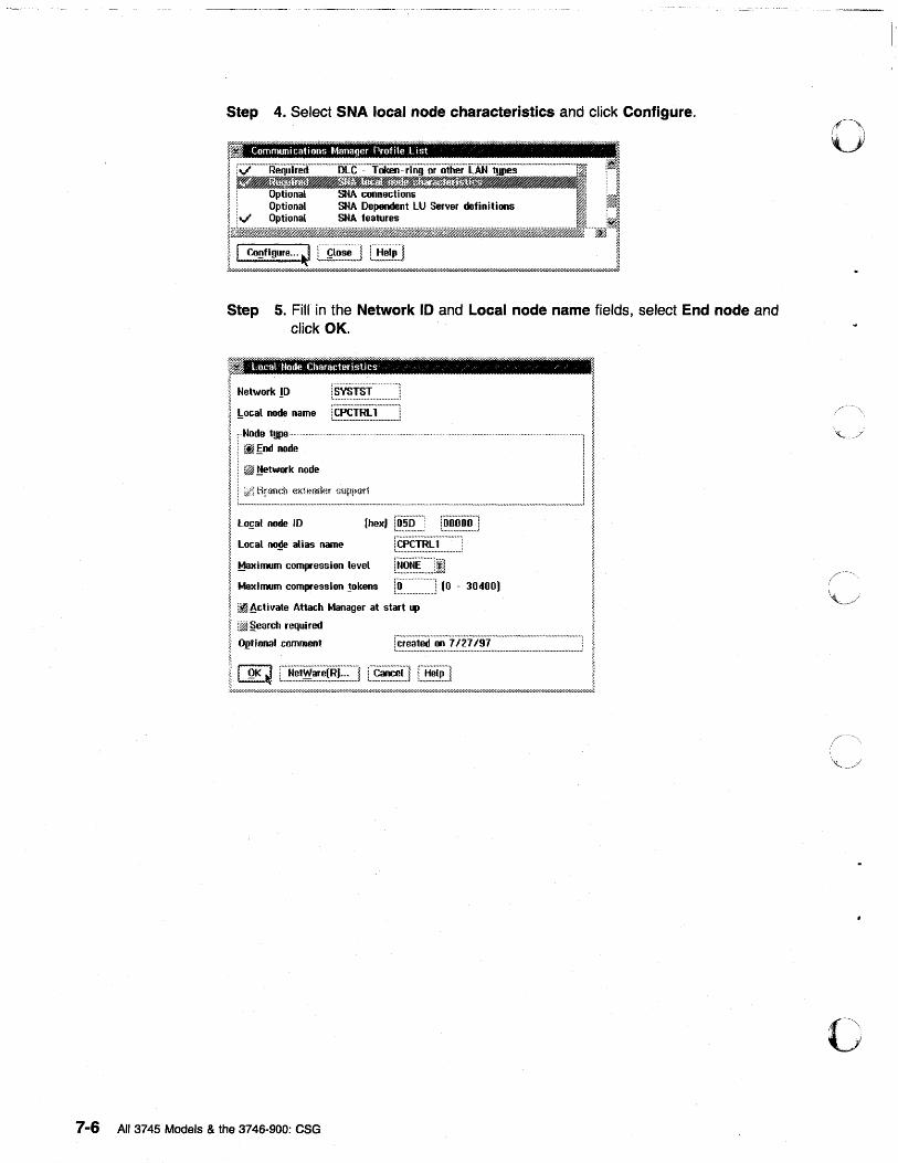
7-6
Step 4. Select SNA local node characteristics and click Configure.
, Communications Manager Profile List
Step 5. Fill in the Network ID and Local node name fields, select End node and click OK.
*
I N.tw .... !D
!:ocal node name
Local Node Characteristics / /
r·CpCTRL·i··_· ... ·····: :....~nu~., .... __ ...... n ....... _._ • ..,.,..,:
r·Node type ..... ............................... . .................................... .
L~~;_~:~~ ______________ J LOfal node ID
Local no~ alias name
Maximum compression level
Ma'limum compression !okens
1'00000'''1 :'u •••• _ • .,. __ .,./.
l"CPCTRLl"··· .. ···· .. ·! ~ .......... ., ...... ., .................. :
[~~.~.~::::JI I'D' "] (0 - 30400)
~ Activate Attach Manager at start up
:twl §earch required
Ol!tlonal comment
All 3745 Models & the 3746-900: eSG
o
c
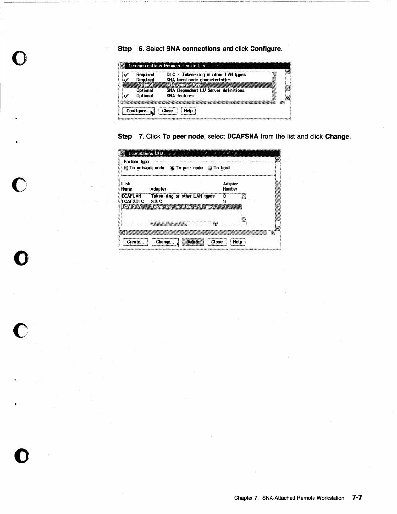
o
c
o
c
o
Step 6. Select SNA connections and click Configure.
~ Communications Manager Profile list
Step 7. Click To peer node, select DCAFSNA from the list and click Change.
. C1)nnectiuns List, ,./ / /./ / "
."..
~ To !!8twork node rf} To l!8er node ~ To !lost
Link Adapter Name Adapter Number :DC·AFLA:if· .... · .. · .. fiiken:·rfng .. ·or .. ·oiher"LAN .. 'igpes .. · ....... O .............. ··· .. ··1 :OCAfSDLC SOLC 0 i r~)~rW~r~..-'ff:~ff.mff~~~'Wff.~~$.r~f,#(;O/(f:'81~ r'$/h#~.wh#~ ... ~jp.w$).l#~;#h::~~;#~~/~.J~h::;.;WU.. ~~ ,
~, ........................ ,iKW..-••• $fr:::::::··:·:···::···::·::.·::.·:]ri.... . ........................ 1
Chapter 7. SNA~Attached' Remote Workstation 7-7
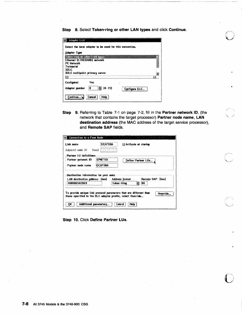
StepS. Select Token-ring or other LAN types and click Continue.
.~ Adapter Li st
I Select tbe _I adapter to be used til< this ...... 01\.1L I.'
I Adapter Type ,
'- s.. ~ $. :-~~l!j~ ~ ~ thernet ETHERAl'I») network a I :PC Network ~
I i~~;;axial , i.~,>~~: ... ;.: ~ !SOLC mullipoint ~imar!J server [I ~ ~ im~~·.~·.·.~·.~·.~~~~·".~~·.·.~~·".~~·"".~~~·.·.~·.~· ..... ~ .. ~ .. ~ .... ~ ............ ~ ...... ~ .. ~~ ...... ~~~ .. ~ .... : .. ~~ .... ~:~~~ .... ~~~~~ ........ ~ ...... ~ .. ~ .. ~ .. ~:~ ........ ~~ .... ~ .... :~ ........ :: .. : .... ~ .... ~~::~ .... : .... ~ .. :~ .... :: .. ~ .... ·.·.~~~~·.:~~·.·.~~~~·.·.·.·.~D ..... J
i ~dapnfl:7::mber f: .. :.·.·.·.~.·.·.~.·.·.·.·.·.·.·.·.·.·l, i .. I, (0 - 15) , .... ·C ...... · .. f .. ;· ...... · ...... D .. · .. L· .. C .... · .... · .. j I ~ - '-H6 L,~u~" Igure ~u";;;",,..l ~
II Conll ... :::: ~ rcanc;tl iHoiPl I .~//////////h .. W////////////////////// ... ////////;::.:.:::::."//.::;;;::::///////////////h»;.-/.'./////////hW////h .......... /////////1'////////////////////.-;-,////////////////1"///////////////1
Step 9. Referring to Table 7-1 on page 7-2, fill in the Partner network 10, (the network that contains the target processor) Partner node name, LAN destination address (the MAC address of the target service processor), and Remote SAP fields.
'" IF ~ Link name ~ -
Connection to a Peer "~ode /
iDCAFSHA f~~ Acti~ate at star~
I AlijiiC\1n1 !~od(-! lD H~(~!(} ,.,~ ... ,~ ... ,~ ... ,~ ... ,~ ... ,,,; ~ , .. Partner LU definitions .. · .......... .............................................................................. . .................. .
I ! Partner ~.twort< II) !iiilE!!i:::=:~ ~ ................................ :.1::::
1 I ! Partner node name r.~.~~.~:~~:: .. :::::::::::::J . .. .... .. ................. ....... . .. . f.
~ " Destination information for peer node ................ '.
~ : LAN destination address (hex) Address !ormat Remo!e SAP {hex}
I i .. ~~~:~~~:~:~~~~~~~;~;;;;;;;;;;;;;;;;;;;;;;;;;;;;L ................. r:~~:~~~;~~~T~;;;;;;;:~;;~~;;;;;~~ ... ~~~~~J ................................................... ..1
I To provide unique link protocol parameters that are different than C .. ·o;;iii·d; .......... j ~ those specified In the OLe adapter profile, select Override... Lmum;;;'m_m,;,;,;_J
~
~
~ ~
~ ~ ~
I 1
~ ~
I ! ~
~
I ~ I C~E:] [~i!~~~~~~::~!~i!!~~:;.~] [~~~~~n [~~] I
~///////////////// ... //////////////////////////////////////",,"-//////////// ... /////////.///////////.//////////////////,Y//////////////////////6..-/////////////////////////////./////////////////////////////////6"-/////////////////6'1'////////"I///.)'
Step 10. Click Define Partner LUs.
7-8 All 3745 Models & the 3746-900: CSG
o
c
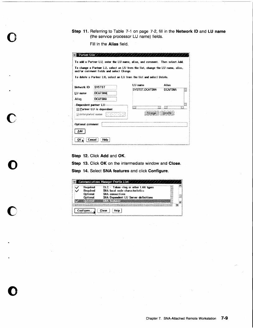
o
c
o
c
o
Step 11. Referring to Table 7-1 on page 7-2, fill in the Network 10 and LU name (the service processor LU name) fields.
Fill in the Alias field.
~ To add a Partner lU, enter the lU name, alias, and comment. Then select Add.
I To change a Partner LU, select an LU from the list, change the lU name, alias, ~ and/or comment fields and select Change.
I To delete a Partner LU. select an lU from the list and select DeLete.
1 ~etwork ID 1 ~ I:U name ~
~ Alia!,!
SYSTST
:.~.~I~.~:::::::::::::::::::: :[5CA'FStiA· .. ······ .. · .. · .... ·,
~ , .. Dependent partner lU ............................................. :
®. : W~ .eartner lU is dependent ; . " ...................................... " ~ : J~nii,krpi&h:·d n<m~~
tuuu.uu ..•.. _ ....... u ....... u._# .. ## •• u## .... _ .•..... ., ...... u.## •••• ., ............. ., .... .,,l
~ Optional !;omment
II ~dd J j
I [~E~~~ L£~~~~!I] :~~~!~£]
lU name Alias
i= .-::·:-;'/// .... ,,////////.~i"~~;.;·;-x .. ;'»;.' ... ;.:0;·;.;.'h;~ ... :·:·;.;'li"u;0;.;//;;-;.;.:v;~·»;-'h'//h;·X-:-;.-;.:/ .... ;.;.;.;.fi.;./;.;.h1-;.'/, ... i"/ .. 'l;~.;.i"h;·;'l;~ ... ;'l ... »;.;·;·;0;. .. ;.;~·,,/.·: ... ;.;.;.;.;-:·;·;-;·;~/h;0;.»;.; ... ;~·;·;·;·;.;0»;';-V/u;';';~';': .·;·;·;~·;·;.:·;-:-: ... ;.;·X .. fii;'l;.;.;.;.;.I' .. ;.;·;·;·;·;~~·;~/,"'"'/.·;~·;.;.;.;.; ;.;
Step 12. Click Add and OK.
Step 13. Click OK on the intermediate window and Close.
Step 14. Select SNA features and click Configure.
= 1. ~;1fJ , r;:j .. ········RequIred .. ·-.. ········"[jCt···::···iOkeii·~·ring··or···otherTAW .. ·t!iPes·································fii itBl ~ ~v" Required SNA local node charactefistics ~S; ~ 1, i OptionaL SNA connections ji;;! .l ~ i OptionaL SNA Dependent LU Server definitions tis i;;31
I-~~! ~ I Co~figure ... ~ L .. £~?',~~."J L~!i~J, r.l/h;.;.H;·I'/.I//h~I'/.I/.I/// ... ;.'///4W/////4;;fiI'41'/..,~;.I'/ ... r.r/h;.»;.//;~;.l'fi;. ..... ;.I'/////~~z.~-»;~~·Y//.·;I/~;-;..;.;.~~~W.lh;.;I/,;·;·;I////////////.'l'h;.l'/.w;l/.~~,;.;;/////.'l..;;/,;',I' ... ;I//.I';I/.Ifi;l ... I' ... ;.y//.·;·;.;·~.;~·~;.;.;.l'/fi;..;.;~ ... .1"/.~// ... ;lfi;..;·;.;'1'//.·~~
Chapter 7. SNA-Attached Remote Workstation 7-9
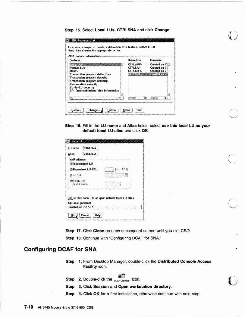
Step 15. Select Local LUs, CTRLSNA and click Change.
r To c.e.", change, o. del.'e • de.;.n;o. o •• Ieo ... e, .... ct • lI.t I ; item, then choose the appropriate action. 1
~ ,··SHA feature information .. · .... · .......... ·· ........ · ........ · ...... · .............. · .... · .. · .. · ............................................................................. , ~ ; features Definition Comment i 1 : rm-JIf_J i·Ct"RLA·PPN····· ···treate(",on··"1)~ Ii ; partner LUs iCTRLLAN Created on 7.i i, i !Modes iCTRLSDLC Created on 7.i ! j i lTransaction program definitions r~Fj~.J.?r~!,p«~.EJ t i IT ransacl i on program defaults r·.akj.J/%.u->~, ~.#~.bW.J~JjJ ~#4 <
~ iTransaction program security ~ ; !conversation sectB'ity; .~.~ i iLU-to-LU security i ! " ; !CPI Communications side information ; i <
: i Iii: i i~ ! ~ ; i%!Ji..·.·.·.·:.~.·.·.:.·.:.·.·:.·.·:.·.·.·:.~·.~·.·.·.· ............. ~ ..... : ......... :.~ ... ~ .... : ... ~ .. ~: ..... ~·.· .. · ... : .. ~:.· ... ·.~~·.·.jLL .... J 1%~Kw~j.·.~.·.~::.~.~.:::.jii ...... %jjM!t)!r.~·.·.·.~·.·.~·.~~~i ...... ; i ~
'~ L.,..,.,.,. .... ,.,. ......... ,.,. ....... ,.,.,. ....... ,. .... n .......... ,. ................. ,. ................................................. " ............................... ,. .......................... ,. ............ .1 ~
1~~uu~uu~::~::~l~u"~"~~"uu'u$n~uu"u'~mmJ Step 16. Fill in the LU name and Alias fields, select use this local LU as your
default local LU alias and click OK.
Ph
~~ ~ ~
!:U name !§i"~~~~~ ~ ~
~ Alias r.~:f.~.~:~~~:::::, ~
1-:~n:=~~ LU I ;~ : ;. i. : ~ Qependent LU NAU I ~ I t!m>t !lr!\< I ;: : Optbmi tU ~.' l' mf)d!)l nmrm ~ ~ g ~ :"' ..... n ......... n .................................................................................................................. : ~
I ~ i ~!lse tIlis local LU as your default local LU alias ~ ; Optional fomment I I ~~~~~:=:~~~_==-=--=~=_~~"~J I l//////////////////////////;:::.:.::;:;::////::;;;;:::///.~'l'//////.r;'/,(//////(,/////''i////////////////.I.'l//////////.'l"///////////////////////1
Step 17. Click Close on each subsequent screen until you exit CS/2.
Step 18. Continue with "Configuring DCAF for SNA."
Configuring DCAF for SNA
Step 1. From Desktop Manager, double-click the Distributed Console Access Facility icon.
Step
Step
r--3-:
.~ 2. Double-click the DCAF Controller icon.
3. Click Session and Open workstation directory.
Step 4. Click OK for a first installation, otherwise continue with next step.
7-10 All 3745 Models & the 3746-900: CSG
o
C".'·\·· , .
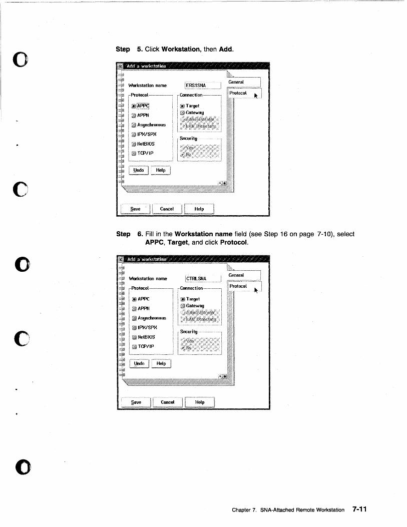
o
o
o
c
o
Step 5. Click Workstation, then Add.
?mJ. Add a work~tatinn / / '/ /, '/ /,/, / / / : ... " .. .,,. .................................................... ,, ........ ,. .. " ...................................................... ~~.
·~:~rjh Hl~L:~ ......... I# ....... m ........... ~. %.JijJi General .;;~# W ... kstation name lERslsNA ~~~ ['.Protocol .................. · .......... , i,··Connection .................... : .. ; W;;:;~~:~;;;::;;::;;~·I :::J#j
~:~ I ~r~.P.:~ :.::f~ i, ~ APPN ~:,~j} ,;;~# I ~ Asynchronous ~~~r~ :::¥,1 i ~ IPX/SPX :::llij
;::l,:~ I ~ NetBIOS .. -- i 6% TCPIIP ;i L~~ ............................................. ,
.~J#j ~~~rm
[ ~jTarget
L ... r Security
Step 6. Fill in the Workstation name field (see Step 16 on page 7-10), select APpe, Target, and click Protocol.
: .................................................................. " ........................................ ,. ....................... .
. :::~ fH~L:'-......... # ...................... ~ i:i~ ~:.~ Workstation name
:::#. ~:"rj .•.. :yij
.. ,: ... ProtocOl ............................. j , .. Connection .... · ...... ······· .... ·, 1 ~ I rtlAPPC
1 @APPN l~ I ~ Asynchronous
:~~~1l ·~~~r~ :;~j .:0p ~~~rm :,:.0,1 ! ~ IPX/SPX ~:¥~ ;;;yi1 ! ~ NetBIOS
;~tjz ~ ~ TCP/IP
j: t ... ~.: ............................................. j :.0t~ ~~~¥~
1 ~Target 1 if~Galle~,a!l
f Security
General fr;;:;~~;~::;;;;:;:~::;:;:·:
... tt;i
Chapter 7. SNA-Attached Remote Workstation 7-11
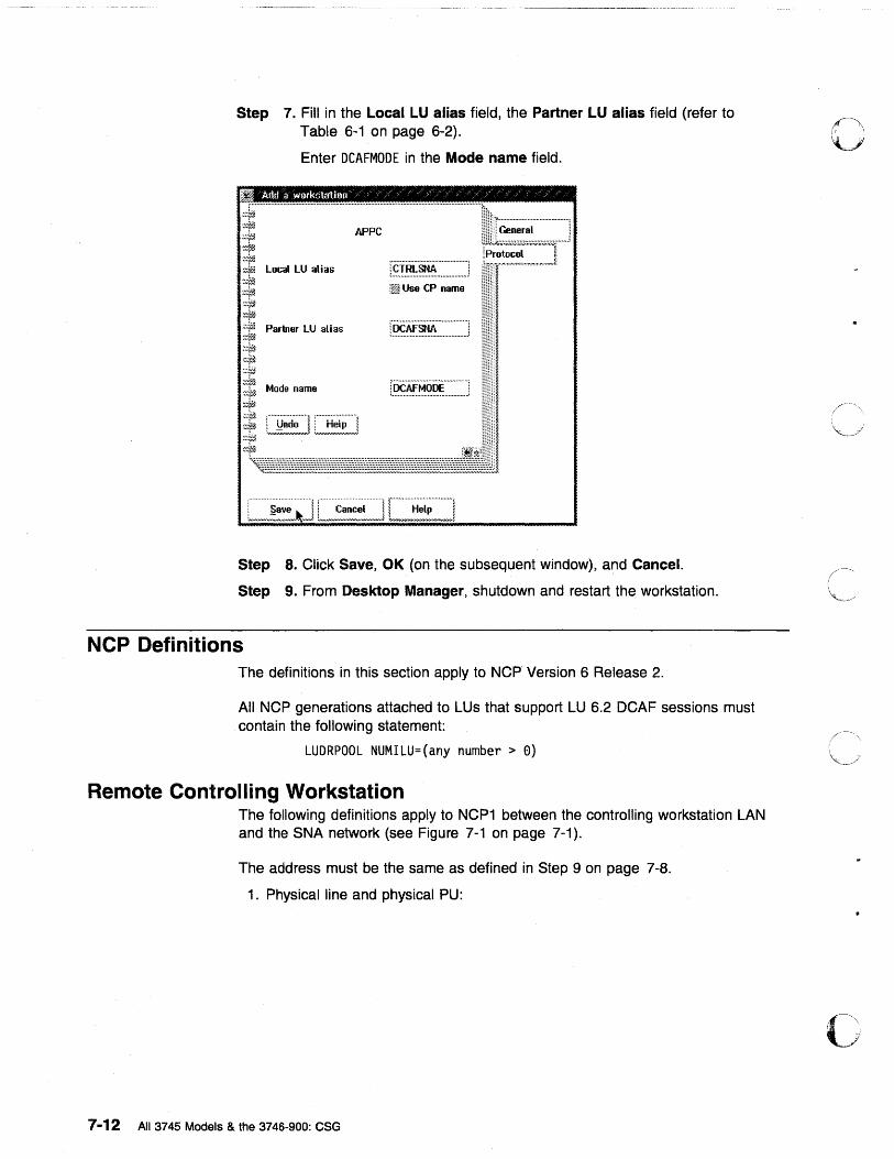
Step 7. Fill in the Local LU alias field, the Partner LU alias field (refer to Table 6-1 on page 6-2).
Enter DCAFMODE in the Mode name field.
Add a workstation /' Z / % /: " )' % / / : / :" /
Partner LU alias
Mode name L~.~~~~~ ............. ;
Step 8. Click Save, OK (on the subsequent window), and Cancel.
Step 9. From Desktop Manager, shutdown and restart the workstation.
NCP Definitions The definitions in this section apply to NCP Version 6 Release 2.
All NCP generations attached to LUs that support LU 6.2 DCAF sessions must contain the following statement:
LUDRPOOL NUMILU=(any number> 0)
Remote Controlling Workstation The following definitions apply to NCP1 between the controlling workstation LAN and the SNA network (see Figure 7-1 on page 7-1).
The address must be the same as defined in Step 9 on page 7-8.
1. Physical line and physical PU:
7-12 All 3745 Models & the 3746-900: CSG
o
o
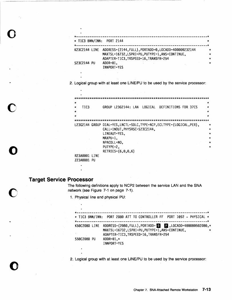
o
o
o
o
o
*----------------------------------------------~----------------------* * TIC3 BNN/INN: PORT 2144 * *---------------------------------------------------------------------* K23C2144 LINE ADDRESS=(2144,FULL),PORTADD=0,LOCADD=400000232144 *
MAXTSL=16732,LSPRI=PU,PUTYPE=1,ANS=CONTINUE, * ADAPTER=TIC3,TRSPEED=16,TRANSFR=2S4 *
S23C2144 PU ADDR=OI, * INNPORT=YES
2. Logical group with at least one L1NE/PU to be used by the service processor:
*********************************************************************** * * TIC3 * *
GROUP L23G2144: LAN LOGICAL DEFINITIONS FOR 37CS * * * *
*********************************************************************** L23G2144 GROUP DIAL=YES,LNCTL=SDLC,TYPE=NCP,ECLTYPE=(LOGICAL,PER),
CALL=INOUT,PHYSRSC=S23C2144,
R23AOOOI LINE Z23AGGGI PU
Target Service Processor
LINEAUT=YES, MAXPU=I, NPACOLL=NO, PUTYPE=2, RETRIES=(6,0,0,6)
The following definitions apply to NCP2 between the service LAN and the SNA network (see Figure 7-1 on page 7-1).
1. Physical line and physical PU:
*---------------------------------------------------------------------* * TIC3 BNN/INN: PORT 2G8G ATT TO CONTROLLER FF PORT 1092 - PHYSICAL * *---------------------------------------------------------------------*
* * * * * *
KSGC2G8G LINE ADDRESS=(2G8G,FULL),PORTADD=1I II , LOCADD=4GOGGOS02080,* MAXTSL=16732,LSPRI=PU,PUTYPE=I,ANS=CONTINUE, * ADAPTER=TIC3,TRSPEED=16,TRANSFR=2S4
SSOC20S0 PU ADDR=Ol,* INNPORT=YES
2. Logical group with at least one L1NE/PU to be used by the service processor:
Chapter 7. SNA-Attached Remote Workstation 7-13
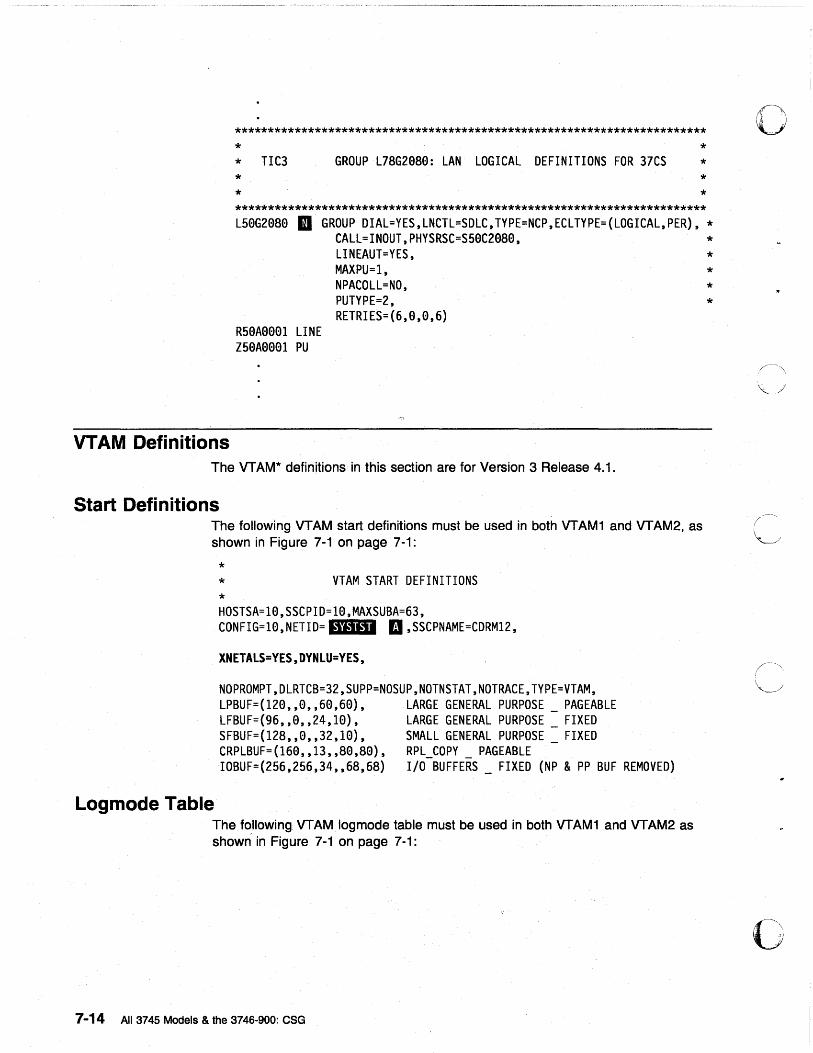
*********************************************************************** * * TIC3 * *
GROUP L7SG29S9: LAN LOGICAL DEFINITIONS FOR 37CS * * * *
*********************************************************************** L59G29S9 II GROUP DIAL=YES, LNCTL=SDLC, TYPE=NCP, ECL TYPE= (LOGICAL, PER), *
R59A9991 LINE Z59A9991 PU
CALL=INOUT,PHYSRSC=S59C29S9, * LINEAUT=YES, * MAXPU=l, * NPACOLL=NO, * PUTYPE=2, * RETRIES=(6,9,9,6)
VTAM Definitions The VT AM'" definitions in this section are for Version 3 Release 4.1.
Start Definitions The following VTAM start definitions must be used in both VTAM1 and VTAM2, as shown in Figure 7-1 on page 7-1:
Logmode Table
* * *
VTAM START DEFINITIONS
HOSTSA=19,SSCPID=19,MAXSUBA=63, CONFIG=19,NETID= I.i·.'~" II ,SSCPNAME=CDRM12,
XNETALS=YES,DYNLU=YES,
NOPROMPT,DLRTCB=32,SUPP=NOSUP,NOTNSTAT,NOTRACE,TYPE=VTAM, LPBUF=(129,,9,,69,69), LFBUF=(96,,9,,24,10), SFBUF=(12S,,0,,32,10), CRPLBUF=(160"13,,S0,S9), IOBUF=(256,256,34,,6S,6S)
LARGE GENERAL PURPOSE PAGEABLE LARGE GENERAL PURPOSE FIXED SMALL GENERAL PURPOSE FIXED RPL_COPY _ PAGEABLE I/O BUFFERS FIXED (NP & PP BUF REMOVED)
The following VTAMlogmode table must be used in both VTAM1 and VTAM2 as shown in Figure 7-1 on page 7-1:
7-14 All 3745 Models & the 3746-900: CSG
o
o
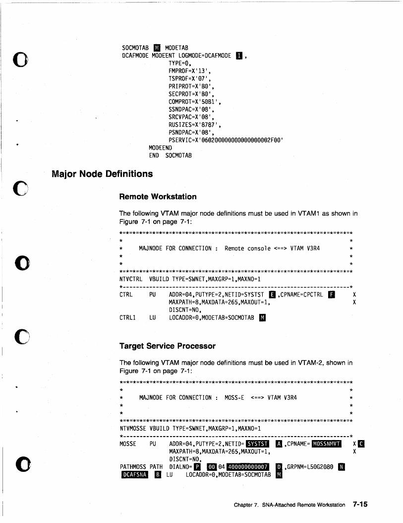
" 0,,','
o
o
o
o
SOCMOTAB II MODETAB DCAFMODE MODEENT LOGMODE=DCAFMODE D,
TYPE=0, FMPROF=X 113 I, TSPROF=X '07 1, PRIPROT=X ' B0 1, SECPROT=X 'B0 1, COMPROT=X ' S0B1 1, SSNDPAC=X '08 1, SRCVPAC=X 'e8 1, RUSIZES=X'8787 I ,
PSNDPAC=X '08 1, PSERVIC=X '06e200000e0ee00000002F0e '
MODE END END SOCMOTAB
Major Node Definitions
Remote Workstation
The following VTAM major node definitions must be used in VTAM1 as shown in Figure 7-1 on page 7-1:
* * * *
MAJNODE FOR CONNECTION: Remote console <==> VTAM V3R4
NTVCTRL VBUILD TYPE=SWNET,MAXGRP=1,MAXNO=1
* * * *
*---------------------------------------------------------------------* CTRL PU
CTRLl LU
ADDR=04,PUTYPE=2,NETID=SYSTST II ,CPNAME=CPCTRL II MAXPATH=8,MAXDATA=26S,MAXOUT=1, DISCNT=NO, LOCADDR=0,MODETAB=SOCMOTAB II
Target Service Processor
The following VTAM major node definitions must be used in VTAM-2, shown in Figure 7-1 on page 7-1:
* * * *
MAJNODE FOR CONNECTION: MOSS-E <==> VTAM V3R4
NTVMOSSE VBUILD TYPE=SWNET,MAXGRP=1,MAXNO=1
* * * *
*---------------------------------------------------------------------*
x X
MOSSE PU ADDR=04, PUTYPE=2, NETID= ,,"." II, CPNAME= '11'.'*'1'1' X II MAXPATH=8,MAXDATA=26S,MAXOUT=1, X DISCNT=NO,
PATHMOSS PATH DIALNO= II m 04 .,0101010101010101010" II ,GRPNM=LS0G208e m Itl'!J"'~t!1 II LU LOCADDR=0,MODETAB=SOCMOTAB II
Chapter 7. SNA-Attached Remote Workstation 7-15

o
o 7-16 All 3745 Models & the 3746-900: CSG
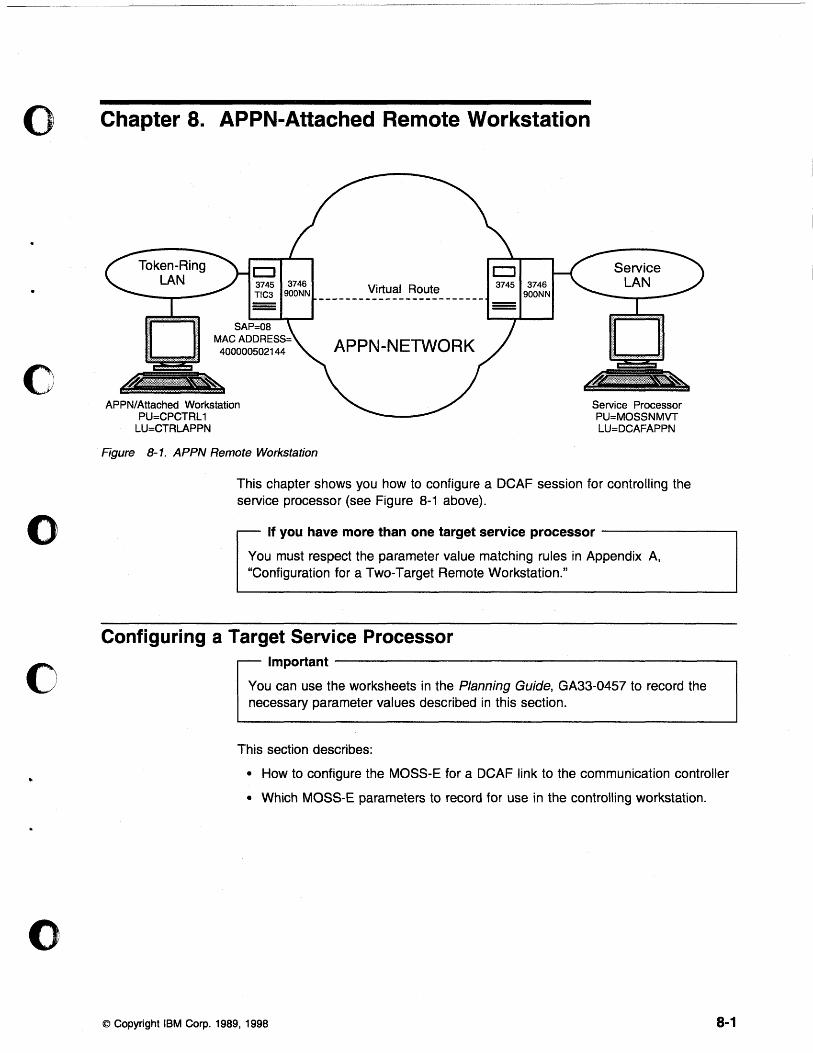
o Chapter 8. APPN-Attached Remote Workstation
o
o
c
o
D 3745 3746 TIC3 900NN
SAP=08 MAC ADDRESS=
400000502144
APPN/Attached Workstation PU=CPCTRL1
LU=CTRLAPPN
Figure 8-1. APPN Remote Workstation
Virtual Route
APPN-NETWORK
CJ 3745 3746
900NN
Service Processor PU=MOSSNMVT LU=DCAFAPPN
This chapter shows you how to configure a DCAF session for controlling the service processor (see Figure 8-1 above).
If you have more than one target service processor ------------,
You must respect the parameter value matching rules in Appendix A, "Configuration for a Two-Target Remote Workstation."
Configuring a Target Service Processor Important ------------------------------------------~
You can use the worksheets in the Planning Guide, GA33-0457 to record the necessary parameter values described in this section.
This section describes:
• How to configure the MOSS-E for a DCAF link to the communication controller
• Which MOSS-E parameters to record for use in the controlling workstation.
© Copyright IBM Corp. 1989, 1998 8-1
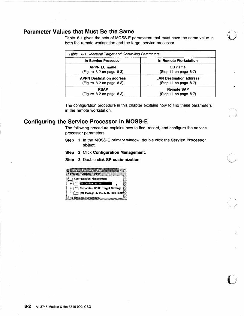
Parameter Values that Must Be the Same Table 8-1 gives the sets of MOSS-E parameters that must have the same value in both the remote workstation and the target service processor.
Table 8-1. Identical Target and Controlling Parameters
In Service Processor In Remote Workstation
APPN LU name LU name (Figure 8-2 on page 8-3) (Step 11 on page 8-7)
APPN Destination address LAN Destination address (Figure 8-2 on page 8-3) (Step 11 on page 8-7)
RSAP Remote SAP (Figure 8-2 on page 8-3) (Step 11 on page 8-7)
The configuration procedure in this chapter explains how to find these parameters in the remote workstation.
Configuring the Service Processor in MOSS-E The following procedure explains how to find, record, and configure the service processor parameters:
Step 1. In the MOSS-E primary window, double click the Service Processor object.
Step 2. Click Configuration Management.
Step 3. Double click SP customization.
8-2 All 3745 Models & the 3746-900: CSG
o
o
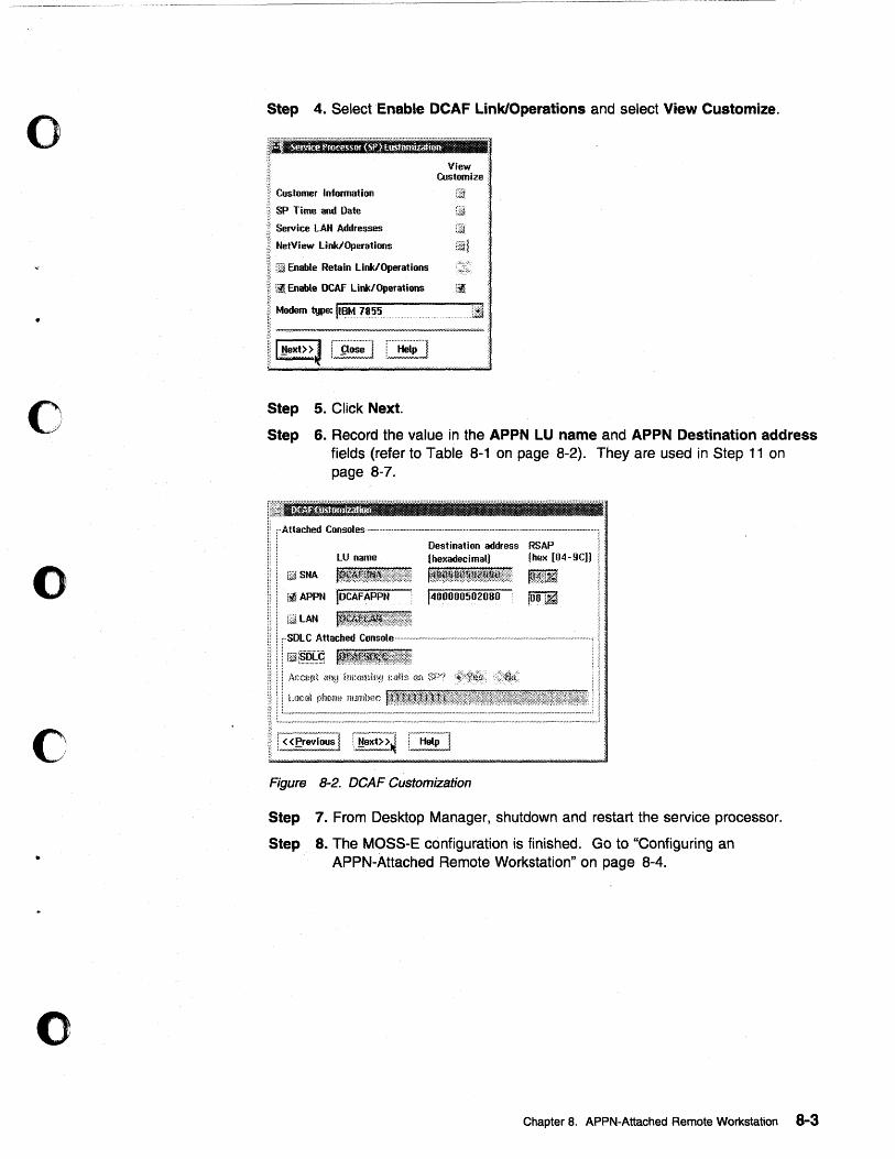
o
o
o
c
o
Step 4. Select Enable DCAF Link/Operations and select View Customize.
~;lltJ,rIQr;lrl'fJJmlmri;I1'tJ:n;{;"''''''''''=''''''''''''
Customer Information
SP Time and Date
Service LAta Addresses
NetView Link/Operations
Gil Enable Retain Link/Operations
II \~ Enable DeAF Link/Operations
II Modem type: IU~t.1J~~5~, ' ...... -' .. ,,_
!tl~~~~~~t r"'~i~~~""1 C'~ip"'''1
5. Click Next.
View ~ Customize:
Step
Step 6. Record the value in the APPN LU name and APPN Destination address fields (refer to Table 8-1 on page 8-2). They are used in Step 11 on page 8-7.
I: rAttached Consoles--' ... --.-.-.. --'----.... '~-·--·-··-........ -· .... ---·-·--_· .. ·--_ .. -1 •
lU name
.. naSNA
Destination address RSAP I • (hexadecimal) (hex [04-9C)) i'
~ : t~~~l~f~~~~t~~~f~~l t. ~'~!i1 ! •
r~ APPN IOCAFAPPN 1400000502080 \
[alAN
f'--', ,--, U!ext> >~ ! Help i
Figure 8-2. DCAF Customization
Step 7. From Desktop Manager, shutdown and restart the service processor.
Step 8. The MOSS-E configuration is finished. Go to "Configuring an APPN-Attached Remote Workstation" on page 8-4.
Chapter 8. APPN-Attached Remote Workstation 8-3
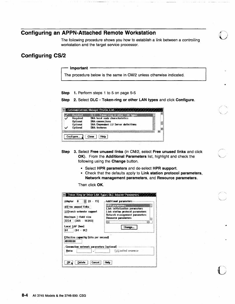
Configuring an APPN-Attached Remote Workstation The following procedure shows you how to establish a link between a controlling workstation and the target service processor.
Configuring CS/2
Important -------------------------------------------------,
The procedure below is the same in CM/2 unless otherwise indicated.
Step 1. Perform steps 1 to 5 on page 5-5
Step 2. Select OLC - Token-ring or other LAN types and click Configure.
Step 3. Select Free unused links (in CM/2, select Free unused links and click OK). From the Additional Parameters list, highlight and check the following using the Change button.
• Select HPR parameters and de-select HPR support. • Check that the defaults apply to Link station protocol parameters,
Network management parameters, and Resource parameters.
Then click OK.
r.'llInr;r:JXlm.fll1r;':III;!!'-{l!fll1flII!IIIU" un ""'11 lin ~ ~
; Adapter rO ........ [I (0 - 15 J '" Add i t i anal parameters """",,"""""'''''''''''''''''''','''''' ~
I, ~,:.~§':'rr··eea··n-cjhDlS·· .. 'e:_~et"·-en~"ldJe"~r~Ss"uppo·; rl I t!ff'(llg~~ II j ~.... i \Link statim protocol parameters i i ~ ~ I [Nelwork management parameters i i ~
! :;~~~1~;:~:3) l~J~~~c~j I I ;~::. <""",ity (bits per second) !
I ~§;~~:~~i:~:;~~~:::~-::::~J I {f////////////////////h'//h',w///////////////////////////////////////////////////////#/////////////////////////h'/#//u//////////////////////////////////////////////////////////////////////////////////&.
8-4 All 3745 Models & the 3746-900: CSG
o
c
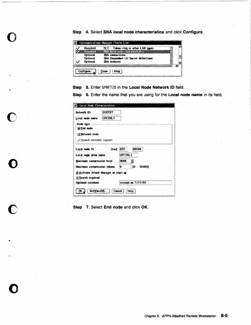
o
o
o
c
to
o
Step 4. Select SNA local node characteristics and click Configure.
· Communications Manager Profile list
1 ~ .... m·········~~f.~~~ii~~i"~i~O:~~h~:A·····-m·_····s·· ... m·····················-·T~ ~ : Optional SNA connections Liv g:!::~:~ :: ~,:=nt LU Server definitions
rl Cog'lgura ... ~ ffiiiiieJ ~ ~ ... //D///// ... //I'//////I'///NflW////I'/ ... ///H.I,t.r'.IA'/I'///////1'..mi'UQ//u///////.tI'//I'//HU//,//«////.·w/I'/,1/I'.lh ....... U/////hW//////,I ... '/// ....... //fi,'/// ... X////////////.r/////////I'.lI'//u////1',///fiW/////,//u///.I///u/UI'////l'bJ
Step 5. Enter SPNETID in the Local Node Network 10 field.
Step 6. Enter the name that you are using for the Local node name in its field.
?r~ II Local Node Characteristics '
~ Network!O ;:
~ !:ocal node name [~~~~~~::~:::] I [-Node type ......................... _ ............................................................................................................................. .
I ~~~,~~ .. ------.. -.. -.. ---.-.. ~ Ilo~al node 10 (he)!1 t~.~~._., r~~~~.~] ~ Local node alias name l"CPcmi::-1······ .. · .. ··: I Ma~imu~ com .. ession level [~~~~~~ji·········' I ~ximum compression tokens r~.·.·:.·.·.·::.·:.·.·:.·.·:.·.] (0 - 30400)
I ~Acliyate Attach Ivtan~ger at start up
I ~ §earch required
~ OJ!1lonal comment rc;-~ated·oo·-7/·2-1"j!)"i" .. ··· .. ····-······················ ....... _ ...... : ~.-...................................... -.-........... -..... --............. ~-.. -.... -.-... --........•..•. ;
~ Step 7. Select End node and click OK.
Chapter 8. APPN-Attached Remote Workstation 8-5
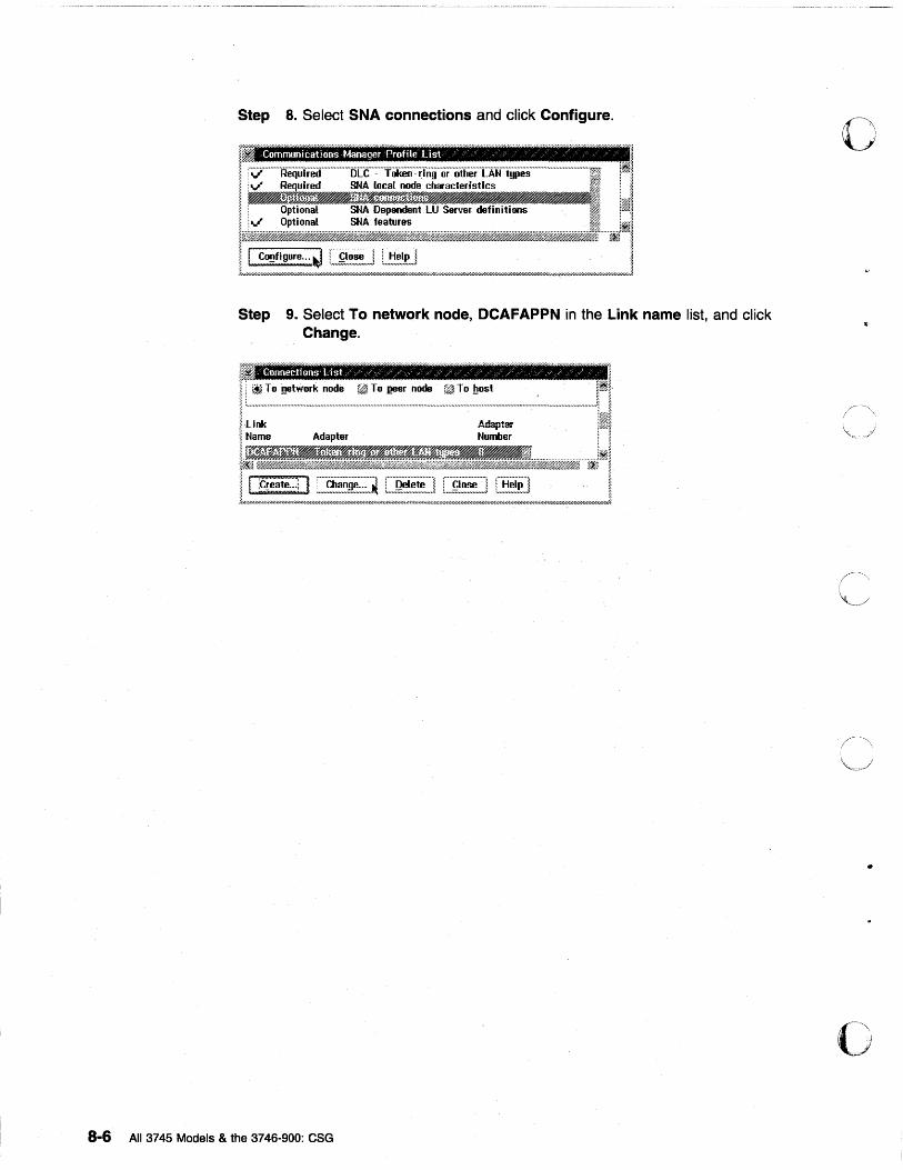
Step 8. Select SNA connections and click Configure.
'0 ~ ,Communications Manager Profile Ust /' z / / / / / /' /
I. 1. \~?""'''''R'e'qiilieir''''''''''''''D[t'''::'''Tiikeil''::'ifnii''or· .. otherTAtf'types········· .. ·····················TF4 Iv" Re uired SNA local node characteristics
~E~~f~~~~~~E.~~~~,,~~~~aI I Optional SNA Dependent LU Server definitions ~f!i
i, jv" Optional SNA 1eatures 11
Step 9. Select To network node, DCAFAPPN in the Link name list, and click Change.
8-6 All 3745 Models & the 3746-900: CSG
•
o
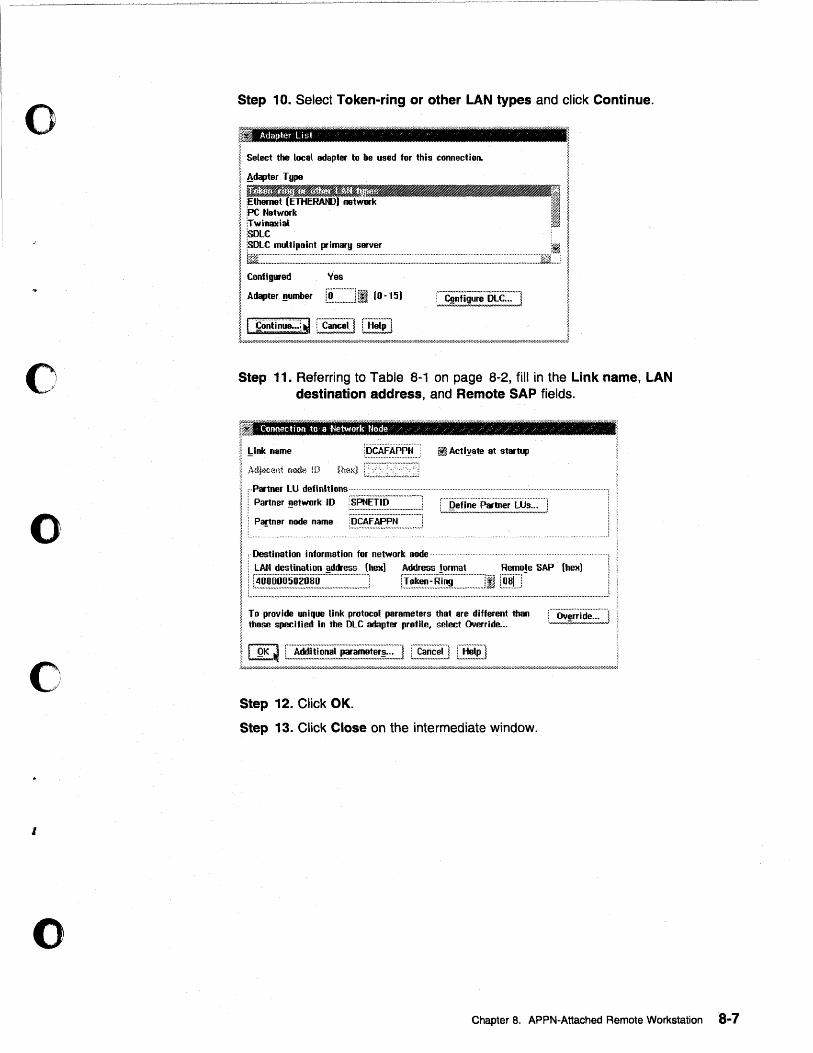
o
0'· y'
o
o
I
o
Step 10. Select Token-ring or other LAN types and click Continue.
r ~ Adapter List
1 Select the local adapter to be used for this connection. ~ ~ Adapter T llpe
i ,.,; ~~I<rm~ .~ 1 ; tharnet (ETHERAttJ) network }if j !PC Network ;1 ., ;~ ~ \Twinaxial :fm ~~ lSDLC
Il:::~=~~;~~~=~=:-::::===~::===:::==:::::::=~====:::::==::H~ I Conflg .. ed Yes
I Adapter ~mber r.~.·:::.·::::::]1 (0 -15) C~~§;';'E~;]
~~~~_#$ __ -J
Step 11. Referring to Table 8-1 on page 8-2, fill in the Link name, LAN destination address, and Remote SAP fields.
'-" ~ Curmection .to a Network Node ./ / / Y ~ , / z / / / / /
I !,Ink name
I Adj<ll.:en1 n>ltle !D {hwd _~, ... ", ... ", .. ,,, ... ,,., ... ,,,; ~ , .. Partner lU definitions .. · ......................................................... . , ; Partner ~etwork ID rSPNETi"O· .................... : ......... ................... . ............... . ~ : ::::::::::::::::::::::::::::::::::::::::::::::; LJ1! .. ~!~!~'!!~!~m~!!!:.::,J II : Partner node name ~!?.~.~~.~.~ ............ ..!
I. . Destination information for network node· .... ~ :
! l~~~~~~~~~~=~ __ ~~E~~~~~_~!J~~~:~ __ ~=~ ____ 1
~ To provide unique link protocol parameters that are different than : .... 0' .......... ;.;1 ............. , ~ those specified In the DLe adapter profile, select Override... L"'"~!!L,,!.:;..:,,J ~
I. I QK ~ C,~~,!!~~~!!:.~~~~!!~~!.i;:;~~] [,~~,~,~.~.~] [~!~,~] , }//////p'////////////////////////////////////h;.W.W/////n/// ... l'////////h~W//////////.'z.·"'hl'///hW""-»Y////"'///hW/////////////////////////////hY///////hW//hn-i' .. ;.;.'///////////..;Y////h;.J~·Y//////I·//4"/////////"':'·Y.~h:-;·;'l' .. ,//hrhil~
Step 12. Click OK.
Step 13. Click Close on the intermediate ~indow.
Chapter 8. APPN-Attached Remote Workstation 8-7
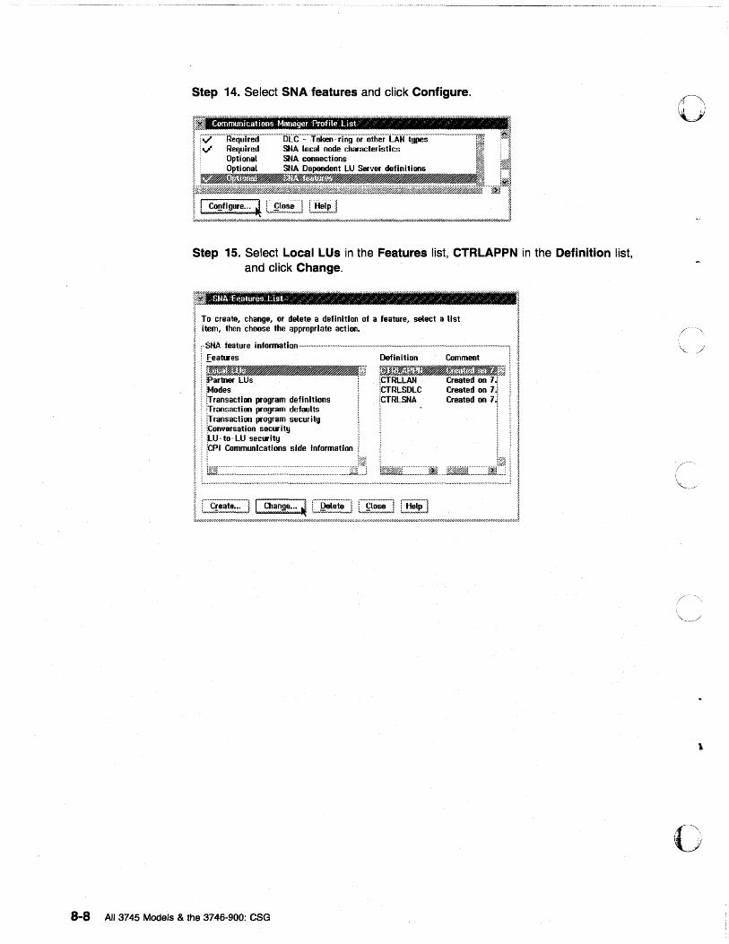
8-8
Step 14. Select SNA features and click Configure.
, Communrcations Manager Ptofile List/ /' ,/, , / , ' /'
~--!:::::r--~~!;7,2j::::=t~L::if"""---------1 ~ Optional SNA connections I i0'~ Optional SNA Dependent LU Server definitions I :~I
1~~mffi ___ ff_~;Wffiiiff#,'t,MM%Wt!#ji;m@j21fmlif.£til&tMftffi2' __ if;0'I$. . .... ~II
L1Y",~:~:~/~:::~~~",~",!~::=::~:::::}",~::.::::;L,>////,»»W///hW//,//////////////////h//////////////////////hr//////////w//////////////////////////////////J Step 15. Select Local LUs in the Features list, CTRLAPPN in the Definition list,
and click Change.
To create, change, or delete a definition of a feature, select a list item, then choose the appropriate action.
,··SHA feature information····· .......... ·· ............ · .......... · .......... · ................................................................................................ :
features Definition Comment i
i artner LUs : Nodes : [rrans8ctloo program definitions : jrransaction program defaults i Jransaction program security : ~on ... ersation security : lLU" to - LU secur ity
~l1JB,r:~r~~J'~"'J.'~ ! iCTRLLAN Created on 1.i ' iCTRLSDLC Created on 1 j rRLSNA
Created .n 7 i
. !CP1 Communications side information : :
.: ~ . !.~.J .. ! ! I%~.:.:::·.·.::: .. · .. · .. : ..... : .. :.·.·.:::·.·::.·.::: .. ::.: ...... :: ... :: ..... : .. ::.: ... : .. : .... : .. : .... :: ..... $;~:~i "'" L. ......................................................................................................................... !:~::::=::::=::.::!::::::~~::::::=::=!:::::::..1
A" 3745 Models & the 3746-900: eSG
o
\
o
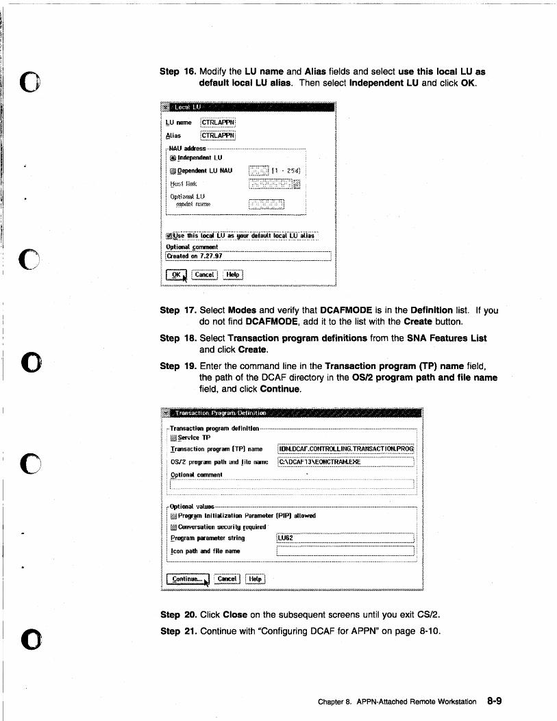
o
o
o
o
o
- •... ~~-~.~--
Step 16. Modify the LU name and Alias fields and select use this local LU as default local LU alias. Then select Independent LU and click OK.
Local LU
~ LU name a -
I Alias [~I.~~:~~~:j ! :··NAU address····························· ~ ! j} Independent LU
II ~ ~pendent LU NAU
li:,';w L ........ ~~.~~ ... ~.:~~.:----........ -...... --.... --................ __ ........ --..... _ ....... :
Step 17. Select Modes and verify that DCAFMODE is in the Definition list. If you do not find DCAFMODE, add it to the list with the Create button.
Step 18. Select Transaction program definitions from the SNA Features List and click Create.
Step 19. Enter the command line in the Transaction program (TP) name field, the path of the DCAF directory in the OS12 program path and file name field, and click Continue.
~ i !" ;;:~~:;:rogram definition ........................................ --...................................................................................................... I i. ! Iransaction program (TPI name [~~~.::~~~.;·~.§.~.~.~.~.~~.§;:~f:~.~~~.~~.!.X§.~.~.~§.~:' ~ ; ~
~ \ OS/2 program path and Jile name r~.~sp..~~:~.~:~S~:§.~§!.~~;.~~~::::::~:::::::::::::::::::::::::::::::::::::]. I i : comment ~ ~ ; ~ :.~:' ~.:.: { ;: ~
I r:~-:;.~,;i:;:-~~~;;~~~-~;;::~------------------------I I ! ~ Conversation security !equired . I I i erogram parameter string r.~~~~~::::~:::::.~:::::::::::::::::::::::::::.~:::::::::::.~:.~:::~:::::::::::::::.~:::::~::::::::::::::::::::]: ' ~ : I I ! leon path and file name [::::::::::..: .. :::::::.~::::::: .. :::::::::::::::::::: .. ::::..::::::::::::::.~:::::::::::::::::::~.::::.~::::::::"::::::::":.'::J: l I...................................................................... ................................................................................................ I II ~ontinue ... ~ ;."C;;;~] [E!~iJ I ~///////////////////////h///////////////////////////////////////////.I.~wQ///.r////.w/////////////////////////////////////.r///////,U//////////////////////////.7/'W/////////'W///////////////by//////////////////////kW//////////////.,A
Step 20. Click Close on the subsequent screens until you exit CS/2.
Step 21. Continue with "Configuring DCAF for APPN" on page 8-10.
Chapter B. APPN·Attached Remote Workstation 8-9
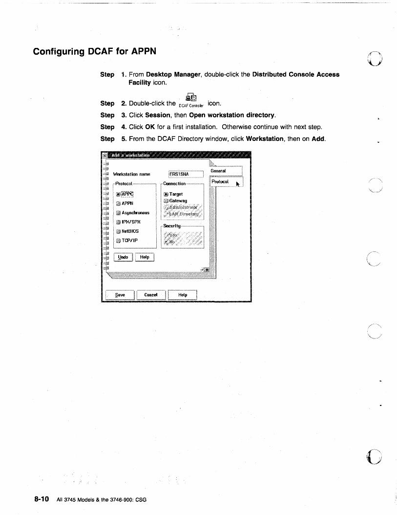
Configuring DCAF for APPN
Step 1. From Desktop Manager, double-click the Distributed Console Access Facility icon.
r--3.
a~ Step 2. Double-click the DCAF Controller icon.
Step 3. Click Session, then Open workstation directory.
Step 4. Click OK for a first installation. Otherwise continue with next step.
Step 5. From the DCAF Directory window, click Workstation, then on Add .
................... 10 •• ., ........ .,.,., ... " ......................................................................................... .
'·~:r~ :::i!~ :.::#.1 Workstation name ~~:rm :::fi}. ["Protocol ............................. ] ·~::rA ··~·fi/; I. itf~,p':~ ::~r~ :::f~ i ~APPN ~%r~ .::~ ;.i ~ Asynchronous :~:t~ :.::1:;' I ~ IPX/SPX ~:}!ji :::rm ~::¥{{ '.::¥fh ~:*~
I ~NetBIOS , 7~TCP/IP ! t:@ . : ....... ., ............ ., ..... ., ..... .,.,., ............. )
~~; [~i~~,~~] [~~~~i] ~::mJ. :~~/Ji
8-10 All 3745 Models & the 3746-900: CSG
r Connecti on ...................... ]
I (JJ Target '
i ~Gateway
I ~~~;:,=~~I
!}~;~;;~l .... · ............... l
o
\"
o
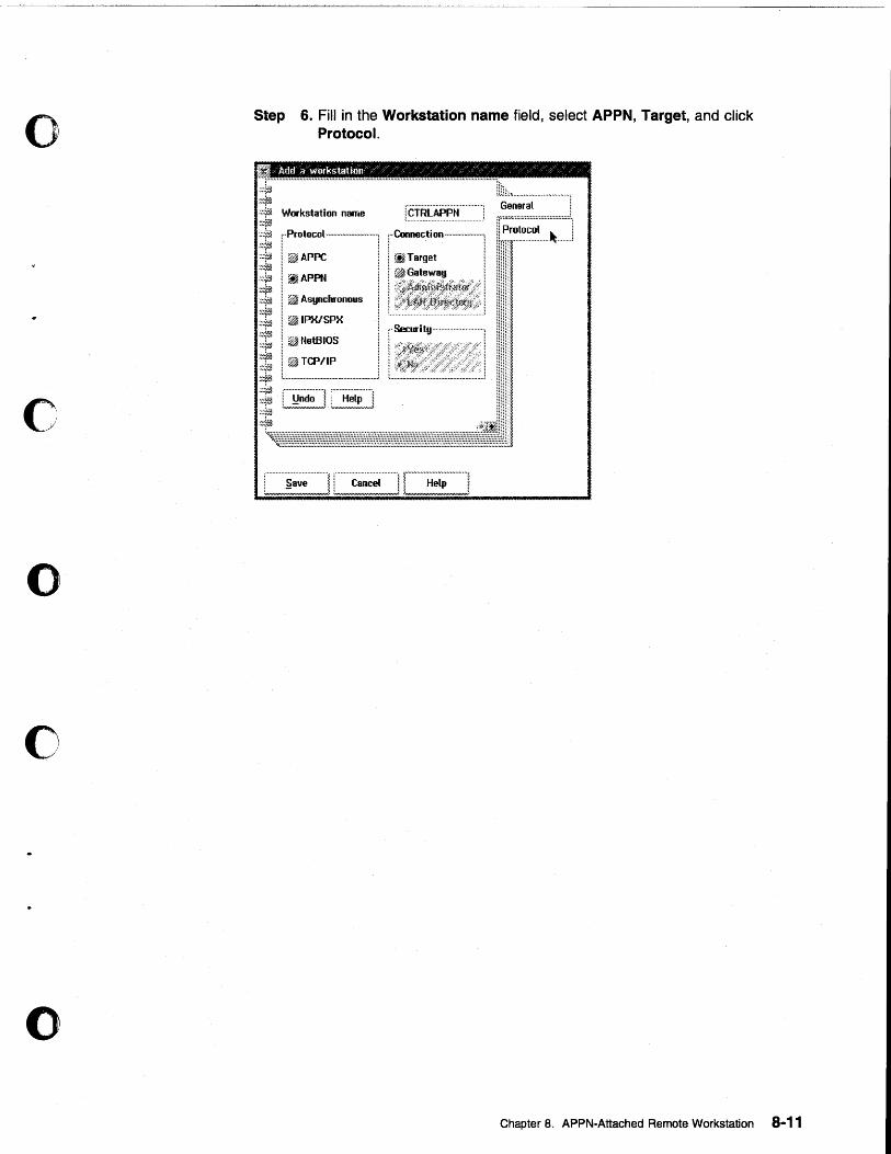
o
c
o
o
o
Step 6. Fill in the Workstation name field, select APPN, Target, and click Protocol.
Add a workstatiun / ~ ~ / ' / / , '
:;"""'"''''''''''''''''''''''''''''''''''''''''''''''''''''''''''''''''''''''''''''''''''''''"""""""''''''''''''''''''''t!~~~~;~I''''''''''''''''''''l
Workstation name [¢.!RlAPP". ........... .'
i:::---1
I ~APPN ! ~ Asynchronous
I ~IPX/SPX ;= ! ~ NetBIOS ~:i#l ~ ~.~ ::!;/i i ~ TCP/IP ::,:j.f~ L,. ••• ,. •.•••• O# .... ".n.,. •••••• ,. ••• ., ... ., ........ l
~~ [~~~] C~~~~~~] :::v».
r Connecti on """'-"-"'''-'1 I ~Target i
! ~G8teW8!1 I
l~~1
.... ~ .... .J
['Security
Chapter 8. APPN-Attached Remote Workstation 8-11
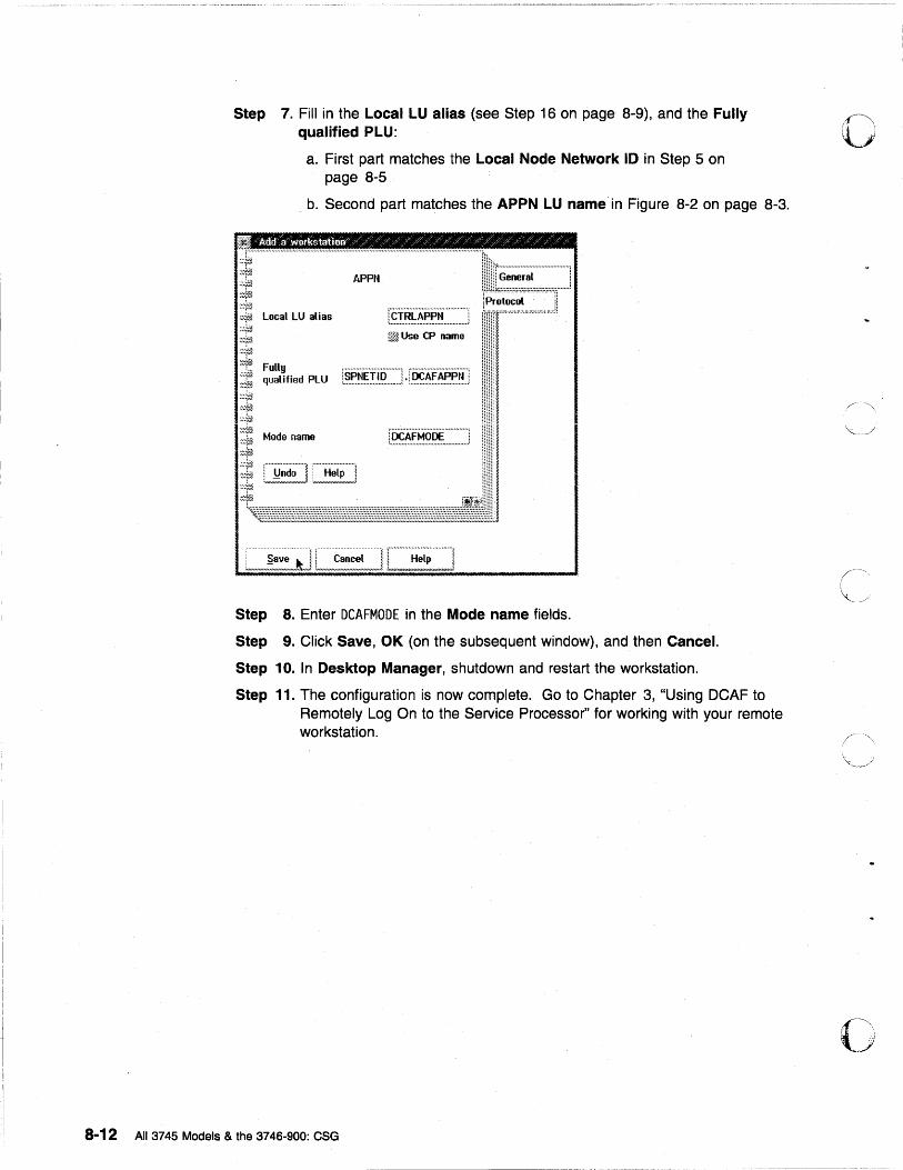
Step 7. Fill in the Local LU alias (see Step 16 on page 8-9), and the Fully qualified PLU:
a. First part matches the Local Node Network 10 in Step 5 on page 8-5
b. Second part matches the APPN LU name in Figure 8-2 on page 8-3.
Step 8. Enter DCAFMODE in the Mode name fields.
Step 9. Click Save, OK (on the subsequent window), and then Cancel.
Step 10. In Desktop Manager, shutdown and restart the workstation.
Step 11. The configuration is now complete. Go to Chapter 3, "Using DCAF to Remotely Log On to the Service Processor" for working with your remote workstation.
8-12 All 3745 Models & the 3746-900: CSG
o
o
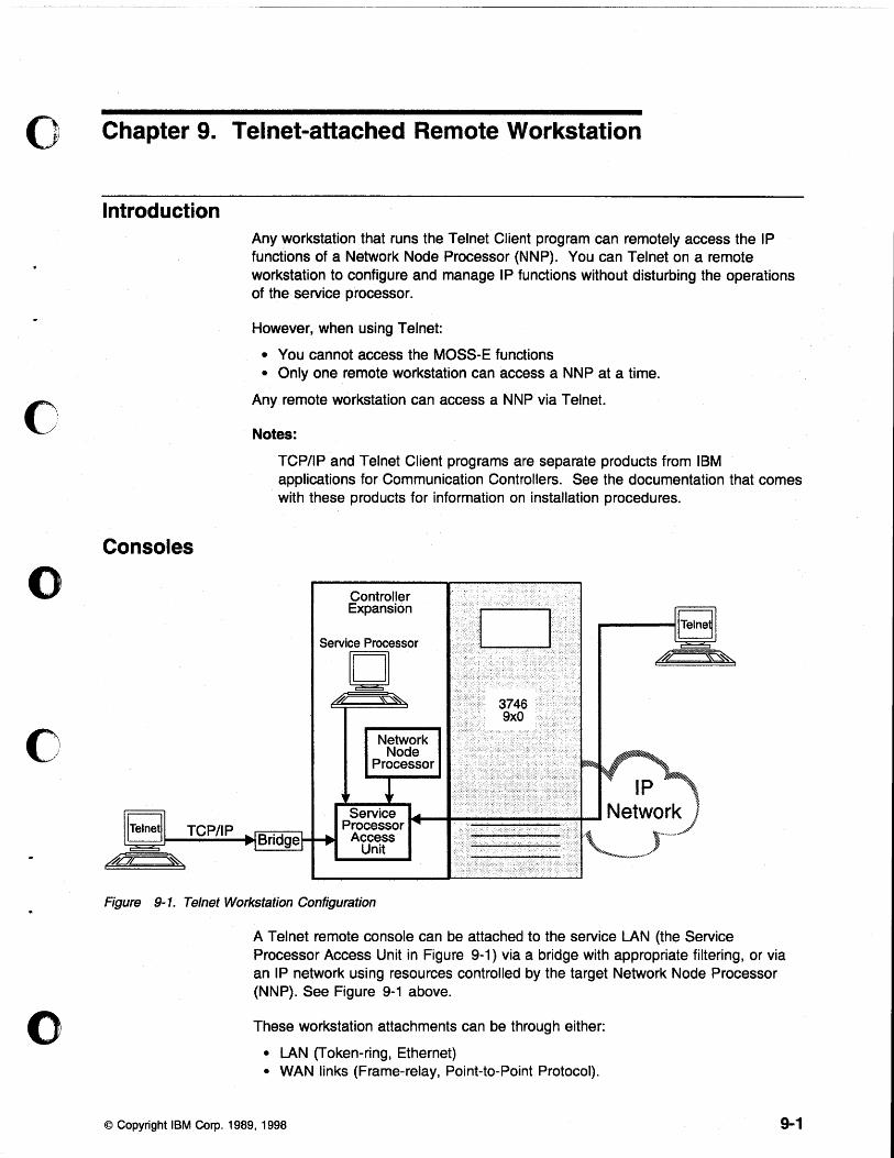
o Chapter 9. Telnet-attached Remote Workstation
c
o
c
o
Introduction
Consoles
TCP/IP
Any workstation that runs the Telnet Client program can remotely access the IP functions of a Network Node Processor (NNP). You can Telnet ona remote workstation to configure and manage IP functions without disturbing the operations of the service processor.
However, when using Telnet:
• You cannot access the MOSS-E functions • Only one remote workstation can access a NNP at a time.
Any remote workstation can access a NNP via TeJnet.
Notes:
TCP/IP and Telnet Client programs are separate products from IBM applications for Communication Controllers. See the documentation that comes with these products for information on installation procedures.
Controller Expansion
Figure 9-1. Telnet Workstation Configuration
A Telnet remote console can be attached to the service LAN (the Service Processor Access Unit in Figure 9-1) via a bridge with appropriate filtering, or via an IP network using resources controlled by the target Network Node Processor (NNP). See Figure 9-1 above.
These workstation attachments can be through either:
• LAN (Token-ring, Ethernet) • WAN links (Frame-relay, Point-to-Point Protocol).
© Copyright IBM Corp. 1989, 1998 9-1
Logon Password Telnet passwords are defined for access to the service processor during the installation of the NNP. If you have problems, see your network administrator.
Programming Requirements For remote access to the functions of a NNP, your workstation must have an operating system (OS/2, for example) that can run TCP/IP.
Hardware Requirements and Recommendations
Installation
Any remote workstation can be used that supports IP and runs the Telnet Client program.
Before you begin the installation procedure for the network node processor, make sure that your t#orkstation can run TCP/IP.
For installing or upgrading the TCP/IP application including the Telnet Client program, refer to the TCP/IP installation guide that comes with the product.
Using Telnet to Remotely Log On to the Network Node Processor
Starting a Session Step 1. Open an operating system window (OS/2, for example).
Step 2. On the command line, type tel net followed by the IP address or nickname of the network node processor.
Step 3. Enter the Telnet password. The Telnet user session starts automatically.
Step 4. Enter one of the following:
• T 6 to configure • T 5 to manage.
For more information, refer to the 3745 Communication Controller Models A, 3746 Nways Multiprotocol Controller Model 900: Basic Operations Guide, SA33-0177.
Closing a Session
To close the session, press ~ and [[] together.
9-2 All 3745 Models & the 3746-900: eSG
(1f\
V', \ " I
/
o
o Part 2. 3745 Models 130 to 610
c
o
c
o © Copyright IBM Corp. 1989, 1998

01',. - 1'-
o All 3745 Models & the 3746-900: eSG
o Chapter 10. Setting Up a Local or an Alternate Console
o
o
c
o
This chapter applies to 3745 Models 130 to 610. It does not apply to Model A.
General Information on Local or Alternate consoles A local console is required, while an alternate console is optional. You can use any of the following:
• An IBM 3151 Display Station (Models 110, 160,310,360,410, or 460) in native mode (recommended) or in IBM 3101 emulation mode.
Note: Models which do not support block mode cannot be used as consoles for the IBM 3745 Communication Controller.
• An IBM 3153 Display Station in IBM 3151 emulation mode.
• An IBM 3161 ASCII Display Station (Model 11, 12, 21, or 22) in IBM 3101 emulation mode.
• An IBM 3163 ASCU Display Station (Model 11, 12, 21, or 22) in IBM 3101 emulation mode (feature code 8235).
• An IBM PS/2, running OS/2 Extended Edition, Release 1.1 or higher.
• An IBM 3727 Operator Console with adhesive keypad labels (part number 03F7773), or any equipment providing equivalent functions (including cable and keyboard).
Check your console cables (for more information, refer to Appendix C in this manual, and the Technical News Letter, GN22-5490 part of Input/Output Equipment Installation Manual- Physical Planning, GN22-5490).
If a cable or console does not work correctly, contact your installation coordinator.
Notes:
1. Consoles can be shared by an IBM 7427 Console Switching Unit. A maximum of four IBM 3745 or IBM 3725 Communication Controllers can share a local console. The maximum distance is 7 meters (23 feet). A maximum of six 3745 or 3725 Communication Controllers can share an alternate console. The maximum distance is 122 meters (400 feet).
2. If you set up certain consoles in an established system, you will need to reload MOSS (IML). Refer to the Advanced Operations Guide, SA33-0097.
© Copyright IBM Corp. 1989, 1998 10-1
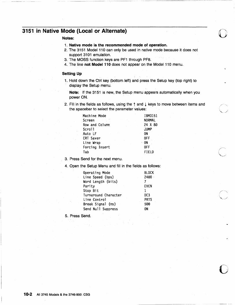
3151 in Native Mode (Local or Alternate) Notes:
1. Native mode is the recommended mode of operation. 2. The 3151 Model 110 can only be used in native mode because it does not
support 3101 emulation. 3. The MOSS function .keys are PF1 through PF8. 4. The line not Model 110 does not appear on the Model 11 0 menu.
Setting Up
1. Hold down the Ctrl key (bottom left) and press the Setup key (top right) to display the Setup menu. '
Note: If the 3151 is new, the Setup menu appears automatically when you power ON.
2. Fill in the fields as follows, using the 1 and ~ keys to move between items and the spacebar to se~ect the parameter values: .
Machi ne Mode IBM3151 Screen NORMAL Rowand Column 24 X S0 Scroll JUMP Auto LF ON CRT Saver OFF Line Wrap . ON Forcing Insert OFF Tab FIELD
3. Press Send for the next menu.
4. Open the Setup Menu and fill in the fields as follows:
Operating Mode BLOCK Line Speed (bps) 2400 Word Length (bits) 7 Pari ty EVEN Stop Bi t 1 Turnaround Character DC3 Line Control PRTS Break Signal (ms) 500 Send Null Suppress ON
5. Press Send.
10-2 All 3745 Models & the 3746-900: eSG
o
II C·'·\
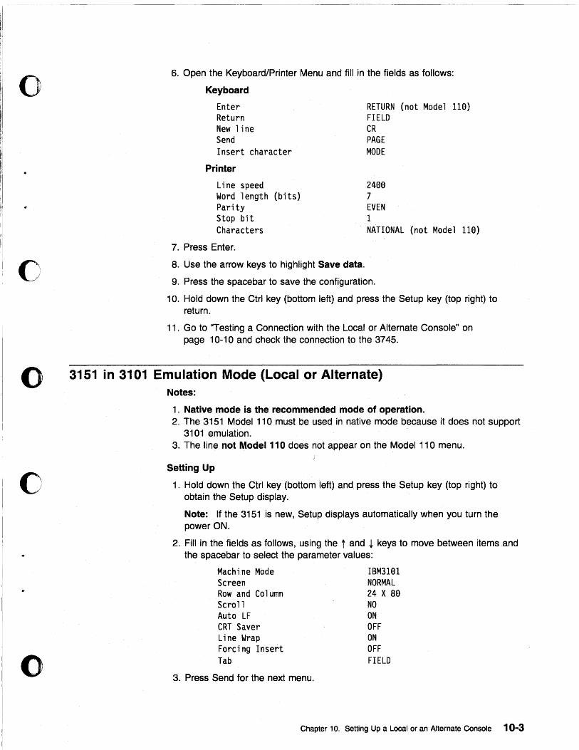
0"'.' 'i
o
6. Open the Keyboard/Printer Menu and fill in the fields as follows:
Keyboard
Enter Return New line Send Insert character
Printer
Line speed Word length (bits) Parity Stop bit Characters
7. Press Enter.
8. Use the arrow keys to highlight Save data.
RETURN (not Model 110) FIELD CR PAGE MODE
2400 7 EVEN 1 NATIONAL (not Model 110)
9. Press the spacebar to save the configuration.
10. Hold down the Ctrl key (bottom left) and press the Setup key (top right) to return.
11. Go to ''Testing a Connection with the Local or Alternate Console" on page 10-10 and check the connection to the 3745.
o 3151 in 3101 Emulation Mode (Local or Alternate) Notes:
c
o
1. Native mode is the recommended mode of operation. 2. The 3151 Model 110 must be used in native mode because it does not support
3101 emulation. 3. The line not Model 110 does not appear on the Model 110 menu.
Setting Up
1. Hold down the Ctrl key (bottom left) and press the Setup key (top right) to obtain the Setup display.
Note: If the 3151 is new, Setup displays automatically when you turn the power ON.
2. Fill in the fields as follows, using the t and ~ keys to move between items and the spacebar to select the parameter values:
Machine Mode Screen Rowand Column Scroll Auto LF CRT Saver Line Wrap Forcing Insert Tab
IBM3101 NORMAL 24 X S0 NO ON OFF ON OFF FIELD
3. Press Send for the next menu.
Chapter 10. Setting Up a Local or an Alternate Console 10-3
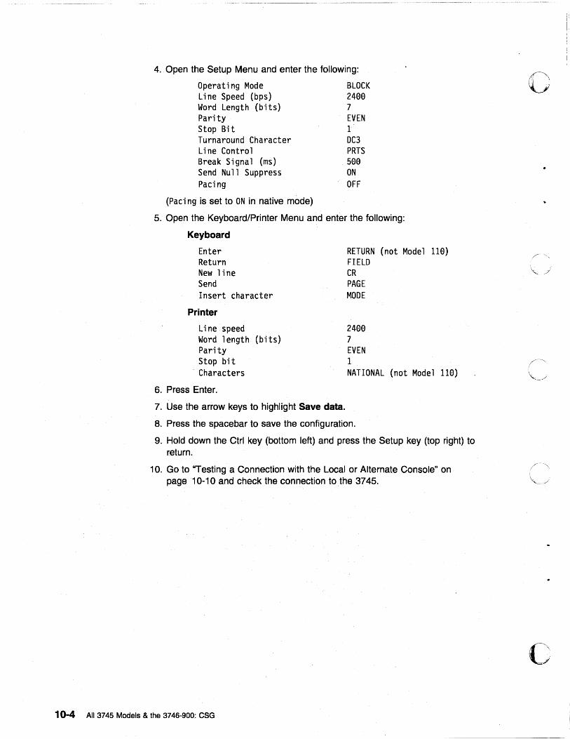
4. Open the Setup Menu and enter the following:
Operating Mode BLOCK Line Speed (bps) 2400 Word Length (bits) 7 Parity EVEN Stop Bit 1 Turnaround Character DC3 Line Control PRTS Break Signal (ms) 500 Send Null Suppress ON Paci ng OFF
(Paci ng is set to ON in native mode)
5. Open the Keyboard/Printer Menu and enter the following:
Keyboard
Enter Return New line Send Insert character
Printer
Li ne speed Word length (bits) Parity Stop bit Characters
6. Press Enter.
7. Use the arrow keys to highlight Save data.
RETURN (not Model 110) FIELD CR PAGE MODE
2400 7 EVEN 1 NATIONAL (not Model 110)
8. Press the spacebar to save the configuration.
9. Hold down the Ctrl key (bottom left) and press the Setup key (top right) to return.
10. Go to "Testing a Connection with the Local or Alternate Console" on page ·10-10 and check the connection to.the 3745.
10-4 All 3745 Models & the 3746-900: eSG
o
c
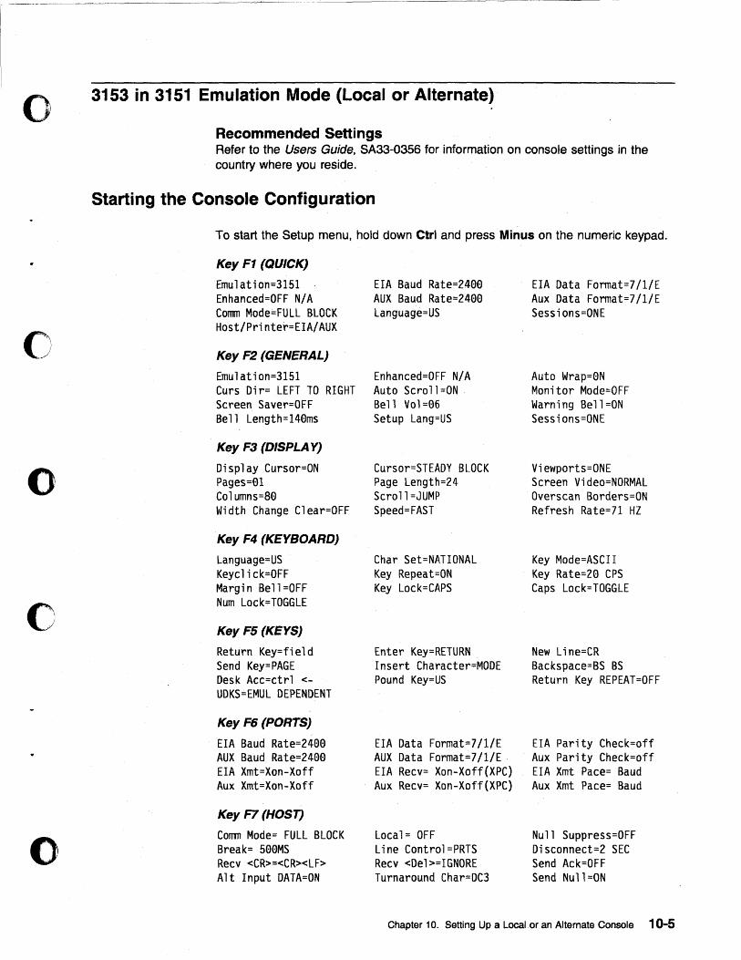
o
o
o
c
o
.~~--~~~-~-----
3153 in 3151 Emulation Mode (Local or Alternate)
Recommended Settings Refer to the Users Guide, SA33-0356 for information on console settings in the country where you reside.
Starting the Console Configuration
To start the Setup menu, hold down Ctrl and press Minus on the numeric keypad.
Key F1 (QUICK)
Emulation=3151 Enhanced=OFF N/A Comm Mode=FULL BLOCK Host/Printer=EIA/AUX
Key F2 (GENERAL)
Emulation=3151 Curs Dir= LEFT TO RIGHT Screen Saver=OFF Bell Length=140ms
Key F3 (DISPLA Y)
Display Cursor=ON Pages=01 Columns=80 Width Change Clear=OFF
Key F4 (KEYBOARD)
Language=US Keyclick=OFF Margi n Bell =OFF Num Lock=TOGGLE
Key FS (KEYS)
Return Key=field Send Key=PAGE Desk Acc=ctrl <UDKS=EMUL DEPENDENT
Key F6 (PORTS)
EIA Baud Rate=2400 AUX Baud Rate=2400 EIA Xmt=Xon-Xoff Aux Xmt=Xon-Xoff
Key F7 (HOST)
Comm Mode= FULL BLOCK Break= 500MS Recv <CR>=<CR><LF> Alt Input DATA=ON
EIA Baud Rate=2400 AUX Baud Rate=2400 Language=US
Enhanced=OFF N/A Auto Scroll =ON Bell Vol=06 Setup Lang=US
Cursor=STEADY BLOCK Page Length=24 Scroll=JUMP Speed=FAST
Char Set=NATIONAL Key Repeat=ON Key Lock=CAPS
Enter Key=RETURN Insert Character=MODE Pound Key=US
EIA Data Format=7/1/E AUX Data Format=7/1/E EIA Recv= Xon-Xoff(XPC) Aux Recv= Xon-Xoff(XPC)
Local= OFF Line Control=PRTS Recv <Del>=IGNORE Turnaround Char=DC3
EIA Data Format=7/1/E Aux Data Format=7/1/E Sessions=ONE
Auto Wrap=0N Monitor Mode=OFF Warn; ng Be 11 =ON Sessions=ONE
Viewports=ONE Screen Video=NORMAL Overscan Borders=ON Refresh Rate=71 HZ
Key Mode=ASCII Key Rate=20 CPS Caps Lock=TOGGLE
New Line=CR Backspace=BS BS Return Key REPEAT=OFF
EIA Parity Check=off Aux Parity Check=off EIA Xmt Pace= Baud Aux Xmt Pace= Baud
Null Suppress=OFF Disconnect=2 SEC Send Ack=OFF Send Null=ON
Chapter 10. Setting Up a Local. or an Alternate Console 10-5
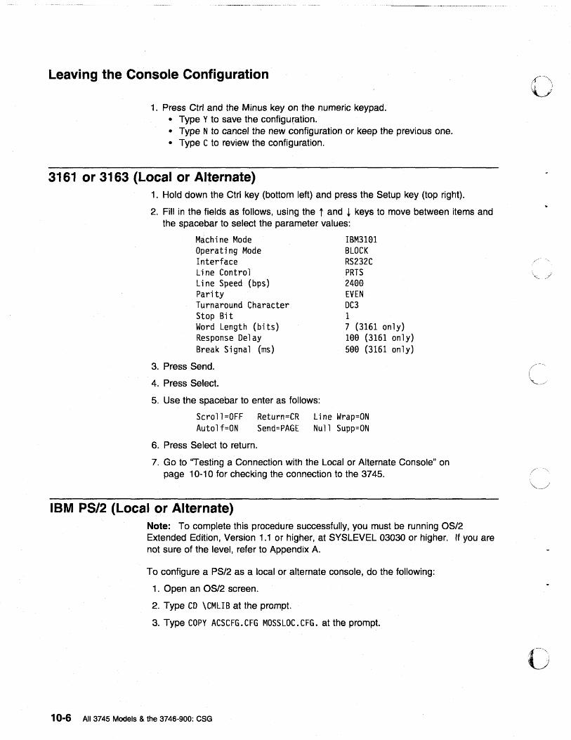
· ...... _ .. _-_._ ........ __ .•............. _ ..... . ~~---....... -.- .......... -... . ..... _--_ .. _ ....... _ ... .
Leaving the Console Configuration
1. Press Ctrl and the Minus key on the numeric keypad. • Type Y to save the configuration. • Type N to cancel the new configuration or keep the previous one. • Type C to review the configuration.
3161 or 3163 (Local or Alternate) 1. Hold down the Ctrl key (bottom left) and press the Setup key (top right).
2. Fill in the fields as follows, using the t and ~ keys to move between items and the spacebar to select the parameter values:
Machine Mode Operating Mode Interface Li ne Control Line Speed (bps) Parity Turnaround Character Stop Bit Word Length (bits) Response Delay Break Signal (ms)
3. Press Send.
4. Press Select.
5. Use the spacebar to enter as follows:
IBM3101 BLOCK RS232C PRTS 2400 EVEN DC3 1 7 (3161 only) 100 (3161 only) 500 (3161 only)
Scroll=OFF Return=CR Line Wrap=ON Autolf=ON Send=PAGE Null Supp=ON
6. Press Select to return.
7. Go to ''Testing a Connection with the Local or Alternate Console" on page 10-10 for checking the connection to the 3745.
IBM PS/2 (Local or Alternate) Note: To complete this procedure successfully, you must be running OS/2 Extended Edition, Version 1.1 or higher, at SYSLEVEL 03030 or higher. If you are not sure of the level, refer to Appendix A.
To configure a PS/2 as a local or alternate console, do the following:
1. Open an OS/2 screen.
2. Type CD \CMUB at the prompt.
3. Type COpy ACSCFG. CFG MOSSLOC. CFG. at the prompt.
10-6 All 3745 Models & the 3746-900: eSG
O·
·'i.,,'\ I _
tj
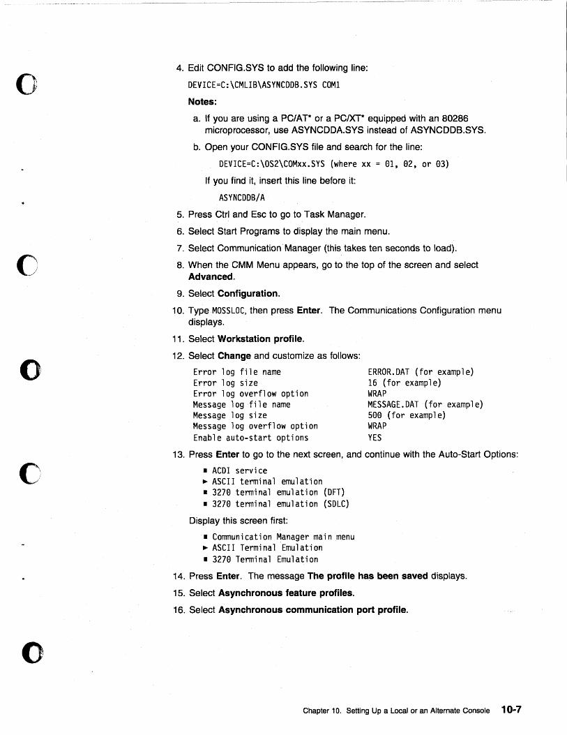
o
o
o
c
o
4. Edit CONFIG.SYS to add the following line:
OEVICE=C:\CMLIB\ASYNCOOB.SYS COM1
Notes:
a. If you are using a PC/AT* or a PCIXT* equipped with an 80286 microprocessor, use ASYNCDDA.SYS instead of ASYNCDDB.SYS.
b. Open your CONFIG.SYS file and search for the line:
OEVICE=C:\OS2\COMxx.SYS (where xx = 81, 82, or 83)
If you find it, insert this line before it:
ASYNCOOB/A
5. Press Ctrl and Esc to go to Task Manager.
6. Select Start Programs to display the main menu.
7. Select Communication' Manager (this takes ten seconds to load).
8. When the CMM Menu appears, go to the top of the screen and select Advanced.
9. Select Configuration.
10. Type MOSSLOC, then press Enter. The Communications Configuration menu displays.
11. Select Workstation profile.
12. Select Change and customize as follows:
Error log file name Error log size Error log overflow option Message log file name Message log size Message log overflow option Enable auto-start options
ERROR.OAT (for example) 16 (for example) WRAP MESSAGE.OAT (for example) 588 (for example) WRAP YES
13. Press Enter to go to the next screen, and continue with the Auto-Start Options:
• ACOI service • ASCII terminal emulation • 3278 terminal emulation (OFT) • 3278 terminal emulation (SDLC)
Display this screen first:
• Communication Manager main menu • ASCII Terminal Emulation • 3278 Terminal Emulation
14. Press Enter. The message The profile has been saved displays.
15. Select Asynchronous feature profiles.
16. Select Asynchronous communication port profile.
Chapter 10. Setting Up a Local or an Alternate Console 1 0-7
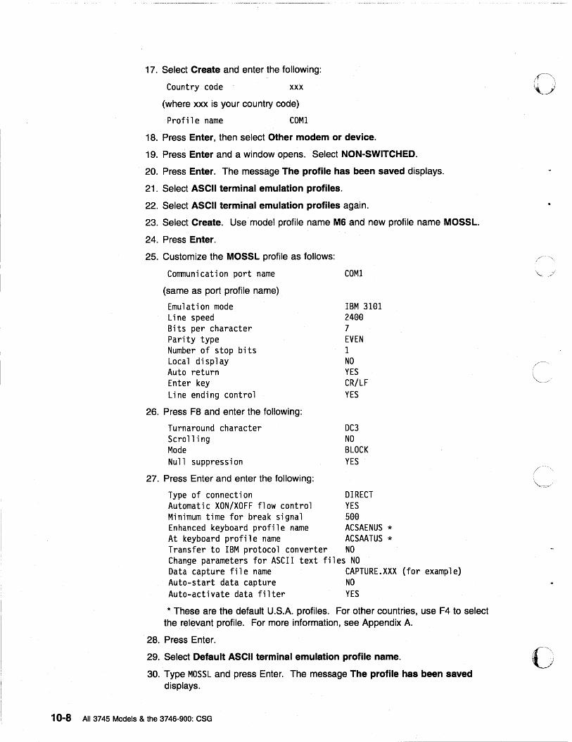
17. Select Create and enter the following:
Country code xxx
(where xxx is your country code)
Profile name COM1
18. Press Enter, then select Other modem or device.
19. Press Enter and a window opens. Select NON-SWITCHED.
20. Press Enter. The message The profile has been saved displays.
21. Select ASCII terminal emulation profiles.
22. Select ASCII terminal emulation profiles again.
23. Select Create. Use· model profile name M6 and new profile name MOSSL.
24. Press Enter.
25. Customize the MOSSL profile as follows:
Communication port name
(same as port profile name)
Emulation mode Line speed Bits per character Parity type Number of stop bits Local display Auto return Enter key Line ending control
26. Press F8 and enter the following:
Turnaround character Scroll i ng Mode Null suppression
27. Press Enter and enter the following:
COM1
IBM 3101 2400 7 EVEN 1 NO YES CR/LF YES
DC3 NO BLOCK YES
Type of connection DIRECT Automatic XON/XOFF flow control YES Minimum time for break signal 500 Enhanced keyboard profile name ACSAENUS * At keyboard profile name ACSAATUS * Transfer to IBM protocol converter NO Change parameters for ASCII text files NO Data capture file name CAPTURE.XXX (for example) Auto-start data capture NO Auto-activate data filter YES
* These are the default U.S.A. profiles. For other countries, use F4 to select the rel~vant profile. For more information, see Appendix A.
28. Press Enter.
29. Select Default ASCII terminal emulation profile name.
30. Type MOSSL and press Enter. The message The profile has been saved displays.
10-8 All 3745 Models & the 3746-900: CSG
o
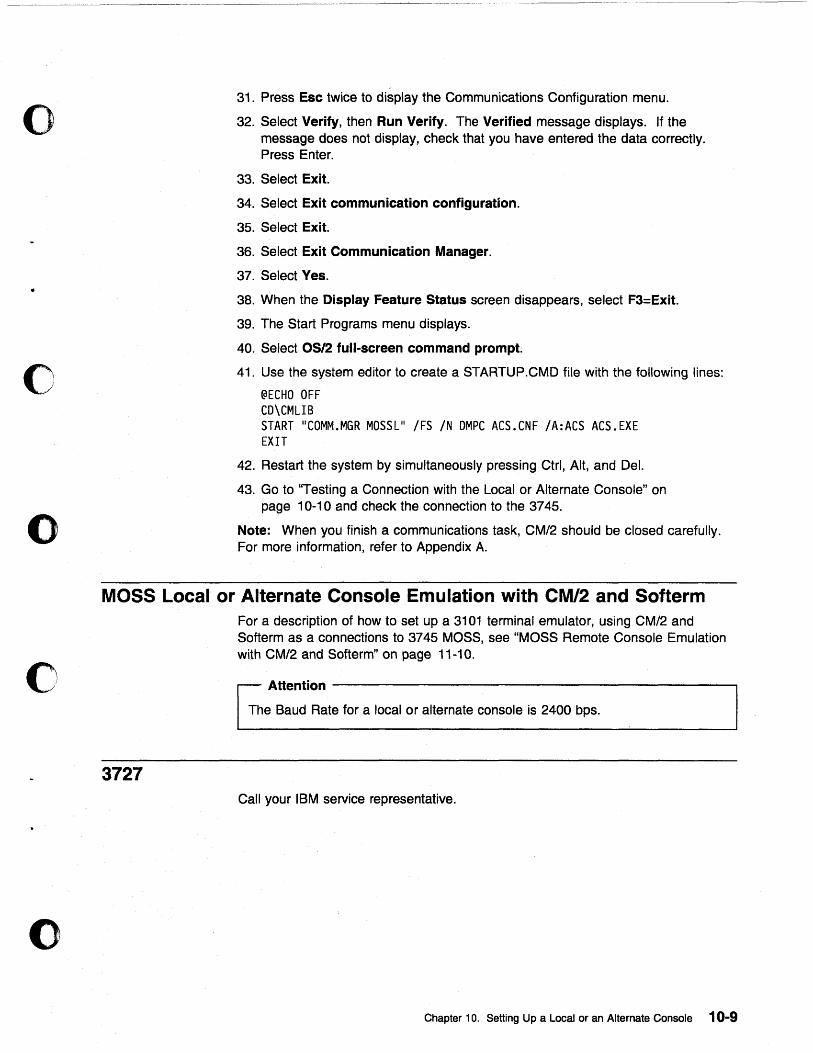
o
o
o
c
o
31. Press Esc twice to display the Communications Configuration menu.
32. Select Verify, then Run Verify. The Verified message displays. If the message does not display, check that you have entered the data correctly. Press Enter.
33. Select Exit.
34. Select Exit communication configuration.
35. Select Exit.
36. Select Exit Communication Manager.
37. Select Yes.
38. When the Display Feature Status screen disappears, select F3=Exit.
39. The Start Programs menu displays.
40. Select OS/2 full-screen command prompt.
41. Use the system editor to create a STARTUP .CMD file with the following lines:
@ECHO OFF CD\CMLIB START "COMM.MGR MOSSL" /FS /N DMPC ACS.CNF /A:ACS ACS.EXE EXIT
42. Restart the system by simultaneously pressing Ctrl, Alt, and Del.
43. Go to "Testing a Connection with the Local or Alternate Console" on page 10-10 and check the connection to the 3745.
Note: When you finish a communications task, CM/2 should be closed carefully. For more information, refer to Appendix A.
MOSS Local or Alternate Console Emulation with CM/2 and Softerm
3727
For a description of how to set up a 3101 terminal emulator, using CM/2 and Softerm as a connections to 3745 MOSS, see "MOSS Remote Console Emulation with CM/2 and Softerm" on page 11-10.
Attention ------------------------,
The Baud Rate for a local or alternate console is 2400 bps.
Call your IBM service representative.
Chapter 10. Setting Up a Local or an Alternate Console 10-9
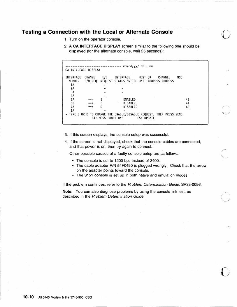
Testing a Connection with the Local or Alternate Console 1. Turn on the operator console.
2. A CA INTERFACE DISPLAY screen similar to the following one should be displayed (for the alternate console, wait 25 seconds):
-------------------------------- mm/dd/yy/ hh : mm CA INTERFACE DISPLAY
INTERFACE NUMBER
1A 2A 3A 4A 5A 5B 7A SA
CHANGE E/D INTERFACE HOST OR CHANNEL NSC E/D REQ REQUEST STATUS SWITCH UNIT ADDRESS ADDRESS
==> ==> ==>
E D D
ENABLED DISABLED DISABLED
- TYPE E OR D TO CHANGE THE ENABLE/DISABLE REQUEST, THEN PRESS SEND F4: MOSS FUNCTIONS F5: UPDATE
3. If this screen displays, the console setup was successful.
40 41 42
4. If the screen is not displayed, check that the console cables are connected, and that power is on, then try again to connect.
Other possible causes of a faulty console setup are as follows:
• The console is set to 1200 bps instead of 2400. • The cable adapter PIN 54F0490 is plugged wrongly. Check that the arrow
on the adapter pOints toward the console. • The 3151 console is set up in both native and emulation modes.
If the problem continues, refer to the Problem Determination Guide, SA33-0096.
Note: You can also diagnose problems by using the console link test, as described in the Problem Determination Guide.
10-10 All 3745 Models & the 3746-900: CSG
o
/\
c
o Chapter 11. Setting Up a Remote Console
o
o
o
o
This chapter applies to 3745 Models 130 to 610. It does not apply to Model A.
General Information (Remote) A remote console is optional. You can use any of the following:
• 3151 Display Station (Models 110, 160,310,360,410, and 460) in native mode (recommended) or in 3101 emulation mode.
Note: Models which do not support block mode cannot be used as consoles for the 3745 Communication Controller.
• 3153 Display Station in 3151 emulation mode.
• 3161 ASCII Display Station (Model 11, 12, 21, or 22) in 3101 emulation mode.
• 3163 ASCII Display Station (Model 11, 12, 21, or 22) in 3101 emulation mode (feature code 8235).
• PS/2 running with an OS/2 Extended Edition, Release 1.1 or higher.
• Personal Computer with an asynchronous communications adapter (or equivalent), running in 3101 emulation mode.
Note: If an adapter card is installed in slot 8 of the PCIXT or Portable or in an expansion unit, you must also install signal jumper (J13).
• Any equipment that can emulate the 3101 with an EIA 232D or ITU-T V.24 interface.
Check your console cables (for more information, refer to Appendix C in this manual, and the Technical News Letter, GN22-5490 part of Input/Output Equipment Installation Manual- Physical Planning, GN22-5490).
If a cable or console is not correct, contact your Installation coordinator.
Note: If you setup certain consoles in an already established system, you will need to reload MOSS (IML). Refer to the Advanced Operations Guide, SA33-0097.
© Copyright IBM Corp. 1989, 1998 11-1
3151 in Native Mode (Remote) Important Note: If you have difficulty in using the 3151 as a remote console for a 3745 Model 210 or 410, contact your IBM service representative to ensure that you have the correct MOSS Console Adapter (MCA) card installed.
Notes:
1. Native mode is the recommended mode of operation. 2. The 3151 Model 110 can only be used in native mode because it does not
support 3101 emulation. 3. The MOSS function keys are PF1 through PF8. 4. The line not Model 110 does not appear on the Model 110 menu.
Setting Up
1. Hold down the Ctrl key (bottom left) and press the Setup key (top right).
Note: If the 3151 is new, Setup displays automatically when you power ON.
2. Fill in the fields as follows (use the t and ~ to move between items and the spacebar to select parameter values):
Machine Mode IBM3151 Screen NORMAL Rowand Column 24 X 80 Scro 11 JUMP Auto LF ON CRT Saver OFF Line Wrap ON Forcing Insert OFF Tab FIELD
3. Press Send to get the next menu.
4. Open the Setup Menu and fill in the fields as follows:
Operating Mode BLOCK Line Speed (bps) 1200 Word Length (bi ts) 7 Pari ty EVEN Stop Bi t 1 Turnaround Character DC3 Line Control PRTS Break Signal (ms) 500 Send Null Suppress ON
5. Press Send.
11-2 All 3745 Models & the 3746-900: CSG
o
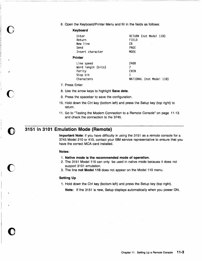
o
o
o
c
o
6. Open the Keyboard/Printer Menu and fill in the fields as follows:
Keyboard
Enter Return New line Send Insert character
Printer
Line speed Word length (bits) Parity Stop bit Characters
7. Press Enter.
RETURN (not Model 110) FIELD CR PAGE
'MODE
2400 7 EVEN 1 NATIONAL (not Model 110)
8. Use the arrow keys to highlight Save data.
9. Press the spacebar to save the configuration.
10. Hold down the Ctrl key (bottom left) and press the Setup key (top right) to return.
11. Go to ''Testing the Modem Connection to a Remote Console" on page 11-13 and check the connection to the 3745.
3151 in 3101 Emulation Mode (Remote) Important Note: If you have difficulty in using the 3151 as a remote console for a 3745 Model 210 or 410, contact your IBM service representative to ensure that you have the correct MCA card installed.
Notes:
1. Native mode is the recommended mode of operation. 2. The 3151 Model 110 can only be used in native mode because it does not
support 3101 emulation. 3. The line not Model 110 does not appear on the Model 110 menu.
Setting Up
1. Hold down the Ctrl key (bottom left) and press the Setup key (top right).
Note: If the 3151 is new, Setup displays automatically when you power ON.
Chapter 11. Setting Up a Remote Console 11-3
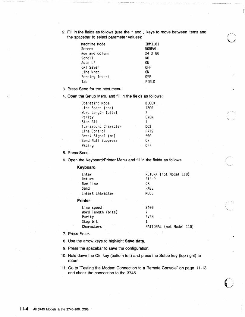
2. Fill in the fields as follows (use the t and ~ keys to move between items and the spacebar to select parameter values):
Machine Mode Screen Rowand Column Scroll Auto LF CRT Saver Line Wrap Forcing Insert Tab
3. Press Send for the next menu.
IBM31Bl NORMAL 24 X 8B NO ON OFF ON OFF
. FIELD
4. Open the Setup Menu and fill in the fields as follows:
Operating Mode BLOCK Line Speed (bps) 12BB Word Length (bits) 7 Parity EVEN Stop Bi t 1 Turnaround Character DC3 Line Control PRTS Break Signal (ms) 5BB Send Null Suppress ON Pacing OFF
5. Press Send.
6. Open the Keyboard/Printer Menu and fill in the fields as follows:
Keyboard
Enter Return New line Send Insert character
Printer
Line speed Word length (bits) Parity Stop bit Characters
7. Press Enter.
8. Use the arrow keys to highlight Save data.
RETURN (not Model lIB) FIELD CR PAGE MODE
24BB 7 EVEN 1 NATIONAL (not Model lIB)
9. Press the spacebar to save the configuration.
10. Hold down the Ctrl key (bottom left) and press the Setup key (top right) to return.
11. Go to ''Testing the Modem Connection to a Remote Console" on page 11-13 and check the connection to the 3745.
11-4 All 3745 Models & the 3746-900: eSG
o
./
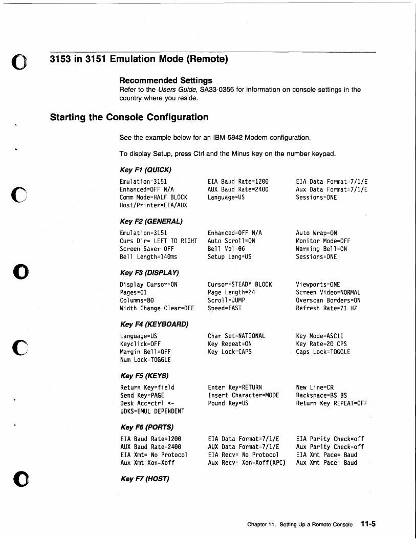
o 3153 in 3151 Emulation Mode (Remote)
Recommended Settings
c
o
c
o
Refer to the Users Guide, SA33-0356 for information on console settings in the country where you reside.
Starting the Console Configuration
See the example below for an IBM 5842 Modem configuration.
To display Setup, press Ctrl and the Minus key on the number keypad.
Key F1 (QUICK)
Emulation=3151 Enhanced=OFF N/A Comm Mode=HALF BLOCK Host/Printer=EIA/AUX
Key F2 (GENERAL)
Emulation=3151 Curs Dir= LEFT TO RIGHT Screen Saver=OFF Bell Length=140ms
Key F3 (DISPLA Y)
Display Cursor=ON Pages=01 Columns=S0 Width Change Clear=OFF
Key F4 (KEYBOARD)
Language=US Keyclick=OFF Margin Bel1=OFF Num Lock=TOGGLE
Key F5 (KEYS)
Return Key=field Send Key=PAGE Desk Acc=ctrl <
UDKS=EMUL DEPENDENT
Key FE; (PORTS)
EIA Baud Rate=12aa AUX Baud Rate=24aa EIA Xmt= No Protocol Aux Xmt=Xon-Xoff
Key F7 (HOST)
EIA Baud Rate=120a AUX Baud Rate=240a Language=US
Enhanced=OFF N/A Auto Scroll =ON Bell Vol=06 Setup Lang=US
Cursor=STEADY BLOCK Page Length=24 Scroll=JUMP Speed=FAST
Char Set=NATIONAL Key Repeat=ON Key Lock=CAPS
Enter Key=RETURN Insert Character=MODE Pound Key=US
EIA Data Format=7/1/E AUX Data Format=7/1/E EIA Recv= No Protocol Aux Recv= Xon-Xoff(XPC)
EIA Data Format=7/1/E Aux Data Format=7/1/E Sessions=ONE
Auto Wrap=aN Monitor Mode=OFF Warni ng Bell =ON Sessions=ONE
Viewports=ONE Screen Video=NORMAL Overscan Borders=ON Refresh Rate=71 HZ
Key Mode=ASCII Key Rate=2a CPS Caps Lock=TOGGLE
New Line=CR Backspace=BS BS Return Key REPEAT=OFF
EIA Parity Check=off Aux Parity Check=off EIA Xmt Pace= Baud Aux Xmt Pace= Baud
Chapter 11. Setting Up a Remote Console 11-5
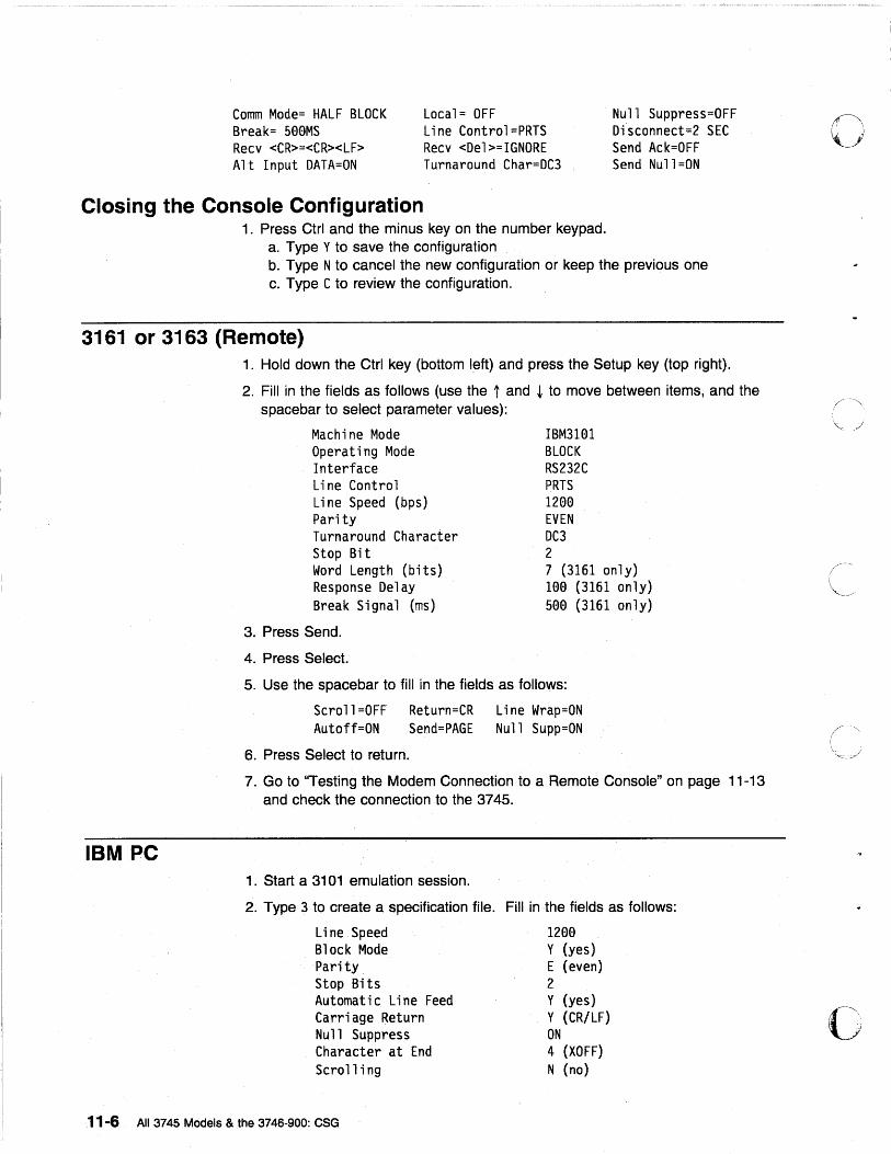
Comm Mode= HALF BLOCK Break= 500MS Recv <CR>=<CR><LF> Alt Input DATA=ON
Local= OFF Line Control=PRTS Recv <Del>=IGNORE Turnaround Char=DC3
Null Suppress=OFF Di~connect=2 SEC Send Ack=OFF Send Null=ON
Closing the Console Configuration 1. Press Ctrl and the minus key on the number keypad.
a. Type Y to save the configuration b. Type N to cancel the new configuration or keep the previous one c. Type C to review the configuration.
3161 or 3163 (Remote)
IBM PC
1. Hold down the Ctrl key (bottom left) and press the Setup key (top right).
2. Fill in the fields as follows (use the t and ~ to move between items, and the spacebar to select parameter values):
Machine Mode Operating Mode Interface Line Control Line Speed (bps) Parity Turnaround Character Stop Bit Word Length (bits) Response Delay Break Signal (ms)
3. Press Send.
4. Press Select.
IBM3HH BLOCK RS232C PRTS 1200 EVEN DC3 2 7 (3161 only) 100 (3161 only) 500(3161 only)
5. Use the spacebar to fill in the fields as follows:
Scroll=OFF Return=CR Line Wrap=ON Autoff=ON Send=PAGE Null Supp=ON
6. Press Select to return.
7. Go to ''Testing the Modem Connection to a Remote Console" on page 11-13 and check the connection to the 3745.
1. Start a 3101 emulation session.
2. Type 3 to create a specification file. Fill in the fields as follows:
Line Speed Block Mode Parity Stop Bits Automatic Line Feed Carriage Return Null Suppress Character at End Scroll i ng
1200 Y (yes) E (even) 2 Y (yes) Y (CR/LF) ON 4 (XOFF) N (no)
11-6 All 37 45 Models & the 3746-900: eSG
./
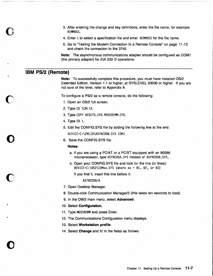
o
o
o
o
o
3. After entering the change and key definitions, enter the file name, for example REMMOSS.
4. Enter 1 to select a specification file and enter REMMOSS for the file name.
5. Go to ''Testing the Modem Connection to a Remote Console" on page 11-13 and check the connection to the 3745.
Note: The asynchronous communications adapter should be confjgured as COM1 (the primary adapter) for EIA 232-0 operations.
IBM PS/2 (Remote) Note: To successfully complete this procedure, you must have installed OS/2 Extended Edition, Version 1.1 or higher, at SYSLEVEL 03030 or higher. Jf you are not sure of the level, refer to Appendix A.
To configure a PS/2 as a remote console, do the following:
1. Open an OS/2 full screen.
2. Type CD \CMLlB.
3. Type COPY ACSCFG.CFG MOSSREMM.CFG.
4. Type CD \.
5. Edit the CONFIG.SYS file by adding the following line at the end:
DEVICE=C:\CMLIB\ASYNCDDB.SYS COMI
6. Save the CONFIG.SYS file.
Notes:
a. If you are using a PC/AT or a PCIXT equipped with an S0286 microprocessor, type ASYNCDDA.SYS instead of ASYNCDDB.SYS.
b. Open your CONF1G.SYS file and look for the line (or lines): DEVICE=C:\OS2\COMxx.SYS (where xx = 81, 82, or 83)
If you find it, insert this line before it:
ASYNCDDB/A
7. Open Desktop Manager.
S. Double-click Communication Manager/2 (this takes ten seconds to load).
9. In the CM/2 main menu, select Advanced.
10. Select Configuration.
11. Type MOSSREMM and press Enter.
12. The Communications Configuration menu displays.
13. Select Workstation profile.
14. Select Change and fill in the fields as follows:
Chapter 11. Setting Up a Remote Console 11-7
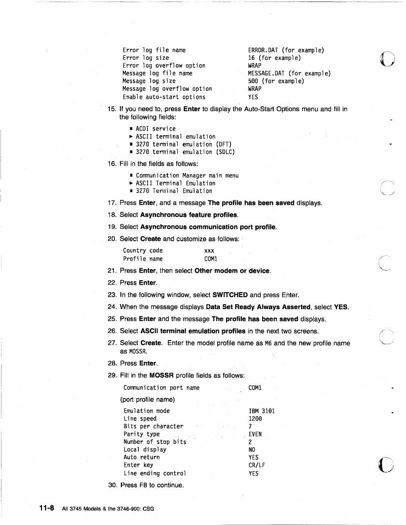
Error log file name Error log size Error log overflow option Message log file name Message log size Message log overflow option Enable auto-start options
ERROR~OAT (for example) 16 (for example) WRAP MESSAGE. OAT (for example) 500 (for example) WRAP YES
15. If you need to, press Enter to display the Auto-Start Options menu and fill in the following fields:
• ACOI service ~ ASCII terminal emulation • 3270 terminal emulation (OFT) • 3270 terminal emulation (SOLC)
16. Fill in the fields as follows:
• Communication Manager main menu ~ ASCII Terminal Emulation i 3270 Terminal Emulation
17. Press Enter, and a message The profile has been saved displays.
18. Select Asynchronous feature profiles.
19. Select Asynchronous communication port profile.
20. Select Create and customize as follows: ..
Country code Profil e name
xxx COM1
21. Press Enter, then select Other modem or device.
22. Press Enter.
23. In the following window, select SWITCHED and press Enter.
24. When the message displays Data Set Ready Always Asserted, select YES.
25. Press Enter and the message The profile has been saved displays.
26. Select ASCII terminal emulation profiles in the next two screens.
27. Select Create. Enter the model profile name as M6 and the new profile name as MOSSR.
28. Press Enter.
29. Fill in the MOSSR profile fields as follows:
Communication port name
(port profile name)
Emulation mode Line speed Bits per character Parity type Number of stop bits Local display Auto return Enter key Line ending control
30. Press F8 to continue.
11-8 All 3745 Models & the 3746-900: CSG
COM1
IBM 3101 1200 7 EVEN 2 NO YES CR/LF YES
o
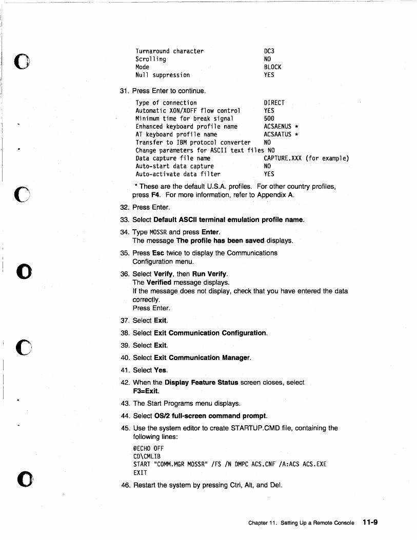
o
o
o
o
o
Turnaround character Scroll i ng Mode Null suppression
31. Press Enter to continue.
DC3 NO BLOCK YES
Type of connection DIRECT Automatic XON/XOFF flow control YES Minimum time f~r break signal 5ee Enhanced keyboard profile name ACSAENUS * AT keyboard profile name ACSAATUS * Transfer to IBM protocol converter NO Change parameters for ASCII text files NO Data capture file name CAPTURE.XXX (for example) Auto-start data capture NO Auto-activate data filter YES
* These are the default U.S.A. profiles. For other country profiles, press F4. For more information, refer to Appendix A.
32. Press Enter.
33. Select Default ASCII terminal emulation profile name.
34. Type MOSSR and press Enter. The message The profile has been saved· displays.
35. Press Esc twice to display the Communications Configuration menu.
36. Select Verify, then Run Verify. The Verified message displays. If the message does not display, check that you have entered the data correctly. Press Enter.
37. Select Exit.
38. Select Exit Communication Configuration.
39. Select Exit.
40. Select Exit Communication Manager.
41. Select Yes.
42. When the Display Feature Status screen closes, select F3=Exit.
43. The Start Programs menu displays.
44. Select OS/2 full-screen command prompt.
45. Use the system editor to create STARTUP .CMD file, containing the following lines:
@ECHO OFF CD\CMLIB START "COMM.MGR MOSSR" IFS IN DMPC ACS.CNF IA:ACS ACS.EXE EXIT
46. Restart the system by pressing Ctrl, Alt, and Del.
Chapter 11. Setting Up a Remote Console 11-9
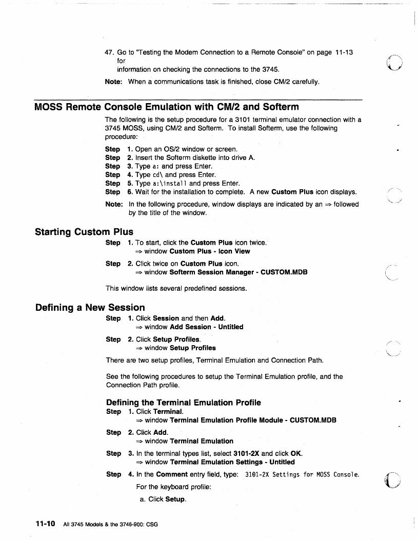
47. Go to "Testing the Modem Connection to a Remote Console" on page 11-13 for information on checking the connections to the 3745.
Note: When a communications task is finished, close CM/2 carefully.
MOSS Remote Console Emulation with CM/2 and Softerm The following is the setup procedure for a 3101 terminal emulator connection with a 3745 MOSS, using CM/2 and Softerm. To install Softerm, use the following procedure:
Step 1. Open an OS/2 window or screen. Step 2. Insert the Softerm diskette into drive A. Step 3. Type a: and press Enter. Step 4. Type cd\ and press Enter. Step 5. Type a: \ ins ta 11 and press Enter. Step 6. Wait for the installation to complete. A new Custom Plus icon displays.
Note: In the following procedure, window displays are indicated by an ~ followed by the title of the window.
Starting Custom Plus Step 1. To start, click the Custom Plus icon twice.
==> window Custom Plus - Icon View
Step 2. Click twice on Custom Plus icon. ==> window Softerm Session Manager - CUSTOM.MOB
This window lists several predefined sessions.
Defining a New Session Step 1. Click Session and then Add.
~ window Add Session - Untitled
Step 2. Click Setup Profiles. ==> window Setup Profiles
There are two setup profiles, Terminal Emulation and Connection Path.
See the following procedures to setup the Terminal Emulation profile, and the Connection Path profile.
Defining the Terminal Emulation Profile Step 1. Click Terminal.
~ window Terminal Emulation Profile Module - CUSTOM.MOB
Step 2. Click Add. ==> window Terminal Emulation
Step 3. In the terminal types list, select 3101-2X and click OK. ==> window Terminal Emulation Settings - Untitled
Step 4. In the Comment entry field, type: 3191-2X Setti ngs for MOSS Con sol e.
For the keyboard profile:
a. Click Setup.
11-10 All 3745 Models & the 3746-900: CSG
o
o
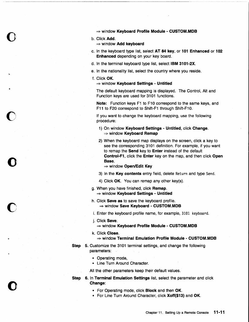
o
o
o
c
o
~ window Keyboard Profile Module - CUSTOM.MOB
b. Click Add. ~ window Add keyboard
c. In the keyboard type list, select AT 84 key, or 101 Enhanced or 102 Enhanced depending on your key board.
d. In the terminal keyboard type list, select IBM 3101-2X.
e. In the nationality list, select the country where you reside.
f. Click OK. ~ window Keyboard Settings - Untitled
The default keyboard mapping is displayed. The Control, Alt and Function keys are used for 3101 functions.
Note: Function keys F1 to F10 correspond to the same keys, and F11 to F20 correspond to Shift-F1 through Shift-F10.
If you want to change the keyboard mapping, use the following procedure:
1) On window Keyboard Settings - Untitled, click Change. ~ window Keyboard Remap
2) When the keyboard map displays on the screen, click a key to see the corresponding 3101 definition. For example, if you want to remap the Send key to Enter instead of the default Control-F1, click the Enter key on the map, and then click Open Base. ~ window Open/Edit Key
3) In the Key contents entry field, delete Return and type Send.
4) Click OK. You can remap any other keyes).
g. When you have finished, click Remap. ~ window Keyboard Settings - Untitled
h. Click Save as to save the keyboard profile. ~ window Save Keyboard - CUSTOM.MOB
i. Enter the keyboard profile name, for example, 3101 keyboard.
j. Click Save. ~ window Keyboard Profile Module - CUSTOM.MOB
k. Click Close. ~ window Terminal Emulation Profile Module - CUSTOM.MOB
Step 5. Customize the 3101 terminal settings, and change the following parameters:
• Operating mode, • Line Turn Around Character.
All the other parameters keep their default values.
Step 6. In Terminal Emulation Settings list, select the parameter and click Change:
• For Operating mode, click Block and then OK. • For Line Turn Around Character, click Xoff($13) and OK.
Chapter 11. Setting Up a Remote Console 11-11
Step 7. Click Save as. ~ window Save Terminal Emulation - CUSTOM.MOB
Step 8. Enter the terminal emulation profile name, for example, 3101 ernul at; on.
Step 9. Click Save. ~ window Terminal Emulation Profile Module - CUSTOM.MOB
Step 10. Click Close.
Defining Connection Path Profile Click Setup Profiles. ~ window Setup Profiles
Step 1. Click Connection. ~ window Connection Path Profile Module - CUSTOM.MOB
Step 2. Click Add twice. ~ window Add Connection Path
Step 3. Enter Standard COM for the communication interface and click OK. ~ window Connection Path Settings - Untitled
• COM1 (default setting) for the COM port • Select (None) for the modem profile name.
Note: You can add a customized profile with modem-supported features, such as auto-dial and auto-answer.
• Connection Path Settings: • Select an item in the list and click Change then OK. • Communications parameters:
- Baud rate = 1200 - Data bits = 7 - Stop bits = 1 - Parity = Even
• Flow Control: None (default setting).
Step 4. Click Save as. ~ window Save Connection Path - CUSTOM.MOB
Step 5. Enter the connection path profile name, for example connect; on.
Step 6. Click Save. ~ window Connection Path Profile Module - CUSTOM.MOB
Step 7. Click Close.
Ending Definition of a New Session Step 1. rn the ~ window Add Session - Untitled, click Add.
~ window Admittance data
Step 2. Click Save as. ~ window Save Session
Step 3. Enter the session name, for example MOSS Console.
Step 4. Click Save. ~ window Softerm Session Manager - CUSTOM.MOB
11-12 All 3745 Models & the 3746-900: eSG
o
-"",
o
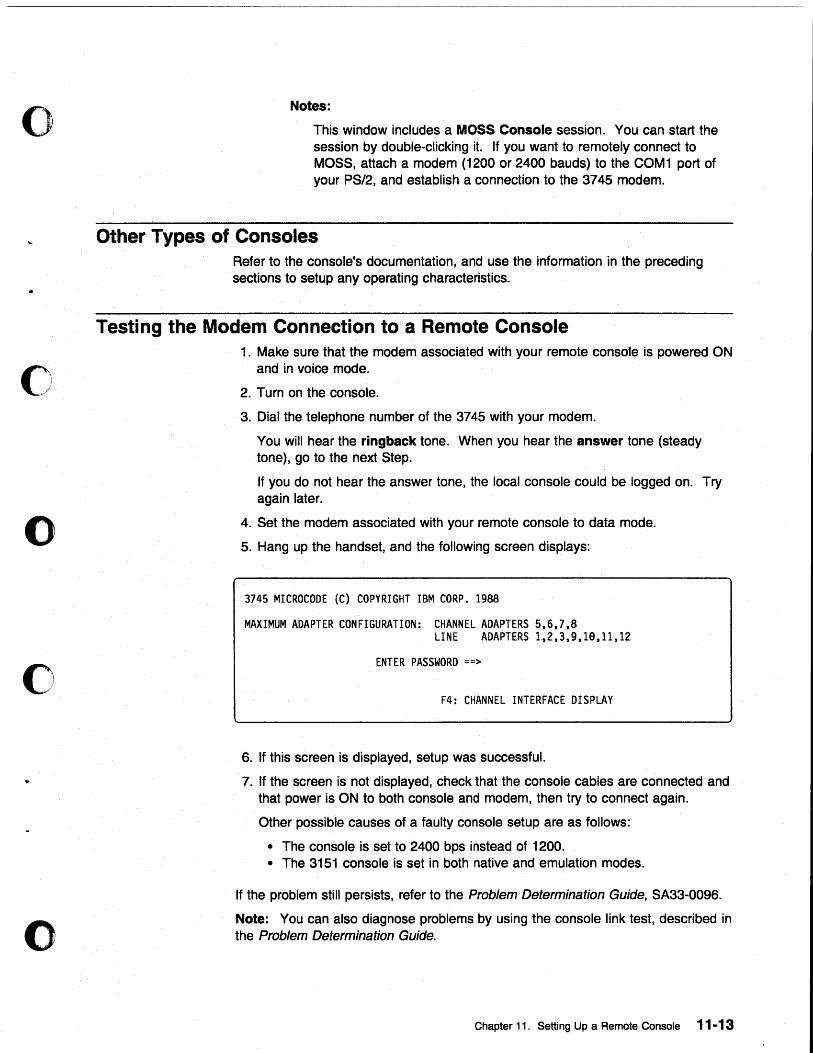
o
o
o
o
o
Notes:
This window includes a MOSS Console session. You can start the session by double-clicking it. If you want to remotely connect to MOSS, attach a modem (1200 or 2400 bauds) to the COM1 port of your PS/2, and establish a connection to the 3745 modem.
Other Types of Consoles Refer to the console's documentation, and use the information in the preceding sections to setup any operating characteristics1
Testing the Modem Connection to a Remote Console 1. Make sure that the modem associated with your remote cons01e is powered ON
and in voice mode.
2. Turn on the console.
3. Dial the telephone number of the 3745 with your modem.
You will hear the ringback tone. When you hear the answer tone (steady tone), go to the next Step.
If you do not hear the answer tone, the local console could be logged on. Try again later.
4. Set the modem associated with your remote consoJe to data mode.
5. Hang up the handset, and the following screen displays:
3745 MICROCODE (C) COPYRIGHT IBM CORP. 1988
MAXIMUM ADAPTER CONFIGURATION: CHANNEL ADAPTERS 5,6,7,8 LINE ADAPTERS 1~2,3,9,1e,11,12
ENTER PASSWORD ==>
F4: CHANNEL INTERFACE DISPLAY
6. If this screen is displayed, setup was successful.
7. If the screen is not displayed, check that the console cables are connected and that power is ON to both console and modem, then try to connect again.
Other possible causes of a faulty console setup are as follows:
• The console is set to 2400 bps instead of 1200. • The 3151 console is set in both native and emulation modes.
If the problem still persists, refer to the Problem Determination Guide, SA33-0096.
Note: You can also diagnose problems by using the console link test, described in the Problem Determination Guide.
Chapter 11. Setting Up a Remote Console 11-13

11-14 All 3745 Models & the 3746-900: CSG
o
(-~
.)
--~-.-.-.- ... -.-.---.-..• -.. --... -- ..... ---.-
o Chapter 12. Modem Setup
•
o
o
o
o
Modems for 3745 Models 130 to 160
Setting Up
The foilowing is a list of modems that can be set up to operate between the remote console and the 3745:
1n the U.S.A.:
• IBM 5841 Modem . • IBM 5842 Modem.
1n the U.S.A., Canada, and Japan:
• IBM 5853 Modem (set to half speed). • Equivalent compatible with Bell 212 A or ITU-T V.22 (1200 bps).
1n other countries:
• Modems compatible with ITU-T V.22 alternative 8 (1200 bps).
For information about setting up RSF modems, refer to Chapter 13, "RSF Modems" on page 13-1.
For the modem to be compatible between the remote console and the 3745, refer to the modem's documentation and set the following modem characteristics:
• Switched line connection • Duplex ope rat jon • Asynchronous operation • 1200 bps speed • 3745 modem set to auto-answer • Remote console modem set to manual dialing.
Notes:
1. Review the modem documentation to ensure compatibility with the 3745. In particular, check the following:
• Error Checking Link (Eel) is disabled. • If the modem has a Test Model, turn it off at the 3745 end. • If the modem is programmable, set the control of the Data Set Ready
(DSR) signal to normal, so that it does not get raised by the Data Terminal Ready (DTR).
2. Some IBM PC modems disconnect from the switched network when the carrier signal drops. To prevent this, set the modem at the PC end to RTS Permanent. For more information, refer to your modem documentation.
© Copyright IBM Corp. 1989, 1998 12-1
Switch Settings for IBM Modems 5841, 5842, and 5853
IBM 5841 Modem Set the modem switches of the remote console as follows:
1. Set back panel DIP switches SW7 and 8 DOWN, all others UP. 2. Set all front panel switches OUT.
Set the modem switches of the 3745 as follows:
1. Set back panel DIP switches SW7 and 8 DOWN, all others UP. 2. Set all front panel switches OUT.
IBM 5842 Modem Set the switches at the remote console site as follows:
1. Set back panel DIP switches SW7 and 8 DOWN, all others UP. 2. Set front panel switches FS IN, all others OUT.
Set the switches at the 3745 site as follows:
1. Set back panel DIP switches SW7 and 8 DOWN, all others UP. 2. Set front panel switches FS IN, all others OUT.
IBM 5853 Modem Set the switches at the 3745 site as follows:
1. Set back panel DIP switches to UP. 2. Set front panel switches FS IN, all others OUT.
Set the switches at the remote console site as follows:
1. Set back panel DIP switches to UP. 2. Set front panel switches FS IN, all others OUT.
Note: Before you set any modem configurations, make sure that both modems have been initialized and then do the following:
1. Push in all the front panel switches. 2. Turn power ON and wait five seconds. 3. Turn power OFF. 4. Set the front panel switches as described above. 5. Turn power ON again.
12-2 All 3745 Models & the 3746-900: eSG
o
c
o
c
o
c
o
Modems for 3745 Models A The procedures jn this section explain how to manipulate the IBM modems recommended for DeAF.
Note: The Hayes modem does not need to be set manually.
Setting the IBM 7855 Modem t. Press both the ~ and ~ buttons on the front panel of the modem. The
modem displays the message I <Exi t Enter> I •
2. Press the ~ button. If the modem displays View Only, go to Step 3. If the modem displays I Password ••••••••• ', use the ~ and the 1 buttons to change the display to I Password •••• 8293 I by changing one character at a time. Press the ~ button one more time, and then check the display again to make sure it shows 'View Only'.
3. Press and release the f or ~ button as needed to change the display to I Fi rst Setup I.
4. Press the ~ button once, press and release the t or ~ button to change the display to I Reset to Factory I •
5. Press the ~ button. The lights on the front panel flash briefly.
6. Set the modem speed to 12000 bps by doing the following:
a. Press both the ~ and -+ buttons. The modem displays: I <Exi t Enter> I •
b. Press and release the -+ button. The modem displays: I Vi ew Only I.
c. Press the ~ button twice. The modem displays: I Qui ck Customi ze' .
d. Press the ~ button. The modem displays: 'OTE interface'.
e. Press the ~ button twice. The modem displays: I PSN Tel co speed'.
f. Press the ~ button. The modem displays: 'PSN 8ps 96ee'.
g. Press the ~ button. The modem displays: 'PSN 8ps 12 eee'.
h. Press the ~ button 6 times. The modem displays: I SYNC I NT 12 eee'.
7. Turn the modem off.
Setting and Saving the Target Service Processor Phone Number
1. Press both the ~ and ~ buttons on the front panel of the modem. The modem displays the message I <Ex it Enter> ' .
2. Press the ~ button. If the modem displays I Vi ew On 1 y , , go to Step 3. If the modem displays I Password ..••••••• ', use the ~ button and the t button to change the display to I Password •••• 8293' by changing one character at a time. Press the ~ button one more time, and then check the display again to make sure it shows 'View Only'.
3. Press and release the t or ~ button as needed to change the display to I Oi rectori es ' .
4. Press the -+ button to display I No Password I. If the display shows I Password
needed' , use the f button and the t button once to change the display to , Local Pass B293' by changing one character at a time.
Chapter 12. Modem Setup 12-3
5. Press the ~ button to display 'Store and Vi ew' .
6. Press the ~ button to display 'Di rectori es xx'.
7. Set the target service processor phone number with the f and ! buttons. Switch to the next number with the ~ button.
8. Press the +- button 8 times to exit.
Setting the IBM 7857 Modem Connected to MPA Card (SYN) 1. Press the! key until the' CONFIG' message displays at the top of the screen.
2. Press the ~ key until the' Sel Factory' message c::iisplays at the bottom of the screen.
3. Press Enter.
4. Press the f· key until '3' displays.
5. Press Enter to load the predefined factory configuration 3.
6. Press the f key until' Ul' displays at the top of the screen.
7. Press the ~ key until 'Sync mode 3' displays. Press Enter to validate.
8. Press the f key until 'U2' displays.
9. Press the ~ key until' Internal' displays. Press Enter to validate.
10. Press the f key until 'U3' displays.
11. Press the ~ key until 'Autobaud' displays. Press Enter to validate.
12. Press the f key until 'U4' displays.
13. Press the ~ key until 'CCITT' displays. Press Enter to validate.
14. Press the f key until 'US' displays.
15. Press the ~ key until '9600 V32 TRE' displays. Press Enter to validate.
16. Press the f key until 'U6 t displays.
17. Press the ~ key until' V42Bi s/MNPS Enabl ed' displays. Press Enter to validate.
18. Press the f key until t U7' displays.
19. Press the ~ key until 'Auto Reliable/V42/MNP' displays. Press Enter to validate.
20. Press the f key until 'US' displays.
21. Press the ~ key until 'Xon/Xoff passed' displays. Press Enter to validate.
22. Press the f key until 'U9' displays.
23. Press the ~ key until 'Xon/Xoff' displays. Press Enter to validate.
24. Press the t key until' U10' displays.
25. Press the ~ key until 'C10S/2' displays. Press Enter to validate.
26. Press the f key until 'Ull' displays.
27. Press the ~ key until' C106 Always follow C10S t displays. Press Enter to C· \. validate. · .... '
28. Press the f key until' U12' displays.
12-4 All 3745 Models & the 3746-900: eSG
o
c
o
c
o
29. Press the - key until I CI07 /C109 Normal Mode I displays. Press Enter to validate.
30. Press the t key until I UI3 I displays.
31. Press the - key until I CI07 Fall ow CI09 (CD) I displays. Press Enter to validate.
32. Press ~ until I Mode I displays.
33. Press - until the message I V25HDLC NRZIASC I displays.
34. Press Enter.
The modem is now in ITU-T V.2S bis synchronous mode. See "Saving the Modem Configuration" below.
Setting the 7857 Modem Connected to COM1 (ASYN) 1. Power OFF the modem
2. Press and hold the t key while power ON the modem.
3. The modem is set to Factory 0 in AT command mode.
See "Saving the Modem Configuration" below.
Setting the 7857 Modem Connected to MPA Card on COM2 (ASYN) 1. Power OFF the modem
2. Press and hold the t key while power ON the modem.
3. The modem is set to Factory 0 in AT command mode.
See "Saving the Modem Configuration" below.
Saving the Modem Configuration
1. Press the .~ key until the I CONFIG I message displays at the top of the screen.
2. Press the - key until the I Store User Conf I message displays at the bottom of the screen.
3. Press Enter.
4. Press the t key, to select the User Configuration Location (0 to 9) where you want to save the configuration.
5. Press Enter to save the current modem configuration.
The defined configuration is now active and saved. Every time the modem is reset (powered ON), this configuration is loaded.
Transmission Speed The IBM 7857 uses an Adaptive line rate facility which can automatically decrease or increase themodem's transmission speeds. This means that if telecommunication line conditions deteriorate, the modem can still function at the highest possible efficiency.
Setting and Saving the Target Service Processor Phone Number
1. Press the ~key untit I Store phone number I displays at the top of the screen.
2. Press the - key to select the first location number.
3. Press Enter.
Chapter 12. Modem Setup 12-5
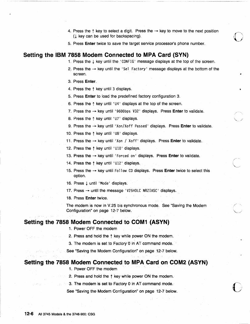
4. Press the t key to select a digit. Press the ~ key to move to the next position 0,':, .. ' I (~ key can be used for backspacing).
5. Press Enter twice to save the target service processor's phone number.
Setting the IBM 7858 Modem Connected to MPA Card (SYN) 1. Press the ~ key until the I CONFIG I message displays at the top of the screen.
2. Press the ~ key until the I Sel Factory I message displays at the bottom of the screen.
3. Press Enter.
4. Press the t key until 3 displays.
5. Press Enter to load the predefined factory configuration 3.
6. Press the t key until I U4 I displays at the top of the screen.
7. Press the ~ key until '9600bps V32 I displays. Press Enter to validate.
8. Press the t key until i U7 i displays.
9. Press the ~ key until I Xon/Xoff Passed I displays. Press Enter to validate.
10. Press the t key until I U8 I displays.
11. Press the ~ key until I Xon / Xoff I displays. Press Enter to validate.
12. Press the t keyuntil ' U10 1 displays.
13. Press the ~ key until I Forced on I displays. Press Enter to validate.
14. Press the tkey until I U12 I displays.
15. Press the ~ key until Follow CD displays. Press Enter twice to select this option.
16. Press ~ until I Mode I displays.,
17. Press ~ until the message I V25HDLC NRZIASC I displays.
18. Press Enter twice.
The modem is now in V.25 bis synchronous mode. See "Saving the Modem Configuration" on page 12-7 below.
Setting the 7858 Modem Connected to COM1 (ASYN) 1. Power OFF the modem
2. Press and hold the t key while power ON the modem.
3. The modem is set to Factory'O rn AT command' mode.
See "Saving the Modem Configuration" on page 12-7 below.
Setting the 7858 Modem Connected to MPACard on COM2 (ASYN) 1. Power OFF the modem
2. Press and hold the t key while power ON the modem.
3. The modem is set to Factory 0 in AT.command mode.
See "Saving the Modem Configuration" on page 12-7 below.
12-6 All 3745 Models & the 3746-900: eSG
,/
o
c
o
o
o
Saving the Modem Configuration
1. Press the ~ key until the 'CONFIG I message displays at the top of the screen.
2. Press the -+ key until the I Store User Conf. I message displays at the bottom of the screen.
3. Press Enter.
4. Press the t key, to select the User Configuration Location (0 to 9) where you want to save the configuration.
5. Press Enter to save the current modem configuration.
The defined configuration is now active and saved. Every time the modem is reset (powered ON), this configuration is loaded.
Transmission Speed The IBM 7858 uses an Adaptive line rate facility which can automatically decrease or increase the modem1s transmission speeds. This means that if telecommunication line conditions deteriorate, the modem can still function at the highest possible efficiency.
Setting and Saving the Target Service Processor Phone Number
1. Press the ~ key until 'Store phone number' display at the top of the screen.
2. Press the -+ key to select the first location number.
3. Press Enter.
4. Press the t key to select a digit. Press the -+ key to move to the next position (~ key can be used for backspacing).
5. Press Enter twice to save the target service processor's phone number.
Chapter 12. Modem Setup 12-7

o
c 12-8 All 3745 Models & the 3746-900: CSG
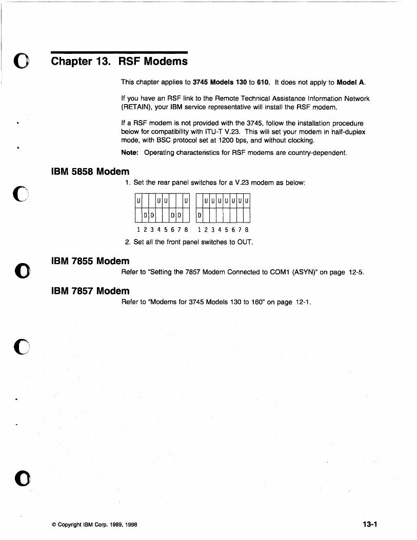
o Chapter 13. RSF Modems
o
o
o
This chapter applies to 3745 Models 130 to 610. It does not apply to Model A.
If you have an RSF link to the Remote Technical Assistance Information Network (RETAIN), your IBM service representative will install the RSF modem.
If a RSF modem is not provided with the 3745, follow the installation procedure below for compatibility with ITU-T V.23. This will set your modem in half-duplex mode, with BSC protocol set at 1200 bps, and without clocking.
Note: Operating characteristics for RSF modems are country-dependent.
IBM 5858 Modem 1. Set the rear panel switches for a V.23 modem as below:
~.u UU u~ ~ ~ 1 2 3 4 5 678 1 2 3 4 5 6 7 8
2. Set all the front panel switches to OUT.
IBM 7855 Modem Refer to "Setting the 7857 Modem Connected to COM1 (ASYN)" on page 12-5.
IBM 7857 Modem Refer to "Modems for 3745 Models 130 to 160" on page 12-1.
© Copyright IBM Corp. 1989, 1998 13-1

~~-----"'--------- -- -~-----~------.-... --.-----.---
o
C\ .' ,-- .
13-2 All 3745 Models & the 3746-900: CSG
---- --......... ---... - .. -~.--.
o Part 3. Appendixes for 3745 Model A and 3746 Model 900
o
o
c
o © Copyright IBM Corp. 1989, 1998

o
c All 3745 Models & the 3746-900: CSG
--------- -------~~---
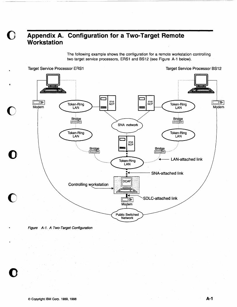
o Appendix A. Configuration for a Two-Target Remote Workstation
o
o
c
o
The following example shows the configuration for a remote workstation controlling two target service processors, ERS1 and 8812 (see Figure A-1 below).
Target Service Processor ERS1
·················· ... f~rid~:1
....•.• .....
CJ
•
3745 NCP
Target Service Processor 8S12
1.~ridEel c::::J ...
l~rid~:I ..... ·············· ....
. .......... +-- LAN-attached link
:+4---- SNA-attached link
Controlling workstation IIOCAFII ............. -------4.~1 =::::::i
d'Z--Sti\(
Figure A-1. A TWO-Target Configuration.
© Copyright IBM Corp. 1989, 1998 A·1
The example in Figure A-1 on page A-1 assumes that the workstation is running:
• CS/2 or CM/2. • NCP Version 6, Release 2 or higher with 3746-900 features. • VT AM Version 3, Release 4.1.
NCP Definitions NCP must contain definitions for the TIC2 or TIC3. These ports are used to attach the controlling workstation and the two service processors to token-ring LANs.
The only other requirement is to manage dynamic LUs by entering the following definition:
LUDRPOOL NUMILU=(a number> O)
VTAM Definitions
Start List The VTAM start list below should contain the XNETALS=YES statement to enable the cross-network SSCP-PU session activation (without SNI), and the statement DYNLU=YES to handle dynamic LUs (see the example below).
HOSTSA=10,SSCPID=10,MAXSUBA=63 CONFIG=10,NETID=SYSTST,SSCPNAME=CDRM20, XNETALS=YES,DYNLU=YES, NOPROMPT,DLRTCB=32,SUPP=NOSUP,NOTNSTAT,NOTRACE,TYPE=VTAM, LPBUF=(120,,0,,60,60), LARGE GENERAL PURPOSE_PAGEABLE LFBUF=(96,,0,,24,10), LARGE GENERAL PURPOSE_FIXED LFBUF=(128,,0,,32,10), SMALL GENERAL PURPOSE_FIXED CRPLBUF=(160,,13,,80,80), RPL_COPY_PAGEABLE IOBUF=(256,256,34,,68,68) I/O BUFFERS_FIXED (NP&PP BUF REMOVED)
A-2 All 3745 Models & the 3746-900: CSG
C', ,I.' , J
J
, .1 C' ' ,_ ...... Ii
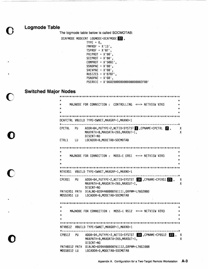
o
o
o
o
()
Logmode Table The log mode table below is called SOCMOTAB:
DCAFMODE MODEENT LOGMODE=DCAFMODE m , TYPE = 0, FMPROF = X 113 I, TSPROF = X' 07 1, PRIPROT = X'B0 1, SECPROT = X' B0 1, COMPROT = X'50B11, SSNDPAC = X'08 1, SRCVPAC = X I 08 I ,
RUSIZES = X'8787 1, PSNDPAC = X'08 1, PSERVIC = X I 060200000000000000002F00 I
Switched Major Nodes
* * * *
MAJNODE FOR CONNECTION: CONTROLLING <==> NETVIEW V2R3
DCAFCTRL VBUILD TYPE=SWNET,MAXGRP=l,MAXNO=l
* * * *
*---------------------------------------------------------------------* CPCTRL PU
CTRLl LU
*
ADDR=04,PUTYPE=2,NETID=SYSTST D ,CPNAME=CPCTRL fJ, MAXPATH=8,MAXDATA=265,MAXOUT=l, DISCNT=NO LOCADDR=0,MODETAB=SOCMOTAB
* MAJNODE FOR CONNECTION: MOSS-E ERS1 <==> NETVIEW V2R3 * *
NTVERS1 VBUILD TYPE=SWNET,MAXGRP=l,MAXNO=l
* * * *
*---------------------------------------------------------------------* CPERSI PU
PATHERS1 PATH MOSSERS1 LU
*
ADDR=04,PUTYPE=2,NETID=SYSTST III ,CPNAME=CPERSI m ' MAXPATH=8,MAXDATA=265,MAXOUT=1, DISCNT=NO DIALNO=0204400000761111,GRPNM=L76G2080 LOCADDR=0,MODETAB=SOCMOTAB
* MAJNODE FOR CONNECTION: MOSS-E BS12 <==> NETVIEW V2R3 * *
NTVBS12 VBUILO TYPE=SWNET,MAXGRP=l,MAXNO=l
* * * *
*---------------------------------------------------------------------*
X X
X X
CPBS12 PU ADOR=04.,PUTYPE=2,NETIO=SYSTST 1m ,CPNAME=CPBS12 MAXPATH=8,MAXDATA=265,MAXOUT=1,
rD, X X
PATHBS12 PATH MOSSBS12 LU
OISCNT=NO DIALNO=0204400000761112,GRPNM=L76G1088 LOCAODR=0,MOOETAB=SOCMOTAB
Appendix A. Configuration for a Two-Target Remote Workstation A-3
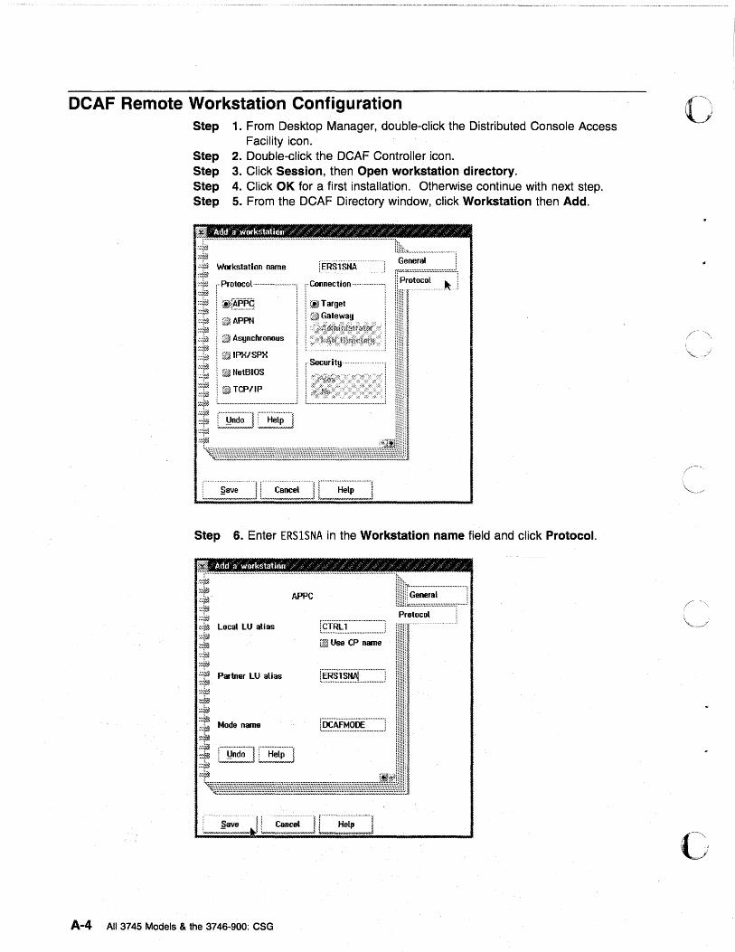
DCAF Remote Workstation Configuration Step 1. From Desktop Manager, double-click the Distributed Console Access
Facility icon. Step 2. Double-click the DCAF Controller icon. Step 3. Click Session, then Open workstation directory. Step 4. Click OK for a first installation. Otherwise continue with next step. Step 5. From the DCAF Directory window, click Workstation then Add.
:'~}f~ . ;;;fiJ I Q'ffi NetBIOS
:~if!i i 1:'0>. TCP/IP ~~~r£1 ;:id». ,::Iij}} ~## •••• ,. ...... u." ... "..". ... O# •• ". ........ ".". ..... ".j
.~~~;j ~~~rm ~~~v~ :::J!!},
! Security·
Step 6. Enter ERSISNA in the Workstation name field and click Protocol.
i-----------------:::-----------------IE:~ .. ::::J
~t Protocol
:::}f£ Local lU alias r.~f~f:r:::::::::::::~~~:~~~~J .......... 1 ~~~~ :~~$. f@1 Use CP name .~~+i& ,::r~
~::~ Partner LU alias r.~~.~~~~:~~[~~:~~::~~:~:J :~~~..1 ~:}~ ;;~iJ
~~ Mode name r~.~.~~~~~~:~~~~~~~~~J ,::rA
~; [j~~~~] [~=~~~~] :~~~
'~:Jeft.i~~71fJff!lijJjj¥JfjjjJffjjjffjfJl~¥Jfffjf!i~Ejjj!!!##!EjjjfJl~~2J;J!;JlJ
A-4 All 3745 Models & the 3746-900: CSG
o
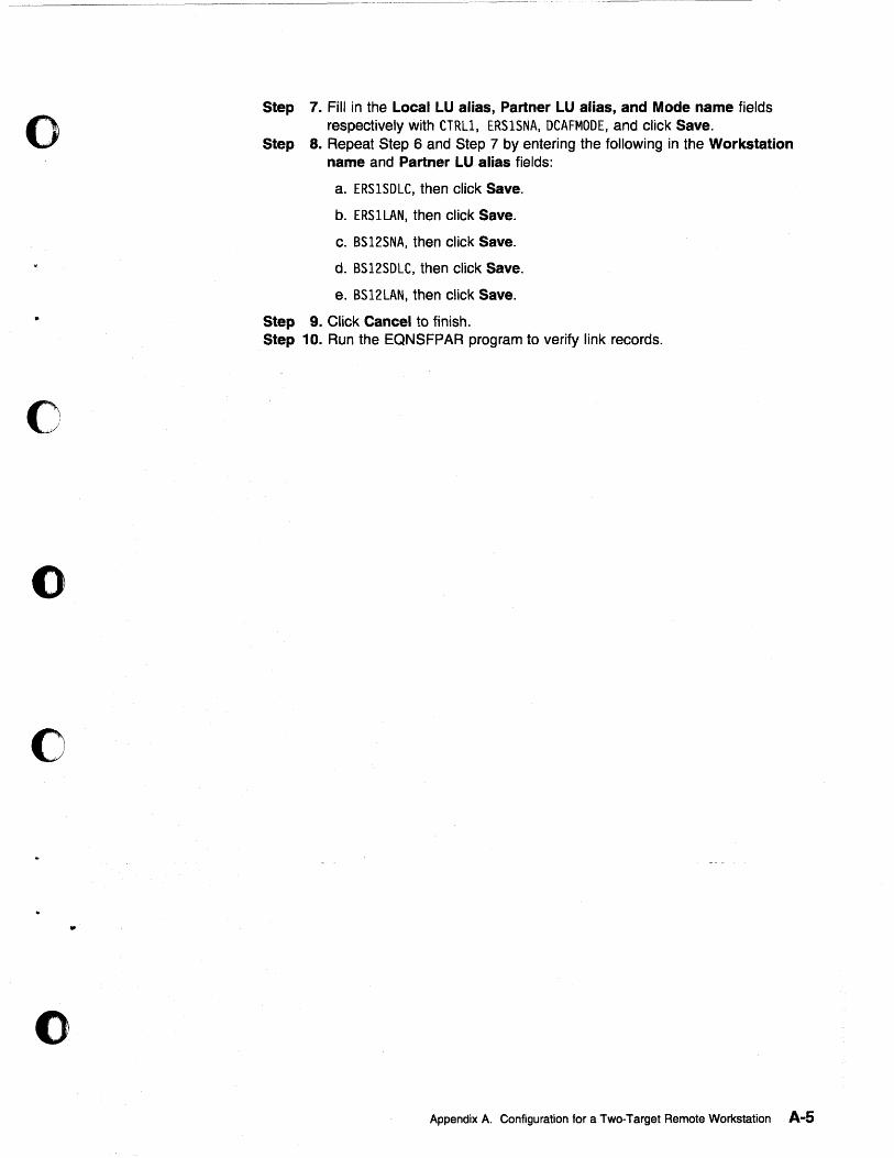
o
o
o
c
•
()
Step 7. Fill in the Local LU alias, Partner LU alias, and Mode name fields respectively with CTRLl, ERSISNA, DCAFMODE, and click Save.
Step 8. Repeat Step 6 and Step 7 by entering the following in the Workstation name and Partner LU alias fields:
a. ERSlSDLC, then click Save.
b. ERSILAN, then click Save.
c. BS12SNA, then click Save.
d. BS12SDLC, then click Save.
e. BS12LAN, then click Save.
Step 9. Click Cancel to finish. Step 10. Run the EQNSFPAR program to verify link records.
Appendix A. Configuration for a Two-Target Remote Workstation A-5

0' \ , ',I ~ ~
,/ ".
c' A.;;6 All 3745 Models & the 3746-900: CSG
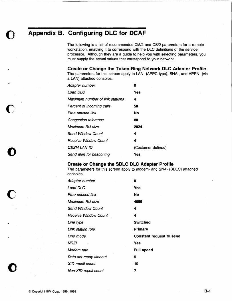
o Appendix B. Configuring DLC for DeAF
•
o
o
o
o
The following is a list of recommended CM/2 and CS/2 parameters for a remote workstation, enabling it to correspond with the OLC definitions of the service processor. Although they are a guide to help you with selecting parameters, you must supply the actual values that correspond to your network.
Create or Change the Token-Ring Network OLC Adapter Profile The parameters for this screen apply to LAN- (APPC-type), SNA-, and APPN- (via a LAN) attached consoles .
Adapter number o Load DLC Yes
Maximum number of link stations 4
Percent of incoming calls
Free unused link
Congestion tolerance
Maximum RU size
Send Window Count
Receive Window Count
C&SM LAN ID
Send alert for beaconing
50
No
80
2024
4
4
(Customer defined)
Yes
Create or Change the SOLC OLe Adapter Profile The parameters for this screen apply to modem- and SNA- (SOLC) attached consoles.
Adapter number
Load DLC
Free unused link
Maximum RU size
Send Window Count
Receive Window Count
Line type
Link station role
Line mode
NRZI
Modem rate
Data set ready timeout
XID repo" count
Non-XID repoll count
© Copyright IBM Corp. 1989, 1998
o Yes
No
4096
4
4
Switched
Primary
Constant request to send
Yes
Full speed
5
10
7
8-1

o
•
c 8-2 All 3745 Models & the 3746-900: eSG
---.. -.. --.--.--... " .. --~--..•. -.--~.------.. -.. ~-
o Part 4. Appendixes for 3745 Models 130 to 610
o
o
c
o © Copyright IBM Corp. 1989, 1998

o
All 3745 Models & the 3746-900: eSG
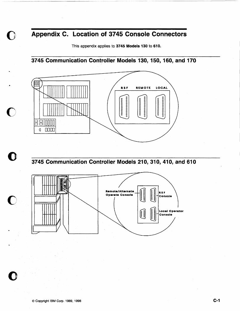
o Appendix C. Location of 3745 Console Connectors
This appendix applies to 3745 Models 130 to 610.
3745 Communication Controller Models 130, 150, 160, and 170
RS F REMOTE
o 3745 Communication Controller Models 210, 310, 410, and 610
Remote/Alternate
o Local Operator Console
o © Copyright IBM Corp. 1989, 1998 C-1

C' , , ~ "
C-2 All 3745 Models & the 3746-900: CSG
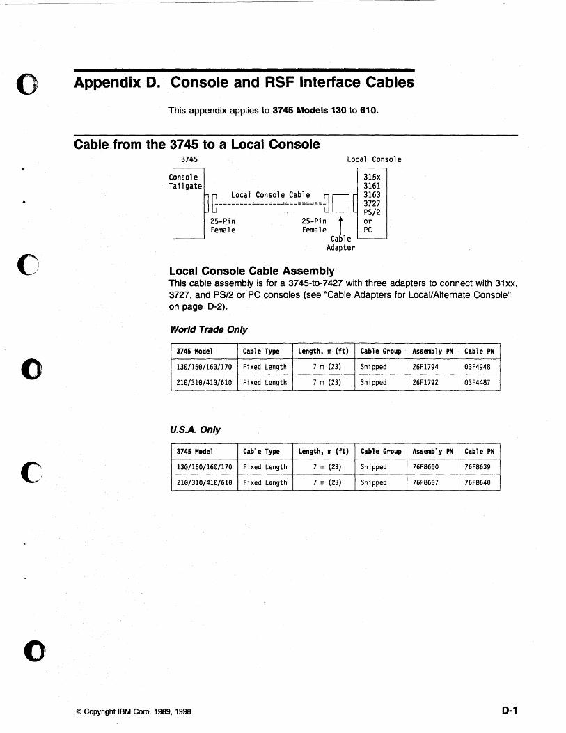
o Appendix D. Console and RSF Interface Cables
o
o
o
o
This appendix applies to 3745 Models 130 to 610.
Cable from the 3745 to a Local Console 3745 Local Console
Console Tailgate
25-Pin Female
[ 25-Pin t Female I
Cable Adapter
Local Console Cable Assembly
315x 3161 3163 3727 PS/2 or PC
This cable assembly is for a 3745-to-7427 with three adapters to connect with 31xx, 3727, and PS/2 or PC consoles (see "Cable Adapters for Local/Alternate Console" on page D-2).
World Trade Only
3745 Model Cable Type Length. m (ft) Cable Group Assembly PN Cable PH
130/150/160/170 Fixed Length 7 m (23) Shipped 26F1794 03F4948
219/310/41(:l/619 Fixed Length 7 m (23) Shipped 26F1792 03F4487
U.S.A. Only
3745 Model Cable Type Length. m (ft) Cable Group Assembly PH Cable PH
130/150/160/170 Fixed Length 7 m (23) Shipped 76F8600 76F8639
210/3Hl/410/610 Fixed Length 7 m (23) Shipped 76F8607 76F8640
© Copyright IBM Corp. 1989, 1998 0-1
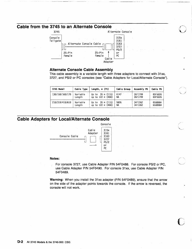
Cable from the 3745 to an Alternate Console 3745 Alternate Console
Console Tailgate
25-Pin Female
25-Pin i Female
[
Cable Adapter
Alternate Console Cable Assembly
315x 3161 3163 3727 PS/2 or PC
This cable assembly is a variable length with three adapters to connect with 31 xx, 3727, and PS/2 or PC consoles (see "Cable Adapters for Local/Alternate Console").
3745 Model Cable Type Length, m (ft)
130/150/160/170 Variable Up to 35 m (115) Length Up to 122 m (400)
210/310/410/610 Variable Up to 35 m (115) Length Up to 122 m (400)
Cable Adapters for Local/Alternate Console
Console Cable ~ =================:======~
Notes:
Cable Adapter
D ---->
Console
315x 3161
[ 3163 3727 PS/2 or PC
Cable Group Assembly PN Cable PN
6147 26Fl799 03F5026 NA 26Fl799 03F5026
5826 34Fl262 65X8984 NA 34Fl262 65X8984
For console 3727, use Cable Adapter PIN 54F0488. For console PS/2 or PC, use Cable Adapter PIN 54F0490. For console 31 xx, use Cable Adapter PIN 54F0489.
Warning: When you install the 31 xx adapter (P/N 54F0489), ensure that the arrow on the side of the adapter points towards the console. If the arrow is reversed, the console will not work.
0-2 All 3745 Models & the 3746-900: CSG
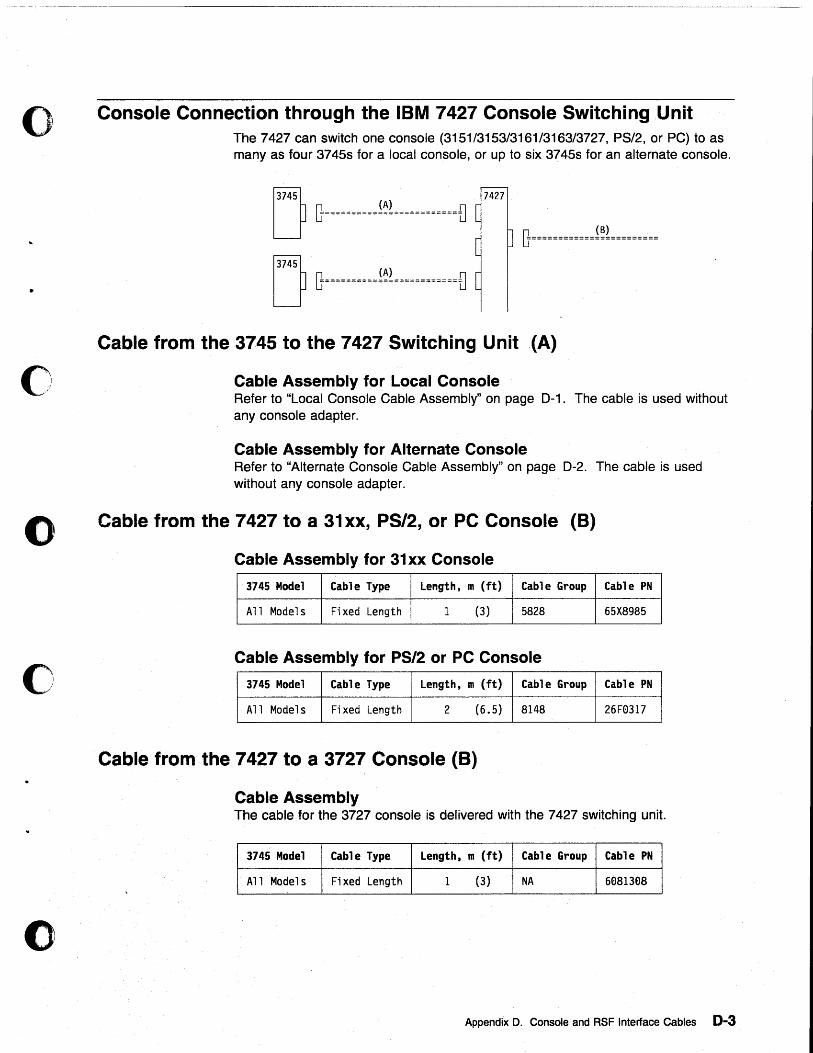
~ .. -~ .. -.--.. -.-.---~~~~~~~~~~~~~~~~~~~~~~--~~~-~--
o
•
o
o
o
o
Console Connection through the IBM 7427 Console Switching Unit The 7427 can switch one console (3151/3153/3161/3163/3727, PS/2, or PC) to as many as four 3745s for a local console, or up to six 3745s for an alternate console.
n 7427
~ G==========!~!============~ [f============i~~=========
Cable from the 3745 to the 7427 Switching Unit (A)
Cable Assembly for Local Console Refer to "Local Console Cable Assembly" on page D-1. The cable is used without any console adapter.
Cable Assembly for Alternate Console Refer to "Alternate Console Cable Assembly" on page D-2. The cable is used without any console adapter.
Cable from the 7427 to a 31xx, PS/2, or PC Console (8)
Cable Assembly for 31xx Console
3745 Model Cable Type Length, m (ft) Cable Group Cable PN
All Model s Fixed Length 1 (3) 5828 65X8985
Cable Assembly for PS/2 or PC Console
3745 Model Cable Type Length, m (ft) Cable Group Cable PN
All Model s Fixed Length 2 (6.5) 8148 26Fe317
Cable from the 7427 to a 3727 Console (B)
Cable Assembly The cable for the 3727 console is delivered with the 7427 switching unit.
3745 Model Cable Type Length, m (ft) Cable Group Cable PN
All Model s Fixed Length 1 (3) NA 6881388
Appendix D. Console and RSF Interface Cables 0-3
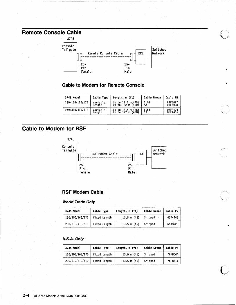
Remote Console Cable 3745
Console Tailgate
~===~::~~:=:~~~~~:=:~~~:====f] 25- 25-Pin Pin Female Male
DCE Switched Network
Cable to Modem for Remote Console
3745 Model Cable Type Length, m (ft) Cable Group Cable PN
138/1S8/168/178 Variable Up to 13.S m !4S1 6148 83FS827 Length Up to 122 m ( 88 NA 83FS828
21(.)/310/410/610 Vari"bl~ Un to 13.5 m (45' 6153 03F4404 Length - Up to 122 m (488j NA 83F448S
Cable to Modem for RSF
3745
Console Tailgate
r RSF Modem Cable ~ ~===========================~
DCE
25- 25-Pin Female
RSF Modem Cable
World Trade Only
3745 Model Cable Type
138/1S8/168/178 Fixed Length
219/318/418/618 Fixed Length
U.S.A. Only
3745 Model Cable Type
138/1S8/168/178 Fixed Length
218/318/418/618 Fixed Length
0-4 All 3745 Models & the 3746-900: CSG
Pi n Male
Length, m (ft)
13.S m (4S)
13.S m (4S)
Length, m (ft)
13.S m(4S)
13.S m (45)
Switched Network
Cable Group Cable PN
Shipped 83F4945
Shipped 6SX8928
Cable Group Cable PN
Shipped 76F8684
Shipped 76F8611
CI .. ',i "
/'
--....... -.. --~--.-.------.~-----~ .. ~-.•.. -..... ~~~~~~~~~~~~~~-
o Part 5. Bibliography, Abbreviations, Glossary, and Index
o
o
o
o © Copyright IBM Corp. 1989, 1998

..
All 3745 Models & the 3746-900: eSG
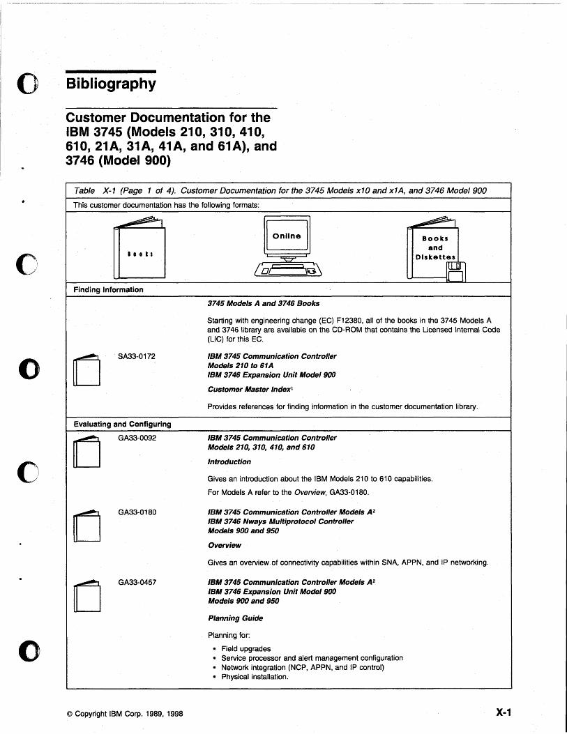
o
•
o
o
o
o
Bibliography
Customer Documentation for the IBM 3745 (Models 210, 310, 410, 610, 21A, 31A, 41A, and 61A), and 3746 (Model 900)
Table X-1 (Page 1 of 4). Customer Documentation for the 3745 Models x10 and x1A, and 3746 Model 900
This customer documentation has the following formats:
I 0 0 k s
(0/
Finding Information
3745 Models A and 3746 Books
Books and
Diskettes
UI----I~
Starting with engineering change (EC) F12380, all of the books in the 3745 Models A and 3746 library are available on the CD-ROM that contains the Licensed Internal Code (L1C) for this EC.
o SA33-0172
Evaluating and Configuring
o GA33-0092
o GA33-0180
o GA33-0457
© Copyright IBM Corp. 1989, 1998
IBM 3745 Communication Controller Models 210 to 61 A IBM 3746 Expansion Unit Model 900
Customer Master Indexl
Provides references for finding information in the customer documentation library.
IBM 3745 Communication Controller Models 210, 310, 410, and 610
Introduction
Gives an introduction about the IBM Models 210 to 610 capabilities.
For Models A refer to the Overview, GA33-0180.
IBM 3745 Communication Controller Models A2 IBM 3746 Nways Multiprotocol Controller Models 900 and 950
Overview
Gives an overview of connectivity capabilities within SNA, APPN, and IP networking.
IBM 3745 Communication Controller Models A2 IBM 3746 Expansion Unit Model 900 Models 900 and 950
Planning Guide
Planning for:
• Field upgrades • Service processor and alert management configuration • Network integration (NCP, APPN, and IP control) • Physical installation.
X-1
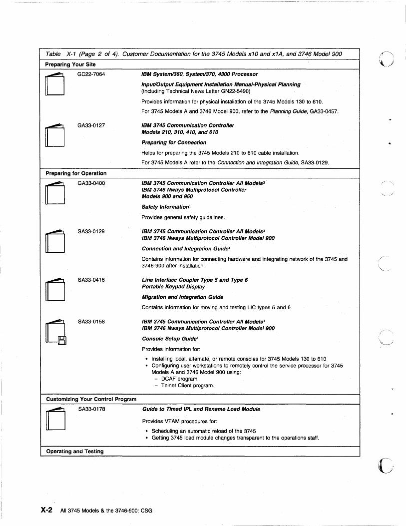
Table X-1 (Page 2 of 4). Customer Documentation for the 3745 Models x10 and x1A, and 3746 Model 900
Preparing Your Site
GC22-7064
o GA33-0127
Preparing for Operation
o GA33-0400
o SA33-0129
o SA33-0416
SA33-0158
Customizing Your Control Program
o SA33-0178
Operating and Testing
IBM Systeml360, Systeml370, 4300 Processor
Input/Output Equipment Installation Manual-Physical Planning (Including Technical News Letter GN22-5490)
Provides information for physical installation of the 3745 Models 130 to 610.
For 3745 Models A and 3746 Model 900, refer to the Planning Guide, GA33-0457.
IBM 3745 Communication Controller Models 210, 310, 410, and 610
Preparing for Connection
Helps for preparing the 3745 Models 210 to 610 cable installation.
For 3745 Models A refer to the Connection and Integration Guide, SA33-0129.
IBM 3745 Communication Controller All Models3
IB~/l3745 ftJ .. ·,sys '.,fultiprotocol Controller Models 900 and 950
Safety Information1
Provides general safety guidelines.
IBM 3745 Communication Controller All Models3
IBM 3746 Nways Multiprotocol Controller Model 900
Connection and Integration Guide1
Contains information for connecting hardware and integrating network of the 3745 and 3746-900 after installation.
Line Interlace Coupler Type 5 and Type 6 Portable Keypad Display
Migration and Integration Guide
Contains information for moving and testing LlC types 5 and 6.
IBM 3745 Communication Controller All Models3
IBM 3746 Nways Multiprotocol Controller Model 900
Console Setup Guide1
Provides information for:
• Installing local, alternate, or remote consoles for 3745 Models 130 to 610 • Configuring user workstations to remotely control the service processor for 3745
Models A and 3746 Model 900 using: - DCAF program - Telnet Client program.
Guide to Timed IPL and Rename Load Module
Provides VT AM procedures for:
• Scheduling an automatic reload of the 3745 • Getting 3745 load module changes transparent to the operations staff.
X-2 All 3745 Models & the 3746-900: CSG
o
- '-,
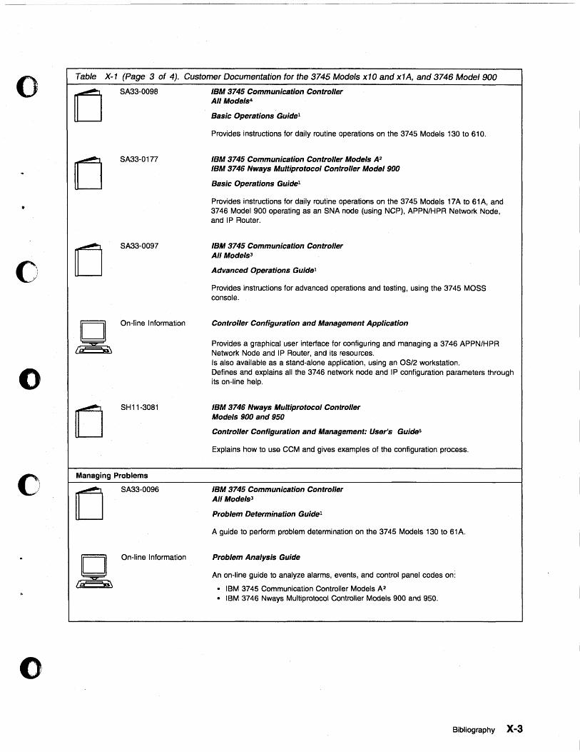
o
o
o
o
c
Table X-1 (Page 3 of 4). Customer Documentation for the 3745 Mode/s x10 and x1A, and 3746 Mode/900
(j SA33-0098
(j SA33-0177
(j SA33-0097
1 "" t On-line Information
[] SH11-3081
Managing Problems
(j SA33-0096
1 ""lon-line Information
IBM 3745 Communication Controller All Models4
Basic Operations Guide1
Provides instructions for daily routine operations on the 3745 Models 130 to 610.
IBM 3745 Communication Controller Models A2 IBM 3746 Nways Multiprotocol Controller Model 900
Basic Operations Guide1
Provides instructions for daily routine operations on the 3745 Models 17A to 61A, and 3746 Model 900 operating as an SNA node (using NCP), APPN/HPR Network Node, and IP Router.
IBM 3745 Communication Controller All Models3
Advanced Operations Guide l
Provides instructions for advanced operations and testing, using the 3745 MOSS console.
Controller Configuration and Management Application
Provides a graphical user interface for configuring and managing a 3746 APPN/HPR Network Node and IP Router, and its resources. Is also available as a stand-alone application, using an OS/2 workstation. Defines and explains all the 3746 network node and IP configuration parameters through its on-line help.
IBM 3746 Nways Multiprotocol Controller Models 900 and 950
Controller Configuration and Management: User's Guides
Explains how to use CCM and gives examples of the configuration process.
IBM 3745 Communication Controller All Models3
Problem Determination Guide1
A guide to perform problem determination on the 3745 Models 130 to 61A.
Problem Analysis Guide
An on-line guide to analyze alarms, events, and control panel codes on:
• IBM 3745 Communication Controller Models A2 • IBM 3746 Nways Multiprotocol Controller Models 900 and 950.
Bibliography X-3
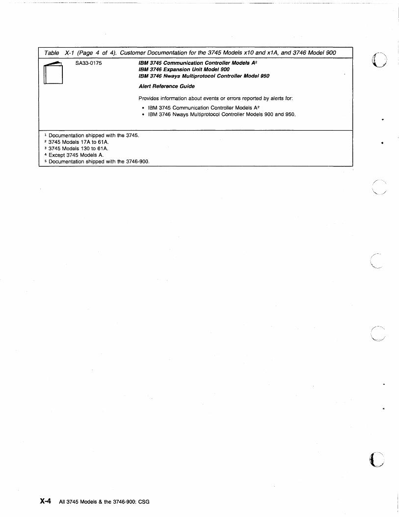
Table X-1 (Page 4 of 4). Customer Documentation for the 3745 Models x10 and x1A, and 3746 Model 900
(] SA33-0175 IBM 3745 Communication Controller Models A2
IBM 3746 Expansion Unit Model 900 IBM 3746 Nways Multiprotocol Controller Model 950
Alert Reference Guide
Provides information about events or errors reported by alerts for:
• IBM 3745 Communication Controller Models A2 • IBM 3746 Nways Multiprotocol Controller Models 900 and 950.
1 Documentation shipped with the 3745. 2 3745 Models 17A to 61A. 3 3745 Models 130 to 61A. 4 Except 3745 Models A. 5 Documentation shipped with the 3746-900.
X-4 All 3745 Models & the 3746-900: CSG
o
./
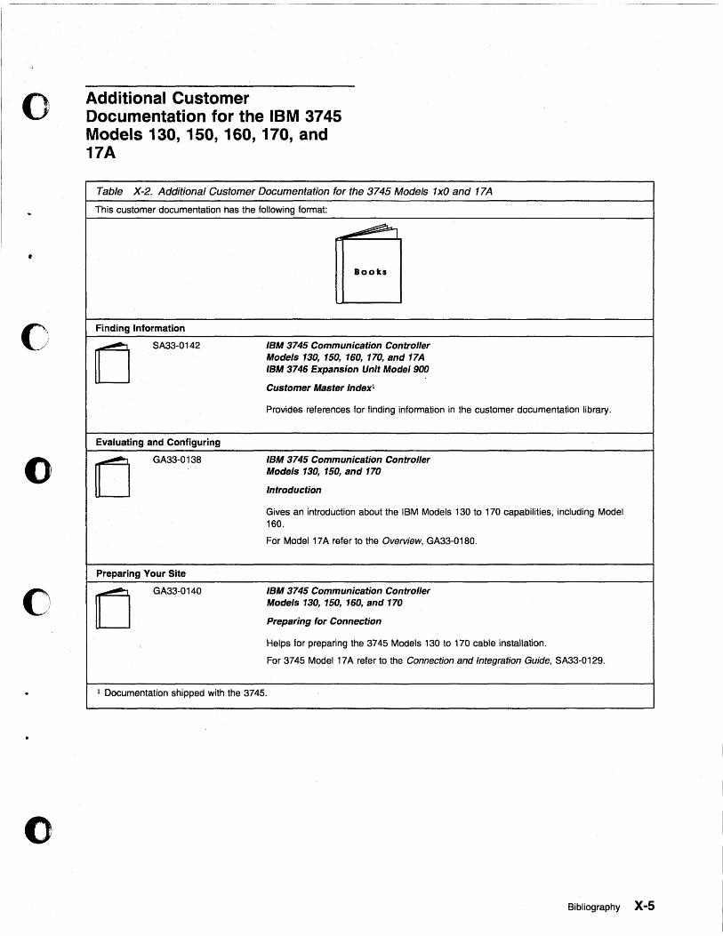
o
•
c
o
o
o
Additional Customer Documentation for the IBM 3745 Models 130, 150, 160, 170, and 17A
Table X-2. Additional Customer Documentation for the 3745 Models lxO and 17A
This customer documentation has the following format:
~ ~ I
Books
Finding Information
0 SA33-0142 IBM 3745 Communication Controller
Models 130, 150, 160, 170, and 17A IBM 3746 Expansion Unit Mode/900
Customer Master Indexl
Provides references for finding information in the customer documentation library.
Evaluating and Configuring
0 GA33-0138 IBM 3745 Communication Controller
Models 130, 150, and 170
Introduction
Gives an introduction about the IBM Models 130 to 170 capabilities, including Model 160.
For Model 17A refer to the Overview, GA33-0180.
Preparing Your Site
[J GA33-0140 IBM 3745 Communication Controller
Models 130, 150, 160, and 170
Preparing for Connection
Helps for preparing the 3745 Models 130 to 170 cable installation.
For 3745 Model 17A refer to the Connection and Integration Guide, SA33-0129.
1 Documentation shipped with the 3745.
Bibliography X-5

•
X-6 All 3745 Models & the 3746-900: eSG
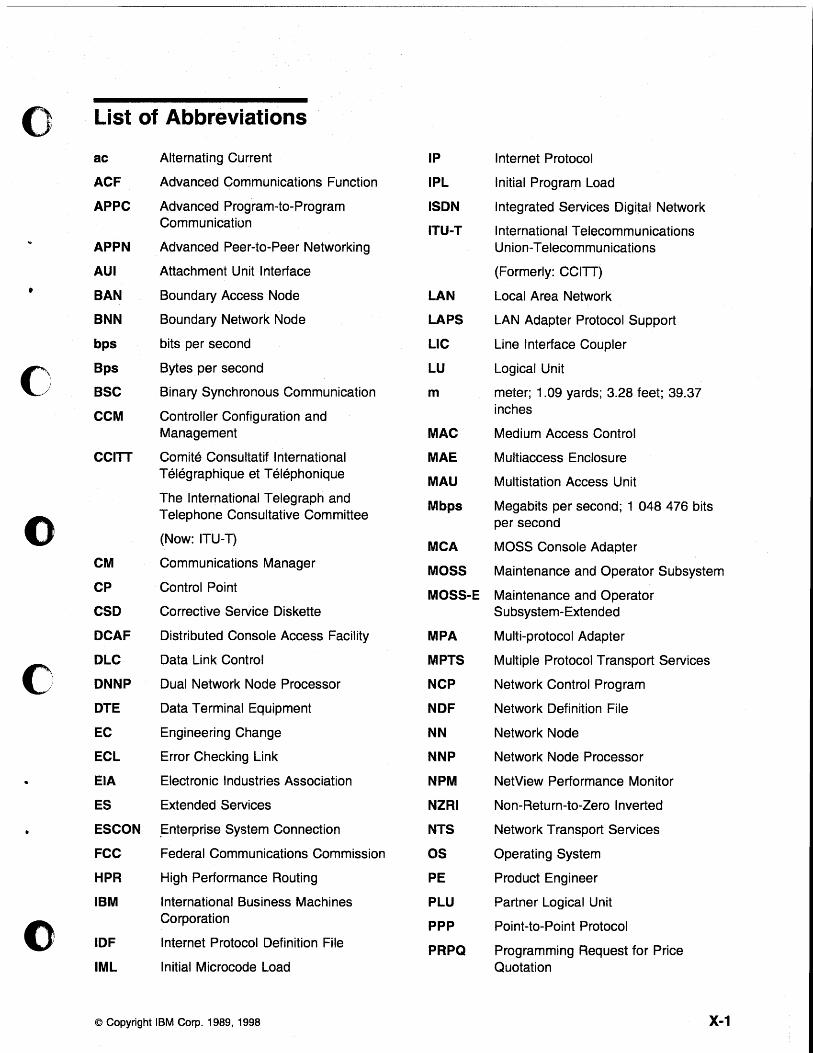
0 List of Abbreviations
ac Alternating Current IP Internet Protocol
ACF Advanced Communications Function IPl Initial Program Load
APPC Advanced Program-to-Program ISDN Integrated Services Digital Network Communication ITU-T International Telecommu nications
APPN Advanced Peer-to-Peer Networking Union-Telecommunications
AUI Attachment Unit Interface (Formerly: CCITT)
• BAN Boundary Access Node lAN Local Area Network
BNN Boundary Network Node lAPS LAN Adapter Protocol Support
bps bits per second LlC Line Interface Coupler
0 Bps Bytes per second lU Logical Unit
BSC Binary Synchronous Communication m meter; 1.09 yards; 3.28 feet; 39.37
CCM Controller Configuration and inches
Management MAC Medium Access Control
CCITT Comite Consultatif International MAE Multiaccess Enclosure Telegraphique et Telephonique MAU Multistation Access Unit The International Telegraph and Mbps Megabits per second; 1 048 476 bits
0 Telephone ConSUltative Committee
per second (Now: ITU-T) MCA MOSS Console Adapter
CM Communications Manager MOSS Maintenance and Operator Subsystem CP Control Point MOSS-E Maintenance and Operator CSD Corrective Service Diskette Subsystem-Extended
DCAF Distributed Console Access Facility MPA Multi-protocol Adapter
C DlC Data Link Control MPTS Multiple Protocol Transport Services
DNNP Dual Network Node Processor NCP Network Control Program
DTE Data Terminal Equipment NDF Network Definition File
EC Engineering Change NN Network Node
ECl Error Checking Link NNP Network Node Processor
EIA Electronic Industries Association NPM NetView Performance Monitor
ES Extended Services NZRI Non-Return-to-Zero Inverted
ESCON .Enterprise System Connection NTS Network Transport Services
FCC Federal Communications Commission OS Operating System
HPR High Performance Routing PE Product Engineer
IBM International Business Machines PlU Partner Logical Unit
() Corporation PPP Point-to-Point Protocol
IDF Internet Protocol Definition File PRPQ Programming Request for Price IMl Initial Microcode Load Quotation
© Copyright IBM Corp. 1989, 1998 X-1
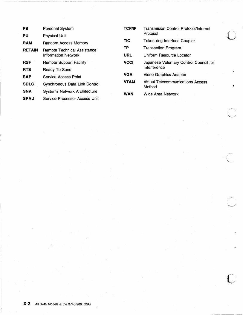
PS Personal System TCP/IP Transmision Control Protocolllnternet
PU Physical Unit Protocol 0 RAM Random Access Memory
TIC Token-ring Interface Coupler
RETAIN Remote Technical Assistance TP Transaction Program
Information Network URL Uniform Resource Locator
RSF Remote Support Facility VCCI Japanese Voluntary Control Council for
RTS Ready To Send Interference
SAP Service Access Point VGA Video Graphics Adapter
SOLC Synchronous Data Link Control VTAM Virtual Telecommunications Access Method •
SNA Systems Network Architecture WAN Wide Area Network SPAU Service Processor Access Unit
c X-2 AU 3745 Models & the 3746-900: CSG
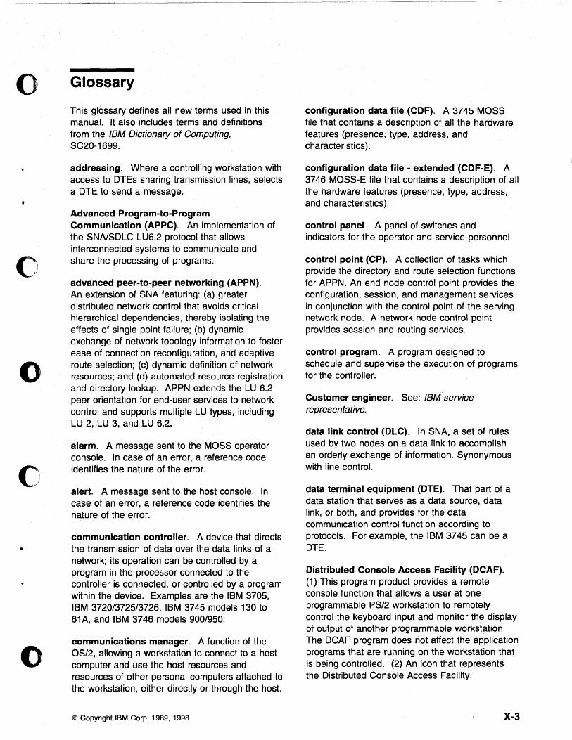
o Glossary
o
o
c
()
This glossary defines all new terms used in this manual. It also includes terms and definitions from the IBM Dictionary of Computing, SC20-1699.
addressing. Where a controlling workstation with access to DTEs sharing transmission lines, selects a DTE to send a message.
Advanced Program-to-Program Communication (APPC). An implementation of the SNAlSDLC LU6.2 protocol that allows interconnected systems to communicate and share the processing of programs.
advanced peer-to-peer networking (APPN). An extension of SNA featuring: (a) greater distributed network control that avoids critical hierarchical dependencies, thereby isolating the effects of single point failure; (b) dynamic exchange of network topology information to foster ease of connection reconfiguration, and adaptive route selection; (c) dynamic definition of network resources; and (d) automated resource registration and directory lookup. APPN extends the LU 6.2 peer orientation for end-user services to network control and supports multiple LU types, including LU 2, LU 3, and LU 6.2.
alarm. A message sent to the MOSS operator console. In case of an error, a reference code identifies the nature of the error.
alert. A message sent to the host console. In case of an error, a reference code identifies the nature of the error.
communication controller. A device that directs the transmission of data over the data links of a network; its operation can be controlled by a program in the processor connected to the controller is connected, or controlled by a program within the device. Examples are the IBM 3705, IBM 3720/3725/3726, IBM 3745 models 130 to 61A, and IBM 3746 models 900/950.
communications manager. A function of the OS/2, allowing a workstation to connect to a host computer and use the host resources and resources of other personal computers attached to the workstation, either directly or through the host.
© Copyright IBM Corp. 1989, 1998
configuration data file (CDF). A 3745 MOSS file that contains a description of all the hardware features (presence, type, address, and characteristics).
configuration data file - extended (CDF-E). A 3746 MOSS-E file that contains a description of all the hardware features (presence, type, address, and characteristics).
control panel. A panel of switches and indicators for the operator and service personnel.
control point (CP). A collection of tasks which provide the directory and route selection functions for APPN. An end node control point provides the configuration, session, and management services in conjunction with the control point of the serving network node. A network node control pOint provides session and routing services.
control program. A program designed to schedule and· supervise the execution of programs for the controller.
Customer engineer. See: IBM service representative.
data link control (DLC). In SNA, a set of rules used by two nodes on a data link to accomplish an orderly exchange of information. Synonymous with line control.
data terminal equipment (DTE). That part of a data station that serves as a data source, data link, or both, and provides for the data communication control function according to protocols. For example, the IBM 3745 can be a DTE.
Distributed Console Access Facility (DCAF). (1) This program product provides a remote console function that allows a user at one programmable PS/2 workstation to remotely control the keyboard input and monitor the display of output of another programmable workstation. The DCAF program does not affect the application programs that are running on the workstation that is being controlled. (2) An icon that represents the Distributed Console Access Facility.
X-3
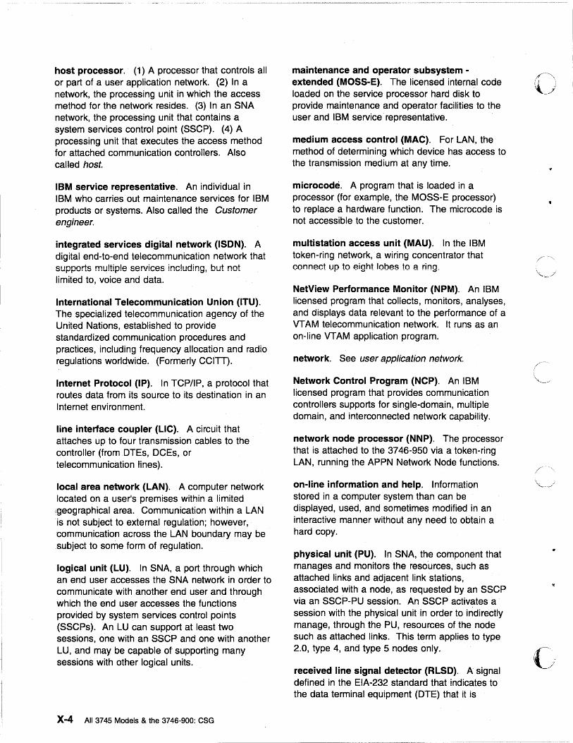
host processor. (1) A processor that controls all or part of a user application network. (2) In a network, the processing unit in which the access method for the network resides. (3) In an SNA network, the processing unit that contains a system services control point (SSCP). (4) A processing unit that executes the access method for attached communication controllers. Also called host.
IBM service representative. An individual in IBM who carries'out maintenance services for IBM products or systems. Also called the Customer engineer.
integrated services digital network (ISDN). A digital end-to-end telecommunication network that supports multiple services including, but not limited to, voice and data.
International Telecommunication Union (ITU). The specialized telecommunication agency of the United Nations, established to provide standardized communication procedures and practices, including frequency allocation and radio regulations worldwide. (Formerly CCITT).
Internet Protocol (IP). In TCP/IP, a protocol that routes data from its source to its destination in an Internet environment.
line interface coupler (LlC). A circuit that attaches up to four transmission cables to the controller (from DTEs, DCEs, or telecommunication lines).
local area network (LAN). A computer network located on a userls premises within a limited ;geographical area. Communication within a LAN is not subject to external regulation; however, communication across the LAN boundary may be subject to some form of regulation.
logical unit (LU). In SNA, a port through which an end user accesses the SNA network in order to communicate with another end user and through which the end user accesses the functions provided by system services control pOints (SSCPs). An LU can support at least two sessions, one with an SSCP and one with another LU, and may be capable of supporting many sessions with other logical units.
X-4 All 3745 Models & the 3746-900: CSG
maintenance and operator subsystem -extended (MOSS-E). The licensed internal code loaded on the service processor hard disk to provide maintenance and operator facilities to the user and IBM service representative.
medium access control (MAC). For LAN, the method of determining which device has access to the transmission medium at any time.
microcode. A program that is loaded in a processor (for example, the MOSS-E processor) to replace a hardware function. The microcode is not accessible to the customer.
multistation access unit (MAU). In the IBM token-ring network,' a wiring concentrator that connect up to eight lobes to a ring,
NetView Performance Monitor (NPM). An IBM licensed program that collects, monitors, analyses, and displays data relevant to the performance of a VT AM telecommunication network. It runs as an on-line VTAM application program.
network. See user application network.
Network Control Program (NCP). An IBM licensed program that provides communication controllers supports for single-domain, multiple domain, and interconnected network capability.
network node processor (NNP). The processor that is attached to the 3746-950 via a token-ring LAN, running the APPN Network Node functions.
on-line information and help. Information stored in a computer system than can be displayed, used, and sometimes modified in an interactive manner without any need to obtain a hard copy.
physical unit (PU). In SNA, the component that manages and monitors the resources, such as attached links and adjacent link stations, associated with a node, as requested by an SSCP via an SSCP-PU session. An SSCP activates a session with the physical unit in order to indirectly manage, through the PU, resources of the node such as attached links. This term applies to type 2.0, type 4, and type 5 nodes only.
received line signal detector (RLSD). A signal defined in the EIA-232 standard that indicates to the data terminal equipment (DTE) that it is
c' ... ·" , ./
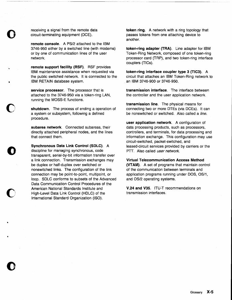
o
..
•
o
o
o
"
()
receiving a signal from the remote data circuit-terminating equipment (DCE).
remote console. A PS/2 attached to the IBM 3746-950 either by a switched line (with modems) or by one of communication lines of the user network.
remote support facility (RSF). RSF provides IBM maintenance assistance when requested via the public switched network. It is connected to the IBM RETAIN database system.
service processor. The processor that is attached to the 3746-950 via a token-ring LAN, running the MOSS-E functions.
shutdown. The process of ending a operation of a system or subsystem, following a defined procedure.
subarea network. Connected subareas, their directly attached peripheral nodes, and the lines that connect them.
Synchronous Data Link Control (SOLC). A discipline for managing synchronous, code transparent, serial-by-bit information transfer over a link connection. Transmission exchanges may be duplex or half-duplex over switched or nonswitched links. The configuration of the link connection may be point-to-point, multipoint, or loop. SDLC conforms to subsets of the Advanced Data Communication Control Procedures of the American National Standards Institute and High-Level Data Link Control (HOLC) of the International Standard Organization (ISO).
token ring. A network with a ring topology that passes tokens from one attaching device to another.
token-ring adapter (TRA). Line adapter for IBM Token-Ring Network, composed of one token-ring processor card (TRP), and two token-ring interface couplers (TICs).
token-ring interface coupler type 3 (TIC3). A circuit that attaches an IBM Token-Ring network to
, an IBM 3746-900 or 3746-950 .
transmission interface. The interface between the controller and the user application network.
transmission line. The physical means for connecting two or more DTEs (via DCEs). It can be nonswitched or switched. Also called a line.
user application network. A configuration of data processing products, such as processors, controllers, and terminals, for data processing and information exchange. This configuration may use circuit-switched, packet-switched, and leased-circuit services provided by carriers or the PTT. Also called user network.
Virtual Telecommunication Access Method (VT AM). A set of programs that maintain control of the communication between terminals and application programs running under ~OS, OS/1, and OS/2 operating systems.
V.24 and V3S. ITU-T recommendations on transmission interfaces.
Glossary X-5

c
•
X-6 All 3745 Models & the 3746-900: eSG
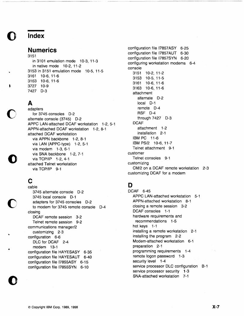
o Index
o
o
•
()
Numerics 3151
in 3101 emulation mode 10-3, 11-3 in native mode 10-2, 11-2
3153 in 3151 emulation mode 10-5,11-5 3161 10-6,11-6 3163 10-6, 11-6 3727 10-9 7427 0-3
A adapters
for 3745 consoles 0-2 alternate console (3745) 0-2 APPC LAN-attached DCAF workstation 1-2, 5-1 APPN-attached DCAF workstation 1-2, 8-1 attached DCAF workstation
via APPN backbone 1-2,8-1 via LAN (APPC-type) 1-2, 5-1 via modem 1-3, 6-1 via SNA backbone 1-2, 7-1 via TCP/IP 1-2, 4-1
attached Telnet workstation via TCP/IP 9-1
C cable
3745 alternate console 0-2 3745 local console 0-1 adapters for 3745 consoles 0-2 to modem for 3745 remote console 0-4
closing DCAF remote session 3-2 Telnet remote session 9-2
communications manager/2 customizing 2-3
configuration 6-6 DLC for DCAF 2-4 modem 13-1
configuration file HA YESASY 6-35 configuration file HAYESAUT 6-40 configuration file 17855ASY 6-15 configuration file 17855SYN 6-10
© Copyright IBM Corp. 1989, 1998
configuration file 17857 ASY 6-25 configuration file 17857 AUT 6-30 configuration file 17857SYN 6-20 configuring workstation modems 6-4 console
3151 10-2,11-2 3153 10-5, 11-5 3161 10-6,11-6 3163 10-6, 11-6 attachment
alternate 0-2 local 0-1 remote 0-4 RSF 0-4 through 7427 0-3
DCAF attachment 1-2 installation 2-1
IBM PC 11-6 IBM PS/2 10-6, 11-7 Telnet attachment 9-1
customer Telnet consoles 9-1
customizing CM/2 on a DCAF remote workstation 2-3
customizing OCAF for a modem
D DCAF 6-45
APPC LAN-attached workstation 5-1 APPN-attached workstation 8-1 closing a remote session 3-2 DCAF consoles 1-1 hardware requirements and
recommendations 1-5 hot keys 1-1 installing a remote workstation 2-1 installing the program 2-2 Modem-attached workstation 6-1 preparation 2-1 programming requirements 1-4 remote logon password 1-3 security level 1-4 service processor DLC configuration B-1 service processor security 1-3 SNA-attached workstation 7-1
X-7
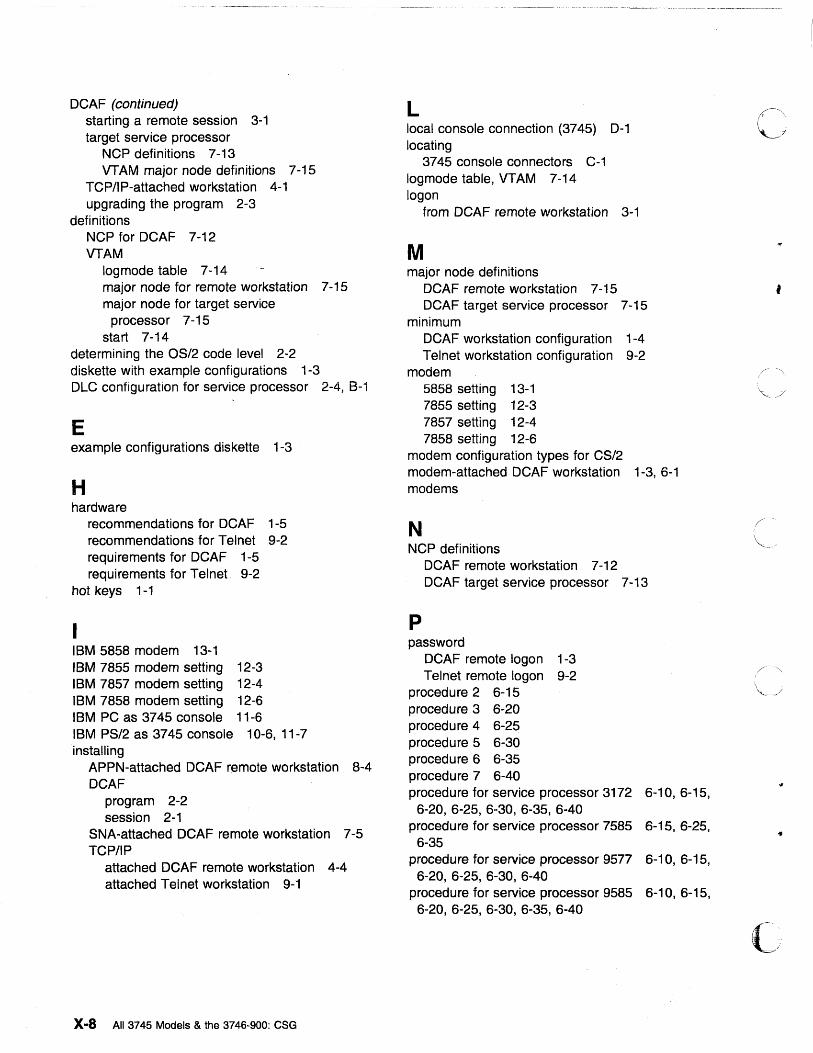
DCAF (continued) starting a remote session 3-1 target service processor
NCP definitions 7 -13 VT AM major node definitions 7-15
TCP/IP-attached workstation 4-1 upgrading the program 2-3
definitions NCP for DCAF 7-12 VTAM
logmode table 7-14 major node for remote workstation 7 -15 major node for target service
processor 7-15 start 7-14
determining the OS/2 code level 2-2 diskette with example configurations 1-3 DLC configuration for service processor 2-4, B-1
E example configurations diskette 1-3
H hardware
recommendations for DCAF 1-5 recommendations for Telnet 9-2 requirements for DCAF 1-5 requirements for Telnet 9-2
hot keys 1-1
IBM 5858 modem 13-1 IBM 7855 modem setting 12-3 IBM 7857 modem setting 12-4 IBM 7858 modem setting 12-6 IBM PC as 3745 console 11-6 IBM PS/2 as 3745 console 10-6, 11-7 installing
APPN-attached DCAF remote workstation 8-4 DCAF
program 2-2 session 2-1
SNA-attached DCAF remote workstation 7-5 TCP/IP
attached DCAF remote workstation 4-4 attached Telnet workstation 9-1
X-8 All 3745 Models & the 3746-900: eSG
L local console connection (3745) D-1 locating
3745 console connectors C-1 log mode table, VTAM 7-14 logon
from DCAF remote workstation 3-1
M major node definitions
DCAF remote workstation 7 -15 DCAF target service processor 7-15
minimum DCAF workstation configuration 1-4 Telnet workstation configuration 9-2
modem 5858 setting 13-1 7855 setting 12-3 7857 setting 12-4 7858 setting 12-6
modem configuration types for CS/2 modem-attached DCAF workstation 1-3, 6-1 modems
N NCP definitions
p
DCAF remote workstation 7 -12 DCAF target service processor 7 -13
password DCAF remote logon 1-3 Telnet remote logon 9-2
procedure 2 6-15 procedure 3 6-20 procedure 4 6-25 procedure 5 6-30 procedure 6 6-35 procedure 7 6-40 procedure for service processor 3172 6-10,6-15,
6-20, 6-25, 6-30, 6-35, 6-40 procedure for service processor 7585 6-15,6-25,
6-35 procedure for service processor 9577 6-10, 6-15,
6-20, 6-25, 6-30, 6-40 procedu re for service processor 9585 6-10, 6-15,
6-20, 6-25, 6-30, 6-35, 6-40
,
•
( ..... " c ..
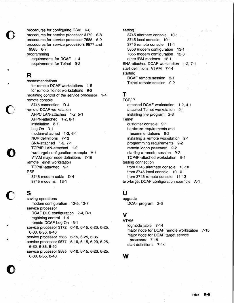
o
o
o
c
()
procedures for configuring CS/2 6-6 procedures for service processor 3172 6-8 procedures for service processor 7585 6-9 procedures for service processors 9577 and
9585 6-7 programming
R
requirements for DCAF 1-4 requirements for Telnet 9-2
recommendations for remote DCAF workstations 1-5 for remote Telnet workstations 9-2
regaining control of the service processor 1-4 remote console
3745 connection D-4 remote DCAF workstation
APPC LAN-attached 1-2, 5-1 APPN-attached 1-2, 8-1 installation 2-1 Log On 3-1 modem-attached 1-3, 6-1 NCP definitions 7-12 SNA-attached 1-2,7-1 TCPIIP LAN-attached 1-2 two-target configuration example A-1 VTAM major node definitions 7-15
remote Telnet workstation TCPIIP-attached 9-1
RSF
S
3745 modem cable D-4 3745 modems 13-1
saving operations modem configuration 12-5, 12-7
service processor DCAF DLC configuration 2-4, B-1 regaining control 1-4 remote DCAF Log On 3-1
service processor 3172 6-10, 6-15, 6-20, 6-25, 6-30, 6-35, 6-40
service processor 7585 6-15, 6-25, 6-35 service processor 9577 6-10,6-15,6-20,6-25,
6-30, 6-35, 6-40 service processor 9585 6-10, 6-15,6-20, 6-25,
setting 3745 alternate console 10-1 3745 local console 1 0-1 3745 remote console 11-1 5858 modem configuration 13-1 7855 modem configuration 12-3 other IBM modems 12-1
SNA-attached DeAF workstation 1-2, 7-1 start definitions, VTAM 7-14 starting
T
DCAF remote session 3-1 Telnet remote session 9-2
TCPIIP attached DCAF workstation 1-2, 4-1 attached Telnet workstation 9-1 installing the program 2-3
Telnet customer console 9~ 1 hardware requirements and
recommendations 9-2 installing a remote workstation 9-1 programming requirements 9-2 remote logon password 9-2 starting a remote session 9-2 TCPIIP-attached workstation 9-1
testing connection from 3745 alternate console 10-10 from 3745 local console 1 0-1 0 from 3745 remote console 11-13
two-target DCAF configuration example A-1
U upgrade
DCAF program 2-3
V VTAM
log mode table 7-14 major node for DCAF remote workstation 7 -15 major node for DCAF target service
processor 7 -15 start definitions 7 -14
6-30, 6-35, 6-40 W
Index X-9
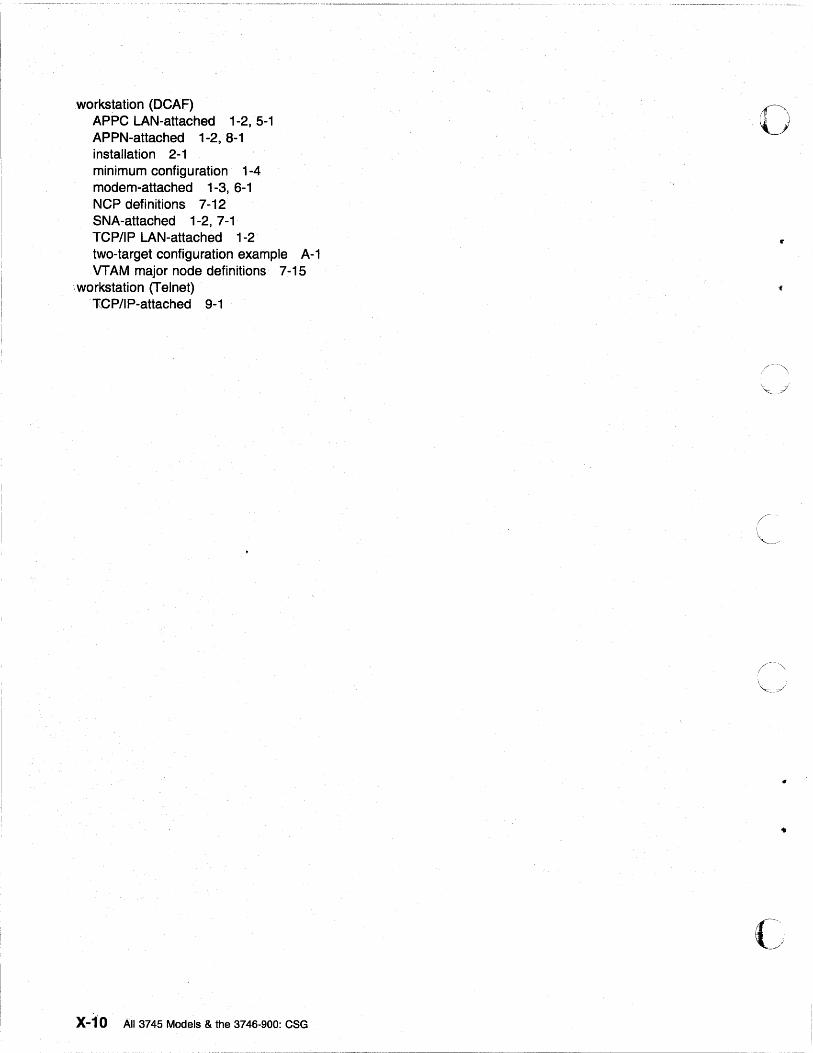
workstation (DCAF) APPC LAN-attached 1-2, 5-1 APPN-attached 1-2, 8-1 installation 2-1 minimum configuration 1-4 modem-attached 1-3, 6-1 NCP definitions 7 -12 SNA-attached 1-2, 7-1 TCP/IP LAN-attached 1-2 two-target configuration example A-1 VT AM major node definitions 7 -15
workstation (Telnet) 'TGP/IP-attached 9-1
X-1'O All 3745 Models & the 3746-900: CSG
o
..
(~'
.... ~".
o
o
o
c
'.
o
Readersl Comments - Weld Like to Hear from You
3745 Communication Controller All Models 3746 Nways Multiprotocol Controller Model 900 Console Setup Guide
Publication No. SA33-0158 .. 09
Please send us your comments concerning this book. We will greatly appreciate them and will consider them for later releases of the present book.
If you prefer sending comments by FAX or electronically, use:
• FAX: 334932477 97 • IBM Internal Use: LGERCF at IBMFR • Internet: [email protected]
In advance, thank you.
Your comments:
Name Address
Company or Organization
Phone No.
Readers I Comments - Weld Like to Hear from You SA33-0158-09
Fold and Tape Please do not staple
--..------------------ ---- -- ---___ w-_ --_.-
Fold and Tape
· · · · · · · · · .. ---_ .... ---- -_ ..... -_ ..................... -- -_ ........ -_ ............................ -... ---.. -- -_ .. --- --_ ........ -----_ ............ --_ .......... -_ ......... ---_ .................. ---_ .... -_ .......... -_ .......... --.. ----_ .......... -------------_ ...... ---------_ .. _ ... _ .. ----------_ .... ---_ ........ --- -_........ ..
IBM France Centre dlEtudes et Recherches Service 0798 - BP 79 06610 La Gaude France
PLACE POSTAGE STAMP HERE
·
... -_ ................... -_ ..... -_ .... --_ ............................. -------- -_ ......... ---_ ............ ------_ ....... -------------------_ ........ ---_ ...... -_ .... --_ ........... -_ ............ -_ .... -_ .... ----.. ----_ .... -_ .... ---_ ..... -_ ......... ---_ ............... ---_ .. --------_ ............... ---_ .... ---" Fold and Tape Please do not staple Fold and Tape
SA33-0158-09
Cut or Fold Along Line
o
«
•
Cut or Fold Along Line

'HI M d
o
•
o
• o ,
•
Part Number: 34F1251
Printed in the United Kingdom
o
•
~ I ,;;) '-J
o
,
I
(


![[External MY] Shopee Collaborative Ads Setup Guide](https://img.dokumen.tips/doc/110x75/63258ea9051fac18490d522c/external-my-shopee-collaborative-ads-setup-guide.jpg)


