Embed Size (px)
Citation preview
507240-03 6/2021
Supersedes 3/2020
Equipment Interface Module (EIM)Installation and Setup Guide
2
Shipping and Packing List .................................................................2Application and Requirements ..........................................................2
Indoor Transformer Requirements ................................................... 2Equipment ....................................................................................... 2
Installation ...........................................................................................4Configuration Setup ...........................................................................4
EIM, 24VAC Furnace and Lennox Communicating Heat Pumps .... 4EIM, Lennox Communicating Furnace and 24VAC Heat Pump ...... 4Unit Type Jumpers ........................................................................... 5Heat Stage Jumper Positions .......................................................... 5Air Temperature Sensor Connections .............................................. 6Lennox Communicating Terminal Connections and Wiring Recommendations ........................................................................... 6Dual-Fuel Terminal Connections ..................................................... 6Conventional Terminal Connections and Wiring Requirement ........ 6LED Indicators ................................................................................. 7Soft Disable ..................................................................................... 7iComfort S30 Commissioning (Conventional Outdoor Unit) ............ 8
Operating Environment Specifications ............................................8Unit Dimensions .................................................................................8Duel-Fuel Operations .........................................................................9Field Wiring .......................................................................................10Alert Codes and Troubleshooting ...................................................16
TABLE OF CONTENTS Shipping and Packing List
Quantity Description1 Equipment Interface Module.
1 Installation and setup guide
1 Warranty certificate
WARNINGImproper installation, adjustment, alteration, ser vice or maintenance can cause property damage, personal injury or loss of life.Installation and service must be performed by a li censed professional HVAC installer (or equivalent) or a service agency.
Application and Requirements
Indoor Transformer RequirementsThe following lists the required indoor unit transformer rating (VA) for specific configurations.
Table 1. System VA Loading Chart
Configuration Minimum Transformer Rating (VA)
2-Stage HP, 3-Stage Electric heat 70
2-Stage HP, 2-Stage Furnace (with tempering) 70
2-Stage HP, 2-Stage Furnace (without tempering) 50
2-Stage AC, 2-Stage Furnace 40
EquipmentThe Equipment Interface Module (EIM) is used with an Lennox communicating thermostat using the R, i+, i-, and C terminals. The EIM is the interface between non-communicating HVAC equipment and Lennox communicating HVAC equipment.
NOTE: EIM will support single-stage outdoor units with single-stage or variable-stage indoor furnaces.
3
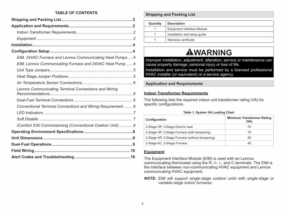
OUTDOOR AIR SENSORCONNECTIONS
DISCHARGE AIRSENSOR CONNECTIONS
ICOMFORT®
CONNECTIONS
NON-COMMUNICATING TERMINALS
STATUS LED
COMMUNICATION INDICATORLED
DUAL-FUELCONNECTIONS
UNIT TYPE JUMPERTERMINALS
HEAT STAGESJUMPER TERMIINALS HEAT PUMP CAPACITY
JUMPER TERMINALS
3 AMP FUSE
Figure 1. Terminals and LEDs
CAUTIONElectrostatic discharge can affect electronic components. Take precautions during unit installation and service to protect the unit’s electronic controls. Precautions will help to avoid control exposure to electrostatic discharge by putting the unit, the control and the technician at the same electrostatic potential. Neutralize electrostatic charge by touching hand and all tools on an unpainted unit surface before performing any service procedure
4
Lennox CommunicatingThermostat
Equipment InterfaceModel (EIM)
24VAC Air Handler or Furnace (Indoor Unit)
iComfort-enabled Air Conditioner or
Heat Pump (Outdoor Unit)
Wiring Legend
4−wire communicating
24VAC conventional
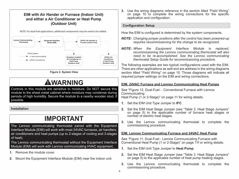
EIM with Air Hander or Furnace (Indoor Unit)and either a Air Conditioner or Heat Pump
(Outdoor Unit)
24VAC Air Conditioner
or Heat Pump(Outdoor Unit)
NOTE: For dual-fuel applications, additional components may be need to be added.
Figure 2. System View
WARNINGControls in this module are sensitive to moisture. Do NOT secure this module to the sheet metal cabinet where moisture may condense during periods of high humidity. Secure the module to a nearby wooden stud, if possible.
Installation
IMPORTANTThe Lennox communicating thermostat paired with the Equipment Interface Module (EIM) will work with most 24VAC furnaces, air handlers, air conditioners and heat pumps (up to 2-stages of cooling and 3-stages of heat).The Lennox communicating thermostat without the Equipment Interface Module (EIM) will work with Lennox communicating HVAC equipment.
1. Remove the module cover.
2. Mount the Equipment Interface Module (EIM) near the indoor unit.
3. Use the wiring diagrams reference in the sectoin titled “Field Wiring” on page 10 to complete the wiring connections for the specific application and configuration.
Configuration Setup
How the EIM is configured is determined by the system components.
NOTE: Changing jumper positions after the control has been powered-up requires recommissioning for the change to be recognized.
NOTE: When the Equipment Interface Module is replaced, recommissioning the Lennox communicating thermostat will also need to be re-accomplished. See the Lennox communicating thermostat Setup Guide for recommissioning procedure.
The following examples are two typical configurations used with the EIM. There are other applications as well and are address in the wiring diagrams section titled “Field Wiring” on page 10. Those diagrams will indicate all required jumper settings on the EIM and wiring connections.
EIM, 24VAC Furnace and Lennox Communicating Heat PumpsSee “Figure 12. Dual-Fuel - Conventional Furnace with Lennox Communicating Heat Pump (1 or 2-Stage)” on page 11 for wiring details.
1. Set the EIM Unit Type Jumper to IFC.
2. Set the EIM Heat Stage Jumper (see “Table 3. Heat Stage Jumpers” on page 5) to the applicable number of furnace heat stages or number of electric heat stages.
3. Use the Lennox communicating thermostat to complete the commissioning procedure.
EIM, Lennox Communicating Furnace and 24VAC Heat PumpSee “Figure 11. Dual-Fuel - Lennox Communicating Furnace with Conventional Heat Pump (1 or 2-Stage)” on page 11f or wiring details.
1. Set the EIM Unit Type Jumper to Heat Pump.
2. Set the EIM Heat Stage Jumper (see “Table 3. Heat Stage Jumpers” on page 5) to the applicable number of heat pump heating stages.
3. Use the Lennox communicating thermostat to complete the commissioning procedure.
5
NOTE: For two-stage heat pump go to the heat pump defrost control, locate P3 - low ambient thermostat pins and disable this function by removing the installed jumper and relocating it to one pin only.
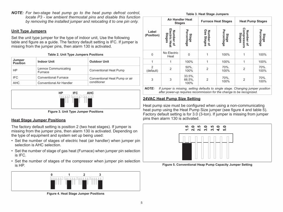
Unit Type JumpersSet the unit type jumper for the type of indoor unit, Use the following table and figure as a guide. The factory default setting is IFC. If jumper is missing from the jumper pins, then alarm 130 is activated.
Table 2. Unit Type Jumpers PositionsJumper Position Indoor Unit Outdoor Unit
HP Lennox Communicating Furnace Conventional Heat Pump
IFC Conventional Furnace Conventional Heat Pump or air conditionerAHC Conventional Air Handler
HP IFC AHC
Figure 3. Unit Type Jumper Positions
Heat Stage Jumper PositionsThe factory default setting is position 2 (two heat stages). If jumper is missing from the jumper pins, then alarm 130 is activated. Depending on the type of equipment and system set up being used: • Set the number of stages of electric heat (air handler) when jumper pin
selection is AHC selection.• Set the number of stage of gas heat (Furnace) when jumper pin selection
is IFC.• Set the number of stages of the compressor when jumper pin selection
is HP.
0 1 2 3
Figure 4. Heat Stage Jumper Positions
Table 3. Heat Stage Jumpers
Label (Position)
Air Handler Heat Stages Furnace Heat Stages Heat Pump Stages
Num
ber of Electric H
eat Stages
Stage Percentage
Num
ber of G
as Stages
Stage Percentage
Num
ber of C
ompressors
Stages
Stage Percentage
0 No Electric Heat 0 1 100% 1 100%
1 1 100% 1 100% 1 100%
2 (default) 2 50%,
100% 2 70%. 100% 2 70%.
100%
3 333.5%, 66.5%, 100%
2 70%, 100% 2 70%.
100%
NOTE: If jumper is missing, setting defaults to single stage. Changing jumper position after power-up requires recommission for the change to be recognized.
24VAC Heat Pump Size SettingHeat pump size must be configured when using a non-communicating heat pump using the Heat Pump Size jumper (see figure 4 and table 5). Factory default setting is for 3.0 (3-ton). If jumper is missing from jumper pins then alarm 130 is activated.
1.5
2.0
2.5
3.0
3.5
4.0
5.0
Figure 5. Conventional Heap Pump Capacity Jumper Setting
6
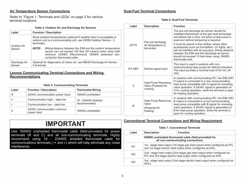
Air Temperature Sensor ConnectionsRefer to “Figure 1. Terminals and LEDs” on page 3 for various terminal locations.
Table 4. Outdoor Air and Discharge Air SensorsLabel Function / Description
Outdoor Air Sensor
Show ambient temperatures (optional if weather feed is acceptable or outdoor unit is a communicating unit; use X2658 Outdoor Sensor - 2 terminals).
NOTE: Wiring distance between the EIM and the outdoor temperature sensor can not exceed 150 feet (45 meters) when wired with minimum 22AWG (Recommend) 18AWG dedicated two-conductor thermostat cable.
Discharge Air Sensor
Optional for diagnostics of indoor air; use 88K38 Discharge Air Sensor - 2 terminals.
Lennox Communicating Terminal Connections and Wiring Recommendations
Table 5. Communicating TerminalsLabel Function / Description Thermostat WiringR 24VAC communication power Input 18AWG unshielded
i+ Communication high – data line 18 - 22AWG shielded (recommended) i- Communication low – data line
C 24VAC communication common power Input 18AWG unshielded
IMPORTANTUse 18AWG unshielded thermostat cable (field-provided) for power terminals (R and C) and all non-communicating terminals. Highly recommend using 18 - 22AWG shielded thermostat cable for communications terminals ( i+ and i-) which will help eliminate any noise interference.
Dual-Fuel Terminal Connections
Table 6. Dual-Fuel Terminals
Label Description Function
DFTSPre-coil discharge air temperature (2 terminals)
The pre -coil discharge air sensor should be installed downstream of the gas heat exchanger and before the in door coil when a heat pump is used and defrost tempering is required.It must be placed in free airflow, where other accessories (such as humidifiers, UV lights, etc.) will not interfere with its accuracy. Wiring distance between the EIM and the discharge air sensor should not exceed 10 feet when using 18AWG thermostat wire.
W1-DEF Defrost signal inputThis input is used in systems with non-communicating heat pumps for defrost indication. The input provides a nominal load of 50 mA, 24 VAC.
0Heat Pump Reversing Valve (Powered for cooling)
In systems with communicating IFC, the EIM (HP) O output is connected to a non-communicating heat pump compatible with O signal for reversing valve operation. A 24VAC signal is generated on O for cooling operation, while the terminal is open for heating operation.
B
Heat Pump Reserving Valve(Powered for heating)
In systems with communicating IFC, the EIM (HP) B output is connected to a non-communicating heat pump compatible with B signal for reversing valve operation. A 24VAC signal is generated on B for heat pump opera tion, while the terminal is open for cooling operation.
Conventional Terminal Connections and Wiring Requirement
Table 7. Conventional Terminals Label Description Function
18AWG unshielded thermostat cable (field-provided) for all non-communicating connections
W1 1st - stage heat output (1st stage gas heat output when configured as IFC and 1st stage electric heat output when configured as AHC.
W2 2nd - stage heat output (2nd stage gas heat output when configured as IFC and 2nd stage electric heat output when configured as AHC.
W3 3rd - stage heat output (3nd stage electric heat output when configured as AHC)
7
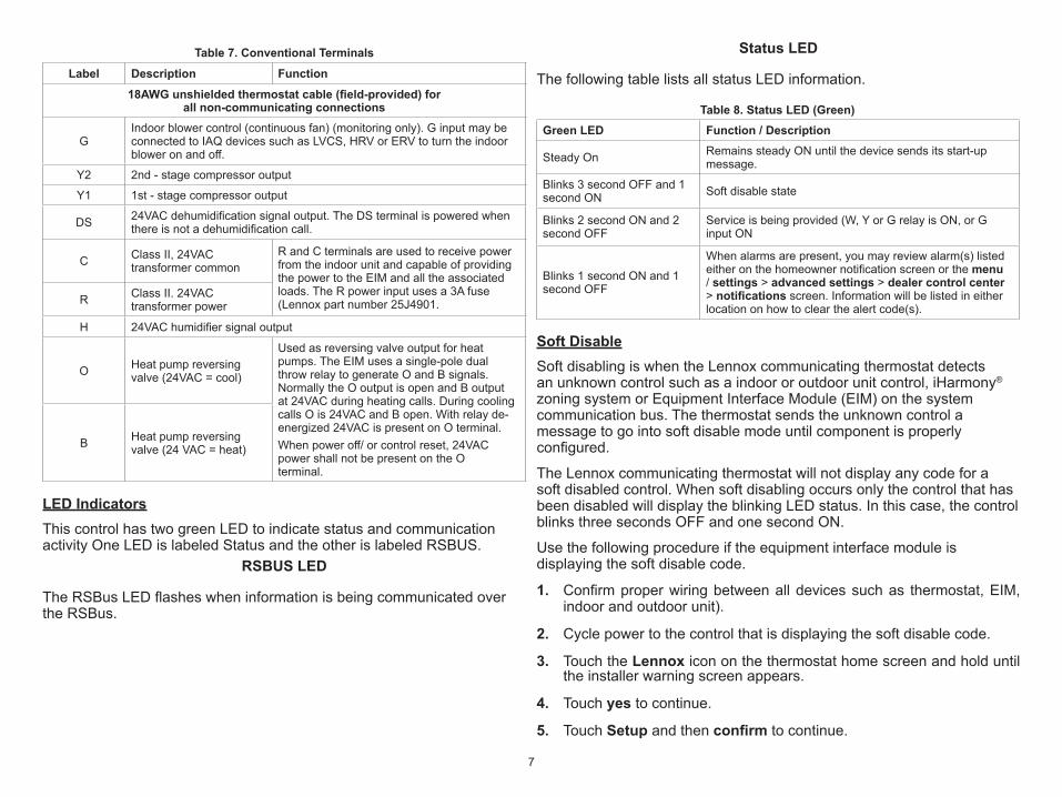
Table 7. Conventional Terminals Label Description Function
18AWG unshielded thermostat cable (field-provided) for all non-communicating connections
GIndoor blower control (continuous fan) (monitoring only). G input may be connected to IAQ devices such as LVCS, HRV or ERV to turn the indoor blower on and off.
Y2 2nd - stage compressor output
Y1 1st - stage compressor output
DS 24VAC dehumidification signal output. The DS terminal is powered when there is not a dehumidification call.
C Class II, 24VAC transformer common
R and C terminals are used to receive power from the indoor unit and capable of provid ing the power to the EIM and all the associated loads. The R power input uses a 3A fuse (Lennox part number 25J4901.R Class II. 24VAC
transformer power
H 24VAC humidifier signal output
O Heat pump reversing valve (24VAC = cool)
Used as reversing valve output for heat pumps. The EIM uses a single-pole dual throw relay to generate O and B signals. Normally the O output is open and B output at 24VAC during heating calls. During cooling calls O is 24VAC and B open. With relay de- energized 24VAC is present on O terminal.When power off/ or control reset, 24VAC power shall not be present on the O terminal.
B Heat pump reversing valve (24 VAC = heat)
LED IndicatorsThis control has two green LED to indicate status and communication activity One LED is labeled Status and the other is labeled RSBUS.
RSBUS LED
The RSBus LED flashes when information is being communicated over the RSBus.
Status LED
The following table lists all status LED information.
Table 8. Status LED (Green)Green LED Function / Description
Steady On Remains steady ON until the device sends its start-up message.
Blinks 3 second OFF and 1 second ON Soft disable state
Blinks 2 second ON and 2 second OFF
Service is being provided (W, Y or G relay is ON, or G input ON
Blinks 1 second ON and 1 second OFF
When alarms are present, you may review alarm(s) listed either on the homeowner notification screen or the menu / settings > advanced settings > dealer control center > notifications screen. Information will be listed in either location on how to clear the alert code(s).
Soft DisableSoft disabling is when the Lennox communicating thermostat detects an unknown control such as a indoor or outdoor unit control, iHarmony® zoning system or Equipment Interface Module (EIM) on the system communication bus. The thermostat sends the unknown control a message to go into soft disable mode until component is properly configured.
The Lennox communicating thermostat will not display any code for a soft disabled control. When soft disabling occurs only the control that has been disabled will display the blinking LED status. In this case, the control blinks three seconds OFF and one second ON.
Use the following procedure if the equipment interface module is displaying the soft disable code.
1. Confirm proper wiring between all devices such as thermostat, EIM, indoor and outdoor unit).
2. Cycle power to the control that is displaying the soft disable code.
3. Touch the Lennox icon on the thermostat home screen and hold until the installer warning screen appears.
4. Touch yes to continue.
5. Touch Setup and then confirm to continue.
8
6. Use this Thermostat? Touch press here to continue.
7. Touch the next button to continue past the next three screens.
8. From the System Devices list, touch reset ALL to reset all devices.
9. Touch the confirm button.
The thermostat will reboot and start through the setup process again.
IMPORTANTIf any jumpers were set incorrectly AFTER commissioning was completed, then reposition jumpers to correct positions. Re-running the commissioning procedure will be required at the Lennox communicating thermostat.
This completes the configuring of the conventional outdoor unit.
iComfort S30 Commissioning (Conventional Outdoor Unit)Both unit capacity and number of compressor stages are required to be configured through the Lennox communicating thermostat. Once the outdoor unit has been installed and connected to the equipment interface module, go to the thermostat and start the configuration process.
1. From the equipment found screen, touch the non-communication equipment location to add non-communicating equipment.
2. A add/remove equipment screen will appear. Under Outdoor Unit Type, select the applicable 1 or 2-stage unit.
3. Touch either the plus or minus buttons to selected the applicable Outdoor Unit Capacity. Valid options are 18, 24, 30, 36, 42, 48 and 60.
4. Touch save to continue.
Operating Environment Specifications
The Equipment Interface Module is designed to operate in the following environmental conditions.• Operating Temperature Range: 40°F to 176°F (40° C to 80°C).• Shipping and Storage Temperature Range: 40° F to 185°F (40°C to
85°C).• Operating Humidity Range: 10% to 90% non-condensing at 104°F.
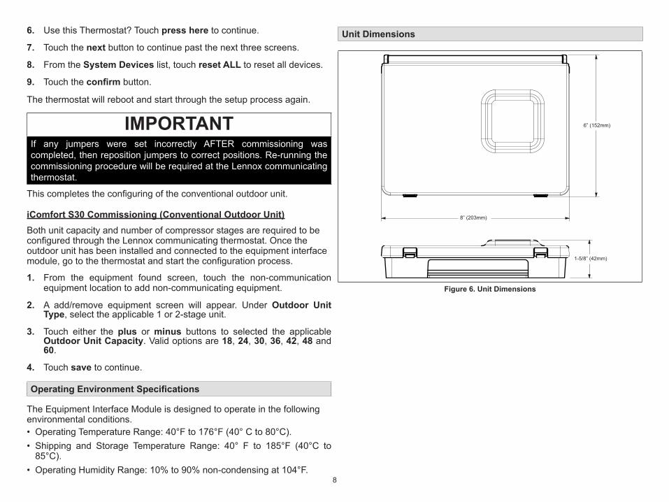
Unit Dimensions
8” (203mm)
6” (152mm)
1-5/8” (42mm)
Figure 6. Unit Dimensions
9
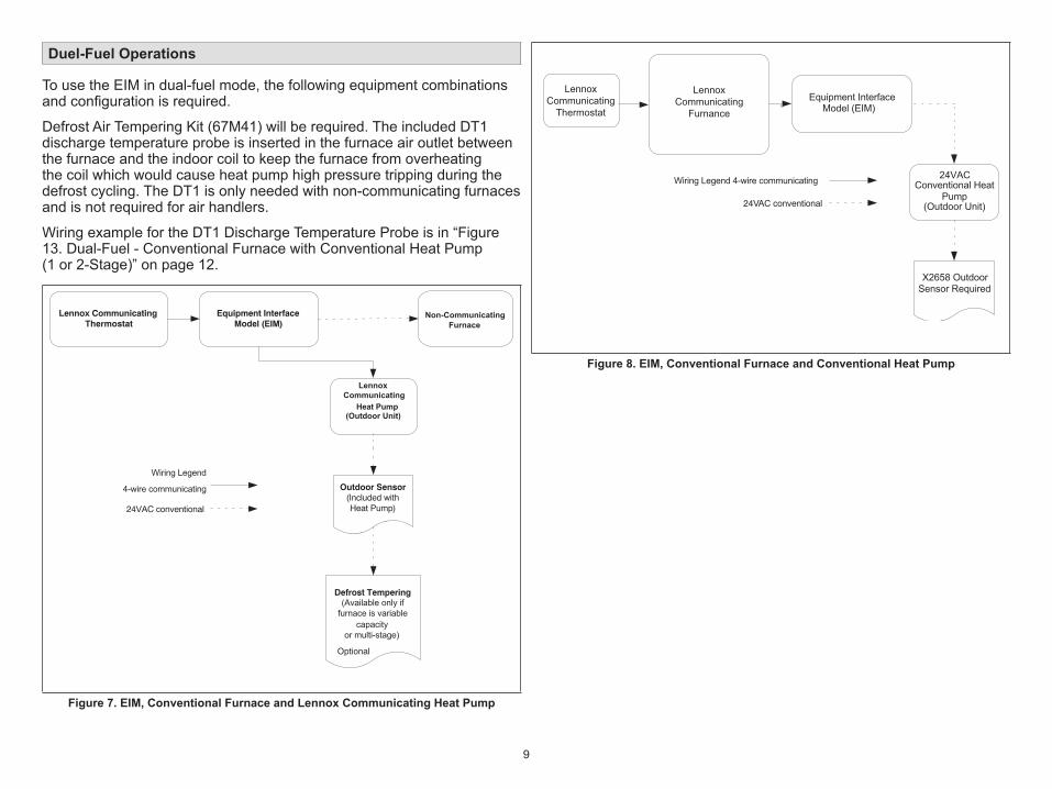
Duel-Fuel Operations
To use the EIM in dual-fuel mode, the following equipment combinations and configuration is required.
Defrost Air Tempering Kit (67M41) will be required. The included DT1 discharge temperature probe is inserted in the furnace air outlet between the furnace and the indoor coil to keep the furnace from overheating the coil which would cause heat pump high pressure tripping during the defrost cycling. The DT1 is only needed with non-communicating furnaces and is not required for air handlers.
Wiring example for the DT1 Discharge Temperature Probe is in “Figure 13. Dual-Fuel - Conventional Furnace with Conventional Heat Pump (1 or 2-Stage)” on page 12.
Lennox CommunicatingThermostat
Equipment InterfaceModel (EIM) Furnace
24VAC conventional
Heat Pump(Outdoor Unit)
Outdoor Sensor(Included withHeat Pump)
Defrost Tempering(Available only if
furnace is variable
Optional
capacity or multi-stage)
Wiring Legend
4-wire communicating
Lennox Communicating
Non-Communicating
Figure 7. EIM, Conventional Furnace and Lennox Communicating Heat Pump
Wiring Legend 4-wire communicating
24VAC conventional
24VAC Conventional Heat
Pump (Outdoor Unit)
X2658 Outdoor Sensor Required
Equipment InterfaceModel (EIM)
LennoxCommunicating
Thermostat
LennoxCommunicating
Furnance
Figure 8. EIM, Conventional Furnace and Conventional Heat Pump
10
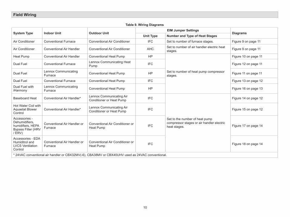
Field Wiring
Table 9. Wiring Diagrams
System Type Indoor Unit Outdoor UnitEIM Jumper Settings
DiagramsUnit Type Number and Type of Heat Stages
Air Conditioner Conventional Furnace Conventional Air Conditioner IFC Set to number of furnace stages. Figure 9 on page 11
Air Conditioner Conventional Air Handler Conventional Air Conditioner AHC Set to number of air handler electric heat stages. Figure 9 on page 11
Heat Pump Conventional Air Handler Conventional Heat Pump HP
Set to number of heat pump compressor stages.
Figure 10 on page 11
Dual Fuel Conventional Furnace Lennox Communicating Heat Pump IFC Figure 12 on page 11
Dual Fuel Lennox Communicating Furnace Conventional Heat Pump HP Figure 11 on page 11
Dual Fuel Conventional Furnace Conventional Heat Pump IFC Figure 13 on page 12
Dual Fuel with iHarmony
Lennox Communicating Furnace Conventional Heat Pump HP Figure 16 on page 13
Baseboard Heat Conventional Air Handler* Lennox Communicating Air Conditioner or Heat Pump IFC
Set to the number of heat pump compressor stages or air handler electric heat stages.
Figure 14 on page 12
Hot Water Coil with Aquastat Blower Control
Conventional Air Handler* Lennox Communicating Air Conditioner or Heat Pump IFC Figure 15 on page 12
Accessories - Dehumidifiers, humidifiers, HEPA Bypass Filter (HRV / ERV)
Conventional Air Handler or Furnace
Conventional Air Conditioner or Heat Pump IFC Figure 17 on page 14
Accessories - EDA Humiditrol and LVCS Ventilation Control
Conventional Air Handler or Furnace
Conventional Air Conditioner or Heat Pump IFC Figure 18 on page 14
* 24VAC conventional air handler or CBX32MV(-6), CBA38MV or CBX40UHV used as 24VAC conventional.
11
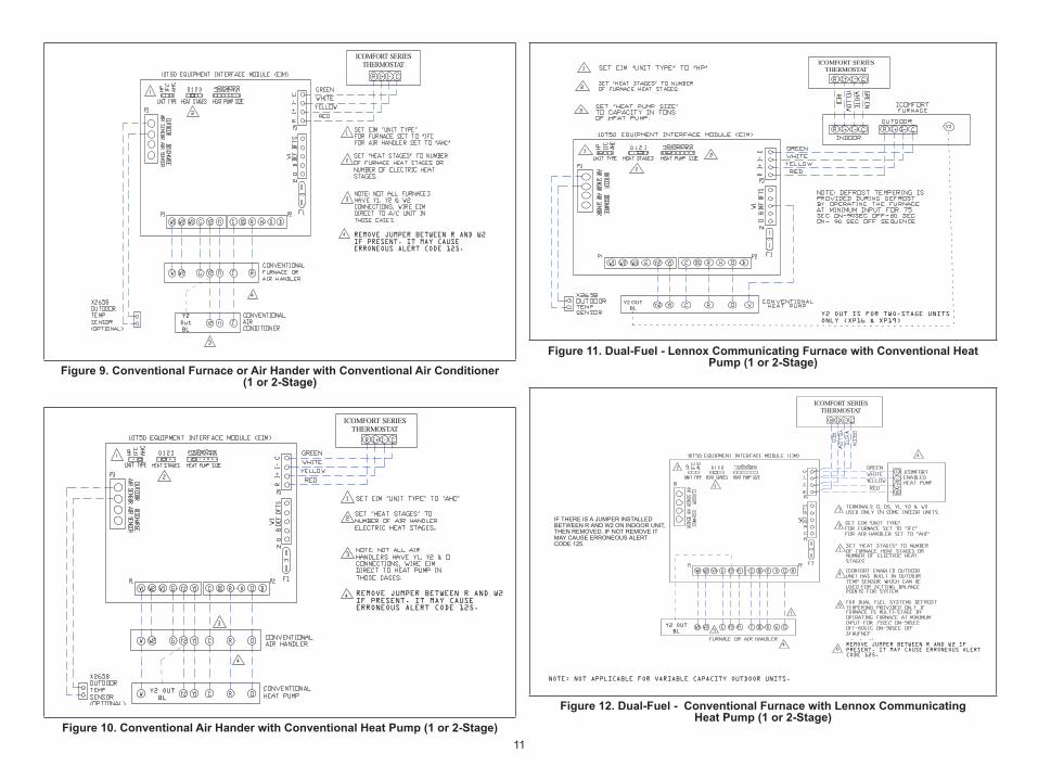
REMOVE JUMPER BETWEEN R AND W2IF PRESENT. IT MAY CAUSEERRONEOUS ALERT CODE 125.
ICOMFORT SERIESTHERMOSTAT
Y2OutBL
Figure 9. Conventional Furnace or Air Hander with Conventional Air Conditioner (1 or 2-Stage)
REMOVE JUMPER BETWEEN R AND W2IF PRESENT. IT MAY CAUSEERRONEOUS ALERT CODE 125.
ICOMFORT SERIESTHERMOSTAT
Y2 OUTBL
Figure 10. Conventional Air Hander with Conventional Heat Pump (1 or 2-Stage)
ICOMFORT SERIESTHERMOSTAT
Y2
Y2 OUTBL
Y2 OUT IS FOR TWO-STAGE UNITSONLY (XP16 & XP19)
Figure 11. Dual-Fuel - Lennox Communicating Furnace with Conventional Heat Pump (1 or 2-Stage)
IF THERE IS A JUMPER INSTALLEDBETWEEN R AND W2 ON INDOOR UNIT,THEN REMOVED. IF NOT REMOVE ITMAY CAUSE ERRONEOUS ALERTCODE 125.
REMOVE JUMPER BETWEEN R AND W2 IFPRESENT. IT MAY CAUSE ERRONEOUS ALERTCODE 125.
ICOMFORT SERIESTHERMOSTAT
Y2 OUTBL
NOTE: NOT APPLICABLE FOR VARIABLE CAPACITY OUTDOOR UNITS.
Figure 12. Dual-Fuel - Conventional Furnace with Lennox Communicating Heat Pump (1 or 2-Stage)
12
REMOVE JUMPER BETWEEN R AND W2IF PRESENT. IT MAY CAUSEERRONEOUS ALERT CODE 125.
ICOMFORT SERIESTHERMOSTAT
Y2 OUTBL
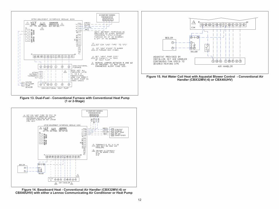
Figure 13. Dual-Fuel - Conventional Furnace with Conventional Heat Pump (1 or 2-Stage)
ICOMFORT SERIESTHERMOSTAT
Y2 OUTBL
Figure 14. Baseboard Heat - Conventional Air Handler (CBX32MV(-6) or CBX40UHV) with either a Lennox Communicating Air Conditioner or Heat Pump
Figure 15. Hot Water Coil Heat with Aquastat Blower Control - Conventional Air Handler (CBX32MV(-6) or CBX40UHV)
13
ICOMFORT SERIESTHERMOSTAT
Y2 OUTBL
3
2
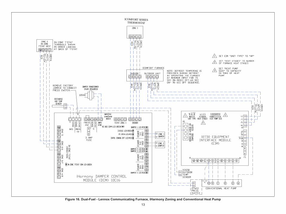
Figure 16. Dual-Fuel - Lennox Communicating Furnace, iHarmony Zoning and Conventional Heat Pump
14
REMOVE JUMPERBETWEEN R ANDW2 IF PRESENT.IT MAY CAUSEERRONEOUS ALERTCODE 125.
ICOMFORT SERIESTHERMOSTAT
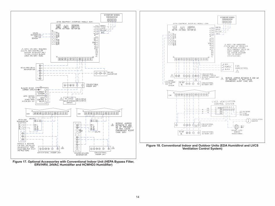
Figure 17. Optional Accessories with Conventional Indoor Unit (HEPA Bypass Filter, ERV/HRV, 24VAC Humidifier and HCWHD3 Humidifier)
REMOVE JUMPER BETWEEN R AND W2IF PRESENT. IT MAY CAUSEERRONEOUS ALERT CODE 125.
ICOMFORT SERIESTHERMOSTAT
Y2 OUTBL
Y2 OUTBL
Figure 18. Conventional Indoor and Outdoor Units (EDA Humiditrol and LVCS Ventilation Control System)
15
Alert Codes and Troubleshooting
Alert Code Types
To expand a specification notification to access a more detail description of the alert code, press the down arrow to expand the description.• Service Urgent alerts are displayed on Home (user) screen under the homeowner and installer alert buttons. Service Urgent means that a service
call is needed to get the system running.• Service Soon / Service Urgent means that the system will likely recover on its own and no interaction is necessary. Typically, either after a specific
timer period or a specific number of instances, some Service Soon alerts will escalate to Service Urgent. • Service Soon alerts are found only in under the installer alert button. • Information Only-Dealer is information only and helps Lennox interpret test results and understand complicated behaviors. Information Only are
not reported to homeowner or dealer.
Communication System: When communication controls are operating in a communication system, all jumper and link setting on controls are ignored. Jumpers and link setting are treated as defaults and would only be active if the system was converted to a non-communicating system.
Error codes are transmitted to the thermostat. No codes are stored in the EIM.
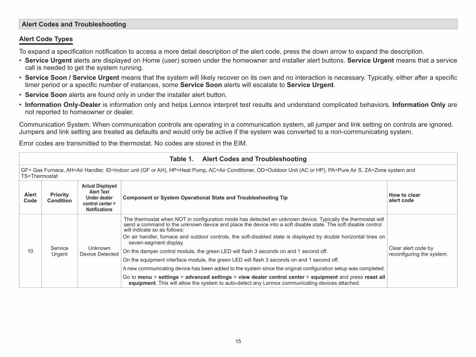
Table 1. Alert Codes and TroubleshootingGF= Gas Furnace, AH=Air Handler, ID=Indoor unit (GF or AH), HP=Heat Pump, AC=Air Conditioner, OD=Outdoor Unit (AC or HP), PA=Pure Air S, ZA=Zone system and TS=Thermostat
Alert Code
Priority Condition
Actual Displayed Alert Text
Under dealer control center > Notifications
Component or System Operational State and Troubleshooting Tip How to clear alert code
10 Service Urgent
Unknown Device Detected
The thermostat when NOT in configuration mode has detected an unknown device. Typically the thermostat will send a command to the unknown device and place the device into a soft disable state. The soft disable control will indicate so as follows:On air handler, furnace and outdoor controls, the soft-disabled state is displayed by double horizontal lines on
seven-segment display.On the damper control module, the green LED will flash 3 seconds on and 1 second off.On the equipment interface module, the green LED will flash 3 seconds on and 1 second off.A new communicating device has been added to the system since the original configuration setup was completed.Go to menu > settings > advanced settings > view dealer control center > equipment and press reset all
equipment. This will allow the system to auto-detect any Lennox communicating devices attached.
Clear alert code by reconfiguring the system.
16
Table 1. Alert Codes and TroubleshootingGF= Gas Furnace, AH=Air Handler, ID=Indoor unit (GF or AH), HP=Heat Pump, AC=Air Conditioner, OD=Outdoor Unit (AC or HP), PA=Pure Air S, ZA=Zone system and TS=Thermostat
Alert Code
Priority Condition
Actual Displayed Alert Text
Under dealer control center > Notifications
Component or System Operational State and Troubleshooting Tip How to clear alert code
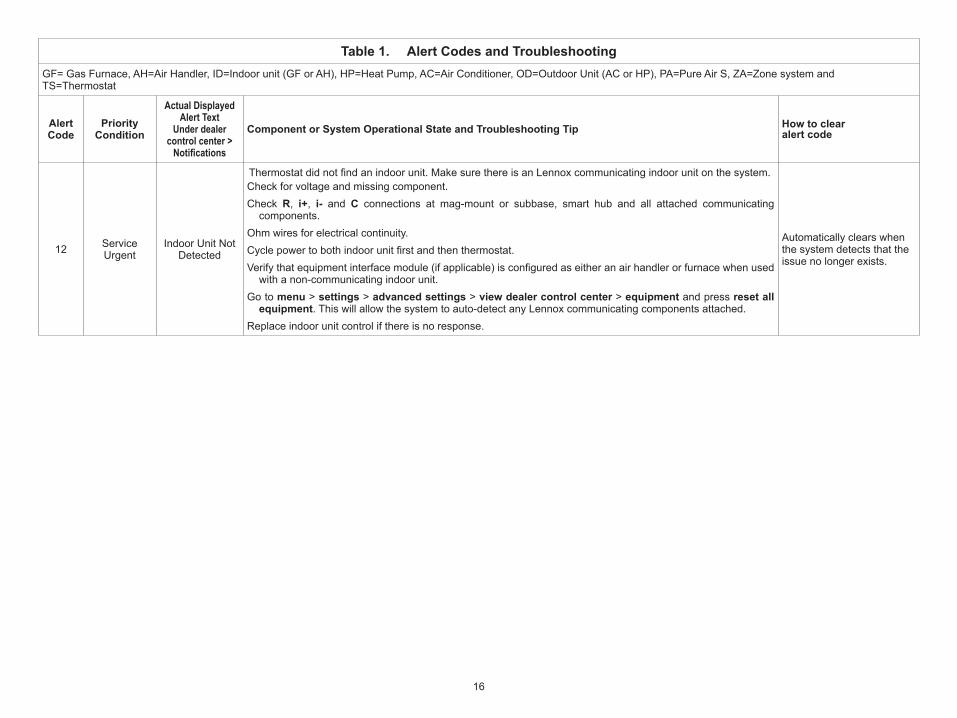
12 Service Urgent
Indoor Unit Not Detected
Thermostat did not find an indoor unit. Make sure there is an Lennox communicating indoor unit on the system. Check for voltage and missing component.Check R, i+, i- and C connections at mag-mount or subbase, smart hub and all attached communicating
components.Ohm wires for electrical continuity.Cycle power to both indoor unit first and then thermostat. Verify that equipment interface module (if applicable) is configured as either an air handler or furnace when used
with a non-communicating indoor unit.Go to menu > settings > advanced settings > view dealer control center > equipment and press reset all
equipment. This will allow the system to auto-detect any Lennox communicating components attached.Replace indoor unit control if there is no response.
Automatically clears when the system detects that the issue no longer exists.
17
Table 1. Alert Codes and TroubleshootingGF= Gas Furnace, AH=Air Handler, ID=Indoor unit (GF or AH), HP=Heat Pump, AC=Air Conditioner, OD=Outdoor Unit (AC or HP), PA=Pure Air S, ZA=Zone system and TS=Thermostat
Alert Code
Priority Condition
Actual Displayed Alert Text
Under dealer control center > Notifications
Component or System Operational State and Troubleshooting Tip How to clear alert code
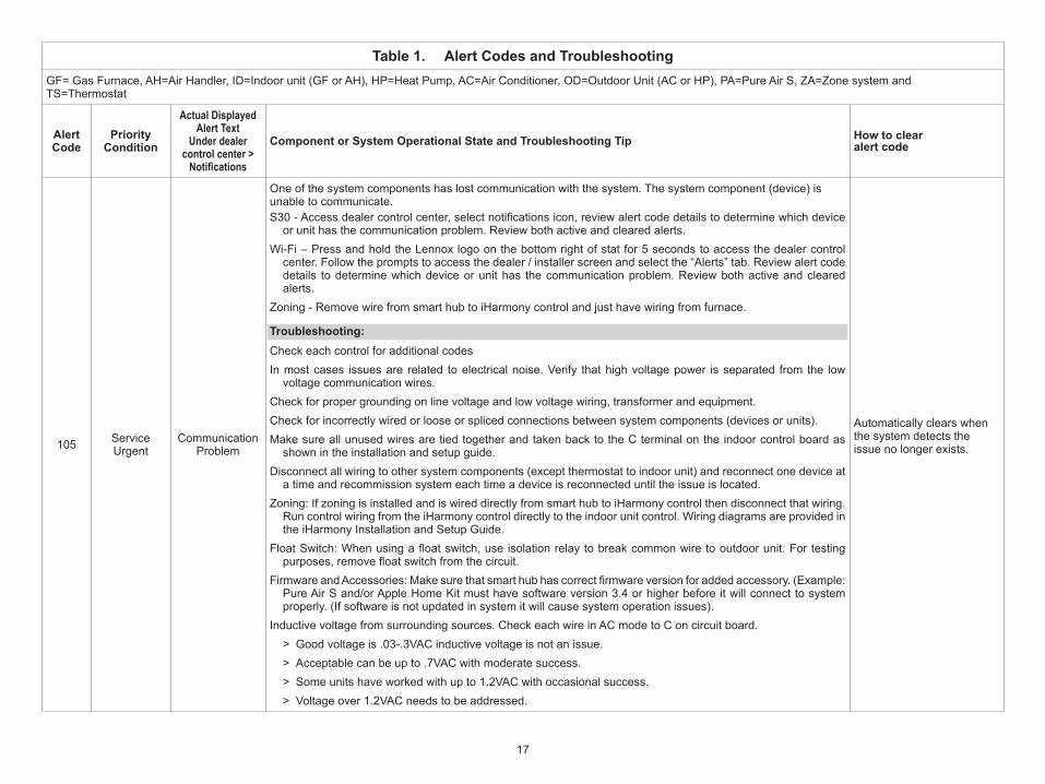
105 Service Urgent
Communication Problem
One of the system components has lost communication with the system. The system component (device) is unable to communicate. S30 - Access dealer control center, select notifications icon, review alert code details to determine which device
or unit has the communication problem. Review both active and cleared alerts.Wi-Fi – Press and hold the Lennox logo on the bottom right of stat for 5 seconds to access the dealer control
center. Follow the prompts to access the dealer / installer screen and select the “Alerts” tab. Review alert code details to determine which device or unit has the communication problem. Review both active and cleared alerts.
Zoning - Remove wire from smart hub to iHarmony control and just have wiring from furnace.
Troubleshooting: Check each control for additional codesIn most cases issues are related to electrical noise. Verify that high voltage power is separated from the low
voltage communication wires. Check for proper grounding on line voltage and low voltage wiring, transformer and equipment.Check for incorrectly wired or loose or spliced connections between system components (devices or units). Make sure all unused wires are tied together and taken back to the C terminal on the indoor control board as
shown in the installation and setup guide. Disconnect all wiring to other system components (except thermostat to indoor unit) and reconnect one device at
a time and recommission system each time a device is reconnected until the issue is located. Zoning: If zoning is installed and is wired directly from smart hub to iHarmony control then disconnect that wiring.
Run control wiring from the iHarmony control directly to the indoor unit control. Wiring diagrams are provided in the iHarmony Installation and Setup Guide.
Float Switch: When using a float switch, use isolation relay to break common wire to outdoor unit. For testing purposes, remove float switch from the circuit.
Firmware and Accessories: Make sure that smart hub has correct firmware version for added accessory. (Example: Pure Air S and/or Apple Home Kit must have software version 3.4 or higher before it will connect to system properly. (If software is not updated in system it will cause system operation issues).
Inductive voltage from surrounding sources. Check each wire in AC mode to C on circuit board. > Good voltage is .03-.3VAC inductive voltage is not an issue. > Acceptable can be up to .7VAC with moderate success. > Some units have worked with up to 1.2VAC with occasional success. > Voltage over 1.2VAC needs to be addressed.
Automatically clears when the system detects the issue no longer exists.
18
Table 1. Alert Codes and TroubleshootingGF= Gas Furnace, AH=Air Handler, ID=Indoor unit (GF or AH), HP=Heat Pump, AC=Air Conditioner, OD=Outdoor Unit (AC or HP), PA=Pure Air S, ZA=Zone system and TS=Thermostat
Alert Code
Priority Condition
Actual Displayed Alert Text
Under dealer control center > Notifications
Component or System Operational State and Troubleshooting Tip How to clear alert code
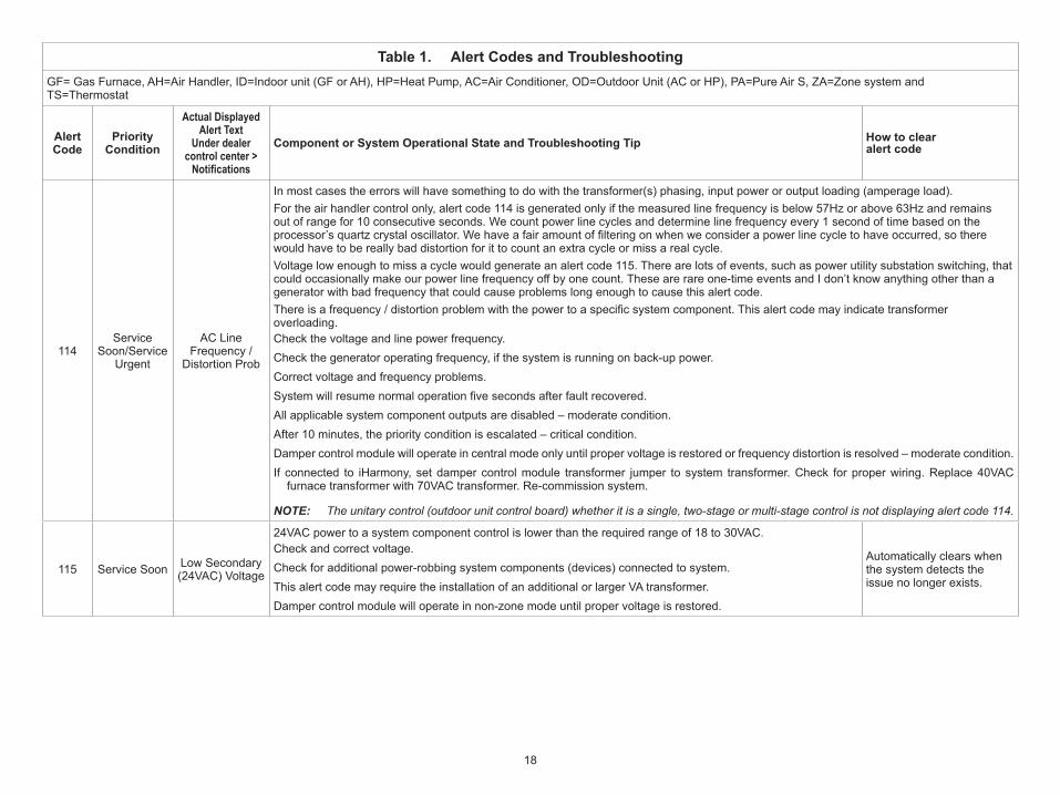
114Service
Soon/Service Urgent
AC Line Frequency /
Distortion Prob
In most cases the errors will have something to do with the transformer(s) phasing, input power or output loading (amperage load). For the air handler control only, alert code 114 is generated only if the measured line frequency is below 57Hz or above 63Hz and remains out of range for 10 consecutive seconds. We count power line cycles and determine line frequency every 1 second of time based on the processor’s quartz crystal oscillator. We have a fair amount of filtering on when we consider a power line cycle to have occurred, so there would have to be really bad distortion for it to count an extra cycle or miss a real cycle. Voltage low enough to miss a cycle would generate an alert code 115. There are lots of events, such as power utility substation switching, that could occasionally make our power line frequency off by one count. These are rare one-time events and I don’t know anything other than a generator with bad frequency that could cause problems long enough to cause this alert code. There is a frequency / distortion problem with the power to a specific system component. This alert code may indicate transformer overloading. Check the voltage and line power frequency. Check the generator operating frequency, if the system is running on back-up power. Correct voltage and frequency problems. System will resume normal operation five seconds after fault recovered.All applicable system component outputs are disabled – moderate condition.After 10 minutes, the priority condition is escalated – critical condition.Damper control module will operate in central mode only until proper voltage is restored or frequency distortion is resolved – moderate condition.If connected to iHarmony, set damper control module transformer jumper to system transformer. Check for proper wiring. Replace 40VAC
furnace transformer with 70VAC transformer. Re-commission system.
NOTE: The unitary control (outdoor unit control board) whether it is a single, two-stage or multi-stage control is not displaying alert code 114.
115 Service Soon Low Secondary (24VAC) Voltage
24VAC power to a system component control is lower than the required range of 18 to 30VAC.Check and correct voltage. Check for additional power-robbing system components (devices) connected to system. This alert code may require the installation of an additional or larger VA transformer.Damper control module will operate in non-zone mode until proper voltage is restored.
Automatically clears when the system detects the issue no longer exists.
19
Table 1. Alert Codes and TroubleshootingGF= Gas Furnace, AH=Air Handler, ID=Indoor unit (GF or AH), HP=Heat Pump, AC=Air Conditioner, OD=Outdoor Unit (AC or HP), PA=Pure Air S, ZA=Zone system and TS=Thermostat
Alert Code
Priority Condition
Actual Displayed Alert Text
Under dealer control center > Notifications
Component or System Operational State and Troubleshooting Tip How to clear alert code
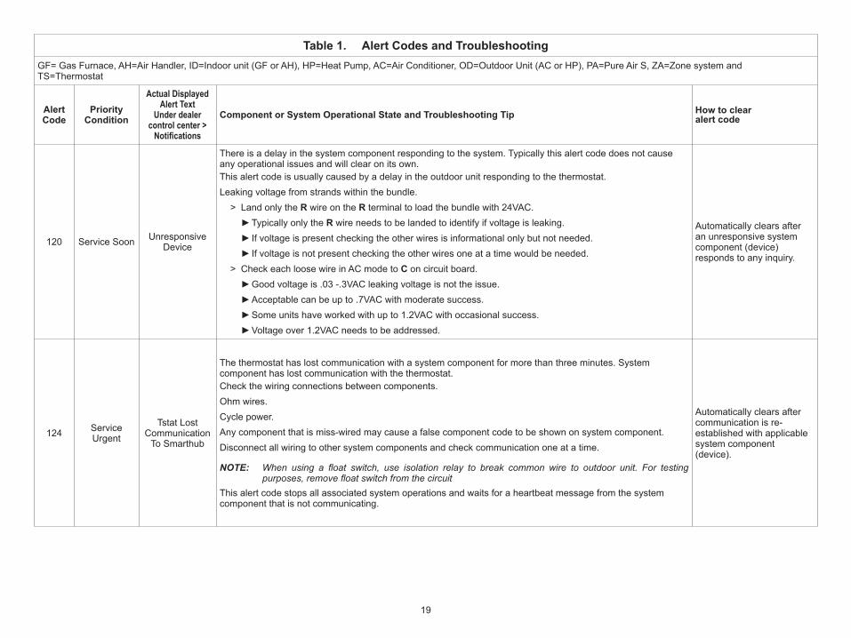
120 Service Soon Unresponsive Device
There is a delay in the system component responding to the system. Typically this alert code does not cause any operational issues and will clear on its own. This alert code is usually caused by a delay in the outdoor unit responding to the thermostat.Leaking voltage from strands within the bundle.
> Land only the R wire on the R terminal to load the bundle with 24VAC. ►Typically only the R wire needs to be landed to identify if voltage is leaking. ►If voltage is present checking the other wires is informational only but not needed. ►If voltage is not present checking the other wires one at a time would be needed.
> Check each loose wire in AC mode to C on circuit board. ►Good voltage is .03 -.3VAC leaking voltage is not the issue. ►Acceptable can be up to .7VAC with moderate success. ►Some units have worked with up to 1.2VAC with occasional success. ►Voltage over 1.2VAC needs to be addressed.
Automatically clears after an unresponsive system component (device) responds to any inquiry.
124 Service Urgent
Tstat Lost Communication
To Smarthub
The thermostat has lost communication with a system component for more than three minutes. System component has lost communication with the thermostat. Check the wiring connections between components.Ohm wires.Cycle power. Any component that is miss-wired may cause a false component code to be shown on system component. Disconnect all wiring to other system components and check communication one at a time.
NOTE: When using a float switch, use isolation relay to break common wire to outdoor unit. For testing purposes, remove float switch from the circuit
This alert code stops all associated system operations and waits for a heartbeat message from the system component that is not communicating.
Automatically clears after communication is re-established with applicable system component (device).
20
Table 1. Alert Codes and TroubleshootingGF= Gas Furnace, AH=Air Handler, ID=Indoor unit (GF or AH), HP=Heat Pump, AC=Air Conditioner, OD=Outdoor Unit (AC or HP), PA=Pure Air S, ZA=Zone system and TS=Thermostat
Alert Code
Priority Condition
Actual Displayed Alert Text
Under dealer control center > Notifications
Component or System Operational State and Troubleshooting Tip How to clear alert code
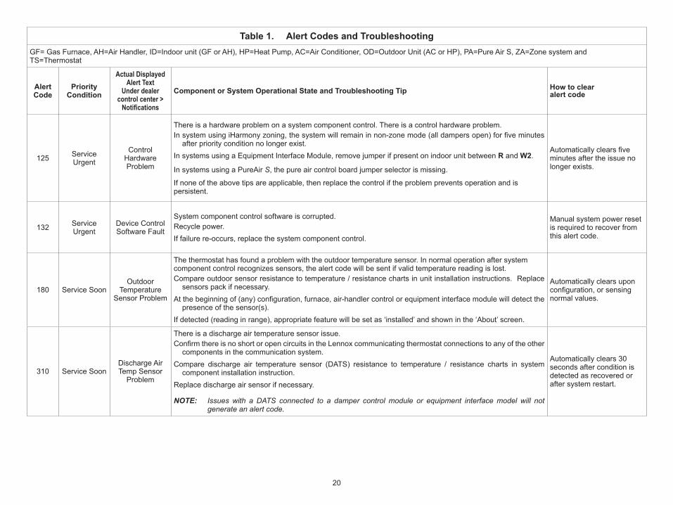
125 Service Urgent
Control Hardware Problem
There is a hardware problem on a system component control. There is a control hardware problem. In system using iHarmony zoning, the system will remain in non-zone mode (all dampers open) for five minutes
after priority condition no longer exist.In systems using a Equipment Interface Module, remove jumper if present on indoor unit between R and W2.
In systems using a PureAir S, the pure air control board jumper selector is missing.
If none of the above tips are applicable, then replace the control if the problem prevents operation and is persistent.
Automatically clears five minutes after the issue no longer exists.
132 Service Urgent
Device Control Software Fault
System component control software is corrupted.Recycle power. If failure re-occurs, replace the system component control.
Manual system power reset is required to recover from this alert code.
180 Service SoonOutdoor
Temperature Sensor Problem
The thermostat has found a problem with the outdoor temperature sensor. In normal operation after system component control recognizes sensors, the alert code will be sent if valid temperature reading is lost. Compare outdoor sensor resistance to temperature / resistance charts in unit installation instructions. Replace
sensors pack if necessary. At the beginning of (any) configuration, furnace, air-handler control or equipment interface module will detect the
presence of the sensor(s).If detected (reading in range), appropriate feature will be set as ‘installed’ and shown in the ‘About’ screen.
Automatically clears upon configuration, or sensing normal values.
310 Service SoonDischarge Air Temp Sensor
Problem
There is a discharge air temperature sensor issue.Confirm there is no short or open circuits in the Lennox communicating thermostat connections to any of the other
components in the communication system.Compare discharge air temperature sensor (DATS) resistance to temperature / resistance charts in system
component installation instruction. Replace discharge air sensor if necessary.
NOTE: Issues with a DATS connected to a damper control module or equipment interface model will not generate an alert code.
Automatically clears 30 seconds after condition is detected as recovered or after system restart.
21
Table 1. Alert Codes and TroubleshootingGF= Gas Furnace, AH=Air Handler, ID=Indoor unit (GF or AH), HP=Heat Pump, AC=Air Conditioner, OD=Outdoor Unit (AC or HP), PA=Pure Air S, ZA=Zone system and TS=Thermostat
Alert Code
Priority Condition
Actual Displayed Alert Text
Under dealer control center > Notifications
Component or System Operational State and Troubleshooting Tip How to clear alert code
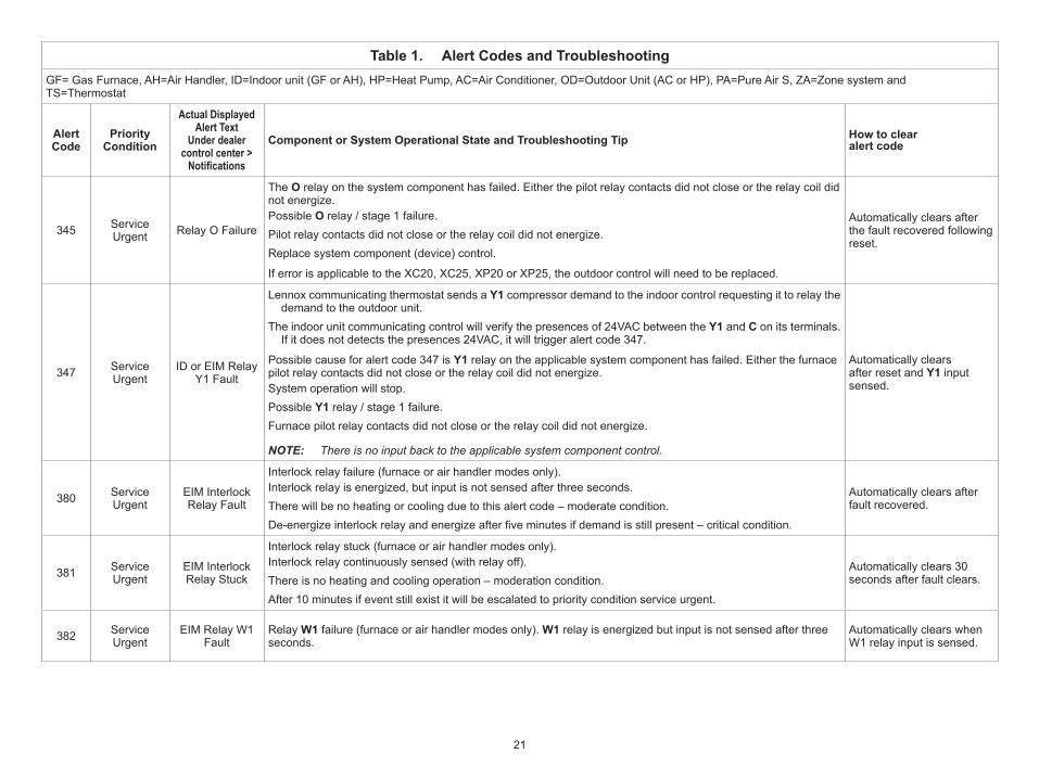
345 Service Urgent Relay O Failure
The O relay on the system component has failed. Either the pilot relay contacts did not close or the relay coil did not energize.Possible O relay / stage 1 failure.Pilot relay contacts did not close or the relay coil did not energize. Replace system component (device) control.
If error is applicable to the XC20, XC25, XP20 or XP25, the outdoor control will need to be replaced.
Automatically clears after the fault recovered following reset.
347 Service Urgent
ID or EIM Relay Y1 Fault
Lennox communicating thermostat sends a Y1 compressor demand to the indoor control requesting it to relay the demand to the outdoor unit.
The indoor unit communicating control will verify the presences of 24VAC between the Y1 and C on its terminals. If it does not detects the presences 24VAC, it will trigger alert code 347.
Possible cause for alert code 347 is Y1 relay on the applicable system component has failed. Either the furnace pilot relay contacts did not close or the relay coil did not energize.System operation will stop. Possible Y1 relay / stage 1 failure. Furnace pilot relay contacts did not close or the relay coil did not energize.
NOTE: There is no input back to the applicable system component control.
Automatically clears after reset and Y1 input sensed.
380 Service Urgent
EIM Interlock Relay Fault
Interlock relay failure (furnace or air handler modes only).Interlock relay is energized, but input is not sensed after three seconds. There will be no heating or cooling due to this alert code – moderate condition.De-energize interlock relay and energize after five minutes if demand is still present – critical condition.
Automatically clears after fault recovered.
381 Service Urgent
EIM Interlock Relay Stuck
Interlock relay stuck (furnace or air handler modes only).Interlock relay continuously sensed (with relay off). There is no heating and cooling operation – moderation condition.After 10 minutes if event still exist it will be escalated to priority condition service urgent.
Automatically clears 30 seconds after fault clears.
382 Service Urgent
EIM Relay W1 Fault
Relay W1 failure (furnace or air handler modes only). W1 relay is energized but input is not sensed after three seconds.
Automatically clears when W1 relay input is sensed.
22
Table 1. Alert Codes and TroubleshootingGF= Gas Furnace, AH=Air Handler, ID=Indoor unit (GF or AH), HP=Heat Pump, AC=Air Conditioner, OD=Outdoor Unit (AC or HP), PA=Pure Air S, ZA=Zone system and TS=Thermostat
Alert Code
Priority Condition
Actual Displayed Alert Text
Under dealer control center > Notifications
Component or System Operational State and Troubleshooting Tip How to clear alert code
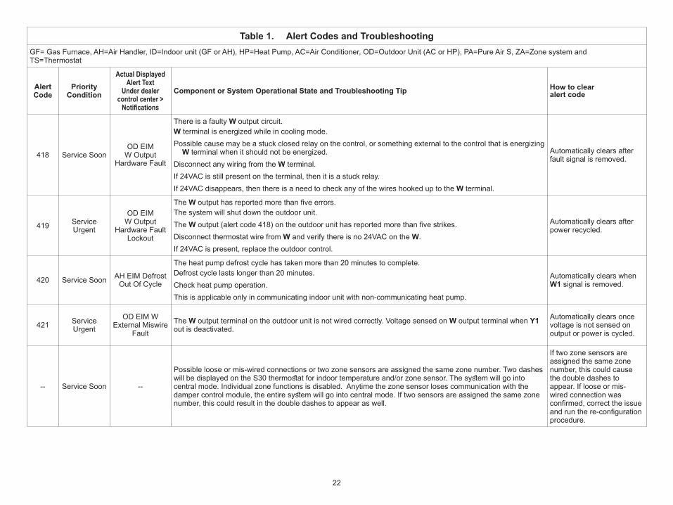
418 Service SoonOD EIM
W Output Hardware Fault
There is a faulty W output circuit.W terminal is energized while in cooling mode. Possible cause may be a stuck closed relay on the control, or something external to the control that is energizing
W terminal when it should not be energized. Disconnect any wiring from the W terminal. If 24VAC is still present on the terminal, then it is a stuck relay. If 24VAC disappears, then there is a need to check any of the wires hooked up to the W terminal.
Automatically clears after fault signal is removed.
419 Service Urgent
OD EIM W Output
Hardware Fault Lockout
The W output has reported more than five errors. The system will shut down the outdoor unit. The W output (alert code 418) on the outdoor unit has reported more than five strikes. Disconnect thermostat wire from W and verify there is no 24VAC on the W. If 24VAC is present, replace the outdoor control.
Automatically clears after power recycled.
420 Service Soon AH EIM Defrost Out Of Cycle
The heat pump defrost cycle has taken more than 20 minutes to complete.Defrost cycle lasts longer than 20 minutes. Check heat pump operation. This is applicable only in communicating indoor unit with non-communicating heat pump.
Automatically clears when W1 signal is removed.
421 Service Urgent
OD EIM W External Miswire
FaultThe W output terminal on the outdoor unit is not wired correctly. Voltage sensed on W output terminal when Y1 out is deactivated.
Automatically clears once voltage is not sensed on output or power is cycled.
-- Service Soon --
Possible loose or mis-wired connections or two zone sensors are assigned the same zone number. Two dashes will be displayed on the S30 thermostat for indoor temperature and/or zone sensor. The system will go into central mode. Individual zone functions is disabled. Anytime the zone sensor loses communication with the damper control module, the entire system will go into central mode. If two sensors are assigned the same zone number, this could result in the double dashes to appear as well.
If two zone sensors are assigned the same zone number, this could cause the double dashes to appear. If loose or mis-wired connection was confirmed, correct the issue and run the re-configuration procedure.

23

24