Embed Size (px)
Citation preview
DM780 / Navigator Setup
DM780 / Navigator Setup 2/20/2008 Page 1 Author: Clint Hurd KK7UQ [email protected]
When you first start with HRD / DM780, you need to define a few Navigator parameters to the program so it can communicate with your radio through the Navigator. The items that need to be defined are: DM780: PTT port DM780: USB Audio Device (sound card) DM780: TX to RX offset to zero DM780: Soundcard levels DM780: Waterfall 1 parameters DM780: Navigator Options settings HRD: Rig Type, CAT Port This document describes how to set and optimize these parameters. The procedures assume that HRD / DM780 has not been setup for the Navigator before, so that when you start, you do not yet know the address of the CAT control. The procedure you will bypass the HRD Connect step and go directly to DM780. The last step will be to set the Connect parameters for HRD. DM780 has an excellent tool to help you with setup of your Navigator: The “Navigator Manager”. DM780 / Tools / Navigator Manager DM780 has an integrated manager for the Navigator Interface. It combines an improved Windows style Device Manager, and the functions normally provided by the US Interface NavOptions Program. On the main screen of DM780, go to the Tools menu and select Navigator Manager. You will get a screen similar to the one below.
DM780 / Navigator Setup
DM780 / Navigator Setup 2/20/2008 Page 2 Author: Clint Hurd KK7UQ [email protected]
Click on the “Connect” button in the upper left of the screen, and you will see both the NavOptions functions on the left, and the improved Device Manager function on the right.

DM780 / Navigator Setup
DM780 / Navigator Setup 2/20/2008 Page 3 Author: Clint Hurd KK7UQ [email protected]
DM780 / Tools / Navigator Manager (cont’d) The screen looks like the one below after the “connect”.
Note that all of the option setting functions are on the left, and can be changed and saved just like in the NavOptions program. A significant improvement of the DM780 version is that the Configuration COM port is known, so there is no need to scan the ports and probe for the Config port. The panel on the right shows all COM port assignments in your computer, with the actual function listed under “Location”. The device name of the dual UART is shown under “Description” on the right. In the normal Windows Device Manager, you see what is shown under Description, but you do not know the Location detail until you double click on the PORT number in the Windows Device Manager. This screen combines all of the information you need. The consolidated screen provided by Simon Brown in DM780 really helps in initial setup with the Navigator. You can have this screen up while you are doing configuration items for easy reference. The rest of this document shows how to configure your Navigator with DM780. Remember that your actual port numbers may vary from the ones in this example – just use Navigator Manager to tell you what your port assignments are.
DM780 / Navigator Setup
DM780 / Navigator Setup 2/20/2008 Page 4 Author: Clint Hurd KK7UQ [email protected]
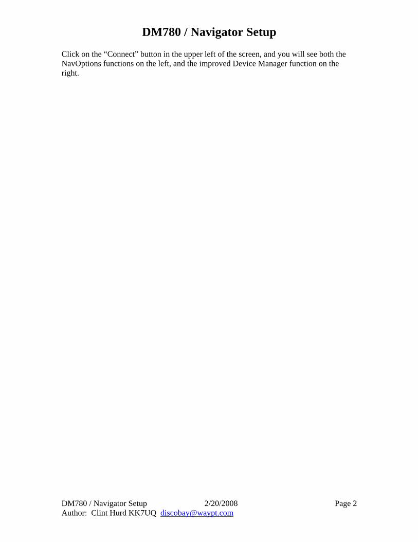
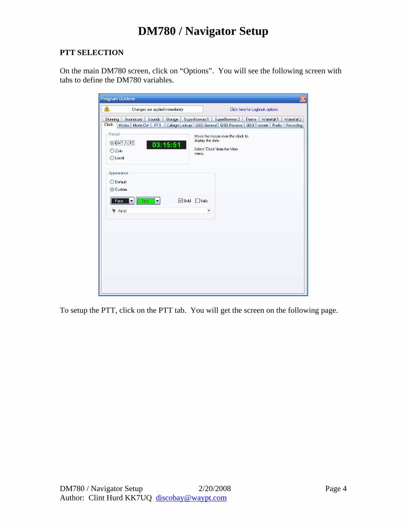
PTT SELECTION On the main DM780 screen, click on “Options”. You will see the following screen with tabs to define the DM780 variables.
To setup the PTT, click on the PTT tab. You will get the screen on the following page.
DM780 / Navigator Setup
DM780 / Navigator Setup 2/20/2008 Page 5 Author: Clint Hurd KK7UQ [email protected]
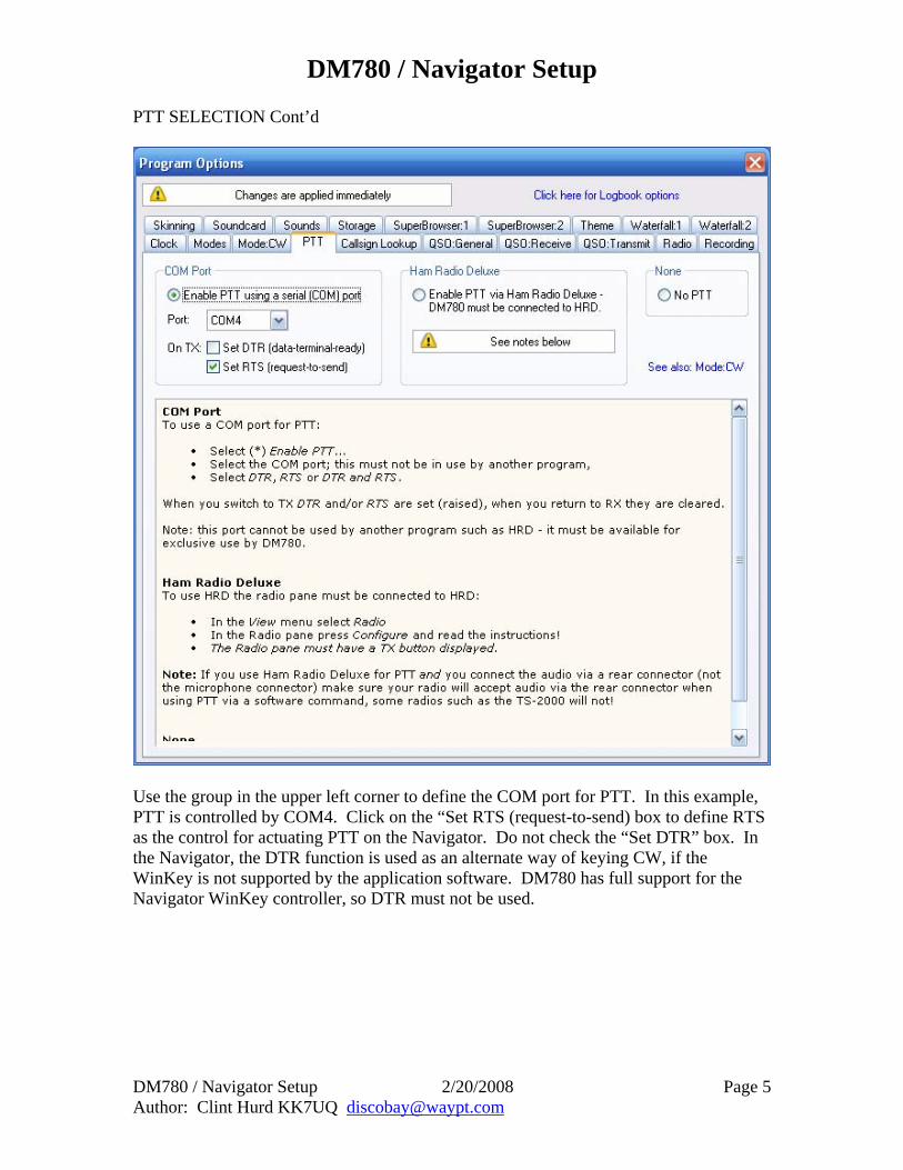
PTT SELECTION Cont’d
Use the group in the upper left corner to define the COM port for PTT. In this example, PTT is controlled by COM4. Click on the “Set RTS (request-to-send) box to define RTS as the control for actuating PTT on the Navigator. Do not check the “Set DTR” box. In the Navigator, the DTR function is used as an alternate way of keying CW, if the WinKey is not supported by the application software. DM780 has full support for the Navigator WinKey controller, so DTR must not be used.
DM780 / Navigator Setup
DM780 / Navigator Setup 2/20/2008 Page 6 Author: Clint Hurd KK7UQ [email protected]
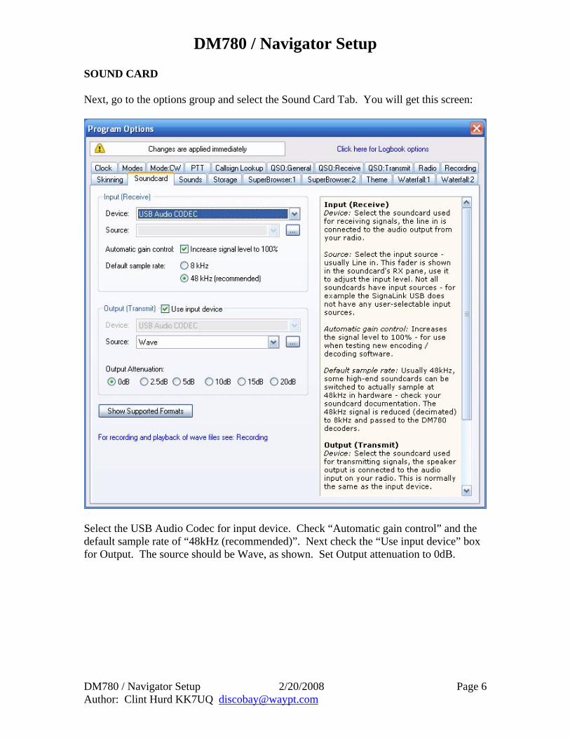
SOUND CARD Next, go to the options group and select the Sound Card Tab. You will get this screen:
Select the USB Audio Codec for input device. Check “Automatic gain control” and the default sample rate of “48kHz (recommended)”. Next check the “Use input device” box for Output. The source should be Wave, as shown. Set Output attenuation to 0dB.
DM780 / Navigator Setup
DM780 / Navigator Setup 2/20/2008 Page 7 Author: Clint Hurd KK7UQ [email protected]
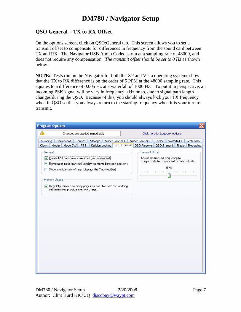
QSO General – TX to RX Offset On the options screen, click on QSO:General tab. This screen allows you to set a transmit offset to compensate for differences in frequency from the sound card between TX and RX. The Navigator USB Audio Codec is run at a sampling rate of 48000, and does not require any compensation. The transmit offset should be set to 0 Hz as shown below. NOTE: Tests run on the Navigator for both the XP and Vista operating systems show that the TX to RX difference is on the order of 5 PPM at the 48000 sampling rate. This equates to a difference of 0.005 Hz at a waterfall of 1000 Hz. To put it in perspective, an incoming PSK signal will be vary in frequency a Hz or so, due to signal path length changes during the QSO. Because of this, you should always lock your TX frequency when in QSO so that you always return to the starting frequency when it is your turn to transmit.
DM780 / Navigator Setup
DM780 / Navigator Setup 2/20/2008 Page 8 Author: Clint Hurd KK7UQ [email protected]
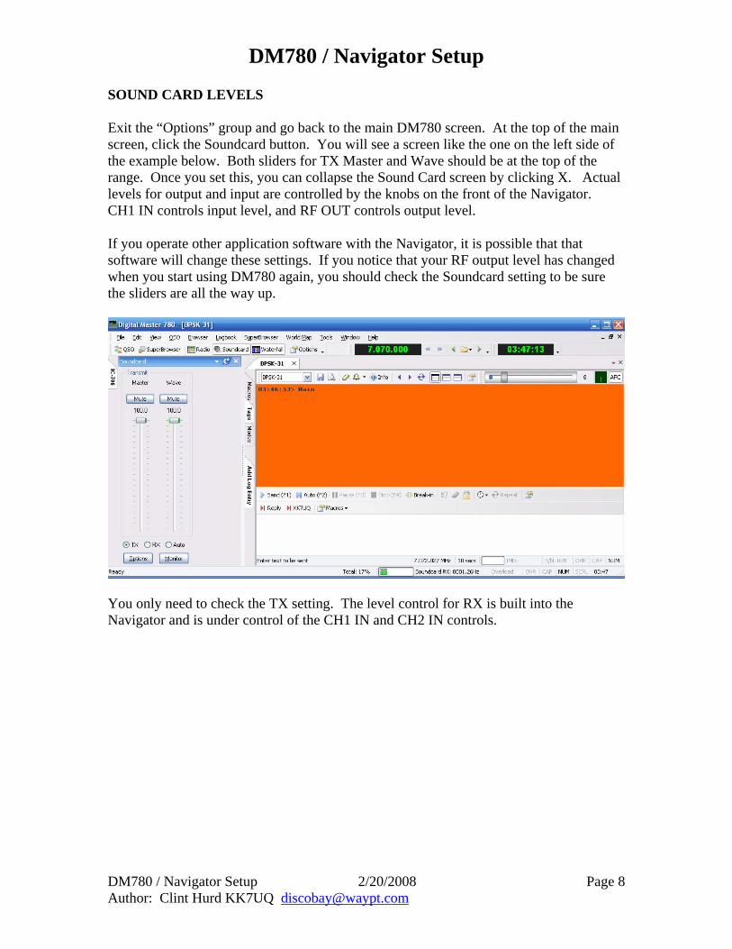
SOUND CARD LEVELS Exit the “Options” group and go back to the main DM780 screen. At the top of the main screen, click the Soundcard button. You will see a screen like the one on the left side of the example below. Both sliders for TX Master and Wave should be at the top of the range. Once you set this, you can collapse the Sound Card screen by clicking X. Actual levels for output and input are controlled by the knobs on the front of the Navigator. CH1 IN controls input level, and RF OUT controls output level. If you operate other application software with the Navigator, it is possible that that software will change these settings. If you notice that your RF output level has changed when you start using DM780 again, you should check the Soundcard setting to be sure the sliders are all the way up.
You only need to check the TX setting. The level control for RX is built into the Navigator and is under control of the CH1 IN and CH2 IN controls.
DM780 / Navigator Setup
DM780 / Navigator Setup 2/20/2008 Page 9 Author: Clint Hurd KK7UQ [email protected]
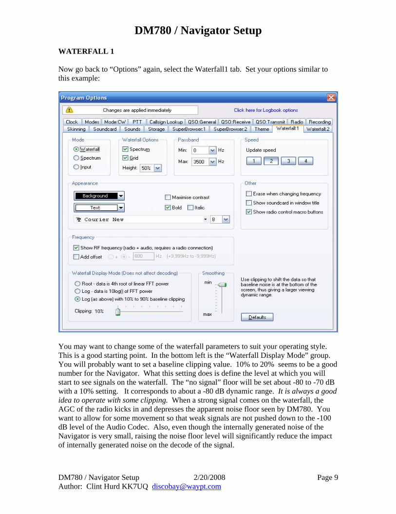
WATERFALL 1 Now go back to “Options” again, select the Waterfall1 tab. Set your options similar to this example:
You may want to change some of the waterfall parameters to suit your operating style. This is a good starting point. In the bottom left is the “Waterfall Display Mode” group. You will probably want to set a baseline clipping value. 10% to 20% seems to be a good number for the Navigator. What this setting does is define the level at which you will start to see signals on the waterfall. The “no signal” floor will be set about -80 to -70 dB with a 10% setting. It corresponds to about a -80 dB dynamic range. It is always a good idea to operate with some clipping. When a strong signal comes on the waterfall, the AGC of the radio kicks in and depresses the apparent noise floor seen by DM780. You want to allow for some movement so that weak signals are not pushed down to the -100 dB level of the Audio Codec. Also, even though the internally generated noise of the Navigator is very small, raising the noise floor level will significantly reduce the impact of internally generated noise on the decode of the signal.
DM780 / Navigator Setup
DM780 / Navigator Setup 2/20/2008 Page 10 Author: Clint Hurd KK7UQ [email protected]
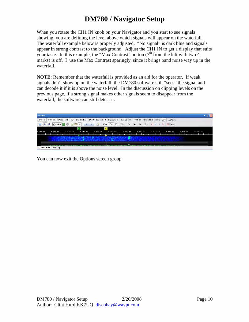
When you rotate the CH1 IN knob on your Navigator and you start to see signals showing, you are defining the level above which signals will appear on the waterfall. The waterfall example below is properly adjusted. “No signal” is dark blue and signals appear in strong contrast to the background. Adjust the CH1 IN to get a display that suits your taste. In this example, the “Max Contrast” button (7th from the left with two ^ marks) is off. I use the Max Contrast sparingly, since it brings band noise way up in the waterfall. NOTE: Remember that the waterfall is provided as an aid for the operator. If weak signals don’t show up on the waterfall, the DM780 software still “sees” the signal and can decode it if it is above the noise level. In the discussion on clipping levels on the previous page, if a strong signal makes other signals seem to disappear from the waterfall, the software can still detect it.
You can now exit the Options screen group.
DM780 / Navigator Setup
DM780 / Navigator Setup 2/20/2008 Page 11 Author: Clint Hurd KK7UQ [email protected]
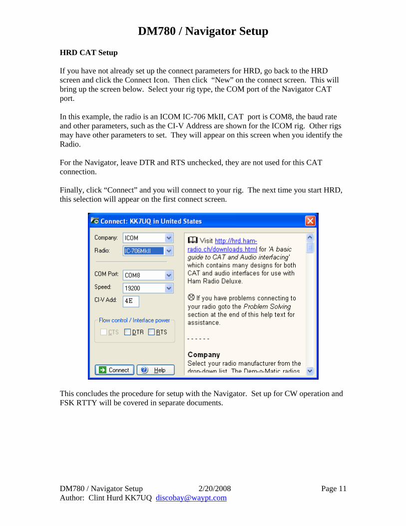
HRD CAT Setup If you have not already set up the connect parameters for HRD, go back to the HRD screen and click the Connect Icon. Then click “New” on the connect screen. This will bring up the screen below. Select your rig type, the COM port of the Navigator CAT port. In this example, the radio is an ICOM IC-706 MkII, CAT port is COM8, the baud rate and other parameters, such as the CI-V Address are shown for the ICOM rig. Other rigs may have other parameters to set. They will appear on this screen when you identify the Radio. For the Navigator, leave DTR and RTS unchecked, they are not used for this CAT connection. Finally, click “Connect” and you will connect to your rig. The next time you start HRD, this selection will appear on the first connect screen.
This concludes the procedure for setup with the Navigator. Set up for CW operation and FSK RTTY will be covered in separate documents.