Embed Size (px)
Citation preview
H. Badioze Zaman et al. (Eds.): IVIC 2009, LNCS 5857, pp. 90–96, 2009. © Springer-Verlag Berlin Heidelberg 2009
Vision-Based Mobile Robot Navigation Using Image Processing and Cell Decomposition
Shahed Shojaeipour, Sallehuddin Mohamed Haris, and Muhammad Ihsan Khairir
Department of Mechanical and Materials Engineering, Universiti Kebangsaan Malaysia, 43600 UKM Bangi, Malaysia
[email protected], [email protected], [email protected]
Abstract. In this paper, we present a method to navigate a mobile robot using a webcam. This method determines the shortest path for the robot to transverse to its target location, while avoiding obstacles along the way. The environment is first captured as an image using a webcam. Image processing methods are then performed to identify the existence of obstacles within the environment. Using the Cell Decomposition method, locations with obstacles are identified and the corresponding cells are eliminated. From the remaining cells, the shortest path to the goal is identified. The program is written in MATLAB with the Image Processing toolbox. The proposed method does not make use of any other type of sensor other than the webcam.
Keywords: Mobile robot, Path planning, Cell Decomposition, Image process-ing, Visual servo.
1 Introduction
Image processing is a form of signal processing where the input signals are images such as photographs or video frames. The output could be a transformed version of the input image or a set of characteristics or parameters related to the image. The computer revolution that has taken place over the last 20 years has led to great ad-vancements in the field of digital image processing. This has in turn, opened up a multitude of applications in various fields, in which the technology could be utilised.
The aim of this paper is to present a method for visual servo control using only visual images from a webcam. Visual servo is the use of image data in closed loop control of a robot. Without doubt, today, the use of vision in robotic applications is rapidly increasing. This is due to the fact that vision based sensors such as webcams are falling in price more rapidly than any other sensor. It is also a richer sensor than traditional ranging devices, particularly since a camera captures much more data si-multaneously [1].
Images can be captured by camera, and subsequently, processed using some par-ticular software. Among them, MATLAB, with its Image Processing toolbox, is well suited to perform such tasks. Information obtained from the image processing exer-cise can then be used to generate motion commands to be sent to the mobile robot.
Vision-Based Mobile Robot Navigation Using Image Processing 91
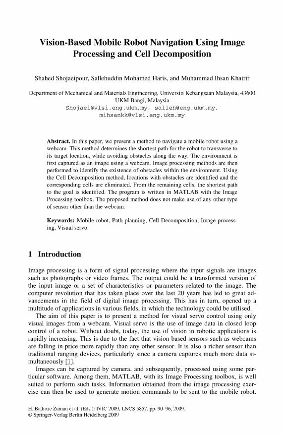
This sequence is depicted in Fig. 1. Consequently, the robot imitates human vision in 6 stages as follows:
1. Image acquisition 2. Image processing 3. Image analysis and assimilation 4. Image intelligence 5. Control signal reception 6. Motion control of parts of the robot.
Fig. 1. Experimental Setup
The mobile robot motion must be controlled so as to reach its destination without colliding into obstacles. In most cases, the shortest collision-free path would be the best preferred route. The process of determining such a route is known as path planning.
In this paper we consider the Cell Decomposition approach to path planning. This general method requires a complete specification of the environment and is often based on the construction of the mobile robot configuration space (C-Space) which reduces the mobile robot to a point. Although a localised method will basically be used, the proposed method can present an alternative approach for guidance of the point, or even joint trajectory planning if complete information about the robot is known [2].
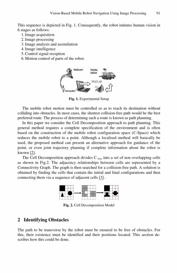
The Cell Decomposition approach divides C free into a set of non overlapping cells as shown in Fig.2. The adjacency relationships between cells are represented by a Connectivity Graph. The graph is then searched for a collision-free path. A solution is obtained by finding the cells that contain the initial and final configurations and then connecting them via a sequence of adjacent cells [3].
Fig. 2. Cell Decomposition Model
2 Identifying Obstacles
The path to be transverse by the robot must be ensured to be free of obstacles. For this, their existence must be identified and their positions located. This section de-scribes how this could be done.
92 S. Shojaeipour, S.M. Haris, and M.I. Khairir
The image is recorded by a webcam which is installed above the robot. The image is then sent via a USB cable to a PC, to be processed by MATLAB. The experiments were carried out using a computer with 3.60GB free space hard disk and 1GB RAM memory. The algorithm was developed using MATLAB (version 7.6 R2008a).
The image is divided into segments, which become the export databases; usually they are the raw pixels data abstracted from the captured image [4,5 and 6]. The pic-ture could be in JPG or BMP format, in which case, every pixel point uses three nu-merical values, representing intensity levels of the primary colours: red, green and blue (RGB) to depict its characteristics. Therefore, in such format, computing work-load to perform image processing would be very high. Hence, it would be desirable to convert the coloured picture into a greyscale image. [7, 8]
Image processing methods are firstly used to identify the existence of obstacles within the image frame. This is implemented in an eight step MATLAB (with the Image Processing Toolbox) program. The following describes the steps: • Step 1. Generate input video objects.
This can be implemented using the command Obj = videoinput(‘adaptorname’, device name, ’format’); Where the adaptor name can be determined using the ‘imaqhwinfo’ command, de-vice name is the name given to the device and format refers to the required image format.
• Step 2. Preview the webcam video image. Preview(‘object name’); where object name is Obj in the last command
• Step 3. Set brightness level of image. set(obj,’ property name’ property value);
• Step 4. Capture still image from webcam video. getsnapshot(object name); The captured image is stored as an array whose elements represent the light level.
• Step 5. Remove the input device from memory. delete( object name);
• Step 6. Convert from RGB to greyscale mode. I=rgb2ind(I,colorcube(150));
• Step 7. Find edges of objects in the image. I=edge(I,’sobel’,(graythresh(I)*.1));
• Step 8. Remove noise. Se90=strel(‘line’,3,90); Se0=strel (‘line’,3,0); I=imdilate(I,[se90 se0]);
I=imfill(I,’holes’); A sample implementation of these steps in MATLAB is shown below:
Input: Take picture using webcam (original image) vid = videoinput('winvideo' , 1,'RGB24_160x120'); preview (vid); set (vid.source, 'Brightness', 30); I = getsnapshot(vid); I = rgb2ind (I,colorcube(150)); PSF = fspecial( 'gaussian',3,3); I = imfilter(I,PSF,'symmetric' ,'conv'); BW = edge (I, 'sobel', (graythresh(I) * .1));
Vision-Based Mobile Robot Navigation Using Image Processing 93
se90 = strel('line',3,90); se0 = strel('line',3,0); BW1 = imdilate(BW, [se90 se0]); P = imfill(BW1, 'holes'); P = ~P; imshow(P);
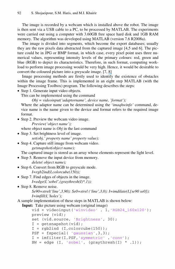
Output: The final is special image The results of running this program can be seen in Fig. 3, where (A) is the original image, (B)-(F) are the intermediate stages of the image and (G) is the final image.
(A) (B) (C)
(D) ( E) (F)
(G)
Fig. 3. A- Original Image, from B to F- intermediate stages of filtering and G- Final image
3 Path Planning
In order to select the shortest path for the robot to transverse, three actions need to be considered: the first is image capture using webcam; the second is to convert the image into a 3D scene, using the Spectral Fractal Dimension (SFD) technique [9, 10]. Previ-ous works have used just two images of the scene for this purpose [11, 12 and 13].
94 S. Shojaeipour, S.M. Haris, and M.I. Khairir
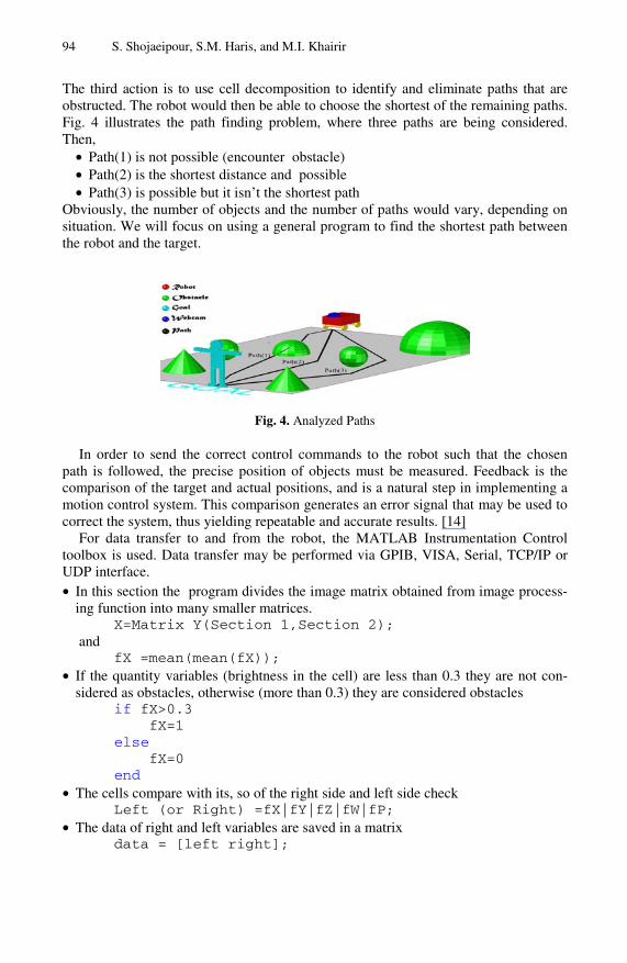
The third action is to use cell decomposition to identify and eliminate paths that are obstructed. The robot would then be able to choose the shortest of the remaining paths. Fig. 4 illustrates the path finding problem, where three paths are being considered. Then,
• Path(1) is not possible (encounter obstacle) • Path(2) is the shortest distance and possible • Path(3) is possible but it isn’t the shortest path
Obviously, the number of objects and the number of paths would vary, depending on situation. We will focus on using a general program to find the shortest path between the robot and the target.
Fig. 4. Analyzed Paths
In order to send the correct control commands to the robot such that the chosen path is followed, the precise position of objects must be measured. Feedback is the comparison of the target and actual positions, and is a natural step in implementing a motion control system. This comparison generates an error signal that may be used to correct the system, thus yielding repeatable and accurate results. [14]
For data transfer to and from the robot, the MATLAB Instrumentation Control toolbox is used. Data transfer may be performed via GPIB, VISA, Serial, TCP/IP or UDP interface.
• In this section the program divides the image matrix obtained from image process-ing function into many smaller matrices.
X=Matrix Y(Section 1,Section 2); and
fX =mean(mean(fX)); • If the quantity variables (brightness in the cell) are less than 0.3 they are not con-
sidered as obstacles, otherwise (more than 0.3) they are considered obstacles if fX>0.3 fX=1 else fX=0 end
• The cells compare with its, so of the right side and left side check Left (or Right) =fX|fY|fZ|fW|fP;
• The data of right and left variables are saved in a matrix data = [left right];
Vision-Based Mobile Robot Navigation Using Image Processing 95
The following is a sample implementation based on MATLAB. Input: p = image of the last section (Final image)
a=p(11:30,73:88);b=p(31:50,57:72);c=p(51:70,41:56);d=p(71:90,25:40);e=p(91:110,9:24); f=p(31:50,89:104);g=p(51:70,105:120);h=p(71:90,121:136);i=p(91:110,137:152); fa=mean(mean(a));fb=mean(mean(b));fc=mean(mean(c));fd=mean(mean(d));fe=mean(mean(e)); ff=mean(mean(fe));fg=mean(mean(g)); fh=mean(mean(h));fi=mean(mean(i)); if fa>.3; fa=1; else; fa=0;end; if fb>.3; fb=1; else; fb=0;end; if fc>.3; fc=1;else; fc=0; end; if fd>.3;fd=1;else;fd=0;end; if fe>.3;fe=1;else;fe=0;end; if ff>.3;ff=1;else;ff=0;end; if fg>.3;fg=1;else;fg=0;end; if fh>.3;fh=1;else;fh=0;end; if fi>.3;fi=1;else;fi=0;end; left=fa|fb|fc|fd|fe; right=fa|ff|fg|fh|fi; data=[left right];
Output: send data to robot Running the program will result in the shortest path to the goal being generated. This path is then used to generate the mobile robot motion.
4 Conclusions and Future Work
This paper provides a framework for mobile robot navigation using a robot mounted webcam. Using images captured by the webcam, the location of obstacles are identi-fied. Then, using the Cell Decomposition technique, the shortest path to the target destination is determined. Future work would be to translate the generated optimal path into input commands to the actual robot. The system would also be further de-veloped for situations with moving obstacles and moving targets.
Acknowledgements
This research was supported by the Ministry of Science Technology and Innovation, Malaysia, Grant No. 03-01-02-SF0459.
References
1. Campbell, J., Sukthankar, R., Nourbakhsh, I., Pahwa, A.: A robust visual odometry and precipice detection system using consumer-grade monocular vision. In: Proc. ICRA 2005, Barcelona, Spain (2005)
96 S. Shojaeipour, S.M. Haris, and M.I. Khairir
2. Latombe, J.C.: Robot Motion planning. Kluwer Academic Publishers, London (1982); Ro-bot Arm Kinematics, Dynamic, and Control. Computer 15(12), 62–80 (1991)
3. Hwang, Y.K., Ahuja, N.: Gross motion planning - a survey. ACMComp. Surveys 24(3), 219–291 (1992)
4. Gonzalez, R., wood, R.: Digital Image Processing, 2nd edn. Prentice-Hall Inc., Englewood Cliffs (2002)
5. Jain, A.: Fundamentals of Digital Image Processing. Prentice-Hall Inc., Englewood Cliffs (1989)
6. Duda, R., Hart, P.E., Stork, D.: Pattern Classification, 2nd edn. John Wiley & Sons, Inc., Chichester (2000)
7. Blanchet, G., Charbit, M.: Digital Signal Image Processing Using MATLAB. ISTE Ltd. (2006)
8. Xingqiao, L., Jiao, G., Feng, J., Dean, Z.: Using MATLAB Image Processing to Monitor the ealth of Fish in Aquiculture. In: Proceeding of the 27th Chinese Control Conference, Kunming, Yunnan China, July 16-18 (2008)
9. Akbar, H., Prabuwono, A.S.: Webcam Based System for Press Part Industrial Inspection. IJCSNS International Journal of Computer Science and Network Security 8(10) (October 2008)
10. Modesto, G., Medina, M., Baez-Lopez, D.: Focusing and Defocusing vision system (SIVEDI). In: International Conference on Electronics, Communications and Computers (CONIECOMP 2005). IEEE, Los Alamitos (2005)
11. Jenn, K.T.: Analysis and application of Auto focusing and Three-Dimensional Shape Re-covery Techniques based on Image Focus and Defocus. PhD Thesis SUNY in Stony Brook (1997)
12. Nayar, S.K., Watanabe, M., Noguch, M.: Real-time focus range sensor. In: Intl. Confer-ence on Computer Vision, June 1995, pp. 995–100 (1995)
13. Subbarao, M.: Spatial-Domain Convolution/ Disconsolation Transform. Technique Report No.91.07.03,Computer Vision Levorotatory, State University of New York, Stony Brook, NY 11794-2350
14. Aung C.H., Lwin, K. T., Myint, Y.M.: Modeling Motion Control System For Motorized Robot Arm using MATLAB. In: PWASET VOLUME ISSN 2070-3740, August 2008, vol. 32 (2008)


