Embed Size (px)
Citation preview

User Manual
UNO-420工業用網關
Intel® Atom™ PoE Powered Device Sensing Gateway with 3 x COM, 2 x LAN(1 x PoE), 8 x GPIO, HDMI, USB3.0

CopyrightThe documentation and the software included with this product are copyrighted 2019by Advantech Co., Ltd. All rights are reserved. Advantech Co., Ltd. reserves the rightto make improvements in the products described in this manual at any time withoutnotice. No part of this manual may be reproduced, copied, translated or transmittedin any form or by any means without the prior written permission of Advantech Co.,Ltd. Information provided in this manual is intended to be accurate and reliable. How-ever, Advantech Co., Ltd. assumes no responsibility for its use, nor for any infringe-ments of the rights of third parties, which may result from its use.
AcknowledgementsIBM, PC/AT, PS/2 and VGA are trademarks of International Business Machines Cor-poration.
Intel®, Core™ and Atom™ are the trademarks of Intel Corporation
Microsoft Windows and MS-DOS are registered trademarks of Microsoft Corp.
All other product names or trademarks are properties of their respective owners.
Support
For more information on this and other Advantech products, please visit our websitesat: http://www.advantech.com
For technical support and service, please visit our support website at:
http://support.advantech.com/
UNO-420, UNO-420-E0A, UNO-420-E1A, UNO-420-E2A, UNO-420-E3A, UNO-421-E0A, UNO-421-E0A, UNO-421-E1A, UNO-421-E2A, UNO-421-E3A, UNO420E0A1901-T, UNO420E0A1902-T, UNO420E0A1903-T, UNO420E0A2001-T, UNO420E0A2002-T, UNO420E0A2003-T, UNO421E0A1901-T, UNO421E0A1902-T, UNO421E0A1903-T, UNO421E0A2001-T, UNO421E0A2002-T, UNO421E0A2003-T, UNO420E0A2101-T, UNO420E0A2102-T, UNO420E0A2103-T, UNO421E0A2101-T, UNO421E0A2102-T, UNO421E0A2103-T, UNO420E0A2201-T, UNO420E0A2202-T, UNO420E0A2203-T, UNO421E0A2201-T, UNO421E0A2202-T, UNO421E0A2203-T
Part No. 2003042000 Edition 1
Printed in China June 2019
UNO-420 User Manual ii

Product Warranty (2 years)Advantech warrants to you, the original purchaser, that each of its products will befree from defects in materials and workmanship for two years from the date of pur-chase.
This warranty does not apply to any products which have been repaired or altered bypersons other than repair personnel authorized by Advantech, or which have beensubject to misuse, abuse, accident or improper installation. Advantech assumes noliability under the terms of this warranty as a consequence of such events.
Because of Advantech’s high quality-control standards and rigorous testing, most ofour customers never need to use our repair service. If an Advantech product is defec-tive, it will be repaired or replaced at no charge during the warranty period. For out-of-warranty repairs, you will be billed according to the cost of replacement materials,service time and freight. Please consult your dealer for more details.
If you think you have a defective product, follow these steps:
1. Collect all the information about the problem encountered. (For example, CPU speed, Advantech products used, other hardware and software used, etc.) Note anything abnormal and list any onscreen messages you get when the problem occurs.
2. Call your dealer and describe the problem. Please have your manual, product, and any helpful information readily available.
3. If your product is diagnosed as defective, obtain an RMA (return merchandize authorization) number from your dealer. This allows us to process your return more quickly.
4. Carefully pack the defective product, a fully-completed Repair and Replacement Order Card and a photocopy proof of purchase date (such as your sales receipt) in a shippable container. A product returned without proof of the purchase date is not eligible for warranty service.
5. Write the RMA number visibly on the outside of the package and ship it prepaid to your dealer.
Declaration of Conformity
CE
This product has passed the CE test for environmental specifications when shieldedcables are used for external wiring. We recommend the use of shielded cables. Thiskind of cable is available from Advantech. Please contact your local supplier forordering information.
FCC Class A
Note: This equipment has been tested and found to comply with the limits for a ClassA digital device, pursuant to part 15 of the FCC Rules. These limits are designed toprovide reasonable protection against harmful interference when the equipment isoperated in a commercial environment. This equipment generates, uses, and canradiate radio frequency energy and, if not installed and used in accordance with theinstruction manual, may cause harmful interference to radio communications. Opera-tion of this equipment in a residential area is likely to cause harmful interference inwhich case the user will be required to correct the interference at his own expense.
iii UNO-420 User Manual

警告使用者
這是甲類測試產品,在居住的環境中使用時,可能會造成射頻干擾,在這種情況下,
使用者會被要求採取某些適當的對策。
Technical Support and Assistance1. Visit the Advantech web site at www.advantech.com/support where you can find
the latest information about the product.2. Contact your distributor, sales representative, or Advantech's customer service
center for technical support if you need additional assistance. Please have the following information ready before you call:– Product name and serial number– Description of your peripheral attachments– Description of your software (operating system, version, application software,
etc.)– A complete description of the problem– The exact wording of any error messages
Safety Precaution - Static ElectricityFollow these simple precautions to protect yourself from harm and the products fromdamage.
To avoid electrical shock, always disconnect the power from your PC chassis before you work on it. Don't touch any components on the CPU card or other cards while the PC is on.
Disconnect power before making any configuration changes. The sudden rush of power as you connect a jumper or install a card may damage sensitive elec-tronic components.
UNO-420 User Manual iv

Safety Instructions1. Read these safety instructions carefully.2. Keep this User Manual for later reference.3. Disconnect this equipment from any AC outlet before cleaning. Use a damp
cloth. Do not use liquid or spray detergents for cleaning.4. For plug-in equipment, the power outlet socket must be located near the equip-
ment and must be easily accessible.5. Keep this equipment away from humidity.6. Put this equipment on a reliable surface during installation. Dropping it or letting
it fall may cause damage.7. The openings on the enclosure are for air convection. Protect the equipment
from overheating. DO NOT COVER THE OPENINGS.8. Make sure the voltage of the power source is correct before connecting the
equipment to the power outlet.9. Position the power cord so that people cannot step on it. Do not place anything
over the power cord.10. All cautions and warnings on the equipment should be noted.11. If the equipment is not used for a long time, disconnect it from the power source
to avoid damage by transient overvoltage.12. Never pour any liquid into an opening. This may cause fire or electrical shock.13. Never open the equipment. For safety reasons, the equipment should be
opened only by qualified service personnel.14. If one of the following situations arises, get the equipment checked by service
personnel:– The power cord or plug is damaged.– Liquid has penetrated into the equipment.– The equipment has been exposed to moisture.– The equipment does not work well, or you cannot get it to work according to
the user's manual.– The equipment has been dropped and damaged.– The equipment has obvious signs of breakage.
15. DO NOT LEAVE THIS EQUIPMENT IN AN ENVIRONMENT WHERE THE STORAGE TEMPERATURE MAY GO BELOW -40°C (-40° F) OR ABOVE 80°C (180°F) for UNO-420.
16. CAUTION: DANGER OF EXPLOSION IF BATTERY IS INCORRECTLY REPLACED. REPLACE ONLY WITH THE SAME OR EQUIVALENT TYPE RECOMMENDED BY THE MANUFACTURER, DISCARD USED BATTERIES ACCORDING TO THE MANUFACTURER'S INSTRUCTIONS.
17. ATTENTION: Danger d'explosion si la batterie est mal REMPLACE. REM-PLACER UNIQUEMENT PAR LE MEME TYPE OU EQUIVALENT RECOM-MANDÉ PAR LE FABRICANT, jeter les piles usagées SELON LES INSTRUCTIONS DU FABRICANT.
18. The sound pressure level at the operator's position according to IEC 704-1:1982 is no more than 70 dB (A).
DISCLAIMER: This set of instructions is given according to IEC 704-1. Advantechdisclaims all responsibility for the accuracy of any statements contained herein.
v UNO-420 User Manual

安全指示
1. 請仔細閱讀此安全操作說明。2. 請妥善保存此用戶手冊供日後參考。3. 用濕抹布清洗設備前,請確認拔除電源線。請勿使用液體或去污噴霧劑清洗設備。4. 對於使用電源線的設備,設備周圍必須有容易接觸到的電源插座。5. 請勿在潮濕環境中試用設備。6. 請在安裝前確保設備放置在可靠的平面上,意外摔落可能會導致設備損壞。7. 設備機殼的開孔適用於空氣對,從而防止設備過熱。請勿覆蓋開孔。8. 當您連接設備到電源插座前,請確認電源插座的電壓符合要求。9. 請將電源線佈置在人們不易絆倒的位置,請勿在電源線上覆蓋任何雜物。10. 請注意設備上所有的警告標示。11. 如果長時間不使用設備,請拔除與電源插座的連結,避免設備被超標的電壓波動損壞。12. 請勿讓任何液體流入通風口,以免引起火灾或短路。13. 請勿自行打開設備。為了確保您的安全,請透過經認證的工程師來打開設備。14. 如遇下列情况,請由專業人員維修:
電源線或插頭損壞;
設備內部有液體流入;
設備曾暴露在過度潮濕環境中使用;
設備無法正常工作,或您無法透過用戶手冊來正常工作;
設備摔落或損壞;
設備有明顯外觀損;
15. 請勿將設備放置在超出建議溫度範圍的環境,即不要低於 -40°C (-40°F)或高於 80°C (180°F),否則可能會造成設備損壞。
16. 注意:若電池更換不正確,將有爆炸危險。因此,只可以使用製造商推薦的同一種或者同等型號的電池進行替換。請按照製造商的指示處理舊電池。
17. 根據 IEC 704‐1:1982 規定,操作員所在位置音量不可高於 70 分貝。18. 限制區域:請勿將設備安裝於限制區域使用。19. 免責聲明:請安全訓示符合 IEC 704‐1 要求。研華公司對其內容之準確性不承
擔任何法律責任。
UNO-420 User Manual vi

Contents
Chapter 1 Overview...............................................11.1 Introduction ............................................................................................... 21.2 Safety Precautions .................................................................................... 21.3 Accessories............................................................................................... 3
Chapter 2 Hardware Functionality.......................52.1 Introduction ............................................................................................... 6
Figure 2.1 Left side view of UNO-420.......................................... 6Figure 2.2 Bottom view of UNO-420............................................ 6Figure 2.3 Right side view of UNO-420 ....................................... 6
2.2 UNO-420 Interface .................................................................................... 72.2.1 LAN: Ethernet Connector.............................................................. 72.2.2 COM Port Interface (COM1, COM2, COM3) ................................ 72.2.3 GPIO Connector ........................................................................... 72.2.4 Power Connector .......................................................................... 72.2.5 USB Connector ............................................................................. 72.2.6 RTC Battery Specification............................................................. 72.2.7 Power Button/Power Management ............................................... 82.2.8 Reset Button ................................................................................. 82.2.9 PCI Express Mini Card Socket...................................................... 8
Figure 2.4 The UNO-420 supports 1x full size mPCIe slot (CN11), and 1x half size mPCIe slot (CN10) ........................... 8
Chapter 3 Initial Setup ..........................................93.1 Connecting Power................................................................................... 103.2 Installing a Wireless LAN Card and Antenna .......................................... 103.3 Mounting type: Din-rail ............................................................................ 123.4 Mounting type: Wall-mount ..................................................................... 123.5 Reassign COM Port Number .................................................................. 133.6 AMI BIOS Setup...................................................................................... 173.7 GPIO Programming Guide ...................................................................... 21
Appendix A System Settings and Pin Assignments23
A.1 System I/O Address and Interrupt Assignment ....................................... 24Table A.1: Interrupt Assignments............................................... 24
A.2 Board Connectors and Jumpers ............................................................. 24Figure A.1 Connector & Jumper Locations for UNO-420 (front) 24Table A.2: Connectors and Jumpers on MB.............................. 25
A.3 Power Connector (PWR)......................................................................... 25Table A.3: Power connector pin assignments............................ 25
A.4 HDMI Display Connector......................................................................... 26Table A.4: HDMI Display Connector .......................................... 26
A.5 COM1/COM2 RS232/422/485 connector................................................ 26A.6 COM3 RS-485 connector........................................................................ 27A.7 Mini PCIE slot (MINIPCIE) ...................................................................... 27A.8 LAN RJ45 connector ............................................................................... 29A.9 GPIO Connector...................................................................................... 30
vii UNO-420 User Manual

Table A.5: GPIO-port pin definition details ................................ 30
UNO-420 User Manual viii

Chapter 1
1 Overview This chapter provides an overviewof UNO-420 specifications. Sections include:
Introduction
Safety precautions
Accessories

1.1 Introduction The UNO-420 is an embedded Hardware Ready Platform that can shorten yourdevelopment time and offers a wide array of networking interfaces to fulfill the exten-sive needs of different projects. UNO-420 includes Intel’s latest Atom technology andprovides rich interfaces including up to 3 x COM port, 2 x LAN port (one with PowerOver Ethernet (PoE) technology), and 8 x GPIO.
The UNO-420 can operate in wide temperatures (from -20 to 60°C). The UNO-420uses Intel Atom CPUs and built-in onboard 2G DDR3L RAM for heavy programs.
UNO-420 provides great expansion including 1 x Full-size mPCIe and 1 x Half-sizemPCIe support. With these expansions UNO-420 has great expandability for Wi-Fi,3G/LTE, GPS.
With multiple OS and driver support, such as Ubuntu,Win10 2019 LTSC, users canintegrate applications easily in an application ready platform that can provide versa-tile functions to fulfill diverse requirements.
1.2 Safety Precautions The following sections tell how to make each connection. In most cases, you will sim-ply need to connect a standard cable.
Warning! Always disconnect the power cord from your chassis whenever you are working on it. Do not connect while the power is on. A sudden rush of power can damage sensitive electronic components. Only experienced electronics personnel should open the chassis.
Warning! Toujours à la terre pour éliminer toute charge d'électricité statique avant toucher UNO-420. Appareils électroniques modernes sont très sensi-bles à charges d'électricité statique. Utilisez un bracelet antistatique à tout moment. Placez tous composants électroniques sur une surface antistatique ou dans un statique-sac blindé.
Caution! Always ground yourself to remove any static electric charge before touching UNO-420. Modern electronic devices are very sensitive to static electric charges. Use a grounding wrist strap at all times. Place all electronic components on a static-dissipative surface or in a static-shielded bag.
Caution! Toujours débrancher le cordon d'alimentation de votre boîtier lorsque vous êtes travailler. Ne branchez pas lorsque l'appareil est allumé. Un afflux soudain de puissance peut endommager les composants électro-niques sensibles. Seulement connu personnel de l'électronique devraient ouvrir le châssis.
UNO-420 User Manual 2

Chapter 1
Overview
1.3 Accessories Please refer below for the accessory list:
2-pin connector (PWR): 1652002205 3-pin connector (COM): 1652000295 8-pin (2*4) connector (8 x GPIO): 1652007590-01 User Manual China RoHs Warranty Card Din-rail kit (Optional) : 1960018849T000If anything is missing or damaged, contact your distributor or sales representative
immediately.
System Hardware Specification– CPU: Intel Atom Single Core E3815 1.46GHz– Memory: 2G DDR3L-1066 MHz– Graphic Engine: Intel HD Graphic– Storage: Built-in 32GB eMMC, 1 x M.2 (up to 512GB)– Ethernet:
* Chipset: Realtek_RTL8119I-CG X 2* 1 x Ethernet (RJ45) with PoE IEEE 802.3at (Type 2) PD; 1 x Ethernet giga LAN
– Serial: 2 x DB9 selectable mode for RS-232/422/485,(Terminal block); 1 x RS-485 (Terminal block)
– GPIO Multi-function I/O: 8 channel, independently programmable, DAC, ADC. 12 bit
– 1 x USB3.0– Display:1 x HDMI, support 1920 x 1080 @60Hz 24bpp– Expansion: 1 x Full-size mPCIe slot; 1 x Half-size mPCIe slot
Operating Temperature:-20 to 60 °C Storage Temperature: -40 ~ 80 °C (-40 ~ 180 °F) Relative Humidity: 10 ~ 95% RH @ 40°C, non-condensing Power Requirements: 10-30Vdc or PoE-In IEEE 802.3at Compliant (Type 2) PD Power Consumption: 12 W (Typical), 20 W (Max) Software OS: Ubuntu Linux, Windows 10 2019 LTSC
Applicable Models:
UNO-420, UNO-420-E0A, UNO-420-E1A, UNO-420-E2A, UNO-420-E3A,
UNO-421-E0A, UNO-421-E0A, UNO-421-E1A, UNO-421-E2A,
UNO-421-E3A, UNO420E0A1901-T, UNO420E0A1902-T,
UNO420E0A1903-T, UNO420E0A2001-T, UNO420E0A2002-T,
UNO420E0A2003-T, UNO421E0A1901-T, UNO421E0A1902-T,
UNO421E0A1903-T, UNO421E0A2001-T, UNO421E0A2002-T,
UNO421E0A2003-T, UNO420E0A2101-T, UNO420E0A2102-T,
UNO420E0A2103-T, UNO421E0A2101-T, UNO421E0A2102-T,
UNO421E0A2103-T, UNO420E0A2201-T, UNO420E0A2202-T,
UNO420E0A2203-T, UNO421E0A2201-T, UNO421E0A2202-T,
UNO421E0A2203-T
3 UNO-420 User Manual

UNO-420 User Manual 4

Chapter 2
2 Hardware FunctionalityThis chapter shows how to setup the UNO-420’s hardware func-tions, including connecting peripherals, setting switches and indicators.Sections include:
Introduction
UNO-420 Interface
LAN: Ethernet Connector
Serial Connector
GPIO Connector
Power Connector
USB Connector
RTC Battery Specification
Power Button/ Power Manage-ment
Reset Button
PCI Express Mini Card Socket

2.1 Introduction The following figures show the connectors on UNO-420. The following sections giveyou information about each peripheral.
Figure 2.1 Left side view of UNO-420
Figure 2.2 Bottom view of UNO-420
Figure 2.3 Right side view of UNO-420
UNO-420 User Manual 6

Chapter 2
Hardw
areF
unctionality
2.2 UNO-420 InterfaceThe UNO-420 PoE Powered Device Sensing Gateway with 3 x COM, 2 x LAN (1 xPoE), 8 x Programmable GPIO, HDMI, USB3.0.
2.2.1 LAN: Ethernet Connector UNO-420 is equipped with two Gigabit LAN controller. For the UNO-420, the control-ler chip used is an Realtek RTL8119E Ethernet controller that is fully compliant withIEEE 802.3u 10/100/1000 Base-T. The Ethernet port is a standard RJ-45 jack, andthere is one support PoE-IN IEEE 802.3at. LED indicators are on the front to show itsLink (Green LED) and Active (Green LED) status.
2.2.2 COM Port Interface (COM1, COM2, COM3) COM1 (RS-232/422/485) DB9, 50~115.2kbps
COM2 (RS-232/422/485) DB9, 50~115.2kbps
COM3 (RS-485) Terminal block, 50~115.2kbps
2.2.3 GPIO Connector GPIO0 to the GPIO7 pins are 0-5 V input/output and digital/analog configurable pins.
2.2.4 Power Connector UNO-420 comes with a Phoenix connector 10~30Vdc or RJ-45 PoE-In IEEE 802.3atCompliant (Type 2) PD (42.4~57.0 V) external power input and features reversed wir-ing protection. Therefore, it will not cause any damage to the system by reversed wir-ing of ground line and power line.
2.2.5 USB Connector The USB interface supports Plug and Play, which enables you to connect or discon-nect a device whenever you want, without turning off the computer. The UNO-420provides one USB 3.0 connector.
2.2.6 RTC Battery Specification The UNO-420 has an RTC Battery to ensure the setting in BIOS and system clockcan be kept, even with power disconnected for a short time.
Type: BR2032 Output Voltage: 3 VDC
Note! The GPIO port is powered by analog devices' AD5593R.
Each pin has a 100K OHM series resistor between the connector and the AD5593R.
Caution! This port is ESD-sensitive. An insulated GPIO connector that prevents direct ESD exposure to the I/O pins is recommended.
7 UNO-420 User Manual

2.2.7 Power Button/Power Management Press the “PWR” button to power on or power off the UNO-420(ATX type). The UNO-420 supports the ACPI (Advanced Configuration and Power Interface). Besidespower on/off, it support multiple suspend modes, such as Power on Suspend (S1),Suspend to RAM (S3), Suspend to Disk (S4). In S3 and S4 suspend mode, thepower consumption can be less than 2W which meet criteria of Energy Star.
2.2.8 Reset Button Press the “Reset” button to activate the hardware reset function.
2.2.9 PCI Express Mini Card Socket The UNO-420 supports one full size and one half size socket for PCI Express minicards.The (MINI1) interface is mainly targeted at supporting multiple wireless mod-ules.
Figure 2.4 The UNO-420 supports 1x full size mPCIe slot (CN11), and 1x half size mPCIe slot (CN10)
UNO-420 User Manual 8

Chapter 3
3 Initial SetupThis chapter introduces how to initialize the UNO-420.Sections include:
Connecting Power
Installing Wireless LAN Card and Antenna
Assembling Din-rail / Wall mounting
Reassign COM Port Number

3.1 Connecting Power This product is intended to be supplied by a Listed Power Adapter or DC powersource, rated at 10-30Vdc, 2A and Tma 60 degree C, if you need further assistance,please contact Advantech for further information.
3.2 Installing a Wireless LAN Card and Antenna1. Loosen screws x 5.
2. Insert wireless module into mPCIe slot.
3. Fasten 2 x screws
UNO-420 User Manual 10

Chapter 3
Initial Setup
4. Assemble SMA socket to correspond SMA slot, then plug SMA cable onto wire-less module.
5. Fasten 5 x screws
11 UNO-420 User Manual

6. Assemble antenna.
3.3 Mounting type: Din-rail
3.4 Mounting type: Wall-mount
UNO-420 User Manual 12

Chapter 3
Initial Setup
3.5 Reassign COM Port Number1. Use "Reassign COMNo Utility" to modify COM Port sequence.
2. Run ReAssignCOMPortNumb.exe
13 UNO-420 User Manual

3. Download and install Net Framework v3.5 while connected to the network.
4. Wail until feature successfully installed.
UNO-420 User Manual 14
Chapter 3
Initial Setup
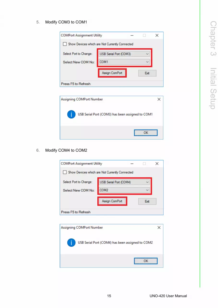
5. Modify COM3 to COM1
6. Modify COM4 to COM2
15 UNO-420 User Manual

7. Modify COM5 to COM3
8. Click on "Exit" once finish setting
UNO-420 User Manual 16

Chapter 3
Initial Setup
9. Go to Device Manager and check if COM port sequence been modified suc-cessfully
10. Reboot system.
3.6 AMI BIOS Setup1. Introduction
With the AMI BIOS Setup program, you can modify BIOS settings and control thespecial features of your computer. The Setup program uses a number of menus formaking changes and turning special features on or off. This chapter describes thebasic navigation of the UNO-420 setup screens.
2. Entering Setup
Press the "Del" or "Esc." key during the Power On Self Test (POST) process to enterthe BIOS setup screen, otherwise the system will continue the POST process.
17 UNO-420 User Manual

3. Main Setup
When you first enter the BIOS Setup Utility, you will enter the Main setup screen. Youcan always return to the Main setup screen by selecting the Main tab. There are twoMain Setup options. They are described in this section. The Main BIOS Setup screenis shown below.
UNO-420 User Manual 18
Chapter 3
Initial Setup
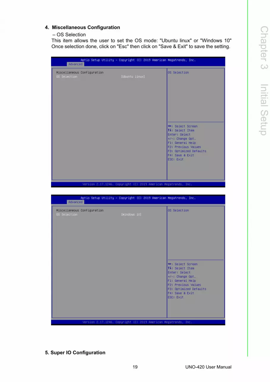
4. Miscellaneous Configuration
– OS SelectionThis item allows the user to set the OS mode: "Ubuntu linux" or "Windows 10"Once selection done, click on "Esc" then click on "Save & Exit" to save the setting.
5. Super IO Configuration
19 UNO-420 User Manual

UNO-420 supports 2xRS-232/422/485 & 1-RS-485.
Serial Port Configuration– Serial Port Termination
This item allows users to enable or disable for "Serial Port".– Device Mode
This item allows users to set the mode to RS-422/485. The default setting is "RS232".
UNO-420 User Manual 20

Chapter 3
Initial Setup
3.7 GPIO Programming Guide 1. Click on start up icon on Windows, go Advantech folder then select "Auxiliary IO
test utility command selection"
21 UNO-420 User Manual

2. Type in command "AuxIO.exe". It will show information of command type, defini-tion and examples.
UNO-420 User Manual 22

Appendix A
A System Settings and Pin Assignments
A.1 System I/O Address and Interrupt Assignment
A.2 Board Connectors and Jumpers There are several connectors and jumpers on the UNO-420 board. The followingsections tell you how to configure the UNO-420 hardware setting.
Figure A.1 shows the locations of UNO-420’s connectors and jumpers.
Figure A.1 Connector & Jumper Locations for UNO-420 (front)
Table A.1: Interrupt Assignments
Interrupt No. Interrupt Source
NMI Parity Error Detected
IRQ0 System timer
IRQ1 Standard 101/102-Key or Microsoft Natural PS/2Keyboard
IRQ2 Interrupt from controller 2 (cascade)
IRQ3 Communications Port (COM2)
IRQ4 Communications Port (COM1)
IRQ6 Available
IRQ8 System CMOS/Real-time clock
IRQ9 Microsoft ACPI-Compliant System
IRQ12 PS/2 Compatible Mouse
IRQ13 Numeric data processor
IRQ14 Reserved
IRQ15 Reserved
UNO-420 User Manual 24

Appendix A
System
Settings
andP
inA
ssignments
A.3 Power Connector (PWR)
Table A.2: Connectors and Jumpers on MB
Label Function
BN1 RTC battery connector
CN1 Power in connector
CN2 RJ45 connect (POE)
CN3 USB3.0
CN4 RJ45 connector
CN5 HDMI connector
CN6 COM3 connector
CN7 COM1 connector
CN10 Half mPCIe socket
CN11 Full mPCIe socket
CN12 M.2 card socket
CN18 SIM cand connector
CN19 COM2 connector
SW1 AT/ATX Mode
SW2 COM1/COM2 Hi / Low Resistor setting
SW3 COM3 Termination Resistor setting
JP1 Clear CMOS switch
PWR1 Power button
RST1 Reset button
Table A.3: Power connector pin assignmentsPin Signal Description
1 Power IN V+10 ~ 30VDC
2 Power IN V- (GND)
25 UNO-420 User Manual

A.4 HDMI Display Connector
A.5 COM1/COM2 RS232/422/485 connector D-SUB Conn. 9P 90D(M) DIP
Table A.4: HDMI Display Connector
Pin Signal Pin Signal
1 TMDS Data2+ 2 TMDS Data2 Shield
3 TMDS Data2- 4 TMDS Data1+
5 TMDS Data1 Shield 6 TMDS Data1-
7 TMDS Data0+ 8 TMDS Data0 Shield
9 TMDS Data0- 10 TMDS Clock+
11 TMDS Clock Shield 12 TMDS Clock-
13 CEC 14 Reserved
15 SCL 16 SDA
17 DDC/CEC/HEC Ground 18 +5 V Power (max 50 mA)
19 Hot Plug Detect
Pin RS232 RS422 RS485
1 DCD TX- D-
2 RX TX+ D+
3 TX RX+
4 DTR RX-
5 GND GND GND
6 DSR
7 RTS
8 CTS
9 RI
UNO-420 User Manual 26

Appendix A
System
Settings
andP
inA
ssignments
A.6 COM3 RS-485 connector
A.7 Mini PCIE slot (MINIPCIE)Supports PCI1.1, PCI1.2 Power Definition
Pin 1 COM3_DATA+
Pin 2 COM3_DATA-
Pin 3 COM3_GND
Pin Signal Description Pin Signal Description
52+3.3Vaux / +3.3V
PCI1.1 was +3.3V, PCI1.2 was +3.3Vaux
51 Reserved NC
50 GND 49 Reserved NC
48 +1.5V 47 Reserved NC
46 NC NC 45 Reserved NC
44 NC NC 43PIN43_MPCIE_PWRSEL The pin to select the Pin 2,
52 power output for +3.3Vaux or +3.3V (PCI1.1 was Reserved and PIC1.2 was GND
42 NC NC 41 +3.3Vaux
40 GND 39 +3.3Vaux
38 USB_D+ USB serial data interface compliant to the USB 2.0 specification
37 GND
36 USB_D- 35 GND
34 GND 33 PETp0
PCI Express differential transmit pair
32SMB_DATA SMBus data signal compli-
ant to the SMBus 2.0 specifi-cation
31 PETn0
30SMB_CLK
29 GND
28 +1.5V 27 GND
26 GND 25 PERp0PCI Express differential receive pair
24 +3.3Vaux 23 PERn0
22 PERST# Functional reset to the card 21 GND
20W_DISABLE#
Active low signal. This signal is used by the system to dis-able radio operation on add-in cards that implement radio frequency applications. When implemented, this sig-nal requires a pull-up resis-tor on the card.
19 Reserved NC
18 GND 17 Reserved NC
Key Key Key Key
16 NC NC 15 GND
14 NC NC 13 REFCLK+
27 UNO-420 User Manual
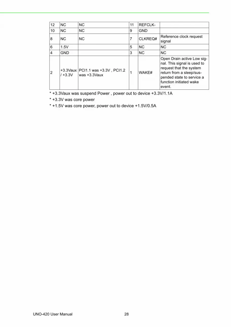
* +3.3Vaux was suspend Power , power out to device +3.3V/1.1A
* +3.3V was core power
* +1.5V was core power, power out to device +1.5V/0.5A
12 NC NC 11 REFCLK-
10 NC NC 9 GND
8 NC NC 7 CLKREQ#Reference clock request signal
6 1.5V 5 NC NC
4 GND 3 NC NC
2+3.3Vaux / +3.3V
PCI1.1 was +3.3V , PCI1.2 was +3.3Vaux
1 WAKE#
Open Drain active Low sig-nal. This signal is used to request that the system return from a sleep/sus-pended state to service a function initiated wake event.
UNO-420 User Manual 28

Appendix A
System
Settings
andP
inA
ssignments
A.8 LAN RJ45 connector
RJ45 Pin Signal Description
1 MDI0+
In BASE-T: Media Dependent Interface[0]: 1000BASE-T: In MDI configuration, MDI[0]+/- corre-
sponds to BI_DA+/- and in MDI-X configuration MDI[0]+/- corresponds to BI_DB+/-.
10BASE-T and 100BASE-TX: In MDI configuration, MDI[0]+/- is used for the transmit pair and in MDIX configuration MDI[0]+/- is used for the receive pair.2 MDI0-
3 MDI1+
In BASE-T: Media Dependent Interface[1]: 1000BASE-T: In MDI configuration, MDI[1]+/- corre-
sponds to BI_DB+ and in MDI-X configuration MDI[1]+/- corresponds to BI_DA+/-.
10BASE-T and 100BASE-TX: In MDI configuration, MDI[1]+/- is used for the receive pair and in MDI-X configuration MDI[1]+/- is used for the transmit pair.6 MDI1-
4 MDI2+ In BASE-T: Media Dependent Interface[3:2]: 1000BASE-T: In MDI and in MDI-X configuration,
MDI[2]+/- corresponds to BI_DC+/- and MDI[3]+/- corre-sponds to BI_DD+/-.
100BASE-TX: Unused. 10BASE-T: Unused.
5 MDI2-
7 MDI3+
8 MDI3-
Right LED Left LED
10Link 100Link 1000 Link Active
Off Orange Green Green
29 UNO-420 User Manual

A.9 GPIO Connector
Table A.5: GPIO-port pin definition details
Pin Signal
1 GPIO0
2 GND
3 GPIO1
4 GND
5 GPIO2
6 GND
7 GPIO3
8 GND
9 GPIO4
10 GND
11 GPIO5
12 GND
13 GPIO6
14 GND
15 GPIO7
16 GND
Note! GPIO0 to the GPIO7 pins are 0-5 V input/output and digital/analog con-figurable pins.
The GPIO port is powered by analog devices' AD5593R.
Each pin has a 100K OHM series resistor between the connector and the AD5593R.
Caution! This port is ESD-sensitive. An insulated GPIO connector that prevents direct ESD exposure to the I/O pins is recommended.
UNO-420 User Manual 30

Appendix A
System
Settings
andP
inA
ssignments
31 UNO-420 User Manual

www.advantech.comPlease verify specifications before quoting. This guide is intended for referencepurposes only.All product specifications are subject to change without notice.No part of this publication may be reproduced in any form or by any means,electronic, photocopying, recording or otherwise, without prior written permis-sion of the publisher.All brand and product names are trademarks or registered trademarks of theirrespective companies.© Advantech Co., Ltd. 2019