Embed Size (px)
Citation preview
Northeast Site Solutions Victoria Masse
420 Main Street #2, Sturbridge, MA 01566 860-306-2326 [email protected] August 25, 2020
Members of the Siting Council
Connecticut Siting Council
Ten Franklin Square
New Britain, CT 06051
RE: Notice of Exempt Modification
23 Kelleher Court, Wethersfield CT 06109
Latitude: 41.715275
Longitude: -72.690275
T-Mobile Site#: CTHA014A_Anchor
Dear Ms. Bachman:
T-Mobile currently maintains nine (9) antennas at the 151-foot level of the existing 179-foot monopole tower at
23 Kelleher Court, Wethersfield CT. The 179-foot tower and property are both owned by the Town of
Wethersfield. T-Mobile now intends to replace three (3) of its existing antennas with three (3) new 2500 MHz
antenna. The new antennas would be installed at the 151-foot level of the tower.
Planned Modifications:
Remove: (6) 1-5/8” Coax
Remove and Replace:
(3)AIR21 B2A/B4P 1900/2100 MHz (REMOVE) - (3) AIR6449 B41 Antenna 2500 MHz (REPLACE)
(2) 9x18 Fiber lines (REMOVE) – (2) 6x12 Fiber Lines (REPLACE)
Install New:
(3) RRU 4415 B25
(3) Diplexers
Existing to Remain:
(3) APXVAARR24_43U-NA20 Antenna 600/700/1900/2100 MHz
(3) AIR32 KRD901146-1 B66A_B2A 1900/2100 MHz
(6) 1-5/8” Coax
(2) Fiber Hybrid Line
(3) Twin TMA
(3) RRU 4449 B12/B71
Ground: Upgrade Existing 6131 Cabinet (Internally) New 6160 Cabinet New B160 Cabinet New 11x12 Concrete pad within existing 225 Sq. ft. lease area
This facility was approved by the Wethersfield ZBA–on April 17, 2002 Town of Wethersfield was approved to
erect two (2) tower shelters and a tower in the side yard of 23 Kelleher CT. Please see attached minutes provided
by the Town of Wethersfield Zoning Department.
Please accept this letter as notification pursuant to Regulations of Connecticut State Agencies§ 16- SOj-73, for
construction that constitutes an exempt modification pursuant to R.C.S.A. § 16-50j-72(b)(2). In accordance with
R.C.SA. § 16-SOj-73, a copy of this letter is being sent to Mayor Michael L Rell, Elected Official and Peter
Gillespie, Zoning Director for the Town of Wethersfield, as well as the property owner and the tower owner.
The planned modifications to the facility fall squarely within those activities explicitly provided for in
R.C.S;A. § 16-50j-72(b)(2).
1. The proposed modifications will not result in an increase in the height of the existing structure.
2. The proposed modifications will not require the extension of the site boundary.
3. The proposed modifications will not increase noise levels at the facility by six decibels or more, or to levels
that exceed state and local criteria.
4. The operation of the replacement antennas will not increase radio frequency emissions at the facility to a level
at or above the Federal Communications Commission safety standard.
5. The proposed modifications will not cause a change or alteration in the physical or environmental
characteristics of the site. ꞏ
6. The existing structure and its foundation can support the proposed loading.
For the foregoing reasons, T-Mobile respectfully submits that the proposed modifications to the above referenced
telecommunications facility constitute an exempt modification under
R.C.S.A. § 16-50j-72(b)(2).
Sincerely,
Victoria Masse
Mobile: 860-306-2326
Fax: 413-521-0558
Office: 420 Main Street, Unit 2, Sturbridge MA 01566
Email: [email protected]
Attachments
cc: Mayor Michael L. Rell -Wethersfield elected official
Peter Gillespie – Director of Planning and Zoning
Town of Wethersfield - as property and tower owner

Exhibit A
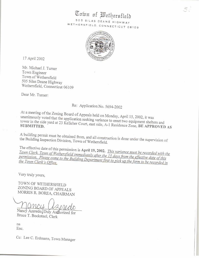

Exhibit B
Other ID:
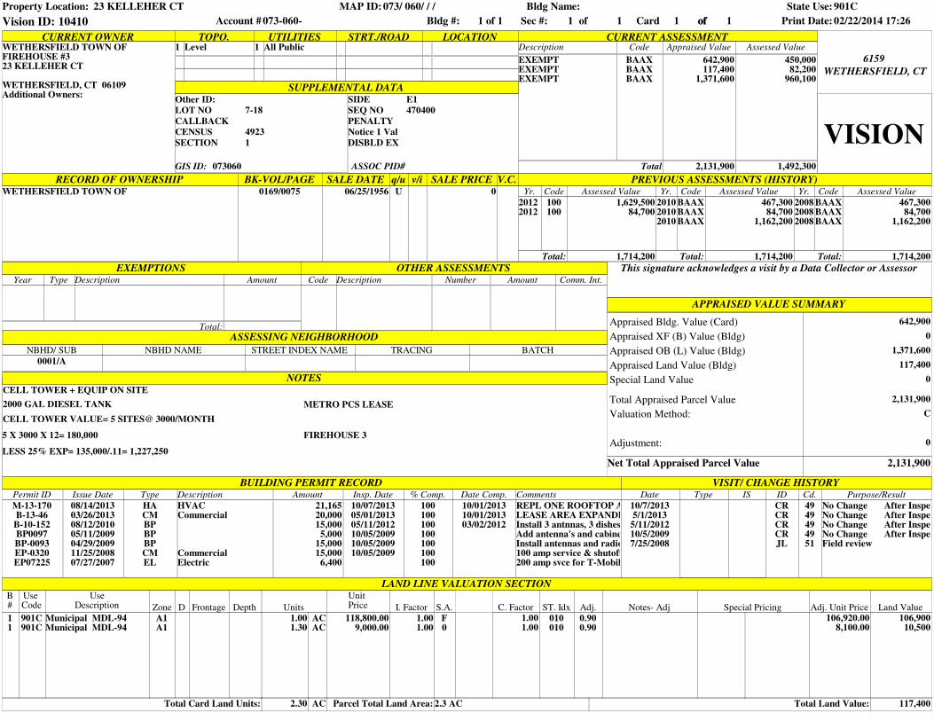
CURRENT OWNER TOPO. UTILITIES STRT./ROAD LOCATION CURRENT ASSESSMENT1 Level 1 All Public Description Code Appraised Value Assessed Value
SUPPLEMENTAL DATA
EXEMPTEXEMPTEXEMPT
BAAXBAAXBAAX
642,900117,400
1,371,600
450,00082,200
960,100
Total 2,131,900 1,492,300
WETHERSFIELD, CT
6159WETHERSFIELD TOWN OFFIREHOUSE #323 KELLEHER CT
WETHERSFIELD, CT 06109Additional Owners:
VISIONGIS ID: 073060
BK-VOL/PAGE SALE DATE q/u v/i SALE PRICE V.C. PREVIOUS ASSESSMENTS (HISTORY)0169/0075 06/25/1956 U 0
EXEMPTIONS OTHER ASSESSMENTS This signature acknowledges a visit by a Data Collector or AssessorYear Description Amount Code Description Number Amount Comm. Int.
APPRAISED VALUE SUMMARY
NOTES
Net Total Appraised Parcel Value 2,131,900
642,900
0
1,371,600
117,400
0
2,131,900
Appraised Bldg. Value (Card)
RECORD OF OWNERSHIP
CELL TOWER + EQUIP ON SITE
2000 GAL DIESEL TANK
WETHERSFIELD TOWN OF
CELL TOWER VALUE= 5 SITES@ 3000/MONTH
5 X 3000 X 12= 180,000
LESS 25% EXP= 135,000/.11= 1,227,250
METRO PCS LEASE
FIREHOUSE 3
C
BUILDING PERMIT RECORDPermit ID Issue Date Type Description Amount Insp. Date % Comp. Date Comp. Comments Date ID Cd. Purpose/Result
M-13-170B-13-46
B-10-152BP0097BP-0093EP-0320EP07225
08/14/201303/26/201308/12/201005/11/200904/29/200911/25/200807/27/2007
HACMBPBPBPCMEL
HVACCommercial
CommercialElectric
21,16520,00015,000
5,00015,00015,000
6,400
10/07/201305/01/201305/11/201210/05/200910/05/200910/05/2009
100100100100100100100
10/01/201310/01/201303/02/2012
REPL ONE ROOFTOP A/CLEASE AREA EXPANDED TO 8"x13'6" PER PLANS & SPECS (METRO PCS)Install 3 antnnas, 3 dishesAdd antenna's and cabinetInstall antennas and radio cabinet100 amp service & shutoff added to cell tower to 2005 NEC200 amp svce for T-Mobile
10/7/20135/1/2013
5/11/201210/5/20097/25/2008
CRCRCRCRJL
4949494951
No Change After InspecNo Change After InspecNo Change After InspecNo Change After InspecField review
LAND LINE VALUATION SECTION
LOT NO 7-18
CALLBACK
CENSUS 4923
SECTION 1 DISBLD EX
Notice 1 Val
PENALTY
SEQ NO
SIDE E1
470400
Appraised XF (B) Value (Bldg)
Appraised OB (L) Value (Bldg)
Appraised Land Value (Bldg)
Special Land Value
Total Appraised Parcel Value
Valuation Method:
Total:
ASSESSING NEIGHBORHOOD
Type IS
VISIT/ CHANGE HISTORY
ASSOC PID#
Adjustment: 0
Type
Yr. Code Assessed Value Yr. Code Assessed Value Yr. Code Assessed Value
100100
1,629,50084,700
201020102010
BAAXBAAXBAAX
467,30084,700
1,162,200
200820082008
BAAXBAAXBAAX
467,30084,700
1,162,200
Total: 1,714,200 Total: Total:
20122012
NBHD/ SUB
0001/A
NBHD NAME STREET INDEX NAME TRACING BATCH
1,714,200 1,714,200
B#
11
Total Card Land Units:
901C901C
Use Code
UseDescription
Municipal MDL-94Municipal MDL-94
A1A1
Zone D Frontage Depth
1.001.30
Units
ACAC
AC2.30 Parcel Total Land Area:
118,800.009,000.00
1.001.00
I. Factor
Unit Price S.A.
F0
2.3 AC
C. Factor1.001.00
010010
ST. Idx Adj.
0.900.90
Total Land Value:
Notes- Adj Special Pricing106,920.00
8,100.00
Adj. Unit Price Land Value106,900
10,500
117,400
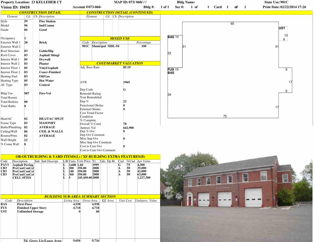
Property Location: 23 KELLEHER CT MAP ID: 073/ 060/ / /
Bldg #: 1 of 1 Card 1 of 1 Print Date: 02/22/2014 17:26Vision ID: 10410 Account # 073-060-
Bldg Name: State Use: 901C
Sec #: 1 ofof 1
FUS
BAS
BAS
UST
65
31
10
34
75
17
9
17
9
31
22
1010
6
Model
CONSTRUCTION DETAILElement Cd. Ch. Description
COST/MARKET VALUATION
BUILDING SUB-AREA SUMMARY SECTIONCode
Ttl. Gross Liv/Lease Area:
Style
Grade
Occupancy
Exterior Wall 2
Roof Structure
Roof Cover
Interior Wall 1
Exterior Wall 1
Interior Wall 2
Interior Floor 1
Interior Floor 2
Heating Fuel
Heating Type
AC Type
Bldg Use
59 Fire Station
96 Ind/Comm
06 Good
1
20 Brick
03 Gable/Hip
03 Asphalt Shingl
05 Drywall
Plaster
Total Rooms
Total Bedrms
Total Baths
Heat/AC
Frame Type
Baths/Plumbing
Ceiling/Wall
Rooms/Prtns
Wall Height
% Comn Wall
MIXED USE
Element Cd. Ch. Description
CONSTRUCTION DETAIL (CONTINUED)
03
05 Vinyl/Asphalt
03
03
Concr-Finished
Oil/Gas
05 Hot Water
03 Central
907 Fire-Vol
00
0
02 HEAT/AC SPLIT
03 MASONRY
02 AVERAGE
06 CEIL & WALLS
02 AVERAGE
12
0
Code
901C
Description
Municipal MDL-94
Percentage
100
BAS
FUS
UST
Description
First Floor
Finished Upper Story
Unfinished Storage
Living Area
4,938
4,718
0
Gross Area
4,938
9,656
4,718
60
9,716
Eff. Area Unit Cost Undeprec. Value
Apr Value
4,30035,00042,00063,0001,227,300
Adj. Base Rate: 85.19
AYB
Dep Code
Remodel Rating
Year Remodeled
Dep %
Functional Obslnc
External Obslnc
Cost Trend Factor
1969
G
22
0
0
Condition
% Complete
Overall % Cond
Apprais ValDep % Ovr
Dep Ovr Comment
Misc Imp Ovr
Misc Imp Ovr Comment
Cost to Cure Ovr
Cost to Cure Ovr Comment
78
642,9000
0
0
OB-OUTBUILDING & YARD ITEMS(L) / XF-BUILDING EXTRA FEATURES(B)
Code SubDescription
PAV1CB3CB3CB3
Asphalt PavingPreCastConCelPreCastConCelPreCastConCelCELL SITES
Sub Descript L/B
LLLLL
Units
3,6002002403605
Unit Price Yr Gde Dp Rt Cnd %Cnd
1.60350.00350.00350.00245,450.00
19992008200820082008
GAAA
75505050
Property Location: 23 KELLEHER CT MAP ID: 073/ 060/ / /
Bldg #: 1 of 1 Card 1 of 1 Print Date: 02/22/2014 17:26Vision ID: 10410 Account # 073-060-
Bldg Name: State Use: 901C
Sec #: 1 ofof 1
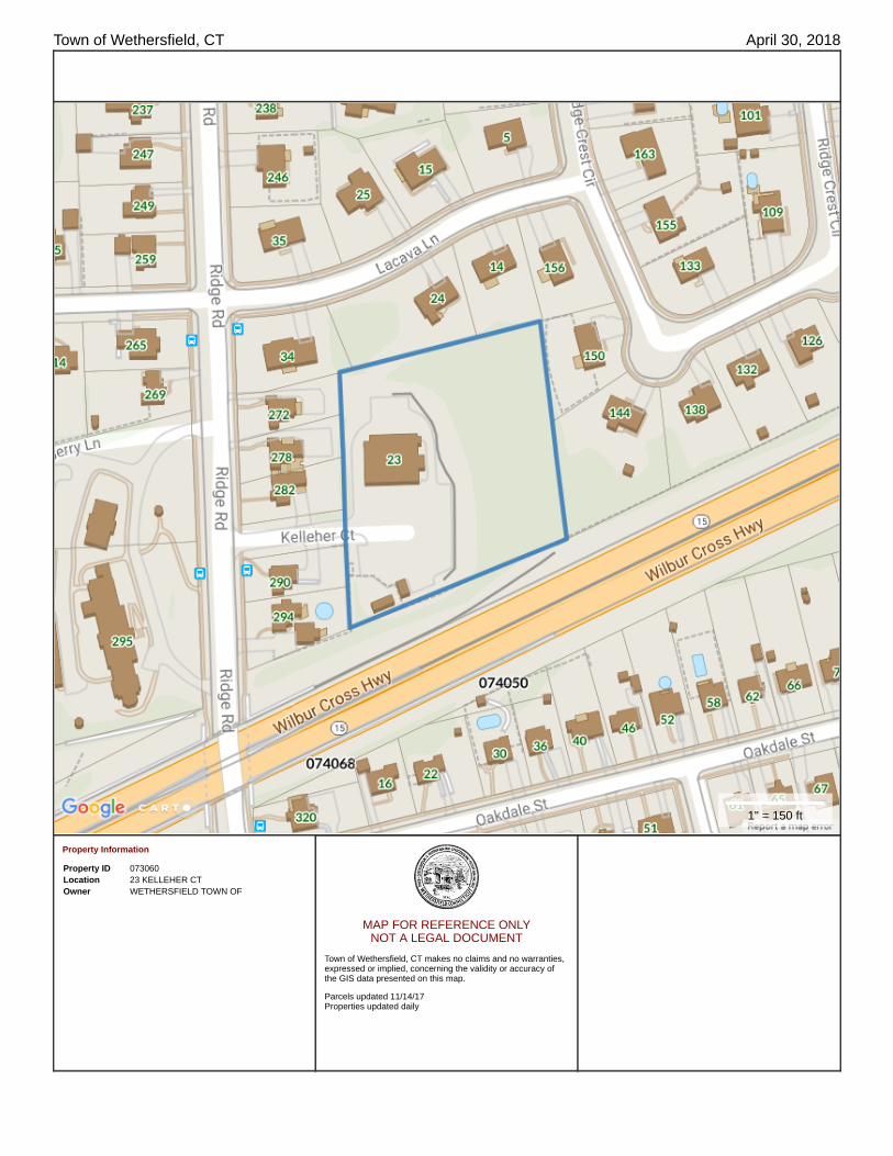
Town of Wethersfield, CT April 30, 2018
Property Information
Property ID 073060Location 23 KELLEHER CTOwner WETHERSFIELD TOWN OF
MAP FOR REFERENCE ONLY NOT A LEGAL DOCUMENT
Town of Wethersfield, CT makes no claims and no warranties,expressed or implied, concerning the validity or accuracy ofthe GIS data presented on this map.
Parcels updated 11/14/17Properties updated daily
1" = 150 ft

Exhibit C
T-1: TITLE SHEET
SITE
LOCATION
SITE
LOCATION
420 MAIN STREET, BLDG 4
STURBRIDGE, MA 01566
203-275-6669
462 WALNUT STREET
NEWTON, MA 02460
617-212-3123
THIS DOCUMENT IS THE DESIGN PROPERTY
AND COPYRIGHT OF FORESITE, LLC. AND
FOR THE EXCLUSIVE USE BY THE TITLE
CLIENT. DUPLICATION OR USE WITHOUT
THE EXPRESS WRITTEN CONSENT
OF THE CREATOR IS STRICTLY PROHIBITED.
DRAWING SCALES ARE INTENDED FOR
11"x17" SIZE PRINTED MEDIA ONLY. ALL
OTHER PRINTED SIZES ARE DEEMED
"NOT TO SCALE".
SITE NUMBER: CTHA014A
SITE NAME: HA014/T OF WETHERSFIELD_MP
SITE ADDRESS: 23 KELLEHER COURT
WETHERSFIELD, CT 06109
SHEET TITLE:
REV DESCRIPTION DATE
A PRELIMINARY 07/30/20
PROFESSIONAL SEAL
PROJECT MANAGER
CONSULTANT:
APPLICANT:
T-MOBILE NORTHEAST LLC
35 GRIFFIN ROAD SOUTH
BLOOMFIELD, CT 06002
860-692-7100
Co
pyrig
ht ©
2
01
8 F
ore
site
L
LC
a
ll rig
hts re
se
rve
d. T
he
d
eta
ils, te
mp
la
te
s, d
ra
win
g fo
rm
ats o
r a
ny p
ortio
n o
f th
is d
ocu
me
nt g
en
era
te
d b
y F
ore
site
L
LC
m
ay n
ot b
e d
up
lica
te
d, tra
ce
d o
r u
se
d o
th
erw
ise
fo
r a
ny p
ro
fit-d
rive
n e
nte
rp
rise
.
0 FINAL ISSUED 08/24/20
1 REVISED CABLE COUNT 08/25/20
ADDRESS:
STRUCTURE TYPE:
MAP/LOT:
ZONING DISTRICT:
COORDINATES:
AVERAGE GROUND ELEV:
PROJECT INFORMATION:
PROJECT TEAM:
SHEET INDEX:
T-MOBILE NORTHEAST LLC
APPLICANT:
PROJECT MANAGER:
CONSULTANTS:
LANDLORD:
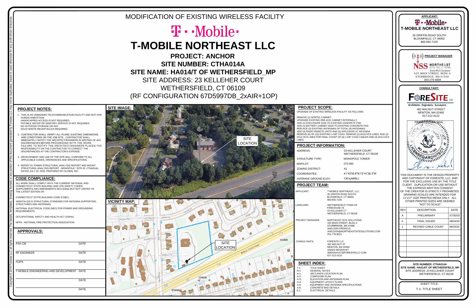
23 KELLEHER COURT
WETHERSFIELD, CT 06109
MONOPOLE TOWER
073 060
A1
41°42'55.6"N 72°41'26.3"W
130'±(AMSL)
T-MOBILE NORTHEAST, LLC.
35 GRIFFIN ROAD SOUTH
BLOOMFIELD, CT 06002
860-692-7100
NORTHEAST SITE SOLUTIONS
420 MAIN STREET, BLDG 4
STURBRIDGE, MA 01566
SHELDON FREINCLE
201-776-8521
FORESITE LLC
462 WALNUT ST
NEWTON, MA 02460
SAEED MOSSAVAT
617-212-3123
SITE IMAGE:
VICINITY MAP:
PROJECT NOTES:
PROJECT SCOPE:
FSA CM
RF ENGINEER
FOPS
T-MOBILE ENGINEERING AND DEVELOPMENT
APPROVALS:
DATE
DATE
DATE
DATE
DATE
DATE
UPGRADE OF EXISTING WIRELESS FACILITY AS FOLLOWS:
REMOVE (1) NORTEL CABINET.
UPGRADE EXISTING RBS 6131 CABINET INTERNALLY.
ADD (1) ENCLOSURE 6160 TO EXISTING CONCRETE PAD.
ADD (1) BATTERY CABINET B160 TO EXISTING CONCRETE PAD.
REPLACE (3) EXISTING ANTENNAS OF TOTAL (9) ANTENNAS.
ADD (3) RADIO REMOTE UNITS AND (3) DIPLEXERS AT ANTENNA.
REMOVE (6) OF (12) EXISTING 1-5/8" COAX, REMOVE (2) 9X18 HCS LINES, ADD (2)
6X12 HCS LINES FOR FINAL COUNT OF (6) 1-5/8" COAX CABLES AND (4) 6X12 HCS
LINES.
PROJECT: ANCHOR
SITE NUMBER: CTHA014A
SITE NAME: HA014/T OF WETHERSFIELD_MP
SITE ADDRESS: 23 KELLEHER COURT
WETHERSFIELD, CT 06109
(RF CONFIGURATION 67D5997DB_2xAIR+1OP)
1. THIS IS AN UNMANNED TELECOMMUNICATION FACILITY AND NOT FOR
HUMAN HABITATION:
HANDICAPPED ACCESS IS NOT REQUIRED.
POTABLE WATER OR SANITARY SERVICE IS NOT REQUIRED.
NO OUTDOOR STORAGE OR ANY
SOLID WASTE RECEPTACLES REQUIRED.
2. CONTRACTOR SHALL VERIFY ALL PLANS, EXISTING DIMENSIONS,
AND CONDITIONS ON THE JOB SITE. CONTRACTOR SHALL
IMMEDIATELY NOTIFY THE ARCHITECT/ENGINEER IN WRITING OF ANY
DISCREPANCIES BEFORE PROCEEDING WITH THE WORK.
FAILURE TO NOTIFY THE ARCHITECT/ENGINEER PLACES THE
RESPONSIBILITY ON THE CONTRACTOR TO CORRECT THE
DISCREPANCIES AT THE CONTRACTOR'S EXPENSE.
3. DEVELOPMENT AND USE OF THE SITE WILL CONFORM TO ALL
APPLICABLE CODES, ORDINANCES AND SPECIFICATIONS.
4. REFER TO TOWER STRUCTURAL ANALYSIS REPORT AND MOUNT
STRUCTURAL ANALYSIS REPORT - MONOPOLE " SITE ID: CTHA014A,
DATED JULY 29, 2020, PREPARED EFI GLOBAL INC.
T-1: TITLE SHEET
N-1: GENERAL NOTES
A-1: WETLANDS LOCATION PLAN
A-2: COMPOUND PLAN
A-3: ELEVATION AND ANTENNAS PLAN
A-4: EQUIPMENT LAYOUT PLANS
A-5: EQUIPMENT AND ANTENNA SPECIFICATIONS
A-6: CONCRETE BAD DETAILS
E-1: ELECTRICAL DETAILS
ALL WORK SHALL COMPLY WITH THE CURRENT NATIONAL AND
CONNECTICUT STATE BUILDING AND LIFE SAFETY CODES,
SUPPLEMENTS AND AMENDMENTS INCLUDING BUT NOT LIMITED TO
THE LATEST EDITION OF:
CONNECTICUT STATE BUILDING CODE (CSBC).
ANSI/TIA-222-G STRUCTURAL STANDARD FOR ANTENNA SUPPORTING
STRUCTURES AND ANTENNAS.
NATIONAL ELECTRICAL CODE (NEC) FOR POWER AND GROUNDING
REQUIREMENTS.
OCCUPATIONAL SAFETY AND HEALTH ACT (OSHA).
NFPA - NATIONAL FIRE PROTECTION ASSOCIATION.
CODE COMPLIANCE:
MODIFICATION OF EXISTING WIRELESS FACILITY
WETHERSFIELD TOWN OF
FIREHOUSE #3
23 KELLEHER CT
WETHERSFIELD, CT 06109
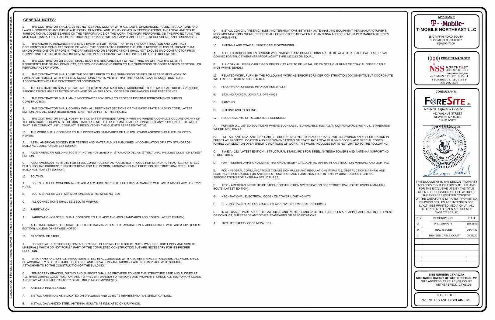
GENERAL NOTES:
N-1: NOTES AND DISCLAIMERS
1. THE CONTRACTOR SHALL GIVE ALL NOTICES AND COMPLY WITH ALL LAWS, ORDINANCES, RULES, REGULATIONS ANDLAWFUL ORDERS OF ANY PUBLIC AUTHORITY, MUNICIPAL AND UTILITY COMPANY SPECIFICATIONS, AND LOCAL AND STATEJURISDICTIONAL CODES BEARING ON THE PERFORMANCE OF THE WORK. THE WORK PERFORMED ON THE PROJECT AND THEMATERIALS INSTALLED SHALL BE IN STRICT ACCORDANCE WITH ALL APPLICABLE CODES, REGULATIONS, AND ORDINANCES.
2. THE ARCHITECT/ENGINEER HAS MADE EVERY EFFORT TO SET FORTH IN THE CONSTRUCTION AND CONTRACTDOCUMENTS THE COMPLETE SCOPE OF WORK. THE CONTRACTOR BIDDING THE JOB IS NEVERTHELESS CAUTIONED THATMINOR OMISSIONS OR ERRORS IN THE DRAWINGS AND OR SPECIFICATIONS SHALL NOT EXCUSE SAID CONTRACTOR FROMCOMPLETING THE PROJECT AND IMPROVEMENTS IN ACCORDANCE WITH THE INTENT OF THESE DOCUMENTS.
3. THE CONTRACTOR OR BIDDER SHALL BEAR THE RESPONSIBILITY OF NOTIFYING (IN WRITING) THE CLIENT'SREPRESENTATIVE OF ANY CONFLICTS, ERRORS, OR OMISSIONS PRIOR TO THE SUBMISSION OF CONTRACTOR'S PROPOSAL ORPERFORMANCE OF WORK.
5. THE CONTRACTOR SHALL VISIT THE JOB SITE PRIOR TO THE SUBMISSION OF BIDS OR PERFORMING WORK TOFAMILIARIZE HIMSELF WITH THE FIELD CONDITIONS AND TO VERIFY THAT THE PROJECT CAN BE CONSTRUCTED INACCORDANCE WITH THE CONSTRUCTION DOCUMENTS.
6. THE CONTRACTOR SHALL INSTALL ALL EQUIPMENT AND MATERIALS ACCORDING TO THE MANUFACTURER'S / VENDOR'SSPECIFICATIONS UNLESS NOTED OTHERWISE OR WHERE LOCAL CODES OR ORDINANCES TAKE PRECEDENCE.
7. THE CONTRACTOR SHALL MAKE NECESSARY PROVISIONS TO PROTECT EXISTING IMPROVEMENTS DURINGCONSTRUCTION.
8. THE CONTRACTOR SHALL COMPLY WITH ALL PERTINENT SECTIONS OF THE BASIC STATE BUILDING CODE, LATESTEDITION, AND ALL OSHA REQUIREMENTS AS THEY APPLY TO THIS PROJEC
9. THE CONTRACTOR SHALL NOTIFY THE CLIENT'S REPRESENTATIVE IN WRITING WHERE A CONFLICT OCCURS ON ANY OFTHE CONTRACT DOCUMENTS. THE CONTRACTOR IS NOT TO ORDER MATERIAL OR CONSTRUCT ANY PORTION OF THE WORKTHAT IS IN CONFLICT UNTIL CONFLICT IS RESOLVED BY THE CLIENT'S REPRESENTATIVE.
10. THE WORK SHALL CONFORM TO THE CODES AND STANDARDS OF THE FOLLOWING AGENCIES AS FURTHER CITEDHEREIN:
A. ASTM: AMERICAN SOCIETY FOR TESTING AND MATERIALS, AS PUBLISHED IN "COMPILATION OF ASTM STANDARDSBUILDING CODES" OR LATEST EDITION.
B. AWS: AMERICAN WELDING SOCIETY INC. AS PUBLISHED IN "STANDARD D1.1-08, STRUCTURAL WELDING CODE" OR LATESTEDITION.
C. AISC: AMERICAN INSTITUTE FOR STEEL CONSTRUCTION AS PUBLISHED IN "CODE FOR STANDARD PRACTICE FOR STEELBUILDINGS AND BRIDGES"; "SPECIFICATIONS FOR THE DESIGN, FABRICATION AND ERECTION OF STRUCTURAL STEEL FORBUILDINGS" (LATEST EDITION).
11. BOLTING:
A. BOLTS SHALL BE CONFORMING TO ASTM A325 HIGH STRENGTH, HOT DIP GALVANIZED WITH ASTM A153 HEAVY HEX TYPENUTS.
B. BOLTS SHALL BE 3/4"∅ MINIMUM (UNLESS OTHERWISE NOTED)
C. ALL CONNECTIONS SHALL BE 2 BOLTS MINIMUM.
12. FABRICATION:
A. FABRICATION OF STEEL SHALL CONFORM TO THE AISC AND AWS STANDARDS AND CODES (LATEST EDITION).
B. ALL STRUCTURAL STEEL SHALL BE HOT-DIP GALVANIZED AFTER FABRICATION IN ACCORDANCE WITH ASTM A123 (LATESTEDITION), UNLESS OTHERWISE NOTED.
13. ERECTION OF STEEL:
A. PROVIDE ALL ERECTION EQUIPMENT, BRACING, PLANKING, FIELD BOLTS, NUTS, WASHERS, DRIFT PINS, AND SIMILARMATERIALS WHICH DO NOT FORM A PART OF THE COMPLETED CONSTRUCTION BUT ARE NECESSARY FOR ITS PROPERERECTION.
B. ERECT AND ANCHOR ALL STRUCTURAL STEEL IN ACCORDANCE WITH AISC REFERENCE STANDARDS. ALL WORK SHALLBE ACCURATELY SET TO ESTABLISHED LINES AND ELEVATIONS AND RIGIDLY FASTENED IN PLACE WITH SUITABLEATTACHMENTS TO THE CONSTRUCTION OF THE BUILDING.
C. TEMPORARY BRACING, GUYING AND SUPPORT SHALL BE PROVIDED TO KEEP THE STRUCTURE SAFE AND ALIGNED ATALL TIMES DURING CONSTRUCTION, AND TO PREVENT DANGER TO PERSONS AND PROPERTY. CHECK ALL TEMPORARY LOADSAND STAY WITHIN SAFE CAPACITY OF ALL BUILDING COMPONENTS.
14. ANTENNA INSTALLATION:
A. INSTALL ANTENNAS AS INDICATED ON DRAWINGS AND CLIENT'S REPRESENTATIVE SPECIFICATIONS.
B. INSTALL GALVANIZED STEEL ANTENNA MOUNTS AS INDICATED ON DRAWINGS.
C. INSTALL COAXIAL / FIBER CABLES AND TERMINATIONS BETWEEN ANTENNAS AND EQUIPMENT PER MANUFACTURER'SRECOMMENDATIONS. WEATHERPROOF ALL CONNECTORS BETWEEN THE ANTENNA AND EQUIPMENT PER MANUFACTURER'SREQUIREMENTS.
15. ANTENNA AND COAXIAL / FIBER CABLE GROUNDING:
A. ALL EXTERIOR #6 GREEN GROUND WIRE "DAISY CHAIN" CONNECTIONS ARE TO BE WEATHER SEALED WITH ANDREWSCONNECTOR/SPLICE WEATHERPROOFING KIT TYPE #221213 OR EQUAL.
B. ALL COAXIAL / FIBER CABLE GROUNDING KITS ARE TO BE INSTALLED ON STRAIGHT RUNS OF COAXIAL / FIBER CABLE(NOT WITHIN BENDS).
16. RELATED WORK, FURNISH THE FOLLOWING WORK AS SPECIFIED UNDER CONSTRUCTION DOCUMENTS, BUT COORDINATEWITH OTHER TRADES PRIOR TO BID:
A. FLASHING OF OPENING INTO OUTSIDE WALLS
B. SEALING AND CAULKING ALL OPENINGS
C. PAINTING
D. CUTTING AND PATCHING
17. REQUIREMENTS OF REGULATORY AGENCIES:
A. FURNISH U.L. LISTED EQUIPMENT WHERE SUCH LABEL IS AVAILABLE. INSTALL IN CONFORMANCE WITH U.L. STANDARDSWHERE APPLICABLE.
B. INSTALL ANTENNA, ANTENNA CABLES, GROUNDING SYSTEM IN ACCORDANCE WITH DRAWINGS AND SPECIFICATION INEFFECT AT PROJECT LOCATION AND RECOMMENDATIONS OF STATE AND LOCAL BUILDING CODES, AND SPECIAL CODESHAVING JURISDICTION OVER SPECIFIC PORTIONS OF WORK. THIS WORK INCLUDES BUT IS NOT LIMITED TO THE FOLLOWING:
C. TIA-EIA - 222 (LATEST EDITION). STRUCTURAL STANDARDS FOR STEEL ANTENNA TOWERS AND ANTENNA SUPPORTINGSTRUCTURES.
D. FAA - FEDERAL AVIATION ADMINISTRATION ADVISORY CIRCULAR AC 70/7460-IH, OBSTRUCTION MARKING AND LIGHTING.
E. FCC - FEDERAL COMMUNICATIONS COMMISSION RULES AND REGULATIONS FORM 715, OBSTRUCTION MARKING ANDLIGHTING SPECIFICATION FOR ANTENNA STRUCTURES AND FORM 715A, HIGH INTENSITY OBSTRUCTION LIGHTINGSPECIFICATIONS FOR ANTENNA STRUCTURES.
F. AISC - AMERICAN INSTITUTE OF STEEL CONSTRUCTION SPECIFICATION FOR STRUCTURAL JOINTS USING ASTM A325BOLTS (LATEST EDITION).
G. NEC - NATIONAL ELECTRICAL CODE - ON TOWER LIGHTING KITS.
H. UL - UNDERWRITER'S LABORATORIES APPROVED ELECTRICAL PRODUCTS.
I. IN ALL CASES, PART 77 OF THE FAA RULES AND PARTS 17 AND 22 OF THE FCC RULES ARE APPLICABLE AND IN THE EVENTOF CONFLICT, SUPERSEDE ANY OTHER STANDARDS OR SPECIFICATIONS.
J. 2009 LIFE SAFETY CODE NFPA - 101.
420 MAIN STREET, BLDG 4
STURBRIDGE, MA 01566
203-275-6669
462 WALNUT STREET
NEWTON, MA 02460
617-212-3123
THIS DOCUMENT IS THE DESIGN PROPERTY
AND COPYRIGHT OF FORESITE, LLC. AND
FOR THE EXCLUSIVE USE BY THE TITLE
CLIENT. DUPLICATION OR USE WITHOUT
THE EXPRESS WRITTEN CONSENT
OF THE CREATOR IS STRICTLY PROHIBITED.
DRAWING SCALES ARE INTENDED FOR
11"x17" SIZE PRINTED MEDIA ONLY. ALL
OTHER PRINTED SIZES ARE DEEMED
"NOT TO SCALE".
SITE NUMBER: CTHA014A
SITE NAME: HA014/T OF WETHERSFIELD_MP
SITE ADDRESS: 23 KELLEHER COURT
WETHERSFIELD, CT 06109
SHEET TITLE:
REV DESCRIPTION DATE
A PRELIMINARY 07/30/20
PROFESSIONAL SEAL
PROJECT MANAGER
CONSULTANT:
APPLICANT:
T-MOBILE NORTHEAST LLC
35 GRIFFIN ROAD SOUTH
BLOOMFIELD, CT 06002
860-692-7100
Co
pyrig
ht ©
2
01
8 F
ore
site
L
LC
a
ll rig
hts re
se
rve
d. T
he
d
eta
ils, te
mp
la
te
s, d
ra
win
g fo
rm
ats o
r a
ny p
ortio
n o
f th
is d
ocu
me
nt g
en
era
te
d b
y F
ore
site
L
LC
m
ay n
ot b
e d
up
lica
te
d, tra
ce
d o
r u
se
d o
th
erw
ise
fo
r a
ny p
ro
fit-d
rive
n e
nte
rp
rise
.
0 FINAL ISSUED 08/24/20
1 REVISED CABLE COUNT 08/25/20
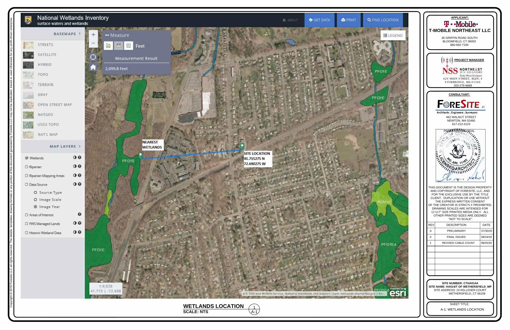
A-1: WETLANDS LOCATION
420 MAIN STREET, BLDG 4
STURBRIDGE, MA 01566
203-275-6669
462 WALNUT STREET
NEWTON, MA 02460
617-212-3123
THIS DOCUMENT IS THE DESIGN PROPERTY
AND COPYRIGHT OF FORESITE, LLC. AND
FOR THE EXCLUSIVE USE BY THE TITLE
CLIENT. DUPLICATION OR USE WITHOUT
THE EXPRESS WRITTEN CONSENT
OF THE CREATOR IS STRICTLY PROHIBITED.
DRAWING SCALES ARE INTENDED FOR
11"x17" SIZE PRINTED MEDIA ONLY. ALL
OTHER PRINTED SIZES ARE DEEMED
"NOT TO SCALE".
SITE NUMBER: CTHA014A
SITE NAME: HA014/T OF WETHERSFIELD_MP
SITE ADDRESS: 23 KELLEHER COURT
WETHERSFIELD, CT 06109
SHEET TITLE:
REV DESCRIPTION DATE
A PRELIMINARY 07/30/20
PROFESSIONAL SEAL
PROJECT MANAGER
CONSULTANT:
APPLICANT:
T-MOBILE NORTHEAST LLC
35 GRIFFIN ROAD SOUTH
BLOOMFIELD, CT 06002
860-692-7100
Co
pyrig
ht ©
2
01
8 F
ore
site
L
LC
a
ll rig
hts re
se
rve
d. T
he
d
eta
ils, te
mp
la
te
s, d
ra
win
g fo
rm
ats o
r a
ny p
ortio
n o
f th
is d
ocu
me
nt g
en
era
te
d b
y F
ore
site
L
LC
m
ay n
ot b
e d
up
lica
te
d, tra
ce
d o
r u
se
d o
th
erw
ise
fo
r a
ny p
ro
fit-d
rive
n e
nte
rp
rise
.
0 FINAL ISSUED 08/24/20
1 REVISED CABLE COUNT 08/25/20
SCALE: NTS
WETLANDS LOCATION
A-1
1
A-2: COMPOUND PLAN
420 MAIN STREET, BLDG 4
STURBRIDGE, MA 01566
203-275-6669
462 WALNUT STREET
NEWTON, MA 02460
617-212-3123
THIS DOCUMENT IS THE DESIGN PROPERTY
AND COPYRIGHT OF FORESITE, LLC. AND
FOR THE EXCLUSIVE USE BY THE TITLE
CLIENT. DUPLICATION OR USE WITHOUT
THE EXPRESS WRITTEN CONSENT
OF THE CREATOR IS STRICTLY PROHIBITED.
DRAWING SCALES ARE INTENDED FOR
11"x17" SIZE PRINTED MEDIA ONLY. ALL
OTHER PRINTED SIZES ARE DEEMED
"NOT TO SCALE".
SITE NUMBER: CTHA014A
SITE NAME: HA014/T OF WETHERSFIELD_MP
SITE ADDRESS: 23 KELLEHER COURT
WETHERSFIELD, CT 06109
SHEET TITLE:
REV DESCRIPTION DATE
A PRELIMINARY 07/30/20
PROFESSIONAL SEAL
PROJECT MANAGER
CONSULTANT:
APPLICANT:
T-MOBILE NORTHEAST LLC
35 GRIFFIN ROAD SOUTH
BLOOMFIELD, CT 06002
860-692-7100
Co
pyrig
ht ©
2
01
8 F
ore
site
L
LC
a
ll rig
hts re
se
rve
d. T
he
d
eta
ils, te
mp
la
te
s, d
ra
win
g fo
rm
ats o
r a
ny p
ortio
n o
f th
is d
ocu
me
nt g
en
era
te
d b
y F
ore
site
L
LC
m
ay n
ot b
e d
up
lica
te
d, tra
ce
d o
r u
se
d o
th
erw
ise
fo
r a
ny p
ro
fit-d
rive
n e
nte
rp
rise
.
0 FINAL ISSUED 08/24/20
1 REVISED CABLE COUNT 08/25/20
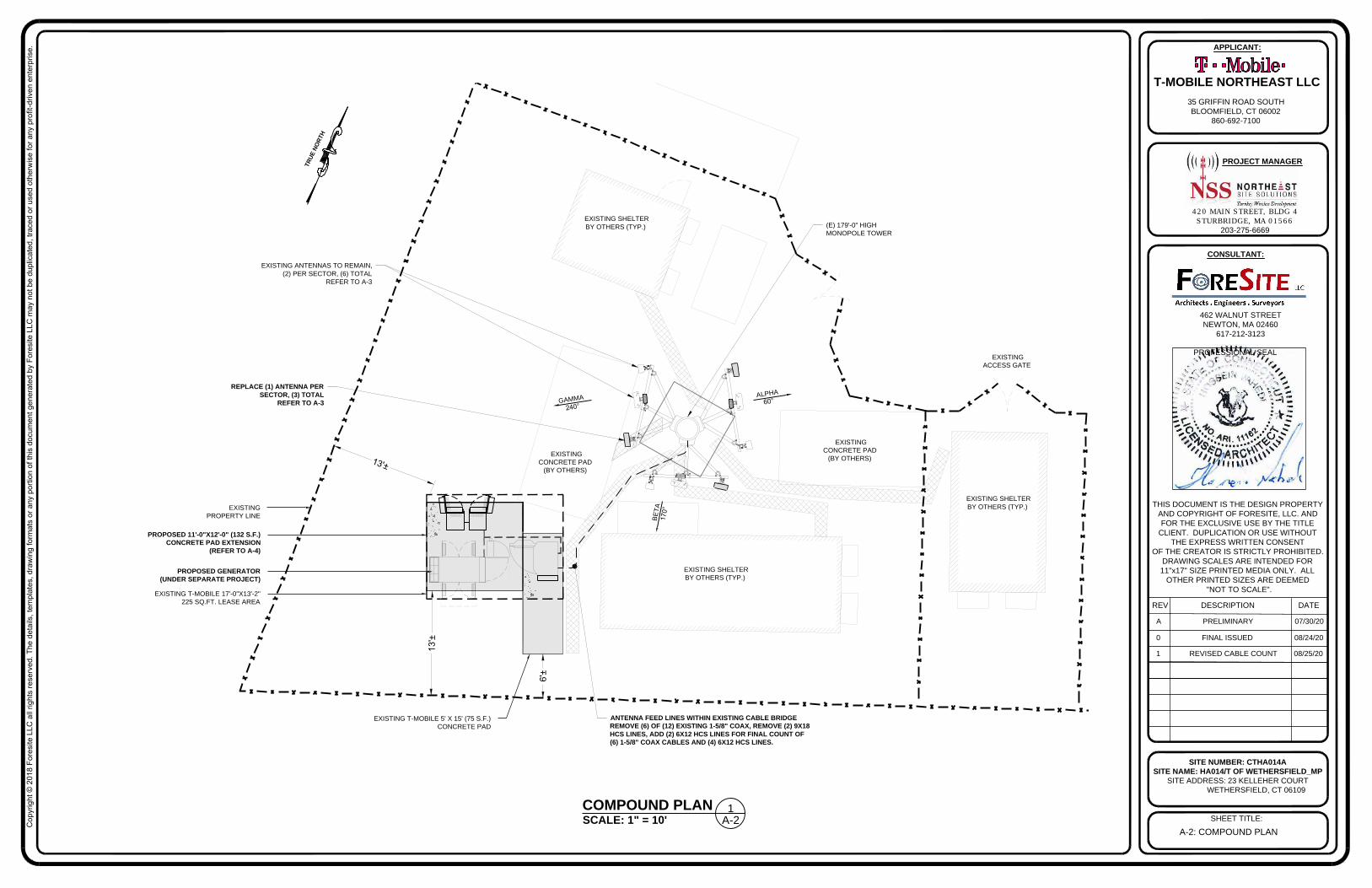
SCALE: 1" = 10'
COMPOUND PLAN
A-2
1
EXISTING SHELTER
BY OTHERS (TYP.)
EXISTING SHELTER
BY OTHERS (TYP.)
EXISTING SHELTER
BY OTHERS (TYP.)
EXISTING
CONCRETE PAD
(BY OTHERS)
EXISTING
CONCRETE PAD
(BY OTHERS)
EXISTING
ACCESS GATE
(E) 179'-0" HIGH
MONOPOLE TOWER
B
E
T
A
1
7
0
°
A
LP
H
A
6
0
°
T
R
U
E
N
O
R
T
H
G
A
M
M
A
2
4
0
°
PROPOSED GENERATOR
(UNDER SEPARATE PROJECT)
EXISTING
PROPERTY LINE
13'±
EXISTING T-MOBILE 17'-0"X13'-2"
225 SQ.FT. LEASE AREA
REPLACE (1) ANTENNA PER
SECTOR, (3) TOTAL
REFER TO A-3
1
3
'±
ANTENNA FEED LINES WITHIN EXISTING CABLE BRIDGE
REMOVE (6) OF (12) EXISTING 1-5/8" COAX, REMOVE (2) 9X18
HCS LINES, ADD (2) 6X12 HCS LINES FOR FINAL COUNT OF
(6) 1-5/8" COAX CABLES AND (4) 6X12 HCS LINES.
EXISTING ANTENNAS TO REMAIN,
(2) PER SECTOR, (6) TOTAL
REFER TO A-3
EXISTING T-MOBILE 5' X 15' (75 S.F.)
CONCRETE PAD
6'±
PROPOSED 11'-0"X12'-0" (132 S.F.)
CONCRETE PAD EXTENSION
(REFER TO A-4)
A-3: ELEVATION AND ANTENNA PLAN
420 MAIN STREET, BLDG 4
STURBRIDGE, MA 01566
203-275-6669
462 WALNUT STREET
NEWTON, MA 02460
617-212-3123
THIS DOCUMENT IS THE DESIGN PROPERTY
AND COPYRIGHT OF FORESITE, LLC. AND
FOR THE EXCLUSIVE USE BY THE TITLE
CLIENT. DUPLICATION OR USE WITHOUT
THE EXPRESS WRITTEN CONSENT
OF THE CREATOR IS STRICTLY PROHIBITED.
DRAWING SCALES ARE INTENDED FOR
11"x17" SIZE PRINTED MEDIA ONLY. ALL
OTHER PRINTED SIZES ARE DEEMED
"NOT TO SCALE".
SITE NUMBER: CTHA014A
SITE NAME: HA014/T OF WETHERSFIELD_MP
SITE ADDRESS: 23 KELLEHER COURT
WETHERSFIELD, CT 06109
SHEET TITLE:
REV DESCRIPTION DATE
A PRELIMINARY 07/30/20
PROFESSIONAL SEAL
PROJECT MANAGER
CONSULTANT:
APPLICANT:
T-MOBILE NORTHEAST LLC
35 GRIFFIN ROAD SOUTH
BLOOMFIELD, CT 06002
860-692-7100
Co
pyrig
ht ©
2
01
8 F
ore
site
L
LC
a
ll rig
hts re
se
rve
d. T
he
d
eta
ils, te
mp
la
te
s, d
ra
win
g fo
rm
ats o
r a
ny p
ortio
n o
f th
is d
ocu
me
nt g
en
era
te
d b
y F
ore
site
L
LC
m
ay n
ot b
e d
up
lica
te
d, tra
ce
d o
r u
se
d o
th
erw
ise
fo
r a
ny p
ro
fit-d
rive
n e
nte
rp
rise
.
0 FINAL ISSUED 08/24/20
1 REVISED CABLE COUNT 08/25/20
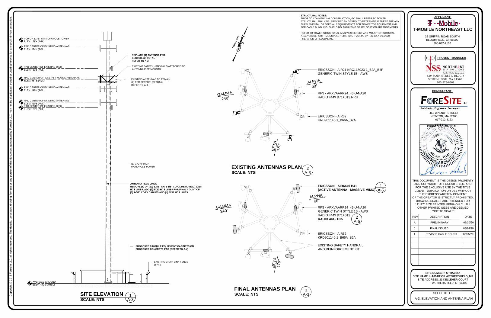
TOP OF EXISTING MONOPOLE TOWER
ELEV: 179'± (AGL)
RAD CENTER OF (E) & (P) T-MOBILE ANTENNAS
ELEV: 151'± (AGL)
RAD CENTER OF EXISTING ANTENNAS
ELEV: 174'± (AGL)
RAD CENTER OF EXISTING DISH
ELEV: 159'± (AGL)
AVERAGE GROUND
ELEV: 130'± (AMSL)
(E) 179'-0" HIGH
MONOPOLE TOWER
EXISTING CHAIN LINK FENCE
(TYP.)
SCALE: NTS
SITE ELEVATION
A-3
1
STRUCTURAL NOTES:
PRIOR TO COMMENCING CONSTRUCTION, GC SHALL REFER TO TOWER
STRUCTURAL ANALYSIS PROVIDED BY DESTEK TO DETERMINE IF THERE ARE ANY
SUPPLEMENTAL OR SPECIAL REQUIREMENTS FOR TOWER TOP EQUIPMENT AND
FOR CABLE BUNDLING, SHIELDING, MOUNTING OR RELOCATION ARRANGEMENTS.
REFER TO TOWER STRUCTURAL ANALYSIS REPORT AND MOUNT STRUCTURAL
ANALYSIS REPORT - MONOPOLE " SITE ID: CTHA014A, DATED JULY 29, 2020,
PREPARED EFI GLOBAL INC.
SCALE: NTS
FINAL ANTENNAS PLAN
B
E
T
A
1
7
0
°
A
L
P
H
A
60°
G
A
M
M
A
240°
RFS - APXVAARR24_43-U-NA20
RADIO 4449 B71+B12 RRU
ERICSSON - AIR32
KRD901146-1_B66A_B2A
ERICSSON - AIR21 KRC118023-1_B2A_B4P
GENERIC TWIN STYLE 1B - AWS
B
E
T
A
1
7
0
°
A
L
P
H
A
60°
G
A
M
M
A
2
4
0
°
RFS - APXVAARR24_43-U-NA20
GENERIC TWIN STYLE 1B - AWS
RADIO 4449 B71+B12
RADIO 4415 B25
ERICSSON - AIR32
KRD901146-1_B66A_B2A
T
R
U
E
N
O
R
T
H
ERICSSON - AIR6449 B41
(ACTIVE ANTENNA - MASSIVE MIMO)
A-3
3
PROPOSED T-MOBILE EQUIPMENT CABINETS ON
PROPOSED CONCRETE PAD (REFER TO A-4)
SCALE: NTS
EXISTING ANTENNAS PLAN
A-3
2
EXISTING SAFETY HANDRAIL
AND REINFORCEMENT KIT
EXISTING SAFETY HANDRAILS ATTACHED TO
ANTENNA PIPE MOUNTS
A-5
2
A-5
1
REPLACE (1) ANTENNA PER
SECTOR, (3) TOTAL
REFER TO A-3
EXISTING ANTENNAS TO REMAIN,
(2) PER SECTOR, (6) TOTAL
REFER TO A-3
RAD CENTER OF EXISTING DISH
ELEV: 126'± (AGL)
RAD CENTER OF EXISTING ANTENNAS
ELEV: 130'± (AGL)
RAD CENTER OF EXISTING ANTENNAS
ELEV: 140'± (AGL)
ANTENNA FEED LINES
REMOVE (6) OF (12) EXISTING 1-5/8" COAX, REMOVE (2) 9X18
HCS LINES, ADD (2) 6X12 HCS LINES FOR FINAL COUNT OF
(6) 1-5/8" COAX CABLES AND (4) 6X12 HCS LINES.
A-4: EQUIPMENT LAYOUT
420 MAIN STREET, BLDG 4
STURBRIDGE, MA 01566
203-275-6669
462 WALNUT STREET
NEWTON, MA 02460
617-212-3123
THIS DOCUMENT IS THE DESIGN PROPERTY
AND COPYRIGHT OF FORESITE, LLC. AND
FOR THE EXCLUSIVE USE BY THE TITLE
CLIENT. DUPLICATION OR USE WITHOUT
THE EXPRESS WRITTEN CONSENT
OF THE CREATOR IS STRICTLY PROHIBITED.
DRAWING SCALES ARE INTENDED FOR
11"x17" SIZE PRINTED MEDIA ONLY. ALL
OTHER PRINTED SIZES ARE DEEMED
"NOT TO SCALE".
SITE NUMBER: CTHA014A
SITE NAME: HA014/T OF WETHERSFIELD_MP
SITE ADDRESS: 23 KELLEHER COURT
WETHERSFIELD, CT 06109
SHEET TITLE:
REV DESCRIPTION DATE
A PRELIMINARY 07/30/20
PROFESSIONAL SEAL
PROJECT MANAGER
CONSULTANT:
APPLICANT:
T-MOBILE NORTHEAST LLC
35 GRIFFIN ROAD SOUTH
BLOOMFIELD, CT 06002
860-692-7100
Co
pyrig
ht ©
2
01
8 F
ore
site
L
LC
a
ll rig
hts re
se
rve
d. T
he
d
eta
ils, te
mp
la
te
s, d
ra
win
g fo
rm
ats o
r a
ny p
ortio
n o
f th
is d
ocu
me
nt g
en
era
te
d b
y F
ore
site
L
LC
m
ay n
ot b
e d
up
lica
te
d, tra
ce
d o
r u
se
d o
th
erw
ise
fo
r a
ny p
ro
fit-d
rive
n e
nte
rp
rise
.
0 FINAL ISSUED 08/24/20
1 REVISED CABLE COUNT 08/25/20
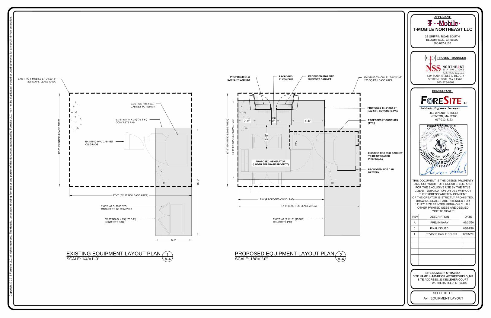
SCALE: 1/4"=1'-0"
EXISTING EQUIPMENT LAYOUT PLAN
A-4
1
PROPOSED EQUIPMENT LAYOUT PLAN
A-4
2
SCALE: 1/4"=1'-0"
PROPOSED GENERATOR
(UNDER SEPARATE PROJECT)
EXISTING T-MOBILE 17'-0"X13'-2"
225 SQ.FT. LEASE AREA
EXISTING S12000 BTS
CABINET TO BE REMOVED
EXISTING RBS 6131
CABINET TO REMAIN
PROPOSED 6160 SITE
SUPPORT CABINET
PROPOSED B160
BATTERY CABINET
PROPOSED 2" CONDUITS
(TYP.)
PROPOSED
2" CONDUIT
12'-0" (PROPOSED CONC. PAD)
11
'-0
" (P
RO
PO
SE
D C
ON
C. P
AD
)
EXISTING RBS 6131 CABINET
TO BE UPGRADED
INTERNALLY
PP
C
8" 4'-6"2'-6"
3'-5
"
PROPOSED 11'-0"X12'-0"
(132 S.F.) CONCRETE PAD
13
'-2
" (E
XIS
TIN
G L
EA
SE
A
RE
A)
17'-0" (EXISTING LEASE AREA)
EXISTING T-MOBILE 17'-0"X13'-2"
225 SQ.FT. LEASE AREA
EXISTING (5' X 15') (75 S.F.)
CONCRETE PAD
PROPOSED SIDE CAR
BATTERY
EXISTING (5' X 15') (75 S.F.)
CONCRETE PAD
EXISTING (5' X 15') (75 S.F.)
CONCRETE PAD
EXISTING PPC CABINET
ON GRADE
13
'-2
" (E
XIS
TIN
G L
EA
SE
A
RE
A)
17'-0" (EXISTING LEASE AREA)
15
'-0
"
5'-0"
420 MAIN STREET, BLDG 4
STURBRIDGE, MA 01566
203-275-6669
462 WALNUT STREET
NEWTON, MA 02460
617-212-3123
THIS DOCUMENT IS THE DESIGN PROPERTY
AND COPYRIGHT OF FORESITE, LLC. AND
FOR THE EXCLUSIVE USE BY THE TITLE
CLIENT. DUPLICATION OR USE WITHOUT
THE EXPRESS WRITTEN CONSENT
OF THE CREATOR IS STRICTLY PROHIBITED.
DRAWING SCALES ARE INTENDED FOR
11"x17" SIZE PRINTED MEDIA ONLY. ALL
OTHER PRINTED SIZES ARE DEEMED
"NOT TO SCALE".
SITE NUMBER: CTHA014A
SITE NAME: HA014/T OF WETHERSFIELD_MP
SITE ADDRESS: 23 KELLEHER COURT
WETHERSFIELD, CT 06109
SHEET TITLE:
REV DESCRIPTION DATE
A PRELIMINARY 07/30/20
PROFESSIONAL SEAL
PROJECT MANAGER
CONSULTANT:
APPLICANT:
T-MOBILE NORTHEAST LLC
35 GRIFFIN ROAD SOUTH
BLOOMFIELD, CT 06002
860-692-7100
Co
pyrig
ht ©
2
01
8 F
ore
site
L
LC
a
ll rig
hts re
se
rve
d. T
he
d
eta
ils, te
mp
la
te
s, d
ra
win
g fo
rm
ats o
r a
ny p
ortio
n o
f th
is d
ocu
me
nt g
en
era
te
d b
y F
ore
site
L
LC
m
ay n
ot b
e d
up
lica
te
d, tra
ce
d o
r u
se
d o
th
erw
ise
fo
r a
ny p
ro
fit-d
rive
n e
nte
rp
rise
.
0 FINAL ISSUED 08/24/20
1 REVISED CABLE COUNT 08/25/20
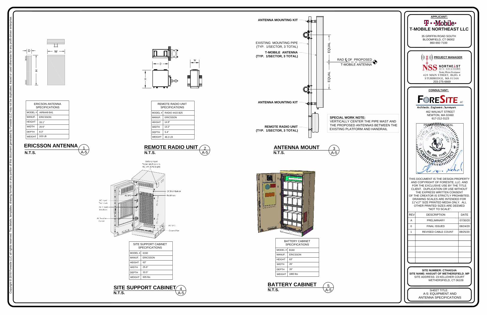
46.3 LB
5.4"
13.2"
14.9"
ERICSSON
RADIO 4415 B25
REMOTE RADIO UNIT
SPECIFICATIONS
MODEL #
MANUF.
HEIGHT
DEPTH
WEIGHT
WIDTH
REMOTE RADIO UNIT
A-5
2
ERICSSON ANTENNA
103 LB
8.3"
20.5"
33.1"
ERICSSON
AIR6449 B41MODEL #
MANUF.
HEIGHT
DEPTH
WEIGHT
WIDTH
ERICSON ANTENNA
SPECIFICATIONS
D
H
W
26"
26"
63"
ERICSSON
B160
BATTERY CABINET
SPECIFICATIONS
MODEL #
MANUF.
HEIGHT
DEPTH
WEIGHT
WIDTH
33.5"
25.6"
63"
ERICSSON
6160
SITE SUPPORT CABINET
SPECIFICATIONS
MODEL #
MANUF.
HEIGHT
DEPTH
WEIGHT
WIDTH
N.T.S.
SITE SUPPORT CABINET
N.T.S.
BATTERY CABINET
605 lbs
1883 lbs
A-5
4
A-5
5
A-5
1
T-MOBILE ANTENNA
(TYP. 1/SECTOR, 3 TOTAL)
REMOTE RADIO UNIT
(TYP. 1/SECTOR, 3 TOTAL)
EXISTING MOUNTING PIPE
(TYP. 1/SECTOR, 3 TOTAL)
ANTENNA MOUNTING KIT
RAD ℄OF PROPOSED
T-MOBILE ANTENNA
EQ
UA
LE
QU
AL
SPECIAL WORK NOTE:
VERTICALLY CENTER THE PIPE MAST AND
THE PROPOSED ANTENNAS BETWEEN THE
EXISTING PLATFORM AND HANDRAIL
ANTENNA MOUNTING KIT
N.T.S.
ANTENNA MOUNT
A-5
3
A-5: EQUIPMENT AND
ANTENNA SPECIFICATIONS
N.T.S.N.T.S.
420 MAIN STREET, BLDG 4
STURBRIDGE, MA 01566
203-275-6669
462 WALNUT STREET
NEWTON, MA 02460
617-212-3123
THIS DOCUMENT IS THE DESIGN PROPERTY
AND COPYRIGHT OF FORESITE, LLC. AND
FOR THE EXCLUSIVE USE BY THE TITLE
CLIENT. DUPLICATION OR USE WITHOUT
THE EXPRESS WRITTEN CONSENT
OF THE CREATOR IS STRICTLY PROHIBITED.
DRAWING SCALES ARE INTENDED FOR
11"x17" SIZE PRINTED MEDIA ONLY. ALL
OTHER PRINTED SIZES ARE DEEMED
"NOT TO SCALE".
SITE NUMBER: CTHA014A
SITE NAME: HA014/T OF WETHERSFIELD_MP
SITE ADDRESS: 23 KELLEHER COURT
WETHERSFIELD, CT 06109
SHEET TITLE:
REV DESCRIPTION DATE
A PRELIMINARY 07/30/20
PROFESSIONAL SEAL
PROJECT MANAGER
CONSULTANT:
APPLICANT:
T-MOBILE NORTHEAST LLC
35 GRIFFIN ROAD SOUTH
BLOOMFIELD, CT 06002
860-692-7100
Co
pyrig
ht ©
2
01
8 F
ore
site
L
LC
a
ll rig
hts re
se
rve
d. T
he
d
eta
ils, te
mp
la
te
s, d
ra
win
g fo
rm
ats o
r a
ny p
ortio
n o
f th
is d
ocu
me
nt g
en
era
te
d b
y F
ore
site
L
LC
m
ay n
ot b
e d
up
lica
te
d, tra
ce
d o
r u
se
d o
th
erw
ise
fo
r a
ny p
ro
fit-d
rive
n e
nte
rp
rise
.
0 FINAL ISSUED 08/24/20
1 REVISED CABLE COUNT 08/25/20
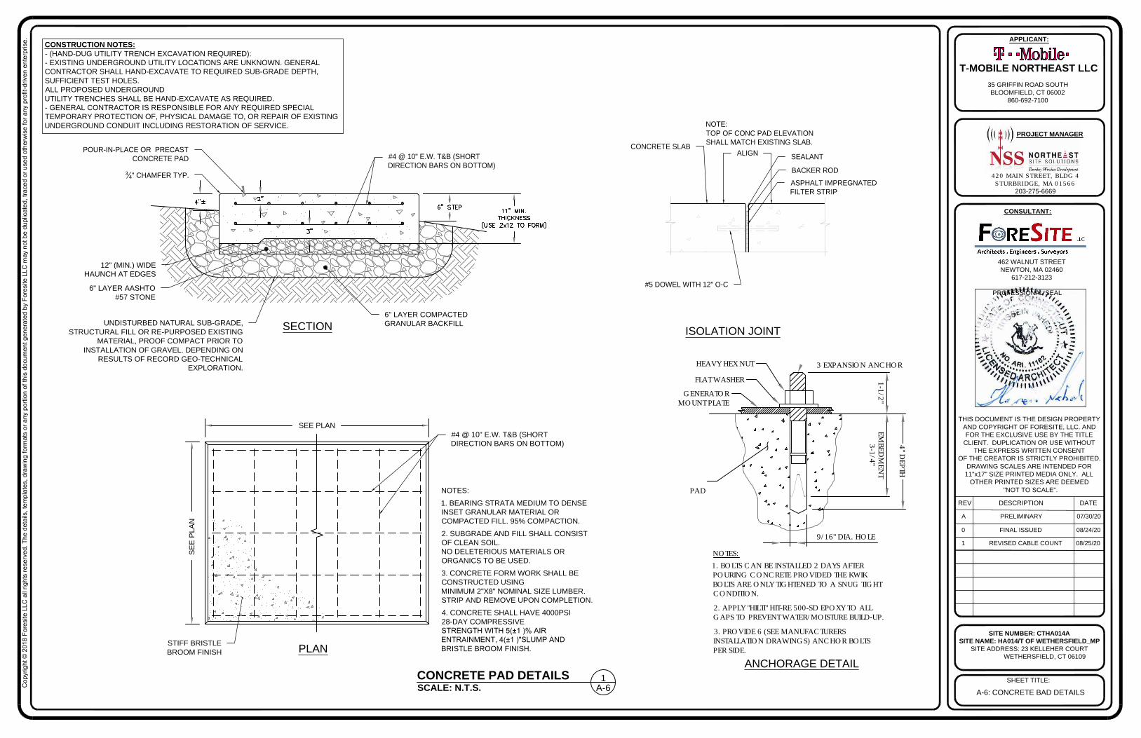
A-6: CONCRETE BAD DETAILS
CONSTRUCTION NOTES:
- (HAND-DUG UTILITY TRENCH EXCAVATION REQUIRED):
- EXISTING UNDERGROUND UTILITY LOCATIONS ARE UNKNOWN. GENERAL
CONTRACTOR SHALL HAND-EXCAVATE TO REQUIRED SUB-GRADE DEPTH,
SUFFICIENT TEST HOLES.
ALL PROPOSED UNDERGROUND
UTILITY TRENCHES SHALL BE HAND-EXCAVATE AS REQUIRED.
- GENERAL CONTRACTOR IS RESPONSIBLE FOR ANY REQUIRED SPECIAL
TEMPORARY PROTECTION OF, PHYSICAL DAMAGE TO, OR REPAIR OF EXISTING
UNDERGROUND CONDUIT INCLUDING RESTORATION OF SERVICE.
SCALE: N.T.S.
CONCRETE PAD DETAILS
A-6
1
POUR-IN-PLACE OR PRECAST
CONCRETE PAD
#4 @ 10" E.W. T&B (SHORT
DIRECTION BARS ON BOTTOM)
3
4
" CHAMFER TYP.
12" (MIN.) WIDE
HAUNCH AT EDGES
6" LAYER AASHTO
#57 STONE
UNDISTURBED NATURAL SUB-GRADE,
STRUCTURAL FILL OR RE-PURPOSED EXISTING
MATERIAL, PROOF COMPACT PRIOR TO
INSTALLATION OF GRAVEL. DEPENDING ON
RESULTS OF RECORD GEO-TECHNICAL
EXPLORATION.
SECTION
6" LAYER COMPACTED
GRANULAR BACKFILL
#4 @ 10" E.W. T&B (SHORT
DIRECTION BARS ON BOTTOM)
NOTES:
1. BEARING STRATA MEDIUM TO DENSE
INSET GRANULAR MATERIAL OR
COMPACTED FILL. 95% COMPACTION.
2. SUBGRADE AND FILL SHALL CONSIST
OF CLEAN SOIL.
NO DELETERIOUS MATERIALS OR
ORGANICS TO BE USED.
3. CONCRETE FORM WORK SHALL BE
CONSTRUCTED USING
MINIMUM 2"X8" NOMINAL SIZE LUMBER.
STRIP AND REMOVE UPON COMPLETION.
4. CONCRETE SHALL HAVE 4000PSI
28-DAY COMPRESSIVE
STRENGTH WITH 5(±1 )% AIR
ENTRAINMENT, 4(±1 )"SLUMP AND
BRISTLE BROOM FINISH.
SEE PLAN
SE
E P
LA
N
PLAN
STIFF BRISTLE
BROOM FINISH
ISOLATION JOINT
#5 DOWEL WITH 12" O-C
CONCRETE SLAB
ALIGN
SEALANT
BACKER ROD
ASPHALT IMPREGNATED
FILTER STRIP
NOTE:
TOP OF CONC PAD ELEVATION
SHALL MATCH EXISTING SLAB.
HEAVY HEX NUT
FLAT WASHER
GENERATORMOUNT PLATE
NOTES:1. BOLTS CAN BE INSTALLED 2 DAYS AFTERPOURING CONCRETE PROVIDED THE KWIKBOLTS ARE ONLY TIGHTENED TO A SNUG TIGHTCONDITION.
2. APPLY "HILTI" HIT-RE 500-SD EPOXY TO ALLGAPS TO PREVENT WATER/MOISTURE BUILD-UP.
PAD
3. PROVIDE 6 (SEE MANUFACTURERSINSTALLATION DRAWINGS) ANCHOR BOLTSPER SIDE.
9/16" DIA. HOLE
3 EXPANSION ANCHOR
3-1/4"EM
BEDM
ENT
4" DEPTH
1-1/2"
ANCHORAGE DETAIL
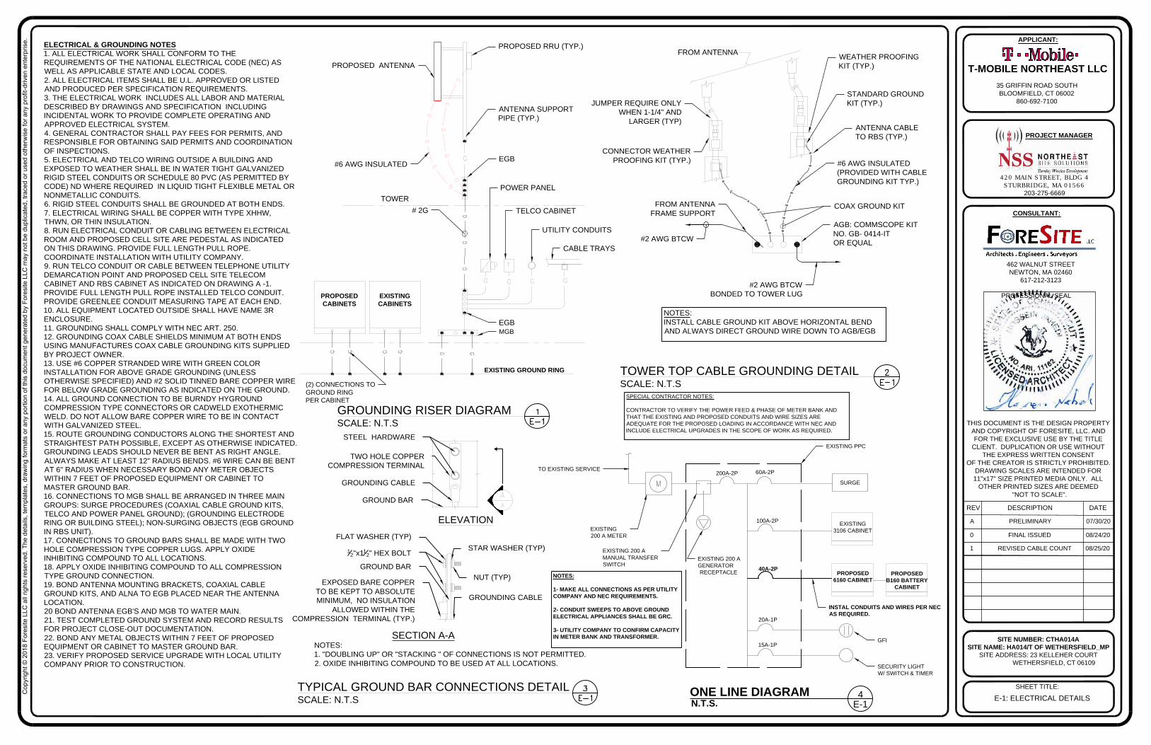
E-1: ELECTRICAL DETAILS
420 MAIN STREET, BLDG 4
STURBRIDGE, MA 01566
203-275-6669
462 WALNUT STREET
NEWTON, MA 02460
617-212-3123
THIS DOCUMENT IS THE DESIGN PROPERTY
AND COPYRIGHT OF FORESITE, LLC. AND
FOR THE EXCLUSIVE USE BY THE TITLE
CLIENT. DUPLICATION OR USE WITHOUT
THE EXPRESS WRITTEN CONSENT
OF THE CREATOR IS STRICTLY PROHIBITED.
DRAWING SCALES ARE INTENDED FOR
11"x17" SIZE PRINTED MEDIA ONLY. ALL
OTHER PRINTED SIZES ARE DEEMED
"NOT TO SCALE".
SITE NUMBER: CTHA014A
SITE NAME: HA014/T OF WETHERSFIELD_MP
SITE ADDRESS: 23 KELLEHER COURT
WETHERSFIELD, CT 06109
SHEET TITLE:
REV DESCRIPTION DATE
A PRELIMINARY 07/30/20
PROFESSIONAL SEAL
PROJECT MANAGER
CONSULTANT:
APPLICANT:
T-MOBILE NORTHEAST LLC
35 GRIFFIN ROAD SOUTH
BLOOMFIELD, CT 06002
860-692-7100
Co
pyrig
ht ©
2
01
8 F
ore
site
L
LC
a
ll rig
hts re
se
rve
d. T
he
d
eta
ils, te
mp
la
te
s, d
ra
win
g fo
rm
ats o
r a
ny p
ortio
n o
f th
is d
ocu
me
nt g
en
era
te
d b
y F
ore
site
L
LC
m
ay n
ot b
e d
up
lica
te
d, tra
ce
d o
r u
se
d o
th
erw
ise
fo
r a
ny p
ro
fit-d
rive
n e
nte
rp
rise
.
0 FINAL ISSUED 08/24/20
1 REVISED CABLE COUNT 08/25/20
NOTES:
1. "DOUBLING UP" OR "STACKING " OF CONNECTIONS IS NOT PERMITTED.
2. OXIDE INHIBITING COMPOUND TO BE USED AT ALL LOCATIONS.
STEEL HARDWARE
GROUND BAR
STAR WASHER (TYP)
NUT (TYP)
GROUNDING CABLE
GROUNDING CABLE
FLAT WASHER (TYP)
1
2
"x1
1
2
" HEX BOLT
GROUND BAR
EXPOSED BARE COPPER
TO BE KEPT TO ABSOLUTE
MINIMUM, NO INSULATION
ALLOWED WITHIN THE
COMPRESSION TERMINAL (TYP.)
SECTION A-A
TYPICAL GROUND BAR CONNECTIONS DETAIL
SCALE: N.T.S
TWO HOLE COPPER
COMPRESSION TERMINAL
ELEVATION
ELECTRICAL & GROUNDING NOTES
1. ALL ELECTRICAL WORK SHALL CONFORM TO THE
REQUIREMENTS OF THE NATIONAL ELECTRICAL CODE (NEC) AS
WELL AS APPLICABLE STATE AND LOCAL CODES.
2. ALL ELECTRICAL ITEMS SHALL BE U.L. APPROVED OR LISTED
AND PRODUCED PER SPECIFICATION REQUIREMENTS.
3. THE ELECTRICAL WORK INCLUDES ALL LABOR AND MATERIAL
DESCRIBED BY DRAWINGS AND SPECIFICATION INCLUDING
INCIDENTAL WORK TO PROVIDE COMPLETE OPERATING AND
APPROVED ELECTRICAL SYSTEM.
4. GENERAL CONTRACTOR SHALL PAY FEES FOR PERMITS, AND
RESPONSIBLE FOR OBTAINING SAID PERMITS AND COORDINATION
OF INSPECTIONS.
5. ELECTRICAL AND TELCO WIRING OUTSIDE A BUILDING AND
EXPOSED TO WEATHER SHALL BE IN WATER TIGHT GALVANIZED
RIGID STEEL CONDUITS OR SCHEDULE 80 PVC (AS PERMITTED BY
CODE) ND WHERE REQUIRED IN LIQUID TIGHT FLEXIBLE METAL OR
NONMETALLIC CONDUITS.
6. RIGID STEEL CONDUITS SHALL BE GROUNDED AT BOTH ENDS.
7. ELECTRICAL WIRING SHALL BE COPPER WITH TYPE XHHW,
THWN, OR THIN INSULATION.
8. RUN ELECTRICAL CONDUIT OR CABLING BETWEEN ELECTRICAL
ROOM AND PROPOSED CELL SITE ARE PEDESTAL AS INDICATED
ON THIS DRAWING. PROVIDE FULL LENGTH PULL ROPE.
COORDINATE INSTALLATION WITH UTILITY COMPANY.
9. RUN TELCO CONDUIT OR CABLE BETWEEN TELEPHONE UTILITY
DEMARCATION POINT AND PROPOSED CELL SITE TELECOM
CABINET AND RBS CABINET AS INDICATED ON DRAWING A -1.
PROVIDE FULL LENGTH PULL ROPE INSTALLED TELCO CONDUIT.
PROVIDE GREENLEE CONDUIT MEASURING TAPE AT EACH END.
10. ALL EQUIPMENT LOCATED OUTSIDE SHALL HAVE NAME 3R
ENCLOSURE.
11. GROUNDING SHALL COMPLY WITH NEC ART. 250.
12. GROUNDING COAX CABLE SHIELDS MINIMUM AT BOTH ENDS
USING MANUFACTURES COAX CABLE GROUNDING KITS SUPPLIED
BY PROJECT OWNER.
13. USE #6 COPPER STRANDED WIRE WITH GREEN COLOR
INSTALLATION FOR ABOVE GRADE GROUNDING (UNLESS
OTHERWISE SPECIFIED) AND #2 SOLID TINNED BARE COPPER WIRE
FOR BELOW GRADE GROUNDING AS INDICATED ON THE GROUND.
14. ALL GROUND CONNECTION TO BE BURNDY HYGROUND
COMPRESSION TYPE CONNECTORS OR CADWELD EXOTHERMIC
WELD. DO NOT ALLOW BARE COPPER WIRE TO BE IN CONTACT
WITH GALVANIZED STEEL.
15. ROUTE GROUNDING CONDUCTORS ALONG THE SHORTEST AND
STRAIGHTEST PATH POSSIBLE, EXCEPT AS OTHERWISE INDICATED.
GROUNDING LEADS SHOULD NEVER BE BENT AS RIGHT ANGLE.
ALWAYS MAKE AT LEAST 12" RADIUS BENDS. #6 WIRE CAN BE BENT
AT 6" RADIUS WHEN NECESSARY BOND ANY METER OBJECTS
WITHIN 7 FEET OF PROPOSED EQUIPMENT OR CABINET TO
MASTER GROUND BAR.
16. CONNECTIONS TO MGB SHALL BE ARRANGED IN THREE MAIN
GROUPS: SURGE PROCEDURES (COAXIAL CABLE GROUND KITS,
TELCO AND POWER PANEL GROUND); (GROUNDING ELECTRODE
RING OR BUILDING STEEL); NON-SURGING OBJECTS (EGB GROUND
IN RBS UNIT).
17. CONNECTIONS TO GROUND BARS SHALL BE MADE WITH TWO
HOLE COMPRESSION TYPE COPPER LUGS. APPLY OXIDE
INHIBITING COMPOUND TO ALL LOCATIONS.
18. APPLY OXIDE INHIBITING COMPOUND TO ALL COMPRESSION
TYPE GROUND CONNECTION.
19. BOND ANTENNA MOUNTING BRACKETS, COAXIAL CABLE
GROUND KITS, AND ALNA TO EGB PLACED NEAR THE ANTENNA
LOCATION.
20 BOND ANTENNA EGB'S AND MGB TO WATER MAIN.
21. TEST COMPLETED GROUND SYSTEM AND RECORD RESULTS
FOR PROJECT CLOSE-OUT DOCUMENTATION.
22. BOND ANY METAL OBJECTS WITHIN 7 FEET OF PROPOSED
EQUIPMENT OR CABINET TO MASTER GROUND BAR.
23. VERIFY PROPOSED SERVICE UPGRADE WITH LOCAL UTILITY
COMPANY PRIOR TO CONSTRUCTION.
PROPOSED ANTENNA
#6 AWG INSULATED
ANTENNA SUPPORT
PIPE (TYP.)
EGB
POWER PANEL
TELCO CABINET
UTILITY CONDUITS
CABLE TRAYS
TOWER
EGB
FROM ANTENNA
JUMPER REQUIRE ONLY
WHEN 1-1/4" AND
LARGER (TYP)
CONNECTOR WEATHER
PROOFING KIT (TYP.)
FROM ANTENNA
FRAME SUPPORT
#2 AWG BTCW
#2 AWG BTCW
BONDED TO TOWER LUG
AGB: COMMSCOPE KIT
NO. GB- 0414-IT
OR EQUAL
COAX GROUND KIT
#6 AWG INSULATED
(PROVIDED WITH CABLE
GROUNDING KIT TYP.)
ANTENNA CABLE
TO RBS (TYP.)
STANDARD GROUND
KIT (TYP.)
WEATHER PROOFING
KIT (TYP.)
GROUNDING RISER DIAGRAM
SCALE: N.T.S
TOWER TOP CABLE GROUNDING DETAIL
SCALE: N.T.S
NOTES:
INSTALL CABLE GROUND KIT ABOVE HORIZONTAL BEND
AND ALWAYS DIRECT GROUND WIRE DOWN TO AGB/EGB
# 2G
PROPOSED RRU (TYP.)
20A-1P
GFI
EXISTING PPC
EXISTING 200 A
GENERATOR
RECEPTACLE
200A-2P
EXISTING
3106 CABINET
PROPOSED
6160 CABINET
40A-2P
60A-2P
SURGE
PROPOSED
B160 BATTERY
CABINET
SECURITY LIGHT
W/ SWITCH & TIMER
100A-2P
15A-1P
INSTAL CONDUITS AND WIRES PER NEC
AS REQUIRED.
N.T.S.
ONE LINE DIAGRAM
E-1
4
NOTES:
1- MAKE ALL CONNECTIONS AS PER UTILITY
COMPANY AND NEC REQUIREMENTS.
2- CONDUIT SWEEPS TO ABOVE GROUND
ELECTRICAL APPLIANCES SHALL BE GRC.
3- UTILITY COMPANY TO CONFIRM CAPACITY
IN METER BANK AND TRANSFORMER.
SPECIAL CONTRACTOR NOTES:
CONTRACTOR TO VERIFY THE POWER FEED & PHASE OF METER BANK AND
THAT THE EXISTING AND PROPOSED CONDUITS AND WIRE SIZES ARE
ADEQUATE FOR THE PROPOSED LOADING IN ACCORDANCE WITH NEC AND
INCLUDE ELECTRICAL UPGRADES IN THE SCOPE OF WORK AS REQUIRED.
TO EXISTING SERVICE
EXISTING
200 A METER
EXISTING 200 A
MANUAL TRANSFER
SWITCH
MGB
EXISTING
CABINETS
PROPOSED
CABINETS
EXISTING GROUND RING
(2) CONNECTIONS TO
GROUND RING
PER CABINET

Exhibit D
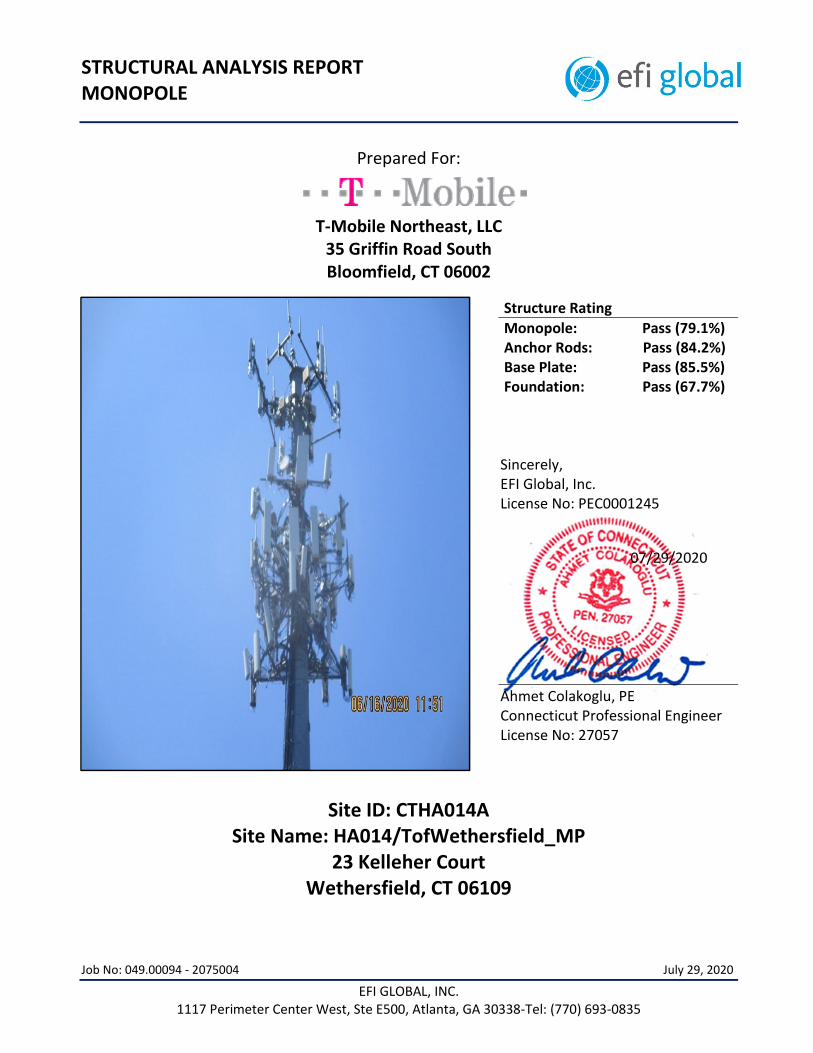
EFI GLOBAL, INC. 1117 Perimeter Center West, Ste E500, Atlanta, GA 30338-Tel: (770) 693-0835
STRUCTURAL ANALYSIS REPORT MONOPOLE
Prepared For:
T-Mobile Northeast, LLC 35 Griffin Road South Bloomfield, CT 06002
Structure Rating
Monopole: Pass (79.1%) Anchor Rods: Pass (84.2%) Base Plate: Pass (85.5%) Foundation: Pass (67.7%)
Sincerely, EFI Global, Inc. License No: PEC0001245
07/29/2020
Ahmet Colakoglu, PE Connecticut Professional Engineer License No: 27057
Site ID: CTHA014A Site Name: HA014/TofWethersfield_MP
23 Kelleher Court Wethersfield, CT 06109
Job No: 049.00094 - 2075004 July 29, 2020
CTHA014A - Structural Analysis Report
P a g e | 0 EFI GLOBAL, INC. 1117 Perimeter Center West, Ste E500, Atlanta, GA 30338 - Tel: (770) 693-0835
CONTENTS
1.0 – SUBJECT AND REFERENCES
1.1 – STRUCTURE
2.0 – EXISTING AND PROPOSED APPURTENANCES
3.0 - CODES AND LOADING
4.0 - STANDARD CONDITIONS FOR ENGINEERING SERVICES ON EXISTING STRUCTURES
5.0 - ANALYSIS AND ASSUMPTIONS
6.0 – RESULTS AND CONCLUSION
APPENDIX A – CALCULATIONS
CTHA014A - Structural Analysis Report
P a g e | 1 EFI GLOBAL, INC. 1117 Perimeter Center West, Ste E500, Atlanta, GA 30338 - Tel: (770) 693-0835
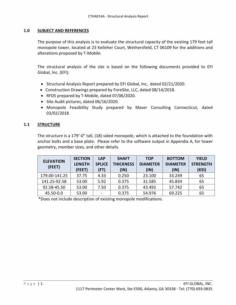
1.0 SUBJECT AND REFERENCES
The purpose of this analysis is to evaluate the structural capacity of the existing 179 feet tall monopole tower, located at 23 Kelleher Court, Wethersfield, CT 06109 for the additions and alterations proposed by T-Mobile.
The structural analysis of the site is based on the following documents provided to EFI Global, Inc. (EFI):
Structural Analysis Report prepared by EFI Global, Inc, dated 02/21/2020.
Construction Drawings prepared by ForeSite, LLC, dated 08/14/2018.
RFDS prepared by T-Mobile, dated 07/06/2020.
Site Audit pictures, dated 06/16/2020.
Monopole Feasibility Study prepared by Maser Consulting Connecticut, dated 03/02/2018.
1.1 STRUCTURE
The structure is a 179’-0” tall, (18) sided monopole, which is attached to the foundation with anchor bolts and a base plate. Please refer to the software output in Appendix A, for tower geometry, member sizes, and other details.
ELEVATION (FEET)
SECTION LENGTH (FEET)
LAP SPLICE
(FT)
SHAFT THICKNESS
(IN)
TOP DIAMETER
(IN)
BOTTOM DIAMETER
(IN)
YIELD STRENGTH
(KSI)
179.00-141.25 37.75 4.33 0.250 23.100 33.249 65
141.25-92.58 53.00 5.92 0.375 31.585 45.834 65
92.58-45.50 53.00 7.50 0.375 43.492 57.742 65
45.50-0.0 53.00 - 0.375 54.976 69.225 65
*Does not include description of existing monopole modifications.
CTHA014A - Structural Analysis Report
P a g e | 2 EFI GLOBAL, INC. 1117 Perimeter Center West, Ste E500, Atlanta, GA 30338 - Tel: (770) 693-0835
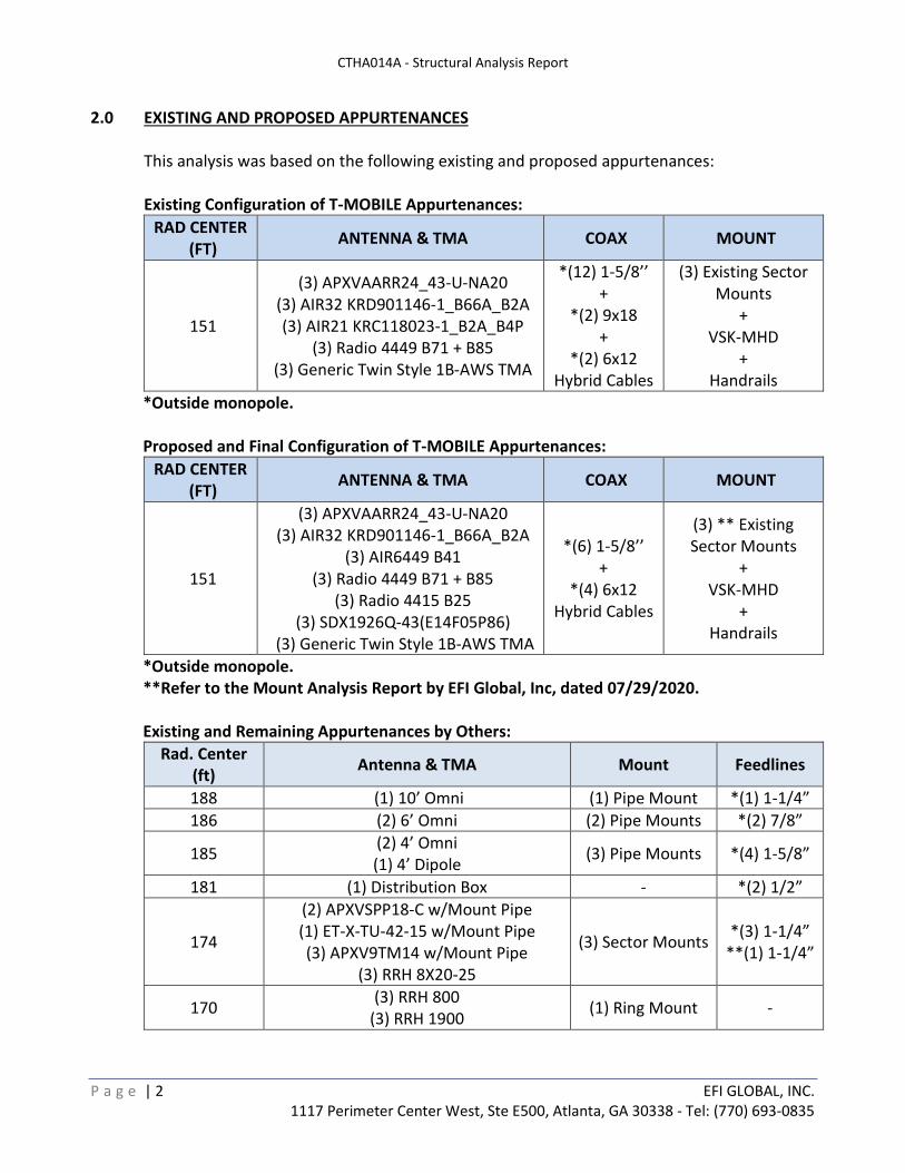
2.0 EXISTING AND PROPOSED APPURTENANCES
This analysis was based on the following existing and proposed appurtenances:
Existing Configuration of T-MOBILE Appurtenances:
RAD CENTER(FT)
ANTENNA & TMA COAX MOUNT
151
(3) APXVAARR24_43-U-NA20(3) AIR32 KRD901146-1_B66A_B2A(3) AIR21 KRC118023-1_B2A_B4P
(3) Radio 4449 B71 + B85(3) Generic Twin Style 1B-AWS TMA
*(12) 1-5/8’’ +
*(2) 9x18 +
*(2) 6x12 Hybrid Cables
(3) Existing SectorMounts
+ VSK-MHD
+ Handrails
*Outside monopole.
Proposed and Final Configuration of T-MOBILE Appurtenances:
RAD CENTER(FT)
ANTENNA & TMA COAX MOUNT
151
(3) APXVAARR24_43-U-NA20(3) AIR32 KRD901146-1_B66A_B2A
(3) AIR6449 B41(3) Radio 4449 B71 + B85
(3) Radio 4415 B25(3) SDX1926Q-43(E14F05P86)
(3) Generic Twin Style 1B-AWS TMA
*(6) 1-5/8’’ +
*(4) 6x12 Hybrid Cables
(3) ** ExistingSector Mounts
+ VSK-MHD
+ Handrails
*Outside monopole.**Refer to the Mount Analysis Report by EFI Global, Inc, dated 07/29/2020.
Existing and Remaining Appurtenances by Others:
Rad. Center (ft)
Antenna & TMA Mount Feedlines
188 (1) 10’ Omni (1) Pipe Mount *(1) 1-1/4”
186 (2) 6’ Omni (2) Pipe Mounts *(2) 7/8”
185 (2) 4’ Omni(1) 4’ Dipole
(3) Pipe Mounts *(4) 1-5/8”
181 (1) Distribution Box - *(2) 1/2”
174
(2) APXVSPP18-C w/Mount Pipe(1) ET-X-TU-42-15 w/Mount Pipe(3) APXV9TM14 w/Mount Pipe
(3) RRH 8X20-25
(3) Sector Mounts*(3) 1-1/4”
**(1) 1-1/4”
170 (3) RRH 800
(3) RRH 1900(1) Ring Mount -
CTHA014A - Structural Analysis Report
P a g e | 3 EFI GLOBAL, INC. 1117 Perimeter Center West, Ste E500, Atlanta, GA 30338 - Tel: (770) 693-0835
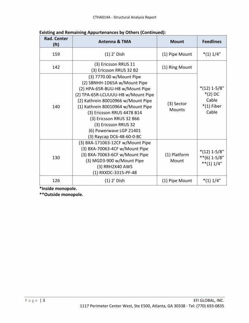
Existing and Remaining Appurtenances by Others (Continued):
Rad. Center (ft)
Antenna & TMA Mount Feedlines
159 (1) 2’ Dish (1) Pipe Mount *(1) 1/4”
142 (3) Ericsson RRUS 11
(3) Ericsson RRUS 32 B2 (1) Ring Mount
*(12) 1-5/8"*(2) DC Cable
*(1) Fiber Cable
140
(3) 7770.00 w/Mount Pipe (2) SBNHH-1D65A w/Mount Pipe
(2) HPA-65R-BUU-H8 w/Mount Pipe (2) TPA-65R-LCUUUU-H8 w/Mount Pipe
(2) Kathrein 80010966 w/Mount Pipe (1) Kathrein 80010964 w/Mount Pipe
(3) Ericsson RRUS 4478 B14 (3) Ericsson RRUS 32 B66
(3) Ericsson RRUS 32 (6) Powerwave LGP 21401 (3) Raycap DC6-48-60-0-8C
(3) Sector Mounts
130
(3) BXA-171063-12CF w/Mount Pipe (3) BXA-70063-4CF w/Mount Pipe (3) BXA-70063-6CF w/Mount Pipe
(3) MGD3-900 w/Mount Pipe (3) RRH2X40 AWS
(1) RXXDC-3315-PF-48
(1) Platform Mount
*(12) 1-5/8”**(6) 1-5/8”**(1) 1/4”
126 (1) 2’ Dish (1) Pipe Mount *(1) 1/4”
*Inside monopole. **Outside monopole.
CTHA014A - Structural Analysis Report
P a g e | 4 EFI GLOBAL, INC. 1117 Perimeter Center West, Ste E500, Atlanta, GA 30338 - Tel: (770) 693-0835
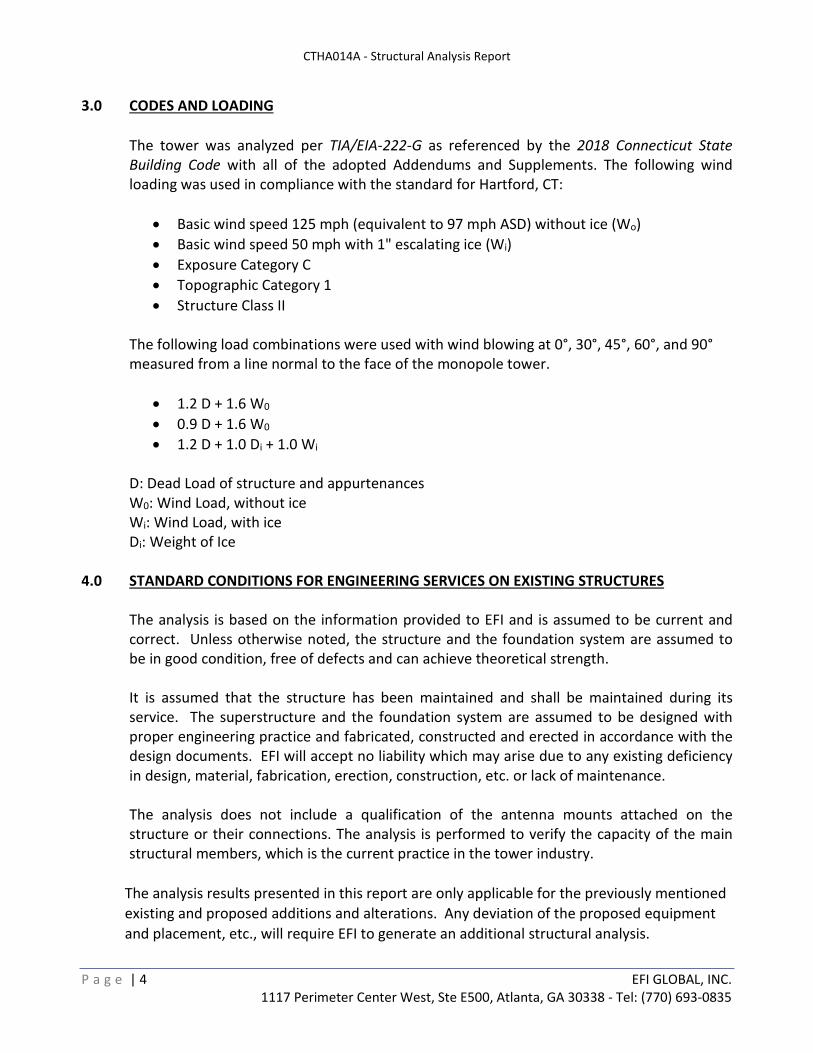
3.0 CODES AND LOADING
The tower was analyzed per TIA/EIA-222-G as referenced by the 2018 Connecticut State Building Code with all of the adopted Addendums and Supplements. The following wind loading was used in compliance with the standard for Hartford, CT:
Basic wind speed 125 mph (equivalent to 97 mph ASD) without ice (Wo)
Basic wind speed 50 mph with 1" escalating ice (Wi)
Exposure Category C
Topographic Category 1
Structure Class II
The following load combinations were used with wind blowing at 0°, 30°, 45°, 60°, and 90° measured from a line normal to the face of the monopole tower.
1.2 D + 1.6 W0
0.9 D + 1.6 W0
1.2 D + 1.0 Di + 1.0 Wi
D: Dead Load of structure and appurtenances W0: Wind Load, without ice Wi: Wind Load, with ice Di: Weight of Ice
4.0 STANDARD CONDITIONS FOR ENGINEERING SERVICES ON EXISTING STRUCTURES
The analysis is based on the information provided to EFI and is assumed to be current and correct. Unless otherwise noted, the structure and the foundation system are assumed to be in good condition, free of defects and can achieve theoretical strength.
It is assumed that the structure has been maintained and shall be maintained during its service. The superstructure and the foundation system are assumed to be designed with proper engineering practice and fabricated, constructed and erected in accordance with the design documents. EFI will accept no liability which may arise due to any existing deficiency in design, material, fabrication, erection, construction, etc. or lack of maintenance.
The analysis does not include a qualification of the antenna mounts attached on the structure or their connections. The analysis is performed to verify the capacity of the main structural members, which is the current practice in the tower industry.
The analysis results presented in this report are only applicable for the previously mentioned
existing and proposed additions and alterations. Any deviation of the proposed equipment
and placement, etc., will require EFI to generate an additional structural analysis.
CTHA014A - Structural Analysis Report
P a g e | 5 EFI GLOBAL, INC. 1117 Perimeter Center West, Ste E500, Atlanta, GA 30338 - Tel: (770) 693-0835
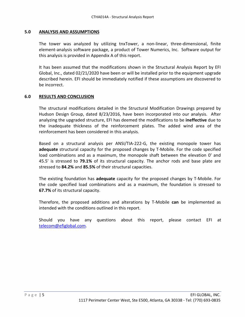
5.0 ANALYSIS AND ASSUMPTIONS
The tower was analyzed by utilizing tnxTower, a non-linear, three-dimensional, finite element-analysis software package, a product of Tower Numerics, Inc. Software output for this analysis is provided in Appendix A of this report.
It has been assumed that the modifications shown in the Structural Analysis Report by EFI Global, Inc., dated 02/21/2020 have been or will be installed prior to the equipment upgrade described herein. EFI should be immediately notified if these assumptions are discovered to be incorrect.
6.0 RESULTS AND CONCLUSION
The structural modifications detailed in the Structural Modification Drawings prepared by Hudson Design Group, dated 8/23/2016, have been incorporated into our analysis. After analyzing the upgraded structure, EFI has deemed the modifications to be ineffective due to the inadequate thickness of the reinforcement plates. The added wind area of the reinforcement has been considered in this analysis.
Based on a structural analysis per ANSI/TIA-222-G, the existing monopole tower hasadequate structural capacity for the proposed changes by T-Mobile. For the code specified load combinations and as a maximum, the monopole shaft between the elevation 0' and 45.5' is stressed to 79.1% of its structural capacity. The anchor rods and base plate are stressed to 84.2% and 85.5% of their structural capacities.
The existing foundation has adequate capacity for the proposed changes by T-Mobile. For the code specified load combinations and as a maximum, the foundation is stressed to 67.7% of its structural capacity.
Therefore, the proposed additions and alterations by T-Mobile can be implemented as intended with the conditions outlined in this report.
Should you have any questions about this report, please contact EFI at [email protected].
APPENDIX A CALCULATIONS
EFI Global, INC 1117 Perimeter Center West, Ste E500
Atlanta, GA Phone: 770-693-0835
FAX:
Job: CTHA014A
Project: 049.00094 - 2075004 Client: T-Mobile Drawn by: Ahmet Colakoglu App'd:
Code: TIA-222-G Date: 07/27/20 Scale: NTS Path:
C:\Users\Srivatsav.Kumar\Sedgwick\Destek Server - Documents\Projects\2020\75 - ForeSite LLC\049.00094 - 004 - CTHA014A\New Scope 07-2020\TNX\CTHA014A.eri
Dwg No. E-1
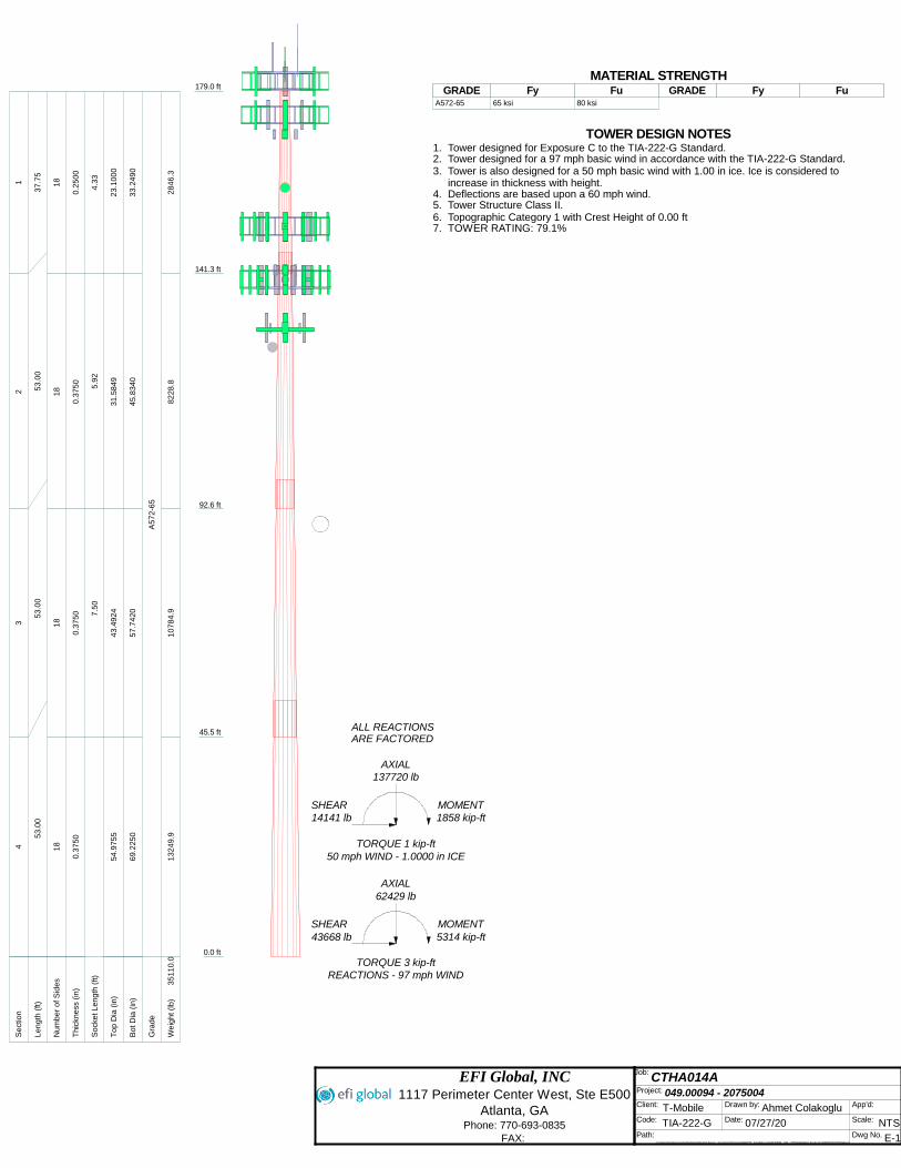
179.0 ft
141.3 ft
92.6 ft
45.5 ft
0.0 ft
REACTIONS - 97 mph WINDTORQUE 3 kip-ft
43668 lbSHEAR
5314 kip-ftMOMENT
62429 lbAXIAL
50 mph WIND - 1.0000 in ICETORQUE 1 kip-ft
14141 lbSHEAR
1858 kip-ftMOMENT
137720 lbAXIAL
ARE FACTOREDALL REACTIONS
S
ect
ion
12
34
L
en
gth
(ft)
37
.75
53
.00
53
.00
53
.00
N
um
be
r o
f S
ide
s1
81
81
81
8
T
hic
kne
ss (
in)
0.2
50
00
.37
50
0.3
75
00
.37
50
S
ock
et L
en
gth
(ft)
4.3
35
.92
7.5
0
T
op
Dia
(in
)2
3.1
00
03
1.5
84
94
3.4
92
45
4.9
75
5
B
ot D
ia (
in)
33
.24
90
45
.83
40
57
.74
20
69
.22
50
G
rad
eA
57
2-6
5
W
eig
ht (l
b)
28
46
.38
22
8.8
10
78
4.9
13
24
9.9
35
11
0.0
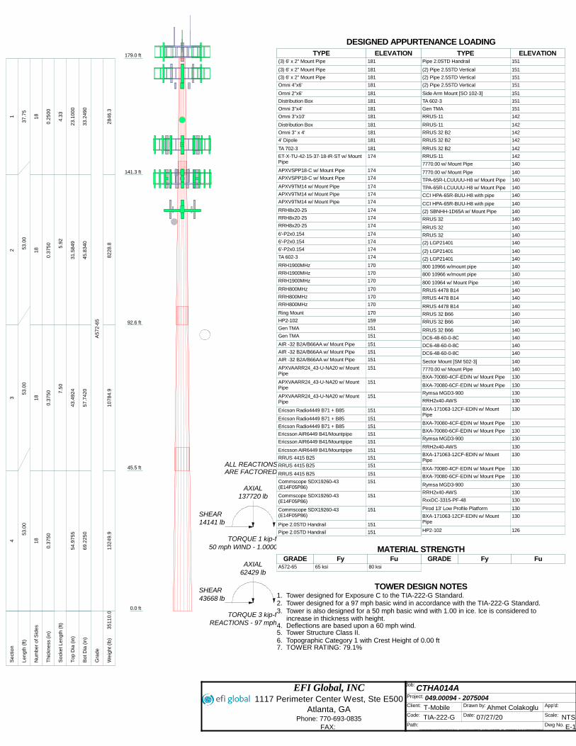
(3) 6' x 2" Mount Pipe 181(3) 6' x 2" Mount Pipe 181(3) 6' x 2" Mount Pipe 181Omni 4"x6' 181Omni 2"x6' 181Distribution Box 181Omni 3"x4' 181Omni 3"x10' 181Distribution Box 181Omni 3" x 4' 1814' Dipole 181TA 702-3 181ET-X-TU-42-15-37-18-iR-ST w/ Mount Pipe
174APXVSPP18-C w/ Mount Pipe 174APXVSPP18-C w/ Mount Pipe 174APXV9TM14 w/ Mount Pipe 174APXV9TM14 w/ Mount Pipe 174APXV9TM14 w/ Mount Pipe 174RRH8x20-25 174RRH8x20-25 174RRH8x20-25 1746'-P2x0.154 1746'-P2x0.154 1746'-P2x0.154 174TA 602-3 174RRH1900MHz 170RRH1900MHz 170RRH1900MHz 170RRH800MHz 170RRH800MHz 170RRH800MHz 170Ring Mount 170HP2-102 159Gen TMA 151Gen TMA 151AIR -32 B2A/B66AA w/ Mount Pipe 151AIR -32 B2A/B66AA w/ Mount Pipe 151AIR -32 B2A/B66AA w/ Mount Pipe 151APXVAARR24_43-U-NA20 w/ Mount Pipe
151APXVAARR24_43-U-NA20 w/ Mount Pipe
151APXVAARR24_43-U-NA20 w/ Mount Pipe
151Ericson Radio4449 B71 + B85 151Ericson Radio4449 B71 + B85 151Ericson Radio4449 B71 + B85 151Ericsson AIR6449 B41/Mountpipe 151Ericsson AIR6449 B41/Mountpipe 151Ericsson AIR6449 B41/Mountpipe 151RRUS 4415 B25 151RRUS 4415 B25 151RRUS 4415 B25 151Commscope SDX19260-43 (E14F05P86)
151Commscope SDX19260-43 (E14F05P86)
151Commscope SDX19260-43 (E14F05P86)
151Pipe 2.0STD Handrail 151Pipe 2.0STD Handrail 151Pipe 2.0STD Handrail 151(2) Pipe 2.5STD Vertical 151(2) Pipe 2.5STD Vertical 151(2) Pipe 2.5STD Vertical 151Side Arm Mount [SO 102-3] 151TA 602-3 151Gen TMA 151RRUS-11 142RRUS-11 142RRUS 32 B2 142RRUS 32 B2 142RRUS 32 B2 142RRUS-11 1427770.00 w/ Mount Pipe 1407770.00 w/ Mount Pipe 140TPA-65R-LCUUUU-H8 w/ Mount Pipe 140TPA-65R-LCUUUU-H8 w/ Mount Pipe 140CCI HPA-65R-BUU-H8 with pipe 140CCI HPA-65R-BUU-H8 with pipe 140(2) SBNHH-1D65A w/ Mount Pipe 140RRUS 32 140RRUS 32 140RRUS 32 140(2) LGP21401 140(2) LGP21401 140(2) LGP21401 140800 10966 w/mount pipe 140800 10966 w/mount pipe 140800 10964 w/ Mount Pipe 140RRUS 4478 B14 140RRUS 4478 B14 140RRUS 4478 B14 140RRUS 32 B66 140RRUS 32 B66 140RRUS 32 B66 140DC6-48-60-0-8C 140DC6-48-60-0-8C 140DC6-48-60-0-8C 140Sector Mount [SM 502-3] 1407770.00 w/ Mount Pipe 140BXA-70080-4CF-EDIN w/ Mount Pipe 130BXA-70080-6CF-EDIN w/ Mount Pipe 130Rymsa MGD3-900 130RRH2x40-AWS 130BXA-171063-12CF-EDIN w/ Mount Pipe
130BXA-70080-4CF-EDIN w/ Mount Pipe 130BXA-70080-6CF-EDIN w/ Mount Pipe 130Rymsa MGD3-900 130RRH2x40-AWS 130BXA-171063-12CF-EDIN w/ Mount Pipe
130BXA-70080-4CF-EDIN w/ Mount Pipe 130BXA-70080-6CF-EDIN w/ Mount Pipe 130Rymsa MGD3-900 130RRH2x40-AWS 130RxxDC-3315-PF-48 130Pirod 13' Low Profile Platform 130BXA-171063-12CF-EDIN w/ Mount Pipe
130HP2-102 126DESIGNED APPURTENANCE LOADING
TYPE TYPEELEVATION ELEVATION(3) 6' x 2" Mount Pipe 181
(3) 6' x 2" Mount Pipe 181
(3) 6' x 2" Mount Pipe 181
Omni 4"x6' 181
Omni 2"x6' 181
Distribution Box 181
Omni 3"x4' 181
Omni 3"x10' 181
Distribution Box 181
Omni 3" x 4' 181
4' Dipole 181
TA 702-3 181
ET-X-TU-42-15-37-18-iR-ST w/ Mount Pipe
174
APXVSPP18-C w/ Mount Pipe 174
APXVSPP18-C w/ Mount Pipe 174
APXV9TM14 w/ Mount Pipe 174
APXV9TM14 w/ Mount Pipe 174
APXV9TM14 w/ Mount Pipe 174
RRH8x20-25 174
RRH8x20-25 174
RRH8x20-25 174
6'-P2x0.154 174
6'-P2x0.154 174
6'-P2x0.154 174
TA 602-3 174
RRH1900MHz 170
RRH1900MHz 170
RRH1900MHz 170
RRH800MHz 170
RRH800MHz 170
RRH800MHz 170
Ring Mount 170
HP2-102 159
Gen TMA 151
Gen TMA 151
AIR -32 B2A/B66AA w/ Mount Pipe 151
AIR -32 B2A/B66AA w/ Mount Pipe 151
AIR -32 B2A/B66AA w/ Mount Pipe 151
APXVAARR24_43-U-NA20 w/ Mount Pipe
151
APXVAARR24_43-U-NA20 w/ Mount Pipe
151
APXVAARR24_43-U-NA20 w/ Mount Pipe
151
Ericson Radio4449 B71 + B85 151
Ericson Radio4449 B71 + B85 151
Ericson Radio4449 B71 + B85 151
Ericsson AIR6449 B41/Mountpipe 151
Ericsson AIR6449 B41/Mountpipe 151
Ericsson AIR6449 B41/Mountpipe 151
RRUS 4415 B25 151
RRUS 4415 B25 151
RRUS 4415 B25 151
Commscope SDX19260-43 (E14F05P86)
151
Commscope SDX19260-43 (E14F05P86)
151
Commscope SDX19260-43 (E14F05P86)
151
Pipe 2.0STD Handrail 151
Pipe 2.0STD Handrail 151
Pipe 2.0STD Handrail 151
(2) Pipe 2.5STD Vertical 151
(2) Pipe 2.5STD Vertical 151
(2) Pipe 2.5STD Vertical 151
Side Arm Mount [SO 102-3] 151
TA 602-3 151
Gen TMA 151
RRUS-11 142
RRUS-11 142
RRUS 32 B2 142
RRUS 32 B2 142
RRUS 32 B2 142
RRUS-11 142
7770.00 w/ Mount Pipe 140
7770.00 w/ Mount Pipe 140
TPA-65R-LCUUUU-H8 w/ Mount Pipe 140
TPA-65R-LCUUUU-H8 w/ Mount Pipe 140
CCI HPA-65R-BUU-H8 with pipe 140
CCI HPA-65R-BUU-H8 with pipe 140
(2) SBNHH-1D65A w/ Mount Pipe 140
RRUS 32 140
RRUS 32 140
RRUS 32 140
(2) LGP21401 140
(2) LGP21401 140
(2) LGP21401 140
800 10966 w/mount pipe 140
800 10966 w/mount pipe 140
800 10964 w/ Mount Pipe 140
RRUS 4478 B14 140
RRUS 4478 B14 140
RRUS 4478 B14 140
RRUS 32 B66 140
RRUS 32 B66 140
RRUS 32 B66 140
DC6-48-60-0-8C 140
DC6-48-60-0-8C 140
DC6-48-60-0-8C 140
Sector Mount [SM 502-3] 140
7770.00 w/ Mount Pipe 140
BXA-70080-4CF-EDIN w/ Mount Pipe 130
BXA-70080-6CF-EDIN w/ Mount Pipe 130
Rymsa MGD3-900 130
RRH2x40-AWS 130
BXA-171063-12CF-EDIN w/ Mount Pipe
130
BXA-70080-4CF-EDIN w/ Mount Pipe 130
BXA-70080-6CF-EDIN w/ Mount Pipe 130
Rymsa MGD3-900 130
RRH2x40-AWS 130
BXA-171063-12CF-EDIN w/ Mount Pipe
130
BXA-70080-4CF-EDIN w/ Mount Pipe 130
BXA-70080-6CF-EDIN w/ Mount Pipe 130
Rymsa MGD3-900 130
RRH2x40-AWS 130
RxxDC-3315-PF-48 130
Pirod 13' Low Profile Platform 130
BXA-171063-12CF-EDIN w/ Mount Pipe
130
HP2-102 126
MATERIAL STRENGTHGRADE GRADEFy FyFu Fu
A572-65 65 ksi 80 ksi
TOWER DESIGN NOTES1. Tower designed for Exposure C to the TIA-222-G Standard.2. Tower designed for a 97 mph basic wind in accordance with the TIA-222-G Standard.3. Tower is also designed for a 50 mph basic wind with 1.00 in ice. Ice is considered to
increase in thickness with height.4. Deflections are based upon a 60 mph wind.5. Tower Structure Class II.6. Topographic Category 1 with Crest Height of 0.00 ft7. TOWER RATING: 79.1%
EFI Global, INC 1117 Perimeter Center West, Ste E500
Atlanta, GA Phone: 770-693-0835
FAX:
Job: CTHA014A
Project: 049.00094 - 2075004 Client: T-Mobile Drawn by: Ahmet Colakoglu App'd:
Code: TIA-222-G Date: 07/27/20 Scale: NTS Path:
C:\Users\Srivatsav.Kumar\Sedgwick\Destek Server - Documents\Projects\2020\75 - ForeSite LLC\049.00094 - 004 - CTHA014A\New Scope 07-2020\TNX\CTHA014A.eri
Dwg No. E-1
179.0 ft
141.3 ft
92.6 ft
45.5 ft
0.0 ft
REACTIONS - 97 mph WINDTORQUE 3 kip-ft
43668 lbSHEAR
5314 kip-ftMOMENT
62429 lbAXIAL
50 mph WIND - 1.0000 in ICETORQUE 1 kip-ft
14141 lbSHEAR
1858 kip-ftMOMENT
137720 lbAXIAL
ARE FACTOREDALL REACTIONS
S
ect
ion
12
34
L
en
gth
(ft)
37
.75
53
.00
53
.00
53
.00
N
um
be
r o
f S
ide
s1
81
81
81
8
T
hic
kne
ss (
in)
0.2
50
00
.37
50
0.3
75
00
.37
50
S
ock
et L
en
gth
(ft)
4.3
35
.92
7.5
0
T
op
Dia
(in
)2
3.1
00
03
1.5
84
94
3.4
92
45
4.9
75
5
B
ot D
ia (
in)
33
.24
90
45
.83
40
57
.74
20
69
.22
50
G
rad
eA
57
2-6
5
W
eig
ht (l
b)
28
46
.38
22
8.8
10
78
4.9
13
24
9.9
35
11
0.0
MATERIAL STRENGTHGRADE GRADEFy FyFu Fu
A572-65 65 ksi 80 ksi
TOWER DESIGN NOTES1. Tower designed for Exposure C to the TIA-222-G Standard.2. Tower designed for a 97 mph basic wind in accordance with the TIA-222-G Standard.3. Tower is also designed for a 50 mph basic wind with 1.00 in ice. Ice is considered to
increase in thickness with height.4. Deflections are based upon a 60 mph wind.5. Tower Structure Class II.6. Topographic Category 1 with Crest Height of 0.00 ft7. TOWER RATING: 79.1%
ttnnxxTToowweerr Job
CTHA014A
Page
1 of 20
EFI Global, INC
1117 Perimeter Center West, Ste E500
Project
049.00094 - 2075004
Date
10:22:53 07/27/20
Atlanta, GA Phone: 770-693-0835
FAX:
Client
T-Mobile Designed by
Ahmet Colakoglu
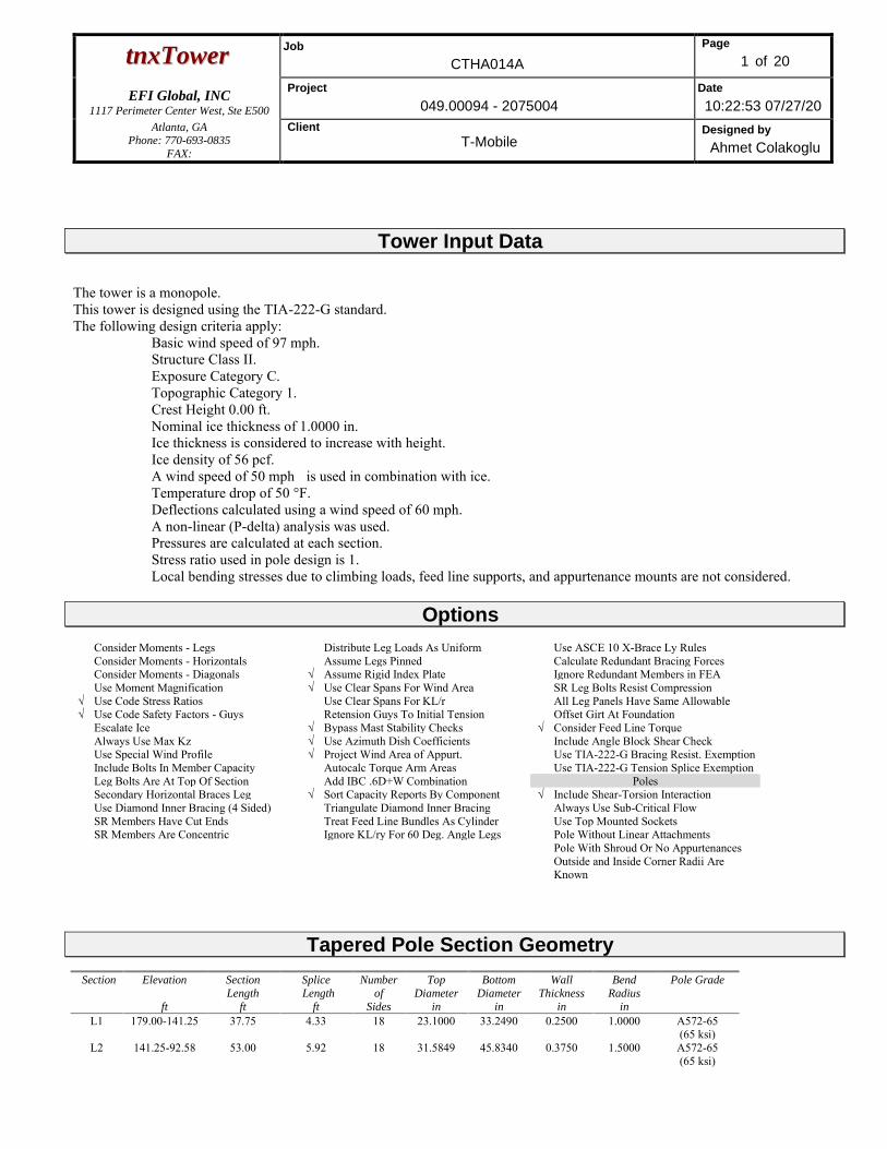
Tower Input Data
The tower is a monopole. This tower is designed using the TIA-222-G standard. The following design criteria apply:
Basic wind speed of 97 mph. Structure Class II. Exposure Category C. Topographic Category 1. Crest Height 0.00 ft. Nominal ice thickness of 1.0000 in. Ice thickness is considered to increase with height. Ice density of 56 pcf. A wind speed of 50 mph is used in combination with ice. Temperature drop of 50 °F. Deflections calculated using a wind speed of 60 mph. A non-linear (P-delta) analysis was used. Pressures are calculated at each section. Stress ratio used in pole design is 1. Local bending stresses due to climbing loads, feed line supports, and appurtenance mounts are not considered.
Options
Consider Moments - Legs Distribute Leg Loads As Uniform Use ASCE 10 X-Brace Ly Rules Consider Moments - Horizontals Assume Legs Pinned Calculate Redundant Bracing Forces Consider Moments - Diagonals √ Assume Rigid Index Plate Ignore Redundant Members in FEA Use Moment Magnification √ Use Clear Spans For Wind Area SR Leg Bolts Resist Compression
√ Use Code Stress Ratios Use Clear Spans For KL/r All Leg Panels Have Same Allowable √ Use Code Safety Factors - Guys Retension Guys To Initial Tension Offset Girt At Foundation Escalate Ice √ Bypass Mast Stability Checks √ Consider Feed Line Torque Always Use Max Kz √ Use Azimuth Dish Coefficients Include Angle Block Shear Check Use Special Wind Profile √ Project Wind Area of Appurt. Use TIA-222-G Bracing Resist. Exemption Include Bolts In Member Capacity Autocalc Torque Arm Areas Use TIA-222-G Tension Splice Exemption Leg Bolts Are At Top Of Section Add IBC .6D+W Combination Poles Secondary Horizontal Braces Leg √ Sort Capacity Reports By Component √ Include Shear-Torsion Interaction Use Diamond Inner Bracing (4 Sided) Triangulate Diamond Inner Bracing Always Use Sub-Critical Flow SR Members Have Cut Ends Treat Feed Line Bundles As Cylinder Use Top Mounted Sockets SR Members Are Concentric Ignore KL/ry For 60 Deg. Angle Legs Pole Without Linear Attachments Pole With Shroud Or No Appurtenances Outside and Inside Corner Radii Are
Known
Tapered Pole Section Geometry Section Elevation
ft
Section
Length
ft
Splice
Length
ft
Number
of
Sides
Top
Diameter
in
Bottom
Diameter
in
Wall
Thickness
in
Bend
Radius
in
Pole Grade
L1 179.00-141.25 37.75 4.33 18 23.1000 33.2490 0.2500 1.0000 A572-65 (65 ksi)
L2 141.25-92.58 53.00 5.92 18 31.5849 45.8340 0.3750 1.5000 A572-65 (65 ksi)
ttnnxxTToowweerr Job
CTHA014A
Page
2 of 20
EFI Global, INC
1117 Perimeter Center West, Ste E500
Project
049.00094 - 2075004
Date
10:22:53 07/27/20
Atlanta, GA Phone: 770-693-0835
FAX:
Client
T-Mobile Designed by
Ahmet Colakoglu
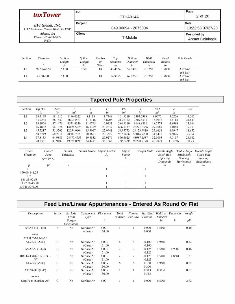
Section Elevation
ft
Section
Length
ft
Splice
Length
ft
Number
of
Sides
Top
Diameter
in
Bottom
Diameter
in
Wall
Thickness
in
Bend
Radius
in
Pole Grade
L3 92.58-45.50 53.00 7.50 18 43.4924 57.7420 0.3750 1.5000 A572-65 (65 ksi)
L4 45.50-0.00 53.00 18 54.9755 69.2250 0.3750 1.5000 A572-65 (65 ksi)
Tapered Pole Properties Section Tip Dia.
in
Area
in2
I
in4
r
in
C
in
I/C
in3
J
in4
It/Q
in2
w
in
w/t
L1 23.4178 18.1315 1196.0325 8.1118 11.7348 101.9219 2393.6388 9.0675 3.6256 14.502 33.7234 26.1847 3602.3567 11.7146 16.8905 213.2772 7209.4536 13.0948 5.4118 21.647
L2 33.1964 37.1476 4571.4330 11.0795 16.0451 284.9110 9148.8811 18.5773 4.8989 13.064 46.4832 54.1076 14126.5228 16.1379 23.2837 606.7137 28271.6336 27.0589 7.4068 19.751
L3 45.7217 51.3205 12054.0604 15.3067 22.0941 545.5773 24123.9819 25.6651 6.9947 18.652 58.5749 68.2811 28389.7820 20.3653 29.3329 967.8466 56816.9200 34.1470 9.5026 25.34
L4 57.8133 64.9883 24477.4753 19.3832 27.9276 876.4625 48987.1587 32.5003 9.0157 24.042 70.2351 81.9487 49078.0698 24.4417 35.1663 1395.5995 98220.7178 40.9821 11.5236 30.73
Tower
Elevation
ft
Gusset
Area (per face)
ft2
Gusset
Thickness
in
Gusset Grade Adjust. Factor
Af
Adjust.
Factor Ar
Weight Mult.
Double Angle
Stitch Bolt Spacing
Diagonals
in
Double Angle
Stitch Bolt Spacing
Horizontals
in
Double Angle
Stitch Bolt Spacing
Redundants
in
L1 179.00-141.25
1 1 1
L2 141.25-92.58
1 1 1
L3 92.58-45.50 1 1 1 L4 45.50-0.00 1 1 1
Feed Line/Linear Appurtenances - Entered As Round Or Flat
Description Sector Exclude
From
Torque
Calculation
Component
Type
Placement
ft
Total
Number
Number
Per Row
Start/End
Position
Width or
Diameter
in
Perimeter
in
Weight
plf
AVA6-50(1-1/4) B No Surface Ar (CaAa)
6.00 - 174.00
1 1 0.000 0.000
1.5600 0.46
**** **151 T-Mobile**
AL7-50(1-5/8'') C No Surface Ar (CaAa)
6.00 - 151.00
6 6 -0.100 -0.100
1.9600 0.52
AVA6-50(1-1/4) C No Surface Af (CaAa)
6.00 - 151.00
2 2 -0.125 -0.125
1.5600 4.9009 0.46
HB114-13U6-S12F18(1-1/4'')
C No Surface Af (CaAa)
6.00 - 151.00
2 2 -0.123 -0.123
1.5400 4.8381 1.51
AL7-50(1-5/8'') C No Surface Ar (CaAa)
6.00 - 130.00
6 6 0.100 0.300
1.9600 0.52
ATCB-B01(1/4'') C No Surface Ar (CaAa)
6.00 - 130.00
1 1 0.313 0.313
0.3150 0.07
***** Step Pegs (Surface Ar) C No Surface Ar 6.00 - 1 1 0.000 0.8000 2.72
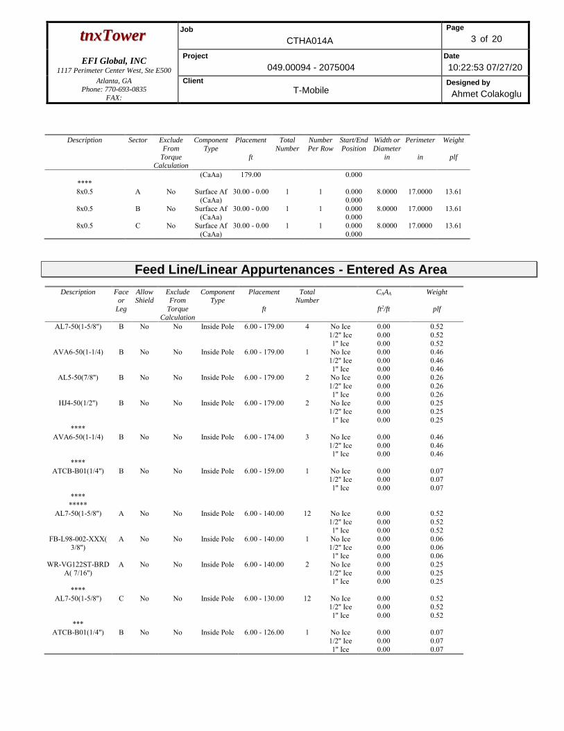
ttnnxxTToowweerr Job
CTHA014A
Page
3 of 20
EFI Global, INC
1117 Perimeter Center West, Ste E500
Project
049.00094 - 2075004
Date
10:22:53 07/27/20
Atlanta, GA Phone: 770-693-0835
FAX:
Client
T-Mobile Designed by
Ahmet Colakoglu
Description Sector Exclude
From
Torque Calculation
Component
Type
Placement
ft
Total
Number
Number
Per Row
Start/End
Position
Width or
Diameter
in
Perimeter
in
Weight
plf
(CaAa) 179.00 0.000 **** 8x0.5 A No Surface Af
(CaAa) 30.00 - 0.00 1 1 0.000
0.000 8.0000 17.0000 13.61
8x0.5 B No Surface Af (CaAa)
30.00 - 0.00 1 1 0.000 0.000
8.0000 17.0000 13.61
8x0.5 C No Surface Af (CaAa)
30.00 - 0.00 1 1 0.000 0.000
8.0000 17.0000 13.61
Feed Line/Linear Appurtenances - Entered As Area
Description Face or
Leg
Allow Shield
Exclude From
Torque
Calculation
Component Type
Placement
ft
Total Number
CAAA
ft2/ft
Weight
plf
AL7-50(1-5/8'') B No No Inside Pole 6.00 - 179.00 4 No Ice 1/2'' Ice 1'' Ice
0.00 0.00 0.00
0.52 0.52 0.52
AVA6-50(1-1/4) B No No Inside Pole 6.00 - 179.00 1 No Ice 1/2'' Ice 1'' Ice
0.00 0.00 0.00
0.46 0.46 0.46
AL5-50(7/8'') B No No Inside Pole 6.00 - 179.00 2 No Ice 1/2'' Ice 1'' Ice
0.00 0.00 0.00
0.26 0.26 0.26
HJ4-50(1/2'') B No No Inside Pole 6.00 - 179.00 2 No Ice 1/2'' Ice 1'' Ice
0.00 0.00 0.00
0.25 0.25 0.25
**** AVA6-50(1-1/4) B No No Inside Pole 6.00 - 174.00 3 No Ice
1/2'' Ice 1'' Ice
0.00 0.00 0.00
0.46 0.46 0.46
**** ATCB-B01(1/4'') B No No Inside Pole 6.00 - 159.00 1 No Ice
1/2'' Ice 1'' Ice
0.00 0.00 0.00
0.07 0.07 0.07
**** *****
AL7-50(1-5/8'') A No No Inside Pole 6.00 - 140.00 12 No Ice 1/2'' Ice 1'' Ice
0.00 0.00 0.00
0.52 0.52 0.52
FB-L98-002-XXX( 3/8'')
A No No Inside Pole 6.00 - 140.00 1 No Ice 1/2'' Ice 1'' Ice
0.00 0.00 0.00
0.06 0.06 0.06
WR-VG122ST-BRDA( 7/16'')
A No No Inside Pole 6.00 - 140.00 2 No Ice 1/2'' Ice 1'' Ice
0.00 0.00 0.00
0.25 0.25 0.25
**** AL7-50(1-5/8'') C No No Inside Pole 6.00 - 130.00 12 No Ice
1/2'' Ice 1'' Ice
0.00 0.00 0.00
0.52 0.52 0.52
*** ATCB-B01(1/4'') B No No Inside Pole 6.00 - 126.00 1 No Ice
1/2'' Ice 1'' Ice
0.00 0.00 0.00
0.07 0.07 0.07
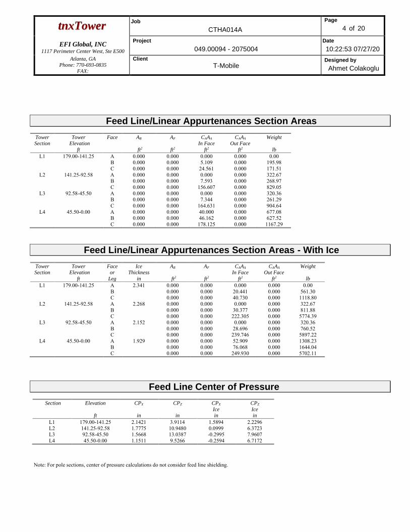
ttnnxxTToowweerr Job
CTHA014A
Page
4 of 20
EFI Global, INC
1117 Perimeter Center West, Ste E500
Project
049.00094 - 2075004
Date
10:22:53 07/27/20
Atlanta, GA Phone: 770-693-0835
FAX:
Client
T-Mobile Designed by
Ahmet Colakoglu
Feed Line/Linear Appurtenances Section Areas Tower Section
Tower Elevation
ft
Face AR
ft2
AF
ft2
CAAA
In Face
ft2
CAAA
Out Face
ft2
Weight
lb
L1 179.00-141.25 A B C
0.000 0.000 0.000
0.000 0.000 0.000
0.000 5.109
24.561
0.000 0.000 0.000
0.00 195.98 171.51
L2 141.25-92.58 A B C
0.000 0.000 0.000
0.000 0.000 0.000
0.000 7.593
156.607
0.000 0.000 0.000
322.67 268.97 829.05
L3 92.58-45.50 A B C
0.000 0.000 0.000
0.000 0.000 0.000
0.000 7.344
164.631
0.000 0.000 0.000
320.36 261.29 904.64
L4 45.50-0.00 A B C
0.000 0.000 0.000
0.000 0.000 0.000
40.000 46.162
178.125
0.000 0.000 0.000
677.08 627.52
1167.29
Feed Line/Linear Appurtenances Section Areas - With Ice Tower Section
Tower Elevation
ft
Face or
Leg
Ice Thickness
in
AR
ft2
AF
ft2
CAAA
In Face
ft2
CAAA
Out Face
ft2
Weight
lb
L1 179.00-141.25 A B C
2.341 0.000 0.000 0.000
0.000 0.000 0.000
0.000 20.441 40.730
0.000 0.000 0.000
0.00 561.30
1118.80 L2 141.25-92.58 A
B C
2.268 0.000 0.000 0.000
0.000 0.000 0.000
0.000 30.377
222.305
0.000 0.000 0.000
322.67 811.88
5774.39 L3 92.58-45.50 A
B C
2.152 0.000 0.000 0.000
0.000 0.000 0.000
0.000 28.696
239.746
0.000 0.000 0.000
320.36 760.52
5897.22 L4 45.50-0.00 A
B C
1.929 0.000 0.000 0.000
0.000 0.000 0.000
52.909 76.068
249.930
0.000 0.000 0.000
1308.23 1644.04 5702.11
Feed Line Center of Pressure
Section Elevation
ft
CPX
in
CPZ
in
CPX
Ice in
CPZ
Ice in
L1 179.00-141.25 2.1421 3.9114 1.5894 2.2296 L2 141.25-92.58 1.7775 10.9480 0.0999 6.3723 L3 92.58-45.50 1.5668 13.0387 -0.2995 7.9607 L4 45.50-0.00 1.1511 9.5266 -0.2594 6.7172
Note: For pole sections, center of pressure calculations do not consider feed line shielding.
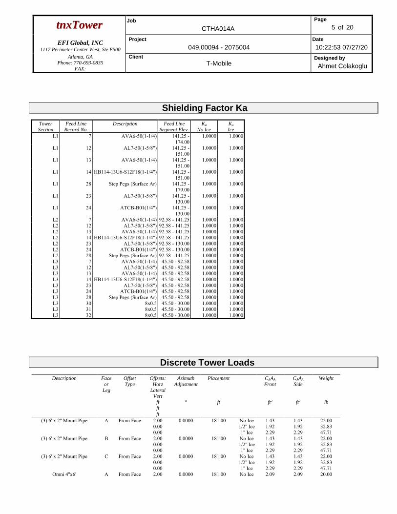
ttnnxxTToowweerr Job
CTHA014A
Page
5 of 20
EFI Global, INC
1117 Perimeter Center West, Ste E500
Project
049.00094 - 2075004
Date
10:22:53 07/27/20
Atlanta, GA Phone: 770-693-0835
FAX:
Client
T-Mobile Designed by
Ahmet Colakoglu
Shielding Factor Ka
Tower Section
Feed Line Record No.
Description Feed Line Segment Elev.
Ka No Ice
Ka Ice
L1 7 AVA6-50(1-1/4) 141.25 - 174.00
1.0000 1.0000
L1 12 AL7-50(1-5/8") 141.25 - 151.00
1.0000 1.0000
L1 13 AVA6-50(1-1/4) 141.25 - 151.00
1.0000 1.0000
L1 14 HB114-13U6-S12F18(1-1/4") 141.25 - 151.00
1.0000 1.0000
L1 28 Step Pegs (Surface Ar) 141.25 - 179.00
1.0000 1.0000
L1 23 AL7-50(1-5/8") 141.25 - 130.00
1.0000 1.0000
L1 24 ATCB-B01(1/4") 141.25 - 130.00
1.0000 1.0000
L2 7 AVA6-50(1-1/4) 92.58 - 141.25 1.0000 1.0000 L2 12 AL7-50(1-5/8") 92.58 - 141.25 1.0000 1.0000 L2 13 AVA6-50(1-1/4) 92.58 - 141.25 1.0000 1.0000 L2 14 HB114-13U6-S12F18(1-1/4") 92.58 - 141.25 1.0000 1.0000 L2 23 AL7-50(1-5/8") 92.58 - 130.00 1.0000 1.0000 L2 24 ATCB-B01(1/4") 92.58 - 130.00 1.0000 1.0000 L2 28 Step Pegs (Surface Ar) 92.58 - 141.25 1.0000 1.0000 L3 7 AVA6-50(1-1/4) 45.50 - 92.58 1.0000 1.0000 L3 12 AL7-50(1-5/8") 45.50 - 92.58 1.0000 1.0000 L3 13 AVA6-50(1-1/4) 45.50 - 92.58 1.0000 1.0000 L3 14 HB114-13U6-S12F18(1-1/4") 45.50 - 92.58 1.0000 1.0000 L3 23 AL7-50(1-5/8") 45.50 - 92.58 1.0000 1.0000 L3 24 ATCB-B01(1/4") 45.50 - 92.58 1.0000 1.0000 L3 28 Step Pegs (Surface Ar) 45.50 - 92.58 1.0000 1.0000 L3 30 8x0.5 45.50 - 30.00 1.0000 1.0000 L3 31 8x0.5 45.50 - 30.00 1.0000 1.0000 L3 32 8x0.5 45.50 - 30.00 1.0000 1.0000
Discrete Tower Loads
Description Face
or
Leg
Offset
Type
Offsets:
Horz
Lateral Vert
ft ft
ft
Azimuth
Adjustment
°
Placement
ft
CAAA
Front
ft2
CAAA
Side
ft2
Weight
lb
(3) 6' x 2'' Mount Pipe A From Face 2.00 0.00 0.00
0.0000 181.00 No Ice 1/2'' Ice 1'' Ice
1.43 1.92 2.29
1.43 1.92 2.29
22.00 32.83 47.71
(3) 6' x 2'' Mount Pipe B From Face 2.00 0.00 0.00
0.0000 181.00 No Ice 1/2'' Ice 1'' Ice
1.43 1.92 2.29
1.43 1.92 2.29
22.00 32.83 47.71
(3) 6' x 2'' Mount Pipe C From Face 2.00 0.00 0.00
0.0000 181.00 No Ice 1/2'' Ice 1'' Ice
1.43 1.92 2.29
1.43 1.92 2.29
22.00 32.83 47.71
Omni 4''x6' A From Face 2.00 0.0000 181.00 No Ice 2.09 2.09 20.00
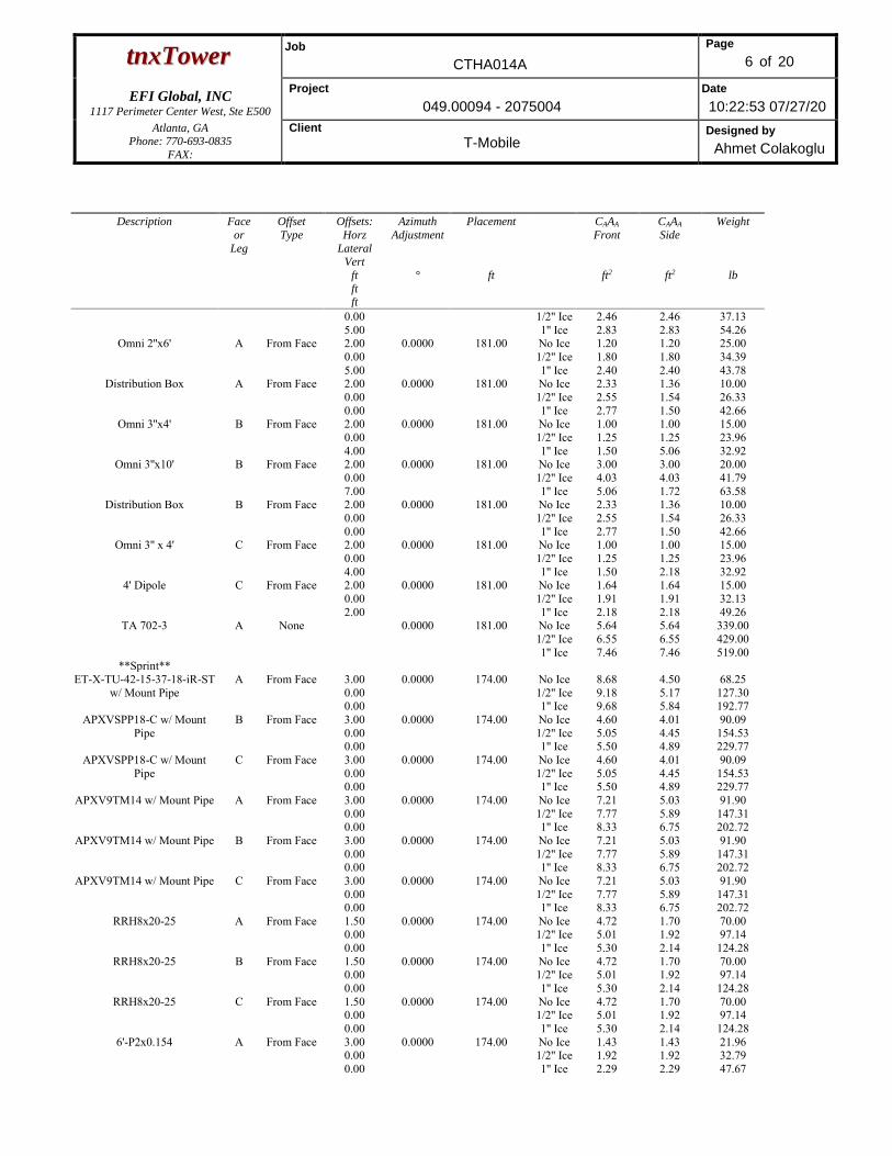
ttnnxxTToowweerr Job
CTHA014A
Page
6 of 20
EFI Global, INC
1117 Perimeter Center West, Ste E500
Project
049.00094 - 2075004
Date
10:22:53 07/27/20
Atlanta, GA Phone: 770-693-0835
FAX:
Client
T-Mobile Designed by
Ahmet Colakoglu
Description Face
or
Leg
Offset
Type
Offsets:
Horz
Lateral Vert
ft
ft ft
Azimuth
Adjustment
°
Placement
ft
CAAA
Front
ft2
CAAA
Side
ft2
Weight
lb
0.00 5.00
1/2'' Ice 1'' Ice
2.46 2.83
2.46 2.83
37.13 54.26
Omni 2''x6' A From Face 2.00 0.00 5.00
0.0000 181.00 No Ice 1/2'' Ice 1'' Ice
1.20 1.80 2.40
1.20 1.80 2.40
25.00 34.39 43.78
Distribution Box A From Face 2.00 0.00 0.00
0.0000 181.00 No Ice 1/2'' Ice 1'' Ice
2.33 2.55 2.77
1.36 1.54 1.50
10.00 26.33 42.66
Omni 3''x4' B From Face 2.00 0.00 4.00
0.0000 181.00 No Ice 1/2'' Ice 1'' Ice
1.00 1.25 1.50
1.00 1.25 5.06
15.00 23.96 32.92
Omni 3''x10' B From Face 2.00 0.00 7.00
0.0000 181.00 No Ice 1/2'' Ice 1'' Ice
3.00 4.03 5.06
3.00 4.03 1.72
20.00 41.79 63.58
Distribution Box B From Face 2.00 0.00 0.00
0.0000 181.00 No Ice 1/2'' Ice 1'' Ice
2.33 2.55 2.77
1.36 1.54 1.50
10.00 26.33 42.66
Omni 3'' x 4' C From Face 2.00 0.00 4.00
0.0000 181.00 No Ice 1/2'' Ice 1'' Ice
1.00 1.25 1.50
1.00 1.25 2.18
15.00 23.96 32.92
4' Dipole C From Face 2.00 0.00 2.00
0.0000 181.00 No Ice 1/2'' Ice 1'' Ice
1.64 1.91 2.18
1.64 1.91 2.18
15.00 32.13 49.26
TA 702-3 A None 0.0000 181.00 No Ice 1/2'' Ice 1'' Ice
5.64 6.55 7.46
5.64 6.55 7.46
339.00 429.00 519.00
**Sprint** ET-X-TU-42-15-37-18-iR-ST
w/ Mount Pipe A From Face 3.00
0.00 0.00
0.0000 174.00 No Ice 1/2'' Ice 1'' Ice
8.68 9.18 9.68
4.50 5.17 5.84
68.25 127.30 192.77
APXVSPP18-C w/ Mount Pipe
B From Face 3.00 0.00 0.00
0.0000 174.00 No Ice 1/2'' Ice 1'' Ice
4.60 5.05 5.50
4.01 4.45 4.89
90.09 154.53 229.77
APXVSPP18-C w/ Mount Pipe
C From Face 3.00 0.00 0.00
0.0000 174.00 No Ice 1/2'' Ice 1'' Ice
4.60 5.05 5.50
4.01 4.45 4.89
90.09 154.53 229.77
APXV9TM14 w/ Mount Pipe A From Face 3.00 0.00 0.00
0.0000 174.00 No Ice 1/2'' Ice 1'' Ice
7.21 7.77 8.33
5.03 5.89 6.75
91.90 147.31 202.72
APXV9TM14 w/ Mount Pipe B From Face 3.00 0.00 0.00
0.0000 174.00 No Ice 1/2'' Ice 1'' Ice
7.21 7.77 8.33
5.03 5.89 6.75
91.90 147.31 202.72
APXV9TM14 w/ Mount Pipe C From Face 3.00 0.00 0.00
0.0000 174.00 No Ice 1/2'' Ice 1'' Ice
7.21 7.77 8.33
5.03 5.89 6.75
91.90 147.31 202.72
RRH8x20-25 A From Face 1.50 0.00 0.00
0.0000 174.00 No Ice 1/2'' Ice 1'' Ice
4.72 5.01 5.30
1.70 1.92 2.14
70.00 97.14
124.28 RRH8x20-25 B From Face 1.50
0.00 0.00
0.0000 174.00 No Ice 1/2'' Ice 1'' Ice
4.72 5.01 5.30
1.70 1.92 2.14
70.00 97.14
124.28 RRH8x20-25 C From Face 1.50
0.00 0.00
0.0000 174.00 No Ice 1/2'' Ice 1'' Ice
4.72 5.01 5.30
1.70 1.92 2.14
70.00 97.14
124.28 6'-P2x0.154 A From Face 3.00
0.00 0.00
0.0000 174.00 No Ice 1/2'' Ice 1'' Ice
1.43 1.92 2.29
1.43 1.92 2.29
21.96 32.79 47.67
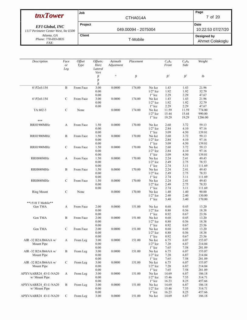
ttnnxxTToowweerr Job
CTHA014A
Page
7 of 20
EFI Global, INC
1117 Perimeter Center West, Ste E500
Project
049.00094 - 2075004
Date
10:22:53 07/27/20
Atlanta, GA Phone: 770-693-0835
FAX:
Client
T-Mobile Designed by
Ahmet Colakoglu
Description Face
or
Leg
Offset
Type
Offsets:
Horz
Lateral Vert
ft
ft ft
Azimuth
Adjustment
°
Placement
ft
CAAA
Front
ft2
CAAA
Side
ft2
Weight
lb
6'-P2x0.154 B From Face 3.00 0.00 0.00
0.0000 174.00 No Ice 1/2'' Ice 1'' Ice
1.43 1.92 2.29
1.43 1.92 2.29
21.96 32.79 47.67
6'-P2x0.154 C From Face 3.00 0.00 0.00
0.0000 174.00 No Ice 1/2'' Ice 1'' Ice
1.43 1.92 2.29
1.43 1.92 2.29
21.96 32.79 47.67
TA 602-3 C None 0.0000 174.00 No Ice 1/2'' Ice 1'' Ice
11.59 15.44 19.29
11.59 15.44 19.29
774.00 990.00
1206.00 ***
RRH1900MHz A From Face 1.50 0.00 0.00
0.0000 170.00 No Ice 1/2'' Ice 1'' Ice
2.60 2.84 3.09
3.72 4.10 4.50
59.13 97.16
139.81 RRH1900MHz B From Face 1.50
0.00 0.00
0.0000 170.00 No Ice 1/2'' Ice 1'' Ice
2.60 2.84 3.09
3.72 4.10 4.50
59.13 97.16
139.81 RRH1900MHz C From Face 1.50
0.00 0.00
0.0000 170.00 No Ice 1/2'' Ice 1'' Ice
2.60 2.84 3.09
3.72 4.10 4.50
59.13 97.16
139.81 RRH800MHz A From Face 1.50
0.00 0.00
0.0000 170.00 No Ice 1/2'' Ice 1'' Ice
2.24 2.49 2.74
2.41 2.75 3.11
49.43 78.53
111.69 RRH800MHz B From Face 1.50
0.00 0.00
0.0000 170.00 No Ice 1/2'' Ice 1'' Ice
2.24 2.49 2.74
2.41 2.75 3.11
49.43 78.53
111.69 RRH800MHz C From Face 1.50
0.00 0.00
0.0000 170.00 No Ice 1/2'' Ice 1'' Ice
2.24 2.49 2.74
2.41 2.75 3.11
49.43 78.53
111.69 Ring Mount C None 0.0000 170.00 No Ice
1/2'' Ice 1'' Ice
1.40 2.40 3.40
1.40 2.40 3.40
90.00 130.00 170.00
**151ft T Mobile** Gen TMA A From Face 2.00
0.00 0.00
0.0000 151.00 No Ice 1/2'' Ice 1'' Ice
0.68 0.80 0.92
0.45 0.56 0.67
13.20 18.38 23.56
Gen TMA B From Face 2.00 0.00 0.00
0.0000 151.00 No Ice 1/2'' Ice 1'' Ice
0.68 0.80 0.92
0.45 0.56 0.67
13.20 18.38 23.56
Gen TMA C From Face 2.00 0.00 0.00
0.0000 151.00 No Ice 1/2'' Ice 1'' Ice
0.68 0.80 0.92
0.45 0.56 0.67
13.20 18.38 23.56
AIR -32 B2A/B66AA w/ Mount Pipe
A From Leg 3.00 0.00 0.00
0.0000 151.00 No Ice 1/2'' Ice 1'' Ice
6.75 7.20 7.65
6.07 6.87 7.58
153.07 214.04 281.89
AIR -32 B2A/B66AA w/ Mount Pipe
B From Leg 3.00 0.00 0.00
0.0000 151.00 No Ice 1/2'' Ice 1'' Ice
6.75 7.20 7.65
6.07 6.87 7.58
153.07 214.04 281.89
AIR -32 B2A/B66AA w/ Mount Pipe
C From Leg 3.00 0.00 0.00
0.0000 151.00 No Ice 1/2'' Ice 1'' Ice
6.75 7.20 7.65
6.07 6.87 7.58
153.07 214.04 281.89
APXVAARR24_43-U-NA20 w/ Mount Pipe
A From Leg 3.00 0.00 0.00
0.0000 151.00 No Ice 1/2'' Ice 1'' Ice
14.69 15.46 16.23
6.87 7.55 8.25
186.18 314.71 457.66
APXVAARR24_43-U-NA20 w/ Mount Pipe
B From Leg 3.00 0.00 0.00
0.0000 151.00 No Ice 1/2'' Ice 1'' Ice
14.69 15.46 16.23
6.87 7.55 8.25
186.18 314.71 457.66
APXVAARR24_43-U-NA20 C From Leg 3.00 0.0000 151.00 No Ice 14.69 6.87 186.18
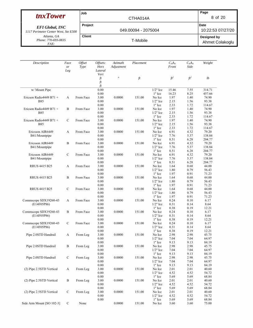
ttnnxxTToowweerr Job
CTHA014A
Page
8 of 20
EFI Global, INC
1117 Perimeter Center West, Ste E500
Project
049.00094 - 2075004
Date
10:22:53 07/27/20
Atlanta, GA Phone: 770-693-0835
FAX:
Client
T-Mobile Designed by
Ahmet Colakoglu
Description Face
or
Leg
Offset
Type
Offsets:
Horz
Lateral Vert
ft
ft ft
Azimuth
Adjustment
°
Placement
ft
CAAA
Front
ft2
CAAA
Side
ft2
Weight
lb
w/ Mount Pipe 0.00 0.00
1/2'' Ice 1'' Ice
15.46 16.23
7.55 8.25
314.71 457.66
Ericson Radio4449 B71 + B85
A From Face 3.00 0.00 0.00
0.0000 151.00 No Ice 1/2'' Ice 1'' Ice
1.97 2.15 2.33
1.40 1.56 1.72
74.90 93.38
114.67 Ericson Radio4449 B71 +
B85 B From Face 3.00
0.00 0.00
0.0000 151.00 No Ice 1/2'' Ice 1'' Ice
1.97 2.15 2.33
1.40 1.56 1.72
74.90 93.38
114.67 Ericson Radio4449 B71 +
B85 C From Face 3.00
0.00 0.00
0.0000 151.00 No Ice 1/2'' Ice 1'' Ice
1.97 2.15 2.33
1.40 1.56 1.72
74.90 93.38
114.67 Ericsson AIR6449
B41/Mountpipe A From Face 3.00
0.00 0.00
0.0000 151.00 No Ice 1/2'' Ice 1'' Ice
6.91 7.76 8.51
4.32 5.37 6.28
79.20 138.84 204.77
Ericsson AIR6449 B41/Mountpipe
B From Face 3.00 0.00 0.00
0.0000 151.00 No Ice 1/2'' Ice 1'' Ice
6.91 7.76 8.51
4.32 5.37 6.28
79.20 138.84 204.77
Ericsson AIR6449 B41/Mountpipe
C From Face 3.00 0.00 0.00
0.0000 151.00 No Ice 1/2'' Ice 1'' Ice
6.91 7.76 8.51
4.32 5.37 6.28
79.20 138.84 204.77
RRUS 4415 B25 A From Face 3.00 0.00 0.00
0.0000 151.00 No Ice 1/2'' Ice 1'' Ice
1.64 1.80 1.97
0.68 0.79 0.91
44.00 56.43 71.23
RRUS 4415 B25 B From Face 3.00 0.00 0.00
0.0000 151.00 No Ice 1/2'' Ice 1'' Ice
1.64 1.80 1.97
0.68 0.79 0.91
44.00 56.43 71.23
RRUS 4415 B25 C From Face 3.00 0.00 0.00
0.0000 151.00 No Ice 1/2'' Ice 1'' Ice
1.64 1.80 1.97
0.68 0.79 0.91
44.00 56.43 71.23
Commscope SDX19260-43 (E14F05P86)
A From Face 3.00 0.00 0.00
0.0000 151.00 No Ice 1/2'' Ice 1'' Ice
0.24 0.31 0.38
0.10 0.14 0.19
6.17 8.64 12.21
Commscope SDX19260-43 (E14F05P86)
B From Face 3.00 0.00 0.00
0.0000 151.00 No Ice 1/2'' Ice 1'' Ice
0.24 0.31 0.38
0.10 0.14 0.19
6.17 8.64 12.21
Commscope SDX19260-43 (E14F05P86)
C From Face 3.00 0.00 0.00
0.0000 151.00 No Ice 1/2'' Ice 1'' Ice
0.24 0.31 0.38
0.10 0.14 0.19
6.17 8.64 12.21
Pipe 2.0STD Handrail A From Leg 3.00 0.00 0.00
0.0000 151.00 No Ice 1/2'' Ice 1'' Ice
2.98 7.04 9.13
2.98 7.04 9.13
45.75 64.97 84.19
Pipe 2.0STD Handrail B From Leg 3.00 0.00 0.00
0.0000 151.00 No Ice 1/2'' Ice 1'' Ice
2.98 7.04 9.13
2.98 7.04 9.13
45.75 64.97 84.19
Pipe 2.0STD Handrail C From Leg 3.00 0.00 0.00
0.0000 151.00 No Ice 1/2'' Ice 1'' Ice
2.98 7.04 9.13
2.98 7.04 9.13
45.75 64.97 84.19
(2) Pipe 2.5STD Vertical A From Leg 3.00 0.00 0.00
0.0000 151.00 No Ice 1/2'' Ice 1'' Ice
2.01 4.52 5.69
2.01 4.52 5.69
40.60 54.72 68.84
(2) Pipe 2.5STD Vertical B From Leg 3.00 0.00 0.00
0.0000 151.00 No Ice 1/2'' Ice 1'' Ice
2.01 4.52 5.69
2.01 4.52 5.69
40.60 54.72 68.84
(2) Pipe 2.5STD Vertical C From Leg 3.00 0.00 0.00
0.0000 151.00 No Ice 1/2'' Ice 1'' Ice
2.01 4.52 5.69
2.01 4.52 5.69
40.60 54.72 68.84
Side Arm Mount [SO 102-3] C None 0.0000 151.00 No Ice 3.60 3.60 75.00
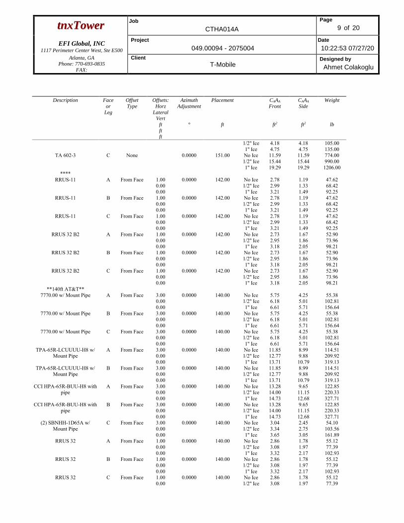
ttnnxxTToowweerr Job
CTHA014A
Page
9 of 20
EFI Global, INC
1117 Perimeter Center West, Ste E500
Project
049.00094 - 2075004
Date
10:22:53 07/27/20
Atlanta, GA Phone: 770-693-0835
FAX:
Client
T-Mobile Designed by
Ahmet Colakoglu
Description Face
or
Leg
Offset
Type
Offsets:
Horz
Lateral Vert
ft
ft ft
Azimuth
Adjustment
°
Placement
ft
CAAA
Front
ft2
CAAA
Side
ft2
Weight
lb
1/2'' Ice 1'' Ice
4.18 4.75
4.18 4.75
105.00 135.00
TA 602-3 C None 0.0000 151.00 No Ice 1/2'' Ice 1'' Ice
11.59 15.44 19.29
11.59 15.44 19.29
774.00 990.00
1206.00 ****
RRUS-11 A From Face 1.00 0.00 0.00
0.0000 142.00 No Ice 1/2'' Ice 1'' Ice
2.78 2.99 3.21
1.19 1.33 1.49
47.62 68.42 92.25
RRUS-11 B From Face 1.00 0.00 0.00
0.0000 142.00 No Ice 1/2'' Ice 1'' Ice
2.78 2.99 3.21
1.19 1.33 1.49
47.62 68.42 92.25
RRUS-11 C From Face 1.00 0.00 0.00
0.0000 142.00 No Ice 1/2'' Ice 1'' Ice
2.78 2.99 3.21
1.19 1.33 1.49
47.62 68.42 92.25
RRUS 32 B2 A From Face 1.00 0.00 0.00
0.0000 142.00 No Ice 1/2'' Ice 1'' Ice
2.73 2.95 3.18
1.67 1.86 2.05
52.90 73.96 98.21
RRUS 32 B2 B From Face 1.00 0.00 0.00
0.0000 142.00 No Ice 1/2'' Ice 1'' Ice
2.73 2.95 3.18
1.67 1.86 2.05
52.90 73.96 98.21
RRUS 32 B2 C From Face 1.00 0.00 0.00
0.0000 142.00 No Ice 1/2'' Ice 1'' Ice
2.73 2.95 3.18
1.67 1.86 2.05
52.90 73.96 98.21
**140ft AT&T** 7770.00 w/ Mount Pipe A From Face 3.00
0.00 0.00
0.0000 140.00 No Ice 1/2'' Ice 1'' Ice
5.75 6.18 6.61
4.25 5.01 5.71
55.38 102.81 156.64
7770.00 w/ Mount Pipe B From Face 3.00 0.00 0.00
0.0000 140.00 No Ice 1/2'' Ice 1'' Ice
5.75 6.18 6.61
4.25 5.01 5.71
55.38 102.81 156.64
7770.00 w/ Mount Pipe C From Face 3.00 0.00 0.00
0.0000 140.00 No Ice 1/2'' Ice 1'' Ice
5.75 6.18 6.61
4.25 5.01 5.71
55.38 102.81 156.64
TPA-65R-LCUUUU-H8 w/ Mount Pipe
A From Face 3.00 0.00 0.00
0.0000 140.00 No Ice 1/2'' Ice 1'' Ice
11.85 12.77 13.71
8.99 9.88 10.79
114.51 209.92 319.13
TPA-65R-LCUUUU-H8 w/ Mount Pipe
B From Face 3.00 0.00 0.00
0.0000 140.00 No Ice 1/2'' Ice 1'' Ice
11.85 12.77 13.71
8.99 9.88 10.79
114.51 209.92 319.13
CCI HPA-65R-BUU-H8 with pipe
A From Face 3.00 0.00 0.00
0.0000 140.00 No Ice 1/2'' Ice 1'' Ice
13.28 14.00 14.73
9.65 11.15 12.68
122.85 220.33 327.71
CCI HPA-65R-BUU-H8 with pipe
B From Face 3.00 0.00 0.00
0.0000 140.00 No Ice 1/2'' Ice 1'' Ice
13.28 14.00 14.73
9.65 11.15 12.68
122.85 220.33 327.71
(2) SBNHH-1D65A w/ Mount Pipe
C From Face 3.00 0.00 0.00
0.0000 140.00 No Ice 1/2'' Ice 1'' Ice
3.04 3.34 3.65
2.45 2.75 3.05
54.10 103.56 161.89
RRUS 32 A From Face 1.00 0.00 0.00
0.0000 140.00 No Ice 1/2'' Ice 1'' Ice
2.86 3.08 3.32
1.78 1.97 2.17
55.12 77.39
102.93 RRUS 32 B From Face 1.00
0.00 0.00
0.0000 140.00 No Ice 1/2'' Ice 1'' Ice
2.86 3.08 3.32
1.78 1.97 2.17
55.12 77.39
102.93 RRUS 32 C From Face 1.00
0.00 0.0000 140.00 No Ice
1/2'' Ice 2.86 3.08
1.78 1.97
55.12 77.39
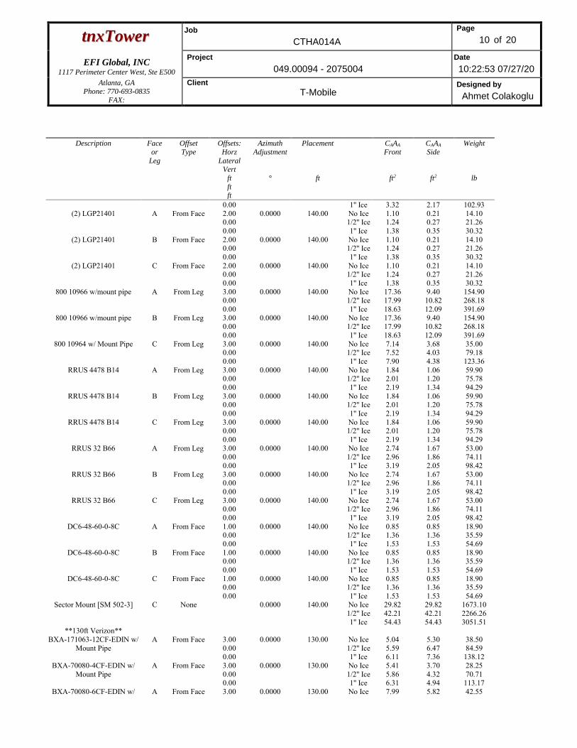
ttnnxxTToowweerr Job
CTHA014A
Page
10 of 20
EFI Global, INC
1117 Perimeter Center West, Ste E500
Project
049.00094 - 2075004
Date
10:22:53 07/27/20
Atlanta, GA Phone: 770-693-0835
FAX:
Client
T-Mobile Designed by
Ahmet Colakoglu
Description Face
or
Leg
Offset
Type
Offsets:
Horz
Lateral Vert
ft
ft ft
Azimuth
Adjustment
°
Placement
ft
CAAA
Front
ft2
CAAA
Side
ft2
Weight
lb
0.00 1'' Ice 3.32 2.17 102.93 (2) LGP21401 A From Face 2.00
0.00 0.00
0.0000 140.00 No Ice 1/2'' Ice 1'' Ice
1.10 1.24 1.38
0.21 0.27 0.35
14.10 21.26 30.32
(2) LGP21401 B From Face 2.00 0.00 0.00
0.0000 140.00 No Ice 1/2'' Ice 1'' Ice
1.10 1.24 1.38
0.21 0.27 0.35
14.10 21.26 30.32
(2) LGP21401 C From Face 2.00 0.00 0.00
0.0000 140.00 No Ice 1/2'' Ice 1'' Ice
1.10 1.24 1.38
0.21 0.27 0.35
14.10 21.26 30.32
800 10966 w/mount pipe A From Leg 3.00 0.00 0.00
0.0000 140.00 No Ice 1/2'' Ice 1'' Ice
17.36 17.99 18.63
9.40 10.82 12.09
154.90 268.18 391.69
800 10966 w/mount pipe B From Leg 3.00 0.00 0.00
0.0000 140.00 No Ice 1/2'' Ice 1'' Ice
17.36 17.99 18.63
9.40 10.82 12.09
154.90 268.18 391.69
800 10964 w/ Mount Pipe C From Leg 3.00 0.00 0.00
0.0000 140.00 No Ice 1/2'' Ice 1'' Ice
7.14 7.52 7.90
3.68 4.03 4.38
35.00 79.18
123.36 RRUS 4478 B14 A From Leg 3.00
0.00 0.00
0.0000 140.00 No Ice 1/2'' Ice 1'' Ice
1.84 2.01 2.19
1.06 1.20 1.34
59.90 75.78 94.29
RRUS 4478 B14 B From Leg 3.00 0.00 0.00
0.0000 140.00 No Ice 1/2'' Ice 1'' Ice
1.84 2.01 2.19
1.06 1.20 1.34
59.90 75.78 94.29
RRUS 4478 B14 C From Leg 3.00 0.00 0.00
0.0000 140.00 No Ice 1/2'' Ice 1'' Ice
1.84 2.01 2.19
1.06 1.20 1.34
59.90 75.78 94.29
RRUS 32 B66 A From Leg 3.00 0.00 0.00
0.0000 140.00 No Ice 1/2'' Ice 1'' Ice
2.74 2.96 3.19
1.67 1.86 2.05
53.00 74.11 98.42
RRUS 32 B66 B From Leg 3.00 0.00 0.00
0.0000 140.00 No Ice 1/2'' Ice 1'' Ice
2.74 2.96 3.19
1.67 1.86 2.05
53.00 74.11 98.42
RRUS 32 B66 C From Leg 3.00 0.00 0.00
0.0000 140.00 No Ice 1/2'' Ice 1'' Ice
2.74 2.96 3.19
1.67 1.86 2.05
53.00 74.11 98.42
DC6-48-60-0-8C A From Face 1.00 0.00 0.00
0.0000 140.00 No Ice 1/2'' Ice 1'' Ice
0.85 1.36 1.53
0.85 1.36 1.53
18.90 35.59 54.69
DC6-48-60-0-8C B From Face 1.00 0.00 0.00
0.0000 140.00 No Ice 1/2'' Ice 1'' Ice
0.85 1.36 1.53
0.85 1.36 1.53
18.90 35.59 54.69
DC6-48-60-0-8C C From Face 1.00 0.00 0.00
0.0000 140.00 No Ice 1/2'' Ice 1'' Ice
0.85 1.36 1.53
0.85 1.36 1.53
18.90 35.59 54.69
Sector Mount [SM 502-3] C None 0.0000 140.00 No Ice 1/2'' Ice 1'' Ice
29.82 42.21 54.43
29.82 42.21 54.43
1673.10 2266.26 3051.51
**130ft Verizon** BXA-171063-12CF-EDIN w/
Mount Pipe A From Face 3.00
0.00 0.00
0.0000 130.00 No Ice 1/2'' Ice 1'' Ice
5.04 5.59 6.11
5.30 6.47 7.36
38.50 84.59
138.12 BXA-70080-4CF-EDIN w/
Mount Pipe A From Face 3.00
0.00 0.00
0.0000 130.00 No Ice 1/2'' Ice 1'' Ice
5.41 5.86 6.31
3.70 4.32 4.94
28.25 70.71
113.17 BXA-70080-6CF-EDIN w/ A From Face 3.00 0.0000 130.00 No Ice 7.99 5.82 42.55
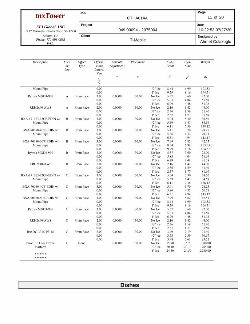
ttnnxxTToowweerr Job
CTHA014A
Page
11 of 20
EFI Global, INC
1117 Perimeter Center West, Ste E500
Project
049.00094 - 2075004
Date
10:22:53 07/27/20
Atlanta, GA Phone: 770-693-0835
FAX:
Client
T-Mobile Designed by
Ahmet Colakoglu
Description Face
or
Leg
Offset
Type
Offsets:
Horz
Lateral Vert
ft
ft ft
Azimuth
Adjustment
°
Placement
ft
CAAA
Front
ft2
CAAA
Side
ft2
Weight
lb
Mount Pipe 0.00 0.00
1/2'' Ice 1'' Ice
8.64 9.29
6.99 8.16
103.53 164.51
Rymsa MGD3-900 A From Face 3.00 0.00 0.00
0.0000 130.00 No Ice 1/2'' Ice 1'' Ice
5.37 5.83 6.29
3.60 4.04 4.48
22.00 51.69 81.38
RRH2x40-AWS A From Face 2.00 0.00 0.00
0.0000 130.00 No Ice 1/2'' Ice 1'' Ice
2.16 2.36 2.57
1.42 1.59 1.77
44.00 61.40 81.69
BXA-171063-12CF-EDIN w/ Mount Pipe
B From Face 3.00 0.00 0.00
0.0000 130.00 No Ice 1/2'' Ice 1'' Ice
5.04 5.59 6.11
5.30 6.47 7.36
38.50 84.59
138.12 BXA-70080-4CF-EDIN w/
Mount Pipe B From Face 3.00
0.00 0.00
0.0000 130.00 No Ice 1/2'' Ice 1'' Ice
5.41 5.86 6.31
3.70 4.32 4.94
28.25 70.71
113.17 BXA-70080-6CF-EDIN w/
Mount Pipe B From Face 3.00
0.00 0.00
0.0000 130.00 No Ice 1/2'' Ice 1'' Ice
7.99 8.64 9.29
5.82 6.99 8.16
42.55 103.53 164.51
Rymsa MGD3-900 B From Face 3.00 0.00 0.00
0.0000 130.00 No Ice 1/2'' Ice 1'' Ice
5.37 5.83 6.29
3.60 4.04 4.48
22.00 51.69 81.38
RRH2x40-AWS B From Face 2.00 0.00 0.00
0.0000 130.00 No Ice 1/2'' Ice 1'' Ice
2.16 2.36 2.57
1.42 1.59 1.77
44.00 61.40 81.69
BXA-171063-12CF-EDIN w/ Mount Pipe
C From Face 3.00 0.00 0.00
0.0000 130.00 No Ice 1/2'' Ice 1'' Ice
5.04 5.59 6.11
5.30 6.47 7.36
38.50 84.59
138.12 BXA-70080-4CF-EDIN w/
Mount Pipe C From Face 3.00
0.00 0.00
0.0000 130.00 No Ice 1/2'' Ice 1'' Ice
5.41 5.86 6.31
3.70 4.32 4.94
28.25 70.71
113.17 BXA-70080-6CF-EDIN w/
Mount Pipe C From Face 3.00
0.00 0.00
0.0000 130.00 No Ice 1/2'' Ice 1'' Ice
7.99 8.64 9.29
5.82 6.99 8.16
42.55 103.53 164.51
Rymsa MGD3-900 C From Face 3.00 0.00 0.00
0.0000 130.00 No Ice 1/2'' Ice 1'' Ice
5.37 5.83 6.29
3.60 4.04 4.48
22.00 51.69 81.38
RRH2x40-AWS C From Face 2.00 0.00 0.00
0.0000 130.00 No Ice 1/2'' Ice 1'' Ice
2.16 2.36 2.57
1.42 1.59 1.77
44.00 61.40 81.69
RxxDC-3315-PF-48 C From Face 2.00 0.00 0.00
0.0000 130.00 No Ice 1/2'' Ice 1'' Ice
3.49 3.73 3.98
2.19 2.39 2.61
21.40 50.67 83.51
Pirod 13' Low Profile Platform
C None 0.0000 130.00 No Ice 1/2'' Ice 1'' Ice
15.70 20.10 24.50
15.70 20.10 24.50
1300.00 1765.00 2230.00
******* *******
Dishes
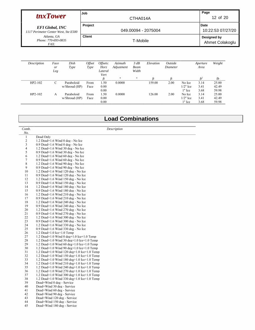
ttnnxxTToowweerr Job
CTHA014A
Page
12 of 20
EFI Global, INC
1117 Perimeter Center West, Ste E500
Project
049.00094 - 2075004
Date
10:22:53 07/27/20
Atlanta, GA Phone: 770-693-0835
FAX:
Client
T-Mobile Designed by
Ahmet Colakoglu
Description Face
or
Leg
Dish
Type
Offset
Type
Offsets:
Horz
Lateral Vert
ft
Azimuth
Adjustment
°
3 dB
Beam
Width
°
Elevation
ft
Outside
Diameter
ft
Aperture
Area
ft2
Weight
lb
HP2-102 C Paraboloid w/Shroud (HP)
From Face
1.50 0.00 0.00
0.0000 159.00 2.00 No Ice 1/2'' Ice 1'' Ice
3.14 3.41 3.68
25.00 42.49 59.98
HP2-102 A Paraboloid w/Shroud (HP)
From Face
1.50 0.00 0.00
0.0000 126.00 2.00 No Ice 1/2'' Ice 1'' Ice
3.14 3.41 3.68
25.00 42.49 59.98
Load Combinations Comb.
No.
Description
1 Dead Only 2 1.2 Dead+1.6 Wind 0 deg - No Ice 3 0.9 Dead+1.6 Wind 0 deg - No Ice 4 1.2 Dead+1.6 Wind 30 deg - No Ice 5 0.9 Dead+1.6 Wind 30 deg - No Ice 6 1.2 Dead+1.6 Wind 60 deg - No Ice 7 0.9 Dead+1.6 Wind 60 deg - No Ice 8 1.2 Dead+1.6 Wind 90 deg - No Ice 9 0.9 Dead+1.6 Wind 90 deg - No Ice
10 1.2 Dead+1.6 Wind 120 deg - No Ice 11 0.9 Dead+1.6 Wind 120 deg - No Ice 12 1.2 Dead+1.6 Wind 150 deg - No Ice 13 0.9 Dead+1.6 Wind 150 deg - No Ice 14 1.2 Dead+1.6 Wind 180 deg - No Ice 15 0.9 Dead+1.6 Wind 180 deg - No Ice 16 1.2 Dead+1.6 Wind 210 deg - No Ice 17 0.9 Dead+1.6 Wind 210 deg - No Ice 18 1.2 Dead+1.6 Wind 240 deg - No Ice 19 0.9 Dead+1.6 Wind 240 deg - No Ice 20 1.2 Dead+1.6 Wind 270 deg - No Ice 21 0.9 Dead+1.6 Wind 270 deg - No Ice 22 1.2 Dead+1.6 Wind 300 deg - No Ice 23 0.9 Dead+1.6 Wind 300 deg - No Ice 24 1.2 Dead+1.6 Wind 330 deg - No Ice 25 0.9 Dead+1.6 Wind 330 deg - No Ice 26 1.2 Dead+1.0 Ice+1.0 Temp 27 1.2 Dead+1.0 Wind 0 deg+1.0 Ice+1.0 Temp 28 1.2 Dead+1.0 Wind 30 deg+1.0 Ice+1.0 Temp 29 1.2 Dead+1.0 Wind 60 deg+1.0 Ice+1.0 Temp 30 1.2 Dead+1.0 Wind 90 deg+1.0 Ice+1.0 Temp 31 1.2 Dead+1.0 Wind 120 deg+1.0 Ice+1.0 Temp 32 1.2 Dead+1.0 Wind 150 deg+1.0 Ice+1.0 Temp 33 1.2 Dead+1.0 Wind 180 deg+1.0 Ice+1.0 Temp 34 1.2 Dead+1.0 Wind 210 deg+1.0 Ice+1.0 Temp 35 1.2 Dead+1.0 Wind 240 deg+1.0 Ice+1.0 Temp 36 1.2 Dead+1.0 Wind 270 deg+1.0 Ice+1.0 Temp 37 1.2 Dead+1.0 Wind 300 deg+1.0 Ice+1.0 Temp 38 1.2 Dead+1.0 Wind 330 deg+1.0 Ice+1.0 Temp 39 Dead+Wind 0 deg - Service 40 Dead+Wind 30 deg - Service 41 Dead+Wind 60 deg - Service 42 Dead+Wind 90 deg - Service 43 Dead+Wind 120 deg - Service 44 Dead+Wind 150 deg - Service 45 Dead+Wind 180 deg - Service
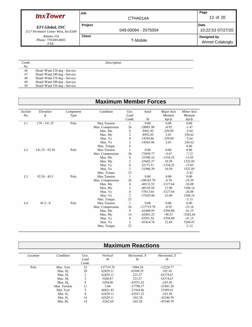
ttnnxxTToowweerr Job
CTHA014A
Page
13 of 20
EFI Global, INC
1117 Perimeter Center West, Ste E500
Project
049.00094 - 2075004
Date
10:22:53 07/27/20
Atlanta, GA Phone: 770-693-0835
FAX:
Client
T-Mobile Designed by
Ahmet Colakoglu
Comb.
No.
Description
46 Dead+Wind 210 deg - Service 47 Dead+Wind 240 deg - Service 48 Dead+Wind 270 deg - Service 49 Dead+Wind 300 deg - Service 50 Dead+Wind 330 deg - Service
Maximum Member Forces Section
No.
Elevation
ft
Component
Type
Condition Gov.
Load
Comb.
Axial
lb
Major Axis
Moment
kip-ft
Minor Axis
Moment
kip-ft
L1 179 - 141.25 Pole Max Tension 1 0.00 0.00 0.00 Max. Compression 26 -28081.98 -0.92 -1.47 Max. Mx 8 -8941.82 -259.89 -2.64 Max. My 2 -8952.03 2.01 256.62 Max. Vy 8 14594.86 -259.89 -2.64 Max. Vx 2 -14563.96 2.01 256.62 Max. Torque 8 0.46
L2 141.25 - 92.58 Pole Max Tension 1 0.00 0.00 0.00 Max. Compression 26 -73858.77 -4.67 -7.12 Max. Mx 8 -25580.16 -1534.25 -13.05 Max. My 2 -25602.37 10.59 1522.85 Max. Vy 8 32172.51 -1534.25 -13.05 Max. Vx 2 -31986.39 10.59 1522.85 Max. Torque 23 -3.42
L3 92.58 - 45.5 Pole Max Tension 1 0.00 0.00 0.00 Max. Compression 26 -100183.78 -6.76 -19.39 Max. Mx 8 -40133.52 -3127.64 -26.08 Max. My 2 -40145.94 21.00 3106.16 Max. Vy 8 37813.64 -3127.64 -26.08 Max. Vx 2 -37629.44 21.00 3106.16 Max. Torque 23 -3.13
L4 45.5 - 0 Pole Max Tension 1 0.00 0.00 0.00 Max. Compression 26 -137719.78 -8.92 -33.18 Max. Mx 8 -62400.95 -5294.00 -41.15 Max. My 14 -62401.25 -40.25 -5262.64 Max. Vy 8 43591.54 -5294.00 -41.15 Max. Vx 2 -43414.74 32.88 5260.87 Max. Torque 23 -3.12
Maximum Reactions
Location Condition Gov. Load
Comb.
Vertical lb
Horizontal, X lb
Horizontal, Z lb
Pole Max. Vert 32 137719.78 -7084.24 -12224.77 Max. Hx 20 62429.11 43509.35 192.10 Max. Hz 2 62429.11 223.27 43374.67 Max. Mx 2 5260.87 223.27 43374.67 Max. Mz 8 5294.00 -43551.22 -243.50 Max. Torsion 11 3.06 -37790.37 -21881.36 Min. Vert 5 46821.83 -21564.86 37499.41 Min. Hx 8 62429.11 -43551.22 -243.50 Min. Hz 14 62429.11 -263.28 -43340.70 Min. Mx 14 -5262.64 -263.28 -43340.70
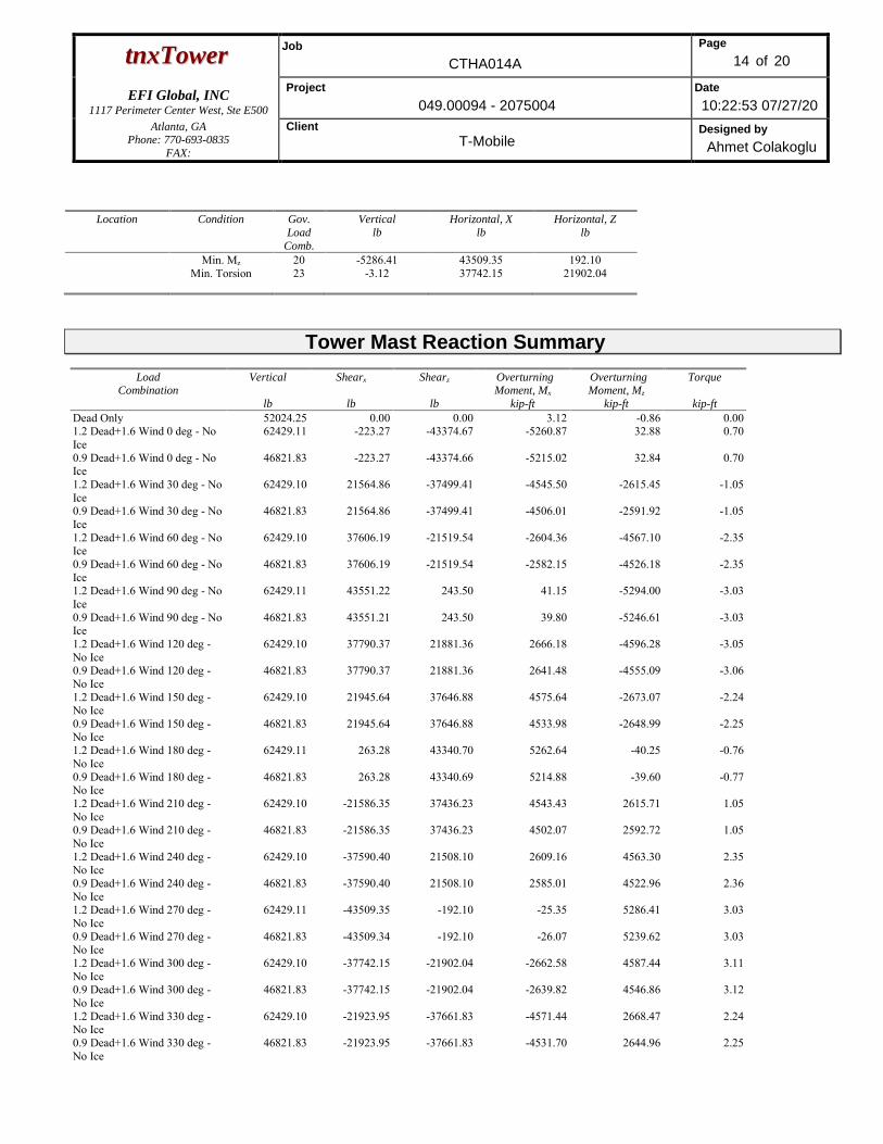
ttnnxxTToowweerr Job
CTHA014A
Page
14 of 20
EFI Global, INC
1117 Perimeter Center West, Ste E500
Project
049.00094 - 2075004
Date
10:22:53 07/27/20
Atlanta, GA Phone: 770-693-0835
FAX:
Client
T-Mobile Designed by
Ahmet Colakoglu
Location Condition Gov.
Load
Comb.
Vertical
lb
Horizontal, X
lb
Horizontal, Z
lb
Min. Mz 20 -5286.41 43509.35 192.10 Min. Torsion 23 -3.12 37742.15 21902.04
Tower Mast Reaction Summary
Load Combination
Vertical
lb
Shearx
lb
Shearz
lb
Overturning Moment, Mx
kip-ft
Overturning Moment, Mz
kip-ft
Torque
kip-ft Dead Only 52024.25 0.00 0.00 3.12 -0.86 0.00 1.2 Dead+1.6 Wind 0 deg - No Ice
62429.11 -223.27 -43374.67 -5260.87 32.88 0.70
0.9 Dead+1.6 Wind 0 deg - No Ice
46821.83 -223.27 -43374.66 -5215.02 32.84 0.70
1.2 Dead+1.6 Wind 30 deg - No Ice
62429.10 21564.86 -37499.41 -4545.50 -2615.45 -1.05
0.9 Dead+1.6 Wind 30 deg - No Ice
46821.83 21564.86 -37499.41 -4506.01 -2591.92 -1.05
1.2 Dead+1.6 Wind 60 deg - No Ice
62429.10 37606.19 -21519.54 -2604.36 -4567.10 -2.35
0.9 Dead+1.6 Wind 60 deg - No Ice
46821.83 37606.19 -21519.54 -2582.15 -4526.18 -2.35
1.2 Dead+1.6 Wind 90 deg - No Ice
62429.11 43551.22 243.50 41.15 -5294.00 -3.03
0.9 Dead+1.6 Wind 90 deg - No Ice
46821.83 43551.21 243.50 39.80 -5246.61 -3.03
1.2 Dead+1.6 Wind 120 deg - No Ice
62429.10 37790.37 21881.36 2666.18 -4596.28 -3.05
0.9 Dead+1.6 Wind 120 deg - No Ice
46821.83 37790.37 21881.36 2641.48 -4555.09 -3.06
1.2 Dead+1.6 Wind 150 deg - No Ice
62429.10 21945.64 37646.88 4575.64 -2673.07 -2.24
0.9 Dead+1.6 Wind 150 deg - No Ice
46821.83 21945.64 37646.88 4533.98 -2648.99 -2.25
1.2 Dead+1.6 Wind 180 deg - No Ice
62429.11 263.28 43340.70 5262.64 -40.25 -0.76
0.9 Dead+1.6 Wind 180 deg - No Ice
46821.83 263.28 43340.69 5214.88 -39.60 -0.77
1.2 Dead+1.6 Wind 210 deg - No Ice
62429.10 -21586.35 37436.23 4543.43 2615.71 1.05
0.9 Dead+1.6 Wind 210 deg - No Ice
46821.83 -21586.35 37436.23 4502.07 2592.72 1.05
1.2 Dead+1.6 Wind 240 deg - No Ice
62429.10 -37590.40 21508.10 2609.16 4563.30 2.35
0.9 Dead+1.6 Wind 240 deg - No Ice
46821.83 -37590.40 21508.10 2585.01 4522.96 2.36
1.2 Dead+1.6 Wind 270 deg - No Ice
62429.11 -43509.35 -192.10 -25.35 5286.41 3.03
0.9 Dead+1.6 Wind 270 deg - No Ice
46821.83 -43509.34 -192.10 -26.07 5239.62 3.03
1.2 Dead+1.6 Wind 300 deg - No Ice
62429.10 -37742.15 -21902.04 -2662.58 4587.44 3.11
0.9 Dead+1.6 Wind 300 deg - No Ice
46821.83 -37742.15 -21902.04 -2639.82 4546.86 3.12
1.2 Dead+1.6 Wind 330 deg - No Ice
62429.10 -21923.95 -37661.83 -4571.44 2668.47 2.24
0.9 Dead+1.6 Wind 330 deg - No Ice
46821.83 -21923.95 -37661.83 -4531.70 2644.96 2.25
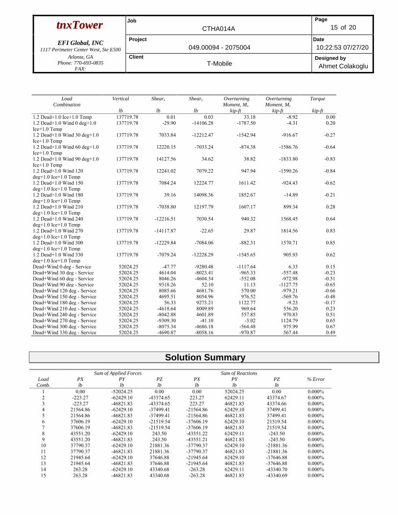
ttnnxxTToowweerr Job
CTHA014A
Page
15 of 20
EFI Global, INC
1117 Perimeter Center West, Ste E500
Project
049.00094 - 2075004
Date
10:22:53 07/27/20
Atlanta, GA Phone: 770-693-0835
FAX:
Client
T-Mobile Designed by
Ahmet Colakoglu
Load
Combination Vertical
lb
Shearx
lb
Shearz
lb
Overturning
Moment, Mx kip-ft
Overturning
Moment, Mz kip-ft
Torque
kip-ft 1.2 Dead+1.0 Ice+1.0 Temp 137719.78 0.01 0.03 33.18 -8.92 0.00 1.2 Dead+1.0 Wind 0 deg+1.0 Ice+1.0 Temp
137719.78 -29.90 -14106.28 -1787.50 -4.31 0.20
1.2 Dead+1.0 Wind 30 deg+1.0 Ice+1.0 Temp
137719.78 7033.84 -12212.47 -1542.94 -916.67 -0.27
1.2 Dead+1.0 Wind 60 deg+1.0 Ice+1.0 Temp
137719.78 12220.15 -7033.24 -874.38 -1586.76 -0.64
1.2 Dead+1.0 Wind 90 deg+1.0 Ice+1.0 Temp
137719.78 14127.56 34.62 38.82 -1833.80 -0.83
1.2 Dead+1.0 Wind 120 deg+1.0 Ice+1.0 Temp
137719.78 12241.02 7079.22 947.94 -1590.26 -0.84
1.2 Dead+1.0 Wind 150 deg+1.0 Ice+1.0 Temp
137719.78 7084.24 12224.77 1611.42 -924.43 -0.62
1.2 Dead+1.0 Wind 180 deg+1.0 Ice+1.0 Temp
137719.78 39.16 14098.36 1852.67 -14.89 -0.21
1.2 Dead+1.0 Wind 210 deg+1.0 Ice+1.0 Temp
137719.78 -7038.80 12197.79 1607.17 899.34 0.28
1.2 Dead+1.0 Wind 240 deg+1.0 Ice+1.0 Temp
137719.78 -12216.51 7030.54 940.32 1568.45 0.64
1.2 Dead+1.0 Wind 270 deg+1.0 Ice+1.0 Temp
137719.78 -14117.87 -22.65 29.87 1814.56 0.83
1.2 Dead+1.0 Wind 300 deg+1.0 Ice+1.0 Temp
137719.78 -12229.84 -7084.06 -882.31 1570.71 0.85
1.2 Dead+1.0 Wind 330 deg+1.0 Ice+1.0 Temp
137719.78 -7079.24 -12228.29 -1545.65 905.93 0.62
Dead+Wind 0 deg - Service 52024.25 -47.77 -9280.48 -1117.64 6.33 0.15 Dead+Wind 30 deg - Service 52024.25 4614.04 -8023.41 -965.33 -557.48 -0.23 Dead+Wind 60 deg - Service 52024.25 8046.26 -4604.34 -552.08 -972.98 -0.51 Dead+Wind 90 deg - Service 52024.25 9318.26 52.10 11.13 -1127.75 -0.65 Dead+Wind 120 deg - Service 52024.25 8085.66 4681.76 570.00 -979.21 -0.66 Dead+Wind 150 deg - Service 52024.25 4695.51 8054.96 976.52 -569.76 -0.48 Dead+Wind 180 deg - Service 52024.25 56.33 9273.21 1122.77 -9.23 -0.17 Dead+Wind 210 deg - Service 52024.25 -4618.64 8009.89 969.64 556.20 0.23 Dead+Wind 240 deg - Service 52024.25 -8042.88 4601.89 557.85 970.83 0.51 Dead+Wind 270 deg - Service 52024.25 -9309.30 -41.10 -3.02 1124.79 0.65 Dead+Wind 300 deg - Service 52024.25 -8075.34 -4686.18 -564.48 975.99 0.67 Dead+Wind 330 deg - Service 52024.25 -4690.87 -8058.16 -970.87 567.44 0.49
Solution Summary
Load
Comb.
Sum of Applied Forces Sum of Reactions
% Error PX
lb
PY
lb
PZ
lb
PX
lb
PY
lb
PZ
lb
1 0.00 -52024.25 0.00 0.00 52024.25 0.00 0.000% 2 -223.27 -62429.10 -43374.65 223.27 62429.11 43374.67 0.000% 3 -223.27 -46821.83 -43374.65 223.27 46821.83 43374.66 0.000% 4 21564.86 -62429.10 -37499.41 -21564.86 62429.10 37499.41 0.000% 5 21564.86 -46821.83 -37499.41 -21564.86 46821.83 37499.41 0.000% 6 37606.19 -62429.10 -21519.54 -37606.19 62429.10 21519.54 0.000% 7 37606.19 -46821.83 -21519.54 -37606.19 46821.83 21519.54 0.000% 8 43551.20 -62429.10 243.50 -43551.22 62429.11 -243.50 0.000% 9 43551.20 -46821.83 243.50 -43551.21 46821.83 -243.50 0.000%
10 37790.37 -62429.10 21881.36 -37790.37 62429.10 -21881.36 0.000% 11 37790.37 -46821.83 21881.36 -37790.37 46821.83 -21881.36 0.000% 12 21945.64 -62429.10 37646.88 -21945.64 62429.10 -37646.88 0.000% 13 21945.64 -46821.83 37646.88 -21945.64 46821.83 -37646.88 0.000% 14 263.28 -62429.10 43340.68 -263.28 62429.11 -43340.70 0.000% 15 263.28 -46821.83 43340.68 -263.28 46821.83 -43340.69 0.000%
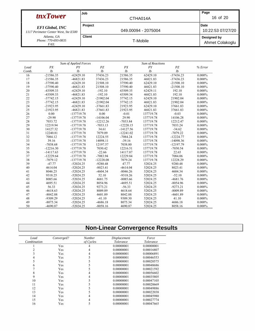
ttnnxxTToowweerr Job
CTHA014A
Page
16 of 20
EFI Global, INC
1117 Perimeter Center West, Ste E500
Project
049.00094 - 2075004
Date
10:22:53 07/27/20
Atlanta, GA Phone: 770-693-0835
FAX:
Client
T-Mobile Designed by
Ahmet Colakoglu
Load
Comb.
Sum of Applied Forces Sum of Reactions
% Error PX
lb
PY
lb
PZ
lb
PX
lb
PY
lb
PZ
lb
16 -21586.35 -62429.10 37436.23 21586.35 62429.10 -37436.23 0.000% 17 -21586.35 -46821.83 37436.23 21586.35 46821.83 -37436.23 0.000% 18 -37590.40 -62429.10 21508.10 37590.40 62429.10 -21508.10 0.000% 19 -37590.40 -46821.83 21508.10 37590.40 46821.83 -21508.10 0.000% 20 -43509.33 -62429.10 -192.10 43509.35 62429.11 192.10 0.000% 21 -43509.33 -46821.83 -192.10 43509.34 46821.83 192.10 0.000% 22 -37742.15 -62429.10 -21902.04 37742.15 62429.10 21902.04 0.000% 23 -37742.15 -46821.83 -21902.04 37742.15 46821.83 21902.04 0.000% 24 -21923.95 -62429.10 -37661.83 21923.95 62429.10 37661.83 0.000% 25 -21923.95 -46821.83 -37661.83 21923.95 46821.83 37661.83 0.000% 26 0.00 -137719.78 0.00 -0.01 137719.78 -0.03 0.000% 27 -29.90 -137719.78 -14106.04 29.90 137719.78 14106.28 0.000% 28 7033.72 -137719.78 -12212.26 -7033.84 137719.78 12212.47 0.000% 29 12219.94 -137719.78 -7033.13 -12220.15 137719.78 7033.24 0.000% 30 14127.32 -137719.78 34.61 -14127.56 137719.78 -34.62 0.000% 31 12240.81 -137719.78 7079.09 -12241.02 137719.78 -7079.22 0.000% 32 7084.12 -137719.78 12224.55 -7084.24 137719.78 -12224.77 0.000% 33 39.16 -137719.78 14098.11 -39.16 137719.78 -14098.36 0.000% 34 -7038.68 -137719.78 12197.57 7038.80 137719.78 -12197.79 0.000% 35 -12216.30 -137719.78 7030.42 12216.51 137719.78 -7030.54 0.000% 36 -14117.63 -137719.78 -22.66 14117.87 137719.78 22.65 0.000% 37 -12229.64 -137719.78 -7083.94 12229.84 137719.78 7084.06 0.000% 38 -7079.12 -137719.78 -12228.08 7079.24 137719.78 12228.29 0.000% 39 -47.77 -52024.25 -9280.48 47.77 52024.25 9280.48 0.000% 40 4614.04 -52024.25 -8023.41 -4614.04 52024.25 8023.41 0.000% 41 8046.25 -52024.25 -4604.34 -8046.26 52024.25 4604.34 0.000% 42 9318.25 -52024.25 52.10 -9318.26 52024.25 -52.10 0.000% 43 8085.66 -52024.25 4681.75 -8085.66 52024.25 -4681.76 0.000% 44 4695.51 -52024.25 8054.96 -4695.51 52024.25 -8054.96 0.000% 45 56.33 -52024.25 9273.21 -56.33 52024.25 -9273.21 0.000% 46 -4618.63 -52024.25 8009.89 4618.64 52024.25 -8009.89 0.000% 47 -8042.88 -52024.25 4601.89 8042.88 52024.25 -4601.89 0.000% 48 -9309.29 -52024.25 -41.10 9309.30 52024.25 41.10 0.000% 49 -8075.34 -52024.25 -4686.18 8075.34 52024.25 4686.18 0.000% 50 -4690.87 -52024.25 -8058.16 4690.87 52024.25 8058.16 0.000%
Non-Linear Convergence Results
Load Combination
Converged? Number of Cycles
Displacement Tolerance
Force Tolerance
1 Yes 4 0.00000001 0.00000001 2 Yes 4 0.00000001 0.00016807 3 Yes 4 0.00000001 0.00006891 4 Yes 5 0.00000001 0.00046553 5 Yes 5 0.00000001 0.00020575 6 Yes 5 0.00000001 0.00048686 7 Yes 5 0.00000001 0.00021592 8 Yes 4 0.00000001 0.00056602 9 Yes 4 0.00000001 0.00035805
10 Yes 5 0.00000001 0.00047105 11 Yes 5 0.00000001 0.00020669 12 Yes 5 0.00000001 0.00049886 13 Yes 5 0.00000001 0.00022038 14 Yes 4 0.00000001 0.00045980 15 Yes 4 0.00000001 0.00027774 16 Yes 5 0.00000001 0.00047665
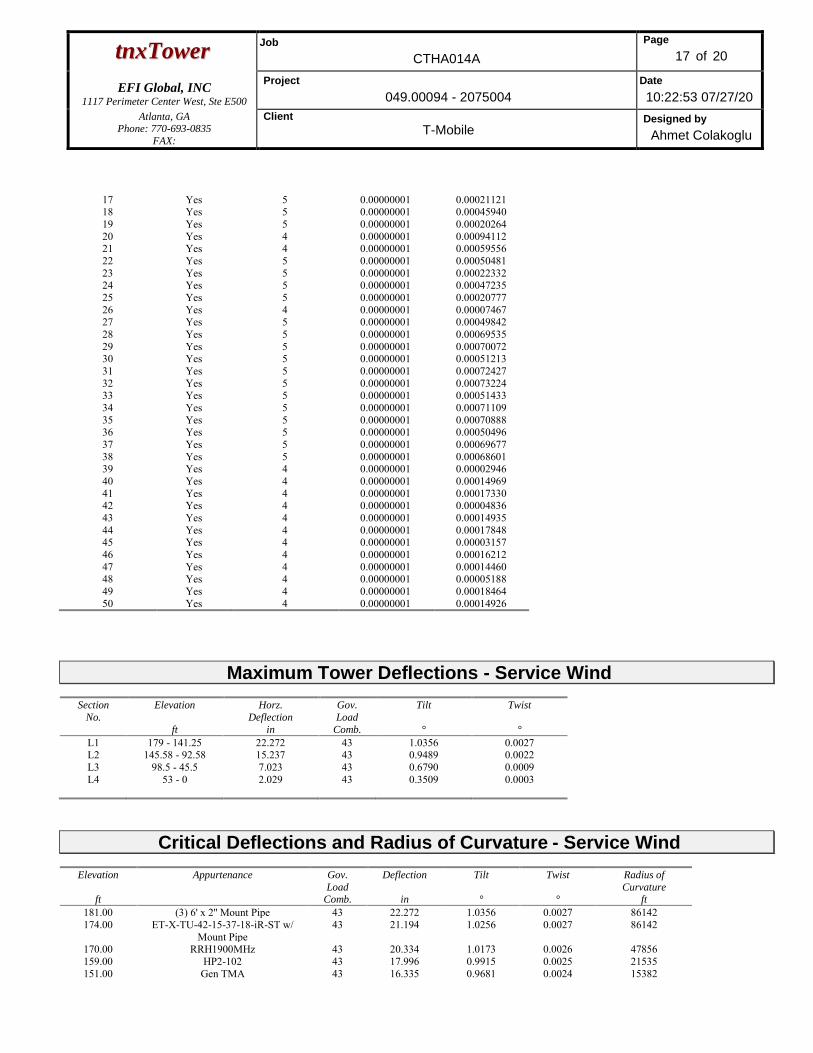
ttnnxxTToowweerr Job
CTHA014A
Page
17 of 20
EFI Global, INC
1117 Perimeter Center West, Ste E500
Project
049.00094 - 2075004
Date
10:22:53 07/27/20
Atlanta, GA Phone: 770-693-0835
FAX:
Client
T-Mobile Designed by
Ahmet Colakoglu
17 Yes 5 0.00000001 0.00021121 18 Yes 5 0.00000001 0.00045940 19 Yes 5 0.00000001 0.00020264 20 Yes 4 0.00000001 0.00094112 21 Yes 4 0.00000001 0.00059556 22 Yes 5 0.00000001 0.00050481 23 Yes 5 0.00000001 0.00022332 24 Yes 5 0.00000001 0.00047235 25 Yes 5 0.00000001 0.00020777 26 Yes 4 0.00000001 0.00007467 27 Yes 5 0.00000001 0.00049842 28 Yes 5 0.00000001 0.00069535 29 Yes 5 0.00000001 0.00070072 30 Yes 5 0.00000001 0.00051213 31 Yes 5 0.00000001 0.00072427 32 Yes 5 0.00000001 0.00073224 33 Yes 5 0.00000001 0.00051433 34 Yes 5 0.00000001 0.00071109 35 Yes 5 0.00000001 0.00070888 36 Yes 5 0.00000001 0.00050496 37 Yes 5 0.00000001 0.00069677 38 Yes 5 0.00000001 0.00068601 39 Yes 4 0.00000001 0.00002946 40 Yes 4 0.00000001 0.00014969 41 Yes 4 0.00000001 0.00017330 42 Yes 4 0.00000001 0.00004836 43 Yes 4 0.00000001 0.00014935 44 Yes 4 0.00000001 0.00017848 45 Yes 4 0.00000001 0.00003157 46 Yes 4 0.00000001 0.00016212 47 Yes 4 0.00000001 0.00014460 48 Yes 4 0.00000001 0.00005188 49 Yes 4 0.00000001 0.00018464 50 Yes 4 0.00000001 0.00014926
Maximum Tower Deflections - Service Wind
Section
No.
Elevation
ft
Horz.
Deflection
in
Gov.
Load
Comb.
Tilt
°
Twist
°
L1 179 - 141.25 22.272 43 1.0356 0.0027 L2 145.58 - 92.58 15.237 43 0.9489 0.0022 L3 98.5 - 45.5 7.023 43 0.6790 0.0009 L4 53 - 0 2.029 43 0.3509 0.0003
Critical Deflections and Radius of Curvature - Service Wind
Elevation
ft
Appurtenance Gov.
Load Comb.
Deflection
in
Tilt
°
Twist
°
Radius of
Curvature ft
181.00 (3) 6' x 2'' Mount Pipe 43 22.272 1.0356 0.0027 86142 174.00 ET-X-TU-42-15-37-18-iR-ST w/
Mount Pipe 43 21.194 1.0256 0.0027 86142
170.00 RRH1900MHz 43 20.334 1.0173 0.0026 47856 159.00 HP2-102 43 17.996 0.9915 0.0025 21535 151.00 Gen TMA 43 16.335 0.9681 0.0024 15382
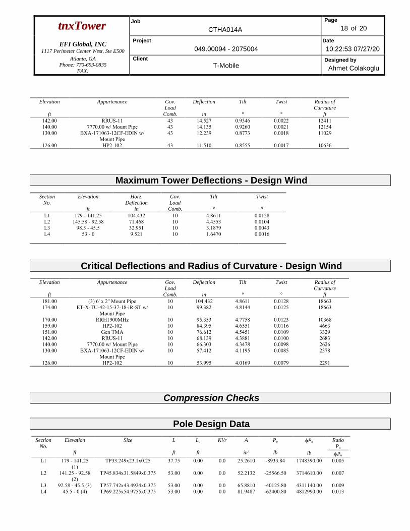
ttnnxxTToowweerr Job
CTHA014A
Page
18 of 20
EFI Global, INC
1117 Perimeter Center West, Ste E500
Project
049.00094 - 2075004
Date
10:22:53 07/27/20
Atlanta, GA Phone: 770-693-0835
FAX:
Client
T-Mobile Designed by
Ahmet Colakoglu
Elevation
ft
Appurtenance Gov.
Load
Comb.
Deflection
in
Tilt
°
Twist
°
Radius of
Curvature
ft
142.00 RRUS-11 43 14.527 0.9346 0.0022 12411 140.00 7770.00 w/ Mount Pipe 43 14.135 0.9260 0.0021 12154 130.00 BXA-171063-12CF-EDIN w/
Mount Pipe 43 12.239 0.8773 0.0018 11029
126.00 HP2-102 43 11.510 0.8555 0.0017 10636
Maximum Tower Deflections - Design Wind
Section
No.
Elevation
ft
Horz.
Deflection in
Gov.
Load Comb.
Tilt
°
Twist
°
L1 179 - 141.25 104.432 10 4.8611 0.0128 L2 145.58 - 92.58 71.468 10 4.4553 0.0104 L3 98.5 - 45.5 32.951 10 3.1879 0.0043 L4 53 - 0 9.521 10 1.6470 0.0016
Critical Deflections and Radius of Curvature - Design Wind
Elevation
ft
Appurtenance Gov. Load
Comb.
Deflection
in
Tilt
°
Twist
°
Radius of Curvature
ft
181.00 (3) 6' x 2'' Mount Pipe 10 104.432 4.8611 0.0128 18663 174.00 ET-X-TU-42-15-37-18-iR-ST w/
Mount Pipe 10 99.382 4.8144 0.0125 18663
170.00 RRH1900MHz 10 95.353 4.7758 0.0123 10368 159.00 HP2-102 10 84.395 4.6551 0.0116 4663 151.00 Gen TMA 10 76.612 4.5451 0.0109 3329 142.00 RRUS-11 10 68.139 4.3881 0.0100 2683 140.00 7770.00 w/ Mount Pipe 10 66.303 4.3478 0.0098 2626 130.00 BXA-171063-12CF-EDIN w/
Mount Pipe 10 57.412 4.1195 0.0085 2378
126.00 HP2-102 10 53.995 4.0169 0.0079 2291
Compression Checks
Pole Design Data Section
No.
Elevation
ft
Size
L
ft
Lu
ft
Kl/r
A
in2
Pu
lb
Pn
lb
Ratio Pu
Pn
L1 179 - 141.25 (1)
TP33.249x23.1x0.25 37.75 0.00 0.0 25.2610 -8933.84 1748390.00 0.005
L2 141.25 - 92.58 (2)
TP45.834x31.5849x0.375 53.00 0.00 0.0 52.2132 -25566.50 3714610.00 0.007
L3 92.58 - 45.5 (3) TP57.742x43.4924x0.375 53.00 0.00 0.0 65.8810 -40125.80 4311140.00 0.009 L4 45.5 - 0 (4) TP69.225x54.9755x0.375 53.00 0.00 0.0 81.9487 -62400.80 4812990.00 0.013
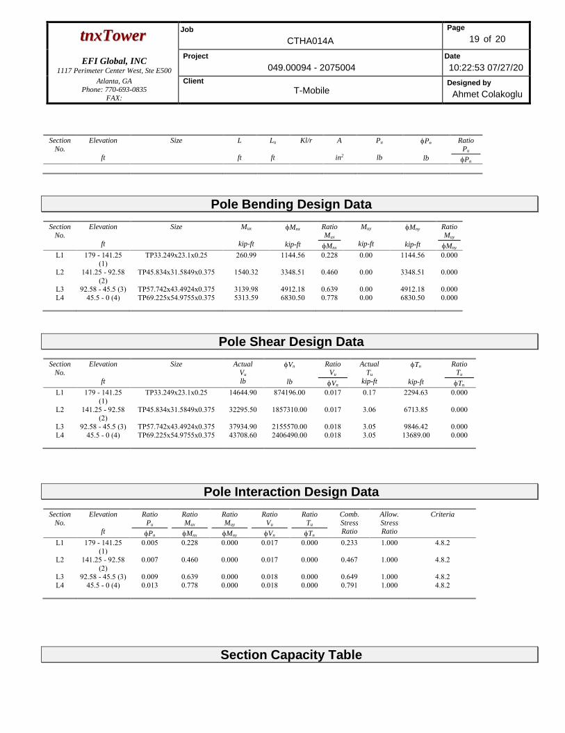
ttnnxxTToowweerr Job
CTHA014A
Page
19 of 20
EFI Global, INC
1117 Perimeter Center West, Ste E500
Project
049.00094 - 2075004
Date
10:22:53 07/27/20
Atlanta, GA Phone: 770-693-0835
FAX:
Client
T-Mobile Designed by
Ahmet Colakoglu
Section
No.
Elevation
ft
Size
L
ft
Lu
ft
Kl/r
A
in2
Pu
lb
Pn
lb
Ratio Pu
Pn
Pole Bending Design Data Section
No.
Elevation
ft
Size
Mux
kip-ft
Mnx
kip-ft
Ratio
Mux
Mnx
Muy
kip-ft
Mny
kip-ft
Ratio
Muy
Mny
L1 179 - 141.25 (1)
TP33.249x23.1x0.25 260.99 1144.56 0.228 0.00 1144.56 0.000
L2 141.25 - 92.58 (2)
TP45.834x31.5849x0.375 1540.32 3348.51 0.460 0.00 3348.51 0.000
L3 92.58 - 45.5 (3) TP57.742x43.4924x0.375 3139.98 4912.18 0.639 0.00 4912.18 0.000 L4 45.5 - 0 (4) TP69.225x54.9755x0.375 5313.59 6830.50 0.778 0.00 6830.50 0.000
Pole Shear Design Data Section
No.
Elevation
ft
Size
Actual
Vu
lb
Vn
lb
Ratio Vu
Vn
Actual
Tu
kip-ft
Tn
kip-ft
Ratio Tu
Tn
L1 179 - 141.25 (1)
TP33.249x23.1x0.25 14644.90 874196.00 0.017 0.17 2294.63 0.000
L2 141.25 - 92.58 (2)
TP45.834x31.5849x0.375 32295.50 1857310.00 0.017 3.06 6713.85 0.000
L3 92.58 - 45.5 (3) TP57.742x43.4924x0.375 37934.90 2155570.00 0.018 3.05 9846.42 0.000 L4 45.5 - 0 (4) TP69.225x54.9755x0.375 43708.60 2406490.00 0.018 3.05 13689.00 0.000
Pole Interaction Design Data Section
No.
Elevation
ft
Ratio Pu
Pn
Ratio Mux
Mnx
Ratio Muy
Mny
Ratio Vu
Vn
Ratio Tu
Tn
Comb.
Stress Ratio
Allow.
Stress Ratio
Criteria
L1 179 - 141.25 (1)
0.005 0.228 0.000 0.017 0.000 0.233 1.000 4.8.2
L2 141.25 - 92.58 (2)
0.007 0.460 0.000 0.017 0.000 0.467 1.000 4.8.2
L3 92.58 - 45.5 (3) 0.009 0.639 0.000 0.018 0.000 0.649 1.000 4.8.2 L4 45.5 - 0 (4) 0.013 0.778 0.000 0.018 0.000 0.791 1.000 4.8.2
Section Capacity Table
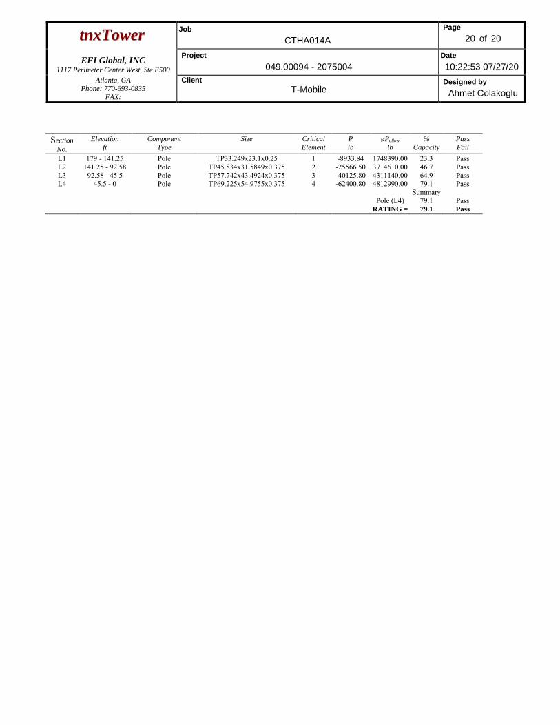
ttnnxxTToowweerr Job
CTHA014A
Page
20 of 20
EFI Global, INC
1117 Perimeter Center West, Ste E500
Project
049.00094 - 2075004
Date
10:22:53 07/27/20
Atlanta, GA Phone: 770-693-0835
FAX:
Client
T-Mobile Designed by
Ahmet Colakoglu
Section
No.
Elevation
ft
Component
Type
Size Critical
Element
P
lb
øPallow
lb
%
Capacity
Pass
Fail
L1 179 - 141.25 Pole TP33.249x23.1x0.25 1 -8933.84 1748390.00 23.3 Pass L2 141.25 - 92.58 Pole TP45.834x31.5849x0.375 2 -25566.50 3714610.00 46.7 Pass L3 92.58 - 45.5 Pole TP57.742x43.4924x0.375 3 -40125.80 4311140.00 64.9 Pass L4 45.5 - 0 Pole TP69.225x54.9755x0.375 4 -62400.80 4812990.00 79.1 Pass
Summary Pole (L4) 79.1 Pass RATING = 79.1 Pass
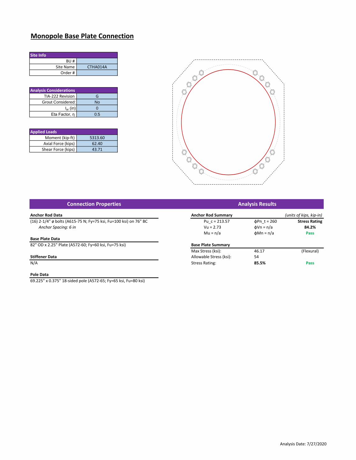
Monopole Base Plate Connection
#VALUE!
Anchor Rod Data Anchor Rod Summary (units of kips, kip-in)
(16) 2-1/4" ø bolts (A615-75 N; Fy=75 ksi, Fu=100 ksi) on 76" BC Pu_c = 213.57 φPn_t = 260 Stress Rating
Anchor Spacing: 6 in Vu = 2.73 φVn = n/a 84.2%
Mu = n/a φMn = n/a Pass
Base Plate Data
82" OD x 2.25" Plate (A572-60; Fy=60 ksi, Fu=75 ksi) Base Plate Summary
Max Stress (ksi): 46.17 (Flexural)
Stiffener Data Allowable Stress (ksi): 54
N/A Stress Rating: 85.5% Pass
Pole Data
69.225" x 0.375" 18-sided pole (A572-65; Fy=65 ksi, Fu=80 ksi)
Analysis ResultsConnection Properties
Iar (in) 0
Eta Factor, η 0.5
Moment (kip-ft) 5313.60
Axial Force (kips) 62.40
Shear Force (kips) 43.71
Moment (kip-ft)
Axial Force (kips)
Shear Force (kips)
0.00
BU #
Applied Loads
Site Name CTHA014A
Order #
Analysis Considerations
Site Info
TIA-222 Revision G
Grout Considered: No
62.40
43.71
Adjusted Pole Reactions
Show image?
Plate Dia.
Shaft Dia.
Pole Shape
Plate Type:
Plate Geometry:
Plate Quantity
Plate Dia. 2
Shaft Dia. 2
Analysis Date: 7/27/2020
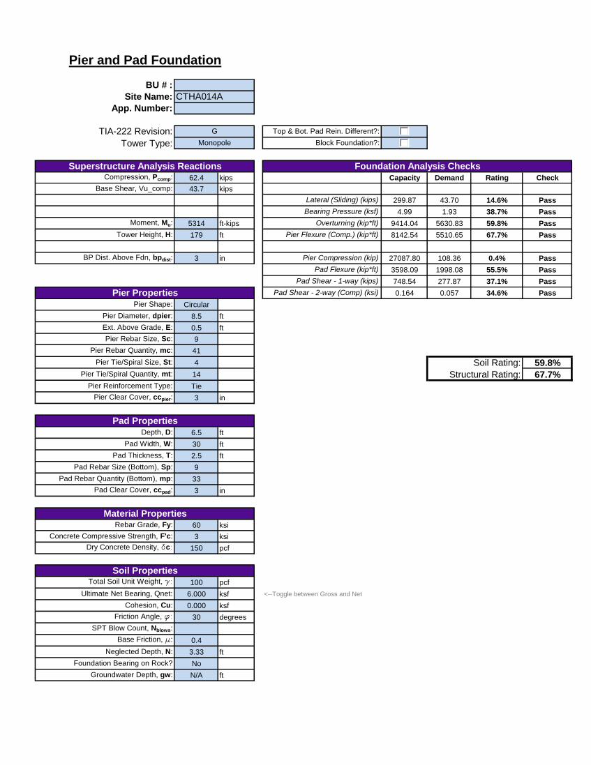
Tower Type:
62.4 kips Capacity Demand Rating Check
43.7 kips 694.24 0.00 0.0% Pass
299.87 43.70 14.6% Pass
4.99 1.93 38.7% Pass
5314 ft-kips 9414.04 5630.83 59.8% Pass
179 ft 8142.54 5510.65 67.7% Pass
ft 295.98 0.00 0.0% Pass
3 in 27087.80 108.36 0.4% Pass
in 3598.09 1998.08 55.5% Pass
748.54 277.87 37.1% Pass
0.164 0.057 34.6% Pass
Circular 3798.65 0.00 0.0% Pass
8.5 ft 0.164 0.000 0.0% Pass
0.5 ft 3798.65 0.00 0.0% Pass
9
41
4 Soil Rating: 59.8%14 Structural Rating: 67.7%Tie
3 in
6.5 ft
30 ft
2.5 ft
9
33
3 in
60 ksi
3 ksi
150 pcf
100 pcf
6.000 ksf <--Toggle between Gross and Net
0.000 ksf
30 degrees
0.4
3.33 ft
No
N/A ft
Uplift, Puplift:
Base Shear, Vu_comp:
Groundwater Depth, gw:
Rebar Grade, Fy:
Dry Concrete Density, δc:
Depth, D:
Pad Width, W:
Pad Thickness, T:
Pad Rebar Size (Bottom), Sp:
Pad Rebar Quantity (Bottom), mp:
Pad Clear Cover, ccpad:
Material Properties
Soil Properties
Friction Angle, ϕ:
Moment, Mu:
Flexural 2-way (Tension) (kip*ft)
Pad Shear - 2-way (Uplift) (ksi)
Pier Properties
BP Dist. Above Fdn, bpdist:
Bolt Circle / Bearing Plate Width, BC:
Flexural 2-way (Comp) (kip*ft)
Block Foundation?:
Pad Shear - 2-way (Comp) (ksi)
Pier Flexure (Tension) (kip*ft)
Overturning (kip*ft)
Pad Flexure (kip*ft)
Pad Shear - 1-way (kips)
Pier Compression (kip)
Pier and Pad Foundation
BU # :Site Name:
Compression, Pcomp:
TIA-222 Revision:
App. Number:
Superstructure Analysis Reactions
G
Monopole
CTHA014A
Pier Flexure (Comp.) (kip*ft)
Lateral (Sliding) (kips)
Bearing Pressure (ksf)
Uplift (kips)
Foundation Analysis Checks
Neglected Depth, N:
Uplift Shear, Vu_uplift:
Pier Shape:
Tower Height, H:
Base Face Width, BW:
Cohesion, Cu:
Ultimate Net Bearing, Qnet:
Top & Bot. Pad Rein. Different?:
Foundation Bearing on Rock?
SPT Blow Count, Nblows:
Base Friction, μ:
Pier Diameter, dpier:
Ext. Above Grade, E:
Pier Rebar Size, Sc:
Total Soil Unit Weight, γ:
Pier Rebar Quantity, mc:
Concrete Compressive Strength, F'c:
Pier Tie/Spiral Quantity, mt:
Pier Reinforcement Type:
Pier Clear Cover, ccpier:
Pad Properties
Pier Tie/Spiral Size, St:

Exhibit E
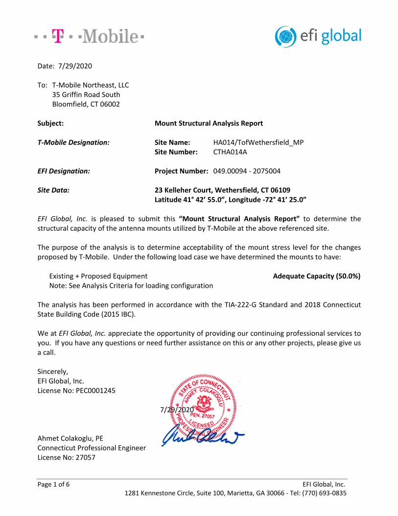
Page 1 of 6 EFI Global, Inc. 1281 Kennestone Circle, Suite 100, Marietta, GA 30066 - Tel: (770) 693-0835
Date: 7/29/2020
To: T-Mobile Northeast, LLC 35 Griffin Road South Bloomfield, CT 06002
Subject: Mount Structural Analysis Report
T-Mobile Designation: Site Name: HA014/TofWethersfield_MP Site Number: CTHA014A
EFI Designation: Project Number: 049.00094 - 2075004
Site Data: 23 Kelleher Court, Wethersfield, CT 06109 Latitude 41° 42’ 55.0”, Longitude -72° 41’ 25.0”
EFI Global, Inc. is pleased to submit this “Mount Structural Analysis Report” to determine the structural capacity of the antenna mounts utilized by T-Mobile at the above referenced site.
The purpose of the analysis is to determine acceptability of the mount stress level for the changes proposed by T-Mobile. Under the following load case we have determined the mounts to have:
Existing + Proposed Equipment Adequate Capacity (50.0%) Note: See Analysis Criteria for loading configuration
The analysis has been performed in accordance with the TIA-222-G Standard and 2018 Connecticut State Building Code (2015 IBC).
We at EFI Global, Inc. appreciate the opportunity of providing our continuing professional services to you. If you have any questions or need further assistance on this or any other projects, please give us a call.
Sincerely, EFI Global, Inc. License No: PEC0001245
7/29/2020
Ahmet Colakoglu, PE Connecticut Professional Engineer License No: 27057
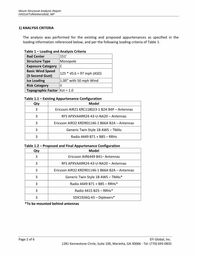
Mount Structural Analysis Report HA014/TofWethersfield_MP
Page 2 of 6 EFI Global, Inc. 1281 Kennestone Circle, Suite 100, Marietta, GA 30066 - Tel: (770) 693-0835
1) ANALYSIS CRITERIA
The analysis was performed for the existing and proposed appurtenances as specified in the loading information referenced below, and per the following loading criteria of Table 1.
Table 1 – Loading and Analysis Criteria
Table 1.1 – Existing Appurtenance Configuration
Table 1.2 – Proposed and Final Appurtenance Configuration
*To be mounted behind antennas
Rad Center 151’
Structure Type Monopole
Exposure Category C
Basic Wind Speed (3-Second Gust)
125 * √0.6 = 97 mph (ASD)
Ice Loading 1.00” with 50 mph Wind
Risk Category II
Topographic Factor Kzt = 1.0
Qty Model
3 Ericsson AIR21 KRC118023-1 B2A B4P – Antennas
3 RFS APXVAARR24-43-U-NA20 – Antennas
3 Ericsson AIR32 KRD901146-1 B66A B2A – Antennas
3 Generic Twin Style 1B AWS – TMAs
3 Radio 4449 B71 + B85 – RRHs
Qty Model
3 Ericsson AIR6449 B41– Antennas
3 RFS APXVAARR24-43-U-NA20 – Antennas
3 Ericsson AIR32 KRD901146-1 B66A B2A – Antennas
3 Generic Twin Style 1B AWS – TMAs*
3 Radio 4449 B71 + B85 – RRHs*
3 Radio 4415 B25 – RRHs*
3 SDX1926Q-43 – Diplexers*
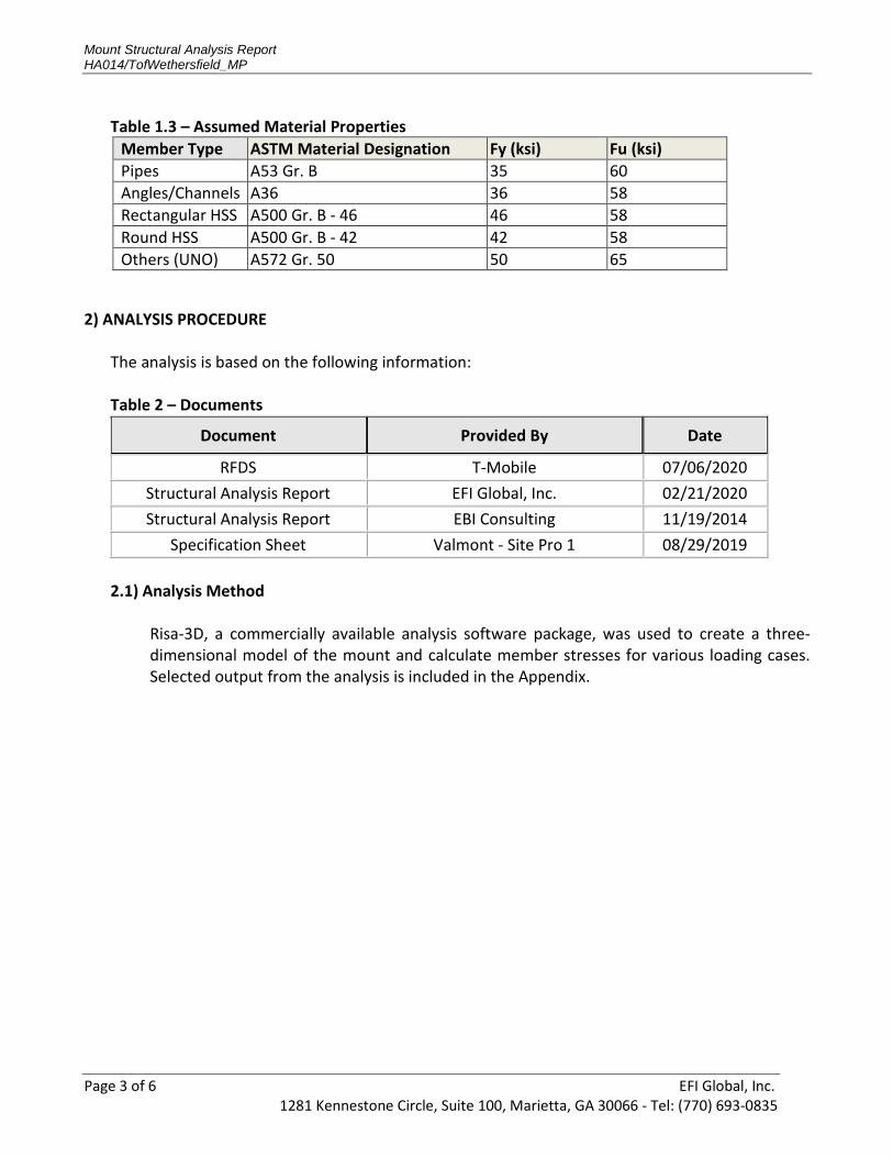
Mount Structural Analysis Report HA014/TofWethersfield_MP
Page 3 of 6 EFI Global, Inc. 1281 Kennestone Circle, Suite 100, Marietta, GA 30066 - Tel: (770) 693-0835
Table 1.3 – Assumed Material Properties
2) ANALYSIS PROCEDURE
The analysis is based on the following information:
Table 2 – Documents
Document Provided By Date
RFDS T-Mobile 07/06/2020
Structural Analysis Report EFI Global, Inc. 02/21/2020
Structural Analysis Report EBI Consulting 11/19/2014
Specification Sheet Valmont - Site Pro 1 08/29/2019
2.1) Analysis Method
Risa-3D, a commercially available analysis software package, was used to create a three-dimensional model of the mount and calculate member stresses for various loading cases. Selected output from the analysis is included in the Appendix.
Member Type ASTM Material Designation Fy (ksi) Fu (ksi)
Pipes A53 Gr. B 35 60
Angles/Channels A36 36 58
Rectangular HSS A500 Gr. B - 46 46 58
Round HSS A500 Gr. B - 42 42 58
Others (UNO) A572 Gr. 50 50 65
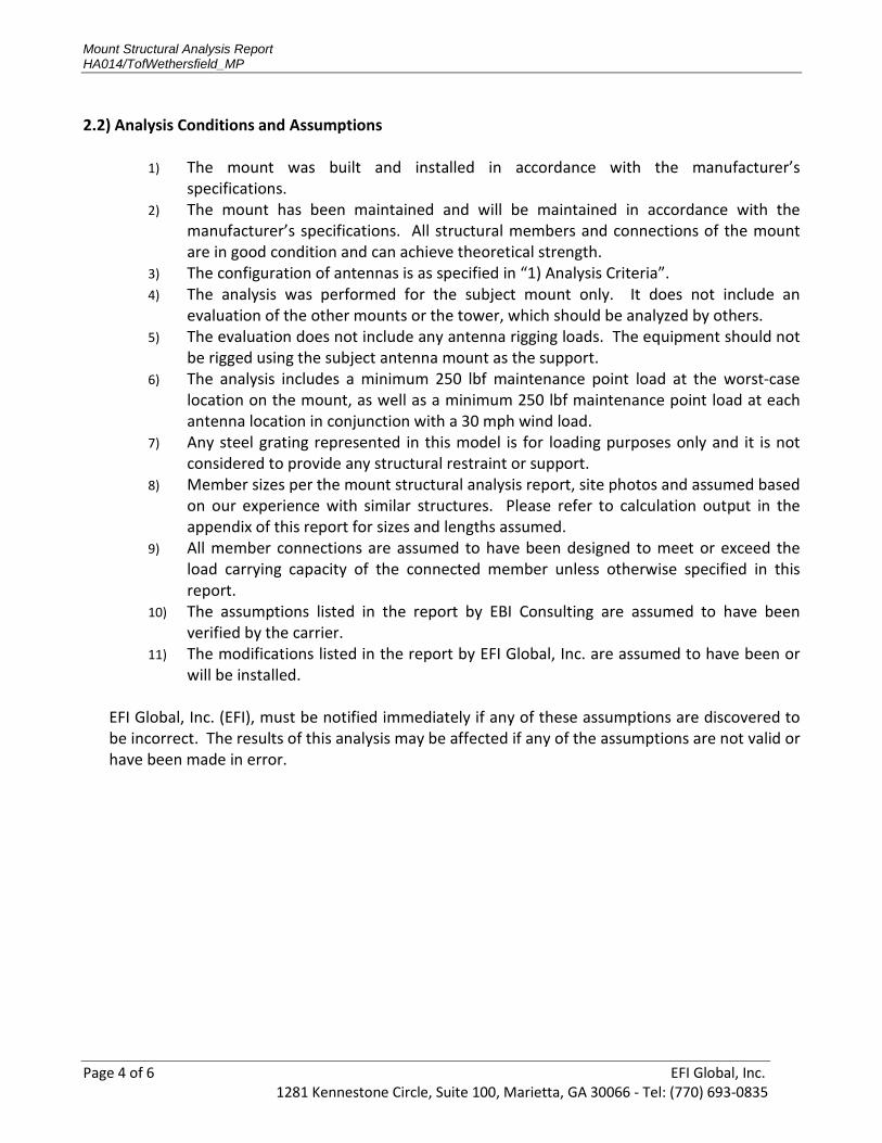
Mount Structural Analysis Report HA014/TofWethersfield_MP
Page 4 of 6 EFI Global, Inc. 1281 Kennestone Circle, Suite 100, Marietta, GA 30066 - Tel: (770) 693-0835
2.2) Analysis Conditions and Assumptions
1) The mount was built and installed in accordance with the manufacturer’s specifications.
2) The mount has been maintained and will be maintained in accordance with the manufacturer’s specifications. All structural members and connections of the mount are in good condition and can achieve theoretical strength.
3) The configuration of antennas is as specified in “1) Analysis Criteria”. 4) The analysis was performed for the subject mount only. It does not include an
evaluation of the other mounts or the tower, which should be analyzed by others. 5) The evaluation does not include any antenna rigging loads. The equipment should not
be rigged using the subject antenna mount as the support. 6) The analysis includes a minimum 250 lbf maintenance point load at the worst-case
location on the mount, as well as a minimum 250 lbf maintenance point load at each antenna location in conjunction with a 30 mph wind load.
7) Any steel grating represented in this model is for loading purposes only and it is not considered to provide any structural restraint or support.
8) Member sizes per the mount structural analysis report, site photos and assumed based on our experience with similar structures. Please refer to calculation output in the appendix of this report for sizes and lengths assumed.
9) All member connections are assumed to have been designed to meet or exceed the load carrying capacity of the connected member unless otherwise specified in this report.
10) The assumptions listed in the report by EBI Consulting are assumed to have been verified by the carrier.
11) The modifications listed in the report by EFI Global, Inc. are assumed to have been or will be installed.
EFI Global, Inc. (EFI), must be notified immediately if any of these assumptions are discovered to be incorrect. The results of this analysis may be affected if any of the assumptions are not valid or have been made in error.
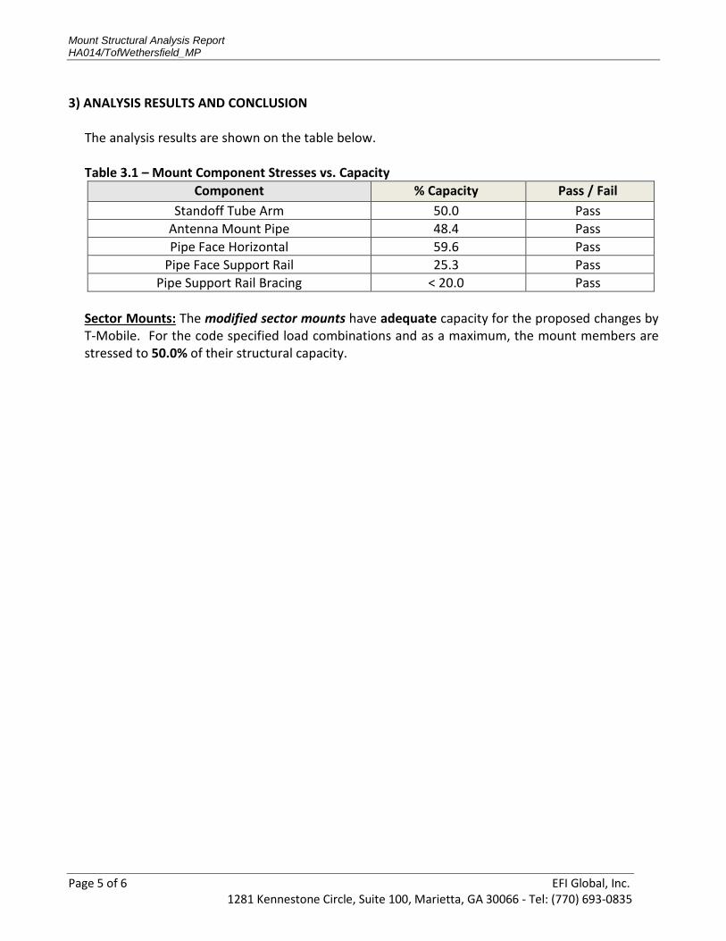
Mount Structural Analysis Report HA014/TofWethersfield_MP
Page 5 of 6 EFI Global, Inc. 1281 Kennestone Circle, Suite 100, Marietta, GA 30066 - Tel: (770) 693-0835
3) ANALYSIS RESULTS AND CONCLUSION
The analysis results are shown on the table below.
Table 3.1 – Mount Component Stresses vs. Capacity
Sector Mounts: The modified sector mounts have adequate capacity for the proposed changes by T-Mobile. For the code specified load combinations and as a maximum, the mount members are stressed to 50.0% of their structural capacity.
Component % Capacity Pass / Fail
Standoff Tube Arm 50.0 Pass
Antenna Mount Pipe 48.4 Pass
Pipe Face Horizontal 59.6 Pass
Pipe Face Support Rail 25.3 Pass
Pipe Support Rail Bracing < 20.0 Pass

Mount Structural Analysis Report HA014/TofWethersfield_MP
Page 6 of 6 EFI Global, Inc. 1281 Kennestone Circle, Suite 100, Marietta, GA 30066 - Tel: (770) 693-0835
APPENDIX
INPUT LOADS ANALYSIS OUTPUT
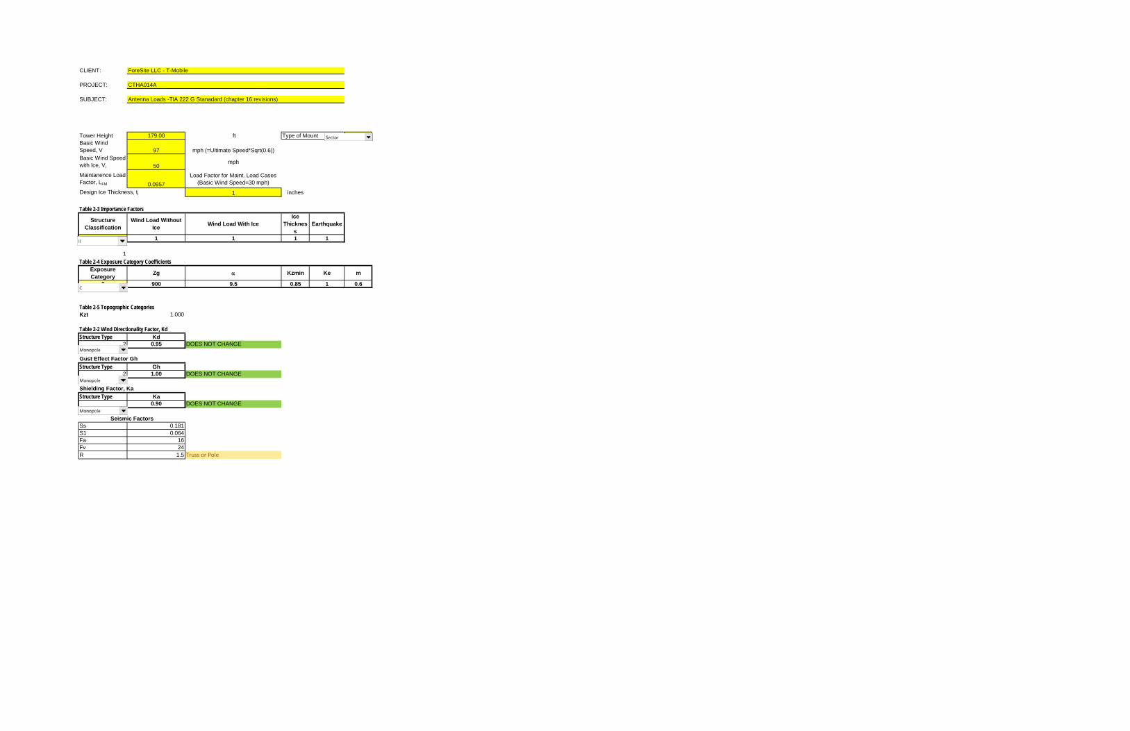
CLIENT: ForeSite LLC - T-Mobile
PROJECT: CTHA014A
SUBJECT: Antenna Loads -TIA 222 G Stanadard (chapter 16 revisions)
Tower Height 179.00 ft Type of Mount 2
Basic Wind
Speed, V 97 mph (=Ultimate Speed*Sqrt(0.6))
Basic Wind Speed
with Ice, Vi 50mph
Maintanence Load
Factor, LFM 0.0957
Load Factor for Maint. Load Cases
(Basic Wind Speed=30 mph)
Design Ice Thickness, ti 1 inches
Table 2-3 Importance Factors
Structure
Classification
Wind Load Without
IceWind Load With Ice
Ice
Thicknes
s
Earthquake
2 1 1 1 1
1
Table 2-4 Exposure Category CoefficientsExposure
CategoryZg Kzmin Ke m
2 900 9.5 0.85 1 0.6
Table 2-5 Topographic CategoriesKzt 1.000
Table 2-2 Wind Directionality Factor, KdStructure Type Kd
2 0.95 DOES NOT CHANGE
Gust Effect Factor Gh
Structure Type Gh2 1.00 DOES NOT CHANGE
Shielding Factor, Ka
Structure Type Ka0.90 DOES NOT CHANGE
Ss 0.181
S1 0.064
Fa 16
Fv 24
R 1.5 Truss or Pole
Seismic Factors
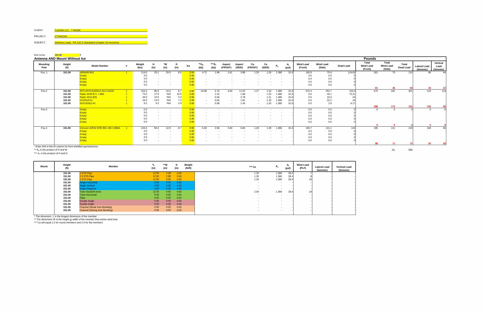
CLIENT: ForeSite LLC - T-Mobile
PROJECT: CTHA014A
SUBJECT: Antenna Loads -TIA 222 G Stanadard (chapter 16 revisions)
Rad Center 151.00 ft
Antenna AND Mount Without Ice
Pos. 1 151.00 AIR6449 B41 1 114.6 33.1 20.5 8.5 0.90 4.72 1.96 1.61 3.88 1.20 1.26 1.380 31.6 160.9 70.4 114.63 161 70 115 80 44
Empty 0.0 - - - 0.90 - - - - - - - - 0.0 0.0 0
Empty 0.0 - - - 0.90 - - - - - - - - 0.0 0.0 0
Empty 0.0 - - - 0.90 - - - - - - - - 0.0 0.0 0
Empty 0.0 - - - 0.90 - - - - - - - - 0.0 0.0 0
81 36 58 40 22
Pos.2 151.00 RFS APXVAARR24-43-U-NA20 1 153.3 95.9 24.0 8.7 0.90 15.98 5.79 4.00 11.02 1.27 1.53 1.380 31.6 575.4 252.7 153.3 575 342 301 210 116
151.00 Radio 4449 B71 + B85 1 73.2 17.9 N/A 10.6 0.90 - 1.32 - 1.68 - 1.20 1.380 31.6 0.0 45.1 73.21
151.00 Radio 4415 B25 1 44.0 15.0 N/A 5.4 0.90 - 0.56 - 2.78 - 1.21 1.380 31.6 0.0 19.3 44
151.00 E15Z01P13 1 24.0 13.0 N/A 7.2 0.90 - 0.65 - 1.81 - 1.20 1.380 31.6 0.0 22.2 24
151.00 SDX1926Q-43 1 6.2 4.2 N/A 2.9 0.90 - 0.08 - 1.43 - 1.20 1.380 31.6 0.0 2.9 6.17
288 172 151 105 58
Pos.3 Empty 0.0 - - - 0.90 - - - - - - - - 0.0 0.0 0 0 0 0 0 0
Empty 0.0 - - - 0.90 - - - - - - - - 0.0 0.0 0
Empty 0.0 - - - 0.90 - - - - - - - - 0.0 0.0 0
Empty 0.0 - - - 0.90 - - - - - - - - 0.0 0.0 0
Empty 0.0 - - - 0.90 - - - - - - - - 0.0 0.0 0
0 0 0 0 0
Pos.4 151.00 Ericsson AIR32 KRD 901 146-1 B66A- 1 143.0 59.3 12.9 8.7 0.90 5.30 3.56 4.60 6.84 1.29 1.39 1.380 31.6 194.7 141.1 143 195 141 143 100 55
Empty 0.0 - - - 0.90 - - - - - - - - 0.0 0.0 0
Empty 0.0 - - - 0.90 - - - - - - - - 0.0 0.0 0
Empty 0.0 - - - 0.90 - - - - - - - - 0.0 0.0 0
Empty 0.0 - - - 0.90 - - - - - - - - 0.0 0.0 0
98 71 72 50 28
* Enter N/A in the W column for front sheilded apurtanances.
** AN is the product of H and W DL 558
*** AT is the product of H and D
151.00 2 STD Pipe 12.00 2.38 0.00 1.20 1.380 28.4 7 - -
151.00 2.5 STD Pipe 12.00 2.88 0.00 1.20 1.380 28.4 8 - -
151.00 3 STD Pipe 12.00 3.50 0.00 1.20 1.380 28.4 10 - -
151.00 Angle Horizontal 0.00 0.00 0.00 - - - - - -
151.00 Angle Vertical 0.00 0.00 0.00 - - - - - -
151.00 Angle Diagonal 0.00 0.00 0.00 - - - - - -
151.00 Tube Standoff (4x4) 12.00 4.00 4.00 2.00 1.380 28.4 19 - -
151.00 Tube Horizontal 0.00 0.00 0.00 - - - - - -
151.00 Plate 0.00 0.00 0.00 - - - - - -
151.00 Double Angle 0.00 0.00 0.00 - - - - - -
151.00 Double Angle 0.00 0.00 0.00 - - - - - -
151.00 Channel (Weak Axis Bending) 0.00 0.00 0.00 - - - - - -
151.00 Channel (Strong Axis Bending) 0.00 0.00 0.00 - - - - - -
* The dimension L is the longest dimension of the member** The dimension W is the height or width of the member that resists wind load
*** Ca will equal 1.2 for round members and 2.0 for flat members
Lateral Load
(Seismic)
Vertical
Load
(Seismic)
Member Kz
Total
Wind Load
(Side)
Dead LoadTotal
Dead Load
Vertical Load
(Seismic)
*L
(in)
**W
(in)
D
(in)
Weight
(lb/ft)
Wind Load
(PLF)
qz
(psf)*** Ca
Total
Wind Load
(Front)
Lateral Load
(Seismic)
Wind Load
(Side)
Ca
(SIDE)Kz
qz
(psf)
***AT
(ft2)
Aspect
(FRONT)
H
(in)
*W
(in)
D
(in)Ka
**AN
(ft2)
Pounds
Mounting
Pole
Height
(ft)Model Number
Weight
(lbs)#
MountHeight
(ft)
Wind Load
(Front)
Aspect
(SIDE)
Ca
(FRONT)
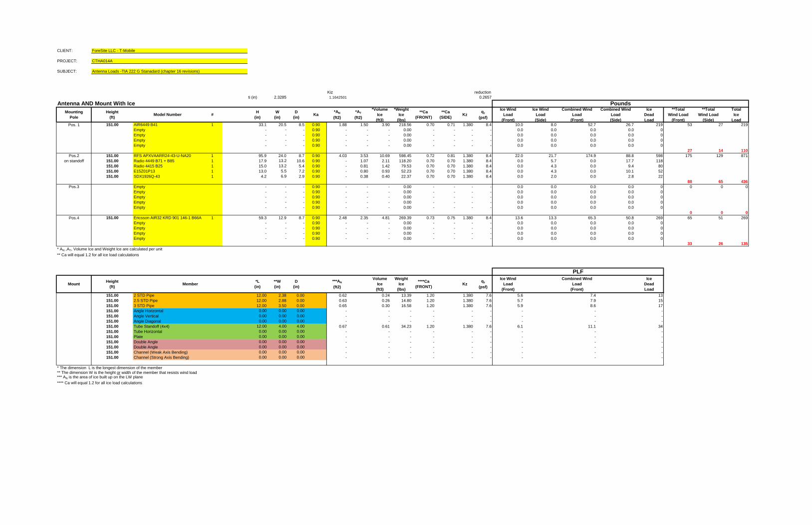
CLIENT: ForeSite LLC - T-Mobile
PROJECT: CTHA014A
SUBJECT: Antenna Loads -TIA 222 G Stanadard (chapter 16 revisions)
Kiz reductionti (in) 2.3285 1.1642501 0.2657
Antenna AND Mount With Ice
Pos. 1 151.00 AIR6449 B41 1 33.1 20.5 8.5 0.90 1.88 1.50 3.90 218.56 0.70 0.71 1.380 8.4 10.0 8.0 52.7 26.7 219 53 27 219
Empty - - - 0.90 - - - 0.00 - - - - 0.0 0.0 0.0 0.0 0
Empty - - - 0.90 - - - 0.00 - - - - 0.0 0.0 0.0 0.0 0
Empty - - - 0.90 - - - 0.00 - - - - 0.0 0.0 0.0 0.0 0
Empty - - - 0.90 - - - 0.00 - - - - 0.0 0.0 0.0 0.0 0
27 14 110
Pos.2 151.00 RFS APXVAARR24-43-U-NA20 1 95.9 24.0 8.7 0.90 4.03 3.53 10.69 598.45 0.72 0.81 1.380 8.4 22.0 21.7 174.9 88.8 598 175 129 871
on standoff 151.00 Radio 4449 B71 + B85 1 17.9 13.2 10.6 0.90 - 1.07 2.11 118.20 0.70 0.70 1.380 8.4 0.0 5.7 0.0 17.7 118
151.00 Radio 4415 B25 1 15.0 13.2 5.4 0.90 - 0.81 1.42 79.53 0.70 0.70 1.380 8.4 0.0 4.3 0.0 9.4 80
151.00 E15Z01P13 1 13.0 5.5 7.2 0.90 - 0.80 0.93 52.23 0.70 0.70 1.380 8.4 0.0 4.3 0.0 10.1 52
151.00 SDX1926Q-43 1 4.2 6.9 2.9 0.90 - 0.38 0.40 22.37 0.70 0.70 1.380 8.4 0.0 2.0 0.0 2.8 22
88 65 436
Pos.3 Empty - - - 0.90 - - - 0.00 - - - - 0.0 0.0 0.0 0.0 0 0 0 0
Empty - - - 0.90 - - - 0.00 - - - - 0.0 0.0 0.0 0.0 0
Empty - - - 0.90 - - - 0.00 - - - - 0.0 0.0 0.0 0.0 0
Empty - - - 0.90 - - - 0.00 - - - - 0.0 0.0 0.0 0.0 0
Empty - - - 0.90 - - - 0.00 - - - - 0.0 0.0 0.0 0.0 0
0 0 0
Pos.4 151.00 Ericsson AIR32 KRD 901 146-1 B66A- 1 59.3 12.9 8.7 0.90 2.48 2.35 4.81 269.39 0.73 0.75 1.380 8.4 13.6 13.3 65.3 50.8 269 65 51 269
Empty - - - 0.90 - - - 0.00 - - - - 0.0 0.0 0.0 0.0 0
Empty - - - 0.90 - - - 0.00 - - - - 0.0 0.0 0.0 0.0 0
Empty - - - 0.90 - - - 0.00 - - - - 0.0 0.0 0.0 0.0 0
Empty - - - 0.90 - - - 0.00 - - - - 0.0 0.0 0.0 0.0 0
33 26 135
* AN ,AT, Volume Ice and Weight Ice are calculated per unit
** Ca will equal 1.2 for all ice load calculations
151.00 2 STD Pipe 12.00 2.38 0.00 0.62 0.24 13.39 1.20 1.380 7.6 5.6 7.4 13
151.00 2.5 STD Pipe 12.00 2.88 0.00 0.63 0.26 14.80 1.20 1.380 7.6 5.7 7.9 15
151.00 3 STD Pipe 12.00 3.50 0.00 0.65 0.30 16.58 1.20 1.380 7.6 5.9 8.6 17
151.00 Angle Horizontal 0.00 0.00 0.00 - - - - - - - - -
151.00 Angle Vertical 0.00 0.00 0.00 - - - - - - - - -
151.00 Angle Diagonal 0.00 0.00 0.00 - - - - - - - - -
151.00 Tube Standoff (4x4) 12.00 4.00 4.00 0.67 0.61 34.23 1.20 1.380 7.6 6.1 11.1 34
151.00 Tube Horizontal 0.00 0.00 0.00 - - - - - - - - -
151.00 Plate 0.00 0.00 0.00 - - - - - - - - -
151.00 Double Angle 0.00 0.00 0.00 - - - - - - - - -
151.00 Double Angle 0.00 0.00 0.00 - - - - - - - - -
151.00 Channel (Weak Axis Bending) 0.00 0.00 0.00 - - - - - - - - -
151.00 Channel (Strong Axis Bending) 0.00 0.00 0.00 - - - - - - - - -
* The dimension L is the longest dimension of the member** The dimension W is the height or width of the member that resists wind load*** AN is the area of ice built up on the LW plane
**** Ca will equal 1.2 for all ice load calculations
PLF
**Total
Wind Load
(Side)
Total
Ice
Load
Ice
Dead
Load
***AN
(ft2)
H
(in)
W
(in)
D
(in)Ka
*AN
(ft2)
PoundsIce Wind
Load
(Side)
Combined Wind
Load
(Front)
Combined Wind
Load
(Side)
**Total
Wind Load
(Front)
Kzqz
(psf)
Ice Wind
Load
(Front)
Combined Wind
Load
(Front)
Ice
Dead
Load
Kzqz
(psf)
Ice Wind
Load
(Front)
MountHeight
(ft)
*L
(in)
**W
(in)
D
(in)Member
Volume
Ice
(ft3)
Weight
Ice
(lbs)
****Ca
(FRONT)
*AT
(ft2)
*Volume
Ice
(ft3)
*Weight
Ice
(lbs)
**Ca
(FRONT)
**Ca
(SIDE)
Mounting
Pole
Height
(ft)Model Number #
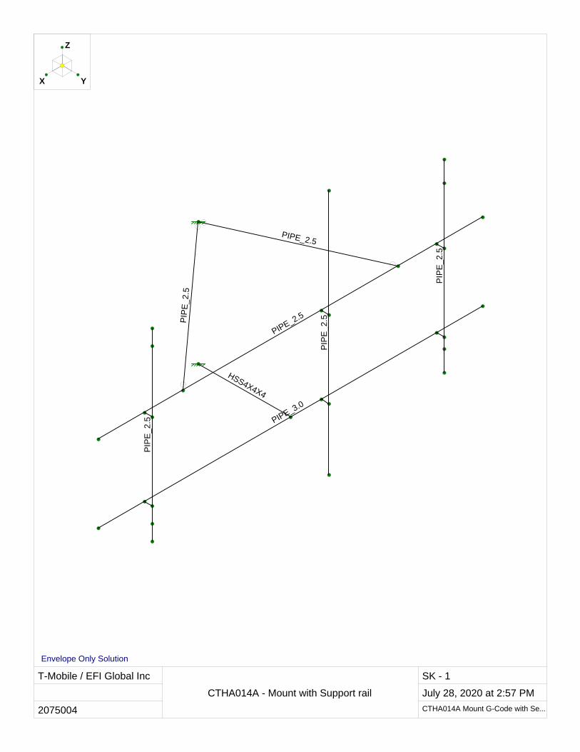
T-Mobile / EFI Global Inc
2075004
CTHA014A - Mount with Support rail
SK - 1
July 28, 2020 at 2:57 PM
CTHA014A Mount G-Code with Se...
HSS4X4X4
PIPE_2.5
PIP
E_
2.5
PIPE_2.5
PIPE_3.0
PIP
E_
2.5
PIP
E_
2.5
PIP
E_
2.5
YX
Z
Envelope Only Solution
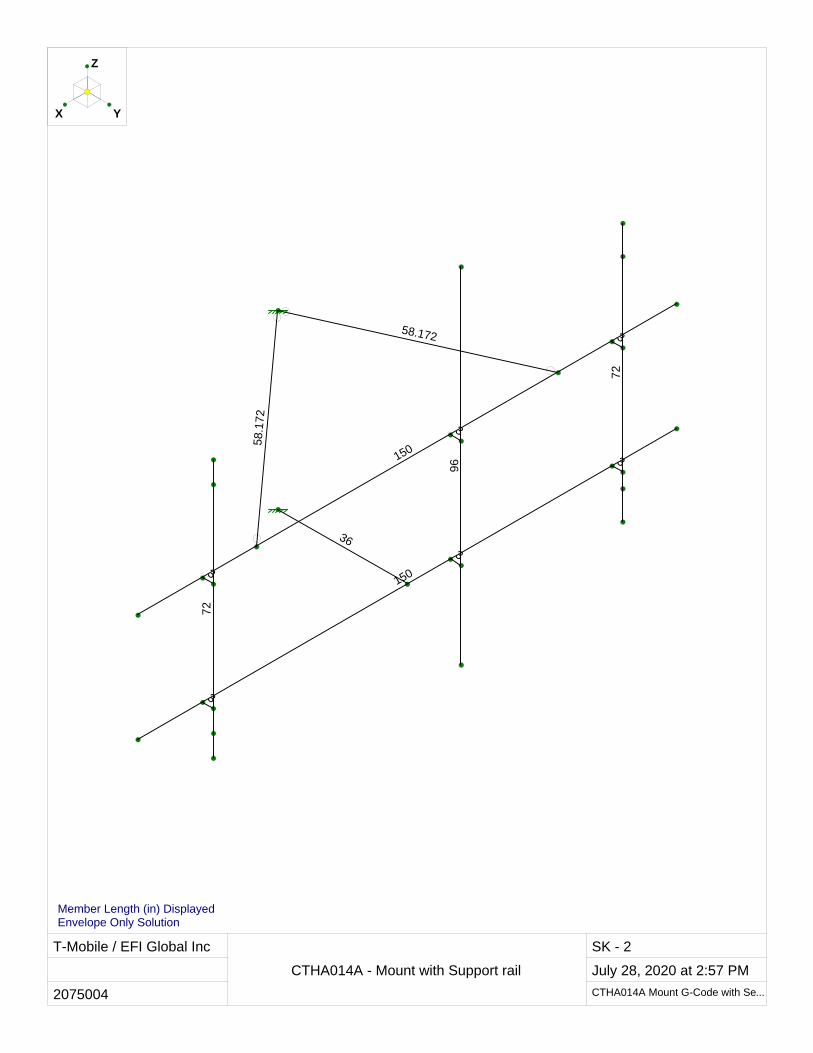
T-Mobile / EFI Global Inc
2075004
CTHA014A - Mount with Support rail
SK - 2
July 28, 2020 at 2:57 PM
CTHA014A Mount G-Code with Se...
36
3
3
3
3
3
358.172
58
.172
150
150
72
96
72
YX
Z
Member Length (in) DisplayedEnvelope Only Solution
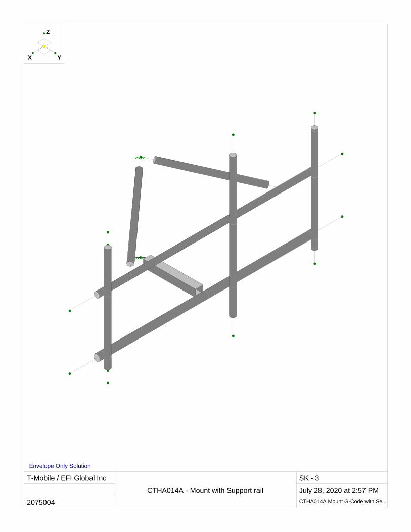
T-Mobile / EFI Global Inc
2075004
CTHA014A - Mount with Support rail
SK - 3
July 28, 2020 at 2:57 PM
CTHA014A Mount G-Code with Se...
YX
Z
Envelope Only Solution
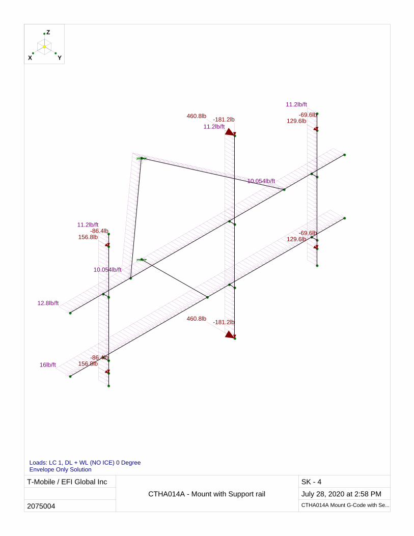
T-Mobile / EFI Global Inc
2075004
CTHA014A - Mount with Support rail
SK - 4
July 28, 2020 at 2:58 PM
CTHA014A Mount G-Code with Se...
10.054lb/ft
10.054lb/ft
12.8lb/ft
16lb/ft
11.2lb/ft
11.2lb/ft
11.2lb/ft
460.8lb-181.2lb
460.8lb-181.2lb
129.6lb-69.6lb
129.6lb-69.6lb
156.8lb-86.4lb
156.8lb-86.4lb
YX
Z
Loads: LC 1, DL + WL (NO ICE) 0 Degree Envelope Only Solution
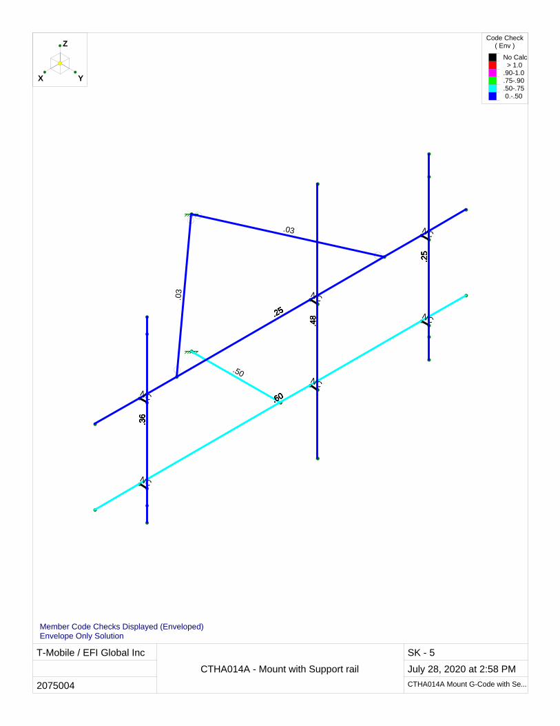
T-Mobile / EFI Global Inc
2075004
CTHA014A - Mount with Support rail
SK - 5
July 28, 2020 at 2:58 PM
CTHA014A Mount G-Code with Se...
.60
.25
.25
NC
.25
.25
.60
NC
.48.25
.50
.25
NC
.60
.03
.25
.25.4
8
NC
.60
.03
.48.25
.36
.36
NC
.60
.36
.25
NC
.25
.36
.36
YX
ZCode Check
( Env )
No Calc > 1.0.90-1.0.75-.90.50-.75 0.-.50
Member Code Checks Displayed (Enveloped)Envelope Only Solution
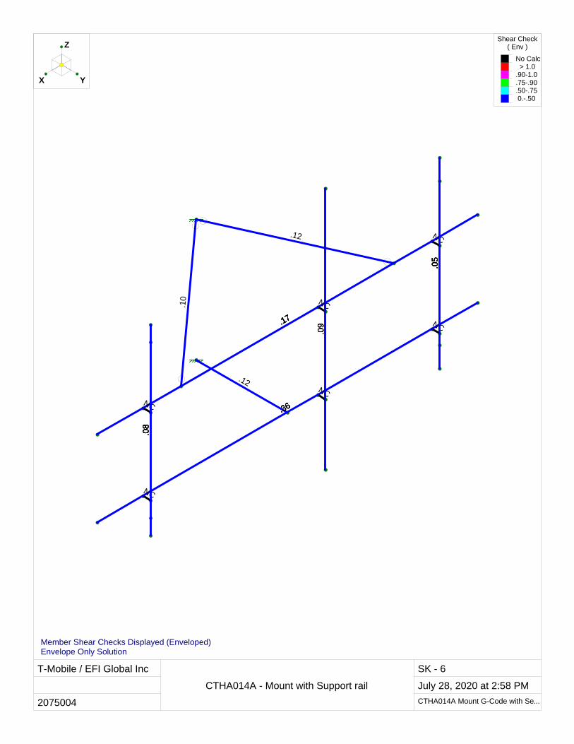
T-Mobile / EFI Global Inc
2075004
CTHA014A - Mount with Support rail
SK - 6
July 28, 2020 at 2:58 PM
CTHA014A Mount G-Code with Se...
.36
.05
.05
NC
.05
.17
.36
NC
.09.17
.12
.05
NC
.36
.12
.05
.17.0
9
NC
.36
.10
.09.17
.08
.08
NC
.36
.08
.17
NC
.17
.08
.08
YX
ZShear Check
( Env )
No Calc > 1.0.90-1.0.75-.90.50-.75 0.-.50
Member Shear Checks Displayed (Enveloped)Envelope Only Solution
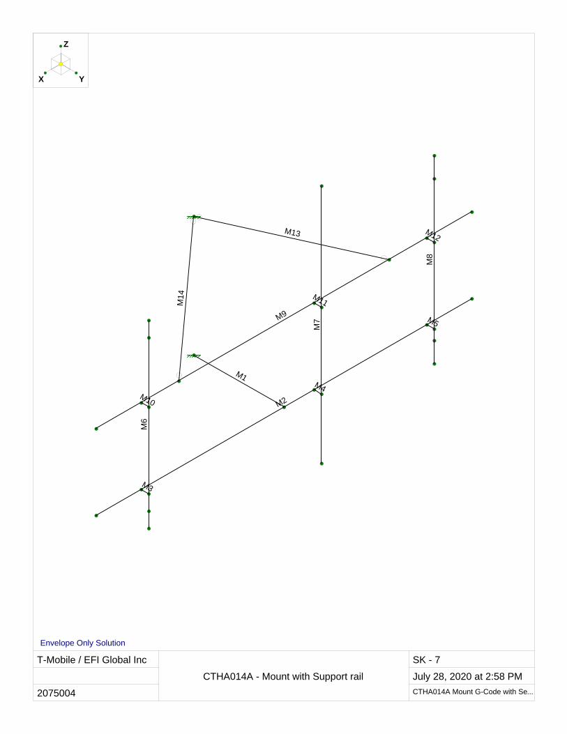
T-Mobile / EFI Global Inc
2075004
CTHA014A - Mount with Support rail
SK - 7
July 28, 2020 at 2:58 PM
CTHA014A Mount G-Code with Se...
M1
M3
M4
M5
M10
M11
M12M13
M14
M9
M2
M6
M7
M8
YX
Z
Envelope Only Solution
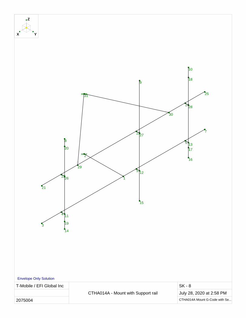
T-Mobile / EFI Global Inc
2075004
CTHA014A - Mount with Support rail
SK - 8
July 28, 2020 at 2:58 PM
CTHA014A Mount G-Code with Se...
1
2
3
4
5
6
7
8
9
10
11
12
13
14
15
16
17
18
19
20
21
22
23
24
25
26
27
28
29
30
31
YX
Z
Envelope Only Solution
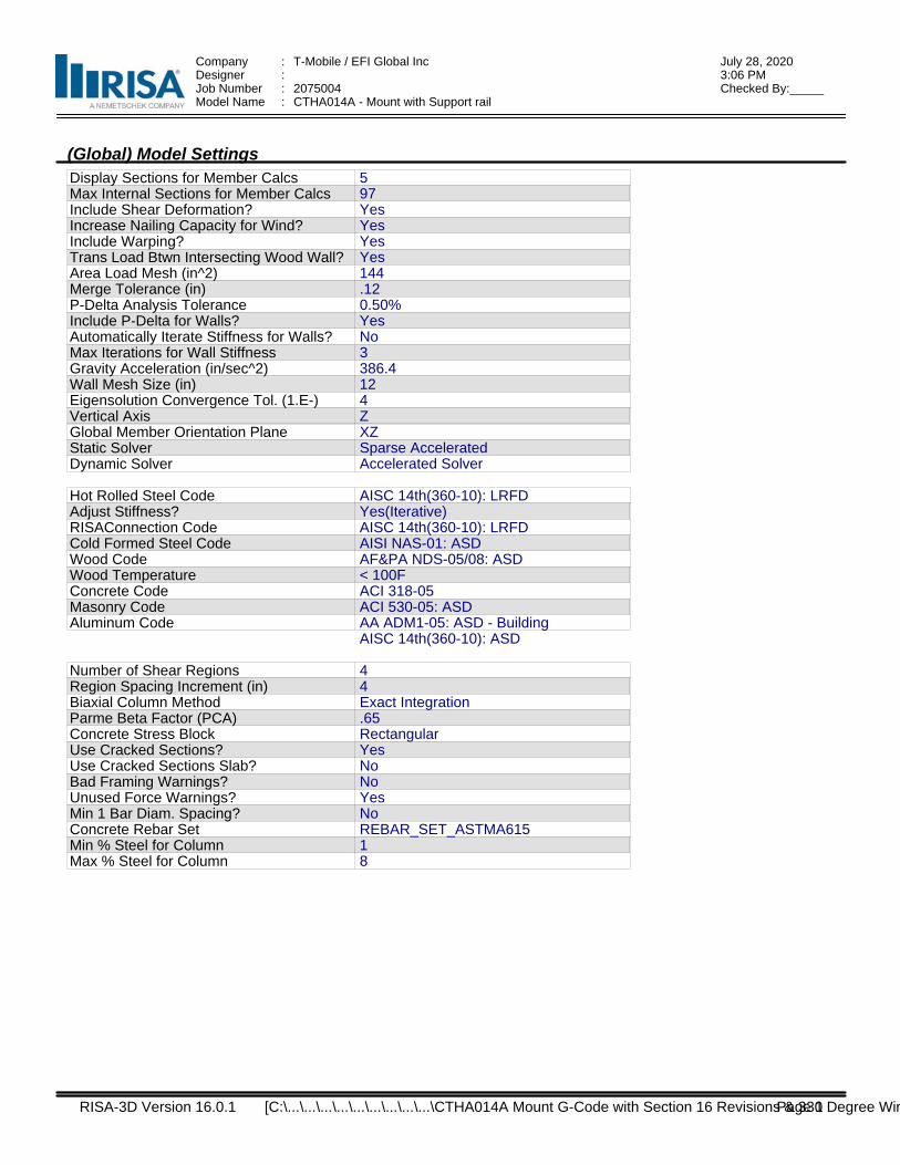
Company : T-Mobile / EFI Global Inc July 28, 20203:06 PMDesigner :
Job Number : 2075004 Checked By:_____Model Name : CTHA014A - Mount with Support rail
(Global) Model SettingsDisplay Sections for Member CalcsMax Internal Sections for Member CalcsInclude Shear Deformation?Increase Nailing Capacity for Wind?Include Warping?Trans Load Btwn Intersecting Wood Wall?Area Load Mesh (in^2)Merge Tolerance (in)P-Delta Analysis ToleranceInclude P-Delta for Walls?Automatically Iterate Stiffness for Walls?Max Iterations for Wall StiffnessGravity Acceleration (in/sec^2)Wall Mesh Size (in)Eigensolution Convergence Tol. (1.E-)Vertical AxisGlobal Member Orientation PlaneStatic SolverDynamic Solver
5 97 YesYesYesYes144.120.50%YesNo3386.4124ZXZSparse AcceleratedAccelerated Solver
Hot Rolled Steel CodeAdjust Stiffness?RISAConnection CodeCold Formed Steel CodeWood CodeWood TemperatureConcrete CodeMasonry CodeAluminum Code
AISC 14th(360-10): LRFDYes(Iterative)AISC 14th(360-10): LRFDAISI NAS-01: ASDAF&PA NDS-05/08: ASD< 100FACI 318-05ACI 530-05: ASDAA ADM1-05: ASD - BuildingAISC 14th(360-10): ASD
Number of Shear RegionsRegion Spacing Increment (in)Biaxial Column MethodParme Beta Factor (PCA)Concrete Stress BlockUse Cracked Sections?Use Cracked Sections Slab?Bad Framing Warnings?Unused Force Warnings?Min 1 Bar Diam. Spacing?Concrete Rebar SetMin % Steel for ColumnMax % Steel for Column
44Exact Integration.65RectangularYesNoNoYesNoREBAR_SET_ASTMA61518
RISA-3D Version 16.0.1 Page 1 [C:\...\...\...\...\...\...\...\...\...\CTHA014A Mount G-Code with Section 16 Revisions & 330 Degree Win
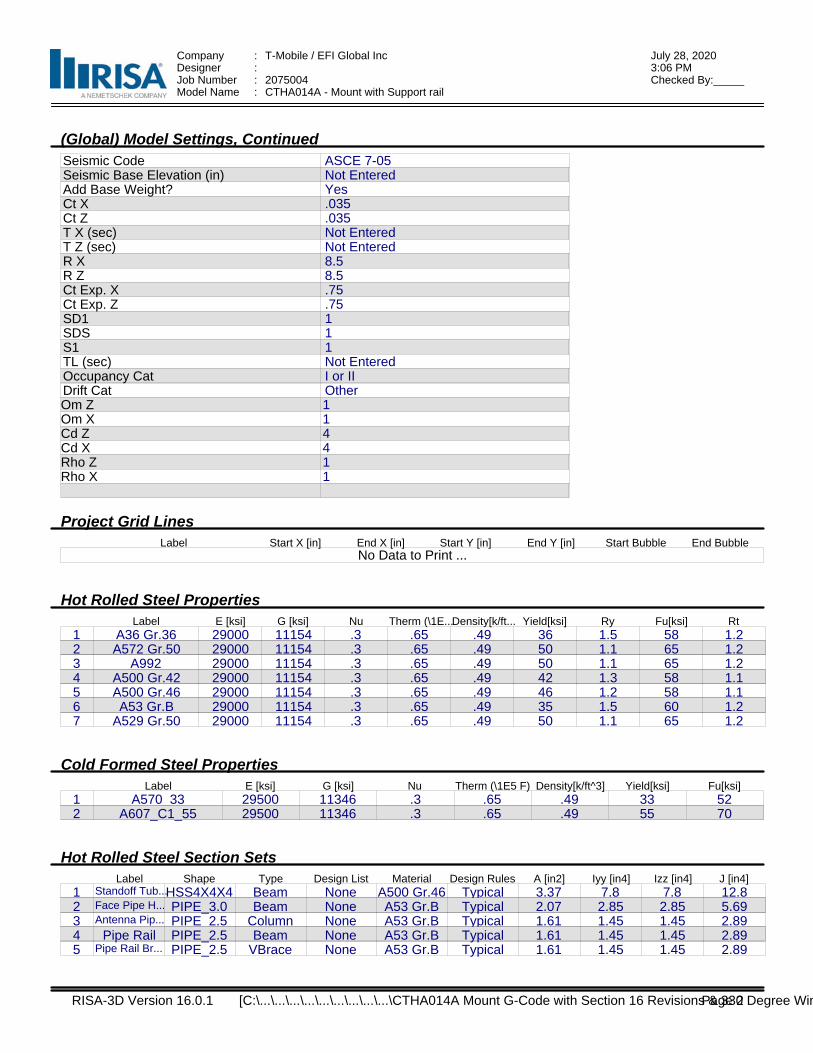
Company : T-Mobile / EFI Global Inc July 28, 20203:06 PMDesigner :
Job Number : 2075004 Checked By:_____Model Name : CTHA014A - Mount with Support rail
(Global) Model Settings, ContinuedSeismic CodeSeismic Base Elevation (in)Add Base Weight?Ct XCt ZT X (sec)T Z (sec)R XR ZCt Exp. XCt Exp. ZSD1SDSS1TL (sec)Occupancy CatDrift Cat
ASCE 7-05Not EnteredYes.035.035Not EnteredNot Entered8.58.5.75.75111Not EnteredI or IIOther
Om ZOm XCd ZCd XRho ZRho X
114411
Project Grid LinesLabel Start X [in] End X [in] Start Y [in] End Y [in] Start Bubble End Bubble
No Data to Print ...
Hot Rolled Steel PropertiesLabel E [ksi] G [ksi] Nu Therm (\1E...Density[k/ft... Yield[ksi] Ry Fu[ksi] Rt
1 A36 Gr.36 29000 11154 .3 .65 .49 36 1.5 58 1.22 A572 Gr.50 29000 11154 .3 .65 .49 50 1.1 65 1.23 A992 29000 11154 .3 .65 .49 50 1.1 65 1.24 A500 Gr.42 29000 11154 .3 .65 .49 42 1.3 58 1.15 A500 Gr.46 29000 11154 .3 .65 .49 46 1.2 58 1.16 A53 Gr.B 29000 11154 .3 .65 .49 35 1.5 60 1.27 A529 Gr.50 29000 11154 .3 .65 .49 50 1.1 65 1.2
Cold Formed Steel PropertiesLabel E [ksi] G [ksi] Nu Therm (\1E5 F) Density[k/ft^3] Yield[ksi] Fu[ksi]
1 A570_33 29500 11346 .3 .65 .49 33 522 A607_C1_55 29500 11346 .3 .65 .49 55 70
Hot Rolled Steel Section SetsLabel Shape Type Design List Material Design Rules A [in2] Iyy [in4] Izz [in4] J [in4]
1 Standoff Tub...HSS4X4X4 Beam None A500 Gr.46 Typical 3.37 7.8 7.8 12.82 Face Pipe H... PIPE_3.0 Beam None A53 Gr.B Typical 2.07 2.85 2.85 5.693 Antenna Pip... PIPE_2.5 Column None A53 Gr.B Typical 1.61 1.45 1.45 2.894 Pipe Rail PIPE_2.5 Beam None A53 Gr.B Typical 1.61 1.45 1.45 2.895 Pipe Rail Br... PIPE_2.5 VBrace None A53 Gr.B Typical 1.61 1.45 1.45 2.89
RISA-3D Version 16.0.1 Page 2 [C:\...\...\...\...\...\...\...\...\...\CTHA014A Mount G-Code with Section 16 Revisions & 330 Degree Win
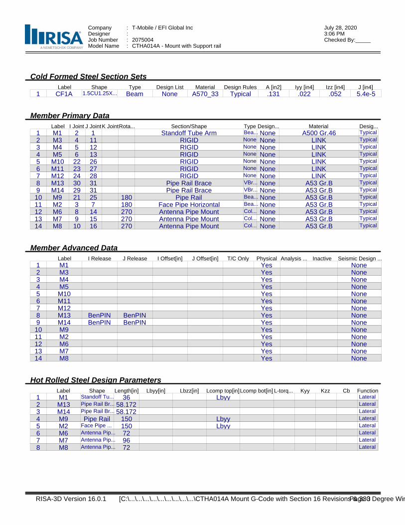
Company : T-Mobile / EFI Global Inc July 28, 20203:06 PMDesigner :
Job Number : 2075004 Checked By:_____Model Name : CTHA014A - Mount with Support rail
Cold Formed Steel Section SetsLabel Shape Type Design List Material Design Rules A [in2] Iyy [in4] Izz [in4] J [in4]
1 CF1A 1.5CU1.25X... Beam None A570_33 Typical .131 .022 .052 5.4e-5
Member Primary DataLabel I Joint J JointK JointRota... Section/Shape Type Design... Material Desig...
1 M1 2 1 Standoff Tube Arm Bea... None A500 Gr.46 Typical
2 M3 4 11 RIGID None None LINK Typical
3 M4 5 12 RIGID None None LINK Typical
4 M5 6 13 RIGID None None LINK Typical
5 M10 22 26 RIGID None None LINK Typical
6 M11 23 27 RIGID None None LINK Typical
7 M12 24 28 RIGID None None LINK Typical
8 M13 30 31 Pipe Rail Brace VBr... None A53 Gr.B Typical
9 M14 29 31 Pipe Rail Brace VBr... None A53 Gr.B Typical
10 M9 21 25 180 Pipe Rail Bea... None A53 Gr.B Typical
11 M2 3 7 180 Face Pipe Horizontal Bea... None A53 Gr.B Typical
12 M6 8 14 270 Antenna Pipe Mount Col... None A53 Gr.B Typical
13 M7 9 15 270 Antenna Pipe Mount Col... None A53 Gr.B Typical
14 M8 10 16 270 Antenna Pipe Mount Col... None A53 Gr.B Typical
Member Advanced DataLabel I Release J Release I Offset[in] J Offset[in] T/C Only Physical Analysis ... Inactive Seismic Design ...
1 M1 Yes None2 M3 Yes None3 M4 Yes None4 M5 Yes None5 M10 Yes None6 M11 Yes None7 M12 Yes None8 M13 BenPIN BenPIN Yes None9 M14 BenPIN BenPIN Yes None10 M9 Yes None11 M2 Yes None12 M6 Yes None13 M7 Yes None14 M8 Yes None
Hot Rolled Steel Design ParametersLabel Shape Length[in] Lbyy[in] Lbzz[in] Lcomp top[in]Lcomp bot[in] L-torq... Kyy Kzz Cb Function
1 M1 Standoff Tu... 36 Lbyy Lateral
2 M13 Pipe Rail Br... 58.172 Lateral
3 M14 Pipe Rail Br... 58.172 Lateral
4 M9 Pipe Rail 150 Lbyy Lateral
5 M2 Face Pipe ... 150 Lbyy Lateral
6 M6 Antenna Pip... 72 Lateral
7 M7 Antenna Pip... 96 Lateral
8 M8 Antenna Pip... 72 Lateral
RISA-3D Version 16.0.1 Page 3 [C:\...\...\...\...\...\...\...\...\...\CTHA014A Mount G-Code with Section 16 Revisions & 330 Degree Win
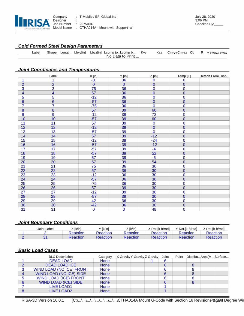
Company : T-Mobile / EFI Global Inc July 28, 20203:06 PMDesigner :
Job Number : 2075004 Checked By:_____Model Name : CTHA014A - Mount with Support rail
Cold Formed Steel Design ParametersLabel Shape Lengt... Lbyy[in] Lbzz[in] Lcomp to...Lcomp b... Kyy Kzz Cm-yyCm-zz Cb R y swayz sway
No Data to Print ...
Joint Coordinates and TemperaturesLabel X [in] Y [in] Z [in] Temp [F] Detach From Diap...
1 1 -0. 36 0 02 2 0 0 0 03 3 75 36 0 04 4 57 36 0 05 5 -12 36 0 06 6 -57 36 0 07 7 -75 36 0 08 8 57 39 60 09 9 -12 39 72 010 10 -57 39 60 011 11 57 39 0 012 12 -12 39 0 013 13 -57 39 0 014 14 57 39 -12 015 15 -12 39 -24 016 16 -57 39 -12 017 17 -57 39 -4 018 18 -57 39 52 019 19 57 39 -6 020 20 57 39 54 021 21 75 36 30 022 22 57 36 30 023 23 -12 36 30 024 24 -57 36 30 025 25 -75 36 30 026 26 57 39 30 027 27 -12 39 30 028 28 -57 39 30 029 29 42 36 30 030 30 -42 36 30 031 31 0 0 48 0
Joint Boundary ConditionsJoint Label X [k/in] Y [k/in] Z [k/in] X Rot.[k-ft/rad] Y Rot.[k-ft/rad] Z Rot.[k-ft/rad]
1 2 Reaction Reaction Reaction Reaction Reaction Reaction2 31 Reaction Reaction Reaction Reaction Reaction Reaction
Basic Load CasesBLC Description Category X GravityY Gravity Z Gravity Joint Point Distribu...Area(M...Surface...
1 DEAD LOAD None -1 62 DEAD LOAD ICE None 6 83 WIND LOAD (NO ICE) FRONT None 6 84 WIND LOAD (NO ICE) SIDE None 6 85 WIND LOAD (ICE) FRONT None 6 86 WIND LOAD (ICE) SIDE None 6 87 LIVE LOAD1 None 18 LIVE LOAD2 None 1
RISA-3D Version 16.0.1 Page 4 [C:\...\...\...\...\...\...\...\...\...\CTHA014A Mount G-Code with Section 16 Revisions & 330 Degree Win
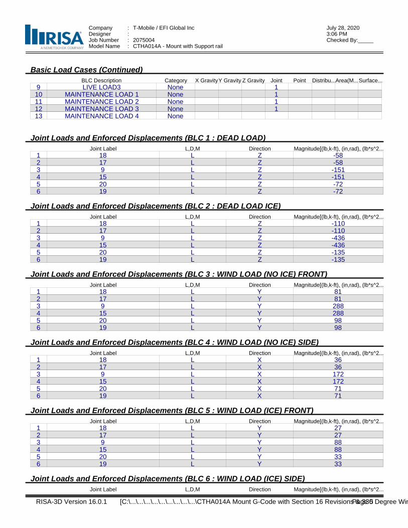
Company : T-Mobile / EFI Global Inc July 28, 20203:06 PMDesigner :
Job Number : 2075004 Checked By:_____Model Name : CTHA014A - Mount with Support rail
Basic Load Cases (Continued)BLC Description Category X GravityY Gravity Z Gravity Joint Point Distribu...Area(M...Surface...
9 LIVE LOAD3 None 110 MAINTENANCE LOAD 1 None 111 MAINTENANCE LOAD 2 None 112 MAINTENANCE LOAD 3 None 113 MAINTENANCE LOAD 4 None
Joint Loads and Enforced Displacements (BLC 1 : DEAD LOAD)Joint Label L,D,M Direction Magnitude[(lb,k-ft), (in,rad), (lb*s^2...
1 18 L Z -582 17 L Z -583 9 L Z -1514 15 L Z -1515 20 L Z -726 19 L Z -72
Joint Loads and Enforced Displacements (BLC 2 : DEAD LOAD ICE)Joint Label L,D,M Direction Magnitude[(lb,k-ft), (in,rad), (lb*s^2...
1 18 L Z -1102 17 L Z -1103 9 L Z -4364 15 L Z -4365 20 L Z -1356 19 L Z -135
Joint Loads and Enforced Displacements (BLC 3 : WIND LOAD (NO ICE) FRONT)Joint Label L,D,M Direction Magnitude[(lb,k-ft), (in,rad), (lb*s^2...
1 18 L Y 812 17 L Y 813 9 L Y 2884 15 L Y 2885 20 L Y 986 19 L Y 98
Joint Loads and Enforced Displacements (BLC 4 : WIND LOAD (NO ICE) SIDE)Joint Label L,D,M Direction Magnitude[(lb,k-ft), (in,rad), (lb*s^2...
1 18 L X 362 17 L X 363 9 L X 1724 15 L X 1725 20 L X 716 19 L X 71
Joint Loads and Enforced Displacements (BLC 5 : WIND LOAD (ICE) FRONT)Joint Label L,D,M Direction Magnitude[(lb,k-ft), (in,rad), (lb*s^2...
1 18 L Y 272 17 L Y 273 9 L Y 884 15 L Y 885 20 L Y 336 19 L Y 33
Joint Loads and Enforced Displacements (BLC 6 : WIND LOAD (ICE) SIDE)Joint Label L,D,M Direction Magnitude[(lb,k-ft), (in,rad), (lb*s^2...
RISA-3D Version 16.0.1 Page 5 [C:\...\...\...\...\...\...\...\...\...\CTHA014A Mount G-Code with Section 16 Revisions & 330 Degree Win
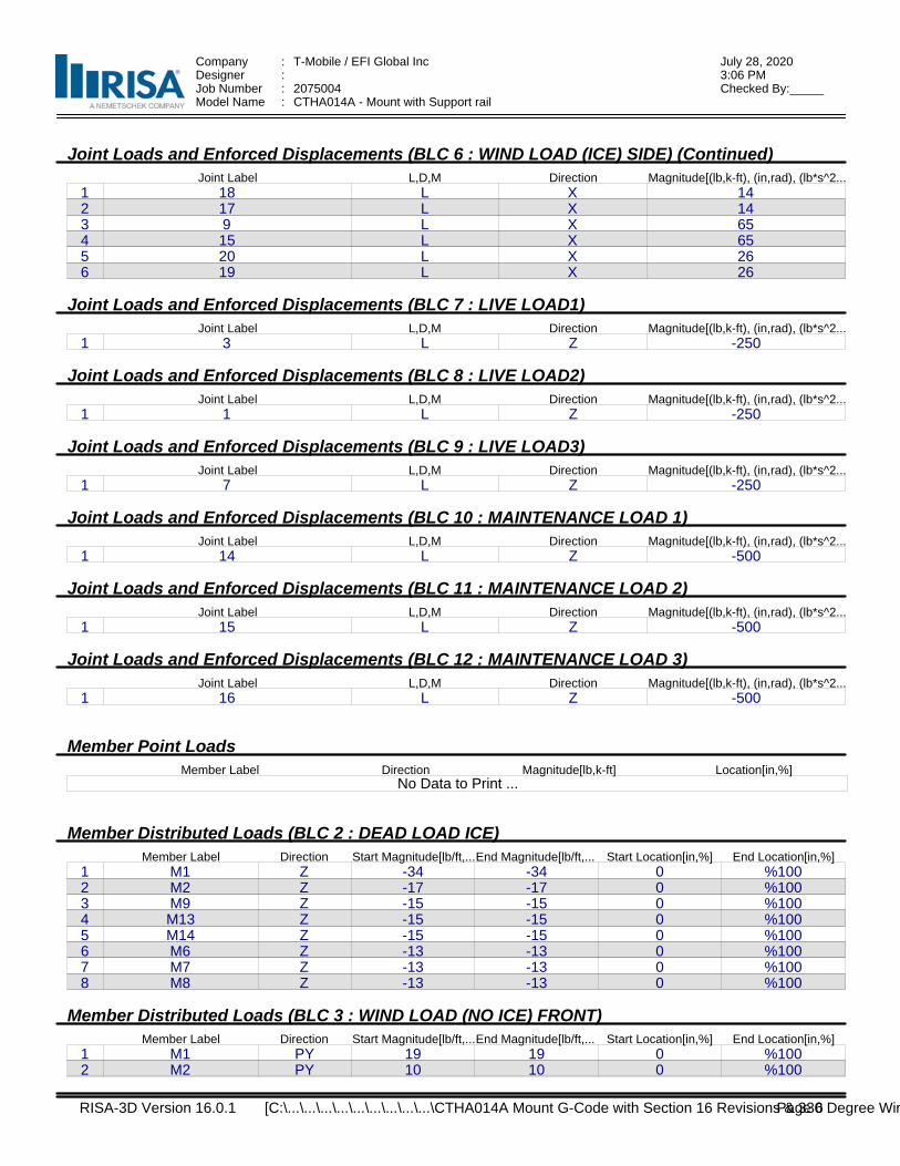
Company : T-Mobile / EFI Global Inc July 28, 20203:06 PMDesigner :
Job Number : 2075004 Checked By:_____Model Name : CTHA014A - Mount with Support rail
Joint Loads and Enforced Displacements (BLC 6 : WIND LOAD (ICE) SIDE) (Continued)Joint Label L,D,M Direction Magnitude[(lb,k-ft), (in,rad), (lb*s^2...
1 18 L X 142 17 L X 143 9 L X 654 15 L X 655 20 L X 266 19 L X 26
Joint Loads and Enforced Displacements (BLC 7 : LIVE LOAD1)Joint Label L,D,M Direction Magnitude[(lb,k-ft), (in,rad), (lb*s^2...
1 3 L Z -250
Joint Loads and Enforced Displacements (BLC 8 : LIVE LOAD2)Joint Label L,D,M Direction Magnitude[(lb,k-ft), (in,rad), (lb*s^2...
1 1 L Z -250
Joint Loads and Enforced Displacements (BLC 9 : LIVE LOAD3)Joint Label L,D,M Direction Magnitude[(lb,k-ft), (in,rad), (lb*s^2...
1 7 L Z -250
Joint Loads and Enforced Displacements (BLC 10 : MAINTENANCE LOAD 1)Joint Label L,D,M Direction Magnitude[(lb,k-ft), (in,rad), (lb*s^2...
1 14 L Z -500
Joint Loads and Enforced Displacements (BLC 11 : MAINTENANCE LOAD 2)Joint Label L,D,M Direction Magnitude[(lb,k-ft), (in,rad), (lb*s^2...
1 15 L Z -500
Joint Loads and Enforced Displacements (BLC 12 : MAINTENANCE LOAD 3)Joint Label L,D,M Direction Magnitude[(lb,k-ft), (in,rad), (lb*s^2...
1 16 L Z -500
Member Point Loads Member Label Direction Magnitude[lb,k-ft] Location[in,%]
No Data to Print ...
Member Distributed Loads (BLC 2 : DEAD LOAD ICE)Member Label Direction Start Magnitude[lb/ft,...End Magnitude[lb/ft,... Start Location[in,%] End Location[in,%]
1 M1 Z -34 -34 0 %1002 M2 Z -17 -17 0 %1003 M9 Z -15 -15 0 %1004 M13 Z -15 -15 0 %1005 M14 Z -15 -15 0 %1006 M6 Z -13 -13 0 %1007 M7 Z -13 -13 0 %1008 M8 Z -13 -13 0 %100
Member Distributed Loads (BLC 3 : WIND LOAD (NO ICE) FRONT)Member Label Direction Start Magnitude[lb/ft,...End Magnitude[lb/ft,... Start Location[in,%] End Location[in,%]
1 M1 PY 19 19 0 %1002 M2 PY 10 10 0 %100
RISA-3D Version 16.0.1 Page 6 [C:\...\...\...\...\...\...\...\...\...\CTHA014A Mount G-Code with Section 16 Revisions & 330 Degree Win
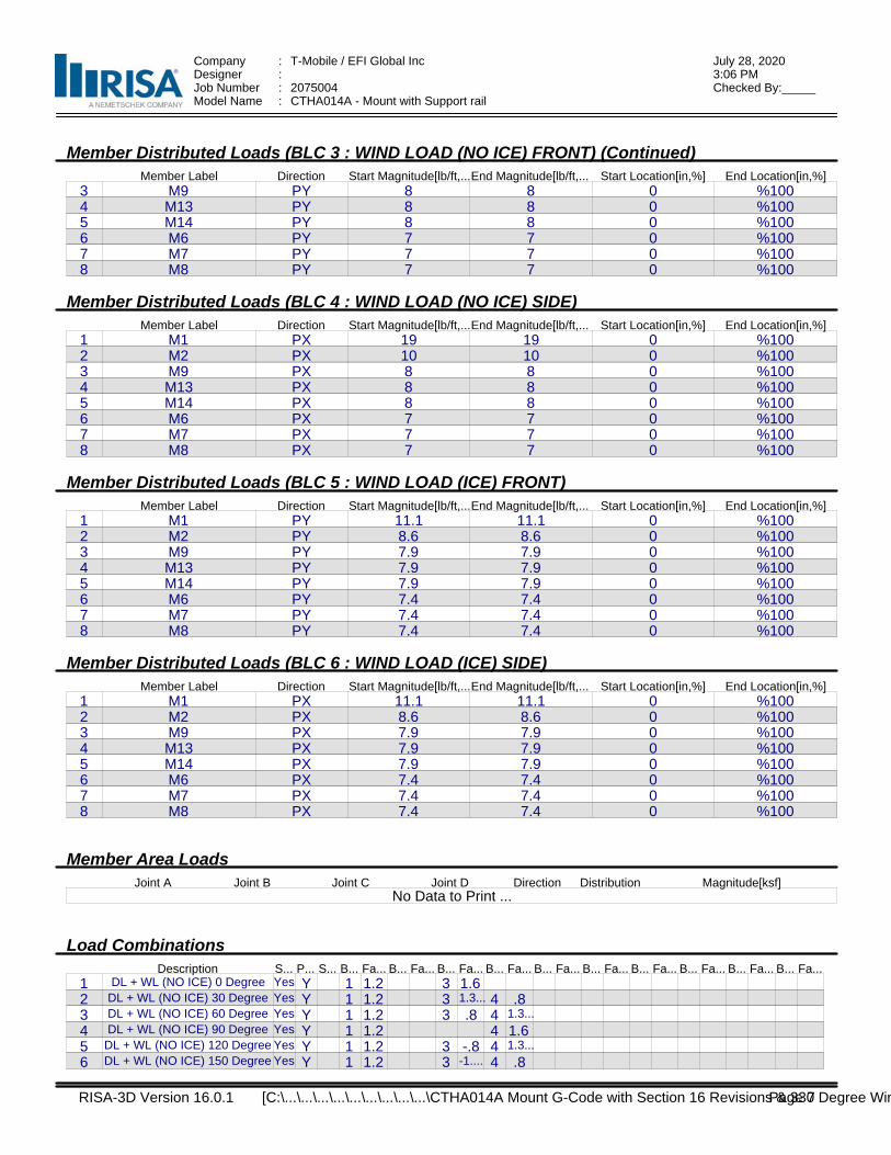
Company : T-Mobile / EFI Global Inc July 28, 20203:06 PMDesigner :
Job Number : 2075004 Checked By:_____Model Name : CTHA014A - Mount with Support rail
Member Distributed Loads (BLC 3 : WIND LOAD (NO ICE) FRONT) (Continued)Member Label Direction Start Magnitude[lb/ft,...End Magnitude[lb/ft,... Start Location[in,%] End Location[in,%]
3 M9 PY 8 8 0 %1004 M13 PY 8 8 0 %1005 M14 PY 8 8 0 %1006 M6 PY 7 7 0 %1007 M7 PY 7 7 0 %1008 M8 PY 7 7 0 %100
Member Distributed Loads (BLC 4 : WIND LOAD (NO ICE) SIDE)Member Label Direction Start Magnitude[lb/ft,...End Magnitude[lb/ft,... Start Location[in,%] End Location[in,%]
1 M1 PX 19 19 0 %1002 M2 PX 10 10 0 %1003 M9 PX 8 8 0 %1004 M13 PX 8 8 0 %1005 M14 PX 8 8 0 %1006 M6 PX 7 7 0 %1007 M7 PX 7 7 0 %1008 M8 PX 7 7 0 %100
Member Distributed Loads (BLC 5 : WIND LOAD (ICE) FRONT)Member Label Direction Start Magnitude[lb/ft,...End Magnitude[lb/ft,... Start Location[in,%] End Location[in,%]
1 M1 PY 11.1 11.1 0 %1002 M2 PY 8.6 8.6 0 %1003 M9 PY 7.9 7.9 0 %1004 M13 PY 7.9 7.9 0 %1005 M14 PY 7.9 7.9 0 %1006 M6 PY 7.4 7.4 0 %1007 M7 PY 7.4 7.4 0 %1008 M8 PY 7.4 7.4 0 %100
Member Distributed Loads (BLC 6 : WIND LOAD (ICE) SIDE)Member Label Direction Start Magnitude[lb/ft,...End Magnitude[lb/ft,... Start Location[in,%] End Location[in,%]
1 M1 PX 11.1 11.1 0 %1002 M2 PX 8.6 8.6 0 %1003 M9 PX 7.9 7.9 0 %1004 M13 PX 7.9 7.9 0 %1005 M14 PX 7.9 7.9 0 %1006 M6 PX 7.4 7.4 0 %1007 M7 PX 7.4 7.4 0 %1008 M8 PX 7.4 7.4 0 %100
Member Area Loads Joint A Joint B Joint C Joint D Direction Distribution Magnitude[ksf]
No Data to Print ...
Load CombinationsDescription S... P... S... B... Fa... B... Fa... B... Fa... B... Fa... B... Fa... B... Fa... B... Fa... B... Fa... B... Fa... B... Fa...
1 DL + WL (NO ICE) 0 Degree Yes Y 1 1.2 3 1.62 DL + WL (NO ICE) 30 Degree Yes Y 1 1.2 3 1.3... 4 .83 DL + WL (NO ICE) 60 Degree Yes Y 1 1.2 3 .8 4 1.3...
4 DL + WL (NO ICE) 90 Degree Yes Y 1 1.2 4 1.65 DL + WL (NO ICE) 120 Degree Yes Y 1 1.2 3 -.8 4 1.3...
6 DL + WL (NO ICE) 150 Degree Yes Y 1 1.2 3 -1.... 4 .8
RISA-3D Version 16.0.1 Page 7 [C:\...\...\...\...\...\...\...\...\...\CTHA014A Mount G-Code with Section 16 Revisions & 330 Degree Win
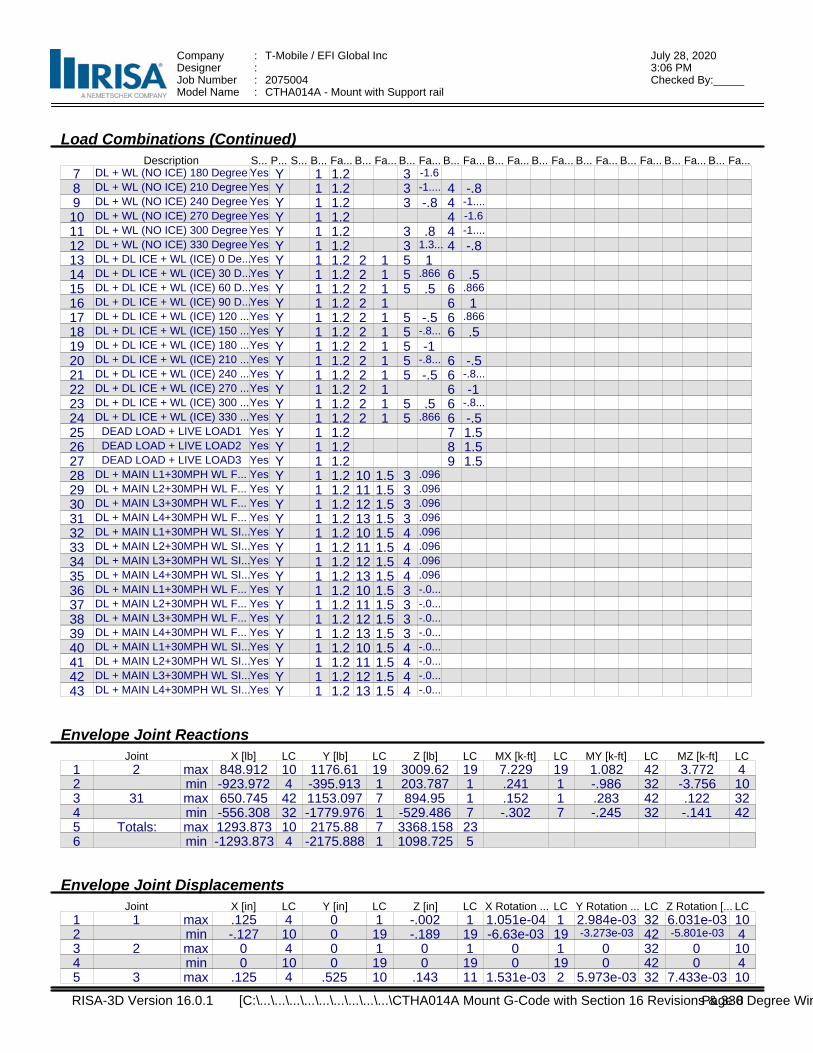
Company : T-Mobile / EFI Global Inc July 28, 20203:06 PMDesigner :
Job Number : 2075004 Checked By:_____Model Name : CTHA014A - Mount with Support rail
Load Combinations (Continued)Description S... P... S... B... Fa... B... Fa... B... Fa... B... Fa... B... Fa... B... Fa... B... Fa... B... Fa... B... Fa... B... Fa...
7 DL + WL (NO ICE) 180 Degree Yes Y 1 1.2 3 -1.6
8 DL + WL (NO ICE) 210 Degree Yes Y 1 1.2 3 -1.... 4 -.89 DL + WL (NO ICE) 240 Degree Yes Y 1 1.2 3 -.8 4 -1....
10 DL + WL (NO ICE) 270 Degree Yes Y 1 1.2 4 -1.6
11 DL + WL (NO ICE) 300 Degree Yes Y 1 1.2 3 .8 4 -1....
12 DL + WL (NO ICE) 330 Degree Yes Y 1 1.2 3 1.3... 4 -.813 DL + DL ICE + WL (ICE) 0 De...Yes Y 1 1.2 2 1 5 114 DL + DL ICE + WL (ICE) 30 D...Yes Y 1 1.2 2 1 5 .866 6 .515 DL + DL ICE + WL (ICE) 60 D...Yes Y 1 1.2 2 1 5 .5 6 .866
16 DL + DL ICE + WL (ICE) 90 D...Yes Y 1 1.2 2 1 6 117 DL + DL ICE + WL (ICE) 120 ...Yes Y 1 1.2 2 1 5 -.5 6 .866
18 DL + DL ICE + WL (ICE) 150 ...Yes Y 1 1.2 2 1 5 -.8... 6 .519 DL + DL ICE + WL (ICE) 180 ...Yes Y 1 1.2 2 1 5 -120 DL + DL ICE + WL (ICE) 210 ...Yes Y 1 1.2 2 1 5 -.8... 6 -.521 DL + DL ICE + WL (ICE) 240 ...Yes Y 1 1.2 2 1 5 -.5 6 -.8...
22 DL + DL ICE + WL (ICE) 270 ...Yes Y 1 1.2 2 1 6 -123 DL + DL ICE + WL (ICE) 300 ...Yes Y 1 1.2 2 1 5 .5 6 -.8...
24 DL + DL ICE + WL (ICE) 330 ...Yes Y 1 1.2 2 1 5 .866 6 -.525 DEAD LOAD + LIVE LOAD1 Yes Y 1 1.2 7 1.526 DEAD LOAD + LIVE LOAD2 Yes Y 1 1.2 8 1.527 DEAD LOAD + LIVE LOAD3 Yes Y 1 1.2 9 1.528 DL + MAIN L1+30MPH WL F... Yes Y 1 1.2 10 1.5 3 .096
29 DL + MAIN L2+30MPH WL F... Yes Y 1 1.2 11 1.5 3 .096
30 DL + MAIN L3+30MPH WL F... Yes Y 1 1.2 12 1.5 3 .096
31 DL + MAIN L4+30MPH WL F... Yes Y 1 1.2 13 1.5 3 .096
32 DL + MAIN L1+30MPH WL SI...Yes Y 1 1.2 10 1.5 4 .096
33 DL + MAIN L2+30MPH WL SI...Yes Y 1 1.2 11 1.5 4 .096
34 DL + MAIN L3+30MPH WL SI...Yes Y 1 1.2 12 1.5 4 .096
35 DL + MAIN L4+30MPH WL SI...Yes Y 1 1.2 13 1.5 4 .096
36 DL + MAIN L1+30MPH WL F... Yes Y 1 1.2 10 1.5 3 -.0...
37 DL + MAIN L2+30MPH WL F... Yes Y 1 1.2 11 1.5 3 -.0...
38 DL + MAIN L3+30MPH WL F... Yes Y 1 1.2 12 1.5 3 -.0...
39 DL + MAIN L4+30MPH WL F... Yes Y 1 1.2 13 1.5 3 -.0...
40 DL + MAIN L1+30MPH WL SI...Yes Y 1 1.2 10 1.5 4 -.0...
41 DL + MAIN L2+30MPH WL SI...Yes Y 1 1.2 11 1.5 4 -.0...
42 DL + MAIN L3+30MPH WL SI...Yes Y 1 1.2 12 1.5 4 -.0...
43 DL + MAIN L4+30MPH WL SI...Yes Y 1 1.2 13 1.5 4 -.0...
Envelope Joint ReactionsJoint X [lb] LC Y [lb] LC Z [lb] LC MX [k-ft] LC MY [k-ft] LC MZ [k-ft] LC
1 2 max 848.912 10 1176.61 19 3009.62 19 7.229 19 1.082 42 3.772 42 min -923.972 4 -395.913 1 203.787 1 .241 1 -.986 32 -3.756 103 31 max 650.745 42 1153.097 7 894.95 1 .152 1 .283 42 .122 324 min -556.308 32 -1779.976 1 -529.486 7 -.302 7 -.245 32 -.141 425 Totals: max 1293.873 10 2175.88 7 3368.158 236 min -1293.873 4 -2175.888 1 1098.725 5
Envelope Joint DisplacementsJoint X [in] LC Y [in] LC Z [in] LC X Rotation ... LC Y Rotation ... LC Z Rotation [... LC
1 1 max .125 4 0 1 -.002 1 1.051e-04 1 2.984e-03 32 6.031e-03 102 min -.127 10 0 19 -.189 19 -6.63e-03 19 -3.273e-03 42 -5.801e-03 43 2 max 0 4 0 1 0 1 0 1 0 32 0 104 min 0 10 0 19 0 19 0 19 0 42 0 45 3 max .125 4 .525 10 .143 11 1.531e-03 2 5.973e-03 32 7.433e-03 10
RISA-3D Version 16.0.1 Page 8 [C:\...\...\...\...\...\...\...\...\...\CTHA014A Mount G-Code with Section 16 Revisions & 330 Degree Win
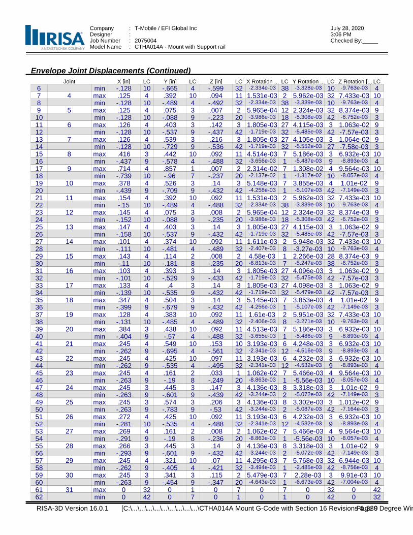
Company : T-Mobile / EFI Global Inc July 28, 20203:06 PMDesigner :
Job Number : 2075004 Checked By:_____Model Name : CTHA014A - Mount with Support rail
Envelope Joint Displacements (Continued)Joint X [in] LC Y [in] LC Z [in] LC X Rotation ... LC Y Rotation ... LC Z Rotation [... LC
6 min -.128 10 -.665 4 -.599 32 -2.334e-03 38 -3.328e-03 10 -9.763e-03 47 4 max .125 4 .392 10 .094 11 1.531e-03 2 5.962e-03 32 7.433e-03 108 min -.128 10 -.489 4 -.492 32 -2.334e-03 38 -3.339e-03 10 -9.763e-03 49 5 max .125 4 .075 3 .007 2 5.965e-04 12 2.324e-03 32 8.374e-03 910 min -.128 10 -.088 9 -.223 20 -3.986e-03 18 -5.308e-03 42 -6.752e-03 311 6 max .126 4 .403 3 .142 3 1.805e-03 27 4.115e-03 3 1.063e-02 912 min -.128 10 -.537 9 -.437 42 -1.719e-03 32 -5.485e-03 42 -7.57e-03 313 7 max .126 4 .539 3 .216 3 1.805e-03 27 4.105e-03 3 1.064e-02 914 min -.128 10 -.729 9 -.536 42 -1.719e-03 32 -5.552e-03 27 -7.58e-03 315 8 max .416 3 .442 10 .092 11 4.514e-03 7 5.186e-03 3 6.932e-03 1016 min -.437 9 -.578 4 -.488 32 -3.656e-03 1 -5.487e-03 9 -8.893e-03 417 9 max .714 4 .857 1 .007 2 2.314e-02 7 1.308e-02 4 9.564e-03 1018 min -.739 10 -.96 7 -.237 20 -2.137e-02 1 -1.317e-02 10 -8.057e-03 419 10 max .378 4 .526 3 .14 3 5.148e-03 7 3.855e-03 4 1.01e-02 920 min -.439 9 -.709 9 -.432 42 -4.258e-03 1 -5.107e-03 42 -7.149e-03 321 11 max .154 4 .392 10 .092 11 1.531e-03 2 5.962e-03 32 7.433e-03 1022 min -.15 10 -.489 4 -.488 32 -2.334e-03 38 -3.339e-03 10 -9.763e-03 423 12 max .145 4 .075 3 .008 2 5.965e-04 12 2.324e-03 32 8.374e-03 924 min -.152 10 -.088 9 -.235 20 -3.986e-03 18 -5.308e-03 42 -6.752e-03 325 13 max .147 4 .403 3 .14 3 1.805e-03 27 4.115e-03 3 1.063e-02 926 min -.158 10 -.537 9 -.432 42 -1.719e-03 32 -5.485e-03 42 -7.57e-03 327 14 max .101 4 .374 10 .092 11 1.611e-03 2 5.948e-03 32 7.433e-03 1028 min -.111 10 -.481 4 -.489 32 -2.407e-03 8 -3.27e-03 10 -9.763e-03 429 15 max .143 4 .114 2 .008 2 4.58e-03 1 2.266e-03 28 8.374e-03 930 min -.11 10 -.181 8 -.235 20 -6.813e-03 7 -5.247e-03 38 -6.752e-03 331 16 max .103 4 .393 3 .14 3 1.805e-03 27 4.096e-03 3 1.063e-02 932 min -.101 10 -.529 9 -.433 42 -1.719e-03 32 -5.475e-03 42 -7.57e-03 333 17 max .133 4 .4 3 .14 3 1.805e-03 27 4.098e-03 3 1.063e-02 934 min -.139 10 -.535 9 -.432 42 -1.719e-03 32 -5.479e-03 42 -7.57e-03 335 18 max .347 4 .504 3 .14 3 5.145e-03 7 3.853e-03 4 1.01e-02 936 min -.399 9 -.679 9 -.432 42 -4.256e-03 1 -5.107e-03 42 -7.149e-03 337 19 max .128 4 .383 10 .092 11 1.61e-03 2 5.951e-03 32 7.433e-03 1038 min -.131 10 -.485 4 -.489 32 -2.406e-03 8 -3.271e-03 10 -9.763e-03 439 20 max .384 3 .438 10 .092 11 4.513e-03 7 5.186e-03 3 6.932e-03 1040 min -.404 9 -.57 4 -.488 32 -3.655e-03 1 -5.486e-03 9 -8.893e-03 441 21 max .245 4 .549 10 .153 10 3.193e-03 6 4.248e-03 3 6.932e-03 1042 min -.262 9 -.695 4 -.561 32 -2.341e-03 12 -4.516e-03 9 -8.893e-03 443 22 max .245 4 .425 10 .097 11 3.193e-03 6 4.232e-03 3 6.932e-03 1044 min -.262 9 -.535 4 -.495 32 -2.341e-03 12 -4.532e-03 9 -8.893e-03 445 23 max .245 4 .161 2 .033 1 1.062e-02 7 5.466e-03 4 9.564e-03 1046 min -.263 9 -.19 8 -.249 20 -8.863e-03 1 -5.56e-03 10 -8.057e-03 447 24 max .245 3 .445 3 .147 3 4.136e-03 8 3.318e-03 3 1.01e-02 948 min -.263 9 -.601 9 -.439 42 -3.244e-03 2 -5.072e-03 42 -7.149e-03 349 25 max .245 3 .574 3 .206 3 4.136e-03 8 3.302e-03 3 1.012e-02 950 min -.263 9 -.783 9 -.53 42 -3.244e-03 2 -5.087e-03 42 -7.164e-03 351 26 max .272 4 .425 10 .092 11 3.193e-03 6 4.232e-03 3 6.932e-03 1052 min -.281 10 -.535 4 -.488 32 -2.341e-03 12 -4.532e-03 9 -8.893e-03 453 27 max .269 4 .161 2 .008 2 1.062e-02 7 5.466e-03 4 9.564e-03 1054 min -.291 9 -.19 8 -.236 20 -8.863e-03 1 -5.56e-03 10 -8.057e-03 455 28 max .266 3 .445 3 .14 3 4.136e-03 8 3.318e-03 3 1.01e-02 956 min -.293 9 -.601 9 -.432 42 -3.244e-03 2 -5.072e-03 42 -7.149e-03 357 29 max .245 4 .321 10 .07 11 4.295e-03 7 5.768e-03 32 6.944e-03 1058 min -.262 9 -.405 4 -.421 32 -3.494e-03 1 -2.485e-03 42 -8.756e-03 459 30 max .245 3 .341 3 .115 2 5.479e-03 7 2.28e-03 3 9.91e-03 1060 min -.263 9 -.454 9 -.347 20 -4.643e-03 1 -6.673e-03 42 -7.004e-03 461 31 max 0 32 0 1 0 7 0 7 0 32 0 4262 min 0 42 0 7 0 1 0 1 0 42 0 32
RISA-3D Version 16.0.1 Page 9 [C:\...\...\...\...\...\...\...\...\...\CTHA014A Mount G-Code with Section 16 Revisions & 330 Degree Win
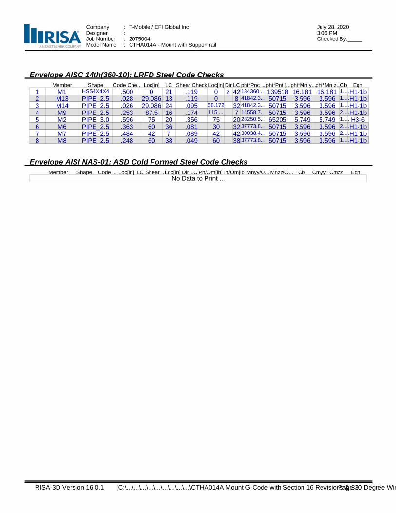
Company : T-Mobile / EFI Global Inc July 28, 20203:06 PMDesigner :
Job Number : 2075004 Checked By:_____Model Name : CTHA014A - Mount with Support rail
Envelope AISC 14th(360-10): LRFD Steel Code ChecksMember Shape Code Che... Loc[in] LC Shear Check Loc[in] Dir LC phi*Pnc ...phi*Pnt [...phi*Mn y...phi*Mn z...Cb Eqn
1 M1 HSS4X4X4 .500 0 21 .119 0 z 42 134360.... 139518 16.181 16.181 1....H1-1b2 M13 PIPE_2.5 .028 29.086 13 .119 0 8 41842.3... 50715 3.596 3.596 1....H1-1b3 M14 PIPE_2.5 .026 29.086 24 .095 58.172 32 41842.3... 50715 3.596 3.596 1....H1-1b4 M9 PIPE_2.5 .253 87.5 16 .174 115.... 7 14558.7... 50715 3.596 3.596 2....H1-1b5 M2 PIPE_3.0 .596 75 20 .356 75 20 28250.5... 65205 5.749 5.749 1.... H3-66 M6 PIPE_2.5 .363 60 36 .081 30 32 37773.8... 50715 3.596 3.596 2....H1-1b7 M7 PIPE_2.5 .484 42 7 .089 42 42 30038.4... 50715 3.596 3.596 2....H1-1b8 M8 PIPE_2.5 .248 60 38 .049 60 38 37773.8... 50715 3.596 3.596 1....H1-1b
Envelope AISI NAS-01: ASD Cold Formed Steel Code ChecksMember Shape Code ... Loc[in] LC Shear ...Loc[in] Dir LC Pn/Om[lb]Tn/Om[lb]Mnyy/O...Mnzz/O... Cb Cmyy Cmzz Eqn
No Data to Print ...
RISA-3D Version 16.0.1 Page 10 [C:\...\...\...\...\...\...\...\...\...\CTHA014A Mount G-Code with Section 16 Revisions & 330 Degree Win

Exhibit F
EBI Consulting
environmental | engineering | due diligence
21 B Street, Burlington, MA 01803 . Tel: (781) 273.2500 . Fax: (781) 273.3311
RADIO FREQUENCY EMISSIONS ANALYSIS REPORT
EVALUATION OF HUMAN EXPOSURE POTENTIAL
TO NON-IONIZING EMISSIONS
T-Mobile Existing Facility
Site ID: CTHA014A
HA014/T Of Wethersfield_MP
23 Kelleher Court
Wethersfield, Connecticut 06109
August 10, 2020
EBI Project Number: 6220003719
Site Compliance Summary
Compliance Status: COMPLIANT
Site total MPE% of FCC general population
allowable limit:
26.02%
EBI Consulting
environmental | engineering | due diligence
21 B Street, Burlington, MA 01803 . Tel: (781) 273.2500 . Fax: (781) 273.3311
August 10, 2020
T-Mobile Attn: Jason Overbey, RF Manager 35 Griffin Road South Bloomfield, Connecticut 06002
Emissions Analysis for Site: CTHA014A - HA014/T Of Wethersfield_MP
EBI Consulting was directed to analyze the proposed T-Mobile facility located at 23 Kelleher Court in Wethersfield, Connecticut for the purpose of determining whether the emissions from the Proposed T-Mobile Antenna Installation located on this property are within specified federal limits.
All information used in this report was analyzed as a percentage of current Maximum Permissible Exposure (% MPE) as listed in the FCC OET Bulletin 65 Edition 97-01and ANSI/IEEE Std C95.1. The FCC regulates Maximum Permissible Exposure in units of microwatts per square centimeter (µW/cm2). The number of µW/cm2 calculated at each sample point is called the power density. The exposure limit for power density varies depending upon the frequencies being utilized. Wireless Carriers and Paging Services use different frequency bands each with different exposure limits; therefore, it is necessary to report results and limits in terms of percent MPE rather than power density.
All results were compared to the FCC (Federal Communications Commission) radio frequency exposure rules, 47 CFR 1.1307(b)(1) – (b)(3), to determine compliance with the Maximum Permissible Exposure (MPE) limits for General Population/Uncontrolled environments as defined below.
General population/uncontrolled exposure limits apply to situations in which the general population may be exposed or in which persons who are exposed as a consequence of their employment may not be made fully aware of the potential for exposure or cannot exercise control over their exposure. Therefore, members of the general population would always be considered under this category when exposure is not employment related, for example, in the case of a telecommunications tower that exposes persons in a nearby residential area.
Public exposure to radio frequencies is regulated and enforced in units of microwatts per square centimeter (μW/cm2). The general population exposure limits for the 600 MHz and 700 MHz frequency bands are approximately 400 μW/cm2 and 467 μW/cm2, respectively. The general population exposure limit for the 1900 MHz (PCS), 2100 MHz (AWS) and 11 GHz frequency bands is 1000 μW/cm2. Because each carrier will be using different frequency bands, and each frequency band has different exposure limits, it is necessary to report percent of MPE rather than power density.
EBI Consulting
environmental | engineering | due diligence
21 B Street, Burlington, MA 01803 . Tel: (781) 273.2500 . Fax: (781) 273.3311
Occupational/controlled exposure limits apply to situations in which persons are exposed as a consequence of their employment and in which those persons who are exposed have been made fully aware of the potential for exposure and can exercise control over their exposure. Occupational/controlled exposure limits also apply where exposure is of a transient nature as a result of incidental passage through a location where exposure levels may be above general population/uncontrolled limits (see below), as long as the exposed person has been made fully aware of the potential for exposure and can exercise control over his or her exposure by leaving the area or by some other appropriate means.
Additional details can be found in FCC OET 65.
CALCULATIONS
Calculations were done for the proposed T-Mobile Wireless antenna facility located at 23 Kelleher Court in Wethersfield, Connecticut using the equipment information listed below. All calculations were performed per the specifications under FCC OET 65. Since T-Mobile is proposing highly focused directional panel antennas, which project most of the emitted energy out toward the horizon, all calculations were performed assuming a lobe representing the maximum gain of the antenna per the antenna manufacturer’s supplied specifications, minus 10 dB for directional panel antennas and 20 dB for highly focused parabolic microwave dishes, was focused at the base of the tower. For this report, the sample point is the top of a 6-foot person standing at the base of the tower.
For all calculations, all equipment was calculated using the following assumptions:
1) 2 LTE channels (600 MHz Band) were considered for each sector of the proposed installation. These Channels have a transmit power of 30 Watts per Channel.
2) 1 NR channel (600 MHz Band) was considered for each sector of the proposed installation. This Channel has a transmit power of 80 Watts.
3) 2 LTE channels (700 MHz Band) were considered for each sector of the proposed installation.
These Channels have a transmit power of 30 Watts per Channel.
4) 4 GSM channels (PCS Band - 1900 MHz) were considered for each sector of the proposed installation. These Channels have a transmit power of 30 Watts per Channel.
5) 4 LTE channels (PCS Band - 1900 MHz) were considered for each sector of the proposed installation. These Channels have a transmit power of 60 Watts per Channel.
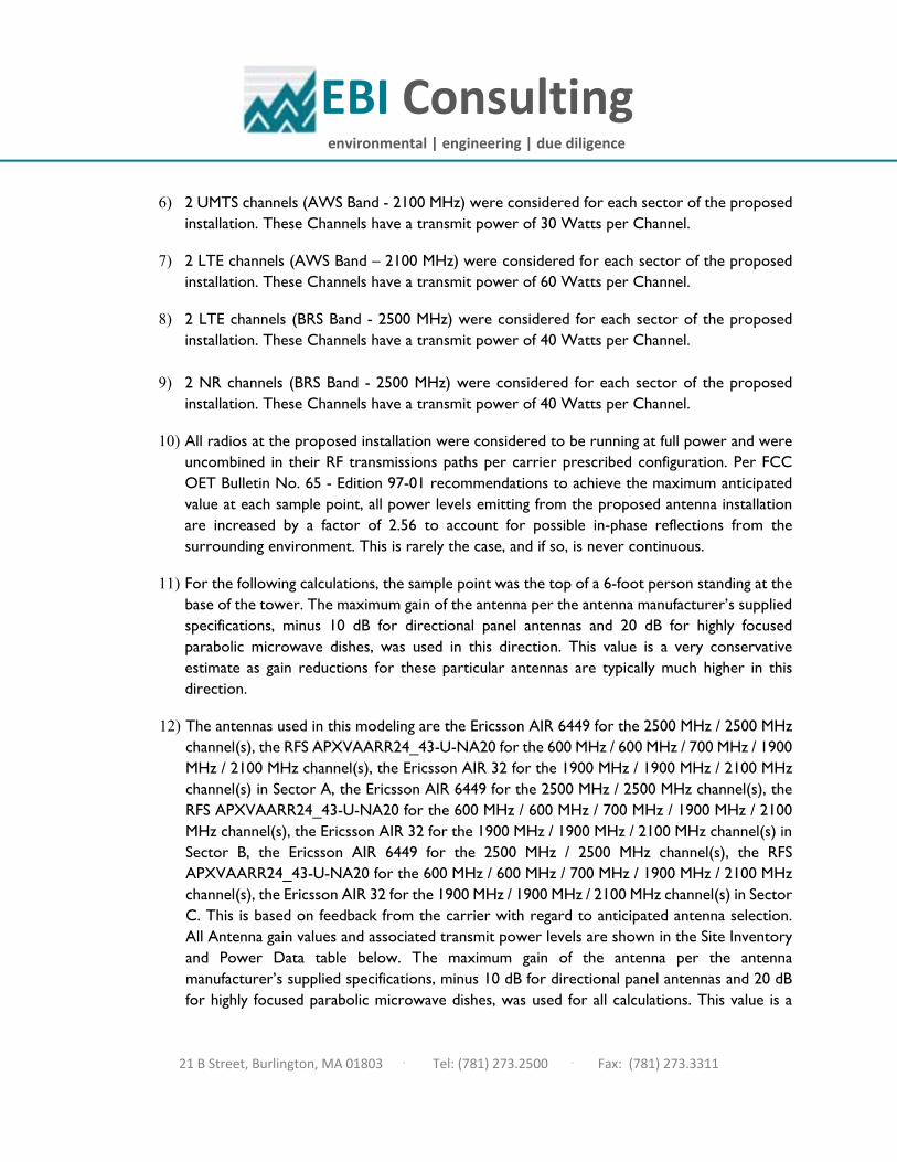
EBI Consulting
environmental | engineering | due diligence
21 B Street, Burlington, MA 01803 . Tel: (781) 273.2500 . Fax: (781) 273.3311
6) 2 UMTS channels (AWS Band - 2100 MHz) were considered for each sector of the proposed installation. These Channels have a transmit power of 30 Watts per Channel.
7) 2 LTE channels (AWS Band – 2100 MHz) were considered for each sector of the proposed installation. These Channels have a transmit power of 60 Watts per Channel.
8) 2 LTE channels (BRS Band - 2500 MHz) were considered for each sector of the proposed installation. These Channels have a transmit power of 40 Watts per Channel.
9) 2 NR channels (BRS Band - 2500 MHz) were considered for each sector of the proposed
installation. These Channels have a transmit power of 40 Watts per Channel.
10) All radios at the proposed installation were considered to be running at full power and were uncombined in their RF transmissions paths per carrier prescribed configuration. Per FCC OET Bulletin No. 65 - Edition 97-01 recommendations to achieve the maximum anticipated value at each sample point, all power levels emitting from the proposed antenna installation are increased by a factor of 2.56 to account for possible in-phase reflections from the surrounding environment. This is rarely the case, and if so, is never continuous.
11) For the following calculations, the sample point was the top of a 6-foot person standing at the base of the tower. The maximum gain of the antenna per the antenna manufacturer’s supplied specifications, minus 10 dB for directional panel antennas and 20 dB for highly focused parabolic microwave dishes, was used in this direction. This value is a very conservative estimate as gain reductions for these particular antennas are typically much higher in this direction.
12) The antennas used in this modeling are the Ericsson AIR 6449 for the 2500 MHz / 2500 MHz channel(s), the RFS APXVAARR24_43-U-NA20 for the 600 MHz / 600 MHz / 700 MHz / 1900 MHz / 2100 MHz channel(s), the Ericsson AIR 32 for the 1900 MHz / 1900 MHz / 2100 MHz channel(s) in Sector A, the Ericsson AIR 6449 for the 2500 MHz / 2500 MHz channel(s), the RFS APXVAARR24_43-U-NA20 for the 600 MHz / 600 MHz / 700 MHz / 1900 MHz / 2100 MHz channel(s), the Ericsson AIR 32 for the 1900 MHz / 1900 MHz / 2100 MHz channel(s) in Sector B, the Ericsson AIR 6449 for the 2500 MHz / 2500 MHz channel(s), the RFS APXVAARR24_43-U-NA20 for the 600 MHz / 600 MHz / 700 MHz / 1900 MHz / 2100 MHz channel(s), the Ericsson AIR 32 for the 1900 MHz / 1900 MHz / 2100 MHz channel(s) in Sector C. This is based on feedback from the carrier with regard to anticipated antenna selection. All Antenna gain values and associated transmit power levels are shown in the Site Inventory and Power Data table below. The maximum gain of the antenna per the antenna manufacturer’s supplied specifications, minus 10 dB for directional panel antennas and 20 dB for highly focused parabolic microwave dishes, was used for all calculations. This value is a
EBI Consulting
environmental | engineering | due diligence
21 B Street, Burlington, MA 01803 . Tel: (781) 273.2500 . Fax: (781) 273.3311
very conservative estimate as gain reductions for these particular antennas are typically much higher in this direction.
13) The antenna mounting height centerline of the proposed antennas is 151 feet above ground level (AGL).
14) Emissions values for additional carriers were taken from the Connecticut Siting Council active database. Values in this database are provided by the individual carriers themselves.
15) All calculations were done with respect to uncontrolled / general population threshold limits.
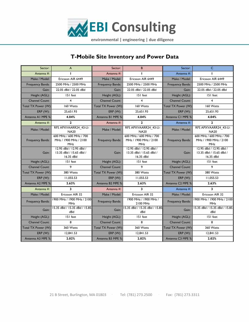
EBI Consulting
environmental | engineering | due diligence
21 B Street, Burlington, MA 01803 . Tel: (781) 273.2500 . Fax: (781) 273.3311
T-Mobile Site Inventory and Power Data
Sector: A Sector: B Sector: C Antenna #: 1 Antenna #: 1 Antenna #: 1
Make / Model: Ericsson AIR 6449 Make / Model: Ericsson AIR 6449 Make / Model: Ericsson AIR 6449 Frequency Bands: 2500 MHz / 2500 MHz Frequency Bands: 2500 MHz / 2500 MHz Frequency Bands: 2500 MHz / 2500 MHz
Gain: 22.05 dBd / 22.05 dBd Gain: 22.05 dBd / 22.05 dBd Gain: 22.05 dBd / 22.05 dBd Height (AGL): 151 feet Height (AGL): 151 feet Height (AGL): 151 feet
Channel Count: 4 Channel Count: 4 Channel Count: 4 Total TX Power (W): 160 Watts Total TX Power (W): 160 Watts Total TX Power (W): 160 Watts
ERP (W): 25,651.93 ERP (W): 25,651.93 ERP (W): 25,651.93 Antenna A1 MPE %: 4.04% Antenna B1 MPE %: 4.04% Antenna C1 MPE %: 4.04%
Antenna #: 2 Antenna #: 2 Antenna #: 2
Make / Model: RFS APXVAARR24_43-U-NA20 Make / Model: RFS APXVAARR24_43-U-
NA20 Make / Model: RFS APXVAARR24_43-U-NA20
Frequency Bands: 600 MHz / 600 MHz / 700 MHz / 1900 MHz / 2100
MHz Frequency Bands:
600 MHz / 600 MHz / 700 MHz / 1900 MHz / 2100
MHz Frequency Bands:
600 MHz / 600 MHz / 700 MHz / 1900 MHz / 2100
MHz
Gain: 12.95 dBd / 12.95 dBd / 13.35 dBd / 15.65 dBd /
16.35 dBd Gain:
12.95 dBd / 12.95 dBd / 13.35 dBd / 15.65 dBd /
16.35 dBd Gain:
12.95 dBd / 12.95 dBd / 13.35 dBd / 15.65 dBd /
16.35 dBd Height (AGL): 151 feet Height (AGL): 151 feet Height (AGL): 151 feet
Channel Count: 9 Channel Count: 9 Channel Count: 9 Total TX Power (W): 380 Watts Total TX Power (W): 380 Watts Total TX Power (W): 380 Watts
ERP (W): 11,055.53 ERP (W): 11,055.53 ERP (W): 11,055.53 Antenna A2 MPE %: 2.63% Antenna B2 MPE %: 2.63% Antenna C2 MPE %: 2.63%
Antenna #: 3 Antenna #: 3 Antenna #: 3 Make / Model: Ericsson AIR 32 Make / Model: Ericsson AIR 32 Make / Model: Ericsson AIR 32
Frequency Bands: 1900 MHz / 1900 MHz / 2100
MHz Frequency Bands:
1900 MHz / 1900 MHz / 2100 MHz
Frequency Bands: 1900 MHz / 1900 MHz / 2100
MHz
Gain: 15.35 dBd / 15.35 dBd / 15.85 dBd Gain: 15.35 dBd / 15.35 dBd / 15.85
dBd Gain: 15.35 dBd / 15.35 dBd / 15.85 dBd
Height (AGL): 151 feet Height (AGL): 151 feet Height (AGL): 151 feet Channel Count: 8 Channel Count: 8 Channel Count: 8
Total TX Power (W): 360 Watts Total TX Power (W): 360 Watts Total TX Power (W): 360 Watts ERP (W): 12,841.53 ERP (W): 12,841.53 ERP (W): 12,841.53
Antenna A3 MPE %: 2.02% Antenna B3 MPE %: 2.02% Antenna C3 MPE %: 2.02%
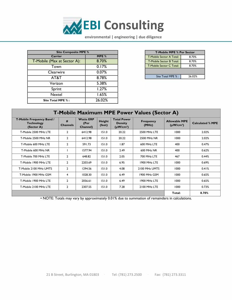
EBI Consulting
environmental | engineering | due diligence
21 B Street, Burlington, MA 01803 . Tel: (781) 273.2500 . Fax: (781) 273.3311
Site Composite MPE % Carrier MPE %
T-Mobile (Max at Sector A): 8.70% Town 0.17%
Clearwire 0.07% AT&T 8.78%
Verizon 5.38% Sprint 1.27% Nextel 1.65%
Site Total MPE % : 26.02%
T-Mobile MPE % Per Sector
T-Mobile Sector A Total: 8.70% T-Mobile Sector B Total: 8.70% T-Mobile Sector C Total: 8.70%
Site Total MPE % : 26.02%
• NOTE: Totals may vary by approximately 0.01% due to summation of remainders in calculations.
T-Mobile Maximum MPE Power Values (Sector A)
T-Mobile Frequency Band / Technology (Sector A)
# Channels
Watts ERP (Per
Channel)
Height (feet)
Total Power Density
(µW/cm²)
Frequency (MHz)
Allowable MPE (µW/cm²)
Calculated % MPE
T-Mobile 2500 MHz LTE 2 6412.98 151.0 20.22 2500 MHz LTE 1000 2.02%
T-Mobile 2500 MHz NR 2 6412.98 151.0 20.22 2500 MHz NR 1000 2.02%
T-Mobile 600 MHz LTE 2 591.73 151.0 1.87 600 MHz LTE 400 0.47%
T-Mobile 600 MHz NR 1 1577.94 151.0 2.49 600 MHz NR 400 0.62%
T-Mobile 700 MHz LTE 2 648.82 151.0 2.05 700 MHz LTE 467 0.44%
T-Mobile 1900 MHz LTE 2 2203.69 151.0 6.95 1900 MHz LTE 1000 0.69%
T-Mobile 2100 MHz UMTS 2 1294.56 151.0 4.08 2100 MHz UMTS 1000 0.41%
T-Mobile 1900 MHz GSM 4 1028.30 151.0 6.49 1900 MHz GSM 1000 0.65%
T-Mobile 1900 MHz LTE 2 2056.61 151.0 6.49 1900 MHz LTE 1000 0.65%
T-Mobile 2100 MHz LTE 2 2307.55 151.0 7.28 2100 MHz LTE 1000 0.73%
Total: 8.70%
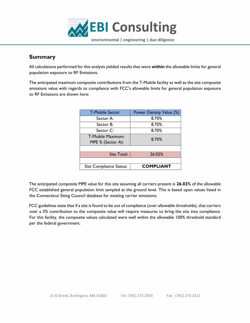
EBI Consulting
environmental | engineering | due diligence
21 B Street, Burlington, MA 01803 . Tel: (781) 273.2500 . Fax: (781) 273.3311
Summary
All calculations performed for this analysis yielded results that were within the allowable limits for general population exposure to RF Emissions.
The anticipated maximum composite contributions from the T-Mobile facility as well as the site composite emissions value with regards to compliance with FCC’s allowable limits for general population exposure to RF Emissions are shown here:
T-Mobile Sector Power Density Value (%) Sector A: 8.70% Sector B: 8.70% Sector C: 8.70%
T-Mobile Maximum MPE % (Sector A):
8.70%
Site Total: 26.02%
Site Compliance Status: COMPLIANT
The anticipated composite MPE value for this site assuming all carriers present is 26.02% of the allowable FCC established general population limit sampled at the ground level. This is based upon values listed in the Connecticut Siting Council database for existing carrier emissions.
FCC guidelines state that if a site is found to be out of compliance (over allowable thresholds), that carriers over a 5% contribution to the composite value will require measures to bring the site into compliance. For this facility, the composite values calculated were well within the allowable 100% threshold standard per the federal government.

Exhibit G
P
Cut on dotted line.
Instructions
Click-N-Ship® Label Record
Electronic R
ate Approved #038555749
Thank you for shipping with the United States Postal Service!Check the status of your shipment on the USPS Tracking® page at usps.com
SH
IPTO
:
1. Each Click-N-Ship® label is unique. Labels are to be used as printed and used only once. DO NOT PHOTO COPY OR ALTER LABEL.
2. Place your label so it does not wrap around the edge of
the package. 3. Adhere your label to the package. A self-adhesive label
is recommended. If tape or glue is used, DO NOT TAPE OVER BARCODE. Be sure all edges are secure.
4. To mail your package with PC Postage®, you may schedule a Package Pickup online, hand to your letter carrier, take to a Post Office™, or drop in a USPS collection box. 5. Mail your package on the "Ship Date" you selected when creating this label.
Priority Mail® Postage:
From:
To:
Print Date:Ship Date:
Click-N
-Ship®
Trans. #:
Expected Delivery Date:
usps.com
US PO
STAG
E
* Retail Pricing Priority Mail rates apply. There is no fee for USPS Tracking® service on Priority Mail service with use of this electronic rate shipping label. Refunds for unused postage paid labels can be requested online 30 days from the print date.
Carrier -- Leave if N
o Response
Ref#: H
A014A
NC
H
USPS TR
AC
KIN
G #
$7.75
505 SILA
S D
EA
NE
HW
Y
PE
TER
GILLE
SP
IE
9405 5036 9930 0011 6462 89
DEBORAH CHASENORTHEAST SITE SOLUTIONS, LLC420 MAIN ST STE 2STURBRIDGE MA 01566-1359
9405 5036 9930 0011 6462 89 0077 5000 0010 6109
PRIO
RITY M
AIL 2-D
AY™C
027
9405 5036 9930 0011 6462 89
Mailed from
01566
Total:504408074
Expected D
elivery Date: 09/04/20
0006
WE
THE
RS
FIELD
CT 06109-2216
DIR
. PLA
NN
ING
& ZO
NIN
G
Ref#: HA014ANCH
062S0000000313
09/01/2020
USPS TRACKING # :
08/31/2020
DE
BO
RA
H C
HA
SE
NO
RTH
EA
ST S
ITE S
OLU
TION
S, LLC
420 MA
IN S
T STE
2S
TUR
BR
IDG
E M
A 01566-1359
Flat Rate E
nv
09/01/2020
PETER GILLESPIEDIR. PLANNING & ZONING505 SILAS DEANE HWYWETHERSFIELD CT 06109-2216
$7.75$7.75
09/04/2020
P
Cut on dotted line.
Instructions
Click-N-Ship® Label Record
Electronic R
ate Approved #038555749
Thank you for shipping with the United States Postal Service!Check the status of your shipment on the USPS Tracking® page at usps.com
SH
IPTO
:
1. Each Click-N-Ship® label is unique. Labels are to be used as printed and used only once. DO NOT PHOTO COPY OR ALTER LABEL.
2. Place your label so it does not wrap around the edge of
the package. 3. Adhere your label to the package. A self-adhesive label
is recommended. If tape or glue is used, DO NOT TAPE OVER BARCODE. Be sure all edges are secure.
4. To mail your package with PC Postage®, you may schedule a Package Pickup online, hand to your letter carrier, take to a Post Office™, or drop in a USPS collection box. 5. Mail your package on the "Ship Date" you selected when creating this label.
Priority Mail® Postage:
From:
To:
Print Date:Ship Date:
Click-N
-Ship®
Trans. #:
Expected Delivery Date:
usps.com
US PO
STAG
E
* Retail Pricing Priority Mail rates apply. There is no fee for USPS Tracking® service on Priority Mail service with use of this electronic rate shipping label. Refunds for unused postage paid labels can be requested online 30 days from the print date.
Carrier -- Leave if N
o Response
Ref#: H
A014-A
NC
H
USPS TR
AC
KIN
G #
$7.75
10 FRA
NK
LIN S
Q
LISA
A M
ATTH
EW
S
9405 5036 9930 0011 6462 96
DEBORAH CHASENORTHEAST SITE SOLUTIONS, LLC420 MAIN ST STE 2STURBRIDGE MA 01566-1359
9405 5036 9930 0011 6462 96 0077 5000 0010 6051
PRIO
RITY M
AIL 2-D
AY™C
006
9405 5036 9930 0011 6462 96
Mailed from
01566
Total:504408074
Expected D
elivery Date: 09/04/20
0006
NE
W B
RITA
IN C
T 06051-2655C
T SITIN
G C
OU
NC
IL
Ref#: HA014-ANCH
062S0000000313
09/01/2020
USPS TRACKING # :
08/31/2020
DE
BO
RA
H C
HA
SE
NO
RTH
EA
ST S
ITE S
OLU
TION
S, LLC
420 MA
IN S
T STE
2S
TUR
BR
IDG
E M
A 01566-1359
Flat Rate E
nv
09/01/2020
LISA A MATTHEWSCT SITING COUNCIL10 FRANKLIN SQNEW BRITAIN CT 06051-2655
$7.75$7.75
09/04/2020

P
Cut on dotted line.
Instructions
Click-N-Ship® Label Record
Electronic R
ate Approved #038555749
Thank you for shipping with the United States Postal Service!Check the status of your shipment on the USPS Tracking® page at usps.com
SH
IPTO
:
1. Each Click-N-Ship® label is unique. Labels are to be used as printed and used only once. DO NOT PHOTO COPY OR ALTER LABEL.
2. Place your label so it does not wrap around the edge of
the package. 3. Adhere your label to the package. A self-adhesive label
is recommended. If tape or glue is used, DO NOT TAPE OVER BARCODE. Be sure all edges are secure.
4. To mail your package with PC Postage®, you may schedule a Package Pickup online, hand to your letter carrier, take to a Post Office™, or drop in a USPS collection box. 5. Mail your package on the "Ship Date" you selected when creating this label.
Priority Mail® Postage:
From:
To:
Print Date:Ship Date:
Click-N
-Ship®
Trans. #:
Expected Delivery Date:
usps.com
US PO
STAG
E
* Retail Pricing Priority Mail rates apply. There is no fee for USPS Tracking® service on Priority Mail service with use of this electronic rate shipping label. Refunds for unused postage paid labels can be requested online 30 days from the print date.
Carrier -- Leave if N
o Response
Ref#: H
A014-A
NC
H
USPS TR
AC
KIN
G #
$7.75
505 SILA
S D
EA
NE
HW
Y
MIC
HA
EL L R
ELL
9405 5036 9930 0011 6463 19
DEBORAH CHASENORTHEAST SITE SOLUTIONS, LLC420 MAIN ST STE 2STURBRIDGE MA 01566-1359
9405 5036 9930 0011 6463 19 0077 5000 0010 6109
PRIO
RITY M
AIL 2-D
AY™C
027
9405 5036 9930 0011 6463 19
Mailed from
01566
Total:504408074
Expected D
elivery Date: 09/04/20
0006
WE
THE
RS
FIELD
CT 06109-2216
MA
YO
R -TO
WN
OF W
ETH
ER
SFIE
LD
Ref#: HA014-ANCH
062S0000001310
09/01/2020
USPS TRACKING # :
08/31/2020
DE
BO
RA
H C
HA
SE
NO
RTH
EA
ST S
ITE S
OLU
TION
S, LLC
420 MA
IN S
T STE
2S
TUR
BR
IDG
E M
A 01566-1359
Flat Rate E
nv
09/01/2020
MICHAEL L RELLMAYOR -TOWN OF WETHERSFIELD505 SILAS DEANE HWYWETHERSFIELD CT 06109-2216
$7.75$7.75
09/04/2020
P
Cut on dotted line.
Instructions
Click-N-Ship® Label Record
Electronic R
ate Approved #038555749
Thank you for shipping with the United States Postal Service!Check the status of your shipment on the USPS Tracking® page at usps.com
SH
IPTO
:
1. Each Click-N-Ship® label is unique. Labels are to be used as printed and used only once. DO NOT PHOTO COPY OR ALTER LABEL.
2. Place your label so it does not wrap around the edge of
the package. 3. Adhere your label to the package. A self-adhesive label
is recommended. If tape or glue is used, DO NOT TAPE OVER BARCODE. Be sure all edges are secure.
4. To mail your package with PC Postage®, you may schedule a Package Pickup online, hand to your letter carrier, take to a Post Office™, or drop in a USPS collection box. 5. Mail your package on the "Ship Date" you selected when creating this label.
Priority Mail® Postage:
From:
To:
Print Date:Ship Date:
Click-N
-Ship®
Trans. #:
Expected Delivery Date:
usps.com
US PO
STAG
E
* Retail Pricing Priority Mail rates apply. There is no fee for USPS Tracking® service on Priority Mail service with use of this electronic rate shipping label. Refunds for unused postage paid labels can be requested online 30 days from the print date.
Carrier -- Leave if N
o Response
Ref#: H
A014A
-AN
C
USPS TR
AC
KIN
G #
$7.75
505 SILA
S D
EA
NE
HW
Y
SU
E S
CH
RO
ED
ER
9405 5036 9930 0011 6463 26
DEBORAH CHASENORTHEAST SITE SOLUTIONS, LLC420 MAIN ST STE 2STURBRIDGE MA 01566-1359
9405 5036 9930 0011 6463 26 0077 5000 0010 6109
PRIO
RITY M
AIL 2-D
AY™C
027
9405 5036 9930 0011 6463 26
Mailed from
01566
Total:504408074
Expected D
elivery Date: 09/04/20
0006
WE
THE
RS
FIELD
CT 06109-2216
AS
ST. TO
WN
CLE
RK
- TOW
N O
F WE
THE
RS
FIELD
Ref#: HA014A-ANC
062S0000001310
09/01/2020
USPS TRACKING # :
08/31/2020
DE
BO
RA
H C
HA
SE
NO
RTH
EA
ST S
ITE S
OLU
TION
S, LLC
420 MA
IN S
T STE
2S
TUR
BR
IDG
E M
A 01566-1359
Flat Rate E
nv
09/01/2020
SUE SCHROEDERASST. TOWN CLERK- TOWN OF WETHERSFIELD505 SILAS DEANE HWYWETHERSFIELD CT 06109-2216
$7.75$7.75
09/04/2020

Exhibit H
1
Deborah Chase
From: Deborah ChaseSent: Monday, August 31, 2020 6:33 PMTo: '[email protected]'; '[email protected]'Cc: '[email protected]'Subject: 23 KELLEHER COURT WETHERSFIELD CT 06109 T-MOBILE EM APPLICATION (CTHA014A)Attachments: 23 KELLEHER COURT WETHERSFIELD CT 06109 T-MOBILE EM APPLICATION (CTHA014A-Anchor).pdf
Good afternoon, On behalf of our client, (T‐Mobile), I am forwarding copies of T‐Mobile’s Exempt Modification Request to collocate on a wireless telecommunications facility located at 23 Kelleher Court Wethersfield, CT Hard copies will be sent as well for your records. Please do not hesitate to contact me with any questions regarding T‐Mobile’s Exempt Modification Request. Thank you very much Deborah Chase Senior Project Coordinator & Analyst Mobile: 860-490-8839
Save a tree. Refuse.Reduce. Reuse. Recycle.