Embed Size (px)
Citation preview


Page 2
TABLE OF CONTENTS
1) INTRODUCTION
2) ANALYSIS CRITERIA Table 2-1 – Proposed Final Antenna Configuration 3) ANALYSIS PROCEDURE Table 3-1 – Documents Provided 3.1 Analysis Method 4) ANALYSIS RESULTS Table 4-1 – Critical Section Capacity (Summary) 4.1 Recommendations 5) ASSUMPTIONS
6) APPENDIX A Calculations

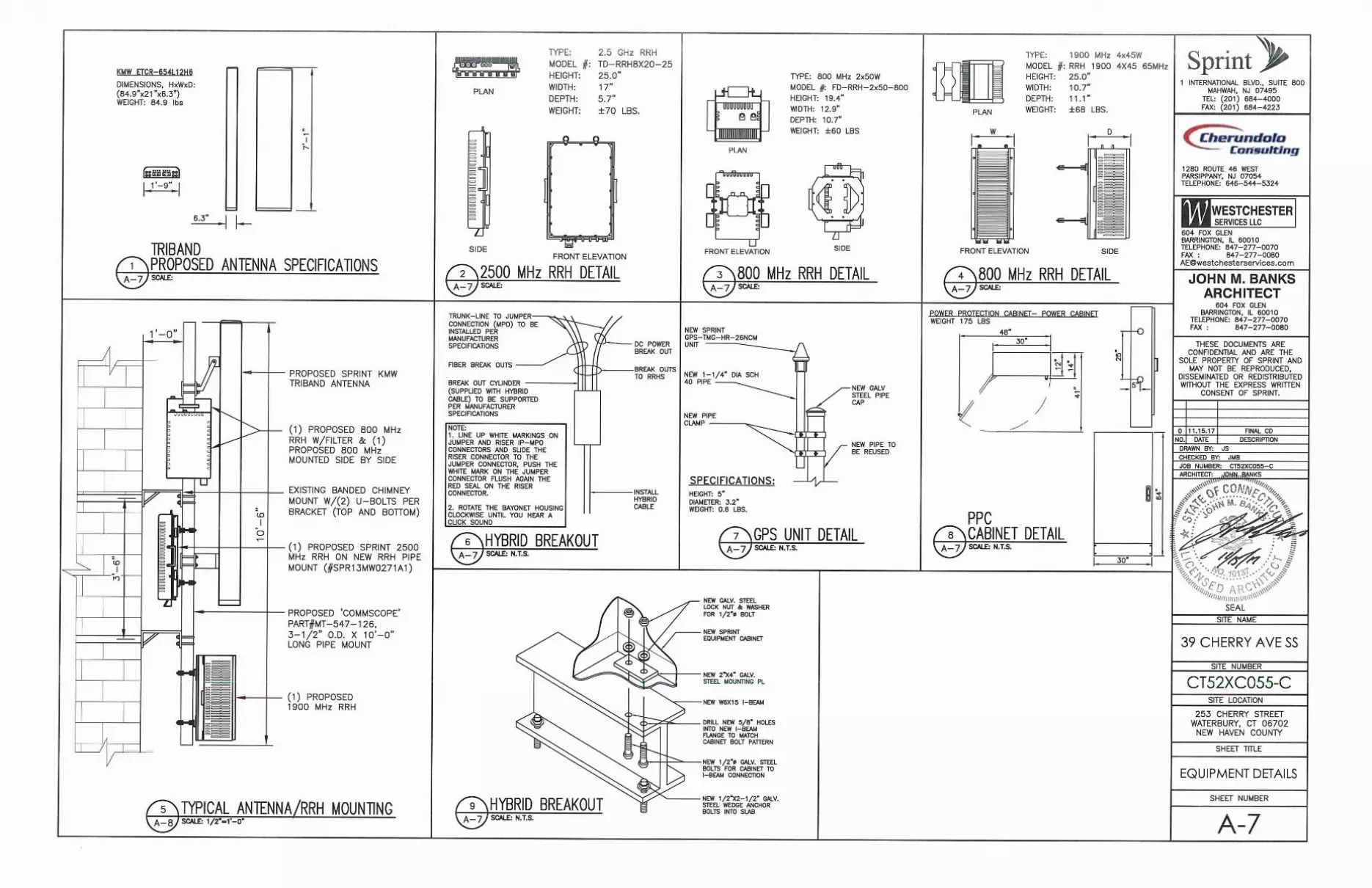
Page 3 1) INTRODUCTION This structure is a 143.5’ chimney is located in New Haven County, CT. The proposed antennas will be mounted on the existing smokestack. 2) ANALYSIS CRITERIA This analysis has been performed in accordance with the 2015 International Building Code based upon an ultimate 3-second gust wind speed of 120 mph converted to a nominal 3-second gust wind speed of 93 mph per section 1609.3.1 as required for use in the TIA-222-G Standard per Exception #5 of Section 1609.1.1., Exposure Category B with topographic category 1, Risk Category II, and crest height of 0 feet were used in this analysis. Table 2-1 – Proposed Final Antenna Configuration (New antennas in bold)
Center Line
Elevation (ft)
Sector Pos. Antenna Radio(s) Note
127 Alpha
1 (1) KMW ETCR-654L12H6 (1) 1900MHz RRH (1) 2500MHZ RRH (2) 800MHZ RRH
2 (1) 24” Dish
3
4
127 Beta
1 (1) KMW ETCR-654L12H6 (1) 1900MHz RRH (1) 2500MHZ RRH (2) 800MHZ RRH
2 (1) 12” Dish
3
4
127 Gamma
1 (1) KMW ETCR-654L12H6 (1) 1900MHz RRH (1) 2500MHZ RRH (2) 800MHZ RRH
2 (1) 12” Dish
3
4
Antennas in position 1 will be mounted to a new 3” Std. pipe, 10’ Long.

Page 4 3) ANALYSIS PROCEDURE
Table 3-1 – Documents Provided
Document Remarks Reference Date Source
Construction Drawings
- WSLLC 09/28/2017 WSLLC
Field Mapping - WSLLC 05/27/2017 WSLLC Structural Analysis - CHA 06/23/2010 Sprint
3.1) Analysis Method
Risa-3D (version 14.0.1) is a finite element analysis software program was used for modeling and analyzing frame structures. The output from the analysis can be found in Appendix A.
4) ANALYSIS RESULTS
Table 4-1 – Critical Section Capacity (Summary) Member Type Elevation (ft) % Capacity Pass/Fail Antenna Pipe 127 22.3 Pass Smokestack - Negligible Increase Pass
Overall 127 22.3 Pass
4.1) Recommendations
The existing antenna mounts and structure have sufficient capacity to carry the existing and
proposed loads.

Page 5 5) ASSUMPTIONS
The analysis performed is to the theoretical capacity of the members and connections. No accommodations are taken for any damaged, rusted, deteriorated, or otherwise compromised member conditions. To this, the tower or structure is assumed to be properly maintained and monitored and this analysis cannot be considered to be a condition assessment of the structure.
The analysis is performed to the minimum design wind, ice, and other environmental loading
prescribed by the governing building codes and standards. Any higher loading conditions required by the local jurisdiction or structure owner should be made known to Westchester immediately for analysis. No lesser conditions will be accommodated.
Member sizes are assumed to be of standard AISC or manufacturer designations unless explicitly
specified otherwise. The geometry of the tower or structure is assumed as schematic. Steel grade and concrete strength are assumed to be conservative standard and fully developed unless otherwise specified.
The information provided to Westchester for analysis is assumed accurate and up to date as supplied.
No independent efforts were taken by Westchester to verify the validity of the information supplied. If any additional information is presented at any time that contradicts what is referenced in the analysis, the analysis is invalid and must be performed again with the new information.
Any reinforcement or modifications are assumed to be fully installed and functional.
All welds are assumed to have been performed to current welding standards and are assumed to
develop their full capacity and to be in good condition. In addition, all bolts and bolt-like anchors are assumed to be fully tightened, fastened, or bonded to the manufacturers' specifications and are assumed to have full capacity.
Numerous connection details of large-scale structures are unobtainable and are omitted from the
structural analysis. This includes, but is not limited to: bolts, welds, flanges, and plates. These connections are considered adequate and are therefore neglected from the analysis. In addition, in the absence of building plans, many wall, floor, and ceiling constructions can only be determined from observable field data and are supplemented by best judgment and experience.
Antennas, dishes, feedlines, and any other such appurtenances are assumed adequate through
manufacturer testing. No analysis is provided for the structural strength or stability of these items unless otherwise specified.
Equipment mounting systems are assumed structurally sound unless specifically called for in the
analysis.
Soil conditions and foundations are not considered unless specified in the analysis and have no deterioration or defects. For sites located on a building, only local effects of the equipment is considered unless otherwise specified. The overall structure of the building and its foundation are assumed to be unaffected by the telecom equipment.
Any changes or differences to the site or site plans at any time prior to installation must be brought to
the attention of Westchester immediately.

Page 6
APPENDIX A
CALCULATIONS
Westchester Services, LLC.604 Fox GlenBarrington, IL 60010PH: [email protected]
39 Cherry Ave SSCT52XC055
Client: Cherundolo - Sprint
Date: 11/13/2017By: PK
Page 1 of 22
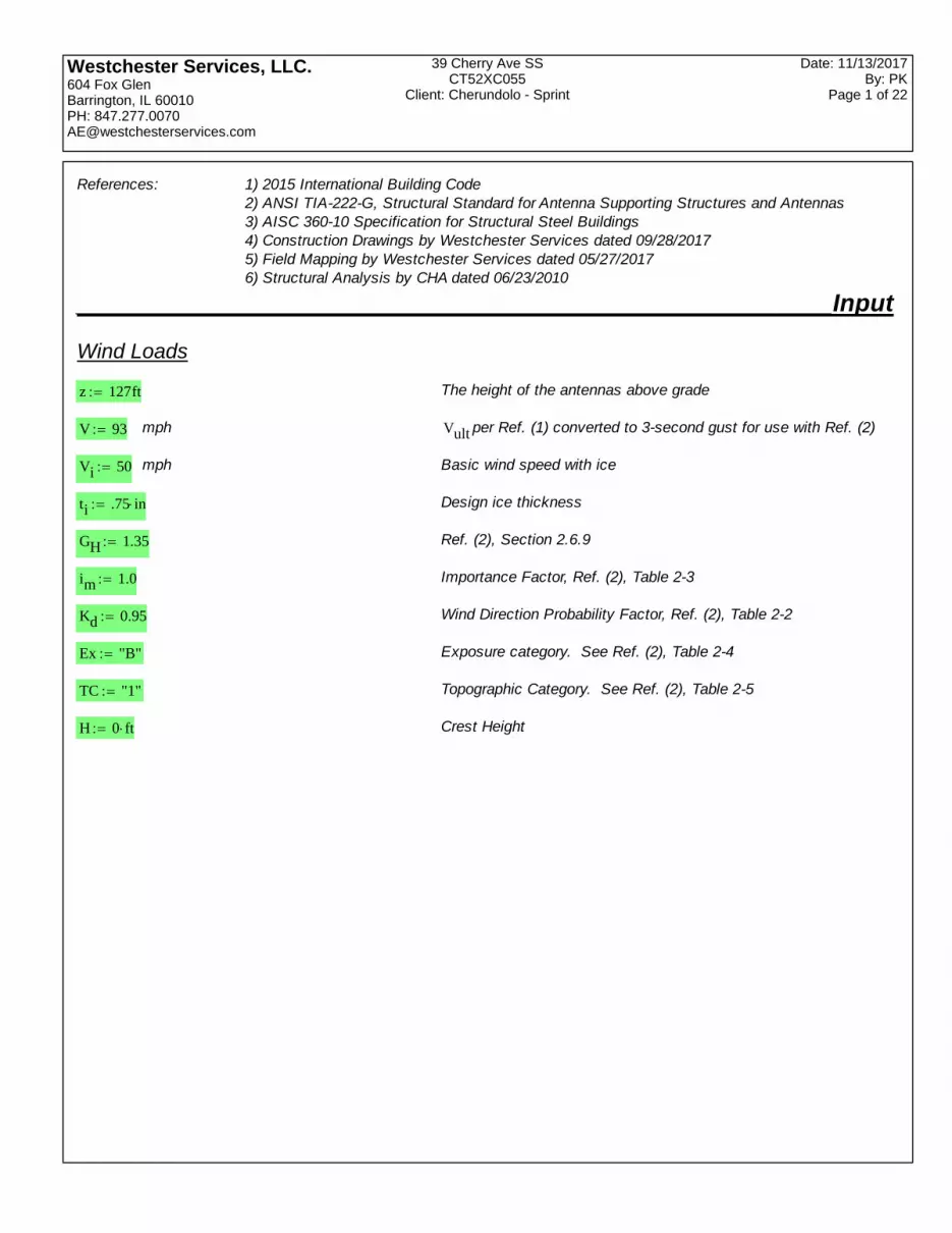
References: 1) 2015 International Building Code2) ANSI TIA-222-G, Structural Standard for Antenna Supporting Structures and Antennas3) AISC 360-10 Specification for Structural Steel Buildings4) Construction Drawings by Westchester Services dated 09/28/20175) Field Mapping by Westchester Services dated 05/27/20176) Structural Analysis by CHA dated 06/23/2010
______________________________________________________Input
Wind Loads
z 127ft The height of the antennas above grade
V 93 mph Vult per Ref. (1) converted to 3-second gust for use with Ref. (2)
Vi 50 mph Basic wind speed with ice
ti .75 in Design ice thickness
GH 1.35 Ref. (2), Section 2.6.9
im 1.0 Importance Factor, Ref. (2), Table 2-3
Kd 0.95 Wind Direction Probability Factor, Ref. (2), Table 2-2
Ex "B" Exposure category. See Ref. (2), Table 2-4
TC "1" Topographic Category. See Ref. (2), Table 2-5
H 0 ft Crest Height

Westchester Services, LLC.604 Fox GlenBarrington, IL 60010PH: [email protected]
39 Cherry Ave SSCT52XC055
Client: Cherundolo - Sprint
Date: 11/13/2017By: PK
Page 2 of 22
Equipment Specs
AntennasNantenna 1 Number of antenna groups
Antenna 1: KMW ETCR-654L12H6
heightant184.9 in Height of antenna Is antenna round?
shapeant1
widthant121in Width of antenna
depthant16.3 in Depth of antenna
weightant184.9lbf Weight of antenna
Radio s
Nradio 3 Number of radiogroups
Radio 1: 2500MHz
Hr125 in Height of radio Is radio round?
Wr117in shaper1
Width of radio
Dr15.7 in Depth of radio
Weightr170 lbf Weight of radio
Radio 2: 1900 MHz
Hr225 in Height of radio Is radio round?
Wr210.7in shaper2
Width of radio
Dr211.1 in Depth of radio
Weightr268 lbf Weight of radio
Radio 3: 800 MHz
Hr319.4 in Height of radio Is radio round?
Wr312.9in shaper3
Width of radio
Dr310.7 in Depth of radio
Weightr360 lbf Weight of radio
Pipes
Hpipe110 ft Overall length of pipe
Pipe1
3 AISC standard pipe size

Westchester Services, LLC.604 Fox GlenBarrington, IL 60010PH: [email protected]
39 Cherry Ave SSCT52XC055
Client: Cherundolo - Sprint
Date: 11/13/2017By: PK
Page 3 of 22
________________________________________________Calculations
Wind
zg 1200 ft Ex "B"=if
900 ft Ex "C"=if
700 ft Ex "D"=if
zg 1.2 103
ft
Kzmin 0.70 Ex "B"=if
0.85 Ex "C"=if
1.03 Ex "D"=if
Kzmin 0.7
α 7.0 Ex "B"=if
9.5 Ex "C"=if
11.5 Ex "D"=if
α 7
Ke 0.90 Ex "B"=if
1.00 Ex "C"=if
1.10 Ex "D"=if
Ke 0.9
Kz 2.01z
zg
2
α
Kz 1.058 Kzmin Kz 2.01 , OK
Kt .43 TC "2"=if
.53 TC "3"=if
.72 TC "4"=if
0 TC "1"=if
Kt 0
f 1.25 TC "2"=if
2.0 TC "3"=if
1.5 TC "4"=if
0 TC "1"=if
f 0
Kh e
f z
H
Kh 1
Kzt 1Ke Kt
Kh
2
Kzt 1 Ref. (2), 2.6.6.4
Kizz
33 ft
0.1
Kiz 1.144 < 1.4, OK
Ka 1.0
Westchester Services, LLC.604 Fox GlenBarrington, IL 60010PH: [email protected]
39 Cherry Ave SSCT52XC055
Client: Cherundolo - Sprint
Date: 11/13/2017By: PK
Page 4 of 22
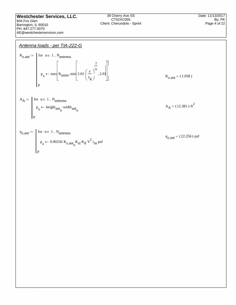
Antenna loads - per TIA-222-G
Kz.ant
pn
max Kzmin min 2.01z
zg
2
α
2.01
n 1 Nantennafor
p
Kz.ant 1.058( )
AA
pn
heightantnwidthantn
n 1 Nantennafor
p
AA 12.381( ) ft2
qz.ant
pn
0.00256 Kz.antn Kzt Kd V
2 im psf
n 1 Nantennafor
p
qz.ant 22.256( ) psf

Westchester Services, LLC.604 Fox GlenBarrington, IL 60010PH: [email protected]
39 Cherry Ave SSCT52XC055
Client: Cherundolo - Sprint
Date: 11/13/2017By: PK
Page 5 of 22
C im Kzt Kz 0.5V widthant
1
ft
CA
Aspectn
heightantn
widthantn
pn
1.2 Aspectn
2.5if
1.2 .2Aspect
n2.5
7 2.5 2.5 Aspect
n 7if
1.4 Aspectn
7=if
1.4 .6Aspect
n7
25 7 7 Aspect
n 25if
2.0 Aspectn
25if
shapeantnif
Aspectn
heightantn
widthantn
pn
.7 Aspectn
2.5if
.7 .1Aspect
n2.5
7 2.5 2.5 Aspect
n 7if
.8 Aspectn
7=if
.8 .4Aspect
n7
25 7 7 Aspect
n 25if
Cn
32if
otherwise
n 1 Nantennafor
C 167.409( )
continued...

Westchester Services, LLC.604 Fox GlenBarrington, IL 60010PH: [email protected]
39 Cherry Ave SSCT52XC055
Client: Cherundolo - Sprint
Date: 11/13/2017By: PK
Page 6 of 22
1.2 Aspectn
25if
3.76
Cn .485
Aspectn
2.5if
3.76
Cn .485
3.37
Cn .415
3.76
Cn .485
Aspectn
2.5
7 2.5 2.5 Aspect
n 7if
3.37
Cn .415
Aspectn
7=if
3.37
Cn .415
38.4
Cn
3.37
Cn .415
Aspectn
7
25 7 7 Aspect
n 25if
38.4
Cn
Aspectn
25if
32 Cn
64if
.5 Aspectn
2.5if
.5 .1Aspect
n2.5
7 2.5 2.5 Aspect
n 7if
.6 Aspectn
7if
Cn
64if
p
cont.
CA 1.269( )
FA
pn
Ka GH qz.antn CAn
AAn
n 1 Nantennafor
p
FA 471.91( ) lbf
Want
1
Nantenna
i
weightant
Want 84.9( ) lbf

Westchester Services, LLC.604 Fox GlenBarrington, IL 60010PH: [email protected]
39 Cherry Ave SSCT52XC055
Client: Cherundolo - Sprint
Date: 11/13/2017By: PK
Page 7 of 22
Ice
tiz.ant
pn
2.0 ti im min 1.4z
33 ft
0.1
Kzt0.35
n 1 Nantennafor
p
tiz.ant 1.716( ) in
AA.ice
pn
heightantn2 tiz.antn
widthantn2 tiz.antn
n 1 Nantennafor
p
AA.ice 14.988( ) ft
2
Westchester Services, LLC.604 Fox GlenBarrington, IL 60010PH: [email protected]
39 Cherry Ave SSCT52XC055
Client: Cherundolo - Sprint
Date: 11/13/2017By: PK
Page 8 of 22
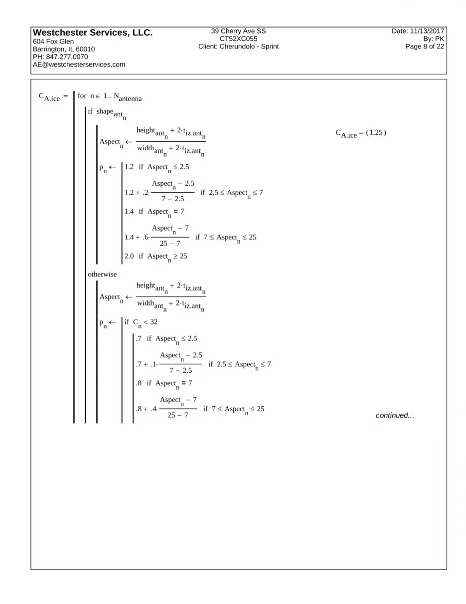
CA.ice
Aspectn
heightantn2 tiz.antn
widthantn2 tiz.antn
pn
1.2 Aspectn
2.5if
1.2 .2Aspect
n2.5
7 2.5 2.5 Aspect
n 7if
1.4 Aspectn
7=if
1.4 .6Aspect
n7
25 7 7 Aspect
n 25if
2.0 Aspectn
25if
shapeantnif
Aspectn
heightantn2 tiz.antn
widthantn2 tiz.antn
pn
.7 Aspectn
2.5if
.7 .1Aspect
n2.5
7 2.5 2.5 Aspect
n 7if
.8 Aspectn
7=if
.8 .4Aspect
n7
25 7 7 Aspect
n 25if
Cn
32if
otherwise
n 1 Nantennafor
CA.ice 1.25( )
continued...

Westchester Services, LLC.604 Fox GlenBarrington, IL 60010PH: [email protected]
39 Cherry Ave SSCT52XC055
Client: Cherundolo - Sprint
Date: 11/13/2017By: PK
Page 9 of 22
1.2 Aspectn
25if
3.76
Cn .485
Aspectn
2.5if
3.76
Cn .485
3.37
Cn .415
3.76
Cn .485
Aspectn
2.5
7 2.5 2.5 Aspect
n 7if
3.37
Cn .415
Aspectn
7=if
3.37
Cn .415
38.4
Cn
3.37
Cn .415
Aspectn
7
25 7 7 Aspect
n 25if
38.4
Cn
Aspectn
25if
32 Cn
64if
.5 Aspectn
2.5if
.5 .1Aspect
n2.5
7 2.5 2.5 Aspect
n 7if
.6 Aspectn
7if
Cn
64if
p
cont.

Westchester Services, LLC.604 Fox GlenBarrington, IL 60010PH: [email protected]
39 Cherry Ave SSCT52XC055
Client: Cherundolo - Sprint
Date: 11/13/2017By: PK
Page 10 of 22
qz.ant.ice
pn
0.00256 Kz.antn Kzt Kd Vi
2 im psf
n 1 Nantennafor
p
qz.ant.ice 6.433( ) psf
FA.ice
pn
Ka GH qz.ant.icen CA.ice
n AA.icen
n 1 Nantennafor
p
FA.ice 162.648( ) lbf
Want.ice
Dcnwidthantn
2depthantn
2 shapeantn
if
widthantnotherwise
xn
56pcf heightantn2 tiz.antn
π tiz.antn Dcn
tiz.antn
weightantn
n 1 Nantennafor
x
Want.ice 449.825( ) lbf

Westchester Services, LLC.604 Fox GlenBarrington, IL 60010PH: [email protected]
39 Cherry Ave SSCT52XC055
Client: Cherundolo - Sprint
Date: 11/13/2017By: PK
Page 11 of 22
Radio loads - per TIA-222-G
Kz.r
pn
max Kzmin min 2.01z
zg
2
α
2.01
n 1 Nradiofor
p
Kz.r
1.058
1.058
1.058
AA.r
pn
HrnWrn
n 1 Nradiofor
p
AA.r
2.951
1.858
1.738
ft2
qz.r
pn
0.00256 Kz.rn Kzt Kd V
2 im psf
n 1 Nradiofor
p
qz.r
22.256
22.256
22.256
psf

Westchester Services, LLC.604 Fox GlenBarrington, IL 60010PH: [email protected]
39 Cherry Ave SSCT52XC055
Client: Cherundolo - Sprint
Date: 11/13/2017By: PK
Page 12 of 22
C im Kzt Kz 0.5V Wr
1
ft
CA.r
Aspectn
Hrn
Wrn
pn
1.2 Aspectn
2.5if
1.2 .2Aspect
n2.5
7 2.5 2.5 Aspect
n 7if
1.4 Aspectn
7=if
1.4 .6Aspect
n7
25 7 7 Aspect
n 25if
2.0 Aspectn
25if
shapernif
Aspectn
Hrn
Wrn
pn
.7 Aspectn
2.5if
.7 .1Aspect
n2.5
7 2.5 2.5 Aspect
n 7if
.8 Aspectn
7=if
.8 .4Aspect
n7
25 7 7 Aspect
n 25if
Cn
32if
otherwise
n 1 Nradiofor
C
135.522
85.299
102.837
continued...

Westchester Services, LLC.604 Fox GlenBarrington, IL 60010PH: [email protected]
39 Cherry Ave SSCT52XC055
Client: Cherundolo - Sprint
Date: 11/13/2017By: PK
Page 13 of 22
1.2 Aspectn
25if
3.76
Cn .485
Aspectn
2.5if
3.76
Cn .485
3.37
Cn .415
3.76
Cn .485
Aspectn
2.5
7 2.5 2.5 Aspect
n 7if
3.37
Cn .415
Aspectn
7=if
3.37
Cn .415
38.4
Cn
3.37
Cn .415
Aspectn
7
25 7 7 Aspect
n 25if
38.4
Cn
Aspectn
25if
32 Cn
64if
.5 Aspectn
2.5if
.5 .1Aspect
n2.5
7 2.5 2.5 Aspect
n 7if
.6 Aspectn
7if
Cn
64if
p
cont.
CA.r
1.2
1.2
1.2
FA.r
pn
Ka GH qz.rn CA.rn
AA.rn
n 1 Nradiofor
p
FA.r
106.411
66.977
62.66
lbf
Wradio
1
Nradio
i
Weightr
Wradio
210
204
180
lbf
Westchester Services, LLC.604 Fox GlenBarrington, IL 60010PH: [email protected]
39 Cherry Ave SSCT52XC055
Client: Cherundolo - Sprint
Date: 11/13/2017By: PK
Page 14 of 22
Ice
tiz.r
pn
2.0 ti im min 1.4z
33 ft
0.1
Kzt0.35
n 1 Nradiofor
p
tiz.r
1.716
1.716
1.716
in
AA.r.ice
pn
Hrn2 tiz.rn
Wrn2 tiz.rn
n 1 Nradiofor
p
AA.r.ice
4.034
2.791
2.59
ft2

Westchester Services, LLC.604 Fox GlenBarrington, IL 60010PH: [email protected]
39 Cherry Ave SSCT52XC055
Client: Cherundolo - Sprint
Date: 11/13/2017By: PK
Page 15 of 22
CA.r.ice
Aspectn
Hrn2 tiz.rn
Wrn2 tiz.rn
pn
1.2 Aspectn
2.5if
1.2 .2Aspect
n2.5
7 2.5 2.5 Aspect
n 7if
1.4 Aspectn
7=if
1.4 .6Aspect
n7
25 7 7 Aspect
n 25if
2.0 Aspectn
25if
shapernif
Aspectn
Hrn2 tiz.rn
Wrn2 tiz.rn
pn
.7 Aspectn
2.5if
.7 .1Aspect
n2.5
7 2.5 2.5 Aspect
n 7if
.8 Aspectn
7=if
.8 .4Aspect
n7
25 7 7 Aspect
n 25if
Cn
32if
otherwise
n 1 Nradiofor
continued...

Westchester Services, LLC.604 Fox GlenBarrington, IL 60010PH: [email protected]
39 Cherry Ave SSCT52XC055
Client: Cherundolo - Sprint
Date: 11/13/2017By: PK
Page 16 of 22
1.2 Aspectn
25if
3.76
Cn .485
Aspectn
2.5if
3.76
Cn .485
3.37
Cn .415
3.76
Cn .485
Aspectn
2.5
7 2.5 2.5 Aspect
n 7if
3.37
Cn .415
Aspectn
7=if
3.37
Cn .415
38.4
Cn
3.37
Cn .415
Aspectn
7
25 7 7 Aspect
n 25if
38.4
Cn
Aspectn
25if
32 Cn
64if
.5 Aspectn
2.5if
.5 .1Aspect
n2.5
7 2.5 2.5 Aspect
n 7if
.6 Aspectn
7if
Cn
64if
p
cont.
CA.r.ice
1.2
1.2
1.2

Westchester Services, LLC.604 Fox GlenBarrington, IL 60010PH: [email protected]
39 Cherry Ave SSCT52XC055
Client: Cherundolo - Sprint
Date: 11/13/2017By: PK
Page 17 of 22
qz.r.ice
pn
0.00256 Kz.rn Kzt Kd Vi
2 im psf
n 1 Nradiofor
p
qz.r.ice
6.433
6.433
6.433
psf
FA.r.ice
pn
Ka GH qz.r.icen CA.r.ice
n AA.r.icen
n 1 Nradiofor
p
FA.r.ice
42.046
29.082
26.989
lbf
Wr.ice
DcnWrn
2Drn
2 shapern
if
Wrnotherwise
xn
56pcf Hrn2 tiz.rn
π tiz.rn Dcn
tiz.rn
Weightrn
n 1 Nradiofor
x
Wr.ice
167.616
153.132
133.721
lbf

Westchester Services, LLC.604 Fox GlenBarrington, IL 60010PH: [email protected]
39 Cherry Ave SSCT52XC055
Client: Cherundolo - Sprint
Date: 11/13/2017By: PK
Page 18 of 22
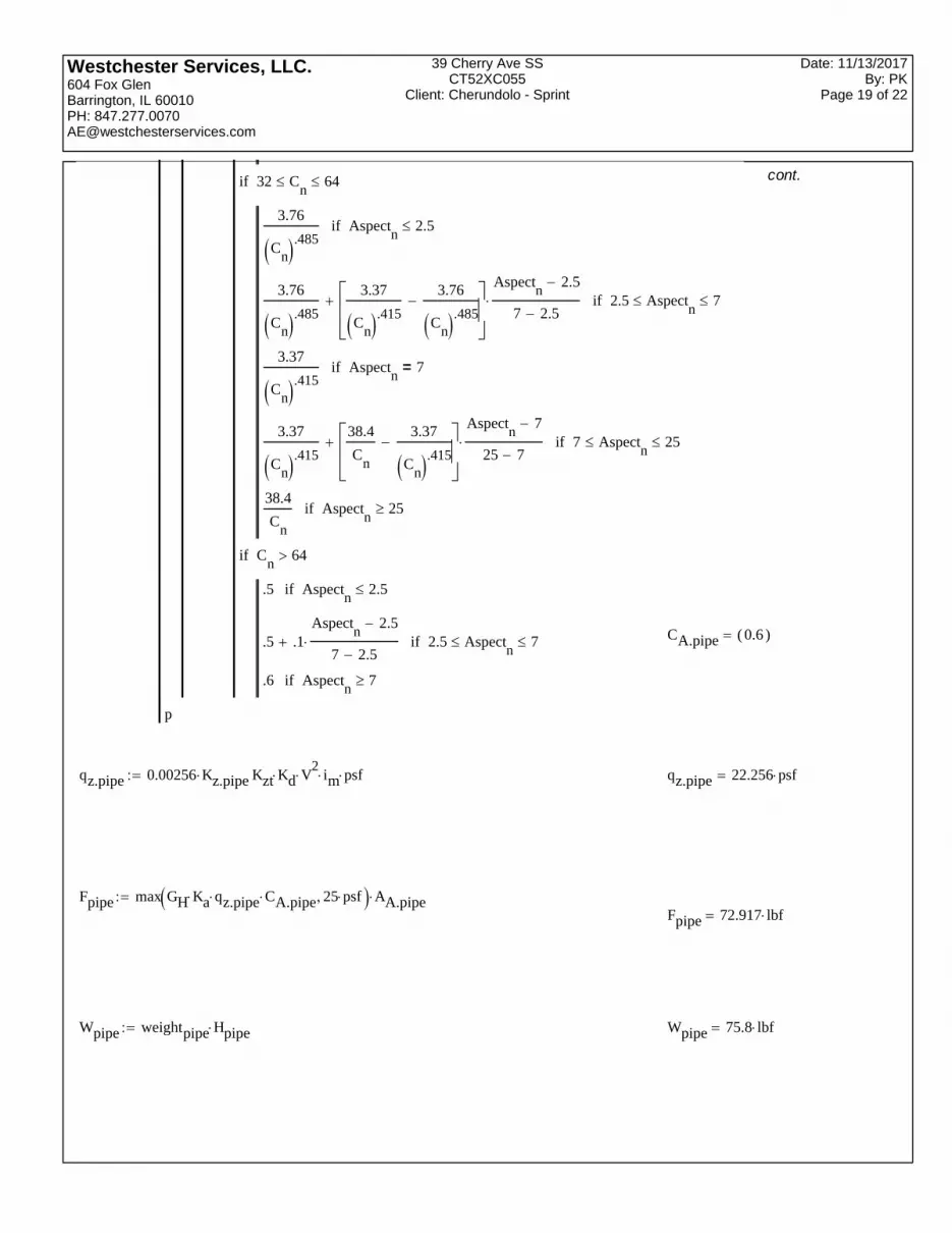
Pipes
Kz.pipe max Kzmin min 2.01z
zg
2
α
2.01
Kz.pipe 1.058
AA.pipe Hpipe Dpipe
AA.pipe 2.917 ft2
CA.pipe
Aspectn
Hpipen
Dpipen
pn
.7 Aspectn
2.5if
.7 .1Aspect
n2.5
7 2.5 2.5 Aspect
n 7if
.8 Aspectn
7=if
.8 .4Aspect
n7
25 7 7 Aspect
n 25if
1.2 Aspectn
25if
Cn
32if
n 1for
continued...
Westchester Services, LLC.604 Fox GlenBarrington, IL 60010PH: [email protected]
39 Cherry Ave SSCT52XC055
Client: Cherundolo - Sprint
Date: 11/13/2017By: PK
Page 19 of 22
3.76
Cn .485
Aspectn
2.5if
3.76
Cn .485
3.37
Cn .415
3.76
Cn .485
Aspectn
2.5
7 2.5 2.5 Aspect
n 7if
3.37
Cn .415
Aspectn
7=if
3.37
Cn .415
38.4
Cn
3.37
Cn .415
Aspectn
7
25 7 7 Aspect
n 25if
38.4
Cn
Aspectn
25if
32 Cn
64if
.5 Aspectn
2.5if
.5 .1Aspect
n2.5
7 2.5 2.5 Aspect
n 7if
.6 Aspectn
7if
Cn
64if
p
cont.
CA.pipe 0.6( )
qz.pipe 0.00256 Kz.pipe Kzt Kd V2
im psf qz.pipe 22.256 psf
Fpipe max GH Ka qz.pipe CA.pipe 25 psf AA.pipeFpipe 72.917 lbf
Wpipe weightpipe Hpipe Wpipe 75.8 lbf

Westchester Services, LLC.604 Fox GlenBarrington, IL 60010PH: [email protected]
39 Cherry Ave SSCT52XC055
Client: Cherundolo - Sprint
Date: 11/13/2017By: PK
Page 20 of 22
Ice
tiz.pipe 2.0 ti im min 1.4z
33 ft
0.1
Kzt0.35
tiz.pipe 1.716 in
qz.pipe.ice 0.00256 Kz.pipe Kzt Kd Vi2
im psf qz.pipe.ice 6.433 psf
AA.pipe.ice Hpipe 2 tiz.pipe Dpipe 2 tiz.pipe AA.pipe.ice 5.943 ft2
CA.pipe.ice
Aspectn
Hpipe tiz.pipe
Dpipe 2 tiz.pipe
pn
.7 Aspectn
2.5if
.7 .1Aspect
n2.5
7 2.5 2.5 Aspect
n 7if
.8 Aspectn
7=if
.8 .4Aspect
n7
25 7 7 Aspect
n 25if
1.2 Aspectn
25if
Cn
32if
if
n 1for
continued...

Westchester Services, LLC.604 Fox GlenBarrington, IL 60010PH: [email protected]
39 Cherry Ave SSCT52XC055
Client: Cherundolo - Sprint
Date: 11/13/2017By: PK
Page 21 of 22
3.76
Cn .485
Aspectn
2.5if
3.76
Cn .485
3.37
Cn .415
3.76
Cn .485
Aspectn
2.5
7 2.5 2.5 Aspect
n 7if
3.37
Cn .415
Aspectn
7=if
3.37
Cn .415
38.4
Cn
3.37
Cn .415
Aspectn
7
25 7 7 Aspect
n 25if
38.4
Cn
Aspectn
25if
32 Cn
64if
.5 Aspectn
2.5if
.5 .1Aspect
n2.5
7 2.5 2.5 Aspect
n 7if
.6 Aspectn
7if
Cn
64if
p
cont.
CA.pipe.ice 0.6( )
Fpipe.ice GH Ka qz.pipe.ice CA.pipe.ice AA.pipe.ice Fpipe.ice 30.966( ) lbf
Wpipe.ice 56pcf Hpipe 2 tiz.pipe πDpipe
2tiz.pipe
2
Hpipe π
Dpipe
2
2
Wpipe
Wpipe.ice 109.258 lbf

Westchester Services, LLC.604 Fox GlenBarrington, IL 60010PH: [email protected]
39 Cherry Ave SSCT52XC055
Client: Cherundolo - Sprint
Date: 11/13/2017By: PK
Page 22 of 22
Wall Mounting Loads
dwall 12in Distance of pipe from wall
nsupport 2 Number of supports
nbolt 4 Number of bolts at each support
Wnew1 Wpipe Want1 Wradio1
Wradio2 2 Wradio3
Wnew1 934.7 lbf Total new weight
Fnew1 Fpipe FA1 FA.r1
FA.r2 2 FA.r3
Fnew1 843.535 lbf Total new wind load
Determine the maximum bending moments in mounting pipes in antenna installation
Case 1 (governing case)
Mnew
Fnew1 3.5 ft
40.738 kip ft Mnew 738.093 lbf ft
Spipe 1.72( ) in3
Fy 35 ksi
Mnew
Spipe5.149( ) ksi < 0.66 Fy 23.1 ksi , The mounting pipes are adequate.
Mnew
Spipe
.66 Fy22.292( ) %
VWnew1
nbolt nsupport V 116.838 lbf Shear at each bolt
TFnew1
nbolt nsupport
Wnew1 dwall
nbolt 3.5 ft T 172.206 lbf Tension/compression at each bolt
The loads on the support bolts are negligible.
The new appurtenances are replacing existing antennas, resulting in a negligible increase in wind load. Per Ref. (6), thesmokestack has adequate capacity for existing and proposed loads.

EBI Consulting environmental | engineering | due diligence
21 B Street . Burlington, MA 01803 . Tel: (781) 273.2500 . Fax: (781) 273.3311
RADIO FREQUENCY EMISSIONS ANALYSIS REPORT EVALUATION OF HUMAN EXPOSURE POTENTIAL
TO NON-IONIZING EMISSIONS
SPRINT Existing Facility
Site ID: CT52XC055
39 Cherry Ave SS 253 Cherry Street
Waterbury, CT 06702
June 7, 2018
EBI Project Number: 6218004190
Site Compliance Summary
Compliance Status: COMPLIANT
Site total MPE% of FCC general population
allowable limit:
8.44 %

EBI Consulting environmental | engineering | due diligence
21 B Street . Burlington, MA 01803 . Tel: (781) 273.2500 . Fax: (781) 273.3311
June 7, 2018
SPRINT
Attn: RF Engineering Manager
1 International Boulevard, Suite 800
Mahwah, NJ 07495
Emissions Analysis for Site: CT52XC055 – 39 Cherry Ave SS
EBI Consulting was directed to analyze the proposed SPRINT facility located at 253 Cherry Street,
Waterbury, CT, for the purpose of determining whether the emissions from the Proposed SPRINT
Antenna Installation located on this property are within specified federal limits.
All information used in this report was analyzed as a percentage of current Maximum Permissible
Exposure (% MPE) as listed in the FCC OET Bulletin 65 Edition 97-01and ANSI/IEEE Std C95.1. The
FCC regulates Maximum Permissible Exposure in units of microwatts per square centimeter (W/cm2).
The number of W/cm2 calculated at each sample point is called the power density. The exposure limit
for power density varies depending upon the frequencies being utilized. Wireless Carriers and Paging
Services use different frequency bands each with different exposure limits, therefore it is necessary to
report results and limits in terms of percent MPE rather than power density.
All results were compared to the FCC (Federal Communications Commission) radio frequency exposure
rules, 47 CFR 1.1307(b)(1) – (b)(3), to determine compliance with the Maximum Permissible Exposure
(MPE) limits for General Population/Uncontrolled environments as defined below.
General population/uncontrolled exposure limits apply to situations in which the general population may
be exposed or in which persons who are exposed as a consequence of their employment may not be made
fully aware of the potential for exposure or cannot exercise control over their exposure. Therefore,
members of the general population would always be considered under this category when exposure is not
employment related, for example, in the case of a telecommunications tower that exposes persons in a
nearby residential area.
General population exposure to radio frequencies is regulated and enforced in units of microwatts per
square centimeter (μW/cm2). The general population exposure limits for the 850 MHz Band is
approximately 567 μW/cm2. The general population exposure limit for the 1900 MHz (PCS) and 2500
MHz (BRS) bands is 1000 μW/cm2. Because each carrier will be using different frequency bands, and
each frequency band has different exposure limits, it is necessary to report percent of MPE rather than
power density.

EBI Consulting environmental | engineering | due diligence
21 B Street . Burlington, MA 01803 . Tel: (781) 273.2500 . Fax: (781) 273.3311
Occupational/controlled exposure limits apply to situations in which persons are exposed as a
consequence of their employment and in which those persons who are exposed have been made fully
aware of the potential for exposure and can exercise control over their exposure. Occupational/controlled
exposure limits also apply where exposure is of a transient nature as a result of incidental passage through
a location where exposure levels may be above general population/uncontrolled limits (see below), as
long as the exposed person has been made fully aware of the potential for exposure and can exercise
control over his or her exposure by leaving the area or by some other appropriate means.
Additional details can be found in FCC OET 65.
CALCULATIONS
Calculations were done for the proposed SPRINT Wireless antenna facility located at 253 Cherry Street,
Waterbury, CT, using the equipment information listed below. All calculations were performed per the
specifications under FCC OET 65. Since SPRINT is proposing highly focused directional panel antennas,
which project most of the emitted energy out toward the horizon, all calculations were performed
assuming a lobe representing the maximum gain of the antenna per the antenna manufactures supplied
specifications, minus 10 dB for directional panel antennas and 20 dB for highly focused parabolic
microwave dishes, was focused at the base of the tower. For this report the sample point is the top of a 6-
foot person standing at the base of the tower.
For all calculations, all equipment was calculated using the following assumptions:
1) 1 CDMA channels (850 MHz) were considered for each sector of the proposed installation.
These Channels have a transmit power of 20 Watts per Channel.
2) 2 LTE channels (850 MHz) were considered for each sector of the proposed installation.
These Channels have a transmit power of 50 Watts per Channel.
3) 5 CDMA channels (1900 MHz (PCS)) were considered for each sector of the proposed
installation. These Channels have a transmit power of 16 Watts per Channel.
4) 2 LTE channels (1900 MHz (PCS)) were considered for each sector of the proposed
installation. These Channels have a transmit power of 40 Watts per Channel.
5) 8 LTE channels (2500 MHz (BRS)) were considered for each sector of the proposed
installation. These Channels have a transmit power of 20 Watts per Channel.
6) 1 microwave backhaul channel (11 GHz) was considered for each sector. These channels
have a transmit power of 1 Watt per channel.

EBI Consulting environmental | engineering | due diligence
21 B Street . Burlington, MA 01803 . Tel: (781) 273.2500 . Fax: (781) 273.3311
7) All radios at the proposed installation were considered to be running at full power and were
uncombined in their RF transmissions paths per carrier prescribed configuration. Per FCC
OET Bulletin No. 65 - Edition 97-01 recommendations to achieve the maximum anticipated
value at each sample point, all power levels emitting from the proposed antenna installation
are increased by a factor of 2.56 to account for possible in-phase reflections from the
surrounding environment. This is rarely the case, and if so, is never continuous.
8) For the following calculations, the sample point was the top of a 6-foot person standing at the
base of the tower. The maximum gain of the antenna per the antenna manufactures supplied
specifications, minus 10 dB for directional panel antennas and 20 dB for highly focused
parabolic microwave dishes, was used in this direction. This value is a very conservative
estimate as gain reductions for these particular antennas are typically much higher in this
direction.
9) The antennas used in this modeling are the Commscope NNVV-65B-R4 and the Nokia
AAHC for transmission in the 850 MHz, 1900 MHz (PCS) and 2500 MHz (BRS) frequency
bands and two (2) 12-inch microwave dishes at sectors A & B and one (1) 24-inch
microwave dish at Sector C for the 11 GHz microwave backhaul. This is based on feedback
from the carrier with regards to anticipated antenna selection. Maximum gain values for all
antennas are listed in the Inventory and Power Data table below. The maximum gain of the
antenna per the antenna manufactures supplied specifications, minus 10 dB for directional
panel antennas and 20 dB for highly focused parabolic microwave dishes, was used for all
calculations. This value is a very conservative estimate as gain reductions for these particular
antennas are typically much higher in this direction.
10) The antenna mounting height centerlines of the proposed panel antennas and microwave
dishes are 127 feet above ground level (AGL) for Sector A, 127 feet above ground level
(AGL) for Sector B and 127 feet above ground level (AGL) for Sector C.
11) Emissions values for additional carriers were taken from the Connecticut Siting Council
active database. Values in this database are provided by the individual carriers themselves.
All calculations were done with respect to uncontrolled / general population threshold limits.

EBI Consulting environmental | engineering | due diligence
21 B Street . Burlington, MA 01803 . Tel: (781) 273.2500 . Fax: (781) 273.3311
SPRINT Site Inventory and Power Data by Antenna
Sector: A Sector: B Sector: C
Antenna #: 1 Antenna #: 1 Antenna #: 1
Make / Model: Commscope
NNVV-65B-R4 Make / Model:
Commscope
NNVV-65B-R4 Make / Model:
Commscope
NNVV-65B-R4
Gain: 12.75 / 15.05 dBd Gain: 12.75 / 15.05 dBd Gain: 12.75 / 15.05 dBd
Height (AGL): 127 feet Height (AGL): 127 feet Height (AGL): 127 feet
Frequency Bands 850 MHz /
1900 MHz (PCS) Frequency Bands
850 MHz /
1900 MHz (PCS) Frequency Bands
850 MHz /
1900 MHz (PCS)
Channel Count 10 Channel Count 10 Channel Count 10
Total TX
Power(W): 280 Watts
Total TX
Power(W): 280 Watts
Total TX
Power(W): 280 Watts
ERP (W): 7,378.61 ERP (W): 7,378.61 ERP (W): 7,378.61
Antenna A1
MPE% 2.24 %
Antenna B1
MPE% 2.24 %
Antenna C1
MPE% 2.24 %
Antenna #: 2 Antenna #: 2 Antenna #: 2
Make / Model: Nokia AAHC Make / Model: Nokia AAHC Make / Model: Nokia AAHC
Gain: 15.05 dBd Gain: 15.05 dBd Gain: 15.05 dBd
Height (AGL): 127 feet Height (AGL): 127 feet Height (AGL): 127 feet
Frequency Bands 2500 MHz (BRS) Frequency Bands 2500 MHz (BRS) Frequency Bands 2500 MHz (BRS)
Channel Count 8 Channel Count 8 Channel Count 8
Total TX Power(W):
160 Watts Total TX
Power(W): 160 Watts
Total TX Power(W):
160 Watts
ERP (W): 5,118.23 ERP (W): 5,118.23 ERP (W): 5,118.23
Antenna A2 MPE%
1.26 % Antenna B2
MPE% 1.26 %
Antenna C2 MPE%
1.26 %
Microwave Backhaul Data Antenna
Type: Gain (dBd)
Height
(feet AGL):
Frequency
Bands
Channel
Count
Total TX
Power(W) ERP (W) MPE % Sector
1-foot
parabolic dish 28.75 dBd 127 11 GHz 1 1 749.89 0.02 A
1-foot parabolic dish 28.75 dBd 127 11 GHz 1 1 749.89 0.02 B
2-foot
parabolic dish 32.35 dBd 127 11 GHz 1 1 1,717.90 0.04 C
Site Composite MPE% Carrier MPE%
SPRINT – Sector C 3.53 %
Clearwire 0.19 %
MetroPCS 1.72 %
T-Mobile 3.00 %
Site Total MPE %: 8.44 %
SPRINT Sector A Total: 3.51 %
SPRINT Sector B Total: 3.51 %
SPRINT Sector C Total: 3.53 %
Site Total: 8.44 %

EBI Consulting environmental | engineering | due diligence
21 B Street . Burlington, MA 01803 . Tel: (781) 273.2500 . Fax: (781) 273.3311
SPRINT _ Frequency Band /
Technology
(Sector C)
#
Channels
Watts ERP
(Per Channel)
Height
(feet)
Total Power
Density
(W/cm2)
Frequency
(MHz)
Allowable
MPE
(W/cm2)
Calculated
% MPE
Sprint 850 MHz CDMA 1 376.73 127 0.93 850 MHz 567 0.16%
Sprint 850 MHz LTE 2 941.82 127 4.63 850 MHz 567 0.82%
Sprint 1900 MHz (PCS) CDMA 5 511.82 127 6.28 1900 MHz (PCS) 1000 0.63%
Sprint 1900 MHz (PCS) LTE 2 1,279.56 127 6.28 1900 MHz (PCS) 1000 0.63%
Sprint 2500 MHz (BRS) LTE 8 639.78 127 12.57 2500 MHz (BRS) 1000 1.26%
Sprint 11 GHz microwave
*NOTE: Totals may vary by 0.01% due to summing of remainders
1 1,717.90 127 0.42 11 GHz 1000 0.04%
Total*: 3.53%

EBI Consulting environmental | engineering | due diligence
21 B Street . Burlington, MA 01803 . Tel: (781) 273.2500 . Fax: (781) 273.3311
Summary
All calculations performed for this analysis yielded results that were within the allowable limits for
general population exposure to RF Emissions.
The anticipated maximum composite contributions from the SPRINT facility as well as the site composite
emissions value with regards to compliance with FCC’s allowable limits for general population exposure
to RF Emissions are shown here:
SPRINT Sector Power Density Value (%)
Sector A: 3.51 %
Sector B: 3.51 %
Sector C: 3.53 %
SPRINT Maximum
Total (Sector C): 3.53 %
Site Total: 8.44 %
Site Compliance Status: COMPLIANT
The anticipated composite MPE value for this site assuming all carriers present is 8.44 % of the allowable
FCC established general population limit sampled at the ground level. This is based upon values listed in
the Connecticut Siting Council database for existing carrier emissions.
FCC guidelines state that if a site is found to be out of compliance (over allowable thresholds), that
carriers over a 5% contribution to the composite value will require measures to bring the site into
compliance. For this facility, the composite values calculated were well within the allowable 100%
threshold standard per the federal government.