Embed Size (px)
Citation preview

Handbook of nonwovens
i
Related titles:
Recycling in textiles(ISBN-13: 978 1-85573-952-9; ISBN-10: 1-85573-952-6)An increasing amount of waste is generated each year from textiles (including carpetsand clothing) and their production. For economic and environmental reasons it isnecessary that as much as possible of this waste is recycled instead of being disposedof in landfill sites. On average approximately ten million tonnes of textile waste iscurrently dumped in Europe and America each year. Recycling in textiles is the firstbook to discuss all the issues, technology, products, processes and applications forthose in the industry who are now looking for ways to recycle their textile waste.
Digital printing of textiles(ISBN-13: 978-1-85573-951-2; ISBN-10: 1-85573-951-8)The textile industry currently produces the majority of its 34 billion square metres ofprinted textile fabric by screen printing, but developments in the digital printing ofpaper are now being adapted for the textiles market. This collection gives full coverageof the current developments in digital textiles printing. It is divided into four partscovering printer and print head technologies, printer software, digital printing colorationand design and business for digital printing. It contains fundamental technicalexplanations along with current research.
Intelligent textiles and clothing(ISBN-13: 978-1-84569-005-2; ISBN-10: 1-84569-005-2)Intelligent textiles and clothing can be defined as those which react to exterior orphysiological stimuli. This book brings together recent research in the area. Thebook is divided into five parts, each one containing an overview chapter followed byspecific research and applications. Its main focus is on phase chromic and conductivematerials. It is an essential read for anyone wanting to know more about the intelligentpossibilities of textiles.
Details of these books and a complete list of Woodhead titles can be obtained by:
∑ visiting our website at www.woodheadpublishing.com∑ contacting Customer Services (e-mail: [email protected];
fax: +44 (0) 1223 893694; tel.: +44 (0) 1223 891358 ext. 30; address: WoodheadPublishing Limited, Abington Hall, Abington, Cambridge CB21 6AH, England)
ii
Handbook of
nonwovens
Edited by
S. J. Russell
CRC Press
Boca Raton Boston New York Washington, DC
W O O D H E A D P U B L I S H I N G L I M I T E DCambridge, England
iii
Published by Woodhead Publishing Limited in association with The Textile InstituteWoodhead Publishing Limited, Abington Hall, AbingtonCambridge CB21 6AH, Englandwww.woodheadpublishing.com
Published in North America by CRC Press LLC, 6000 Broken Sound Parkway, NW,Suite 300, Boca Raton, FL 33487, USA
First published 2007, Woodhead Publishing Limited and CRC Press LLC© 2007, Woodhead Publishing LimitedThe authors have asserted their moral rights.
This book contains information obtained from authentic and highly regarded sources.Reprinted material is quoted with permission, and sources are indicated. Reasonable effortshave been made to publish reliable data and information, but the authors and the publisherscannot assume responsibility for the validity of all materials. Neither the authors nor thepublishers, nor anyone else associated with this publication, shall be liable for any loss,damage or liability directly or indirectly caused or alleged to be caused by this book.
Neither this book nor any part may be reproduced or transmitted in any form or by anymeans, electronic or mechanical, including photocopying, microfilming and recording, orby any information storage or retrieval system, without permission in writing fromWoodhead Publishing Limited.
The consent of Woodhead Publishing Limited does not extend to copying for generaldistribution, for promotion, for creating new works, or for resale. Specific permission mustbe obtained in writing from Woodhead Publishing Limited for such copying.
Trademark notice: Product or corporate names may be trademarks or registered trademarks,and are used only for identification and explanation, without intent to infringe.
British Library Cataloguing in Publication DataA catalogue record for this book is available from the British Library.
Library of Congress Cataloging in Publication DataA catalog record for this book is available from the Library of Congress.
Woodhead Publishing ISBN-13: 978-1-85573-603-0 (book)Woodhead Publishing ISBN-10: 1-85573-603-9 (book)Woodhead Publishing ISBN-13: 978-1-84569-199-8 (e-book)Woodhead Publishing ISBN-10: 1-84569-199-7 (e-book)CRC Press ISBN-13: 978-0-8493-2596-0CRC Press ISBN-10: 0-8493-2596-XCRC Press order number: WP2596
The publishers’ policy is to use permanent paper from mills that operate asustainable forestry policy, and which has been manufactured from pulpwhich is processed using acid-free and elementary chlorine-free practices.Furthermore, the publishers ensure that the text paper and cover board usedhave met acceptable environmental accreditation standards.
Project managed by Macfarlane Production Services, Dunstable, Bedfordshire(email: [email protected])Typeset by Replika Press Pvt Ltd, IndiaPrinted by T J International Limited, Padstow, Cornwall, England
iv
Contents
Contributor contact details xi
1 Development of the nonwovens industry 1A WILSON, Nonwovens Report International, UK
1.1 Definition and classification 11.2 Dry, wet and polymer-laid nonwovens 41.3 Market structure and development 101.4 Key companies 151.5 References 15
2 Dry-laid web formation 16A G BRYDON, Garnett Group of Associated Companies, UK
(Sections 2.1–2.12) and A. POURMOHAMMADI, Consultant, Iran
(Sections 2.13–2.20)
2.1 Introduction 162.2 Selection of raw materials for carding 162.3 Opening of fibres 192.4 Mixing and blending 242.5 Carding: working and stripping principles 322.6 Roller operations 372.7 Card clothing 442.8 Card and Garnett machine configurations 532.9 Card feed control, weight measurement and other
control systems 582.10 Cross-lapping 672.11 Batt drafting 712.12 Vertically lapped (perpendicular-laid) web
formation 722.13 Airlaid web formation: raw materials and fibre
preparation 762.14 Airlaying technology 80
v
2.15 Developments in airlaying 982.16 Airflow and fibre dynamics in airlaying 1012.17 Bonding and web consolidation 1042.18 Physical properties and practical applications of
airlaid fabrics 1062.19 Direct feed batt formation 1092.20 References 109
3 Wet-laid web formation 112
C WHITE, Consultant, France
3.1 Introduction 1123.2 Background and historical developments 1123.3 Theoretical basis of wet forming 1143.4 Raw materials for wet-laid nonwovens 1163.5 Cellulose fibre preparation 1263.6 Man-made fibre preparation 1263.7 Web-forming process technology 1283.8 Bonding systems for wet-laid nonwovens 1353.9 Finishing 1383.10 Product applications 1393.11 Sources of further information 1413.12 References 141
4 Polymer-laid web formation 143G S BHAT, University of Tennessee, USA and S R MALKAN,Synfil Technologies, USA
4.1 Introduction 1434.2 Resins for spunbonding and meltblowing 1434.3 Spunbond fabric production 1494.4 Spunbond production systems 1554.5 Bonding techniques 1574.6 Operating variables in the spunbond process 1604.7 Structure and properties of spunbond fabrics 1684.8 Spunbond fabric applications 1714.9 Meltblown fabric production 1724.10 Meltblown characterization techniques 1804.11 Characteristics and properties of meltblown fabrics 1844.12 Meltblown fabric applications 1854.13 Mechanics of the spunbond and meltblown processes 1864.14 Composite fabrics and other extrusion processes 1924.15 Future trends 1954.16 References 195
Contentsvi
5 Mechanical bonding 201S C ANAND, The University of Bolton, UK (Sections 5.1–5.8);D BRUNNSCHWEILER, Consultant, and G SWARBRICK,Foster Needle Ltd, UK (Sections 5.9–5.13); and S J RUSSELL,University of Leeds, UK (Sections 5.14–5.19)
5.1 Stitch bonding: introduction 2015.2 The Maliwatt and Malivlies stitch-bonding systems 2025.3 The Malimo stitch-bonding system 2065.4 Malipol 2145.5 Voltex 2155.6 Kunit 2165.7 Multiknit stitch-bonding systems 2175.8 Recent developments in stitch bonding 2205.9 Needlepunching: introduction 2235.10 Needle design and selection 2265.11 Penetration depth and other factors affecting needle use 2345.12 Needlepunching technology 2405.13 Applications of needlepunched fabrics 2515.14 Hydroentanglement: introduction 2555.15 The principles of hydroentanglement 2565.16 Fibre selection for hydroentanglement 2645.17 Process layouts 2695.18 Hydroentanglement process technology 2755.19 Applications of hydroentangled fabrics 2885.20 Acknowledgements 2945.21 References 294
6 Thermal bonding 298A POURMOHAMMADI, Consultant, Iran
6.1 Introduction 2986.2 Principle of thermal bonding 2996.3 Raw materials 3006.4 Calender (contact) bonding 3056.5 Through-air and impingement bonding 3186.6 Thermal radiation/infra-red and ultrasonic bonding 3226.7 Thermally bonded fabric structure 3256.8 Applications of thermally bonded fabrics 3276.9 References 328
7 Chemical bonding 330R A CHAPMAN, Warwick Innovation Limited, UK
7.1 Introduction 3307.2 Chemical binder polymers 331
Contents vii
7.3 Mechanism of chemical bonding 3447.4 Methods of binder application 3497.5 Drying 3567.6 Applications of chemically bonded nonwovens 3617.7 References 366
8 Nonwoven fabric finishing 368A I AHMED, NIRI, UK
8.1 Introduction 3688.2 Wet finishing 3698.3 Application of chemical finishes 3768.4 Lamination 3858.5 Mechanical finishing 3898.6 Surface finishing 3948.7 Developing technologies 3988.8 Fabric inspection 3998.9 Acknowledgements 400
9 Characterisation, testing and modelling of nonwoven
fabrics 401N MAO and S J RUSSELL, University of Leeds, UK (Sections 9.1–9.21);B POURDEYHIMI, Nonwovens Cooperative Research Centre,
North Carolina State University, USA (Section 9.22)
9.1 Introduction: characterisation of nonwoven fabrics 4019.2 Characterisation of fabric bond structure 4039.3 Fabric weight, thickness, density and other structural
parameters 4089.4 General standards for testing nonwovens 4139.5 Measurement of basic parameters 4269.6 Measuring fibre orientation distribution 4309.7 Measuring porosity, pore size and pore size distribution 4319.8 Measuring tensile properties 4399.9 Measuring gas and liquid permeability 4409.10 Measuring water vapour transmission 4419.11 Measuring wetting and liquid absorption 4429.12 Measuring thermal conductivity and insulation 4489.13 Modelling pore size and pore size distribution 4499.14 Modelling tensile strength 4529.15 Modelling bending rigidity 4559.16 Modelling specific permeability 4579.17 Modelling absorbency and liquid retention 4679.18 Modelling capillary wicking 4689.19 Modelling thermal resistance and thermal conductivity 474
Contentsviii

9.20 Modelling acoustic impedance 4789.21 Modelling filtration properties 4839.22 The influence of fibre orientation distribution on the properties
of thermal bonded nonwoven fabrics 4929.23 References 502
Index 515
Contents ix

x
Contributor contact details
Editor
Professor S. J. RussellNonwovens Research GroupSchool of DesignUniversity of LeedsLeeds LS2 9JTUK
E-mail: [email protected]
Chapter 1
Mr Adrian Wilson19 Sandal CliffSandalWakefield WF2 6AUUK
E-mail: [email protected]
Chapter 2
Alan Brydon (main contact forSections 2.1–2.12)Garnett Controls Ltd3 Water LaneBradford BD1 2JLUK
E-mail:[email protected]
Dr Ali Pourmohammadi (maincontact for Sections 2.13–2.20)3rd Floor, No. 23, 6th StreetBokharest AvenueTehran 15146Iran
E-mail: [email protected]
Chapter 3
Mr Colin WhiteConsultant in nonwovenstechnologyLes RossignolsChemin de la font del SauzeVinas le Bas34700 LodèveFrance
E-mail: [email protected]
xi

Chapter 4
Professor Gajanan Bhat434 Dougherty EngineeringbuildingUniversity of TenesseeKnoxvilleTN 37996-2200USA
E-mail: [email protected]
Professor Sanjiv R MalkanPresident and CEOSynfil TechnologiesP.O. Box 31486KnoxvilleTN 37930-1486USA
E-mail: [email protected]
Chapter 5
Professor S. Anand (main contactfor Sections 5.1–5.8)Centre for Materials Research andInnovationUniversity of BoltonDeane RoadBolton BL3 5ABUK
E-mail: [email protected]
Professor D. Brunnschweiler (maincontact for Sections 5.9.–5.13)Balderstone LodgeCommons LaneBalderstoneBlackburn BB2 7LPUK
Contributor contact detailsxii
George SwarbrickFoster Needle LimitedP.O. Box 7246Wigston LE18 4WWUK
E-mail: [email protected]
Professor S. Russell (main contactfor Sections 5.14–5.19)School of Nonwovens ResearchGroup DesignUniversity of LeedsLeeds LS2 9JTUK
E-mail: [email protected]
Chapter 6
Dr Ali Pourmohammadi3rd Floor, No. 23, 6th StreetBokharest AvenueTehran 15146Iran
E-mail: [email protected]
Chapter 7
Mr R. A. Chapman3 The WardensKenilworth CV8 2UHUK
E-mail:[email protected]
Chapter 8
Dr A. Idris AhmedNIRIWoodhouse LaneLeeds LS2 9JTUK
Email:[email protected]
Chapter 9
Dr N. MaoNonwovens Research GroupCentre for Technical TextilesSchool of DesignWoodhouse LaneUniversity of LeedsLeeds LS2 9JTUK
E-mail: [email protected]
Professor S. J. RussellNonwovens Research GroupSchool of DesignUniversity of LeedsLeeds LS2 9JTUK
E-mail: [email protected]
Professor Behnam Pourdeyhimi(main contact for Section 9.22)Nonwovens Cooperative ResearchCenterThe College of TextilesNorth Carolina State University2401 Research DriveRaleighNC 277769-8301USA
E-mail: [email protected]
Contributor contact details xiii
xiv
1
1.1 Definition and classification
In defining what a nonwoven is, there is always at least one exception thatbreaks the rule. This is perhaps fitting, since while being now recognised inits own right, the nonwovens industry has drawn on the practices and know-how of many other more well-established fields of polymer and materialsmanufacturing with a piratical disregard and an eye to the most diverse rangeof end-use products. For this reason, it is possible for companies with almostnothing in common, with vastly different structures, raw materials andtechnologies, areas of research and development and finally, customers to begrouped together under the nonwovens ‘umbrella’. Many would definethemselves by the customers they serve, as being in the medical, automotive,hygiene or civil engineering industries, for example.
The term ‘nonwoven’ arises from more than half a century ago whennonwovens were often regarded as low-price substitutes for traditional textilesand were generally made from drylaid carded webs using converted textileprocessing machinery. The yarn spinning stage is omitted in the nonwovenprocessing of staple fibres, while bonding (consolidation) of the web byvarious methods, chemical, mechanical or thermal, replaces the weaving (orknitting) of yarns in traditional textiles. However, even in the early days ofthe industry, the process of stitchbonding, which originated in Eastern Europein the 1950s, employed both layered and consolidating yarns, and the paralleldevelopments in the paper and synthetic polymer fields, which have beencrucial in shaping today’s multi-billion dollar nonwovens industry, had onlytenuous links with textiles in the first place. Therefore, the nonwoven industryas we know it today has grown from developments in the textile, paper andpolymer processing industries. Today, there are also inputs from other industriesincluding most branches of engineering as well as the natural sciences.
Certainly today, the nonwovens industry is reluctant to be associated withthe conventional textile industry and its commodity associations nor wouldit want its products to be called ‘nonpapers’ or ‘nonplastics’. The term
1Development of the nonwovens industry
A W I L S O NNonwovens Report International, UK
Handbook of nonwovens2
‘nonwoven’, then, which describes something that a product is not, as opposedto what it actually is, has never accurately represented its industry, but anyattempts to replace it over the years have floundered. The illusion created bythis misnomer has been for some to think of nonwovens as some kind of bulkcommodity, even cheap trade goods, when the opposite is often true. Thenonwovens industry is highly profitable and very sophisticated, with healthyannual growth rates in double digits in certain sectors and parts of the world.It is perhaps one of the most intensive industries in terms of its investmentin new technology, and also in research and development.
EDANA, (The European Disposables and Nonwovens Association) definesa nonwoven as ‘a manufactured sheet, web or batt of directionally or randomlyorientated fibres, bonded by friction, and/or cohesion and/or adhesion’, butgoes on to exclude a number of materials from the definition, includingpaper, products which are woven, knitted, tufted or stitchbonded (incorporatingbinding yarns or filaments), or felted by wet-milling, whether or not additionallyneedled. To distinguish wetlaid nonwovens from wetlaid paper materials, thefollowing differentiation is made, ‘more than 50% by mass of its fibrouscontent is made up of fibres (excluding chemically digested vegetable fibres)with a length to diameter ratio greater than 300’. Other types of fabric can beclassified as nonwoven if, ‘more than 30% by mass of its fibrous content ismade up of fibres (excluding chemically digested vegetable fibres) with alength to diameter ratio greater than 300 and its density is less than 0.40g/m3. This definition, which forms ISO 9092:1988 and EN 29092, was mostlikely coined prior to the enhancement of plastic film layers which havebecome broadly indistinguishable from fabrics in modern multi-componentor composite nonwovens.
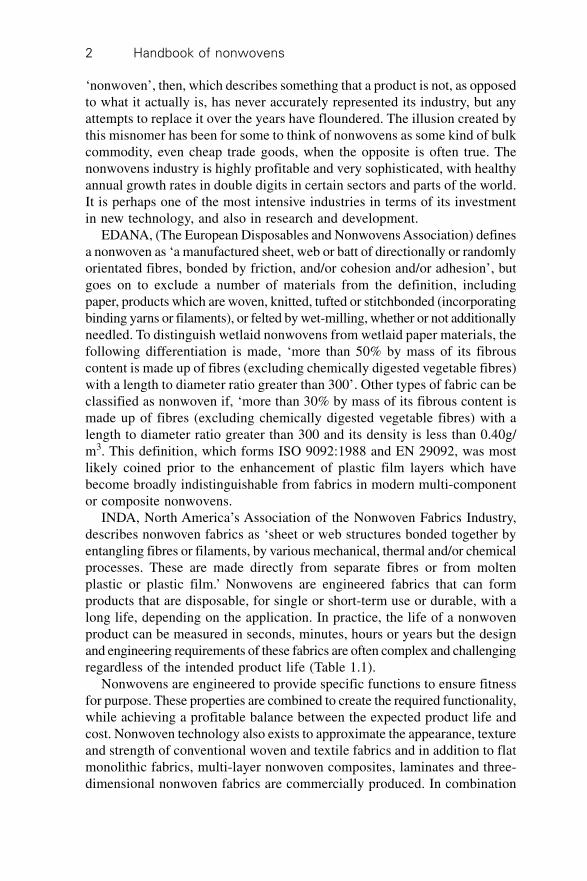
INDA, North America’s Association of the Nonwoven Fabrics Industry,describes nonwoven fabrics as ‘sheet or web structures bonded together byentangling fibres or filaments, by various mechanical, thermal and/or chemicalprocesses. These are made directly from separate fibres or from moltenplastic or plastic film.’ Nonwovens are engineered fabrics that can formproducts that are disposable, for single or short-term use or durable, with along life, depending on the application. In practice, the life of a nonwovenproduct can be measured in seconds, minutes, hours or years but the designand engineering requirements of these fabrics are often complex and challengingregardless of the intended product life (Table 1.1).
Nonwovens are engineered to provide specific functions to ensure fitnessfor purpose. These properties are combined to create the required functionality,while achieving a profitable balance between the expected product life andcost. Nonwoven technology also exists to approximate the appearance, textureand strength of conventional woven and textile fabrics and in addition to flatmonolithic fabrics, multi-layer nonwoven composites, laminates and three-dimensional nonwoven fabrics are commercially produced. In combination
De
ve
lop
me
nt o
f the
no
nw
ove
ns in
du
stry
3Table 1.1 Examples of nonwoven product applications
Hygiene Wipes Medical Protective Filtration Interlinings Shoes, leather- Upholstery, Floor- Building Civiland clothing (gas and and goods and furniture coverings and engineeringsurgical liquids) garments coating and roofing and
substrates bedding geosynthetics
Baby diapers Disposable Surgical Disposable Teabags Fusible Boot and Ticking Contract House Landfilland training wipes (dry swabs clean-room interlinings shoe carpets and wrap membranepants and pre- garments and linings linings carpet tiles protectors
moistened)
Adult incont- Dusters Wound Laboratory Drinks Shoulder Synthetic Mattress Underlays Thermal Drainageinence pads dressings overalls filtration pads leather pads and carpet and sound systems
shoe uppers backing insulationfabrics
Sanitary Dish- Surgical Fire Oil Glove Shoe Waddings Automo- Roof Lining systemsnapkins cloths gowns, protective sorption linings construction and fillings tive carpets linings for reservoirs
masks and linings components and trims and pondscaps
Tampons Mops Orthopaedic Thermal Industrial Luggage Sheets Under- Erosion controlcasts insulation gas and bags and slating and ground
fillings filtration blankets stabilisation
Cosmetic Surgical High Respira- Window Plaster- Soil-separationremoval drapes, wraps visibility tory blinds boardpads and packs clothing filters facings
Nasal Transdermal Chemical Vaccum Quilt Pipestrips drug defence filter backings wraps
delivery suits bags
Disposable Heat and Odour Dust Fabricunderwear procedure control covers tiles
packs (shingles)
Note that the intended lifespan of a nonwoven product can be measured in seconds, minutes, hours, days, weeks, months or years depending onthe particular product end-use. Compare for example the expected lifespan of a disposable wipe with a contract floorcovering. Nonwoven productsmay be intended for (i) single use with a short life (e.g. a teabag), (ii) single use with a long-life (e.g. a landfill protector) or (iii) multiple-use ofvariable life (e.g. a drinks’ machine filter).
Handbook of nonwovens4
with other materials nonwovens provide a spectrum of products with diversechemical and physical properties. This is reflected in the large variety ofindustrial, engineering, consumer and healthcare goods into which nonwovenfabrics are incorporated. The conversion of nonwoven role products intofinished products is a further important component step in the process andcan also affect final product properties. The most common products madewith nonwovens listed by INDA include:
∑ disposable nappies∑ sanitary napkins and tampons∑ sterile wraps, caps, gowns, masks and curtains used in the medical field∑ household and personal wipes∑ laundry aids (fabric dryer-sheets)∑ apparel interlinings∑ carpeting and upholstery fabrics, padding and backing∑ wallcoverings∑ agricultural coverings and seed strips∑ automotive headliners and upholstery∑ filters∑ envelopes∑ tags∑ labels∑ insulation∑ house wraps∑ roofing products∑ civil engineering fabrics/geotextiles.
In Europe, EDANA1 publish detailed annual statistical tables relating to thedeliveries of European-produced nonwovens in each of the various sectorsand end-use categories. A breakdown showing the percentage for each enduse in relation to the total weight of nonwoven deliveries is presented inTable 1.2.
Hygiene is by far the largest of these categories, accounting for over 33%of European nonwovens production, followed by civil engineering/constructionand building materials with 17.9%. The astonishing growth in recent years ofthe usage of wipes, both wet and dry, in a range of household and industrialproducts, is illustrated by their representing some 14.8% of nonwovendeliveries.
1.2 Dry, wet and polymer-laid nonwovens
Generally, in dividing nonwovens into three major areas – drylaid, wetlaidand polymer-laid (encompassing the spunmelt technologies of spunbond,meltblown and flashspun), it can be said that drylaid materials have their
Development of the nonwovens industry 5
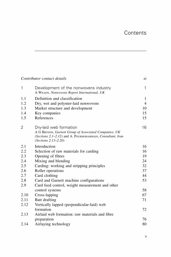
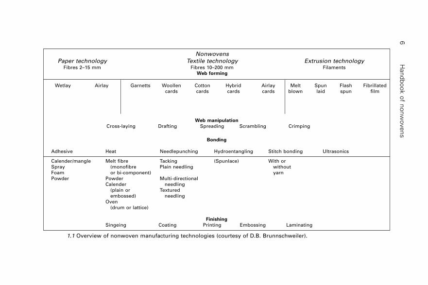
origins in textiles, wetlaid materials in papermaking, and polymer-laid productsin polymer extrusion and plastics (remembering that there is always at leastone exception to the rule). An overview of nonwoven manufacturingtechnologies is given in Fig. 1.1.
1.2.1 Drylaid nonwovens
The first drylaid systems owe much to the felting process known sincemedieval times. In the pressed felt industry, cards and web lappers were usedto make a batt containing wool or a wool blend that is subsequently felted(hardened) using moisture, agitation and heat. Some of the drylaid web-forming technologies used in the nonwovens industry, specifically cardingand garnetting, originate from the textile industry and manipulate fibres inthe dry state. In drylaid web formation, fibres are carded (including cardingand cross-lapping) or aerodynamically formed (airlaid) and then bonded bymechanical, chemical or thermal methods. These methods are needlepunching,hydroentanglement, stitchbonding (mechanical), thermal bonding (sometimesreferred to as thermobonding) and chemical bonding.
Airlaid pulp web formation originated from the paper industry. Fabricsare formed by converting wood pulp in blends with man-made fibres intorandom-laid absorbent webs, using air as the dispersing medium and as themeans of transferring fibres to the web-forming zone. In the traditionalairlaid process, synthetic resin bonding agents were applied to the pulp web
Table 1.2 European-produced nonwoven
deliveries by end use
Classification % of total
Hygiene 33.1
Medical/surgical 2.6
Wipes, personal care 8.1
Wipes, other 6.7
Garments 0.8
Interlinings 2.1
Shoe leathergoods 1.9
Coating substrates 2.4
Upholstery/table
linen/household 6.8
Floorcovering 2.3
Liquid filtration 3.7
Air/gas filtration 2.4
Building/roofing 12.5
Civil engineering/underground 5.4
Automotive 3.9
Others/unidentified 5.3
Source: EDANA
Han
db
oo
k o
f no
nw
ove
ns
6
NonwovensPaper technology Textile technology Extrusion technology
Fibres 2–15 mm Fibres 10–200 mm FilamentsWeb forming
Wetlay Airlay Garnetts Woollen Cotton Hybrid Airlay Melt Spun Flash Fibrillatedcards cards cards cards blown laid spun film
Web manipulation
Cross-laying Drafting Spreading Scrambling Crimping
Bonding
Adhesive Heat Needlepunching Hydroentangling Stitch bonding Ultrasonics
Calender/mangle Melt fibre Tacking (Spunlace) With orSpray (monofibre Plain needling withoutFoam or bi-component) yarnPowder Powder Multi-directional
Calender needling(plain or Texturedembossed) needling
Oven(drum or lattice)
Finishing
Singeing Coating Printing Embossing Laminating
1.1 Overview of nonwoven manufacturing technologies (courtesy of D.B. Brunnschweiler).

Development of the nonwovens industry 7
using a spray process. Airlaid nonwovens are forecast to grow most rapidlyby around 8% a year but from a very low base. Drylaid fabrics are the largestsegment of the nonwovens industry and are forecast to expand by 5.3% overthe next ten years.
1.2.2 Wetlaid nonwovens
Paper-like nonwoven fabrics are manufactured with machinery designed tomanipulate short fibres suspended in liquid and are referred to as ‘wetlaid’.To distinguish wetlaid nonwovens from wetlaid papers, a material is regardedby EDANA as a nonwoven if ‘more than 50% by mass of its fibrous contentis made up of fibres (excluding chemically-digested vegetable fibres) with alength to diameter ratio greater than 300, or more than 30% fibre content formaterials with a density less than 0.40 g/cm3’. This definition excludes mostwetlaid glass fibre constructions which sectors of the industry would class asnonwovens. The use of the wetlaid process is confined to a small number ofcompanies, being extremely capital intensive and utilising substantial volumesof water. In addition to cellulose papers, technical papers composed of high-performance fibres such as aramids, glass and ceramics are produced.
1.2.3 Polymer-laid nonwovens
Polymer-laid or ‘spunmelt’ nonwovens including spunbond (spunlaid),meltblown, flash-spun, apertured films as well as layered composites ofthese materials, are manufactured with machinery developed from polymerextrusion. In a basic spunbonding system, sheets of synthetic filaments areextruded from molten polymer onto a moving conveyor as a randomlyorientated web in the closest approximation to a continuous polymer-to-fabric operation. Global spunmelt demand has grown on average by 11% perannum in recent years and it now has an estimated 25% share of the globalnonwovens industry. Hygiene product components such as coverstocks, backs,distribution layers and leg-cuffs account for around 62% of spunmeltproduction, of which spunmelt materials account for around 65% of hygieneproduct components, and this is expected to rise still further to at least 72%in the coming years.
Most of the first spunbonding systems were originated by fibre producerssuch as DuPont in the USA, Rhone-Poulenc in France and Freudenberg inGermany. DuPont is regarded as the first to successfully commercialisespunbonding with its Typar product, launched as a tufted carpet backing inthe mid-1960s. The first commercial spunbonding system to be offered tothe industry was the Docan system developed by the Lurgi engineeringgroup in the 1960s. This was licensed to Corovin (now BBA) in Germany,Sodoca in France (now BBA), Chemie Linz in Austria, and Crown Zellerbach
Handbook of nonwovens8
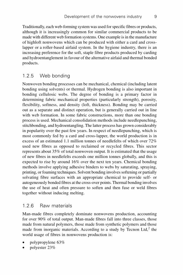
and Kimberly-Clark in the USA. The next major step towards the globalcommercialisation of the spunbond process was the introduction ofReifenhäuser’s Reicofil system in 1984, which enabled many manufacturersto enter the market. The staggering increase in the productivity of spunbondmachines over time is highlighted in Table 1.3.
1.2.4 Web formation
In all nonwoven web formation processes, fibres or filaments are eitherdeposited onto a forming surface to form a web or are condensed into a weband fed to a conveyor surface. The conditions at this stage can be dry, wet,or molten – drylaid, wetlaid or polymer-laid (also referred to as spunlaid andspunmelt processes). Web formation involves converting staple fibres orfilaments into a two-dimensional (web) or a three-dimensional web assembly(batt), which is the precursor for the final fabric. Their structure and compositionstrongly influences the dimensions, structure and properties of the final fabric.The fibre (or film) orientation in the web is controlled during the processusing machinery adapted from the textile, paper or polymer extrusion industries.The arrangement of fibres in the web, specifically the fibre orientation,governs the isotropy of fabric properties and most nonwovens are anisotropic.Although it is possible to make direct measurements of the fibre orientationin a web, the normal approach is to measure the machine direction/crossdirection (MD:CD) ratio of the web or more usually the fabric. This ratio offabric properties, usually tensile strength, measured in the machine direction(MD) and cross direction (CD) reflects the fibre orientation in the fabric.
Commercially, obtaining a web or a fabric with a truly isotropic structure,that is, with an MD:CD=1, is rarely achieved and technically is frequentlyunnecessary. Other critical fabric parameters influenced at the web formationstage are the unfinished product weight and the manufactured width.
Table 1.3 Development of Reifenhäuser Reicofil
Technology, increase of specific throughput from
1986–2002 (kg per hour per metre of beam)
Reicofil 1 system Year kg/hour/m of beam
1986 50
1992 100
Reicofil 2 system
1992 125
1995 145
Reicofil 3 system
1995 150
2002 195
Reicofil 4 system
2002 225
Source: Reifenhäuser
Development of the nonwovens industry 9
Traditionally, each web-forming system was used for specific fibres or products,although it is increasingly common for similar commercial products to bemade with different web formation systems. One example is in the manufactureof highloft nonwovens which can be produced with either a card and cross-lapper or a roller-based airlaid system. In the hygiene industry, there is anincreasing preference for the soft, staple fibre products produced by cardingand hydroentanglement in favour of the alternative airlaid and thermal bondedproducts.
1.2.5 Web bonding
Nonwoven bonding processes can be mechanical, chemical (including latentbonding using solvents) or thermal. Hydrogen bonding is also important inbonding cellulosic webs. The degree of bonding is a primary factor indetermining fabric mechanical properties (particularly strength), porosity,flexibility, softness, and density (loft, thickness). Bonding may be carriedout as a separate and distinct operation, but is generally carried out in linewith web formation. In some fabric constructions, more than one bondingprocess is used. Mechanical consolidation methods include needlepunching,stitchbonding, and hydroentangling. The latter process has grown considerablyin popularity over the past few years. In respect of needlepunching, which ismost commonly fed by a card and cross-lapper, the world production is inexcess of an estimated 1.1 million tonnes of needlefelts of which over 72%used new fibres as opposed to reclaimed or recycled fibres. This sectorrepresents about 35% of total nonwoven output. It is estimated that the usageof new fibres in needlefelts exceeds one million tonnes globally, and this isexpected to rise by around 16% over the next ten years. Chemical bondingmethods involve applying adhesive binders to webs by saturating, spraying,printing, or foaming techniques. Solvent bonding involves softening or partiallysolvating fibre surfaces with an appropriate chemical to provide self- orautogeneously bonded fibres at the cross-over points. Thermal bonding involvesthe use of heat and often pressure to soften and then fuse or weld fibrestogether without inducing melting.
1.2.6 Raw materials
Man-made fibres completely dominate nonwovens production, accountingfor over 90% of total output. Man-made fibres fall into three classes, thosemade from natural polymers, those made from synthetic polymers and thosemade from inorganic materials. According to a study by Tecnon Ltd,2 theworld usage of fibres in nonwovens production is:
∑ polypropylene 63%∑ polyester 23%
Handbook of nonwovens10
∑ viscose rayon 8%∑ acrylic 2%∑ polyamide 1.5%∑ other speciality fibres 3%.
The share of viscose rayon is thought to have increased due to its increasedimportance in the spunlace wipes market. While the tonnage of man-madecellulosics sold into European nonwovens held remarkably constant for thirtyor more years and viscose rayon participated hardly at all in the massivegrowth of the industry and its market share by 2000 was a tenth of the 1970figure. Viscose rayon staple fibres were, in 1966, the cheapest man-madefibre but by 2000 were around twice the price of the main synthetics withoutthe ability to be easily spunlaid or thermally bonded. The solvent spun cellulosicfibre, Lyocell is becoming increasingly important in the nonwovens industrypartly as a result of its absorbency and high wet strength. Polypropylenefibres are predominant in the nonwovens industry. Some of the reasons forthis include:
∑ low density and specific gravity enabling lightweight fabrics to be produced∑ low glass transition and melting temperature, which is attractive for
thermal bonding∑ inherent hydrophobicity that can be modified using fibre finishes and
other treatments∑ provides fabrics with good bulk and cover∑ chemical stability∑ biological degradation resistance (mildew, perspiration)∑ stain and soil release∑ good mechanical strength and abrasion resistance.
Polypropylene is available in a variety of grades and its surface chemistry,absorbency, mechanical properties, degradation, softness, flame retardancyand colouration are modified by auxiliary chemicals and other treatments bythe fibre suppliers. Fibres having different cross-sectional configurations arealso available, which affect the physical properties of resulting fabrics. Theunique combination of properties offers the manufacturers of nonwovens avaluable high-performance nonwoven fibre for a competitive price.
1.3 Market structure and development
Until about the 1990s, much of the world’s nonwovens industry was based inthose areas where the process technologies were conceived and developed,the USA, Europe and Japan. Many of these companies were and still remainsmall-scale enterprises, sometimes part of textile companies operating witha limited range of technologies often centred around carding and drylaid
Development of the nonwovens industry 11
web formation and needlepunching, chemical or thermal bonding. Meanwhile,the larger companies, such as Freudenberg, Kimberly-Clark, DuPont, Ahlstrom,Polymer Group Inc. (PGI), BBA and Asahi amongst others have beenresponsible for major process innovations and have nurtured them tocommercial scale. A significant patent estate has also been developed toprotect these developments, particularly by Kimberly-Clark.
The large-scale production facilities set up by the big companies werehighly capital intensive, making it too risky for smaller companies to set upproduction, certainly of spunlaid, wetlaid, airlaid pulp and hydroentanglingbusinesses. The industry can still be regarded as capital intensive today,when considering that, according to the latest estimates, some 40 companiesare responsible for 90% of total global nonwovens sales. When machinerybuilders, notably Reifenhäuser, among others, began to produce ‘turn-key’production lines capable of making high-quality nonwoven fabrics atcompetitive costs, the result was further strong growth in the original threeregions of the USA, Europe and Japan as new end-markets for nonwovenfabrics developed with the increased fabric supply from new nonwovenproducers. At the same time, the industry began to expand globally withmany new local producers. Most world regions now have nonwovens productionand growth remains high, with many countries still in the early stage ofindustrialisation. The influence of developments in the man-made fibre industryon the technical progress and economic viability of the nonwovens industryshould not be underestimated.
1.3.1 Structure of the market
The latest estimates, taking into account official INDA and EDANA figures,put the total global nonwovens production at over 3.3 million tonnes, withWestern Europe accounting for around 33%, North America 31%, the Asia-Pacific region 25%, and the remaining 11% produced outside these regions.The value placed on this production is somewhere between 710–11 billion.
Western Europe
Europe has only recently overtaken the USA as the leading nonwovens producerregion as a result of multiple new installations over the past few years.According to figures released by EDANA, production of nonwovens in Europereached a record 1,335,900 tonnes in 2004, compared to 1,025,900 tonnes in2000. This additional production has mainly come from new developmentsin airlaid, spunlaid and hydroentangled nonwovens, essentially for disposableor short-life end-uses, but also from the inclusion of some companiesbased in countries which have only recently become part of the EuropeanUnion.
Handbook of nonwovens12
North America
North American nonwoven consumption climbed to 1,074,000 tonnes in2003 up from 964,000 tonnes in 2000, according to industry body INDA.While expansion in the absorbent hygiene industry is expected to be modest,strong growth is expected in wipes and various airlaid pulp applications.Nonwoven consumption climbed to 1,004,000 tonnes in 2001 from 964,000tonnes in 2000, which represents a 4.1% annual increase, according to industrybody INDA. This equates to 22.2 billion square metres. INDA forecastsNorth American nonwovens will rise in tonnage to 1,355,000 tonnes over thenext five years, representing an average annual growth of 6.3%. This forecastis consistent with the industry’s historical performance, which grew at anaverage rate of about 6% per year throughout the 1990s. While expansion inthe absorbent hygiene industry is expected to be modest, strong growth isexpected in wipes and various airlaid pulp applications. INDA adds that thesquare metre demand by the consumer and industrial wipes markets rose 8%during 2001 over the previous year, following many new consumer andindustrial product introductions during the previous two years. Wipes accountedfor retail sales of about $2 billion and the growth forecast for the wipesindustry is 6–7% per year to 2006. There is growing use of the airlaid andhydroentangled (spunlaced) nonwoven technologies by this market.
Far East
In 2001 total nonwovens output in Japan fell for the first time since 1997 byaround 5%, to just under 300,000 tonnes, according to figures released bythe Japanese Ministry of Economy, Trade and Industry (METI). The value ofthis production is put at Yen 190.4 billion (71.57 billion). There is a cleartrend among Japanese companies of moving production to other Asiancountries. Production in Korea also fell, though by just 1%, to 130,694tonnes in 2001. Drylaid production dominates Korea’s nonwovens industry,accounting for more than 70% of total production. According to the KoreanNonwovens Industry Co-operative, there are now 262 production lines in thecountry, with only 16 being spunbond and/or metblown. From an output of10,000 tonnes in 1980, China’s nonwoven production reached 350,000 tonnesin 2000 and targets 800,000 tonnes by 2010, according to figures from theChina Nonwovens Technical Association (CNTA). Since making man-madefibre production a strategic target in the early 1950s, China’s share of theworld man-made fibre market has grown from 0.3% in 1960 to 24% in 2000,or almost seven million tonnes, according to a study by the Chinese Academyof Engineering. The Chinese population doubled to 1.32 billion over this period.
While much of the country’s production is accounted for by olderneedlepunch and carding technology, the country is investing heavily in
Development of the nonwovens industry 13
modern production technology. In considering the Chinese market’s potentialgrowth, it is necessary to consider that, as a proportion of Chinese skilledworker income, Western-style disposable nappies and femcare still appearabout ten times as expensive as they do in Europe or the USA. A month’ssupply of Western-style femcare requires 2% of a Chinese secretary’s income,but nevertheless, this market is growing well. For nappies, the wage percentagefigure is between 11 and 23% and this is too high to allow regular use atpresent. Overall, there are more than enough nonwovens produced in Chinato meet current internal market needs, so a lot is being exported at verycompetitive prices and it has been predicted that the biggest Chinese nonwovencompanies will be starting up plants in the West within ten years. Spunbondand hydroentanglement machinery has also been developed in China at muchlower cost than Western machines, and these are now available for export tothe USA and Europe.
Middle East
The Middle East represents only between 4 and 5% of global production,most of it in Israel. There has been significant investment in new spunbond,airlaid and thermal bonding facilities in the region.
Mercosur
Figures show that the Mercosur countries; Argentina, Brazil, Paraguay andUruguay produce a total of 88,000 tonnes of nonwovens per year. Of this,spunbonds are the majority, followed by carded-thermal and airlay. Mercosurimports 11,000 tpa and exports 10,000 tpa, giving a 0.4 kg per-capitaconsumption of nonwovens – about one-tenth of the USA figure. Growthpotential is therefore enormous. For nappies, for example, Brazil has nearlyten million children under the age of two and nappy sales penetration of lessthan 30%. At the same time, this nappy market was said to have seen salesfall by 18% in recent years.
Hygiene disposables
The hygiene disposables market is by far the biggest in the nonwovensindustry and its major consumer goods players, notably Procter & Gamble,Kimberly-Clark and Johnson & Johnson, understandably have a tremendousinfluence. Parallels can be drawn with the Tier 1, Tier 2 and Tier 3 structureof the automotive industry, where nonwovens manufacturers are sub-supplierstied in to extensive contracts for which entire manufacturing lines, evenentire plants, can be exclusively dedicated. The main three hygiene disposableproduct areas are nappies, feminine hygiene products and adult incontinence
Handbook of nonwovens14
products, and there is also considerable overlap in other fields such as medicalnonwovens and wipes which are also manufactured by the consumer giants.
In 1999 USA consultancy John Starr Inc. estimated the global hygieneabsorbent products market to be worth $40 billion. Disposables were said to
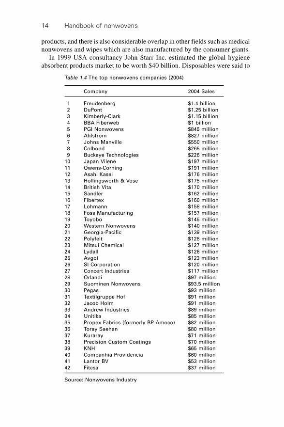
Table 1.4 The top nonwovens companies (2004)
Company 2004 Sales
1 Freudenberg $1.4 billion
2 DuPont $1.25 billion
3 Kimberly-Clark $1.15 billion
4 BBA Fiberweb $1 billion
5 PGI Nonwovens $845 million
6 Ahlstrom $827 million
7 Johns Manville $550 million
8 Colbond $265 million
9 Buckeye Technologies $226 million
10 Japan Vilene $197 million
11 Owens-Corning $191 million
12 Asahi Kasei $176 million
13 Hollingsworth & Vose $175 million
14 British Vita $170 million
15 Sandler $162 million
16 Fibertex $160 million
17 Lohmann $158 million
18 Foss Manufacturing $157 million
19 Toyobo $145 million
20 Western Nonwovens $140 million
21 Georgia-Pacific $139 million
22 Polyfelt $128 million
23 Mitsui Chemical $127 million
24 Lydall $126 million
25 Avgol $123 million
26 SI Corporation $120 million
27 Concert Industries $117 million
28 Orlandi $97 million
29 Suominen Nonwovens $93.5 million
30 Pegas $93 million
31 Textilgruppe Hof $91 million
32 Jacob Holm $91 million
33 Andrew Industries $89 million
34 Unitika $85 million
35 Propex Fabrics (formerly BP Amoco) $82 million
36 Toray Saehan $80 million
37 Kuraray $71 million
38 Precision Custom Coatings $70 million
39 KNH $65 million
40 Companhia Providencia $60 million
41 Lantor BV $53 million
42 Fitesa $37 million
Source: Nonwovens Industry
Development of the nonwovens industry 15
have now penetrated about 15% of the total available market, or 41% of themajor geographic markets. Nappies and training pants amounted to $19billion or 84 billion units, tampons, sanitary napkins and pantyliners wereworth $16 billion or 160 billion units (the tampons accounting for 16 billionunits) and there were 12 billion adult incontinence products sold – a marketworth $5 billion. The industry consumed 36 billion square metres of coverstock,3.3 million tonnes of pulp, 1.1 million tonnes of SAP and 500,000 tonnes ofbarrier film. Of a nappy maker’s total manufacturing revenue, 40% is spenton raw materials.
1.4 Key companies
According to the American magazine Nonwovens Industry, the total combinedestimated sales of the top 42 nonwovens companies accounted for more than90% of total global nonwoven sales. Within this top 42, ‘the many companiesinvesting capital within their businesses, whether new production machinery,new plants or the acquisition of smaller companies, considerably outweighedmore negative factors such as plant closings and financial troubles’. Thecompanies are listed in Table 1.4.
Each company is ranked on the basis of their 2004 sales figures, but thetop five players, while encountering fluctuating fortunes, have remained atthe helm for many years. The top five companies have achieved nonwovensales of over 75 billion – approaching half of the total sales of the top 42manufacturers. These 42 companies control 90% of the nonwovens industry,and significantly just five companies control half of that.
1.5 References
1. EDANA 2004 Nonwoven Statistics2. Nonwoven Textiles 1997–2007 World Survey, Tecnon Ltd.
16
2.1 Introduction
The dry-laid nonwoven sector utilises carding, garnetting, airlaying and incertain specialist applications, direct feed batt formation processes to convertstaple fibres into a web or batt structure that is uniform in weight per unitarea.
2.2 Selection of raw materials for carding
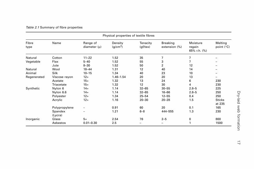
Virtually any fibre that can be carded can be, and probably already is, usedin nonwovens including both organic and inorganic fibres. As noted in Chapter1, man-made fibres account for the majority of raw materials used in thenonwovens industry, and in the carding sector, polyester is the most widelyused. This is principally because of its suitability for many product applicationsand comparatively low cost. Polypropylene is also important, particularly inthe manufacture of heavyweight needled fabrics for durable products such asfloorcoverings and geosynthetics as well as in needlepunched filtration mediaand lightweight thermal bonded fabrics for hygiene disposables. Viscoserayon is extensively used in the medical and hygiene sectors, principallybecause of its high moisture regain. The flexibility of the carding process isreflected by the diversity of staple fibre types that are utilised by the industryand includes polymers, glass and ceramic materials. Table 2.1 gives a generaloverview of the fibres that are carded either alone or in blends. Fundamentalto the suitability of a particular fibre for dry-laid processing is its machinecompatibility as well as its influence on fabric properties. There are numerousexamples of new fibre developments that have been slow to develop becauseof processing problems, particularly during carding.
Common problems are uncontrolled static electricity, low fibre-to-fibrecohesion and low fibre extension (the minimum required is 2–5%) leading tofibre breakage and poor yield. Whilst natural fibres such as cotton and woolhave been carded as long as cards have been in existence, man-made fibres
2Dry-laid web formation
A G B R Y D O NGarnett Group of Associated Companies, UK
(Sections 2.1–2.12) andA P O U R M O H A M M A D I
Consultant, Iran (Sections 2.13–2.20)
Dry
-laid
we
b fo
rmatio
n1
7
Table 2.1 Summary of fibre properties
Physical properties of textile fibres
Fibre Name Range of Density Tenacity Breaking Moisture Melting
type diameter (m) (g/cm3) (gf/tex) extension (%) regain point (∞C)
65% r.h. (%)
Natural Cotton 11–22 1.52 35 7 7 –
Vegetable Flax 5–40 1.52 55 3 7 –
Jute 8–30 1.52 50 2 12 –
Natural Wool 18–44 1.31 12 40 14 –
Animal Silk 10–15 1.34 40 23 10 –
Regenerated Viscose rayon 12+ 1.46–1.54 20 20 13 –
Acetate 15+ 1.32 13 24 6 230
Triacetate 15+ 1.32 12 30 4 230
Synthetic Nylon 6 14+ 1.14 32–65 30–55 2.8–5 225
Nylon 6.6 14+ 1.14 32–65 16–66 2.8–5 250
Polyester 12+ 1.34 25–54 12–55 0.4 250
Acrylic 12+ 1.16 20–30 20–28 1.5 Sticks
at 235
Polypropylene – 0.91 60 20 0.1 165
Spandex – 1.21 6–8 444–555 1.3 230
(Lycra)
Inorganic Glass 5+ 2.54 76 2–5 0 800
Asbestos 0.01–0.30 2.5 – – 1 1500
Handbook of nonwovens18
such as polyester have evolved to improve compatibility with high-speednonwoven carding systems. The applied forces in carding give rise to fibrebreakage and permanent fibre elongation, which modifies the original fibrelength distribution and in some low-temperature materials such as PVC maybe subject to thermal shrinkage during the process.
Whilst exceptions do exist, the general range of fibre dimensions suitablefor the carding sector can be given approximately as 1–300 dtex fibre lineardensity and 15–250 mm mean fibre length. In practice such a range of fibredimensions could not be satisfactorily processed on one card without modifyingthe card roller configuration and layout, settings and the card wire. Blendingextends the range of fibre lengths and finenesses that can be processed andin certain sectors of the industry carrier fibres are used to aid processing ofshort, stiff or low surface friction materials. It should also be understood thatthe mean fibre length and the fibre length distribution as measured beforecarding is substantially different after carding due to fibre breakage orpermanent elongation of fibres in the process. Cotton and other short-staplefibres of <60 mm fibre length are used in the short-staple spinning industry,where traditionally, a modular sequence of processes has been developed toprepare, card and spin the fibre into yarn. Man-made fibres of similar diameterto cotton are therefore cut to a similar length so that they can be processedon the same machinery, either in 100% or blended form, depending on end-use requirements. Fibres are commonly square-cut to one length prior toprocessing. This gives a different fibre length distribution from natural fibres,which typically have a trapezoidal-shaped distribution.
Cotton cards are sometimes used to manufacture, for example, femininehygiene and some absorbent medical products from short-staple fibres of c.28–45 mm mean fibre length composed of bleached cotton and viscoserayon. However, the use of short-staple or cotton ‘flat’ cards in the nonwovensindustry is not extensive because the revolving flats limit the maximumwidth of the card to about 1.5 m and the mixing power of the machine issignificantly lower than a worker-stripper card. Most carded nonwovens aremanufactured from fibres with a mean length typically in the range 45–100mm, although in some specialist applications fibres outside this range arecarded. Accordingly, worker-stripper cards originally developed to processlonger fibres are most commonly used by the nonwovens carding industry.
Fibre characteristics not only influence fabric properties but also processingperformance. Web cohesion, fibre breakage, nep formation and web weightuniformity are key quality parameters and are influenced by fibre diameter,fibre length, fibre tensile properties, fibre finish and crimp. During theproduction of man-made fibres, crimp is introduced to increase web cohesion,bulk and sometimes elastic recovery. The crimp shape and frequency as wellas its uniformity depend on the manufacturing conditions and in practice aresubject to significant variation. The crimp may decay during carding due to
Dry-laid web formation 19
the applied forces and temperatures that occur; cellulose fibres are particularlyprone to this. Fibre finish modifies both fibre to fibre friction (cohesion) andfibre to metal friction (holding power of the wire) during carding.
Although polymer additives can be introduced before extrusion to influenceproperties, fibre finish is normally topically applied after extrusion, beforethe fibre is baled and despatched for carding. Both the static and dynamicfriction are important, fibre to fibre and fibre to metal. The ability of a fibrefinish to increase fibre cohesion whilst at the same time reducing friction isan example of frictional ‘stick-slip’ behaviour. A useful analogy is to imaginetwo sheets of glass coated by a thin film of lubricant. Placed together, theglass sheets easily slide over each other but it is not so easy to prise thesheets apart.
In carding, the fibres should readily slide against each other but in acontrolled manner. Fibre finishes also contain anti-static agents, theeffectiveness of which is particularly important when carding hydrophobicfibres such as polypropylene. Other finish additives may be used either toimprove downstream processing efficiency or to meet the end-use requirementsof the finished fabric. Accordingly, it is possible to use finish additives toimprove wetting out of fibres by modifying surface energy, reduce foamingin processes such as hydroentanglement, meet food contact approval regulationsand create biodegradable formulations for disposable fabrics. The moisturecontent or regain of fibres is also important because of the opportunity tocontrol static electricity during carding as well as the influence of imbibedwater on the tensile properties of hygroscopic fibres.
2.3 Opening of fibres
It is traditionally said that ‘well opened is half carded’ and this old adageremains remarkably true. The more work that has to be done to raw materialson the card in order to break down the tufts into individual fibres and convertthem into a homogeneous web, the more likely are fibre breakage, nepformation and poor quality webs. Traditionally, the need for opening andblending emerged to tackle the inconsistency within and between batches offibres, particularly as fibres used in carding at that time were predominantlynatural and hence their physical properties were affected by seasonal andenvironmental factors that were beyond the control of industrial processors.Natural fibres also require mechanical cleaning to remove impurities. Althoughreclaimed natural and man-made fibres are used by the nonwovens industry,for example, in the automotive, bedding and floorcovering sectors, the majorityis virgin man-made fibre. Such fibre is cut to length or to a defined lengthdistribution and has a fibre finish pre-applied to aid processing.
The fibre, which is supplied in dense press-packed bales, usually needs tobe opened prior to carding. The consequent reduction in tuft size promotes
Handbook of nonwovens20
consistent fibre feeding to the card, which is particularly important in highproduction installations. Although the general rule is to open the fibre asuniformly as possible, it is possible to open a batch of fibres too well, withthe result that it is so voluminous that problems are experienced in cardfeeding. This is a particular problem in high production carding where a low-density fibre flow can restrict the maximum production rate of the cardfeeder. The volume of opened fibre also depends on the fibre type, fibrefineness, crimp and stiffness. Partly for this reason, fibres having differentspecifications cannot be expected to be processed using the same machinesettings. If the tuft density is too low, fibres may roll in the feed hopperleading to nep formation and entanglements. This can be overcome by providinga suitable feed rate differential between the feed entering the hopper and thestream leaving the hopper. This maintains a reservoir so that consolidationcan be achieved by gravitational compaction, either in the hopper chamberor in the volumetric feed chute.
The opening process converts large, densely packed tufts from a bale tosmaller tufts or in some cases individual fibres. Generally, subsequentconsolidation of the opened fibre in bales or storage bins prior to carding,simply compresses the mass of individual fibres together into a moremanageable condition. Intensive fibre opening is not problematic providedthe production rate of the opened fibre is matched with the rest of the processingline. The goal is to maximise the degree of opening at a particular openingdevice, whilst minimising the associated fibre damage, particularly fibrebreakage. In practice this is achieved by selecting appropriate throughputrates for a given fibre type and tuft density and selection of appropriate typesof opening system. Variations in feed rate through an opening machine willtend to lead to variations in the degree of fibre opening and the associatedfibre damage. The sequencing of opening systems also influences the abilityto achieve progressive opening as well as minimise fibre damage. A suitabledwell time within a condenser or hopper chamber or other suitable bufferzone is required to ensure that a sufficient mass of fibre passes through thefeeder to evenly distribute the batch and to achieve the desired productionrate.
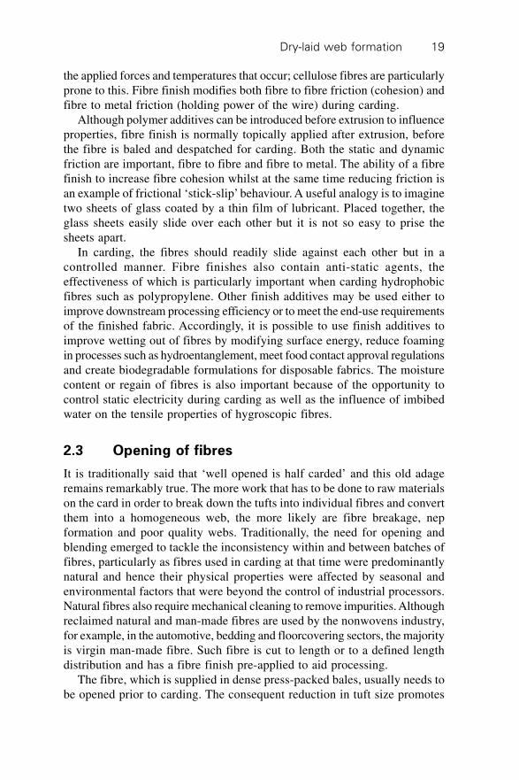
2.3.1 Bale breakers
Commonly, bale breaking hopper feeders are the first point of entry of fibreto a nonwoven process line (see Fig. 2.1). A bale breaker is similar to aconventional hopper feeder in its construction but is usually more robust,particularly the design of the spiked lattice and the beater rolls. An extendedfloor apron, often constructed from a chain of steel rolls rather than a conveyorbelt, accepts bales directly from a fork-lift truck. Where the width of the baleopener is relatively narrow (e.g., 1500 mm) each feeder accommodates a
Dry-laid web formation 21
single line of bales. Alternatively, a wide bale opener is used which canaccommodate several bales side by side. The individual bales may consist ofthe same raw material or several different components to make up the blend.Such bales are very dense and the purpose of the bale breaker, as its namesuggests, is simply to break it down into manageable clumps and topneumatically feed these at a relatively consistent flow rate to the openingmachine.
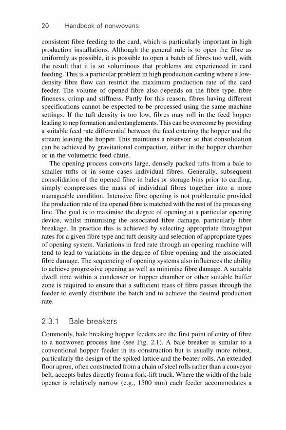
2.3.2 Bale pickers
Although blending large batches of fibre for nonwoven manufacturing mainlyinvolves bale breakers, bale pickers used in the cotton spinning industry can
(a)
(b)
4
3
2
1. Feed table2. Feed lattice3. Spiked (inclined) lattice4. Evener roller
2.1 (a) and (b) Bale opener (courtesy of Trützschler GmbH, Germany).
Handbook of nonwovens22
also be utilised. In such systems, rows of bales are positioned in line formation(usually adjacent) and a mechanical picking device traverses across the topof the bales, progressively removing uniform small tufts of each in the correctproportion (see Fig. 2.2). Rotating spiked rollers set on a pivot arm inside thebale picker head remove the tufts as they run across the top of the bales.Because of the small tufts a well-distributed mix can be produced in theblending bin. Systems have been introduced that use a variation of thisconcept for long staple fibres.
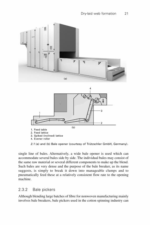
2.3.3 Fibre openers
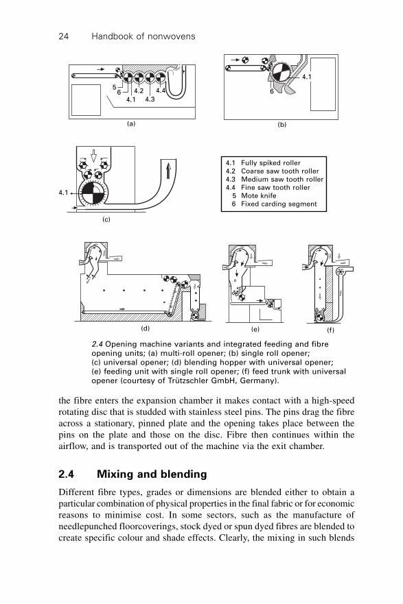
Fibre openers used by the nonwovens industry have evolved from traditionalmachines that were originally designed for the short-staple cotton and woolprocessing industries. Heavy-duty fibre openers such as Fearnoughts (seeFig. 2.3) are used in some sectors of the nonwoven industry, for examplethose processing fibres of >50 mm and colour blends. Multi-roll openers,pickers or fine openers commonly suffice for other applications. Fineopeners provide efficient in-line opening for fibres up to about 100 mmlength. Such machines are arranged horizontally or vertically and areincorporated in feeding units and chutes as well as blending hoppers (seeFigs 2.3 and 2.4). In chute feed systems, a pair of feed rollers presents fibreto a revolving opening roller that is clothed with either pins or coarse cardwire. A secondary chute with delivery rollers that feed a finely pinned openingroller operating with a high surface speed follows this. Examples are shownin Fig. 2.4.
Single roll openers are frequently suitable for opening polyester whereasa multi-roll opener may be used to open bleached cotton or viscose rayonwhere the tufts are more heavily entangled. One of the most importantconsiderations in opening is the state or condition of the incoming fibre in
2.2 Bale picker – (automatic bale opener) (courtesy of TrützschlerGmbH, Germany).
Dry-laid web formation 23
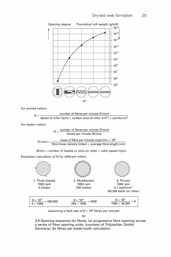
terms of fibre entanglement and tuft density. Fibre entanglement is generallyreduced at the expense of unwanted fibre breakage and to minimise suchfibre damage, gradual opening using a sequence of opening units (ratherthan one single unit) is required to progressively reduce the tuft size. Basedon this stepwise approach, in which a sequence of opening units is used, atheoretical optimum opening curve has been proposed (see example in Fig. 2.5).
As well as the design of the feed system and the number of openingrollers used, the type of clothing, pin density or blade frequency, gaugesettings and surface speeds are also varied according to the fibre openingrequired and the incoming tuft size. The most intensive opening is generallyachieved by presenting fibre to the opener roller (or beater) via a pair ofclamped feed rollers rather than by an airstream. The theoretical tuft sizeafter each stage of opening can be estimated based on the opening rollerdesign, feed rate and fibre linear density.
It is important to recognise that decreasing the average tuft size byprogressive fibre separation promotes homogeneous mixing of the differentfibre components because the tufts are smaller. Also, as the tufts are reducedin size impurities are more likely to be liberated from the fibre. Clearly, it isadvantageous to remove such impurities before carding, if possible, to maximisethe life of the card clothing and yield.
2.3.4 Disc opener
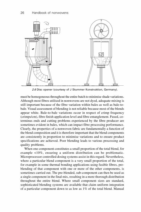
The disc opener shown in Fig. 2.6 is remarkable in that it has only onemoving part. Fibre is drawn through the system under negative pressure. As
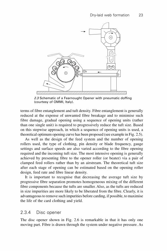
2.3 Schematic of a Fearnought Opener with pneumatic doffing(courtesy of OMMI, Italy).
Handbook of nonwovens24
the fibre enters the expansion chamber it makes contact with a high-speedrotating disc that is studded with stainless steel pins. The pins drag the fibreacross a stationary, pinned plate and the opening takes place between thepins on the plate and those on the disc. Fibre then continues within theairflow, and is transported out of the machine via the exit chamber.
2.4 Mixing and blending
Different fibre types, grades or dimensions are blended either to obtain aparticular combination of physical properties in the final fabric or for economicreasons to minimise cost. In some sectors, such as the manufacture ofneedlepunched floorcoverings, stock dyed or spun dyed fibres are blended tocreate specific colour and shade effects. Clearly, the mixing in such blends
2.4 Opening machine variants and integrated feeding and fibreopening units; (a) multi-roll opener; (b) single roll opener;(c) universal opener; (d) blending hopper with universal opener;(e) feeding unit with single roll opener; (f) feed trunk with universalopener (courtesy of Trützschler GmbH, Germany).
(a) (b)
(c)
(d) (e) (f)
4.1 Fully spiked roller4.2 Coarse saw tooth roller4.3 Medium saw tooth roller4.4 Fine saw tooth roller 5 Mote knife 6 Fixed carding segment
5
4.16 4.2
4.3
4.4
4.1
6
4.1
Dry-laid web formation 25
Opening degree Theoretical tuft weight (g/tuft)
10–6
10–5
10–4
10–3
10–2
10–1
100
101
102
103
(a)
For pinned rollers:
N = number of fibres per minute (F/min)
speed of roller (rpm) surface area of roller (cm ) points/cm2 2¥ ¥
For beater rollers:
N = number of fibres per minute (F/min)
blows per minute (B/min)
(F/min) = mass of fibre per minute (mg/min) 10
fibre linear density (mtex) average fibre length (cm)
5¥
¥
B/min = number of blades or pins on roller ¥ roller speed (rpm)
Examples: calculation of N for different rollers
1. Three bladed 2. Multibladed 3. Pinned1000 rpm 1000 rpm 1560 rpm3 blades 250 blades 3.7 teeth/cm2
(48,355 teeth on roller)
6 10
3 1000 = 200,000
8¥
¥
6 10
250 1000 = 2400
8¥
¥
6 10
1560 48,355 = 8
8¥
¥
(assuming a feed rate of 6 ¥ 108 fibres per minute)
(b)
2.5 Opening sequence for fibres; (a) progressive fibre opening acrossa series of fibre opening units; (courtesy of Trützschler GmbH,Germany) (b) fibres per blade tooth calculation.
Handbook of nonwovens26
must be homogeneous throughout the entire batch to minimise shade variations.Although most fibres utilised in nonwovens are not dyed, adequate mixing isstill important because of the fibre variation within bales as well as bale-to-bale. Visual assessment of blending is not reliable because most of the blendsappear white. Bale-to-bale variations occur in respect of crimp frequency(crimps/cm), fibre finish application level and fibre entanglement. Fused, co-terminus ends and cutting problems experienced by the fibre producer aresometimes evident in bales, which can impact fibre processing performance.Clearly, the properties of a nonwoven fabric are fundamentally a function ofthe blend composition and it is therefore important that the blend componentsare consistently in proportion to minimise variations and to ensure productspecifications are achieved. Poor blending leads to various processing andquality problems.
When one component constitutes a small proportion of the total blend, forexample <10%, ensuring a uniform distribution can be problematic.Microprocessor controlled dosing systems assist in this regard. Nevertheless,where a particular blend component is a very small proportion of the total,for example in some thermal bonding applications using fusible fibres, pre-blending of that component with one or more of the other components, issometimes carried out. The pre-blended, sub-component can then be used asa single component in the final mix, resulting in a more thorough distributionthroughout the entire blend. Where small component sizes are standard,sophisticated blending systems are available that claim uniform integrationof a particular component down to as low as 1% of the total blend. Manual
2.6 Disc opener (courtesy of J Stummer Konstruktion, Germany).
Dry-laid web formation 27
feed weigh-blenders are used in small blend rooms or as a preparatory blendingdevice to pre-mix small components.
Weigh-blenders incorporate a weigh conveyor onto which blend componentsare manually layered one on top of the other by the operator, in the correctweight proportions to produce a sandwich blend. A continuous succession ofsuch blend sandwiches is then transported on the conveyor to a hopper oropener and subsequently intimately mixed within a blending system.
2.4.1 Multi-hopper systems
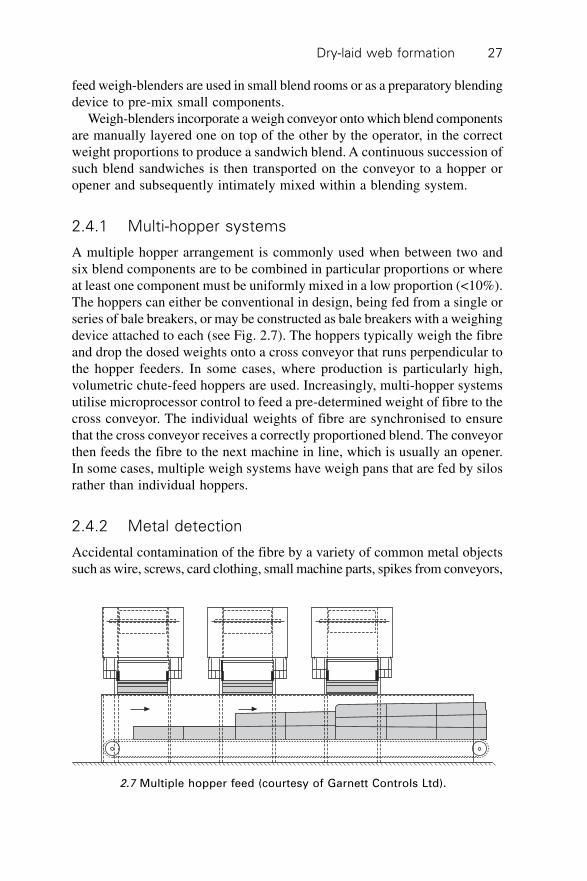
A multiple hopper arrangement is commonly used when between two andsix blend components are to be combined in particular proportions or whereat least one component must be uniformly mixed in a low proportion (<10%).The hoppers can either be conventional in design, being fed from a single orseries of bale breakers, or may be constructed as bale breakers with a weighingdevice attached to each (see Fig. 2.7). The hoppers typically weigh the fibreand drop the dosed weights onto a cross conveyor that runs perpendicular tothe hopper feeders. In some cases, where production is particularly high,volumetric chute-feed hoppers are used. Increasingly, multi-hopper systemsutilise microprocessor control to feed a pre-determined weight of fibre to thecross conveyor. The individual weights of fibre are synchronised to ensurethat the cross conveyor receives a correctly proportioned blend. The conveyorthen feeds the fibre to the next machine in line, which is usually an opener.In some cases, multiple weigh systems have weigh pans that are fed by silosrather than individual hoppers.
2.4.2 Metal detection
Accidental contamination of the fibre by a variety of common metal objectssuch as wire, screws, card clothing, small machine parts, spikes from conveyors,
2.7 Multiple hopper feed (courtesy of Garnett Controls Ltd).
Handbook of nonwovens28
and any number of unusual objects sometimes occurs. Consequently it isnecessary to incorporate metal-detection devices in blending systems as wellas at the feeding section of cards. The consequences of allowing metal toenter a card in terms of damage and lost production are serious. The simplestform of metal detection is the ‘magnetic hump’ which is fitted with powerfulmagnets to catch stray metal objects. The unit is fitted in-line within theductwork that conveys the fibre. In-line diverting devices detect metal withinductwork by electronic means. When metal is detected a signal is generatedby a microprocessor, which opens the duct to divert the contaminated fibreto a holding bin where the metal can be manually removed and the fibrerecovered. Many hopper feeders have a row of magnets mounted above thespiked apron. Metal-detection devices can be fitted above the card feedapron or integrated into the card feed rollers. Because of the fine gaugesetting between the feed rollers, any metal that passes though the feed rollerscomes into contact with both rollers and completes a circuit that triggers anemergency stop either to the feed section or the entire card.
2.4.3 Fibre lubrication and spray systems
Although fibre lubrication is not universally used by the nonwovens industrybecause fibres are delivered ready for processing by the man-made fibresupplier, it is sometimes desirable to apply additional liquid to a blend. Thismay be a lubricant in the case of natural fibres, or an auxiliary such as ananti-static agent. Spray systems accurately dose and apply such additivesdirectly onto the fibre. In some cases, the addition of water alone is aneffective processing aid. Water can be sprayed during the blending and openingstages of processing or on-line using an atomiser to apply a fine mist priorto carding.
2.4.4 The influence of moisture content
Moisture is important both in respect of fibre processing performance andthe properties of the final fabric. Some hydrophobic fibres, particularly polyesterand polypropylene are prone to static electricity during carding, which becomesmost evident when the relative humidity is low. This can lead to problems inhandling lightweight webs. The fibre breaking strength of cotton increasesas the moisture content increases, whereas for viscose rayon and most otherhygroscopic fibres the reverse is true. The extension at break of manyhygroscopic fibres as well as frictional properties are also affected by changesin moisture content. Hydrophilic fibre finishes are applied to hydrophobicman-made fibres, to improve wetting out during hydroentanglement as wellas to control static in carding. There are also important economic considerationsin relation to moisture content, particularly where hygroscopic fibres are to
Dry-laid web formation 29
be converted into medical, hygiene or wipe products because of the changein mass. Moisture measurement and control systems continuously monitorthe moisture content of fibres, batts and fabrics on-line. These systems eithersimply measure and report, giving alarms when the moisture content driftsbeyond the pre-set limits or they can effect automatic control.
Automatic re-hydration is achieved by water sprays or control of thethroughput speed. The moisture content can also be controlled by automatictemperature adjustment in the dryer. In processing, the benefits of controllingthe moisture content can be seen in the productivity of the process, in termsof both higher throughput and the reduction of static. Where a product is soldby weight, it is clearly important to ensure that the correct moisture contentis maintained. For example, hygiene products such as cotton wool are producedand packed to a specific invoice weight. This packed weight is thereforemade up of the fibre as well as an allowable amount of absorbed moisture.Areas of the industry where moisture control is utilised includes femininehygiene products, medical products, absorbent wipes, backing forfloorcoverings, hydroentanglement installations and some thermal bondingapplications.
2.4.5 Blending hoppers and self-emptying bins
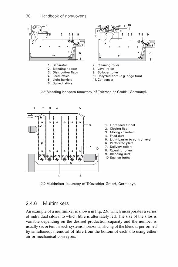
The traditional method of batch blending involves successive horizontallayering of the entire blend (composed of many bales) to form a block or‘stack’ and then vertical slicing to produce small tufts and a homogeneousblend. The same principle is used in automatic blending bins. Semi-continuousand continuous blending are also common in the nonwoven industry, wherethe production line allows blending between only a few bales (<1 tonne),rather than the entire blend (1–>10 tonnes). Blending hoppers allow continuousmixing. Fibre is fed into the machine either from a telescopic or fixed rotarydistributor and is deposited into horizontal layers.
In modern small to medium capacity blending bins, a moving floor conveysthe fibre in the direction of a revolving spiked lattice, which takes verticalslices from the fibre and discharges it pneumatically to the next machine(Fig. 2.8). The movement of the floor is electronically controlled to optimisethroughput, preventing feeding variations. Large capacity automatic self-emptying bins work on a similar principle to blending hoppers except thatthey allow a much larger blend to be assembled and are intended mainly forbatch rather than continuous blending. In this case, the bin emptier moveswithin the bin in a controlled manner. Fibre is deposited into the rectangularbin using a telescopic duct and rotary spreader to form horizontal layers anda spiked apron removes the fibre in vertical slices. A spiked inclined apronforms part of the emptying unit that moves progressively into the bin toremove the fibre.
Handbook of nonwovens30
2.4.6 Multimixers
An example of a multimixer is shown in Fig. 2.9, which incorporates a seriesof individual silos into which fibre is alternately fed. The size of the silos isvariable depending on the desired production capacity and the number isusually six or ten. In such systems, horizontal slicing of the blend is performedby simultaneous removal of fibre from the bottom of each silo using eitherair or mechanical conveyors.
31
3 5 2 7 8 9 11
6
4
3 5 2 7 8 9
1110
6
4
1. Separator2. Blending hopper3. Distribution flaps4. Feed lattice5. Light barriers6. Spiked lattice
7. Cleaning roller8. Level roller9. Stripper roller10. Recycled fibre (e.g. edge trim)11. Condenser
2.8 Blending hoppers (courtesy of Trützschler GmbH, Germany).
1 2 3 4 5
6
710
9 8
1. Fibre feed funnel2. Closing flap3. Mixing chamber4. Feed duct5. Light barrier to control level6. Perforated plate7. Delivery rollers8. Opening rollers9. Blending duct10. Suction funnel
2.9 Multimixer (courtesy of Trützschler GmbH, Germany).
Dry-laid web formation 31
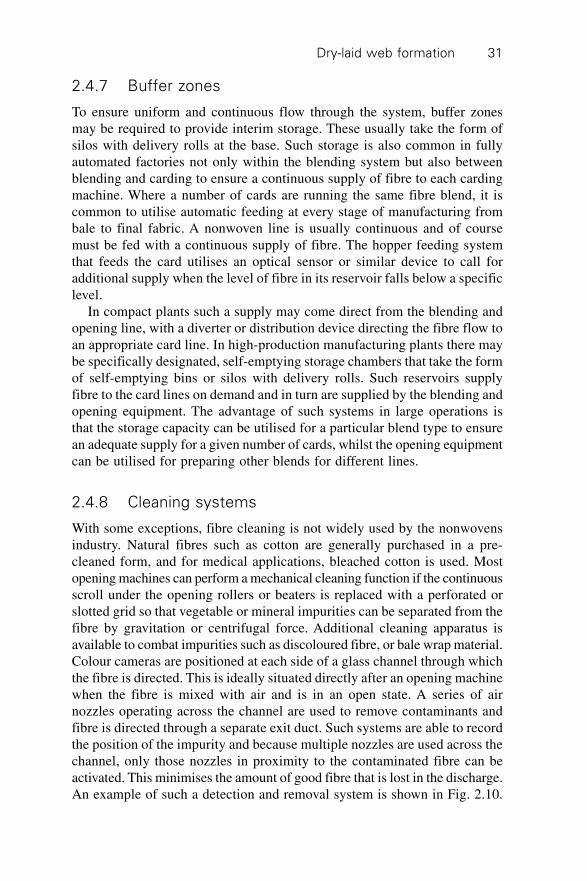
2.4.7 Buffer zones
To ensure uniform and continuous flow through the system, buffer zonesmay be required to provide interim storage. These usually take the form ofsilos with delivery rolls at the base. Such storage is also common in fullyautomated factories not only within the blending system but also betweenblending and carding to ensure a continuous supply of fibre to each cardingmachine. Where a number of cards are running the same fibre blend, it iscommon to utilise automatic feeding at every stage of manufacturing frombale to final fabric. A nonwoven line is usually continuous and of coursemust be fed with a continuous supply of fibre. The hopper feeding systemthat feeds the card utilises an optical sensor or similar device to call foradditional supply when the level of fibre in its reservoir falls below a specificlevel.
In compact plants such a supply may come direct from the blending andopening line, with a diverter or distribution device directing the fibre flow toan appropriate card line. In high-production manufacturing plants there maybe specifically designated, self-emptying storage chambers that take the formof self-emptying bins or silos with delivery rolls. Such reservoirs supplyfibre to the card lines on demand and in turn are supplied by the blending andopening equipment. The advantage of such systems in large operations isthat the storage capacity can be utilised for a particular blend type to ensurean adequate supply for a given number of cards, whilst the opening equipmentcan be utilised for preparing other blends for different lines.
2.4.8 Cleaning systems
With some exceptions, fibre cleaning is not widely used by the nonwovensindustry. Natural fibres such as cotton are generally purchased in a pre-cleaned form, and for medical applications, bleached cotton is used. Mostopening machines can perform a mechanical cleaning function if the continuousscroll under the opening rollers or beaters is replaced with a perforated orslotted grid so that vegetable or mineral impurities can be separated from thefibre by gravitation or centrifugal force. Additional cleaning apparatus isavailable to combat impurities such as discoloured fibre, or bale wrap material.Colour cameras are positioned at each side of a glass channel through whichthe fibre is directed. This is ideally situated directly after an opening machinewhen the fibre is mixed with air and is in an open state. A series of airnozzles operating across the channel are used to remove contaminants andfibre is directed through a separate exit duct. Such systems are able to recordthe position of the impurity and because multiple nozzles are used across thechannel, only those nozzles in proximity to the contaminated fibre can beactivated. This minimises the amount of good fibre that is lost in the discharge.An example of such a detection and removal system is shown in Fig. 2.10.
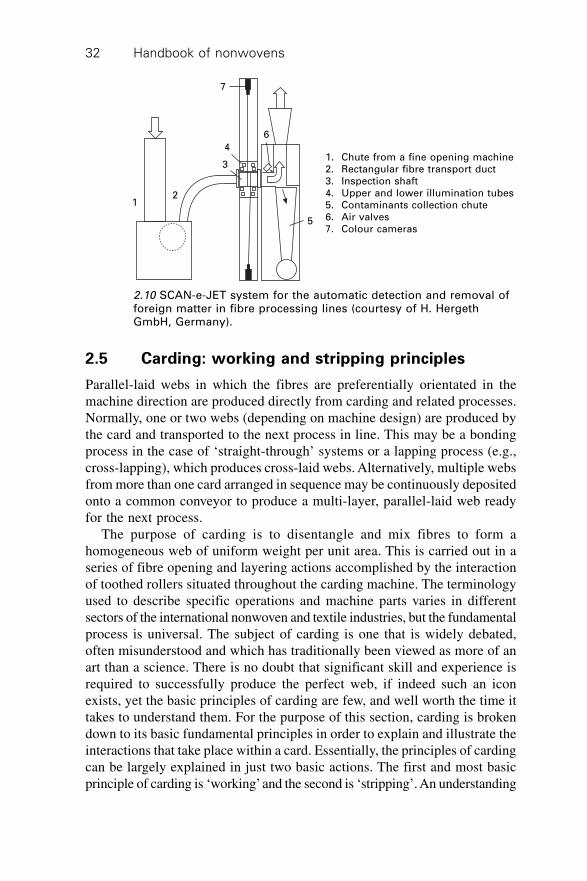
Handbook of nonwovens32
2.5 Carding: working and stripping principles
Parallel-laid webs in which the fibres are preferentially orientated in themachine direction are produced directly from carding and related processes.Normally, one or two webs (depending on machine design) are produced bythe card and transported to the next process in line. This may be a bondingprocess in the case of ‘straight-through’ systems or a lapping process (e.g.,cross-lapping), which produces cross-laid webs. Alternatively, multiple websfrom more than one card arranged in sequence may be continuously depositedonto a common conveyor to produce a multi-layer, parallel-laid web readyfor the next process.
The purpose of carding is to disentangle and mix fibres to form ahomogeneous web of uniform weight per unit area. This is carried out in aseries of fibre opening and layering actions accomplished by the interactionof toothed rollers situated throughout the carding machine. The terminologyused to describe specific operations and machine parts varies in differentsectors of the international nonwoven and textile industries, but the fundamentalprocess is universal. The subject of carding is one that is widely debated,often misunderstood and which has traditionally been viewed as more of anart than a science. There is no doubt that significant skill and experience isrequired to successfully produce the perfect web, if indeed such an iconexists, yet the basic principles of carding are few, and well worth the time ittakes to understand them. For the purpose of this section, carding is brokendown to its basic fundamental principles in order to explain and illustrate theinteractions that take place within a card. Essentially, the principles of cardingcan be largely explained in just two basic actions. The first and most basicprinciple of carding is ‘working’ and the second is ‘stripping’. An understanding
7
6
4
3
21
5
1. Chute from a fine opening machine2. Rectangular fibre transport duct3. Inspection shaft4. Upper and lower illumination tubes5. Contaminants collection chute6. Air valves7. Colour cameras
2.10 SCAN-e-JET system for the automatic detection and removal offoreign matter in fibre processing lines (courtesy of H. HergethGmbH, Germany).
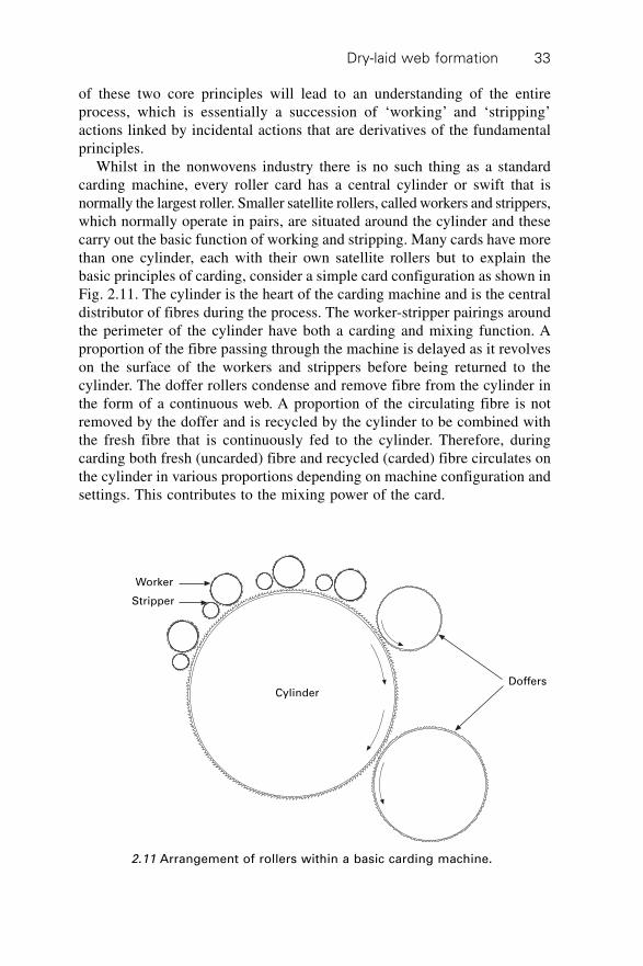
Dry-laid web formation 33
of these two core principles will lead to an understanding of the entireprocess, which is essentially a succession of ‘working’ and ‘stripping’actions linked by incidental actions that are derivatives of the fundamentalprinciples.
Whilst in the nonwovens industry there is no such thing as a standardcarding machine, every roller card has a central cylinder or swift that isnormally the largest roller. Smaller satellite rollers, called workers and strippers,which normally operate in pairs, are situated around the cylinder and thesecarry out the basic function of working and stripping. Many cards have morethan one cylinder, each with their own satellite rollers but to explain thebasic principles of carding, consider a simple card configuration as shown inFig. 2.11. The cylinder is the heart of the carding machine and is the centraldistributor of fibres during the process. The worker-stripper pairings aroundthe perimeter of the cylinder have both a carding and mixing function. Aproportion of the fibre passing through the machine is delayed as it revolveson the surface of the workers and strippers before being returned to thecylinder. The doffer rollers condense and remove fibre from the cylinder inthe form of a continuous web. A proportion of the circulating fibre is notremoved by the doffer and is recycled by the cylinder to be combined withthe fresh fibre that is continuously fed to the cylinder. Therefore, duringcarding both fresh (uncarded) fibre and recycled (carded) fibre circulates onthe cylinder in various proportions depending on machine configuration andsettings. This contributes to the mixing power of the card.
Worker
Stripper
CylinderDoffers
2.11 Arrangement of rollers within a basic carding machine.
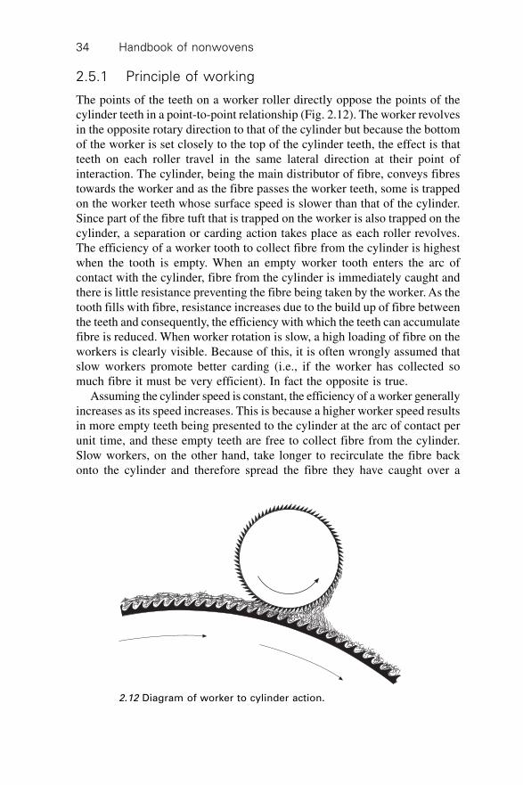
Handbook of nonwovens34
2.5.1 Principle of working
The points of the teeth on a worker roller directly oppose the points of thecylinder teeth in a point-to-point relationship (Fig. 2.12). The worker revolvesin the opposite rotary direction to that of the cylinder but because the bottomof the worker is set closely to the top of the cylinder teeth, the effect is thatteeth on each roller travel in the same lateral direction at their point ofinteraction. The cylinder, being the main distributor of fibre, conveys fibrestowards the worker and as the fibre passes the worker teeth, some is trappedon the worker teeth whose surface speed is slower than that of the cylinder.Since part of the fibre tuft that is trapped on the worker is also trapped on thecylinder, a separation or carding action takes place as each roller revolves.The efficiency of a worker tooth to collect fibre from the cylinder is highestwhen the tooth is empty. When an empty worker tooth enters the arc ofcontact with the cylinder, fibre from the cylinder is immediately caught andthere is little resistance preventing the fibre being taken by the worker. As thetooth fills with fibre, resistance increases due to the build up of fibre betweenthe teeth and consequently, the efficiency with which the teeth can accumulatefibre is reduced. When worker rotation is slow, a high loading of fibre on theworkers is clearly visible. Because of this, it is often wrongly assumed thatslow workers promote better carding (i.e., if the worker has collected somuch fibre it must be very efficient). In fact the opposite is true.
Assuming the cylinder speed is constant, the efficiency of a worker generallyincreases as its speed increases. This is because a higher worker speed resultsin more empty teeth being presented to the cylinder at the arc of contact perunit time, and these empty teeth are free to collect fibre from the cylinder.Slow workers, on the other hand, take longer to recirculate the fibre backonto the cylinder and therefore spread the fibre they have caught over a
2.12 Diagram of worker to cylinder action.
Dry-laid web formation 35
greater area. This results in more efficient mixing. In summary, faster workerspromote more efficient carding, whilst slower workers provide better mixing.Usually a balance of the two factors is required, which is feasible given themultiple worker-stripper pairings available on a full-size nonwoven card.
2.5.2 Principles of stripping
Once trapped by the worker the fibre is carried around as the roller rotates.Before the worker teeth are re-presented to the cylinder, the fibre must beremoved, otherwise the worker will continue to collect fibre until it becomesfull and can no longer ‘work’. The role of the stripper is to remove fibre fromthe worker and to re-present that fibre back onto the cylinder (see Fig. 2.13).To do this efficiently the teeth of the stripper must interact with the back ofthose on the worker. In turn, the fibre is removed from the stripper by theteeth on the cylinder whose points interact with the back of those on thestripper. Therefore, there is an initial ‘working’ action between the workerand the cylinder, then a stripping action between the stripper and the worker,followed by a further stripping action between the cylinder and the stripper.This series of actions represent the fundamental operational function of acarding machine. It is by a succession of such interactions that fibre isprogressively, ‘worked’ and ‘stripped’ within a carding machine until thefibres are so uniformly distributed and individualised that a homogeneousweb can be formed.
2.5.3 Interaction between card rollers
As shown in Fig. 2.13, fibre presented to a worker must first pass beneath thecorresponding stripper. The reason the stripper is not placed at the other side
2.13 Diagram of worker and stripper.
Handbook of nonwovens36
of the worker is because this would adversely affect fibre separation, particularlywhen carding longer fibres. If the stripper is situated behind the worker,rather than in front of it, the transfer of fibre from cylinder, to worker, thenfrom worker to stripper and subsequently back to cylinder would still becarried out, and a degree of working would indeed take place. However,because of the short linear distance between the pick-up points of the workerand stripper, fibres longer than this distance could be trapped by both rollersat the same time leading to fibre breakage or rolling, which results in nepformation. By positioning the stripper at the other side of the worker, theworker is able to draw the full length of a fibre away from the cylinder, thusseparating the incoming fibre bundles, and straightening the fibres before re-presenting the fibre back to the cylinder via the stripper. A further argumentis that by changing the relative positions of the worker and stripper, and atthe same time changing the direction of the worker, a satisfactory arrangementmay be achieved that would carry out the same carding function but withoutrepresenting fibre to the same worker. However, in such a case, the fibre isre-presented to the next worker in line and although overall, less re-presentationof fibre to the same workers takes place, this also leads to reduced fibreworking. Moreover, in that situation, the teeth of the worker travel in anopposing direction to those on the cylinder and the worker needs to be drivenagainst the opposing force of the cylinder. This leads to higher energyexpenditure because of the large mechanical forces placed on the machinedrives, rollers and card clothing. This is particularly disadvantageous in theearly stages of carding where the fibre bundles are entangled. By rotating theteeth away from those on the cylinder, the worker effectively yields to theforce of the cylinder. More importantly, the force between the two rollers,can be controlled by adjusting the worker speed.
As an example, where fibre loadings are to be reduced by increasing theworker speed and hence an increase in the number of fresh empty workerpoints presented to the cylinder; when operating in the reverse directionthese points are presented at increased opposing speed and the applied forcesincrease. This can result in fibre breakage and increased fibre packing betweenthe teeth. In contrast, when the worker revolves in the normal direction, morefresh points are presented by increasing the speed in the same direction asthe cylinder, creating reduced opposing forces. This results in a gentler actionand more effective transfer of fibre. Carding efficiency also increases becauseof the increased ratio of empty teeth to incoming fibre. It is also important toconsider the following point, which is one that is commonly misunderstood.In Fig. 2.13 fibre is carried by the cylinder and trapped by the worker. Thefibre is carried around the worker until it is removed by the stripper and thenin turn is removed from the stripper and is re-taken by the cylinder. At thispoint the fibre is again presented to the same worker, and it is easy tospeculate as to why it does not simply continue to be trapped by the same
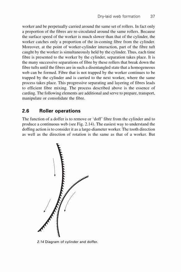
Dry-laid web formation 37
worker and be perpetually carried around the same set of rollers. In fact onlya proportion of the fibres are re-circulated around the same rollers. Becausethe surface speed of the worker is much slower than that of the cylinder, theworker catches only a proportion of the in-coming fibre from the cylinder.Moreover, at the point of worker-cylinder interaction, part of the fibre tuftcaught by the worker is simultaneously held by the cylinder. Thus, each timefibre is presented to the worker by the cylinder, separation takes place. It isthe many successive separations of fibre by these rollers that break down thefibre tufts until the fibres are in such a disentangled state that a homogeneousweb can be formed. Fibre that is not trapped by the worker continues to betrapped by the cylinder and is carried to the next worker, where the sameprocess takes place. This progressive separating and layering of fibres leadsto efficient fibre mixing. The process described above is the essence ofcarding. The following elements are additional and serve to prepare, transport,manipulate or consolidate the fibre.
2.6 Roller operations
The function of a doffer is to remove or ‘doff’ fibre from the cylinder and toproduce a continuous web (see Fig. 2.14). The easiest way to understand thedoffing action is to consider it as a large-diameter worker. The tooth directionas well as the direction of rotation is the same as that of a worker. But
2.14 Diagram of cylinder and doffer.
Handbook of nonwovens38
whereas the function of a worker is to ‘work’ the fibre, to break down thefibre bundles, and return it via the stripper to the same cylinder, the functionof a doffer is to consolidate it into a web structure so that it can be removedin the form of a web. The essential difference between a doffer and a workeris that the doffer accepts fibre from the cylinder and conveys it away, withoutre-circulating the fibre to the cylinder using a stripper. The doffer teeth aredesigned to accept fibre and to hold it efficiently and the doffer is larger indiameter than a worker creating a greater arc of contact between the dofferand the cylinder. This allows more efficient fibre transfer as well promotingthe formation of fibres into a web. Generally, as an individual tooth becomesfull, its ability to hold more fibre decreases. Consequently, the faster a doffertravels, the more empty teeth it presents to the cylinder and therefore, morefibres leave the cylinder. As more fibres leave via the doffer, fewer re-circulatearound the cylinder. This explains why increased doffer speeds result inlower cylinder loadings.
It is known that increasing the throughput, with the consequent increasein cylinder loading, tends to negatively influence fibre breakage, nep formationand general web quality. Adjustment of the doffer speed or specifically, theswift-doffer surface speed ratio, is one of the most efficient methods ofcontrolling cylinder loading and hence web quality. The doffer wire designis also important and is discussed in Section 2.7. A further consideration isthe doffer to cylinder setting. Although decreasing the setting gap theoreticallypromotes increased transfer efficiency, in practice, with a suitable dofferwire design and doffer speed, efficient fibre transfer can be achieved withouttight settings. This is helpful in minimising wear of the card wire.
2.6.1 Multiple doffers
Nonwoven cards commonly utilise a double-doffer arrangement and somecards have been designed with up to four separate doffers or web take-offdevices. As previously noted, the fibre transfer efficiency from cylinder tothe doffer is maximised when the teeth are empty. When card throughput ishigh, the transfer efficiency of a doffer decreases as it fills up and a greaterproportion of the incoming fibre recirculates on the cylinder leading to cylinderloading. Quality problems such as nep formation then arise particularly withfine fibres. While increasing the doffer speed reduces the loading, it mayalso lead to problems removing the web, particularly when a fly-comb isused. Additionally, an upper speed limitation is imposed by subsequentmachines in the production line, for example the cross-lapper. Double dofferstend to increase the fibre transfer efficiency from the cylinder allowing higherproduction rates to be achieved without overloading the cylinder or necessitatingthe use of very high doffer speeds.
However, the structure and uniformity of the two webs (top and bottom)
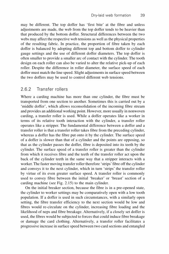
Dry-laid web formation 39
may be different. The top doffer has ‘first bite’ at the fibre and unlessadjustments are made, the web from the top doffer tends to be heavier thanthat produced by the bottom doffer. Structural differences between the twowebs may affect the respective web tensions as well as the physical propertiesof the resulting fabric. In practice, the proportion of fibre taken by eachdoffer is balanced by adopting different top and bottom doffer to cylindergauge settings and the use of different doffer diameters. The top doffer isoften smaller to provide a smaller arc of contact with the cylinder. The toothdesign on each roller can also be varied to alter the relative pick-up of eachroller. Despite the difference in roller diameter, the surface speed of eachdoffer must match the line speed. Slight adjustments in surface speed betweenthe two doffers may be used to control different web tensions.
2.6.2 Transfer rollers
Where a carding machine has more than one cylinder, the fibre must betransported from one section to another. Sometimes this is carried out by a‘middle doffer’, which allows reconsolidation of the incoming fibre streamand provides an additional working point. However, more usually in nonwovencarding, a transfer roller is used. While a doffer operates like a worker interms of its relative tooth interaction with the cylinder, a transfer rolleroperates like a stripper. The fundamental difference between a doffer and atransfer roller is that a transfer roller takes fibre from the preceding cylinder,whereas a doffer has the fibre put onto it by the cylinder. The surface speedof a doffer is slower than that of a cylinder and the points are opposing, sothat as the cylinder passes the doffer, fibre is deposited into its teeth by thecylinder. The surface speed of a transfer roller is greater than the cylinderfrom which it receives fibre and the teeth of the transfer roller act upon theback of the cylinder teeth in the same way that a stripper interacts with aworker. The faster moving transfer roller therefore ‘strips’ fibre off the cylinderand conveys it to the next cylinder, which in turn ‘strips’ the transfer rollerby virtue of its even greater surface speed. A transfer roller is commonlyused to convey fibre between the initial ‘breaker’ or ‘breast’ section of acarding machine (see Fig. 2.15) to the main cylinder.
On the initial breaker section, because the fibre is in a pre-opened state,the cylinder to worker settings may be comparatively open with a low toothpopulation. If a doffer is used in such circumstances, with a similarly opensetting, the fibre transfer efficiency to the next section would be low andfibres would re-circulate on the cylinder, increasing fibre loading and thelikelihood of neps and fibre breakage. Alternatively, if a closely set doffer isused, the fibres would be subjected to forces that could induce fibre breakageor damage the card clothing. Alternatively, a transfer roller facilitates aprogressive increase in surface speed between two card sections and entangled
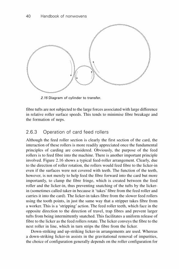
Handbook of nonwovens40
fibre tufts are not subjected to the large forces associated with large differencein relative roller surface speeds. This tends to minimise fibre breakage andthe formation of neps.
2.6.3 Operation of card feed rollers
Although the feed roller section is clearly the first section of the card, theinteraction of these rollers is more readily appreciated once the fundamentalprinciples of carding are considered. Obviously, the purpose of the feedrollers is to feed fibre into the machine. There is another important principleinvolved. Figure 2.16 shows a typical feed-roller arrangement. Clearly, dueto the direction of roller rotation, the rollers would feed fibre to the licker-ineven if the surfaces were not covered with teeth. The function of the teeth,however, is not merely to help feed the fibre forward into the card but moreimportantly, to clamp the fibre fringe, which is created between the feedroller and the licker-in, thus preventing snatching of the tufts by the licker-in (sometimes called taker-in because it ‘takes’ fibre from the feed roller andcarries it into the card). The licker-in takes fibre from the slower feed rollersusing the tooth points, in just the same way that a stripper takes fibre froma worker. This is a ‘stripping’ action. The feed roller teeth, which face in theopposite direction to the direction of travel, trap fibres and prevent largertufts from being intermittently snatched. This facilitates a uniform release offibre to the licker as the feed rollers rotate. The licker conveys the fibre to thenext roller in line, which in turn strips the fibre from the licker.
Down-striking and up-striking licker-in arrangements are used. Whereasa down-striking licker-in assists in the gravitational removal of impurities,the choice of configuration generally depends on the roller configuration for
2.15 Diagram of cylinder to transfer.
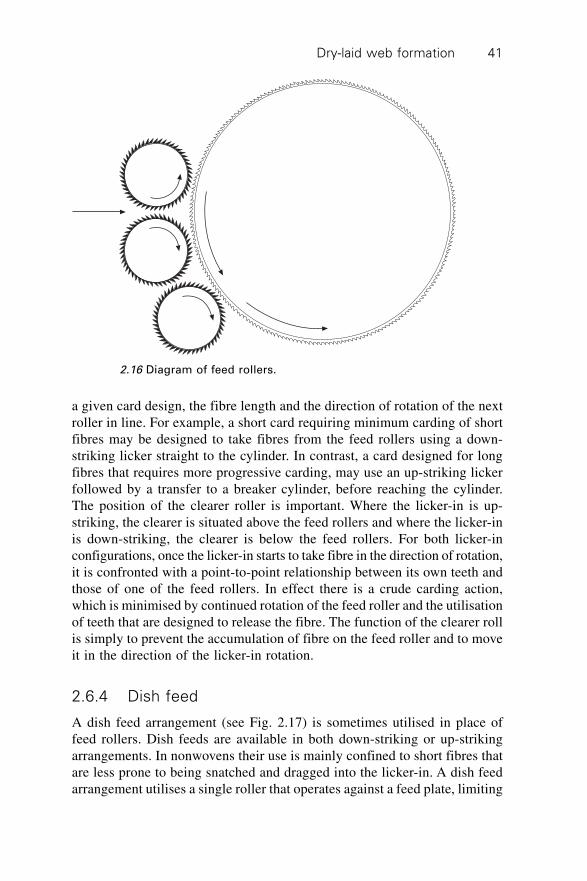
Dry-laid web formation 41
a given card design, the fibre length and the direction of rotation of the nextroller in line. For example, a short card requiring minimum carding of shortfibres may be designed to take fibres from the feed rollers using a down-striking licker straight to the cylinder. In contrast, a card designed for longfibres that requires more progressive carding, may use an up-striking lickerfollowed by a transfer to a breaker cylinder, before reaching the cylinder.The position of the clearer roller is important. Where the licker-in is up-striking, the clearer is situated above the feed rollers and where the licker-inis down-striking, the clearer is below the feed rollers. For both licker-inconfigurations, once the licker-in starts to take fibre in the direction of rotation,it is confronted with a point-to-point relationship between its own teeth andthose of one of the feed rollers. In effect there is a crude carding action,which is minimised by continued rotation of the feed roller and the utilisationof teeth that are designed to release the fibre. The function of the clearer rollis simply to prevent the accumulation of fibre on the feed roller and to moveit in the direction of the licker-in rotation.
2.6.4 Dish feed
A dish feed arrangement (see Fig. 2.17) is sometimes utilised in place offeed rollers. Dish feeds are available in both down-striking or up-strikingarrangements. In nonwovens their use is mainly confined to short fibres thatare less prone to being snatched and dragged into the licker-in. A dish feedarrangement utilises a single roller that operates against a feed plate, limiting
2.16 Diagram of feed rollers.
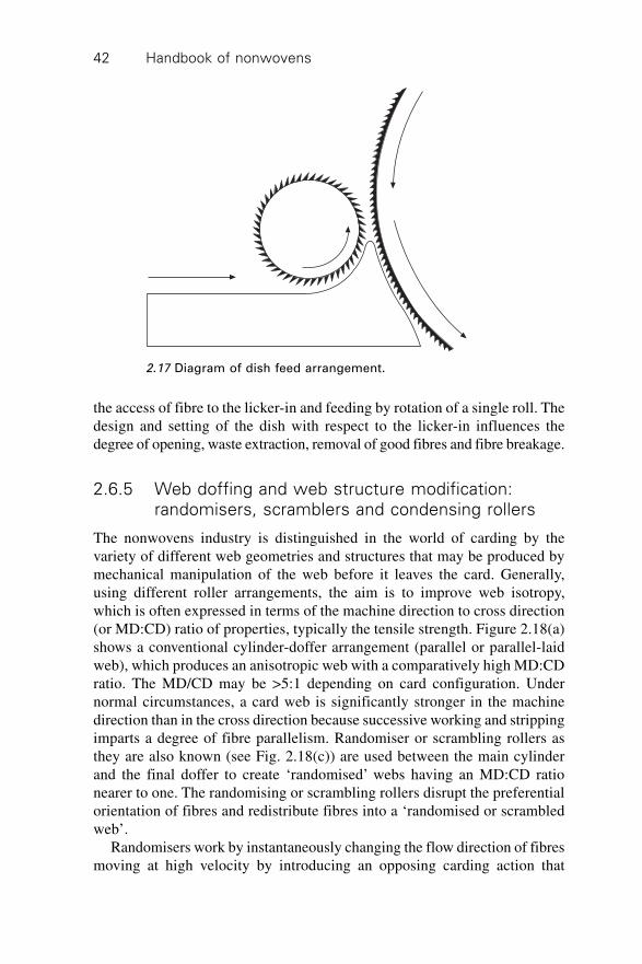
Handbook of nonwovens42
the access of fibre to the licker-in and feeding by rotation of a single roll. Thedesign and setting of the dish with respect to the licker-in influences thedegree of opening, waste extraction, removal of good fibres and fibre breakage.
2.6.5 Web doffing and web structure modification:
randomisers, scramblers and condensing rollers
The nonwovens industry is distinguished in the world of carding by thevariety of different web geometries and structures that may be produced bymechanical manipulation of the web before it leaves the card. Generally,using different roller arrangements, the aim is to improve web isotropy,which is often expressed in terms of the machine direction to cross direction(or MD:CD) ratio of properties, typically the tensile strength. Figure 2.18(a)shows a conventional cylinder-doffer arrangement (parallel or parallel-laidweb), which produces an anisotropic web with a comparatively high MD:CDratio. The MD/CD may be >5:1 depending on card configuration. Undernormal circumstances, a card web is significantly stronger in the machinedirection than in the cross direction because successive working and strippingimparts a degree of fibre parallelism. Randomiser or scrambling rollers asthey are also known (see Fig. 2.18(c)) are used between the main cylinderand the final doffer to create ‘randomised’ webs having an MD:CD rationearer to one. The randomising or scrambling rollers disrupt the preferentialorientation of fibres and redistribute fibres into a ‘randomised or scrambledweb’.
Randomisers work by instantaneously changing the flow direction of fibresmoving at high velocity by introducing an opposing carding action that
2.17 Diagram of dish feed arrangement.
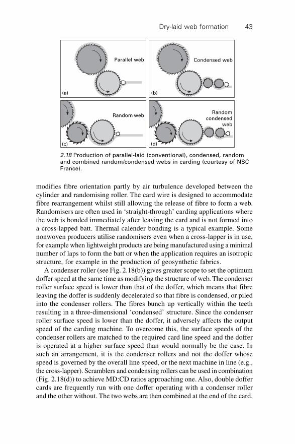
Dry-laid web formation 43
modifies fibre orientation partly by air turbulence developed between thecylinder and randomising roller. The card wire is designed to accommodatefibre rearrangement whilst still allowing the release of fibre to form a web.Randomisers are often used in ‘straight-through’ carding applications wherethe web is bonded immediately after leaving the card and is not formed intoa cross-lapped batt. Thermal calender bonding is a typical example. Somenonwoven producers utilise randomisers even when a cross-lapper is in use,for example when lightweight products are being manufactured using a minimalnumber of laps to form the batt or when the application requires an isotropicstructure, for example in the production of geosynthetic fabrics.
A condenser roller (see Fig. 2.18(b)) gives greater scope to set the optimumdoffer speed at the same time as modifying the structure of web. The condenserroller surface speed is lower than that of the doffer, which means that fibreleaving the doffer is suddenly decelerated so that fibre is condensed, or piledinto the condenser rollers. The fibres bunch up vertically within the teethresulting in a three-dimensional ‘condensed’ structure. Since the condenserroller surface speed is lower than the doffer, it adversely affects the outputspeed of the carding machine. To overcome this, the surface speeds of thecondenser rollers are matched to the required card line speed and the dofferis operated at a higher surface speed than would normally be the case. Insuch an arrangement, it is the condenser rollers and not the doffer whosespeed is governed by the overall line speed, or the next machine in line (e.g.,the cross-lapper). Scramblers and condensing rollers can be used in combination(Fig. 2.18(d)) to achieve MD:CD ratios approaching one. Also, double doffercards are frequently run with one doffer operating with a condenser rollerand the other without. The two webs are then combined at the end of the card.
(a) (b)
(c) (d)
Parallel web Condensed web
Random webRandom
condensedweb
2.18 Production of parallel-laid (conventional), condensed, randomand combined random/condensed webs in carding (courtesy of NSCFrance).
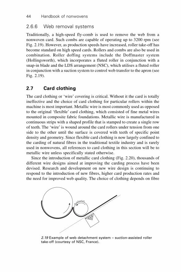
Handbook of nonwovens44
2.6.6 Web removal systems
Traditionally, a high-speed fly-comb is used to remove the web from anonwoven card. Such combs are capable of operating up to 3200 rpm (seeFig. 2.19). However, as production speeds have increased, roller take-off hasbecome standard on high speed cards. Rollers and combs are also be used incombination. Roller doffing systems include the Doffmaster system(Hollingsworth), which incorporates a fluted roller in conjunction with asnap-in blade and the LDS arrangement (NSC), which utilises a fluted rollerin conjunction with a suction system to control web transfer to the apron (seeFig. 2.19).
2.7 Card clothing
The card clothing or ‘wire’ covering is critical. Without it the card is totallyineffective and the choice of card clothing for particular rollers within themachine is most important. Metallic wire is most commonly used as opposedto the original ‘flexible’ card clothing, which consisted of fine metal wiresmounted in composite fabric foundations. Metallic wire is manufactured incontinuous strips with a shaped profile that is stamped to create a single rowof teeth. The ‘wire’ is wound around the card rollers under tension from oneside to the other until the surface is covered with teeth of specific pointdensity and geometry. Since flexible card clothing is now largely confined tothe carding of natural fibres in the traditional textile industry and is rarelyused in nonwovens, all references to card clothing in this section will be tometallic wire unless specifically stated otherwise.
Since the introduction of metallic card clothing (Fig. 2.20), thousands ofdifferent wire designs aimed at improving the carding process have beendevised. Research and development on new wire design is continuing torespond to the introduction of new fibres, higher card production rates andthe need for improved web quality. The choice of clothing depends on fibre
2.19 Example of web detachment system – suction-assisted rollertake-off (courtesy of NSC, France).
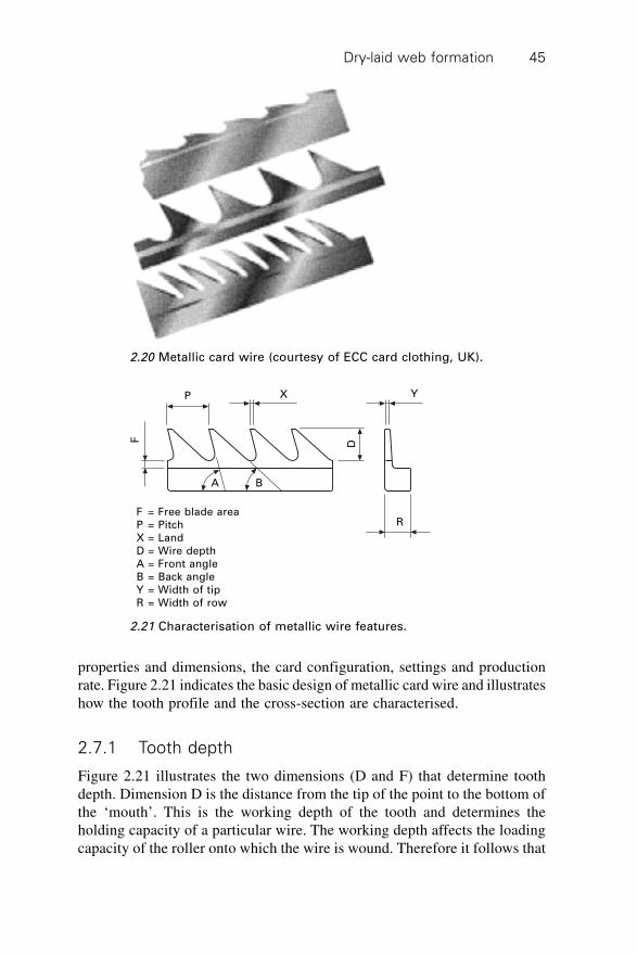
Dry-laid web formation 45
properties and dimensions, the card configuration, settings and productionrate. Figure 2.21 indicates the basic design of metallic card wire and illustrateshow the tooth profile and the cross-section are characterised.
2.7.1 Tooth depth
Figure 2.21 illustrates the two dimensions (D and F) that determine toothdepth. Dimension D is the distance from the tip of the point to the bottom ofthe ‘mouth’. This is the working depth of the tooth and determines theholding capacity of a particular wire. The working depth affects the loadingcapacity of the roller onto which the wire is wound. Therefore it follows that
2.20 Metallic card wire (courtesy of ECC card clothing, UK).
P X Y
F
A B
D
RF = Free blade areaP = PitchX = LandD = Wire depthA = Front angleB = Back angleY = Width of tipR = Width of row
2.21 Characterisation of metallic wire features.
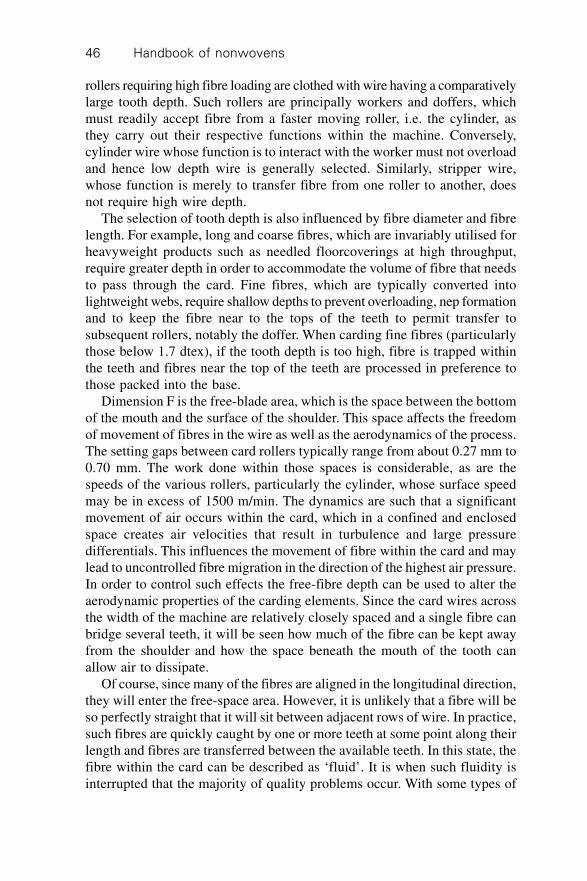
Handbook of nonwovens46
rollers requiring high fibre loading are clothed with wire having a comparativelylarge tooth depth. Such rollers are principally workers and doffers, whichmust readily accept fibre from a faster moving roller, i.e. the cylinder, asthey carry out their respective functions within the machine. Conversely,cylinder wire whose function is to interact with the worker must not overloadand hence low depth wire is generally selected. Similarly, stripper wire,whose function is merely to transfer fibre from one roller to another, doesnot require high wire depth.
The selection of tooth depth is also influenced by fibre diameter and fibrelength. For example, long and coarse fibres, which are invariably utilised forheavyweight products such as needled floorcoverings at high throughput,require greater depth in order to accommodate the volume of fibre that needsto pass through the card. Fine fibres, which are typically converted intolightweight webs, require shallow depths to prevent overloading, nep formationand to keep the fibre near to the tops of the teeth to permit transfer tosubsequent rollers, notably the doffer. When carding fine fibres (particularlythose below 1.7 dtex), if the tooth depth is too high, fibre is trapped withinthe teeth and fibres near the top of the teeth are processed in preference tothose packed into the base.
Dimension F is the free-blade area, which is the space between the bottomof the mouth and the surface of the shoulder. This space affects the freedomof movement of fibres in the wire as well as the aerodynamics of the process.The setting gaps between card rollers typically range from about 0.27 mm to0.70 mm. The work done within those spaces is considerable, as are thespeeds of the various rollers, particularly the cylinder, whose surface speedmay be in excess of 1500 m/min. The dynamics are such that a significantmovement of air occurs within the card, which in a confined and enclosedspace creates air velocities that result in turbulence and large pressuredifferentials. This influences the movement of fibre within the card and maylead to uncontrolled fibre migration in the direction of the highest air pressure.In order to control such effects the free-fibre depth can be used to alter theaerodynamic properties of the carding elements. Since the card wires acrossthe width of the machine are relatively closely spaced and a single fibre canbridge several teeth, it will be seen how much of the fibre can be kept awayfrom the shoulder and how the space beneath the mouth of the tooth canallow air to dissipate.
Of course, since many of the fibres are aligned in the longitudinal direction,they will enter the free-space area. However, it is unlikely that a fibre will beso perfectly straight that it will sit between adjacent rows of wire. In practice,such fibres are quickly caught by one or more teeth at some point along theirlength and fibres are transferred between the available teeth. In this state, thefibre within the card can be described as ‘fluid’. It is when such fluidity isinterrupted that the majority of quality problems occur. With some types of
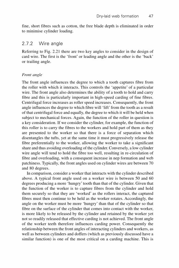
Dry-laid web formation 47
fine, short fibres such as cotton, the free blade depth is eliminated in orderto minimise cylinder loading.
2.7.2 Wire angle
Referring to Fig. 2.21 there are two key angles to consider in the design ofcard wire. The first is the ‘front’ or leading angle and the other is the ‘back’or trailing angle.
Front angle
The front angle influences the degree to which a tooth captures fibre fromthe roller with which it interacts. This controls the ‘appetite’ of a particularwire. The front angle also determines the ability of a tooth to hold and carryfibre and this is particularly important in high-speed carding of fine fibres.Centrifugal force increases as roller speed increases. Consequently, the frontangle influences the degree to which fibre will ‘lift’ from the tooth as a resultof that centrifugal force and equally, the degree to which it will be held whensubject to mechanical forces. Again, the function of the roller in question isa key consideration. If we consider the cylinder, for example, the function ofthis roller is to carry the fibres to the workers and hold part of them as theyare presented to the worker so that there is a force of separation whichdisentangles the tufts, yet at the same time it must progressively release thefibre preferentially to the worker, allowing the worker to take a significantshare and thus avoiding overloading of the cylinder. Conversely, a low cylinderwire angle will tend to hold the fibre too well, resulting in re-circulation offibre and overloading, with a consequent increase in nep formation and webpatchiness. Typically, the front angles used on cylinder wires are between 70and 80 degrees.
In comparison, consider a worker that interacts with the cylinder describedabove. A typical front angle used on a worker wire is between 50 and 60degrees producing a more ‘hungry’ tooth than that of the cylinder. Given thatthe function of the worker is to capture fibres from the cylinder and holdthem securely so that they are ‘worked’ as the rollers interact, the capturedfibres must then continue to be held as the worker rotates. Accordingly, theangle on the worker must be more ‘hungry’ than that of the cylinder so thatfibre on the surface of the cylinder that comes into contact with the worker,is more likely to be released by the cylinder and retained by the worker yetnot so readily released that effective carding is not achieved. The front angleof the worker teeth therefore influences carding power. Consequently therelationship between the front angles of interacting cylinders and workers, aswell as between cylinders and doffers (which as previously discussed have asimilar function) is one of the most critical on a carding machine. This is
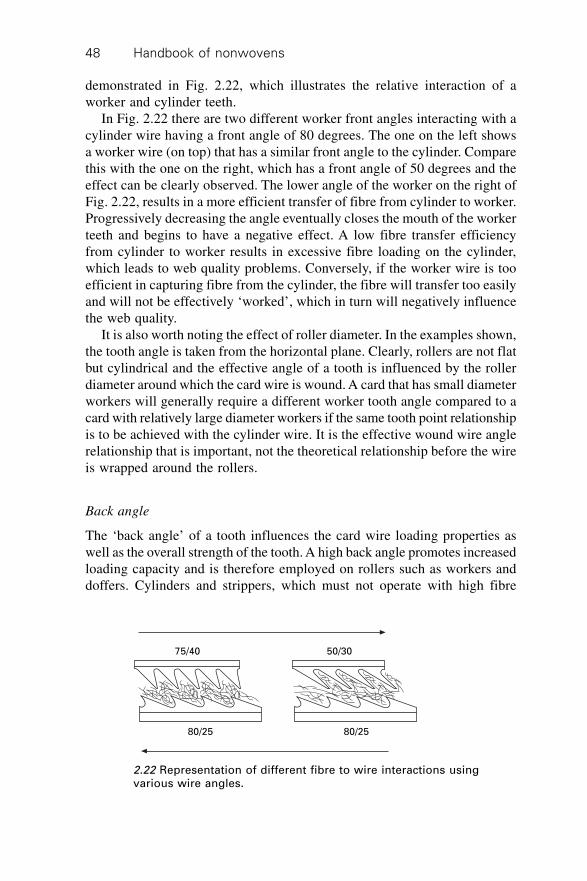
Handbook of nonwovens48
demonstrated in Fig. 2.22, which illustrates the relative interaction of aworker and cylinder teeth.
In Fig. 2.22 there are two different worker front angles interacting with acylinder wire having a front angle of 80 degrees. The one on the left showsa worker wire (on top) that has a similar front angle to the cylinder. Comparethis with the one on the right, which has a front angle of 50 degrees and theeffect can be clearly observed. The lower angle of the worker on the right ofFig. 2.22, results in a more efficient transfer of fibre from cylinder to worker.Progressively decreasing the angle eventually closes the mouth of the workerteeth and begins to have a negative effect. A low fibre transfer efficiencyfrom cylinder to worker results in excessive fibre loading on the cylinder,which leads to web quality problems. Conversely, if the worker wire is tooefficient in capturing fibre from the cylinder, the fibre will transfer too easilyand will not be effectively ‘worked’, which in turn will negatively influencethe web quality.
It is also worth noting the effect of roller diameter. In the examples shown,the tooth angle is taken from the horizontal plane. Clearly, rollers are not flatbut cylindrical and the effective angle of a tooth is influenced by the rollerdiameter around which the card wire is wound. A card that has small diameterworkers will generally require a different worker tooth angle compared to acard with relatively large diameter workers if the same tooth point relationshipis to be achieved with the cylinder wire. It is the effective wound wire anglerelationship that is important, not the theoretical relationship before the wireis wrapped around the rollers.
Back angle
The ‘back angle’ of a tooth influences the card wire loading properties aswell as the overall strength of the tooth. A high back angle promotes increasedloading capacity and is therefore employed on rollers such as workers anddoffers. Cylinders and strippers, which must not operate with high fibre
75/40 50/30
80/25 80/25
2.22 Representation of different fibre to wire interactions usingvarious wire angles.
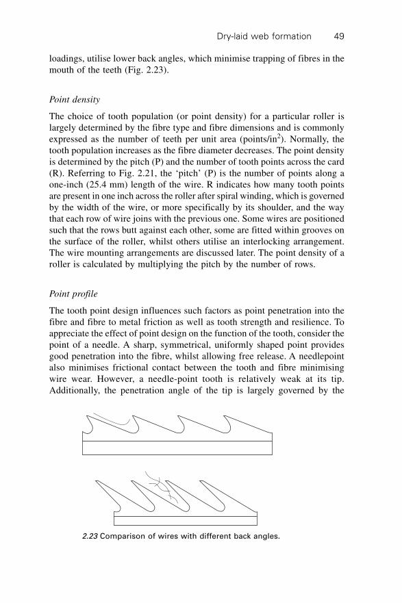
Dry-laid web formation 49
loadings, utilise lower back angles, which minimise trapping of fibres in themouth of the teeth (Fig. 2.23).
Point density
The choice of tooth population (or point density) for a particular roller islargely determined by the fibre type and fibre dimensions and is commonlyexpressed as the number of teeth per unit area (points/in2). Normally, thetooth population increases as the fibre diameter decreases. The point densityis determined by the pitch (P) and the number of tooth points across the card(R). Referring to Fig. 2.21, the ‘pitch’ (P) is the number of points along aone-inch (25.4 mm) length of the wire. R indicates how many tooth pointsare present in one inch across the roller after spiral winding, which is governedby the width of the wire, or more specifically by its shoulder, and the waythat each row of wire joins with the previous one. Some wires are positionedsuch that the rows butt against each other, some are fitted within grooves onthe surface of the roller, whilst others utilise an interlocking arrangement.The wire mounting arrangements are discussed later. The point density of aroller is calculated by multiplying the pitch by the number of rows.
Point profile
The tooth point design influences such factors as point penetration into thefibre and fibre to metal friction as well as tooth strength and resilience. Toappreciate the effect of point design on the function of the tooth, consider thepoint of a needle. A sharp, symmetrical, uniformly shaped point providesgood penetration into the fibre, whilst allowing free release. A needlepointalso minimises frictional contact between the tooth and fibre minimisingwire wear. However, a needle-point tooth is relatively weak at its tip.Additionally, the penetration angle of the tip is largely governed by the
2.23 Comparison of wires with different back angles.
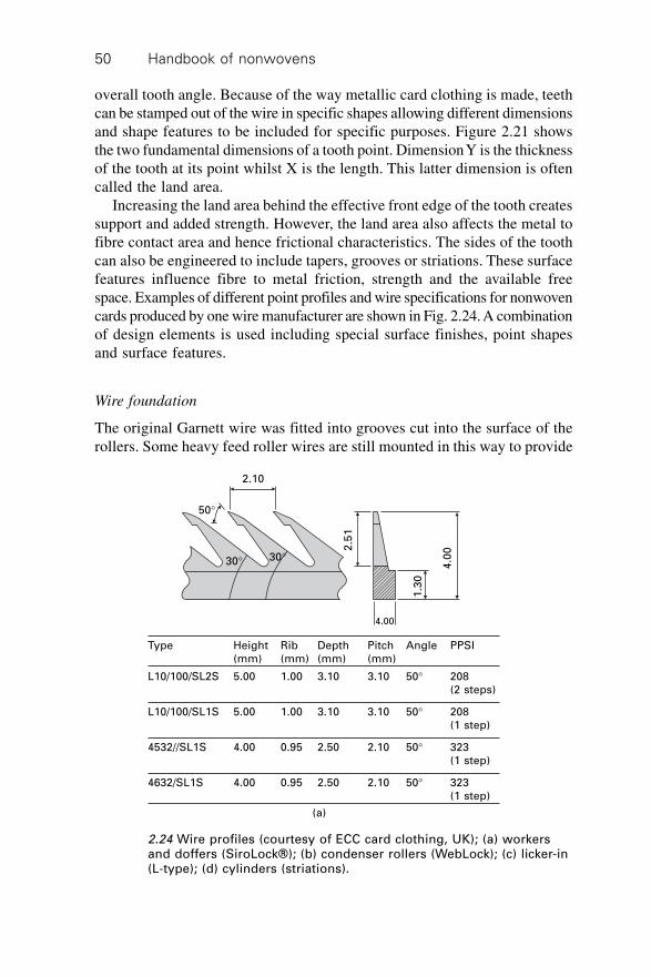
Handbook of nonwovens50
overall tooth angle. Because of the way metallic card clothing is made, teethcan be stamped out of the wire in specific shapes allowing different dimensionsand shape features to be included for specific purposes. Figure 2.21 showsthe two fundamental dimensions of a tooth point. Dimension Y is the thicknessof the tooth at its point whilst X is the length. This latter dimension is oftencalled the land area.
Increasing the land area behind the effective front edge of the tooth createssupport and added strength. However, the land area also affects the metal tofibre contact area and hence frictional characteristics. The sides of the toothcan also be engineered to include tapers, grooves or striations. These surfacefeatures influence fibre to metal friction, strength and the available freespace. Examples of different point profiles and wire specifications for nonwovencards produced by one wire manufacturer are shown in Fig. 2.24. A combinationof design elements is used including special surface finishes, point shapesand surface features.
Wire foundation
The original Garnett wire was fitted into grooves cut into the surface of therollers. Some heavy feed roller wires are still mounted in this way to provide
2.10
50∞
30∞ 30∞
2.5
1
1.3
0
4.0
0
4.00
(a)
Type Height Rib Depth Pitch Angle PPSI(mm) (mm) (mm) (mm)
L10/100/SL2S 5.00 1.00 3.10 3.10 50∞ 208(2 steps)
L10/100/SL1S 5.00 1.00 3.10 3.10 50∞ 208(1 step)
4532//SL1S 4.00 0.95 2.50 2.10 50∞ 323(1 step)
4632/SL1S 4.00 0.95 2.50 2.10 50∞ 323(1 step)
2.24 Wire profiles (courtesy of ECC card clothing, UK); (a) workersand doffers (SiroLock®); (b) condenser rollers (WebLock); (c) licker-in(L-type); (d) cylinders (striations).
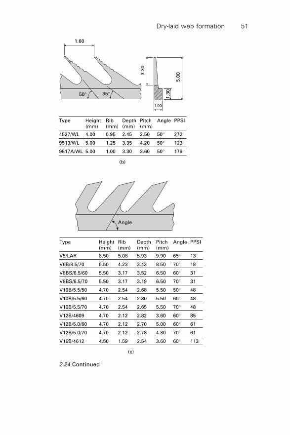
Dry-laid web formation 51
Angle
(c)
Type Height Rib Depth Pitch Angle PPSI(mm) (mm) (mm) (mm)
V5/LAR 8.50 5.08 5.93 9.90 65∞ 13
V6B/8.5/70 5.50 4.23 3.43 8.50 70∞ 18
V8BS/6.5/60 5.50 3.17 3.52 6.50 60∞ 31
V8BS/6.5/70 5.50 3.17 3.19 6.50 70∞ 31
V10B/5.5/50 4.70 2.54 2.68 5.50 50∞ 48
V10B/5.5/60 4.70 2.54 2.80 5.50 60∞ 48
V10B/5.5/70 4.70 2.54 2.65 5.50 70∞ 48
V12B/4609 4.70 2.12 2.82 3.60 60∞ 85
V12B/5.0/60 4.70 2.12 2.70 5.00 60∞ 61
V12B/5.0/70 4.70 2.12 2.78 4.80 70∞ 61
V16B/4612 4.50 1.59 2.54 3.60 60∞ 113
2.24 Continued
1.60
50∞ 35∞
3.3
0
5.0
0
1.3
0(b)
Type Height Rib Depth Pitch Angle PPSI(mm) (mm) (mm) (mm)
4527/WL 4.00 0.95 2.45 2.50 50∞ 272
9513/WL 5.00 1.25 3.35 4.20 50∞ 123
9517A/WL 5.00 1.00 3.30 3.60 50∞ 179
1.00
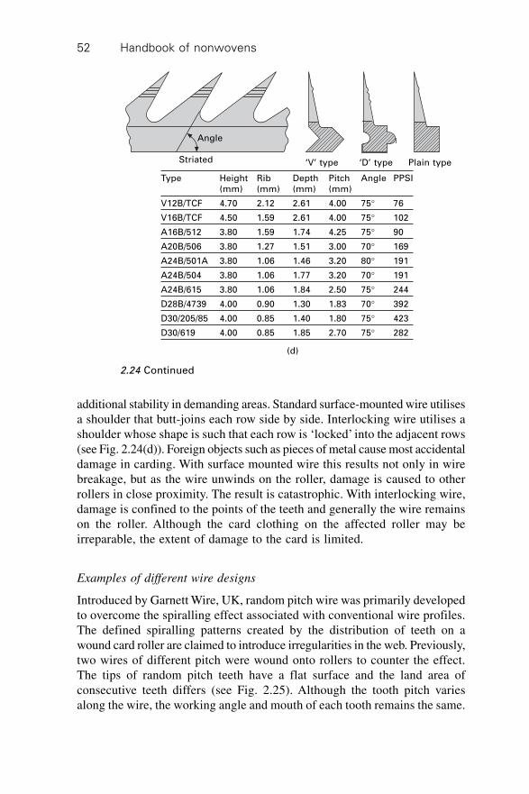
Handbook of nonwovens52
additional stability in demanding areas. Standard surface-mounted wire utilisesa shoulder that butt-joins each row side by side. Interlocking wire utilises ashoulder whose shape is such that each row is ‘locked’ into the adjacent rows(see Fig. 2.24(d)). Foreign objects such as pieces of metal cause most accidentaldamage in carding. With surface mounted wire this results not only in wirebreakage, but as the wire unwinds on the roller, damage is caused to otherrollers in close proximity. The result is catastrophic. With interlocking wire,damage is confined to the points of the teeth and generally the wire remainson the roller. Although the card clothing on the affected roller may beirreparable, the extent of damage to the card is limited.
Examples of different wire designs
Introduced by Garnett Wire, UK, random pitch wire was primarily developedto overcome the spiralling effect associated with conventional wire profiles.The defined spiralling patterns created by the distribution of teeth on awound card roller are claimed to introduce irregularities in the web. Previously,two wires of different pitch were wound onto rollers to counter the effect.The tips of random pitch teeth have a flat surface and the land area ofconsecutive teeth differs (see Fig. 2.25). Although the tooth pitch variesalong the wire, the working angle and mouth of each tooth remains the same.
(d)
Striated
Angle
‘V’ type ‘D’ type Plain type
Type Height Rib Depth Pitch Angle PPSI(mm) (mm) (mm) (mm)
V12B/TCF 4.70 2.12 2.61 4.00 75∞ 76
V16B/TCF 4.50 1.59 2.61 4.00 75∞ 102
A16B/512 3.80 1.59 1.74 4.25 75∞ 90
A20B/506 3.80 1.27 1.51 3.00 70∞ 169
A24B/501A 3.80 1.06 1.46 3.20 80∞ 191
A24B/504 3.80 1.06 1.77 3.20 70∞ 191
A24B/615 3.80 1.06 1.84 2.50 75∞ 244
D28B/4739 4.00 0.90 1.30 1.83 70∞ 392
D30/205/85 4.00 0.85 1.40 1.80 75∞ 423
D30/619 4.00 0.85 1.85 2.70 75∞ 282
2.24 Continued
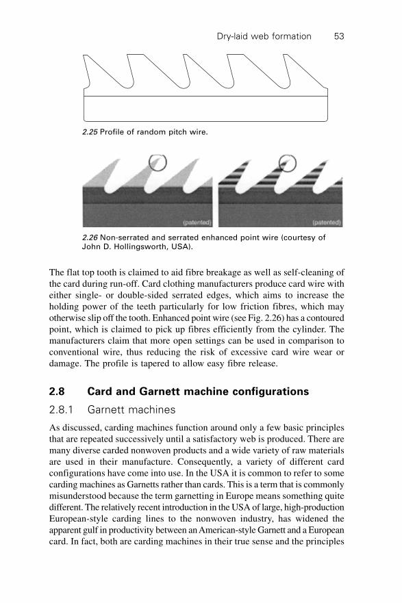
Dry-laid web formation 53
The flat top tooth is claimed to aid fibre breakage as well as self-cleaning ofthe card during run-off. Card clothing manufacturers produce card wire witheither single- or double-sided serrated edges, which aims to increase theholding power of the teeth particularly for low friction fibres, which mayotherwise slip off the tooth. Enhanced point wire (see Fig. 2.26) has a contouredpoint, which is claimed to pick up fibres efficiently from the cylinder. Themanufacturers claim that more open settings can be used in comparison toconventional wire, thus reducing the risk of excessive card wire wear ordamage. The profile is tapered to allow easy fibre release.
2.8 Card and Garnett machine configurations
2.8.1 Garnett machines
As discussed, carding machines function around only a few basic principlesthat are repeated successively until a satisfactory web is produced. There aremany diverse carded nonwoven products and a wide variety of raw materialsare used in their manufacture. Consequently, a variety of different cardconfigurations have come into use. In the USA it is common to refer to somecarding machines as Garnetts rather than cards. This is a term that is commonlymisunderstood because the term garnetting in Europe means something quitedifferent. The relatively recent introduction in the USA of large, high-productionEuropean-style carding lines to the nonwoven industry, has widened theapparent gulf in productivity between an American-style Garnett and a Europeancard. In fact, both are carding machines in their true sense and the principles
2.25 Profile of random pitch wire.
2.26 Non-serrated and serrated enhanced point wire (courtesy ofJohn D. Hollingsworth, USA).
Handbook of nonwovens54
involved are the same. Garnetting in Europe refers to the process in whichtextile waste, either in yarn or fabric form, is recycled by first cutting andthen tearing pieces in an extremely robust machine. Feed materials aboveabout 50 mm in length need to be cut prior to the process.
Garnett machines were originally manufactured by P&C Garnett Ltd inthe UK. The process is also called ‘rag tearing’, ‘pulling’ or ‘rag grinding’and in traditional industries the resulting reclaimed material was called ‘mungo’(from hard waste) and ‘shoddy’ (from soft waste). Nowadays it is morecommonly referred to as waste recycling and the reclaimed fibre is used asflock or is directly formed into products. Traditionally, Garnett machinesconverted recycled waste such as used clothing, yarns and pieces into battsand fabrics for carpet underlay, mattress components, acoustic and thermalinsulation for automotive and other technical uses. Many machines are stillin use. The recycling machinery was fundamentally similar to a card in thatthe point to point ‘working’ principle was utilised. However, the purpose ofgarnetting is to break down waste yarn and fabric and not specifically toproduce a homogeneous web. To do this, the machine is robustly built andutilises small diameter rollers. The workers and strippers are the same diameterbut are situated in a different position from that of a card.
In traditional Garnett machines the worker is placed before the stripperbecause the main function is to break down the waste then simply to moveit on to the next worker. Consequently, there is considerable fibre breakagein the process and limited fibre mixing. Many years ago, the association andlater the amalgamation of P&C Garnett with the Bywater Machine Company,who developed some of the first needlepunching technology, resulted inGarnett-Bywater becoming a leading manufacturer of turn-key nonwovenlines. It is from this early history that the term ‘Garnett’ originated in respectto its use in the USA. Although the compact carding machines produced byGarnett specifically for nonwovens were different from the larger rollercards used in traditional fibre processing, the carding principles were thesame. The rollers were smaller and the machines were shorter. This reflectedthe preference for processing short fibres and the limited amount of workthat was required to produce a web for wadding at that time. Inevitably, asthe popularity of compact cards for that purpose increased, other manufacturers,principally in the USA, began to produce their own versions of small, compactcards, specifically for nonwovens and Garnett became a generic term.
2.8.2 Carding machines
Commercial nonwoven carding installations vary from small low-productionmachines used for manufacturing specialist products, for example, in themedical industry for wound dressing components, to high-speed units for themanufacture of coverstock and high-volume roll goods for consumer products.
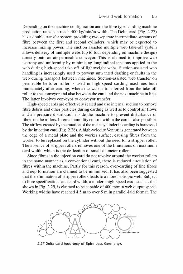
Dry-laid web formation 55
Depending on the machine configuration and the fibre type, carding machineproduction rates can reach 400 kg/min/m width. The Delta card (Fig. 2.27)has a double transfer system providing two separate intermediate streams offibre between the first and second cylinders, which may be expected toincrease mixing power. The suction assisted multiple web take-off systemallows delivery of multiple webs (up to four depending on machine design)directly onto an air-permeable conveyor. This is claimed to improve webisotropy and uniformity by minimising longitudinal tensions applied to theweb during high-speed take off of lightweight webs. Suction-assisted webhandling is increasingly used to prevent unwanted drafting or faults in theweb during transport between machines. Suction-assisted web transfer onpermeable belts or roller is used in high-speed carding machines bothimmediately after carding, where the web is transferred from the take-offroller to the conveyor and also between the card and the next machine in line.The latter involves conveyor to conveyor transfer.
High-speed cards are effectively sealed and use internal suction to removefibre debris and other particles during carding as well as to control air flowsand air pressure distribution inside the machine to prevent disturbance offibres on the rollers. Internal humidity control within the card is also possible.The airflow created by the rotation of the main cyclinder in carding is harnessedby the injection card (Fig. 2.28). A high-velocity Venturi is generated betweenthe edge of a metal plate and the worker surface, causing fibres from theworker to be replaced on the cylinder without the need for a stripper roller.The absence of stripper rollers removes one of the limitations on maximumcard width, which is the deflection of small-diameter rollers.
Since fibres in the injection card do not revolve around the worker rollersin the same manner as a conventional card, there is reduced circulation offibres within the machine. Partly for this reason, over-carding of fine fibresand nep formation are claimed to be minimised. It has also been suggestedthat the elimination of stripper rollers leads to a more isotropic web. Subjectto fibre specifications and card width, a modern high-speed card, such as thatshown in Fig. 2.29, is claimed to be capable of 400 m/min web output speed.Working widths have reached 4.5 m to over 5 m in parallel-laid format. The
2.27 Delta card (courtesy of Spinnbau, Germany).
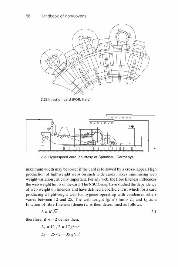
Handbook of nonwovens56
maximum width may be lower if the card is followed by a cross-lapper. Highproduction of lightweight webs on such wide cards makes minimising webweight variation critically important. For any web, the fibre fineness influencesthe web weight limits of the card. The NSC Group have studied the dependencyof web weight on fineness and have defined a coefficient K, which for a cardproducing a lightweight web for hygiene operating with condenser rollersvaries between 12 and 25. The web weight (g/m2) limits L1 and L2 as afunction of fibre fineness (denier) n is then determined as follows,
L K n = 2.1
therefore, if n = 2 denier then,
L12 = 12 2 = 17g/m
L22 = 25 2 = 35 g/m
2.28 Injection card (FOR, Italy).
2.29 Hyperspeed card (courtesy of Spinnbau, Germany).
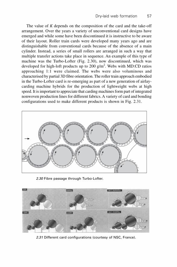
Dry-laid web formation 57
The value of K depends on the composition of the card and the take-offarrangement. Over the years a variety of unconventional card designs haveemerged and while some have been discontinued it is instructive to be awareof their layout. Roller train cards were developed many years ago and aredistinguishable from conventional cards because of the absence of a maincylinder. Instead, a series of small rollers are arranged in such a way thatmultiple transfer actions take place in sequence. An example of this type ofmachine was the Turbo-Lofter (Fig. 2.30), now discontinued, which wasdeveloped for high-loft products up to 200 g/m2. Webs with MD:CD ratiosapproaching 1:1 were claimed. The webs were also voluminous andcharacterised by partial 3D fibre orientation. The roller train approach embodiedin the Turbo-Lofter card is re-emerging as part of a new generation of airlay-carding machine hybrids for the production of lightweight webs at highspeed. It is important to appreciate that carding machines form part of integratednonwoven production lines for different fabrics. A variety of card and bondingconfigurations used to make different products is shown in Fig. 2.31.
2.30 Fibre passage through Turbo-Lofter.
2.31 Different card configurations (courtesy of NSC, France).
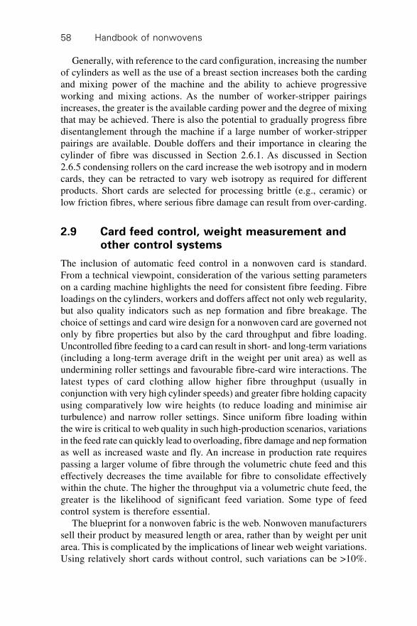
Handbook of nonwovens58
Generally, with reference to the card configuration, increasing the numberof cylinders as well as the use of a breast section increases both the cardingand mixing power of the machine and the ability to achieve progressiveworking and mixing actions. As the number of worker-stripper pairingsincreases, the greater is the available carding power and the degree of mixingthat may be achieved. There is also the potential to gradually progress fibredisentanglement through the machine if a large number of worker-stripperpairings are available. Double doffers and their importance in clearing thecylinder of fibre was discussed in Section 2.6.1. As discussed in Section2.6.5 condensing rollers on the card increase the web isotropy and in moderncards, they can be retracted to vary web isotropy as required for differentproducts. Short cards are selected for processing brittle (e.g., ceramic) orlow friction fibres, where serious fibre damage can result from over-carding.
2.9 Card feed control, weight measurement andother control systems
The inclusion of automatic feed control in a nonwoven card is standard.From a technical viewpoint, consideration of the various setting parameterson a carding machine highlights the need for consistent fibre feeding. Fibreloadings on the cylinders, workers and doffers affect not only web regularity,but also quality indicators such as nep formation and fibre breakage. Thechoice of settings and card wire design for a nonwoven card are governed notonly by fibre properties but also by the card throughput and fibre loading.Uncontrolled fibre feeding to a card can result in short- and long-term variations(including a long-term average drift in the weight per unit area) as well asundermining roller settings and favourable fibre-card wire interactions. Thelatest types of card clothing allow higher fibre throughput (usually inconjunction with very high cylinder speeds) and greater fibre holding capacityusing comparatively low wire heights (to reduce loading and minimise airturbulence) and narrow roller settings. Since uniform fibre loading withinthe wire is critical to web quality in such high-production scenarios, variationsin the feed rate can quickly lead to overloading, fibre damage and nep formationas well as increased waste and fly. An increase in production rate requirespassing a larger volume of fibre through the volumetric chute feed and thiseffectively decreases the time available for fibre to consolidate effectivelywithin the chute. The higher the throughput via a volumetric chute feed, thegreater is the likelihood of significant feed variation. Some type of feedcontrol system is therefore essential.
The blueprint for a nonwoven fabric is the web. Nonwoven manufacturerssell their product by measured length or area, rather than by weight per unitarea. This is complicated by the implications of linear web weight variations.Using relatively short cards without control, such variations can be >10%.
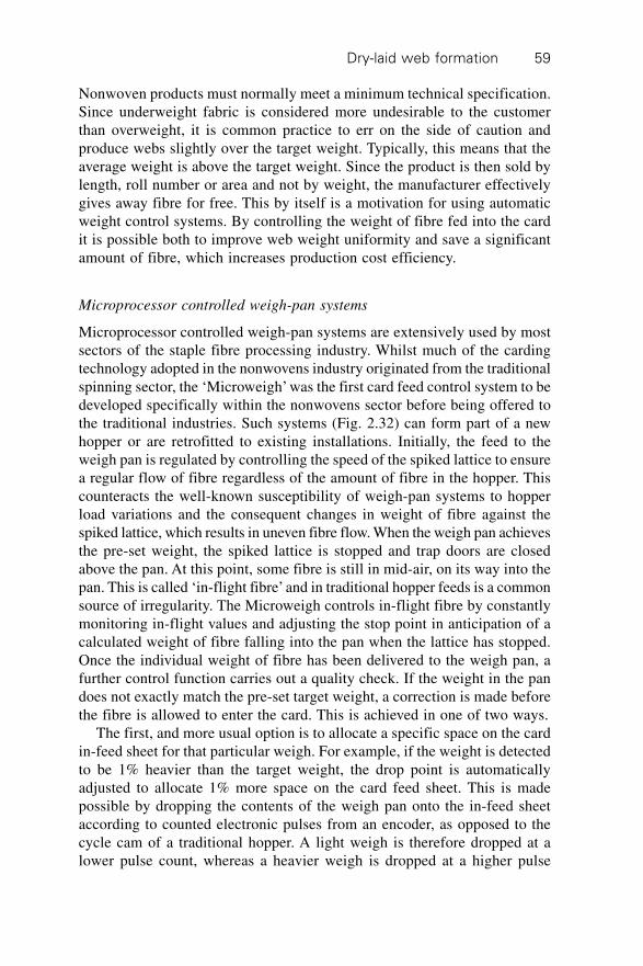
Dry-laid web formation 59
Nonwoven products must normally meet a minimum technical specification.Since underweight fabric is considered more undesirable to the customerthan overweight, it is common practice to err on the side of caution andproduce webs slightly over the target weight. Typically, this means that theaverage weight is above the target weight. Since the product is then sold bylength, roll number or area and not by weight, the manufacturer effectivelygives away fibre for free. This by itself is a motivation for using automaticweight control systems. By controlling the weight of fibre fed into the cardit is possible both to improve web weight uniformity and save a significantamount of fibre, which increases production cost efficiency.
Microprocessor controlled weigh-pan systems
Microprocessor controlled weigh-pan systems are extensively used by mostsectors of the staple fibre processing industry. Whilst much of the cardingtechnology adopted in the nonwovens industry originated from the traditionalspinning sector, the ‘Microweigh’ was the first card feed control system to bedeveloped specifically within the nonwovens sector before being offered tothe traditional industries. Such systems (Fig. 2.32) can form part of a newhopper or are retrofitted to existing installations. Initially, the feed to theweigh pan is regulated by controlling the speed of the spiked lattice to ensurea regular flow of fibre regardless of the amount of fibre in the hopper. Thiscounteracts the well-known susceptibility of weigh-pan systems to hopperload variations and the consequent changes in weight of fibre against thespiked lattice, which results in uneven fibre flow. When the weigh pan achievesthe pre-set weight, the spiked lattice is stopped and trap doors are closedabove the pan. At this point, some fibre is still in mid-air, on its way into thepan. This is called ‘in-flight fibre’ and in traditional hopper feeds is a commonsource of irregularity. The Microweigh controls in-flight fibre by constantlymonitoring in-flight values and adjusting the stop point in anticipation of acalculated weight of fibre falling into the pan when the lattice has stopped.Once the individual weight of fibre has been delivered to the weigh pan, afurther control function carries out a quality check. If the weight in the pandoes not exactly match the pre-set target weight, a correction is made beforethe fibre is allowed to enter the card. This is achieved in one of two ways.
The first, and more usual option is to allocate a specific space on the cardin-feed sheet for that particular weigh. For example, if the weight is detectedto be 1% heavier than the target weight, the drop point is automaticallyadjusted to allocate 1% more space on the card feed sheet. This is madepossible by dropping the contents of the weigh pan onto the in-feed sheetaccording to counted electronic pulses from an encoder, as opposed to thecycle cam of a traditional hopper. A light weigh is therefore dropped at alower pulse count, whereas a heavier weigh is dropped at a higher pulse
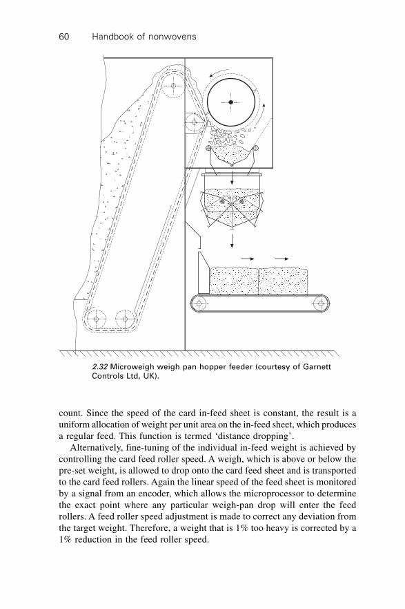
Handbook of nonwovens60
count. Since the speed of the card in-feed sheet is constant, the result is auniform allocation of weight per unit area on the in-feed sheet, which producesa regular feed. This function is termed ‘distance dropping’.
Alternatively, fine-tuning of the individual in-feed weight is achieved bycontrolling the card feed roller speed. A weigh, which is above or below thepre-set weight, is allowed to drop onto the card feed sheet and is transportedto the card feed rollers. Again the linear speed of the feed sheet is monitoredby a signal from an encoder, which allows the microprocessor to determinethe exact point where any particular weigh-pan drop will enter the feedrollers. A feed roller speed adjustment is made to correct any deviation fromthe target weight. Therefore, a weight that is 1% too heavy is corrected by a1% reduction in the feed roller speed.
2.32 Microweigh weigh pan hopper feeder (courtesy of GarnettControls Ltd, UK).
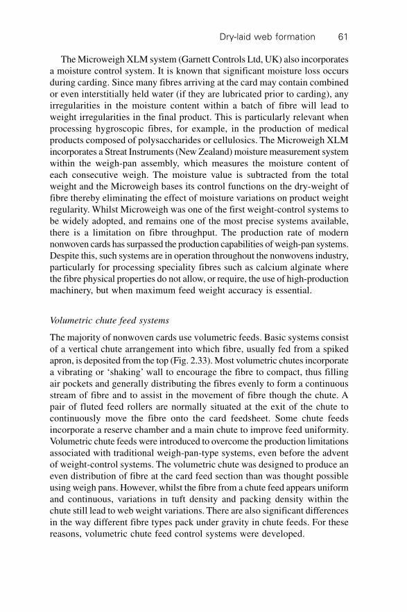
Dry-laid web formation 61
The Microweigh XLM system (Garnett Controls Ltd, UK) also incorporatesa moisture control system. It is known that significant moisture loss occursduring carding. Since many fibres arriving at the card may contain combinedor even interstitially held water (if they are lubricated prior to carding), anyirregularities in the moisture content within a batch of fibre will lead toweight irregularities in the final product. This is particularly relevant whenprocessing hygroscopic fibres, for example, in the production of medicalproducts composed of polysaccharides or cellulosics. The Microweigh XLMincorporates a Streat Instruments (New Zealand) moisture measurement systemwithin the weigh-pan assembly, which measures the moisture content ofeach consecutive weigh. The moisture value is subtracted from the totalweight and the Microweigh bases its control functions on the dry-weight offibre thereby eliminating the effect of moisture variations on product weightregularity. Whilst Microweigh was one of the first weight-control systems tobe widely adopted, and remains one of the most precise systems available,there is a limitation on fibre throughput. The production rate of modernnonwoven cards has surpassed the production capabilities of weigh-pan systems.Despite this, such systems are in operation throughout the nonwovens industry,particularly for processing speciality fibres such as calcium alginate wherethe fibre physical properties do not allow, or require, the use of high-productionmachinery, but when maximum feed weight accuracy is essential.
Volumetric chute feed systems
The majority of nonwoven cards use volumetric feeds. Basic systems consistof a vertical chute arrangement into which fibre, usually fed from a spikedapron, is deposited from the top (Fig. 2.33). Most volumetric chutes incorporatea vibrating or ‘shaking’ wall to encourage the fibre to compact, thus fillingair pockets and generally distributing the fibres evenly to form a continuousstream of fibre and to assist in the movement of fibre though the chute. Apair of fluted feed rollers are normally situated at the exit of the chute tocontinuously move the fibre onto the card feedsheet. Some chute feedsincorporate a reserve chamber and a main chute to improve feed uniformity.Volumetric chute feeds were introduced to overcome the production limitationsassociated with traditional weigh-pan-type systems, even before the adventof weight-control systems. The volumetric chute was designed to produce aneven distribution of fibre at the card feed section than was thought possibleusing weigh pans. However, whilst the fibre from a chute feed appears uniformand continuous, variations in tuft density and packing density within thechute still lead to web weight variations. There are also significant differencesin the way different fibre types pack under gravity in chute feeds. For thesereasons, volumetric chute feed control systems were developed.
Handbook of nonwovens62
Long-term variation controllers
Controllers of long-term feed weight variations usually operate by maintaininga constant average feed into the card. Their operation often relies oncontinuously adjusting the card feed roller speed in response to measuredshort-term variations in the in-feed fibre stream.
Electromagnetic radiation systems
Servolap, originally developed by HDB (Belgium) was one of the firstvolumetric weight-control systems on the market. The system measures the
2.33 Volumetric feed system (courtesy of Garnett Controls Ltd, UK).
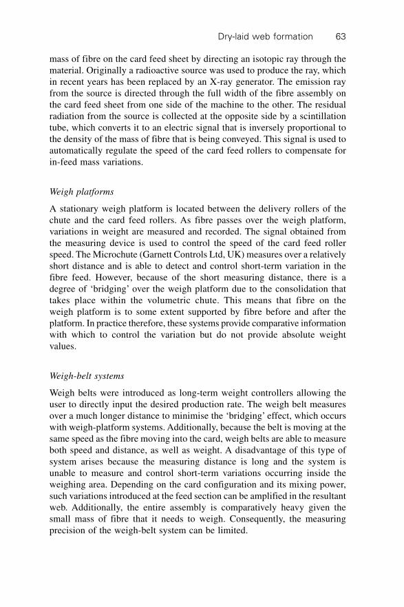
Dry-laid web formation 63
mass of fibre on the card feed sheet by directing an isotopic ray through thematerial. Originally a radioactive source was used to produce the ray, whichin recent years has been replaced by an X-ray generator. The emission rayfrom the source is directed through the full width of the fibre assembly onthe card feed sheet from one side of the machine to the other. The residualradiation from the source is collected at the opposite side by a scintillationtube, which converts it to an electric signal that is inversely proportional tothe density of the mass of fibre that is being conveyed. This signal is used toautomatically regulate the speed of the card feed rollers to compensate forin-feed mass variations.
Weigh platforms
A stationary weigh platform is located between the delivery rollers of thechute and the card feed rollers. As fibre passes over the weigh platform,variations in weight are measured and recorded. The signal obtained fromthe measuring device is used to control the speed of the card feed rollerspeed. The Microchute (Garnett Controls Ltd, UK) measures over a relativelyshort distance and is able to detect and control short-term variation in thefibre feed. However, because of the short measuring distance, there is adegree of ‘bridging’ over the weigh platform due to the consolidation thattakes place within the volumetric chute. This means that fibre on theweigh platform is to some extent supported by fibre before and after theplatform. In practice therefore, these systems provide comparative informationwith which to control the variation but do not provide absolute weightvalues.
Weigh-belt systems
Weigh belts were introduced as long-term weight controllers allowing theuser to directly input the desired production rate. The weigh belt measuresover a much longer distance to minimise the ‘bridging’ effect, which occurswith weigh-platform systems. Additionally, because the belt is moving at thesame speed as the fibre moving into the card, weigh belts are able to measureboth speed and distance, as well as weight. A disadvantage of this type ofsystem arises because the measuring distance is long and the system isunable to measure and control short-term variations occurring inside theweighing area. Depending on the card configuration and its mixing power,such variations introduced at the feed section can be amplified in the resultantweb. Additionally, the entire assembly is comparatively heavy given thesmall mass of fibre that it needs to weigh. Consequently, the measuringprecision of the weigh-belt system can be limited.
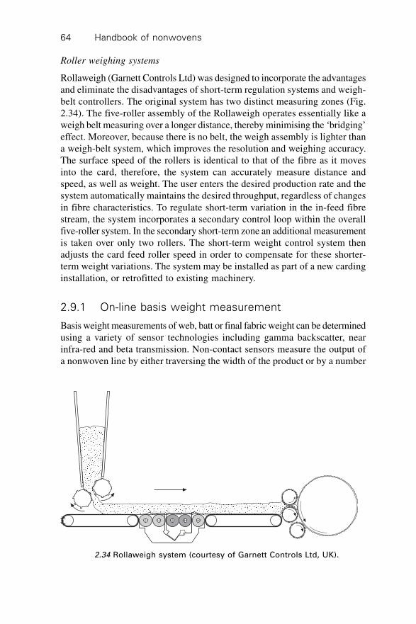
Handbook of nonwovens64
Roller weighing systems
Rollaweigh (Garnett Controls Ltd) was designed to incorporate the advantagesand eliminate the disadvantages of short-term regulation systems and weigh-belt controllers. The original system has two distinct measuring zones (Fig.2.34). The five-roller assembly of the Rollaweigh operates essentially like aweigh belt measuring over a longer distance, thereby minimising the ‘bridging’effect. Moreover, because there is no belt, the weigh assembly is lighter thana weigh-belt system, which improves the resolution and weighing accuracy.The surface speed of the rollers is identical to that of the fibre as it movesinto the card, therefore, the system can accurately measure distance andspeed, as well as weight. The user enters the desired production rate and thesystem automatically maintains the desired throughput, regardless of changesin fibre characteristics. To regulate short-term variation in the in-feed fibrestream, the system incorporates a secondary control loop within the overallfive-roller system. In the secondary short-term zone an additional measurementis taken over only two rollers. The short-term weight control system thenadjusts the card feed roller speed in order to compensate for these shorter-term weight variations. The system may be installed as part of a new cardinginstallation, or retrofitted to existing machinery.
2.9.1 On-line basis weight measurement
Basis weight measurements of web, batt or final fabric weight can be determinedusing a variety of sensor technologies including gamma backscatter, nearinfra-red and beta transmission. Non-contact sensors measure the output ofa nonwoven line by either traversing the width of the product or by a number
2.34 Rollaweigh system (courtesy of Garnett Controls Ltd, UK).
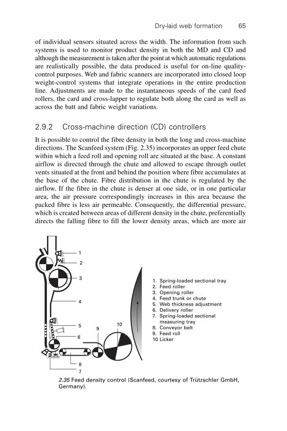
Dry-laid web formation 65
of individual sensors situated across the width. The information from suchsystems is used to monitor product density in both the MD and CD andalthough the measurement is taken after the point at which automatic regulationsare realistically possible, the data produced is useful for on-line quality-control purposes. Web and fabric scanners are incorporated into closed loopweight-control systems that integrate operations in the entire productionline. Adjustments are made to the instantaneous speeds of the card feedrollers, the card and cross-lapper to regulate both along the card as well asacross the batt and fabric weight variations.
2.9.2 Cross-machine direction (CD) controllers
It is possible to control the fibre density in both the long and cross-machinedirections. The Scanfeed system (Fig. 2.35) incorporates an upper feed chutewithin which a feed roll and opening roll are situated at the base. A constantairflow is directed through the chute and allowed to escape through outletvents situated at the front and behind the position where fibre accumulates atthe base of the chute. Fibre distribution in the chute is regulated by theairflow. If the fibre in the chute is denser at one side, or in one particulararea, the air pressure correspondingly increases in this area because thepacked fibre is less air permeable. Consequently, the differential pressure,which is created between areas of different density in the chute, preferentiallydirects the falling fibre to fill the lower density areas, which are more air
1. Spring-loaded sectional tray2. Feed roller3. Opening roller4. Feed trunk or chute5. Web thickness adjustment6. Delivery roller7. Spring-loaded sectional
measuring tray8. Conveyor belt9. Feed roll10 Licker
2.35 Feed density control (Scanfeed, courtesy of Trützschler GmbH,Germany).
1
2
3
4
5
6
8
7
910
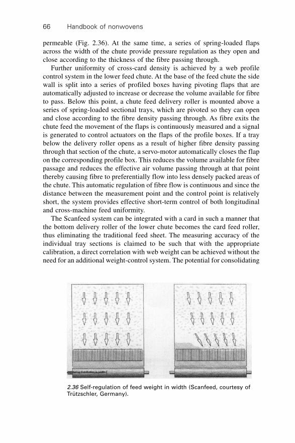
Handbook of nonwovens66
permeable (Fig. 2.36). At the same time, a series of spring-loaded flapsacross the width of the chute provide pressure regulation as they open andclose according to the thickness of the fibre passing through.
Further uniformity of cross-card density is achieved by a web profilecontrol system in the lower feed chute. At the base of the feed chute the sidewall is split into a series of profiled boxes having pivoting flaps that areautomatically adjusted to increase or decrease the volume available for fibreto pass. Below this point, a chute feed delivery roller is mounted above aseries of spring-loaded sectional trays, which are pivoted so they can openand close according to the fibre density passing through. As fibre exits thechute feed the movement of the flaps is continuously measured and a signalis generated to control actuators on the flaps of the profile boxes. If a traybelow the delivery roller opens as a result of higher fibre density passingthrough that section of the chute, a servo-motor automatically closes the flapon the corresponding profile box. This reduces the volume available for fibrepassage and reduces the effective air volume passing through at that pointthereby causing fibre to preferentially flow into less densely packed areas ofthe chute. This automatic regulation of fibre flow is continuous and since thedistance between the measurement point and the control point is relativelyshort, the system provides effective short-term control of both longitudinaland cross-machine feed uniformity.
The Scanfeed system can be integrated with a card in such a manner thatthe bottom delivery roller of the lower chute becomes the card feed roller,thus eliminating the traditional feed sheet. The measuring accuracy of theindividual tray sections is claimed to be such that with the appropriatecalibration, a direct correlation with web weight can be achieved without theneed for an additional weight-control system. The potential for consolidating
2.36 Self-regulation of feed weight in width (Scanfeed, courtesy ofTrützschler, Germany).
Dry-laid web formation 67
a batt produced by such a feed system directly (using, for example,hydroentanglement or needlepunching) without the use of a traditional web-forming step has also been proposed. For making heavyweight products, forexample quilted fabrics, the use of a volumetric hopper feeder to form a battstructure in place of the conventional card and cross-lapper has beendemonstrated.
2.10 Cross-lapping
A cross-lapper (or cross-folder) is a continuous web transfer machine thatnormally follows a card or Garnett machine as part of an integrated webformation system. The web is layered from side to side onto a lower conveyoror bottom lattice, which runs perpendicular to the in-feed web to form adiagonally stratified batt, wadding or fleece, which typically consists of4–>15 layers depending on requirements. Commercially, cross-lapped battweights range from about 50 g/m2 to over 1500 g/m2 depending on fibreproperties and the web weight per unit area. The ratio of the web in-feedspeed to the output speed determines the laydown angle and the linearproduction speed is a function of both laydown width and the number oflayers. The laydown width varies depending on requirements and for specialistapplications such as papermakers’ felts, it may be >17 m. Therefore, cross-lapping enables the production of batts much wider than the initial web fedfrom the carding machine which is limited to <5 m and is more usually about2.5 m. The fibres in the carded web entering the cross-lapper tend to have apreferential fibre orientation in the MD although they are by no meansparallel to the web axis. Since during cross-lapping the cross-laid web (orbatt) leaves the machine perpendicular to the card, the fibres in the batt havea preferential fibre orientation which is nearer to the CD. In fact, two peakorientation angles can be measured in the batt after cross-lapping.
The precise peak angles depend on the web input to web output surfacespeed ratio. In certain applications, such as filtration media production,reinforcing scrims or yarns are introduced into the centre of the batt duringcross-lapping to increase fabric dimensional stability. More than one webcan be lapped together from two different cards if required. In operation,cross-lapping machines undergo significant shifts in mass at high speed. Aircurrents and inter-belt tension variations can produce web faults since thewebs are extremely delicate and are easily deformed by mechanical andaerodynamic forces. The original method of producing a transversely laidbatt used a camel back, so termed because of the shape of the web path usedby the machine. In the camel back, a conveyor transports the emerging webfrom a card, upwards to a pivot point from which the conveyor systemreciprocates to layer the web onto a cross conveyor. Such systems utilisedsimple harmonic motion to reciprocate the web layering conveyor and as
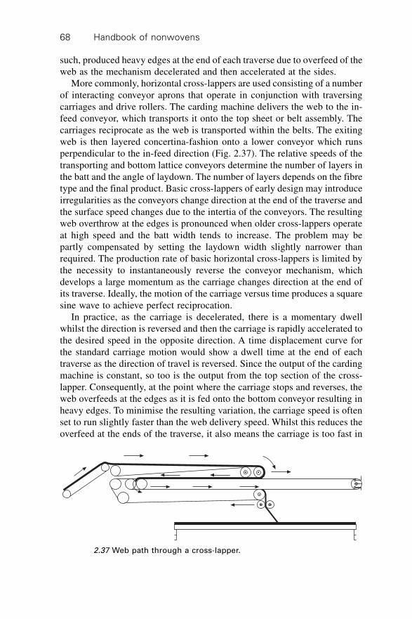
Handbook of nonwovens68
such, produced heavy edges at the end of each traverse due to overfeed of theweb as the mechanism decelerated and then accelerated at the sides.
More commonly, horizontal cross-lappers are used consisting of a numberof interacting conveyor aprons that operate in conjunction with traversingcarriages and drive rollers. The carding machine delivers the web to the in-feed conveyor, which transports it onto the top sheet or belt assembly. Thecarriages reciprocate as the web is transported within the belts. The exitingweb is then layered concertina-fashion onto a lower conveyor which runsperpendicular to the in-feed direction (Fig. 2.37). The relative speeds of thetransporting and bottom lattice conveyors determine the number of layers inthe batt and the angle of laydown. The number of layers depends on the fibretype and the final product. Basic cross-lappers of early design may introduceirregularities as the conveyors change direction at the end of the traverse andthe surface speed changes due to the intertia of the conveyors. The resultingweb overthrow at the edges is pronounced when older cross-lappers operateat high speed and the batt width tends to increase. The problem may bepartly compensated by setting the laydown width slightly narrower thanrequired. The production rate of basic horizontal cross-lappers is limited bythe necessity to instantaneously reverse the conveyor mechanism, whichdevelops a large momentum as the carriage changes direction at the end ofits traverse. Ideally, the motion of the carriage versus time produces a squaresine wave to achieve perfect reciprocation.
In practice, as the carriage is decelerated, there is a momentary dwellwhilst the direction is reversed and then the carriage is rapidly accelerated tothe desired speed in the opposite direction. A time displacement curve forthe standard carriage motion would show a dwell time at the end of eachtraverse as the direction of travel is reversed. Since the output of the cardingmachine is constant, so too is the output from the top section of the cross-lapper. Consequently, at the point where the carriage stops and reverses, theweb overfeeds at the edges as it is fed onto the bottom conveyor resulting inheavy edges. To minimise the resulting variation, the carriage speed is oftenset to run slightly faster than the web delivery speed. Whilst this reduces theoverfeed at the ends of the traverse, it also means the carriage is too fast in
2.37 Web path through a cross-lapper.
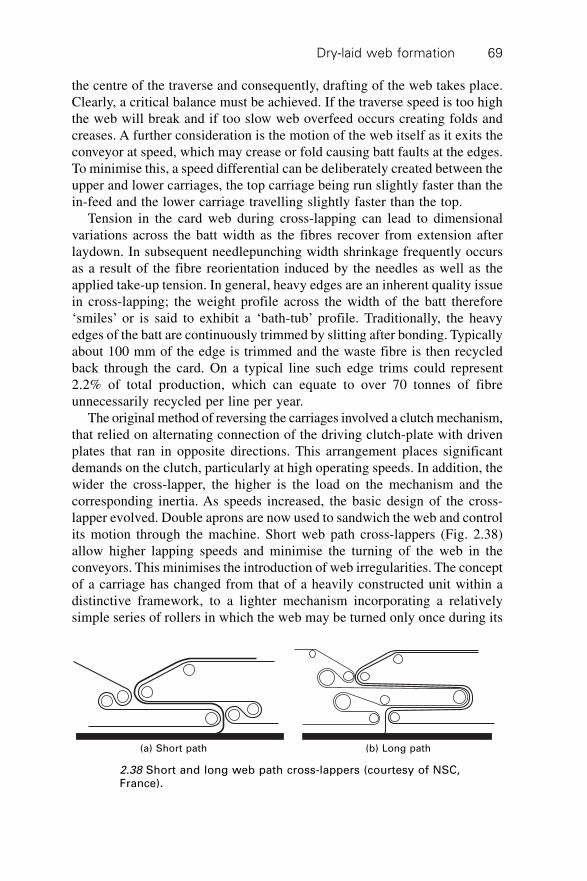
Dry-laid web formation 69
the centre of the traverse and consequently, drafting of the web takes place.Clearly, a critical balance must be achieved. If the traverse speed is too highthe web will break and if too slow web overfeed occurs creating folds andcreases. A further consideration is the motion of the web itself as it exits theconveyor at speed, which may crease or fold causing batt faults at the edges.To minimise this, a speed differential can be deliberately created between theupper and lower carriages, the top carriage being run slightly faster than thein-feed and the lower carriage travelling slightly faster than the top.
Tension in the card web during cross-lapping can lead to dimensionalvariations across the batt width as the fibres recover from extension afterlaydown. In subsequent needlepunching width shrinkage frequently occursas a result of the fibre reorientation induced by the needles as well as theapplied take-up tension. In general, heavy edges are an inherent quality issuein cross-lapping; the weight profile across the width of the batt therefore‘smiles’ or is said to exhibit a ‘bath-tub’ profile. Traditionally, the heavyedges of the batt are continuously trimmed by slitting after bonding. Typicallyabout 100 mm of the edge is trimmed and the waste fibre is then recycledback through the card. On a typical line such edge trims could represent2.2% of total production, which can equate to over 70 tonnes of fibreunnecessarily recycled per line per year.
The original method of reversing the carriages involved a clutch mechanism,that relied on alternating connection of the driving clutch-plate with drivenplates that ran in opposite directions. This arrangement places significantdemands on the clutch, particularly at high operating speeds. In addition, thewider the cross-lapper, the higher is the load on the mechanism and thecorresponding inertia. As speeds increased, the basic design of the cross-lapper evolved. Double aprons are now used to sandwich the web and controlits motion through the machine. Short web path cross-lappers (Fig. 2.38)allow higher lapping speeds and minimise the turning of the web in theconveyors. This minimises the introduction of web irregularities. The conceptof a carriage has changed from that of a heavily constructed unit within adistinctive framework, to a lighter mechanism incorporating a relativelysimple series of rollers in which the web may be turned only once during its
(a) Short path (b) Long path
2.38 Short and long web path cross-lappers (courtesy of NSC,France).
Handbook of nonwovens70
passage through the cross-lapper. Fibre reinforced composite rollers havereplaced metal. External chain drives, a common source of mechanicalproblems, particularly when exposed to airborne fibres, have been eliminatedin favour of integral drive systems where the aprons act as the main meansof transmission as well as the web carrier. Reversing clutches have beenreplaced by gears and brakes, allowing controlled deceleration and accelerationof the apron carriage. Laydown rollers beneath the cross-lapper positivelylay the web in a controlled manner, rather than relying on gravity as waspreviously the norm.
The use of perforated conveyor aprons allows the evacuation of air toreduce undesirable air currents whilst anti-static aprons minimise problemssuch as fibre sticking to the aprons causing laps, web breaks, productionstoppages and batt irregularities. The complex arrangement of conveyor beltswithin a cross-lapper, the high speeds, and the relative movement of respectiveroller positions make it important to control the lateral position of the conveyors.A cross-lapper apron is a consumable item that is expensive to replace. Earlycross-lappers suffered from tracking problems and variations in tension causedgradual migration of the apron to one side leading to serious damage. Trackingcontrol systems are used to prevent such events by ensuring that equal tensionis maintained at both sides of each apron to prevent distortion. Should adeviation of the apron position occur, tension is applied to the appropriateside to force the apron back onto the correct path. In some systems the apronedges are continuously monitored by optical sensors and automatic adjustmentsare made by a tracking control system.
Recent developments in cross-lapping technology have primarily focusedon increasing speeds. The increased productivity has further highlighted theneed to reconcile the problem of achieving high web uniformity at highproduction rates. The common practice of trimming over-weight edges producessignificant waste and an alternative approach is preferred. To directly addressthe problem, modern cross-lappers include sophisticated drive control systems.The logistical aspects of the process are worthy of consideration. The inputwidth of a cross-lapper is the same as the card, which feeds it and is typically2.5 m wide. Since the cross-lapper must accommodate the web with room ateach side to prevent roller laps, the width of the corresponding conveyorcould be 2.7 m. The output of the cross-lapper is not restricted by the widthof the card. Indeed, this is one of the advantages of having a cross-lapper inthe line. Generally, the subsequent bonding process, which is commonlyneedlepunching, is capable of much lower linear speeds than a card. A cardthat is 2.5 m working width can be used to feed a bonding process that is atleast twice that width, thus optimising the production capacity of the cardand maximising product width in an economical manner. In practice, althoughmachine widths are continuing to increase, most of the industry uses battwidths of 5 m and below.
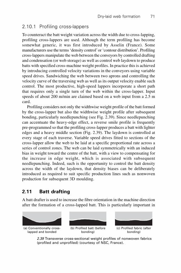
Dry-laid web formation 71
2.10.1 Profiling cross-lappers
To counteract the batt weight variation across the width due to cross-lapping,profiling cross-lappers are used. Although the term profiling has becomesomewhat generic, it was first introduced by Asselin (France). Somemanufacturers use the terms ‘density control’ or ‘contour distribution’. Profilingcross-lappers manipulate the web between the conveyors by controlled draftingand condensation (or web storage) as well as control web laydown to producebatts with specified cross-machine weight profiles. In practice this is achievedby introducing controlled velocity variations in the conveyors using variablespeed drives. Sandwiching the web between two aprons and controlling thevelocity curve of the traversing web as well as its output velocity enable suchcontrol. The most productive, high-speed lappers incorporate a short paththat requires only a single turn of the web within the cross-lapper. Inputspeeds of about 200 m/min are claimed based on a web input from a 2.5 mcard.
Profiling considers not only the widthwise weight profile of the batt formedby the cross-lapper but also the widthwise weight profile after subsequentbonding, particularly needlepunching (see Fig. 2.39). Since needlepunchingcan accentuate the heavy-edge effect, a reverse smile profile is frequentlypre-programmed so that the profiling cross-lapper produces a batt with lighteredges and a heavy middle section (Fig. 2.39). The laydown is controlled atevery stage of each traverse. Variable speed drives fitted to sections of thecross-lapper allow the web to be laid at a specific proportional rate across aseries of control zones. The web can be laid symmetrically with an inducedbias in weight toward the centre of the batt, with a view to compensating forthe increase in edge weight, which is associated with subsequentneedlepunching. Indeed, such is the opportunity to control the batt densityacross the width of the laydown, that density biases can be deliberatelyintroduced as required to suit specific production lines such as nonwovenproduction for subsequent 3D moulding.
2.11 Batt drafting
A batt drafter is used to increase the fibre orientation in the machine directionafter the formation of a cross-lapped batt. This is particularly important in
(a) Conventionally cross-lapped and bonded
(b) Profiled batt (beforebonding)
(c) Profiled fabric (afterbonding)
2.39 Transverse cross-sectional weight profiles of nonwoven fabrics(profiled and unprofiled) (courtesy of NSC, France).
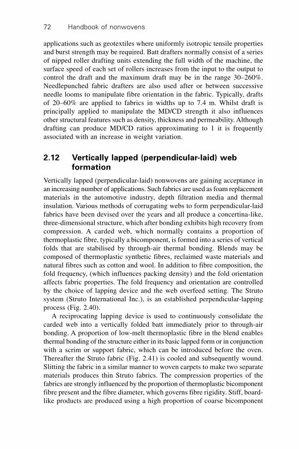
Handbook of nonwovens72
applications such as geotextiles where uniformly isotropic tensile propertiesand burst strength may be required. Batt drafters normally consist of a seriesof nipped roller drafting units extending the full width of the machine, thesurface speed of each set of rollers increases from the input to the output tocontrol the draft and the maximum draft may be in the range 30–260%.Needlepunched fabric drafters are also used after or between successiveneedle looms to manipulate fibre orientation in the fabric. Typically, draftsof 20–60% are applied to fabrics in widths up to 7.4 m. Whilst draft isprincipally applied to manipulate the MD/CD strength it also influencesother structural features such as density, thickness and permeability. Althoughdrafting can produce MD/CD ratios approximating to 1 it is frequentlyassociated with an increase in weight variation.
2.12 Vertically lapped (perpendicular-laid) webformation
Vertically lapped (perpendicular-laid) nonwovens are gaining acceptance inan increasing number of applications. Such fabrics are used as foam replacementmaterials in the automotive industry, depth filtration media and thermalinsulation. Various methods of corrugating webs to form perpendicular-laidfabrics have been devised over the years and all produce a concertina-like,three-dimensional structure, which after bonding exhibits high recovery fromcompression. A carded web, which normally contains a proportion ofthermoplastic fibre, typically a bicomponent, is formed into a series of verticalfolds that are stabilised by through-air thermal bonding. Blends may becomposed of thermoplastic synthetic fibres, reclaimed waste materials andnatural fibres such as cotton and wool. In addition to fibre composition, thefold frequency, (which influences packing density) and the fold orientationaffects fabric properties. The fold frequency and orientation are controlledby the choice of lapping device and the web overfeed setting. The Strutosystem (Struto International Inc.), is an established perpendicular-lappingprocess (Fig. 2.40).
A reciprocating lapping device is used to continuously consolidate thecarded web into a vertically folded batt immediately prior to through-airbonding. A proportion of low-melt thermoplastic fibre in the blend enablesthermal bonding of the structure either in its basic lapped form or in conjunctionwith a scrim or support fabric, which can be introduced before the oven.Thereafter the Struto fabric (Fig. 2.41) is cooled and subsequently wound.Slitting the fabric in a similar manner to woven carpets to make two separatematerials produces thin Struto fabrics. The compression properties of thefabrics are strongly influenced by the proportion of thermoplastic bicomponentfibre present and the fibre diameter, which governs fibre rigidity. Stiff, board-like products are produced using a high proportion of coarse bicomponent
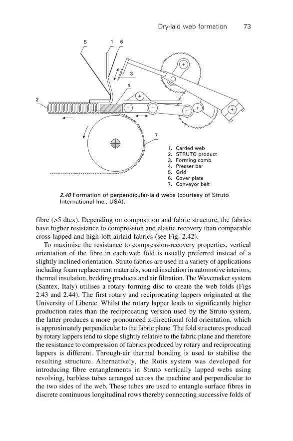
Dry-laid web formation 73
fibre (>5 dtex). Depending on composition and fabric structure, the fabricshave higher resistance to compression and elastic recovery than comparablecross-lapped and high-loft airlaid fabrics (see Fig. 2.42).
To maximise the resistance to compression-recovery properties, verticalorientation of the fibre in each web fold is usually preferred instead of aslightly inclined orientation. Struto fabrics are used in a variety of applicationsincluding foam replacement materials, sound insulation in automotive interiors,thermal insulation, bedding products and air filtration. The Wavemaker system(Santex, Italy) utilises a rotary forming disc to create the web folds (Figs2.43 and 2.44). The first rotary and reciprocating lappers originated at theUniversity of Liberec. Whilst the rotary lapper leads to significantly higherproduction rates than the reciprocating version used by the Struto system,the latter produces a more pronounced z-directional fold orientation, whichis approximately perpendicular to the fabric plane. The fold structures producedby rotary lappers tend to slope slightly relative to the fabric plane and thereforethe resistance to compression of fabrics produced by rotary and reciprocatinglappers is different. Through-air thermal bonding is used to stabilise theresulting structure. Alternatively, the Rotis system was developed forintroducing fibre entanglements in Struto vertically lapped webs usingrevolving, barbless tubes arranged across the machine and perpendicular tothe two sides of the web. These tubes are used to entangle surface fibres indiscrete continuous longitudinal rows thereby connecting successive folds of
5 1 6
3
4
2
7
1. Carded web2. STRUTO product3. Forming comb4. Presser bar5. Grid6. Cover plate7. Conveyor belt
2.40 Formation of perpendicular-laid webs (courtesy of StrutoInternational Inc., USA).
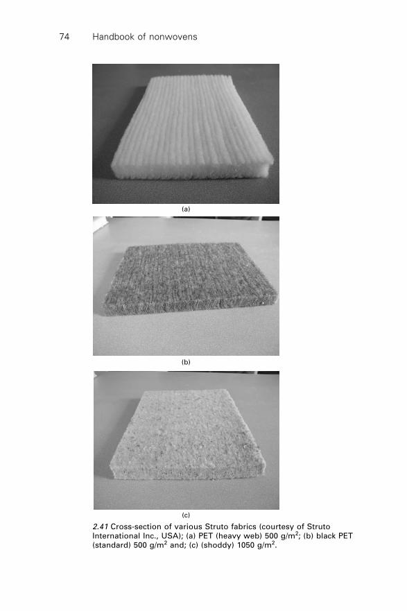
Handbook of nonwovens74
(a)
(b)
(c)
2.41 Cross-section of various Struto fabrics (courtesy of StrutoInternational Inc., USA); (a) PET (heavy web) 500 g/m2; (b) black PET(standard) 500 g/m2 and; (c) (shoddy) 1050 g/m2.
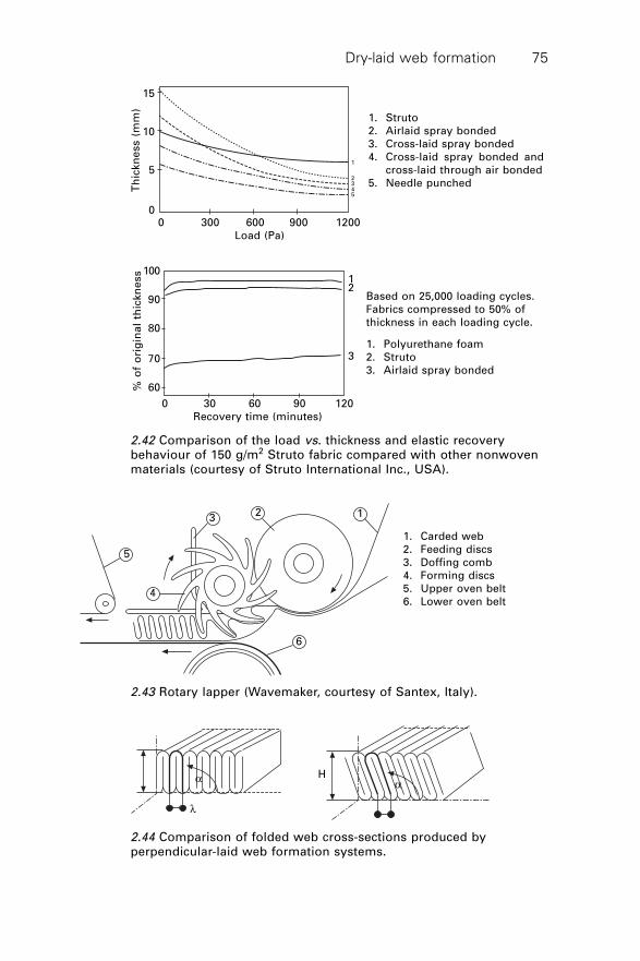
Dry-laid web formation 75
1
2345
0 300 600 900 1200Load (Pa)
15
10
5
0
Th
ickn
ess (
mm
)
100
90
80
70
60% o
f o
rig
ina
l th
ickn
ess
0 30 60 90 120Recovery time (minutes)
12
3
1. Struto2. Airlaid spray bonded3. Cross-laid spray bonded4. Cross-laid spray bonded and
cross-laid through air bonded5. Needle punched
Based on 25,000 loading cycles.Fabrics compressed to 50% ofthickness in each loading cycle.
1. Polyurethane foam2. Struto3. Airlaid spray bonded
2.42 Comparison of the load vs. thickness and elastic recoverybehaviour of 150 g/m2 Struto fabric compared with other nonwovenmaterials (courtesy of Struto International Inc., USA).
5
4
32 1
6
1. Carded web2. Feeding discs3. Doffing comb4. Forming discs5. Upper oven belt6. Lower oven belt
2.43 Rotary lapper (Wavemaker, courtesy of Santex, Italy).
a
l
Ha
2.44 Comparison of folded web cross-sections produced byperpendicular-laid web formation systems.
Handbook of nonwovens76
web in-plane. Preformed scrims or fabrics may also be introduced fromabove and below to form a composite fabric structure in situ.
2.13 Airlaid web formation: raw materials and fibrepreparation
Airlaying (aerodynamic or airlaid web formation) refers to a family of dry-laid web formation processes used in the manufacture of disposable, single-use products containing short, pulp fibres (including wipes, absorbent layersfor incontinence products and food packaging pads) and durable products(including high-loft waddings, filtration media, interlinings, automotivecomponents and mattress fillings) produced from longer fibres. A characteristicfeature of airlaid webs is their isotropicity. In contrast to carded webs, MD:CDratios approaching 1 may be obtained depending on fibre specifications andmachine parameters. Airlaid webs are therefore frequently referred to as‘random-laid’. Additionally, airlay processes are highly versatile in terms oftheir compatibility with different fibre types and specifications. This versatilitypartly arises from the principles of fibre transport and deposition used inairlaying as well as the variety of airlay machine designs available.
Airlaying, like other technologies, has certain benefits and limitations.Among the benefits are:
∑ isotropic web properties∑ three-dimensional structure if the basis weight is above about 50 g/m2
producing voluminous, high-loft structures with a very low density∑ compatibility with a wide variety of generic fibre types including natural
and synthetic polymer fibres, ceramics, metals including steel, carbon,melamine, aramids and other high-performance fibres.
The main limitations are:
∑ Fabric uniformity is highly dependent on fibre opening andindividualisation prior to web forming.
∑ Air flow irregularity adjacent to the walls of the conduit leads to variabilityacross the web structure.
∑ Fibre entanglement in the airstream can lead to web faults.
Depending on fibre type and fineness, airlaying is claimed to be more efficientthan carding in the production of webs greater than 150–200 g/m2, whereproduction rates of 250 kg/h/m can be achieved.1
2.13.1 Raw material specifications and fibre preparation
for airlaying
A variety of fibres are used by the airlaying industry. Wood pulp continuesto play a major role in the pulp or short-fibre airlay industry and thecharacteristics of some typical pulps are now briefly discussed.
Dry-laid web formation 77
Wood pulp and natural fibres
Wood pulp can be produced by mechanical or chemical processes.Thermomechanical pulping (TMP) involves passing wood chips betweenrotating plates having raised bars at high temperature and pressure. Theheating softens the lignin, which is a natural phenolic resin holding thecellulose fibres together, making it possible to separate the fibres. A yield ofover 90% of wood fibres can be obtained. In contrast, chemical pulping(Kraft process) dissolves the lignin using suitable chemicals such as causticsoda and sulphur under heat and pressure. The chemical pulping processproduces lower fibre yield than mechanical pulping, typically 50–60%.2
Some typical wood pulp fibres currently used in airlaying are:
∑ Southern Softwood Kraft. Manufactured in the southeastern USA andused in products where absorbency, softness, cleanliness and brightnessare required. Softwood fibres are used to provide strength and bulk.They tend to produce less dust and lint, providing a cleaner conversionprocess.
∑ Scandinavian Sulfate (Kraft). Fluffs are of shorter length and coarserthan American southern pines (see Table 2.2).
∑ Northern Softwood Sulfite. Used on a smaller scale for speciality productswhere superior formation (low fibre entanglement), softness and highbrightness are required. They are mainly used in products such as airlaidtabletop covers and wipes as well as feminine hygiene pads.3
The main critical parameters that characterise wood pulp fibres are:4
∑ wood species∑ pulping process (mechanical or chemical process)∑ fibre length∑ fibre fineness∑ fibre stiffness∑ special treatments.
Table 2.2 Key properties of wood pulp fibres
Pulp type Main species Fibre length Fineness Fibres/g
(mm) (mg/100 m) (¥ 106)
Southern US (Kraft) Southern pine 2.70 45.6 2.6
Scandinavian (Kraft) Spruce/pine 2.06 27.0 5.0
Northwest (Sulfite) Spruce/fir 2.08 33.0 4.2
Cotton linter pulp 1.8 25.0
Cold caustic extracted 1.8 34.0
cellulose
Cross-linked cellulose 2.3 40.0
Handbook of nonwovens78
Table 2.2 summarises some of the key properties of wood pulp fibres relevantto the airlaying industry. Generally the finer pulp fibres give rise to highersoftness, wicking rate and printability. On the other hand, coarse and longfibres produce more resilient and bulkier fabric structures with better totalabsorption capacity and a higher porosity.
Man-made fibres
The man-made fibres used by the airlaying industry fall into two maincategories, natural polymer-based fibres (e.g., regenerated cellulosic fibres,such as viscose rayon and Tencel) and synthetic polymer-based fibres (e.g.,polyamide, polyester and the polyolefins). The regenerated cellulose fibressuch as viscose rayon and Tencel (solvent-spun cellulose) are very hydrophilicand similar in their absorbency characteristics to wood pulp. They can hydrogenbond and are typically cut to fibre lengths of 3–12 mm. The longer fibrelengths makes them suitable for inclusion in airlaid products particularly inblends with wood pulp, as this increases the strength of the airlaid fabric.Additionally, these longer fibres contribute to higher abrasion resistance andoften, a softer handle as compared to the shorter, stiff wood pulp fibres.
The synthetic polymer fibres, specifically PET, PA, PP and PE arehydrophobic and are particularly effective in maintaining the bulkiness ofairlaid fabrics in wet conditions. Such fibres are used in blends with woodpulp and sometimes SAP in liquid acquisition layers for nappies as well asother absorptive materials. Synthetic fibres have a high wet strength as comparedto viscose rayon (which decreases in strength when wet) and can markedlyincrease the durability and strength of the fabric in use. The effect of fibreparameters (crimp level, fibre fineness, fibre length and fibre cross-sectionalconfiguration) on the performance of a thermally bonded airlaid fabric wasinvestigated by Gammelgard,5 using both Dan-web and M&J airlaying systems.The main findings of the study may be summarised as follows:
∑ Finer fibres increase the tensile strength of the product. Changing from3.3 dtex to 1.7 dtex fibres increased the tensile strength by up to 40%.
∑ The tensile strength of the airlaid web increased with decreasing crimplevel. This may be attributed to the fewer bonding points available incrimped fibres. Also it was pointed out that the lower the crimp level thehigher the fibre throughput. Therefore, crimp may be used to control theproduction capacity of an airlaid line, and should be optimised dependingon the type of web formation system employed (i.e. Dan-web or M&Jsystem).
∑ The tensile strength varied with the proportion of PE in the PP/PEbicomponent (BICO) fibre. Up to a certain point the tensile strengthincreased with an increase in the proportion of PE. Further increases
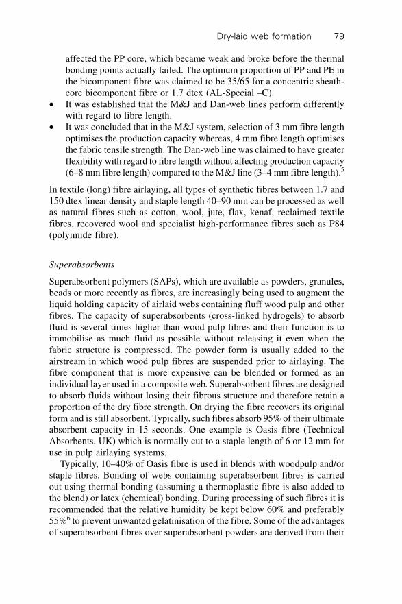
Dry-laid web formation 79
affected the PP core, which became weak and broke before the thermalbonding points actually failed. The optimum proportion of PP and PE inthe bicomponent fibre was claimed to be 35/65 for a concentric sheath-core bicomponent fibre or 1.7 dtex (AL-Special –C).
∑ It was established that the M&J and Dan-web lines perform differentlywith regard to fibre length.
∑ It was concluded that in the M&J system, selection of 3 mm fibre lengthoptimises the production capacity whereas, 4 mm fibre length optimisesthe fabric tensile strength. The Dan-web line was claimed to have greaterflexibility with regard to fibre length without affecting production capacity(6–8 mm fibre length) compared to the M&J line (3–4 mm fibre length).5
In textile (long) fibre airlaying, all types of synthetic fibres between 1.7 and150 dtex linear density and staple length 40–90 mm can be processed as wellas natural fibres such as cotton, wool, jute, flax, kenaf, reclaimed textilefibres, recovered wool and specialist high-performance fibres such as P84(polyimide fibre).
Superabsorbents
Superabsorbent polymers (SAPs), which are available as powders, granules,beads or more recently as fibres, are increasingly being used to augment theliquid holding capacity of airlaid webs containing fluff wood pulp and otherfibres. The capacity of superabsorbents (cross-linked hydrogels) to absorbfluid is several times higher than wood pulp fibres and their function is toimmobilise as much fluid as possible without releasing it even when thefabric structure is compressed. The powder form is usually added to theairstream in which wood pulp fibres are suspended prior to airlaying. Thefibre component that is more expensive can be blended or formed as anindividual layer used in a composite web. Superabsorbent fibres are designedto absorb fluids without losing their fibrous structure and therefore retain aproportion of the dry fibre strength. On drying the fibre recovers its originalform and is still absorbent. Typically, such fibres absorb 95% of their ultimateabsorbent capacity in 15 seconds. One example is Oasis fibre (TechnicalAbsorbents, UK) which is normally cut to a staple length of 6 or 12 mm foruse in pulp airlaying systems.
Typically, 10–40% of Oasis fibre is used in blends with woodpulp and/orstaple fibres. Bonding of webs containing superabsorbent fibres is carriedout using thermal bonding (assuming a thermoplastic fibre is also added tothe blend) or latex (chemical) bonding. During processing of such fibres it isrecommended that the relative humidity be kept below 60% and preferably55%6 to prevent unwanted gelatinisation of the fibre. Some of the advantagesof superabsorbent fibres over superabsorbent powders are derived from their
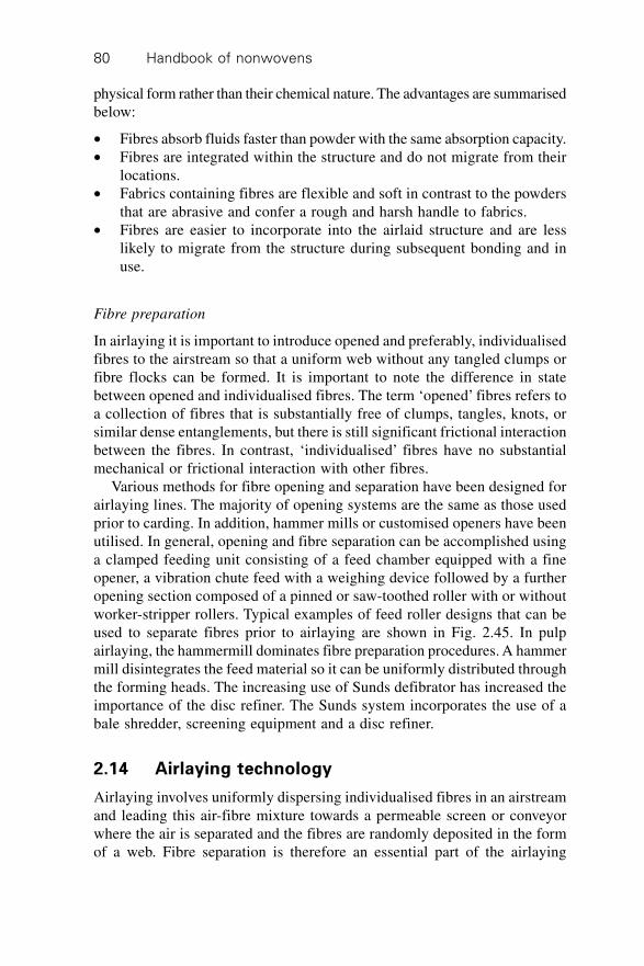
Handbook of nonwovens80
physical form rather than their chemical nature. The advantages are summarisedbelow:
∑ Fibres absorb fluids faster than powder with the same absorption capacity.∑ Fibres are integrated within the structure and do not migrate from their
locations.∑ Fabrics containing fibres are flexible and soft in contrast to the powders
that are abrasive and confer a rough and harsh handle to fabrics.∑ Fibres are easier to incorporate into the airlaid structure and are less
likely to migrate from the structure during subsequent bonding and inuse.
Fibre preparation
In airlaying it is important to introduce opened and preferably, individualisedfibres to the airstream so that a uniform web without any tangled clumps orfibre flocks can be formed. It is important to note the difference in statebetween opened and individualised fibres. The term ‘opened’ fibres refers toa collection of fibres that is substantially free of clumps, tangles, knots, orsimilar dense entanglements, but there is still significant frictional interactionbetween the fibres. In contrast, ‘individualised’ fibres have no substantialmechanical or frictional interaction with other fibres.
Various methods for fibre opening and separation have been designed forairlaying lines. The majority of opening systems are the same as those usedprior to carding. In addition, hammer mills or customised openers have beenutilised. In general, opening and fibre separation can be accomplished usinga clamped feeding unit consisting of a feed chamber equipped with a fineopener, a vibration chute feed with a weighing device followed by a furtheropening section composed of a pinned or saw-toothed roller with or withoutworker-stripper rollers. Typical examples of feed roller designs that can beused to separate fibres prior to airlaying are shown in Fig. 2.45. In pulpairlaying, the hammermill dominates fibre preparation procedures. A hammermill disintegrates the feed material so it can be uniformly distributed throughthe forming heads. The increasing use of Sunds defibrator has increased theimportance of the disc refiner. The Sunds system incorporates the use of abale shredder, screening equipment and a disc refiner.
2.14 Airlaying technology
Airlaying involves uniformly dispersing individualised fibres in an airstreamand leading this air-fibre mixture towards a permeable screen or conveyorwhere the air is separated and the fibres are randomly deposited in the formof a web. Fibre separation is therefore an essential part of the airlaying
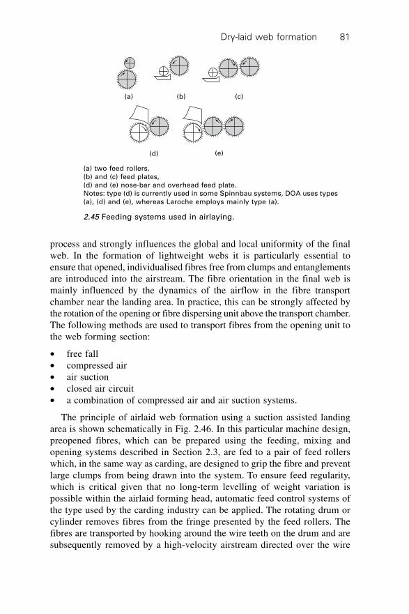
Dry-laid web formation 81
process and strongly influences the global and local uniformity of the finalweb. In the formation of lightweight webs it is particularly essential toensure that opened, individualised fibres free from clumps and entanglementsare introduced into the airstream. The fibre orientation in the final web ismainly influenced by the dynamics of the airflow in the fibre transportchamber near the landing area. In practice, this can be strongly affected bythe rotation of the opening or fibre dispersing unit above the transport chamber.The following methods are used to transport fibres from the opening unit tothe web forming section:
∑ free fall∑ compressed air∑ air suction∑ closed air circuit∑ a combination of compressed air and air suction systems.
The principle of airlaid web formation using a suction assisted landingarea is shown schematically in Fig. 2.46. In this particular machine design,preopened fibres, which can be prepared using the feeding, mixing andopening systems described in Section 2.3, are fed to a pair of feed rollerswhich, in the same way as carding, are designed to grip the fibre and preventlarge clumps from being drawn into the system. To ensure feed regularity,which is critical given that no long-term levelling of weight variation ispossible within the airlaid forming head, automatic feed control systems ofthe type used by the carding industry can be applied. The rotating drum orcylinder removes fibres from the fringe presented by the feed rollers. Thefibres are transported by hooking around the wire teeth on the drum and aresubsequently removed by a high-velocity airstream directed over the wire
(a) (b) (c)
(d) (e)
(a) two feed rollers,(b) and (c) feed plates,(d) and (e) nose-bar and overhead feed plate.Notes: type (d) is currently used in some Spinnbau systems, DOA uses types(a), (d) and (e), whereas Laroche employs mainly type (a).
2.45 Feeding systems used in airlaying.
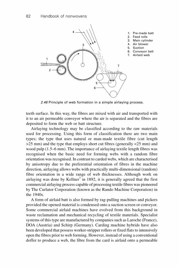
Handbook of nonwovens82
4
3
1
2
7
6
5
1. Pre-made batt2. Feed rolls3. Main cylinder4. Air blower5. Suction6. Conveyor belt7. Airlaid web
teeth surface. In this way, the fibres are mixed with air and transported withit to an air permeable conveyor where the air is separated and the fibres aredeposited to form the web or batt structure.
Airlaying technology may be classified according to the raw materialsused for processing. Using this form of classification there are two maintypes; the type that uses natural or man-made textile fibre (cut length>25 mm) and the type that employs short cut fibres (generally <25 mm) andwood pulp (1.5–6 mm). The importance of airlaying textile length fibres wasrecognised when the basic need for forming webs with a random fibreorientation was recognised. In contrast to carded webs, which are characterisedby anisotropy due to the preferential orientation of fibres in the machinedirection, airlaying allows webs with practically multi-dimensional (random)fibre orientation in a wide range of web thicknesses. Although work onairlaying was done by Kellner7 in 1892, it is generally agreed that the firstcommercial airlaying process capable of processing textile fibres was pioneeredby The Curlator Corporation (known as the Rando Machine Corporation) inthe 1940s.
A form of airlaid batt is also formed by rag-pulling machines and pickersprovided the opened material is condensed onto a suction screen or conveyor.Some commercial airlaid machines have evolved from this background inwaste reclamation and mechanical recycling of textile materials. Specialistsystems of this type are manufactured by companies such as Laroche (France),DOA (Austria) and Schirp (Germany). Carding machine hybrids have alsobeen developed that possess worker-stripper rollers or fixed flats to intensivelyopen the fibres prior to web forming. However, instead of using a conventionaldoffer to produce a web, the fibre from the card is airlaid onto a permeable
2.46 Principle of web formation in a simple airlaying process.
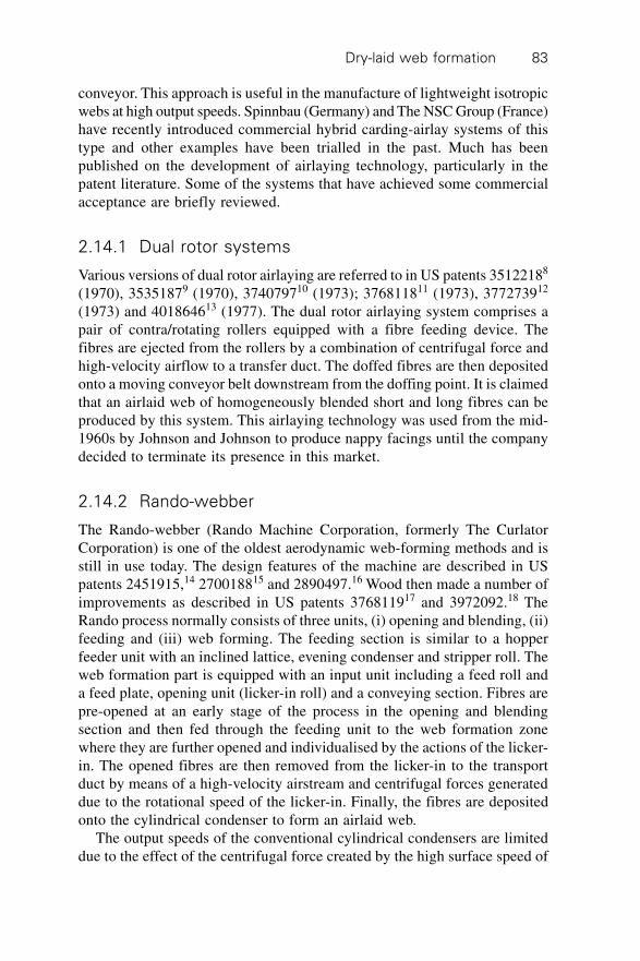
Dry-laid web formation 83
conveyor. This approach is useful in the manufacture of lightweight isotropicwebs at high output speeds. Spinnbau (Germany) and The NSC Group (France)have recently introduced commercial hybrid carding-airlay systems of thistype and other examples have been trialled in the past. Much has beenpublished on the development of airlaying technology, particularly in thepatent literature. Some of the systems that have achieved some commercialacceptance are briefly reviewed.
2.14.1 Dual rotor systems
Various versions of dual rotor airlaying are referred to in US patents 35122188
(1970), 35351879 (1970), 374079710 (1973); 376811811 (1973), 377273912
(1973) and 401864613 (1977). The dual rotor airlaying system comprises apair of contra/rotating rollers equipped with a fibre feeding device. Thefibres are ejected from the rollers by a combination of centrifugal force andhigh-velocity airflow to a transfer duct. The doffed fibres are then depositedonto a moving conveyor belt downstream from the doffing point. It is claimedthat an airlaid web of homogeneously blended short and long fibres can beproduced by this system. This airlaying technology was used from the mid-1960s by Johnson and Johnson to produce nappy facings until the companydecided to terminate its presence in this market.
2.14.2 Rando-webber
The Rando-webber (Rando Machine Corporation, formerly The CurlatorCorporation) is one of the oldest aerodynamic web-forming methods and isstill in use today. The design features of the machine are described in USpatents 2451915,14 270018815 and 2890497.16 Wood then made a number ofimprovements as described in US patents 376811917 and 3972092.18 TheRando process normally consists of three units, (i) opening and blending, (ii)feeding and (iii) web forming. The feeding section is similar to a hopperfeeder unit with an inclined lattice, evening condenser and stripper roll. Theweb formation part is equipped with an input unit including a feed roll anda feed plate, opening unit (licker-in roll) and a conveying section. Fibres arepre-opened at an early stage of the process in the opening and blendingsection and then fed through the feeding unit to the web formation zonewhere they are further opened and individualised by the actions of the licker-in. The opened fibres are then removed from the licker-in to the transportduct by means of a high-velocity airstream and centrifugal forces generateddue to the rotational speed of the licker-in. Finally, the fibres are depositedonto the cylindrical condenser to form an airlaid web.
The output speeds of the conventional cylindrical condensers are limiteddue to the effect of the centrifugal force created by the high surface speed of
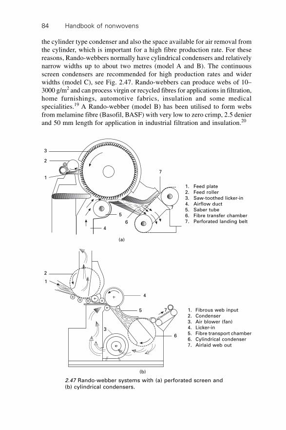
Handbook of nonwovens84
the cylinder type condenser and also the space available for air removal fromthe cylinder, which is important for a high fibre production rate. For thesereasons, Rando-webbers normally have cylindrical condensers and relativelynarrow widths up to about two metres (model A and B). The continuousscreen condensers are recommended for high production rates and widerwidths (model C), see Fig. 2.47. Rando-webbers can produce webs of 10–3000 g/m2 and can process virgin or recycled fibres for applications in filtration,home furnishings, automotive fabrics, insulation and some medicalspecialities.19 A Rando-webber (model B) has been utilised to form websfrom melamine fibre (Basofil, BASF) with very low to zero crimp, 2.5 denierand 50 mm length for application in industrial filtration and insulation.20
2.47 Rando-webber systems with (a) perforated screen and(b) cylindrical condensers.
1. Feed plate2. Feed roller3. Saw-toothed licker-in4. Airflow duct5. Saber tube6. Fibre transfer chamber7. Perforated landing belt
4
3
1
2
7
6
5
7
(a)
1. Fibrous web input2. Condenser3. Air blower (fan)4. Licker-in5. Fibre transport chamber6. Cylindrical condenser7. Airlaid web out
4
3
1
2
6
5 7
(b)
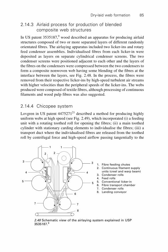
Dry-laid web formation 85
2.14.3 Airlaid process for production of blended
composite web structures
In US patent 3535187,9 wood described an apparatus for producing airlaidstructures composed of two or more separated layers of different randomlyorientated fibres. The airlaying apparatus included two licker-ins and rotaryfeed condenser assemblies. Individualised fibres from each licker-in weredeposited as layers on separate cylindrical condenser screens. The twocondenser screens were positioned adjacent to each other and the layers ofthe fibres on the condensers were compressed between the two condensers toform a composite nonwoven web having some blending of the fibres at theinterface between the layers, see Fig. 2.48. In the process, the fibres wereremoved from their respective licker-ins by high-speed turbulent air streamswith higher velocities than the peripheral speeds of the licker-ins. The websproduced were composed of textile fibres, although processing of continuousfilaments and wood pulp fibres was also suggested.
2.14.4 Chicopee system
Lovgren in US patent 447527121 described a method for producing highlyuniform webs at high speed (see Fig. 2.49), which incorporated (i) a feedingunit with a rotating toothed roll for opening the fibres; (ii) a main toothedcylinder with stationary carding elements to individualise the fibres; (iii) atransport duct where the individualised fibres are released from the toothedroll by centrifugal force and high-speed airflow passing tangentially to the
1. Fibre feeding chutes2. Continuous filament supply
units (creel and warp beam)3. Condenser rolls4. Feed rolls5. Conventional licker-in6. Fibre transport chamber7. Condenser rolls8. Landing conveyor
4
3
1
2
6
5
7
1
2
3
7
4
5
8
2.48 Schematic view of the airlaying system explained in USP3535187.9
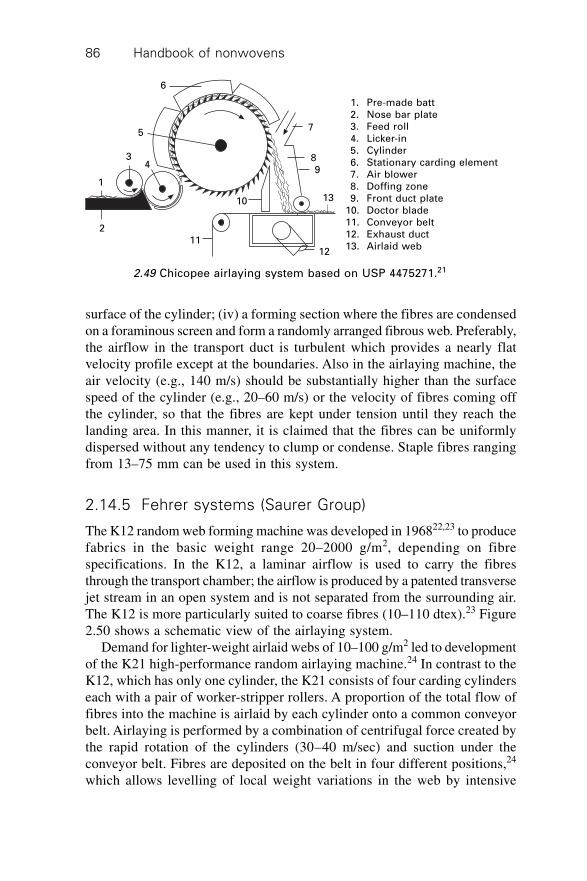
Handbook of nonwovens86
surface of the cylinder; (iv) a forming section where the fibres are condensedon a foraminous screen and form a randomly arranged fibrous web. Preferably,the airflow in the transport duct is turbulent which provides a nearly flatvelocity profile except at the boundaries. Also in the airlaying machine, theair velocity (e.g., 140 m/s) should be substantially higher than the surfacespeed of the cylinder (e.g., 20–60 m/s) or the velocity of fibres coming offthe cylinder, so that the fibres are kept under tension until they reach thelanding area. In this manner, it is claimed that the fibres can be uniformlydispersed without any tendency to clump or condense. Staple fibres rangingfrom 13–75 mm can be used in this system.
2.14.5 Fehrer systems (Saurer Group)
The K12 random web forming machine was developed in 196822,23 to producefabrics in the basic weight range 20–2000 g/m2, depending on fibrespecifications. In the K12, a laminar airflow is used to carry the fibresthrough the transport chamber; the airflow is produced by a patented transversejet stream in an open system and is not separated from the surrounding air.The K12 is more particularly suited to coarse fibres (10–110 dtex).23 Figure2.50 shows a schematic view of the airlaying system.
Demand for lighter-weight airlaid webs of 10–100 g/m2 led to developmentof the K21 high-performance random airlaying machine.24 In contrast to theK12, which has only one cylinder, the K21 consists of four carding cylinderseach with a pair of worker-stripper rollers. A proportion of the total flow offibres into the machine is airlaid by each cylinder onto a common conveyorbelt. Airlaying is performed by a combination of centrifugal force created bythe rapid rotation of the cylinders (30–40 m/sec) and suction under theconveyor belt. Fibres are deposited on the belt in four different positions,24
which allows levelling of local weight variations in the web by intensive
7
84
1211
3
9
6
1310
5
2
1
1. Pre-made batt2. Nose bar plate3. Feed roll4. Licker-in5. Cylinder6. Stationary carding element7. Air blower8. Doffing zone9. Front duct plate
10. Doctor blade11. Conveyor belt12. Exhaust duct13. Airlaid web
2.49 Chicopee airlaying system based on USP 4475271.21
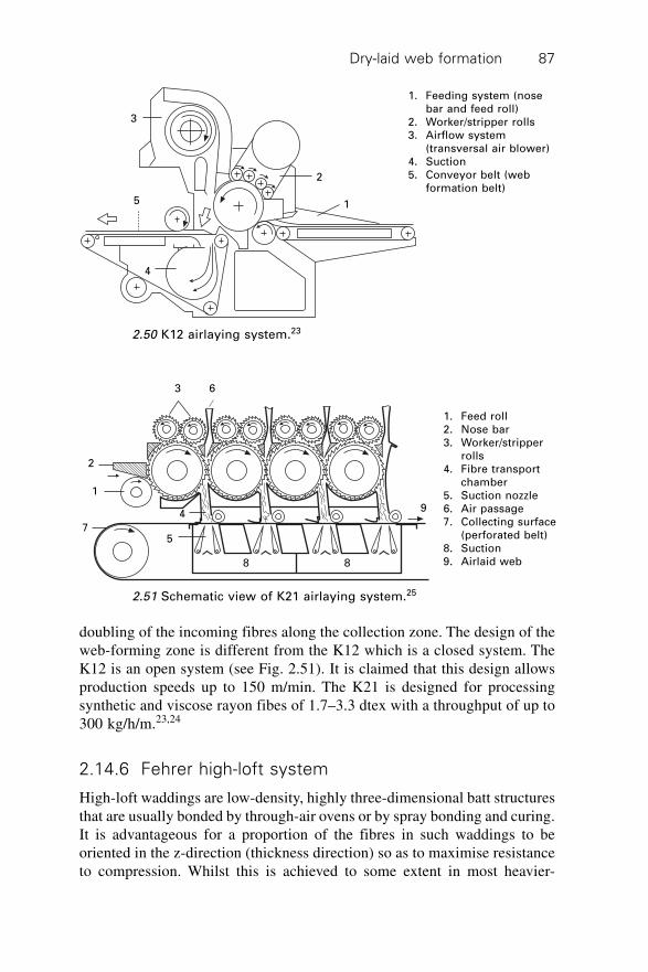
Dry-laid web formation 87
doubling of the incoming fibres along the collection zone. The design of theweb-forming zone is different from the K12 which is a closed system. TheK12 is an open system (see Fig. 2.51). It is claimed that this design allowsproduction speeds up to 150 m/min. The K21 is designed for processingsynthetic and viscose rayon fibes of 1.7–3.3 dtex with a throughput of up to300 kg/h/m.23,24
2.14.6 Fehrer high-loft system
High-loft waddings are low-density, highly three-dimensional batt structuresthat are usually bonded by through-air ovens or by spray bonding and curing.It is advantageous for a proportion of the fibres in such waddings to beoriented in the z-direction (thickness direction) so as to maximise resistanceto compression. Whilst this is achieved to some extent in most heavier-
3
2
15
4
1. Feeding system (nosebar and feed roll)
2. Worker/stripper rolls3. Airflow system
(transversal air blower)4. Suction5. Conveyor belt (web
formation belt)
2.50 K12 airlaying system.23
1. Feed roll2. Nose bar3. Worker/stripper
rolls4. Fibre transport
chamber5. Suction nozzle6. Air passage7. Collecting surface
(perforated belt)8. Suction9. Airlaid web
63
2
1
4
75
9
8 8
2.51 Schematic view of K21 airlaying system.25
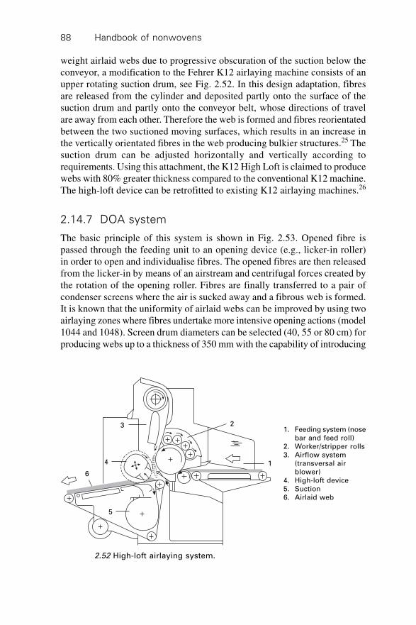
Handbook of nonwovens88
weight airlaid webs due to progressive obscuration of the suction below theconveyor, a modification to the Fehrer K12 airlaying machine consists of anupper rotating suction drum, see Fig. 2.52. In this design adaptation, fibresare released from the cylinder and deposited partly onto the surface of thesuction drum and partly onto the conveyor belt, whose directions of travelare away from each other. Therefore the web is formed and fibres reorientatedbetween the two suctioned moving surfaces, which results in an increase inthe vertically orientated fibres in the web producing bulkier structures.25 Thesuction drum can be adjusted horizontally and vertically according torequirements. Using this attachment, the K12 High Loft is claimed to producewebs with 80% greater thickness compared to the conventional K12 machine.The high-loft device can be retrofitted to existing K12 airlaying machines.26
2.14.7 DOA system
The basic principle of this system is shown in Fig. 2.53. Opened fibre ispassed through the feeding unit to an opening device (e.g., licker-in roller)in order to open and individualise fibres. The opened fibres are then releasedfrom the licker-in by means of an airstream and centrifugal forces created bythe rotation of the opening roller. Fibres are finally transferred to a pair ofcondenser screens where the air is sucked away and a fibrous web is formed.It is known that the uniformity of airlaid webs can be improved by using twoairlaying zones where fibres undertake more intensive opening actions (model1044 and 1048). Screen drum diameters can be selected (40, 55 or 80 cm) forproducing webs up to a thickness of 350 mm with the capability of introducing
1. Feeding system (nosebar and feed roll)
2. Worker/stripper rolls3. Airflow system
(transversal airblower)
4. High-loft device5. Suction6. Airlaid web
6
3 2
1
5
4
2.52 High-loft airlaying system.
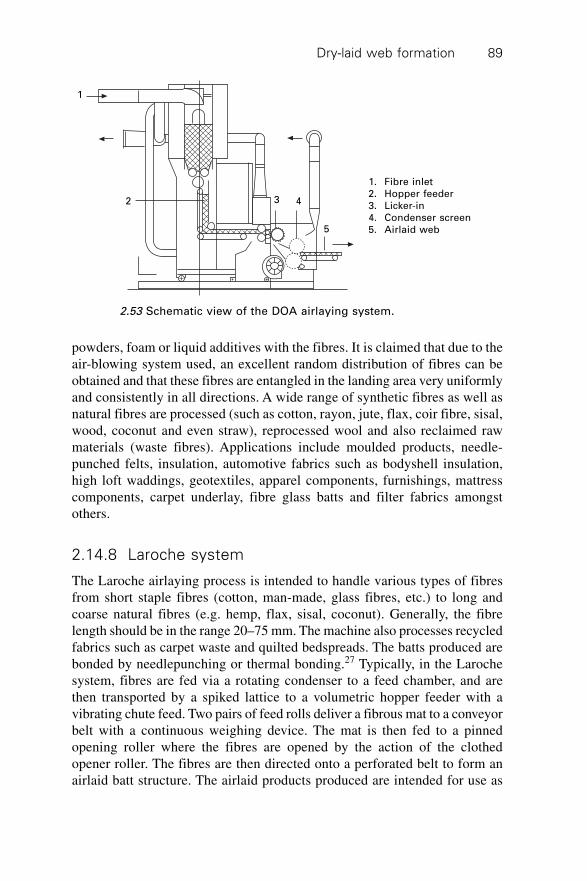
Dry-laid web formation 89
powders, foam or liquid additives with the fibres. It is claimed that due to theair-blowing system used, an excellent random distribution of fibres can beobtained and that these fibres are entangled in the landing area very uniformlyand consistently in all directions. A wide range of synthetic fibres as well asnatural fibres are processed (such as cotton, rayon, jute, flax, coir fibre, sisal,wood, coconut and even straw), reprocessed wool and also reclaimed rawmaterials (waste fibres). Applications include moulded products, needle-punched felts, insulation, automotive fabrics such as bodyshell insulation,high loft waddings, geotextiles, apparel components, furnishings, mattresscomponents, carpet underlay, fibre glass batts and filter fabrics amongstothers.
2.14.8 Laroche system
The Laroche airlaying process is intended to handle various types of fibresfrom short staple fibres (cotton, man-made, glass fibres, etc.) to long andcoarse natural fibres (e.g. hemp, flax, sisal, coconut). Generally, the fibrelength should be in the range 20–75 mm. The machine also processes recycledfabrics such as carpet waste and quilted bedspreads. The batts produced arebonded by needlepunching or thermal bonding.27 Typically, in the Larochesystem, fibres are fed via a rotating condenser to a feed chamber, and arethen transported by a spiked lattice to a volumetric hopper feeder with avibrating chute feed. Two pairs of feed rolls deliver a fibrous mat to a conveyorbelt with a continuous weighing device. The mat is then fed to a pinnedopening roller where the fibres are opened by the action of the clothedopener roller. The fibres are then directed onto a perforated belt to form anairlaid batt structure. The airlaid products produced are intended for use as
1
2 3 4
5
1. Fibre inlet2. Hopper feeder3. Licker-in4. Condenser screen5. Airlaid web
2.53 Schematic view of the DOA airlaying system.
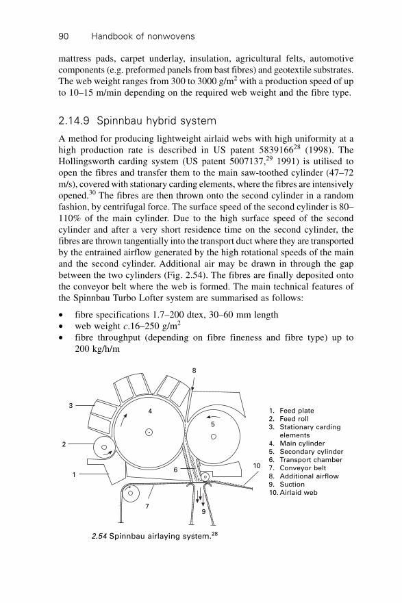
Handbook of nonwovens90
mattress pads, carpet underlay, insulation, agricultural felts, automotivecomponents (e.g. preformed panels from bast fibres) and geotextile substrates.The web weight ranges from 300 to 3000 g/m2 with a production speed of upto 10–15 m/min depending on the required web weight and the fibre type.
2.14.9 Spinnbau hybrid system
A method for producing lightweight airlaid webs with high uniformity at ahigh production rate is described in US patent 583916628 (1998). TheHollingsworth carding system (US patent 5007137,29 1991) is utilised toopen the fibres and transfer them to the main saw-toothed cylinder (47–72m/s), covered with stationary carding elements, where the fibres are intensivelyopened.30 The fibres are then thrown onto the second cylinder in a randomfashion, by centrifugal force. The surface speed of the second cylinder is 80–110% of the main cylinder. Due to the high surface speed of the secondcylinder and after a very short residence time on the second cylinder, thefibres are thrown tangentially into the transport duct where they are transportedby the entrained airflow generated by the high rotational speeds of the mainand the second cylinder. Additional air may be drawn in through the gapbetween the two cylinders (Fig. 2.54). The fibres are finally deposited ontothe conveyor belt where the web is formed. The main technical features ofthe Spinnbau Turbo Lofter system are summarised as follows:
∑ fibre specifications 1.7–200 dtex, 30–60 mm length∑ web weight c.16–250 g/m2
∑ fibre throughput (depending on fibre fineness and fibre type) up to200 kg/h/m
1. Feed plate2. Feed roll3. Stationary carding
elements4. Main cylinder5. Secondary cylinder6. Transport chamber7. Conveyor belt8. Additional airflow9. Suction10. Airlaid web
3
2
1
4
8
5
6
79
10
2.54 Spinnbau airlaying system.28
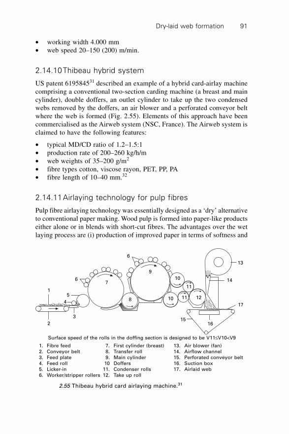
Dry-laid web formation 91
∑ working width 4.000 mm∑ web speed 20–150 (200) m/min.
2.14.10Thibeau hybrid system
US patent 619584531 described an example of a hybrid card-airlay machinecomprising a conventional two-section carding machine (a breast and maincylinder), double doffers, an outlet cylinder to take up the two condensedwebs removed by the doffers, an air blower and a perforated conveyor beltwhere the web is formed (Fig. 2.55). Elements of this approach have beencommercialised as the Airweb system (NSC, France). The Airweb system isclaimed to have the following features:
∑ typical MD/CD ratio of 1.2–1.5:1∑ production rate of 200–260 kg/h/m∑ web weights of 35–200 g/m2
∑ fibre types cotton, viscose rayon, PET, PP, PA∑ fibre length of 10–40 mm.32
2.14.11Airlaying technology for pulp fibres
Pulp fibre airlaying technology was essentially designed as a ‘dry’ alternativeto conventional paper making. Wood pulp is formed into paper-like productseither alone or in blends with short-cut fibres. The advantages over the wetlaying process are (i) production of improved paper in terms of softness and
2.55 Thibeau hybrid card airlaying machine.31
1
2
5
4
3
67
6
9
10
11
10 11 12
14
13
17
1615
Surface speed of the rolls in the doffing section is designed to be V11£V10<V9
1. Fibre feed 7. First cylinder (breast) 13. Air blower (fan)2. Conveyor belt 8. Transfer roll 14. Airflow channel3. Feed plate 9. Main cylinder 15. Perforated conveyor belt4. Feed roll 10 Doffers 16. Suction box5. Licker-in 11. Condenser rolls 17. Airlaid web6. Worker/stripper rollers 12. Take up roll
8
Handbook of nonwovens92
bulk and (ii) lower capital investment and low environmental impact. Theearly developments in pulp airlay technology were mainly concerned withpaper products rather than textile or nonwoven fabrics. Since the focus wason web formation from cellulose pulp derived from trees, the fibre lengthsused varied from about 3–20 mm. The highest production speeds were achievedwith the shortest fibres and long fibres required utilisation of a higher airvolume because a lower concentration of fibre in air helps to minimise fibreentanglement during the process.
At an early stage, this type of airlaying technology was limited by outputspeed, web uniformity and web weight limitations. Due to the uniformityproblems, it was not practical to make isotropic webs lighter than 30 g/m2.The main manufacturers of pulp airlaying machinery are M&J Fibretech(Saurer Group), Dan-Webforming International (both of Denmark) and Honshu,in Japan. Historically, in the late 1950s Hejtl (a Finnish engineer) issued apatent on dry-forming webs from cellulose pulp. He started joint work withDanish inventor Karl Kroyer and developed a process called the CombinedFiber Distributor. Before 1980, Kroyer’s systems were sold to the AmericanCan Company and the Fort Howard Paper Co. The American Can Co. wasbought by James River Corporation. Later the James River and Ford Howardpaper makers were merged together into one business called Fort James, oneof the biggest airlaid suppliers of its time. In 2000, Fort James Corp. wasacquired by Georgia-Pacific. Moller & Jochumsen Paper Division’s (M&J)connection with Kroyer began in October 1981.
In late 1986, M&J entered into an agreement with Kroyer whereby M&Jwould market, license and sell airlaid plants based on the Kroyer patents.Under the agreement M&J would use Kroyer’s patent rights, both existingand future, within the field of dry forming and wet forming.28 Since the firstpatent, Kroyer has described several different apparatuses to modify andimprove airlaying technology. Some of these are detailed in USP 3581706,33
1971, USP 4014635,34 1977, USP 4144619,35 1979, USP 4494278,36 1985,USP 5471712,37 1995. In 1975 John Mosgaard left Kroyer and set up abusiness based on drum former airlaying technology (Scan-Web, renamedDan-Web in 1981). The basic difference between the Dan-Web and Kroyerprocess is the means by which fibres are distributed before deposition ontothe perforated screen to form a web. Kroyer’s process uses agitators todistribute fibres, while Dan-Web uses two rotating drum formers with brushrolls inside each drum. Independently, Honshu Paper (now part of Oji Paper)developed and commercialised a third process (USP 3781150, 1973)38 thatwas kept for internal use, apart from licensing to Johnson & Johnson. In thissystem pulp is first broken and then defibrillated in a rotator inside a stationarycylindrical screen. The fibres pass through the screen and a vacuum pullsthem onto a moving wire where the web is made. The web is then spraybonded.
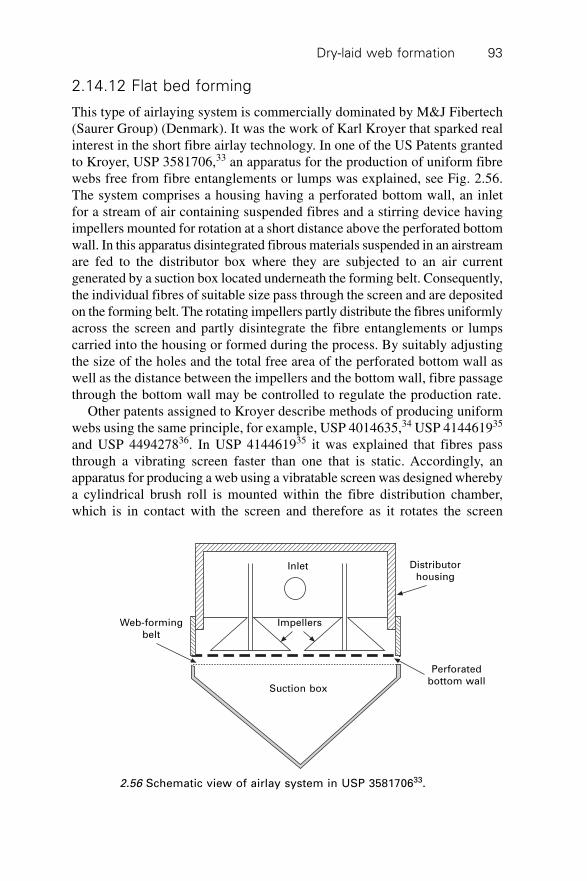
Dry-laid web formation 93
2.14.12 Flat bed forming
This type of airlaying system is commercially dominated by M&J Fibertech(Saurer Group) (Denmark). It was the work of Karl Kroyer that sparked realinterest in the short fibre airlay technology. In one of the US Patents grantedto Kroyer, USP 3581706,33 an apparatus for the production of uniform fibrewebs free from fibre entanglements or lumps was explained, see Fig. 2.56.The system comprises a housing having a perforated bottom wall, an inletfor a stream of air containing suspended fibres and a stirring device havingimpellers mounted for rotation at a short distance above the perforated bottomwall. In this apparatus disintegrated fibrous materials suspended in an airstreamare fed to the distributor box where they are subjected to an air currentgenerated by a suction box located underneath the forming belt. Consequently,the individual fibres of suitable size pass through the screen and are depositedon the forming belt. The rotating impellers partly distribute the fibres uniformlyacross the screen and partly disintegrate the fibre entanglements or lumpscarried into the housing or formed during the process. By suitably adjustingthe size of the holes and the total free area of the perforated bottom wall aswell as the distance between the impellers and the bottom wall, fibre passagethrough the bottom wall may be controlled to regulate the production rate.
Other patents assigned to Kroyer describe methods of producing uniformwebs using the same principle, for example, USP 4014635,34 USP 414461935
and USP 449427836. In USP 414461935 it was explained that fibres passthrough a vibrating screen faster than one that is static. Accordingly, anapparatus for producing a web using a vibratable screen was designed wherebya cylindrical brush roll is mounted within the fibre distribution chamber,which is in contact with the screen and therefore as it rotates the screen
Web-formingbelt
Distributorhousing
Perforatedbottom wall
Suction box
Impellers
Inlet
2.56 Schematic view of airlay system in USP 358170633.
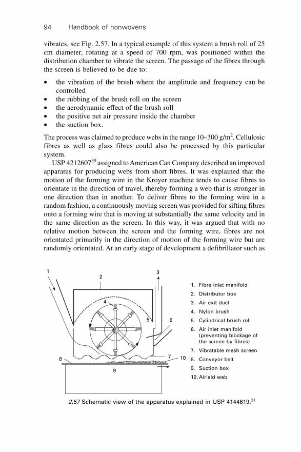
Handbook of nonwovens94
vibrates, see Fig. 2.57. In a typical example of this system a brush roll of 25cm diameter, rotating at a speed of 700 rpm, was positioned within thedistribution chamber to vibrate the screen. The passage of the fibres throughthe screen is believed to be due to:
∑ the vibration of the brush where the amplitude and frequency can becontrolled
∑ the rubbing of the brush roll on the screen∑ the aerodynamic effect of the brush roll∑ the positive net air pressure inside the chamber∑ the suction box.
The process was claimed to produce webs in the range 10–300 g/m2. Cellulosicfibres as well as glass fibres could also be processed by this particularsystem.
USP 421260739 assigned to American Can Company described an improvedapparatus for producing webs from short fibres. It was explained that themotion of the forming wire in the Kroyer machine tends to cause fibres toorientate in the direction of travel, thereby forming a web that is stronger inone direction than in another. To deliver fibres to the forming wire in arandom fashion, a continuously moving screen was provided for sifting fibresonto a forming wire that is moving at substantially the same velocity and inthe same direction as the screen. In this way, it was argued that with norelative motion between the screen and the forming wire, fibres are notorientated primarily in the direction of motion of the forming wire but arerandomly orientated. At an early stage of development a defibrillator such as
12
3
4
5 6
78 10
9
1. Fibre inlet manifold
2. Distributor box
3. Air exit duct
4. Nylon brush
5. Cylindrical brush roll
6. Air inlet manifold(preventing blockage ofthe screen by fibres)
7. Vibratable mesh screen
8. Conveyor belt
9. Suction box
10. Airlaid web
2.57 Schematic view of the apparatus explained in USP 4144619.31
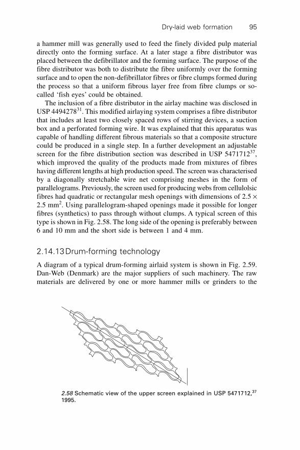
Dry-laid web formation 95
a hammer mill was generally used to feed the finely divided pulp materialdirectly onto the forming surface. At a later stage a fibre distributor wasplaced between the defibrillator and the forming surface. The purpose of thefibre distributor was both to distribute the fibre uniformly over the formingsurface and to open the non-defibrillator fibres or fibre clumps formed duringthe process so that a uniform fibrous layer free from fibre clumps or so-called ‘fish eyes’ could be obtained.
The inclusion of a fibre distributor in the airlay machine was disclosed inUSP 449427831. This modified airlaying system comprises a fibre distributorthat includes at least two closely spaced rows of stirring devices, a suctionbox and a perforated forming wire. It was explained that this apparatus wascapable of handling different fibrous materials so that a composite structurecould be produced in a single step. In a further development an adjustablescreen for the fibre distribution section was described in USP 547171237,which improved the quality of the products made from mixtures of fibreshaving different lengths at high production speed. The screen was characterisedby a diagonally stretchable wire net comprising meshes in the form ofparallelograms. Previously, the screen used for producing webs from cellulolsicfibres had quadratic or rectangular mesh openings with dimensions of 2.5 ¥2.5 mm2. Using parallelogram-shaped openings made it possible for longerfibres (synthetics) to pass through without clumps. A typical screen of thistype is shown in Fig. 2.58. The long side of the opening is preferably between6 and 10 mm and the short side is between 1 and 4 mm.
2.14.13Drum-forming technology
A diagram of a typical drum-forming airlaid system is shown in Fig. 2.59.Dan-Web (Denmark) are the major suppliers of such machinery. The rawmaterials are delivered by one or more hammer mills or grinders to the
2.58 Schematic view of the upper screen explained in USP 5471712,37
1995.
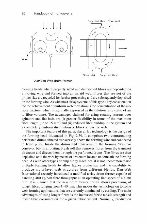
Handbook of nonwovens96
forming heads where properly sized and distributed fibres are deposited ona moving wire and formed into an airlaid web. Fibres that are not of theproper size are recycled for further processing and are subsequently depositedon the forming wire. As with most airlay systems of this type a key considerationfor the achievement of uniform web formation is the concentration of the air-fibre mixture, which is normally expressed as the dilution ratio (ratio of airto fibre volume). The advantages claimed for using rotating screens overagitators and flat beds are (i) greater flexibility in terms of the maximumfibre length (up to 15 mm) and (ii) reduced fibre buildup in the system anda completely uniform distribution of fibres across the web.
The important feature of this particular airlay technology is the design ofthe forming head illustrated in Fig. 2.59. It comprises two contrarotatingperforated drums situated transversely above the forming wire and connectedto fixed pipes. Inside the drums and transverse to the forming ‘wire’ orconveyor belt is a rotating brush roll that removes fibres from the transportairstream and directs them through the perforated drums. The fibres are thendeposited onto the wire by means of a vacuum located underneath the forminghead. As with other types of pulp airlay machines, it is not uncommon to usemultiple forming heads to allow higher production and the capability toproduce multi-layer web structures from different blends. Dan-WebInternational recently introduced a modified airlay drum former capable ofhandling 400 kg/h/m fibre throughput at an operating line speed of 400 m/min. It is claimed that the new drum former design allows processing oflonger fibres ranging from 4–40 mm. This moves the technology on to someweb-forming applications that are currently dominated by carding. The mainadvantages of using longer fibres is the increased fabric tensile strength andlower fibre consumption for a given fabric weight. Normally, production
Wire
Recycled fibre Fibre inlet
Fibre inlet Recycled fibre
2.59 Dan-Web drum former.
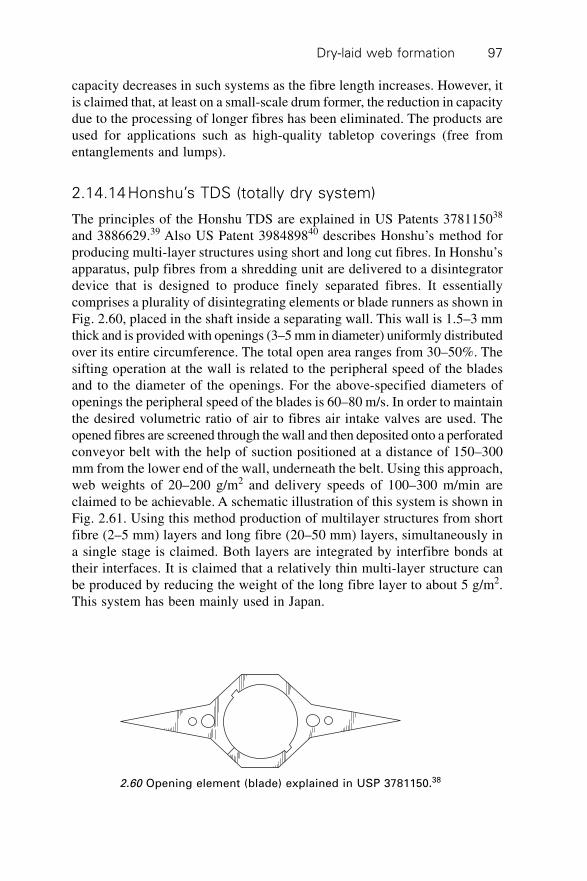
Dry-laid web formation 97
capacity decreases in such systems as the fibre length increases. However, itis claimed that, at least on a small-scale drum former, the reduction in capacitydue to the processing of longer fibres has been eliminated. The products areused for applications such as high-quality tabletop coverings (free fromentanglements and lumps).
2.14.14Honshu’s TDS (totally dry system)
The principles of the Honshu TDS are explained in US Patents 378115038
and 3886629.39 Also US Patent 398489840 describes Honshu’s method forproducing multi-layer structures using short and long cut fibres. In Honshu’sapparatus, pulp fibres from a shredding unit are delivered to a disintegratordevice that is designed to produce finely separated fibres. It essentiallycomprises a plurality of disintegrating elements or blade runners as shown inFig. 2.60, placed in the shaft inside a separating wall. This wall is 1.5–3 mmthick and is provided with openings (3–5 mm in diameter) uniformly distributedover its entire circumference. The total open area ranges from 30–50%. Thesifting operation at the wall is related to the peripheral speed of the bladesand to the diameter of the openings. For the above-specified diameters ofopenings the peripheral speed of the blades is 60–80 m/s. In order to maintainthe desired volumetric ratio of air to fibres air intake valves are used. Theopened fibres are screened through the wall and then deposited onto a perforatedconveyor belt with the help of suction positioned at a distance of 150–300mm from the lower end of the wall, underneath the belt. Using this approach,web weights of 20–200 g/m2 and delivery speeds of 100–300 m/min areclaimed to be achievable. A schematic illustration of this system is shown inFig. 2.61. Using this method production of multilayer structures from shortfibre (2–5 mm) layers and long fibre (20–50 mm) layers, simultaneously ina single stage is claimed. Both layers are integrated by interfibre bonds attheir interfaces. It is claimed that a relatively thin multi-layer structure canbe produced by reducing the weight of the long fibre layer to about 5 g/m2.This system has been mainly used in Japan.
2.60 Opening element (blade) explained in USP 3781150.38
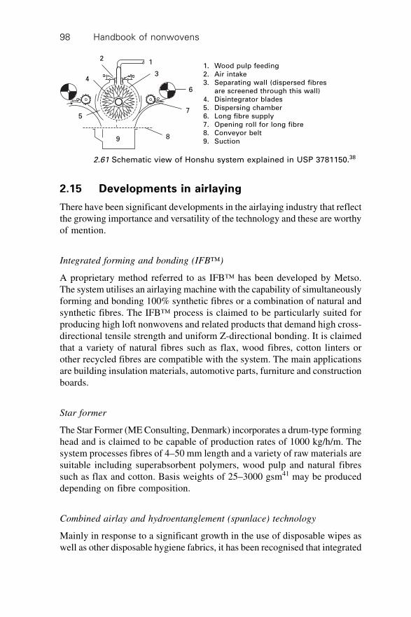
Handbook of nonwovens98
2.15 Developments in airlaying
There have been significant developments in the airlaying industry that reflectthe growing importance and versatility of the technology and these are worthyof mention.
Integrated forming and bonding (IFB™)
A proprietary method referred to as IFB™ has been developed by Metso.The system utilises an airlaying machine with the capability of simultaneouslyforming and bonding 100% synthetic fibres or a combination of natural andsynthetic fibres. The IFB™ process is claimed to be particularly suited forproducing high loft nonwovens and related products that demand high cross-directional tensile strength and uniform Z-directional bonding. It is claimedthat a variety of natural fibres such as flax, wood fibres, cotton linters orother recycled fibres are compatible with the system. The main applicationsare building insulation materials, automotive parts, furniture and constructionboards.
Star former
The Star Former (ME Consulting, Denmark) incorporates a drum-type forminghead and is claimed to be capable of production rates of 1000 kg/h/m. Thesystem processes fibres of 4–50 mm length and a variety of raw materials aresuitable including superabsorbent polymers, wood pulp and natural fibressuch as flax and cotton. Basis weights of 25–3000 gsm41 may be produceddepending on fibre composition.
Combined airlay and hydroentanglement (spunlace) technology
Mainly in response to a significant growth in the use of disposable wipes aswell as other disposable hygiene fabrics, it has been recognised that integrated
2
4
1
3
6
7
89
5
1. Wood pulp feeding2. Air intake3. Separating wall (dispersed fibres
are screened through this wall)4. Disintegrator blades5. Dispersing chamber6. Long fibre supply7. Opening roll for long fibre8. Conveyor belt9. Suction
2.61 Schematic view of Honshu system explained in USP 3781150.38
Dry-laid web formation 99
multi-layer fabrics that combine airlaid webs with other web types couldbring improved product performance, particularly in respect of high liquidabsorption and fabric wet strength. Carded webs and airlaid webs composedof wood pulp produced on the same line are combined and then hydroentangledto produce a multi-layer product.
If required, a similar approach can be used to combine the airlaid webwith those produced by other technologies including spunlaid and meltblown(or a combination of different web types). Two claimed benefits for thisapproach are the capability to replace viscose rayon fibre with wood pulp,which is about one-third cheaper, while still retaining the required physicalproperties of the product and the potential to increase production capacity.
It is claimed that to ensure good bonding and minimal loss of wood pulp,the carded web component must be pre-bonded, for example, by through-airthermal bonding and the pulp layer hydroentangled on a flat-wire sectionwith 8–10 injectors. The composite is integrated by hydroentangling theindividual layers. Even with these precautions, 4–5% of the wood pulp is lostthrough the hydroentanglement machine conveyor and is removed and discardedfrom the water during recycling. The capital investment involved in such aprocess is comparatively high and is less flexible than a carding line. Therefore,in practice an airlaying machine of this type may need to be dedicated to afew similar product types.42,43
Hydroentangled wood pulp fabrics
A 100% hydroentangled wood pulp fabric that can be used in distribution orabsorption layers, or certain industrial applications has been described.44
Multi-layer nappy composites
In the super-site concept the manufacture of disposable nappies is simplifiedby assembling the various layers in the construction using individual airlayforming heads operating over a common conveyor belt. In this way, theacquisition layer, absorbent core and retaining layer can be assembled beforebonding. One advantage is that very thin absorbent layers can be produced.The airlay assembly approach simplifies the conventional production routefor a nappy which normally involves unwinding and laminating multiplepreformed fabrics containing wood pulp, SAP and other components to formthe final composite.
3D web preforms and moulds
A method of airlaid web formation using an intensive fibre opening machinehas been developed which features a large collection area to promote the
Handbook of nonwovens100
formation of a uniform web as well as reduced airflow velocities (see Fig.2.62). This process may be used to form preformed, contoured or profiledwebs, within certain process boundaries.45 Technically, shaped or preformedmoulded webs can be produced directly on many airlaying systems using athree-dimensional, contoured forming surface and appropriate suction. Thebasic approach using a rotary conveyor has been described by Eldim (USA)and is relevant to other fibre or filament deposition processes.
Roller draft airlaying system
Fu-Jiun Lin et al. designed an experimental airlaying system intended toimprove the web weight uniformity and fibre randomisation using mechanicalattenuation and airflow.46 The approach, referred to as ‘roller drafting airlaying’,basically consists of a roller drafting device, a web collection unit, a conveyorand suction box as shown in Fig. 2.63. A sliver is drafted by three pairs ofrollers and converted into loose fibres. The airflow from the suction devicetransports the loose fibres into the suction tube at high speed and transportsthem towards the main chamber where their velocity is immediately reduceddue to the geometry of the chamber. Finally, fibres are collected on theconveyor belt and form a web with random fibre orientations.
2.62 Basic principle of the aerodynamic web formation processexplained by Paschen.45
1
5
2
6
3
4
1. Drafting device
2. Suction tube
3. Suction box
4. Conveyor belt
5. Fibrous web
6. Take up roll
2.63 Schematic diagram of roller drafting system.46
Dry-laid web formation 101
Inverted airlaying systems
The combination of webs from multiple web formation systems has alsobeen demonstrated (Fig. 2.64). Significant work on inverted airlaying hasbeen done by Dan-Web.
2.16 Airflow and fibre dynamics in airlaying
In this section the importance of the airflow and fibre dynamics in thetransport chamber of airlaying machines is discussed. Some manufacturersmake use of turbulent flow in the transport chamber, while others considerturbulent flow to be detrimental to the process and seek to achieve a laminarflow in the transfer chamber. Either way, it is important to understand howthe airflow affects the uniformity and fibre orientation in an airlaid web.Once fibre has been dispersed into the airflow the air-fibre mixture generallypasses through a duct or chamber before the fibres are deposited on theconveyor or screen. The duct or chamber is sometimes referred to as thetransport chamber.
Airlaying of textile fibres
USP 447527121 explains the preference for turbulent airflow in the transportchannel of an airlaying machine. The average airflow velocity is higher thanthe fibre velocity where fibres are under tension during their travel towardsthe landing area. Such turbulent flow, except for the narrow boundary edgesat the sides of the channel, produces a relatively flat velocity profile, whichencourages the formation of a uniform web across the width of the machine.In contrast, laminar flow produces a more curved velocity profile, whichtends to deposit more fibres in the centre of the web than at the sides. Anairlaying system using a straight and laminar airflow profile in the transportchamber is described in WO 9720976.47
The speed of airflow was less than 95% of the disperser roller. It isclaimed that otherwise the airstream tends to blow fibre off the disperser roll,undermining the intended effect of centrifugally doffing the fibre. If the fibreis blown off the roller, it tends to come off in clumps and creates an unstableflow (i.e. more turbulence, larger eddies and vortices). The straightenedairstream passing over the surface of the roller resulted in a smoother, moregentle delivery of fibres from the teeth on the roller to the straightened/laminar airstream. In a study by Pourmohammadi et al.,48 on the fibre trajectoryin the transport channel of a small-scale airlaying system (of the Fehrer K12type), the airflow in the transport channel was estimated to be turbulent witha relatively flat velocity profile across the width of the channel. The fibretrajectory in the transport channel was then theoretically modelled. The
Handbook of nonwovens102
2.64 Combination of airlaid with other web formation methods;(a) airlaid with carded web; (b) airlaid with spunbond/Meltblown;(c) airlaid with wetlaid.
Web weightscanner
Compression roll
Web width adjustment
Airlaidforming
head
Combined web
Preformed-carded web or spunlaced web orfilm, foil or other types of fibrous web
(a)
Web weightscanner Compression
roll
Web widthadjustment
Airlaidforming
head
Spunbond ormeltblown
system
Combined web
Using this technique fibres are blown directly into a spunbond or meltblown fibre stream.(b)
Web weightscanner
Compressionroll
Web widthadjustment
Airlaidforming head
Combinedweb
Wetlaidheadbox
(c)
Suction box Suction box Suction box Suction box
Suction
Suction
Suction
Suction
Dry-laid web formation 103
theoretical results were then compared with the experimental observationsobtained by high-speed photography and reasonable agreements were obtained.This may suggest that the assumption of turbulent airflow is relevant. In thisstudy the effect of machine parameters on the fibre trajectory was alsoreported.48
Airlaying of short fibres and pulp
The airflow dynamics in the transport chamber of an experimental pulpairlaying system have been studied using a Laser Doppler Anemometer.49
The velocity varies along both the length and height of the transport chamberand the velocity variation is markedly affected and increased by rotation ofthe rotors in the fibre dispersing section above the transport chamber. Generally,the velocity increased from the top to the bottom of the transport chamber.In another attempt to improve understanding of the airflow behaviour insuch airlaying systems, Bradean et al. used computational fluid dynamics(CFD) to model the effect of blade rotation on the airflow pattern in theregion between the top grid and the conveyor belt. The results showed thatthe airflow patterns in this region are very dependent on the inlet velocityprofile when the grid size is large and is independent of the geometry belowthe belt when the belt size is small. By decreasing the grid size the flowbetween the grid and the belt becomes more uniform but of course in practice,any decrease in the grid size is limited by the need to ensure fibre penetration.Therefore, depending on the rotational speed of the blades and the grid size,the flow in the region between the grid and the conveyor belt is either steadyand uniformly downwards or unsteady and three-dimensional, in which casethe rotation of the blades is the most important machine parameter affectingthe airflow and fibre dynamics.50
One of the limiting factors in airlaying is the tendency of fibres to entangle.The probability of entanglement increases as the fibre length increases, andthis negatively impacts web uniformity therefore a high dilution factor, i.e.,a low concentration of fibre in air, is needed to prevent fibre entanglement.A basic tool is to apply the fibre stacking theory, first discussed by Wood.51
He assumed that the amount of air required for each fibre to be conveyedwithout being entangled with its neighbour is equal to the volume of a spherehaving a diameter equal to the fibre length. Based on this assumption the
quantity of fluid (air) required to maintain fibre separation (Q) is; Q = K.P.LD
2
where D is the fibre linear density (denier), L is the fibre length (units), P isthe production rate of the machine (units) and K is a constant.
The same principle has been applied in the wet-laying of pulp wherefibre-to-fibre interactions in the liquid suspension are minimised by a lowconcentration of fibre in the flow. The concentration is generally in the range
Handbook of nonwovens104
of 104 fibres per litre. This gives a crowding factor, N, of less than 1.0. Thecrowding factor is defined as the number of fibres in a spherical volume witha diameter equal to the fibre length. A crowding factor value of < 1 signifiesthat fibres should come into only occasional contact.52 Kumar et al.53 discussedthe main parameters influencing the passage of fibres through slots in pulpscreening. The fibre passage efficiency increases with increasing velocitythrough the slot or aperture (due to the suction applied underneath) as wellas the slot width. Fibre passage also increases with an increase in fibreflexibility and a decrease in fibre length.
2.16.1 Fibre dynamics in airlaying
A comprehensive study of the fibre dynamics in the transport chamber of anexperimental Kroyer type airlaying system54 has been conducted using high-speed photography. It was established that fibres move intensively in threedimensions at the top of the transport chamber and as they travel towards thelanding area their motion becomes more steady and uniform. Fibre landingbehaviour was also studied by analysing sequential photographic images becauselanding behaviour has a direct effect on structure and therefore, the physicalproperties of the formed web. This experimental study (which used 5 mmlength, uncrimped viscose fibre) showed that about 38% of fibres landed onend before falling down flat onto the conveyor belt (hit-fall configuration),about 30% landed flat, along their full length (flat landing configuration), andabout 16% were curved in the middle and land on one side (mid curved land).54
A mathematical model has been developed of the fluid and fibre dynamicsin the transport chamber of the same system.55 The airflow was consideredto be turbulent because of the magnitude of the air velocity and the geometryof the machine. The fibres were modelled as ellipsoids and the trajectories ofthe centre of mass of the fibres were obtained. Reasonable agreement wasfound between theoretical predictions and experimental findings.
2.17 Bonding and web consolidation
Different bonding technologies are utilised to consolidate airlaid webs includinglatex or chemical bonding, thermal bonding, multi-bonding and mechanicalbonding (mainly needlepunching and hydroentanglement). The choice ofsystem depends on the final fabric properties required, web weight and fibredimensions (principally fibre length).56,57
2.17.1 Latex bonding airlaying (LBAL)
Latex bonding was one of the first bonding methods used by the airlayingindustry. In 2000 it was reported that despite all the interest in thermal and
Dry-laid web formation 105
combined (multi-) bonding, about 85% of pulp fibre based airlaid productswere still latex bonded. The latex binders used are synthetic copolymersproduced via emulsion polymerisation to form a stable emulsion or latex. Atypical binder solution is sprayed onto the airlaid web, which is then curedin an oven. Latex bonded fabrics have a cloth-like appearance and feel andcan be used in place of conventional tissue and synthetic woven fabrics. Themajor problem in Latex bonding is the ability of the binder to penetrate thickstructures. Since the binder is sprayed onto the surface of a web and istransported into the interior by the water carrier and the applied vacuum, anincrease in web thickness and web weight reduces the ability of the binder toreach the centre of the web. Generally, the lower the glass transition temperature(Tg) the softer is the binder. Currently, the biggest market opportunity forLBAL is in the feminine hygiene absorbent core and wiping sectors.
2.17.2 Thermal bonding airlaying (TBAL)
Thermal bonding involves forming a homogeneous airlaid web of the basefibre (e.g., pulp) and the bonding component (i.e., a bicomponent or homofilthermoplastic fibre or particle), heating the web to the softening temperatureof the fusible bonding element and then cooling the web. As the heated fibresor particles start to melt, they become adhesive in nature and create bondingpoints in the web. The thermal bonding process offers web design flexibility,since the web can be embossed with different patterns during thermal calenderbonding. The utilisation of bicomponent fibres can produce a high-loft webwith excellent bonding in the X, Y and Z directions of the web.57 High loft,thick airlaid fabric structures provide increased void areas within the weband consequently increase the liquid holding capacity. Thermally bondedairlaid products are generally used in absorbent core articles and medicaldisposable products.
This type of bonding is advantageous because it saves energy, there is lessenvironmental pollution and the recycling of webs and fabric is possible.The main limitations of thermally bonded airlaid webs are, first, the dustgenerated during high-speed production, which necessitates frequent linestoppages for cleaning. The second concern is the low or irregular tensilestrength of the final product particularly when low levels of binder fibre areused, therefore the industry is being forced to modify and optimise theprocess to overcome these apparent problems.
2.17.3 Multi-bonding airlaying (MBAL)
The response of the industry to the challenge for products with lower dustlevels (due to wood pulp drop out) and higher strength has been the developmentof multi-bonded airlaid webs. In simple terms, MBAL is a combination of
Handbook of nonwovens106
thermal and latex bonding technology. It produces a finished web that hashigh loft, low density, exceptional fluid penetration, high absorbent capacity,good tensile strength, a soft cloth-like handle and a very low lint or dustlevel.
2.17.4 Mechanical bonding
Needlepunching is one of the oldest methods of bonding nonwoven fabrics.The principle of needling, or needlepunching, consists of mechanicallyinterlocking fibres by repeatedly punching through the fibre batt with anarray of barbed needles. Typically, needling is used to consolidate a fibrousstructure, to densify it and/or control the porosity. High-speed needle loomsare capable of 3000 rpm although for bonding airlaid webs, lower speedlooms are capable of balancing production. Needlepunched airlaid productscan be made from a large variety of textile-length fibres including Basofil®,Miraflex,58 PET, PP, jute, flax and kenaf for applications such as protectiveapparel, filtration, geotextiles, automotive panel components (e.g., car doors)and shoe linings. Hydroentanglement or spunlacing of pulp or short cut fibreairlaid webs has been commercialised under the tradenames of AquaJet59
and Airlace.60 The SBAL process (airlaid-spunlace combination) gives a lowraw material cost product, which it is claimed, can be tailormade to suit anyrequirements. Composite fabric structures can also be produced from multiplewebs using hydroentanglement for applications in the medical and sanitary,personal and health care and cosmetics (e.g., applicators) sectors.
2.18 Physical properties and practical applications ofairlaid fabrics
Airlaid webs are characterised by a more random fibre orientation than acarded web but they are not truly isotropic particularly in the Z-direction.Theoretically, a random web would have an isotropic structure having thesame properties in all directions. Since the web structure is often modifiedby the bonding process, hence the properties of the resulting fabric areisotropic. The cross-section of the web as it builds up in the fibre landingarea during pulp fibre airlaying tends to be wedge shaped.61 Many of theincoming fibres continually land on the tapered end because the suction isstronger at this side and fewer fibres obscure the openings in the belt. Theangle of the taper depends on the level of suction. Incoming fibres tend tofall against the taper wall and thus, their orientation in the structure is partlygoverned by the angle of the taper. The web density is also influenced by thesuction level and increasing the suction tends to increase the web density.The differences in fabric properties between fabrics produced from airlaidand carded webs as well as composite structures have been compared.62
Dry-laid web formation 107
Generally, airlaid fabrics exhibit lower anisotropy than parallel-laid cardedwebs.
The physical properties of nonwoven fabrics are highly dependent on thephysical properties of the constituent fibres, the blend ratio, the web geometryand the bonding process. The general properties of airlaid fabrics are:
∑ high isotropicity∑ high loft (if required)∑ high porosity (95–>99%)∑ high absorbency and wicking rate∑ soft handle∑ adequate tensile strength∑ good resiliency (compression recovery)∑ high thermal resistance.
Airlaid fabrics are claimed to have higher absorption and faster liquid transfer(acquisition and distribution) compared to the other conventional nonwovenfabrics particularly those produced from carded webs.63 One example ofsuch a product is the five-layer composite fabric used in nappies.64 The useof airlaid webs in the core of such liquid barrier products improves theperformance and allows a thinner product to be manufactured, which isadvantageous in sanitary and incontinence applications. The acquisition ratedepends on the fibre type and fibre dimensions (length, fineness, crimp leveland cross-sectional shape). The surface chemistry is also important as thisinfluences surface wetting during the introduction of liquid. There is evidenceto suggest that pulp fibre airlaid webs produce more rigid fabric structuresand also lower air permeability than fabrics produced from carded webs.
2.18.1 Applications and markets for airlaid products
Depending on the fibre composition and the bonding method, a wide varietyof airlaid products can be made. These include, high-loft products for theclothing and furniture industry, wadding, medical and hygiene fabrics,geotextiles and roofing felts, filters, insulation and barrier materials, walland floor coverings, moulded products, wipes (domestic or industrial), pre-formed automotive components, absorbent cores, acquisition and distributionlayers.65 Airlaid product applications can also be classified in terms of thedifferent bonding routes as shown below:
∑ Chemical bonding: napkins, table cloths and wipes∑ Thermal bonding: nappies (different components, i.e., acquisition layer,
distribution layer and absorption core), feminine hygiene/incontinenceproducts and insulation
∑ Spunlacing: wet and dry wipes for domestic and industrial applications,
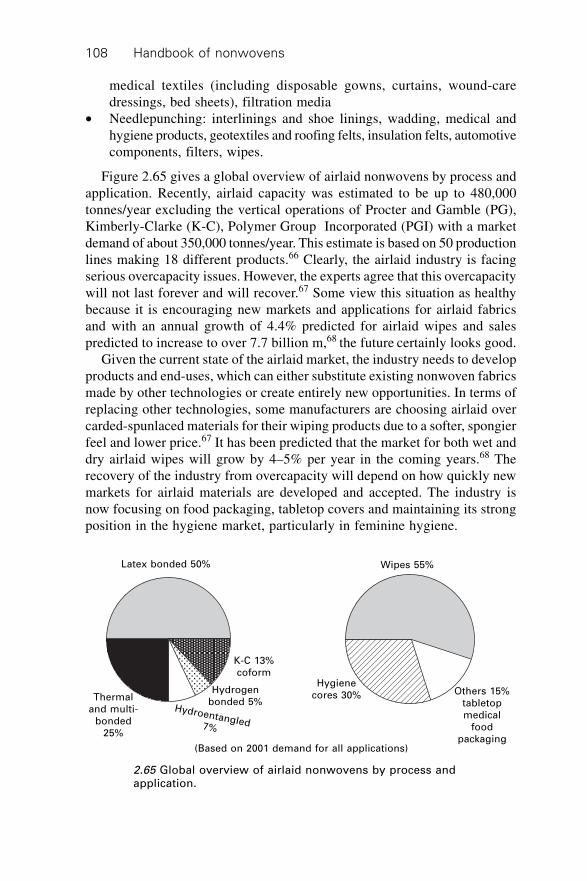
Handbook of nonwovens108
medical textiles (including disposable gowns, curtains, wound-caredressings, bed sheets), filtration media
∑ Needlepunching: interlinings and shoe linings, wadding, medical andhygiene products, geotextiles and roofing felts, insulation felts, automotivecomponents, filters, wipes.
Figure 2.65 gives a global overview of airlaid nonwovens by process andapplication. Recently, airlaid capacity was estimated to be up to 480,000tonnes/year excluding the vertical operations of Procter and Gamble (PG),Kimberly-Clarke (K-C), Polymer Group Incorporated (PGI) with a marketdemand of about 350,000 tonnes/year. This estimate is based on 50 productionlines making 18 different products.66 Clearly, the airlaid industry is facingserious overcapacity issues. However, the experts agree that this overcapacitywill not last forever and will recover.67 Some view this situation as healthybecause it is encouraging new markets and applications for airlaid fabricsand with an annual growth of 4.4% predicted for airlaid wipes and salespredicted to increase to over 7.7 billion m,68 the future certainly looks good.
Given the current state of the airlaid market, the industry needs to developproducts and end-uses, which can either substitute existing nonwoven fabricsmade by other technologies or create entirely new opportunities. In terms ofreplacing other technologies, some manufacturers are choosing airlaid overcarded-spunlaced materials for their wiping products due to a softer, spongierfeel and lower price.67 It has been predicted that the market for both wet anddry airlaid wipes will grow by 4–5% per year in the coming years.68 Therecovery of the industry from overcapacity will depend on how quickly newmarkets for airlaid materials are developed and accepted. The industry isnow focusing on food packaging, tabletop covers and maintaining its strongposition in the hygiene market, particularly in feminine hygiene.
Latex bonded 50% Wipes 55%
K-C 13%coform
Hydrogenbonded 5%
Hydroentangled7%
Thermaland multi-
bonded25%
Hygienecores 30% Others 15%
tabletopmedical
foodpackaging
(Based on 2001 demand for all applications)
2.65 Global overview of airlaid nonwovens by process andapplication.
Dry-laid web formation 109
2.19 Direct feed batt formation
In certain applications, for example in the production of batts for quilting, itis possible to eliminate the need for carding and cross-lapping or airlayingaltogether and a highly compact direct batt forming process can be adopted.Provided the fibre is sufficiently opened in prior mechanical opening processes,it is possible to form a comparatively uniform batt using a carefully constructedvolumetric feed hopper. The batt emerging from the hopper can be directlyquilted or otherwise bonded. The minimum batt weight is limited to about250 g/m2 and the width is 1.6 m–3.2 m. The maximum fibre length that canbe processed in this way is about 75 mm and such systems are claimed to becapable of up to 400 kg/h.
2.20 References
1. Lunenschloss J. and Albrecht W., (eds), Non-woven bonded fabrics, translator, JanetHock; translation editor, David Sharp, New York: Halstead Press, 1985.
2. www.ppic.org.uk3. www.nonwovens.com4. Sens D., ‘Fluff fibre morphology’, paper presented in Marketing Technology Service,
MTS, conference, Ottawa, Canada, 2002.5. Gammelgard E., ‘Fibres for airlaid thermal bonding’, Nonwovens World, spring
1997, p. 81–85.6. Heath R. and Akers P., ‘High performance airlaid fabrics containing SA fibres’,
Nonwovens World, vol. 5, spring 1996, p. 66–69.7. Kellner C., Art of preparing short fibres for spinning and other purposes, US patent
480588, Aug. 1892.8. Langdon H.H., Machine for forming random fibre webs, US patent 3512218, May
1970.9. Wood D.E., Apparatus for manufacturing nonwoven textile articles, US patent 3535187,
October 1970.10. Farrington A.P., Method of forming webs and apparatus therefore, US patent 3740797,
June 1973.11. Ruffo A.P. and Goyal P.K., Web forming process, US patent 3768118, October 1973.12. Lovgren E.G., Web forming apparatus, US patent 3772739, November 1973.13. Ruffo A.P. et al., Nonwoven fabric, US patent 4018646, April 1977.14. Buresh F.M., Machine and method for forming fibre webs, US patent 2451915,
October 1948.15. Buresh F.M. et al., Fibre web forming machine, US patent 2700188, January 1955.16. Langdon H.H., Machine for forming random fibre web, US patent 2890497, June
1959.17. Wood D.E., Machine for forming random fibre webs, US patent 3768119, October
1973.18. Wood D.E., Machine for forming fiber webs US patent 3972092, Aug. 1976.19. Pivko I 1991, January, Nonwovens Industry.20. Reader A.M., Preparation of 100% Melamine fibre web via air-laying technology,
Book of papers, INDA-Tec 1997, Massachusetts, USA.
Handbook of nonwovens110
21. Lovgren E.G. et al., Process and apparatus for producing uniform fibrous web at
high rate of speed, US Patent 4475271, 1984, Chicopee.22. Fehrer E. and Fehrer R., Improvement in or relating to apparatus for the manufacture
of a hair or fiber web, GB patent 1090827, 1967.23. Jakob H., ‘Experience with random web technology’, Melliand Textilberichte, vol.
70, no. 3, 1989, E76.24. Fehrer E., Apparatus for making a fibrous web, US patent 4583267, April 1986.25. Lennox-Kerr, ‘High loft offers more for less’, Nonwoven Report International, p.
21, March 1998.26. Jakob H., ‘Aerodynamic web-forming and needle-punching’, Textile Technology
International, p. 79–80, 1996.27. Poillet P., Textile World, vol. 150, no. 4, p. 27–28, 2000.28. Graute H., Carding machine and process for producing an aerodynamic card web,
US patent 5839166, Nov., 1998, Spinnbau.29. Graute H., Carding apparatus, US patent 5007137, April 1991, Hergeth Hollingsworth
GmbH.30. Siegfried Bernhardt, Nonwovens World, June–July 2001, p. 79.31. DuPont J., Method and an installation for forming a fiber web by the airlay technique,
US patent 6195845, March 2001, Thibeau.32. Kleppe J., ‘Air-laid: Care and feeding of a growing market’, Nonwovens World,
September–October, 1990, p. 27–29.33. Rasmussen T.B., Apparatus for uniformly distributing a disintegrated fibrous material
on a fibre layer forming surface, US patent 3581706, June 1971.34. Kroyer K.K.K., Apparatus for the deposition of a uniform layer of dry fibres on a
foraminous forming surface, US patent 4014635, March 1977.35. White D.G.W., Dry-laying a web of particulate or fibrous material, US patent 4144619,
March 1979.36. Kroyer K.K.K. et al., Apparatus for the production of a fibrous web, US patent
4494278, January 1985.37. Kroyer K.K.K., Adjustable screen for a distribution for making a sheet-formed
fibrous product, US patent 5471712, December 1995.38. Matsumura H., Apparatus for producing multilayer fibrous structures, US patent
3781150, December 1973.39. Nakai S. and Matsumura H., Apparatus for producing fibrous mats, US patent 3886629,
June 1975.40. Matsumura H. et al., Multilayer fibrous structures, US patent 3984898, October
1976.41. Westphal J., ‘New air lay system for longer fibres’, paper presented in Marketing
Technology Service, MTS, Conference, Ottawa, Canada, 2002.42. Dobel J., ‘The future of airlaid forming’, Nonwovens World, June–July 2002, p. 53.43. Feroe D., ‘Two layer air-lace technology’, Paper presented in Marketing Technology
Service, MTS, Conference, Ottawa, Canada, 2002.44. Jensen H.S., ‘Moving air-laid forward-hydroentangling 100% woodpulp and M&J
novel Highloft Synthetics Technology’, INSIGHT 2002.45. Paschen A. and Wulfhorst B., ‘Aerodynamic web formation for the creation of new
nonwoven structures’, Technical Textiles, vol. 44, p. 13–16, February 2001.46. Fu-Jiun Lin and I-Shou Tsai, ‘Configuration of PET fibre arrangement in roller
drafting air-laid webs’, Textile Research Journal, vol. 71, no. 1, p. 75–80, 2001.47. Staples P.O. et al., Feeding carded fibre to an airlay, WO patent 9720976, June
1997.
Dry-laid web formation 111
48. Pourmohammadi A., Fibre dynamics in air-laid nonwoven process, PhD thesis,University of Leeds, 1998.
49. Pourmohammadi A. et al., ‘A study of the Airflow and Fibre Dynamics in theTransport Chamber of a Sifting Air-laying System’ Part I, International Nonwovens,
Journal, 31–34, summer 2000.50. Bradean R. et al., ‘Modelling of an Aerodynamic Technique of Forming Web Structures
in Textile Industries: I. Turbulent air flow past filters’, Mathematical Engineering
Industry, vol. 8, no. 2. p. 197–160, 2001.51. Wood D.E., Air-laid low density nonwovens, Nonwoven conference papers, edited
by G.E. Cusick, Manchester UMIST, 1980.52. Kerekes R.J. and Schell C.J., Journal of Pulp and Paper Science, vol. 18, issue 1, p.
32, 1992.53. Kumar A., Robert W., Richard J., ‘Factors Controlling the Passage of Fibres through
Slots’, TAPPI Journal, vol. 81, no. 5, p. 247–254, 1998.54. Pourmohammadi A. et al., ‘A study of the Airflow and Fibre Dynamics in the
Transport Chamber of a Sifting Air-laying System’ Part II, International Nonwovens,
Journal, p. 22–26, autumn 2000.55. Ingham D.B. et al., ‘Mathematical and Computational modelling of Fluid and Fibre
Dynamics in a Sifting Air-Laying Process’, Int. J. of Applied Mechanics and
Engineering, vol. 6, no. 2, p. 287–306, 2001.56. Mango P., ‘Low density latex bonded airlaid’, Nonwovens World, spring 1998,
p. 54–61.57. Westphal J., ‘Bonding options for airlaid webs’, Nonwovens World, spring 1997,
p. 63–69.58. Kenney C.M. et al., ‘New-glass fibre geometry – a study of nonwovens processability’,
Tappi Journal, vol. 80, no. 3, 1997, p. 169–177.59. Ruckert M, ‘Fleissner AquaJet needling process for nonwovens in the technical and
medical sphere’, AVR Allgemeiner Vliesstoff Report, vol. 27, no. 3, p. 11, 1999.60. ICBT Perfojet, Nonwovens Industry, vol. 30, Issue 5, 1999, p. 88.61. Pourmohammadi A. et al., ‘Structurally engineered air laid webs’, INDA-Tec, Sept.
1999, Atlanta, Georgia, USA.62. Vaughn E.A., Jarvis C.W., Arena M.O., 13th Annual technical symposium, Boston,
1985, pp. 267–302.63. Gammelgaard E.G., ‘What are the future prospects for carded, thermal bonded and
airlaid nonwovens?’, Nonwovens Report International, March 1998, p. 24–29.64. Jensen H.S., ‘The super site for ultra thin air-laid diaper production’, presented at
Insight 1999.65. Conley J.T., ‘Airlaid markets – the next wave’, Nonwovens World, June–July 2002,
p. 75–79.66. Stevens B., ‘History I’, paper presented in Marketing Technology Service, MTS,
conference, Ottawa, Canada, 2002.67. Bitz K., ‘Air laid: what’s next?, Nonwovens Industry, October 2002, p. 30.68. Pricie Hanna, ‘Key Factors Driving Airlaid Demand, Supply and Profitability’, INTC
2002.
112
3.1 Introduction
In any discussion of wet-laid nonwovens it is necessary to emphasise thatmuch of the pioneering work in this area occurred before the general acceptanceof the term ‘wet-laid nonwoven’. The early published work refers to theproduction of ‘synthetic fibre papers’ rather than wet-laid nonwoven webs. Itis also necessary to arrive at a definition of what should be correctly consideredas a wet-laid nonwoven and what more correctly should be classified as areinforced paper. In the CEN (European Committee for Standardisation)definition of Nonwovens EN 29092, which is based on the ISO (InternationalStandards Organisation) definition and which in turn is based on the EDANA(European Disposables and Nonwovens Association); the relevant section isas follows:
To distinguish wet-laid nonwovens from wet-laid papers, a material shallbe regarded as a nonwoven if:
more than 50% by mass of its fibrous content is made up of fibres (excludingchemically digested vegetable fibres) with a length to diameter ratio ofgreater than 300; or if the conditions in (a) do not apply then, if thefollowing conditions are fulfilled: more than 30% by mass of its fibrouscontent is made up of fibres (excluding chemically digested vegetablefibres) with a length to diameter ratio greater than 300 and its density isless than 0.40 g/cm3.
This formal definition is important in any legal matters concerning wet-laidnonwovens, for example matters connected with customs and excise duties,and has validity within the European Union as it has been approved by theEuropean Courts.
3.2 Background and historical developments
There are a number of references to fabrics that we would today classify aswet-laid nonwovens that date back to antiquity. The technology of wet-laid
3Wet-laid web formation
C W H I T E, Consultant, France
Wet-laid web formation 113
nonwovens is closely related to that of paper and papermaking which itselfgoes back some 2000 years with the craft of making paper by hand beingdeveloped in China and credited to Ts’ai Lun, who was considered to be thegod of papermaking. Many papers at this time were produced from fibresderived from rags composed of natural materials. Another paper product,papyrus, was prepared from water reeds, Cyperus papyrus. Although theexact method of preparation is subject to some discussion, some believe thatthe slabs were diametrically cut across the stem, whilst others believe thatthe layers were peeled from the surface rather like peeling layers of an onion.Strips of the inner pith from the lower portion of the stem were cut, dried, re-wetted and laid side by side on a piece of cloth. More strips were placed onthem, but with their alignment at right-angles to those in the first layer andthis process was continued. The whole mass of layers was moistened, eitherwith water or more often with an adhesive, pressed and dried, making astructure more closely related to a latex bonded wet-laid nonwoven than aconventional paper sheet.
Papyrus was an important precursor of modern wet-laid materials and theworks of the great Greek and Roman scholars were written on it.1 Otherreports from a Japanese scientist, Inagaki2 have traced the production ofpaper from long fibres of 15–17 mm length to a passage from Choya Gunsai,a type of paper that was used to make clothes between 983 BC and AD 4. Inthis description, the fibres are formed into sheets and then the sheets aretreated with mannan glue and reinforced with persimmon tannin. In a processanalogous to creping, the ‘cloth’ is repeatedly ‘crumpled’ to develop softnessand a supple texture. There were some developments in the papermakingfield in the late 1890s with respect to inclined wire structures but these wereconcerned with paper grades and there was no attempt to examine othermaterials.
Moving into the more recent past, early work at C H Dexter, WindsorLocks, Connecticut, USA, by F H Osborne made significant contributions tothe development of a continuous process to manufacture long fibre papersand wet-laid nonwoven structures.3 Osborne made an analysis of the propertiesof soft, strong flexible tissue wrap and durable stencil papers produced inJapan and developed a method to modify the papermaking process toaccommodate these fibres which he found were ‘sixty times longer, fourtimes thinner and significantly more uniform than fibres used in normalpapermaking’. Following a detailed examination of many natural fibres andsome of the then recently available man-made fibres, Osborne elected to usemanila hemp for his initial programme. Processing of these long fibres at thedilution ratios normally used in papermaking was quickly shown not to work.Osborne’s solution to this problem was to lower the dispersion concentrationfrom a normal 0.5% to 0.0025% fibre to water ratio and to modify theforming machine by inclining the forming wire to an angle of 20∞.
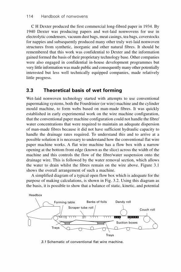
Handbook of nonwovens114
C H Dexter produced the first commercial long-fibred paper in 1934. By1940 Dexter was producing papers and wet-laid nonwovens for use inelectrolytic condensers, vacuum dust bags, meat casings, tea bags, coverstocksfor nappies and subsequently produced many other truly wet-laid nonwovenstructures from synthetic, inorganic and other natural fibres. It should beremembered that this work was confidential to Dexter and the informationgained formed the basis of their proprietary technology base. Other companieswere also engaged in confidential in-house development programmes butvery little information was made public and consequently many other potentiallyinterested but less well technically equipped companies, made relativelylittle progress.
3.3 Theoretical basis of wet forming
Wet-laid nonwoven technology started with attempts to use conventionalpapermaking systems, both the Fourdrinier (or wire) machine and the cylindermould machine, to form webs based on man-made fibres. It was quicklyestablished in early experimental work on the wire machine configuration,that the conventional paper machine configuration could not handle the fibre/water concentrations that were required to maintain an adequate dispersionof man-made fibres because it did not have sufficient hydraulic capacity tohandle the drainage rates required. To understand this and to arrive at apossible solution it is necessary to understand how the conventional flat wirepaper machine works. A flat wire machine has a flow box with a narrowopening at the bottom front edge (known as the slice) across the width of themachine and this controls the flow of the fibre/water suspension onto thedrainage wire. This is followed by the water removal section, which allowsthe water to drain whilst the fibres remain on the wire above. Figure 3.1shows the overall arrangement of such a machine.
A simplified diagram of a typical open flow box which is adequate for thepurpose of making calculations, is shown in Fig. 3.2. Using this diagram asthe basis, it is possible to show that a balance of static, kinetic, and potential
Headbox
Forming table
Scraper tube roll
Banks of foils Dandy roll
Couch roll
Suction boxes
Trays
Trays
3.1 Schematic of conventional flat wire machine.
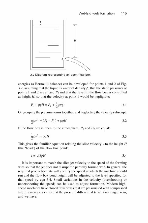
Wet-laid web formation 115
energies (a Bernoulli balance) can be developed for points 1 and 2 of Fig.3.2, assuming that the liquid is water of density r, that the static pressures atpoints 1 and 2 are P1 and P2 and that the level in the flow box is controlledat height H, so that the velocity at point 1 would be negligible:
P gH P v1 2 22 + = + 1
2r r 3.1
Or grouping the pressure terms together, and neglecting the velocity subscript:
12
= ( – ) + 21 2r rv P P gH 3.2
If the flow box is open to the atmosphere, P1 and P2 are equal:
12
= 2r rv gH 3.3
This gives the familiar equation relating the slice velocity v to the height H(the ‘head’) of the flow box pond:
v gH = 2 3.4
It is important to match the slice jet velocity to the speed of the formingwire so that the jet does not disrupt the partially formed web. In general therequired production rate will specify the speed at which the machine shouldrun and the flow box pond height will be adjusted to the level specified forthat speed by eqn 3.4. Small variations in the velocity (overshooting orundershooting the speed) can be used to adjust formation. Modern high-speed machines have closed flow boxes that are pressurised with compressedair, this increases P1 so that the pressure differential term is no longer zero,and we have:
1
2
H
3.2 Diagram representing an open flow box.
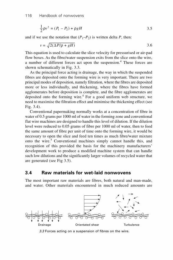
Handbook of nonwovens116
12
= ( – ) + 21 2r rv P P gH 3.5
and if we use the notation that (P1–P2) is written delta P, then:
v P gH = 2( / + )D r 3.6
This equation is used to calculate the slice velocity for pressurised or air-padflow boxes. As the fibre/water suspension exits from the slice onto the wire,a number of different forces act upon the suspension.4 These forces areshown schematically in Fig. 3.3.
As the principal force acting is drainage, the way in which the suspendedfibres are deposited onto the forming wire is very important. There are twoprincipal modes of deposition, namely filtration, where the fibres are depositedmore or less individually, and thickening, where the fibres have formedagglomerates before deposition is complete, and the fibre agglomerates aredeposited onto the forming wire.4 For a good uniform web structure, weneed to maximise the filtration effect and minimise the thickening effect (seeFig. 3.4).
Conventional papermaking normally works at a concentration of fibre inwater of 0.5 grams per 1000 ml of water in the forming zone and conventionalflat wire machines are designed to handle this level of dilution. If the dilutionlevel were reduced to 0.05 grams of fibre per 1000 ml of water, then to feedthe same amount of fibre per unit of time onto the forming wire, it would benecessary to open the slice and feed ten times as much fibre/water mixtureonto the wire.5 Conventional machines simply cannot handle this, andrecognition of this provided the basis for the machinery manufacturers’development work to produce a modified machine system that can handlesuch low dilutions and the significantly larger volumes of recycled water thatare generated (see Fig 3.5).
3.4 Raw materials for wet-laid nonwovens
The most important raw materials are fibres, both natural and man-made,and water. Other materials encountered in much reduced amounts are
Drainage Orientated shear Turbulence
3.3 Forces acting on a suspension of fibres on the wire.
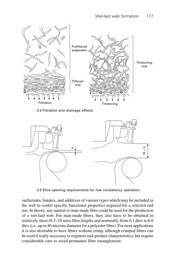
Wet-laid web formation 117
surfactants, binders, and additives of various types which may be included inthe web to confer specific functional properties required for a selected enduse. In theory, any natural or man-made fibre could be used for the productionof a wet-laid web. For man-made fibres, they also have to be obtained inrelatively short (0.3–10 mm) fibre lengths and nominally from 0.1 dtex to 6.0dtex (i.e., up to 46 microns diameter for a polyester fibre). For most applicationsit is also desirable to have fibres without crimp, although crimped fibres canbe used if really necessary to engineer end-product characteristics, but requireconsiderable care to avoid premature fibre entanglement.
Filtration Thickening
Filtered
mat
Prefiltered
suspension
Thickening
mat
3.4 Filtration and drainage effects.
h
10
¥ h
3.5 Slice opening requirements for low consistency operation.
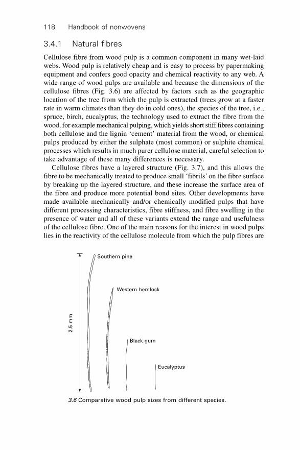
Handbook of nonwovens118
3.4.1 Natural fibres
Cellulose fibre from wood pulp is a common component in many wet-laidwebs. Wood pulp is relatively cheap and is easy to process by papermakingequipment and confers good opacity and chemical reactivity to any web. Awide range of wood pulps are available and because the dimensions of thecellulose fibres (Fig. 3.6) are affected by factors such as the geographiclocation of the tree from which the pulp is extracted (trees grow at a fasterrate in warm climates than they do in cold ones), the species of the tree, i.e.,spruce, birch, eucalyptus, the technology used to extract the fibre from thewood, for example mechanical pulping, which yields short stiff fibres containingboth cellulose and the lignin ‘cement’ material from the wood, or chemicalpulps produced by either the sulphate (most common) or sulphite chemicalprocesses which results in much purer cellulose material, careful selection totake advantage of these many differences is necessary.
Cellulose fibres have a layered structure (Fig. 3.7), and this allows thefibre to be mechanically treated to produce small ‘fibrils’ on the fibre surfaceby breaking up the layered structure, and these increase the surface area ofthe fibre and produce more potential bond sites. Other developments havemade available mechanically and/or chemically modified pulps that havedifferent processing characteristics, fibre stiffness, and fibre swelling in thepresence of water and all of these variants extend the range and usefulnessof the cellulose fibre. One of the main reasons for the interest in wood pulpslies in the reactivity of the cellulose molecule from which the pulp fibres are
2.5
mm
Southern pine
Western hemlock
Black gum
Eucalyptus
3.6 Comparative wood pulp sizes from different species.
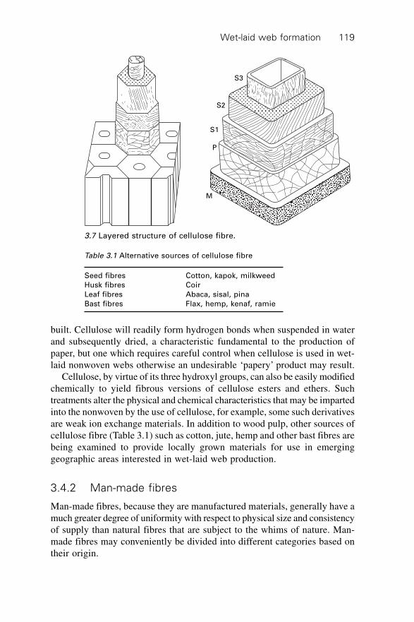
Wet-laid web formation 119
built. Cellulose will readily form hydrogen bonds when suspended in waterand subsequently dried, a characteristic fundamental to the production ofpaper, but one which requires careful control when cellulose is used in wet-laid nonwoven webs otherwise an undesirable ‘papery’ product may result.
Cellulose, by virtue of its three hydroxyl groups, can also be easily modifiedchemically to yield fibrous versions of cellulose esters and ethers. Suchtreatments alter the physical and chemical characteristics that may be impartedinto the nonwoven by the use of cellulose, for example, some such derivativesare weak ion exchange materials. In addition to wood pulp, other sources ofcellulose fibre (Table 3.1) such as cotton, jute, hemp and other bast fibres arebeing examined to provide locally grown materials for use in emerginggeographic areas interested in wet-laid web production.
3.4.2 Man-made fibres
Man-made fibres, because they are manufactured materials, generally have amuch greater degree of uniformity with respect to physical size and consistencyof supply than natural fibres that are subject to the whims of nature. Man-made fibres may conveniently be divided into different categories based ontheir origin.
S3
S2
S1
P
M
3.7 Layered structure of cellulose fibre.
Table 3.1 Alternative sources of cellulose fibre
Seed fibres Cotton, kapok, milkweed
Husk fibres Coir
Leaf fibres Abaca, sisal, pina
Bast fibres Flax, hemp, kenaf, ramie
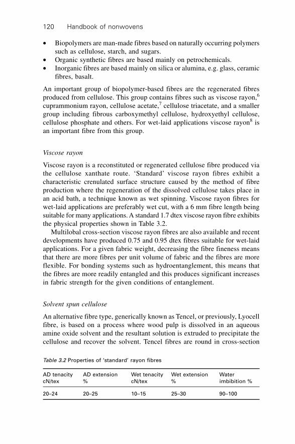
Handbook of nonwovens120
∑ Biopolymers are man-made fibres based on naturally occurring polymerssuch as cellulose, starch, and sugars.
∑ Organic synthetic fibres are based mainly on petrochemicals.∑ Inorganic fibres are based mainly on silica or alumina, e.g. glass, ceramic
fibres, basalt.
An important group of biopolymer-based fibres are the regenerated fibresproduced from cellulose. This group contains fibres such as viscose rayon,6
cuprammonium rayon, cellulose acetate,7 cellulose triacetate, and a smallergroup including fibrous carboxymethyl cellulose, hydroxyethyl cellulose,cellulose phosphate and others. For wet-laid applications viscose rayon8 isan important fibre from this group.
Viscose rayon
Viscose rayon is a reconstituted or regenerated cellulose fibre produced viathe cellulose xanthate route. ‘Standard’ viscose rayon fibres exhibit acharacteristic crenulated surface structure caused by the method of fibreproduction where the regeneration of the dissolved cellulose takes place inan acid bath, a technique known as wet spinning. Viscose rayon fibres forwet-laid applications are preferably wet cut, with a 6 mm fibre length beingsuitable for many applications. A standard 1.7 dtex viscose rayon fibre exhibitsthe physical properties shown in Table 3.2.
Multilobal cross-section viscose rayon fibres are also available and recentdevelopments have produced 0.75 and 0.95 dtex fibres suitable for wet-laidapplications. For a given fabric weight, decreasing the fibre fineness meansthat there are more fibres per unit volume of fabric and the fibres are moreflexible. For bonding systems such as hydroentanglement, this means thatthe fibres are more readily entangled and this produces significant increasesin fabric strength for the given conditions of entanglement.
Solvent spun cellulose
An alternative fibre type, generically known as Tencel, or previously, Lyocellfibre, is based on a process where wood pulp is dissolved in an aqueousamine oxide solvent and the resultant solution is extruded to precipitate thecellulose and recover the solvent. Tencel fibres are round in cross-section
Table 3.2 Properties of ‘standard’ rayon fibres
AD tenacity AD extension Wet tenacity Wet extension Water
cN/tex % cN/tex % imbibition %
20–24 20–25 10–15 25–30 90–100
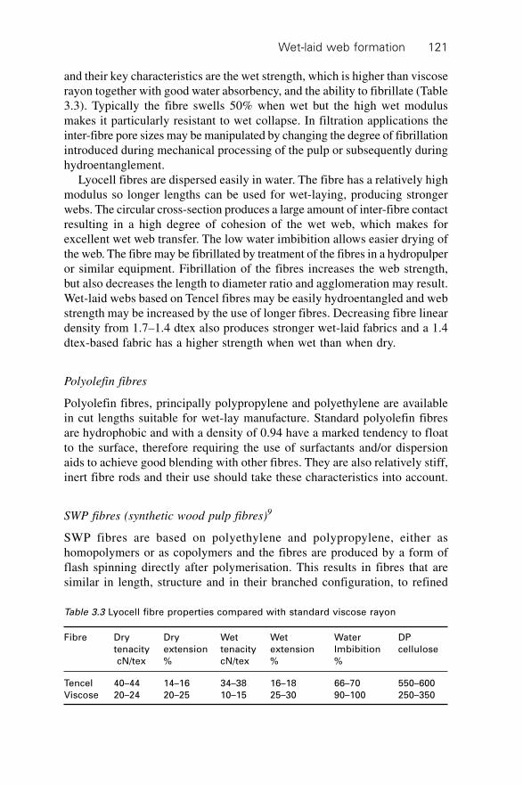
Wet-laid web formation 121
and their key characteristics are the wet strength, which is higher than viscoserayon together with good water absorbency, and the ability to fibrillate (Table3.3). Typically the fibre swells 50% when wet but the high wet modulusmakes it particularly resistant to wet collapse. In filtration applications theinter-fibre pore sizes may be manipulated by changing the degree of fibrillationintroduced during mechanical processing of the pulp or subsequently duringhydroentanglement.
Lyocell fibres are dispersed easily in water. The fibre has a relatively highmodulus so longer lengths can be used for wet-laying, producing strongerwebs. The circular cross-section produces a large amount of inter-fibre contactresulting in a high degree of cohesion of the wet web, which makes forexcellent wet web transfer. The low water imbibition allows easier drying ofthe web. The fibre may be fibrillated by treatment of the fibres in a hydropulperor similar equipment. Fibrillation of the fibres increases the web strength,but also decreases the length to diameter ratio and agglomeration may result.Wet-laid webs based on Tencel fibres may be easily hydroentangled and webstrength may be increased by the use of longer fibres. Decreasing fibre lineardensity from 1.7–1.4 dtex also produces stronger wet-laid fabrics and a 1.4dtex-based fabric has a higher strength when wet than when dry.
Polyolefin fibres
Polyolefin fibres, principally polypropylene and polyethylene are availablein cut lengths suitable for wet-lay manufacture. Standard polyolefin fibresare hydrophobic and with a density of 0.94 have a marked tendency to floatto the surface, therefore requiring the use of surfactants and/or dispersionaids to achieve good blending with other fibres. They are also relatively stiff,inert fibre rods and their use should take these characteristics into account.
SWP fibres (synthetic wood pulp fibres)9
SWP fibres are based on polyethylene and polypropylene, either ashomopolymers or as copolymers and the fibres are produced by a form offlash spinning directly after polymerisation. This results in fibres that aresimilar in length, structure and in their branched configuration, to refined
Table 3.3 Lyocell fibre properties compared with standard viscose rayon
Fibre Dry Dry Wet Wet Water DP
tenacity extension tenacity extension Imbibition cellulose
cN/tex % cN/tex % %
Tencel 40–44 14–16 34–38 16–18 66–70 550–600
Viscose 20–24 20–25 10–15 25–30 90–100 250–350
Handbook of nonwovens122
wood pulp; hence the designation ‘synthetic wood pulp’ (SWP). SWP fibresfor wet-lay applications are normally 0.75–1.5 mm in length and highlyfibrillated. They are supplied at approximately 50% moisture in a pressedsheet form. The fibres are easily dispersed in water with conventional equipmentused for handling wood pulp. Dispersion at higher temperatures speeds theprocess and blends of wood pulp and other fibres are easily achieved. SWPfibres are often used as ‘binder’ fibres10 where their ability to be thermallybonded or moulded is useful.
Polyester fibres
A number of different polyester fibres are now available for use in wet-layforming either alone or blended with other fibres. Most of the polyesterfibres used are based on PolyEthylene Terephthalate (PET) but fibres fromPolyTrimethylene Terephthalate11 (PTT) are now becoming available as ispolyester fibre with an eight-leg cross-section known as ‘deep grooved polyesterfibre’.12 These special shaped fibres exhibit a high surface area and providebulk, whilst the grooves are claimed to transport fluids spontaneously withinthe web. This characteristic makes them particularly interesting in webs usedin absorbent products. Polyester fibres have good tensile strength and chemicalresistance and are now available with a narrow fibre length distribution (Fig.3.8) and cut ends free from defects. Most types of polyester fibres are treatedbefore supply, if specified for wet-lay, to make them easy to disperse.
High-performance organic fibres
A variety of high-performance fibres13 can be successfully processed withwet-lay technology including fibres based on PEEK (Poly ether ether ketone),PEI (Poly ether imide), PPS (Poly phenylene sulphide)14, DuPont Nomex™,DuPont Kevlar™. Aramid fibres are one of the few organic polymers thatcan be fibrillated in a manner similar to wood pulp and using the sameequipment. High-performance fibres are used in wet-laid webs that findapplications in fields such as surface veils, heat-resistant webs, flame-retardantstructures and other applications where their high cost can be justified by theenhanced performance characteristics that they confer.
Polyamide fibres
Nylon fibres are used in some products to increase tear strength. They areavailable in various forms, for example as Polyamide 6.6 S.G. 1.14 g/cm3
2.2 dtex (16 micron) with a melting point of 215 ∞C and a fibre length of6–12 mm. Alternatively, Perlon fibres based on Polyamide 6 at 3.3 dtex(19 micron) with a melting point of 255 ∞C and 6–12 mm length may be
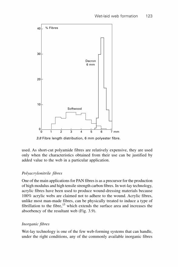
Wet-laid web formation 123
used. As short-cut polyamide fibres are relatively expensive, they are usedonly when the characteristics obtained from their use can be justified byadded value to the web in a particular application.
Polyacrylonitrile fibres
One of the main applications for PAN fibres is as a precursor for the productionof high modulus and high tensile strength carbon fibres. In wet-lay technology,acrylic fibres have been used to produce wound-dressing materials because100% acrylic webs are claimed not to adhere to the wound. Acrylic fibres,unlike most man-made fibres, can be physically treated to induce a type offibrillation to the fibre,15 which extends the surface area and increases theabsorbency of the resultant web (Fig. 3.9).
Inorganic fibres
Wet-lay technology is one of the few web-forming systems that can handle,under the right conditions, any of the commonly available inorganic fibres
% Fibres
Dacron
6 mm
Softwood
40
30
20
10
00 1 2 3 4 5 6 7 mm
3.8 Fibre length distribution, 6 mm polyester fibre.
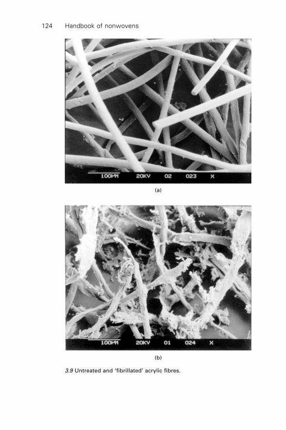
Handbook of nonwovens124
3.9 Untreated and ‘fibrillated’ acrylic fibres.
(b)
(a)
Wet-laid web formation 125
and form uniform structured webs. Inorganic fibres that are normallyencountered are cut glass strand,16 microfibre glass (Tables 3.4 and 3.5),ceramics (Table 3.6), silica, alumina and carbon-coated fibres such as nickel-coated carbon fibres. The use of cut glass strand (not always classed as anonwoven) is large-volume business, with the main outlet being the roofingsubstrate sector. Glass microfibres are a smaller volume business and areapplied in the high-efficiency filtration area, high-temperature insulation andlow-temperature cryogenic insulation sectors. Ceramic fibres17 are suitablefor use in very high-temperature thermal insulation applications replacingthe much thicker and heavier firebrick materials traditionally used. Lightweightwebs are also used in molten metal processing and filter media.18
Table 3.4 Dimensions of glass microfibres
Glass reference Glass type Fibre diameter in
code microns
90 475 0.26
102 475 753 0.40
104 475 753 E 0.50
106 475 753 E 0.65
108B 475 753 E 1.80
110 475 753 2.70
112 475 4.00
Table 3.5 Physical properties glass microfibres
Property 475 glass 753 glass E glass
Specific gravity 2.61 2.52 2.58
Refractive index 1.522 1.515 1.556
Softening point ∞C 679 677 843
Service temp. ∞C 538 538 649
Table 3.6 Ceramic fibre physical properties
Ceramic fibre – typical physical properties
Fibre content 85% minimum
Colour White to light grey
Melting point ∞C 1790
Fibre diameter – mean (in microns) 1.2
Fibre length mm 3
Specific gravity g/cm3 2.7
Specific heat at 1093 ∞C J/kg∞C 1130
Fibre surface area m2/g 2.5
Handbook of nonwovens126
3.5 Cellulose fibre preparation
Cellulose fibres may be prepared for use in wet-lay nonwoven production bythe processes normally used to prepare these fibres for papermaking. Cellulosefibres are normally suspended in water by feeding the pulp sheets into ahydropulper, which is basically a high shear mixer, and which breaks up thepulp sheets and disperses the fibres in the water. This may be achieved atbetween 3–6% concentration of fibre. The dispersed fibre may be used as itis at this stage of treatment to blend with other, normally man-made fibres;or it may be treated further by means of a refining or beating process. In thisfurther treatment, the suspension of cellulose fibres in water is fed to amachine, either a refiner or a beater, which forces the fibre suspension betweentwo metal bars where the hydraulic forces applied to the fibres cause them tofibrillate (split into small fibrils) and swell by the absorption of water intothe fibre structure.
These fibrillation and swelling characteristics are possible because of thestructure of the cellulose fibre which is made up of a number of layers ofcellulose molecules, laid in different orientations and which can be ‘peeled’away to produce the fibrils and allow water to penetrate. Whilst thesecharacteristics are of fundamental importance in papermaking, controlleddevelopment of the cellulose fibres used in wet-laid nonwoven structures canbe used to advantage for some products, but it must be used with careotherwise a web with characteristics more closely associated with somepaper grades results. Once the cellulose fibres are treated, they are ready tobe blended with the other fibre components as required for the product.
3.6 Man-made fibre preparation
Man-made fibres are supplied in cut lengths and at a selected fibre diameter(normally specified in terms of the linear density) and in highly compressedbales. The first requirement for wet-laid is to select fibres that are free fromcutting defects to avoid problems in the system. Fibre defects are nowincreasingly less common as the fibre producers take the requirements of thenonwoven business more seriously and the nonwoven producers have betterdesigned systems. Fibre associated problems to be avoided are:
∑ logs or sticks: bundles of fibres with aligned cut ends that are neverdispersed
∑ dumb-bells: paired clumps of fibres connected by one or more longfibres, and
∑ ropes: assemblages of fibres, with unaligned ends, that are clearly moreagglomerated than in the general dispersion.
Logs are normally a fibre supply problem or can be the result of seriousunder agitation of the initial dispersion. Dumb-bells require two conditions
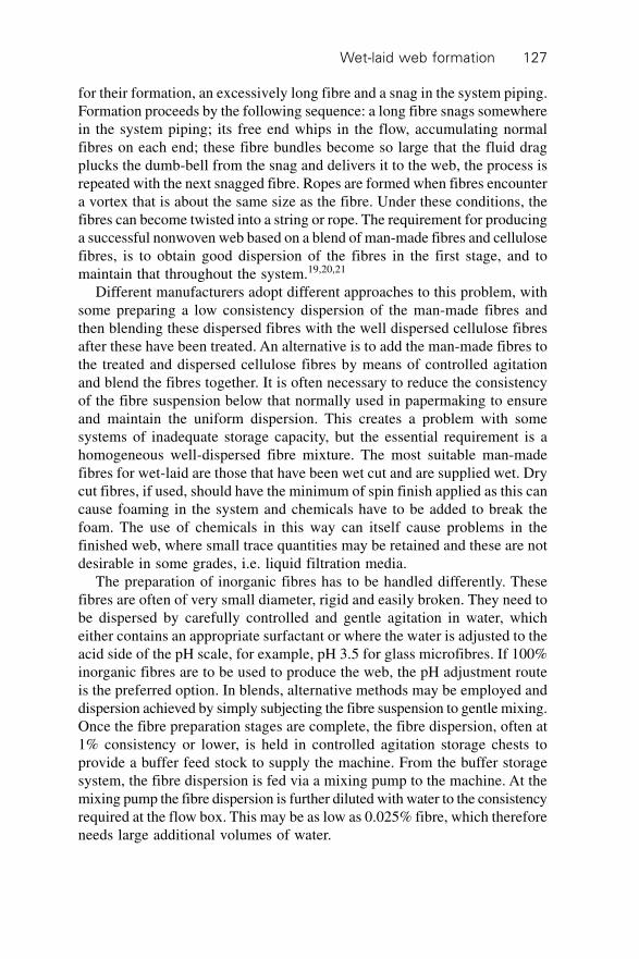
Wet-laid web formation 127
for their formation, an excessively long fibre and a snag in the system piping.Formation proceeds by the following sequence: a long fibre snags somewherein the system piping; its free end whips in the flow, accumulating normalfibres on each end; these fibre bundles become so large that the fluid dragplucks the dumb-bell from the snag and delivers it to the web, the process isrepeated with the next snagged fibre. Ropes are formed when fibres encountera vortex that is about the same size as the fibre. Under these conditions, thefibres can become twisted into a string or rope. The requirement for producinga successful nonwoven web based on a blend of man-made fibres and cellulosefibres, is to obtain good dispersion of the fibres in the first stage, and tomaintain that throughout the system.19,20,21
Different manufacturers adopt different approaches to this problem, withsome preparing a low consistency dispersion of the man-made fibres andthen blending these dispersed fibres with the well dispersed cellulose fibresafter these have been treated. An alternative is to add the man-made fibres tothe treated and dispersed cellulose fibres by means of controlled agitationand blend the fibres together. It is often necessary to reduce the consistencyof the fibre suspension below that normally used in papermaking to ensureand maintain the uniform dispersion. This creates a problem with somesystems of inadequate storage capacity, but the essential requirement is ahomogeneous well-dispersed fibre mixture. The most suitable man-madefibres for wet-laid are those that have been wet cut and are supplied wet. Drycut fibres, if used, should have the minimum of spin finish applied as this cancause foaming in the system and chemicals have to be added to break thefoam. The use of chemicals in this way can itself cause problems in thefinished web, where small trace quantities may be retained and these are notdesirable in some grades, i.e. liquid filtration media.
The preparation of inorganic fibres has to be handled differently. Thesefibres are often of very small diameter, rigid and easily broken. They need tobe dispersed by carefully controlled and gentle agitation in water, whicheither contains an appropriate surfactant or where the water is adjusted to theacid side of the pH scale, for example, pH 3.5 for glass microfibres. If 100%inorganic fibres are to be used to produce the web, the pH adjustment routeis the preferred option. In blends, alternative methods may be employed anddispersion achieved by simply subjecting the fibre suspension to gentle mixing.Once the fibre preparation stages are complete, the fibre dispersion, often at1% consistency or lower, is held in controlled agitation storage chests toprovide a buffer feed stock to supply the machine. From the buffer storagesystem, the fibre dispersion is fed via a mixing pump to the machine. At themixing pump the fibre dispersion is further diluted with water to the consistencyrequired at the flow box. This may be as low as 0.025% fibre, which thereforeneeds large additional volumes of water.
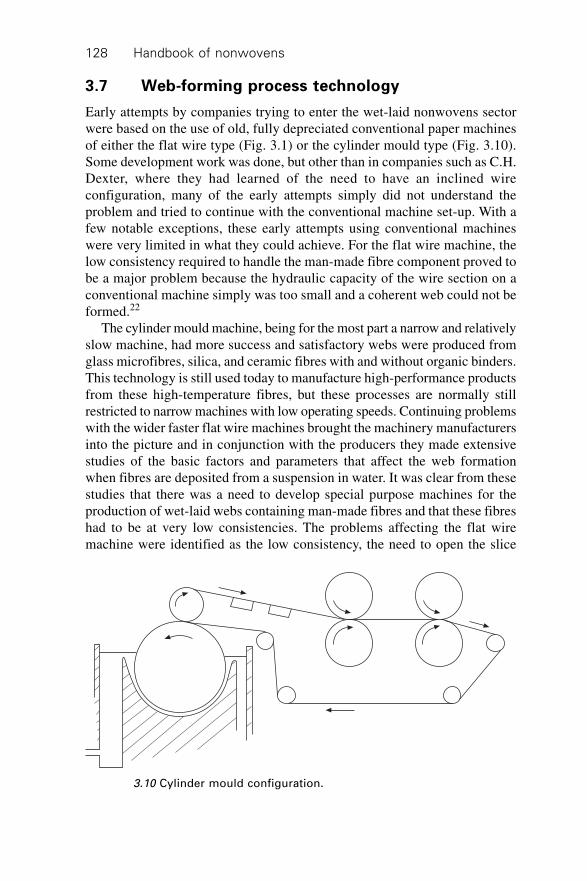
Handbook of nonwovens128
3.7 Web-forming process technology
Early attempts by companies trying to enter the wet-laid nonwovens sectorwere based on the use of old, fully depreciated conventional paper machinesof either the flat wire type (Fig. 3.1) or the cylinder mould type (Fig. 3.10).Some development work was done, but other than in companies such as C.H.Dexter, where they had learned of the need to have an inclined wireconfiguration, many of the early attempts simply did not understand theproblem and tried to continue with the conventional machine set-up. With afew notable exceptions, these early attempts using conventional machineswere very limited in what they could achieve. For the flat wire machine, thelow consistency required to handle the man-made fibre component proved tobe a major problem because the hydraulic capacity of the wire section on aconventional machine simply was too small and a coherent web could not beformed.22
The cylinder mould machine, being for the most part a narrow and relativelyslow machine, had more success and satisfactory webs were produced fromglass microfibres, silica, and ceramic fibres with and without organic binders.This technology is still used today to manufacture high-performance productsfrom these high-temperature fibres, but these processes are normally stillrestricted to narrow machines with low operating speeds. Continuing problemswith the wider faster flat wire machines brought the machinery manufacturersinto the picture and in conjunction with the producers they made extensivestudies of the basic factors and parameters that affect the web formationwhen fibres are deposited from a suspension in water. It was clear from thesestudies that there was a need to develop special purpose machines for theproduction of wet-laid webs containing man-made fibres and that these fibreshad to be at very low consistencies. The problems affecting the flat wiremachine were identified as the low consistency, the need to open the slice
3.10 Cylinder mould configuration.
Wet-laid web formation 129
control of the flow onto the wire to produce a web at the same web weightand operating speed (see Fig. 3.5). The increased volume flow onto the wirehad to be drained and this required the modification of the wire section.
Early experimental work showed that inclination of the wire and the useof vacuum boxes under the wire to increase drainage resulted in a machineconfiguration that could handle these materials.23,24,25 Once the basic operatingparameters had been established, further developments led to reduced formingangles, extended flow boxes and multilayer forming capabilities26 (see Fig.3.11). An example of the current application of inclined wire former technologyis illustrated by the Voith Hydroformer®. The Hydroformer belongs to agroup of inclined wire formers where the flow box and the sheet formingzone are one unit. The converging nozzle consists of an upper front wall anda lower dewatering box through which the forming wire passes. The nonwovenmat is formed continuously on the wire above the dewatering box from asuspension of uniform stock consistency. Stock consistencies of 0.01–0.8%are typical for this machine. With the Hydroformer, single and multilayernonwovens as well as long-fibred papers can be produced from almost anydispersible fibres and fibre mixtures. Fibres up to 35 mm can be processedunder the right conditions into homogeneous webs. The machine is availablein different formats.
3.7.1 Single-layer HydroFormer
The HydroFormer was first developed in the mid-1960s. Since that time theconcept has been continuously developed and since 1996 the HydroFormerhas included a hydraulically closed flow box. Machines are available in
3.11 Sandy Hill twin-layer inclined wire former.
Handbook of nonwovens130
widths up to 5.2 m and with production speeds of over 500 m/min. Productswith web weights in the range 7–300 g/m2 can be produced. Optimal sheetformation is obtained by individual adjustment of the flow rates in eachdewatering chamber.
3.7.2 Double-layer HydroFormer
The top sheet is formed directly after the formation of the primary layersheet. The process is made possible by a separate supply of the top layersuspension into a special flow box. The result is very good adhesion betweenthe two layers. The combination of two individual layers having differentfibre compositions can create final mat characteristics that can be achievedwith separate individual layers.
3.7.3 White-water circuit
The choice of an open or a closed white-water circuit is largely determinedby the filtration resistance of the product to be produced and by the spaceavailable for the machine. For the open white-water circuit, the maximumvacuum value in the dewatering chambers is determined by the level betweenthe flow box and the level of the white-water tank. With the closed white-water system, the white-water tank is subjected to a vacuum. By changingthe vacuum in the white-water tank, the dewatering vacuum can be changedover a wide range, which provides a high degree of flexibility.
3.7.4 Alternative wet-lay forming technologies
The cylinder mould machine
In the cylinder mould configuration, the forming wire is wrapped round acylinder, which is contained within a vat through which the fibre suspensionflows (see Fig. 3.12). The water drains through the wire onto the cylinderand the web is built up on the cylinder surface and then transferred viavacuum boxes mounted under the transfer felt, through a lightweight presssection, to the drying section of the machine and on to the reel-up. Mouldsused for wet-laid nonwovens were almost exact copies of the moulds used tomake paper. Although these machines are normally quite narrow in width(down to 0.5 m) and slow running with some line speeds as low as 10 m/min,they are extremely versatile and can produce webs from 15–1000 g/m2 onthe same machine with very little adjustment. The original cylinder produceshigh quality printing and banknote papers from cotton fibres.
Developments based on the cylinder mould forming concept led to theproduction by Sandy Hill Corporation USA of the Rotiformer™ machine
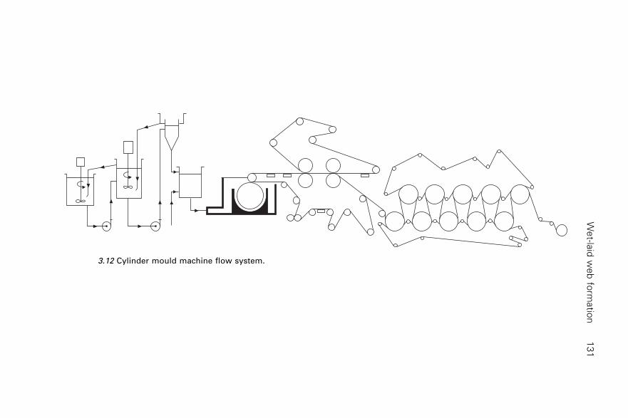
We
t-laid
we
b fo
rmatio
n1
31
3.12 Cylinder mould machine flow system.
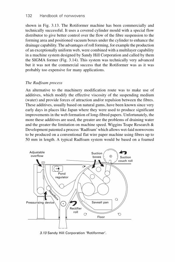
Handbook of nonwovens132
shown in Fig. 3.13. The Rotiformer machine has been commercially andtechnically successful. It uses a covered cylinder mould with a special flowdistributor to give better control over the flow of the fibre suspension to theforming area and positioned vacuum boxes under the cylinder to enhance thedrainage capability. The advantages of roll forming, for example the productionof an exceptionally uniform web, were combined with a multilayer capabilityin a machine system designed by Sandy Hill Corporation and called by themthe SIGMA former (Fig. 3.14). This system was technically very advancedbut it was not the commercial success that the Rotiformer was as it wasprobably too expensive for many applications.
The Radfoam process
An alternative to the machinery modification route was to make use ofadditives, which modify the effective viscosity of the suspending medium(water) and provide forces of attraction and/or repulsion between the fibres.These additives, usually based on natural gums, have been known since veryearly days in places like Japan where they were used to produce significantimprovements in the web formation of long-fibred papers. Unfortunately, themore these additives are used, the greater are the problems of draining waterand the greater the limitation on machine speed. Wiggins Teape Research &Development patented a process ‘Radfoam’ which allows wet-laid nonwovensto be produced on a conventional flat wire paper machine using fibres up to50 mm in length. A typical Radfoam system would be based on a foamed
Adjustable
overflowSuction
boxes Suction
couch roll
Pond
regulator
Headbox
Pressurising device
Rectifier
roll
Saveall pan
Floor
3.13 Sandy Hill Corporation ‘Rotiformer’.
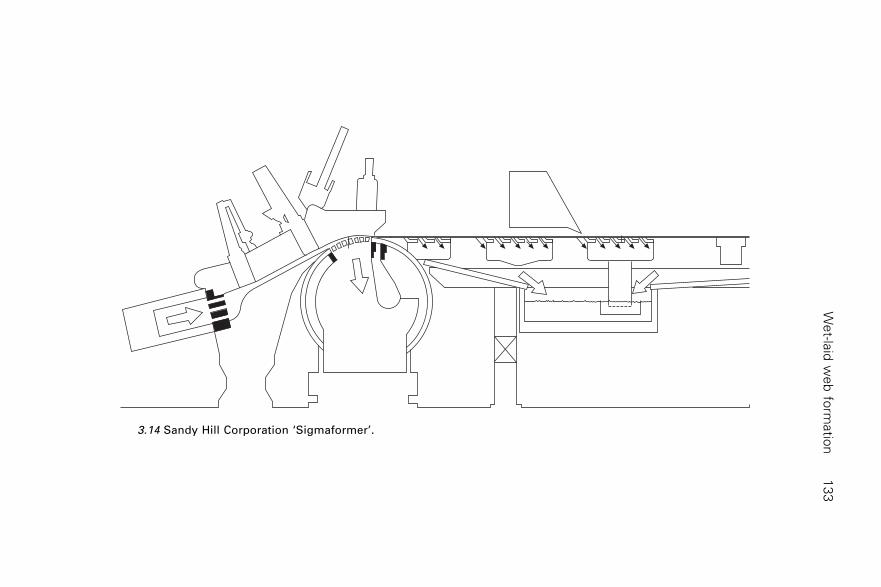
We
t-laid
we
b fo
rmatio
n1
33
3.14 Sandy Hill Corporation ‘Sigmaformer’.
Handbook of nonwovens134
suspension of the fibres with an air content of 60%. Under these conditionslong fibres are processed at a 0.4% forming consistency. British patent 1129757relates to the basic concept of the Radfoam process and a number of subsequentpatents were filed in many different countries. A US patent was allowed inSeptember 1972 and the process was made available on a licensed basis. Websin the weight range 30–120 g/m2 were produced at speeds up to 325 m/min.
The Lystil OY (now Ahlstrom) process
In 1996 Lystil OY of Finland announced a significant development in thewet-laid nonwovens field. Since the early developments of wet-lay, it hasalways been recognised that there would be advantages in being able toproduce multilayer structures. Earlier developments had resulted in multipleforming devices which allowed one layer to be deposited on the formingwire followed by a second layer and with care, a third layer could be added.In these cases the water suspension of the first layer was drained through theforming wire; for the second layer the water was drained through the previouslyformed first layer and when there was a third layer, the suspending water wasdrained through the first two wet layers on the wire. This forming methodwas limited by the natural compaction of the initial layers on the formingwire and this made the forming of the second and third layers problematicalin a number of cases. Although it has never been disclosed exactly howLystil OY achieve their simultaneous forming of three layers, it is likely tobe a development of twin wire forming technology used in paper and boardmaking. In 1968 Beloit Corporation published results of their research workinto simultaneous convergent forming. This research has been successfullyapplied to board making and to producing twin wire soft tissue, where veryhigh-speed jets of fibre/water suspension converge between two drainagewires to form a web of significantly improved formation (Fig. 3.15).
This technology allowed the manufacture of a three-layer soft tissue sheetthat had very soft cellulose fibres on the two outside layers and the stiffer butstronger fibres in the centre layer, thus providing a web that was soft totouch, but strong enough to be of practical use. It should be remembered thata soft tissue machine runs at speeds in excess of 2000 m/min and this highspeed is a necessary feature of the two-sided simultaneous dewatering thatmakes the sheet formation possible. Unfortunately, in the early stages of thisdevelopment there did not appear to be a way of achieving the same effectsat relatively slow speeds consistent with the forming of wet-laid nonwovens.There is little doubt that Lystil OY have developed a system that enables themsimultaneously to form three layers of water-dispersed fibres into a coherentnonwoven web. Although very little has been disclosed about the machinesystem built to do this, there is no doubt, judging from the materials produced,that this represents a major extension of wet-lay technology for nonwovens.
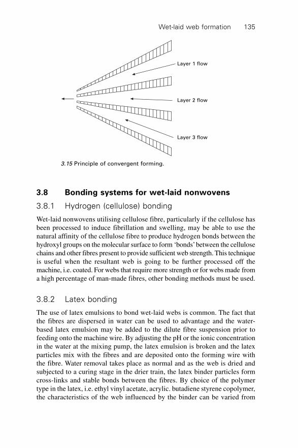
Wet-laid web formation 135
3.8 Bonding systems for wet-laid nonwovens
3.8.1 Hydrogen (cellulose) bonding
Wet-laid nonwovens utilising cellulose fibre, particularly if the cellulose hasbeen processed to induce fibrillation and swelling, may be able to use thenatural affinity of the cellulose fibre to produce hydrogen bonds between thehydroxyl groups on the molecular surface to form ‘bonds’ between the cellulosechains and other fibres present to provide sufficient web strength. This techniqueis useful when the resultant web is going to be further processed off themachine, i.e. coated. For webs that require more strength or for webs made froma high percentage of man-made fibres, other bonding methods must be used.
3.8.2 Latex bonding
The use of latex emulsions to bond wet-laid webs is common. The fact thatthe fibres are dispersed in water can be used to advantage and the water-based latex emulsion may be added to the dilute fibre suspension prior tofeeding onto the machine wire. By adjusting the pH or the ionic concentrationin the water at the mixing pump, the latex emulsion is broken and the latexparticles mix with the fibres and are deposited onto the forming wire withthe fibre. Water removal takes place as normal and as the web is dried andsubjected to a curing stage in the drier train, the latex binder particles formcross-links and stable bonds between the fibres. By choice of the polymertype in the latex, i.e. ethyl vinyl acetate, acrylic. butadiene styrene copolymer,the characteristics of the web influenced by the binder can be varied from
Layer 1 flow
Layer 2 flow
Layer 3 flow
3.15 Principle of convergent forming.
Handbook of nonwovens136
soft and drapable to stiff, rigid or rubbery. Latex emulsion binders may alsobe added to the wet web after forming (and if required after partial drying)if surface bonding is particularly important or the web properties requireddictate this approach.
3.8.3 Thermal bonding
Wet-laid webs may be thermally bonded by the application of heat providingthe web contains a fibre or an additive that will fuse at the selected bondingtemperature and will flow between the fibre junctions. On cooling, the bindermaterial locks the fibre network together. It is possible, if the web contains,for example, polyethylene fibres of the SWP type, that these may be meltedin discrete points (point bonded) to create bonds, but it is now generallypreferable to use specific binder fibres such as copolyesters or bicomponentsbased on the PP/PE or PET/CoPET27 structure. With bicomponent fibres ofthe side-by-side or sheath/core configuration, the lower melting point polymeris the polymer that forms the bond. The big advantage that the use ofbicomponents brings is that they do not leave a ‘hole’ in the web when thebond is formed because the higher melting point component remains as anintegral part of the web. The value of this is that it prevents wet web collapsein use. A special case of thermal bonding is the use of glass fibre to create athermally induced bond in structures formed from ceramic or other high-melting-point fibres. In this case, a small quantity of glass fibre, meltingpoint about 500 ∞C, is used to create a bond in ceramic fibre webs (meltingpoint 1750 ∞C).
3.8.4 Binder fibres based on polyvinyl alcohol28
A family of fibres based on polyvinyl alcohol (PVA) is available from Japanand some members of this group are soluble in water at various temperatures.Using a percentage of these fibres at the web-forming stage, with a solublisationtemperature of 80 ∞C, means that as the web passes through the drying train,the elevated temperature of the web will cause the fibres to dissolve in theresidual water. On cooling the solubilised PVA will form bonds between theother fibre components in the web, which have a higher solubilisationtemperature than polyvinyl alcohol.
3.8.5 Hydroentanglement
Hydroentanglement29 or spunlacing is the process of using high-energycolumnar water jets to entangle a network of fibres formed at the web-forming stage. Wet-laid webs can be successfully bonded using comparativelylow-pressure hydroentanglement alone or in combination with other bonding
Wet-laid web formation 137
methods depending on the required end-product properties. When used aloneto bond the web, the advantage is that there is no added binder component,which would otherwise modify the physical properties of the fabric. Secondly,the entanglement process is capable of producing a fabric with good physicalstrength without increasing the fabric stiffness to the extent of other bondingsystems. Hydroentanglement of webs containing bicomponent fibres followedby thermal bonding is also practised to enhance overall bonding and similarly,in the case of webs composed of natural fibres such as cotton, a smallquantity of latex binder may be applied to the hydroentangled fabric toprovide a more fully bonded surface.
3.8.6 Inorganic binder systems
For the high-performance inorganic fibres used in some wet-laid nonwovenapplications, there is a need to have a binder system that ensures the structureremains stable at elevated temperatures. ‘Conventional’ binder systems basedon organic materials are of little use under such conditions. However, sinceit is fundamental to wet-lay technology that the fibres are suspended inwater, this provides a route by which an inorganic binder system may becreated in situ. The adjustment of the pH or changing of the ionic concentrationof the liquid can be beneficial to the fibre dispersion, and this may be usedto create a binder. For example, using ceramic fibre to produce a high-temperature insulation material requires that the ceramic web be stabilisedup to its operating temperature. This can be achieved by creating an inorganicbinder within the web.
Aluminium sulphate dissolved in water creates an acid solution, which issuitable for dispersion of the ceramic fibre. At the mixing pump, ammoniumhydroxide solution is added to increase the pH to the alkaline side andprecipitate the gelatinous aluminium hydroxide that is formed by the chemicalreaction between the aluminium sulphate and the ammonium hydroxide.This gelatinous material is trapped within the fibre network as it is formedon the wire. As the web is dried, this gelatinous precipitate first loses waterand then, when the web is subsequently raised to its operating temperature,loses more water through crystallisation and forms alumina, which providesoperational high-temperature stability. The binder formed in this way increasesthe strength of the ceramic web (Figure 3.16). To be of practical use, suchwebs also need to have a ‘green strength’ binder, which will provide webflexibility when the web is dry from the machine and sent to be slit or cut tosize. Such a binder may be added by using a compatible latex emulsion thatwill be stable at the initial acid pH conditions and will precipitate when thepH is adjusted. This will provide the initial web flexibility that is requiredand as the web temperature is raised when the material is in use the latexbinder will burn off.
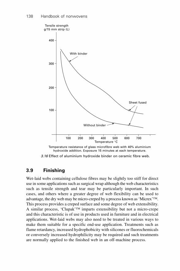
Handbook of nonwovens138
3.9 Finishing
Wet-laid webs containing cellulose fibres may be slightly too stiff for directuse in some applications such as surgical wrap although the web characteristicssuch as tensile strength and tear may be particularly important. In suchcases, and others where a greater degree of web flexibility can be used toadvantage, the dry web may be micro-creped by a process known as ‘Micrex’™.This process provides a creped surface and some degree of web extensibility.A similar process, ‘Clupak’™ imparts extensibility but not a micro-crepeand this characteristic is of use in products used in furniture and in electricalapplications. Wet-laid webs may also need to be treated in various ways tomake them suitable for a specific end-use application. Treatments such asflame retardancy, increased hydrophobicity with silicones or fluorochemicalsor conversely increased hydrophilicity may be required and such treatmentsare normally applied to the finished web in an off-machine process.
Tensile strength
g/15 mm strip (L)
400
300
200
100
With binder
Sheet fused
Without binder
100 200 300 400 500 600 700
Temperature ∞C
3.16 Effect of aluminium hydroxide binder on ceramic fibre web.
Temperature resistance of glass microfibre web with 40% aluminium
hydroxide addition. Exposure 15 minutes at each temperature.
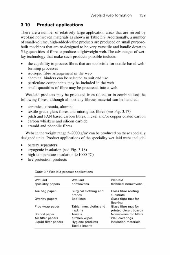
Wet-laid web formation 139
3.10 Product applications
There are a number of relatively large application areas that are served bywet-laid nonwoven materials as shown in Table 3.7. Additionally, a numberof small-volume, high-added-value products are produced on small purpose-built machines that are re-designed to be very versatile and handle down to5 kg quantities of fibre to produce a lightweight web. The advantages of wet-lay technology that make such products possible include:
∑ the capability to process fibres that are too brittle for textile-based web-forming processes
∑ isotropic fibre arrangement in the web∑ chemical binders can be selected to suit end use∑ particulate components may be included in the web∑ small quantities of fibre may be processed into a web.
Wet-laid products may be produced from (alone or in combination) thefollowing fibres, although almost any fibrous material can be handled:
∑ ceramics, zirconia, alumina∑ textile grade glass fibres and microglass fibres (see Fig. 3.17)∑ pitch and PAN based carbon fibres, nickel and/or copper coated carbon∑ carbon whiskers and silicon carbide∑ aramid and phenolic fibres.
Webs in the weight range 5–2000 g/m2 can be produced on these speciallydesigned units. Product applications of the speciality wet-laid webs include:
∑ battery separators∑ cryogenic insulation (see Fig. 3.18)∑ high-temperature insulation (>1000 ∞C)∑ fire protection products
Table 3.7 Wet-laid product applications
Wet-laid Wet-laid Wet-laid
speciality papers nonwovens technical nonwovens
Tea bag paper Surgical clothing and Glass fibre roofing
drapes substrate
Overlay papers Bed linen Glass fibre mat for
flooring
Plug wrap paper Table linen, cloths and Glass fibre mat for
napkins printed circuit boards
Stencil paper Towels Nonwovens for filters
Air filter papers Kitchen wipes Wall coverings
Liquid filter papers Hygiene products Insulation materials
Textile inserts
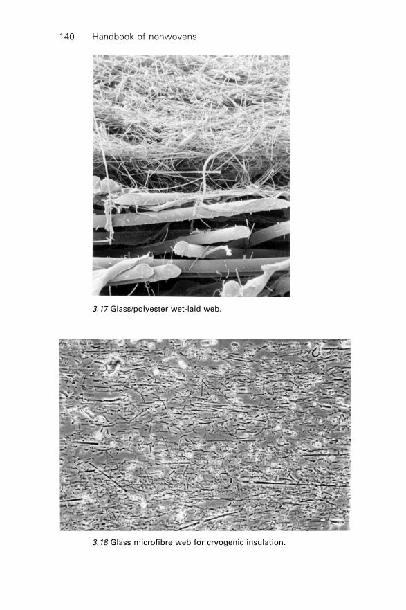
Handbook of nonwovens140
3.17 Glass/polyester wet-laid web.
3.18 Glass microfibre web for cryogenic insulation.
Wet-laid web formation 141
∑ static dissipation surfacing veils∑ RFI shielding veils∑ pultrusion materials∑ heat and controlled electrical conductance materials∑ electrolytic condenser separators.
3.11 Sources of further information
White Colin, Synthetic fibres in papermaking systems (including wetlaid nonwovens),PIRA International Leatherhead Surrey UK 1993.
White Colin F, Wetlaid and short fibre airlaid nonwovens, PIRA International LeatherheadSurrey UK 1996.
3.12 References
1. Grant J, Young J H and Watson B, Paper and Board Manufacture, Technical Division,British Paper & Board Industry Federation, 1978.
2. Inagaki H, Nonwovens Asia, Miller Freeman, San Francisco, USA 1989.3. Osbourne F H, The History of Dexter’s Long Fiber Paper Development, C.H. Dexter,
Windsor Locks, Connecticut, USA 1975.4. Parker J D, The Sheet Forming Process, Proc. TAPPI Stap No 9, TAPPI, Technical
Association of the Pulp & Paper Industry USA 1972.5. Schoffmann E, Neue Bruderhaus NoWoFormer Bulletin6. Hardy C, Fine dtex cellulosic fibres offer significant advantages, Nonwoven Report
International Yearbook 1991, No 245 p 50–52.7. Smith J E, Cellulose acetate fibrets: A fibrillated high surface area pulp for speciality
industrial applications, TAPPI Nonwovens Conference Proceedings 5–8 April 1988p 237–243.
8. Cruz M M, Rayons in Battista O A (ed.), Synthetic Fibers in Papermaking, Interscience1964.
9. Derwick G van Breen A W, A new polypropylene fibre for the paper industry Pira/BPBIF/PRI Conference 28–29 November 1978 p 4.1–4.4.
10. White C F, The use of synpulps for bonding inorganic nonwoven structures, INDA-TEC International Nonwoven Fabrics Conference 30 May–2 June 1989 PhiladelphiaUSA.
11. Brown H S, Casey P K and Donahue J M, Poly (Trimethylene Terephthalate) Polymerfor fibers, Nonwovens World, summer 1998.
12. Haile W A and Phillips B M, Deep grooved polyester fiber for wetlay applicationsTAPPI Journal Vol 78 No 9. September 1995.
13. Ramirez J E and Dwiggins C F, High temperature papers made of polybenzimidazole,TAPPI Converting & Packaging December 1985.
14. Parker R B, Sulfar PPS fibers for nonwovens, TAPPI Journal May 1992.15. Evans R E, Fibrillatable acrylic fibers for speciality nonwovens, PIRA High
performance fibers and structures seminar 4 December 1990 Wilmslow UK.16. Bailey R M and McKean W T, The characteristics of glass fibers in papermaking,
TAPPI Journal August 1989.17. Fryatt J, Production properties and applications of ceramic fibers, PIRA High
performance fibers and structures seminar, 4 December 1990 Wilmslow UK.
Handbook of nonwovens142
18. White C F and Moore G K, Ceramic and Mineral wool fibers in wetlay formingprocesses, TAPPI Journal December 1987.
19. Keith J M, Dispersion of synthetic fiber for wetlay nonwovens, TAPPI Journal Vol77 No 6 June.
20. Shiffler D A, Characterising the dispersion kinetics of synthetic fibers in water,TAPPI Journal August 1985.
21. Stassen W N, Dispersing glass fibers in the wet process, TAPPI Nonwovens Conference1983.
22. Meierhoefer A W, Wetlaid nonwovens – a survey of the fundamentals of making
speciality fabrics on papermaking machinery, Nonwoven Fabrics Forum, ClemsonUniversity 19–26 June 1989 Clemson USA.
23. Schoffmann E and Schwend F, Meeting trend developments in wet forming, TAPPINonwovens Conference 12–16 May Marco Island Fl USA 1991.
24. Schoffmann E, The use of inclined wire formers to produce nonwoven materials for
medical/health care applications, PIRA Nonwovens in Medical and HealthcareApplications seminar 10–12 November, Brighton UK 1987.
25. Magill D G, Operation and capabilities of wet forming devices for long fiberedstructures, TAPPI Journal January 1987.
26. Dunn M P, Multiply sheet formation on inclined wire formers, TAPPI Journal October1988.
27. Haile W, Dean L and Gregory D, Co Polyester Polymers for binder fibers, Nonwovens
World, summer 1998.28. Ohmori A, A new water soluble synthetic fibre for nonwoven applications, EDANA
INDEX 96 symposium Geneva 1996 R&D Session.29. White C F, Hydroentanglement technology applied to wet formed and other precursor
webs, TAPPI Journal, June 1990.
143
4.1 Introduction
Polymer-laid, spunlaid or ‘spunmelt’ nonwoven fabrics are produced byextrusion spinning processes, in which filaments are directly collected toform a web instead of being formed into tows or yarns as in conventionalspinning. As these processes eliminate intermediate steps, they provideopportunities for increasing production and cost reductions. In fact, meltspinning is one of the most cost efficient methods of producing fabrics.Commercially, the two main polymer-laid processes are spunbonding(spunbond) and meltblowing (meltblown). Both are similar in principle, butthe technologies used are quite different. Because of distinct differences inthe structure and properties of the fabrics, these processes have grown inparallel since their inception in the late 1950s and for some applications theyare also used in combination to produce bilaminates, trilaminates (e.g., SMS)and other multilayer fabrics. Advancements in polymer chemistry and extrusiontechnology have enabled an increasingly varied range of products to bedeveloped based on the core spunlaid and meltblown technologies. Some ofthe most important research commenced in the late 1950s, and an extensivenumber of processing and product patents have been reported over the years.More recently, there has been a dramatic resurgence of research anddevelopment concerned with polymer-laid systems as well as an increasedacceptance of the fabrics in new product areas.
4.2 Resins for spunbonding and meltblowing
In general, high molecular weight and broad molecular weight distributionpolymers such as polypropylene, polyester and polyamide can be processedby spunbonding to produce uniform webs. Medium melt viscosity polymers,commonly used for production of fibers by melt spinning, are also used. Incontrast, low molecular weight and relatively narrow molecular weightdistribution polymers are preferred for meltblowing.
4Polymer-laid web formation
G S B H ATUniversity of Tennessee, USA and
S R M A L K A NSynfil Technologies, USA
Handbook of nonwovens144
In the past decade, the use of polyolefins, especially polypropylene, hasdominated the production of meltblown and spunbonded nonwovens. One ofthe main reasons for the growing use of polyolefins in polymer-laid nonwovensis that the raw materials are relatively inexpensive and available throughoutthe world. Polyolefin resins are widely used in nonwovens mainly becausethey offer a relatively attractive cost combined with good value and ease ofuse when compared to conventional resins, such as polyesters and polyamides.Moreover, continuing advances in polyolefin fiber grade resins are strengtheningthe olefin’s price-properties ratio, which make them more suitable for polymer-laid nonwoven applications.
Commercial polyolefin technologies over the last six decades have gonethrough significant changes. They have gone through introduction, growth,and stabilization or maturity phases.1 The drive for technology evolution hasbeen the industry’s desire to continuously improve control of the moleculararchitecture, which leads to improved polymer performance. The keydevelopments or milestones in polyolefin technology are as follows:2
∑ In the 1930s, ICI set a trend of making versatile plastics by introducingits high-pressure process for making polyethylene resins.
∑ In the 1950s, the discovery of stereo-regular polyolefins and the incrediblyrapid development of catalysts and processes led to commercializationof crystalline isotactic polypropylene and HDPE resins.
∑ In the 1970s and through the 1990s, the invention of the low-pressure,gas phase process for making linear polyolefins started the wheels turning.
∑ In the 2000s, the introduction of a single site catalyst for making superiorpolyolefin resins set another technological trend.
4.2.1 Markets
Polyolefins are the most widely used resins in polymer-laid nonwovens.Table 4.1 shows the total usage of PP and PE in nonwovens.3 It is estimatedthat, of this total usage, about 45 to 55% is used in polymer-laid nonwovensapplications. Polypropylene has the major share of the disposable diapers,sanitary product markets, and medical apparel, and is the principal fiber usedin geotextiles, nonwoven furniture construction sheeting, and carpet
Table 4.1 World consumption of polyolefin resins3
Region Polypropylene (PP) Polyethylene
in million lbs. (PE)
United States 815 75
Europe 760 40
Japan and the Far East 150 <5
Polymer-laid web formation 145
components. It is also widely used in wet filtration applications. Polyethyleneis used predominantly in the United States for industrial garments, housewrap,envelopes, and other paper-like products.
4.2.2 Polyolefin resins
Commercially available polyolefin resins span a very wide range of molecularweights and comonomer contents ranging from extremely viscous highmolecular weight resins to low molecular weight liquids; from highlycrystalline, stiff materials to low modulus, amorphous polymers. The twomain polyolefin resins used in polymer-laid nonwovens are polypropylene(PP) and polyethylene (PE). Although both of these resins are members ofthe olefin family, they have significantly different processing requirementsand performance variations.3
Polypropylene is the most widely used resin in polymer-laid nonwovensand it exists in three forms: isotactic, syndiotactic, and atactic. Commercially,isotactic PP is the principal type.
1. Isotactic PP is a stereo specific polymer because the propylene units areadded head to tail so that their methyl groups are all on the same side ofthe plane of the polymeric backbone. It crystallizes in a helical form andexhibits good mechanical properties, such as stiffness and tensile strength.Isotactic PP is sold commercially in three basic types of product:homopolymer, random copolymer, and block copolymer. Homopolymerhas the highest stiffness and melting point of the three types and ismarketed in a wide range of melt flow rates (MFR).
2. Syndiotactic PP is made by inserting the monomer units in an alternatingconfiguration. It lacks the stiffness of the isotactic form, but has betterimpact and clarity.
3. Atactic PP is made via random insertion of the monomer. This formlacks the crystallinity of the other two. It is mainly used in roofing tarsand adhesives applications.
Fibre grade PP resins are mainly isotactic homopolymers. PP homopolymerwhen drawn or oriented, gives a material with improved tensile, stiffness andtear strength, and clarity due to the molecular alignment. Several importantfiber technologies take advantage of the drawability of PP resins and aremajor consumers of PP resins. Low melt flow resins are used for monofilamentsand slit film applications. Medium to high melt flow rate polypropylene isused to produce continuous fine denier filaments, extruded through spinneretsin melt spinning. Spunbonding usually requires a narrow molecular weightdistribution and high melt flow rate (MFR) resins, typically of 30 to 80MFR. Melt blowing is compatible with a variety of narrow molecular weightmelt flow rate resins, typically these are 30 to 1500 MFR.3
Handbook of nonwovens146
Polyethylene (PE) resins are made by polymerizing ethylene monomer. Itcan also be copolymerized with other materials to modify or enhance certainproperties. For example, the density of polyethylene can be manipulated bythe type and amount of comonomer reacted with ethylene to make the polymer.This comonomer, in combination with the manufacturing process, affects thetype, frequency, and length of branching that occurs in the molecule. Thisvariation results in different types of polyethylene.3 There are three basictypes of polyethylene, namely:
1. HDPE resin. The term HDPE is an abbreviation for high densitypolyethylene. The typical density of this resin is 0.950 g/cm3 and higher.
2. LDPE resin. The term LDPE is an abbreviation for low densitypolyethylene. The typical density of this resin ranges from 0.910 to0.925 g/cm3.
3. LLDPE resin. The term LLDPE is an abbreviation for linear low densitypolyethylene, which typically ranges from 0.915 to 0.930 g/cm3.
Fiber grade PE resins are mainly HDPE and LLDPE. Low melt flow rateHDPE resins are used for filament applications. Medium to high melt flowrate LLDPE resins are used to produce continuous fine denier filaments.Both spunbonding and meltblowing require medium melt flow rate PE resins.The typical range is 0.5 to 300 MFR.
The extrusion and spinning characteristics of all polyolefin resins arequite distinct. It is known that polypropylene resin is more difficult to extrudethan polyethylene.4 This is mainly due to the high shear sensitivity ofpolypropylene resin and to a limited extent, the higher melting point. Generallyspeaking, the output for polypropylene from a given size of extruder is lowerthan that of polyethylene and has a greater tendency to surge.4 On the otherhand, both polypropylene and polyethylene resins are relatively easy to spininto fine denier filaments provided the resins have a narrow molecular weightdistribution and an appropriate MFR.
The main resin characteristics affecting the extrusion and spinning processesduring the production of polymer-laid nonwovens are as follows:3
∑ Melting point. Most PP resins melt at around 165 ∞C whereas PE resinsmelt at around 120 to 140 ∞C. The melting point directly affects the melttemperature during processing. The higher the melting point, the higherthe energy requirements.
∑ Thermal bonding. Thermal bonding is an integral step in manyspunbonding processes. It influences the structural integrity and drapecharacteristics of the finished product. PP has a broader thermal bondingwindow than PE, mainly due to a higher melting range and highercrystallinity. The thermal bonding range for PP is from 125 to 155 ∞Cand for PE it ranges from 90 to 110 ∞C.
Polymer-laid web formation 147
∑ Molecular weight distribution (MWD). Both spunbonding andmeltblowing require relatively narrow molecular weight resins. The narrowmolecular weight distribution reduces the melt elasticity and melt strengthof the resin so that the melt stream can be drawn into fine denier filamentswithout excessive draw force. The broad MWD increases melt elasticityand melt strength, which prohibit fiber drawing therefore a broad MWDresin is prone to produce fiber breaks due to draw resonance (meltinstability) phenomena.
∑ Melt viscosity. Melt viscosity is a function of MFR and melt temperature.The melt viscosity of the melt has to be appropriate in order to form finefilaments. The MFR range suitable for spunbonding is 30 to 80 and formelt blowing it is 30 to 1500.
∑ Resin cleanliness. Owing to the fine capillary diameter of the spinneretutilized in spunbonding and meltblowing, it is important to have a resinwith practically no contaminants. The contaminants block the spinneretholes during processing causing inconsistency in the final product. Usuallythe contaminants are removed using a two-step melt filtration system.
Polyolefin technology is growing faster than any other polymer technology.To understand new developments, we must first understand the catalysts ingeneral. In polyolefin manufacturing, the monomers are reacted using acatalyst. All catalysts have reactive sites enabling them to perform theirfunction, which is linking individual molecules to form a polymeric chain.Conventional catalysts have many reactive sites located randomly on thesurface of the catalyst. This produces different and varying polymers. Thenew catalyst system, which is known as a single-site catalyst, also has manyreactive sites, but all sites are identical. This in turn gives identical polymersand minimizes the variability of polymers.2,5–6
The most commonly used single-site catalyst to manufacture polyolefinresins is the metallocene catalyst. Companies around the world have startedproducing metallocene based polyolefin resins.6 The metallocene based resinsoffer various attributes, as described below:
∑ They allow control of the molecular structure of polyolefins.∑ They enable the virtual elimination of non-targeted molecular weight
species in resins.∑ They allow incorporation of comonomers and termonomers with greater
precision.∑ They offer a greater control of MWD and comonomer incorporation
than other types of catalysts.∑ Only a small catalyst residue is left in the finished product.
The fiber grade metallocene based polyolefin resin used in spunbonding andmeltblowing offer the following advantages over conventional resin:3
Handbook of nonwovens148
∑ finer denier fibers than conventional resins∑ the optimum bonding temperatures in spunbonding are lower because of
the lower melting point∑ fabric strengths are comparable∑ excellent spinning continuity∑ can be spun at higher draw force∑ substantial reduction in volatile deposits∑ a broader MFR range, especially for meltblowing.
4.2.3 Polyester
Polyester is used in a number of commercial spunbond products and offerscertain advantages over polypropylene, although it is more expensive. Unlikepolypropylene, polyester scrap is not readily recycled in spunbondmanufacturing. The tensile strength, modulus, and heat stability of polyesterfabrics are superior to those of polypropylene. Polyester fabrics are easilydyed and printed with conventional non-aqueous processes.
4.2.4 Polyamide
Spunbond fabrics are made from both nylon-6 (PA-6), and nylon-6,6 (PA6.6).Nylon is highly energy intensive and therefore more expensive than polyesteror polypropylene. Nylon-6,6 spunbond fabrics are produced with weights aslow as 10 g/m2 and with excellent cover and strength. Unlike olefins andpolyester fabrics, those made from nylon readily absorb water by means ofhydrogen bonding between the amide group and water molecules.
4.2.5 Polyurethane
Following development work by various workers, spunbond fabrics madefrom thermoplastic polyurethane (TPU), was commercially developed inJapan. Unique properties are claimed for this product, which appears to bewell suited for apparel, hygiene products and other applications requiringgood stretch, recovery and fit. Various polymer suppliers produce TPUs andwhile problems can be experienced in processing with static electricity andother practical problems, the use of these polymers has gained increasinginterest for both meltblown and spunbond fabrics. Spunbond fabrics containingcore-sheath bicomponent filaments have been commercialized by ADC (ajoint venture between BBA Fiberweb and Dow). These spunbond fabricscontain filaments with an elastomeric PU core and a very thin sheath of apolyolefin, which gives the fabric a characteristic textile handle. To aid dyeing,the use of PET sheaths is anticipated.
Polymer-laid web formation 149
4.2.6 Rayon
Many types of rayons (including viscose and cuprammonium rayon) havebeen successfully processed into usable spunbond webs using wet-spinningtechnology. The main advantage of rayon is that it provides good drapeproperties and softness to web.
4.2.7 Bicomponents (Bicos) and mixed polymers
Some fabrics are composed of several polymers. A lower melting polymercan function as the binder that may be a separate fiber interspersed withhigher melting fibers, or two polymers may be combined into a single fibertype. In the latter case the so-called bicomponent fibers or filaments possessa lower melting component, which acts as a sheath covering a higher melttemperature core. Bicomponent filaments are also spun by extrusion of twoadjacent polymers. Polyethylene, nylon-6 and polyesters modified byisophthalic acid are used as the lower-melting point bicomponent elements.New polymers such as PTT and PTAT have been shown to produce goodquality spunbond webs. PTT has an intermediate melt temperature betweenthat of PP and PET and has no shrinkage problems compared to regular PET.PTAT is a copolyester that is biodegradable and has the definite advantage ofdisposability with low environmental impact. Many other new polymers,copolymers and polymer blends are being evaluated as candidates forspunbonding. Whereas each polymer or combination of polymers can claimcertain advantages, the cost of these resins, at least initially, prevents theirgrowth. Unless the property advantages offered by these new resins outweighthe higher cost, their growth will be limited to specialty applications.
Splittable bicomponents are also found in spunbond fabrics and havesome interesting applications. The cross-section of these bicomponent filamentshas at least two different polymer components, which in spunbonding arenormally arranged sequentially in a segmented pie form. To aid mechanicalsplitting, the core of the filament may be hollow. Evolon® fabrics producedby Freudenberg are made of segmented bicomponent filaments that are splitinto microfibres during hydroentanglement of the spunlaid web. The resultingfabrics are extremely soft, particularly after finishing, and have thereforebeen considered for use in clothing, hygiene and medical dressing components.Additionally, bicomponent fibres with an eccentric sheath core arrangementare used to develop crimp in spunlaid fabrics by differential thermal shrinkageof the two polymer components.
4.3 Spunbond fabric production
The concept of spunbond fabric production (or spunlaid web formation)developed simultaneously in Europe and the USA in the late 1950s but it was
Handbook of nonwovens150
later, in the mid-1960s to the early 1970s, that the commercial potential ofspunbond technology was fully recognized. Numerous patents on spunbondprocess design were filed during this period and some were commerciallyadopted. In the USA, DuPont developed and commercialized the first spunbondprocess in the late 1950s.7 In 1965, research at DuPont resulted in a polyesterspunbond product called Reemay® manufacture. This was followed by thepolypropylene spunbond fabric Typar® and the flashspun polyethylene fabricTyvek®.8 Although DuPont subsequently sold both the Reemay® and Typar®
technologies to Reemay Inc., DuPont still remains a significant force in thespunbond market with Tyvek® branded products.
In Europe, the German company Freudenberg filed several patents on thespunbond process in 1959. Six years later, Freudenberg introduced their firstspunbond process, Lutravil® and made a product called Viledon M®, madefrom mixed polyamides.9 The German company became the first Europeanspunbond manufacturer and in 1970 Freudenberg incorporated all its spunbondactivities into the Carl Freudenberg Spunbond Division based in Kaiserslautern.At this facility, polyester, polyamide, and later polypropylene spunbondedfabrics were produced. About the same time in 1970, Lurgi Kohle &Mineraloltechnik GmbH, Germany introduced the Docan® spunbond processand in 1971 started licensing the process in the USA. Many US and Europeanspunbond roll goods manufacturers use the Docan® process with proprietarymodifications.
There were comparatively few major developments in the spunbondingprocess from 1971 to the early 1980s until in 1984, Reifenhauser GmbH,Germany, introduced the Reicofil® spunbond process. A few years before itsintroduction, Reifenhauser had purchased the rights to an East German patentfor the production of polyamide spunbond webs.7 Considerable research anddevelopment effort based on the original East German process resulted in thedevelopment of the Reicofil® system for producing webs primarily frompolypropylene.7
Further spunbond processes have been introduced. Amoco Fibers andFabrics, USA introduced the RFX® system and Sodoca, France introducedthe S-TEX® system.10 These processes are reported to make highly uniformwebs even at low basis weights, thereby providing opportunities that theearlier spunbonding processes were unable to meet. Kobelco, Japan, Neumag-Ason, Germany and Nordson, USA are also operating in this market withnew spunbonding systems and in Italy, Meccaniche Moderne S.p.A is offeringspunbond equipment. Spunbond machinery manufacturers are listed in Table4.2. Reifenhauser supplies about 70% of current commercial productionlines.
A primary factor in the production of spunbonded fabrics is the control offour simultaneous, integrated operations: filament extrusion, drawing, laydown, and bonding. The first three operations are directly adapted from
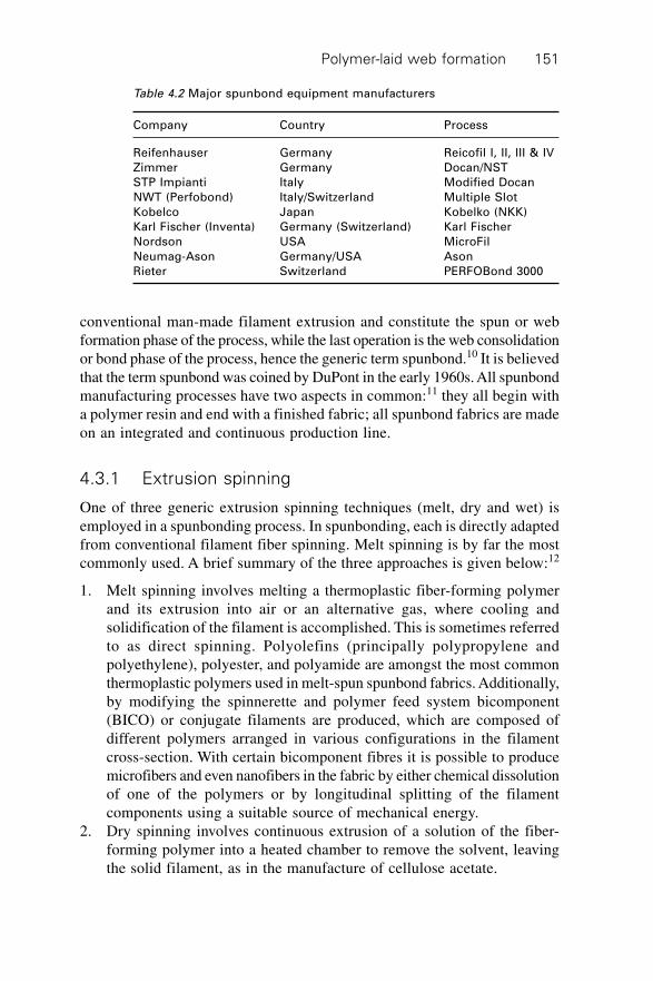
Polymer-laid web formation 151
conventional man-made filament extrusion and constitute the spun or webformation phase of the process, while the last operation is the web consolidationor bond phase of the process, hence the generic term spunbond.10 It is believedthat the term spunbond was coined by DuPont in the early 1960s. All spunbondmanufacturing processes have two aspects in common:11 they all begin witha polymer resin and end with a finished fabric; all spunbond fabrics are madeon an integrated and continuous production line.
4.3.1 Extrusion spinning
One of three generic extrusion spinning techniques (melt, dry and wet) isemployed in a spunbonding process. In spunbonding, each is directly adaptedfrom conventional filament fiber spinning. Melt spinning is by far the mostcommonly used. A brief summary of the three approaches is given below:12
1. Melt spinning involves melting a thermoplastic fiber-forming polymerand its extrusion into air or an alternative gas, where cooling andsolidification of the filament is accomplished. This is sometimes referredto as direct spinning. Polyolefins (principally polypropylene andpolyethylene), polyester, and polyamide are amongst the most commonthermoplastic polymers used in melt-spun spunbond fabrics. Additionally,by modifying the spinnerette and polymer feed system bicomponent(BICO) or conjugate filaments are produced, which are composed ofdifferent polymers arranged in various configurations in the filamentcross-section. With certain bicomponent fibres it is possible to producemicrofibers and even nanofibers in the fabric by either chemical dissolutionof one of the polymers or by longitudinal splitting of the filamentcomponents using a suitable source of mechanical energy.
2. Dry spinning involves continuous extrusion of a solution of the fiber-forming polymer into a heated chamber to remove the solvent, leavingthe solid filament, as in the manufacture of cellulose acetate.
Table 4.2 Major spunbond equipment manufacturers
Company Country Process
Reifenhauser Germany Reicofil I, II, III & IV
Zimmer Germany Docan/NST
STP Impianti Italy Modified Docan
NWT (Perfobond) Italy/Switzerland Multiple Slot
Kobelco Japan Kobelko (NKK)
Karl Fischer (Inventa) Germany (Switzerland) Karl Fischer
Nordson USA MicroFil
Neumag-Ason Germany/USA Ason
Rieter Switzerland PERFOBond 3000
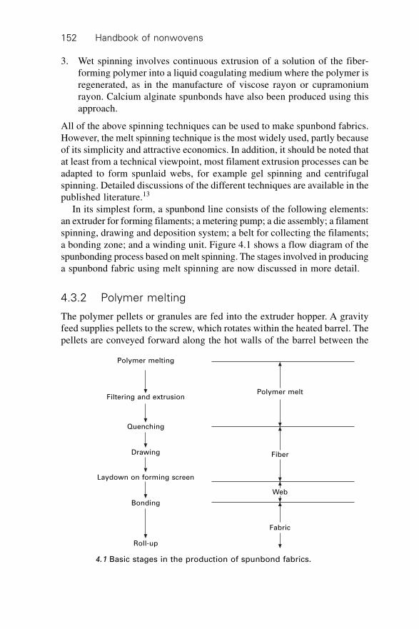
Handbook of nonwovens152
3. Wet spinning involves continuous extrusion of a solution of the fiber-forming polymer into a liquid coagulating medium where the polymer isregenerated, as in the manufacture of viscose rayon or cupramoniumrayon. Calcium alginate spunbonds have also been produced using thisapproach.
All of the above spinning techniques can be used to make spunbond fabrics.However, the melt spinning technique is the most widely used, partly becauseof its simplicity and attractive economics. In addition, it should be noted thatat least from a technical viewpoint, most filament extrusion processes can beadapted to form spunlaid webs, for example gel spinning and centrifugalspinning. Detailed discussions of the different techniques are available in thepublished literature.13
In its simplest form, a spunbond line consists of the following elements:an extruder for forming filaments; a metering pump; a die assembly; a filamentspinning, drawing and deposition system; a belt for collecting the filaments;a bonding zone; and a winding unit. Figure 4.1 shows a flow diagram of thespunbonding process based on melt spinning. The stages involved in producinga spunbond fabric using melt spinning are now discussed in more detail.
4.3.2 Polymer melting
The polymer pellets or granules are fed into the extruder hopper. A gravityfeed supplies pellets to the screw, which rotates within the heated barrel. Thepellets are conveyed forward along the hot walls of the barrel between the
Polymer melting
Filtering and extrusion
Quenching
Drawing
Laydown on forming screen
Bonding
Roll-up
Polymer melt
Fiber
Web
Fabric
4.1 Basic stages in the production of spunbond fabrics.
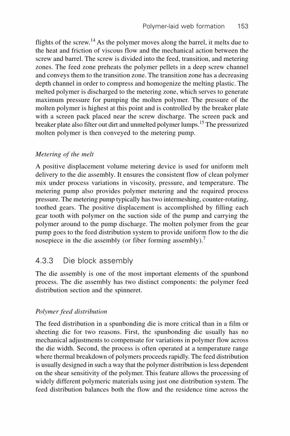
Polymer-laid web formation 153
flights of the screw.14 As the polymer moves along the barrel, it melts due tothe heat and friction of viscous flow and the mechanical action between thescrew and barrel. The screw is divided into the feed, transition, and meteringzones. The feed zone preheats the polymer pellets in a deep screw channeland conveys them to the transition zone. The transition zone has a decreasingdepth channel in order to compress and homogenize the melting plastic. Themelted polymer is discharged to the metering zone, which serves to generatemaximum pressure for pumping the molten polymer. The pressure of themolten polymer is highest at this point and is controlled by the breaker platewith a screen pack placed near the screw discharge. The screen pack andbreaker plate also filter out dirt and unmelted polymer lumps.15 The pressurizedmolten polymer is then conveyed to the metering pump.
Metering of the melt
A positive displacement volume metering device is used for uniform meltdelivery to the die assembly. It ensures the consistent flow of clean polymermix under process variations in viscosity, pressure, and temperature. Themetering pump also provides polymer metering and the required processpressure. The metering pump typically has two intermeshing, counter-rotating,toothed gears. The positive displacement is accomplished by filling eachgear tooth with polymer on the suction side of the pump and carrying thepolymer around to the pump discharge. The molten polymer from the gearpump goes to the feed distribution system to provide uniform flow to the dienosepiece in the die assembly (or fiber forming assembly).7
4.3.3 Die block assembly
The die assembly is one of the most important elements of the spunbondprocess. The die assembly has two distinct components: the polymer feeddistribution section and the spinneret.
Polymer feed distribution
The feed distribution in a spunbonding die is more critical than in a film orsheeting die for two reasons. First, the spunbonding die usually has nomechanical adjustments to compensate for variations in polymer flow acrossthe die width. Second, the process is often operated at a temperature rangewhere thermal breakdown of polymers proceeds rapidly. The feed distributionis usually designed in such a way that the polymer distribution is less dependenton the shear sensitivity of the polymer. This feature allows the processing ofwidely different polymeric materials using just one distribution system. Thefeed distribution balances both the flow and the residence time across the
Handbook of nonwovens154
width of the die. There are basically two types of feed distribution that areemployed in the spunbonding die, the T-type (tapered and untapered) and thecoat-hanger type. An in-depth mathematical and design description of eachtype of feed distribution is given by Mastubara.16–20 The T-type feed distributionis widely used because it gives both even polymer flow and even residencetime across the full width of the die.
Spinneret
From the feed distribution channel the polymer melt goes directly to thespinneret. The spinneret is one of the components of the die assembly. Theweb uniformity partially hinges on the design and fabrication of the spinneret,therefore the spinneret in the spunbonding process requires very closetolerances, which has continued to make their fabrication very costly. Aspinneret is made from a single block of metal having several thousanddrilled orifices or holes. The orifices or holes are bored by mechanical drillingor electric discharge machining (EDM) in a certain pattern. The spinneretsare usually circular or rectangular in shape. In commercial spunbondingprocesses, the objective is usually to produce a wide web (of up to about5 m), and therefore many spinnerets are placed side by side to generatesufficient fibers across the width.21 The grouping of spinnerets is often calleda block or bank. In commercial production lines, two or more blocks areused in tandem in order to increase the coverage of the filaments.
4.3.4 Filament spinning, drawing, and deposition
The proper integration of filament spinning, drawing, and deposition is criticalin the spunbonding process. The main collective function is to solidify, draw,and entangle the extruded filaments from the spinneret and deposit themonto an air-permeable conveyor belt or collector.
Drawing
Filament drawing follows spinning. In conventional extrusion spinning, drawingis achieved using one or more set of draw rollers. While roller drawing cancertainly be used in spunbonding, a specially designed aerodynamic devicesuch as a Venturi tube is commonly adopted.
Deposition
Filament deposition follows the drawing step. Filament deposition is alsofrequently achieved with the aid of a specially designed aerodynamicdevice referred to as a fanning or entangler unit. The fanning unit is intended
Polymer-laid web formation 155
to cross or translate adjacent filaments to increase cross-directional webintegrity.
4.4 Spunbond production systems
Many filament spinning, drawing, and deposition systems have been patentedand commercialized. Some of the basic principles involved as proposed byHartman,22 are shown in Fig. 4.2 and are explained below:
∑ Route 1 (Fig. 4.2(a)) is a system using longitudinal spinnerets, with airslots on both sides of the spinneret for the expulsion of the drawing gas‘1’ (primary air). The room air (secondary air) ‘2’ is carried along andafter lay down of the filaments, the air is removed by suction ‘3’. Thisprocess is well suited for tacky polymers, such as linear polyurethene.The web is truly ‘spunbonded’, that is, the continuous filaments afterweb collection bond themselves (self-bond) at their crossover points dueto their inherent tackiness. Crystallization, which then sets in, subsequentlyeliminates the stickiness of the filaments after the bonding step.
∑ Route 2 (Fig. 4.2(b)) shows how a higher draw ratio can be achieved,which results in increased molecular orientation of filaments. Filamentsare drawn with several air or gas streams using drawing conduits. The airis removed by suction ‘4’ after web formation. This process has advantagesin preparing lightweight spunbond webs containing fine filaments witha textile-like appearance and handle.
(a) (b) (c) (d)
1 1
2
3
2
1 1
2
3
2
3
3 4 4 4
4.2 Schematic of filament spinning, drawing and deposition systems(based on ref. 22).
Handbook of nonwovens156
∑ Route 3 (Fig. 4.2(c)), operates with regular cooling ducts ‘1’ and drawingjets ‘3’. The drawing and cooling arrangements can be operated to givevery high spinning speeds with the result that highly oriented filamentsare produced. The room air ‘2’, of controlled temperature and moisturecontent, can be entrained to control the development of filament properties.The air is removed by suction ‘4’ after web formation.
∑ Route 4 (Fig. 4.2(d)), has a mechanical drawing step ‘2’ between thespinneret and lay down zones. This route is similar to conventionalspinning and is especially useful for polymers, which in regular airdrawing do not give optimum filament molecular orientation. Again, airstreams are used for cooling ‘1’ and for lay down ‘3’ and ‘4’. Webs withhigh strength and low elongation can be made using this particular route.
A large number of different spunbond processes can be classified accordingto one of these four routes with appropriate modifications or refinements.There are many examples of process improvements in the patent literaturerelating to drawing and web deposition. Some of the most successful spinning,drawing, and deposition spunbond systems merit a brief discussion.
4.4.1 Docan system
Developed by Lurgi Kohle & Mineraloltechnik GmbH, Germany in 1970,many nonwoven companies have licensed this process from the LurgiCorporation for commercial production. The Docan route is based on meltspinning, where the melt is forced by spin pumps through special spinneretshaving a large number of holes.7 By suitable choice of extrusion and spinningconditions, the desired filament denier is obtained. The blow ducts locatedbelow individual spinnerets continuously cool the filaments with conditionedair. The force required for filament drawing and orientation is produced byan aerodynamic system. Each continuous filament bundle is picked up by adraw-off jet operated at high pressure and is passed through a guide tube toa separator which effects separation and fanning of the filaments.23 Finally,the filament fan leaving the separators is deposited as a notionally randomweb on a moving mesh belt. Suction below the sieve belt assists the filamentlay down.
4.4.2 Reicofil system
This route was developed by Reifenhauser GmbH, Germany and can bepurchased as a turn-key installation. Commercially, many nonwoven companiesuse the Reicofil system of which there are now multiple generations. Thisroute is based on melt spinning and the melt is forced by spin pumps throughspinnerets having a large number of holes.7 Primary blow ducts, locatedbelow the spinneret block, continuously cool the filaments with conditioned
Polymer-laid web formation 157
air. The secondary blow ducts, located below the primary blow ducts,continuously supply the auxiliary air at room temperature. A ventilator operatingacross the width of the machine, generates under-pressure and sucks thefilaments together with the mixed air down from the spinnerets and coolingchambers. The continuous filaments are sucked through a Venturi (high velocitylow pressure zone) to a distributing chamber, where fanning and entanglingof the drawn filaments takes place. Finally, the entangled filaments are depositedon a moving suctioned mesh belt to form a web. Filament orientation in theweb is influenced by turbulence in the air stream, which generally serves toincrease randomization. However, a small bias in the machine direction isusual due to some directionality imparted by the conveyor belt.7
4.4.3 Lutravil system
Developed by The Carl Freudenberg Company, Germany in 1965, thisspunbonding process is proprietary and is not available for commerciallicensing. The melted polymer is forced by spin pumps through the spinnerets.The primary blow ducts, located below the spinneret block, continuouslycool the filaments with conditioned air. The secondary blow ducts, locatedbelow the primary blow ducts, continuously supply controlled room temperatureair. The filaments are passed through a device where high-pressure tertiaryair is introduced to draw and orient the filaments. Finally, the filaments aredeposited as a web on a moving mesh belt.
4.4.4 Ason/Neumag system
This process uses a slot design to generate higher filament speed. During the1990s various attempts were made by spunbond machine manufacturers toproduce lighter-weight spunbond fabrics, particuarly for hygiene applications.To achieve this, there is a need to produce webs containing finer filamentsand consequently there has been much discussion about the prospect ofspunbond fabrics replacing meltblowns in certain product applications. TheAson-Neumag process is claimed to be quite flexible with several benefitssuch as the capability to process a multitude of polymers at high spinningspeeds. Another benefit is a smaller filament diameter. Finer (sub-denier)filaments allow greater fabric coverage and a softer but frequently strongerfabric (due to the increased filament surface area). The elevated spinningspeed allows for a stronger filament due to higher molecular orientation aswell as, in some cases, increased fabric elasticity.
4.5 Bonding techniques
The conveyor belt carries the unbonded web to the bonding zone. There arethree basic bonding techniques employed in a spunbond process: thermal,
Handbook of nonwovens158
chemical/adhesive, and mechanical. The choice of technique is dictated mainlyby the ultimate fabric application and the web weight. Occasionally, acombination of two or more bonding techniques is employed.
4.5.1 Thermal (fusion) bonding
Thermal bonding is the most widely used method in spunbonding. Bondingis achieved by fusing filaments in the web at their cross-over points. Thefusion is achieved by the direct action of heat and pressure via calenderrollers (contact bonding) or an oven (through-air bonding). The degree offusion determines many mechanical and physical fabric properties includingfabric handle.
Point and area bonding
In respect of the process, rather than the bonded structure, point bondinginvolves cohering filaments in multiple, small, discrete, and closely spacedareas in the web using both temperature and pressure to achieve a thermalbond. Heated calender rollers in which one or more of the rollers are embossedwith a ‘point-pattern’ are used to achieve this. Since point bonding can beaccomplished with as little as 10% bonding area (90% unbonded area), suchfabrics are considerably softer and more textile-like in handle than areabonded webs.21 Notionally, area-bonding uses all available bond sites in theweb. Using a thermal calender, heat and pressure is applied to the web acrossthe entire structure causing fusion between a larger proportion of filamentsthan in point bonding. Sometimes, the surface of nonwoven fabrics bondedby some other process, e.g. needlepunching, are melted or ‘skinned’ using athermal calender. In area-bonded webs not every contact point is necessarilybonded, since not every contact point is capable of forming a bond.24 Calenderedwebs of this type are stiffer and more paper-like in appearance than a point-bonded web.
Thermal bonding approaches
In addition to thermal fusion of the filaments in the web to achieve bonding,various additional methods of thermally bonding spunlaid webs can be used,as listed below:
∑ Combining filaments of the same generic polymer type having differentsoftening points, for example, Typar® is bonded by utilizing undrawnpolypropylene filaments as a binder for spunlaid webs of polypropylene,which produces a softening point difference of 3 ∞C.
∑ Distribution of other thermoplastic materials in the form of powders
Polymer-laid web formation 159
through the spunlaid web, for example co-polyesters and co-polyamides.With this technique it is very difficult to achieve uniform bonding.
∑ As an alternative to homofilaments, core/sheath (or core-skin) and side/side bicomponent heterofilaments can be spunlaid. The two componentsnormally have different melting points, so that during thermal bondingonly one of the polymers softens leaving the second intact. Clearly, inthe case of core-sheath filaments, the sheath has the lower melting point.Core/sheath filaments are usually easier to manufacture. By varying thecharacteristics of the sheath polymer, the ratio of core-to-sheath polymers,and the proportion of the heterofilaments in the web, a wide variety ofwebs can be engineered. Examples of bicomponent filament compositionsinclude polyamide 66/polyamide 6, polyester/polyamide 6, andpolypropylene/polyethylene.25
Ultrasonic bonding
Ultrasonic bonding is similar to thermal point bonding, except that heatingof the web is achieved by converting mechanical energy applied during thebonding process. To achieve this, frequencies higher than 18,000 Hz areused. In one example, 50–60 Hz of electrical power is converted to about20,000 Hz of electrical energy, which is conducted to an electro-mechanicalconverter that transforms high frequency electrical oscillations into mechanicalvibrations.26 A waveguide assembly that is made up of a booster and a horntransfers the mechanical vibrations to the web, normally as the web passesover an embossed surface. The local heat generated in the web causes bondsor weld points at these locations. The three critical parameters in ultrasonicbonding are pressure (on the web), amplitude and time.
4.5.2 Chemical and solvent bonding
In chemical or adhesive bonding, a polymer latex or a polymer solution isdeposited in and around the web structure and then cured thermally to achievebonding. The bonding agent is usually sprayed onto the web or saturated intothe web. In spray bonding the bonding agent usually stays close to thesurface, resulting in a web with little strength and high bulk. In saturationbonding all the fibers are bonded in a continuous matrix, which tends to givehigh rigidity and stiffness to fabrics. The most widely used bonding methodin spunbonding is really a form of solvent bonding or partial solvation bonding.This method, which is applicable only to fabrics composed of polyamide,uses gaseous hydrogen chloride. The gaseous HCl solvates the outer surfaceof the carrier fiber by disrupting hydrogen bonds and bonds the fibers togetherat all cross-over points by melding together the contacting solvated surfaces.The removal or neutralization of the solvent is the final step in bond formation.27
Handbook of nonwovens160
An example of this type of bonded product is Cerex® (by Cerex Nonwovens).The effect of bonding on the properties of the fabric is the same for any typeof bonding.28
4.5.3 Mechanical
Needlepunching is easily adapted to spunbonding and requires less precisecontrol than thermal bonding. In addition, it is the only bonding methodsuitable for the production of heavyweight spunbonded fabrics, for example800 g/m2. It is, however, only suitable for the production of uniform fabricsover 100 g/m2, since needling tends to concentrate fibers in areas resulting inloss of visual uniformity at lower weights.21 An example of a spunlaid,needlepunched fabric is Trivira® (by Hoechst Celanese). Hydroentangling(also called spunlacing) is becoming increasingly important in spunbondingfor the formation of fabrics from splittable bicomponent fibres. This is thebasis of the Evolon process (Freudenberg). High-pressure water jets are usedto mechanically split the filaments to form microfibers in the fabric. Becauseof the unique texture and surface properties obtained by hydroentangling,this process is becoming popular for several other niche applications.
Winding
The spunbond fabric is usually wound on a cardboard core and processedfurther according to the end-use requirements. The combination of fiberentanglement and fiber-to-fiber bonding generally produces sufficient strengthto enable the web to be readily handled without further treatment.
4.6 Operating variables in the spunbond process
The processing variables can be divided into two categories: (i) materialvariables, and (ii) operational variables. By manipulating both a variety ofspunbond fabrics can be produced with the desired properties. Each of thesevariables plays a significant role in process economics and product reliabilitytherefore it is essential that each of these variables be precisely defined andunderstood in order to optimize the spunbond process.
4.6.1 Material variables
The material variables include polymer type, molecular weight and molecularweight distribution, polymer additives, polymer degradation, and polymerforms such as pellets or granules. Basically, any fiber-forming polymer thatcan give an acceptable melt viscosity at a suitable processing temperatureand can solidify before landing on the collector screen can be spunbond. The
Polymer-laid web formation 161
polymer molecular weight and molecular weight distribution (MWD) areimportant material variables. The spunbond process requires moderately highermolecular weight and broad molecular weight distribution resins to produceuniform webs. Polypropylene and polyethylene polymers of low MFRs havebeen used successfully for the spunbond process. They range from 12 to 70MFR. Typically, polypropylenes with about 20–25 MFR are used in Europeand 35 MFR PP is used in the USA. A wide range of polymers have beenspunbonded, as will be explained.
4.6.2 Operational variables
The operational variables can be classified as (i) on-line and (ii) off-line.Both variables directly affect the fiber diameter, fiber structure, web laydown, physical properties, and tactile properties of the web. By manipulatingthese variables, a variety of spunbond webs can be engineered. The on-linevariables can be changed according to requirements during production andvary according to the spinning, drawing, and deposition system used.Essentially, polymer throughput, polymer/die temperature, quench air rateand temperature, take-up speed, and bonding conditions are the mainvariables.7
∑ Polymer throughput rate and polymer/die temperature basically controlthe final fiber diameter and to a certain extent the texture of the filaments.
∑ Quench air rate helps to control the draw down and air drag. Quench airtemperature controls the cooling of the filament and hence the developmentof microstructure.
∑ Take-up speed controls the final draw down and filament deposition onthe conveyor belt.
∑ Bonding temperature and pressure (assuming calender bonding is used)influence the tensile properties of the final fabric.
The off-line processing variables can be changed only when the productionline is not in operation, for example spinneret hole size, spinneret-to-collectordistance, bonding system amongst others. Most of the off-line processingvariables are set constant for a particular product line.
Filament formation and drawing
The important process variables that have an impact on filament propertiesand subsequently on the structure and properties of the final fabric are listedin Table 4.3.29 The structure and properties of the filaments formed aredetermined by the dynamics of the threadline and the effect of air drag onspinline that are dependent on elongational deformation and crystallizationduring solidification. Malkan et al.30 studied the effect of several process
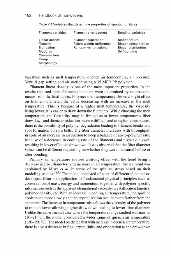
Handbook of nonwovens162
variables such as melt temperature, quench air temperature, air pressure,Venturi gap setting and air suction using a 35 MFR PP polymer.
Filament linear density is one of the most important properties. In theresults reported here, filament diameters were determined by microscopicmeans from the final fabric. Polymer melt temperature shows a slight effecton filament diameter, the value decreasing with an increase in the melttemperature. This is because at a higher melt temperature, the viscositybeing lower, it is easier to draw down the filaments. While choosing the melttemperature, the flexibility may be limited as at lower temperatures fiberdraw down and diameter reduction become difficult and at higher temperatures,there is the possibility of polymer degradation leading to filament breaks andspot formation on spin belts. The fiber diameter increases with throughput,in spite of an increase in air suction to keep a balance of air-to-polymer ratiobecause of a decrease in cooling rate of the filaments and higher die swellresulting in lower effective drawdown. It was observed that the fiber diametervalues can be different depending on whether they were measured before orafter bonding.
Primary air temperature showed a strong effect with the trend being adecrease in fiber diameter with increase in air temperature. Such a trend wasexplained by Misra et al. in terms of the spinline stress based on theirmodeling studies.31,32 The model consisted of a set of differential equationsdeveloped from the application of fundamental physical principles such asconservation of mass, energy and momentum, together with polymer-specificinformation such as the apparent elongational viscosity, crystallization kinetics,polymer density, etc. With an increase in cooling air temperature, the spinlinecools much more slowly and the crystallization occurs much farther from thespinneret. The increase in temperature also allows the viscosity of the polymerto remain lower allowing higher draw down leading to lower fiber diameter.Unlike the experimental case where the temperature range studied was narrow(10–21 ∞C), the model considered a wider range of quench air temperature(120–150 ∞C). The model predicted that with increase in quench air temperature,there is also a decrease in final crystallinity and orientation as the draw down
Table 4.3 Variables that determine properties of spunbond fabrics
Filament variables Filament arrangement Bonding variables
Linear density Filament separation Binder nature
Tenacity Fabric weight uniformity Binder concentration
Elongation Random vs. directional Binder distribution
Modulus Self-bonding
Cross-section
Crimp
Morphology
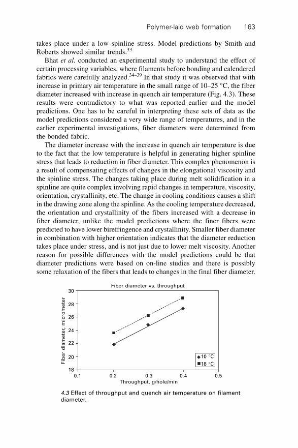
Polymer-laid web formation 163
takes place under a low spinline stress. Model predictions by Smith andRoberts showed similar trends.33
Bhat et al. conducted an experimental study to understand the effect ofcertain processing variables, where filaments before bonding and calenderedfabrics were carefully analyzed.34–39 In that study it was observed that withincrease in primary air temperature in the small range of 10–25 ∞C, the fiberdiameter increased with increase in quench air temperature (Fig. 4.3). Theseresults were contradictory to what was reported earlier and the modelpredictions. One has to be careful in interpreting these sets of data as themodel predictions considered a very wide range of temperatures, and in theearlier experimental investigations, fiber diameters were determined fromthe bonded fabric.
The diameter increase with the increase in quench air temperature is dueto the fact that the low temperature is helpful in generating higher spinlinestress that leads to reduction in fiber diameter. This complex phenomenon isa result of compensating effects of changes in the elongational viscosity andthe spinline stress. The changes taking place during melt solidification in aspinline are quite complex involving rapid changes in temperature, viscosity,orientation, crystallinity, etc. The change in cooling conditions causes a shiftin the drawing zone along the spinline. As the cooling temperature decreased,the orientation and crystallinity of the fibers increased with a decrease infiber diameter, unlike the model predictions where the finer fibers werepredicted to have lower birefringence and crystallinity. Smaller fiber diameterin combination with higher orientation indicates that the diameter reductiontakes place under stress, and is not just due to lower melt viscosity. Anotherreason for possible differences with the model predictions could be thatdiameter predictions were based on on-line studies and there is possiblysome relaxation of the fibers that leads to changes in the final fiber diameter.
Fiber diameter vs. throughput
10 ∞C18 ∞C
0.1 0.2 0.3 0.4 0.5Throughput, g/hole/min
Fib
er
dia
me
ter,
mic
rom
ete
r
30
28
26
24
22
20
18
4.3 Effect of throughput and quench air temperature on filamentdiameter.
Handbook of nonwovens164
To understand some of the intricate changes that take place in the spinline,Misra et al. investigated the spinnability of nine different PP resins having arange of MFRs and MWDs, and the structure and properties of the filamentsmelt spun from them.31,32 It was observed that increasing molecular weight(with same MWD) led to higher spinline stress, faster filament draw down,higher crystallization rates, higher levels of crystallinity and orientation,higher tensile strength and lower breaking elongation for filaments spununder similar conditions. Breadth of MWD also had a great influence on thespinline behavior and the structure and properties of the filaments. Whilebroad MWD resulted in fibers with higher density and lower birefringencethan the samples from narrow MWD, fibers spun from narrow MWD hadhigher tensile strength and lower elongation to break. Broader MWD polymershowed more elongation thinning and higher elongational viscosity, and ahigher tendency to undergo stress induced crystallization. These led to ashift in drawdown points closer to the spinneret although the birefringencerises earlier along the spinline, develops more slowly and reaches a lowerfinal value for broader MWD.
For the PP copolymer investigated,40 changes in processing conditionsshowed a trend similar to that observed for the homopolymer. However, theactual values of crystallinity and birefringence were lower for the copolymerfilaments even though the fiber diameters were comparable to that of thehomopolymer PP. Also, copolymer filaments had lower tensile strength andmodulus, and higher breaking elongation.
An increase in quenching air pressure, which was accomplished by addingmore auxiliary air resulted in a decrease in final fiber diameter. Obviously anincrease in air pressure led to an increase in the spinline draw ratio of thefilaments. The effect of a Venturi gap on the fiber diameter did not show anytrend. The Venturi gap has an effect on fiber laydown and fabric propertiesrather than on the fiber properties as such.
Air suction has an obvious effect on the fiber structure as the air suctiondirectly corresponds to take-up speed. The fiber diameter decreases withincrease in air suction speed. The effect of take-up speed on residual drawratio of the spun fibers for PET and PA were also similar.41
The relationship between fiber diameter and birefringence is shown inFig. 4.4. The general observation is that with decrease in filament diameterthere is an increase in birefringence values indicating higher orientation.Fibers with higher molecular orientation had higher crystallinity values aswell. The tensile properties are strongly related to birefringence. With increasein birefringence, the filaments had higher tensile strength and lower breakingelongation, which is an expected result due to higher molecular orientation.Air drag has been shown to have a major role in determining the morphologyof the fibers in a spunbonding process.42 In the new Ason-Neumag process,air drag in the spinline is manipulated by slot attenuation with low pressure
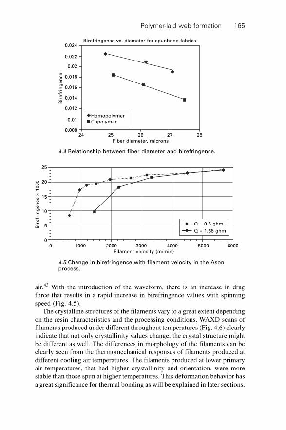
Polymer-laid web formation 165
air.43 With the introduction of the waveform, there is an increase in dragforce that results in a rapid increase in birefringence values with spinningspeed (Fig. 4.5).
The crystalline structures of the filaments vary to a great extent dependingon the resin characteristics and the processing conditions. WAXD scans offilaments produced under different throughput temperatures (Fig. 4.6) clearlyindicate that not only crystallinity values change, the crystal structure mightbe different as well. The differences in morphology of the filaments can beclearly seen from the thermomechanical responses of filaments produced atdifferent cooling air temperatures. The filaments produced at lower primaryair temperatures, that had higher crystallinity and orientation, were morestable than those spun at higher temperatures. This deformation behavior hasa great significance for thermal bonding as will be explained in later sections.
Bir
efr
ing
en
ce
¥ 1
00
0
25
20
15
10
5
0
Q = 0.5 ghm
Q = 1.68 ghm
0 1000 2000 3000 4000 5000 6000Filament velocity (m/min)
4.5 Change in birefringence with filament velocity in the Asonprocess.
Birefringence vs. diameter for spunbond fabrics
Bir
efr
ing
en
ce
0.024
0.022
0.02
0.018
0.016
0.014
0.012
0.01
0.008
HomopolymerCopolymer
24 25 26 27 28Fiber diameter, microns
4.4 Relationship between fiber diameter and birefringence.
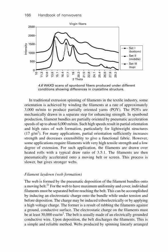
Handbook of nonwovens166
In traditional extrusion spinning of filaments in the textile industry, someorientation is achieved by winding the filaments at a rate of approximately3,000 m/min to produce partially oriented yarns (POY). The POYs aremechanically drawn in a separate step for enhancing strength. In spunbondproduction, filament bundles are partially oriented by pneumatic accelerationspeeds of up to about 6,000 m/min. Such high speeds result in partial orientationand high rates of web formation, particularly for lightweight structures(17 g/m2). For many applications, partial orientation sufficiently increasesstrength and decreases extensibility to give a functional fabric. However,some applications require filaments with very high tensile strength and a lowdegree of extension. For such application, the filaments are drawn overheated rolls with a typical draw ratio of 3.5:1. The filaments are thenpneumatically accelerated onto a moving belt or screen. This process isslower, but gives stronger webs.
Filament laydown (web formation)
The web is formed by the pneumatic deposition of the filament bundles ontoa moving belt.21 For the web to have maximum uniformity and cover, individualfilaments must be separated before reaching the belt. This can be accomplishedby inducing an electrostatic charge onto the bundle while under tension andbefore deposition. The charge may be induced triboelectrically or by applyinga high voltage charge. The former is a result of rubbing the filaments againsta ground, conductive surface. The electrostatic charge on the filaments mustbe at least 30,000 esu/m2. The belt is usually made of an electrically groundedconductive wire. Upon deposition, the belt discharges the filaments. This isa simple and reliable method. Webs produced by spinning linearly arranged
2500
2000
1500
1000
500
0
Inte
nsit
yVirgin fibers
Set I(bottom)
Set II(middle)
Set III(top)
10
11
.3
12
.6
13
.8
15
.1
16
.4
17
.7 19
20
.2
21
.5
22
.8
24
.1
25
.4
26
.6
27
.9
29
.2
2 Theta
4.6 WAXD scans of spunbond fibers produced under differentconditions showing differences in crystalline structure.
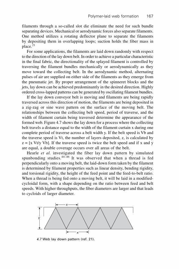
Polymer-laid web formation 167
filaments through a so-called slot die eliminate the need for such bundleseparating devices. Mechanical or aerodynamic forces also separate filaments.One method utilizes a rotating deflector plane to separate the filamentsby depositing them in overlapping loops; suction holds the fiber mass inplace.21
For some applications, the filaments are laid down randomly with respectto the direction of the lay down belt. In order to achieve a particular characteristicin the final fabric, the directionality of the splayed filament is controlled bytraversing the filament bundles mechanically or aerodynamically as theymove toward the collecting belt. In the aerodynamic method, alternatingpulses of air are supplied on either side of the filaments as they emerge fromthe pneumatic jet. By proper arrangement of the spinneret blocks and thejets, lay down can be achieved predominantly in the desired direction. Highlyordered cross-lapped patterns can be generated by oscillating filament bundles.
If the lay down conveyor belt is moving and filaments are being rapidlytraversed across this direction of motion, the filaments are being deposited ina zig-zag or sine wave pattern on the surface of the moving belt. Therelationships between the collecting belt speed, period of traverse, and thewidth of filament curtain being traversed determine the appearance of theformed web. Figure 4.7 shows the lay down for a process where the collectingbelt travels a distance equal to the width of the filament curtain x during onecomplete period of traverse across a belt width y. If the belt speed is Vb andthe traverse speed is Vt, the number of layers deposited, z, is calculated byz = [x Vt/y Vb]. If the traverse speed is twice the belt speed and if x and yare equal, a double coverage occurs over all areas of the belt.
Hearle et al. investigated the fiber lay down pattern by simulatedspunbonding studies.44–46 It was observed that when a thread is fedperpendicularly onto a moving belt, the laid-down form taken by the filamentis determined by filament properties such as linear density, bending rigidity,and torsional rigidity, the height of the feed point and the feed-to-belt ratio.When a thread is being fed onto a moving belt, it will be laid in a modified-cycloidal form, with a shape depending on the ratio between feed and beltspeeds. With higher throughputs, the fiber diameters are larger and that leadsto cycloids of larger diameter.
y
x
x
4.7 Web lay down pattern (ref. 21).
Handbook of nonwovens168
The Venturi gap in the Reicofil machine has a notable effect on fiberlaydown as the change in gap alters the air velocities and air profilesconsiderably. It was observed that for any basis weight, smaller Venturi gapsresulted in a less uniform web than one with larger gaps.30 With small Venturigaps, there is higher cabin pressure that imparts higher oscillations andinstabilities to the fiber stream, which results in a nonuniform web structure.With an increase in the Venturi gap, the uniformity of the web increasedconsiderably.
4.7 Structure and properties of spunbond fabrics
Spunbond fabrics are produced by an integrated process of spinning, attenuation,deposition, bonding, and winding to form rolls. The fabrics are up to 5.2 mwide and are usually not less than 3.0 m in width for acceptable productivity.Filament linear density ranges from 0.8 to 50 dtex (0.07–45 denier), althougha range of 1.5–20 dtex (1.36–18 denier) is most common. A combination ofthickness, filament denier, and the number of filaments per unit area determinesthe fabric basis weight, which ranges from 10 to 800 g/m2. Most typically, fabricbasis weight is from 17 to 180 g/m2. Like all nonwoven fabrics, the propertiesof a spunbonded fabric reflect both composition and the fabric structure.
4.7.1 Composition
The method of manufacture determines the fabric geometry, whereas thepolymer determines the intrinsic properties. Properties such as filament density,temperature resistance, chemical and light stability, ease of coloration, surfaceenergies, amongst others are a function of the base polymer. Although anyfilament forming polymer can be used in the spunbonding process, mostspunbond fabrics are based on isotactic polypropylene and polyester. Smallquantities are made from nylon-66, and increasing amounts from high densitypolyethylene (HDPE). Linear low density polyethylene (LLDPE) is alsoused as a base polymer because it gives a softer fabric.
4.7.2 Characteristics and physical properties
Most spunbonding processes can yield a fabric with near planar-isotropicproperties owing to the random lay down of the filaments. Unlike wovenfabrics, such spunbond fabrics are non-directional and can be cut and usedwithout concern for stretching in the bias direction or unraveling at theedges. Anisotropic properties are obtained by controlling the orientation ofthe filaments during the preparation of the web. Commercially, in the majorityof the cases, spunbond webs are anisotropic with preferred orientation in themachine direction. This is because the filaments must be deposited on a
Polymer-laid web formation 169
high-speed conveyor. Anisotropy is determined by both filament diameterand filament to belt speed ratio, the latter having a greater impact. All processingconditions that affect the diameter have an effect on laydown and thus thedirectionality of key properties. Uniformity of the fabric is measured bybasis weight. Image analysis has been shown to be useful for determininguniformity at various levels.47 This particular technique, since it uses transmittedlight, is suitable only for lightweight webs. Other advantages of image analysisare its ability to determine filament/fiber diameter, diameter variation andfiber orientation by automated techniques.48
Some of the main characteristics and properties of a spunbonded webare:30
∑ near random fibrous structure∑ generally, the web is white with high opacity per unit area∑ most spunbond webs are layered or have a shingled structure, the number
of layers increases with increasing basis weight∑ basis weight ranges between 5 and 800 g/m2, typically 10–200 g/m2
∑ fiber diameter range is between 1 and 50 mm, but the preferred range isbetween 15 and 35 mm
∑ web thickness ranges between 0.1 and 4.0 mm, typically 0.2–1.5 mm∑ high strength-to-weight ratios compared to other nonwoven, woven, and
knitted structures∑ high tear strength (for area-bonded webs only)∑ planar isotropic properties due to random lay down of the fibers∑ good fray and crease resistance∑ high liquid retention capacity due to high void content∑ high in-plane shear resistance∑ low drape.
The method of bonding greatly affects the thickness of the sheet and othercharacteristics. Fiber webs bonded by calendering are thinner thanneedlepunched webs since calendering compresses the structure, whereasneedlepunching moves fibers from the xy plane of the fabric into the zdirection (thickness).
Modeling approaches have been successful in predicting the stress-strainresponses of some spunbonded fabrics using the stress-strain behavior ofconstituent fibers, fiber orientation angle distribution, fabric Poisson’s ratiosand their shear strain.49, 50 For Cerex spunbonded fabric, it was shown thatCox’s fiberweb model can be used to predict the tensile response.51
The burst strength and tear strength follow trends similar to those oftensile strength in the majority of cases. The tear strength shows highervalues in the CD due to the greater amount of resistance offered by filamentspreferentially arranged in the MD. The air permeability increases with achange in processing conditions leading to increased filament diameter. This
Handbook of nonwovens170
increase in diameter results in lower fabric density after calendering, whichis responsible for an observed increase in air permeability. Fabric hand,which depends on fabric rigidity and modulus is a function of filamentdiameter and bonding. Fabrics composed of finer filaments are softer andmore flexible. Similarly, bonding at a lower temperature and a lower basisweight results in increased softness.
It is clear that the structure and properties of the spunbonded fabrics canbe varied by several means. It is possible to engineer the fabric properties byappropriate selection of polymer and processing conditions. This gives agreat amount of flexibility. However, the effect of certain processing conditionson specific properties is still not clear because of the complexities involved.Additional research in some of these areas will help to further expand spunbondmarkets.
4.7.3 Models for the prediction of fabric properties
Several theoretical models have been proposed to predict nonwoven fabricproperties that can be used or adapted for spunbonded filament networks:
∑ Backer and Petterson52
– The filaments are assumed to be straight and oriented in the machinedirection
– Filament properties and orientation are assumed to be uniform frompoint to point in the fabric.
∑ Hearle et al.53, 54
– The model accounts for the local fiber curvature (curl)– The fiber orientation distribution, fiber stress-strain relationships
and the fabric’s Poisson ratio must be determined in advance.∑ Komori and Makishima55
– Estimation of fiber orientation and length– Assumed that the fibers are straight-line segments of the same length
and are uniformly suspended in a unit volume of the assembly.∑ Britton et al.56
– Demonstrated the feasibility of computer simulation of nonwovens– The model is not based on real fabrics and is designed for mathematical
convenience.∑ Grindstaff and Hansen57
– Stress-strain curve simulation of point-bonded fabrics– Fiber orientation is not considered.
∑ Mi and Batra58
– A model to predict the stress-strain behavior of certain point-bondedgeometries
– Incorporated fiber stress-strain properties and the bond geometryinto the model.
Polymer-laid web formation 171
∑ Kim and Pourdeyhimi59
– Image simulation and data acquisition– Prediction of stress-strain curves from fiber stress-strain properties,
network orientation, and bond geometry– Simulated fibers are represented as straight lines.
4.8 Spunbond fabric applications
Spunbond fabrics are finding applications in a variety of end uses. In theearly 1970s, spunbonds were predominantly used for durable applications,such as carpet backing, furniture, bedding, and geotextiles. By 1980, disposableapplications accounted for an increasingly large proportion, primarily becauseof the acceptance of lighter spunbonded polypropylene fabrics in coverstockfor diapers and incontinence devices.21 The main markets for spunbonds are:
∑ automotive∑ civil engineering∑ hygiene and medical∑ packaging
Other spunbonds are home furnishings and house wrap and roofing materials.
4.8.1 Automotive
One of the major uses in automobiles is as a backing for tufted floorcoverings.Spunbonds are also used for trim parts, trunkliners, interior door panels, andseat covers.
4.8.2 Civil engineering
Civil engineering remains the largest single market segment for spunbondsaccounting for over 25% of the total sales. Geosynthetic end-uses includeerosion control, revetment protection, railway bed stabilization, canal andreservoir lining protection, highway and airfield black top cracking prevention.Another important area is in roofing.25 In these applications, the chemicaland physical stability, high strength/cost ratio, and engineering potential ofspunbonded fabric structures are attractive to end-users.25
4.8.3 Hygiene and medical
The use of spunbond fabrics in coverstock for diapers and incontinencedevices has grown dramatically. This is mainly because of the structuralcharacteristics of spunbonds, which helps keep the skin of the user dry andcomfortable.21 Spunbond fabrics are seen as cost effective compared to othernonwovens. Spunbonds are widely used in sanitary napkins and to a limited
Handbook of nonwovens172
extent in tampons. In the medical sector, certain traditional textile materialsare being replaced by spunbonds. The properties of spunbond fabrics that areof interest to the medical industry are adjustable fabric breathability, resistanceto fluid penetration, the lint-free structure, sterilizability, and impermeabilityto bacteria. Existing medical applications include disposable operating roomgowns, shoe covers, and sterilizable packaging.21
4.8.4 Packaging
Spunbond fabrics are widely used as packaging materials where paper productsand plastic films are not satisfactory. Examples include metal-core wrap,sterile medical packaging, floppy disk liners, high-performance envelopesand stationery products.
4.9 Meltblown fabric production
Microfibers (also referred to as superfine or meltblown fibers) are less thanabout ten microns in diameter. Such fibers are found in nature, for examplespider silk and pineapple leaf fibers.60 Man-made microfibers are producedusing a variety of polymers and production techniques. Sub-micron glassfibers in ‘glass wool’ are a prime example. There are various methods offorming microfibers including direct extrusion spinning, bicomponent spinning(followed by splitting or dissolution of some components), spray spinning,electrostatic spinning and centrifugal spinning. Commercially, a very importantmethod is meltblowing, which involves the introduction of dissolved or moltenpolymers into high-velocity streams of air or gas, which rapidly convert theliquid into microfibers.61
In recent years, there has been considerable interest in the meltblowingprocess from both commercial and scientific viewpoints. The meltblowingprocess falls under the general classification of a polymer-laid nonwovenfabric and is defined as follows:62
Meltblowing is a process in which, usually, a thermoplastic fiber formingpolymer is extruded through a linear die containing several hundred smallorifices. Convergent streams of hot air (exiting from the top and bottomsides of the die nosepiece) rapidly attenuate the extruded polymer streamsto form extremely fine diameter fibers (1–5 mm). The attenuated fibers aresubsequently blown by high-velocity air onto a collector conveyor, thusforming a fine fibered self-bonded nonwoven meltblown web (Figs 4.8and 4.9).
The fibers in the meltblown web are held together by a combination ofentanglement and cohesive sticking. Because the fibers are drawn to theirfinal diameters while still in the semi-molten state, there is no downstream
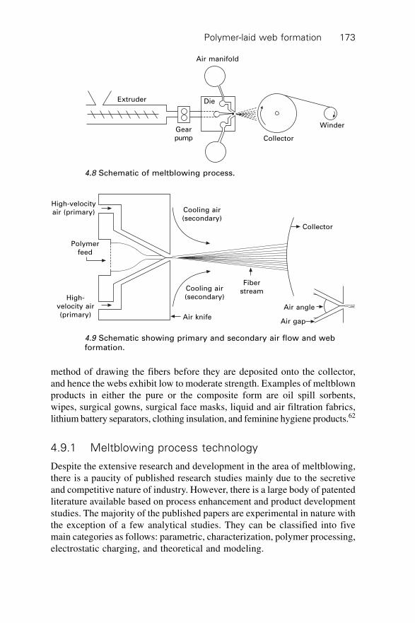
Polymer-laid web formation 173
method of drawing the fibers before they are deposited onto the collector,and hence the webs exhibit low to moderate strength. Examples of meltblownproducts in either the pure or the composite form are oil spill sorbents,wipes, surgical gowns, surgical face masks, liquid and air filtration fabrics,lithium battery separators, clothing insulation, and feminine hygiene products.62
4.9.1 Meltblowing process technology
Despite the extensive research and development in the area of meltblowing,there is a paucity of published research studies mainly due to the secretiveand competitive nature of industry. However, there is a large body of patentedliterature available based on process enhancement and product developmentstudies. The majority of the published papers are experimental in nature withthe exception of a few analytical studies. They can be classified into fivemain categories as follows: parametric, characterization, polymer processing,electrostatic charging, and theoretical and modeling.
Air manifold
Extruder Die
Gearpump Collector
Winder
4.8 Schematic of meltblowing process.
High-velocityair (primary)
Polymerfeed
High-velocity air(primary)
Cooling air(secondary)
FiberstreamCooling air
(secondary)
Air knife
Air angle
Air gap
Collector
4.9 Schematic showing primary and secondary air flow and webformation.
Handbook of nonwovens174
Parametric studies
The meltblowing process is intuitively simple but scientifically it is verycomplex and therefore, there is a considerable literature on parametric studiesof the process. These give a great deal of insight on the fundamentalunderstanding of the meltblowing process.
Effect of resin melt flow index and polydispersity
Jones,63 reported the effects of resin melt flow rate (MFR) and polydispersityon the mechanical properties of meltblown webs. In general, it was foundthat the strength properties peaked at an MFR of 300 and decreased as themelt flow rate increased significantly above that. The fabric strength wasbelieved to be a combination of individual fiber strength and good thermalbonding and/or fiber entanglements. The study also reported that the changein polydispersity of the polymers did not appreciably affect the mechanicalproperties. Only a slight downward trend of the fabric strength with increaseddegrees of polydispersity was observed. The elongation decreased withincreased molecular weight distribution. The decrease in elongation wasattributed to the larger diameter fibers and fewer fiber entanglements resultingfrom higher die swell of the broad molecular weight distribution resins.Finally, the study showed that the effects of varying extruder temperaturesand throughput rate on the strength properties were readily evident. Thedecreased extruder temperatures increased tenacity and bursting strength.The increased throughput rate decreased the bursting strength. Malkan62 hasalso shown the same trend.
Straeffer and Goswami64 reported the effects of MFR and polydispersityindex on the mechanical properties of meltblown webs. Three different resinmelt flow rate resins with varying polydispersity indices were meltblown.The air flow rate used for the study was considerably lower than the normalmeltblowing conditions. The study concluded that 1100 MFR (melt flowindex) resin degraded more than the 300 MFR resin. This result was rathersurprising. Malkan65 has showed the opposite trend. Usually, the lower MFIresins degrade more than the higher MFR resins. The study also showed thatthe fiber diameter distribution appeared to be narrower as the air velocitywas increased and there was no discernible difference in the crystallinity ofthe fibers.
Effects of pigments
Eaton et al.,66 studied the effects of pigments on the physical properties ofmeltblown nonwovens. The objective of the work was to demonstrate thefeasibility of processing pigmented resins into meltblown webs. Different
Polymer-laid web formation 175
melt flow rate pigmented polypropylene resins were meltblown under differentprocessing conditions. The physical properties of pigmented webs werecompared with the properties of unpigmented webs. The study found thatmeltblown webs of uniform coloration were readily obtainable by the masspigmentation of polypropylene resins. It was believed that the pigmentsacted as nucleating agents in the high melt flow rate (MFR) resins that weremeltblown. The average fiber diameter decreased slightly with increasedMFR for both pigmented and unpigmented webs. The apparent colors of thewebs became lighter with increased resin MFR. This effect was attributed tothe increased ratio of fiber surface area to the amount of pigment resultingwith the finer fibers produced with the higher MFR resins. Thephotomicrographs showed no notable differences between the pigmentedand unpigmented webs in terms of fiber and web structure. The pigmentedwebs generally exhibited higher stiffness than the unpigmented webs.
Effects of machine settings
Wente and co-workers67 first established the feasibility of manufacturingsubmicron fibers from a variety of thermoplastic polymeric materials. Themain objective of the study was to design an apparatus that would producesubmicron fibers. It was thought that a nonwoven material composed entirelyof submicron fibers would be very useful for aerosol filtration as well as fordielectric insulation.
The study of Wente describes the various aspects of the meltblown process,such as processing parameters, single fibre properties, and equipment design.It was found that since the molten polymer issues from the die nose tipdirectly into the confluence of the air streams, the greatest amount of attenuationoccurs at the point of exit. Thus, the orifice size has little importance providedit is large enough to pass the melt without plugging. Malkan68, 69 also showedthat the orifice size has very little effect on the final fiber diameter. Theability of a polymer to attenuate to a fine fiber is dependent on its meltingpoint, viscosity-temperature characteristics, and surface tension. These findingsappear to imply a streamline attenuation behavior such as in air drag meltspinning. But according to Milligan and Haynes,70 the attenuation of fibersin meltblowing is primarily due to the shape they assume during their flightfrom the die face to the collector screen, otherwise known as ‘form drag’. Itwas also found that a steeper air angle gives a higher degree of fiber dispersionand random orientation. A smaller air angle yields a greater number of parallelfibers, greater attenuation, and less fiber breakage.
Buntin and Lohkamp,71 described the development of the meltblowingprocess for converting polypropylene into low-cost fine fibrous webs. Twoprocess design concepts of using multiple dies and a circular die were alsodiscussed. The study found that by using multiple dies high production rates
Handbook of nonwovens176
can be achieved without increasing polymer throughput rates above theoptimum. Multiple dies also produced more uniform webs with fewer fabricdefects. The main disadvantage of the multiple dies operation was that forheavy basis weight the bonding between layers was found to be unsatisfactory.In a circular die, a die with the orifices in a circle was used. The die wasoperated in such a way that the conical fiber blast from the orifices wasfocused roughly on a point where the fibers were formed into a continuouscylindrical roving. The technique was studied to make fine fibered cigarettefilters. The study also reported that during the normal operation of themeltblowing process, fiber breakage occurred continuously and that fiberlengths were on the order of a few inches. The fiber breakage was associatedwith the incidence of ‘shot’ (they defined shot as a particle of polymer,considerably larger than the fibers, which is formed by the elastic ‘snapback’ of the fiber ends upon breaking. However, the current understanding ofthe process suggest that the fibers are continuous in nature therefore theorigin and nature of shot remains debatable.
Below a certain melt temperature a given thermoplastic polymer forms alarge granule of non-fibrous material called ‘shot’. High air pressure generallyyields uniform and shot free fibers but, at the same time, interferes with theseparation of fiber and air because of the excess volume of fibers. Early inthe studies of the process it was known that meltblown webs derive somestrength from the mechanical entanglement and frictional forces existing inthe fine network of microfibers in the web.
Tsai et al.72 studied the effects of water spraying near the die exit duringmeltblowing web production. The study showed that the water sprayingimproved the mechanical properties of the web, such as tensile, bursting, andtear strength. Water spraying also reduces shot formation during meltblowing.The use of water spray did not affect the fiber diameter, air permeability, andfiltration efficiency of the webs. Water spraying at higher processing and airtemperatures was suggested as a means of producing fine fibered webs withreduced shot intensity.
Wadsworth and Jones73 demonstrated the effects of die-to-collector distances,polymer throughput rates, and die orifice diameters on meltblown fabricproperties. The study found that machine direction (MD) tenacity decreasedwith increased die-to-collector distance whereas the cross direction (CD)tenacity and bursting strength remained relatively constant. Fiber diametersincreased slightly with increased die-to-collector distance. The MD tenacityincreased with increased polymer throughput rates at corresponding collectingdistances. On the other hand, the CD tenacity changed little. The study alsoshowed that bursting strength decreased with increased throughput rates.The webs produced with the small orifice die were found to have slightlylarger fiber diameters than the webs produced with standard orifice die. Itwas hypothesized that greater die swell could have occurred with small
Polymer-laid web formation 177
orifice die resulting in a net increase in filament diameter compared to thestandard orifice die. This finding was in contrast to findings by Wente74 andMalkan.62,69,70 Wente and Malkan reported that the orifice size had very littleeffect on the final fiber diameter.
Khan75 studied the effects of die geometry and process variables on fiberdiameter, and shot formation of meltblown polypropylene webs. The studyincluded die orifice L/D/ratio, nose piece angle, air gap, nosetip setback,polymer throughput rate, air throughput rate, die-to-collector distance, andresin melt flow rate. The statistical analysis showed that the L/D ratio, airgap, melt flow rate, and polymer throughput rate have a significant effect onthe average fiber diameter. Based on statistical interaction analysis, it wasshown that all the variables had a significant effect on shot and fly generation.It was shown that by maintaining a constant air-to-polymer ratio, a web withknown fiber diameter could be obtained. There was no conclusive evidencethat the setback had a significant effect on the average fiber diameter. However,the shot intensity increased slightly with increase in setback. Shot notablyincreased with increase in polymer throughput rate and orifice diameter.Wente74 and Malkan62,69,70 have also shown a similar trend. A part of thestudy showed that the increase in orifice size from 15 to 20 mm increased theresultant average fiber diameter. This increase was attributed to higher shearviscosity for the 20 mm orifice size. This finding was contradicted by thefindings by Malkan,62 but agreed with the findings of Wadsworth and Jones.73
The 60∞ die tip resulted in slightly smaller diameter fibers than the 90∞die tip. However, web properties such as air permeability, filtrationefficiency, and bursting strength were higher for the 90∞ die tip compared tothe 60∞ tip.
Lee and Wadsworth76 studied the relationships among the processingconditions, structure, and filtration efficiency of polypropylene meltblownwebs. The structure of the meltblown webs was varied using different die-to-collector distances and smooth roll thermal calendering. The study foundthat air permeability, and mean and maximum pore sizes increased withincreased die-to-collector distance. The filtration efficiencies for water aerosolscontaining 0.5 and 0.8 mm latex spheres, and for bacteria (Staphylococcus
aureus) were found to be dependent on mean pore diameter and the parameterof basis weight divided by the square of the average fiber diameter. Thecalendering process decreased the web thickness, maximum pore diameter,and air permeability regardless of the original values.
Choi et al.,77 studied the strength properties of the meltblown webs. Amethod to obtain the tenacity and Young’s modulus of meltblown webswithout direct measurement of web thickness was proposed and tested usingseveral series of web samples with different basis weight. The web tenacityand Young’s modulus, which were, of course, normalized for weight, werefound to be nearly independent of basis weight and gauge length. However,
Handbook of nonwovens178
these properties were greatly affected by the processing conditions. Tenacityand Young’s modulus decreased with increased die temperature, air pressureat the die, and die-to-collector distance. The study also measured and comparedthe strength properties of single meltblown fibers with the strength of theweb and the high-speed melt spun filaments prepared from the same resins.Single fiber strength tended to be intermediate between the strength of theweb and that of the high-speed melt spun filaments. The low strength of thesingle fiber was attributed to low molecular orientation, irregular diameterprofiles along the length of the fibers, and the existence of voids in the fibers.
Malkan62,69,70 studied the process-structure-property relationships inmeltblowing for different polypropylene resins. This extensive study discussedthe various aspects of meltblowing ranging from process and resin variablesto the characterization of web and single fibers. It was hypothesized that thereason for the increase in fiber diameters with increasing polymer throughputswas because of the increased die swell and the change in air-to-polymer ratioat higher polymer throughput rates. A ‘processing window’ was establishedto optimize the processing parameters to ensure good web quality. The DSCand X-ray diffraction results indicated that the presence of double endothermicpeaks might have been due to the presence of different crystal forms, namely,a-form (monoclinic) and b-form (hexagonal). It was hypothesized that thehigher polymer throughput rate condition caused a change in the morphologicalor crystalline structure of meltblown polypropylene fibers. It has been shownby Bodaghi86 that water-quenched polypropylene fibers have a para-crystallinestructure and the air quenched fibers have a regular monoclinic crystal structure.However, there have been arguments against the possibility of differentmorphologies (folded chain crystals or extended chain crystals) since thedouble endotherms were produced at an isothermal crystallization temperatureas low as 130 ∞C. This temperature appears to avoid the possibility of extendedchain crystal formation.
Milligan et al.78 have reported the use of a stream of unheated cross-flowair to make finer meltblown fibers. The authors claim that in addition to finerfiber diameters the variation in fiber diameter was smaller with the use ofcross-flow air. The motivation for this research was the earlier finding byMilligan and Haynes70 that the fiber form drag, due to large amplitude flappingof the molten polymer jet as it gets blown away from the die, played asignificant role in contributing to the total air drag force necessary for fiberattenuation during meltblowing. The study pointed out the possibility ofsubstituting unheated cross-flow air for a portion of the primary hot air,resulting in energy savings. Haynes79 data on a single hole orifice meltblowingdie indicates that at a constant volumetric flow rate of primary air, theaverage fiber diameter is not affected by its velocity (the velocity change hadbeen brought about by the change in air gap). Although the velocity changedmore than 200% the average fiber diameter stayed the same. In one case the
Polymer-laid web formation 179
air velocity was ~220 m/sec and in the other case it was ~520 m/sec. In bothcases a similar magnitude fiber with an average diameter of 7.08 mm wasobtained.
According to Haynes,79 the smaller air gap (higher air velocity) gave astandard deviation of 5.53 mm, while with the larger gap (lower air velocity),the standard deviation was ~3.4 mm. It appears that the larger air gap (lowerair velocity) produced a narrower fiber diameter distribution. This indicatesthat the velocity of primary air in itself does not affect the average fiberdiameter significantly in the range of velocities discussed here (high end ofthe possible velocity scale). A careful examination of average fiber diametersproduced at low air velocities indicates a notable effect of air velocity on averagefiber diameter, even at constant SCFM. Further evidence to this observationis presented elsewhere by Haynes.79. The fiber diameter decreased when thevelocity was increased by increasing the mass flow rate of air at constant airgap. This result implies that the primary controlling variable of fiber diameteris the mass flow rate of air and therefore increasing the velocity alone,without increasing the mass flow rate of primary air is not of much significancewith respect to fiber diameter. This finding was in contrast to popular beliefthat a smaller air gap gave finer fibers at a constant primary air flow rate.
Warner et al.80 observed spherulitic crystalline morphology in meltblownfibers using scanning electron microscope and fibres >10 mm have essentiallyno molecular orientation. This implies that such fibers do not contribute tomeltblown web strength. It should be noted that the mass of a fiber per unitlength is proportional to the square of its diameter. Therefore the mass diameterdistribution of the web will be more appropriate than the number diameterdistribution as a means to calculate the fiber strength realization in a meltblownweb.
Formation of ultrafine microfibres
Wadsworth and Muschelewicz81 reported the results of a study designed toproduce extremely fine meltblown fibers using 35, 300 and 700 MFR resins.The study established the optimized meltblown processing conditions toproduce fine fibered webs, with less than 2 mm fiber diameters. The studyfound that the small orifice die (with orifice diameter in the range of 0.2–0.3mm) resulted in statistically smaller mean fiber diameters than the die withstandard size orifices (approximately 0.4 mm diameter orifices). However,the actual difference was found to be minimal, considering the fact that thecross-sectional areas of the small die holes differed by a factor greater thantwo. The study also reported that increased air flow rates decreased meanfiber diameters. The air gap settings did not have any noticeable effectsexcept that much larger diameters were obtained with the standard die tipand the smaller air gap setting with 300 and 700 MFR resins. Notably higher
Handbook of nonwovens180
bursting strength values were achieved with the small die holes, indicatingincreased fiber strength with greater draw-down.
4.10 Meltblown characterization techniques
This section provides a brief review of some of the characterization techniquesused to study meltblown web properties or phenomena. Mostly, meltblownwebs are characterized in terms of stress-strain properties, filtration efficiencyand air permeability. Many of these properties can be characterized usingstandard ASTM or INDA methods. However, researchers have developednew and advanced techniques to characterize web properties, such as fiberdiameter, mean pore size analysis, and on-line fiber diameter measurementsthrough light scattering and other techniques.
Tsai82 proposed a mathematical relationship to characterize key webproperties using an air flow technique. This mathematical relationship usesair permeability data and determines approximate fiber size and pore size.Naqwi et al.83 developed an interferometric optical technique, referred to asan adaptive phase/Doppler velocimeter (APV) for in-situ sizing of sphericaland cylindrical objects as applied to spunbond and meltblown fibers. It hasbeen suggested that this technique could be used to monitor changes inprocessing conditions during the meltblowing process, specifically fiberdiameter. Bhat84 used sonic velocity measurements to characterize meltblownwebs. The sonic velocity can be used as an indication of the overall arrangementof structural elements in the fabric. The results showed a good correlationbetween the measured sonic velocity values and spunbond fabric mechanicalproperties.
Wallen et al.85 investigated the use of small angle light scattering to studytransient single fiber diameter and to monitor the fiber attenuation process asa function of distance from the die during the meltblowing process. The fiberdiameters were determined from the total intensity of the scattered light. Thestudy concluded that the meltblown process is not a steady state below acertain timescale and that the fiber attenuation process is not constant withrespect to time or distance from the die. Bodaghi86 has described manymeltblown microfiber characterization techniques. He found that water-quenched polypropylene fibers showed a para-crystalline crystal structurewhereas air-quenched fibers showed a regular monoclinic crystal structure.
4.10.1 Polymers for meltblowing
It is known that the meltblowing process is highly versatile in respect of therange of polymers that can be processed. Although polypropylene is themost widely used resin in meltblowing due to its ease of processing andsuitability for end-use, researchers have successfully meltblown a variety of
Polymer-laid web formation 181
different resins including polyamide, polyester, TPX, fluoropolymers,polyphenylene sulphide, and PBT. Most of these studies have been aimed atdeveloping specific nonwoven products for industry. In experimental studies,polyethylene is claimed to be more difficult to meltblow into fine fiber websthan polypropylene, that Nylon 6 is easier to process and has less tendencyto make shot than polypropylene and that most thermoplastic polymers canbe meltblown sucessfully into good finished products with few exceptions.87
Cheng and Kwalik88 described the requirements of polypropylene resins,such as melt viscosity, MWD and melting point for processing. The resinselection criteria for meltblowing, including the choice of additives, MFR,pellets or granules, resin cleanliness, and MWD are also discussed. Khanand Wadsworth89 demonstrated the feasibility of meltblowing cellulose acetateand polyvinyl alcohol resins. The aim was to produce a biodegradable webto be used in disposable consumer products. Meltblowing of fluoropolymerresins was demonstrated by Wadsworth and Fagan90. Different grades of‘Halar’ fluoropolymer resins (Ausimont, Inc.) were meltblown. It was concludedthat the higher MFR fluoropolymer resins process well and were comparablein terms of processing characteristics to high MFR PP resins. Polybutyleneterephthalate (PBT) resins have been meltblown by Bhat et al.91 The higherintrinsic viscosity (IV) PBT produced higher fiber diameters than the lowerIV PBT.
Recycled polymers can be meltblown. The study discussed the propertiesof dried and undried PET meltblown webs and also blends of virgin andrecycled PET. The webs produced with undried PET, which had a highermoisture content than dried PET, had a lower intrinsic viscosity as well assmaller fiber diameters, higher tenacity in the MD and lower air permeability.The blend containing the highest amount of low intrinsic viscosity polymerresulted in a thin webs containing smaller fiber diameters, lower air permeabilityand higher tenacity in the machine direction as compared to regular PP MBwebs. Meltblown adhesive webs are commercially available for laminationapplications. Meltblowing of adhesive polyester for use in lamination wherestrong, durable bonds are required is possible using adhesive copolyesters.The resultant adhesive webs have been used to prepare fabric-to-foam andfabric-to-fabric laminates.
4.10.2 Electrostatic charging
Arguably one of the most celebrated uses of PP meltblown fabrics is in airand liquid filtration. This is mainly because PP can be readily charged toenhance the filtration efficiency. As an example, the filtration efficiency ofan uncharged PP meltblown fabric ranges from 20 to 40%, while for theelectrically charged web, it ranges from 80 to 99% depending on the chargingtechnique used.92–102
Handbook of nonwovens182
4.10.3 Theoretical studies and modeling
Narasimhan and Shambaugh103 have attempted to model the meltblowingprocess based on a single die hole rig, with a circular air slot surrounding themeltblown spinnerette nozzle. However, the most commonly used meltblowndie geometry consists of a row of spinnerettes with sheets of hot air exitingfrom the top and bottom sides of the die. Shambaugh continued this study104
and applied macroscopic energy balance and dimensional analysis conceptsto meltblowing. These two concepts were analyzed using different diegeometries. Three operating regions were identified in the melt blowingprocess according to the extent of the air flow rate as follows:
Region I has a low gas velocity similar to a commercial melt spinningoperation in so far as the fibers are continuous.Region II is unstable as the gas velocity is increased. In this region filamentsbreak up into fiber segments and undesirable lumps.Region III occurs at a very high air velocity and involves excessive fiberbreakage.
The meltblown process predominately uses a low airflow rate (Region I)and is most energy efficient in this region. A monodisperse fiber distributionis claimed to require less energy to produce than a polydisperse fiberdistribution. The dominant dimensionless groups in the meltblowingprocess are claimed to be the gas Reynolds number, the polymer Reynoldsnumber, fiber attenuation, and the ratio of the polymer viscosity to the gasviscosity.
Milligan and Haynes105 studied the air drag on monofilament fibers. Theaim was to study the air drag by simulating actual meltblowing conditions.The experimental set-up closely simulated a commercial meltblowing operation.The air drag was studied as a function of fiber length, upstream stagnationpressure, air injection angle, and gravity orientation. Four series of experimentswere conducted as follows:
1. Determination of air drag for a fiber of constant length over a range ofair stagnation pressures.
2. Determination of air drag for a range of fiber lengths at a constant valueof stagnation pressure.
3. Determination of air drag for a fiber of known length and stagnationpressure using different injection angles (15∞, 30∞, and 45∞).
4. Determination of air drag by changing the die orientation, with respectto gravity, using a 30∞ air injection angle with different fiber length andstagnation pressures.
The study concluded the following:
∑ The drag increased with fiber length when all other parameters were
Polymer-laid web formation 183
constant. The drag peaked at a length of 2.5 cm. This was due to largeamplitude flapping of the fiber.
∑ The drag increased linearly with stagnation pressure for stagnationpressures up to 207 kPa.
∑ The drag increased with decreased air injection angle for any particularstagnation pressure. This finding was in basic agreement with thefundamental momentum consideration.
∑ Orientation of the die with respect to gravity using an injection angle of30∞ (45∞ above the horizontal to 90∞ below the horizontal) showed nomeasureable difference in drag. It was concluded that the viscous andpressure forces on the filament far exceed the gravitational force for theflow conditions investigated.
Uyttendaele and Shaumbagh106 have reported various analytical studiesinvolving mathematical modeling of meltblowing. Majumdar and Shaumbagh107
have calculated the air drag on fine filaments in the meltblowing processusing a wide range of filament diameters, gas velocities (primary air velocity),and Reynolds number. Milligan and Haynes105 studied the air drag onmonofilaments simulating the actual meltblowing conditions, except that thehigh-velocity air was at room temperature and one end of the monofilamentwas secured to a tensiometer. It was found from the investigation that smaller airinjection angles gave larger drag with the other parameters remaining constant.
4.10.4 Minimization of energy consumption
Milligan108 analyzed several design concepts to minimize energy costs inmeltblowing. The pressure losses associated with the air pipework and theair heater were two of the principal sources of energy consumption. Severaldesign rules have been presented to minimize the cost of air utilization basedon Darcy’s pressure drop relation:
DP/L = r.f.V2/2D 4.1
where DP = the pressure dropL = the length of the pipeD = inner diameter of the pipeP = air densityf = pipe friction factor (dependent on D and pipe roughness)V = air velocity in the pipe.
The design rules are:
1. The piping between the air compressor and the die assembly should beas short in length and as large in diameter as possible.
2. The air heater should be as close as possible to the die assembly.3. The number of pipe fittings should be minimized, and all piping should
be well insulated.
Handbook of nonwovens184
The study also highlighted the importance of correctly sizing the compressorin a meltblown pilot line. The suggested design rules minimize energy cost,specifically by reducing the pressure losses associated with the air pipingand efficient location of air heaters.
Milligan, Wadsworth, and Cheng109 investigated the energy requirementsfor the meltblowing of different polymers. The studied polymers werepolypropylene, linear low-density polyethylene, nylon and polyester. Theenergy requirements were reported in kW-HR per kg of polymer. It wasapparent from the reported data that the energy cost per unit mass of theproduct greatly depended on the air flow rate, air temperature, polymerthroughput rate, and polymer molecular weight. The results also showed thata large fraction (greater than 85% for all the materials investigated) of theenergy required was associated with the hot air streams. The study alsofound that the difference in total energy consumed and the actual energyrequired at the die can be attributed to improper compressor size, compressorcooling, and heat losses from the die and piping. The study suggested thatsubstantially lower energy consumption is possible if a meltblowing line iscarefully designed and operated with the objective of minimizing energyconsumption.
4.11 Characteristics and properties of meltblownfabrics
Meltblown fabric properties can be tuned depending on end-use requirementsby adjusting polymer selection, process variables, bonding and finishingprocesses. Some of the main characteristics and properties of meltblownwebs are:110
∑ Random fiber orientation.∑ Low to moderate web strength.∑ Generally, the web is highly opaque (high cover factor).∑ Meltblown webs derive their strength from mechanical entanglement
and frictional forces.∑ Most meltblown webs are layered or shingled structure, the number of
layers increases with increasing basis weight.∑ Fiber diameter ranges between 0.5 and 30 mm, but the typical range is 2
to 7 mm.∑ Basis weight ranges between 8 and 350 g/m2, typically 20–200 g/m2.∑ Microfibers provide high surface areas for good insulator and filter
characteristics.∑ The fibers have a smooth surface texture and appear to be circular in
cross-section.∑ The fibers vary in diameter along a single fiber.∑ Close examination of approximately 800 photomicrographs showed no
Polymer-laid web formation 185
‘fibre-ends’ (except a few near areas where ‘shot’ is present), therefore,the fibers are believed to be mostly continuous in length.
∑ The fibers show thermal branching. The exact cause of thermal branchingis not known, but according to Malkan62 the branching of the fibersoccurs when propagating fibers collide with other propagating fibers,which in turn, strip off portions of polymer streams as fine branches(filaments). Richardson111 pointed out that when the velocity of theliquid jet relative to air jet increases, portions of the liquid are strippedoff as filaments. Bresee and Wadsworth112 stated that fiber splitting(branching) occurs when extrudate is stressed in complex ways in flighttowards the collector.
4.12 Meltblown fabric applications
Owing to the inherently large fiber surface area in meltblown fabrics,applications are in filtration, insulation, and liquid absorption. The finefiber network (and large surface area) results in some characteristicproperties:113–116
∑ enhanced filtration efficiency∑ good barrier properties∑ good wicking action.
4.12.1 Filter media
The original development work on meltblowing was focused on the productionof microfibers which could be used in high-performance filtration products.Therefore, the filtration market segment remains the largest single marketfor meltblown webs, representing about 30% of the total.117 The future growthis projected to be quite strong. Generally, meltblown webs are used for themore critical filtration applications where the superior filtration performanceof the fine fiber network can be exploited, for example in medical applications.Applications for meltblown fabrics are:
∑ room air filter and recirculation∑ precious metal filtration and recovery∑ food and beverage filtration∑ surgical mask, respiratory filtration and healthcare products∑ water and liquid filtration (including blood and body fluids).
4.12.2 Insulation
Meltblown webs provide good insulation because of the large surface area,which creates significant drag forces on air convection currents passingthrough the fabric. The trapping of still air as a means of providing high
Handbook of nonwovens186
thermal insulation is a concept that has been exploited successfully inThinsulate® (3M) for outdoor sports and leisure clothing. Ando116 has alsopresented applications for meltblown webs in thermal insulating media. Heattransfer through any nonwoven fabric may occur by conduction, convectionor radiation. The thermal insulation can be assessed by measuring thermalresistance using heat transfer rate equations. For the purpose of simplicity,the thermal resistance for conduction is given below. Consider a dense,meltblown web of thickness L held between two plates at temperatures T1
and T2. The thermal resistance R for conduction is (steady state, one dimensionalflow):
R = DT/qx = L/kA 4.2
where DT is the temperature difference between the two surfacesqx is the conduction heat transfer rateqx = kADT/LL is the thicknessA = cross-sectional areak = thermal conductivity of the air and fiberk = vfk f + vaka
f = fibera = airv = volume fraction.
4.12.3 Absorption
Meltblown webs are widely used in oil and liquid absorption. This market isgrowing due to growing governmental regulations concerning spillages,contamination of ground water, and environmental cleanliness. There aremany meltblown products on the market that require liquid absorption suchas sanitary napkins, household and industrial wipes, oil sorbent pads andbooms, amongst others. White118 has also shown the effective use of meltblownwebs in food fat absorption.
4.13 Mechanics of the spunbond and meltblownprocesses
Spunbonding and meltblowing incorporate many engineering concepts, someof which are discussed in this section.
4.13.1 Dynamics of melt spinning process
Spunbonding and meltblowing involve multi-filament fiber spinning and arean extension of the conventional fiber spinning process. In order to understandthe theoretical framework of these processes, it is necessary to understand
Polymer-laid web formation 187
the dynamics of melt spinning first. The following is a discussion on thebasic equation involved in the melt spinning process based on a single filamentmodel. The equations for multi-filament fiber spinning (related to spunbondingand meltblowing processes) are quite complex. It is beyond the scope of thisbook to cover multi-filament spinning but further reading is available.119,120
The dynamics of melt spinning is based on mass balance, force balance, andenergy balance principles. The balance equations are now considered.
Based on the principle of conservation of mass, the following mass balancerelation can be written:121,122,123
W = rAV 4.3
The above equation for a cylindrically shaped filament becomes:
W = r p (D/2)2 V 4.4
The overall force balance for fiber spinning can be written asfollows:121–123,13
Frheo = F0 + Finert + Fdrag - Fgrav - Fsurf 4.5
where Frheo = the rheological force in the fiberF0 = the rheological force at the beginning of the spinlineFinert = the inertial force as the fiber is acceleratedFdrag = the drag force caused by the fiber moving through a stationary
fluidFgrav = the gravitational force on the fiberFsurf = the surface tension force at the fiber-air interface and is
generally considered negligible compared to the magnitudeof the other forces.
The individual forces may be expressed as follows:121–123,13
Frheo = W(V – V0)
Fdrag = p D s f dz
Fgrav = r g (p D2 / 4) dz
Fsurf = (p s) /2 (D0 – D) dz 4.6
where W = the mass throughput rate (related to mass balance)V0 = the average polymer velocity in the dieD0 = the die diameters f = the shear stress at the fiber-air interface due to aerodynamic drags = the surface tension of polymer melt with respect to airz = the distance along the fibre away from the die.
Neglecting the radial variations and the force due to surface tension, thegradient of axial tension along the spinline can be written using eqns 4.3 and4.4 as:
Handbook of nonwovens188
dF/dz = W dV/dz + 1/2 ra Cd V2 p D – W g/V 4.7
where D = the filament diameterV = the filament velocityg = the gravitational acceleration constantCd = the drag coefficient and is defined using the equation for the
shear stress at the fiber-air interface due to aerodynamic drag.
s f = 1/2 ra Cd V2 4.8
The rheological force in the spinline is related to the axial spinline stresss 11 or s zz as
s11 = Frheo/(p D2/4)
and
szz = h (T) dV/dz 4.9
where h is the viscosity at temperature T.
One of the principal unknowns in the force balance equation is the airdrag force, which becomes increasingly important at high spinning speeds.Numerous theoretical investigations have focused on identifying the natureof the drag coefficient Cd, in the drag force equation. To evaluate Cd for meltspinning, Matsui124 has formulated a simple expression for C based on airReynolds number using turbulent theory.
Cd = KRe–n 4.10
where Re is the air Reynolds number and is given by
Re = (raVD/ma)
K = 0.37 and n = 0.61
The energy balance is required to determine the fiber temperature as a functionof distance from the spinneret. Heat transfer from the melt spinline to theambient medium involves several mechanisms; radiation, free convectionand forced convection. The effect of radiation is strongly dependent on thetemperature of fiber. In polymer melt spinning the radiation contribution isusually negligible compared to the convective heat transfer. Heat releaseddue to crystallization can be neglected for slow crystallizing polymers, butshould be considered for fast crystallizing polymers. Neglecting radialtemperature variations and including heat of crystallization, the differentialenergy balance equation can be written as:
dT/dz = – p D h (T – Ta) / W Cp + DHf/Cp * dX/dz 4.11
where T = the fiber temperatureTa = the ambient air temperature
Polymer-laid web formation 189
DHf = the heat of fusionX = the crystalline fractionh = the heat transfer coefficient
Cp = the resin heat capacity.
Usually, the temperature of filament during melt spinning is determinedexperimentally as a function of the distance from the spinneret using aninfra-red sensor. Then eqn 4.11 is used to calculate the heat transfer coefficientas a function of the distance from the spinneret.
4.13.2 Deposition ratio
In spunbonding and meltblowing, the deposition of filaments on the conveyerbelt is an important variable. The manner in which the filaments are laiddown dictates the web geometry and hence some key fabric properties. It isdifficult to quantify this step mechanistically, but a ‘deposition ratio’ (Dr)can be defined (see eqn 4.12). By manipulating the ratio, the transversestrength of the fabric can be altered. Higher ratios give higher transversestrength and lower ratios give lower transverse strength. However, the ratiohas little effect on the longitudinal strength of the web.
Dr = Vf/Vb 4.12
where Vf = the filament speedVb = the conveyer belt speed.
The filament speed can be calculated using the mass balance equation usingthe initial and final diameter of the filament. The conveyer belt speed isgiven by:
Vb = m/(G ¥ Wc) 4.13
where m = the polymer mass throughput rateG = the desired web weight
Wc = the width of the conveyer belt.
4.13.3 Polymer residence time in the extruder
The polymer residence time in an extruder can be calculated as follows:
t = (rmelt * v) / W 4.14
where t is residence time in minutes
rmelt = polymer melt density in g/cm3
v = the screw volume in cm3
W = the polymer throughput rate in g/min.
Handbook of nonwovens190
4.13.4 Determination of the airflow rate
In meltblowing and spunbonding air plays an important role in fiber formation.It is necessary to know the air mass flow rate as well as the velocity of air inthe system. The determination of airflow rate and velocity is complicated bythe effect of temperature and pressure and also by the fact that the flow islikely to be unsteady or subject to disturbances. Therefore measurementconditions, instruments, and methods should be specific and reliable125. Inpractice, the air mass flow rate is usually determined using an orifice plateor Venturi meter. The air velocity is usually measured using an anemometeror a pitot tube. The measurement procedures are established by the AmericanSociety of Mechanical Engineers (ASME).126 More detailed descriptions ofair measurement techniques are available.127,128
The following describes the determination of the air mass flow rate usingorifice plates in a pipe. The orifice plate is usually flat and consists of acircular hole in the center. Its most common use is as a flow quantity measuringdevice. The determination of the airflow rate using an orifice is based on theuse of Torricelli’s theorem and Bernoulli’s equation.129 The air mass flowrate using an orifice plate can be calculated as follows:130
W = 359 CFd Yhh2
w 4.15
where Wh = the air mass flow rate in lbs/hr (multiply by 1.26 ¥ 10–4 forkg/sec)
C = the discharge coefficientd = the diameter of the orifice in inches (multiply by 0.0254 for
m)hw = the differential pressure in H2O (multiply by 249.06 for Pa)Y = the weight of air in lbs/ft3 (multiply by 16.018 for kg/m3)
entering the orificeF = the velocity of approach factor and is expressed as
F = 1
1 – ; = d
D4bb 4.16
where d is the orifice plate diameter and D is the pipe diameter.The orifice diameter, d, is 1.335 in. (0.034 m) and the inside pipe diameter,
D, is 2.9 in. (0.074 m). This gives a diameter ratio of 0.46. Evaluation of eqn4.4 gives a velocity of approach factor, F = 1.023. Thus, eqn 4.3 becomes:
W = 654.64 C Yhh w 4.17
The specific weight of the air entering the orifice, U, can be determined fromthe ideal gas equation of state:
Polymer-laid web formation 191
Y = PRT
4.18
where P is the absolute pressure in lb/ft2 (multiply by 4.88 for kg/m2), T isthe absolute temperature in ∞R, and R is the gas constant of air, 53.34 ft-lb/lbm-∞R (multiply by 3.407 ¥ 103 for kg.mol.∞R);. The absolute pressureupstream of the orifice is given by:
P1 = P2 + rghw + P• 4.19
where P1 = the pressure upstream of orifice in psia (multiply by 6894 forPa)
P2 = the pressure downstream of orifice in psig (multiply by 6894for Pa)
rg = the specific weight of H2O in 0.0361 lb/in3 (multiply by27 ¥ 103 for kg/m3)
P• = the ambient pressure in psia (multiply by 6894 for Pa).
The coefficient of discharge, C, is a function of B and the Reynoldsnumber, Re, based on the inside pipe diameter. The expression for the Reynoldsnumber is given by:
Re = YVD
m4.20
where V = the air velocity in ft/s (multiply by 0.30480 for m/s)m = the dynamic viscosity in lb/ft-sD = the inside diameter of pipe in ft. (multiply by 0.30480 for m).
The viscosity of air is a function of the temperature. The following expression,derived from the Sutherland equation is useful to determine the viscosity interms of the absolute temperature
m = 1.3183 10 T(T + 200)
in lbft – sec
–61.5
¥ 4.21
Equation 4.10 gives the air velocity in the pipe:
V = W
Y D4
13600
in ftsec
h2p 4.22
The flow rate, eqn 4.5, can be converted to standard cubic feet per minute(SCFM) using a standard density, evaluated at P = 14.7 psia and T = 68 ∞F(20 ∞C). The standard density is = 0.07516 lb/ft3 (multiply by 16.018 for kg/m3). The volumetric flow rate in SCFM (multiply by 4.72 ¥ 10–4 for m3/s);is given by:
Q = W
60Y in SCFMh
s4.23
Handbook of nonwovens192
4.14 Composite fabrics and other extrusionprocesses
Spunbond and meltblown webs are often combined at the production stageto achieve a variety of composite structures for protective applicationsparticularly in the hygiene and medical sectors. The benefits of combiningspunbond and meltblown webs are:
∑ barrier to liquid permeation especially of bodily fluids in medicalgowns
∑ increase in the cover of the base spunbond web∑ barrier to penetration of particulate matter in filter applications
In the SMS composite structure, the spunbond fabric provides the strengthand the abrasion resistance and the meltblown component provides the liquidand particulates barrier. The spunbond-meltblown-spunbond (SMS) conceptwas first introduced and patented by the Kimberly-Clark Corporation.Combining these two media has become a common practice in spunbondmanufacturing and is finding rapid acceptance and integration in a variety ofproducts. There are a variety of spunbond-meltblown structural combinationsavailable, such as spunbond-meltblown-spunbond (SMS), spunbond-meltblown-meltblown-spunbond (SMMS), spunbond-spunbond-meltblown-meltblown-spunbond (SSMMS) and others depending on the desirable finalproduct properties. In some applications, films, including elastomerics arecombined with spunbond and meltblown fabric components at the webformation stage.
4.14.1 Coform®
The Coform® process is operated by Kimberly Clark and produces meltblownwebs containing wood pulp as a liquid absorbent. During the process, thewood pulp in sheet form is fiberized and the separated pulp is injected fromone side onto the still tacky meltblown filaments as they travel from the dieto the collector. In this way, the wood pulp adheres to the filaments as theycool. The fabrics are composed of approximatly 60–70% wood pulp and areparticularly thin given their liquid absorption properties. Once the web islaid down, a preformed spunbond or meltblown fabric or film is thermallylaminated to at least one side to form an absorbent composite. By changingthe number and composition of these layers, a variety of products can beproduced. These are used in liquid containment applications in the hygienesector. Applications include wipes for domestic, hospital and nursinghomes, incontinence, birthing, and nursing pads and fenestration areas ondrapes.
Polymer-laid web formation 193
4.14.2 Solution flash spinning
Flash spinning is an alternative technique for the conversion of fiber-formingpolymers into spunlaid webs using a dry spinning technique. The process,which is proprietary and is not available for commercial licensing, wasdeveloped by DuPont USA in the late 1960s. In flash spinning a polymer,typically polyethylene, is blended with a solvent (typically methylene chloride)under high temperature (about 25 ∞C or more above the boiling point of thesolvent) and under high pressure. The blended solution is then releasedunder controlled conditions to produce what is effectively an explosive reactionin which the solvent flashes off to produce a three-dimensional network ofthin, continuous interconnected ribbons many of which are less than 4 mmthick. The fibrous elements are usually termed film-fibrils or plexifilaments.131
Sometimes dissolved inert gas, for example CO2, is used to increase thedegree of fibrillation.25 The fibrous network is collected on a moving conveyorand is consolidated. The individual plexifilaments have high molecularorientation, leading to high strength. Tyvek® fabrics (DuPont) are producedusing this method. Flash spinning is the most complex and difficult methodof manufacturing spunbond fabrics because of the need to spin a heated andpressurized solution under precise conditions.21
4.14.3 Electrospinning systems
Fibers having diameters in the nanometer range (<500 nm) are becomingincreasingly important. The unique characteristics of nanofiber fabrics concerntheir comparatively high porosity and pore volume, high moisture vaportransport, small fiber diameter, high surface area, high absorbency, and theability to possess large numbers of chemically functional groups. Nanofiberfabrics are already applied to improve electrolytes that heighten the efficiencyand lifespan of rechargeable batteries, and for making artificial skin andhighly efficient hazard suits that filter germs. Potential applications fornanofibers include filtration products, barrier fabrics, and biomedical devices.The application of electrical technology to produce nonwovens based onnanofibers is opening up many applications in the protective clothing areas,as well as other value-added products such as battery separators, specialtywipes and high-performance filters. Bhat and Lee have summarized the recentdevelopments, and the current state of nanotechnology in the fiber andnonwovens areas.132
In the electrospinning (ES) process, the tensile force is generated by theinteraction of an applied electric field with the electrical charge carried bythe jet rather than the spindles and reels used in the conventional spinningprocess. According to the literature, higher electrical fields can be attained inthe high vacuum of space and electrospinning could be the most economical
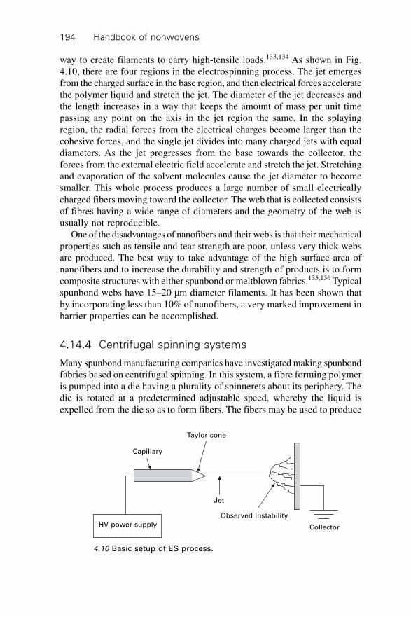
Handbook of nonwovens194
way to create filaments to carry high-tensile loads.133,134 As shown in Fig.4.10, there are four regions in the electrospinning process. The jet emergesfrom the charged surface in the base region, and then electrical forces acceleratethe polymer liquid and stretch the jet. The diameter of the jet decreases andthe length increases in a way that keeps the amount of mass per unit timepassing any point on the axis in the jet region the same. In the splayingregion, the radial forces from the electrical charges become larger than thecohesive forces, and the single jet divides into many charged jets with equaldiameters. As the jet progresses from the base towards the collector, theforces from the external electric field accelerate and stretch the jet. Stretchingand evaporation of the solvent molecules cause the jet diameter to becomesmaller. This whole process produces a large number of small electricallycharged fibers moving toward the collector. The web that is collected consistsof fibres having a wide range of diameters and the geometry of the web isusually not reproducible.
One of the disadvantages of nanofibers and their webs is that their mechanicalproperties such as tensile and tear strength are poor, unless very thick websare produced. The best way to take advantage of the high surface area ofnanofibers and to increase the durability and strength of products is to formcomposite structures with either spunbond or meltblown fabrics.135,136 Typicalspunbond webs have 15–20 mm diameter filaments. It has been shown thatby incorporating less than 10% of nanofibers, a very marked improvement inbarrier properties can be accomplished.
4.14.4 Centrifugal spinning systems
Many spunbond manufacturing companies have investigated making spunbondfabrics based on centrifugal spinning. In this system, a fibre forming polymeris pumped into a die having a plurality of spinnerets about its periphery. Thedie is rotated at a predetermined adjustable speed, whereby the liquid isexpelled from the die so as to form fibers. The fibers may be used to produce
4.10 Basic setup of ES process.
Capillary
Taylor cone
Jet
HV power supply
Observed instability
Collector
Polymer-laid web formation 195
a continuous web, fibrous tow and yarn through appropriate collection andtake-up systems. To the best of the author’s knowledge, this system is notbeing used commercially at present.
4.15 Future trends
Current developments are focused on improving the uniformity and functionalperformance characteristics of fabrics so that they can compete in new markets.Some of the approaches include increased spinning velocities to producefine denier fibers, utilization of new polymers, multi-component spinning,especially bicomponent systems, and the utilization of alternative web forming(e.g. Nanoval) and bonding systems such as hydroentanglement. Theseapproaches are likely to produce fabrics with a unique combination of propertiessuitable for many niche applications in areas that have not so far been penetrated.
4.16 References
1. Stahl, A. et. al. : 5th Annual TANDEC Conference, October 31–November 2, TheUniversity of Tennessee, Knoxville, TN, USA, 1995.
2. Montgana, A. and Floyd, J. : Book of Papers, MetCon’93, May 26–28, Houston,TX, Paper # 171, 1993.
3. Malkan, S. R. : Book of Papers, Hi-Per Fab 96 Conference, Singapore, April 24–26, 1996.
4. Cheng, C. Y. : TAPPI Nonwovens Conference, February 14–16, Orlando, Florida,USA, pp. 39–49, 1994.
5. Anonymous : Metallocene Catalyst Initiate New Era In Polymer Synthesis, Chemical& Engineering News, September 11, 1995, pp. 15–20.
6. Anonymous : Metallocenes, Modern Plastics, January 1996, pp. 56–57.7. Malkan, S. R. and Wadsworth, L. C. International Nonwovens Bulletin, Fall 1992
and Winter 1993.8. Hill, R. G. : Book of Papers, Fiber Producer Conference, Greenville, South Carolina,
April 23–25, pp. 3A1–4, 1990.9. Bradhe, L. : Textile Asia, No. 10, Volume 4, pp. 32–37, 1973.
10. Vaughn, E. A. : Nonwovens World Fact Book 1991, Miller Freeman Publications,Inc., San Francisco, California, USA, 1990.
11. Wooten, H. L. : Book of Papers, Fiber Producer Conference, Greenville, SouthCarolina, April 24–26, pp. 3A/17 - 3A/23, 1990.
12. Anonymous : Man-Made Fiber Dictionary, Celanese Corporation, New York, 1978.13. Ziabicki, A. : Fundamentals of fibre formation : the science of fibre spinning and
drawing, Wiley, New York, 1976.14. McCrum, N. G. : Principles of Polymer Engineering, Oxford University Press,
New York, pp. 264–265, 1988.15. Rodriguez, F. : Principles of Polymer Engineering, McGraw Hill, New York, pp.
330–331, 1982.16. Mastubara, Y. : US Patent # 4,285,655, 1981.17. Mastubara, Y. : Polymer Engineering and Science, Volume 19, No. 3, pp. 169–172,
1979.
Handbook of nonwovens196
18. Mastubara, Y. : Polymer Engineering and Science, Volume 20, No. 3, pp. 212–214,1980.
19. Mastubara, Y. : Polymer Engineering and Science, Volume 20, No. 11, pp. 716–719, 1980.
20. Mastubara, Y. : Polymer Engineering and Science, Volume 23, No., pp. 17–19,1983.
21. Smorada, R. L. : Encyclopedia of Polymer Science and Enginnering., Vol. 10, 227–253, 1985.
22. Hartmann, L. : Textile Manufacturer, Volume 101, September, pp. 26, 29, and 30,1974.
23. Anonymous : Nonwovens Reports International, #135, July 1982, pp. 7–10.24. Bhat, G. and Malkan, S. R. : Journal of Applied Polymer Science, Volume 83, pp.
572–585, 2002.25. Porter, K. : Encyclopedia of Chemical Technology, 3rd Edition, Volume 16, pp. 72–
104.26. Mao, Z. and Goswami, B. C. : Book of Papers, INDA-TEC 99, Cary, NC, 1999.27. Hoyle, A. G. : Tappi Journal, Volume 72, pp. 109–112, April, 1989.28. Dent, R. : Nonwovens ‘71, Ed. by J. W. S. Hearle and M. S. Burnip, The Textile
Trade Press, Manchester, England, 155–169, 1971.29. Ericson, C. W. and Baxter, J. F. : Textile Research Journal, 43, 371–378, 1973.30. Malkan, S. R., Wadsworth, L. C. and Davey, C. : International Nonwovens Journal,
Vol. 6, #2, 42–70, 1994.31. Misra, S., Spruiell, J. E. and Richeson, G. C. : INDA Journal of Nonwovens
Research, Vol. 5, No. 3, 13–19, 1993.32. Misra, S., Lu, F. M., Spruiell, J. E. and Richeson, G. C. : Journal of Applied
Polymer Science, Vol. 56, 1761–1779, 1995.33. Smith, C. and Roberts Jr., W. W. : International Nonwovens Journal, Vol. 6, #1,
31–41, 1994.34. Bhat, G. S., Zhang, D., Malkan, S. R. and Wadsworth, L. C. : Proceedings of the
Fourth Annual TANDEC Conference, Knoxville, TN Nov. 14–16, 1994.35. Zhang, D., Bhat, G. S., Malkan, S. R. and Wadsworth, L. C. : Proceedings of the
1996 TANDEC Conference, Knoxville, TN, Nov. 1996.36. Zhang, D. : Ph.D. Dissertation, University of Tennessee, Knoxville, TN, 1996.37. Bhat, G. S., Zhang, D., Malkan, S. R. and Wadsworth, L. C. : Proceedings of the
Joint Conference on Fibers & Yarns, Textile Institute, Manchester, UK, December,1996.
38. Zhang, D., Bhat, G. S., Malkan, S. R. and Wadsworth, L. C. : Journal of Thermal
Analysis, 49, 161–167, 1997.39. Zhang, D., Bhat, G. S., Malkan, S. R. and Wadsworth, L. C. : Textile Research
Journal, 68(1), 27–35, 1998.40. Bhat, G. S. : Proceedings of the Clemson University Polypropylene Conference,
Clemson, SC August 23–24, 1995.41. Beyreuther, R. and Malcome, H. J. : Melliand Textilnerichte, Vol. 4, 287–290 and
E133–135, 1993.42. Chen, C. H., White, J. L., Spruiell, J. E. and Goswami, B. C. : Textile Research
Journal, 44–51, 1983.43. Lu, F. : Proceedings of the 1997 TANDEC Conference, Knoxville, TN, Nov. 1997.44. Hearle, J. W. S., Sultan, M. A. I. and Govender, S.: Journal of the Textile Institute,
Vol.67, #11, 373–376, 1976.
Polymer-laid web formation 197
45. Hearle, J. W. S., Sultan, M. A. I. and Govender, S.: Journal of the Textile Institute,Vol. 67, #11, 377–381, 1976.
46. Hearle, J. W. S., Sultan, M. A. I. and Govender, S.: Journal of the Textile Institute,Vol. 67, #11, 382–386, 1976.
47. Huang, X. C. and Bresee, R. R. : INDA Journal of Nonwovens Research, Vol. 5, #3,28–38, 1993.
48. Huang, X. C. and Bresee, R. R. : INDA Journal of Nonwovens Research, Vol. 6, #4,53–59, 1994.
49. Bais-Singh, S. and Goswami, B. C. : Journal of Textile Institute, 86, #2, 271–287,1995.
50. Bais-Singh, S., Biggers Jr., S. B., and Goswami, B. C. : Textile Research Journal,68(5), 327–342, 1998.
51. Shang, P. P. : PhD Dissertation, North Carolina State University, Raleigh, NC,USA, 1995.
52. Backer, S. and Patterson, D. R. : Textile Research Journal, 30, 704–711, 1960.53. Hearle, J. W. S. and Stevenson, P. J. : Textile Research Journal, 38, 343–351, 1968.54. Hearle, J. W. S. and Stevenson, P. J. : Textile Research Journal, 34, 181–191, 1964.55. Komori, T. and Makishima, K. : Textile Research Journal, 47, 13–17. 1977.56. Britton, P. and Simpson, A. J. : Textile Research Journal, 53, pp 1–5 and pp 363–
368, 1983.57. Grindstaff, T. H. and Hansen, S. M. : Textile Research Journal, 56(6) 383. 1986.58. Gilmore, T. F. Mi Z. and Batra, S. K. : Proceedings of the TAPPI Conference May
1993.59. Kim, H. S. and Pourdeyhimi, B. : Journal of Textile and Apparel Technology and
Management, Vol. 1 (4) 1–7, 2001.60. Ahmed, M. : Polypropylene Fiber Science and Technology, Elsevier Scientific
Publishing Company, New York, 1982, pp. 434–448.61. Malkan, S. R. and Wadsworth, L. C. : International Nonwovens Bulletin, 2/91 and
3/91, pp. 46–52 and ppp. 22–28, 1991.62. Malkan, S. R. : PhD Dissertation, The University of Tennessee, Knoxville, TN
USA, May 1990.63. Jones, A. M. : A Study of Resin Melt Flow Rate And Polydispersity Effects On The
Mechanical Properties of Melt Blown Polypropylene Webs, Book of Papers, FourthInternational Conference on Polypropylene Fibers and Textiles, Nottingham, England,September 23–25, 1987, pp. 47.1–47.10.
64. Straeffer, G. and Goswami, B. C. : Book of Papers, INDA-TEC, Baltimore, MD,USA, June 5–8, pp. 385–419, 1990.
65. Malkan, S. R. et al. : Nonwovens – An Advanced Tutorial, TAPPI Press, Atlanta,GA, USA, 1989, pp. 101–129.
66. Eaton, G. M. : The Effects of Pigments on The Physical Properties of Melt Blown
Nonwovens, Book of Papers, INDA-TEC 87, Hilton Head, SC, USA, May 18–21,1997, pp. 1–11.
67. Wente, V. A. et. al. : Manufacture of Superfine Organic Fibers, United Departmentof Commerce, Office of Technical Services Report No. PB111437, NRL 4364,April 15, 1954.
68. Malkan, S. R. and Wadsworth, L. C. : Process-Structure-Property Relationships In
Melt Blowing of Different Molecular Weight Polypropylene Resins, Part I – PhysicalProperties, INDA Journal of Nonwovens Research, Volume 3, No. 2, 1991.
69. Malkan, S. R. and Wadsworth, L. C. : Process-Structure-Property Relationships In
Handbook of nonwovens198
Melt Blowing of Different Molecular Weight Polypropylene Resins, Part II –Morphological and Process Conditions, INDA Journal of Nonwovens Research,Volume 3, No. 3, 1991.
70. Milligan, M. W. and Haynes, B. D. : Air Drag on Monofilament Fibers – Meltblowing
Application, American Society of Mechanical Engineers, Vol. 54, pp. 47–50.71. Buntin, R. R. and Lohkamp, D. T. : Tappi, Volume 56, No. 4, pp. 74.77, 1973.72. Tsai, P. P. et. al. : Meltblown Web Properties Improved by Water Spraying the
Fibers Near the Die Exit, Unpublished Research73. Wadsworth, L. C. and Jones, A. M. : Book of Papers, INDA-TEC, Philadelphia,
Pennsylvania, June 2–6, pp. 312–320, 1986.74. Wente, V. A. : Superfine Thermoplastic Fibers, Industrial and Engineering Chemistry,
Vol. 48, No. 8, August 1956, pp. 1342–1346.75. Khan. A. Y. A. : PhD Dissertation, The University of Tennessee, Knoxville, TN,
USA, 1993.76. Lee, Y. and Wadsworth, L. C. : Polymer Engineering and Science, Vol. 30, No. 22,
November 1990, pp. 1413–1419.77. Choi, K. J. et. al. : Polymer Engineering and Science, Volume 28, No. 2, pp. 81–
89, 1988.78. Milligan, M. W. and Fumin, Lu : Book of Papers, Second Annual TANDEC
Conference, The University of Tennessee, Knoxville, TN, October 13–15, 1992.79. Haynes, B. D. : PhD Dissertation, The University of Tennessee, Knoxville, TN,
1991.80. Warner, S. B. et. al. : INDA Journal of Nonwovens Research, Vol. 2, No. 2, pp. 33–
40, 1990.81. Wadsworth, L. C. and Muschelewicz, A. O. : Book of Papers, 4th International
Conference on Polypropylene Fibers and Textiles, Nottingham, England, Septemebr23–25, 1987, pp. 47.11–47.20.
82. Tsai, P. P. : Characterization of Melt Blown Web Properties Using Air Flow Technique,Unpublished Research.
83. Naqwi, A. et. al. : 5th Annual TANDEC Conference, Knoxville, TN, USA, October31–November 2, 1995.
84. Bhat, G. : INDA Journal of Nonwovens Research, Vol. 4, No. 3, pp. 26–28, 1992.85. Wallen, J. et. al. : International Nonwovens Journal, Vol. 7, No. 3, pp. 49–50,
1995.86. Bodaghi, H. : Book of Papers, INDA-TEC, Philadelphia, Pennsylvania, USA, May
30–June 2, pp. 535–571, 1989.87. Malkan, S. R. and Wadsworth, L. C. : Processing of TPX (4-Methylpentene-1
Copolymer), Unpublished Research, TANDEC.88. Cheng, C. Y. and Kwalik, K. M. : Meltblown Technology Today, Miller Freeman
Publications, San Francisco, CA, USA, pp. 64–68, 1989.89. Khan, A. Y. A. and Wadsworth, L. C. : Melt Blown Processing and Characterization
of Cellulose Acetate and Polyvinyl Alcohol Resins, Book of Papers, 1993 TAPPINonwovens Conference, Atlanta, GA, USA, April 18–21, 1993, pp. 111–113.
90. Wadsworth, L. C. and Fagan, J. : INDA Journal of Nonwovens Research, No.1,1993.
91. Bhat, G. et. al. : Melt Blown Nonwovens from Poly(Butylene Terephthalate), 1992TAPPI Nonwovens Conference, pp. 61–68.
92. Tsai, P. P. et. al. : Theory and Techniques of Electrostatic Charging of Melt-BlownNonwoven Webs, TAPPI Journal, Vol. 81, No. 1, January, 1998, pp. 274. 278.
Polymer-laid web formation 199
93. Tsai, P. P. et. al. : Electrostatic Properties of Fibrous Electret Filters, 1998 TAPPINonwovens Conference and Trade Fair, pp. 115–124.
94. Tsai, P. P. and Wadsworth, L. C. : Polymeric Types for Electrostatic Charging of
Fibrous Filter Media, 6th Annual TANDEC Conference, Knoxville, TN, USA,November 18–20, 1996.
95. Tsai, P. P. et. al. : Effect of Aerosol Properties on the Filtration Efficiency of
Meltblown Webs and Their Electrets, Unpublished Research, UTK.96. Wadsworth, L. C. and Tsai, P. P. : Effect of Polymers and Additives on the Electrostatic
Charging of Different Melt Blown Web Structures, Unpublished Research, UTK.97. Tsai, P. P. and Wadsworth, L. C. : Air Filtration Improved by Electrostatically
Charging Fibrous Materials, Particulate Science and Technology, Vol. 12, 1994,pp. 323–332.
98. Turnhout, J. V. : Electret Filters for High-Efficiency Air Cleaning, Journal ofElectrostatics, Vol. 8, 1980, pp. 369–379.
99. Bergmann, L. : Electret Nonwovens – A Fast Growing Breed of Filtration Fabrics,International Techtextil Symposium, Frankfurt, Germany, May 21–23, 1990.
100. Bergmann, L. : Microfiber and Electrostatically Charged Nonwovens In Filtration,Nonwovens Industry, February, 1991, pp. 28–31.
101. Lathrache, R. : Performance Evaluation of Electrostatically Charged Nonwovens
As Filter Media In Air Filtration, Session Applications 1 – Filtration and Separation,INDEX 90 Congress, Geneva, Switzerland, pp. 1–9.
102. Budliger, J. P. et. al. : Fiber Charging of the Melt Blowing Process by Means of a
Superposed Electrostatic Field, A report by Telmeco, S. A. to Exxon ChemicalCompany, 1988.
103. Narasimahan, K. M. and Shambaugh, R. L. : Book of Papers, INDA_TEC, HiltonHead, SC, USA, May 18–21, pp. 189–205, 1987.
104. Shambaugh, R. L. : A Macroscopic View of the Melt-Blowing Process for ProducingMicrofibers, Ind. Eng. Chem. Res., Vol. 27, No. 12, pp. 2363–2372.
105. Milligan, M. W. and Haynes, B. D. : American Society of Mechanical Engineers,Vol. 54, pp. 47–50, 1989.
106. Uyttendaele, M. A. J. and Shambaugh, R. L. : AIChE Journal, Vol. 36, No. 2,February, pp. 175–186, 1990.
107. Majumdar, B. and Shambaugh, R. L. : Journal of Rheology, Vol. 34, No. 4, pp.591–601, May, 1990.
108. Milligan, M. W. : Nonwovens – An Advanced Tutorial, Tappi Press, Atlanta, GA,USA, 1989, pp. 93.99.
109. Milligan, M. W. et. al: Book of Papers, INDA-TEC, Philadelphia, PA, USA, May30–June 2, 1989, pp. 573–583.
110. Malkan, S. R. and Wadsworth, L. C. Polymer-laid Systems, A chapter in Nonwovens:Theory, Process, Performance, and Testing edited by A. F. Turbak, Tappi Press,Atlanta, GA, USA, 1993.
111. Richardson, E. G. : Flow Properties of Disperse Systems, Chapter IV, Edited byHermans, J. J., North-Holland Publication Corp., Amsterdam, 1953, pp. 266–298.
112. Bresee, R. R. and Wadswoth, L. C. : Book of Papers, Exxon Melt Blown Seminar,Baytown, Texas, September 15-16, 1988.
113. McCulloch, W. J. G. : Book of Papers, Fiber Producer Conference, Greenville,South Carolina, USA, 1990, April 23–25, pp. 3B/8–15.
114. Okamoto, M. : Japan Textile News, No. 276-277, 1977, pp. 94.97.115. Blair, E. R. : Formed Fabric Industry, December 1974, pp. 39–50.
Handbook of nonwovens200
116. Ando, K. : Book of Papers, International Symposium on Fiber Science & Technology,Hakone, Japan, August 20–24, 1985, p. 238.
117. Anonymous : Meltblown Technology Today, Miller Freeman Publications, SanFrancisco, pp. 7–12.
118. White, L. R. : Tappi Journal, Vol. 71, No. 2, 1988, pp. 79–81.119. Ishitara, H. et. al. : International Polymer Processing, 4(2): 91, 1989.120. Dutta, A. : Polymer Engineering and Science, 27(14): 1050, 1987.121. Patel, R. : PhD Dissertation, The University of Tennessee, Knoxville, TN, August
1991.122. Kase, S. and Matsuo, T. : Journal of Polymer Science, 3: 2541, 1965.123. Kase, S. and Matsuo, T. : Journal of Polymer Science, 11: 251, 1967.124. Matsui, M. : Transactions of Society of Rheology, 20: 465, 1976.125. Anonymous : Pneumatic Handbook, 3rd. edn., Trade and Technical Press Vtd.,
Surrey, England, 1972.126. Fluid Meters, H. S. Bean Editor, The American Society of Mechanical Engineers,
New York, 1971.127. Anonymous : Flow Measurements, The American Society of Mechanical Engineers,
Power Test Code, PTC, 19.5; 4–1959.128. Owner, E. and Pankhurst, R. C. : The Measurement of Air Flow, Pergamon Presss,
New York, 1977.129. Hardison, T. B. : Fluid Mechanics for Technicians, Reston Publishing, Reston, VA,
1977.130. Milligan, M. W. : Unpublished Research, The University of Tennessee, Knoxville,
TN, USA, 1990.131. Blades, H. and White, J. R. : US Patent 3.081,519, 1962.132. Lee, Y. and Bhat, G. “Recent Advances in Electrospun nanofibers,” in Processing
and Fabrication of Advanced Materials for High Temperature Applications III,The Materials Society, Warrendale, PA, (2003).
133. Reneker, D. H. and Chun, I. Nanotechnology, 7, 216–223, 1996.134. Reneker, D. H. Chun, I. and Ertley, D. U. S. Patent 6,382,526, 2002.135. Doshi, J. Mainz, M. H. and Bhat, G. S. Proceedings of the Tenth TANDEC Nonwoven
Conference, Knoxville, TN, 2000.136. Grage, T. and Graham, K. Int. Non. J., 51, 2003.
201
5.1 Stitch bonding: introduction
Stitch bonded fabric has been defined as a fabric in which fibres, yarns,fibres and yarns, or fibres and a ground fabric are held together by subsequentstitching or knitting-in additional yarns.1 The Textile Institute defines stitchbonded or ‘sew-knit’ fabric as a multi-component fabric, one component ofwhich is a series of interlooped stitches running along the fabric length.2 Theother components may be a fibre web, yarns, or preformed fabric. Manystitch bonded fabrics are excluded from industry definitions of nonwovensbut are discussed here for completeness.
A number of different stitch bonding systems have been developed andcommercially employed since the end of the Second World War; includingAra machines (Czech Republic); Mali machines (Germany); Liba machines(Germany) and A Ch V-Sh VP machines (Russia). Within each of thesemachine families, a modular concept was developed and utilised so that avariety of product combinations could be produced using one basic stitchinghead or one headstock, with the possibility of feeding different substrates orcombination of substrates. Commercially, a wide spectrum of products areproduced using stitch bonding including apparel, household and technicalfabrics. This is because different combinations of substrates, raw materialsor even preformed fabrics can be combined during stitch bonding to modifyor improve the characteristics of the final product.
Currently, the full range of stitch bonding equipment is produced by onlyone manufacturer, with another well-known company offering a multiaxialstitch bonding system for which they are universally recognised. Historically,a Russian company, which ceased trading in the 1970s, produced a limitednumber of VP machines that saw operation mainly within Eastern Europe. In1964, the production of Arachne machines started in Czechoslovakia andduring the 1970s Arachne offered a full range of stitch bonding machineryincluding the Arabeva, Arachne, Aranit, Arutex, Araloop and Bicolor Araloopsystems. This type of machine was extensively operated throughout Europe
5Mechanical bonding
S C A N A N DThe University of Bolton, UK, Sections 5.1–5.8
D B R U N N S C H W E I L E R, Consultant andG S WA R B R I C K
Foster Needle Ltd, UK, Sections 5.9–5.13 andS J R U S S E L L
University of Leeds, UK, Sections 5.14–5.19
Handbook of nonwovens202
and many other countries until the early to mid-1990s and Arachne finallydiscontinued production of new equipment. Liba Maschinenfabrik GmbH,Germany, manufactures Multiaxial stitch bonding equipment and in the pasthas also manufactured bespoke stitch bonding equipment exclusively forspecific companies, including Cosmopolitan Textiles Ltd, UK. In what wasthen the German Democratic Republic, the Institute for Textile Machines, inKarl-Marx-Stadt (now Chemnitz), developed a ‘sew-knit’ machine based onthe patents of Heinrich Mauersberger. The principle of sewing was used forproducing bonded nonwoven fabrics and took advantage of the high sewingspeeds that could be obtained with suitably designed mechanisms.3 MalimoMaschinenbau GmbH, Chemnitz, Germany, was acquired by Karl MayerTextilmaschinenfabrik GmbH, Obertshausen, Germany, in 1992. Subsequently,Karl Mayer has redesigned these stitch bonding systems and further commercialdevelopments have been introduced.
5.2 The Maliwatt and Malivlies stitch bondingsystems
5.2.1 Maliwatt
The Maliwatt system consists of the following components:
1. stitch bonding unit with drive system for the working elements2. web feed system3. yarn feeding and monitoring systems4. take-up of stitch bonded fabric and fabric storage or plaiting5. cutting and tearing unit, and a machine control and drive system.
The main elements of a Maliwatt stitching head are illustrated in Fig. 5.1 anda close-up view of the stitching action is given in Fig. 5.2. The horizontalcompound needle and closing wire system, which operates in conjunctionwith the knock-over sinker and the supporting rail, penetrates through thesubstrate which is normally a cross-laid web. The sheet of stitching yarn,which is inserted via the guides into the open hooks of the compound needles,forms stitches that penetrate the web. Pillar stitch and tricot stitch are possibleon the basic version with one guide bar (cam shogging). On two-guide-barmachines, by shogging the first or second guide bar via pattern discs, all thebasic two-guide-bar structures can be produced up to a repeat length ofsixteen courses. By adjusting the compound needle and closing wire system,it is possible to incorporate fibres from the web into the stitches at the sametime, thereby preventing the stitches from running from the end knitted last.
With tricot lapping, a parallel warp yarn system can be placed into theweb and subsequently incorporated into the stitch bonded fabric. Retainingpins, together with the supporting rail, prevent the web from moving during
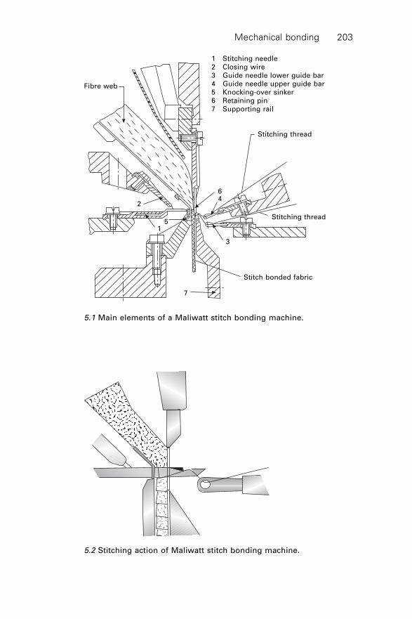
Mechanical bonding 203
1 Stitching needle
2 Closing wire
3 Guide needle lower guide bar
4 Guide needle upper guide bar
5 Knocking-over sinker
6 Retaining pin
7 Supporting rail
Fibre web
Stitching thread
Stitching thread
Stitch bonded fabric
2
64
3
51
7
5.1 Main elements of a Maliwatt stitch bonding machine.
5.2 Stitching action of Maliwatt stitch bonding machine.
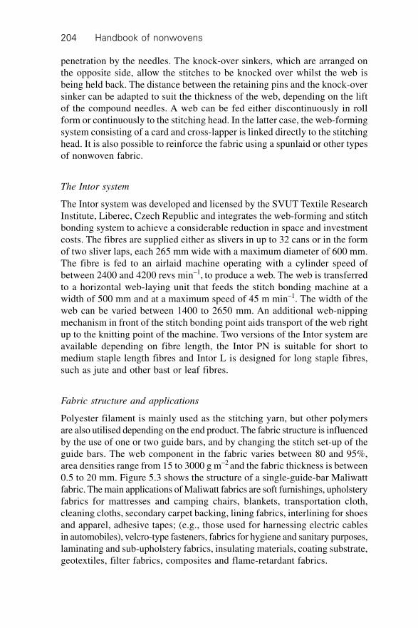
Handbook of nonwovens204
penetration by the needles. The knock-over sinkers, which are arranged onthe opposite side, allow the stitches to be knocked over whilst the web isbeing held back. The distance between the retaining pins and the knock-oversinker can be adapted to suit the thickness of the web, depending on the liftof the compound needles. A web can be fed either discontinuously in rollform or continuously to the stitching head. In the latter case, the web-formingsystem consisting of a card and cross-lapper is linked directly to the stitchinghead. It is also possible to reinforce the fabric using a spunlaid or other typesof nonwoven fabric.
The Intor system
The Intor system was developed and licensed by the SVUT Textile ResearchInstitute, Liberec, Czech Republic and integrates the web-forming and stitchbonding system to achieve a considerable reduction in space and investmentcosts. The fibres are supplied either as slivers in up to 32 cans or in the formof two sliver laps, each 265 mm wide with a maximum diameter of 600 mm.The fibre is fed to an airlaid machine operating with a cylinder speed ofbetween 2400 and 4200 revs min–1, to produce a web. The web is transferredto a horizontal web-laying unit that feeds the stitch bonding machine at awidth of 500 mm and at a maximum speed of 45 m min–1. The width of theweb can be varied between 1400 to 2650 mm. An additional web-nippingmechanism in front of the stitch bonding point aids transport of the web rightup to the knitting point of the machine. Two versions of the Intor system areavailable depending on fibre length, the Intor PN is suitable for short tomedium staple length fibres and Intor L is designed for long staple fibres,such as jute and other bast or leaf fibres.
Fabric structure and applications
Polyester filament is mainly used as the stitching yarn, but other polymersare also utilised depending on the end product. The fabric structure is influencedby the use of one or two guide bars, and by changing the stitch set-up of theguide bars. The web component in the fabric varies between 80 and 95%,area densities range from 15 to 3000 g m–2 and the fabric thickness is between0.5 to 20 mm. Figure 5.3 shows the structure of a single-guide-bar Maliwattfabric. The main applications of Maliwatt fabrics are soft furnishings, upholsteryfabrics for mattresses and camping chairs, blankets, transportation cloth,cleaning cloths, secondary carpet backing, lining fabrics, interlining for shoesand apparel, adhesive tapes; (e.g., those used for harnessing electric cablesin automobiles), velcro-type fasteners, fabrics for hygiene and sanitary purposes,laminating and sub-upholstery fabrics, insulating materials, coating substrate,geotextiles, filter fabrics, composites and flame-retardant fabrics.
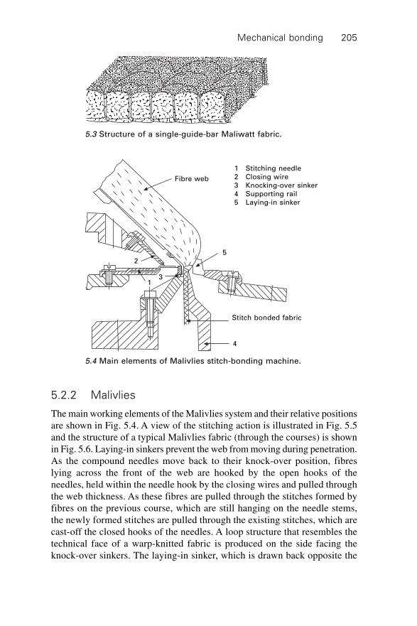
Mechanical bonding 205
5.2.2 Malivlies
The main working elements of the Malivlies system and their relative positionsare shown in Fig. 5.4. A view of the stitching action is illustrated in Fig. 5.5and the structure of a typical Malivlies fabric (through the courses) is shownin Fig. 5.6. Laying-in sinkers prevent the web from moving during penetration.As the compound needles move back to their knock-over position, fibreslying across the front of the web are hooked by the open hooks of theneedles, held within the needle hook by the closing wires and pulled throughthe web thickness. As these fibres are pulled through the stitches formed byfibres on the previous course, which are still hanging on the needle stems,the newly formed stitches are pulled through the existing stitches, which arecast-off the closed hooks of the needles. A loop structure that resembles thetechnical face of a warp-knitted fabric is produced on the side facing theknock-over sinkers. The laying-in sinker, which is drawn back opposite the
5.3 Structure of a single-guide-bar Maliwatt fabric.
Fibre web
1 Stitching needle
2 Closing wire
3 Knocking-over sinker
4 Supporting rail
5 Laying-in sinker
Stitch bonded fabric
4
31
2
5
5.4 Main elements of Malivlies stitch-bonding machine.
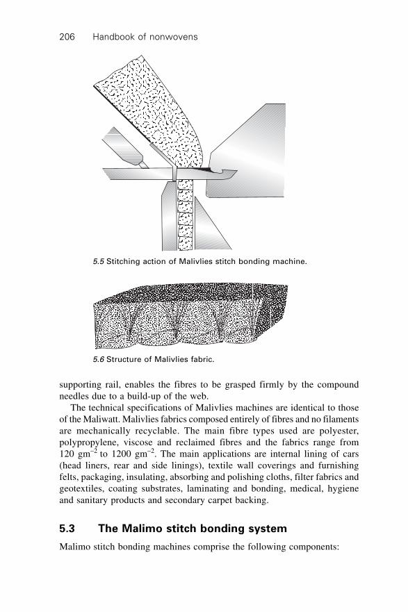
Handbook of nonwovens206
supporting rail, enables the fibres to be grasped firmly by the compoundneedles due to a build-up of the web.
The technical specifications of Malivlies machines are identical to thoseof the Maliwatt. Malivlies fabrics composed entirely of fibres and no filamentsare mechanically recyclable. The main fibre types used are polyester,polypropylene, viscose and reclaimed fibres and the fabrics range from120 gm–2 to 1200 gm–2. The main applications are internal lining of cars(head liners, rear and side linings), textile wall coverings and furnishingfelts, packaging, insulating, absorbing and polishing cloths, filter fabrics andgeotextiles, coating substrates, laminating and bonding, medical, hygieneand sanitary products and secondary carpet backing.
5.3 The Malimo stitch bonding system
Malimo stitch bonding machines comprise the following components:
5.5 Stitching action of Malivlies stitch bonding machine.
5.6 Structure of Malivlies fabric.
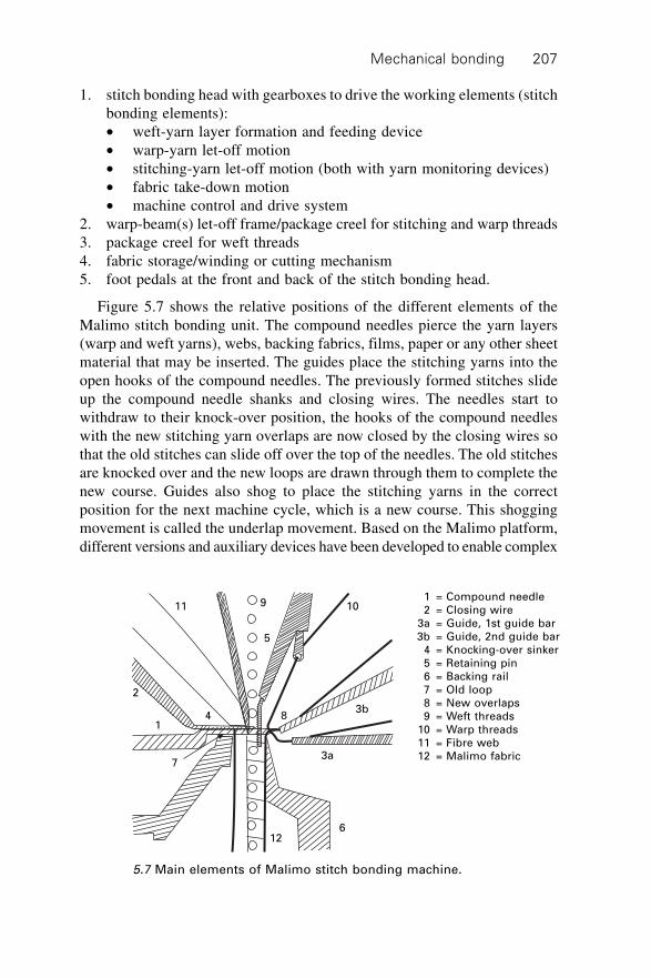
Mechanical bonding 207
1. stitch bonding head with gearboxes to drive the working elements (stitchbonding elements):∑ weft-yarn layer formation and feeding device∑ warp-yarn let-off motion∑ stitching-yarn let-off motion (both with yarn monitoring devices)∑ fabric take-down motion∑ machine control and drive system
2. warp-beam(s) let-off frame/package creel for stitching and warp threads3. package creel for weft threads4. fabric storage/winding or cutting mechanism5. foot pedals at the front and back of the stitch bonding head.
Figure 5.7 shows the relative positions of the different elements of theMalimo stitch bonding unit. The compound needles pierce the yarn layers(warp and weft yarns), webs, backing fabrics, films, paper or any other sheetmaterial that may be inserted. The guides place the stitching yarns into theopen hooks of the compound needles. The previously formed stitches slideup the compound needle shanks and closing wires. The needles start towithdraw to their knock-over position, the hooks of the compound needleswith the new stitching yarn overlaps are now closed by the closing wires sothat the old stitches can slide off over the top of the needles. The old stitchesare knocked over and the new loops are drawn through them to complete thenew course. Guides also shog to place the stitching yarns in the correctposition for the next machine cycle, which is a new course. This shoggingmovement is called the underlap movement. Based on the Malimo platform,different versions and auxiliary devices have been developed to enable complex
11 9
5
10
8
2
43b
3a
612
7
1
1 = Compound needle
2 = Closing wire
3a = Guide, 1st guide bar
3b = Guide, 2nd guide bar
4 = Knocking-over sinker
5 = Retaining pin
6 = Backing rail
7 = Old loop
8 = New overlaps
9 = Weft threads
10 = Warp threads
11 = Fibre web
12 = Malimo fabric
5.7 Main elements of Malimo stitch bonding machine.
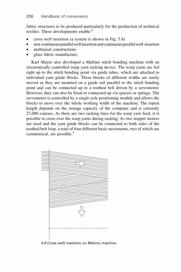
Handbook of nonwovens208
fabric structures to be produced particularly for the production of technicaltextiles. These developments enable:4
∑ cross weft insertion (a system is shown in Fig. 5.8)∑ non-continuous parallel weft insertion and continuous parallel weft insertion∑ multiaxial constructions∑ glass fabric manufacture.
Karl Mayer also developed a Malimo stitch bonding machine with anelectronically controlled warp yarn racking device. The warp yarns are fedright up to the stitch bonding point via guide tubes, which are attached toindividual yarn guide blocks. These blocks of different widths are easilymoved as they are mounted on a guide rail parallel to the stitch bondingpoint and can be connected up to a toothed belt driven by a servomotor.However, they can also be fixed or connected up via spacers or springs. Theservomotor is controlled by a single-axle positioning module and allows theblocks to move over the whole working width of the machine. The repeatlength depends on the storage capacity of the computer and is currently27,000 courses. As there are two racking lines for the warp yarn feed, it ispossible to cross over the warp yarns during racking. As two stepper motorsare used and the yarn guide blocks can be connected to both sides of thetoothed belt loop, a total of four different basic movements, two of which aresymmetrical, are possible.5
5.8 Cross weft insertion on Malimo machine.
Mechanical bonding 209
5.3.1 Cross weft insertion
Weft yarns can be fed from a stationary package creel located at the side ofthe Malimo stitch bonding system via yarn guide elements to the centre ofthe machine and into the weft yarn laying device. The end of the weft yarnis held by a clamp, which is stationary in the running direction. When theweft yarn laying device has reached the other side of the machine, the weftyarn is again clamped. By lowering the stationary clamps on both sidessimultaneously, the yarns are transferred to a yarn transport device and cutbetween the stationary clamp and the transport device on the side where theweft is deposited. On the weft insertion side, the clamps are blow-cleaned.With each movement of the weft carriage, eighteen weft yarns are drawn offand inserted into the clamps. The Malimo P1 has a maximum working widthof 1800 mm and the gauge ranges from 7 to 18 needles/25 mm. One or twoguide bars are used and a warp yarn system and a backing substrate areintroduced if required.
5.3.2 Parallel weft insertion
In a typical example of this system sixteen weft yarns are transported 0.5inches apart and simultaneously inserted into the hooks of the moving hookchain and a stationary auxiliary device. After the weft yarn is inserted andsecured on one side, the weft carriage travels to the other side. Once the weftyarns reach the opposite insertion position, the pulled out weft yarn loop istransferred to the transport chain by moving the control hook bar, which isactivated by a double-stroke magnet, to the first side thus giving a parallelweft yarn layer. The resulting yarn loops are cut off and removed by asuction device. A warp yarn or backing fabric feed mechanism may be fittedand parallel weft insertion system are available.
5.3.3 Manufacture of glass composite preforms
A system for the production of preforms for composites was developed byKarl Mayer. Typical end-uses are:
∑ structural sections and panels for use in the construction industry andmachine-building
∑ boat-building, surfboards, skis, the vehicle industry∑ pipes, poles and container making∑ moulding (press moulding)∑ coating, pipe repairs∑ sports hall floors∑ rotors for wind-driven power generators∑ components for aviation and the space industry∑ composites.
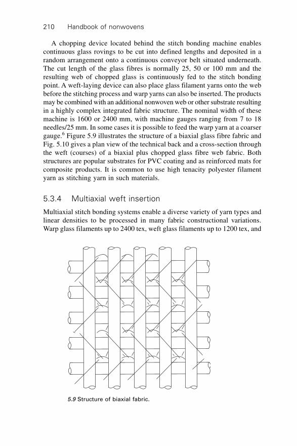
Handbook of nonwovens210
A chopping device located behind the stitch bonding machine enablescontinuous glass rovings to be cut into defined lengths and deposited in arandom arrangement onto a continuous conveyor belt situated underneath.The cut length of the glass fibres is normally 25, 50 or 100 mm and theresulting web of chopped glass is continuously fed to the stitch bondingpoint. A weft-laying device can also place glass filament yarns onto the webbefore the stitching process and warp yarns can also be inserted. The productsmay be combined with an additional nonwoven web or other substrate resultingin a highly complex integrated fabric structure. The nominal width of thesemachine is 1600 or 2400 mm, with machine gauges ranging from 7 to 18needles/25 mm. In some cases it is possible to feed the warp yarn at a coarsergauge.6 Figure 5.9 illustrates the structure of a biaxial glass fibre fabric andFig. 5.10 gives a plan view of the technical back and a cross-section throughthe weft (courses) of a biaxial plus chopped glass fibre web fabric. Bothstructures are popular substrates for PVC coating and as reinforced mats forcomposite products. It is common to use high tenacity polyester filamentyarn as stitching yarn in such materials.
5.3.4 Multiaxial weft insertion
Multiaxial stitch bonding systems enable a diverse variety of yarn types andlinear densities to be processed in many fabric constructional variations.Warp glass filaments up to 2400 tex, weft glass filaments up to 1200 tex, and
5.9 Structure of biaxial fabric.
Mechanical bonding 211
diagonal glass filaments up to 800 tex may be combined in fabrics with anarea density from 300 to 3000 g m–2. Composite materials with a high degreeof structural complexity are produced. In multiaxial stitch bonded structures,it is important to optimise the number, angle and linear densities of eachindividual yarn layer in the composite as well as the machine gauge, thespecification of the stitching yarn and the geometry of the fabric. The aboveparameters are of course dictated by the specific application of the composite.Fabric structure can be based on:7 one warp yarn layer (0∞); two weft yarnlayers of ~90∞; two weft yarn layers of ~ –45∞; two weft yarn layers of ~90∞;two weft yarn layers of ~+45∞; one stitching yarn layer or one chopped glassweb layer. Diagonal layers orientated at 45∞ can therefore be introduced. Inthe Malimo weft yarn-laying technique the yarn-laying angle varies from 1∞to 5∞ from the angles stated above, which is claimed to enable:
∑ improved load-bearing yarn distribution∑ improved wettability and resin impregnation in the finished product due
to the lower packing density∑ improved draping property∑ reduced delamination tendency in the composite material.
The maximum working width is normally 1600 mm, which can be reducedif required, and machine gauges range from 3.5 to 18 needles/25 mm. The
5.10 Structure of biaxial fabric with glass mat: plan view (technicalback) and cross-section through courses.
Handbook of nonwovens212
stitch bonding point of a Malimo multiaxial machine is illustrated in Fig.5.11. This consists of a pointed head compound needle bar and closing wirebar, knock-over sinker bar, supporting bar, counter retaining sinker bar, stitchingyarn guide bars and filler (warp 0∞) thread guide bars. Multiaxial multi-plyfabrics are used to reinforce different matrices. The combination of multi-directional fibre layers and matrices has proved capable of absorbing anddistributing extraordinarily high strain forces in use. The thread angles maybe varied from 30∞ to 60∞ for diagonal yarns (+45∞ and –45∞ yarns). Themajor attributes of multiaxial reinforcement for both flexible and rigidcomposites are dimensional stability in any direction (high shear strength inthe bias or diagonal directions), isotropic mechanical properties, reduceddelamination tendency, non-crimped and parallel yarn sheets, low specificarea density, adjustable stiffness between extremely stiff and high extensibility,non-corrosive, non-magnetic, resistant to chemicals, high mechanical loadresistance and, above all, high resistance to crack propagation.
Major applications for multiaxial structures are for inflatable structuressuch as airships and boats, flexible roofing membranes, rotor blades for windpower stations, moulded parts for automotive application, aircraft and shipbuilding, equipment for sports and leisure activities such as skis, snowboards,surfboards and boats. Most high performance materials are compatible withthe multiaxial system, such as fibreglass, aramid, carbon, high-tenacitypolyester, polyamide, polyethylene and polypropylene. Thermosetting andthermoplastic matrix materials are used and even pressure setting matrixmaterials such as concrete and cement have been successfully utilised. Figure5.12 shows stacking of the different yarn layers, including a nonwoven webor preformed substrate. All five or more layers are stitched together with the
4 4 5
67
32
1
1 = Compound needle bar
2 = Closing wire bar
3 = Knock-over sinker bar
4 = Stitching yarn guide bars
5 = Warp (0∞) yarn guide bar
6 = Supporting bar
7 = Counter retaining sinker bar
5.11 Main elements of Malimo multiaxial stitch bonding machine.
Mechanical bonding 213
stitching yarn, which is commonly high-tenacity polyester filament. Thestructure of a multiaxial fabric is shown in Fig. 5.13.
5.3.5 The Schusspol technique
This modification of the Malimo system produces fabrics for floor coverings,upholstery and furnishings. The machine uses two guide bars, stitching yarn,pile yarn and a weft yarn. The pile, usually between 5 and 11 mm in height,appears only on the face of the fabric and is bound firmly into the groundfabric. This is achieved by lapping the pile yarn and the stitching yarn systemin a special manner. A pile sinker is also utilised to create the pile on one faceof the fabric.
5.12 Different layers stacked and stitched together.
5.13 Structure of multiaxial stitch bonded fabric.
Angles
adjustable
Handbook of nonwovens214
5.3.6 The Malifol technique
Films, rather than yarns, are used for the warp and weft threads, whilstconventional yarns are used for the stitching threads. The warp film in openwidth is fed into the stitching head directly from the warp beam unwindingframe, while the weft films are slit on the film web forming mechanism and,as on the Malimo machine, they are suspended in the hook needles of the weftcarrier chains by the weft yarn laying device. These stitch bonded fabrics havea low area density with good fabric cover and are dimensionally stable. Theirpolymer composition is normally chosen to enable UV, rot and insect resistanceto be achieved since the main areas of application are in coating substrates,packaging, insulation, secondary carpet backing, filtration media and geotextiles.
5.4 Malipol
Malipol stitch bonding systems have the following main elements:
∑ pile yarn∑ ground fabric∑ stitch bonding head∑ fabric take-down and batching.
The main stitching elements are shown in Fig. 5.14. The compound needlespenetrate the ground fabric and the stitching or pile yarn is overlapped in theneedle hook. The pile yarn is also laid on top of the pile sinker at the sametime so that a tricot movement, i.e. 1–0/1–2, is used to create the pile andknit the yarn into the ground structure. The machine is available in gauges of10, 12 and 14 (needles/25 mm), pile sinker heights from 1 to 11 mm andstitch lengths of 1 to 3 mm can be achieved by using the change gears. The
5.14 Main elements of Malipol stitch bonding machine.
7
4
2
1
5 6
3
1 = Compound needle bar
2 = Closing wire bar
3 = Guide bar for pile yarn
4 = Knock-over sinker bar
5 = Pile sinker bar
6 = Pile yarn
7 = Ground fabric
Mechanical bonding 215
machine speed usually ranges from 900 to 1300 courses/minute. The pileyarn is fed either from a creel of the single end or magazine type, or from awarp beam arrangement.
The choice of feed system is governed by the quality of the product andthe product versatility required. The optimum pile yarn linear density isinfluenced by the machine gauge and ranges from 140 tex for a 10 gauge to50 tex for a 14 gauge machine. Any substrate through which the compoundneedles can penetrate may be used as the ground fabric, as long as it willremain intact. Twill and satin woven fabrics are the most suitable, althoughloose plain weave fabrics are compatible. Alternatives include stitch bondedfabrics, foams, knitted fabrics and films. Woven cotton or viscose fabrics of100 to 200 g m–2 are the most common for blankets and upholstery fabricsand polyamide or polyester filament fabrics of 50 to 100 g m–2 are favouredfor lining plush, soft-toy plush and imitation fur. The major end-uses forMalipol fabrics include blankets (raised on one or both sides), beachwearand leisurewear, babywear, bathroom sets, bath robes and gowns, upholsteryfabrics, imitation furs, soft-toy plush and floor coverings.
5.5 Voltex
Voltex fabrics are high pile or high plush fabrics based on two principalpreformed elements, a ground fabric and a web, which are continuouslyintroduced. No stitching yarn or yarn preparation, such as winding or warpingare required. A cross-section through the main stitching parts of a Voltexsystem is shown in Fig. 5.15. A continuous Voltex system consists of a web-forming line coupled to the stitch bonding unit. Typical working widths are1700 and 2500 mm and machine gauge ranges from 7, 10, 12, 14 (needlesper 25 mm). Pile sinker heights vary from 1 to 23 mm (depending upon thelift of the compound needles) and stitch lengths from 0.55 to 5.0 mm. Machinespeed depends on the stitch length, pile sinker height and the line speed of
4
2
1
5
6
3
1 = Compound needle bar
2 = Closing wire bar
3 = Fibre web
4 = Knock-over sinker bar
5 = Pile sinker bar
6 = Ground fabric
5.15 Main elements of Voltex stitch bonding machine.
Handbook of nonwovens216
the web formation unit and is adjustable from 500 to 1500 r.p.m. Voltexfabrics have found applications in lining fabrics, imitation furs, soft-toyplush, shoe uppers and shoe lining, floor coverings and upholstery fabrics.
5.6 Kunit
Kunit and Multiknit are two important developments of the Malimo systemlaunched in 1991 and 1993 respectively. Both were developed with the aimof producing fabrics directly from fibres without the need for yarn. In theKunit process, fibres are fed to the stitch bonding head in the form of eithera thin web or a batt. Voluminous, three-dimensional pile fabrics can beproduced that have a distinctive folded pile; the pile can have a variablethickness and density if required. A compound needle having a round headis used. It uses a brushing bar in conjunction with the stitch-forming elements,whose oscillating path may be varied between 6 and 51 mm by exchangingthe cams. The setting governs the height of the pile fold.
The elements of a Kunit machine and their relative positions are shown inFig. 5.16. The flat, oscillating brush compacts the lightweight web, whosefibres are mainly orientated in the machine direction, so that the fibres arepressed into the needle hooks and formed into stitches. The fibres that arenot knitted are arranged as cross-orientated pile folds. Parallel-laid webs areparticularly suitable composed of fibres of 40–120 mm and 1.7–3.3 dtex.The brush oscillation setting (6–51 mm brush stroke) is influenced by thefibre length in the incoming web. For short fibres (<60 mm) an 8 mm maximumoscillating cam stroke is recommended while for long fibres (>60 mm) a34 mm maximum oscillating cam stroke is used. The web area density isnormally 20–80 g m–2 and stitch lengths between 0.55 to 5.0 mm.
5.16 Main elements of Kunit stitch-bonding machine.
1 = Stitching needle bar
2 = Closing wire bar
3 = Knocking-over sinker bar
4 = Backing rail
5 = Oscillating brushing device
6 = Fibrous web
7 = Fibre stitches
8 = Kunit fabric
9 = Support rail
32
1
5
6
7
4
8
9
Mechanical bonding 217
Machine speed ranges between 500 and 1200 r min–1. The delivery speedof the web-forming unit and the oscillation of the brushing device affect themachine speed. Kunit systems have been produced in gauges from 3.5 to 22(needles per 25 mm) and working widths of 1700 to 2800 mm. Final fabricarea density ranges from 90 to 700 g m–2. Figure 5.17 illustrates the loopstructure of a Kunit fabric. Kunit fabrics have been used in linings, soft-toyfabrics, filtration media (particularly depth filters), covering materials forpolishing discs, coating substrates and as upholstery materials for car interiors.Kunit fabrics are sometimes finished and the processes used depend on theintended end-use and the fibre composition. No finishing is required formany applications or when the fabrics are to undergo further processing onthe Multiknit machine. Finishing processes applicable to Kunit materials areback-coating, raising, polishing and shearing, tumbling to achieve surfaceeffects, coating and laminating with other substrates.
5.7 Multiknit stitch bonding systems
In the most basic form of Multiknit, both sides of the fabric are formed intoa dense knitted construction by intermeshing pile fibres on the surface of theincoming Kunit fabric. The fibres in the pile folds are stitch bonded toproduce a double-sided, three-dimensional, nonwoven fabric with an innerpile structure connecting the two faces. The pile surfaces in two separateKunit fabrics can be joined in this way to make one integrated multi-layerstructure. Other structures, such as fabrics, webs or even fibres and powders,can be incorporated within the base web and covered by stitch bonding themultilayer material to produce a composite material. A Multiknit line typicallyincludes a card that continuously supplies a Kunit machine that stitch bondsthe web on one side only and in the second stage, the stitch bonded fabric isfed continuously to the Multiknit machine where it is stitch bonded on theother side. The stitch bonding heads of Kunit and Multiknit machines aresimilar, but in the case of the Multiknit system, a pointed head needle is
5.17 Structure of Kunit fabric.
Handbook of nonwovens218
employed and different adjustable components are used for stitch formation.A retaining or sinker bar is also used when further processing a Kunit fabric.The stitch bonding parts of a Multiknit machine are shown in Fig. 5.18,which, if required, can also be combined with a warp yarn feed system,fabric feed system or a scattering device, enabling a wide range of multilayerstructures to be produced with a stitch bonded structure on both faces of thefabric. Fabric area densities currently range from around 120 to 800 gm–2 forsingle layer Multiknit nonwovens and from about 150 to 1500 gm–2 formultilayer constructions.
On upgraded Kunit and Multiknit models, maximum working widths of1.7 m, 2.9 m and 4.15 m are supplied and the width can be reduced steplessly.Maximum machine speeds up to 1800 r.p.m. are attainable, depending on thetype of fibre being processed and the required thickness of the fabric. The finalarea density of the single-layer fabric is between 120 gm–2 and 800 gm–2 andthe fabric thickness varies between 2 and 11 mm. These fabrics are alsofinished, if required, by processes including heat-setting, chemical and thermalbonding, coating and lamination. The structure of a single-layer Multiknitfabric is illustrated in Fig. 5.19
3
2
1
5
6
7
41 Compound needle bar
2 Closing wire bar
3 Knocking-over sinker bar
4 Substrate feeding bar
5 Retaining pin bar
6 Kunit substrate
7 Multiknit fabric
5.18 Main elements of Multiknit stitch bonding machine.
5.19 Structure of Multiknit fabric.
Mechanical bonding 219
Multiknit fabrics have excellent compressibility, low area density and lowbulk density, excellent heat, noise and vibration insulation, excellentmouldability with a smooth and uniform surface on both sides and are weldableif the composition is predominantly thermoplastic. Multiknit fabrics havebeen used in upholstered furniture parts, seating for automobiles and otherfurniture as a PU foam replacement material. Other applications includefilter fabrics, insulation materials, garment interlinings and non-delaminatingmouldable composite materials.
There are nearly forty-five million cars produced worldwide each yearand each car uses between 10 and 12 m2 of seating fabric. The seating fabricis a laminate consisting of a face fabric, which is normally produced fromeither air textured or false twist polyester yarn, which is flame bonded to PUfoam and a warp knitted scrim, in such a manner that the foam is sandwichedbetween the polyester face fabric and polyester warp knitted scrim. The PUfoam has excellent elastic compression recovery and imparts softness andbulk to the seating fabric, which in turn makes the seat comfortable. Thefoam, however, is negatively associated with emissions from additives, includingflame-retardant chemicals and full life-cycle problems relating to after-usedisposal and recycling. Other problems are that during the flame bondingprocess, singed substances are responsible for strong fogging. Foam seatingmaterials also exhibit poor air permeability, moisture and water vapourpermeability and facilitate poor moisture and temperature regulation. Caliwebis the registered trademark of products manufactured by the Kalitherm-Technique. Caliweb is used for mechanically and thermally bonded nonwovensas well as for lamination of nonwoven composites with fabrics such as thoseused for car seating. In this system, Kunit or Multiknit fabrics that have beenthermally bonded are utilised to produce a foam substitute.
Calibration is preferably carried out using flat-bed laminating systems.The nonwoven foam substitute requires a proportion of low melt or bicomponentfibres (sheath-core type) to effect stabilisation in thermal bonding. If producedfrom 100% polyester, these materials can be completely recyclable and havehigh air permeability, moisture and water vapour permeability and goodageing behaviour. They have low emissions and do not cause fogging. Thisis only one example of the successful utilisation of three-dimensional nonwovenstructures made by the Kunit and Multiknit techniques. These lightweight,low-density, high-volume, 100% nonwoven structures with structured andsmooth surfaces either on one face (Kunit) or on both faces (Multiknit) aresuccessfully used as heat, noise, vibration and sound insulation materials, asdust filters, as adhesive tapes, as shoe linings, as anti-decubitus mattings andas medical, hygiene and sanitary materials.
Handbook of nonwovens220
5.8 Recent developments in stitch bonding
5.8.1 Maliwatt and Malivlies machines and products
Since 1993, Maliwatt and Malivlies stitch bonding machines have beenredesigned and upgraded to set new standards in quality and performance.The latest systems are up to 6150 mm working width, which can be decreasedas required. The yarn let-off motion for the two guide bars is via an electronicallycontrolled let-off system EBA, which is standard in many types of high-speed warp knitting machines. Both guide bars can also be controlled bypattern discs and can have stitch set-up or structure for stitching repeating upto 16 courses. The speed of Maliwatt and Malivlies machines can be variedbetween 1500 and 2200 r.p.m. depending upon a number of factors associatedwith product design and specifications. The machine gauge can vary from3.5 to 22 needles per 25 mm. The increased performance and higher fabricquality are achieved by:
∑ a low vibration machine frame∑ precise gauge accuracy of the stitch bonding elements by automatic bar
heating facility, which features narrow temperature tolerances for heatingall the bars with additional monitoring function
∑ electronic beam control EBA for yarn let-off mechanism∑ pattern disc control of stitching yarn guide bars up to 16 courses repeat∑ slider crank mechanism for compound needle and closing wire bars
(running in oil bath)∑ reduced weight, high-strength components for all the moving elements∑ up to 40% increase in productivity with up to 520 linear m hour–1 for
Maliwatt and 590 linear m hour–1 for Malivlies extra wide 6150 mmmachines.
Maliwatt G and Maliwatt C are used for specific technical textile products.Maliwatt G is a special machine for processing chopped glass mats. Randomlylaid glass fibres either 50 or 100 mm long in a mat form are stitched withpolyester filaments or glass yarns for textile reinforced composite materials.Maliwatt C is suitable for applications where several substrates or materialssuch as webs, yarns, fabrics, films, textile waste materials, powdered orgranular materials arranged in layers one on top of the other need to bebonded mechanically. Ten years ago, the majority of Maliwatt and Malivliesfabrics were marketed for household goods, such as bed ticking, curtains andcurtain lining, bedspreads, wall coverings, garden furniture, transportationand packing blankets, etc. Currently, they are finding applications in technicaltextiles, such as adhesive tapes, roof lining, rear and side linings in cars,coating substrates, filter fabrics, geotextiles and healthcare and hygieneproducts.
Mechanical bonding 221
5.8.2 Biaxial stitch bonding
Karl Mayer has redesigned and improved the performance of Malimo biaxialstitch bonding machines. The new biaxial M/NM stitch bonding machinesbear a closer resemblance to their RS2(3)MSUS Raschel machines. As withthe RS2(3)MSUS Raschel units, Biaxial M/NM stitch bonding machines areintended to produce textile-reinforced structures for both flexible and rigidor load-bearing composite materials. High-performance yarns, such as fibreglass, carbon, aramid, high-tenacity and high-modulus thermoplastic polymerfilaments, may be processed to produce biaxial all yarn or biaxial yarn plusany nonwoven web, or a fabric, or any other substrate to produce the correctcomposite fabric for either saturation coating, lamination, or for combiningwith a suitable matrix to produce a complex composite material. A numberof different versions have been designed:
∑ biaxial system with parallel weft insertion that is in line with the stitchcourses with or without the glass chopper mat attachment (Biaxial M orM/Ch)
∑ biaxial system with parallel weft insertion that is not in line with thestitch courses with or without the glass chopper mat attachment (BiaxialNM or NM/Ch)
∑ biaxial system with a cross weft (from 1∞ to 5∞) insertion that is not inline with the stitch courses with or without the glass chopper matattachment.
All versions have the possibility of feeding different base materials.The use of the established parallel weft insertion system in line with the
stitch courses, or MSUS principle, is a distinctive feature of these machines.This system is already used in some warp knitting machines and is capableof handling a wide variety of yarn types and linear densities. The other majordistinction between biaxial M and biaxial NM models is that in the formercase, the stitching elements are positioned in a similar fashion to all othertypes of stitch bonding machine. In the case of model NM machines, thestitch bonding elements are positioned in a similar fashion to Raschel machines,with the compound needle bar and closing wire bar being positioned in avertical direction. The other important features that influence the machineefficiency and fabric quality are:
∑ electronically controlled warp beam let-off motion EBA or as an alternativebraked warp beams with yarn feeding facility
∑ single-end monitoring of knitting yarns electronically enhanced by eitherdrop wires or by laser stop
∑ use of the patented ‘complementary weft insertion device’ featuring almostconstant weft yarn draw-off speeds (i.e., without any acceleration peaks)
∑ chromium-plated yarn guiding and feeding rollers.
Handbook of nonwovens222
5.8.3 Multiaxial stitch bonding
Liba Maschinenfabrik GmbH, Germany, developed a commercial multiaxialwarp knitting machine based on parallel weft insertion not in line with thecourses known as the Copcentra Multiaxial. Karl Mayer’s first multiaxialwarp knitting machine with diagonal weft insertion in line with the courseswas called the RS2-DS ‘Carousel machine’ and its first multiaxial machinemodel 14016 based on the principle of crosswise weft insertion not in linewith the courses followed. The latest Karl Mayer multiaxial stitch bondingmachines have the following technical specifications:
1. Working widths: max. 1525 mm, 2550 mm and 3300 mm; min. 1025 mm,2000 mm and 2600 mm. Working widths can be adjusted in steps of25 mm.
2. Machine gauges: 3.5 to 14 (needles per 25 mm).3. Yarn feeding devices for stitching yarns: electronically controlled EBA
system.4. Yarn stop motion: Protechna Laserstop (monitors single ends).5. Speed: up to 1400 r.p.m.6. Production: up to 4.4 m min–1.7. Number of guide bars: 1 or 2 for stitching yarn and 1 for warp yarn.8. Number of weft insertion devices: up to 4, depending upon requirements.9. Additional substrates possible: possibility of feeding in chopped glass
strands above or below the weft layers. Other type of substrates can alsobe used.
10. Bobbin creel.
The industries of aerospace, aviation and space travel, shipbuilding andhigh-performance automobiles have always been important sectors but inthe last four years in particular, wind turbine sites have become establishedas a growing market and the number of multiaxial machines operatingworldwide has increased to nearly one hundred.8 Carbon fibre reinforcedplastics (CRP) incorporating carbon tow multiaxial structures as reinforcementhave made it possible to reduce the weight of composite materials considerably,they have a long life, are heat and fire resistant and are resistant to corrosionand chemicals. Multiaxial structures can absorb and distribute exceptionallylarge forces because of the ability to orientate yarn layers in different pre-determined directions (0∞/90∞/+45∞/–45∞). A system of stitching yarns fixesthese layers in position. This parallel orientation in which the yarns are freeof crimp, permits optimum utilisation of the yarn strength in every stressdirection, which is an advantage compared to woven fabrics. These preformstructures have improved interlaminar shear strength, increased impactresistance and strength, dimensional stability in all directions, uniformelongation behaviour and enable rapid wetting of the resin in composite
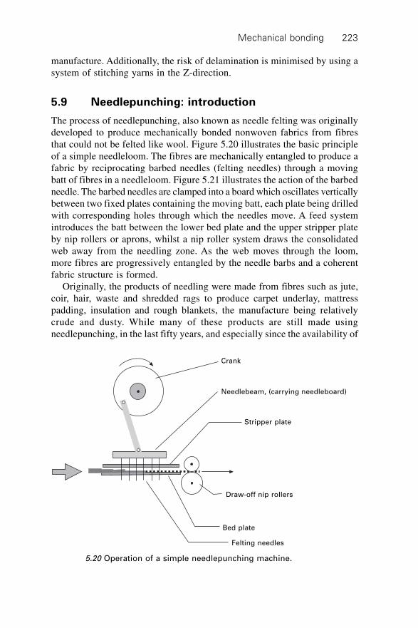
Mechanical bonding 223
manufacture. Additionally, the risk of delamination is minimised by using asystem of stitching yarns in the Z-direction.
5.9 Needlepunching: introduction
The process of needlepunching, also known as needle felting was originallydeveloped to produce mechanically bonded nonwoven fabrics from fibresthat could not be felted like wool. Figure 5.20 illustrates the basic principleof a simple needleloom. The fibres are mechanically entangled to produce afabric by reciprocating barbed needles (felting needles) through a movingbatt of fibres in a needleloom. Figure 5.21 illustrates the action of the barbedneedle. The barbed needles are clamped into a board which oscillates verticallybetween two fixed plates containing the moving batt, each plate being drilledwith corresponding holes through which the needles move. A feed systemintroduces the batt between the lower bed plate and the upper stripper plateby nip rollers or aprons, whilst a nip roller system draws the consolidatedweb away from the needling zone. As the web moves through the loom,more fibres are progressively entangled by the needle barbs and a coherentfabric structure is formed.
Originally, the products of needling were made from fibres such as jute,coir, hair, waste and shredded rags to produce carpet underlay, mattresspadding, insulation and rough blankets, the manufacture being relativelycrude and dusty. While many of these products are still made usingneedlepunching, in the last fifty years, and especially since the availability of
Crank
Needlebeam, (carrying needleboard)
Stripper plate
Draw-off nip rollers
Bed plate
Felting needles
5.20 Operation of a simple needlepunching machine.
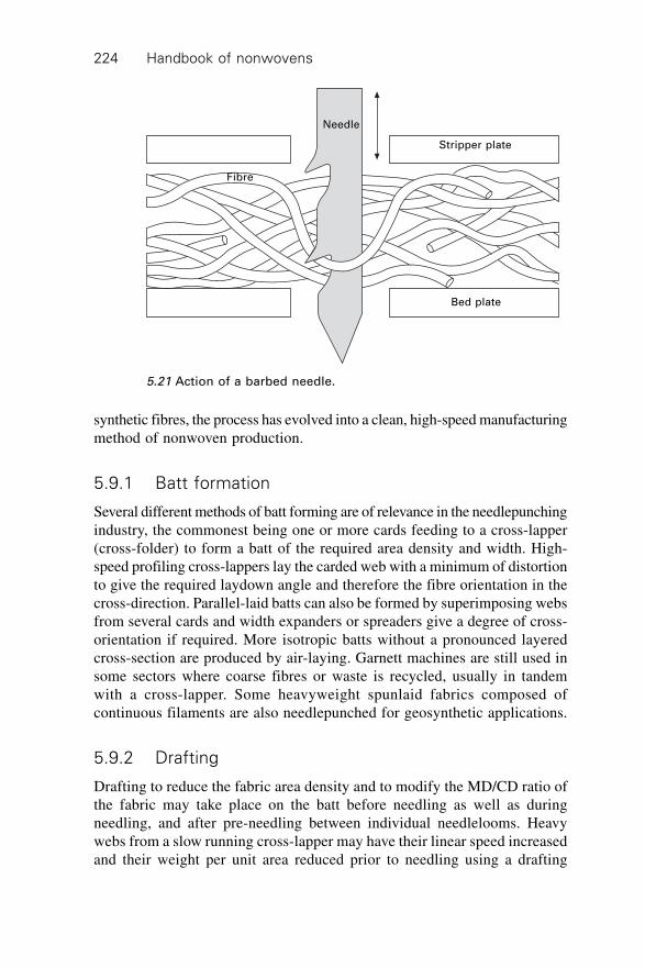
Handbook of nonwovens224
synthetic fibres, the process has evolved into a clean, high-speed manufacturingmethod of nonwoven production.
5.9.1 Batt formation
Several different methods of batt forming are of relevance in the needlepunchingindustry, the commonest being one or more cards feeding to a cross-lapper(cross-folder) to form a batt of the required area density and width. High-speed profiling cross-lappers lay the carded web with a minimum of distortionto give the required laydown angle and therefore the fibre orientation in thecross-direction. Parallel-laid batts can also be formed by superimposing websfrom several cards and width expanders or spreaders give a degree of cross-orientation if required. More isotropic batts without a pronounced layeredcross-section are produced by air-laying. Garnett machines are still used insome sectors where coarse fibres or waste is recycled, usually in tandemwith a cross-lapper. Some heavyweight spunlaid fabrics composed ofcontinuous filaments are also needlepunched for geosynthetic applications.
5.9.2 Drafting
Drafting to reduce the fabric area density and to modify the MD/CD ratio ofthe fabric may take place on the batt before needling as well as duringneedling, and after pre-needling between individual needlelooms. Heavywebs from a slow running cross-lapper may have their linear speed increasedand their weight per unit area reduced prior to needling using a drafting
Needle
Fibre
Stripper plate
Bed plate
5.21 Action of a barbed needle.
Mechanical bonding 225
machine employing a series of drafting zones between three or more rollernips which successively elongate the structure. Some draft inevitably occursduring the first needling operation as the batt is pulled through the needlescontinuously. Such draft is uncontrolled and has to be minimised by consideringthe advance per stroke and the needle penetration.
Drafting after pre-needling can provide better control of fibre reorientationand provides a means of adjusting the MD/CD ratio for strength in cross-laidstructures. Whilst some production lines take advantage of the needle loomas a drafting unit, great care has to be taken to avoid the introduction ofshort-term irregularities. In drafting after pre-needling the web is wrappedsuccessively around the upper and lower peripheries of a series of rollers toincrease the tension in the fabric to introduce elongation. The progressivelyincreasing surface speed and high friction coverings of the rollers are designedto provide a controlled and adjustable draft. The calculated draft between theentry and exit nip rollers must be adjusted to take account of roller slip andthe elastic recovery of the fabric when the tension is reduced.
5.9.3 Basics of needlepunching (needleloom) operation
The needleloom consists of a heavy, substantial frame carrying the fixed bedplate and stripper plate between which the batt passes and the verticallyreciprocating needleboard carrying the needles, which generates significantvibrational forces at high speed, which the frame must absorb. The needleboardis driven with simple harmonic motion, the method of suspension varyingaccording to the machinery maker. The batt, which is normally of very lowdensity, must be supported by aprons or rollers as it is carried into the gapbetween the bed plate and the stripper plate. Two batt compression aprons,which converge towards the entry point, are commonly used to positivelyfeed the batt into the gap between the stripper and bed plates. This helps toprevent differential slippage of fibres in the exterior and interior portions ofthe batt. The gap between the stripper and bed plates is also adjusted tocontrol the batt compression during needling and may be wedge-set.
Clearly, batt compression is particularly important in pre-needling wherethe consolidation in terms of thickness is largest. After needling, the fabricis transported away from the needling zone by take-up rollers, the movementof which may be intermittent or continuous depending on the design and ageof the machine. The object of an intermittent take-up, which was the originalmethod, is to have the batt stationary whilst the needles are penetrating theweb to minimise needle breakage and to avoid marking of the fabric. This isdesirable for weak batts at low speed, but for synthetic fibres and highneedleloom speeds, continuous take-up systems predominate.
Handbook of nonwovens226
5.10 Needle design and selection
The design of the felting needle, its thickness (gauge), length, cross-sectionalshape and the number, projection, spacing and dimensions of the barbs hasan important effect on the needlepunching process and the properties of thefinal fabric. Batt weight per unit area, fibre type and fibre dimensions areessential considerations when selecting needles for various applications.Generally coarser needles with larger barbs are used for coarse fibres andvice versa. Fibre breakage needs to be minimised and fibre lubrication canbe helpful to reduce friction in the process. Synthetic polymer fibres, particularlyPET and PP exhibit good strength and abrasion resistance as well as consistentfibre properties enabling high needling speeds and fabric production rates tobe achieved.
Figure 5.22 shows a typical felting needle with a view of the workingblade and barbed apices. The shank locates in the hole in the needleboardand the crank is clamped between the upper surface of the needleboard andthe needlebeam, thus holding it firmly and vertically aligned in the loom.Traditionally, the cross-section of the felting needle is triangular and carriesa total of nine barbs, three per apex. The dimensions of the barb, theirrelative spacing and proximity to the point are varied depending on theapplication and machine operation.
5.10.1 Needle reduction
An outline of two types of needle used by the industry is shown in Fig. 5.23.The single reduction needle has two sections, the shank and the blade. Theshank normally has a diameter of 15 wire gauge (1.83 mm) although othersare available. The function of this part is to hold the needle in the needleboard.The blade is the working part of the needle. It is triangular in cross-sectionand can be made in a variety of diameters, from 43 gauge (the finest) up to17 gauge (the coarsest) depending upon the fibre type and fibre dimensionsto be processed. The barbs are formed or pressed into the apices of thetriangular blade. The double reduction needle also has a middle or intermediatesection, which is a transition stage between the different diameters of theshank and the blade. It is round in cross-section and is usually 18 gauge(1.21 mm) in diameter. Other diameters of 17 or 16 gauge are sometimesused. The single reduction needle is much stiffer than the double reductiontype and is usually made only for coarse gauge needles. It is used for punchingstiff fibres including ceramic materials, waste fibre blends and shoddy wherethe needle forces are high. Needlepunching of spunlaid webs can be associatedwith high needle forces.
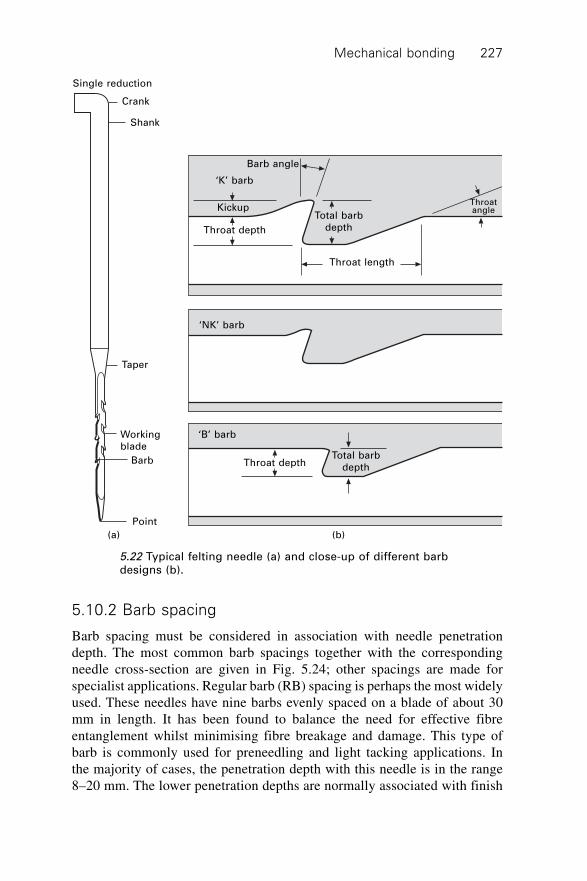
Mechanical bonding 227
5.10.2 Barb spacing
Barb spacing must be considered in association with needle penetrationdepth. The most common barb spacings together with the correspondingneedle cross-section are given in Fig. 5.24; other spacings are made forspecialist applications. Regular barb (RB) spacing is perhaps the most widelyused. These needles have nine barbs evenly spaced on a blade of about 30mm in length. It has been found to balance the need for effective fibreentanglement whilst minimising fibre breakage and damage. This type ofbarb is commonly used for preneedling and light tacking applications. Inthe majority of cases, the penetration depth with this needle is in the range8–20 mm. The lower penetration depths are normally associated with finish
Single reduction
Crank
Shank
Taper
Working
blade
Barb
Point
(a)
Barb angle
‘K’ barb
Kickup
Throat depth
Total barb
depth
Throatangle
Throat length
‘NK’ barb
Throat depthTotal barb
depth
(b)
5.22 Typical felting needle (a) and close-up of different barbdesigns (b).
‘B’ barb
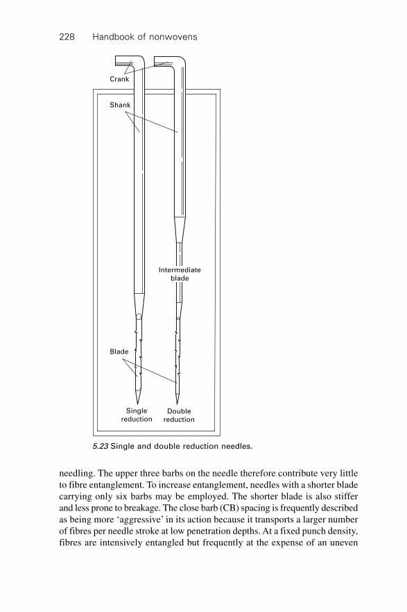
Handbook of nonwovens228
needling. The upper three barbs on the needle therefore contribute very littleto fibre entanglement. To increase entanglement, needles with a shorter bladecarrying only six barbs may be employed. The shorter blade is also stifferand less prone to breakage. The close barb (CB) spacing is frequently describedas being more ‘aggressive’ in its action because it transports a larger numberof fibres per needle stroke at low penetration depths. At a fixed punch density,fibres are intensively entangled but frequently at the expense of an uneven
Crank
Shank
Intermediate
blade
Blade
Single
reductionDouble
reduction
5.23 Single and double reduction needles.
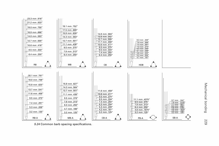
Me
ch
an
ical b
on
din
g2
29
23.3 mm .916”
21.2 mm .833”
19.0 mm .750”
16.9 mm .666”
14.8 mm .583”
12.7 mm .500”
10.6 mm .416”
8.5 mm .333”
6.4 mm .250”
RB
20.1 mm .791”
18.0 mm .708”
15.8 mm .625”
13.7 mm .541”
11.6 mm .458”
9.5 mm .375”
7.4 mm .291”
5.3 mm .208”
3.2 mm .125”
RB-A
19.1 mm .752”
17.5 mm .689”
15.9 mm .626”
14.3 mm .563”
12.7 mm .501”
11.1 mm .438”
9.5 mm .375”
7.9 mm .313”
6.4 mm .250”
MB
14.8 mm .584”
13.8 mm .542”
12.7 mm .500”
11.7 mm .459”
10.6 mm .417”
9.5 mm .375”
8.5 mm .334”
7.4 mm .292”
6.4 mm .250”
CB
8.3 mm .326”
7.8 mm .308”
7.4 mm .291”
7.0 mm .274”6.5 mm .256”
6.1 mm .239”
5.6 mm .222”
5.2 mm .204”
4.7 mm .187”
HDB
15.9 mm .627”
14.3 mm .564”
12.7 mm .501”
11.1 mm .438”
9.5 mm .376”
7.9 mm .313”
6.3 mm .250”
4.7 mm .188”
3.2 mm .125”
MB-A
11.6 mm .459”
10.6 mm .417”
9.5 mm .375”
8.5 mm .334”
7.4 mm .292”
6.3 mm .250”
5.3 mm .209”
4.2 mm .167”
3.2 mm .125”
CB-A
11.1 mm .4375”
9.5 mm .375”
7.9 mm .313”
6.4 mm .250”
4.8 mm .1875”
3.2 mm .125”
PB-A
8.7 mm .344”
7.9 mm .3125”7.1 mm .281”6.4 mm .250”5.6 mm .219”4.8 mm .1875”4.0 mm .156”3.2 mm .125”
SB-A
5.24 Common barb spacing specifications.
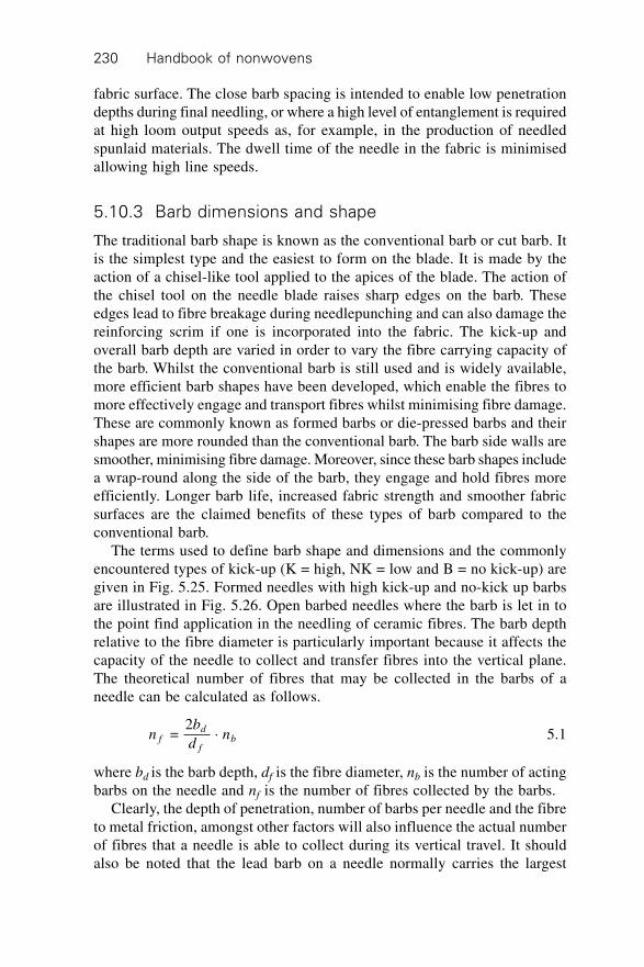
Handbook of nonwovens230
fabric surface. The close barb spacing is intended to enable low penetrationdepths during final needling, or where a high level of entanglement is requiredat high loom output speeds as, for example, in the production of needledspunlaid materials. The dwell time of the needle in the fabric is minimisedallowing high line speeds.
5.10.3 Barb dimensions and shape
The traditional barb shape is known as the conventional barb or cut barb. Itis the simplest type and the easiest to form on the blade. It is made by theaction of a chisel-like tool applied to the apices of the blade. The action ofthe chisel tool on the needle blade raises sharp edges on the barb. Theseedges lead to fibre breakage during needlepunching and can also damage thereinforcing scrim if one is incorporated into the fabric. The kick-up andoverall barb depth are varied in order to vary the fibre carrying capacity ofthe barb. Whilst the conventional barb is still used and is widely available,more efficient barb shapes have been developed, which enable the fibres tomore effectively engage and transport fibres whilst minimising fibre damage.These are commonly known as formed barbs or die-pressed barbs and theirshapes are more rounded than the conventional barb. The barb side walls aresmoother, minimising fibre damage. Moreover, since these barb shapes includea wrap-round along the side of the barb, they engage and hold fibres moreefficiently. Longer barb life, increased fabric strength and smoother fabricsurfaces are the claimed benefits of these types of barb compared to theconventional barb.
The terms used to define barb shape and dimensions and the commonlyencountered types of kick-up (K = high, NK = low and B = no kick-up) aregiven in Fig. 5.25. Formed needles with high kick-up and no-kick up barbsare illustrated in Fig. 5.26. Open barbed needles where the barb is let in tothe point find application in the needling of ceramic fibres. The barb depthrelative to the fibre diameter is particularly important because it affects thecapacity of the needle to collect and transfer fibres into the vertical plane.The theoretical number of fibres that may be collected in the barbs of aneedle can be calculated as follows.
nb
dnf
d
fb =
2 ◊ 5.1
where bd is the barb depth, df is the fibre diameter, nb is the number of actingbarbs on the needle and nf is the number of fibres collected by the barbs.
Clearly, the depth of penetration, number of barbs per needle and the fibreto metal friction, amongst other factors will also influence the actual numberof fibres that a needle is able to collect during its vertical travel. It shouldalso be noted that the lead barb on a needle normally carries the largest
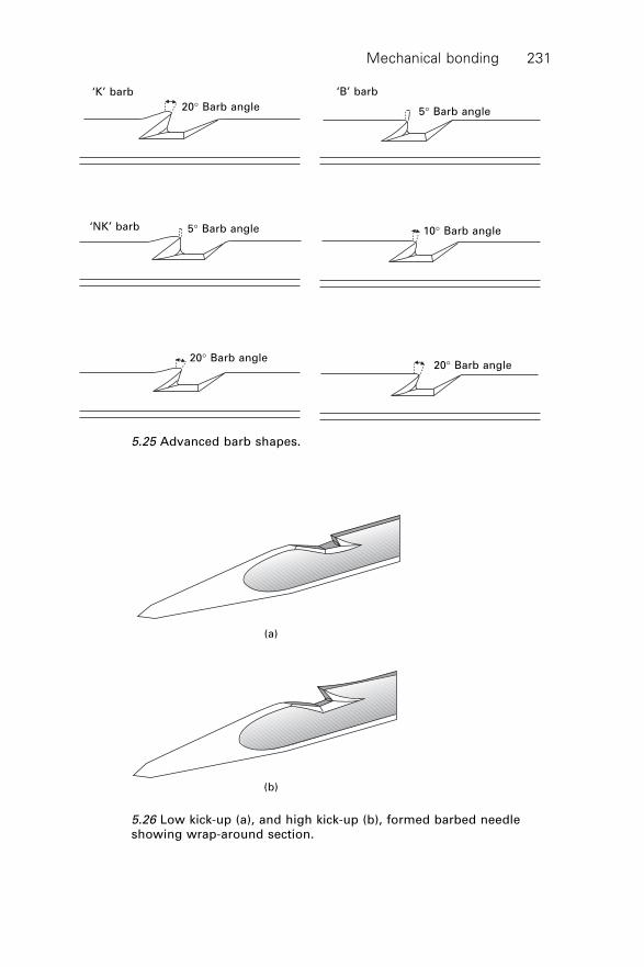
Mechanical bonding 231
(a)
(b)
5.26 Low kick-up (a), and high kick-up (b), formed barbed needleshowing wrap-around section.
‘K’ barb ‘B’ barb
20∞ Barb angle 5∞ Barb angle
10∞ Barb angle‘NK’ barb 5∞ Barb angle
20∞ Barb angle20∞ Barb angle
5.25 Advanced barb shapes.
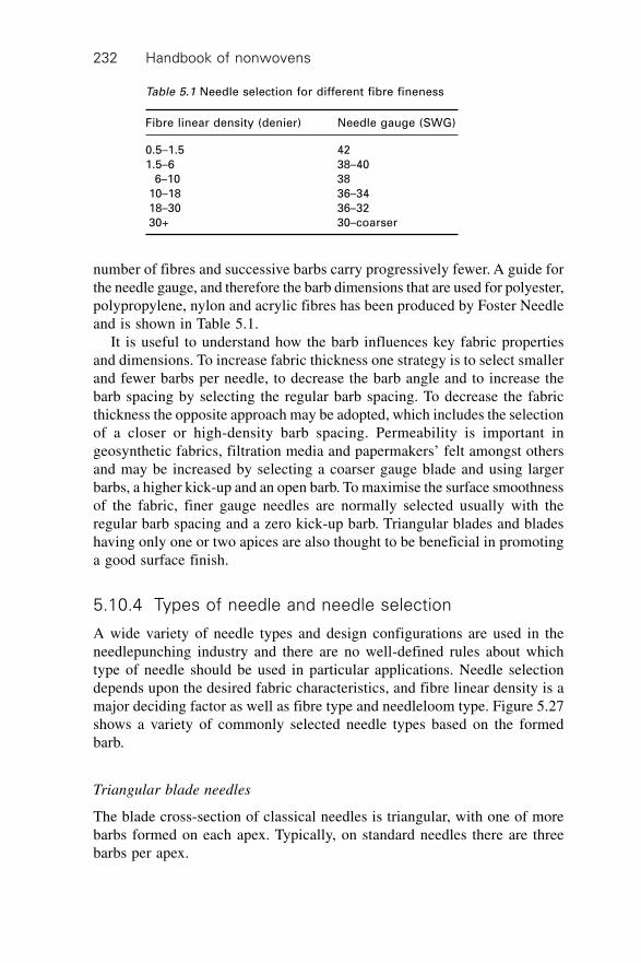
Handbook of nonwovens232
number of fibres and successive barbs carry progressively fewer. A guide forthe needle gauge, and therefore the barb dimensions that are used for polyester,polypropylene, nylon and acrylic fibres has been produced by Foster Needleand is shown in Table 5.1.
It is useful to understand how the barb influences key fabric propertiesand dimensions. To increase fabric thickness one strategy is to select smallerand fewer barbs per needle, to decrease the barb angle and to increase thebarb spacing by selecting the regular barb spacing. To decrease the fabricthickness the opposite approach may be adopted, which includes the selectionof a closer or high-density barb spacing. Permeability is important ingeosynthetic fabrics, filtration media and papermakers’ felt amongst othersand may be increased by selecting a coarser gauge blade and using largerbarbs, a higher kick-up and an open barb. To maximise the surface smoothnessof the fabric, finer gauge needles are normally selected usually with theregular barb spacing and a zero kick-up barb. Triangular blades and bladeshaving only one or two apices are also thought to be beneficial in promotinga good surface finish.
5.10.4 Types of needle and needle selection
A wide variety of needle types and design configurations are used in theneedlepunching industry and there are no well-defined rules about whichtype of needle should be used in particular applications. Needle selectiondepends upon the desired fabric characteristics, and fibre linear density is amajor deciding factor as well as fibre type and needleloom type. Figure 5.27shows a variety of commonly selected needle types based on the formedbarb.
Triangular blade needles
The blade cross-section of classical needles is triangular, with one of morebarbs formed on each apex. Typically, on standard needles there are threebarbs per apex.
Table 5.1 Needle selection for different fibre fineness
Fibre linear density (denier) Needle gauge (SWG)
0.5–1.5 42
1.5–6 38–40
6–10 38
10–18 36–34
18–30 36–32
30+ 30–coarser
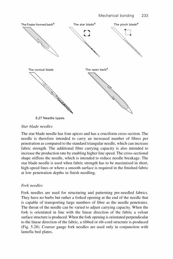
Mechanical bonding 233
Star blade needles
The star blade needle has four apices and has a cruciform cross-section. Theneedle is therefore intended to carry an increased number of fibres perpenetration as compared to the standard triangular needle, which can increasefabric strength. The additional fibre carrying capacity is also intended toincrease the production rate by enabling higher line speed. The cross-sectionalshape stiffens the needle, which is intended to reduce needle breakage. Thestar blade needle is used when fabric strength has to be maximised in short,high-speed lines or where a smooth surface is required in the finished fabricat low penetration depths in finish needling.
Fork needles
Fork needles are used for structuring and patterning pre-needled fabrics.They have no barbs but rather a forked opening at the end of the needle thatis capable of transporting large numbers of fibre as the needle penetrates.The throat of the needle can be varied to adjust carrying capacity. When thefork is orientated in line with the linear direction of the fabric a veloursurface structure is produced. When the fork opening is orientated perpendicularto the linear direction of the fabric, a ribbed or rib-cord structure is produced(Fig. 5.28). Coarser gauge fork needles are used only in conjunction withlamella bed plates.
The Foster formed barb® The star blade® The pinch blade®
The conical blade The open barb®
5.27 Needle types.
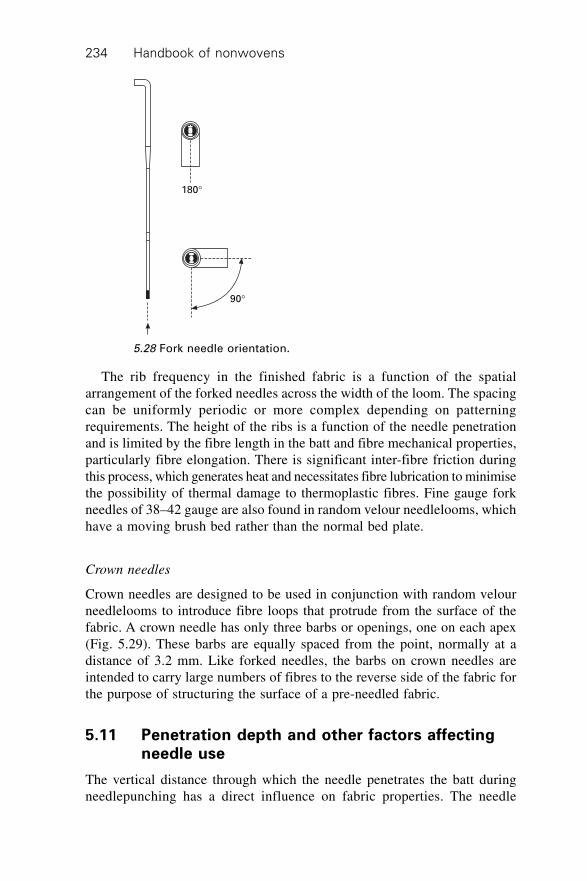
Handbook of nonwovens234
The rib frequency in the finished fabric is a function of the spatialarrangement of the forked needles across the width of the loom. The spacingcan be uniformly periodic or more complex depending on patterningrequirements. The height of the ribs is a function of the needle penetrationand is limited by the fibre length in the batt and fibre mechanical properties,particularly fibre elongation. There is significant inter-fibre friction duringthis process, which generates heat and necessitates fibre lubrication to minimisethe possibility of thermal damage to thermoplastic fibres. Fine gauge forkneedles of 38–42 gauge are also found in random velour needlelooms, whichhave a moving brush bed rather than the normal bed plate.
Crown needles
Crown needles are designed to be used in conjunction with random velourneedlelooms to introduce fibre loops that protrude from the surface of thefabric. A crown needle has only three barbs or openings, one on each apex(Fig. 5.29). These barbs are equally spaced from the point, normally at adistance of 3.2 mm. Like forked needles, the barbs on crown needles areintended to carry large numbers of fibres to the reverse side of the fabric forthe purpose of structuring the surface of a pre-needled fabric.
5.11 Penetration depth and other factors affectingneedle use
The vertical distance through which the needle penetrates the batt duringneedlepunching has a direct influence on fabric properties. The needle
180∞
90∞
5.28 Fork needle orientation.

Mechanical bonding 235
penetration depth is defined as the distance between the upper surface of thebed plate and the tip of the needle when the needles are located at bottomdead centre. Since the amplitude of the reciprocating needles is constant, thepenetration depth is normally adjusted by raising or lowering the bed plate.On all looms there is some means of mechanically achieving this, the settingsbeing indicated by a measuring index on the loom frame, or by an electronicsensor. The penetration depth is important because it determines the numberof barbs penetrating the batt or fabric on each stroke, and hence the level offibre entanglement and bonding that can be achieved. The barb spacing ofthe needle is therefore an important consideration when changing thepenetration depth. The penetration depth also influences the linear speed oradvance per stroke of the needleloom. If the penetration is large, the advance
5.29 Crown needle.
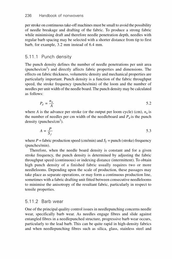
Handbook of nonwovens236
per stroke on continuous take-off machines must be small to avoid the possibilityof needle breakage and drafting of the fabric. To produce a strong fabricwhile minimising draft and therefore needle penetration depth, needles withregular barb spacing may be selected with a shorter distance from tip to firstbarb, for example, 3.2 mm instead of 6.4 mm.
5.11.1 Punch density
The punch density defines the number of needle penetrations per unit area(punches/cm2) and directly affects fabric properties and dimensions. Theeffects on fabric thickness, volumetric density and mechanical properties areparticularly important. Punch density is a function of the fabric throughputspeed, the stroke frequency (punches/min) of the loom and the number ofneedles per unit width of the needle board. The punch density may be calculatedas follows:
Pn
Adn = 5.2
where A is the advance per stroke (or the output per loom cycle) (cm), nn isthe number of needles per cm width of the needleboard and Pd is the punchdensity (punches/cm2).
APS f
= 5.3
where P = fabric production speed (cm/min) and Sf = punch (stroke) frequency(punches/min).
Therefore, when the needle board density is constant and for a givenstroke frequency, the punch density is determined by adjusting the fabricthroughput speed (continuous) or indexing distance (intermittent). To obtainhigh punch density of a finished fabric usually requires two or moreneedlelooms. Depending upon the scale of production, these passages maytake place as separate operations, or may form a continuous production line,sometimes with a fabric drafting unit fitted between consecutive needleloomsto minimise the anisotropy of the resultant fabric, particularly in respect totensile properties.
5.11.2 Barb wear
One of the principal quality control issues in needlepunching concerns needlewear, specifically barb wear. As needles engage fibres and slide againstentangled fibres in a needlepunched structure, progressive barb wear occurs,particularly to the lead barb. This can be quite rapid in high-density fabricsand when needlepunching fibres such as silica, glass, stainless steel and
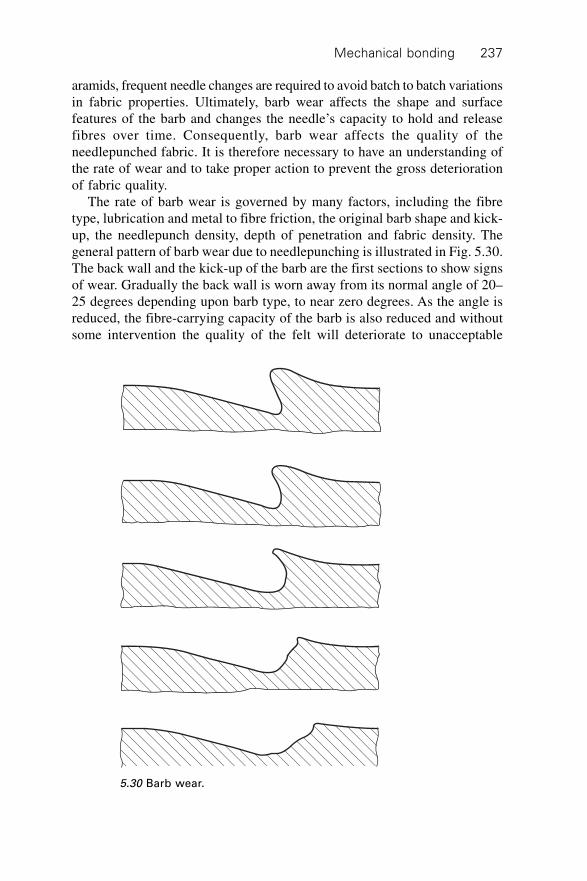
Mechanical bonding 237
aramids, frequent needle changes are required to avoid batch to batch variationsin fabric properties. Ultimately, barb wear affects the shape and surfacefeatures of the barb and changes the needle’s capacity to hold and releasefibres over time. Consequently, barb wear affects the quality of theneedlepunched fabric. It is therefore necessary to have an understanding ofthe rate of wear and to take proper action to prevent the gross deteriorationof fabric quality.
The rate of barb wear is governed by many factors, including the fibretype, lubrication and metal to fibre friction, the original barb shape and kick-up, the needlepunch density, depth of penetration and fabric density. Thegeneral pattern of barb wear due to needlepunching is illustrated in Fig. 5.30.The back wall and the kick-up of the barb are the first sections to show signsof wear. Gradually the back wall is worn away from its normal angle of 20–25 degrees depending upon barb type, to near zero degrees. As the angle isreduced, the fibre-carrying capacity of the barb is also reduced and withoutsome intervention the quality of the felt will deteriorate to unacceptable
5.30 Barb wear.
Handbook of nonwovens238
levels. At angles less than zero degrees, the barb contributes little fibreentanglement and is reflected in fabric tensile properties. The greatest weartends to take place on the barb closest to the tip of the needle and decreasesas the barb distance moves further away from the tip. Therefore, it is importanteither to renew the needles or to increase the penetration depth therebyintroducing more of the less worn barbs into the needling zone. However, anincrease in penetration depth to introduce new barbs can only be accomplishedif the loom settings and fabric properties allow and therefore it is not alwaysa practical solution. For example, if the line speed is high, the increase inneedle penetration would increase the dwell time leading to greater draftingand needle breakage.
5.11.3 Needle rotation
It is normally not recommended to replace all needles in the board at thesame time but rather to carry out a partial replacement in which needles arereplaced in sections. This is because the properties of a fabric made withworn, low-efficiency needles are markedly different from those producedwith new needles. It is better practice to change only sections of the needleboardat any one time. To illustrate this, let us assume the lifetime of the needle isthirty million punches. The needleboard can be divided into three sections,the first section can be changed after ten million punches, the second sectionchanged after a further ten million punches and the third section changedafter ten million punches. In this way, over the total needle lifetime newneedles are periodically introduced or rotated through the board. This procedurehas been found to maximise the uniformity of fabric properties with respectto time.
In a production situation it is not always easy to calculate the number ofpunches since the last needle change, particularly when many different fibresand batches are processed on the same needeloom. More often other parametersare monitored and used as a guide such as:
∑ Linear production (number of metres of fabric produced).∑ A significant change in a fabric characteristic is detected: this method is
usually effective when the fabric is made to a narrow specification andparameters are regularly measured such as a decrease in tensile strengthor an increase in thickness. Clearly, such an approach lends itself to theuse of statistical control techniques.
∑ Total weight of fibre processed by the machine.∑ Running time of the machine.
The physical wear rate can be found only by direct inspection of the needle,which of course requires the machine to be stopped. Periodically, needlesshould be taken from the board after a predetermined interval and checked
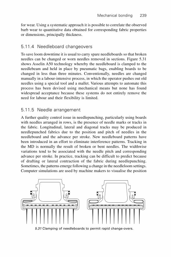
Mechanical bonding 239
for wear. Using a systematic approach it is possible to correlate the observedbarb wear to quantitative data obtained for corresponding fabric propertiesor dimensions, principally thickness.
5.11.4 Needleboard changeovers
To save loom downtime it is usual to carry spare needleboards so that brokenneedles can be changed or worn needles removed in sections. Figure 5.31shows Asselin A50 technology whereby the needleboard is clamped to theneedlebeam and held in place by pneumatic bags, enabling boards to bechanged in less than three minutes. Conventionally, needles are changedmanually in a labour-intensive process, in which the operator pushes out oldneedles using a special tool and a mallet. Various attempts to automate thisprocess has been devised using mechanical means but none has foundwidespread acceptance because these systems do not entirely remove theneed for labour and their flexibility is limited.
5.11.5 Needle arrangement
A further quality control issue in needlepunching, particularly using boardswith needles arranged in rows, is the presence of needle marks or tracks inthe fabric. Longitudinal, lateral and diagonal tracks may be produced inneedlepunched fabrics due to the position and pitch of needles in theneedleboard and the advance per stroke. New needleboard patterns havebeen introduced in an effort to eliminate interference patterns. Tracking inthe MD is normally the result of broken or bent needles. The widthwisevariations tend to be associated with the needle pitch and correspondingadvance per stroke. In practice, tracking can be difficult to predict becauseof drafting or lateral contraction of the fabric during needlepunching.Sometimes, the patterns emerge following a change in the needleloom settings.Computer simulations are used by machine makers to visualise the position
5.31 Clamping of needleboards to permit rapid change-overs.
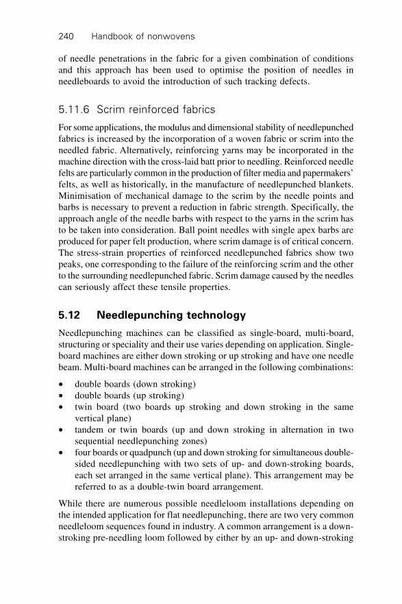
Handbook of nonwovens240
of needle penetrations in the fabric for a given combination of conditionsand this approach has been used to optimise the position of needles inneedleboards to avoid the introduction of such tracking defects.
5.11.6 Scrim reinforced fabrics
For some applications, the modulus and dimensional stability of needlepunchedfabrics is increased by the incorporation of a woven fabric or scrim into theneedled fabric. Alternatively, reinforcing yarns may be incorporated in themachine direction with the cross-laid batt prior to needling. Reinforced needlefelts are particularly common in the production of filter media and papermakers’felts, as well as historically, in the manufacture of needlepunched blankets.Minimisation of mechanical damage to the scrim by the needle points andbarbs is necessary to prevent a reduction in fabric strength. Specifically, theapproach angle of the needle barbs with respect to the yarns in the scrim hasto be taken into consideration. Ball point needles with single apex barbs areproduced for paper felt production, where scrim damage is of critical concern.The stress-strain properties of reinforced needlepunched fabrics show twopeaks, one corresponding to the failure of the reinforcing scrim and the otherto the surrounding needlepunched fabric. Scrim damage caused by the needlescan seriously affect these tensile properties.
5.12 Needlepunching technology
Needlepunching machines can be classified as single-board, multi-board,structuring or speciality and their use varies depending on application. Single-board machines are either down stroking or up stroking and have one needlebeam. Multi-board machines can be arranged in the following combinations:
∑ double boards (down stroking)∑ double boards (up stroking)∑ twin board (two boards up stroking and down stroking in the same
vertical plane)∑ tandem or twin boards (up and down stroking in alternation in two
sequential needlepunching zones)∑ four boards or quadpunch (up and down stroking for simultaneous double-
sided needlepunching with two sets of up- and down-stroking boards,each set arranged in the same vertical plane). This arrangement may bereferred to as a double-twin board arrangement.
While there are numerous possible needleloom installations depending onthe intended application for flat needlepunching, there are two very commonneedleloom sequences found in industry. A common arrangement is a down-stroking pre-needling loom followed by either by an up- and down-stroking
Mechanical bonding 241
loom or a four board up- and down-stroking machine. A variety ofneedlepunching arrangements are given in Fig. 5.32 all of which requiremore than one needleloom in sequence. Typical applications for thesearrangements are listed as follows:
(a) filtration media(b) synthetic leather, preneedling is in the order of 50–80 punches/cm2 followed
by flat needling of 1000–3000 punches/cm3
(c) underlay composed of recovered fibres(d) floorcoverings; preneedling is in the order of 75–150 punches/cm2 and
finish needling is around 150–300 punches/cm2
(e) automotive headliners(f) blankets.
In general, flat needlelooms are intended only for bonding whereas structuringlooms are designed to introduce structured effects, pile and patterns in pre-needled fabrics.
5.12.1 Preneedling or tacking
Initially, the batt is pre-consolidated by a needleloom and a low needleboarddensity of between 1000 and 3000 per linear metre is not unusual. The pre-needling loom normally punches from one side only and the aim is to gentlyconsolidate the batt and to introduce some fibre entanglement therebydecreasing batt thickness prior to full consolidation or finish needling. Thepunch density of the preneedled fabric depends upon the desired productcharacteristics but 10–75 punches/cm2 is not unusual. The needleloom normallyhas some means of compressing the batt as it is fed between the bed andstripper plate. A pair of driven batt compression aprons mounted just in frontof the needling zone is commonly utilised. These aprons converge to enableprogressive compression and to minimise slippage of the outer layers of thebatt relative to the inner layers. Examples of different batt feeding methodsin preneedling are illustrated in Fig. 5.33, (a) by apron, (b) by roller and (c)by locating the needlebeam within a driven perforated cylinder, which formsthe stripper and bed plates. The latter arrangement is referred to as a rotarytacker.
Needlelooms are frequently operated with the stripper plate angled downtowards the output side of the needling zone to assist in batt compressionduring bonding. This together with a wide bed plate to stripper plate gapsetting helps to accommodate the batt. Since the bed plate to stripper plategap can be large, 90 mm (31/2 inch) needles, or sometimes longer are required.The penetration depth or stroke of a preneedling loom is usually larger thanfor finishing looms since there is a greater batt thickness to consolidate. Toproduce a uniform fabric with a smooth surface finish a needle with a regular
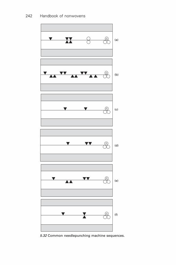
Handbook of nonwovens242
(a)
(b)
(c)
(d)
(e)
(f)
5.32 Common needlepunching machine sequences.
Mechanical bonding 243
barb spacing is normally selected. The wide barb spacing along the blade ofsuch needles ensures small groups of fibre are engaged by the barb throughthe cross-section without the need for a large penetration depth. Reducingthe spacing between barbs in preneedling often leads to the reorientation ofa larger number of fibres and produces a cratered surface in the fabric. Suchcrater marks in the surface are difficult to remove in subsequent needling.The consolidation of the fabric with a closely spaced barbed needle is howevermore rapid as compared with a regular spaced barbed needle.
It should be noted that not all needlepunching applications require two-stage needling and in some cases, a preneedling loom alone is used. Forexample, in the manufacture of wound dressing fabrics composed of
(a) (b)
(c)
5.33 Methods of batt feeding in preneedling (courtesy of Asselin,France); (a) apron; (b) roller; (c) perforated cylinder.
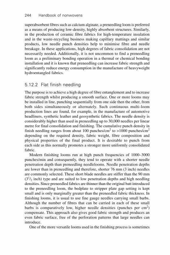
Handbook of nonwovens244
superabsorbent fibres such as calcium alginate, a preneedling loom is preferredas a means of producing low-density, highly absorbent structures. Similarly,in the production of ceramic fibre fabrics for high-temperature insulationand in the waste-recycling business making capillary mattings and similarproducts, low needle punch densities help to minimise fibre and needlebreakage. In these applications, high degrees of fabric consolidation are notnecessarily needed. Additionally, it is not uncommon to find a preneedlingloom as a preliminary bonding operation in a thermal or chemical bondinginstallation and it is known that preneedling can increase fabric strength andsignificantly reduce energy consumption in the manufacture of heavyweighthydroentangled fabrics.
5.12.2 Flat finish needling
The purpose is to achieve a high degree of fibre entanglement and to increasefabric strength whilst producing a smooth surface. One or more looms maybe installed in line, punching sequentially from one side then the other, fromboth sides simultaneously or alternately. Such continuous multi-loomproduction lines are found, for example, in the manufacture of automotiveheadliners, synthetic leather and geosynthetic fabrics. The needle density isconsiderably higher than used in preneedling up to 30,000 needles per linearmetre for final consolidation and finishing. The cumulative punch density infinish needling ranges from about 100 punches/cm2 to >1000 punches/cm2
depending on the required density, fabric weight, fibre composition andphysical properties of the final product. It is desirable to punch fromeach side as this normally promotes a stronger more uniformly consolidatedfabric.
Modern finishing looms run at high punch frequencies of 1000–3000punches/min and consequently, they tend to operate with a shorter needlepenetration depth than preneedling needlelooms. Needle penetration depthsare lower than in preneedling and therefore, shorter 76 mm (3 inch) needlesare commonly selected. These short blade needles are stiffer than the 90 mm(31/2 inch) type and are suited to low penetration depths and high needlingdensities. Since preneedled fabrics are thinner than the original batt introducedto the preneedling loom, the bedplate to stripper plate gap setting is keptsmall and is only marginally greater than the preneedled fabric thickness. Infinishing looms, it is usual to use fine gauge needles carrying small barbs.Although the number of fibres that can be carried in each of these smallbarbs is comparatively low, higher needle densities (punches per cm2)compensate. This approach also gives good fabric strength and produces aneven fabric surface, free of the perforation patterns that large needles canintroduce.
One of the more versatile looms used in the finishing process is sometimes
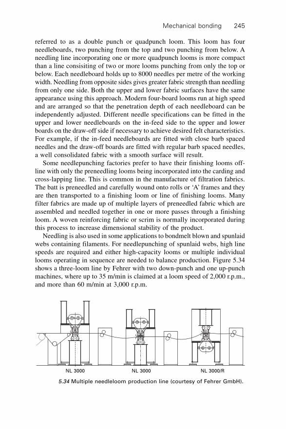
Mechanical bonding 245
referred to as a double punch or quadpunch loom. This loom has fourneedleboards, two punching from the top and two punching from below. Aneedling line incorporating one or more quadpunch looms is more compactthan a line consisiting of two or more looms punching from only the top orbelow. Each needleboard holds up to 8000 needles per metre of the workingwidth. Needling from opposite sides gives greater fabric strength than needlingfrom only one side. Both the upper and lower fabric surfaces have the sameappearance using this approach. Modern four-board looms run at high speedand are arranged so that the penetration depth of each needleboard can beindependently adjusted. Different needle specifications can be fitted in theupper and lower needleboards on the in-feed side to the upper and lowerboards on the draw-off side if necessary to achieve desired felt characteristics.For example, if the in-feed needleboards are fitted with close barb spacedneedles and the draw-off boards are fitted with regular barb spaced needles,a well consolidated fabric with a smooth surface will result.
Some needlepunching factories prefer to have their finishing looms off-line with only the preneedling looms being incorporated into the carding andcross-lapping line. This is common in the manufacture of filtration fabrics.The batt is preneedled and carefully wound onto rolls or ‘A’ frames and theyare then transported to a finishing loom or line of finishing looms. Manyfilter fabrics are made up of multiple layers of preneedled fabric which areassembled and needled together in one or more passes through a finishingloom. A woven reinforcing fabric or scrim is normally incorporated duringthis process to increase dimensional stability of the product.
Needling is also used in some applications to bondmelt blown and spunlaidwebs containing filaments. For needlepunching of spunlaid webs, high linespeeds are required and either high-capacity looms or multiple individuallooms operating in sequence are needed to balance production. Figure 5.34shows a three-loom line by Fehrer with two down-punch and one up-punchmachines, where up to 35 m/min is claimed at a loom speed of 2,000 r.p.m.,and more than 60 m/min at 3,000 r.p.m.
NL 3000 NL 3000 NL 3000/R
5.34 Multiple needleloom production line (courtesy of Fehrer GmbH).
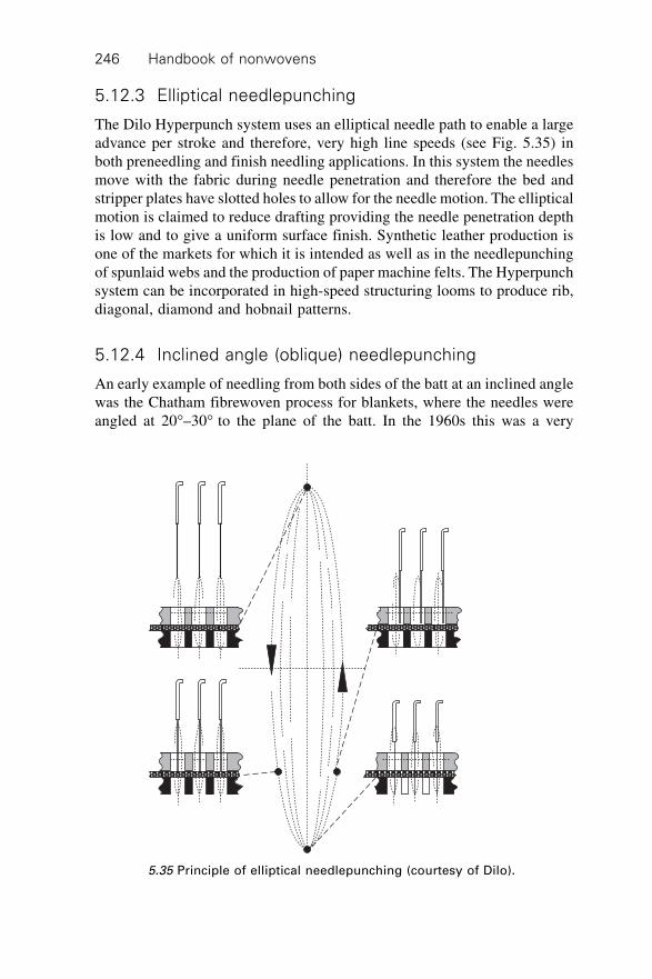
Handbook of nonwovens246
5.12.3 Elliptical needlepunching
The Dilo Hyperpunch system uses an elliptical needle path to enable a largeadvance per stroke and therefore, very high line speeds (see Fig. 5.35) inboth preneedling and finish needling applications. In this system the needlesmove with the fabric during needle penetration and therefore the bed andstripper plates have slotted holes to allow for the needle motion. The ellipticalmotion is claimed to reduce drafting providing the needle penetration depthis low and to give a uniform surface finish. Synthetic leather production isone of the markets for which it is intended as well as in the needlepunchingof spunlaid webs and the production of paper machine felts. The Hyperpunchsystem can be incorporated in high-speed structuring looms to produce rib,diagonal, diamond and hobnail patterns.
5.12.4 Inclined angle (oblique) needlepunching
An early example of needling from both sides of the batt at an inclined anglewas the Chatham fibrewoven process for blankets, where the needles wereangled at 20∞–30∞ to the plane of the batt. In the 1960s this was a very
5.35 Principle of elliptical needlepunching (courtesy of Dilo).
Mechanical bonding 247
sophisticated machine in concept and engineering design, producing blanketswith good strength and dimensional stability but output speeds were low bymodern standards. A current method of achieving angled needle penetrationis the Fehrer H1 system which employs a curved bed and stripper plate witha corresponding needleboard. The changing curvature varies the angle ofneedle penetration as the fabric passes through the needling zone, givingfibre pillars of different angular inclinations within the cross-section. Claimedeffects are an improvement in the isotropy of the fabric with respect totensile properties and a general increase in tensile strength as compared totraditional needlepunching systems. The H1 system is employed for themanufacture of geosynthetics, synthetic leather, filtration fabrics, shoe linings,automotive fabrics and papermakers’ felts.
5.12.5 Structuring needlelooms
Surface textured needlepunched fabrics are produced using structuringneedlelooms.
Rib fabrics
Preneedled fabrics may be textured to produce a looped pile using forkedneedles which transport fibres between lamella strips that serve as the bedplate(Fig. 5.36 and Fig. 5.37). Such structuring looms are typically down-punchmachines producing rib or velour surface structures depending on the orientationof the needle fork relative to the incoming fabric. Patterning is introduced byvarying the position of needles in the board and by controlling the advanceper stroke. By lifting and lowering the lamella table, the height of the fibrepile is adjusted. In certain systems the needleboard position is raised orlowered to enable the pile height to be adjusted.
Velour fabrics
Classical velour fabrics are produced using coarse gauge fork needles orientatedin the correct direction and operating in conjunction with a lamella bed plate.In the production of random velours, in place of the lamella bed plate, acontinuous, moving brush conveyor is employed to produce a fine, high-density velour finish. The design of the brush, particularly the density, brushfilament diameter, height and uniformity, influence the appearance and structureof pile surface produced in the fabric. Damage or wear of the brush as aresult of needlepunching produces quality problems such as pile height variationand other defects. Fine gauge fine fork needles and crown needles, sometimesin combination, are commonly used to manufacture random velour fabrics.The pile is formed in the brush conveyor and at the same time carried
Handbook of nonwovens248
Depth
Width
5.36 Forked needle.
Fork needleStripper plate
Lamella
5.37 Lamella strips.
forward until the finished fabric is drawn out of the brush belt by the take-up rollers.
In double random velour systems, more than one needling head is positionedover a common brush conveyor to give a high pile density, and possibly to
Mechanical bonding 249
introduce coloured effects by means of yarns or other material. Such yarnsare tacked in to the fabric structure after being introduced from an overheadcreel. An example of a random velour structuring machine (Di-lour IV) isshown in Fig. 5.38. Two needleboards have a backing felt introduced beforethe second needling zone. This gives a close pile and added stability to thefinished product. Rib and velour fabrics with large repeat patterns with apatterned surround or border on all sides can be made on the Fehrer NL11/Twin-SE Carpet Star® instead of using two machines in tandem. The CarpetStar® operates with two independent needle zones that are electronicallysynchronised to maximise pattern flexibility at high speed. Simulated orientalcarpet patterns are claimed to be possible using this system. In anothersystem known as the Dilo DiLoop RR Rug-Runner, register control is providedbetween two looms when complex relief patterns are produced.
5.12.6 Specialist needlelooms
Continuous belts
Needlepunched fabrics are produced in long continuous belt form for use inthe manfacture of paper. These needlepunched papermakers’ felts are used inthe pressing and drying stages of the papermaking process and have verylarge working widths of more than twelve metres. The felts form a wideendless belt consisting of layers of preneedled or carded web needled into aspecial monofilament scrim. The quality control requirements are extremelyhigh since structural imperfections in the belt affect the quality of subsequentpapermaking.
5.38 A velour structuring machine.
Handbook of nonwovens250
Tubular fabrics
Tubular needlepunched fabrics can be produced using a specially adaptedneedleloom design developed by Dilo. These tubes normally have an insidediameter of 25–500 mm. In some cases, tubes with diameters of only 5 mmmay be produced. The Rontex S 2000 loom employs two needling unitsacting from opposite sides with different angles of needle penetration. Acontinuous needlepunched spiral is produced which may be layered with thetube wall having different types of fibre.
Three dimensional linked fabrics
The Laroche Napco 3D web linker produces three-dimensional fabrics (Fig.5.39). The machine is fed with two fibrous webs (A and B) between twostripper plates and one or two spacer tables consisting of bars or tubes. Asthe webs pass through the machine the barbed needles drive fibres from oneweb to the other creating fibre bridges. Spaces between the spacer bars areused to introduce components such as wires and cables. Spacer tubes allowthe insertion of powders, fluids or foams, as it is being made.
Yarn and fabric punching
The concept of yarn punching has been developed by Fehrer and involvesneedlepunching coarse yarns to increase their tensile strength. This is intendedfor carpet, mop and effect yarns as well as for friction-spun and open-endyarns requiring sheath-core stabilisation. The yarn is fed along a narrow
Composite product
Web A
Web B
5.39 The Laroche Napco 3D web linker.
Mechanical bonding 251
channel through which the needles pass in a reciprocating motion.Needlepunching has also found commercial application as a finishing processfor woven coating substrates.
5.12.7 Fabric structure and strength
There is a considerable body of published research on the complex subjectof needled fabric properties. Examination of fibre migration and the formationof ‘pillars’ of fibre in the cross-section due to the action of the barbed needleare facilitated by the use of tracer fibres and optical microscopy. Some of thefibres are incorporated into these pillars along most of their length, whilstothers remain predominantly in the fabric plane. The first two or three barbsengage the largest number of fibres from the upper region of the web whichhas the effect of tying-in these fibres to the lower surface thereby providingcohesion and a reduction in fabric thickness. Initially, as pillars are createdthe fabric strength increases, but after peaking the fabric strength subsequentlydecreases as fibres are broken and the fabric begins to perforate. It should beremembered that the presence of the structural pillars of fibre in the cross-section depends both on fibre and process factors. Few pillars are formedand therefore fabric strength increases little unless fibres are able to deformand extend whilst in contact with the barbs. The number of fibres in eachpillar, their frequency and interconnection, are a function of barb dimensions,needle punch density, the depth of penetration and the advance per strokeamongst other factors. It is therefore possible to engineer the structure of aneedlepunched fabric to a large extent by considering these aspects.
Fibre composition, length, diameter, fibre tensile properties, fabric densityand thickness are particularly important with respect to fabric properties.Fabric strength properties most frequently measured are tensile, tear andpuncture. In the early days, comparisons were always made with the strengthof woven fabrics, but since synthetic fibres became cheap, plentiful andavailable in lengths, thickness and crimp tailored to the needlepunchingprocess, the properties of needlepunch are considered in their own right.Because needlepunched fabrics were originally viewed as cheap alternatives,they were made with relatively weak fibres such as rayon and wool, whichcould easily break under the action of the needle barbs therefore many studiesmade before nylon, polyester, polyethylene and polypropylene becameavailable, may not be relevant to the modern industry. Similarly much workwas done at what would today be considered very low speeds and it isdoubtful that this is relevant to current industrial practice.
5.13 Applications of needlepunched fabrics
The applications of needlepunched fabrics are extensive and extend intomany niche product areas including, for example, medical wound dressings,
Handbook of nonwovens252
composite breather felts, capillary mattings for horticulture, fire barriers andballistic-impact-resistant fabrics. Some of the main product applications aregiven below but this list is not exhaustive.
5.13.1 Geosynthetics
Needled fabrics are used in civil engineering applications that requiredeformability, high tensile and burst strength as well as controlled permeabilityand weight, for road reinforcement, subsoil stabilisation, pond liners, hazardouswaste containment protection liners and drainage. Staple fibre geotextilesare typically composed of polypropylene, polyester or polyamide. Wherespunlaid webs are needlepunched, they are produced at high linear speedwith a relatively low degree of needling. The Foster star blade needle havingfour barbed edges has found use in such applications where high strengthgeotextiles made from both staple fibre and spunlaid webs are produced.Needlepunched geosynthetic clay liners are installed for low water permeabilityin landfills, canals, ponds and pollution-prevention barriers in highway andairfield construction. Rolls of bentonite clay are sandwiched between twofabrics, one or both of which are nonwoven. Needling the composite locksthe bentonite clay in place. The clay is the critical component as it providesextremely low hydraulic conductivity.
In needling, the abrasive nature of the clay means that manufacturingconditions and needle design must be controlled to minimise needle wear.Conventional needlepunched spunlaid fabrics for geosynthetic applicationsare made from about 120 g/m2 to 340 g/m2. Needlepunched spunlaid fabricsare utilised in the laying of asphalt as stress-absorbing-membrane interlayers;fabrics dipped in bitumen help to improve the adhesion between layers ofasphalt.
5.13.2 Filter media
Fabric density and permeability are properties relevant to the filtration ofgases and liquids, and depth filters are particularly suited to needlepunchedfabrics because of their substantial thickness. Woven scrim reinforcement isneeded in industrial bag house applications, whilst staple glass, silica oraramid fibres are utilised in high-temperature conditions. For general filtrationapplications, PET, PA and PP are found, but for high-temperature or corrosiveenvironments other high-performance organic and inorganic fibres areneedlepunched to make chemically or thermally stable filter fabrics includingPTFE alone or in blends, polyimide, basalt and stainless steel amongst others.Electret filters are also needlepunched based on drylaid blends of staplefibres selected for their relative position in the triboelectric series. The surfaceof needlepunched fabrics may be coated, singed or calendered to adjust the
Mechanical bonding 253
surface structure and therefore both the cleaning and filtration efficiencies ofthe media. The fabric density may also be graduated through the fabriccross-section by adjusting needle penetration and needlepunching density,which influences filtration efficiency in use. Both roll products and tubularneedlepunched fabrics are used as filtration media.
5.13.3 Synthetic leather
Needled synthetic leather fabrics imitate the natural product with a denselyentangled fibre construction that is impregnated with a polyurethane resin togive a smooth surface free from needle marking and with a high surfaceabrasion resistance. Typical production lines may have as many as eightneedlelooms in sequence from preneedling to finish needling. The density isprogressively increased in successive needlepunching stages. To avoid markingof the fabric and to minimise needle force, fine gauge needles with smallbarbs and small tip to first barb distance are selected. Sometimes, single barbneedles with high needlepunching densities are employed to produce, finehigh-density fabrics with a uniform surface. Only small needle penetrationsare required in the process using such needles. To further increase the surfacearea and density of the fabric, a proportion of high-shrink thermoplasticfibres may be included in the blend, which after heating induce contractionof the fabric. Splittable bicomponent fibres have also been developed thatare designed to split in needlepunching in a similar manner to that inhydroentanglement of such fibres. Non-apparel end uses of needlepunchedsynthetic leather are luggage, automobile seats and panels, upholstery, wallcoverings, and footwear.
5.13.4 Waddings and paddings
Based on fibre consumption, waddings and paddings are one of the largestsingle application areas for needlepunching and the fabrics are incorporatedinto mattresses and furniture as insulator pads (in contact with the sprungunit) as well as comfort layers to provide support, carpet underlay, sound andheat insulation for automobiles and other industrial uses. Fibre selectionranges from recycled natural and synthetic fibres, usually obtained frompulled waste clothing, jute, sisal, coir and cotton as well as virgin syntheticfibres, particularly PET, PP and acrylic.
5.13.5 Floor coverings
Flat floor coverings generally consist of a face layer, a scrim and a bottom layerand are produced by preneedling, flat needling and in many cases, structuring.Needling from both sides tends to increase the wear resistance of the face
Handbook of nonwovens254
layer. As described previously, structuring involves needlelooms with lamellabed plates in which forked needles are used, or random velour needleloomswith brush conveyor belts in which fine gauge fork needles or special crownneedles are used. Needlepunched floor coverings are commonly producedfrom PP and blends of PP and PA, which is spun-dyed and blended prior tocarding, cross-lapping and needlepunching. In some low traffic applications,where softness is needed, PET is sometimes selected. Different fibre lineardensities are frequently blended to adjust the durability and compressionrecovery properties of the floor covering. Linear densities are about 12–20denier and fabric weights are in the order of 300–800 g/m2. A small proportionof very coarse fibres may therefore be added to a base blend of 17 dtex fibres.
5.13.6 Automotive fabrics
End uses for needled fabrics consist of decorative trim including headliners,door trims, seatbacks, boot liners, load floors and package trays. In the USA,the interior trim is composed of spun-dyed PP whereas PET is importantelsewhere in the world. Fibre linear densities range from 15–18 denier in theUSA, where the abrasion resistance specifications are high, to as low as 6denier in the Far East and Japan. Other products include sound dampers,underfelts, padding, performance gaskets, seals, filters and shields. Extensiveuse is made of random velour fabrics in automotive applications particularlyin small to medium sized cars and structured needlepunched fabrics areencountered in more expensive interiors. In moulded floor fabrics up toabout 65% of the total fibre content is visible as surface pile. The qualitycontrol issues are particularly stringent and a major consideration is colourconsistency and colour matching between batches even in solid shades. Thereis also growth in the composites field and blends of wood fibres with syntheticfibres are needled prior to resin impregnation and the formation of rigidpanels. Glass fibre composites are made in a similar manner and there is on-going development in the use of natural fibres including hemp, flax, sisal andother bast fibres in automotive composites. Composites are now fitted aroundthe firewall, dashboard, speaker, engine bay and parcel shelf structures.
5.13.7 Insulation
Both thermal and acoustic insulation fabrics are formed by needlepunching.In high-temperature applications, blown or spun ceramic fibres in batt formare needlepunched and the finished material may be up to 75 mm thick.Avoiding damage to the brittle fibres is a primary objective. High-temperaturefibres are needlepunched to form thermal insulation suitable for the automotiveand aerospace sectors and are subject to stringent regulation. Insulation paddingsare also made by needling recycled fibres extracted from clothing and lowgrade wool and cotton.
Mechanical bonding 255
5.13.8 Blankets
This was one of the earliest applications for needling, and whilst high-quality natural and synthetic fibres are still used occasionally, the process iscommonly found where cheap blankets made from mixtures of regeneratedfibres are needed, including emergency and disposable blankets. It is commonfor reinforcing yarns or scrims to be incorporated into such fabrics.
5.13.9 Wipes
Needling is used for some heavy-duty household and industrial wipes andpolishing cloths. Use of spun dyed viscose staple blended with a thermoplasticbonding fibre is popular and many other fibres including Lyocell have beenneedled for personal care and industrial wipe applications. In pre-moistenedwipes, needlepunched fabrics are competing in some sectors because it ispossible to store larger volumes of lotion in the structure compared to ahydroentangled wipe. One application is in post-operative wipes containinganti-bacterial soap.
5.13.10 Roofing
Needlepunched spunlaid fabrics composed of PET find applications as bitumen-coated roofing felts because they have good puncture and tear resistance.Glass scrim reinforcement may be introduced during needling to improvedimensional stability.
5.14 Hydroentanglement: introduction
Hydroentangling, spunlacing, hydraulic entanglement and water jet needlingare synonymous terms describing the process of bonding fibres (or filaments)in a web by means of high-velocity water jets. The interaction of the energisedwater with fibres in the web and the support surface increases the fibreentanglement and induces displacement and rearrangement of fibre segmentsin the web. In addition to mechanical bonding, structural patterns, aperturesand complex three-dimensional effects are produced if required by the selectionof appropriate support surfaces. Hydroentanglement also provides a convenientmethod of mechanically combining two or more webs to produce multilayerfabrics.
The early work on the process of hydroentanglement has been principallyattributed to Chicopee (division of Johnson and Johnson) and DuPont in theUSA. The respective technical contributions of these companies are describedin a series of detailed patents filed from the 1950s to the early 1970s.9,10,11
Originally, the utilisation of relatively low-pressure water jets (<150 psi) and
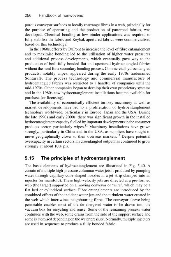
Handbook of nonwovens256
porous conveyor surfaces to locally rearrange fibres in a web, principally forthe purpose of aperturing and the production of patterned fabrics, wasdeveloped. Chemical bonding at low binder applications was required tofully stabilise the fabric and Keybak apertured fabrics were commercialisedbased on this technology.
In the 1960s, efforts by DuPont to increase the level of fibre entanglementand to maximise bonding led to the utilisation of higher water pressuresand additional process developments, which eventually gave way to theproduction of both fully bonded flat and apertured hydroentangled fabricswithout the need for a secondary bonding process. Commercial hydroentangledproducts, notably wipes, appeared during the early 1970s tradenamedSontara®. The process technology and commercial manufacture ofhydroentangled fabrics was restricted to a handful of companies until themid-1970s. Other companies began to develop their own proprietary systemsand in the 1980s new hydroentanglement installations became available forpurchase (or licensing).
The availability of economically efficient turnkey machinery as well asmarket developments have led to a proliferation of hydroentanglementtechnology worldwide, particularly in Europe, Japan and the USA. Duringthe late 1990s and early 2000s, there was significant growth in the installedhydroentanglement capacity fuelled by important developments in the consumerproducts sector, particularly wipes.12 Machinery installations have grownstrongly, particularly in China and in the USA, as suppliers have sought tomove geographically closer to their overseas markets.13 Despite potentialovercapacity in certain sectors, hydroentangled output has continued to growstrongly at about 10% p.a.
5.15 The principles of hydroentanglement
The basic elements of hydroentanglement are illustrated in Fig. 5.40. Acurtain of multiple high-pressure columnar water jets is produced by pumpingwater through capillary cone-shaped nozzles in a jet strip clamped into aninjector (or manifold). These high-velocity jets are directed at a pre-formedweb (the target) supported on a moving conveyor or ‘wire’, which may be aflat bed or cylindrical surface. Fibre entanglements are introduced by thecombined effects of the incident water jets and the turbulent water created inthe web which intertwines neighbouring fibres. The conveyor sleeve beingpermeable enables most of the de-energised water to be drawn into thevacuum box for recycling and reuse. Some of the remaining process watercontinues with the web, some drains from the side of the support surface andsome is atomised depending on the water pressure. Normally, multiple injectorsare used in sequence to produce a fully bonded fabric.
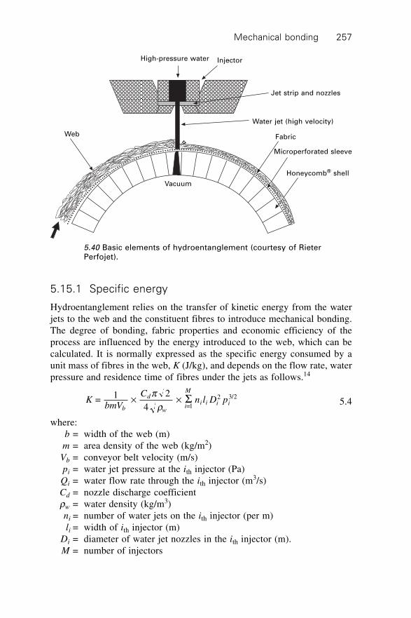
Mechanical bonding 257
5.15.1 Specific energy
Hydroentanglement relies on the transfer of kinetic energy from the waterjets to the web and the constituent fibres to introduce mechanical bonding.The degree of bonding, fabric properties and economic efficiency of theprocess are influenced by the energy introduced to the web, which can becalculated. It is normally expressed as the specific energy consumed by aunit mass of fibres in the web, K (J/kg), and depends on the flow rate, waterpressure and residence time of fibres under the jets as follows.14
KbmV
Cn l D p
b
d
wi
M
i i i i = 1 2
4
=1
2 3/2¥ ¥pr
S 5.4
where:b = width of the web (m)m = area density of the web (kg/m2)Vb = conveyor belt velocity (m/s)pi = water jet pressure at the ith injector (Pa)Qi = water flow rate through the ith injector (m3/s)Cd = nozzle discharge coefficientrw = water density (kg/m3)ni = number of water jets on the ith injector (per m)li = width of ith injector (m)
Di = diameter of water jet nozzles in the ith injector (m).M = number of injectors
High-pressure water Injector
Jet strip and nozzles
Web
Water jet (high velocity)
Fabric
Microperforated sleeve
Honeycomb® shell
Vacuum
5.40 Basic elements of hydroentanglement (courtesy of RieterPerfojet).
Handbook of nonwovens258
For capillary cone down nozzle configurations, the value of Cd is usuallyabout 0.60–0.66. The pressure-volumetric flow curve normally correspondsto a root function, the precise shape of which depends on the nozzle diameter,the number of nozzles per width and the nozzle geometry.15 Unfortunately,not all the energy applied to the web is utilised in directly entangling thefibres. The energy consumption required to produce a serviceable fabricdepends on the physical and mechanical properties of the constituent fibresin the web, the fibre orientation, web thickness and density (which influencesthe position of fibres relative to the incident jets and their mobility), theporosity and design of the conveyor surface (which influences the probabilityof turbulent flows in the web that are thought to increase entanglement), andthe water content of the web (standing water reduces energy transfer to thefibres). Other potential sources of energy consumption include fibre to fibrefrictional forces, fluid drag forces and web compression. The drag forces areassociated with the development of fibre entanglement.
Fundamentally, the fibre entanglement resulting from the energy transferdepends on the quality of the jet and the mechanical and physical propertiesof the fibres in the web. Particularly important is their ability to wet out,deform and entangle in response to the applied mechanical forces. To maximiseeconomic efficiency, acceptable fabric strength has to be obtained at thelowest possible energy consumption and highest achievable delivery speed.These competing requirements are difficult to balance and partly depend onraw materials and process conditions.
Because the economics of hydroentanglement depend on the energyconsumption, the selection of an appropriate jet pressure profile that minimisesthe specific energy consumption whilst obtaining satisfactory bonding isimportant to ensure economic efficiency. The specific energy coefficent (SEc)is the ratio of energy consumption to the fabric tensile strength16 and is auseful means of assessing the efficiency of hydroentanglement in terms ofthe development of fabric strength.
SEKTc
s
= 5.5
where: K = the total energy consumption (sum of all injectors) and
TT T
mss MD s CD
= + 2
100( ) ( ) ¥ 5.6
Ts(MD) = tensile strength of fabric in the machine direction, Ts(CD) = tensilestrength in the cross direction and m = fabric weight per unit area.
5.15.2 Jet impact force
The jet impact force affects the consolidation, thickness and entanglement ofthe web during hydroentanglement and depends on the water pressure p and
Mechanical bonding 259
the jet impact area which is influenced by the jet diameter d. The actualdiameter is affected by jet constriction.
F p d 4
2µ p5.7
Therefore at a fixed pressure the impact force will increase if the nozzlediameter increases15 providing a potentially more effective means of increasingfibre entanglement by involving more fibres (fibre segments) in theentanglement. The ratio of the impact force F to conveyor speed Vb influencesthe structure of the fabric particularly the transverse fibre orientation,local density variations and fabric thickness. In practice, increasing the F/Vb
ratio tends to encourage fibres to stick to the conveyor surface and in extremeconditions, to web perforation. For hydroentangled composites,the ratio is adjusted to control the degree of interlaminar bonding. Athigh pressure, physical modifications such as longitudinal splitting ofsegmented-pie bicomponents and fibrillation of fibres such as Lyocell can beobserved.
5.15.3 Mechanism of hydroentanglement and fabricstructure
There is an incomplete picture of the mechanism of fibre entanglementduring hydroentanglement, which reflects the difficulties of observing complexdynamic interactions of fibres with water jets. Understanding is based onanalyses of fabric microstructure and theoretical considerations of the probablejet-fibre interactions as well as the interaction of the fibre with the wires andholes in the support conveyor. In hydroentangled fabrics, the fibres or morespecifically fibre segments are tangled, intertwined and interlaced with others.The rearrangement of fibres is influenced by the interaction of fibres withthe water as well as with the support surface. As the incident water jetpenetrates the web towards the support surface, some fibre segments aredeflected downwards or displaced sideways and entanglements are producedby eddies present within the fluid medium.17 A method for determining theclustering of transverse fibre segments by analysis of photomicrographsbased on the ratio of areas has been described.18 The number of fibres impactedby the water jet depends on their spatial arrangement, which is governed bythe web structure and by the dimensions and frequency of the issuing waterjets. Particularly in lightweight fabrics, it has been suggested that high energywater droplets may be reflected from the support surface once the jet haspenetrated the web thereby increasing fibre entanglement.17 The nature ofthe turbulent effects created in the web near the support surface and the dragforces on fibres, most notably the turbulence created between adjacent waterjets, are still to be fully elucidated.
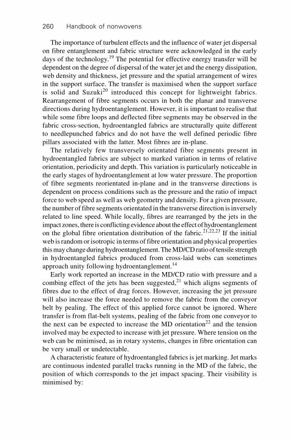
Handbook of nonwovens260
The importance of turbulent effects and the influence of water jet dispersalon fibre entanglement and fabric structure were acknowledged in the earlydays of the technology.19 The potential for effective energy transfer will bedependent on the degree of dispersal of the water jet and the energy dissipation,web density and thickness, jet pressure and the spatial arrangement of wiresin the support surface. The transfer is maximised when the support surfaceis solid and Suzuki20 introduced this concept for lightweight fabrics.Rearrangement of fibre segments occurs in both the planar and transversedirections during hydroentanglement. However, it is important to realise thatwhile some fibre loops and deflected fibre segments may be observed in thefabric cross-section, hydroentangled fabrics are structurally quite differentto needlepunched fabrics and do not have the well defined periodic fibrepillars associated with the latter. Most fibres are in-plane.
The relatively few transversely orientated fibre segments present inhydroentangled fabrics are subject to marked variation in terms of relativeorientation, periodicity and depth. This variation is particularly noticeable inthe early stages of hydroentanglement at low water pressure. The proportionof fibre segments reorientated in-plane and in the transverse directions isdependent on process conditions such as the pressure and the ratio of impactforce to web speed as well as web geometry and density. For a given pressure,the number of fibre segments orientated in the transverse direction is inverselyrelated to line speed. While locally, fibres are rearranged by the jets in theimpact zones, there is conflicting evidence about the effect of hydroentanglementon the global fibre orientation distribution of the fabric.21,22,23 If the initialweb is random or isotropic in terms of fibre orientation and physical propertiesthis may change during hydroentanglement. The MD/CD ratio of tensile strengthin hydroentangled fabrics produced from cross-laid webs can sometimesapproach unity following hydroentanglement.14
Early work reported an increase in the MD/CD ratio with pressure and acombing effect of the jets has been suggested,21 which aligns segments offibres due to the effect of drag forces. However, increasing the jet pressurewill also increase the force needed to remove the fabric from the conveyorbelt by pealing. The effect of this applied force cannot be ignored. Wheretransfer is from flat-belt systems, pealing of the fabric from one conveyor tothe next can be expected to increase the MD orientation22 and the tensioninvolved may be expected to increase with jet pressure. Where tension on theweb can be minimised, as in rotary systems, changes in fibre orientation canbe very small or undetectable.
A characteristic feature of hydroentangled fabrics is jet marking. Jet marksare continuous indented parallel tracks running in the MD of the fabric, theposition of which corresponds to the jet impact spacing. Their visibility isminimised by:
Mechanical bonding 261
∑ ensuring successive jets do not impact the same area∑ increasing the number of injectors in series∑ using finer jets in the final injectors∑ reciprocating an injector from side to side.
Jet marking is more pronounced if a high pressure is utilised early in theprocess or when prewetting is incomplete prior to hydroentanglement.Additional textural features observed in the fabric are associated with thestructure of the support conveyor, which are transferred to the fabric duringthe process.
5.15.4 The degree of bonding
Initially, as the water pressure is incrementally increased in small steps fromzero, no significant increase in fabric strength may be observed, dependingon fibre properties until a threshold pressure is reached. After this point,additional small increments in pressure lead to large increases in tensilestrength; as the pressure increases, the tensile strength of the resulting fabricincreases to a maximum fabric strength before levelling. The initial rate ofincrease of the strength depends on fibre and process-related parameters.Fibre fineness and wet modulus are particularly important. Depending onconditions and fibre type, as the pressure continues to increase, the breakingload may eventually decrease due to fibre damage. The maximum fabricstrength (MFS) obtained by increasing the water pressure varies dependingon a number of factors. A critical pressure can be identified for a given webof fibres14 that results in the highest strength and modulus. The fabric strengthcan be developed with a few injectors operating at relatively high pressure orby an appropriate pressure profile. The choice of approach influences theenergy consumption of the process.
Some of the considerations affecting the MFS are as follows:
∑ Fibre type. Strong fibres normally have a high MFS but the energyexpended in reaching that maximum may be unacceptably high from aneconomic viewpoint. With high modulus fibres the increased water pressurerequired can lead to fibre damage, which prevents the theoretical MFS
from being reached in practice.∑ The pressure profile and the ratio of specific energies applied to the face
and back. A lower MFS may be obtained if the fabric is hydroentangledfrom one side only as compared to both sides. An alternating treatmentof the web is preferred.
∑ The web weight. Normally, a higher MFS is obtained if web weight isincreased.
Figure 5.41 exemplifies the nature of initial increases in fabric strengthobtained as energy begins to increase for different fibre types. It illustrates
Handbook of nonwovens262
that different energy levels are required to initiate increases in fabric strengthdepending on fibre type.
Fabrics produced using the same specific energy input but with a differentcombination of jet pressures, a different number of injectors or a differentface and back treatment of the web do not necessarily possess the sametensile properties. The impact force rather than specific energy may be thedominant factor24 since fabrics produced at similar specific energies usingdifferent process parameters do not always yield the same fabric strength.25
It should also be remembered that the aim is not always to produce thehighest possible fabric strength, since this may compromise other desirableproperties such as the bulk density and absorbency. In practice, the specificenergy required to satisfactorily bond fabrics ranges from about 0.1–0.85kWh/kg depending on web weight15 and there is an approximately linearrelation between the energy consumption and web weight.
The entanglement completeness and the entanglement frequency expressthe degree of bonding in hydroentangled fabrics based on average values oftensile strip tests conducted in the MD and CD. The entanglement completenessis a measure of the proportion of fibres that break (rather than slip out of thefabric) based on fabric breaking loads obtained at different gauge lengthsand strip widths, whereas the entanglement frequency is a measure of thebond point frequency along individual fibre lengths in the bonded fabric.10
CD pp 1.7
MD pp 1.7
MD Vis 1.7
CD Vis 1.7
y = 1.5346e0.1585x
R2 = 0.833
K = 5.6 KJ/m^2)
for viscose fabrics
K = 17.8 KJ/m^2)
for PP fabrics
y = 72.063 Ln(x) – 79.755
R2 = 0.8865
y = 34.334Ln(x) – 14.676
R2 = 0.9361
y = 2.8173e0.1006x
R2 = 0.8787
1.0 6.0 11.0 16.0 21.0 26.0 31.0
Applied energy (kJ/m^2)
Te
nsil
e s
tre
ng
th (
N)
400
350
300
250
200
150
100
50
0
5.41 Influence of applied energy on the initial increases in tensilestrength of hydroentangled fabrics (1.7 dtex PP and 1.7 dtex viscoserayon in the machine (MD) and cross-directions (CD)).
Mechanical bonding 263
High entanglement frequencies are associated with improved pilling resistanceand fabric surface stability. Durable non-bonded fabrics can be expected tohave an entanglement frequency of 7.9/cm and an entanglement completenessof at least 0.5.10
Another approach is to estimate the theoretical hydroentanglementintensity26,27 introduced by the jets. This is based on a simplified model ofpart of the bonding mechanism, which considers the number of fibres impacted,N, in a unit area of the web by the incident water jets and the resultingbending of these fibres according to their mechanical properties, y. Thisapproach does not consider the additional complex interactions between thewater and the fibres at the support surface. The deflection depth of a fibresegment in the z-direction, y, can be calculated based on the dynamic impactforce of a water jet on a fibre segment,26
yg
Ed
C p D d
mv
f
f
w d x
b
= 212 2
0.5 0.5 2 3p r r
¥Ê
ËÁÁ
ˆ
¯˜ 1 + 1+ 48
2 2
2 22
2 4 3p r rg
Ed mv K
nC pD dw
f
f
b
d x5.8
whererw water density (1000 kgm–3)rf fibre density (kgm–3)Cd water flow discharge coefficientD orifice diameter (m)df fibre diameter (m)dx diameter of a water jet at the web surface (m)E Young’s Modulus of the fibre (Nm–2)Ke kinetic energy of the water jets consumed in bending the fibres per unit
area of the web (J/m2).m area density of the web (kgm–2)n number of jets in the jet strip (jets/m)p hydrostatic pressure drop (Nm–2)vb conveyor belt velocity (m/s)y deflection depth of a fibre due to a dynamic impact (m).
If it is assumed that the coefficient of jet constriction is equal to one thenthe applied energy can be written as follows.26
KnC D p
ve
d
b w
= 1.11
(J/m )3 2 1.5
0.52
r 5.9
The number of impacted fibre segments N is proportional to the total impactarea of the water jets on the web and the deflection depth of each impacted fibresegment depends both on fibre properties and the applied energy.
Handbook of nonwovens264
NmA
d dv
mn
d
w
f x fb f f
=
4
1 = 4
2 2p r p r
(Number of impacted fibre segments/m2) 5.10
where Aw is the impact area of a single water jet on the web per unit time(m2), N is the number of fibre segments deformed in a unit area of the webduring jet impact (fibres/m2) H is the hydroentanglement intensity (m).26
H yNg
Ed
n C p D d
vf
w d x
b
= = 2
3 4
0.5 0.5 2 3r
¥Ê
ËÁÁ
ˆ
¯˜ 1 + 1 + 48
2 2
2 22
2 4 3p r rg
Ed mv K
nC pD dw
f
f
b
d x5.11
The influence of fibre stiffness on the hydroentanglement intensity can beobtained from
HR d
mv
nC p Dd
f f b
d x
w
2.43* 101
20.5
0.5 1.5 0.75 1.5
0.25ª
ÊËÁ
ˆ¯ÊË
ˆ¯
ÊËÁ
ˆ¯r r
when
1.03*10 >> 1
–6
2
22
2 4 3
R
d
mv K
n C D d pf
b
d xr 5.12
where R is the flexural rigidity of a fibre with a circular cross-section (Nm2).
5.16 Fibre selection for hydroentanglement
Virtually all polymeric fibres of a wide range of dimensions are compatiblewith hydroentanglement providing they can be first formed into a web atcommercially acceptable production speeds. However, the processefficiency, fabric properties and economics of hydroentanglement varydepending on fibre selection. It is important in hydroentanglement to maximisebonding whilst minimising the energy. Fibre properties have a significantinfluence on the degree of bonding that can be achieved for a given energyconsumption.
5.16.1 Fibre stiffness
Formation of coherent fabrics with minimum energy consumption requiresflexible, deformable fibres that can be readily entangled. Fibre flexural rigiditydepends on its diameter, Young’s modulus, cross-sectional shape and density.Depending on fibre type some of these properties are strongly moisture-
Mechanical bonding 265
dependent, particularly the modulus, which is important in hydroentanglement.Fibre flexural rigidity values are frequently associated with hydroentanglementefficiency but the fibre bending deformations in hydroentanglement are believedto be three-rather than two-dimensional in nature and the torsional rigidity ofthe fibre should be considered.17 Viscose rayon has a low wet modulus andthis partly explains the ease with which this fibre can be hydroentangled. Atlow pressure and energy, heavily entangled fabrics are produced from viscoserayon, whereas at the same conditions the entanglement is significantly lowerin fabrics containing, for example, PP.
While it is possible to hydroentangle high modulus fibres such as glassand carbon fibre, the strength realisation tends to be poor because of thelimited fibre entanglement that is introduced. Attempts to increase theentanglement by increasing the applied pressure might lead to fibre damageand some fibres may be pulverised rather than entangled even at relativelylow pressure. Fine fibres are therefore more flexible than coarse fibres of thesame polymer composition, they hydroentangle more intensively for a givenenergy consumption and produce stronger fabrics. The accompanying increasein fibre surface area and the increased number of fibre intersections as thefibre diameter decreases contributes to increased fabric strength. For a givenpolymer type, fibre cross-sectional shape also affects entanglement. Triangular-shaped fibres require more energy than do round fibres and elliptical and flatfibre cross-sections hydroentangle quite efficiently.
5.16.2 Wettability
Effective hydroentanglement requires uniform and rapid wetting of the web.The choice of spin finish is particularly important to ensure proper wetting-out of hydrophobic fibres such as PP and to minimise foaming during theprocess as the finish is removed in the waste water. The antistatic componentof the finish can be particularly associated with foaming but formulationshave now been developed that minimise the problems. Prior to the maininjectors, pre-wetting reduces the web thickness by displacing air from thestructure and therefore the web should wet-out at this stage. Due to thehydrophobic nature of synthetic fibres such as PP and PET, in particular,hydrophilic fibre finishes are utilised for synthetic fibres intended forhydroentanglement. In one example a finish containing one monoester ofglycerol and a fatty acid having from six to fourteen carbon atoms is appliedas an aqueous dispersion.28 The durability of hydrophilic finishes is low andthey are effectively removed during hydroentanglement. This necessitatesreapplication of hydrophilic agents to synthetic fibre fabrics intended forabsorbent products following hydroentanglement. Durable hydrophilisationhas been demonstrated by some fibre manufacturers29 and PP fibres specificallyfor hydroentanglement are produced.30 Treatments such as plasma discharge
Handbook of nonwovens266
methods, used to functionalise the surface of synthetic polymers withhydrophilic groups, have been demonstrated.
5.16.3 Fibre dimensions
Fibre linear density normally ranges from 1.1–3.3 dtex; common linear densityand fibre length combinations are 1.7 dtex/38 mm, 3.3 dtex/50 mm and 3.3dtex/60 mm. The fibre length and slenderness ratio also influences compatibilitywith preceding web-forming processes. Fine fibres have a high specificsurface area for a given fabric weight leading to good fabric strength. Thereis also a direct relation between fibre diameter and bending stiffness, whichinfluences entanglement efficiency. For good fabric formation, fibres mustbe mobile and capable of deformation and deflection in the web. Whileshort-cut fibres hydroentangle quite efficiently, there is a positive relationshipbetween fibre length and fabric strength within a narrow length range. Whenfibre fineness is constant, fabric strength increases with fibre length up to amaximum length of about 50–60 mm.16 For viscose rayon, fabric strengthhas been shown to increase with fibre lengths up to 51 mm.17 While crimppromotes cohesion in carded webs prior to bonding, it also influences thestrength of fabrics produced by low to medium pressure hydroentanglementsystems.16 As a consequence of the high resistance to compression, helicallycrimped fibres require higher energy inputs to obtain fabrics with acceptablestrength. The effect of crimp is particularly noticeable in the hydroentanglementof fine wool, which has a high crimp frequency and requires high pressureto produce a coherent, abrasion-resistant structure.
5.16.4 Fibre types
Commercially, staple fibre PET and viscose rayon are most important inhydroentanglement and may be blended with wood pulp. Partly as aconsequence of the growth of hydroentangled wipes and medical productsthe consumption of viscose rayon has increased. The wet strength and volumeof viscose rayon fabrics can be increased by blending with PET or PP. Woodpulp is widely utilised in hydroentangled fabrics as a low-cost absorbent fordry wipes, surgical gowns and drapes but only in blends or multi-layerstructures. Airlaid wood pulp is blended with viscose or PET in proportionsup to 50% and hydroentangled. The staple fibre matrix traps the pulp insidethe fabric. Assuming appropriate water filtration is available as part of thehydroentanglement system, webs composed of linters and noils as well asbleached cotton are hydroentangled to produce absorbent products includingwet wipes, medical gauzes and cosmetic pads. The fibres are usually 7–25mm and 1.2–1.8 denier31 and a large proportion of cotton wax can be removedfrom unbleached fibre during hydroentanglement at comparatively low energy(below 1 MJ/kg), which increases the hydrophilicity.
Mechanical bonding 267
The strength of hydroentangled cotton fabrics tends to increase as thefibre fineness decreases but the fabrics have a harsher handle. One limitationof bleached cotton is that it can be difficult to card, which affects the productionrate of a hydroentanglement line. The consumption of the solvent-spun fibre,Lyocell, in hydroentangled fabrics, has seen a rapid increase in recent years,particularly in absorbent products such as wipes, where the high wet strengthis advantageous. Wipes containing Lyocell also have excellent pattern definition.
High temperature fibres
High-temperature-resistant hydroentangled fabrics have been produced foryears, largely pioneered by DuPont. Meta-aramid hydroentangled fabrics arefound in aerospace and protective clothing markets32,33 together with para-aramids for high-temperature protection and blends of meta and para-aramidsare utilised in thermal barrier, heat-shielding materials. Hydroentangedmelamine and aramid fibres have been developed for fire-retardant clothing34
and hydroentangled Basofil® fabrics are available. Provided the impact forcesare low to minimise fibre damage, inorganic fibres such as glass and silicacan be hydroentangled to produce pre-pregs for composites. Thehydroentanglement of ceramic fibres has been discussed.35 Fibres with ahigh metal oxide composition including silica (SiO2) are liable to breakduring low-pressure hydroentanglement and fabrics produced from such fibrestend to have low integral strength because of the limited fibre entanglementthat can be introduced.
Splittable bicomponent (Bico) fibres
The formation of microfibres in situ by splitting segmented-pie bicomponentfibres within fabrics during hydroentanglement is particularly well establishedin the Far East. Synthetic leather coating substrates, upholstery fabrics, high-performance wipes for applications such as optical glass cleaning are producedin this way. Carded and cross-lapped batts containing segmented-piebicomponent fibres are hydroentangled to produce microfibres by splitting.Afterwards, fabric density can be increased by inducing thermal shrinkageof additional thermoplastic fibres blended with the bicomponent fibres in theweb. The elimination of conventional leather production steps such as shrinking,splitting and grinding, leads to a significant saving in raw materials. Syntheticleather fabrics have excellent strength and durability and depending on polymercomposition can be dyed and finished to develop attractive softness andhandle characteristics.
The cross-sectional configuration of splittable bicomponent fibres andfilaments varies and the choice affects splitting efficiency and fabric properties.Rather than separating the embedded filaments in the bicomponent using
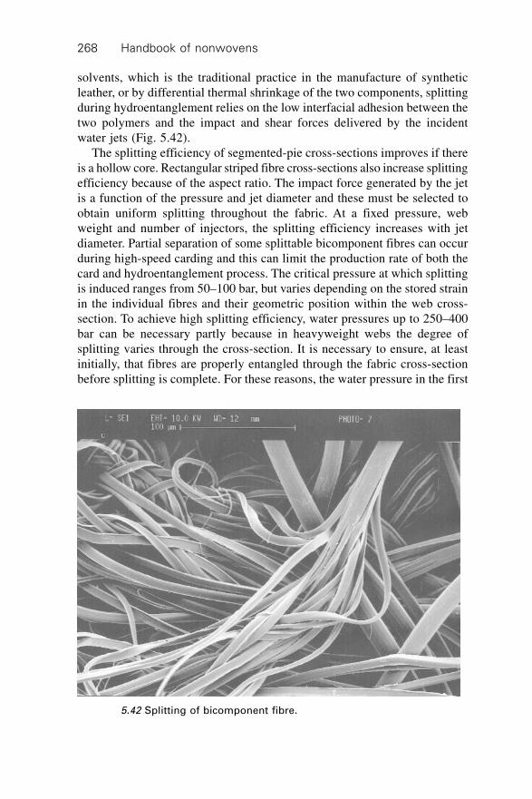
Handbook of nonwovens268
solvents, which is the traditional practice in the manufacture of syntheticleather, or by differential thermal shrinkage of the two components, splittingduring hydroentanglement relies on the low interfacial adhesion between thetwo polymers and the impact and shear forces delivered by the incidentwater jets (Fig. 5.42).
The splitting efficiency of segmented-pie cross-sections improves if thereis a hollow core. Rectangular striped fibre cross-sections also increase splittingefficiency because of the aspect ratio. The impact force generated by the jetis a function of the pressure and jet diameter and these must be selected toobtain uniform splitting throughout the fabric. At a fixed pressure, webweight and number of injectors, the splitting efficiency increases with jetdiameter. Partial separation of some splittable bicomponent fibres can occurduring high-speed carding and this can limit the production rate of both thecard and hydroentanglement process. The critical pressure at which splittingis induced ranges from 50–100 bar, but varies depending on the stored strainin the individual fibres and their geometric position within the web cross-section. To achieve high splitting efficiency, water pressures up to 250–400bar can be necessary partly because in heavyweight webs the degree ofsplitting varies through the cross-section. It is necessary to ensure, at leastinitially, that fibres are properly entangled through the fabric cross-sectionbefore splitting is complete. For these reasons, the water pressure in the first
5.42 Splitting of bicomponent fibre.
Mechanical bonding 269
few injectors must not induce excessive splitting but rather should entanglethe fibres to introduce satisfactory bonding through the cross-section.
The fineness of the fibres or filaments after splitting depends on thenumber of segments in the bicomponent cross-section. Typically, after splittingthe fineness ranges from about 0.05–0.3 denier depending on the type ofbicomponent. Experimentally, island in the sea filaments have been producedwith 600–1120 individual PP filaments embedded in a soluble PVA matrixwithin the cross-section.36 While at present only segmented fibres are intendedfor splitting in hydroentanglement, hydroentangled nanofibre fabrics producedfrom splittable bicomponents is technically feasible and hydroentanglementof nanofibre filaments has been demonstrated.37
Fibrillating fibres
Longitudinal splitting of microfibrillar fibres is induced at high impact forceswhich can be exploited to engineer the physical properties of fabrics. Suchfibrillation during hydroentanglement can be observed in natural cellulosicsincluding cotton and bast fibres as well as Lyocell, polynosics, polyacrylonitrileand even para-aramids if the water pressure is sufficiently high. Fibrillationusually occurs by splitting of the fibre from the outside in; the fibrils arepartially exposed and project from the surface of the parent fibre and arereadily entangled with neighbouring fibrils. The water pressure at whichfibrillation begins varies depending on the fibre type and grade and for manycommercial fabrics, hydroentanglement conditions are purposely selected toavoid the onset of fibrillation. The increase in surface area associated withmass fibrillation modifies the physical, optical and mechanical properties ofthe fabric. There is a decrease in fabric permeability, which is useful in thedesign of filter media, and an increase in the fabric opacity.
Following mechanical finishing, a microfibre pile may be produced onthe fabric surface, which markedly increases fabric softness. If finishing isnot carried out, fibrillation tends to lead to a paper-like surface, which givesthe fabric a harsh handle. Lyocell has attracted interest partly because of itspropensity to fibrillate at high pressure, which can be harnessed to bothincrease entanglement and modify key fabric properties such as tensile strength,permeability and liquid transport. Applications for hydroentangled fibrillatedLyocell fabrics include filtration, such as cigarette filters and wipes.
5.17 Process layouts
Between the end of 1998 and 2000 alone, the market for hydroentanglementmachinery increased by 50%, with the largest growth in Europe. Significantgrowth has also been experienced in China and the USA and the first linesfor India and Pakistan have been announced. The main turn-key
Handbook of nonwovens270
hydroentanglement machinery suppliers are Fleissner GmbH (Germany),who supply the Aquajet system and Rieter Perfojet (France) who supply theJetlace 3000 system. These companies have been responsible for the installationof the majority of new installations since the late 1990s in the case of FleissnerGmbH and since the 1980s in the case of Perfojet. Other machinery installationshave been constructed by Mitsubishi Engineering in Japan while in China,for example, installations have been developed by local engineering companies.Hydroentanglement has become increasingly cost-effective and accessibleto manufacturing companies globally. The Leanjet system38 is a low cost,entry level system for manufacturers producing a narrow range of products.One or two microporous shells (MPS) or sleeves are used as support surfacesdepending on the product to maximise fabric strength and minimise theenergy consumption.
In addition to contemporary systems, older hydroentanglement installationsremain in operation which, to remain competitive, have been extensivelymodified and updated since their original installation. Machines over fivemetres wide capable of line speeds up to 300 m/min with drylaid web formationhave been commissioned and higher productivity and process efficiencycontinue to be major drivers for development. Production rates up to 1100kg/hr/m have been reached. In the production of lightweight hygiene fabricsline speeds of 200 m/min to over 250 m/min are in operation but not allhydroentangled fabrics are produced at such high speeds. In the productionof cosmetic pads composed of cotton for example, production rates can be aslow as 30–60 m/min.
The water pressure, number of injectors and machine width influence thecosts of the process. Consequently, minimising these while obtainingsatisfactory fabric properties, particularly strength, can be advantageousproviding the versatility of the line is not lost. The investment costs of aninstallation are claimed to approximately double for every 100 bar increasein pressure39 taking into account the costs of the water pump, electric motor,inverter and high-pressure pipework. The electrical power consumption ofan injector is linked to the pressure used. Based on a 3.5 m operating width,approximately 155 kWh is consumed by an injector at 200 bar, 544 kWh at400 bar and 1088 kWh at 600 bar.40 Over about 150 bar, the costs increasefurther with machine width.
Commercially, there is no universal layout; the machine configurationdepends on
∑ raw material properties and the method of web formation used to supplythe machine
∑ fabric weight∑ cost (particularly with respect to energy consumption)∑ the need to introduce other components such as webs, scrims or preformed
fabrics to manufacture multi-layer structures
Mechanical bonding 271
∑ the required patterning or aperturing capabilities∑ whether or not additional bonding will take place, e.g. thermal or chemical
bonding∑ the intended product application and the degree of machine versatility
required.
Injectors may be arranged over the top of a flat conveyor or around thecircumference of a rotary drum or cylinder. In practice, both arrangementsare frequently incorporated in a modular machine in sequence. Examples ofintegrated machine systems are shown in Fig. 5.43. Rotary drums are favouredif, as is usual, a dual-sided treatment of the web is required although historicallythis has also been accomplished in flat belt systems using an overhead transferand turn-back arrangement fitted between modules.41 Dewatering, fabricthreading, floorspace requirements and pealing of the fabric from the conveyorsurface are improved with the rotary system. In the flat belt system, fibreends can partially penetrate the conveyor and when dragged over the suctionslots during processing this inhibits web removal.
The precursor web fed to the hydroentanglement machine largely determinesthe isotropy and quality of the final fabric, and in a production line webformation is often the rate-determining step. Web weights can range from15–400 g/m2 but commercially, most are 40–150 g/m2 depending on fibrefineness. The majority of commercial fabrics remain below 100 g/m2.Technically, all generic web types can be hydroentangled including spunlaid,meltblown, carded, airlaid and wetlaid including composites of these.
5.17.1 Carding – hydroentanglement installations
Commercially, drylaid systems predominate in hydroentangled fabricproduction. Webs are usually prepared by straight-through carding and thefibre length ranges from 25–60 mm. Parallel-laid webs tend to require higherenergy to obtain adequate CD strength than do cross-laid webs. In straight-through carding systems, one or more double doffer cards are used to supplyweb weights from about 20–80 g/m2. Where a card and profiling cross-lapper are utilised, basis weights range from 80–400 g/m2. Web spreadingusing rollers is sometimes used to increase the width and to modify fibreorientation prior to hydroentanglement. In the manufacture of cotton make-up removal pads, multiple cotton cards are employed to produce web weightsup to 200–250 g/m2. The design of high production nonwoven cards forproducing lightweight, isotropic webs that are capable of balancing the highdelivery speeds in hydroentanglement continues to be a challenge. Highspeed cards capable of 400 kg/hr/m (depending on fibre specifications) allowweb geometry to be modified by scrambling or randomising to minimise theMD/CD ratio. However, scrambling rollers decrease the linear web speed.
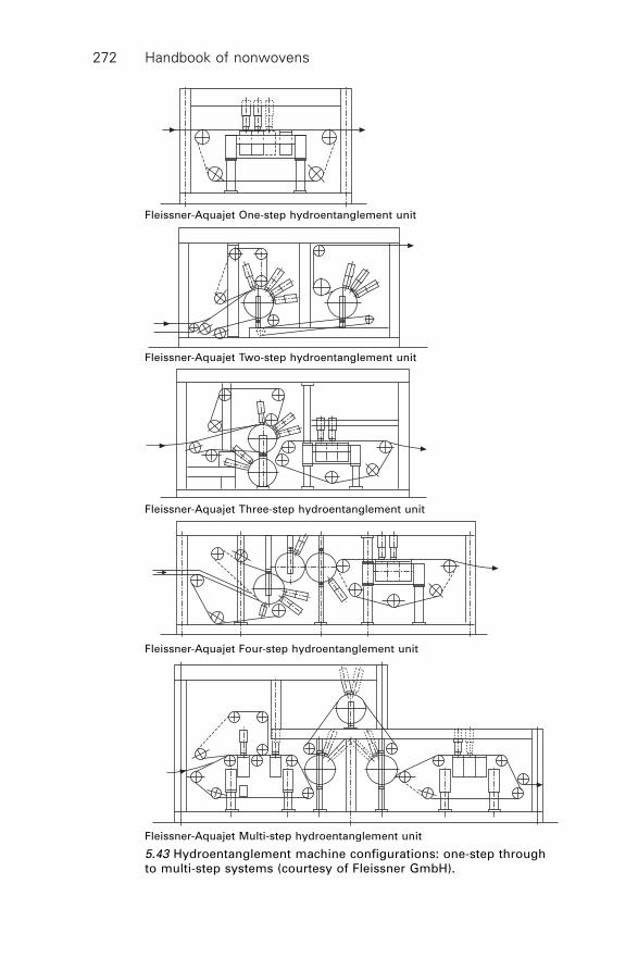
Handbook of nonwovens272
Fleissner-Aquajet One-step hydroentanglement unit
Fleissner-Aquajet Two-step hydroentanglement unit
Fleissner-Aquajet Three-step hydroentanglement unit
Fleissner-Aquajet Four-step hydroentanglement unit
Fleissner-Aquajet Multi-step hydroentanglement unit
5.43 Hydroentanglement machine configurations: one-step throughto multi-step systems (courtesy of Fleissner GmbH).
Mechanical bonding 273
Hybrid card-airlay systems have also been introduced (see Chapter 2) thatproduce webs with very low MD/CD ratios. Nevertheless, regardless of theisotropy of the initial web, the resulting hydroentangled fabric can have ahigher MD/CD ratio.
Card widths extend to 5.1 m for producing hydroentangled fabric althoughtrim widths may be lower at about 4.6 m.42 A line designed for the productionof ‘straight-through’ carded low to medium weight fabrics of <150 g/m2 atdelivery speeds up to >250 m/min might consist of the following components:a worker-stripper nonwoven card, a batt compression device and a twincylinder alternating hydroentanglement module operating with multipleinjectors followed by hydroentanglement on a flat belt using two injectors.Drying is commonly by through-air single drum dryer before wind-up. If inaddition to low to medium weight webs, higher weights up to 500 g/m2 arerequired with good isotropy, twin cards are employed. In this example, oneof the cards operates with a cross-lapper to increase the versatility of theline. Following combination of the two webs, batt drafting enables modificationof the MD/CD ratio to increase isotropy. Four cylinders are employed withalternating injectors before the final flat belt section, which in this exampleis fitted with one injector. Through-air double drum drying precedes windingup.
5.17.2 Carding and pre-formed tissue hydroentanglementinstallations
For the production of carded web and tissue composites, the tissue is introducedonto the pre-bonded carded web between the first and secondhydroentanglement modules. Carding is followed by prewetting and the webis then hydroentangled using twin-cylinder modules fitted with alternatinginjectors. The carded web and tissue are combined on a flat belthydroentanglement module using two injectors to integrate the two components.Through-air drum drying and winding then follows.
5.17.3 Carding-airlaid composite hydroentanglementinstallations
Sifted airlaid (and wetlaid) webs containing short cut fibre of 3–15 mm arehydroentangled in 100% form and in blends with wood pulp but scrims,films, textile fabrics and filaments may also be integrated into such compositesbetween layers of webs during the process. Three-layer carded-airlaid (woodpulp)-carded (CPC) hydroentangled composite fabrics produced by combiningboth carded and airlaid webs are particularly suitable for wet wipe applications.Two-layer, carded-airlaid (CP) hydroentangled composites can also be producedby by-passing the second card but CPC products help to prevent dusting of
Handbook of nonwovens274
the pulp from the wipe during use. To produce CPC composites, pulp isairlaid onto a preformed carded web composed of PET, PP or viscose rayonusing a sifting air-laying process. Alternatively, pre-formed tissue may beintroduced onto the web. A second carded web is laid on top of the CP layerprior to prewetting. Twin-cylinder hydroentanglement follows using alternatinginjectors and the composite is then fed to a flat belt hydroentanglementmodule fitted with two injectors. Through-air drum drying and winding upcompletes the installation.
5.17.4 Spunlaid hydroentanglement installations
Spunlaid webs can be hydroentangled to introduce fibre entanglement and tomechanically combine webs in the production of twin-layer or mutilayerfabrics. Although high water pressures of 300–400 bar are potentially requiredto adequately bond spunlaid fabrics, one of the attractions is the opportunityto produce at high linear delivery speeds up to 600 m/min in widths up to 5.4m. In an example of a spunlaid-hydroentanglement installation, a web of 10–400 g/m2 is compressed and hydroentangled on a multi-drumhydroentanglement installation using five injectors. The fabric is thenhydroentangled on a flat belt module fitted with at least one injector. Through-air drum drying and winding up completes the line.
Since spunlaid hydroentangled fabrics are free of thermo-fused regionsintroduced by calender bonding, the fabrics have comparatively high bulkand good tactile characteristics as well as high tear strength and a comparativelylow flexural rigidity. The risk of thermal degradation of the polymer duringbonding is obviated. Using a spunlaid platform followed by hydroentanglement,low to medium weight fabrics, particularly in the hygiene, filtration andgeosynthetic sectors have been targeted because, for example, the polymertype, the additives used and the linear density of the filaments can be changedas required prior to hydroentanglement. Examples of spunlaid-hydroentangledfabrics include Polymer Group Inc.’s Spinlace™ fabrics produced from 0.5–3 denier continuous filaments and Freudenberg’s Evolon® fabrics producedfrom splittable bicomponent filaments. The Spunjet system of Rieter Perfojetis an example of an integrated spunlaid web formation and hydroentanglementsystem.
5.17.5 Combination bonding
Commercially, thermal or chemical bonding may be utilised afterhydroentanglement to produce the final fabric. Traditionally, apertured fabricsproduced at low pressure have been chemically bonded to adequately stabilisethe fabric. In household wipes applications, approximately 7–27% of thefabric weight can be binder; the higher proportions being applied to viscose
Mechanical bonding 275
rayon fabrics. In viscose-PET blends the binder content is reduced. Rotaryscreen printing, for example, is used to apply a binder and pigment to thehydroentangled fabric. Fabrics may be produced using one to three low-pressure injectors operating at pressures below 80 bar; thermal or chemicalbonding then follows to develop the required fabric properties. For chemicalbonding, it is common to apply a low acrylic binder add-on of 2–5% owf byfoam padding. This increases the modulus, tensile strength and abrasionresistance of the fabric while minimising associated increases in stiffness43
and such fabrics may be flat or apertured.The hydroentanglement-chemical bonding route is used commercially to
produce linings and interlinings and some wipes products. Chemically bondedhydroentangled fabrics overcome the delamination problems associated withtraditional carded-chemically bonded fabrics. Hydroentanglement followedby thermal point bonding provides a potential means to minimise energycosts and to permit high production rates since both the water pressureutilised in hydroentanglement and the temperature and pressure applied inthermal bonding are lower than would be selected if one method alone wasemployed. Resulting fabrics also tend to be softer than those produced bythermal bonding alone since extensive thermo-fusion of the thermoplasticfibres in the fabric is not required to develop acceptable fabric properties.The hydroentanglement of thermally bonded fabrics is also known as a meansof reducing their stiffness and the separation and subsequent entanglementof continuous filaments in a thermally bonded spunbond fabric usinghydroentanglement has been suggested as a route to the production of highlydurable and dyeable nonwovens.44
5.18 Hydroentanglement process technology
5.18.1 Web/batt compaction and pre-wetting
Pre-wetting evacuates air from the web or batt prior to hydroentanglement inorder to:
∑ prevent uncontrolled disturbance of the fibre arrangement to minimisechanges in the MD/CD ratio of the web prior to bonding
∑ minimise jet marking when the web is impacted by the main jets∑ enable the web to pass between the first injector and the support surface∑ lightly adhere the web to the conveyor to prevent slippage.
Pre-wetting must be uniform to minimise variations in the degree of bondingintroduced by subsequent injectors. In practice, various methods of pre-wetting have been employed. A low-pressure injector can be used, but jetmarking is a common problem with such an approach and it reduces theefficiency of the hydroentanglement line. Similarly, spraying systems introduce
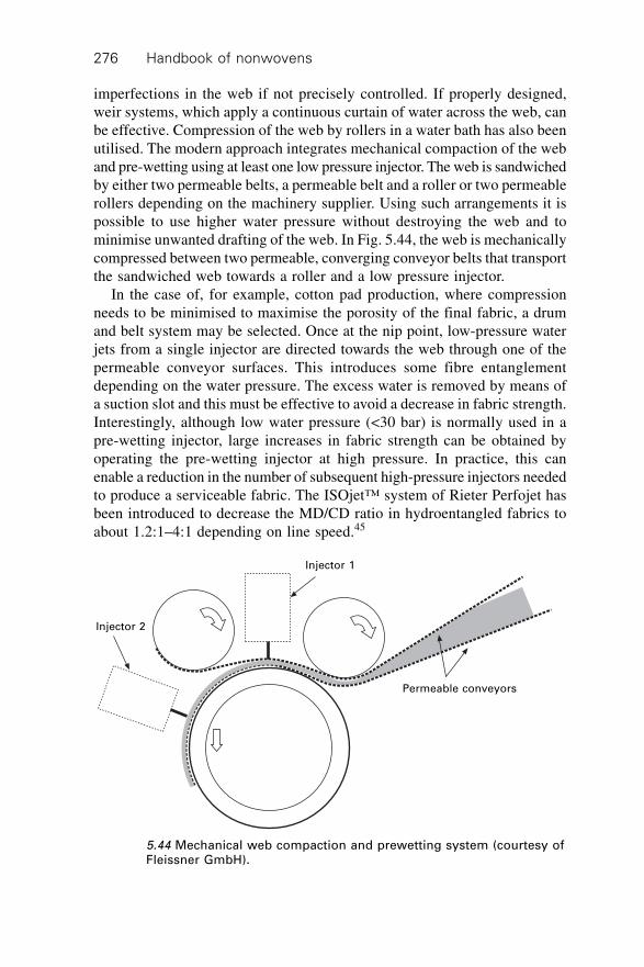
Handbook of nonwovens276
imperfections in the web if not precisely controlled. If properly designed,weir systems, which apply a continuous curtain of water across the web, canbe effective. Compression of the web by rollers in a water bath has also beenutilised. The modern approach integrates mechanical compaction of the weband pre-wetting using at least one low pressure injector. The web is sandwichedby either two permeable belts, a permeable belt and a roller or two permeablerollers depending on the machinery supplier. Using such arrangements it ispossible to use higher water pressure without destroying the web and tominimise unwanted drafting of the web. In Fig. 5.44, the web is mechanicallycompressed between two permeable, converging conveyor belts that transportthe sandwiched web towards a roller and a low pressure injector.
In the case of, for example, cotton pad production, where compressionneeds to be minimised to maximise the porosity of the final fabric, a drumand belt system may be selected. Once at the nip point, low-pressure waterjets from a single injector are directed towards the web through one of thepermeable conveyor surfaces. This introduces some fibre entanglementdepending on the water pressure. The excess water is removed by means ofa suction slot and this must be effective to avoid a decrease in fabric strength.Interestingly, although low water pressure (<30 bar) is normally used in apre-wetting injector, large increases in fabric strength can be obtained byoperating the pre-wetting injector at high pressure. In practice, this canenable a reduction in the number of subsequent high-pressure injectors neededto produce a serviceable fabric. The ISOjet™ system of Rieter Perfojet hasbeen introduced to decrease the MD/CD ratio in hydroentangled fabrics toabout 1.2:1–4:1 depending on line speed.45
5.44 Mechanical web compaction and prewetting system (courtesy ofFleissner GmbH).
Injector 2
Injector 1
Permeable conveyors
Mechanical bonding 277
5.18.2 Support surface
The design of the conveyor surface or ‘wire’ influences the fabric strength,fabric structure, visual appearance and energy consumption. The conveyorsurface may be a permeable, continuously woven mesh of metal or polymericconstruction, a solid metal roll, or a sleeve, which is normally perforated.The latter enables precise control of the open area and surface structure aswell as allowing dewatering and may be engraved to transfer patterns orapertures during hydroentanglement. To promote bonding and the formationof dense fabrics by maximising energy transfer into the web, mesh structureswith a small open area of 15–25% are preferred, whereas meshes with largeropen areas produce permeable fabrics with lower tensile strength. Duringoperation, the interstices in the conveyor belt can fill with fibre debris andcontamination, negatively affecting drainage and causing the web to stick.When woven belts are utilised it has been claimed that energised waterhitting the surface is randomly reflected and is not directed back into web toincrease fibre entanglement.40 Consequently, because of the energy absorptionby the mesh belt, more injectors are required to compensate for the lowenergy transfer efficiency. In early Perfojet systems, injectors were operatedin conjunction with opposed deflector plates that were designed to reflectenergised water back in to the web creating turbulence and additional bonding.Utilisation of up to 40% of the initial water jet energy has been claimedusing this approach.46
Historically, impermeable drum and conveyor surfaces have been foundto increase the energy transfer to the web and produce complex turbulenteffects on the support surface that are believed to account for increased fibreentanglement. In the original Unicharm system, drums of 50–300 mm diameterwere arranged in series operating in combination with at least one injector.47
Lightweight webs were bonded at relatively low energy by injectors positionedon one side of the web surface. The maximum web weight in these systemswas limited to 15–100 g/m2, although 20–60 g/m2 was preferred. In additionto defects in the fabric, impermeable drums tend to flood, which limits themaximum flow rate of each injector. Water drains along the rollers and at theedges of the web by gravity for collection in a drip tray under the machine.To avoid flooding in all hydroentanglement systems, the flow rate introducedby the injectors must be balanced by the water removal rate from the weband support surface. Perforated rollers operating with an internal suction slotassist with dewatering. The perforations are organised in regular patternsand their size and the open area is sufficiently large to permit efficient waterdrainage at high flow rates. The solid surface also provides potential forgood energy transfer and therefore an increase in the final fabric strength andenergy efficiency.
To avoid the introduction of unwanted shadow marking and striping of
Handbook of nonwovens278
fabrics produced with perforated rollers having a zig-zag arrangement ofperforations, sleeves having a random distribution of smaller microperforatedholes (normally 250–300 mm) have been introduced with an open area of 3–12% to maximise water drainage.48 Commercial systems consist of a thinserigraphic nickel sleeve mounted on a metal honeycomb support cylinder,which has an open area of about 95% to maximise drainage.40 Spacers extendbeyond the honeycomb cells to maximise the open area immediately belowthe sleeve to minimise flooding. Such microperforated sleeves increase theenergy efficiency of hydroentanglement by increasing the fibre entanglementfor a given energy input. As the open area of the support surface increases,the probability of energised water dissipating from the system is higher andtherefore lower fibre entanglement is produced. Using microperforated sleeves,high fabric strength can be obtained using relatively low pressure, which isenergy efficient. It has been claimed that if the open area of the sleeve isincreased from 8% to 15% the number of injectors has to be doubled toobtain the same fabric tensile strength.40
Wire meshes with a pronounced knuckle height or drum surfaces withraised projections are used to produce apertured fabrics with a gauze-like orthree-dimensional appearance.49 The water jets displace fibre segments fromthe surface of these projections producing apertures, the shape, size andfrequency of which are directly affected by the three-dimensional geometryof the support surface. The methods used to produce the drum surface orsleeve, that are readily linked to computer-aided design packages, includeserigraphy, which relies on electrolytic deposition of nickel or other metalsto build up the required surface and laser engraving, which provide extensivedesign opportunities for customisation of hydroentangled fabrics by embosspatterning.
5.18.3 Injector operation
Injectors (or manifolds) are constructed of steel and are robustly designed towithstand high water pressures. They are now built to widths of over 5 m butthere are many more machines in operation of 1.6–2.5 m wide. Whilecommercially, hydroentanglement systems capable of water pressures up to600–1000 bar have been designed, the majority of commercial installationsoperate at much lower pressures up to a maximum of about 250 bar. This ispartly to minimise the energy consumption and to maximise the life of the jetstrips, which wear out quickly at high pressures. To minimise wear andenergy consumption it is desirable to use the minimum possible water pressureneeded to obtain acceptable mechanical and physical fabric properties.Continuous improvements in the geometry and construction of injectors andjet strips as well as the use of microperforated support surfaces have led toimproved energy transfer from the jets to the web. Consequently, fabric
Mechanical bonding 279
tensile properties can be achieved today at lower pressure than was possiblein the past; however, pressures of up to about 300 bar are still required tofully bond heavyweight webs of, for example, 400g/m2 50 and webs composedof splittable bicomponent fibres, where high splitting efficiency is requiredalso require high-pressure inputs.40 Separate high-pressure pumps serve eachinjector, which enables independent adjustment of pressure. This is moreenergy efficient than using one pump connected to multiple injectors sincethrottling losses are avoided. It also allows greater flexibility in processing.Piston pumps are normally preferred over centrifugal pumps and pump pressureis regulated by variable-frequency-controlled AC motors.
The design of injectors has been subject to extensive modelling andsimulation work by the machinery manufacturers to improve energy efficiencyand to ensure uniform flow conditions across wide operating widths.Computational fluid dynamics (CFD) modelling has proved invaluable inthis area. Following fundamental studies, a significant increase in energyefficiency has been achieved by replacing drilled injectors with the fine slottype, and as result it is claimed that webs of 300 g/m2 that previously required300 bar for entanglement now require only 180 bar.40
Drilled and slot-type injectors have been described.40,51 The drilled typeconsists of a main body with an upper and lower chamber that is capable ofwithstanding high pressure. In the upper part, there is a cylindrical chamberinto which the high-pressure water is fed. Inside the chamber is a cartridge,which may consist of a perforated cylinder lined with a metal sleeve that actsnot only as a filter but also as a water distributor. The high-pressure water fedinto the chamber then passes through cylindrical holes arranged at intervalsacross the width of the injector and these holes are between 4–10 mm indiameter and 3–5 mm apart. These holes, which can be conical at the outlet,feed the high-pressure water to the lower part of the chamber where thewater flows towards the jet strip nozzles. At pressures >50 bar, the geometryof such injectors can lead to turbulence in the lower chamber, specifically inthe regions between the consecutive hole outlets in the lower chamber resultingin energy losses. This can lead to heterogeneous bonding and variations infabric density and appearance.
An improved high-pressure injector design40,51 consists of a cylindricalfeed chamber inside which the high-pressure water flows through a filter andthen enters a distribution region, which transports the water towards the jetstrip nozzles. Inside the feed chamber there is a cartridge consisting of aperforated cylinder lined with a filter system. The pressurised water is feddown to the jet strip via a narrow rectangular slot that extends the full widthof the injector. Commercially, reciprocating injectors have been introducedas a means of minimising jet marks, and high-capacity injector systems havealso been developed that incorporate either two (duplex) or three (triplex) jetstrips in a single injector.31
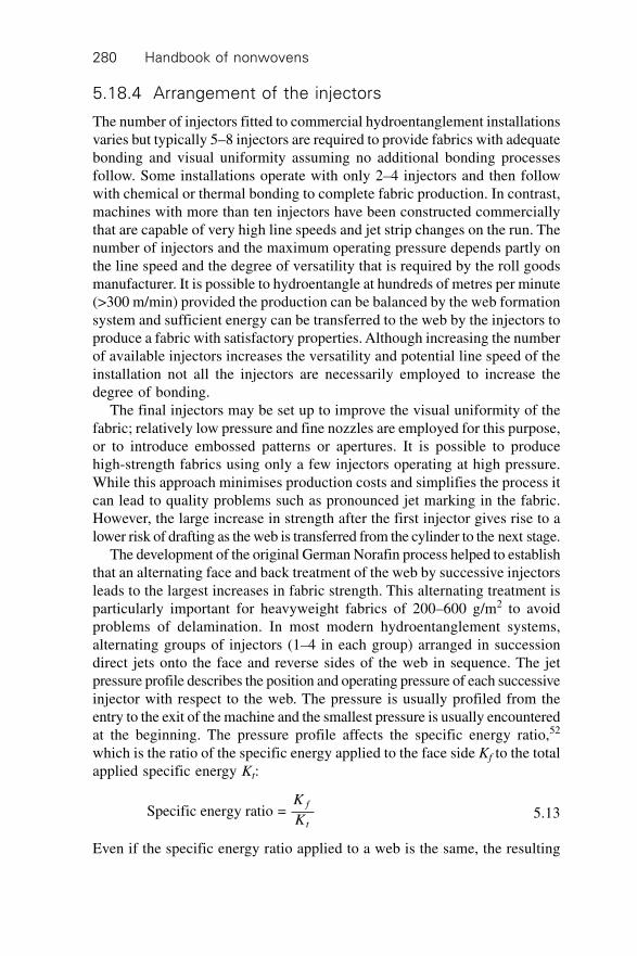
Handbook of nonwovens280
5.18.4 Arrangement of the injectors
The number of injectors fitted to commercial hydroentanglement installationsvaries but typically 5–8 injectors are required to provide fabrics with adequatebonding and visual uniformity assuming no additional bonding processesfollow. Some installations operate with only 2–4 injectors and then followwith chemical or thermal bonding to complete fabric production. In contrast,machines with more than ten injectors have been constructed commerciallythat are capable of very high line speeds and jet strip changes on the run. Thenumber of injectors and the maximum operating pressure depends partly onthe line speed and the degree of versatility that is required by the roll goodsmanufacturer. It is possible to hydroentangle at hundreds of metres per minute(>300 m/min) provided the production can be balanced by the web formationsystem and sufficient energy can be transferred to the web by the injectors toproduce a fabric with satisfactory properties. Although increasing the numberof available injectors increases the versatility and potential line speed of theinstallation not all the injectors are necessarily employed to increase thedegree of bonding.
The final injectors may be set up to improve the visual uniformity of thefabric; relatively low pressure and fine nozzles are employed for this purpose,or to introduce embossed patterns or apertures. It is possible to producehigh-strength fabrics using only a few injectors operating at high pressure.While this approach minimises production costs and simplifies the process itcan lead to quality problems such as pronounced jet marking in the fabric.However, the large increase in strength after the first injector gives rise to alower risk of drafting as the web is transferred from the cylinder to the next stage.
The development of the original German Norafin process helped to establishthat an alternating face and back treatment of the web by successive injectorsleads to the largest increases in fabric strength. This alternating treatment isparticularly important for heavyweight fabrics of 200–600 g/m2 to avoidproblems of delamination. In most modern hydroentanglement systems,alternating groups of injectors (1–4 in each group) arranged in successiondirect jets onto the face and reverse sides of the web in sequence. The jetpressure profile describes the position and operating pressure of each successiveinjector with respect to the web. The pressure is usually profiled from theentry to the exit of the machine and the smallest pressure is usually encounteredat the beginning. The pressure profile affects the specific energy ratio,52
which is the ratio of the specific energy applied to the face side Kf to the totalapplied specific energy Kt:
Specific energy ratio = K
K
f
t5.13
Even if the specific energy ratio applied to a web is the same, the resulting
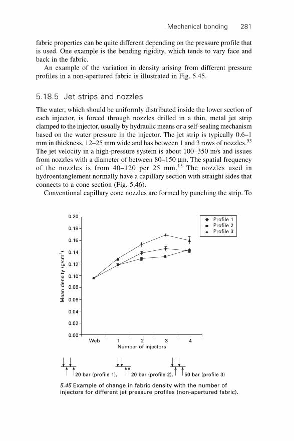
Mechanical bonding 281
fabric properties can be quite different depending on the pressure profile thatis used. One example is the bending rigidity, which tends to vary face andback in the fabric.
An example of the variation in density arising from different pressureprofiles in a non-apertured fabric is illustrated in Fig. 5.45.
5.18.5 Jet strips and nozzles
The water, which should be uniformly distributed inside the lower section ofeach injector, is forced through nozzles drilled in a thin, metal jet stripclamped to the injector, usually by hydraulic means or a self-sealing mechanismbased on the water pressure in the injector. The jet strip is typically 0.6–1mm in thickness, 12–25 mm wide and has between 1 and 3 rows of nozzles.53
The jet velocity in a high-pressure system is about 100–350 m/s and issuesfrom nozzles with a diameter of between 80–150 mm. The spatial frequencyof the nozzles is from 40–120 per 25 mm.15 The nozzles used inhydroentanglement normally have a capillary section with straight sides thatconnects to a cone section (Fig. 5.46).
Conventional capillary cone nozzles are formed by punching the strip. To
Profile 1
Profile 2
Profile 3
Web 1 2 3 4
Number of injectors
20 bar (profile 1), 20 bar (profile 2), 50 bar (profile 3)
Me
an
de
nsit
y (
g/c
m3)
0.20
0.18
0.16
0.14
0.12
0.10
0.08
0.06
0.04
0.02
0.00
5.45 Example of change in fabric density with the number ofinjectors for different jet pressure profiles (non-apertured fabric).
Handbook of nonwovens282
obtain stable, high-velocity columnar jets, nozzles are usually operated inthe ‘cone-down’ rather than the ‘cone-up’ position. The capillary portion ofthe nozzle therefore influences the jet diameter. The energy efficiency of theprocess is largely dependent on the formation of a constricted jet whichremains intact between the nozzle and the web. Break-up or dispersal of thejet once it emerges from the nozzle results in poor energy transfer to the weband reduces the overall efficiency of the hydroentanglement process. For
Cone section
Capillary section
(a) Cone up
Cone section
Capillary section
(b) Cone down
5.46 Capillary cone nozzles (the ratio of the length of the capillarysection to the inlet nozzle diameter is normally about 1. Lower aspectratios are also used to promote a constricted jet).
Mechanical bonding 283
cone-up nozzles, there tends to be greater jet instability and the water pressuremore strongly influences the discharge coefficient54. Operation in the cone-down position reduces the discharge coefficient and increases the velocitycoefficient with a uniform jet. It also assists in the prevention of cavitation,which tends to break up the jet. The nozzle geometry, particularly around thecapillary inlet, is one of the factors influencing jet break-up. The nozzleaspect ratio is also important. The flow characteristics of jets emerging fromnozzles and the effect of nozzle geometry on jet stability have been extensivelystudied by means of computer simulations as well as experimentalobservations.55,56,57
Commercially, one of the limitations in hydroentanglement is the life ofthe jet strip, which extends to about four thousand hours at best or only onehundred hours depending on operating conditions, particularly water pressureand water composition.58 Nozzle damage due to cavitation, abrasion or chemicaldegradation alters nozzle geometry and resultant jet formation may be affectedgiving rise to instability of the jet and fabric quality problems such as variationsin fabric density and texture as well as reduced energy transfer efficiency. Athigh pressures, such as 400 bar, stainless steel jet strips can deterioratequickly within hours. One solution is to use nozzle inserts where a very hardmaterial surrounds the orifice and stainless steel or a hard coating comprisesthe rest of the strip.59 The hardness of conventional stainless steel jet stripsis about 250 shore but to increase wear resistance, which is essential in highpressure systems, modern strips constructed from new alloys have a hardnessof about 1200 shore.40
In practice, the nozzle inlet diameter and the number of nozzles/m in thejet strips fitted to each consecutive injector head varies. For example, in thefirst few injectors, strips with relatively large nozzles (120–150 microns) arefitted to maximise impact force and fibre entanglement. Jet strips in the finalinjectors commonly have finer nozzles (80–100 microns), which reduce theappearance of jet marks and produce a smoother fabric surface. In practice,hydroentanglement of webs of >200 g/m2 may limit the nozzle diameter toabout 100 mm to minimise flooding.
5.18.6 De-watering
Suction is used to remove excess water from the support surface duringhydroentanglement to prevent flooding. Flat belt systems are particularlyprone to flooding. Excess water not removed by suction is allowed to drainbelow the machine. Flooding leads to energy losses that can cause reducedfabric strength and interference with the bonding process. Flooding producesdefects in the fabric. Approximately, 100–1000 mm head of water is needed,500 mm head of water is preferable. De-watering is further improved bymangling the fabric prior to drying by means of squeeze rollers. Roberto®
Handbook of nonwovens284
rolls constructed from fibre are capable of drawing out water from the fabricas it passes through.
5.18.7 The water circuit and filtration
The filtration system is a major cost in a hydroentanglement installation andwater quality affects process efficiency. Some of the main problems associatedwith filtration systems are blocked jet strips leading to jet marking andvariations in fabric uniformity, the high cost of frequent filter bag replacement,bacterial growth, the potential loss of sand and damage to machinery, excessivedischarge of water in the backwashing of filters and the requirement toreplenish sand filters. In terms of water quality a neutral pH and a lowcontent of metallic ions, for example calcium is required. Depending onmachine size, the quantity of water in the circuit is about 40–100 m3/h andthe trend is to reduce the circulating water to improve process efficiency. Fora 3.5 m wide machine producing fabric for wet wipes, the quantity of circulatingwater has been estimated to be about 100 m3/h.40
Commercially, the waste water produced in hydroentanglement is recycledand circulated back to the main high-pressure pumps. Fibre finish, fibredebris and other impurities present in the waste water must be removed bythe installed filtration system. Whether or not this is practicable depends onthe particular design of the filtration system and the volume of impuritiesremoved from the fibre during the process. Self-cleaning filters are employedto minimise cost and for cotton or pulp, flotation and sand filters are selected.Filtration developments have made it possible to process a greater variety offibre types although traditionally, sophisticated filtration systems are requiredfor cellulosics such as cotton, pulp and viscose rayon compared to syntheticssuch as PET. Chemical mixing and flocculation, dissolved air flotation unitsand sand filters are employed. Sand filtration systems enable the removal ofsuspended solids and a reduction in fibre finish in the water circuit. Thechoice of filtration system largely governs the versatility of thehydroentanglement line in terms of the compatible fibre types as well ascost. In a system processing cellulose pulp, a closed loop arrangement consistsof a flotation unit that sends water to a sand filter operating with a back-washing recovery system. The back-washed water is returned to the flotationunit, while the remaining water from the sand filter is UV sterilised and sentto a bag filtration system prior to being returned to the beginning of theprocess.60 For cotton, filtration systems have been designed to treat the wastewater directly in sand filters without the need to use an initial flotationunit.61 A two-stage process can be adopted where back-washed water fromthe sand filter is sent to a flotation unit and additional sand filter before beingreturned to the circuit.
Mechanical bonding 285
5.18.8 Drying
Immediately after the fabric is hydroentangled, a proportion of the waterheld interstitially within the hydroentangled fabric is mechanically removedby suction, which for synthetic fibres is quite effective in reducing the moisturecontent to well below 100%. One advantage is lower overall drying costs.For cellulosics and other hygroscopic fibres, the water content is much highereven after mechanical extraction, which places a high demand on the subsequentdrying process. Drum drying, can drying and through-air flat conveyor dryingare all found in operation although through-air drum drying is the mostcommon solution.
5.18.9 Aperturing and patterning effects
Apertured fabrics are produced by hydroentangling on a cylinder with surfaceprojections or raised cross-over points referred to as ‘knuckles’ in the wiremesh around which fibres are directed and entangled. Depending on thegeometry of the projections or knuckles, particularly the wall angle relativeto the conveyor, fibre segments on top of the projections are displaced toadjacent regions. Because of this, the local density in the regions adjacent tothe apertures is significantly higher than the global fabric density. Aperturingcan also occur on support surfaces with a high open area. The support surfacetherefore influences the periodic structure and texture of the fabric as well asthe geometry and spacing of the apertures. Analysis of the forces involved inrearranging fibres in the web into a bonded structure concluded that the workis only about 1% of the input energy.62 Normally, aperturing takes place afterthe web has been pre-entangled to maximise pattern definition assumingfibre segments are still mobile. Aperture definition tends to improve as fibrelength decreases because fewer fibre segments bridge between the aperturesthat are formed during fabric formation.
Water consumption can be higher in the production of apertured andpatterned fabrics since large-bore nozzles of 120–150 mm are preferred toobtain good definition. A high flow rate and impact force are therefore veryimportant in producing high-quality apertured structures. Jet strips with threerows of holes are used by some manufacturers to increase the water flow rateto the fabric. Apertured and patterned lightweight fabrics are important indisposable and short-life products in the medical (e.g., replacement gauzedressings) and hygiene industries (e.g., wipes and coverstocks).
Three-dimensional patterns, ribs, logos and surface pile effects are introducedby hydroentangling a pre-entangled web on a surface containing recessesinto which fibres are pushed. These embossed effects may be combined withapertures. Early in the development of hydroentanglement, embossinggeometric patterns was identified as a potential way of producing textile-
Handbook of nonwovens286
like, hydroentangled fabrics having the appearance of woven fabrics.11 Furtherdevelopments have led to the adoption of more complex surface patternsproduced by CAD and laser engraving on to which webs are hydroentangled.
5.18.10Apex™ technology
Apex™ technology (Polymer Group Inc., PGI) allows the introduction ofcomplex, embossed patterns in hydroentangled fabrics in the range 50–400g/m2. These are known as Miratec® fabrics and derivatives are Mirastretch®
and Miraguard®, which have good elastic recovery and barrier propertiesrespectively. Some of the complex structural patterns introduced in to Miratec®
fabrics resemble the appearance of woven and knitted textiles. Fabrics areproduced by hydroentangling webs on laser imaged three-dimensionallypatterned support surfaces to enable transfer of these patterns into the fabric.To improve image definition in the fabric, the web tension should be low andthere should be no differential in the imaging surface and web speeds. Afterhydroentanglement, polymeric binders are added to stabilise the fabric or tointroduce elastic properties and finishing processes such as compressiveshrinkage (e.g., compaction by Sanforising) are undertaken to further adjustthe softness and drape of the fabrics.
In variations to the process, blends containing fusible binder fibres avoidthe need for chemical bonding after hydroentanglement, and scrims can beintroduced to increase durability and pattern definition in the fabric.63 Thecomplex patterns enable the cleaning performance of wipes and dusters to beimproved, for example recessed pockets may be formed in fabrics to improvethe collection of low-viscosity contaminants present on skin.64 Miratec®
fabrics are designed to be durable and compatible with traditional finishingprocesses such as jet dyeing, rotary screen and heat transfer printing.65 Fabricapplications include automotive interiors, food service towels, windowdressings, upholstery fabrics, pillow covers, wall coverings, bedspreads andapparel fabrics.
5.18.11Evolon® fabrics66,67
The Evolon® family of hydroentangled fabrics were an outcome ofFreudenberg’s Omega project, which aimed to develop technology combiningthe benefits of staple fibre (carded) nonwovens such as high softness, drape,bulkiness and resilience with the benefits of spunlaid fabrics, particularly thehigh MD and CD tensile strength. To replicate the characteristics of staplefibre nonwovens using a spunlaid platform, two bicomponent extrusiontechnologies can be exploited. The first relies on the differential shrinkagethat can take place in an asymmetric or eccentric sheath-core bicomponentfilament via quenching, drawing and heat treatment. The resulting helically
Mechanical bonding 287
crimped filaments increase the bulk of the fabric. The characteristic softnessand textile-like handle of Evolon® fabrics principally relies on the use ofsegmented-pie splittable bicomponent technology. A spunlaid web is producedfrom splittable bicomponent filaments (normally 16 segmented pie, PET/PA6.6 in a weight ratio of 65%/35%) of about 2 dtex, which is hydroentangledat up to 400 bar to split the filament cross-section into multiple microfilaments.These microfilaments have a linear density of 0.09–0.13 dtex.
Splitting efficiency, which is claimed to be at least 97%, is maximised bythe use of hollow-core segmented-pie filaments and is influenced by thenozzle diameter in the spinneret, quenching, the stretching rate and, of course,the water pressure. To maximise fabric softness the fabrics are mechanicallyfinished using processes such as tumbling. Owing to the combination offabric softness, high filament surface area, strength and abrasion resistancein Evolon fabrics, applications include some clothing markets in sports andactivity wear (e.g., hiking, skiing, cycling) where fabric weights are in therange 100–220 g/m2. Other applications include workwear, automotive (e.g.,interior trim, carpets for sound absorption), shoe components (e.g., linings,heel grips, PU coating substrates), luggage and home furnishings (e.g., bedlinen). Evolon fabrics can be jet dyed and finished and are said to withstandmultiple domestic washes. Additional potential applications include cleanroom wipes.
5.18.12Multi-layer ‘composite’ hydroentangled fabrics
Webs (as well as pre-bonded nonwoven fabrics) can be simultaneously bondedand combined during hydroentanglement to produce flexible multi-layer fabrics.Where spunbond and meltblown webs are combined in this way, the approachcan be viewed as the mechanically bonded analogue of thermally bondedSM or SMS composites (see Chapter 4). Hydroentangled multi-layer fabricsare found in both disposable and durable applications although it is in absorbentwipes products that most of the development has taken place. Commercialtwin-layer hydroentangled fabrics include:
∑ spunbond with airlaid pulp (SP)∑ spunbond with carded web (SC)∑ spunbond with wetlaid (pulp, glass or other short fibre papers).
Hydroentangled fabrics having three or more layers are:
∑ spunbond-pulp-spunbond (SPS) – where the pulp may be in the form of apre-formed roll or deposited directly by means of a sifting airlaying system
∑ carded-pulp-carded (CPC)∑ carded-pulp-spunbond (CPS)∑ carded-spunbond-carded (CSC)∑ carded-net-carded (CNC).
Handbook of nonwovens288
In addition, scrims and carded webs may be combined duringhydroentanglement to modify tensile properties, particularly in lightweightfabrics. Hydroentangling fibres or pulp with elastomeric foam,68 filamentsor perforated films have all been explored as a means of increasing fabricelasticity. Amongst other end uses, CPC fabrics are intended for disposablewipes, CPS in incontinence products such as nappies and both CNC andCSC in industrial wipes. SPS composites consisting of a spunbond-airlaidpulp-spunbond sandwich are intended for wet wipes as well as for absorbentmedical applications.
The economics of SPS fabrics are attractive because of the low cost ofpulp. The pulp acts as an absorbent core and the spunlaid layers provideabrasion resistance and structural reinforcement when the pulp is wet. Thespunlaid fabrics also resist linting, dusting and pilling in use. To reduce thefabric density and to increase the softness, the filaments in the two spunlaidlayers can be crimped during production. The pulp in CPC, CPS and SPSfabrics is either airlaid directly onto a web or introduced as preformed cellulosictissue (paper) before hydroentanglement. As an alternative to pulp, airlaidcotton linters are utilised. The carded components normally consist of PET,PP, viscose rayon or cotton. Hydroentangled composites are expected tohave an increasingly important role in the future of hygiene and medicalproducts and have the advantage that no thermal lamination or bonding isrequired. Opportunities in heavier-weight durable applications in, for example,roofing composed of PET and geosynthetics using both drylaid and spunlaidwebs are evolving.
5.19 Applications of hydroentangled fabrics
While hydroentangled fabrics have become heavily associated with wipesdue to the growth and diversification of this sector, their use spans a muchgreater variety of applications, both in single-use and durable articles. Diverseproducts include protective clothing particularly medical gowns, syntheticleather, filtration media, wound dressings, composites and garment linings.The utilisation of hydroentanglement to mechanically join rather than thermallylaminate webs or fabrics together continues to fuel product developmentopportunities. There has been rapid growth in global hydroentanglementcapacity with strong demand for higher productivity with wider and fastermachinery. Price pressure in some consumer markets and increasingcompetition is intensifying demand for product differentiation and has increasedinterest in new market opportunities. Some of the emergent niche marketsfor hydroentangled fabrics in technical markets will probably not require thehigh production capacities of current hydroentanglement installations to meetmarket demand in the future.
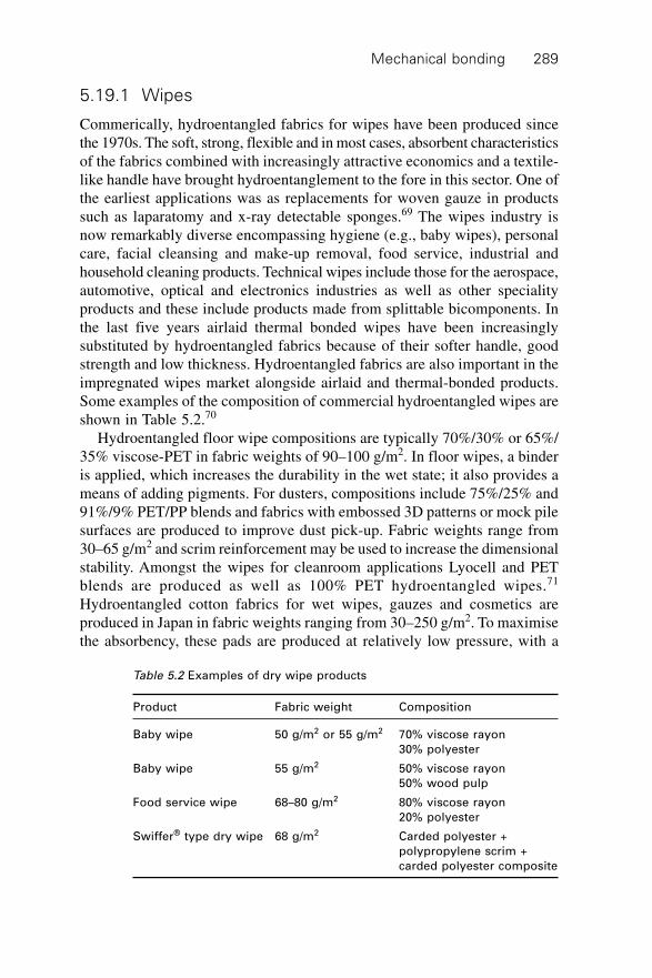
Mechanical bonding 289
5.19.1 Wipes
Commerically, hydroentangled fabrics for wipes have been produced sincethe 1970s. The soft, strong, flexible and in most cases, absorbent characteristicsof the fabrics combined with increasingly attractive economics and a textile-like handle have brought hydroentanglement to the fore in this sector. One ofthe earliest applications was as replacements for woven gauze in productssuch as laparatomy and x-ray detectable sponges.69 The wipes industry isnow remarkably diverse encompassing hygiene (e.g., baby wipes), personalcare, facial cleansing and make-up removal, food service, industrial andhousehold cleaning products. Technical wipes include those for the aerospace,automotive, optical and electronics industries as well as other specialityproducts and these include products made from splittable bicomponents. Inthe last five years airlaid thermal bonded wipes have been increasinglysubstituted by hydroentangled fabrics because of their softer handle, goodstrength and low thickness. Hydroentangled fabrics are also important in theimpregnated wipes market alongside airlaid and thermal-bonded products.Some examples of the composition of commercial hydroentangled wipes areshown in Table 5.2.70
Hydroentangled floor wipe compositions are typically 70%/30% or 65%/35% viscose-PET in fabric weights of 90–100 g/m2. In floor wipes, a binderis applied, which increases the durability in the wet state; it also provides ameans of adding pigments. For dusters, compositions include 75%/25% and91%/9% PET/PP blends and fabrics with embossed 3D patterns or mock pilesurfaces are produced to improve dust pick-up. Fabric weights range from30–65 g/m2 and scrim reinforcement may be used to increase the dimensionalstability. Amongst the wipes for cleanroom applications Lyocell and PETblends are produced as well as 100% PET hydroentangled wipes.71
Hydroentangled cotton fabrics for wet wipes, gauzes and cosmetics areproduced in Japan in fabric weights ranging from 30–250 g/m2. To maximisethe absorbency, these pads are produced at relatively low pressure, with a
Table 5.2 Examples of dry wipe products
Product Fabric weight Composition
Baby wipe 50 g/m2 or 55 g/m2 70% viscose rayon
30% polyester
Baby wipe 55 g/m2 50% viscose rayon
50% wood pulp
Food service wipe 68–80 g/m2 80% viscose rayon
20% polyester
Swiffer® type dry wipe 68 g/m2 Carded polyester +
polypropylene scrim +
carded polyester composite
Handbook of nonwovens290
maximum injector pressure of 40 bar to maximise their porosity. Therefore,whereas the fabric surfaces are well entangled to minimise linting in use, thecore is lightly entangled to maximise the absorbent capacity. Localising theentanglement to the surfaces of a fabric is a strategy used in the formation ofother wipes products.72
The ability to differentiate and personalise wipes products for customershelps manufacturers to avoid the effect of commoditisation. Complex patterning,the introduction of raised (three-dimensional) embossed effects inhydroentangled fabrics and multi-layer hydroentangled composites all providea means of adding value to wipes products. To underpin the expandingtechnical requirements of the wipes sector and to enable further diversification,production of hydroentangled composites in which different web types arecombined during hydroentanglement is a growth area. Such composites enablesignificant improvements in wiping performance, dimensional stability,absorption and soil cleaning according to the composition of the layers thatare combined. Composites for wipes are based on combinations of carded +airlaid wood pulp, carded + scrim and spunlaid + wood pulp combinations.Carded staple fibre webs and airlaid wood pulp blends are combined toproduce wipes with good absorbency in baby wipes, bodycare, food serviceand industrial cleaning. Hydroentangled composites containing wood pulpare particularly important for wet wipe applications. Products containingwood pulp rather than viscose rayon have been a particular focus ofdevelopment.
It has been a challenge to produce fabrics with the required softness anddrape which do not lint or produce dust using wood pulp. To achieve this,hydroentangled composites composed of 40–45 g/m2 wood pulp sandwichedbetween two carded PET webs of 8–10 g/m2 were developed. In twin layercomposites, the carded web weight is increased to 25 g/m2.40 To increasedurability for applications such as industrial wipes, wood pulp is hydroentangledinto a spunlaid web. Scrim-reinforced carded-hydroentangled fabrics areutilised in domestic wipes such as P&G’s Swiffer®.
Hydroentangled biodegradable and water dispersible wipes have beendeveloped in response to environmental concerns, particularly in Europe.Some of these materials rely on ion-sensitive cationic polymers that areapplied as binders to webs or lightly bonded hydroentangled fabrics. Inanother approach, a hydroentangled fabric consisting of three laminatedlayers with a pulp core has been described in which some areas are leftunbonded to promote disintegration of the structure in the sewer system.73
Hydraspun® 784 is a dispersible wet wipe composed of a latex binder-freehydroentangled fabric.74 The fabric, which is composed of a synthetic andnatural fibre blend, is designed to break down under agitation in water. Thisfabric has a flush index (tube test-first break) of 7–8 turns depending on itsweight, which is either 55 or 65 g/m2.
Mechanical bonding 291
Cotton pads for make-up removal are traditionally produced by bondinga drylaid batt using one of three approaches; surface impregnation with abinder, thermal bonding with bicomponent fibres and embossing (undercompressive force) with engraved pattern rollers. To enable the manufactureof 100% cotton products with acceptable surface abrasion, cotton pads arealso produced using hydroentanglement. Hydroentangled cotton pads andwipes are produced from 30–300 g/m2 with apertured or smooth surfaces.75
Low-pressure hydroentanglement allows bonding to be concentrated only atthe surface thereby maximising fabric porosity. Hydroentangled microfibrefabrics are produced and find applications as sports towels and facial cleaningcloths.
5.19.2 Washable domestic fabrics
Hydroentangled cotton fabrics for semi-durable bedsheets, napkins andtablecloths have been produced that can be washed up to ten times beforedisposal. Since they are cotton based, such fabrics can be dyed or printed.Impregnating hydroentangled fabrics with 0.2%–1.0% owf of polyamide-amine-epichlorohydrin resin76 is claimed to enable repeated washing ofhydroentangled cotton fabrics. Durable hydroentangled fabrics intended forrepeated laundering have also been developed by stitching the fabrics overthe top, by applying a binder or by incorporating thermally fusible binderfibres in the fabric.77 Such fabrics can also be dyed and finished. A furthermethod of increasing the durability of fabrics for washing without the needfor chemical or thermofusible binders is to hydroentangle at very high waterpressure but the energy consumption is high.
5.19.3 High-temperature protective clothing
Hydroentangled aramids, including blends of meta- and para-aramids, arewell established as protective liners and moisture barrier substrates in fire-fighting garments. In addition to the high-temperature resistance derivedfrom the polymer, the fabrics are favoured because of their softness, drapeand light weight. Fabrics composed of of 50% Basofil®/50% aramid areutilised in thermal protection lining fabrics that form components in fire-fighting garments and such linings are commonly quilted to a woven aramidface fabric. A protective liner fabric composed of hydroentangled FR cottonand Basofil® is produced to improve comfort in high-temperature clothing.Meta-aramid fibres are commonly found in thermal protection liners and50% Lenzing FR®/50% aramid blend hydroentangled fabrics have also beendeveloped for fire-fighting jackets to give improved resistance to flame break-open. In addition to fire-fighting garments, hydroentangled fire-blockingfabrics for upholstery and mattresses are produced from Type Z11 Kevlar®
Handbook of nonwovens292
and Type E92/Kevlar blends are produced as fire blockers for aircraft seatsand as thermal liners in protective clothing.78
5.19.4 Artificial leather
The production of synthetic leather and coating substrates usinghydroentanglement is well established particularly in the Far East, notablyJapan, Korea and Taiwan. Hydroentangled fabrics are widely used as backingsfor PU coated synthetic leather. In addition to the traditional method ofdissolving part of the matrix in a bicompnent fibre using a suitable solvent,synthetic leather articles are produced by hydroentangling splittablebicomponent fibres composed typically of 6, 16 or 36 segments in the cross-section. Such fabrics find applications as specialist wipes, particularly forcleaning glass.
5.19.5 Surgical fabrics
Hydroentangled fabrics have long been favoured for surgical gowns, scrubsuits, sheet and drapes for their excellent comfort and softness. In surgicalgowns, infection control is paramount and spunmelts and composites containingbreathable films are favoured over hydroentangled fabrics where there is aneed for improved barrier protection. In surgical gowns, hydroentangledfabrics such as Softesse®, formerly known as Sontara® for medical protectiongarments and warming gowns, are well established and composites composedof wood pulp from paper hydroentangled onto a PET layer are produced.Disposable hot-water soluble PVA hydroentangled fabrics for surgical scrubsuits, gowns and drapes have also been developed.
5.19.6 Medical gauze
Traditionally, yarn-based fabrics found in wound dressings are composed ofcotton or cotton blended with up to 50% viscose rayon. As an alternative,apertured hydroentangled fabrics have led to significant cost savings in thismarket partly because fewer layers are required. Commercially, hydroentangledgauze fabrics composed of 70% viscose rayon and 30% polyester providehigh absorbency and low linting properties.
5.19.7 Linings and clothing
Dyed or printed hydroentangled fabrics find use in shoe linings and clothinglinings and hydroentangled fabrics have long been used in the manufactureof linings for traditional garments. Hydroentangled fabrics composed ofmerino wool have been developed79 and such fabrics have been incorporated
Mechanical bonding 293
in performance outerwear products such as outdoor clothing. Sports shirtsand vests have also been produced from hydroentangled fabrics.
5.19.8 Filtration
Hydroentangled fabrics intended for air filtration, particularly bag houseapplications, are manufactured in addition to pleated hydroentangled mediafor liquid filtration. Hydroentangled PET media80 as well as fabrics composedof PTFE have been developed. As is common in needlepunched fabrics,scrim reinforced hydroentangled fabrics composed of high-temperature-resistant fibres improve dimensional stability for filtration applications. Hycofilis a pleated textile or metal scrim reinforced hydroentangled fabric for fluegas filtration composed of polyimide or aramid fibres.81
5.19.9 Automotive
Hydroentangled fabrics composed of 100% polyester have been developedfor backing materials for one-step injection moulding of interior trim automotivecomponents replacing heavier-weight needlepunched fabrics. This process isused by car-part manufacturers to produce interior trim. The fabric is laminatedto a knitted facing before the injection moulding process and the use ofhydroentangled fabrics is claimed to improve acoustics in the car.82
Experimentally, hydroentangled flax and hemp fabrics up to 1500 g/m2 havebeen produced for potential use in automotive composites.
5.19.10 Other applications
The technical and durable applications for hydroentangled fabrics aredeveloping rapidly. In the composites sector, hydroentangled PET is used asa carrier web in pultrusion products and for filament wound pipe production,and similar fabrics are found as surface veilings for fibreglass reinforcedplastics. Some hydroentangled geosynthetic and construction materials arecommercially produced as well as microfibre filter fabrics. The high strengthto weight ratio of hydroentangled fabrics means there is potential to reducefabric weight and obtain raw material savings in the roofing sector.Experimental thermal insulation fabrics, in which nanoporous silica gels areintroduced within cavities in the cross-section of hydroentangled fabrics,have been developed using Hydrospace™ technology.83 Such fabrics havealso been designed for the storage and controlled release of actives and byappropriate control of the fabric permeability; delivery can be confined mainlyto one side of the fabric. Outside the nonwoven sector, hydroentanglementtechnology has been successfully developed to enhance the appearance andphysical properties of textile fabrics in a process known as hydroenhancement
Handbook of nonwovens294
to control the permeability of airbag and filtration fabrics and to improveseam strength and fabric softness. Attachment of secondary carpet backingsby hydroentangling webs onto the back of the carpet has also been developedas a means of simplifying the traditional production process.
5.20 Acknowledgements
The authors are indebted to a number of people for their valuable contributions,advice and support during the preparation of this chapter. They are extremelygrateful to Mr Matthew Yeabsley, Karl Mayer Textile Machinery Ltd, UK,for providing the technical literature and above all for supporting a visit toKarl Mayer Malimo company at Chemnitz, Germany. His kindness andfriendship is always appreciated. The authors would also like to thank thefollowing personnel at Karl Mayer Malimo Textilmachinenfabrik GmbH,Chemnitz, Germany, for their kind cooperation and assistance in explainingtheir current and future stitch bonding equipment programme and for providingthe literature and samples for use in this review: Mr Alexander Battel, DrHolger Erth, Mr Axel Wintermeyer and Mr Daniel Standt. Finally, they arealso grateful to Dr Monica Seegar and Mr Wolfgang Schilde of SächsischesTextil Forschungs Institut e.V., Chemnitz, Germany, for their kindness andfriendship during visits to their Institute. A great deal of information hasbeen used here directly from the Karl Mayer literature that could not beindividually referenced. The contribution of Foster Needle is gratefullyacknowledged. The authors wish to thank Fleissner GmbH, of Egelsbach,Germany, and Rieter Perfojet of Grenoble, France, for their assistance andvaluable contributions to this chapter.
5.21 References
1. Cotterill, P.J., ‘Production and properties of stitch bonded fabrics’, Textile Progress,The Textile Institute, 1975, 7, (2), p. 101.
2. Textile Terms and Definitions, The Textile Institute, eleventh edition, 2002, p. 333.3. Krcma, R., Nonwoven Textiles, Manchester, Textile Trade Press, 1967 p. 156.4. Kettenwirk Praxis, 1993 (1) E22.5. Kettenwirk Praxis, 1994 (2) E5.6. Anand, S.C., ‘Karl Mayer warp knitting equipment at I T M A’99, Asian Textile
Journal, 1999 (9) p. 49.7. Kettenwirk Praxis, 1994 (2) E8.8. Kettenwirk Praxis, 2002 (2) 25.9. Evans, F.J., US3,485,706: 1969.
10. Bunting, W.W., Evans, F.J. and Hook, D.E., US3,508,308: 1970.11. Evans, F.J. and Shambelan, C., US3,498,874: 1970.12. Coppin, P., ‘The Future of Spunlacing’, Nonwovens World, December 2001–January
2002, pp. 60–67.13. http://www.nonwovens-industry.com/articles/2005/03/feature2.php
Mechanical bonding 295
14. Ghassemieh, E., Acar, M. and Versteeg, H.K., ‘Improvement of the efficiency ofenergy transfer in the hydroentanglement process’, Journal of Composite Science &
Technology, 61(12), 2001, pp. 1681–1694, ISSN 0266–3538.15. Watzl, A., New Concepts for Fiber Production and Spunlace Technology for
Microdenier Bicomponent Split Fibers – From Polymer to Final Product, INDEX99 Congress, Manufacturing Session 1, Geneva, April 1999, pp. 1–13.
16. Moschler, W., Some Results in the Fields of Hydroentanglement of Fibrous Webs
and Their Thermal After-Treatment, International Nonwovens Symposium, EDANA,1995, pp. 1–23.
17. Bertram, D., ‘Cellulosic Fibers in Hydroentanglement’, INDA Journal, 1993, vol. 5,no. 2, pp. 34–41.
18. Bunting, W.W., Evans, F.J. and Hook, D.E., US3,493,462: 1970.19. Guerin, J.A. and Jeandron, H.T., US3,214,819: 1965.20. Suzuki, M., Kobayshi, T. and Imai, S., US4,718,152: 1998.21. Moschler, W., Meyer, A. and Brodtka, M., Influences of Fibre and Process on the
Properties of Spunlaced Fabrics, ITB Nonwovens, Industrial Textiles, 1995, 2, pp.26–31.
22. Zheng, H., Seyam, A.M. and Shiffler, D., ‘The Impact of Input Energy on thePerformance of Hydroentangled Nonwoven Fabrics’, International Nonwovens Journal,Summer, 2003, pp. 34–44.
23. Pourdeyhimi, B. and Minton, A., ‘Structure-Process-Property Relationships inHydroentangled Nonwovens, Part 1: Preliminary Experimental Observations’,International Nonwovens Journal, Winter, 2004, pp. 15–21.
24. Seyam, A.M. and Shiffler, D., ‘An Examination of the Hydroentangling ProcessVariables’, International Nonwovens Journal, Spring, 2005, pp. 25–33.
25. Pourmohammadi, A., Russell, S.J. and Hoeffele, S., ‘Effect of Water Jet PressureProfile and Initial Web Geometry on the Physical Properties of CompositeHydroentangled Fabrics’, Textile Research Journal, 2003, 73(6), pp. 503–508.
26. Mao, N. and Russell, S.J., ‘A Framework for Determining the Bonding Intensity inHydroentangled Fabrics’, Journal of Composites Science and Technology, 2006, 66(1), pp. 80–91.
27. Mao, N. and Russell, S.J., ‘Towards a Quantification of the Structural Consolidationin Hydroentanglement and its Influence on the Permeability of Fabrics’, Nonwovens
Research Academy Proceedings, EDANA, 2005.28. Mathis, R., US6,190,736: 2001.29. Yoshiharu, U. and Wakesaka, K., JP2002146630: 2002.30. FiberVisions® Hy-Entangle WA, www.fibervisions.com31. www.fleissner.de32. Forsten, H.H., ‘New Sontara Spunlaced Aramid Structures’, Nonwovens Symposium,
1985, p. 25133. www.aramid.com34. Kelly, K.D., Hill, T.A., Lapierre, F., DeLuca, S. and DeLeon, S.D., US6,764,971: 2001.35. Rogers, J.J., Erickson, J.L. and Sanocki, S.M., US5,380,580: 1995.36. www.hillsinc.net/nanofiber.shtml37. Zucker, J., WO2004092471: 2004.38. http://www.fleissner.de/ne_25112005_e.htm39. Noelle, F., Spunlace: Improvements which enhance production efficiencies and reduce
operating costs, Technical Textiles, 2001, vol. 44, April, pp. 100–101.40. Völker, K., ‘Advancements in Spunlacing Technology’, Nonwovens World, 2002,
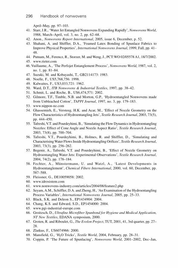
Handbook of nonwovens296
April–May, pp. 97–103.41. Starr, J.R., ‘Water Jet Entangled Nonwovens Expanding Rapidly’, Nonwovens World,
1988, March–April, vol. 3, no. 2, pp. 62–68.42. Anon., Nonwovens Report International, 2005, issue 6, December, p. 52.43. Shahani, A. and Shiffler, D.A., ‘Foamed Latex Bonding of Spunlace Fabrics to
Improve Physical Properties’, International Nonwovens Journal, 1999, Fall, pp. 41–48.
44. Putnam, M., Ferencz, R., Storzer, M. and Weng, J., PCT:WO 02/05578 A1, 18/7/2002.45. www.rieter.com46. Vuillaume, A., ‘The Perfojet Entanglement Process’, Nonwovens World, 1987, vol. 2,
no. 1, pp. 81–84.47. Suzuki, M. and Kobayashi, T., GB2114173: 1983.48. Noelle, F., US5,768,756: 1998.49. Kalwaites, F., US3,033,721: 1962.50. Ward, D.T., ITB Nonwovens & Industrial Textiles, 1997, pp. 38–42.51. Schmit, L. and Roche, B., US6,474,571: 2002.52. Gilmore, T.F., Timble, N.B. and Morton, G.P., ‘Hydroentangled Nonwovens made
from Unbleached Cotton’, TAPPI Journal, 1997, no. 3, pp. 179–183.53. www.nippon-nz.com54. Ghassemieh, E., Versteeg, H.K. and Acar, M., ‘Effect of Nozzle Geometry on the
Flow Characteristics of Hydroentangling Jets’, Textile Research Journal, 2003, 73(5),pp. 444–450.
55. Tafreshi, V.T. and Pourdeyhimi, B., ‘Simulating the Flow Dynamics in HydroentanglingNozzles: Effect of Cone Angle and Nozzle Aspect Ratio’, Textile Research Journal,2003, 73(8), pp. 700–704.
56. Tafreshi, V.T., Pourdeyhimi, B., Holmes, R. and Shiffler, D., ‘Simulating andCharacterising Water Flows Inside Hydroentangling Orifices’, Textile Research Journal,2003, 73(3), pp. 256–262.
57. Begenir, A., Tafreshi, V.T. and Pourdeyhimi, B., ‘Effect of Nozzle Geometry onHydroentangling Water Jets: Experimental Observations’, Textile Research Journal,2004, 74(2), pp. 178–184.
58. Fechter, A., Münstermann, U. and Watzl, A., ‘Latest Developments inHydroentanglement’, Chemical Fibers International, 2000, vol. 60, December, pp.587–588.
59. Fleissner, G., DE10059058: 2002.60. www.idrosistem.com61. www.nonwovens-industry.com/articles/2004/08/feature2.php62. Seyam, A.M., Schiffler, D.A. and Zheng, H., ‘An Examination of the Hydroentangling
Process Variables’, International Nonwovens Journal, 2005, pp. 25–33.63. Black, S.K. and Deleon S., EP1434904: 2004.64. Chang, K.S. and Edward, S.D., EP1454000: 2004.65. www.pgi-industrial-europe.com66. Groitzsch, D., Ultrafine Microfiber Spunbond for Hygiene and Medical Application,
NT New Textiles, EDANA symposium, 2000.67. Groten, R. and Riboulet, G., The Evolon Project, TUT, 2001, 41, 3rd quarter, pp. 27–
28.68. Zlatkus, F., US6074966: 2000.69. Mansfield, G., ‘H2O Tricks’, Textile World, 2004, February, pp. 28–31.70. Coppin, P. ‘The Future of Spunlacing’, Nonwovens World, 2001–2002, Dec–Jan,
Mechanical bonding 297
pp. 60–67.71. www.contecinc.com72. Barge, P. and Carter, N., US2004068849: 2004.73. Ngai M.C., EP1354093: 2003.74. Ahlstrom, Fiber Composites Hydraspun® 784 Dispersible Wet Wipe Leaflet, 2005.75. Watzl, A. and Eisenacher, J., ‘Spunlace Process for Cotton Pads and Other Products,
ITB’, Nonwovens & Industrial Textiles, 2000, pp. 16–18.76. Vuillaume, A., Lacazale, J.C., US5393304: 1995.77. Putnam, M.J. and Hartgrove, H., USP6,669,799: 2003.78. http://www.dupont.com/nomex/spunlacepdf801.pdf79. http://www.technical-textiles.net/archive/htm/att_20020601.475879.htm80. Pearce, C.R. and DeLeon, S., WO2004073834: 2004.81. Schmalz, E., Hycofil: Spunlace Scrim Supported Nonwoven, TUT, 2005, 65, 2nd
quarter, pp. 27–30.82. http://www.engineeringtalk.com/news/pgr/pgr101.html83. Hoeffele, S., Russell, S.J. and Brook, D.B., ‘Lightweight Nonwoven Thermal Protection
Fabrics Containing Nanostructured Materials’, International Nonwovens Journal,2005, vol. 14, no. 4, pp. 10–16.
298
6.1 Introduction
Thermal bonding is successfully employed in bonding dry-laid, polymer-laid and wet-laid webs as well as multi-layer materials. The basic concept ofthermal bonding was introduced by Reed in 1942. He described a process inwhich a web consisting of thermoplastic and non-thermoplastic fibres wasmade and then heated to the melting or softening temperature of the constituentthermoplastic fibres followed by cooling to solidify the bonding area. In theearly development of thermal bonding, rayon fibres (the base fibre component)were blended with plasticised cellulose acetate or vinyl chloride (the binderfibre component). Typically, a carded web from a blend of base fibre andbinder fibre was produced and hot calendered followed by cooling to solidifyand bond the web structure. The resulting thin, strong and relatively denseproduct was more akin to a paper product than a textile material. Productioncosts for this material were very high, primarily because the available binderfibres were expensive. Its applications were limited to products requiring asmooth surface, low porosity, high strength and lower thickness. Given theproduct limitations and the high cost of such binder fibres, nonwoven producerscontinued to prefer latex bonding using chemical binders.
The rising cost of energy and greater awareness of the environmentalimpact of latex bonding led to a change in direction. A comparison of energyconsumption by various web-bonding processes is given in Fig. 6.1 whichshows a considerable energy saving for the thermal bonding process.1 Thehigh production rates possible with thermal bonding and the significant energysavings as compared to chemical bonding, due to the absence of significantwater evaporation during bonding, makes the process economically attractive.In contrast to chemical bonding, the environmental impact of the process isalso significantly reduced. The growing market demand for disposable anddurable products spurred developments in new thermoplastic and thermosetmaterials in the form of powder, films, webs, hot melt compounds as well asimproved production methods such as point-bonding calenders, through-air
6Thermal bonding
A P O U R M O H A M M A D IConsultant, Iran
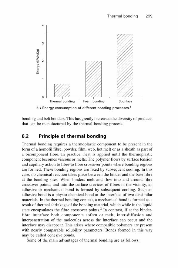
Thermal bonding 299
bonding and belt bonders. This has greatly increased the diversity of productsthat can be manufactured by the thermal-bonding process.
6.2 Principle of thermal bonding
Thermal bonding requires a thermoplastic component to be present in theform of a homofil fibre, powder, film, web, hot melt or as a sheath as part ofa bicomponent fibre. In practice, heat is applied until the thermoplasticcomponent becomes viscous or melts. The polymer flows by surface tensionand capillary action to fibre-to fibre crossover points where bonding regionsare formed. These bonding regions are fixed by subsequent cooling. In thiscase, no chemical reaction takes place between the binder and the base fibreat the bonding sites. When binders melt and flow into and around fibrecrossover points, and into the surface crevices of fibres in the vicinity, anadhesive or mechanical bond is formed by subsequent cooling. Such anadhesive bond is a physio-chemical bond at the interface of two dissimilarmaterials. In the thermal bonding context, a mechanical bond is formed as aresult of thermal shrinkage of the bonding material, which while in the liquidstate encapsulates the fibre crossover points.2 In contrast, if at the binder-fibre interface both components soften or melt, inter-diffusion andinterpenetration of the molecules across the interface can occur and theinterface may disappear. This arises where compatible polymers are presentwith nearly comparable solubility parameters. Bonds formed in this waymay be called cohesive bonds.
Some of the main advantages of thermal bonding are as follows:
En
erg
y (
KW
h/K
g)
4
3
2
1
0
Thermal bonding Foam bonding Spunlace
6.1 Energy consumption of different bonding processes.1
Handbook of nonwovens300
∑ Products can be relatively soft and textile-like depending on blendcomposition and bond area.
∑ Good economic efficiency compared to chemical bonding involvinglower thermal energy requirements and less expensive machinery.
∑ High bulk products can be bonded uniformly throughout the web cross-section.
∑ 100% recycling of fibre components can be achieved.∑ Environmentally friendly since no latex binders are required.
6.3 Raw materials
Thermally bonded fabrics are produced both from entirely thermoplasticmaterials and from blends containing fibres that are not intended to soften orflow on heating. The non-binder component may be referred to as the basefibre component and commercially, a variety of base fibre types are used.The binder fibre component normally ranges from 5–50% on weight of fibredepending on the physical property requirements of the final product.
6.3.1 Base fibres types
The base fibre contributes to key physical, chemical and mechanical propertiesof the fabric derived from the polymer from which it is constituted. Thisinfluences dyeing characteristics, flame resistance, tensile and attritionalproperties, hydrolytic resistance, biodegradability amongst many otherproperties. The commonly used base fibres include natural fibres (regeneratedcellulosic fibres, bast, vegetable and protein fibres such as wool), syntheticfibres (polyester, polypropylene, acrylic, nylon, aramid and many others),mineral fibres (e.g., glass and silica) and metallic fibres. Sometimes the basefibre (carrier fibre) is the core of a bicomponent fibre, with the sheath componentbeing the binder portion.
6.3.2 Binder materials
Binder components are produced in many different forms including fibre orfilament (homogeneous or bicomponent; sheath/core or side-by-side typemelt-bonding fibres), powder, film, low melt webs, and hot melts. The physicalform of the binder affects its distribution throughout the fibre matrix whichhas a significant impact on fabric properties. The amount of binder alsoplays an important role in determining the properties of the resultant nonwovenfabric. If the binder content is more than 50% of the total blend the fabricbehaves like a reinforced plastic. At a binder content of 10% the fabric is abulky, porous and flexible structure with relatively low strength. To minimiseenergy costs it is desirable that binder fibres have a high melting speed, a low
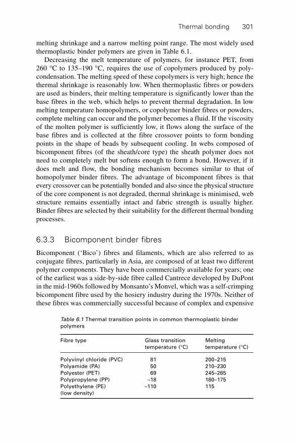
Thermal bonding 301
melting shrinkage and a narrow melting point range. The most widely usedthermoplastic binder polymers are given in Table 6.1.
Decreasing the melt temperature of polymers, for instance PET, from260 ∞C to 135–190 ∞C, requires the use of copolymers produced by poly-condensation. The melting speed of these copolymers is very high; hence thethermal shrinkage is reasonably low. When thermoplastic fibres or powdersare used as binders, their melting temperature is significantly lower than thebase fibres in the web, which helps to prevent thermal degradation. In lowmelting temperature homopolymers, or copolymer binder fibres or powders,complete melting can occur and the polymer becomes a fluid. If the viscosityof the molten polymer is sufficiently low, it flows along the surface of thebase fibres and is collected at the fibre crossover points to form bondingpoints in the shape of beads by subsequent cooling. In webs composed ofbicomponent fibres (of the sheath/core type) the sheath polymer does notneed to completely melt but softens enough to form a bond. However, if itdoes melt and flow, the bonding mechanism becomes similar to that ofhomopolymer binder fibres. The advantage of bicomponent fibres is thatevery crossover can be potentially bonded and also since the physical structureof the core component is not degraded, thermal shrinkage is minimised, webstructure remains essentially intact and fabric strength is usually higher.Binder fibres are selected by their suitability for the different thermal bondingprocesses.
6.3.3 Bicomponent binder fibres
Bicomponent (‘Bico’) fibres and filaments, which are also referred to asconjugate fibres, particularly in Asia, are composed of at least two differentpolymer components. They have been commercially available for years; oneof the earliest was a side-by-side fibre called Cantrece developed by DuPontin the mid-1960s followed by Monsanto’s Monvel, which was a self-crimpingbicomponent fibre used by the hosiery industry during the 1970s. Neither ofthese fibres was commercially successful because of complex and expensive
Table 6.1 Thermal transition points in common thermoplastic binder
polymers
Fibre type Glass transition Melting
temperature (∞C) temperature (∞C)
Polyvinyl chloride (PVC) 81 200–215
Polyamide (PA) 50 210–230
Polyester (PET) 69 245–265
Polypropylene (PP) –18 160–175
Polyethylene (PE) –110 115
(low density)
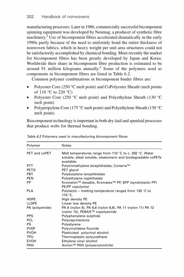
Handbook of nonwovens302
manufacturing processes. Later in 1986, commercially successful bicomponentspinning equipment was developed by Neumag, a producer of synthetic fibremachinery.3 Use of bicomponent fibres accelerated dramatically in the early1990s partly because of the need to uniformly bond the entire thickness ofnonwoven fabrics, which in heavy weight per unit area structures could notbe satisfactorily accomplished by chemical bonding. More recently the marketfor bicomponent fibres has been greatly developed by Japan and Korea.Worldwide their share in bicomponent fibre production is estimated to bearound 91 million kilograms annually.4 Some of the polymers used ascomponents in bicomponent fibres are listed in Table 6.2.
Common polymer combinations in bicomponent binder fibres are:
∑ Polyester Core (250 ∞C melt point) and CoPolyester Sheath (melt pointsof 110 ∞C to 220 ∞C)
∑ Polyester Core (250 ∞C melt point) and Polyethylene Sheath (130 ∞Cmelt point)
∑ Polypropylene Core (175 ∞C melt point) and Polyethylene Sheath (130 ∞Cmelt point).
Biocomponent technology is important in both dry-laid and spunlaid processesthat produce webs for thermal bonding.
Table 6.2 Polymers used in manufacturing bicomponent fibres
Polymer Notes
PET and coPET Melt temperatures range from 110 ∞C to c. 250 ∞C. Water
soluble, alkali soluble, elastomeric and biodegradable coPETs
available.
PTT Polytrimethylene terephthalate, Corterra™
PETG PET glycol
PBT Polybutylene terephthalate
PEN Polyethylene naphthalate
PP Kromalon™ dyeable, Kromatex™ PP, SPP (syndiotactic PP)
PE/PP copolymer
PLA Polylactic – melting temperature ranges from 130 ∞C to
170 ∞C.
HDPE High density PE
LLDPE Linear low density PE
PA (polyamide) PA 6 (nylon 6), PA 6,6 (nylon 6,6), PA 11 (nylon 11) PA 12
(nylon 12), PEBAX™ copolyamide
PPS Polyphenylene sulphide
PCL Polycaprolactone
PS Polystyrene
PVDF Polyvinylidene fluoride
PVOH Plasticised polyvinyl alcohol
TPU Thermoplastic polyurethane
EVOH Ethylene vinyl alcohol
PAN Amlon™ PAN (polyacrylonitrile)
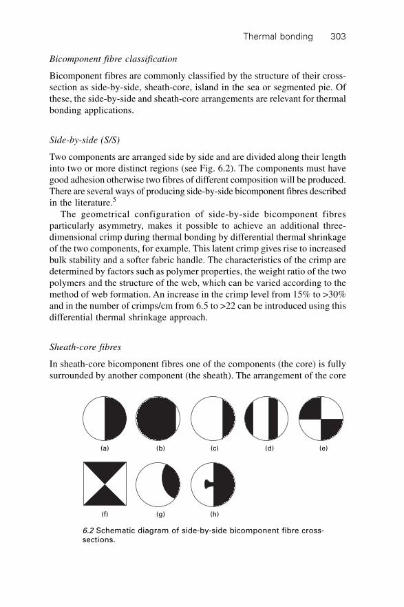
Thermal bonding 303
Bicomponent fibre classification
Bicomponent fibres are commonly classified by the structure of their cross-section as side-by-side, sheath-core, island in the sea or segmented pie. Ofthese, the side-by-side and sheath-core arrangements are relevant for thermalbonding applications.
Side-by-side (S/S)
Two components are arranged side by side and are divided along their lengthinto two or more distinct regions (see Fig. 6.2). The components must havegood adhesion otherwise two fibres of different composition will be produced.There are several ways of producing side-by-side bicomponent fibres describedin the literature.5
The geometrical configuration of side-by-side bicomponent fibresparticularly asymmetry, makes it possible to achieve an additional three-dimensional crimp during thermal bonding by differential thermal shrinkageof the two components, for example. This latent crimp gives rise to increasedbulk stability and a softer fabric handle. The characteristics of the crimp aredetermined by factors such as polymer properties, the weight ratio of the twopolymers and the structure of the web, which can be varied according to themethod of web formation. An increase in the crimp level from 15% to >30%and in the number of crimps/cm from 6.5 to >22 can be introduced using thisdifferential thermal shrinkage approach.
Sheath-core fibres
In sheath-core bicomponent fibres one of the components (the core) is fullysurrounded by another component (the sheath). The arrangement of the core
(a) (b) (c) (d) (e)
(f) (g) (h)
6.2 Schematic diagram of side-by-side bicomponent fibre cross-sections.
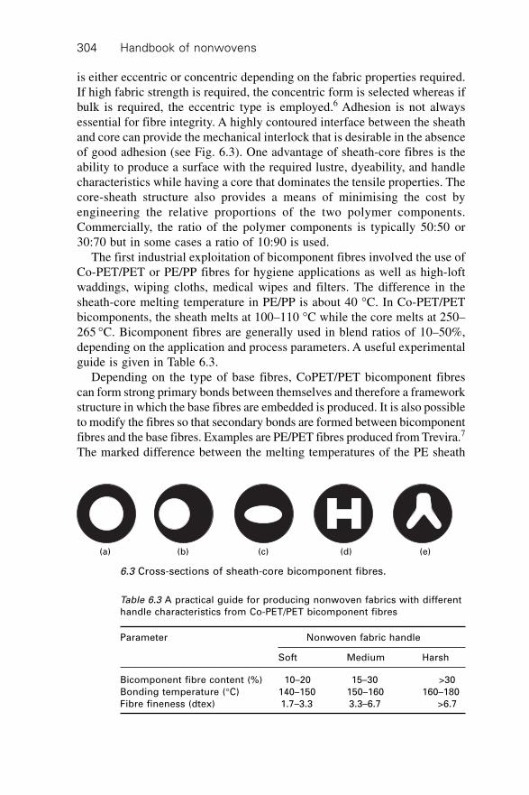
Handbook of nonwovens304
is either eccentric or concentric depending on the fabric properties required.If high fabric strength is required, the concentric form is selected whereas ifbulk is required, the eccentric type is employed.6 Adhesion is not alwaysessential for fibre integrity. A highly contoured interface between the sheathand core can provide the mechanical interlock that is desirable in the absenceof good adhesion (see Fig. 6.3). One advantage of sheath-core fibres is theability to produce a surface with the required lustre, dyeability, and handlecharacteristics while having a core that dominates the tensile properties. Thecore-sheath structure also provides a means of minimising the cost byengineering the relative proportions of the two polymer components.Commercially, the ratio of the polymer components is typically 50:50 or30:70 but in some cases a ratio of 10:90 is used.
The first industrial exploitation of bicomponent fibres involved the use ofCo-PET/PET or PE/PP fibres for hygiene applications as well as high-loftwaddings, wiping cloths, medical wipes and filters. The difference in thesheath-core melting temperature in PE/PP is about 40 ∞C. In Co-PET/PETbicomponents, the sheath melts at 100–110 ∞C while the core melts at 250–265 ∞C. Bicomponent fibres are generally used in blend ratios of 10–50%,depending on the application and process parameters. A useful experimentalguide is given in Table 6.3.
Depending on the type of base fibres, CoPET/PET bicomponent fibrescan form strong primary bonds between themselves and therefore a frameworkstructure in which the base fibres are embedded is produced. It is also possibleto modify the fibres so that secondary bonds are formed between bicomponentfibres and the base fibres. Examples are PE/PET fibres produced from Trevira.7
The marked difference between the melting temperatures of the PE sheath
(a) (b) (c) (d) (e)
6.3 Cross-sections of sheath-core bicomponent fibres.
Table 6.3 A practical guide for producing nonwoven fabrics with different
handle characteristics from Co-PET/PET bicomponent fibres
Parameter Nonwoven fabric handle
Soft Medium Harsh
Bicomponent fibre content (%) 10–20 15–30 >30
Bonding temperature (∞C) 140–150 150–160 160–180
Fibre fineness (dtex) 1.7–3.3 3.3–6.7 >6.7
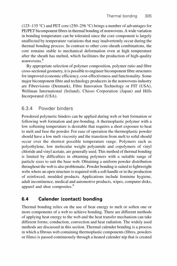
Thermal bonding 305
(125–135 ∞C) and PET core (250–256 ∞C) brings a number of advantages forPE/PET bicomponent fibres in thermal bonding of nonwovens. A wide variationin bonding temperature can be tolerated since the core component is largelyunaffected by temperature variations that may inadvertently occur during thethermal bonding process. In contrast to other core-sheath combinations, thecore remains stable to mechanical deformation even at high temperatureafter the sheath has melted, which facilitates the production of high-qualitynonwovens.8
By appropriate selection of polymer composition, polymer ratio and fibrecross-sectional geometry, it is possible to engineer bicomponent fibre structuresfor improved economic efficiency, cost-effectiveness and functionality. Somemajor bicomponent fibre and technology producers in the nonwovens industryare Fibrevisions (Denmark), Fibre Innovation Technology or FIT (USA),Wellman International (Ireland), Chisso Corporation (Japan) and HillsIncorporated (USA).
6.3.4 Powder binders
Powdered polymeric binders can be applied during web or batt formation orfollowing web formation and pre-bonding. A thermoplastic polymer with alow softening temperature is desirable that requires a short exposure to heatto melt and fuse the powder. For ease of operation the thermoplastic powdershould have a low melt viscosity and the transition from melt to solid shouldoccur over the shortest possible temperature range. Polymers such aspolyethylene, low molecular weight polyamide and copolymers of vinylchloride and vinyl acetate, are generally used. This method of thermal bondingis limited by difficulties in obtaining polymers with a suitable range ofparticle sizes to suit the base web. Obtaining a uniform powder distributionthroughout the web is also problematic. Powder bonding is suited to lightweightwebs where an open structure is required with a soft handle or in the productionof reinforced, moulded products. Applications include feminine hygiene,adult incontinence, medical and automotive products, wipes, computer disks,apparel and shoe composites.9
6.4 Calender (contact) bonding
Thermal bonding relies on the use of heat energy to melt or soften one ormore components of a web to achieve bonding. There are different methodsof applying heat energy to the web and the heat transfer mechanism can takedifferent forms; conduction, convection and heat radiation. The widely usedmethods are discussed in this section. Thermal calender bonding is a processin which a fibrous web containing thermoplastic components (fibres, powdersor films) is passed continuously through a heated calender nip that is created
Handbook of nonwovens306
by two rolls pressed against each other. Multi-nip calenders are also employeddepending on the web weight and degree of bonding required. Both rolls areinternally heated to a temperature that usually exceeds the melting point ofthe binder components in the web to ensure there is sufficient heat transferto induce softening at the prevailing line speed. As the web passes betweenthe calender nip, fibres are both heated and compressed. This causes thebinder components of the web to become soft and tacky and induces polymerflow in and around the base fibres (if present). The fluid polymer tends tocollect at fibre crossover or contact points and bonding sites are formed.Cooling leads to solidification of the polymer and bonding.
Calender bonding is mainly applicable to light and medium-weight websbecause the fibres in a thick web insulate heat from the interior of the structureleading to a temperature gradient and variation in the degree of bondingthrough the cross-section. To increase the efficiency of the process, the webmay be pre-heated immediately prior to calendar bonding sometimes byinfra-red heaters. Commercially, light-weight webs of 25–30 g/m2 for medicaland hygiene applications and medium-weight webs of 100 g/m2 for interliningand filtration applications are thermally bonded using calendar bonding.10
The degree of bonding depends on temperature, pressure and speed, whichdetermines the contact or dwell time. The properties of the fabric are influencedby the total bond area, which is normally expressed in percentage terms. Inpractice, area bonding (100%) or point bonding (embossing) is possible(<100%).
6.4.1 Area bonding
Two or more smooth rollers are designed to heat the entire surface of theweb. The binder fibres produce bonding at all the crossover points betweenthe base and binder fibres. The fabric is therefore thin and stiff with a paper-like handle and has minimal permeability. Area bonding is used to developmaximum strength and minimum thickness. A combination of metal and/orelastic rollers is used. Elastic rollers are composed of a deformable plasticsuch as urethane, silicon rubber, wool or cotton filling or nylon shells. Morethan two rollers are used to create multiple bonding zones for bonding heavy-weight webs. Generally in the three-roller calender the heated roll is in themiddle, whereas in the four-roll configuration the heated rolls are on the topand bottom with the composition rolls in the middle.
6.4.2 Point bonding
Point bonding is based on a calender nip consisting of an engraved roller anda smooth roller. In some cases both rollers are engraved. When the webenters the nip the temperature increases to a point at which tackiness and
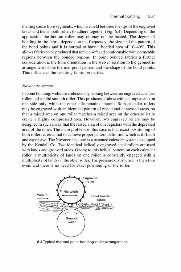
Thermal bonding 307
melting cause fibre segments, which are held between the tips of the engravedlands and the smooth roller, to adhere together (Fig. 6.4). Depending on theapplication the bottom roller may or may not be heated. The degree ofbonding in the fabric depends on the frequency, the size and the pattern ofthe bond points and it is normal to have a bonded area of 10–40%. Thisallows fabrics to be produced that remain soft and comformable with permeableregions between the bonded regions. In point bonded fabrics a furtherconsideration is the fibre orientation in the web in relation to the geometricarrangement of the thermal point pattern and the shape of the bond points.This influences the resulting fabric properties.
Novonette system
In point bonding, webs are embossed by passing between an engraved calenderroller and a solid smooth roller. This produces a fabric with an impression onone side only, while the other side remains smooth. Both calender rollersmay be engraved with an identical pattern of raised and depressed areas, sothat a raised area on one roller matches a raised area on the other roller tocreate a highly compressed area. However, two engraved rollers may bedesigned in such a way that the raised area of one registers with the depressedarea of the other. The main problem in this case is that exact positioning ofboth rollers is essential to achieve proper pattern definition which is difficultand expensive. The Novonette pattern is a patented calender system developedby the Kendall Co. Two identical helically engraved steel rollers are usedwith lands and grooved areas. Owing to this helical pattern on each calenderroller, a multiplicity of lands on one roller is constantly engaged with amultiplicity of lands on the other roller. The pressure distribution is thereforeeven, and there is no need for exact positioning of the roller.
Web inNip width
Engraved
roller
Point bonded
fabric
Smooth
roller
6.4 Typical thermal point bonding roller arrangement.
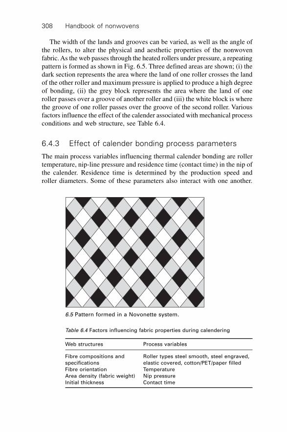
Handbook of nonwovens308
The width of the lands and grooves can be varied, as well as the angle ofthe rollers, to alter the physical and aesthetic properties of the nonwovenfabric. As the web passes through the heated rollers under pressure, a repeatingpattern is formed as shown in Fig. 6.5. Three defined areas are shown; (i) thedark section represents the area where the land of one roller crosses the landof the other roller and maximum pressure is applied to produce a high degreeof bonding, (ii) the grey block represents the area where the land of oneroller passes over a groove of another roller and (iii) the white block is wherethe groove of one roller passes over the groove of the second roller. Variousfactors influence the effect of the calender associated with mechanical processconditions and web structure, see Table 6.4.
6.4.3 Effect of calender bonding process parameters
The main process variables influencing thermal calender bonding are rollertemperature, nip-line pressure and residence time (contact time) in the nip ofthe calender. Residence time is determined by the production speed androller diameters. Some of these parameters also interact with one another.
6.5 Pattern formed in a Novonette system.
Table 6.4 Factors influencing fabric properties during calendering
Web structures Process variables
Fibre compositions and Roller types steel smooth, steel engraved,
specifications elastic covered, cotton/PET/paper filled
Fibre orientation Temperature
Area density (fabric weight) Nip pressure
Initial thickness Contact time
Thermal bonding 309
For example, the nip width varies with the square root of pressure whichaffects nip residence time.
Bonding temperature
Bonding temperature determines the structure of fibres at the bonding points.In bonding areas where fibres are flattened but not completely melted to afilm-like structure, fabrics with high strength are produced. Therefore it isimportant that the temperature of the roller surfaces is adjusted in a way thatthe so-called sintering11 of the fibre surfaces can be achieved while avoidingcomplete fibre melting and film formation. Fabric softness can also bemaintained by keeping the fibres between bonding points at a temperaturebelow the melting point. This may be accomplished by using differenttemperatures for the smooth and engraved rollers. In this way fibrecharacteristics in the area between the raised points can be maintained.
The main method of heat transfer in calender bonding is conduction andthe effect of convection and radiation is limited.10 The process of heat transferthrough the thickness of a fabric can be explained using the finite platemodel.10 However, as the web passes through the nip, web density decreasescausing changes in the heat transfer coefficient, thermal conductivity andweb thickness. Web conductivity increases close to that of the solid polymeras a result of web compression and removal of air from the fabric. A relativelyvoid-free bonding spot may be obtained; in practice a 5% void content hasbeen measured.12 It has been suggested that the temperature in the centre ofthe web during bonding is substantially lower than the surface. Consequentlyheat transfer alone cannot provide sufficient bonding through the cross-section and therefore additional thermal inputs are required. A preheatingstage is sometimes used to improve bonding, however, preheating increasesthe crystallinity of the web necessitating higher bonding temperatures. In thecase of heavier webs, delamination is a problem and so the temperatureshould be instantaneously raised while the web is in the calender nip. Schwartz13
suggested that this might be done by introducing a thin jet of steam into theweb, coincident with its introduction into the nip. In practice, the choice ofcalender temperature involves balancing the requirements of fabric softnessand flexibility with tensile strength.
Extensive studies on the effect of bonding temperature on fabric physicalproperties have been conducted. It is known that increasing bonding temperatureup to a certain point increases the tensile properties of the fabric due to theformation of a well-developed bonding structure. SEM images of bond pointsproduced at high temperature show a regular shape and a smooth fabricsurface. Further increases in bonding temperature reduce the tensile propertiesof the fabric which may be attributed to the loss of fibre integrity and theformation of film-like spots as well as the reduction in load transfer from
Handbook of nonwovens310
fibres to the bonding points.14,15 Over-bonding of this kind leads to ‘popping’of the structure under tensile load as the fabric fails at the point bond locations.The shear modulus and bending rigidity of calender bonded fabrics are alsoincreased by increasing the bonding temperature.16
Calender nip pressure
The influence of nip pressure in calender bonding has been extensivelyinvestigated17,18,19 and an appropriate optimum pressure needs to be found toobtain maximum strength while maintaining other properties, in particularsoftness and fabric handle. As the pressure increases, the binder fibres aredeformed and the air that acts as an insulator is removed from the nonwovenfabric. This maximises the contact areas of the web with the rollers andconsequently increases the rate of heat transfer from the rollers to the web.The nip pressure therefore influences the heat transfer to and then throughthe web as well as the melting point, flow and viscosity of the polymer.
Influence of pressure on heat conduction
In calender bonding the heat is transferred by conduction and therefore theheat conductivity of the fibres in the web is important, see Table 6.5. Thereis a temperature gradient across the fibre diameter as shown in Fig. 6.6 (i.e.,the highest temperature is on the fibre surface in contact with the heatedroller and the lowest temperature is on the other side of the fibre). Thegeneral equation used to explain heat transfer due to conduction is given below:
Q = K AdTdX
◊ ◊ 6.1
whereQ = heat transferred per unit of timeK = thermal conductivityA = area (perpendicular to the direction of heat transfer)
dTdX = temperature gradient.
Table 6.5 Thermal conductivity of some polymers, steel and air
Materials Heat conductivity
(w/m·K)
Steel 48.0
Polyamide 0.22
Polyester 0.36
Air at high temperature 250 ∞C 0.04
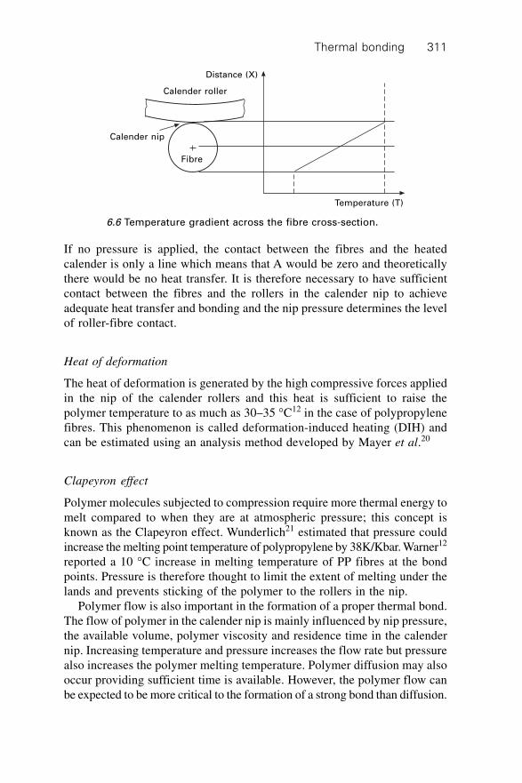
Thermal bonding 311
If no pressure is applied, the contact between the fibres and the heatedcalender is only a line which means that A would be zero and theoreticallythere would be no heat transfer. It is therefore necessary to have sufficientcontact between the fibres and the rollers in the calender nip to achieveadequate heat transfer and bonding and the nip pressure determines the levelof roller-fibre contact.
Heat of deformation
The heat of deformation is generated by the high compressive forces appliedin the nip of the calender rollers and this heat is sufficient to raise thepolymer temperature to as much as 30–35 ∞C12 in the case of polypropylenefibres. This phenomenon is called deformation-induced heating (DIH) andcan be estimated using an analysis method developed by Mayer et al.20
Clapeyron effect
Polymer molecules subjected to compression require more thermal energy tomelt compared to when they are at atmospheric pressure; this concept isknown as the Clapeyron effect. Wunderlich21 estimated that pressure couldincrease the melting point temperature of polypropylene by 38K/Kbar. Warner12
reported a 10 ∞C increase in melting temperature of PP fibres at the bondpoints. Pressure is therefore thought to limit the extent of melting under thelands and prevents sticking of the polymer to the rollers in the nip.
Polymer flow is also important in the formation of a proper thermal bond.The flow of polymer in the calender nip is mainly influenced by nip pressure,the available volume, polymer viscosity and residence time in the calendernip. Increasing temperature and pressure increases the flow rate but pressurealso increases the polymer melting temperature. Polymer diffusion may alsooccur providing sufficient time is available. However, the polymer flow canbe expected to be more critical to the formation of a strong bond than diffusion.
Calender roller
Distance (X)
Calender nip
Fibre
Temperature (T)
6.6 Temperature gradient across the fibre cross-section.
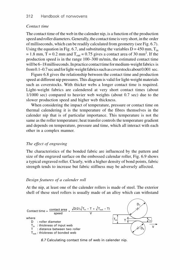
Handbook of nonwovens312
Contact time
The contact time of the web in the calender nip, is a function of the productionspeed and roller diameters. Generally, the contact time is very short, in the orderof milliseconds, which can be readily calculated from geometry (see Fig. 6.7).Using the equation in Fig. 6.7, and substituting the variables D = 450 mm, Tin
= 1.8 mm, T = 0.2 mm and Tout = 0.75 gives a contact area of 30 mm2. If theproduction speed is in the range 100–300 m/min, the estimated contact timewill be 6–18 milliseconds. In practice contact time for medium-weight fabrics isfrom 0.1–0.7 sec and for light-weight fabrics such as coverstocks about 0.001 sec.
Figure 6.8 gives the relationship between the contact time and productionspeed at different nip pressures. This diagram is valid for light-weight materialssuch as coverstocks. With thicker webs a longer contact time is required.Light-weight fabrics are calendered at very short contact times (about1/1000 sec) compared to heavier web weights (about 0.7 sec) due to theslower production speed and higher web thickness.
When considering the impact of temperature, pressure or contact time onthermal calendering it is the temperature of the fibres themselves in thecalender nip that is of particular importance. This temperature is not thesame as the roller temperature; heat transfer controls the temperature gradientand depends on temperature, pressure and time, which all interact with eachother in a complex manner.
The effect of engraving
The characteristics of the bonded fabric are influenced by the pattern andsize of the engraved surface on the embossed calendar roller, Fig. 6.9 showsa typical engraved roller. Clearly, with a higher density of bond points, fabricstrength tends to increase but fabric stiffness may be adversely affected.
Design features of a calender roll
At the nip, at least one of the calender rollers is made of steel. The exteriorshell of these steel rollers is usually made of an alloy which can withstand
D1
ToutTin T
D2V
Contact time = contact area
speed =
D/2 ( T – T + T – T)
V
in out
where
D : roller diameter
Tin : thickness of input web
T : distance between two roller
Tout : thickness of bonded web
6.7 Calculating contact time of web in calender nip.
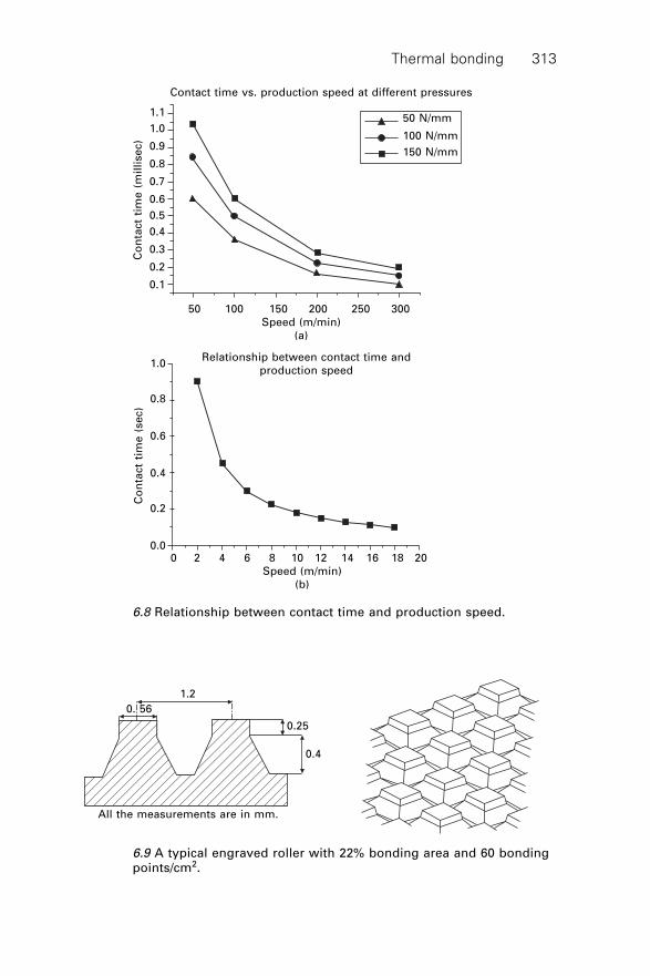
Thermal bonding 313
Contact time vs. production speed at different pressures
50 N/mm
100 N/mm
150 N/mm
50 100 150 200 250 300
Speed (m/min)
(a)
Co
nta
ct
tim
e (
mil
lise
c)
1.1
1.0
0.9
0.8
0.7
0.6
0.5
0.4
0.3
0.2
0.1
Relationship between contact time and
production speed
Co
nta
ct
tim
e (
se
c)
1.0
0.8
0.6
0.4
0.2
0.00 2 4 6 8 10 12 14 16 18 20
Speed (m/min)
(b)
6.8 Relationship between contact time and production speed.
1.2
0. 56
0.25
0.4
All the measurements are in mm.
6.9 A typical engraved roller with 22% bonding area and 60 bondingpoints/cm2.
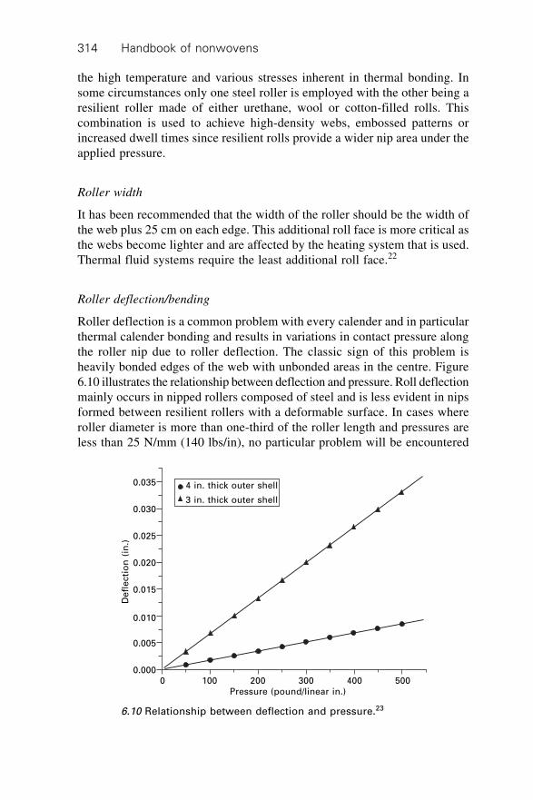
Handbook of nonwovens314
the high temperature and various stresses inherent in thermal bonding. Insome circumstances only one steel roller is employed with the other being aresilient roller made of either urethane, wool or cotton-filled rolls. Thiscombination is used to achieve high-density webs, embossed patterns orincreased dwell times since resilient rolls provide a wider nip area under theapplied pressure.
Roller width
It has been recommended that the width of the roller should be the width ofthe web plus 25 cm on each edge. This additional roll face is more critical asthe webs become lighter and are affected by the heating system that is used.Thermal fluid systems require the least additional roll face.22
Roller deflection/bending
Roller deflection is a common problem with every calender and in particularthermal calender bonding and results in variations in contact pressure alongthe roller nip due to roller deflection. The classic sign of this problem isheavily bonded edges of the web with unbonded areas in the centre. Figure6.10 illustrates the relationship between deflection and pressure. Roll deflectionmainly occurs in nipped rollers composed of steel and is less evident in nipsformed between resilient rollers with a deformable surface. In cases whereroller diameter is more than one-third of the roller length and pressures areless than 25 N/mm (140 lbs/in), no particular problem will be encountered
4 in. thick outer shell
3 in. thick outer shell
0 100 200 300 400 500
Pressure (pound/linear in.)
De
fle
cti
on
(in
.)
0.035
0.030
0.025
0.020
0.015
0.010
0.005
0.000
6.10 Relationship between deflection and pressure.23
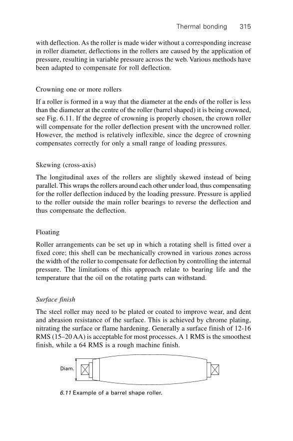
Thermal bonding 315
with deflection. As the roller is made wider without a corresponding increasein roller diameter, deflections in the rollers are caused by the application ofpressure, resulting in variable pressure across the web. Various methods havebeen adapted to compensate for roll deflection.
Crowning one or more rollers
If a roller is formed in a way that the diameter at the ends of the roller is lessthan the diameter at the centre of the roller (barrel shaped) it is being crowned,see Fig. 6.11. If the degree of crowning is properly chosen, the crown rollerwill compensate for the roller deflection present with the uncrowned roller.However, the method is relatively inflexible, since the degree of crowningcompensates correctly for only a small range of loading pressures.
Skewing (cross-axis)
The longitudinal axes of the rollers are slightly skewed instead of beingparallel. This wraps the rollers around each other under load, thus compensatingfor the roller deflection induced by the loading pressure. Pressure is appliedto the roller outside the main roller bearings to reverse the deflection andthus compensate the deflection.
Floating
Roller arrangements can be set up in which a rotating shell is fitted over afixed core; this shell can be mechanically crowned in various zones acrossthe width of the roller to compensate for deflection by controlling the internalpressure. The limitations of this approach relate to bearing life and thetemperature that the oil on the rotating parts can withstand.
Surface finish
The steel roller may need to be plated or coated to improve wear, and dentand abrasion resistance of the surface. This is achieved by chrome plating,nitrating the surface or flame hardening. Generally a surface finish of 12-16RMS (15–20 AA) is acceptable for most processes. A 1 RMS is the smoothestfinish, while a 64 RMS is a rough machine finish.
Diam.
6.11 Example of a barrel shape roller.
Handbook of nonwovens316
6.4.4 Methods of heating calender rolls
Various methods have been devised to heat the calender rollers. The commonlyused heating systems are briefly explained.
Hot water/liquid or steam
The electro-hot liquid roller is centre bored and sealed to produce an enclosedchamber. This chamber is partially filled with liquid. An electrical heatingcoil within the chamber heats the liquid producing pressurised steam. Thesteam condenses on the inner boring’s surface and the heat is transferred intothe steel and through the steel to the roller surface. Advantages are goodtemperature uniformity, an enclosed heating system (no external heatingsystem is required), low investment and low maintenance cost. To reduce thesteam pressure at high temperatures, liquids with a higher boiling point thanwater can be used. This system is limited in heat capacity and normally usedfor a maximum temperature up to 180 ∞C.
Electrical or cal-rod system
Electrically heated rollers are heated internally and controlled by measuringthe roller shell temperature near the surface, therefore they are much moreeasily and quickly controlled compared to the liquid heated systems. Alsothey do not use any hot or pressurised liquids and high surface temperaturesup to 420 ∞C are possible. The drawbacks are high initial investment andmaintenance cost. Electric conductive heated rollers have a dual shell designor a centre boring. An electric heating coil can be wound on the inner shell,and the top shell is pulled over the inner shell. In centre bored rolls a heatedcoil is mounted in the inner boring. All remaining spaces are filled with aheat transfer medium. Thermal losses are limited to normal convection lossesfrom the roller surfaces.
Gas heating system
This type of heating system normally uses a ribbon type burner in a boredsteel roll. The maximum temperature is about 260 ∞C. This system employsa live flame which could be a safety problem in many facilities. Also theburner pipe inside the roll is difficult to manufacture over 160 in. long andto remain straight at these temperatures.
Hot oil heating system
A straight turbulator is fitted to a bore steel roller. Hot oil is passed throughthe spiral and the bore using a closed-loop system. This is normally a good
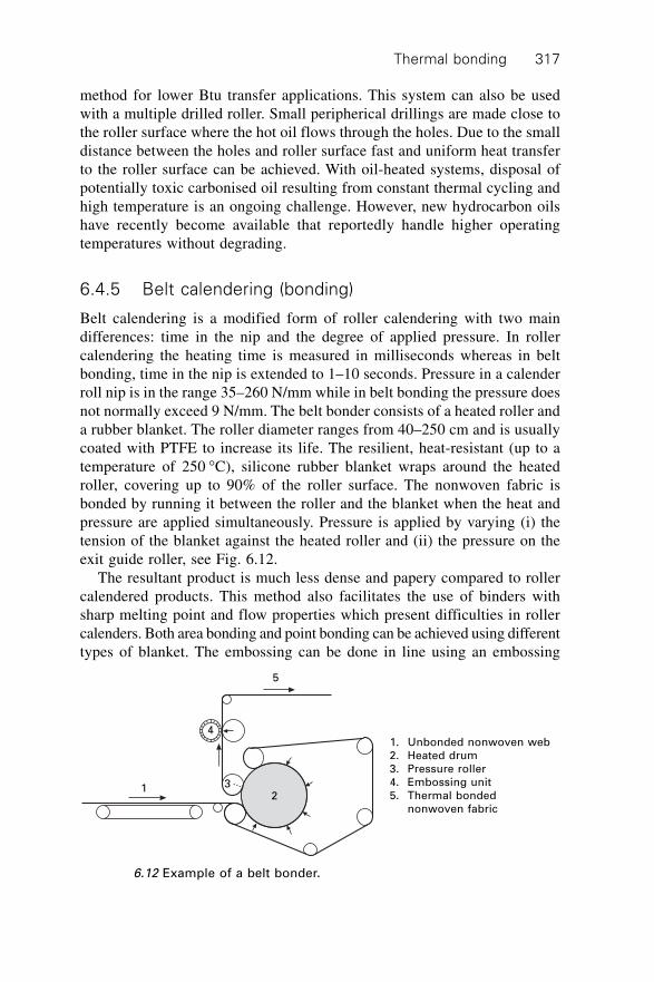
Thermal bonding 317
method for lower Btu transfer applications. This system can also be usedwith a multiple drilled roller. Small peripherical drillings are made close tothe roller surface where the hot oil flows through the holes. Due to the smalldistance between the holes and roller surface fast and uniform heat transferto the roller surface can be achieved. With oil-heated systems, disposal ofpotentially toxic carbonised oil resulting from constant thermal cycling andhigh temperature is an ongoing challenge. However, new hydrocarbon oilshave recently become available that reportedly handle higher operatingtemperatures without degrading.
6.4.5 Belt calendering (bonding)
Belt calendering is a modified form of roller calendering with two maindifferences: time in the nip and the degree of applied pressure. In rollercalendering the heating time is measured in milliseconds whereas in beltbonding, time in the nip is extended to 1–10 seconds. Pressure in a calenderroll nip is in the range 35–260 N/mm while in belt bonding the pressure doesnot normally exceed 9 N/mm. The belt bonder consists of a heated roller anda rubber blanket. The roller diameter ranges from 40–250 cm and is usuallycoated with PTFE to increase its life. The resilient, heat-resistant (up to atemperature of 250 ∞C), silicone rubber blanket wraps around the heatedroller, covering up to 90% of the roller surface. The nonwoven fabric isbonded by running it between the roller and the blanket when the heat andpressure are applied simultaneously. Pressure is applied by varying (i) thetension of the blanket against the heated roller and (ii) the pressure on theexit guide roller, see Fig. 6.12.
The resultant product is much less dense and papery compared to rollercalendered products. This method also facilitates the use of binders withsharp melting point and flow properties which present difficulties in rollercalenders. Both area bonding and point bonding can be achieved using differenttypes of blanket. The embossing can be done in line using an embossing
5
4
312
1. Unbonded nonwoven web
2. Heated drum
3. Pressure roller
4. Embossing unit
5. Thermal bonded
nonwoven fabric
6.12 Example of a belt bonder.
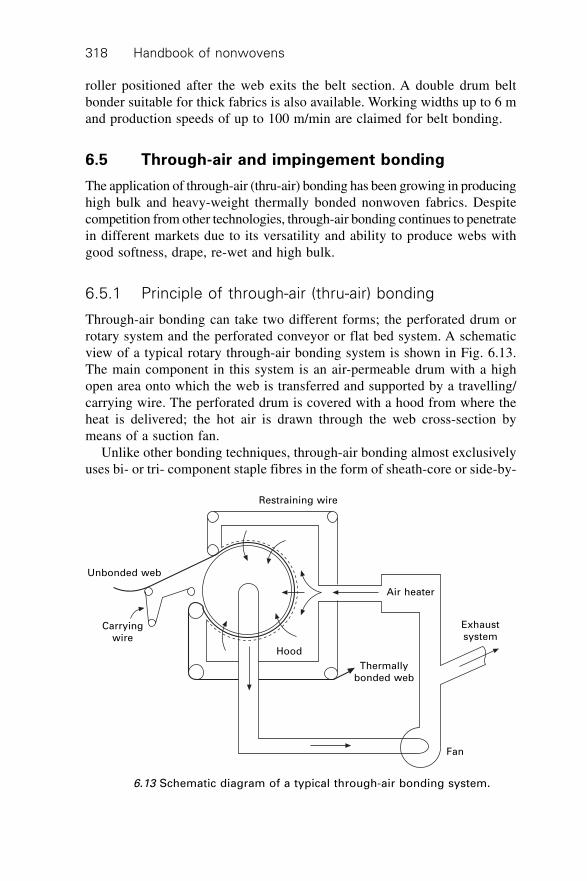
Handbook of nonwovens318
roller positioned after the web exits the belt section. A double drum beltbonder suitable for thick fabrics is also available. Working widths up to 6 mand production speeds of up to 100 m/min are claimed for belt bonding.
6.5 Through-air and impingement bonding
The application of through-air (thru-air) bonding has been growing in producinghigh bulk and heavy-weight thermally bonded nonwoven fabrics. Despitecompetition from other technologies, through-air bonding continues to penetratein different markets due to its versatility and ability to produce webs withgood softness, drape, re-wet and high bulk.
6.5.1 Principle of through-air (thru-air) bonding
Through-air bonding can take two different forms; the perforated drum orrotary system and the perforated conveyor or flat bed system. A schematicview of a typical rotary through-air bonding system is shown in Fig. 6.13.The main component in this system is an air-permeable drum with a highopen area onto which the web is transferred and supported by a travelling/carrying wire. The perforated drum is covered with a hood from where theheat is delivered; the hot air is drawn through the web cross-section bymeans of a suction fan.
Unlike other bonding techniques, through-air bonding almost exclusivelyuses bi- or tri- component staple fibres in the form of sheath-core or side-by-
Restraining wire
Unbonded web
Carrying
wire
Hood
Thermally
bonded web
Air heater
Exhaust
system
Fan
6.13 Schematic diagram of a typical through-air bonding system.
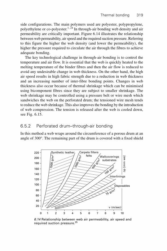
Thermal bonding 319
side configurations. The main polymers used are polyester, polypropylene,polyethylene or co-polyester.1, 24 In through-air bonding web density and airpermeability are critically important. Figure 6.14 illustrates the relationshipbetween web permeability, air speed and the required suction pressure. Referringto this figure the higher the web density (and lower the permeability), thehigher the pressure required to circulate the air through the fibres to achieveadequate bonding.
The key technological challenge in through-air bonding is to control thetemperature and air flow. It is essential that the web is quickly heated to themelting temperature of the binder fibres and then the air flow is reduced toavoid any undesirable change in web thickness. On the other hand, the highair speed results in high fabric strength due to a reduction in web thicknessand an increasing number of inter-fibre bonding points. Changes in webthickness also occur because of thermal shrinkage which can be minimisedusing bicomponent fibres since they are subject to smaller shrinkage. Theweb shrinkage may be controlled using a pressure belt or wire mesh whichsandwiches the web on the perforated drum; the tensioned wire mesh tendsto reduce the web shrinkage. This also improves the bonding by the introductionof web compression. The tension is released after the web is cooled down,see Fig. 6.15.
6.5.2 Perforated drum–through-air bonding
In this method a web wraps around the circumference of a porous drum at anangle of 300∞. The remaining part of the drum is covered with a fixed shield
220
200
180
160
140
120
100
80
60
40
20
0 1 2 3 4 5 6 7 8 9 10
Synthetic leather
15
00
g/m
2
1000 g
/m2
Carpets filters
felts Wallcoverings
substrates
400
g/m
2
150 g/m
2
Interlinings
Dp
[m
m w
s]
Disposables
15 g/m2
v (m/sec)
6.14 Relationship between web air permeability, air speed andrequired suction pressure.25
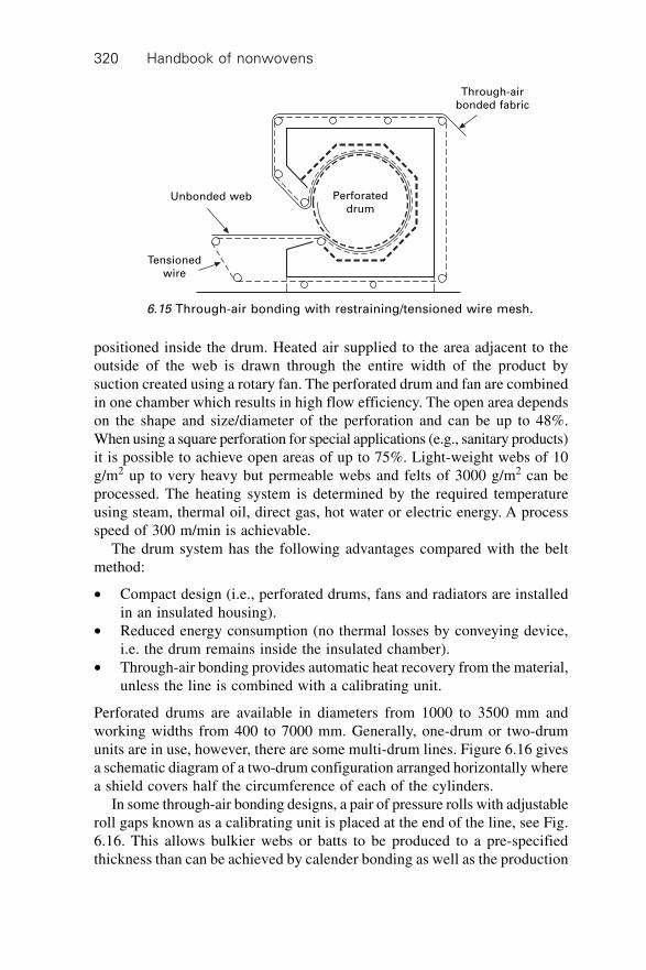
Handbook of nonwovens320
Through-air
bonded fabric
Unbonded web Perforated
drum
Tensioned
wire
6.15 Through-air bonding with restraining/tensioned wire mesh.
positioned inside the drum. Heated air supplied to the area adjacent to theoutside of the web is drawn through the entire width of the product bysuction created using a rotary fan. The perforated drum and fan are combinedin one chamber which results in high flow efficiency. The open area dependson the shape and size/diameter of the perforation and can be up to 48%.When using a square perforation for special applications (e.g., sanitary products)it is possible to achieve open areas of up to 75%. Light-weight webs of 10g/m2 up to very heavy but permeable webs and felts of 3000 g/m2 can beprocessed. The heating system is determined by the required temperatureusing steam, thermal oil, direct gas, hot water or electric energy. A processspeed of 300 m/min is achievable.
The drum system has the following advantages compared with the beltmethod:
∑ Compact design (i.e., perforated drums, fans and radiators are installedin an insulated housing).
∑ Reduced energy consumption (no thermal losses by conveying device,i.e. the drum remains inside the insulated chamber).
∑ Through-air bonding provides automatic heat recovery from the material,unless the line is combined with a calibrating unit.
Perforated drums are available in diameters from 1000 to 3500 mm andworking widths from 400 to 7000 mm. Generally, one-drum or two-drumunits are in use, however, there are some multi-drum lines. Figure 6.16 givesa schematic diagram of a two-drum configuration arranged horizontally wherea shield covers half the circumference of each of the cylinders.
In some through-air bonding designs, a pair of pressure rolls with adjustableroll gaps known as a calibrating unit is placed at the end of the line, see Fig.6.16. This allows bulkier webs or batts to be produced to a pre-specifiedthickness than can be achieved by calender bonding as well as the production
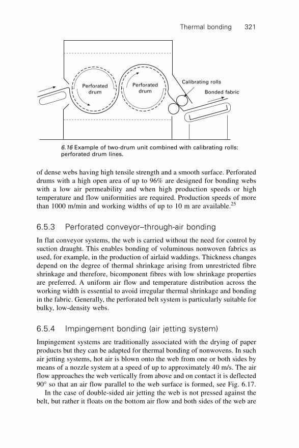
Thermal bonding 321
of dense webs having high tensile strength and a smooth surface. Perforateddrums with a high open area of up to 96% are designed for bonding webswith a low air permeability and when high production speeds or hightemperature and flow uniformities are required. Production speeds of morethan 1000 m/min and working widths of up to 10 m are available.25
6.5.3 Perforated conveyor–through-air bonding
In flat conveyor systems, the web is carried without the need for control bysuction draught. This enables bonding of voluminous nonwoven fabrics asused, for example, in the production of airlaid waddings. Thickness changesdepend on the degree of thermal shrinkage arising from unrestricted fibreshrinkage and therefore, bicomponent fibres with low shrinkage propertiesare preferred. A uniform air flow and temperature distribution across theworking width is essential to avoid irregular thermal shrinkage and bondingin the fabric. Generally, the perforated belt system is particularly suitable forbulky, low-density webs.
6.5.4 Impingement bonding (air jetting system)
Impingement systems are traditionally associated with the drying of paperproducts but they can be adapted for thermal bonding of nonwovens. In suchair jetting systems, hot air is blown onto the web from one or both sides bymeans of a nozzle system at a speed of up to approximately 40 m/s. The airflow approaches the web vertically from above and on contact it is deflected90∞ so that an air flow parallel to the web surface is formed, see Fig. 6.17.
In the case of double-sided air jetting the web is not pressed against thebelt, but rather it floats on the bottom air flow and both sides of the web are
Perforated
drum
Perforated
drum
Calibrating rolls
Bonded fabric
6.16 Example of two-drum unit combined with calibrating rolls:perforated drum lines.
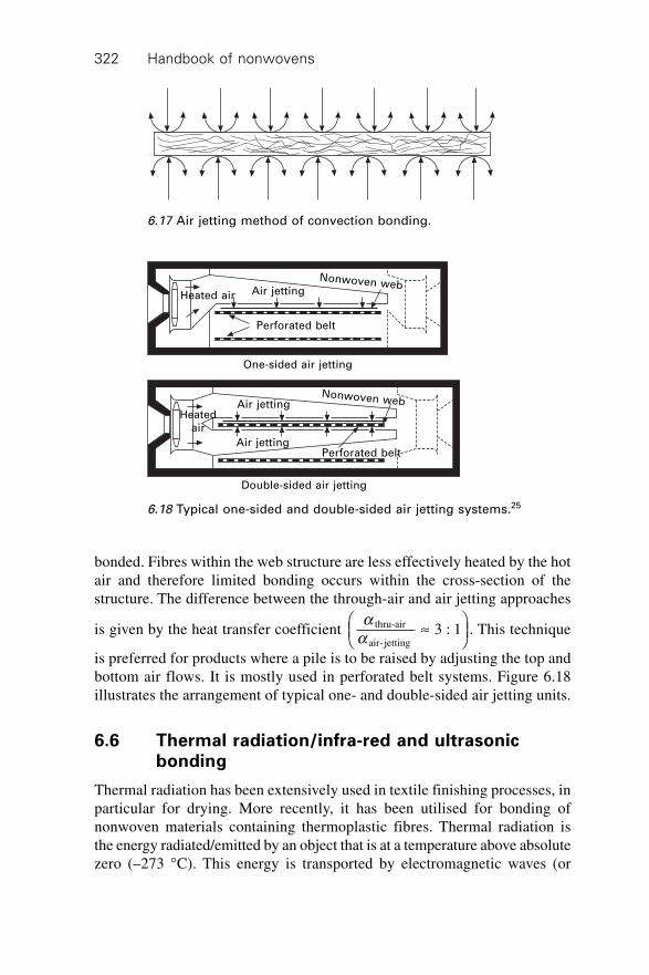
Handbook of nonwovens322
bonded. Fibres within the web structure are less effectively heated by the hotair and therefore limited bonding occurs within the cross-section of thestructure. The difference between the through-air and air jetting approaches
is given by the heat transfer coefficient a
athru-air
air-jetting 3 : 1ªÊ
ËÁˆ¯
. This technique
is preferred for products where a pile is to be raised by adjusting the top andbottom air flows. It is mostly used in perforated belt systems. Figure 6.18illustrates the arrangement of typical one- and double-sided air jetting units.
6.6 Thermal radiation/infra-red and ultrasonicbonding
Thermal radiation has been extensively used in textile finishing processes, inparticular for drying. More recently, it has been utilised for bonding ofnonwoven materials containing thermoplastic fibres. Thermal radiation isthe energy radiated/emitted by an object that is at a temperature above absolutezero (–273 ∞C). This energy is transported by electromagnetic waves (or
6.17 Air jetting method of convection bonding.
Heated air Air jetting
Nonwoven web
Perforated belt
One-sided air jetting
Heated
air
Air jettingNonwoven web
Double-sided air jetting
Air jettingPerforated belt
6.18 Typical one-sided and double-sided air jetting systems.25
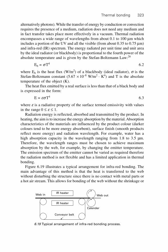
Thermal bonding 323
alternatively photons). While the transfer of energy by conduction or convectionrequires the presence of a medium, radiation does not need any medium andin fact transfer takes place more effectively in a vacuum. Thermal radiationencompasses a wide range of wavelengths from about 0.1 to 100 mm whichincludes a portion of the UV and all the visible (from about 0.35 to 0.75 mm)and infra-red (IR) spectrum. The energy radiated per unit time and unit areaby the ideal radiator (or blackbody) is proportional to the fourth power of theabsolute temperature and is given by the Stefan-Boltzmann Law:26
Eb = s T4 6.2
where Eb is the heat flux (W/m2) of a blackbody (ideal radiator), s is theStefan-Boltzmann constant (5.67 ¥ 10–8 W/m2 · K4) and T is the absolutetemperature of the object (K).
The heat flux emitted by a real surface is less than that of a black body andis expressed in the form:
E = es T4 6.3
where e is a radiative property of the surface termed emissivity with valuesin the range 0 £ e £ 1.
Radiation energy is reflected, absorbed and transmitted by the product. Inheating, the aim is to increase the energy absorption by the material. Absorptioncharacteristics of the materials are influenced by the product colour (darkercolours tend to be more energy absorbent), surface finish (smooth productsreflect more energy) and radiation wavelength. For example, water has ahigh absorption capacity in the wavelength ranging from 1.8 to 3.5 mm.Therefore, the wavelength ranges must be chosen to achieve maximumabsorption by the web, for example, by changing the emitter temperature.The emission spectrum of the emitter cannot be varied as required thereforethe radiation method is not flexible and has a limited application in thermalbonding.
Figure 6.19 illustrates a typical arrangement for infra-red bonding. Themain advantage of this method is that the heat is transferred to the webwithout disturbing the structure since there is no contact with metal parts ora hot air stream. This allows for bonding of the web without the shrinkage or
IR heaterWeb in Web out
IR heater
Conveyor belt
Calender
6.19 Typical arrangement of infra-red bonding process.
Handbook of nonwovens324
distortion of fibres associated with other methods of heating. It is also ofparticular use in powder bonding. The major drawback is the fact that thesurface of the web is heated faster than the centre and uniform bondingthrough the cross-section of the web therefore presents practical difficulties.
6.6.1 Ultrasonic bonding
The application of ultrasonics to thermally bond webs is well known. Incontrast to other methods of bonding, which use either hot air or hot surfaces,in ultrasonic bonding thermal energy is conveyed by a mechanical hammeringaction (high frequency vibration) of the web surface. This involves a briefcontact time with a limited pressure between the ultrasonic horn and the webcarried out at an ultrasonic frequency of about 20,000 cycles/sec. Energy istherefore transferred to well defined, restricted areas in the web to inducethermal bonding as the mechanical energy applied to the fibres is convertedinto heat.
A schematic view of the ultrasonic bonding process is shown in Fig. 6.20.A fibrous web is compacted between an embossed patterned roller (referredto as an anvil) and an ultrasonic tool (horn). The horn is vibrated at highfrequency in the range of 20–40 KHz; the lower limit is normally used forthermal bonding of webs. Materials used for manufacture of vibrating tools(horn) should have a high wear resistance; titanium and aluminium are widelyused. The vibration of the horn imparts intense thermal energy to the webimmediately above the raised points on the patterned roller causing fibres tomelt and undergo compression in the area above the raised points.
6.20 A schematic ultrasonic bonding with raised bonding points.
Ultrasonically
bonded web out
Ultrasonic horn
Unbonded web in
Rotary anvil
Thermal bonding 325
There is no need for a second binder component when synthetic fibres areused since these are self-bonding. However, to bond natural fibres about50% by web weight of binder fibres is usually required. An advantage of thismethod is that energy is imparted only to the points at which bonding takesplace and no energy is transferred to the surrounding unbonded areas of theweb. Localisation of bonding energy leads to fabrics with well defined bondpoints and an excellent aesthetic appearance. The main problem is transferringuniform vibrational energy across the full width of wide fabrics. This requiresmany overlapping horns to be used which results in visible lines of overlapin the fabric. Also ultrasonic horns must be carefully maintained and theprocess is slow if reasonably large bond areas are to be obtained > 25%.Fabrics manufactured by ultrasonic bonding are soft, breathable, absorbentand strong. Ultrasonic bonding is also suitable for manufacturing patternedcomposites and laminates, such as quilts and outdoor jackets.
6.7 Thermally bonded fabric structure
One of the main structural attributes determining fabric applications is fabricstrength, in particular tensile strength. It is known that stronger fibres makestronger fabrics when all the other constructional factors are similar. However,in thermally bonded fabrics it is possible to make a weak fabric using strongfibre if bonding conditions are not set appropriately. The failure mode offabrics changes with bonding conditions. For example, the tensile failures oflight-weight PET (20–30 g/m2) calender bonded fabrics are explained bythree main mechanisms depending on manufacturing process conditions.
1. Failure of adhesion between fibres within the bonding sites (bond pointdisintegration).
2. Failure of individual fibres; fibre breakage in the perimeter of bondpoints where they are attached to the bond points or somewhere alongthe side of the fibre length between bond points.
3. Fracture of bond points.
The occurrence of the above mechanisms depends on how the fabrics aremade. Increasing the bonding temperature changes the failure method fromthat of the first method to the second. Failure by the third method is expectedat very high temperature and in very stiff fabrics.27
6.7.1 Effect of fibre structure on properties of thermally
bonded fabrics
The published research reviewed by Dharmadhikary10 suggests that changesin fibre structure produced during point bonding impacts the properties ofthe fabric, and to understand these changes a comprehensive understanding
Handbook of nonwovens326
of the structure and properties of individual polymer types is required. Therole of the binder and base fibre structures is of particular importance. Astudy of PET area bonded fabrics with respect to the changes in bindermorphology28 suggested that crystalline binder fibres produce fabrics with ahigher tenacity, modulus and breaking extension than amorphous binderfibres. In terms of fabric strength, these differences may be difficult todistinguish below a critical temperature and pressure.
Another study by Wei et al.29 used commercial polypropylene fibres ofvarying draw ratios. Fibres with a lower orientation compared with fibreswith a higher orientation and microfibrillar structure, had a higher tensilestrength and flexural rigidity. They suggested that this was due to the lessorientated amorphous regions and lamellar crystal structure promoting fibrefusion, while the orientated microfibrillar structure was inhibiting fibre fusionduring thermal bonding. Fabric shrinkage was also determined by the fibremorphology; they suggested that this resulted from molecular retraction inthe amorphous regions. The highly orientated fibres also showed highershrinkage and this resulted in increased fabric thickness.
Point bonded fabric consists of a network of fibres, bonded in localisedregions (bond points), by the application of heat and pressure. This results inpartial melting of the crystals which is essential for the formation of bondpoints. Although the point bond process is simple, a clear understanding ofthe properties of point bonded fabrics has yet to be established and there isonly limited information about the ideal fibre structures required for pointbonding and the changes that occur in fibre structure and properties duringbonding. The morphology of the bond points and the bridging fibres is animportant influence on properties. Bond strength influences fabric strengthand this has been studied by Mi et al.30 Results from their model suggest thathigh strength bonds, (fabric failure caused by failure of the bridging fibres)led to the strongest fabrics. The failure of a fabric will be determined both bythe nature and character of the bond points and the stress/strain relationshipof bridging fibres.
During point bonding, depending upon the specific process variables adoptedand the bridging fibres, the properties associated with the bond point differfrom those of the virgin fibre. Various workers have referred to this aspect,Warner12 suggested that fibres break at the bond periphery because of thelocal thermo-mechanical polymer history and that the strength of point bondedfabrics is therefore controlled by the bond periphery strength. Wei et al.29
commented that the physical properties of thermally bonded fabrics are aresult of the nature and quality of the bonding regions. The influences ofpressure on polymer properties during point bonding are not well understood.Pressure might be expected to increase the melting point and the glass transitiontemperature and therefore might influence the crystallisation rate. Crystalnucleation and growth is also influenced by pressure and could producecomplex interactions.
Thermal bonding 327
6.8 Applications of thermally bonded fabrics
There are now a vast number of varied end uses, almost too numerous tomention, for thermal bonded nonwoven fabrics across all sectors of theindustry including both single use hygiene disposable products and durablebuilding and construction materials. A major application is in hygiene, forexample PP coverstock found in sanitary and incontinence products of 10–30 g/m2, based on calender point bonded dry-laid or spunbond webs, theformer using bicomponent fibres. Other disposables include wipes producedfrom airlaid short fibres, which are through-air bonded to make products inthe 25–150 g/m2 weight range and through-air bonded carded wipes productsof about 100–250 g/m2. Through-air bonding in this application is preferredto maximise the bulk of the fabric. Recently some thermally bonded wipesproducts have seen strong competition from dry-laid-hydroentangled fabrics.Wet-laid fabrics intended for tea-bag applications may be through-air bonded.Calender bonding is utilised to bond spunbond, meltblown and compositesof these webs for numerous medical and hygiene applications includingsurgical gowns and drapes.
Durable thermally bonded products produced from spunlaid webs areeither through-air bonded or calendered. Those using through-air bonding inan oven are frequently based on bicomponent filament webs. Core-sheathPET-PA6 filament spunbonds have applications in carpet backing whereascore-sheath PP-PE spunbonds have applications in geosynthetics and technicaltextiles as air and water filtration media, horticultural products, and in clothingand footwear. Thermally bonded spunbond geosynthetic fabrics of 80–250g/m2, find uses in various civil engineering applications. Roofing felts orcarriers of about 150–350 g/m2 are an application for thermally bondedspunlaid fabrics whereas needlepunched fabrics are used as bitumen carriersin flat roofs. Thermally bonded spunlaid fabrics are installed in pitched roofsas bituminous underslating. Such fabrics are normally composed of PETpartly to give better heat stability during bitumen coating.
Many dry-laid filter fabrics are needlepunched, particularly those intendedfor high-temperature applications but others are through-air bonded in weightranges from 100–1000 g/m2. Through-air bonded spunbond fabric of 150–200 g/m2 is produced for carpet backing applications. A traditional thermalbond application is in the manufacture of linings and interlinings ranging inweight from 25–150 g/m2 using either calender or through-air bonding methods.In some applications, point bonding using a calender follows mechanicalbonding to produce the final product. Powder and thermo-dot bonded, fusibleand non-fusible nonwoven fabrics for garment interlining applications, frompolyester and EVA are also made. Shoe lining fabrics of about 150–200 g/m2
composed of blended bicomponent fibres are thermally point bonded with acalender.
Handbook of nonwovens328
Dry-laid, thermally bonded reinforcement fabrics, and substrates forelectrical insulating materials, pressure sensitive tapes and filtration membranesare made from PET. Other applications include furniture and beddingcomponents, horticultural and agricultural fabrics including crop cover, highloft waddings and paddings for thermal insulation and automotive fabrics.Spunlaid filtration fabrics stabilised by thermal bonding find applications ascabin filters in the automotive industry and are can be pleated to increase thesurface area available for filtration.
6.9 References
1. Watzl A., ‘Fusion bonding, thermobonding and heat-setting of nonwoven – theoreticalfundamentals, practical experience, market trends’, Melliand English Vol. 10, 1994,P. E217.
2. Batra S.K. and Pourdeyhimi B., ‘Thermal Bonding’, Nonwovens Cooperative Research
Center, North Carolina State University, Raleigh, NC. USA.3. Rave H., Schemken M. and Beck A., ‘State of the art of bicomponent staple fibre
production’, Chemical fibre international Vol. 52, April 2002.4. http://www.ifg.com/issue/june98/story3.html5. Jeffries R., ‘Bicomponent Fibres’, Merrow Publishing Co. Ltd, 1971. BP 1048370,
NAP 66-12238, Shell International Research.6. Marcher B., ‘Tailor-made polypropylene and bicomponent fibres for the nonwovens
industry’, Tappi Journal, Vol. 74, No. 12, 1991, P. 103–107.7. Thonnessen F. and Dahringer J., ‘Trevira bicomponent fibres for nonwovens’, Chemical
fibre international, Vol. 53, No. 12, 2003, P. 422.8. Raidt P., ‘Polyester/Polyethylene bicomponent fibres for thermal bonding of
nonwovens’, Index 87 Congress).9. Hoag T.S. ‘From time-tested methods to recent innovations, bonding exhibits
versatility’, Nonwovens World Vol. 4, No. 1 1989, P. 2610. Dharmadhikary P.K., Gilmore T.F., Davis H.A. and Batra S.K., ‘Thermal bonding of
nonwoven fabrics’, Textile Progress Vol. 26, 1995, P. 26.11. Muller D.H., ‘Improvement of thermalbonded nonwovens’, Melliand Textilberichte,
Vol. 70, No. 7, 1989, P. 499–502, E210.12. Warner S.B., ‘Thermal Bonding of Polypropylene Fibres’, Textile Research Journal,
Vol. 59, No. 3, 1989, P. 151–159.13. Schwartz R.J., US Patent 4100319, 1978.14. Haoming R. and Bhat G.S., ‘Preparation and properties of cotton-ester nonwovens’,
International Nonwovens Journal, No. 12, No. 2, 2003, P. 55.15. Kwok W.K., Crane J.P. and Gorrafa A., ‘Polyester staple for thermally bonded
nonwovens’, Nonwovens Industry, 19 (6), 1988, P. 30–33.16. Kim H.S., Pourdeyhimi B., Desai P. and Abhiraman A.S., ‘Anisotropy in the mechanical
properties of thermally spot-bonded nonwovens: Experimental Observations’, Textile
Research Journal, 2001, Vol. 71, No. 11, P. 965.17. Muller D.H., ‘How to improve the thermal bonding of heavy webs’, INDA J. Nonwoven
Research, 1989, Vol. 1, No. 1, P. 35–43.18. Shimalla C.J. and Whitwell J.C., ‘Thermomechanical behaviour of nonwovens, Part
I: Responses to changes in processing and post-bonding variables’, Textile Research
Journal, 1976, Vol. 46, P. 405–417.
Thermal bonding 329
19. DeAngelis V., DiGioacchino T. and Olivieri P., ‘Hot calendered polypropylenenonwoven fabrics’, in Proceedings of 2nd International Conference on Polypropylene
Fibres and Textiles, Plastics and Rubber Institiutes, University of York, England,1979, PP. 52.1–52. 13.
20. Mayer J.W., Haward R.N. and Hay J.N., ‘Study of the thermal effects of necking ofpolymers with the use of an infrared camera’, Journal of Polymer Science Polymer
Physics, edn 18, 1980, P. 2169–2179.21. Wunderlich B., Macromolecular Physics, Academic Press New York, Vol. 3, 1986.22. Gunter D.S., ‘Calender selection for nonwovens’, Tappi Journal, January, Vol. 81,
No. 1, 1998, P. 208.23. Gunter D.S. ‘Thermal bonding utilising calender’, Tappi Journal, Vol. 77, No. 6,
1994, P 221.24. Wuagneux E.L., ‘Full of hot air’, Nonwovens Industry, Vol. 30, No. 4, 1999, P. 52–
56.25. Watzl A., Instruction manual of Fleissner through air bonding machinery. Internal
Fleissner machine document.26. Holman J.P., ‘Heat Transfer’, McGraw Hill, ninth edition, 2002.27. Gibson P.E. and McGill R.L. ‘Thermally bondable polyester fibre: the effect of
calender temperature’, Tappi Journal, Vol. 70, No. 12, 1987, P. 82.28. Dantuluri S.R., Goswami B.C. and Vigo T.L. ‘Thermally Bonded Polyester Nonwovens:
Effect of fibre morphology’ in Proceedings of INDA Technical symposium, 1987,P. 263–270.
29. Wei K.V., Vigo T.L. and Goswami B.C., ‘Structure-property relationship of thermallybonded polypropylene nonwovens’, Journal of Applied Polymer Science, Vol. 30,1985, P 1523–1524.
30. Mi Z.X., Batra S.K. and Gilmore T.F., ‘Computational Model for Mechanical Behaviour
of Point-Bonded Web’ First Annual Report, Nonwovens Cooperative Research Center,1992.
330
7.1 Introduction
Textile Terms and Definitions1 defines a binder as an adhesive material usedto hold together the fibres in a nonwoven structure. The word ‘binder’ describesthe function of a composition in the final product. The terms ‘binder’, ‘bindingagent’, ‘binder composition’,‘binder system’, ‘nonwoven binder’, ‘chemicalbinder’ are used in the literature to describe the polymer, polymer and carrier,part-formulation or total formulation used in chemical bonding – the meaningshifts according to the context. A binder not only ‘holds fibres together’ butalso affects the final properties of the nonwoven fabric including its strength(both tensile and compressive), stiffness, softness, waterproofness, breathabilityand flammability. The choice of binder also influences the capability of thefabric to be recycled or biochemically degraded at the end of its useful life.Chemical bonding remains popular because of the large range of adhesivebinders available, the durability of the products and the broad variety of finalproperties that can be engineered in the fabrics.
While in the early days of development natural binders such as starch andrubber were used, synthetic polymers now dominate the industry. Mostly inresponse to the needs for more environmentally sustainable materials, concernsabout free formaldehyde, and to aid ease of disposal, there is a resurgence ofinterest in the biodegradeable binders derived from agricultural sources forparticular applications. These include starches, pectins, oils and casein amongstothers. Binders are also applied to nonwoven fabrics that are already bondedto provide additional functionality, since the binder can be mixed with activecomponents or solids such as flame retardants and functional finishes, ceramicsand metals. For example, in the manufacture of wipe products, pigments andchemical binders are commonly printed onto the surface of hydroentangledfabrics to increase the wet strength, to control wet pick-up and to improvethe visual appearance of the product. It is increasingly common to use such‘combination bonding’ procedures in which several different bonding methodsare used in succession. Thermally bonded airlaid fabrics, needlepunched and
7Chemical bonding
R A C H A P M A NWarwick Innovation Limited, UK
Chemical bonding 331
hydroentangled fabrics are frequently subject to secondary chemical bondingto modify fabric properties or appearance.
Binder polymers can be dissolved in a solvent including water or they canbe dispersions or emulsions. The most important binders are latices (alsocalled latexes) of emulsion polymers. These are fine dispersions of specificpolymers in water. They are applied in a number of different ways to nonwovensubstrates and because their viscosity is close to that of water, they can easilypenetrate thick or dense nonwoven structures by simple immersion. Afterapplication of the binder by, for example, immersion, they are dried and thewater evaporates. Typically, the binder forms an adhesive film across orbetween fibre intersections and fibre bonding is obtained. Binders create anetwork of interlocked fibres, which can be throughout the fabric structureor in selected areas depending on the required end-use.
The distribution of the binder in the fabric structure and its properties canbe affected by the use of coagulating and crosslinking agents as well as theapplication method utilised. In chemically bonded fabrics, the concentrationof binder on the surfaces and in the interior may not be uniform and thisaffects fabric stiffness, handle and the probability of delamination in somecases. The concentration of binder may be graduated in the fabric cross-section, for example it may decrease from the fabric surface towards themiddle due to migration of the binder towards the surfaces during drying.Alternatively, as in some foam bonding operations, for example, the applicationof the binder may be purposely designed to be concentrated differentlythroughout the fabric cross-section. The binder system wets the fabric andfollowing drying and/or crosslinking, forms a bonded structure. Althoughhomopolymer emulsions can be utilised, copolymers or blends with fillersare common. Copolymers provide some tailoring of the main homopolymerproperties, for example, to enable increased softness, and fillers help toreduce cost and provide additional useful properties such as improved thermalresistance, abrasion resistance, flame retardancy, water repellency or antistaticproperties. Generally, fillers are an economical way of achieving such propertiesin contrast to changing the fibre composition.
Commercially, binder systems are applied at levels between about 5% and150% on the dry weight of fabric. A 5% binder addition is often sufficient tobond fibres at the surface. Addition levels as high as 150% are sometimesused to make stiff reinforcement components such as those found in shoes.
7.2 Chemical binder polymers
7.2.1 Introduction
Various binder polymers are used including vinyl polymers and copolymers,acrylic ester polymers and copolymers, rubber and synthetic rubber, and
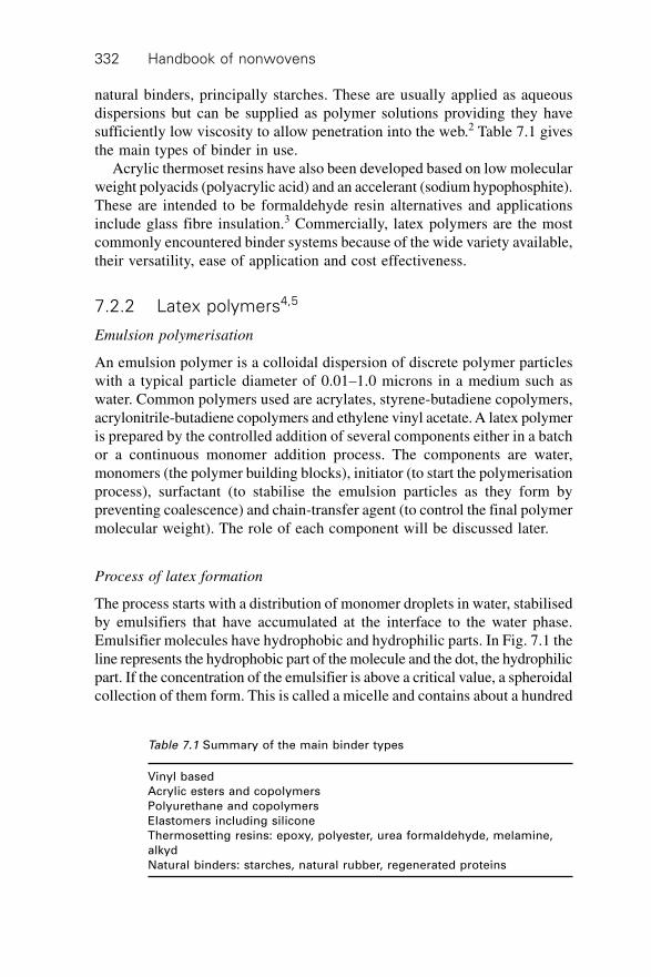
Handbook of nonwovens332
natural binders, principally starches. These are usually applied as aqueousdispersions but can be supplied as polymer solutions providing they havesufficiently low viscosity to allow penetration into the web.2 Table 7.1 givesthe main types of binder in use.
Acrylic thermoset resins have also been developed based on low molecularweight polyacids (polyacrylic acid) and an accelerant (sodium hypophosphite).These are intended to be formaldehyde resin alternatives and applicationsinclude glass fibre insulation.3 Commercially, latex polymers are the mostcommonly encountered binder systems because of the wide variety available,their versatility, ease of application and cost effectiveness.
7.2.2 Latex polymers4,5
Emulsion polymerisation
An emulsion polymer is a colloidal dispersion of discrete polymer particleswith a typical particle diameter of 0.01–1.0 microns in a medium such aswater. Common polymers used are acrylates, styrene-butadiene copolymers,acrylonitrile-butadiene copolymers and ethylene vinyl acetate. A latex polymeris prepared by the controlled addition of several components either in a batchor a continuous monomer addition process. The components are water,monomers (the polymer building blocks), initiator (to start the polymerisationprocess), surfactant (to stabilise the emulsion particles as they form bypreventing coalescence) and chain-transfer agent (to control the final polymermolecular weight). The role of each component will be discussed later.
Process of latex formation
The process starts with a distribution of monomer droplets in water, stabilisedby emulsifiers that have accumulated at the interface to the water phase.Emulsifier molecules have hydrophobic and hydrophilic parts. In Fig. 7.1 theline represents the hydrophobic part of the molecule and the dot, the hydrophilicpart. If the concentration of the emulsifier is above a critical value, a spheroidalcollection of them form. This is called a micelle and contains about a hundred
Table 7.1 Summary of the main binder types
Vinyl based
Acrylic esters and copolymers
Polyurethane and copolymers
Elastomers including silicone
Thermosetting resins: epoxy, polyester, urea formaldehyde, melamine,
alkyd
Natural binders: starches, natural rubber, regenerated proteins
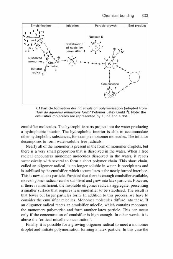
Chemical bonding 333
emulsifier molecules. The hydrophilic parts project into the water producinga hydrophobic interior. The hydrophobic interior is able to accommodateother hydrophobic substances, for example monomer molecules. The initiatordecomposes to form water-soluble free radicals.
Nearly all of the monomer is present in the form of monomer droplets, butthere is a very small proportion that is dissolved in the water. When a freeradical encounters monomer molecules dissolved in the water, it reactssuccessively with several to form a short polymer chain. This short chain,called an oligomer radical, is no longer soluble in water. It precipitates andis stabilised by the emulsifier, which accumulates at the newly formed interface.This is now a latex particle. Provided that there is enough emulsifier available,more oligomer radicals can be stabilised and grow into latex particles. However,if there is insufficient, the insoluble oligomer radicals aggregate, presentinga smaller surface that requires less emulsifier to be stabilised. The result isthat fewer but larger particles form. In addition to this process, we have toconsider the emulsifier micelles. Monomer molecules diffuse into these. Ifan oligomer radical meets an emulsifier micelle, which contains monomer,the monomers polymerise and form another latex particle. This can occuronly if the concentration of emulsifier is high enough. In other words, it isabove the ‘critical micelle concentration’.
Finally, it is possible for a growing oligomer radical to meet a monomerdroplet and initiate polymerisation forming a latex particle. In this case the
Emulsification Initiation Particle growth End product
Monomerpool
Dissolvedmonomer
1
Initiatorradical
2
Chainformation
3
Stabilisationof nuclei byemulsifier 4
Nucleus 5
6
Coalescence
7
8
7.1 Particle formation during emulsion polymerisation (adapted fromHow do aqueous emulsions form? Polymer Latex GmbH4). Note: theemulsifier molecules are represented by a line and a dot.
Handbook of nonwovens334
latex particle would be large – about the size of the original monomer droplet.While possible, it is a rare occurrence. Now the formation of latex particlesis completed and growth starts. There is a flow of monomer from the waterand the monomer droplets to the latex particles where polymerisation occurs.The latex particle grows larger and rounder and it can contain hundreds orthousands of closely packed molecules in one particle. If there is a shortageof emulsifier then the growing particles do not grow as above but coalesce.As propagation proceeds, more particles are added in layers to form a largerlatex particle.
Binder components
Monomers
The monomers selected form the basic building blocks of the binder. Theselection of monomers is determined by cost and the final fabric propertiesrequired. Monomers are often characterised as ‘hard’ or ‘soft’ depending ontheir glass transition temperature, Tg. The binder Tg influences fabric handleand the perception of softness in use. Indicative glass transition temperaturesfor typical monomers used for making binders vary slightly depending onthe source. The values in Table 7.2 are approximate values.
A calculated estimate of the Tg of any copolymer can be obtained usingthe Fox equation:6
1/Tg = Wx /Tgx + Wy /Tgy 7.1
where Tgx and Tgy = glass transition temperatures of polymers x and y
respectively and Wx and Wy = weight fraction of polymers x and y respectivelyand Wx + Wy = 1. In addition to affecting the handle and bending stiffness of
Table 7.2 Glass transition temperatures
Monomer Tg (∞C)
Soft
Ethylene –120
2-ethylhexyl acrylate –85
Butadiene –78
n-butyl acrylate –52
Ethyl acrylate –22
HardMethyl acrylate +9
Vinyl acetate +30
Vinyl chloride +80
Methyl methacrylate +105
Styrene +105
Acrylonitrile +130
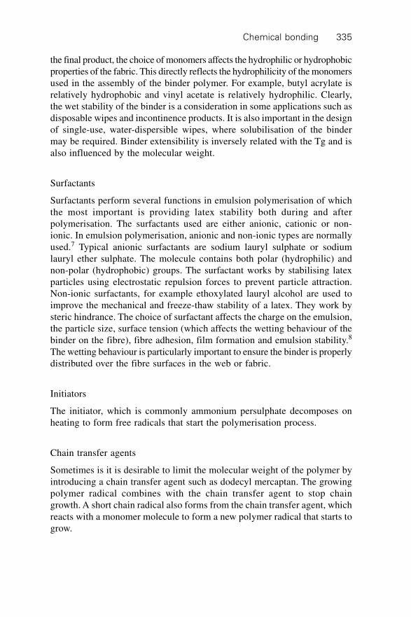
Chemical bonding 335
the final product, the choice of monomers affects the hydrophilic or hydrophobicproperties of the fabric. This directly reflects the hydrophilicity of the monomersused in the assembly of the binder polymer. For example, butyl acrylate isrelatively hydrophobic and vinyl acetate is relatively hydrophilic. Clearly,the wet stability of the binder is a consideration in some applications such asdisposable wipes and incontinence products. It is also important in the designof single-use, water-dispersible wipes, where solubilisation of the bindermay be required. Binder extensibility is inversely related with the Tg and isalso influenced by the molecular weight.
Surfactants
Surfactants perform several functions in emulsion polymerisation of whichthe most important is providing latex stability both during and afterpolymerisation. The surfactants used are either anionic, cationic or non-ionic. In emulsion polymerisation, anionic and non-ionic types are normallyused.7 Typical anionic surfactants are sodium lauryl sulphate or sodiumlauryl ether sulphate. The molecule contains both polar (hydrophilic) andnon-polar (hydrophobic) groups. The surfactant works by stabilising latexparticles using electrostatic repulsion forces to prevent particle attraction.Non-ionic surfactants, for example ethoxylated lauryl alcohol are used toimprove the mechanical and freeze-thaw stability of a latex. They work bysteric hindrance. The choice of surfactant affects the charge on the emulsion,the particle size, surface tension (which affects the wetting behaviour of thebinder on the fibre), fibre adhesion, film formation and emulsion stability.8
The wetting behaviour is particularly important to ensure the binder is properlydistributed over the fibre surfaces in the web or fabric.
Initiators
The initiator, which is commonly ammonium persulphate decomposes onheating to form free radicals that start the polymerisation process.
Chain transfer agents
Sometimes is it is desirable to limit the molecular weight of the polymer byintroducing a chain transfer agent such as dodecyl mercaptan. The growingpolymer radical combines with the chain transfer agent to stop chaingrowth. A short chain radical also forms from the chain transfer agent, whichreacts with a monomer molecule to form a new polymer radical that starts togrow.
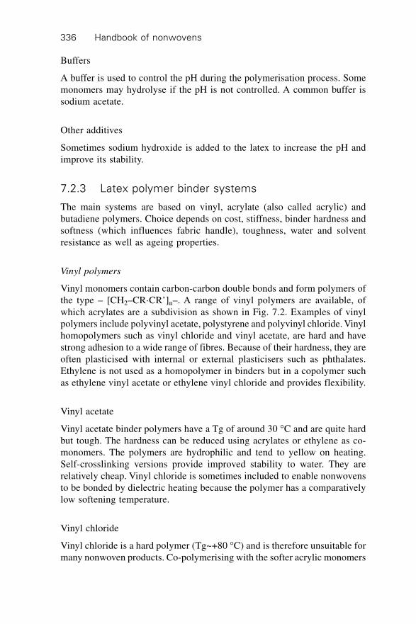
Handbook of nonwovens336
Buffers
A buffer is used to control the pH during the polymerisation process. Somemonomers may hydrolyse if the pH is not controlled. A common buffer issodium acetate.
Other additives
Sometimes sodium hydroxide is added to the latex to increase the pH andimprove its stability.
7.2.3 Latex polymer binder systems
The main systems are based on vinyl, acrylate (also called acrylic) andbutadiene polymers. Choice depends on cost, stiffness, binder hardness andsoftness (which influences fabric handle), toughness, water and solventresistance as well as ageing properties.
Vinyl polymers
Vinyl monomers contain carbon-carbon double bonds and form polymers ofthe type – [CH2–CR·CR’]n–. A range of vinyl polymers are available, ofwhich acrylates are a subdivision as shown in Fig. 7.2. Examples of vinylpolymers include polyvinyl acetate, polystyrene and polyvinyl chloride. Vinylhomopolymers such as vinyl chloride and vinyl acetate, are hard and havestrong adhesion to a wide range of fibres. Because of their hardness, they areoften plasticised with internal or external plasticisers such as phthalates.Ethylene is not used as a homopolymer in binders but in a copolymer suchas ethylene vinyl acetate or ethylene vinyl chloride and provides flexibility.
Vinyl acetate
Vinyl acetate binder polymers have a Tg of around 30 ∞C and are quite hardbut tough. The hardness can be reduced using acrylates or ethylene as co-monomers. The polymers are hydrophilic and tend to yellow on heating.Self-crosslinking versions provide improved stability to water. They arerelatively cheap. Vinyl chloride is sometimes included to enable nonwovensto be bonded by dielectric heating because the polymer has a comparativelylow softening temperature.
Vinyl chloride
Vinyl chloride is a hard polymer (Tg~+80 ∞C) and is therefore unsuitable formany nonwoven products. Co-polymerising with the softer acrylic monomers
Chemical bonding 337
reduces the hardness of the homopolymer improving its utility for nonwovenapplications. These polymers are often used because of their inherent flameretardancy arising from the chlorine content. They are also thermoplasticand can be welded using dielectric heating but like vinyl acetate they tend toyellow on heating.
Ethylene vinyl chloride
These binder polymers can be considered similar to vinyl chloride polymersbut with the ethylene monomer acting as an internal plasticiser to providegreater polymer ductility. This class of binders has a slightly broader rangeof stiffnesses than vinyl chloride but without the need for an external plasticiser.The vinyl chloride monomer also provides some attractive flame retardantproperties and can be welded using dielectric heating. They bond well tosynthetic fibres and provide good abrasion and acid resistance.
Ethylene vinyl acetate (EVA)
EVA polymers can be made with a wide range of softnesses. They tend to becheaper than acrylics and have good adhesion to many synthetic fibres. Theyare less resistant to solvents than acrylics but provide a good combination of
C
H
H
C
R¢
R
C
H
H
C
R¢
R
C
H
H
C C
H
H
C
R¢
R
R¢
R
Vinyl monomer which when polymerised formsrepeating units to produce a vinyl polymer.
Vinyl polymer
R R¢ Monomer
H H EthyleneH Cl Vinyl chlorideCl Cl Vinylidene chlorideH OCOCH3 Vinyl acetateH C6H5 StyreneH CHCH2 ButadieneH CN AcrylonitrileH COOH Acrylic acidCH3 COOH Methacrylic acidH COOC2H5 Ethyl acrylateH COOC4 H9 Butyl acrylateCH3 COOCH3 Methyl methacrylateH CONH2 AcrylamideH CONHCH2OH N-Methylol acrylamide
7.2 Vinyl monomers (adapted from Pangrazi 1992).9
Handbook of nonwovens338
high wet strength, excellent absorbency, durability and softness. They areoften used in disposable hygiene products such as wipes and are increasinglyused in the bonding of short fibre pulp airlaid fabrics used in disposablehygiene fabrics.
Vinyl acetate acrylate
These are mostly based on butyl acrylate. They can be regarded as being acompromise between vinyl acetate and acrylics, both in performance andcost. The vinyl acetate monomer is generally cheaper than the acrylics. Theacrylic monomer decreases the sensitivity to moisture and solvents.
Acrylonitrile
The homopolymer is not used as a binder by itself but when the acrylonitrilemonomer is used to make nitrile rubber it provides excellent resistance tosolvents, oil and moisture.
Styrene
Styrene monomers are hard and provide stiffness and hydrophobicity.Polystyrene homopolymer is hard and brittle at room temperature and doesnot easily form a film. For this reason it is difficult to use as an effective binder.
Acrylate polymers
Polyacrylates (commonly referred to as acrylics) are a type of vinyl polymer.The most important are copolymers of acrylic acid derivatives, especiallyacrylic acid and methacrylic acid esters. They are made from acrylatemonomers, which are esters containing vinyl groups, i.e. a group of twocarbon atoms double bonded to each other, directly attached to the carbonylatom. There are more than thirty monomers used. Their hardness and solventresistance decreases with increasing chain length of the alcohol moiety.Polymethacrylates have higher film hardness than polyacrylates.10 Crosslinkingimproves their resistance to washing at the boil and dry-cleaning but theytend to be more expensive than other binders. Common examples are ethylacrylate and butyl acrylate. To increase stiffness, these may be copolymerisedwith methacrylate, methylmethacrylate or styrene. For increased hydrophilicitymethyl acrylate monomers are used. Specifically, for increased hydrophobicity,2-ethylhexyl acrylate or styrene can be used.11 Styrenated acrylics arehydrophobic, tough binders, which are relatively cheap. They are usedwhere high wet strength is needed but at some sacrifice of UV and solventresistance.
Chemical bonding 339
Butadiene polymers
Polymers based on butadiene CH2=CH·CH=CH2 usually have relatively highelasticity and toughness and have been used since the early years of thenonwovens industry. They include natural rubber latex (polyisoprene),polychloroprene, styrene butadiene rubber (SBR) and nitrile butadiene rubber(NBR).
Natural rubber latex
This was one of the earliest binders used in the manufacture of nonwovenfabrics and was superseded by styrene butadiene and nitrile butadiene rubbers.After drying, the temperature is increased to initiate polymer crosslinking(vulcanisation). It provides an excellent soft handle and high elasticity.
Chloroprene
Polychloroprene binders are unusual in that they crystallise, causing an increasein stiffness. Their resistance to organic solvents and oils is not quite as highas NBR copolymers but they are exceptionally acid resistant. Their resistanceto weathering is better than NBR and SBR but their discoloration is greaterand they are used for some nonwoven shoe materials.
Styrene butadiene rubber (SBR)
SBR binder polymers are tough, flexible and have excellent solvent resistance.Their stiffness and hardness increases with the level of styrene. They arecheaper than acrylates and nitrile rubbers (but less elastic than the latter).Crosslinking gives them excellent water resistance.
Nitrile rubber
These are butadiene acrylonitrile copolymers. Increasing the level ofacrylonitrile in such rubbers increases the hardness. Compared to other polymersused as binders, they have low thermoplasticity and so can be sueded (orsubject to intensive mechanical abrasion) without melting the fibres in thefabric. They also have high abrasion resistance and are often used to makesynthetic leather.
7.2.4 Other polymer binders
Polyurethane
Polyurethane (PU) based binders have been favoured for many years in themanufacture of synthetic leather nonwoven fabrics as well as products where
Handbook of nonwovens340
good extensibility is required. They are applied from solvent or are producedas aqueous dispersions. Today, most PU binders are actually polyester-polyurethane copolymers. They tend to have excellent adhesion and filmforming properties. Film structure is controlled by the pH of the aqueousdispersion and acid coagulation can enable the formation of microporousfilms used in breathable membranes and coatings. In the case of solventsystems, the PU is first dissolved in dimethylformamide (DMF) and after thefabric has been impregnated, the DMF is displaced and the PU is coagulated.During drying a dense, porous structure is formed.12 PU polymers providesoft, elastic binders and films with comparatively good resistance to hydrolysisand light fastness. Water based dispersions are increasingly favoured oversolvent based PUs but they tend to have lower wet stability. PU is frequentlyused to produce low cost hydrophilic breathable coatings on fabrics.Traditionally, PEO is used to increase the inherent hydrophilicity of thesePU materials.
Phenolics
Phenolic binders are occasionally used for full saturation bonding of fabricsto make durable filter fabrics and for fabrics requiring high abrasion resistancethat are operated at high temperature, for example in clutch and brake pads.
Epoxy resins
Waterborne epoxy resins are used for bonding nonwovens when high chemicalresistance, stability at high temperatures or electrical insulation propertiesare required. Epoxy resins are particularly important in the field of fibrereinforced composites. Obviously the chemical and mechanical properties ofthe constituent fibres need to be carefully selected to achieve the correctblend of overall properties.13
7.2.5 Characteristic properties of latex polymerdispersions
Suppliers typically provide data sheets indicating the binder properties asshown in Table 7.3.14
7.2.6 Minimum film forming temperature
The minimum film forming temperature is the lowest temperature at whichan emulsion polymer can form a continuous film. It is usually several degreesabove the glass transition temperature (Tg). An emulsion polymer comprisesabout 50% by weight of polymer particles in water. As the water evaporates
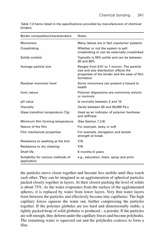
Chemical bonding 341
the particles move closer together and become less mobile until they toucheach other. They can be imagined as an agglomeration of spherical particlespacked closely together in layers. At their closest packing the level of solidsis about 75%. As the water evaporates from the surface of the agglomeratedspheres, it is replaced by water from lower layers. Very thin water layersform between the particles and effectively become tiny capillaries. The highcapillary forces squeeze the water out, further compressing the particlestogether. If the polymer globules are too hard and dimensionally stable, atightly packed heap of solid globules is produced – a powder. If the particlesare soft enough, they deform under the capillary forces and become polyhedra.The remaining water is squeezed out and the polyhedra coalesce to form afilm.
Table 7.3 Items listed in the specifications provided by manufacturers of chemical
binders
Binder composition/characteristics Notes
Monomers Many latices are in fact copolymer systems
Crosslinking Whether or not the system is self-
crosslinking or can be externally crosslinked
Solids content Typically is 50% solids and can be between
30 and 60%
Average particle size Ranges from 0.01 to 1 micron. The particle
size and size distribution affects the
properties of the binder and the ease of film
formation
Residual monomer level Some monomers can present a hazard to
health
Ionic nature Polymer dispersions are commonly anionic
or nonionic
pH value Is normally between 2 and 10
Viscosity Varies between 50 and 50,000 Pa.s
Glass transition temperature (Tg) Used as an indicator of polymer hardness
and stiffness
Minimum film forming temperature (See Section 7.2.6)
Nature of the film For example, tacky or soft
Film mechanical properties For example, elongation and tensile
strength at break
Resistance to washing at the boil Y/N
Resistance to dry cleaning Y/N
Shelf life 6 months–5 years
Suitability for various methods of e.g., saturation, foam, spray and print
application
Handbook of nonwovens342
The binder ‘hardness’ or ‘softness’ that affects the ease of film formationdepends on how the polymer chains in the latex particles are packed together.If they have no side chains (branches), they can pack together closely andbecome relatively immobile, needing significant energy, for example heatenergy, to separate them. These structures are ‘hard’. If the molecular chainshave side branches, they cannot so uniformly pack together and remain moremobile. These are ‘soft’ structures. This polymer chain mobility dependstherefore on the polymer structure and the temperature (heat energy).
As the temperature is raised, the mobility of the molecules reaches a pointcalled the minimum film forming temperature. Above this temperature thelatex particles are able to merge to form a film – polymer chains on adjacentlatex particles entwine and fuse the particles together. The ease of filmformation can be enhanced by the use of plasticisers which facilitate themovement of the polymer molecules. Water can act as a plasticiser. If water-soluble molecular units, for example acrylic acid or methacrylic acid, areincorporated into the latex particle, they act as plasticisers. Conversely, themobility can be impeded by crosslinking the molecular chains. The crosslinksinhibit the deformation of the globules to form polyhedra and the ability ofthe molecules to interpenetrate one another at the polyhedra boundaries.
Although the ability to form a film is necessary for bonding using latices,not all latex binders used in a formulation need to be film forming. Sometimesa formulation will include two latices, one a high styrene latex that will notform a film in the drying process, and the other, one that is capable of filmformation. The combination of the two introduces the required high stiffnessinto the product.
7.2.7 Functionality of latex polymers
In addition to monomers that provide the backbone of the polymer anddetermine the key physical properties of the binder, other specific monomersare added to provide specific functionality. These are of particular importanceto the processes of coagulation and crosslinking.
Coagulation and migration
As an impregnated nonwoven dries, the temperature difference through thecross-section of the fabric can cause the binder polymer to migrate to thehigher temperature regions. This differential migration results in a non-uniformdistribution of binder where the surfaces tend to have a higher concentrationof binder than the core of the fabric, which is depleted. This can lead toproblems such as fabric delamination but can be beneficial in some applicationssuch as in the manufacture of synthetic leather. In this process, the impregnatednonwoven is split through its thickness, as is natural leather, and it is important
Chemical bonding 343
that each ‘split’ component has similar properties. Thickeners have beenused to inhibit migration but they reduce penetration during impregnationand slow the process down. Some polymers can be modified so that duringdrying they coagulate and do not migrate. This is achieved by making themthermo-sensitive. When the binder reaches a particular temperature, thecoagulation temperature, the latex particles coagulate on the fibres ratherthan migrating through the fabric. The ability of a binder system to be heat-sensitised depends on the particular monomers and the level and type ofsurfactant present. Nitrile rubbers and high styrene SBR polymers can beheat sensitised. Several heat sensitising systems are known, for example,based on polyvinyl alkyl ethers, polypropylene glycols/polyacetals, divalentmetal cations/amine and organopolysiloxanes. Latices tend to be increasinglyunstable as the pH is reduced and so low pH aids heat sensitisation. The pHis adjusted with, for example, acetic acid or ammonia. Small amounts ofsome nonionic surfactant stabilisers are added. These have lower solubilityin hot water than cold. They aid room temperature stability and become lessstable as the temperature is raised, helping gelation.15 Migration of the bindercan also occur at the drying stage due to differential temperatures in thecross-section of the fabric.
Troesch and Hoffman16 commented that the binder system migrates bycapillary flow during the early stages of drying. The heat causes thermo-sensitised dispersions to form agglomerates whose diameters are larger thanthe capillaries; coagulation happens in a ‘shock-like’ manner. They point outthat the difference between the wet-bulb temperature of the material in dryingand the coagulation temperature of the binder is crucial. For complete preventionof binder migration, the coagulation temperature must be at least 5 ∞C belowthe wet bulb temperature which is typically 70–80 ∞C. They describeagglomerate structure as being fine, coarse or compact; the structure is acharacteristic of the binder and is only slightly influenced by the type ofcoagulant. The agglomerate structure of the binder can also influence fabricmechanical properties.
Crosslinking
Crosslinking the binder polymer can increase stiffness and waterproofnessof the bonded nonwoven by providing covalent bonds between polymerchains, which reduce their mobility. The crosslinking potential of a bindersystem can be classified as follows:
∑ non-crosslinking∑ crosslinkable∑ self-crosslinking∑ thermosetting.
Handbook of nonwovens344
The most well-known example of crosslinking is the vulcanisation of naturallatex or butadiene polymers with sulphur, an accelerator and zinc oxide. Theprocess is complicated and the crosslinked product tends to discolour.Functional groups are introduced into the binder polymers to make self-crosslinking systems, which are initiated by heating. Alternatively groupscan be introduced which can react with a curing resin. Acrylic emulsionstypically contain about 1–3% of functional groups such as amine, epoxy,carboxyl, ketone, hydroxyl and amide, associated with the copolymer backbonewhich react on heating to induce self-crosslinking.
Crosslinkable polymers
Functional monomers which contain hydroxyl or carboxyl groups can beintroduced into the polymer. These can be crosslinked after impregnationusing melamine formaldehyde or urea formaldehyde.
Self-crosslinking polymers
If N-methylol functional groups are introduced into the polymer, for example,as N-methylolacrylamide, they can react with themselves when the impregnatednonwoven is heated to form covalent bonds. The problem is that such emulsionscontain free formaldehyde. This is present during the preparation, storageand use of the binder. Formaldehyde is now recognised as presenting a riskto health. As a result latex suppliers developed formaldehyde scavengerssuch as acetoacetamide17 and are developing formaldehyde-free binders.18
7.2.8 Formulated binder systems
The properties of binder systems are enhanced (or the cost reduced) by theaddition of other materials. This is both necessary to facilitate processingand to enhance the properties of the bonded nonwoven, or to reduce cost.These additions are done just before application to the nonwoven batt, webor fabric. Examples of such auxiliaries are listed in Table 7.4. A descriptionof the factors affecting latex stability and rheology is given by Dodge.19
When developing a new product, polymer suppliers can often provide initialformulations.
7.3 Mechanism of chemical bonding
7.3.1 Introduction
The physical properties of a bonded nonwoven, especially the strength, aredetermined by the fibre, the polymer, the additives and the interaction between
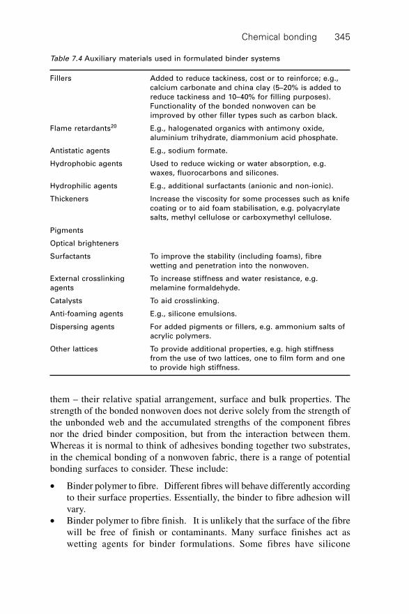
Chemical bonding 345
them – their relative spatial arrangement, surface and bulk properties. Thestrength of the bonded nonwoven does not derive solely from the strength ofthe unbonded web and the accumulated strengths of the component fibresnor the dried binder composition, but from the interaction between them.Whereas it is normal to think of adhesives bonding together two substrates,in the chemical bonding of a nonwoven fabric, there is a range of potentialbonding surfaces to consider. These include:
∑ Binder polymer to fibre. Different fibres will behave differently accordingto their surface properties. Essentially, the binder to fibre adhesion willvary.
∑ Binder polymer to fibre finish. It is unlikely that the surface of the fibrewill be free of finish or contaminants. Many surface finishes act aswetting agents for binder formulations. Some fibres have silicone
Table 7.4 Auxiliary materials used in formulated binder systems
Fillers Added to reduce tackiness, cost or to reinforce; e.g.,
calcium carbonate and china clay (5–20% is added to
reduce tackiness and 10–40% for filling purposes).
Functionality of the bonded nonwoven can be
improved by other filler types such as carbon black.
Flame retardants20 E.g., halogenated organics with antimony oxide,
aluminium trihydrate, diammonium acid phosphate.
Antistatic agents E.g., sodium formate.
Hydrophobic agents Used to reduce wicking or water absorption, e.g.
waxes, fluorocarbons and silicones.
Hydrophilic agents E.g., additional surfactants (anionic and non-ionic).
Thickeners Increase the viscosity for some processes such as knife
coating or to aid foam stabilisation, e.g. polyacrylate
salts, methyl cellulose or carboxymethyl cellulose.
Pigments
Optical brighteners
Surfactants To improve the stability (including foams), fibre
wetting and penetration into the nonwoven.
External crosslinking To increase stiffness and water resistance, e.g.
agents melamine formaldehyde.
Catalysts To aid crosslinking.
Anti-foaming agents E.g., silicone emulsions.
Dispersing agents For added pigments or fillers, e.g. ammonium salts of
acrylic polymers.
Other lattices To provide additional properties, e.g. high stiffness
from the use of two lattices, one to film form and one
to provide high stiffness.
Handbook of nonwovens346
preparations deliberately applied to inhibit wetting. Hydrophilic fibrefinishes are applied to hydrophobic fibres such as polypropylene forhygiene applications, including wipes to aid wetting out and processingefficiency in hydroentanglement. A further complication is that thesefinishes are rarely applied uniformly.
∑ Binder polymer to added filler. Fillers such as china clay are frequentlyadded to binders.
In some bonding situations the weight of binder in relation to the materialsbeing bonded, is low. At high levels of binder to fibre ratio, for example 1:1,the system could be considered not as a binder sticking together the fibres toform a network but as a continuous or porous binder matrix, filled (or reinforced)with a fibrous network, and possibly an inorganic filler such as calciumcarbonate or china clay. We also need to consider the cohesive properties ofthe binder polymer itself. Its function is not only to glue the fibres togetherbut also to contribute to the performance of the finished product, for example,by providing toughness, stiffness or elasticity.
7.3.2 Wetting
For adhesion to occur an adhesive first needs to wet the substrate, in thiscase, the fibre and the binder carrier needs to spread across the surface of thefibre. This requires the fibre surface to have a higher surface energy than thebinder polymer. It is important to realise that the surface of, for example, apolyester fibre will usually have an applied finish, and possibly contaminants,on it. This finish might not be continuous but present as ‘islands’. Thepotential bond therefore might be between binder polymer and fibre polymer,binder polymer and finish or in some cases between binder polymer andcontaminants. Some fibres are treated with silicone finishes to provide waterrepellence or increase fabric softness and such finishes are particularly difficultto bond with existing binders.
Based on the levels of binder that are most often applied, the bondednonwoven is not a fibre-filled polymer matrix, in fact, there are large spacesbetween the fibres. The binder system, normally an aqueous dispersion, isfree to move by capillary forces as the water evaporates. Therefore it canbridge two fibres where they come close together or touch, thus a bondednetwork is created and the bonded fibres are able to contribute to the overallstrength of the nonwoven. The contribution that the binder makes to theoverall mechanical properties of the fabric depends on: (i) binder polymercohesion properties (i.e., bonding to itself); (ii) binder polymer adhesionproperties (i.e., bonding to fibre, finish, filler, etc.) (iii) distribution of thebinder and the volume of binder present in relation to the volume of fibre.
Chemical bonding 347
7.3.3 Binder polymer cohesion properties
The cohesion of a liquid is the attraction between its molecules that enablesdroplets and films to form. For a film to form, the polymer particles mustcoalesce. This happens as the carrier, water, evaporates. During evaporation,capillary forces between the emulsion particles causes them to squeeze togetherto form either a powder or a film. For good bonding, formation of a film isrequired. Smaller binder polymer particles will form a more effective filmthan larger particles.21
Adhesion can be defined as the intermolecular forces that hold the touchingsurfaces of the fibre and binder polymer together. For good adhesion, thepolymer particles and carrier, i.e. water, need to wet the fibre adequately. Forthis to happen the binder carrier and the binder polymer need to have a lowersurface energy than the fibre. Water, even at temperatures close to 100 ∞C asin a dryer, is still above the surface energy of many fibres. Therefore forwetting to occur a wetting agent usually needs to be present. Polypropylenefibres have a low surface energy (about 23 mN/m)22 and are difficult tobond. Corona and plasma treatments are sometimes used to change the chemicalnature of the surface and improve wetting.
Polyester fibres have a higher surface energy of about 42 mN/m. Cellulosefibres not only have a higher surface energy than both polypropylene andpolyester synthetic fibres, they are also relatively porous enabling liquid topenetrate and to present a higher surface area that gives better bonding.Commercially available fibres have surface chemical finishes present. Thesecan be left over from the fibre manufacturing process or are deliberatelyapplied to the fibre to facilitate wetting or to modify fibre friction andelectrostatic charge generation in carding prior to bonding. They can bepresent as continuous or discontinuous thin layers. Wetting agents are oftenadded to aid liquid spreading. Even if the surface energy of the binder systemis lower than that of the fibre, wetting can be impaired if the viscosity of thebinder is high. Factors that impair film formation such as crystallinity orhigh Tg can hinder adhesion by reducing polymer flow.23 After the fibresurface has been wet, various interactions between the fibre and binder resultin a bond. If crosslinking groups are present, further heating will increase thebonds between the binder polymer molecules and the cohesive strength ofthe film. Some attempts have been made to engineer binders to migrate tofibre crossover points and not coat fibres.24 Rochery et al.25 studied theinteraction of fibres and binders in chemically bonded nonwovens andconcluded that fibre to matrix adhesion depends on many phenomena includingthe fibre surface, the way the latex is processed and the choice of latexreactants.
Handbook of nonwovens348
7.3.4 Distribution of the binder and binder to fibre ratio
Assuming that the binder carrier wets the fibre, if there is a high density offibre crossover points and sufficient binder, capillary forces can attract it tothe crossover point to form a bond. If there are relatively few crossoverpoints or a low level of binder, then the fibres will wet and coat with binderas the water evaporates and there is reduced opportunity for migration of thebinder to a crossover point. If the binder system has been sprayed on, thespray droplets may not land near a fibre crossover point and consequently,no bonding will occur in that particular region. The physical structure of thebond points that develop therefore depends on the web structure, particularlyfibre orientation and fabric density, the level of binder application, the binderflow properties and the method of application. The resulting physical structureof the bond points and their relation with surrounding fibres directly influencesfabric mechanical properties including fabric bending rigidity that is relatedto handle.
Commonly, the role of the binder is simply to bond the fibres together toachieve an increase in network strength and the binder is not intended to playa major role in dictating other properties of the final product. Nonwovenfabrics are porous materials varying in porosity from about 50% to >99% forfabric such as high loft waddings and battings. A typical polyesterneedlepunched fabric of 300 g/m2 might be 2 mm thick. Typically, the fibrein such a structure will occupy only about 10% of the total volume or spacein the fabric; most of the product is in fact air. As the binder takes up moreand more space in the fibre network, i.e. the ratio of binder to fibre isincreased, the role of the latex as a binder for the fibres becomes less important.Ultimately, as the binder content increases, the nonwoven effectively becomesa fibre-reinforced polymer (FRP) composite, the properties of which aredependent on the relative proportion of fibre polymer and binder polymerpresent. The cohesive strength of the binder polymer then strongly influencesthe strength of the fabric. This situation arises in the saturation bonding ofsome shoe reinforcement materials.
As discussed, during drying the binder system can migrate to the surfacesof the nonwoven, resulting in binder-rich surfaces and a binder-starved core.This can result in poor laminar fabric strength and is also important in themanufacture of synthetic leather where the impregnated nonwoven is splitand is important that each ‘split’ has similar levels of binder. Additionally,the chemical binder concentration can vary through the fabric cross-sectiondue to the method used to apply binder. Surface bonding and graduatedbinder content can be obtained depending on requirements.
For certain fibres, adhesion without modification of the surface by, forexample, plasma or corona treatments, is not possible. If a high level ofbinder polymer is used, then the fibres in the web can be in effect surrounded
Chemical bonding 349
or encapsulated by the binder polymer without effective surface adhesionbetween the two.
7.4 Methods of binder application
The most common methods of applying a binder system to a drylaid web ornonwoven fabric are saturation, foam, spray and print bonding. Coatingmethods are also used. For wetlaid nonwovens, most of the same methodscan used but bonding is applied after partial drying. For printing, the webmust be dry.
7.4.1 Saturation
Saturation bonding involves the complete immersion of the web or pre-bonded nonwoven either in a binder bath or by flooding the nonwoven as itenters the nip of a pair of rolls. The rate at which the binder is taken updepends on its permeability and ease of wetting. Nip rolls or vacuum slotsremove excess binder and regulate the applied binder concentration. Thismethod can provide high binder to fibre levels uniformly throughout thenonwoven.
Figures 7.3 and 7.4 show the basic principle of applying a binder usingpadding. The nonwoven is guided through the saturation bath by rollers andthen passes between a pair of nip rolls to squeeze out excess liquid. Clearly,this also compresses the substrate reducing its thickness. Sometimes threerolls are used to spread the binder more evenly and give greater penetration.In some systems, the nonwoven is pressed while it is in the bath using animmersed nip. This enables air to be removed and the nonwoven to wet fastergiving more even distribution.
The amount of binder taken up by the nonwoven depends on its weightper unit area, the length of time in the bath, the wettability of the fibres andthe nip pressure. The nip gap is usually set and maintained by applied pressure.In systems where no gap setting is required, only pressure, it is usual for oneof the rolls to be rubber coated, the other usually being chrome steel. Thetrough and nip system is often called padding or ‘dip and squeeze’. Paddersare usually either vertical or horizontal (Figs 7.3 and 7.4).
In a pad machine, the binder system is usually pumped around continuouslyand the level and concentration kept constant. Obviously, nonwovens need tobe sufficiently strong to be self-supporting when passing through the trough.Sometimes they are pre-bonded by, for example, needlepunching or thermalbonding to confer sufficient strength. It is not essential to have a bath ortrough. In the horizontal flooded nip system shown in Fig. 7.5 the nonwovenpasses through a pool of binder held above the rolls. Advantages over the vatmethod include the use of less binder and easier cleaning. Disadvantages
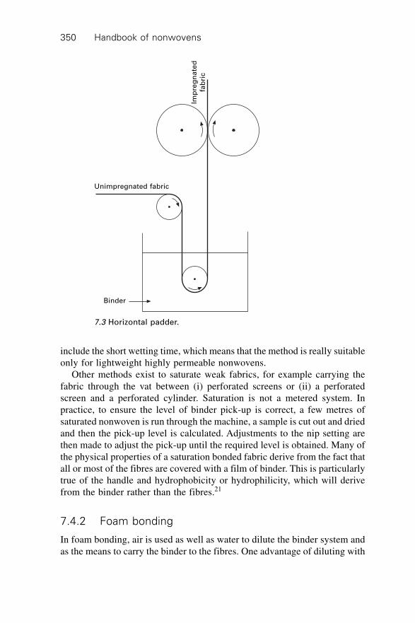
Handbook of nonwovens350
include the short wetting time, which means that the method is really suitableonly for lightweight highly permeable nonwovens.
Other methods exist to saturate weak fabrics, for example carrying thefabric through the vat between (i) perforated screens or (ii) a perforatedscreen and a perforated cylinder. Saturation is not a metered system. Inpractice, to ensure the level of binder pick-up is correct, a few metres ofsaturated nonwoven is run through the machine, a sample is cut out and driedand then the pick-up level is calculated. Adjustments to the nip setting arethen made to adjust the pick-up until the required level is obtained. Many ofthe physical properties of a saturation bonded fabric derive from the fact thatall or most of the fibres are covered with a film of binder. This is particularlytrue of the handle and hydrophobicity or hydrophilicity, which will derivefrom the binder rather than the fibres.21
7.4.2 Foam bonding
In foam bonding, air is used as well as water to dilute the binder system andas the means to carry the binder to the fibres. One advantage of diluting with
Imp
reg
na
ted
fab
ric
Unimpregnated fabric
Binder
7.3 Horizontal padder.
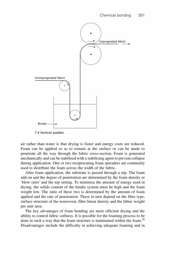
Chemical bonding 351
air rather than water is that drying is faster and energy costs are reduced.Foam can be applied so as to remain at the surface or can be made topenetrate all the way through the fabric cross-section. Foam is generatedmechanically and can be stabilised with a stabilising agent to prevent collapseduring application. One or two reciprocating foam spreaders are commonlyused to distribute the foam across the width of the fabric.
After foam application, the substrate is passed through a nip. The foamadd-on and the degree of penetration are determined by the foam density or‘blow ratio’ and the nip setting. To minimise the amount of energy used indrying, the solids content of the binder system must be high and the foamweight low. The ratio of these two is determined by the amount of foamapplied and the rate of penetration. These in turn depend on the fibre type,surface structure of the nonwoven, fibre linear density and the fabric weightper unit area.
The key advantages of foam bonding are more efficient drying and theability to control fabric softness. It is possible for the foaming process to bedone in such a way that the foam structure is maintained within the foam.26
Disadvantages include the difficulty in achieving adequate foaming and in
Impregnated fabric
Unimpregnated fabric
Binder
7.4 Vertical padder.

Handbook of nonwovens352
controlling the process to give a uniform binder distribution. Non-stabilisedfoams called ‘froths’ are sometimes used. The foam is applied as in theflooded nip system or through a slot followed by a vacuum extractor (Fig.7.6). It breaks down as it is applied and so is like saturation. As some of the‘carrier’ is air, less drying is needed than for saturation.27 Froth applicationcan be thought of as an alternative method of saturation bonding. The propertiesand uses of the fabrics are identical.21
Imp
reg
na
ted
fa
bri
cU
nim
pre
gn
ate
d f
ab
ric
Binder
Impregnated fabric
Foam or froth
7.5 Horizontal flooded nip.
7.6 Froth padder.
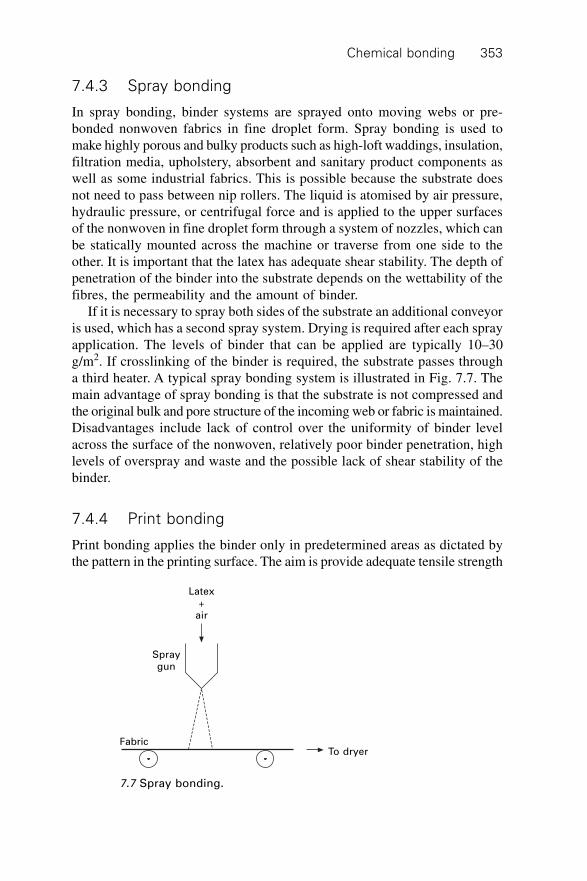
Chemical bonding 353
7.4.3 Spray bonding
In spray bonding, binder systems are sprayed onto moving webs or pre-bonded nonwoven fabrics in fine droplet form. Spray bonding is used tomake highly porous and bulky products such as high-loft waddings, insulation,filtration media, upholstery, absorbent and sanitary product components aswell as some industrial fabrics. This is possible because the substrate doesnot need to pass between nip rollers. The liquid is atomised by air pressure,hydraulic pressure, or centrifugal force and is applied to the upper surfacesof the nonwoven in fine droplet form through a system of nozzles, which canbe statically mounted across the machine or traverse from one side to theother. It is important that the latex has adequate shear stability. The depth ofpenetration of the binder into the substrate depends on the wettability of thefibres, the permeability and the amount of binder.
If it is necessary to spray both sides of the substrate an additional conveyoris used, which has a second spray system. Drying is required after each sprayapplication. The levels of binder that can be applied are typically 10–30g/m2. If crosslinking of the binder is required, the substrate passes througha third heater. A typical spray bonding system is illustrated in Fig. 7.7. Themain advantage of spray bonding is that the substrate is not compressed andthe original bulk and pore structure of the incoming web or fabric is maintained.Disadvantages include lack of control over the uniformity of binder levelacross the surface of the nonwoven, relatively poor binder penetration, highlevels of overspray and waste and the possible lack of shear stability of thebinder.
7.4.4 Print bonding
Print bonding applies the binder only in predetermined areas as dictated bythe pattern in the printing surface. The aim is provide adequate tensile strength
Latex+
air
Spraygun
FabricTo dryer
7.7 Spray bonding.
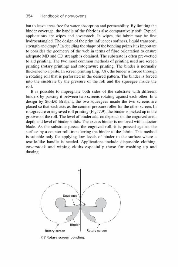
Handbook of nonwovens354
but to leave areas free for water absorption and permeability. By limiting thebinder coverage, the handle of the fabric is also comparatively soft. Typicalapplications are wipes and coverstock. In wipes, the fabric may be firsthydroentangled. The design of the print influences softness, liquid transport,strength and drape.8 In deciding the shape of the bonding points it is importantto consider the geometry of the web in terms of fibre orientation to ensureadequate MD and CD strength is obtained. The substrate is often pre-wettedto aid printing. The two most common methods of printing used are screenprinting (rotary printing) and rotogravure printing. The binder is normallythickened to a paste. In screen printing (Fig. 7.8), the binder is forced througha rotating roll that is perforated in the desired pattern. The binder is forcedinto the susbtrate by the pressure of the roll and the squeegee inside theroll.
It is possible to impregnate both sides of the substrate with differentbinders by passing it between two screens rotating against each other. In adesign by Stork® Brabant, the two squeegees inside the two screens areplaced so that each acts as the counter pressure roller for the other screen. Inrotogravure or engraved roll printing (Fig. 7.9), the binder is picked up in thegrooves of the roll. The level of binder add-on depends on the engraved area,depth and level of binder solids. The excess binder is removed with a doctorblade. As the substrate passes the engraved roll, it is pressed against thesurface by a counter roll, transferring the binder to the fabric. This methodis suitable only for applying low levels of binder to the surface where atextile-like handle is needed. Applications include disposable clothing,coverstock and wiping cloths especially those for washing up anddusting.
Squeegee
Rotary screen
Binder
Rotary screen
7.8 Rotary screen bonding.
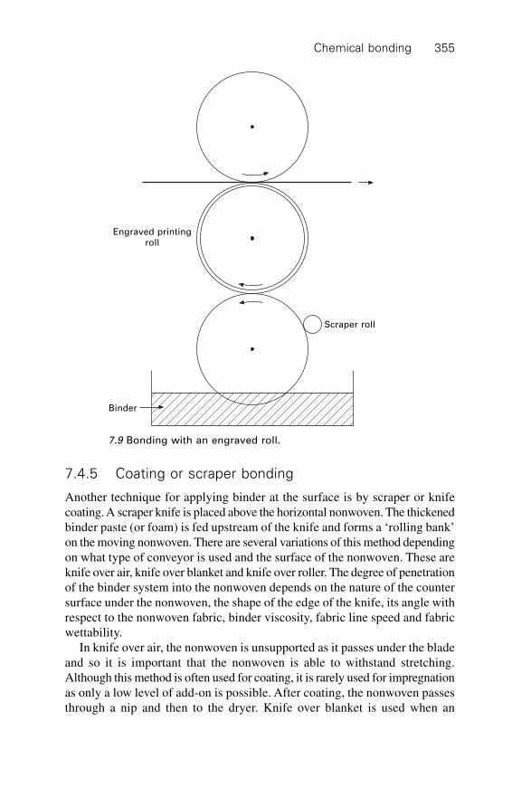
Chemical bonding 355
7.4.5 Coating or scraper bonding
Another technique for applying binder at the surface is by scraper or knifecoating. A scraper knife is placed above the horizontal nonwoven. The thickenedbinder paste (or foam) is fed upstream of the knife and forms a ‘rolling bank’on the moving nonwoven. There are several variations of this method dependingon what type of conveyor is used and the surface of the nonwoven. These areknife over air, knife over blanket and knife over roller. The degree of penetrationof the binder system into the nonwoven depends on the nature of the countersurface under the nonwoven, the shape of the edge of the knife, its angle withrespect to the nonwoven fabric, binder viscosity, fabric line speed and fabricwettability.
In knife over air, the nonwoven is unsupported as it passes under the bladeand so it is important that the nonwoven is able to withstand stretching.Although this method is often used for coating, it is rarely used for impregnationas only a low level of add-on is possible. After coating, the nonwoven passesthrough a nip and then to the dryer. Knife over blanket is used when an
Engraved printingroll
Scraper roll
Binder
7.9 Bonding with an engraved roll.
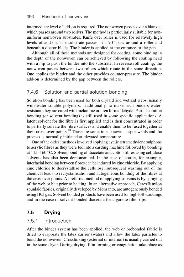
Handbook of nonwovens356
intermediate level of add-on is required. The nonwoven passes over a blanket,which passes around two rollers. The method is particularly suitable for non-uniform nonwoven substrates. Knife over roller is used for relatively highlevels of add-on. The substrate passes in a 90∞ pass around a roller andbeneath a doctor blade. The binder is applied at the entrance to the gap.
Although all of these methods are designed for coating, some binding inthe depth of the nonwoven can be achieved by following the coating headwith a nip to push the binder into the substrate. In reverse roll coating, thenonwoven passes between two rollers which rotate in the same direction.One applies the binder and the other provides counter-pressure. The binderadd-on is determined by the gap between the rollers.
7.4.6 Solution and partial solution bonding
Solution bonding has been used for both drylaid and wetlaid webs, usuallywith water soluble polymers. Traditionally, to make such binders water-resistant, they are cured with melamine or urea formaldehyde. Partial solutionbonding (or solvent bonding) is still used in some specific applications. Alatent solvent for the fibre is first applied and is then concentrated in orderto partially solvate the fibre surfaces and enable them to be fused together attheir cross-over points.28 These are sometimes known as spot-welds and theprocess is normally initiated at elevated temperature.
One of the oldest methods involved applying cyclic tetramethylene sulphoneto acrylic fibres as they were fed into a carding machine followed by bondingat 115–160 ∞C. Solvent bonding of diacetate and cotton fibres using cellulosesolvents has also been demonstrated. In the case of cotton, for example,interfacial bonding between fibres can be induced by zinc chloride. By applyingzinc chloride to decrystallise the cellulose, subsequent washing out of thechemical leads to recrystallisation and autogeneous bonding of the fibres atthe crossover points. A preferred method of applying solvents is by sprayingof the web or batt prior to heating. In an alternative approach, Cerex® nylonspunlaid fabrics, originally developed by Monsanto, are autogeneously bondedusing HCl gas. Solvent bonded products have been used for high loft waddingsand in the case of solvent bonded diacetate for cigarette filter tips.
7.5 Drying
7.5.1 Introduction
After the binder system has been applied, the web or prebonded fabric isdried to evaporate the latex carrier (water) and allow the latex particles tobond the nonwoven. Crosslinking (external or internal) is usually carried outin the same dryer. During drying, film forming or coagulation take place as
Chemical bonding 357
well as evaporation of the water and crosslinking (if crosslinking groups arepresent in the binder formulation). There are several types of dryer availableof which probably the most well known are the drum dryer, flat belt dryerand stenter-based dryers. The selection of the type of dryer depends on:
∑ type and amount of bonding agent∑ weight per unit area, strength, density and permeability of the wet
nonwoven∑ properties required in the finished product. For example, the method of
drying can affect the surface finish and stiffness of the product∑ production speed required.
The three most common drying methods used in chemical bonding rely onthe following heat transfer mechanisms: convection, conduction and radiation.
7.5.2 Convection drying
In convection drying hot air is introduced to the nonwoven to heat andevaporate the water. If the nonwoven is sufficiently permeable, the hot aircan be drawn through it and this is called ‘through-air’ drying. If the nonwovenis not permeable, hot air can be blown towards it from one or both sides. Thisis called ‘air impingement’ or ‘nozzle aeration’. In a variant of this dryingmethod, air is directed parallel to the surface of the nonwoven. The air canbe heated directly, for example, via, heat exchangers or indirectly, for example,with gas.
Through-air dryers
In a through-air dryer, the hot air is sucked through the material, leading toa very effective heat and mass transfer. The nonwoven is guided over aperforated conveyor surface (usually a drum or flat belt conveyor) throughwhich heated air passes. The most common arrangement is a perforateddrum and large radial fan. Air is withdrawn from the inside of the drum,heated and returned to the drum surface, this producing suction which holdsthe nonwoven against the drum, preventing the formation of creases.
An arrangement of several drums in sequence is common. These can bearranged horizontally, or to save space, vertically. The use of several drumsenables a temperature profile to be set through the dryer. For example, thefirst part of the arrangement might be for drying and the second part forcrosslinking.
As the nonwoven passes from drum to drum, the air is able to penetratefrom both sides. The nonwoven travels almost tension free through the dryer.The perforated drum is designed to maximise air throughput, for examplesome use a honeycomb structure to maximise the permeability and open
Handbook of nonwovens358
area. By varying the fan speed, it is possible to adjust the drying capacity ofthe line according to the characteristics (e.g., air permeability and weight perunit area) of the nonwoven.12 Fabric shrinkage can be achieved by overfeedingthe nonwoven onto the first drum. The flow of air is designed to control thetemperature at the surface to within 1 ∞C. The maximum operating temperatureis typically 250 ∞C. An alternative arrangement is a conveyor dryer. Thisprovides continuous suction through the nonwoven, unlike an array of perforateddrums. The principles of through-air drying are discussed by.29,30
Air impingement dryers
These dryers are also known as nozzle aeration dryers. For high density orlow permeability nonwovens, including paper, air impingement dryers areused. Nozzles direct the air from one or both sides to speed up evaporationby applying turbulent airflows close to the nonwoven surface. Moist air isswept away and recirculated, with some dry air being introduced.
Figures 7.10 and 7.11 show examples of single-belt and twin-belt dryers.The single-belt dryer is for drying and chemical bonding of lightweightnonwovens around 20 g/m2 and less than 3 mm thick and the double-beltsystem is for thicker nonwovens.
The temperature of the air feeding the top and bottom can be controlledseparately. A variation of the air impingement dryer is the flotation dryer(Fig. 7.12), which is often used for delicate fabric structures and is widelyused for paper products. The nonwoven floats through the space betweenalternate nozzle arrays and very high line speeds can be achieved as comparedto other systems. Figure 7.13 shows an example of a stenter dryer. Thenonwoven is held at its edges by clips or pins on revolving stenter chains asit passes through a series of oven chambers. The stenter dryer can have twoheater fans that can be separately controlled.
7.5.3 Conduction dryers
Conduction or contact dryers are sometimes used for thin, impermeablenonwovens because of their relatively low capital cost and high evaporativecapacity. They are particularly used for nonwovens that have high steampermeability especially wet-laid webs. They usually comprise a line of revolvingheated drums over which the nonwoven passes in alternate directions, givinga wrap angle that can be as high as 300∞. The surface of the nonwovenadjacent to the drum heats up and water evaporates and moves through thethickness of the nonwoven heating and evaporating in successive layers.Light nonwovens are often carried on backing felts for support. Thedisadvantages of contact drying compared to through-air drying include aslower heat transfer rate and an increase in the thermal insulation of the
Ch
em
ical b
on
din
g3
59
10
3
3
57
24
8
6
9
10
1
10
9
8
7
6
5
4
3
2
1 Gas burners
Fan+drive
Nozzle system
Circulating air intake chamber
Circulating air pressure chamber
Product
Transport conveyor
Lint filters
Door (insulated lining)
Air exhaust
7.10 Single-belt dryer.
Han
db
oo
k o
f no
nw
ove
ns
36
0
1
2
3
4
5
6
7
8
9
10
2
5
3
1010
6
4
1
8
9 3
77
7
Gas burners
Fan drive
Nozzle system
Circulating air intake chamber
Circulating air pressure chamber
Product
Transport conveyor
Lint filters
Door insulated lining
Air exhaust
7.11 Double-belt dryer.
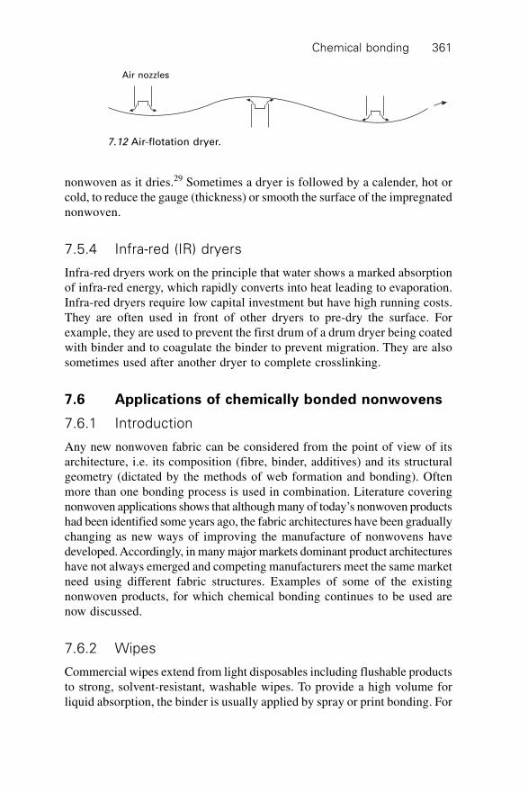
Chemical bonding 361
nonwoven as it dries.29 Sometimes a dryer is followed by a calender, hot orcold, to reduce the gauge (thickness) or smooth the surface of the impregnatednonwoven.
7.5.4 Infra-red (IR) dryers
Infra-red dryers work on the principle that water shows a marked absorptionof infra-red energy, which rapidly converts into heat leading to evaporation.Infra-red dryers require low capital investment but have high running costs.They are often used in front of other dryers to pre-dry the surface. Forexample, they are used to prevent the first drum of a drum dryer being coatedwith binder and to coagulate the binder to prevent migration. They are alsosometimes used after another dryer to complete crosslinking.
7.6 Applications of chemically bonded nonwovens
7.6.1 Introduction
Any new nonwoven fabric can be considered from the point of view of itsarchitecture, i.e. its composition (fibre, binder, additives) and its structuralgeometry (dictated by the methods of web formation and bonding). Oftenmore than one bonding process is used in combination. Literature coveringnonwoven applications shows that although many of today’s nonwoven productshad been identified some years ago, the fabric architectures have been graduallychanging as new ways of improving the manufacture of nonwovens havedeveloped. Accordingly, in many major markets dominant product architectureshave not always emerged and competing manufacturers meet the same marketneed using different fabric structures. Examples of some of the existingnonwoven products, for which chemical bonding continues to be used arenow discussed.
7.6.2 Wipes
Commercial wipes extend from light disposables including flushable productsto strong, solvent-resistant, washable wipes. To provide a high volume forliquid absorption, the binder is usually applied by spray or print bonding. For
Air nozzles
7.12 Air-flotation dryer.
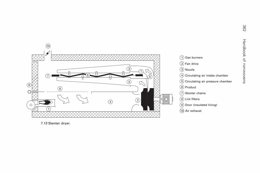
Han
db
oo
k o
f no
nw
ove
ns
36
2
7.13 Stenter dryer.
1
2
3
4
5
6
7
8
9
10
5
3
3
24
8
1
9
7
10
67
Gas burners
Fan drive
Nozzle
Circulating air intake chamber
Circulating air pressure chamber
Product
Stenter chains
Lint filters
Door (insulated lining)
Air exhaust
Chemical bonding 363
body care, softness and high water absorbency are needed and so absorbentfibres such as viscose rayon are used (often in a blend with polyester toimprove the wet strength of the fabric) with a soft binder such as a nitrilerubber having a Tg less than –18 ∞C. These are often carboxylated so thatthey can be crosslinked to increase their wet strength. Acrylics are also used.An example is print coated apertured hydroentangled nonwoven fabrics,which provide softness, good wiping efficiency, absorbency and adequatewet strength. Sometimes ethylene vinyl acetate is used for disposable wipesin place of acrylics, to reduce cost.
For industrial wipes crosslinkable styrene-butadiene is often used as thishas good solvent resistance and handle. Ethylene vinyl acetate is also usedbecause it is cheaper but it is not as resistant to solvents. When high resistanceto solvents and oil is required, acrylonitrile is used. Flushable wipes havealso been introduced, in which soluble polymer binders, for example, allowrapid breakdown of the fabric as the bond strength deteriorates in aqueousconditions. Various methods of producing flushable nonwovens rely on theappropriate choice of binder. A comprehensive list of methods to form flushablenonwovens has been given by Woodings.31
∑ hydrogen-bonded cellulose∑ hydrogen bonded and hydroentangled cellulose∑ man-made fibres bonded with water soluble polymers, for example
starches, carboxymethyl celluloses, polyethylene oxides, polyvinylalcohols, polyacrylates amongst others
∑ polyolefin fibres or films loaded with water soluble polymers, for examplepolyethylene oxide or derivatives engineered for better melt spinnability
∑ biodegradable polymers, for example PLA, blended with water solublepolymers to make fibres and fabrics
∑ fabrics made from, or pulp bonded with, water soluble fibres∑ fabrics bonded with crosslinked water soluble polymers, for example
superabsorbents in fibre or powder form∑ fabrics bonded with bicomponent fibres having a water-soluble or
hydrolysable polymer sheath∑ fabrics bonded with soft synthetic latices, which may be incompletely
cured∑ fabrics made from cellulose/synthetic blends bonded by heat where the
cellulose/synthetic thermal bond is easily disrupted by cellulose swelling∑ laminates with water soluble films or layers bonded with water soluble
adhesives∑ thin films extruded onto flushable nonwovens, which are waterproof
when the film side is wetted, but easily fragmented when both sides arewetted.
Handbook of nonwovens364
7.6.3 Interlinings
Garment interlinings require resistance to dry cleaning, washing and yellowing,as well as a level of stiffness needed for the particular part of the garment.Acrylic binders are commonly used, for example ethyl and butyl acrylateswhich are self-crosslinking to give good resistance to dry cleaning. Alsocarboxylated butadiene methacrylates are used with a Tg of 20 ∞C and 30%butadiene. A particular example is a self-crosslinking binder based on ethylacrylate and methacrylate; the methacrylate increases the stiffness. This hasa Tg of 49 ∞C and gives a clear, colourless film. It is used for impregnatingpolyester nonwovens by spray or foaming. Wetlaid, carded, airlaid,hydroentangled, needled and spunbonded nonwovens have all been used ininterlinings.
7.6.4 Hygiene and medical products
Many incontinence products are chemically bonded. These are often basedon carded or airlaid webs and require a high rate of absorption, high capacityand some softness. Very soft grades of styrene butadiene or self-crosslinkingbutyl acrylates are used. Some medical products require barrier properties.Nowadays this is provided by selection of an appropriate nonwoven fabricstructure, for example meltblowns and SMS composites or the insertion ofcontinuous films. However, some products, for example head and shoe coversas well as some surgical drapes, are chemically bonded. Acrylic binders areoften used as they are not degraded by sterilisation and are soft and hydrophobic.Another application is adhesive tape backings for medical applications, whichare made by coating carded webs with acrylic binders.
7.6.5 Footwear
Impregnated nonwovens have been used for many years as a substitute forleather in footwear. All the leather parts of a shoe except the sole can bereplaced by nonwovens, however, particular nonwoven technologies arefavoured for particular components. The outer part of the shoe, the upper, isoften made from microfibre nonwovens saturated with a coagulatedpolyurethane. These materials have excellent handle and abrasion resistancebut are expensive.
The toe and heel of a shoe are often stiffened by the incorporation of anonwoven stiffener material. These are usually needlepunched fabrics saturatedwith carboxylated styrene butadiene. High binder to fibre levels are used toachieve high stiffness and adequate resilience. In shoemaking the stiffenersare heated in the shoe in order to shape them. The Tg of the binder has to bechosen (i) sufficiently low that it is possible to shape the stiffener in shoemaking
Chemical bonding 365
without damaging the leather but (ii) sufficiently high that the stiffener doesnot lose its shape in the shop window or storage. Polystyrene binders aresometimes used. Toe stiffeners made with this latex can be activated forreshaping using either heat or solvent. Plasticisers or other latices have to beadded to bring the film-forming temperature to below 100 ∞C.
The sole and upper are attached to the insole. The two technologies usedto make a suitable nonwoven insole material are (i) the manufacture ofcellulose board using styrene butadiene as a binder and (ii) a polyesterneedlepunched fabric is saturated with a self-crosslinking styrene butadienebinder. The requirements of an insole are high perspiration absorption, stiffnessand the ability to stick the upper and sole onto it. These structures arerelatively porous and so provide the necessary perspiration absorption andsome adhesion through mechanical bonding.
The lining at the back of a high heel shoe is designed to hold the shoe onby gripping the heel. Heel linings are often polyester needlefelts saturatedwith nitrile butadiene rubber. This provides excellent abrasion resistance andsoftness. As these materials are often impregnated and dried before splitting intotwo, four or more ‘splits’, the latex is designed to coagulate to prevent migration.
7.6.6 Automotive
Nonwovens are used in car carpets, tray coverings, luggage compartmentlinings, headliners and door coverings. Needlepunched nonwovens are favoured,which are subsequently secondary bonded by chemical or thermal processes.The most common binder is styrene-butadiene although some polyvinylacetateand acrylates are used. For moulded parts to be thermoformed, the add-on isup to 60%. Saturation bonding is being replaced by foam bonding.29,30 Fibrereinforced composites consisting of glass or increasingly biocompositesincorporating bast fibre nonwovens composed of flax, jute or sisal alone orin blends are impregnated with polyester thermoset resins for use as automotivecomponents. Door panels, parcel trays and an increasing variety of additionallow-stress bearing components are being made in this way using nonwovenreinforcements. Thermoplastic PP resins are also being utilised in themanufacture of automotive components using porous drylaid andneedlepunched nonwovens as the fibre component.
7.6.7 Furniture
For the bonding of fibrefill for upholstery and bedding, self-crosslinkingstyrene acrylic copolymers with a Tg of around 8 ∞C are used. This gives asoft, only slightly extensible and tack-free film at room temperature. It hasgood resistance to a wide range of chemicals and good ageing properties. Itcan be applied by saturation, spray or foam.
Handbook of nonwovens366
7.6.8 Examples of other applications
Additional chemical bonding applications include the following:
∑ Spray bonding of high loft airlaid batts with acrylic binders for insulation.∑ Polyamide fibre abrasive pads for scrubbing pots, automotive and metal
component finishing, etc. Batts are spray bonded with phenolic binderspre-mixed with abrasive particles of carefully selected size to preventscratching.
∑ Cleaning cloths for the outside of aircraft consist of a needlepunchedweb sprayed on one side with a styrene butadiene slurry containinghydropropyl methylcellulose and nitrile rubber particles.32
∑ Prefilters can be made from high-loft airlaid nonwovens sprayed with acrosslinkable styrene butadiene binder.
∑ Roofing membranes impregnated with bitumen can be based onneedlepunched fabrics saturated with a relatively hard styrene acrylatebinder.
7.7 References
1. McIntyre J E and Daniels P N, 1995, Textile Terms and Definitions, tenth edition,Manchester, The Textile Institute.
2. Pangrazi R, 1992, ‘Nonwoven bonding technologies: there’s more than one way tobond a web’, Nonwovens Industry, October, 32–34.
3. Clamen G and Dobrowolski R, ‘Acrylic Thermosets: A Safe Alternative toFormaldehyde Resins’, 2004, Nonwovens World, Vol. 13, No. 2, pp. 96–102.
4. Polymer Latex 1 refers to How do aqueous emulsions form? by Polymer LatexGmbH & Co. KG. 0/8000136/360e.
5. Polymer Latex 2 refers to How are films produced? by Polymer Latex GmbH & Co.KG. 0/8000136/366e.
6. Wang A E, Watson S L and Miller W P, ‘Fundamentals of binder chemistry’, Journal
of coated fabrics, Vol.11, April, 208–225. (undated)7. Wilson White W, 1985, ‘Functionalised styrene-butadiene latexes for non-wovens’,
in Nonwovens binders: additives, chemistry and use seminar, TAPPI Notes, September30-October 2.
8. Pangrazi R J, 1997, ‘Chemical bonding: spray, saturation, print, & foam applicationmethods and uses’, Inda-Tec 97 Book of Papers, 6.0–6.5.
9. Pangrazi R, 1992, ‘Chemical binders for nonwovens – a primer’, INDA Journal of
Nonwovens Research, Vol. 4 No. 2 Spring, 33–36.10. Ullmann’s encyclopedia of industrial chemistry, 1996, Vol. A17 Nonwoven fabrics.11. Morris H C and Mlynar M, 1995, ‘Chemical binders and adhesives for nonwoven
fabrics’, INDA-TEC Conference 123–136.12. Lunenschloss J and Albrecht W, 1985, Non-woven Bonded Fabrics, New York, John
Wiley & Sons Inc.13. Powell K L, 1985, ‘Waterborne epoxy resins’, in Nonwovens binders: additives,
chemistry and use seminar, TAPPI Notes, September 30–October 2.14. Mango P A, 1985, ‘Binder quality – measurement, maintenance, and effect on the
Chemical bonding 367
end user’, in Nonwovens binders: additives, chemistry and use seminar, TAPPINotes, September 30–October 2.
15. Synthomer 1 refers to Heat sensitisable binders for non-woven fabrics, SynthomerLimited, Harlow, Essex. NON2 7/99.
16. Troesch J and Hoffman G, 1975, ‘The effect of binder distribution and structure onthe physical properties of nonwovens’, Paper Synthetics Conference, TAPPI, 25–35.
17. North B and Whitley D, ‘Polymer emulsion’, European Patent Office, Pat. No.0438284, July 1991.
18. Schumacher K-H and Rupaner R, 1996, ‘A formaldehyde-free acrylic binder forconstructing completely recyclable high performance nonwovens – reuse of fibersand binder’ Vliesstoff Nonwoven International Vol. 11 No. 6–8, 181–182.
19. Dodge J S, 1985, ‘Colloid chemistry fundamentals of latexes’, in Nonwovens binders:
additives, chemistry and use seminar, TAPPI Notes, September 30-October 2.20. Weil E D, 1985, ‘Flame retardants for nonwovens’, in Nonwovens binders: additives,
chemistry and use seminar, TAPPI Notes, September 30-October 2. (undated)21. Horrocks A R and Anand S C, 2000, Handbook of Technical Textiles, Cambridge,
Woodhead.22. Gupta B S and Whang H S, 1999, ‘Surface wetting and energy properties of cellulose
acetate, polyester and polypropylene fibers’, International Nonwovens Journal, Vol.8, No. 1 Spring.
23. Di Stefano F V, 1985, ‘Chemical bonding of air laid webs’, Nonwovens Industry,Vol. 16, No. 6, 16 19–20, 22, 24.
24. Blanch R M, Blanch A, Borsinger G, Lences C F and Seven M K, 2002, ‘Bindersbased on alpha-olefin/carboxylic acid/polyamide polymers and their ionomers’, UnitedStates Patent Application 20020077011, June.
25. Rochery M, Fourdrin S, Lewandowski M, Ferreira M and Bourbigot S, 2002, ‘Studyof fiber/binder adhesion in chemically bonded non-wovens’, 47th International SAMPE
Symposium, May 12–16, 1755–1766.26. Parsons J, 1999, ‘Chemical binder application technology’, 30th Nonwoven Fabrics
Symposium, Clemson University, 21–24 June.27. Mlynar M M and Sweeney E J, 1993, ‘Processing aids for resin bonded nonwoven
webs’, INDA Publication, Principles of Nonwovens, 249–257.28. Hoyle A G, 1988, ‘Bonding as a nonwoven design tool’, TAPPI Nonwovens Conference,
5–8 April, 65–69.29. Watzl A, 1989, ‘The modern concept of through drying for the nonwoven and paper
industries’, Nonwovens Conference, TAPPI Proceedings, 87–104.30. Watzl A, Production lines for nonwovens used in the automobile industry, Fleissner
publication. (undated)31. Woodings C., (http://www.nonwoven.co.uk/reports/flushability.htm):32. Mann L J and Winter P M, ‘Cleaning articles and method of making’, United States
Patent Application 20020173214, November 2002.
368
8.1 Introduction
The finishing of nonwoven fabrics is of increasing importance as producersseek to add value by increasing technical functionality, appearance or aestheticsto improve fitness for purpose. However, there are still many nonwovenproducts that undergo little finishing prior to the conversion and packagingstages of production. Some nonwoven finishing processes such as dyeing,padding and calendering have evolved from the traditional textile industrywhereas others have their origins in paper and leather finishing. Additionalprocedures have developed specifically for functionalising nonwoven substratesand are rarely applied in traditional textile finishing. Accordingly, there is nostandard finishing routine for nonwoven fabrics; the selection of processesand the finishing effects introduced depend on the particular end-use application.The increasing variety of both mechanical and particularly chemical finishesis providing significant new opportunities for transforming nonwoven basefabrics and widening the product offering.
Traditionally, finishing is classified as either wet finishing, for examplewashing, chemical impregnation, dyeing and coating or dry finishing, forexample calendering, embossing, emerising and microcreping. Nonwovensare also printed, flocked or combined with other fabrics, films and foils toform laminates, which combine the properties of each contributing layer.The impregnation of nonwoven fabrics with cosmetics, detergents, cleaningagents, medicaments and other lotions is a major activity, particularly in thehygiene and medical industries, and is frequenty undertaken as part ofconverting prior to packaging. Nonwovens are increasingly designed asapplicators or delivery vehicles for chemical compositions. Depending onthe finish required continuous processing is possible or a separate batchoperation may be adopted. A general point regarding all wet finishing operationsand dry finishing of nonwovens is the need to minimise and control operatingtensions on the fabric where possible. Nonwoven fabrics, particularly whenwater laden or when hot in the case of thermoplastics, are extensible and are
8Nonwoven fabric finishing
A I A H M E DNIRI, UK
Nonwoven fabric finishing 369
easily stretched and deformed. The fabrics tend to have comparatively poorelastic recovery and there is a risk of permanent elongation under load. Ifelongation cannot be recovered at a later stage of processing, for exampleduring drying or compacting, fabric weight and density variations can arise.A further complication is that the tensile properties of nonwoven fabrics areusually anisotropic and they have high shear rigidity, which is often nearerto paper than to conventional textile materials.
8.2 Wet finishing
8.2.1 Washing (scouring)
Washing is one of the first wet processes applied to fabrics particularlywhere aqueous dyeing or a chemical finish is to follow. Applications includethe manufacture of certain nonwoven linings such as those used in shoes thatare subsequently dyed and filtration fabrics used by the food industry. Thefabric is treated in an aqueous media, usually containing a detergent. Syntheticdetergents have largely replaced natural soaps and non-ionics are widelyused. Non-ionic detergents have good fibre compatibility and stability tovariations in water supply. They are particularly stable in hard water. Non-ionics are effective de-greasing agents, which can adversely affect fabricsoftness and anionics are selected if improved handle is required. Syntheticdetergents are easily rinsed from the fabric, are relatively cheap and aresupplied as liquids for ease of use. Washing can have a softening effect ascontaminants are removed and strain induced during fabric formation isrelaxed. Temperature, processing time, mechanical action and the additionof detergent are key factors influencing washing efficiency. The detergentcreates a separating layer between the fibre and the contaminant, coating thecontaminant with detergent. The contaminant collects into a globule, whichdetaches from the fibre. Ionic charges help prevent re-deposition ofcontaminants onto the fabric; the contaminant held in a scouring emulsion isusually stabilised by the presence of alkali. Removal of contaminants is alsofacilitated by mechanical action such as squeeze rollers, which mechanicallyseparate the contaminants from the fabric. Washing is followed by rinsing,with attention to gradual dilution of the washing emulsion, to maintain emulsionstability.
Washing machines are normally open width and continuous. The fabricmay pass around guide rollers and through a series of vats containing scouringand rinsing liquors. The fabric is squeezed at intervals to promote a scouringand liquor interchange minimising transfer of liquor from the scouring to therinsing baths. Other designs involve the use of spray bars or tangential jets,which impinge the fabric with liquor across the width of the fabric. Suction,introduced by vacuum slots, is sometimes used instead of nip rollers or in the
Handbook of nonwovens370
scouring bath itself to transfer liquor through the fabric to promote scouring.However, even with driven rollers to promote fabric overfeed and reducetension, these types of machine may impose too much strain for many nonwovenmaterials, particularly light-weights. Another favoured design includes theuse of perforated drums, around which the fabric passes. Tension is minimisedduring transport, as the fabric is overfed onto the drums. Cleaning is achievedby sucking the washing and rinsing liquors through the drum.
Washing machines are usually modular in construction and processingtensions can be further reduced by the use of relaxation zones between thescouring modules. Minimum liquor scouring reduces water use (andconcentrates detergent action) and rinsing liquors are often recycled to theinitial scour baths to further reduce water use, effluent waste and costs.
Nonwoven fabrics composed of dope dyed fibre or bonded byhydroentanglement are normally sufficiently clean and may not require furtherwet processing. It is known that hydroentanglement is capable of removinga large proportion of the wax on cotton even at low specific energy inputs.Similarly, fibre finish is stripped from the fibre necessitating low foam finishesto be applied to the fibres prior to the process.
Batch scouring, for example rope scouring, is not suitable for nonwovenfabrics because of the high propensity for creasing and the reduced processingloads. Solvent scouring is increasingly used in some areas of the industry,particularly for removing oil, waxes or spin finishes and contaminants thatare not removed successfully or adequately by aqueous scouring. Cleanfabrics reduce emissions at procedures such as heat setting. Machineryimprovements have seen totally enclosed systems, which limit perchlorethyleneemissions to reduced levels, within legislative requirements.
8.2.2 Coloration
Coloration is undertaken with either dyestuffs or pigments. For nonwovenmaterials, fabric coloration is performed in open width to avoid the creasingthat results in rope dyeing. Several coloration methods are available, principally:
∑ In dope dyeing (producer coloration or melt dyeing) the dye or pigmentsare added to the molten polymer (spinning dope) prior to melt extrusion.Dope dyeing has the disadvantage that colour commitment is made at anearly stage but excellent colour fastness can be achieved.
∑ Pigments have little fibre substantivity (or solubility) and are appliedalong with a suitable binder resin. Pigments are often applied by printingonto the nonwoven fabric along with a binder or added to the binderresin in chemical bonding processes. The bonding agent fixes the pigmentto the fibre surfaces during drying and thermal curing. Pigments must befinely ground and sufficiently well dispersed in the binder dispersion,
Nonwoven fabric finishing 371
with even application of the binder dispersion to the web to achieve auniform shade. The use of pigments when correctly bound to the fibreoffers good non-fading properties and fastness to perspiration but wetand dry rub and crock fastness may be unacceptable. Work is continuingto develop softer binder resins to minimise deleterious effects on handle.
∑ Coloration with conventional dyestuffs can be applied to the nonwovenfabric, using either batch or continuous systems. Consideration must begiven to the type of nonwoven fabric to be dyed and the nature of thefibre composition. Single fibre types dyeable with one dyestuff type isrelatively straightforward, but blends present some difficulties particularlyif the fibres cannot be dyed with the same type of dyestuff. Nonwovenfabrics composed of conventional fibres tend to dye to a deeper shadethan woven or knitted fabrics of the same composition and have a greateraccessible fibre surface area because of the high permeability and absenceof twisted yarns and yarn intersections in the fabric structure.
Typical auxiliaries for coloration processes include wetting and penetratingagents, levelling and anti-frosting agents, blocking agents if applicable in thecase of blends, dispersing agents, chemicals to adjust pH and pH buffers,anti-foaming agents, swelling and fixation chemicals (mainly pad batch).Adequate dyestuff fixation (fastness), dyestuff levelness (throughout the fabricand edge to edge) and shade reproducibility is achieved by optimising andreproducing procedures.
Modern exhaust dyeing machines enable dyeing cycles to be controlledand reproduced batch to batch. Optimised flow rates in, for example, beamdyeing, ensure dye levelness with minimal fibre damage, thus improvingfabric quality. In general, heavy or high-loft fabrics are dyed continuously, asbatch dyeing systems such as beams allow small loads, which is economicallyunfavourable and increases the possibility of shade variation. Additionally,the lateral pressure during batch processing would reduce fabric bulk.Lightweight nonwoven fabrics, however, are dyed on batch type machinery.In batch exhaust dyeing, the fabrics are loaded into the system, followed byan initial treatment in the auxiliary chemicals. During this time adequatewetting of the fabric is achieved, the auxiliary chemicals are uniformly appliedand the required pH is achieved. The dyestuffs (pre-dissolved) are then addedand the dyes are gradually exhausted from the dye bath and fixed to the fibre,by controlling pH, time, temperature and chemical addition. In beam dyeing,fabrics are initially loaded under controlled batching tension onto a perforatedbeam (the perforations enable forced liquor circulation through the fabric).The edges are aligned so that the edges of the fabric build uniformly.
It is usual practice to pre-wrap the beam with a permeable wrapper fabricto prevent marking of the beam perforations. If the beam perforations are nottotally covered by the fabric or wrapper they should be blanked off to preventchannelling during dyeing. The prepared beam is placed into a chamber,
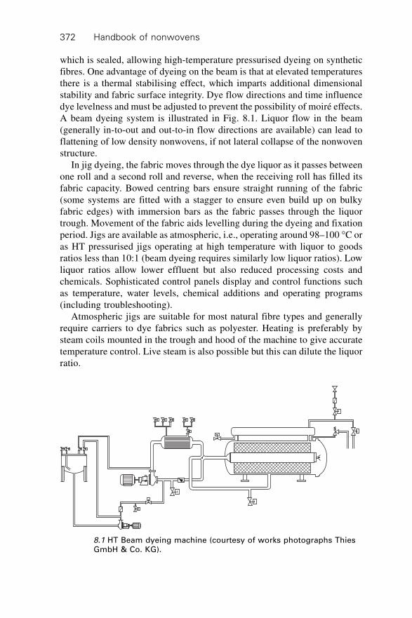
Handbook of nonwovens372
which is sealed, allowing high-temperature pressurised dyeing on syntheticfibres. One advantage of dyeing on the beam is that at elevated temperaturesthere is a thermal stabilising effect, which imparts additional dimensionalstability and fabric surface integrity. Dye flow directions and time influencedye levelness and must be adjusted to prevent the possibility of moiré effects.A beam dyeing system is illustrated in Fig. 8.1. Liquor flow in the beam(generally in-to-out and out-to-in flow directions are available) can lead toflattening of low density nonwovens, if not lateral collapse of the nonwovenstructure.
In jig dyeing, the fabric moves through the dye liquor as it passes betweenone roll and a second roll and reverse, when the receiving roll has filled itsfabric capacity. Bowed centring bars ensure straight running of the fabric(some systems are fitted with a stagger to ensure even build up on bulkyfabric edges) with immersion bars as the fabric passes through the liquortrough. Movement of the fabric aids levelling during the dyeing and fixationperiod. Jigs are available as atmospheric, i.e., operating around 98–100 ∞C oras HT pressurised jigs operating at high temperature with liquor to goodsratios less than 10:1 (beam dyeing requires similarly low liquor ratios). Lowliquor ratios allow lower effluent but also reduced processing costs andchemicals. Sophisticated control panels display and control functions suchas temperature, water levels, chemical additions and operating programs(including troubleshooting).
Atmospheric jigs are suitable for most natural fibre types and generallyrequire carriers to dye fabrics such as polyester. Heating is preferably bysteam coils mounted in the trough and hood of the machine to give accuratetemperature control. Live steam is also possible but this can dilute the liquorratio.
8.1 HT Beam dyeing machine (courtesy of works photographs ThiesGmbH & Co. KG).
Nonwoven fabric finishing 373
High temperature (HT) pressure jigs are enclosed systems allowing dyeingtemperatures of around 140 ∞C. This offers the possibility of reduced dyeingtimes and eliminates the need for carriers. Both beam and jig techniquesprovide open width dyeing avoiding the problems of creases and processingmarks which tend to occur if nonwovens are dyed in traditional batch ropetype dyeing systems and winches.
Some comment should also be made about the thermoplastic binderspresent in certain nonwoven fabrics. Clearly, the binder should be distributedregularly, should not soften or flow during dyeing at elevated temperatureand should also possess similar affinity to the dye to enable level dyeing andfastness. Binders can vary in crystallinity compared to nonwoven fibre andthis will yield unlevel dyeing. In jig dyeing, it has been found that softeningof bonding agents can lead to adherence of separate layers of nonwovenfabric, which disturbs the fabric surface and makes controlled rolling andunrolling problematic. Other coloration procedures relevant to nonwovenfabrics include pad application (the padding procedure is discussed later) ofdye to the fabric. Two methods are used:
∑ Cold pad batch dyeing, which involves padding (immersion of thenonwoven in dye liquor followed by squeezing off the excess liquor) thefabric with dyestuff and auxiliary chemicals, followed by batching thefabric on a roll for a predetermined time to allow dyestuff fixation. Thefabric batch is usually covered with impermeable sheeting to avoid drying(which reduces dye fixation) and the batch rotated during the fixationprocess to avoid seepage. Depending upon the dyestuff used it is alsopossible to heat the batch. After an appropriate time, the nonwovenfabric is open width washed to remove unfixed dyestuff and auxiliarychemicals. This procedure uses little energy for dyestuff fixation butdoes require batching equipment and batching space. It is mainly applicableto polyamide types.
∑ Continuous pad – steam dyeing in which the nonwoven fabric, particularlyheavy or high bulk fabrics, are initially padded and then steamed orsubjected to thermofixation, followed by open width washing and drying.
In chemical bonding installations, combined bonding and coloration ofnonwovens is possible, for example, in foam bonding operations, where boththe binder and pigment are dispersed in the foam before application to theweb.
8.2.3 Printing
Nonwoven fabrics are printed for many applications, particularly in the homefurnishing area including wall and floor coverings as well as tablecloths.Print bonding, in which a pigment is applied at the same time as the binder,
Handbook of nonwovens374
is also important in the manufacture of household wipes to increase wetstrength, modify appearance and to control the wet pick up of the wipe inuse. Flat screen or rotary screen techniques offer wide colour and designrange possibilities. The nonwoven fabric is fed continuously along the printtable by a moving belt and passes either continuously (in the case of rotaryprinting) or intermittently (in the case of flat screen printing) below the printscreen. A series of screens are used to build up the print design. Adhesive isapplied to the belt to keep the fabric in position. This is important to preventthe fabric from lifting during printing, which would affect print definition. Aprinting paste consisting of pigment or dyestuff (together with chemicalauxiliaries used in printing paste) is added (metered) to the print screen andcolour applied by a blade, squeegee or magnetic rod to specific areas, asdetermined by the print design. Rotary and flat screen printing (rotarypredominantly) remain the most important methods for printing high volumesof fabrics.
Improvements to these methods include reduced set up times, increasedprinting speeds, low tension fabric feed, precise screen location, minimumchangeover times between patterns, absolute control of squeegee pressuresand evenness and individual drive of printing positions for increased precision.Online print monitoring systems located after the last screen detect andreport any repetitive printing faults as they occur during rotary screen printingprocesses. Faults such as misfits, lint, miss colour and screen blockages canbe instrumentally monitored for quality control allowing modifications to bemade to reduce waste.
In the application of dyestuffs thickeners include alginates, guar gumderivatives and synthetic thickeners. Thixotropic thickeners are also usedwhich shear due to the mechanical action of the squeegee. The viscosity(dictacted by the thickener type and concentration) of the print paste isimportant to ensure the required definition and clarity of the printed area.Paste penetration into the fabric is important for some dyestuffs and fibretypes to achieve adequate fixation of the dye and solidarity/depth of shade.Prints with poor paste penetration can have poor mechanical properties, forexample, low crock (rub) fastness. Moreover, the thickening agent must bestable and maintain print definition during subsequent fixation treatments,for example steaming. Any breakdown results in flushing of the print andloss of print definition. Other additives to the print paste include wetting andlevelling agents, fixing agents, anti-foam, humectants, sequestrants andantioxidants.
Pigments are applied along with a suitable binder. Auxiliary chemicalsinclude a thickener (to improve the rheology of the paste), a cross linkingcatalyst for the binder and softeners. The pigment is applied together withthe binder in the print-bonding process. After printing and drying, the fabricis baked to cure the binder and fix the pigment. Washing is not always
Nonwoven fabric finishing 375
necessary but pigment printed fabrics can have a firm handle in the printedareas and may not be suitable for large areas of print. Concurrent with fixingthe pigment to the fibre, binders have a secondary effect on the bonding ofthe nonwoven which can enhance fabric dimensional stability.
Discharge prints allow the production of light colours on predominantlydark backgrounds using suitable dyestuffs. Generally, the fabric is initiallydyed to the required dark shade and then overprinted with a paste containinga discharging agent to discharge some/all of the base dyed colour. Thedischarging paste can contain dyes stable to the discharging agent, so that asthe base colour is discharged it is replaced by the stable applied dyestuff.Light and bright shades can be produced on dark grounds with sharp edgeand good print definition. This can be difficult to achieve if printing light anddark shades in intricate close proximity designs (print registration) usingconventional techniques. Care must be taken to optimise the dischargingprocedure as the discharging agents and procedures can affect fibre properties.
Other print procedures include engraved roller printing and sublimationtransfer techniques. With the latter, dyestuffs are transferred by sublimationfrom a release paper and pre-printed with the design and appropriate dyestuffsonto the nonwoven fabric. The release paper and fabric are brought togetherand passed around a heated drum, the design being transferred by a combinationof heat and pressure. Polyester fabrics are most suitable for printing withsublimable disperse type dyestuffs. Sublimation temperatures of around 200∞C are used and it is important that any web resin binders are stable to theapplication temperature. Disperse dyestuffs sublime at different rates andpenetration depending upon molecular weight and processing times reflectthis.
Digital ink-jet printing enables intricate computer design patterns to betransferred onto nonwoven fabric substrates. Initially developed for patternwork and shorter sampling times, full production type machinery is beingdeveloped. The print design is generated using computer software with outputto a wide bed printer of sufficient width to print directly onto fabric. Thereis no need for roll or screen engraving and use, as with conventional printing.Various systems are available, one example is the DOD system which usesthermal or bubble-jet technology whereby the print head ejects a drop of dyeat high temperature. Dyestuffs (printing inks) include reactive and acid types,disperse and pigments. Production rates are at present limited, but advancescontinue in print head mechanisms and print speeds, pre-treatment and after-treatment processes, dyestuffs with improved flow and fastness properties,etc., and CAD/software systems for fabric design and reproducibility. Thehigh porosity and variable surface structure of many nonwoven fabricsnecessitates their pre-coating or thermal calendering to provide a more suitablesurface for ink-jet printing.
Handbook of nonwovens376
8.3 Application of chemical finishes
The application of topical finishes and treatments to nonwovens is a primarymeans of functionalising fabrics but not all these finishes are durable to wettreatment and other agencies of wear. It should be noted that masterbatchadditives are now available that enable a range of functionalities to be integratedinto the fibre or filament prior to web conversion, bonding and finishing.Masterbatch additives include UV absorbers, UV stabilisers and UV filters,migratory, conductive and permanent anti-stats, antimicrobials and evenfragrances of different types.
8.3.1 Types of chemical finishes
A wide variety of chemical finishes are applied to nonwoven fabrics; someare dealt with below.
Antistatic agents
Nonwoven fabrics, particularly those composed of synthetic fibres, may beliable to clinging and the electrostatic attraction of airborne soil and dirt.Soiling is important in areas such as home furnishings including needlepunchedfloorcoverings. The mode of operation of antistatic agents vary. Some workby increasing the fibre conductivity by applying hydrophilic compounds tothe surface, others impart a charge opposite to that normally generated,neutralising the static build up. As with all the chemical finishes, durable,semi-durable and non-durable products are available from chemicalmanufacturers for specific fibre types and end uses.
Antimicrobial or biocidal finishes
These are applied where protection is required from biological degradationresulting from the growth of undesirable organisms such as bacteria andfungi. Applications include, sportswear, insulating materials, mattress tickingand bedding components, domestic furnishings, floor and wall coverings,hygiene, woundcare and healthcare products. In the case of dust mites, theproducts of which are a common irritant for asthma sufferers, antibacterialfinishes are designed to reduce the bacterial/fungal growth on which the dustmites feed. Anti-microbial finishes also help to prevent physical degradationcaused by microbial activity (e.g., mildew) or reduce the odour emissionassociated with the degradation by microbial attack of perspiration. Proprietarycompounds, metallic compounds containing silver or natural biopolymerssuch as chitosan (which can be derived from crab shells) are important in thisfield. Aqueous dispersions of chlorinated phenoxy-compounds containing
Nonwoven fabric finishing 377
pyrithione are effective against bacteria, algae, yeast and fungi and can beapplied to fabrics other than those composed of polypropylene. Liquidformulations of non-ionic AOX free formulations containing isothiazolinonesapplied to nonwovens are effective against bacteria, fungi and yeast and havegood wash stability. Padding, spraying or aqeuous coatings and foam applicationare utilised.
Lubricants (or slip agents)
Lubricants are applied to impart softness to certain nonwoven fabrics butmore particularly to reduce fibre to fibre and fibre to metal friction. This isparticularly important for procedures such as sewing (for interlinings) wherehigh velocity needles penetrate the nonwoven fabric and a lubricant is neededto reduce frictional heating and the associated mechanical damage.
Flameproof finishes
These are designed to reduced flame propagation, afterglow and charringand the suppression of smoke emission. More recent finishes for cellulosicfabrics are based on nitrogen-phosphorous compounds, often applied withhygroscopic auxiliaries which also act to suppress flammability. Phosphorousorganic compounds form the basis of the Proban R process which utilises anammonia after cure to cross link the applied polymer in the core of thefabric. Many proprietary flameproof and smoke depressant formulations areavailable for a variety of fibre types and are usually applied with binders orcatalysts for durability. In automotive fabrics, back coating of organicphosphorous salts is used to impart flame retardancy in combination with apolymer dispersion coating. In fabrics intended for use by the constructionindustry, inorganic mineral fillers act as flame retardants and can be paddedor coated in conjunction with a polymer dispersion coating. Problems withflameproof finishes can include yellowing of the fabric, decreased tensilestrength, and colour change.
Waterproof finishes
These are commonly based on silicone or fluorocarbon compounds appliedas an aqueous dispersion by padding, extraction, spraying or foam and fornonwovens anionic compounds are preferred. Fluorocarbons in particularare claimed to produce a low surface tension, which inhibits wetting. Theyare used not only for water repellency but also oil, diesel and gasoline repellencyon glass and synthetic fibres. Compared to traditional wax finishes, breathabilityand fabric aesthetics are largely maintained. Fluorocarbon finishes often
Handbook of nonwovens378
require re-proofing after laundering and this is usually accomplished bypressing, to reactivate the finish.
Softeners
In addition to protective garments and clothing, softness is of importance inhygiene products such as sanitary coverstocks and wipes but the chemicalcomposition is an important consideration in skin contact applications.Hydrophilic softeners have the additional effect of increasing wettability sothat liquids can be distributed away from areas of high liquid concentration.Hydrophilic finishes are often known as rewetters.
Stiffeners
Stiffening agents and fillers are applied to add weight, firmness and bulk tofabrics or binder chemicals to add strength and abrasion resistance by spotwelding of adjacent fibres. Spot welding also gives some control overdimensional stability. Polymer dispersions are applied by padding, slop padding,foam, spray and knife coating. For example, micro-dispersed anionicpolystyrene copolymer is applied to needlepunched carpet fabrics as a stiffener.Self-crosslinking anionic acrylate polymers are applied to needlepunchedfabrics and other nonwovens to improve dimensional stability and washresistance. Glass fabrics and polyester spunbonds are sometimes finishedwith self-crosslinking anionic polystyrene acrylate dispersions and haveexcellent thermal resistance and dimensional stability. Thermoplastic bindersare important in the manufacture of nonwoven fabrics intended for mouldingoperations. Other binding chemical finishes include anti-dust finishes, whichbind and depress dust in applications such as mats.
UV stabilisers
UV (ultraviolet) light stabilisers protect polymers and adhesives fromphotodegradation. This may be apparent by discoloration or even chemicalbreakdown, resulting in a loss of polymer properties. In the case of adhesives,even if shielded between fabric layers, edges exposed to light can degradewith loss of adhesive properties. UV protection may be achieved by use ofUV absorbers, which essentially absorb harmful UV radiation and protectthe polymer and hindered amine stabilisers, which do not absorb UV butenable a complex reaction, protecting the polymer from chemical breakdown.
8.3.2 Methods of applying chemical finishes
There are various procedures available to apply chemical finishes. Paddingand coating techniques are commonly used.
Nonwoven fabric finishing 379
Padding
Padding involves impregnating the fabric with treatment liquor or foam bymechanically forcing it into the fabric with the aid of squeeze rollers. Thefabric is squeezed to remove excess liquid to a pre-determined pick-up oradd-on. Padding is suitable for fabrics containing fibres that have littlesubstantively for the treatment chemical which could not be exhausted ontothe fabric from long liquor. If the pick-up is controlled, the level of chemicaladd-on can be determined. Depending upon the application and fibre type, itis usual practice to aim for pick-ups below saturation levels. This is mainlybecause as well as treating the fibre, the interstices between fibres holdexcess liquor, which is not cost-effective. During drying, excessive waterremoval can result in unwanted chemical migration. The situation is furthercomplicated by wet-on-dry or wet-on-wet padding. In wet-on-dry padding,the fabric is saturated with pad liquor (in most cases unevenly at this stage).Little time is available to expel air from the fabric and replace it with treatmentliquor to achieve sufficient wetting and a uniform application, during thepadding process. Wetting and de-aerating or de-foaming agents can aid thisprocess. For wet-on-wet padding the fabric is already wetted but during theprocess there must be sufficient interchange of liquor to permit replacementof wetting water by the treatment liquor to achieve the required chemicaladd-on. As with similar processes where roller nip pressure is involved (e.g.,pad dyeing), uniform application of the treatment edge to edge and throughoutthe fabric is of paramount importance.
Much work has been done regarding roller compositions and also design,for example cambered rollers, which bend when load is applied to giveuniform squeezing pressure at the ends, are well known. Other sophisticatedsystems exist that rely on self-regulating internal pressure rolls to achieveuniform line pressure.
The required application level (for wet on dry padding) can be calculatedas follows.
treatment level (%) 1000liquor pick up %
= g product / litre of pad solution
¥ 8.1
Therefore, for a treatment level of 1.5% at a pad liquor pick up of 80%
1.5 100080
= 18.8 g/ l¥ product required per litre of pad solution.
8.2
The pick-up can be established with a short piece of fabric, noting the pressuresettings and ensuring the pick-up is even across the width of the padding nip.It is only beneficial to store excess pad liquor providing the chemical beingapplied has adequate shelf life. Attention should also be paid to processing
Handbook of nonwovens380
colours; any loose dye from a previous batch will readily contaminate furtherbatches. The pad should be thoroughly cleaned down, particularly if differenttreatments are to be carried out in the same pad. Padding is usually followeddirectly by batching, drying or curing as necessary. In another application, afoamed binder is applied to both sides of a nonwoven carrier fabric beforedrying and/or curing to produce cleaning cloths.
Coating
Coating is particularly important in the application of chemical finishes (orcoating preparations) to both single use and durable nonwoven fabrics including,for example, wipes and interlinings. Coatings are generally aqueous basedand may be in the form of solutions or dispersions. In nonwoven coatingcontrol of fabric, let-off is important in the minimisation of processing tensionsto avoid undue stretching of the fabric. Weft straightening devices, magiceye centring and edge uncurling devices are also used. Aqueous coating linesare followed by hot air drying and curing, usually in a stenter if constantwidth control is required, or cans or through-air drum dryers. Economically,it is preferable to apply a coating application in one pass, providing a uniformand correct thickness of application can be achieved. However, depending onthe application, it is normally necessary to build up the coating by more thanone application. In this way, any defects such as holes or gaps caused bysolvent evaporation from the coating surface can be avoided. However,successive layers must effectively adhere.
A widely used procedure is application by rotating roller directly onto thenonwoven fabric, known as slop padding or kiss roll. Usually the slop paddingroller is loaded directly with the preparation to be applied, for examplepartially immersed in the coating preparation (float). To achieve controlledpick-ups and also to control penetration of the coating preparation, it ispossible to vary roller speed and also roller direction. These are modified tocomplement the solids content and viscosity of the application. Generally,roller direction gives greater penetration of the coating into the fabric. Excessis removed by a scraper and end plates act as dams. Helically wound wiremetering rods (known as Meyer bars) can also be used. An excess of coatingapplication is applied to the fabric and the application is controlled by thebar profile, as surplus is scraped off the fabric surface. Different diameterand profile bars are available to control the level of pick-up.
In reverse roll coating the coating preparation is metered into the nipbetween two rotating rollers, a metering roller and an application roller. Thenip or gap setting controls the level of application, which is then coated ontothe fabric as it passes around a support roller and between the applicationand support rollers. A further technique involves passing the fabric over tworollers set a predetermined distance apart, between which a knife or doctor
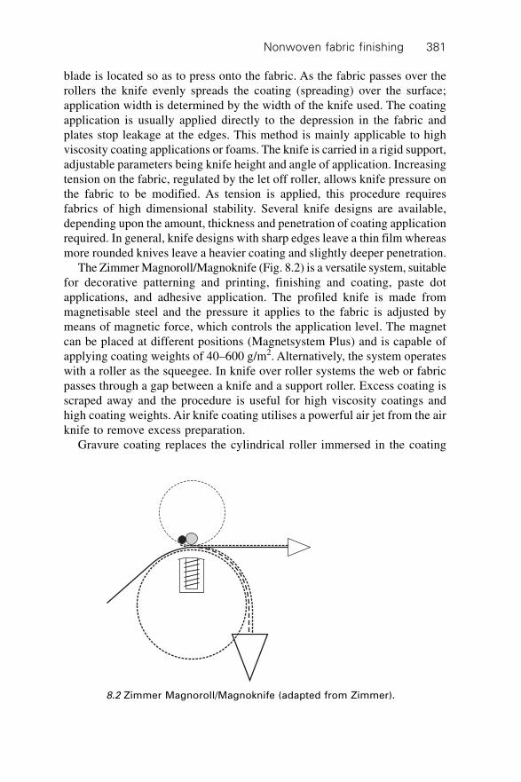
Nonwoven fabric finishing 381
blade is located so as to press onto the fabric. As the fabric passes over therollers the knife evenly spreads the coating (spreading) over the surface;application width is determined by the width of the knife used. The coatingapplication is usually applied directly to the depression in the fabric andplates stop leakage at the edges. This method is mainly applicable to highviscosity coating applications or foams. The knife is carried in a rigid support,adjustable parameters being knife height and angle of application. Increasingtension on the fabric, regulated by the let off roller, allows knife pressure onthe fabric to be modified. As tension is applied, this procedure requiresfabrics of high dimensional stability. Several knife designs are available,depending upon the amount, thickness and penetration of coating applicationrequired. In general, knife designs with sharp edges leave a thin film whereasmore rounded knives leave a heavier coating and slightly deeper penetration.
The Zimmer Magnoroll/Magnoknife (Fig. 8.2) is a versatile system, suitablefor decorative patterning and printing, finishing and coating, paste dotapplications, and adhesive application. The profiled knife is made frommagnetisable steel and the pressure it applies to the fabric is adjusted bymeans of magnetic force, which controls the application level. The magnetcan be placed at different positions (Magnetsystem Plus) and is capable ofapplying coating weights of 40–600 g/m2. Alternatively, the system operateswith a roller as the squeegee. In knife over roller systems the web or fabricpasses through a gap between a knife and a support roller. Excess coating isscraped away and the procedure is useful for high viscosity coatings andhigh coating weights. Air knife coating utilises a powerful air jet from the airknife to remove excess preparation.
Gravure coating replaces the cylindrical roller immersed in the coating
8.2 Zimmer Magnoroll/Magnoknife (adapted from Zimmer).
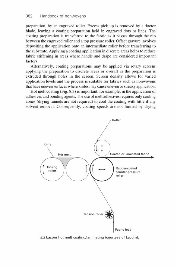
Handbook of nonwovens382
preparation, by an engraved roller. Excess pick up is removed by a doctorblade, leaving a coating preparation held in engraved dots or lines. Thecoating preparation is transferred to the fabric as it passes through the nipbetween the engraved roller and a top pressure roller. Offset gravure involvesdepositing the application onto an intermediate roller before transferring tothe substrate. Applying a coating application in discrete areas helps to reducefabric stiffening in areas where handle and drape are considered importantfactors.
Alternatively, coating preparations may be applied via rotary screensapplying the preparation to discrete areas or overall as the preparation isextruded through holes in the screen. Screen density allows for variedapplication levels and the process is suitable for fabrics such as nonwovensthat have uneven surfaces where knifes may cause uneven or streaky application.
Hot melt coating (Fig. 8.3) is important, for example, in the application ofadhesives and bonding agents. The use of melt adhesives requires only coolingzones (drying tunnels are not required) to cool the coating with little if anysolvent removal. Consequently, coating speeds are not limited by drying
Knife
Dosingroller
Hot melt
Roller
Coated or laminated fabric
Rubber-coatedcounter-pressureroller
Tension roller
Fabric feed
8.3 Lacom hot melt coating/laminating (courtesy of Lacom).
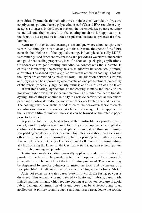
Nonwoven fabric finishing 383
capacities. Thermoplastic melt adhesives include copolyamides, polyesters,copolyesters, polyurethanes, polyurethane, coPVCs and EVA (ethylene vinylacetate) polymers. In the Lacom system, the thermoplastic coating polymeris melted and then metered to the coating machine for application tothe fabric. This operation is linked to pressure rollers to produce the finallaminate.
Extrusion (slot or slot die) coating is a technique where a hot melt polymeris extruded through a slot at an angle to the substrate, the speed of the fabriccontrols the thickness of the applied coating. Polyethylene (usually LDPE)is commonly used for economic reasons and provides a waterresistant barrierand good heat-sealing properties, ideal for food and packaging applications.Calenders ensure good coating and adhesive contact with the substrate. Inextrusion laminating, the coating acts as an adhesive between two (or more)substrates. The second layer is applied whilst the extrusion coating is hot andthe layers are combined by pressure rolls. The adhesion between substrateand polymer can be improved by electrostatic corona pre-treatment, preheatingof the fabric (especially high density fabrics) or co-extrusion of a tie layer.
In transfer coating, application of the coating is made indirectly to thenonwoven fabric via a release carrier material in a similar manner to transferdyeing. The coating is applied initially to a release carrier such as siliconisedpaper and then transferred to the nonwoven fabric at elevated heat and pressure.The coating must have sufficient adhesion to the nonwoven fabric to createa continuous film on the surface. A claimed advantage of this approach isthat a smooth film of uniform thickness can be formed on the release paperprior to transfer.
In powder dot coating, heat activated thermo-fusible dry powders basedon polyamides, polyesters and modified ethylene compounds are applied incoating and lamination processes. Applications include clothing interlinings,seat padding and door interiors for automotive fabrics and shoe linings amongstothers. The powders are normally applied by printing with either a rotaryscreen or direct contact using a heated engraved roller to give uniform coatingsat a high coating thickness. In the Caviflex system (Fig. 8.4) screen, gravureand slot die coating are possible.
Scatter (or powder) coating generally applies a random distribution ofpowder to the fabric. The powder is fed from hoppers that have moveablesidewalls to match the width of the fabric being processed. The powder maybe dispensed by needle cylinders to meter the flow and by means of asweeping blade. Applications include carpet backing and upholstery fabrics.
Paste dot relies on a water based system in which the fusing powder isdispersed. This technique is most suited to lightweight fabrics, particularlylinings and interlinings, which require coating at a low temperature to avoidfabric damage. Minimisation of drying costs can be achieved using foamapplicators. Auxiliary foaming agents and stabilisers are added to the coating
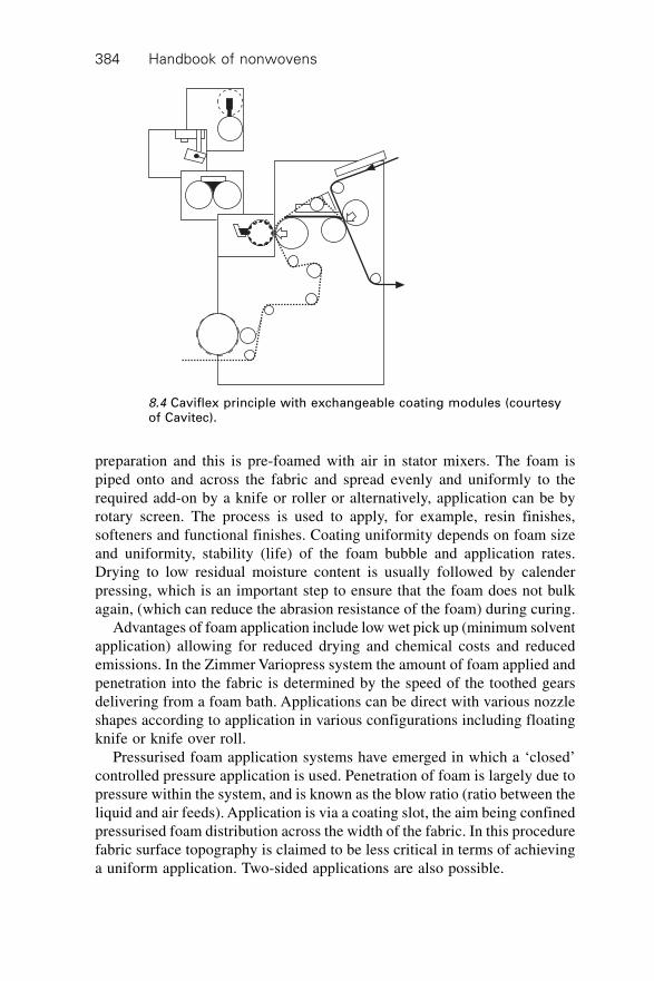
Handbook of nonwovens384
preparation and this is pre-foamed with air in stator mixers. The foam ispiped onto and across the fabric and spread evenly and uniformly to therequired add-on by a knife or roller or alternatively, application can be byrotary screen. The process is used to apply, for example, resin finishes,softeners and functional finishes. Coating uniformity depends on foam sizeand uniformity, stability (life) of the foam bubble and application rates.Drying to low residual moisture content is usually followed by calenderpressing, which is an important step to ensure that the foam does not bulkagain, (which can reduce the abrasion resistance of the foam) during curing.
Advantages of foam application include low wet pick up (minimum solventapplication) allowing for reduced drying and chemical costs and reducedemissions. In the Zimmer Variopress system the amount of foam applied andpenetration into the fabric is determined by the speed of the toothed gearsdelivering from a foam bath. Applications can be direct with various nozzleshapes according to application in various configurations including floatingknife or knife over roll.
Pressurised foam application systems have emerged in which a ‘closed’controlled pressure application is used. Penetration of foam is largely due topressure within the system, and is known as the blow ratio (ratio between theliquid and air feeds). Application is via a coating slot, the aim being confinedpressurised foam distribution across the width of the fabric. In this procedurefabric surface topography is claimed to be less critical in terms of achievinga uniform application. Two-sided applications are also possible.
8.4 Caviflex principle with exchangeable coating modules (courtesyof Cavitec).
Nonwoven fabric finishing 385
In solvent coating, the coating polymer is mixed with a suitable solventproviding a coating of suitable viscosity for application to the fabric. Generally,less heat is required to remove the solvent during drying when compared toaqueous systems but the emission of solvents or VOC (volatile organiccompound) is increasingly scrutinised and emissions should be controlled orneutralised. Water-based solvents are less problematic in this respect butrequire more energy to dry.
8.4 Lamination
Joining of two (or more) pre-formed nonwoven fabrics or alternatively,nonwoven fabrics with other roll products such as films, scrims and textilematerials, is important in the nonwovens industry and is frequently associatedwith moulding processes. The lamination of films to nonwovens, for example,is often intended to modify barrier properties (including liquids, particlesand microbes and pathogens), permeability (gases, liquids and biologicalfluids), surface properties (abrasives, friction, appearance), dimensional stabilityand other mechanical properties (including elasticity, modulus and bendingstiffness). Commercially, there are a large number of products in most sectorsof the nonwoven industry that consist of nonwoven laminates. For the laminateto become permanently joined, either one or both of the preformed fabricsmust have adhesive properties or an adhesive resin must be applied to one orboth surfaces or an ‘intermediate’ adhesive scrim placed between adjacentsurfaces must be used. Bonding is achieved by the application of heat andpressure.
Lamination can be wet or dry. In wet lamination the adhesives are appliedfrom a solvent or water dispersion and the adhesive is commonly applied toone substrate. Application is by spraying, slop padding, knife coating orspreading and printing, depending on the solvent system used, applicationlevel and surface penetration required. Concerning handle (for both wet anddry lamination) application of the adhesive in discrete, localised or pointareas by processes such as printing produces comparatively good softnessand drape in laminated fabrics. However, such localised application can leadto differential shrinkage between the laminated layers during laundering orsubsequent wet treatments.
Dry lamination uses thermoplastic resins including powders and meltadhesives composed of polyesters, polyamides and co-polymers (coPET),polyolefins, polyurethanes or scrims made from thermoplastic filaments orfibres that are placed between the two substrates to be joined. Certain co-polymers will fuse below 100 ∞C. According to the Tg, polymers can be hardand tough or flexible, soft and extensible, depending on end use; the moltenviscosity and flow characteristics are important influences in bonding. Inthe case of polymers little solvent, if any, is present for evaporation and so
Handbook of nonwovens386
a high solids bonding medium with little penetration into the fabric isachieved.
Interleaving scrims or adhesive webs for lamination are usually lightweightspunbond or meltblown materials composed of extruded low melt polymers.Despite being lightweight they must have acceptable tensile strength, elasticity,hardness, porosity and bond strength to provide the required weight toperformance ratio. They are based on polyamide, polyester, thermoplasticpolyurethane (TPU) and polyolefin polymers. Melting points are typicallybetween 75 ∞C and 200 ∞C. In the automotive industry the main uses arebonding, pre-coating, support backing, positioning, moulding and as slipsurfaces to facilitate cutting operations. Headliners, parcel trays, door appliquésand panels, seat parts, and flooring components are produced using adhesivewebs. In the manufacture of office seating, adhesive webs are used to bondmoulded foam cushions to upholstery fabrics. In luggage manufacturing, thewebs bond leather or vinyl fabrics to foam and in manufacturing compositestructures, adhesive webs are used to position glass fibres and carbon strandsin the laying-up process. In the assembly of wet filtration media, the websare used to bond needlepunched and meltblown nonwovens.
In calender (hot roll) lamination (Fig. 8.5) the film and substrate aredrawn from separate rollers and heat calendered. The temperature activatesthe adhesive film and bonds the fabrics together. Calendar laminators typicallycomprise a heated three-roll stack to heat and activate the adhesive film.Good adhesion is achieved by the interaction of line speed (which determinesthe dwell time), operating temperature and nip pressure. Wrinkling of thefilm or the laminated substrate is a known problem and is due to uncontrolledlet off tension. Wind-up tension and cooling rates need to be considered toprevent sticking and deformation of the laminated fabric.
In the Ecosafe process high processing speeds are possible because themachine heats only the thermoplastic adhesive (previously applied by scattercoating) and the surface of the second substrate, instead of the whole package
Fabric, filmor websubstrate
Film
Heated three-rollstacks or cans
Exit
8.5 Calender lamination.
Nonwoven fabric finishing 387
of materials. The process is claimed to be environmentally friendly with lowenergy consumption and application to a wide variety of substrates.
Extrusion laminating relies on the application of thermoplastic polymersto the nonwoven fabric, which are melt extruded as an adhesive sheet tolaminate two fabrics, one either side of the extruded molten film. A pressureroller nip ensures good adhesive contact. The thermoplastic polymer is meltedand pumped into a die, forming it into a thin continuous sheet. Polyethylene(particularly LDPE) is most commonly used as it is durable and easily extruded.Extrusion coating is similar but only one substrate is joined with the moltenpolymer. Pressure, speed and operating temperatures are importantconsiderations. Increasing the pressure or tension on the fabric or film canincrease the penetration of the extruded polymer into the substrate. Theviscosity can be adjusted to compensate by varying the temperature. Followingprocedures include trimming and slitting the roll to the required width. Withall coating and laminating procedures bond strength between the base fabricand the coating medium is important. For example, one layer is a base fabricand the other a molten film. In order for a good bond to be formed it isusually necessary for the molten film to ‘flow’ slightly into the base fabric toachieve good mechanical bonding. Alternatively, polymer intermediates oradhesives may be applied to the base fabric to ensure adhesion of thefilm.
Flat bed lamination relies on a different principle for combining the substratesand film. The substrate and adhesive film are combined prior to entering aheated, sometimes pressurised section. Usually a plate or belt type systembinds the substrates together. This is followed by cooling to solidify theadhesive. Infra-red pre-heaters increase the temperature of the fabric beforelamination. Advantages of the flat bed system are claimed to be versatility ofoperation (production can be piece to piece panel or roll to roll) and substratetype to be laminated. Improved adhesion is claimed due to the much longerduration times in the heating and pressing zone as compared to a nip typecontact. Extendable or modular tunnel systems allow laminating temperaturesto be much closer to the adhesive glue-line temperature, resulting in a lowertemperature during bonding and consequently, improved fabric quality. Theuse of thermoplastic or hot melt polymers in lamination is attractive becauseof the low levels of effluent and the reduced drying costs.
Flame lamination (Fig. 8.6) is widely operated in the bonding of filmsand/or nonwoven fabrics to polyurethane foams, mainly for automotiveapplications such as headliners, door panels, seats, sun visors, headrests,carpets and car boot liners. The process involves passing foam over an openflame (for one-sided operation) or between two sets of flame burners forlamination to both sides (3-ply laminate). A thin layer of molten polymer isproduced on the surface of the foam, which is combined with the substrateand film whilst still molten. The most commonly used foams are open-cell
Handbook of nonwovens388
polyester, polyether urethanes, and cross-linked polyethylene. The gas inputand flame intensity, flame height, spread and nip pressure influence bondstrength. One disadvantage of flame lamination is the gaseous emissionsproduced.
In hot melt spraying, molten synthetic polymers are heated to a hightemperature to achieve a sufficiently low viscosity to permit spraying onto afabric. During spraying the resin may be atomised to enable uniform applicationat low application levels. This is important for permeable fabrics such asnonwovens to achieve an even coverage. Immediately after spraying thecoated and non treated fabrics are brought together and bonded. The resincures on cooling and exposure to air. Claimed advantages include no additionalheating or curing step is required, no solvent is used to dissolve the resin andimproved handle and drape are claimed compared to other application systemsbecause of the minimal surface area that is coated with the polymer. Infra-red heating is often used in line with laminating systems to activate andsoften low melt temperature adhesives including polyethylene, prior tocombining fabrics for lamination. The two fabrics are subsequently laminatedusing a calendar.
End product
Pressure roller
Fabric
Flame
Foam
Flame
Film
8.6 Flame lamination.
Nonwoven fabric finishing 389
8.5 Mechanical finishing
8.5.1 Splitting and winding
To produce certain high density nonwoven fabrics with relatively low thicknessit is sometimes only possible and economical to produce a thicker structureand then to split (or level) it to the required thickness. The nonwoven fabricis fed at controlled tension over a feed table and fed between feed rollers toa precisely adjusted rotating hoop knife. The two layers are then separatedby different roller outfeed configurations and wound onto separate controlledtension winding beams. Mechanical adjustments enable splitting of nonwovenmaterials including heavily bonded needlepunched fabrics such as syntheticleather fabrics and heavyweight chemically bonded fabrics. Similarly, splittingof perpendicular-laid (Struto) fabrics has been found necessary to producethin fabrics.
8.5.2 Perforating
Perforation of nonwoven fabrics using heated needles or modified calenderrollers, for example, is useful for various purposes including increasing thevertical liquid transfer in hygiene coverstocks as well as increasing fabricsoftness and drape in interlinings. The vertical profile of the perforation canbe adjusted. Conical profiles can be made depending on the type of perforatingneedle used in order to modify the drainage properties of hygiene coverstocks.In chemically bonded nonwovens rather than reducing fabric strength, theuse of hot needles can beneficially promote cross-linking of the resin bondingagents. In slitting, longer perforations (or slits) are made in the fabric, thelength of the slit and the distance between slits can be calculated to minimisefabric strength loss.
8.5.3 Drying
Nonwoven fabrics are subjected to tension during fabric manufacture andconsequently may stretch and increase in length often with a decrease inwidth. This is particularly true when the webs are wet processed and are hot.If the extension is fully stabilised in bonding then the fabric should bedimensionally stable. If, however, it is not fully stabilised then shrinkagemay occur in further processing. Nonwoven structures often exhibit poorelastic recovery and there is a need to remove or reduce unwanted fabricextension by the introduction of relaxation or overfeed zones, for example.Tensionless steam relaxation involves continuous overfeed onto a vibratingtable and steaming without tension before cooling.
Stenter frames are applicable for drying and heat setting of some nonwovenfabrics. The fabric is held at the edges by pins or clips located on chains or
Handbook of nonwovens390
rails, which continuously transport the fabric in openwidth through the dryingchambers. Minimum width tension is needed to allow width relaxation andsome stenters are equipped with supporting beds to allow minimum tensionprocessing (as used for knitted fabrics). The rails can be adjusted in or out tocontrol width dimensions. Overfeed to allow length shrinkage may be appliedwhere the fabric is fed to the stenter pins at a speed slightly in excess of thechain running speed, usually by rubber covered rollers. When the fabric isadjusted correctly on the pins, it is transported through a series of dryingchambers. Modern stenters are equipped with optimised airflow systems toensure uniform and cost efficient drying. Moisture meters fitted to controlthe residual moisture content of fabric exiting from the dryer provide automaticfeedback to control drying parameters. Infra-red pyrometers measure fabrictemperature, optimising dwell time for fabric quality and operating costsduring heat setting or heat bonding operations. Alternatively, for thermalbonding and drying of nonwovens, forced through-air systems are used.Upper and lower nozzles allow airflow above and below the conveyor to beadjusted to control the calibration of the material.
In thermal fusion ovens, flow through and overflow techniques allow thesame oven to heat air permeable and impermeable materials. Control ofnozzle height, temperature and air regulation is possible for powder or fibrebonding, drying and heat setting. Interest in natural and recyclable nonwovenmaterials composed of bast fibres, for example flax and hemp for buildinginsulation, is a further extension of belt drying. After batt formation, thefibres are chemically impregnated to protect against mildew attack andweathering, insect damage or a flame resistant treatment is applied. The battis dried by through-air flow and compressed as it passes through the drier.Instead of heated air, heated belts or plates are used in some machines andheat is then conducted into the fabric.
Can (or drum) drying is still used for nonwovens particularly in chemicalbonding installations. The fabric to be dried is fed over a series of heatedcans, set vertically in a frame. As the fabric passes from one stainless steelcan to the next, both the face and back of the fabric are brought into contactwith the drying surface. Temperature can be graduated to ensure uniform andgradual drying and cooling. Minimisation of fabric tension and dimensioncontrol in can drying is problematic which limits the compatibility of extensiblenonwoven fabrics.
In hot flue dryers the fabric travels in festoon folds over rollers through aheated chamber. Drying air is channelled between the folds, but as with candrying, fabric tension may be high unless the rollers are driven to minimisetension and drag on the fabric. Alternative methods for drying include biaxialroll spreaders for thermoplastic nonwoven fabrics. The rollers are heated andby adjusting input and exit speeds, the fabric thickness and weight can beadjusted.
Nonwoven fabric finishing 391
Through-air drum drying and heat setting are of major importance in thenonwovens industry. Several configurations are available, including singledrum, twin vertical drum or multidrum horizontal. Generally, these are modularunits and the drum diameter varies depending on the required drying capacity.The fabric permeability is calculated to enable optimisation of drying efficiency.Through-air drying gives high heat and mass transfer through the fabric. Theair is drawn out of the drum interior by a high-capacity radial fan passingover heating elements and is forced back to the drum. This creates a pressuredifference (suction) to maintain fabric and drum contact. Tension is minimaland the fabric can be overfed from drum to drum to allow relaxation, whichis advantageous for nonwovens. This mode of drying also helps to producefabrics with good bulk and softness. High specific drying rates are claimedwith minimum energy consumption and low pattern distortion.
Infra-red heaters and drying ovens are important for pre-drying, localisedarea of thicker or higher density drying and curing. Other applications arecoagulation of thermo-sensitive binders and sintering of binder powders in,for example, the production of interlinings. Infra-red sources produce highenergy input in a short dwell time, allowing operating temperatures to bereached rapidly. Infra-red systems are being considered as a replacement forflame bonding to improve air quality.
Further post drying relaxation may be necessary. Natural (non-compressive)relaxation can be achieved using tensionless steam relaxation tables. Thefabric is continuously overfed onto the table with vibration and steaming,followed by cooling. Enclosed heads minimise but intensify the steam, givingcontrol over steaming conditions with little exhaust required, when comparedto conventional open tables.
8.5.4 Compressive finishes
Mechanical compressive shrinkage (sanforising) was originally developedfor reducing shrinkage potential to very low levels in cotton fabrics. Duringsanforising, shrinkage is achieved by passing the pre-wetted or steamedfabric around a heated cylinder in contact with a rubber belt or blanket. Thefabric is compressed in-plane as it is held in contact with the blanket (usuallyelastomeric) and the drying cylinder. As the blanket recovers originaldimensions, the fabric is compacted. Clupak (wrenching) is similar in that acontinuous rubber belt is pressed against a heated cylinder however, thecompression ratio is achieved by changing the diameter of the roll. Compactionprocesses of this type can significantly modify fabric properties. Fabric weightincreases, greater bulk and softness is observed and tensile properties maybe affected. Thermoplastic binding agents can assist the compaction processbut attention must be given to the nature of the binding agent to avoidproblems of stickiness. Hydrophobic fibres do not necessarily compact
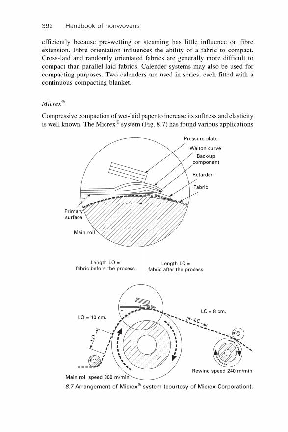
Handbook of nonwovens392
efficiently because pre-wetting or steaming has little influence on fibreextension. Fibre orientation influences the ability of a fabric to compact.Cross-laid and randomly orientated fabrics are generally more difficult tocompact than parallel-laid fabrics. Calender systems may also be used forcompacting purposes. Two calenders are used in series, each fitted with acontinuous compacting blanket.
Micrex®
Compressive compaction of wet-laid paper to increase its softness and elasticityis well known. The Micrex® system (Fig. 8.7) has found various applications
8.7 Arrangement of Micrex® system (courtesy of Micrex Corporation).
Pressure plate
Walton curve
Back-upcomponent
Retarder
Fabric
Length LO =fabric before the process
Length LC =fabric after the process
LO = 10 cm.LC = 8 cm.
LC
LO
Main roll speed 300 m/min
Rewind speed 240 m/min
Primarysurface
Main roll
Nonwoven fabric finishing 393
in the nonwovens industry. The machine has a short mechanical compactingzone. The fabric is fed onto the main roll and conveyed into a cavity, wherecompaction takes place. The system is equipped with a retarder blade etchedwith grooves. These grooves provide numerous treatment zones into whichthe fabric is compacted. The fabric is usually processed dry at relatively lowtemperatures, although the temperature can be adjusted depending on therequired tensile properties of the fabric. Normally, with thermoplastic fabricsas the temperature increases the softness decreases but the elasticity increases.
Modification of fabric softness, drape, bulk and extensibility can be impartedto wet or drylaid structures, spunbonds, spray and point bonded webs andspunlaced fabrics. A three-dimensional crepe pattern of variable amplitudeand wavelength is a characteristic feature of fabrics finished with the Micrexprocess. Marked 3D textural effects in the fabric may be formed, whichsignificantly increase the elasticity of the fabric but reduce its length. This isreferred to as microcreping. The textural effects, and increased elasticity thatare achieved have found applications in the wipes industry, particularly inrelation to staple fibre hydroentangled fabrics. The surface texture aftermicrocreping is claimed to improve the cleaning efficiency of wipes.
The degree of compaction can be calculated from the following formulae:
Compaction C(%) = LO – LC
LO 100¥ 8.3
Stretch S(%) = LO – LC
LC 100¥ 8.4
where LO is the original measured length and LC is the compacted measuredlength.
8.5.5 Calendering
Calenders are extensively used for finishing of nonwovens as well as thermalbonding. Calender designs vary but the most common are the type I designwhere the rollers are arranged vertically in line and the type L design wherethe bottom roller is set slightly forward. In hot calendering, the rollers aregenerally oil heated. Composition roll surfaces deform and enable the linepressure to be transmitted uniformly to the fabric. They are compounded tohave a range of durabilities and resilience, to withstand high temperaturesand retain properties at varying temperatures and pressures. After calenderingthe fabrics are passed over cooling rollers to reduce stretching in the hot-state during winding. In calendering, there is generally some compaction (orclosing) of the structure as the fabric is compressed, a decrease in thickness(which can result in stiffening) and, depending on the pressure used, smoothingof the fabric surface. To ensure the fabric is free from creases and runs
Handbook of nonwovens394
straight into the calender devices such as scroll openers and curved rubberexpanding rollers are fitted. For greater control of width, belt stretchingsystems are more commonly fitted where the fabric edges are nipped byrubber covered diverging pulleys extending the full width of the fabric.Alternatively, equalising pin frames are used.
Roller bulge has been used to compensate for line pressure variationsacross the calender caused by bending of the rollers during operation. Generally,the diameter of the roller in the middle was greater than that at the ends.Cross axial alignment of the rollers is also a well established approach. Inthe HyCon calender system (Fig. 8.8), an elastic sleeve compensates forvariations in deformation and allows adjustment of the line pressure. Therollers are supported by hydrostatic elements. Uniform, infinitely variablelinear forces are transmitted to the sleeve contact via an oil film. Bysymmetrically turning on and off the supporting elements, the pressing widthcan be adjusted. Generally, temperatures in this type of calender are lowerthan stainless steel calendars.
In the S-Roll (swimming roll) calender, roller deflections are compensatedacross the entire width of the fabric. A steel tube rotates around a fixed axleand the annular gap is separated by seals into two semi-circular chambers.The chamber facing the nip is hydraulically pressurised by oil. In this way,the external linear pressure is balanced by the internal oil pressure cushionwhich acts as a linear load with an infinite number of support points. S-Rollsare found in padding systems and to maximise uniformity of finish or dyeapplications two swimming rolls may be used.
Modification of finished fabric thickness and density following thermalbonding or activation of a chemical binder in a through-air oven frequentlyinvolves use of a cold calender. Belt calendering (or drum and blanket) is arather different mode of action. In conventional calendering, pressure isapplied at the roller nip whereas in belt calendering, the nonwoven fabric ispressed against a heated drum by a tensioned blanket. The contact (bonding)time is therefore significantly longer than in conventional calendering butthe pressure is reduced. The resulting fabrics are claimed to have a lesspapery finish than nonwovens processed by conventional calenders.
8.6 Surface finishing
8.6.1 Singeing
Singeing removes protruding fibres as the fabric passes at high speed overgas burner flames. An alternative system uses indirect singeing, where burnersheat panels that radiate energy onto the fabric. This procedure is claimed togive more uniform singeing, evening out variations that occur in a gas flamewith lower risk of fabric damage. Singeing of fabrics is desirable when a
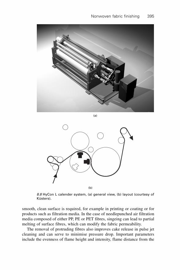
Nonwoven fabric finishing 395
smooth, clean surface is required, for example in printing or coating or forproducts such as filtration media. In the case of needlepunched air filtrationmedia composed of either PP, PE or PET fibres, singeing can lead to partialmelting of surface fibres, which can modify the fabric permeability.
The removal of protruding fibres also improves cake release in pulse jetcleaning and can serve to minimise pressure drop. Important parametersinclude the evenness of flame height and intensity, flame distance from the
(a)
8.8 HyCon L calender system, (a) general view, (b) layout (courtesy ofKüsters).
(b)
Handbook of nonwovens396
fabric, fabric speed and singeing angle. Singeing at right-angles to the fabricor at an angle is normally dependent on fibre and fabric type. For temperaturesensitive fabrics singeing is performed over a water cooled roller. The moisturecontent should be uniform throughout the fabric to ensure even singeingperformance. After singeing the fabric is rapidly cooled or wetted to preventafter burn and uneven treatment. Washing to remove singeing residues andodour usually follows.
8.6.2 Shearing
Also known as cropping or cutting, shearing is less invasive than singeing,for removing surface fibre. Compared to singeing, only partial surface fibreremoval is achieved since the variations in fabric surface topography determinethe cutting height. In shearing the fabric is usually brushed initially, to raiseloose surface fibre before passing through a series of tensioning bars andguides to the shearing cylinder. The shearing cylinder is wound with helicalblades and rotates at high speed (1000–1200 r/min). Prior to reaching theshearing cylinder, the fabric passes over an angled bed, where surface fibresare made to stand erect. These are caught by the rapidly rotating blades(usually serrated to improve contact) and cut against a stationary ledgerblade, to a pre-set height. Segmented beds allow for bulky edges and themachine operates with strong vacuum to remove cut fibres (flock) to avoidclogging of the blades. The vacuum also acts across the blades to help raisesurface fibre and along with oiled felts, to cool the shearing blades.
8.6.3 Flocking
Flocking produces a three-dimensional pile on the surface of a nonwovenbacking fabric. Flock is short cut from synthetic fibre to a pre-determinedlength or in the case of natural fibres, ground into short fibres. To adhere theflock to the base fabric, the base fabric is pre-treated with an adhesive resin,which is either area coated for total cover flocking or printed into pre-defined areas to produce patterns. Flock landing on non-printed areas readilyfalls away leaving the flocked pattern firmly anchored by adhesive to thefabric base. For high-quality velvet-like finishes, electrostatic flocking ispreferred where fibres are lined up vertically in an electrostatic field as theyland on the backing fabric. Flocked products have many applications includinginterior textiles and automotive interior panels, shoes, apparel, filters, drapesor for pattern decoration effects. Mechanical flocking methods involvingshaking or sprinkling mechanisms do not preferentially align the flock fibresand a randomised pile is produced on the fabric surface.
Nonwoven fabric finishing 397
8.6.4 Raising
Raising includes a variety of processes that produce fibrous pile structureson the surface of pre-formed fabrics. Traditionally, the fabric is passedtangentially over a series of small rotating cylinders, arranged around a largedrum (which also rotates). The small cylinders are wrapped with a filletraising wire. Fibres are raised from the surface of the fabric to produce adense collection of protruding ends (a pile). There are different cylinderconfigurations, speeds and directions (pile or counterpile). Wire types anddensity are chosen to enable a variety of raised surfaces to be produced.Depending on fibre type, raising can be carried out wet or dry. Fabric tensionis particularly important for uniform raising and to avoid fabric damage.Stencilled raising (and shearing) machines operate by using a stencil to‘blank off’ areas of the fabric. This produces either a raised pattern effect ora patterned shear effect, the shearing blades removing surface fibres notprotected by the stencil.
Sueding is a mechanical surface treatment, similar to raising except theraising wires are replaced by an emerising fillet, which abrades the fabricsurface. The process breaks surface fibres and produces a dense pile withgood softness and a subdued appearance. Sueding is applicable to mechanicallybonded fabrics containing fine fibres particularly microfibres and fabricscontaining fibres susceptible to fibrillation. A microfibrous pile can be producedfrom nonwovens containing split bicomponent fibres to produce a soft pilesurface.
8.6.5 Polishing
Polishing improves the surface lustre in fabrics with a pile surface. Surfacefibres are reorientated in one preferred direction during polishing, therebyincreasing the lustre. The fabric is brought into contact with a rapidly rotatingheated drum etched with deep spiralled grooves. The fabric is usually carriedby a blanket, which brings it into contact with the drum. Significantimprovements in handle and lustre can be achieved. For natural and hygroscopicfibres, wetting improves the effect and finish stability and reducing agentsare sometimes used to further permanise the finish. Alternatively, siliconesofteners are applied to the pile surface prior to polishing to accentuatesoftening. In cotton nonwovens, the possibility of utilising an enzymaticapproach to remove surface hairs through a process of biopolishing has beeninvestigated as a possible means of improving the surface finish.
8.6.6 Softening
Mechanical softening of fabrics (as opposed to surface softening) has seenmuch development in recent years. Fabrics are treated in an endless rope
Handbook of nonwovens398
form. Basically the fabric is transported by air (pneumatic) and in somecases lightly touching belts at high speed to impact against baffle plates orgrids. The fabric then relaxes in the bottom of the machine before continuedtreatment, until the desired finish is required. Treated fabrics have muchreduced stiffness and improved handle, bulk and drape. Many systems enablesteam or functional chemicals such as softening agents and enzymes to beintroduced for further effects. Elsewhere, low-pressure hydroentanglementafter, for example, thermal or chemical bonding has been found to improvefabric softness.
8.7 Developing technologies
8.7.1 Plasma
Plasma is an ionised gas of high energy and it is capable of chemicallymodifying the properties of fibre surfaces, particularly the surface chemistry.Glow discharge processes have been known for years but more recentlyapplications have been found in the nonwoven industry. In the plasma treatmentof fabrics, the surface of the polymer may be (i) partially removed or etched,(ii) materials may be deposited on to the surface and (iii) the surface may beactivated by an increase in surface energy. Among the various applications ofplasma processes in nonwovens, increasing the hydrophilicity of syntheticpolymer surfaces particularly with respect to polypropylene fabrics for hygieneapplications is well known. It has been shown that wetting out of nonwovenfabrics and the interaction of dyestuffs, pigments and chemical finishes canbe improved by plasma treatments. Oxygen plasma treated PP blood filtershave been produced with much higher flow rates because of improved wettingproperties. Nonwovens containing synthetic fibres such as polyester andpolypropylene can be treated to further increase hydrophobicity to obviatethe need for a fluorochemical treatment. Environmental advantages are claimeddue to low energy consumption, dry processing and no waste or effluentdisposal problems.
8.7.2 Microencapsulation
Microencapsulation is a delivery vehicle for active compounds that can beapplied to fabrics during finishing. Industrial, pharmaceutical and cosmeticapplications have been developed. A small volume of a chemical or a particleis surrounded by a coating to produce a capsule. There are a number ofpossible delivery mechanisms including wall fracture and diffusion amongstothers. The wall of the capsule may be permeable to allow controlled deliveryof the contents once applied to the fabric, or the capsule may be designed tofracture in use to release the contents. Perfumes, cosmetic lotions,
Nonwoven fabric finishing 399
thermochromic inks, thermoactive phase change materials (PCMs) and anti-microbial chemicals, for example, are applied to fabrics in the form ofmicrocapsules, usually in association with a binder resin. Another type ofencapsulation involves the use of b-cyclodextrin derivatives. These productscan be chemically attached to fibres and act as capsules to hold fragrances orother compounds which are slowly released.
8.7.3 Laser etching
Lasers, including copper vapour lasers have been shown to produce physicalmodifications to the surface of fibres in preformed fabrics. Patterning offabrics using laser impingement methods has also been demonstrated.
8.7.4 Biomimetic finishes
The structure of biological materials and the relationship with their propertiescontinues to inform new developments in functional finishing. Among thevarious examples, one that is relevant to the nonwovens industry, particularlyin respect of improving the performance of medical protective fabrics, isNanosphere® technology, which claims to simulate the surface structure ofthe lotus leaf. The particular nano-topography of the leaf surface combinedwith its hydrophobicity prevents wetting out and is claimed to render it self-cleaning. By attempting to replicate this surface structure, a self-cleaningmechanism can be conferred on the surface of fabrics. Liquids and dispersionsof various viscosities have been shown not to wet out such treated surfacesand particle contaminants can be readily removed. A simulated lotus leafstructure can be produced on a hydrophobic polymer surface by depositingtiny metal or polymer particles in a ordered array. There is significant scopeto mimic the nano- and micro-structural features of other biological structuresas a route to establishing new functional finishes.
8.7.5 Electrochemical finishes
These finishes involve pre-metallisation of a fabric surface before anelectrochemical treatment to render the surface conductive. Applications arefabric based sensors and actuators, electroluminescent fabrics and fabricelectrodes.
8.8 Fabric inspection
Fabric inspection is an important and developing area relevant to nonwovenfinishing. Inspection monitors can detect web faults such as holes, thick andthin areas and the distribution of fibres in a web, contamination and various
Handbook of nonwovens400
additional marks and process-specific defects. Real-time monitoring andfeedback of fabric weight variations (and coated fabric weights), thickness,moisture content, permeability and other properties are commercially available.
The Mahlo QMS-10A is a modular system, which can accommodate up tofour traverse assemblies, each with the facility to be attached with up to threetypes of sensor. These reciprocate across the product and provide a widthprofile. Standard interfaces enable the system to be linked to the user company’sdata network and a modem can establish a worldwide line of communicationwith the manufacturer. The Cognex SmartView uses on-line cameras andlighting to give on-line detection, identification and visualisation of defectsin nonwoven fabrics including blow-outs, calender cuts, polymer drips, fibreclumps and holes.
Trends in fault and quality inspection are towards faster inspection, widermonitoring widths and closer measuring tolerances to reduce safety margins,to reduce waste and as a consequence improve end product consistency andquality. Remote diagnosis allows data to be compared between productionlines within factories or within factory groups to control quality and exchangedata and parameter settings.
Colorimetry systems measure and control differences in colour acrossnonwoven webs, giving information on dyeing variations. For continuousdyeing ranges such as pad batch, many colour measuring systems willcharacterise colour distribution and the data enables padding settings to beadjusted to maximise dyeing quality. The SVA Lite is a compact tool thatmeasures, analyses and controls fabric shade consistency. The system isbased on a moving spectrophotometer to enable side to side and beginning toend shade variation to be characterised. The system provides a selection ofshade standards to be used as references including a fabric swatch.
8.9 Acknowledgements
My sincere thanks are due to Mr Steve Myers for his expert assistance in thepreparation of this chapter and to Mr Manoj Rathod of the NonwovensResearch Group at the University of Leeds who also helped to compile thischapter. The contributions of the following organisations are gratefullyacknowledged: EDANA, www.nonwovens.com, www.ptj.com.pk,www.textileworld.com, www.europlasma.com, The International Dyer,Nonwovens Report International (UK), JTN Monthly, www.txm.vdma.org,Ciba and www.txm.vdma.org. Thanks are also due to Küsters (Germany),Micrex Corporation (USA), Cavitec (Switzerland), Lacom (Germany), Zimmer(Austria) and Thies GmbH and Co. (Germany).
401
9.1 Introduction: characterisation of nonwovenfabrics
The physical, chemical and mechanical properties of nonwoven fabrics thatgovern their suitability for use depend on the properties of the compositionand the fabric structure. The composition in this context refers to the fibreproperties as well as chemical binders, fillers and finishes present on, betweenor within the fibres in the fabric. This chapter focuses on the characterisationof nonwoven materials and considers the influences of fabric structure on thephysical and mechanical properties of fabrics. Standard and specialised testingmethods used to determine structure and properties are presented and modelsdesigned to describe the relationship between the nonwoven structure andsome important nonwoven properties are introduced.
A nonwoven can be defined as a manufactured sheet, web or batt ofdirectionally or randomly orientated fibres, bonded by friction, and/or cohesionand/or adhesion, excluding paper and products which are woven, knitted,tufted, stitch-bonded incorporating binding yarns or filaments, or felted bywet-milling, whether or not additionally needled.1 A nonwoven structure isdifferent from some other textile structures because:
1. It principally consists of individual fibres or layers of fibrous websrather than yarns.
2. It is anisotropic both in terms of its structure and properties due to bothfibre alignment (i.e., the fibre orientation distribution) and the arrangementof the bonding points in its structure.
3. It is usually not uniform in either fabric weight and/or fabric thickness,or both.
4. It is highly porous and permeable.
In addition to the constituent fibre properties and binders, if present, thestructure of a nonwoven fabric is influenced by the web formation process,bonding method and fabric finishing processes. Although nonwoven fabrics
9Characterisation, testing and modelling of
nonwoven fabrics
N M A O and S J R U S S E L LUniversity of Leeds, UK (Sections 9.1–9.21)
B P O U R D E Y H I M INonwovens Cooperative Research Center, North Carolina
State University, USA (Section 9.22)
Handbook of nonwovens402
share some characteristics with textiles, paper and plastics in terms of structure,the fabric structures produced are particularly diverse and may be manipulatedto obtain specific functionalities and performance characteristics. The structureand properties of a nonwoven fabric are determined by fibre properties, thetype of bonding elements, the bonding interfaces between the fibres andbinder elements (if present) and the fabric structural architecture. Examplesof dimensional and structural parameters may be listed as follows:
1. Fibre dimensions and properties: fibre diameter, diameter variation (forexample, in meltblown microfibre and electrospun nanofibre webs), cross-sectional shape, crimp wave frequency and amplitude, length, density;fibre properties (Young’s modulus, elasticity, tenacity, bending and torsionrigidity, compression, friction coefficient), fibrillation propensity, surfacechemistry and wetting angle.
2. Fibre alignment: fibre orientation distribution.3. Fabric dimensions and variation: dimensions (length, width, thickness,
and weight per unit area), dimensional stability, density and thicknessuniformity.
4. Structural properties of bond points: bonding type, shape, size, bondingarea, bonding density, bond strength, bond point distribution, geometricalarrangement, the degree of liberty of fibre movement within the bondingpoints, interface properties between binder and fibre; surface propertiesof bond points.
5. Porous structural parameters: fabric porosity, pore size, pore sizedistribution, pore shape.
Examples of important nonwoven fabric properties are:
1. Mechanical properties: tensile properties (Young’s modulus, tenacity,strength and elasticity, elastic recovery, work of rupture), compressionand compression recovery, bending and shear rigidity, tear resistance,burst strength, crease resistance, abrasion, frictional properties (smoothness,roughness, friction coefficient), energy absorption.
2. Fluid handling properties: permeability, liquid absorption (liquidabsorbency, penetration time, wicking rate, re-wet, bacteria/particlecollection, repellency and barrier properties, run-off, strike time), watervapour transport and breathability.
3. Physical properties: thermal and acoustic insulation and conductivity,electrostatic properties, dielectric constant and electrical conductivity,opacity and others.
4. Chemical properties: surface wetting angle, oleophobicity andhydrophobicity, interface compatibility with binders and resins, chemicalresistance and durability to wet treatments, flame resistance, dyeingcapability, flammability, soiling resistance.
Characterisation, testing and modelling of nonwoven fabrics 403
5. Application specific performance: linting (particle generation), aestheticsand handle, filtration efficiency, biocompatibility, sterilisation compatibility,biodegradability and health and safety status.
9.2 Characterisation of fabric bond structure
Nonwoven fabrics contain bond structures, the type, shape, rigidity, size anddensity of which may be characterised. The bond points can be grouped intotwo categories: rigid, solid bonds and flexible, elastic joints, the prevalenceof which in the fabric depends on choice of manufacturing process. Thebond points in a mechanically bonded fabric, for example needlepunchedand hydroentangled, are formed by either interlacing of individual fibres orloose fibrous strands. These bonds are flexible and the component fibres areable to slip or move within the bonding points. By contrast, the bonds inthermally bonded and chemically bonded fabrics are formed by adhesion orcohesion between polymer surfaces, in which a small portion of the fibrousnetwork is firmly bonded and the fibres have little freedom to move withinthe bond points. The bond points in thermoplastic spunbond and through-airbonded fabrics are formed by melting polymer surfaces to produce bondingat fibre cross-over points and the fibres associated with these bonds cannotmove individually. In meltblown fabrics, the fibres are usually not so wellbonded together as in spunbonded fabrics and in some applications, the largesurface area is sufficient to give the web acceptable cohesion without needfor thermal, chemical or mechanical bonding. Stitch-bonded fabrics arestabilised by knitting fibres or yarns through the web and the bonding pointsare flexible but connected together by these yarns and fibres.
The size of the bond points is influenced by fabric manufacturing parameters,such as the size of needle barb depth in relation to the fibre diameter, punchdensity and number of barbs that penetrate the batt on the downstroke(needlepunching), water jet diameter, specific energy and number of injectors(hydroentanglement), the land area and bond point area, pressure and thesize of adhesive particles (thermal bonding), the method of binder application,for example full saturation, spray or printing and binder viscosity (chemicalbonding).
The rigidity of solid bond points in most nonwoven materials can bephysically characterised in terms of the measured tensile properties, forexample, strength and elasticity, while the degree of bonding may be directlydetermined by microscopic analysis of the fabric cross-section. In mechanicallybonded fabric, specifically needlepunched and hydroentangled fabric, thedepth of bent fibre loops in the bonding points can be determined and basedon the depth of these fibre segment loops, a simple but limited estimate ofbonding intensity can be derived.2
Handbook of nonwovens404
9.2.1 Needlepunched fabrics
Needlepunched fabrics have characteristic periodicities in their structuralarchitecture that result from the interaction of fibres with the needle barbs.Fibre segments are reorientated and migrated from the surface of the webtowards the interior of the fabric forming pillars of fibre orientatedapproximately perpendicular to the plane. On the fabric surface, needle markingis frequently visible, which is due to the series of punch hole locations thatmay be joined by reorientated fibres in the fabric plane running in the machinedirection.3
On a microstructural scale, needlepunched fabrics consist of at least twodifferent regions. The first, between the impact areas associated with theneedle marks, is not directly disturbed by the needles and retains a similarstructure as the original un-bonded web. The second region, the needle-marked area, contains fibre segments that are orientated approximatelyperpendicular to the fabric plane. Some fibres are realigned in the machinedirection. This rearrangement of fibre segments induced by the process,effectively increases the structural anisotropy as compared with the originalweb and therefore the structure of needlepunched fabrics is not homogeneous.Both the number of needle marks and the depth of fibre penetration arerelated to the fabric bonding quality and fabric tensile strength. The shapeand number of the holes depends mainly on the number of needles in theneedle board, the size of the needles and the needle throat depth, the fibretype and dimensions relative to the barb dimensions, the advance per strokeand the punch density.
The depth of needle penetration, the number of barbs that pass throughthe web and the distance each barb and its attached fibres travel are importantvariables influencing the microstructure. Previously, the effects of changesin penetration depth and the number of barbs3–5 on the fabric structure havebeen investigated. These experiments have demonstrated that fabric strengthis influenced by any changes in barb position as the needle passes throughthe web. Maximum fabric tenacity for a given web may be obtained withonly three barbs per apex if the depth of penetration is adjusted accordingly.Needlepunched fabrics have some fibre segments aligned in the transversedirection,4 although the majority remain aligned in-plane and the fabricshave a greater porosity and a larger number of curved inter-connected porechannels than woven fabrics. Hearle et al.3 observed that the punched loopsof fibre do not protrude from the lower surface of the fabric when the needlepenetration is small and the resulting fabric appearance and needle marks areillustrated in Fig. 9.1(a). A pseudo-knitted appearance resulting from linkedloops of fibre tufts3 produced by the needle barbs can be detected on thefabric surface when the needle penetration is large, as illustrated in Fig.9.1(b).
Characterisation, testing and modelling of nonwoven fabrics 405
9.2.2 Hydroentangled fabrics
The microstructure of hydroentangled fabrics is quite different fromneedlepunched fabrics in that the formation of discrete pillars of fibre in thefabric cross-section is absent. However, the incident high-speed water jetslocally migrate, fibre segments, both in the transverse and in-plane machinedirections. Some fibre segments impacted by the water jets are bent andformed into ‘U’ shape configurations. Bonding depends on the intertwiningof fibres together within the web.
Since fabrics are consolidated mainly in the areas where the water jetsimpact, jet marks are formed on the fabric surface, which appear as visible‘lines’ on the jet-side of the fabric running in the machine direction. Jetmarking becomes less pronounced as the number of injectors increases.Where the support surface is three-dimensional, fibres are displaced fromthe projections in the surface to form apertures and other structural patterns.This effectively produces local density variations in the fabric that can influencetensile and fluid flow properties as well as introducing variations in localfibre segment orientation. Therefore, even if the original web is isotropic,structural anisotropy is introduced during hydroentanglement that may be ofa periodic nature.
The structure of hydroentangled fabrics depends on process parametersand fibre properties. At low water jet pressure, only a small portion of fibresegments in the surface of the web are entangled and intertwined. At a highwater jet pressure, some fibre segments are reorientated towards the reverseside of the web and some fibre ends project. Fibre rigidity and bendingrecovery influence the ability of the jet to produce fibre entanglements duringhydroentanglement and therefore the structural features of hydroentangledfabrics can differ according to fibre type. An example is fabrics made frompolypropylene and viscose rayon using the same process conditions. Thespecific flexural rigidity of polypropylene fibre (0.51 mN.mm/tex2) is higherthan viscose rayon (0.35 mN.mm/tex2), and polypropylene fibre has higher
(a) Low level of needling density and low
needle penetration
(b) High level of needling density and
high needle penetration
9.1 Needled fabric structures.3
Handbook of nonwovens406
compression recovery, bending recovery and tensile recovery6 compared toviscose rayon fibre.7 In a polypropylene hydroentangled fabric, when thewater pressure is low only the surface fibres are effectively bonded, and thefibres inside the fabric are poorly entangled. The surface is therefore morecompact than the fabric core. In contrast, a viscose rayon fabric is moreconsistently bonded through the cross-section and the compaction is greaterthan in the corresponding polypropylene fabric.
9.2.3 Stitch-bonded fabrics
Stitch-bonded fabrics are formed by stitching a fibrous web together byusing either a system of additional yarns (filaments) or the fibres in the webusing a warp-knitting action. Because the formation of a stitch-bond fabricis basically a hybrid of warp-knitting and sewing, it is reflected in the fabricstructure. The fabric integrates stitching and fibrous webs, the fabric has aclear stitching pattern on at least one side of the fabric, and the stitches holdthe fibres in the fibrous web together.
There are three basic types of stitch-bonded fabric structure: (i) fibresbonded with the constituent fibres in which the stitches are observed on oneside of the fabric (Malivlies); (ii) stitches of yarns on one surface and aprojecting pile of pleated fibres on the reverse surface (Kunit); (iii) stitchesof yarns on both surfaces (Multiknit, Maliwatt). The basic structuralcharacteristics of these different types of stitch-bonded fabric structure maybe summarised as follows:8
∑ Malivlies. Malivlies fabrics are bonded by knitting fibres in the webrather than by additional yarns (filaments); therefore the fabric consistsof staple fibres. They have a warp knitted-loop stitch pattern on one sideof the fabric and the intensity of stitch bonding depends on the numberof fibres carried in the needle hook. The carrying capacity depends onthe dimensions of the hook and the fibre fineness.
∑ Kunit. Kunit fabric is a three-dimensional pile structure made from100% fibres stitched using the constituent fibres in the web. Fibres onone side of the fabric are formed into stitches, while the other side of thefabric has a pile loop structure with fibres arranged with an almostperpendicular orientation with respect to the plane. The fabric has verygood air permeability because of the high-loft structure, and excellentcompression elasticity because of the vertical pile loop structure.
∑ Multiknit (Malimo) Multiknit constructions are formed from Kunit pileloop fabric, and both sides are formed into a closed surface by stitchedloops of fibre. The two sides of the fabric are joined together by fibresorientated almost perpendicular to the plane. The fabric is stitched usingthe fibres in the original web rather than by additional yarns and therefore,a three-dimensional fabric composed of 100% staple fibres is formed.
Characterisation, testing and modelling of nonwoven fabrics 407
∑ Maliwatt. Maliwatt fabrics are fibrous webs stitched through with oneor two stitch-forming yarns. Both sides of the fabric have a yarn stitchpattern and the fabric weight per unit area ranges from 15 to 3,000 g/m2
with a fabric thickness of up to 20 mm, and a stitching yarn lineardensity in the range 44 to 4,400 dtex.
In stitch-bonded fabrics, yarn stitches are usually aligned in the fabric planewhile the fibre piles or the fibre pile loops are fixed by the stitches and aregenerally orientated perpendicular to the stitched fabric surface. Stitchbondfabric structure is determined by the warp-knitting action applied by themachine, fibre properties and dimensions, web density and structure, stitchingyarn structure, stitch density, machine gauge (number of needles per25 mm), stitching yarn tension and stitch length. Both the stitch holes andthe pile formed in the fabric surface are two unique structural characteristicsof stitchbond fabrics. The number and size of the stitch holes depends on theproperties of the stitching yarn, the properties of the fibrous web, machinegauge (number of needles per 25 mm), intermeshing intensity, interlacingand stitching yarn tension. The pile height, visible in certain stitch bondedfabrics ranges from 2 to 20 mm and depends on how the oscillating elementis set at the stitch-bonding position. Both the stitch holes and the pilesformed in the fabric surface influence fabric properties. The warp-knittingstructure in stitch-bonded nonwovens has an open fabric construction andshort underlaps, it is dimensionally extensible in the cross direction (CD) aswell as in the machine direction (MD). To increase the fabric tensile strengthin the MD a specific stitch construction is used (pillar stitch). To increase thewidthwise stability, the underlaps are lengthened (e.g., satin stitch) and athree-dimensionally stable structure is achieved by combining these twotypes of stitch construction (e.g., pillar-satin).
9.2.4 Thermal-bonded fabrics
The types of bonding structure formed in thermal-bonded fabrics depends onthe method used to introduce heat to the fibres as well as the web structureand the type of binder fibre present. In calendered thermal point-bondedfabrics, the fibres are compressed together and heat is introduced by conduction.This produces deformation of the fibres and polymer flow around the bondpoints. Around the immediate vicinity of the bond points, the heating ofsurrounding fibres can introduce interfacial bonding at the cross-overpoints of uncompressed fibres. This is known as secondary bonding and isparticularly noticeable when bicomponent fibres are present as the bindercomponent.
In through-air thermal bonded fabrics, core-sheath bicomponent fibresare commonly utilised and convected heat introduced during the process
Handbook of nonwovens408
produces the interfacial bonding at the fibre cross-over points as the polymersoftens and flows. There is no associated deformation of the fibres at theselocations and therefore the resulting fabric density is lower as compared toa calendered thermally bonded fabric. Calendered thermal bond structuresare found in a host of nonwoven materials both in monolithic and multi-layerfabrics including SMS and other spunbond-meltblown web combinations.
9.2.5 Chemically bonded fabrics
Chemically bonded fabrics are produced by the application of a resin emulsion(e.g., acrylic, polyvinyl acetate, or other suitable chemical binder) to the webthat is then dried and cured. The distribution of the resin binder in the fabricis largely governed by its method of application to the web and the flowproperties of the resin between fibres. Large numbers of fibres may beenveloped by a film binder connecting both fibre cross-over points and inter-fibre spaces and large segments of these film binders are visible in suchstructures that span adjacent fibres. Alternatively, the polymer may beconcentrated at the fibre cross-over points producing localised bonding inthese regions and either rigid or flexible bonds depending on the polymercomposition of the binder.
9.3 Fabric weight, thickness, density and otherdimensional parameters
The structure and dimensions of nonwoven fabrics are frequently characterisedin terms of fabric weight per unit area, thickness, density, fabric uniformity,fabric porosity, pore size and pore size distribution, fibre orientation distribution,bonding segment structure and the distribution.
Nonwoven fabric weight (or fabric mass) is defined as the mass per unitarea of the fabric and is usually measured in g/m2 (or gsm). Fabric thicknessis defined as the distance between the two fabric surfaces under a specifiedapplied pressure, which varies if the fabric is high-loft (or compressible).The fabric weight and thickness determine the fabric packing density, whichinfluences the freedom of movement of the fibres and determines the porosity(the proportion of voids) in a nonwoven structure. The freedom of movementof the fibres plays an important role in nonwoven mechanical properties andthe proportion of voids determines the fabric porosity, pore sizes andpermeability in a nonwoven structure. Fabric density, or bulk density, is theweight per unit volume of the nonwoven fabric (kg/m3). It equals the measuredweight per unit area (kg/m2) divided by the measured thickness of thefabric (m). Fabric bulk density together with fabric porosity is importantbecause they influence how easily fluids, heat and sound transport througha fabric.
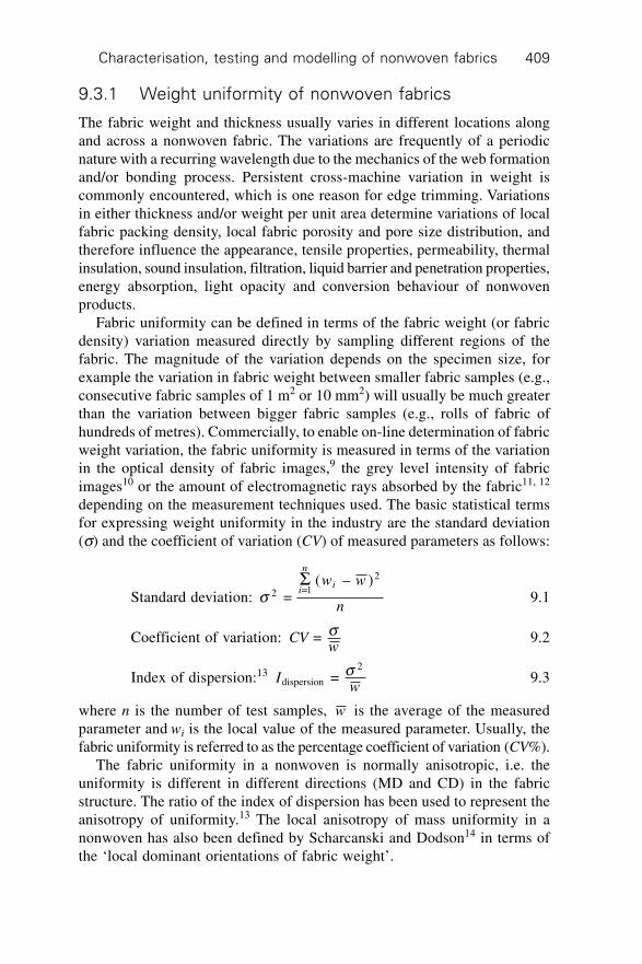
Characterisation, testing and modelling of nonwoven fabrics 409
9.3.1 Weight uniformity of nonwoven fabrics
The fabric weight and thickness usually varies in different locations alongand across a nonwoven fabric. The variations are frequently of a periodicnature with a recurring wavelength due to the mechanics of the web formationand/or bonding process. Persistent cross-machine variation in weight iscommonly encountered, which is one reason for edge trimming. Variationsin either thickness and/or weight per unit area determine variations of localfabric packing density, local fabric porosity and pore size distribution, andtherefore influence the appearance, tensile properties, permeability, thermalinsulation, sound insulation, filtration, liquid barrier and penetration properties,energy absorption, light opacity and conversion behaviour of nonwovenproducts.
Fabric uniformity can be defined in terms of the fabric weight (or fabricdensity) variation measured directly by sampling different regions of thefabric. The magnitude of the variation depends on the specimen size, forexample the variation in fabric weight between smaller fabric samples (e.g.,consecutive fabric samples of 1 m2 or 10 mm2) will usually be much greaterthan the variation between bigger fabric samples (e.g., rolls of fabric ofhundreds of metres). Commercially, to enable on-line determination of fabricweight variation, the fabric uniformity is measured in terms of the variationin the optical density of fabric images,9 the grey level intensity of fabricimages10 or the amount of electromagnetic rays absorbed by the fabric11, 12
depending on the measurement techniques used. The basic statistical termsfor expressing weight uniformity in the industry are the standard deviation(s) and the coefficient of variation (CV) of measured parameters as follows:
Standard deviation: s 2 =1
2
= ( – )S
i
n
iw w
n9.1
Coefficient of variation: CVw
= s 9.2
Index of dispersion:13 Iwdispersion
2 = s 9.3
where n is the number of test samples, w is the average of the measuredparameter and wi is the local value of the measured parameter. Usually, thefabric uniformity is referred to as the percentage coefficient of variation (CV%).
The fabric uniformity in a nonwoven is normally anisotropic, i.e. theuniformity is different in different directions (MD and CD) in the fabricstructure. The ratio of the index of dispersion has been used to represent theanisotropy of uniformity.13 The local anisotropy of mass uniformity in anonwoven has also been defined by Scharcanski and Dodson14 in terms ofthe ‘local dominant orientations of fabric weight’.
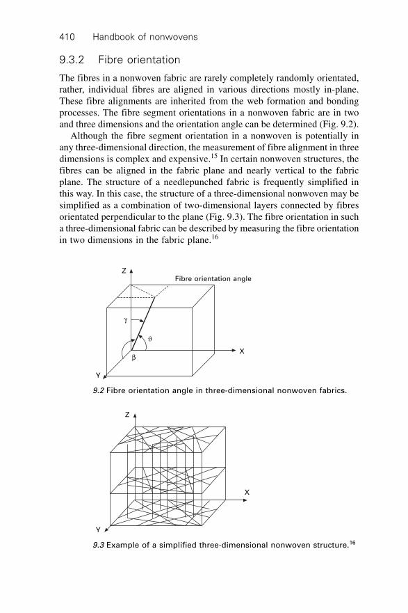
Handbook of nonwovens410
9.3.2 Fibre orientation
The fibres in a nonwoven fabric are rarely completely randomly orientated,rather, individual fibres are aligned in various directions mostly in-plane.These fibre alignments are inherited from the web formation and bondingprocesses. The fibre segment orientations in a nonwoven fabric are in twoand three dimensions and the orientation angle can be determined (Fig. 9.2).
Although the fibre segment orientation in a nonwoven is potentially inany three-dimensional direction, the measurement of fibre alignment in threedimensions is complex and expensive.15 In certain nonwoven structures, thefibres can be aligned in the fabric plane and nearly vertical to the fabricplane. The structure of a needlepunched fabric is frequently simplified inthis way. In this case, the structure of a three-dimensional nonwoven may besimplified as a combination of two-dimensional layers connected by fibresorientated perpendicular to the plane (Fig. 9.3). The fibre orientation in sucha three-dimensional fabric can be described by measuring the fibre orientationin two dimensions in the fabric plane.16
Fibre orientation angleZ
g
J
b
Y
X
9.2 Fibre orientation angle in three-dimensional nonwoven fabrics.
Y
Z
X
9.3 Example of a simplified three-dimensional nonwoven structure.16
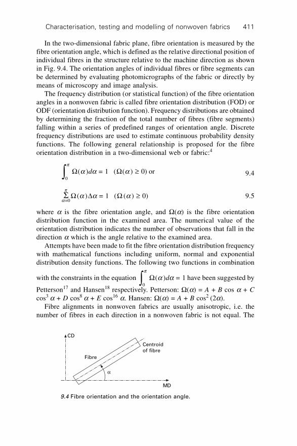
Characterisation, testing and modelling of nonwoven fabrics 411
In the two-dimensional fabric plane, fibre orientation is measured by thefibre orientation angle, which is defined as the relative directional position ofindividual fibres in the structure relative to the machine direction as shownin Fig. 9.4. The orientation angles of individual fibres or fibre segments canbe determined by evaluating photomicrographs of the fabric or directly bymeans of microscopy and image analysis.
The frequency distribution (or statistical function) of the fibre orientationangles in a nonwoven fabric is called fibre orientation distribution (FOD) orODF (orientation distribution function). Frequency distributions are obtainedby determining the fraction of the total number of fibres (fibre segments)falling within a series of predefined ranges of orientation angle. Discretefrequency distributions are used to estimate continuous probability densityfunctions. The following general relationship is proposed for the fibreorientation distribution in a two-dimensional web or fabric:4
0
( ) = 1 ( ( ) 0) orp
a a aÚ ≥W Wd 9.4
S W D Wa
pa a a
=0( ) = 1 ( ( ) 0)≥ 9.5
where a is the fibre orientation angle, and W(a) is the fibre orientationdistribution function in the examined area. The numerical value of theorientation distribution indicates the number of observations that fall in thedirection a which is the angle relative to the examined area.
Attempts have been made to fit the fibre orientation distribution frequencywith mathematical functions including uniform, normal and exponentialdistribution density functions. The following two functions in combination
with the constraints in the equation 0
( ) = 1p
a aÚ W d have been suggested by
Petterson17 and Hansen18 respectively. Petterson: W(a) = A + B cos a + Ccos3 a + D cos8 a + E cos16 a. Hansen: W(a) = A + B cos2 (2a).
Fibre alignments in nonwoven fabrics are usually anisotropic, i.e. thenumber of fibres in each direction in a nonwoven fabric is not equal. The
a
Fibre
CD
MD
Centroid
of fibre
9.4 Fibre orientation and the orientation angle.
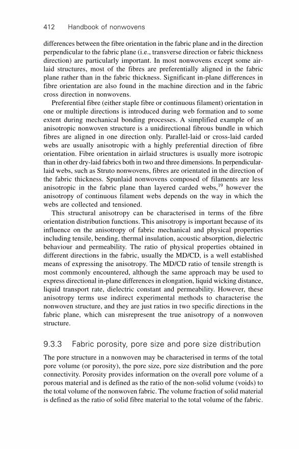
Handbook of nonwovens412
differences between the fibre orientation in the fabric plane and in the directionperpendicular to the fabric plane (i.e., transverse direction or fabric thicknessdirection) are particularly important. In most nonwovens except some air-laid structures, most of the fibres are preferentially aligned in the fabricplane rather than in the fabric thickness. Significant in-plane differences infibre orientation are also found in the machine direction and in the fabriccross direction in nonwovens.
Preferential fibre (either staple fibre or continuous filament) orientation inone or multiple directions is introduced during web formation and to someextent during mechanical bonding processes. A simplified example of ananisotropic nonwoven structure is a unidirectional fibrous bundle in whichfibres are aligned in one direction only. Parallel-laid or cross-laid cardedwebs are usually anisotropic with a highly preferential direction of fibreorientation. Fibre orientation in airlaid structures is usually more isotropicthan in other dry-laid fabrics both in two and three dimensions. In perpendicular-laid webs, such as Struto nonwovens, fibres are orientated in the direction ofthe fabric thickness. Spunlaid nonwovens composed of filaments are lessanisotropic in the fabric plane than layered carded webs,19 however theanisotropy of continuous filament webs depends on the way in which thewebs are collected and tensioned.
This structural anisotropy can be characterised in terms of the fibreorientation distribution functions. This anisotropy is important because of itsinfluence on the anisotropy of fabric mechanical and physical propertiesincluding tensile, bending, thermal insulation, acoustic absorption, dielectricbehaviour and permeability. The ratio of physical properties obtained indifferent directions in the fabric, usually the MD/CD, is a well establishedmeans of expressing the anisotropy. The MD/CD ratio of tensile strength ismost commonly encountered, although the same approach may be used toexpress directional in-plane differences in elongation, liquid wicking distance,liquid transport rate, dielectric constant and permeability. However, theseanisotropy terms use indirect experimental methods to characterise thenonwoven structure, and they are just ratios in two specific directions in thefabric plane, which can misrepresent the true anisotropy of a nonwovenstructure.
9.3.3 Fabric porosity, pore size and pore size distribution
The pore structure in a nonwoven may be characterised in terms of the totalpore volume (or porosity), the pore size, pore size distribution and the poreconnectivity. Porosity provides information on the overall pore volume of aporous material and is defined as the ratio of the non-solid volume (voids) tothe total volume of the nonwoven fabric. The volume fraction of solid materialis defined as the ratio of solid fibre material to the total volume of the fabric.

Characterisation, testing and modelling of nonwoven fabrics 413
While the fibre density is the weight of a given volume of the solid componentonly (i.e., not containing other materials), the porosity can be calculated asfollows using the fabric bulk density and the fibre density:
frr(%) = 100%fabric
fibre¥ 9.6
e(%) = (1 – f) ¥ 100% 9.7
where e is the fabric porosity (%), f is the volume fraction of solid material(%), rfabric (kg/m3) is the fabric bulk density and rfibre(kg/m3) is the fibredensity.
In resin coated, impregnated or laminated nonwoven composites, a smallproportion of the pores in the fabric is not accessible (i.e., they are notconnected to the fabric surface). The definition of porosity as shown aboverefers to the so-called total porosity of the fabric. Thus, the open porosity (oreffective porosity) is defined as the ratio of accessible pore volume to totalfabric volume, which is a component part of the total fabric porosity. Themajority of nonwoven fabrics have porosities >50% and usually above 80%.A fabric with a porosity of 100% is a totally open fabric and there is no suchfabric, while a fabric with a porosity of 0% is a solid polymer without anypore volume; there is no such fabric either. High-loft nonwoven fabricsusually have a low bulk density because they have more pore space than aheavily compacted nonwoven fabric; the porosity of high-loft nonwovenscan reach >98%.
Pore connectivity, which gives the geometric pathway between pores cannotbe readily quantified and described. If the total pore area responsible forliquid transport across any distance along the direction of liquid transport isknown, its magnitude and change in magnitude are believed to indicate thecombined characteristics of the pore structure and connectivity.
9.4 General standards for testing nonwovens
Various testing methods and techniques have been developed for themeasurement of nonwoven fabric properties. These test methods can begrouped as follows:
∑ standard test methods defined by standard authorities (e.g., ISO, EN/BS,ASTM, and ANSI)
∑ test methods established by industrial associations (e.g., INDA, EDANA,AATCC, etc.) and individual companies
∑ non-standard test techniques designed for research purposes.
The standard test methods, which are defined as orderly procedures in areproducible environment, are designed to provide reliable measurements
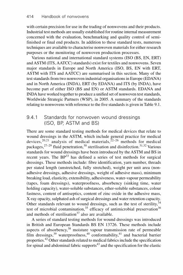
Handbook of nonwovens414
with certain precision for use in the trading of nonwovens and their products.Industrial test methods are usually established for routine internal measurementconcerned with the evaluation, benchmarking and quality control of semi-finished or final end products. In addition to these standard tests, numeroustechniques are available to characterise nonwoven materials for either researchpurposes or the monitoring of nonwoven production processes.
Various national and international standard systems (ISO (BS, EN, ERT)and ASTM (ITS, AATCC) standards) exist for textiles and nonwovens. Sevenmajor standards in Europe and North America (ISO, BS, EN with ERT,ASTM with ITS and AATCC) are summarised in this section. Many of thetest standards from two nonwoven industrial organisations in Europe (EDANA)and in North America (INDA), ERT (by EDANA) and ITS (by INDA), havebecome part of either ISO (BS and EN) or ASTM standards. EDANA andINDA have worked together to produce a unified set of nonwoven test standards,Worldwide Strategic Partners (WSP), in 2005. A summary of the standardsrelating to nonwovens with reference to the five standards is given in Table 9.1.
9.4.1 Standards for nonwoven wound dressings(ISO, BP, ASTM and BS)
There are some standard testing methods for medical devices that relate towound dressings in the ASTM, which include general practice for medicaldevices,20,21 analysis of medical materials,22–26 methods for medicalpackages,27–29 fluid penetration,30 sterilisation and disinfection.31,32 Variousstandards for wound dressings have been introduced by the ASTM and BS inrecent years. The BP33 has defined a series of test methods for surgicaldressings. These methods include: fibre identification, yarn number, threadsper stated length (unstretched, fully stretched), weight per unit area (non-adhesive dressings, adhesive dressings, weight of adhesive mass), minimumbreaking load, elasticity, extensibility, adhesiveness, water-vapour permeability(tapes, foam dressings), waterproofness, absorbency (sinking time, waterholding capacity), water-soluble substances, ether-soluble substances, colourfastness, content of antiseptics, content of zinc oxide in the adhesive mass,X-ray opacity, sulphated ash of surgical dressings and water retention capacity.Other standards relevant to wound dressings, such as the test of sterility,34
test of microbial contamination,35 efficacy of antimicrobial preservation36
and methods of sterilisation37 also are available.A series of standard testing methods for wound dressings was introduced
in British and European Standards BS EN 13726. These methods includeaspects of absorbency,38 moisture vapour transmission rate of permeablefilm dressings,39 waterproofness,40 conformability,41 and bacterial barrierproperties.42 Other standards related to medical fabrics include the specificationfor spinal and abdominal fabric supports43 and the specification for the elastic
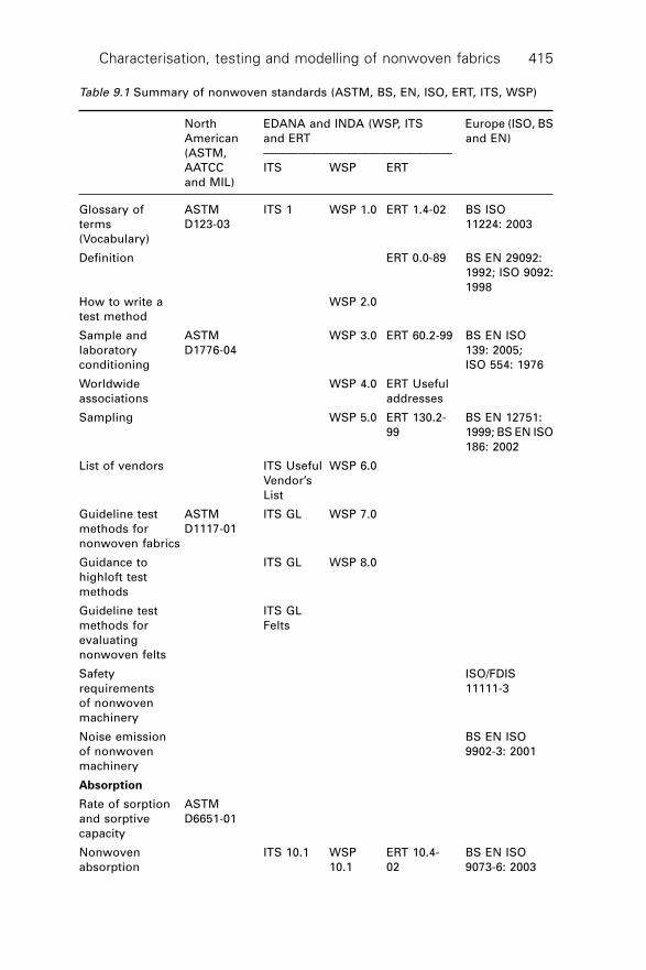
Characterisation, testing and modelling of nonwoven fabrics 415
Table 9.1 Summary of nonwoven standards (ASTM, BS, EN, ISO, ERT, ITS, WSP)
North EDANA and INDA (WSP, ITS Europe (ISO, BS
American and ERT and EN)
(ASTM, ————————————————
AATCC ITS WSP ERT
and MIL)
Glossary of ASTM ITS 1 WSP 1.0 ERT 1.4-02 BS ISO
terms D123-03 11224: 2003
(Vocabulary)
Definition ERT 0.0-89 BS EN 29092:
1992; ISO 9092:
1998
How to write a WSP 2.0
test method
Sample and ASTM WSP 3.0 ERT 60.2-99 BS EN ISO
laboratory D1776-04 139: 2005;
conditioning ISO 554: 1976
Worldwide WSP 4.0 ERT Useful
associations addresses
Sampling WSP 5.0 ERT 130.2- BS EN 12751:
99 1999; BS EN ISO
186: 2002
List of vendors ITS Useful WSP 6.0
Vendor’s
List
Guideline test ASTM ITS GL WSP 7.0
methods for D1117-01
nonwoven fabrics
Guidance to ITS GL WSP 8.0
highloft test
methods
Guideline test ITS GL
methods for Felts
evaluating
nonwoven felts
Safety ISO/FDIS
requirements 11111-3
of nonwoven
machinery
Noise emission BS EN ISO
of nonwoven 9902-3: 2001
machinery
Absorption
Rate of sorption ASTM
and sorptive D6651-01
capacity
Nonwoven ITS 10.1 WSP ERT 10.4- BS EN ISO
absorption 10.1 02 9073-6: 2003
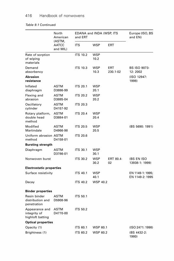
Handbook of nonwovens416
Rate of sorption ITS 10.2 WSP
of wiping 10.2
materials
Demand ITS 10.3 WSP ERT BS ISO 9073-
absorbency 10.3 230.1-02 12: 2002
Abrasion (ISO 12947:
resistance 1998)
Inflated ASTM ITS 20.1 WSP
diaphragm D3886-99 20.1
Flexing and ASTM ITS 20.2 WSP
abrasion D3885-04 20.2
Oscillatory ASTM ITS 20.3
cylinder D4157-92
Rotary platform, ASTM ITS 20.4 WSP
double head D3884-01 20.4
method
Modified ASTM ITS 20.5 WSP (BS 5690: 1991)
Martindale D4966-98 20.5
Uniform abrasion ASTM ITS 20.6
method D4158-01
Bursting strength
Diaphragm ASTM ITS 30.1 WSP
D3786-01 30.1
Nonwoven burst ITS 30.2 WSP ERT 80.4- (BS EN ISO
30.2 02 13938-1: 1999)
Electrostatic properties
Surface resistivity ITS 40.1 WSP EN 1149-1: 1995;
40.1 EN 1149-2: 1995
Decay ITS 40.2 WSP 40.2
Binder properties
Resin binder ASTM ITS 50.1
distribution and D5908-96
penetration
Appearance and ASTM ITS 50.2
integrity of D4770-00
highloft batting
Optical properties
Opacity (1) ITS 60.1 WSP 60.1 (ISO 2471: 1998)
Brightness (1) ITS 60.2 WSP 60.2 (BS 4432-2:
1980)
Table 9.1 Continued
North EDANA and INDA (WSP, ITS Europe (ISO, BS
American and ERT and EN)
(ASTM, ————————————————
AATCC ITS WSP ERT
and MIL)
Characterisation, testing and modelling of nonwoven fabrics 417
Brightness (2) WSP ERT BS ISO 2470:
60.3 100.1-78 1999
Opacity (2) WSP ERT BS ISO 2471:
60.4 110.1-78 1998
Permeability
Air permeability ASTM ITS 70.1 WSP ERT BS EN ISO 9237:
D737-04; 70.1 140.2-99 1995; ISO/CD
9073-15: 2005
Water vapour ASTM ITS 70.2
transmission D671-01
(multiple tests)
Liquid strike- ITS 70.3 WSP ERT BS EN ISO
through time 70.3 150.5-02 9073-8: 1998
(simulated urine)
Water vapour ITS 70.4 WSP
transmission 70.4
(Mocon) (rates of
500 to 100,000
gm/m2/day)
Water vapour WSP ERT New
transmission 70.5 Method
(Mocon) (relative part 1
humidity)
Water vapour WSP ERT New
transmission 70.6 Method
rate (Lyssy) part 2
Repeated liquid WSP ERT ISO 9073-13:
strike-through 70.7 153.0-02 2001;
time 04/30094395 DC
Repellency
Repellency ERT 120.2-02 ISO 811: 1981
EN 20811: 1992
Surface wetting ITS 80.1 WSP 80.1
spray test
Penetration by AATCC 42- ITS 80.2 WSP
water (rain test) 94 80.2
Penetration by ITS 80.3 WSP ISO/CD 9073-17
water (spray 80.3
impact test)
Penetration by AATCC ITS 80.4 (WSP
water (hydrostatic 127-98 80.6)
pressure test)
Table 9.1 Continued
North EDANA and INDA (WSP, ITS Europe (ISO, BS
American and ERT and EN)
(ASTM, ————————————————
AATCC ITS WSP ERT
and MIL)
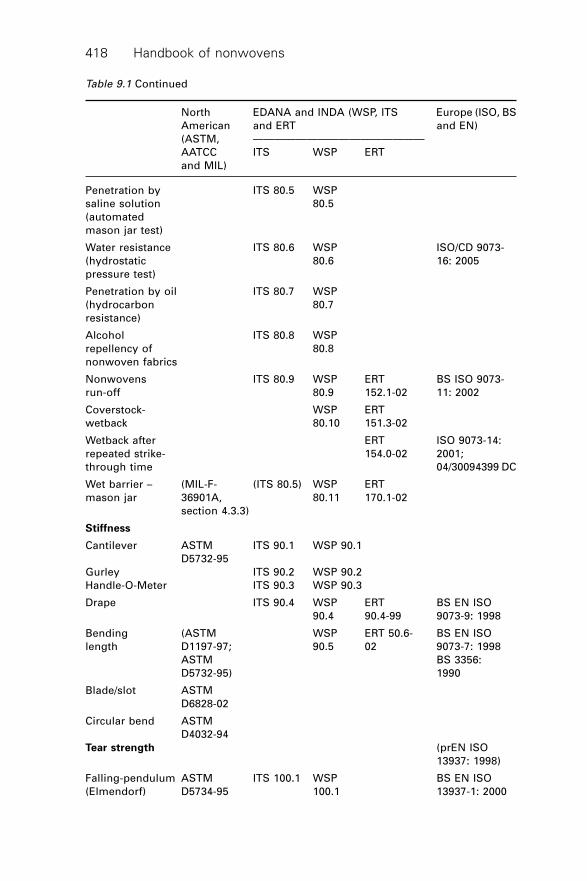
Handbook of nonwovens418
Penetration by ITS 80.5 WSP
saline solution 80.5
(automated
mason jar test)
Water resistance ITS 80.6 WSP ISO/CD 9073-
(hydrostatic 80.6 16: 2005
pressure test)
Penetration by oil ITS 80.7 WSP
(hydrocarbon 80.7
resistance)
Alcohol ITS 80.8 WSP
repellency of 80.8
nonwoven fabrics
Nonwovens ITS 80.9 WSP ERT BS ISO 9073-
run-off 80.9 152.1-02 11: 2002
Coverstock- WSP ERT
wetback 80.10 151.3-02
Wetback after ERT ISO 9073-14:
repeated strike- 154.0-02 2001;
through time 04/30094399 DC
Wet barrier – (MIL-F- (ITS 80.5) WSP ERT
mason jar 36901A, 80.11 170.1-02
section 4.3.3)
Stiffness
Cantilever ASTM ITS 90.1 WSP 90.1
D5732-95
Gurley ITS 90.2 WSP 90.2
Handle-O-Meter ITS 90.3 WSP 90.3
Drape ITS 90.4 WSP ERT BS EN ISO
90.4 90.4-99 9073-9: 1998
Bending (ASTM WSP ERT 50.6- BS EN ISO
length D1197-97; 90.5 02 9073-7: 1998
ASTM BS 3356:
D5732-95) 1990
Blade/slot ASTM
D6828-02
Circular bend ASTM
D4032-94
Tear strength (prEN ISO
13937: 1998)
Falling-pendulum ASTM ITS 100.1 WSP BS EN ISO
(Elmendorf) D5734-95 100.1 13937-1: 2000
Table 9.1 Continued
North EDANA and INDA (WSP, ITS Europe (ISO, BS
American and ERT and EN)
(ASTM, ————————————————
AATCC ITS WSP ERT
and MIL)
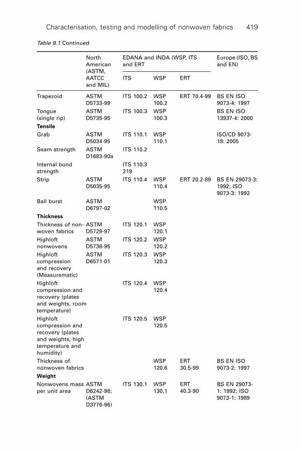
Characterisation, testing and modelling of nonwoven fabrics 419
Trapezoid ASTM ITS 100.2 WSP ERT 70.4-99 BS EN ISO
D5733-99 100.2 9073-4: 1997
Tongue ASTM ITS 100.3 WSP BS EN ISO
(single rip) D5735-95 100.3 13937-4: 2000
Tensile
Grab ASTM ITS 110.1 WSP ISO/CD 9073-
D5034-95 110.1 18: 2005
Seam strength ASTM ITS 110.2
D1683-90a
Internal bond ITS 110.3
strength 219
Strip ASTM ITS 110.4 WSP ERT 20.2-89 BS EN 29073-3:
D5035-95 110.4 1992; ISO
9073-3: 1992
Ball burst ASTM WSP
D6797-02 110.5
Thickness
Thickness of non- ASTM ITS 120.1 WSP
woven fabrics D5729-97 120.1
Highloft ASTM ITS 120.2 WSP
nonwovens D5736-95 120.2
Highloft ASTM ITS 120.3 WSP
compression D6571-01 120.3
and recovery
(Measurematic)
Highloft ITS 120.4 WSP
compression and 120.4
recovery (plates
and weights, room
temperature)
Highloft ITS 120.5 WSP
compression and 120.5
recovery (plates
and weights, high
temperature and
humidity)
Thickness of WSP ERT BS EN ISO
nonwoven fabrics 120.6 30.5-99 9073-2: 1997
Weight
Nonwovens mass ASTM ITS 130.1 WSP ERT BS EN 29073-
per unit area D6242-98; 130.1 40.3-90 1: 1992; ISO
(ASTM 9073-1: 1989
D3776-96)
Table 9.1 Continued
North EDANA and INDA (WSP, ITS Europe (ISO, BS
American and ERT and EN)
(ASTM, ————————————————
AATCC ITS WSP ERT
and MIL)
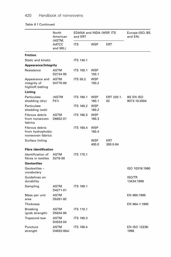
Handbook of nonwovens420
Friction
Static and kinetic ITS 140.1
Appearance/Integrity
Resistance ASTM ITS 150.1 WSP
D2724-95 150.1
Appearance and ASTM ITS 50.2 WSP
integrity of D4770-00 150.2
highloft batting
Linting
Particulate (ASTM ITS 160.1 WSP ERT 220.1- BS EN ISO
shedding (dry) F51) 160.1 02 9073-10:2004
Particulate ITS 160.2 WSP
shedding (wet) 160.2
Fibrous debris ASTM ITS 160.3 WSP
from nonwoven D6652-01 160.3
fabrics
Fibrous debris ITS 160.4 WSP
from hydrophobic 160.4
nonwoven fabrics
Surface linting WSP ERT
400.0 300.0-84
Fibre identification
Identification of ASTM ITS 170.1
fibres in textiles D276-00
Geotextiles
Geotextiles – ISO 10318:1990
vocabulary
Guidelines on ISO/TR
durability 13434:1998
Sampling ASTM ITS 180.1
D4271-01
Mass per unit ASTM EN 965:1995
area D5261-92
Thickness EN 964-1:1995
Breaking ASTM ITS 110.1
(grab strength) D5034-95
Trapezoid tear ASTM ITS 180.3
D4533-04
Puncture ASTM ITS 180.4 EN ISO 12236:
strength D4833-00el 1996
Table 9.1 Continued
North EDANA and INDA (WSP, ITS Europe (ISO, BS
American and ERT and EN)
(ASTM, ————————————————
AATCC ITS WSP ERT
and MIL)
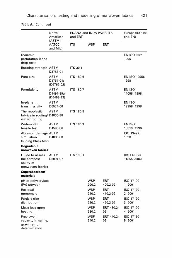
Characterisation, testing and modelling of nonwoven fabrics 421
Dynamic EN ISO 918:
perforation (cone 1995
drop test)
Bursting strength ASTM ITS 30.1
D3786-01
Pore size ASTM ITS 180.6 EN ISO 12956:
D4751-04; 1998
(D6767-02)
Permittivity ASTM ITS 180.7 EN ISO
D4491-99a; 11058: 1998
(D5493-93)
In-plane ASTM EN ISO
transmissivity D6574-00 12958: 1998
Thermoplastic ASTM ITS 180.8
fabrics in roofing/ D4830-98
waterproofing
Wide-width ASTM ITS 180.9 EN ISO
tensile test D4595-86 10319: 1996
Abrasion damage ASTM ISO 13427:
simulation D4886-88 1998
(sliding block test)
Degradable
nonwoven fabrics
Guide to assess ASTM ITS 190.1 (BS EN ISO
the compost- D6094-97 14855:2004)
ability of
nonwoven fabrics
Superabsorbent
materials
pH of polyacrylate WSP ERT ISO 17190-
(PA) powder 200.2 400.2-02 1: 2001
Residual WSP ERT ISO 17190-
monomers 210.2 410.2-02 2: 2001
Particle size WSP ERT ISO 17190-
distribution 220.2 420.2-02 3: 2001
Mass loss upon WSP ERT 430.2- ISO 17190-
heating 230.2 02 4: 2001
Free swell WSP ERT 440.2- ISO 17190-
capacity in saline, 240.2 02 5: 2001
gravimetric
determination
Table 9.1 Continued
North EDANA and INDA (WSP, ITS Europe (ISO, BS
American and ERT and EN)
(ASTM, ————————————————
AATCC ITS WSP ERT
and MIL)
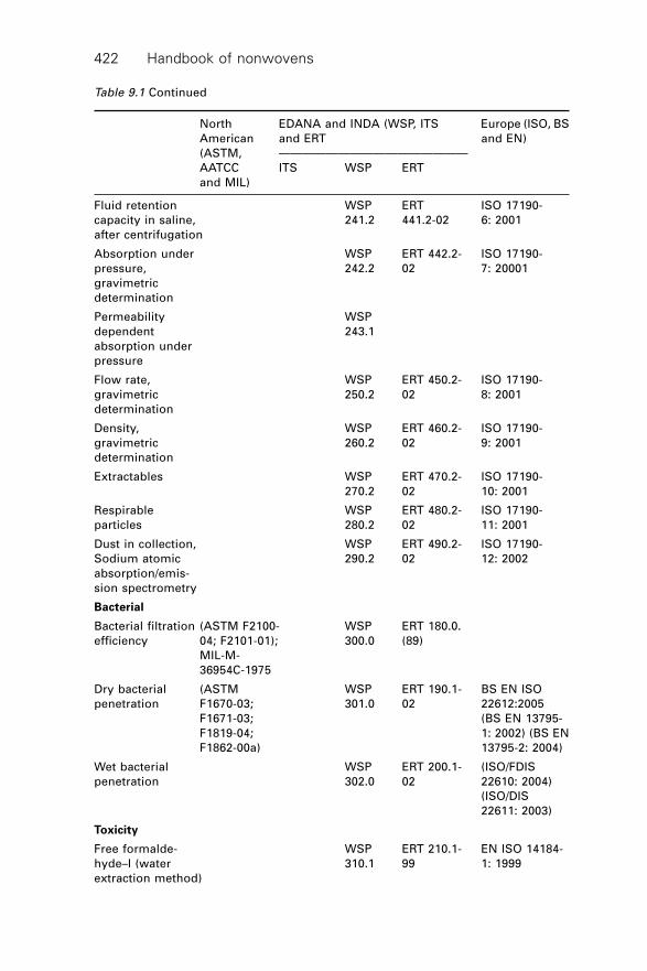
Handbook of nonwovens422
Fluid retention WSP ERT ISO 17190-
capacity in saline, 241.2 441.2-02 6: 2001
after centrifugation
Absorption under WSP ERT 442.2- ISO 17190-
pressure, 242.2 02 7: 20001
gravimetric
determination
Permeability WSP
dependent 243.1
absorption under
pressure
Flow rate, WSP ERT 450.2- ISO 17190-
gravimetric 250.2 02 8: 2001
determination
Density, WSP ERT 460.2- ISO 17190-
gravimetric 260.2 02 9: 2001
determination
Extractables WSP ERT 470.2- ISO 17190-
270.2 02 10: 2001
Respirable WSP ERT 480.2- ISO 17190-
particles 280.2 02 11: 2001
Dust in collection, WSP ERT 490.2- ISO 17190-
Sodium atomic 290.2 02 12: 2002
absorption/emis-
sion spectrometry
Bacterial
Bacterial filtration (ASTM F2100- WSP ERT 180.0.
efficiency 04; F2101-01); 300.0 (89)
MIL-M-
36954C-1975
Dry bacterial (ASTM WSP ERT 190.1- BS EN ISO
penetration F1670-03; 301.0 02 22612:2005
F1671-03; (BS EN 13795-
F1819-04; 1: 2002) (BS EN
F1862-00a) 13795-2: 2004)
Wet bacterial WSP ERT 200.1- (ISO/FDIS
penetration 302.0 02 22610: 2004)
(ISO/DIS
22611: 2003)
Toxicity
Free formalde- WSP ERT 210.1- EN ISO 14184-
hyde–I (water 310.1 99 1: 1999
extraction method)
Table 9.1 Continued
North EDANA and INDA (WSP, ITS Europe (ISO, BS
American and ERT and EN)
(ASTM, ————————————————
AATCC ITS WSP ERT
and MIL)
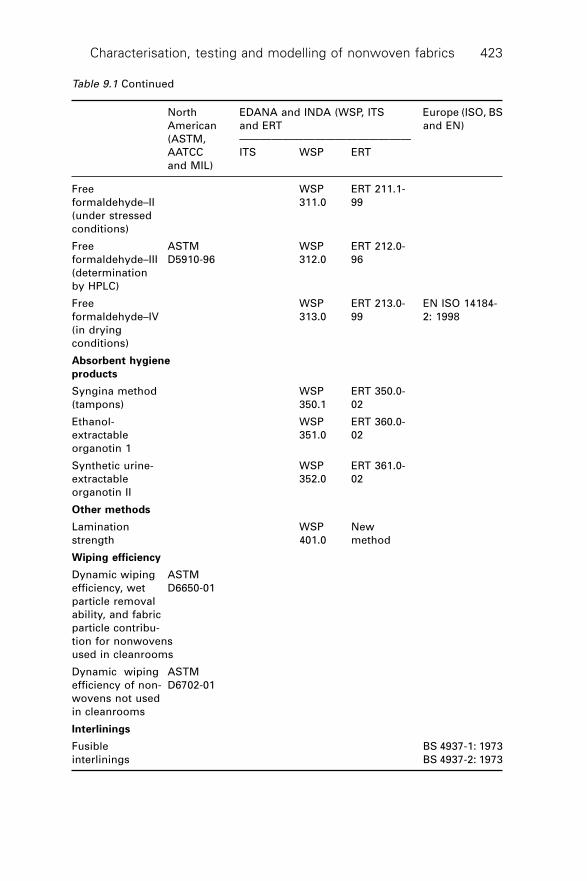
Characterisation, testing and modelling of nonwoven fabrics 423
Free WSP ERT 211.1-
formaldehyde–II 311.0 99
(under stressed
conditions)
Free ASTM WSP ERT 212.0-
formaldehyde–III D5910-96 312.0 96
(determination
by HPLC)
Free WSP ERT 213.0- EN ISO 14184-
formaldehyde–IV 313.0 99 2: 1998
(in drying
conditions)
Absorbent hygiene
products
Syngina method WSP ERT 350.0-
(tampons) 350.1 02
Ethanol- WSP ERT 360.0-
extractable 351.0 02
organotin 1
Synthetic urine- WSP ERT 361.0-
extractable 352.0 02
organotin II
Other methods
Lamination WSP New
strength 401.0 method
Wiping efficiency
Dynamic wiping ASTM
efficiency, wet D6650-01
particle removal
ability, and fabric
particle contribu-
tion for nonwovens
used in cleanrooms
Dynamic wiping ASTM
efficiency of non- D6702-01
wovens not used
in cleanrooms
Interlinings
Fusible BS 4937-1: 1973
interlinings BS 4937-2: 1973
Table 9.1 Continued
North EDANA and INDA (WSP, ITS Europe (ISO, BS
American and ERT and EN)
(ASTM, ————————————————
AATCC ITS WSP ERT
and MIL)
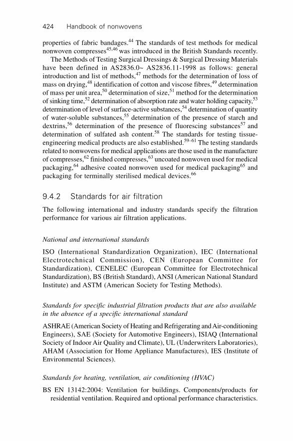
Handbook of nonwovens424
properties of fabric bandages.44 The standards of test methods for medicalnonwoven compresses45,46 was introduced in the British Standards recently.
The Methods of Testing Surgical Dressings & Surgical Dressing Materialshave been defined in AS2836.0~ AS2836.11-1998 as follows: generalintroduction and list of methods,47 methods for the determination of loss ofmass on drying,48 identification of cotton and viscose fibres,49 determinationof mass per unit area,50 determination of size,51 method for the determinationof sinking time,52 determination of absorption rate and water holding capacity,53
determination of level of surface-active substances,54 determination of quantityof water-soluble substances,55 determination of the presence of starch anddextrins,56 determination of the presence of fluorescing substances57 anddetermination of sulfated ash content.58 The standards for testing tissue-engineering medical products are also established.59–61 The testing standardsrelated to nonwovens for medical applications are those used in the manufactureof compresses,62 finished compresses,63 uncoated nonwoven used for medicalpackaging,64 adhesive coated nonwoven used for medical packaging65 andpackaging for terminally sterilised medical devices.66
9.4.2 Standards for air filtration
The following international and industry standards specify the filtrationperformance for various air filtration applications.
National and international standards
ISO (International Standardization Organization), IEC (InternationalElectrotechnical Commission), CEN (European Committee forStandardization), CENELEC (European Committee for ElectrotechnicalStandardization), BS (British Standard), ANSI (American National StandardInstitute) and ASTM (American Society for Testing Methods).
Standards for specific industrial filtration products that are also available
in the absence of a specific international standard
ASHRAE (American Society of Heating and Refrigerating and Air-conditioningEngineers), SAE (Society for Automotive Engineers), ISIAQ (InternationalSociety of Indoor Air Quality and Climate), UL (Underwriters Laboratories),AHAM (Association for Home Appliance Manufactures), IES (Institute ofEnvironmental Sciences).
Standards for heating, ventilation, air conditioning (HVAC)
BS EN 13142:2004: Ventilation for buildings. Components/products forresidential ventilation. Required and optional performance characteristics.
Characterisation, testing and modelling of nonwoven fabrics 425
BS EN 13053:2001: Ventilation for buildings. Air handling units. Ratingsand performance for units, components and sections.
BS EN 779:2002: Particulate air filters for general ventilation. Determinationof the filtration performance.
BS EN 1822-1:1998 High efficiency air filters (HEPA and ULPA).Classification, performance testing, marking.
BS EN 1822-2:1998, High efficiency air filters (HEPA and ULPA). Aerosolproduction, measuring equipment, particle counting statistics.
BS EN 1822-3:1998 High efficiency air filters (HEPA and ULPA). Testingmethod for flat sheet filter media.
BS EN 1822-4:2000 High efficiency air filters (HEPA and ULPA). Describesdetermination of the leakage of a filter element (scan method).
BS EN 1822-5:2000 High efficiency air filters (HEPA and ULPA). Describesdetermination of the efficiency of a filter element.
ASHRAE 52.2 Method of Testing General Ventilation Air-cleaning Devicesfor Removal Efficiency by Particle Size.
Mil F-51068F Filters, Particulate (High- Efficiency Fire Resistant).IES RP-CC021.1 HEPA and ULPA Filter Media.IES RP-CC001.3 HEPA and ULPA Filters.
Standards for healthcare and medical
BS EN 13328-1:2001: Breathing system filters for anaesthetic and respiratoryuse. Salt test method to assess filtration performance.
Nelson Laboratories: Bacterial & Virus Filtration efficiency test.
Standards for automotive industry
ISO/TS 11155-1: Road vehicles – Air filters for passenger compartments –Part 1: Test for particulate filtration (DIN 71460-1:2001).
ISO/TS 11155-2: Road vehicles – Air filters for passenger compartments –Part 2: Test for gaseous filtration (DIN 71460-2: 2003).
Standards for appliances: vacuum cleaners, room air cleaners and room
air purifiers
IEC 60312: Vacuum cleaners for Household use – Methods of measuring theperformance (2001-11).
ASTM 1977-99: Standard Test Method for Determining Initial, FractionalEfficiency of a Vacuum Cleaner System.
ANSI AHAM AC-1-1988: Method for Measuring Performance of PortableHousehold Electric Cord-Connected Room Air Cleaners (RAC).
ASTM D 6830-02 Standard Test Method for Characterizing the PressureDrop and Filtration Performance of Cleanable Filter Media.
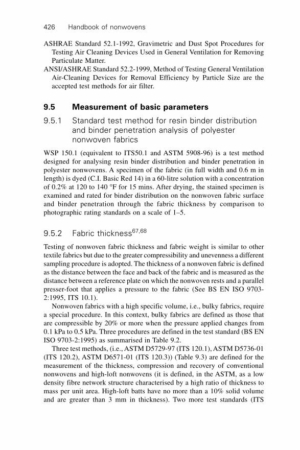
Handbook of nonwovens426
ASHRAE Standard 52.1-1992, Gravimetric and Dust Spot Procedures forTesting Air Cleaning Devices Used in General Ventilation for RemovingParticulate Matter.
ANSI/ASHRAE Standard 52.2-1999, Method of Testing General VentilationAir-Cleaning Devices for Removal Efficiency by Particle Size are theaccepted test methods for air filter.
9.5 Measurement of basic parameters
9.5.1 Standard test method for resin binder distributionand binder penetration analysis of polyesternonwoven fabrics
WSP 150.1 (equivalent to ITS50.1 and ASTM 5908-96) is a test methoddesigned for analysing resin binder distribution and binder penetration inpolyester nonwovens. A specimen of the fabric (in full width and 0.6 m inlength) is dyed (C.I. Basic Red 14) in a 60-litre solution with a concentrationof 0.2% at 120 to 140 ∞F for 15 mins. After drying, the stained specimen isexamined and rated for binder distribution on the nonwoven fabric surfaceand binder penetration through the fabric thickness by comparison tophotographic rating standards on a scale of 1–5.
9.5.2 Fabric thickness67,68
Testing of nonwoven fabric thickness and fabric weight is similar to othertextile fabrics but due to the greater compressibility and unevenness a differentsampling procedure is adopted. The thickness of a nonwoven fabric is definedas the distance between the face and back of the fabric and is measured as thedistance between a reference plate on which the nonwoven rests and a parallelpresser-foot that applies a pressure to the fabric (See BS EN ISO 9703-2:1995, ITS 10.1).
Nonwoven fabrics with a high specific volume, i.e., bulky fabrics, requirea special procedure. In this context, bulky fabrics are defined as those thatare compressible by 20% or more when the pressure applied changes from0.1 kPa to 0.5 kPa. Three procedures are defined in the test standard (BS ENISO 9703-2:1995) as summarised in Table 9.2.
Three test methods, (i.e., ASTM D5729-97 (ITS 120.1), ASTM D5736-01(ITS 120.2), ASTM D6571-01 (ITS 120.3)) (Table 9.3) are defined for themeasurement of the thickness, compression and recovery of conventionalnonwovens and high-loft nonwovens (it is defined, in the ASTM, as a lowdensity fibre network structure characterised by a high ratio of thickness tomass per unit area. High-loft batts have no more than a 10% solid volumeand are greater than 3 mm in thickness). Two more test standards (ITS
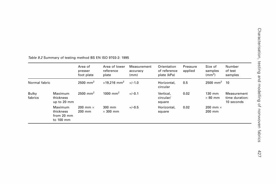
Ch
ara
cte
risatio
n, te
stin
g a
nd
mo
de
lling
of n
on
wo
ve
n fa
bric
s4
27
Table 9.2 Summary of testing method BS EN ISO 9703-2: 1995
Area of Area of lower Measurement Orientation Pressure Size of Number
presser reference accuracy of reference applied samples of test
foot plate plate (mm) plate (kPa) (mm2) samples
Normal fabric 2500 mm2 >19,216 mm2 +/–1.0 Horizontal, 0.5 2500 mm2 10
circular
Bulky Maximum 2500 mm2 1000 mm2 +/–0.1 Vertical, 0.02 130 mm Measurement
fabrics thickness circular/ ¥ 80 mm time duration:
up to 20 mm square 10 seconds
Maximum 200 mm ¥ 300 mm +/–0.5 Horizontal, 0.02 200 mm ¥thickness 200 mm ¥ 300 mm square 200 mm
from 20 mm
to 100 mm
Han
db
oo
k o
f no
nw
ove
ns
42
8
Table 9.3 Summary of testing method ASTM D5729-97 (ITS 120.1). ASTM D5736-01 (ITS 120.2) and ASTM D6571-01 (ITS 120.3)
Dimension of Pressure Size of Number of Test duration Report
presser foot applied (kPa) samples samples time
plate (mm)
Thickness Conventional Diameter 4.14 ± 0.21 20% greater 10 5 s Thickness,
treated or 25.4 ± 0.02 than presser SD, CV
untreated foot
fabrics,
(ASTM
D5729-97)
Highloft 300 mm by 0.03 130 mm by 5 9~10 s
nonwovens* 300 mm 80 mm
(ASTM D5736-95,
ITS 120.2)
Comp- ASTM D6571-01 0.03 /1.73/ 200 mm by 5 10 s/30 min/ Percentage
ression and 0.03 200 mm 5 min compression;
Recovery percentage
of Highloft recovery
non- Repeated 230 mm by 1.83 200 mm by Applied and 10 mins to Compression
wovens* compression and 230 mm by 200 mm by removed at 56 hours resistance;
recovery (Weight- 6.4 mm (min) 100 mm a series of elastic loss;
plate, ITS120.4; time intervals. immediate
ITS120.5) recovery;
long-term
recovery
* Highloft nonwovens are defined as porosity >90% and thickness >=3 mm
Characterisation, testing and modelling of nonwoven fabrics 429
120.4, ITS 120.5) are defined for rapid measurement of the compression andrecovery of high-loft nonwovens.
9.5.3 Fabric mass per unit area
The measurement of a nonwoven weight per unit area requires a specificsampling procedure, specific dimensions for the test samples, and a greaterbalance accuracy than for conventional textiles. According to the ISO standards(BS EN 29073-1:1992, ISO 9073-1:1989, ITS10.1), the measurement ofnonwoven fabric mass per unit area of nonwovens requires each piece offabric sample to be at least 50,000 mm2. The mean value of fabric weight iscalculated in grams per square metre and the coefficient of variation isexpressed as a percentage.
9.5.4 Fabric weight uniformity
Nonwoven fabric uniformity refers to the variations in local fabric structures,which include thickness and density, but is usually expressed as the variationof the weight per unit area. Both subjective and objective techniques are usedto evaluate the fabric uniformity. In subjective assessment, visual inspectioncan distinguish non-uniform areas as small as about 10 mm2 from a distanceof about 30 cm. Qualitative assessments of this type can be used to produceratings of nonwoven fabric samples by a group of experts against benchmarkstandards. The consensual benchmark standards are usually established byan observer panel using paired comparison, graduated scales or similar votingtechniques; these standard samples are then used to grade future samples.
Indirect objective measurements of the web weight uniformity have beendeveloped based on variations in other properties that vary with fabric weightincluding the transmission and reflection of beta rays, gamma rays (CO60),lasers, optical and infra-red light,69 and variation in tensile strength.
With optical light scanning methods, the fabrics are evaluated for uniformityusing an optical electronic method, which screens the nonwoven to register32 different shades of grey.9,70 The intensity of the points in the differentshades of grey provides a measure of the uniformity. A statistical analysis ofthe optical transparency and the fabric uniformity is then produced. Thismethod is suitable for lightweight nonwovens of 10–50 g/m2. Optical lightmeasurements are commonly coupled with image analysis to determine thecoefficient of variation of grey level intensities from scanned images ofnonwoven fabrics.71
In practice, nonwoven fabric uniformity depends on fibre properties, fabricweight and manufacturing conditions. It is usually true that the variation infabric thickness and fabric weight decreases as the mean fabric weight increases.Wet-laid nonwovens are usually more uniform in terms of thickness than
Handbook of nonwovens430
dry-laid fabrics. Short fibre airlaid fabrics are commonly more uniform thancarded and crosslaid and parallel-laid fabrics, and spunbond and meltblownfabrics are often more uniform than fabrics produced from staple fibres.
9.6 Measuring fibre orientation distribution
In modelling the properties of nonwoven fabrics and particularly in anyquantitative analysis of the anisotropic properties of nonwoven fabrics, it isimportant to obtain an accurate measurement of the fibre orientation distribution(FOD). A number of measuring techniques have been developed. A directvisual and manual method of measurement was first described by Petterson.17
Hearle and co-workers72,73 found that visual methods produce accuratemeasurements and it is the most reliable way to evaluate the fibre orientation.Manual measurements of fibre segment angles relative to a given directionwere conducted and the lengths of segment curves were obtained within agiven range. Chuleigh74 developed an optical processing method in which anopaque mask was used in a light microscope to highlight fibre segments thatare orientated in a known direction. However, the application of this methodis limited by the tedious and time-consuming work required in visualexaminations.
To increase the speed of assessment, various indirect-measuring techniqueshave been introduced including both the zero span75,76 and short span77
tensile analysis for predicting the fibre orientation distribution. Stenemur78
devised a computer system to monitor fibre orientation on running websbased on the light diffraction phenomenon. Methods that employ X-ray-diffraction analysis and X-ray diffraction patterns of fibre webs have alsobeen studied.79,80 In this method the distribution of the diffraction peak ofthe fibre to X-ray is directly related to the distribution of the fibre orientation.Other methods include the use of microwaves,81 ultrasound,82 light diffractionmethods,83 light reflection and light refraction,84 electrical measurements85,86
and liquid-migration-pattern analysis.87,88
In the last few decades, image analysis has been employed to identifyfibres and their orientation,89–92 and computer simulation techniques havecome into use for the creation of computer models of various nonwovenfabrics.93–96 Huang and Bressee89 developed a random sampling algorithmand software to analyse fibre orientation in thin webs. In this method, fibresare randomly selected and traced to estimate the orientation angles; testresults showed excellent agreement with results from visual measurements.Xu and Ting96 used image techniques to measure structural characteristics offibre or fibre bundle segments in a thin nonwoven fabric. The structuralcharacteristics measured included length, thickness, curl and the orientationof fibre segments.
Pourdeyhimi et al.97–100 completed a series of studies on the fibre orientation
Characterisation, testing and modelling of nonwoven fabrics 431
of nonwovens by using an image analyser to determine the fibre orientationin which image processing techniques such as computer simulation, fibretracking, Fourier transforms and flow field techniques were employed. Incontrast to two-dimensional imaging techniques suitable only for thin nonwovenfabrics, the theory of Hilliard-Komori-Makishima101 and the visualisationsmade by Gilmore et al.15 using X-ray tomographic techniques have provideda means of analysing the three-dimensional orientation.
Image analysis is a computer-based means of converting the visual qualitativefeatures of a particular image into quantitative data. The measurement of thefibre orientation distribution in nonwoven fabrics using image analysis isbased on the assumption that in thin materials a two-dimensional structurecan be assumed, although in reality the fibres in a nonwoven are arranged inthree dimensions. However, there is currently no generally accepted way ofcharacterising the fabric structure in terms of the three-dimensional geometry.The fabric geometry is reduced to two dimensions by evaluation of theplanar projections of the fibres within the fabric. The assumption of a two-dimensional fabric structure is adequate to describe thin fabrics. The imageanalysis system in the measurement of the fibre orientation distribution isbased on a computerised image capture system operating with an integratedimage analysis software package in which numerous functions can beperformed.102 A series of sequential operations is required to perform imageanalysis and, in a simple system, the following procedures are carried out:102
production of a grey image of the sample fabric, processing the grey image,detection of the grey image and conversion into binary form, storage andprocessing of the binary image, measurement of the fibre orientation andoutput of results.
9.7 Measuring porosity, pore size and pore sizedistribution
Porosity can be obtained from the ratio of the fabric density and the fibredensity. In addition to the direct method of determination for resin impregnateddense nonwoven composites, the fabric porosity can be determined bymeasuring densities using liquid buoyancy or gas expansion porosimetry.103
Other methods include small angle neutron, small angle X-ray scattering andquantitative image analysis for total porosity. Open porosity may be obtainedfrom xylene and water impregnation techniques,104 liquid metal (mercury)impregnation, nitrogen adsorption and air or helium penetration.
Existing definitions of pore geometry and the size of pores in a nonwovenare based on various physical models of fabrics for specific applications. Ingeneral, cylindrical, spherical or convex shaped pores are assumed with adistribution of pore diameters. Three groups of pore size are defined: (i) thenear-largest pore size (known as apparent opening pore size, or opening pore
Handbook of nonwovens432
size), (ii) the constriction pore size (known as the pore-throat size) and (iii)the pore volume size. Pore size and the pore size distribution of nonwovenfabrics can be measured using optical methods, density methods, gas expansionand adsorption, electrical resistance, image analysis, porosimetry andporometry. The apparent pore opening (or opening pore) size is determinedby the passage of spherical solid glass beads of different sizes (50 mm to500 mm) through the largest pore size of the fabric under specified conditions.The pore size can be measured using sieving test methods (dry sieving, wetsieving and hydrodynamic sieving).
The opening pore sizes are important for determining the filtration andclogging performance of nonwoven geotextiles and it enables the determinationof the absolute rating of filter fabrics. The constriction pore size, or pore-throat size, is different from the apparent pore opening size. The constrictionpore size is the dimension of the smallest part of the flow channel in a poreand it is important for fluid flow transport in nonwoven fabrics. The largestpore-throat size is called the bubble point pore size, which is related to thedegree of clogging of geotextiles and the performance of filter fabrics. Thepore-throat size distribution and the bubble point pore size can be obtainedby liquid expulsion methods. However, it is found that wetting fluid, airpressure and equipment type affects the measured constriction pore size.105,106
A summary of the test methods for the determination of pore size distributionis produced in Table 9.4.
9.7.1 Dry sieving (ASTM D4751107 and BS 6906-2108)
Dry sieving involves passing spherical glass beads (or sand particles) througha nonwoven fabric to determine the fraction of bead sizes for which 5% (or10%, 50%) or less, by weight, passes through the fabric. The apparent openingsize (AOS) or O95 (or O90, O50) of the fabric is determined. However, the testaccuracy for pore opening sizes smaller than 90 mm is questionable due tovarious problems in the testing procedure.109,110
9.7.2 Wet sieving111,112
Wet sieving is based on the dry sieving method, the primary differences arethat a continuous water spray is applied to the glass beads and the test fabricduring shaking. The continuous water spray reduces electrostatic chargingassociated with the glass bead particles; mixtures of many different glassbead sizes are used in testing rather than size fractions.
9.7.3 Hydrodynamic sieving113–115
Hydrodynamic sieving is based on hydrodynamic filtration as proposed byFayoux.113 Glass bead mixtures are sieved through nonwovens by introducing
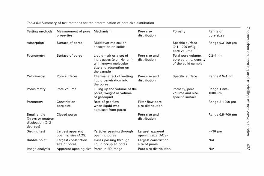
Ch
ara
cte
risatio
n, te
stin
g a
nd
mo
de
lling
of n
on
wo
ve
n fa
bric
s4
33
Table 9.4 Summary of test methods for the determination of pore size distribution
Testing methods Measurement of pore Mechanism Pore size Porosity Range of
properties distribution pore sizes
Adsorption Surface of pores Multilayer molecular Specific surface Range 0.3–200 mm
adsorption on solids (0.1–1000 m2/g),
pore volume
Pycnometry Surface of pores Liquid – air or a set of Pore size and Total pore volume, 0.2–1 nm
inert gases (e.g., Helium) distribution pore volume, density
with known molecular of the solid sample
size and adsorption on
the sample
Calorimetry Pore surfaces Thermal effect of wetting Pore size and Specific surface Range 0.5–1 nm
liquid penetration into distribution
the pores
Porosimetry Pore volume Filling up the volume of the Porosity, pore Range 1 nm–
pores, weight or volume volume and size, 1000 mm
of gas/liquid specific surface
Porometry Constriction Rate of gas flow Filter flow pore Range 2–1000 mm
pore size when liquid was size distribution
expulsed from pores
Small angle Closed pores Pore size and Range 0.5–700 nm
X-rays or neutron distribution
dissipation (0–2
degrees)
Sieving test Largest apparent Particles passing through Largest apparent >=90 mm
opening size (AOS) opening pores opening size (AOS)
Bubble point Largest constriction Gases passing through Largest constriction N/A
size of pores liquid occupied pores size of pores
Image analysis Apparent opening size Pores in 2D image Pore size distribution N/A
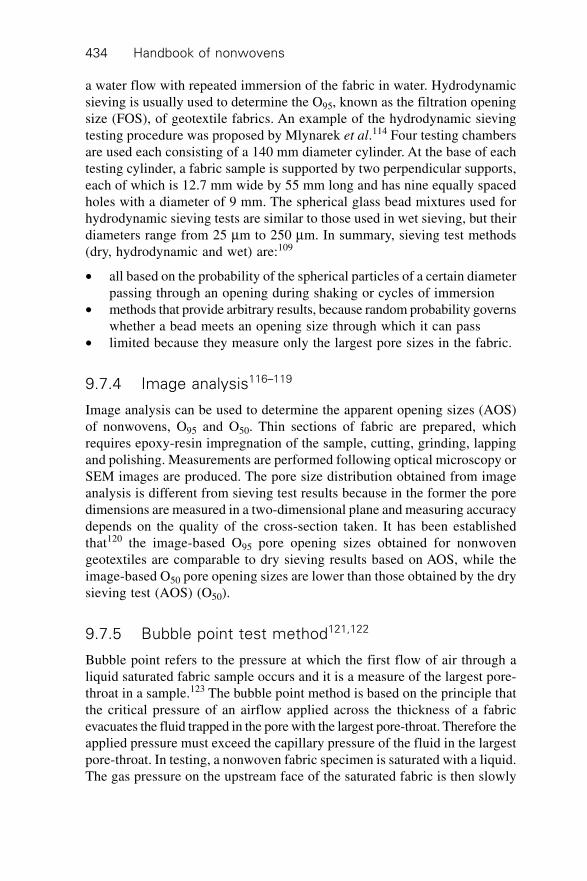
Handbook of nonwovens434
a water flow with repeated immersion of the fabric in water. Hydrodynamicsieving is usually used to determine the O95, known as the filtration openingsize (FOS), of geotextile fabrics. An example of the hydrodynamic sievingtesting procedure was proposed by Mlynarek et al.114 Four testing chambersare used each consisting of a 140 mm diameter cylinder. At the base of eachtesting cylinder, a fabric sample is supported by two perpendicular supports,each of which is 12.7 mm wide by 55 mm long and has nine equally spacedholes with a diameter of 9 mm. The spherical glass bead mixtures used forhydrodynamic sieving tests are similar to those used in wet sieving, but theirdiameters range from 25 mm to 250 mm. In summary, sieving test methods(dry, hydrodynamic and wet) are:109
∑ all based on the probability of the spherical particles of a certain diameterpassing through an opening during shaking or cycles of immersion
∑ methods that provide arbitrary results, because random probability governswhether a bead meets an opening size through which it can pass
∑ limited because they measure only the largest pore sizes in the fabric.
9.7.4 Image analysis116–119
Image analysis can be used to determine the apparent opening sizes (AOS)of nonwovens, O95 and O50. Thin sections of fabric are prepared, whichrequires epoxy-resin impregnation of the sample, cutting, grinding, lappingand polishing. Measurements are performed following optical microscopy orSEM images are produced. The pore size distribution obtained from imageanalysis is different from sieving test results because in the former the poredimensions are measured in a two-dimensional plane and measuring accuracydepends on the quality of the cross-section taken. It has been establishedthat120 the image-based O95 pore opening sizes obtained for nonwovengeotextiles are comparable to dry sieving results based on AOS, while theimage-based O50 pore opening sizes are lower than those obtained by the drysieving test (AOS) (O50).
9.7.5 Bubble point test method121,122
Bubble point refers to the pressure at which the first flow of air through aliquid saturated fabric sample occurs and it is a measure of the largest pore-throat in a sample.123 The bubble point method is based on the principle thatthe critical pressure of an airflow applied across the thickness of a fabricevacuates the fluid trapped in the pore with the largest pore-throat. Therefore theapplied pressure must exceed the capillary pressure of the fluid in the largestpore-throat. In testing, a nonwoven fabric specimen is saturated with a liquid.The gas pressure on the upstream face of the saturated fabric is then slowly
Characterisation, testing and modelling of nonwoven fabrics 435
increased to a critical pressure when the first air bubble passes through thelargest pore-throat in the saturated fabric. Based on the Laplace equationof capillary pressure, the diameter of the largest pore-throat can then becalculated.
9.7.6 Liquid expulsion porometry123,124
Both the pore-throat size distribution and the largest pore-throat size can bedetermined by means of porometry, which is based on liquid expulsion.First, the relationship between the airflow rate through a liquid saturatedfabric and the applied pressure when the liquid is expelled from the saturatedfabric sample is determined. In the test, the airflow pressure is applied acrossthe saturated fabric to force liquid out of the pores. With an increase in theapplied pressure, the trapped liquid in the pores of the fabric is graduallyforced out. According to the Laplace theory of capillary pressure, the smallerthe pore diameter, the greater the applied pressure needed to overcome thecapillary pressure and to push the liquid out of the pore. The relationshipbetween the applied pressure, the pore sizes and the airflow rate through thepores can be established. However, to quantify the airflow rate through poresof different sizes, the relationship between the airflow rate through the poresin the dry fabric sample and the applied pressure should be established.
By comparing the flow rates for both a dry and a saturated sample at thesame applied pressure, the percentage of flow passing through pores largerthan or equal to a certain size can be calculated, and the pore size distributionbetween the pore diameters corresponding to any pressure interval l to h
from flows at l and h in terms of air flow rate (not in terms of the number ofpores in the fabric) can be defined:
Qh
hll
= wet flowdry flow
– wet flow dry flow
100%ÊË
ˆ¯
¥ 9.8
The pore size corresponding to the applied pressure can be determined bythe following equation:
dp
= 4 106s ¥
9.9
where d is the pore diameter (mm); s is the surface tension (N/m) of theliquid and the contact angle between the liquid and the pore wall is assumedto be zero; p is the capillary pressure (equivalent to the applied pressure)(Pa). An example of the flow rate against applied pressure for wet and dryruns, performed on a nonwoven fabric is given in Fig. 9.5.
Handbook of nonwovens436
9.7.7 Pore volume distribution and mercuryporosimetry125–128
Unlike porometry where the measurement of the pore-throat size distributionis based on measurement of the airflow rate through a fabric sample, the pore
0.00 0.78 0.83 1.14 1.33 1.43 1.60 2.06 2.65 3.45 4.5 5.5
Applied pressure (kPa)
(a)
Pressure at
smallest pore
Pressureat largest
pore
Pressureat mean
flow pore
Wet run
Dry run
Half of dry runR
ate
of
air
flo
w (
ml/
s)
1200
1000
800
600
400
200
0
Po
re s
ize
dis
trib
uti
on
(%
)
25
20
15
10
5
056.28 72.32 94.41 121.99 140.32 152.17 168.43 221.69 259.97
Pore diameter (mm)
(b)
9.5 Examples of differential flow pore size distributions for anonwoven fabric measured by liquid expulsion porometry. (a) Therate of airflow against applied pressure for wet and dry runs,performed on a nonwoven fabric. (b) Differential flow pore sizedistribution of the nonwoven fabric.
Characterisation, testing and modelling of nonwoven fabrics 437
volume distribution is determined by liquid porosimetry, which is based onthe liquid uptake concept proposed by Haines.129 A fabric sample (either dryor saturated) is placed on a perforated plate and connected to a liquid reservoir.The liquid having a known surface tension and contact angle is graduallyforced into or out of the pores in the fabric by an external applied pressure.Porosimetry is grouped into two categories based on the liquid used, whichis either non-wetting (e.g., mercury) or wetting (e.g., water). Each is used forintrusion porosimetry and extrusion porosimetry where the advancing contactangle and receding contact angle are applied in liquid intrusion and extrusionporosimetry respectively.
Mercury has a high surface tension and is strongly non-wetting on mostfabrics at room temperature. In a typical mercury porosimetry measurement,a nonwoven fabric is evacuated to remove moisture and impurities and thenimmersed in mercury. A gradually increasing pressure is applied to the sampleforcing mercury into increasingly smaller ‘pores’ in the fabric. The pressureP required to force a non-wetting fluid into a circular cross-section capillaryof diameter d is given by:
Pd
Hg Hg =
4 cos s g9.10
where sHg is the surface tension of the mercury (0.47 N/m),130 and gHg is thecontact angle of the mercury on the material being intruded (the contactangle ranges from 135∞~180∞), and d is the diameter of a cylindrical pore.The incremental volume of mercury is recorded as a function of the appliedpressure to obtain a mercury intrusion curve. The pore size distribution ofthe sample can be estimated in terms of the volume of the pores intruded fora given cylindrical pore diameter d.
The pressure can be increased incrementally or continuously (scanningporosimetry). The process is reversed by lowering the pressure to allow themercury to extrude from the pores in the fabric to generate a mercury extrusioncurve. Analysis of the data is based on a model that assumes the pores in thefabric are a series of parallel non-intersecting cylindrical capillaries of randomdiameters (capillary tube model).131 However, as a consequence of the non-wetting behaviour of mercury in mercury intrusion porosimetry, relativelyhigh pressure is needed to force mercury into the smaller pores thereforecompressible nonwoven fabrics are not suitable for testing using the mercuryporosimetry method.
Liquids other than mercury find use in porosimetry132–134 and have beencommercialised.135 Test procedure is similar to that of mercury porosimetrybut any liquid that wets the sample, such as water, organic liquids, or solutionsmay be utilised. The cumulative and differential pore volume distribution,total pore volume, porosity, average, main, effective and equivalent poresize can be obtained.
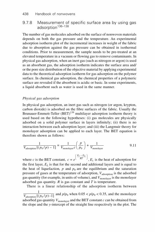
Handbook of nonwovens438
9.7.8 Measurement of specific surface area by using gas
adsorption136–138
The number of gas molecules adsorbed on the surface of nonwoven materialsdepends on both the gas pressure and the temperature. An experimentaladsorption isotherm plot of the incremental increases in weight of the fabricdue to absorption against the gas pressure can be obtained in isothermalconditions. Prior to measurement, the sample needs to be pre-treated at anelevated temperature in a vacuum or flowing gas to remove contaminants. Inphysical gas adsorption, when an inert gas (such as nitrogen or argon) is usedas an absorbent gas, the adsorption isotherm indicates the surface area and/or the pore size distribution of the objective material by applying experimentaldata to the theoretical adsorption isotherm for gas adsorption on the polymersurface. In chemical gas adsorption, the chemical properties of a polymericsurface are revealed if the absorbent is acidic or basic. In some experiments,a liquid absorbent such as water is used in the same manner.
Physical gas adsorption
In physical gas adsorption, an inert gas such as nitrogen (or argon, krypton,carbon dioxide) is adsorbed on the fibre surfaces of the fabric. Usually theBrunauer-Emmett-Teller (BET)139 multilayer adsorption isotherm theory isused based on the following hypotheses: (i) gas molecules are physicallyadsorbed on a solid polymer surface in layers infinitely; (ii) there is nointeraction between each adsorption layer; and (iii) the Langmuir theory formonolayer adsorption can be applied to each layer. The BET equation istherefore shown as follows:
1[( / ) – 1]
= 1 + 1adsorption 0 monolayer 0 monolayerV p p V c
p
p VÊË
ˆ¯ 9.11
where c is the BET constant, c e E
E E
RTL
= , 1 –
1
ÊË
ˆ¯ is the heat of adsorption for
the first layer, EL is that for the second and additional layers and is equal tothe heat of liquefaction, p and p0 are the equilibrium and the saturationpressure of gases at the temperature of adsorption, Vadsorption is the adsorbedgas quantity (for example, in units of volume), and Vmonolayer is the monolayeradsorbed gas quantity. R is gas constant and T is temperature.
There is a linear relationship of the adsorption isotherm between
1[( / )–1]adsorption 0V p p
and p/p0 when 0.05 < p/p0 < 0.35, and the monolayer
adsorbed gas quantity Vmonolayer and the BET constant c can be obtained fromthe slope and the y-intercept of the straight line respectively in the plot. The
Characterisation, testing and modelling of nonwoven fabrics 439
total surface area of the nonwoven, Stotal, and the specific surface area, S, cantherefore be obtained as follows:
SV Ns
Mtotalmonolayer
= 9.12
SS
a = total 9.13
where N is Avogadro’s number (6.022 ¥ 1023), s is the adsorption cross-section of the fibre polymer material to specific gases, M is the molecularweight of the fibre polymer materials, and a is the weight of the fabricsample.
Chemical gas adsorption
In chemical gas adsorption a reactive gas such as hydrogen or carbon monoxideis used to obtain information on the active properties of the porous materialand is frequently used in the characterisation of nano-scale pores in polymermembranes and metal materials but not usually for nonwoven fabrics containingbigger pores.
Helium porosity analysis using pycnometry
Helium-pycnometry gives information on the true density of solids (or skeletaldensity) by means of helium, which is able to enter the smallest voids orpores (up to 1 angstrom) in the surface to measure the volume per unitweight.
9.8 Measuring tensile properties
Some of the most important fabric properties governing the functionality ofnonwoven materials include mechanical properties (tensile, compression,bending and stiffness), gaseous and liquid permeability, water vapourtransmission, liquid barrier properties, sound absorption properties anddielectric properties.
Mechanical properties of nonwoven fabrics are usually tested in bothmachine direction (MD) and cross-direction (CD), and may be tested inother bias directions if required. Several test methods are available for tensiletesting of nonwovens, chief among these are the strip and grab test methods.In the grab test, the central section across the fabric width is clamped by jawsa fixed distance apart. The edges of the sample therefore extend beyond thewidth of the jaws. In the standard grab tests for nonwoven fabrics,140 thewidth of the nonwoven fabric strip is 100 mm, and the clamping width in thecentral section of the fabric is 25 mm. The fabric is stretched at a rate of 100
Handbook of nonwovens440
mm/min (according to the ISO standards) or 300 mm/min (according to theASTM standards) and the separation distance of the two clamps is 200 mm(ISO standards) or 75 mm (ASTM standards). Nonwoven fabrics usuallygive a maximum force before rupture. In the strip test, the full width of thefabric specimen is gripped between the two clamps. The width of the fabricstrip is 50 mm (ISO standard) or either 25 mm or 50 mm (ASTM standards).Both the stretch rate and the separation distance of the two clamps in a striptest are the same as they are in the grab test. The separation distance of thetwo clamps is 200 mm (ISO standards) or 75 mm (ASTM standards). Theobserved force for a 50 mm specimen is not necessarily double the observedforce for a 25 mm specimen.
9.9 Measuring gas and liquid permeability
Intrinsic permeability (also called the specific permeability or absolutepermeability) of a nonwoven fabric is a characteristic feature of the fabricstructure and represents the void capacity through which a fluid can flow.
The specific permeability k is defined by D’Arcy as: vk d p
dx = – ,h where v is
the volumetric flow rate of the fluid in a unit flow area (m/s); h is the liquidviscosity (Pa.s); dp is the difference in hydraulic pressure (Pa); dx is theconduit distance (m) and k is the specific permeability (m2).
In practical engineering applications of D’Arcy’s law, sometimes thepreference is to use the permeability coefficient, K, which is also referred toas conductivity or D’Arcy’s coefficient. This characterises a fluid flowingthrough the porous medium at a superficial flow rate. The permeabilitycoefficient K is defined in D’Arcy’s law as: v = K * i. Where v is thevolumetric flow rate of the fluid in a unit flow area (m/s); i is the hydraulicgradient, (i.e., the differential hydraulic head per conduit distance (m/m));and K is the permeability coefficient (m/s). The relationship between k andK is given as: k = Kh/rg (m2), where r is the liquid density (kg/m3) and g isthe gravity accelerator constant (m/s2). When the liquid is water at a temperatureof 20∞C, the constant becomes, k(m2) = 1.042 ¥ 10–7K(m/s).
In permeability testing, the fluids used are either air or water, and thevolumetric rate of the fluid flow per unit cross-sectional area are measuredand recorded against specific differential pressures to obtain the air permeabilityor water permeability. The testing of air permeability in nonwoven fabrics isdefined by the ASTM,141 ISO,142 and WSP143 (ITS and ERT) standards. Thetesting equipment includes the Frazier air permeability tester, the liquidexpulsion porometer and the water permeability tester for geotextiles. In airpermeability tests, the volumetric airflow rate through a nonwoven fabric ofunit cross-sectional area at a unit differential pressure under laminar flowconditions is the fabric permeability.
Characterisation, testing and modelling of nonwoven fabrics 441
In water permeability tests, the volumetric flow rate of water flow througha fabric of unit cross-sectional area at a unit differential pressure underlaminar flow conditions is measured as the hydraulic conductivity or permittivityunder standard conditions (also frequently called the permeability coefficient).Two procedures are utilised; the constant hydraulic pressure head methodand the falling hydraulic pressure head methods. In the falling hydraulichead test, a column of water is introduced to the fabric to induce flowthrough its structure and both the water flow rate and the pressure changeagainst time are taken. The constant head test is used when the fabric is sohighly porous that the flow rate becomes very large and it is difficult toobtain a relationship of the pressure change against time during the fallinghydraulic test.
The intrinsic permeability may be obtained by dividing this fluid flow rateby both the fabric thickness and the viscosity of air (or water). However, thethickness of the nonwoven fabric is usually compressed by the applied pressureduring permeability testing, which makes it impossible to use the nominalthickness of the fabric if an accurate assessment of specific permeability isto be obtained. In the water permeability test, the in-plane permeability ofnonwoven fabrics144–146 is also defined and has been studied for manyapplications including RTM for composites, geotextiles and medical textiles.A test standard for measuring the in-plane permeability is defined by theASTM for geotextiles. Adams and Rebenfeld146 developed a method to quantifythe directional specific permeability of anisotropic fabrics using an imageanalysis apparatus that allowed flow visualisation of in-plane radial flowmovement. Montgomery147 studied the directional in-plane permeability ofgeotextiles and gave methods for obtaining the maximum and minimumprincipal specific permeabilities and the resulting degree of anisotropy in thefabric.
In the test, viscous liquid is forced by gas pressure to flow within a fabricsample. A mirror is positioned just below the apparatus so that the shape andthe position of the radially advancing liquid front can be measured by meansof an image analysis system. In this way, the local and dynamic anisotropyof liquid transport through a fabric can be evaluated and the specificpermeabilities can be calculated. Capacitance methods173 have also beendesigned to measure the in-plane directional permeability in which separatecapacitance segments are arranged radially around a central point to enabledirectional measurements of liquid volume to be measured in real time.
9.10 Measuring water vapour transmission148
The water vapour transmission rate through a nonwoven refers to the mass ofthe water vapour (or moisture) at a steady state flow through a thickness ofunit area per unit time. This is taken at a unit differential pressure across the
Handbook of nonwovens442
fabric thickness under specific conditions of temperature and humidity(g/Pa.s.m2). It can be tested by two standard methods, the desiccant methodand water methods. In the desiccant method, the specimen is sealed to an openmouth of a test dish containing a desiccant, and the assembly is placed in acontrolled atmosphere. Periodic weighings determine the rate of water vapourmovement through the specimen into the desiccant. In the water method, thedish contains distilled water, and the weighings determine the rate of watervapour movement through the specimen to the controlled atmosphere. Thevapour pressure difference is nominally the same in both methods exceptwhen testing conditions are with the extremes of humidity on opposite sides.
9.11 Measuring wetting and liquid absorption
There are two main types of liquid transport in nonwovens. One is the liquidabsorption which is driven by the capillary pressure in a porous fabric andthe liquid is taken up by a fabric through a negative capillary pressure gradient.The other type of liquid transport is forced flow in which liquid is driventhrough the fabric by an external pressure gradient. The liquid absorptionthat takes place when one edge of a fabric is dipped in a liquid so that it isabsorbed primarily in the fabric plane is referred to as wicking. When theliquid front enters into the fabric from one face to the other face of the fabric,it is referred to as demand absorbency or spontaneous uptake.
9.11.1 Wettability and contact angle
The wettability of a nonwoven fabric refers to its ability to be wetted byliquid,149 and is determined by the balance of surface energies in the interfacebetween air, liquid and solid materials (i.e., fibres or filaments in the fabric).Wetting is concerned with the initial behaviour of the nonwoven when it isfirst brought into contact with the liquid,150 and involves the displacement ofa solid-air (vapour) interface with a solid-liquid interface. Thus, the wettabilityof nonwoven fabric depends on the chemical nature of the fibre surface,151
the fibre geometry152 (especially surface roughness153), and the nonwovenfabric structure. The wettability of a fibre is determined by the fibre-liquidcontact angles.154 The wettability of any fabric containing a single fibre typeis the same as its constituent single fibres151 and therefore the wettability ofa nonwoven fabric can be determined by fabric-liquid contact angles.
However, wetting of a nonwoven fabric is a much more complex processthan wetting of a fibre since simultaneously other wetting mechanisms, suchas spreading, immersion, adhesion, and capillary penetration are at play.155
Because nonwovens are usually porous, heterogeneous and anisotropic instructure, the reliability of contact angle measurement is debatable, especiallywhen the fabric is hydrophilic. Although the contact angle of nonwovens is
Characterisation, testing and modelling of nonwoven fabrics 443
measured by either a goniometer or other indirect methods, there is no standardprocedure and it is always difficult to obtain reliable measurements.156 Thecontact angle is usually evaluated by two types of technique: direct measurementof the contact angle by observation or optical techniques, including thegoniometer and the direct imaging sessile drop method; Wettingforce measurement including the Wilhelmy technique157,158 and othermethods.159–161 This particular group of measurement methods does not givethe contact angle (q) directly but usually requires either a force measurementor compensation of a capillary force to show g cos q (where g is the liquidsurface tension that needs to be known or determined independently). Methodsused in testing the wettability of other porous materials,162,163 can also providea good reference.
9.11.2 Wettability and liquid strike time (areal wicking
spot test)
The areal wicking spot test method is based on the modification of twoexisting standards, BS3554 (1970), Determination of wettability of textilefabrics and AATCC method (79–2000), Absorbency of bleached textiles.The ‘spot’ test attempts to measure the in-plane wickability, or the capabilityof a liquid drop to spread over the fabric. In the test, a liquid droplet of eitherdistilled water or, for highly wettable fabrics, a 50% sugar solution, is deliveredfrom a height of approximately 6 mm onto a flat pre-conditioned nonwovenfabric. A beam of light illuminates the fabric to create bright reflections fromthe droplet surface as it contacts the fabric. The elapsed time between thedroplet reaching the fabric surface and the disappearance of the reflectionfrom the liquid surface is measured. The disappearance of the reflection isassumed to indicate that the liquid has spread over and wetted the fabricsurface. The elapsed time is taken as a direct measure of the fabric wettability.The shorter the time, the more wettable the fabric. In some cases, the wettedarea of the fabric at the moment reflection ceases is also recorded.164 Analternative approach is to replace the droplet by a continuous supply ofliquid delivered by a capillary tube or a saturated fabric ‘wick’ in contactwith the test specimen and to measure the rate of increase in diameter of thewetted region.165 For the single drop test, the results are dependent on thelocal fabric structure, and therefore the measurements are subject to markedvariation even within the same fabric.
9.11.3 Liquid absorbency
The capacity of a nonwoven fabric to retain the liquid, or the liquid absorptioncapacity, is defined in INDA, EDANA and ISO test methods. Contrary to thestrip test to measure the amount of liquid wicking into a nonwoven fabric in
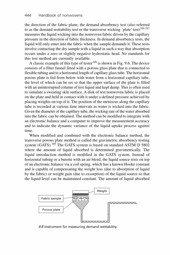
Handbook of nonwovens444
the direction of the fabric plane, the demand absorbency test (also referredto as the demand wettability test or the transverse wicking ‘plate’ test)166,167
measures the liquid wicking into the nonwoven fabric driven by the capillarypressure in the direction of fabric thickness. In demand absorbency tests, theliquid will only enter into the fabric when the sample demands it. These testsinvolve contacting the dry sample with a liquid in such a way that absorptionoccurs under a zero or slightly negative hydrostatic head. No standards forthis test method are currently available.
A classic example of this type of tester166 is shown in Fig. 9.6. The deviceconsists of a filter funnel fitted with a porous glass plate that is connected toflexible tubing and to a horizontal length of capillary glass tube. The horizontalporous plate is fed from below with water from a horizontal capillary tube,the level of which can be set so that the upper surface of the plate is filledwith an uninterrupted column of test liquid and kept damp. This is often usedto simulate a sweating skin surface. A disk of test nonwoven fabric is placedon the plate and held in contact with it under a defined pressure achieved byplacing weights on top of it. The position of the meniscus along the capillarytube is recorded at various time intervals as water is wicked into the fabric.Given the diameter of the capillary tube, the wicking rate of the water absorbedinto the fabric can be obtained. The method can be modified to integrate withan electronic balance and a computer to improve the measurement accuracyand to indicate the dynamic variance of the liquid uptake process againsttime.
When modified and combined with the electronic balance method, thetransverse porous plate method is called the gravimetric absorbency testingsystem (GATS).168 The GATS system is based on standard ASTM D 5802where the amount of liquid absorbed is determined gravimetrically. Theliquid introduction method is modified in the GATS system. Instead ofhorizontal tubing or a burette with an air bleed, the liquid source rests on topof an electronic balance via a coil spring, which has a known Hooke constantand is capable of compensating the weight loss (due to absorption of liquidby the fabric) or weight gain (due to exsorption) of the liquid source so thatthe liquid level can be maintained constant. The amount of liquid absorbed
Weight
Fabric sample
Porous plate
9.6 Instrument for measuring demand wettability.
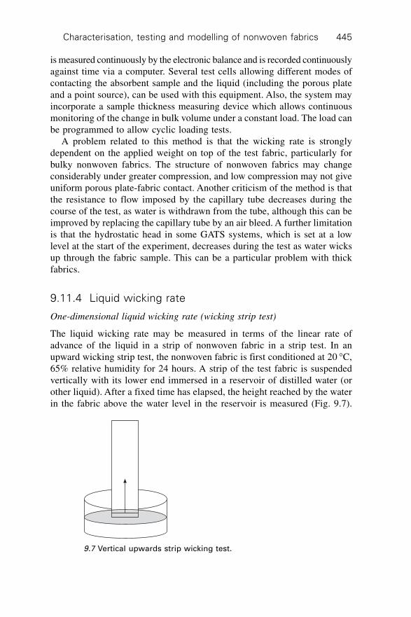
Characterisation, testing and modelling of nonwoven fabrics 445
is measured continuously by the electronic balance and is recorded continuouslyagainst time via a computer. Several test cells allowing different modes ofcontacting the absorbent sample and the liquid (including the porous plateand a point source), can be used with this equipment. Also, the system mayincorporate a sample thickness measuring device which allows continuousmonitoring of the change in bulk volume under a constant load. The load canbe programmed to allow cyclic loading tests.
A problem related to this method is that the wicking rate is stronglydependent on the applied weight on top of the test fabric, particularly forbulky nonwoven fabrics. The structure of nonwoven fabrics may changeconsiderably under greater compression, and low compression may not giveuniform porous plate-fabric contact. Another criticism of the method is thatthe resistance to flow imposed by the capillary tube decreases during thecourse of the test, as water is withdrawn from the tube, although this can beimproved by replacing the capillary tube by an air bleed. A further limitationis that the hydrostatic head in some GATS systems, which is set at a lowlevel at the start of the experiment, decreases during the test as water wicksup through the fabric sample. This can be a particular problem with thickfabrics.
9.11.4 Liquid wicking rate
One-dimensional liquid wicking rate (wicking strip test)
The liquid wicking rate may be measured in terms of the linear rate ofadvance of the liquid in a strip of nonwoven fabric in a strip test. In anupward wicking strip test, the nonwoven fabric is first conditioned at 20 ∞C,65% relative humidity for 24 hours. A strip of the test fabric is suspendedvertically with its lower end immersed in a reservoir of distilled water (orother liquid). After a fixed time has elapsed, the height reached by the waterin the fabric above the water level in the reservoir is measured (Fig. 9.7).
9.7 Vertical upwards strip wicking test.
Handbook of nonwovens446
Both the wicking rate and the ultimate height the water reaches are taken asdirect indications of the wickability of the test fabric. Liquid wicking in boththe machine and cross-directions of the nonwoven fabric are tested to obtainthe anisotropic liquid wicking properties. The main standard test methodsare:
1. BS3424-18, method 21(1988): methods for determination of the resistanceto wicking and lateral leakage.
2. ERT 10.4 (2002): Nonwoven absorption.3. ITS 10.1(1995): Standard test method for absorbency time, absorbency
capacity and wicking rate.4. WSP 10.1(2005): Three standard test methods for nonwoven absorption.5. BS EN ISO 9073-6 (2003): Textile test methods for nonwovens–
Absorption.
There are some differences in these test procedures. The BS3424-18 (Method21) specifies a very long test period (24h) and is intended for coated fabricswith very slow wicking rates. In contrast, other test methods (e.g., ITS10.1,ERT10.4, WSP 10.1 and BS EN ISO 9073-6) specify a much shorter testtime (maximum 5 min) and applies to fabrics that exhibit rapid wicking. Theupward wicking strip test method can be connected with a computer integratedimage analyser to obtain dynamic wicking measurements or it can be modifiedfor integration with an electronic balance to monitor the mass of waterabsorbed. A downward wicking strip test is also reported to enable the wickingrate and capillary pressure to be obtained.169 Other test methods include thehorizontal strip test.
When the strip test method is used for determining the rate of advance ofthe liquid front, the position of the advancing front might not be obviousbecause of the so-called finger-effect.170 This occurs in nonwoven fabrics,which are usually of high porosity and heterogeneous with local variationsin fabric density. However, comparison of the strip test results in fabricshaving large differences in fabric structure needs caution. The effect ofliquid evaporation cannot be ignored in a strip test performed for a long timeand the influence of the fabric structure on the gravity effect in the strip testneeds to be considered.
Two-dimensional liquid wicking rate
The demand absorbency ‘plate’ test method can be converted into a two-dimensional radial dynamic wicking measurement method168 when the liquidis introduced from a point source into the nonwoven fabric (also known asthe point source demand wettability test). One example of this method is theGATS system mentioned in Section 9.11.3 when a point source liquidintroduction cell was used.
Characterisation, testing and modelling of nonwoven fabrics 447
Modified laser-Doppler anemometry (MLDA)171 is another alternativemethod to monitor liquid wicking in the two-dimensional fabric plane basedon the Doppler principle. When a laser beam is passed through a flowingliquid, light is scattered by the particles suspended in the liquid. The scatteredlight is subject to a frequency shift and contains information about the velocityof the particles which can then be examined by electro-optical techniques. Inorder to obtain the velocity of liquid flow in a nonwoven fabric using thismethod, it is required that the flow medium be partly transparent and containparticles that scatter light used in the measurement.
Electrical capacitance techniques have been used to monitor the liquidabsorption in multi-directions in a nonwoven fabric plane.172,173 The principleof the method is based on the fact that the dielectric constant of water isabout 15 to 40 times higher than that of normal fibres and fabrics andtherefore the capacitance of a transducer in a measuring system will be verysensitive to the amount of liquid absorbed by a fabric. The device iscomputerised and is able to provide both dynamic (real time) and multi-directional measurements of the wicking rate in terms of the volume ofliquid absorbed. Problems in testing nonwovens may arise from the influenceof the significant geometric deformations in saturated fabrics, the liquidevaporation and limitations in the size of the capacitance transducers. Also,different types of fibrous material may have different dielectric constants,which can lead to difficulties when comparing different materials.
Similar to measuring the permeability and the anisotropy of liquid transportin the nonwoven fabric plane,146 the image analysis method has been usedto track the in-plane radial liquid advancing front to determine the rate ofcapillary spreading in the two-dimensional fabric plane. Kawase et al.174,175
used a video camera to determine the capillary spreading of liquids in the fabricplane. The apparatus used in his studies comprised a desiccator with a 200 mmdiameter. The cover had an orifice for inserting a micropipette. The liquid usedwas n-decane which was placed at the bottom of the desiccator to minimisevolatilisation of the liquid spreading in the fabrics. To aid observation of theliquid spreading in test fabrics, the n-decane was dyed with a 0.1% solutionof Sudan IV or acid blue 9. The fabric was mounted on a 12.0 cm woodenring (embroidery hoop) and placed into the desiccator along with a stopwatch.The cell was covered and the fabric was left for at least two hours. A measuredamount (0.05 to 0.20 ml) of liquid was introduced onto the fabric by amicropipette. The area of the spreading liquid and the reading on the stopwatchwere recorded simultaneously using a video camera. The spreading area wascopied onto film, cut out, and weighed. A calibration curve was determinedby recording areas of several known sizes and weighing the copied film inevery experiment in order to determine the actual spreading area. The correlationcoefficients of the calibration curves were reported to be higher than 0.999.
With the aid of advanced image analysis software, an image analyser
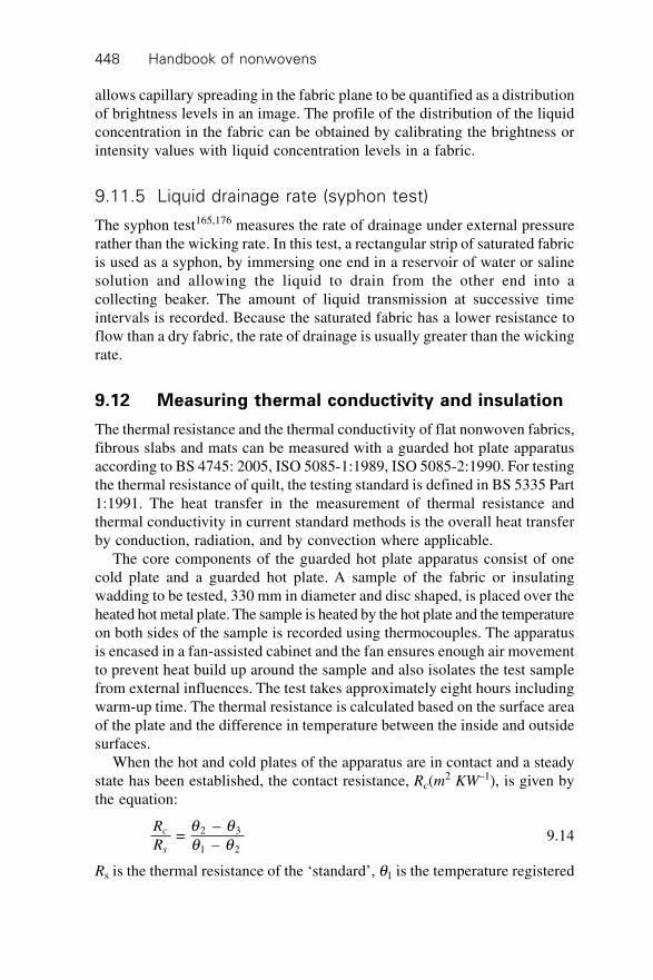
Handbook of nonwovens448
allows capillary spreading in the fabric plane to be quantified as a distributionof brightness levels in an image. The profile of the distribution of the liquidconcentration in the fabric can be obtained by calibrating the brightness orintensity values with liquid concentration levels in a fabric.
9.11.5 Liquid drainage rate (syphon test)
The syphon test165,176 measures the rate of drainage under external pressurerather than the wicking rate. In this test, a rectangular strip of saturated fabricis used as a syphon, by immersing one end in a reservoir of water or salinesolution and allowing the liquid to drain from the other end into acollecting beaker. The amount of liquid transmission at successive timeintervals is recorded. Because the saturated fabric has a lower resistance toflow than a dry fabric, the rate of drainage is usually greater than the wickingrate.
9.12 Measuring thermal conductivity and insulation
The thermal resistance and the thermal conductivity of flat nonwoven fabrics,fibrous slabs and mats can be measured with a guarded hot plate apparatusaccording to BS 4745: 2005, ISO 5085-1:1989, ISO 5085-2:1990. For testingthe thermal resistance of quilt, the testing standard is defined in BS 5335 Part1:1991. The heat transfer in the measurement of thermal resistance andthermal conductivity in current standard methods is the overall heat transferby conduction, radiation, and by convection where applicable.
The core components of the guarded hot plate apparatus consist of onecold plate and a guarded hot plate. A sample of the fabric or insulatingwadding to be tested, 330 mm in diameter and disc shaped, is placed over theheated hot metal plate. The sample is heated by the hot plate and the temperatureon both sides of the sample is recorded using thermocouples. The apparatusis encased in a fan-assisted cabinet and the fan ensures enough air movementto prevent heat build up around the sample and also isolates the test samplefrom external influences. The test takes approximately eight hours includingwarm-up time. The thermal resistance is calculated based on the surface areaof the plate and the difference in temperature between the inside and outsidesurfaces.
When the hot and cold plates of the apparatus are in contact and a steadystate has been established, the contact resistance, Rc(m
2 KW–1), is given bythe equation:
R
Rc
s
= – –
2 3
1 2
q qq q 9.14
Rs is the thermal resistance of the ‘standard’, q1 is the temperature registered
Characterisation, testing and modelling of nonwoven fabrics 449
by thermocouple, T1, q2 is the temperature registered by T2 and q3 is thetemperature registered by T3.
Thus, the thermal resistance of the test specimen, Rf (m2 KW –1), is given
by the equation:
R
R
f
s
= – –
– – –
2 3
1 2
2 3
1 2
¢ ¢¢ ¢
q qq q
q qq q 9.15
where ¢q1 is the temperature registered by T1, ¢q 2 is the temperature registeredby T2 and ¢q 3 is the temperature registered by T3. Since Rs (m
2KW–1) is aknown constant and can be calibrated for each specific apparatus,Rf (m
2KW –1) can thus be calculated. Then the thermal conductivity of thespecimen, k(Wm–1K –1) can be calculated from the equation:
kd mm
R m KWf
= ( )*10
( )
–3
2 –19.16
The conditioning and testing atmosphere shall be one of the standardatmospheres for testing textiles defined in ISO139, i.e., a relative humidityof 65%+/–2% R.H. and a temperature of 20 ∞C+/– 2∞C.
9.13 Modelling pore size and pore size distribution
In the design and engineering of nonwoven fabrics to meet the performancerequirements of industrial applications, it is desirable to make predictionsbased on the fabric components and the structural parameters of the fabric.Although work has been conducted to simulate isotropic nonwoven structuresin terms of, for example, the fibre contact point numbers177 and inter-crossdistances,178 only the models concerned with predicting the pore size aresummarised in this section.
9.13.1 Models of pore size
Although it is arguable if the term ‘pore’ accurately describes the voids in ahighly connective, low density nonwoven fabric, it is still helpful to use thisterm in quantifying a porous nonwoven structure. The pore size in simplifiednonwoven structures can be approximately estimated by Wrotnowski’smodel179,180 (Fig. 9.8) although the assumptions that are made for the fabricstructure are based on fibres that are circular in cross-section, straight, parallel,equidistant and arranged in a square pattern. The radius of a pore inWrotnowski’s model is shown as follows,
rTex d f
= 0.075737 – 2fabricr
ÊËÁ
ˆ¯
9.17
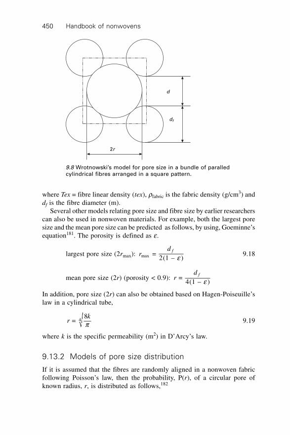
Handbook of nonwovens450
where Tex = fibre linear density (tex), rfabric is the fabric density (g/cm3) anddf is the fibre diameter (m).
Several other models relating pore size and fibre size by earlier researcherscan also be used in nonwoven materials. For example, both the largest poresize and the mean pore size can be predicted as follows, by using, Goeminne’sequation181. The porosity is defined as e.
largest pore size (2rmax): rd f
max = 2(1 – )e 9.18
mean pore size (2r) (porosity < 0.9): rd f
= 4(1 – )e
In addition, pore size (2r) can also be obtained based on Hagen-Poiseuille’slaw in a cylindrical tube,
rk
= 8
4p 9.19
where k is the specific permeability (m2) in D’Arcy’s law.
9.13.2 Models of pore size distribution
If it is assumed that the fibres are randomly aligned in a nonwoven fabricfollowing Poisson’s law, then the probability, P(r), of a circular pore ofknown radius, r, is distributed as follows,182
d
df
2r
9.8 Wrotnowski’s model for pore size in a bundle of paralledcylindrical fibres arranged in a square pattern.
Characterisation, testing and modelling of nonwoven fabrics 451
P(r) = –(2pv¢) exp(–pr2v¢) 9.20
where ¢vr
= 0.36,2
and is defined as the number of fibres per unit area.
In geotextiles, a series of critical pore sizes have been defined, i.e. the fabricapparent opening size (AOS, or O95) and the fabric filtration opening size(FOS). The apparent opening size (AOS, or O95) indicates the approximatelargest particle that would effectively pass through the geotextile. In the drysieving method, it is defined as the bead size at which 5% or less of theweight of the beads pass through the nonwoven fabric.
Giroud110 proposed a theoretical equation for calculating the filtrationpore size of nonwoven geotextiles. The equation is based on the fabric porosity,fabric thickness, and fibre diameter in a nonwoven geotextile fabric.
Od
hdf
f
f = 11 –
– 1 + (1 – )e
xee
È
ÎÍ
˘
˚˙ 9.21
where df = fibre diameter, e = porosity, h = fabric thickness, x = an unkowndimensionless parameter to be obtained by calibration with test data to accountfor the further influence of geotextile porosity and x = 10 for particularexperimental results, and Of = filtration opening size, usually given by thenearly largest constriction size of a geotextile (e.g., O95).
Lambard183 and Faure184 applied Poissonian line network theory to establisha theoretical model of the ‘opening sizing’ of nonwoven fabrics. In thismodel, the fabric thickness is assumed to consist of randomly stackedelementary layers, each layer has a thickness Te and is simulated by two-dimensional straight lines, (a Poissonian line network). Faure et al.185 andGourc and Faure186 also presented a theoretical technique for determiningconstriction size based on the Poissonian polyhedra model. In Faure’s approach,epoxy-impregnated nonwoven geotextile specimens were sliced and thenonwoven geotextile was modelled as a pile of elementary layers, in whichfibres were randomly distributed in planar images of the fabric. The cross-sectional images were obtained by slicing at a thickness of fibre diameter df
and the statistical distribution of pores was modelled by inscribing a circleinto each polygon defined by the fibres (Fig. 9.9).
The pore size distribution, which is obtained from the probability of passageof different spherical particles (similar to glass beads in a dry sieving test)through the layers forming the geotextile, can thus be determined theoreticallyusing the following equation:185
Q dd d
de
f
f
N
Nd( ) = (1 – )2 + ( + )
2 +
2
–fl
llÊ
ËÁˆ¯
9.22
l pf
= 4 (1 – ), and =
dN
Tdf f
9.23
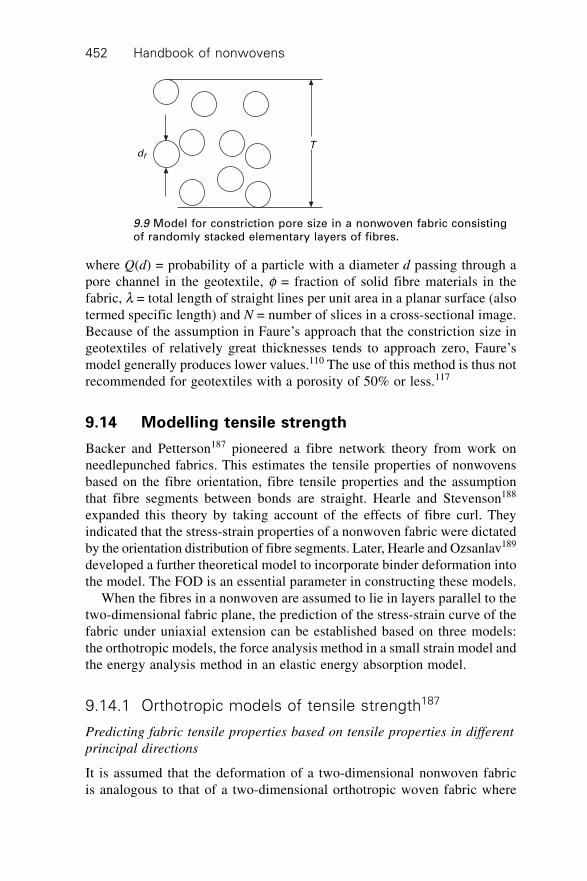
Handbook of nonwovens452
where Q(d) = probability of a particle with a diameter d passing through apore channel in the geotextile, f = fraction of solid fibre materials in thefabric, l = total length of straight lines per unit area in a planar surface (alsotermed specific length) and N = number of slices in a cross-sectional image.Because of the assumption in Faure’s approach that the constriction size ingeotextiles of relatively great thicknesses tends to approach zero, Faure’smodel generally produces lower values.110 The use of this method is thus notrecommended for geotextiles with a porosity of 50% or less.117
9.14 Modelling tensile strength
Backer and Petterson187 pioneered a fibre network theory from work onneedlepunched fabrics. This estimates the tensile properties of nonwovensbased on the fibre orientation, fibre tensile properties and the assumptionthat fibre segments between bonds are straight. Hearle and Stevenson188
expanded this theory by taking account of the effects of fibre curl. Theyindicated that the stress-strain properties of a nonwoven fabric were dictatedby the orientation distribution of fibre segments. Later, Hearle and Ozsanlav189
developed a further theoretical model to incorporate binder deformation intothe model. The FOD is an essential parameter in constructing these models.
When the fibres in a nonwoven are assumed to lie in layers parallel to thetwo-dimensional fabric plane, the prediction of the stress-strain curve of thefabric under uniaxial extension can be established based on three models:the orthotropic models, the force analysis method in a small strain model andthe energy analysis method in an elastic energy absorption model.
9.14.1 Orthotropic models of tensile strength187
Predicting fabric tensile properties based on tensile properties in different
principal directions
It is assumed that the deformation of a two-dimensional nonwoven fabricis analogous to that of a two-dimensional orthotropic woven fabric where
df
T
9.9 Model for constriction pore size in a nonwoven fabric consistingof randomly stacked elementary layers of fibres.
Characterisation, testing and modelling of nonwoven fabrics 453
stress (s)-strain (e) relationships are known for the two principal directionsof the nonwoven fabric. It is assumed that the following properties are known:elastic modulus (EX, EY) in two principal directions respectively; shear modulus(GXY) between the two principal directions; and the Poissons’ ratio
vvXY
YX
X
Y
= 1 = ee
ÊË
ˆ¯ in two principal directions.
For a unidirectional force acting on the fabric with a small strain
s qe q q
( )( )
= ( )EÊË
ˆ¯
, the fabric modulus, and the Poissons’ ratio in the direction
q are as follows:
1( )
= ( )( )
= cos
+ 1 – 2
cos sin + sin4
2 24
E E G
v
E EX XY
XY
X Yqe qs q
qq q
qÊËÁ
ˆ¯
v( ) = –( )
+ 2
qe q
e qpÊ
ˈ¯
=
1 + 1 – 1 cos sin – (cos + sin )
cos + 1 –
2 cos +
sin
2 24 4
42
4
E E Gv
E
E G
v
E E
X Y XYYX
X
X XY
XY
X Y
ÊËÁ
ˆ¯
ÊËÁ
ˆ¯
q qq q
q
9.24
Predicting fabric tensile properties based on fibre orientation distribution
and fibre properties
In a nonwoven fabric, it is assumed that (i) the fibres in the fabric arestraight and cylindrical with no buckling, (ii) the bond strength betweenfibres in the fabric is considerably higher than the fibre strength (i.e.,nonwoven rupture results from fibre failure) and (iii) the shear stress andshear strain are negligible. Thus, we have the following equations fornonwoven fabric tensile properties, where the fibre orientation distributionfunction in the fabric is W(b)
s q e b q b b b bp
p
( ) = (cos – ( )sin cos ) ( )– /2
/24 2 2E v df x Ú W 9.25
s q p e b b q b b bp
p
+ 2
= (sin cos – ( )sin ) ( )– /2
/22 2 4Ê
ˈ¯ ÚE v df x W
9.26
Handbook of nonwovens454
v
d
d
( ) =
(sin cos ) ( )( )
(sin ) ( )
– /2
/22 2
– /2
/24
qb b b b
b b b
p
p
p
p
ÚÚ
W
W9.27
E( ) = ( )( )
qs qe q
= cos –
(sin cos ) ( )
(sin ) ( )
sin cos– /2
/24 – /2
/22 2
– /2
/24
2 2E
d
d
fp
pp
p
p
pbb b b b
b b bb bÚ
ÚÚ
Ê
Ë
ÁÁÁÁ
ˆ
¯
˜˜˜˜
W
W
¥ W (b)db 9.28
When a nonwoven fabric is isotropic i.e., ( ) = 1W b pÊË
ˆ¯ , from the above
equations, we have v( ) = 13
q .
9.14.2 Force analysis method in a small strain model
In force analysis in a small strain model, the following assumptions aremade about the nonwoven structure.
1. The fibres are assumed to lie in layers parallel to the two-dimensionalfabric plane.
2. The fabric is subjected to a small strain.3. The nonwoven fabric is a pseudo-elastic material and Hooke’s law applies.4. No lateral contraction of the material takes place.5. No transverse force exists between fibres.6. No curl is present in the fibres.
The stress-strain relationship can be established by using the analysis of thecomponents of force in the fibre elements in a nonwoven fabric is given asfollows.187,188
(1 + ej)2 = (1 + e L)2 cos2 qj + [1 + eT + (1 + eL) cot qj tan b]2 sin2qj
9.29
where b is the shear undertaken by the fabric, ej is the fibre strain in the jthfibre element, eL and eT are the fabric strains in the longitudinal direction andtransverse direction respectively; qj is the fibre orientation angle of the jthfibre element. If there is no shear in the fabric plane, we have
(1 + ej)2 = (1 + eL)2 cos2qj + (1 + eT)2 sin2qj 9.30
Characterisation, testing and modelling of nonwoven fabrics 455
9.14.3 Energy analysis method190
In the previous models, the fibres are assumed to be straight cylindrical rods.In fact, fibres in real nonwoven fabrics usually have various degrees of curl,thus energy analysis methods have been adopted to improve tensile propertymodelling. The nonwoven structure is treated as a network of energy absorbingfibrous elastic elements, where elastic energy in reversible deformation canbe solely determined by changes in fibre length. The deformation geometryis defined by minimum energy criteria. The applied stresses and strain areused in the analysis rather than the applied forces and displacement used inthe first method. The following assumptions are made:
1. The fabric is a two-dimensional planar sheet.2. The sheet consists of networks of fibre elements between bond points.3. The bond points move in a way that corresponds to the overall fabric
deformation.4. Stored energy is derived from changes solely in fibre length; (i.e., no
contribution of binder, each point is freely jointed, fibres are free tomove independently between bonds).
When a unidirectional force is applied, we have:
¢e e q q qjj
L j XY j jCv = 1 [(1 + )cos + (1 – sin ) sin ] – 12 2 2 2 2
12 9.31
s
e m sq
e
mL
Lj
N
j j
j
j j
j
N
j
C =
(1 + ) cos
(1 + )=1
2
2
=1
S
S
¢
Ê
ËÁˆ
¯9.32
where ¢e j = strain in the jth fibre element, eL = overall fabric strain, sj = stressin the jth fibre element sL = overall fabric stress and vXY = fabric contractionfactor, which is defined as the contraction in the Y direction due to a forcein the X direction, which is equal to the ratio of strain in the Y direction tothe strain in the X direction. qj = orientation angle of the jth fibre element,Cj = curl factor of the jth fibre element, mj = mass of the jth fibre element andN = total number of fibre elements.
9.15 Modelling bending rigidity191
The bending rigidity (or flexural rigidity) of adhesive bonded nonwovenswas evaluated by Freeston and Platt.191 A nonwoven fabric is assumed to becomposed of unit cells and the bending rigidity of the fabric is the sum of thebending rigidities of all the unit cells in the fabric, defined as the bendingmoment times the radius of curvature of a unit cell. The analytical equations
Handbook of nonwovens456
for bending rigidity were established in the two cases of ‘no freedom’ and‘complete freedom’ of relative motion of the fibres inside a fabric. Thefollowing assumptions about the nonwoven structure are made for modellingthe bending rigidity.
1. The fibre cross-section is cylindrical and constant along the fibre length.2. The shear stresses in the fibre are negligible.3. The fibres are initially straight and the axes of the fibres in the bent cell
follow a cylindrical helical path.4. The fibre diameter and fabric thickness are small compared to the radius
of curvature; the neutral axis of bending is in the geometric centreline ofthe fibre.
5. The fabric density is high enough that the fibre orientation distributiondensity function is continuous.
6. The fabric is homogeneous in the fabric plane and in the fabric thickness.
The general unit cell bending rigidity, (EI)cell, is therefore as follows:
( ) = [ cos + sin cos ] ( )cell– /2
/24 2 2EI N E I GI df f f p
p
p
q q q q qÚ W
9.33
where Nf = number of fibres in the unit cell, EfIf = fibre bending rigidityaround the fibre axis, G = shear modulus of the fibre, Ip = polar moment ofthe inertia of the fibre cross section, which is a torsion term and W(q) = thefibre orientation distribution in the direction, q.
The bending rigidities of a nonwoven fabric in two specific cases of fibremobility are as follows:
1. ‘Complete freedom’ of relative fibre motion. If the fibres are free totwist during fabric bending (e.g., in a needlepunched fabric), the torsionterm (GIp sin2 q cos2 q) will be zero. Therefore,
( ) = 64
( )coscell
4
– /2
/24EI
d N Ed
f f fpq q q
p
p
Ú W 9.34a
where df = fibre diameter, Ef = Young’s modulus of the fibre2. ‘No freedom’ of relative fibre motion. In chemically bonded nonwovens,
the freedom of relative fibre motion is severely restricted. It is assumedin this case that there is no freedom of relative fibre motion and the unitcell bending rigidity (EI)cell, is therefore:
( ) = 48
)coscell
2
– /2
/24EI
N E d hd
f f fpq q q
p
p
Ú W( 9.34b
where h = fabric thickness and df = fibre diameter.
Characterisation, testing and modelling of nonwoven fabrics 457
9.16 Modelling specific permeability
The specific permeability of a nonwoven fabric is solely determined bynonwoven fabric structure and is defined based on D’Arcy’s Law,192 whichmay be written as follows:
Qk p
h = –h
D9.35
where Q is the volumetric flow rate of the fluid flow through a unit cross-sectional area in the porous structure (m/s), h is the viscosity of the fluid(Pa.s), Dp is the pressure drop (Pa) along the conduit length of the fluid flowh (m) and k is the specific permeability of the porous material (m2).
9.16.1 Theoretical models of specific permeability
Numerous theoretical models describing laminar flow through porous mediahave been proposed to predict permeability. The existing theoretical modelsof permeability applied in nonwoven fabrics can be grouped into two maincategories based on:
i. capillary channel theory, for example Kozeny,204 Carman,193 Davies,194
Piekaar and Clarenburg195 and Dent.196
ii. drag force theory, for example Emersleben,197 Brinkman,198 Iberall,199
Happel,200 Kuwabara,201 Cox,202 and Sangani and Acrivos.203
Many permeability models established for textile fabrics are based oncapillary channel theory or the hydraulic radius model, which is based on thework of Kozeny204 and Carman.193 The flow through a nonwoven fabric istreated as a conduit flow between cylindrical capillary tubes. The Hagen–Poiseuille equation for fluid flow through such a cylindrical capillary tubestructure is as follows:
qr P
h =
8
4ph
D9.36
where r is the radius of the hydraulic cylindrical tube. However, it has beenargued that models based on capillary channel theory are suitable only formaterials having a low porosity and are unsuitable for highly porous mediawhere the porosity is greater than 0.8, see, for example, Carman.193
In drag force theory, the walls of the pores in the structure are treated asobstacles to an otherwise straight flow of the fluid. Drag force theory isbelieved to be more applicable to highly porous fibrous assemblies, such asnonwoven fabrics, where the single fibres can be regarded as elements withinthe fluid that cannot be displaced, see Scheidegger.213 The drag of the fluidacting on each portion of the wall is estimated from the Navier-Stokes equations,
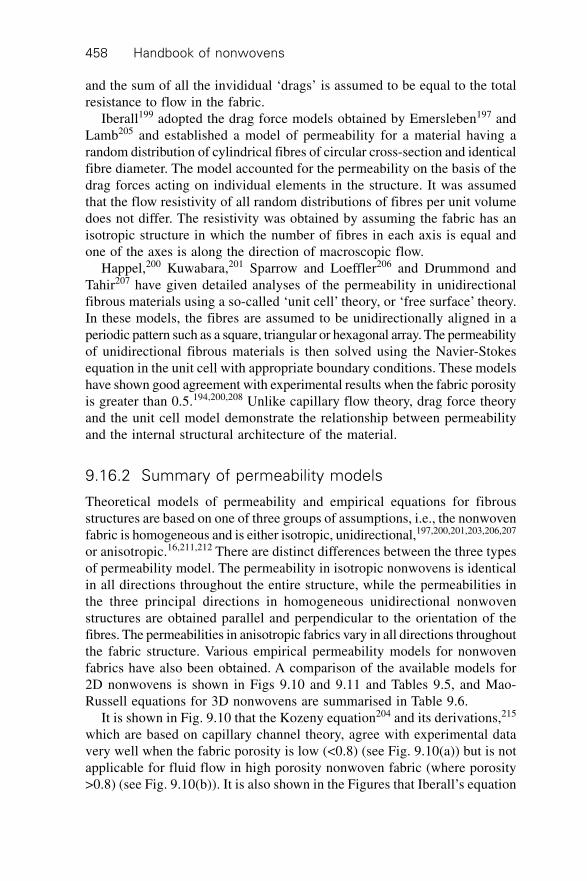
Handbook of nonwovens458
and the sum of all the invididual ‘drags’ is assumed to be equal to the totalresistance to flow in the fabric.
Iberall199 adopted the drag force models obtained by Emersleben197 andLamb205 and established a model of permeability for a material having arandom distribution of cylindrical fibres of circular cross-section and identicalfibre diameter. The model accounted for the permeability on the basis of thedrag forces acting on individual elements in the structure. It was assumedthat the flow resistivity of all random distributions of fibres per unit volumedoes not differ. The resistivity was obtained by assuming the fabric has anisotropic structure in which the number of fibres in each axis is equal andone of the axes is along the direction of macroscopic flow.
Happel,200 Kuwabara,201 Sparrow and Loeffler206 and Drummond andTahir207 have given detailed analyses of the permeability in unidirectionalfibrous materials using a so-called ‘unit cell’ theory, or ‘free surface’ theory.In these models, the fibres are assumed to be unidirectionally aligned in aperiodic pattern such as a square, triangular or hexagonal array. The permeabilityof unidirectional fibrous materials is then solved using the Navier-Stokesequation in the unit cell with appropriate boundary conditions. These modelshave shown good agreement with experimental results when the fabric porosityis greater than 0.5.194,200,208 Unlike capillary flow theory, drag force theoryand the unit cell model demonstrate the relationship between permeabilityand the internal structural architecture of the material.
9.16.2 Summary of permeability models
Theoretical models of permeability and empirical equations for fibrousstructures are based on one of three groups of assumptions, i.e., the nonwovenfabric is homogeneous and is either isotropic, unidirectional,197,200,201,203,206,207
or anisotropic.16,211,212 There are distinct differences between the three typesof permeability model. The permeability in isotropic nonwovens is identicalin all directions throughout the entire structure, while the permeabilities inthe three principal directions in homogeneous unidirectional nonwovenstructures are obtained parallel and perpendicular to the orientation of thefibres. The permeabilities in anisotropic fabrics vary in all directions throughoutthe fabric structure. Various empirical permeability models for nonwovenfabrics have also been obtained. A comparison of the available models for2D nonwovens is shown in Figs 9.10 and 9.11 and Tables 9.5, and Mao-Russell equations for 3D nonwovens are summarised in Table 9.6.
It is shown in Fig. 9.10 that the Kozeny equation204 and its derivations,215
which are based on capillary channel theory, agree with experimental datavery well when the fabric porosity is low (<0.8) (see Fig. 9.10(a)) but is notapplicable for fluid flow in high porosity nonwoven fabric (where porosity>0.8) (see Fig. 9.10(b)). It is also shown in the Figures that Iberall’s equation
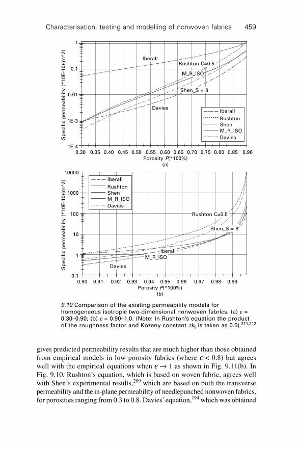
Characterisation, testing and modelling of nonwoven fabrics 459
gives predicted permeability results that are much higher than those obtainedfrom empirical models in low porosity fabrics (where e < 0.8) but agreeswell with the empirical equations when e Æ 1 as shown in Fig. 9.11(b). InFig. 9.10, Rushton’s equation, which is based on woven fabric, agrees wellwith Shen’s experimental results,209 which are based on both the transversepermeability and the in-plane permeability of needlepunched nonwoven fabrics,for porosities ranging from 0.3 to 0.8. Davies’ equation,194 which was obtained
Iberall
Rushton
Shen
M_R_ISO
Davies
IberallRushton C=0.5
M_R_ISO
Shen_S = 8
Davies
0.30 0.35 0.40 0.45 0.50 0.55 0.60 0.65 0.70 0.75 0.80 0.85 0.90
Porosity P(*100%)
(a)
Sp
ecif
ic p
erm
ea
bil
ity
(*
10
E-1
0)(
m^
2)
1
0.1
0.01
1E-3
1E-4
Iberall
Rushton
Shen
M_R_ISO
Davies
Rushton C=0.5
Iberall
Davies
Shen_S = 8
M_R_ISO
0.90 0.91 0.92 0.93 0.94 0.95 0.96 0.97 0.98 0.99
Porosity P(*100%)
(b)
Sp
ecif
ic p
erm
ea
bil
ity
(*
10
E-1
0)(
m^
2)
10000
1000
100
10
1
0.1
9.10 Comparison of the existing permeability models forhomogeneous isotropic two-dimensional nonwoven fabrics. (a) e =0.30–0.90; (b) e = 0.90–1.0. (Note: In Rushton’s equation the productof the roughness factor and Kozeny constant tk0 is taken as 0.5).211,212
Handbook of nonwovens460
from experimental results of air permeability in fabrics composed of glassfibres having a porosity of 0.70~0.99, appears to provide reasonable predictionsfor structures having higher porosities of 0.70~0.99.
The Mao-Russell equation for isotropic fibrous structures (denoted asM_R_ISO in Fig. 9.10) shows good agreement with capillary theory at lowporosity and is also in reasonable agreement with the results of empirical
Happel _P
Kuwabara
M_R_30
M_R_45
Happel_V
M_R_60
Happel_P
Emersleben
M_R_60
M_R_45M_R_30
Happel_V
Kuwabara
0.30 0.35 0.40 0.45 0.50 0.55 0.60 0.65 0.70 0.75 0.80 0.85 0.90
Porosity P(*100%)
(a)
Sp
ecif
ic p
erm
ea
bil
ity
(*
10
E-1
0)(
m^
2) 1
0.1
0.01
1E-3
Happel _P
Kuwabara
M_R_30
M_R_45
Happel_V
M_R_60
Happel_P
Emersleben
M_R_60
M_R_45
M_R_30
Happel_V
Kuwabara
0.90 0.91 0.92 0.93 0.94 0.95 0.96 0.97 0.98 0.99
Porosity P(*100%)
(b)
Sp
ecif
ic p
erm
ea
bil
ity
(*
10
E-1
0)(
m^
2)
100
10
1
0.1
9.11 Comparison of the existing permeability models forhomogeneous unidirectional fibrous materials.211,212 (a) (P = 0.30–0.9); (b) (P = 0.90–1.00). (Note: M–R–30, M–R–45 and M–R–60 arereferred to as the directional permeabilities of unidirectional fabrics
kd
f( )=–1
32
2
qf
ST
T Ssin + cos2 2q q
ÏÌÔ
ÓÔ
¸˝ÔÔ
when q p p q p =
6,
4 and =
3
respectively.)
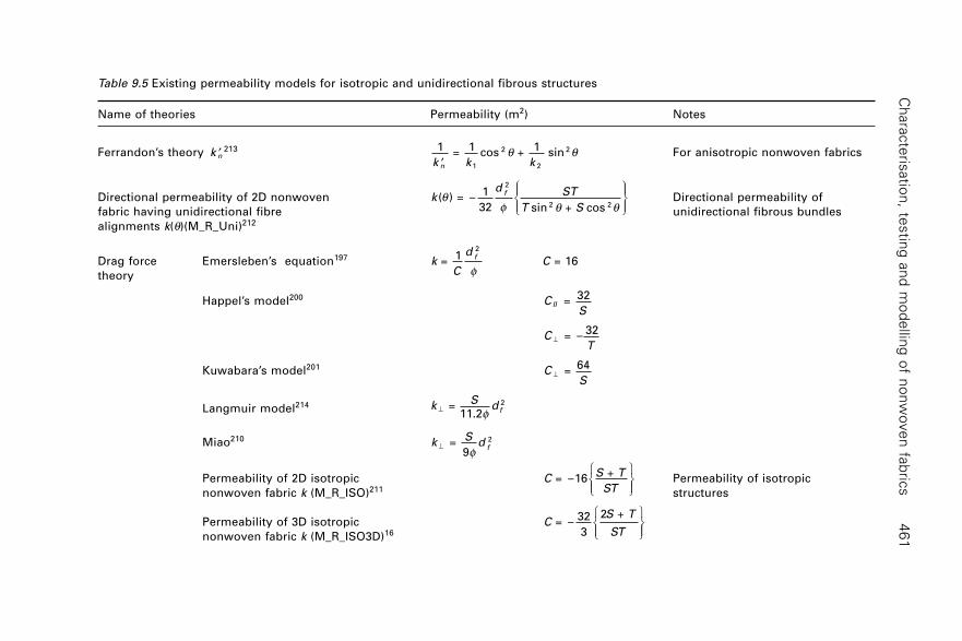
Ch
ara
cte
risatio
n, te
stin
g a
nd
mo
de
lling
of n
on
wo
ve
n fa
bric
s4
61
Table 9.5 Existing permeability models for isotropic and unidirectional fibrous structures
Name of theories Permeability (m2) Notes
Ferrandon’s theory ¢k n213
1 =
1cos +
1 sin
1
2
2
2
¢k k kn
q q For anisotropic nonwoven fabrics
Directional permeability of 2D nonwoven
kd ST
T S
f( ) = –
1
32 sin + cos
2
2 2q
f q q
ÏÌÔ
ÓÔ
¸˝ÔÔ
Directional permeability of
fabric having unidirectional fibre unidirectional fibrous bundles
alignments k(q)(M_R_Uni)212
Drag force Emersleben’s equation197
kC
df
= 1
2
fC = 16
theory
Happel’s model200
C
SII =
32
C
T^ = –
32
Kuwabara’s model201
C
S^ =
64
Langmuir model214
k
Sd f^ =
11.22
f
Miao210
kS
df^ =
9
2
f
Permeability of 2D isotropic
CS T
ST = –16
+ ÏÌÓÔ
¸˝Ô
Permeability of isotropic
nonwoven fabric k (M_R_ISO)211 structures
Permeability of 3D isotropic
CS T
ST = –
32
3
2 + ÏÌÓÔ
¸˝Ônonwoven fabric k (M_R_ISO3D)16
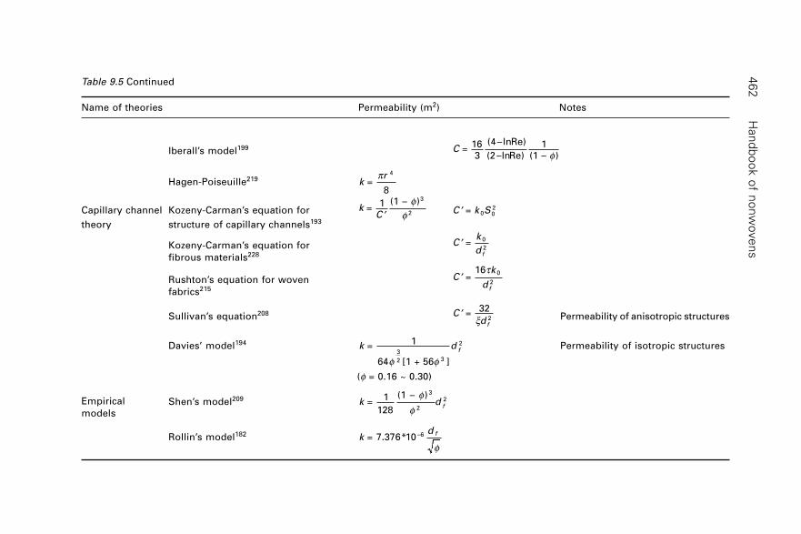
Han
db
oo
k o
f no
nw
ove
ns
46
2Table 9.5 Continued
Name of theories Permeability (m2) Notes
Iberall’s model199
C =
16
3
(4–lnRe)
(2–lnRe) (1 – )
1
f
Hagen-Poiseuille219
k
r =
8
4p
Capillary channel Kozeny-Carman’s equation for k
C =
1 (1 – )3
2¢f
f ¢C k S = 0 02
theory structure of capillary channels193
Kozeny-Carman’s equation for
¢Ck
d f
= 0
2
fibrous materials228
Rushton’s equation for woven
¢Ck
d f
= 16 0
2
t
fabrics215
Sullivan’s equation208
¢C
d f
= 32
2x Permeability of anisotropic structures
Davies’ model194
k df
= 1
64 [1 + 56 ]3
2 3
2
f f
Permeability of isotropic structures
(f = 0.16 ~ 0.30)
Shen’s model209
k df
= 1
128
(1 – ) 3
2
2f
f
Rollin’s model182
kd f
= 7.376*10 –6
f
Empirical
models
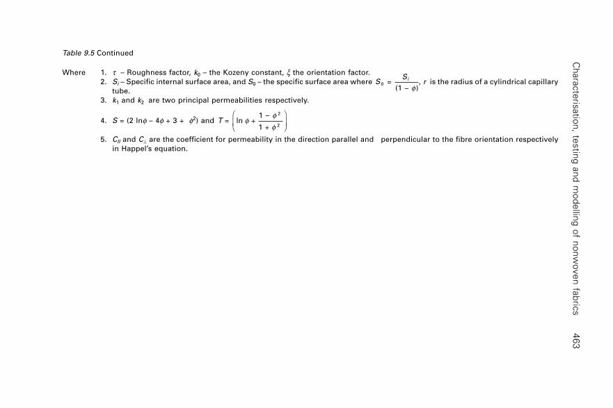
Ch
ara
cte
risatio
n, te
stin
g a
nd
mo
de
lling
of n
on
wo
ve
n fa
bric
s4
63
Table 9.5 Continued
Where 1. t – Roughness factor, k0 – the Kozeny constant, x the orientation factor.
2. Si – Specific internal surface area, and S0 – the specific surface area where
SS
ri
0 = (1 – )
, f
is the radius of a cylindrical capillary
tube.
3. k1 and k2 are two principal permeabilities respectively.
4. S = (2 lnf – 4f + 3 + f2) and
T = ln + 1 –
1 +
2
2f
f
f
Ê
ËÁ
ˆ
¯˜
5. CII and C^ are the coefficient for permeability in the direction parallel and perpendicular to the fibre orientation respectively
in Happel’s equation.
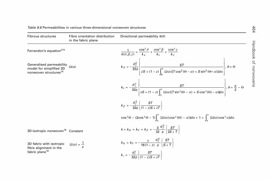
Han
db
oo
k o
f no
nw
ove
ns
46
4Table 9.6 Permeabilities in various three-dimensional nonwoven structures
Fibrous structures Fibre orientation distribution Directional permeability k(q )
in the fabric plane
Ferrandon’s equation213
Generalised permeability
model for simplified 3D
nonwoven structures16
3D isotropic nonwoven16
3D fabric with isotropic
fibre alignment in the
fabric plane16
1
( , , ) =
cos +
cos +
cos2 2 2
k k k kX Y ZJJ
b gb g
kd ST
zS z T S d
Xf = –
32 + (1 – ) ( )[ cos ( – ) + sin ( )]
, =
2
0
2 2f
a a a aq
p
Ú
Ï
ÌÔÔ
ÓÔÔ
¸
˝
ÔÔ
˛
ÔÔW Q Q
Q–
kd ST
zS z T S d
Yf
= –32
+ (1 – ) ( )[ sin ( – ) + cos ( ) – )]
, = 2
–
2
0
2 2f
a a a aq p
p
Ú
Ï
ÌÔÔ
ÓÔÔ
¸
˝ÔÔ
˛ÔÔW Q Q
Q
kd ST
z S zTZ
f = –
32 (1 – ) +
2
fÏÌÓ
¸˝˛
cos – (2cos – 1) [ ( )cos ( ) – )] = 1 + [ ( )cos ]2 2
0
2
0
2Q Q W Q Wp p
a a a a a aÚ Úd d
k k k kd ST
S TX Y Z
f = = = = –
3
32 2 +
2
fÏÌÓ
¸˝˛
W( ) =
1ap
k kz
d ST
S TX Y
f = = –
1
16(1 – ) +
2
fÏÌÓ
¸˝˛
k
d ST
z S zTz
f = –32 (1 – ) +
2
fÏÌÓ
¸˝˛
W(a)
Constant
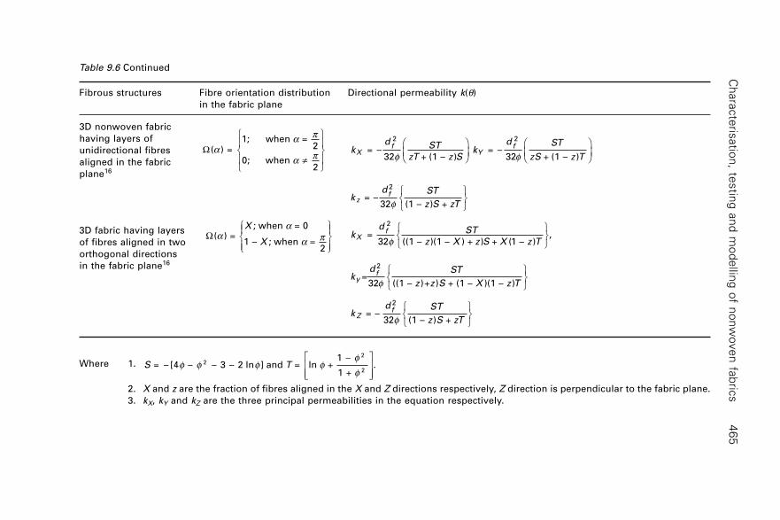
Ch
ara
cte
risatio
n, te
stin
g a
nd
mo
de
lling
of n
on
wo
ve
n fa
bric
s4
65
Table 9.6 Continued
Fibrous structures Fibre orientation distribution Directional permeability k(q)
in the fabric plane
3D nonwoven fabric
having layers of
unidirectional fibres
aligned in the fabric
plane16
3D fabric having layers
of fibres aligned in two
orthogonal directions
in the fabric plane16
W( ) = 1; when =
2
0; when 2
aa p
a pπ
Ï
ÌÔ
ÓÔ
¸
˝Ô
˛Ô
kd ST
zT z Sk
d ST
zS z TX
fY
f = –
32 + (1 – ) = –
32 + (1 – )
2 2
f fÊ
ËÁˆ
¯
Ê
ËÁˆ
¯
kd ST
z S zTz
f = –32 (1 – ) +
2
fÏÌÓ
¸˝˛
W( ) = ; when = 0
1 – ; when = 2
aa
a pX
X
ÏÌÔ
ÓÔ
¸˝Ô
Ô
kd ST
z X z S X z TX
f =
32 ((1 – )(1 – ) + ) + (1 – ),
2
fÏÌÓ
¸˝˛
kd ST
z z S X z Ty
f=32 ((1 – )+ ) + (1 – )(1 – )
2
fÏÌÓ
¸˝˛
kd ST
z S zTZ
f = –32 (1 – ) +
2
fÏÌÓ
¸˝˛
Where 1.
S T = – [4 – – 3 – 2 ln ] and = ln + 1 –
1 + .2
2
2f f f f
f
f
È
ÎÍÍ
˘
˚˙˙
2. X and z are the fraction of fibres aligned in the X and Z directions respectively, Z direction is perpendicular to the fabric plane.
3. kX, kY and kZ are the three principal permeabilities in the equation respectively.
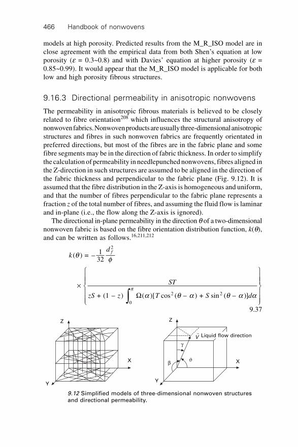
Handbook of nonwovens466
models at high porosity. Predicted results from the M_R_ISO model are inclose agreement with the empirical data from both Shen’s equation at lowporosity (e = 0.3~0.8) and with Davies’ equation at higher porosity (e =0.85~0.99). It would appear that the M_R_ISO model is applicable for bothlow and high porosity fibrous structures.
9.16.3 Directional permeability in anisotropic nonwovens
The permeability in anisotropic fibrous materials is believed to be closelyrelated to fibre orientation208 which influences the structural anisotropy ofnonwoven fabrics. Nonwoven products are usually three-dimensional anisotropicstructures and fibres in such nonwoven fabrics are frequently orientated inpreferred directions, but most of the fibres are in the fabric plane and somefibre segments may be in the direction of fabric thickness. In order to simplifythe calculation of permeability in needlepunched nonwovens, fibres aligned inthe Z-direction in such structures are assumed to be aligned in the direction ofthe fabric thickness and perpendicular to the fabric plane (Fig. 9.12). It isassumed that the fibre distribution in the Z-axis is homogeneous and uniform,and that the number of fibres perpendicular to the fabric plane represents afraction z of the total number of fibres, and assuming the fluid flow is laminarand in-plane (i.e., the flow along the Z-axis is ignored).
The directional in-plane permeability in the direction q of a two-dimensionalnonwoven fabric is based on the fibre orientation distribution function, k(q),and can be written as follows.16,211,212
kd f
( ) = – 132
2
q f
¥
Ï
ÌÔÔ
ÓÔÔ
¸
˝ÔÔ
˛ÔÔÚ
+ (1 – ) ( )[ cos ( – ) + sin ( – )]0
2 2
ST
zS z T S dp
a q a q a aW
9.37
Z
g
Jb
Y
X
Z
X
Y
r
V Liquid flow direction
9.12 Simplified models of three-dimensional nonwoven structuresand directional permeability.
Characterisation, testing and modelling of nonwoven fabrics 467
where S = –[4f – f2 – 3 – 2 ln f] and T = ln + 1 –
1 + ,
2
2f
ff
qÈ
ÎÍ
˘
˚˙ , is the flow
direction, a is the fibre orientation in each direction in the fabric plane, f isthe volume fraction of the solid material, k(q) is the directional permeabilityof the fabric, df is the fibre diameter, W(a) is the fibre orientation distributionfunction and z is the fraction of fibres aligned perpendicular to the fabricplane. The permeability perpendicular to the fabric plane, kZ, can be written as:
kd ST
z S zTz
f = – 1
32 (1 – ) +
2
fÏÌÓ
¸˝˛
9.38
9.17 Modelling absorbency and liquid retention
Liquid absorbency (or liquid absorption capacity), C, is defined as the weightof the liquid absorbed at equilibrium by a unit weight of nonwoven fabric.Thus, liquid absorbency is based on determining the total interstitial spaceavailable for holding fluid per unit dry mass of fibre. The equation is shownas follows:216
C AT
W
V
Wf f
d
f
= – 1 + (1 – )r a 9.39
where, A is the area of the fabric, T is the thickness of the fabric, Wf is themass of the dry fabric, rf is the density of the dry fibre,Vd is the amount offluid diffused into the structure of the fibres and a is the ratio of increase involume of a fibre upon wetting to the volume of fluid diffused into the fibre.
In the above equation, the second term is negligible compared to the firstterm, and the third term is nearly zero if a fibre is assumed to swell strictlyby replacement of fibre volume with fluid volume.217 Thus, the dominantfactor that controls the fabric absorbent capacity is the fabric thickness perunit mass on a dry basis (T/Wf).
In a given fabric and fluid system, only the mean pore radius r andthickness per unit mass (T/Wf) in the above equation are not constant. Thevalue of r is predicted by the following equation based on the assumptionthat a capillary is bound by three fibres, orientated parallel or randomly, andthe specific volume of the capillary unit cell is equal to that of the parentfabric.218
r AT
W f f
d n d n
f
= 16
+
– 1 + 1 2
1 2 2 1
1 1
1
2 2
2
12
pxr r
r r r r¥ÊËÁ
ˆ¯ÊË
ˆ¯
È
ÎÍ
˘
˚˙ 9.40
for n1 = 3 – n2, nf d
f d f d22 1
1 2 2 1 =
3 +
Handbook of nonwovens468
where the subscripts 1 and 2 represent different fibre types and x is a constantwith a value of 9 ¥ 105, d is fibre denier, r is fibre density (g/cm3) and f isthe mass fraction of a fibre in the blend (f1 + f2 = 1).
9.18 Modelling capillary wicking
Liquid wicking in nonwovens can be studied as a steady state fluid flow ina porous media, although in many practical situations the liquid is in fact anunsteady state flow where the nonwoven fabric is not uniformly and completelysaturated. There is usually a saturation gradient in the medium along thedirection of flow and this saturation gradient changes with time as the absorptionprocess continues. Wicking processes can be divided into four categories:
1. Pure wicking of a liquid without diffusion into the interior of the fibres.2. Wicking accompanied by diffusion of the liquid into the fibres or into a
finish on the fibre surface.3. Wicking accompanied by adsorption by fibres.4. Wicking involving adsorption and diffusion into fibres.
9.18.1 Capillary pressure (Laplace’s equation)
Liquid wicking into a nonwoven fabric is driven by the capillary pressure inthe void spaces between adjacent fibres in the fabric. It is known that capillarypressure in a cylindrical capillary tube is given by Laplace’s equation,
Prcap =
2 cos s g9.41
where r is the radius of the capillary tube, g is the contact angle between theliquid and the capillary tube surface and s is the surface tension of the liquid.Nonwoven fabrics containing capillary pores having an average diameter 2r
are frequently modelled as an equivalent system of parallel cylindrical capillarytubes having the same diameter 2r.
9.18.2 Hagen-Poiseuille equation
From a consideration of the laws of hydrodynamic flow through capillarychannels, Poiseuille219 first deduced the relation between the volume of fluidflowing through a narrow tube and the pressure difference across its ends.The Hagen-Poiseuille equation for a laminar fluid flow through a cylindricalcapillary tube is as follows:
dh
dtr P
h =
8
2
hD
9.42
Characterisation, testing and modelling of nonwoven fabrics 469
where h is the distance through which the fluid flows in time t, and h is theviscosity of the fluid.
9.18.3 Lucas-Washburn equation
Based on Poiseuille’s equation, Lucas220 and Washburn131 calculated thedistance along which turbulence occurs and, by converting the volume-flowin Poiseuille’s equation into linear-flow in uniform cylindrical tubes, theydeveloped the Lucas-Washburn equation as follows:
h Ct = 12 9.43
where h is the distance through which the fluid flows in time t and C is aconstant related to both the liquid properties and nonwoven fabric structure.
A typical example of the application of the Lucas-Washburn equation isin liquid absorption in the upwards vertical strip test, in which the capillarypores in a nonwoven fabric are modelled as a series of parallel capillarytubes vertically supported and liquid is absorbed from one end upwards intothe tube. The upward driving pressure is as follows:
DP = Pcap – rgh 9.44
where Pcap is the capillary pressure in the tube, h is the rising height of liquidin the tube, g is the acceleration of gravity and, r is the liquid density.
Substituting equation 9.44 and Laplace’s equation into Hagen-Poiseuille’sequation, the rising height of the liquid capillary flow is as follows:
dh
dtrh
rg =
4 cos –
8
2
h s g h rÊË
ˆ¯ 9.45
The solution of this equation is:
th
r g r g
grhe = –
8 –
16 cos log 1 –
2 cos 2 3 2 2
hr
hs gr
rs g
ÏÌÓ
¸˝˛
9.46
To obtain a simplified form of the relationship between t and h, Laughlin221
rewrote the above equation as follows:
bt hh
hhm e
m
= – log 1 – – ÏÌÓ
¸˝˛
9.47
where hab
ar
br g
m = with = cos 4
and = 8
2s gh
rh
By using Taylor’s expansion,222 and when the gravity effect is negligible(e.g. h << hm) the equation can be reduced to the form of the Lucas-Washburnequation131,220,223 as follows:
Handbook of nonwovens470
hr
t = cos 2
12 1
2s g
hÏÌÓ
¸˝˛
9.48
These equations can be applied to approximate the horizontal and verticalliquid wicking in nonwoven fabrics respectively, where r would be the averagepore size of the fabric. To calculate the mass transmission of water absorbedduring the upwards vertical strip test, Law224 developed an equation as follows:
m t Bx t h
dtv
t
vm
= 1( )
– 1
0ÚÏÌÓ
¸˝˛
9.49
where Br
Kg m sv = cos
4 ( / )
3rp s gh ◊
Many authors223,225 have shown that the flow of liquids through textile fabricsobeys the Lucas-Washburn equation. This equation is reported to characteriseaccurately the water penetration in other fibrous materials, such as paper.226
9.18.4 Directional capillary pressure and anisotropic liquid
wicking in nonwovens (Mao-Russell equations)
According to the capillary channel theory as shown in both the Poiseuilleequation and the Lucas-Washburn equation, capillary wicking is determinedby the geometric structure of the pores in a nonwoven fabric. However, thereare difficulties in quantifying the average equivalent capillary radii227 ofpores in nonwoven fabrics because (i) the capillary channels differ in sizeand shape. They are inter-connected as well as interdependent to form athree-dimensional network system; (ii) the capillary channels in real nonwovenfabrics do not have circular cross-sections and are not necessarily uniformalong their lengths. Also, because most of the volume of a nonwoven fabricconsists of pore voids (the porosity of high-loft nonwovens may be as highas 0.99) and the spaces between fibres are very large and widely distributed,any attempt to give an exact analysis of a fabric based on theoretical capillarychannels would be impracticable because of the complex nature of thenonwoven structure.
Two-dimensional models of capillary pressure in a nonwoven fabric
The liquid flow over a fibre during wicking in a two-dimensional nonwovenfabric plane is shown in Fig. 9.13. The fibre of a particular unit length isaligned in the direction a and the liquid flow over the fibre driven by capillarypressure is in the direction q. The model of capillary wicking in the two-dimensional nonwoven fabric plane is based on both the hydraulic radius
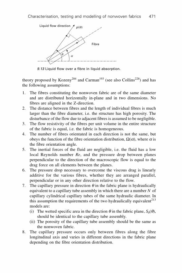
Characterisation, testing and modelling of nonwoven fabrics 471
theory proposed by Kozeny204 and Carman193 (see also Collins228) and hasthe following assumptions:
1. The fibres constituting the nonwoven fabric are of the same diameterand are distributed horizontally in-plane and in two dimensions. Nofibres are aligned in the Z-direction.
2. The distance between fibres and the length of individual fibres is muchlarger than the fibre diameter, i.e. the structure has high porosity. Thedisturbance of the flow due to adjacent fibres is assumed to be negligible.
3. The flow resistivity of the fibres per unit volume in the entire structureof the fabric is equal, i.e. the fabric is homogeneous.
4. The number of fibres orientated in each direction is not the same, butobeys the function of the fibre orientation distribution, W(a), where a isthe fibre orientation angle.
5. The inertial forces of the fluid are negligible, i.e. the fluid has a lowlocal Reynolds number Re, and the pressure drop between planesperpendicular to the direction of the macroscopic flow is equal to thedrag force on all elements between the planes.
6. The pressure drop necessary to overcome the viscous drag is linearlyadditive for the various fibres, whether they are arranged parallel,perpendicular or in any other direction relative to the flow.
7. The capillary pressure in direction q in the fabric plane is hydraulicallyequivalent to a capillary tube assembly in which there are a number N ofcapillary cylindrical capillary tubes of the same hydraulic diameter. Inthis assumption the requirements of the two hydraulically equivalent213
models are:(i) The wetted specific area in the direction q in the fabric plane, S0(q),
should be identical to the capillary tube assembly.(ii) The porosity of the capillary tube assembly should be the same as
the nonwoven fabric.8. The capillary pressure occurs only between fibres along the fibre
longitudinal axis and varies in different directions in the fabric planedepending on the fibre orientation distribution.
Liquid flow direction p (q )
q a
Fibre
9.13 Liquid flow over a fibre in liquid absorption.
Handbook of nonwovens472
This assumption is based on the fact that the capillary phenomenon onlyoccurs along the direction of the fibre orientation and the drag resistanceexists perpendicular to the fibre orientation, this resistance force was modelledby Princen.229
Directional capillary pressure230
For a nonwoven fabric having the fibre orientation distribution function inthe fabric plane W(a) (where a is the fibre orientation angle), the capillarypressure in the direction q in the fabric, p(q), is as follows,230
pd
n
f
( ) = 4 ( ) | cos( – ) |
(1 – ) cos
=0qf a q a
f s gaS W
9.50
where g is the contact angle of the fibre, s is the surface tension of the liquid,df is the fibre diameter and f is the fraction of the solid fibre in the fabric.
Anisotropic liquid wicking
The volumetric rate of liquid wicking can be described by D’Arcy’s law andis thus rewritten as follows:
Qk p
x( ) = –
( ) ( )( )
qqh
qq 9.51
where Q(q) = volumetric flow rate through a unit area in the fabric cross-section (m3/s* m2) in the direction q, p(q) = capillary pressure difference(N/m2) in the direction q, x(q) = conduit distance (m) in the direction q andk(q) = specific permeability of sample (m2) in the direction q.
With reference to the capillary pressure, p(q) as given above the directionalpermeability, k(q), has been established in previous work (see Sections 9.16.2and 9.16.3) as follows:211
kd ST
T S d
f( ) = – 1
32( )[ cos ( – ) + sin ( – )]
2
0
2 2
q fa q a q a a
p
Ú
Ï
ÌÔÔ
ÓÔÔ
¸
˝ÔÔ
˛ÔÔ
W
9.52
where df is the fibre diameter and f is the volume fraction of the solid
material (defined as frr = ,fabric
fibre where rfabric is the density of a fibrous pack
in a vacuum and rfibre is the fibre density). W(a) is the fibre orientation
Characterisation, testing and modelling of nonwoven fabrics 473
distribution function, which defines the arrangement of fibres within the
nonwoven fabric structure. T = ln + 1 –
1 +
2
2f
ff
È
ÎÍ
˘
˚˙ and S = [2 ln f – 4f + 3 +
f2].Substituting k(q) and p(q) into D’Arcy’s law, the rate of liquid absorption
(or the wicking rate) in direction q, Q(q), can be written as follows:230
Qd
x
f( ) = –
8(1 – ) ( )q f q
¥
Ï
ÌÔÔ
ÓÔÔ
¸
˝ÔÔ
˛ÔÔ
ST
T S
S
S
W
W
a
p
a
p
a q a
a q a q a
s gh
=0
=0
2 2
( )| cos ( – )|
( ) [ cos ( – ) + sin ( – )]
cos
9.53
There are two important conclusions to be drawn from this equation. Firstly,it has been shown that the liquid absorption velocity depends on the fibrediameter, the fibre orientation distribution and the fabric porosity, in additionto the liquid properties (viscosity and surface tension) and conditions at thefibre surface (liquid contact angle). Secondly, it is evident that the anisotropyof liquid wicking in nonwoven fabrics largely depends on the combinationof the fibre orientation distribution and the fabric porosity.
In addition, the relationship between the distance wicked by the liquidand the wicking time in the form of the Lucas-Washburn equation, can beobtained from equation 9.53 as follows:
x Ct( ) = 12q 9.54
where
Cd ST
T S
f = 1
2–
(1 – )
( ) | cos ( – ) |
( )[ cos ( – ) + sin ( – )]
cos=0
=0
2 2
12
f
a q a
a q a q a
s gh
a
p
a
p
S
S
W
W
Ï
ÌÔÔ
ÓÔÔ
¸
˝ÔÔ
˛ÔÔ
È
Î
ÍÍÍÍ
˘
˚
˙˙˙˙
9.18.5 Liquid diffusion into nonwovens containing
absorbent polymeric materials
For absorbent fibres, it is believed that the spontaneous flow of liquid withincapillary spaces is accompanied by a simultaneous diffusion of the liquidinto the interior of the fibre or a film on the fibre surface.231 The sorption of
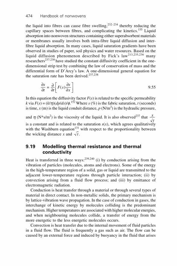
Handbook of nonwovens474
the liquid into fibres can cause fibre swelling,232–234 thereby reducing thecapillary spaces between fibres, and complicating the kinetics.155 Liquidabsorption into nonwoven structures containing either superabsorbent materialsor membranes usually involves both intra-fibre liquid diffusion and inter-fibre liquid absorption. In many cases, liquid saturation gradients have beenobserved in studies of paper, soil physics and water resources. Based on theliquid diffusion phenomenon described by Fick’s law213,235,236 manyresearchers237,238 have studied the constant diffusivity coefficient in the one-dimensional strip test by combining the law of conservation of mass and thedifferential form of D’Arcy’s law. A one-dimensional general equation forthe saturation rate has been derived.237,238
∂∂
∂∂
∂∂
ÈÎÍ
˘
˚
s
t tF s
s
x = ( ) 9.55
In this equation the diffusivity factor F(s) is related to the specific permeabilityk via F(s) = (k/h)(dp/ds)/f.152 Where s (%) is the fabric saturation, t (seconds)is time, x (m) is the liquid conduit distance, p (N/m2) is the hydraulic pressure,
and h (N*s/m2) is the viscosity of the liquid. It is also observed237 that x
tis a constant and is related to the saturation s(x), which agrees qualitativelywith the Washburn equation131 with respect to the proportionality betweenthe wicking distance x and t .
9.19 Modelling thermal resistance and thermalconductivity
Heat is transferred in three ways:239,240 (i) by conduction arising from thevibration of particles (molecules, atoms and electrons). Some of the energyin the high-temperature region of a solid, gas or liquid are transmitted to theadjacent lower-temperature regions through particle interaction; (ii) byconvection arising from a fluid flow process; and (iii) by emittance ofelectromagnetic radiation.
Conduction is heat transfer through a material or through several types ofmaterial in direct contact. In non-metallic solids, the primary mechanism isby lattice-vibration wave propagation. In the case of conduction in gases, theinterchange of kinetic energy by molecules colliding is the predominantmechanism. Higher temperatures are associated with higher molecular energies,and when neighbouring molecules collide, a transfer of energy from themore energetic to the less energetic molecules occurs.
Convection is heat transfer due to the internal movement of fluid particlesin a fluid flow. The fluid is frequently a gas such as air. The flow can becaused by an external force and induced by buoyancy in the fluid that arises
Characterisation, testing and modelling of nonwoven fabrics 475
from fluid density variations caused by temperature variations in the fluid.Convection depends on the conditions in the boundary layer, which areinfluenced by surface geometry, the nature of the fluid motion, and the fluidthermodynamic and transport properties; convective heat transfer can occurbetween solids and fluids.
Thermal radiation is heat transfer between two bodies by means ofelectromagnetic waves, i.e. the radiation or propagation of a collection ofparticles termed photons or quanta. Radiation is a surface phenomenon. Theheat flow in the ‘steady state’ condition passing through a flat plate materialis found to be proportional to the area and to the temperature differencebetween the two faces, and inversely proportional to the thickness of theplate material. The heat transfer can be expressed as a one-dimensional formof Fourier’s heat conduction equation for steady-state heat flow through theflat plate as follows:
Q kAT
d =
D9.56
where Q is the heat flow rate per unit area, Wm–2, k is the thermal conductivity,Wm–1K–1, A is the unit area normal to the heat flow, m–2; DT is the temperaturedifference across the plate (K) and d is the fabric thickness (m).
Based on the above equation, the thermal conductivity and thermal resistancehave been defined to quantify the thermal properties of materials as follows:
1. Thermal conductivity. The thermal conductivity (k) is a material propertywhich defines the capacity of the material to conduct heat through itsmass. It is defined as the amount of heat/energy in watts (W) that willflow through a unit area of (m2) and unit thickness of (one metre) of thematerial when a temperature difference of 1K is established between itssurfaces. Thermal conductivity can be expressed in Wm–1 K–1.
2. Thermal resistance. The thermal resistance, Rf(m2 KW–1), is related to
the thermal conductivity of the material and its thickness by the relationship:
Rd
k Kf =
(mm) * 10
(Wm )
–3
–1 –19.57
Nonwoven fabrics are a mixture of fibre and air (and chemical binders ifpresent), and the thermal conductivity of air and solid materials (e.g. fibres)when heat transfers through the fabric. The overall heat transfer in nonwovensis the sum of the heat transfer contributions through the fibre and the trappedair, which may involve multiple transport mechanisms. Therefore, the thermalconductivity of a nonwoven fabric, k, is the sum of all the individualconductivities of the structural components. The heat transfer value includesall the conduction, convection, and radiation values of air, solid fibre (andbinders if any). The thermal conductivities of a nonwoven fabric can thereforebe expressed as follows:
Handbook of nonwovens476
k = kair conduction + kfconduction + kconvection + kradiation + kfibre-air
where kair conduction = conduction of air; kfconduction = conduction through fibres;kconvection = heat transfer by convection; kradiation = heat transfer by radiation;kfibre-air = heat interaction between air and fibre. The heat transfer (specificallythe thermal conductivity) of a nonwoven fabric is influenced by many factorsincluding the thermal conductivity of the solid polymer materials, nonwovenfabric structure and the ambient temperature.
The thermal conductivities of some solid polymer materials and fabricsare listed in Tables 9.7 and 9.8. Steam has the lowest thermal conductivity(0.016 Wm–1K–1) whereas silver has the highest thermal conductivity(406 Wm–1K–1). Among polymers, polypropylene has a low thermalconductivity (0.10 Wm–1K–1) and high-density polyethylene (HDPE) has acomparatively high thermal conductivity (0.52 Wm–1K–1).
The fabric structural parameters affecting heat transfer include the thermalconductivity of component fibre materials, fabric bulk density, porosity andthe fabric architecture. Conduction occurs in the fibre and in the air trappedwithin the spaces between the fibres. Free convection in the presence of agravity field and radiation with the environment at the surface of the nonwoven
Table 9.7 Thermal conductivity of polymer materials commonly used in the textile
industry
Materials Density Thermal conductivity Source of data
(Kg/m3) (Wm–1K–1)
Nylon 6 fibre 1140 0.25 Morton and Hearle7
PET fibre 1390 0.14
PP fibre 910 0.12
PE fibre 920 0.34
PVC fibre 1360 0.16
Wool keratin 1300 0.20 Baxter244
Silver 10,490 406 Kreider245
Air (25∞C) 1.29 0.024
Water 1000 0.58
Table 9.8 Thermal conductivity of some textile fabrics
Materials Density Thermal conductivity Source of data
(Kg/m3) (Wm–1K–1)
Silk pad 500 0.05 Morton and Hearle7
Cotton pad 500 0.071
Wool pad 500 0.054
Wool felt 320 0.047 ASHRAE246
Wool felt 300 0.071 Kreider245
Loose wool 100 0.03
Human hair felt 100 0.05
Characterisation, testing and modelling of nonwoven fabrics 477
fabric, and internally among the fibres can occur. Both convection and radiationcan be reduced with an increase in the fabric bulk density, but the thermalconduction through the fibres can increase simultaneously. When the increasein thermal conduction out-weighs the decrease in radiation, this results in aminimal value of the thermal conductivity curve for a given fabric densityand temperature. Therefore, in order to maximise the thermal insulationproperties of a nonwoven fabric, i.e. to minimise the effective thermalconductivity of the fabric, it is necessary to find a balance between minimisingfibre content to reduce conduction, while providing sufficient fibre surfacearea to prevent convection and to decrease radiation effects.
For many nonwoven fabrics, the bulk density of the fabric is the primaryfactor contributing to the heat transfer through the fabric.241 However, thethermal conductivity of a fabric is not linearly related to the fabric density.There is a range of very low fabric densities in which the thermal conductivityof nonwovens decreases with an increase in the fabric density. The thermalconductivity of the constituent fibres dominates the heat transfer of thefabric because the increased fabric density blocks a large proportion of theradiation, convection and air infiltration effects. When fabric density increasesto a threshold point, the thermal conductivity of the fabric then increaseswith an increase in the fabric density.
To fully understand the influence of the fabric structure on heat transfer innonwoven fabrics, the relationship between the thermal conductivity of afabric and the proportion of the fibres within it has been summarised inempirical equations by Schuhmeister.242 He found that the thermal conductivityof a homogeneous and isotropic fabric at a certain regain, k, is as follows:
k k v k vk k
k v k v = 1
3( + ) + 2
3 + 1 1 2 21 2
1 2 2 1
ÊË
ˆ¯ 9.58
where v1 and v2 are the fractional volumes of the media of thermal conductivityk1, and k2, respectively, and v1 + v2 = 1.
When nonwovens are composed of wool fibres, Baxter244 expandedSchuhmeister’s equation and found that the thermal conductivity of the woolfabric is as follows:
k x k v k v yk k
k v k vm = ( + ) + + 1 1 2 21 2
1 2 2 1
ÊË
ˆ¯ 9.59
where x = 0.21, y = 0.79, k1 is the thermal conductivity of air (k1 = 0.0264),k2 is the thermal conductivity of wool fibre at a certain regain (k2 = 0.2226at a regain of 0.7%, k2 = 0.1933 at a regain of 10.7%) and v1 and v2 are thefractional volumes of air and the wool fibre respectively.
With the assumptions that (i) a nonwoven structure can be approximatedas a homogeneous medium of conductivity k; (ii) the interaction of fibresinfluencing k can be averaged over a unit volume; (iii) any individual fibre
Handbook of nonwovens478
can be assumed to be a spheroid whose major axis is very large comparedwith the minor axis, and (iv) fibres are perpendicular to the heat flow, Starkand Fricke243 established a model to determine the thermal conductivity, k,as follows,
k kZ
= 1 + – 1
1 + (1 + ( – 1)/( + 1))1b
a b bÊËÁ
ˆ¯ 9.60
Where a b = , = 1
2
2
1
v
v
k
k
and v1 and v2 are the fractional volumes of the media of thermal conductivityk1, and k2, respectively, and v1 + v2 = 1. Z is the fraction of the fibresperpendicular to the macroscopic heat flow (Z = 1, 0.66, 0.83 respectivelywhen fibres orientated in the cases perpendicular to the heat flux, randomlyand parallel to the heat flux).
The thermal conductivity of a nonwoven fabric increases with an increasein the environmental temperature246 because the contribution of radiation,convection and conduction to the thermal conductivity of a fabric increasessignificantly with an increase in the heating temperature.
9.20 Modelling acoustic impedance247–251
Sound is concerned with the transmission of energy through a medium (e.g.,air, water and fibre) in the form of mechanical vibrations. Sound waves arecharacterised by the wavelength, l, the sound frequency, f, and the velocityof sound propagation, v. They have the relationships v = l*f. Sound energyis characterised by sound intensity and sound pressure. Sound propagationin air-filled, high porosity nonwoven materials involves the elastic responseof the fibre segments as well as thermal and viscous effects at the fibre-airboundaries.
There are three acoustical effects in nonwoven fabrics when sound wavestransport through the structure: reflection, transmission and absorption ofsound. The latter two depend on the interaction between sound waves andfibres in the fabrics, and they are the two main mechanisms of sound isolation.Nonwoven fabrics are good sound absorption materials but are relativelypoor sound barriers. Sound absorption in nonwoven structures involves theability of the fibres in the nonwoven to absorb sound energy by convertingit into heat. Sound isolation is also possible in a dense nonwoven composedof stiff fibres which tends to reflect sound waves to stop the propagation ofthe sound through the fabric, while nonwovens of low density tend to bepoor sound insulators because sound waves propagate easily through thefabric. Nonwoven fabrics can be used in a wide range of sound transmission
Characterisation, testing and modelling of nonwoven fabrics 479
control applications, including wall claddings, acoustic barriers and acousticceilings. Understanding sound propagation through nonwoven fabrics is ofprime importance for evaluating their noise absorption capacities.
9.20.1 Theoretical models
Most of the present theoretical analyses of sound propagation in nonwovenfabrics are based on the assumption that nonwovens are two-phase mediacontaining both solid (rigid or flexible) fibres and air. In fact, the flexibilityof fibres and deformability of the bonded structure in nonwovens makessound transmission in such structures quite complicated. Therefore, existingtheoretical models introduced in this section help to give some indicationsfor the design and engineering of nonwoven structures for noise insulationbut reliable predictive models are not yet established. In this section wefocus on the reflection and absorption of small amplitude, air-borne soundwaves from nonwoven fabric surfaces in the audio-frequency range.
In general, propagation of sound in an isotropic homogeneous material isdetermined by two complex quantities, the characteristic impedance Z0(f, df,e) = z0(R) – jz0(I) and the propagation coefficient per metre g (f, df, e) = a +jb. The normal-incidence energy absorption coefficient is defined as follows:
arr = 1 –
–
+
0 0
0 0
2Z c
Z c9.61
where r0 and c0 are the density of free air and the speed of sound in free airrespectively. When a nonwoven of small thickness, h (up to 10 cm), is fixedon a rigid wall, the impedance Z of the nonwoven fabric may be calculatedfrom the following equation:
Z0 = Z coth g (f, df, e)h 9.62
Here zo (R) and zo(I) are the real and imaginary parts of Zo (f, d f, e) respectively,and the absorption coefficient of the fabric given in equation 9.61 can berewritten as follows,
ar
r =
4 ( )
( ( ) + ) + ( )0 0 0
0 0 02
02
z R c
z R c z I9.63
The absorption coefficients of a nonwoven fabric are based on the theoryof sound propagation through nonwoven structures. Three types of modelare available for sound transport in nonwoven fabrics:248 parallel capillarypore models, parallel fibre models and semi-empirical models based on thepreceeding two models. In the parallel capillary pore models, the fabric ismodelled as a medium containing identical parallel cylindrical capillary poresrunning normal to the fabric surface. There are two groups of parallel fibres
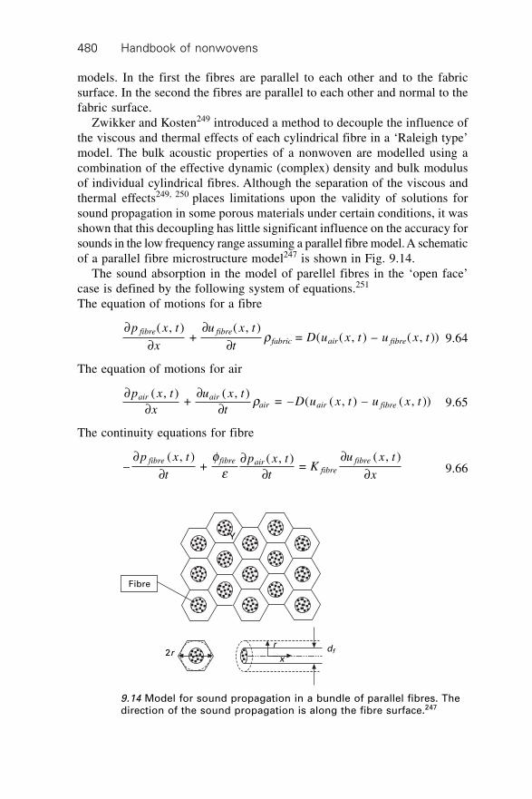
Handbook of nonwovens480
models. In the first the fibres are parallel to each other and to the fabricsurface. In the second the fibres are parallel to each other and normal to thefabric surface.
Zwikker and Kosten249 introduced a method to decouple the influence ofthe viscous and thermal effects of each cylindrical fibre in a ‘Raleigh type’model. The bulk acoustic properties of a nonwoven are modelled using acombination of the effective dynamic (complex) density and bulk modulusof individual cylindrical fibres. Although the separation of the viscous andthermal effects249, 250 places limitations upon the validity of solutions forsound propagation in some porous materials under certain conditions, it wasshown that this decoupling has little significant influence on the accuracy forsounds in the low frequency range assuming a parallel fibre model. A schematicof a parallel fibre microstructure model247 is shown in Fig. 9.14.
The sound absorption in the model of parellel fibres in the ‘open face’case is defined by the following system of equations.251
The equation of motions for a fibre
∂∂
∂∂
p x t
x
u x t
tD u x t u x t
fibre fibre
fabric air fibre
( , ) +
( , )= ( ( , ) – ( , ))r 9.64
The equation of motions for air
∂∂
∂∂
p x t
x
u x t
tD u x t u x t
air airair air fibre
( , ) +
( , ) = – ( ( , ) – ( , ))r 9.65
The continuity equations for fibre
–( , )
+ ( , )
= ( , )∂
∂∂
∂∂
∂p x t
t
p x t
tK
u x t
x
fibre fibre airfibre
fibrefe 9.66
Y
Fibre
2r dfr
x
9.14 Model for sound propagation in a bundle of parallel fibres. Thedirection of the sound propagation is along the fibre surface.247
Characterisation, testing and modelling of nonwoven fabrics 481
The continuity equations for air
–( , )
= ( , )
+ ( – )( , )
0∂
∂∂
∂∂
∂p x t
tK
u x t
xK P
u x t
xair
airair
air fibre
fibree f
9.67
and the following boundary conditions associated with the above equations are:
uair (h, t) = 0
ufibre(h, t) = 0
epfibre(0, t) = ffibrepair(0, t)
x Π[0, h]
t Π[0, T]
Where r0 and rp are the densities of free air and the fibre polymer materialrespectively, e and ffibre are the porosity of the fabric and the volume fraction
of fibre respectively, i.e., = 1 – , and in Fig. 9.14, = 1 – 2
2
f e efibre
fd
R
ÊËÁ
ˆ¯
Ê
ËÁ
ˆ
¯˜ ,
rair and rfabric are the bulk densities of the component and solid fibre componentin a unit volume of nonwoven fabric respectively, (i.e., rair = r0e and rfabric
= rfibreffibre), h is the thickness of the fabric, x is the distance, t is the time,p is the pressure and u(x, t) is the sound velocity. Kfibre is the fibre bulkmodulus, Kair is the air bulk modulus and P0 is the air pressure.
The coupling parameter, D(uair(x, t) – ufibre(x, t)), representing the dragforce between the solid fibre material and air is given by:249
D(uair(x, t) – ufibre(x, t)) = ivrair (m – 1) + e2s 9.68
where w = 2pf is the angular frequency, m is the structure constant and s isthe resistance constant. The characteristic impedance at the front face (x = 0)of a nonwoven fabric is given as follows:251
1 = ( + )( – )
( – ) coth( )0
1 2
1 2 1 1Z
u u u u
z ik h
fibre air air fibre
f
a bb b
– ( + )( – )
( – ) coth( )2 1
1 2 2 2
u u u u
z ik h
fibre air air fibre
f
a bb b 9.69
where
aw q
qjair
k
fibre
k
air f
j
fibre
U
U
u ck
iB
u i B
j
j = =
1 – –
( – )
2
2ÊËÁ
ˆ¯
Ê
ËÁ
ˆ
¯˜

Handbook of nonwovens482
b
q w q
q q w
jair
k
fibre
k
f
j
fibre air f
j
air
P
P
i ck
iB
u i B i u ck
u
j
j = =
(1 – ) 1 – –
(1 – (1 + )) –
2
2
2
2
ÊËÁ
ˆ¯
Ê
ËÁ
ˆ
¯˜
ÊËÁ
ˆ¯
zP
U k
u i B i u ck
u ifj
fibre
k
fibre
kj
fibre air f
j
fibrefabric
j
j = =
(1 – (1 + )) –
–
2
2
wq q w
q r
ÊËÁ
ˆ¯
where cK
f
fibre
fabric
2 = r is the square of the fibre wave velocity,
q r w = ( ( , ) – ( , ))D u x t u x tair fibre
a
is a dimensionless coupling coefficient,
Bair
fabric
= ,rr and the subscripts air and fibre refer to the air and fibre phases,
respectively. Thus, the sound absorption coefficient, a, can be obtained fromthe characteristic impedance, Z0, as shown above.
9.20.2 Empirical model – Voronina models252
Since the real part of the characteristic impedance, z0(R), is the most sensitiveto the influence of fibrous structure, the structural characteristic252 (Q) isusually defined as Q = z0(R) – 1. Voronina also defined other two dimensionlessparameters, a structural factor (Ks) and the airflow resistance per unit thickness(s) in complex forms as follows,253,254
K z z
ks
eb a
= ( (R) – (I) )0 0 9.70
s a b = lim ( (R) – (I) )0
0 0k
z zÆ
where z0(R) and z0(I) are the real and imaginary parts of Z0, a and b are theattenuation and phase constants, and e is the fabric porosity.
Based on the sound absorption performance (sound frequencies f = 250 ~2000 Hz) absorption performance of a range of nonwoven materials composedof glass fibre, silica fibre, mineral wool and basalt fibre respectively (df = 2~ 8mm, e = 0.996 ~ 0.92), Voronina established approximate empirical modelsof sound propagation through nonwoven fibrous media as follows,
Z(f, df, e) = (1 + Q) – jQ 9.71
g e( , , ) = (2 + )
(1 + ) + (1 + )f d
kQ Q
Qjk Qf 9.72
Characterisation, testing and modelling of nonwoven fabrics 483
kQs
e = 1 + 2 9.73
s = 2kQ 9.74
To predict the sound absorption properties based on nonwoven fabric structuralparameters, Voronina established the following empirical equations forstructural characteristics (Q) and sound resistance (s) in nonwoven soundabsorption materials.253,254 Based on his experimental results,
Qd cf
= (1 – )(1 + 0.25 10 (1 – ) ) 8–4 –2
0 0
e ee
hwr
*9.75
se e h
e r =
16(1 – ) (1 + 0.25 10 (1 – ) )2 –4 –2
2 20 0
*d cf
9.76
where h = 1.85* 10–5 is the dynamic viscosity of air (Pas), r0 is the air
density (kg/m3); c0 is the sound velocity in air (m/s); wp
= 2
0
f
c is the wave
number (m–1).
9.20.3 Empirical model – Delany–Bazley equations255
For nonwoven fabrics of large thickness (up to 2 m) and when the sound
waves are in the range of 10 1000,£ £f
s the Delany-Bazley equations are
as follows.
z
c
f0
0 0
–0.75(R) = 1 + 9.08r s
ÊË
ˆ¯ 9.77
z
c
f0
0 0
–0.73(I) = 11.9r s
ÊË
ˆ¯ 9.78
ap
s = 10.32
0
–0.59f
c
fÊË
ˆ¯ÊË
ˆ¯ 9.79
bp
s = 2
1 + 10.80
–0.70f
c
fÊË
ˆ¯
ÊË
ˆ¯
È
ÎÍ
˘
˚˙ 9.80
9.21 Modelling filtration properties
Filtration processes are usually grouped in terms of dry filtration (air filtration,aerosol filtration), wet filtration (mist filtration) and liquid filtration. Theprime objectives of filtration are to obtain the maximum separation of targeted
Handbook of nonwovens484
solid/liquid particulates from the fluid flow while minimising the pressuredrop of the fluid flow across the filter thickness. Nonwoven filters are highlypermeable and offer relatively low resistance to fluid flow with a high particlecapture capacity. Many nonwoven filters are operated as depth filters, inwhich the targeted particles gradually penetrate through the filter in thedirection of the filter thickness to be captured by individual fibres. Somesinged, coated and/or composite nonwoven filters are used for surface filtrationin which the targeted particles are blocked on the surface. The mechanism offiltration varies with the properties of the targeted particles and the fluidcarriers, thus the filtration processes and the performance of a nonwovenfilter cannot be treated in a universal model. In this section, the mechanismof air filtration using nonwoven filters and some relevant models are reviewed.
9.21.1 Filtration mechanisms and evaluation of filter
performance256,257
The particle capture in a nonwoven filter is influenced by the interactionbetween targeted particles, individual fibres in the filter media and the fluidmolecules. In filtration processes, the most frequently encountered mechanismsof particle-fibre-fluid interactions in generalised filtration models are straining,Brownian diffusion, direct interception and inertial impaction. The effects ofelectrostatic forces and of gravity sedimentation are also important in specificfiltration processes. The relative importance of these mechanisms dependsin part on the particle size and the surface area of the fibres amongst otherfactors.
Straining. Straining refers to the entrapment of particles between adjacentfibres when the particle is larger than the opening between the fibres in thefilter. Straining is the dominant method for removing large particles in lowefficiency air filters.Inertial impaction (impingement). Impaction occurs when the particleinertia is so high that it breaks the air streamlines and impacts the fibre. Thestreamline of the fluid flow circumvents a fibre in a curve and a large particlewith high velocity in the fluid can not follow the streamline around the fibreperiphery. Instead, it proceeds in a straight line due to the effect of its inertiaand collides with the fibre. This inertial effect is proportional to the squareof the particle size and the velocity of the fluid flow, and the temperatureeffect is reflected by the viscosity of the fluid.Direct interception. A particle can be caught by a fibre if it approaches thefibre within a small distance (it usually assumes that the distance is equal toor smaller than half the particle diameter). It occurs when a particle followinga normal airflow streamline is carried to within contact range of a fibre, atwhich point it will become attached. The effect is therefore proportional to
Characterisation, testing and modelling of nonwoven fabrics 485
particle size, and there is usually a high possibility that any particles of 1micron or larger in a fluid flow can be intercepted in a typical high-efficiencynonwoven filter. This process is of importance for normal filter velocitiesand small particle filtration including microbial filtration.Brownian diffusion. Brownian diffusion (Brownian motion) is the randommovement of a particle in the fluid flow stream caused by the collision ofother particles with the molecules of the fluid media on a molecular scale.Because of the Brownian motion, the particles do not follow the flow linesof the fluid around the fibres but deviate from the flow streamlines anddeposit on the fibre surface. Diffusion is a removal process that is importantfor particles smaller than about 0.1 micron.258,259 The effect of Brownianmotion is influenced by the particle size, the fibre diameter, the fluid flowvelocity and the temperature of the fluid flow.
These filtration mechanisms depend on the type of particles, the particlesize, the structure of the nonwoven fabric, fluid flow rates, and the mechanicaland physiochemical interactions of the particle-fluid-filter material system.
A high quality filter usually has a high separation capacity with a minimumpressure loss and these two parameters should ideally remain constant duringthe service life of the filter. The major criteria characterising the performanceof a filter include the filter quality coefficient, filter efficiency, pressuredrop, filter loading, filter clogging and filter cleaning and filtration cyclingtime. They are defined as follows.
Filter efficiency
The filter efficiency, E, is the ability of the filter to retain particles and isdefined as the percentage of particles of a given size retained by the filter. Itcan be calculated from the ratio of the particle concentrations in the upstream(Pin) and downstream (Pout) fluid flows respectively.
EP
P = 1 – out
in9.81
Pressure drop
The pressure drop refers to the difference in pressures in the upstream (pin)and downstream (pout) fluid flows across the filter thickness.
Dp = pin – pout 9.82
Filter quality performance
The filter quality performance, or the filter quality coefficient, is defined as theratio of the filtration efficiency to the pressure drop across the filter thickness.
Handbook of nonwovens486
QE
p =
–ln(1 – )D 9.83
Dust-holding capacity
Dust-holding capacity, or filter capacity, is defined as the amount of thedeposited particles that the filter is capable of accumulating before reachinga certain pressure drop for particles of a given size.
9.21.2 Filter efficiency in dry air filtration
Nomenclature
Cc = cunningham slip factor Cd
ecp
d p
= 1 + 2.492 + 0.84 .–0.435
l lÊËÁ
ˆ¯
Ê
ËÁ
ˆ
¯˜
Dd = the particle diffusion coefficient, (m2/s); this characterises the degree ofdiffusion motion and is a function of the mean free path of the fluid
molecules, DC k T
ddC B
p
= 3ph .
df fibre diameter.dp particle diameter.ef effective fibre length factor; which is the ratio of the theoretical pressure
drop for a Kuwabara flow field to the experimental pressure drop262,264
(ef = 16huifh/ ( ))2OKud Pf D .
E single fibre collection efficiency; it is the fraction of the particles that canbe collected by a fibre from a normal cross-sectional area of the gasstream equal to the frontal area of the fibre.
Ej single fibre collection efficiency for a size sub-range j of a polydisperseaerosol.
G gravity parameter, Gd g
u
p p
i
= 18
.rh
Ku Kuwabara hydrodynamic factor, Ku = – 34
– 12
ln + – 14
.2f f fg gravitational acceleration.h thickness of filter.kB Boltzmann’s constant, 1.3708 ¥ 10–23 J/K.n aerosol number concentration leaving filter.no aerosol number concentration entering filter.
N¢cap simplified capillary number, ¢N = cos capuh
s g .
Pe Peclet number, it characterises the intensity of diffusion deposition and
Characterisation, testing and modelling of nonwoven fabrics 487
an increase in the Peclet number will decrease the single-fibre diffusion
efficiency, PU d
De
f
d
= .0
DP0 pressure drop across the dry filter.
R interception parameter, Rd
d
p
f
= .
Re Reynolds number, Reu di f
= .rh
Stk Stokes number; is the ratio of the particle kinetic energy to work done
against viscous drag over a distance of one fibre radius, Stku d
d
p i p
f
= 9
.2r
hT temperature (K).u superficial gas velocity (m/s).ui interstitial gas velocity (m/s).Y filter efficiency (%).e porosity of filter.f packing density of dry filter (fibre volume fraction).h gas absolute viscosity (Ns/m2).l mean free path of gas molecules at NTP (0.067mm260), it is inversely
proportional to the air pressure.g contact angle between liquid and fibre.r density of gas.rp density of particle.s surface tension of liquid (N/m).
Background
Nonwoven filters can be modelled as layered two-dimensional fibrous networksof high porosity. During the filtration process, a small proportion of theparticles in the fluid flow penetrates through the fabric but most of theparticles are gradually deposited on the surface of the fibres. As the fibresare gradually covered with particles, a filter cake is produced and thepermeability of the filter structure gradually decreases. Therefore, the overallfiltration process is not constant. The deposition of particles leads to anincrease in pressure drop but there may be an increase in the filtration efficiencyas smaller particles are retained. The formation of the filter cake duringfiltration makes modelling the filtration process complex because the filtercake largely influences both the particulate capture capacities of the filterand the pressure drop across the filter thickness.
The prime performance of a nonwoven filter can be characterised by thefilter quality coefficient. In this section, we focus on the filter fabric designbased on the models of the relationship between the filter quality coefficient(i.e., filter efficiency and pressure drop) and the structure of the fabric. This
Handbook of nonwovens488
mainly relates to depth air filtration, and the filter efficiency of a nonwovenfabric filter is modelled based on the single-fibre collection efficiency theory.
Filter efficiency based on a single fibre collection efficiency
Any nonwoven filter is composed of many individual fibres, thus the filterefficiency depends on the particle collection efficiency of a single fibre. Theequation defining overall filter efficiency of a nonwoven fabric, Y(df), for anyparticle size, dp, and set of conditions is as follows.194,261–264
Y dEh
d eff f
( ) = 1 – exp–4
(1 – )f
p fÊËÁ
ˆ¯
9.84
The particle collection efficiency of a single fibre, E, depends on the particlesize, air velocity, and fibre properties based on the six primary mechanismsthat operate in filtration: impaction (EI), direct interception(ER), diffusion(ED), enhanced interception due to diffusion (EDr), gravitational settling (EG)and electrostatic attractions (Eq). Several equations have been proposed forpredicting E from these different collection mechanisms; in particular,Davies’ equation:194
E = EDRI = (R + (0.25 + 0.4R)(Stk + 2 Pe–1 ) 9.85
– 0.0263R(Stk + 2 Pe–1 )2)(0.16 + 10.9f – 17f2)
Friederlandler265,266
E ERP
RP R RP RDRIe
e e e e = = 1 6 + 313
16
13
16
3ÊËÁ
ˆ¯
ÊËÁ
ˆ¯
Ê
ËÁ
ˆ
¯˜ 9.86
and Stenhouse273
E = ED + ER + EDr + EI + EG 9.87
Each of the component collection efficiencies is as follows:
Diffusion267
EKu
P PD e e = 2.91 –
+ 0.62–1
3 – 23 –1fÊ
ˈ¯
9.88
(Valid for 0.005 < f < 0.2, 0.1 < U0 < 2m/s; 0.1 < df < 50 mm; Re < 1).
Interception258,261,270
ER
KuR
RR RR =
(1 + )2
2 ln(1 + ) – 1 + + 11 +
1 – 2
–2
(1 + (1 + )2
2ff fÊ
ˈ¯
ÊË
ˆ¯
Ê
ËÁˆ
¯
Characterisation, testing and modelling of nonwoven fabrics 489
= (1 – )
2 (1 + )
2
23(1– )
f
f
R
Ku R9.89
Impaction271
EStk J
KI
u
= ( )
2 29.90
where Stkd C U
d
d p c
f
= 18
20r
hJ = (29.6 – 28f0.62)R2 – 27.5R2.8 for 0.01 < R < 0.4
and 0.0035 < f < 0.111J = 2 for R > 0.4.
Enhanced diffusion due to interception of diffusing particles268
ER
KuPe
PeDr = 1.24
( ) for > 100
23
12
9.91
Gravitational settling269
EG @ (1 + R)G for VTS and U0 in the same direction.EG @ –(1 + R)G, for VTS and U0 in the opposite direction.EG @ –G2, for VTS and U0 in the orthogonal direction.
where GV
U
d C g
UTS d p c
= = 180
2
0
rh
Electrostatic attraction194
Eq
d d U ln Req
p f
= – 1 + 1 3 2 – )
12 2
20
''
ÊË
ˆ¯
Ê
ËÁˆ
¯ph (9.92
Where ' is the dielectric constant of the particle and q is the charge on theparticle.
Filter efficiency of nonwoven filters having multiple fibre components
When particles of multiple sizes are filtered by a fabric consisting of fibres
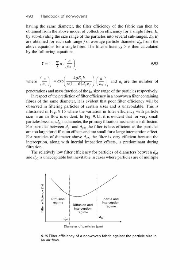
Handbook of nonwovens490
having the same diameter, the filter efficiency of the fabric can then beobtained from the above model of collection efficiency for a single fibre, E,by sub-dividing the size range of the particles into several sub-ranges. Ej, Ej
are obtained for each sub-range j of average particle diameter dpj from theabove equations for a single fibre. The filter efficiency Y is then calculatedby the following equations.
Y an
njj
j
= 1 –0
S ÊË
ˆ¯ 9.93
where n
n
E h
d e
n
nj
j
f f j0 0 = exp
4
(1 – ); Ê
ˈ¯
ÊËÁ
ˆ¯
ÊË
ˆ¯
fp f and aj are the number of
penetrations and mass fraction of the jth size range of the particles respectively.In respect of the prediction of filter efficiency in a nonwoven filter containing
fibres of the same diameter, it is evident that poor filter efficiency will beobserved in filtering particles of certain sizes and is unavoidable. This isillustrated in Fig. 9.15 where the variation in filter efficiency with particlesize in an air flow is evident. In Fig. 9.15, it is evident that for very smallparticles less than dp1 in diameter, the primary filtration mechanism is diffusion.For particles between dp1 and dp2, the filter is less efficient as the particlesare too large for diffusion effects and too small for a large interception effect.For particles of diameter above dp2, the filter is very efficient because theinterception, along with inertial impaction effects, is predominant duringfiltration.
The relatively low filter efficiency for particles of diameters between dp1
and dp2 is unacceptable but inevitable in cases where particles are of multiple
Fil
ter
eff
icie
ncy
(%
)
Diffusion
regime
dp1
Diffusion and
interception
regime
Inertia and
interception
regime
dp2
Diameter of particles (mm)
9.15 Filter efficiency of a nonwoven fabric against the particle size inan air flow.
Characterisation, testing and modelling of nonwoven fabrics 491
sizes in the fluid being filtered. To design a nonwoven filter with high filterefficiency, nonwoven fabrics composed of fibres of more than one diameterare common. For example, high-efficiency and HEPA filters consist of fibrediameters ranging from 0.65 to 6.5 microns, usually in three nominal diametergroups.272 If a nonwoven filter is composed of multiple fibre components,the filter efficiency when dealing with a fluid containing particles of multiplediameters will be as follows:
Y an
njj
j
= 1 – where0
S ÊË
ˆ¯ 9.94
nn
E d h
d ej
dj f
f f
f
0 = exp
4 ( )
(1 – )ÊË
ˆ¯
Ê
ËÁÁ
ˆ
¯˜˜
f
p f
S
Ej(df) = ED(df)j + ER(df)j + EDr(df)j + EI(df)j + EG(df)j + Ee(df)j
where nn
j0
ÊË
ˆ¯ and aj are the number of penetrations and mass fraction of the
jth size range of the particles respectively and Ej(df) is the collection efficiencyof a single fibre having a diameter of df against a particle of diameter dpj.
9.21.3 Pressure drop in dry air filtration
The pressure drop across a dry fibrous filter, DP0, can be predicted using theexpression developed by Davies.259
DPU h
d f
00
21.5 3 = (64 + (1 + 56 ))
hf f 9.95
9.21.4 Wet-operating filters273
For nonwoven fabrics intended for mist filtration or the filtration of liquidparticles, the specified collection efficiencies can be obtained with variouscombinations of filter thickness, fibre diameter, packing density and gasvelocity. For a specified efficiency of 90%, the required filter thicknessvaries according to the approximate relation h = 5f–1.5 d f
2.5 . The correspondingpressure drop at constant filtration efficiency is insensitive to df but variesapproximately according to the relation DPwet µ f0.6U0.3 when f > 0.01.
Handbook of nonwovens492
9.21.5 Liquid filtration
Particle capture in liquid filtration is much more complicated and less efficientthan in air filtration. For example, captured particles may easily re-enter theliquid flow, and this particle re-entrainment may be one of the key factorsresponsible for the low filter efficiency of liquid filter media compared to airfiltration. The pressure drop through the fabric is determined using the followingexpression:
DP = DPH–P + DPB–P 9.96
where DPH–P is the pressure drop for a Hagen-Poiseuille fluid, and DPB–P isthe pressure drop due to the particle flow resistance. This can be calculatedbased on the assumption that the captured bed of particles consists of sphericalparticles274 in the equations
DPf hUA
OAH P– 2
= ( )
h9.97
DPk hU
dB P
p–
2
2 2 =
(1 – )h ee 9.98
where U is the face velocity, A is the filter area, and OA is the open filter areafor flow, f is the correction factor for the clean filter fraction as determinedexperimentally, h is the filter thickness, dp is the mean particle diameter, k isthe Carman-Kozeny constant, and e is the dynamic porosity of the filtercontaining deposited particles. The filter porosity, e, should be calculated byconsidering the total area of the filter and the area covered by the depositedparticles, thus e will change with time.
9.22 The influence of fibre orientation distributionon the properties of thermal bonded nonwovenfabrics
Nonwovens, regardless of the process utilised, are assemblies of fibres bondedtogether by chemical, mechanical or thermal means. In most nonwovens, theoverwhelming majority of fibres are planar x, y stacks of fibres having littleor no orientation through the plane (z direction). Some airlaid processesmake an attempt to create a third dimension in the orientation of webs theyproduce. It may be argued that needlepunching and perhaps hydroentanglingalso result in some fibres lying in the z direction. However, the ratio of fibresin the z direction is a small fraction of the total number of fibres and theplanar x-y orientation is still responsible for the performance of the nonwoven.It may be argued therefore, that the x, y planar fibre orientation is the mostimportant structural characteristic in any nonwoven. Clearly, the properties
Characterisation, testing and modelling of nonwoven fabrics 493
of a nonwoven fabric will depend on the nature of the component fibres aswell as the way in which the fibres are arranged and bonded.275–280
Modelling and predicting the performance of nonwovens cannot be separatedfrom the fibre orientation distribution and the structure anisotropy it bringsabout. Equally important is the so-called basis weight uniformity of a nonwoven.This refers to the degree of mass variation in a nonwoven normally measuredover a certain scale. Local variation of the mass results in an unattractiveappearance, but more importantly will lead to, and potentially dictate, thefailure point of a nonwoven. For example, tensile failure may be initiatedand propagated first in areas that are fibre-poor (regions with low mass), orbarrier properties are lost because of the existence of fibre-poor regions inthe fabric. Another characteristic of a nonwoven may be the extent to whichthe fibre diameter varies in a nonwoven. This is particularly important inspunbonded and meltblown structures where the fibre diameter variationmay come about as a result of roping (fibres sticking together to form bundles)or because of the process, which leads to thick and thin places along thelength of the fibres. This becomes significant at the micro scale and can leadto failure in a similar manner to the variations in basis weight. In addition toweight variation, the fibre orientation distribution function is of particularimportance in governing fabric properties and the directional variation inproperties within a fabric. The rest of this section discusses fibre orientationand its role on performance by examining some case studies.
9.22.1 Fibre orientation distribution
The definition of Folgar and Tucker275 best describes the fibre orientationdistribution function (ODF) in a nonwoven. The orientation distribution function(ODF) y is a function of the angle a. The integral of the function y from anangle a1 to a2 is equal to the probability that a fibre will have an orientationbetween the angles a1 and a2. The function y must additionally satisfy thefollowing conditions:
y(a + p) = y(a)
0
( ) = 1p
y a aÚ d 9.99
The peak direction mean is at an anglea given by:276
aa a
a a = 1
2 tan
( ) sin 2
( ) cos 2
–1 =1
=1
S
S
i
N
i i
i
N
i i
f
f
9.100
while the standard deviation about this mean is given by:276
Handbook of nonwovens494
s a a a a( ) = 12
( )(1 – cos 2( – ))=1
1/2
Nf
i
N
i iSÈ
ÎÍ
˘
˚˙ 9.101
Anisotropy is often described as the ratio of the maximum to the minimumfrequency of the ODF. For uni-modal distributions, in the range 0 to 180degrees, the degree of anisotropy can also be characterised by the width ofthe orientation distribution peak given above. These definitions have to bereinterpreted for bimodal distributions in the range 0 to 180 degrees such asare obtained from cross-lapped webs or for crimped fibre webs viewed atshort segment lengths. A more general approach would be to use the so-called cos2 anisotropy parameter, Ht, given by281
Ht = 2·cos2 fÒ – 1, 9.102
where · Ò Úcos = ( ) cos ( )2
– /2
/22f f f f
p
p
f dt
The average cos2 anisotropy parameters can range between –1 and 1. A valueof 1 indicates a perfect alignment of the fibres parallel to a reference directionand a value of –1 indicates a perfect perpendicular alignment to that direction.A uniform ODF (random ODF) would yield a zero value. It is customary toset the reference direction to the machine direction. More appropriately, thepeak direction should be used as the reference instead of the machine direction.
A direct experimental method for measuring fibre orientation extendsback several decades when orientation was measured manually.280 Otherindirect methods explored since include short span tensile analysis,282–284
microwaves (used primarily for paper),285 ultrasound,286 diffraction methods281
and more recently, image analysis287,288 methods. In a series of publications,the present author evaluated various optical means and methods for determiningthe fibre orientation distribution in nonwovens.289–294 There are variouscommercial systems now available for measuring fibre orientationdistribution.295
9.22.2 The influence of the production method onanisotropy
Today, nonwovens are made by a variety of processes, alone or together. Thefinal structure and its anisotropy is therefore, a function of the ODF, thebonding and the layering of various webs to form a consolidated web.Orientation anisotropies are induced by various nonwoven processes. Mostthermally bonded nonwoven fabrics are made by hot calendering a cardedweb of short staple fibres. A typical thermal bonding line has an openingsection, a carding section, and a subsequent calender-bonding section. The
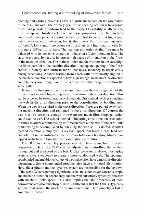
Characterisation, testing and modelling of nonwoven fabrics 495
opening and carding processes have a significant impact on the orientationof the resultant web. The primary goal of the opening section is to separatefibres and provide a uniform feed to the cards. Openability is affected byfibre crimp and finish level. Each of these properties must be carefullycontrolled if the opener is to provide a uniform batt to the card. A high crimpvalue provides more cohesion, but it also makes the fibre opening moredifficult. A low-crimp fibre opens easily and yields a high-quality web, butit is more difficult to process. The opening properties of the fibre must bebalanced with its cohesive properties to have an efficient bonding line. Thecarding process, by nature, imparts a high degree of orientation to the fibresin the machine direction. The main cylinder and the workers in the card alignthe fibres parallel to the machine direction. Inadequate opening of the fibrescreates a blotchy, non-uniform fabric that has a tendency to break easilyduring processing. A fabric formed from a web with fibres mostly aligned inthe machine direction is expected to have high strength in the machine directionand relatively low strength in the cross direction. Other properties follow thesame pattern.
To improve the cross-direction strength requires the rearrangement of thefibres so as to have a higher degree of orientation in the cross direction. Thiscan be achieved by several mechanical methods. One method involves stretchingthe web in the cross direction prior to the consolidation or bonding step.When the web is stretched in the cross direction, fibres are pulled away fromthe machine direction and realigned in the cross direction. Of course, theweb must be cohesive enough to prevent too much fibre slippage, whichcould tear the web. The second method of imparting cross direction orientationto fibres involves a randomising doff mechanism at the exit of the card. Thisrandomising is accomplished by buckling the web as it is doffed. Anothermethod commonly employed is a cross-lapper that takes a card feed andcross-laps it into a uniform batt before consolidation or bonding. Most cross-lapped webs have a bimodal fibre orientation distribution.
The ODF in the wet lay process can also have a machine directiondependency. Here, the ODF can be adjusted by controlling the relativethroughput and the speed of the belt. Unlike the systems above, most airlaysystems have a tendency to create a more randomised web. The spunmeltspunbonded and meltblown variety of webs also often have a machine directiondependency. Some spunbonded products also have a bimodal distribution.Here, the aspirator and the laydown system are responsible for the laydownof the webs. What is perhaps significant is that most nonwovens are anisotropicand machine direction dependency and the web anisotropy typically increaseswith machine (belt) speed. This also implies that the properties of mostnonwovens are also anisotropic. Also significant is that the ODF is typicallysymmetrical around the machine or cross directions. The symmetry is lost atany other direction.
Handbook of nonwovens496
9.22.3 The role of ODF on mechanical performance
When a simple tensile deformation is applied along a direction around whichthe initial orientation distribution is symmetric, it will remain symmetricthrough the deformation process. However, if it is applied along a differentdirection, the symmetry could be lost with respect to the initial symmetrydirection, but develop progressively with regard to the test direction. Thechanges in ODF that occur as a result of fabric strain can be followed by thefollowing three average anisotropy parameters and an asymmetry parameter.Overall average anisotropy parameter, Ht, given below
Ht = 2·cos2 fÒ – 1, 9.103
where · Ò Úcos = ( ) cos ( )2
– /2
/22f f f f
p
p
f dt
We define a left-quadrant average anisotropy parameter, HtL , as
HtL
L = 2 cos –1,2· Òf 9.104
where · ÒÚÚ
cos =
)cos ( )
( )
2 – /2
02
– /2
0f
f f f
f f
p
p
L
t
t
f d
f d
(
and a right-quadrant average anisotropy parameter, HtR , as:
HtR
R = 2 cos – 1,2· Òf 9.105
where · ÒÚÚ
cos =
) cos ( )
( )
2 0
/22
0
/2f
f f f
f f
p
pR
t
t
f d
f d
(
We can therefore, define an asymmetry parameter, Atm( ) , as:
A f dtm
t R( )
0
/22 2 = 4 ( ) cos sin
p
f f f fÚÊËÁˆ¯· Ò
Ê
ËÁ
– ) cos sin– /2
02 2
pf f f fÚ
Ê
ËÁˆ
¯· Ò
ˆ
¯f dt L( 9.106
Each of the average anisotropy parameters can range between –1 and 1. Avalue of 1 indicates a perfect alignment of the fibres parallel to a referencedirection and a value of –1 indicates a perfect perpendicular alignment tothat direction. A uniform ODF (random ODF) would yield a zero value. The
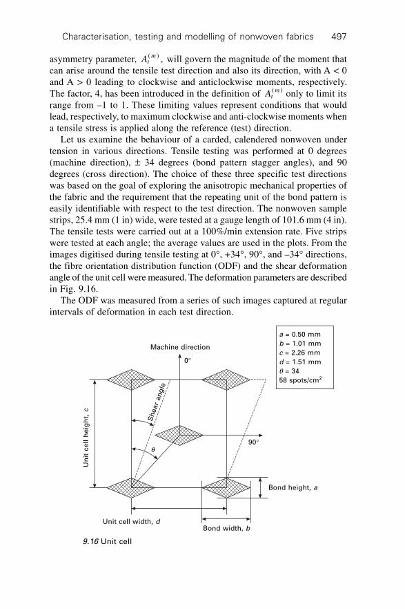
Characterisation, testing and modelling of nonwoven fabrics 497
asymmetry parameter, Atm( ) , will govern the magnitude of the moment that
can arise around the tensile test direction and also its direction, with A < 0and A > 0 leading to clockwise and anticlockwise moments, respectively.The factor, 4, has been introduced in the definition of At
m( ) only to limit itsrange from –1 to 1. These limiting values represent conditions that wouldlead, respectively, to maximum clockwise and anti-clockwise moments whena tensile stress is applied along the reference (test) direction.
Let us examine the behaviour of a carded, calendered nonwoven undertension in various directions. Tensile testing was performed at 0 degrees(machine direction), ± 34 degrees (bond pattern stagger angles), and 90degrees (cross direction). The choice of these three specific test directionswas based on the goal of exploring the anisotropic mechanical properties ofthe fabric and the requirement that the repeating unit of the bond pattern iseasily identifiable with respect to the test direction. The nonwoven samplestrips, 25.4 mm (1 in) wide, were tested at a gauge length of 101.6 mm (4 in).The tensile tests were carried out at a 100%/min extension rate. Five stripswere tested at each angle; the average values are used in the plots. From theimages digitised during tensile testing at 0∞, +34∞, 90∞, and –34∞ directions,the fibre orientation distribution function (ODF) and the shear deformationangle of the unit cell were measured. The deformation parameters are describedin Fig. 9.16.
The ODF was measured from a series of such images captured at regularintervals of deformation in each test direction.
a = 0.50 mm
b = 1.01 mm
c = 2.26 mm
d = 1.51 mm
q = 34
58 spots/cm2
Machine direction
0∞
q90∞
Bond height, a
Bond width, bUnit cell width, d
Un
it c
ell
he
igh
t, c
Sh
ear
an
gle
9.16 Unit cell
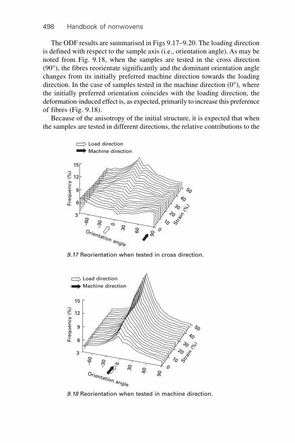
Handbook of nonwovens498
The ODF results are summarised in Figs 9.17–9.20. The loading directionis defined with respect to the sample axis (i.e., orientation angle). As may benoted from Fig. 9.18, when the samples are tested in the cross direction(90∞), the fibres reorientate significantly and the dominant orientation anglechanges from its initially preferred machine direction towards the loadingdirection. In the case of samples tested in the machine direction (0∞), wherethe initially preferred orientation coincides with the loading direction, thedeformation-induced effect is, as expected, primarily to increase this preferenceof fibres (Fig. 9.18).
Because of the anisotropy of the initial structure, it is expected that whenthe samples are tested in different directions, the relative contributions to the
Load direction
Machine direction
Fre
qu
en
cy
(%
)
15
12
9
6
3
–60
–30
0
30
60
90Orientation angle
Str
ain (
%)
50
40
3020
10
0
9.17 Reorientation when tested in cross direction.
Load direction
Machine direction
Fre
qu
en
cy
(%
)
15
12
9
6
3
–60
–30
0
30
60
90Orientation angle
Str
ain (
%)
50
40
3020
10
0
9.18 Reorientation when tested in machine direction.
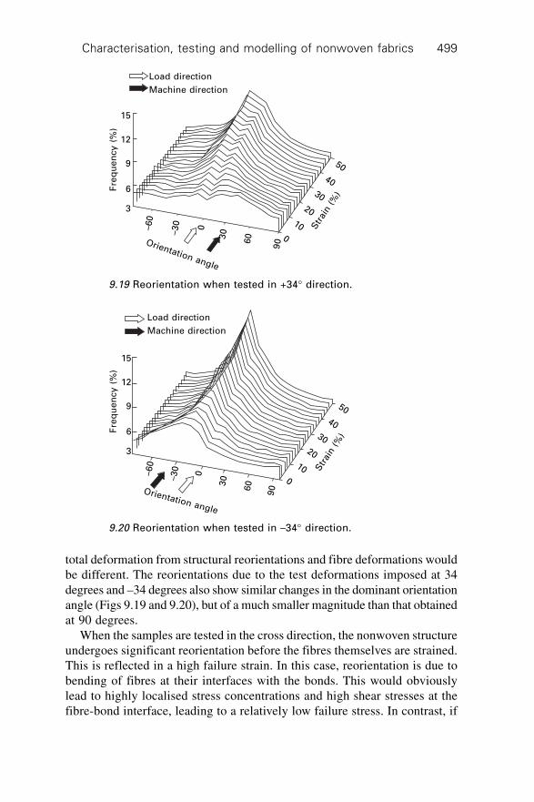
Characterisation, testing and modelling of nonwoven fabrics 499
total deformation from structural reorientations and fibre deformations wouldbe different. The reorientations due to the test deformations imposed at 34degrees and –34 degrees also show similar changes in the dominant orientationangle (Figs 9.19 and 9.20), but of a much smaller magnitude than that obtainedat 90 degrees.
When the samples are tested in the cross direction, the nonwoven structureundergoes significant reorientation before the fibres themselves are strained.This is reflected in a high failure strain. In this case, reorientation is due tobending of fibres at their interfaces with the bonds. This would obviouslylead to highly localised stress concentrations and high shear stresses at thefibre-bond interface, leading to a relatively low failure stress. In contrast, if
Load direction
Machine direction
Fre
qu
en
cy
(%
)15
12
9
6
3
–60
–30
0
30
60
90Orientation angle
Str
ain (
%)
50
40
30
20
10
0
9.19 Reorientation when tested in +34∞ direction.
Load direction
Machine direction
Fre
qu
en
cy
(%
)
15
12
9
6
3
–60
–30
0
30
60
90Orientation angle
Str
ain (
%)
50
40
30
20
10
0
9.20 Reorientation when tested in –34∞ direction.
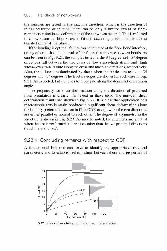
Handbook of nonwovens500
the samples are tested in the machine direction, which is the direction ofinitial preferred orientation, there can be only a limited extent of fibre-reorientation facilitated deformation of the nonwoven material. This is reflectedin a low strain but high stress at failure, occurring predominantly due totensile failure of the fibres.
If the bonding is optimal, failure can be initiated at the fibre-bond interface,or any other position in the path of the fibres that traverse between bonds. Ascan be seen in Fig. 9.21, the samples tested in the 34 degree and –34 degreedirections fall between the two cases of ‘low stress–high strain’ and ‘highstress–low strain’ failure along the cross and machine directions, respectively.Also, the failures are dominated by shear when the fabrics are tested at 34degrees and –34 degrees. The fracture edges are shown for each case in Fig.9.21. As expected, failure tends to propagate along the dominant orientationangle.
The propensity for shear deformation along the direction of preferredfibre orientation is clearly manifested in these tests. The unit-cell sheardeformation results are shown in Fig. 9.22. It is clear that application of amacroscopic tensile strain produces a significant shear deformation alongthe initially preferred direction in fibre ODF, except when the two directionsare either parallel or normal to each other. The degree of asymmetry in thestructure is shown in Fig. 9.23. As may be noted, the moments are greatestwhen the test is performed in directions other than the two principal directions(machine and cross).
9.22.4 Concluding remarks with respect to ODF
A fundamental link that can serve to identify the appropriate structuralparameters, and to establish relationships between them and properties of
0∞
–34∞34∞
90∞
0 20 40 60 80 100 120
Extension (%)
Lo
ad
(N
)
30
25
20
15
10
5
0
9.21 Stress strain behaviour and fracture surfaces.
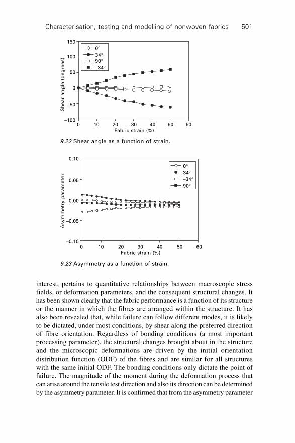
Characterisation, testing and modelling of nonwoven fabrics 501
interest, pertains to quantitative relationships between macroscopic stressfields, or deformation parameters, and the consequent structural changes. Ithas been shown clearly that the fabric performance is a function of its structureor the manner in which the fibres are arranged within the structure. It hasalso been revealed that, while failure can follow different modes, it is likelyto be dictated, under most conditions, by shear along the preferred directionof fibre orientation. Regardless of bonding conditions (a most importantprocessing parameter), the structural changes brought about in the structureand the microscopic deformations are driven by the initial orientationdistribution function (ODF) of the fibres and are similar for all structureswith the same initial ODF. The bonding conditions only dictate the point offailure. The magnitude of the moment during the deformation process thatcan arise around the tensile test direction and also its direction can be determinedby the asymmetry parameter. It is confirmed that from the asymmetry parameter
0∞34∞90∞–34∞
0 10 20 30 40 50 60
Fabric strain (%)
Sh
ea
r a
ng
le (
de
gre
es)
150
100
50
0
–50
–100
9.22 Shear angle as a function of strain.
9.23 Asymmetry as a function of strain.
0∞34∞–34∞90∞
0 10 20 30 40 50 60
Fabric strain (%)
Asy
mm
etr
y p
ara
me
ter
0.10
0.05
0.00
–0.05
–0.10
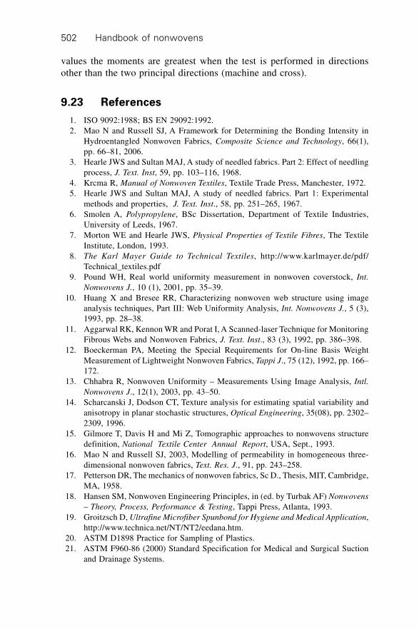
Handbook of nonwovens502
values the moments are greatest when the test is performed in directionsother than the two principal directions (machine and cross).
9.23 References
1. ISO 9092:1988; BS EN 29092:1992.2. Mao N and Russell SJ, A Framework for Determining the Bonding Intensity in
Hydroentangled Nonwoven Fabrics, Composite Science and Technology, 66(1),pp. 66–81, 2006.
3. Hearle JWS and Sultan MAJ, A study of needled fabrics. Part 2: Effect of needlingprocess, J. Text. Inst, 59, pp. 103–116, 1968.
4. Krcma R, Manual of Nonwoven Textiles, Textile Trade Press, Manchester, 1972.5. Hearle JWS and Sultan MAJ, A study of needled fabrics. Part 1: Experimental
methods and properties, J. Text. Inst., 58, pp. 251–265, 1967.6. Smolen A, Polypropylene, BSc Dissertation, Department of Textile Industries,
University of Leeds, 1967.7. Morton WE and Hearle JWS, Physical Properties of Textile Fibres, The Textile
Institute, London, 1993.8. The Karl Mayer Guide to Technical Textiles, http://www.karlmayer.de/pdf/
Technical_textiles.pdf9. Pound WH, Real world uniformity measurement in nonwoven coverstock, Int.
Nonwovens J., 10 (1), 2001, pp. 35–39.10. Huang X and Bresee RR, Characterizing nonwoven web structure using image
analysis techniques, Part III: Web Uniformity Analysis, Int. Nonwovens J., 5 (3),1993, pp. 28–38.
11. Aggarwal RK, Kennon WR and Porat I, A Scanned-laser Technique for MonitoringFibrous Webs and Nonwoven Fabrics, J. Text. Inst., 83 (3), 1992, pp. 386–398.
12. Boeckerman PA, Meeting the Special Requirements for On-line Basis WeightMeasurement of Lightweight Nonwoven Fabrics, Tappi J., 75 (12), 1992, pp. 166–172.
13. Chhabra R, Nonwoven Uniformity – Measurements Using Image Analysis, Intl.
Nonwovens J., 12(1), 2003, pp. 43–50.14. Scharcanski J, Dodson CT, Texture analysis for estimating spatial variability and
anisotropy in planar stochastic structures, Optical Engineering, 35(08), pp. 2302–2309, 1996.
15. Gilmore T, Davis H and Mi Z, Tomographic approaches to nonwovens structuredefinition, National Textile Center Annual Report, USA, Sept., 1993.
16. Mao N and Russell SJ, 2003, Modelling of permeability in homogeneous three-dimensional nonwoven fabrics, Text. Res. J., 91, pp. 243–258.
17. Petterson DR, The mechanics of nonwoven fabrics, Sc D., Thesis, MIT, Cambridge,MA, 1958.
18. Hansen SM, Nonwoven Engineering Principles, in (ed. by Turbak AF) Nonwovens
– Theory, Process, Performance & Testing, Tappi Press, Atlanta, 1993.19. Groitzsch D, Ultrafine Microfiber Spunbond for Hygiene and Medical Application,
http://www.technica.net/NT/NT2/eedana.htm.20. ASTM D1898 Practice for Sampling of Plastics.21. ASTM F960-86 (2000) Standard Specification for Medical and Surgical Suction
and Drainage Systems.
Characterisation, testing and modelling of nonwoven fabrics 503
22. ASTM F561-97 Practice for Retrieval and Analysis of Implanted Medical Devices,and Associated Tissues.
23. ASTM F619-79 (1997) Standard Practice for Extraction of Medical Plastics.24. ASTM F997-98a Standard Specification for Polycarbonate Resin for Medical
Applications.25. ASTM F1251 Terminology Relating to Polymeric Biomaterials in Medical and
Surgical Devices.26. ASTM F1855-00 Standard Specification for Polyoxymethylene (Acetal) for Medical
Applications.27. ASTM F1585-00 Standard Guide for Integrity Testing of Porous Barrier Medical
Packages.28. ASTM F1886-98 Standard Test Method for Determining Integrity of Seals for
Medical Packaging by Visual Inspection.29. ASTM F1929-98 Standard Test Method for Detecting Seal Leaks in Porous Medical
Packaging by Dye Penetration.30. ASTM F1862-00a Standard Test Method for Resistance of Medical Face Masks to
Penetration by Synthetic Blood (Horizontal Projection of Fixed Volume at a KnownVelocity).
31. ASTM E1766-95 Standard Test Method for Determination of Effectiveness ofSterilization Processes for Reusable Medical Devices.
32. ASTM E1837-96 Standard Test Method to Determine Efficacy of DisinfectionProcesses for Reusable Medical Devices (Simulated Use Test).
33. Appendix XX, Methods of Test for Surgical Dressings (A~T), British Pharmacopoeia
1993, A214.34. Appendix XVIA, Test of sterility, British Pharmacopoeia 1993, A180.35. Appendix XVIB, Test of microbial contamination, British Pharmacopoeia 1993,
A184.36. Appendix XVIC, Efficacy of antimicrobial preservation, British Pharmacopoeia
1993, A191.37. Appendix XVIII, Methods of sterilisation, British Pharmacopoeia 1993, A197.38. BS EN 13726-1:2002. Test methods for primary wound dressings. Part 1. Aspects
of absorbency.39. BS EN 13726-2:2002. Test methods for primary wound dressings. Part 2. Moisture
vapour transmission rate of permeable film dressings.40. BS EN 13726-3:2003. Test methods for primary wound dressings. Part 3.
Waterproofness.41. BS EN 13726-4:2003. Test methods for primary wound dressings. Part 4.
Conformability.42. BS EN 13726-5:2003. Test methods for primary wound dressings. Part 5. Bacterial
barrier properties.43. BS 5473:1977 Specification for spinal and abdominal fabric supports.44. BS 7505:1995 Specification for the elastic properties of flat, non-adhesive, extensible
fabric bandages.45. BS EN 1644-1:1997 Test methods for nonwoven compresses for medical use:
Nonwovens used in the manufacture of compresses.46. BS EN 1644-2:2000 Test methods for nonwoven compresses for medical use:
Finished compresses.47. AS 2836.0-1998 defined the Methods of Testing Surgical Dressings & Surgical
Dressing Materials in the following areas: General Introduction & List of Methods.
Handbook of nonwovens504
48. AS 2836.1-1998 Methods of Testing Surgical Dressings & Surgical Dressing Materials– Method for the Determination of Loss of Mass on Drying.
49. AS 2836.2-1998 Methods of Testing Surgical Dressing & Surgical Dressing Materials– Method for the Identification of Cotton & Viscose Fibres.
50. AS 2836.3-1998 Methods of Testing Surgical Dressing & Surgical Dressing Materials– Method for the Determination of Mass per Unit Area.
51. AS 2836.4-1998 Methods of Testing Surgical Dressings & Surgical Dressing Materials– Method for the Determination of Size.
52. AS 2836.5-1998 Methods of Testing Surgical Dressings & Surgical Dressing Materials– Method for the Determination of Sinking Time.
53. AS 2836.6-1998 Methods of Testing Surgical Dressings & Surgical Dressing Materials– Method for the Determination of Absorption Rate & Water Holding Capacity.
54. AS 2836.7-1998 Methods of Testing Surgical Dressings & Surgical Dressing Materials– Method for the Determination of Level of Surface-active Substances.
55. AS 2836.8-1998 Methods of Testing Surgical Dressings & Surgical Dressing Materials– Method for the Determination of Quantity of Water-soluble Substances.
56. AS 2836.9-1998 Methods of Testing Surgical Dressings & Surgical Dressing Materials– Method for the Determination of the Presence of Starch & Dextrins.
57. AS 2836.10-1998 Methods of Testing Surgical Dressings & Surgical DressingMaterials – Method for the Determination of the Presence of Fluorescing Substances.
58. AS 2836.11-1998 Methods of Testing Surgical Dressings & Surgical DressingMaterials – Method for the Determination of Sulfated Ash Content.
59. ASTM F2027-00 Standard Guide for Characterization and Testing of SubstrateMaterials for Tissue-Engineered Medical Products.
60. ASTM F2211-04 Standard Classification for Tissue Engineered Medical Products(TEMPs).
61. ASTM F2150-02e1 Standard Guide for Characterization and Testing of BiomaterialScaffolds Used in Tissue-Engineered Medical Products.
62. BS EN 1644-1:1997 Test methods for nonwoven compresses for medical use.Nonwovens used in the manufacture of compresses.
63. BS EN 1644-2:2000 Test methods for nonwoven compresses for medical use.Finished compresses.
64. BS EN 868-9: 2000 Packaging materials and systems for medical devices whichare to be sterilized. Uncoated nonwoven materials of polyolefines for use in themanufacture of heat sealable pouches, reels and lids. Requirements and test methods.
65. BS EN 868-10: 2000 Packaging materials and systems for medical devices whichare to be sterilized. Adhesive coated nonwoven materials of polyolefines for use inthe manufacture of heat sealable pouches, reels and lids. Requirements and testmethods.
66. ISO 11607:2003 Packaging for terminally sterilized medical devices.67. ASTM D5729-97 Standard Test Method for Thickness of Nonwoven Fabrics.68. ASTM D5736-95 Standard Test Method for Thickness of Highloft Nonwoven Fabrics.69. Chen HJ, Huang DK, Online measurement of nonwoven weight evenness using
optical methods, ACT paper, 1999.70. Hunter Lab Color Scale, http://www.hunterlab.com/appnotes/an08_96a.pdf71. Chhabra R, Nonwoven Uniformity – Measurements Using Image Analysis, Int.
Nonwovens J., 12(1), pp. 43–50, 2003.72. Hearle JWS and Stevenson PJ, Nonwoven fabric studies, part 3: The anisotropy of
nonwoven fabrics, Text. Res. J., 33, pp. 877–888, 1963.
Characterisation, testing and modelling of nonwoven fabrics 505
73. Hearle JWS and Ozsanlav V, Nonwoven fabric studies, part 5: Studies of adhesive-bonded nonwoven fabrics part 3: The determination of fibre orientation and curl,J. Text. Inst., 70, pp. 487–497, 1979.
74. Chuleigh PW, Image formation by fibres and fibre assemblies, Text. Res. J., 54, p.813, 1983.
75. Kallmes OJ, Techniques for determining the fibre orientation distribution throughoutthe thickness of a sheet, TAPPI, No. 52, pp. 482–485, 1969.
76. Votava A, Practical method-measuring paper asymmetry regarding fibre orientation,Tappi J., 65, p. 67, 1982.
77. Cowan WF and Cowdrey EJK, Evaluation of paper strength components by shortspan tensile analysis, Tappi J., 57(2), p. 90, 1973.
78. Stenemur B, Method and device for monitoring fibre orientation distributions basedon light diffraction phenomenon, Int. Nonwovens J., 4, pp. 42–45, 1992.
79. Comparative degree of preferred orientation in nineteen wood pulps as evaluatedfrom X-ray diffraction patterns, Tappi J., 33, p. 384, 1950.
80. Prud’homme B, et al., determination of fibre orientation of cellulosic samples byX-ray diffraction, J. Polym. Sci., 19, p. 2609, 1975.
81. Osaki S, Dielectric anisotropy of nonwoven fabrics by using the microwave method,Tappi J., 72, p. 171, 1989.
82. Lee S, Effect of fibre orientation on thermal radiation in fibrous media, J. Heat
Mass Transfer, 32(2), p. 311, 1989.83. McGee SH and McCullough RL, Characterization of fibre orientation in short-
fibre composites, J. Appl. Phys., 55(1), p. 1394, 1983.84. Orchard GA, The measurement of fibre orientation in card webs, J. Text. Inst., 44,
T380, 1953.85. Tsai PP and Bresse RR, Fibre orientation distribution from electrical measurements.
Part 1, theory, Int. Nonwovens J., 3(3), p. 36, 1991.86. Tsai PP and Bresse RR, Fibre orientation distribution from electrical measurements.
Part 2, instrument and experimental measurements, Int. Nonwovens J., 3(4), p. 32,1991.
87. Chaudhray MM, MSc Dissertation, University of Manchester, 1972.88. Judge SM, MSc Dissertation, University of Manchester, 1973.89. Huang XC and Bressee RR, Characteristizing nonwoven web structure using image
analysing techniques, Part 2: Fibre orientation analysis in thin webs, Int. Nonwovens
J., No. 2, pp. 14–21, 1993.90. Pourdeyhimi B and Nayernouri A, Assessing fibre orientation in nonwoven fabrics,
INDA J. Nonw. Res., 5, pp. 29–36, 1993.91. Pouredyhimi B and Xu B, Characterizing pore size in nonwoven fabrics: Shape
considerations, Int. Nonwoven J., 6(1), pp. 26–30, 1993.92. Gong RH and Newton A, Image analysis techniques Part II: The measurement of
fibre orientation in nonwoven fabrics, Text. Res. J., 87, p. 371, 1996.93. Britton PN, Sampson AJ, Jr, Elliot CF, Grabben HW and Gettys WE, Computer
simulation of the technical properties of nonwoven fabrics, part 1: The method,Text. Res. J., 53, pp. 363–368, 1983.
94. Grindstaff TH and Hansen SM, Computer model for predicting point-bondednonwoven fabric strength, Part 1: Text. Res. J., 56, pp. 383–388, 1986.
95. Jirsak O, Lukas D and Charrat R, A two-dimensional model of mechanical propertiesof textiles, J. Text. Inst., 84, pp. 1–14, 1993.
96. Xu B and Ting Y, Measuring structural characteristics of fibre segments in nonwovenfabrics, Text. Res. J., 65, pp. 41–48, 1995.
Handbook of nonwovens506
97. Pourdeyhimi B, Dent R and Davis H, Measuring fibre orientation in nonwovens.Part 3: Fourier transform, Text. Res. J., 67, pp. 143–151, 1997.
98. Pourdeyhimi B, Ramanathan R and Dent R, Measuring fibre orientation in nonwovens.Part 2: Direct tracking, Text. Res. J., 66, pp. 747–753, 1996.
99. Pourdeyhimi B, Ramanathan R and Dent R, Measuring fibre orientation in nonwovens.Part 1: Simulation, Text. Res. J., 66, pp. 713–722, 1996.
100. Pourdeyhimi B, Dent R, Measuring fibre orientation in nonwovens. Part 4: Flowfield analysis, Text. Res. J., 67, pp. 181–187, 1997.
101. Komori T, Makishima K, Number of fibre-to-fibre contacts in general fibre assemblies,Text. Res. J., 47, pp. 13–17, 1977.
102. Manual of Quantimet 570, Leica Microsystems Imaging Solutions, Cambridge,UK, 1993.
103. BS 1902-3.8, Determination of bulk density, true porosity and apparent porosity of
dense shaped products (method 1902-308).104. BS EN 993-1:1995, BS 1902-3.8:1995 Methods of test for dense shaped refractory
products. Determination of bulk density, apparent porosity and true porosity.105. Bhatia SK and Smith JL, 1995, Application of the bubble point method to the
characterization of the pore size distribution of geotextile, Geotech. Test. J., 18(1),pp. 94–105.
106. Bhatia SK and Smith JL, 1996, Geotextile characterization and pore size distribution,Part II: A review of test methods and results, Geosynthet. Int., 3(2), pp. 155–180.
107. ASTM D4751, Test Method for Determining Apparent Opening Size of a Geotextile.108. BS 6906-2:1989 Methods of test for geotextiles. Determination of the apparent
pore size distribution by dry sieving.109. Van der Sluys L and Dierickx W, Comparative studies of different porometry
determination methods for geotextiles, Geotext. Geomembr., 9, pp. 183–198, 1991.110. Giroud JP, Granular filters and geotextile filters, Proc., Geo-filters’96, Montréal,
565–680, 1996.111. Saathoff F and Kohlhase S, 1986, Research at the Franzius-Institut on Geotextile
Filters in Hydraulic Engineering, Proceedings of the Fifth Congress Asian and
Pacific Regional Division, ADP/IAHR, Seoul, Korea, pp. 9–10.112. BSEN ISO 12956: 1999 Geotextiles and geotextile-related products. Determination
of the characteristic opening size.113. Fayoux D, 1977, FiltrationHydrodynamique des Sols par des Textiles, Proceedings
of the International Conference on the Use of Fabrics in Geotechnics, 2, pp. 329–332, Paris, France, April 1977, (in French).
114. Mlynarek J, Lafleur J, Rollin R and Lombard G, Filtration Opening Size of Geotextilesby Hydrodynamic Sieving, ASTM Geotechnical Testing Journal, 16(1), pp. 61–69,1993.
115. CAN/CGSB-148.1–10.116. Rollin AL, Denis R, Estaque L and Masounave J, Hydraulic behaviour of synthetic
nonwoven filter fabrics, Can. J. Chem. Eng., pp. 226–234, 1982.117. Aydilek AH, Oguz SH and Edil TB, Constriction Size of Geotextile Filters, Journal
of Geotechnical and Geoenvironmental Engineering, 131(1), pp. 28–38, 2005.118. Dierickx W, 1999, Opening size determination of technical textiles used in agricultural
applications, Geotext. Geomembr., 17(4), pp. 231–245.119. Bhatia SK, Huang Q and Smith JL, Application of digital image processing in
morphological analysis of geotextiles, Proc. conf. on Digital Image Processing:
Techniques and Applications in Civil Engineering, 1, ASCE, New York, pp. 95–108, 1993.
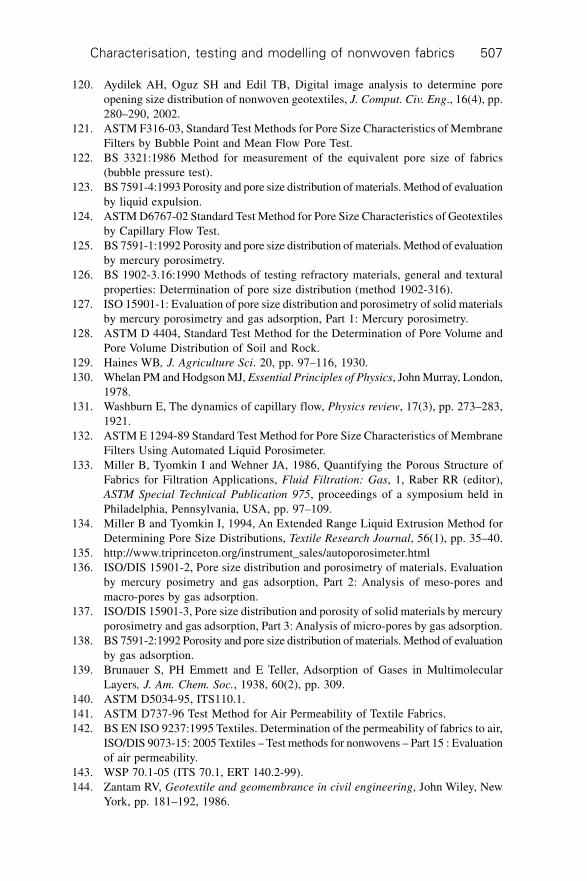
Characterisation, testing and modelling of nonwoven fabrics 507
120. Aydilek AH, Oguz SH and Edil TB, Digital image analysis to determine poreopening size distribution of nonwoven geotextiles, J. Comput. Civ. Eng., 16(4), pp.280–290, 2002.
121. ASTM F316-03, Standard Test Methods for Pore Size Characteristics of MembraneFilters by Bubble Point and Mean Flow Pore Test.
122. BS 3321:1986 Method for measurement of the equivalent pore size of fabrics(bubble pressure test).
123. BS 7591-4:1993 Porosity and pore size distribution of materials. Method of evaluationby liquid expulsion.
124. ASTM D6767-02 Standard Test Method for Pore Size Characteristics of Geotextilesby Capillary Flow Test.
125. BS 7591-1:1992 Porosity and pore size distribution of materials. Method of evaluationby mercury porosimetry.
126. BS 1902-3.16:1990 Methods of testing refractory materials, general and texturalproperties: Determination of pore size distribution (method 1902-316).
127. ISO 15901-1: Evaluation of pore size distribution and porosimetry of solid materialsby mercury porosimetry and gas adsorption, Part 1: Mercury porosimetry.
128. ASTM D 4404, Standard Test Method for the Determination of Pore Volume andPore Volume Distribution of Soil and Rock.
129. Haines WB, J. Agriculture Sci. 20, pp. 97–116, 1930.130. Whelan PM and Hodgson MJ, Essential Principles of Physics, John Murray, London,
1978.131. Washburn E, The dynamics of capillary flow, Physics review, 17(3), pp. 273–283,
1921.132. ASTM E 1294-89 Standard Test Method for Pore Size Characteristics of Membrane
Filters Using Automated Liquid Porosimeter.133. Miller B, Tyomkin I and Wehner JA, 1986, Quantifying the Porous Structure of
Fabrics for Filtration Applications, Fluid Filtration: Gas, 1, Raber RR (editor),ASTM Special Technical Publication 975, proceedings of a symposium held inPhiladelphia, Pennsylvania, USA, pp. 97–109.
134. Miller B and Tyomkin I, 1994, An Extended Range Liquid Extrusion Method forDetermining Pore Size Distributions, Textile Research Journal, 56(1), pp. 35–40.
135. http://www.triprinceton.org/instrument_sales/autoporosimeter.html136. ISO/DIS 15901-2, Pore size distribution and porosimetry of materials. Evaluation
by mercury posimetry and gas adsorption, Part 2: Analysis of meso-pores andmacro-pores by gas adsorption.
137. ISO/DIS 15901-3, Pore size distribution and porosity of solid materials by mercuryporosimetry and gas adsorption, Part 3: Analysis of micro-pores by gas adsorption.
138. BS 7591-2:1992 Porosity and pore size distribution of materials. Method of evaluationby gas adsorption.
139. Brunauer S, PH Emmett and E Teller, Adsorption of Gases in MultimolecularLayers, J. Am. Chem. Soc., 1938, 60(2), pp. 309.
140. ASTM D5034-95, ITS110.1.141. ASTM D737-96 Test Method for Air Permeability of Textile Fabrics.142. BS EN ISO 9237:1995 Textiles. Determination of the permeability of fabrics to air,
ISO/DIS 9073-15: 2005 Textiles – Test methods for nonwovens – Part 15 : Evaluationof air permeability.
143. WSP 70.1-05 (ITS 70.1, ERT 140.2-99).144. Zantam RV, Geotextile and geomembrance in civil engineering, John Wiley, New
York, pp. 181–192, 1986.
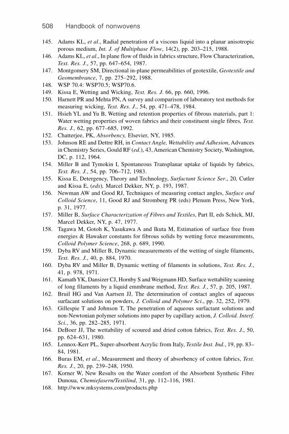
Handbook of nonwovens508
145. Adams KL, et al., Radial penetration of a viscous liquid into a planar anisotropicporous medium, Int. J. of Multiphase Flow, 14(2), pp. 203–215, 1988.
146. Adams KL, et al., In plane flow of fluids in fabrics structure, Flow Characterization,Text. Res. J., 57, pp. 647–654, 1987.
147. Montgomery SM, Directional in-plane permeabilities of geotextile, Geotextile and
Geomembrance, 7, pp. 275–292, 1988.148. WSP 70.4: WSP70.5; WSP70.6.149. Kissa E, Wetting and Wicking, Text. Res. J. 66, pp. 660, 1996.150. Harnett PR and Mehta PN, A survey and comparison of laboratory test methods for
measuring wicking, Text. Res. J., 54, pp. 471–478, 1984.151. Hsieh YL and Yu B, Wetting and retention properties of fibrous materials, part 1:
Water wetting properties of woven fabrics and their constituent single fibres, Text.
Res. J., 62, pp. 677–685, 1992.152. Chatterjee, PK, Absorbency, Elsevier, NY, 1985.153. Johnson RE and Dettre RH, in Contact Angle, Wettability and Adhesion, Advances
in Chemistry Series, Gould RF (ed.), 43, American Chemistry Society, Washington,DC, p. 112, 1964.
154. Miller B and Tymokin I, Spontaneous Transplanar uptake of liquids by fabrics,Text. Res. J., 54, pp. 706–712, 1983.
155. Kissa E, Detergency, Theory and Technology, Surfactant Science Ser., 20, Cutlerand Kissa E, (eds), Marcel Dekker, NY, p. 193, 1987.
156. Newman AW and Good RJ, Techniques of measuring contact angles, Surface and
Colloid Science, 11, Good RJ and Stromberg PR (eds) Plenum Press, New York,p. 31, 1977.
157. Miller B, Surface Characterization of Fibres and Textiles, Part II, eds Schick, MJ,Marcel Dekker, NY, p. 47, 1977.
158. Tagawa M, Gotoh K, Yasukawa A and Ikuta M, Estimation of surface free fromenergies & Hawaker constants for fibrous solids by wetting force measurements,Colloid Polymer Science, 268, p. 689, 1990.
159. Dyba RV and Miller B, Dynamic measurements of the wetting of single filaments,Text. Res. J., 40, p. 884, 1970.
160. Dyba RV and Miller B, Dynamic wetting of filaments in solutions, Text. Res. J.,41, p. 978, 1971.
161. Kamath YK, Dansizer CJ, Hornby S and Weigmann HD, Surface wettability scanningof long filaments by a liquid emmbrane method, Text. Res. J., 57, p. 205, 1987.
162. Bruil HG and Van Aartsen JJ, The determination of contact angles of aqueoussurfacant solutions on powders, J. Colloid and Polymer Sci., pp. 32, 252, 1979.
163. Gillespie T and Johnson T, The penetration of aqueous surfactant solutions andnon-Newtonian polymer solutions into paper by capillary action, J. Colloid. Interf.
Sci., 36, pp. 282–285, 1971.164. DeBoer JJ, The wettability of scoured and dried cotton fabrics, Text. Res. J., 50,
pp. 624–631, 1980.165. Lennox-Kerr PL, Super-absorbent Acrylic from Italy, Textile Inst. Ind., 19, pp. 83–
84, 1981.166. Buras EM, et al., Measurement and theory of absorbency of cotton fabrics, Text.
Res. J., 20, pp. 239–248, 1950.167. Korner W, New Results on the Water comfort of the Absorbent Synthetic Fibre
Dunoua, Chemiefasern/Textilind, 31, pp. 112–116, 1981.168. http://www.mksystems.com/products.php
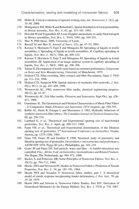
Characterisation, testing and modelling of nonwoven fabrics 509
169. Miller B, Critical evaluation of upward wicking tests, Int. Nonwovens J., 9(1), pp.35–40, 2000.
170. Montgomery SM, Miller B and Rebenfeld L, Spatial distribution of local permeabilityin fibrous networks, Text. Res. J., 62, pp. 151–161, 1992.
171. Howaldt M and Yoganathan AP, Laser-Doppler anemometry to study fluid transportin fibrous assemblies, Text. Res. J., 53(9), 1983, pp. 544–551.
172. Mao N, PhD thesis, 2000, University of Leeds.173. Russell SJ and Mao N, Journal of Autex, 1(2), pp. 47–53, 2001.174. Kawase T, Morimoto Y, Fujii T and Minagawa M, Spreading of liquids in textile
assemblies, I. Spreading of liquids in textile assemblies. II. Capillary spreading ofliquids, Text. Res. J., 56(7), 1986, pp. 409–414.
175. Kawase T, Morimoto Y, Fujii T and Minagawa M, Spreading of liquids in textileassemblies, III. Application of an image analyser system to capillary spreading ofliquids, Text. Res. J., 58(5), 1988, pp. 306–308.
176. Tanner D, Development of textile yarns based on customer performance, Symposium
on Yarns and Yarn Manufacturing, University of Manchester, 1979.177. Dodson CTJ, Fibre crowding, fibre contacts and fibre flocculation, Tappi J. 79(9)
pp. 211–216, 1996.178. Dodson CTJ, Sampson WW, Spatial statistics of stochastic fibre networks, J. Stat.
Phys, 96 (1–2), pp. 447–458, 1999.179. Wrotnowski AC, 1962, nonwoven filter media, chemical engineering progress,
58(12), pp. 61–67.180. Wrotnowski AC, Felt filter media, Filtration and Separation, Sept./Oct., pp. 426–
431, 1968.181. Goeminne, H., The Geometrical and Filtration Characteristics of Metal-Fiber Filters
– A Comparative Study,Filtration and Separation 1974 (August), pp. 350–355.182. Rollin AL, Denis R, Estaque L and Masounave J, 1982, Hydraulic behaviour of
synthetic nonwoven filter fabrics, The Canadian Journal of Chemical Engineering,60, pp. 226–234.
183. Lambard G, et al., Theoretical and Experimental opening size of heat-bondedgeotextiles, Text. Res. J., April, pp. 208–217, 1988.
184. Faure YH, et al., Theoretical and Experimental determination of the filtrationopening size of geotextiles, 3rd International Conference on Geotextiles, Vienna,Austria, pp. 1275–1280, 1989.
185. Faure YH, Gourc JP and Gendrin P, 1990, Structural study of porometry andfiltration opening size of geotextiles, Geosynthetics: microstructure and performance,ASTM STP 1076, Peggs ID (ed.), Philadelphia, pp. 102–119.
186. Gourc JP and Faure YH, Soil particle, water and fiber – A fruitful interaction noncontrolled, Proc., 4th Int. Conf. on Geotextiles, Geomembranes and Related Products,
The Hague, The Netherlands, pp. 949–971, 1990.187. Backer, S, and Petterson, DR, Some Principles of Nonwoven Fabrics, Text. Res. J.,
30(12), pp. 704–711, 1960.188. Hearle, JWS and Stevenson PJ, Studies in Nonwoven Fabrics: Prediction of Tensile
Properties, Text. Res. J., 34, pp. 181–191, 1964.189. Hearle JWS and Ozsanlav V, Nonwoven fabric studies, part 1: A theoretical
model of tensile response incorporating binder deformation, J. Text. Inst., 70, pp.19–28, 1979.
190. Hearle JWS and Newton A, Nonwoven Fabric Studies, Part XIV: Derivation ofGeneralized Mechanics by the Energy Method, Text. Res. J. 37(9), p. 778, 1967.
Handbook of nonwovens510
191. Freeston WD and Platt MM, Mechanics of Elastic Performance of Textile Materials,Part XVI: Bending Rigidity of Nonwoven Fabrics, Text. Res. J. 35(1), pp. 48–57,1965.
192. Darcy H, 1856, Les Fontaines Publiques de la Ville de Dijon (Paris: Victor Valmont).193. Carman PC, Flow of Gases through Porous Media, Academic Press, New York,
1956.194. Davies CN, 1952, The separation of airborne dust and particles. Proc. Instn mech.
Engrs IB, 185–213.195. Piekaar HW and Clarenburg LA, Aerosol filters: Pore size distribution in fibrous
filters, Chem. Eng. Sci., 22, pp. 1399, 1967.196. Dent RW, The air permeability of nonwoven fabrics, J. Text. Inst., 67, pp. 220–223,
1976.197. Emersleben VO, Das darcysche Filtergesetz, Physikalische Zeitschrift, 26, p. 601,
1925.198. Brinkman HC, On the permeability of media consisting of closely packed porous
particles, Applied Scientific Research, A1, p. 81, 1948.199. Iberall AS, Permeability of glass wool and other highly porous media, J. Res. Natl.
Bureau Standards 45: 398, 1950.200. Happel J, 1959, Viscous flow relative to arrays of cylinders, AIChE J., 5, pp. 174–
177.201. Kuwabara SJ, 1959, The forces experienced by randomly distributed parallel circular
cylinder or spheres in a viscous flow at small Reynolds numbers, J. Phys. Soc.
Japan, 14, p. 527.202. Cox RG, The motion of long slender bodies in a viscous fluid, Part 1, J. Fluid
Mechanics, 44, pp. 791–810, 1970.203. Sangani AS and Acrivos A, Slow flow past periodic arrays of cylinders with
applications to heat transfer, Int. J. Multiphase Flow, 8, pp. 193–206, 1982.204. Kozeny J, Royal Academy of Science, Vienna, Proc. Class 1, 136, p. 271, 1927.205. Lamb H, Hydrodynamics. Cambridge Univ. Press, 1932.206. Sparrow EM, and Loeffler AL Jr, Longitudinal laminar flow between cylinders
arranged in regular array, AIChEJ. 5, pp. 325–330, 1959.207. Drummond JE and Tahir MI, Laminar viscous flow through regular arrays of
parallel solid cylinders, Int. J. Multiphase Flow, 10, pp. 515–540, 1983.208. Sullivan RR, Specific surface measurements on compact bundles of parallel fibres,
J. App. Phys, 13, pp. 725–730, 1942.209. Shen X, An application of needle-punched nonwovens in the press casting of
concrete, PhD Thesis, University of Leeds, 1996.210. Miao L, The gas filtration properties of needlefelts, PhD Thesis, Department of
Textile Industries, University of Leeds, 1989.211. Mao N and Russell SJ, Directional permeability of homogeneous anisotropic fibrous
material, Part 1, J. Text. Inst, 91, pp. 235–243, 2000a.212. Mao N and Russell SJ, Directional permeability of homogeneous anisotropic fibrous
material, Part 2, J. Text. Inst, 91, pp. 244–258, 2000b.213. Scheidegger AE, The Physics of Flow Through Porous Media, University of Toronto
Press, Toronto, 1972.214. Langmuir I, Report on Smokes and Filters, Section I. U.S. Office of Scientific
Research and Development, No. 865, Part IV, 1942.215. Rushton A, The analysis of textile filter media, Separation and Filtration, Nov./
Dec., p. 516, 1968.
Characterisation, testing and modelling of nonwoven fabrics 511
216. Gupta BS and Whang HS, Capillary Absorption Behaviors of Hydroentangled andNeedlepunched Webs of Cellulosic Fibers, Proceedings of INDA-TEC 96:
International nonwovens conference, September 11–13, 1996, Hyatt Regency CrystalCity, Crystal City, Virginia, USA.
217. Gupta BS and Smith DK, Nonwovens in Absorbent Materials, Textile Sci. and
Technol., 13, pp. 349–388, 2002.218. Gupta BS, The Effect of Structural Factors on Absorbent Characteristics of
Nonwovens, Tappi J. 71, pp. 147–152, 1988.219. Poiseuille JL, C.R. Acad. Sci., Paris, 11, pp. 961, 1041, 1840; 12, p. 112, 1841.220. Lucas R, Über das Zeitgesetz des Kapillaren Aufstiegs von Flussigkeiten, Kolloid
Z., 23, p. 15, 1918.221. Laughlin RD and Davies JE, Some aspects of capillary absorption in fibrous textile
wicking, Text. Res. J., 31, p. 904, 1961.222. Bahder TB, Mathematica for scientists and engineers, Reading, Addison-Wesley
Pub. Co., 1995.223. Gupta BS and Wadsworth LC, Differentially Absorbent Cotton-Surfaced Spunbond
Copoplyester and Spunbond PP with Wetting Agent, Proceedings of 7th NonwovensConference at 2004 Beltwide Cotton Conferences, San Antonio, TX, January 5–9,2004.
224. Law WM, Water transport in fabric, PhD Thesis, Department of Textiles, Universityof Leeds, 1988.
225. Minor FW, Schwartz AM, Buckles LC and Wulkow EA, The migration of liquidsin textile assemblies, Text. Res. J., 29, p. 931, 1959.
226. Peek RL and McLean DA, Ind. Eng. Chem. Anal., ed. 6, p. 85, 1934.227. Robinson GD, A study of the voids within the interlock structure and their influence
on thermal properties of fabric (PhD Thesis), Department of Textile Industries,University of Leeds, 1982.
228. Collins RE, Flow of Fluids through Porous Materials, Reinhold PublishingCorporation, New York, 1961.
229. Princen HM, J. Colloid Interface Sci., 30, 359, 1969.230. Mao N and Russell SJ, Anisotropic liquid absorption in homogeneous two-
dimensional nonwoven structures, J. App. Phys., 2003, 94(6), p. 4135–4138.231. De Boer JJ, The wettability of scoured and dried cotton fabrics, Text. Res. J., 50,
p. 624, 1980.232. Rowland SP, Stanonis DJ and King WD, Penetration-sorption of cotton fibres
measured by immersed weight, J. Appl. Polym Sci, 25, p. 2229, 1980.233. Rowland SP and Bertoniere NR, Some interactions of water-soluble solutes with
cellulose and Sephadex, Text. Res. J., 46, p. 770, 1976.234. Stanonis DJ and Rowland SP, Interactions of Carbamates and their N-Methylol
derivatives with cotton and Sephadex, measured by gel filtration, Text. Res. J., 49,p. 72, 1979.
235. Carslaw HS and Jaeger JC, Conduction of Heat in Solids, 2nd edn, Clarendo Press,Oxford, 1959.
236. Crank J, Mathematics of Diffusion, Clarendon Press, London, 1956, p. 148.237. Rudd DF, J. Phys. Chem., 64, p. 1254, 1960.238. Bird RB, Stewart WE, and Lightfoot EN, Transport Phenomena, J. Wiley, NY,
1960.239. Bankvall C, Heat Transfer In Fibrous Material, J. of Testing and Evaluation, pp.
235–243, May, 1973.
Handbook of nonwovens512
240. Bomberg M and Klarsfeld S, Semi-Empirical Model of Heat Transfer in DryMineral Fiber Insulations, J. of Thermal Insulation, 6(1), pp. 157–173, 1983.
241. Grewal RS and Banks-Lee P, Development of Thermal Insulation For Textile WetProcessing Machinery Using Needlepunched Nonwoven Fabrics, Int. Nonwovens
J., 2, pp. 121–129, 1999.242. Schuhmeister J, Ber. K. Akad. Wien (Math.-Naturw. Klasse), 76, p. 283, 1877.243. Stark C and Fricke J, Improved heat-transfer models for fibrous insulations,
International Journal of Heat and Mass Transfer, 36(3), pp. 617–625, 1993.244. Baxter S, The thermal conductivity of textiles, Proceedings of the Physical Society.
58, pp. 105–118, 1946.245. Kreider JF, Handbook of Heating, Ventilation, and Air Conditioning, London,
CRC Press LLC, 2001.246. American Society of Heating. Refrigerating and Air Conditioning Engineers, Inc.,
1993 ASHRAE Handbook, Fundamentals, 1-P edition, Atlanta, 1993.247. Kirby R and Cummings A, Prediction of the bulk accoustic properties of fibrous
materials at low frequencies, Applied Acoustics, 56(2), pp. 101–125, 1999.248. Attenborough Y, Acoustical characteristics of porous materials, Physics Reports
(Review Section of Physics Letters) 82(3), 1982, pp. 179–227, North-HollandPublishing Company.
249. Zwikker C and Kosten CW, Sound absorbing materials, Amsterdam, Elsevier, 1949.250. Tijdeman H, On the propagation of sound waves in cylindrical tubes. Journal of
Sound and Vibration 39, pp. 1–33, 1975.251. Shoshani Y and Yakubov Y, Numerical assessment of maximal absorption coefficients
for nonwoven fibrewebs, Applied Acoustics, 59(1), 2000, pp. 77–87.252. Voronina NN, Acoustic properties of fibrous materials, Applied Acoustics, 42,
1994, pp. 165–174.253. Voronina NN, Empirical equations for a calculation of acoustic parameters of
fibrous materials in terms their structural characteristic, Tr./NIISF, Building Acoustics,pp. 20–27, 1976.
254. Attenborough Y. Acoustical characteristics of porous materials, Physics Reports
(Review Section of Physics Letters) 82(3), pp. 179–227, 1982.255. Delany ME and Bazley EN, 1970, Acoustical properties of fibrous absorbent materials,
Applied Acoustics (3), pp. 105–116.256. BS EN 779:2002, Particulate air filters for general ventilation – Determination of
the filtration performance.257. BS ISO 19438:2003, Diesel fuel and petrol filters for internal combustion engines
– Filtration efficiency using particle counting and contaminant retention capacity.258. Brown RC, Air Filtration – An Integrated Approach to the Theory and Applications
of Fibrous Filters, Pergamon Press, 1988, Oxford, UK.259. Davies CN (ed.) Air filtration, Academic Press, London, 1973.260. Reist PC, Aerosol Science and Technology, McGraw Hill, New York, 1993.261. Kirsh AA and Stechkina IB, The theory of Aerosol Filtration with Fibrous Filters,
in Fundamentals of Aerosol Science, (eds) Shaw DT, Wiley, 1978.262. Kirsh AA and Fuchs NA, 1968, Investigation of fibrous filters: diffusional deposition
of aerosols in fibrous filters. Colloid J. 30, p. 630.263. Stechkina IB, Kirsh AA and Fuchs NA, 1970, Effect of inertia on the captive
coefficient of aerosol particles by cylinders at low Stokes’ numbers, Kolloid Zh.
32, p. 467.264. Stechkina IB, Kirsh AA and Fuchs NA, 1969, Studies on fibrous aerosol filters. IV.
Characterisation, testing and modelling of nonwoven fabrics 513
Calculation of aerosol deposition in model filters in the range of maximum penetration.Ann Occup. Hyg, 12, pp. 1–8.
265. Friedlander SK, Theory of aerosol filtration, Ind. Engng Chem., 30, pp. 1161–1164, 1958.
266. Friedlander SK, Aerosol filtration by fibrous filters, in Biochemical and Biological
Engineering (edited by Blakebrough), Vol. 1, Chap 3, Academic Press, London,1967.
267. Steckina IB and Fuchs NA, Studies on fibrous aerosol filters I: Calculation ofdiffusional deposition of aerosols in fibrous filters, Ann. Occ. Hyg., 1966, 9, pp.59–64.
268. Kirsch AA and Chechuer PV, Diffusion deposition of aerosol in fibrous filters atintermediate Peclet numbers. Aerosol Science and Technology, 4(1), 11–16, 1985.
269. Hinds WC, Aerosol Technology: Properties, behaviour and measurements of airborne
particles, John Wiley and Sons, New York, 1999.270. Lee KW and Gieseke JA, Note on the approximation of interceptional collection
efficiencies, J. Aerosol Sci., 1980, 11, pp. 335–341.271. Yeh, HC and Liu BYH, 1974, Aerosol filtration by fibrous filters, J. Aerosol Sci. 5,
191–217.272. Vaughan NP and Brown RC, Observations of the microscopic structure of fibrous
filters, Filtration & Separation, 9, pp. 741–748, 1996.273. Stenhouse, JIT, 1975, Filtration of air by fibrous filters, Filtration and Separation,
12 (May/June), pp. 268–274.274. Bird RB, Steward WE and Lightfood EN, 2002, Transport Phenomena, John Wiley
and Sons, pp. 196–200.275. Folgar F, Tucker III, C, J. of Reinforced Plastics and Composites, 3, 98–119,
(1984).276. Kim, HS, Deshpande A, Pourdeyhimi B, Abhiraman AS and Desai P, Characterizing
Structural Changes in Point-Bonded Nonwoven Fabrics during Load-DeformationExperiments, Text. Res. J., 71(2), 157–164 (2001).
277. Kim HS, Pourdeyhimi B, Abhiraman AS and Desai P, Angular Mechanical Propertiesin Thermally Point-Bonded Nonwovens, Part I: Experimental Observations, Text.
Res. J., to appear.278. Lee SM and Argon AS, The Mechanics of the Bending of Nonwoven Fabrics, Part
I: Spunbonded Fabric (Cerex), J. Text. Inst., No. 1, 1–11, (1983).279. Lee SM and Argon AS, The Mechanics of the Bending of Nonwoven Fabrics, Part
II: Spunbonded Fabric with Spot Bonds (Fibretex), J. Text. Inst., No. 1, 12–18,(1983).
280. Lee SM and Argon AS, The Mechanics of the Bending of Nonwoven Fabrics, PartIII: Print-Bonded Fabric (Masslinn), J. Text. Inst., No. 1, 19–30, (1983).
281. Pourdeyhimi B, Dent R, Jerbi A, Tanaka S and Deshpande A, Measuring FibreOrientation in Nonwovens, Part V: Real Fabrics, Text. Res. J., 69, 185–92, (1999).
282. Lee SM and Argon AS, The Mechanics of the Bending of Nonwoven Fabrics, PartIV: Print-Bonded Fabric with a Pattern of Elliptical Holes (Keybak), J. Text. Inst.,No. 1, 31–37, (1983).
283. Patel SV and Warner SB, Modeling the Bending Stiffness of Point Bonded NonwovenFabrics, Text. Res. J., 64(9), 507–513 (1994).
284. Pourdeyhimi B and Xu B, Characterizing Pore Size in Nonwoven Fabrics: ShapeConsiderations, Int. Nonwovens J., 6, (1), 26–30, (1994).
Handbook of nonwovens514
285. Pourdeyhimi B, Ramanathan R and Dent R, Measuring Fibre Orientation inNonwovens, Part II: Direct Tracking, Text. Res. J., 66, 747–753, (1996).
286. Pourdeyhimi B, Dent R and Davis H, Measuring Fibre Orientation in Nonwovens,Part III: Fourier Transform, Text. Res. J., 67, 143–151, (1997).
287. Guceri SI, Gillespie JW and Ravi Shanker, Polymer Engineering and Science, Vol.31, 3, (1991), p. 161.
288. http://www.allasso-industries.com289. Xuan-chao H and Bresee R, Characterizing Nonwoven Web Structure Using Image
Analysis Techniques, Part III: Web Uniformity Analysis. INDA Journal of Nonwovens
Research, 5, (3) 28–38, (1994).290. Drouin B, Gagnon R, Cheam C and Silvy J, A New Way for Testing Paper Sheet
Formation, Composite Science and Technology, 61, 389–393, (2001).291. Kallmes OJ, Techniques for Determining the Fiber Orientation Distribution
Throughout the Thickness of a Sheet, Tappi, 52, 482, 1969.292. Kallmes OJ and Corte H, Formation and Structure of Paper, 1, Technical section
British Paper and Board Maker’s Association, William Clowes & Sons, Ltd., London,(1962), pp. 13–46.
293. Boeckerman P, Meeting the Special Requirements for on-line Basis WeightMeasurement of Lightweight Nonwoven Fabrics, Tappi, 166–172, 1992.
294. Weigert RG, The Selection of an Optimum Quadrant Size for Sampling the StandardCrop of Grasses and Forbes, Ecology, (43), 125–129, (1962).
295. Pourdeyhimi B and Kohel L, Area Based Strategy For Determining Web Uniformity,Text. Res. J., 72 (12), 1065–1072, (2002).
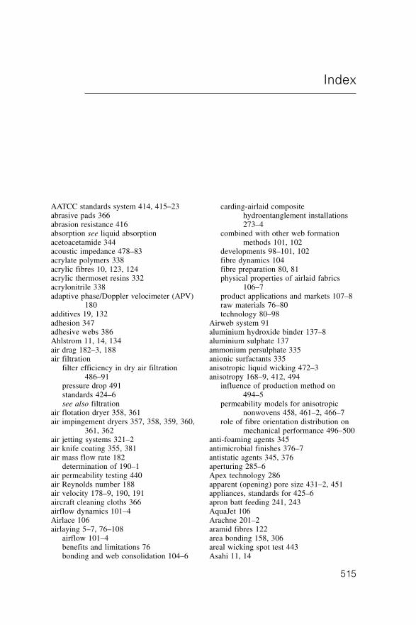
515
AATCC standards system 414, 415–23abrasive pads 366abrasion resistance 416absorption see liquid absorptionacetoacetamide 344acoustic impedance 478–83acrylate polymers 338acrylic fibres 10, 123, 124acrylic thermoset resins 332acrylonitrile 338adaptive phase/Doppler velocimeter (APV)
180additives 19, 132adhesion 347adhesive webs 386Ahlstrom 11, 14, 134air drag 182–3, 188air filtration
filter efficiency in dry air filtration486–91
pressure drop 491standards 424–6see also filtration
air flotation dryer 358, 361air impingement dryers 357, 358, 359, 360,
361, 362air jetting systems 321–2air knife coating 355, 381air mass flow rate 182
determination of 190–1air permeability testing 440air Reynolds number 188air velocity 178–9, 190, 191aircraft cleaning cloths 366airflow dynamics 101–4Airlace 106airlaying 5–7, 76–108
airflow 101–4benefits and limitations 76bonding and web consolidation 104–6
carding-airlaid compositehydroentanglement installations273–4
combined with other web formationmethods 101, 102
developments 98–101, 102fibre dynamics 104fibre preparation 80, 81physical properties of airlaid fabrics
106–7product applications and markets 107–8raw materials 76–80technology 80–98
Airweb system 91aluminium hydroxide binder 137–8aluminium sulphate 137ammonium persulphate 335anionic surfactants 335anisotropic liquid wicking 472–3anisotropy 168–9, 412, 494
influence of production method on494–5
permeability models for anisotropicnonwovens 458, 461–2, 466–7
role of fibre orientation distribution onmechanical performance 496–500
anti-foaming agents 345antimicrobial finishes 376–7antistatic agents 345, 376aperturing 285–6Apex technology 286apparent (opening) pore size 431–2, 451appliances, standards for 425–6apron batt feeding 241, 243AquaJet 106Arachne 201–2aramid fibres 122area bonding 158, 306areal wicking spot test 443Asahi 11, 14
Index
Index516
Ason-Neumag system 150, 157, 164–5ASTM standards 414, 415–23
nonwoven wound dressings 414–24asymmetry parameter 500, 501atactic polypropylene 145atmospheric jigs 372automotive applications 171, 219, 254, 293,
365automotive industry air filtration standards
425
back angle 45, 48–9Backer and Petterson model 170bacterial filtration 422bacterial penetration 422bale breakers 20–1bale pickers 21–2barbed needles 223, 224, 226
barb designs 227barb dimensions and shape 230–2barb spacing 227–30barb wear 236–8
basis weight uniformity 493batch exhaust dyeing 371batch scouring 370batt compaction 225, 275–7batt drafters 71–2batt feeding 241, 243BBA 11, 14beam dyeing 371–2belt calendering 317–18, 394bending rigidity 264–5, 418
modelling 455–6bentonite clay 252b-cyclodextrin derivatives 399biaxial roll spreaders 390biaxial stitch-bonding machines 209–10,
211, 221bicomponent fibres/filaments (bicos) 149,
159splittable 149, 267–9in thermal bonding 301–5
binder distribution test method 426binder penetration analysis 426binder to fibre ratio 348–9binders 416
chemical bondingbinder polymers 330, 331–44bonding surfaces 345–6cohesion properties 347formulated binder systems 344, 345methods of application 349–56
distribution of 348–9, 426printing 374–5thermal bonding 300–5
binder fibres 300–5powder binders 305
biocidal finishes 376–7biomimetic finishes 399biopolymers 120birefringence 164–5blankets 255blended composite web airlaying system 85blending 24–32blending hoppers 29, 30bond points 403bonding 1, 6, 9
airlaying 104–6characterisation of fabric bond structure
403–8chemical see chemical bondingdegree of bonding 261–4mechanical see mechanical bondingspunbonding 157–60
fabric properties 169temperature and pressure 161
thermal see thermal bondingwet-laid nonwovens 135–8
bonding surfaces 345–6BP 414branches (side chains) 342bridging effect 63Britton et al model 170Brownian motion 485, 488, 490Brunauer-Emmett-Teller (BET) multilayer
adsorption isotherm theory 438–9brush conveyors 247–9BS standards 414, 415–23
nonwoven wound dressings 414–24bubble point 432
test method 434–5buffer zones 31buffers 336bundle separation devices 166–7bursting strength 416butadiene polymers 339Bywater Machine Company 54
cal-rod system 316calender bonding 6, 158, 305–18
area bonding 158, 306belt calendering 317–18effect of process parameters 308–15methods of heating calender rolls
316–17point bonding 158, 306–8, 325–6
calender lamination 386calendering 393–4, 395calibrating unit 320–1Caliweb 219camel back 67–8can (drum) drying 390Cantrece 301–2capacitance techniques 447
Index 517
capillary channel theory 457, 458–66capillary cone nozzles 281–3capillary pressure 442, 468, 470–3
directional 472–3two-dimensional models of 470–2
capillary wicking 443–8modelling 468–74
capital intensity 11card clothing 44–53card configurations 57, 58carding 6, 32–67
card clothing 44–53combined with airlaying 102control systems 58–67Garnett machines 53–4hybrid carding-airlaying systems 82–3,
90–1interaction between card rollers 35–7machines 54–8roller operations 37–44selection of raw materials for 16–19thermal bonding line 494–5working and stripping principles 32–7
carding-airlaid compositehydroentanglement installations273–4
carding-hydroentanglement installations271–3
carding-preformed tissuehydroentanglement installations273
Carpet Star 249catalysts 147, 345Caviflex coating system 383, 384cellulose bonding 135cellulose fibres 118–19
layered structure 118, 119preparation for wet-laying 126see also wood pulp
centrifugal spinning systems 194–5ceramic fibres 125, 137–8Cerex nylon spunlaid fabrics 356chain transfer agents 332, 335characterisation see fabric propertieschemical bonding 6, 9, 298, 330–67
airlaying 104–5, 107, 108bond structure of chemical-bonded
nonwovens 408chemical binder polymers 330, 331–44drying 356–61hydroentanglement with 274–5mechanism of 344–9
binder polymer cohesion properties347
distribution of the binder and binderto fibre ratio 348–9
wetting 346
methods of binder application 349–56product applications 361–6spunbond process 159–60wet-laid nonwovens 135–6
chemical finishes 376–85methods of application 378–85types of 376–8
chemical gas adsorption 439chemical properties 402
see also under individual properties
chemical pulping 77Chicopee 255
airlaying system 85–6China 12–13chloroprene 339circular dies 176civil engineering 171, 252, 327Clapeyron effect 311classification of nonwovens 2–4cleaning systems 31–2cleanliness of resin 147clearer roll 41close barb (CB) spacing 228–30clothing 292–3Clupak process 138CNC (carded-net-carded) fabrics 287, 288coagulation 342–3coating 6
chemical bonding 355–6chemical finishes 380–5
coefficient of variation 409Coform process 192Cognex SmartView 400cohesion 347cohesive bonds 299cold pad batch dyeing 373coloration 370–3colorimetry systems 400combination bonding 274–5, 330–1combs 44compaction 225, 275–7
degree of 393‘complete freedom’ bending rigidity 456composite fabrics
blended composite airlaying process 85carded web and tissue composites 273carding-airlaid composite
hydroentanglement installations273–4
glass composite preforms 209–10, 211multi-layer composite hydroentangled
fabrics 287–8nappy composites 99, 107spunbond and meltblown webs 192
compression resistance 73, 75compressive finishes 391–3computational fluid dynamics (CFD) 103, 279
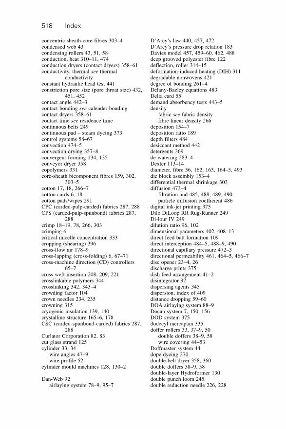
Index518
concentric sheath-core fibres 303–4condensed web 43condensing rollers 43, 51, 58conduction, heat 310–11, 474conduction dryers (contact dryers) 358–61conductivity, thermal see thermal
conductivityconstant hydraulic head test 441constriction pore size (pore throat size) 432,
451, 452contact angle 442–3contact bonding see calender bondingcontact dryers 358–61contact time see residence timecontinuous belts 249continuous pad – steam dyeing 373control systems 58–67convection 474–5convection drying 357–8convergent forming 134, 135conveyor dryer 358copolymers 331core-sheath bicomponent fibres 159, 302,
303–5cotton 17, 18, 266–7cotton cards 6, 18cotton pads/wipes 291CPC (carded-pulp-carded) fabrics 287, 288CPS (carded-pulp-spunbond) fabrics 287,
288crimp 18–19, 78, 266, 303crimping 6critical micelle concentration 333cropping (shearing) 396cross-flow air 178–9cross-lapping (cross-folding) 6, 67–71cross-machine direction (CD) controllers
65–7cross weft insertion 208, 209, 221crosslinkable polymers 344crosslinking 342, 343–4crowding factor 104crown needles 234, 235crowning 315cryogenic insulation 139, 140crystalline structure 165–6, 178CSC (carded-spunbond-carded) fabrics 287,
288Curlator Corporation 82, 83cut glass strand 125cylinder 33, 34
wire angles 47–9wire profile 52
cylinder mould machines 128, 130–2
Dan-Web 92airlaying system 78–9, 95–7
D’Arcy’s law 440, 457, 472D’Arcy’s pressure drop relation 183Davies model 457, 459–60, 462, 488deep grooved polyester fibre 122deflection, roller 314–15deformation-induced heating (DIH) 311degradable nonwovens 421degree of bonding 261–4Delany-Bazley equations 483Delta card 55demand absorbency tests 443–5density
fabric see fabric densityfibre linear density 266
deposition 154–7deposition ratio 189depth filters 484desiccant method 442detergents 369de-watering 283–4Dexter 113–14diameter, fibre 56, 162, 163, 164–5, 493die block assembly 153–4differential thermal shrinkage 303diffusion 473–4
filtration and 485, 488, 489, 490particle diffusion coefficient 486
digital ink-jet printing 375Dilo DiLoop RR Rug-Runner 249Di-lour IV 249dilution ratio 96, 102dimensional parameters 402, 408–13direct feed batt formation 109direct interception 484–5, 488–9, 490directional capillary pressure 472–3directional permeability 461, 464–5, 466–7disc opener 23–4, 26discharge prints 375dish feed arrangement 41–2disintegrator 97dispersing agents 345dispersion, index of 409distance dropping 59–60DOA airlaying system 88–9Docan system 7, 150, 156DOD system 375dodecyl mercaptan 335doffer rollers 33, 37–9, 50
double doffers 38–9, 58wire covering 44–53
Doffmaster system 44dope dyeing 370double-belt dryer 358, 360double doffers 38–9, 58double-layer Hydroformer 130double punch loom 245double reduction needle 226, 228
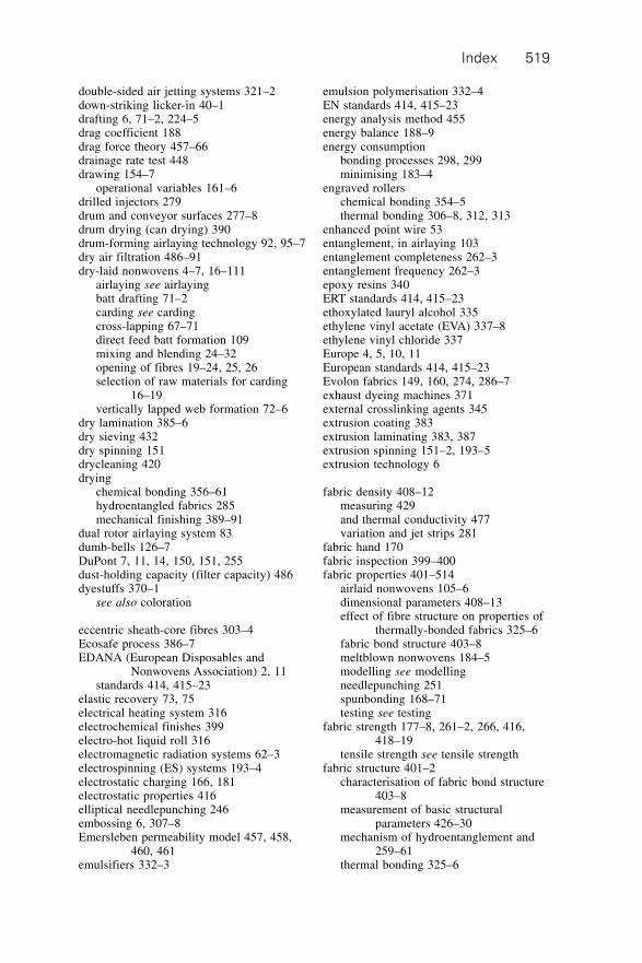
Index 519
double-sided air jetting systems 321–2down-striking licker-in 40–1drafting 6, 71–2, 224–5drag coefficient 188drag force theory 457–66drainage rate test 448drawing 154–7
operational variables 161–6drilled injectors 279drum and conveyor surfaces 277–8drum drying (can drying) 390drum-forming airlaying technology 92, 95–7dry air filtration 486–91dry-laid nonwovens 4–7, 16–111
airlaying see airlayingbatt drafting 71–2carding see cardingcross-lapping 67–71direct feed batt formation 109mixing and blending 24–32opening of fibres 19–24, 25, 26selection of raw materials for carding
16–19vertically lapped web formation 72–6
dry lamination 385–6dry sieving 432dry spinning 151drycleaning 420drying
chemical bonding 356–61hydroentangled fabrics 285mechanical finishing 389–91
dual rotor airlaying system 83dumb-bells 126–7DuPont 7, 11, 14, 150, 151, 255dust-holding capacity (filter capacity) 486dyestuffs 370–1
see also coloration
eccentric sheath-core fibres 303–4Ecosafe process 386–7EDANA (European Disposables and
Nonwovens Association) 2, 11standards 414, 415–23
elastic recovery 73, 75electrical heating system 316electrochemical finishes 399electro-hot liquid roll 316electromagnetic radiation systems 62–3electrospinning (ES) systems 193–4electrostatic charging 166, 181electrostatic properties 416elliptical needlepunching 246embossing 6, 307–8Emersleben permeability model 457, 458,
460, 461emulsifiers 332–3
emulsion polymerisation 332–4EN standards 414, 415–23energy analysis method 455energy balance 188–9energy consumption
bonding processes 298, 299minimising 183–4
engraved rollerschemical bonding 354–5thermal bonding 306–8, 312, 313
enhanced point wire 53entanglement, in airlaying 103entanglement completeness 262–3entanglement frequency 262–3epoxy resins 340ERT standards 414, 415–23ethoxylated lauryl alcohol 335ethylene vinyl acetate (EVA) 337–8ethylene vinyl chloride 337Europe 4, 5, 10, 11European standards 414, 415–23Evolon fabrics 149, 160, 274, 286–7exhaust dyeing machines 371external crosslinking agents 345extrusion coating 383extrusion laminating 383, 387extrusion spinning 151–2, 193–5extrusion technology 6
fabric density 408–12measuring 429and thermal conductivity 477variation and jet strips 281
fabric hand 170fabric inspection 399–400fabric properties 401–514
airlaid nonwovens 105–6dimensional parameters 408–13effect of fibre structure on properties of
thermally-bonded fabrics 325–6fabric bond structure 403–8meltblown nonwovens 184–5modelling see modellingneedlepunching 251spunbonding 168–71testing see testing
fabric strength 177–8, 261–2, 266, 416,418–19
tensile strength see tensile strengthfabric structure 401–2
characterisation of fabric bond structure403–8
measurement of basic structuralparameters 426–30
mechanism of hydroentanglement and259–61
thermal bonding 325–6
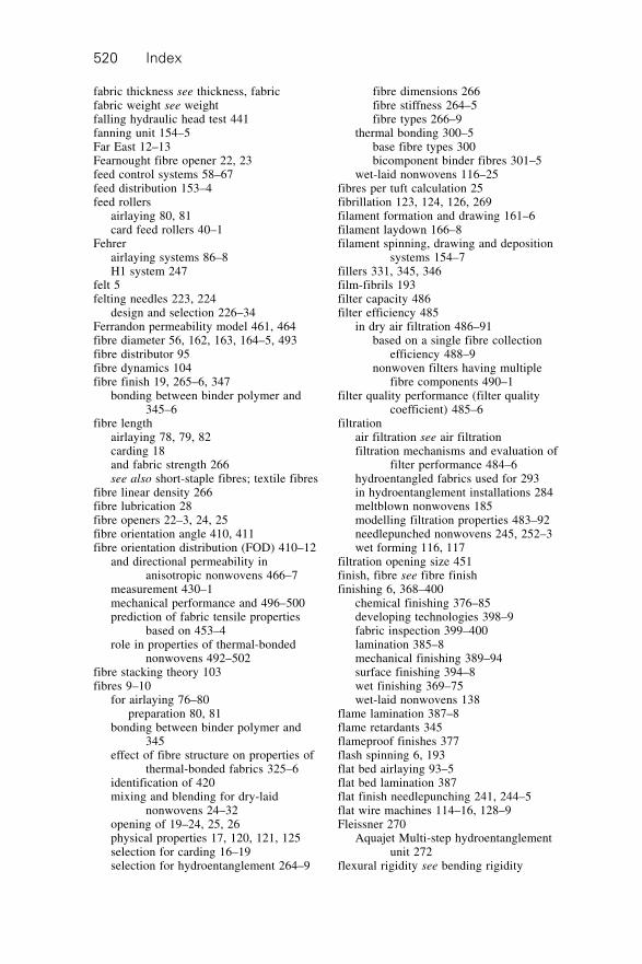
Index520
fabric thickness see thickness, fabricfabric weight see weightfalling hydraulic head test 441fanning unit 154–5Far East 12–13Fearnought fibre opener 22, 23feed control systems 58–67feed distribution 153–4feed rollers
airlaying 80, 81card feed rollers 40–1
Fehrerairlaying systems 86–8H1 system 247
felt 5felting needles 223, 224
design and selection 226–34Ferrandon permeability model 461, 464fibre diameter 56, 162, 163, 164–5, 493fibre distributor 95fibre dynamics 104fibre finish 19, 265–6, 347
bonding between binder polymer and345–6
fibre lengthairlaying 78, 79, 82carding 18and fabric strength 266see also short-staple fibres; textile fibres
fibre linear density 266fibre lubrication 28fibre openers 22–3, 24, 25fibre orientation angle 410, 411fibre orientation distribution (FOD) 410–12
and directional permeability inanisotropic nonwovens 466–7
measurement 430–1mechanical performance and 496–500prediction of fabric tensile properties
based on 453–4role in properties of thermal-bonded
nonwovens 492–502fibre stacking theory 103fibres 9–10
for airlaying 76–80preparation 80, 81
bonding between binder polymer and345
effect of fibre structure on properties ofthermal-bonded fabrics 325–6
identification of 420mixing and blending for dry-laid
nonwovens 24–32opening of 19–24, 25, 26physical properties 17, 120, 121, 125selection for carding 16–19selection for hydroentanglement 264–9
fibre dimensions 266fibre stiffness 264–5fibre types 266–9
thermal bonding 300–5base fibre types 300bicomponent binder fibres 301–5
wet-laid nonwovens 116–25fibres per tuft calculation 25fibrillation 123, 124, 126, 269filament formation and drawing 161–6filament laydown 166–8filament spinning, drawing and deposition
systems 154–7fillers 331, 345, 346film-fibrils 193filter capacity 486filter efficiency 485
in dry air filtration 486–91based on a single fibre collection
efficiency 488–9nonwoven filters having multiple
fibre components 490–1filter quality performance (filter quality
coefficient) 485–6filtration
air filtration see air filtrationfiltration mechanisms and evaluation of
filter performance 484–6hydroentangled fabrics used for 293in hydroentanglement installations 284meltblown nonwovens 185modelling filtration properties 483–92needlepunched nonwovens 245, 252–3wet forming 116, 117
filtration opening size 451finish, fibre see fibre finishfinishing 6, 368–400
chemical finishing 376–85developing technologies 398–9fabric inspection 399–400lamination 385–8mechanical finishing 389–94surface finishing 394–8wet finishing 369–75wet-laid nonwovens 138
flame lamination 387–8flame retardants 345flameproof finishes 377flash spinning 6, 193flat bed airlaying 93–5flat bed lamination 387flat finish needlepunching 241, 244–5flat wire machines 114–16, 128–9Fleissner 270
Aquajet Multi-step hydroentanglementunit 272
flexural rigidity see bending rigidity
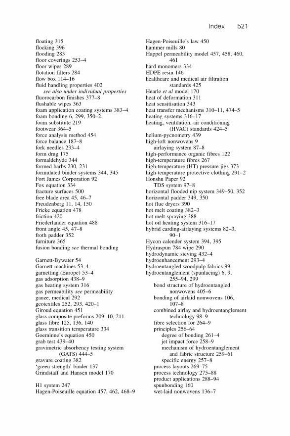
Index 521
floating 315flocking 396flooding 283floor coverings 253–4floor wipes 289flotation filters 284flow box 114–16fluid handling properties 402
see also under individual properties
fluorocarbon finishes 377–8flushable wipes 363foam application coating systems 383–4foam bonding 6, 299, 350–2foam substitute 219footwear 364–5force analysis method 454force balance 187–8fork needles 233–4form drag 175formaldehyde 344formed barbs 230, 231formulated binder systems 344, 345Fort James Corporation 92Fox equation 334fracture surfaces 500free blade area 45, 46–7Freudenberg 11, 14, 150Fricke equation 478friction 420Friederlander equation 488front angle 45, 47–8froth padder 352furniture 365fusion bonding see thermal bonding
Garnett-Bywater 54Garnett machines 53–4garnetting (Europe) 53–4gas adsorption 438–9gas heating system 316gas permeability see permeabilitygauze, medical 292geotextiles 252, 293, 420–1Giroud equation 451glass composite preforms 209–10, 211glass fibre 125, 136, 140glass transition temperature 334Goeminne’s equation 450grab test 439–40gravimetric absorbency testing system
(GATS) 444–5gravure coating 382‘green strength’ binder 137Grindstaff and Hansen model 170
H1 system 247Hagen-Poiseuille equation 457, 462, 468–9
Hagen-Poiseuille’s law 450hammer mills 80Happel permeability model 457, 458, 460,
461hard monomers 334HDPE resin 146healthcare and medical air filtration
standards 425Hearle et al model 170heat of deformation 311heat sensitisation 343heat transfer mechanisms 310–11, 474–5heating systems 316–17heating, ventilation, air conditioning
(HVAC) standards 424–5helium-pycnometry 439high-loft nonwovens 9
airlaying system 87–8high-performance organic fibres 122high-temperature fibres 267high-temperature (HT) pressure jigs 373high-temperature protective clothing 291–2Honshu Paper 92
TDS system 97–8horizontal flooded nip system 349–50, 352horizontal padder 349, 350hot flue dryers 390hot melt coating 382–3hot melt spraying 388hot oil heating system 316–17hybrid carding-airlaying systems 82–3,
90–1Hycon calender system 394, 395Hydraspun 784 wipe 290hydrodynamic sieving 432–4hydroenhancement 293–4hydroentangled woodpulp fabrics 99hydroentanglement (spunlacing) 6, 9,
255–94, 299bond structure of hydroentangled
nonwovens 405–6bonding of airlaid nonwovens 106,
107–8combined airlay and hydroentanglement
technology 98–9fibre selection for 264–9principles 256–64
degree of bonding 261–4jet impact force 258–9mechanism of hydroentanglement
and fabric structure 259–61specific energy 257–8
process layouts 269–75process technology 275–88product applications 288–94spunbonding 160wet-laid nonwovens 136–7
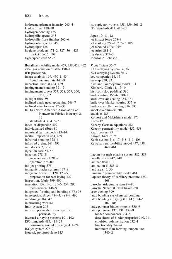
Index522
hydroentanglement intensity 263–4Hydroformer 129–30hydrogen bonding 135hydrophilic agents 345hydrophilic fibre finishes 265–6hydrophobic agents 345hydropulper 126hygiene products 171–2, 327, 364, 423
market 13–15, 107hyperspeed card 55–7
Iberall permeability model 457, 458, 459, 462ideal gas equation of state 190–1IFB process 98image analysis 169, 430–1, 434
liquid wicking rate 447–8impaction, inertial 484, 489impingement bonding 321–2impingement dryers 357, 358, 359, 360,
361, 362in-flight fibre 59inclined angle needlepunching 246–7inclined wire formers 129–30INDA (North American Association of
Nonwoven Fabrics Industry) 2,12
standards 414, 415–23index of dispersion 409individualised fibres 80industrial test methods 413–14inertial impaction 484, 489infra-red bonding 322–4infra-red drying 361, 391initiators 332, 335injection card 55, 56injectors 278–81
arrangement of 280–1operation 278–80
ink-jet printing 375inorganic binder systems 137–8inorganic fibres 17, 120, 123–5
preparation for wet-laying 127inspection, fabric 399–400insulation 139, 140, 185–6, 254, 293
measurement 448–9integrated forming and bonding (IFB) 98interception, direct 484–5, 488–9, 490interlinings 364, 423interlocking wire 52Intor system 204intrinsic permeability see specific
permeabilityinverted airlaying systems 101, 102ISO standards 414, 415–23
nonwoven wound dressings 414–24ISOjet system 276–7isotactic polypropylene 145
isotropic nonwovens 458, 459, 461–2ITS standards 414, 415–23
Japan 10, 11, 12jet impact force 258–9jet marking 260–1, 276–7, 405jet rebound effect 259jet strips 281–3jig dyeing 372–3Johnson & Johnson 13
K coefficient 56–7K12 airlaying system 86, 87K21 airlaying system 86–7key companies 14, 15kick-up 230, 231Kim and Pourdeyhimi model 171Kimberly-Clark 11, 13, 14kiss roll (slop padding) 380knife coating 355–6, 380–1knife over air coating 355, 381knife over blanket coating 355–6knife over roller coating 356, 381knock-over sinkers 204knuckles 285Komori and Makishima model 170Korea 12Kozeny-Carman equations 462Kozeny permeability model 457, 458Kraft process 77Kroyer, Karl 92, 93Kunit system 216–17, 218, 219, 406Kuwabara permeability model 457, 458,
460, 461
Lacom hot melt coating system 382, 383lamella strips 247, 248laminar flow 101lamination 6, 385–8land area 45, 50Langmuir permeability model 461Laplace theory of capillary pressure 435,
468Laroche airlaying system 89–90Laroche Napco 3D web linker 250laser etching 399latex bonding see chemical bondinglatex bonding airlaying (LBAL) 104–5,
107, 108latex polymer binder systems 336–9latex polymers 137, 331, 332–9
binder components 334–6data sheets of binder properties 340, 341emulsion polymerisation 332–4functionality 342–4minimum film forming temperature
340–2
Index 523
lay down, filament 166–8LDPE resin 146LDS system 44LLDPE resin 146Leanjet system 270Liba Maschinenfabrik 202, 222licker-in 40–1, 51linear density, fibre 266linings 292–3, 327, 364, 423linting 420liquid absorption 186, 415–16
measurement 442–8modelling liquid absorbency 467–8
liquid drainage rate 448liquid expulsion porometry 435–6liquid filtration, modelling 492liquid heating system 316liquid permeability see permeabilityliquid retention, modelling 467–8liquid strike time 443logs/sticks 126–7long-term variation controllers 62long web path cross-lappers 69lubricants (slip agents) 377lubrication, fibre 28Lucas-Washburn equation 469–70Lutravil system 150, 157Lyocell 10, 120–1, 267, 269Lystil OY process 134
M & J Fibretech 78–9, 92, 93machine direction/cross direction (MD:CD)
8, 42, 412machine settings 175–9magnetic hump 28Mahlo QMS-10A system 400Malifol technique 214Malimo stitch-bonding system 206–14, 221
cross weft insertion 208, 209Malifol technique 214manufacture of glass composite
preforms 209–10, 211multiaxial weft insertion 210–13parallel weft insertion 209recent developments in biaxial stitch-
bonding 221Schusspol technique 213
Malipol system 214–15Malivlies system 205–6, 220, 406Maliwatt system 202–5, 220, 407man-made fibres 78–9, 82
wet-laid nonwovens 119–25preparation of fibres 126–7
manufacturing technologies 4–5, 6Mao-Russell model 459, 460–6, 470–3market structure 10–15mass balance 187
maximum fabric strength (MFS) 261mechanical bonding 9, 201–97
airlaying 106hydroentanglement see
hydroentanglementneedlepunching see needlepunchingspunbond process 160stitch-bonding see stitch-bonding
mechanical finishing 389–94mechanical properties 402
see also under individual properties
medical products 172, 292, 364melt flow rate (MFR) 174melt spinning 143, 151
dynamics of process 186–9melt viscosity 147meltblowing 6, 143, 172–91
characterisation techniques 180–4characteristics and properties of
meltblown fabrics 184–5combined with airlaying 102composite fabrics 192fabric production 172–80mechanics of process 186–91process technology 173–80product applications 185–6resins for 143–9
melting, polymer 152–3melting point 146Mercosur 13mercury porosimetry 436–7metal detection 27–8metallic wire card clothing 44–53metallocene-based resins 147–8metering pump 153Mi and Batra model 170Miao permeability model 461micelles 332–3Micrex system 138, 392–3Microchute 63, 64microencapsulation 398–9microfibres 172
see also meltblowingmicroperforated sleeves 278microprocessor controlled weigh-pan
systems 59–61Microweigh system 59–61
XLM system 61Middle East 13migration 342–3MIL standards 415–23minimum film forming temperature 340–2Miraguard 286Mirastretch 286Miratec fabrics 286mixed polymers 149mixing fibres 24–32
Index524
modelling 449–92absorbency and liquid retention 467–8acoustic impedance 478–83bending rigidity 455–6capillary wicking 468–74filtration properties 483–92meltblowing process 182–3pore size and pore size distribution
449–52prediction of spunbonded nonwoven
fabric properties 170–1role of fibre orientation distribution on
properties of thermal-bondednonwovens 492–502
specific permeability 457–67tensile strength 452–5thermal resistance and thermal
conductivity 474–8modified laser-doppler anemometry
(MLDA) 447moisture content 28–9moisture control 61molecular weight 161molecular weight distribution (MWD) 147,
161, 164monomers 332–3, 334–5Monvel 301–2moulded webs 99–100multiaxial stitch-bonding 210–13, 222–3multi-board needlepunching machines 240multi-bonding airlaying (MBAL) 105–6multi-hopper systems 27Multiknit system 216, 217–19, 406–7multi-layer composite hydroentangled
fabrics 287–8multi-layer nappy composites 99, 107multimixers 30multiple dies 175–6multi-roll openers 22, 24mungo 54
nanofibres 193–4Nanosphere technology 399nappy composite fabric 99, 107natural fibres 17, 77–8, 82
wet-laid nonwovens 118–19preparation of fibres 126
see also cellulose fibres; wood pulpnatural polymer-based fibres 78–9natural rubber latex (polyisoprene) 339needle arrangement 239–40needle gauge 232needle rotation 238–9needle types 232–4, 235needleboard changeovers 239needlepunching 6, 9, 71, 223–55
airlaying 106, 108
basics of operation 225batt formation 224bond structure of needlepunched
nonwovens 404–5drafting 224–5needle design and selection 226–34penetration depth and other factors
affecting needle use 234–40product applications 251–5spunbonding 160technology 240–51
needlepunching machine sequences 240–1,242
nip pressure 310–11, 313nitrile butadiene rubber (NBR) 339‘no freedom’ bending rigidity 456Nomex 291non-ionic detergents 369non-ionic surfactants 335nonwoven wound dressing standards
414–24nonwovens industry 1–15
European-produced nonwovens 4, 5global production 11key companies 14, 15market structure and development 10–15
Norafin process 280North America 12
standards 414, 415–23Northern Softwood Sulphite 77Novonette system 307–8nozzle aeration dryers 357, 358, 359, 360,
361, 362nozzles 281–3
Oasis fibre 78oblique needlepunching 246–7off–line processing variables 161offset gravure 382oligomer radicals 333on-line basis weight measurement 64–5on-line processing variables 161one-dimensional liquid wicking rate 445–6open flow box 114–16open porosity (effective porosity) 413, 431opening
of fibres 19–24, 25, 26airlaying opened fibres 80
thermal bonding line 494–5opening pore size 431–2, 451optical brighteners 345optical properties 416–17organic synthetic fibres 120orientation angle 410, 411orientation distribution function (ODF) see
fibre orientation distributionorifice plates 190–1
Index 525
orthotropic models of tensile strength 452–4Osborne, F.H. 113
packaging 172pad machine 349, 350, 351padding/pad machines
application of chemical binders 349,350, 351
application of chemical finishes 379–80coloration 373
paddings 253paper technology 6papers 113–14
wet-laid speciality papers 139papyrus 113parallel capillary pore models 479parallel fibre models 479–82parallel web 42, 43parallel weft insertion 209, 221parametric studies 173–80partial solution bonding (solvent bonding)
9, 159–60, 356partially oriented yarns (POYs) 166particle diffusion coefficient 486paste dot coating 383patterning effects 285–6Peclet number 486–7penetration depth 234–6, 404–5Perfojet 270, 277perforated conveyor aprons 70perforated conveyor through-air bonding 321perforated drum through-air bonding 318,
319–21perforation 389permeability 417
directional permeability 461, 464–5,466–7
modelling specific permeability 457–67summary of permeability models
458–66testing 440–1water vapour transmission testing 441–2
perpendicular-laid web formation 72–6phenolic binders 340physical gas adsorption 438–9physical properties 402
airlaid fabrics 106–7fibres 17, 120, 121, 125spunbond fabrics 168–70see also under individual properties
pigments 174–5, 345, 370–1printing 374–5see also coloration
pile height 407pillar stitch 407pitch 45, 49plasma treatment 398
plasticisers 342plexifilaments 193point bonding 158, 306–8, 325–6point density 49point profile 45, 49–2polishing 397polyacrylates 338polyacrylonitrile (PAN) fibres 10, 123, 124polyamide
fibres 10, 122–3resin 148
polydispersity 174polyester
fibres 9, 16, 17, 122, 123resin 148
polyethylene (PE)fibres 78–9resins 144–8
polymer feed distribution 153–4Polymer Group Inc. (PGI) 11, 14polymer-laid nonwovens 4–5, 7–8, 143–200
combining spunbonding/meltblowingwith airlaying 108
composite fabrics 192future trends 195mechanics of spunbond and meltblown
processes 186–91meltblowing see meltblowingresins 143–9spinning processes 151–2, 193–5spunbonding see spunbonding
polymer melting 152–3polymer throughput 161polymers
chemical binder polymers 330, 331–44for meltblowing 180–1thermal conductivity 476
polymethacrylates 338polyolefins
fibres 121resins 144–8see also polyethylene; polypropylene
polypropylene (PP)fibres 9, 10, 16, 17, 78–9resins 144–8, 180–1
polyurethane (PU)binders 339–40resins 148
polyvinyl alcohol (PVA) 136pond height, flow box 115pore connectivity 413pore size 412–13
measurement 431–9modelling 449–50
pore size distribution 412–13measurement 431–9modelling 450–2
Index526
pore throat size (constriction pore size) 432,451, 452
pore volume distribution 436–7pore volume size 432porometry 435–6porosimetry 436–7porosity 412–13
measurement 431–9powder bonding 305powder coating (scatter coating) 383powder dot coating 383preformed webs 99–100preneedling 241–4pressure drop 485
in dry air filtration 491liquid filtration 492
pressurised foam application systems 384pre-wetting 275–7print bonding 353–5, 373–4printing 6, 373–5Proban R process 377process variables
calender bonding 308–15spunbonding 160–8
Procter & Gamble 13product applications 2–4, 5
airlaying 107–8chemical bonding 361–6hydroentangled fabrics 288–94meltblown fabrics 185–6needlepunching 251–5spunbond fabrics 171–2thermal bonding 327–8wet-laid nonwovens 139–41
product lifetime 2, 3profiling cross-lappers 71protective clothing 291–2PTAT 149PTT 149pulp, wood see wood pulppunch density 236pycnometry 439
quadpunch loom 245qualitative assessment 429quench air rate 161quench air temperature 161, 162–3
Radfoam process 132–4radiation, thermal 475
thermal radiation bonding 322–4rag tearing (rag grinding) 54raising 397Rando Machine Corporation 82
Rando-webber 83–4random-laid nonwovens see airlayingrandom condensed web 43
random pitch wire 52–3random web 42, 43randomisers 42–3raw materials 9–10
airlaying 76–80carding 16–19polymer-laid nonwovens 143–9thermal bonding 300–5wet-laid nonwovens 116–25
rayons 149see also viscose rayon
reciprocating lapper 72–3recycled polymers 181reduction needles 226, 228Reemay 150regular barb (RB) spacing 227–8, 229Reifenhauser 8, 11, 150
Reicofil system 8, 150, 156–7relaxation 391repellency 417–18residence time (contact time)
calender bonding 308, 312, 313polymer residence time in extruder 189
resin melt flow rate (MFR) 174resins 143–9resistance to compression 73, 75reverse roll coating 356, 380Reynolds number 191RFX system 150rib fabrics 247roll calendering 305–17Rollaweigh 64roller batt feeding 241, 243roller deflection 314–15roller draft airlaying system 100–1roller train cards 57roller weighing systems 64roller width 314rollers, carding 33
interaction between 35–7roller operations 37–44
Rollin’s permeability model 462roofing products 255, 327, 366room air cleaners/purifiers 425–6ropes 126–7rotary lapper 73, 75rotary screen bonding 354rotary screen coating 382rotary tacker 241, 243Rotiformer 130–2Rotis system 73–6row width 45, 49Rushton permeability model 459, 462
S-Roll calender 394S-TEX system 150sand filters 284
Index 527
sanforising 391–3satellite rollers 33satin stitch 407saturation bonding 349–50, 351saturation rate 474SBAL process (airlaid-spunlace
combination) 106scale of production 10–11SCAN-e-JET system 31–2Scandinavian Sulphate 77Scanfeed system 65–7scatter (powder) coating 383Schuhmeister equation 477Schusspol technique 213scouring 369–70scramblers 6, 42–3scraper bonding 355–6scrim reinforced fabrics 240seating fabric 219secondary bonding 407self-crosslinking polymers 344self-emptying bins 29Servolap 62–3shear deformation 500, 501shearing (cropping) 396sheath-core bicomponent fibres 159, 302,
303–5Shen permeability model 459, 462shoddy 54short-staple fibres 18
airlaying 82, 91–8, 103–4short web path cross-lappers 69–70shot 176side-by-side (S/S) bicomponent fibres 159,
303side chains (branches) 342sieving test methods 432–4Sigmaformer 132, 133singeing 6, 394–6single-belt dryer 358, 359single-board needlepunching machines
240single fibre collection efficiency 486
filter efficiency bsed on 488–9single-layer Hydroformer 129–30single reduction needle 226, 228single roll openers 22, 24skewing 315slice 114
opening requirements for lowconsistency operation 116, 117
slice velocity 115–16slop padding (kiss roll) 380slot coating (slot die coating) 383slot die 167slot-type injectors 279–80small strain model 454
SMS (spunbond-meltblown-spunbond)composite structure 192
sodium hydroxide 336sodium lauryl ether sulphate 335sodium lauryl sulphate 335soft monomers 334softeners 378softening 397–8solution bonding 356solvent bonding (partial solution bonding)
9, 159–60, 356solvent coating 385solvent scouring 370solvent spun cellulose (Lyocell) 10, 120–1,
267, 269sonic velocity 180Sontara 256sound energy absorption coefficient 479,
481–2sound propagation 478–83Southern Softwood Kraft 77specialist needlelooms 249–51specific energy 257–8, 280–1specific permeability 440
modelling 457–67specific surface area 438–9spin finish 265–6Spinlace fabrics 274Spinnbau airlaying system 90–1spinnerets 154spinning, drawing and deposition systems
154–7spinning techniques 151–2, 193–5spiralling effect 52splittable bicomponent fibres 149, 267–9splitting 389spray bonding 6, 353spray systems 28SPS (spunbond-pulp-spunbond) fabrics 287,
288spunbonding 6, 7–8, 143, 149–72
airlaying combined with 102bonding techniques 157–60composite fabrics 192fabric production 149–55
die block assembly 153–4extrusion spinning 151–2filament spinning, drawing and
deposition 154–5polymer melting 152–3
fabric structure and properties 168–71mechanics of process 186–91operating variables 160–8
material variables 160–1operational variables 161–8
product applications 171–2production systems 155–7
Index528
resins for 143–9spunbond hydroentanglement
installations 274SpunJet system 274spunlacing see hydroentanglementstandard deviation 409standard test methods 413–26
see also testingstar blade needles 233Star Former 98steam heating system 316steel rollers 312–14Stefan-Boltzmann law 323stencilled raising machines 397Stenhouse equation 488stenter dryers 358, 362, 389–90stiffeners 378stiffness see bending rigiditystitch-bonding 1, 6, 9, 201–23
bond structure of stitch-bondednonwovens 406–7
Kunit system 216–17, 218, 219, 406Malimo system 206–14, 221Malipol system 214–15Malivlies system 205–6, 220, 406Maliwatt system 202–5, 220, 407Multiknit system 216, 217–19, 406–7recent developments 220–3Voltex system 215–16
stitch holes 407Stokes number 487straining 484strength, fabric see fabric strength; tensile
strengthstress-strain behaviour 454, 499–500strip test 440stripper 32–7
principles of stripping 35structural parameters 402
measurement of 426–30see also fabric structure
structuring needlepunching machines 241,247–9
Struto system 72–3, 74, 75styrenated acrylics 338styrene butadiene rubber (SBR) 339sublimation transfer printing 375suction-assisted web handling 55sueding 397Sullivan permeability model 462Sunds system 80superabsorbent polymers (SAPs) 79–80,
421–2support surface 277–8surface finish of steel roller 315surface finishing 394–8surfactants 332, 335, 345
surgical fabrics 292SVA Lite 400swelling 126syndiotactic polypropylene 145synthetic fibres 17, 78–9
see also man-made fibressynthetic leather 253, 292synthetic wood pulp (SWP) fibres 121–2syphon test 448
tacking 241–4take-up speed 161TDS (totally dry system) 97–8tear strength 418–19technical nonwovens, wet–laid 139technical wipes 289teeth 40
point density 49point profile 45, 49–2tooth depth 45–7
temperaturebonding temperature 309–10glass transition temperature 334minimum film forming temperature
340–2polymer/die temperature 161quench air temperature 161, 162–3
tenacity 177–8Tencel (Lyocell) 10, 120–1, 267, 269tensile strength 78–9, 325, 419
hydroentanglement 261–2modelling 452–5needlepunched fabrics 251
tensile testing 439–40role of fibre orientation distribution on
fabric properties 496–500tensioned wire mesh 319, 320testing 413–49
basic structural parameters 426–30fibre orientation distribution 430–1gas and liquid permeability 440–1general standards for 413–26porosity, pore size and pore size
distribution 431–9tensile properties 439–40thermal conductivity and insulation
448–9water vapour transmission 441–2wetting and liquid absorption 442–8
textile fabrics, thermal conductivity of 476textile fibres, airlaying 78–9, 82, 101–3textile technology 6thermal bonding 6, 9, 298–329
bond structure of thermally-bondednonwovens 407–8
calender bonding 6, 158, 305–18fabric structures 325–6
Index 529
hydroentanglement with 274–5impingement bonding 321–2principle of 299–300product applications 327–8raw materials 300–5role of fibre orientation distribution in
fabric properties 492–502spunbonding 146, 158–9thermal radiation bonding 322–4through-air bonding 318–21ultrasonic bonding 324–5wet-laid nonwovens 136
thermal bonding airlaying (TBAL) 105,107, 108
thermal conductivity 310measurement 448–9modelling 474–8
thermal fusion ovens 390thermal insulation see insulationthermal radiation see radiation, thermalthermal resistance 186
measurement 448–9modelling 474–8
thermomechanical pulping (TMP) 77thermoplastic binders 300–1, 373thermoplastic polyurethane (TPU) 148Thibeau hybrid card-airlay machine 91thickeners 345, 374thickening 116, 117thickness 408–12, 419
testing 426–9Thinsulate 185three-dimensional linked fabrics 250three-dimensional web preforms and
moulds 99–100through-air bonding 158, 318–21
principle 318–19through-air dryers 357–8, 391tip width 45, 50tissue and carded web composites 273tooth depth 45–7
see also teethtotal porosity 413toxicity 422–3transfer coating 383transfer rollers 39–40transport chamber 101transverse wicking plate test 443–5triangular blade needles 232tricot lapping 202–4tubular fabrics 250tuft size 23, 25Turbo Lofter system 57, 90–1turbulent flow 101–3twin-layer inclined wire former 129two-dimensional liquid wicking rate
446–8
two-dimensional models of capillarypressure 470–2
Typar 150, 158Tyvek 150, 193
ultrafine microfibres 179–80ultrasonic bonding 6, 159, 324–5underlap movement 207Unicharm system 277unidirectional nonwovens 458, 460, 461uniformity, fabric weight 409, 429–30, 493unit cell models 458United States (USA) 10, 11, 12up-striking licker-in 41upwards vertical strip test 445–6, 469–70US patent 3535187 85UV stabilisers 378
vacuum cleaners 425–6velour fabrics 247–9Venturi gaps 157, 168vertical padder 349, 351vertically lapped web formation 72–6vibrating screen 93–4Viledon M 150vinyl acetate 336vinyl acetate acrylate 338vinyl chloride 336–7vinyl polymers 336–8viscose rayon 10, 16, 17, 120, 265, 266viscosity 191Voltex system 215–16volumetric chute feed systems 61–2Voronina models 482–3vulcanisation 339, 344
waddings 253warp yarn racking device 208washable domestic fabrics 291washing 369–70waste recycling 54water circuit 284water method for water vapour transmission
442water permeability testing 441water spraying 176water vapour transmission testing 441–2waterproof finishes 377–8Wavemaker system 73, 75web bonding see bondingweb compaction 225, 275–7web detachment systems 44web formation 8–9
dry-laid see dry-laid nonwovenspolymer-laid see meltblowing; polymer-
laid nonwovens; spunbondingwet-laid see wet-laid nonwovens
Index530
web manipulation 6carding 42–3
web weight 56weigh-belt systems 63weigh-blenders 27weigh platforms 63weight
fabric weight 408–12, 419uniformity 409, 429–30, 493
on-line basis weight measurement 64–5profiles 71web weight and fineness 56
weight measurement control systems 58–67wet finishing 369–75wet-laid nonwovens 4–5, 6, 7, 112–42
background and historical development112–14
bonding systems 135–8combining wet-laying with airlaying
102fibre preparation 126–7finishing 138product applications 139–41raw materials 116–25theoretical basis 114–16web-forming process technology 128–35
wet lamination 385wet-on-dry padding 379wet-on-wet padding 379wet-operating filters 491wet sieving 432wet spinning 120, 152wettability 265–6, 442–3wetting 346, 347
measuring 442–8wetting agents 347white-water circuit 130wicking 442
areal wicking spot test 443measurement 443–8modelling 468–74one-dimensional liquid wicking rate
445–6two-dimensional liquid wicking rate
446–8wicking strip tests 445–6, 469–70winding 160, 389wipes 4, 5, 255
airlaid nonwovens 108chemically bonded nonwovens 361–3hydroentangled nonwovens 289–91
wiping efficiency 423wire angles 45, 47–9wire covering, card 44–53wire depth 45–6wire foundation 50–2wood pulp 76–8, 82, 103–4, 118–19, 266
airlaying technology for 91–8hydroentangled wood pulp fabric 99see also cellulose fibres
wool fabric 477worker 32–7, 38, 50
interaction with cylinder and wire angles47–8
principle of working 34–5Worldwide Strategic Partners (WSP)
standards 414, 415–23wound dressings, standards for 414–24Wrotnowski’s model 449–50
yarn punching 250–1Young’s modulus 177–8
ZimmerMagnoroll/Magnoknife 381Variopress system 384


