Embed Size (px)
Citation preview
/ 5 3 / o S
UNIVERSAL DYNAMIC SIMULATOR FOR ROBOTIC MANIPULATORS: KINEMATIC MODELING
A disser tat ion submit ted to the
Depa r tmen t of Electr ical Engineer ing , Univers i ty of M o r a t u w a
in partial fu l f i l lment of the r equ i remen t s fo r the
degree of Mas te r of Sc ience
by
LASANTHA KURUKULARACHCHI LIBRARY
UNIVERSITY OF MORATUWA, SFJ LANKA MORATUWA 3 v s c * 3
t!
Supervised by: Dr . R o h a n M u n a s i n g h e
Department of Electrical Engineering University of Moratuwa, Sri Lanka
January 2008
University of Moratuwa
9 \ Z O 8
9120?
L
9 1 2 0 8

DECLARATION
The work submitted in this dissertation is the result of m y own investigation,
except where otherwise stated.
It has not already been accepted for any degree, and is also not being concurrently
submitted for any other degree.
Date- 19/2/2008
1 endorse the declaration by the candidate.
II
Table of Contents
Title
Declaration
Tables of Contents
Abstract
Acknowledgement
List of Figures
List of Tables
List of Principal Symbols
List of Acronyms
l.Chapter - Introduction of the Simulator Design
1.1 Background of the requirement
1.2 Problem Statement
1.3 Available Simulators
1.4 Aims & Objectives
1.5 Literature survey
1.5.1 Kinematics Modeling for Universal Manipulator
1.5.2 Jacobian Base Numerical Inverse Kinematic Solution
1.5.3 Alternative Methods for Inverse kinematics Approaches
2.Chapter -Design Methodology
2.1 Manipulator Modeling Fundamentals for Universal Manipulator
2.2 Designing Approach
2.2.1. Forward Kinematic Approach
2.2.2. Inverse Kinematic Approach
III
3. Chapter - Forward Kinematics Modeling Theories
3.1 Mechanical Structure and Notation of the Manipulator
3.2 Denavit and Hartenberg Notation for Manipulator Configuration
3.3 Algorithm for Link Frame Assignment
3.4 Manipulator Jacobian which Relate to Build the Inverse Kinematic
Algorithm
3.5 Jacobian Singularities
4.Chapter-Inverse Kinematic Approach on Dynamic Simulator
4.1 Used Method for Inverse Kinematic Solving Techniques
4.2 Inverse Kinematic Algorithm
4.4.1 Computed Inverse Kinematic Model by Using Newton - I
Techniques
4.4.2 Computed Inverse Kinematic Model by Using Taylor Ser
Expansion
4.3 Calculation the Singularities and Testing the Convergence
5.Chapter-Design the Software Tool 39
5.1 Object Oriented Programming 40
5.2 Supporting C++ Libraries 40
5.2.1 NEWMAT 11 Mathematic Library 41
5.2.2 NT Graph3D Graph Library 42
5.3Software architecture 42
5.3.1 CManipulator Class 43
5.3.2 Serialization Tool 43
5.3.3 Calculation Tool Box 43
5.3.4 Matrix Output Viewer 44
5.3.5 Link Tool 44
5.3.6 3D Graph Viewer 44
5.3.7 2D Graphic Output Viewer 44
IV
rtaphson
:ies
18
. 18
19
22
27
31
32
32
34
34
35
36
5.3.8 Manipulator Database Access Object 44
5.4.Functional Relationship between the Classes for Simulator Designing 44
5.4.1 Functional Relationship for the Forward Kinematic 45
5.4.2 Matrix Viewer 46
5.4.3 Functional Relationship for the Inverse Kinematic 48
48
6.Chapter -Implementation of Programming Interface 51
6.1 Programming Interface 52
6.2 New link Interring Dialog 53
6.3 Link Properties Dialog 55
6.4 Trajectory Planning and Inverse Kinematic Calculation 57
7. Chapter - Implementation & Results 58
7.1 Testing the Developed Simulator on Actual Manipulator 58
7.2 Testing Process 59
7.3 Further Improvement 62
Conclusions 63
References
Appendix A -Function of Forward Kinematics A1-A6
Appendix B -Function of Jacobian Matrix B1
Appendix C -Function of Inverse Kinematics C1-C5
V
Abstract
This project highly focuses on a total simulating solution to the robotic manipulator users. The
existing simulators are narrow with limited applications. Therefore the simulator users do not
have an adequate solution for the universal manipulators. The simulating solution developed
through this project is the combination of kinematic, dynamic, trajectory planning and frictional
model on a one interface. This project has been divided into four different research components
because of the vast extent of the research areas.
This thesis is based on the kinematic behavior of this robotic simulator. Under the kinematic
behavior, the forward kinematic and the reverse kinematic have been focus on. In the forward
kinematic bases, the systematic analytic approaches are used to develop the algorithm. This
algorithm describes the spatial relationship between links & link parameters of the manipulator
and it supports to find the end-effector position and orientation with respect to the joint space
parameters in a graphical way. On the other hand the forward kinematic supports to visualize the manipulator in the 3D environment.
The reverse kinematic is required to find a set of joint variables that would bring the end-effector
in the specified position and orientation. In general this solution is non-unique for the universal
model, but solving the inverse kinematic is most important to design the practical manipulators.
Therefore the inverse kinematic algorithm is the combination of Jacobian transformation and the
Taylor series expansion. This combination is ideal to solve the inverse kinematic in this simulator.
The software tool is the final output of this project. The kinematics module supports to find the
manipulator geometry and the joint angles. But the software tool is the combination of
kinematics, dynamics and the trajectory planning.
The object-oriented program is well adapted to this application since OOP can describe each part
of the robot as one object with its own properties and behavior. Even if C++ is not a perfect 0 0
language, a lot of very useful libraries are available, and maintains very good efficiency for
VI
intensive computations. The robotic applications will be highly popular in the future. Therefore
this software tool may be most important to develop the manipulator application because it
provides a total solution for designing the application. Still nobody has developed this type of an
application tool to manipulator designers. This software application operates with out any
hindrance and the major advantage is that this simulator can be used for universal serial link
manipulator for N-degree of freedom.
VII

Acknowledgements
I would like to thank my supervisor, Dr Rohan Munasighe for his guidance though out my
project to achieve its goals and his valuable suggestions to direct this project in the correct
direction.
My sincere thanks are extended to Mr. Hiran Perera Automation Engineer in ANSELL LANKA
(PVT) LTD for his support to test this simulator in the practical environment and also I thank
my colleagues Rajeeve, Bannayake and Mahinda for giving full support to develop a dynamic
simulator tool.
I am grateful to my family for their never ending love and support. I would also like to thank my
friends both in the university and factory for their friendship. Finally I thank all the members of
the staff in the Electrical Department of University of Moratuwa.
VIII
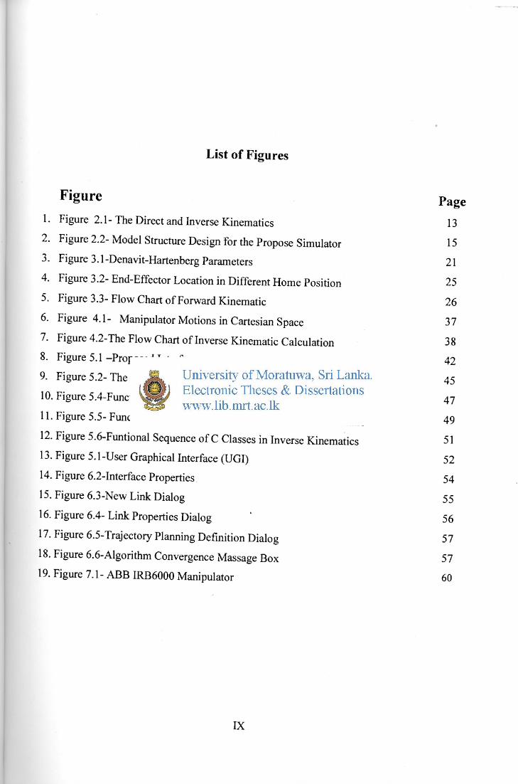
List of Figures
F i § u r e Page 1. Figure 2.1-The Direct and Inverse Kinematics 13
2. Figure 2.2- Model Structure Design for the Propose Simulator 15
3. Figure 3.1-Denavit-Hartenberg Parameters 2 1
4. Figure 3.2-End-Effector Location in Different Home Position 25
5. Figure 3.3-Flow Chart of Forward Kinematic 26
6. Figure 4.1- Manipulator Motions in Cartesian Space 37
7. Figure 4.2-The Flow Chart of Inverse Kinematic Calculation 38
8. Figure 5.1-Proposed Interface 42
9. Figure 5.2- The Software Architecture 45
10. Figure 5.4-Functional Relationship between the Basic Classes 47
11. Figure 5.5- Functional Sequence of C Class for Forward Kinematic 49
12. Figure 5.6-Funtional Sequence of C Classes in Inverse Kinematics 51
13. Figure 5.1 -User Graphical Interface (UGI) 52
14. Figure 6.2-Interface Properties 54
15. Figure 6.3-New Link Dialog 55
16. Figure 6.4-Link Properties Dialog ' 56
17. Figure 6.5-Trajectory Planning Definition Dialog 57
18. Figure 6.6-Algorithm Convergence Massage Box 57
19. Figure 7.1 - ABB IRB6000 Manipulator 60
IX
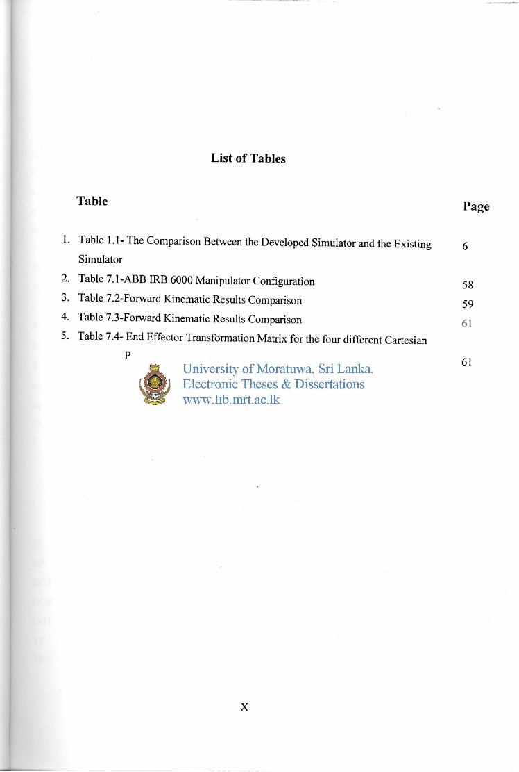
List of Tables
Table P a g e
1. Table 1.1 - The Comparison Between the Developed Simulator and the Existing 6
Simulator
2. Table 7.1 -ABB IRB 6000 Manipulator Configuration 5 8
3. Table 7.2-Forward Kinematic Results Comparison 59
4. Table 7.3-Forward Kinematic Results Comparison
5. Table 7.4- End Effector Transformation Matrix for the four different Cartesian
Points for Inverse kinematic Results Comparison g j
X

List of Principal Symbols
qs Joint Variable
e Joint Angle
a; Link Length
a, Link Twist
di Link Offset
"A, Homogeneous Transformation Matrix.
Ri Rotation Matrix
Pi Translation Vector
T Forward Kinematics Equation
J Jacobian Matrix
X 6x1 Cartesian Velocity Vector
q nxl Vector of n Joint Velocity
CO; Angular Velocity of ith Link
Sq Small Displacement of Joint Variable
Sx Small Displacement of Cartesian Variable
I Identity Matrix
List of Acronyms
IK Inverse kinematic
RP Revolute & prismatic
DOF Degree of freedom
OOP Object oriented programming
D-H Denavit-Hartenberg parameters
TP Trajectory planning
TPA Trajectory planning algorithm
XI


