Embed Size (px)
Citation preview
UNIT -II
Water Distribution Systems
The purpose of distribution system is to deliver water to consumer with appropriate quality,
quantity and pressure. Distribution system is used to describe collectively the facilities used to
supply water from its source to the point of usage.
Requirements of Good Distribution System
1. Water quality should not get deteriorated in the distribution pipes.
2. It should be capable of supplying water at all the intended places with sufficient pressure
head.
3. It should be capable of supplying the requisite amount of water during fire fighting.
4. The layout should be such that no consumer would be without water supply, during the
repair of any section of the system.
5. All the distribution pipes should be preferably laid one metre away or above the sewer
lines.
6. It should be fairly water-tight as to keep losses due to leakage to the minimum.
Layouts of Distribution Network
The distribution pipes are generally laid below the road pavements, and as such their layouts
generally follow the layouts of roads. There are, in general, four different types of pipe networks;
any one of which either singly or in combinations, can be used for a particular place. They are:
Dead End System
Grid Iron System
Ring System
Radial System
Distribution Reservoirs
Distribution reservoirs, also called service reservoirs, are the storage reservoirs, which store the
treated water for supplying water during emergencies (such as during fires, repairs, etc.) and also
to help in absorbing the hourly fluctuations in the normal water demand.
Functions of Distribution Reservoirs:
• to absorb the hourly variations in demand.
• to maintain constant pressure in the distribution mains.
• water stored can be supplied during emergencies.
Location and Height of Distribution Reservoirs:
• should be located as close as possible to the center of demand.
• water level in the reservoir must be at a sufficient elevation to permit gravity flow at an
adequate pressure.
Types of Reservoirs
1. Underground reservoirs.
2. Small ground level reservoirs.
3. Large ground level reservoirs.
4. Overhead tanks.
Storage Capacity of Distribution Reservoirs
The total storage capacity of a distribution reservoir is the summation of:
1. Balancing Storage: The quantity of water required to be stored in the reservoir for
equalising or balancing fluctuating demand against constant supply is known as the balancing
storage (or equalising or operating storage). The balance storage can be worked out by mass
curve method.
2. Breakdown Storage: The breakdown storage or often called emergency storage is the
storage preserved in order to tide over the emergencies posed by the failure of pumps, electricity,
or any othe mechanism driving the pumps. A value of about 25% of the total storage capacity of
reservoirs, or 1.5 to 2 times of the average hourly supply, may be considered as enough provision
for accounting this storage.
3. Fire Storage: The third component of the total reservoir storage is the fire storage. This
provision takes care of the requirements of water for extinguishing fires. A provision of 1 to 4
per person per day is sufficient to meet the requirement.
The total reservoir storage can finally be worked out by adding all the three storages.
Pipe Network Analysis
Analysis of water distribution system includes determining quantities of flow and head losses in
the various pipe lines, and resulting residual pressures. In any pipe network, the following two
conditions must be satisfied:
1. The algebraic sum of pressure drops around a closed loop must be zero, i.e. there can be
no discontinuity in pressure.
2. The flow entering a junction must be equal to the flow leaving that junction; i.e. the law
of continuity must be satisfied.Based on these two basic principles, the pipe networks are
generally solved by the methods of successive approximation. The widely used method of pipe
network analysis is the Hardy-Cross method.
Hardy-Cross Method
This method consists of assuming a distribution of flow in the network in such a way that the
principle of continuity is satisfied at each junction. A correction to these assumed flows is then
computed successively for each pipe loop in the network, until the correction is reduced to an
acceptable magnitude.If Qa is the assumed flow and Q is the actual flow in the pipe, then the
correction d is given by d=Q-Qa; or Q=Qa+d
Now, expressing the head loss (HL) as
HL=K.Qx
we have, the head loss in a pipe
=K.(Qa+d)x
=K.[Qax + x.Qax-1d + .........negligible terms]
=K.[Qax + x.Qax-1d]
Now, around a closed loop, the summation of head losses must be zero.
SK.[Qax + x.Qax-1d] = 0
or SK.Qax = - SKx Qax-1d
Since, d is the same for all the pipes of the considered loop, it can be taken out of the summation.
SK.Qax = - d. SKx Qax-1
or d =-SK.Qax/ Sx.KQax-1
Since d is given the same sign (direction) in all pipes of the loop, the denominator of the above
equation is taken as the absolute sum of the individual items in the summation. Hence,
or d =-SK.Qax/ S l x.KQax-1 l
where HL is the head loss for assumed flow Qa.
The numerator in the above equation is the algebraic sum of the head losses in the various pipes
of the closed loop computed with assumed flow. Since the direction and magnitude of flow in
these pipes is already assumed, their respective head losses with due regard to sign can be easily
calculated after assuming their diameters. The absolute sum of respective KQax- 1 or HL/Qa is
then calculated. Finally the value of d is found out for each loop, and the assumed flows are
corrected. Repeated adjustments are made until the desired accuracy is obtained.
The value of x in Hardy- Cross method is assumed to be constant (i.e. 1.85 for Hazen-William's
formula, and 2 for Darcy-Weisbach formula) Flow in Pipes of a Distribution Network by Hardy
Cross Method
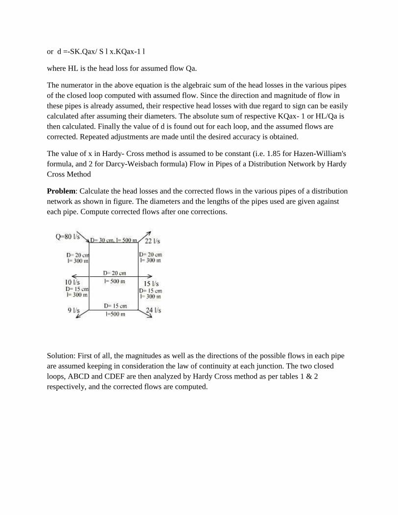
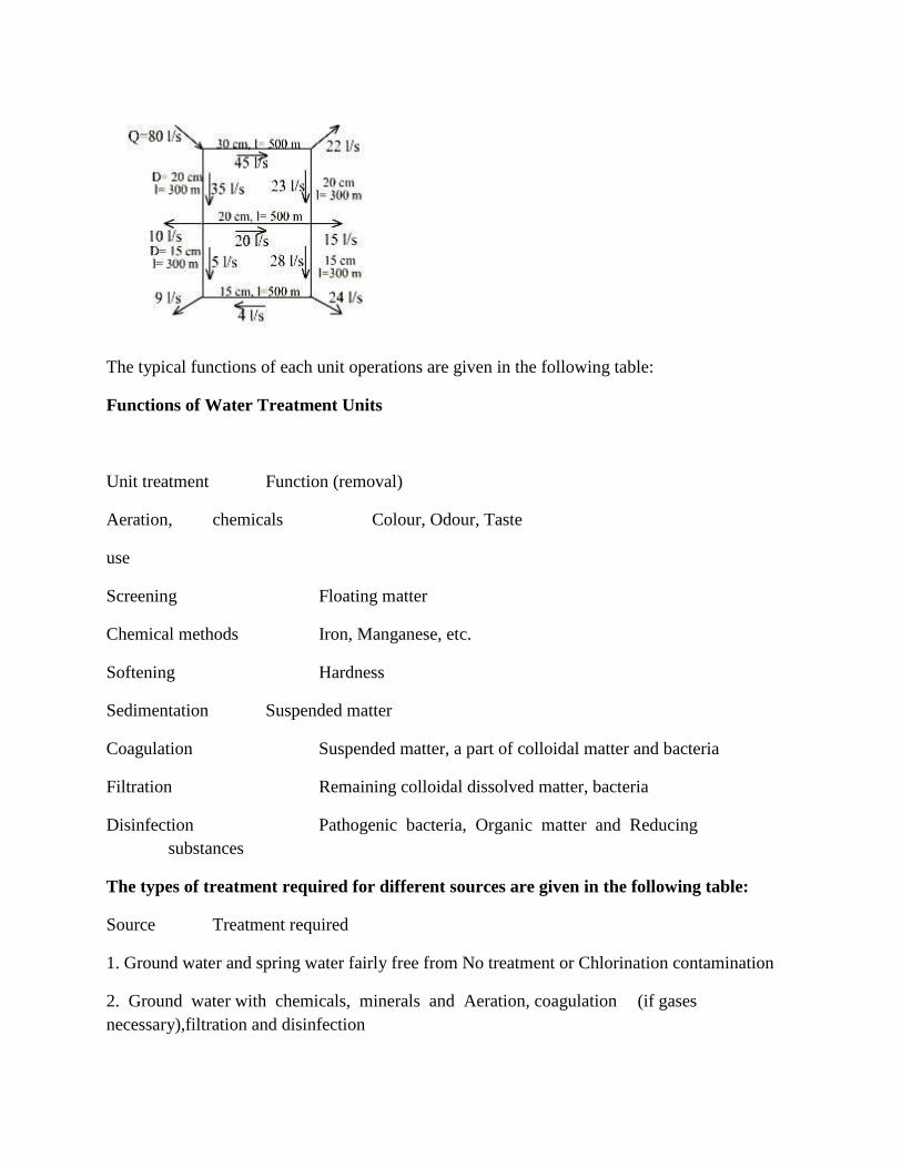
Problem: Calculate the head losses and the corrected flows in the various pipes of a distribution
network as shown in figure. The diameters and the lengths of the pipes used are given against
each pipe. Compute corrected flows after one corrections.
Solution: First of all, the magnitudes as well as the directions of the possible flows in each pipe
are assumed keeping in consideration the law of continuity at each junction. The two closed
loops, ABCD and CDEF are then analyzed by Hardy Cross method as per tables 1 & 2
respectively, and the corrected flows are computed.
The typical functions of each unit operations are given in the following table:
Functions of Water Treatment Units
Unit treatment Function (removal)
Aeration, chemicals Colour, Odour, Taste
use
Screening Floating matter
Chemical methods Iron, Manganese, etc.
Softening Hardness
Sedimentation Suspended matter
Coagulation Suspended matter, a part of colloidal matter and bacteria
Filtration Remaining colloidal dissolved matter, bacteria
Disinfection Pathogenic bacteria, Organic matter and Reducing
substances
The types of treatment required for different sources are given in the following table:
Source Treatment required
1. Ground water and spring water fairly free from No treatment or Chlorination contamination
2. Ground water with chemicals, minerals and Aeration, coagulation (if gases
necessary),filtration and disinfection
3.Lakes, surface water reservoirs with less Disinfection amount of pollution
4.Other surface waters such as rivers, canals Complete treatment and impounded reservoirs with
a considerable amount of pollution
Aeration
• Aeration removes odour and tastes due to volatile gases like hydrogen sulphide and due
to algae and related organisms.
• Aeration also oxidise iron and manganese, increases dissolved oxygen content in water,
removes CO2 and reduces corrosion and removes methane and other flammable gases.
• Principle of treatment underlines on the fact that volatile gases in water escape into
atmosphere from the air-water interface and atmospheric oxygen takes their place in water,
provided the water body can expose itself over a vast surface to the atmosphere. This process
continues until an equilibrium is reached depending on the partial pressure of each specific gas in
the atmosphere.
Types of Aerators
1. Gravity aerators
2. Fountain aerators
3. Diffused aerators
4. Mechanical aerators.
Gravity Aerators (Cascades): In gravity aerators, water is allowed to fall by gravity such that a
large area of water is exposed to atmosphere, sometimes aided by turbulence.
Fountain Aerators: These are also known as spray aerators with special nozzles to produce a
fine spray. Each nozzle is 2.5 to 4 cm diameter discharging about 18 to 36 l/h. Nozzle spacing
should be such that each m3 of water has aerator area of 0.03 to 0.09 m2 for one hour.Injection
or Diffused Aerators: It consists of a tank with perforated pipes, tubes or diffuser plates, fixed at
the bottom to release fine air bubbles from compressor unit. The tank depth is kept as 3 to 4 m
and tank width is within 1.5 times its depth. If depth is more, the diffusers must be placed at 3 to
4 m depth below water surface. Time of aeration is 10 to 30 min and 0.2 to 0.4 litres of air is
required for 1 litre of water.
Mechanical Aerators: Mixing paddles as in flocculation are used. Paddles may be either
submerged or at the surface.
Settling
Solid liquid separation process in which a suspension is separated into two phases –
• Clarified supernatant leaving the top of the sedimentation tank (overflow).
• Concentrated sludge leaving the bottom of the sedimentation tank (underflow).
Purpose of Settling
• To remove coarse dispersed phase.
• To remove coagulated and flocculated impurities.
• To remove precipitated impurities after chemical treatment.
• To settle the sludge (biomass) after activated sludge process / tricking filters.
Principle of Settling
• Suspended solids present in water having specific gravity greater than that of water tend
to settle down by gravity as soon as the turbulence is retarded by offering storage.
• Basin in which the flow is retarded is called settling tank.
• Theoretical average time for which the water is detained in the settling tank is called the
detention period.
Types of Settling
Type I: Discrete particle settling - Particles settle individually without interaction with
neighboring particles.
Type II: Flocculent Particles – Flocculation causes the particles to increase in mass and settle at a
faster rate.
Type III: Hindered or Zone settling –The mass of particles tends to settle as a unit with
individual particles remaining in fixed positions with respect to each other. Type IV:
Compression – The concentration of particles is so high that sedimentation can only occur
through compaction of the structure.
Type I Settling
• Size, shape and specific gravity of the particles do not change with time.
• Settling velocity remains constant.

If a particle is suspended in water, it initially has two forces acting upon it: force of gravity:
Fg=ρpgVp
Buoyant force quantified by Archimedes as: Fb=ρgVp
If the density of the particle differs from that of the water, a net force is exerted and the particle
is accelaratd in the direction of the force: Fnet=(ρp-ρ)gVp
This net force becomes the driving force.
Once the motion has been initiated, a third force is created due to viscous friction. This force,
called the drag force, is quantified by: Fd=CDAp ρv2/2
CD= drag coefficient.
Ap = projected area of the particle.
Because the drag force acts in the opposite direction to the driving force and increases as the
square of the velocity, accelaration occurs at a decreasing rate until a steady velocity is reached
at a point where the drag force equals the driving force:
(ρp- ρ )gVp = CDAp ρv2/2
• Settling basins may be either long rectangular or circular in plan. Long narrow
rectangular tanks with horizontal flow are generally preferred to the circular tanks with radial or
spiral flow.
Long Rectangular Settling Basin
• Long rectangular basins are hydraulically more stable, and flow control for large volumes
is easier with this configuration.
• A typical long rectangular tank have length ranging from 2 to 4 times their width. The
bottom is slightly sloped to facilitate sludge scraping. A slow moving mechanical sludge scraper
continuously pulls the settled material into a sludge hopper from where it is pumped out
periodically.
Drag of sedimentation tank
A long rectangular settling tank can be divided into four different functional zones:
Inlet zone: Region in which the flow is uniformly distributed over the cross section such that the
flow through settling zone follows horizontal path.
Settling zone: Settling occurs under quiescent conditions.
Outlet zone: Clarified effluent is collected and discharge through outlet weir. Sludge zone: For
collection of sludge below settling zone.
Inlet and Outlet Arrangement
Inlet devices: Inlets shall be designed to distribute the water equally and at uniform velocities. A
baffle should be constructed across the basin close to the inlet and should project several feet
below the water surface to dissipate inlet velocities and provide uniform flow;Outlet Devices:
Outlet weirs or submerged orifices shall be designed to maintain velocities suitable for settling in
the basin and to minimize short-circuiting. Weirs shall be adjustable, and at least equivalent in
length to the perimeter of the tank. However, peripheral weirs are not acceptable as they
tend to cause excessive short-circuiting.
Weir Overflow Rates
Large weir overflow rates result in excessive velocities at the outlet. These velocities extend
backward into the settling zone, causing particles and flocs to be drawn into the outlet. Weir
loadings are generally used upto 300 m3/d/m. It may be necessary to provide special inboard
weir designs as shown to lower the weir overflow rates.
Inboard Weir Arrangement to Increase Weir Length
Circular Basins
• Circular settling basins have the same functional zones as the long rectangular basin, but
the flow regime is different. When the flow enters at the center and is baffled to flow radially
towards the perimeter, the horizontal velocity of the water is continuously decreasing as the
distance from the center increases. Thus, the particle path in a circular basin is a parabola as
opposed to the straight line path in the long rectangular tank.
• Sludge removal mechanisms in circular tanks are simpler and require less maintenance.
Settling Operations
• Particles falling through the settling basin have two components of velocity:
1) Vertical component: vt= (ρp- ρ )gd2 18μ
2) Horizontal component: vh=Q/A
The path of the particle is given by the vector sum of horizontal velocity vh and vertical settling
velocity vt.
• Assume that a settling column is suspended in the flow of the settling zone and that the
column travels with the flow across the settling zone. Consider the particle in the batch analysis
for type-1 settling which was initially at the surface and settled through the depth of the column
Z0, in the time t0. If t0 also corresponds to the time required for the column to be carried
horizontally across the settling zone, then the particle will fall into the
sludge zone and be removed from the suspension at the point at which the column reaches the
end of the settling zone.
• All particles with vt>v0 will be removed from suspension at some point along the settling
zone.
• Now consider the particle with settling velocity < v0. If the initial depth of this particle
was such that Zp/vt=t0, this particle will also be removed. Therefore, the removal of suspended
particles passing through the settling zone will be in proportion to the ratio of the individual
settling velocities to the settling velocity v0.
• The time t0 corresponds to the retention time in the settling zone.
• t= V = LZ0W
• Q Q Also, t0= Z0v0
Therefore, Z0 = LZ0W and v0= Q 0 Q LW or v0= Q AS
Thus, the depth of the basin is not a factor in determining the size particle that can be removed
completely in the settling zone. The determining factor is the quantity Q/As, which has the units
of velocity and is referred to as the overflow rate q0. This overflow rate is the design factor for
settling basins and corresponds to the terminal setting velocity of the particle that is 100%
removed.
Design Details
1. Detention period: for plain sedimentation: 3 to 4 h, and for coagulated sedimentation: 2 to
2.5 h.
2. Velocity of flow: Not greater than 30 cm/min (horizontal flow).
3. Tank dimensions: L:B = 3 to 5:1. Generally L= 30 m (common) maximum 100 m.
Breadth= 6 m to 10 m. Circular: Diameter not greater than 60 m. generally 20 to 40 m.
4. Depth 2.5 to 5.0 m (3 m).
5. Surface Overflow Rate: For plain sedimentation 12000 to 18000 L/d/m2 tank area; for
thoroughly flocculated water 24000 to 30000 L/d/m2 tank area.
6. Slopes: Rectangular 1% towards inlet and circular 8%.
Sedimentation Tank Design
Problem: Design a rectangular sedimentation tank to treat 2.4 million litres of raw water per
day. The detention period may be assumed to be 3 hours.
Solution: Raw water flow per day is 2.4 x 10⁶ l. Detention period is 3h. Volume of tank = Flow
x Detention period = 2.4 x 103 x 3/24 = 300 m3 Assume depth of tank = 3.0 m.
Surface area = 300/3 = 100 m2 L/B = 3 (assumed). L = 3B.
3B2 = 100 m2 i.e. B = 5.8 m L = 3B = 5.8 X 3 = 17.4 m
Hence surface loading (Overflow rate) = 2.4 x 106 = 24,000 l/d/m2 < 40,000 l/d/m2 (OK) 100
Flocculation
Flocculation is stimulation by mechanical means to agglomerate destabilised particles into
compact, fast settleable particles (or flocs). Flocculation or gentle agitation results from velocity
differences or gradients in the coagulated water, which causes the fine moving, destabilized
particles to come into contact and become large, readily settleable flocs. It is a common practice
to provide an initial rapid (or) flash mix for the dispersal of the coagulant or other chemicals into
the water. Slow mixing is then done, during which the growth of the floc takes place.
Rapid or Flash mixing is the process by which a coagulant is rapidly and uniformly dispersed
through the mass of water. This process usually occurs in a small basin immediately preceding or
at the head of the coagulation basin. Generally, the detention period is 30 to 60 seconds and the
head loss is 20 to 60 cms of water. Here colloids are destabilised and the nucleus for the floc is
formed.Slow mixing brings the contacts between the finely divided destabilised matter formed
during rapid mixing.
Perikinetic and Orthokinetic Flocculation
The flocculation process can be broadly classified into two types, perikinetic and orthokinetic.
Perikinetic flocculation refers to flocculation (contact or collisions of colloidal particles) due to
Brownian motion of colloidal particles. The random motion of colloidal particles results from
their rapid and random bombardment by the molecules of the fluid.Orthokinetic flocculation
refers to contacts or collisions of colloidal particles resulting from bulk fluid motion, such as
stirring. In systems of stirring, the velocity of the fluid varies both spatially (from point to point)
and temporally (from time to time). The spatial changes in velocity are identified by a velocity
gradient, G. G is estimated as G=(P/μV)1/2, where P=Power, V=channel volume, and μ=
Absolute viscosity.
Mechanism of Flocculation
Gravitational flocculation: Baffle type mixing basins are examples of gravitational flocculation.
Water flows by gravity and baffles are provided in the basins which induce the required velocity
gradients for achieving floc formation.Mechanical flocculation: Mechanical flocculator consists
of revolving paddles with horizontal or vertical shafts or paddles suspended from horizontal
oscillating beams, moving up and down.
Coagulation in Water Treatment
• Salts of Al(III) and Fe(III) are commonly used as coagulants in water and wastewater
treatment.
• When a salt of Al(III) and Fe(III) is added to water, it dissociates to yield trivalent ions,
which hydrate to form aquometal complexes Al(H2O)63+ and Fe(H2O)63+. These complexes
then pass through a series of hydrolytic reactions in which H2O molecules in the hydration shell
are replaced by OH- ions to form a variety of soluble species such as Al(OH)2+ and Al(OH)2+.
These products are quite effective as coagulants as they adsorb very strongly onto the surface of
most negative colloids.
Jar Test
The jar test is a common laboratory procedure used to determine the optimum operating
conditions for water or wastewater treatment. This method allows adjustments in pH, variations
in coagulant or polymer dose, alternating mixing speeds, or testing of different coagulant or
polymer types, on a small scale in order to predict the functioning of a large scale treatment
operation.
Jar Testing Apparatus
The jar testing apparatus consists of six paddles which stir the contents of six 1 liter containers.
One container acts as a control while the operating conditions can be varied among the
remaining five containers. A rpm gage at the top-center of the device allows for the uniform
control of the mixing speed in all of the containers.
Jar Test Procedure
• The jar test procedures involves the following steps:
• Fill the jar testing apparatus containers with sample water. One container will be used as
a control while the other 5 containers can be adjusted depending on what conditions are being
tested. For example, the pH of the jars can be adjusted or variations of coagulant dosages can be
added to determine optimum operating conditions.
• Add the coagulant to each container and stir at approximately 100 rpm for 1 minute. The
rapid mix stage helps to disperse the coagulant throughout each container.
• Turn off the mixers and allow the containers to settle for 30 to 45 minutes. Then measure
the final turbidity in each container.
• Reduce the stirring speed to 25 to 35 rpm and continue mixing for 15 to 20 minutes. This
slower mixing speed helps promote floc formation by enhancing particle collisions which lead to
larger flocs.
• Residual turbidity vs. coagulant dose is then plotted and optimal conditions are
determined. The values that are obtained through the experiment are correlated and adjusted in
order to account for the actual treatment system.
Filtration
• The resultant water after sedimentation will not be pure, and may contain some very fine
suspended particles and bacteria in it. To remove or to reduce the remaining impurities still
further, the water is filtered through the beds of fine granular material, such as sand, etc. The
process of passing the water through the beds of such granular materials is known as Filtration.
Filtration Mechanisms
• There are four basic filtration mechanisms:
• SEDIMENTATION : The mechanism of sedimentation is due to force of gravity and the
associate settling velocity of the particle, which causes it to cross the streamlines and reach the
collector.
• INTERCEPTION : Interception of particles is common for large particles. If a large
enough particle follows the streamline, that lies very close to the media surface it will hit the
media grain and be captured.
• BROWNIAN DIFFUSION : Diffusion towards media granules occurs for very small
particles, such as viruses. Particles move randomly about within the fluid, due to thermal
gradients. This mechanism is only important for particles with diameters < 1 micron. INERTIA :
Attachment by inertia occurs when larger particles move fast enough to travel off their
streamlines and bump into media grains.
Filter Materials
Sand: Sand, either fine or coarse, is generally used as filter media. The size of the sand is
measured and expressed by the term called effective size. The effective size, i.e. D10 may be
defined as the size of the sieve in mm through which ten percent of the sample of sand by weight
will pass. The uniformity in size or degree of variations in sizes of particles is measured and
expressed by the term called uniformity coefficient. The uniformity coefficient, i.e.(D60/D10)
may be defined as the ratio of the sieve size in mm through which 60 percent of the sample of
sand will pass, to the effective size of the sand.
Gravel: The layers of sand may be supported on gravel, which permits the filtered water to move
freely to the under drains, and allows the wash water to move uniformly upwards.
Other materials: Instead of using sand, sometimes, anthrafilt is used as filter media. Anthrafilt is
made from anthracite, which is a type of coal-stone that burns without smoke or flames. It is
cheaper and has been able to give a high rate of filtration.
Types of Filter
Slow sand filter: They consist of fine sand, supported by gravel. They capture particles near the
surface of the bed and are usually cleaned by scraping away the top layer of sand that contains
the particles.
Rapid-sand filter: They consist of larger sand grains supported by gravel and capture particles
throughout the bed. They are cleaned by backwashing water through the bed to 'lift out' the
particles.
Multimedia filters: They consist of two or more layers of different granular materials, with
different densities. Usually, anthracite coal, sand, and gravel are used. The different layers
combined may provide more versatile collection than a single sand layer. Because of the
differences in densities, the layers stay neatly separated, even after backwashing.
Principles of Slow Sand Filtration
• In a slow sand filter impurities in the water are removed by a combination of processes:
sedimentation, straining, adsorption, and chemical and bacteriological action.
• During the first few days, water is purified mainly by mechanical and physical-chemical
processes. The resulting accumulation of sediment and organic matter forms a thin layer on the
sand surface, which remains permeable and retains particles even smaller than the spaces
between the sand grains.
• As this layer (referred to as “Schmutzdecke”) develops, it becomes living quarters of vast
numbers of micro-organisms which break down organicmaterial retained from the water,
converting it into water, carbon dioxide and other oxides.

• Most impurities, including bacteria and viruses, are removed from the raw water as it
passes through the filter skin and the layer of filter bed sand just below. The purification
mechanisms extend from the filter skin to approx. 0.3-0.4 m below the surface of the filter bed,
gradually decreasing in activity at lower levels as the water becomes purified and contains less
organic material.
• When the micro-organisms become well established, the filter will work efficiently and
produce high quality effluent which is virtually free of disease carrying organisms and
biodegradable organic matter.
• They are suitable for treating waters with low colors, low turbidities and low bacterial
contents.
Sand Filters vs. Rapid Sand Filters
• Base material: In SSF it varies from 3 to 65 mm in size and 30 to 75 cm in depth while in
RSF it varies from 3 to 40 mm in size and its depth is slightly more, i.e. about 60 to 90 cm.
• Filter sand: In SSF the effective size ranges between 0.2 to 0.4 mm and uniformity
coefficient between 1.8 to 2.5 or 3.0. In RSF the effective size ranges between 0.35 to 0.55 and
uniformity coefficient between 1.2 to 1.8.
• Rate of filtration: In SSF it is small, such as 100 to 200 L/h/sq.m. of filter area while in
RSF it is large, such as 3000 to 6000 L/h/sq.m. of filter area.
• Flexibility: SSF are not flexible for meeting variation in demand whereas RSF are quite
flexible for meeting reasonable variations in demand.
• Post treatment required: Almost pure water is obtained from SSF. However, water may
be disinfected slightly to make it completely safe. Disinfection is a must after RSF.
• Method of cleaning: Scrapping and removing of the top 1.5 to 3 cm thick layer is done to
clean SSF. To clean RSF, sand is agitated and backwashed with or without compressed air.
• Loss of head: In case of SSF approx. 10 cm is the initial loss, and 0.8 to 1.2m is the final
limit when cleaning is required. For RSF 0.3m is the initial loss, and 2.5 to 3.5m is the final limit
when cleaning is required.
Clean Water Headloss
Several equations have been developed to describe the flow of clean water through a porous
medium. Carman-Kozeny equation used to calculate head loss is as follows:
h= f (1-n)Lvs2 Φ n3dg
f =150 (1-n) + 1.75 Ng
where, h = headloss, m f = friction factor n = porosity
Φ = particle shape factor (1.0 for spheres, 0.82 for rounded sand, 0.75 for average sand,0.73 for
crushed coal and angular sand)
L = depth of filter bed or layer, m d = grain size diameter, m vs = superficial (approach) filtration
velocity, m/s g = accelaration due to gravity, 9.81 m/s2
p = fraction of particles ( based on mass) within adjacent sieve sizes dg = geometric mean
diameter between sieve sizes d1 and d2
Ng = Reynolds number μ = viscosity, N-s/m2
Backwashing of Rapid Sand Filter
• For a filter to operate efficiently, it must be cleaned before the next filter run. If the water
applied to a filter is of very good quality, the filter runs can be very long. Some filters can
operate longer than one week before needing to be backwashed. However, this is not
recommended as long filter runs can cause the filter media to pack down so that it is difficult to
expand the bed during the backwash.
• Treated water from storage is used for the backwash cycle. This treated water is generally
taken from elevated storage tanks or pumped in from the clear well.
• The filter backwash rate has to be great enough to expand and agitate the filter media and
suspend the floc in the water for removal. However, if the filter backwash rate is too high, media
will be washed from the filter into the troughs and out of the filter.
When is Backwashing Needed
The filter should be backwashed when the following conditions have been met:
• The head loss is so high that the filter no longer produces water at the desired rate; and/or
Floc starts to break through the filter and the turbidity in the filter effluent increases; and/or A
filter run reaches a given hour of operation.
Operational Troubles in Rapid Gravity Filters
Air Binding:
• When the filter is newly commissioned, the loss of head of water percolating through the
filter is generally very small. However, the loss of head goes on increasing as more and more
impurities get trapped into it.
• A stage is finally reached when the frictional resistance offered by the filter media
exceeds the static head of water above the and bed. Most of this resistance is offered by the top
10 to 15 cm sand layer. The bottom sand acts like a vacuum, and water is sucked through the
filter media rather than getting filtered through it.
• The negative pressure so developed, tends to release the dissolved air and other gases
present in water. The formation of bubbles takes place which stick to the sand grains. This
phenomenon is known as Air Binding as the air binds the filter and stops its functioning.
• To avoid such troubles, the filters are cleaned as soon as the head loss exceeds the
optimum allowable value.
Formation of Mud Balls:
• The mud from the atmosphere usually accumulates on the sand surface to form a dense
mat. During inadequate washing this mud may sink down into the sand bed and stick to the sand
grains and other arrested impurities, thereby forming mud balls.
Cracking of Filters:
• The fine sand contained in the top layers of the filter bed shrinks and causes the
development of shrinkage cracks in the sand bed. With the use of filter, the loss of head and,
therefore, pressure on thesand bed goes on increasing, which further goes on widening these
cracks.
Remedial Measures to Prevent Cracking of Filters and Formation of Mud Balls
• Breaking the top fine mud layer with rakes and washing off the particles.
• Washing the filter with a solution of caustic soda.
• Removing, cleaning and replacing the damaged filter sand.
Standard design practice of Rapid Sand filter: Maximum length of lateral = not less than 60 times
its diameter. Spacing of holes = 6 mm holes at 7.5 cm c/c or 13 at 15 c/c. C.S area of lateral = not
less than 2 times area of perforations. C.S area of manifold = 2 times total area of laterals.
Maximum loss of head = 2 to 5 m. Spacing of laterals = 15 to 30 cm c/c. Pressure of wash water
at perforations = not greater than 1.05 kg/cm2. Velocity of flow in lateral = 2 m/s. Velocity of
flow in manifold = 2.25 m/s. Velocity of flow in manifold for washwater= 1.8 to 2.5 m/s.
Velocity of rising washwater= 0.5 to 1.0 m/min. Amount of washwater = 0.2 to 0.4% of total
filtered water. Time of backwashing = 10 to 15 min. Head of water over the filter = 1.5 to 2.5 m.
Free board = 60 cm. Bottom slope = 1 to 60 towards manifold.
Q = (1.71 x b x h3/2)
where Q is in m3/s, b is in m, h is in m. L:B = 1.25 to 1.33:1 .
Rapid Sand Filter Design
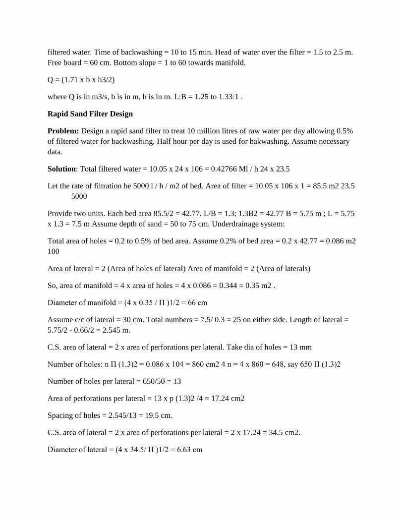
Problem: Design a rapid sand filter to treat 10 million litres of raw water per day allowing 0.5%
of filtered water for backwashing. Half hour per day is used for bakwashing. Assume necessary
data.
Solution: Total filtered water = 10.05 x 24 x 106 = 0.42766 Ml / h 24 x 23.5
Let the rate of filtration be 5000 l / h / m2 of bed. Area of filter = 10.05 x 106 x 1 = 85.5 m2 23.5
5000
Provide two units. Each bed area 85.5/2 = 42.77. L/B = 1.3; 1.3B2 = 42.77 B = 5.75 m ; L = 5.75
x 1.3 = 7.5 m Assume depth of sand = 50 to 75 cm. Underdrainage system:
Total area of holes = 0.2 to 0.5% of bed area. Assume 0.2% of bed area = 0.2 x 42.77 = 0.086 m2
100
Area of lateral = 2 (Area of holes of lateral) Area of manifold = 2 (Area of laterals)
So, area of manifold = 4 x area of holes = 4 x 0.086 = 0.344 = 0.35 m2 .
Diameter of manifold = (4 x 0.35 / П )1/2 = 66 cm
Assume c/c of lateral = 30 cm. Total numbers = 7.5/ 0.3 = 25 on either side. Length of lateral =
5.75/2 - 0.66/2 = 2.545 m.
C.S. area of lateral = 2 x area of perforations per lateral. Take dia of holes = 13 mm
Number of holes: n П (1.3)2 = 0.086 x 104 = 860 cm2 4 n = 4 x 860 = 648, say 650 П (1.3)2
Number of holes per lateral = 650/50 = 13
Area of perforations per lateral = 13 x p (1.3)2 /4 = 17.24 cm2
Spacing of holes = 2.545/13 = 19.5 cm.
C.S. area of lateral = 2 x area of perforations per lateral = 2 x 17.24 = 34.5 cm2.
Diameter of lateral = (4 x 34.5/ П )1/2 = 6.63 cm
Check: Length of lateral < 60 d = 60 x 6.63 = 3.98 m. l = 2.545 m (Hence acceptable). Rising
washwater velocity in bed = 50 cm/min.
Washwater discharge per bed = (0.5/60) x 5.75 x 7.5 = 0.36 m3/s.
Velocity of flow through lateral = 0.36 = 0.36 x 10 4 = 2.08 m/s (ok)
Total lateral area 50 x 34.5
Manifold velocity = 0.36 = 1.04 m/s < 2.25 m/s (ok)
0.345
Washwater gutter
Discharge of washwater per bed = 0.36 m3/s. Size of bed = 7.5 x 5.75 m. Assume 3 troughs
running lengthwise at 5.75/3 = 1.9 m c/c.
Discharge of each trough = Q/3 = 0.36/3 = 0.12 m3/s. Q =1.71 x b x h3/2
Assume b =0.3 m h3/2 = 0.12 = 0.234 1.71 x 0.3
h = 0.378 m = 37.8 cm = 40 cm = 40 + (free board) 5 cm = 45 cm; slope 1 in 40 Clear water
reservoir for backwashing
For 4 h filter capacity, Capacity of tank = 4 x 5000 x 7.5 x 5.75 x 2 = 1725 m3 1000
Assume depth d = 5 m. Surface area = 1725/5 = 345 m2 L/B = 2; 2B2 = 345; B = 13 m & L = 26
m.
Dia of inlet pipe coming from two filter = 50 cm.
Velocity <0.6 m/s. Diameter of washwater pipe to overhead tank = 67.5 cm. Air compressor unit
= 1000 l of air/ min/ m2 bed area.
For 5 min, air required = 1000 x 5 x 7.5 x 5.77 x 2 = 4.32 m3 of air.
Disinfection
The filtered water may normally contain some harmful disease producing bacteria in it. These
bacteria must be killed in order to make the water safe for drinking. The process of killing these
bacteria is known as Disinfection or Sterilization.
Disinfection Kinetics
When a single unit of microorganisms is exposed to a single unit of disinfectant, the reduction in
microorganisms follows a first-order reaction.
dN/dt=-kN N=N0e-kt
This equation is known as Chick‟s Law:-
N = number of microorganism (N0 is initial number) k = disinfection constant
t = contact time
Methods of Disinfection
1.Boiling: The bacteria present in water can be destroyed by boiling it for a long time. However
it is not practically possible to boil huge amounts of water. Moreover it cannot take care of future
possible contaminations.
2.Treatment with Excess Lime: Lime is used in water treatment plant for softening. But if excess
lime is added to the water, it can in addition, kill the bacteria also. Lime when added raises the
pH value o water making it extremely alkaline. This extreme alkalinity has been found
detrimental to the survival of bacteria. This method needs the removal of excess lime from the
water before it can be supplied to the general public. Treatment like
recarbonation for lime removal should be used after disinfection.
3.Treament with Ozone: Ozone readily breaks down into normal oxygen, and releases nascent
oxygen. The nascent oxygen is a powerful oxidising agent and removes the organic matter as
well as the bacteria from the water.
4.Chlorination: The germicidal action of chlorine is explained by the recent theory of Enzymatic
hypothesis, according to which the chlorine enters the cell walls of bacteria and kill the enzymes
which are essential for the metabolic processes of living organisms.
Chlorine Chemistry
Chlorine is added to the water supply in two ways. It is most often added as a gas, Cl2(g).
However, it also can be added as a salt, such as sodium hypochlorite (NaOCl) or bleach.
Chlorine gas dissolves in water following Henry's Law.
Free Chlorine, Chloramine, and Ammonia Nitrogen Reactions
Chlorine Demand
Free chlorine and chloramines readily react with a variety compounds, including organic
substances, and inorganic substances like iron and manganese. The stoichiometry of chlorine
reactions with organics can be represented as shown below:
HOCl:1/10C5H7O2N + HOCl 4/10CO2 + 1/10HCO3- + 1/10NH4++ H+ + Cl- +
1/10H2O
OCl-:
1/10C5H7O2N + OCl- 4/10CO2 + 1/10HCO3- + 1/10NH4++ Cl- + 1/10H2O
NH2Cl:
1/10C5H7O2N + NH2Cl + 9/10H2O 4/10CO2 + 1/10HCO3- + 11/10NH4++ Cl-
Chlorine demand can be increased by oxidation reactions with inorganics, such as reduced iron
at corrosion sites at the pipe wall. Possible reactions with all forms of chlorine and iron are as
follows:
Treatment Plant Layout and Siting
Plant layout is the arrangement of designed treatment units on the selected site. Siting is the
selection of site for treatment plant based on features as character, topography, and shoreline.
Site development should take the advantage of the existing site topography. The following
principles are important to consider:
1. A site on a side-hill can facilitate gravity flow that will reduce pumping requirements and
locate normal sequence of units without excessive excavation or fill.
2. When landscaping is utilized it should reflect the character of the surrounding area. Site
development should alter existing naturally stabilized site contours and drainage as little as
possible.
3. The developed site should be compatible with the existing land uses and the
comprehensive development plan.