Embed Size (px)
Citation preview

1
Unit-II
Method Study
Introduction to Work Study
Frederick Winslow Taylor (1856-1915) and Frank B. Gilberth (1869-1924) are
originators of work study (Time & Motion study). Time and motion study were
developed separately. Taylor invented time study whereas Gilberth invented motion
study. Work study is a technique which deals with the problems:
As to how should a job be done/completed, and
How much time a job should take for completion.
Objective of work study is to determine the best method of performing each operation
and to eliminate wastage so that production increases with less human fatigue. The work
study is also used in determining the standard time that a qualified worker should take to
perform the operation when working at a normal pace.
Method Study (Motion Study)
Historical Background
In this field, pioneering work was done by Frank B. Gilberth. In 1885, at the age of 17,
was a junior apprentice bricklayer at Whidden and Co. He soon discovered that if proper
coordination between the mason and labor is maintained then the speed of bricklaying
increases many times. During 1910, lot of work was done by him with name of “motion
study”. In 1917, he suggested the adoption of “Motion Study”. Later on, the scope of
motion study was enlarged and it was named as “Method Study”.
Definitions
According to Frank B. Gilberth, motion study is “the science of eliminating wastefulness
as well as unnecessary, ill-directed and in-efficient motions”. Frank B. Gilberth was only
interested in motion economy by eliminating repetitive motions during the performance
of a job and determining the best and convenient method of performing a job under the
existing conditions so that a worker can consistently work for a longer time with
maximum comfort and safety.

2
Method study is the systematic recording and critical examination of existing and
proposed ways of doing work as a means of developing and applying easier and more
effective methods and reducing costs.
Objectives of Method Study
Some important objectives of method study are:
i. The improvement of processes and procedures.
ii. To eliminate wastage of time and labor.
iii. Prevention of fatigue and breaking the monotony (dullness) of repetitive work.
iv. To find the best way of doing a job.
v. To improve the design of workplace layout.
vi. To train the individual worker in its practice as per standardized method.
vii. Reduction of waste and scrap, improvement in quality.
viii. Effective material handling.
ix. Greater job satisfaction, higher standards of safety and health.
x. Improvement in the flow of production and processes.
Need of Method Study
i. Method/motion study is a means of enhancing the production efficiency
(productivity) of the firm by elimination of waste and unnecessary operations.
ii. It is a technique to identify non-value adding operations by investigation of all the
factors affecting the job.
iii. It is the only accurate and systematic procedure oriented techniques to establish
time standards.
iv. It is going to contribute to the profit as the savings will start immediately and
continue throughout the life of the product.
v. It has got universal applications such as in:
a. Industries
b. Marketing, sales and distributions
c. Material handling
d. Design
e. Building and other constructions
f. Hospitals

3
g. Transport etc.
Pre-requisites of Conducting a Method Study
The workers must be taken into confidence
They should not feel that they are kept in dark
Good human relationship
Good working conditions
Role of Work Study in Improving Productivity
Both the aspects of work study i.e. method study and work measurement tend to raise the
productive efficiency of the workers and hence, the productivity of an industry.
Work Study
Method Study Work Measurement
Higher Productivity
Method study increases productivity because it:
i. Cuts down the work content of the job by eliminating unnecessary and un-
useful/unproductive motions
ii. Develops the best method of doing a job which imparts least fatigue to the
operators
iii. Results more effective use of machinery, man-power and material.
iv. Improves design of work place layout
v. Improves the better working conditions and relations
Work measurement increases productivity because it:
i. Reduces ineffective time
ii. Suggest rest, pauses and other allowances which results the operators in a position
to maintain their productive efficiency
iii. Provide a sound basis for giving incentives to the workers to produce more
iv. Calculates the correct man-power required for doing a job, and
Results in more effective use
of material, manpower, plant
and equipment
Making possible improved planning
and control. Making as a basis for
sound incentive schemes

4
v. Aids in accurate production planning
Hence, if correct and systematic work study is done in any organization than higher
productivity is natural.
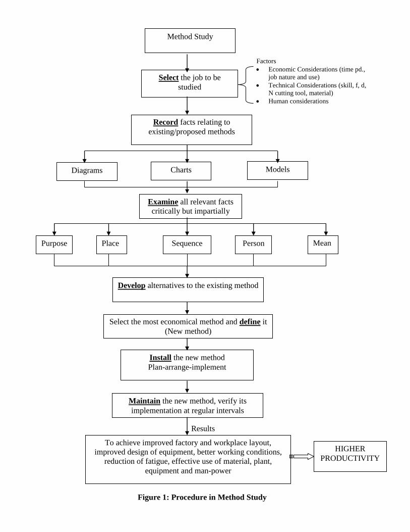
Procedure of conducting Method Study
Method study procedure consists of the following steps (See Figure 1):
1. Select
2. Record
3. Critically examine
4. Develop the best method
5. Define
6. Install
7. Maintain
Recording Techniques
The recording techniques are designed to simplify and standardize the recording work.
The purpose of recording can be summarized as follows:
i. To enable the process to be clearly understood
ii. To present the existing facts for analysis
iii. To submit the proposals to the management in a form which can be easily
understood
iv. To guide supervisors and operators regarding detailed operating instructions
In order to make presentation of facts clearly, without any difficulty and to enable to
grasp them quickly and clearly, it is better to use symbols instead of written description.
The following are the basic types of diagrammatic aids used for recording and
communicating a work method. These are:
i. Process Charts
ii. Diagrams
iii. Templates and Models
5
Results
Recor
Method Study
Select the job to be
studied
Record facts relating to
existing/proposed methods
Examine all relevant facts
critically but impartially
Diagrams Charts Models
Place Person Sequence Mean
s Purpose
Develop alternatives to the existing method
Select the most economical method and define it
(New method)
Install the new method
Plan-arrange-implement
Maintain the new method, verify its
implementation at regular intervals
To achieve improved factory and workplace layout,
improved design of equipment, better working conditions,
reduction of fatigue, effective use of material, plant,
equipment and man-power
HIGHER
PRODUCTIVITY
Figure 1: Procedure in Method Study
Factors
Economic Considerations (time pd.,
job nature and use)
Technical Considerations (skill, f, d,
N cutting tool, material)
Human considerations

6
Process Charts
Definition
A chart representing a process may be called a process chart and is used for recording a
process in a compact manner, as a means of better understanding it and improving it. The
chart represents graphically or diagrammatically the sequence of operations or events that
occur during the performance of a task or a process. The chart uses various sets of
symbols and aids for better understanding and examining the process.
Process Chart Types
Process charts are of the following types:
i. Outline Process Chart
ii. Flow Process Chart
iii. Two-hand Process Chart
iv. Multiple Activity Chart
Process Chart Symbols
In 1947 American Society of Mechanical Engineers (ASME) established five (05)
standard symbols which are universally accepted to prepare charts. The various symbols
used in process charts are as follows (Table 1):
Table 1: Description of Process Chart Symbols
S.No. Event/Activity Symbol Operation/Description
1. Operation Operation represents an action i.e.
change in the location or condition
of a product. Example: cutting of a
bar on a power hacksaw; turning;
filling; joining; assembling etc.
2. Storage
It represents a stage when a finished
good or raw material awaits an
action. Example: Nut is to be
assembled with bolt, milling cutter
lying in tool store; finished goods
ready for sale etc.
3. Inspection
It is an act of checking for
correctness of the quantity or quality
of the item. Example: checking the
hardness of a MS piece; checking
the weight of a packed tin etc.

7
4. Transport
It indicated the movement of an
item from one location to another.
Example: Oil flowing through a
penstock; MS bar being sent from
store to M/c shop; gear blank from
lathe to milling M/c etc.
5. Delay or Temporary
Storage
Delay occurs when something stops
the process and a product waits for
the next event. Example: Power
failure; traffic jam; machine
breakdown etc.
6. Operation-cum-
Transportation
Example: Article are being painted
as they are transported by belt
conveyor.
7. Inspection-cum-
Operation
Example: Powder milk tin is being
weighed (inspection) as it is filled.
Both the events occur
simultaneously.
Flow Process Chart
A flow process chart is detailed version of outline process chart and it records all the
events. It is defined as a graphical representation of all events, operations, inspections,
transportations, delays and storages occurring during a process by means of process
symbols. There are three types of flow process charts, namely:
i. Man-type flow process chart
ii. Material-type flow process chart
iii. Equipment-type flow process chart
Man-type-records activity of worker/operator (See Figure 2(a))
Material-type-records what happens to the material (See Figure 2(b))
Equipment-type-records the manner in which the equipment is used (See Figure 2(c))
Exercise 1: Task: Riveting the two MS plates by means of rivets (Butt Joint).
Figure 2(a): Man-type Flow Process Chart

8
Summary
Events No. Time Distance
(in meters)
7
1
1
2 30
1
Total 12 30m
Exercise 2: Task: Making the casting ready for machining.
Chart begins- Casting lying in foundry
Chart ends- Casting ready for machining
Activity Operations Distance
moved
(in meters)
Time
(in minutes)
Remarks
(if any)
Casting lying in the
store
Moved to gas cutting
M/c
10 3 By trolley
Wait cutting M/c
being set
5
Risers cut/out
20
Wait for trolley
10
Moved to inspection
department
6 2 By trolley
Inspection before
M/cing
15
Moved to M/c shop
10 3 By trolley
Figure 2(b): Flow Process Chart of Material type

9
Summary
Events Number Time Distance
1 20
1
2 15
3 8 26
1
Total 8
Exercise 3: Task: Flow process chart of equipment type- Watering the garden using hose
pipe.
Equipment: Hose-pipe
Job: Watering the garden
Chart begins: Hose lying in the cupboard Summary:
Chart ends: Hose lying in the cupboard
Pipe lying in cupboard
Lifted
Removed from tap
To tap Fixed to tap Used for watering
3m To cupboard
1m
Re-placed in cupboard
1
1
1 2 3 4
2
5 2 Lying in
cupboard
Figure 2(c): Flow Process Chart of Equipment type
Events No. Time
(in mints.)
Distance
(in m)
5 - -
2 - -
2 - 4

10
Exercises:
Writing a letter using a shorthand typist.
Polishing the specimen and looking for the microstructure.
Issuing of book (any type) from book bank.
Draw a flow process chart (man type) performing an operation on UTS M/c.
Two-hand Process Chart
A two hand process chart is a process chart in which the activities of a worker’s left hand
and right hand along with limbs are recorded while he is performing an operation at any
work station. The activities of two hands and limbs can be analyzed by providing a time
scale on the chart and repetitive, unnecessary, uneconomical activities can be neglected.
Here meaning of symbols is slightly changed as:
-----When hand is idle not performing any activity,
----- Hold---Hand holds the object so that other hand to some activities on that object,
---- Movement of hand here & their, and
------- Operation—grasps, release, assemble etc.
This chart is generally used for analysis of short duration and assembly work.
Exercise 1: Assembly of two washers and nut to bolt (See Figure 3(a)).
Chart begins: Hand empty, material in boxes.
Chart ends: Completed assembly placed in other box.
Method: Present/Proposed
Left Hand
Description
Symbol
(LH)
Time
(Minutes)
Symbol
(RH)
Right Hand
Description
To bolt 0.5m 0.5m To first washer
Pick up bolt Pick up washer
To position 0.5m 0.5m To position
Hold Assemble to bolt
Hold 0.5m To second washer
Hold Pick up washer
Hold 0.5m To position
Hold Assemble to bolt
Hold 0.5m To nut
Hold Pick up nut
Hold 0.5m To position
To box 0.5m Assemble to bolt
Put in the box Idle
Figure 3(a): Left Hand and Right Hand Chart
For Home
Assignment

11
Summary:
Symbol Number Time Distance Symbol Number Time Distance
2 6
3 1.5m 6 3.0m
- 1
9 -
Exercise 2: Assembly of nut and bolt (See Figure 3(b)).
LH Symbol
RH LH RH
Pick up bolt Idle
Hold Pick up nut
Hold To left hand
Hold Assemble (screw up)
To box Idle
Figure 3(b): Left Hand and Right Hand Chart
Summary:
LH Nos. RH Nos.
1 2
3 -
1 1
- 2
Exercises:
1. Draw a left hand and right hand chart for signing a letter and give detailed
summary.
2. Draw a LH and RH chart for opening a bottle of coke.
3. Draw a RH and LH chart for changing the battery of wall cloak.
Multi-activity Chart
It is a chart where a number of workers work in a group or an individual operator handles
two or more machines or equipments, their activities are recorded on a common time
scale and thus, shows inter-relations between them.
They may be of the following type:
i. Man-machine chart---one man handling one job or one machine.
ii. Man-multi machine chart---one man handling number of machines.
iii. Multi-man chart---a group is doing one job.
For Home
Assignment

12
iv. Multi-man-machine chart---a number of persons working on a computer system.
Exercise 1: An operator working on two machines (See Figure 4(a)).
Time
(in minutes)
Man
(Operator)
Machine-1 Machine-2
10 Setting M/c-1
M/c being set Idle
5 Setting M/c-2
M/c-1 working
M/c is being set
10 Idle
M/c-2 working
5 Setting M/c-2 M/c-2 being set
5 Idle M/c-2 working
5 Setting M/c-1 M/c-1 being set
10 Setting M/c-2
M/c-1 working
M/c-2 being set
5 Idle Working
Figure 4(a): Multi Activity Chart of one Man Working on Two Machine
Summary:
Working Time
(minutes)
Idle Time
(minutes)
Operator 35 20
Machine-1 40 Nil
Machine-2 25 10
Exercise 2: Job-Making a slot on the casting (See Figure 4(b)).
Time
(in minutes)
Man Machine Time
(in minutes)
0.2
Removes finished casting
cleans with compressed air
Idle 0.2
0.4
Cleans machine with
compressed air
Idle 0.4
0.6
Locate a new casting in a
fixture, start machine and
auto feed
Idle 0.6
0.8
Break sharp edges with file,
clean with compressed air
Cutting slot 0.8
1.0 Gauges depth of slot on
surface plate
Cutting slot 1.0
1.2 Places casting in a box, pick
up new casting
Idle 1.2
1.4 Idle Cutting slot 1.4
Figure 4(b): Man-machine Chart
13
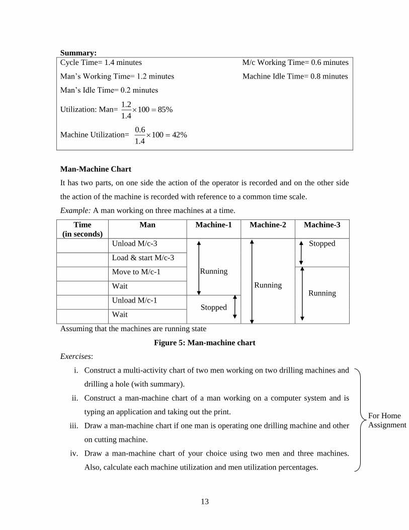
Summary:
Cycle Time= 1.4 minutes M/c Working Time= 0.6 minutes
Man’s Working Time= 1.2 minutes Machine Idle Time= 0.8 minutes
Man’s Idle Time= 0.2 minutes
Utilization: Man= %851004.1
2.1
Machine Utilization= %421004.1
6.0
Man-Machine Chart
It has two parts, on one side the action of the operator is recorded and on the other side
the action of the machine is recorded with reference to a common time scale.
Example: A man working on three machines at a time.
Time
(in seconds)
Man Machine-1 Machine-2 Machine-3
Unload M/c-3
Running
Running
Stopped
Load & start M/c-3
Move to M/c-1
Running Wait
Unload M/c-1 Stopped
Wait
Assuming that the machines are running state
Figure 5: Man-machine chart
Exercises:
i. Construct a multi-activity chart of two men working on two drilling machines and
drilling a hole (with summary).
ii. Construct a man-machine chart of a man working on a computer system and is
typing an application and taking out the print.
iii. Draw a man-machine chart if one man is operating one drilling machine and other
on cutting machine.
iv. Draw a man-machine chart of your choice using two men and three machines.
Also, calculate each machine utilization and men utilization percentages.
For Home
Assignment

14
Flow Diagram
It is a drawing or a diagram which is drawn to scale and marks the path followed by men
and materials. Flow diagram is used to supplement the flow process chart. It shows the
relative position of productive machinery, storage area, jigs, fixtures, etc. shown by
joining the symbols with straight lines. Flow diagram may minimize the number of
movements or repetitive movements which results in a lot of saving both in cost as well
as efforts required to do a job.
Figure 6: Flow Diagram of Flow of Material on a Shop Floor
Exercises:
i. Construct a flow diagram of a notice being circulated in University Polytechnic
regarding minimum percentage of attendance for appearing in examination
consisting of four sections.
ii. Construct a flow diagram of issuing a book, reading in the reading room and
returning the same at Maulana Azad Library.
iii. Construct a flow diagram of University Polytechnic Workshop if a raw material is
issued from Workshop store is processed through various shops namely fitting,
welding, foundry, machine shops, and finally in inspection unit to the market.
B 2 A
3
1
4
A, B, C & D----Shops
Store 5
Out
2 1
1
C
1
D 1
For Home
Assignment

15
Principles of Motion Economy
Principles Governing Motion Study
Set of rules were designed by Gilberth in order to develop better method. They are:
Both hands should move simultaneously. This reduces fatigue.
Both hands should complete their movements at the same time i.e. they should
start and finish their motions at the same time.
Both hands should not be idle at the same time unless in a rest period.
Between two movements there should be some time gap. The time gap is called
elapsed time (pass).
Motion of both the hands should be symmetrical and in opposite directions and
should be made simultaneously.
Hesitation in any movement observed at any time should be analyzed.
The shortest time demonstrated by any worker should be marked and efforts
should be made to attain it.
The number of motions required to do a particular work should be clearly
specified.
Variations in time for any movement should be avoided and causes recorded.
All motions should be easy, natural and should reduce fatigue.
Introduction to Therbligs
To facilitate the analysis of motion, Gilberth developed a set of smaller hand motions
some of which could be combined to give a complete motion. The smaller motions he
termed as “Therbligs” (reverse spelling of his name). They are 18 in numbers. For the
purpose of recording the motions, he split up different motions of a process into 18
fundamental hand motions. Every therblig is represented by a symbol, a definite color
and with a word or two to record the same (See Table 2).
A chart which uses or employs Therbligs is referred as “micro-motion study
chart” while a chart which uses symbols like etc. which are macroscopic
in nature is referred as process chart. SIMO chart is a microscopic chart. A single
operation may consist of many Therbligs.

16
For example:
Macroscopic motion Microscopic Motion
(Therbligs)
Operation of picking away a screw
driver
Reach hand for screw driver
(Transport empty)
Grasp the same (Grasp)
Take away the screw driver (Transport
loaded)
Table 2: List of Therbligs
S. No. Name Abbreviation Symbol
1. Search S
2. Hold H
3. Select SE → 4. Grasp G
5. Release Load RL
6. Transport Loaded TL
7. Transport Empty TE
8. Position P و 9. Preposition PP
10. Assemble A # 11. Dissemble DA ╫
12. Use U U
13. Inspect I
14. Avoidable Delay AD
15. Unavoidable Delay UD
16. Rest R
17. Plan PN
18. Find F
Micro-motion Study
Micro-motion study means the study of micro (small) motions know as Therbligs. Each
human activity is divided or split into small movements. The purpose of such study is to
find for an operator one best pattern of movement which involves less efforts, time, and
fatigue to accomplish a task. This study is best suited for those operations which are short
in cycle and are repeated thousands of time (such as packing of sweets into boxes, food
canes into cartons, launching of space craft, missiles, modern cricket, athletics etc.).
17
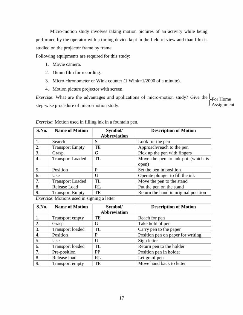
Micro-motion study involves taking motion pictures of an activity while being
performed by the operator with a timing device kept in the field of view and than film is
studied on the projector frame by frame.
Following equipments are required for this study:
1. Movie camera.
2. 16mm film for recording.
3. Micro-chronometer or Wink counter (1 Wink=1/2000 of a minute).
4. Motion picture projector with screen.
Exercise: What are the advantages and applications of micro-motion study? Give the
step-wise procedure of micro-motion study.
Exercise: Motion used in filling ink in a fountain pen.
S.No. Name of Motion Symbol/
Abbreviation
Description of Motion
1. Search S Look for the pen
2. Transport Empty TE Approach/reach to the pen
3. Grasp G Pick up the pen with fingers
4. Transport Loaded TL Move the pen to ink-pot (which is
open)
5. Position P Set the pen in position
6. Use U Operate plunger to fill the ink
7. Transport Loaded TL Move the pen to the stand
8. Release Load RL Put the pen on the stand
9. Transport Empty TE Return the hand in original position
Exercise: Motions used in signing a letter
S.No. Name of Motion Symbol/
Abbreviation
Description of Motion
1. Transport empty TE Reach for pen
2. Grasp G Take hold of pen
3. Transport loaded TL Carry pen to the paper
4. Position P Position pen on paper for writing
5. Use U Sign letter
6. Transport loaded TL Return pen to the holder
7. Pre-position PP Position pen in holder
8. Release load RL Let go of pen
9. Transport empty TE Move hand back to letter
For Home
Assignment

18
Exercise: Study the motions used in following operations using therbligs:
i. Cleaning your teeth with tooth brush.
ii. Packing three types of sweets in a box.
iii. Punching a hole in a lock body.
iv. Planting a flower plant in the pot.
Note: Use both the hands in performing the above tasks.
**************
For Home
Assignment


