Embed Size (px)
Citation preview
, China
PHYSICAL REVIEW B 1 JANUARY 1998-IIVOLUME 57, NUMBER 2
Tunneling conductance and magnetoresistance of ferromagnet/ferromagnetic insulator„semiconductor…/ferromagnet junctions
Yun LiDepartment of Physics, Peking University, Beijing 100871, China
Bo-Zang Li and Wu-Shou ZhangInstitute of Physics & Center for Condensed Matter Physics, Chinese Academy of Sciences, P.O. Box 603-99, Beijing 100080
Dao-Sheng DaiDepartment of Physics, Peking University, Beijing 100871, China
~Received 27 May 1997; revised manuscript received 3 September 1997!
The tunneling conductance~TC! and magnetoresistance~TMR! are investigated for magnetic junctionsconsisting of two ferromagnetic electrodes separated by a ferromagnetic insulator~semiconductor!. The inves-tigations are based on the nearly-free-electron approximation. The results show that TC and TMR stronglydepend on the magnetization configuration of the junction such that TC and TMR reach their maximums whenthe magnetic moments of the two electrodes are parallel to each other but antiparallel to that of the barrier,whereas the minimums appear when the magnetic moments of both electrodes and the barrier are parallel. Thetunneling probability~TP! relates to the spin orientation of incident electrons and the magnetization configu-ration of the junction. The variation of TC and TMR with the relative orientation of magnetization of bothelectrodes and the barrier can be explained by two effects: the ferromagnet-ferromagnet tunneling and spin-filtering effect. Our results agree well with experiment.@S0163-1829~98!03402-X#
otioer
nswn
to-
tthaghefnt
ecouha
sptinr
vth
ns
ls.f
ndefo-ter-o ahentson-re-nce
heier,ry
ling-
R.ny
ec-gn-theesar-asothan
theres
Recently there has been much effort on the studyelectron-transport properties related to the magnetizaconfiguration of the conduction system since the discovof the giant magnetoresistance~GMR! effect in Fe/Crsuperlattices.1 The magnetic tunneling valve effect2 is verysimilar to that of GMR. The effect is spin-polarized electrotunneling between two ferromagnetic metals. Having tferromagnetic electrodes with different coercive fields, ocan expect the tunneling conductance~TC! to be dependenon the relative alignment of magnetizations in the twelectrodes.3–7 Julliere put forward a model for electron tunneling in a ferromagnet/nonmagnetic insulator~semi-conductor!/ferromagnet@FM/I~S!/FM# junction,3 assumingthat spin is conserved in tunneling8 and tunneling currendepends on the density of states of the two electrodes. Inmodel, one expects that the TC will be larger when the mnetic moments of the two metals are parallel than when tare antiparallel. A simple model4 gives the relative change oTC due to the change of magnetization directions from aparallel to parallel alignment equal to 2P1P2, whereP1 andP2 are the conduction-band spin polarization of the eltrodes. However, the observed changes of TC for varicombinations of FM electrodes and barrier are far less tthe expected values based on the simple model.
Another theory of FM/I~S!/FM tunneling proposed bySlonczewski analyzed the transmission of charge andcurrents flowing through a rectangular barrier separafree-electron-like FM’s.7 It showed how the expression fothe relative change of conductance of Maekawa and Ga¨fvertmay be modified by matching free-electron-model wafunctions at the interface between the ferromagnet andbarrier. According to this theory, the orientation of spitunneling across the FM-I~S! interface is strongly influenced
570163-1829/98/57~2!/1079~6!/$15.00
fny
oe
is-y
i-
-sn
ing
ee
by the barrier height. However, the polarization obtained14 islarger than predicted by either of these theoretical mode
Nowak and Rauluszkiewicz9 measured the hysteresis othe tunneling resistance of Gd/GdOx/Fe and Fe/GdOx/Fejunctions in a magnetic field. The domain structures amagnetization reversal process were investigated using dcused electron microscopy. They concluded that the hysesis of the resistance with magnetic field was attributed tspin-filtering effect in the magnetic barrier rather than to tparallel and antiparallel alignment of the magnetic momein electrodes. It seems that the spin-filtering effect is respsible for the existence of the hysteresis of the tunnelingsistance. All observed hystereses of tunneling resistawere obtained for junctions with magnetic barrier. Tsimple model of tunneling through the nonmagnetic barrtaking into account only the spin polarization of FM, is vedifficult to experimentally verify.
This paper presents the treatment of TC and tunnemagnetoresistance~TMR! for ferromagnet/ferromagnetic insulator ~semiconductor!/ferromagnet @FM/FI~S!/FM# junc-tions. We derived the analytic solutions for TC and TMUnlike those obtained by Slonczewski, we do not make aapproximation. Our investigations show that the elastic eltron tunneling between FM’s strongly depends on the aliment of magnetic moments both in electrodes and inbarrier as well. When the magnetizations of two electrodare parallel to each other but antiparallel to that of the brier, the TC and TMR reach their maximal values, wherethe minimal values appear when the magnetizations of belectrodes and the barrier align parallelly. The TMR creach very high values. The tunneling probability~TP! re-lates to the spin orientation of incident electrons andmagnetization configuration of the junction. Such structu
1079 © 1998 The American Physical Society
oee
feionate
inl
.
be
e
cd.gh-
ef
-
he
pald
1080 57YUN LI, BO-ZANG LI, WU-SHOU ZHANG, AND DAO-SHENG DAI
have the ability to distinguish the two possible spin statesthe incident electrons. Our calculated value of TMR agrwell with the experimental result9 and Fig. 6 therein can beunderstood from our results.
Consider two ferromagnetic electrodes separated by aromagnetic barrier. In a nearly-free-electron approximatof the spin-polarized conduction electrons, the longitudipart of the effective one-electron Hamiltonian can be writas
H52\2
2mj*
d2
dx21U~x!1h~ j !–s, ~1!
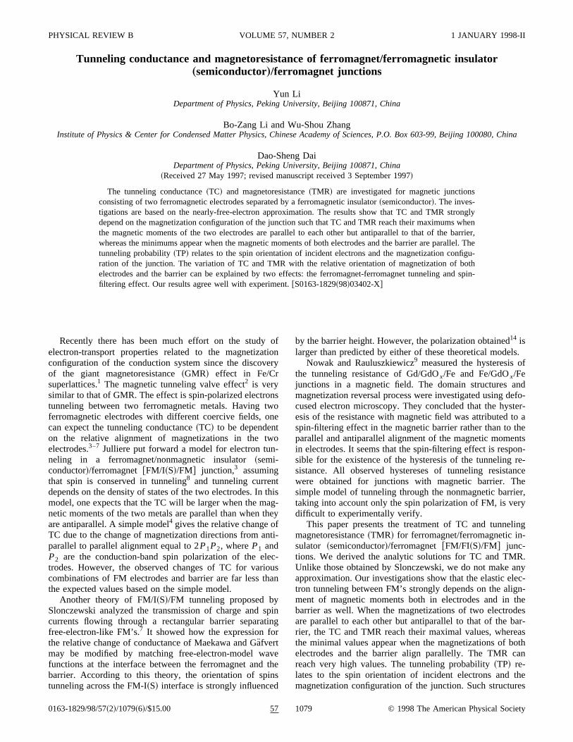
wheremj* ~ j 51,2,3! denotes the electron effective massesthree regions labeled in Fig. 1.U~x! represents the potentiaprofile, namely,U~x!5U for 0,x,d andU50 otherwise.h~ j !–s represents thes-d exchange energy whereh„j … is themolecular field ands~52s! is the conventional Pauli spinoperator. uh~1!u5uh~3!u5h0 and uh~2!u5h are constantsThe directions ofh~1!, h~2!, andh~3! differ by anglesu1andu2 as depicted in Fig. 1.
Let a plane wave of spin-up electrons with unit fluxsteadily incident in region 1, the solution to the Schro¨dingerequation in region 1 is
c1↑5k1↑21/2eik1↑x1R↑e
2 ik1↑x ,~2!
c1↓5R↓e2 ik1↓x, x<0.
In regions 2 and 3, the eigenfunctions ofH are
c2s5Ase2k2sx1Bsek2sx, 0<x<d, ~3!
c3s5Cseik3s~x2d!, x>d, ~4!
where \k1~3!s5A2m1~3!* ~E2sh0!, and \k2s
5A2m2* ~U2E1sh! are the electron momentum along thx axis. s561 corresponds tos5↓,↑, respectively. Herespin-up or↑ indicates that the magnetic moment of the eletron is in the positive direction of the molecular fielAs , Bs , andCs are constants to be determined. Althoutransverse momentum\kuu is omitted from the above notations, the effect of summation overkuu will be accounted forin the results.
To obtain the eight coefficientsAs ,Bs ,Cs, andRs~s5↑,↓ !, we derived the formulas that connect the coficients by matchingcs anddcs /dx at the interfacesx50
FIG. 1. Schematic potential for two metallic ferromagnets serated by a ferromagnetic barrier. The directions of molecular fieh„1…, h„2…, andh„3… differ by anglesu1 andu2.
fs
r-nl
n
-
-
andx5d. The change in quantization axes atx50 andx5drequires the spinor transformation:
c1↑5cos S u1
2 Dc2↑1sin S u1
2 Dc2↓ ,~5!
c1↓52sin S u1
2 Dc2↑1cos S u1
2 Dc2↓ ;
c2↑5cos S u2
2 Dc3↑1sin S u2
2 Dc3↓ ,~6!
c2↓52sin S u2
2 Dc3↑1cos S u2
2 Dc3↓
for x50 andx5d, respectively, and similarly for the derivatives.
Thus, the formulas for the coefficients are
~A↑1B↑!cosS u1
2 D1~A↓1B↓!sin S u1
2 D2R↑5k1↑21/2,
~A↑1B↑!sinS u1
2 D2~A↓1B↓!cos S u1
2 D1R↓50,
k2↑~2A↑1B↑!cos S u1
2 D1k2↓~2A↓1B↓!sinS u1
2 D1 ik1↑R↑
5 ik1↑1/2,
k2↑~A↑2B↑!sin S u1
2 D1k2↓~2A↓1B↓!cosS u1
2 D1 ik1↓R↓
50, ~7!
A↑e2k2↑d1B↑e
k2↑d2C↑cos S u2
2 D2C↓sin S u2
2 D50,
A↓e2k2↓d1B↓e
k2↓d1C↑sin S u2
2 D2C↓ cos S u 2
2 D 50,
k2↑~2A↑e2k2↑d1B↑e
k2↑d!2 i Fk3↑C↑cos S u2
2 D1k3↓C↓sinS u2
2 D G50,
k2↓~A↓e2k2↓d1B↓e
k2↓d!1 i Fk3↑C↑sinS u2
2 D2k3↓C↓cosS u2
2 D G50.
Some algebra produces the following solutions for tcoefficients:
-s
fo
r-t
rly
iedoxi-rgel
ns-
.
57 1081TUNNELING CONDUCTANCE AND MAGNETORESISTANCE . . .
R↑5~a22b12a12b2!
~a11a222a12a21!,
R↓52~a21b12a11b2!
~a11a222a12a21!,
A↑51
2k2↑Fk1↑
21/2 ~k2↑2 ik1↑!cosS u1
2 D1~k2↑1 ik1↑!R↑cosS u1
2 D2~k2↑1 ik1↓!R↓sinS u1
2 D G ,B↑5
1
2k2↑Fk1↑
21/2 ~k2↑1 ik1↑!cos S u1
2 D1~k2↑2 ik1↑!R↑cos S u1
2 D2~k2↑2 ik1↓!R↓sinS u1
2 D G ,A↓5
1
2k2↓Fk1↑
21/2 ~k2↓2 ik1↑!sin S u1
2 D1~k2↓1 ik1↑!R↑sinS u1
2 D1~k2↓1 ik1↓!R↓cos S u1
2 D G ,~8!
B↓51
2k2↓Fk1↑
21/2 ~k2↓1 ik1↑!sin S u1
2 D1~k2↓2 ik1↑!R↑sinS u1
2 D1~k2↓2 ik1↓!R↓cosS u1
2 D G ,C↑5~A↑e
2k2↑d1B↑ek2↑d!cos S u2
2 D2~A↓e2k2↓d
1B↓ek2↓d!sinS u2
2 D ,
C↓5~A↑e2k2↑d1B↑e
k2↑d!sin S u2
2 D1~A↓e2k2↓d
1B↓ek2↓d!cosS u2
2 D ,
wherea11, a12, a21, a22, b1, andb2 are defined as
a115a12b1,
a125a22b2,
a215a32b3,~9!
a225a42b4,
b15a52b5,
b25a62b6,
referring to the Appendix about the expressionsa1, b1, a2, b2, a3, b3, a4, b4, a5, b5, a6, andb6.
The probability current density is
r
j 52 i\
2m*~c* ¹c2c¹c* !. ~10!
Thus, the transmissivity of the electron is given by
T↑5j 3
j 15Im(
scs*
dcs
dx, s5↑,↓, ~11!
where j 1 and j 3 represent the incident and transmitted curent density, respectively, the subscript↑ means the incidenelectrons are of spin-up. Summation of2eT↑ over occupiedstates gives the total charge current~ I e! per unit area flowingfrom region 1 to region 3, which does not depend onx bycontinuity.
At the absolute zero of temperature and for the neanormal incidence, the electrons withEx nearEF carry mostof the current, so that we can replacekj s~Ex!~ j 51,2,3,s5↑,↓ ! with kj s~EF!, in calculating the conduc-tance due to tunneling. In addition, for small voltage applacross the barrier the wave function involved can be apprmately taken as that for zero voltage. By summing the chatransmission overEx andkuu for occupied states in the usuamanner:10
I e52er uu
h EEF2eV
EFdEE
0
E
dEuuD~eV;E2Euu!, ~12!
r uu5m*
2p\2, ~13!
Euu5\2kuu
2
2m*, ~14!
whereD~eV;E2Euu! is the electron transmissivity andh isthe Planck constant, one finds the expression of TC for tramitted electrons of spin-s, in our notation,
Gs5dIe
dV5S e2
4p2\D S k2sT↑
d D , s5↑,↓, ~15!
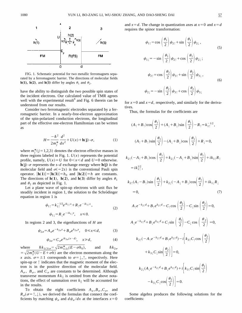
wheree is the electron charge andd is the barrier thicknessFor the one-band case,k1↓5 ik~0<k,`! is imaginary.
While for the two-band case,k1↓ is real ~see Fig. 2!. If theincident electrons are of both spin,T↑ in Eq. ~15! should bereplaced byT↑1T↓ ,
Gs5S e2
4p2\D Fk2s~T↑1T↓!
d G , s5↑,↓, ~16!
whereT↓ can be obtained from the expression ofT↑ with k1↑andk1↓ interchanged.
According to Refs. 7 and 11, the total TC is
G5(s
Gs , s5↑,↓ . ~17!
We define the TMR ratioh~u1 ,u2! as
h~u1 ,u2!52@G~u1 ,u2!2Gp#
@G~u1 ,u2!1Gp#, ~18!
thncf
io
re
asnm
cz
he
a
iza-ar-
e.,
the. 9,n-rupt
ag-s ofllel
theel toC
o-es,
themag-rier
s
d 6. Itentnc-llelforec-ionr,pre-
n-
1082 57YUN LI, BO-ZANG LI, WU-SHOU ZHANG, AND DAO-SHENG DAI
which reflects the relative change in TC with respect tochange of relative orientation of magnetic moments of jution, whereGp is the TC value for the parallel alignment omagnetic moments both in electrodes and in the barrier.
Taking the Fe/GdOx/Fe ~Ref. 9! tunnel junction as anexample, we calculate the TP, TC, and TMR of the junctaccording to Eqs.~11!, ~17!, and~18!. In the calculation,k1s
is taken to equalk3s~s5↑,↓ ! for convenience, andEFs is
taken according to Ref. 11. Electron effective masses in thregions are taken asm1* 5m2* 5m3* 5me ,11 whereme is theelectron bare mass. We calculate the TP, TC, and TMRfunction of the magnetization configuration of the junctiorespectively. The TMR can reach very high values. For coparison with the experiment of Nowak and Rauluszkiewithe barrier heightF and thicknessd are taken according toRef. 9,h0 andh are fitted to the experiment.9 Our calculatedvalue of TMR is 7.70%, which is in good agreement with texperimental result of 7.7%.9
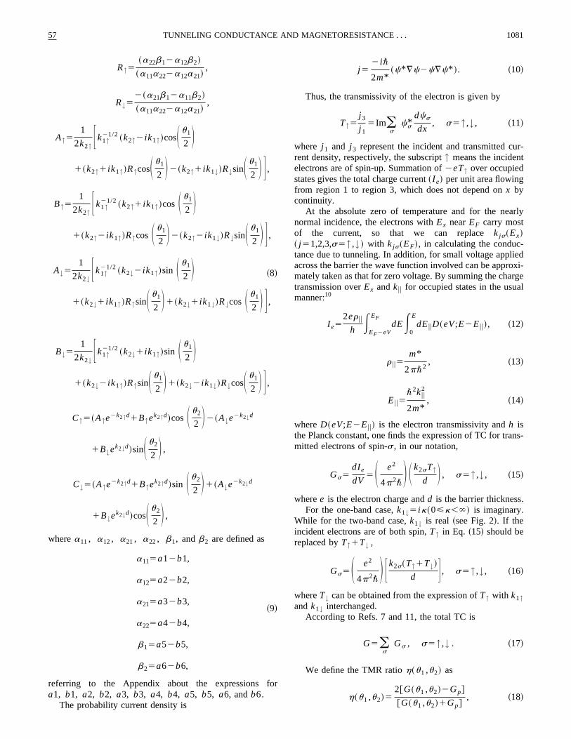
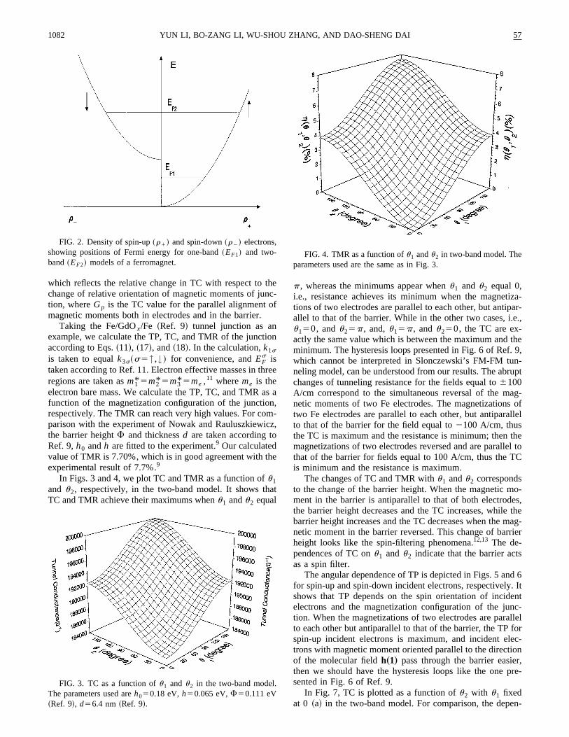
In Figs. 3 and 4, we plot TC and TMR as a function ofu1and u2, respectively, in the two-band model. It shows thTC and TMR achieve their maximums whenu1 andu2 equal
FIG. 2. Density of spin-up~r1! and spin-down~r2! electrons,showing positions of Fermi energy for one-band~EF1! and two-band~EF2! models of a ferromagnet.
FIG. 3. TC as a function ofu1 andu2 in the two-band model.The parameters used areh050.18 eV,h50.065 eV,F50.111 eV~Ref. 9!, d56.4 nm~Ref. 9!.
e-
n
e
a,-,
t
p, whereas the minimums appear whenu1 and u2 equal 0,i.e., resistance achieves its minimum when the magnettions of two electrodes are parallel to each other, but antipallel to that of the barrier. While in the other two cases, i.u150, andu25p, and,u15p, andu250, the TC are ex-actly the same value which is between the maximum andminimum. The hysteresis loops presented in Fig. 6 of Refwhich cannot be interpreted in Slonczewski’s FM-FM tuneling model, can be understood from our results. The abchanges of tunneling resistance for the fields equal to6100A/cm correspond to the simultaneous reversal of the mnetic moments of two Fe electrodes. The magnetizationtwo Fe electrodes are parallel to each other, but antiparato that of the barrier for the field equal to2100 A/cm, thusthe TC is maximum and the resistance is minimum; thenmagnetizations of two electrodes reversed and are parallthat of the barrier for fields equal to 100 A/cm, thus the Tis minimum and the resistance is maximum.
The changes of TC and TMR withu1 andu2 correspondsto the change of the barrier height. When the magnetic mment in the barrier is antiparallel to that of both electrodthe barrier height decreases and the TC increases, whilebarrier height increases and the TC decreases when thenetic moment in the barrier reversed. This change of barheight looks like the spin-filtering phenomena.12,13 The de-pendences of TC onu1 andu2 indicate that the barrier actas a spin filter.
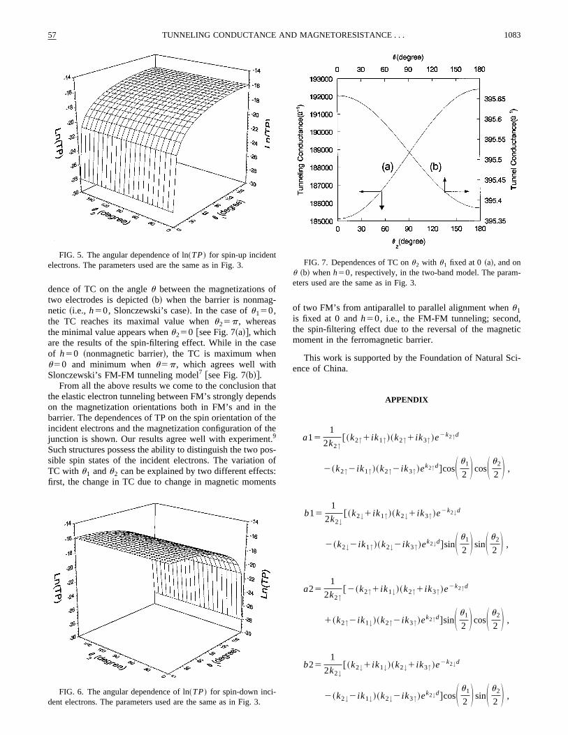
The angular dependence of TP is depicted in Figs. 5 anfor spin-up and spin-down incident electrons, respectivelyshows that TP depends on the spin orientation of incidelectrons and the magnetization configuration of the jution. When the magnetizations of two electrodes are parato each other but antiparallel to that of the barrier, the TPspin-up incident electrons is maximum, and incident eltrons with magnetic moment oriented parallel to the directof the molecular fieldh„1… pass through the barrier easiethen we should have the hysteresis loops like the onesented in Fig. 6 of Ref. 9.
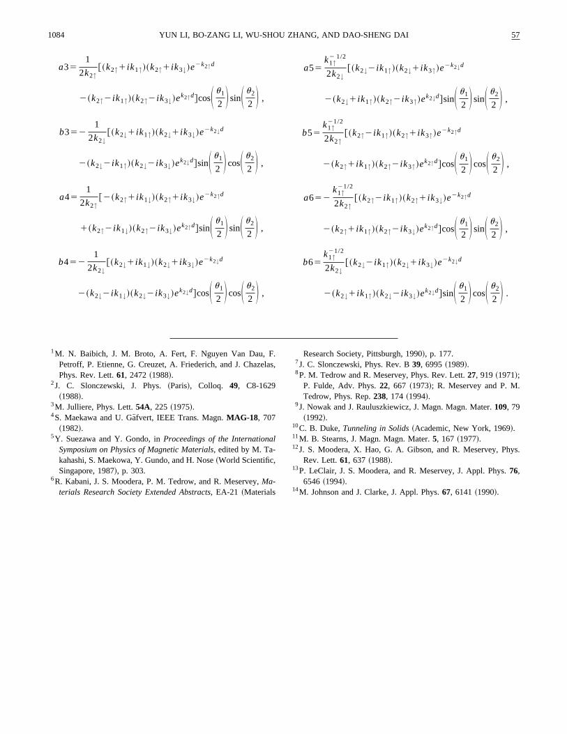
In Fig. 7, TC is plotted as a function ofu2 with u1 fixedat 0 ~a! in the two-band model. For comparison, the depe
FIG. 4. TMR as a function ofu1 andu2 in two-band model. Theparameters used are the same as in Fig. 3.
f-
s
thndheththt.
poo
s:n
,tic
ci-
.
m-
57 1083TUNNELING CONDUCTANCE AND MAGNETORESISTANCE . . .
dence of TC on the angleu between the magnetizations otwo electrodes is depicted~b! when the barrier is nonmagnetic ~i.e., h50, Slonczewski’s case!. In the case ofu150,the TC reaches its maximal value whenu25p, whereasthe minimal value appears whenu250 @see Fig. 7~a!#, whichare the results of the spin-filtering effect. While in the caof h50 ~nonmagnetic barrier!, the TC is maximum whenu50 and minimum whenu5p, which agrees well withSlonczewski’s FM-FM tunneling model7 @see Fig. 7~b!#.
From all the above results we come to the conclusionthe elastic electron tunneling between FM’s strongly depeon the magnetization orientations both in FM’s and in tbarrier. The dependences of TP on the spin orientation ofincident electrons and the magnetization configuration ofjunction is shown. Our results agree well with experimen9
Such structures possess the ability to distinguish the twosible spin states of the incident electrons. The variationTC with u1 andu2 can be explained by two different effectfirst, the change in TC due to change in magnetic mome
FIG. 5. The angular dependence of ln~TP! for spin-up incidentelectrons. The parameters used are the same as in Fig. 3.
FIG. 6. The angular dependence of ln~TP! for spin-down inci-dent electrons. The parameters used are the same as in Fig. 3
e
ats
ee
s-f
ts
of two FM’s from antiparallel to parallel alignment whenu1is fixed at 0 andh50, i.e., the FM-FM tunneling; secondthe spin-filtering effect due to the reversal of the magnemoment in the ferromagnetic barrier.
This work is supported by the Foundation of Natural Sence of China.
APPENDIX
a151
2k2↑@~k2↑1 ik1↑!~k2↑1 ik3↑!e
2k2↑d
2~k2↑2 ik1↑!~k2↑2 ik3↑!ek2↑d#cosS u1
2 D cosS u2
2 D ,
b151
2k2↓@~k2↓1 ik1↑!~k2↓1 ik3↑!e
2k2↓d
2~k2↓2 ik1↑!~k2↓2 ik3↑!ek2↓d#sinS u1
2 D sinS u2
2 D ,
a251
2k2↑@2~k2↑1 ik1↓!~k2↑1 ik3↑!e
2k2↑d
1~k2↑2 ik1↓!~k2↑2 ik3↑!ek2↑d#sinS u1
2 D cosS u2
2 D ,
b251
2k2↓@~k2↓1 ik1↓!~k2↓1 ik3↑!e
2k2↓d
2~k2↓2 ik1↓!~k2↓2 ik3↑!ek2↓d#cosS u1
2 D sinS u2
2 D ,
FIG. 7. Dependences of TC onu2 with u1 fixed at 0~a!, and onu ~b! whenh50, respectively, in the two-band model. The paraeters used are the same as in Fig. 3.
1084 57YUN LI, BO-ZANG LI, WU-SHOU ZHANG, AND DAO-SHENG DAI
a351
2k2↑@~k2↑1 ik1↑!~k2↑1 ik3↓!e
2k2↑d
2~k2↑2 ik1↑!~k2↑2 ik3↓!ek2↑d#cosS u1
2 D sinS u2
2 D ,
b3521
2k2↓@~k2↓1 ik1↑!~k2↓1 ik3↓!e
2k2↓d
2~k2↓2 ik1↑!~k2↓2 ik3↓!ek2↓d#sinS u1
2 D cosS u2
2 D ,
a451
2k2↑@2~k2↑1 ik1↓!~k2↑1 ik3↓!e
2k2↑d
1~k2↑2 ik1↓!~k2↑2 ik3↓!ek2↑d#sinS u1
2 D sinS u2
2 D ,
b4521
2k2↓@~k2↓1 ik1↓!~k2↓1 ik3↓!e
2k2↓d
2~k2↓2 ik1↓!~k2↓2 ik3↓!ek2↓d#cosS u1
2 D cosS u2
2 D ,
.la
l
a55k1↑
2 1/2
2k2↓@~k2↓2 ik1↑!~k2↓1 ik3↑!e
2k2↓d
2~k2↓1 ik1↑!~k2↑2 ik3↑!ek2↓d#sinS u1
2 D sinS u2
2 D ,
b55k1↑
21/2
2k2↑@~k2↑2 ik1↑!~k2↑1 ik3↑!e
2k2↑d
2~k2↑1 ik1↑!~k2↑2 ik3↑!ek2↑d#cosS u1
2 D cosS u2
2 D ,
a652k1↑
21/2
2k2↑@~k2↑2 ik1↑!~k2↑1 ik3↓!e
2k2↑d
2~k2↑1 ik1↑!~k2↑2 ik3↓!ek2↑d#cosS u1
2 D sinS u2
2 D ,
b65k1↑
21/2
2k2↓@~k2↓2 ik1↑!~k2↓1 ik3↓!e
2k2↓d
2~k2↓1 ik1↑!~k2↓2 ik3↓!ek2↓d#sinS u1
2 D cosS u2
2 D .
ys.
1M. N. Baibich, J. M. Broto, A. Fert, F. Nguyen Van Dau, FPetroff, P. Etienne, G. Creuzet, A. Friederich, and J. ChazePhys. Rev. Lett.61, 2472~1988!.
2J. C. Slonczewski, J. Phys.~Paris!, Colloq. 49, C8-1629~1988!.
3M. Julliere, Phys. Lett.54A, 225 ~1975!.4S. Maekawa and U. Ga¨fvert, IEEE Trans. Magn.MAG-18, 707
~1982!.5Y. Suezawa and Y. Gondo, inProceedings of the Internationa
Symposium on Physics of Magnetic Materials,edited by M. Ta-kahashi, S. Maekowa, Y. Gundo, and H. Nose~World Scientific,Singapore, 1987!, p. 303.
6R. Kabani, J. S. Moodera, P. M. Tedrow, and R. Meservey,Ma-terials Research Society Extended Abstracts, EA-21 ~Materials
s,Research Society, Pittsburgh, 1990!, p. 177.
7J. C. Slonczewski, Phys. Rev. B39, 6995~1989!.8P. M. Tedrow and R. Meservey, Phys. Rev. Lett.27, 919 ~1971!;
P. Fulde, Adv. Phys.22, 667 ~1973!; R. Meservey and P. M.Tedrow, Phys. Rep.238, 174 ~1994!.
9J. Nowak and J. Rauluszkiewicz, J. Magn. Magn. Mater.109, 79~1992!.
10C. B. Duke,Tunneling in Solids~Academic, New York, 1969!.11M. B. Stearns, J. Magn. Magn. Mater.5, 167 ~1977!.12J. S. Moodera, X. Hao, G. A. Gibson, and R. Meservey, Ph
Rev. Lett.61, 637 ~1988!.13P. LeClair, J. S. Moodera, and R. Meservey, J. Appl. Phys.76,
6546 ~1994!.14M. Johnson and J. Clarke, J. Appl. Phys.67, 6141~1990!.


