Embed Size (px)
Citation preview

1
TK RIPPER
By
Charles Volk
Vince Priolo
Zach McKibbin
Project Advisor: John Fabijanic
Instructors Grade: ___________
Date: _________________
2
Prepared By:
Charles Volk
Vince Priolo
Zach McKibbin
3
Statement of Disclaimer Since this project is a result of a class assignment, it has been graded and accepted as fulfillment of the course requirements. Acceptance does not imply technical accuracy or reliability. Any use of information in this report is done at the risk of the user. These risks may include catastrophic failure of the device or infringement of patent or copyright laws. California Polytechnic State University at San Luis Obispo and its staff cannot be held liable for any use or misuse of the project.

4
TABLE OF CONTENTS LIST OF TABLES.......................................................................................................................................................6
EXECUTIVE SUMMARY .........................................................................................................................................7
CHAPTER 1 INTRODUCTION................................................................................................................................9
INTRODUCTION...................................................................................................................................................10 OBJECTIVES .........................................................................................................................................................10 SPECIFICATION DEVELOPMENT .....................................................................................................................10
CHAPTER 2 BACKROUND....................................................................................................................................12
EXISTING PRODUCTS.........................................................................................................................................13 CURRENT STATE OF THE ART..........................................................................................................................15 METHOD OF APPROACH....................................................................................................................................16 EXPERIMENTATION ...........................................................................................................................................17 APPLICABLE STANDARDS................................................................................................................................19
CHAPTER 3 DESIGN DEVELOPMENT ..............................................................................................................20
DISCUSSION OF CONCEPTUAL DESIGNS.......................................................................................................21 CONCEPT AND GEOMETRY SELECTION........................................................................................................21 SUPPORTING PRELIMINARY ANALYSIS/RESULTS .....................................................................................27
CHAPTER 4...............................................................................................................................................................34
LAYOUT/DESCRIPTION WITH LABELED SOLID MODEL............................................................................35 COST ANALYSIS ..................................................................................................................................................36 MATERIAL SELECTION......................................................................................................................................39 COMPONENT SELECTION..................................................................................................................................39 MANUFACTURING PLAN...................................................................................................................................41 SAFETY CONSIDERATIONS ..............................................................................................................................44
CHAPTER 5 - DESIGN VERIFICATION PLAN..................................................................................................45
TEST DESCRIPTION AND EQUIPMENT ...........................................................................................................46 SPECIFICATION VERIFICATION CHECKLIST ................................................................................................48
CHAPTER 6 - PROJECT MANAGEMENT PLAN..............................................................................................50
PROJECT MANAGEMENT PLAN .......................................................................................................................51
APPENDIX ................................................................................................................................................................52
APPENDIX A: SPOOL AXLE HAND CALCULATIONS....................................................................................53 APPENDIX B: BILL OF MATERIALS (BOM).....................................................................................................59 APPENDIX C: QFD HOUSE OF QUALITY ...............................................................................................................63 APPENDIX D: GANTT CHART ................................................................................................................................65 ATTACHMENT E: DRAWING PACKAGE ....................................................................................................................66

5
LIST OF FIGURES Figure 1: SmittyBuilt winch used for towing heavy equipment ..................................................... 1 Figure 2: The Ridiculous Winch..................................................................................................... 1 Figure 3: The Grinch Winch ........................................................................................................... 1 Figure 4: 12 Gauge Revolver 2.0.................................................................................................... 1 Figure 5: Air-Powered winch from McMaster-Carr....................................................................... 1 Figure 6: Hydraulic powered winch ............................................................................................... 1 Figure 7: Loads from deep water starts........................................................................................... 1 Figure 8: Sketches of frame taken from Vince Priolo’s log book. ............................................... 23 Figure 9: representation Final design............................................................................................ 26 Figure 10: Side view of TkRipper frame used in the analysis to determine if the selected beam dimensions will be strong enough to prevent significant deflection............................................. 27 Figure 11: Constraints placed on the TkRipper frame for the FEA model. The two orange symbols in the lower left and right corners represent pin connectors restricting the motion of the model. On the angled member, the yellow arrow represents rider loads....................................... 1 Figure 12: Maximum deflection of steel frame .............................................................................. 1 Figure 13: Deflection of the aluminum frame ............................................................................... 1 Figure 14: Frame with assumptions of pinned joints................................................................... 31 Figure 15: Half model of connecting rod...................................................................................... 32 Figure 16: Stress in connecting rod .............................................................................................. 33 Figure 17: Deflection of connecting rod....................................................................................... 33 Figure 18. TkRipper isometric view for part identification.......................................................... 35 Figure 19. TkRipper isometric view for part identification.......................................................... 35 Figure 20. Chain Selection using EES.......................................................................................... 41 Figure 21: Template for tack welding frame sides ....................................................................... 43 Figure 22: Welding procedures for base....................................................................................... 43

6
List of Tables
Figure 1: Data collection costs…………………………………………………………………. 37
7
Executive Summary
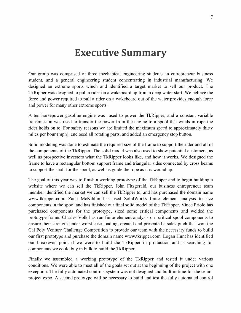
Our group was comprised of three mechanical engineering students an entrepreneur business student, and a general engineering student concentrating in industrial manufacturing. We designed an extreme sports winch and identified a target market to sell our product. The TkRipper was designed to pull a rider on a wakeboard up from a deep water start. We believe the force and power required to pull a rider on a wakeboard out of the water provides enough force and power for many other extreme sports.
A ten horsepower gasoline engine was used to power the TkRipper, and a constant variable transmission was used to transfer the power from the engine to a spool that winds in rope the rider holds on to. For safety reasons we are limited the maximum speed to approximately thirty miles per hour (mph), enclosed all rotating parts, and added an emergency stop button.
Solid modeling was done to estimate the required size of the frame to support the rider and all of the components of the TkRipper. The solid model was also used to show potential customers, as well as prospective investors what the TkRipper looks like, and how it works. We designed the frame to have a rectangular bottom support frame and triangular sides connected by cross beams to support the shaft for the spool, as well as guide the rope as it is wound up.
The goal of this year was to finish a working prototype of the TkRipper and to begin building a website where we can sell the TkRipper. John Fitzgerald, our business entrepreneur team member identified the market we can sell the TkRipper to, and has purchased the domain name www.tkripper.com. Zach McKibbin has used SolidWorks finite element analysis to size components in the spool and has finished our final solid model of the TkRipper. Vince Priolo has purchased components for the prototype, sized some critical components and welded the prototype frame. Charles Volk has run finite element analysis on critical spool components to ensure their strength under worst case loading, created and presented a sales pitch that won the Cal Poly Venture Challenge Competition to provide our team with the necessary funds to build our first prototype and purchase the domain name www.tkripper.com. Logan Hunt has identified our breakeven point if we were to build the TkRipper in production and is searching for components we could buy in bulk to build the TkRipper.
Finally we assembled a working prototype of the TkRipper and tested it under various conditions. We were able to meet all of the goals set out at the beginning of the project with one exception. The fully automated controls system was not designed and built in time for the senior project expo. A second prototype will be necessary to build and test the fully automated control
8
system, but for the time being a fully functional prototype exists for mechanical testing. Mounting the TkRipper to the ground was taken care of by its own weight and little mechanical mounting was necessary on soft ground. When the TkRipper was mounted on harder surfaces a chain was required to keep the TkRipper stationary while in use. We found our working prototype had more than enough power than what was required to pull a rider from a deep water start which would allow us to use a lighter, less expensive engine.
A second prototype is required prior to the launch of our company, and a more fully developed website will be necessary in order to move our product. Currently we have no plans to pursue a fully fledged company, however once we have built up some capital the possibility will become more realistic.
9
CHAPTER 1 INTRODUCTION
INTRODUCTION/ PROBLEM DEFINITION
OBJECTIVE
SPECIFICATION DEVELOPMENT
10
INTRODUCTION
The TkRipper is an extreme sports winch designed to pull a rider from 0-30 mph for 1,000 feet wherever and whenever. The TkRipper can be taken anywhere due to its light weight, compact size, two person operation (including towed person) and completely independent power generation. The primary market is wakeboarding and wakeskating with additional markets of snow skiing/boarding, skateboarding, skimboarding, surfing, biking, and sandboarding. The goal of our project was to produce a quality product at a competitive price by following the Cal Poly’s design process and meeting the specifications included in this report.
Due to the high price of existing extreme sports winches currently on the market many people build their own winches. The home fabrication of winches has lead to very unsafe machines that are dangerous to the rider, operator, and in some cases bystanders. The goal of this project was to offer a winch that is cheap enough to curtail the number of home winch builders while offering the features of the current extreme sports winches as well as additional user interface features that increase the quality of the ride. We will introduce a quality product to the commercial market that will be successful enough to support our company while we enter into larger more lucrative markets once our final prototype has been fully tested.
OBJECTIVES
The TkRipper can pull an average person about 1,000 feet across water, snow, asphalt, or sand on the board of their choice from 0 to 30 mph. The TkRipper is easy to operate, transport and able to pull the rider under its own power. The current list of specifications to ensure we produced the best product can be seen in Appendix C.
SPECIFICATION DEVELOPMENT
The requirements in the Quality Function Deployment (QFD) came from various avenues such as specific parts available, current product comparison, personal experience, testing and our Senior Project Lectures. There is a towing line currently on the market that is specifically designed for winch applications that is very thin, lightweight, non-stretch, plastic coated, and ultra violet light protected. Only one company produces a specific towing line for extreme sports winches, providing only 600 foot and 1,000 foot lengths. Current winch products come with 600 feet of line, therefore one way we produced a superior product was to use 1,000 feet of line. The rider speed specification comes from their personal comfort level, and we provided a winch with ample speed for the majority of riders, therefore we will provide a winch with a maximum speed of 30 mph. To determine the maximum angle the rider will be off center from the winch we used
11
personal experience from riding behind a boat as well as test data. We feel the maximum angle the rider will pull at may change after preliminary testing.
The QFD aided in applying specific numbers for the requirements, which can be seen in Attachment C. Some additional requirements were exemplified by the QFD we had missed earlier, such as the ability to run consistently in 120oF for 6 hours. The QFD allowed us to perform a more rigorous analysis for the specifications of the TkRipper. All of our specifications are obtainable to ensure we will be able to measure and reach our goals by the end of the project. We do expect some specifications to change in the future along with the addition of more requirements.

12
CHAPTER 2 BACKROUND
EXISTING PRODUCTS
CURRENT STATE OF ART
METHOD OF APPROACH
EXPERIMENTATION
13
EXISTING PRODUCTS
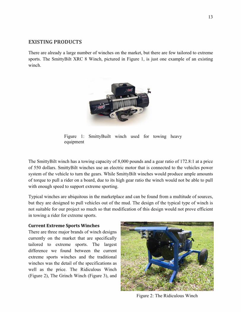
There are already a large number of winches on the market, but there are few tailored to extreme sports. The SmittyBilt XRC 8 Winch, pictured in Figure 1, is just one example of an existing winch.
The SmittyBilt winch has a towing capacity of 8,000 pounds and a gear ratio of 172.8:1 at a price of 550 dollars. SmittyBilt winches use an electric motor that is connected to the vehicles power system of the vehicle to turn the gears. While SmittyBilt winches would produce ample amounts of torque to pull a rider on a board, due to its high gear ratio the winch would not be able to pull with enough speed to support extreme sporting.
Typical winches are ubiquitous in the marketplace and can be found from a multitude of sources, but they are designed to pull vehicles out of the mud. The design of the typical type of winch is not suitable for our project so much so that modification of this design would not prove efficient in towing a rider for extreme sports.
Current Extreme Sports Winches There are three major brands of winch designs currently on the market that are specifically tailored to extreme sports. The largest difference we found between the current extreme sports winches and the traditional winches was the detail of the specifications as well as the price. The Ridiculous Winch (Figure 2), The Grinch Winch (Figure 3), and
Figure 1: SmittyBuilt winch used for towing heavyequipment
Figure 2: The Ridiculous Winch

14
the 12 Gauge Revolver 2.0 (Figure 4) all ranged in price from 1,500-2,500 dollars and did not specify how much towing capacity they had. Current extreme sports winches on the market all had engines ranging from 5-7 horsepower and used a clutch to transfer the power to the spool. One feature all of the winches offered was an adapter to a truck hitch as well as wheels to aid in transport.
Alternative Winch Styles
We considered using a different source of power other than present gas powered engines to power our winch.
McMaster-Carr offered a variety of styles of winches unlike the typical electric and gasoline winces. Research was preformed investigating air-powered and hydraulic winches. We found an air-powered lifting winch with continuous-duty and 1500 pound capacity (product number 3651T22 from McMaster-Carr) seen in Figure 5.
Air-powered winches have the distinct advantage of continuous operation as well as offering a variable speed control; however the air-powered winch has a maximum rated speed of 40 fpm (0.45mph), which does not offer enough speed to support extreme sports, as well as costing upwards of 4,000 dollars.
Also found in the McMaster-Carr catalogue was a hydraulic winch (product number 3232T21) offering much more towing capacity than required for extreme sports. Problems encountered with the air-powered winch were also inherent in the hydraulic powered winches. The hydraulic powered winch alone costs 1,000 dollars and the maximum towing speed is not sufficient for
Figure 3: The Grinch Winch
Figure 4: 12 Gauge Revolver 2.0
Figure 5: Air-Powered winch from McMaster-Carr

15
extreme sports. Figure 6 shows the hydraulic winch which has a duty cycle of 20 minutes on and 20 minutes off which would not work for extreme sports.
CURRENT STATE OF THE ART
The Grinch Winch currently holds the largest share of the extreme sports market. While their product seems to meet the demand of wakeboarding, there are limited technical details regarding its capacity. A motorcycle style throttle and braking system is employed to control the winch resulting in the operator needing experience to be able to pull a rider, as well as allowing the operator to reel in the line until the handle is pulled into the winch resulting in damage and/or injury.
Figure 6: Hydraulic powered winch
16
METHOD OF APPROACH
Our design was primarily driven by the type of drive system we choose, which dictated how the rest of the system was designed. Researching different drive methods, such as electrical or hydraulic power was the first step in our design process. A small gasoline engine with a torque converter to drive a spool is the current accepted drive system, so we are researching the potential of using a gasoline generator and electric motor as well as using a hydraulic system in case they could provide a superior product. Our first objective was to understand if hydraulic or electric systems can meet our most important requirements, price and weight.
The drive system directly depends on the amount of power we need. To find the required power for an extreme sports winch a load profile was created. Experimental data was taken on October 24, 2009 recording the speed and pulling force of a rider on a wakeboard behind a boat, which was used to create a load profile. We used an Omega load cell with a range of 0 to 1,000 lbs in line with the towrope to measure the pulling force for various situations, a Garmin Nuvi 200 GPS to measure the absolute speed of the rider, and a homemade protractor was used to measure the pull angle of the rider. Data was collected during a deep water start, while the rider was changing angle relative to the boat, as well as straight ahead riding at various speeds; fuel consumption and preparation time was also recorded. With information from October 24th we were able to properly size an electric, hydraulic or gasoline drive systems and compare for a final decision.
After the type of drive system was chosen, design of the drive system and chassis followed. Force analysis was applied to the system to determine the characteristics of pulling a rider which helped to build a chassis that was stable. Major areas of concern when designing the chassis were the engine mounts, spool attachment, and ground attachments. Correct analysis allowed for proper sizing of torque converter, drive sprockets, drive chain/belts, bearings, spool design, and chassis material/tube size.
While the chassis and drive system are being sized a SolidWorks model was built to test the compatibility of the various parts. A SolidWorks model also helped us foresee potential problems before we begin the build process. Once we addressed all the potential problems from the SolidWorks model we began building a single prototype for testing. A testing plan was written before testing begins, which ensured the appropriate requirements were tested in the correct manner. The prototype was tested according to the test plan with small loads then increasing loads until we reach the maximum capability of the prototype. We wanted to see how much abuse the prototype can handle and where the single point of failure occurs, so could design failure to occur in a safe manner if. If the prototype had failed, a full analysis would have been done to determine the cause of failure. After the cause of failure had been determined modifications would have been made to the prototype, or another prototype would have been
17
built based on the magnitude of failure. Iterations of the prototype would have continued until the prototypes meet all the requirements.
Manufacturing notes were taken while building the prototype. Manufacturing time and costs needed to be minimized to make the product viable, which was one of the most important aspects of our product. Modifications to the design were made during this process; therefore a written manufacturing plan was developed while building the prototype(s). The manufacturing plan was clear, concise, and easy to read to promote fast assembly along with quality assurance.
Notes were taken in our logbooks during the entire process for legal documentation. Our logbooks included pictures, schematics and personal observations/reflections ensuring our ideas and observations were not be get over looked or forgotten. We wanted to build a quality product that will be successful enough to support our company while we enter into larger more lucrative markets.
EXPERIMENTATION
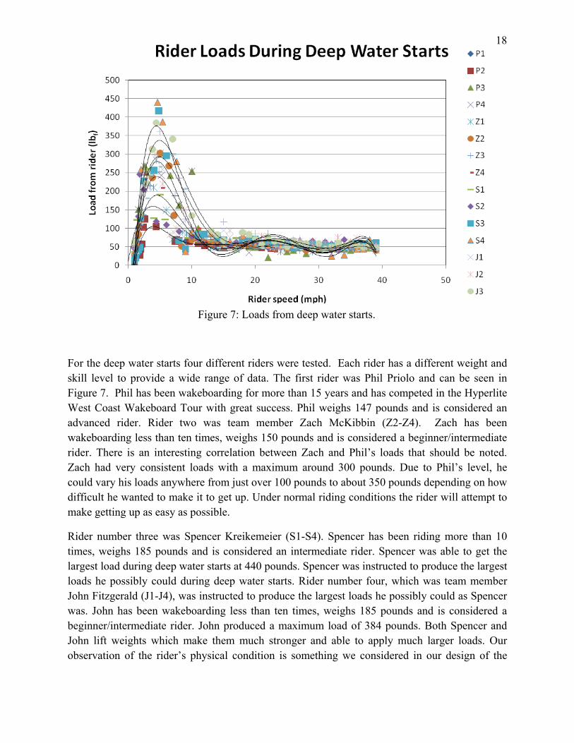
Preliminary Experimentation An experiment was done on October 24, 2009 at Lake Nacimiento to measure the loads applied by the rider for various wakeboarding scenarios. Testing included deep water starts, constant cruising speeds up to 30 mph and hard carving away from the wake behind a 2003 Mastercraft X-Star. Figure 7 displays the deep water start loads from all the different test subjects as deep water starts apply the largest loads and would be the single point failure situation. An Omega load cell was placed in line with the wakeboarding rope to measure the loads applied by the rider while performing the different scenarios. The load cell was connected to a digital readout, which was calibrated using known weights. A Garmin Nuvi 200 GPS was used to correlate the speed of the rider and boat with recorded loads. We used two video cameras to record the loads and speed together, as well as the rider position in the water. To correlate all of the data the two cameras were synchronized before each test. Testing results can be seen in Figure 7.
18
For the deep water starts four different riders were tested. Each rider has a different weight and skill level to provide a wide range of data. The first rider was Phil Priolo and can be seen in Figure 7. Phil has been wakeboarding for more than 15 years and has competed in the Hyperlite West Coast Wakeboard Tour with great success. Phil weighs 147 pounds and is considered an advanced rider. Rider two was team member Zach McKibbin (Z2-Z4). Zach has been wakeboarding less than ten times, weighs 150 pounds and is considered a beginner/intermediate rider. There is an interesting correlation between Zach and Phil’s loads that should be noted. Zach had very consistent loads with a maximum around 300 pounds. Due to Phil’s level, he could vary his loads anywhere from just over 100 pounds to about 350 pounds depending on how difficult he wanted to make it to get up. Under normal riding conditions the rider will attempt to make getting up as easy as possible.
Rider number three was Spencer Kreikemeier (S1-S4). Spencer has been riding more than 10 times, weighs 185 pounds and is considered an intermediate rider. Spencer was able to get the largest load during deep water starts at 440 pounds. Spencer was instructed to produce the largest loads he possibly could during deep water starts. Rider number four, which was team member John Fitzgerald (J1-J4), was instructed to produce the largest loads he possibly could as Spencer was. John has been wakeboarding less than ten times, weighs 185 pounds and is considered a beginner/intermediate rider. John produced a maximum load of 384 pounds. Both Spencer and John lift weights which make them much stronger and able to apply much larger loads. Our observation of the rider’s physical condition is something we considered in our design of the
Figure 7: Loads from deep water starts.
19
TkRipper. Spencer was able to create a larger load than John due to his increased wakeboarding experience. Both John and Spencer noticed there was a point when they were getting the largest loads they would be pulled to their feet otherwise the rope would be pulled out of their hands.
We believe the data collected is a good representation of the applied loads of deep water starts for the average rider. Our system was designed to carry loads larger than the ones seen for deep water starts by applying a safety factor. The safety factor also compensated for the discrepancies in the collected data. Figure 7 shows there were not an abundant amount of load cell values during the start up for each individual rider. The load cell and digital readout could only display 3-4 values during initial startup which provides a poor approximation of the actual loads of the system. We believe there is a possibility the largest loads may have been missed by the load cell, which required careful consideration when designing the TkRipper. We can see a clear increase and decrease in loads but the resolution is not enough to say with 100% confidence we recorded the largest loads applied by the rider. The maximum possible load applied cannot be much more than the recorded loads due to a human’s limited ability to hold onto the rope, therefore we used anthropomorphic data to help us decide on a maximum towing capacity for the TkRipper. We determined a safety factor to provide ample pulling force to pull a rider out of the water without pulling the riders arms out of their sockets.
The loads we obtained from deep water starts drove the design of the entire system. The drive train must be able to sustain these loads which act as repeated loads, the power plant must be able to produce the needed torque to get the rider up, the frame must be able to support the entire system without yielding, and the system must stay stationary while the loads are applied.
APPLICABLE STANDARDS
The only applicable standards are from the California Air Recourses Board (CARB) which pertains to the gasoline engine which must be CARB certified. We need to design for an engine that comes from the manufacturer with a CARB certification for our production run allowing us to use the TkRipper in California anywhere small engines are allowed to be run.

20
CHAPTER 3 DESIGN DEVELOPMENT
DISCUSSION OF CONCEPTUAL DESIGNS
CONCEPT AND GEOMETRY SELECTION
SUPPORTING PRELIMINARY ANALYSIS/RESULTS

21
DISCUSSION OF CONCEPTUAL DESIGNS
The power generation mode drove the design of the entire system so we decided to choose this parameter first. Different power generation modes such as: electric motor, hydraulic motor and gasoline engine were researched to analyze their viability for our application. Gasoline engine power generation is the industry standard and may be the optimum choice but the additional modes were considered.
After the power generation mode was decided upon, the frame design was the next part to design. Each team member was given 3 days to produce at least 6 different frame concepts on their own which were produced in each team members log book. This was done in hopes that very diverse concepts would be produced by each team member. We then met at a team to discuss all the concepts and come up with a final design.
CONCEPT AND GEOMETRY SELECTION
POWER GENERATION Vince Priolo researched electric motors and compared the system to our design specifications. His findings are below.
An electric motor would suite our application very well with the largest forces coming at low rpm. Electric motors produce constant torque which is completely independent of motor rpm. The low end torque would increase the systems capability of deep water starts which is the most critical time. The problems with an electric motor arise with the system specifications of independent run time, weight, and price. There is a large amount of additional items needed to support an electric motor.
It was difficult to meet the specification because of the 6 hour run time without recharge/refuel. Batteries also did not meet design specifications because of the need for 4 Optima Deep Cycle which are $190 and 42.5 lbs each. The multiple batteries put the system over the price specification with an estimated cost of parts only of $1800. An alternate way to meet the 6 hour specification required a generator incorporated into the system. The most effective way to incorporate a generator to supply the electric motor with the required electricity would have been to purchase a Genset. A Genset is a system sold as a single unit including a gasoline engine, alternator, battery, wiring, and plugs to plug in any electrical unit. The Genset would have allowed for the operator to fill up the gasoline gas tank with enough fuel to meet the 6 hour specification. A sufficient Genset would have cost over $1,000 which did not meet the design specification for price as well as be too heavy. The support required for an electric motor make this option unacceptable.
22
Zach McKibbin researched hydraulic motors and compared the system to our design specifications. Hydraulic systems have many advantages over traditional mechanical systems but also have their disadvantages. Hydraulics can replace complex mechanical linkages to simplify the design. Torque is constant while the system is running and can be adjusted easily by a control valve. These advantages are great for the application of the TkRipper but the disadvantages outweigh the advantages. Hydraulic motors have many reliability and safety concerns. The liquid is stored at high pressure and the oil can be very hot. All hydraulic systems are prone to have leaks which can damage the product or injure the user. Also, the system will need some type of external power source such as an electric motor and generator. Added cost and weight to the TkRipper is passed directly to the consumer which lowered the advantages of our winch over the competition.
Due to the inability for electric and hydraulic motor power generation systems to meet design specifications, we used gasoline engine power generation. It is known from previously established products and gasoline engine price research that gasoline engines meet the design requirements. A gasoline engine which would meet out design requirements costs around 1/3 the price of an electric motor at $350.00.
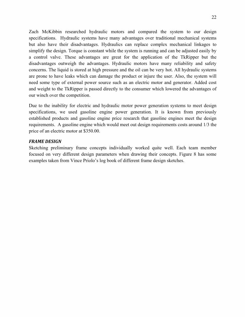
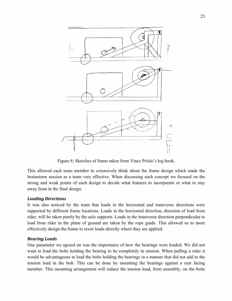
FRAME DESIGN Sketching preliminary frame concepts individually worked quite well. Each team member focused on very different design parameters when drawing their concepts. Figure 8 has some examples taken from Vince Priolo’s log book of different frame design sketches.
23
Figure 8: Sketches of frame taken from Vince Priolo’s log book.
This allowed each team member to extensively think about the frame design which made the brainstorm session as a team very effective. When discussing each concept we focused on the strong and weak points of each design to decide what features to incorporate or what to stay away from in the final design.
Loading Directions It was also noticed by the team that loads in the horizontal and transverse directions were supported by different frame locations. Loads in the horizontal direction, direction of load from rider, will be taken purely by the axle supports. Loads in the transverse direction perpendicular to load from rider in the plane of ground are taken by the rope guide. This allowed us to more effectively design the frame to resist loads directly where they are applied.
Bearing Loads One parameter we agreed on was the importance of how the bearings were loaded. We did not want to load the bolts holding the bearing to be completely in tension. When pulling a rider it would be advantageous to load the bolts holding the bearings in a manner that did not add to the tension load in the bolt. This can be done by mounting the bearings against a rear facing member. This mounting arrangement will reduce the tension load, from assembly, on the bolts
24
which will increase the life of the bolts and bearings. We incorporated this with a rear facing member at a slight angle which was driven by other design parameters.
Weight We looked at each concept and attempted to load each beam in its most effective manner so to use the least amount of material as possible. Keeping the weight as low as possible is very important to the success of the TkRipper. Unnecessary beams would have only add additional weight, along with cost, manufacturing time etc., which was unacceptable. This forced us to also decide on a simple design without intricate pieces.
Appearance We wanted to make sure the final product looked cool. We are entering an industry where looks are extremely important. The TkRipper had to look like something teenagers will see in a magazine or video and want. Our product also had to look durable. Consumers will not buy our product if does not look like it will hold up, even if we are sure it will.
Safety We want the TkRipper to be as safe as we can make it. To do this we decided on an external frame we could mount a metal skin to completely encase the rotating assembly. This keeps people's appendages, water, and any other foreign objects from coming in contact with the rotating machinery. We also added an emergency stop button on the top of the TkRipper that the operator can hit to stop the machine in the even the rider becomes entangled in the line.
The extreme sports winch was designed for public use. When any product is going to be sold to the public safety requirements are a big concern when designing a product. People can find any way possible to break or injure themselves with our product. With the increase of law suits on products designing for safety is extremely important. Most people think of this when it comes to safety. Other things also need to be considered when thinking of safety such as an inherently safe design, safety factors, a negative feedback system, and multiple safety barriers.
When designing for safety, there are four major points to look at that apply to most fields of engineering. The first point was to design an inherently safe design. This means to look at what materials are going to be used in the product and how they are going to be used. Exclude all of the hazards of actually using the product and look at what parts of the product can be safer. Specific to the extreme sports winch, we looked into using an upgraded gas tank that protected the gas better and have better leak protection.
Safety factors were the second point to look at when designing a product. This is to design not only for the loads the product will encounter but also loads larger than what the product was designed for. The extreme sports winch has safety factors because there will be shafts and gears running in the product. With under designed shafts or weak chains, the winch would have potentially been dangerous to use.

25
A system with negative feedback was essential in case something happens to the product when it was being used; the system shuts itself down to minimize harm done. The winch needed this type of system for the engine in case it starts to overheat. An automatic engine shutdown was considered to be factored into our design so the engine will not blow up from overheating, however time constraints made this feature a goal of the second prototype. It would also have been good to have one that will stop the engine when the tow rope is all the way in so that the handle would not get sucked into the rotating portion of the winch.
The last part of designing for safety was to look at having independent safety barriers in place. The winch has many moving parts and each part has its own compartment. We needed to design barriers between many of the different parts because many of the parts are not designed to work in wet conditions. We had to put a barrier between the wet rotating spool and the bearings used for the shafts. We wanted as little water as possible to get out of the spool compartment and into the other areas.
Designing for safety had many different components. We considered not only safety for the user, but safety for the environment, safety of the equipment, safety from failure, and creating an inherently safe design.
Manufacturing We also designed for manufacturing when the TkRipper product will be mass produced. Our products success relies very much on manufacturing. We will be selling this product to the general public. There will hopefully be a large amount of TkRippers build and sold. The manufacturing will be a large part of the final cost affecting turnaround time from order to delivery and provide quality of the product.
Manufacturing will be a large part of the final cost of the TkRipper. We had to design our product to minimize manufacturing complexity by decreasing the number of assembly steps. Decreasing the number of assembly steps provided for fewer chances of mistakes and increase quality. We also wanted to make each manufacturing step as easy as possible. For example, we ded not want to give a step to weld a joint then have the next step install a bolt close by. The assembly worker may burn himself or have to wait for the metal to cool which is a liability and increases manufacturing time. Liability and time cost the company money which increases the final cost. The more parts used will also drive the cost up by increasing assembly time and parts cost.
The turnaround time from order placement and delivery to the customer is very important. To be successful we must be competitive with other manufactures. A customer may purchase another product purely based on turnaround time. The more parts included into our product, the higher the chance for us waiting on another business.
Tolerances while manufacturing were important as well. We ded not want to call out for a tolerance the assemblyman is incapable of doing. For example, we ded not want to call for a
26
tolerance of ±0.002inches on a bracket which must be welded on by hand. This is not possible simply due to the tendency of metal to warp from welding and would require precision machining. Tolerance stacking was considered as well to ensure parts installed toward the end of the process fit and work correctly. Due to the rotating assembly, there were close tolerances that had to be correct to limit unwanted vibrations. We had to make sure these tolerances were not dependent on certain locations. This came from our design to simplify the process and make sure these tolerances were met.
The final cost, turnaround time, and quality of our product was dictated by our manufacturing process. We wanted a machine that runs smoothly and meets all of the design specifications. When designing our product, the manufacturing time and complexity, safety, tolerances and assembly procedure were also considered. We took notes during the build of the prototype for design changes that had to be made. We will not introduce our product to the market until we are satisfied with the quality of our product to ensure the success of the TkRipper.
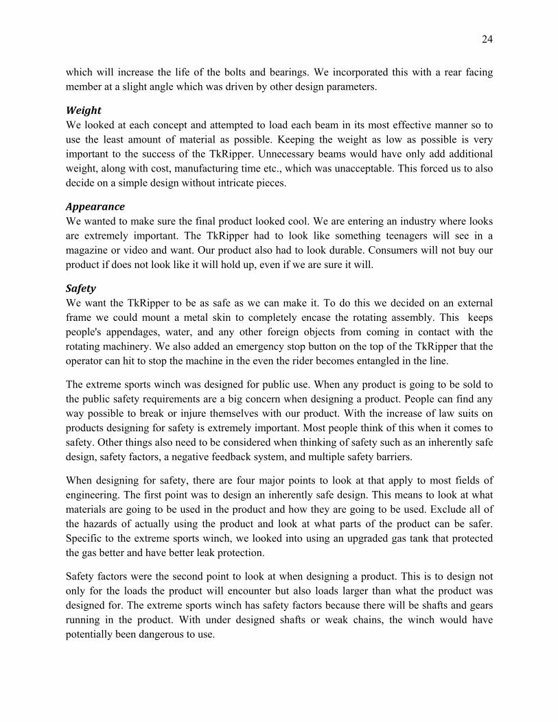
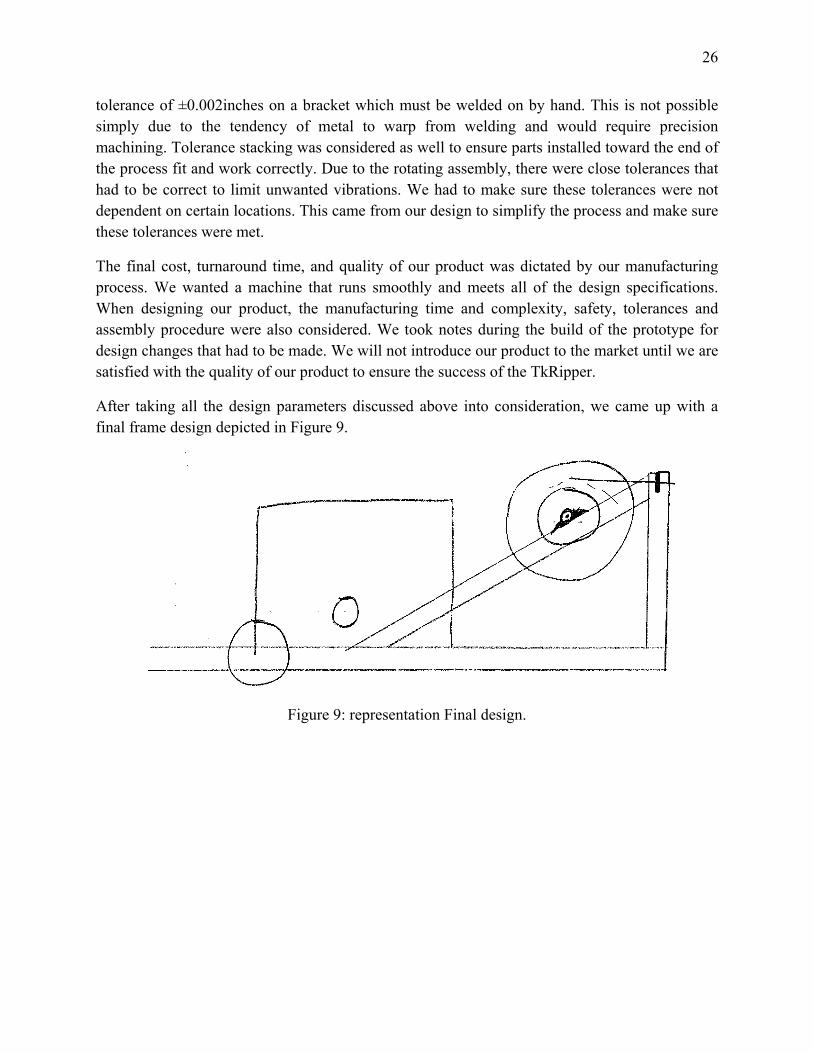
After taking all the design parameters discussed above into consideration, we came up with a final frame design depicted in Figure 9.
Figure 9: representation Final design.
27
SUPPORTING PRELIMINARY ANALYSIS/RESULTS
To size the tubing used for the frame we calculated the stresses from the maximum applied loads. This was done using the Finite Element Analysis method using ABAQUS and verified using hand calculations. Both methods are explained below.
The spool connecting rods were also modeled using ABAQUS to ensure failure would be avoided in worst case scenario.
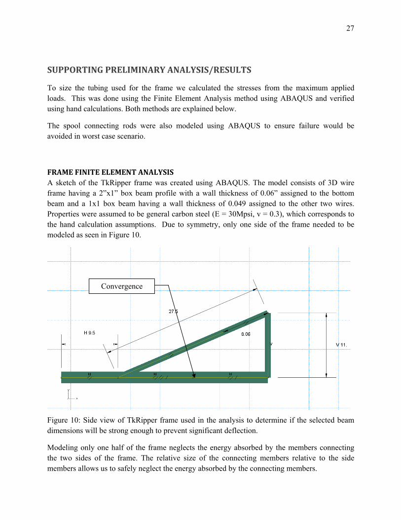
FRAME FINITE ELEMENT ANALYSIS A sketch of the TkRipper frame was created using ABAQUS. The model consists of 3D wire frame having a 2”x1” box beam profile with a wall thickness of 0.06” assigned to the bottom beam and a 1x1 box beam having a wall thickness of 0.049 assigned to the other two wires. Properties were assumed to be general carbon steel (E = 30Mpsi, v = 0.3), which corresponds to the hand calculation assumptions. Due to symmetry, only one side of the frame needed to be modeled as seen in Figure 10.
Figure 10: Side view of TkRipper frame used in the analysis to determine if the selected beam dimensions will be strong enough to prevent significant deflection.
Modeling only one half of the frame neglects the energy absorbed by the members connecting the two sides of the frame. The relative size of the connecting members relative to the side members allows us to safely neglect the energy absorbed by the connecting members.
Convergence
28
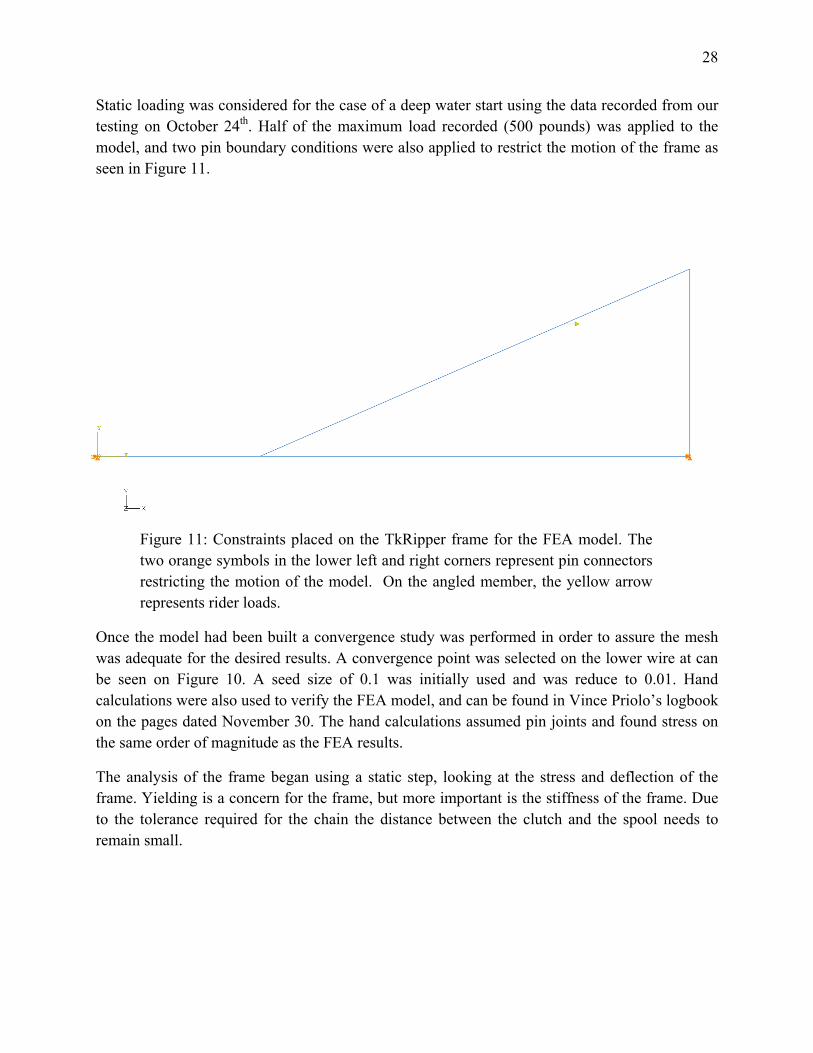
Static loading was considered for the case of a deep water start using the data recorded from our testing on October 24th. Half of the maximum load recorded (500 pounds) was applied to the model, and two pin boundary conditions were also applied to restrict the motion of the frame as seen in Figure 11.
Once the model had been built a convergence study was performed in order to assure the mesh was adequate for the desired results. A convergence point was selected on the lower wire at can be seen on Figure 10. A seed size of 0.1 was initially used and was reduce to 0.01. Hand calculations were also used to verify the FEA model, and can be found in Vince Priolo’s logbook on the pages dated November 30. The hand calculations assumed pin joints and found stress on the same order of magnitude as the FEA results.
The analysis of the frame began using a static step, looking at the stress and deflection of the frame. Yielding is a concern for the frame, but more important is the stiffness of the frame. Due to the tolerance required for the chain the distance between the clutch and the spool needs to remain small.
Figure 11: Constraints placed on the TkRipper frame for the FEA model. Thetwo orange symbols in the lower left and right corners represent pin connectorsrestricting the motion of the model. On the angled member, the yellow arrowrepresents rider loads.
29
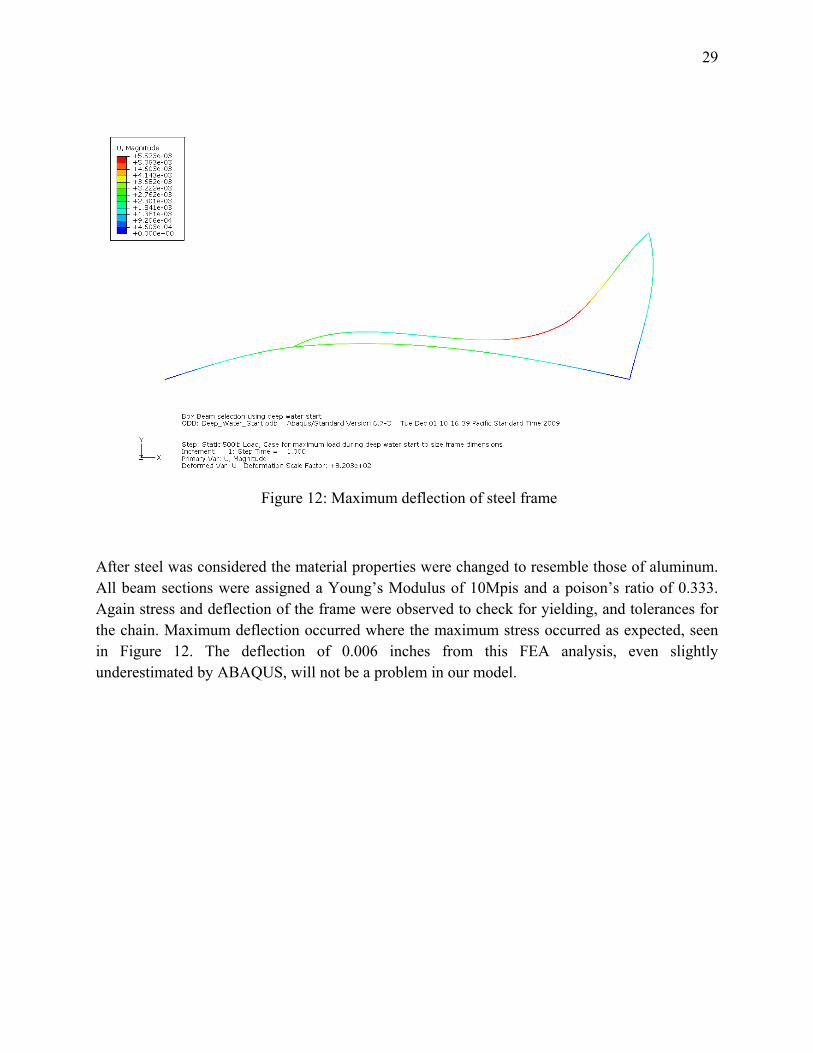
After steel was considered the material properties were changed to resemble those of aluminum. All beam sections were assigned a Young’s Modulus of 10Mpis and a poison’s ratio of 0.333. Again stress and deflection of the frame were observed to check for yielding, and tolerances for
the chain. Maximum deflection occurred where the maximum stress occurred as expected, seen in Figure 12. The deflection of 0.006 inches from this FEA analysis, even slightly underestimated by ABAQUS, will not be a problem in our model.
Figure 12: Maximum deflection of steel frame

30
Figure 13 deflection of the aluminum frame shows slightly larger deflection than the steel frame with a maximum of 0.032 inches. The lower Young’s Modulus is the cause of the higher deflection, but still is within tolerance of the chain.
CONCLUSIONS FROM THE FEA ANALYSIS Results from the finite element analysis suggest neither stress nor deflection will be a limiting factor if this frame size and geometry from this analysis is used. In order to make the selection between a steel and aluminum frame cost and weight, two critical design factors were considered. The weight of the steel frame was estimated to be 29 pounds and the weight of the aluminum frame was estimated to be 16 pounds, which is what we expected. When calculating the cost of the steel and aluminum frame we found a counterintuitive result. The steel frame cost approximately 300 dollars while the cost of the aluminum frame was estimated to be only 150 dollars. Normally steel is cheaper than aluminum, however in order to keep the weight of the frame to a minimum the wall thickness of the box beams was kept as low as possible which resulted in driving the cost of the steel up higher than the cost of the aluminum. I sugested using an aluminum frame for the TkRipper because it was lighter and cheaper than a steel frame while still providing the necessary strength and stiffness to pull a rider from a deep water start. I also suggested running another analysis of smaller, thicker walled beams in order to see if the price and weight can be driven down further.
Figure 13: Deflection of the aluminum frame
31
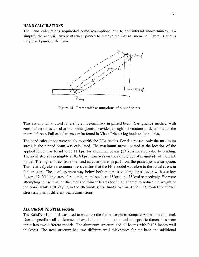
HAND CALCULATIONS The hand calculations requireded some assumptions due to the internal indeterminacy. To simplify the analysis, two joints were pinned to remove the internal moment. Figure 14 shows the pinned joints of the frame.
Figure 14: Frame with assumptions of pinned joints.
This assumption allowed for a single indeterminacy in pinned beam. Castigliano's method, with zero deflection assumed at the pinned joints, provides enough information to determine all the internal forces. Full calculations can be found in Vince Priolo's log book on date 11/30.
The hand calculations were solely to verify the FEA results. For this reason, only the maximum stress in the pinned beam was calculated. The maximum stress, located at the location of the applied force, was found to be 11 kpsi for aluminum beams (23 kpsi for steel) due to bending. The axial stress is negligible at 0.16 kpsi. This was on the same order of magnitude of the FEA model. The higher stress from the hand calculations is in part from the pinned joint assumption. This relatively close maximum stress verifies that the FEA model was close to the actual stress in the structure. These values were way below both materials yielding stress, even with a safety factor of 2. Yielding stress for aluminum and steel are 35 kpsi and 75 kpsi respectively. We were attempting to use smaller diameter and thinner beams too in an attempt to reduce the weight of the frame while still staying in the allowable stress limits. We used the FEA model for further stress analysis of different beam dimensions.
ALUMINUM VS. STEEL FRAME The SolidWorks model was used to calculate the frame weight to compare Aluminum and steel. Due to specific wall thicknesses of available aluminum and steel the specific dimensions were input into two different models. The aluminum structure had all beams with 0.125 inches wall thickness. The steel structure had two different wall thicknesses for the base and additional
32
beam, 0.06 inches and 0.049 inches respectively. The weights of the aluminum and steel structures were 16 lb and 28 lbs. Aluminum was obviously much lighter which, was one of the most important design specifications. Further analysis was done with smaller beam which reduced the weight of our frame.
The cost comparison between aluminum and steel also shows the advantages of using an aluminum frame. We priced the raw material cost for building the frame from McMaster-Carr. The aluminum frame materials cost a total of 150 dollars compared to the steel which costs 300 dollars. The higher cost of the steel is due to the thinner wall material. Further analysis of smaller diameter and thinner wall thickness beams was done before a final decision was made.
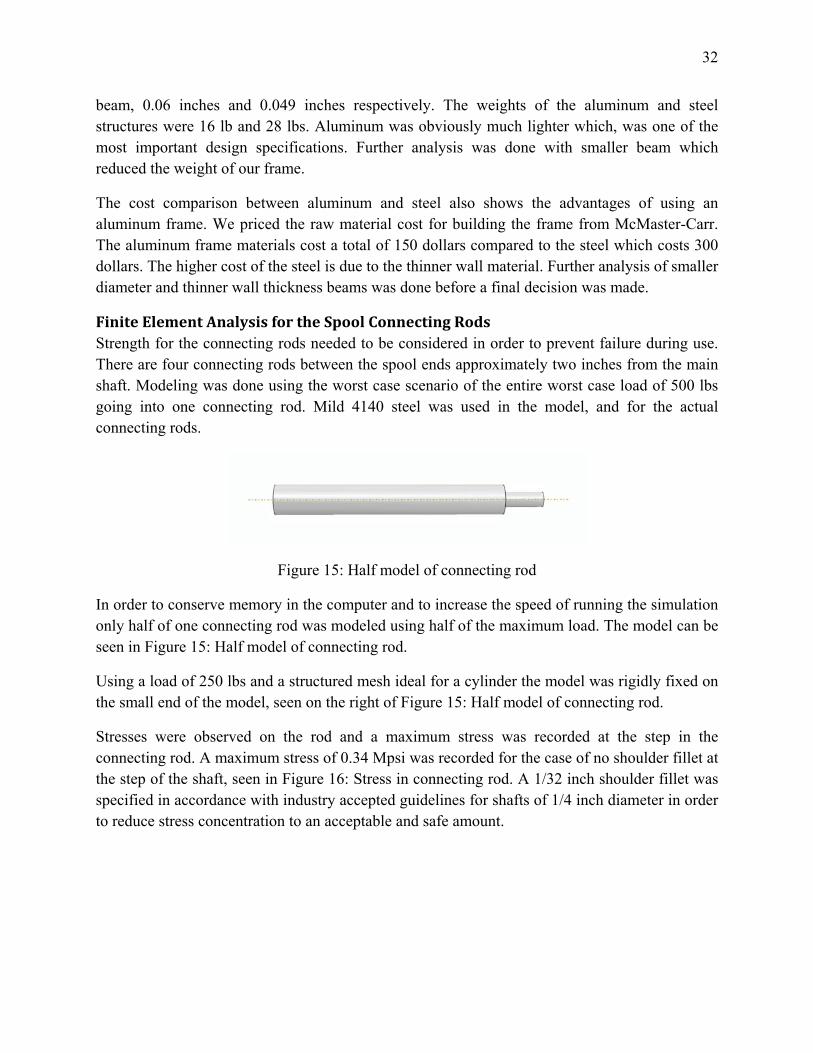
Finite Element Analysis for the Spool Connecting Rods Strength for the connecting rods needed to be considered in order to prevent failure during use. There are four connecting rods between the spool ends approximately two inches from the main shaft. Modeling was done using the worst case scenario of the entire worst case load of 500 lbs going into one connecting rod. Mild 4140 steel was used in the model, and for the actual connecting rods.
Figure 15: Half model of connecting rod
In order to conserve memory in the computer and to increase the speed of running the simulation only half of one connecting rod was modeled using half of the maximum load. The model can be seen in Figure 15: Half model of connecting rod.
Using a load of 250 lbs and a structured mesh ideal for a cylinder the model was rigidly fixed on the small end of the model, seen on the right of Figure 15: Half model of connecting rod.
Stresses were observed on the rod and a maximum stress was recorded at the step in the connecting rod. A maximum stress of 0.34 Mpsi was recorded for the case of no shoulder fillet at the step of the shaft, seen in Figure 16: Stress in connecting rod. A 1/32 inch shoulder fillet was specified in accordance with industry accepted guidelines for shafts of 1/4 inch diameter in order to reduce stress concentration to an acceptable and safe amount.

33
Figure 16: Stress in connecting rod
The maximum stress was reduced in the final design by adding the shoulder fillet which reduced the stress to a level preventing yielding.
Maximum displacement was also checked in order to verify the connecting rods will not deflect more than an acceptable amount. A maximum deflection of 0.047 inches at the midpoint of the connecting rod seen in Figure 17: Deflection of connecting rod.
Figure 17: Deflection of connecting rod
SPOOL AXLE ANALYSIS The spool axle has a repeated loading as it rotates. For the stress analysis to choose the size of the axle, we followed the shaft design in Shigleys Mechanical Engineering Design. We looked at available axles and saw that a 1 inch OD steel axle was compatible with additional parts we used. For this reason we analyzed a 1 inch steel axle with a ¼ inch keyway supporting a repeating load of 500 lbs. The full analysis can be found in APPENDIX A: SPOOL AXLE HAND CALCULATIONS. A safety factor of 3.64 was found which is sufficient for our application.
34
CHAPTER 4
LAYOUT/DESCRIPTION WITH LABELED SOLID MODEL
COST ANALYSIS
MATERIAL SELECTION
COMPONENT SELECTION
MANUFACTURING PLAN
SAFETY CONSIDERATIONS
35
LAYOUT/DESCRIPTION WITH LABELED SOLID MODEL
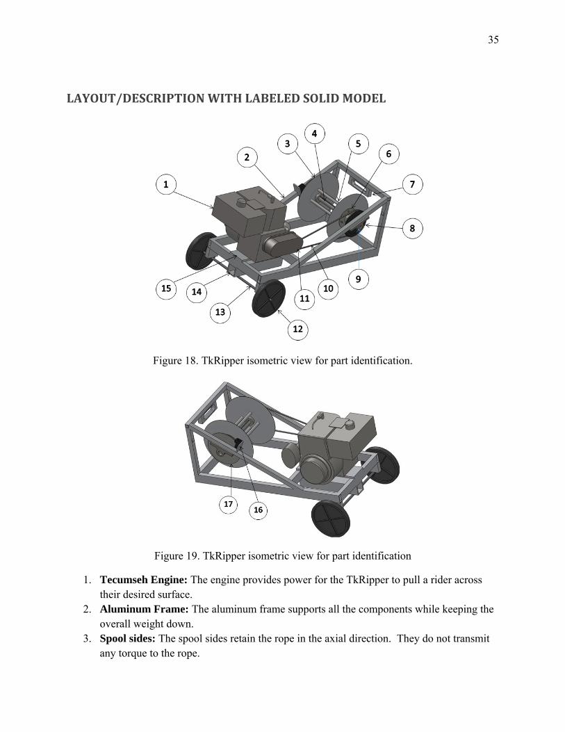
Figure 18. TkRipper isometric view for part identification.
Figure 19. TkRipper isometric view for part identification
1. Tecumseh Engine: The engine provides power for the TkRipper to pull a rider across their desired surface.
2. Aluminum Frame: The aluminum frame supports all the components while keeping the overall weight down.
3. Spool sides: The spool sides retain the rope in the axial direction. They do not transmit any torque to the rope.
36
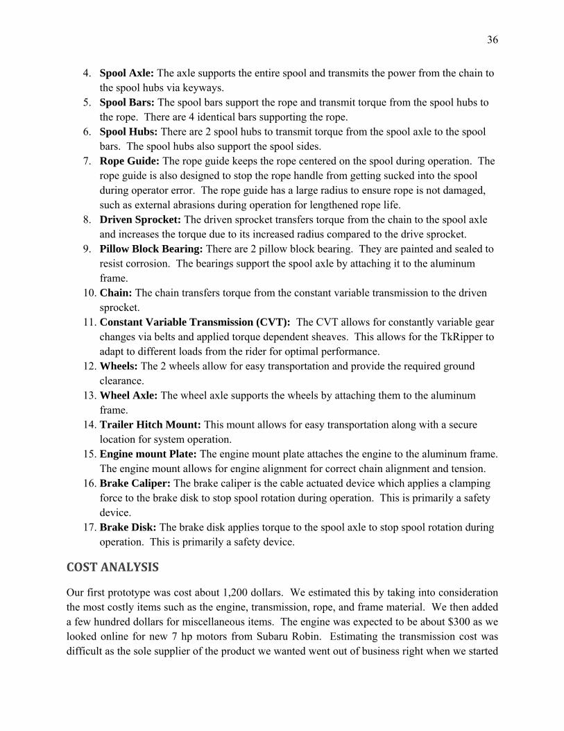
4. Spool Axle: The axle supports the entire spool and transmits the power from the chain to the spool hubs via keyways.
5. Spool Bars: The spool bars support the rope and transmit torque from the spool hubs to the rope. There are 4 identical bars supporting the rope.
6. Spool Hubs: There are 2 spool hubs to transmit torque from the spool axle to the spool bars. The spool hubs also support the spool sides.
7. Rope Guide: The rope guide keeps the rope centered on the spool during operation. The rope guide is also designed to stop the rope handle from getting sucked into the spool during operator error. The rope guide has a large radius to ensure rope is not damaged, such as external abrasions during operation for lengthened rope life.
8. Driven Sprocket: The driven sprocket transfers torque from the chain to the spool axle and increases the torque due to its increased radius compared to the drive sprocket.
9. Pillow Block Bearing: There are 2 pillow block bearing. They are painted and sealed to resist corrosion. The bearings support the spool axle by attaching it to the aluminum frame.
10. Chain: The chain transfers torque from the constant variable transmission to the driven sprocket.
11. Constant Variable Transmission (CVT): The CVT allows for constantly variable gear changes via belts and applied torque dependent sheaves. This allows for the TkRipper to adapt to different loads from the rider for optimal performance.
12. Wheels: The 2 wheels allow for easy transportation and provide the required ground clearance.
13. Wheel Axle: The wheel axle supports the wheels by attaching them to the aluminum frame.
14. Trailer Hitch Mount: This mount allows for easy transportation along with a secure location for system operation.
15. Engine mount Plate: The engine mount plate attaches the engine to the aluminum frame. The engine mount allows for engine alignment for correct chain alignment and tension.
16. Brake Caliper: The brake caliper is the cable actuated device which applies a clamping force to the brake disk to stop spool rotation during operation. This is primarily a safety device.
17. Brake Disk: The brake disk applies torque to the spool axle to stop spool rotation during operation. This is primarily a safety device.
COST ANALYSIS
Our first prototype was cost about 1,200 dollars. We estimated this by taking into consideration the most costly items such as the engine, transmission, rope, and frame material. We then added a few hundred dollars for miscellaneous items. The engine was expected to be about $300 as we looked online for new 7 hp motors from Subaru Robin. Estimating the transmission cost was difficult as the sole supplier of the product we wanted went out of business right when we started

37
this project. We assumed another company would soon start making similar products and would sell them for relatively the same price of $200. The rope was known to be $300 as we already knew exactly what we wanted. Frame material was expected to cost 150.00 as we estimated the tube lengths we needed to finish the frame.
Upon completion, we were not too far off with our initial cost estimate. The final prototype cost was $1454.84 as seen in APPENDIX B: BILL OF MATERIALS (BOM). There are a few things we got for free such as material for the rope guide, disk brake, brake caliper, throttle cable, brake cable, and hand controls. The cost of these items will need to taken into consideration when the final cost of consumer products is estimated.
There are also items that produced large amounts of wasted material which could be used for making more identical items. We had to buy a large amount of material for the disk brake hub for holding the material in the lathe for machining. Multiple disk brake hubs could be made from the wasted material. This will bring the final cost down as well as the machining time.
The price of the TkRipper could be greatly reduced by buying parts in bulk. The price of fasteners (bolts, washers, nuts, and nylocks) would be a small fraction of what we paid at Home Depot for them. For example, we paid about 33 cents for each 10-24x3 inch bolt for the splash shield. The same bolts are 10 cents each when purchased in a box of 100 which is 30% less. If this savings were applied to more parts, the cost of a production ran product would be much less.
The machining of custom parts would increase the cost of production for the TkRipper. The most custom part was the hub for the disk brake. It took about 4 hours to make on the lathe and mill at the Cal Poly Aerospace Hangar. After the part was finished, we analyzed the process and concluded it could be made much simpler. A drill press could make the part in about 1 hour. It took a great deal of time reducing the outer diameter of the steel bar from 2.5 inches to 1.8 inches in diameter. 2.5 inch diameter bar was the only material available at the time of manufacturing. If 1.75 inch diameter round bar was purchased, the turning process on the lathe could me omitted. There was also a large amount of time taken to make sure the inner diameter was precisely 1.008 inches for a correct fit onto the shaft. We used an adjustable ream to find the desired final diameter while measuring after every pass. During production runs, the ream could be adjusted to the desire diameter and left at that diameter. This would make drilling the center hole a very easy and quick process, especially with a jig. A jig would make drilling the bolt holes easy as well. The technician making the disk brake hub could make the hub in less than one hour. This simpler process, using only a drill press, would bring the price down because a lathe and mill would no longer need to be purchased for manufacturing.
Multiple parts could be made much cheaper as well. Manufacturing the frame could be made much simpler by making jigs for welding the structure together. The gussets were welded in after the frame was completed for the prototype. The gussets could be added to the sides when

38
initially welded together reducing manufacturing time and difficulty. This would also produce parts much more precise than the prototype was made.
The engine mount surely would be purchased from a metal fabrication shop that runs CNC machines. This would bring the price down and reduce the manufacturing steps for the TkRipper technician. The rope guide would be made by another shop as well and purchased completed, ready for assembly.
We are confident the production cost for multiple products would allow for a final cost around $1200. Additional analysis was done to ensure the additional costs from labor, manufacturing facilities such as tools, rent, electricity, company insurance, and advertising provide a sufficient profit margin. This analysis was done by John Fitzgerald and Logan Hunt. Their reports can be found in the Cal Poly Senior Project library in the Entrepreneur Business and Industrial Manufacturing Engineering collections.
We spent a little over $100 for the data collection day at Lake Nacimiento. Tabulated expenses can be seen in Table 1: Data collection costs. The load cell and digital readout were borrowed from Cal Poly for the day at no charge.
Table 1: Data collection costs.
Data Collection
Date 10/24/2009 Item Cost 14.544 gallons of gas used in the boat and truck at 3.519$/gallon $51.18
$10.00 boat and parking fee when entering the marina to launch the boat $10.00 Lunch $32.54 Refreshments $16.85 Load cell $0.00 Digital readout $0.00
Total $110.57
39
MATERIAL SELECTION
Frame Material A few different materials were looked at when deciding what to use for the basic frame of the TkRipper. When deciding on which materials to use for the frame we had to consider the different characteristics we needed our frame to have. The frame needed to be strong enough to handle a maximum force of 500 lbs. when in use. It needs to be light so it can easily be transported by 2 people without too much effort. It must be able to absorb some abuse without being completely destroyed. These are some of the factors we had to consider when deciding on the frame material. We ended up choosing an Aluminum 6061 alloy for its strength and weight characteristics along with its ability to be welded easily. By using aluminum instead of steel, we were able to cut the frame weight almost in half.
Spool Material To handle the 500 lbs force acting on the spool bars, we chose to use 4041 steel rod. This material has enough strength to handle a point load of 500 lbs to the center of the rod.
Quarter inch thick acrylic was used as the spool ends. This material does not need to handle much load because we are using a spool hub that takes the load. Acryllic will work well for our application and minimize the risk of cutting the rope.
Galvanic Corrosion Consideration When using different types of metals in the same structure, there was concern of galvanic corrosion. Galvanic corrosion is the process of one metal corroding when in contact with a different type of metal when any type of electrolyte is present. This electrolyte can be something as simple as water. Because we used aluminum for our frame and some of our components were steel and is specifically designed to be used in water, we made sure that galvanic corrosion did not occur. The best way to prevent this from happening was to make sure the two types of bare metal ded not come into direct contact with each other. Contact could have been avoided with something as simple as a layer of paint but the best way to separate the materials was to add a rubber spacer between the components.
COMPONENT SELECTION
Axle Selection To found an axle that worked for our application, we started by looking at what was available. We found a wide array of axles designed for go kart axles with a 1 inch diameter shaft being the standard. To transfer the multiple modes of power transmission needed at various locations on the axle by a go kart such as drive sprocket, the 1 inch shafts utilized a ¼ inch keyway. Using a 1 inch keyed shaft allowed us to use a driven sprocket and disk brake designed for a go kart which allows for cheap mass produced parts for us to use. To verify that a 1 inch steel shaft with a ¼
40
inch keyway was sufficient for our application, rotating shaft design with stress concentration calculations were done using Shigley's Mechanical Engineering Desing.1
A point load of 500 lbs was used which was larger than what was found during testing to be applied by a rider. Using a larger load than recorded in our tests a safety factor for the design was provided. The bearings were modeled as point loads supporting no moment 18 inch apart at the ends of the axle. Bearings have a small amount of axial tolerance for misalignment so the application of a moment by the bearings was neglected. Resistance to rotation from the bearings is very small compared to the torque applied to pull a rider so it was assumed the bearings apply zero torque. The torque to pull a rider with a 0.5 foot radius driven sprocket gave an applied torque of 250 ft-lb. A point load of 500 lbs was split to 250 lbs and applied at the driven sprocket location and the other spool end attachment location 10 inch away. A diagram of the applied loads/torques can be seen in Appendix A.
Notch sensitivity was calculated first and applied to a common shaft material of AISI 1045 steel. The stress concentration created from the keyway in the shaft reduces the ultimate tensile strength down from 91 kpsi to about 85 kpsi. Design parameters of 99% reliability, a machined or cold drawn surface finish, average load factors of bending, no extreme temperature situations, and a standard notch radius of 0.02mm.
Shear and moment diagrams were drawn to find the critical location along the shaft and the shear/moment values at that location. The critical load location was found to be at the driven sprocket location as expected due to the applied torque to the shaft was located at that point along with the point load from the rider. A 204 kpsi shear force and 166 ft-lb moment were found to be applied at the critical location.
The distortion energy failure theory using the Von Mises stresses and Modified Goodman Fatigue Failure criterion were used for the shaft analysis. Including the notch sensitive analysis, a factor of safety of 3.64 was found. A large safety factor for the shaft was desirable due to the devastating effects a broken shaft would produce, such as severe damage to the TkRipper and possible injury. A solid steel shaft with a ¼ inch keyway was purchased from Manufactures Supply. The part number and price can be seen in the bill of materials in Appendix B, and the analysis can be found in Appendix A.
Spoolsprocket hub The spool to shaft sprocket hub was chosen based on adaptability to the shaft, price, and strength. Sprocket hubs chosen were designed to attach a sprocket to a 1 inch shaft with a ¼ inch keyway for power transmission. The same hubs were used for the driven sprocket and the spool allowing a reduction in the number of different parts in the final assembly.
A total of three Sprocket hubs were purchased from Go Kart Supply for the two spool ends and driven sprocket. The part number and price can be seen in the bill of materials in Appendix B.

41
Driven Sprocket The driven sprocket was chosen by the desired number of teeth, hub attachment and price. From our calculations and availability a 58-63 tooth driven sprocket was desired. We found a 60 tooth aluminum sprocket compatible to our sprocket hub. This sprocket was also just less than the average price for a 60 tooth sprocket. The chosen sprocket was designed for #40 chain which drove the component selection of the CVT.
Chain As discussed above, a #40 chain was used. An iterative computer calculation to correctly size the chain was performed using EES. The computer simulation verified a #40 chain will be sufficient to support our maximum loads and can be seen in Figure 20. Chain Selection using EES. Before purchasing a chain and other components including the constant variable transmission and driven sprocket, the strength and prices were made sure to be sufficient. Tensile strength of a #40 chain is 3,125 lbs with a working load of 810 lbs which was above our working load of 500 lbs. For 15,000 hours of use with a #40 chain, a 7.7 horsepower engine run at full power should be used. The equations used to determine the life of the chain were taken from Shigley's Mechanical Engineering Desing.1 The TkRipper will very rarely see the maximum loads and time of use which were used in our design so we decided that a single #40 chain will be sufficient for our use. Properly sized roller chains very rarely fail due to the tensile load applied to them. The most common source of failure is due to continuous use and improper maintenance. A ten foot length section of #40 chain was purchased from Northern Tool and was reduced to the required length during assembly. The part number and price can be seen in the bill of materials in Appendix B.
Figure 20. Chain Selection using EES
MANUFACTURING PLAN
Manufacturing the frame to the correct tolerance was very important. Building to too small of tolerances would have drastically increase manufacturing time and surely produce wasted material, both of which increased the manufacturing cost. We cannot build to too loose tolerances due to possible parts not fitting later during the assembly process.
42
Frame Cutting the material for the frame was the first process for building the TkRipper. The pieces were cut with a tolerance of ±0.05 inches. This ensured tolerance stack up did not produce large discrepancies later during assembly process and was possible by using a band saw. These close tolerances also made welding the joints much easier and stronger.
Welding Due to thermal expansion and from experience, aluminum expanded and shrank during welding. The welding procedure was important to ensure the engine stayed square while the frame was welded. To do this, we had the help of Kevin Williams a Cal Poly Industrial Manufacturing Engineering Lab Instructor. Mr. Williams helped us develop a welding procedure that kept the frame square during welding and also was the easiest for the actual welder, which was Vince Priolo.
Vince has welding experience from attending Wyoming Technical Institute and working at Maximum Motorsports. While attending Wyoming Technical Institute Vince was instructed on proper metal inert gas (MIG), tungsten inert gas (TIG) and oxyacetylene welding techniques with many hours of welding practice to advance his skills. Vince’s welding skills were put to the test by building a custom 4-link suspension to allow for large suspension travel on a 1994 Chevy truck. All welding on the truck was performed using MIG. This was not the same welding process used for the TkRipper but the welding experience greatly increased Vince’s understanding and competency of welding critical structures. Vince’s welding skills were further advanced while working at Maximum Motorsports in San Luis Obispo manufacturing aftermarket Ford Mustang racing parts. With Vince’s experience, it was decided that Vince would perform the welding on the aluminum TkRipper frame.
The welding procedure started by splitting the frame into left and right sides, tack weld those together and tack welding the two sides together with the cross supports. Assembling the entire frame with tack welds allowed us to inspect the entire frame for correct fit and make changes if needed before welding the frame. After performing full welds, there was no going back to change anything. Due to limited resources, the TkRipper was TIG welded. Cal Poly does not have a wire feed torch for welding aluminum. A Miller Dynasty 200 TIG welder set to A/C current at 143 amps was used to weld the aluminum frame. Vince practiced for 2 weeks on scrap aluminum prior to welding the frame. Kevin Williams inspected Welds performed by Vince for proper penetration, heat control and limited inclusions. Once Kevin Williams verified Vince’s welds were sufficient, welding on the frame started.
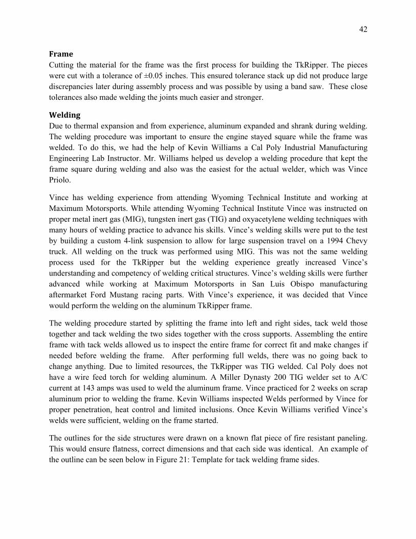
The outlines for the side structures were drawn on a known flat piece of fire resistant paneling. This would ensure flatness, correct dimensions and that each side was identical. An example of the outline can be seen below in Figure 21: Template for tack welding frame sides.
43
Figure 21: Template for tack welding frame sides
Using the template, the left and right sides were tack welded and compared to each other, which produced identical structures. Next, the side structures were tack welded together by the 3 lower and 1 upper crosspiece. Following the tack welding of the entire structure, we checked all the joints for correct fit and checked the frame to ensure it was square before final welding. It was found the rear lower cross piece had become twisted and the joints were off by an estimated 1/8 inch. The tack welds were ground down to remove the piece so it could be tack welded correctly. After the rear lower cross piece was installed and tacked, the frame was inspected for any discontinuities. After inspection, the frame was verified ready for welding by the design team.
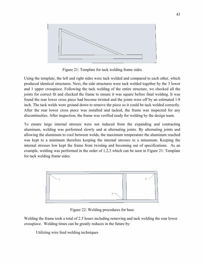
To ensure large internal stresses were not induced from the expanding and contracting aluminum, welding was performed slowly and at alternating joints. By alternating joints and allowing the aluminum to cool between welds, the maximum temperature the aluminum reached was kept to a minimum therefore keeping the internal stresses to a minumum. Keeping the internal stresses low kept the frame from twisting and becoming out of specifications. As an example, welding was performed in the order of 1,2,3 which can be seen in Figure 21: Template for tack welding frame sides.
Figure 22: Welding procedures for base
Welding the frame took a total of 2.5 hours including removing and tack welding the rear lower crosspiece. Welding times can be greatly reduces in the future by:
Utilizing wire feed welding techniques
44
Increased welding experience by person performing welds
Use of welding fixtures
Future prototypes will surely have lower manufacturing times due to these factors as well as increased quality.
SAFETY CONSIDERATIONS
There are some inherent risks to the user associated with using the TkRipper. The machine itself presents the minimum amount of safety hazards to the operator. Two main safety concerns on the TkRipper were a belt transferring torque from the engine through the CVT and a chain transferring torque from the CVT to the spool. Because the belt and the chain rotate at a high rate of speed the possibility exists for an object to become caught causing catastrophic failure or more importantly a body part to become stuck causing serious injury. In order to mitigate these safety hazards a belt guard for the CVT was installed and a chain guard was built out of 1/8 inch sheet metal and installed. The chain and belt guards completely cover the top and sides of the chain leaving only a gap in the bottom of the guards. During operation the TkRipper will be solidly mounted on the ground making it very difficult for an object or body part to become caught in the chain or belt. Using our engineering judgment we believe the TkRipper is safe during normal operation and poses no unnecessary risk or danger to the operator, however please note the rider rides at their own risk.
The shaft used for the spool was about three inches longer than the frame was wide resulting in a piece of the shaft hanging out of one side of the TkRipper. Later modifications to the TkRipper may result in the need for DC power to run an automatic control system which will require an alternator. The alternator could be mounted on the excess shaft in order to produce AC current from the rotating shaft which could then be transformed into DC and used in the control system. For the current prototype a box cover was manufactured out of 1/8 inch sheet metal which completely covers the excess shaft. Although the safety hazard posed by the rotating shaft was not as great as the chain and belt hazards we felt the added safety provided by covering the shaft was well worth our time.
Heat created by the engine could also have posed a threat to the operator after extended use of the TkRipper. A cover completely encasing the engine was considered, however we felt a cover could accumulate noxious gases from the engine exhaust as well as lead to overheating of the engine. Hazards associated with hot surfaces on the engine were mitigated by warning the operator of the hazard as well as not allowing young children to play near the TkRipper during operation.

45
CHAPTER 5 DESIGN VERIFICATION
PLAN
TEST DESCRIPTION AND EQUIPMENT
SPECIFICATION VERIFICATION CHECKLIST
46
TEST DESCRIPTION AND EQUIPMENT
Testing commenced on May 22, 2010 at Lake Lopez from 2:30 pm to 3:40 pm. The testing started with the team searching for a spot with optimal distance to unwind the rope for testing. We also looked for a sandy beach to make securing the TkRipper to the ground easy. Once we found an optimal location we secured the TkRipper to the ground with twist stakes and kite string. We decided to pull Vince Priolo on a skim board while lying on his stomach for the first test as the surface area is large and will be easier to pull across the water. Once that test was completed with ease, Vince did a deep water start on the skim board. Test number 3 was with a Hyperlite Premier 134cm wakeboard from a deep water start. There were a few more tests done pulling Vince from deep water starts on a wakeboard. Once the required data was collected we discussed the results and then packed up the TkRipper for the day.
Wheels The wheels and axle gave the TkRipper adequate ground clearance to easily roll over minor obstacles. The TkRipper had been on the wheels for the past few weeks and had not seen any faults at that time. The ground clearance design specification was for the ripper to have at least 4 inches of clearance and it had more than 4 inches of clearance when on the wheels.
Moving the machine with a single person was not an overly easy job. The placement of a handle on one of the sides would have greatly increase the ease of transportation by a single person. At the time of testing there was not a convenient place to hold onto the frame and causes the user to walk in an awkward position.
Engine / Power The engine had more than enough torque to pull a wakeboarder out of the water in a deep water starting position. The deep water start created the situation where the most amount of power is needed. We calculated the maximum horsepower needed would be 7 horsepower and that seems to be true. The 10 horsepower motor did not struggle at all when used for the deep water start.
One improvement or addition to the TkRipper would have been to add some sort of speedometer so the hand control user knows how fast they are pulling the rider. During testing, it was very difficult to tell how fast the rider was being pulled because of the geometry to the hand control user.
Hand Controls The hand controls for the throttle were easy to use. The hard part was being consistent with the throttle position. The motorcycle twist throttle worked great except for the fact that there was no return spring to allow the throttle to snap closed when let go. The throttle had to be rotated the opposite direction to stop the throttle. This could have been dangerous if the user is not experienced with motorcycle type throttles. A spring could have been added to the throttle linkage to fix this problem.
47
Splash Guard Water was not a problem with the splash guard installed. The clear splash guard was an excellent decision because we were able to watch the spool and line so if there were any problems we would have been able to identify the problem quickly and fix it before it became a larger problem. The part of the guard that wraped around the line could have been a little larger so the cable did not rub when it was not wraped tight around the spool.
Frame There were no problems with the frame during testing. One thing that was seen as a possible problem was the engine mount. The engine mounting plate was attached with bolts so we could have made small adjustment. There was a large amount of vibration from the engine and the bolts could have become lose due to the high vibration. The engine mount could be welded to the frame once the ideal engine position was determined and this possible problem would no longer be an issue.
Ground mount Securing the TkRipper to the ground was a very important process when pulling riders. We tested the TkRipper without any ground mounts and found with enough load, the rear of the machine was lifted off the ground. There were two eyelet bolts in the rear to attach to stakes but the setup we had was not sufficient. We considered using the stakes that we already had and adding some mountain climbing carabineers so the stakes could have been placed and then latched to the eyelet bolts.
Brake The large mountain bike brake we used had plenty of stopping power for this application. With the throttle in the closed position the engine stopped the spool in approximately one full rotation. With the brake applied the spool stopped immediately. With the engine braking and the disc brake, the spool nearly stopped instantly.
Spool / Line The spool held up to the testing load with no problems even though the spool bars were not perfectly horizontal, due to the hubs used. The acrylic spool ends rotated nicely due to the symmetry and very precise sizing from cutting them with the laser cutter in the Bonderson machine shop.
The cable worked well with no stretch during operation. The line easily pulled the rider out of the water and did not cause any spring action by stretching. It was very important to keep the line tight on the spool because it was seen that with a loose line, it can hit the frame and begin to cause major wear on the line's protective covering.
Rider Feel Rider feel was very important when testing the quality of the TkRipper. The TkRipper was able to easily pull the rider out of the water and had a similar feel to a boat. There are a few things

48
that needed to be adjusted for the next round of testing. The winch was able to pull the rider at too high of speeds. There needed to be a speed limiting device added for the safety of the rider. Another thing to be careful about was the rider speed when getting close to the shore. The rider can come in towards shore too fast which could have been dangerous for the rider.
SPECIFICATION VERIFICATION CHECKLIST
Design Specification Verification
Specification Verified (Y/N)
Mode for Verification Notes
Pull rider from a deep water start
Y Start rider in deep water and pull rider up with device
Pulled Vince up from a deep water start.
Pull a rider across water @ a maximum speed of 30 mph.
Y Estimate speed of rider by rider feel. Vince is very good at estimating wakeboarding speed from many years experience
Speed estimated to be 30 mph at 1/2 throttle. 35-40 mph may be possible.
Able to pull rider for 950 feet
Y Unwind entire 1,000 foot rope and pull rider close to device. Measure remaining rope not wound in spool.
Remaining line was 37.5 feet
Pull a rider on snow ski or board up a 30 degree incline @2.5 mph
Estimate by pulling rider up street on skateboard.
Not official tested but from wakeboarding tests, we concluded we have much more power than is needed.
Allow for 6 hours of run time without refuel/recharge
Y Estimated manufacturer running time limit for one tank of gas.
Manufacturer estimates 10 hours of normal usage for single tank of gas.
Primary Transport shall be done by a standard 2 inch automotive tow hitch
N Fit verification Tow hitch still needs to be installed.
Stable running by solely attaching to dirt, sand, or snow surface
Y Test device by pulling rider while attached solely to one of these specified surfaces.
Dog screw stakes were used but did not work with eyebolts due to the depth need to keep stakes in sand. String was used to attach 2 dog screw stakes to eyebolts at rear of frame. Longer stakes are required.
Stable running by solely attaching to trailer hitch
N Test device by pulling rider while attached to trailer hitch.
Tow hitch still needs to be installed
Ability to disconnect spool from drive for easy unwinding
N Part verification Spool release still needs to be designed, tested, and installed
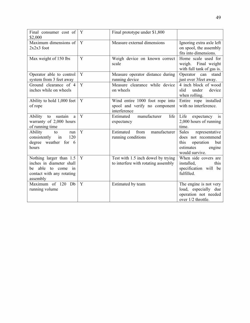
49
Final consumer cost of $2,000
Y Final prototype under $1,800
Maximum dimensions of 2x2x3 foot
Y Measure external dimensions Ignoring extra axle left on spool, the assembly fits into dimensions.
Max weight of 150 lbs Y Weigh device on known correct scale
Home scale used for weigh. Final weight with full tank of gas is.
Operator able to control system from 3 feet away
Y Measure operator distance during running device
Operator can stand just over 3feet away.
Ground clearance of 4 inches while on wheels
Y Measure clearance while device on wheels
4 inch block of wood slid under device when rolling.
Ability to hold 1,000 feet of rope
Y Wind entire 1000 foot rope into spool and verify no component interference
Entire rope installed with no interference.
Ability to sustain a warranty of 2,000 hours of running time
Y Estimated manufacturer life expectancy
Life expectancy is 2,000 hours of running time.
Ability to run consistently in 120 degree weather for 6 hours
Y Estimated from manufacturer running conditions
Sales representative does not recommend this operation but estimates engine would survive.
Nothing larger than 1.5 inches in diameter shall be able to come in contact with any rotating assembly
Y Test with 1.5 inch dowel by trying to interfere with rotating assembly
When side covers are installed, this specification will be fulfilled.
Maximum of 120 Db running volume
Y Estimated by team The engine is not very loud, especially due operation not needed over 1/2 throttle.

50
CHAPTER 6 PROJECT MANAGEMENT
PLAN
51
PROJECT MANAGEMENT PLAN
Considering the many aspects of brainstorming, designing, searching for patents, building and testing for the TkRipper a proper time management plan was necessary. In order to insure the TkRipper was built with plenty of time for testing, aggressive goals were set for each quarter.
Technical research of existing products on the market began early in the first quarter. Each group member researched websites and patent listings searching for existing products that were trying to achieve the same goals as the TkRipper. After a substantial amount of research was performed a list of technical requirements was created in an attempt to create a more marketable and superior product than what the marked currently offered. Once we had technical targets to design to, we then created an experimental procedure to gather data we could use in making calculations to meet our technical targets. The loads gathered from experimentation were used to begin designing the support frame for the TkRipper. By beginning design before winter break we were able to order parts and wait for them to arrive while we were taking time off which was critical in keeping schedule.
The second quarter consisted of finalizing the design of the components in the TkRipper and building. By mid-quarter we were done with design and ready for a complete build. At the same time we were competing in the Cal Poly Entrepreneur Club Venture Challenge in an attempt to find funding for the TkRipper. Our build time was slightly delayed due to the Venture Challenge competition; however we were able to justify the delay once we won the competition which covered our costs of prototype construction. Frame construction was completed and nearly all of the other components for the TkRipper were ordered by the end of the second quarter.
Completion of prototype construction and testing were the goals of the third quarter. The final hardware demo in the beginning of May gave us a build deadline. Safety guards for all of the rotating components were installed after the final hardware demo and the TkRipper was then ready for testing. Preliminary testing was very successful at which point we began cleaning and painting the TkRipper for the senior expo.
Persistent scheduling and group meetings were essential in ensuring the success of the TkRipper. By keeping everyone on track and on time we were able to meet our deadlines without having serious time conflicts. An overall Gantt chart (seen in Appendix D) was used throughout the project as well as small weekly calendars for the short term goals. Weekly scheduling meetings were also very helpful when coordinating parallel activities to expedite our progress.

52
APPENDIX

53
APPENDIX A: SPOOL AXLE HAND CALCULATIONS
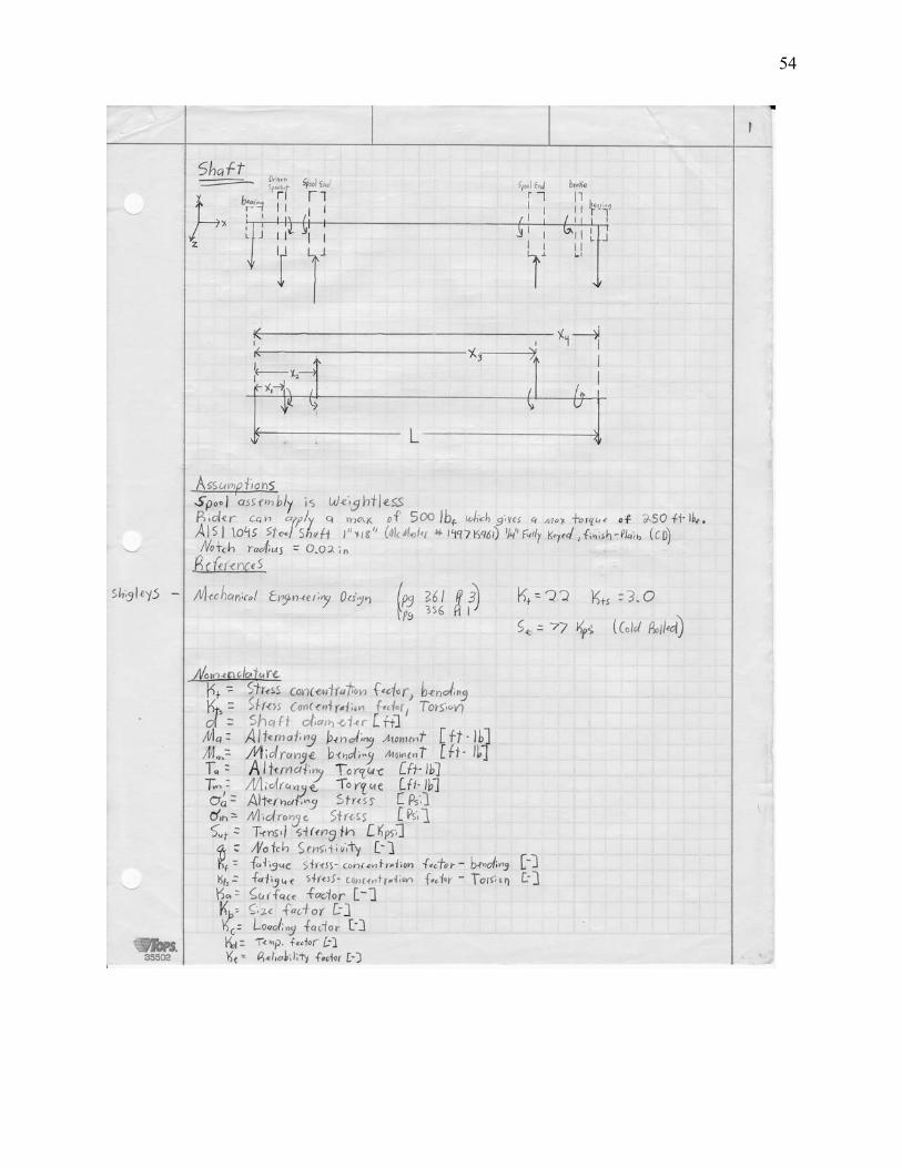
54

55
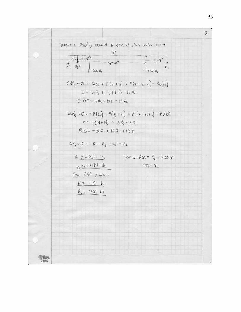
56
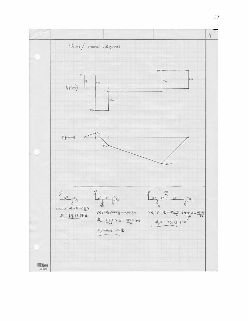
57
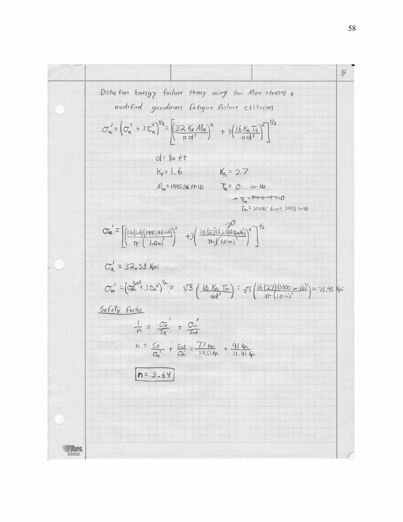
58
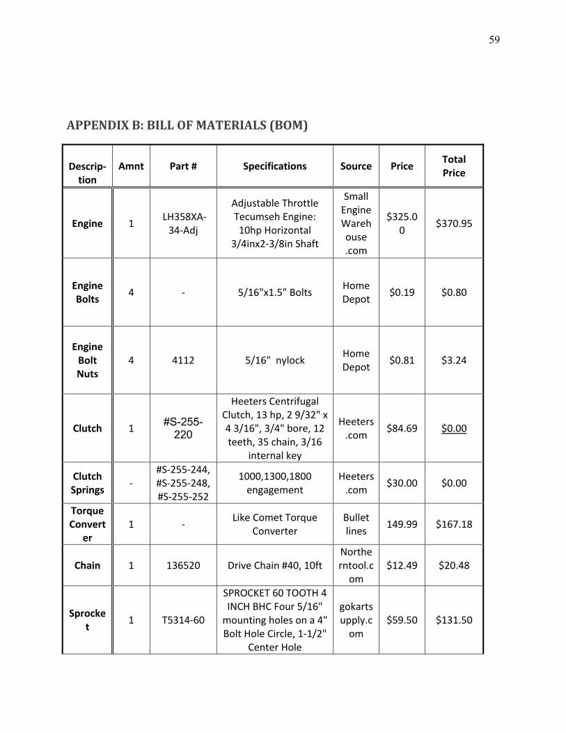
59
APPENDIX B: BILL OF MATERIALS (BOM)
Descrip‐tion
Amnt Part # Specifications Source Price Total Price
Engine 1 LH358XA‐34‐Adj
Adjustable Throttle Tecumseh Engine: 10hp Horizontal
3/4inx2‐3/8in Shaft
Small Engine Warehouse .com
$325.00
$370.95
Engine Bolts
4 ‐ 5/16"x1.5" Bolts Home Depot
$0.19 $0.80
Engine Bolt Nuts
4 4112 5/16" nylock Home Depot
$0.81 $3.24
Clutch 1 #S-255-220
Heeters Centrifugal Clutch, 13 hp, 2 9/32" x 4 3/16", 3/4" bore, 12 teeth, 35 chain, 3/16
internal key
Heeters.com
$84.69 $0.00
Clutch Springs
‐ #S‐255‐244, #S‐255‐248, #S‐255‐252
1000,1300,1800 engagement
Heeters.com
$30.00 $0.00
Torque Convert
er 1 ‐
Like Comet Torque Converter
Bullet lines
149.99 $167.18
Chain 1 136520 Drive Chain #40, 10ft Northerntool.com
$12.49 $20.48
Sprocket
1 T5314‐60
SPROCKET 60 TOOTH 4 INCH BHC Four 5/16" mounting holes on a 4" Bolt Hole Circle, 1‐1/2"
Center Hole
gokartsupply.com
$59.50 $131.50
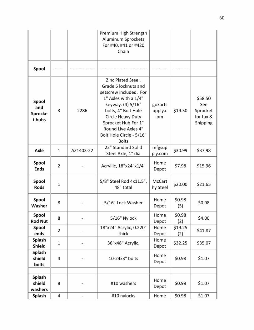
60
Premium High Strength Aluminum Sprockets For #40, #41 or #420
Chain
Spool ‐‐‐‐‐‐ ‐‐‐‐‐‐‐‐‐‐‐‐‐‐‐‐ ‐‐‐‐‐‐‐‐‐‐‐‐‐‐‐‐‐‐‐‐‐‐‐‐‐‐‐‐‐‐‐ ‐‐‐‐‐‐‐‐‐‐ ‐‐‐‐‐‐‐‐‐‐
Spool and
Sprocket hubs
3 2286
Zinc Plated Steel. Grade 5 locknuts and setscrew included. For 1" Axles with a 1/4" keyway. (4) 5/16" bolts, 4" Bolt Hole Circle Heavy Duty
Sprocket Hub For 1" Round Live Axles 4"
Bolt Hole Circle ‐ 5/16" Bolts
gokartsupply.com
$19.50
$58.50 See
Sprocket for tax & Shipping
Axle 1 AZ1403‐22 22" Standard Solid Steel Axle, 1" dia
mfgsupply.com
$30.99 $37.98
Spool Ends
2 ‐ Acryllic, 18"x24"x1/4" Home Depot
$7.98 $15.96
Spool Rods
1 5/8" Steel Rod 4x11.5",
48" total McCarthy Steel
$20.00 $21.65
Spool Washer
8 ‐ 5/16" Lock Washer Home Depot
$0.98 (5)
$0.98
Spool Rod Nut
8 ‐ 5/16" Nylock Home Depot
$0.98 (2)
$4.00
Spool ends
2 ‐ 18"x24" Acrylic, 0.220"
thick Home Depot
$19.25 (2)
$41.87
Splash Shield
1 ‐ 36"x48" Acrylic, Home Depot
$32.25 $35.07
Splash shield bolts
4 ‐ 10‐24x3" bolts Home Depot
$0.98 $1.07
Splash shield washers
8 ‐ #10 washers Home Depot
$0.98 $1.07
Splash 4 ‐ #10 nylocks Home $0.98 $1.07
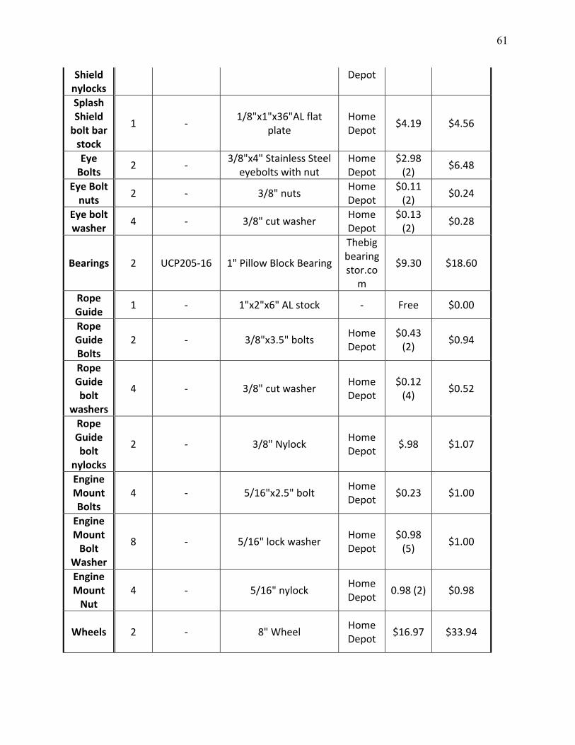
61
Shield nylocks
Depot
Splash Shield bolt bar stock
1 ‐ 1/8"x1"x36"AL flat
plate Home Depot
$4.19 $4.56
Eye Bolts
2 ‐ 3/8"x4" Stainless Steel
eyebolts with nut Home Depot
$2.98 (2)
$6.48
Eye Bolt nuts
2 ‐ 3/8" nuts Home Depot
$0.11 (2)
$0.24
Eye bolt washer
4 ‐ 3/8" cut washer Home Depot
$0.13 (2)
$0.28
Bearings 2 UCP205‐16 1" Pillow Block Bearing
Thebigbearingstor.com
$9.30 $18.60
Rope Guide
1 ‐ 1"x2"x6" AL stock ‐ Free $0.00
Rope Guide Bolts
2 ‐ 3/8"x3.5" bolts Home Depot
$0.43 (2)
$0.94
Rope Guide bolt
washers
4 ‐ 3/8" cut washer Home Depot
$0.12 (4)
$0.52
Rope Guide bolt
nylocks
2 ‐ 3/8" Nylock Home Depot
$.98 $1.07
Engine Mount Bolts
4 ‐ 5/16"x2.5" bolt Home Depot
$0.23 $1.00
Engine Mount Bolt
Washer
8 ‐ 5/16" lock washer Home Depot
$0.98 (5)
$1.00
Engine Mount Nut
4 ‐ 5/16" nylock Home Depot
0.98 (2) $0.98
Wheels 2 ‐ 8" Wheel Home Depot
$16.97 $33.94
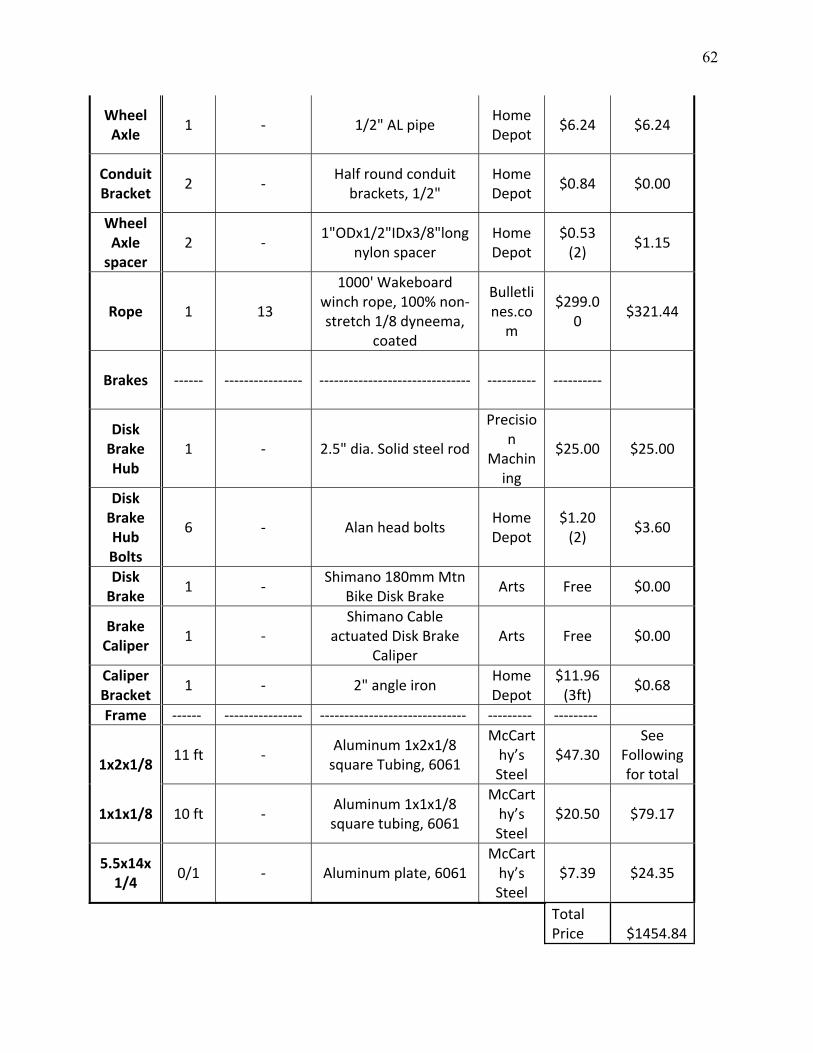
62
Wheel Axle
1 ‐ 1/2" AL pipe Home Depot
$6.24 $6.24
Conduit Bracket
2 ‐ Half round conduit brackets, 1/2"
Home Depot
$0.84 $0.00
Wheel Axle spacer
2 ‐ 1"ODx1/2"IDx3/8"long
nylon spacer Home Depot
$0.53 (2)
$1.15
Rope 1 13
1000' Wakeboard winch rope, 100% non‐stretch 1/8 dyneema,
coated
Bulletlines.com
$299.00
$321.44
Brakes ‐‐‐‐‐‐ ‐‐‐‐‐‐‐‐‐‐‐‐‐‐‐‐ ‐‐‐‐‐‐‐‐‐‐‐‐‐‐‐‐‐‐‐‐‐‐‐‐‐‐‐‐‐‐‐ ‐‐‐‐‐‐‐‐‐‐ ‐‐‐‐‐‐‐‐‐‐
Disk Brake Hub
1 ‐ 2.5" dia. Solid steel rod
Precision
Machining
$25.00 $25.00
Disk Brake Hub Bolts
6 ‐ Alan head bolts Home Depot
$1.20 (2)
$3.60
Disk Brake
1 ‐ Shimano 180mm Mtn
Bike Disk Brake Arts Free $0.00
Brake Caliper
1 ‐ Shimano Cable
actuated Disk Brake Caliper
Arts Free $0.00
Caliper Bracket
1 ‐ 2" angle iron Home Depot
$11.96 (3ft)
$0.68
Frame ‐‐‐‐‐‐ ‐‐‐‐‐‐‐‐‐‐‐‐‐‐‐‐ ‐‐‐‐‐‐‐‐‐‐‐‐‐‐‐‐‐‐‐‐‐‐‐‐‐‐‐‐‐‐ ‐‐‐‐‐‐‐‐‐ ‐‐‐‐‐‐‐‐‐
1x2x1/8
11 ft ‐ Aluminum 1x2x1/8 square Tubing, 6061
McCarthy’s Steel
$47.30 See
Following for total
1x1x1/8 10 ft ‐ Aluminum 1x1x1/8 square tubing, 6061
McCarthy’s Steel
$20.50 $79.17
5.5x14x1/4
0/1 ‐ Aluminum plate, 6061 McCarthy’s Steel
$7.39 $24.35
Total Price $1454.84
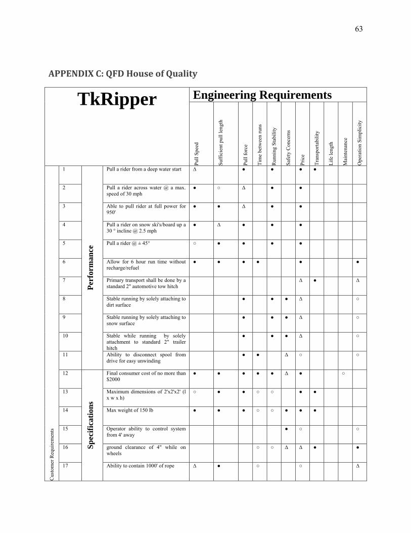
63
APPENDIX C: QFD House of Quality
Engineering Requirements TkRipper
Pull
Spee
d
Suff
icie
nt p
ull l
engt
h
Pull
forc
e
Tim
e be
twee
n ru
ns
Run
ning
Sta
bilit
y
Safe
ty C
once
rns
Pric
e
Tran
spor
tabi
lity
Life
leng
th
Mai
nten
ance
Ope
ratio
n Si
mpl
icity
1 Pull a rider from a deep water start ∆ ● ● ● ●
2 Pull a rider across water @ a max. speed of 30 mph
● ○ ∆ ● ●
3 Able to pull rider at full power for 950'
● ● ∆ ● ●
4 Pull a rider on snow ski's/board up a 30 ° incline @ 2.5 mph
● ∆ ● ● ●
5 Pull a rider @ ± 45° ○ ● ● ● ●
6 Allow for 6 hour run time without recharge/refuel
● ● ● ● ● ●
7 Primary transport shall be done by a standard 2" automotive tow hitch
∆ ● ∆
8 Stable running by solely attaching to dirt surface
● ● ● ∆ ○
9 Stable running by solely attaching to snow surface
● ● ● ∆ ○
10 Stable while running by solely attachment to standard 2" trailer hitch
● ● ● ∆ ○
11
Perf
orm
ance
Ability to disconnect spool from drive for easy unwinding
● ● ∆ ○ ○
12 Final consumer cost of no more than $2000
● ● ● ● ● ∆ ● ○
13 Maximum dimensions of 2'x2'x2' (l x w x h)
○ ● ● ○ ○ ● ●
14 Max weight of 150 lb ● ● ● ○ ○ ● ● ●
15 Operator ability to control system from 4' away
● ○ ○
16 ground clearance of 4" while on wheels
○ ○ ∆ ∆ ● ●
Cus
tom
er R
equi
rem
ents
17
Spec
ifica
tions
Ability to contain 1000' of rope ∆ ● ○ ○ ∆

64
18 Product shall be able to sustain a warranty of 2000 hours of running time
● ● ● ● ○ ●
19 Able to run consistently in 120oF weather for 6 hours
● ● ● ●
20 Limited Maintenance ● ● ○ ● ●
21 Turnaround time of 10 business days from customer purchase to delivery
○
22 Simple operation i.e. Easy to learn operation of winch
● ∆ ∆ ● ●
23 Set up time for each use ● ∆ ∆ ● ●
24
Sim
plic
ity
Ability to use for salt water riding ● ● ●
25 Nothing larger than 1.5" in diameter shall be able to come in contact with rotating assembly
● ∆ ●
26 No external parts over 150˚F ∆ ∆ ● ∆ ∆ ●
27
Safe
ty
Maximum of 20 db running volume ● ● ● ● ●
Units 31 27 47 29 36 25 54 17 9 14 42
Targets
Benchmark #1
Benchmark #2
● 3 units
Strong Correlation
○ 2 units
Medium Correlation
∆ 1 unit Small Correlation
Blank 0 units
No Correlation
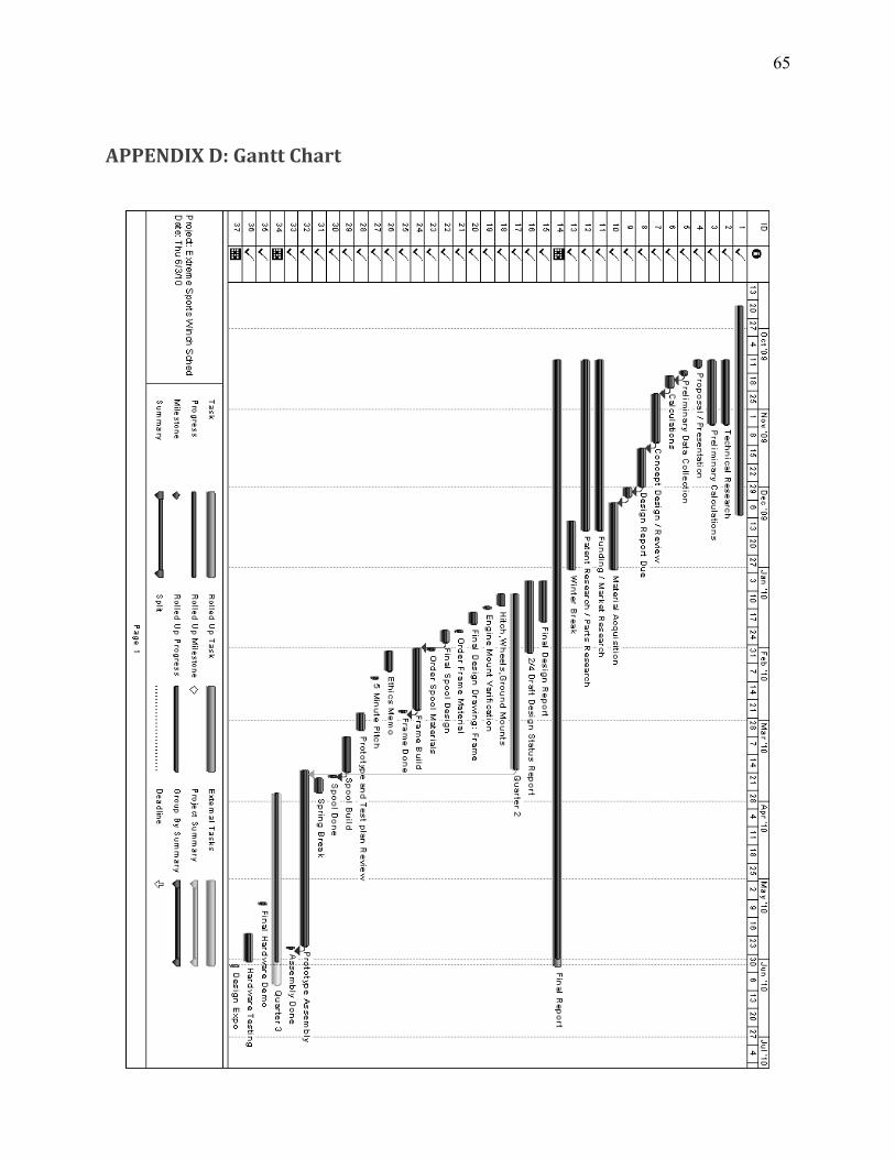
65
APPENDIX D: Gantt Chart
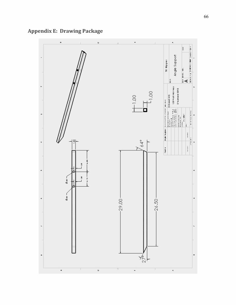
66
Appendix E: Drawing Package
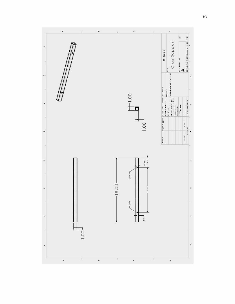
67
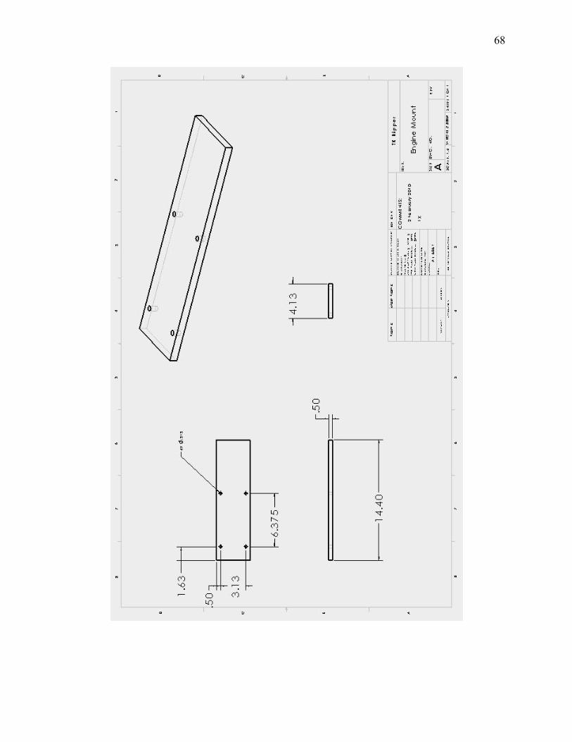
68
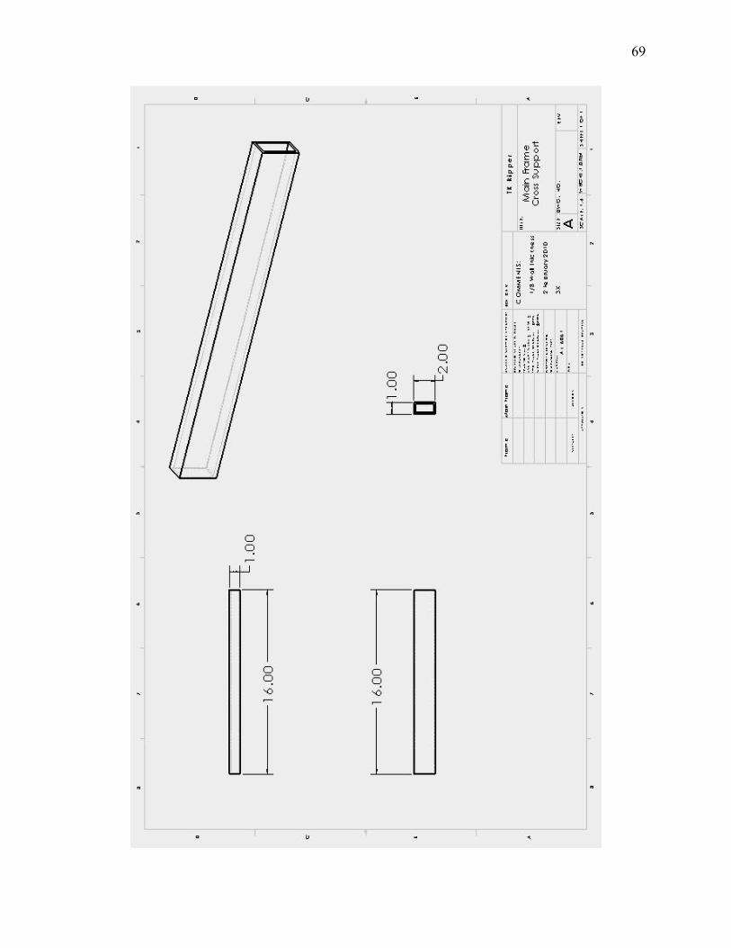
69
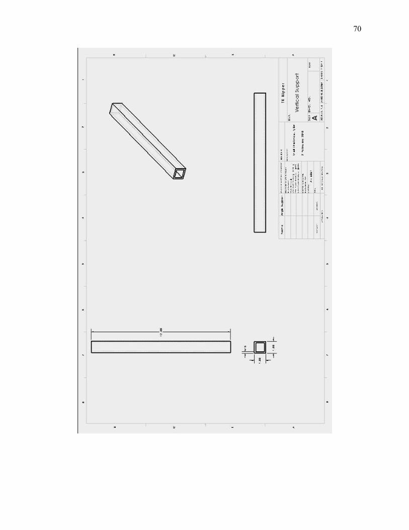
70

71
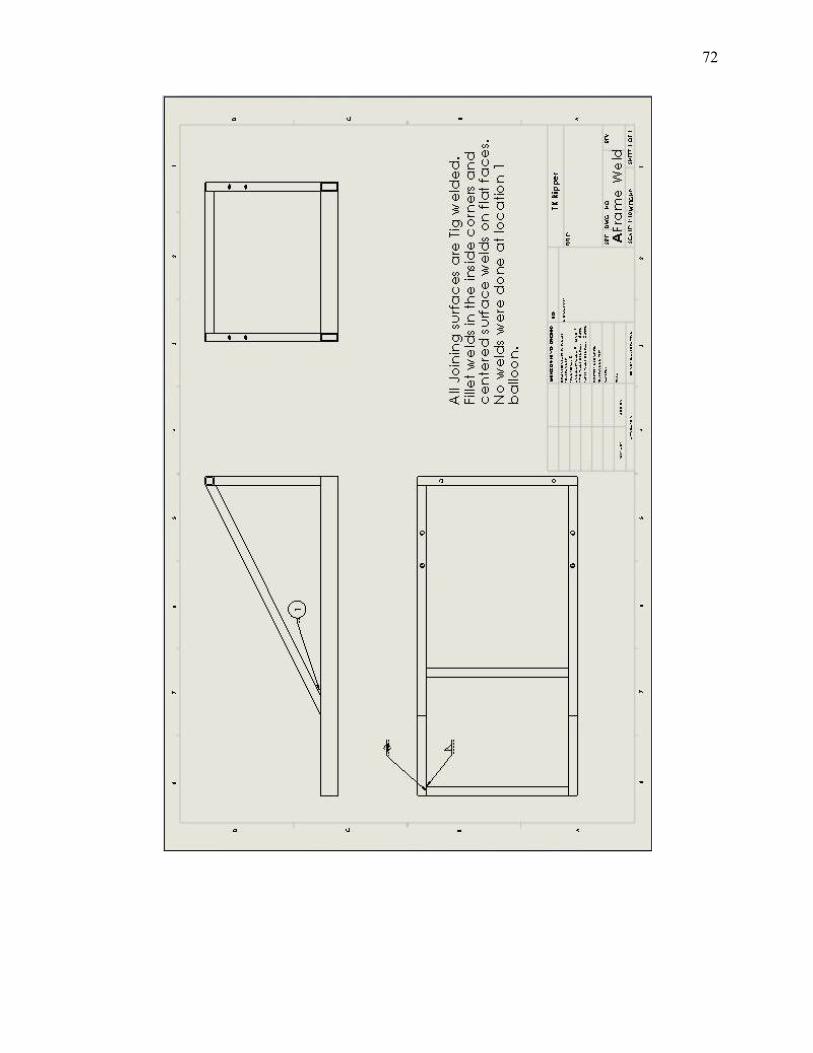
72
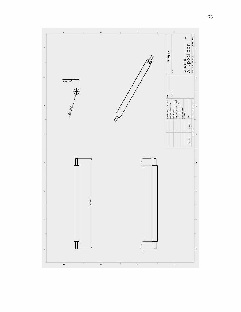
73
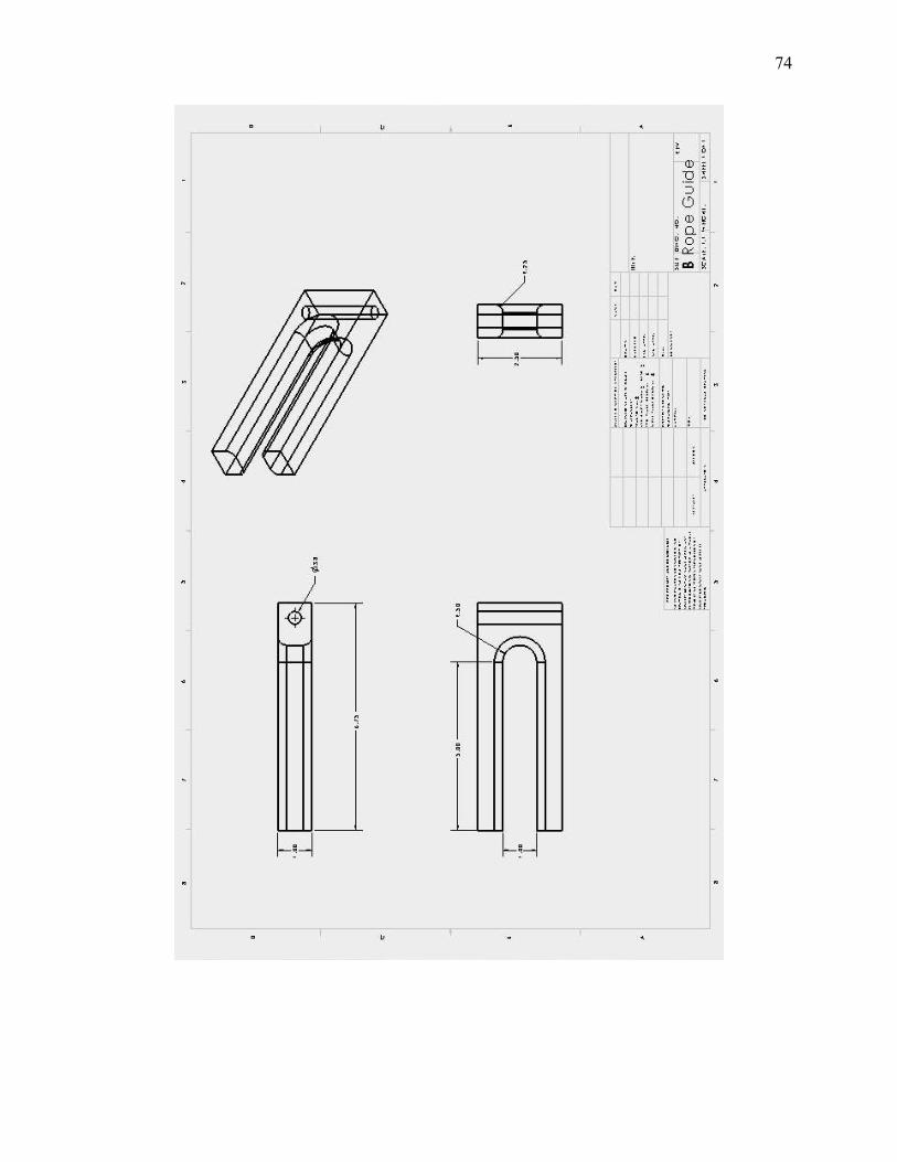
74
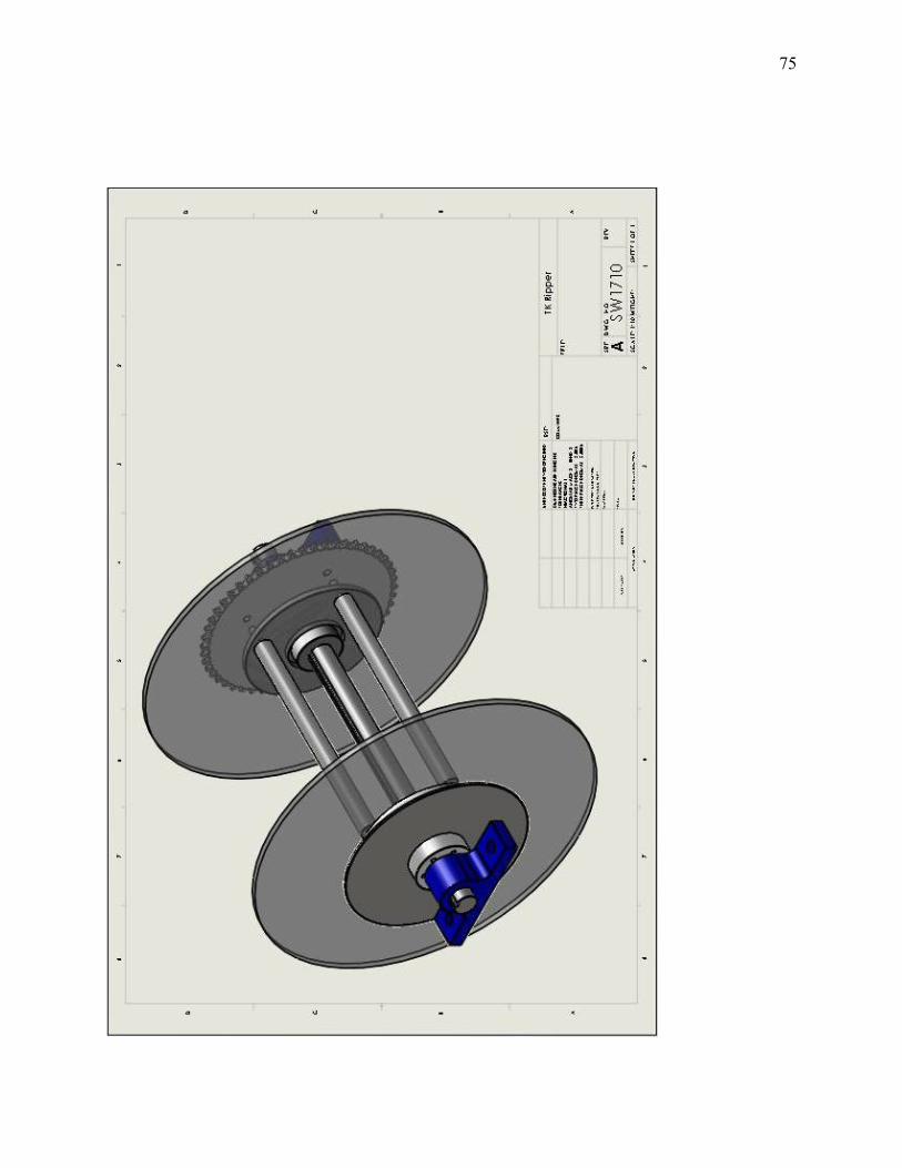
75
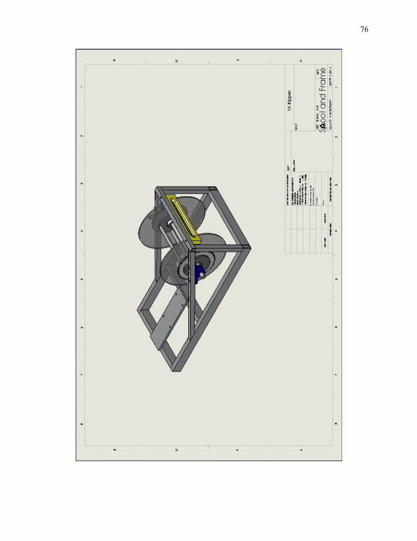
76


