Embed Size (px)
Citation preview
8th Adaptation to scientific and technical progress
of exemptions 2(c), 3 and 5 of Annex II to Directive
2000/53/EC (ELV) Report for the European Commission DG Environment under Framework
Contract No ENV.C.2/FRA/2011/0020
Final Report
Authors:
Carl-Otto Gensch, Oeko-Institut
Yifaat Baron, Oeko-Institut
Katja Moch, Oeko-Institut
17/02/2016

Evaluation of ELV Exemptions
Report for:
The European Commission
Prepared by:
Oeko-Institut e.V.
Freiburg Head Office
P.O. Box 1771
79017 Freiburg, Germany
Street Address
Merzhauser Str. 173
79100 Freiburg, Germany
Tel.:+49 (0) 761 – 4 52 95-0
Fax +49 (0) 761 – 4 52 95-288
Web: www.oeko.de
Approved by:
Adrian Gibbs, Eunomia
………………………………………………….
Contact Details
Eunomia Research & Consulting Ltd
37 Queen Square
Bristol
BS1 4QS
United Kingdom
Tel.: +44 (0)117 – 9172250
Fax: +44 (0)8717 – 142942
Web: www.eunomia.co.uk
Disclaimer
Eunomia Research & Consulting, Oeko-Institut and Fraunhofer IZM have taken due care in the
preparation of this report to ensure that all facts and analysis presented are as accurate as possible
within the scope of the project. However, no guarantee is provided in respect of the information
presented, and Eunomia Research & Consulting, Oeko-Institut and Fraunhofer IZM are not responsible
for decisions or actions taken on the basis of the content of this report.
The information and views set out in this report are those of the authors and do not necessarily reflect
the official opinion of the Commission. The Commission does not guarantee the accuracy of the data
included in this study. Neither the Commission nor any person acting on the Commission's behalf may
be held responsible for the use, which may be made of the information contained therein.

Evaluation of ELV Exemptions
i
Contents Contents .......................................................................................................................................... i
1.0 Background .......................................................................................................................... 1
2.0 Scope ................................................................................................................................... 1
3.0 Overview ............................................................................................................................... 2
4.0 Exemption 2(c) “Aluminium with a lead content up to 0.4 % by weight” .......................... 4
4.1 Description of Requested Exemption ................................................................................ 4
4.1.1 History of the Exemption ............................................................................................. 5
4.1.2 Technical Background ................................................................................................. 6
4.1.3 Amount of Lead Used under the Exemption .............................................................. 7
4.2 Stakeholders’ Justification for the Exemption .................................................................. 8
4.2.1 General Justification .................................................................................................... 8
4.2.2 Cast Alloys ..................................................................................................................... 8
4.2.3 Wrought Alloys ............................................................................................................ 10
4.3 Critical Review ................................................................................................................... 12
4.3.1 Cast Alloys ................................................................................................................... 12
4.3.2 Wrought Alloys ............................................................................................................ 14
4.3.3 Conclusions ................................................................................................................ 18
4.4 Recommendation .............................................................................................................. 20
4.5 References Exemption 2(c) .............................................................................................. 20
5.0 Exemption 3 “Copper alloy containing up to 4 % lead by weight” ................................... 22
5.1 Description of Requested Exemption .............................................................................. 22
5.1.1 History of the Exemption ........................................................................................... 23
5.1.2 Technical Background ............................................................................................... 23
5.1.3 Amount of Lead Used under the Exemption ............................................................ 25
5.2 Stakeholder Contributions ................................................................................................ 27
5.2.1 Stakeholders Justification for Exemption Renewal ................................................. 27
5.2.2 Possible Substance Alternatives ............................................................................... 30
5.2.3 Road Map for Substitution ........................................................................................ 35
5.3 Critical Review ................................................................................................................... 36
5.4 Recommendation .............................................................................................................. 40
5.5 References Exemption 3 .................................................................................................. 40
6.0 Exemption 5 “Lead and lead compounds in batteries” ................................................... 42
6.1 Description of Exemption ................................................................................................. 43
6.1.1 History of the Exemption ........................................................................................... 44
16/02/2016
ii
6.1.2 Technical Background .............................................................................................. 44
6.1.3 Alternative Battery Chemistries ................................................................................ 51
6.1.4 Possible Alternatives that May Reduce the Use of Lead in Batteries ................... 59
6.1.5 Stakeholder Justification for Exemption Renewal .................................................. 59
6.1.6 Stakeholder Justification for Lead-acid Battery Phase-Out and Revoking of
Exemption 5 ............................................................................................................................ 60
6.1.7 Economic Aspects ..................................................................................................... 61
6.1.8 Environmental Arguments ........................................................................................ 64
6.1.9 Road Map for Substitution ....................................................................................... 66
6.1.10 Conflicting Views Regarding the Performance of Li-Ion Batteries and their
Suitability as a Substitute for Lead-acid Batteries ............................................................... 69
6.2 Critical Review .................................................................................................................. 77
6.2.1 Scientific and Technical Practicability of Lead Substitution in Automotive
Batteries .................................................................................................................................. 77
6.2.2 Aspects Related to the Recycling of Batteries ........................................................ 84
6.2.3 Conclusions ................................................................................................................ 87
6.3 Recommendation ............................................................................................................. 90
6.4 References Exemption 5 ................................................................................................. 92
A.1.0 Appendix A.1.0: The History of Exemption 2(c) ............................................................. 95
A.2.0 Appendix A.2.0: List of Relevant Properties and Performance Indicators Related to
Exemption 2(c) ............................................................................................................................ 97
A.3.0 Appendix A.3.0 Summary of Test Reports submitted as Annexes to the contribution of
ACEA et al. (2014) Concerning Exemption 3 .............................................................................. 98
A.4.0 Appendix A.4.0: Comparison of Information Provided Related to Ecobrass from the
Various Stakeholder, Concerning Exemption 3 ........................................................................ 102
A.5.0 Appendix A.5.0 : Information Concerning Vehicles on the Market not Utilising a Lead-
Acid Battery System .................................................................................................................. 104
A.6.0 Appendix A.6.0: Description of Relevant Stages Required as Part of the Development
Tasks of Battery Technologies at the Component and Vehicle Levels. ................................... 105
Evaluation of ELV Exemptions
1
1.0 Background Directive 2000/53/EC on end-life-vehicles ("ELV” Directive) restricts the use of
certain hazardous substances in vehicles. The Directive includes a list of exemptions
to these use restrictions, which is adapted regularly to scientific and technical
progress according to the respective provisions in the Directive.
Following the requirements of Article 4(2)(a) of Directive 2000/53/EC on end-of-life
vehicles, Member States of the European Union have to ensure that materials and
components of vehicles put on the market since 1 July 2003 do not contain lead,
mercury, hexavalent chromium and cadmium. A limited number of applications
exempted from the provision of this article are listed in Annex II to the Directive as
well as the scope and the expiry date of the exemption and the labelling requirement
according to Article 4(2)(b)(iv)1 (if applicable).
Based on Article 4(2)(b), Annex II is to be adapted to scientific and technical progress
by the Commission on a regular basis. This is done in order to check whether existing
exemptions are still justified with regard to the requirements laid down in Article
4(2)(b)(ii), whether additional exemptions have been proposed on the basis of the
same article and whether exemptions are no longer justified and need to be deleted
from the Annex with regard to Article 4(2)(b)(iii). Furthermore, the adaptation
procedure has to – as necessary – establish maximum concentration values up to
which the restricted substances shall be tolerated (Article 4(2)(b)(i)) and designate
those materials and components that need to be labelled.
With regard to this adaptation, Annex II has already been adapted 6 times (2002,
2005, 2008, 2010, 2011 and 2013)2.
2.0 Scope Under Framework Contract no. ENV.C.2/FRA/2011/0020, a consortium led by
Eunomia Research & Consulting was requested by DG Environment of the European
Commission to provide technical assistance for the evaluation of selected exemptions
of the ELV Directive. The evaluation is to provide recommendations for a clear and un-
ambiguous wording of the reviewed exemptions. The work has been undertaken by
the Oeko-Institut, and has been peer reviewed by Eunomia Research & Consulting.
The evaluation includes consultation with stakeholders on the possible adaptation of
the Annexes and the set-up of a website in order to keep stakeholders informed on
the progress of work (http://elv.exemptions.oeko.info/index.php?id=58).
1 Article 4(2)(b)(iv) provides that designated materials and components of vehicles that can be stripped
before further treatment have to be labelled or made identifiable by other appropriate means.
2 For further information please see: http://ec.europa.eu/environment/waste/elv_index.htm
16/02/2016
2
In the course of the project, a stakeholder consultation was conducted. The
consultation was launched, on 24 September 2014, and ran for twelve weeks, until
17 December 2014. The exemptions covered in this stakeholder consultation,
specified in Table 3-1, were reviewed in agreement with the Commission, in light of
the review period specified for these exemptions in Annex II of the ELV Directive. All
non-confidential stakeholder contributions, submitted during the consultation, were
made available on the ELV Exemptions website as well as on the EU CIRCABC website
(Communication and Information Resource Centre for Administrations, Businesses
and Citizens):
https://circabc.europa.eu (Browse categories > European Commission >
Environment > ELV exemptions, at top left, click on "Library").
Furthermore, a targeted stakeholder meeting took place on 10 April 2015,
concerning two of the exemptions, to facilitate a better understanding of the available
information. Presentations held at the meeting have also been made available on the
EU CIRCABC website as well as on the ELV Exemptions website.
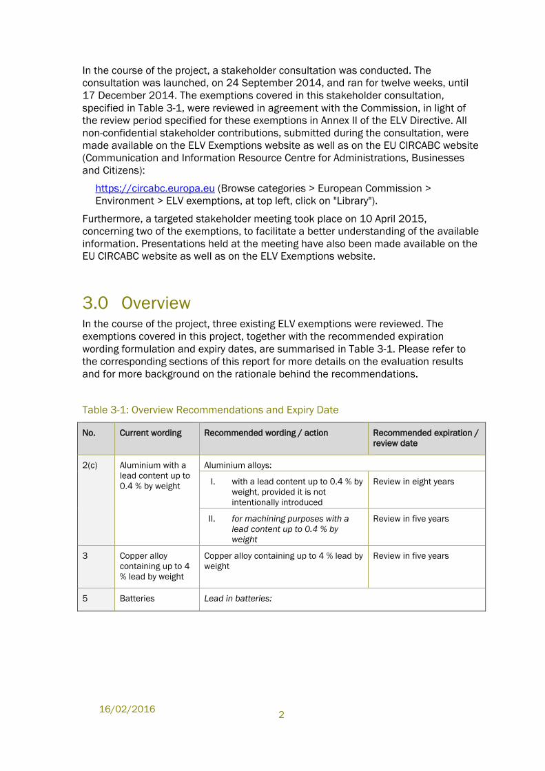
3.0 Overview In the course of the project, three existing ELV exemptions were reviewed. The
exemptions covered in this project, together with the recommended expiration
wording formulation and expiry dates, are summarised in Table 3-1. Please refer to
the corresponding sections of this report for more details on the evaluation results
and for more background on the rationale behind the recommendations.
Table 3-1: Overview Recommendations and Expiry Date
No. Current wording Recommended wording / action Recommended expiration /
review date
2(c) Aluminium with a
lead content up to
0.4 % by weight
Aluminium alloys:
I. with a lead content up to 0.4 % by
weight, provided it is not
intentionally introduced
Review in eight years
II. for machining purposes with a
lead content up to 0.4 % by
weight
Review in five years
3 Copper alloy
containing up to 4
% lead by weight
Copper alloy containing up to 4 % lead by
weight
Review in five years
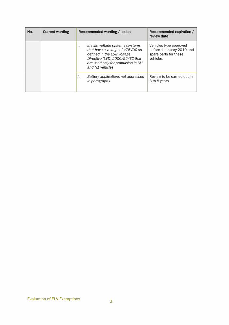
5 Batteries Lead in batteries:
Evaluation of ELV Exemptions
3
No. Current wording Recommended wording / action Recommended expiration /
review date
I. in high voltage systems (systems
that have a voltage of >75VDC as
defined in the Low Voltage
Directive (LVD) 2006/95/EC that
are used only for propulsion in M1
and N1 vehicles
Vehicles type approved
before 1 January 2019 and
spare parts for these
vehicles
II. Battery applications not addressed
in paragraph I.
Review to be carried out in
3 to 5 years
16/02/2016
4
4.0 Exemption 2(c) “Aluminium with a lead
content up to 0.4 % by weight”
Abbreviations and Definitions
AA 2011 Aluminium alloy containing lead
AlEco62Sn Lead free alloy alternative used to substitute AA 2011
AA 6023 Lead free alloy alternative used to substitute AA 2011, also
known as AlMgSiSnBi
Al Aluminium
CEN European Committee for Standardization (from French: Comité
Européen de Normalisation’)
EAA European Aluminium Association
EN AW-AlMg1SiPb Al alloy containing lead also known as EN AW 6262
EN AW-AlCu6BiPb Al alloy containing lead also known as EN AW-2011
OEA Organisation of European Aluminium Refiners and Remelters
OEM Original Equipment Manufacturer
Pb Lead
R&D Research & Development
Declaration
The phrasings and wordings of stakeholders’ explanations and arguments have been
adopted from the documents provided by the stakeholders as far as required and
reasonable in the context of the evaluation at hand. Formulations have been altered
in cases where it was necessary to maintain the readability and comprehensibility of
the text.
4.1 Description of Requested Exemption
The current wording of Exemption 2(c) in Annex II of the ELV Directive is:
Aluminium with a lead content up to 0.4 % by weight.
The exemption is specified in the Annex as due for review in 2015. Industry
stakeholders from ACEA, JAMA, KAMA, CLEPA and EAA3 submitted a joint response
during the consultation and requested the continuation of Exemption 2(c).
3 ACEA et al. (2014) ACEA, JAMA, KAMA, CLEPA and EAA, Industry contribution of ACEA, JAMA, KAMA,
CLEPA and EAA, submitted 10.12.2014,
Evaluation of ELV Exemptions
5
4.1.1 History of the Exemption
Article 4(2)(b) of the legal text of the ELV Directive published in 2000 required that
the Commission evaluate the need for exempting the use of the ELV substances in a
number of applications. This included applications, in which lead a constituent of
aluminium alloys used in wheel rims, engine parts and window levers. In light of this
requirement, an evaluation was carried out, results of which recommended an
exemption. A first version of the exemption was published in the first amendment of
the Directive, for “Aluminium for machining purposes…” The exemption scope, and
respective formulation, changed a few time since publication of this first version (for
further details see Appendix A.1.0).
The first revision of Annex II4 contained a footnote specifying, “a maximum
concentration value up to 0.4 % by weight of lead in aluminium shall also be
tolerated provided it is not intentionally introduced” This footnote was eventually
deleted. In the third revision of Annex II in 2008, the wording of the exemption was
changed, based on request of the Organisation of European Aluminium Refiners and
Remelters (OEA) and the European Aluminium Association (EAA) who claimed a
general exemption of up to 0.4% for the unintentional content of lead in aluminium
alloys was needed. Oeko-Institut5 recommended the deletion of “for machining
purposes” from the wording, resulting in the following formulation: “Aluminium with a
lead content up to 0.4% by weight”, which thereby inherently allows unintentionally
present lead within the scope of the exemption (though not specifically mentioned in
the wording formulation).
Exemption 2(c) in its current wording was published in the third revision of Annex II in
20086 and reviewed in 2009/2010. At that time, a review within five years was
recommended, seeing as industry did not provide sufficiently detailed evidence, to
clarify that a reduction of lead concentrations in aluminium alloys was not feasible,
despite the general availability of lead free alternatives that had become apparent.7
The requirement to review Exemption 2(c) in 2015 was published in the fifth revision
of Annex II in 2011.8
http://elv.exemptions.oeko.info/fileadmin/user_upload/Consultation_2014_1/Ex_2c/20141210_ACE
A_AnnexII_2c_amended.pdf; last accessed 10.03.2015
4 Commission Decision 2002/525/EC of 27 June 2002 amending Annex II of Directive 2000/53/EC of
the European Parliament and of the Council on end-of-life vehicles
5 Oeko-Institut (2008), Dr. Joachim Lohse et al., Oeko-Institut; Otmar Deubzer, Fraunhofer IZM:
Adaptation to Scientific and Technical Progress of Annex II Directive 2000/53/EC, Contract
N°07010401/2007/470145/ATA/G4, final report; Freiburg, 16 January 2008;
http://elv.exemptions.oeko.info/fileadmin/user_upload/Background/Final_report_ELV_Annex_II_revisi
on.pdf
6 Commission Decision 2008/689/EC amending Annex II of Directive 2000/53/EC of the European
Parliament and of the Council on end-of-life vehicles
7 Op. cit. Oeko-Institut 2010
8 Commission Directive 2011/37/EU of 30 March 2011 amending Annex II to Directive 2000/53/EC
of the European Parliament and of the Council on end-of-life vehicles
16/02/2016
6
4.1.2 Technical Background
ACEA et al. (2014)9 differentiate between aluminium alloys where the lead content is
unintentional, due to the use of secondary raw material from aluminium scrap, used
for cast alloys, and between aluminium alloys, where lead is intentionally added for
machining purposes, which are used for (some types of) wrought alloys.
Aluminium, as castings and wrought alloys (extrusions, forgings and sheets), is used
in car bodies, closures, chassis, suspensions and wheels.10
4.1.2.1 Cast Alloys
ACEA et al.11 state that in cast alloys, the lead content is a result of the use of
recycled (secondary) aluminium. Lead is present as an impurity in the Al recycling
stream and is not necessary to attain specific properties in cast alloys.
Cast alloys are used for big parts in vehicles. Applications indicated by ACEA et al.12
are engine-blocks, cylinder-heads, gearbox housings, engine sub frames. ACEA et al.13
estimate that 95% of the total lead in aluminium alloys per vehicle is introduced
through cast aluminium alloys.
CEN standards allow a lead content up to 0.6% in these alloys.14 ACEA et al.15
estimate that casting alloys might contain 0.2 to 0.4% lead, depending on the source
of material.
4.1.2.2 Wrought Alloys
According to ACEA et al.16 leaded Al wrought alloys are needed for a small number of
car components to “ensure appropriate material properties for machining and safety-
related corrosion resistance purposes.”
The wrought alloys require that lead be added intentionally to mediate favourable
machining properties, such as a sufficient surface finish, part precision and a long
tool life. ACEA et al.17 explain that the minimal performance for the properties low
9 Op. cit. ACEA et al. (2014)
10 EAA (2013), European Aluminium Association EAA (2013), Aluminium in Cars – Unlocking the light-
weighting potential; http://www.alueurope.eu/wp-content/uploads/2013/10/EAA-Aluminium-in-Cars-
Unlocking-the-light-weighting-potential_September2013_03.pdf
11 Op. cit. ACEA et al. (2014)
12 Op. cit. ACEA et al. (2014)
13 Op. cit. ACEA et al. (2014)
14 European standard EN 1706 sets standards for a great number of aluminium alloys and specifies
different limits for lead.
15 Op. cit. ACEA et al. (2014)
16 Op. cit. ACEA et al. (2014)
17 Op. cit. ACEA et al. (2014)
Evaluation of ELV Exemptions
7
friction and corrosion resistance are also achieved in consequence of the addition of
lead.
Application examples where the use of lead is unavoidable indicated by ACEA et al.18
are: valve actuation, valve operation, internal bushing of accelerator sensors,
expansion valves, pressure sliding plates, axis pins for pivot levers, pumps, high
pressure regulating valves, plungers, pistons, brake power assist units and oil return
stop valves.
ACEA et al. state that wrought alloy components are usually small parts and make up
5% of the total lead in Al alloys per vehicle.19
4.1.3 Amount of Lead Used under the Exemption
ACEA et al.20 estimate that the use of the different Al alloys results in an average lead
content of 80 g per vehicle. The lead content due to Al alloys can range from 40 to
200 g of lead in Aluminium material per vehicle depending on the car model; the 200
g lead per vehicle refers to car models with for example, automatic drive and large
engines.
Based on the 13.3 million vehicles newly registered in the EU 27 in 2013, ACEA et
al.21 estimate that the use of Al alloys results in a total amount of lead of 1,064
tonnes per year.
The following table compiles data available from ACEA et al.22 and from earlier
reviews to demonstrate how the average lead content in Al alloys per vehicle has
changed over the past few years. For 2022, ACEA et al.23 expect that the
unintentional lead content in Al alloys will decrease by an average of approximately
0.1%24 by weight (see Section 4.2.2 for further background), resulting in a lead
content per vehicle of 50 g.
18 Op. cit. ACEA et al. (2014)
19 Op. cit. ACEA et al. (2014)
20 Op. cit. ACEA et al. (2014)
21 Op. cit. ACEA et al. (2014)
22 Op. cit. ACEA et al. (2014)
23 Op. cit. ACEA et al. (2014)
24 The estimation of ACEA et al. on the development of the lead content in recycled Al is presented in
section 4.2.2. In this estimation, ACEA et al. (2014) indicate an overall average decrease of the lead
amount in Al alloys: understood to mean that the maximum lead content in recycled Al might drop from
0.4% (see Table 4-2) to an estimated EU wide average of 0.3% by weight.
16/02/2016
8
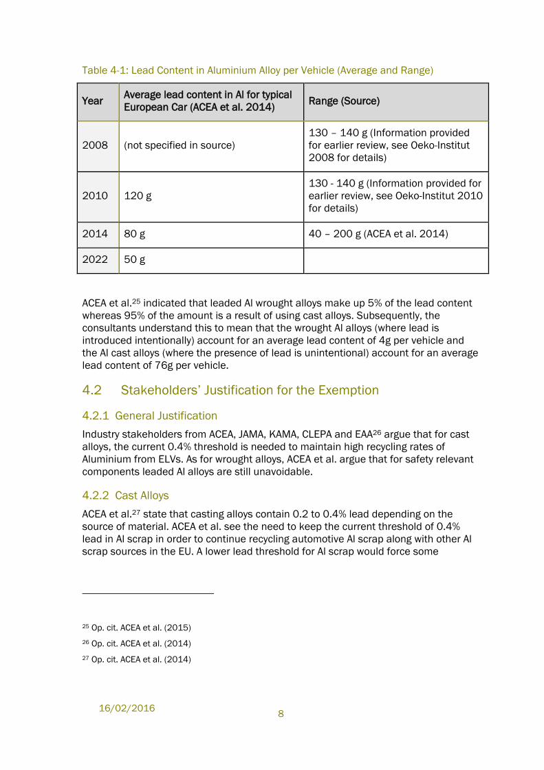
Table 4-1: Lead Content in Aluminium Alloy per Vehicle (Average and Range)
Year Average lead content in Al for typical
European Car (ACEA et al. 2014) Range (Source)
2008 (not specified in source)
130 – 140 g (Information provided
for earlier review, see Oeko-Institut
2008 for details)
2010 120 g
130 - 140 g (Information provided for
earlier review, see Oeko-Institut 2010
for details)
2014 80 g 40 – 200 g (ACEA et al. 2014)
2022 50 g
ACEA et al.25 indicated that leaded Al wrought alloys make up 5% of the lead content
whereas 95% of the amount is a result of using cast alloys. Subsequently, the
consultants understand this to mean that the wrought Al alloys (where lead is
introduced intentionally) account for an average lead content of 4g per vehicle and
the Al cast alloys (where the presence of lead is unintentional) account for an average
lead content of 76g per vehicle.
4.2 Stakeholders’ Justification for the Exemption
4.2.1 General Justification
Industry stakeholders from ACEA, JAMA, KAMA, CLEPA and EAA26 argue that for cast
alloys, the current 0.4% threshold is needed to maintain high recycling rates of
Aluminium from ELVs. As for wrought alloys, ACEA et al. argue that for safety relevant
components leaded Al alloys are still unavoidable.
4.2.2 Cast Alloys
ACEA et al.27 state that casting alloys contain 0.2 to 0.4% lead depending on the
source of material. ACEA et al. see the need to keep the current threshold of 0.4%
lead in Al scrap in order to continue recycling automotive Al scrap along with other Al
scrap sources in the EU. A lower lead threshold for Al scrap would force some
25 Op. cit. ACEA et al. (2015)
26 Op. cit. ACEA et al. (2014)
27 Op. cit. ACEA et al. (2014)
Evaluation of ELV Exemptions
9
recyclers to dilute their recycled alloys with more primary material to stay below the
exempted levels.
Compared to the last revision, ACEA et al.28 recognize a slight reduction of the
average lead amount in recycling Al material because vehicles that were
manufactured under the regime of the ELV lead restrictions (adopted in 2000)
started to appear in the recycling stream in 2010 (assuming an average lifetime of
cars of 10 to 15 years). ACEA et al. further explain that the trend of a lower lead
content in Al scrap is more apparent in Northern Europe than in Southern / Eastern
Europe because vehicles have a longer lifetime in the latter regions and vehicles
produced under the stricter ELV lead restrictions shall enter the recycling loop later.
ACEA et al. estimate that the average amount of lead in Al scrap shall only decrease
below the 0.4% threshold for lead after the year 2020 (see Table 4-2).
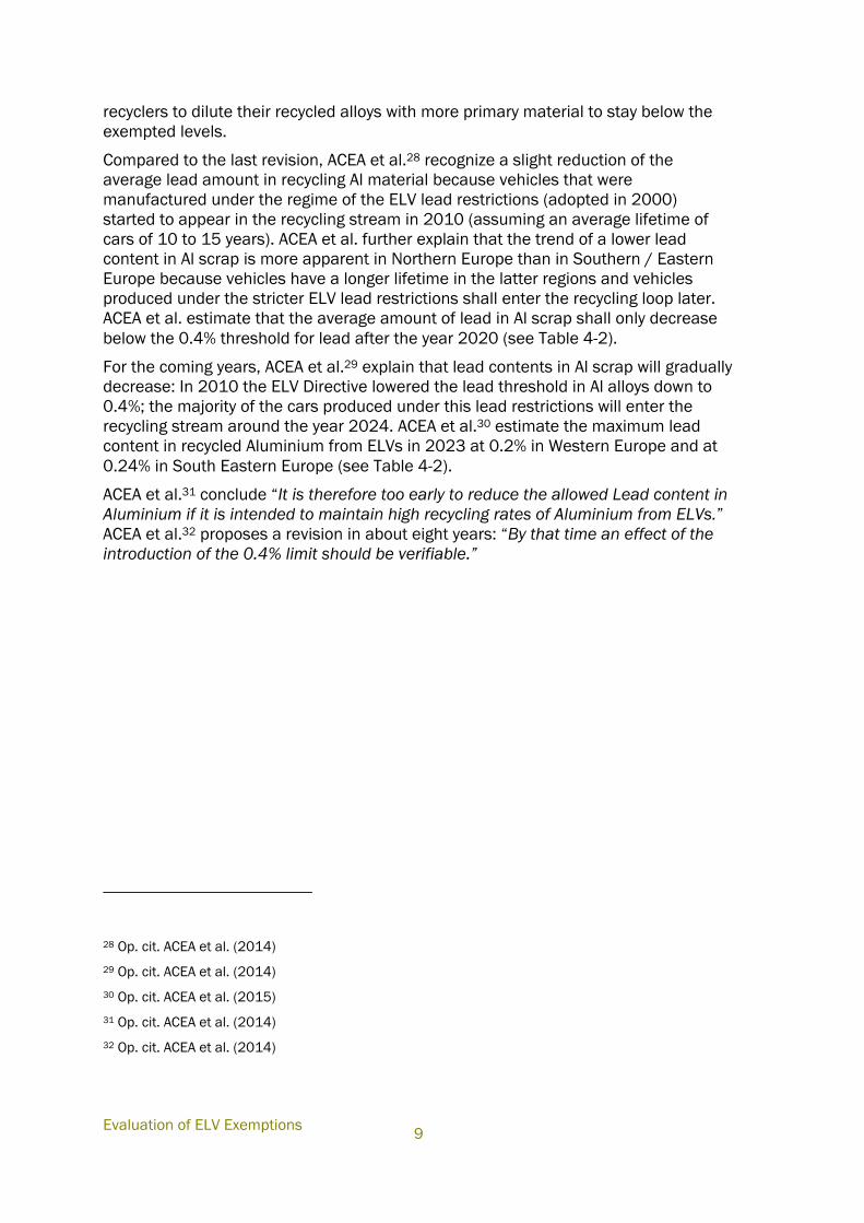
For the coming years, ACEA et al.29 explain that lead contents in Al scrap will gradually
decrease: In 2010 the ELV Directive lowered the lead threshold in Al alloys down to
0.4%; the majority of the cars produced under this lead restrictions will enter the
recycling stream around the year 2024. ACEA et al.30 estimate the maximum lead
content in recycled Aluminium from ELVs in 2023 at 0.2% in Western Europe and at
0.24% in South Eastern Europe (see Table 4-2).
ACEA et al.31 conclude “It is therefore too early to reduce the allowed Lead content in
Aluminium if it is intended to maintain high recycling rates of Aluminium from ELVs.”
ACEA et al.32 proposes a revision in about eight years: “By that time an effect of the
introduction of the 0.4% limit should be verifiable.”
28 Op. cit. ACEA et al. (2014)
29 Op. cit. ACEA et al. (2014)
30 Op. cit. ACEA et al. (2015)
31 Op. cit. ACEA et al. (2014)
32 Op. cit. ACEA et al. (2014)
16/02/2016
10
Table 4-2: Estimated Maximum Lead Content in Recycled Aluminium from ELVs in
Western Europe and South Eastern Europe
Source: ACEA et al. (2015)
As for possible processes to remove lead from Al scrap, ACEA et al.33 state that they
are in the stage of laboratory/academic research or small scale testing, and that they
are economically and ecologically not viable mostly due to the high amount of energy
required. To support this conclusion, ACEA et al. refer to a literature study on “Existing
technologies for lead removal from Aluminium melts” commissioned by OEA. The
study was carried out by MIMI Tech UG and finalized in June 2012. The study
reviewed a number of methods to remove lead from aluminium alloys. ACEA et al.34
summarised the study in their contribution. The summary focuses on the feasibility of
the methods “phase separation, electrochemical refining and vacuum distillation,
concluding that “All three methods are in the stage of laboratory/academic research
and small scale testing, the obstacles to the development of these methods are not
only economic in terms of system and equipment cost, but also an environmental
issue, mostly due to the high amount of energy required”.
4.2.3 Wrought Alloys
ACEA et al.35 state that “For a very limited number of parts, lead content is still
required to ensure:
a) necessary material properties (machining / durability / low friction); and
b) high safety standard (part precision and corrosion resistance);
33 Op. cit. ACEA et al. (2014)
34 Op. cit. ACEA et al. (2014)
35 Op. cit. ACEA et al. (2014)
Evaluation of ELV Exemptions
11
The industry has changed to lead free alloys as far as possible.”
ACEA et al.36 state that some applications of the AA 2011 alloy have been replaced by
applying the lead-free alternatives e.g. AlEco62Sn or AA 6023 (AlMgSiSnBi).
In this regard, where asked where such lead free alternatives are used, ACEA et al. 37
specified that “Lead free Aluminium alloys are applied e.g. in housings, disk plates,
closing bodies, hexagonal nuts, sealing plugs, anchors, washers. One has to be
aware that part designation is not standardized and can vary from company to
company. In general, applications are in focus where high surface precision is not
crucial and high mechanical mostly static load needs to be transmitted”.
However it is explained that there are still various properties relevant for the
machining of lead, for which the use of lead [currently38] cannot be avoided. In this
respect ACEA et al.39 specify machining as follows: “The lead content is necessary to
reach the performance and accuracy requirements for machining purposes
(sufficient surface finish, part precision and tool life, lowering energy requirement to
machine parts), low friction properties.”.
ACEA et al.40 stress that there are additional properties achieved by the addition of
lead, such as corrosion resistance. The corrosion resistance is specified to be
important for safety relevant parts: “Resistances against corrosion – in special pitting
corrosion in acid systems e.g. brake systems. This corrosion resistance can only be
achieved by lead – alternative alloys are not available. To prevent serious safety
risks, it is unavoidable to use Lead as an alloy element for safety relevant
parts/components like on chassis and brake-system applications.”
As an additional property of leaded Al wrought alloys, ACEA et al.41 also mention
emergency lubrication properties. This is not further detailed by ACEA et al.
ACEA et al.42 state that “To our knowledge there are no machining aluminium
wrought alloys with lower specified intentional lead content available on the market.
There is no information on lead-free substitutes with equivalent machining
properties.”
ACEA et al.43 do not expect a solution to be found in the short or medium term and
ask for a continuation of the exemption for eight years.
36 Op. cit. ACEA et al. (2014)
37 Op. cit. ACEA et al. (2015)
38 Added by the consultants.
39 Op. cit. ACEA et al. (2014)
40 Op. cit. ACEA et al. (2014)
41 Op. cit. ACEA et al. (2015)
42 Op. cit. ACEA et al. (2015)
43 Op. cit. ACEA et al. (2014)
16/02/2016
12
4.3 Critical Review
ACEA et al.44 provided information that clarifies that a large share of aluminium alloys
are used for casting, where lead is not needed to ensure material properties, though
it is unintentionally present due to the use of recycled aluminium. Additionally, ACEA
et al.45 provided data that shows that due to the lead restriction for the use in
aluminium alloys, lead content in the scrap stream will continuously decrease.
As for wrought alloys, ACEA et al. provide some new information regarding
applications of wrought alloys in which substitutes have been applied to replace
alloys containing lead, however still contending that for other applications alternatives
are currently not available.
4.3.1 Cast Alloys
As already mentioned above lead in cast alloys is not intentionally added but a result
of the use of scrap aluminium. ACEA at al.46 claim that due to a growing lead
restriction (i.e., a decrease in the allowance for using lead in aluminium alloys) under
the ELV regime, the lead content in the Al recycling stream is expected to further
decrease. Lead is restricted in automotive applications since 2000.
Besides the information provided by ACEA et al., it is understood that in the recycling
of aluminium the accumulation of impurities is a general problem for operators,
including Si (Silicon), Mg (Magnesium), Ni (Nickel), Zn (Zinc), Pb (Lead), Cr
(Chromium), Fe (Iron), Cu (Copper), V (Vanadium) and Mn (Manganese).47 E.g. the
review of Gaustad et al. (2012) but also other publications48 mention two approaches
commonly used today to deal with the negative impact of recycling of aluminium
related to the presence of undesired impurities: Dilution with primary aluminium and
“Down-cycling” where wrought scrap is used in cast products. Cast alloys have less
strict chemical composition limits compared to wrought alloys. The compensation of
impurities in aluminium recycling by dilution with purer aluminium fractions or with
primary aluminium in order to reach specified product quality is thus also assumed to
contribute to the dilution of the lead content in recycled aluminium, aside from the
understanding that lead introduced through the ELV waste stream is decreasing (at
least on a ‘per vehicle’ basis) as a result of the Directive. According to the European
Aluminium Association, ELV-recycled aluminium is currently only partially filling the
44 Op. cit. ACEA et al. (2014)
45 Op. cit. ACEA et al. (2015)
46 Op. cit. ACEA et al. (2014) und (2015)
47 Gaustad et al. (2012), Gaustad, G. et al. (2012), Improving aluminum recycling: A survey of sorting
and impurity removal technologies; Resources, Conservation and Recycling 58 (2012) 79– 87.
48 Paraskevas, D. et al. (2013), Paraskevas, D. et al. (2013), Closed and Open Loop Recycling of
Aluminium: A Life Cycle Assessment perspective; 11th Global Conference on Sustainable
Manufacturing, 23rd to 25th September Berlin, Germany.
Evaluation of ELV Exemptions
13
demand for automotive aluminium49 (the consultants understand this to mean that
the quantity of castings in which recycled alloys are used exceeds the supply of ELV
derived scrap alloys). Therefore, the consultants assume that primary aluminium is
continuously used to satisfy the remaining demand (as explained in the following
paragraph).
Other trends that will affect impurities, in Al scrap in general, are future developments
in the Al recycling schemes as well as in the demand for aluminium in general.
Regarding recycling schemes, future developments comprise of optimised sorting
techniques of different wrought alloys both from cars50 and from other sources.
Furthermore, it is understood that the overall growing demand for aluminium requires
the use of additional primary Al (i.e. there is a lack of supply of recycled material).51
Aluminium is increasingly used in cars because it is a lightweight material. According
to the European Aluminium Association (EAA), the average amount of aluminium used
per car produced in Europe almost tripled between 1990 and 2012, increasing from
50 kg to 140 kg.52 According to a study53 conducted by Ducker Worldwide in
cooperation with the EAA, the amount is predicted to rise further, to 160 kg by 2020,
and might reach as much as 180 kg if small and medium cars follow the evolution
recorded in the upper segments of the automobile industry. The trend of an increased
use of Al in the car production is also related to an increased use of casting alloys.
ACEA et al.54 indicate that car models with e.g. automatic drive and big engines use
larger amounts of Al alloys and therefore today a higher average lead content in
aluminium alloy per vehicle (see section 4.1.3).
On the basis of these trends it can be followed that the average lead content per unit
of recycled Al shall continue to decrease as the intentional use of lead in ELVs has
been in decline since 2000, and this has only recently started having an impact on
the lead in the recycled Al stream. Secondly, lead in the Al recycling stream is also
decreasing since the recyclers intentionally dilute Al scrap with primary Al to limit
general impurity problems. Additionally, the increased demand of Al in vehicles
49 Part 1.4.5 ELV recycling – Future trends and use of recovered automotive aluminium in EAA (2012),
European Aluminium Association EAA (2012), The Aluminium Automotive Manual, Materials –
Resources; http://www.alueurope.eu/wp-content/uploads/2012/01/AAM-Materials-1-Resources.pdf
50 Op. cit EAA (2012)
EAA/OEA Recycling Division (2006), European Aluminium Association EAA and Organisation of
European Aluminium Refiners and Remelters OEA (2006), Aluminium Recycling in Europe, The Road to
High Quality Products, 2006; http://www.alueurope.eu/wp-content/uploads/2011/08/Aluminium-
recycling-in-Europe-2007.pdf: The EAA and OEA anticipate a growing volume of wrought alloy scrap as
of 2015/2020 due to an increased use of specialized wrought alloys.
51 Op. cit EAA (2013)
52 Op. cit. EAA (2013)
53 Ducker Worldwide and EAA (2012), Ducker Worldwide in cooperation with the European Aluminium
Association (EAA) (2012), EAA Aluminium penetration in cars; Final Report, March 13, 2012;
http://www.alueurope.eu/wp-content/uploads/2012/04/EAA-Aluminium-Penetration-in-cars_Final-
Report-Public-version.pdf
54 Op. cit. ACEA et al. (2014)
16/02/2016
14
requires an increased feed in of primary aluminium, which contributes to the dilution
effect.55
Finally, it should be noted, that ACEA et al. agree with the reduction of the allowed
lead content in recycled aluminium and expect the reduction to be verifiable in eight
years. This is supported with the data provided by ACEA regarding the estimated
trends in the amount of lead in recycled Al expected to develop in the EU in the
various regions (see Table 4-2). It can thus be followed that a review within a shorter
period would be less efficient, in so far that ACEA et al. cannot influence these
developments in aluminium recycling as the ELVs that are to contribute to the trend
are already on the market.
4.3.2 Wrought Alloys
ACEA et al. detail a number of applications for which lead free aluminium alloys can
be applied, however claiming that for other applications, alternatives are not yet
available. They56 contend that:
“For a small number of car components a certain low amount of Lead in
Aluminium is needed to ensure appropriate material properties for machining
and safety-related corrosion resistance purposes. Substitutes for Lead are not
available; no material is known to have the same properties; e.g. research
activities / studies show that the required properties cannot be achieved by
using Tin/Bismuth as substitute (having properties most similar to Lead in
Aluminium alloys).
ACEA et al.57 further argue that the reduction potential for lead in wrought aluminium
alloys has already been identified and that substitutes have been applied where
possible and that no new alternative or substitute has been identified that is relevant
to areas where alloys containing lead are still needed:
“From 2003 to 2008 the reduction potential for lead in wrought aluminium
alloys has been investigated and all known potentials have been identified and
applied as far as possible. By this, the intentional lead content was reduced
from up to 4 % down to 0.4 %. There are no Aluminium wrought materials
known being specified for an intentional lead content less than 0.4 % wt…
Because no new alloys or materials could have been identified as alternative or
substitute the situation for the wrought alloys is unchanged.”
ACEA et al.58 did not provide information of any new research or other activities that
indicate efforts to substitute the remaining applications of leaded Al wrought alloys.
ACEA et al. 59 specify that lead containing aluminium wrought alloys EN AW-AlMg1SiPb
(EN AW 6262) and EN AW-AlCu6BiPb (EN AW-2011) are still needed for the remaining
55 Op. cit. EAA (2012)
56 Op. cit. ACEA et al. (2014)
57 Op. cit. ACEA et al. (2015)
58 Op. cit. ACEA et al. (2014) and (2015)
Evaluation of ELV Exemptions
15
applications, which have special requirements, i.e., where “lightweight, surface
accuracy, emergency lubrication properties and corrosion resistance” are relevant.
For the alloy type EN AW 6262, lead-free alternatives are offered on the market that
contain tin and bismuth: As for EN AW-AlMg1SiPb (EN AW 6262), manufacturers
provide the lead-free EN AW 6262A as a direct alternative to EN AW 6262 used for
automotive brake components, hydraulic valve blocks and many other applications.60
EN AW 6262A substitutes lead with a mix of tin and bismuth. A patent and marked
research on new alloy developments published in 201161 also confirms that AlMgSi
alloys (6xxx series) and AlCu alloys (2xxx series) contain either lead with a maximum
of 0.4% or as substitution elements, a combination of tin and bismuth.
It is apparent from the paragraph above that there are alternatives on the market for
certain lead based alloys. However, it is not clear in what cases, or on what basis they
cannot be used as substitutes for alloys with lead, which are understood, from the
information provided by ACEA et al., to still be in use. To clarify if they are not used at
all or just not for the full range of application of those alloys, further information is
needed. i.e., it is necessary to indicate the “small number of components”, in which
“a certain low amount of lead in Aluminium is needed to ensure appropriate material
properties for machining and safety-related corrosion resistance purposes”. Specific
technical requirements and performance indicators relevant for these components
should be defined in parallel.
ACEA et al.62 generally question the substitution of lead with alternatives including tin
or bismuth saying that:
“Substitution of Lead by tin or bismuth in alloys will
1. Increase cutting forces / energy consumption and shorten tool-life
2. Cannot provide the needed surface-finish & low friction properties
3. Increase environmental impact of Aluminium production
- Bismuth is a by-product of Lead production
- to produce 1 Ton of Bismuth production of 30-200 tons of Lead are
necessary (2)
4. Lower the eutectic point
5. Exclude use of significant amounts of end-of-life scrap as material source.
(2) ‘Recommendation on the non-use of bismuth for Lead substitution’, 2007, European
Copper Institute.”63
59 Op. cit. ACEA et al. (2015)
60 Datasheet Aluminium Alloy AA6262A/en aw 6262ª by Impol;
http://www.impol.si/files/default/Tehnoloski-listi/AC62-AA6262A_JS.pdf
61 Op. cit. Koch et al. (2011)
62 Op. cit. ACEA et al. (2014)
16/02/2016
16
This general questioning of bismuth in alloys that can be used as substitute for lead
alloys does not coincide with other statements of ACEA et al.64, which among others
indicate that the alternatives AlEco62Sn and AA 6023, which contain bismuth, are
used for some applications of the EN AW-2011 alloy.
Based on various data sheets, the alloy AlEco62Sn contains bismuth in a range of 0.4
to 0.9% per weight65 and the alloy AA 6023 contains bismuth in a range of 0.3 to
0.8 % per weight66. ACEA et al.67 specified the following applications as applications
where these lead free alternatives are used; “housings, disk plates, closing bodies,
hexagonal nuts, sealing plugs, anchors, washers.”68 Part designation is explained not
to be standardized, possibly varying from company to company.” It thus remains
unclear, whether these lead-free bismuth containing alloys have been applied in all
car models or only by some car manufacturers. It is also not clear if these are the only
applications where these substitutes can be used, or rather the only applications
where substitution has been realised throughout the full automotive range.
ACEA et al. explain some of the limitations of bismuth in alloys used to substitute lead
based alloys. “As substitute for lead as machining (co-)enabler bismuth is in use and
Bi and Pb are used in the same alloy. Compared to the system lead liquid /aluminium
solid with 327°C, the system bismuth liquid /aluminium solid has a characteristic
temperature of 271 °C69. As a consequence temperature resistance is lower.
Furthermore the electrochemical potentials of Pb and Bi are different (lead -126 mV,
bismuth +280 mV copper +340 mV, aluminium -1660 mV). In addition, where most
of all materials are shrinking from liquid to solid phase bismuth expands for around 4
%. This can cause mechanical stress in the material. The different physical properties
of Bismuth are considered as a reason that e.g. for hydraulic applications – as of
pistons or cylinders of brake systems – lead free respectively Bi containing alloys are
63 European Copper Institute (2007), Recommendation on the non-use of bismuth for lead substitution
Paper on behalf of European Copper Institute, September 2007;
http://copperalliance.eu/docs/default-source/reach-documents/bismuthnonsuitability.pdf?sfvrsn=2
64 Op. cit. ACEA et al. (2014)
65 AlEco62Sn contains Bismuth in a range of 0.4 to 0.9% per weight, see e.g. datasheet at
http://www.haeuselmann.ch/webautor-data/40/Alecod01_05.pdf
66 According to different datasheets, AA 6023 contains Bismuth in a range of 0.3 to 0.8 % per weight;
see e.g the following datasheets available at the web: http://www.impol.si/files/default/Tehnoloski-
listi/AC61-%20AA6023%20Conforming%20to%20RoHS_JS.pdf;
http://www.alu-menziken.com/fileadmin/user_upload/alu-
menziken/dokumente/Extrusion/Promotion/100427_Menzikal003_e.pdf;
http://www.matweb.com/search/DataSheet.aspx?MatGUID=96be7b8b0c2b47b7b5573902cf294d8
5
67 Op. cit. ACEA et al. (2015)
68 Op. cit. ACEA et al. (2015)
69 Referenced in ACEA et al. (2015) as „Aluminium Taschenbuch Band1 Bilder 3.15d und 3.16 a
Aluminium Verlag Düsseldorf 2002“
Evaluation of ELV Exemptions
17
not applied.” ACEA et al. conclude that “in order to provide the needed reliability to
safety relevant parts, Pb cannot be substituted by alternatives”.70
Though it can be followed from the information above, that bismuth would not allow
substituting lead in Al alloys for certain applications, it appears to be in use as a
substitute for others. It is however not clear if the lists provided by ACEA et al. are
exhaustive, nor if other alloys are in use as substitutes in some applications. The
consultants can follow that a comprehensive list may be long and impractical for
refining the scope of the exemption in Annex II. However, the scope of the current
exemption is viewed as very wide, and thus possibly open to misuse. As ACEA et al.
claim that substitutes have been applied where this was possible, the consultants
would expect that the scope could be narrowed based on application groups or based
on critical properties and required performance.
Though particular properties which require the use of lead in Al alloys have been
detailed by ACEA et al., it is assumed that these could further be specified through
referring to quantitative thresholds, above (or below) which the use of lead in Al alloys
is currently unavoidable. Assuming that an exhaustive list of properties could be
formulated (including aspects mentioned in this review such as machining, durability,
low friction and corrosion resistance), it should be possible to specify the required
performance level and the relevant performance indicators that are relevant for such
properties, to allow adjusting the scope of the exemption while also clarifying on what
basis possible substitutes could be evaluated.
If, as ACEA et al. claim, lead has been substituted in all applications where this was
possible, through the use of available substitutes, the automotive industry should be
able to clarify how the scope could be adjusted to reflect the state of scientific and
technical progress. Though time may be needed in order to screen all relevant
automotive applications to arrive at a comprehensive list (of applications or of
properties) this effort is presumed to be feasible as well as important for
communicating to suppliers where additional effort is needed in the development of
substitutes in the future.
Furthermore, the possible increase in use of specialized wrought alloys as described
by EAA and OEA71 should also be observed in the future to clarify that it does not lead
to an unjustified increase in the use of leaded Al wrought alloys. This aspect supports
the adjustment of the scope of Ex. 2(c), which would assist in limiting future trends to
areas where substitution remains not possible within the limits of contemporary
scientific and technical progress.
70 Op. cit. ACEA et al. (2015)
71 EAA/OEA Recycling Division (2006)
16/02/2016
18
4.3.3 Conclusions
Overall, it seems important to differentiate in the future between applications of
aluminium alloys where lead is unintentionally present and between applications
where lead provides necessary properties and is intentionally added. The entry
pathways of lead into automotive applications are different. Whereas in wrought
alloys lead is needed for specific properties, lead in Al scrap is an unintentional
impurity.72 Though currently the lead allowances for both application areas are
identical, the presence of lead in these two cases is related to completely different
technical aspects, which should be reflected in the wording formulation of the
exemption.
As for the unintentional lead in Al scrap, ACEA et al.73 expect the threshold to
decrease over the years due to the lead restrictions under ELV. The threshold under
the ELV Directive has decreased over the years from 2% in Al alloys for machining
purposes to 0.4% since 2010. It can be followed that this trend shall continue over
the next few years as the lead restricted Al alloys from these more recent ELVs reach
end-of-life (i.e., are sent to recycling and thus start to have a larger impact on the
recycled stream). For the cast alloys produced from Al scrap, the substitution of lead
is consequently not an issue, though retaining the lead allowance shall ensure that
the trend continues in the form of a decreasing lead content in recycled Al.
In wrought alloys, it is understood that for a small number of applications, lead free
alloys have been applied in some cases. As it was not completely clear how far such
substitution had been applied throughout the automotive sector, ACEA et al. were
consulted.
ACEA74 et al.explained that the components proposed are taken from examples for
the application of a specific lead-free aluminium alloy. However, this is not a generic
approach and the process to apply these alloys depends on the function of the
component and its surrounding/ambient conditions. This means in several cases a
use might be possible but impossible in other applications. Furthermore, ACEA et al.
emphasize that the designation of parts is not standardized and can therefore not be
used for a legally binding and technically sufficient description of specific
applications.
The consultants can thus understand that the use of lead in the various components
mentioned may still not be avoidable in all cases. Nonetheless, it is clear from the
various information that lead based alloys are needed in various cases. This is a
result of properties that the addition of lead ensures in some cases and/or of the
environmental conditions of use of Al alloys. ACEA were thus asked to clarify what
properties and operative conditions are relevant and what interrelations exist
between such aspects, i.e., in which cases a substitute must provide the relevant
72 Op. cit. Gaustad et al. (2012), Lohse et al. (2001)
73 Op. cit ACEA et al. (2014)
74 ACEA et al. (2015b), ACEA, JAMA, KAMA, CLEPA and EAA , Statement for draft proposals on entry 2c
Annex II, submitted to the EU COM 3.7.2015 and forwarded to the consultant.
Evaluation of ELV Exemptions
19
performance for multiple requirements. The information was submitted in table form
(see Appendix A.2.0)75 and clarifies that applying substitutes in different cases may
be complex. ACEA was also asked to provide performance indicators for each
requirement as this would be a basis for comparing the applicability of substitutes
where these become available. However, it was explained that completing this last
task would require more time, in light of the need to clarify such aspects with the
supply chain, members of which prepare and apply the alloys that are later present in
automotive components. As the consultants can agree that collecting and compiling
such information could require more time, it can be followed that, at present, the
reference to wrought alloys in the exemption could not further specify between
components or properties for which the use of lead has become avoidable.
It can be followed that changing the scope of the exemption in this respect would
require a comprehensive review of the various applications of leaded wrought Al
alloys to allow clarifying an exhaustive list of components where Pb is still needed in
Al alloys to ensure specific properties. Should such a study be carried out, technical
requirements and relevant performance criteria could be derived in order to discuss
possible substitutes and respectively the possibilities of specifying the exemption for
a narrower scope of applications than that relevant for the current exemption or for
an exemption for Al alloys used for machining purposes.
Based on these aspects, it is currently suggested to split the exemption, in order to
differentiate between lead in casting alloys and in wrought alloys.
For casting alloys, the trends of Pb presence in recycled aluminium streams
suggest that quantities shall continue to decrease. The current threshold is
understood to remain relevant over the next few years, and should be
reconsidered in future reviews in light of the expectation for Pb contents to
further decrease. As the motivators for this trend are in some cases external
(dilution) and in some cases shall have a slower impact over time (entry of
ELVs into the waste stream), the consultants agree with ACEA et al. that the
next review could be held at a later period.
In contrast, for wrought alloys, the available information does not suffice for a
further adjustment of the scope, which would require more detail as to
applications where substitution is not possible (or property thresholds relevant
for such applications). As the consultants can follow that the collection of such
data would require more time in light of the need to involve various levels of
the supply chain, a revised formulation of the exemption could be granted for
a short period. After this period, industry would be expected to provide
information to allow a further limitation of the exemption scope to areas where
the use of lead is unavoidable. In this regard it should be noted, that even if
this effort would not immediately lead to a change in the amounts to be used,
at least it would allow communicating to the R&D sector in what areas they
should focus research on the development of new substitutes.
75 ACEA et al. (2015c), ACEA, JAMA, KAMA, CLEPA and EAA, Ex. 2C List of Relevant Properties and
Performance Indicators, submitted per email 22.8.2015
16/02/2016
20
4.4 Recommendation
As explained above, it is recommended to split the exemption to allow addressing the
various applications separately in future reviews, while also clarifying where it is more
urgent to search for substitutes.
It is understood that the unintentional content of lead in Al scrap will decrease
gradually within the coming years with a reduction in the lead share expected to
become apparent in 2023 throughout the EU. A review is thus recommended in eight
years as requested by ACEA et al.
The second part of the exemption is proposed to be reformulated by re-introducing
the limitation “for machining purposes”. This should provide a first limitation of the
exemption to wrought alloy applications. Further specification, however is still
presumed to be relevant and should be discussed within a few years, to allow the
automotive industry to collect and compile data from the supply chain to allow further
specification. A review period of five years is proposed to allow a thorough supply
chain survey. As industry has communicated that potential substitutes for lead have
been applied where currently possible, the consultants assume that collecting and
compiling such information should be achievable, despite the time that this could
require. Though environmental benefits may not be immediately related with such an
effort, specifying the actual areas where the use of lead is considered unavoidable
will comprise an essential exercise for clarifying further potentials for future
substitution, which could be the focus of further scientific and technical research.
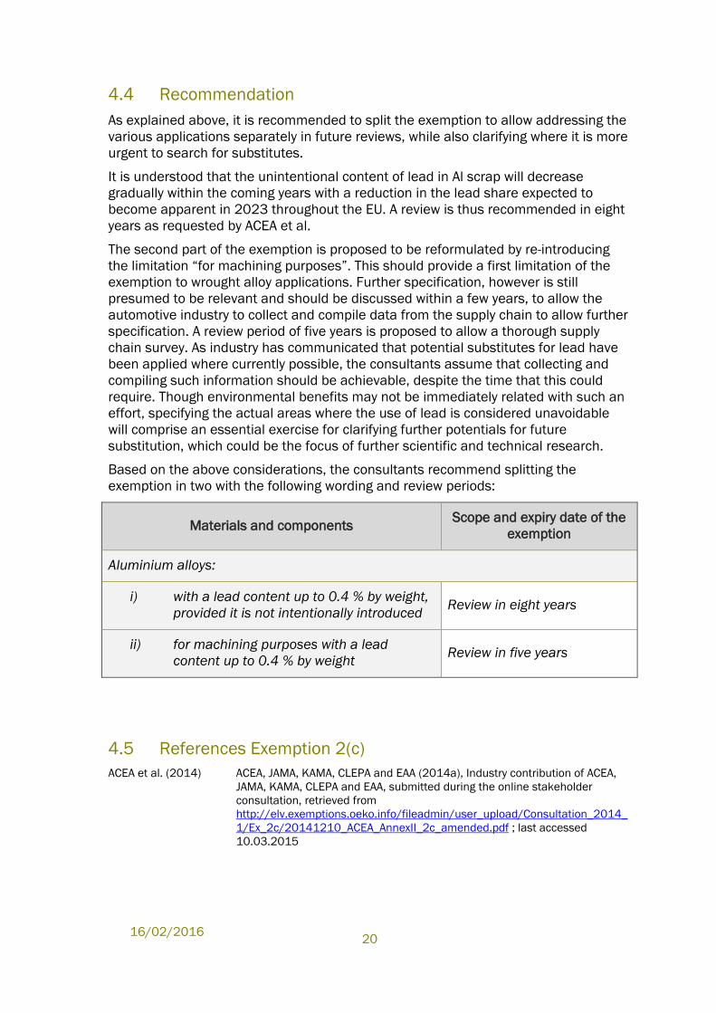
Based on the above considerations, the consultants recommend splitting the
exemption in two with the following wording and review periods:
Materials and components Scope and expiry date of the
exemption
Aluminium alloys:
i) with a lead content up to 0.4 % by weight,
provided it is not intentionally introduced Review in eight years
ii) for machining purposes with a lead
content up to 0.4 % by weight Review in five years
4.5 References Exemption 2(c)
ACEA et al. (2014) ACEA, JAMA, KAMA, CLEPA and EAA (2014a), Industry contribution of ACEA,
JAMA, KAMA, CLEPA and EAA, submitted during the online stakeholder
consultation, retrieved from
http://elv.exemptions.oeko.info/fileadmin/user_upload/Consultation_2014_
1/Ex_2c/20141210_ACEA_AnnexII_2c_amended.pdf ; last accessed
10.03.2015
Evaluation of ELV Exemptions
21
ACEA et al. (2015) ACEA, JAMA, KAMA, CLEPA and EAA (2015), Answers to Clarification
Questionnaire, provided 27 February 2015.
ACEA et al. (2015b) ACEA, JAMA, KAMA, CLEPA and EAA (2015b), Statement for draft proposals
on entry 2c Annex II, submitted to the EU COM 3.7.2015 and forwarded to the
consultant.
ACEA et al. (2015c) ACEA, JAMA, KAMA, CLEPA and EAA (2015c), Ex. 2C List of Relevant
Properties and Performance Indicators, submitted per email 22.8.2015
Ducker Worldwide and EAA (2012)
Ducker Worldwide in cooperation with the European Aluminium Association
(EAA) (2012), EAA Aluminium penetration in cars; Final Report, March 13,
2012; http://www.alueurope.eu/wp-content/uploads/2012/04/EAA-
Aluminium-Penetration-in-cars_Final-Report-Public-version.pdf
EAA (2012) European Aluminium Association EAA (2012), The Aluminium Automotive
Manual, Materials – Resources; http://www.alueurope.eu/wp-
content/uploads/2012/01/AAM-Materials-1-Resources.pdf
EAA (2013) European Aluminium Association EAA (2013), Aluminium in Cars – Unlocking
the light-weighting potential; http://www.alueurope.eu/wp-
content/uploads/2013/10/EAA-Aluminium-in-Cars-Unlocking-the-light-
weighting-potential_September2013_03.pdf
EAA/OEA Recycling Division (2006)
European Aluminium Association EAA and Organisation of European
Aluminium Refiners and Remelters OEA (2006), Aluminium Recycling in
Europe, The Road to High Quality Products, 2006;
http://www.alueurope.eu/wp-content/uploads/2011/08/Aluminium-
recycling-in-Europe-2007.pdf
Gaustad et al. (2012) Gaustad, G. et al. (2012), Improving aluminium recycling: A survey of sorting
and impurity removal technologies; Resources, Conservation and Recycling
58 (2012) 79– 87.
Koch et al. (2011) Koch, S., Antrekowitsch, H. (2011), Investigations of Lead-free Aluminium
Alloys for Machining; World of Metallurgy – ERZMETALL 64 (2011) No 1., 26 –
30
Lohse et al. (2001) Lohse, J. et al. (2001), Final report heavy metals in vehicles II; July 2001;
Oekopol – Institut für Ökologie und Politik GmbH Hamburg;
http://ec.europa.eu/environment/waste/studies/elv/heavy_metals.pdf
Oeko-Institut (2008) Dr. Joachim Lohse et al., Oeko-Institut; Otmar Deubzer, Fraunhofer IZM:
Adaptation to Scientific and Technical Progress of Annex II Directive
2000/53/EC, Contract N°07010401/2007/470145/ATA/G4, final report;
Freiburg, 16 January 2008;
http://elv.exemptions.oeko.info/fileadmin/user_upload/Background/Final_re
port_ELV_Annex_II_revision.pdf
Oeko-Institut (2010) Stéphanie Zangl et al., Oeko-Institut; Otmar Deubzer, Fraunhofer IZM (2010),
Adaptation to scientific and technical progress of Annex II to Directive
2000/53/EC (ELV) and of the Annex to Directive 2002/95/EC (RoHS), final
report; Freiburg, 28 July 2010;
http://elv.exemptions.oeko.info/fileadmin/user_upload/Final_Report/Corr_Fi
nal_report_ELV_RoHS_28_ 07_2010.pdf
Paraskevas et al. (2013) Paraskevas, D. et al. (2013), Closed and Open Loop Recycling of Aluminium:
A Life Cycle Assessment perspective; 11th Global Conference on Sustainable
Manufacturing, 23rd to 25th September Berlin, Germany.
16/02/2016
22
5.0 Exemption 3 “Copper alloy containing up to 4
% lead by weight”
Abbreviations and Definitions
C36000 CuZn39Pb3, brass alloy with 3.3% Pb
Cu Copper
CuZn42 Lead-free copper alloy with a higher zinc content
CuZn38As Lead-free copper alloy with a higher zinc content (As – Arsenic)
CuZn39Pb3 Brass alloy with 3.3% Pb
CuZn38Pb2 Brass alloy with 2% Pb
CuZn21Si3 Silicon alloyed copper
OEM Original Equipment Manufacturer
Pb Lead
Si Silicon
Zn Zinc
Declaration
The phrasings and wordings of stakeholders’ explanations and arguments have been
adopted from the documents provided by the stakeholders as far as was required and
reasonable in the context of the evaluation at hand. Formulations have been altered
in cases where it was necessary to maintain the readability and comprehensibility of
the text.
5.1 Description of Requested Exemption
The current wording of Exemption 3 in Annex II of the ELV Directive is
Copper alloy containing up to 4 % lead by weight.
The exemption has become due for review in 2015. The automotive industry
associations ACEA, CLEPA, JAMA, KAMA et al. have submitted a contribution during
the stakeholder consultation in support of the renewal of the above mentioned
exemption and claim an unlimited prolongation of the exemption and propose a
review time of eight years.76
76 ACEA et al. (2014) Industry contribution of ACEA, JAMA, JAPIA, KAMA and CLEPA, Industry
contribution of ACEA, JAMA, JAPIA, KAMA and CLEPA, submitted 10.12.2014,
http://elv.exemptions.oeko.info/fileadmin/user_upload/Consultation_2014_1/Ex_3/20141210_ACE
A_AnnexII_3.pdf; last accessed 10.03.2015
Evaluation of ELV Exemptions
23
During the stakeholder consultation Mitsubishi Shindoh Co., Ltd submitted a
contribution objecting the renewal of the above mentioned exemption and proposes
Ecobrass as a lead free copper alloy alternative.77
A stakeholder meeting was held on 10 April 2015 as part of the evaluation that was
attended by representatives from ACEA et al. and Mitsubishi Shindoh Co., Ltd.
5.1.1 History of the Exemption
Since the publication of the ELV Directive, Exemption 3 has been listed in Annex II
with the above mentioned wording. Exemption 3 was reviewed in 2009/2010. A
review in five years was recommended by Oeko-Institut in 201078 because:
Lead free copper alloys were available at the time, but stakeholders claimed
that they were not technically equivalent for all applications;
There were contradicting opinions on the technical feasibility of lead reduction
in copper alloys.
The review of Exemption 3 in 2010 was published in the fifth revision of Annex II in
2011.79
5.1.2 Technical Background
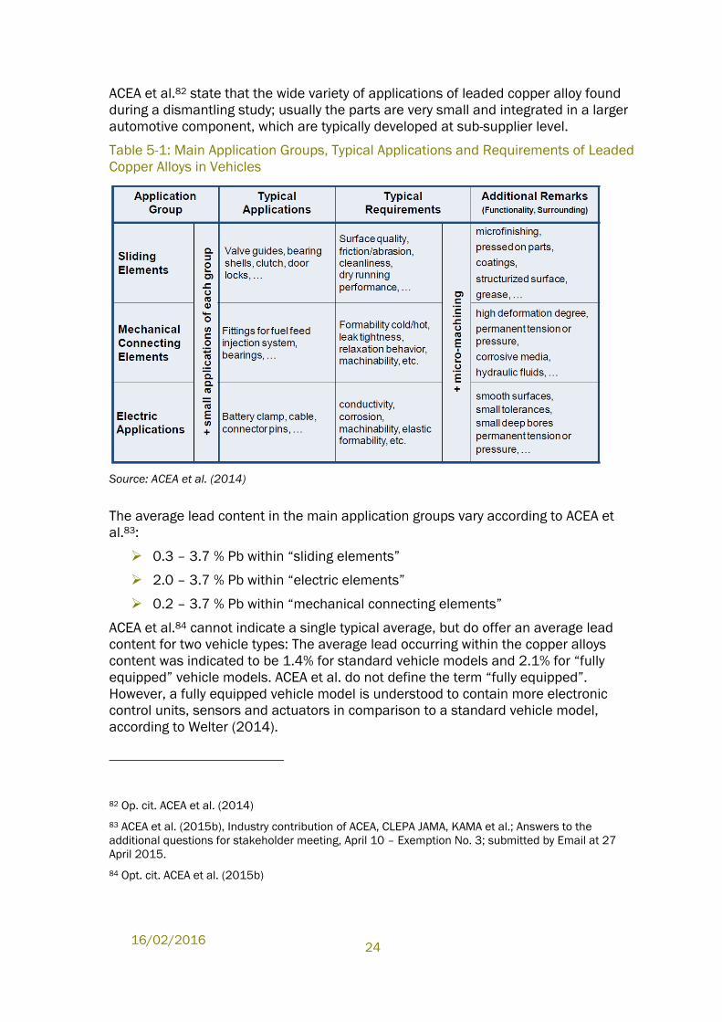
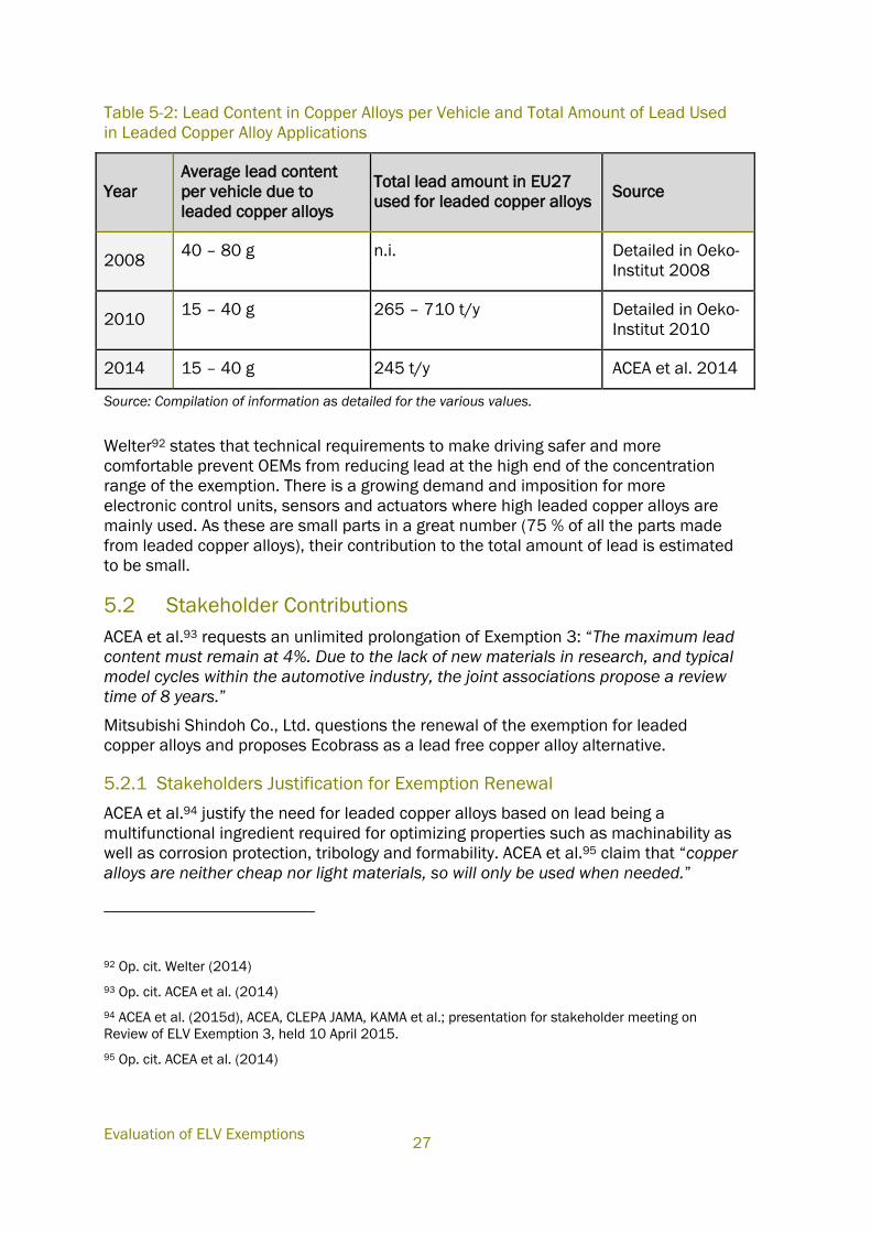
ACEA et al.80 identified three main application groups for the wide variety of small
components consisting of leaded copper alloy: sliding elements, mechanical
connecting elements and electric applications. Provided by ACEA et al., Table 5-1
summarizes typical applications their technical requirements.
ACEA et al. state81 that “500 mainly tiny components are the detected maximum
quantity in a fully equipped vehicle”. ACEA et al. further detail that the total number of
automotive components might even be larger as the applications and requirements
are different within each vehicle.
77 Mitsubishi Shindoh Co., Ltd. (2014), Contribution of Mitsubishi Shindoh Co., Ltd., submitted during
the online stakeholder consultation, retrieved from
http://elv.exemptions.oeko.info/fileadmin/user_upload/Consultation_2014_1/Ex_3/2014-12-
10_Mitsubishi_elv-exception-main-en.pdf
78 Oeko-Institut (2010), Stéphanie Zangl et al., Oeko-Institut; Otmar Deubzer, Fraunhofer IZM (2010),
Adaptation to scientific and technical progress of Annex II to Directive 2000/53/EC (ELV) and of the
Annex to Directive 2002/95/EC (RoHS), final report; Freiburg, 28 July 2010;
http://elv.exemptions.oeko.info/fileadmin/user_upload/Final_Report/Corr_Final_report_ELV_RoHS_2
8_07_2010.pdf
79 Commission Directive 2011/37/EU of 30 March 2011 amending Annex II to Directive 2000/53/EC
of the European Parliament and of the Council on end-of-life vehicles
80 Op. cit. ACEA et al. (2014)
81 ACEA et al. (2015c), Industry contribution of ACEA, CLEPA JAMA, KAMA et al.; Answers to the
additional questions after stakeholder meeting, April 10 – Exemption No. 3; submitted by Email at 27
April 2015.
16/02/2016
24
ACEA et al.82 state that the wide variety of applications of leaded copper alloy found
during a dismantling study; usually the parts are very small and integrated in a larger
automotive component, which are typically developed at sub-supplier level.
Table 5-1: Main Application Groups, Typical Applications and Requirements of Leaded
Copper Alloys in Vehicles
Source: ACEA et al. (2014)
The average lead content in the main application groups vary according to ACEA et
al.83:
0.3 – 3.7 % Pb within “sliding elements”
2.0 – 3.7 % Pb within “electric elements”
0.2 – 3.7 % Pb within “mechanical connecting elements”
ACEA et al.84 cannot indicate a single typical average, but do offer an average lead
content for two vehicle types: The average lead occurring within the copper alloys
content was indicated to be 1.4% for standard vehicle models and 2.1% for “fully
equipped” vehicle models. ACEA et al. do not define the term “fully equipped”.
However, a fully equipped vehicle model is understood to contain more electronic
control units, sensors and actuators in comparison to a standard vehicle model,
according to Welter (2014).
82 Op. cit. ACEA et al. (2014)
83 ACEA et al. (2015b), Industry contribution of ACEA, CLEPA JAMA, KAMA et al.; Answers to the
additional questions for stakeholder meeting, April 10 – Exemption No. 3; submitted by Email at 27
April 2015.
84 Opt. cit. ACEA et al. (2015b)
Evaluation of ELV Exemptions
25
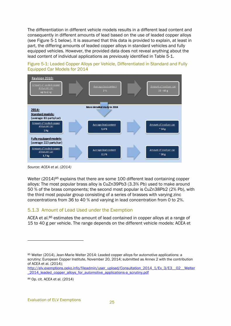
The differentiation in different vehicle models results in a different lead content and
consequently in different amounts of lead based on the use of leaded copper alloys
(see Figure 5-1 below). It is assumed that this data is provided to explain, at least in
part, the differing amounts of leaded copper alloys in standard vehicles and fully
equipped vehicles. However, the provided data does not reveal anything about the
lead content of individual applications as previously identified in Table 5-1.
Figure 5-1: Leaded Copper Alloys per Vehicle, Differentiated in Standard and Fully
Equipped Car Models for 2014
Source: ACEA et al. (2014)
Welter (2014)85 explains that there are some 100 different lead containing copper
alloys: The most popular brass alloy is CuZn39Pb3 (3.3% Pb) used to make around
50 % of the brass components; the second most popular is CuZn38Pb2 (2% Pb), with
the third most popular group consisting of a series of brasses with varying zinc
concentrations from 36 to 40 % and varying in lead concentration from 0 to 2%.
5.1.3 Amount of Lead Used under the Exemption
ACEA et al.86 estimates the amount of lead contained in copper alloys at a range of
15 to 40 g per vehicle. The range depends on the different vehicle models: ACEA et
85 Welter (2014), Jean-Marie Welter 2014: Leaded copper alloys for automotive applications: a
scrutiny; European Copper Institute, November 20, 2014; submitted as Annex 2 with the contribution
of ACEA et al. (2014);
http://elv.exemptions.oeko.info/fileadmin/user_upload/Consultation_2014_1/Ex_3/E3__02__Welter
_2014_leaded_copper_alloys_for_automotive_applications-a_scrutiny.pdf
86 Op. cit. ACEA et al. (2014)
16/02/2016
26
al.87 explain that a standard car model contains about 14 g of lead in copper alloys
due to an average of 83 parts (about one kg) of leaded copper alloys. A fully equipped
model contains about 36 g of lead in copper alloys due to an average of 223 parts
with a total weight of 1.7 kg of leaded copper alloys (see Figure 5-1 above).
ACEA et al.88 further detail that more than 75% of the parts have a weight of less than
10 grams. It is also indicated that more than the half of the parts contain 3 to 4%
lead but these only account for 25% of the total weight of leaded copper alloys, for
many of these parts are less than 10 grams per part and according to Welter
(2014)89 usually even less than 1 g per part.
ACEA et al. estimates a total lead consumption for leaded copper alloys of 245 tonnes
per year in the EU. This estimation is based on the number of newly registered
vehicles in EU 27 in 2013, which was 13.3. million, and is further based on 80%
standard vehicle models and 20% “fully equipped” vehicle models.90
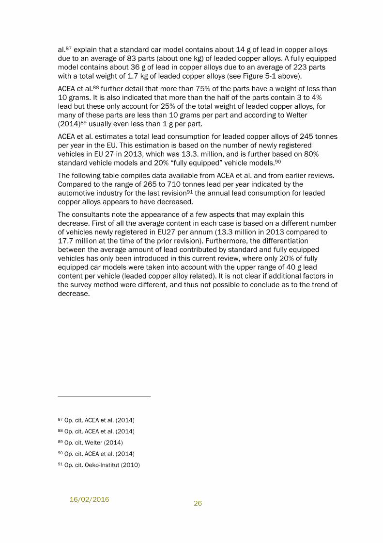
The following table compiles data available from ACEA et al. and from earlier reviews.
Compared to the range of 265 to 710 tonnes lead per year indicated by the
automotive industry for the last revision91 the annual lead consumption for leaded
copper alloys appears to have decreased.
The consultants note the appearance of a few aspects that may explain this
decrease. First of all the average content in each case is based on a different number
of vehicles newly registered in EU27 per annum (13.3 million in 2013 compared to
17.7 million at the time of the prior revision). Furthermore, the differentiation
between the average amount of lead contributed by standard and fully equipped
vehicles has only been introduced in this current review, where only 20% of fully
equipped car models were taken into account with the upper range of 40 g lead
content per vehicle (leaded copper alloy related). It is not clear if additional factors in
the survey method were different, and thus not possible to conclude as to the trend of
decrease.
87 Op. cit. ACEA et al. (2014)
88 Op. cit. ACEA et al. (2014)
89 Op. cit. Welter (2014)
90 Op. cit. ACEA et al. (2014)
91 Op. cit. Oeko-Institut (2010)
Evaluation of ELV Exemptions
27
Table 5-2: Lead Content in Copper Alloys per Vehicle and Total Amount of Lead Used
in Leaded Copper Alloy Applications
Year
Average lead content
per vehicle due to
leaded copper alloys
Total lead amount in EU27
used for leaded copper alloys Source
2008 40 – 80 g n.i. Detailed in Oeko-
Institut 2008
2010 15 – 40 g 265 – 710 t/y Detailed in Oeko-
Institut 2010
2014 15 – 40 g 245 t/y ACEA et al. 2014
Source: Compilation of information as detailed for the various values.
Welter92 states that technical requirements to make driving safer and more
comfortable prevent OEMs from reducing lead at the high end of the concentration
range of the exemption. There is a growing demand and imposition for more
electronic control units, sensors and actuators where high leaded copper alloys are
mainly used. As these are small parts in a great number (75 % of all the parts made
from leaded copper alloys), their contribution to the total amount of lead is estimated
to be small.
5.2 Stakeholder Contributions
ACEA et al.93 requests an unlimited prolongation of Exemption 3: “The maximum lead
content must remain at 4%. Due to the lack of new materials in research, and typical
model cycles within the automotive industry, the joint associations propose a review
time of 8 years.”
Mitsubishi Shindoh Co., Ltd. questions the renewal of the exemption for leaded
copper alloys and proposes Ecobrass as a lead free copper alloy alternative.
5.2.1 Stakeholders Justification for Exemption Renewal
ACEA et al.94 justify the need for leaded copper alloys based on lead being a
multifunctional ingredient required for optimizing properties such as machinability as
well as corrosion protection, tribology and formability. ACEA et al.95 claim that “copper
alloys are neither cheap nor light materials, so will only be used when needed.”
92 Op. cit. Welter (2014)
93 Op. cit. ACEA et al. (2014)
94 ACEA et al. (2015d), ACEA, CLEPA JAMA, KAMA et al.; presentation for stakeholder meeting on
Review of ELV Exemption 3, held 10 April 2015.
95 Op. cit. ACEA et al. (2014)
16/02/2016
28
ACEA et al.96 explain that the “zero lead approach” - substitution by lead-free copper
alloys - failed in several tests conducted for the last revision of the exemption in 2008
because the lead-free copper alloys did not fulfil the technical requirements.
Therefore ACEA et al. initiated a copper inventory after the last revision in order to
define the parts of leaded copper alloys and the amount of lead therein and secondly
to define the function of lead in these parts. Based on the functions identified during
the copper inventory, ACEA et al. defined the three main application groups of leaded
copper alloys. The main application groups and their technical requirements are
summarised in Figure 5-2.
Figure 5-2: Automotive Requirements of the Main Application Groups for Leaded
Copper Alloys
Source: ACEA et al. (2014)
ACEA et al.97 explain: “Looking into the supply chain we also noticed that specific and
for these groups generally valid test standards could not be identified and we were in
contact on this topic with several material producers. Due to this shortfall we (finally)
had to develop specific test programs on our own and then we mandated tests.”
96 Op. cit. ACEA et al. (2015c)
97 Op. cit. ACEA et al. (2015c)
Evaluation of ELV Exemptions
29
ACEA et al.98 submitted 16 test reports as Annexes to their contribution.99 They are
summarised in Table 6-3 in Appendix A.2.0 and are referred to in the following
discussion by codes to identify the test, such as E3_[01] etc.. The alternative
materials that were investigated comprise brass with higher zinc content than leaded
brass (mostly CuZn42), silicon-alloyed coppers (sometimes specified as Ecobrass)
and also lead-reduced alloys (Pb content 0.2%; in one case 0.2 to 0.8%; in another
case (E3_[29]), the lead reduced alloy contained 2.2% Pb). The tests did not use the
same alternative alloys and not all tests included Ecobrass as a substitute. ACEA et
al. did not specify the causes for selecting different substitutes.
The test reports can be clustered into tests regarding physical properties, regarding
types of components and regarding machinability:
Five test reports explored physical properties of the lead-free copper alloys
(E3_[09]: wear resistance; E3_[10]: galvanic corrosion; E3_[11]: stress
corrosion cracking; E3_[30]: corrosion in aggressive conditions).
Five tests compared the conventionally fabricated components with
components made from lead-free copper alloys. In four cases, the lead-free
copper alloy components were assessed to have failed (pinions, shift forks,
valve stems, crimp contact material). In the case of fittings to fuel feeding
systems (E3_[18]), it is understood that the silicon-based alloys achieved the
best results.
Six tests addressed the machinability of alternative copper alloys. Five
machinability tests were performed in the way that the existing equipment was
operated and the process with lead reduced / lead free alternatives mostly
malfunctioned. One test approach applied was to adapt the tools (E3_[07]).
The results of the tests of E3_[07] with different tool material are not
presented as they were still ongoing at the time the results were submitted.
The research project on micro-drilling explores an adaption of the drilling
strategy (E3_[12]).
ACEA et al.100 conclude from these tests: “The test results illustrated, that none of the
tested lead-free machining alloys was able to fulfil the diverse set of minimum
requirements for one application group. Therefore, this approach to find alloys being
able to replace leaded material for at least one main application group was not
successful. This is the most recent research status.”
98 Op. cit. ACEA et al. (2014)
99 ACEA et al. (2014) submitted 19 Annexes to its contribution; they can be found at
http://elv.exemptions.oeko.info/index.php?id=60. The majority of these annexes were test reports.
Literature studies were included as two annexes, these labelled as “E3_[01]_[WE-
03]_Literature_Study_completed_2013-09-03.pdf” and “E3_[02]_Welter_2014_leaded copper alloys
for automotive applications-a scrutiny.pdf”. One further Annex is a compilation of information from
material data sheets, labelled as “E3_[08]_Compilation_Material property data sheets lead and lead
free alloys.pdf”. These three Annexes are not included in the summary of the test reports in Table 6-3
in Appendix A.2.0.
100 Op. cit. ACEA et al. (2015c)
16/02/2016
30
5.2.2 Possible Substance Alternatives
5.2.2.1 Input of ACEA et al.
According to ACEA et al.101, mainly three families of machinable lead-free copper
alloys are available on the market:
Brass with higher zinc content than leaded brass as well as some other minor
additions (CuZn38-42 alloys);
Silicon-alloyed copper, e.g. CuZn21Si3; Ecobrass® is the brand name of one
of these alloys;
Bismuth-alloyed copper; bismuth containing alloys were not included in the
test programs according to Welter.102 Bismuthed copper was not considered to
be a reliable alternative since the revision in 2007 according to Oeko-Institut
(2010) because of cold and hot cracking.
ACEA et al.103 claim to have checked the general suitability of alternative alloys using
a set of tests that are defined in the test reports submitted as Annexes (see
Table 6-3).
ACEA et al.104 present an evaluation of the general suitability for each main
application group against different material and testing requirements (see Table 5-1).
The alternative alloys are silicon-alloyed copper in the left hand column and two lead-
free copper alloys with a higher zinc content (CuZn42 and CuZn38As) in the right
hand columns compared to CuZn39Pb3. ACEA et al.105 state that a 20% worse test
result compared to the most widely used leaded copper alloy CuZn39Pb3 should be
considered unacceptable performance. As already mentioned, ACEA et al. conclude
that no lead-free machining alloys were able to fulfil the diverse set of minimum
requirements relevant for the various application groups.
101 Op. cit. ACEA et al. (2014)
102 Op. cit. Welter (2014)
103 Op. cit. ACEA et al. (2015d)
104 Op. cit. ACEA et al. (2014)
105 Op. cit. ACEA et al. (2015c)
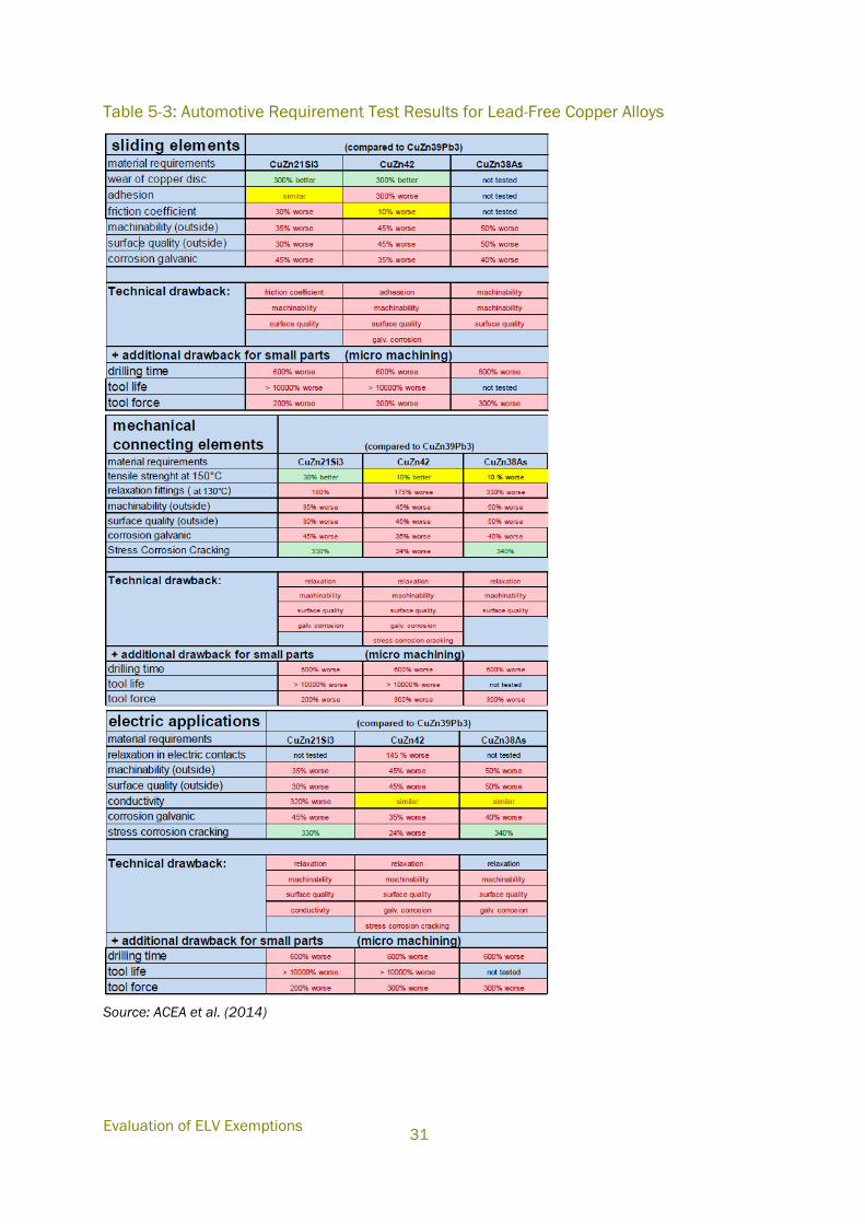
Evaluation of ELV Exemptions
31
Table 5-3: Automotive Requirement Test Results for Lead-Free Copper Alloys
Source: ACEA et al. (2014)
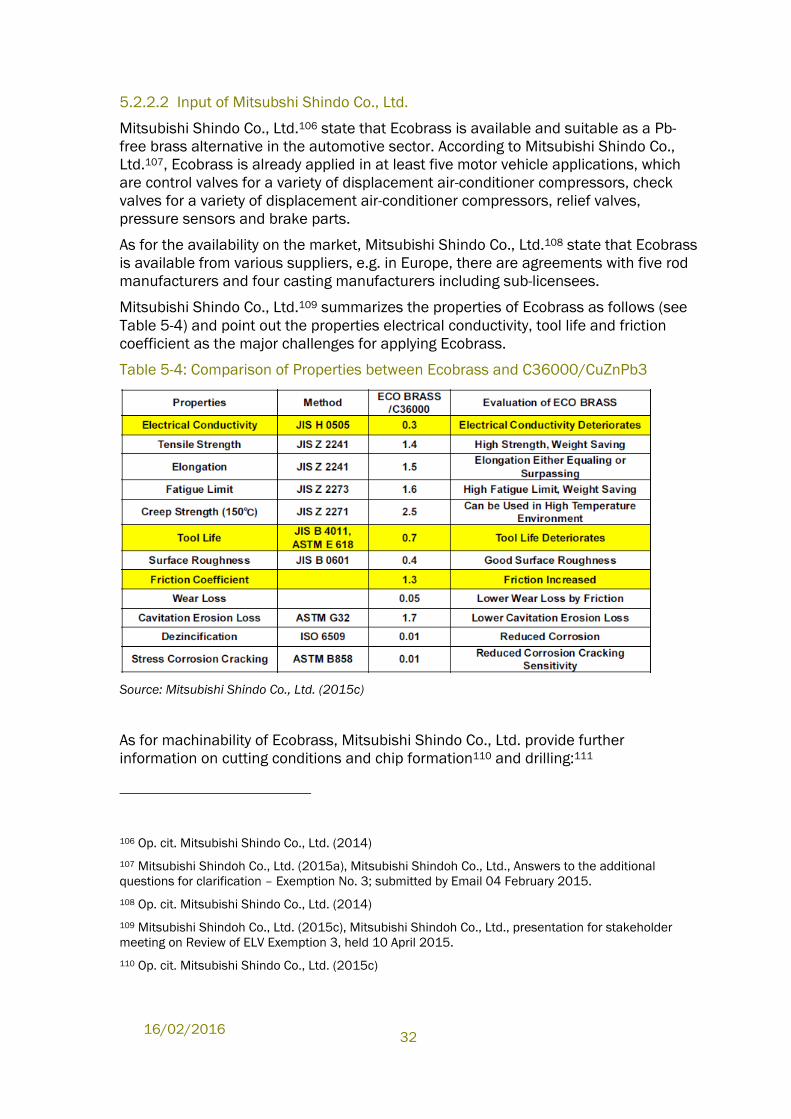
16/02/2016
32
5.2.2.2 Input of Mitsubshi Shindo Co., Ltd.
Mitsubishi Shindo Co., Ltd.106 state that Ecobrass is available and suitable as a Pb-
free brass alternative in the automotive sector. According to Mitsubishi Shindo Co.,
Ltd.107, Ecobrass is already applied in at least five motor vehicle applications, which
are control valves for a variety of displacement air-conditioner compressors, check
valves for a variety of displacement air-conditioner compressors, relief valves,
pressure sensors and brake parts.
As for the availability on the market, Mitsubishi Shindo Co., Ltd.108 state that Ecobrass
is available from various suppliers, e.g. in Europe, there are agreements with five rod
manufacturers and four casting manufacturers including sub-licensees.
Mitsubishi Shindo Co., Ltd.109 summarizes the properties of Ecobrass as follows (see
Table 5-4) and point out the properties electrical conductivity, tool life and friction
coefficient as the major challenges for applying Ecobrass.
Table 5-4: Comparison of Properties between Ecobrass and C36000/CuZnPb3
Source: Mitsubishi Shindo Co., Ltd. (2015c)
As for machinability of Ecobrass, Mitsubishi Shindo Co., Ltd. provide further
information on cutting conditions and chip formation110 and drilling:111
106 Op. cit. Mitsubishi Shindo Co., Ltd. (2014)
107 Mitsubishi Shindoh Co., Ltd. (2015a), Mitsubishi Shindoh Co., Ltd., Answers to the additional
questions for clarification – Exemption No. 3; submitted by Email 04 February 2015.
108 Op. cit. Mitsubishi Shindo Co., Ltd. (2014)
109 Mitsubishi Shindoh Co., Ltd. (2015c), Mitsubishi Shindoh Co., Ltd., presentation for stakeholder
meeting on Review of ELV Exemption 3, held 10 April 2015.
110 Op. cit. Mitsubishi Shindo Co., Ltd. (2015c)
Evaluation of ELV Exemptions
33
Ecobrass differs from the leaded copper alloy CuZn39Pb3 in the chip breaking
mechanism: The dispersed soft Pb particles melt due to machining heat and
result in chip breakage. “In the case of ECO BRASS, stress is concentrated on
the hard phases of κ and γ and chips are divided.”112 Mitsubishi Shindo Co.,
Ltd.113 claims that by reducing the cutting speed and increasing the feed, good
chip breaking performance is achieved and should be the basis for setting
cutting conditions.
Mitsubishi Shindo Co., Ltd.114 provided a drilling report based on the drilling
strategy published in the test report of the German Copper Institute and RWTH
Aachen University115 and applying adaptations such as e.g. a different drill
material.
Mitsubishi Shindo Co., Ltd.116 conclude that Ecobrass is “suitable for forging,
machining, and casting. Examples of all these processing methods have been
provided to demonstrate that industry can adapt to Pb-free materials, can realize
production gains, and can utilize advanced material properties to cut costs and make
better products.” However, at the stakeholder meeting Mitsubishi Shindo Co., Ltd.
stated that they assess the pros and cons from a material suppliers’ point of view.
They admitted that they cannot comment on the performance criteria at the level of
automobile components.
5.2.2.3 Comparison of Inputs
There is agreement between both groups of stakeholders as to the physical
properties of Ecobrass (for more details see Table 6-4 in Appendix A.2.0):
Stakeholders agree that Ecobrass has properties that are favourable to
CuZn39Pb3 / C36000 in tensile strength, wear of copper disc and stress
corrosion cracking.
Stakeholders agree that for friction coefficient and electrical conductivity,
Ecobrass has less favourable properties than CuZn39Pb3 / C36000.
There are conflicting views among the stakeholders regarding the micro machining
properties of Ecobrass, which are summarized in the following Table 5-5. The
quantitative statements are expressed in relation to different reference values. As the
consistency of the testing conditions could not be assessed by the consultants, the
111 Mitsubishi Shindoh Co., Ltd. (2015b), Mitsubishi Shindoh Co., Ltd., Micro-Drilling test report;
submitted by Email 13 March 2015.
112 Op. cit. Mitsubishi Shindo Co., Ltd. (2015a)
113 Op. cit. Mitsubishi Shindo Co., Ltd. (2015a)
114 Op. cit. Mitsubishi Shindo Co., Ltd. (2015b)
115 E3_[12]_[LU-02]_Micro drilling final.pdf;
http://elv.exemptions.oeko.info/fileadmin/user_upload/Consultation_2014_1/Ex_3/_12_-source-
microdrilling-FINAL_amended.pdf
116 Op. cit. Mitsubishi Shindo Co., Ltd. (2014)
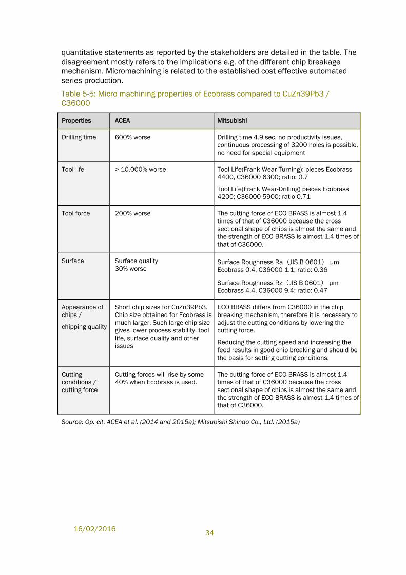
16/02/2016
34
quantitative statements as reported by the stakeholders are detailed in the table. The
disagreement mostly refers to the implications e.g. of the different chip breakage
mechanism. Micromachining is related to the established cost effective automated
series production.
Table 5-5: Micro machining properties of Ecobrass compared to CuZn39Pb3 /
C36000
Properties ACEA Mitsubishi
Drilling time 600% worse Drilling time 4.9 sec, no productivity issues,
continuous processing of 3200 holes is possible,
no need for special equipment
Tool life > 10.000% worse Tool Life(Frank Wear-Turning): pieces Ecobrass
4400, C36000 6300; ratio: 0.7
Tool Life(Frank Wear-Drilling) pieces Ecobrass
4200; C36000 5900; ratio 0.71
Tool force 200% worse The cutting force of ECO BRASS is almost 1.4
times of that of C36000 because the cross
sectional shape of chips is almost the same and
the strength of ECO BRASS is almost 1.4 times of
that of C36000.
Surface Surface quality
30% worse Surface Roughness Ra(JIS B 0601) μm
Ecobrass 0.4, C36000 1.1; ratio: 0.36
Surface Roughness Rz(JIS B 0601) μm
Ecobrass 4.4, C36000 9.4; ratio: 0.47
Appearance of
chips /
chipping quality
Short chip sizes for CuZn39Pb3.
Chip size obtained for Ecobrass is
much larger. Such large chip size
gives lower process stability, tool
life, surface quality and other
issues
ECO BRASS differs from C36000 in the chip
breaking mechanism, therefore it is necessary to
adjust the cutting conditions by lowering the
cutting force.
Reducing the cutting speed and increasing the
feed results in good chip breaking and should be
the basis for setting cutting conditions.
Cutting
conditions /
cutting force
Cutting forces will rise by some
40% when Ecobrass is used.
The cutting force of ECO BRASS is almost 1.4
times of that of C36000 because the cross
sectional shape of chips is almost the same and
the strength of ECO BRASS is almost 1.4 times of
that of C36000.
Source: Op. cit. ACEA et al. (2014 and 2015a); Mitsubishi Shindo Co., Ltd. (2015a)
Evaluation of ELV Exemptions
35
For electrical connecting elements, Mitsubishi Shindo Co., Ltd.117 agrees that
Ecobrass does not provide the necessary properties but instead proposes another
lead-free copper alloy C18625118 with good electrical conductivity that was so far not
included in tests by ACEA et al.
As for recycling, the two stakeholders have opposing views but did not provide
technical evidences to explain their views. Mitsubishi Shindo Co., Ltd.119 state that at
the end of product life, Ecobrass can easily be recycled through the regular scrap
stream into standard brass; segregating Ecobrass scrap allows for cost savings when
recycling back into Ecobrass as already established in the sanitary supply industry.
ACEA et al.120 point out that a mixed use of leaded and silicon-based alloy types would
damage existing recycling cycles as Si has low limits as an impurity in leaded copper
alloy specifications and in scrap streams a separation of leaded and silicon
containing copper is not possible.
5.2.3 Road Map for Substitution
ACEA et al. 121 intend to further reduce lead content in certain applications or
application groups. Based on experiences from the last years, ACEA et al. explain that
further lead reduction is possible for parts, which already have a low lead content.122
Thereby ACEA et al. intend to focus on most relevant applications or application
groups in terms of weight:123
“Priority is on bigger parts currently containing lead alloyed copper. So based
on a Pareto-approach we will consider most relevant cases in terms of weight
resp. lead. For these components agreements on the necessary test program
have to be defined jointly with supply chain partners and material producers
including Mitsubishi Shindoh.”
To implement substitution, ACEA et al.124 state that they need to identify “new high
performing materials” and “economical processing technologies.” For the current
lead-free copper alloys, ACEA et al.125 see a need for “considerable additional
development in production equipment and technology”.
117 Op. cit. Mitsubishi Shindo Co., Ltd. (2015c)
118 High Copper Alloy (99.40% Cu) according to Copper Development Association Inc. at
http://alloys.copper.org/alloy/C18625?referrer=facetedsearch
119 Op. cit. Mitsubishi Shindo Co., Ltd. (2015c)
120 Op. cit. ACEA et al. (2015b)
121 ACEA et al. (2015d), ACEA, CLEPA JAMA, KAMA et al.; presentation for stakeholder meeting on
Review of ELV Exemption 3, held 10 April 2015. and op. cit. Welter (2014)
122 Lead reduction does not mean reducing the lead content, but a substitute material with similar
characteristics.
123 Op. cit. ACEA et al. (2015c)
124 Op. cit. ACEA et al. (2015c)
125 Op. cit. ACEA et al. (2014)
16/02/2016
36
As for the time frame, ACEA et al.126 estimate that implementation of reduction and or
substitution will require over 10 years for material testing and component testing in
vehicles. ACEA et al.127 estimate that the component-oriented approach (copper alloy
lead reduction test programmes for individual components, defined jointly between
supply chain partners and material producers) will take 3 to 5 years. The components
then need to pass through test programs within complete vehicles, which will also
require 3 to 5 years.
5.3 Critical Review
ACEA et al. state that in more than 500 different components the use of leaded
copper alloys is still unavoidable. Based on a detailed inventory, ACEA et al. deduced
three main application groups and defined the technical requirements. Some of the
testing requirements are published in the Annexes submitted with the contribution
during the stakeholder consultation (see Table 6-3).
From the Annexes submitted by ACEA et al., it is not obvious for which applications a
lead reduction or use of lead free alternatives is envisaged. ACEA et al.128 estimate
that a further lead reduction is most likely to be successful in parts with an already
low lead content. This is not reflected by the test reports submitted for the
manufacturing of unions (E3_[29]) containing normally leaded copper alloys at the
high end of the lead allowance of the exemption (Pb 3.7%); a lead-reduced material
with 2.2% Pb content was tested.
The tests on components being directly substituted with lead-free copper alloys ended
with the conclusion that lead-free alloys failed and did not explore further solutions,
e.g. using other types of lead-free copper alloys. In addition, the majority of the tests
on machinability did not explore further solutions: Four machinability tests only
applied the existing equipment to lead reduced / lead free alternatives; the tests
ended concluding that the lead reduced / lead free alternatives have failed. To
conclude, it is not obvious whether the substitution strategy consistently explored all
possibilities.
ACEA et al. (2014) summarizes a series of test results conducted for the main
application groups (see Table 5-3: ). The summary evaluates three lead-free
alternatives compared to the most applied leaded copper alloys. The results of the
alternative materials also depend on processing technology, especially relating to
metal-cutting manufacturing. It is unclear if attempts were made to adjust the
processing to accommodate the various alternatives tested. This makes it difficult to
assess the overall conclusion of ACEA et al. stating that none of the tested lead-free
machining alloys was able to fulfil the diverse set of minimum requirements for one
application group. It may also be noted that one of the identified lead free alloys
126 Op. cit. ACEA et al. (2015c)
127 Op. cit. ACEA et al. (2015c)
128 Op. cit. ACEA et al. (2014)
Evaluation of ELV Exemptions
37
C18625, a high copper alloy, that may be suitable for electrical applications, is not
included in the tests of ACEA et al..
In order to draw a clearer roadmap to identify, which applications could be
substituted earlier, a matrix for single applications mapping the key requirements
would help to monitor the further efforts for substitution. As ACEA et al. are able to
identify the average number of components for different vehicle models (standard
and fully equipped) and the respective average lead content (see Table 5-1), the
consultants assume that such a matrix is feasible. As from the information provided
by ACEA et al. and Mitsubishi Shindo Co., Ltd., it is understood that an earlier
substitution is possible in applications with an already low lead content and possibly
in cases where machining can be adapted:
It is understood that a reduction of the threshold for lead is not possible as
small parts in electrical applications with a lead content at the high end of the
exemption are increasingly applied. ACEA et al. agreed that applications with
an already low lead content are most promising for achieving substitution.
Within the ‘sliding elements’ and ‘mechanical connecting elements’
application groups there are applications with an already low lead content
(close to 0.3% Pb within sliding elements and 0.2% Pb within mechanical
connecting elements). As such, the consultants expect that ACEA et al. will be
able to identify specific components in the future that can be evaluated for the
applicability of substitution.
The consultants can follow that substitutes may still suffer technical
drawbacks that still delay their implementation, e.g. in the case of Ecobrass,
for micromachining in automated series production. Mitsubishi Shindo Co.,
Ltd. suggests how machining processes could be adapted to process
Ecobrass: E.g. Mitsubishi Shindo Co., Ltd.129 submitted a drilling report that
used a different drilling bit (carbide compared to high speed steel applied by
ACEA et al.130). These adaptations are important in cases where machining
knowledge on these alloys or usability of required equipment for these alloys
consist the key requirements (see Figure 5-2) for successful application.
Thus, it is understood that some restrictions on putting lead-free copper alloys into
successful application especially for Ecobrass might be overcome in the coming
years. ACEA et al.131 refer to further tests on machinability and cooperation with
material suppliers including Mitsubishi as future challenges. ACEA et al.132 argue that
machining and processing of alternative alloys is in a very basic research stage today,
because public funded research on fundamental parameters is still on-going in the
129 Op. cit. Mitsubishi Shindo Co., Ltd. (2015c)
130 ACEA et al. (2014) in Annex E3_[12]_[LU-02]_Micro drilling final.pdf;
http://elv.exemptions.oeko.info/fileadmin/user_upload/Consultation_2014_1/Ex_3/_12_-source-
microdrilling-FINAL_amended.pdf
131 Op. cit. ACEA et al. (2015c)
132 Op. cit. ACEA et al. (2014)
16/02/2016
38
field of machining. Welter133 state that there is little know-how among the
subcontractors specialized in micromachining and their tool suppliers and machining
companies.
The matrix suggested above would further help to clarify whether or more importantly
how, the scope of the exemption could be narrowed in the future. A possibility to
narrow the scope of the exemption could be e.g. to limit the scope of the exemption to
very small parts, adding a size/weight threshold e.g. such as “Copper alloy containing
up to 4% lead by weight in parts with a weight below XXX gr or in parts with a volume
below XXX mm3”. So far, ACEA et al.134 see no possibility to derive a common
definition for the parts because even larger parts seem to be dependent on lead
containing alloys and need micro-machining.
ACEA et al. state that “a mixed use of leaded and silicon-based alloy types would
damage existing recycling cycles as Si has low limits as an impurity in leaded copper
alloy specifications and as in scrap streams a separation of leaded and silicon
containing copper is not possible”. It is understood that Mitsubishi assume that such
a segregation is possible, stating that “segregating Pb-free material from leaded
brass will have the benefit of saving cost and energy of lead (Pb) removal… Silicon,
the chip-breaker in ECO BRASS, can easily be removed in secondary recycling.” On
the basis of available documents concerning copper recycling135,136,137, there is a
distinction between the technological processes used on parts that can be
disassembled and parts that are left in the vehicle after disassembling efforts (thus
being included in the shredded fraction):
Where parts can be easily disassembled, they can be redirected to separate
recycling (re-melting which is more efficient from an energy consumption
perspective).
Where parts are less accessible in terms of disassembling, or where there size
would not make the disassembling effort worthwhile, they remain in the ELV
133 Op. cit. Welter (2014)
134 Op. cit. ACEA et al. (2015c)
135 Deutsches Kupferinstitut (n.d.), Deutsches Kupferinstitut (n.d.), Recycling von Kupferwerkstoffen;
http://admin.copperalliance.eu/docs/librariesprovider3/recycling-von-kupferwerkstoffen---final-
pdf.pdf?sfvrsn=0&sfvrsn=0
136 Kawohl (2011), Kawohl, C. (2011), Multi-Metal Recycling bei der Aurubis AG, Praxisdialog
„Ressourcen- und materialeffiziente Produktgestaltung“ 2. November 2011, Berlin;
http://www.deutsche-
rohstoffagentur.de/DERA/DE/Downloads/Praxisdialog_02112011_Kawohl.pdf?__blob=publicationFile
&v=5
137 CAR (2006), Manufacturing, Engineering & Technology Group Center for Automotive Research
(November 2006), Copper in End-of-Life Vehicle Recycling, prepared for the Copper Development
Association (CDA), available under:
http://www.google.de/url?sa=t&rct=j&q=&esrc=s&frm=1&source=web&cd=1&cad=rja&uact=8&ved=
0CCEQFjAA&url=http%3A%2F%2Fwww.cargroup.org%2F%3Fmodule%3DPublications%26event%3DDo
wnload%26pubID%3D35%26fileID%3D41&ei=H9eCVY-AMqW17gaN-
YTQBw&usg=AFQjCNGgmRl_kH_OCNK0SXwbCkto2bfGug
Evaluation of ELV Exemptions
39
which is decontaminated (of battery and liquids etc.) and shredded prior to
further processing.
From the information provided by ACEA it can be understood that that the
applications of leaded copper alloys are for the most part in small components.
Copper recyclers explain that the relevant parts in e.g. ELV scrap are becoming
smaller, increasing the need for sorting and refining in comparison to the past.138
Alloy specific re-melting is becoming difficult especially in light of this trend towards
smaller parts.139 It is thus assumed that most of the small parts would end up in the
shredded fraction.
As for the shredded fraction, the separation stages that are performed are
understood to suffice to separate between copper and other metal impurities
including lead. It is understood that this is done through the use of reduction and
oxidation during the smelting and refining stages.140 Silicon acts as a reducing agent
during these process steps and is brought out as a part of iron silicate, a major by-
product of copper refining.141
On this basis, the consultant cannot follow the statement of ACEA et al.142 that “a
mixed use of leaded and silicon-based alloy types would damage existing recycling
cycles.” Although the smelting and refining stages for shredded ELVs is identified to
be less preferable (more complex and with a higher energy use than disassembly and
re-melt), the approach appears capable of extracting and separating the relevant
impurities, and thus effective recycling cycles can be maintained.
Against the background of scope of the exemption being general (wide) and with the
trend towards smaller and smaller parts in a growing number of applications
(especially electrical) with a lead content at the high end of the exemption, the
consultant recommends a shorter review period for the exemption then proposed by
ACEA et al. There is potential for significant quantities of lead to enter the market in
light of this exemption, and hence progress needs to be made soon to seek to reduce
lead use via this route.
A further review within a shorter period than proposed by the applicant should still be
beneficial, and may lead to additional reductions in hazardous substances in a
shorter time period. Even if in the next review, leaded copper alloys can still not be
substituted in a number of applications, the above described matrix would help to
clarify the substitution strategy for the applications with different lead contents as
well as the different time needed for the implementation of the substitution. Also, the
matrix would assist to evaluate the possibility of a narrower scope of the exemption.
138 Op cit. Deutsches Kupferinstitut (n.d.)
139 Op. cit. Kawohl (2011)
140 See also https://www.aurubis.com/en/en/corp/products/recycling/technology
141 Aurubis AG (2015), Aurubis AG Recyclingzentrum Lünen, Dr. Hendrik Roth, Director Environmental
Protection Lünen.
142 Op. cit. ACEA et al. (2015b)
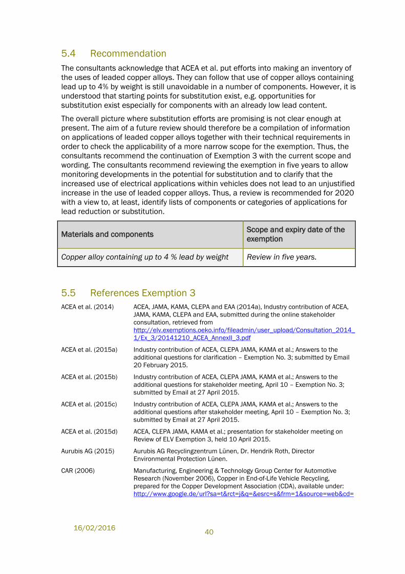
16/02/2016
40
5.4 Recommendation
The consultants acknowledge that ACEA et al. put efforts into making an inventory of
the uses of leaded copper alloys. They can follow that use of copper alloys containing
lead up to 4% by weight is still unavoidable in a number of components. However, it is
understood that starting points for substitution exist, e.g. opportunities for
substitution exist especially for components with an already low lead content.
The overall picture where substitution efforts are promising is not clear enough at
present. The aim of a future review should therefore be a compilation of information
on applications of leaded copper alloys together with their technical requirements in
order to check the applicability of a more narrow scope for the exemption. Thus, the
consultants recommend the continuation of Exemption 3 with the current scope and
wording. The consultants recommend reviewing the exemption in five years to allow
monitoring developments in the potential for substitution and to clarify that the
increased use of electrical applications within vehicles does not lead to an unjustified
increase in the use of leaded copper alloys. Thus, a review is recommended for 2020
with a view to, at least, identify lists of components or categories of applications for
lead reduction or substitution.
Materials and components Scope and expiry date of the
exemption
Copper alloy containing up to 4 % lead by weight Review in five years.
5.5 References Exemption 3
ACEA et al. (2014) ACEA, JAMA, KAMA, CLEPA and EAA (2014a), Industry contribution of ACEA,
JAMA, KAMA, CLEPA and EAA, submitted during the online stakeholder
consultation, retrieved from
http://elv.exemptions.oeko.info/fileadmin/user_upload/Consultation_2014_
1/Ex_3/20141210_ACEA_AnnexII_3.pdf
ACEA et al. (2015a) Industry contribution of ACEA, CLEPA JAMA, KAMA et al.; Answers to the
additional questions for clarification – Exemption No. 3; submitted by Email
20 February 2015.
ACEA et al. (2015b) Industry contribution of ACEA, CLEPA JAMA, KAMA et al.; Answers to the
additional questions for stakeholder meeting, April 10 – Exemption No. 3;
submitted by Email at 27 April 2015.
ACEA et al. (2015c) Industry contribution of ACEA, CLEPA JAMA, KAMA et al.; Answers to the
additional questions after stakeholder meeting, April 10 – Exemption No. 3;
submitted by Email at 27 April 2015.
ACEA et al. (2015d) ACEA, CLEPA JAMA, KAMA et al.; presentation for stakeholder meeting on
Review of ELV Exemption 3, held 10 April 2015.
Aurubis AG (2015) Aurubis AG Recyclingzentrum Lünen, Dr. Hendrik Roth, Director
Environmental Protection Lünen.
CAR (2006) Manufacturing, Engineering & Technology Group Center for Automotive
Research (November 2006), Copper in End-of-Life Vehicle Recycling,
prepared for the Copper Development Association (CDA), available under:
http://www.google.de/url?sa=t&rct=j&q=&esrc=s&frm=1&source=web&cd=
Evaluation of ELV Exemptions
41
1&cad=rja&uact=8&ved=0CCEQFjAA&url=http%3A%2F%2Fwww.cargroup.org
%2F%3Fmodule%3DPublications%26event%3DDownload%26pubID%3D35%
26fileID%3D41&ei=H9eCVY-AMqW17gaN-
YTQBw&usg=AFQjCNGgmRl_kH_OCNK0SXwbCkto2bfGug
Deutsches Kupferinstitut (n.d.)
Deutsches Kupferinstitut (n.d.), Recycling von Kupferwerkstoffen;
http://admin.copperalliance.eu/docs/librariesprovider3/recycling-von-
kupferwerkstoffen---final-pdf.pdf?sfvrsn=0&sfvrsn=0
Kawohl (2011) Kawohl, C. (2011), Multi-Metal Recycling bei der Aurubis AG, Praxisdialog
„Ressourcen- und materialeffiziente Produktgestaltung“ 2. November 2011,
Berlin; http://www.deutsche-
rohstoffagentur.de/DERA/DE/Downloads/Praxisdialog_02112011_Kawohl.p
df?__blob=publicationFile&v=5
Mitsubishi Shindoh Co., Ltd. (2014)
Contribution of Mitsubishi Shindoh Co., Ltd., submitted during the online
stakeholder consultation, retrieved from
http://elv.exemptions.oeko.info/fileadmin/user_upload/Consultation_2014_
1/Ex_3/2014-12-10_Mitsubishi_elv-exception-main-en.pdf
Mitsubishi Shindoh Co., Ltd. (2015a)
Mitsubishi Shindoh Co., Ltd., Answers to the additional questions for
clarification – Exemption No. 3; submitted by Email 04 February 2015.
Mitsubishi Shindoh Co., Ltd. (2015b)
Mitsubishi Shindoh Co., Ltd., Micro-Drilling test report; submitted by Email 13
March 2015.
Mitsubishi Shindoh Co., Ltd. (2015c)
Mitsubishi Shindoh Co., Ltd., presentation for stakeholder meeting on Review
of ELV Exemption 3, held 10 April 2015.
Oeko-Institut (2008) Dr. Joachim Lohse et al., Oeko-Institut; Otmar Deubzer, Fraunhofer IZM:
Adaptation to Scientific and Technical Progress of Annex II Directive
2000/53/EC, Contract N°07010401/2007/470145/ATA/G4, final report;
Freiburg, 16 January 2008;
http://elv.exemptions.oeko.info/fileadmin/user_upload/Background/Final_re
port_ELV_Annex_II_revision.pdf
Oeko-Institut (2010) Stéphanie Zangl et al., Oeko-Institut; Otmar Deubzer, Fraunhofer IZM (2010),
Adaptation to scientific and technical progress of Annex II to Directive
2000/53/EC (ELV) and of the Annex to Directive 2002/95/EC (RoHS), final
report; Freiburg, 28 July 2010;
http://elv.exemptions.oeko.info/fileadmin/user_upload/Final_Report/Corr_Fi
nal_report_ELV_RoHS_28_ 07_2010.pdf
Welter (2014) Jean-Marie Welter 2014: Leaded copper alloys for automotive applications: a
scrutiny; European Copper Institute, November 20, 2014; submitted as Annex
2 with the contribution of ACEA et al. (2014);
http://elv.exemptions.oeko.info/fileadmin/user_upload/Consultation_2014_
1/Ex_3/E3__02__Welter_2014_leaded_copper_alloys_for_automotive_appli
cations-a_scrutiny.pdf
16/02/2016
42
6.0 Exemption 5 “Lead and lead compounds in
batteries”
Abbreviations and Definitions
AGM Absorbent‐glass matt [lead based batteries]
BMS Battery management system
CCA Cold cranking amperage
EFB Enhanced flooded [lead based] batteries
EN-50342 British Standard European Norm 50342-1, 2006
EV Electric vehicles
HEV Full-hybrid electric vehicles
ICE Internal combustion engine
LAB Lead acid batteries
Li-Ion Lithium-ion
LFP Lithium-iron-phosphate
LTO Lithium titanate (lithium titanium oxide)
NiMH Nickel-metal hydride
NMC Lithium manganese cobalt oxide
Pb Lead
PHEV Plug-in hybrid electric vehicles
SLI Main battery functions in conventional vehicles: Starting the internal
combustion engine, Lighting and Ignition
SOC State of charge
VDA-LV124 Standards MBN LV124-1 & -2, Electric and Electronic Components in
Motor Vehicles up to 3,5t – General Requirements, Test Conditions
and Tests
Declaration
The phrasings and wordings of stakeholders’ explanations and arguments have been
adopted from the documents provided by the stakeholders as far as possible.
Formulations have been altered in cases where it was necessary to maintain the
readability and comprehensibility of the text.
Evaluation of ELV Exemptions
43
6.1 Description of Exemption
The current wording of Exemption 5 in Annex II of the ELV Directive is
Lead and lead compounds in batteries.
The exemption has become due for review in 2015.
In a joint contribution, ACEA, JAMA, KAMA, CLEPA, ILA and EUROBAT143 request the
continuation of Exemption 5. ACEA et al. explain that lead acid batteries (LAB) are
essential for various types of vehicles:
Conventional internal combustion engine (ICE) vehicles;
All hybrid vehicles; and
Full electric vehicles (EV).
According to ACEA et al.144 Pb-based batteries are the only mass market battery
system available for conventional vehicles (including vehicles with start-stop
functionality and micro-hybrid systems). These batteries are required to start the
engine and supply the complete 12V electrical system (i.e. the starter-lighting-ignition
or “SLI”). “Its excellent cold-cranking capability, with decades of proven reliability, low
combined cost and compatibility with these vehicles’ 12 V electrical system set the
Pb battery apart from other battery technologies in conventional vehicles”. ACEA et al
also explain Pb-based batteries to be essential for hybrid vehicles which include
electric power trains (advanced micro-hybrid, mild-hybrid and full-hybrid vehicles),
plug-in hybrid vehicles and full electric vehicles. In these vehicles, a 12 V lead-based
battery is employed for controls, comfort features, redundancy and safety features. It
is explained that a 12V lead-based battery powers the following functionality: (non-
exhaustive):
Starter, lighting, ignition;
Emergency flashers;
Electronic locks;
Airbag control units;
ABS (anti-lock braking system) control units;
ESP (Electronic Stability Control) control units;
Defrost systems;
Displays for car information;
Power steering;
143 ACEA et al. (2014) ACEA, JAMA, KAMA, CLEPA, ILA and EUROBAT (2014a), Industry contribution of
ACEA, JAMA, KAMA, CLEPA, ILA and EUROBAT, submitted 10.12.2014,
http://elv.exemptions.oeko.info/fileadmin/user_upload/Consultation_2014_1/Ex_5/20141210_ACE
A_AnnexII_5.pdf; last accessed 10.03.2015
144 Op. cit. ACEA et al. (2014)
16/02/2016
44
Electric windows levers;
Audio/stereo systems;
DVD systems; and
Heated seats.
In addition to the above functions, 12v batteries are important in hybrid and electric
vehicles for providing the battery management system and to power range extenders.
6.1.1 History of the Exemption
The legal text of the ELV Directive published in 2000 required in Article 4(2)(b), that
the Commission shall evaluate the need for exempting the use of the ELV substances
in a number of applications. This included evaluations for a number of specific
applications including the use of lead in batteries. In light of this requirement, an
evaluation was carried out, results of which recommended an exemption,
subsequently added to Annex II. Exemption 5 has been available for such applications
as early as the first amendment of Annex II to the Directive. It was last reviewed in
2009/2010, at which time it was recommended to extend the exemption, scheduling
a review within five years. Based on evidence available at the time, the main rationale
behind the recommendation was that substitution with the available lead-free
alternatives would reduce the functionality and reliability of vehicles. The requirement
to review Exemptions 5 in 2015 was published in the fifth revision of Annex II in 2011
and has led to the current evaluation.145
6.1.2 Technical Background
EUROBAT el al. 146 explain that batteries of several technologies are employed in
different automotive applications. A range of different vehicle types are currently
available on the European market, featuring increasing degrees of hybridisation and
electrification:
“Conventional (ICE) vehicles – No electrification. The battery is used only for
Starting the internal combustion engine, Lighting and Ignition (commonly
referred to as SLI functions).
Start-stop vehicles – Low degree of electrification. The internal combustion
engine is automatically shut down under braking and rest.
145 Commission Directive 2011/37/EU of 30 March 2011 amending Annex II to Directive 2000/53/EC
of the European Parliament and of the Council on end-of-life vehicles
146 EUROBAT el al. (2014), EUROBAT, ILA, ACEA, JAMA and KAMA (2014), A Review of Battery
Technologies for Automotive Applications - A joint industry analysis of the technological suitability of
different battery technologies for use across various automotive applications in the foreseeable future,
available under: http://ewfa.org/sites/default/files/rev_of_battery_executive_web_1.pdf, last
accessed 10.03.2015
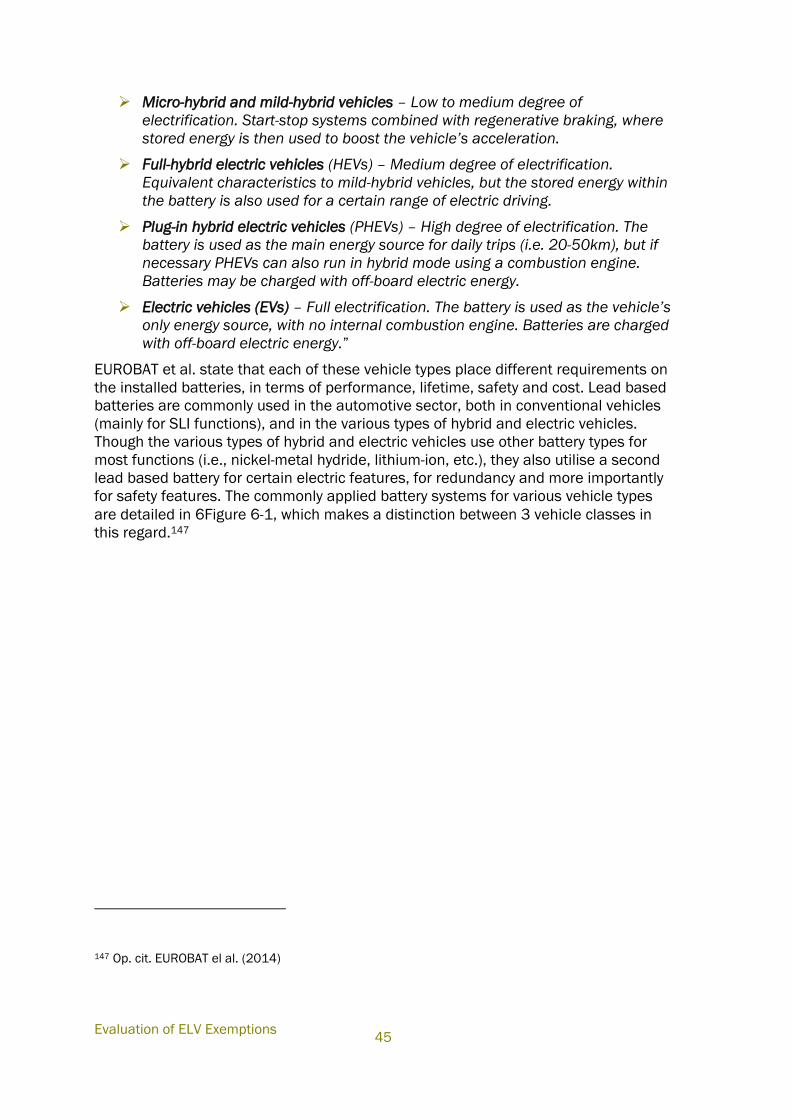
Evaluation of ELV Exemptions
45
Micro-hybrid and mild-hybrid vehicles – Low to medium degree of
electrification. Start-stop systems combined with regenerative braking, where
stored energy is then used to boost the vehicle’s acceleration.
Full-hybrid electric vehicles (HEVs) – Medium degree of electrification.
Equivalent characteristics to mild-hybrid vehicles, but the stored energy within
the battery is also used for a certain range of electric driving.
Plug-in hybrid electric vehicles (PHEVs) – High degree of electrification. The
battery is used as the main energy source for daily trips (i.e. 20-50km), but if
necessary PHEVs can also run in hybrid mode using a combustion engine.
Batteries may be charged with off-board electric energy.
Electric vehicles (EVs) – Full electrification. The battery is used as the vehicle’s
only energy source, with no internal combustion engine. Batteries are charged
with off-board electric energy.”
EUROBAT et al. state that each of these vehicle types place different requirements on
the installed batteries, in terms of performance, lifetime, safety and cost. Lead based
batteries are commonly used in the automotive sector, both in conventional vehicles
(mainly for SLI functions), and in the various types of hybrid and electric vehicles.
Though the various types of hybrid and electric vehicles use other battery types for
most functions (i.e., nickel-metal hydride, lithium-ion, etc.), they also utilise a second
lead based battery for certain electric features, for redundancy and more importantly
for safety features. The commonly applied battery systems for various vehicle types
are detailed in 6Figure 6-1, which makes a distinction between 3 vehicle classes in
this regard.147
147 Op. cit. EUROBAT el al. (2014)
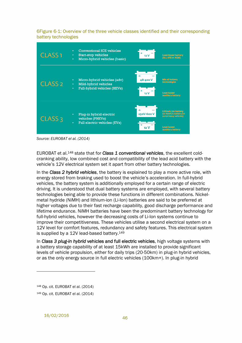
16/02/2016
46
6Figure 6-1: Overview of the three vehicle classes identified and their corresponding
battery technologies
Source: EUROBAT el al. (2014)
EUROBAT et al.148 state that for Class 1 conventional vehicles, the excellent cold-
cranking ability, low combined cost and compatibility of the lead acid battery with the
vehicle’s 12V electrical system set it apart from other battery technologies.
In the Class 2 hybrid vehicles, the battery is explained to play a more active role, with
energy stored from braking used to boost the vehicle’s acceleration. In full-hybrid
vehicles, the battery system is additionally employed for a certain range of electric
driving. It is understood that dual battery systems are employed, with several battery
technologies being able to provide these functions in different combinations. Nickel-
metal hydride (NiMH) and lithium-ion (Li-Ion) batteries are said to be preferred at
higher voltages due to their fast recharge capability, good discharge performance and
lifetime endurance. NiMH batteries have been the predominant battery technology for
full-hybrid vehicles, however the decreasing costs of Li-Ion systems continue to
improve their competitiveness. These vehicles utilise a second electrical system on a
12V level for comfort features, redundancy and safety features. This electrical system
is supplied by a 12V lead-based battery.149
In Class 3 plug-in hybrid vehicles and full electric vehicles, high voltage systems with
a battery storage capability of at least 15kWh are installed to provide significant
levels of vehicle propulsion, either for daily trips (20-50km) in plug-in hybrid vehicles,
or as the only energy source in full electric vehicles (100km+). In plug-in hybrid
148 Op. cit. EUROBAT el al. (2014)
149 Op. cit. EUROBAT el al. (2014)
Evaluation of ELV Exemptions
47
vehicles, the battery must also perform hybrid functions (i.e. regenerative braking)
when its capability for electric drive is depleted. Plug-in hybrid and electric passenger
cars are propelled by Li-Ion battery systems. Due to their high energy density, fast
recharge capability and high discharge power, Li-Ion batteries are the only available
technology capable of meeting OEM requirements for vehicle driving range and
charging time. For commercial applications, harsh environments and heavy-duty
vehicles, sodium-nickel chloride batteries are a competitive option. NiMH batteries
and Pb-based batteries cannot meet these requirements at a competitive weight.
Similar to hybrid vehicles, an auxiliary 12V lead-based battery is installed in all plug-in
hybrid and electric vehicles to supply their electrical components, including the safety
relevant features. 150
Of relevance to the auxiliary batteries described above, ACEA et al. explain that the
on-board electronics of vehicles operate at 12V. This is relevant for understanding
limitations for the auxiliary batteries mentioned in Class 2 and Class 3 vehicles, but is
also a general aspect that is relevant for developing battery technologies on the
vehicle level. On board electronics include the lighting for the car as well as control
electronics, entertainment, navigation and safety devices like airbags or door lock
systems. The vehicle electrical system has developed over decades in parallel and
together with the 12V lead acid starter battery. Operating voltage of electrical and
electronic components has been globally standardized at this level, and installed
batteries must be compatible with these 12V systems. The vehicle electrical system is
globally standardised for all vehicles – from ICE up to EV – to be compatible with 12V
lead-based batteries. This compatibility is true also for designs targeting vehicles with
start-stop systems, like enhanced flooded (EFB) and AGM batteries.151
Currently, all automotive components have been developed for 12V power supply.
Changing the voltage of the system would require a total redesign of the electrical
system and components of all cars, which would impose a significant cost onto OEMs
and suppliers of automotive parts. On-board electric systems of vehicles currently in
production are designed for an optimal use of a 12V battery, in practice a lead-based
battery. Changing the battery output voltage would imply a full redesign of many of
the vehicle’s electrical components (e.g. its starter, generator, various electric
powered appliances, engine controllers, security features and switches,
entertainment, comfort and guidance devices). These components would have to be
redesigned to make optimal use of the battery system, as is the case for currently
employed lead-based battery systems. 152
6.1.2.1 Details as to lead based batteries - summary
EUROBAT et al.153 state that lead-based batteries are currently the only available
mass-market technology for SLI applications in conventional vehicles, including those
150 Op. cit. EUROBAT el al. (2014)
151 Op. cit. ACEA et al. (2014)
152 Op. cit. ACEA et al. (2014)
153 Op. cit. EUROBAT el al. (2014)
16/02/2016
48
with start-stop and basic micro-hybrid systems, due to their excellent cold cranking
performance, reliability and low cost. Starter batteries of 12V are standardised
globally. All lead-based batteries use the same basic chemistry. It is explained that in
vehicles, three lead-based sub-technologies are currently available:
Flooded SLI batteries;
Enhanced Flooded Batteries (EFB); and
Absorbent Glass Mat (AGM) batteries.
Lead-based batteries all use the same basic chemistry. The active material of the
positive plate mainly consists of lead dioxide, and the active material of the negative
plate is finely dispersed metallic lead. These active materials react with the sulphuric
acid electrolyte to form lead sulphate on discharge and the reactions are reversed on
recharge. Batteries are constructed with lead grids to support the active materials.
Individual cells are connected in series within a single plastic case. The nominal
voltage of a cell is 2.0V. Components of lead-based batteries include: 154
Lead and lead dioxide: average 60% of the total weight
Electrolyte: diluted sulphuric acid: average 30% of the total weight
Others, like alloying components and polymers (separators PE, battery case
PP): average 10% of the total weight
Because of their lower cost, flooded lead-based batteries are used in the vast majority
of conventional ICE vehicles to provide SLI functions. Flooded lead-based batteries
are characterised by a vented design and an excess of free-flowing electrolyte
between and above the electrode stack. 155
ACEA et. al.156 explain that advanced lead-based batteries (AGM and EFB
technologies) are installed to meet extra requirements in start-stop and basic micro-
hybrid vehicles, due to their increased charge recoverability and higher deep-cycle
resistance. In addition to start-stop functionality, these batteries provide braking
recuperation and passive boosting (resulting in 5-10% fuel efficiency improvements).
Successful efforts have been made to increase the efficiency of the lead-based
battery by reducing the amount of lead needed to achieve the required performance.
However, the increasing number of electrical components in cars and the additional
functions that the battery is required to cover (e.g. start-stop functionality for
improving fuel efficiency) has imposed extra requirements on the automotive battery
(i.e. deeper and more frequent discharge), meaning there has not been a
corresponding reduction in battery weight for EFB and AGM technologies.
The average total weight of a lead-based battery (flooded and EFB/AGM) for a
compact passenger car is 18-20kg. The lifetime of an SLI battery heavily depends on
154 Op. cit. EUROBAT el al. (2014)
155 Op. cit. EUROBAT el al. (2014)
156 Op. cit. ACEA et al. (2014)
Evaluation of ELV Exemptions
49
usage patterns and the climate in the area of use. A lifetime estimate of 5 to 7 years
is provided by EUROBAT.157 An equivalent operational life is also demonstrated by
advanced AGM/EFB batteries in start-stop and basic micro-hybrid applications, after
years of operation in partial states of charge (PSoC).158
EUROBAT et al.159 explain that in comparison with other battery technologies, lead-
based traction batteries are not competitive for use in full hybrid electric vehicles or
electric vehicles because of their lower specific energy and higher weight. However,
for all electrified powertrains (from micro-hybrid to full electric vehicles), the 12V
board-net and electronic component supply are currently provided by auxiliary 12V
lead-based batteries (in addition to the larger traction battery). The 12V lead-based
battery is also used to maintain the safety management of the larger traction battery.
This is expected to continue for the foreseeable future.
6.1.2.2 Amount of Lead Used under the Exemption
A report prepared by IHS et al.160 concerning the availability of Pb based automotive
batteries for recycling, estimated the Pb component of a lead based automotive
battery to make up for approximately 60% of the weight of the battery. The report
states that automotive batteries have an average life expectancy of more than six
years161. The estimation of the total amount of batteries available for collection is
based on a method developed in the study. The authors used two existing recognised
data sources:
• “Used automotive batteries recovered within the vehicle lifetime: Using IHS162
proprietary parc data by vehicle age, and then applying a formula for the battery’s
expected lifetime within the vehicle.
• Used automotive batteries recovered from end-of-life vehicles: Using EUROSTAT
data on End-of-Life vehicles (ELV), by Member State where the battery is recovered
during vehicle scrappage.”
Based on these data sources, the authors estimate “the quantity of used automotive
lead-based batteries “available for collection and recycling” in the current year (units)
157 Op. cit. EUROBAT el al. (2014)
158 Op. cit. ACEA et al. (2014)
159 Op. cit. EUROBAT el al. (2014)
160 IHS et. al. (2014) IHS, EUROBAT, ILA, ACEA, JAMA and KAMA (2014), The Availability of Automotive
Lead-Based Batteries for Recycling in the EU - A joint industry analysis of EU collection and recycling
rates 2010-2012, prepared by information company IHS, Pg. 20, available under:
http://www.eurobat.org/sites/default/files/ihs_eurobat_report_lead_lores_final.pdf
161 According to IHS et. al. (2014) the average replacement cycle for light vehicles is said to be
between 3 to 10 years, and 6 years on average. The average replacement cycle for heavy vehicles is
said to be between 1 to 3 years and 2 years on average.
162 Explained in the report: IHS/Polk Car Parc gives a segmentation of the European vehicle parc in
each EU member state for 15 years (the reference years in the study were 2010, 2011 and 2012) split
by age and by vehicle type.
16/02/2016
50
by quantifying used batteries recovered within the vehicle’s lifetime (i.e. batteries that
come to the end of their life and are replaced in the vehicle) and used automotive
batteries recovered from end-of-life vehicles (ELVs). Over the three years between
2010 and 2012, it was estimated that:
Approximately 54.1 million lead based automotive batteries were available for
collection in the EU market from use in light vehicles163 (estimated to weigh
approximately 945 thousand tonnes);
Approximately 3.7 million lead based automotive batteries were available for
collection in the EU market from use in heavy vehicles163 (estimated to weigh
approximately 165.6 thousand tonnes);
In total close to 58 million lead based automotive batteries were available for
collection in the EU market for recycling, with a total weight of approximately
1,110 thousand tonnes;
The consultants would like to point out that the information provided in this respect is
relevant only for batteries available for recycling, understood to be collected batteries.
The amount of batteries available for collection over three years does not allow
calculating the exact amount of batteries placed on the EU market per annum as is
further explained in Section 6.2.2 below. However, this data provides insight as to the
magnitude of lead based batteries put on the EU market per annum. Along with the
estimation of the lead components weight from the total battery weight, this provides
some indication as to how much Pb is placed on the EU market per annum, through
the application relevant to ELV Exemption 5.
6.1.2.3 End-of-Life of Lead-acid Batteries
According to an analysis prepared by IHS et al. 164, the recycling rate of automotive
lead batteries is estimated to be close to 99% (as explained above, understood to be
99% of collected batteries). As some of the material components are recycled and
reused in the manufacture of new automotive batteries, the report considers
automotive lead battery manufacture to operate in a closed loop as suggests the
following information:
“In the EU, used automotive lead-based batteries are typically returned to the
point of sale, for example, vehicle workshops, vehicle dealerships, accessory
shops, and DIY stores; or they are returned to recycling businesses or metal
dealerships. In all cases they are then sent on to collection points… specialised
companies… transport and deliver the batteries to secondary smelting plants
operating under strict environmental regulations… the battery is broken down
into component parts, the majority of which can be recycled. The lead-acid
163 According to IHS et. al. (2014),“‘Light Vehicles’ are defined as vehicles of less than 3.5 tonnes.;
‘Heavy Vehicles’ are vehicles of more than 3.5 tonnes.” The weight of batteries used in this estimation
was between 15-22.5 Kg for batteries used in light vehicles and 45 kg for batteries used in heavy
vehicles. Heavy vehicles usually use more than one lead based battery for SLI requirements.
164 Op. cit. IHS et. al. (2014)
Evaluation of ELV Exemptions
51
battery is an excellent example of a product allowing an almost complete end-
of-life recycling, with more than 93% of a lead-based battery available for
recycling. The only component of the battery that cannot be recycled is the
separators (these represent just 2% to 7% of the battery). The components that
can be recycled and re-used are as follows:
The lead components (approximately 60% of the weight) are smelted and
refined to be used to make new batteries.
The battery casing, which is made of plastic (approximately 7% of the
weight), is usually separated before the lead is recycled, depending on the
method used, and is then reprocessed and re-used for batteries or for other
products in the automobile industry, for example in bumpers, wheel arches
and other parts.
The spent electrolyte (diluted sulphuric acid, approximately 30% of the
weight) is treated in a variety of ways. In some processes the spent
electrolyte is separated and filtered to make it suitable for regenerating
fresh acid for a variety of applications. Other processes convert the spent
electrolyte into calcium sulphate (gypsum) or sodium sulphate (soda),
which can be used for various applications such as building products or
detergents. Some processes neutralise the spent electrolyte and then
dispose of it.
It is useful to note that even without the pressure from resource conservation
and environmental protection, there is a significant incentive to collect and
recycle used automotive lead-based batteries. Recycling lead is relatively simple
and cost effective and in most of the applications where lead is used, especially
lead-based batteries, it is possible to recover it for use over and over again
without any loss in quality. The lead-battery recycling process can be repeated
indefinitely, meaning that new lead batteries are made with materials that have
been recycled many times over. Furthermore, as all lead-based batteries have
the same basic chemistry, this means that all types of lead battery can be
processed easily by lead smelters. This is not the case with all automotive
battery technologies…”165
6.1.3 Alternative Battery Chemistries
Various technologies have been developed with the aim of finding alternatives for
automotive systems. Information provided by stakeholders covers several
technologies described below, with a summary provided in Table 6-1.
ACEA et. al. 166 refer to a comparison of lead-based batteries and alternative
technologies which is covered in the study “A review of battery technologies for
165 Op. cit. IHS et. al. (2014)
166 Op. cit. ACEA et al. (2014)
16/02/2016
52
automotive applications”167. ACEA summarise relevant information for the various
technologies as follows:
Despite on-going research, nickel and sodium based batteries are not
considered as an alternative for use in SLI, start-stop and micro hybrid
applications.
Super-capacitors coupled with a lead-acid battery would not substantially
reduce the size, or lead demand, of the main battery.
Hybrid lead-acid batteries [such as the PbC® battery or the UltraBatteryTM]
are still in the developmental phase, but cannot meet the stable voltage
requirement of automotive power supply systems. However, the
electrochemical elements are based on the same lead chemistry and the
components are similar to those found in standard 12 V lead-based batteries.
Furthermore, the amount of lead in these technologies is not expected to be
significantly different from those in a standard lead-based battery.
Research into Li-Ion batteries as an alternative for use in SLI, start-stop and
micro hybrid applications has been undertaken, and been shown to be
effective under certain conditions. However, ACEA et al. explain Li-Ion solutions
to require improvements in order to be considered a viable mass market
alternative.
Nonetheless, it is understood from other stakeholders that current development of Li-
Ion batteries has already overcome some of the obstacles mentioned by ACEA et al.
and that they have already been applied in first models available on the EU market.
As the consultants understand such batteries to currently be most advanced in terms
of providing an alternative for Pb-based batteries, more detail is provided concerning
such technologies in the following subsection. Other technologies are only mentioned
in this report, where this is understood to be relevant for establishing the application
range of lead based batteries in vehicles at present. Further information provided by
stakeholders concerning other battery technologies can be viewed in the various
online contributions made to the stakeholder consultation. Such information is not
reproduced here, as these technologies were deemed not to have potential for
substituting lead based batteries168.
6.1.3.1 Lithium-ion Batteries
A123 Systems, Fraunhofer, LG Chem and Samsung SDI have made a joint
contribution, explaining that there are three dominant chemistries applicable for
automotive Li-Ion batteries. These are lithium-iron-phosphate (LFP) cathode/graphite
anode, lithium manganese cobalt oxide (NMC) cathode/ graphite anode, and NMC
cathode/lithium titanate (LTO) anode.169
167 See http://www.eurobat.org/sites/default/files/rev_of_battery_executive_web_1.pdf
168 See Exemption 5 consultation page available under
169 A123 et. Al. (2014), Joint contribution of A123 Systems, Fraunhofer, LG Chem and Samsung SDI
(2014), Contribution submitted to ELV Stakeholder Consultation Concerning Ex. 5, submitted
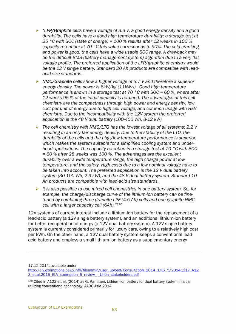
Evaluation of ELV Exemptions
53
“LFP/Graphite cells have a voltage of 3.3 V, a good energy density and a good
durability. The cells have a good high temperature durability: a storage test at
25 °C with SOC (state of charge) = 100 % results after 12 weeks in 100 %
capacity retention; at 70 °C this value corresponds to 90%. The cold-cranking
and power is good, the cells have a wide usable SOC range. A drawback may
be the difficult BMS (battery management system) algorithm due to a very flat
voltage profile. The preferred application of the LFP/graphite chemistry would
be the 12 V single battery. Standard 20 Ah products are compatible with lead-
acid size standards.
NMC/Graphite cells show a higher voltage of 3.7 V and therefore a superior
energy density. The power is 6kW/kg (11kW/l). Good high temperature
performance is shown in a storage test at 70 °C with SOC = 60 %, where after
12 weeks 95 % of the initial capacity is retained. The advantages of this cell
chemistry are the compactness through high power and energy density, low
cost per unit of energy due to high cell voltage, and common usage with HEV
chemistry. Due to the incompatibility with the 12V system the preferred
application is the 48 V dual battery (100-400 Wh, 8-12 kW).
The cell chemistry with NMC/LTO has the lowest voltage of all systems: 2.2 V
resulting in an only fair energy density. Due to the stability of the LTO, the
durability of the cells and the high/low temperature performance is superior,
which makes the system suitable for a simplified cooling system and under-
hood applications. The capacity retention in a storage test at 70 °C with SOC
= 60 % after 28 weeks was 100 %. The advantages are the excellent
durability over a wide temperature range, the high charge power at low
temperature, and the safety. High costs due to a low nominal voltage have to
be taken into account. The preferred application is the 12 V dual battery
system (30-100 Wh, 2-3 kW), and the 48 V dual battery system. Standard 10
Ah products are compatible with lead-acid size standards.
It is also possible to use mixed cell chemistries in one battery system. So, for
example, the charge/discharge curve of the lithium-ion battery can be fine-
tuned by combining three graphite-LPF (4.5 Ah) cells and one graphite-NMC
cell with a larger capacity cell (6Ah).”170
12V systems of current interest include a lithium-ion battery for the replacement of a
lead-acid battery (a 12V single battery system), and an additional lithium-ion battery
for better recuperation of energy (a 12V dual battery system). A 12V single battery
system is currently considered primarily for luxury cars, owing to a relatively high cost
per kWh. On the other hand, a 12V dual battery system keeps a conventional lead-
acid battery and employs a small lithium-ion battery as a supplementary energy
17.12.2014, available under
http://elv.exemptions.oeko.info/fileadmin/user_upload/Consultation_2014_1/Ex_5/20141217_A12
3_et.al.2015_ELV_exemption_5_review_-_Li-ion_stakeholders.pdf
170 Cited in A123 et. al. (2014) as G. Kamitani, Lithium-ion battery for dual battery system in a car
utilizing conventional technology, AABC Asia 2014
16/02/2016
54
storage system. In this 12V dual system, the lead-acid and lithium-ion technology
complement each other, and the combination is expected to be an economically
viable 12V storage system. 48V systems have also drawn much attention in recent
years. Several OEMs plan to put vehicles with a 48V system on the market by
2016.171
Depending on automakers’ needs for pack location and systems design, their interest
in cell chemistry varies from conventional carbonaceous anodes, to LTO anodes, to
LFP cathodes. For 12 V battery systems, both a battery with LFP cathode and
carbonaceous anode materials (LFP cells) and a battery based on an LTO anode (LTO
cells) meet a voltage range of the conventional 12 V power networks. LFP and LTO
cells require 4 to 6 cells connected in series for voltage compatibility. LFP cells have
an advantage of higher energy density, but LTO cells have a wider range of
operational temperatures, and better durability. LFP cells have been used in some
vehicles as a 12V single system replacing lead acid batteries, and LTO cells have
been utilized as a supplementary battery on the market. For 48V systems, all three
chemistries could be applied.172
For use in SLI, start-stop and micro hybrid applications, ACEA et al. claim that Li-Ion
batteries still require improvements in cold cranking ability and economic packaging
(including cost level) in order to be considered as a viable mass-market alternative to
lead-based batteries. The further advancement and development of Li--Ion batteries
could allow an opportunity for their use in limited SLI applications, albeit primarily as
a performance option when weight saving is a sufficient driving factor that increased
cost and their lower performance in cold conditions can be accepted. ACEA further
explains that the operation of Li-Ion batteries is restricted to a specific temperature
and voltage range. If operated at temperatures or cell voltages outside of the
operational window the battery no longer provides services, with potential risk to its
surroundings.173
A123 agrees that cold cranking amperage (CCA) is the most important performance
metric for a starter battery, and explains that the perceived deficiency of Li-Ion cold
crank performance is likely the most discussed topic with regard to usage in 12V
lead-acid starter battery applications. However, it is further explained that Li-Ion
battery performance at cold temperatures has improved dramatically. EN-50342,
VDA-LV124174 and SAE-J537 are all commonly recognized automotive specifications
which outline cold crank requirements for 12V starter batteries. These specifications
do not define specific CCA for a particular battery capacity, rather only test setup and
171 Op. cit. A123 et al. (2014)
172 Cited in A123 et. al. (2014) as W. Jeong, Lithium-Ion Battery Technology for Low-Voltage Hybrids:
Present and Future, AABC Asia 2014
173 Op. cit. ACEA et al. (2014)
174 EN-50342: British Standard European Norm 50342-1, 2006
VDA-LV124: MBN LV124-1 & -2, Electric and Electronic Components in Motor Vehicles up to 3,5t –
General Requirements, Test Conditions and Tests

Evaluation of ELV Exemptions
55
parameters such as temperature, duration, and minimum voltage drop allowed during
the cranking pulse. The target CCA is left to the manufacturer to define. Without
specific CCA targets with which to compare the performance of Li-Ion to lead-acid it is
reasonably assumed that the industry’s expectation for cold crank performance is
reflected in the CCA rating indicated on battery labels for production advanced lead-
acid (AGM) batteries. A123 et al. compare data on performance of various Pb-based
and Li-Ion batteries and conclude that modern Li-Ion batteries have reached parity in
cold crank performance against lead-acid batteries used in the same application at -
18C, which is the temperature at which automotive 12V starter batteries are often
specified and labelled. Today’s Li-Ion batteries are said to also meet those industry
standards in which cold cranking requirements are specified at -25C (LV124). A123
et al. explain that many OEMs have their own specifications for cold crank
requirements at temperatures as low as -30C, for which modern Li-Ion batteries have
not reached parity with lead-acid, though it is estimated that such performance shall
be achieved throughout the next 3–5 years. 175
EUROBAT et al.176 estimate that significant resources will continue to be spent on
improving the performance, cost, systems integration, production processes, safety
and recyclability of high-voltage Li-Ion battery systems for hybrid and electric
applications. Large performance and cost improvements are expected through
developments in cell materials and components (i.e. anode, cathode, separator and
electrolyte). Lower cost cell design is expected by 2025, along with improvements in
materials properties and the gradual scaling up in production of large cell formats.
These improvements will increase the competitiveness of Li-Ion batteries in other
applications. It is expected that by 2025, Li-Ion batteries will be implemented in some
48V dual-battery systems together with a 12V lead-based battery in order to further
increase fuel-efficiency in advanced micro-hybrid and mild-hybrid vehicles.
A123 et al.177, 178 provide information regarding various vehicles in which Li-Ion
battery systems are already applied in vehicles. A few vehicle models are mentioned
in which single Li-Ion batteries are applied in vehicles available on the EU market, in
some cases to support micro-hybridization and in others with light-weighting being the
main driver. Furthermore, examples are provided of vehicles with dual batteries,
which are available on the global market, some using Li-Ion technology. For details,
see referenced documents as well as Appendix A.5.0.
175 Op. cit. A123 et al. (2014)
176 Op. cit. EUROBAT et al. (2014)
177 Op. cit. A123 et al. (2014)
178 A123 et al. (2015a) Joint contribution of A123 Systems, Fraunhofer, LG Chem and
Samsung SDI, Answers to Questionnaire Clarification: Exemption No. 5, submitted per email
6.3.2015
16/02/2016
56
6.1.3.1.1 Super-capacitors coupled with Li-Ion Batteries;
Olife has developed a new car battery claimed to provide the first full substitute for
lead acid batteries. The technology combines LFP chemistry with super-capacitors,
which is said to guarantee high cranking power at temperatures as low as -50°C. The
Li-Ion batteries continuously refill the super-capacitors, thus serving as a source of
Reserve Capacity. The battery has a low value of self-discharge and it will stay ready
to start even after two years out of operation. Unlike batteries, super-capacitors store
and release electrical energy as electric charge and not in the form of bound chemical
energy. This means that the release of electric current does not require a chemical
reaction. The super-capacitors thus provide the necessary cranking current, while at
any normal vehicle driving temperature (from -30°C to +50°C), the Li-Ion batteries
will continuously refill the super-capacitors. They also serve as a reliable source of
necessary reserve capacity. The super-capacitors further level out all current peaks
during normal operation of the car battery, giving the Li-Ion cells ideal protection and
maximising battery life. The Olife battery is said to be 7–10 kg lighter than a lead acid
battery (depending on the LAB and vehicle type), which is reported to enable
significant carbon savings. The production technology procedure development has
recently been finalised and Olife is currently undergoing verification of the production
technology by producing a limited number of batteries. The aim is to launch full
commercial production at the end of 2015. Planned production capacity is hundreds
of thousands of pieces per year.179
6.1.3.2 Nickel-metal Hydride Batteries
An overview of the use of NiMH batteries in automotive applications is provided by
EUROBAT et al. (2014):
“NiMH batteries have been the technology of choice in the HEV market over
the last decade, due to their design flexibility, good energy density, high power
performance and better environmental compatibility. This was the technology
selected by Toyota when the Prius HEV was introduced in 1997. NiMH
batteries are still significantly more expensive than lead-based batteries, and
have not been considered for use in SLI functions because of their inferior
cold-cranking performance and other limitations.
NiMH batteries are primarily used in mild-hybrid and full-hybrid vehicles,
where they have been the technology of choice over Li-Ion batteries because
of their durability and lower cost…For plug-in HEVs and EVs, NiMH batteries
have been an important technology while Li-Ion batteries develop to reach a
sufficient maturity. However, their heavier weight, lower energy density and
lower deep-cycling capability mean that they will not be able to compete with
Li-Ion batteries for the next generation of plug-in HEVs and full EVs. This is
apparent in Toyota’s decision to use lithium-ion batteries for their plug-in
179 Olife (2014a), Response to the consultation on the “8th Adaptation to scientific and technical
progress of exemptions 2(c), 3 and 5 of Annex II to Directive 2000/53/EC (ELV)”,
http://elv.exemptions.oeko.info/fileadmin/user_upload/Consultation_2014_1/Ex_5/Ex_5_Contributio
n_17122014_OLIFE_response_to_ELV_consultation_161214-Public.pdf

Evaluation of ELV Exemptions
57
hybrid Prius model…their potential for further market penetration is limited by
the increased performance and reduced cost of Li-Ion batteries. Because they
have already reached a high degree of technological maturity, limited
improvements are expected between now and 2025.
At end of life, and in compliance with the Batteries and ELV Directives, all
NiMH batteries from automotive applications are collected and recycled. The
metals are used predominantly in the steel industry.” 180
180 Op. cit. EUROBAT et al. (2014)
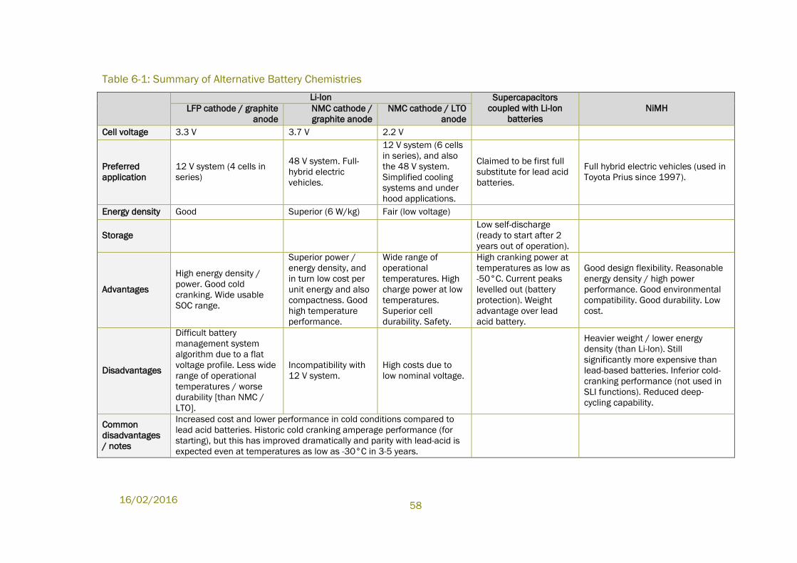
16/02/2016
58
Table 6-1: Summary of Alternative Battery Chemistries
Li-Ion Supercapacitors
coupled with Li-Ion
batteries
NiMH LFP cathode / graphite
anode
NMC cathode /
graphite anode
NMC cathode / LTO
anode
Cell voltage 3.3 V 3.7 V 2.2 V
Preferred
application
12 V system (4 cells in
series)
48 V system. Full-
hybrid electric
vehicles.
12 V system (6 cells
in series), and also
the 48 V system.
Simplified cooling
systems and under
hood applications.
Claimed to be first full
substitute for lead acid
batteries.
Full hybrid electric vehicles (used in
Toyota Prius since 1997).
Energy density Good Superior (6 W/kg) Fair (low voltage)
Storage
Low self-discharge
(ready to start after 2
years out of operation).
Advantages
High energy density /
power. Good cold
cranking. Wide usable
SOC range.
Superior power /
energy density, and
in turn low cost per
unit energy and also
compactness. Good
high temperature
performance.
Wide range of
operational
temperatures. High
charge power at low
temperatures.
Superior cell
durability. Safety.
High cranking power at
temperatures as low as
-50°C. Current peaks
levelled out (battery
protection). Weight
advantage over lead
acid battery.
Good design flexibility. Reasonable
energy density / high power
performance. Good environmental
compatibility. Good durability. Low
cost.
Disadvantages
Difficult battery
management system
algorithm due to a flat
voltage profile. Less wide
range of operational
temperatures / worse
durability [than NMC /
LTO].
Incompatibility with
12 V system.
High costs due to
low nominal voltage.
Heavier weight / lower energy
density (than Li-Ion). Still
significantly more expensive than
lead-based batteries. Inferior cold-
cranking performance (not used in
SLI functions). Reduced deep-
cycling capability.
Common
disadvantages
/ notes
Increased cost and lower performance in cold conditions compared to
lead acid batteries. Historic cold cranking amperage performance (for
starting), but this has improved dramatically and parity with lead-acid is
expected even at temperatures as low as -30°C in 3-5 years.
Evaluation of ELV Exemptions
59
6.1.4 Possible Alternatives that May Reduce the Use of Lead in Batteries
A123 further explain that there are paths to the reduction of lead usage in batteries,
which are also economical. As explained above, dual battery architectures utilize a
low-cost lead-acid battery for cold cranking and a small Li-Ion battery to supplement
the system performance, particularly during energy recuperation. The incremental
cost of this secondary Li-Ion battery is proportional to its size and when considering
total system cost it is possible to engineer a dual battery system, which is somewhat
less costly than a single Li-Ion starter battery. The economics of the dual battery
approach make it commercially viable to at least limit the capacity of lead-acid
batteries in future vehicles. 181
6.1.5 Stakeholder Justification for Exemption Renewal
EUROBAT et al.182 explain that currently several battery technologies are installed in
European vehicles, from automotive batteries for internal combustion engine
cranking (SLI) and start-stop functionalities to industrial traction batteries for hybrid,
plug-in hybrid and electric vehicles. Where a single battery system cannot cope with
all requirements at the same time, different combinations of several battery types are
installed to allow operation at different voltage levels. For example, all hybrid, plug-in
hybrid and electric vehicles are currently equipped with both an industrial traction
battery and an auxiliary lead-based automotive battery which is used to support the
on-board electronics and safety features.
ACEA et. al. 183 argue that the substitution of lead-based batteries in automotive
vehicles is still not possible, estimating that they are vital to ensure mobility on
European roads for [at least] the next 10-15 years. In particular, the cold cranking
properties of Pb-based batteries are said to make these battery types essential. At
low temperatures, no other commercially available battery system, ready for volume
production, is able to meet the required performance or demand (starting ability at
temperatures around -30°C required).
EUROBAT et al.184 estimate that 12V lead-based batteries will continue to be the
essential mass-market system in Class 1 vehicles for the foreseeable future, while
also continuing to be used as auxiliary batteries in Class 2 and 3 vehicles. By 2025,
they are expected to provide extra services in micro-hybrid vehicles to increase the
internal combustion engine’s fuel efficiency (i.e. stop-in-motion, voltage stabilisation).
Therefore, their cycle life, power density and charge acceptance will be further
improved. Lead-carbon batteries are expected to be commercialised in the near
future, and will provide high performance in terms of charge acceptance and through
181 Op. cit. A123 et. Al. (2014)
182 Op. cit. EUROBAT el al. (2014)
183 Op. cit. ACEA et al. (2014)
184 Op. cit. EUROBAT el al. (2014)
16/02/2016
60
their ability to operate at partial states of charge in start-stop and micro-hybrid
vehicles. Dual batteries using lead-based batteries and other technologies at different
voltages will also see accelerated commercialisation in the next decade.
6.1.6 Stakeholder Justification for Lead-acid Battery Phase-Out and Revoking
of Exemption 5
The automotive industry considers lead-based battery systems to be essential in
automotive applications for the foreseeable future. ACEA et al. claim that despite
ongoing industry R&D efforts on enhanced energy storage systems no feasible mass
market alternatives to lead-based batteries are currently available.185
However, other stakeholders have submitted information regarding the applicability of
Li-Ion alternatives for various automotive applications, claiming that state of
development would allow at least a partial phase-out of lead acid batteries in
automotive applications.
A123 et al.186 have provided information to demonstrate the latest developments in
Li-Ion battery technology (see also Section 6.1.3.1 above). They claim that Li-Ion
solutions in plug-in hybrid electric vehicles and full electric vehicles could already be
used to replace LAB based solutions in vehicles for which cold cranking performance
is not a relevant requirement. They elaborate on this statement in order to clarify the
relevance for various types of vehicles:
“In the case of an electric vehicle (EV), sometimes called a battery electric
vehicle (BEV), there is no internal combustion engine installed and no such
vehicle has an engine cranking requirement. In an EV, a 12V lead-acid battery
is typically still installed to support vehicle electronics which are common with
other vehicle types and still operate at 12V. We are aware of no valid
argument why the use of lead in this application is not immediately avoidable.
Another relevant class of vehicle is a plug-in hybrid electric vehicle (PHEV)
which is generally designed to drive on electric power until the battery energy
is consumed and then operation switches over to power from a combustion
engine. As with a fully electric vehicle (EV), there is generally a 12V lead-acid
battery on-board. When operating conditions require starting of the
combustion engine in a PHEV, it is technically possible to crank the engine
using power from either the high-voltage lithium-ion battery or the 12V lead-
acid battery. While the members of this response group are not experts on the
architecture of every PHEV in the market, we are aware that some use the
lithium-ion battery to crank the engine, thereby relieving the lead-acid battery
of that responsibility. In the cases where the lead-acid battery is not involved
185 ACEA et al.(2015a), Industry contribution of ACEA, CLEPA JAMA, KAMA, ILA and EUROBAT, Answers
to Clarification Questions, submitted 27.3.2015 per email
186 A123 et al. (2015b), Joint contribution of A123 Systems, Fraunhofer, LG Chem and Samsung SDI,
Answers to Clarification Questions Following the Stakeholder Meeting of 10.4, submitted per email
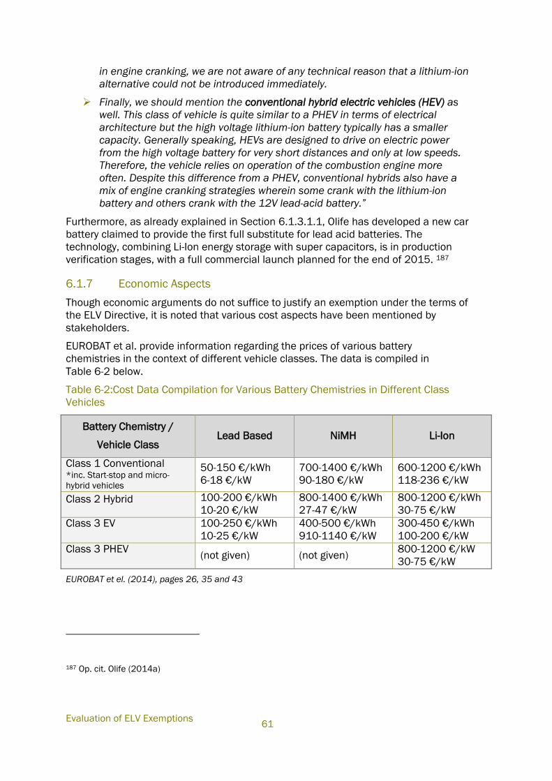
Evaluation of ELV Exemptions
61
in engine cranking, we are not aware of any technical reason that a lithium-ion
alternative could not be introduced immediately.
Finally, we should mention the conventional hybrid electric vehicles (HEV) as
well. This class of vehicle is quite similar to a PHEV in terms of electrical
architecture but the high voltage lithium-ion battery typically has a smaller
capacity. Generally speaking, HEVs are designed to drive on electric power
from the high voltage battery for very short distances and only at low speeds.
Therefore, the vehicle relies on operation of the combustion engine more
often. Despite this difference from a PHEV, conventional hybrids also have a
mix of engine cranking strategies wherein some crank with the lithium-ion
battery and others crank with the 12V lead-acid battery.”
Furthermore, as already explained in Section 6.1.3.1.1, Olife has developed a new car
battery claimed to provide the first full substitute for lead acid batteries. The
technology, combining Li-Ion energy storage with super capacitors, is in production
verification stages, with a full commercial launch planned for the end of 2015. 187
6.1.7 Economic Aspects
Though economic arguments do not suffice to justify an exemption under the terms of
the ELV Directive, it is noted that various cost aspects have been mentioned by
stakeholders.
EUROBAT et al. provide information regarding the prices of various battery
chemistries in the context of different vehicle classes. The data is compiled in
Table 6-2 below.
Table 6-2:Cost Data Compilation for Various Battery Chemistries in Different Class
Vehicles
Battery Chemistry /
Vehicle Class Lead Based NiMH Li-Ion
Class 1 Conventional *inc. Start-stop and micro-
hybrid vehicles
50-150 €/kWh
6-18 €/kW
700-1400 €/kWh
90-180 €/kW
600-1200 €/kWh
118-236 €/kW
Class 2 Hybrid
100-200 €/kWh
10-20 €/kW
800-1400 €/kWh
27-47 €/kW
800-1200 €/kWh
30-75 €/kW
Class 3 EV
100-250 €/kWh
10-25 €/kW
400-500 €/kWh
910-1140 €/kW
300-450 €/kWh
100-200 €/kW
Class 3 PHEV
(not given) (not given)
800-1200 €/kW
30-75 €/kW
EUROBAT et el. (2014), pages 26, 35 and 43
187 Op. cit. Olife (2014a)
16/02/2016
62
ACEA et al. 188 explain that there is no experience of the use of other batteries as SLI
batteries, and thus it is not possible to assess the cost per vehicle. However, they do
provide information to allow a partial comparison: Pb-based batteries remain by far
the most cost-effective and durable battery technology for SLI applications in
conventional powertrains (in the region of 50-150 €/kWh). On top of their lower cell-
level cost, they do not require heat shielding, active cooling, or a battery management
system.
This is an important consideration for consumers and the automotive industry, due to
the higher financial burdens that a more expensive alternative battery system would
place on them. On a cell level, the upfront costs of Li-Ion batteries remain significantly
higher than those of equivalent lead-based batteries. System level cost is further
increased by the required battery management system, shielding and housing (with
total upfront system cost ranging from 600-1200 €/kWh). ACEA et al. state that
although some of these high upfront costs could eventually be distributed over the
Total Cost of Ownership (TCO), they remain another barrier against Li-Ion batteries
being considered as a viable alternative to Pb-based batteries for use in mass-market
conventional vehicles with a single 12V battery with SLI function.
In this regard, Olife189 state that cost “is mainly a commercial issue but should be
calculated over the lifetime of the vehicle. For the ELV directive, the cost of batteries
over the lifetime of the vehicle is the true representative cost. In this case a high
initial cost would not be a limitation if the battery life is long enough.“ The anticipated
selling price for the Olife battery is likely to be about double the retail price of an
equivalent AGM LAB. The anticipated life of the Olife battery—particularly in micro-
hybrid applications—is estimated to be four times that of lead acid.
In a later document Olife190 further explains that: “The whole life cost of the Olife
technology is superior to lead acid for the consumer in terms of lower emissions from
reduced weight and the use of modern stop-start technology; the longer service life,
approximately eight times that of lead acid and the lack of toxicity in the products of
manufacture. However, the aftermarket is price driven and there might be reluctant
to accept the product with higher absolute price. This is despite the fact that the life
service cost is significantly below currently used the lead acid products”
A123 et al. agree that compared to lead-acid batteries Li-Ion technology is more
expensive on a kWh basis. Currently, a Li-Ion starter battery with 1 kWh of energy
capacity costs less than 500 € for [manufacture of]191 more than 10,000 pieces per
year. However, this cost is set to fall dramatically in the near future due to
improvements in technology and higher production volumes. As cold cranking power
continues to improve, various vehicle manufacturers are already developing
188 Op. cit. ACEA et al. (2014)
189 Op. cit. Olife (2014a)
190 Olife Energy (2015), Answers to Oeko-Institut Clarification Questions, sent per email on 27.3.2015
191 Consultant’s addition.
Evaluation of ELV Exemptions
63
production vehicle programs and meeting their cold cranking requirements with less
than 1 kWh of Li-Ion capacity. A123 et al. state that several Li-Ion vendors are offering
fully compliant starter batteries below 300 € for annual volumes of less than
500,000 units starting in 2017. Furthermore, the industry has additional potential to
improve, particularly as volumes increase.
For a complete analysis, it has to be considered that a Li-Ion battery with 60 Ah
capacity can replace a 95 Ah lead-acid battery in a micro hybrid application. While the
lead-acid battery may cost approximately 80 €, it weighs nearly 15 kg more. While
different vehicle manufacturers value mass reduction at various levels, a typical OEM
would pay as much as 100 € to achieve such mass savings [per vehicle]192.
Furthermore, a Li-Ion battery will last at least twice as long as a lead-acid battery in
the same application, so one must count twice the lead-acid cost when comparing the
cost of competing Li-Ion technology. However, even this assessment is too generous
to lead-acid because the consumer pays much more for the replacement lead-acid
battery than the vehicle manufacturer paid for the one initially installed in the
vehicle.193
A123 et al. state that although Li-Ion starter batteries have already been introduced
into the market for luxury and sports cars, improvements have to be made with
respect to the costs to allow a break-through in the mass market. 194
A123 et al. explain that Li-Ion batteries have a further advantage. As noted above, Li-
Ion technology offers charge acceptance that far exceeds that of the best lead-acid
technologies. When a vehicle manufacturer installs a Li-Ion starter battery, relatively
little system engineering is required in order to use the battery’s superior charge
acceptance to reduce emissions through a stronger recuperation strategy.
To illustrate the value of this benefit, assume that the vehicle manufacturer is slightly
above the 2015 requirement of 130g CO2/km and that the more aggressive
recuperation strategy enabled by the Li-Ion battery yields a modest improvement of
3% or 4g CO2/km. In 2015, a manufacturer who is 4g over the limit must pay a fine
of 140 EUR per vehicle. Of course, vehicle manufacturers already have strategies to
meet the 2015 emissions requirements but these requirements are becoming
steadily more stringent and the penalties for non-compliance will grow dramatically in
the next several years. When evaluating only life and mass advantages, Li-Ion
technology will become cost competitive over the next few years and the incremental
ability to enable emissions reductions provides a compelling business case
independent of the ELV exemption under consideration here. 195
192 Consultant’s addition.
193 Op. cit. A123 et. al. (2014)
194 Op. cit. A123 et. al. (2014)
195 Op. cit. A123 et. al. (2014)
16/02/2016
64
6.1.8 Environmental Arguments
Although the intention of the ELV Directive is to “minimise the impact of end-of life
vehicles on the environment” (recital (1)), it does not directly require the comparison
of applications using ELV substances and their possible alternatives in terms of
possible environmental impacts in the context of exemption justification.
Nonetheless, ACEA et al. have drawn attention to various aspects relevant to
automotive batteries in terms of environmental impacts, shortly summarised below.
Information was provided regarding the recyclability of lead acid batteries (see
Section 6.1.2.3) to show the advantages of lead acid batteries at the End-of-Life
phase over possible alternatives. As for the recyclability of Li-Ion batteries, though
ACEA et al. 196 state that the “recycling of lithium batteries is in its infancy”, A123 et
al.197 provide some information regarding the recycling processes of Li-Ion:
“Such recycling processes are already available from companies such as
Umicore and Toxco, although not yet in mass volume since the production
volumes do not yet warrant such a scale. Lithium and other components are
relatively benign with regard to toxicity to humans when compared to lead. All
batteries will be dismembered and recycled at end of life for economic and
social reasons. But in the case of lithium-ion batteries, there is far less
concern with regard to toxic waste and thus recyclability is generally not
considered a market barrier for this technology.
Lithium-ion battery recycling is being scaled as needed to match increasing
market demands of lithium-ion batteries because the process is relatively
simple and efficient. The basic procedure involves feeding the materials into a
high temperature smelter where some of the metals (i.e. cobalt, nickel,
copper, and iron) are gathered as an alloy for further refining into reusable
battery materials. The other elements (i.e. aluminium, lithium, calcium) end up
in an oxidized slag form which can be reused in other industries and
applications. Most of the energy needed for the recycling process comes
directly from the battery materials themselves (i.e. graphite, plastics,
electrolyte, aluminium.) Only the materials containing fluorine (less than 3%)
need to be landfilled responsibly.”
Concerning manufacture with attention to recyclability, Olife has said about its
batteries:
“Olife considers recycling part of our responsibility as well as compliance with
the legislation. A proposed model is emerging from consideration of the
existing technologies… Olife can make its batteries more recyclable by
implementing changes to its products. Prior to full production, Olife plans to
discuss the battery design with a recycling facility… and other facilities along
with researchers in this field in order to obtain technology and product design
recommendations and collaborate to adjust the batteries accordingly in order
196 Op. cit ACEA et al. (2014)
197 Op. cit. A123 et al. (2014)
Evaluation of ELV Exemptions
65
to make the whole process as economically-efficient as possible… At the
moment there is not a Li-Ion- battery recycling infrastructure in Europe in
terms of collection, logistics and recycling. What exists is based on the
voluntary efforts of individual companies who intend to bring this new product
to the market. Lithium as an energy source for electric vehicles is a new
technology that is growing but the recycling infrastructure is yet to be built.
Today, there are a number of projects that aim to overcome the challenges in
lithium recycling.
One initiative, which is particularly interesting, is the Lithorec II project: On the
Way to an “Intelligent” Recycling of Traction Batteries. The objective of the
LithoRec project is to find answers to these questions and to show a way of
“intelligent” recycling with a very high recovery rate and very high energy
efficiency. Therefore, almost the entire life cycle of lithium ion batteries—from
the demounting of the batteries from the (electric) vehicle to the preparation
of new battery cells out of recycled materials —is being researched within the
LithoRec project. The project is funded by the German Federal Ministry for the
Environment, Nature Conservation and Nuclear Safety (BMU) and coordinated
by the Automotive Research Centre Niedersachsen (NFF) and 12 partners
take part in this project”.198
EUROBAT et al.199 explain that:
“When recycling lithium-ion batteries, a high recovery rate of materials is
challenging in comparison with lead-based and nickel-based batteries. This is
primarily due to the wide varieties of chemical components and system
complexity. Several industrial recycling processes have begun to be
established, and research projects are ongoing to recover a wider range of
components, with nickel, cobalt and copper the most interesting
constituents”.
It is further understood that the identification of Li-Ion batteries in the sorting stage
needs to be further developed to ensure that batteries are directed to the correct
treatment facilities. In this regard, Olife200 mention the following possible changes
that could be made in coordination with recyclers in the design of their product to
facilitate recyclability in the future:
“Inclusion of labels or other distinguishing features — Various labelling
technologies could help to categorize the battery chemistry at the collection or
initial sorting stage such as:
Bar code
RFID chips
198 Op. cit. Olife (2015)
199 Op. cit. EUROBAT et al. (2014)
200 Op. cit. Olife (2015)
16/02/2016
66
Paint colour or type (e.g., visible under black light)”
A life cycle analysis was also provided by ACEA et al., comparing various aspects of
lead-acid chemistry alternatives (e.g. flooded lead-based batteries, enhanced flooded
lead-based batteries (EFB) and absorbent glass matt (AGM) lead-based batteries)201.
However, the LCA study does not cover battery types, which have been mentioned as
potential candidates to replace lead batteries. Against this background, details of the
LCA based comparison provided by ACEA et al. are not further specified here. For
further details, see the LCA Executive Summary202.
6.1.9 Road Map for Substitution
ACEA et al. 203 explain that a wide variety of different national, European and
worldwide R&D projects are conducted with the aim of developing energy storage
systems with higher energy density and lower weight, suitable even for harsh climatic
conditions. Nonetheless, ACEA concludes that these systems are not yet available for
the automotive industry and that the results of these research projects need to be
further developed and tested in pilot applications in order to verify if these systems
are able to meet the criteria for volume serial production.
To accommodate a completely different battery technology into new vehicle models,
European OEMs estimate that the required installation and ramp up of the technology
would, as a worst case, require an implementation time of over 10 years. Under this
worst-case timescale, if a technology were already available as a technical substitute
for 12V batteries used in conventional vehicles, it would not be until at least 10 years
later that it could be implemented into new vehicles being released onto the
European market.
ACEA et al. differentiate in this regard between the component level of development
of an alternative and the later development of applications at the vehicle level. Before
focussing at vehicle level, component development needs to be considered. After
research at component level is completed, and elementary component tests have
characterised their properties, the next step towards vehicle specific integration can
be assessed and developed. It has to be clear that efficient use of new mobile energy
storage devices needs specific electronic control units embedded in the software and
energy management of a vehicle’s board-net design. Pilot applications will deliver the
necessary knowhow needed to start development for volume production including
safety and reliability aspects. ACEA et al. provide a non-exhaustive overview of
different development tasks at component and vehicle level, as presented in
201 Usbeck, V. C., Kacker, A. and Gediga, J., PE International (2014), Life Cycle Assessment of Lead-
based Batteries for Vehicles, prepared for EUROBAT, ACEA, KAMA, JAMA & ILA, Executive summary
available under: http://www.acea.be/uploads/publications/LCA_of_Pb-based_batteries_for_vehicles_-
_Executive_summary_10_04_2014.pdf
202 See link in footnote 201
203 Op. cit. ACEA et al. (2014)
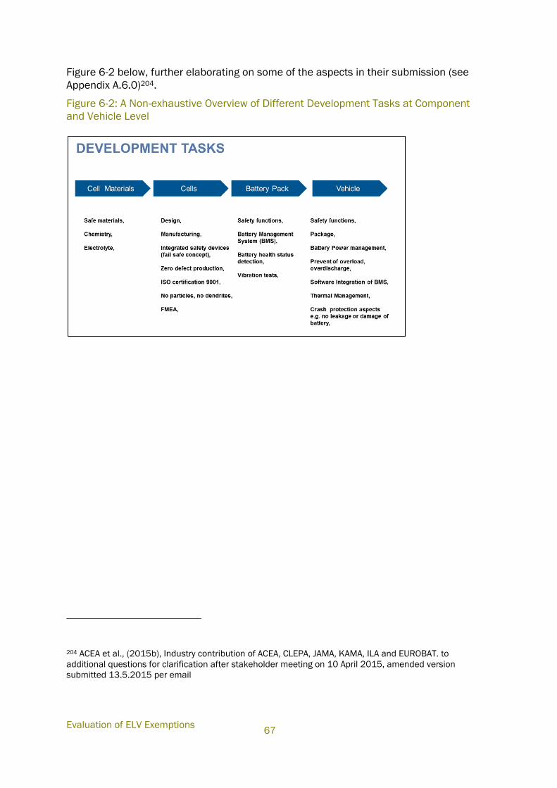
Evaluation of ELV Exemptions
67
Figure 6-2 below, further elaborating on some of the aspects in their submission (see
Appendix A.6.0)204.
Figure 6-2: A Non-exhaustive Overview of Different Development Tasks at Component
and Vehicle Level
204 ACEA et al., (2015b), Industry contribution of ACEA, CLEPA, JAMA, KAMA, ILA and EUROBAT. to
additional questions for clarification after stakeholder meeting on 10 April 2015, amended version
submitted 13.5.2015 per email
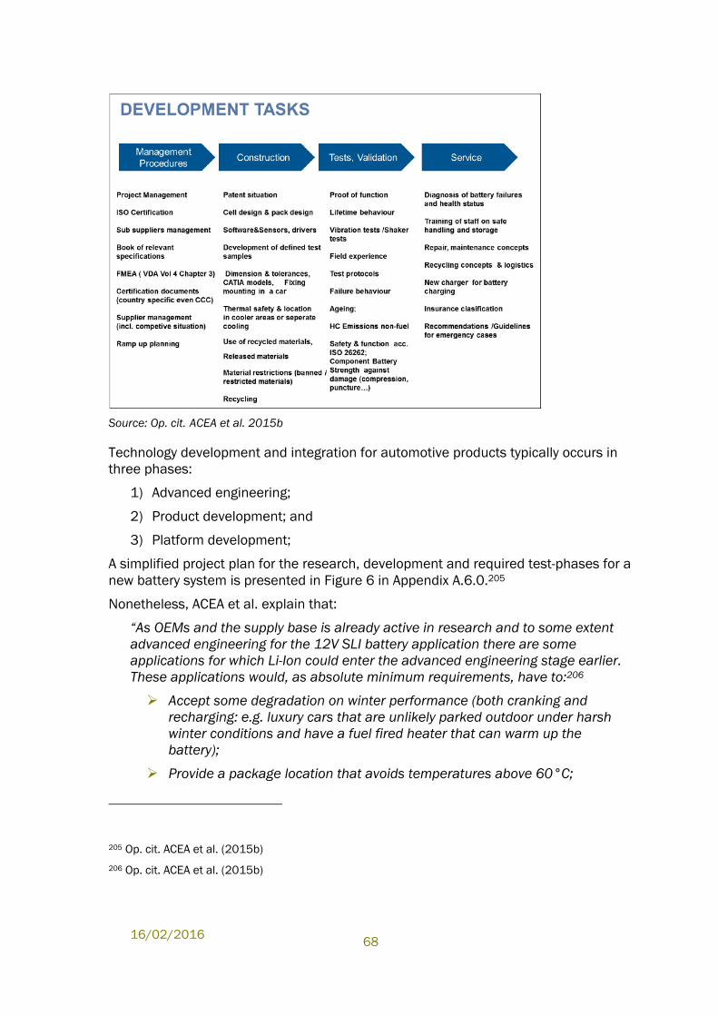
16/02/2016
68
Source: Op. cit. ACEA et al. 2015b
Technology development and integration for automotive products typically occurs in
three phases:
1) Advanced engineering;
2) Product development; and
3) Platform development;
A simplified project plan for the research, development and required test-phases for a
new battery system is presented in Figure 6 in Appendix A.6.0.205
Nonetheless, ACEA et al. explain that:
“As OEMs and the supply base is already active in research and to some extent
advanced engineering for the 12V SLI battery application there are some
applications for which Li-Ion could enter the advanced engineering stage earlier.
These applications would, as absolute minimum requirements, have to:206
Accept some degradation on winter performance (both cranking and
recharging: e.g. luxury cars that are unlikely parked outdoor under harsh
winter conditions and have a fuel fired heater that can warm up the
battery);
Provide a package location that avoids temperatures above 60°C;
205 Op. cit. ACEA et al. (2015b)
206 Op. cit. ACEA et al. (2015b)
Evaluation of ELV Exemptions
69
Provide a package location outside crash zones; and
Not require any significant platform/architecture modifications.”
6.1.10 Conflicting Views Regarding the Performance of Li-Ion Batteries and
their Suitability as a Substitute for Lead-acid Batteries
The automotive industry considers lead-based battery systems to be necessary in
volume serial production for the foreseeable future, explaining that no feasible mass
market alternatives to lead-based batteries are currently available207. Although the
alternative technologies described by Olife and A123 et al. are recognised as having a
number of positive attributes they are, however, still considered to be immature.
OEMs cannot be confident that the technologies will deliver the required
functionalities and considerable time is required to determine whether these
alternative technologies are suitable for the applications discussed. ACEA et al.
further explain that for a battery technology to be technically feasible it has to meet
technical and safety requirements at a component level in full, then meet the
specifications for a prototype vehicle at the next level, before finally meeting all of the
requirements for an on-road vehicle capable of volume production and proven reliable
service. 208
ACEA et al. point out the following limitations and requirements to support this view.
Each point is followed by relevant information provided by other stakeholders to
clarify within context where conflicting views are apparent.
Market availability and road experience: ACEA et al. state that they:
“disagree with the statement [that] ‘a number of Li-Ion alternatives are
already available on the market at the component level for use as a
single battery’. It should be stressed that vehicles using single 12 V Li-
Ion batteries equate to 0.001% of the current fleet of vehicles. Lead-
based batteries are used in the remaining 99.999% of vehicles. It
would be more accurate to say that a very small number of Li-ion
batteries are being offered for SLI applications for special
applications… this is a very small and expensive market segment and
the vehicles in question are high performance sports cars.
Based on the limited experiences available today, these applications
need to be assessed as not suitable for any volume production... More
development efforts are essential as well as sufficient field experience
at least over one model cycle, before any decision on volume
production is possible…A123 quote a figure of 4 years field experience
but this refers to a supercar with less than 400 cars built which is
significantly different to a typical on-road vehicle. The other vehicles
using these single Li-Ion batteries have two years or less field
207 Op. cit. ACEA et al. (2015a)
208 Op. cit. ACEA et al. (2015b)
16/02/2016
70
experience, which is not sufficient to assess the applicability of the
technology.” 209
Regarding road experience with Li-Ion applications, A123 et al. 210 specify that:
“The first series production of a lithium-ion starter battery occurred in
Europe in 2011. That program started the development and validation
testing phases in 2009. Additional applications from additional vehicle
manufacturers entered the European market in 2013”.
For the Olife technology:
“Prototype production processes are established and prototypes have
been successfully on trial this year in start-‐stop vehicles... Full-scale
production is targeted for the end of Q2 2015. Equipment procurement
for production and process scaling is underway, in collaboration with
an industry partner in the Czech Republic.”211
In a later document, Olife further elaborates:
“The initial sales and market penetration is expected to provide a first
year production of 10,000 batteries by the end of 2016. With
successful market acceptance and favourable customer response, a
growth of approximately 200,000 units per annum for the subsequent
five years is forecast. To reach a turnover of one million units, it would
require approximately 9 to 12 months to build a factory which could
produce at this level.” 212
Drop-in applicability of alternative technologies: ACEA et al. explain that:
“In a minority of these vehicles, OEMs offer a Li-Ion battery as an
option for racing conditions due to the weight savings. In these cases,
the vehicle is specially designed to enable replacement of the lead
battery with a Li-Ion battery. However, drop-in of 12 V Li-Ion batteries
would not be possible in other vehicles without significant and
expensive re-design. It should also be mentioned that the Olife package
that contains both a Li-Ion battery and a super-capacitor could, in our
opinion, not be available as a drop-in alternative… Whilst super-
capacitors are not as affected by temperature, independent tests have
found that in order to support the required cranking time and energy,
the capacitor banks have to be relatively large and very costly and, due
to their self-discharge characteristics, require management to isolate
them when the vehicle is switched off so as to avoid a flat battery.” 213
209 Op. cit. ACEA et al. (2015b)
210 Op. cit. A123 et al. (2015b)
211 Op. cit. Olife (2014a)
212 Op. cit. Olife (2015)
213 Op. cit. ACEA et al. (2015b)
Evaluation of ELV Exemptions
71
A123 et al.214 also state that they:
“dispute the conclusion that the currently available solutions cannot be
a drop-in replacement. While the present examples in series production
in Europe still have a relatively low sales volume, the vehicles using
those solutions were not redesigned to accept a lithium-ion starter
battery. In these present examples, the vehicle manufacturers also
concluded through validation testing that the lithium-ion alternative
was already sufficient to meet the vehicle’s cold cranking
requirements… No additional equipment is necessary to introduce
lithium-ion starter batteries in series production and generally
speaking, the size of a lithium-ion alternative is equal to or smaller than
the lead-acid solution it replaces.” Information as to vehicles available
on the market with a single Li-Ion battery is presented in
Appendix A.5.0.
Though the technology is not yet available, Olife say that theirs is a drop-in
substitute:
“Because the Olife technology is designed as a direct replacement for
the 12 volt LAB it can be incorporated into the energy management
system with no adjustments. Additionally, the engine managements
systems contain safeguards, which prevent batteries being over
discharged or overcharged... The Olife prototype battery has been
tested in commercially available passenger vehicle BMW type 630i with
start/stop system. The test was conducted with the aim to simulate all
possible vehicle situations (urban, off-urban, long-standing, different
operating temperature ranges etc.). The test duration has been 13
months, so far.”215
Development of Technical Standards:
From the information provided by ACEA216, it can be understood that
standards are developed by the various appropriate organisations, also
involving representatives from industry; Standards for batteries are regularly
updated with full participation of OEMs and the battery industry especially in
European standardisation committees (Cenelec). The Automotive Industry
Association (Verband der Automobilindustrie - VDA) is also said to have been
active in issuing new standards for lead-acid automotive batteries as vehicle
requirements have changed, and requirements developed by UNECE also have
to be respected.
ACEA et al. state in this regard:
214 Op. cit. A123 et al. (2015b)
215 Op. cit. Olife (2015)
216 Op. cit. ACEA et al. (2015b)
16/02/2016
72
“For Li-Ion batteries, technical standards are not yet developed and for
lead-acid SLI batteries, the requirements are defined in EN 50342-1
and for lead-acid batteries for stop and start applications… by EN
50342-6 which is not yet published. The EN 50342 family of
specifications does not reflect requirements for Li-Ion batteries... A new
EN standard is required to specify requirements for Li-Ion starter
batteries. Requirements derived from the vehicle application, such as
capacity, high-rate cranking capability, vibration resistance and so on
may be similar to EN 50342-1… new tests specific to Li-Ion
characteristics may be included. Accelerated life tests specific to Li-Ion
batteries require extended field experience on failure modes. Such
investigations on the road have scarcely been started... According to
the experiences of OEMs…” It has taken 6 years to get ISO 12405
(“Electric road vehicles – Test specification for Li-Ion traction battery
systems”) completely published (from May 2008 to May 2014). 217
Thermal environment for batteries: ACEA et al. state:
“The life time of Li-Ion batteries depends to a high degree on efficient
thermal management. If the thermal load on these batteries is too high
very fast ageing will occur and the battery will fail prematurely.
Internally generated heat from the component during charging and
discharging over the battery life time is important and also the local
ambient temperature levels are important. If temperatures are too
high, additional specific cooling systems become necessary and this
has to be considered in the component, location, package and vehicle
design… It should be noted that the requirement for cold cranking at -
30oC is not changed but lead-acid batteries are not damaged at -40oC
and will continue to operate. Unless and until Li-Ion batteries can
provide robust performance over a full temperature range, they cannot
be specified to replace LABs without significant restrictions.” 218
In this regard A123 et al. explain:
“All starter batteries are known to have shorter operating lives in hot
environments and this is true for lithium-ion as well. The maximum
operating temperature of a lithium-ion battery varies by supplier but
safe operation in ambient temperatures up to 70 C can be assured.
Due to the cost increment of lithium-ion technology in starter battery
applications, vehicle manufacturers often set life targets for the
lithium-ion alternatives, which exceed the life requirements defined for
lead-acid. To achieve superior life, lithium-ion starter batteries are
typically installed where they are not directly exposed to engine
temperatures. In most series production applications to date, prior
217 Op. cit. ACEA et al. (2015b)
218 Op. cit. ACEA et al. (2015b)
Evaluation of ELV Exemptions
73
versions of the vehicle had already located the lead-acid battery away
from the engine so the lithium-ion alternative was installed in the same
location. In cases where the current battery location is adjacent to the
engine, vehicle manufacturers can install a heat shield made of sheet
metal to extend life of the lithium-ion battery and/or install the battery
further from the heat source.” 219
According to Olife, Lithium batteries are able to operate over a wide
temperature range of at least ‐20°C to +70°C:
“Recent developments by various manufacturers are extending the
operating range; values of ‐50°C to +80°C are now being quoted. Olife
has conducted successful field trials in hot climates with under hood
temperatures exceeding +60°C. Independent testing by TUV will be
carried out to determine the maximum safe operating range.”220.
Battery crash and safety aspects: ACEA et al. state:
“The battery needs to be resistant to mechanical damage in the form
of compression, shock and puncture. To comply with product
responsibility with regard to crash behaviour, methods to avoid fire and
explosions have to be considered… for Li-Ion batteries. For batteries
defined as rechargeable energy storage systems (REESS), there should
be no leakage to the battery during the crash test and no thermal
runaway. The car industry would therefore have to locate Li-Ion starter
batteries in a non-crash-sensitive area… This is a packaging issue and
generally a full redesign of the vehicle platform is required…Reinforcing
the car body area to establish a crash safe cage for a component
needs to be implemented in the total crash behaviour design of a
vehicle. This is a key concern of all OEMs, and no vehicle can be
offered for sale until crash safety has been correctly established…
There are two very important restrictions. The first, in case of a crash,
is that the battery should not catch fire and the second is that during
normal operation the battery should not be destroyed or ruptured by
heating. In the vast majority of European cars starter batteries are
installed in hot installation spaces; i.e. in the engine compartment or in
the vicinity of the exhaust pipes… the operating temperatures at up to
peaks of 100°C are limitations for a safe installation of any available
batteries working with an organic electrolyte (e.g. Li-Ion batteries or
high capacity electrolytic capacitors).” 221
A123 et al. agree that:
219 Op. cit. A123 et al. (2015b)
220 Op. cit. Olife (2015)
221 Op. cit. ACEA et al. (2015b)
16/02/2016
74
“It is generally preferred to install a lithium-ion battery outside of the
vehicle zones which are designed to deform in a vehicle collision.
Nevertheless, multiple vehicle manufactures are currently studying
installation of a lithium-ion starter battery in such so-called “crush
zones”. Furthermore, there are vehicles in the field today wherein a
high voltage lithium-ion battery of an EV or HEV has been safely
installed in a vehicle crush zone. Large capacity, high voltage lithium-
ion batteries by their nature introduce greater safety risks than lithium-
ion starter batteries. Therefore, the engineering knowledge in the
market today is more than adequate to ensure that vehicles containing
lithium-ion starter batteries are safely constructed.”222
Battery management system (BMS): ACEA et al. state:
“Lithium batteries require a more complex BMS for reliability and
safety reasons, which for example has to communicate current and
voltage limits as functions of temperature, state of charge, and ageing,
to control thermal management in terms of absolute and relative
temperature limits, to disconnect the battery in case of severe failure.
Existing BMS for high voltage batteries cannot be carried over because
of different functionality, package, and cost requirements...
Development of a BMS for li-ion starter batteries that would be feasible
and fully qualified for mass production is a substantial engineering and
verification task on its own. Verification and validation have to be
foreseen both on system (battery) and vehicle integration level.” 223
Concerning the above aspects generally and further specific design aspects, ACEA et
al. summarise:
“OEMs specify a number of requirements for battery technologies used in
mass market vehicles... that Li-Ion batteries would need to comply with in
order to be applied in mass market vehicles. Examples of these are: a) Cold
cranking; b) Safety; c) Durability at high temperatures; d) Positive charge
balance at low temperatures; e) Sustainable Recycling; f) Cost. In particular,
all the requirements have to be met simultaneously. For example, LFP
batteries with improved high temperature robustness usually show degraded
cold cranking performance. These trade-offs have to be eliminated by
technology breakthroughs before LFP or any other alternative can even be
considered for replacing lead-acid in the vast majority of car applications...
While the supply base is making progress, it is still too early to predict when
these breakthroughs will be achieved and robustly implemented in cells
capable of mass manufacture, irrespective of pack and vehicle integration
and prove-out.”224
222 Op. cit. A123 et al. (2015b)
223 Op. cit. ACEA et al. (2015b)
224 Op. cit. ACEA et al. (2015b)
Evaluation of ELV Exemptions
75
The information above is relevant for the possible use of Li-Ion batteries as SLI
batteries. However, the information provided by EUROBAT et al. suggests that the use
of lead-acid batteries for propulsion in dual battery systems could be banned.
Regarding future trends of battery applications, EUROBAT et al.225 explain that:
In Class 2, hybrid electric vehicles (including advanced micro-hybrid, mild-
hybrid and full hybrid vehicles): lead based batteries are “Primarily expected to
be used as an auxiliary battery to support the board-net. Increased industrial
potential of advanced lead-based batteries [is expected]226 in micro-hybrid
and mild-hybrid applications.”
In Class 3, plug-in hybrid electric vehicles and full electric vehicles: lead based
batteries are “Expected to be used only as auxiliary battery to support the
board-net and for supply of an active redundancy safety mechanism.”
ACEA et al. were thus asked to explain on what basis the main battery of such dual
battery systems cannot already be excluded from the scope of Exemption 5. ACEA et
al. explain:227
Class 2: Hybrid electric Vehicles: “Due to the need for high energy density, this
segment is currently dominated by high voltage Li-Ion battery systems, due to
their superior energy density, fast recharge capability and high discharge
power… research and development is on-going to assess the suitability of both
Li-Ion and lead based batteries as the main 48 V battery in these
applications… Advanced designs of lead-acid batteries are available that will
meet the 48 V battery specifications using lead-carbon, bipolar constructions
and special electrode structures. These all share the low cost materials,
simplicity of construction and recyclability of this chemistry.
For the reasons quoted above, and given the short timescale to meet new
emissions standards and achieve a phase out of lead batteries in 48 V
applications, this could lead to a decrease in the uptake of these vehicles and
make it difficult to meet emission targets. Phase-out may become an option in
the future as new platforms are introduced with a safer place to install the Li-
Ion battery and if it can be demonstrated that they can meet the desired
functionality. It would be wrong to jeopardise the use of lead-acid batteries in
dual battery solutions considered above as these systems have the potential
to realise lower carbon dioxide emissions at less cost and in shorter
timescales than would be achieved with only Li-Ion batteries being permitted
as the second battery.”
Class 3 - Plug-in hybrid electric vehicles and full electric vehicles: As in the
case of Class 2, the main battery referred to in Class 3 is considered as a
traction or propulsion battery and therefore very different from the 12 V
225 Op. cit. EUROBAT et al. (2014)
226 Added by consultants to make sense of the sentence.
227 Op. cit. ACEA et al. (2015b)
16/02/2016
76
batteries under discussion in these answers. Due to the need for high energy
density, this segment is currently dominated by high voltage Li-Ion battery
systems, due to their superior energy density, fast recharge capability and high
discharge power. The functionality and the requirements of these batteries are
very different to those of 12 V batteries used as an auxiliary battery and
therefore cannot be compared.
In comparison, A123 et al. 228 believe that where the functions of the lead-acid
battery do not include engine cranking, the use of lead is avoidable today. This
statement is relevant for:
Hybrid and electric vehicles, in which an auxiliary lead-battery is used to
support the conventional vehicles electronics (such as the radio, gauges,
window motors, etc.);
In premium start / stop systems, in which some vehicles currently use two
lead-acid batteries to support start / stop functionality. While the first battery
is used for cranking the engine, the role of the second battery is to protect the
vehicle electronics from the brief decline in voltage that normally happens
during engine cranking. This second lead-acid battery could be replaced by a
lithium-ion alternative;
Micro-hybrids – such vehicles can use dual battery systems with one lead-acid
battery used mainly for engine cranking and another energy storage device
used for basic hybrid functionality at either the 12V or 48V level. Here too the
second battery can be specified as a lead-free alternative.
A123 et al. 229 further contend that from a technical vehicle integration perspective,
the space currently used for the dual battery system would suffice to support the
space needs of a single Li-Ion battery and its required supporting equipment. Since
the lithium-ion alternative is already equal in size or smaller than a single lead-acid
battery, any vehicle, which already has two batteries represents the easiest transition.
A123 et al., however, note that the share of vehicles with two batteries in the market
today is rather small and that restricting the use of LAB as proposed above could
have the unintended effect of vehicle manufacturers using one larger lead-acid
battery in some cases rather than keeping the second battery and converting it to a
new technology.
228 Op. cit. A123 et al. (2015b)
229 Op. cit. A123 et al. (2015b)
Evaluation of ELV Exemptions
77
6.2 Critical Review
6.2.1 Scientific and Technical Practicability of Lead Substitution in
Automotive Batteries
The information available concerning various automotive battery applications reveals
a complex situation. As shall be explained in the points below, it is apparent from
various vehicles already on the EU market that battery technologies other than lead-
acid can be applied in some cases. Nonetheless, reaching conclusions as to the
applicability of the various alternatives to the specific vehicle classes and types that
are part of the vehicle market range requires considering multiple factors.
6.2.1.1 Aspects of Relevance to Lead-Acid Starter Battery Replacement
The points raised in Section 6.1.10 are discussed in the following:
Market availability and road experience:
ACEA et al. present the view that Li-Ion alternatives are not yet available on the
market at the component level for use as a single battery.
This statement cannot be accepted, as it is clear that first vehicles have indeed been
placed on the market in which Li-Ion batteries are in use as a single battery (see
Appendix A.5.0). The consultants understand this to be an attempt to dismiss the
experience with Li-Ion single battery systems, in terms of its applicability to more
conventional vehicles, as well as in terms of the availability of a mass-market
alternative. The consultants understand that the vehicles, in which single Li-Ion
battery systems are applied, have particular characteristics, making the further
implementation of such systems in other vehicles less straightforward, and thus
possibly time consuming.
ACEA et al. state230 in this regard that:
“Car manufacturers have to follow strictly defined development processes in
order to get to robust and safe vehicle implementations. This applies as well
for Li-Ion SLI batteries, considering the impact of Li-Ion technology on vehicle
safety with regard to both component safety (hazards caused by the battery as
well as the impact of abuse or accident to the battery) and vehicle safety in
general (e.g. functional safety of electrified chassis or driver assistance
systems affected by power supply failure).”
Regarding vehicles where Li-Ion starter batteries are already installed in the first
vehicles on the market, ACEA et al. continue to explain that:
“Those cars that are presently equipped with Li-Ion starter batteries have run
through modified pilot processes which are not applicable for mass volume
production. Hence, applications are restricted, for example, to moderate
climate markets because of the limitations of Li-Ion technology already
230 Op. cit. ACEA et al. (2015b)
16/02/2016
78
described. The current field trials feature over dimensioned Li-Ion batteries with
a very high cost impact and very high integration efforts, linked with functional
limitations and are only feasible in order to obtain first long-term field
experience. Furthermore volumes are kept very low, with the customer vehicles
being closely monitored by OEMs.”
Though it is explained that such vehicles go through modified pilot processes not
applicable to mass volume production, the consultants assume that as consumer
products they must also adhere for example to vehicle safety regulation and further
requirements that would also be relevant for more conventional vehicles. Experience
with these vehicles is thus understood to provide the basis for learning what
modifications would be needed in other vehicle types and models.
As the ACEA et al. contributions indicate that on-road experience with alternatives is
paramount, before wider phase-in can be considered, the consultants wonder what
field experience would be considered to be relevant and sufficient for determining the
suitability of alternative battery technologies. Detailed information as to how such
experience is collected in practice and how many years of relevant field experience
would suffice for OEMs to be able to consider application in various types of
conventional vehicles is not clear.
Drop-in applicability of alternative technologies:
ACEA et al. explain that Li-Ion batteries to be used as a single battery in further
automotive applications would require significant and expensive re-design.
This view is not shared by A123 et al. on the basis that current vehicles using such
batteries did not require redesign to accommodate the Li-Ion alternative. Nor is the
view shared by Olife, who claim their Li-Ion super-capacitor alternative to be a drop-in
solution.
In line with the information provided by A123 et al., the consultants would expect
there be additional models, aside from luxury-sport vehicles, in which the
transformation from LAB to Li-Ion could be easier. ACEA was thus asked if there were
vehicle types in which implementation of such alternative battery systems could be
more manageable in terms of the needed redesign, in light of a higher availability of
space for battery system supporting equipment, and in light of suitable operational
conditions (temperature). A detailed answer was not provided, with ACEA explaining
that: “such an approach would require world standard vehicles, but even the various
vehicle models of one producer are quite different in their design, equipment and
package.”231
The consultants agree that various vehicle models differ from one another, possibly
requiring significant time to screen OEM vehicles relevant for the EU market in order
to provide a comprehensive answer. However, from the consultants’ experience, the
battery location may differ from vehicle to vehicle (see in the following paragraphs),
and it is thus expected that phase-in efforts could be easier in some vehicles,
231 Op. cit. ACEA et al. (2015b)
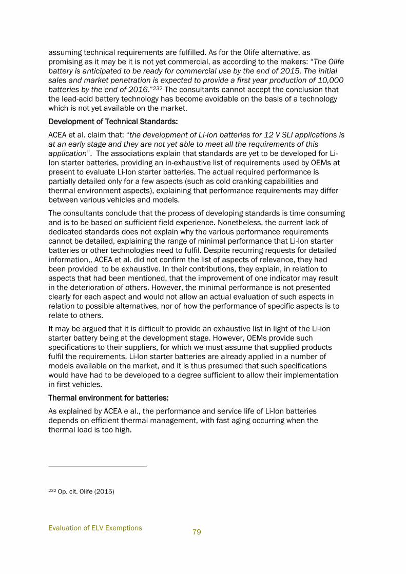
Evaluation of ELV Exemptions
79
assuming technical requirements are fulfilled. As for the Olife alternative, as
promising as it may be it is not yet commercial, as according to the makers: “The Olife
battery is anticipated to be ready for commercial use by the end of 2015. The initial
sales and market penetration is expected to provide a first year production of 10,000
batteries by the end of 2016.”232 The consultants cannot accept the conclusion that
the lead-acid battery technology has become avoidable on the basis of a technology
which is not yet available on the market.
Development of Technical Standards:
ACEA et al. claim that: “the development of Li-Ion batteries for 12 V SLI applications is
at an early stage and they are not yet able to meet all the requirements of this
application”. The associations explain that standards are yet to be developed for Li-
Ion starter batteries, providing an in-exhaustive list of requirements used by OEMs at
present to evaluate Li-Ion starter batteries. The actual required performance is
partially detailed only for a few aspects (such as cold cranking capabilities and
thermal environment aspects), explaining that performance requirements may differ
between various vehicles and models.
The consultants conclude that the process of developing standards is time consuming
and is to be based on sufficient field experience. Nonetheless, the current lack of
dedicated standards does not explain why the various performance requirements
cannot be detailed, explaining the range of minimal performance that Li-Ion starter
batteries or other technologies need to fulfil. Despite recurring requests for detailed
information,, ACEA et al. did not confirm the list of aspects of relevance, they had
been provided to be exhaustive. In their contributions, they explain, in relation to
aspects that had been mentioned, that the improvement of one indicator may result
in the deterioration of others. However, the minimal performance is not presented
clearly for each aspect and would not allow an actual evaluation of such aspects in
relation to possible alternatives, nor of how the performance of specific aspects is to
relate to others.
It may be argued that it is difficult to provide an exhaustive list in light of the Li-ion
starter battery being at the development stage. However, OEMs provide such
specifications to their suppliers, for which we must assume that supplied products
fulfil the requirements. Li-Ion starter batteries are already applied in a number of
models available on the market, and it is thus presumed that such specifications
would have had to be developed to a degree sufficient to allow their implementation
in first vehicles.
Thermal environment for batteries:
As explained by ACEA e al., the performance and service life of Li-Ion batteries
depends on efficient thermal management, with fast aging occurring when the
thermal load is too high.
232 Op. cit. Olife (2015)
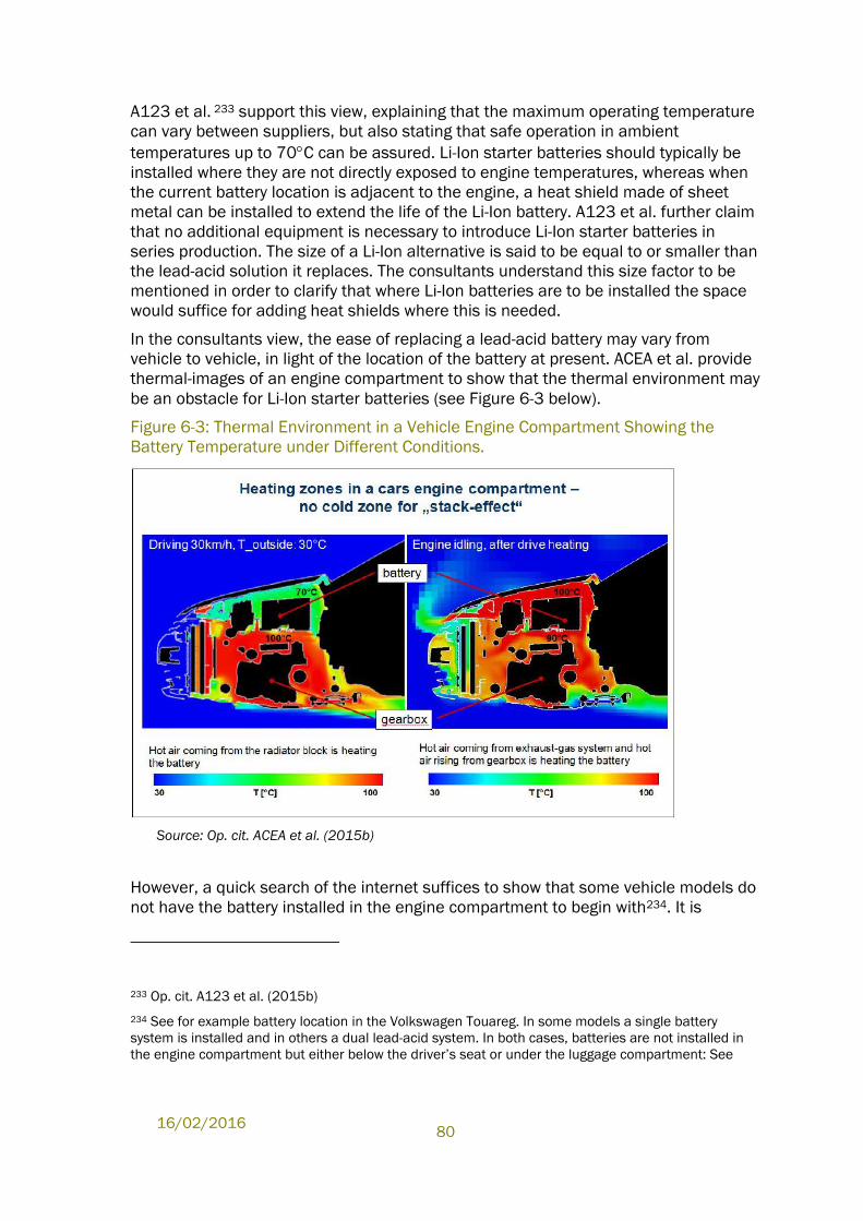
16/02/2016
80
A123 et al. 233 support this view, explaining that the maximum operating temperature
can vary between suppliers, but also stating that safe operation in ambient
temperatures up to 70C can be assured. Li-Ion starter batteries should typically be
installed where they are not directly exposed to engine temperatures, whereas when
the current battery location is adjacent to the engine, a heat shield made of sheet
metal can be installed to extend the life of the Li-Ion battery. A123 et al. further claim
that no additional equipment is necessary to introduce Li-Ion starter batteries in
series production. The size of a Li-Ion alternative is said to be equal to or smaller than
the lead-acid solution it replaces. The consultants understand this size factor to be
mentioned in order to clarify that where Li-Ion batteries are to be installed the space
would suffice for adding heat shields where this is needed.
In the consultants view, the ease of replacing a lead-acid battery may vary from
vehicle to vehicle, in light of the location of the battery at present. ACEA et al. provide
thermal-images of an engine compartment to show that the thermal environment may
be an obstacle for Li-Ion starter batteries (see Figure 6-3 below).
Figure 6-3: Thermal Environment in a Vehicle Engine Compartment Showing the
Battery Temperature under Different Conditions.
Source: Op. cit. ACEA et al. (2015b)
However, a quick search of the internet suffices to show that some vehicle models do
not have the battery installed in the engine compartment to begin with234. It is
233 Op. cit. A123 et al. (2015b)
234 See for example battery location in the Volkswagen Touareg. In some models a single battery
system is installed and in others a dual lead-acid system. In both cases, batteries are not installed in
the engine compartment but either below the driver’s seat or under the luggage compartment: See
Evaluation of ELV Exemptions
81
presumed that such models would allow substitution more easily in this respect in
light of the larger distance from heat zones and in light of additional space-availability
should the battery need to be equipped with additional safety equipment. The
conflicting views do not allow for a clear view on what changes may be needed to
accommodate the Li-Ion battery with a sufficient battery management system, nor if
such changes would require additional space and design changes, nor what time
might be needed for their implementation.
The thermal environment aspect also regards operation of the battery (and
subsequently of the vehicle) under extremely cold temperatures. It is understood that
the requirement for cold cranking of Li-Ion starter batteries is -30oC. A123 et al. have
explained that today’s Li-Ion batteries can meet industry standards in which cold
cranking requirements are specified at -25 oC and that research and development are
focused on further improvements in this area. They expect Li-Ion battery technology to
fully close this final gap in the next three to five years.
In this regard ACEA et al. 235 explain that the vehicle market is global in nature and
that obviously temperatures can range widely from country to country, as is the case
in Europe. Customers expect to be able to operate their vehicle in all conditions
irrespective of the model they purchase. For this reason, cold cranking capabilities
are required as part of OEM vehicle specifications to ensure cranking function can be
provided in very cold weather conditions as low as -30°C.
The consultants conclude that the cold-cranking performance of Li-Ion starter
batteries has not reached this specification; however, it can also be concluded that
further developments over the next few years may allow parity to be achieved at
the -30°C level.
For example, Olife236 explained that their technology does not have problems with the
cold cranking requirement: “The supercapacitors operate independently of the
temperature and will function at near 100% capability below ‐30C. The combination
of supercapacitors and a Li FePO4 battery enable cold cranking performances
comparable to, or better than, lead acid batteries”. Though this technology is not yet
available on the market, such cold cranking performance would solve what has been
communicated in the past as one of the larger obstacles for Li-Ion batteries in
automotive applications.
Battery crash and safety aspects:
both http://vwts.ru/electro/touareg/tou_27_eng.pdf and
http://www.clubtouareg.com/forums/attachment.php?attachmentid=10758&d=1289554571, both
last accessed 10.06.2015.
235 Op. cit. ACEA et al. (2015b)
236 Olife Energy (2014b), Answers to Specific questions from report of Oeko Institute dated 28 July
2010, Chapter 4.5 Exemption No 5, submitted 17.12.2014, available under:
http://elv.exemptions.oeko.info/fileadmin/user_upload/Consultation_2014_1/Ex_5/Ex_5_Contributio
n_17122014_Olife_Specific_questions_from_report_of_O__ko_Institute_dated_28_July_2010.pdf
16/02/2016
82
ACEA detailed various safety requirements such as resistance to mechanical damage
in the form of compression, shock and puncture, consideration of fire, and explosion
prevention. It recommended locating Li-Ion starter batteries in a non-crash-sensitive
area, which would generally require a full redesign of the vehicle platform. In this
respect, Figure 6-4 clarifies which areas of a vehicle are understood to be the crush
zones.
Figure 6-4: Package Space for Vehicle Electronics Considering Crash Behaviour
Source: Op. cit. ACEA et al. (2015b)
A123 et al. generally agree with the need to install Li-Ion starter batteries away from
the crush zone. They explained, however, that there is experience with the installation
of high voltage, Li-Ion batteries in a vehicle crush zone, whereas these batteries are
said to introduce greater safety risks than Li-Ion starter batteries.
It can be concluded that safety requirements would make replacing LABs with Li-Ion
starter batteries challenging in some cases, requiring time for redesign and testing.
However, here too it is understood that there are certain vehicles on the market in
which the battery is currently located away from crush zones. Such models are thus
understood to allow substitution more easily.
6.2.1.2 Aspects of Relevance to Lead-Acid Replacement in Dual Battery Systems
The information provided by the various stakeholders clarifies that in class 2 and
class 3 vehicles a dual battery system is usually implemented in which one battery
(the main battery) provides the propulsion functionality while a second battery (the
auxiliary battery) is used to support the conventional vehicles electronics, while in
some cases also used for engine cranking.
Evaluation of ELV Exemptions
83
EUROBAT et al.237 have detailed in this respect that in Class 2 vehicles, LABs are
primarily used as the auxiliary battery, while in Class 3 vehicles they are expected to
be used only as the auxiliary battery.
A123 et al. contend that in these vehicles, where the functions of the lead-acid
battery do not include engine cranking, the use of lead is avoidable today. They
explain that the lead acid battery can be replaced in hybrid and electric vehicles, in
which cranking of the engine is not required of the auxiliary battery. In micro-hybrid
vehicles and in premium start/stop systems in which a dual battery system is in use,
it is explained that the battery that is not used for cranking the engine could also be
specified with a lead-free alternative.
Furthermore, from a technical vehicle integration perspective, A123 et al. claim that
the space currently used for dual battery systems would suffice to support the space
needs of a single Li-Ion battery and its required supporting equipment. It is noted that
the share of vehicles with two batteries in the market today is rather small. Thus,
A123 et al. mention that restricting the use of LAB as proposed above could have the
unintended effect of vehicle manufacturers using one larger LAB in some cases
rather than keeping the second battery and converting it to a new technology.
ACEA et al. agree that both the Class 2 and Class 3 segments are currently dominated
by high voltage Li-Ion battery systems, used as the primary battery, also including a
lead-acid auxiliary battery. However, for Class 2 vehicles, it is argued that research
and development is on-going to assess the suitability of both Li-Ion and Pb based
batteries as the main 48 V battery in these applications. In this regard, for example,
ACEA et al. 238 explain that research projects from the Advanced Lead Acid Battery
Consortium (ALABC) have demonstrated the successful use of advanced lead-based
battery systems in mild-hybrid vehicles, either individually or in 48V/12V dual battery.
The consultants can accept that banning the use of lead-acid batteries in the above
cases could impact the current development trends towards dual systems. However,
Article 4(2)(b)(ii) of the ELV Directive only allows to “exempt certain materials and
components of vehicles from the provisions of subparagraph (a) if the use of these
substances is unavoidable”. As it is concluded that the use of lead-acid batteries as
the primary propulsion battery in Class 2 and Class 3 vehicles is avoidable, an
exemption for such applications would not be justified. All the more so, as the use of
such chemistries for the primary battery is understood to be fairly uncommon at
present. The fact that the suitability of Pb based batteries is under assessment, as
the main 48 V battery in Class 2 vehicles is thus understood to be contradictory to the
efforts toward the substitution of lead in automotive applications, and contradictory to
the ELV ban on lead.
The consultants can agree that in some cases it is possible that the use of lead based
technologies may provide environmental benefits that outweigh the benefits of lead
free technologies. This aspect is, however, not mentioned in the ELV Directive as a
237 Op. cit. EUROBAT et al. (2014)
238 Op. cit. ACEA et al. (2014)
16/02/2016
84
criterion for justifying an exemption, though it is often considered in other legislation
restricting hazardous substances (e.g., Directive 2011/65/EU). As in any case,
information was not available to enable a comprehensive comparison of the
environmental impacts of Li-Ion and Pb alternatives, and therefore such a comparison
would at present be inconclusive.
6.2.2 Aspects Related to the Recycling of Batteries
The various stakeholders have provided information concerning the recyclability of
different types of batteries.
Based on this information it can be concluded that the infrastructure for
recycling LABs in the EU is quite developed, and provides a good basis for
enabling the recycling of lead-acid batteries that are collected. However, the
consultants feel that this information does not allow a conclusion to be
reached as to the number of LABs placed on the market that are collected and
recycled in the EU, as shall be explained below, but only as to the recycled
share of collected batteries.
Regarding other battery technologies, as explained by the various
stakeholders, such batteries are already used in some vehicles available on
the market; however, their market share in vehicles is still very small in
comparison with LABs. Furthermore, in some of these cases batteries shall
have a service life comparable to or above that of LABs, and thus, since their
application is vehicles is more recent, it is expected that until now much
smaller volumes have reached end-of-life.
In this sense, it can be seen that the infrastructure for such battery
technologies is still developing. As indicated by some of the stakeholders, it is
expected that such systems shall develop as the market share of alternative
automotive batteries develops, along with their share in the waste stream. This
is also understood to be supported by the ELV Directive, which places the
responsibility to increase the share of components that can be recycled
primarily on vehicle manufacturers, as well as a responsibility to increase the
feasibility of that recycling, for which Member State governments are also
obligated to create the necessary framework conditions.
Regarding the possible difference between the number of automotive batteries put on
the EU market and the number of batteries collected and recycled, the consultants
would like to note that the export of vehicles to non-EU countries may influence the
availability of batteries for recycling at end-of-life, as well as the soundness of the
recycling of such batteries.
The following information suggests that a significant amount of vehicles are exported,
in some cases illegally, and it is assumed that batteries used in these vehicles thus
end up being recycled in non-EU facilities. This aspect is relevant to all automotive
batteries. However, most of the vehicles on the market are understood to use lead-
acid batteries, and as such, these batteries are assumed to have a larger share in
batteries that are exported in second-hand vehicles or through illegal export of
vehicles (second hand vehicles as well as ELVs).
Evaluation of ELV Exemptions
85
In 2014, BIOIS et al.239 concluded an “Ex-post evaluation of certain waste stream
Directives”, including a review of the ELV Directive. According to this source, one of
the remaining challenges for the Directive is the illegal shipment of ELVs, which
hinders the achievement of the environmental benefits of the Directive:
“It is estimated that some 25%240 of all ELVs arising in the EU do not end up in
ATFs [authorised treatment facilities]… Member States may be recycling over
90% of ELVs ending up in ATFs but if those ELVs only represent a share of the
total number of ELVs arising in Member States, the “real” recycling rates are
lower. There is evidence to suggest that considerable numbers of ELVs are
exported illegally from EU Member States, predominantly to Africa and the
Middle East. This is supported by several press reports as well as by the results
of joint activity inspections in the framework of an IMPEL-TFS project completed
in 2008, where several cases of illegal shipment of ELVs were reported –
mostly to African countries241.“
Though it can be understood that some vehicles are exported illegally, it is also worth
noting the significant amount of cars exported as used cars. The Austrian Umwelt
Bundesamt GmbH (AUBA)242 has compiled data on the export of used cars (see
Figure 6-5 below) explaining that over 30% of these are exported to African countries
as well as to other countries (see Figure 6-6). The AUBA report also details a few
information sources (press reports) showing that illegal shipment of ELVs takes place.
239 BIOIS et al. (2014) Bio Intelligence Service, Arcadis and the Institute for European Environmental
Policy (IEEP) (2014), Ex-post evaluation of certain waste stream Directives, Final report, prepared by
Mudgal, S., Fedrigo, D., Kong, M., A., Lambert, S., Lecerf, L., Mitsios, A., Pahal, S,, Van Acoleyen, M.,
and Watkins, E. for the European Commission – DG Environment, dated 18 April 2014
240 This estimation is based on the study Oeko-Institut et al. (2011) European second-hand car market
analysis, European Commission
241 Cited as European Parliament (2010) End-of-life Vehicles: Legal aspects, national practices and
recommendations for future successful approach
242 AUBA (2010) Austrian Umweltbundesamt GmbH, End of Life Vehicles: Legal Aspects, National
Practices and Recommendations for Future Successful Approach, Authors: Schneider, J., Karigl, B.,
Neubauer, C., Tesar, T., Oliva, J., and Read, B,
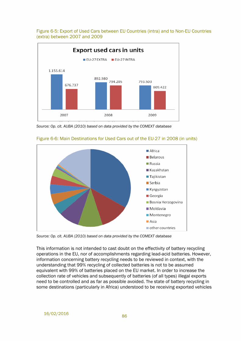
16/02/2016
86
Figure 6-5: Export of Used Cars between EU Countries (intra) and to Non-EU Countries
(extra) between 2007 and 2009
Source: Op. cit. AUBA (2010) based on data provided by the COMEXT database
Figure 6-6: Main Destinations for Used Cars out of the EU-27 in 2008 (in units)
Source: Op. cit. AUBA (2010) based on data provided by the COMEXT database
This information is not intended to cast doubt on the effectivity of battery recycling
operations in the EU, nor of accomplishments regarding lead-acid batteries. However,
information concerning battery recycling needs to be reviewed in context, with the
understanding that 99% recycling of collected batteries is not to be assumed
equivalent with 99% of batteries placed on the EU market. In order to increase the
collection rate of vehicles and subsequently of batteries (of all types) illegal exports
need to be controlled and as far as possible avoided. The state of battery recycling in
some destinations (particularly in Africa) understood to be receiving exported vehicles
Evaluation of ELV Exemptions
87
(and thus batteries) further raises concerns that these practices are in some cases
related to adverse environmental and health impacts.243
6.2.3 Conclusions
The consultants can follow that the development state of Li-ion starter batteries has
changed. Though there are conflicting views, it is understood that this technology has
matured and may now provide sufficient performance in relation to some of the OEM
requirements. There are conflicting views as to the ease of implementation of this
technology as a starter battery in vehicles, as well as regarding the time that this
would require. This aspect is considered to be of importance for consideration of a
phase-out of lead acid batteries in the near future. However, the fact remains that the
cold-cranking performance of Li-Ion batteries still requires improvement to reach the -
30C requirement. Though the Olife technology may solve this problem, it is not yet
market mature and thus cannot yet be considered a viable alternative.
In this sense, we conclude that Li-Ion alternatives cannot yet be used as a mass-
market alternative starter battery. Subsequently, the use of lead-acid batteries cannot
yet be considered avoidable for SLI functions. Nonetheless, the current state of the
various alternatives suggests that within a few years, the use of lead-acid batteries
may become avoidable, at least in some vehicles, with other vehicles possibly
requiring more time for implementation than others.
A future review should thus be carried out within a few years regarding the need for
an exemption for starter battery applications, as with the maturing of the various
technologies it is expected that estimating the length of the needed transition period
shall be possible.
A few points need to be noted in this regard:
First of all, in relation to the possible exemption of certain components from the ELV
substance restrictions, a “gradual” phase-in could only be enforced if it were possible
to make a clear distinction between components of a certain component group for
which the availability of substitutes is different. For example, if one could clearly point
out that for batteries of a certain type (e.g., rated voltage) or used for specific
purposes (e.g. SLI or propulsion functions) lead batteries had become avoidable.
However, one cannot prescribe targets for gradual phase-out within a component
group or sub-group through the current exemption mechanism. In other words, it is
understood that where it is established that the use of an ELV substance has become
avoidable, and the Annex is respectively amended, a phase-out is foreseen for all
relevant components starting the expiry date specified in the second column. In
exemptions which have expired, it is observed that the only further permission for use
of a component containing an ELV restricted substance, is for as spare parts (or
replacement parts) for vehicles type approved prior to the change. In this sense, the
above reference to a gradual phase-in is only possible on a sub-application basis, but
243 See for example:
http://www.johnsoncontrols.com/content/us/en/about/our_company/featured_stories/battery-
recycling-ghana.html
16/02/2016
88
not in terms of the period over which a phase-in is to occur. The Exemption
Mechanism in the Directive does not allow for a gradual phase-in, regardless of the
ability of suppliers to make substitutes available in a suitable quantity and regardless
of the benefits that a gradual approach may offer.
A second point of importance regards how this limitation affects suppliers of
substitutes and more importantly the certainty needed in the research and
development community to promote innovations and to lead to their take-up on the
market. At development stages, innovators require a minimum certainty as to the
possible take-up of their products on the market, in order to be able to raise required
capital for further development. According to Coogan et al., technology developers
and financers often refer to the ‘valley of death’ as an obstacle for innovative
technologies to make the leap from the lab to the market. Technologies at early
stages (un-proven, proven) and at middle-stages (pre-commercialisation) of
development are still viewed by private investors as being too risky, and have
difficulties receiving funds. 244 This is not to say that exemptions should be amended
to promote the uptake of innovation, but only to note the obstacles that the current
mechanism creates for developers, in light of the time needed for reaching market
readiness and the time needed for upscaling manufacture.
Though some time may be needed to understand the optimal applicability range of
substitutes in terms of vehicle classes and types, the current automotive roadmap
creates an obstacle that could result in grave impacts on innovation. Without more
certainty as to the potential for Li-Ion (or Li-Ion-supercapacitor) starter battery uptake,
such initiatives shall have difficulties to make further developments towards OEM
needs, as financing shall be limited and in some cases may be withdrawn.
A123 have made proposals for requiring the phase-in of Li-Ion starter batteries within
a small share of vehicles by a certain date as a first stage to substitution. This would
not only allow a reduction of lead in vehicles and in the future waste stream, but
would also support both developers and OEMs in gathering more field experience with
alternatives. However, this approach is not supported by the exemption mechanism
and could not be recommended as long as a particular component sub-group or
vehicle group cannot be addressed.
In the case of alternative starter battery technologies, in the consultants view a few
alternatives have reached a certain market maturity. The cold cranking performance
of Li-Ion starter batteries has almost reached parity with that of the LAB and is
expected to be resolved in the near future. Other obstacles such as the location of
these batteries away from crush zones and areas with high thermal stress mainly play
a role in vehicles with batteries located in the engine compartment. Here too,
integration of BMS and heat protection is expected to be easier and thus more rapidly
deployable in some models than in others.
244 Coogan, A, Earhart, R, Eggl, B., Handke, V., Kamburow, C., Krauth, V., Marshall, A. and van Ermen, R.,.
(2007), FUNDETEC - Comparison and Assessment of Funding Schemes for the Development of New Activities and Investments in Environmental Technologies, prepared by European Partners for the Environment, see link
Evaluation of ELV Exemptions
89
It follows that the automotive industry cannot commit to a certain timeframe without
first surveying all models and without planning the various stages needed to complete
and implement the redesign of vehicles. On this basis, it also follows that setting a
date for phase-out is not currently possible. However, a long-termed renewal of the
exemption could be the death-sentence of possible alternatives, which are
understood to provide some qualities that may be advantageous in some vehicle
types in comparison with LAB alternatives.
A123 et al. estimate that the cold-cranking of Li-ion starter batteries shall reach
parity with LABs within three to five years. A review of the status within a few years
shall ensure that obstacles have been overcome, while also giving industry time to
perform surveys and consider how much time is truly needed for phase-in in certain
vehicle types (sub-groups of vehicle classes). This should allow for the setting of
phase-out dates (at least for some vehicles types) in the next review, providing both
the Li-Ion community and the automotive sector with more certainty as to how the
roadmap to substitution can be formed. As a period of 3-5 years is assumed to reach
parity, it is recommended to schedule the next review following this period.
Regarding the use of lead-acid batteries in other applications than starter
applications, it is apparent that the case is different. LABs are understood to be used
as an auxiliary battery in class 2 and class 3 vehicles in which a dual battery system is
in use. In most of these cases this battery is still needed for cold cranking and is thus
still understood to fulfil starter functions, for which the LAB as above is still
considered unavoidable. However, the other than lead-acid battery technologies have
been used traditionally for the primary battery in such vehicles. For exemptions to be
granted, Article 4(2)(b)(ii) of the ELV Directive requires the use of the ELV restricted
substances to be unavoidable. Against this criterion, the consultants view is that an
application, for which the use of lead acid batteries is at present still uncommon,
would be considered an application in which the use of lead is avoidable. As it is
concluded that the use of lead-acid batteries as the primary propulsion battery in
Class 2 and Class 3 vehicles is avoidable, an exemption for such applications would
not be justified.
As for the auxiliary battery, though it is understood that in some cases this battery
does not need to fulfil starter functions, the available information does not show that
any field experience has been accumulated for batteries other than lead-based
batteries for this application. Though replacement with Li-Ion batteries sounds
promising, the consultants understand that such substitution would need to at least
be tested in pilot vehicles before bringing such vehicles on the market. The same is
true for Class 1 vehicles with start/stop functions, equipped with two lead-acid
batteries, for which one does not supply starter functionalities. Though the
consultants view is that Li-Ion batteries are a candidate for replacing lead-acid
batteries in this application, first experience should be gathered before deciding on
the complete phase-out of Pb in batteries for such applications.
The consultants understand that banning the use of lead-acid batteries in the above
cases could impact the current development trends towards dual systems, however,
this would not justify an exemption based on the ELV criteria. The fact that the
suitability of Pb based batteries is under assessment as the main 48 V battery in
Class 2 vehicles would not justify an exemption. Even if such developments could be
16/02/2016
90
shown in the future to be beneficial for the environment, the current legislation does
not give weight to such factors.
To facilitate future evaluations, it is further emphasised that the performance
requirements relevant for battery alternatives need to be clearly addressed and
quantifiable to allow a comprehensive comparison. Such information would need to
be public for a comparison to be transparent. It is further conceivable that a life cycle
analysis of such alternative battery technologies would assist in verifying the range of
environmental impacts and in ensuring that the adverse impacts are not a result of
possible future trends. Though such aspects are at present not reflected in the ELV
Directive exemption criteria, the information should at least be available to allow
decision makers to consider environmental rebound impacts of possible phase-out in
the future. This is understood to be particularly of interest in areas where resources
are limited as well as in light of the differences of energy consumption relevant for
manufacturing and recycling operations.
6.3 Recommendation
Based on the information submitted, the use of lead in automotive batteries cannot
be avoided at present, in cases where starter functionality is of relevance.
It is also presumed that in cases where a dual battery system is in use, the use of a
LAB as an auxiliary battery would not be avoidable even where starter functionality is
not needed. This is based on the understanding that there is a lack of experience with
batteries other than LAB for this function, though this could change over the next few
years as Li-Ion batteries are understood to provide a suitable candidate for such
cases. Three to five years are envisioned to be needed in this case to allow reaching
parity of cold cranking performance. As replacement with Li-Ion batteries is not yet
implemented in vehicles on the market, it can be followed that more time would be
needed to finalise testing and type approval processes, once parity was established.
In contrast, in the primary battery of dual systems, where the battery is only needed
for propulsion, other chemistries are currently in use, making the use of lead in
batteries avoidable. The consultants recommend that the exemption for lead in
batteries be reformulated to exclude such primary batteries from its scope.
The use of lead in other battery applications is still considered unavoidable but
should be revisited within three to five years, as first alternatives are already in use in
vehicles available on the EU market and could become relevant for mass-market
applications in the near future. Three to five years are needed to allow Li-Ion
alternatives a chance to close the cold cranking temperature gap, at which time the
Olife battery is also expected to become commercial.
The consultants would recommend the next review is held within 3 years. Once cold-
cranking is established, Li-Ion developers will have difficulty advancing to mass
production as long as there is no sign as to when the revoke of the exemption could
be expected. Even if cold-cranking is established earlier, it shall not be until after the
next review of this exemptions that Li-Ion developers shall be able to estimate
possible changes to the market as a means of promoting the next stages of
development. In contrast, once cold cranking has been established (and possibly first
experience with the Olife alternative is available) the automotive industry shall be
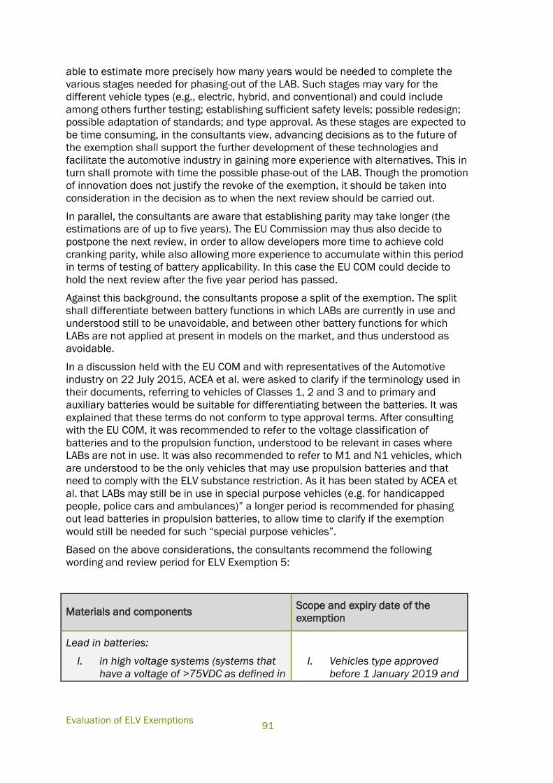
Evaluation of ELV Exemptions
91
able to estimate more precisely how many years would be needed to complete the
various stages needed for phasing-out of the LAB. Such stages may vary for the
different vehicle types (e.g., electric, hybrid, and conventional) and could include
among others further testing; establishing sufficient safety levels; possible redesign;
possible adaptation of standards; and type approval. As these stages are expected to
be time consuming, in the consultants view, advancing decisions as to the future of
the exemption shall support the further development of these technologies and
facilitate the automotive industry in gaining more experience with alternatives. This in
turn shall promote with time the possible phase-out of the LAB. Though the promotion
of innovation does not justify the revoke of the exemption, it should be taken into
consideration in the decision as to when the next review should be carried out.
In parallel, the consultants are aware that establishing parity may take longer (the
estimations are of up to five years). The EU Commission may thus also decide to
postpone the next review, in order to allow developers more time to achieve cold
cranking parity, while also allowing more experience to accumulate within this period
in terms of testing of battery applicability. In this case the EU COM could decide to
hold the next review after the five year period has passed.
Against this background, the consultants propose a split of the exemption. The split
shall differentiate between battery functions in which LABs are currently in use and
understood still to be unavoidable, and between other battery functions for which
LABs are not applied at present in models on the market, and thus understood as
avoidable.
In a discussion held with the EU COM and with representatives of the Automotive
industry on 22 July 2015, ACEA et al. were asked to clarify if the terminology used in
their documents, referring to vehicles of Classes 1, 2 and 3 and to primary and
auxiliary batteries would be suitable for differentiating between the batteries. It was
explained that these terms do not conform to type approval terms. After consulting
with the EU COM, it was recommended to refer to the voltage classification of
batteries and to the propulsion function, understood to be relevant in cases where
LABs are not in use. It was also recommended to refer to M1 and N1 vehicles, which
are understood to be the only vehicles that may use propulsion batteries and that
need to comply with the ELV substance restriction. As it has been stated by ACEA et
al. that LABs may still be in use in special purpose vehicles (e.g. for handicapped
people, police cars and ambulances)” a longer period is recommended for phasing
out lead batteries in propulsion batteries, to allow time to clarify if the exemption
would still be needed for such “special purpose vehicles”.
Based on the above considerations, the consultants recommend the following
wording and review period for ELV Exemption 5:
Materials and components Scope and expiry date of the
exemption
Lead in batteries:
I. in high voltage systems (systems that
have a voltage of >75VDC as defined in
I. Vehicles type approved
before 1 January 2019 and
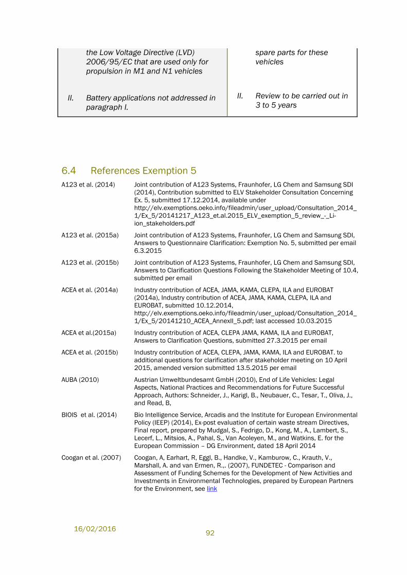
16/02/2016
92
the Low Voltage Directive (LVD)
2006/95/EC that are used only for
propulsion in M1 and N1 vehicles
II. Battery applications not addressed in
paragraph I.
spare parts for these
vehicles
II. Review to be carried out in
3 to 5 years
6.4 References Exemption 5
A123 et al. (2014) Joint contribution of A123 Systems, Fraunhofer, LG Chem and Samsung SDI
(2014), Contribution submitted to ELV Stakeholder Consultation Concerning
Ex. 5, submitted 17.12.2014, available under
http://elv.exemptions.oeko.info/fileadmin/user_upload/Consultation_2014_
1/Ex_5/20141217_A123_et.al.2015_ELV_exemption_5_review_-_Li-
ion_stakeholders.pdf
A123 et al. (2015a) Joint contribution of A123 Systems, Fraunhofer, LG Chem and Samsung SDI,
Answers to Questionnaire Clarification: Exemption No. 5, submitted per email
6.3.2015
A123 et al. (2015b) Joint contribution of A123 Systems, Fraunhofer, LG Chem and Samsung SDI,
Answers to Clarification Questions Following the Stakeholder Meeting of 10.4,
submitted per email
ACEA et al. (2014a) Industry contribution of ACEA, JAMA, KAMA, CLEPA, ILA and EUROBAT
(2014a), Industry contribution of ACEA, JAMA, KAMA, CLEPA, ILA and
EUROBAT, submitted 10.12.2014,
http://elv.exemptions.oeko.info/fileadmin/user_upload/Consultation_2014_
1/Ex_5/20141210_ACEA_AnnexII_5.pdf; last accessed 10.03.2015
ACEA et al.(2015a) Industry contribution of ACEA, CLEPA JAMA, KAMA, ILA and EUROBAT,
Answers to Clarification Questions, submitted 27.3.2015 per email
ACEA et al. (2015b) Industry contribution of ACEA, CLEPA, JAMA, KAMA, ILA and EUROBAT. to
additional questions for clarification after stakeholder meeting on 10 April
2015, amended version submitted 13.5.2015 per email
AUBA (2010) Austrian Umweltbundesamt GmbH (2010), End of Life Vehicles: Legal
Aspects, National Practices and Recommendations for Future Successful
Approach, Authors: Schneider, J., Karigl, B., Neubauer, C., Tesar, T., Oliva, J.,
and Read, B,
BIOIS et al. (2014) Bio Intelligence Service, Arcadis and the Institute for European Environmental
Policy (IEEP) (2014), Ex-post evaluation of certain waste stream Directives,
Final report, prepared by Mudgal, S., Fedrigo, D., Kong, M., A., Lambert, S.,
Lecerf, L., Mitsios, A., Pahal, S,, Van Acoleyen, M., and Watkins, E. for the
European Commission – DG Environment, dated 18 April 2014
Coogan et al. (2007) Coogan, A, Earhart, R, Eggl, B., Handke, V., Kamburow, C., Krauth, V.,
Marshall, A. and van Ermen, R.,. (2007), FUNDETEC - Comparison and
Assessment of Funding Schemes for the Development of New Activities and
Investments in Environmental Technologies, prepared by European Partners
for the Environment, see link
Evaluation of ELV Exemptions
93
EUROBAT el al. (2014) EUROBAT, ILA, ACEA, JAMA and KAMA (2014), A Review of Battery
Technologies for Automotive Applications - A joint industry analysis of the
technological suitability of different battery technologies for use across
various automotive applications in the foreseeable future, available under:
http://ewfa.org/sites/default/files/rev_of_battery_executive_web_1.pdf, last
accessed 10.03.2015
IHS et. al. (2014) IHS, EUROBAT, ILA, ACEA, JAMA and KAMA (2014), The Availability of
Automotive Lead-Based Batteries for Recycling in the EU - A joint industry
analysis of EU collection and recycling rates 2010-2012, prepared by
information company IHS, Pg. 20, available under:
http://www.eurobat.org/sites/default/files/ihs_eurobat_report_lead_lores_fi
nal.pdf
Olife (2014a) Olife Energy (2014a), Response to the consultation on the “8th Adaptation to
scientific and technical progress of exemptions 2(c), 3 and 5 of Annex II to
Directive 2000/53/EC (ELV)”,
http://elv.exemptions.oeko.info/fileadmin/user_upload/Consultation_2014_
1/Ex_5/Ex_5_Contribution_17122014_OLIFE_response_to_ELV_consultatio
n_161214-Public.pdf
Olife (2014b) Olife Energy (2014b), Answers to Specific questions from report of Oeko
Institute dated 28 July 2010, Chapter 4.5 Exemption No 5, submitted
17.12.2014, available under:
http://elv.exemptions.oeko.info/fileadmin/user_upload/Consultation_2014_
1/Ex_5/Ex_5_Contribution_17122014_Olife_Specific_questions_from_repor
t_of_O__ko_Institute_dated_28_July_2010.pdf
Olife (2015) Olife Energy (2015a), Answers to Oeko-Institut Clarification Questions, sent
per email on 27.3.2015
Usbeck et al. (2014) Usbeck, V. C., Kacker, A. and Gediga, J., PE International (2014), Life Cycle
Assessment of Lead-based Batteries for Vehicles, prepared for EUROBAT,
ACEA, KAMA, JAMA & ILA, Executive summary available under:
http://www.acea.be/uploads/publications/LCA_of_Pb-
based_batteries_for_vehicles_-_Executive_summary_10_04_2014.pdf

16/02/2016
94
Appendices
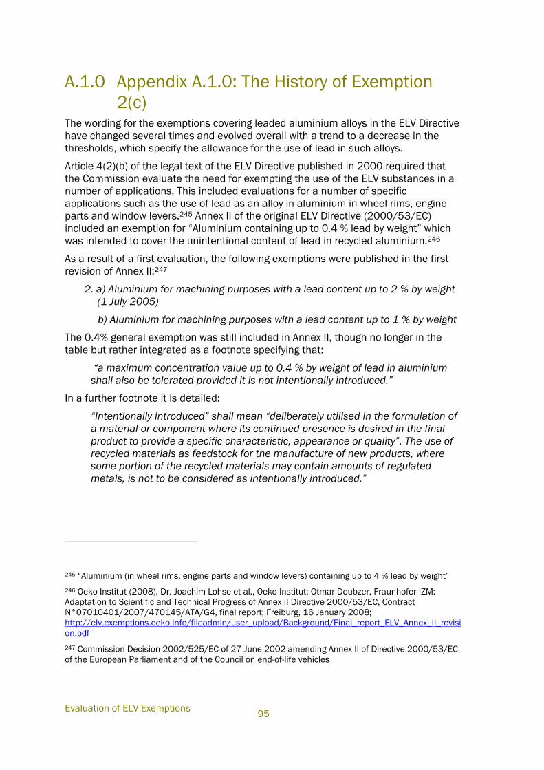
Evaluation of ELV Exemptions
95
A.1.0 Appendix A.1.0: The History of Exemption
2(c) The wording for the exemptions covering leaded aluminium alloys in the ELV Directive
have changed several times and evolved overall with a trend to a decrease in the
thresholds, which specify the allowance for the use of lead in such alloys.
Article 4(2)(b) of the legal text of the ELV Directive published in 2000 required that
the Commission evaluate the need for exempting the use of the ELV substances in a
number of applications. This included evaluations for a number of specific
applications such as the use of lead as an alloy in aluminium in wheel rims, engine
parts and window levers.245 Annex II of the original ELV Directive (2000/53/EC)
included an exemption for “Aluminium containing up to 0.4 % lead by weight” which
was intended to cover the unintentional content of lead in recycled aluminium.246
As a result of a first evaluation, the following exemptions were published in the first
revision of Annex II:247
2. a) Aluminium for machining purposes with a lead content up to 2 % by weight
(1 July 2005)
b) Aluminium for machining purposes with a lead content up to 1 % by weight
The 0.4% general exemption was still included in Annex II, though no longer in the
table but rather integrated as a footnote specifying that:
“a maximum concentration value up to 0.4 % by weight of lead in aluminium
shall also be tolerated provided it is not intentionally introduced.”
In a further footnote it is detailed:
“Intentionally introduced” shall mean “deliberately utilised in the formulation of
a material or component where its continued presence is desired in the final
product to provide a specific characteristic, appearance or quality”. The use of
recycled materials as feedstock for the manufacture of new products, where
some portion of the recycled materials may contain amounts of regulated
metals, is not to be considered as intentionally introduced.”
245 “Aluminium (in wheel rims, engine parts and window levers) containing up to 4 % lead by weight”
246 Oeko-Institut (2008), Dr. Joachim Lohse et al., Oeko-Institut; Otmar Deubzer, Fraunhofer IZM:
Adaptation to Scientific and Technical Progress of Annex II Directive 2000/53/EC, Contract
N°07010401/2007/470145/ATA/G4, final report; Freiburg, 16 January 2008;
http://elv.exemptions.oeko.info/fileadmin/user_upload/Background/Final_report_ELV_Annex_II_revisi
on.pdf
247 Commission Decision 2002/525/EC of 27 June 2002 amending Annex II of Directive 2000/53/EC
of the European Parliament and of the Council on end-of-life vehicles
16/02/2016
96
As a result of the second revision248, the allowance for lead in aluminium alloys for
machining purposes was further reduced:
2(a). Aluminium for machining purposes with a lead content up to 1.5 % by
weight (Scope and expiry date of the exemption 1 July 2008)
2(b). Aluminium for machining purposes with a lead content up to 0.4 % by
weight
The footnote referring to the general exemption of 0.4 % by weight of lead in
aluminium did not appear in the second revision. It was deleted with the Council
Decision dated 20 September 2005. A justification for the deletion was not detailed.
In the third revision of Annex II in 2008,249 the exemption evolved to include three
entries, only the third (Ex. No. 2(c) as detailed above) is still applicable for use in new
vehicles put on the EU market. Based on recommendations of Oeko-Institut250, the
wording of the exemption was changed from “Aluminium for machining purposes with
a lead content up to 0.4% by weight” by deleting the wording “for machining
purposes” in order to (re-)include unintentionally present lead in the scope of the
exemption. The Organisation of European Aluminium Refiners and Remelters (OEA)
and the European Aluminium Association (EAA) had requested a general exemption of
up to 0.4% for the unintentional content of lead in aluminium alloys.
The last review took place in 2009/2010. For Exemption 2(c), a review within five
years was recommended on the basis that industry did not provide sufficiently
detailed evidence at the time, to clarify that a reduction of lead concentrations in
aluminium alloys was not feasible, despite the general availability of lead-free
alternatives that had become apparent251. The requirement to review Exemption 2(c)
in 2015 was published in the fifth revision of Annex II in 2011.252
248 Council Decision 2005/673/EC of 20 September 2005 amending Annex II of Directive
2000/53/EC of the European Parliament and of the Council on end-of-life vehicles
249 Commission Decision 2008/689/EC amending Annex II of Directive 2000/53/EC of the European
Parliament and of the Council on end-of-life vehicles
250 Oeko-Institut (2008), Dr. Joachim Lohse et al., Oeko-Institut; Otmar Deubzer, Fraunhofer IZM:
Adaptation to Scientific and Technical Progress of Annex II Directive 2000/53/EC, Contract
N°07010401/2007/470145/ATA/G4, final report; Freiburg, 16 January 2008;
http://elv.exemptions.oeko.info/fileadmin/user_upload/Background/Final_report_ELV_Annex_II_revisi
on.pdf
251 Oeko-Institut (2010), Stéphanie Zangl et al., Oeko-Institut; Otmar Deubzer, Fraunhofer IZM:
Adaptation to scientific and technical progress of Annex II to Directive 2000/53/EC (ELV) and of the
Annex to Directive 2002/95/EC (RoHS), final report; Freiburg, 28 July 2010;
http://elv.exemptions.oeko.info/fileadmin/user_upload/Final_Report/Corr_Final_report_ELV_RoHS_2
8_07_2010.pdf
252 Commission Directive 2011/37/EU of 30 March 2011 amending Annex II to Directive 2000/53/EC
of the European Parliament and of the Council on end-of-life vehicles
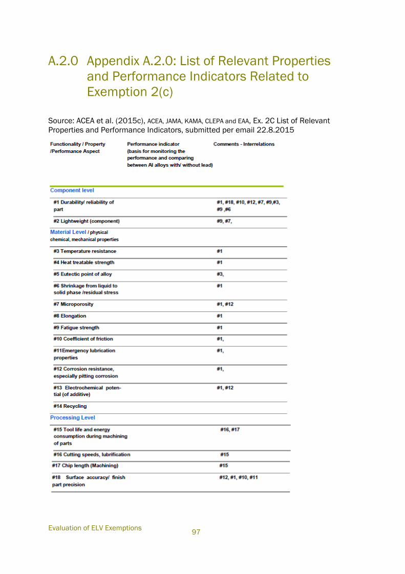
Evaluation of ELV Exemptions
97
A.2.0 Appendix A.2.0: List of Relevant Properties
and Performance Indicators Related to
Exemption 2(c)
Source: ACEA et al. (2015c), ACEA, JAMA, KAMA, CLEPA and EAA, Ex. 2C List of Relevant
Properties and Performance Indicators, submitted per email 22.8.2015
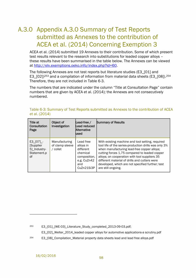
16/02/2016
98
A.3.0 Appendix A.3.0 Summary of Test Reports
submitted as Annexes to the contribution of
ACEA et al. (2014) Concerning Exemption 3 ACEA et al. (2014) submitted 19 Annexes to their contribution. Some of which present
test results relevant to the research into substitutions for leaded copper alloys –
these results have been summarised in the table below. The Annexes can be viewed
at http://elv.exemptions.oeko.info/index.php?id=60.
The following Annexes are not test reports but literature studies (E3_[01] and
E3_[02])253 and a compilation of information from material data sheets (E3_[08]).254
Therefore, they are not included in Table 6-3.
The numbers that are indicated under the column “Title at Consultation Page” contain
numbers that are given by ACEA et al. (2014); the Annexes are not consecutively
numbered.
Table 6-3: Summary of Test Reports submitted as Annexes to the contribution of ACEA
et al. (2014)
Title at
Consultation
Page
Object of
Investigation
Lead-free /
Lead reduced
Alternative
used
Summary of Results
E3_[07]_-
[Supplier
5]_Industry-
Statement.p
df
Manufacturing
of clamp sleeve
/ collet
Lead free
alloys in
different
chemical
composition,
e.g. CuZn42
and
CuZn21Si3P
With existing machine and tool setting, required
tool life of the series-production drills was only 3%
when manufacturing lead-free copper alloys;
cutting forces 1,75 compared to leaded copper
alloys; on cooperation with tool suppliers 35
different material of drills and cutters were
developed, which are not specified further; test
are still ongoing.
253 E3_[01]_[WE-03]_Literature_Study_completed_2013-09-03.pdf;
E3_[02]_Welter_2014_leaded copper alloys for automotive applications-a scrutiny.pdf
254 E3_[08]_Compilation_Material property data sheets lead and lead free alloys.pdf
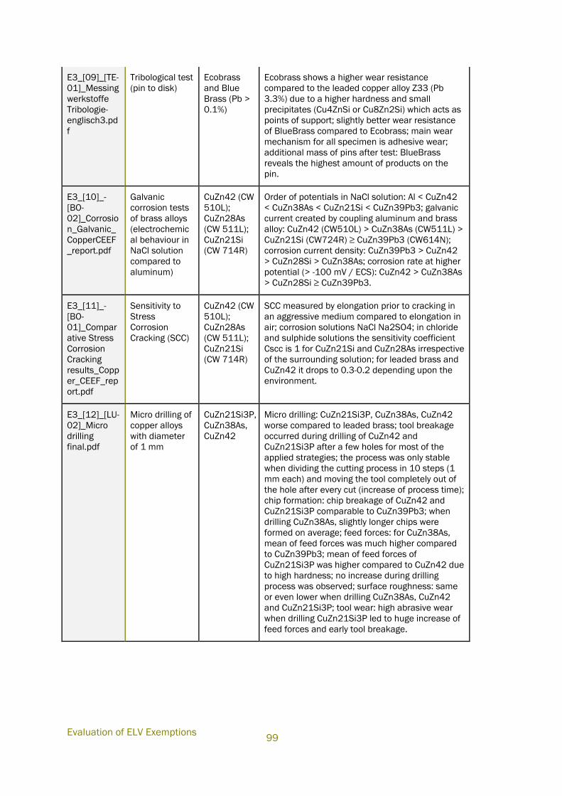
Evaluation of ELV Exemptions
99
E3_[09]_[TE-
01]_Messing
werkstoffe
Tribologie-
englisch3.pd
f
Tribological test
(pin to disk)
Ecobrass
and Blue
Brass (Pb >
0.1%)
Ecobrass shows a higher wear resistance
compared to the leaded copper alloy Z33 (Pb
3.3%) due to a higher hardness and small
precipitates (Cu4ZnSi or Cu8Zn2Si) which acts as
points of support; slightly better wear resistance
of BlueBrass compared to Ecobrass; main wear
mechanism for all specimen is adhesive wear;
additional mass of pins after test: BlueBrass
reveals the highest amount of products on the
pin.
E3_[10]_-
[BO-
02]_Corrosio
n_Galvanic_
CopperCEEF
_report.pdf
Galvanic
corrosion tests
of brass alloys
(electrochemic
al behaviour in
NaCl solution
compared to
aluminum)
CuZn42 (CW
510L);
CuZn28As
(CW 511L);
CuZn21Si
(CW 714R)
Order of potentials in NaCl solution: Al < CuZn42
< CuZn38As < CuZn21Si < CuZn39Pb3; galvanic
current created by coupling aluminum and brass
alloy: CuZn42 (CW510L) > CuZn38As (CW511L) >
CuZn21Si (CW724R) ≥ CuZn39Pb3 (CW614N);
corrosion current density: CuZn39Pb3 > CuZn42
> CuZn28Si > CuZn38As; corrosion rate at higher
potential (> -100 mV / ECS): CuZn42 > CuZn38As
> CuZn28Si ≥ CuZn39Pb3.
E3_[11]_-
[BO-
01]_Compar
ative Stress
Corrosion
Cracking
results_Copp
er_CEEF_rep
ort.pdf
Sensitivity to
Stress
Corrosion
Cracking (SCC)
CuZn42 (CW
510L);
CuZn28As
(CW 511L);
CuZn21Si
(CW 714R)
SCC measured by elongation prior to cracking in
an aggressive medium compared to elongation in
air; corrosion solutions NaCl Na2SO4; in chloride
and sulphide solutions the sensitivity coefficient
Cscc is 1 for CuZn21Si and CuZn28As irrespective
of the surrounding solution; for leaded brass and
CuZn42 it drops to 0.3-0.2 depending upon the
environment.
E3_[12]_[LU-
02]_Micro
drilling
final.pdf
Micro drilling of
copper alloys
with diameter
of 1 mm
CuZn21Si3P,
CuZn38As,
CuZn42
Micro drilling: CuZn21Si3P, CuZn38As, CuZn42
worse compared to leaded brass; tool breakage
occurred during drilling of CuZn42 and
CuZn21Si3P after a few holes for most of the
applied strategies; the process was only stable
when dividing the cutting process in 10 steps (1
mm each) and moving the tool completely out of
the hole after every cut (increase of process time);
chip formation: chip breakage of CuZn42 and
CuZn21Si3P comparable to CuZn39Pb3; when
drilling CuZn38As, slightly longer chips were
formed on average; feed forces: for CuZn38As,
mean of feed forces was much higher compared
to CuZn39Pb3; mean of feed forces of
CuZn21Si3P was higher compared to CuZn42 due
to high hardness; no increase during drilling
process was observed; surface roughness: same
or even lower when drilling CuZn38As, CuZn42
and CuZn21Si3P; tool wear: high abrasive wear
when drilling CuZn21Si3P led to huge increase of
feed forces and early tool breakage.
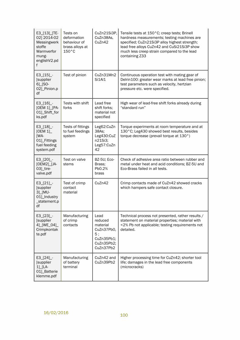
16/02/2016
100
E3_[13]_[TE-
02] 2014-02
Messingwerk
stoffe
Warmverfor
mung-
englishV2.pd
f
Tests on
deformation
behaviour of
brass alloys at
150°C
CuZn21Si3P,
CuZn38As,
CuZn42
Tensile tests at 150°C; creep tests; Brinell
hardness measurements; testing machines are
specified; CuZn21Si3P alloy highest strength;
lead free alloys CuZn42 and CuSi21Si3P show
much less creep strain compared to the lead
containing Z33
E3_[15]_-
[supplier
6]_[SO-
02]_Pinion.p
df
Test of pinion CuZn31Mn2
Si1Al1
Continuous operation test with mating gear of
Delrin100: greater wear marks at lead free pinion;
test parameters such as velocity, hertzian
pressure etc. were specified.
E3_[16]_-
[OEM 1]_[PA-
01]_Shift_for
ks.pdf
Tests with shift
forks
Lead free
shift forks;
material not
specified
High wear of lead-free shift forks already during
“standard run”
E3_[18]_-
[OEM 1]_
[WA-
01]_Fittings
fuel feeding
system.pdf
Tests of fittings
to fuel feedings
system
Leg62:CuZn
38As;
Leg430:CuZ
n21Si3;
Leg57:CuZn
42
Torque experiments at room temperature and at
130°C; Leg430 showed best results, besides
torque decrease (prevail torque at 130°)
E3_[20]_-
[OEM2]_[JA-
03]_tire-
valve.pdf
Test on valve
stems
BZ-5U; Eco-
Brass;
Pb0.2%
brass
Check of adhesive area ratio between rubber and
metal under heat and acid conditions; BZ-5U and
Eco-Brass failed in all tests.
E3_[21]_-
[supplier
3]_[MU-
01]_Industry
_statement.p
df
Test of crimp
contact
material
CuZn42 Crimp contacts made of CuZn42 showed cracks
which hampers safe contact closure.
E3_[23]_-
[supplier
4]_[WE_04]_
Crimpkontak
te.pdf
Manufacturing
of crimp
contacts
Lead
reduced
material
CuZn37Pb0,
5 ;
CuZn35Pb1;
CuZn35Pb2;
CuZn37Pb2
Technical process not presented, rather results /
statement on material properties; material with
<2% Pb not applicable; testing requirements not
detailed.
E3_[24]_-
[supplier
1]_[LA-
01]_Batterie
klemme.pdf
Manufacturing
of battery
terminal
CuZn42 and
CuZn39Pb2
Higher processing time for CuZn42; shorter tool
life; damages in the lead free components
(microcracks)
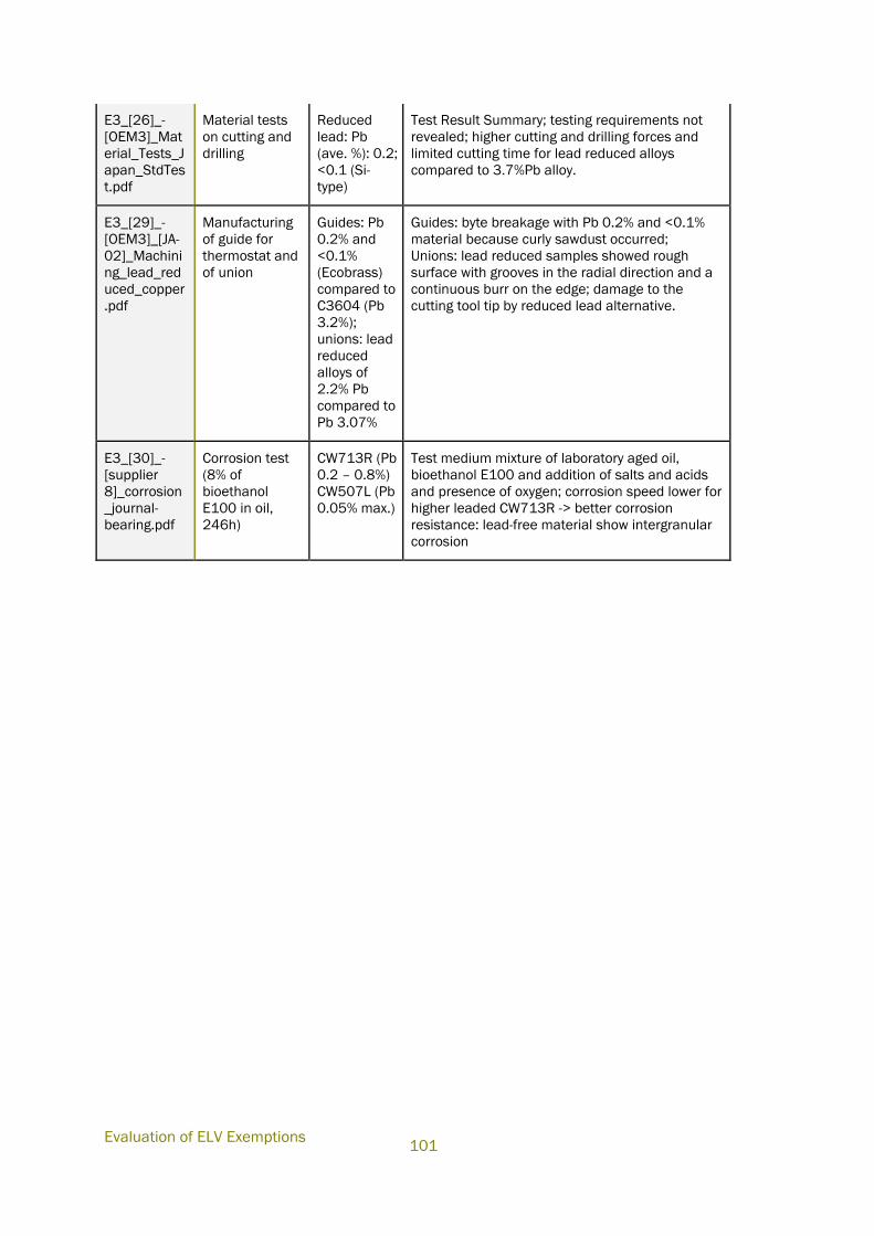
Evaluation of ELV Exemptions
101
E3_[26]_-
[OEM3]_Mat
erial_Tests_J
apan_StdTes
t.pdf
Material tests
on cutting and
drilling
Reduced
lead: Pb
(ave. %): 0.2;
<0.1 (Si-
type)
Test Result Summary; testing requirements not
revealed; higher cutting and drilling forces and
limited cutting time for lead reduced alloys
compared to 3.7%Pb alloy.
E3_[29]_-
[OEM3]_[JA-
02]_Machini
ng_lead_red
uced_copper
Manufacturing
of guide for
thermostat and
of union
Guides: Pb
0.2% and
<0.1%
(Ecobrass)
compared to
C3604 (Pb
3.2%);
unions: lead
reduced
alloys of
2.2% Pb
compared to
Pb 3.07%
Guides: byte breakage with Pb 0.2% and <0.1%
material because curly sawdust occurred;
Unions: lead reduced samples showed rough
surface with grooves in the radial direction and a
continuous burr on the edge; damage to the
cutting tool tip by reduced lead alternative.
E3_[30]_-
[supplier
8]_corrosion
_journal-
bearing.pdf
Corrosion test
(8% of
bioethanol
E100 in oil,
246h)
CW713R (Pb
0.2 – 0.8%)
CW507L (Pb
0.05% max.)
Test medium mixture of laboratory aged oil,
bioethanol E100 and addition of salts and acids
and presence of oxygen; corrosion speed lower for
higher leaded CW713R -> better corrosion
resistance: lead-free material show intergranular
corrosion
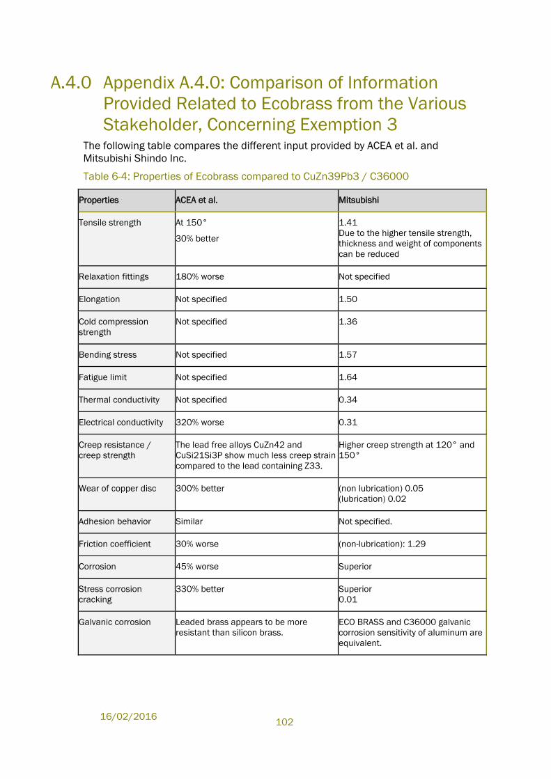
16/02/2016
102
A.4.0 Appendix A.4.0: Comparison of Information
Provided Related to Ecobrass from the Various
Stakeholder, Concerning Exemption 3 The following table compares the different input provided by ACEA et al. and
Mitsubishi Shindo Inc.
Table 6-4: Properties of Ecobrass compared to CuZn39Pb3 / C36000
Properties ACEA et al. Mitsubishi
Tensile strength At 150°
30% better
1.41
Due to the higher tensile strength,
thickness and weight of components
can be reduced
Relaxation fittings 180% worse Not specified
Elongation Not specified 1.50
Cold compression
strength
Not specified 1.36
Bending stress Not specified 1.57
Fatigue limit Not specified 1.64
Thermal conductivity Not specified 0.34
Electrical conductivity 320% worse 0.31
Creep resistance /
creep strength
The lead free alloys CuZn42 and
CuSi21Si3P show much less creep strain
compared to the lead containing Z33.
Higher creep strength at 120° and
150°
Wear of copper disc 300% better (non lubrication) 0.05
(lubrication) 0.02
Adhesion behavior Similar Not specified.
Friction coefficient 30% worse (non-lubrication): 1.29
Corrosion 45% worse Superior
Stress corrosion
cracking
330% better Superior
0.01
Galvanic corrosion Leaded brass appears to be more
resistant than silicon brass.
ECO BRASS and C36000 galvanic
corrosion sensitivity of aluminum are
equivalent.
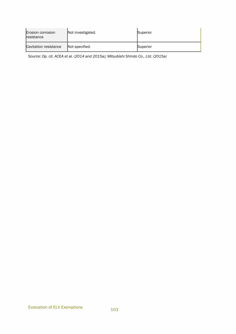
Evaluation of ELV Exemptions
103
Erosion corrosion
resistance
Not investigated. Superior
Cavitation resistance Not specified. Superior
Source: Op. cit. ACEA et al. (2014 and 2015a); Mitsubishi Shindo Co., Ltd. (2015a)
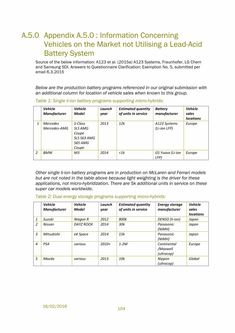
16/02/2016
104
A.5.0 Appendix A.5.0 : Information Concerning
Vehicles on the Market not Utilising a Lead-Acid
Battery System Source of the below information: A123 et al. (2015a) A123 Systems, Fraunhofer, LG Chem
and Samsung SDI, Answers to Questionnaire Clarification: Exemption No. 5, submitted per
email 6.3.2015
Below are the production battery programs referenced in our original submission with
an additional column for location of vehicle sales when known to this group.
Table 1: Single li-ion battery programs supporting micro-hybrids:
Vehicle Manufacturer
Vehicle Model
Launch year
Estimated quantity of units in service
Battery manufacturer
Vehicle sales locations
1 Mercedes Mercedes-AMG
S-Class SLS AMG Coupe SLS S63 AMG S65 AMG Coupe
2013 12k A123 Systems (Li-ion LFP)
Europe
2 BMW M3 2014 <1k GS Yuasa (Li-ion LFP)
Europe
Other single li-ion battery programs are in production on McLaren and Ferrari models
but are not noted in the table above because light weighting is the driver for these
applications, not micro-hybridization. There are 5k additional units in service on these
super car models worldwide.
Table 2: Dual energy storage programs supporting micro-hybrids:
Vehicle Manufacturer
Vehicle Model
Launch year
Estimated quantity of units in service
Energy storage manufacturer
Vehicle sales locations
1 Suzuki Wagon R 2012 800k DENSO (li-ion) Japan
2 Nissan DAYZ ROOX 2014 30k Panasonic (NiMH)
Japan
3 Mitsubishi eK Space 2014 15k Panasonic (NiMH)
Japan
4 PSA various 2010+ 1-2M Continental /Maxwell (ultracap)
Europe
5 Mazda various 2013 10k Nippon (ultracap)
Global
Evaluation of ELV Exemptions
105
A.6.0 Appendix A.6.0: Description of Relevant Stages
Required as Part of the Development Tasks of
Battery Technologies at the Component and
Vehicle Levels. Source of the below information: ACEA et al., (2015b), Submission of ACEA, CLEPA, JAMA,
KAMA, ILA and EUROBAT. to additional questions for clarification after stakeholder meeting
on 10 April 2015, amended version submitted 13.5.2015 per email
Component level specific R&D issues
The development of Li-ion batteries for 12 V SLI applications is at an early stage and
they are not yet able to meet all the requirements of this application. A full
programme of research and development needs to be carried out to ensure OEM
specifications and technical standards can be met. For Li-ion batteries, technical
standards are not yet developed and for lead-acid SLI batteries, the requirements are
defined in EN 50342-1 and for lead-acid batteries for stop and start applications, they
are being defined by EN 50342-6 which is not yet published.
However, the EN 50342 family of specifications is particular to lead-acid batteries, as
its title “lead acid batteries” indicates. Only some EN 50342-1 requirements are
derived from the vehicle application, such capacity, high-rate cranking capability and
vibration resistance.
Furthermore, many requirements defined in EN 50342-1 address battery
characteristics specific to lead-acid, which have been identified over years of
operation of lead-acid batteries in vehicles. For example the procedure for forced
deep discharge (“over-discharge”) of lead-acid batteries and capability for recovery
afterwards.
Li-ion batteries must not be subjected to any deep discharge (“over-discharge”) and
therefore are self-protected by disconnection, even if vehicle function may be
compromised.
On the other hand, some requirements have not been addressed in EN-50342 as it is
common knowledge that there is no need for a particular requirement, either as it is
not critical for any lead-acid battery, or the requirement is implicitly covered by
another requirement.
As an example, system overvoltage at the 12 V/14 V level, from a transient or a
defect of the voltage controller of the alternator, is a quite common failure. Therefore,
vehicle manufacturers specify the electronic devices used to be resistant to damage
by an overvoltage for a limited period of time, e.g. 1 hour at 18 V. However, EN-50342
does not need to specify such a situation, as it is common knowledge that lead-acid
batteries can easily withstand such a situation, even at elevated temperatures,
without losing function or being a potential hazard. Some degradation (grid corrosion,
water electrolysis) is accepted under such an abuse condition, even if the overall
operating period may be somewhat compromised. Implicitly, this topic is also
addressed in the water loss test (constant voltage 14.4 V overcharge at 60°C for
many weeks).
16/02/2016
106
Li-ion batteries are sensitive to overcharge, especially at high temperatures, and
therefore protect themselves by disconnecting, even if vehicle function may be
compromised.
Furthermore, there are laboratory tests specified in EN-50342 which have been
demonstrated to reflect failure modes similar to failure modes seen in the field over
years of experience. Such so called accelerated life tests do not emulate vehicle
operating conditions (as this would require years of testing) but failure modes, to
allow for a full evaluation after a few weeks.
The procedure for 50% depth-of-discharge cycling is an example. Accelerated life
tests of this type are specific to the electrochemical system. Furthermore, extended
field experience on failure modes has to be collected, and a robust statistical
verification of any new-designed accelerated life test against a full statistical analysis
of failure modes is required before specification and implementation of such a test.
All of this indicates that the EN 50342 family of specifications does not reflect
requirements for Li-ion batteries, and is not intended to do so. A new EN standard is
required to specify requirements for Li-ion starter batteries. Requirements derived
from the vehicle application, such as capacity, high-rate cranking capability, vibration
resistance and so on may be similar to EN 50342-1. Tests specific to lead-acid may
be dropped, while new tests specific to Li-ion characteristics may be included.
Accelerated life tests specific to Li-ion batteries require extended field experience on
failure modes. Such investigations on the road have scarcely been started. Whenever
further design changes of Li-ion batteries are made (or will be made in future), this
has to be considered and updated.
EN 50342-1 defines cold cranking requirements for lead-acid batteries, low rate
capacity at the 20 h rate, charge retention, corrosion resistance, cyclic endurance,
vibration resistance, water loss and electrolyte retention. Water loss and electrolyte
retention are specific to lead-acid and would not be applicable to Li-ion. Cold
cranking, low rate capacity, charge retention, cyclic endurance and vibration
resistance requirements should be equivalent for Li-ion as these are vehicle
requirements but the tests may be different as discussed. The charge retention is
measured by storage of a fully charged battery at an elevated temperature (40oC) for
a period and then measuring its CCA performance. The corrosion test is a high
temperature durability test where the battery is held at elevated temperature (60oC)
on a constant voltage charge for a period and then measuring the CCA performance.
Each period is a unit and durability is measured in number of units before failure.
Cyclic endurance is measured on a shallow cycle for 180 cycles and the CCA is
checked.
EN 50342-6 is not yet a standard but will define requirements for micro-cycling,
dynamic charge acceptance, endurance at 17.5% depth-of-discharge and endurance
at 50% depth-of-discharge following a deep discharge. The basic requirements of EN-
50342 remain in place. OEMs and battery manufacturers are working on this
standard as an expert committee.
As illustrated in Table 1 existing standards can only partly be used as a basis to
develop the required standards for li-ion SLI batteries. They have to be modified and
adapted to the specific conditions. For some test specifications completely new
standards have to be developed.
Evaluation of ELV Exemptions
107
According to the experiences of OEMs and described above, this is a time consuming
process. It has taken 6 years from May 2008 (kick-off meeting for ISO 12405-1) to
May 2014 (ISO 12405-3 published) to get ISO 12405 (“Electric road vehicles – Test
specification for Li-ion traction battery systems”) completely published.
In addition to the standards in the table there is actually work ongoing for a Li-ion cell
safety standard (IEC 62660-3), in which Li-ion cells for starter batteries are not yet in
the scope (“Secondary Li-ion cells for the propulsion of electric road vehicles”). This
standard as well as the standards in Table 1 has to be developed as a completely
new standard for Li-ion cells for 12 V SLI batteries.
Table 1 Comparison of relevant standards and applicability for li-ion SLI batteries
(below).
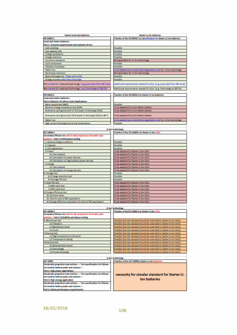
16/02/2016
108
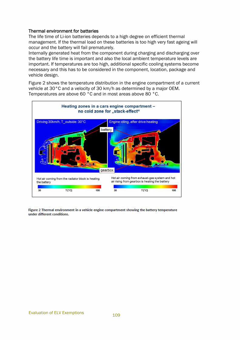
Evaluation of ELV Exemptions
109
Thermal environment for batteries
The life time of Li-ion batteries depends to a high degree on efficient thermal
management. If the thermal load on these batteries is too high very fast ageing will
occur and the battery will fail prematurely.
Internally generated heat from the component during charging and discharging over
the battery life time is important and also the local ambient temperature levels are
important. If temperatures are too high, additional specific cooling systems become
necessary and this has to be considered in the component, location, package and
vehicle design.
Figure 2 shows the temperature distribution in the engine compartment of a current
vehicle at 30°C and a velocity of 30 km/h as determined by a major OEM.
Temperatures are above 60 °C and in most areas above 80 °C.
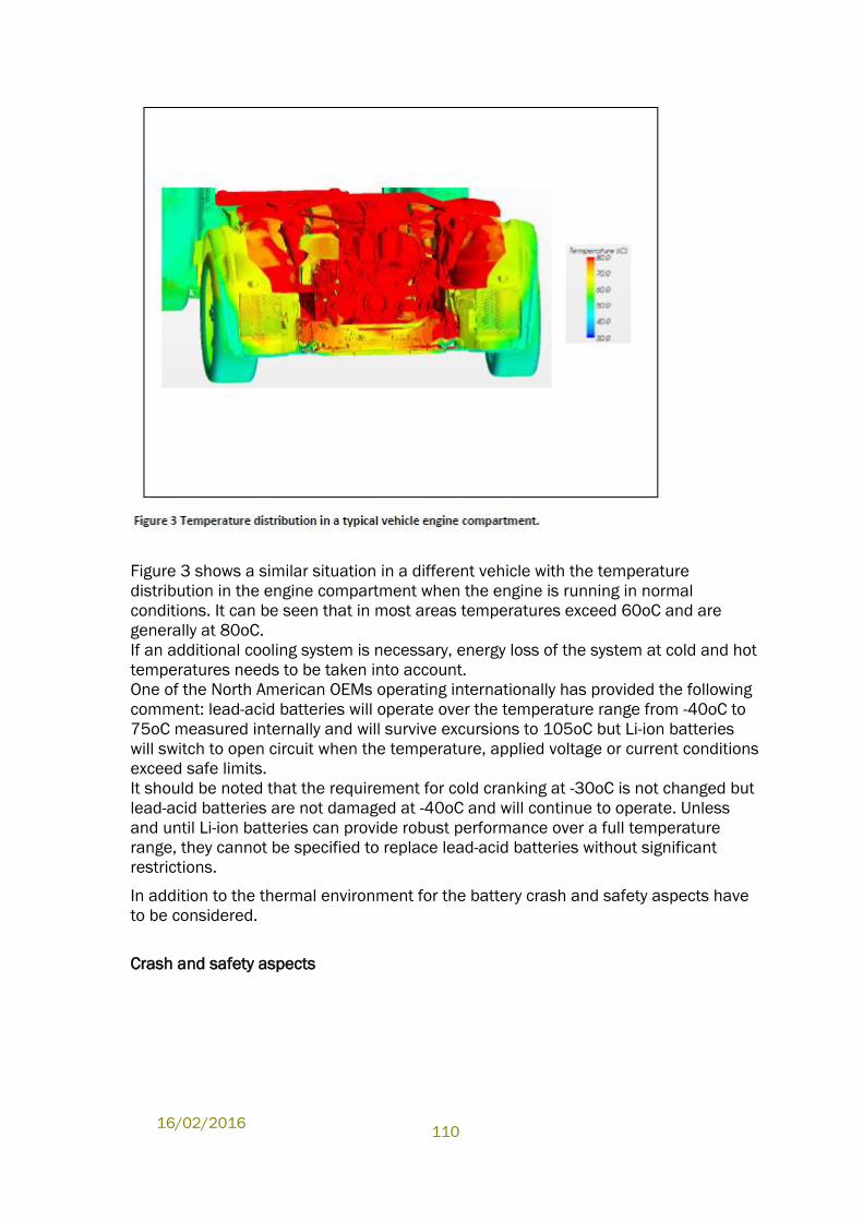
16/02/2016
110
Figure 3 shows a similar situation in a different vehicle with the temperature
distribution in the engine compartment when the engine is running in normal
conditions. It can be seen that in most areas temperatures exceed 60oC and are
generally at 80oC.
If an additional cooling system is necessary, energy loss of the system at cold and hot
temperatures needs to be taken into account.
One of the North American OEMs operating internationally has provided the following
comment: lead-acid batteries will operate over the temperature range from -40oC to
75oC measured internally and will survive excursions to 105oC but Li-ion batteries
will switch to open circuit when the temperature, applied voltage or current conditions
exceed safe limits.
It should be noted that the requirement for cold cranking at -30oC is not changed but
lead-acid batteries are not damaged at -40oC and will continue to operate. Unless
and until Li-ion batteries can provide robust performance over a full temperature
range, they cannot be specified to replace lead-acid batteries without significant
restrictions.
In addition to the thermal environment for the battery crash and safety aspects have
to be considered.
Crash and safety aspects
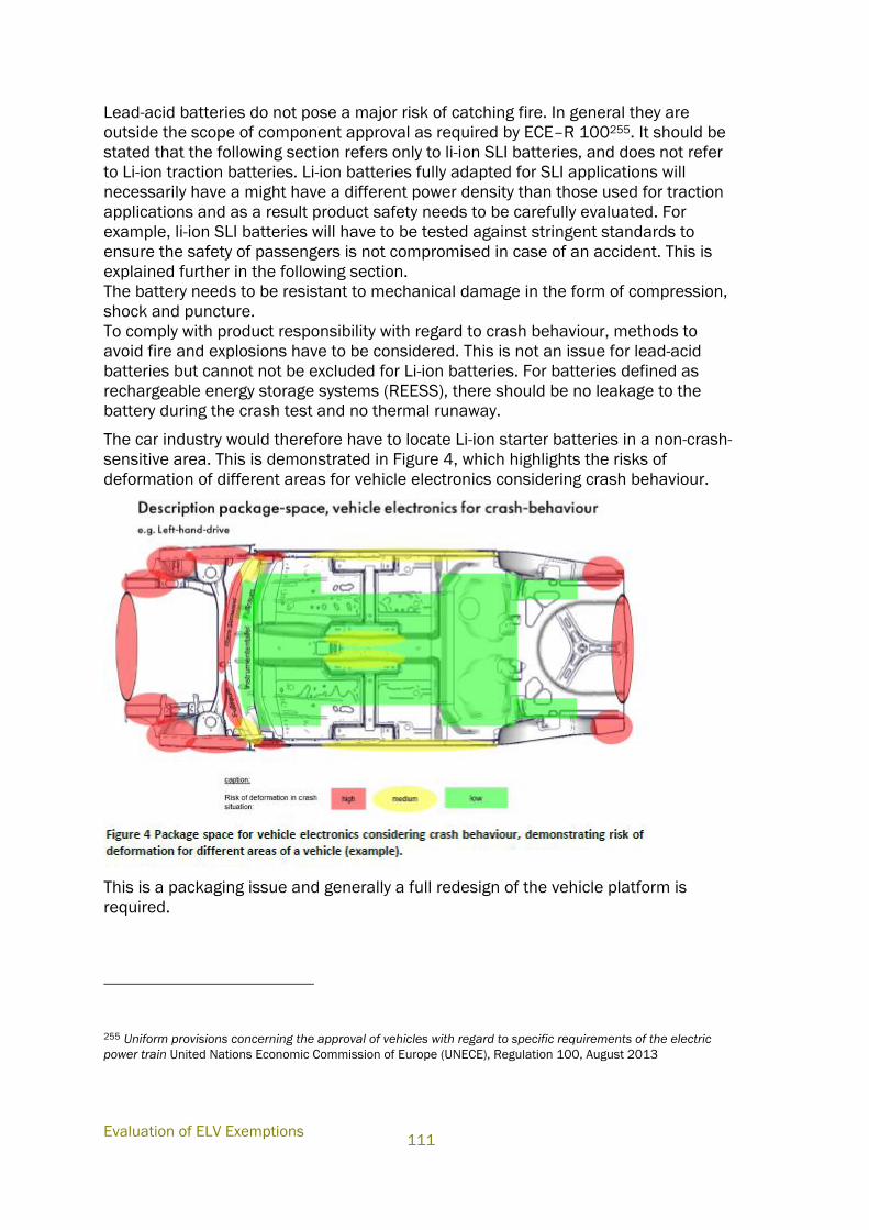
Evaluation of ELV Exemptions
111
Lead-acid batteries do not pose a major risk of catching fire. In general they are
outside the scope of component approval as required by ECE–R 100255. It should be
stated that the following section refers only to li-ion SLI batteries, and does not refer
to Li-ion traction batteries. Li-ion batteries fully adapted for SLI applications will
necessarily have a might have a different power density than those used for traction
applications and as a result product safety needs to be carefully evaluated. For
example, li-ion SLI batteries will have to be tested against stringent standards to
ensure the safety of passengers is not compromised in case of an accident. This is
explained further in the following section.
The battery needs to be resistant to mechanical damage in the form of compression,
shock and puncture.
To comply with product responsibility with regard to crash behaviour, methods to
avoid fire and explosions have to be considered. This is not an issue for lead-acid
batteries but cannot not be excluded for Li-ion batteries. For batteries defined as
rechargeable energy storage systems (REESS), there should be no leakage to the
battery during the crash test and no thermal runaway.
The car industry would therefore have to locate Li-ion starter batteries in a non-crash-
sensitive area. This is demonstrated in Figure 4, which highlights the risks of
deformation of different areas for vehicle electronics considering crash behaviour.
This is a packaging issue and generally a full redesign of the vehicle platform is
required.
255 Uniform provisions concerning the approval of vehicles with regard to specific requirements of the electric
power train United Nations Economic Commission of Europe (UNECE), Regulation 100, August 2013
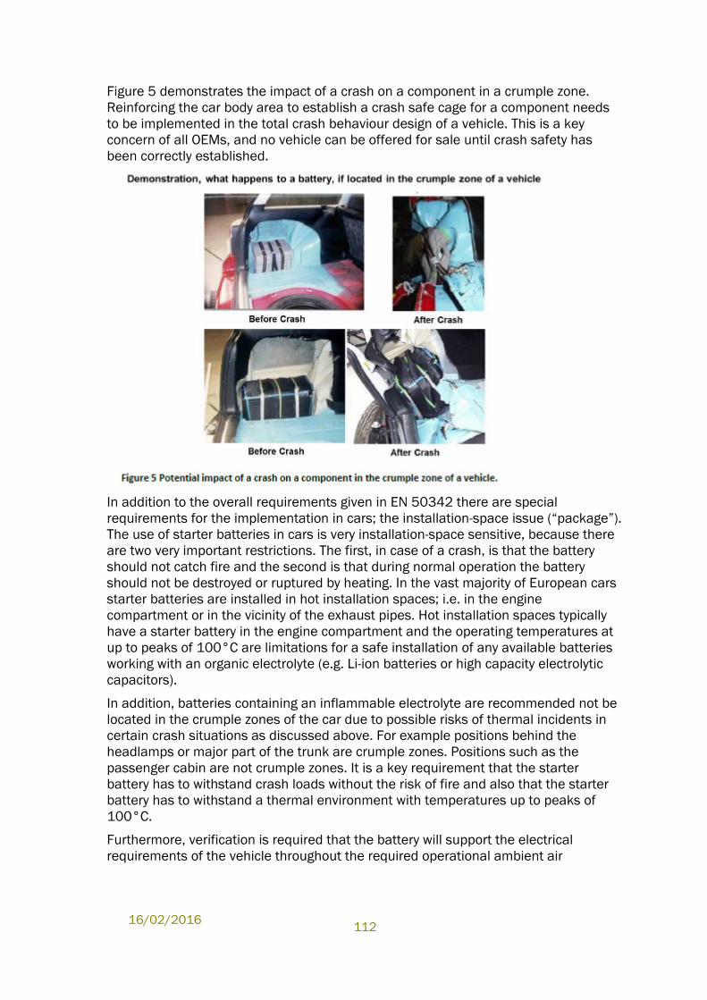
16/02/2016
112
Figure 5 demonstrates the impact of a crash on a component in a crumple zone.
Reinforcing the car body area to establish a crash safe cage for a component needs
to be implemented in the total crash behaviour design of a vehicle. This is a key
concern of all OEMs, and no vehicle can be offered for sale until crash safety has
been correctly established.
In addition to the overall requirements given in EN 50342 there are special
requirements for the implementation in cars; the installation-space issue (“package”).
The use of starter batteries in cars is very installation-space sensitive, because there
are two very important restrictions. The first, in case of a crash, is that the battery
should not catch fire and the second is that during normal operation the battery
should not be destroyed or ruptured by heating. In the vast majority of European cars
starter batteries are installed in hot installation spaces; i.e. in the engine
compartment or in the vicinity of the exhaust pipes. Hot installation spaces typically
have a starter battery in the engine compartment and the operating temperatures at
up to peaks of 100°C are limitations for a safe installation of any available batteries
working with an organic electrolyte (e.g. Li-ion batteries or high capacity electrolytic
capacitors).
In addition, batteries containing an inflammable electrolyte are recommended not be
located in the crumple zones of the car due to possible risks of thermal incidents in
certain crash situations as discussed above. For example positions behind the
headlamps or major part of the trunk are crumple zones. Positions such as the
passenger cabin are not crumple zones. It is a key requirement that the starter
battery has to withstand crash loads without the risk of fire and also that the starter
battery has to withstand a thermal environment with temperatures up to peaks of
100°C.
Furthermore, verification is required that the battery will support the electrical
requirements of the vehicle throughout the required operational ambient air
Evaluation of ELV Exemptions
113
temperature range per each particular application and package location. This involves
the following:
1) Capability to provide power for engine cranking, electronics support when the
vehicle is switched off and back-up support when the alternator or DC/DC converter
fails or is switched off.
Robust operation down to -30oC is required which, presently, lithium batteries do not
provide. Operation to -25oC is possible but it requires compromise to the engine start
function and is typically only achieved by the most expensive lithium options to date.
In addition, diesel engines are not supported. Whilst supercapacitors are not as
affected by temperature, independent tests have found that in order to support the
required cranking time and energy, the capacitor banks have to be relatively large
and very costly and, due to their self-discharge characteristics, require management
to isolate them when the vehicle is switched off so as to avoid a flat battery. As a
result, seamless and direct replacement for a lead-acid battery is not feasible.
2) Capability to sustain power delivery capability throughout assigned drive
cycles/use cases performed throughout the required operational temperature range.
Due to the recharge limitation of lithium batteries, tests have found that present
lithium battery technology, (even those capable of operation to -25oC ), do not
support short journey operation of vehicles and still maintain the required
functionality at temperatures below -10oC as the batteries inevitably move to a lower
state-of-charge.
3) Confirmation of robustness of the battery for vehicle operation throughout the
temperature range.
This requires a detailed evaluation to ensure that the sensitivity of the lithium battery
to fluctuating electrical vehicle loads is well understood. Presently, there is a concern
regarding lithium plating occurring due to the transient nature of certain high power
vehicle loads (heated windows, suspension pumps, braking systems and other
systems). The pulses caused by switching off may cause the battery to be charged at
a higher rate than allowed which may cause lithium plating, damage to the electrodes
and may lead to short circuits. This, at least, must be evaluated to understand the
magnitude of the issue but, additionally, the automated connection and
disconnection strategies, which the batteries require are potential weak areas which
have the potential to significantly weaken the safety case unless appropriate
countermeasures can be developed. Finally, a full component standard will then need
to be developed to ensure that the robustness of the battery may be fully verified
against the transient load factors, which have been identified.
4) Verified compatibility is between the voltage range required by the battery to
maintain safe and robust operation and the range expected by the existing vehicle
electrical modules, which are designed for the voltage range provided by lead-acid
batteries.
This is an issue if the chemistry of the lithium battery prevents operation in certain
voltage ranges expected by the existing electrical system modules and engine control
units (ECUs). Functionality may be restricted which then will require redesign of the
affected module. The impact will depend upon the battery chemistry used and, as
lithium chemistry is not well standardised, may result in complexity, cost and service
replacement issues.
16/02/2016
114
5) Verified Compatibility between the vehicle powernet controller and the battery
management system especially as regards accuracy and robustness of the battery
state estimation signals which are essential to maintain safe operation.
The performance and accuracy of existing lead-acid battery management systems
(BMS) is well known and incorporated into existing vehicle designs. Lithium batteries
require a more complex BMS for reliability and safety reasons, which for example has
to communicate current and voltage limits as functions of temperature, state of
charge, and ageing, to control thermal management in terms of absolute and relative
temperature limits, to disconnect the battery in case of severe failure. Existing BMS
for high voltage batteries cannot be carried over because of different functionality,
package, and cost requirements. It should be noted that li-Ion cell suppliers are
typically not familiar with and usually not approved for automotive electronics and
software development processes. Development of a BMS for li-ion starter batteries
that would be feasible and fully qualified for mass production is a substantial
engineering and verification task on its own. Verification and validation have to be
foreseen both on system (battery) and vehicle integration level. Additionally, high
voltage systems cannot be utilised because their design and composition is entirely
different to that needed for stand-alone 12 V and the cost impact is huge.
6) Verified robustness of the powernet against the fitment of an incorrect battery.
Lead-acid is relatively benign so the fitment of an incorrect battery does not have a
significant impact upon the safe operation of the vehicle even though the supported
functionality may be affected to some extent. Lithium is a very different chemistry and
if charged incorrectly, may cause significant safety issues. As customers are only used
to lead-acid batteries then they expect to be able to simply purchase a direct
replacement from a shop with the same applying to a battery charger.
7) Compatibility confirmation with manufacturing facility but especially the service
infrastructure.
As per the previous issue, dealerships’ equipment for charging and diagnosis are only
set up for lead-acid batteries. Suitable replacement equipment will need to be
identified, proven and sourced at significant cost and, more importantly, this will take
time to achieve.
8) Definition and agreement of how to treat 12 V lithium batteries at end-of-life in
relation to both the End-of-Life Vehicle and Batteries Directives and, ideally to agree a
recycling process. These issues associated with Li-ion recycling have already been
discussed at length in our previous submissions.
b. Please include detail of required development stages and the time estimated for
their completion (the time needed for each stage). If relevant please refer to differing
battery chemistries.
As explained in our previous contributions, there are many obstacles and challenges
for Li-ion batteries to overcome before they can be considered as an alternative
technology in SLI applications (slide 5 of our presentation during the stakeholder
meeting). One of the key challenges remains to ensure the life duration. These
obstacles were agreed by A123 in the April 10 meeting. If these are overcome, and an
alternative technology developed, European OEMs estimate that the required
installation and ramp up of the technology would require an implementation time of
at least 10 years. Under this timescale, if a technology were already available as a
Evaluation of ELV Exemptions
115
technical substitute for 12 V batteries used in conventional vehicles, it would not be
until about 10 years later that it could be implemented into new vehicles being
released onto the European market256.
This process involves many stages, starting with tests on cell level, component tests
under a range of different conditions followed by the development of prototype
vehicles. If these are successful, summer and winter tests need to be carried out and
then pilot applications will be undertaken to ensure correct and reliable operation.
Car manufacturers have to follow strictly defined development processes in order to
get to robust and safe vehicle implementations. This applies as well for Li-ion SLI
batteries, considering the impact of Li-ion technology on vehicle safety with regard to
both component safety (hazards caused by the battery as well as the impact of abuse
or accident to the battery) and vehicle safety in general (e.g. functional safety of
electrified chassis or driver assistance systems affected by power supply failure).
Those cars that are presently equipped with Li-ion starter batteries have run through
modified pilot processes which are not applicable for mass volume production. Hence
applications are restricted for example to moderate climate markets because of the
limitations of Li-ion technology already described. The current field trials feature over
dimensioned Li-ion batteries with a very high cost impact and very high integration
efforts, linked with functional limitations and are only feasible in order to obtain first
long-term field experience.
Furthermore volumes are kept very low, with the customer vehicles being closely
monitored by OEMs. An additional reason for these very low volumes are the present
limitations in service and recycling capabilities. These early adopter applications have
to be considered as early field trials rather than as regular series applications.
Technology development and integration for automotive products typically occurs in 3
phases: advanced engineering, product development and platform development. A
simplified project plan for the research, development and the required test-phases for
a new battery system is presented in the figure below (Figure 6):
256 A review of battery technologies for automotive applications Joint industry analysis 2014
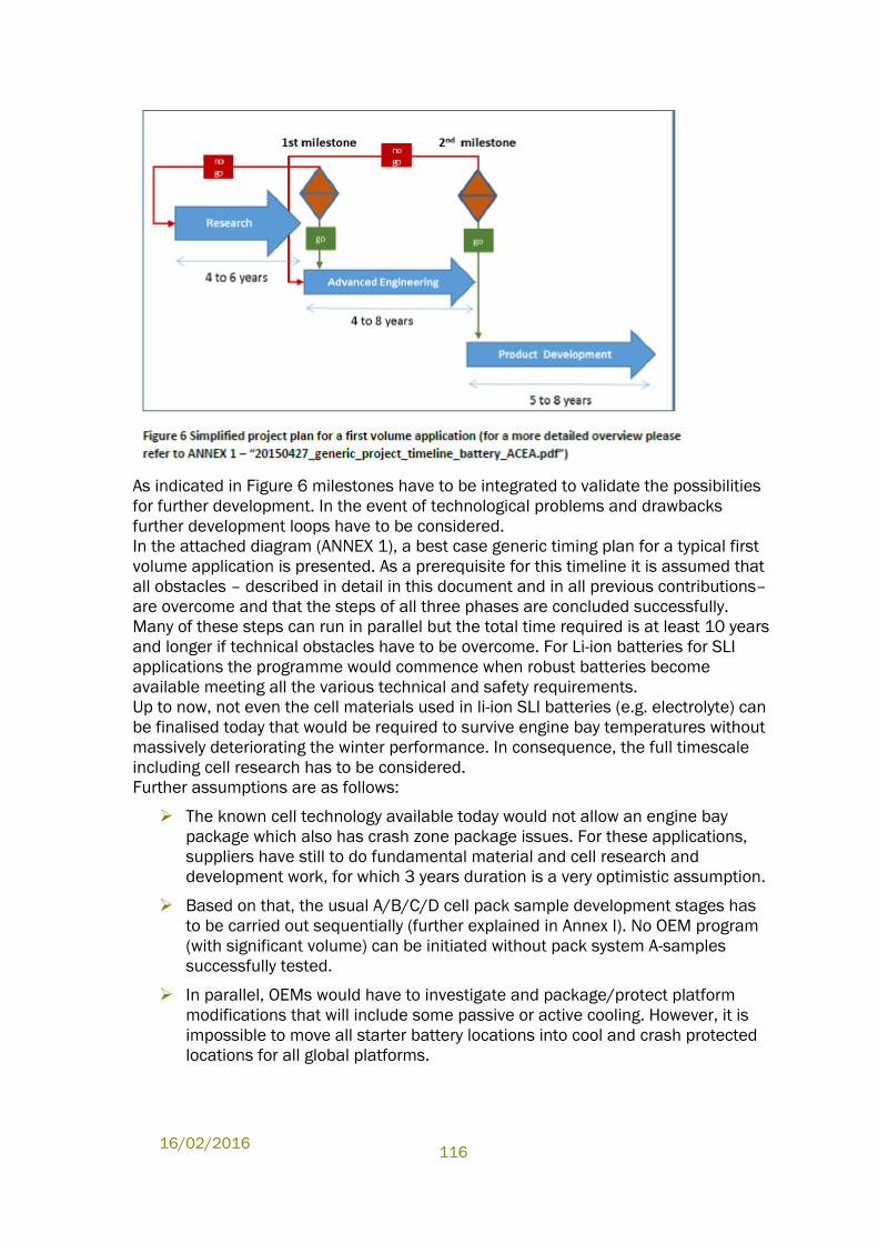
16/02/2016
116
As indicated in Figure 6 milestones have to be integrated to validate the possibilities
for further development. In the event of technological problems and drawbacks
further development loops have to be considered.
In the attached diagram (ANNEX 1), a best case generic timing plan for a typical first
volume application is presented. As a prerequisite for this timeline it is assumed that
all obstacles – described in detail in this document and in all previous contributions–
are overcome and that the steps of all three phases are concluded successfully.
Many of these steps can run in parallel but the total time required is at least 10 years
and longer if technical obstacles have to be overcome. For Li-ion batteries for SLI
applications the programme would commence when robust batteries become
available meeting all the various technical and safety requirements.
Up to now, not even the cell materials used in li-ion SLI batteries (e.g. electrolyte) can
be finalised today that would be required to survive engine bay temperatures without
massively deteriorating the winter performance. In consequence, the full timescale
including cell research has to be considered.
Further assumptions are as follows:
The known cell technology available today would not allow an engine bay
package which also has crash zone package issues. For these applications,
suppliers have still to do fundamental material and cell research and
development work, for which 3 years duration is a very optimistic assumption.
Based on that, the usual A/B/C/D cell pack sample development stages has
to be carried out sequentially (further explained in Annex I). No OEM program
(with significant volume) can be initiated without pack system A-samples
successfully tested.
In parallel, OEMs would have to investigate and package/protect platform
modifications that will include some passive or active cooling. However, it is
impossible to move all starter battery locations into cool and crash protected
locations for all global platforms.
Evaluation of ELV Exemptions
117
Given the high technological risk, fast adaptation for mainstream volumes
would require standardisation of requirements, avoiding the need for multiple
OEM specific parallel tests and reducing the engineering risk. 4 years is an
optimistic timing assumption for this process that will include life tests
validation in several iterations. The recent development of EN 50342-6 for 12
V lead/acid micro hybrid-batteries took 4 years from kick-off to decision about
the draft for voting (the voting and administrative process steps are still
pending and causing another 8-12 months delay before the standard is in
force). Notwithstanding this, mass production was already launched several
years before and field data is available. Collaborative working relationships
between OEMs and the battery supply base have been established for
decades. Still, no harmonization with other regions (e.g. North America, Japan
and China) was possible within this time frame. In addition, it has taken 6
years from May 2008 (kick-off meeting for ISO 12405-1) to May 2014 (ISO
12405-3 published) to create ISO 12405 (“Electric road vehicles – test
specification for Li-ion traction battery systems”).
As OEMs and the supply base is already active in research, and to some extent
advanced engineering, for the 12V SLI battery application, there are some
applications for which Li-ion could enter the advanced engineering stage earlier.
These applications would, as absolute minimum requirements, have to
accept some degradation on winter performance (both cranking and
recharging: e.g. luxury cars that are unlikely parked outdoor under harsh
winter conditions and have a fuel fired heater that can warm up the battery),
provide a package location that avoids temperatures above 60°C,
provide a package location outside crash zones,
not require any significant platform/architecture modifications.
If the available cells are compatible with package and technical requirements of a
given vehicle, the research phase can be significantly shortened. This may apply only
to a fraction of the vehicles that have the battery at least not packaged in the engine
bay. Nevertheless, as outlined in the other parts of this document, roll-out to
mainstream applications even if they fulfil the above conditions is far from
straightforward. Moreover, in many battery locations outside the engine bay, the 55 to
60°C temperature limits would still be exceeded, e.g. in the vicinity of the exhaust tail
pipe. It was not possible to quantify this fraction more precisely due to the
competitively sensitive nature of the information involved.


