Embed Size (px)
Citation preview
FPGA-based High Performance Page Layout Segmentation
Topic numbers: 8, 12
Dept. of Computer Science
Nalini K. Ratha, Anil K. Jain
Diane T. RoverDept. of Electrical Engineering
Michigan State University,East Lansing, MI - 48824
517-353-7735Fax. 517-353-1980Tel.
email: [email protected]
1
FPGA-based High Performance Page Layout SegmentationNalini K. Ratha, Anil K. Jain and Diane T. Rover�Department of Computer Science� Department of Electrical EngineeringMichigan State UniversityEast Lansing, MI [email protected], [email protected], [email protected] page layout segmentation algorithm for locating text, background and halftone areasis presented. The algorithm has been implemented on Splash 2 { an FPGA based arrayprocessor. The synthesis speed as determined by the Xilinx synthesis tools projects theapplications speed of 5 MHz. For documents of size 1,024 � 1,024 pixels, a signi�cantspeedup in the range of 250 has been achieved.1 IntroductionImage segmentation is an important step in a computer vision system. The process of spatialpartitioning of an image into mutually exclusive, connected and \homogeneous" image regionsis known as image segmentation [3, 9]. Each region is expected to be homogeneous with respectto a de�ned image property such as gray level, color and texture. Typically, image segmentationis carried out in early stages of a vision system to facilitate proper handling of di�erent regions.An image segmentation problem is similar to the problem of multidimensional pattern clusteringin the sense that we need to de�ne the similarity criterion between pixels or pattern vectorsand the number of segments or clusters [6]. Algorithms for image segmentation are based onthe following approaches: (i) thresholding or clustering, (ii) boundary detection, and (iii) regiongrowing. The similarity between pixels is based on attributes like gray level, color, texture andoptical ow.In this paper, we describe the design and implementation of a high performance system forimage segmentation. In particular, we demonstrate the design of a FPGA-based architecture forpage layout segmentation based on \local" properties of the image such as mean and variance.In an automated document image understanding system, page layout segmentation plays animportant role for segmenting text, graphics and background areas. Segmentation allows us toapply character recognition algorithms to only the regions of text, and to apply graphics and1

symbol recognition algorithms in the graphics areas. A number of algorithms have been reportedfor page layout segmentation [10]. Haralick et al. [2] use image morphology-based techniques.Jain and Bhattacharya [4] have used a multi-channel �ltering approach based on Gabor �lters.Jain and Chen [5] have used color information along with Gabor �lter outputs for page layoutanalysis applicable to locating address labels. Recently, Jain and Karu [7] have proposed analgorithm to learn texture discriminating masks needed for segmentation. The performance ofthis approach for page layout segmentation has been demonstrated by Jain and Zhong [8]. Asimpler method for page layout segmention is based on computation of mean and variance ina limited spatial domain (7 � 7) around each pixel. We have implemented this algorithm (seesection 3) on Splash 2 to demonstrate the advantages of this architecture.The architecture of a general-purpose compute element is designed so that it provides a rea-sonable performance over a wide variety of applications. Even the newer processors having thelatest architectural features such as superscalar, superpipelined units are not capable of providingsupport for the high computing demands of specialized applications. Many compute-intensiveapplication areas, including image processing, face the challenge of optimizing the performanceof algorithms on general-purpose architectures. A number of parallel processing approaches havebeen used for image processing applications. Application Speci�c Integrated Circuits (ASICs)have been designed for situations where parallel processing techniques are not able to provide thedesired performance cost-e�ectively. However, the ASIC-based approach su�ers from the follow-ing limitations: (i) once an ASIC is fabricated, it is di�cult to make changes in the design; (ii)the design cycle is fairly long; and (iii) ASIC solution is very costly if a large number of units arenot produced to amortize the �xed cost of the masks needed for fabrication. These limitations ofASICs can be overcome by adopting the Field-Programmable Gate Array (FPGA)-based customcomputing approach. Designers can implement their algorithms on FPGAs easily without usingany special fabrication facility. The main architectural advantage of this approach in contrastto general-purpose processing is that the designer is not constrained by a general-purpose in-struction set. The special instructions suitable for the given application can be implemented toenhance the overall performance of the system. Using the recon�gurable property of the FPGAs,several applications can be developed, or existing designs can be modi�ed. The design time isreduced substantially, and the system cost is signi�cantly less because o�-the-shelf componentscan be used.The paper is organized as follows. Section 2 contains a brief description of Splash 2, the FPGA-based attached array processor used for prototyping the algorithm. The sequential algorithm andits computational complexity is outlined in Section 3. The mapping of the algorithm onto Splash2 is presented in Section 4. The experimental results are described in Section 5. Conclusionsand future work are outlined in Section 6.2 Splash 2The Splash 2 system consists of an array of Xilinx 4010 FPGAs. Figure 1(a) shows a system-levelview of the Splash 2 architecture. The Splash 2 is connected to the host through an interfaceboard that extends the address and data buses. The Sun host can read/write to memories andmemory-mapped control registers of Splash 2 via these buses. A detailed description of the2
X0
X1 X2 X3
X16 X15 X14
X4 X5 X6 X7 X8
X9X10X11X12X13
Crossbar
X0
X1 X2 X3
X16 X15 X14
X4 X5 X6 X7 X8
X9X10X11X12X13
Crossbar
X0
X1 X2 X3
X16 X15 X14
X4 X5 X6 X7 X8
X9X10X11X12X13
Crossbar
XL
XR
SIMD
RBus
SBusExtension
InputDMA
OutputDMA
Bus
Interface Board
Splash Boards
SparcStationHost
Processing
36 36
18 16
DataAddress
32
32
Processor
To Right
36
To Crossbar
RD
WR WR
RD
SBus
SBus
Inhibit
To Left
Element (PE)
MemorySBus Read
SBus Write
Data
Neighbor Neighbor
Address
Xilinx 4010
256K 16-bit
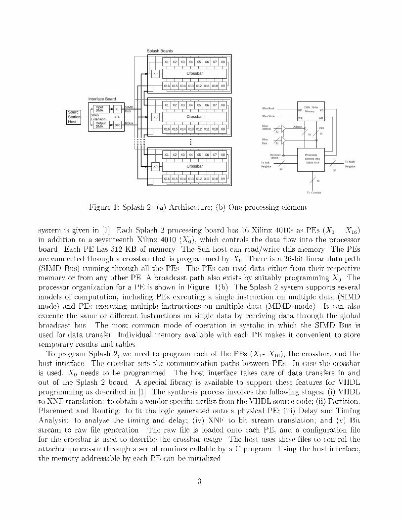
Figure 1: Splash 2: (a) Architecture; (b) One processing element.system is given in [1]. Each Splash 2 processing board has 16 Xilinx 4010s as PEs (X1 � X16)in addition to a seventeenth Xilinx 4010 (X0), which controls the data ow into the processorboard. Each PE has 512 KB of memory. The Sun host can read/write this memory. The PEsare connected through a crossbar that is programmed by X0. There is a 36-bit linear data path(SIMD Bus) running through all the PEs. The PEs can read data either from their respectivememory or from any other PE. A broadcast path also exists by suitably programming X0. Theprocessor organization for a PE is shown in Figure 1(b). The Splash 2 system supports severalmodels of computation, including PEs executing a single instruction on multiple data (SIMDmode) and PEs executing multiple instructions on multiple data (MIMD mode). It can alsoexecute the same or di�erent instructions on single data by receiving data through the globalbroadcast bus. The most common mode of operation is systolic in which the SIMD Bus isused for data transfer. Individual memory available with each PE makes it convenient to storetemporary results and tables.To program Splash 2, we need to program each of the PEs (X1- X16), the crossbar, and thehost interface. The crossbar sets the communication paths between PEs. In case the crossbaris used, X0 needs to be programmed. The host interface takes care of data transfers in andout of the Splash 2 board. A special library is available to support these features for VHDLprogramming as described in [1]. The synthesis process involves the following stages: (i) VHDLto XNF translation: to obtain a vendor speci�c netlist from the VHDL source code; (ii) Partition,Placement and Routing: to �t the logic generated onto a physical PE; (iii) Delay and TimingAnalysis: to analyze the timing and delay; (iv) XNF to bit stream translation; and (v) Bitstream to raw �le generation. The raw �le is loaded onto each PE, and a con�guration �lefor the crossbar is used to describe the crossbar usage. The host uses these �les to control theattached processor through a set of routines callable by a C program. Using the host interface,the memory addressable by each PE can be initialized.3
Input Image
Classify pixel as
foreground
belonging to belonging to
background
Classify pixel as
Classify pixel as Classify pixel as belonging totext regionhalf-tone region
belonging to
Segmented Page Image
No
No Yes
Yes
Calculate the mean and variance of
the gray values at each pixel
Foreground pixelis mean < 120?
For each
For each pixelis variance < 250?
in a 7 X 7 window
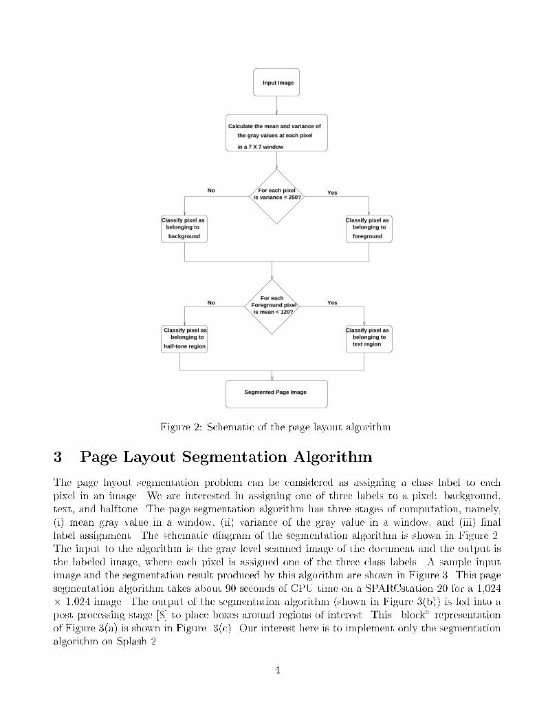
Figure 2: Schematic of the page layout algorithm.3 Page Layout Segmentation AlgorithmThe page layout segmentation problem can be considered as assigning a class label to eachpixel in an image. We are interested in assigning one of three labels to a pixel: background,text, and halftone. The page segmentation algorithm has three stages of computation, namely,(i) mean gray value in a window, (ii) variance of the gray value in a window, and (iii) �nallabel assignment. The schematic diagram of the segmentation algorithm is shown in Figure 2.The input to the algorithm is the gray level scanned image of the document and the output isthe labeled image, where each pixel is assigned one of the three class labels. A sample inputimage and the segmentation result produced by this algorithm are shown in Figure 3. This pagesegmentation algorithm takes about 90 seconds of CPU time on a SPARCstation 20 for a 1,024� 1,024 image. The output of the segmentation algorithm (shown in Figure 3(b)) is fed into apost processing stage [8] to place boxes around regions of interest. This \block" representationof Figure 3(a) is shown in Figure 3(c). Our interest here is to implement only the segmentationalgorithm on Splash 2. 4
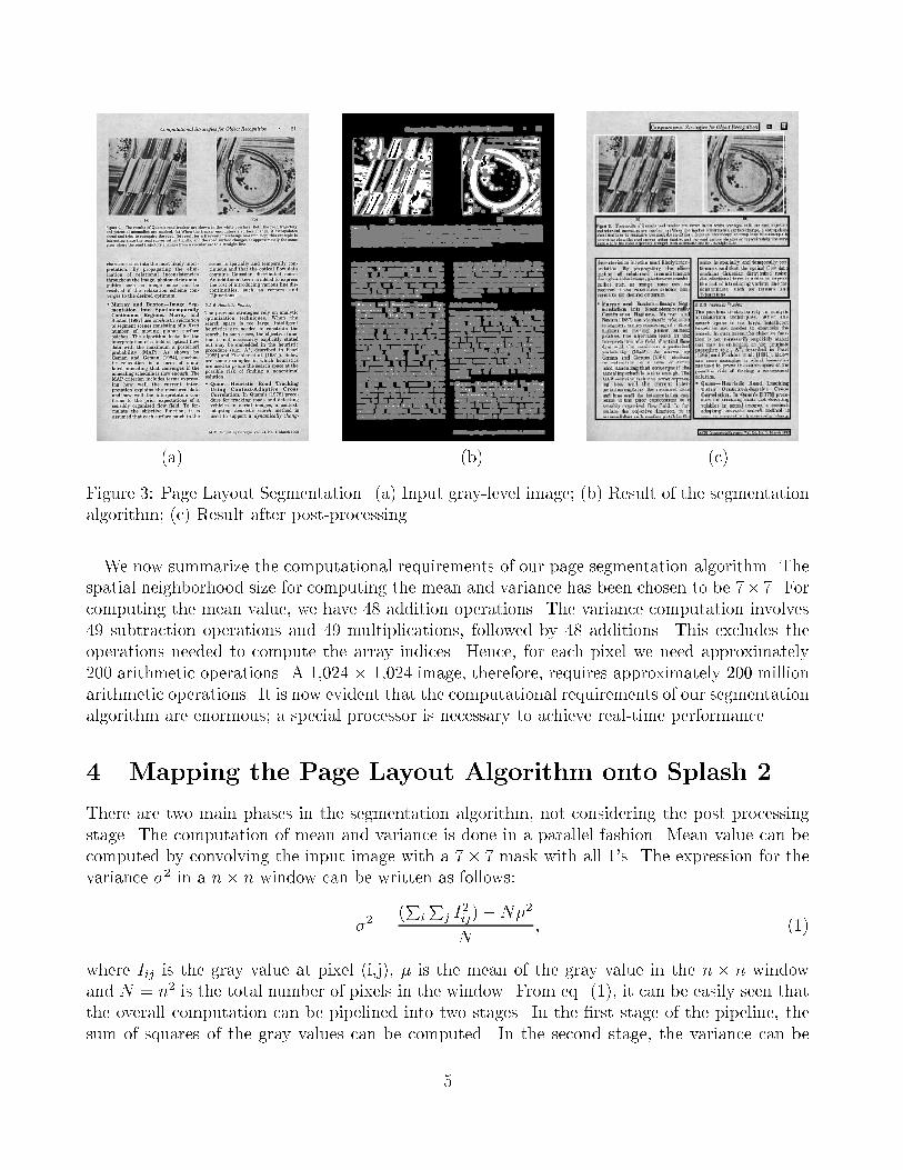
(a) (b) (c)Figure 3: Page Layout Segmentation. (a) Input gray-level image; (b) Result of the segmentationalgorithm; (c) Result after post-processing.We now summarize the computational requirements of our page segmentation algorithm. Thespatial neighborhood size for computing the mean and variance has been chosen to be 7� 7. Forcomputing the mean value, we have 48 addition operations. The variance computation involves49 subtraction operations and 49 multiplications, followed by 48 additions. This excludes theoperations needed to compute the array indices. Hence, for each pixel we need approximately200 arithmetic operations. A 1,024 � 1,024 image, therefore, requires approximately 200 millionarithmetic operations. It is now evident that the computational requirements of our segmentationalgorithm are enormous; a special processor is necessary to achieve real-time performance.4 Mapping the Page Layout Algorithm onto Splash 2There are two main phases in the segmentation algorithm, not considering the post processingstage. The computation of mean and variance is done in a parallel fashion. Mean value can becomputed by convolving the input image with a 7� 7 mask with all 1's. The expression for thevariance �2 in a n� n window can be written as follows:�2 = (PiPj I2ij)�N�2N ; (1)where Iij is the gray value at pixel (i,j), � is the mean of the gray value in the n � n windowand N = n2 is the total number of pixels in the window. From eq. (1), it can be easily seen thatthe overall computation can be pipelined into two stages. In the �rst stage of the pipeline, thesum of squares of the gray values can be computed. In the second stage, the variance can be5
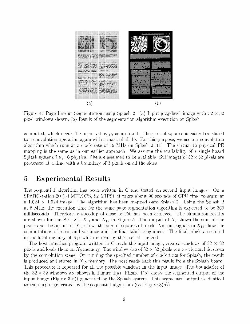
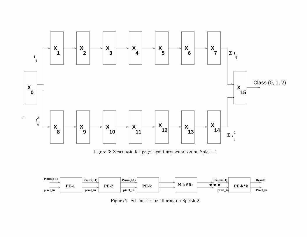
(a) (b)Figure 4: Page Layout Segmentation using Splash 2. (a) Input gray-level image with 32 � 32pixel windows shown; (b) Result of the segmentation algorithm execution on Splash.computed, which needs the mean value, �, as an input. The sum of squares is easily translatedto a convolution operation again with a mask of all 1's. For this purpose, we use our convolutionalgorithm which runs at a clock rate of 19 MHz on Splash 2 [11]. The virtual to physical PEmapping is the same as in our earlier approach. We assume the availability of a single-boardSplash system, i.e., 16 physical PEs are assumed to be available. Subimages of 32� 32 pixels areprocessed at a time with a boundary of 3 pixels on all the sides.5 Experimental ResultsThe sequential algorithm has been written in C and tested on several input images. On aSPARCstation 20 (33 MFLOPS, 82 MIPS), it takes about 90 seconds of CPU time to segmenta 1,024 � 1,024 image. The algorithm has been mapped onto Splash 2. Using the Splash 2at 5 MHz, the execution time for the same page segmentation algorithm is expected to be 360milliseconds. Therefore, a speedup of close to 250 has been achieved. The simulation resultsare shown for the PEs X7, X14 and X15 in Figure 5. The output of X7 shows the sum of thepixels and the output of X14 shows the sum of squares of pixels. Various signals in X15 show thecomputations of mean and variance and the �nal label assignment. The �nal labels are storedin the local memory of X15 which is read by the host at the end.The host interface program written in C reads the input image, creates windows of 32 � 32pixels and loads them on X0 memory. The window size of 32 � 32 pixels is a restriction laid downby the convolution stage. On running the speci�ed number of clock ticks for Splash, the resultis produced and stored in X15 memory. The host reads back this result from the Splash board.This procedure is repeated for all the possible windows in the input image. The boundaries ofthe 32� 32 windows are shown in Figure 4(a). Figure 4(b) shows the segmented output of theinput image (Figure 3(a)) generated by the Splash system. This segmented output is identicalto the output generated by the sequential algorithm (see Figure 3(b)).6
6 Conclusions and future workOur analysis of the computational demand of page layout segmentation shows a large disparitybetween the computational requirements and the available computational power at an a�ordablecost. This gap is bridged by using novel custom computing machines. We have described a systembased on FPGAs for meeting the computational load of a page layout segmentation algorithmusing Splash 2. Our implementation leads us to the conclusion that custom computing machineswill play a vital role in designing compute-intensive applications. Splash 2 system can containmultiple processing boards. We will utilize this feature to attain greater speedups. This will becarried out in the next phase of the project.In the current implementation, we have observed that the overall clock speed of 5 MHz onSplash 2 is limited because of the slow integer multipliers in the Synopsys library. We will explorereplacing these with faster multipliers that will improve the overall application speed by a factorof two. We are in the process of evaluating di�erent hardware integer multipliers.References[1] Duncan A. Buell, Je�rey M. Arnold, and Walter J. Kleinfelder, editors. Splash 2: FPGAsfor Custom Computing Machines. IEEE Computer Society Press, Los Alamitos, 1995.[2] Robert M. Haralick. Document image undestanding: Geometric and Logical layout. InProc. of IEEE Computer Vision and Pattern Recognition, Seattle, 1994, pages 385{390.[3] Robert M. Haralick and Linda G. Shapiro. Image segmentation techniques. ComputerVision, Graphics, and Image Processing, 29(1):100{132, January 1985.[4] Anil K. Jain and Sushil Bhattacharjee. Text segmentation using Gabor �lters for automaticdocument processing. Machine Vision and Applications, 5:169{184, 1992.[5] Anil K. Jain and Yao Chen. Address block location using color and texture analysis. CVGIP:Image Understanding, 60(2):179{190, September 1994.[6] Anil K. Jain and Richard C. Dubes. Algorithms for Clustering Data. Prentice-Hall, Engle-wood Cli�s, New Jersy, 1988.[7] Anil K. Jain and Kalle Karu. Learning texture discrimination masks. IEEE Trans. onPattern Analysis and Machine Intelligence, 1995. To appear.[8] Anil K. Jain and Yu Zhong. Page layout segementaion based on texture analysis. InProc. 2nd International Conf. on Image Processing, Washington D. C., 1995. Accepted forPublication.[9] Nikhil R. Pal and Sankar K. Pal. A review on image segmentation techniques. PatternRecognition, 26(9):1277{1294, September 1993.7
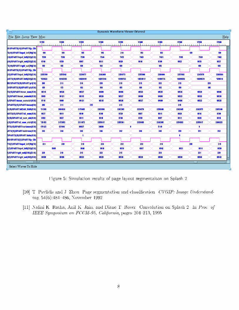
Figure 5: Simulation results of page layout segmentaiton on Splash 2.[10] T. Pavlidis and J. Zhou. Page segmentation and classi�cation. CVGIP: Image Understand-ing, 54(6):484{486, November 1992.[11] Nalini K. Ratha, Anil K. Jain, and Diane T. Rover. Convolution on Splash 2. In Proc. ofIEEE Symposium on FCCM-95, California, pages 204{213, 1995.
8
X
X1
X X X X X X
0
2 3 4 5 6 7
X8
X X X X X
X
9 10 11X
12 13 14
15
Σ
Σ
Class (0, 1, 2)
ij
2
ij
2
ij
ijI
I
I
I
Figure 6: Schematic for page layout segmentaiton on Splash 2.
PE-1 PE-2pixel_in
Psum(t-1) Psum(t-1)
pixel_in pixel_in
Psum(t-1)
PE-k N-k SRsPixel_inpixel_in
Psum(t-1) Result
PE-k*kFigure 7: Schematic for �ltering on Splash 2.
9


