Embed Size (px)
Citation preview

Black DIC32300X42-V42-D100_FJ500
42V42D1000X42-V42-D100
oHonda Motor Co., Ltd. 2013
TILLER
OWNER'S MANUAL
FJ500
00X42-V42-D100_FJ500_Cover.indd 100X42-V42-D100_FJ500_Cover.indd 1 2013/09/17 17:25:502013/09/17 17:25:50
Keep this owner’s manual handy so you can refer to it at any time. Thisowner’s manual is considered a permanent part of the tiller andshould remain with the tiller if resold.
The information and specifications included in this publication were ineffect at the time of approval for printing. Honda Motor Co., Ltd.reserves the right, however, to discontinue or change specifications ordesign at any time without notice and without incurring any obligationwhatever.
1
INTRODUCTION
Congratulations on your selection of a Honda tiller. We are certain youwill be pleased with your purchase of one of the finest tillers on themarket.
We want to help you get the best results from your new tiller and tooperate it safely. This manual contains the information on how to dothat; please read it carefully.
As you read this manual, you will find information preceded by asymbol. That information is intended to help you avoid
damage to your tiller, other property, or the environment.
We suggest you read the warranty policy to fully understand itscoverage and your responsibilities of ownership. The warranty policyis a separate document that should have been given to you by yourdealer.
When your tiller needs scheduled maintenance, keep in mind that yourHonda servicing dealer is specially trained in servicing Honda tillers.Your Honda servicing dealer is dedicated to your satisfaction and willbe pleased to answer your questions and concerns.
Best Wishes,Honda Motor Co., Ltd.
2
INTRODUCTION
A FEW WORDS ABOUT SAFETY
Safety Labels
Safety Messages
Safety Headings
Safety Section
Instructions
Your safety and the safety of others are very important. And using thistiller safely is an important responsibility.
To help you make informed decisions about safety, we have providedoperating procedures and other information on labels and in thismanual. This information alerts you to potential hazards that couldhurt you or others.
Of course, it is not practical or possible to warn you about all thehazards associated with operating or maintaining a tiller. You mustuse your own good judgment.
You will find important safety information in a variety of forms,including:
–– on the tiller.
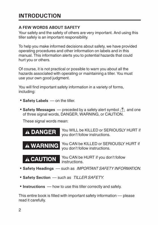
–– preceded by a safety alert symbol and oneof three signal words, DANGER, WARNING, or CAUTION.
These signal words mean:
You WILL be KILLED or SERIOUSLY HURT ifyou don’t follow instructions.
You CAN be KILLED or SERIOUSLY HURT ifyou don’t follow instructions.
You CAN be HURT if you don’t followinstructions.
–– such as IMPORTANT SAFETY INFORMATION.
–– such as TILLER SAFETY.
–– how to use this tiller correctly and safely.
This entire book is filled with important safety information –– pleaseread it carefully.
3
CONTENTSTILLER SAFETY
CONTROLS
BEFORE OPERATION
SERVICING YOUR TILLER
IMPORTANT SAFETY INFORMATIONSAFETY LABEL LOCATIONS
COMPONENT & CONTROL LOCATIONSCONTROLS
Fuel ValveChoke LeverEngine SwitchStarter GripThrottle LeverHandlebar Height AdjusterMain Clutch LeverGearshift LeverDrag BarHitch Box
ARE YOU READY TO GET STARTED?IS YOUR TILLER READY TO GO?
Check the EngineCheck the Tiller
STARTING THE ENGINEOPERATING THE CONTROLS FOR TILLINGHANDLING TIPSSTOPPING THE ENGINE
THE IMPORTANCE OF MAINTENANCEMAINTENANCE SAFETYMAINTENANCE SCHEDULEREFUELINGFUEL RECOMMENDATIONSENGINE OIL LEVEL CHECKENGINE OIL CHANGEENGINE OIL RECOMMENDATIONSTRANSMISSION OIL LEVEL CHECKAIR FILTER INSPECTIONAIR FILTER CLEANING
55
10
1111
13131313141414151515161717171818
20233940
414142
......................................................................................................................
......................................................
........................................................................................................................
.................................................................................................................................................................
.......................................................................................................................................................
.........................................................................................................................................................
...........................................................................................................................
.............................................................................................................................................................................................................................................
.............................................................................................................
........................................................................................................................................................................................
........................................................................
OPERATION 20....................................................................................Safe operating precautions 19......................................................
............................................................
........................................................................
.....................................................................................................
............................................................
............................................................
............................................................
............................................................434445464748495050
............................................................
............................................................
............................................................
............................................................
............................................................
............................................................
............................................................
............................................................
............................................................
4
CONTENTS
SERVICING YOUR TILLER (continued)SPARK PLUG SERVICETHROTTLE CABLE ADJUSTMENTSEDIMENT CUP CLEANING
OUTER ROTARY TINETINE INSTALLATION
INNER ROTARY TINETINES AND FASTENERS CHECKTIRE PRESSURE CHECK
525455
5756
585960
...........................................................................................................
.......................................................
..................................................................................................................................
.........................................................
STORAGE
TRANSPORTING
TAKING CARE OF UNEXPECTED PROBLEMS
TECHNICAL & CONSUMER INFORMATION
QUICK REFERENCE INFORMATION
RECOIL STARTER COVER CHECK AND CLEANINGHANDLE BAR HEIGHT ADJUSTER TIGHTNESS CHECK
STORAGE PREPARATIONCleaningFuelDraining fuel tank and carburetorEngine Oil
STORAGE PRECAUTIONSREMOVAL FROM STORAGE
ENGINE PROBLEMSEngine Will Not StartEngine Lacks Power
TILLING PROBLEMSPoor Tilling Quality
TECHNICAL INFORMATIONSerial Number LocationsCarburetor Modification for High Altitude OperationEmission Control System InformationSpecifications
CONSUMER INFORMATIONCustomer Service Information
6363636466686969
70
717171727373
7474747576787979
Inside back cover
6162
..................................................................................................................................................
.............................................................................................................................................................................
.............................................................................................................................
...............................................................................................................
.............................................................................
.................................................................................................
.................................................................................................................................
...................................................................
...................................................................
.........................................................................................
............................................................................
..................................................................................................................
........................................................................................................
.......................
.........................
...............................................................................................................
5
TILLER SAFETY
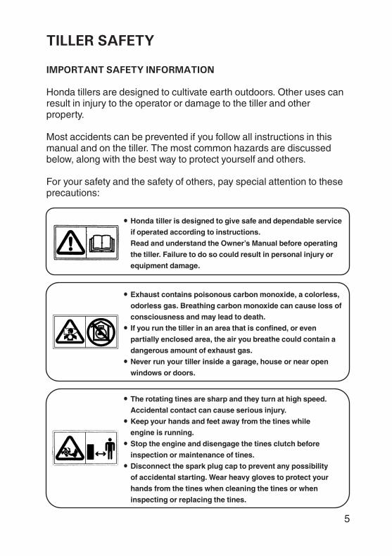
IMPORTANT SAFETY INFORMATION
Honda tiller is designed to give safe and dependable service
if operated according to instructions.
Read and understand the Owner’s Manual before operating
the tiller. Failure to do so could result in personal injury or
equipment damage.
Exhaust contains poisonous carbon monoxide, a colorless,
odorless gas. Breathing carbon monoxide can cause loss of
consciousness and may lead to death.
If you run the tiller in an area that is confined, or even
partially enclosed area, the air you breathe could contain a
dangerous amount of exhaust gas.
Never run your tiller inside a garage, house or near open
windows or doors.
The rotating tines are sharp and they turn at high speed.
Accidental contact can cause serious injury.
Keep your hands and feet away from the tines while
engine is running.
Stop the engine and disengage the tines clutch before
inspection or maintenance of tines.
Disconnect the spark plug cap to prevent any possibility
of accidental starting. Wear heavy gloves to protect your
hands from the tines when cleaning the tines or when
inspecting or replacing the tines.
For your safety and the safety of others, pay special attention to theseprecautions:
Honda tillers are designed to cultivate earth outdoors. Other uses canresult in injury to the operator or damage to the tiller and otherproperty.
Most accidents can be prevented if you follow all instructions in thismanual and on the tiller. The most common hazards are discussedbelow, along with the best way to protect yourself and others.
6
TILLER SAFETY
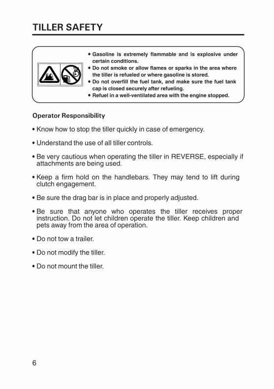
Gasoline is extremely flammable and is explosive undercertain conditions.Do not smoke or allow flames or sparks in the area wherethe tiller is refueled or where gasoline is stored.Do not overfill the fuel tank, and make sure the fuel tankcap is closed securely after refueling.Refuel in a well-ventilated area with the engine stopped.
Operator Responsibility
Know how to stop the tiller quickly in case of emergency.
Understand the use of all tiller controls.
Be very cautious when operating the tiller in REVERSE, especially ifattachments are being used.
Keep a firm hold on the handlebars. They may tend to lift duringclutch engagement.
Be sure the drag bar is in place and properly adjusted.
Be sure that anyone who operates the tiller receives properinstruction. Do not let children operate the tiller. Keep children andpets away from the area of operation.
Do not tow a trailer.
Do not mount the tiller.
Do not modify the tiller.
-
TILLER SAFETY
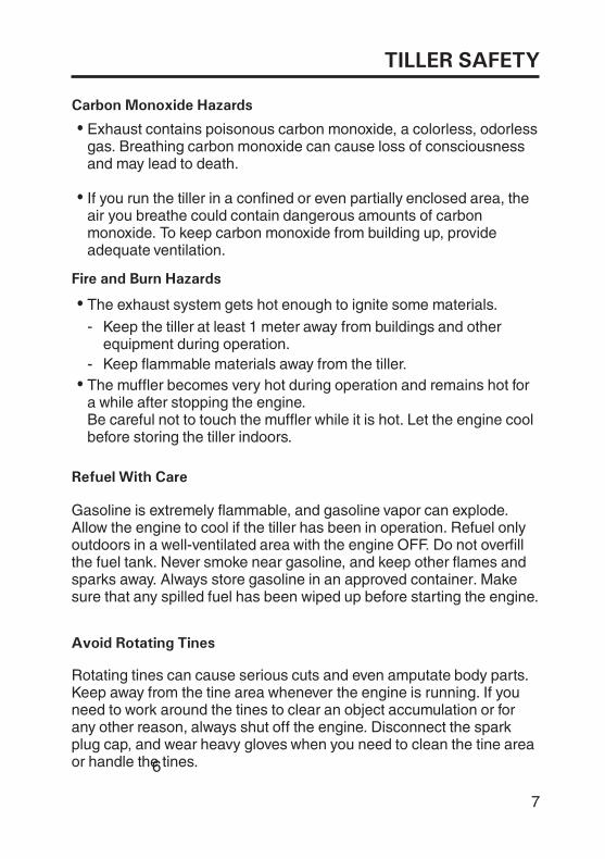
Fire and Burn Hazards
Carbon Monoxide Hazards
Refuel With Care
Avoid Rotating Tines
Exhaust contains poisonous carbon monoxide, a colorless, odorlessgas. Breathing carbon monoxide can cause loss of consciousnessand may lead to death.
If you run the tiller in a confined or even partially enclosed area, theair you breathe could contain dangerous amounts of carbonmonoxide. To keep carbon monoxide from building up, provideadequate ventilation.
The exhaust system gets hot enough to ignite some materials.
Keep flammable materials away from the tiller.
Keep the tiller at least 1 meter away from buildings and otherequipment during operation.
The muffler becomes very hot during operation and remains hot fora while after stopping the engine.Be careful not to touch the muffler while it is hot. Let the engine coolbefore storing the tiller indoors.
Gasoline is extremely flammable, and gasoline vapor can explode.Allow the engine to cool if the tiller has been in operation. Refuel onlyoutdoors in a well-ventilated area with the engine OFF. Do not overfillthe fuel tank. Never smoke near gasoline, and keep other flames andsparks away. Always store gasoline in an approved container. Makesure that any spilled fuel has been wiped up before starting the engine.
Rotating tines can cause serious cuts and even amputate body parts.Keep away from the tine area whenever the engine is running. If youneed to work around the tines to clear an object accumulation or forany other reason, always shut off the engine. Disconnect the sparkplug cap, and wear heavy gloves when you need to clean the tine areaor handle the tines.
-
6
7
8
TILLER SAFETY
Clear Tilling Area
Keep Shields in Place
Wear Protective Clothing
Turn Engine Off When Not Operating the Tiller
A tine can throw rocks and other objects with enough force to causeserious injury. Before tilling, carefully inspect the area and remove allstones, sticks, bones, nails, pieces of wire, and other loose objects.Be aware; if children are in the shop area, stop the tiller. Do notoperate the tine on gravel, cement, slab or stony mountain.
Guards and shields are designed to protect you from being hit bythrown objects and to keep you from touching hot engine parts andmoving components. For your safety and the safety of others, keep allshields in place when the engine is running.
Wearing protective clothing will reduce your risk of injury. Long pantsand eye protection reduces the risk of injuries from thrown objects.Sturdy shoes with aggressive soles provide better traction.
If you need to leave the operating point for any reason, even just toinspect the area ahead, always turn the engine off.
9
TILLER SAFETY
Slope Operation
Tilling Conditions
Tools and Attachments
When tilling on slopes, keep the fuel tank less than half full tominimize fuel spillage.
Till across the slope (at equally spaced intervals) rather than up anddown it.
Be very careful when changing the direction of the tiller on a slope.
Do not use the tiller on a slope of more than 10°. Before starting theengine, check that the tiller is not damaged and is in good condition.For your safety and the safety of others, exercise extreme care whenusing the tiller on a slope.
Operate the tiller only in daylight or good artificial light. Do not operatethe tiller at night or under poor light conditions.
To install a tool or attachment on the tiller, follow the instructionsfurnished with the tool or attachment. Ask your Honda dealer foradvice if you encounter any problem or difficulty in installing a tool orattachment.
10
TILLER SAFETY
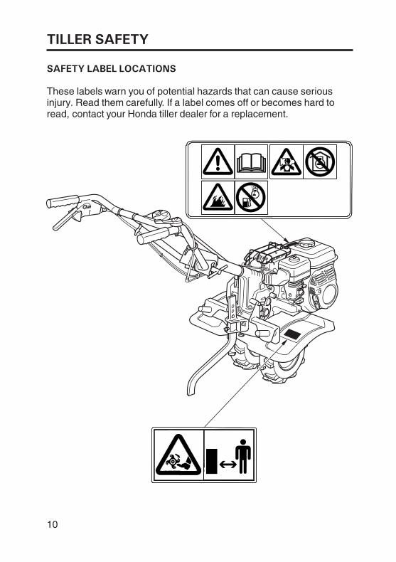
SAFETY LABEL LOCATIONS
These labels warn you of potential hazards that can cause seriousinjury. Read them carefully. If a label comes off or becomes hard toread, contact your Honda tiller dealer for a replacement.
11
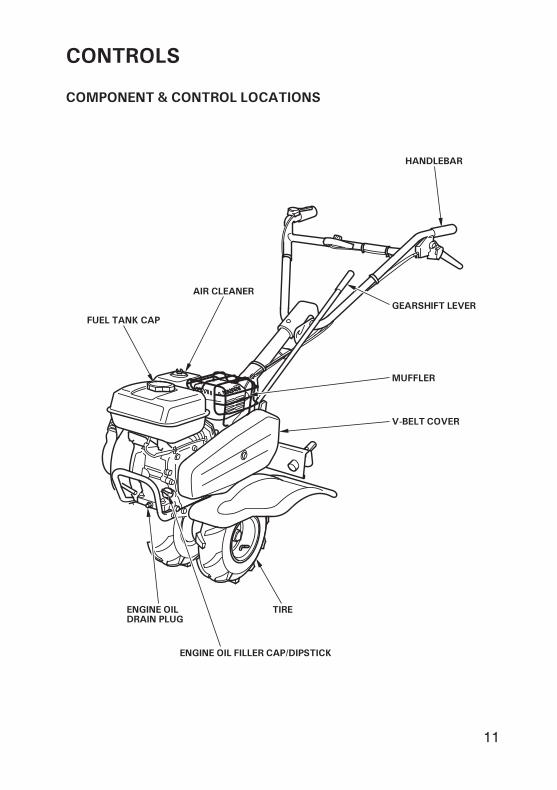
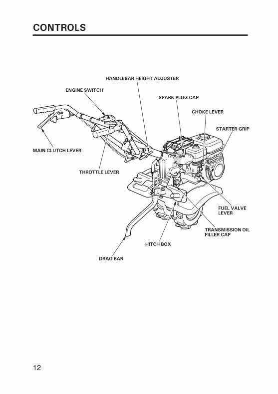
COMPONENT & CONTROL LOCATIONS
CONTROLS
TIRE
HANDLEBAR
AIR CLEANER
MUFFLER
V-BELT COVER
ENGINE OILDRAIN PLUG
ENGINE OIL FILLER CAP/DIPSTICK
GEARSHIFT LEVER
FUEL TANK CAP
12
CONTROLS
DRAG BAR
MAIN CLUTCH LEVER
THROTTLE LEVER
SPARK PLUG CAP
HITCH BOX
TRANSMISSION OILFILLER CAP
CHOKE LEVER
STARTER GRIP
FUEL VALVELEVER
HANDLEBAR HEIGHT ADJUSTER
ENGINE SWITCH
13
--
CONTROLS
CONTROLS
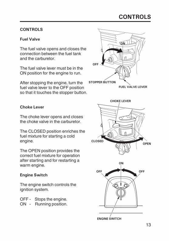
Fuel Valve
Engine Switch
Choke Lever
OFF
CLOSED
ON
OONN
CHOKE LEVER
OPEN
OFFOFF
ENGINE SWITCH
STOPPER BUTTON
FUEL VALVE LEVER
The fuel valve opens and closes theconnection between the fuel tankand the carburetor.
The fuel valve lever must be in theON position for the engine to run.
ON Running position.OFF Stops the engine.
The engine switch controls theignition system.
The choke lever opens and closesthe choke valve in the carburetor.
The CLOSED position enriches thefuel mixture for starting a coldengine.
The OPEN position provides thecorrect fuel mixture for operationafter starting and for restarting awarm engine.
After stopping the engine, turn thefuel valve lever to the OFF positionso that it touches the stopper button.
14
CONTROLS
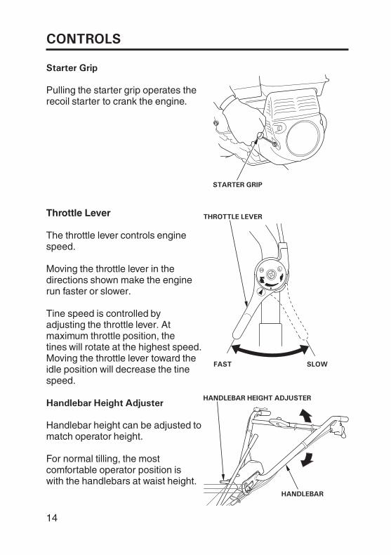
Throttle Lever
Handlebar Height Adjuster
Starter Grip
STARTER GRIP
FAST SLOW
HANDLEBAR HEIGHT ADJUSTER
HANDLEBAR
THROTTLE LEVER
The throttle lever controls enginespeed.
Moving the throttle lever in thedirections shown make the enginerun faster or slower.
Tine speed is controlled byadjusting the throttle lever. Atmaximum throttle position, thetines will rotate at the highest speed.Moving the throttle lever toward theidle position will decrease the tinespeed.
Handlebar height can be adjusted tomatch operator height.
For normal tilling, the mostcomfortable operator position iswith the handlebars at waist height.
Pulling the starter grip operates therecoil starter to crank the engine.
15
CONTROLS
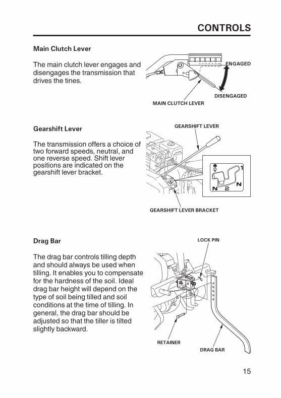
Main Clutch Lever
Gearshift Lever
Drag Bar
MAIN CLUTCH LEVER
EENNGGAAGGEEDD
DISENGAGED
GEARSHIFT LEVER
GEARSHIFT LEVER BRACKET
The main clutch lever engages anddisengages the transmission thatdrives the tines.
The transmission offers a choice oftwo forward speeds, neutral, andone reverse speed. Shift leverpositions are indicated on thegearshift lever bracket.
The drag bar controls tilling depthand should always be used whentilling. It enables you to compensatefor the hardness of the soil. Idealdrag bar height will depend on thetype of soil being tilled and soilconditions at the time of tilling. Ingeneral, the drag bar should beadjusted so that the tiller is tiltedslightly backward.
LOCK PIN
RETAINER
DRAG BAR
16
CONTROLS
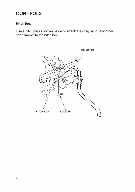
Hitch box
Use a hitch pin as shown below to attach the drag bar or any otherattachments to the hitch box.
HITCH BOX LOCK PIN
HITCH PIN
17
BEFORE OPERATION
ARE YOU READY TO GET STARTED?
Knowledge
IS YOUR TILLER READY TO GO?
Your safety is your responsibility. A little time spent in preparation willsignificantly reduce your risk of injury.
Read and understand this manual. Know what the controls do andhow to operate them.
Familiarize yourself with the tiller and its operation before you beginusing it. Know how to quickly shut off the tiller in case of anemergency.
For your safety, to ensure compliance with environmental regulations,and to maximize the service life of your equipment, it is very importantto take a few moments before you operate the tiller to check itscondition. Be sure to take care of any problem you find, or have yourservicing dealer correct it, before you operate the tiller.
Improperly maintaining this tiller, orfailing to correct a problem beforeoperation, could cause amalfunction in which you could beseriously injured.
Always perform a pre-operationinspection before each operation,and correct any problem.
18
BEFORE OPERATION
Check the Engine
Check the Tiller
Do not place flammable objects close to the engine.
Before beginning your pre-operation checks, be sure the tiller is on alevel surface and the engine switch is in the OFF position.
Check the oil level (see page 46).
Check the air filter (see page 50). A dirty air filter will restrict air flow tothe carburetor, reducing engine and tiller performance.
Check the fuel level (see page 44). Starting with a full tank will help toeliminate or reduce operating interruptions for refueling.
Check the transmission oil (see page 49).
Check that the all nuts, bolts, screws are tightened (see page 57,58).

19
BEFORE OPERATION
Carbon monoxide gas is toxic.Breathing it can causeunconsciousness and even kill you.
Avoid any enclosed areas oractivities that expose you to carbonmonoxide.
SAFE OPERATING PRECAUTIONS
Before operating the tiller for the first time, please review both theTILLER SAFETY chapter and the chapter titled BEFORE OPERATION.
For your safety, do not start or operate the tiller in an enclosed areasuch as a garage. Your tiller’s exhaust contains poisonous carbonmonoxide gas that can collect rapidly in an enclosed area and causeillness or death.
20
OPERATION
STARTING THE ENGINE
OONN
FUEL VALVE LEVER
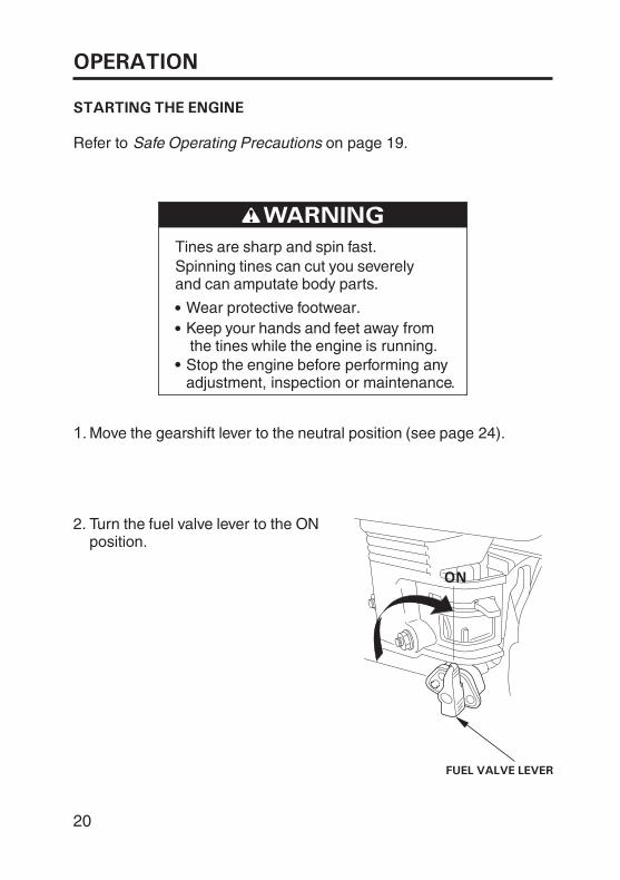
Refer to Safe Operating Precautions on page 19.
Tines are sharp and spin fast.Spinning tines can cut you severelyand can amputate body parts.
Wear protective footwear.Keep your hands and feet away fromthe tines while the engine is running.Stop the engine before performing anyadjustment, inspection or maintenance.
Move the gearshift lever to the neutral position (see page 24).
Turn the fuel valve lever to the ONposition.
1.
2.
21
OPERATION
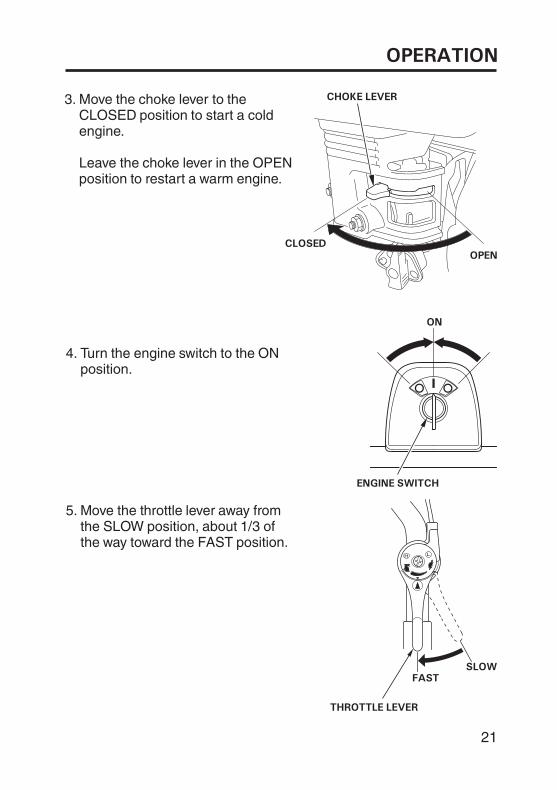
ON
ENGINE SWITCH
SLOWFAST
THROTTLE LEVER
Turn the engine switch to the ONposition.
Move the throttle lever away fromthe SLOW position, about 1/3 ofthe way toward the FAST position.
4.
5.
CHOKE LEVER
CLOSEDOPEN
Move the choke lever to theCLOSED position to start a coldengine.
Leave the choke lever in the OPENposition to restart a warm engine.
3.
22
OPERATION
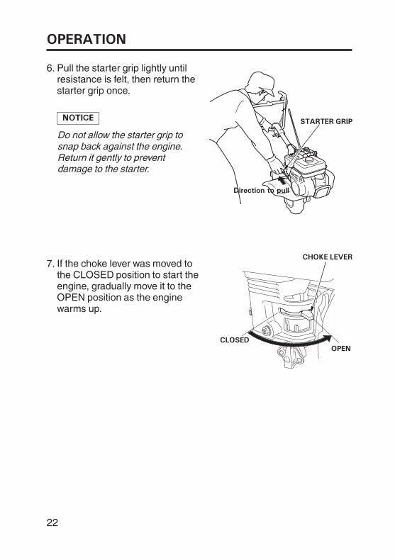
CHOKE LEVER
CLOSEDOPEN
Pull the starter grip lightly untilresistance is felt, then return thestarter grip once.
Do not allow the starter grip tosnap back against the engine.Return it gently to preventdamage to the starter.
6.
If the choke lever was moved tothe CLOSED position to start theengine, gradually move it to theOPEN position as the enginewarms up.
7.
STARTER GRIP
Dir ction to p llDirection to pull
23
OPERATION
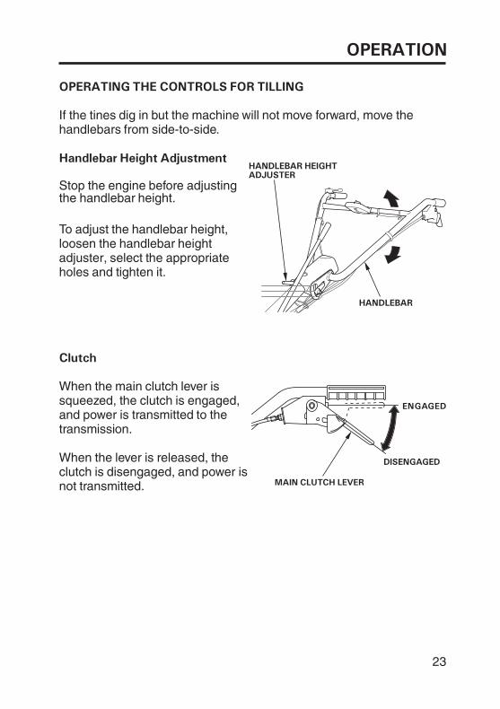
OPERATING THE CONTROLS FOR TILLING
Handlebar Height Adjustment
Clutch
DISENGAGED
MAIN CLUTCH LEVER
EENNGGAAGGEEDD
HANDLEBAR
HANDLEBAR HEIGHTADJUSTER
If the tines dig in but the machine will not move forward, move thehandlebars from side-to-side.
Stop the engine before adjustingthe handlebar height.
To adjust the handlebar height,loosen the handlebar heightadjuster, select the appropriateholes and tighten it.
When the main clutch lever issqueezed, the clutch is engaged,and power is transmitted to thetransmission.
When the lever is released, theclutch is disengaged, and power isnot transmitted.
24
OPERATION
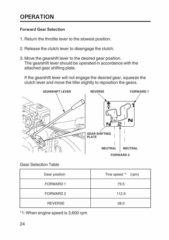
Forward Gear Selection
GEARSHIFT LEVER REVERSE FORWARD 1
GEAR SHIFTINGPLATE
FORWARD 2
NEUTRALNEUTRAL
The gearshift lever should be operated in accordance with theattached gear shifting plate.
If the gearshift lever will not engage the desired gear, squeeze theclutch lever and move the tiller slightly to reposition the gears.
Return the throttle lever to the slowest position.
Release the clutch lever to disengage the clutch.
Move the gearshift lever to the desired gear position.
Gear Selection Table
1.
3.
2.
When engine speed is 3,600 rpm*1:
Gear position
FORWARD 1
FORWARD 2
REVERSE
*1Tine speed (rpm)
79.5
112.9
28.0
25
OPERATION
Reverse Gear Operation
Use the reverse gear only when it is necessary to move the tiller awayfrom an obstacle.
The tiller tines propel the tillertoward the operator when operatedin reverse.
Contact with rotating tines willcause serious injury.
Be prepared to quickly release theclutch lever when operating thetiller in reverse.
Check the area behind you and make sure it is clear of any obstacles.
Move the throttle to the SLOW position.
Raise the handlebar slightly and engage the main clutch lever.Carefully walk the tiller backwards. Be prepared to release the mainclutch lever quickly.
Make sure the main clutch lever is released. Move the gearshift leverto the REVERSE position.
Release the main clutch lever, lower the handlebar, and move thegearshift lever out of the REVERSE position when done.
1.
2.
3.
4.
5.
26
OPERATION
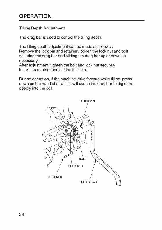
Tilling Depth Adjustment
The drag bar is used to control the tilling depth.
The tilling depth adjustment can be made as follows :Remove the lock pin and retainer, loosen the lock nut and boltsecuring the drag bar and sliding the drag bar up or down asnecessary.After adjustment, tighten the bolt and lock nut securely.Insert the retainer and set the lock pin.
During operation, if the machine jerks forward while tilling, pressdown on the handlebars. This will cause the drag bar to dig moredeeply into the soil.
LOCK PIN
DRAG BAR
LOCK NUT
BOLT
RETAINER
27
OPERATION
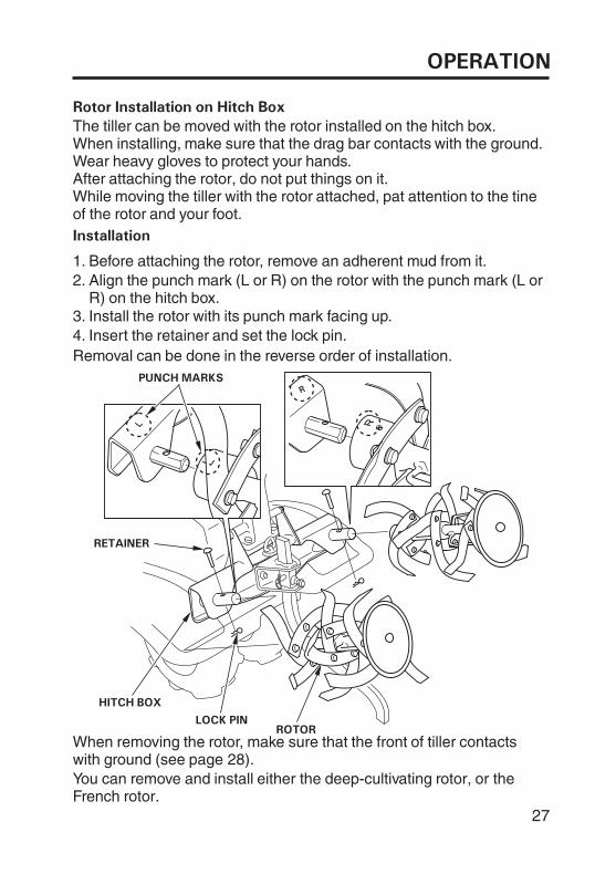
Rotor Installation on Hitch Box
Installation
RETAINER
HITCH BOX
LOCK PINROTOR
PUNCH MARKS
The tiller can be moved with the rotor installed on the hitch box.When installing, make sure that the drag bar contacts with the ground.Wear heavy gloves to protect your hands.After attaching the rotor, do not put things on it.While moving the tiller with the rotor attached, pat attention to the tineof the rotor and your foot.
Before attaching the rotor, remove an adherent mud from it.Align the punch mark (L or R) on the rotor with the punch mark (L orR) on the hitch box.Install the rotor with its punch mark facing up.Insert the retainer and set the lock pin.
Removal can be done in the reverse order of installation.
1.2.
3.4.
When removing the rotor, make sure that the front of tiller contactswith ground (see page 28).You can remove and install either the deep-cultivating rotor, or theFrench rotor.
OPERATION
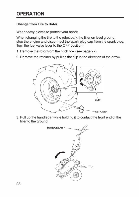
Change from Tire to Rotor
CLIP
RETAINER
HANDLEBAR
Wear heavy gloves to protect your hands.
When changing the tire to the rotor, park the tiller on level ground,stop the engine and disconnect the spark plug cap from the spark plug.Turn the fuel valve lever to the OFF position.
Remove the rotor from the hitch box (see page 27).
Remove the retainer by pulling the clip in the direction of the arrow.
Pull up the handlebar while holding it to contact the front end of thetiller to the ground.
1.
2.
3.
28
OPERATION
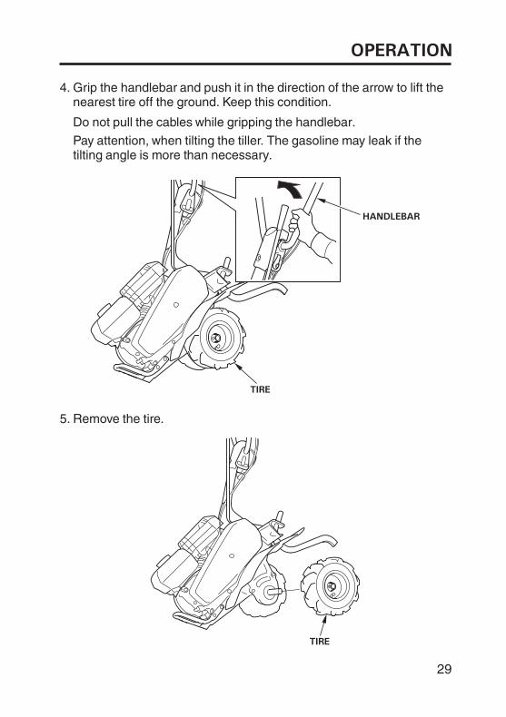
Grip the handlebar and push it in the direction of the arrow to lift thenearest tire off the ground. Keep this condition.
Do not pull the cables while gripping the handlebar.
Pay attention, when tilting the tiller. The gasoline may leak if thetilting angle is more than necessary.
Remove the tire.
4.
5.
29
HANDLEBAR
TIRE
TIRE
OPERATION
PUNCH MARKS
FENDER
LOCK PIN
ROTOR
AXLE
RETAINER
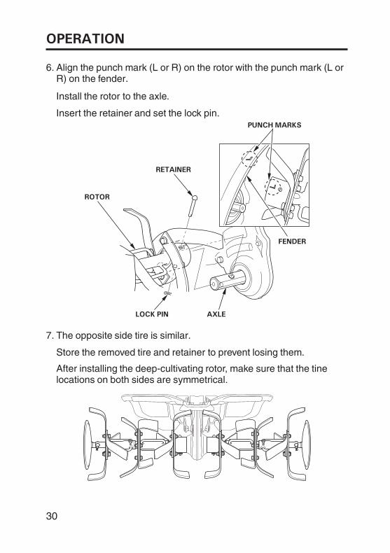
Align the punch mark (L or R) on the rotor with the punch mark (L orR) on the fender.
Install the rotor to the axle.
Insert the retainer and set the lock pin.
Store the removed tire and retainer to prevent losing them.
The opposite side tire is similar.
After installing the deep-cultivating rotor, make sure that the tinelocations on both sides are symmetrical.
6.
7.
30
OPERATION
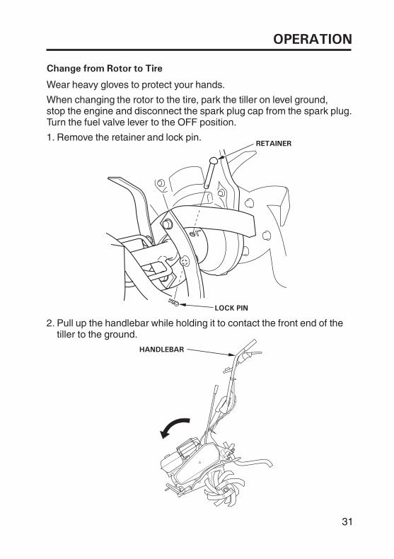
Change from Rotor to Tire
HANDLEBAR
RETAINER
LOCK PIN
Wear heavy gloves to protect your hands.
When changing the rotor to the tire, park the tiller on level ground,stop the engine and disconnect the spark plug cap from the spark plug.Turn the fuel valve lever to the OFF position.
Remove the retainer and lock pin.
Pull up the handlebar while holding it to contact the front end of thetiller to the ground.
1.
2.
31
OPERATION
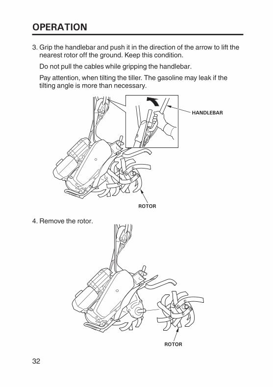
Grip the handlebar and push it in the direction of the arrow to lift thenearest rotor off the ground. Keep this condition.
Do not pull the cables while gripping the handlebar.
Pay attention, when tilting the tiller. The gasoline may leak if thetilting angle is more than necessary.
Remove the rotor.
3.
4.
32
HANDLEBAR
ROTOR
ROTOR
OPERATION
BACKWARD
AXLE
CLIPSKEW PART
RETAINERTIRE
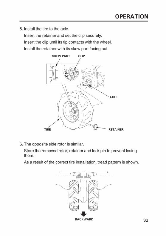
Install the tire to the axle.
Insert the retainer and set the clip securely.
The opposite side rotor is similar.
Store the removed rotor, retainer and lock pin to prevent losingthem.
As a result of the correct tire installation, tread pattern is shown.
Install the retainer with its skew part facing out.
Insert the clip until its tip contacts with the wheel.
5.
6.
33
OPERATION
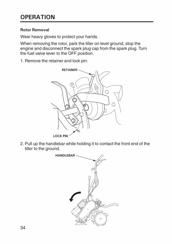
Rotor Removal
HANDLEBAR
RETAINER
LOCK PIN
Wear heavy gloves to protect your hands.
Remove the retainer and lock pin.
Pull up the handlebar while holding it to contact the front end of thetiller to the ground.
When removing the rotor, park the tiller on level ground, stop theengine and disconnect the spark plug cap from the spark plug. Turnthe fuel valve lever to the OFF position.
1.
2.
34
OPERATION
ROTOR
HANDLEBAR
ROTOR
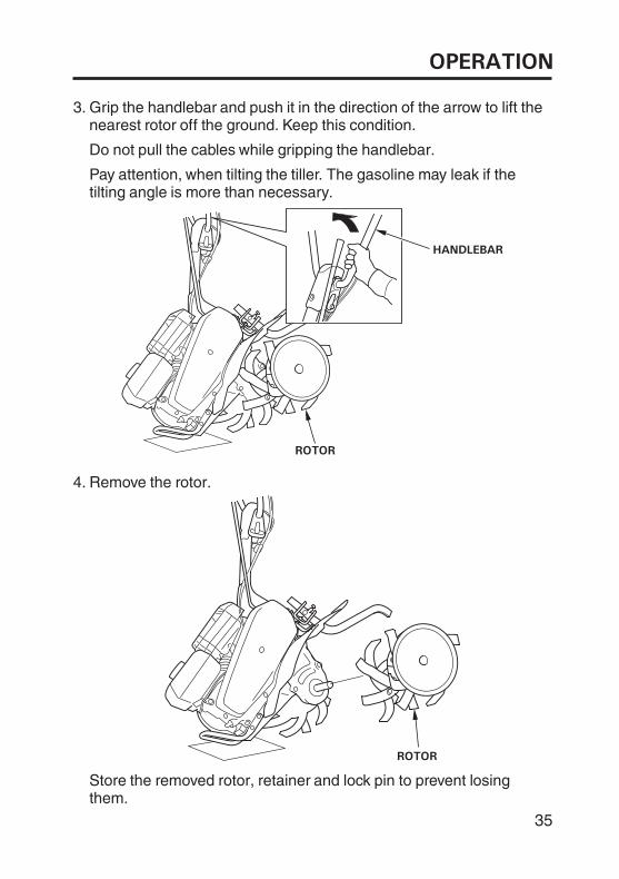
Pay attention, when tilting the tiller. The gasoline may leak if thetilting angle is more than necessary.
Grip the handlebar and push it in the direction of the arrow to lift thenearest rotor off the ground. Keep this condition.
Do not pull the cables while gripping the handlebar.
Store the removed rotor, retainer and lock pin to prevent losingthem.
Remove the rotor.
3.
4.
35
OPERATION
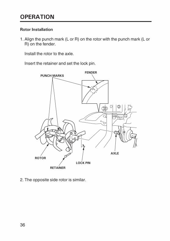
Rotor Installation
FENDERPUNCH MARKS
LOCK PIN
RETAINER
AXLE
ROTOR
The opposite side rotor is similar.
Insert the retainer and set the lock pin.
Install the rotor to the axle.
Align the punch mark (L or R) on the rotor with the punch mark (L orR) on the fender.
1.
2.
36
OPERATION
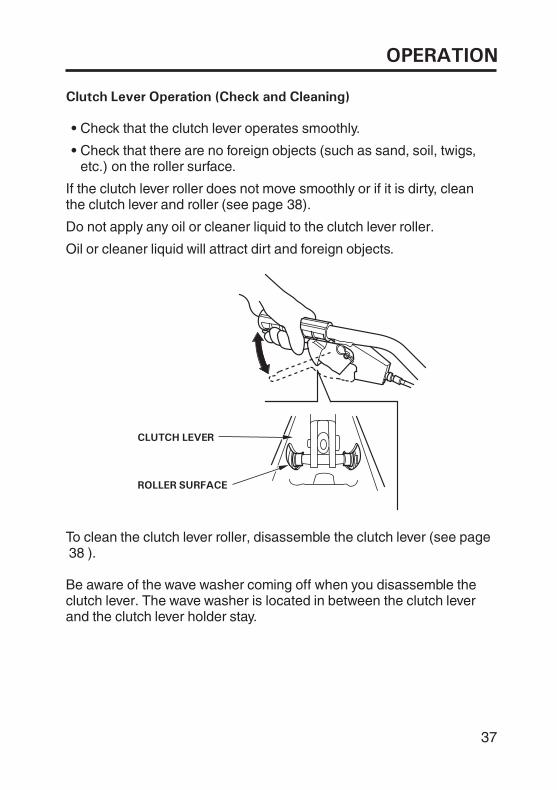
Clutch Lever Operation (Check and Cleaning)
CLUTCH LEVER
ROLLER SURFACE
Check that the clutch lever operates smoothly.
Check that there are no foreign objects (such as sand, soil, twigs,etc.) on the roller surface.
If the clutch lever roller does not move smoothly or if it is dirty, cleanthe clutch lever and roller (see page 38).
Do not apply any oil or cleaner liquid to the clutch lever roller.
Oil or cleaner liquid will attract dirt and foreign objects.
To clean the clutch lever roller, disassemble the clutch lever (see page).
Be aware of the wave washer coming off when you disassemble theclutch lever. The wave washer is located in between the clutch leverand the clutch lever holder stay.
38
37
OPERATION
UPPER
WAVE WASHER SNAP PINFRONT
FULCRUM PIN
PROJECTION
CLUTCH LEVER
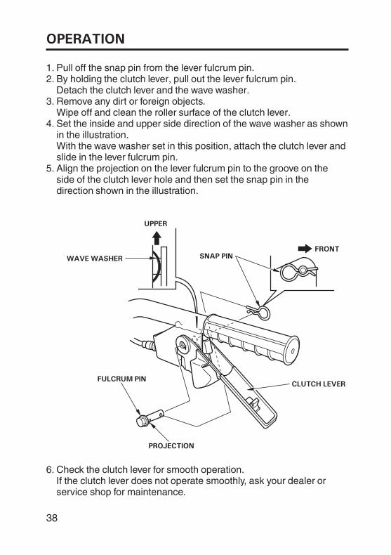
Pull off the snap pin from the lever fulcrum pin.By holding the clutch lever, pull out the lever fulcrum pin.Detach the clutch lever and the wave washer.Remove any dirt or foreign objects.Wipe off and clean the roller surface of the clutch lever.Set the inside and upper side direction of the wave washer as shownin the illustration.With the wave washer set in this position, attach the clutch lever andslide in the lever fulcrum pin.Align the projection on the lever fulcrum pin to the groove on theside of the clutch lever hole and then set the snap pin in thedirection shown in the illustration.
Check the clutch lever for smooth operation.If the clutch lever does not operate smoothly, ask your dealer orservice shop for maintenance.
1.2.
3.
4.
5.
6.
38
OPERATION
HANDLING TIPS
Adjust the handlebar height to a comfortable position (waist heightfor normal tilling).
The drag bar should always be used when tilling. It enables you tocompensate for the hardness of the soil. The ideal height of the dragbar will depend on the type of soil being tilled and soil conditions atthe time of tilling. In general, however, the drag bar should beadjusted so that the tiller is tilted slightly backward.
If the machine jerks forward while tilling, press down on thehandlebars. This will cause the drag bar to dig more deeply into thesoil.
If tines dig in but the machine will not move forward, move thehandlebars from side to side.
Stop the tines before crossing gravel drives, walks, or roads. Stayalert for hidden hazards or traffic.
Stop the engine immediately if the tiller vibrates abnormally. Checkthe tiller for damage or loose parts, and repair or replace thembefore using the tiller again. Vibration is usually a sign of trouble.
Break-in operation: 20 minutesBefore starting the engine, make sure that the gearshift lever is set inneutral position and the clutch lever is released.Move the throttle lever to SLOW position and run the engine for 10minutes, then move to FAST position and run for 10 minutes more.
Raise the tiller immediately if it overturns. Stop the engine, look overcarefully; inspect the engine for oil or fluid leaks, check the tightnessof nuts and bolts, and operation of control parts such as thehandlebar and control levers. If you decide that the tiller is capableof driving and safety, restart the engine. Consult your dealer, if theengine does not start again.
1.
2.
39
OPERATION
STOPPING THE ENGINE
DISENGAGEDMAIN CLUTCH LEVER
ENGINE SWITCH
OFF OFF
OOFFFF
STOPPER BUTTON
FUEL VALVE LEVER
SLOW
THROTTLELEVER
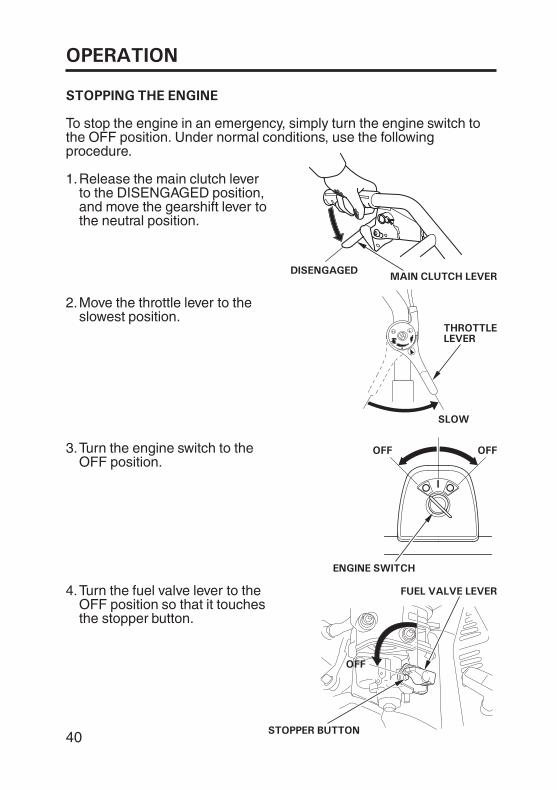
Move the throttle lever to theslowest position.
To stop the engine in an emergency, simply turn the engine switch tothe OFF position. Under normal conditions, use the followingprocedure.
Release the main clutch leverto the DISENGAGED position,and move the gearshift lever tothe neutral position.
Turn the fuel valve lever to theOFF position so that it touchesthe stopper button.
Turn the engine switch to theOFF position.
1.
2.
3.
4.
40
THE IMPORTANCE OF MAINTENANCE
SERVICING YOUR TILLER
Good maintenance is essential for safe, economical, and trouble-freeoperation. It will also help reduce air pollution.
To help you properly care for your tiller, the following pages include amaintenance schedule, routine inspection procedures, and simplemaintenance procedures using basic hand tools. Other service tasksthat are more difficult or require special tools are best handled byprofessionals and are normally performed by a Honda technician orother qualified mechanic.
The maintenance schedule applies to normal operating conditions. Ifyou operate your tiller under unusual conditions, such as sustainedhigh-load or high-temperature operation or use in dusty conditionsconsult your servicing dealer for recommendations applicable to yourindividual needs and use.
Remember that your servicing dealer knows your tiller best and is fullyequipped to maintain and repair it.
Improper maintenance or failure tocorrect a problem before operation,can cause a malfunction in whichyou can be seriously hurt or killed.
Always follow the inspection andmaintenance recommendations andschedules in this owner’s manual.
To ensure the best quality and reliability, use only new, HondaGenuine parts or their equivalents for repair and replacement.
41
-
-
-
SERVICING YOUR TILLER
MAINTENANCE SAFETY
Injury from moving parts.
Burns from hot parts.
Carbon monoxide poisoning from engine exhaust.
Safety precautions
Some of the most important safety precautions follow. However, wecannot warn you of every conceivable hazard that can arise inperforming maintenance. Only you can decide whether or not youshould perform a given task.
Do not run the engine unless instructed to do so.
Let the engine and exhaust system cool before touching.
Be sure there is adequate ventilation whenever you operate theengine.
Disconnect the spark plug cap and wear heavy gloves when workingnear the belts or tine blades.
To reduce the possibility of fire or explosion, be careful whenworking around gasoline. Use only a non-flammable solvent, notgasoline, to clean parts. Keep cigarettes, sparks, and flames awayfrom all fuel-related parts.
Read the instructions before you begin, and make sure you have thetools and skills required.
Make sure the engine is off before you begin any maintenance orrepairs. This will eliminate several potential hazards:
Failure to properly followmaintenance instructions andprecautions can cause you to beseriously hurt or killed.
Always follow the procedures andprecautions in the owner’s manual.
42
SERVICING YOUR TILLER
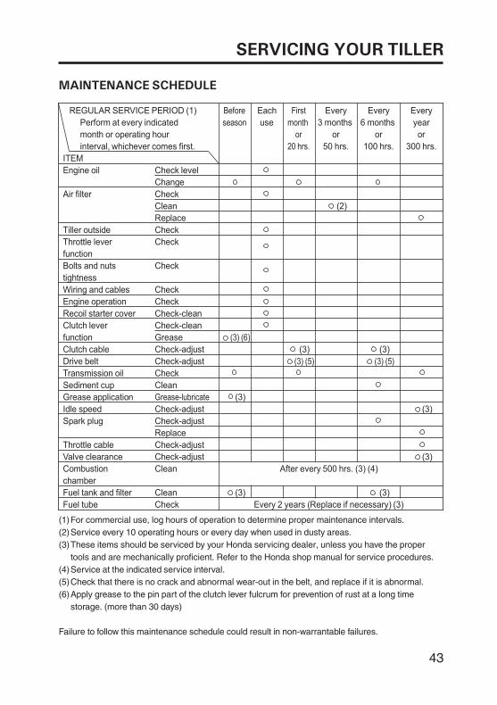
MAINTENANCE SCHEDULE
For commercial use, log hours of operation to determine proper maintenance intervals.Service every 10 operating hours or every day when used in dusty areas.These items should be serviced by your Honda servicing dealer, unless you have the propertools and are mechanically proficient. Refer to the Honda shop manual for service procedures.
Check that there is no crack and abnormal wear-out in the belt, and replace if it is abnormal.Apply grease to the pin part of the clutch lever fulcrum for prevention of rust at a long timestorage. (more than 30 days)
(1)(2)(3)
(4)(5)(6)
Perform at every indicated
month or operating hour
interval, whichever comes first.
REGULAR SERVICE PERIOD (1)
ITEM
Each
use
Every
3 months
or
50 hrs.
Every
6 months
or
100 hrs.
Every
year
or
300 hrs.
Engine oil
Air filter
Tiller outside
Throttle lever
function
Bolts and nuts
tightness
Wiring and cables
Engine operation
Recoil starter cover
Clutch lever
function
Clutch cable
Drive belt
Transmission oil
Sediment cup
Grease application
Idle speed
Spark plug
Throttle cable
Valve clearance
Combustion
chamber
Fuel tank and filter
Fuel tube
Check level
Change
Check
Clean
Replace
Check
Check
Check
Check
Check
Check-clean
Check-clean
Grease
Check-adjust
Check-adjust
Check
Clean
Check-adjust
Check-adjust
Replace
Check-adjust
Check-adjust
Clean
Clean
Check Every 2 years (Replace if necessary) (3)
After every 500 hrs. (3) (4)
(2)
(3)
(3)
(3) (3)
(3)
(3)
(3)
Before
season
First
month
or
20 hrs.
Grease-lubricate
(3) (6)
(3) (5) (3) (5)
Service at the indicated service interval.
Failure to follow this maintenance schedule could result in non-warrantable failures.
43
SERVICING YOUR TILLER
REFUELING
LEVEL MARK
FUEL TANK CAP
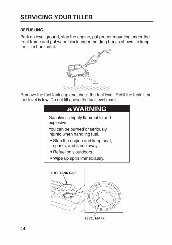
Wipe up spills immediately.
Stop the engine and keep heat,sparks, and flame away.
Gasoline is highly flammable andexplosive.
You can be burned or seriouslyinjured when handling fuel.
Refuel only outdoors.
Remove the fuel tank cap and check the fuel level. Refill the tank if thefuel level is low. Do not fill above the fuel level mark.
Park on level ground, stop the engine, put proper mounting under thefront frame and put wood block under the drag bar as shown, to keepthe tiller horizontal.
44
SERVICING YOUR TILLER
FUEL RECOMMENDATIONS
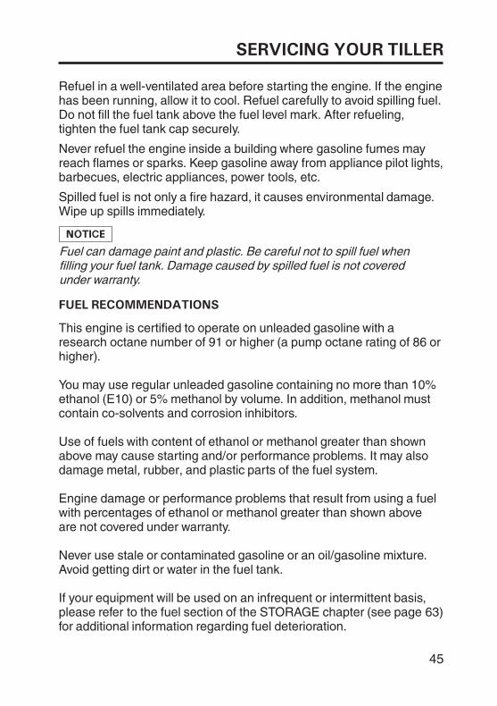
Refuel in a well-ventilated area before starting the engine. If the enginehas been running, allow it to cool. Refuel carefully to avoid spilling fuel.Do not fill the fuel tank above the fuel level mark. After refueling,tighten the fuel tank cap securely.
Never refuel the engine inside a building where gasoline fumes mayreach flames or sparks. Keep gasoline away from appliance pilot lights,barbecues, electric appliances, power tools, etc.
Spilled fuel is not only a fire hazard, it causes environmental damage.Wipe up spills immediately.
Fuel can damage paint and plastic. Be careful not to spill fuel whenfilling your fuel tank. Damage caused by spilled fuel is not coveredunder warranty.
This engine is certified to operate on unleaded gasoline with aresearch octane number of 91 or higher (a pump octane rating of 86 orhigher).
If your equipment will be used on an infrequent or intermittent basis,please refer to the fuel section of the STORAGE chapter (see page 63)for additional information regarding fuel deterioration.
Never use stale or contaminated gasoline or an oil/gasoline mixture.Avoid getting dirt or water in the fuel tank.
Engine damage or performance problems that result from using a fuelwith percentages of ethanol or methanol greater than shown aboveare not covered under warranty.
Use of fuels with content of ethanol or methanol greater than shownabove may cause starting and/or performance problems. It may alsodamage metal, rubber, and plastic parts of the fuel system.
You may use regular unleaded gasoline containing no more than 10%ethanol (E10) or 5% methanol by volume. In addition, methanol mustcontain co-solvents and corrosion inhibitors.
45
SERVICING YOUR TILLER
ENGINE OIL LEVEL CHECK
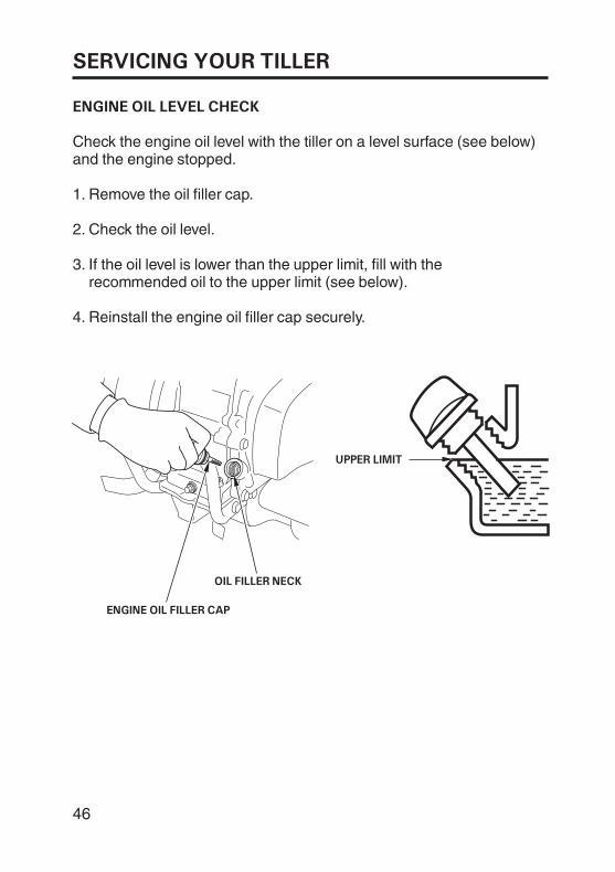
UPPER LIMIT
OIL FILLER NECK
ENGINE OIL FILLER CAP
Check the engine oil level with the tiller on a level surface (see below)and the engine stopped.
Remove the oil filler cap.
Check the oil level.
If the oil level is lower than the upper limit, fill with therecommended oil to the upper limit (see below).
Reinstall the engine oil filler cap securely.
1.
2.
3.
4.
46
SERVICING YOUR TILLER
ENGINE OIL CHANGE
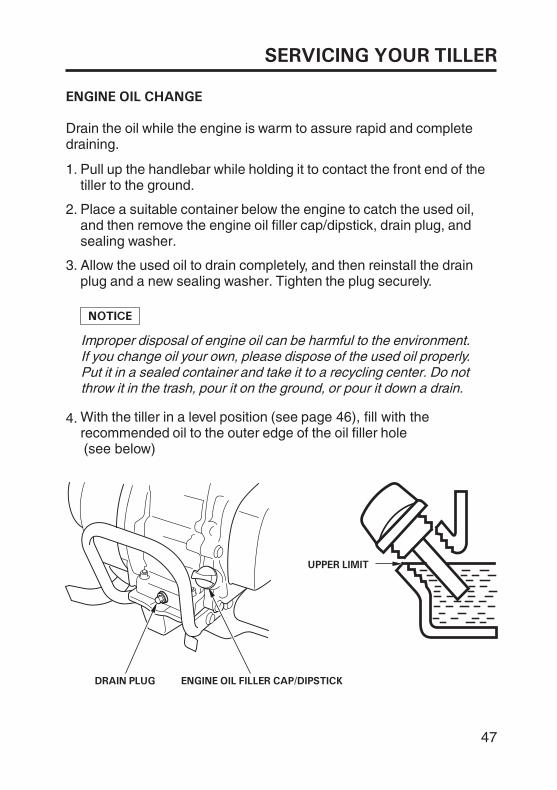
UPPER LIMIT
DRAIN PLUG ENGINE OIL FILLER CAP/DIPSTICK
Drain the oil while the engine is warm to assure rapid and completedraining.
Pull up the handlebar while holding it to contact the front end of thetiller to the ground.
Place a suitable container below the engine to catch the used oil,and then remove the engine oil filler cap/dipstick, drain plug, andsealing washer.
Improper disposal of engine oil can be harmful to the environment.If you change oil your own, please dispose of the used oil properly.Put it in a sealed container and take it to a recycling center. Do notthrow it in the trash, pour it on the ground, or pour it down a drain.
Allow the used oil to drain completely, and then reinstall the drainplug and a new sealing washer. Tighten the plug securely.
1.
2.
3.
With the tiller in a level position (see page 46), fill with therecommended oil to the outer edge of the oil filler hole
4.
(see below)
47
SERVICING YOUR TILLER
ENGINE OIL RECOMMENDATIONS
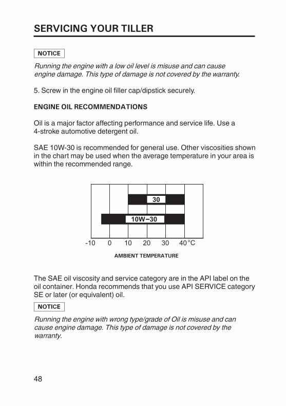
AMBIENT TEMPERATURE
Running the engine with a low oil level is misuse and can causeengine damage. This type of damage is not covered by the warranty.
Screw in the engine oil filler cap/dipstick securely.
Oil is a major factor affecting performance and service life. Use a4-stroke automotive detergent oil.
SAE 10W-30 is recommended for general use. Other viscosities shownin the chart may be used when the average temperature in your area iswithin the recommended range.
The SAE oil viscosity and service category are in the API label on theoil container. Honda recommends that you use API SERVICE categorySE or later (or equivalent) oil.
Running the engine with wrong type/grade of Oil is misuse and cancause engine damage. This type of damage is not covered by thewarranty.
5.
48
SERVICING YOUR TILLER
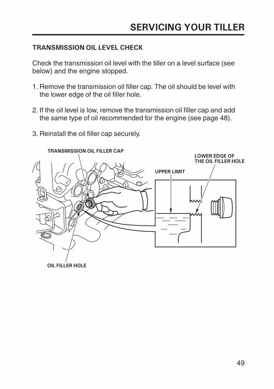
TRANSMISSION OIL LEVEL CHECK
OIL FILLER HOLE
LOWER EDGE OFTHE OIL FILLER HOLE
TRANSMISSION OIL FILLER CAP
UPPER LIMIT
If the oil level is low, remove the transmission oil filler cap and addthe same type of oil recommended for the engine (see page 48).
Check the transmission oil level with the tiller on a level surface (seebelow) and the engine stopped.
Remove the transmission oil filler cap. The oil should be level withthe lower edge of the oil filler hole.
Reinstall the oil filler cap securely.
1.
2.
3.
49
SERVICING YOUR TILLER
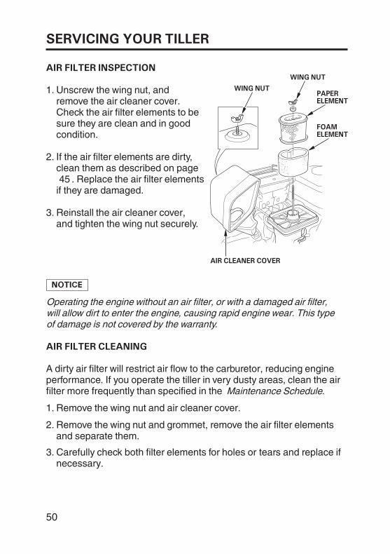
AIR FILTER INSPECTION
AIR FILTER CLEANING
AIR CLEANER COVER
PAPERELEMENT
FOAMELEMENT
WING NUT
WING NUT
Unscrew the wing nut, andremove the air cleaner cover.Check the air filter elements to besure they are clean and in goodcondition.
Reinstall the air cleaner cover,and tighten the wing nut securely.
If the air filter elements are dirty,clean them as described on page
. Replace the air filter elementsif they are damaged.
Operating the engine without an air filter, or with a damaged air filter,will allow dirt to enter the engine, causing rapid engine wear. This typeof damage is not covered by the warranty.
A dirty air filter will restrict air flow to the carburetor, reducing engineperformance. If you operate the tiller in very dusty areas, clean the airfilter more frequently than specified in the Maintenance Schedule.
Remove the wing nut and air cleaner cover.
Remove the wing nut and grommet, remove the air filter elementsand separate them.
Carefully check both filter elements for holes or tears and replace ifnecessary.
1.
2.
3.
1.
2.
3.
45
50
SERVICING YOUR TILLER
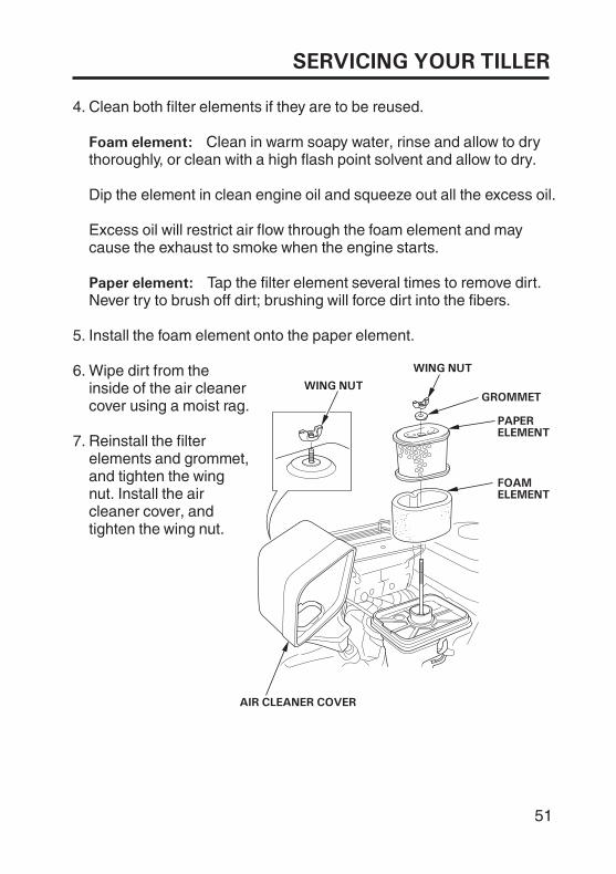
Foam element:
Paper element:
WING NUT
AIR CLEANER COVER
WING NUT
GROMMET
PAPERELEMENT
FOAMELEMENT
Clean both filter elements if they are to be reused.
Clean in warm soapy water, rinse and allow to drythoroughly, or clean with a high flash point solvent and allow to dry.
Dip the element in clean engine oil and squeeze out all the excess oil.
Excess oil will restrict air flow through the foam element and maycause the exhaust to smoke when the engine starts.
Tap the filter element several times to remove dirt.Never try to brush off dirt; brushing will force dirt into the fibers.
Install the foam element onto the paper element.
Wipe dirt from theinside of the air cleanercover using a moist rag.
Reinstall the filterelements and grommet,and tighten the wingnut. Install the aircleaner cover, andtighten the wing nut.
5.
6.
7.
4.
51
SERVICING YOUR TILLER
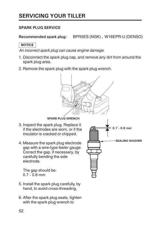
SPARK PLUG SERVICE
Recommended spark plug:
SPARK PLUG WRENCH
SEALING WASHER
0.7 - 0.8 mm
Disconnect the spark plug cap, and remove any dirt from around thespark plug area.
W16EPR-U (DENSO)
An incorrect spark plug can cause engine damage.
Remove the spark plug with the spark plug wrench.
0.7 - 0.8 mm
Measure the spark plug electrodegap with a wire-type feeler gauge.Correct the gap, if necessary, bycarefully bending the sideelectrode.
The gap should be:
Inspect the spark plug. Replace itif the electrodes are worn, or if theinsulator is cracked or chipped.
BPR5ES (NGK) ,
Install the spark plug carefully, byhand, to avoid cross-threading.
After the spark plug seats, tightenwith the spark plug wrench to
2.
3.
4.
5.
6.
1.
52
SERVICING YOUR TILLER
If reinstalling a used spark plug, tighten 1/8 - 1/4 turn after thespark plug seats.
If installing a new spark plug, tighten 1/2 turn after the spark plugseats.
Attach the spark plug cap.
A loose spark plug can overheat and damage the engine.Overtightening the spark plug can damage the threads in thecylinder head.
7.
53
SERVICING YOUR TILLER
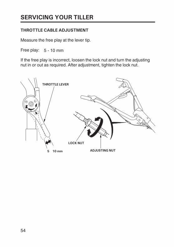
THROTTLE CABLE ADJUSTMENT
LOCK NUT
ADJUSTING NUT5 10 mm
THROTTLE LEVER
Measure the free play at the lever tip.
Free play:
If the free play is incorrect, loosen the lock nut and turn the adjustingnut in or out as required. After adjustment, tighten the lock nut.
5 - 10 mm
54
SERVICING YOUR TILLER
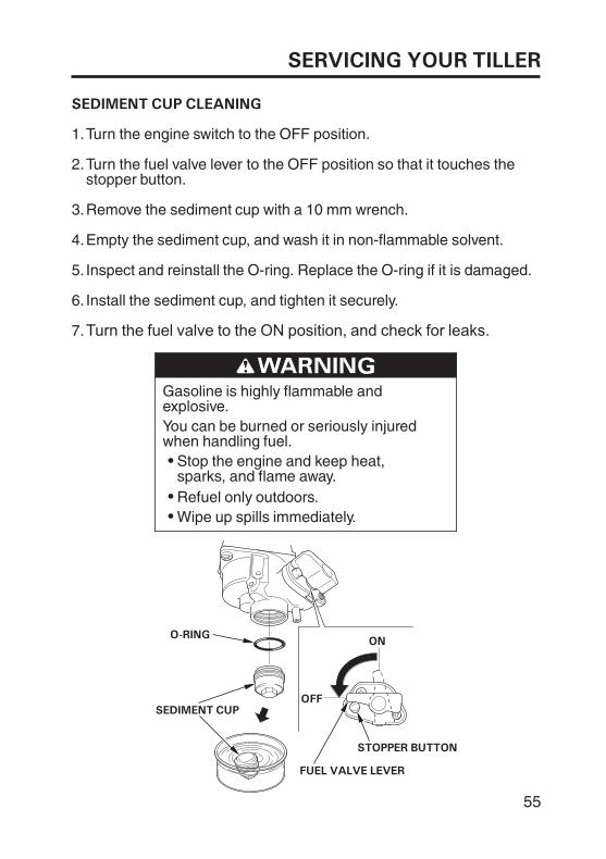
SEDIMENT CUP CLEANING
O-RING
SEDIMENT CUP
STOPPER BUTTON
ON
FUEL VALVE LEVER
OOFFFF
Turn the engine switch to the OFF position.
Turn the fuel valve lever to the OFF position so that it touches thestopper button.
Remove the sediment cup with a 10 mm wrench.
Empty the sediment cup, and wash it in non-flammable solvent.
Inspect and reinstall the O-ring. Replace the O-ring if it is damaged.
Install the sediment cup, and tighten it securely.
Turn the fuel valve to the ON position, and check for leaks.
You can be burned or seriously injuredwhen handling fuel.
Stop the engine and keep heat,sparks, and flame away.
Gasoline is highly flammable andexplosive.
Refuel only outdoors.Wipe up spills immediately.
1.
2.
3.
4.
5.
6.
7.
55
SERVICING YOUR TILLER
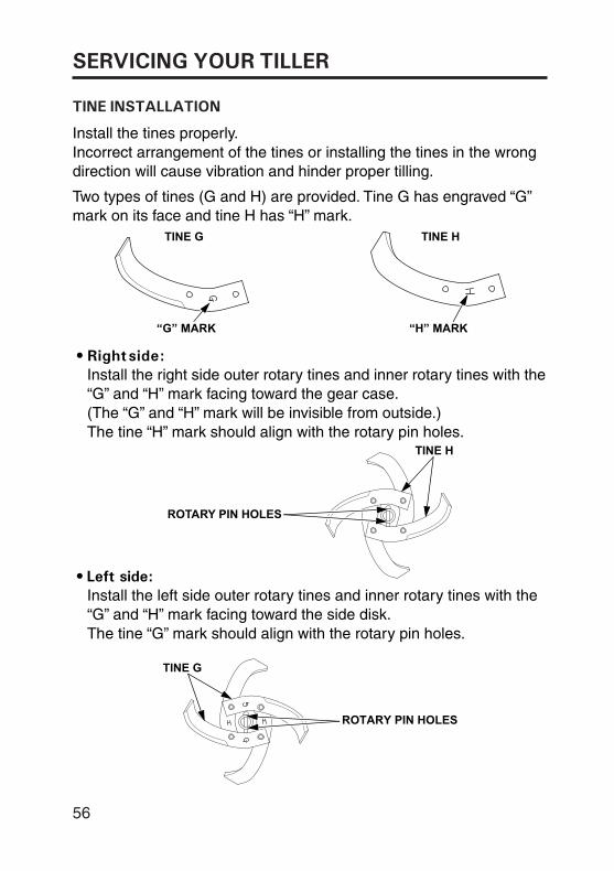
TINE INSTALLATION
56
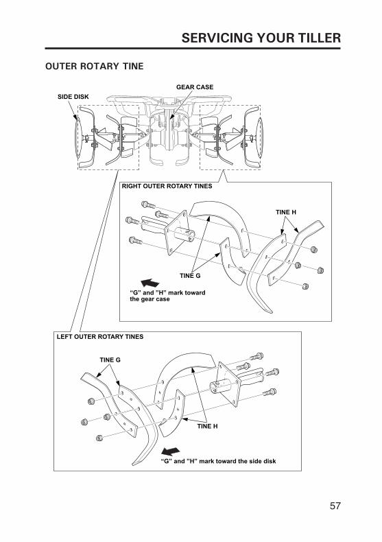
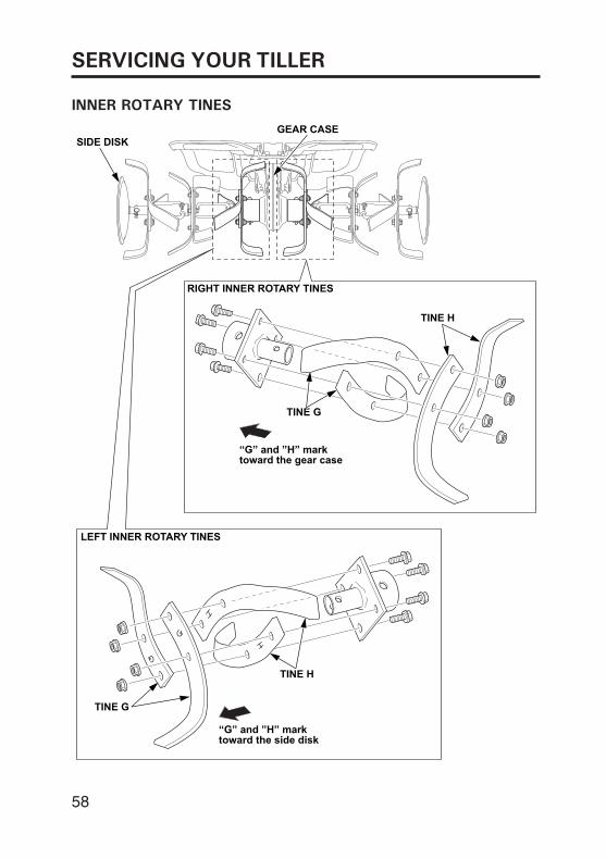
Install the tines properly. Incorrect arrangement of the tines or installing the tines in the wrong direction will cause vibration and hinder proper tilling.
Two types of tines (G and H) are provided. Tine G has engraved “G” mark on its face and tine H has “H” mark.
• Right side:Install the right side outer rotary tines and inner rotary tines with the “G” and “H” mark facing toward the gear case. (The “G” and “H” mark will be invisible from outside.) The tine “H” mark should align with the rotary pin holes.
• Left side:Install the left side outer rotary tines and inner rotary tines with the “G” and “H” mark facing toward the side disk. The tine “G” mark should align with the rotary pin holes.
“H” MARK“G” MARK
TINE G TINE H
TINE H
ROTARY PIN HOLES
ROTARY PIN HOLES
TINE G
SERVICING YOUR TILLER
57
“L” MARK “R” MARK
“G” and ”H” mark toward the gear case
SIDE DISK
RIGHT OUTER ROTARY TINES
GEAR CASE
TINE G
TINE H
LEFT OUTER ROTARY TINES
“G” and ”H” mark toward the side disk
TINE G
TINE H
OUTER ROTARY TINE
SERVICING YOUR TILLER
58
INNER ROTARY TINES
“L” MARK “R” MARK
“G” and ”H” mark toward the gear case
SIDE DISK
RIGHT INNER ROTARY TINES
GEAR CASE
TINE G
TINE H
LEFT INNER ROTARY TINES
“G” and ”H” mark toward the side disk
TINE G
TINE H
SERVICING YOUR TILLER
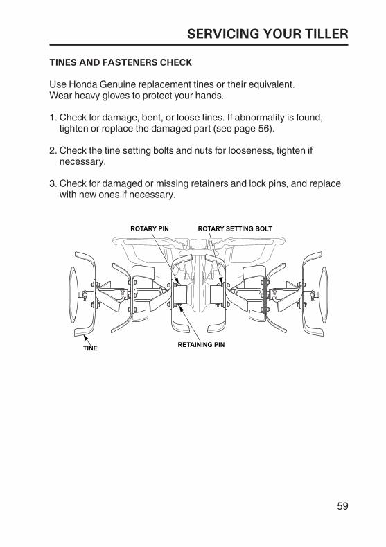
TINES AND FASTENERS CHECK
Use Honda Genuine replacement tines or their equivalent.Wear heavy gloves to protect your hands.
Check the tine setting bolts and nuts for looseness, tighten ifnecessary.
Check for damaged or missing retainers and lock pins, and replacewith new ones if necessary.
Check for damage, bent, or loose tines. If abnormality is found,tighten or replace the damaged part (see page 56).
1.
2.
3.
59
ROTARY SETTING BOLTROTARY PIN
RETAINING PINTINE
SERVICING YOUR TILLER
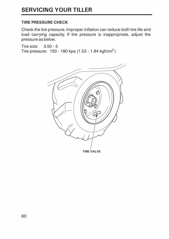
TIRE PRESSURE CHECK
TIRE VALVE
Tire size:2Tire pressure: 150 - 180 kpa (1.53 - 1.84 kgf/cm )
3.50 - 5
60
Check the tire pressure. Improper inflation can reduce both tire life and load carrying capacity. If tire pressure is inappropriate, adjust the pressure as below.
SERVICING YOUR TILLER
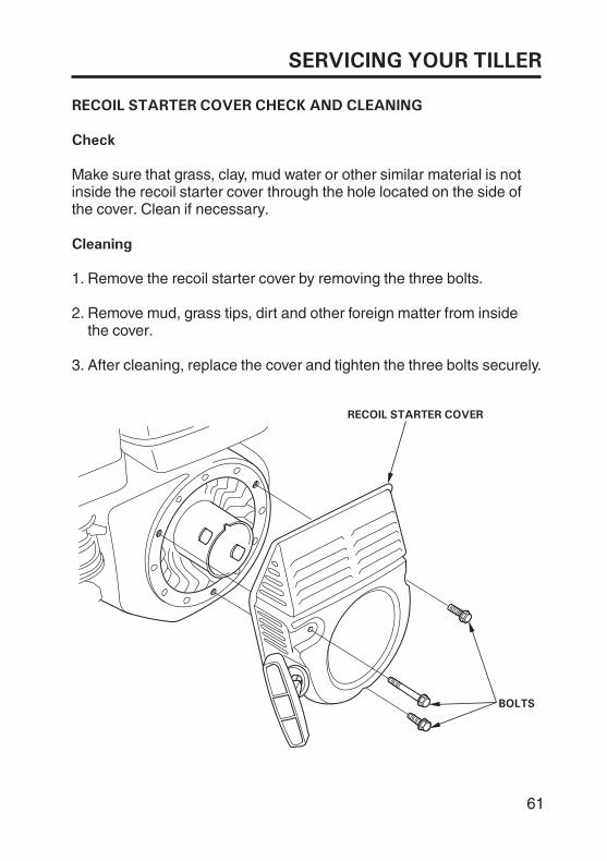
RECOIL STARTER COVER CHECK AND CLEANING
Check
Cleaning
RECOIL STARTER COVER
BOLTS
Make sure that grass, clay, mud water or other similar material is notinside the recoil starter cover through the hole located on the side ofthe cover. Clean if necessary.
Remove the recoil starter cover by removing the three bolts.
Remove mud, grass tips, dirt and other foreign matter from insidethe cover.
After cleaning, replace the cover and tighten the three bolts securely.
1.
2.
3.
61
SERVICING YOUR TILLER
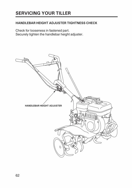
HANDLEBAR HEIGHT ADJUSTER TIGHTNESS CHECK
HANDLEBAR HEIGHT ADJUSTER
Check for looseness in fastened part.Securely tighten the handlebar height adjuster.
62
STORAGE
STORAGE PREPARATION
Tiller
Engine
Cleaning
Proper storage preparation is essential for keeping your tillertrouble-free and looking good. The following steps will help to keeprust and corrosion from impairing your tiller’s function andappearance, and will make the engine easier to start when you use thetiller again.
Spraying water on hot tine shaft bearings can cause them to bedamaged from cooling too quickly.
If using a garden hose or pressure washing equipment to clean thetiller, be careful to avoid getting water on the belts.
Water contacting a hot engine can cause damage. If the enginehas been running, allow it to cool for at least half an hour beforewashing.
Using a garden hose or pressure washing equipment can forcewater into the air cleaner. Water in the air cleaner will soak thefilter elements and can enter the carburetor or engine cylinder,causing damage.
Wash the engine by hand, and be careful to prevent water fromentering the air cleaner.
Wash the tiller, including the underside.1.
63
STORAGE
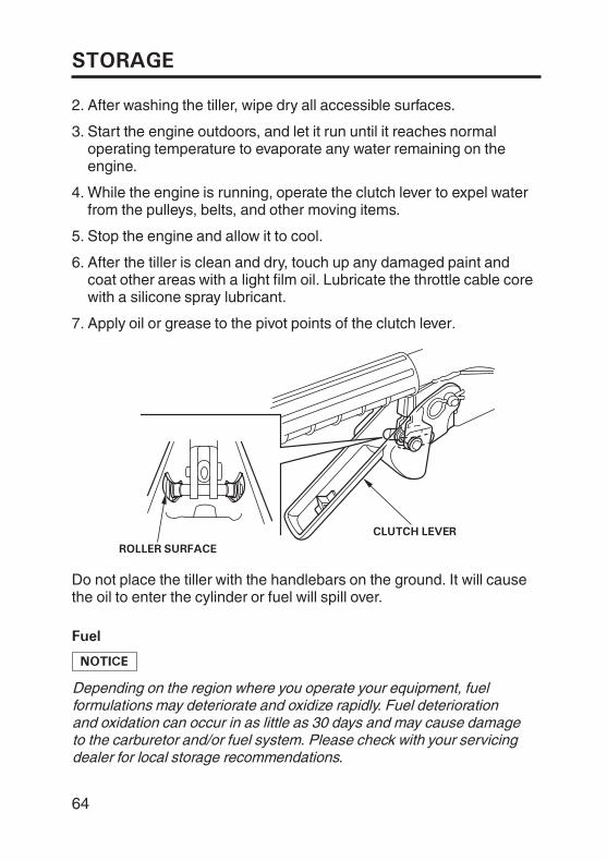
Fuel
ROLLER SURFACE
CLUTCH LEVER
After washing the tiller, wipe dry all accessible surfaces.
Start the engine outdoors, and let it run until it reaches normaloperating temperature to evaporate any water remaining on theengine.
After the tiller is clean and dry, touch up any damaged paint andcoat other areas with a light film oil. Lubricate the throttle cable corewith a silicone spray lubricant.
Stop the engine and allow it to cool.
While the engine is running, operate the clutch lever to expel waterfrom the pulleys, belts, and other moving items.
Depending on the region where you operate your equipment, fuelformulations may deteriorate and oxidize rapidly. Fuel deteriorationand oxidation can occur in as little as 30 days and may cause damageto the carburetor and/or fuel system. Please check with your servicingdealer for local storage recommendations.
Apply oil or grease to the pivot points of the clutch lever.
Do not place the tiller with the handlebars on the ground. It will causethe oil to enter the cylinder or fuel will spill over.
2.
3.
4.
5.
6.
7.
64
STORAGE
Gasoline will oxidize and deteriorate in storage. Old gasoline willcause hard starting and it leaves gum deposits that clog the fuelsystem. If the gasoline in your tiller deteriorates during storage, youmay need to have the carburetor and other fuel system componentsserviced or replaced.
The length of time that gasoline can be left in your fuel tank andcarburetor without causing functional problems will vary with suchfactors as gasoline blend, your storage temperatures and whether thefuel tank is partially or completely filled. The air in a partially filled fueltank promotes fuel deterioration. Very warm storage temperaturesaccelerate fuel deterioration. Fuel deterioration problems may occurwithin a few months or even less if the gasoline was not fresh whenyou filled the fuel tank.
The warranty does not cover fuel system damage or engineperformance problems resulting from neglected storage preparation.
65
STORAGE
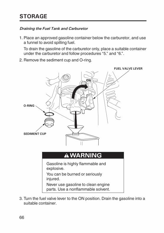
Draining the Fuel Tank and Carburetor
O-RING
FUEL VALVE LEVER
OONN
SEDIMENT CUP
Place an approved gasoline container below the carburetor, and usea funnel to avoid spilling fuel.
To drain the gasoline of the carburetor only, place a suitable containerunder the carburetor and follow procedures ‘‘5.’’ and ‘‘6.’’.
Remove the sediment cup and O-ring.
Gasoline is highly flammable andexplosive.You can be burned or seriouslyinjured.Never use gasoline to clean engineparts. Use a nonflammable solvent.
Turn the fuel valve lever to the ON position. Drain the gasoline into asuitable container.
2.
3.
1.
66
STORAGE
STOPPER BUTTON
PPrreessss
DRAIN
OOFFFF
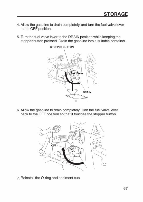
Allow the gasoline to drain completely, and turn the fuel valve leverto the OFF position.
Turn the fuel valve lever to the DRAIN position while keeping thestopper button pressed. Drain the gasoline into a suitable container.
Allow the gasoline to drain completely. Turn the fuel valve leverback to the OFF position so that it touches the stopper button.
Reinstall the O-ring and sediment cup.
4.
5.
7.
6.
67
STORAGE
Engine Oil
Change the engine oil (see page 47).
Pour a tablespoon (5 - 10 cc) of clean engine oil into the cylinder.
Remove the spark plug (see page 52).
Gently pull the starter grip several times to distribute the oil in thecylinder.
Pull the starter grip (see page 22) slowly until you feel resistance,then return the starter grip gently. This closes the valves so moisturecannot enter.
Reinstall the spark plug and spark plug cap.
6.
5.
1.
2.
3.
4.
68
STORAGE
STORAGE PRECAUTIONS
REMOVAL FROM STORAGE
If your tiller will be stored with gasoline in the fuel tank and carburetor,it is important to reduce the hazard of gasoline vapor ignition. Select awell-ventilated storage area away from any appliance that operateswith a flame, such as a furnace, water heater, or clothes dryer. Alsoavoid any area with a spark-producing electric motor or where powertools are operated.
If possible, avoid storage areas with high humidity because thatpromotes rust and corrosion.
Unless all fuel has been drained from the fuel tank, leave the fuel valvein the OFF position to reduce the possibility of fuel leakage.
Place the tiller on a level surface. Tilting can cause fuel or oil leakage.
When the engine and exhaust system is cool, cover the tiller to keepout dust. A hot engine and exhaust system can ignite or melt somematerials. Do not use sheet plastic as a dust cover. A nonporous coverwill trap moisture around the tiller, promoting rust and corrosion.
If the fuel was drained during storage preparation, fill the tank withfresh gasoline. If you keep a container of gasoline for refueling, besure that it contains only fresh gasoline. Gasoline oxidizes anddeteriorates over time, causing hard starting.
If the cylinder was coated with oil during storage preparation, theengine may smoke briefly at start-up. This is normal.
Check your tiller as described in the BEFORE OPERATION chapter ofthis manual (see page17).
69
TRANSPORTING
BEFORE LOADING
LOADING AND UNLOADING
If the engine has been running, allow it to cool for at least 15 minutesbefore loading the tiller on the transport vehicle. A hot engine andexhaust system can burn you and can ignite some materials.
If a suitable loading ramp is not available, two people should lift thetiller on and off the transport vehicle while holding the tiller level.
Position the tiller so it sits flat on the bed of the transport vehicle. Tiethe tiller down with rope or straps. Keep the tie-down rope or strapsaway from the controls, adjustment levers, cables, and the carburetor.
Always turn the engine switch to the OFF position. Make sure to turnthe fuel valve OFF.
70
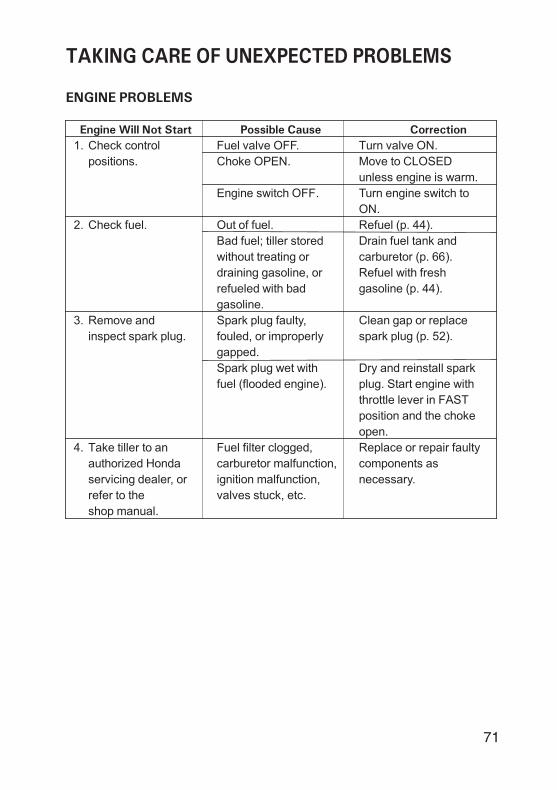
ENGINE PROBLEMS
Possible Cause CorrectionEngine Will Not Start
TAKING CARE OF UNEXPECTED PROBLEMS
Check control
positions.
Check fuel.
Remove and
inspect spark plug.
Take tiller to an
authorized Honda
servicing dealer, or
refer to the
shop manual.
Fuel valve OFF.
Choke OPEN.
Engine switch OFF.
Out of fuel.
Bad fuel; tiller stored
without treating or
draining gasoline, or
refueled with bad
gasoline.
Spark plug faulty,
fouled, or improperly
gapped.
Spark plug wet with
fuel (flooded engine).
Fuel filter clogged,
carburetor malfunction,
ignition malfunction,
valves stuck, etc.
Turn valve ON.
Move to CLOSED
unless engine is warm.
Turn engine switch to
ON.
Refuel (p. 44).
Drain fuel tank and
carburetor (p. 66).
Refuel with fresh
gasoline (p. 44).
Clean gap or replace
spark plug (p. 52).
Dry and reinstall spark
plug. Start engine with
throttle lever in FAST
position and the choke
open.
Replace or repair faulty
components as
necessary.
1.
2.
3.
4.
71
TAKING CARE OF UNEXPECTED PROBLEMS
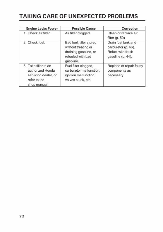
Possible Cause CorrectionEngine Lacks Power
Check air filter.
Check fuel.
Take tiller to an
authorized Honda
servicing dealer, or
refer to the
shop manual.
Air filter clogged.
Bad fuel; tiller stored
without treating or
draining gasoline, or
refueled with bad
gasoline.
Fuel filter clogged,
carburetor malfunction,
ignition malfunction,
valves stuck, etc.
Clean or replace air
filter (p. 50)
Drain fuel tank and
carburetor (p. 66).
Refuel with fresh
gasoline (p. 44).
Replace or repair faulty
components as
necessary.
1.
2.
3.
72
TAKING CARE OF UNEXPECTED PROBLEMS
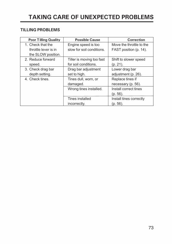
TILLING PROBLEMS
Possible Cause CorrectionPoor Tilling Quality
Engine speed is too
slow for soil conditions.
Tiller is moving too fast
for soil conditions.
Drag bar adjustment
set to high.
Tines dull, worn, or
damaged.
Wrong tines installed.
Tines installed
incorrectly.
Check that the
throttle lever is in
the SLOW position.
Reduce forward
speed.
Check drag bar
depth setting.
Check tines.
Move the throttle to the
FAST position (p. 14).
Shift to slower speed
(p. 21).
Lower drag bar
adjustment (p. 26).
Replace tines if
necessary (p. 56).
Install correct tines
(p. 56).
Install tines correctly
(p. 56).
1.
2.
3.
4.
73
TECHNICAL INFORMATION
TECHNICAL & CONSUMER INFORMATION
Engine serial number:
Frame serial number:
Date of purchase:
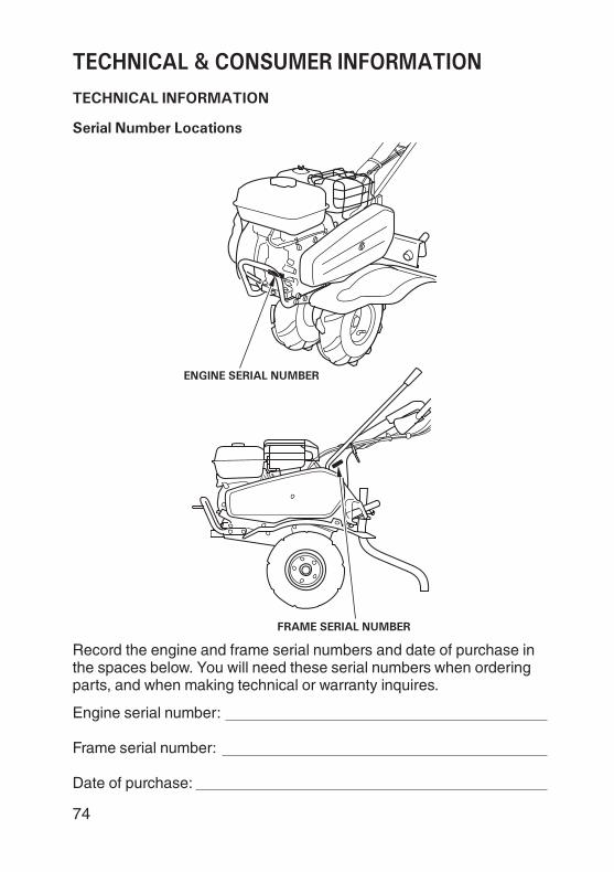
Record the engine and frame serial numbers and date of purchase inthe spaces below. You will need these serial numbers when orderingparts, and when making technical or warranty inquires.
74
ENGINE SERIAL NUMBER
FRAME SERIAL NUMBER
Serial Number Locations
TECHNICAL & CONSUMER INFORMATION
Carburetor Modification for High Altitude Operation
At high altitude, the standard carburetor air-fuel mixture will be toorich. Performance will decrease, and fuel consumption will increase. Avery rich mixture will also foul the spark plug and cause hard starting.Operation at an altitude that differs from that at which this engine wascertified, for extended periods of time, may increase emissions.
High altitude performance can be improved by specific modificationsto the carburetor. If you always operate your tiller at altitudes above1,500 meters, have your servicing dealer perform this carburetormodification. This engine, when operated at high altitude with thecarburetor modifications for high altitude use, will meet each emissionstandard throughout its useful life.
Even with carburetor modification, engine horsepower will decreaseabout 3.5% for each 300-meter increase in altitude. The effect ofaltitude on horsepower will be greater than this if no carburetormodification is made.
When the carburetor has been modified for high altitude operation,the air-fuel mixture will be too lean for low altitude use. Operation ataltitudes below 1,500 meters with a modified carburetor may causethe engine to overheat and result in serious engine damage. For use atlow altitudes, have your servicing dealer return the carburetor tooriginal factory specification.
75
TECHNICAL & CONSUMER INFORMATION
Emission Control System Information
Source of Emissions
Tampering and Altering
Honda utilizes appropriate air/fuel ratios and other emissions controlsystems to reduce the emissions of carbon monoxide, oxides ofnitrogen and hydrocarbons.
Additionally, Honda fuel systems utilize components and controltechnologies to reduce evaporative emissions.
The combustion process produces carbon monoxide, oxides ofnitrogen and hydrocarbons. Control of hydrocarbons and oxides ofnitrogen is very important because, under certain conditions, theyreact to form photochemical smog when subjected to sunlight. Carbonmonoxide does not react in the same way, but it is toxic.
Tampering with or altering the emission control system may increaseemissions beyond the legal limit. Among those acts that constitutetampering are:
Removal or alteration of any part of intake, fuel or exhaust system.
Altering or defeating the governor linkage or speed-adjustingmechanism to cause the engine to operate outside its designparameters.
76
TECHNICAL & CONSUMER INFORMATION
Problems That May Affect Emissions
Replacement Parts
Maintenance
If you are aware of any of the following symptoms, have your engineinspected and repaired by your authorized Honda servicing dealer.
Hard starting or stalling after starting
Rough idle
Misfiring or backfiring under load
Afterburning (backfiring)
Black exhaust smoke or high fuel consumption
The emission control systems on your new Honda engine weredesigned, built and certified to conform to applicable emissionregulations. We recommend the use of Honda Genuine partswhenever you have maintenance done. These original designreplacement parts are manufactured to the same standards as theoriginal parts, so you can be confident of their performance. The useof replacement parts that are not of the original design and qualitymay impair the effectiveness of your emission control system.
A manufacturer of an aftermarket part assumes the responsibility thatthe part will not adversely affect emission performance. Themanufacturer or rebuilder of the part must certify that use of the partwill not result in a failure of the engine to comply with emissionregulations.
Follow the MAINTENANCE SCHEDULE on page . Rememberthat this schedule is based on the assumption that your machine willbe used for its designed purpose. Sustained high-load or high-temperature operation, or use in unusually wet or dusty conditions,will require more frequent service.
43
77
TECHNICAL & CONSUMER INFORMATION
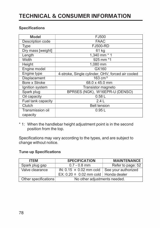
Specifications
Tune-up Specifications
Model
ITEM SPECIFICATION MAINTENANCE
FAAC
Belt tension
W16EPR-U (DENSO)BPR5ES (NGK)Transistor magneto
GX160
68.0 x 45.0 mm163 cm
0.58 L
0.95 L
2.4 L
FJ500
FJ500-RD
925 mm *11,340 mm * 1
61 kg
1,080 mm
Description codeTypeDry mass [weight]LengthWidthHeightEngine modelEngine typeDisplacementBore x StrokeIgnition systemSpark plugOil capacityFuel tank capacityClutchTransmission oilcapacity
Spark plug gapValve clearance
Other specifications No other adjustments needed.
IN: 0.15 0.02 mm coldEX: 0.20 0.02 mm cold
0.7 - 0.8 mm Refer to page: 52See your authorizedHonda dealer
4-stroke, Single cylinder, OHV, forced air cooled
,
Specifications may vary according to the types, and are subject tochange without notice.
When the handlebar height adjustment point is in the secondposition from the top.
* 1:
±±
78
TECHNICAL & CONSUMER INFORMATION
Customer Service Information
CONSUMER INFORMATION
Honda Power Equipment dealership personnel are trainedprofessionals. They should be able to answer any question you mayhave. If you encounter a problem that your dealer does not solve toyour satisfaction, please discuss it with the dealership’s management.The Service Manager or General Manager can help. Almost allproblems are solved in this way.
If you are dissatisfied with the decision made by the dealership’smanagement, contact the Honda Power Equipment CustomerRelations Office.
When you write or call, please give us this information:
Model and serial numbers (see page 74).
Name of the dealer who sold the tiller to you
Name and address of the dealer who services your tiller
Date of purchase
Your name, address, and telephone number
A detailed description of the problem
79
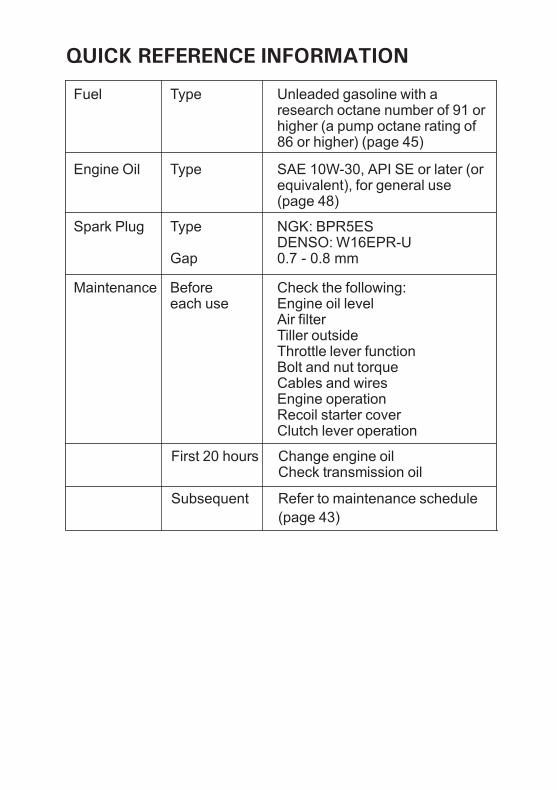
QUICK REFERENCE INFORMATION
0.7 - 0.8 mmDENSO: W16EPR-UNGK: BPR5ES
SAE 10W-30, API SE or later (orequivalent), for general use
Fuel
Engine Oil
Spark Plug
Maintenance
Type
Type
Type
Gap
Beforeeach use
First 20 hours
Subsequent
Unleaded gasoline with aresearch octane number of 91 orhigher (a pump octane rating of86 or higher) (page 45)
Check the following:Engine oil levelAir filterTiller outsideThrottle lever functionBolt and nut torqueCables and wiresEngine operationRecoil starter coverClutch lever operation
Change engine oilCheck transmission oil
Refer to maintenance schedule
(page 43)
(page 48)

Black DIC32300X42-V42-D100_FJ500
42V42D1000X42-V42-D100
oHonda Motor Co., Ltd. 2013
TILLER
OWNER'S MANUAL
FJ500
00X42-V42-D100_FJ500_Cover.indd 100X42-V42-D100_FJ500_Cover.indd 1 2013/09/17 17:25:502013/09/17 17:25:50