Embed Size (px)
Citation preview
Printed in China
EM5000SX/EM6500SX31Z2362100X31-Z23-6210 2021 Honda Motor Co., Ltd. -All Rights Reserved
GENERATOREM5000SX/EM6500SX
Owner’s Manual
H i
FMN
C
AH 英
K
See page 12 for instructions on assembling your generator.See page 17 for Initial Use Instructions.
背幅3mmPANTONE186C
Keep this owner’s manual handy so that you can refer to it any time.This owner’s manual is considered a permanent part of the generator and should remain with the generator if resold.
The information and specifications included in this publication were in effect at the time of approval for printing. Honda Motor Co., Ltd. reserves the right, however, to discontinue or change specifications or design at any time without notice and without incurring any obligation whatsoever.
The illustration may vary according to the type.
The engine exhaust from this product contains chemicals known to the State of California to
cause cancer, birth defects or other reproductive harm.
Exhaust contains poisonous carbon monoxide gas that can build up to dangerous levels in enclosed or partly enclosed areas.
Breathing carbon monoxide can cause unconsciousness or death.
Never run this product's engine in an enclosed, or even partly enclosed area.

INTRODUCTIONThank you for purchasing a Honda generator.
We would like to help you get the best results from your new generator and to operate it safely. This manual contains the information on how to do that; please read it carefully.
We suggest you read the "Distributor’s Limited Warranty" (see page 98) to fully understand its coverage and your responsibilities of ownership.
When your generator needs scheduled maintenance, keep in mind that your Honda servicing dealer is specially trained in servicing Honda generators and is supported by the parts and service divisions of American Honda. Your Honda servicing dealer is dedicated to your satisfaction and will be pleased to answer your questions and concerns.
1
INTRODUCTION
A FEW WORDS ABOUT SAFETY
Your safety and the safety of others are very important.
We have provided important safety messages in this manual and on the generator. This information alerts you to potential hazards that could hurt you or others. Please read these messages carefully.
Of course, it is not practical or possible to warn you about all the hazards associated with operating or maintaining a generator. You must use your own good judgment.
You will find important safety information in a variety of forms:
• Safety Labels — on the generator.
• Instructions — how to use this generator correctly and safely.
• Safety Headings — such as IMPORTANT SAFETY INFORMATION.
• Safety Messages — preceded by a safety alert symbol and one of three signal words, DANGER, WARNING, or CAUTION.
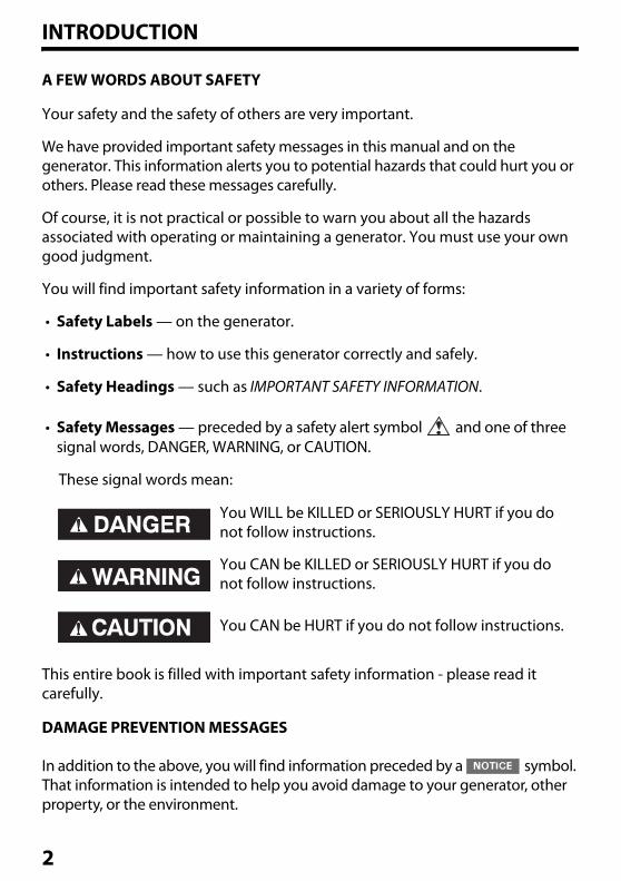
These signal words mean:
This entire book is filled with important safety information - please read it carefully.
DAMAGE PREVENTION MESSAGES
In addition to the above, you will find information preceded by a symbol. That information is intended to help you avoid damage to your generator, other property, or the environment.
You WILL be KILLED or SERIOUSLY HURT if you do not follow instructions.
You CAN be KILLED or SERIOUSLY HURT if you do not follow instructions.
You CAN be HURT if you do not follow instructions.
2
CONTENTSINTRODUCTION ................................................................................................ 1
GENERATOR SAFETY ........................................................................................ 7IMPORTANT SAFETY INFORMATION................................................................................ 7
Operator Responsibility................................................................................................... 7Carbon Monoxide Hazards.............................................................................................8Electric Shock Hazards ..................................................................................................... 9Fire and Burn Hazards ...................................................................................................... 9Refuel With Care...............................................................................................................10Vehicles and Transportation Hazards.......................................................................10
SAFETY LABEL LOCATIONS................................................................................................11
ASSEMBLY ....................................................................................................... 12SAFETY......................................................................................................................................12
The Importance of Proper Assembly ........................................................................12ASSEMBLY................................................................................................................................13
Unpacking ..........................................................................................................................13Loose Parts (Wheel kit and handle)...........................................................................13Handle Installation ..........................................................................................................14Wheel Kit Installation......................................................................................................15Battery..................................................................................................................................16
INITIAL USE INSTRUCTIONS ........................................................................... 17ENGINE OIL..............................................................................................................................17ENGINE OIL RECOMMENDATIONS..................................................................................18FUEL...........................................................................................................................................19FUEL RECOMMENDATIONS...............................................................................................21
CONTROLS & FEATURES................................................................................. 22COMPONENT & CONTROL LOCATIONS ........................................................................22CONTROLS...............................................................................................................................24
Engine Switch....................................................................................................................24Starter Grip .........................................................................................................................24Fuel Valve Lever................................................................................................................25CO-MINDER (CO Shut-off System) .............................................................................26Voltage Selector Switch.................................................................................................28Auto Throttle® System ...................................................................................................29AC Circuit Breaker ............................................................................................................29AC Circuit Protectors ......................................................................................................30Ground Fault Circuit Interrupter (GFCI) Receptacle ............................................31DC Terminals .....................................................................................................................32DC Circuit Protector ........................................................................................................32Folding Handle .................................................................................................................33
3
CONTENTS
FEATURES ................................................................................................................................34Oil Alert® System ..............................................................................................................34Automatic Engine Stop Function...............................................................................34Auto Choke and Throttle Control System...............................................................35iAVR (Intelligent Auto Voltage Regulator) ..............................................................35Fuel Gauge .........................................................................................................................36Ground Terminal..............................................................................................................36Bluetooth® Function ........................................................................................................37Smartphone application ...............................................................................................37
BEFORE OPERATION....................................................................................... 38ARE YOU READY TO GET STARTED? ...............................................................................38
Knowledge .........................................................................................................................38IS YOUR GENERATOR READY TO GO?............................................................................38
Check the Engine.............................................................................................................39Check the GFCI..................................................................................................................39AC Appliance and Power Cord....................................................................................39
ENGINE OIL LEVEL CHECK ..................................................................................................40AIR FILTER CHECK .................................................................................................................41SAFE OPERATING PRECAUTIONS ....................................................................................43
OPERATION ..................................................................................................... 44STARTING THE ENGINE .......................................................................................................44STOPPING THE ENGINE.......................................................................................................48STARTING AND STOPPING THE ENGINE with Bluetooth® ENABLED
SMARTPHONE ...................................................................................................................49HOW TO RESTART WHEN STOPPED BY CO-MINDER (CO SHUT-OFF SYSTEM)
................................................................................................................................................49GFCI OPERATION CHECK....................................................................................................50AC OPERATION ......................................................................................................................53
AC Applications ................................................................................................................55AC Receptacle Selection................................................................................................56Power Producing Circuits .............................................................................................56Voltage Selector Switch.................................................................................................57
DC OPERATION ......................................................................................................................58Connecting the battery charging cable (optional equipment): .....................58Disconnecting the battery charging cable:............................................................59
AUTO THROTTLE® SYSTEM ................................................................................................60STANDBY POWER..................................................................................................................61
Connections to a Building’s Electrical System.......................................................61System Ground .................................................................................................................61Special Requirements.....................................................................................................62
4
CONTENTS
SERVICING YOUR GENERATOR ...................................................................... 63THE IMPORTANCE OF MAINTENANCE...........................................................................63MAINTENANCE SAFETY ......................................................................................................64
Safety Precautions...........................................................................................................64MAINTENANCE SCHEDULE................................................................................................65ENGINE OIL CHANGE ...........................................................................................................66AIR CLEANER SERVICE .........................................................................................................67
Foam Air Filter Cleaning................................................................................................67SPARK PLUG SERVICE ..........................................................................................................68SPARK ARRESTER SERVICE .................................................................................................70SEDIMENT CUP CLEANING ................................................................................................71BATTERY SERVICE..................................................................................................................72
Emergency Procedures..................................................................................................72Battery Removal ...............................................................................................................73Battery Charging ..............................................................................................................74Battery Installation ..........................................................................................................74
FUSE...........................................................................................................................................76
STORAGE ......................................................................................................... 77STORAGE PREPARATION ....................................................................................................77
Cleaning ..............................................................................................................................77Fuel .......................................................................................................................................77Engine Oil ...........................................................................................................................80Engine Cylinder ................................................................................................................80Battery..................................................................................................................................80
STORAGE PRECAUTIONS....................................................................................................81REMOVAL FROM STORAGE................................................................................................81
TRANSPORTING .............................................................................................. 82
TAKING CARE OF UNEXPECTED PROBLEMS ................................................. 84ENGINE WILL NOT START ...................................................................................................84ENGINE LACKS POWER........................................................................................................85NO POWER AT THE AC RECEPTACLES ...........................................................................85NO POWER AT THE DC TERMINALS................................................................................86ENGINE AUTOMATICALLY STOP AND THE CO ALARM INDICATOR
FLASHING ...........................................................................................................................86ENGINE AUTOMATICALLY STOP AND THE FAULT/CO SENSOR LIFE
INDICATOR FLASHING....................................................................................................86FAULT/CO SENSOR LIFE INDICATOR FLASHING WHEN RUNNING
THE ENGINE........................................................................................................................86
5
CONTENTS
TECHNICAL INFORMATION ............................................................................ 87SERIAL NUMBER LOCATION ..............................................................................................87CARBURETOR MODIFICATION FOR HIGH ALTITUDE OPERATION.......................88EMISSION CONTROL SYSTEM INFORMATION.............................................................89SPECIFICATION ......................................................................................................................92WIRING DIAGRAM.................................................................................................................94
CONSUMER INFORMATION............................................................................ 96DEALER LOCATOR INFORMATION..................................................................................96Honda PUBLICATIONS.........................................................................................................96CUSTOMER SERVICE INFORMATION ..............................................................................97Distributor’s Limited Warranty .......................................................................................98Emission Control System Warranty ............................................................................ 103REGISTRATION .................................................................................................................... 108
OPTIONAL PARTS ......................................................................................... 109REMOTE CONTROL KIT..................................................................................................... 109
Remote Control Box..................................................................................................... 110HANGER KIT ......................................................................................................................... 111
REFERENCE INFORMATION.......................................................................... 112
INDEX ............................................................................................................ 113
QUICK REFERENCE INFORMATION ....................................... inside back cover
6
GENERATOR SAFETYIMPORTANT SAFETY INFORMATION
Honda generators are designed for use with electrical equipment that has suitable power requirements. Other uses can result in injury to the operator or damage to the generator and other property.
Most injuries or property damage can be prevented if you follow all instructions in this manual and on the generator. The most common hazards are discussed below, along with the best way to protect yourself and others.
Operator Responsibility• Never attempt to modify the generator. It can cause an accident as well as
damage to the generator and appliances.
• Know how to stop the generator quickly in case of emergency.
• Understand the use of all generator controls, output receptacles, and connections.
• Be sure that anyone who operates the generator receives proper instruction.
• Protect children by keeping them at a safe distance from the generator.
• Obey all applicable laws and regulations where the generator is used.
7
GENERATOR SAFETY
Carbon Monoxide HazardsA generator's exhaust contains toxic carbon monoxide, which you cannot see or smell. Breathing carbon monoxide can KILL YOU IN MINUTES. To avoid carbon monoxide poisoning, follow these instructions when operating a generator:
• Only run a generator OUTSIDE, far away from windows, doors, and vents with engine exhaust directed away from occupied structures.
• Never operate a generator inside a house, garage, basement, crawl space, any type of vehicle, trailer, or boat, or any enclosed or partly enclosed space.
• Never operate a generator near open doors, windows, vents, or hatches.
• Get fresh air and seek medical attention immediately if you suspect you have inhaled carbon monoxide.
Early symptoms of carbon monoxide exposure include headache, fatigue, shortness of breath, nausea, and dizziness. Continued exposure to carbon monoxide can cause loss of muscular coordination, loss of consciousness, and then death.
To alert you to potentially dangerous levels of carbon monoxide coming from a generator operating outside or from other sources, install battery operated carbon monoxide alarms or plug-in carbon monoxide alarms with battery back-up on every level of your home, outside sleeping areas, inside any type of vehicle, trailer, or boat in accordance with the alarm’s instructions.
CO-MINDER:This generator is equipped with a CO-MINDER system that automatically stops the engine before the surrounding carbon monoxide concentration exceeds a certain concentration.• Do not modify the CO-MINDER.• The CO-MINDER cannot prevent all danger associated with or caused by
carbon monoxide. Pay careful attention to the location of the generator (see page 26).
8
GENERATOR SAFETY
Electric Shock HazardsThe generator produces enough electric power to cause a serious shock or electrocution if misused.
• Do not use in wet conditions. Keep the generator dry.– Do not use in the rain or snow.– Do not use near pool or a sprinkler system.– Do not use when your hands are wet.
• If the generator is stored outdoors, unprotected from the weather, check all of the electrical components on the control panel before each use. Moisture or ice can cause a malfunction or short circuit in electrical components that could result in electrocution.
• Do not connect to a building’s electrical system unless an isolation switch has been installed by a qualified electrician.
Fire and Burn Hazards• The exhaust system gets hot enough to ignite some materials.
– Keep the generator at least 3 feet (1 meter) away from buildings and any type of vehicle, trailer, boat, or other equipment during operation.
– Do not enclose the generator in any structure.– Keep flammable materials away from the generator.– Generators with standard equipment transport wheels must not be
operated with the wheels and/or stands removed.– Do not block intake or exhaust vents, hoses, ports, or restrict air into or
away from generator.– Do not add, remove, or modify covers, panels, cowlings, or straps.
• The muffler becomes very hot during operation and remains hot for a while after stopping the engine. Be careful not to touch the muffler while it is hot. Let the engine cool before storing the generator.
• Do not pour the water directly on the generator to put out the fire when it occurs. Use an appropriate fire extinguisher specially designed for electric fire or oil fire.
9
GENERATOR SAFETY
Refuel With CareGasoline is highly flammable, and gasoline vapor can explode.
• Do not refuel during operation.
• Allow the engine to cool if it has been in operation.
• Refuel only outdoors in a well-ventilated area and on a level surface.
• Never smoke near gasoline, and keep other flames and sparks away.
• Do not overfill the fuel tank.
• Make sure that any spilled fuel has been wiped up and cleaned before starting the engine.
• Always store gasoline in an approved container.
Vehicles and Transportation Hazards• Do not operate the generator while it is being transported or while it is
mounted to any type vehicle, trailer, or boat.
• Do not operate the generator when it is in a storage, cargo, or security enclosure, including any RV generator bay.
• Always completely remove the generator from the vehicle, RV, truck, trailer, boat, other equipment or structure during operation.
• The generator must remain stationary while in operation.
10
GENERATOR SAFETY
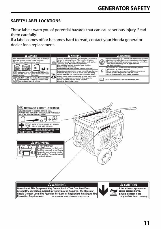
SAFETY LABEL LOCATIONS
These labels warn you of potential hazards that can cause serious injury. Read them carefully.If a label comes off or becomes hard to read, contact your Honda generator dealer for a replacement.
11
ASSEMBLYSAFETY
The Importance of Proper AssemblyProper assembly is essential to operator safety and the reliability of the machine.
We cannot warn you of every conceivable hazard that can arise in performing this assembly. Only you can decide whether or not you should perform a given task.
Improper assembly can cause an unsafe condition.
Failure to properly follow assembly procedures can lead to serious injury or death.
Follow the procedures and precautions in this owner’s manual carefully.
12
ASSEMBLY
ASSEMBLY
Unpacking1. Remove the generator and loose parts box from the carton.
2. Compare the loose parts with the inventory list below.
Tools Required: 12 mm wrench (2), pliers
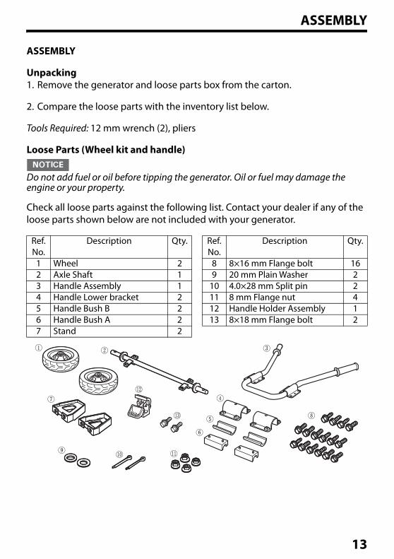
Loose Parts (Wheel kit and handle)
Do not add fuel or oil before tipping the generator. Oil or fuel may damage the engine or your property.
Check all loose parts against the following list. Contact your dealer if any of the loose parts shown below are not included with your generator.
Ref. No.
Description Qty. Ref. No.
Description Qty.
1 Wheel 2 8 8×16 mm Flange bolt 162 Axle Shaft 1 9 20 mm Plain Washer 23 Handle Assembly 1 10 4.0×28 mm Split pin 24 Handle Lower bracket 2 11 8 mm Flange nut 45 Handle Bush B 2 12 Handle Holder Assembly 16 Handle Bush A 2 13 8×18 mm Flange bolt 27 Stand 2
13
ASSEMBLY
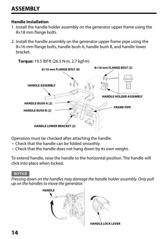
Handle Installation1. Install the handle holder assembly on the generator upper frame using the
8×18 mm flange bolts.
2. Install the handle assembly on the generator upper frame pipe using the 8×16 mm flange bolts, handle bush A, handle bush B, and handle lower bracket.
Torque: 19.5 lbf·ft (26.5 N·m, 2.7 kgf·m)
Operation must be checked after attaching the handle.• Check that the handle can be folded smoothly.• Check that the handle does not hang down by its own weight.
To extend handle, raise the handle to the horizontal position. The handle will click into place when locked.
Pressing down on the handles may damage the handle holder assembly. Only pull up on the handles to move the generator.
8×18 mm FLANGE BOLT (2)8×16 mm FLANGE BOLT (8)
HANDLE ASSEMBLY
HANDLE BUSH A (2)
HANDLE BUSH B (2)
HANDLE LOWER BRACKET (2)
FRAME PIPE
HANDLE HOLDER ASSEMBLY
HANDLE
HANDLE LOCK LEVER
14
ASSEMBLY
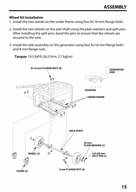
Wheel Kit Installation1. Install the two stands on the under frame using four 8×16 mm flange bolts.
2. Install the two wheels on the axle shaft using the plain washers and split pins. After installing the split pins, bend the pins to ensure that the wheels are secured to the axle.
3. Install the axle assembly on the generator using four 8×16 mm flange bolts and 8 mm flange nuts.
Torque: 19.5 lbf·ft (26.5 N·m, 2.7 kgf·m)
8×16 mm FLANGE BOLT (8)
SHORTER
UNDER FRAME
GENERATORSIDE
AXLE SHAFT
20 mmPLAIN WASHER (2)
4.0×28 mmSPLIT PIN (2)
8 mm FLANGE NUT (4)STAND (2)
WHEEL (2)
15
ASSEMBLY
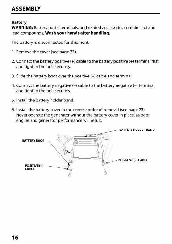
BatteryWARNING: Battery posts, terminals, and related accessories contain lead and lead compounds. Wash your hands after handling.
The battery is disconnected for shipment.
1. Remove the cover (see page 73).
2. Connect the battery positive (+) cable to the battery positive (+) terminal first, and tighten the bolt securely.
3. Slide the battery boot over the positive (+) cable and terminal.
4. Connect the battery negative (–) cable to the battery negative (–) terminal, and tighten the bolt securely.
5. Install the battery holder band.
6. Install the battery cover in the reverse order of removal (see page 73).Never operate the generator without the battery cover in place, as poor engine and generator performance will result.
BATTERY BOOT
POSITIVE (+)CABLE
BATTERY HOLDER BAND
NEGATIVE (–) CABLE
16
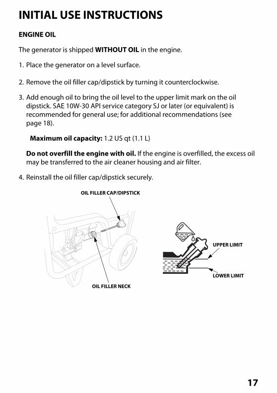
INITIAL USE INSTRUCTIONSENGINE OIL
The generator is shipped WITHOUT OIL in the engine.
1. Place the generator on a level surface.
2. Remove the oil filler cap/dipstick by turning it counterclockwise.
3. Add enough oil to bring the oil level to the upper limit mark on the oil dipstick. SAE 10W-30 API service category SJ or later (or equivalent) is recommended for general use; for additional recommendations (see page 18).
Maximum oil capacity: 1.2 US qt (1.1 L)
Do not overfill the engine with oil. If the engine is overfilled, the excess oil may be transferred to the air cleaner housing and air filter.
4. Reinstall the oil filler cap/dipstick securely.
UPPER LIMIT
OIL FILLER CAP/DIPSTICK
OIL FILLER NECK
LOWER LIMIT
17
INITIAL USE INSTRUCTIONS
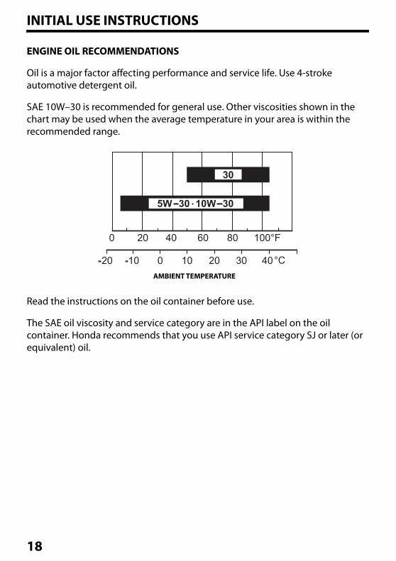
ENGINE OIL RECOMMENDATIONS
Oil is a major factor affecting performance and service life. Use 4-stroke automotive detergent oil.
SAE 10W–30 is recommended for general use. Other viscosities shown in the chart may be used when the average temperature in your area is within the recommended range.
Read the instructions on the oil container before use.
The SAE oil viscosity and service category are in the API label on the oil container. Honda recommends that you use API service category SJ or later (or equivalent) oil.
AMBIENT TEMPERATURE
18
INITIAL USE INSTRUCTIONS
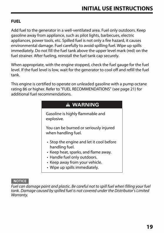
FUEL
Add fuel to the generator in a well-ventilated area. Fuel only outdoors. Keep gasoline away from appliance, such as pilot lights, barbecues, electric appliances, power tools, etc. Spilled fuel is not only a fire hazard, it causes environmental damage. Fuel carefully to avoid spilling fuel. Wipe up spills immediately. Do not fill the fuel tank above the upper level mark (red) on the fuel strainer. After fueling, reinstall the fuel tank cap securely.
When appropriate, with the engine stopped, check the fuel gauge for the fuel level. If the fuel level is low, wait for the generator to cool off and refill the fuel tank.
This engine is certified to operate on unleaded gasoline with a pump octane rating 86 or higher. Refer to "FUEL RECOMMENDATIONS" (see page 21) for additional fuel recommendations.
Fuel can damage paint and plastic. Be careful not to spill fuel when filling your fuel tank. Damage caused by spilled fuel is not covered under the Distributor’s Limited Warranty.
Gasoline is highly flammable and explosive.
You can be burned or seriously injured when handling fuel.
• Stop the engine and let it cool before handling fuel.
• Keep heat, sparks, and flame away.• Handle fuel only outdoors.• Keep away from your vehicle.• Wipe up spills immediately.
19
INITIAL USE INSTRUCTIONS
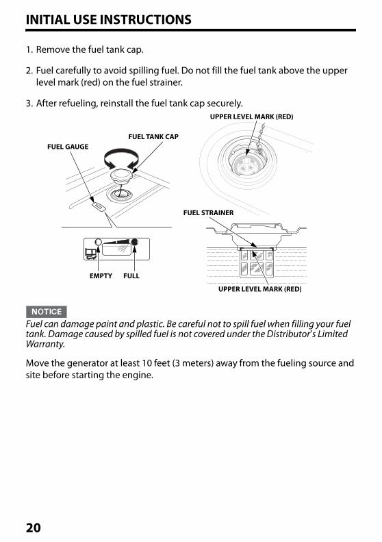
1. Remove the fuel tank cap.
2. Fuel carefully to avoid spilling fuel. Do not fill the fuel tank above the upper level mark (red) on the fuel strainer.
3. After refueling, reinstall the fuel tank cap securely.
Fuel can damage paint and plastic. Be careful not to spill fuel when filling your fuel tank. Damage caused by spilled fuel is not covered under the Distributor’s Limited Warranty.
Move the generator at least 10 feet (3 meters) away from the fueling source and site before starting the engine.
UPPER LEVEL MARK (RED)
FUEL STRAINER
UPPER LEVEL MARK (RED)
FULLEMPTY
FUEL GAUGEFUEL TANK CAP
20
INITIAL USE INSTRUCTIONS
FUEL RECOMMENDATIONS
This engine is certified to operate on regular unleaded gasoline with a pump octane rating of 86 or higher.
Never use gasoline that is stale, contaminated, or mixed with oil. Avoid getting dirt or water in the fuel tank.
You may use regular unleaded gasoline containing no more than 10% ethanol (E10) or 5% methanol by volume. In addition, methanol must contain cosolvents and corrosion inhibitors.
Use of fuels with content of ethanol or methanol greater than shown above may cause starting and/or performance problems. It may also damage metal, rubber, and plastic parts of the fuel system.
Engine damage or performance problems that result from using a fuel with percentages of ethanol or methanol greater than shown above and leaded gasoline are not covered under the Distributor Limited Warranty.
If your equipment will be used on an infrequent basis, refer to the fuel section of "STORAGE" chapter (see page 77) for additional information regarding fuel deterioration.
21
CONTROLS & FEATURESCOMPONENT & CONTROL LOCATIONS
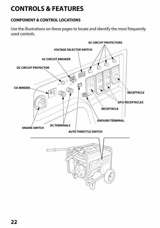
Use the illustrations on these pages to locate and identify the most frequently used controls.
VOLTAGE SELECTOR SWITCH
AC CIRCUIT BREAKER
DC CIRCUIT PROTECTOR
ENGINE SWITCHDC TERMINALS
AUTO THROTTLE SWITCH
GROUND TERMINAL
AC CIRCUIT PROTECTORS
GFCI RECEPTACLES
RECEPTACLE
RECEPTACLE
CO-MINDER
22
CONTROLS & FEATURES
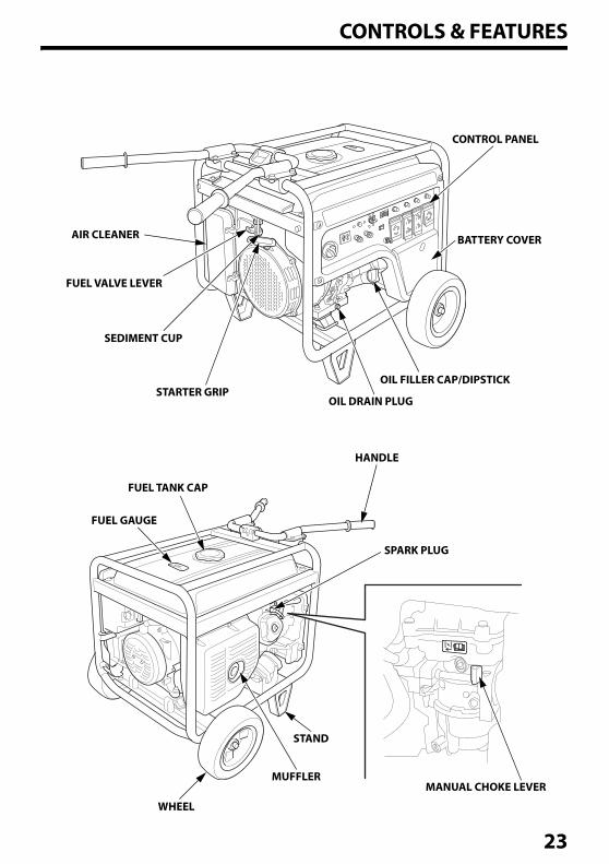
AIR CLEANER
FUEL VALVE LEVER
SEDIMENT CUP
STARTER GRIPOIL DRAIN PLUG
OIL FILLER CAP/DIPSTICK
BATTERY COVER
CONTROL PANEL
HANDLE
SPARK PLUG
FUEL TANK CAP
FUEL GAUGE
WHEEL
MUFFLER
STAND
MANUAL CHOKE LEVER
23
CONTROLS & FEATURES
CONTROLS
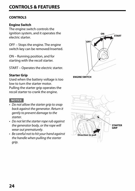
Engine SwitchThe engine switch controls the ignition system, and it operates the electric starter.
OFF – Stops the engine. The engine switch key can be removed/inserted.
ON – Running position, and for starting with the recoil starter.
START – Operates the electric starter.
Starter GripUsed when the battery voltage is too low to turn the starter motor.Pulling the starter grip operates the recoil starter to crank the engine.
• Do not allow the starter grip to snap back against the generator. Return it gently to prevent damage to the starter.
• Do not let the starter rope rub against the generator body, or the rope will wear out prematurely.
• Be careful not to hit your hand against the handle when pulling the starter grip.
ENGINE SWITCH
OFF
ON
STARTER GRIP
START
Direction to pull
24

CONTROLS & FEATURES
Fuel Valve LeverThe fuel valve lever is located between the fuel tank and carburetor.
The fuel valve must be in the ON position for the engine to run.
After stopping the engine, turn the fuel valve to the OFF position.
ON
OFF
FUEL VALVE LEVER
25
CONTROLS & FEATURES
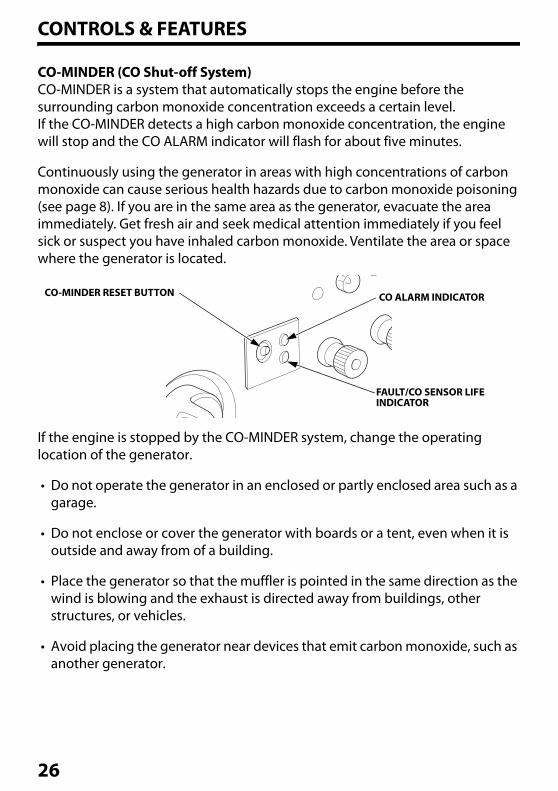
CO-MINDER (CO Shut-off System)CO-MINDER is a system that automatically stops the engine before the surrounding carbon monoxide concentration exceeds a certain level. If the CO-MINDER detects a high carbon monoxide concentration, the engine will stop and the CO ALARM indicator will flash for about five minutes.
Continuously using the generator in areas with high concentrations of carbon monoxide can cause serious health hazards due to carbon monoxide poisoning (see page 8). If you are in the same area as the generator, evacuate the area immediately. Get fresh air and seek medical attention immediately if you feel sick or suspect you have inhaled carbon monoxide. Ventilate the area or space where the generator is located.
If the engine is stopped by the CO-MINDER system, change the operating location of the generator.
• Do not operate the generator in an enclosed or partly enclosed area such as a garage.
• Do not enclose or cover the generator with boards or a tent, even when it is outside and away from of a building.
• Place the generator so that the muffler is pointed in the same direction as the wind is blowing and the exhaust is directed away from buildings, other structures, or vehicles.
• Avoid placing the generator near devices that emit carbon monoxide, such as another generator.
CO-MINDER RESET BUTTON CO ALARM INDICATOR
FAULT/CO SENSOR LIFE INDICATOR
26
CONTROLS & FEATURES
RESTARTING THE ENGINEWhen the engine is stopped automatically by CO-MINDER, press the CO-MINDER reset button to restart the engine.If the engine is restarted without pressing the CO-MINDER reset button, the engine will automatically stop immediately after restarting and the CO ALARM indicator will flash for approximately five minutes.Resetting the CO-MINDER is possible only after the CO ALARM indicator is turned off.
CO-MINDER MALFUNCTION DETECTIONIf the CO-MINDER detects a system malfunction, the engine will stop automatically and the FAULT/CO SENSOR LIFE indicator will flash for approximately five minutes. Press the CO-MINDER reset button to turn off the FAULT/CO SENSOR LIFE indicator. If the engine will not remain running after attempting to restart it and the FAULT/CO SENSOR LIFE indicator comes on again, there may be a system malfunction. If this occurs, do not attempt to restart the generator more than two times. If the CO-MINDER system is malfunctioning, it cannot warn you of potential high concentrations of carbon monoxide. Move the generator to a well-ventilated location and consult an authorized Honda Power Equipment dealer.
CO SENSOR LIFEIf the FAULT/CO SENSOR LIFE indicator flashes when operating the generator, the CO-MINDER may be reaching the end of its useful lifespan and will eventually need replacement.• If the indicator flashes once every four seconds, this means there is
approximately six months to one year of life left in the CO-MINDER.• If the indicator flashes once every two seconds, this means there is
approximately six months of life or less left in the CO-MINDER.
• The FAULT/CO SENSOR LIFE indicator indicates the estimated life left in the CO-MINDER.
• The generator stopping period and storage period are also included in the useful lifespan of the CO-MINDER.
• Contact an authorized Honda Power Equipment dealer for CO-MINDER replacement.
27
CONTROLS & FEATURES
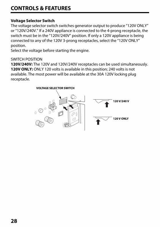
Voltage Selector SwitchThe voltage selector switch switches generator output to produce “120V ONLY” or “120V/240V.” If a 240V appliance is connected to the 4-prong receptacle, the switch must be in the “120V/240V” position. If only a 120V appliance is being connected to any of the 120V 3-prong receptacles, select the “120V ONLY” position.Select the voltage before starting the engine.
SWITCH POSITION120V/240V: The 120V and 120V/240V receptacles can be used simultaneously.120V ONLY: ONLY 120 volts is available in this position; 240 volts is not available. The most power will be available at the 30A 120V locking plug receptacle.
VOLTAGE SELECTOR SWITCH
120 V/240 V
120 V ONLY
28
CONTROLS & FEATURES
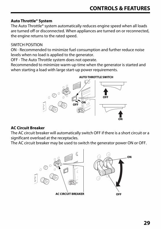
Auto Throttle® SystemThe Auto Throttle® system automatically reduces engine speed when all loads are turned off or disconnected. When appliances are turned on or reconnected, the engine returns to the rated speed.
SWITCH POSITIONON - Recommended to minimize fuel consumption and further reduce noise levels when no load is applied to the generator.OFF - The Auto Throttle system does not operate.Recommended to minimize warm-up time when the generator is started and when starting a load with large start-up power requirements.
AC Circuit BreakerThe AC circuit breaker will automatically switch OFF if there is a short circuit or a significant overload at the receptacles.The AC circuit breaker may be used to switch the generator power ON or OFF.
AUTO THROTTLE SWITCH
OFF
ON
ONOFF
AC CIRCUIT BREAKER
ON
OFF
29
CONTROLS & FEATURES
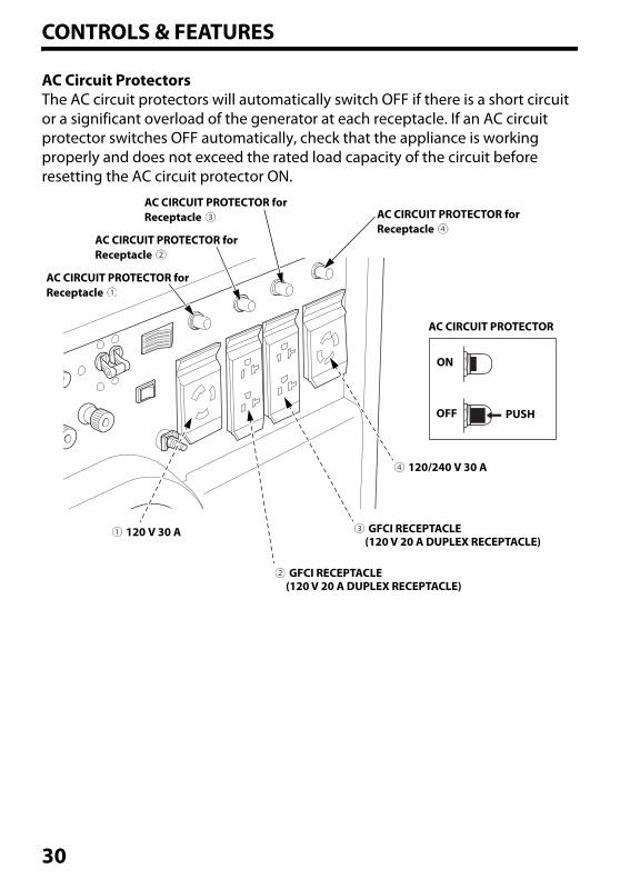
AC Circuit ProtectorsThe AC circuit protectors will automatically switch OFF if there is a short circuit or a significant overload of the generator at each receptacle. If an AC circuit protector switches OFF automatically, check that the appliance is working properly and does not exceed the rated load capacity of the circuit before resetting the AC circuit protector ON.
AC CIRCUIT PROTECTOR for Receptacle
AC CIRCUIT PROTECTOR for Receptacle
AC CIRCUIT PROTECTOR for Receptacle
AC CIRCUIT PROTECTOR for Receptacle
120 V 30 A
120/240 V 30 A
GFCI RECEPTACLE (120 V 20 A DUPLEX RECEPTACLE)
GFCI RECEPTACLE (120 V 20 A DUPLEX RECEPTACLE)
OFF
ON
PUSH
AC CIRCUIT PROTECTOR
30
CONTROLS & FEATURES
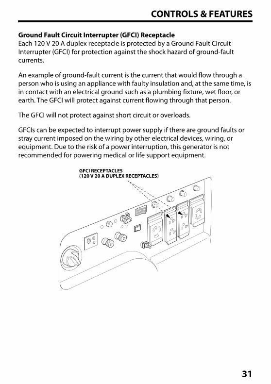
Ground Fault Circuit Interrupter (GFCI) ReceptacleEach 120 V 20 A duplex receptacle is protected by a Ground Fault Circuit Interrupter (GFCI) for protection against the shock hazard of ground-fault currents.
An example of ground-fault current is the current that would flow through a person who is using an appliance with faulty insulation and, at the same time, is in contact with an electrical ground such as a plumbing fixture, wet floor, or earth. The GFCI will protect against current flowing through that person.
The GFCI will not protect against short circuit or overloads.
GFCIs can be expected to interrupt power supply if there are ground faults or stray current imposed on the wiring by other electrical devices, wiring, or equipment. Due to the risk of a power interruption, this generator is not recommended for powering medical or life support equipment.
GFCI RECEPTACLES(120 V 20 A DUPLEX RECEPTACLES)
31
CONTROLS & FEATURES
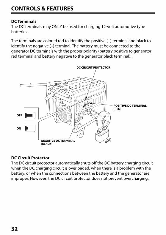
DC TerminalsThe DC terminals may ONLY be used for charging 12-volt automotive type batteries.
The terminals are colored red to identify the positive (+) terminal and black to identify the negative (–) terminal. The battery must be connected to the generator DC terminals with the proper polarity (battery positive to generator red terminal and battery negative to the generator black terminal).
DC Circuit ProtectorThe DC circuit protector automatically shuts off the DC battery charging circuit when the DC charging circuit is overloaded, when there is a problem with the battery, or when the connections between the battery and the generator are improper. However, the DC circuit protector does not prevent overcharging.
DC CIRCUIT PROTECTOR
POSITIVE DC TERMINAL (RED)
NEGATIVE DC TERMINAL (BLACK)
OFF
ON
32
CONTROLS & FEATURES
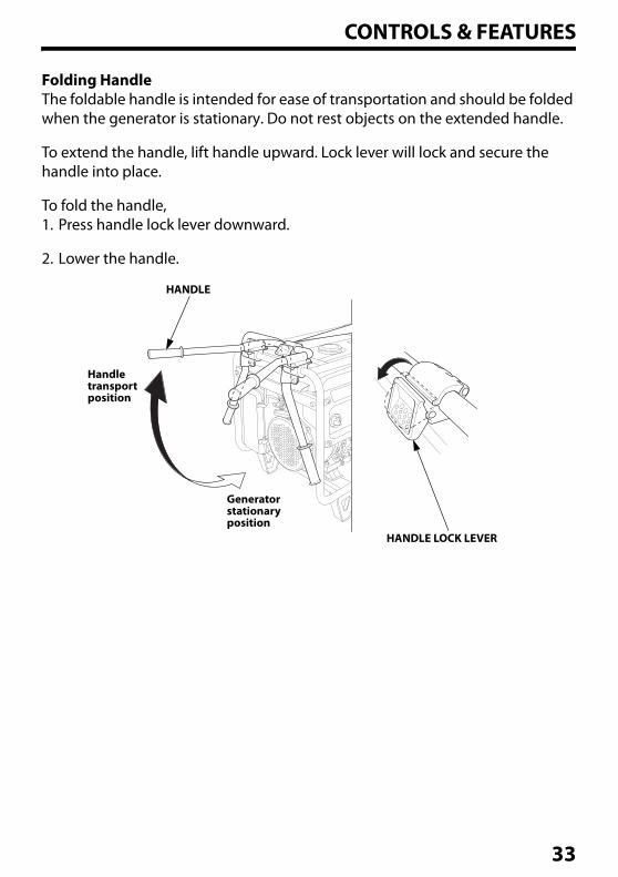
Folding HandleThe foldable handle is intended for ease of transportation and should be folded when the generator is stationary. Do not rest objects on the extended handle.
To extend the handle, lift handle upward. Lock lever will lock and secure the handle into place.
To fold the handle,1. Press handle lock lever downward.
2. Lower the handle.
HANDLE LOCK LEVER
HANDLE
Handle transport position
Generator stationary position
33
CONTROLS & FEATURES
FEATURES
Oil Alert® SystemThe Oil Alert system is designed to prevent engine damage caused by an insufficient amount of oil in the crankcase. Before the oil level in the crankcase can fall below a safe limit, the Oil Alert system will automatically stop the engine (the engine switch will remain in the ON position).
If the engine stops and will not restart, check the engine oil level (see page 40) before troubleshooting in other areas.
Automatic Engine Stop Function
OIL ALERT FUNCTIONDuring operation, the engine will automatically stop if there is not enough oil in the tank. Moreover, if the generator is on a slope, the oil alert function may operate and stop the engine.
OVERSPEED DETECTION FUNCTIONTo protect the engine from exceeding the engine load, the engine will automatically stop if the engine speed becomes abnormal.
ABNORMAL VOLTAGE DETECTION FUNCTIONThe engine will automatically stop during generation when it detects abnormal voltage.
If the engine stops, make sure the oil level is correct. Wait a few minutes, and then try to restart the engine. If the engine still won’t start, take the generator to your authorized servicing Honda Power Equipment dealer.
34
CONTROLS & FEATURES
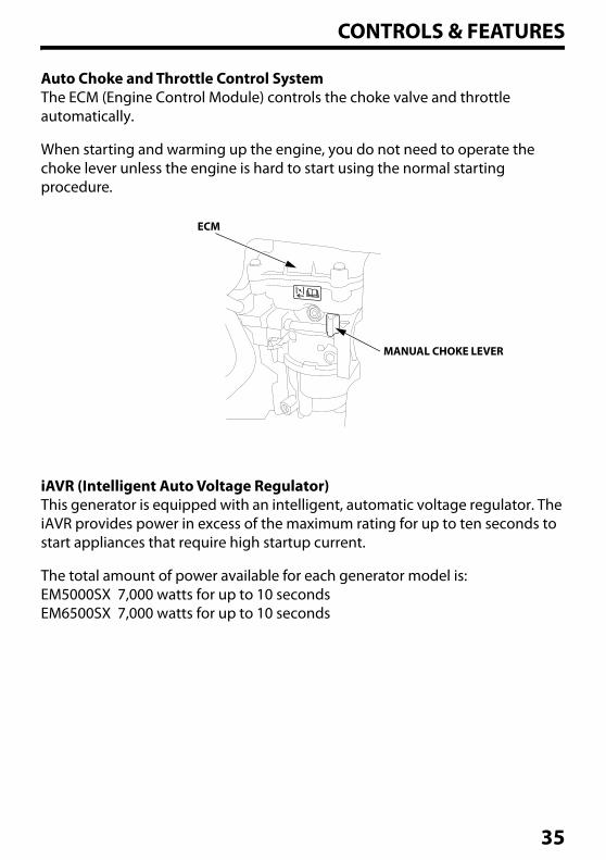
Auto Choke and Throttle Control SystemThe ECM (Engine Control Module) controls the choke valve and throttle automatically.
When starting and warming up the engine, you do not need to operate the choke lever unless the engine is hard to start using the normal starting procedure.
iAVR (Intelligent Auto Voltage Regulator)This generator is equipped with an intelligent, automatic voltage regulator. The iAVR provides power in excess of the maximum rating for up to ten seconds to start appliances that require high startup current.
The total amount of power available for each generator model is:EM5000SX 7,000 watts for up to 10 secondsEM6500SX 7,000 watts for up to 10 seconds
MANUAL CHOKE LEVER
ECM
35
CONTROLS & FEATURES
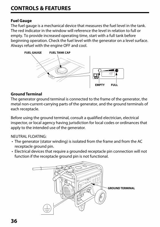
Fuel GaugeThe fuel gauge is a mechanical device that measures the fuel level in the tank. The red indicator in the window will reference the level in relation to full or empty. To provide increased operating time, start with a full tank before beginning operation. Check the fuel level with the generator on a level surface. Always refuel with the engine OFF and cool.
Ground TerminalThe generator ground terminal is connected to the frame of the generator, the metal non-current-carrying parts of the generator, and the ground terminals of each receptacle.
Before using the ground terminal, consult a qualified electrician, electrical inspector, or local agency having jurisdiction for local codes or ordinances that apply to the intended use of the generator.
NEUTRAL FLOATING:• The generator (stator winding) is isolated from the frame and from the AC
receptacle ground pin.• Electrical devices that require a grounded receptacle pin connection will not
function if the receptacle ground pin is not functional.
FUEL GAUGE FUEL TANK CAP
FULLEMPTY
GROUND TERMINAL
36
CONTROLS & FEATURES
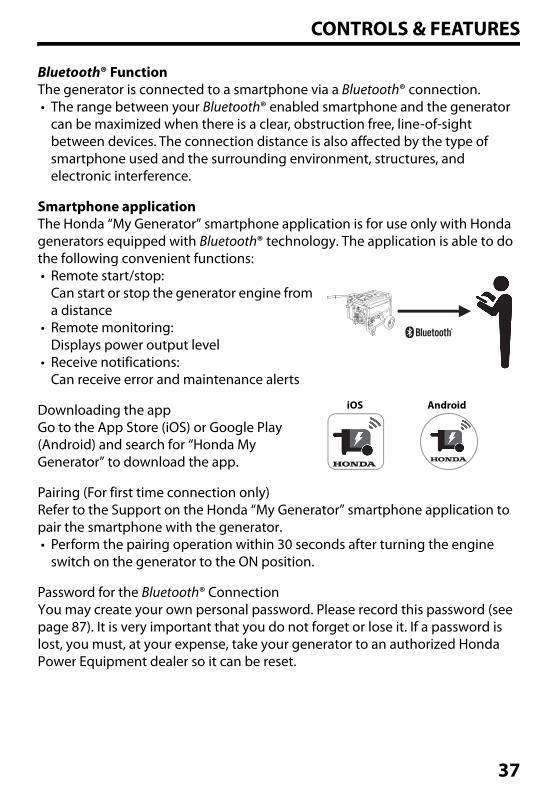
Bluetooth® FunctionThe generator is connected to a smartphone via a Bluetooth® connection.• The range between your Bluetooth® enabled smartphone and the generator
can be maximized when there is a clear, obstruction free, line-of-sight between devices. The connection distance is also affected by the type of smartphone used and the surrounding environment, structures, and electronic interference.
Smartphone applicationThe Honda “My Generator” smartphone application is for use only with Honda generators equipped with Bluetooth® technology. The application is able to do the following convenient functions:• Remote start/stop:
Can start or stop the generator engine from a distance
• Remote monitoring: Displays power output level
• Receive notifications: Can receive error and maintenance alerts
Downloading the appGo to the App Store (iOS) or Google Play (Android) and search for “Honda My Generator” to download the app.
Pairing (For first time connection only)Refer to the Support on the Honda “My Generator” smartphone application to pair the smartphone with the generator.• Perform the pairing operation within 30 seconds after turning the engine
switch on the generator to the ON position.
Password for the Bluetooth® ConnectionYou may create your own personal password. Please record this password (see page 87). It is very important that you do not forget or lose it. If a password is lost, you must, at your expense, take your generator to an authorized Honda Power Equipment dealer so it can be reset.
iOS Android
37
BEFORE OPERATIONARE YOU READY TO GET STARTED?
Your safety is your responsibility. A little time spent in preparation will significantly reduce your risk of injury.
KnowledgeRead and understand this manual. Know what the controls do and how to operate them.
Familiarize yourself with the generator and its operation before you begin using it. Know how to quickly shut off the generator in case of an emergency.
If the generator is being used to power appliances, be sure that they do not exceed the generator’s load rating (see page 55).
IS YOUR GENERATOR READY TO GO?
For your safety, to ensure compliance with environmental regulations, and to maximize the service life of your equipment, it is very important to take a few moments before you operate the generator to check its condition. Be sure to take care of any problem you find, or have your servicing dealer correct it, before you operate the generator.
To prevent a possible fire, keep the generator at least 3 feet (1 meter) away from building walls, vehicles, and other equipment during operation. Do not place flammable objects close to the engine or exhaust.
Failure to properly maintain this generator, or failing to correct a problem before operation, could result in a significant malfunction.
Some malfunctions can cause serious injuries or death.
Always perform a pre-operation inspection before each operation and correct any problems.
38
BEFORE OPERATION
Before beginning your pre-operation checks, be sure the generator is on a level surface and the engine switch is in the OFF position.
Generators with standard equipment transport wheels must not be operated with the wheels and/or stands removed or else the generator may not operate correctly and can become damaged.
Check the Engine• Before each use, look around and underneath the engine for signs of oil or
gasoline leaks.
• Check the engine oil level (see page 40). A low engine oil level will cause the Oil Alert system to shut down the engine.
• Check the air filters (see page 41). Dirty air filters will restrict air flow to the fuel system, reducing engine and generator performance.
• Check the fuel level (see page 19). Starting with a full tank will help to eliminate or reduce operating interruptions for refueling.
Check the GFCICheck the GFCI operation (see page 50) after starting the engine.
AC Appliance and Power CordBefore connecting an AC appliance or power cord to the generator:
• Use grounded 3-prong extension cords, tools, and appliances, or double-insulated tools and appliances.
• Inspect cords and plugs, and replace if damaged.
• Do not use cord lengths greater than 164 feet (50 meters), and do not use multiple tools and appliances with built-in noise filters. Such use may activate the GFCI and interrupt power supply.
• Make sure that the appliance is in good working order. Faulty appliances or power cords can create a potential for electric shock.
• Make sure the electrical rating of the tool or appliance does not exceed the rated power of the generator or the receptacle being used.
• Do not exceed the current limit specified for any one receptacle.
39
BEFORE OPERATION
ENGINE OIL LEVEL CHECK
Check the engine oil level with the engine stopped and in a level position.
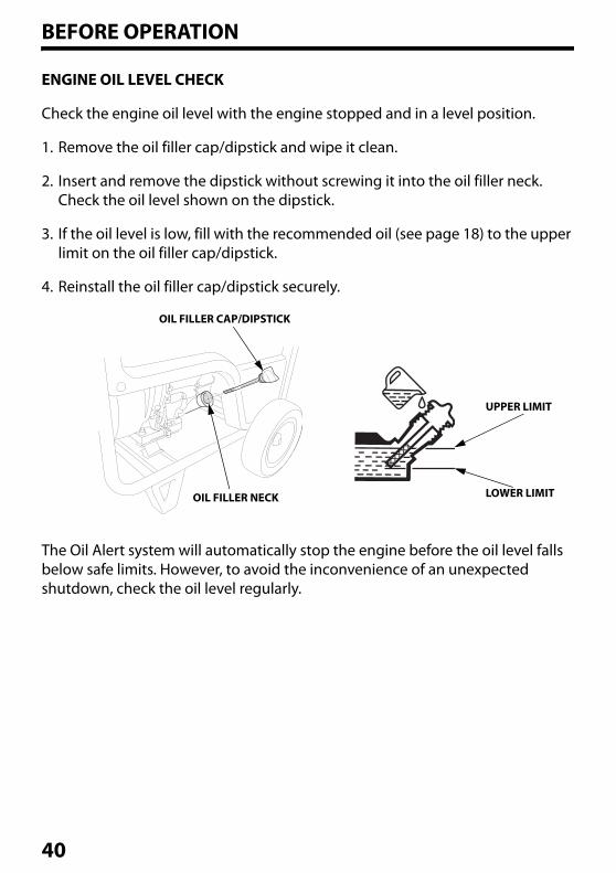
1. Remove the oil filler cap/dipstick and wipe it clean.
2. Insert and remove the dipstick without screwing it into the oil filler neck. Check the oil level shown on the dipstick.
3. If the oil level is low, fill with the recommended oil (see page 18) to the upper limit on the oil filler cap/dipstick.
4. Reinstall the oil filler cap/dipstick securely.
The Oil Alert system will automatically stop the engine before the oil level falls below safe limits. However, to avoid the inconvenience of an unexpected shutdown, check the oil level regularly.
OIL FILLER CAP/DIPSTICK
OIL FILLER NECK
UPPER LIMIT
LOWER LIMIT
40
BEFORE OPERATION
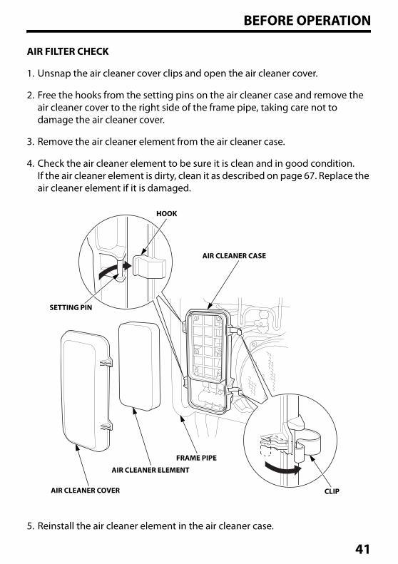
AIR FILTER CHECK
1. Unsnap the air cleaner cover clips and open the air cleaner cover.
2. Free the hooks from the setting pins on the air cleaner case and remove the air cleaner cover to the right side of the frame pipe, taking care not to damage the air cleaner cover.
3. Remove the air cleaner element from the air cleaner case.
4. Check the air cleaner element to be sure it is clean and in good condition.If the air cleaner element is dirty, clean it as described on page 67. Replace the air cleaner element if it is damaged.
5. Reinstall the air cleaner element in the air cleaner case.
HOOK
SETTING PIN
AIR CLEANER CASE
FRAME PIPE
AIR CLEANER ELEMENT
AIR CLEANER COVER CLIP
41
BEFORE OPERATION
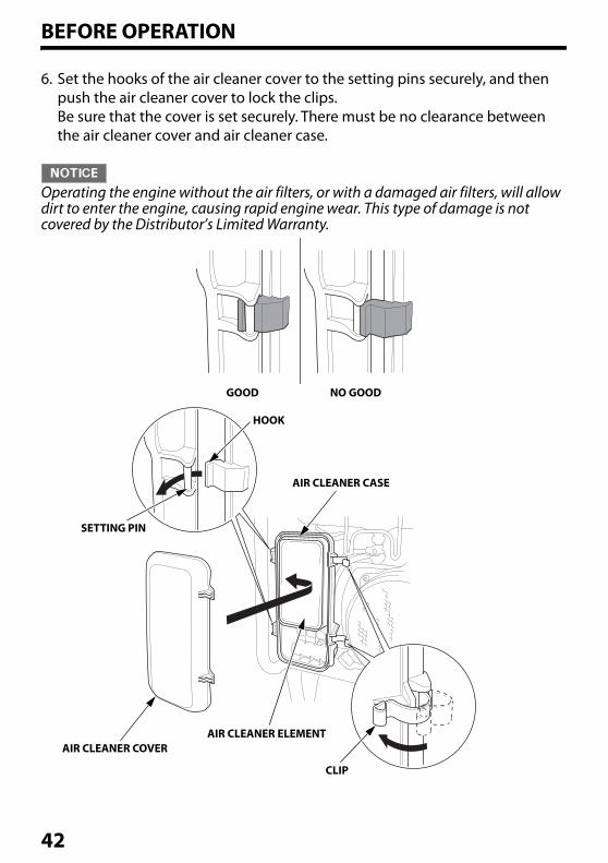
6. Set the hooks of the air cleaner cover to the setting pins securely, and then push the air cleaner cover to lock the clips.Be sure that the cover is set securely. There must be no clearance between the air cleaner cover and air cleaner case.
Operating the engine without the air filters, or with a damaged air filters, will allow dirt to enter the engine, causing rapid engine wear. This type of damage is not covered by the Distributor’s Limited Warranty.
GOOD NO GOOD
HOOK
AIR CLEANER CASE
AIR CLEANER ELEMENT
CLIP
AIR CLEANER COVER
SETTING PIN
42
BEFORE OPERATION
SAFE OPERATING PRECAUTIONS
Before operating the generator, review chapters "GENERATOR SAFETY" (see page 7).
For your safety, do not operate the generator in an enclosed, or partly enclosed area such as a garage (even if the door is open) or near structures or vehicles. Your generator's exhaust contains poisonous carbon monoxide gas that can collect rapidly in such areas, structures, vehicles, trailers, or boats.
• Do not operate the generator when it is in a storage, cargo, or security enclosure, including any RV generator bay.
• Always completely remove the generator from the vehicle, trailer, boat or other equipment or structure during operation.
• The generator must remain stationary while in operation.
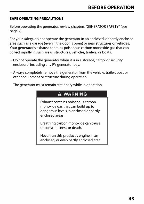
Exhaust contains poisonous carbon monoxide gas that can build up to dangerous levels in enclosed or partly enclosed areas.
Breathing carbon monoxide can cause unconsciousness or death.
Never run this product's engine in an enclosed, or even partly enclosed area.
43
OPERATIONSTARTING THE ENGINE
To prevent a possible fire, keep the generator at least 3 feet (1 meter) away from building or trailer walls, vehicles, trailers, boats, and other equipment during operation. Do not place flammable objects close to the engine.
• Operating this generator less than 3 feet (1 meter) from a building, obstruction, or when it is in an enclosure, a storage or security compartment/bay, can cause overheating and damage the generator.
• For proper cooling, allow at least 3 feet (1 meter) of empty space above and around the generator.
• Since the CO-MINDER may detect the carbon monoxide concentration and the engine may stop automatically, pay attention to the direction of exhaust and where the generator is located (see page 26).
Refer to "SAFE OPERATING PRECAUTIONS" on page 43 and perform the "IS YOUR GENERATOR READY TO GO?" checks (see page 38).
Refer to "AC OPERATION" (see page 53) or "DC OPERATION" (see page 58) for connecting loads to the generator.
44
OPERATION
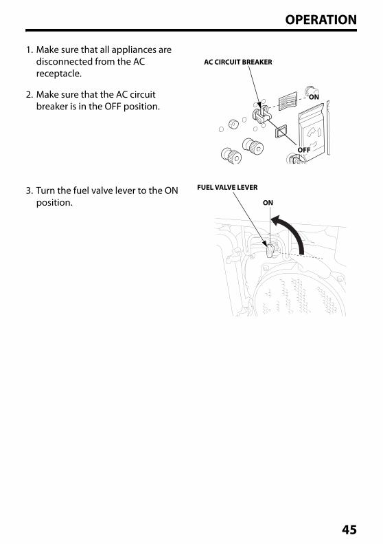
1. Make sure that all appliances are disconnected from the AC receptacle.
2. Make sure that the AC circuit breaker is in the OFF position.
3. Turn the fuel valve lever to the ON position.
AC CIRCUIT BREAKER
FUEL VALVE LEVER
ON
ON
OFF
45
OPERATION
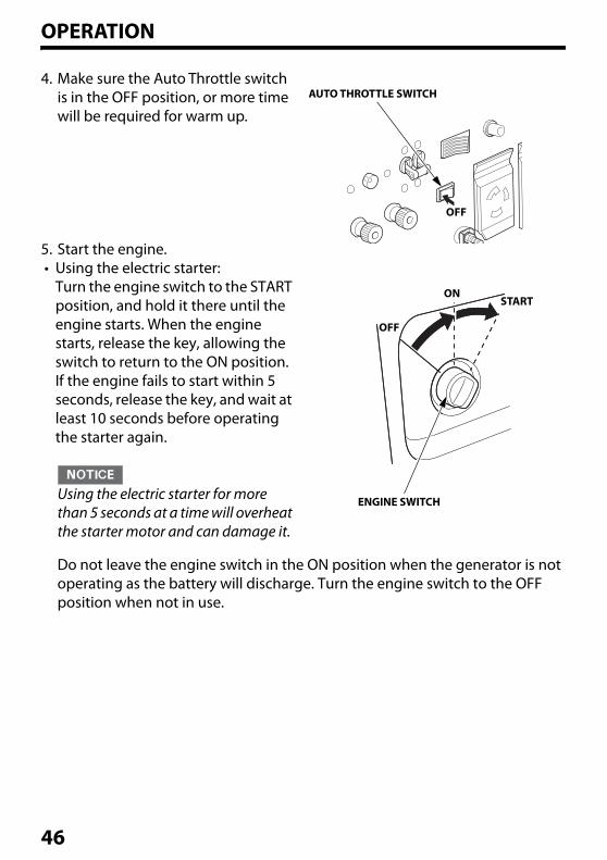
4. Make sure the Auto Throttle switch is in the OFF position, or more time will be required for warm up.
5. Start the engine.• Using the electric starter:
Turn the engine switch to the START position, and hold it there until the engine starts. When the engine starts, release the key, allowing the switch to return to the ON position.If the engine fails to start within 5 seconds, release the key, and wait at least 10 seconds before operating the starter again.
Using the electric starter for more than 5 seconds at a time will overheat the starter motor and can damage it.
Do not leave the engine switch in the ON position when the generator is not operating as the battery will discharge. Turn the engine switch to the OFF position when not in use.
AUTO THROTTLE SWITCH
OFF
ONSTART
OFF
ENGINE SWITCH
46
OPERATION
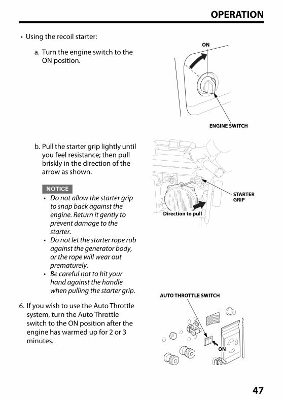
• Using the recoil starter:
a. Turn the engine switch to the ON position.
b. Pull the starter grip lightly until you feel resistance; then pull briskly in the direction of the arrow as shown.
• Do not allow the starter grip to snap back against the engine. Return it gently to prevent damage to the starter.
• Do not let the starter rope rub against the generator body, or the rope will wear out prematurely.
• Be careful not to hit your hand against the handle when pulling the starter grip.
6. If you wish to use the Auto Throttle system, turn the Auto Throttle switch to the ON position after the engine has warmed up for 2 or 3 minutes.
ENGINE SWITCH
ON
STARTER GRIP
Direction to pull
AUTO THROTTLE SWITCH
ON
47
OPERATION
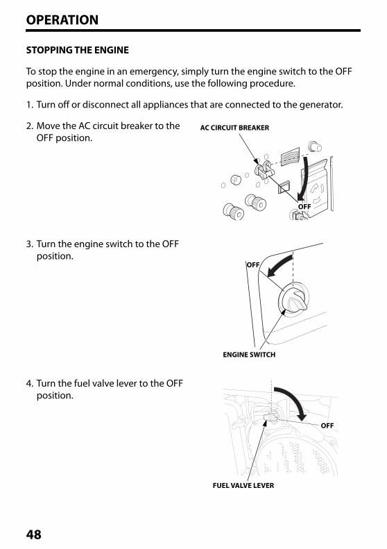
STOPPING THE ENGINE
To stop the engine in an emergency, simply turn the engine switch to the OFF position. Under normal conditions, use the following procedure.
1. Turn off or disconnect all appliances that are connected to the generator.
2. Move the AC circuit breaker to the OFF position.
3. Turn the engine switch to the OFF position.
4. Turn the fuel valve lever to the OFF position.
AC CIRCUIT BREAKER
OFF
ENGINE SWITCH
OFF
FUEL VALVE LEVER
OFF
48
OPERATION
STARTING AND STOPPING THE ENGINE with Bluetooth® ENABLED SMARTPHONE
The engine can be started/stopped via a Bluetooth® enabled smartphone using a Bluetooth® application.Refer to the Bluetooth® application to check the connection, operation, and for help pairing a smartphone.
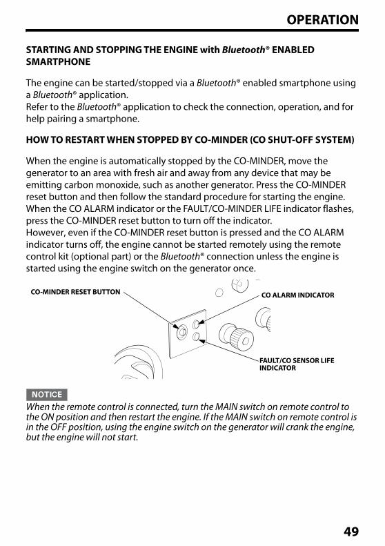
HOW TO RESTART WHEN STOPPED BY CO-MINDER (CO SHUT-OFF SYSTEM)
When the engine is automatically stopped by the CO-MINDER, move the generator to an area with fresh air and away from any device that may be emitting carbon monoxide, such as another generator. Press the CO-MINDER reset button and then follow the standard procedure for starting the engine. When the CO ALARM indicator or the FAULT/CO-MINDER LIFE indicator flashes, press the CO-MINDER reset button to turn off the indicator.However, even if the CO-MINDER reset button is pressed and the CO ALARM indicator turns off, the engine cannot be started remotely using the remote control kit (optional part) or the Bluetooth® connection unless the engine is started using the engine switch on the generator once.
When the remote control is connected, turn the MAIN switch on remote control to the ON position and then restart the engine. If the MAIN switch on remote control is in the OFF position, using the engine switch on the generator will crank the engine, but the engine will not start.
CO-MINDER RESET BUTTON CO ALARM INDICATOR
FAULT/CO SENSOR LIFE INDICATOR
49
OPERATION
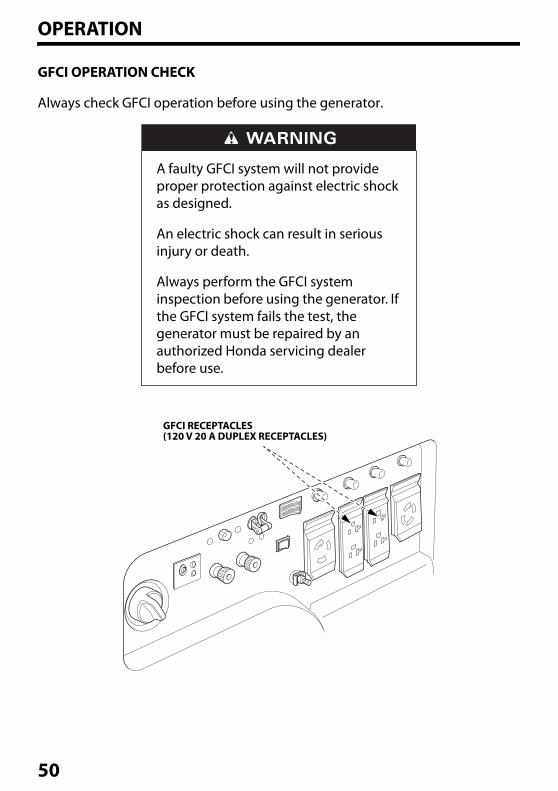
GFCI OPERATION CHECK
Always check GFCI operation before using the generator.
A faulty GFCI system will not provide proper protection against electric shock as designed.
An electric shock can result in serious injury or death.
Always perform the GFCI system inspection before using the generator. If the GFCI system fails the test, the generator must be repaired by an authorized Honda servicing dealer before use.
GFCI RECEPTACLES(120 V 20 A DUPLEX RECEPTACLES)
50
OPERATION
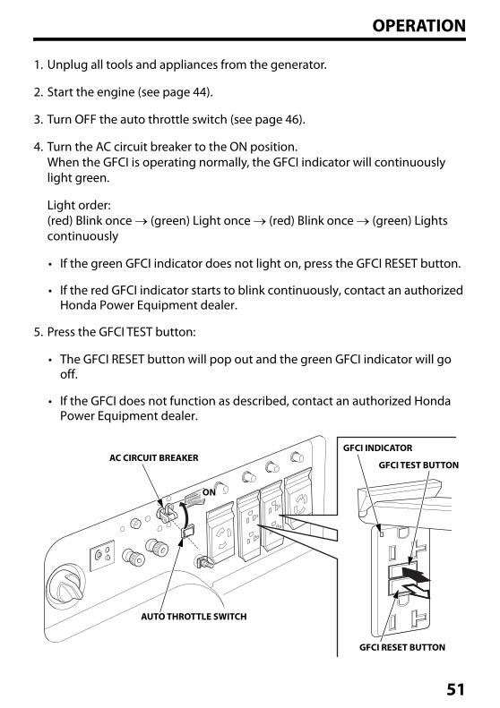
1. Unplug all tools and appliances from the generator.
2. Start the engine (see page 44).
3. Turn OFF the auto throttle switch (see page 46).
4. Turn the AC circuit breaker to the ON position.When the GFCI is operating normally, the GFCI indicator will continuously light green.
Light order:(red) Blink once (green) Light once (red) Blink once (green) Lights continuously
• If the green GFCI indicator does not light on, press the GFCI RESET button.
• If the red GFCI indicator starts to blink continuously, contact an authorized Honda Power Equipment dealer.
5. Press the GFCI TEST button:
• The GFCI RESET button will pop out and the green GFCI indicator will go off.
• If the GFCI does not function as described, contact an authorized Honda Power Equipment dealer.
GFCI INDICATOR
GFCI RESET BUTTON
ON
AC CIRCUIT BREAKER
AUTO THROTTLE SWITCH
GFCI TEST BUTTON
51
OPERATION
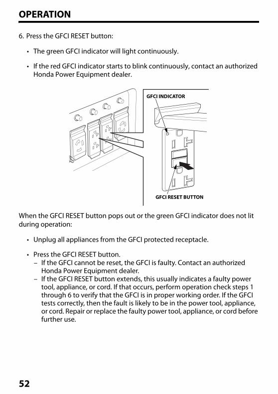
6. Press the GFCI RESET button:
• The green GFCI indicator will light continuously.
• If the red GFCI indicator starts to blink continuously, contact an authorized Honda Power Equipment dealer.
When the GFCI RESET button pops out or the green GFCI indicator does not lit during operation:
• Unplug all appliances from the GFCI protected receptacle.
• Press the GFCI RESET button.– If the GFCI cannot be reset, the GFCI is faulty. Contact an authorized
Honda Power Equipment dealer.– If the GFCI RESET button extends, this usually indicates a faulty power
tool, appliance, or cord. If that occurs, perform operation check steps 1 through 6 to verify that the GFCI is in proper working order. If the GFCI tests correctly, then the fault is likely to be in the power tool, appliance, or cord. Repair or replace the faulty power tool, appliance, or cord before further use.
GFCI INDICATOR
GFCI RESET BUTTON
52
OPERATION
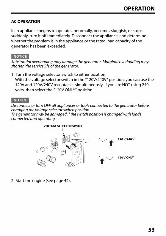
AC OPERATION
If an appliance begins to operate abnormally, becomes sluggish, or stops suddenly, turn it off immediately. Disconnect the appliance, and determine whether the problem is in the appliance or the rated load capacity of the generator has been exceeded.
Substantial overloading may damage the generator. Marginal overloading may shorten the service life of the generator.
1. Turn the voltage selector switch to either position.With the voltage selector switch in the “120V/240V” position, you can use the 120V and 120V/240V receptacles simultaneously. If you are NOT using 240 volts, then select the “120V ONLY” position.
Disconnect or turn OFF all appliances or tools connected to the generator before changing the voltage selector switch position. The generator may be damaged if the switch position is changed with loads connected and operating.
2. Start the engine (see page 44).
VOLTAGE SELECTOR SWITCH
120 V/240 V
120 V ONLY
53
OPERATION
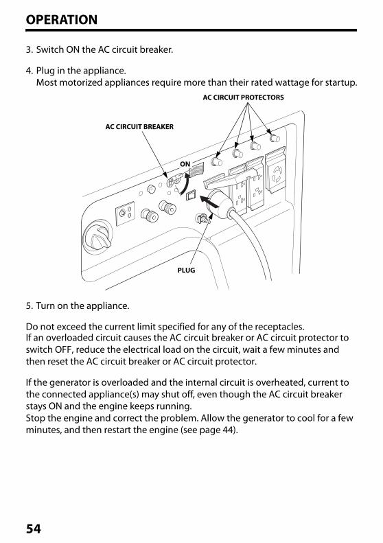
3. Switch ON the AC circuit breaker.
4. Plug in the appliance.Most motorized appliances require more than their rated wattage for startup.
5. Turn on the appliance.
Do not exceed the current limit specified for any of the receptacles.If an overloaded circuit causes the AC circuit breaker or AC circuit protector to switch OFF, reduce the electrical load on the circuit, wait a few minutes and then reset the AC circuit breaker or AC circuit protector.
If the generator is overloaded and the internal circuit is overheated, current to the connected appliance(s) may shut off, even though the AC circuit breaker stays ON and the engine keeps running.Stop the engine and correct the problem. Allow the generator to cool for a few minutes, and then restart the engine (see page 44).
AC CIRCUIT BREAKER
PLUG
ON
AC CIRCUIT PROTECTORS
54
OPERATION
AC ApplicationsBefore connecting an appliance or power cord to the generator:
• Make sure that it is in good working order. A faulty appliance or power cord can create a potential for electrical shock.
• If an appliance begins to operate abnormally, becomes sluggish, or stops suddenly, turn it off immediately. Disconnect the appliance, and determine whether the problem is the appliance or the rated load capacity of the generator has been exceeded.
Most appliance motors require more than their rated wattage for startup.Make sure the electrical rating of the tool or appliance does not exceed the maximum power rating of the generator.
Maximum power is:
EM5000SX: 5.0 kVAEM6500SX: 6.5 kVA
For continuous operation, do not exceed the rated power.Rated power is:
EM5000SX: 4.5 kVAEM6500SX: 5.5 kVA
In either case, the total power requirements (VA) of all appliances connected must be considered. Appliance and power tool manufacturers usually list rating information near the model number or serial number.
Substantial overloading will open the AC circuit breaker. Slightly overloading the generator may not switch the AC circuit breaker OFF, but will shorten the service life of the generator.
55
OPERATION
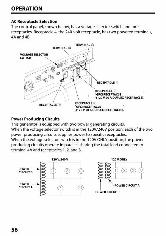
AC Receptacle SelectionThe control panel, shown below, has a voltage selector switch and four receptacles. Receptacle 4, the 240-volt receptacle, has two powered terminals, 4A and 4B.
Power Producing CircuitsThis generator is equipped with two power generating circuits.When the voltage selector switch is in the 120V/240V position, each of the two power producing circuits supplies power to specific receptacles.When the voltage selector switch is in the 120V ONLY position, the power producing circuits operate in parallel, sharing the total load connected to terminal 4A and receptacles 1, 2, and 3.
VOLTAGE SELECTOR SWITCH
TERMINAL
RECEPTACLE
TERMINAL
RECEPTACLE
RECEPTACLE GFCI RECEPTACLE (120 V 20 A DUPLEX RECEPTACLE)
RECEPTACLE GFCI RECEPTACLE (120 V 20 A DUPLEX RECEPTACLE)
POWERCIRCUIT B
POWERCIRCUIT A
120 V/240 V 120 V ONLY
POWER CIRCUIT B
POWER CIRCUIT A
56
OPERATION
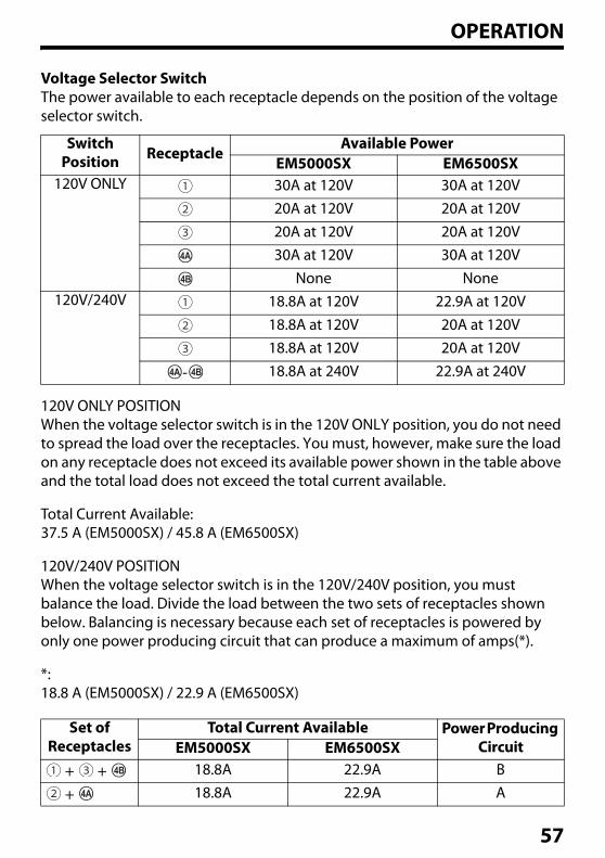
Voltage Selector SwitchThe power available to each receptacle depends on the position of the voltage selector switch.
120V ONLY POSITIONWhen the voltage selector switch is in the 120V ONLY position, you do not need to spread the load over the receptacles. You must, however, make sure the load on any receptacle does not exceed its available power shown in the table above and the total load does not exceed the total current available.
Total Current Available:37.5 A (EM5000SX) / 45.8 A (EM6500SX)
120V/240V POSITIONWhen the voltage selector switch is in the 120V/240V position, you must balance the load. Divide the load between the two sets of receptacles shown below. Balancing is necessary because each set of receptacles is powered by only one power producing circuit that can produce a maximum of amps(*).
*:18.8 A (EM5000SX) / 22.9 A (EM6500SX)
Switch Position Receptacle
Available PowerEM5000SX EM6500SX
120V ONLY 30A at 120V 30A at 120V20A at 120V 20A at 120V20A at 120V 20A at 120V30A at 120V 30A at 120V
None None120V/240V 18.8A at 120V 22.9A at 120V
18.8A at 120V 20A at 120V18.8A at 120V 20A at 120V
- 18.8A at 240V 22.9A at 240V
Set of Receptacles
Total Current Available Power Producing CircuitEM5000SX EM6500SX
+ + 18.8A 22.9A B
+ 18.8A 22.9A A
57
OPERATION
DC OPERATION
The DC receptacle should ONLY be used for charging 12-volt automotive type batteries. The DC charging output is not regulated.
Connecting the battery charging cable (optional equipment):1. Before connecting the battery charging cable (optional equipment) to a
battery that is installed in a vehicle, disconnect the vehicle battery ground cable from the negative (–) battery terminal.
WARNING: Battery posts, terminals, and related accessories contain lead and lead compounds. Wash your hands after handling.
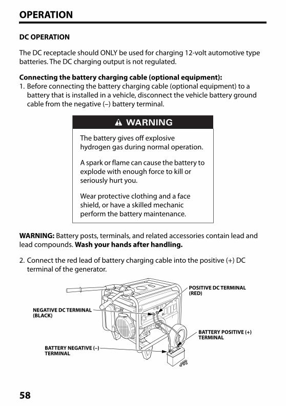
2. Connect the red lead of battery charging cable into the positive (+) DC terminal of the generator.
The battery gives off explosive hydrogen gas during normal operation.
A spark or flame can cause the battery to explode with enough force to kill or seriously hurt you.
Wear protective clothing and a face shield, or have a skilled mechanic perform the battery maintenance.
POSITIVE DC TERMINAL(RED)
NEGATIVE DC TERMINAL (BLACK)
BATTERY NEGATIVE (–) TERMINAL
BATTERY POSITIVE (+) TERMINAL
58
OPERATION
3. Connect the black lead of battery charging cable into the negative (–) DC terminal of the generator.
4. Connect the red lead of the battery charging cable to the positive (+) battery terminal and the black lead to the negative (–) battery terminal.
5. Start the generator.
Do not start the vehicle while the battery charging cable is connected and the generator is running. The vehicle or the generator may be damaged.
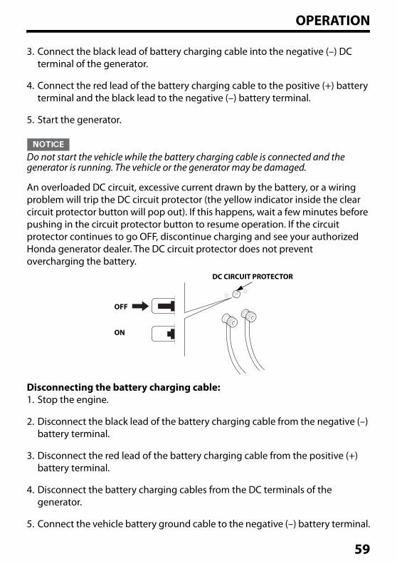
An overloaded DC circuit, excessive current drawn by the battery, or a wiring problem will trip the DC circuit protector (the yellow indicator inside the clear circuit protector button will pop out). If this happens, wait a few minutes before pushing in the circuit protector button to resume operation. If the circuit protector continues to go OFF, discontinue charging and see your authorized Honda generator dealer. The DC circuit protector does not prevent overcharging the battery.
Disconnecting the battery charging cable:1. Stop the engine.
2. Disconnect the black lead of the battery charging cable from the negative (–) battery terminal.
3. Disconnect the red lead of the battery charging cable from the positive (+) battery terminal.
4. Disconnect the battery charging cables from the DC terminals of the generator.
5. Connect the vehicle battery ground cable to the negative (–) battery terminal.
DC CIRCUIT PROTECTOR
OFF
ON
59
OPERATION
AUTO THROTTLE® SYSTEM
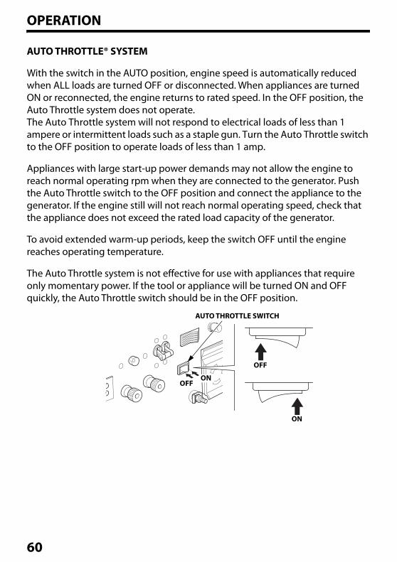
With the switch in the AUTO position, engine speed is automatically reduced when ALL loads are turned OFF or disconnected. When appliances are turned ON or reconnected, the engine returns to rated speed. In the OFF position, the Auto Throttle system does not operate.The Auto Throttle system will not respond to electrical loads of less than 1 ampere or intermittent loads such as a staple gun. Turn the Auto Throttle switch to the OFF position to operate loads of less than 1 amp.
Appliances with large start-up power demands may not allow the engine to reach normal operating rpm when they are connected to the generator. Push the Auto Throttle switch to the OFF position and connect the appliance to the generator. If the engine still will not reach normal operating speed, check that the appliance does not exceed the rated load capacity of the generator.
To avoid extended warm-up periods, keep the switch OFF until the engine reaches operating temperature.
The Auto Throttle system is not effective for use with appliances that require only momentary power. If the tool or appliance will be turned ON and OFF quickly, the Auto Throttle switch should be in the OFF position.
AUTO THROTTLE SWITCH
OFF
ON
ONOFF
60
OPERATION
STANDBY POWER
Connections to a Building’s Electrical SystemConnections for standby power to a building’s electrical system must be made by a qualified electrician. The connection must isolate the generator power from utility power, and must comply with all applicable laws and electrical codes.
In some areas, generators are required by law to be registered with local utility companies. Check local regulations for proper registration and use procedures.
System GroundThis generator has a system ground that connects generator frame components to ground terminals in the AC output receptacles. The system ground is not connected to the AC neutral wire.
Improper connections to a building’s electrical system can allow current from the generator to backfeed into the utility lines.
Such backfeed may electrocute utility company workers or others who contact the lines during a power outage, and the generator may explode, burn, or cause fires when utility power is restored.
Consult the utility company or a qualified electrician prior to making any power connections.
61
OPERATION
Special RequirementsThere may be Federal or State Occupational Safety and Health Administration (OSHA) regulations, local codes, or ordinances that apply to the intended use of the generator. Please consult a qualified electrician, electrical inspector, or the local agency having jurisdiction.
• In some areas, generators are required to be registered with local utility companies.
• If the generator is used at a construction site, there may be additional regulations that must be observed.
62
SERVICING YOUR GENERATORTHE IMPORTANCE OF MAINTENANCE
Good maintenance is essential for safe, economical, and trouble-free operation. It will also help reduce air pollution.
To help you properly care for your generator, the following pages include a maintenance schedule, routine inspection procedures, and simple maintenance procedures using basic hand tools. Other service tasks that are more difficult or require special tools are best handled by professionals and are normally performed by a Honda technician or other qualified mechanic.
The maintenance schedule applies to normal operating conditions. If you operate your generator under unusual conditions, such as sustained high-load or high-temperature operation, or use it in dusty conditions, consult your servicing dealer for recommendations applicable to your individual needs and use.
Remember that an authorized Honda Power Equipment dealer knows your generator best and is fully equipped to maintain and repair it.
To ensure the best quality and reliability, use only new, Honda Genuine parts or their equivalents for repair and replacement.
Maintenance, replacement, or repair of the emission control devices and systems may be performed by any engine repair establishment or individual, using parts that are “certified” to EPA standards.
Failure to properly maintain this generator, or failing to correct a problem before operation, could result in a significant malfunction.
Some malfunctions can cause serious injuries or death.
Always follow the inspection and maintenance recommendations and schedules in this owner’s manual.
63
SERVICING YOUR GENERATOR
MAINTENANCE SAFETY
Some of the most important safety precautions follow. However, we cannot warn you of every conceivable hazard that can arise in performing maintenance. Only you can decide whether or not you should perform a given task.
Safety PrecautionsRead the instructions before you begin, and make sure you have the tools and skills required.
• Make sure the engine is off before you begin any maintenance or repairs. This will eliminate several potential hazards:
– Carbon monoxide poisoning from engine exhaustOperate outside away from open windows or doors with engine exhaust directed away from occupied structures.
– Burns from hot partsLet the engine and exhaust system cool before touching.
– Injury from moving partsDo not run the engine unless instructed to do so.
• To reduce the possibility of fire or explosion, be careful when working around gasoline. Use only a non-flammable solvent, not gasoline, to clean parts. Keep cigarettes, sparks, and flames away from all fuel-related parts.
Improper maintenance can cause an unsafe condition.
Failure to properly follow maintenance instructions and precautions can cause serious injuries or death.
Always follow the procedures and precautions in this owner’s manual.
64
SERVICING YOUR GENERATOR
MAINTENANCE SCHEDULE
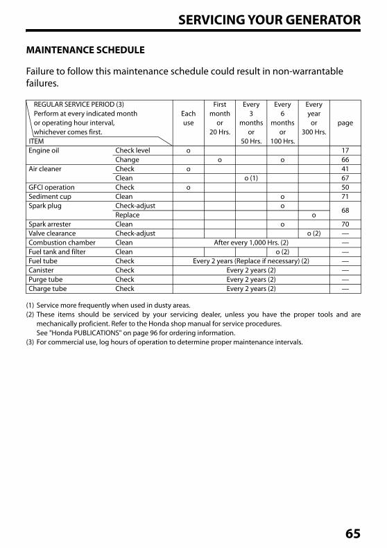
Failure to follow this maintenance schedule could result in non-warrantable failures.
(1) Service more frequently when used in dusty areas.(2) These items should be serviced by your servicing dealer, unless you have the proper tools and are
mechanically proficient. Refer to the Honda shop manual for service procedures.See "Honda PUBLICATIONS" on page 96 for ordering information.
(3) For commercial use, log hours of operation to determine proper maintenance intervals.
REGULAR SERVICE PERIOD (3) Perform at every indicated month or operating hour interval,whichever comes first.
Eachuse
Firstmonth
or20 Hrs.
Every3
monthsor
50 Hrs.
Every6
monthsor
100 Hrs.
Everyyear
or300 Hrs.
page
Engine oil Check level o 17Change o o 66
Air cleaner Check o 41Clean o (1) 67
GFCI operation Check o 50Sediment cup Clean o 71Spark plug Check-adjust o
68Replace o
Spark arrester Clean o 70Valve clearance Check-adjust o (2) —Combustion chamber Clean After every 1,000 Hrs. (2) —Fuel tank and filter Clean o (2) —Fuel tube Check Every 2 years (Replace if necessary) (2) —Canister Check Every 2 years (2) —Purge tube Check Every 2 years (2) —Charge tube Check Every 2 years (2) —
ITEM
65
SERVICING YOUR GENERATOR
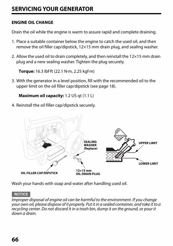
ENGINE OIL CHANGE
Drain the oil while the engine is warm to assure rapid and complete draining.
1. Place a suitable container below the engine to catch the used oil, and then remove the oil filler cap/dipstick, 12×15 mm drain plug, and sealing washer.
2. Allow the used oil to drain completely, and then reinstall the 12×15 mm drain plug and a new sealing washer. Tighten the plug securely.
Torque: 16.3 lbf·ft (22.1 N·m, 2.25 kgf·m)
3. With the generator in a level position, fill with the recommended oil to the upper limit on the oil filler cap/dipstick (see page 18).
Maximum oil capacity: 1.2 US qt (1.1 L)
4. Reinstall the oil filler cap/dipstick securely.
Wash your hands with soap and water after handling used oil.
Improper disposal of engine oil can be harmful to the environment. If you change your own oil, please dispose of it properly. Put it in a sealed container, and take it to a recycling center. Do not discard it in a trash bin, dump it on the ground, or pour it down a drain.
UPPER LIMITSEALING WASHER(Replace)
12×15 mm OIL DRAIN PLUGOIL FILLER CAP/DIPSTICK
LOWER LIMIT
66
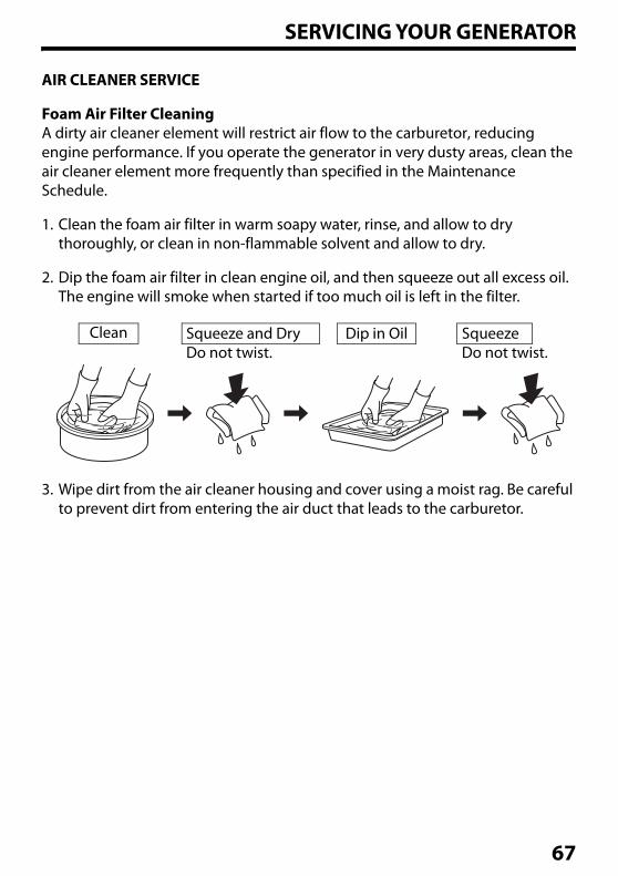
SERVICING YOUR GENERATOR
AIR CLEANER SERVICE
Foam Air Filter CleaningA dirty air cleaner element will restrict air flow to the carburetor, reducing engine performance. If you operate the generator in very dusty areas, clean the air cleaner element more frequently than specified in the Maintenance Schedule.
1. Clean the foam air filter in warm soapy water, rinse, and allow to dry thoroughly, or clean in non-flammable solvent and allow to dry.
2. Dip the foam air filter in clean engine oil, and then squeeze out all excess oil. The engine will smoke when started if too much oil is left in the filter.
3. Wipe dirt from the air cleaner housing and cover using a moist rag. Be careful to prevent dirt from entering the air duct that leads to the carburetor.
Clean Squeeze and DryDo not twist.
Dip in Oil SqueezeDo not twist.
67
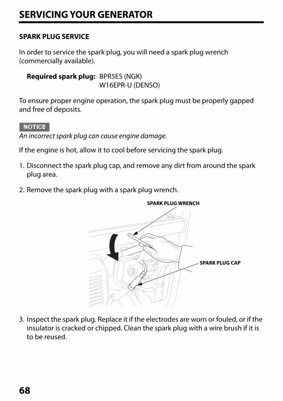
SERVICING YOUR GENERATOR
SPARK PLUG SERVICE
In order to service the spark plug, you will need a spark plug wrench (commercially available).
Required spark plug: BPR5ES (NGK)W16EPR-U (DENSO)
To ensure proper engine operation, the spark plug must be properly gapped and free of deposits.
An incorrect spark plug can cause engine damage.
If the engine is hot, allow it to cool before servicing the spark plug.
1. Disconnect the spark plug cap, and remove any dirt from around the spark plug area.
2. Remove the spark plug with a spark plug wrench.
3. Inspect the spark plug. Replace it if the electrodes are worn or fouled, or if the insulator is cracked or chipped. Clean the spark plug with a wire brush if it is to be reused.
SPARK PLUG WRENCH
SPARK PLUG CAP
68
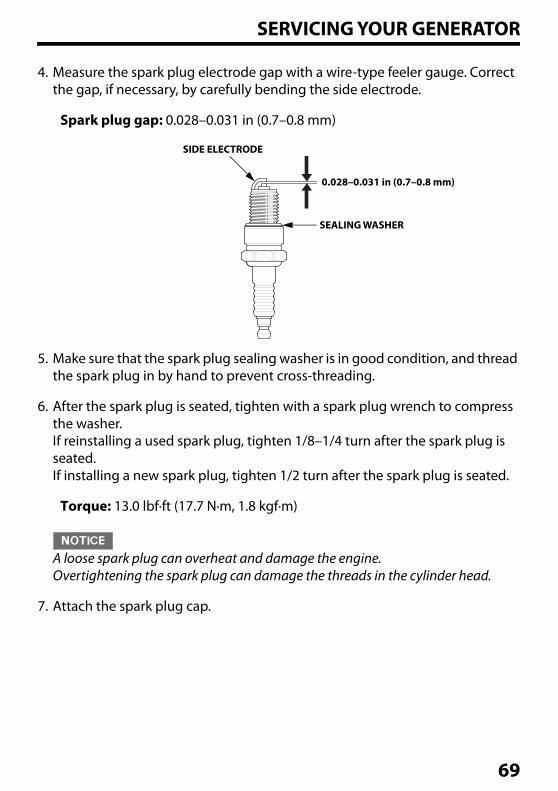
SERVICING YOUR GENERATOR
4. Measure the spark plug electrode gap with a wire-type feeler gauge. Correct the gap, if necessary, by carefully bending the side electrode.
Spark plug gap: 0.028–0.031 in (0.7–0.8 mm)
5. Make sure that the spark plug sealing washer is in good condition, and thread the spark plug in by hand to prevent cross-threading.
6. After the spark plug is seated, tighten with a spark plug wrench to compress the washer.If reinstalling a used spark plug, tighten 1/8–1/4 turn after the spark plug is seated.If installing a new spark plug, tighten 1/2 turn after the spark plug is seated.
Torque: 13.0 lbf·ft (17.7 N·m, 1.8 kgf·m)
A loose spark plug can overheat and damage the engine. Overtightening the spark plug can damage the threads in the cylinder head.
7. Attach the spark plug cap.
SIDE ELECTRODE
0.028–0.031 in (0.7–0.8 mm)
SEALING WASHER
69
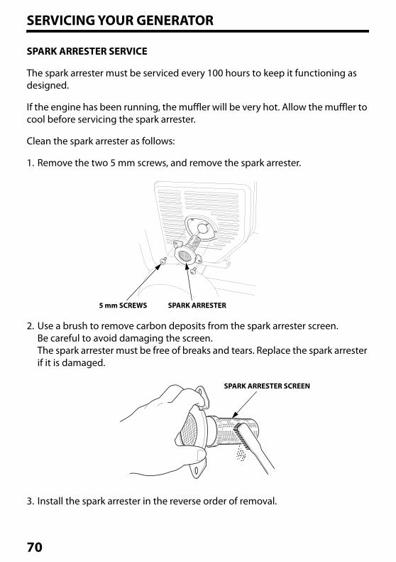
SERVICING YOUR GENERATOR
SPARK ARRESTER SERVICE
The spark arrester must be serviced every 100 hours to keep it functioning as designed.
If the engine has been running, the muffler will be very hot. Allow the muffler to cool before servicing the spark arrester.
Clean the spark arrester as follows:
1. Remove the two 5 mm screws, and remove the spark arrester.
2. Use a brush to remove carbon deposits from the spark arrester screen.Be careful to avoid damaging the screen.The spark arrester must be free of breaks and tears. Replace the spark arrester if it is damaged.
3. Install the spark arrester in the reverse order of removal.
5 mm SCREWS SPARK ARRESTER
SPARK ARRESTER SCREEN
70
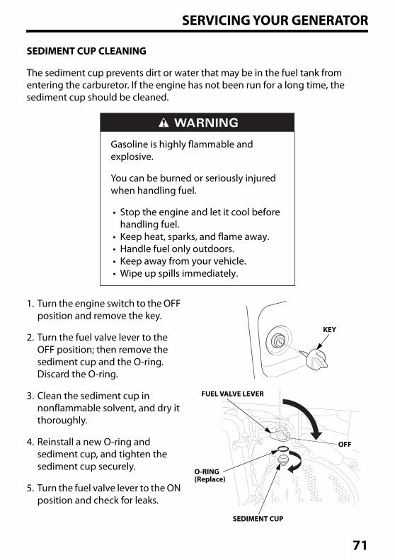
SERVICING YOUR GENERATOR
SEDIMENT CUP CLEANING
The sediment cup prevents dirt or water that may be in the fuel tank from entering the carburetor. If the engine has not been run for a long time, the sediment cup should be cleaned.
1. Turn the engine switch to the OFF position and remove the key.
2. Turn the fuel valve lever to the OFF position; then remove the sediment cup and the O-ring. Discard the O-ring.
3. Clean the sediment cup in nonflammable solvent, and dry it thoroughly.
4. Reinstall a new O-ring and sediment cup, and tighten the sediment cup securely.
5. Turn the fuel valve lever to the ON position and check for leaks.
Gasoline is highly flammable and explosive.
You can be burned or seriously injured when handling fuel.
• Stop the engine and let it cool before handling fuel.
• Keep heat, sparks, and flame away.• Handle fuel only outdoors.• Keep away from your vehicle.• Wipe up spills immediately.
KEY
FUEL VALVE LEVER
O-RING(Replace)
SEDIMENT CUP
OFF
71
SERVICING YOUR GENERATOR
BATTERY SERVICE
Your generator’s engine charging system charges the battery while the engine is running. However, if the generator is only used periodically, the battery must be charged monthly to maintain the battery service life.
Emergency ProceduresEyes – Wash your eye(s) with plenty of water avoiding damaging your eye(s) with water pressure. Call your local Poison Center or a doctor immediately.
Skin – Remove contaminated clothing. Wash the skin with large quantities of water. Call your local Poison Center or a doctor immediately.
Swallowing – Wash mouth with a large amount of water and drink a cup of water. Call your local Poison Center or a doctor immediately.
The battery contains sulfuric acid (electrolyte), which is highly corrosive and poisonous.
Getting electrolyte in your eyes or on your skin can cause serious burns.
Wear protective clothing and eye protection when working near the battery.
72
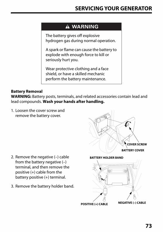
SERVICING YOUR GENERATOR
Battery RemovalWARNING: Battery posts, terminals, and related accessories contain lead and lead compounds. Wash your hands after handling.
1. Loosen the cover screw and remove the battery cover.
2. Remove the negative (–) cable from the battery negative (–) terminal, and then remove the positive (+) cable from the battery positive (+) terminal.
3. Remove the battery holder band.
The battery gives off explosive hydrogen gas during normal operation.
A spark or flame can cause the battery to explode with enough force to kill or seriously hurt you.
Wear protective clothing and a face shield, or have a skilled mechanic perform the battery maintenance.
COVER SCREW
BATTERY COVER
BATTERY HOLDER BAND
POSITIVE (+) CABLE NEGATIVE (–) CABLE
73
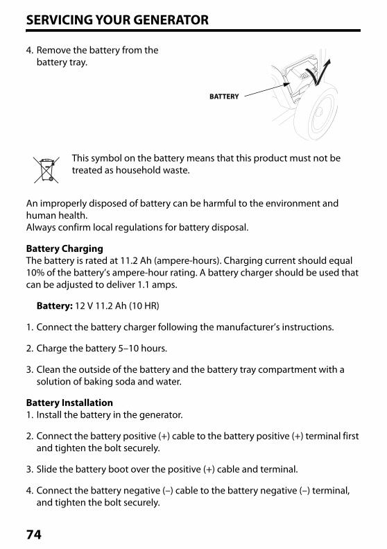
SERVICING YOUR GENERATOR
4. Remove the battery from the battery tray.
This symbol on the battery means that this product must not be treated as household waste.
An improperly disposed of battery can be harmful to the environment and human health.Always confirm local regulations for battery disposal.
Battery ChargingThe battery is rated at 11.2 Ah (ampere-hours). Charging current should equal 10% of the battery’s ampere-hour rating. A battery charger should be used that can be adjusted to deliver 1.1 amps.
Battery: 12 V 11.2 Ah (10 HR)
1. Connect the battery charger following the manufacturer’s instructions.
2. Charge the battery 5–10 hours.
3. Clean the outside of the battery and the battery tray compartment with a solution of baking soda and water.
Battery Installation1. Install the battery in the generator.
2. Connect the battery positive (+) cable to the battery positive (+) terminal first and tighten the bolt securely.
3. Slide the battery boot over the positive (+) cable and terminal.
4. Connect the battery negative (–) cable to the battery negative (–) terminal, and tighten the bolt securely.
BATTERY
74
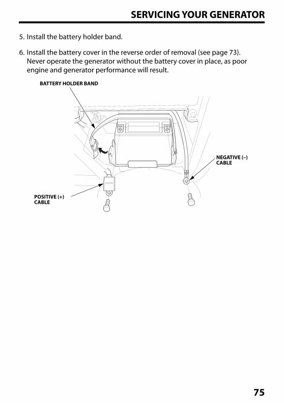
SERVICING YOUR GENERATOR
5. Install the battery holder band.
6. Install the battery cover in the reverse order of removal (see page 73).Never operate the generator without the battery cover in place, as poor engine and generator performance will result.
BATTERY HOLDER BAND
POSITIVE (+)CABLE
NEGATIVE (–)CABLE
75
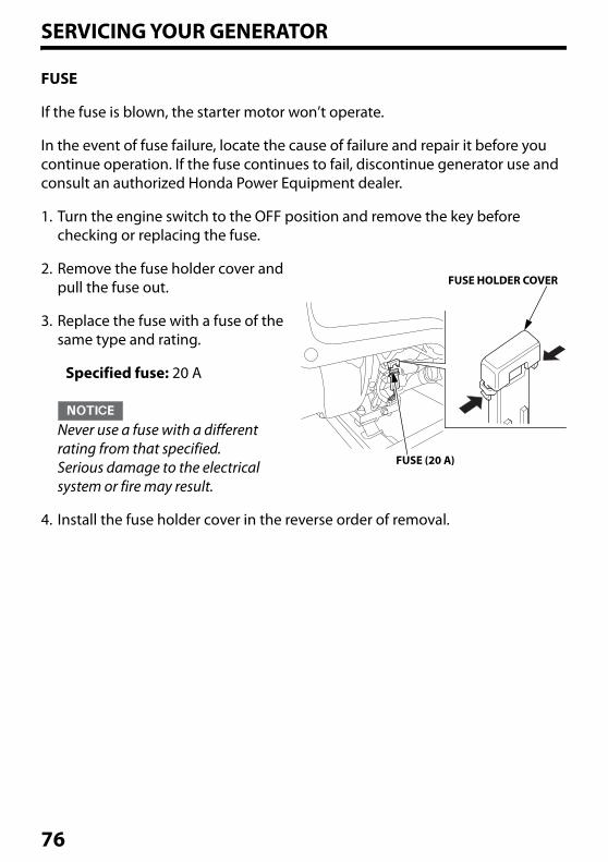
SERVICING YOUR GENERATOR
FUSE
If the fuse is blown, the starter motor won’t operate.
In the event of fuse failure, locate the cause of failure and repair it before you continue operation. If the fuse continues to fail, discontinue generator use and consult an authorized Honda Power Equipment dealer.
1. Turn the engine switch to the OFF position and remove the key before checking or replacing the fuse.
2. Remove the fuse holder cover and pull the fuse out.
3. Replace the fuse with a fuse of the same type and rating.
Specified fuse: 20 A
Never use a fuse with a different rating from that specified. Serious damage to the electrical system or fire may result.
4. Install the fuse holder cover in the reverse order of removal.
FUSE (20 A)
FUSE HOLDER COVER
76
STORAGESTORAGE PREPARATION
Proper storage preparation is essential for keeping your generator trouble-free and looking good. The following steps will help to keep rust and corrosion from impairing your generator’s function and appearance, and will make the engine easier to start when you use the generator again.
CleaningWipe the generator with a moist cloth. After the generator has dried, touch up any damaged paint, and coat other areas that may rust with a light film of oil.
Fuel
Depending on the region where you operate your equipment, fuel formulations may deteriorate and oxidize rapidly. Fuel deterioration and oxidation can occur in as little as 30 days and may cause damage to the carburetor and/or fuel system. Please check with your servicing dealer for local storage recommendations.
Gasoline will oxidize and deteriorate in storage. Old gasoline will cause hard starting, and it leaves gum deposits that clog the fuel system. If the gasoline in your generator deteriorates during storage, you may need to have the carburetor and other fuel system components serviced or replaced.The length of time that gasoline can be left in your fuel tank and carburetor without causing functional problems will vary with such factors as gasoline blend, your storage temperatures, and whether the fuel tank is partly or completely filled. The air in a partly filled fuel tank promotes fuel deterioration. Very warm storage temperatures accelerate fuel deterioration. Fuel deterioration problems may occur within a few months, or even less if the gasoline was not fresh when you filled the fuel tank.
The Distributor’s Limited Warranty does not cover fuel system damage or engine performance problems resulting from neglected storage preparation.You can extend fuel storage life by adding a gasoline stabilizer that is formulated for that purpose, or you can avoid fuel deterioration problems by draining the carburetor, sediment cup, and/or fuel tank.
77
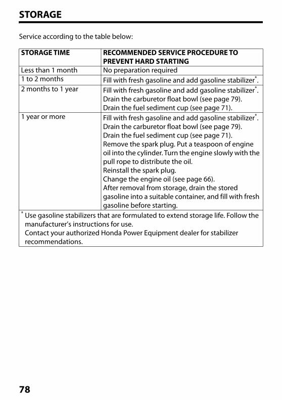
STORAGE
Service according to the table below:
STORAGE TIME RECOMMENDED SERVICE PROCEDURE TO PREVENT HARD STARTING
Less than 1 month No preparation required1 to 2 months Fill with fresh gasoline and add gasoline stabilizer*.2 months to 1 year Fill with fresh gasoline and add gasoline stabilizer*.
Drain the carburetor float bowl (see page 79).Drain the fuel sediment cup (see page 71).
1 year or more Fill with fresh gasoline and add gasoline stabilizer*.Drain the carburetor float bowl (see page 79).Drain the fuel sediment cup (see page 71).Remove the spark plug. Put a teaspoon of engine oil into the cylinder. Turn the engine slowly with the pull rope to distribute the oil.Reinstall the spark plug.Change the engine oil (see page 66).After removal from storage, drain the stored gasoline into a suitable container, and fill with fresh gasoline before starting.
* Use gasoline stabilizers that are formulated to extend storage life. Follow the manufacturer’s instructions for use.Contact your authorized Honda Power Equipment dealer for stabilizer recommendations.
78
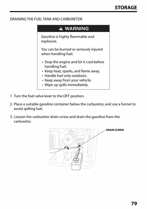
STORAGE
DRAINING THE FUEL TANK AND CARBURETOR
1. Turn the fuel valve lever to the OFF position.
2. Place a suitable gasoline container below the carburetor, and use a funnel to avoid spilling fuel.
3. Loosen the carburetor drain screw and drain the gasoline from the carburetor.
Gasoline is highly flammable and explosive.
You can be burned or seriously injured when handling fuel.
• Stop the engine and let it cool before handling fuel.
• Keep heat, sparks, and flame away.• Handle fuel only outdoors.• Keep away from your vehicle.• Wipe up spills immediately.
DRAIN SCREW
79
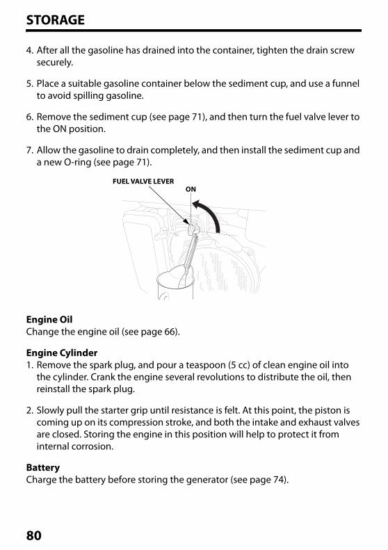
STORAGE
4. After all the gasoline has drained into the container, tighten the drain screw securely.
5. Place a suitable gasoline container below the sediment cup, and use a funnel to avoid spilling gasoline.
6. Remove the sediment cup (see page 71), and then turn the fuel valve lever to the ON position.
7. Allow the gasoline to drain completely, and then install the sediment cup and a new O-ring (see page 71).
Engine OilChange the engine oil (see page 66).
Engine Cylinder1. Remove the spark plug, and pour a teaspoon (5 cc) of clean engine oil into
the cylinder. Crank the engine several revolutions to distribute the oil, then reinstall the spark plug.
2. Slowly pull the starter grip until resistance is felt. At this point, the piston is coming up on its compression stroke, and both the intake and exhaust valves are closed. Storing the engine in this position will help to protect it from internal corrosion.
BatteryCharge the battery before storing the generator (see page 74).
FUEL VALVE LEVERON
80
STORAGE
STORAGE PRECAUTIONS
If your generator will be stored with gasoline in the fuel tank and carburetor, it is important to reduce the hazard of gasoline vapor ignition.
Select a well ventilated storage area away from any appliance that operates with a flame, such as a furnace, water heater, or clothes dryer. Also avoid any area with a spark-producing electric motor, or where power tools are operated.
If possible, avoid storage areas with high humidity, because that promotes rust and corrosion.
Unless all fuel has been drained from the fuel tank, leave the engine switch in the OFF position, and the fuel valve lever in the OFF position (see page 48) to reduce the possibility of leakage.
Place the generator on a level surface. Tilting or laying it on its side can cause fuel or oil leakage.
With the engine and exhaust system cool, cover the generator to keep out dust. A hot engine and exhaust system can ignite or melt some materials.
Do not use a plastic sheet as a dust cover. A nonporous cover will trap moisture around the generator, promoting rust and corrosion.
REMOVAL FROM STORAGE
Check your generator as described in the "BEFORE OPERATION" chapter of this manual (see page 38).
If the generator was stored for 1 year or longer, drain the fuel tank (see page 79) and refuel with fresh gasoline. If you keep a container of gasoline for refueling, be sure that it contains only fresh gasoline. Gasoline oxidizes and deteriorates over time, causing hard starting.
If the cylinder was coated with oil during storage preparation, the engine may smoke briefly at startup. This is normal.
81
TRANSPORTING
To prevent spillage when transporting, the generator should be secured upright in its normal operating position, with the fuel valve OFF.
Do not lay the generator on its side when moving, storing, or operating it. Oil or fuel may leak and damage the engine or your property.
Do not operate the generator while it is being transported or while it is mounted to any type of vehicle, trailer, or boat.
Take care not to drop or strike the generator when transporting. Do not place heavy objects on the generator.
When using ropes or tie-down straps to secure the generator for transportation, be sure to only use the frame bars as attachment points. Do not fasten ropes or straps to any portions of the generator body or handle bar.
An engine that has been running will remain very hot for a period of time.
A hot engine and exhaust system can burn you and ignite some material.
If the generator has been used, allow it to cool for at least 15 minutes before loading the generator on the transport vehicle.
82
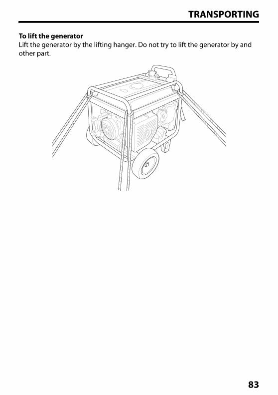
TRANSPORTING
To lift the generatorLift the generator by the lifting hanger. Do not try to lift the generator by and other part.
83
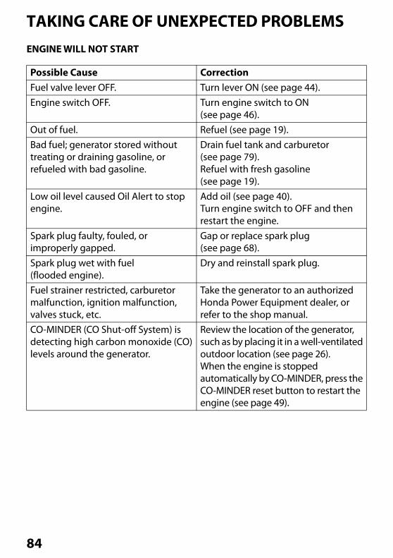
TAKING CARE OF UNEXPECTED PROBLEMSENGINE WILL NOT START
Possible Cause CorrectionFuel valve lever OFF. Turn lever ON (see page 44).Engine switch OFF. Turn engine switch to ON
(see page 46).Out of fuel. Refuel (see page 19).Bad fuel; generator stored without treating or draining gasoline, or refueled with bad gasoline.
Drain fuel tank and carburetor (see page 79).Refuel with fresh gasoline(see page 19).
Low oil level caused Oil Alert to stop engine.
Add oil (see page 40).Turn engine switch to OFF and then restart the engine.
Spark plug faulty, fouled, or improperly gapped.
Gap or replace spark plug(see page 68).
Spark plug wet with fuel (flooded engine).
Dry and reinstall spark plug.
Fuel strainer restricted, carburetor malfunction, ignition malfunction, valves stuck, etc.
Take the generator to an authorized Honda Power Equipment dealer, or refer to the shop manual.
CO-MINDER (CO Shut-off System) is detecting high carbon monoxide (CO) levels around the generator.
Review the location of the generator, such as by placing it in a well-ventilated outdoor location (see page 26).When the engine is stopped automatically by CO-MINDER, press the CO-MINDER reset button to restart the engine (see page 49).
84
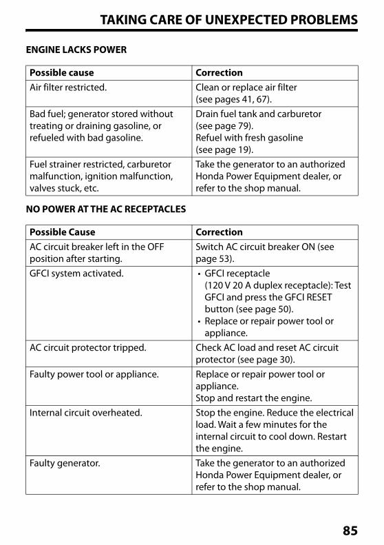
TAKING CARE OF UNEXPECTED PROBLEMS
ENGINE LACKS POWER
NO POWER AT THE AC RECEPTACLES
Possible cause CorrectionAir filter restricted. Clean or replace air filter
(see pages 41, 67).Bad fuel; generator stored without treating or draining gasoline, or refueled with bad gasoline.
Drain fuel tank and carburetor(see page 79).Refuel with fresh gasoline(see page 19).
Fuel strainer restricted, carburetor malfunction, ignition malfunction, valves stuck, etc.
Take the generator to an authorized Honda Power Equipment dealer, or refer to the shop manual.
Possible Cause CorrectionAC circuit breaker left in the OFF position after starting.
Switch AC circuit breaker ON (see page 53).
GFCI system activated. • GFCI receptacle (120 V 20 A duplex receptacle): Test GFCI and press the GFCI RESET button (see page 50).
• Replace or repair power tool or appliance.
AC circuit protector tripped. Check AC load and reset AC circuit protector (see page 30).
Faulty power tool or appliance. Replace or repair power tool or appliance.Stop and restart the engine.
Internal circuit overheated. Stop the engine. Reduce the electrical load. Wait a few minutes for the internal circuit to cool down. Restart the engine.
Faulty generator. Take the generator to an authorized Honda Power Equipment dealer, or refer to the shop manual.
85
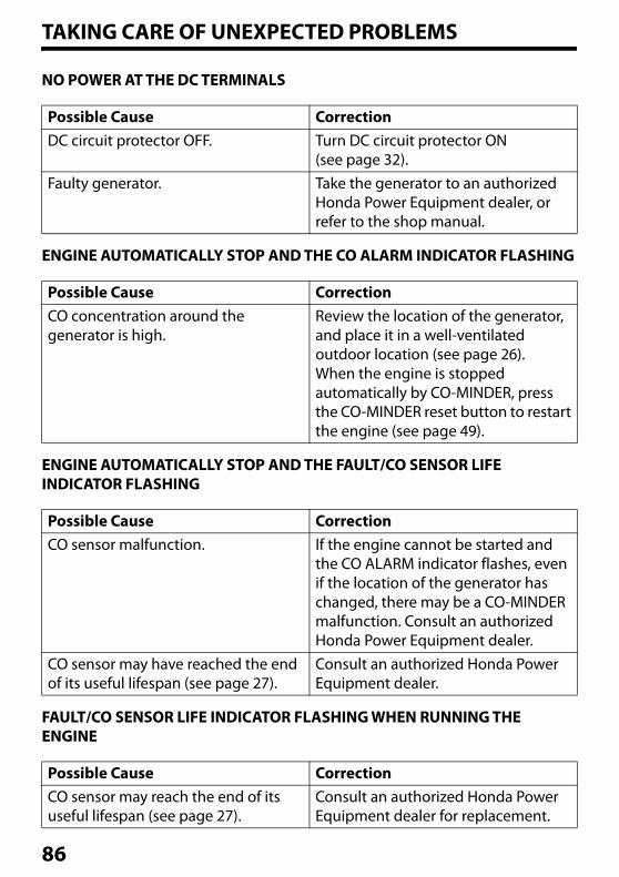
TAKING CARE OF UNEXPECTED PROBLEMS
NO POWER AT THE DC TERMINALS
ENGINE AUTOMATICALLY STOP AND THE CO ALARM INDICATOR FLASHING
ENGINE AUTOMATICALLY STOP AND THE FAULT/CO SENSOR LIFE INDICATOR FLASHING
FAULT/CO SENSOR LIFE INDICATOR FLASHING WHEN RUNNING THE ENGINE
Possible Cause CorrectionDC circuit protector OFF. Turn DC circuit protector ON
(see page 32).Faulty generator. Take the generator to an authorized
Honda Power Equipment dealer, or refer to the shop manual.
Possible Cause CorrectionCO concentration around the generator is high.
Review the location of the generator, and place it in a well-ventilated outdoor location (see page 26).When the engine is stopped automatically by CO-MINDER, press the CO-MINDER reset button to restart the engine (see page 49).
Possible Cause CorrectionCO sensor malfunction. If the engine cannot be started and
the CO ALARM indicator flashes, even if the location of the generator has changed, there may be a CO-MINDER malfunction. Consult an authorized Honda Power Equipment dealer.
CO sensor may have reached the end of its useful lifespan (see page 27).
Consult an authorized Honda Power Equipment dealer.
Possible Cause CorrectionCO sensor may reach the end of its useful lifespan (see page 27).
Consult an authorized Honda Power Equipment dealer for replacement.
86
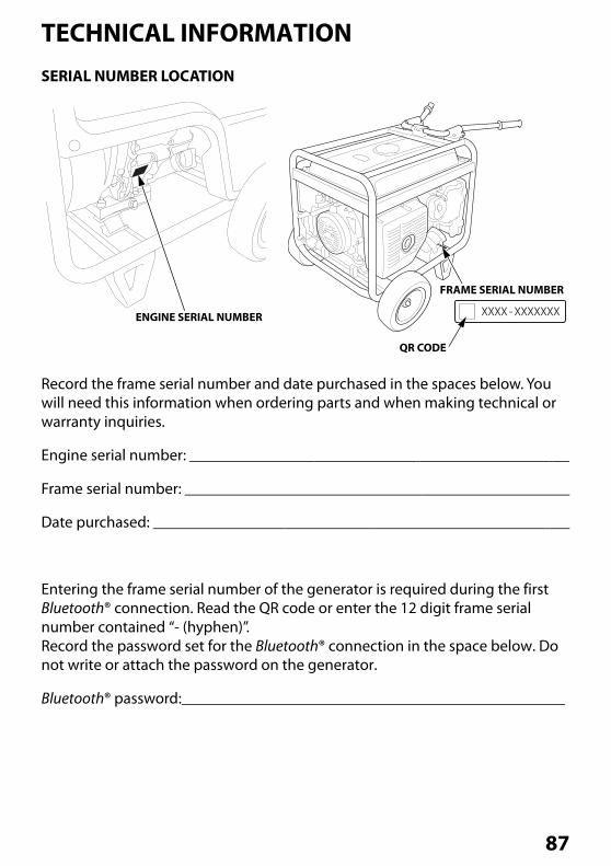
TECHNICAL INFORMATIONSERIAL NUMBER LOCATION
Record the frame serial number and date purchased in the spaces below. You will need this information when ordering parts and when making technical or warranty inquiries.
Engine serial number:
Frame serial number:
Date purchased:
Entering the frame serial number of the generator is required during the first Bluetooth® connection. Read the QR code or enter the 12 digit frame serial number contained “- (hyphen)”.Record the password set for the Bluetooth® connection in the space below. Do not write or attach the password on the generator.
Bluetooth® password:
ENGINE SERIAL NUMBER
FRAME SERIAL NUMBER
QR CODE
87
TECHNICAL INFORMATION
CARBURETOR MODIFICATION FOR HIGH ALTITUDE OPERATION
At high altitude, the standard carburetor air-fuel mixture will be too rich. Performance will decrease, and fuel consumption will increase. A very rich mixture will also foul the spark plug and cause hard starting. Operation at an altitude that differs from that at which this engine was certified, for extended periods of time, may increase emissions.
High altitude performance can be improved by specific modifications to the carburetor. If you always operate your generator at altitudes above 2,000 feet (610 meters), have your authorized Honda servicing dealer perform this carburetor modification. This engine, when operated at high altitude with the carburetor modifications for high altitude use, will meet each emission standard throughout its useful life.
Even with carburetor modification, engine horsepower will decrease about 3.5% for each 1,000-foot (300-meter) increase in altitude. The effect of altitude on horsepower will be greater than this if no carburetor modification is made.
When the carburetor has been modified for high altitude operation, the air/fuel mixture will be too lean for low altitude use. Operation at altitudes below 2,000 feet (610 meters) with a modified carburetor may cause the engine to overheat and result in serious engine damage. For use at low altitudes, have your servicing dealer return the carburetor to original factory specifications.
88
TECHNICAL INFORMATION
EMISSION CONTROL SYSTEM INFORMATION
Source of EmissionsThe combustion process produces carbon monoxide, oxides of nitrogen, and hydrocarbons. Control of hydrocarbons and oxides of nitrogen is very important because, under certain conditions, they react to form photochemical smog when subjected to sunlight. Carbon monoxide does not react in the same way, but it is toxic.
Honda utilizes appropriate air/fuel ratios and other emissions control systems to reduce the emissions of carbon monoxide, oxides of nitrogen, and hydrocarbons.
Additionally, Honda fuel systems utilize components and control technologies to reduce evaporative emissions.
The U.S. and California Clean Air Acts, and Environment and Climate Change Canada (ECCC)U.S. EPA, California and Canadian regulations require all manufacturers to furnish written instructions describing the operation and maintenance of emission control systems.
The following instructions and procedures must be followed in order to keep the emissions from your Honda engine within the emission standards.
Tampering and Altering
Tampering is a violation of federal and California law.
Tampering with or altering the emission control system may increase emissions beyond the legal limit. Among those acts that constitute tampering are:
• Removal or alteration of any part of intake, fuel, or exhaust systems.
• Alterations that would cause the engine to operate outside its design parameters.
89
TECHNICAL INFORMATION
Problems That May Affect EmissionsIf you are aware of any of the following symptoms, have your engine inspected and repaired by your authorized Honda Power Equipment dealer.
• Hard starting or stalling after starting.
• Rough idle.
• Misfiring or backfiring under load.
• Afterburning (backfiring).
• Black exhaust smoke or high fuel consumption.
Replacement PartsThe emissions control systems on your new Honda engine were designed, built, and certified to conform with EPA, California (models certified for sale in California only), and Canadian emissions regulations. We recommend the use of Honda Genuine parts whenever you have maintenance done. These original design replacement parts are manufactured to the same standards as the original parts, so you can be confident of their performance. Honda cannot deny coverage under the emission warranty solely for the use of non-Honda replacement parts or service performed at a location other than an authorized Honda dealership; you may use comparable EPA certified parts, and have service performed at non-Honda locations. However, the use of replacement parts that are not of the original design and quality may impair the effectiveness of your emissions control system.A manufacturer of an aftermarket part assumes the responsibility that the part will not adversely affect emissions performance. The manufacturer or rebuilder of the part must certify that use of the part will not result in a failure of the engine to comply with emissions regulations.
MaintenanceAs the power equipment engine owner, you are responsible for completing all required maintenance listed in your owner's manual. Honda recommends that you retain all receipts covering maintenance on your power equipment engine, but Honda cannot deny warranty coverage solely for the lack of receipts or for your failure to ensure that all scheduled maintenance has been completed.Follow the "MAINTENANCE SCHEDULE" on page 65. Remember that this schedule is based on the assumption that your Honda engine product will be used for its designed purpose. Sustained high-load or high-temperature operation, or use in dusty conditions, will require more frequent service.
90
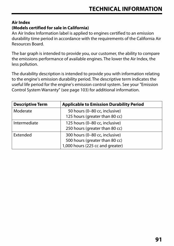
TECHNICAL INFORMATION
Air Index(Models certified for sale in California)An Air Index Information label is applied to engines certified to an emission durability time period in accordance with the requirements of the California Air Resources Board.
The bar graph is intended to provide you, our customer, the ability to compare the emissions performance of available engines. The lower the Air Index, the less pollution.
The durability description is intended to provide you with information relating to the engine’s emission durability period. The descriptive term indicates the useful life period for the engine’s emission control system. See your "Emission Control System Warranty" (see page 103) for additional information.
Descriptive Term Applicable to Emission Durability PeriodModerate 50 hours (0–80 cc, inclusive)
125 hours (greater than 80 cc)Intermediate 125 hours (0–80 cc, inclusive)
250 hours (greater than 80 cc)Extended 300 hours (0–80 cc, inclusive)
500 hours (greater than 80 cc)1,000 hours (225 cc and greater)
91
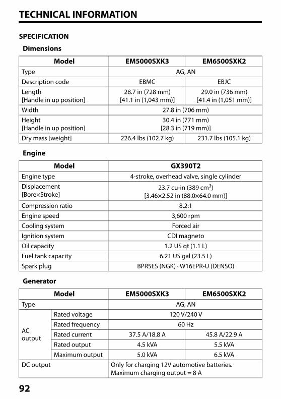
TECHNICAL INFORMATION
SPECIFICATION
Dimensions
Engine
Generator
Model EM5000SXK3 EM6500SXK2Type AG, AN
Description code EBMC EBJC
Length[Handle in up position]
28.7 in (728 mm)[41.1 in (1,043 mm)]
29.0 in (736 mm)[41.4 in (1,051 mm)]
Width 27.8 in (706 mm)
Height[Handle in up position]
30.4 in (771 mm)[28.3 in (719 mm)]
Dry mass [weight] 226.4 lbs (102.7 kg) 231.7 lbs (105.1 kg)
Model GX390T2Engine type 4-stroke, overhead valve, single cylinder
Displacement[Bore×Stroke]
23.7 cu-in (389 cm3)[3.46×2.52 in (88.0×64.0 mm)]
Compression ratio 8.2:1
Engine speed 3,600 rpm
Cooling system Forced air
Ignition system CDI magneto
Oil capacity 1.2 US qt (1.1 L)
Fuel tank capacity 6.21 US gal (23.5 L)
Spark plug BPR5ES (NGK) · W16EPR-U (DENSO)
Model EM5000SXK3 EM6500SXK2Type AG, AN
ACoutput
Rated voltage 120 V/240 V
Rated frequency 60 Hz
Rated current 37.5 A/18.8 A 45.8 A/22.9 A
Rated output 4.5 kVA 5.5 kVA
Maximum output 5.0 kVA 6.5 kVA
DC output Only for charging 12V automotive batteries.Maximum charging output = 8 A
92
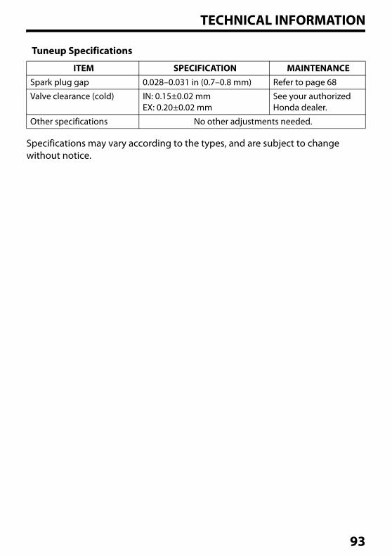
TECHNICAL INFORMATION
Tuneup Specifications
Specifications may vary according to the types, and are subject to change without notice.
ITEM SPECIFICATION MAINTENANCESpark plug gap 0.028–0.031 in (0.7–0.8 mm) Refer to page 68
Valve clearance (cold) IN: 0.15±0.02 mmEX: 0.20±0.02 mm
See your authorized Honda dealer.
Other specifications No other adjustments needed.
93
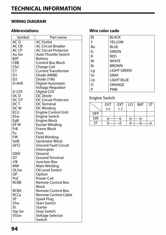
TECHNICAL INFORMATION
WIRING DIAGRAM
AbbreviationsSymbol Part name
AC OAC CBAC CPAu SwBATCBBChCCTD1D2D-AVR
D-CDIDC DDC CPDC TDC WECUESwEgBEX WFrBFuFWGeBGFCI
GNDGTJ/BMWOLSwOPPoCRCBB
RCBXRCCaSPSSwStStp SwVSSw
AC OutletAC Circuit BreakerAC Circuit ProtectorAuto Throttle SwitchBatteryControl Box BlockCharge CoilCurrent TransformerDiode (MMB)Diode (196)Digital-AutomaticVoltage RegulatorDigital-CDIDC DiodeDC Circuit ProtectorDC TerminalDC WindingEngine Control UnitEngine SwitchEngine BlockExciter WindingFrame BlockFuseField WindingGenerator BlockGround Fault Circuit InterrupterGroundGround TerminalJunction BoxMain WindingOil Level SwitchOptionPower CoilRemote Control BoxBlockRemote Control BoxRemote Control CableSpark PlugStart SwitchStarterStop SwitchVoltage SelectorSwitch
Wire color code
Engine Switch
BlYBuGRWBrLgGrLbOP
BLACKYELLOWBLUEGREENREDWHITEBROWNLIGHT GREENGRAYLIGHT BLUEORANGEPINK
EXT(+)
EXT(–)
LO BAT ST
OFFON o o o oST o o o o o
94
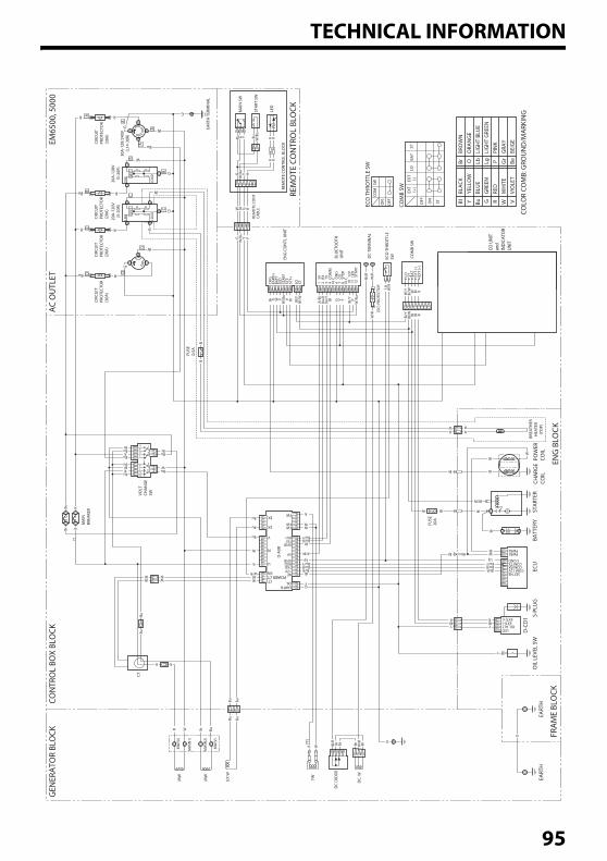
TECHNICAL INFORMATION
A
A
A
A
BC
B
W
G
C G
W
Bu
D W
W
R
RR
R
BBu R
CR R
D DBu R
RG
G
G
BrBu
Br
Br
BuR
R
Bu
Bu
Bu
Bu R
Br R
WBu
Y R
W/B
uW G RBl
Bu
R R
Bu
R+
W
G
Bl/R
Br Br W/R BrBr
BuYBlR
Bl
G
Y
W
Bl
Br
R RRW
W
WBl
Bl
LgBu/Y
Bl/RBu/R
YBlR
Bu
R W BuBr
Bu
Bu
GY
Bl
Bl
Bl/RBu/RBu/Y
Lg
Bu/RBu/Y
R/Bl
WW
R
W
W
R
Bu
Bu
Bu
W/RBl
WBl
WBl
G Y P
W/B
u
YGG G Y VG Br Y/R
Y/BuY/
R
Bl/Y
Bl/W BlW R
Bl/Y
Bl/W BlW R
Y/Bu
Y/G
W/O
W/O
W/G
Bl/R
W/R
W/R
Br R/Bl
Bu/R
Bu/Y Bl G PV YBr Bl/Y
Bl/Y
W/B
u
Bl/WG P
W/B
uVW
W/RLg
W
W
Bl
W
Bl/W
G YBu W/B
uBu
RR
RR
GLI
NE
LOA
D
20A
-120
V
(5-2
0R)
FUSE
0.5A
FUSE
20A
CTPOWER CT
U
D-A
VR
MW
(U)
MW
MW
EX W
FW
DC
DIO
DE
DC.
W
MW
(V)
MW
(N1)
MW
(N2)
EARTHOIL
NE12VTXDRXDGND
GND
RX1
FWFW
FW
TX1
5VN
V
EX
EX
SW
MA
INBR
EAKE
R
CTVO
LT
CHA
NG
ESW
GFC
ILI
NE
LOA
D
20A
-120
V
(5-2
0R)
GFC
I
30A
-120
/240
V
(L1
4-30
R)
CIRC
UIT
PRO
TECT
OR
(30A
)
EART
H T
ERM
INA
L
CIRC
UIT
PRO
TECT
OR
(30A
)
CIRC
UIT
PRO
TECT
OR
(20A
)
CIRC
UIT
PRO
TECT
OR
(20A
)
COM
ECO
TH
ROTT
LE S
W
ECO
TH
ROTT
LESWD
C TE
RMIN
AL
BLU
ETO
OTH
UN
IT
ENG
CO
NTL
UN
IT
COM
B SW
COM
B SW
OFFON
SW
OFF ON
ST
LOST
BAT
EXT
(+)
EXT
(-)
ENG
BLO
CK
REM
OTE
CO
NTR
OL
BLO
CK
EM65
00, 5
000
AC
OU
TLET
GEN
ERA
TOR
BLO
CKCO
NTR
OL
BOX
BLO
CK
REM
OTE
CO
NTR
OL
BLO
CK
FRA
ME
BLO
CK
OIL
LEV
EL S
W
D-C
D1 S-
PLU
GEC
UBA
TTER
YST
ART
ERPO
WER
COIL
BREA
THER
HEA
TER
(Y
OP)
CHA
RGE
COIL
EART
HEA
RTH
1 S
TOP-
2 S
TOP+
3 E
ART
H 4
EA
RTH
5 P
OW
ER_S
UPP
LY+
11
PO
WER
_SU
PPLY
-
6 N
. C.
10
N. C
.
14
N. C
.
16
N. C
.
20
N. C
. 2
1 N
. C.
22
N. C
. 2
3 N
. C.
24
N. C
.
18
N. C
. 1
9 R
ELA
Y
17
TES
T
15
ING
12
N. C
. 1
3 R
ESET
8 N
. C.
9 I
ND
2_TR
OU
BLE
7 I
ND
1_CO
LED OIL ALT
EXT(+) EXT(-)
1 E
ART
H2
IND
_CO
3 IN
D_T
ROU
BLE
4 T
EST_
SW5
RES
ET_S
W
LO ST BAT
EXT
(-)EX
T (+
)
CHG
REM
OTE
CO
NT
CABL
E
EART
HBA
TTLE
DST
ART
SET-
SET+
LO ST 1 5
V
(DC)
PRO
TECT
OR
2 R
X3
TX
4 C
OM
MN
. C.
N. C
.10
12
V11
LE
D12
ST
ART
LED
STA
RT S
W
MA
IN S
W
6
GN
D
7 C
O8
STO
P
10127 11
8
5
2
9
1346
SET NECOM 12V
COM RXCOM TX
S GND
PWR1PWR2
M
Bu G R WBlBL
ACK
YELL
OW
BRO
WN
BrO
RAN
GE
OLI
GH
T BL
UE
LbLI
GH
T G
REEN
LgPI
NK
PG
RAY
Gr
BLU
EG
REEN
RED
WH
ITE
VBE
IGE
BeVI
OLE
T
Y
COLO
R CO
MB:
GRO
UN
D/M
ARK
ING
CO U
NIT
and
INDI
CATO
R UN
IT
95
CONSUMER INFORMATIONDEALER LOCATOR INFORMATION
To find an authorized Honda Servicing Dealer anywhere in the United States, visit our website: http://powerequipment.honda.com/dealer-locator
Honda PUBLICATIONS
Shop ManualThis manual covers complete maintenance and overhaul procedures. It is intended to be used by a skilled technician.Available through your Honda dealer or visit http://powerequipment.honda.com/support/shop-manuals
Parts CatalogThis manual provides complete, illustrated parts lists for your generator. Visit peparts.honda.com for free online access to the parts catalog. It is also available for purchase in paper form through your Honda dealer.
Accessories CatalogYour authorized Honda Power Equipment dealer offers a wide selection of accessories (optional equipment) to make your generator even more useful.Visit http://powerequipment.honda.com/generators/accessories and click on See all generator accessories to see the entire catalog of accessories.
96
CONSUMER INFORMATION
CUSTOMER SERVICE INFORMATION
Honda Power Equipment dealership personnel are trained professionals. They should be able to answer any question you may have. If you encounter a problem that your dealer does not solve to your satisfaction, please discuss it with the dealership’s management.The Service Manager or General Manager can help. Almost all problems are solved in this way.
If you are dissatisfied with the decision made by the dealership’s management, contact the Honda Power Equipment Customer Relations Office. You can write to:
American Honda Motor Co., Inc.Power Equipment DivisionCustomer Relations Office4900 Marconi DriveAlpharetta, Georgia 30005-8847
Or telephone: (770) 497-6400 M-F 9:00am - 7:30pm ET
When you write or call, please give us this information:
• Model and serial numbers (see page 87)
• Name of the dealer who sold the generator to you
• Name and address of the dealer who services your generator
• Date of purchase
• Your name, address, and telephone number
• A detailed description of the problem
97
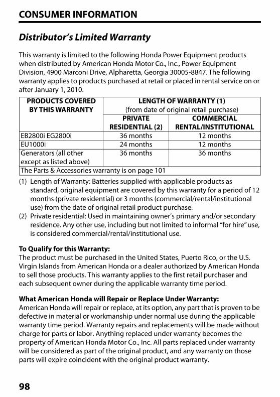
CONSUMER INFORMATION
Distributor’s Limited Warranty
This warranty is limited to the following Honda Power Equipment products when distributed by American Honda Motor Co., Inc., Power Equipment Division, 4900 Marconi Drive, Alpharetta, Georgia 30005-8847. The following warranty applies to products purchased at retail or placed in rental service on or after January 1, 2010.
(1) Length of Warranty: Batteries supplied with applicable products as standard, original equipment are covered by this warranty for a period of 12 months (private residential) or 3 months (commercial/rental/institutional use) from the date of original retail product purchase.
(2) Private residential: Used in maintaining owner’s primary and/or secondary residence. Any other use, including but not limited to informal ‘‘for hire’’ use, is considered commercial/rental/institutional use.
To Qualify for this Warranty:The product must be purchased in the United States, Puerto Rico, or the U.S. Virgin Islands from American Honda or a dealer authorized by American Honda to sell those products. This warranty applies to the first retail purchaser and each subsequent owner during the applicable warranty time period.
What American Honda will Repair or Replace Under Warranty:American Honda will repair or replace, at its option, any part that is proven to be defective in material or workmanship under normal use during the applicable warranty time period. Warranty repairs and replacements will be made without charge for parts or labor. Anything replaced under warranty becomes the property of American Honda Motor Co., Inc. All parts replaced under warranty will be considered as part of the original product, and any warranty on those parts will expire coincident with the original product warranty.
PRODUCTS COVEREDBY THIS WARRANTY
LENGTH OF WARRANTY (1)(from date of original retail purchase)
PRIVATERESIDENTIAL (2)
COMMERCIALRENTAL/INSTITUTIONAL
EB2800i EG2800i 36 months 12 monthsEU1000i 24 months 12 monthsGenerators (all other except as listed above)
36 months 36 months
The Parts & Accessories warranty is on page 101
98
CONSUMER INFORMATION
To Obtain Warranty Service:You must, at your expense, take the Honda Power Equipment product, accessory, replacement part, apparel, or the power equipment on which the accessory or replacement part is installed, and proof of purchase to any Honda Power Equipment dealer in the United States, Puerto Rico, or the U.S. Virgin Islands who is authorized to sell that product, during the dealer’s normal business hours. To locate a dealer near you, visit our web site at http://powerequipment.honda.com/dealer-locator/. If you are unable to obtain warranty service or are dissatisfied with the warranty service you receive, contact the owner of the dealership involved; normally this will resolve the problem. However, if you should require further assistance, write or call the Power Equipment Customer Relations Dept. of American Honda Motor Co., Inc. at the following address:
American Honda Motor Co., Inc.Power Equipment Customer Relations Dept.
4900 Marconi DriveAlpharetta, GA 30005-8847 Telephone: (770) 497-6400
99
CONSUMER INFORMATION
Exclusions:1. Any damage or deterioration resulting from the following:
– Neglect of the periodic maintenance as specified in this manual– Improper repair or maintenance– Operating methods other than those indicated in this manual– The use of non-genuine Honda parts and accessories other than those
approved by Honda (other than recommended lubricants and fluids)– Exposure of the product to soot and smoke, chemical agents, bird
droppings, sea water, salt or other corrosive environments – Collision, fuel contamination or deterioration, neglect, unauthorized
alteration, misuse, incorporation or use of unsuitable attachments or parts– Natural wear and tear (natural fading of painted or plated surfaces, sheet
peeling and other natural deterioration)2. Consumable parts: Honda does not warrant parts deterioration due to
natural wear and tear. The parts listed below are not covered by warranty (unless they are needed as a part of another warranted repair):– Spark plug, fuel filter, air cleaner element, clutch disc, tire, wheel bearing,
recoil starter rope, cable, belt, cutter blade.– Lubricant: oil and grease.
3. Cleaning, adjustment, and normal periodic maintenance work (carburetor cleaning, engine oil draining, blade sharpening, belt and cable adjustments).
4. Any product that has ever been declared a total loss or sold for salvage by a financial institution or insurer.
5. Auger and paddle assemblies of snowthrowers, tiller tines of rototillers, mower blades and mower deck housings, are specifically not warranted against impact damage, including but not limited to, abrasive damage.
Disclaimer of Consequential Damage and Limitation of Implied Warranties:American Honda disclaims any responsibility for loss of time or use of the product, transportation, commercial loss, or any other incidental or consequential damage. Any implied warranties are limited to the duration of this written limited warranty. Some states do not allow limitations on how long an implied warranty lasts and/or do not allow the exclusion or limitation of incidental or consequential damages, so the above exclusions and limitations may not apply to you. This warranty gives you specific legal rights, and you may also have other rights which vary from state to state.
100
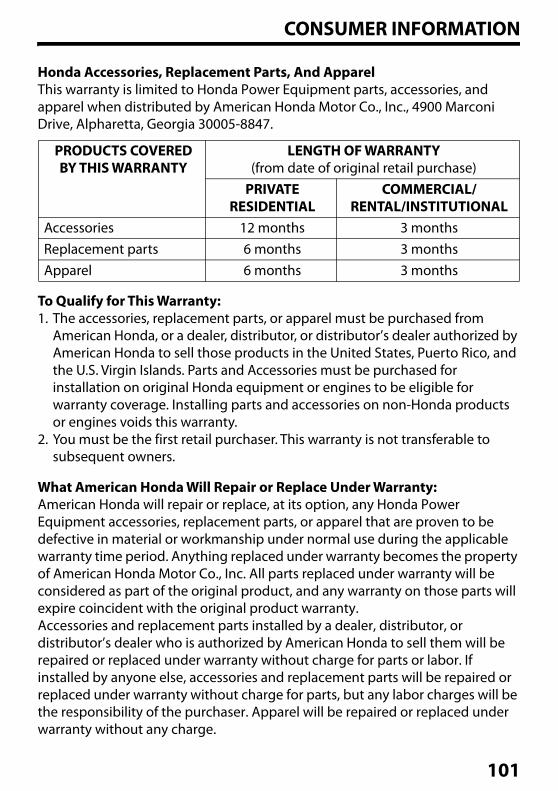
CONSUMER INFORMATION
Honda Accessories, Replacement Parts, And ApparelThis warranty is limited to Honda Power Equipment parts, accessories, and apparel when distributed by American Honda Motor Co., Inc., 4900 Marconi Drive, Alpharetta, Georgia 30005-8847.
To Qualify for This Warranty:1. The accessories, replacement parts, or apparel must be purchased from
American Honda, or a dealer, distributor, or distributor’s dealer authorized by American Honda to sell those products in the United States, Puerto Rico, and the U.S. Virgin Islands. Parts and Accessories must be purchased for installation on original Honda equipment or engines to be eligible for warranty coverage. Installing parts and accessories on non-Honda products or engines voids this warranty.
2. You must be the first retail purchaser. This warranty is not transferable to subsequent owners.
What American Honda Will Repair or Replace Under Warranty:American Honda will repair or replace, at its option, any Honda Power Equipment accessories, replacement parts, or apparel that are proven to be defective in material or workmanship under normal use during the applicable warranty time period. Anything replaced under warranty becomes the property of American Honda Motor Co., Inc. All parts replaced under warranty will be considered as part of the original product, and any warranty on those parts will expire coincident with the original product warranty.Accessories and replacement parts installed by a dealer, distributor, or distributor’s dealer who is authorized by American Honda to sell them will be repaired or replaced under warranty without charge for parts or labor. If installed by anyone else, accessories and replacement parts will be repaired or replaced under warranty without charge for parts, but any labor charges will be the responsibility of the purchaser. Apparel will be repaired or replaced under warranty without any charge.
PRODUCTS COVEREDBY THIS WARRANTY
LENGTH OF WARRANTY(from date of original retail purchase)
PRIVATERESIDENTIAL
COMMERCIAL/RENTAL/INSTITUTIONAL
Accessories 12 months 3 monthsReplacement parts 6 months 3 monthsApparel 6 months 3 months
101
CONSUMER INFORMATION
To Obtain Warranty Service:You must, at your expense, take the Honda Power Equipment accessory, replacement part, apparel, or the Honda Power Equipment on which the accessory or replacement part is installed, and proof of purchase to any Honda Power Equipment dealer, distributor, or distributor’s dealer in the United States, Puerto Rico, or the U.S. Virgin Islands who is authorized to sell that product, during the dealer’s or distributor’s normal business hours. To locate a dealer near you, go to our web site at http://powerequipment.honda.com/dealer-locator/. If you are unable to obtain warranty service or are dissatisfied with the warranty service you receive, contact the owner of the dealership or distributorship involved; normally this will resolve the problem. However, if you should require further assistance, write or call the Power Equipment Customer Relations Department of America Honda Motor Co., Inc. Refer to page 99 for contact information.
Exclusions:This warranty does not extend to accessories, parts, or apparel affected or damaged by collision, normal wear, use in an application for which the product was not designed or any other misuse, neglect, incorporation or use of unsuitable attachments or parts, unauthorized alteration, improper installation, or any causes other than defects in material or workmanship of the product. Installing Parts and Accessories on non-Honda products or engines voids this warranty.
Disclaimer of Consequential Damage and Limitation of Implied Warranties:American Honda disclaims any responsibility for loss of time or use of the product, or the power equipment on which the product is installed, transportation, commercial loss, or any other incidental or consequential damage. Any implied warranties are limited to the duration of this written warranty. Some states do not allow limitations on how long an implied warranty lasts and/or do not allow the exclusion or limitation of incidental or consequential damages, so the above exclusions and limitations may not apply to you. This warranty gives you specific legal rights, and you may also have other rights which vary from state to state.
102
CONSUMER INFORMATION
Emission Control System Warranty
Your new Honda Power Equipment engine complies with the U.S. EPA, Environment Canada, and State of California (models certified for sale in California only) emission regulations. American Honda Motor Co., Inc. provides the emission warranty coverage for engines in the United States and its territories. Honda Canada Inc. provides the emission warranty for engines in the 13 provinces and territories of Canada. In the remainder of this Emission Control System Warranty, American Honda Motor Co., Inc. and Honda Canada Inc. will be referred to as Honda.
CALIFORNIA EXHAUST AND EVAPORATIVE EMISSIONS CONTROL WARRANTY STATEMENT YOUR WARRANTY RIGHTS AND OBLIGATIONS
The California Air Resources Board and Honda are pleased to explain the exhaust and evaporative emissions (“emissions”) control system warranty on your 2020 and later Honda Power Equipment engine. In California, new equipment that use small off-road engines must be designed, built, and equipped to meet the State's stringent anti-smog standards. Honda must warrant the emissions control system on your power equipment engine for the periods of time listed below provided there has been no abuse, neglect, or improper maintenance of your small off-road engine or equipment leading to the failure of the emissions control system.
Your emissions control system may include parts such as the carburetor or fuel-injection system, the ignition system, catalytic converter, fuel tanks, fuel lines (for liquid fuel and fuel vapors), fuel caps, valves, canisters, filters, clamps and other associated components. Also included may be hoses, belts, connectors, and other emission-related assemblies (see page 107 for additional covered parts).
Where a warrantable condition exists, Honda will repair your power equipment engine at no cost to you including diagnosis, parts and labor.
MANUFACTURER'S WARRANTY COVERAGE:
The exhaust and evaporative emissions control system on your Honda power equipment engine is warranted for two years. If any emissions-related part on your Honda power equipment engine is defective, the part will be repaired or replaced by Honda.
103
CONSUMER INFORMATION
OWNER'S WARRANTY RESPONSIBILITY:
• As the power equipment engine owner, you are responsible for the performance of the required maintenance listed in your owner's manual. Honda recommends that you retain all receipts covering maintenance on your power equipment engine, but Honda cannot deny warranty coverage solely for the lack of receipts or for your failure to ensure the performance of all scheduled maintenance.
• As the power equipment engine owner, you should however be aware that Honda may deny you warranty coverage if your power equipment engine or a part has failed due to abuse, neglect, improper maintenance, or unapproved modifications.
• You are responsible for presenting your power equipment engine to a Honda Power Equipment servicing dealer as soon as the problem exists. The warranty repairs shall be completed in a reasonable amount of time, not to exceed 30 days.
If you have any questions regarding your warranty rights and responsibilities, you should contact the Honda office in your region:
American Honda Motor Co., Inc.Power Equipment Customer Relations4900 Marconi DriveAlpharetta, Georgia 30005-8847Telephone: (888) 888-3139Email: powerequipmentemissions
@ahm.honda.com
or
Honda Canada Inc.Power Equipment Customer Relations180 Honda Blvd.Markham, ON, L6C 0H9Telephone: (888) 946-6329
104
CONSUMER INFORMATION
YOUR WARRANTY RIGHTS AND OBLIGATIONS
Other States, U.S. territories, and Canada:In other areas of the United States and in Canada, your engine must be designed, built, and equipped to meet the U.S. EPA and Environment Canada emission standards for spark-ignited engines at or below 19 kilowatts.
Specific Honda products that do not meet the California emissions regulations can be identified by a “California: Not for sale or use” or “California: Only for use in Farming or Construction Equipment” decal.
All of the United States and Canada:The exhaust and evaporative emissions control system on your Honda power equipment engine sold in the United States and Canada is warranted for two years from the date of delivery to the ultimate purchaser or the length of the Honda Distributor’s Limited Warranty, whichever is longer. This warranty is transferable to each subsequent purchaser for the duration of the warranty period.
If any emissions-related part on your Honda power equipment engine is defective, the part will be repaired or replaced by Honda. All defective parts replaced under this warranty become the property of Honda. Only Honda approved replacement parts may be used in the performance of any warranty repairs and must be provided without charge to the owner. A list of warranted parts is on the reverse side of this warranty statement. All emission related parts are under warranty for the remainder of the warranty period. Normal maintenance items, such as spark plugs and filters, that are on the warranted parts list are warranted up to their required replacement interval only.
Honda will also replace other engine components damaged by a failure of any warranted part during the warranty period. Honda cannot deny coverage under the emission warranty solely for use of non-Honda replacement parts or service performed at a location other than an authorized Honda dealership; however, use of a part that is not functionally identical to the original equipment part in any respect that may in any way affect emissions (including durability) could result in denial of coverage. If such a non-Honda replacement part is used in the repair or maintenance of your engine, and an authorized Honda dealer determines it is defective or causes a failure of a warranted part, your claim for repair of your engine may be denied. If the part in question is not related to the reason your engine requires repair, your claim will not be denied.
105
CONSUMER INFORMATION
TO OBTAIN WARRANTY SERVICE:
You must, at your own expense, take your Honda Power Equipment engine or the product on which it is installed, along with your sales registration card or other proof of original purchase date, to any Honda Power Equipment dealer who is authorized by Honda to sell and service that Honda product during their normal business hours. Claims for repair or adjustment found to be caused solely by defects in material or workmanship will not be denied because the engine was not properly maintained and used.If you are unable to obtain emission warranty service or are dissatisfied with the warranty service you received, contact the owner of the dealership involved. Normally this should resolve your problem. However, if you require further assistance, contact the Honda office in your region:
EXCLUSIONS:
Failures other than those resulting from defects in material or workmanship are not covered by this warranty. This warranty does not extend to emission control systems or parts that are affected or damaged by owner abuse, neglect, improper maintenance, or unapproved modifications.This warranty does not cover replacement of expendable maintenance items made in connection with required maintenance service after the item's first scheduled replacement as listed in the maintenance section of the product owner's manual, such as: spark plugs and filters.
American Honda Motor Co., Inc.Power Equipment Customer Relations4900 Marconi DriveAlpharetta, Georgia 30005-8847Telephone: (888) 888-3139Email: powerequipmentemissions
@ahm.honda.com
or
Honda Canada Inc.Power Equipment Customer Relations180 Honda Blvd.Markham, ON, L6C 0H9Telephone: (888) 946-6329
106
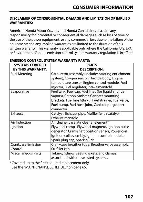
CONSUMER INFORMATION
DISCLAIMER OF CONSEQUENTIAL DAMAGE AND LIMITATION OF IMPLIED WARRANTIES:
American Honda Motor Co., Inc. and Honda Canada Inc. disclaim any responsibility for incidental or consequential damages such as loss of time or the use of the power equipment, or any commercial loss due to the failure of the equipment; and any implied warranties are limited to the duration of this written warranty. This warranty is applicable only where the California, U.S. EPA, or Environment Canada emission control system warranty regulation is in effect.
EMISSION CONTROL SYSTEM WARRANTY PARTS:
*Covered up to the first required replacement only.See the "MAINTENANCE SCHEDULE" on page 65.
SYSTEMS COVEREDBY THIS WARRANTY:
PARTSDESCRIPTION:
Fuel Metering Carburetor assembly (includes starting enrichment system), Oxygen sensor, Throttle body, Engine temperature sensor, Engine control module, Fuel injector, Fuel regulator, Intake manifold
Evaporative Fuel tank, Fuel cap, Fuel lines (for liquid and fuel vapors), Carbon canister, Canister mounting brackets, Fuel line fittings, Fuel strainer, Fuel valve, Fuel pump, Fuel hose joint, Canister purge port connector
Exhaust Catalyst, Exhaust pipe, Muffler (with catalyst), Exhaust manifold
Air Induction Air cleaner case, Air cleaner element*Ignition Flywheel comp., Flywheel magneto, Ignition pulse
generator, Crankshaft position sensor, Power coil, Ignition coil assembly, Ignition control module, Spark plug cap, Spark plug*
Crankcase Emission Control
Crankcase breather tube, Breather valve assembly, Oil filler cap
Miscellaneous Parts Tubing, fittings, seals, gaskets, and clamps associated with these listed systems.
107
CONSUMER INFORMATION
REGISTRATION
Please Register Your GeneratorIf your dealer did not collect registration information from you, please take a few minutes and register your purchase with Honda. This allows us to contact you with any important updates regarding your generator. Please note registration is not required to obtain warranty service. You can register your generator by visiting the Honda Power Equipment website, http://powerequipment.honda.com/support and click on Product Registration. Your information will remain confidential. It will not be released to any other company or organization.
108
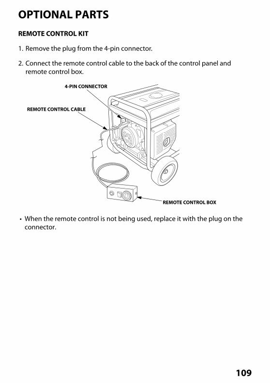
OPTIONAL PARTSREMOTE CONTROL KIT
1. Remove the plug from the 4-pin connector.
2. Connect the remote control cable to the back of the control panel and remote control box.
• When the remote control is not being used, replace it with the plug on the connector.
REMOTE CONTROL CABLE
4-PIN CONNECTOR
REMOTE CONTROL BOX
109
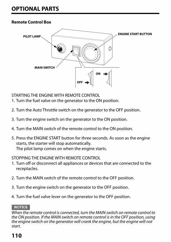
OPTIONAL PARTS
Remote Control Box
STARTING THE ENGINE WITH REMOTE CONTROL1. Turn the fuel valve on the generator to the ON position.
2. Turn the Auto Throttle switch on the generator to the OFF position.
3. Turn the engine switch on the generator to the ON position.
4. Turn the MAIN switch of the remote control to the ON position.
5. Press the ENGINE START button for three seconds. As soon as the engine starts, the starter will stop automatically. The pilot lamp comes on when the engine starts.
STOPPING THE ENGINE WITH REMOTE CONTROL1. Turn off or disconnect all appliances or devices that are connected to the
receptacles.
2. Turn the MAIN switch of the remote control to the OFF position.
3. Turn the engine switch on the generator to the OFF position.
4. Turn the fuel valve lever on the generator to the OFF position.
When the remote control is connected, turn the MAIN switch on remote control to the ON position. If the MAIN switch on remote control is in the OFF position, using the engine switch on the generator will crank the engine, but the engine will not start.
PILOT LAMP
MAIN SWITCH
ENGINE START BUTTON
ON
OFF
110
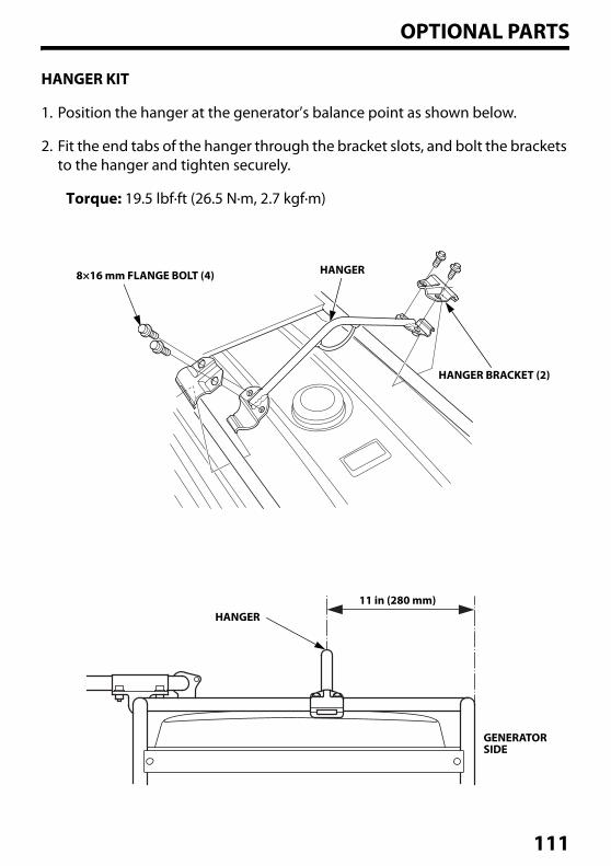
OPTIONAL PARTS
HANGER KIT
1. Position the hanger at the generator’s balance point as shown below.
2. Fit the end tabs of the hanger through the bracket slots, and bolt the brackets to the hanger and tighten securely.
Torque: 19.5 lbf·ft (26.5 N·m, 2.7 kgf·m)
8×16 mm FLANGE BOLT (4) HANGER
HANGER BRACKET (2)
11 in (280 mm)HANGER
GENERATORSIDE
111
REFERENCE INFORMATION“QR Code” is registered trademark of DENSO WAVE INCORPORATED.
The Bluetooth word mark and logos are registered trademarks owned by Bluetooth SIG, Inc., and any use of such marks by Honda Motor Co., Ltd., is under license. Other trademarks and trade names are those of their respective owners.
FCC Compliance StatementThis device complies with part 15 of the FCC Rules. Operation is subject to the following two conditions: (1) This device may not cause harmful interference, and (2) this device must accept any interference received, including interference that may cause undesired operation.
FCC CAUTIONChanges or modifications not expressly approved by the party responsible for compliance could void the user's authority to operate the equipment.
Responsible Party – U.S. Contact InformationHosiden America Corp.120 East State Parkway, Schaumburg, IL. 60173, U.S.A.E-mail address: [email protected]
Note: The Bluetooth unit included with this equipment has been tested and found to comply with the limits for a Class B digital device, pursuant to part 15 of the FCC Rules. These limits are designed to provide reasonable protection against harmful interference in a residential installation. This equipment generates, uses and can radiate radio frequency energy and, if not installed and used in accordance with the instructions, may cause harmful interference to radio communications. However, there is no guarantee that interference will not occur in a particular installation. If this equipment does cause harmful interference to radio or television reception, which can be determined by turning the equipment off and on, the user is encouraged to try to correct the interference by one or more of the following measures:-- Reorient or relocate the receiving antenna.-- Increase the separation between the equipment and receiver.-- Connect the equipment into an outlet on a circuit different from that to
which the receiver is connected.-- Consult the dealer or an experienced radio/TV technician for help.
112
INDEXA
AC Appliance and Power Cord........................................................................................ 39AC Applications .................................................................................................................... 55AC Circuit Breaker ................................................................................................................ 29AC Circuit Protectors .......................................................................................................... 30AC OPERATION ..................................................................................................................... 53AC Receptacle Selection.................................................................................................... 56AIR CLEANER SERVICE ........................................................................................................ 67AIR FILTER CHECK ................................................................................................................ 41Air Index .................................................................................................................................. 91ARE YOU READY TO GET STARTED? .............................................................................. 38ASSEMBLY........................................................................................................................ 12, 13Auto Choke and Throttle Control System................................................................... 35AUTO THROTTLE® SYSTEM ........................................................................................ 29, 60Automatic Engine Stop Function................................................................................... 34
BBattery Charging .................................................................................................................. 74Battery Installation .............................................................................................................. 74Battery Removal ................................................................................................................... 73BATTERY SERVICE................................................................................................................. 72Battery............................................................................................................................... 16, 80BEFORE OPERATION ........................................................................................................... 38Bluetooth® Function ............................................................................................................ 37
CCarbon Monoxide Hazards................................................................................................. 8CARBURETOR MODIFICATION FOR HIGH ALTITUDE OPERATION...................... 88Check the Engine................................................................................................................. 39Check the GFCI...................................................................................................................... 39Cleaning .................................................................................................................................. 77CO-MINDER (CO Shut-off System) ................................................................................. 26COMPONENT & CONTROL LOCATIONS ....................................................................... 22Connecting the battery charging cable (optional equipment): ......................... 58Connections to a Building’s Electrical System........................................................... 61CONSUMER INFORMATION.............................................................................................. 96CONTROLS & FEATURES .................................................................................................... 22CONTROLS.............................................................................................................................. 24CUSTOMER SERVICE INFORMATION ............................................................................. 97
113
INDEX
DDC Circuit Protector ............................................................................................................ 32DC OPERATION ..................................................................................................................... 58DC Terminals ......................................................................................................................... 32DEALER LOCATOR INFORMATION................................................................................. 96Disconnecting the battery charging cable:................................................................ 59Distributor’s Limited Warranty .......................................................................................98
EElectric Shock Hazards ......................................................................................................... 9Emergency Procedures...................................................................................................... 72EMISSION CONTROL SYSTEM INFORMATION............................................................ 89Emission Control System Warranty ............................................................................ 103ENGINE AUTOMATICALLY STOP AND THE CO ALARM INDICATOR
FLASHING .......................................................................................................................... 86ENGINE AUTOMATICALLY STOP AND THE FAULT/CO SENSOR LIFE
INDICATOR FLASHING................................................................................................... 86Engine Cylinder .................................................................................................................... 80ENGINE LACKS POWER....................................................................................................... 85ENGINE OIL CHANGE .......................................................................................................... 66ENGINE OIL LEVEL CHECK ................................................................................................. 40ENGINE OIL RECOMMENDATIONS................................................................................. 18ENGINE OIL...................................................................................................................... 17, 80Engine Switch........................................................................................................................ 24ENGINE WILL NOT START .................................................................................................. 84
FFAULT/CO SENSOR LIFE INDICATOR FLASHING WHEN RUNNING
THE ENGINE....................................................................................................................... 86FEATURES ............................................................................................................................... 34Fire and Burn Hazards .......................................................................................................... 9Foam Air Filter Cleaning.................................................................................................... 67Folding Handle ..................................................................................................................... 33Fuel Gauge ............................................................................................................................. 36FUEL RECOMMENDATIONS.............................................................................................. 21Fuel Valve Lever ................................................................................................................... 25FUEL................................................................................................................................... 19, 77FUSE.......................................................................................................................................... 76
114
INDEX
GGENERATOR SAFETY............................................................................................................. 7GFCI OPERATION CHECK................................................................................................... 50Ground Fault Circuit Interrupter (GFCI) Receptacle ................................................ 31Ground Terminal.................................................................................................................. 36
HHandle Installation .............................................................................................................. 14HANGER KIT ........................................................................................................................ 111Honda PUBLICATIONS........................................................................................................ 96HOW TO RESTART WHEN STOPPED BY CO-MINDER (CO SHUT-OFF SYSTEM)
............................................................................................................................................... 49
IiAVR (Intelligent Auto Voltage Regulator) .................................................................. 35IMPORTANT SAFETY INFORMATION............................................................................... 7INITIAL USE INSTRUCTIONS.............................................................................................. 17INTRODUCTION ...................................................................................................................... 1IS YOUR GENERATOR READY TO GO?........................................................................... 38
KKnowledge ............................................................................................................................. 38
LLoose Parts (Wheel kit and handle)............................................................................... 13
MMAINTENANCE SAFETY ..................................................................................................... 64MAINTENANCE SCHEDULE............................................................................................... 65
NNO POWER AT THE AC RECEPTACLES .......................................................................... 85NO POWER AT THE DC TERMINALS............................................................................... 86
OOil Alert® System .................................................................................................................. 34OPERATION ............................................................................................................................ 44Operator Responsibility....................................................................................................... 7OPTIONAL PARTS.............................................................................................................. 109
PPower Producing Circuits ................................................................................................. 56
115
INDEX
QQUICK REFERENCE INFORMATION .................................................. inside back cover
RREFERENCE INFORMATION ........................................................................................... 112Refuel With Care................................................................................................................... 10REGISTRATION ................................................................................................................... 108Remote Control Box......................................................................................................... 110REMOTE CONTROL KIT.................................................................................................... 109REMOVAL FROM STORAGE............................................................................................... 81
SSAFE OPERATING PRECAUTIONS ................................................................................... 43SAFETY LABEL LOCATIONS............................................................................................... 11Safety Precautions............................................................................................................... 64SAFETY..................................................................................................................................... 12SEDIMENT CUP CLEANING ............................................................................................... 71SERIAL NUMBER LOCATION ............................................................................................. 87SERVICING YOUR GENERATOR........................................................................................ 63Smartphone application ................................................................................................... 37SPARK ARRESTER SERVICE ................................................................................................ 70SPARK PLUG SERVICE ......................................................................................................... 68Special Requirements......................................................................................................... 62SPECIFICATION ..................................................................................................................... 92STANDBY POWER................................................................................................................. 61Starter Grip ............................................................................................................................. 24STARTING AND STOPPING THE ENGINE with Bluetooth® ENABLED
SMARTPHONE .................................................................................................................. 49STARTING THE ENGINE ...................................................................................................... 44STOPPING THE ENGINE...................................................................................................... 48STORAGE PRECAUTIONS................................................................................................... 81STORAGE PREPARATION ................................................................................................... 77STORAGE................................................................................................................................. 77System Ground..................................................................................................................... 61
TTAKING CARE OF UNEXPECTED PROBLEMS............................................................... 84TECHNICAL INFORMATION .............................................................................................. 87THE IMPORTANCE OF MAINTENANCE.......................................................................... 63The Importance of Proper Assembly ............................................................................ 12TRANSPORTING .................................................................................................................... 82
116
INDEX
UUnpacking .............................................................................................................................. 13
VVehicles and Transportation Hazards........................................................................... 10Voltage Selector Switch.............................................................................................. 28, 57
WWheel Kit Installation.......................................................................................................... 15WIRING DIAGRAM................................................................................................................ 94
117

MEMO
118

MEMO
119

MEMO
120
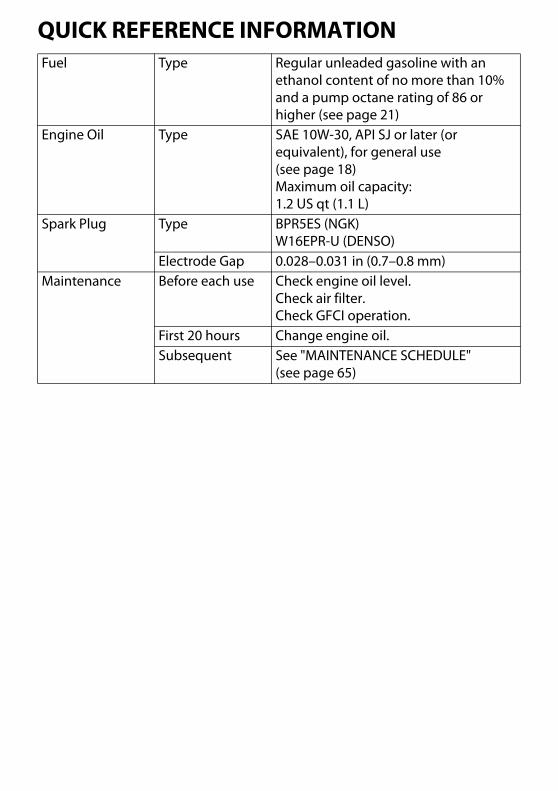
QUICK REFERENCE INFORMATIONFuel Type Regular unleaded gasoline with an
ethanol content of no more than 10% and a pump octane rating of 86 or higher (see page 21)
Engine Oil Type SAE 10W-30, API SJ or later (or equivalent), for general use (see page 18)Maximum oil capacity:1.2 US qt (1.1 L)
Spark Plug Type BPR5ES (NGK)W16EPR-U (DENSO)
Electrode Gap 0.028–0.031 in (0.7–0.8 mm)Maintenance Before each use Check engine oil level.
Check air filter.Check GFCI operation.
First 20 hours Change engine oil.Subsequent See "MAINTENANCE SCHEDULE"
(see page 65)

Printed in China
EM5000SX/EM6500SX31Z2362100X31-Z23-6210 2021 Honda Motor Co., Ltd. -All Rights Reserved
GENERATOREM5000SX/EM6500SX
Owner’s Manual
H i
FMN
C
AH 英
K
See page 12 for instructions on assembling your generator.See page 17 for Initial Use Instructions.
背幅3mmPANTONE186C


