Embed Size (px)
Citation preview
How to use this manual
How to use this manualSPECIFICATIONS 1SERVICE INFORMATION 2MAINTENANCE 3TROUBLESHOOTING 4COVER 5FUEL SYSTEM 6GOVERNOR SYSTEM 7GENERATOR/CHARGING SYSTEM 8IGNITION SYSTEM 9STARTING SYSTEM 10OTHER ELECTRICAL 11MUFFLER 12ENGINE REMOVAL/INSTALLATION 13LUBRICATION SYSTEM 14CYLINDER 15CRANKCASE 16TECHNICAL FEATURES 17WIRING DIAGRAMS 18INDEX
The marked sections contain no changes. They are not covered in this supplement.
© Honda Motor Co., Ltd.SERVICE PUBLICATION OFFICEDate of Issue: May 2012
INTRODUCTIONThis supplement covers the construction, function, and servicing procedures of the Honda EM10000K1 (SH, SKH, LDH type) generators.For service information that is not covered in this supplement, please refer to the EM10000K1/ET120000K1 base shop manual (part number 62Z2650).
All information contained in this manual is based on the latest product information available at the time of printing. We reserve the right to make changes at anytime without notice.
No part of this publication may be reproduced, stored in a retrieval system, or transmitted, in any form, by any means, electronic, mechanical, photocopying, recording, or otherwise, without prior written permission of the publisher. This includes text, figures, and tables.
As you read this manual, you will find information that is preceded by a symbol. The purpose of this message is to help prevent damage to this Honda product, other property, or the environment.
SAFETY MESSAGES
Your safety and the safety of others are very important. To help you make informed decisions, we have provided safety messages and other safety information throughout this manual. Of course, it is not practical or possible to warn you about all the hazards associated with servicing these products. You must use your own good judgement.
You will find important safety information in a variety of forms, including:
· Safety Labels – on the product.· Safety Messages – preceded by a safety alert symbol
and one of three signal words, DANGER, WARNING, or CAUTION. These signal words mean:
· Instructions – how to service these products correctly and safely.
You WILL be KILLED or SERIOUSLY HURT if you don’t follow instructions.
You CAN be KILLED or SERIOUSLY HURT if you don’t follow instructions.
You CAN be HURT if you don’t follow instructions.
OUTLINE OF CHANGES
0-1
How to use this manual
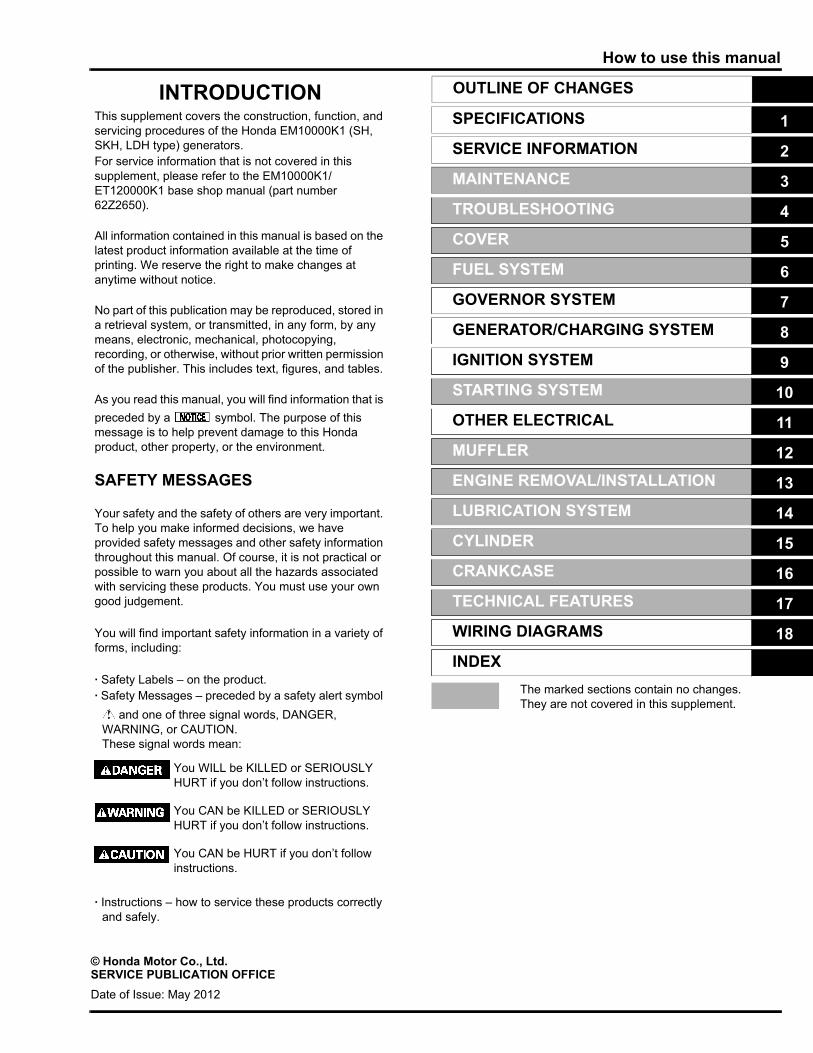
SYMBOLSThe symbols used throughout this manual show specific service procedures. If supplementary information is required pertaining tothese symbols, it will be explained specifically in the text without the use of the symbols.
Replace the part(s) with new one(s) before assembly.
Use the recommend engine oil, unless otherwise specified.
Use molybdenum oil solution (mixture of the engine oil and molybdenum grease in a ratio of 1:1).
Use multi-purpose grease (lithium based multi-purpose grease NLGI #2 or equivalent).
Use marine grease (water resistant urea based grease).
Apply a locking agent. Use a medium strength locking agent unless otherwise specified.
Apply sealant.
Use automatic transmission fluid.
( x ) ( ) Indicates the diameter, length, and quantity of metric bolts used.page 1-1 Indicates the reference page.
0-2
How to use this manualOUTLINE OF CHANGES
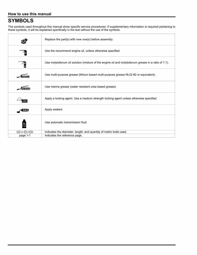
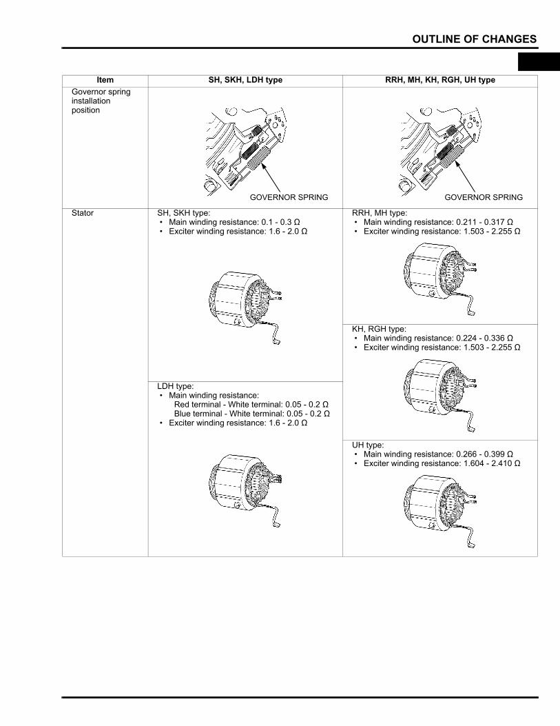
Item SH, SKH, LDH type RRH, MH, KH, RGH, UH typeGovernor spring installation position
Stator SH, SKH type: • Main winding resistance: 0.1 - 0.3 Ω • Exciter winding resistance: 1.6 - 2.0 Ω
RRH, MH type: • Main winding resistance: 0.211 - 0.317 Ω • Exciter winding resistance: 1.503 - 2.255 Ω
KH, RGH type: • Main winding resistance: 0.224 - 0.336 Ω • Exciter winding resistance: 1.503 - 2.255 Ω
LDH type: • Main winding resistance:
Red terminal - White terminal: 0.05 - 0.2 ΩBlue terminal - White terminal: 0.05 - 0.2 Ω
• Exciter winding resistance: 1.6 - 2.0 Ω
UH type: • Main winding resistance: 0.266 - 0.399 Ω • Exciter winding resistance: 1.604 - 2.410 Ω
GOVERNOR SPRING GOVERNOR SPRING
0-3
How to use this manualOUTLINE OF CHANGES
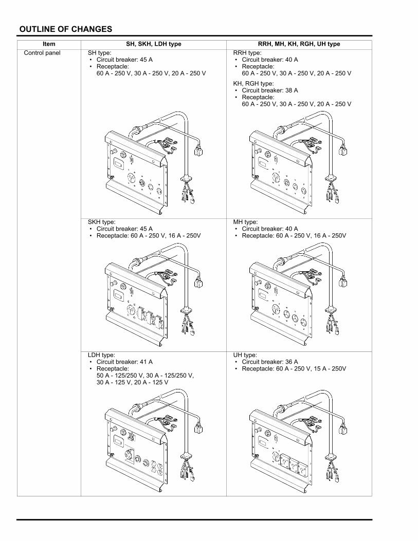
Control panel SH type: • Circuit breaker: 45 A • Receptacle:
60 A - 250 V, 30 A - 250 V, 20 A - 250 V
RRH type: • Circuit breaker: 40 A • Receptacle:
60 A - 250 V, 30 A - 250 V, 20 A - 250 V
KH, RGH type: • Circuit breaker: 38 A • Receptacle:
60 A - 250 V, 30 A - 250 V, 20 A - 250 V
SKH type: • Circuit breaker: 45 A • Receptacle: 60 A - 250 V, 16 A - 250V
MH type: • Circuit breaker: 40 A • Receptacle: 60 A - 250 V, 16 A - 250V
LDH type: • Circuit breaker: 41 A • Receptacle:
50 A - 125/250 V, 30 A - 125/250 V, 30 A - 125 V, 20 A - 125 V
UH type: • Circuit breaker: 36 A • Receptacle: 60 A - 250 V, 15 A - 250V
Item SH, SKH, LDH type RRH, MH, KH, RGH, UH type
0-4
dummytext
1. SPECIFICATIONS
1
SERIAL NUMBER LOCATION ·····················1-2
SPECIFICATIONS·········································1-2
PERFORMANCE CURVES··························· 1-4
1-1
dummyheaddummyhead
SPECIFICATIONS
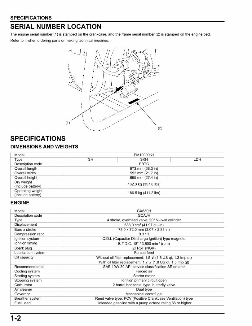
SPECIFICATIONSSERIAL NUMBER LOCATIONThe engine serial number (1) is stamped on the crankcase, and the frame serial number (2) is stamped on the engine bed.Refer to it when ordering parts or making technical inquiries.
SPECIFICATIONSDIMENSIONS AND WEIGHTS
ENGINE
(1)(2)
Model EM10000K1Type SH SKH LDHDescription code EBTCOverall length 973 mm (38.3 in)Overall width 552 mm (21.7 in)Overall height 695 mm (27.4 in)Dry weight (Include battery) 162.3 kg (357.8 lbs)
Operating weight (Include battery) 186.5 kg (411.2 lbs)
Model GX630HDescription code GCAJHType 4 stroke, overhead valve, 90° V–twin cylinderDisplacement 688.0 cm3 (41.97 cu–in)Bore x stroke 78.0 x 72.0 mm (3.07 x 2.83 in)Compression ratio 9.3 : 1Ignition system C.D.I. (Capacitor Discharge Ignition) type magnetoIgnition timing B.T.D.C. 18° / 3,600 min-1 (rpm)Spark plug ZFR5F (NGK)Lubrication system Forced feedOil capacity Without oil filter replacement: 1.5 (1.6 US qt, 1.3 Imp qt)
With oil filter replacement: 1.7 (1.8 US qt, 1.5 Imp qt)Recommended oil SAE 10W-30 API service classification SE or laterCooling system Forced airStarting system Starter motorStopping system Ignition primary circuit openCarburetor 2 barrel horizontal type, butterfly valveAir cleaner Dual typeGovernor Mechanical centrifugalBreather system Reed valve type, PCV (Positive Crankcase Ventilation) typeFuel used Unleaded gasoline with a pump octane rating 86 or higher
1-2
dummyheaddummyhead
SPECIFICATIONS
GENERATORCHARACTERISTICS
Model EM10000K1Type SH SKH LDHDescription code EBTCGenerator type Double electrode field rotation typeExcitation Self–excitation and power coil excitationVoltage regulation system Digital AVR (Automatic Voltage Regulator)Phase Single phaseRotating direction Counterclockwise (Viewed from the generator)Rated output
AC 9.0 kVADC –
Rated frequency 60 HzAC Rated
voltage 220 V 120 / 240 V
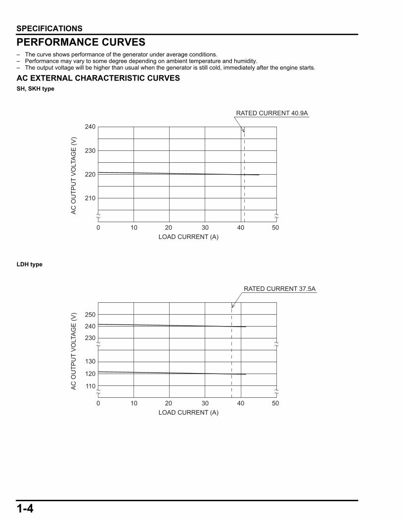
Rated current 40.9 A 37.5 x 2 / 37.5 A
DC Rated voltage –
Rated current –
Power factor 1.0 cosθ
Model EM10000K1Type SH SKH LDHVoltage variation rate
Momentary 15% max.Average 7% max.Average time 5 sec. max.
Voltage stability ± 1% max.Frequency variation rate
Momentary 15% max.Average 7% max.Average time 5 sec. max.
Frequency stability ± 1 Hz max.Insulation resistance 10 MΩ min.AC circuit protector 45 A 41 ADC circuit protector –Insulation type Type FFuel tank capacity 31.0 (8.19 US gal, 6.82 Imp gal)Fuel consumption at rated load 5.8 (1.53 US gal, 1.28 Imp gal) /Hr.
Max. operating hours at rated load 5.3 Hr.
Sound power level (LWA) at rated load LWA 103.4 dB(A)
1-3
dummyheaddummyhead
SPECIFICATIONS
PERFORMANCE CURVES– The curve shows performance of the generator under average conditions.– Performance may vary to some degree depending on ambient temperature and humidity.– The output voltage will be higher than usual when the generator is still cold, immediately after the engine starts.
AC EXTERNAL CHARACTERISTIC CURVESSH, SKH type
LDH type
240
230
220
210
4030 50LOAD CURRENT (A)
AC
OU
TPU
T V
OLT
AG
E (V
)
RATED CURRENT 40.9A
100 20
230
250
240
120
110
130
4030 50LOAD CURRENT (A)
AC
OU
TPU
T V
OLT
AG
E (V
)
RATED CURRENT 37.5A
100 20
1-4
dummytext
2. SERVICE INFORMATION
2
MAINTENANCE STANDARDS ·····················2-2
HOW TO READ CONNECTOR DRAWINGS···························2-3
HARNESS ROUTING···································· 2-4
2-1
dummyheaddummyhead
SERVICE INFORMATION
SERVICE INFORMATIONMAINTENANCE STANDARDSENGINEALL typeUnit: mm (in)
GENERATORALL type
Unit: mm (in)
SH, SKH type
LDH type
Part Item Standard Service limitEngine Engine speed (at no load) 3,750 ± 150 min-1 (rpm) –Carburetor Pilot screw
openingNo.1 cylinder 2 - 1/2 turns out –No.2 cylinder 2 - 7/8 turns out –
Part Item Standard Service limitBrush holder Brush length 15.5 (0.61) 9.5 (0.37)
Part Item Connector/terminal Standard
Stator
Main winding voltage (Red) - (Blue) 220 ± 11 VACMain winding voltage(when the battery connected to the field winding)
(Red) - (Blue) 103 ± 15 VAC
Main winding resistance (Red) - (Blue) 0.1 - 0.3 ΩExciter winding voltage(when the battery connected to the field winding)
No.1 (Light green/White) - No.3 (Light green/White) 43 ± 8 VAC
Exciter winding resistance No.1 (Light green/White) - No.3 (Light green/White) 1.6 - 2.0 Ω
Rotor Field winding voltage (Red/White) - (Black/White) 38 ± 6 VDCField winding resistance Between the slip rings 49 - 59 Ω
D-AVR Resistance No.1 - No.5 1.0 kΩ minimum
Part Item Connector/terminal Standard
Stator
Main winding voltage (Red) - (Blue) 240 ± 12 VAC (Red) - (White) 120 ± 6 VAC (Blue) - (White)
Main winding voltage(when the battery connected to the field winding)
(Red) - (Blue) 112 ± 20 VAC (Red) - (White) 56 ± 10 VAC (Blue) - (White)
Main winding resistance (Red) - (White) 0.05 - 0.2 Ω (Blue) - (White)Exciter winding voltage(when the battery connected to the field winding)
No.1 (Light green/White) - No.3 (Light green/White) 43 ± 8 VAC
Exciter winding resistance No.1 (Light green/White) - No.3 (Light green/White) 1.6 - 2.0 Ω
Rotor Field winding voltage (Red/White) - (Black/White) 38 ± 6 VDCField winding resistance Between the slip rings 49 - 59 Ω
D-AVR Resistance No.1 - No.5 1.0 kΩ minimum
2-2
dummyheaddummyhead
SERVICE INFORMATION
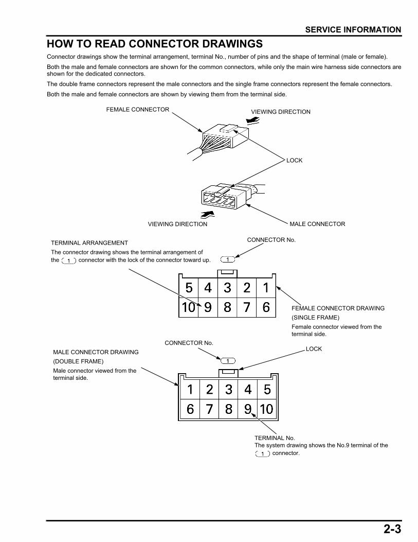
HOW TO READ CONNECTOR DRAWINGSConnector drawings show the terminal arrangement, terminal No., number of pins and the shape of terminal (male or female).
Both the male and female connectors are shown for the common connectors, while only the main wire harness side connectors areshown for the dedicated connectors.
The double frame connectors represent the male connectors and the single frame connectors represent the female connectors.
Both the male and female connectors are shown by viewing them from the terminal side.
FEMALE CONNECTOR
MALE CONNECTOR
LOCK
VIEWING DIRECTION
VIEWING DIRECTION
FEMALE CONNECTOR DRAWING(SINGLE FRAME)Female connector viewed from the terminal side.
CONNECTOR No.MALE CONNECTOR DRAWING(DOUBLE FRAME)Male connector viewed from the terminal side.
LOCK
CONNECTOR No.TERMINAL ARRANGEMENTThe connector drawing shows the terminal arrangement of the connector with the lock of the connector toward up.
TERMINAL No.The system drawing shows the No.9 terminal of the
connector.
2-3
dummyheaddummyhead
SERVICE INFORMATION
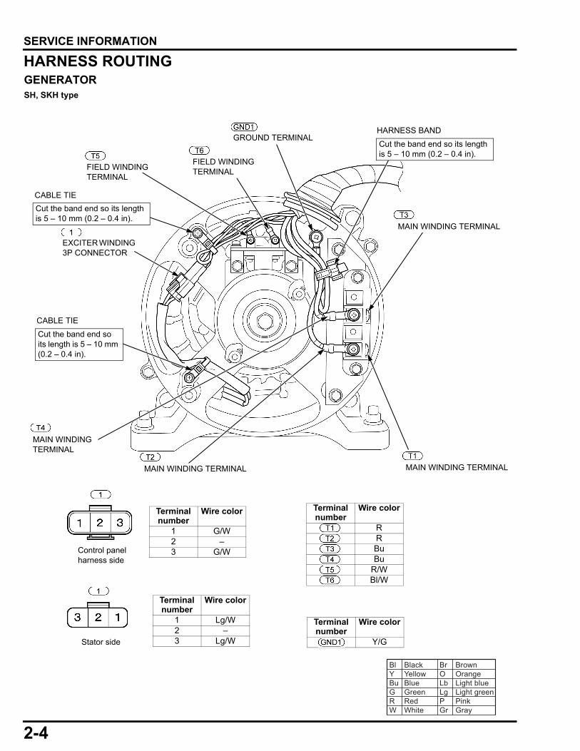
HARNESS ROUTINGGENERATORSH, SKH type
Terminal number
Wire color
1 G/W2 –3 G/W
Terminal number
Wire color
1 Lg/W2 –3 Lg/W
Terminal number
Wire color
RRBuBu
R/WBl/W
Terminal number
Wire color
Y/G
FIELD WINDING TERMINAL
FIELD WINDING TERMINAL
GROUND TERMINAL
Control panel harness side
Stator side
MAIN WINDING TERMINAL
MAIN WINDING TERMINALMAIN WINDING TERMINAL
MAIN WINDING TERMINAL
HARNESS BAND
Bl Black Br BrownY Yellow O OrangeBu Blue Lb Light blueG Green Lg Light greenR Red P PinkW White Gr Gray
EXCITER WINDING 3P CONNECTOR
CABLE TIE
CABLE TIE
Cut the band end so its length is 5 – 10 mm (0.2 – 0.4 in).
Cut the band end so its length is 5 – 10 mm (0.2 – 0.4 in).
Cut the band end so its length is 5 – 10 mm (0.2 – 0.4 in).
2-4
dummyheaddummyhead
SERVICE INFORMATION
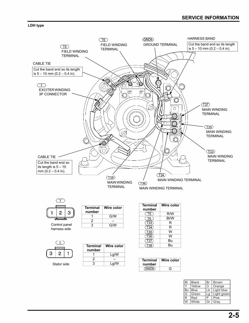
LDH typeTerminal number
Wire color
1 G/W2 –3 G/W
Terminal number
Wire color
1 Lg/W2 –3 Lg/W
Terminal number
Wire color
R/WBl/W
RRWWBuBu
Terminal number
Wire color
G
FIELD WINDING TERMINAL
FIELD WINDING TERMINAL
GROUND TERMINAL
Control panel harness side
Stator side
MAIN WINDING TERMINAL
MAIN WINDING TERMINAL
Bl Black Br BrownY Yellow O OrangeBu Blue Lb Light blueG Green Lg Light greenR Red P PinkW White Gr Gray
EXCITER WINDING 3P CONNECTOR
CABLE TIE
MAIN WINDING TERMINAL
MAIN WINDING TERMINAL
MAIN WINDING TERMINAL
MAIN WINDING TERMINAL
CABLE TIE
HARNESS BAND
Cut the band end so its length is 5 – 10 mm (0.2 – 0.4 in).
Cut the band end so its length is 5 – 10 mm (0.2 – 0.4 in).
Cut the band end so its length is 5 – 10 mm (0.2 – 0.4 in).
2-5
dummyheaddummyhead
SERVICE INFORMATION
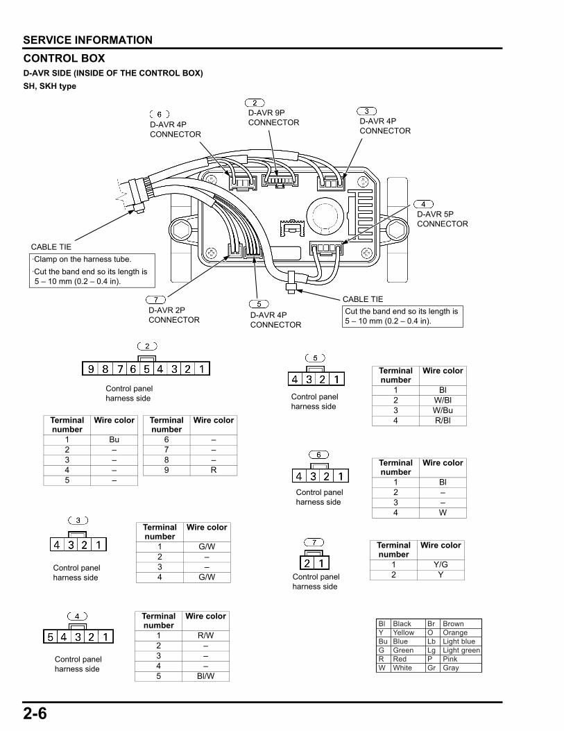
CONTROL BOXD-AVR SIDE (INSIDE OF THE CONTROL BOX)SH, SKH typeTerminal number
Wire color Terminal number
Wire color
1 Bu 6 –2 – 7 –3 – 8 –4 – 9 R5 –
Terminal number
Wire color
1 Y/G2 Y
Terminal number
Wire color
1 R/W2 –3 –4 –5 Bl/W
Terminal number
Wire color
1 Bl2 W/Bl3 W/Bu4 R/Bl
Terminal number
Wire color
1 G/W2 –3 –4 G/W
Terminal number
Wire color
1 Bl2 –3 –4 W
Control panel harness side
Bl Black Br BrownY Yellow O OrangeBu Blue Lb Light blueG Green Lg Light greenR Red P PinkW White Gr Gray
Control panel harness side Control panel
harness side
Control panel harness side
Control panel harness side
Control panel harness side
D-AVR 2P CONNECTOR D-AVR 4P
CONNECTOR
D-AVR 5P CONNECTOR
D-AVR 4P CONNECTOR
D-AVR 9P CONNECTOR D-AVR 4P
CONNECTOR
·Clamp on the harness tube.·Cut the band end so its length is 5 – 10 mm (0.2 – 0.4 in).
CABLE TIE
CABLE TIECut the band end so its length is 5 – 10 mm (0.2 – 0.4 in).
2-6
dummyheaddummyhead
SERVICE INFORMATION
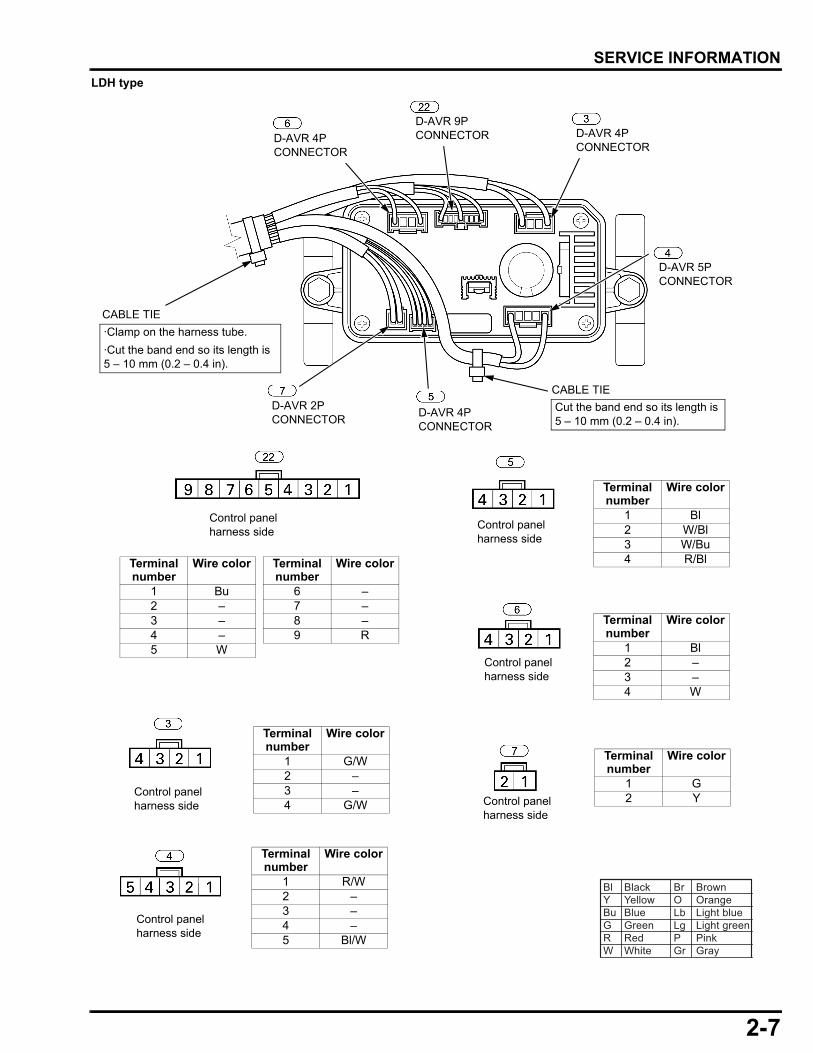
LDH typeD-AVR 2P CONNECTOR D-AVR 4P
CONNECTOR
D-AVR 5P CONNECTOR
D-AVR 4P CONNECTOR
D-AVR 9P CONNECTOR D-AVR 4P
CONNECTOR
·Clamp on the harness tube.·Cut the band end so its length is 5 – 10 mm (0.2 – 0.4 in).
CABLE TIE
CABLE TIECut the band end so its length is 5 – 10 mm (0.2 – 0.4 in).
Terminal number
Wire color
1 G2 Y
Terminal number
Wire color
1 R/W2 –3 –4 –5 Bl/W
Terminal number
Wire color
1 Bl2 W/Bl3 W/Bu4 R/Bl
Terminal number
Wire color
1 G/W2 –3 –4 G/W
Terminal number
Wire color
1 Bl2 –3 –4 W
Control panel harness side
Bl Black Br BrownY Yellow O OrangeBu Blue Lb Light blueG Green Lg Light greenR Red P PinkW White Gr Gray
Control panel harness side Control panel
harness side
Control panel harness side
Control panel harness side
Control panel harness side
Terminal number
Wire color Terminal number
Wire color
1 Bu 6 –2 – 7 –3 – 8 –4 – 9 R5 W
Control panel harness side
2-7
dummyheaddummyhead
SERVICE INFORMATION
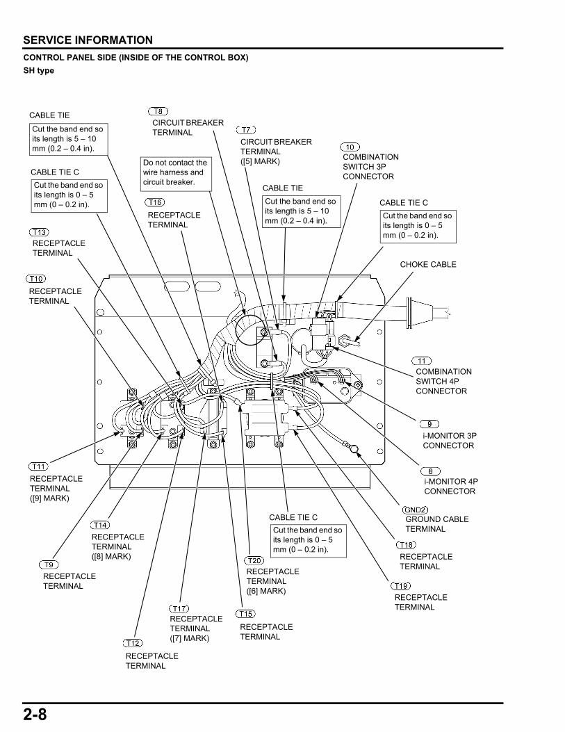
CONTROL PANEL SIDE (INSIDE OF THE CONTROL BOX)SH typeGROUND CABLE TERMINAL
CIRCUIT BREAKER TERMINAL ([5] MARK)
RECEPTACLE TERMINALRECEPTACLE
TERMINAL ([6] MARK)
RECEPTACLE TERMINAL
RECEPTACLE TERMINAL
RECEPTACLE TERMINAL ([7] MARK)
RECEPTACLE TERMINAL ([8] MARK)
RECEPTACLE TERMINAL ([9] MARK)
RECEPTACLE TERMINAL
RECEPTACLE TERMINAL
RECEPTACLE TERMINAL
CIRCUIT BREAKER TERMINAL
COMBINATION SWITCH 3P CONNECTOR
COMBINATION SWITCH 4P CONNECTOR
CHOKE CABLE
i-MONITOR 3P CONNECTOR
i-MONITOR 4P CONNECTOR
RECEPTACLE TERMINAL
RECEPTACLE TERMINAL
CABLE TIE
CABLE TIE
CABLE TIE C
CABLE TIE
Cut the band end so its length is 0 – 5 mm (0 – 0.2 in).
Cut the band end so its length is 0 – 5 mm (0 – 0.2 in).
CABLE TIE CDo not contact the wire harness and circuit breaker.
Cut the band end so its length is 5 – 10 mm (0.2 – 0.4 in).
Cut the band end so its length is 5 – 10 mm (0.2 – 0.4 in). Cut the band end so
its length is 0 – 5 mm (0 – 0.2 in).
CABLE TIE C
2-8
dummyheaddummyhead
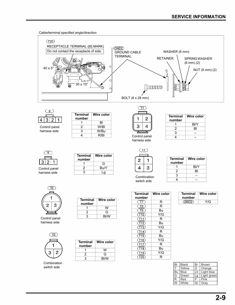
SERVICE INFORMATION
Terminal number
Wire color
1 Bl2 W/Bl3 W/Bu4 R/Bl
Terminal number
Wire color
1 G2 Bu/Y3 Lg
Terminal number
Wire color
1 W2 G3 Bl/W
Terminal number
Wire color
1 W2 G3 Bl/W
Terminal number
Wire color
1 Bl/Y2 Bl3 –4 –
Terminal number
Wire color
1 Bl/Y2 Bl3 –4 –
Terminal number
Wire color
RRBuY/GRBuY/GRBuY/GRBuY/GR
Terminal number
Wire color
Y/G
Combination switch side
Control panel harness side
Combination switch side
Control panel harness side
Control panel harness side
Control panel harness side
Bl Black Br BrownY Yellow O OrangeBu Blue Lb Light blueG Green Lg Light greenR Red P PinkW White Gr Gray
30 ± 10°
40 ± 5°
Cable/terminal specified angle/direction
RECEPTACLE TERMINAL ([6] MARK)Do not contact the receptacle of side. GROUND CABLE
TERMINAL
NUT (6 mm) (2)
RETAINER
WASHER (6 mm)
SPRING WASHER (6 mm) (2)
BOLT (6 x 28 mm)
2-9
dummyheaddummyhead
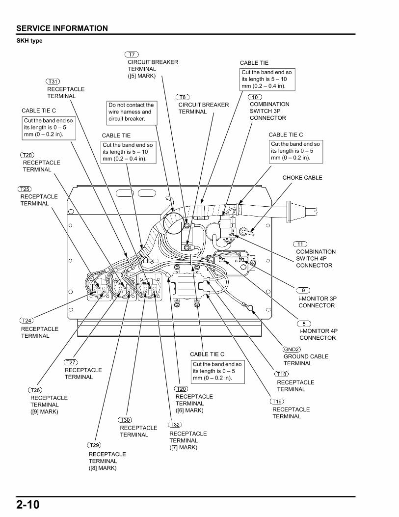
SERVICE INFORMATION
SKH typeCIRCUIT BREAKER TERMINAL ([5] MARK)
RECEPTACLE TERMINAL
RECEPTACLE TERMINAL ([6] MARK) RECEPTACLE
TERMINAL
RECEPTACLE TERMINAL ([7] MARK)
RECEPTACLE TERMINAL
RECEPTACLE TERMINAL
RECEPTACLE TERMINAL
RECEPTACLE TERMINAL
RECEPTACLE TERMINAL
RECEPTACLE TERMINAL
CIRCUIT BREAKER TERMINAL
COMBINATION SWITCH 3P CONNECTOR
COMBINATION SWITCH 4P CONNECTOR
CHOKE CABLE
i-MONITOR 3P CONNECTOR
i-MONITOR 4P CONNECTOR
RECEPTACLE TERMINAL ([8] MARK)
RECEPTACLE TERMINAL ([9] MARK)
CABLE TIE C GROUND CABLE TERMINAL
CABLE TIE
CABLE TIE
Cut the band end so its length is 5 – 10 mm (0.2 – 0.4 in).
Cut the band end so its length is 0 – 5 mm (0 – 0.2 in).
Cut the band end so its length is 5 – 10 mm (0.2 – 0.4 in).
Cut the band end so its length is 0 – 5 mm (0 – 0.2 in).
CABLE TIE CDo not contact the wire harness and circuit breaker.
Cut the band end so its length is 0 – 5 mm (0 – 0.2 in).
CABLE TIE C
2-10
dummyheaddummyhead
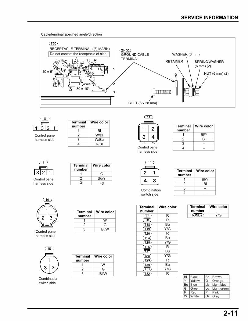
SERVICE INFORMATION
Terminal number
Wire color
1 Bl2 W/Bl3 W/Bu4 R/Bl
Terminal number
Wire color
1 G2 Bu/Y3 Lg
Terminal number
Wire color
1 W2 G3 Bl/W
Terminal number
Wire color
1 W2 G3 Bl/W
Terminal number
Wire color
1 Bl/Y2 Bl3 –4 –
Terminal number
Wire color
1 Bl/Y2 Bl3 –4 –
Terminal number
Wire color
Y/G
Terminal number
Wire color
RRBuY/GRBuY/GRBuY/GRBuY/GR
Combination switch side
Control panel harness side
Combination switch side
Control panel harness side
Control panel harness side
Control panel harness side
Bl Black Br BrownY Yellow O OrangeBu Blue Lb Light blueG Green Lg Light greenR Red P PinkW White Gr Gray
30 ± 10°
40 ± 5°
Cable/terminal specified angle/direction
RECEPTACLE TERMINAL ([6] MARK)Do not contact the receptacle of side. GROUND CABLE
TERMINAL
NUT (6 mm) (2)
RETAINER
WASHER (6 mm)
SPRING WASHER (6 mm) (2)
BOLT (6 x 28 mm)
2-11
dummyheaddummyhead
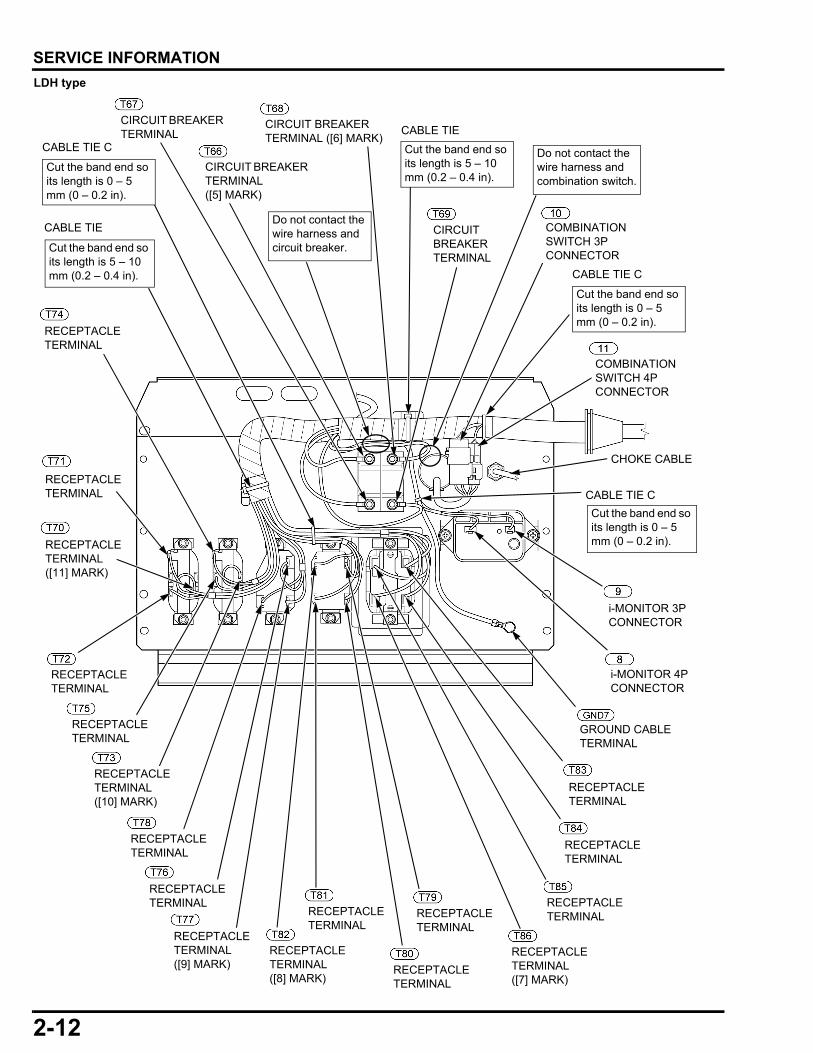
SERVICE INFORMATION
LDH typeRECEPTACLE TERMINAL
RECEPTACLE TERMINAL
RECEPTACLE TERMINAL
RECEPTACLE TERMINAL
RECEPTACLE TERMINAL
RECEPTACLE TERMINAL ([10] MARK)
RECEPTACLE TERMINAL ([11] MARK)
RECEPTACLE TERMINAL ([9] MARK)
RECEPTACLE TERMINAL
CIRCUIT BREAKER TERMINAL
COMBINATION SWITCH 3P CONNECTOR
COMBINATION SWITCH 4P CONNECTOR
CHOKE CABLE
i-MONITOR 3P CONNECTOR
i-MONITOR 4P CONNECTOR
RECEPTACLE TERMINAL
RECEPTACLE TERMINAL
RECEPTACLE TERMINAL
GROUND CABLE TERMINAL
CABLE TIE CCABLE TIE
CABLE TIE C
Do not contact the wire harness and circuit breaker.
Cut the band end so its length is 0 – 5 mm (0 – 0.2 in).
Cut the band end so its length is 5 – 10 mm (0.2 – 0.4 in).
Cut the band end so its length is 5 – 10 mm (0.2 – 0.4 in).
Cut the band end so its length is 0 – 5 mm (0 – 0.2 in).
CABLE TIE
RECEPTACLE TERMINAL ([7] MARK)
CIRCUIT BREAKER TERMINAL ([5] MARK)
CIRCUIT BREAKER TERMINAL
RECEPTACLE TERMINAL ([8] MARK)
RECEPTACLE TERMINAL
RECEPTACLE TERMINAL
RECEPTACLE TERMINAL
CABLE TIE C
Cut the band end so its length is 0 – 5 mm (0 – 0.2 in).
Do not contact the wire harness and combination switch.
CIRCUIT BREAKER TERMINAL ([6] MARK)
2-12
dummyheaddummyhead
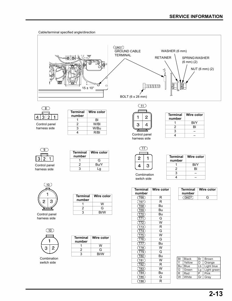
SERVICE INFORMATION
Terminal number
Wire color
1 Bl2 W/Bl3 W/Bu4 R/Bl
Terminal number
Wire color
1 G2 Bu/Y3 Lg
Terminal number
Wire color
1 W2 G3 Bl/W
Terminal number
Wire color
1 W2 G3 Bl/W
Terminal number
Wire color
1 Bl/Y2 Bl3 –4 –
Terminal number
Wire color
1 Bl/Y2 Bl3 –4 –
Terminal number
Wire color
G
Terminal number
Wire color
RRBuBuBuGWRGWGBuWGBuWRWBuGR
Combination switch side
Control panel harness side
Combination switch side
Control panel harness side
Control panel harness side
Control panel harness side
Bl Black Br BrownY Yellow O OrangeBu Blue Lb Light blueG Green Lg Light greenR Red P PinkW White Gr Gray
15 ± 10°
Cable/terminal specified angle/direction
GROUND CABLE TERMINAL
NUT (6 mm) (2)
RETAINER
WASHER (6 mm)
SPRING WASHER (6 mm) (2)
BOLT (6 x 28 mm)
2-13

dummyheaddummyhead
MEMO
dummytext
7. GOVERNOR SYSTEM
7
GOVERNOR ARM/CONTROL REMOVAL/INSTALLATION··························7-27-1
7-2
dummyheaddummyhead
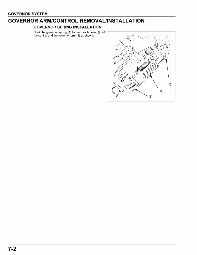
GOVERNOR SYSTEMGOVERNOR SYSTEMGOVERNOR ARM/CONTROL REMOVAL/INSTALLATIONGOVERNOR SPRING INSTALLATIONHook the governor spring (1) to the throttle lever (2) ofthe control and the governor arm (3) as shown.
(3)
(2)
(1)
dummytext
8. GENERATOR/CHARGING SYSTEM
8
GENERATOR SYSTEM DIAGRAM ··············8-2GENERATOR SYSTEM TROUBLESHOOTING···································8-5
REAR HOUSING/STATOR REMOVAL/INSTALLATION··························8-9
MAIN WINDING INSPECTION···················· 8-11
EXCITER WINDING INSPECTION ············· 8-14
FIELD WINDING INSPECTION ·················· 8-15
8-1
dummyheaddummyhead
GENERATOR/CHARGING SYSTEM
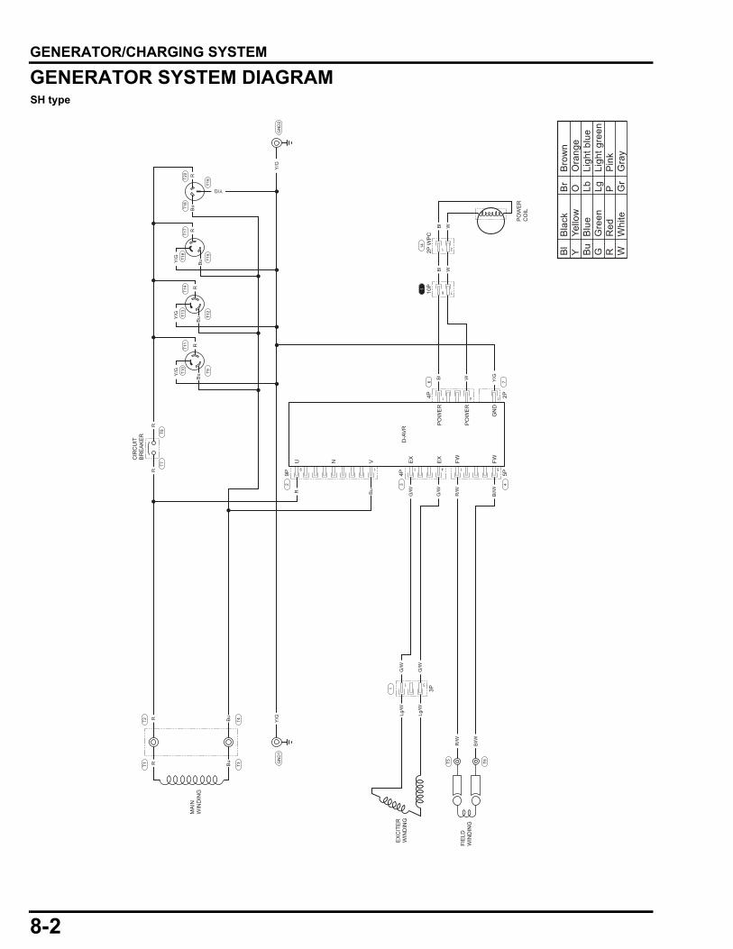
GENERATOR/CHARGING SYSTEMGENERATOR SYSTEM DIAGRAMSH type4 11
1 511
31
9 4
U
PO
WE
R
PO
WE
R
GN
D
N V EX
EX
FW FW
D-A
VR
MA
INW
IND
ING
FIE
LDW
IND
ING
EX
CIT
ER
WIN
DIN
G
CIR
CU
ITB
RE
AK
ER
T20
T18
T19
T17
T16
T15
4P 2P
6
4P
3P
5P
3
1
T4T3
T2T1
4
9P2
7
T6T5
7610P1
21
PO
WE
RC
OIL
14
T14
T13
T12
T11
T10
T9
T8T7
GN
D1
GN
D2
2P W
PC
Y/G
Y/G
Y/G
Y/G
WBl
WBl
Bl/WR/W
Lg/W
Lg/W
G/W
G/W
G/W
G/W
Bl
W
Y/G
Y/G
Bl/WR/WBu
R Bu
R Bu
Y/G
R
RR
Bu
Bu
Bu
Bu
RR
RR
Bl
Bla
ckB
rB
row
nY
Yello
wO
Ora
nge
Bu
Blu
eLb
Ligh
t blu
eG
Gre
enLg
Ligh
t gre
enR
Red
PP
ink
WW
hite
Gr
Gra
y
8-2
dummyheaddummyhead
GENERATOR/CHARGING SYSTEM
SKH type414P6
7610P1
21
2P W
PC
PO
WE
RC
OIL
14
WBl
WBl
WBl
1
1 511
31
9 4
U
PO
WE
R
PO
WE
R
GN
D
N V EX
EX
FW FW
D-A
VR
MA
INW
IND
ING
FIE
LDW
IND
ING
EX
CIT
ER
WIN
DIN
G
CIR
CU
ITB
RE
AK
ER
2P
4P
3P
5P
3
1
T4T3
T2T1
4
9P2
7
T6T5
T8T7
GN
D1
GN
D2
Y/G
Y/G
Bl/WR/W
Lg/W
Lg/W
G/W
G/W
G/W
G/W
Y/G
Y/G
Bl/WR/WBu
R Bu
R Bu
Y/G
R
RR
Bu
Bu
RR
Y/G
Bu
R
Y/G
Bu
RT2
0T1
8T3
0T3
2
T19
T31
T27
T29
T28
T24
T26
T25
Bl
Bla
ckB
rB
row
nY
Yello
wO
Ora
nge
Bu
Blu
eLb
Ligh
t blu
eG
Gre
enLg
Ligh
t gre
enR
Red
PP
ink
WW
hite
Gr
Gra
y
8-3
dummyheaddummyhead
GENERATOR/CHARGING SYSTEM
LDH type414P6
7610P1
21
2P W
PC
PO
WE
RC
OIL
14
WBl
WBl
WBl
1
1 5115
31
9 4
U
PO
WE
R
PO
WE
R
GN
D
N V EX
EX
FW FW
D-A
VR
MA
INW
IND
ING
FIE
LDW
IND
ING
EX
CIT
ER
WIN
DIN
G
T83
T84
T85
T81
T78
T77
T76
T75
T73
T74
T72
T70
T71
T80
T86
T82
T79
2P
4P
3P
5P
3
1
T38
T37
T34
T33
T36
T35
4
9P22
7
T6T5
CIR
CU
ITB
RE
AK
ER T6
7T6
6
T69
T68
GN
D6
GN
D7
G
Bu
W
W
W
R
R
Bu
Bu
G
G
G
G
Bu
W
W
Bl/WR/W
Lg/W
Lg/W
G/W
G/W
G/W
G/W
G
GB
l/WR/WBuW
R WW
Bu
R Bu G
R
R
R
R
Bu
Bu
Bl
Bla
ckB
rB
row
nY
Yello
wO
Ora
nge
Bu
Blu
eLb
Ligh
t blu
eG
Gre
enLg
Ligh
t gre
enR
Red
PP
ink
WW
hite
Gr
Gra
y
8-4
dummyheaddummyhead
GENERATOR/CHARGING SYSTEM
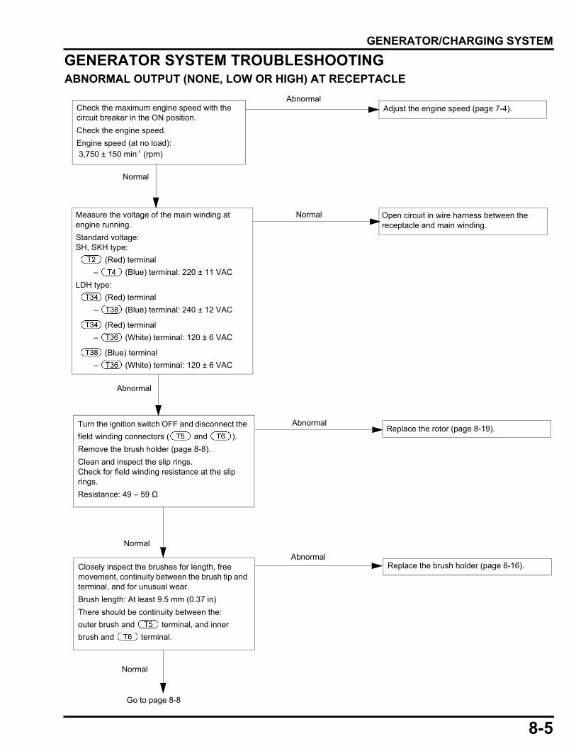
GENERATOR SYSTEM TROUBLESHOOTINGABNORMAL OUTPUT (NONE, LOW OR HIGH) AT RECEPTACLE
Measure the voltage of the main winding at engine running.Standard voltage: SH, SKH type: (Red) terminal – (Blue) terminal: 220 ± 11 VACLDH type: (Red) terminal – (Blue) terminal: 240 ± 12 VAC
(Red) terminal – (White) terminal: 120 ± 6 VAC
(Blue) terminal – (White) terminal: 120 ± 6 VAC
Open circuit in wire harness between the receptacle and main winding.
Normal
Normal
Go to page 8-8
Normal
Check the maximum engine speed with the circuit breaker in the ON position.Check the engine speed. Engine speed (at no load): 3,750 ± 150 min-1 (rpm)
AbnormalAdjust the engine speed (page 7-4).
Abnormal
Turn the ignition switch OFF and disconnect the field winding connectors ( and ).Remove the brush holder (page 8-8).Clean and inspect the slip rings.Check for field winding resistance at the slip rings.Resistance: 49 – 59 Ω
Replace the rotor (page 8-19). Abnormal
Replace the brush holder (page 8-16).
Normal
AbnormalClosely inspect the brushes for length, free movement, continuity between the brush tip and terminal, and for unusual wear.Brush length: At least 9.5 mm (0.37 in)There should be continuity between the:outer brush and terminal, and inner brush and terminal.
8-5
dummyheaddummyhead
GENERATOR/CHARGING SYSTEM
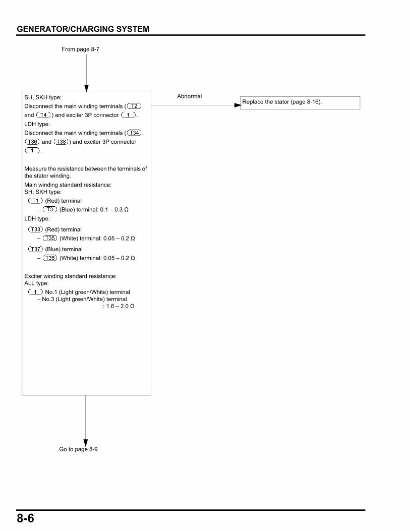
SH, SKH type:Disconnect the main winding terminals ( and ) and exciter 3P connector .LDH type:Disconnect the main winding terminals ( ,
and ) and exciter 3P connector .
Measure the resistance between the terminals of the stator winding.Main winding standard resistance: SH, SKH type: (Red) terminal – (Blue) terminal: 0.1 – 0.3 ΩLDH type:
(Red) terminal – (White) terminal: 0.05 – 0.2 Ω
(Blue) terminal – (White) terminal: 0.05 – 0.2 Ω
Exciter winding standard resistance:ALL type: No.1 (Light green/White) terminal – No.3 (Light green/White) terminal : 1.6 – 2.0 Ω
From page 8-7
Go to page 8-9
Replace the stator (page 8-16). Abnormal
8-6
dummyheaddummyhead
GENERATOR/CHARGING SYSTEM
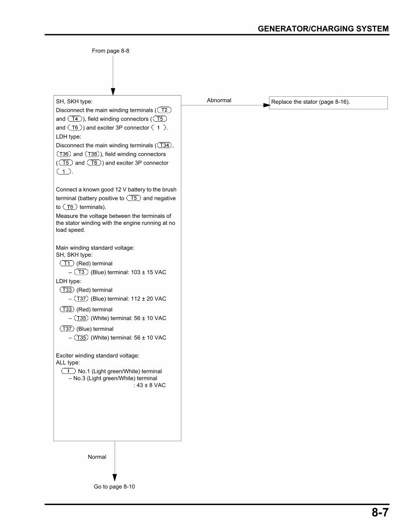
From page 8-8
SH, SKH type:Disconnect the main winding terminals ( and ), field winding connectors ( and ) and exciter 3P connector .LDH type:Disconnect the main winding terminals ( ,
and ), field winding connectors ( and ) and exciter 3P connector
.
Connect a known good 12 V battery to the brush terminal (battery positive to and negative to terminals).Measure the voltage between the terminals of the stator winding with the engine running at no load speed.
Main winding standard voltage: SH, SKH type: (Red) terminal – (Blue) terminal: 103 ± 15 VACLDH type: (Red) terminal – (Blue) terminal: 112 ± 20 VAC
(Red) terminal – (White) terminal: 56 ± 10 VAC
(Blue) terminal – (White) terminal: 56 ± 10 VAC
Exciter winding standard voltage:ALL type: No.1 (Light green/White) terminal – No.3 (Light green/White) terminal : 43 ± 8 VAC
Normal
Go to page 8-10
Replace the stator (page 8-16). Abnormal
8-7
dummyheaddummyhead
GENERATOR/CHARGING SYSTEM
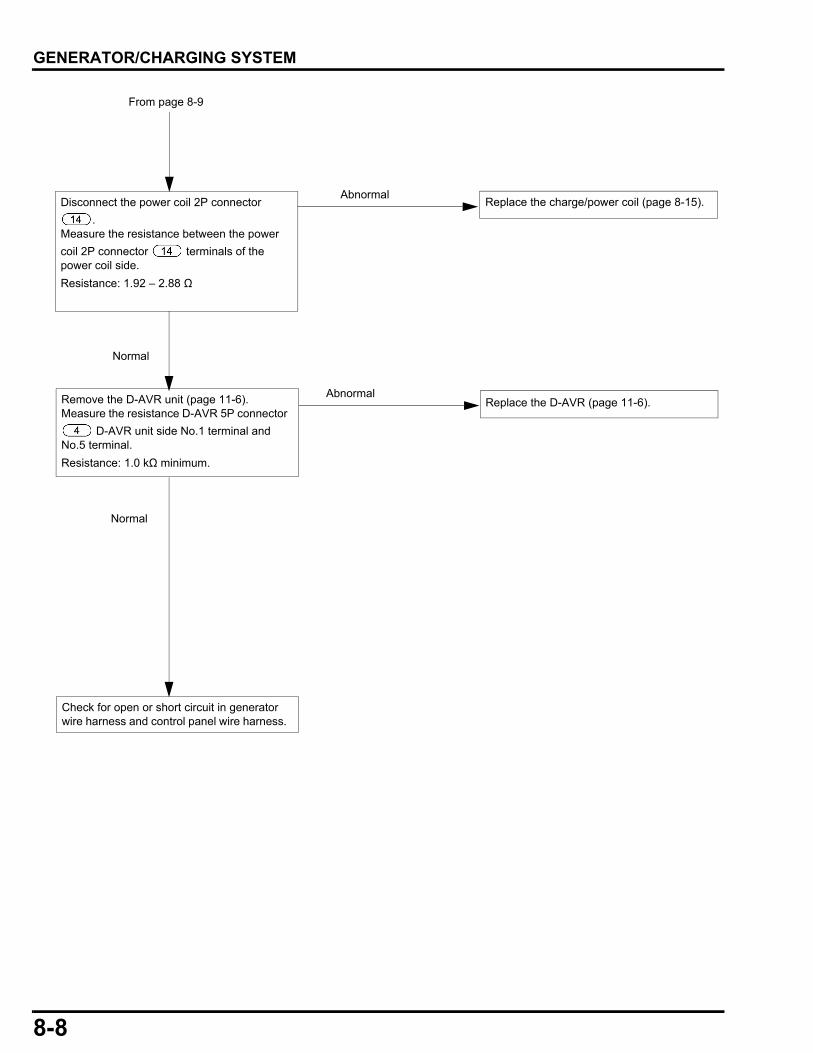
Check for open or short circuit in generator wire harness and control panel wire harness.
Normal
Replace the D-AVR (page 11-6).Abnormal
Replace the charge/power coil (page 8-15).
Normal
AbnormalDisconnect the power coil 2P connector
.Measure the resistance between the power coil 2P connector terminals of the power coil side.Resistance: 1.92 – 2.88 Ω
From page 8-9
Remove the D-AVR unit (page 11-6).Measure the resistance D-AVR 5P connector
D-AVR unit side No.1 terminal and No.5 terminal. Resistance: 1.0 kΩ minimum.
8-8
dummyheaddummyhead
GENERATOR/CHARGING SYSTEM
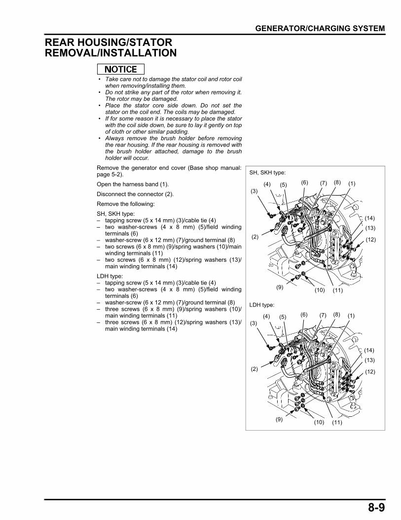
REAR HOUSING/STATOR REMOVAL/INSTALLATION
• Take care not to damage the stator coil and rotor coilwhen removing/installing them.
• Do not strike any part of the rotor when removing it.The rotor may be damaged.
• Place the stator core side down. Do not set thestator on the coil end. The coils may be damaged.
• If for some reason it is necessary to place the statorwith the coil side down, be sure to lay it gently on topof cloth or other similar padding.
• Always remove the brush holder before removingthe rear housing. If the rear housing is removed withthe brush holder attached, damage to the brushholder will occur.
Remove the generator end cover (Base shop manual:page 5-2).
Open the harness band (1).
Disconnect the connector (2).
Remove the following:
SH, SKH type:– tapping screw (5 x 14 mm) (3)/cable tie (4)– two washer-screws (4 x 8 mm) (5)/field winding
terminals (6)– washer-screw (6 x 12 mm) (7)/ground terminal (8)– two screws (6 x 8 mm) (9)/spring washers (10)/main
winding terminals (11)– two screws (6 x 8 mm) (12)/spring washers (13)/
main winding terminals (14)
LDH type:– tapping screw (5 x 14 mm) (3)/cable tie (4)– two washer-screws (4 x 8 mm) (5)/field winding
terminals (6)– washer-screw (6 x 12 mm) (7)/ground terminal (8)– three screws (6 x 8 mm) (9)/spring washers (10)/
main winding terminals (11)– three screws (6 x 8 mm) (12)/spring washers (13)/
main winding terminals (14)
(4) (1)
(2)
(3)(5) (6)
(9) (10) (11)
(14)
(13)
(12)
(7) (8)
(4) (1)
(2)
(3)(5) (6)
(9) (10) (11)
(14)
(13)
(12)
(7) (8)
SH, SKH type:
LDH type:
8-9
dummyheaddummyhead
GENERATOR/CHARGING SYSTEM
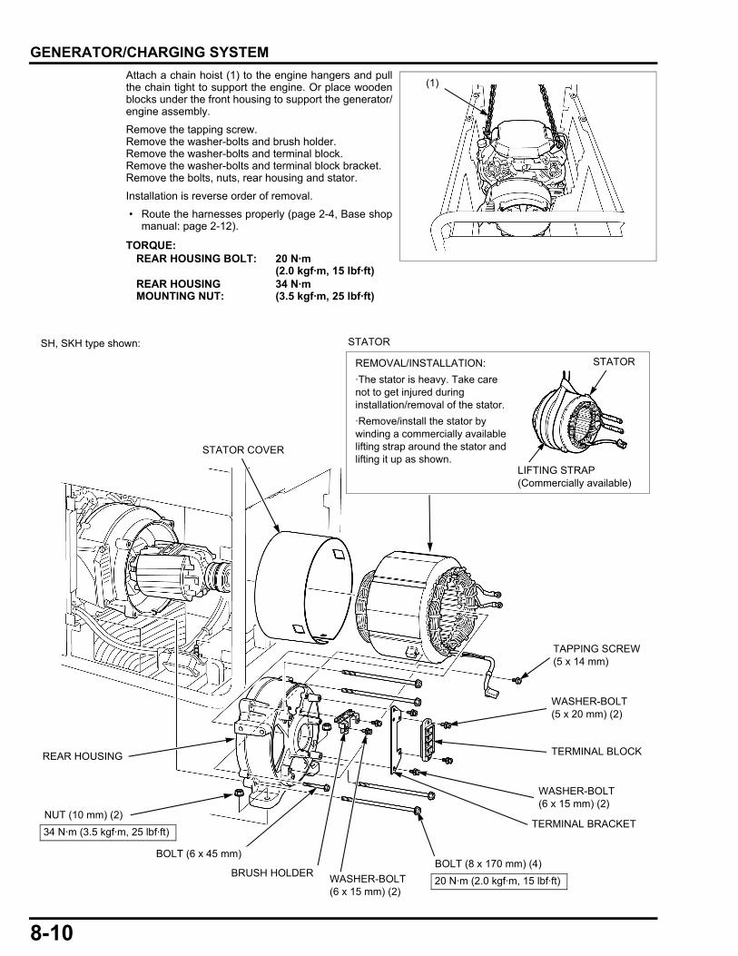
Attach a chain hoist (1) to the engine hangers and pullthe chain tight to support the engine. Or place woodenblocks under the front housing to support the generator/engine assembly.Remove the tapping screw.Remove the washer-bolts and brush holder.Remove the washer-bolts and terminal block.Remove the washer-bolts and terminal block bracket.Remove the bolts, nuts, rear housing and stator.
Installation is reverse order of removal.
• Route the harnesses properly (page 2-4, Base shopmanual: page 2-12).
TORQUE:REAR HOUSING BOLT: 20 N·m
(2.0 kgf·m, 15 lbf·ft)REAR HOUSING MOUNTING NUT:
34 N·m (3.5 kgf·m, 25 lbf·ft)
(1)
REAR HOUSING
20 N·m (2.0 kgf·m, 15 lbf·ft)
STATORREMOVAL/INSTALLATION:·The stator is heavy. Take care not to get injured during installation/removal of the stator.·Remove/install the stator by winding a commercially available lifting strap around the stator and lifting it up as shown.
STATOR
STATOR COVER
WASHER-BOLT (6 x 15 mm) (2)
BRUSH HOLDER
TERMINAL BRACKET
WASHER-BOLT (6 x 15 mm) (2)
TERMINAL BLOCK
WASHER-BOLT (5 x 20 mm) (2)
BOLT (8 x 170 mm) (4)BOLT (6 x 45 mm)
NUT (10 mm) (2)34 N·m (3.5 kgf·m, 25 lbf·ft)
LIFTING STRAP(Commercially available)
TAPPING SCREW (5 x 14 mm)
SH, SKH type shown:
8-10
dummyheaddummyhead
GENERATOR/CHARGING SYSTEM
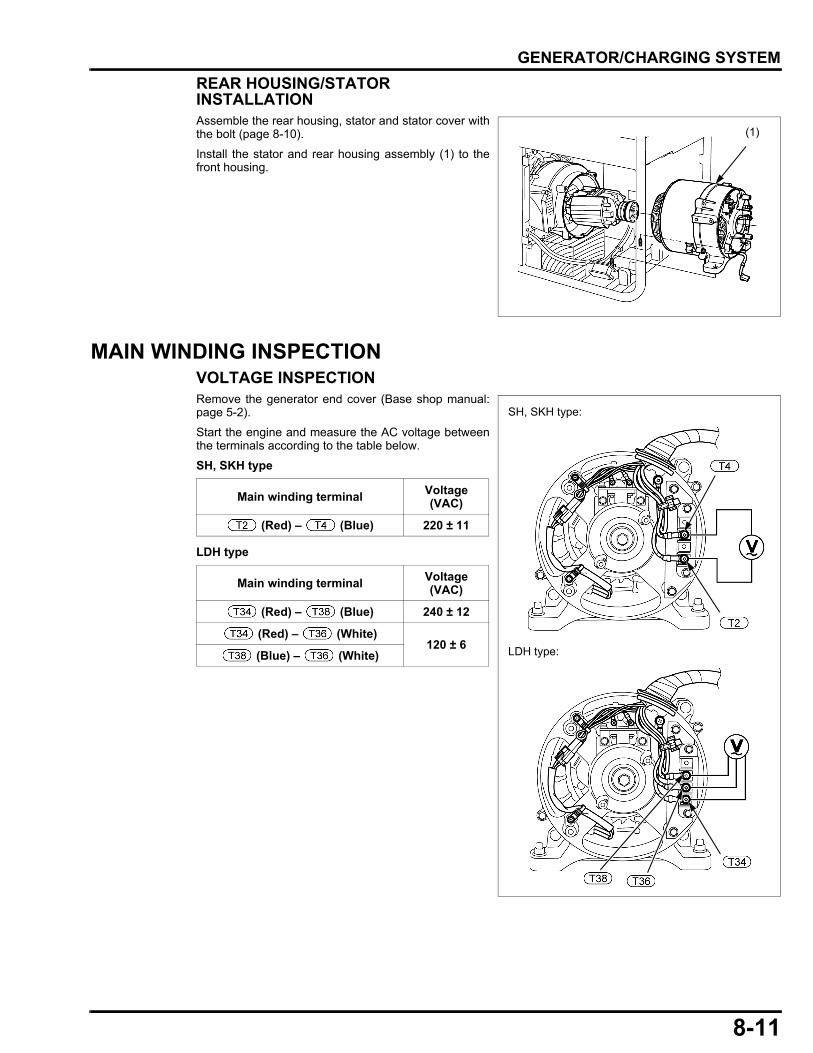
REAR HOUSING/STATOR INSTALLATIONAssemble the rear housing, stator and stator cover withthe bolt (page 8-10).Install the stator and rear housing assembly (1) to thefront housing.
MAIN WINDING INSPECTIONVOLTAGE INSPECTIONRemove the generator end cover (Base shop manual:page 5-2).
Start the engine and measure the AC voltage betweenthe terminals according to the table below.
SH, SKH type
LDH type
(1)
Main winding terminal Voltage (VAC)
(Red) – (Blue) 220 ± 11
Main winding terminal Voltage (VAC)
(Red) – (Blue) 240 ± 12
(Red) – (White)120 ± 6
(Blue) – (White)
SH, SKH type:
LDH type:
8-11
dummyheaddummyhead
GENERATOR/CHARGING SYSTEM
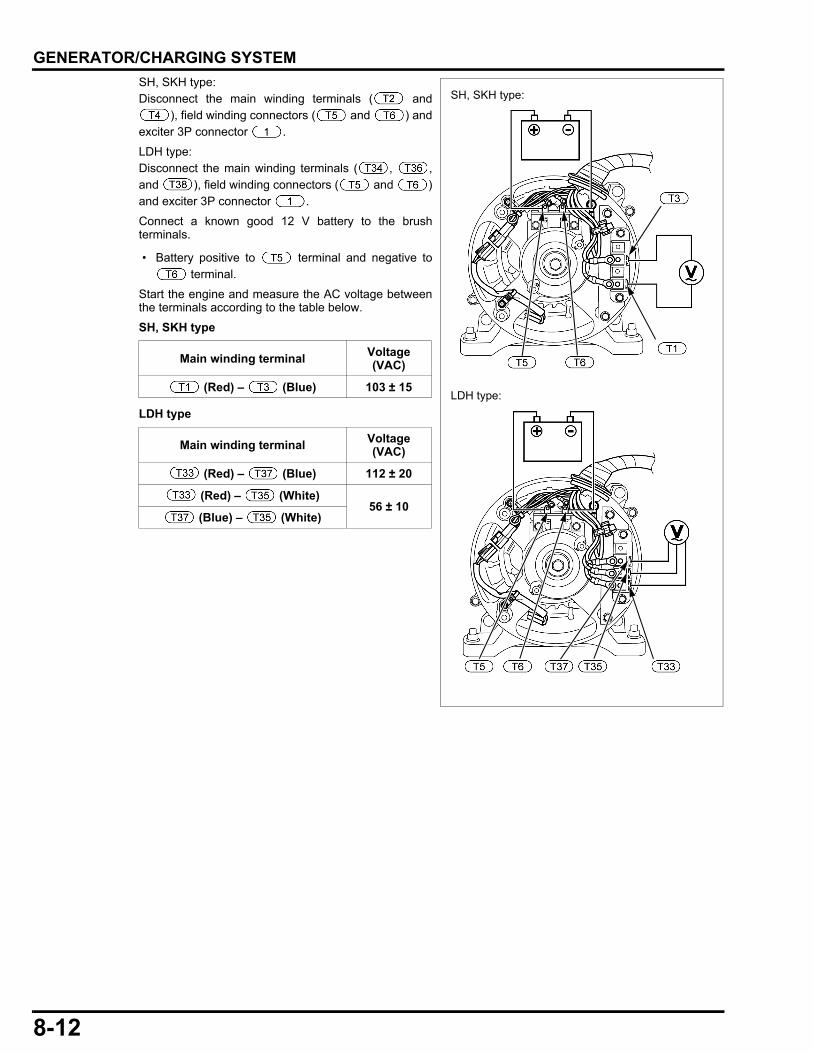
SH, SKH type:Disconnect the main winding terminals ( and), field winding connectors ( and ) andexciter 3P connector .
LDH type:Disconnect the main winding terminals ( , ,and ), field winding connectors ( and )and exciter 3P connector .
Connect a known good 12 V battery to the brushterminals.
• Battery positive to terminal and negative to terminal.
Start the engine and measure the AC voltage betweenthe terminals according to the table below.
SH, SKH type
LDH type
Main winding terminal Voltage (VAC)
(Red) – (Blue) 103 ± 15
Main winding terminal Voltage (VAC)
(Red) – (Blue) 112 ± 20
(Red) – (White)56 ± 10
(Blue) – (White)
SH, SKH type:
LDH type:
8-12
dummyheaddummyhead
GENERATOR/CHARGING SYSTEM
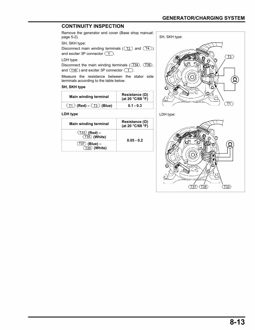
CONTINUITY INSPECTIONRemove the generator end cover (Base shop manual:page 5-2).SH, SKH type:Disconnect main winding terminals ( and )and exciter 3P connector .
LDH type:Disconnect the main winding terminals ( , ,and ) and exciter 3P connector .
Measure the resistance between the stator sideterminals according to the table below.
SH, SKH type
LDH type
Main winding terminal Resistance (Ω)(at 20 °C/68 °F)
(Red) – (Blue) 0.1 - 0.3
Main winding terminal Resistance (Ω)(at 20 °C/68 °F)
(Red) – (White)
0.05 - 0.2 (Blue) –
(White)
SH, SKH type:
LDH type:
8-13
dummyheaddummyhead
GENERATOR/CHARGING SYSTEM
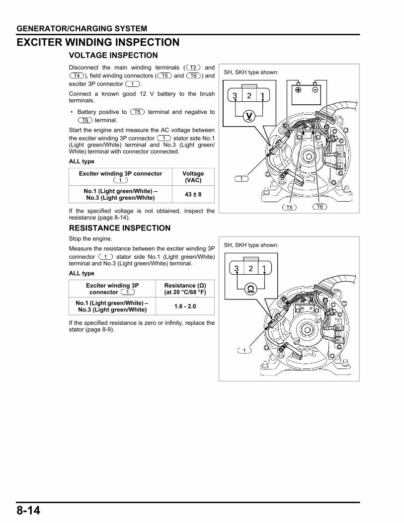
EXCITER WINDING INSPECTIONVOLTAGE INSPECTIONDisconnect the main winding terminals ( and
), field winding connectors ( and ) andexciter 3P connector .
Connect a known good 12 V battery to the brushterminals.
• Battery positive to terminal and negative to terminal.
Start the engine and measure the AC voltage betweenthe exciter winding 3P connector stator side No.1(Light green/White) terminal and No.3 (Light green/White) terminal with connector connected.
ALL type
If the specified voltage is not obtained, inspect theresistance (page 8-14).
RESISTANCE INSPECTIONStop the engine.
Measure the resistance between the exciter winding 3Pconnector stator side No.1 (Light green/White)terminal and No.3 (Light green/White) terminal.
ALL type
If the specified resistance is zero or infinity, replace thestator (page 8-9).
Exciter winding 3P connector Voltage (VAC)
No.1 (Light green/White) – No.3 (Light green/White) 43 ± 8
Exciter winding 3P connector
Resistance (Ω)(at 20 °C/68 °F)
No.1 (Light green/White) – No.3 (Light green/White) 1.6 - 2.0
SH, SKH type shown:
SH, SKH type shown:
8-14
dummyheaddummyhead
GENERATOR/CHARGING SYSTEM
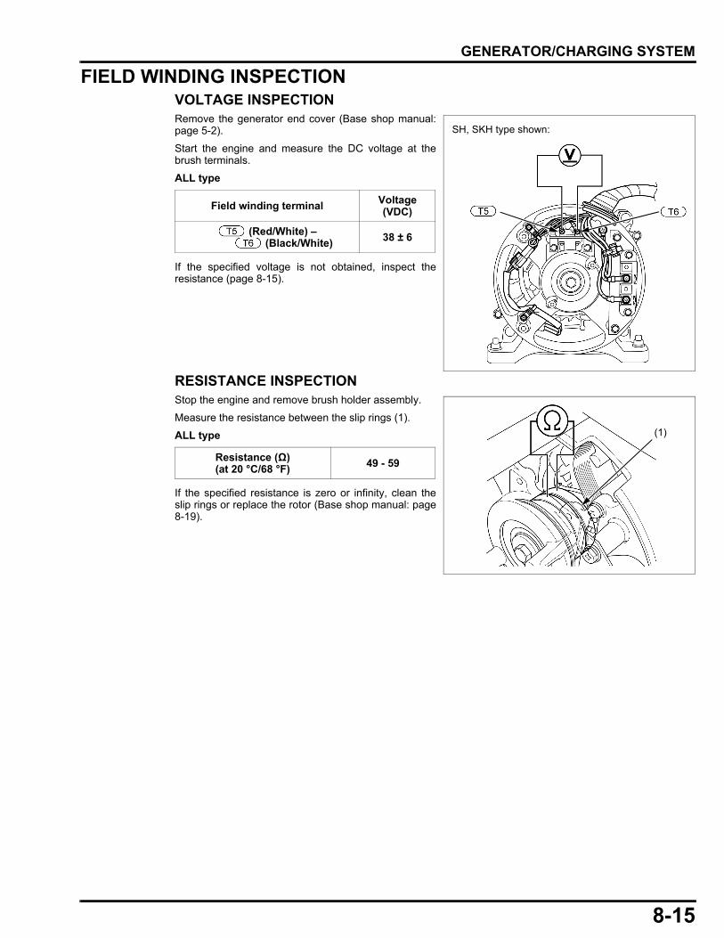
FIELD WINDING INSPECTIONVOLTAGE INSPECTIONRemove the generator end cover (Base shop manual:page 5-2).
Start the engine and measure the DC voltage at thebrush terminals.
ALL type
If the specified voltage is not obtained, inspect theresistance (page 8-15).
RESISTANCE INSPECTIONStop the engine and remove brush holder assembly.
Measure the resistance between the slip rings (1).
ALL type
If the specified resistance is zero or infinity, clean theslip rings or replace the rotor (Base shop manual: page8-19).
Field winding terminal Voltage (VDC)
(Red/White) – (Black/White) 38 ± 6
SH, SKH type shown:
Resistance (Ω)(at 20 °C/68 °F) 49 - 59
(1)
8-15

dummyheaddummyhead
MEMO
dummytext
9. IGNITION SYSTEM
9
IGNITION COIL INSPECTION·······················9-2
9-1
9-2
dummyheaddummyhead
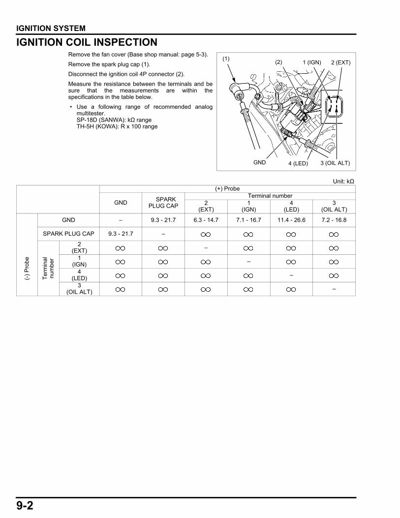
IGNITION SYSTEMIGNITION SYSTEMIGNITION COIL INSPECTIONRemove the fan cover (Base shop manual: page 5-3).
Remove the spark plug cap (1).
Disconnect the ignition coil 4P connector (2).
Measure the resistance between the terminals and besure that the measurements are within thespecifications in the table below.
• Use a following range of recommended analogmultitester.SP-18D (SANWA): kΩ rangeTH-5H (KOWA): R x 100 range
4 (LED)
1 (IGN) 2 (EXT)(1)
GND 3 (OIL ALT)
(2)
Unit: kΩ(+) Probe
GND SPARK PLUG CAP
Terminal number2
(EXT)1
(IGN)4
(LED)3
(OIL ALT)
GND – 9.3 - 21.7 6.3 - 14.7 7.1 - 16.7 11.4 - 26.6 7.2 - 16.8
SPARK PLUG CAP 9.3 - 21.7 –
(-) P
robe
Term
inal
nu
mbe
r
2(EXT) –
1(IGN) –
4(LED) –
3(OIL ALT) –
dummytext
11. OTHER ELECTRICAL
11
CONTROL BOX REMOVAL/INSTALLATION························11-2
CONTROL BOX DISASSEMBLY/ASSEMBLY ······················11-5
CONTROL PANEL DISASSEMBLY/ASSEMBLY······················ 11-6
CIRCUIT BREAKER INSPECTION ············ 11-9
11-1
dummyheaddummyhead
OTHER ELECTRICAL
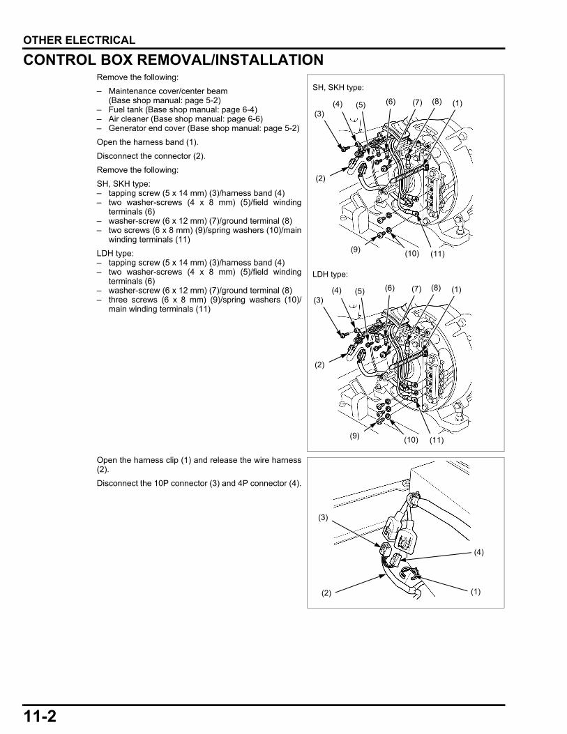
OTHER ELECTRICALCONTROL BOX REMOVAL/INSTALLATIONRemove the following:– Maintenance cover/center beam (Base shop manual: page 5-2)
– Fuel tank (Base shop manual: page 6-4)– Air cleaner (Base shop manual: page 6-6)– Generator end cover (Base shop manual: page 5-2)
Open the harness band (1).
Disconnect the connector (2).
Remove the following:
SH, SKH type:– tapping screw (5 x 14 mm) (3)/harness band (4)– two washer-screws (4 x 8 mm) (5)/field winding
terminals (6)– washer-screw (6 x 12 mm) (7)/ground terminal (8)– two screws (6 x 8 mm) (9)/spring washers (10)/main
winding terminals (11)
LDH type:– tapping screw (5 x 14 mm) (3)/harness band (4)– two washer-screws (4 x 8 mm) (5)/field winding
terminals (6)– washer-screw (6 x 12 mm) (7)/ground terminal (8)– three screws (6 x 8 mm) (9)/spring washers (10)/
main winding terminals (11)
Open the harness clip (1) and release the wire harness(2).
Disconnect the 10P connector (3) and 4P connector (4).
(4) (1)
(2)
(3)(5) (6)
(9) (10) (11)
(7) (8)
(4) (1)
(2)
(3)(5) (6)
(9) (10) (11)
(7) (8)
SH, SKH type:
LDH type:
(3)
(1)(2)
(4)
11-2
dummyheaddummyhead
OTHER ELECTRICAL
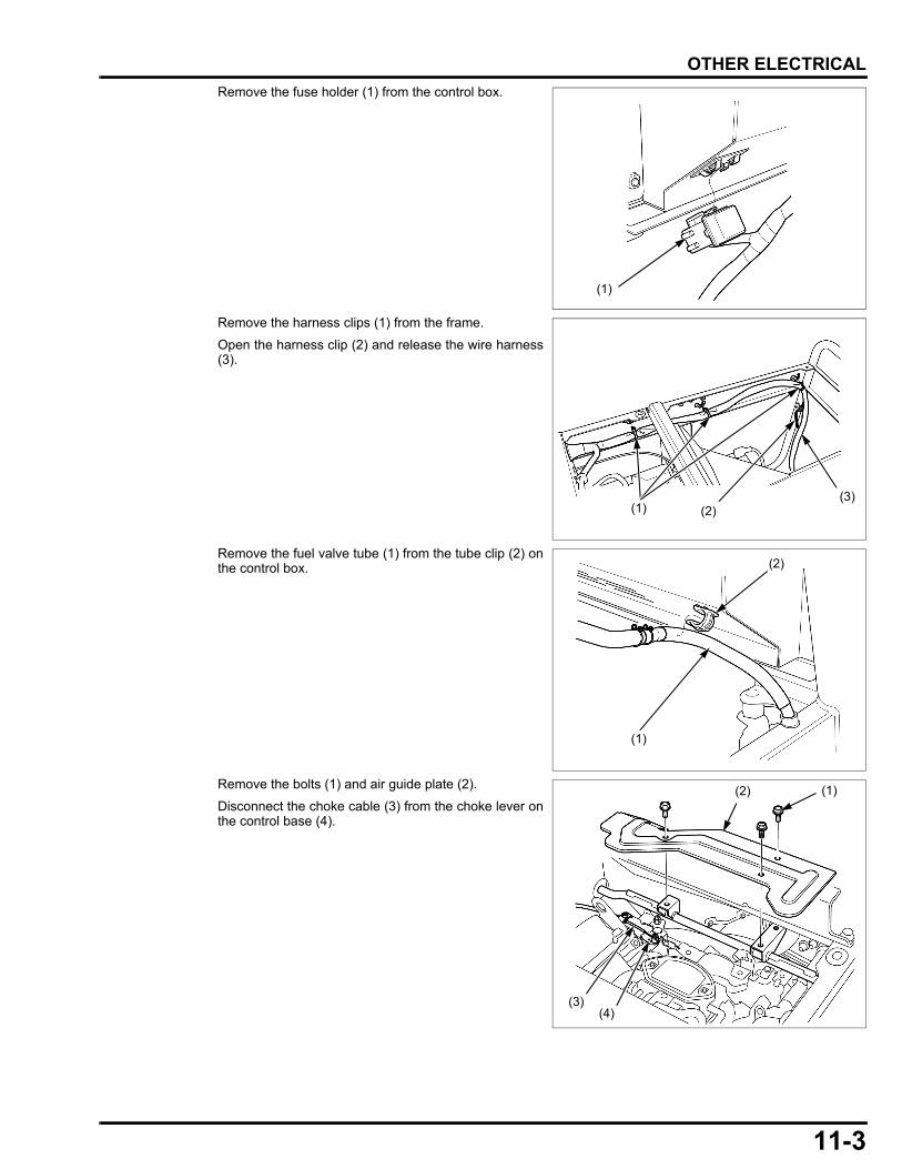
Remove the fuse holder (1) from the control box.Remove the harness clips (1) from the frame.
Open the harness clip (2) and release the wire harness(3).
Remove the fuel valve tube (1) from the tube clip (2) onthe control box.
Remove the bolts (1) and air guide plate (2).
Disconnect the choke cable (3) from the choke lever onthe control base (4).
(1)
(1) (2)(3)
(1)
(2)
(3)
(2) (1)
(4)
11-3
dummyheaddummyhead
OTHER ELECTRICAL
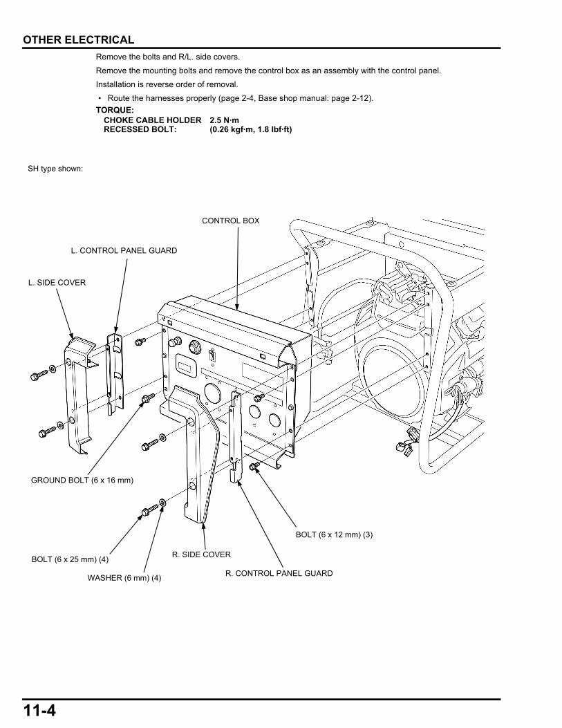
Remove the bolts and R/L. side covers.Remove the mounting bolts and remove the control box as an assembly with the control panel.
Installation is reverse order of removal.
• Route the harnesses properly (page 2-4, Base shop manual: page 2-12).TORQUE:
CHOKE CABLE HOLDER RECESSED BOLT:
2.5 N·m (0.26 kgf·m, 1.8 lbf·ft)
BOLT (6 x 25 mm) (4) R. SIDE COVER
CONTROL BOX
L. SIDE COVER
R. CONTROL PANEL GUARD
L. CONTROL PANEL GUARD
WASHER (6 mm) (4)
BOLT (6 x 12 mm) (3)
GROUND BOLT (6 x 16 mm)
SH type shown:
11-4
dummyheaddummyhead
OTHER ELECTRICAL
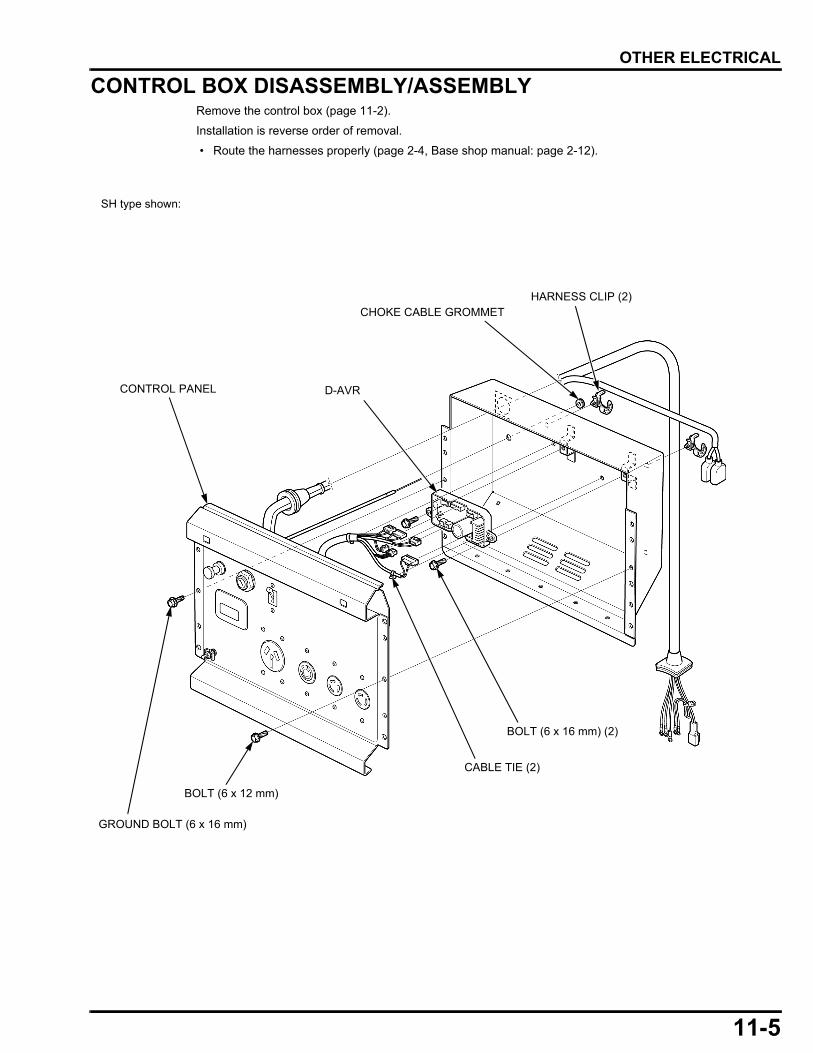
CONTROL BOX DISASSEMBLY/ASSEMBLYRemove the control box (page 11-2).
Installation is reverse order of removal.
• Route the harnesses properly (page 2-4, Base shop manual: page 2-12).
CONTROL PANEL
HARNESS CLIP (2)CHOKE CABLE GROMMET
BOLT (6 x 12 mm)
GROUND BOLT (6 x 16 mm)
BOLT (6 x 16 mm) (2)
D-AVR
CABLE TIE (2)
SH type shown:
11-5
dummyheaddummyhead
OTHER ELECTRICAL
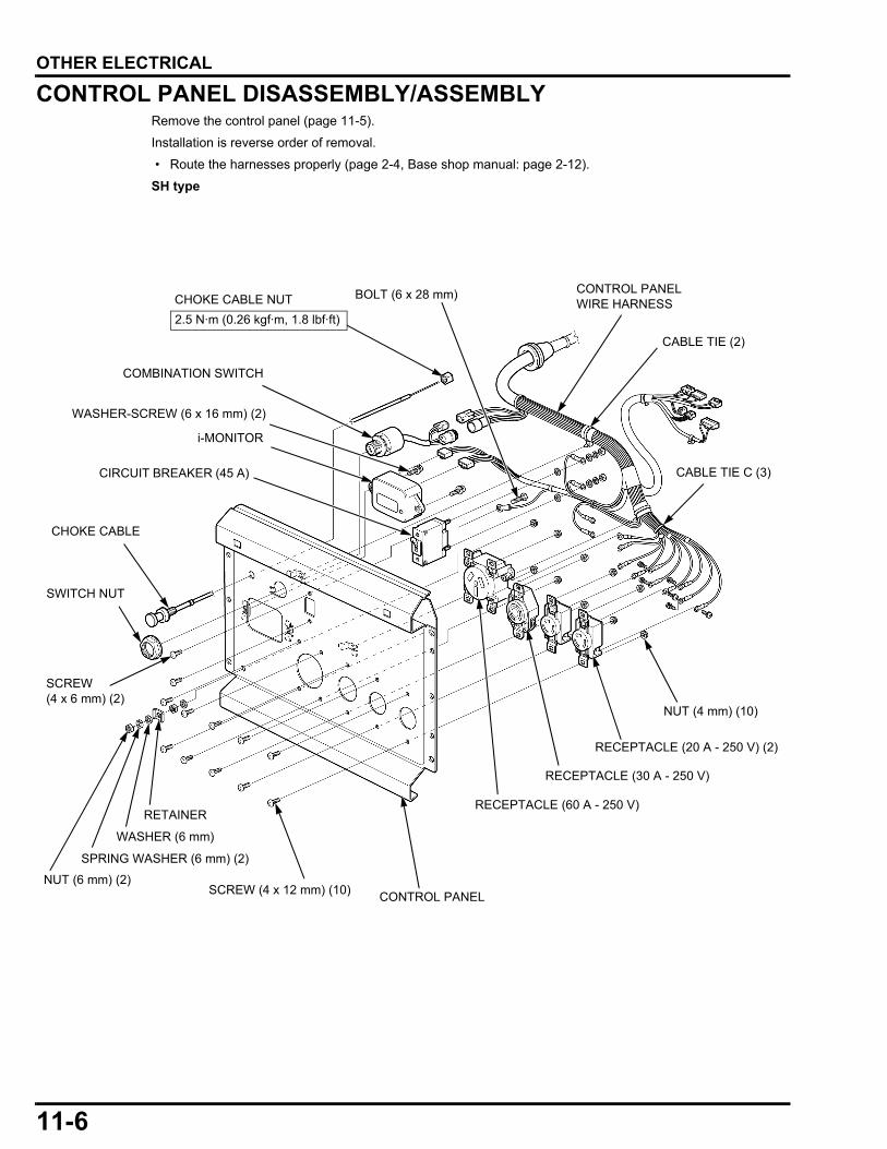
CONTROL PANEL DISASSEMBLY/ASSEMBLYRemove the control panel (page 11-5).
Installation is reverse order of removal.
• Route the harnesses properly (page 2-4, Base shop manual: page 2-12).
SH type
WASHER-SCREW (6 x 16 mm) (2)
CONTROL PANEL
CHOKE CABLE
COMBINATION SWITCH
i-MONITOR
CONTROL PANEL WIRE HARNESS
NUT (6 mm) (2)
NUT (4 mm) (10)
SCREW (4 x 12 mm) (10)
SCREW (4 x 6 mm) (2)
RECEPTACLE (20 A - 250 V) (2)
RECEPTACLE (30 A - 250 V)
RECEPTACLE (60 A - 250 V)
CIRCUIT BREAKER (45 A)
CABLE TIE (2)
CABLE TIE C (3)
RETAINER
BOLT (6 x 28 mm)
WASHER (6 mm)
SPRING WASHER (6 mm) (2)
CHOKE CABLE NUT2.5 N·m (0.26 kgf·m, 1.8 lbf·ft)
SWITCH NUT
11-6
dummyheaddummyhead
OTHER ELECTRICAL
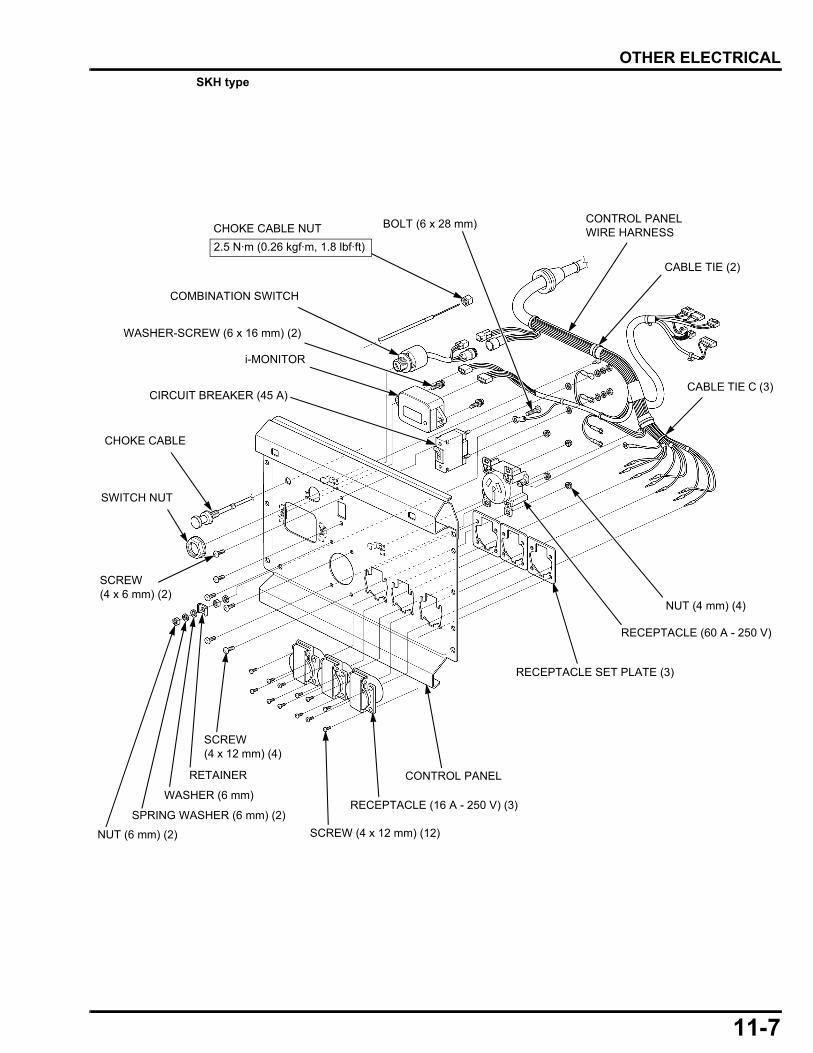
SKH typeWASHER-SCREW (6 x 16 mm) (2)
CONTROL PANEL
CHOKE CABLE
COMBINATION SWITCH
i-MONITOR
CONTROL PANEL WIRE HARNESS
NUT (6 mm) (2)
NUT (4 mm) (4)
SCREW (4 x 12 mm) (12)
SCREW (4 x 6 mm) (2)
RECEPTACLE (16 A - 250 V) (3)
RECEPTACLE (60 A - 250 V)
CIRCUIT BREAKER (45 A)
CABLE TIE (2)
CABLE TIE C (3)
RETAINER
BOLT (6 x 28 mm)
WASHER (6 mm)
SPRING WASHER (6 mm) (2)
SCREW (4 x 12 mm) (4)
RECEPTACLE SET PLATE (3)
CHOKE CABLE NUT2.5 N·m (0.26 kgf·m, 1.8 lbf·ft)
SWITCH NUT
11-7
dummyheaddummyhead
OTHER ELECTRICAL
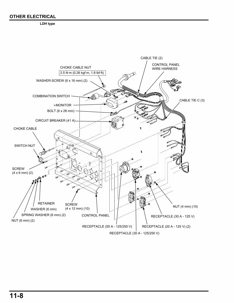
LDH typeWASHER-SCREW (6 x 16 mm) (2)
CONTROL PANEL
CHOKE CABLE
COMBINATION SWITCH
i-MONITOR
CONTROL PANEL WIRE HARNESS
NUT (6 mm) (2)
NUT (4 mm) (10)
SCREW (4 x 6 mm) (2)
CIRCUIT BREAKER (41 A)
CABLE TIE (2)
CABLE TIE C (3)
RETAINER
BOLT (6 x 28 mm)
WASHER (6 mm)
SPRING WASHER (6 mm) (2)
CHOKE CABLE NUT2.5 N·m (0.26 kgf·m, 1.8 lbf·ft)
RECEPTACLE (20 A - 125 V) (2)RECEPTACLE (50 A - 125/250 V)
RECEPTACLE (30 A - 125 V)
RECEPTACLE (30 A - 125/250 V)
SCREW (4 x 12 mm) (10)
SWITCH NUT
11-8
dummyheaddummyhead
OTHER ELECTRICAL
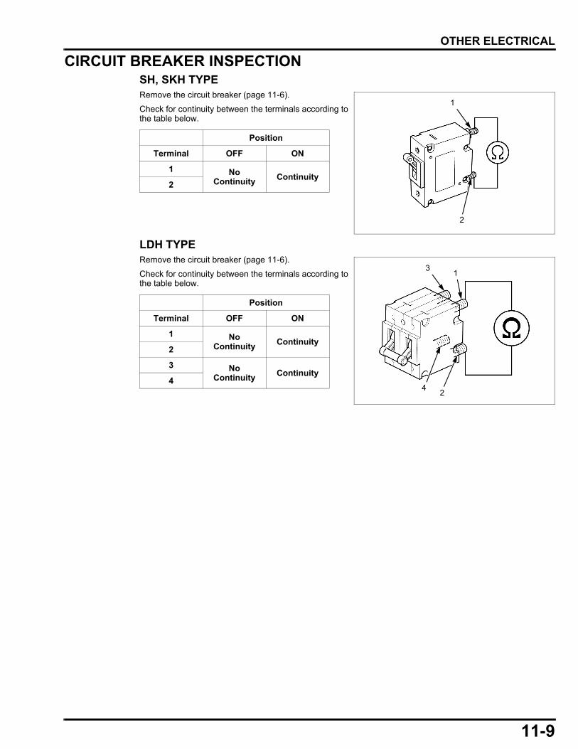
CIRCUIT BREAKER INSPECTIONSH, SKH TYPERemove the circuit breaker (page 11-6).
Check for continuity between the terminals according tothe table below.
LDH TYPERemove the circuit breaker (page 11-6).
Check for continuity between the terminals according tothe table below.
Position
Terminal OFF ON
1 No Continuity Continuity
2
1
2
Position
Terminal OFF ON
1 No Continuity Continuity
2
3 NoContinuity Continuity
4
13
24
11-9

dummyheaddummyhead
MEMO
dummytext
18. WIRING DIAGRAMS
18
HOW TO READ A WIRING DIAGRAM & RELATED INFORMATION ······················18-2
WIRING DIAGRAMS··································· 18-3
18-1
dummyheaddummyhead
WIRING DIAGRAMS
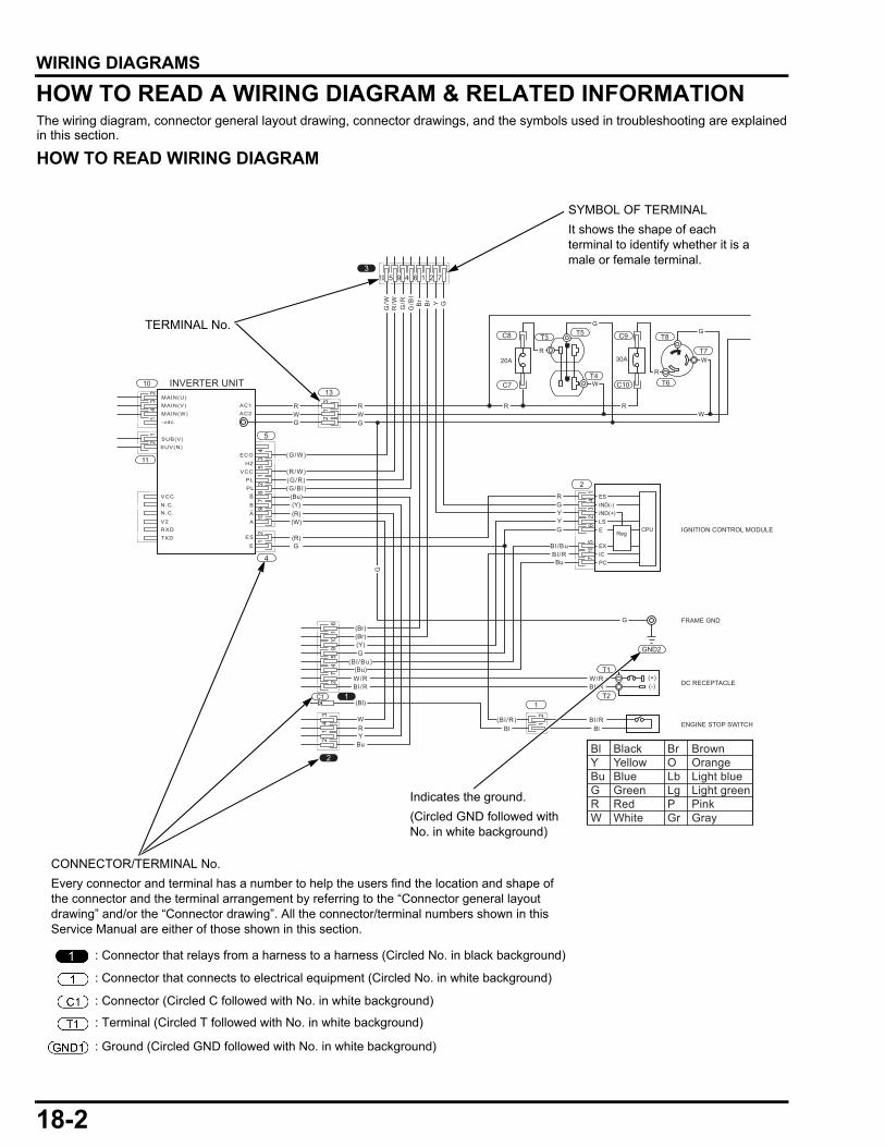
WIRING DIAGRAMSHOW TO READ A WIRING DIAGRAM & RELATED INFORMATIONThe wiring diagram, connector general layout drawing, connector drawings, and the symbols used in troubleshooting are explainedin this section.HOW TO READ WIRING DIAGRAM
1
2
C1
4
5
GND2
T1
T21
2
1310
11
3
C8
C7
12
53
46
710
9 1 25 4 6 710
12
3
12
12
34
91
25
34
87
101
2
92
54
710
12
34
16
12
C10
C9 T8
T6
T7
T5T3
T4
G
G/W
G/R
G/B
l
R/W Br
Br Y
GG
R
R
R R
W
W
W
R
Bl/RBl/Bu
G
G
YY
Bu
W/RBl/R
G
Bl/RBl
(Br)(Br)
G
(Bl/R)
(Bl /Bu)
(Y)
W/RBl/R
(Bu)
(Bl)
BlY
Bu
RW
G
RW
G
RW
G
(G/W)
(G/R)(G/Bl)
(R/W)
(Y)(Bu)
(R)
(R)
(W)
G
MAIN(U)MAIN(V)
SUB(V)SUV(N)
MAIN(W)-vdc
AC1AC2
VCC
VCC
N.C.N.C.
RXDTXD
V2
ECO
HZ
PL
PL
B
B
AA
ES
E
ES
EXIC
CPU
PC
E Reg
LS
IND(-)IND(+)
INVERTER UNIT
IGNITION CONTROL MODULE
FRAME GND
ENGINE STOP SWITCH
30A20A
DC RECEPTACLE(+)(-)
Bl Black Br BrownY Yellow O OrangeBu Blue Lb Light blueG Green Lg Light greenR Red P PinkW White Gr Gray
SYMBOL OF TERMINALIt shows the shape of each terminal to identify whether it is a male or female terminal.
TERMINAL No.
CONNECTOR/TERMINAL No.Every connector and terminal has a number to help the users find the location and shape of the connector and the terminal arrangement by referring to the “Connector general layout drawing” and/or the “Connector drawing”. All the connector/terminal numbers shown in this Service Manual are either of those shown in this section.
Indicates the ground.(Circled GND followed with No. in white background)
: Connector that relays from a harness to a harness (Circled No. in black background)
: Connector that connects to electrical equipment (Circled No. in white background)
: Connector (Circled C followed with No. in white background)
: Terminal (Circled T followed with No. in white background)
: Ground (Circled GND followed with No. in white background)
18-2
dummyheaddummyhead
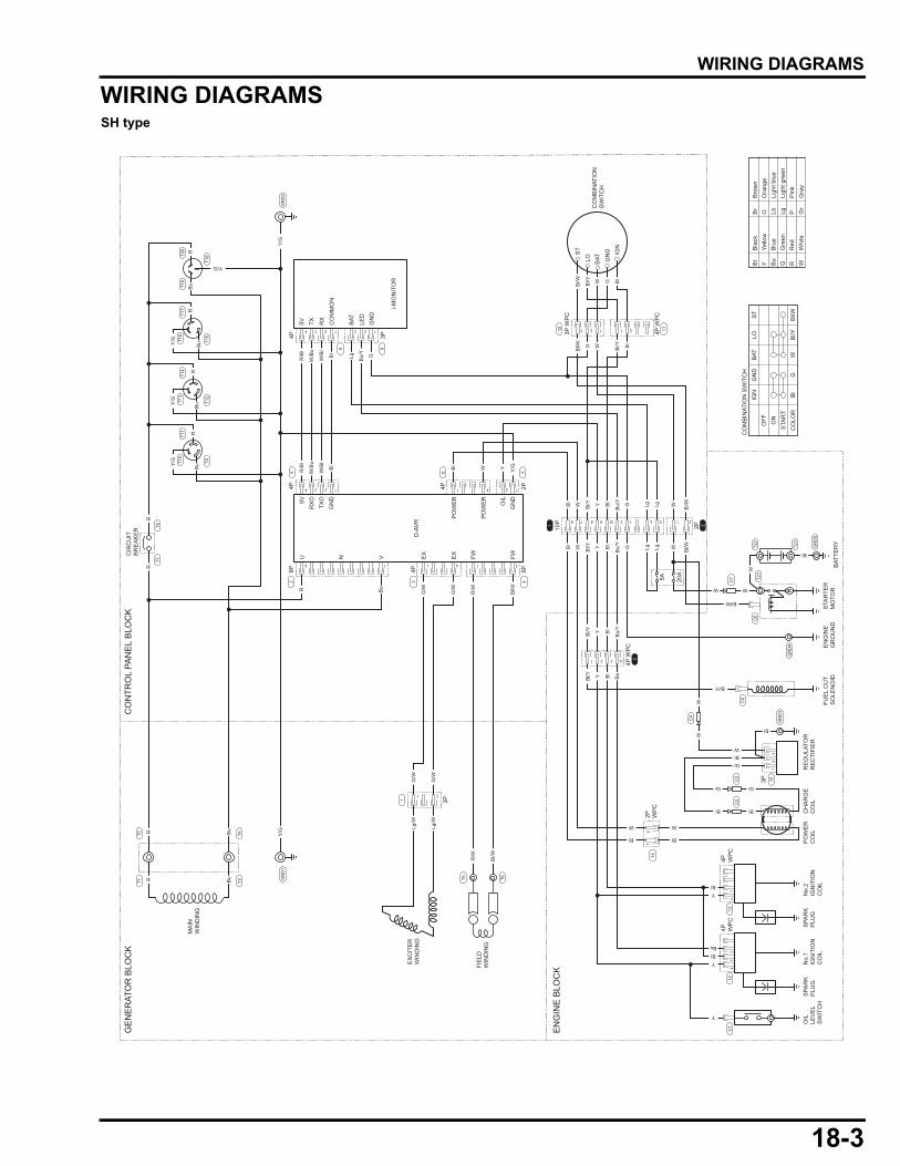
WIRING DIAGRAMS
WIRING DIAGRAMSSH type
OIL
LEV
EL
SW
ITC
H
No.
2IG
NIT
ION
CO
IL
RE
GU
LATO
RR
EC
TIFI
ER
FUE
L C
UT
SO
LEN
OID
EN
GIN
EG
RO
UN
DS
TAR
TER
MO
TOR
BAT
TER
Y
ST
IGN
LO GN
D
BAT
1
4 2 14 3 2 1 1
23 21
4231
76 98 10
1 511
31
9
4 3 2 1 3 2 1
4
1
12
3
3 54 21
SPA
RK
PLU
GS
PAR
KP
LUG
PO
WE
RC
OIL
CH
AR
GE
CO
ILN
o.1
IGN
ITIO
NC
OIL
5V
4P 3P
TX RX
CO
MM
ON
U5V
RX
O
TXO
GN
D
PO
WE
R
PO
WE
R
OIL
GN
D
N V EX
EX
FW FW
BAT
LED
GN
D
i-MO
NIT
OR
D-A
VR
MA
INW
IND
ING
GE
NE
RAT
OR
BLO
CK
CO
NTR
OL
PAN
EL
BLO
CK
EN
GIN
E B
LOC
KFIE
LDW
IND
ING
EX
CIT
ER
WIN
DIN
G
CIR
CU
ITB
RE
AK
ER
T20
T18
T19
T17
T16
T15
8
4P 4P 2P
65
4P
3P
5P
3
1
T4T3
T2T1
4
9P2
7
3P W
PC
10
T22
T21
C7
C6
C5
C4
14
T6T5
C3
C2
15
4
12
113
41
312
C1
T23
10P1 22P
4P WP
C4P W
PC
34P
WP
C
3P
5A 20A
4P W
PC
CO
MB
INAT
ION
SW
ITC
H
CO
MB
INAT
ION
SW
ITC
H
IGN
OFF ON
STA
RT
CO
LOR
ST
GN
DB
ATLO
Bl
Bl/W
GW
Bl/Y
11
9
T14
T13
T12
T11
T10
T9
T8T7
GN
D5
GN
D4
GN
D1
GN
D3
GN
D2
2P WP
C
Bl
Bla
ckB
rB
row
nY
Yello
wO
Ora
nge
Bu
Blu
eLb
Ligh
t blu
eG
Gre
enLg
Ligh
t gre
enR
Red
PP
ink
WW
hite
Gr
Gra
y
Bl/W WG Bl/Y Bl
Bl/W Bl/Y W G Bl
Bl/WBl/Y
Bu/
Y
W WY G Lg LgBl
Bl/W
Y/G
Y/G
Y/G
Y/G
Bl/Y
Gr
Gr
Bl
Bl
W
Bl
W
BlY
BlBu
Y
Y
Gr
Bl
BlW
Bl/WBl/Y
Bu/
Y
W W
WW
W
W
Bl
W
Bl
Y G Lg LgBl
Bl
Bl
Bl/Y
Bu/
Y
Y Bl
Bl/Y
Bl/WR/W
Lg/W
Lg/W
G/W
G/W
G/W
G/W
R/B
l
W/B
u
W/B
l
Bl
WBl
R/B
l
Y/G
W/B
u
W/B
l
Bl
Bu/
Y
GLg
Y Y/G
Bl/WR/W
Y Bl
Bu
Bu
R Bu
R Bu
Y/G
R
RR
Bu
Bu
Bu
Bu
RR
RR
18-3
dummyheaddummyhead
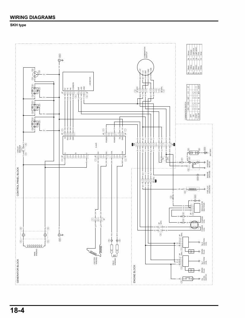
WIRING DIAGRAMS
SKH typeOIL
LEV
EL
SW
ITC
H
No.
2IG
NIT
ION
CO
IL
RE
GU
LATO
RR
EC
TIFI
ER
FUE
L C
UT
SO
LEN
OID
EN
GIN
EG
RO
UN
DS
TAR
TER
MO
TOR
BAT
TER
Y
ST
IGN
LO GN
D
BAT
1
4 2 14 3 2 1 1
23 21
4231
76 98 10
1 511
31
9
4 3 2 1 3 2 1
4
1
12
3
3 54 21
SPA
RK
PLU
GS
PAR
KP
LUG
PO
WE
RC
OIL
CH
AR
GE
CO
ILN
o.1
IGN
ITIO
NC
OIL
5V
4P 3P
TX RX
CO
MM
ON
U5V
RX
O
TXO
GN
D
PO
WE
R
PO
WE
R
OIL
GN
D
N V EX
EX
FW FW
BAT
LED
GN
D
i-MO
NIT
OR
D-A
VR
MA
INW
IND
ING
GE
NE
RAT
OR
BLO
CK
CO
NTR
OL
PAN
EL
BLO
CK
EN
GIN
E B
LOC
KFIE
LDW
IND
ING
EX
CIT
ER
WIN
DIN
G
CIR
CU
ITB
RE
AK
ER
T20
T18
T30
T32
T19
T31
T27
T29
T28
T24
T26
T25
8
4P 4P 2P
65
4P
3P
5P
3
1
T4T3
T2T1
4
9P2
7
3P W
PC
10
T22
T21
C7
C6
C5
C4
14
T6T5
C3
C2
15
4
12
113
41
312
C1
T23
10P1 22P
4P WP
C4P W
PC
34P
WP
C
3P
5A 20A
4P W
PC
CO
MB
INAT
ION
SW
ITC
H
CO
MB
INAT
ION
SW
ITC
H
IGN
OFF ON
STA
RT
CO
LOR
ST
GN
DB
ATLO
Bl
Bl/W
GW
Bl/Y
11
9
T8T7
GN
D5
GN
D4
GN
D1
GN
D3
GN
D2
2P WP
C
Bl
Bla
ckB
rB
row
nY
Yello
wO
Ora
nge
Bu
Blu
eLb
Ligh
t blu
eG
Gre
enLg
Ligh
t gre
enR
Red
PP
ink
WW
hite
Gr
Gra
y
Bl/W WG Bl/Y Bl
Bl/W Bl/Y W G Bl
Bl/WBl/Y
Bu/
Y
W WY G Lg LgBl
Bl/W
Y/G
Y/G
Bl/Y
Gr
Gr
Bl
Bl
W
Bl
W
BlY
BlBu
Y
Y
Gr
Bl
BlW
Bl/WBl/Y
Bu/
Y
W W
WW
W
W
Bl
W
Bl
Y G Lg LgBl
Bl
Bl
Bl/Y
Bu/
Y
Y Bl
Bl/Y
Bl/WR/W
Lg/W
Lg/W
G/W
G/W
G/W
G/W
R/B
l
W/B
u
W/B
l
Bl
WBl
R/B
l
Y/G
W/B
u
W/B
l
Bl
Bu/
Y
GLg
Y Y/G
Bl/WR/W
Y Bl
Bu
Bu
R Bu
R Bu
Y/G
R
RR
Bu
Bu
RR
Y/G
Bu
R
Y/G
Bu
R
18-4
dummyheaddummyhead
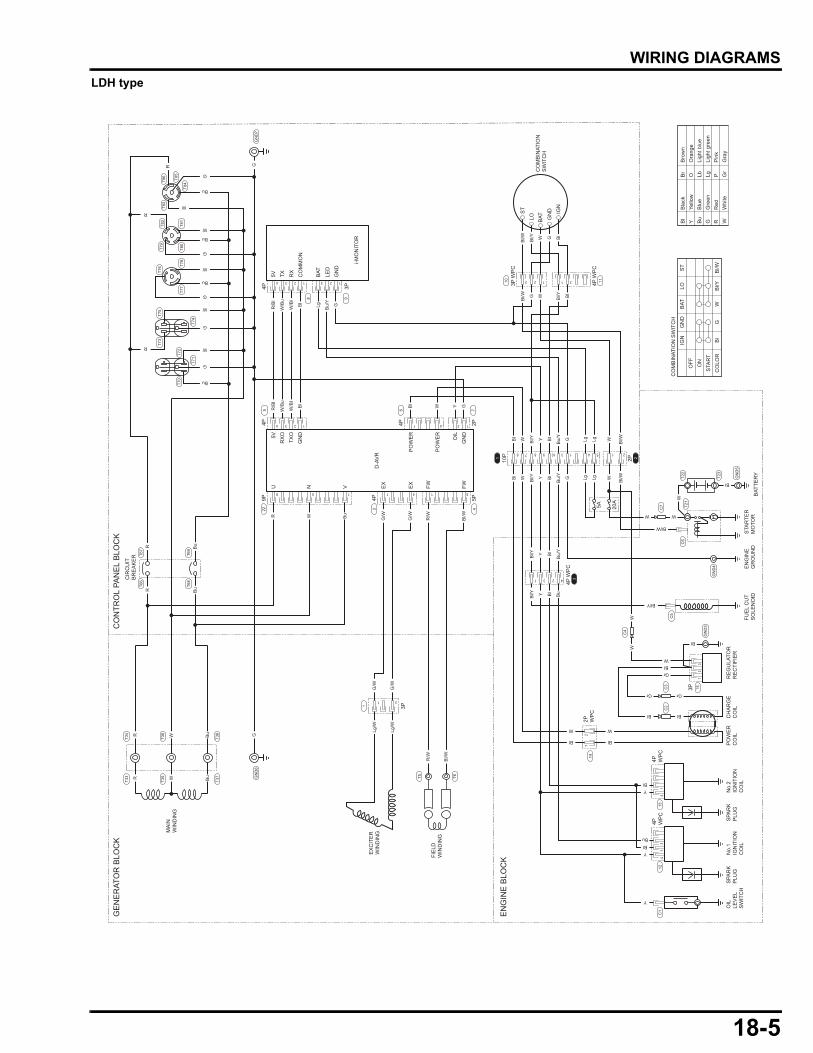
WIRING DIAGRAMS
LDH typeOIL
LEV
EL
SW
ITC
H
No.
2IG
NIT
ION
CO
IL
RE
GU
LATO
RR
EC
TIFI
ER
FUE
L C
UT
SO
LEN
OID
EN
GIN
EG
RO
UN
DS
TAR
TER
MO
TOR
BAT
TER
Y
ST
IGN
LO GN
D
BAT
1
4 2 14 3 2 1 1
23 21
4231
76 98 10
1 5115
31
9
4 3 2 1 3 2 1
4
1
12
3
3 54 21
SPA
RK
PLU
GS
PAR
KP
LUG
PO
WE
RC
OIL
CH
AR
GE
CO
ILN
o.1
IGN
ITIO
NC
OIL
5V
4P 3P
TX RX
CO
MM
ON
U5V
RX
O
TXO
GN
D
PO
WE
R
PO
WE
R
OIL
GN
D
N V EX
EX
FW FW
BAT
LED
GN
D
i-MO
NIT
OR
D-A
VR
MA
INW
IND
ING
GE
NE
RAT
OR
BLO
CK
CO
NTR
OL
PAN
EL
BLO
CK
EN
GIN
E B
LOC
KFIE
LDW
IND
ING
EX
CIT
ER
WIN
DIN
G
T83
T84
T85
T81
T78
T77
T76
T75
T73
T74
T72
T70
T71
T80
T86
T82
T79
8
4P 4P 2P
65
4P
3P
5P
3
1
T38
T37
T34
T33
T36
T35
4
9P22
7
3P W
PC
10
T22
T21
C7
C6
C5
C4
14
T6T5
C3
C2
15
4
12
113
41
312
C1
T23
10P1 22P
4P WP
C4P W
PC
34P
WP
C
3P
5A 20A
4P W
PC
CO
MB
INAT
ION
SW
ITC
H
CO
MB
INAT
ION
SW
ITC
H
IGN
OFF ON
STA
RT
CO
LOR
ST
GN
DB
ATLO
Bl
Bl/W
GW
Bl/Y
11
9
CIR
CU
ITB
RE
AK
ER T6
7T6
6
T69
T68
GN
D5
GN
D4
GN
D6
GN
D3
GN
D7
2P WP
C
Bl
Bla
ckB
rB
row
nY
Yello
wO
Ora
nge
Bu
Blu
eLb
Ligh
t blu
eG
Gre
enLg
Ligh
t gre
enR
Red
PP
ink
WW
hite
Gr
Gra
y
Bl/W WG Bl/Y Bl
Bl/W Bl/Y W G Bl
Bl/WBl/Y
Bu/
Y
W WY G Lg LgBl
Bl/W
G
Bu
W
W
W
R
R
Bu
Bu
G
G
G
G
Bu
W
W
Bl/Y
Gr
Gr
Bl
Bl
W
Bl
W
BlY
BlBu
Y
Y
Gr
Bl
BlW
Bl/WBl/Y
Bu/
Y
W W
WW
W
W
Bl
W
Bl
Y G Lg LgBl
Bl
Bl
Bl/Y
Bu/
Y
Y Bl
Bl/Y
Bl/WR/W
Lg/W
Lg/W
G/W
G/W
G/W
G/W
R/B
l
W/B
u
W/B
l
Bl
WBl
R/B
l
G
W/B
u
W/B
l
Bl
Bu/
Y
GLg
Y GB
l/WR/W
Y Bl
Bu
BuW
R WW
Bu
R Bu G
R
R
R
R
Bu
Bu
18-5
dummyheaddummyhead
MEMO
19-1
19
dummytext
INDEXCCIRCUIT BREAKER INSPECTION ······························11-9CONTROL BOX DISASSEMBLY/ASSEMBLY ·············11-5CONTROL BOX REMOVAL/INSTALLATION···············11-2CONTROL PANEL DISASSEMBLY/ASSEMBLY ·········11-6EEXCITER WINDING INSPECTION·······························8-14FFIELD WINDING INSPECTION ····································8-15GGOVERNOR ARM/CONTROL REMOVAL/INSTALLATION············································7-2HHARNESS ROUTING ·····················································2-4HOW TO READ A WIRING DIAGRAM & RELATED INFORMATION········································18-2HOW TO READ CONNECTOR DRAWINGS ·················2-3IIGNITION COIL INSPECTION········································9-2
MMAIN WINDING INSPECTION····································· 8-11MAINTENANCE STANDARDS ······································ 2-2PPERFORMANCE CURVES············································ 1-4RREAR HOUSING/STATOR REMOVAL/INSTALLATION············································ 8-9SSERIAL NUMBER LOCATION······································· 1-2SPECIFICATIONS·························································· 1-2SYSTEM DIAGRAM
GENERATOR SYSTEM············································· 8-2TTROUBLESHOOTING
GENERATOR SYSTEM············································· 8-5WWIRING DIAGRAMS ···················································· 18-3
INDEX