Embed Size (px)
Citation preview
TECHNICAL SPECIFICATIONS FOR THE GAS
SUPPRESSION SYSTEM FOR THE PROPOSED
ARCHIEVE ROOM IN THE ADMINISTRATION
BUILDING AT THE IDC BUILDING
1
Contents 1 PART 1 – GENERAL ............................................................................................................................................... 3
1.1 DESCRIPTION OF WORK: .............................................................................................................................. 3
1.2 APPLICABLE PUBLICATIONS: ........................................................................................................................ 3
1.3 REQUIREMENTS: .......................................................................................................................................... 4
1.4 GENERAL: ..................................................................................................................................................... 4
1.5 SUBMITTAL: ................................................................................................................................................. 5
2 PART 2 – PRODUCTS ............................................................................................................................................ 6
2.1 SYSTEM DESCRIPTION AND OPERATION: ..................................................................................................... 6
2.2 SEQUENCE OF OPERATION: ............................................................................................................................. 6
2.3 AUXILIARY COMPONENTS: ............................................................................................................................... 7
3 PART 3 – MATERIAL AND EQUIPMENT ................................................................................................................ 8
3.1 GENERAL REQUIREMENTS: ........................................................................................................................... 8
3.2 GENERAL MATERIALS – ELECTRICAL: ................................................................................................................ 8
3.3 CONTROL SYSTEMS – GENERAL: ..................................................................................................................... 10
3.4 CONTROL PANEL – AUTOPULSE Z-20 CONTROL SYSTEM ................................................................................ 10
3.5 PROGRAMMABLE ELECTRONIC SOUNDERS .................................................................................................... 14
3.6 VISUAL NOTIFICATION APPLIANCES ................................................................................................................ 14
3.7 AUDIBLE/VISUAL COMBINATION DEVICES ...................................................................................................... 14
3.8 ANALOG ADDRESSABLE PHOTOELECTRIC SMOKE DETECTOR ......................................................................... 14
3.9 ANALOG ADDRESSABLE IONIZATION SMOKE DETECTOR ................................................................................ 14
3.10 ANALOG ADDRESSABLE DUCT SMOKE DETECTOR .......................................................................................... 15
3.11 ABORT SWITCH .............................................................................................................................................. 16
3.12 MAINTENANCE LOCK-OUT SWITCH ................................................................................................................ 17
3.13 SELECTOR SWITCH ......................................................................................................................................... 17
4 PART 4 – SYSTEM ARRANGEMENT .................................................................................................................... 17
4.1 INERGEN FIRE SUPPRESSION SYSTEM: ............................................................................................................ 17
4.2 FLOW CALCULATIONS: ................................................................................................................................... 18
5 PART 5 – EQUIPMENT AND MATERIAL (MECHANICAL) .................................................................................... 19
5.1 PIPE MATERIAL – INERGEN SYSTEM: .............................................................................................................. 19
5.2 EXTINGUISHING AGENT: ................................................................................................................................. 19
5.3 INERGEN STORAGE CYLINDERS: ...................................................................................................................... 20
5.4 CYLINDER BRACKET: ....................................................................................................................................... 20
5.5 VALVE ACTUATORS: ........................................................................................................................................ 20
5.6 DISCHARGE HOSE/CHECK VALVE: ................................................................................................................... 20
5.7 DISCHARGE NOZZLES: ..................................................................................................................................... 21
5.8 ORIFICE UNION/NIPPLE ASSEMBLIES: ............................................................................................................. 21

2
5.9 SYSTEM CHECKOUT AND TESTING: ................................................................................................................. 22
6 PART 6 – WARRANTY ......................................................................................................................................... 24
6.1 6.1 WARRANTY: ......................................................................................................................................... 24

3
1 PART 1 – GENERAL 1.1 DESCRIPTION OF WORK:
A Design and installation of an engineered fire detection and INERGEN total flooding, gaseous agent, fire suppression system with automatic detection and control
B System design is based on the use of Selector valves to direct the flow of INERGEN agent into the protected zone where indicated on drawings. Quantity of INERGEN cylinders is to be based on the largest zone of protection. Cylinders shall be provided to offer adequate protection of the largest zone of protection. Selector valves shall be provided to supply discharge of proper design concentration of INERGEN agent into the protected zone.
C Drawings: The contract drawings indicate the general arrangements of the areas to
receive detection and INERGEN system protection. Contractor is to review all drawings so that all items affecting the operation of the fire detection/INERGEN fire suppression system (such as equipment location, air diffusers, damper closures, and door openings) are considered in the design of the engineered system.
1.2 APPLICABLE PUBLICATIONS:
A The following publications of the issues listed below, but referred to thereafter by basic designation only, form a part of this specification to the extent indicated by the reference thereto (latest edition):
1. National Fire Protection Association (NFPA) Standards:
∗ NFPA 2001: Standard on Clean Agent Fire Extinguishing Systems
2. South African National Standards ( SANS)
∗ SANS 10400 Part T. Fire Installations ∗ SANS 14520 : Fixed firefighting Systems: Gas extinguishing Systems
B. The standards listed, as well as all other applicable codes, standards, and good
engineering practices, shall be used as “minimum" design standards.
4
1.3 REQUIREMENTS:
A. This installation shall be made in strict accordance with the drawings, specifications and applicable NFPA & SANS Standards. All equipment and devices used shall be listed by the standardizing agencies.
B. Design and installation of the gas suppression system will be in strict accordance with the following guidelines and regulatory agencies:
1. NFPA 2001 Standard on Clean Agent Fire Extinguishing Systems
2. SANS 10400 Part T Fire Installations
3. SANS 14520 : Fixed firefighting Systems: Gas extinguishing Systems
1.4 GENERAL:
B Furnish all engineering design and materials for a complete fire detection/INERGEN fire suppression system including charged INERGEN storage cylinders, nozzles, control unit, detectors, wiring, annunciators, alarm and all other equipment necessary for a complete operational system.
C Major system components shall be produced by a SANS approved supplier (no
alternatives) and shall be installed by an authorized SAQCC Distributor certified for the design, installation, and service of INERGEN fire suppression systems.
D New and unused materials and equipment must be used for system.
E Contractor shall, as a minimum, provide 24-hour emergency service, 7 days a week and
shall be able to respond to an emergency situation within 2 hours of receiving an emergency trouble call.
5
1.5 SUBMITTAL:
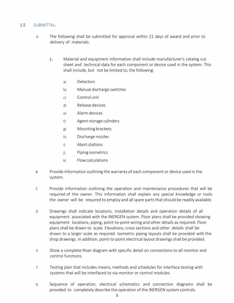
A The following shall be submitted for approval within 21 days of award and prior to delivery of materials:
1. Material and equipment information shall include manufacturer's catalog cut sheet and technical data for each component or device used in the system. This shall include, but not be limited to, the following:
a) Detectors
b) Manual discharge switches
c) Control unit
d) Release devices
e) Alarm devices
f) Agent storage cylinders
g) Mounting brackets
h) Discharge nozzles
i) Abort stations
j) Piping isometrics
k) Flow calculations
B Provide information outlining the warranty of each component or device used in the system.
C Provide information outlining the operation and maintenance procedures that will be
required of the owner. This information shall explain any special knowledge or tools the owner will be required to employ and all spare parts that should be readily available.
D Drawings shall indicate locations, installation details and operation details of all
equipment associated with the INERGEN system. Floor plans shall be provided showing equipment locations, piping, point-to-point wiring and other details as required. Floor plans shall be drawn to scale. Elevations, cross sections and other details shall be drawn to a larger scale as required. Isometric piping layouts shall be provided with the shop drawings. In addition, point-to-point electrical layout drawings shall be provided.
E Show a complete Riser diagram with specific detail on connections to all monitor and
control functions.
F Testing plan that includes means, methods and schedules for interface testing with systems that will be interfaced to via monitor or control modules.
G Sequence of operation, electrical schematics and connection diagrams shall be
provided to completely describe the operation of the INERGEN system controls.
6
2 PART 2 – PRODUCTS 2.1 SYSTEM DESCRIPTION AND OPERATION:
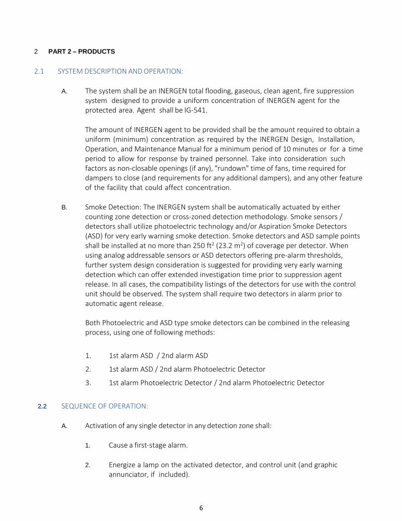
A. The system shall be an INERGEN total flooding, gaseous, clean agent, fire suppression system designed to provide a uniform concentration of INERGEN agent for the protected area. Agent shall be IG-541.
The amount of INERGEN agent to be provided shall be the amount required to obtain a uniform (minimum) concentration as required by the INERGEN Design, Installation, Operation, and Maintenance Manual for a minimum period of 10 minutes or for a time period to allow for response by trained personnel. Take into consideration such factors as non-closable openings (if any), "rundown" time of fans, time required for dampers to close (and requirements for any additional dampers), and any other feature of the facility that could affect concentration.
B. Smoke Detection: The INERGEN system shall be automatically actuated by either
counting zone detection or cross-zoned detection methodology. Smoke sensors / detectors shall utilize photoelectric technology and/or Aspiration Smoke Detectors (ASD) for very early warning smoke detection. Smoke detectors and ASD sample points shall be installed at no more than 250 ft2 (23.2 m2) of coverage per detector. When using analog addressable sensors or ASD detectors offering pre-alarm thresholds, further system design consideration is suggested for providing very early warning detection which can offer extended investigation time prior to suppression agent release. In all cases, the compatibility listings of the detectors for use with the control unit should be observed. The system shall require two detectors in alarm prior to automatic agent release. Both Photoelectric and ASD type smoke detectors can be combined in the releasing process, using one of following methods:
1. 1st alarm ASD / 2nd alarm ASD
2. 1st alarm ASD / 2nd alarm Photoelectric Detector
3. 1st alarm Photoelectric Detector / 2nd alarm Photoelectric Detector
2.2 SEQUENCE OF OPERATION:
A. Activation of any single detector in any detection zone shall:
1. Cause a first-stage alarm.
2. Energize a lamp on the activated detector, and control unit (and graphic
annunciator, if included).
7
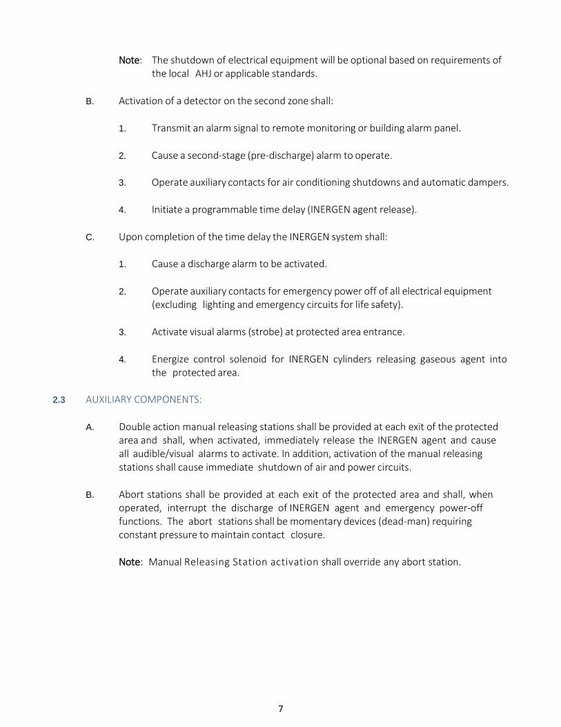
Note: The shutdown of electrical equipment will be optional based on requirements of the local AHJ or applicable standards.
B. Activation of a detector on the second zone shall:
1. Transmit an alarm signal to remote monitoring or building alarm panel.
2. Cause a second-stage (pre-discharge) alarm to operate.
3. Operate auxiliary contacts for air conditioning shutdowns and automatic dampers.
4. Initiate a programmable time delay (INERGEN agent release).
C. Upon completion of the time delay the INERGEN system shall:
1. Cause a discharge alarm to be activated.
2. Operate auxiliary contacts for emergency power off of all electrical equipment
(excluding lighting and emergency circuits for life safety).
3. Activate visual alarms (strobe) at protected area entrance.
4. Energize control solenoid for INERGEN cylinders releasing gaseous agent into the protected area.
2.3 AUXILIARY COMPONENTS:
A. Double action manual releasing stations shall be provided at each exit of the protected
area and shall, when activated, immediately release the INERGEN agent and cause all audible/visual alarms to activate. In addition, activation of the manual releasing stations shall cause immediate shutdown of air and power circuits.
B. Abort stations shall be provided at each exit of the protected area and shall, when
operated, interrupt the discharge of INERGEN agent and emergency power-off functions. The abort stations shall be momentary devices (dead-man) requiring constant pressure to maintain contact closure.
Note: Manual Releasing Station activation shall override any abort station.
8
3 PART 3 – MATERIAL AND EQUIPMENT 3.1 GENERAL REQUIREMENTS:
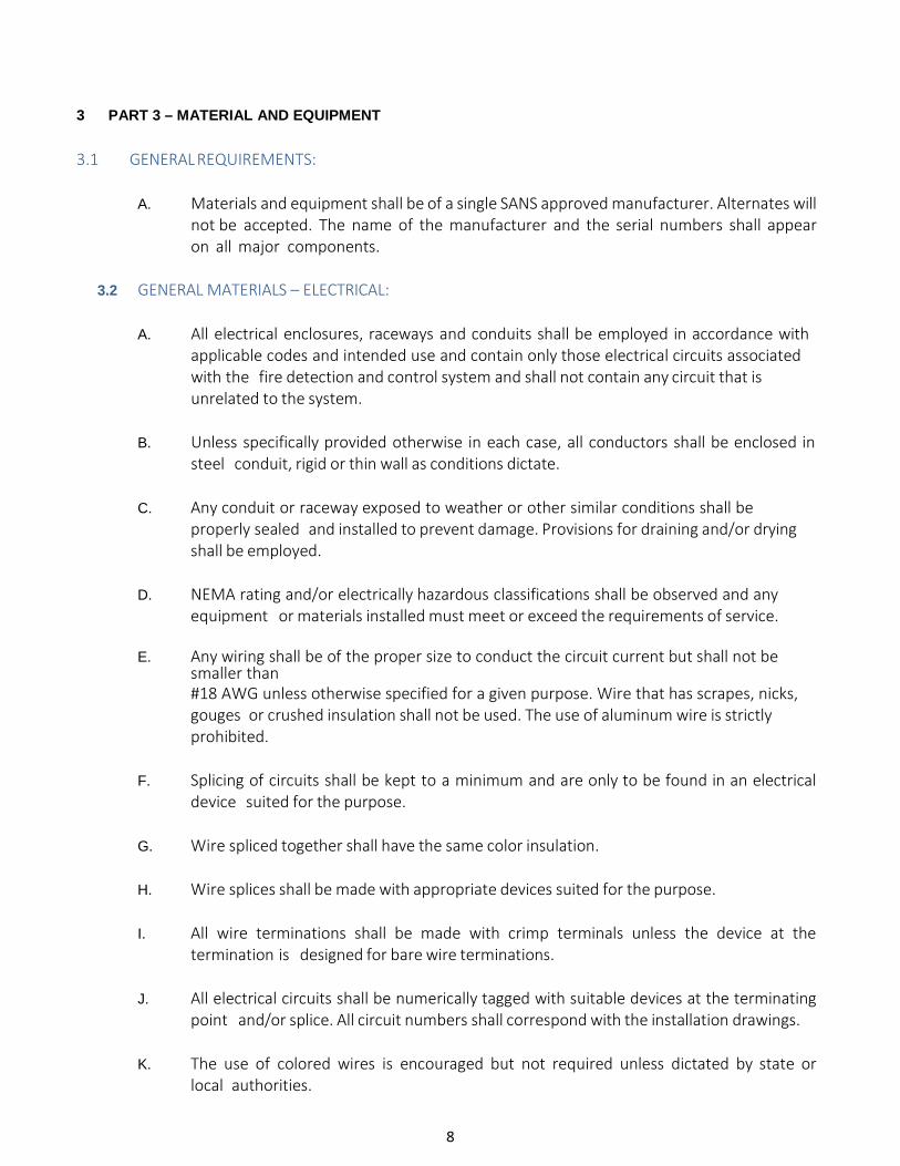
A. Materials and equipment shall be of a single SANS approved manufacturer. Alternates will not be accepted. The name of the manufacturer and the serial numbers shall appear on all major components.
3.2 GENERAL MATERIALS – ELECTRICAL:
A. All electrical enclosures, raceways and conduits shall be employed in accordance with
applicable codes and intended use and contain only those electrical circuits associated with the fire detection and control system and shall not contain any circuit that is unrelated to the system.
B. Unless specifically provided otherwise in each case, all conductors shall be enclosed in
steel conduit, rigid or thin wall as conditions dictate.
C. Any conduit or raceway exposed to weather or other similar conditions shall be properly sealed and installed to prevent damage. Provisions for draining and/or drying shall be employed.
D. NEMA rating and/or electrically hazardous classifications shall be observed and any
equipment or materials installed must meet or exceed the requirements of service.
E. Any wiring shall be of the proper size to conduct the circuit current but shall not be smaller than #18 AWG unless otherwise specified for a given purpose. Wire that has scrapes, nicks, gouges or crushed insulation shall not be used. The use of aluminum wire is strictly prohibited.
F. Splicing of circuits shall be kept to a minimum and are only to be found in an electrical
device suited for the purpose.
G. Wire spliced together shall have the same color insulation.
H. Wire splices shall be made with appropriate devices suited for the purpose.
I. All wire terminations shall be made with crimp terminals unless the device at the termination is designed for bare wire terminations.
J. All electrical circuits shall be numerically tagged with suitable devices at the terminating
point and/or splice. All circuit numbers shall correspond with the installation drawings.
K. The use of colored wires is encouraged but not required unless dictated by state or local authorities.

9
L. White-colored wire shall be used exclusively for the identification of the neutral conductor of an alternating current circuit.
M. Green-colored wire shall be used exclusively for the identification of the earth ground
conductor of an AC or DC circuit.
10
3.3 CONTROL SYSTEMS – GENERAL:
A. All control systems shall be SANS Listed and approved and shall be utilized with listed or approved compatible operating devices and shall be capable of the following features:
1. Ground fault indication
2. Supervised detection circuit(s)
3. Supervised alarm circuit(s)
4. Supervised release circuit(s)
5. Supervised manual pull circuit (if applicable)
6. Supervised primary power circuit
7. Battery standby
8. 4.3” color touchscreen LCD operator interface and LED indicating lamps
9. Key lock steel enclosure
10. Programmable time delay
11. Programmable detection logic
12. Microprocessor based logic
13. History buffer
3.4 CONTROL PANEL – AUTOPULSE Z-20 CONTROL SYSTEM
A. The Fire Alarm Control Panel (FACP) shall be an AUTOPULSE Z-20 control panel with the capability of protecting up to 20 separate hazard areas. The panel shall contain a Central Processing Unit (CPU) with integral 8 amp power supply which is rated to provide 8 amp for “Special Application” appliances including suppression release peripherals such as horns, strobes and horn/strobes and rated to 6 amp for “regulated 24 VDC” appliance power. The CPU shall communicate with and control the following types of equipment used to make up the system: addressable and conventional initiating devices, addressable modules, annunciators, and other system controlled devices.
B. System Capacity and General Operation:
1. The control panel and remote annunciator (optional) shall include a full featured,
intuitive color touch screen display capable of supporting up to two languages. The menu-driven interface shall provide color coded system status LEDs, allow for direct control of the fire alarm system and also allow for quick access to more detailed system information.
2. The control panel shall provide the following features:
a) Drift Compensation to extend detector accuracy over life.
b) Maintenance Alert to warn of excessive smoke detector dirt or dust accumulation.

11
c) Rapid manual station reporting (under 2 seconds).
d) Non-Alarm points for general (non-fire) control.
e) Periodic Detector Test conducted automatically by software.
f) Pre-alarm for advanced fire warning.
g) Counting/Cross Zoning with the capability of: counting 2 detectors in alarm, 2
software zones in alarm, or 1 smoke detector and 1 thermal detector in alarm.
h) Walk Test
i) Check for 2 detectors set to same address.
j) The real time clock may also be used to control non-fire functions at programmed time-of-day, day-of-week, and day-of-year.
k) Day/Night automatic adjustment of detector sensitivity.
l) Device Blink Control for sleeping areas.
m) Discrete status LEDs for Alarm, Priority 2, Supervisory, Trouble, Alarm Silenced
and AC power indications plus three additional programmable LEDs with associated control switches with provisions for custom labels.
C. Central Microprocessor:
1. The microprocessor unit shall communicate with, monitor, and control all external interfaces with the control panel. It shall include system program storage in non- volatile memory for building-specific program storage, and a "watch dog" timer circuit to detect and report microprocessor failure.
2. The microprocessor unit shall contain and execute all control-by-event
programs for specific action to be taken if an alarm condition is detected by the system. Such control- by-event programs shall be held in non-volatile programmable memory and shall not be lost even if system primary and secondary power failure occurs.
3. The microprocessor unit shall also provide a real-time clock for time annotation
of system displays and history file.
D. Display:
1. The touch screen display shall provide all the controls and indicators used by the system operator.
2. The display shall include status information and custom alphanumeric
labels for all addressable and conventional detectors, addressable modules, and software zones.

12
3. The display shall by a 4.3 inch color touch screen display.
E. Signaling Line Circuit (SLC):
1. The loop interface board(s) shall receive and process information from all
detectors to determine whether normal, alarm, supervisory or trouble conditions exist for each detector. The software shall automatically maintain the detector's desired sensitivity level by adjusting for the effects of environmental factors, including the accumulation of dust in each detector. The information shall also be used for automatic detector testing and for the automatic determination of detector maintenance requirements.
2. The detector software shall meet SANS, requirements and be certified by
SANS as a calibrated sensitivity test instrument.
3. The detector software shall allow manual or automatic sensitivity adjustment.
F. Enclosures:
1. The control panel shall be housed in a cabinet suitable for surface or semi-flush mounting. Cabinet and front shall be corrosion protected, given a rust-resistant prime coat, and manufacturer's standard finish.
2. The door shall provide a key lock and include a glass or other transparent opening
for viewing of all indicators.
G. All interfaces and associated equipment are to be protected so they will not be affected by voltage surges or line transients.
H. Power Supply:
1. The power supply shall operate on 120 VAC, 50Hz, and shall provide all
necessary power for the control panel. The power supply shall have a 6 A output rating which provides current for special application devices
2. It shall provide a battery charger for 24 hours of standby using dual-rate charging
techniques for fast battery recharge.
3. It shall provide an earth detection circuit capable of detecting earth faults on I/O modules field wired circuits connected to power supply.
I. Field Wiring Terminal Blocks:
1. For ease of service, all panel I/O wiring terminal blocks shall have sufficient capacity for 18 to 12 AWG wire.
J. Field Programming:
1. All programming shall be accomplished through a standard PC laptop.
2. All field defined programs shall be stored in non-volatile memory.
3. The programming function shall be enabled with a password that may be
defined specifically for the system when it is installed. Three levels of password protection shall be provided in addition to a key-lock cabinet. One level is used
13
for status level changes such as zone disable or manual on/off commands. A third level (higher-level) is used for actual change of program information.
4. A special program check function shall be provided to detect common operator
errors.
K. Specific System Operations:
1. Smoke Detector Sensitivity Adjust: Means shall be provided for adjusting the sensitivity of any or all analog intelligent smoke detectors in the system from the system keypad.
2. Alarm Verification: The alarm verification delay shall be programmable from 5 to 30 seconds and each zone shall be able to be selected for verification. The control panel shall keep a count of the number of times that each zone has entered the verification cycle. These counters may be displayed and reset by the proper operator commands.
3. Point Disable: Any device in the system may be enabled or disabled through
the system keypad. 4. Point Read: The system shall be able to display or print the following
point status diagnostic functions: a) Device status.
b) Device type.
c) Custom device label.
d) View analog detector values.
e) Device zone assignments.
f) All program parameters.
5. Automatic Detector Maintenance Alert: The control panel shall automatically
interrogate each intelligent smoke detector and analyze the detector responses over a period of time.
a) If any intelligent smoke detector in the system responds with a reading that
is below or above normal limits, the system will enter the trouble mode and the particular detector will be annunciated on the system display. This feature shall in no way inhibit the receipt of alarm conditions in the system nor shall it require any special hardware, special tools or computer expertise to perform.
6. Pre-Alarm Function: The system shall provide 2 levels of pre-alarm warning to
give advance notice of a possible fire situation. Both pre-alarm levels shall be fully field adjustable. The first level shall give an audible indication at the panel. The second level shall give an audible indication and may also activate control relays. The system shall also have the ability to activate local detector sounder bases at the pre-alarm level to assist in avoiding nuisance alarms.
14
L. Batteries:
1. Batteries shall be 12 volt (2 required).
2. Batteries shall have sufficient capacity to power the fire alarm system for not
less than 24 hours in standby plus 5 minutes of alarm upon a normal AC power failure.
3. Batteries are to be completely maintenance free. No liquids are required. Fluid level checks, refilling, spills and leakage shall not be accepted.
3.5 PROGRAMMABLE ELECTRONIC SOUNDERS
A. Electronic sounders shall be SANS Approved and operate on 24 VDC nominal.
B. Electronic sounders shall be field programmable without the use of special tools to
choose 1 of 8 tones with an output sound level of at least 90 dBA measured at 10 ft
(3.0 m) from the device.
C. Electronic sounders shall be flush or semi-flush mounted as shown on plans.
3.6 VISUAL NOTIFICATION APPLIANCES
A. Strobe lights shall operate on 24 VDC nominal.
3.7 AUDIBLE/VISUAL COMBINATION DEVICES
A. Audible/visual combination devices shall meet the applicable requirements of Section
3.5 listed above for audibility.
B. Audible/visual combination devices shall meet the requirements of Section 3.6 (listed
above) for visibility.
3.8 ANALOG ADDRESSABLE PHOTOELECTRIC SMOKE DETECTOR
A. The detectors shall use the photoelectric (light-scattering) principle to measure smoke density and shall, on command from the control panel, send data to the panel representing the analog level of smoke density.
3.9 ANALOG ADDRESSABLE IONIZATION SMOKE DETECTOR
A. The detectors shall use the dual-chamber ionization principle to measure products of
combustion and shall, on command from the control panel, send data to the panel
representing the analog level of products of combustion.
15
3.10 ANALOG ADDRESSABLE DUCT SMOKE DETECTOR
A. In-duct smoke detector housing shall accommodate either an intelligent ionization
sensor or an intelligent photoelectric sensor, which provides continuous analog
monitoring and alarm verification from the panel.
B. When sufficient smoke is sensed, an alarm signal is initiated at the control panel and
appropriate action is taken to change over air handling systems to help prevent the
rapid distribution of toxic smoke and fire gases throughout the areas served by the
duct system.
16
3.11 ABORT SWITCH
A. The abort switch shall be used where an investigative delay is desired between
detection and actuation of the fire suppression system.
B. This switch shall be a momentary contact "dead-man" type switch requiring constant
pressure to transfer one set of contacts. Clear operating instructions shall be
provided at the abort switch.
C. This switch shall be rated for 2A resistive @ 30 VDC.
D. The terminal connections shall be of the screw type.
17
3.12 MAINTENANCE LOCK-OUT SWITCH
A. The maintenance lock-out switch shall be used where it is desired to disable the fire
suppression system during routine maintenance.
B. This switch shall be key operated allowing removal of the key only in "Normal"
position. A red indicator lamp shall be included on the switch assembly to be
illuminated when in the "Lock-Out" position. The control unit is used to indicate a
supervisory condition when in the "Lock-Out" position.
C. The switch shall include 1 set of normally open and 1 set of normally closed control
contacts rated for 2A resistive @ 30 VDC.
D. The terminal connections shall be of the screw type.
3.13 SELECTOR SWITCH
A. The selector switch shall be used where a connected reserve is required.
B. This switch shall be key operated allowing removal of the key in either the "Main" or "Reserve" position.
C. This switch shall be rated at 28 VDC @ 1.1 amp make/break or 6 amp continuous carry.
D. The terminal connections shall be of the screw type. 4 PART 4 – SYSTEM ARRANGEMENT
4.1 INERGEN FIRE SUPPRESSION SYSTEM:
A. The INERGEN fire suppression system shall be of the engineered, permanently piped, fixed nozzle type with all pertinent components.
B. All agent storage cylinders shall be centrally located as vertical, free-standing cylinders
with wall and/or floor mounted retaining brackets. Where multiple cylinders are required for the same hazard, a common manifold shall be employed. (Cylinders mounted horizontally shall be installed in accordance to the manufacturer's design manual.)
C. On multiple cylinder arrangements (discharging into a common hazard), one cylinder
shall be designated as the pilot cylinder and employ both the restorable electric and mechanical manual actuators. All remaining cylinders shall be pneumatically/back-pressure operated from the INERGEN agent discharge of the pilot cylinder into the manifold.
18
D. Manifolded cylinders shall employ a flexible discharge hose to facilitate installation and system maintenance. Each cylinder on a manifold shall also include an agent check valve installed to the manifold inlet.
E. Maximum height distance between cylinder(s) and nozzle(s) can be up to 100 ft
(30.48 m) vertical. Horizontal distance is limited to hydraulic calculation.
4.2 FLOW CALCULATIONS:
A. Computerized verification of flow calculations shall be submitted for each INERGEN fire suppression system and include the following data as a minimum:
1. Quantity of agent per nozzle
2. Type of nozzle
3. Pressure at nozzle
4. Nozzle body nominal pipe size
5. Number and size of cylinders
6. Total agent
7. Pipe size per pipe section
8. Pipe schedule per pipe section
9. Number, size and type of fitting per pipe section
10. Actual length per pipe section
11. Equivalent length per pipe section
12. Discharge time
19
5 PART 5 – EQUIPMENT AND MATERIAL (MECHANICAL)
5.1 PIPE MATERIAL – INERGEN SYSTEM:
A. System piping shall be of non-combustible materials having physical and chemical characteristics such that its integrity under stress can be predicted with reliability.
B. As a minimum, piping materials shall be black steel pipe conforming to ASTM A-53A
ERW or ASTM A-106A seamless.
C. Under no conditions shall ordinary cast iron pipe, steel pipe conforming to ASTM A-120 or ASTM A-53/A-120 be used.
D. Piping joints shall be suitable for the design conditions and shall be selected with
consideration of joint tightness and mechanical strength.
E. Piping shall be installed in accordance with good commercial practice to the appropriate codes, securely supported with SANS Approved hangers and arranged with close attention to the design layout since deviations may alter the design flow performance as calculated.
F. Piping shall be bracketed within 12 in. (0.3 m) of all discharge nozzles.
G. All piping shall be reamed, blown clear and swabbed with appropriate solvent to
remove mill varnish and cutting oils before assembly.
H. Multi-outlet fittings other than tees shall not be permitted.
I. Assembly of all joints shall conform to the appropriate standards. Threaded pipe joints shall utilize Teflon tape applied to the male threads only.
5.2 EXTINGUISHING AGENT:
A. The agent shall be INERGEN agent, a registered trademark.
B. The agent shall be a mixture of three inerting (oxygen diluting) gases: 52% nitrogen, 40%
argon, and 8% carbon dioxide.
20
5.3 INERGEN STORAGE CYLINDERS:
A. Cylinder assemblies shall be of steel construction with a standard RED enamel paint finish. Each cylinder shall be equipped with a pressure seat-type valve and gauge. The system shall utilize ANSUL CV-98 valve assemblies. When the system's capacity exceeds 40 cylinders, a second pilot valve shall be provided and used for cylinder activation. Each valve shall be constructed of forged brass and shall attach to the cylinder providing a leak-tight seal.
1. For 150 bar cylinders, each valve shall also include a safety pressure relief
device, which provides relief at 3000 to 3360 psi (206.8 to 231.7 bar) per SANS test methods. Cylinder charging pressure is 2175 psi at 70 °F (150 bar at 21 °C).
2. For 200 bar cylinders, each valve shall also include a safety pressure relief
device, which provides relief at 4000 to 4480 psi (276 to 309 bar) per SANS test methods. Cylinder charging pressure is 2900 psi at 70 °F (200 bar at 21 °C).
5.4 CYLINDER BRACKET:
A. Each cylinder assembly shall be furnished with a bracket made from welded steel. The
bracket shall hold the cylinders in a saddle with a front bracket piece that secures the cylinders. The brackets shall be modular in design to allow added bracketing or stacking of cylinders depending on installation requirements.
B. Cylinder brackets shall be SANS approved for use with the INERGEN system.
5.5 VALVE ACTUATORS:
A. Electric valve actuators shall be of brass construction and stackable design with swivel
connections to allow removal of actuators for maintenance or testing.
B. Operation of actuators shall not require replacement of components. NO ELECTRO- EXPLOSIVE DEVICES may be used to actuate the valve assembly.
C. Electric actuators shall be the magnetic latch, continuous duty type for 12 VDC operation.
D. Actuation devices shall be UL listed and/or FM approved for use with the INERGEN
fire suppression system.
5.6 DISCHARGE HOSE/CHECK VALVE:
A. When manifolding, all cylinder assemblies shall include a flexible discharge hose and check valve for connection to the manifold inlet.
B. All hose/check valves shall be SANS approved for use with the CV-98 INERGEN. (Flexible
Discharge Bend)
21
5.7 DISCHARGE NOZZLES:
A. Standard Discharge Nozzle
1. Discharge nozzles shall be of two-piece construction and sized to provide flow rates in accordance with system design flow calculations.
2. Orifice(s) shall be machined in the nozzle body to provide a horizontal discharge pattern based upon the approved coverage arrangements.
3. Nozzles shall be permanently marked with the manufacturer's part number. The
nozzles shall be threaded directly to the discharge piping without the use of special adapters.
B. Acoustic Damping Discharge Nozzle
1. Acoustic damping discharge nozzles shall be used in installations requiring
reduced acoustic footprint, such as data centers. The reduced acoustic footprint limits sensitive electronics from being exposed to high sound levels.
2. For acoustic sensitive installations, an acoustic impact evaluation should be
performed specific to the hazard area being protected. The report shall include the sound power generated by the suppression system, room parameters and estimated sound pressure level impact on sensitive electronic equipment such as Hard Disc Drives.
3. Discharge nozzles shall be constructed to provide flow rates in accordance with
system design flow calculations.
4. The nozzles shall be threaded to the discharge piping via an orifice pipe assembly that includes the nozzle inlet orifice plate.
5. Agent discharge orifice(s) shall be machined in the nozzle body to provide a
horizontal discharge pattern based upon the approved coverage arrangements.
6. Sound control mechanisms shall be deployed as an integral element of the Acoustic Nozzles.
7. Nozzles shall be UL listed and the acoustic performance shall be UL verified as
manufactured by Johnson Controls.
5.8 ORIFICE UNION/NIPPLE ASSEMBLIES:
A. An orifice union/nipple shall be included in the manifold to reduce pressure in the downstream pipe network.
B. Orifice union/nipple assemblies shall be rated at 2000 lb. Class minimum.
22
C. Orifice union/nipple assemblies shall be permanently marked with the manufacturer's orifice code. The union orifice/nipple shall be threaded directly to the manifold piping without the use of special adapters.
D. Union orifice/nipple assemblies shall be SANS Approved for use with the INERGEN fire suppression system.
5.9 SYSTEM CHECKOUT AND TESTING:
A. The completed installation shall be inspected by factory authorized and trained
personnel. The inspection shall include a full operational test of all components per the equipment manufacturer's recommendations. A system discharge may also be performed if the IDC requires one.
B. Inspection shall be performed in the presence of the owner's representative,
architect's or engineer's representative, insuring authority and/or the local Fire Department.
C. All mechanical and electrical components shall be tested according to the
manufacturer's recommended procedure to verify system integrity.
D. Inspection shall include a complete checkout of the detection/control system and certification of cylinder pressure. A written report shall be filed with the owner.
E. As-built drawings shall be provided by the contractor (2 copies) indicating the installation
details. All routing of piping, electrical conduit and accessories shall be noted.
F. Equipment installation and maintenance manuals shall be provided in addition to the as-built drawings.
G. Prior to final acceptance, the contractor shall provide operational training in all concepts of the system to the owner's key personnel. Training shall consist of:
1. Control system operation
2. Trouble procedures
3. Abort procedures
4. Emergency procedures
5. Safety requirements
6. Demonstration of the system (excluding INERGEN agent release)
H. The quantity of agent shall reflect the actual design quantity of INERGEN agent.
I. A functional test shall be completed prior to the concentration test consisting of detection, alarm, release, accessories related to the system, AUTOPULSE Z - 2 0 control unit, and a review of the cylinders, piping, fittings, hangers, and cylinder pressure.
23
J. Concentration testing shall be performed under the supervision of the contractor's authorized personnel in the presence of the owner's representative, local authorities and any other insuring authority.
K. INERGEN system test procedures shall be recommended by the equipment
manufacturer and/or the INERGEN equipment supplier.
L. The contractor shall provide a gas analyzer capable of automatically recording sampling points. Concentration recording shall continue until authorities are satisfied with hazard integrity or until 10 minutes have elapsed.
M. The sampling point(s) shall be located at a strategic area(s) but no higher than the highest combustible contents.
N. If the test results indicate that the design concentration was not achieved and/or
held, the contractor shall determine the cause of the failure. After determination of the cause, the system shall be recharged and again placed in operation. The contractor shall only be responsible for retest based on equipment design failure.
24
6 PART 6 – WARRANTY 6.1 6.1 WARRANTY:
A. Environmental: The manufacturer shall offer a 20-year warranty covering regulations banning or restricting use of the INERGEN agent due to environmental issues.
B. Components/System: Limited one-year warranty shall be offered for defects in
workmanship and material.