Embed Size (px)
Citation preview

©2
www.echorobotics.com
Technical ManualRobotic Mower
TM-2000
019 ECHO Incorporated. All Rights Reserved.EN ENGLISH
P/N 99922205383
VERSION 1.0
05/28/2019
Table of Contents
Chapter: 1 Important Information . . . . . . . . . . . . . . . . . . . . . . . . . . . 1Administrative Support . . . . . . . . . . . . . . . . . . . . . . . . . . . . 1FCC Declarations . . . . . . . . . . . . . . . . . . . . . . . . . . . . . . . 1California Proposition 65 . . . . . . . . . . . . . . . . . . . . . . . . . . . 1
Chapter: 2 Safety Information . . . . . . . . . . . . . . . . . . . . . . . . . . . . . . 1Safety Symbols . . . . . . . . . . . . . . . . . . . . . . . . . . . . . . . . 2
Chapter: 3 Theory of Operation . . . . . . . . . . . . . . . . . . . . . . . . . . . . . 2
Chapter: 4 System Components . . . . . . . . . . . . . . . . . . . . . . . . . . . . . 3Robot Components . . . . . . . . . . . . . . . . . . . . . . . . . . . . . . 3The Charging Station . . . . . . . . . . . . . . . . . . . . . . . . . . . . . 6
Chapter: 5 How the Robot Works . . . . . . . . . . . . . . . . . . . . . . . . . . . . 6Autonomous Mission State . . . . . . . . . . . . . . . . . . . . . . . . . 6Inactive Modes . . . . . . . . . . . . . . . . . . . . . . . . . . . . . . . 10Service State . . . . . . . . . . . . . . . . . . . . . . . . . . . . . . . . . 10
Chapter: 6 Installation . . . . . . . . . . . . . . . . . . . . . . . . . . . . . . . . . 11Station Loop Wire Installation . . . . . . . . . . . . . . . . . . . . . . . 11Peripheral Wire Installation . . . . . . . . . . . . . . . . . . . . . . . . 12Peripheral Wire Installation Offsets . . . . . . . . . . . . . . . . . . . . 12Sites Containing Narrow Straits . . . . . . . . . . . . . . . . . . . . . . 13Sites With Long Lanes . . . . . . . . . . . . . . . . . . . . . . . . . . . 14Obstacles . . . . . . . . . . . . . . . . . . . . . . . . . . . . . . . . . . 14Islands . . . . . . . . . . . . . . . . . . . . . . . . . . . . . . . . . . . . 14Water Obstacle . . . . . . . . . . . . . . . . . . . . . . . . . . . . . . . 15Sloped Fields . . . . . . . . . . . . . . . . . . . . . . . . . . . . . . . . 16
i
Chapter: 7 Configuration . . . . . . . . . . . . . . . . . . . . . . . . . . . . . . . 16Overlaps . . . . . . . . . . . . . . . . . . . . . . . . . . . . . . . . . . . 18Multi-Field Peripheral Wire Installation . . . . . . . . . . . . . . . . . . 18Configuration . . . . . . . . . . . . . . . . . . . . . . . . . . . . . . . . 19Configuration Examples . . . . . . . . . . . . . . . . . . . . . . . . . . 21
Chapter: 8 Using the Robot . . . . . . . . . . . . . . . . . . . . . . . . . . . . . . 26Safety Measures . . . . . . . . . . . . . . . . . . . . . . . . . . . . . . 26The LCD Screen . . . . . . . . . . . . . . . . . . . . . . . . . . . . . . . 27The Actions Menu . . . . . . . . . . . . . . . . . . . . . . . . . . . . . . 27The Settings Menu . . . . . . . . . . . . . . . . . . . . . . . . . . . . . 28 Service Menu . . . . . . . . . . . . . . . . . . . . . . . . . . . . . . . . 30Advanced Parameters . . . . . . . . . . . . . . . . . . . . . . . . . . . 34Technician's Menu . . . . . . . . . . . . . . . . . . . . . . . . . . . . . 34Error Messages . . . . . . . . . . . . . . . . . . . . . . . . . . . . . . . 43Connecting to Robots . . . . . . . . . . . . . . . . . . . . . . . . . . . . 46
Chapter: 9 Maintenance . . . . . . . . . . . . . . . . . . . . . . . . . . . . . . . . 53Maintenance Chart . . . . . . . . . . . . . . . . . . . . . . . . . . . . . 53Winter Service Check List . . . . . . . . . . . . . . . . . . . . . . . . . 53Maintenance Procedures . . . . . . . . . . . . . . . . . . . . . . . . . . 55
Chapter: 10 Service Procedures . . . . . . . . . . . . . . . . . . . . . . . . . . . . 59Sonar Replacement . . . . . . . . . . . . . . . . . . . . . . . . . . . . . 59Bumper Replacement . . . . . . . . . . . . . . . . . . . . . . . . . . . 59Front Lift Cushion Replacement . . . . . . . . . . . . . . . . . . . . . . 60Rear Lift Cushion Replacement . . . . . . . . . . . . . . . . . . . . . . 60Front Wheel Replacement . . . . . . . . . . . . . . . . . . . . . . . . . 60Rear Wheel Replacement . . . . . . . . . . . . . . . . . . . . . . . . . 61Gear Motor Replacement . . . . . . . . . . . . . . . . . . . . . . . . . 61Battery Removal and Installation . . . . . . . . . . . . . . . . . . . . . 62Cutting Disk Service . . . . . . . . . . . . . . . . . . . . . . . . . . . . . 63Blade Replacement . . . . . . . . . . . . . . . . . . . . . . . . . . . . . 64Aluminum Anti-friction Disc Replacement . . . . . . . . . . . . . . . . 64Cutting Head Reassembly . . . . . . . . . . . . . . . . . . . . . . . . . 65Cutting Motor Service . . . . . . . . . . . . . . . . . . . . . . . . . . . 65Cutting Motor Cable Replacement . . . . . . . . . . . . . . . . . . . . 65Correcting Stop Button Lid Closure Problems . . . . . . . . . . . . . . 66
Chapter: 11 Robot Accessories . . . . . . . . . . . . . . . . . . . . . . . . . . . . . 68Wheel Brush Kit . . . . . . . . . . . . . . . . . . . . . . . . . . . . . . . 68Groomer Kit . . . . . . . . . . . . . . . . . . . . . . . . . . . . . . . . . 68
Chapter: 12 Battery Service and Installation . . . . . . . . . . . . . . . . . . . . . 68
ii
Safety Information . . . . . . . . . . . . . . . . . . . . . . . . . . . . . 69Operation . . . . . . . . . . . . . . . . . . . . . . . . . . . . . . . . . . 69Battery Removal and Installation . . . . . . . . . . . . . . . . . . . . . 69Storage . . . . . . . . . . . . . . . . . . . . . . . . . . . . . . . . . . . . 71Recycling . . . . . . . . . . . . . . . . . . . . . . . . . . . . . . . . . . . 71
Chapter: 13 Torque References . . . . . . . . . . . . . . . . . . . . . . . . . . . . . 71Mower Body . . . . . . . . . . . . . . . . . . . . . . . . . . . . . . . . . 72Cutting Height . . . . . . . . . . . . . . . . . . . . . . . . . . . . . . . . 73Electrical Box, Battery, and Housing . . . . . . . . . . . . . . . . . . . . 74Lift Sensors . . . . . . . . . . . . . . . . . . . . . . . . . . . . . . . . . 75Wheels, Motor and Gear Box . . . . . . . . . . . . . . . . . . . . . . . 76Cutting Head . . . . . . . . . . . . . . . . . . . . . . . . . . . . . . . . 77Electrical Parts . . . . . . . . . . . . . . . . . . . . . . . . . . . . . . . . 78Main Frame . . . . . . . . . . . . . . . . . . . . . . . . . . . . . . . . . 79Main Bars . . . . . . . . . . . . . . . . . . . . . . . . . . . . . . . . . . 80Accessories . . . . . . . . . . . . . . . . . . . . . . . . . . . . . . . . . 81Cover and Chassis . . . . . . . . . . . . . . . . . . . . . . . . . . . . . . 82Gear Motor, Cutting Head, and Front Wheel . . . . . . . . . . . . . . . 84
Chapter: 14 Specifications . . . . . . . . . . . . . . . . . . . . . . . . . . . . . . . 85Capacity . . . . . . . . . . . . . . . . . . . . . . . . . . . . . . . . . . . 85Cutting . . . . . . . . . . . . . . . . . . . . . . . . . . . . . . . . . . . . 85Battery . . . . . . . . . . . . . . . . . . . . . . . . . . . . . . . . . . . . 85Weight and Dimensions . . . . . . . . . . . . . . . . . . . . . . . . . . 85Software and Monitoring . . . . . . . . . . . . . . . . . . . . . . . . . 85Intelligence . . . . . . . . . . . . . . . . . . . . . . . . . . . . . . . . . 85Safety . . . . . . . . . . . . . . . . . . . . . . . . . . . . . . . . . . . . 85Dimensions . . . . . . . . . . . . . . . . . . . . . . . . . . . . . . . . . 86
iii
IMPORTANT INFORMATION ADMINISTRATIVE SUPPORT
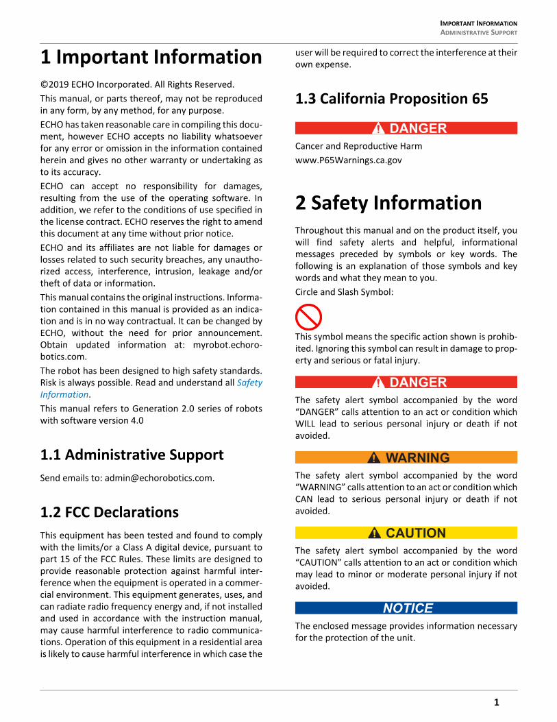
1 Important Information©2019 ECHO Incorporated. All Rights Reserved.This manual, or parts thereof, may not be reproducedin any form, by any method, for any purpose.ECHO has taken reasonable care in compiling this docu-ment, however ECHO accepts no liability whatsoeverfor any error or omission in the information containedherein and gives no other warranty or undertaking asto its accuracy.ECHO can accept no responsibility for damages,resulting from the use of the operating software. Inaddition, we refer to the conditions of use specified inthe license contract. ECHO reserves the right to amendthis document at any time without prior notice.ECHO and its affiliates are not liable for damages orlosses related to such security breaches, any unautho-rized access, interference, intrusion, leakage and/ortheft of data or information.This manual contains the original instructions. Informa-tion contained in this manual is provided as an indica-tion and is in no way contractual. It can be changed byECHO, without the need for prior announcement.Obtain updated information at: myrobot.echoro-botics.com.The robot has been designed to high safety standards.Risk is always possible. Read and understand all SafetyInformation.This manual refers to Generation 2.0 series of robotswith software version 4.0
1.1 Administrative SupportSend emails to: [email protected].
1.2 FCC DeclarationsThis equipment has been tested and found to complywith the limits/or a Class A digital device, pursuant topart 15 of the FCC Rules. These limits are designed toprovide reasonable protection against harmful inter-ference when the equipment is operated in a commer-cial environment. This equipment generates, uses, andcan radiate radio frequency energy and, if not installedand used in accordance with the instruction manual,may cause harmful interference to radio communica-tions. Operation of this equipment in a residential areais likely to cause harmful interference in which case the
user will be required to correct the interference at theirown expense.
1.3 California Proposition 65
Cancer and Reproductive Harmwww.P65Warnings.ca.gov
2 Safety InformationThroughout this manual and on the product itself, youwill find safety alerts and helpful, informationalmessages preceded by symbols or key words. Thefollowing is an explanation of those symbols and keywords and what they mean to you.Circle and Slash Symbol:
This symbol means the specific action shown is prohib-ited. Ignoring this symbol can result in damage to prop-erty and serious or fatal injury.
The safety alert symbol accompanied by the word“DANGER” calls attention to an act or condition whichWILL lead to serious personal injury or death if notavoided.
The safety alert symbol accompanied by the word“WARNING” calls attention to an act or condition whichCAN lead to serious personal injury or death if notavoided.
The safety alert symbol accompanied by the word“CAUTION” calls attention to an act or condition whichmay lead to minor or moderate personal injury if notavoided.
The enclosed message provides information necessaryfor the protection of the unit.
1
THEORY OF OPERATIONSAFETY SYMBOLS
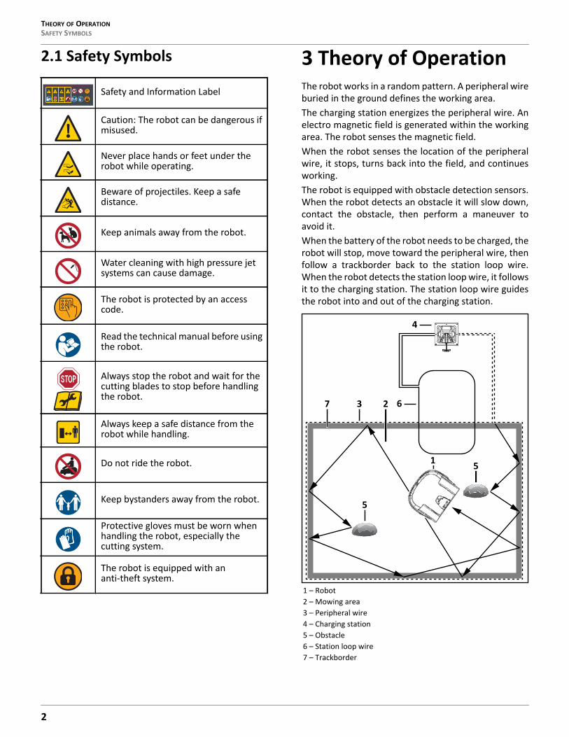
2.1 Safety Symbols 3 Theory of OperationThe robot works in a random pattern. A peripheral wireburied in the ground defines the working area.The charging station energizes the peripheral wire. Anelectro magnetic field is generated within the workingarea. The robot senses the magnetic field.When the robot senses the location of the peripheralwire, it stops, turns back into the field, and continuesworking.The robot is equipped with obstacle detection sensors.When the robot detects an obstacle it will slow down,contact the obstacle, then perform a maneuver toavoid it.When the battery of the robot needs to be charged, therobot will stop, move toward the peripheral wire, thenfollow a trackborder back to the station loop wire.When the robot detects the station loop wire, it followsit to the charging station. The station loop wire guidesthe robot into and out of the charging station.
Safety and Information Label
Caution: The robot can be dangerous if misused.
Never place hands or feet under the robot while operating.
Beware of projectiles. Keep a safe distance.
Keep animals away from the robot.
Water cleaning with high pressure jet systems can cause damage.
The robot is protected by an access code.
Read the technical manual before using the robot.
Always stop the robot and wait for the cutting blades to stop before handling the robot.
Always keep a safe distance from the robot while handling.
Do not ride the robot.
Keep bystanders away from the robot.
Protective gloves must be worn when handling the robot, especially the cutting system.
The robot is equipped with an anti-theft system.
1 – Robot2 – Mowing area3 – Peripheral wire4 – Charging station5 – Obstacle6 – Station loop wire7 – Trackborder
4
1
5
7 3 2
5
6
2
SYSTEM COMPONENTS ROBOT COMPONENTS
4 System Components 4.1 Robot Components
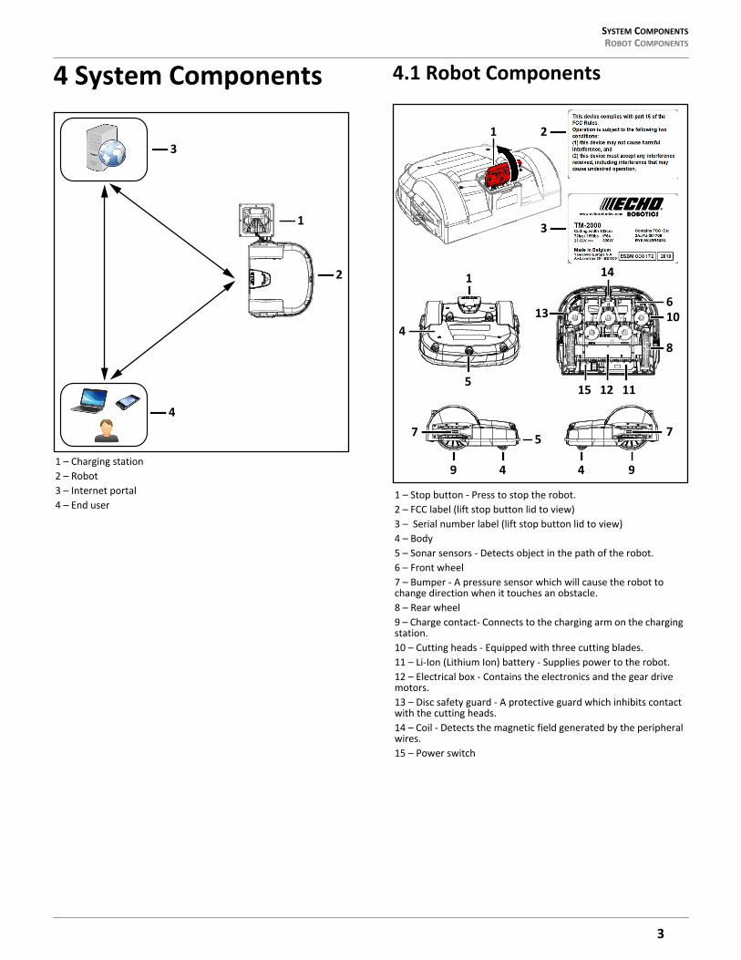
1 – Charging station2 – Robot3 – Internet portal4 – End user
3
1
2
4
1 – Stop button - Press to stop the robot.2 – FCC label (lift stop button lid to view)3 – Serial number label (lift stop button lid to view)4 – Body5 – Sonar sensors - Detects object in the path of the robot.6 – Front wheel7 – Bumper - A pressure sensor which will cause the robot to change direction when it touches an obstacle.8 – Rear wheel9 – Charge contact- Connects to the charging arm on the charging station.10 – Cutting heads - Equipped with three cutting blades.11 – Li-Ion (Lithium Ion) battery - Supplies power to the robot.12 – Electrical box - Contains the electronics and the gear drive motors.13 – Disc safety guard - A protective guard which inhibits contact with the cutting heads.14 – Coil - Detects the magnetic field generated by the peripheral wires.15 – Power switch
7
13
1
4
5
9 4
5
14
610
8
15 1112
4 9
7
1 2
3
3
SYSTEM COMPONENTSROBOT COMPONENTS
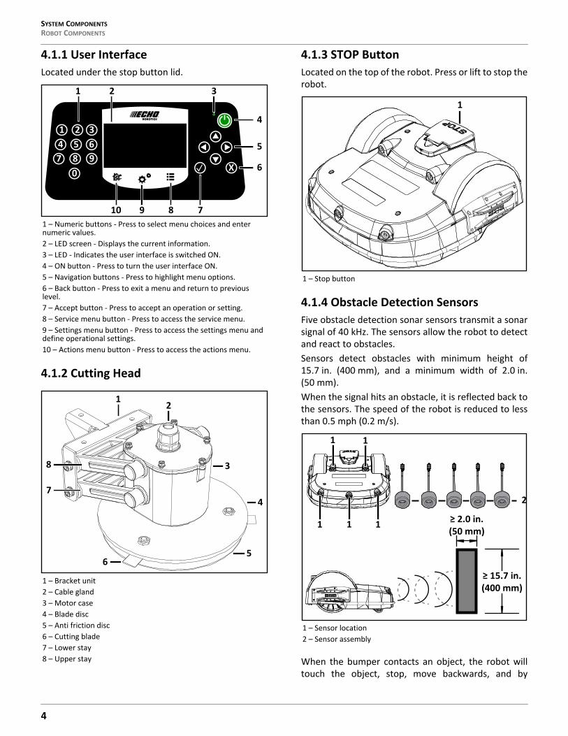
4.1.1 User InterfaceLocated under the stop button lid.
4.1.2 Cutting Head
4.1.3 STOP ButtonLocated on the top of the robot. Press or lift to stop therobot.
4.1.4 Obstacle Detection SensorsFive obstacle detection sonar sensors transmit a sonarsignal of 40 kHz. The sensors allow the robot to detectand react to obstacles.Sensors detect obstacles with minimum height of15.7 in. (400 mm), and a minimum width of 2.0 in.(50 mm).When the signal hits an obstacle, it is reflected back tothe sensors. The speed of the robot is reduced to lessthan 0.5 mph (0.2 m/s).
When the bumper contacts an object, the robot willtouch the object, stop, move backwards, and by
1 – Numeric buttons - Press to select menu choices and enter numeric values.2 – LED screen - Displays the current information.3 – LED - Indicates the user interface is switched ON.4 – ON button - Press to turn the user interface ON.5 – Navigation buttons - Press to highlight menu options.6 – Back button - Press to exit a menu and return to previous level.7 – Accept button - Press to accept an operation or setting.8 – Service menu button - Press to access the service menu.9 – Settings menu button - Press to access the settings menu and define operational settings.10 – Actions menu button - Press to access the actions menu.
1 – Bracket unit2 – Cable gland3 – Motor case4 – Blade disc5 – Anti friction disc6 – Cutting blade7 – Lower stay8 – Upper stay
31 26
80
4 57 9
X
4
1 2 3
5
6
10 9 8 7
12
5
3
4
6
7
8
1 – Stop button
1 – Sensor location2 – Sensor assembly
1
4
SYSTEM COMPONENTS ROBOT COMPONENTS
default, turn between 60° and 120°, then continuemoving forward.
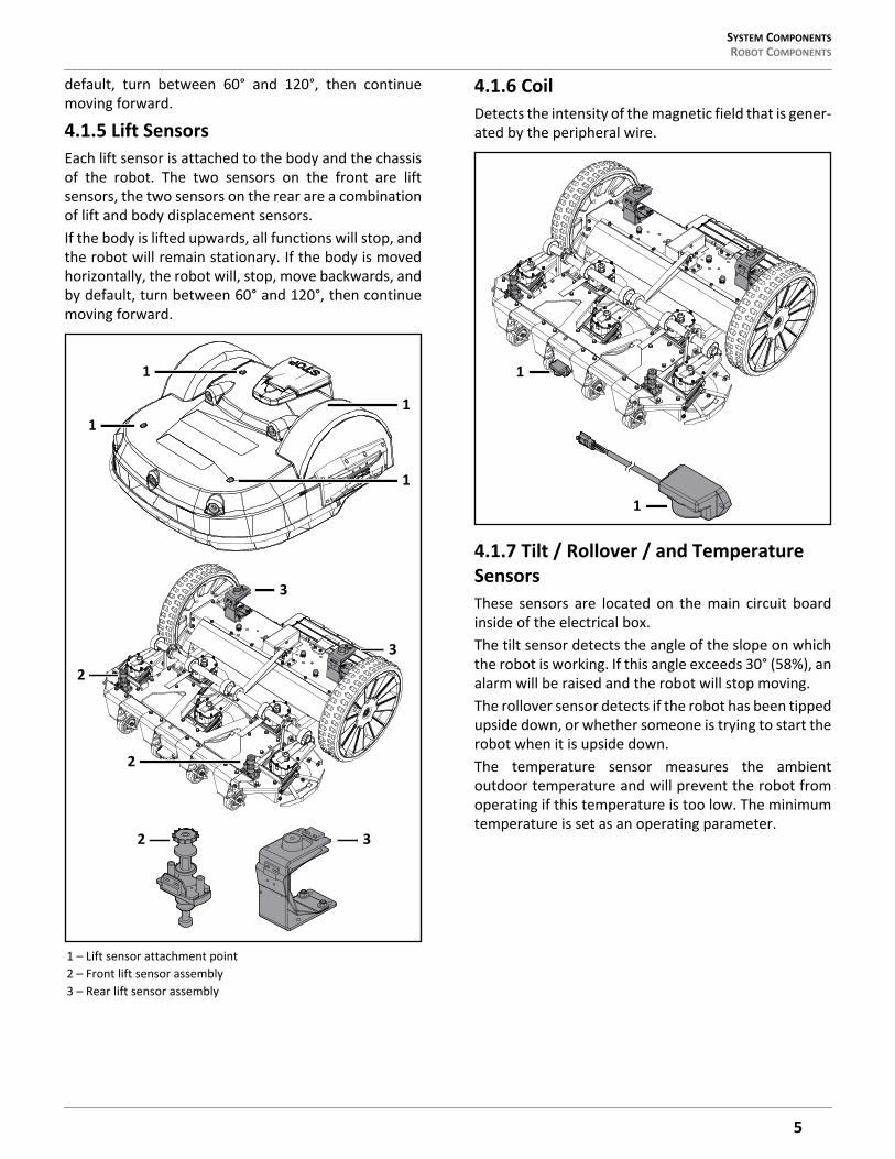
4.1.5 Lift SensorsEach lift sensor is attached to the body and the chassisof the robot. The two sensors on the front are liftsensors, the two sensors on the rear are a combinationof lift and body displacement sensors.If the body is lifted upwards, all functions will stop, andthe robot will remain stationary. If the body is movedhorizontally, the robot will, stop, move backwards, andby default, turn between 60° and 120°, then continuemoving forward.
4.1.6 CoilDetects the intensity of the magnetic field that is gener-ated by the peripheral wire.
4.1.7 Tilt / Rollover / and Temperature SensorsThese sensors are located on the main circuit boardinside of the electrical box.The tilt sensor detects the angle of the slope on whichthe robot is working. If this angle exceeds 30° (58%), analarm will be raised and the robot will stop moving.The rollover sensor detects if the robot has been tippedupside down, or whether someone is trying to start therobot when it is upside down.The temperature sensor measures the ambientoutdoor temperature and will prevent the robot fromoperating if this temperature is too low. The minimumtemperature is set as an operating parameter.
1 – Lift sensor attachment point2 – Front lift sensor assembly3 – Rear lift sensor assembly
1
1
1
1
3
3
2
2 3
2
1
1
5
HOW THE ROBOT WORKSTHE CHARGING STATION
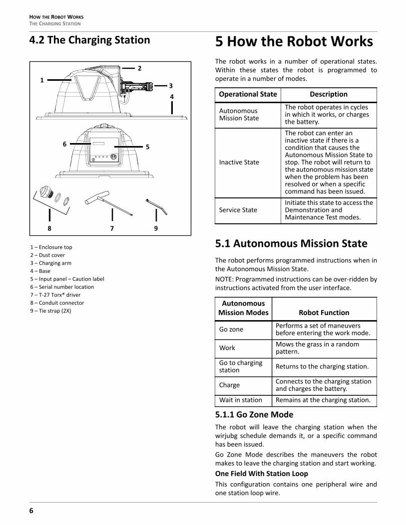
4.2 The Charging Station 5 How the Robot WorksThe robot works in a number of operational states.Within these states the robot is programmed tooperate in a number of modes.
5.1 Autonomous Mission StateThe robot performs programmed instructions when inthe Autonomous Mission State.NOTE: Programmed instructions can be over-ridden byinstructions activated from the user interface.
5.1.1 Go Zone ModeThe robot will leave the charging station when thewirjubg schedule demands it, or a specific commandhas been issued.Go Zone Mode describes the maneuvers the robotmakes to leave the charging station and start working.One Field With Station LoopThis configuration contains one peripheral wire andone station loop wire.
1 – Enclosure top2 – Dust cover3 – Charging arm4 – Base5 – Input panel – Caution label6 – Serial number location7 – T-27 Torx® driver8 – Conduit connector9 – Tie strap (2X)
2
6
134
5
98 7
Operational State Description
Autonomous Mission State
The robot operates in cycles in which it works, or charges the battery.
Inactive State
The robot can enter an inactive state if there is a condition that causes the Autonomous Mission State to stop. The robot will return to the autonomous mission state when the problem has been resolved or when a specific command has been issued.
Service StateInitiate this state to access the Demonstration and Maintenance Test modes.
Autonomous Mission Modes Robot Function
Go zone Performs a set of maneuvers before entering the work mode.
Work Mows the grass in a random pattern.
Go to charging station Returns to the charging station.
Charge Connects to the charging station and charges the battery.
Wait in station Remains at the charging station.
6
HOW THE ROBOT WORKS AUTONOMOUS MISSION STATE
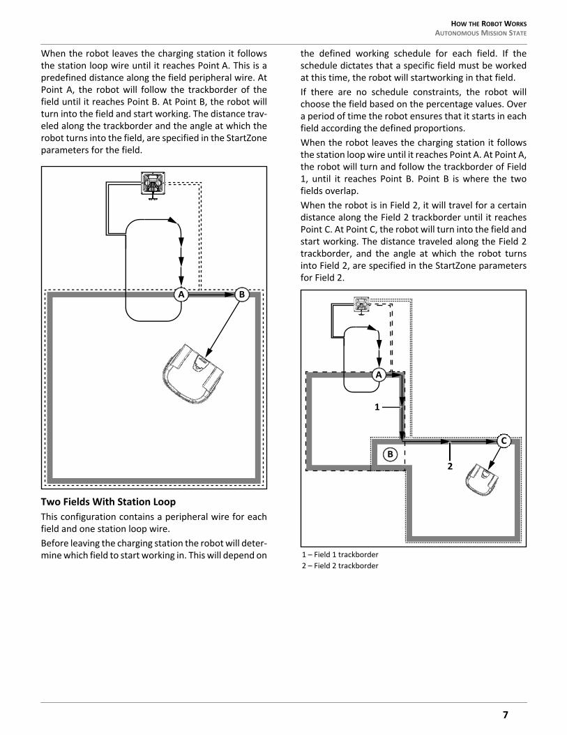
When the robot leaves the charging station it followsthe station loop wire until it reaches Point A. This is apredefined distance along the field peripheral wire. AtPoint A, the robot will follow the trackborder of thefield until it reaches Point B. At Point B, the robot willturn into the field and start working. The distance trav-eled along the trackborder and the angle at which therobot turns into the field, are specified in the StartZoneparameters for the field.
Two Fields With Station LoopThis configuration contains a peripheral wire for eachfield and one station loop wire.Before leaving the charging station the robot will deter-mine which field to start working in. This will depend on
the defined working schedule for each field. If theschedule dictates that a specific field must be workedat this time, the robot will startworking in that field.If there are no schedule constraints, the robot willchoose the field based on the percentage values. Overa period of time the robot ensures that it starts in eachfield according the defined proportions.When the robot leaves the charging station it followsthe station loop wire until it reaches Point A. At Point A,the robot will turn and follow the trackborder of Field1, until it reaches Point B. Point B is where the twofields overlap.When the robot is in Field 2, it will travel for a certaindistance along the Field 2 trackborder until it reachesPoint C. At Point C, the robot will turn into the field andstart working. The distance traveled along the Field 2trackborder, and the angle at which the robot turnsinto Field 2, are specified in the StartZone parametersfor Field 2.
A B
1 – Field 1 trackborder2 – Field 2 trackborder
CB
A
2
1
7
HOW THE ROBOT WORKSAUTONOMOUS MISSION STATE
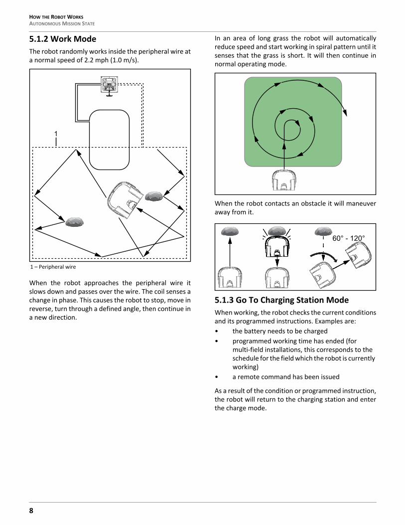
5.1.2 Work ModeThe robot randomly works inside the peripheral wire ata normal speed of 2.2 mph (1.0 m/s).
When the robot approaches the peripheral wire itslows down and passes over the wire. The coil senses achange in phase. This causes the robot to stop, move inreverse, turn through a defined angle, then continue ina new direction.
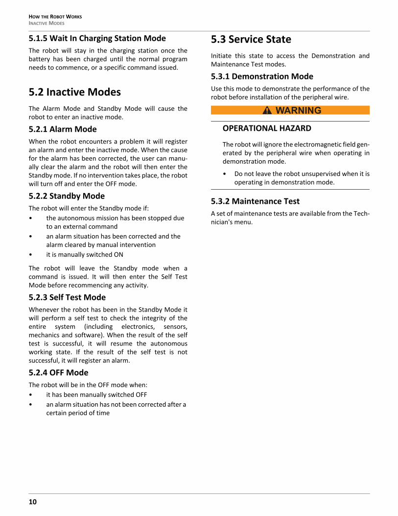
In an area of long grass the robot will automaticallyreduce speed and start working in spiral pattern until itsenses that the grass is short. It will then continue innormal operating mode.
When the robot contacts an obstacle it will maneuveraway from it.
5.1.3 Go To Charging Station ModeWhen working, the robot checks the current conditionsand its programmed instructions. Examples are:• the battery needs to be charged• programmed working time has ended (for
multi-field installations, this corresponds to the schedule for the field which the robot is currently working)
• a remote command has been issued
As a result of the condition or programmed instruction,the robot will return to the charging station and enterthe charge mode.
1 – Peripheral wire
1
60° - 120°
8

HOW THE ROBOT WORKS AUTONOMOUS MISSION STATE
One Field With Station Loop Two Fields With Station LoopAt Point A, the robot returns to the charging station. Itmoves towards the Field 2 peripheral wire and followsthe Field 2 trackborder until it reaches Point B. This isthe area where both fields overlap. It then follows theField 1 trackborder until it reaches Point C. This iswhere the Field 1 peripheral wire and station loop wireoverlap. Next, the robot follows the station loop wireuntil it docks at the charging station.
5.1.4 Charge ModeIn Charge Mode the robot will dock and remain in thecharging station until the battery is fully charged.The next operations that will be performed depend onprogramming and external conditions.The robot will remain at the charging station if: • rest periods have been scheduled• it has been programmed to stay in the station• the temperature is too low
Otherwise, it will continue with the scheduledprogram.The robot will remain at the charging station once thebattery has been charged until: • the normal program needs to commence• a specific command is issued
1 – Trackborder2 – Peripheral wire
A
B
1 2
1 – Field 2 / Field 2 peripheral wire2 – Field 2 trackborder3 – Field 1 trackborder
A
B
1
C
2
3
9
HOW THE ROBOT WORKSINACTIVE MODES
5.1.5 Wait In Charging Station ModeThe robot will stay in the charging station once thebattery has been charged until the normal programneeds to commence, or a specific command issued.
5.2 Inactive ModesThe Alarm Mode and Standby Mode will cause therobot to enter an inactive mode.
5.2.1 Alarm ModeWhen the robot encounters a problem it will registeran alarm and enter the inactive mode. When the causefor the alarm has been corrected, the user can manu-ally clear the alarm and the robot will then enter theStandby mode. If no intervention takes place, the robotwill turn off and enter the OFF mode.
5.2.2 Standby ModeThe robot will enter the Standby mode if:• the autonomous mission has been stopped due
to an external command• an alarm situation has been corrected and the
alarm cleared by manual intervention• it is manually switched ON
The robot will leave the Standby mode when acommand is issued. It will then enter the Self TestMode before recommencing any activity.
5.2.3 Self Test ModeWhenever the robot has been in the Standby Mode itwill perform a self test to check the integrity of theentire system (including electronics, sensors,mechanics and software). When the result of the selftest is successful, it will resume the autonomousworking state. If the result of the self test is notsuccessful, it will register an alarm.
5.2.4 OFF ModeThe robot will be in the OFF mode when:• it has been manually switched OFF• an alarm situation has not been corrected after a
certain period of time
5.3 Service StateInitiate this state to access the Demonstration andMaintenance Test modes.
5.3.1 Demonstration ModeUse this mode to demonstrate the performance of therobot before installation of the peripheral wire.
OPERATIONAL HAZARD
The robot will ignore the electromagnetic field gen-erated by the peripheral wire when operating indemonstration mode.
• Do not leave the robot unsupervised when it isoperating in demonstration mode.
5.3.2 Maintenance TestA set of maintenance tests are available from the Tech-nician's menu.
10
INSTALLATION STATION LOOP WIRE INSTALLATION
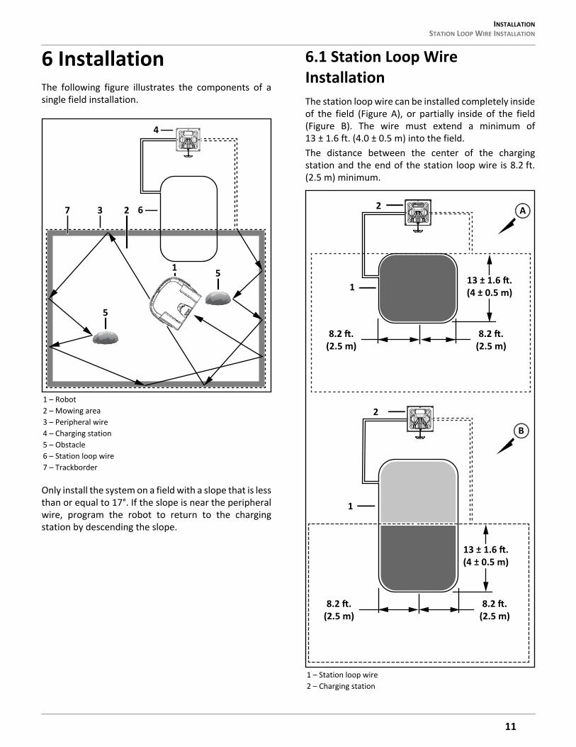
6 InstallationThe following figure illustrates the components of asingle field installation.
Only install the system on a field with a slope that is lessthan or equal to 17°. If the slope is near the peripheralwire, program the robot to return to the chargingstation by descending the slope.
6.1 Station Loop Wire InstallationThe station loop wire can be installed completely insideof the field (Figure A), or partially inside of the field(Figure B). The wire must extend a minimum of13 ± 1.6 ft. (4.0 ± 0.5 m) into the field.The distance between the center of the chargingstation and the end of the station loop wire is 8.2 ft.(2.5 m) minimum.
1 – Robot2 – Mowing area3 – Peripheral wire4 – Charging station5 – Obstacle6 – Station loop wire7 – Trackborder
4
1
5
7 3 2
5
6
1 – Station loop wire2 – Charging station
2
1
2
1
A
B
(2.5 m)
(4 ± 0.5 m)
(2.5 m)
(2.5 m)
(4 ± 0.5 m)
(2.5 m)
11
INSTALLATIONPERIPHERAL WIRE INSTALLATION
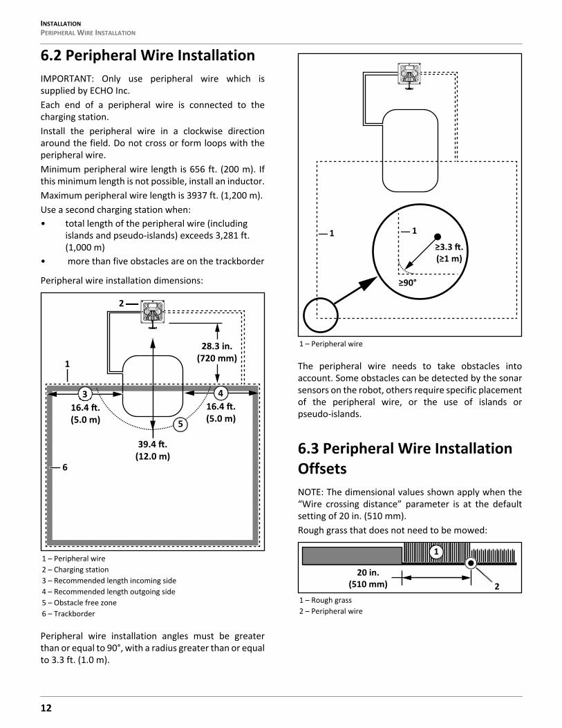
6.2 Peripheral Wire InstallationIMPORTANT: Only use peripheral wire which issupplied by ECHO Inc.Each end of a peripheral wire is connected to thecharging station.Install the peripheral wire in a clockwise directionaround the field. Do not cross or form loops with theperipheral wire.Minimum peripheral wire length is 656 ft. (200 m). Ifthis minimum length is not possible, install an inductor.Maximum peripheral wire length is 3937 ft. (1,200 m).Use a second charging station when:• total length of the peripheral wire (including
islands and pseudo-islands) exceeds 3,281 ft. (1,000 m)
• more than five obstacles are on the trackborder
Peripheral wire installation dimensions:
Peripheral wire installation angles must be greaterthan or equal to 90°, with a radius greater than or equalto 3.3 ft. (1.0 m).
The peripheral wire needs to take obstacles intoaccount. Some obstacles can be detected by the sonarsensors on the robot, others require specific placementof the peripheral wire, or the use of islands orpseudo-islands.
6.3 Peripheral Wire Installation OffsetsNOTE: The dimensional values shown apply when the“Wire crossing distance” parameter is at the defaultsetting of 20 in. (510 mm).Rough grass that does not need to be mowed:
1 – Peripheral wire2 – Charging station3 – Recommended length incoming side4 – Recommended length outgoing side5 – Obstacle free zone6 – Trackborder
(5.0 m) (5.0 m)
(12.0 m)
28.3 in.(720 mm)
2
1
3 4
5
6
1 – Peripheral wire
1 – Rough grass2 – Peripheral wire
1
220 in.
(510 mm)
12

INSTALLATION SITES CONTAINING NARROW STRAITS
Raised hard landscaping:
Hard landscaping level with grass:
NOTE: A path that crosses the field to be mowed shouldbe level with the grass.Lawn-level planting (e.g. flower bed).
6.4 Sites Containing Narrow StraitsThese sites require specific installation of the periph-eral wire.The required minimum width of the strait, depends onthe length of the strait. If this minimum width is notavailable when the robot is in Zone B, it will not be ableto pass through the strait and return to the chargingstation. In this case, installation of an additionalcharging station in Zone B is required.
The table below presents the minimum distancebetween wires required to enable the robot to followits trackborder from Zone B through the strait andreturn to the charging station in Zone A.
1 – Terrace / Path / Wall2 – Peripheral wire3 – Area not mowed
1 – Terrace / Path2 – Peripheral wire
1 – Flower bed2 – Peripheral wire3 – Area not mowed
1 3
229.5 in.
(750 mm)
9.5 in.(240 mm)
1
211.8 in.(300 mm)
2
1
3
29.5 in.(750 mm)
3.5 in.(90 mm)
1 – Narrow strait2 – Peripheral wire3 – Minimum distance between peripheral wire4 – Length of strait
2
Zone AZone B31
4
13
INSTALLATIONSITES WITH LONG LANES
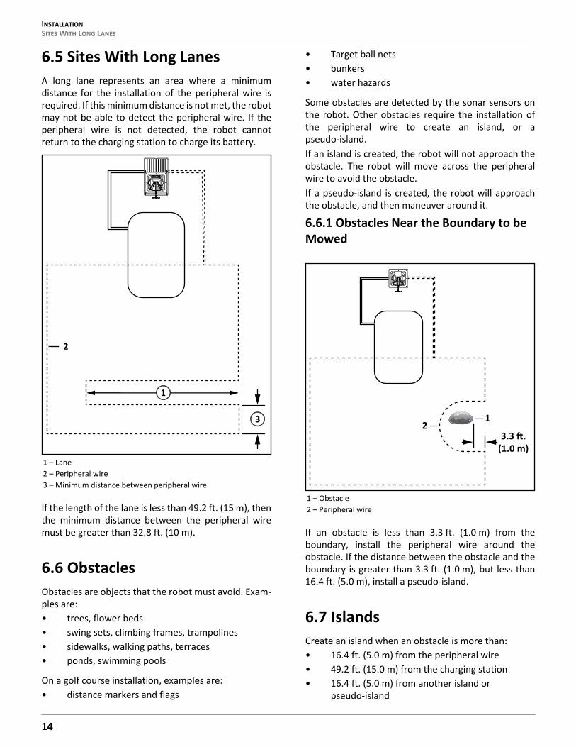
6.5 Sites With Long LanesA long lane represents an area where a minimumdistance for the installation of the peripheral wire isrequired. If this minimum distance is not met, the robotmay not be able to detect the peripheral wire. If theperipheral wire is not detected, the robot cannotreturn to the charging station to charge its battery.
If the length of the lane is less than 49.2 ft. (15 m), thenthe minimum distance between the peripheral wiremust be greater than 32.8 ft. (10 m).
6.6 ObstaclesObstacles are objects that the robot must avoid. Exam-ples are:• trees, flower beds• swing sets, climbing frames, trampolines• sidewalks, walking paths, terraces• ponds, swimming pools
On a golf course installation, examples are:• distance markers and flags
• Target ball nets• bunkers• water hazards
Some obstacles are detected by the sonar sensors onthe robot. Other obstacles require the installation ofthe peripheral wire to create an island, or apseudo-island.If an island is created, the robot will not approach theobstacle. The robot will move across the peripheralwire to avoid the obstacle.If a pseudo-island is created, the robot will approachthe obstacle, and then maneuver around it.
6.6.1 Obstacles Near the Boundary to be Mowed
If an obstacle is less than 3.3 ft. (1.0 m) from theboundary, install the peripheral wire around theobstacle. If the distance between the obstacle and theboundary is greater than 3.3 ft. (1.0 m), but less than16.4 ft. (5.0 m), install a pseudo-island.
6.7 IslandsCreate an island when an obstacle is more than:• 16.4 ft. (5.0 m) from the peripheral wire• 49.2 ft. (15.0 m) from the charging station• 16.4 ft. (5.0 m) from another island or
pseudo-island
1 – Lane2 – Peripheral wire3 – Minimum distance between peripheral wire
2
1
3
1 – Obstacle2 – Peripheral wire
21
(1.0 m)
14
INSTALLATION WATER OBSTACLE
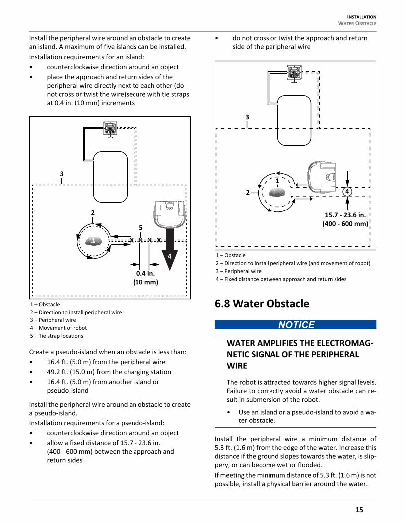
Install the peripheral wire around an obstacle to createan island. A maximum of five islands can be installed.Installation requirements for an island:• counterclockwise direction around an object• place the approach and return sides of the
peripheral wire directly next to each other (do not cross or twist the wire)secure with tie straps at 0.4 in. (10 mm) increments
Create a pseudo-island when an obstacle is less than:• 16.4 ft. (5.0 m) from the peripheral wire• 49.2 ft. (15.0 m) from the charging station• 16.4 ft. (5.0 m) from another island or
pseudo-island
Install the peripheral wire around an obstacle to createa pseudo-island.Installation requirements for a pseudo-island:• counterclockwise direction around an object• allow a fixed distance of 15.7 - 23.6 in.
(400 - 600 mm) between the approach and return sides
• do not cross or twist the approach and return side of the peripheral wire
6.8 Water Obstacle
WATER AMPLIFIES THE ELECTROMAG-NETIC SIGNAL OF THE PERIPHERAL WIRE
The robot is attracted towards higher signal levels.Failure to correctly avoid a water obstacle can re-sult in submersion of the robot.
• Use an island or a pseudo-island to avoid a wa-ter obstacle.
Install the peripheral wire a minimum distance of5.3 ft. (1.6 m) from the edge of the water. Increase thisdistance if the ground slopes towards the water, is slip-pery, or can become wet or flooded.If meeting the minimum distance of 5.3 ft. (1.6 m) is notpossible, install a physical barrier around the water.
1 – Obstacle2 – Direction to install peripheral wire3 – Peripheral wire4 – Movement of robot5 – Tie strap locations
x x x x
2
5
3
4
1
0.4 in.(10 mm)
1 – Obstacle2 – Direction to install peripheral wire (and movement of robot)3 – Peripheral wire4 – Fixed distance between approach and return sides
2
3
41
15.7 - 23.6 in.(400 - 600 mm)
15
CONFIGURATIONSLOPED FIELDS
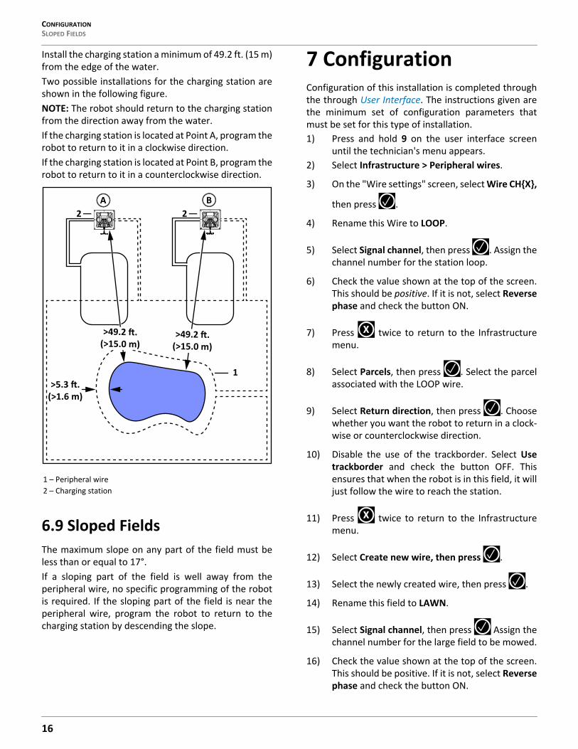
Install the charging station a minimum of 49.2 ft. (15 m)from the edge of the water.Two possible installations for the charging station areshown in the following figure.NOTE: The robot should return to the charging stationfrom the direction away from the water.If the charging station is located at Point A, program therobot to return to it in a clockwise direction. If the charging station is located at Point B, program therobot to return to it in a counterclockwise direction.
6.9 Sloped FieldsThe maximum slope on any part of the field must beless than or equal to 17°.If a sloping part of the field is well away from theperipheral wire, no specific programming of the robotis required. If the sloping part of the field is near theperipheral wire, program the robot to return to thecharging station by descending the slope.
7 ConfigurationConfiguration of this installation is completed throughthe through User Interface. The instructions given arethe minimum set of configuration parameters thatmust be set for this type of installation.1) Press and hold 9 on the user interface screen
until the technician's menu appears.2) Select Infrastructure > Peripheral wires.
3) On the "Wire settings" screen, select Wire CH{X},
then press .
4) Rename this Wire to LOOP.
5) Select Signal channel, then press . Assign thechannel number for the station loop.
6) Check the value shown at the top of the screen.This should be positive. If it is not, select Reversephase and check the button ON.
7) Press twice to return to the Infrastructuremenu.
8) Select Parcels, then press . Select the parcelassociated with the LOOP wire.
9) Select Return direction, then press . Choosewhether you want the robot to return in a clock-wise or counterclockwise direction.
10) Disable the use of the trackborder. Select Usetrackborder and check the button OFF. Thisensures that when the robot is in this field, it willjust follow the wire to reach the station.
11) Press twice to return to the Infrastructuremenu.
12) Select Create new wire, then press .
13) Select the newly created wire, then press .
14) Rename this field to LAWN.
15) Select Signal channel, then press Assign thechannel number for the large field to be mowed.
16) Check the value shown at the top of the screen.This should be positive. If it is not, select Reversephase and check the button ON.
1 – Peripheral wire2 – Charging station
A B
1
2 2
(>1.6 m)
(>15.0 m) (>15.0 m)
X
X
16

CONFIGURATION SLOPED FIELDS
17) Press twice to return to the Infrastructuremenu.
18) Select Parcels, then press . Select the parcelassociated with the LAWN wire.
19) Set the Return direction to the same as above.
20) Select Use trackborder and check the button ON.This ensures that when the robot is in this field, itwill follow the trackborder until it reaches theLOOP field.
21) Select Neighboring parcels, then press .Check the button next to the LOOP parcel.
22) Press to exit this menu.
23) Select Edit parcels percentage, then press .Set the value to 100% for the lawn parcel.
24) Press to return to the Infrastructure menu.
25) Select Infrastructure > Stations > Create new
station, then press .
26) A name is generated that you can modify if youwant.
27) Select Connected to parcels, then press .Alist of parcels is presented. Select the parcelinside the LOOP wire and check the button ON.
28) Select Station inside parcel's wire. Check thebutton ON if the station is inside the LOOP wire.In the example shown above it is outside thewire.
Connect a total of one station loop and two peripheralwires to a single charging station. • Each field is defined by a peripheral wire that
starts and ends at the charging station.• Each peripheral wire is assigned to a different
signal channel in the charging station.• The charging station must contain one signal
channel board for every peripheral wire required.
• The area inside of each peripheral wire is defined as a field. Each peripheral wire must overlap with its neighboring one.
• Each pair of wires which overlap must be desig-nated as neighboring fields.
Station loop wire 1 / Field 1, is the small wire to whichthe charging station is connected. In this example itoverlaps the larger peripheral wires and fields. When inthis field, the robot will not use the trackborder, it willfollow the station loop wire to enter the chargingstation.All three fields are neighbors to each other.The overlap area is a transition zone used to connectthe main working areas of the fields.The proportion of time that the robot spends workingin fields 1 and 2 is determined by the percentage valuesassigned to the corresponding fields. For the stationloop field, the percentage can be set to 0.The elementsof a multiple field installation are shown in thefollowing figure.
X
X
X
1 – Station loop wire / Field 12 – Peripheral wire 2 / Field 23 – Peripheral wire 3 / Field 34 – Overlap area
4
1
2 3
2 3
17
CONFIGURATIONOVERLAPS
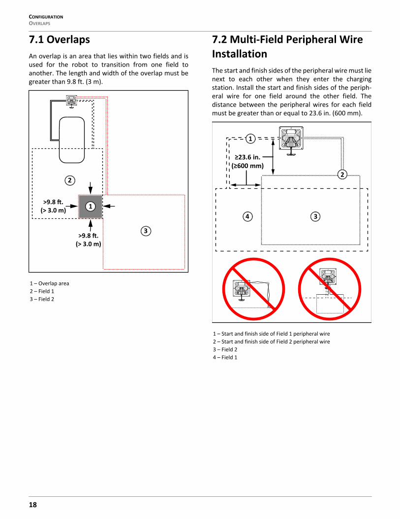
7.1 OverlapsAn overlap is an area that lies within two fields and isused for the robot to transition from one field toanother. The length and width of the overlap must begreater than 9.8 ft. (3 m).
7.2 Multi-Field Peripheral Wire InstallationThe start and finish sides of the peripheral wire must lienext to each other when they enter the chargingstation. Install the start and finish sides of the periph-eral wire for one field around the other field. Thedistance between the peripheral wires for each fieldmust be greater than or equal to 23.6 in. (600 mm).
1 – Overlap area2 – Field 13 – Field 2
2
3
1(> 3.0 m)
(> 3.0 m)
1 – Start and finish side of Field 1 peripheral wire2 – Start and finish side of Field 2 peripheral wire3 – Field 24 – Field 1
4
1
18
CONFIGURATION CONFIGURATION
7.3 ConfigurationOnce the peripheral wire(s) and the charging stationhave been set in place, the installation needs to beconfigured.Access the User Interface to configure single andmulti-field installations.
7.3.1 General Configuration Procedure Using a Station Loop1) Open the technician's menu.2) Select Infrastructure > Peripheral wires and
create the required number of wires for theinstallation.
3) For each wire assign the channel number andcheck the reverse phase.
4) Select Infrastructure > Parcels.
5) Define the properties of the parcel that is associ-ated with each wire.
6) Create new parcels if necessary.
7) If the installation is a multi-field installation,define the start zone parameters for a parcel.
8) Select Infrastructure > Stations.
9) Select Create new station.
10) Select Connected to parcels and connect thestation to the loop parcel.
11) Select Station Inside Parcel's Wire and specifywhether the station is on the inside or theoutside of the station loop wire.
7.3.2 Start ZonesStart zones define where and how the robot startsworking.• A start zone is defined for a parcel.• Multiple start zones can be defined for the same
wire/parcel.
The Start Zone screen displays the following:
List of defined start zonesFor each one the line below shows some characteristicsof the zone.
Create new start zoneEnables you to create a new zone with all the proper-ties listed below.
7.3.3 Start Zone Properties
Following fromThis option appears if you are defining a start zone forstation with a positioning beacon. It specifies the parcelin which the start zone is implemented.For a multi-field installation, you can specify thespecific parcel.Default means coming from any other parcel.
Coming fromThis option appears if you are defining a start zone fora parcel.It defines the parcel preceding the one in which thestart zone will be implemented.
Edit percentageAllows you to edit the percentages applied to differentparcels.If only one parcel is defined this value must be set to100%.Do not edit the percentage until more than one startzone has been defined.
DirectionThis specifies the clockwise or counterclockwise direc-tion the robot will take to move along the trackborderafter leaving the charging station.When the robot leaves the charging station, it followsthe station loop wire for a predefined distance until itarrives in the trackborder of the field, it then takes thespecified direction.
19
CONFIGURATIONCONFIGURATION
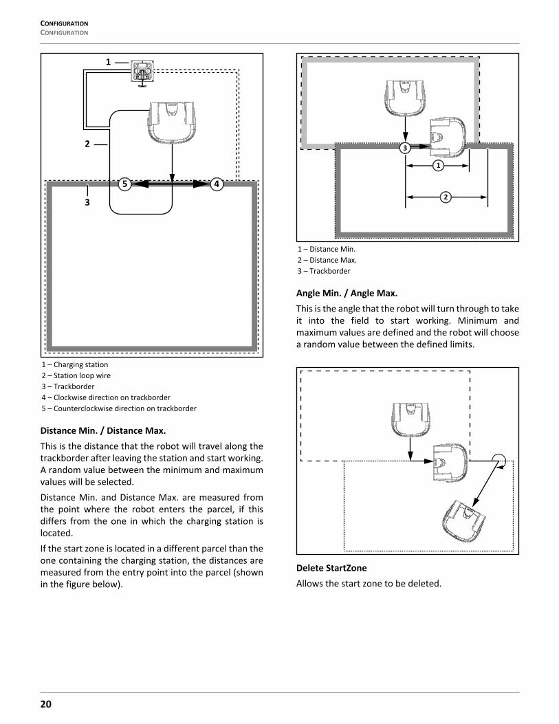
Distance Min. / Distance Max.This is the distance that the robot will travel along thetrackborder after leaving the station and start working.A random value between the minimum and maximumvalues will be selected.Distance Min. and Distance Max. are measured fromthe point where the robot enters the parcel, if thisdiffers from the one in which the charging station islocated.If the start zone is located in a different parcel than theone containing the charging station, the distances aremeasured from the entry point into the parcel (shownin the figure below).
Angle Min. / Angle Max.This is the angle that the robot will turn through to takeit into the field to start working. Minimum andmaximum values are defined and the robot will choosea random value between the defined limits.
Delete StartZoneAllows the start zone to be deleted.
1 – Charging station2 – Station loop wire3 – Trackborder4 – Clockwise direction on trackborder5 – Counterclockwise direction on trackborder
1
5
3
4
2
1 – Distance Min.2 – Distance Max.3 – Trackborder
1
2
3
20
CONFIGURATION CONFIGURATION EXAMPLES
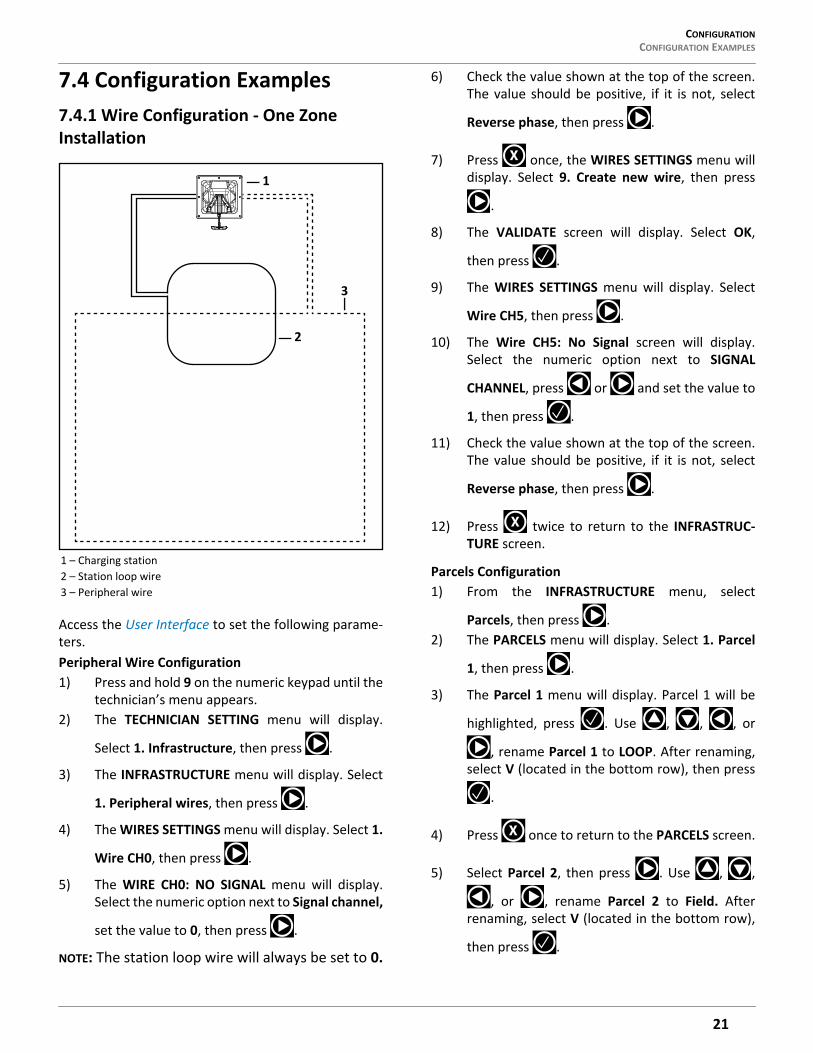
7.4 Configuration Examples7.4.1 Wire Configuration - One Zone Installation
Access the User Interface to set the following parame-ters.Peripheral Wire Configuration1) Press and hold 9 on the numeric keypad until the
technician’s menu appears.2) The TECHNICIAN SETTING menu will display.
Select 1. Infrastructure, then press .
3) The INFRASTRUCTURE menu will display. Select
1. Peripheral wires, then press .
4) The WIRES SETTINGS menu will display. Select 1.
Wire CH0, then press .
5) The WIRE CH0: NO SIGNAL menu will display.Select the numeric option next to Signal channel,
set the value to 0, then press .
NOTE: The station loop wire will always be set to 0.
6) Check the value shown at the top of the screen.The value should be positive, if it is not, select
Reverse phase, then press .
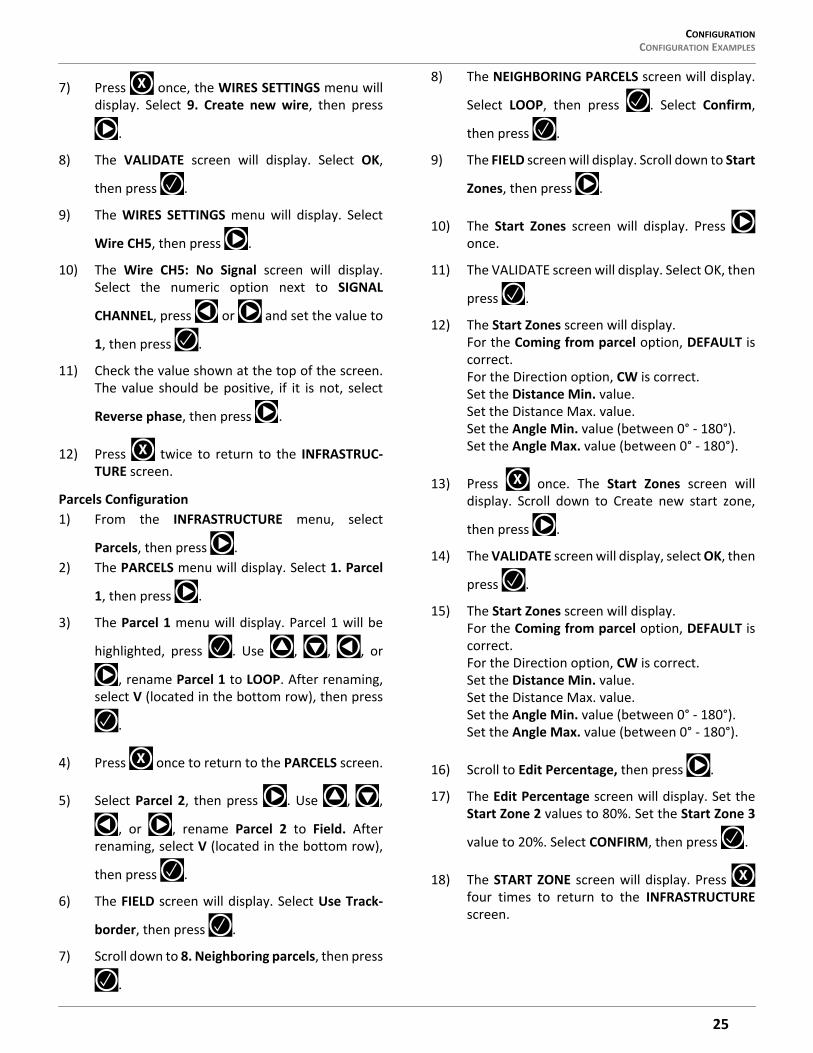
7) Press once, the WIRES SETTINGS menu willdisplay. Select 9. Create new wire, then press
.
8) The VALIDATE screen will display. Select OK,
then press .
9) The WIRES SETTINGS menu will display. Select
Wire CH5, then press .
10) The Wire CH5: No Signal screen will display.Select the numeric option next to SIGNAL
CHANNEL, press or and set the value to
1, then press .
11) Check the value shown at the top of the screen.The value should be positive, if it is not, select
Reverse phase, then press .
12) Press twice to return to the INFRASTRUC-TURE screen.
Parcels Configuration1) From the INFRASTRUCTURE menu, select
Parcels, then press .2) The PARCELS menu will display. Select 1. Parcel
1, then press .
3) The Parcel 1 menu will display. Parcel 1 will be
highlighted, press . Use , , , or
, rename Parcel 1 to LOOP. After renaming,select V (located in the bottom row), then press
.
4) Press once to return to the PARCELS screen.
5) Select Parcel 2, then press . Use , ,
, or , rename Parcel 2 to Field. Afterrenaming, select V (located in the bottom row),
then press .
1 – Charging station2 – Station loop wire3 – Peripheral wire
1
2
3
X
X
X
21
CONFIGURATIONCONFIGURATION EXAMPLES
6) The FIELD screen will display. Select Use Track-
border, then press .
7) Scroll down to 8. Neighboring parcels, then press
.
8) The NEIGHBORING PARCELS screen will display.
Select LOOP, then press . Select Confirm,
then press .
9) The FIELD screen will display. Press twice toreturn to the INFRASTRUCTURE screen.
Station Configuration
1) Select 3. Stations, then press .
2) Select 9. Create manual station, then press .
3) The VALIDATE screen will display. Select OK,
then press .
4) The Manual Station 1 screen will display. Select
Connected to parcels, then press .
5) The VALIDATE screen will display. Select OK,
then press .
6) The Connected Parcels screen will display. Theoption for Wire CH0 will be highlighted. Press
to change it to LOOP, then press .
7) Press once to return to the Manual Stationscreen.
8) Select Station inside parcel’s wire. Press ifthe charging station is inside of the station loopwire.
9) Press twice to return to the INFRASTRUC-TURE screen.
10) Press twice, the Waiting for new missionscreen will display.
11) Press once, the SERVICE SETTINGS screen
will display. Select 3. Operations, then press .
12) The OPERATIONS screen will display. Select Edit
parcels percentage, then press .
13) The PARCELS PERCENTAGE screen will display.Select the numeric option next to LOOP, set thenumber to O. Select the numeric option next toFIELD, set the number to100. Select CONFIRM,
then press .
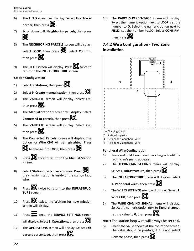
7.4.2 Wire Configuration - Two Zone Installation
Peripheral Wire Configuration1) Press and hold 9 on the numeric keypad until the
technician’s menu appears.2) The TECHNICIAN SETTING menu will display.
Select 1. Infrastructure, then press .
3) The INFRASTRUCTURE menu will display. Select
1. Peripheral wires, then press .
4) The WIRES SETTINGS menu will display. Select 1.
Wire CH0, then press .
5) The WIRE CH0: NO SIGNAL menu will display.Select the numeric option next to Signal channel,
set the value to 0, then press .
NOTE: The station loop wire will always be set to 0.6) Check the value shown at the top of the screen.
The value should be positive, if it is not, select
Reverse phase, then press .
X
X
X
X
1 – Charging station2 – Station loop wire3 – Field Zone 1 peripheral wire4 – Field Zone 2 peripheral wire
2
3 4
1
22
CONFIGURATION CONFIGURATION EXAMPLES
7) Press once, the WIRES SETTINGS menu willdisplay. Select 9. Create new wire, then press
.
8) The VALIDATE screen will display. Select OK,
then press .
9) The WIRES SETTINGS menu will display. Select
Wire CH5, then press .
10) The Wire CH5: No Signal screen will display.Select the numeric option next to SIGNAL
CHANNEL, press or and set the value to
1, then press .
11) Check the value shown at the top of the screen.The value should be positive, if it is not, select
Reverse phase, then press .
12) Press once, the WIRES SETTINGS menu willdisplay. Select 9. Create new wire, then press
13) The VALIDATE screen will display. Select OK,
then press .
14) The WIRES SETTINGS menu will display. Select
Wire CH5, then press .
15) The Wire CH5: No Signal screen will display.Select the numeric option next to SIGNAL
CHANNEL, press or and set the value to
2, then press .
16) Check the value shown at the top of the screen.The value should be positive, if it is not, select
Reverse phase, then press
17) Press twice to return to the INFRASTRUC-TURE screen.
Parcels Configuration1) From the INFRASTRUCTURE screen, select
Parcels, then press .2) The PARCELS menu will display. Select 1. Parcel
1, then press .
3) The Parcel 1 menu will display. Parcel 1 will be
highlighted, press . Use , , , or
, rename Parcel 1 to LOOP. After renaming,select V (located in the bottom row), then press
.
4) Press once to return to the PARCELS screen.
5) Select Parcel 2, then press . Use , ,
, or , rename Parcel 2 to Field 1. Afterrenaming, select V (located in the bottom row),
then press .
6) The FIELD 1screen will display. Select Use Track-
border, then press .
7) Press once to return to the PARCELS screen.
8) Select Parcel 3, then press . Use , ,
, or , rename Parcel 3 to Field 2. Afterrenaming, select V (located in the bottom row),
then press .
9) The FIELD 2 screen will display. Select Use Track-
border, then press .
10) Scroll down to 8. Neighboring parcels, then press
.
11) The NEIGHBORING PARCELS screen will display.
Scroll down to select LOOP, then press .
Scroll down to Confirm, then press .
12) Press once to return to the PARCELS screen.
13) Scroll down to Field 1, then press .
14) Scroll down to Neighboring parcels, then press
.
15) The NEIGHBORING PARCELS screen will display.
Scroll down to select LOOP, then press .
Scroll down to Confirm, then press .
16) The FIELD screen will display. Press twice toreturn to the INFRASTRUCTURE screen.
X
X
X
X
X
X
X
23
CONFIGURATIONCONFIGURATION EXAMPLES
Station Configuration
1) Select 3. Stations, then press .
2) Select 9. Create manual station, then press .
3) The VALIDATE screen will display. Select OK,
then press .
4) The Manual Station 1 screen will display. Select
Connected to parcels, then press .
5) The VALIDATE screen will display. Select OK,
then press .
6) The Connected Parcels screen will display. Theoption for Wire CH0 will be highlighted. Press
to change it to LOOP, then press .
7) Press once to return to the Manual Stationscreen.
8) Select Station inside parcel’s wire. Press ifthe charging station is inside of the station loopwire.
9) Press twice to return to the INFRASTRUC-TURE screen.
10) Press twice, the Waiting for new missionscreen will display.
11) Press once, the SERVICE SETTINGS screen
will display. Select 3. Operations, then press .
12) The OPERATIONS screen will display. Select Edit
parcels percentage, then press .
13) The PARCELS PERCENTAGE screen will display.Select the numeric option next to LOOP, set thenumber to O. Select the numeric option next toFIELD, set the number to100. Select CONFIRM,
then press .
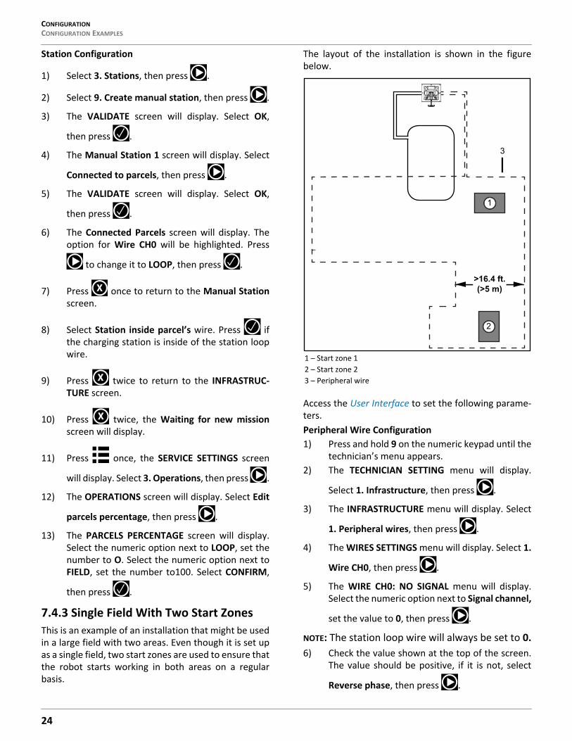
7.4.3 Single Field With Two Start ZonesThis is an example of an installation that might be usedin a large field with two areas. Even though it is set upas a single field, two start zones are used to ensure thatthe robot starts working in both areas on a regularbasis.
The layout of the installation is shown in the figurebelow.
Access the User Interface to set the following parame-ters.Peripheral Wire Configuration1) Press and hold 9 on the numeric keypad until the
technician’s menu appears.2) The TECHNICIAN SETTING menu will display.
Select 1. Infrastructure, then press .
3) The INFRASTRUCTURE menu will display. Select
1. Peripheral wires, then press .
4) The WIRES SETTINGS menu will display. Select 1.
Wire CH0, then press .
5) The WIRE CH0: NO SIGNAL menu will display.Select the numeric option next to Signal channel,
set the value to 0, then press .
NOTE: The station loop wire will always be set to 0.6) Check the value shown at the top of the screen.
The value should be positive, if it is not, select
Reverse phase, then press .
X
X
X
1 – Start zone 12 – Start zone 23 – Peripheral wire
>16.4 ft.(>5 m)
1
2
3
24
CONFIGURATION CONFIGURATION EXAMPLES
7) Press once, the WIRES SETTINGS menu willdisplay. Select 9. Create new wire, then press
.
8) The VALIDATE screen will display. Select OK,
then press .
9) The WIRES SETTINGS menu will display. Select
Wire CH5, then press .
10) The Wire CH5: No Signal screen will display.Select the numeric option next to SIGNAL
CHANNEL, press or and set the value to
1, then press .
11) Check the value shown at the top of the screen.The value should be positive, if it is not, select
Reverse phase, then press .
12) Press twice to return to the INFRASTRUC-TURE screen.
Parcels Configuration1) From the INFRASTRUCTURE menu, select
Parcels, then press .2) The PARCELS menu will display. Select 1. Parcel
1, then press .
3) The Parcel 1 menu will display. Parcel 1 will be
highlighted, press . Use , , , or
, rename Parcel 1 to LOOP. After renaming,select V (located in the bottom row), then press
.
4) Press once to return to the PARCELS screen.
5) Select Parcel 2, then press . Use , ,
, or , rename Parcel 2 to Field. Afterrenaming, select V (located in the bottom row),
then press .
6) The FIELD screen will display. Select Use Track-
border, then press .
7) Scroll down to 8. Neighboring parcels, then press
.
8) The NEIGHBORING PARCELS screen will display.
Select LOOP, then press . Select Confirm,
then press .
9) The FIELD screen will display. Scroll down to Start
Zones, then press .
10) The Start Zones screen will display. Press once.
11) The VALIDATE screen will display. Select OK, then
press .
12) The Start Zones screen will display. For the Coming from parcel option, DEFAULT iscorrect.For the Direction option, CW is correct.Set the Distance Min. value.Set the Distance Max. value.Set the Angle Min. value (between 0° - 180°).Set the Angle Max. value (between 0° - 180°).
13) Press once. The Start Zones screen willdisplay. Scroll down to Create new start zone,
then press .
14) The VALIDATE screen will display, select OK, then
press .
15) The Start Zones screen will display. For the Coming from parcel option, DEFAULT iscorrect.For the Direction option, CW is correct.Set the Distance Min. value.Set the Distance Max. value.Set the Angle Min. value (between 0° - 180°).Set the Angle Max. value (between 0° - 180°).
16) Scroll to Edit Percentage, then press .
17) The Edit Percentage screen will display. Set theStart Zone 2 values to 80%. Set the Start Zone 3
value to 20%. Select CONFIRM, then press .
18) The START ZONE screen will display. Press four times to return to the INFRASTRUCTUREscreen.
X
X
X
X
X
25

USING THE ROBOTSAFETY MEASURES
Station Configuration
1) Select 3. Stations, then press .
2) Select 9. Create manual station, then press .
3) The VALIDATE screen will display. Select OK,
then press .
4) The Manual Station 1 screen will display. Select
Connected to parcels, then press .
5) The VALIDATE screen will display. Select OK,
then press .
6) The Connected Parcels screen will display. Theoption for Wire CH0 will be highlighted. Press
to change it to LOOP, then press .
7) Press once to return to the Manual Stationscreen.
8) Select Station inside parcel’s wire. Press ifthe charging station is inside of the station loopwire.
9) Press twice to return to the INFRASTRUC-TURE screen.
10) Press twice, the Waiting for new missionscreen will display.
11) Press once, the SERVICE SETTINGS screen
will display. Select 3. Operations, then press .
12) The OPERATIONS screen will display. Select Edit
parcels percentage, then press .
13) The PARCELS PERCENTAGE screen will display.Select the numeric option next to LOOP, set thenumber to O. Select the numeric option next toFIELD, set the number to 100. Select CONFIRM,
then press .
8 Using the Robot
PERSONAL INJURY HAZARD
Contact with the robot during operation can causepersonal injury.
• Press the STOP button before handling the ro-bot.
The operator or user is responsible for accidents orhazards occurring to other people or their property.Safety and information symbols are located on the backof the robot. Follow and understand all Safety Symbolsbefore using the robot.Maintain and service the robot on a regular basis.
8.1 Safety Measures• Remove all non-stationary obstacles from the
working area before using the robot.• Never leave the robot on a slope.• Only use the robot charging station to charge the
robot’s battery. Use of any other charger can cause damage and loss of warranty coverage.
• Never connect an external electrical element to the battery cable.
• Never pick up or carry the robot while the motor is running.
• Do not leave the robot to operate unattended if there are pets, children or people in the vicinity.
• Never operate the robot if it has defective guards or shields, or without safety devices.
• Avoid using the robot in bad weather conditions especially when there is a risk of lightning or flooding.
X
X
X
26
USING THE ROBOT THE LCD SCREEN
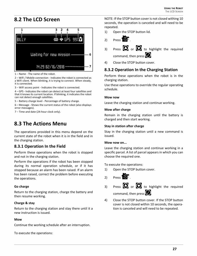
8.2 The LCD Screen
8.3 The Actions MenuThe operations provided in this menu depend on thecurrent state of the robot when it is in the field and inthe charging station.
8.3.1 Operation In the FieldPerform these operations when the robot is stoppedand not in the charging station.Perform the operations if the robot has been stoppedduring its normal operation schedule, or if it hasstopped because an alarm has been raised. If an alarmhas been raised, correct the problem before executingthe operations.
Go chargeReturn to the charging station, charge the battery andthen resume working.
Charge & stayReturn to the charging station and stay there until it anew instruction is issued.
MowContinue the working schedule after an interruption.
To execute the operations:
NOTE: If the STOP button cover is not closed withing 10seconds, the operation is canceled and will need to berepeated.1) Open the STOP button lid.
2) Press .
3) Press or to highlight the required
command, then press .
4) Close the STOP button cover.
8.3.2 Operation In the Charging StationPerform these operations when the robot is in thecharging station.Use these operations to override the regular operatingschedule.
Mow nowLeave the charging station and continue working.
Mow after chargeRemain in the charging station until the battery ischarged and then start working.
Stay in station after chargeStay in the charging station until a new command isissued.
Mow now on...Leave the charging station and continue working in aspecific parcel. A list of parcel appears in which you canchoose the required one.
To execute the operations:1) Open the STOP button cover.
2) Press .
3) Press or to highlight the required
command, then press .
4) Close the STOP button cover. If the STOP buttoncover is not closed within 10 seconds, the opera-tion is canceled and will need to be repeated.
1 – Name - The name of the robot.2 – WiFi / Mobile connection - Indicates the robot is connected as a WiFi client. When blinking, it is trying to connect. When steady, it is connected.3 – WiFi access point - Indicates the robot is connected.4 – GPS - Indicates the robot can detect at least four satellites and that it knows its current location. If blinking, it indicates the robot can not detect enough satellites.5 – Battery charge level - Percentage of battery charge.6 – Message - Shows the current status of the robot (also displays error messages).7 – Time and date (24-hour clock only).
1 3 2 4 5
6
7
27
USING THE ROBOTTHE SETTINGS MENU
8.4 The Settings MenuUse the options in this menu to control the operationof the robot.
8.4.1 ScheduleNOTE: The schedule is based on a 24-hour clock.Use this command to:• Define the weekly working schedule.• Define a schedule for each day of the week.• Define working periods for each day and each
parcel. Each defined period can be active (imple-mented) or inactive (ignored).
• Copy a schedule for one day, and for one parcel, to other days of the week.
• Set the robot to work at all times (which is a default factory setting).
To define a working schedule:
1) Press .
2) Press or to highlight Schedule, then
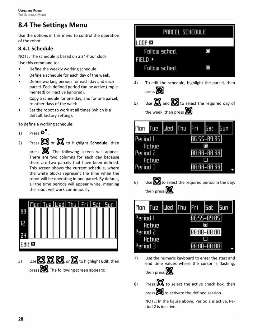
press . The following screen will appear.There are two columns for each day becausethere are two parcels that have been defined.This screen shows the current schedule, wherethe white blocks represent the time when therobot will be operating in one parcel. By default,all the time periods will appear white, meaningthe robot will work continuously.
3) Use , , , or to highlight Edit, then
press . The following screen appears:
4) To edit the schedule, highlight the parcel, then
press .
5) Use and to select the required day of
the week, then press .
6) Use to select the required period in the day,
then press .
7) Use the numeric keyboard to enter the start andend time values where the cursor is flashing,
then press .
8) Press to select the active check box, then
press to activate the defined session.
NOTE: In the figure above, Period 1 is active, Pe-riod 2 is inactive.
28
USING THE ROBOT THE SETTINGS MENU
9) Repeat the process for all days and time periodsrequired. note: The defined schedule can becopied to another day.
10) Press to return to the “Parcel Schedule”screen.
11) Use the arrows to select Follow sched. Press to check the button ON to ensure that the robotfollows the defined schedule. When unchecked,the robot will ignore the timetable and workcontinuously.
To copy the schedule from one day to another:1) Follow the procedure above to define the
working schedule for one day.2) When all the required periods have been
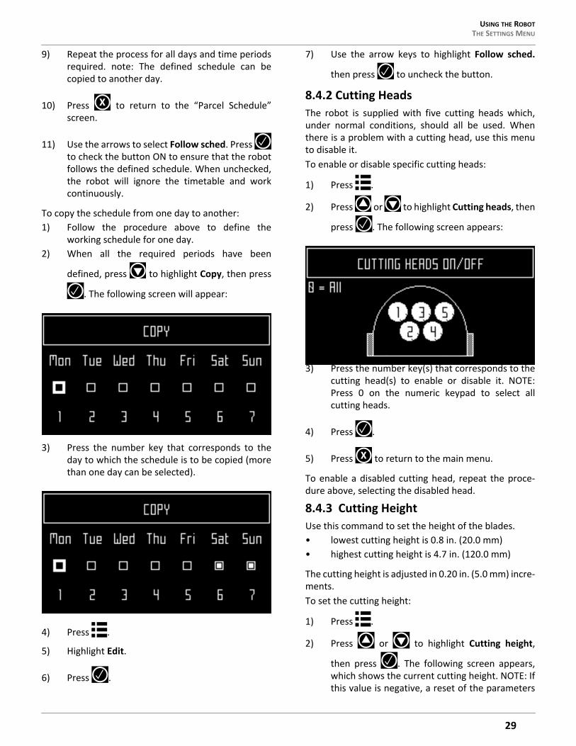
defined, press to highlight Copy, then press
. The following screen will appear:
3) Press the number key that corresponds to theday to which the schedule is to be copied (morethan one day can be selected).
4) Press .
5) Highlight Edit.
6) Press .
7) Use the arrow keys to highlight Follow sched.
then press to uncheck the button.
8.4.2 Cutting HeadsThe robot is supplied with five cutting heads which,under normal conditions, should all be used. Whenthere is a problem with a cutting head, use this menuto disable it.To enable or disable specific cutting heads:
1) Press .
2) Press or to highlight Cutting heads, then
press . The following screen appears:
3) Press the number key(s) that corresponds to thecutting head(s) to enable or disable it. NOTE:Press 0 on the numeric keypad to select allcutting heads.
4) Press .
5) Press to return to the main menu.
To enable a disabled cutting head, repeat the proce-dure above, selecting the disabled head.
8.4.3 Cutting HeightUse this command to set the height of the blades.• lowest cutting height is 0.8 in. (20.0 mm)• highest cutting height is 4.7 in. (120.0 mm)
The cutting height is adjusted in 0.20 in. (5.0 mm) incre-ments.To set the cutting height:
1) Press .
2) Press or to highlight Cutting height,
then press . The following screen appears,which shows the current cutting height. NOTE: Ifthis value is negative, a reset of the parameters
X
X
29

USING THE ROBOTSERVICE MENU
has taken place and the cutting height needs tobe re-calibrated.
3) Press to highlight the Set value.
4) Use and to scroll to the required value.
5) Press to return to the main menu.
8.4.4 System LockingUse this command to lock the use of the robot. Thecommand is useful if the field area is in use during thetime when the robot is scheduled to be working. Therobot will remain locked until the system is unlocked.NOTE: It is also possible to create PIN code which mustbe entered before specific commands can be issued.To lock the system:
1) Press .
2) Press or to highlight System locking,
then press .
3) Highlight OK, then press . Enter the robot’sPIN code to access the menu again.
To unlock the system:
1) Enter the PIN code, then press . The robot willwait for a new command to be issued.
8.4.5 LCD SettingsTo modify the LCD settings:
1) Press and hold for three seconds. The LCDSetting screen will appear.
2) Press or to change the contrast.
3) Press or to highlight Temperature AutoAdj. When this option is checked ON, the LCDcontrast is automatically adjusted according to
the ambient temperature. Press to check oruncheck this option.
4) Press the 9 key to invert the black and whitecolors.
5) Press the 0 key to revert to the factory settings.
6) Press to exit the menu.
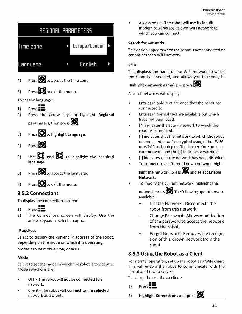
8.5 Service Menu8.5.1 Regional ParametersUse this menu to set the robot time zone and thelanguage.To set the time zone:
1) Press .2) Press the arrow keys to highlight Regional
parameters, then press .
3) Use and to scroll to the required timezone.
X
X
30
USING THE ROBOT SERVICE MENU
4) Press to accept the time zone.
5) Press to exit the menu.
To set the language:
1) Press .2) Press the arrow keys to highlight Regional
parameters, then press .
3) Press to highlight Language.
4) Press .
5) Use and to highlight the requiredlanguage.
6) Press to accept the language.
7) Press to exit the menu.
8.5.2 ConnectionsTo display the connections screen:
1) Press .2) The Connections screen will display. Use the
arrow keypad to select an option.
IP addressSelect to display the current IP address of the robot,depending on the mode on which it is operating.Modes can be mobile, vpn, or WiFi.
ModeSelect to set the mode in which the robot is to operate.Mode selections are:
• OFF - The robot will not be connected to a network.
• Client - The robot will connect to the selected network as a client.
• Access point - The robot will use its inbuilt modem to generate its own WiFi network to which you can connect.
Search for networksThis option appears when the robot is not connected orcannot detect a WiFi network.
SSIDThis displays the name of the WiFi network to whichthe robot is connected, and allows you to modify it.
Highlight {network name} and press .
A list of networks will display.
• Entries in bold text are ones that the robot has connected to.
• Entries in normal text are available but which have not been used.
• [*] indicates the actual network to which the robot is connected.
• [!] indicates that the network to which the robot is connected, is not encrypted using either WPA or WPA2 technologies. This is therefore an inse-cure network and the [!] indicates a warning.
• [-] indicates that the network has been disabled.• To connect to a different known network, high-
light the network, press and select Enable Network.
• To modify the current network, highlight the
network, press . The following operations are available:– Disable Network - Disconnects the
robot from this network.– Change Password - Allows modification
of the password to access the network from the robot.
– Forget Network - Removes the recogni-tion of this known network from the robot.
8.5.3 Using the Robot as a ClientFor normal operation, set up the robot as a WiFi client.This will enable the robot to communicate with theportal on the web-server.To set up the robot as a client:
1) Press .
2) Highlight Connections and press
X
X
31
USING THE ROBOTSERVICE MENU
3) Highlight Mode and set it to Client. If the robothas not been connected to a WiFi network,selecting the option Search for networks willsearch for networks and present a list of thoseavailable.
4) Highlight the WiFi network required and press
.
5) Enter the password for the network using thekeyboard.
6) Highlight V and press .
8.5.4 OperationsUse this menu to set the following operating parame-ters:
Min tempSets the lowest operating temperature for the robot.The default value is 41.0 °F (5.0 °C).
Edit parcels percentageUse this option to view and modify each of the parcelsthat have been defined. The percentage value assignedto a parcel determines the proportion of times therobot will start working in the parcel.
To set the operating parameters:
1) Press .2) Use the arrow keys to highlight Operations, then
press .
3) Press or to highlight the requiredparameter.
4) Enter the required value.
5) Check that the current values have beenupdated.
6) Press to return to the main menu.
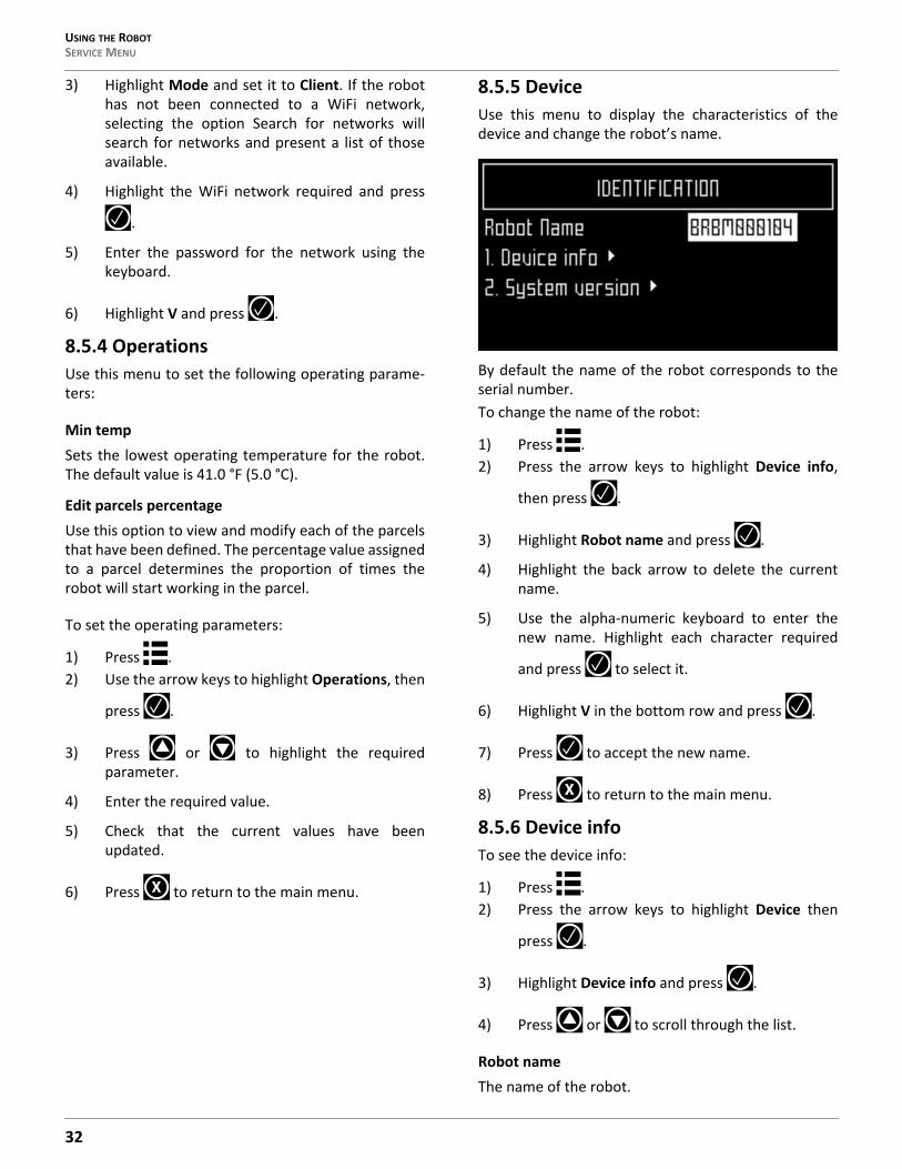
8.5.5 DeviceUse this menu to display the characteristics of thedevice and change the robot’s name.
By default the name of the robot corresponds to theserial number.To change the name of the robot:
1) Press .2) Press the arrow keys to highlight Device info,
then press .
3) Highlight Robot name and press .
4) Highlight the back arrow to delete the currentname.
5) Use the alpha-numeric keyboard to enter thenew name. Highlight each character required
and press to select it.
6) Highlight V in the bottom row and press .
7) Press to accept the new name.
8) Press to return to the main menu.
8.5.6 Device infoTo see the device info:
1) Press .2) Press the arrow keys to highlight Device then
press .
3) Highlight Device info and press .
4) Press or to scroll through the list.
Robot nameThe name of the robot.
X
X
32
USING THE ROBOT SERVICE MENU
Serial numberSerial number of the robot.
LatitudeCurrent latitude of the robot position.
LongitudeCurrent longitude of the robot position.
Visible satellitesNumber of satellites that the device can currentlydetect.
Lat [GF center]The current latitude of the center of the Geofencesecurity zone.
Long [GF center]The current longitude of the center of the Geofencesecurity zone.
RadiusCurrent radius of the Geofence security zone.
Dist. to beaconThis option is not used in North America.
DW board not installedThis option is not used in North America.
Magnetic distanceThe distance between the robot and the peripheralwire.This value should be positive when the robot is insidethe peripheral wire loop. If the distance is shown as anegative value, it is necessary to reverse the phase. SeeInfrastructure > Peripheral wires > WireCH# from thetechnician’s menu.
MAC addressMAC address.
8.5.7 System versionTo see the System version information:
• Press .• Press the arrow keys to highlight Device, then
press .
• Highlight System version, then press .
• Press or to scroll through the list.
VersionCurrent software version.
Brain versionCurrent AI version.
System versionCurrent version of the system software.
Software versionCurrent version of the application software.
Bootloader ver.Current bootloader version.
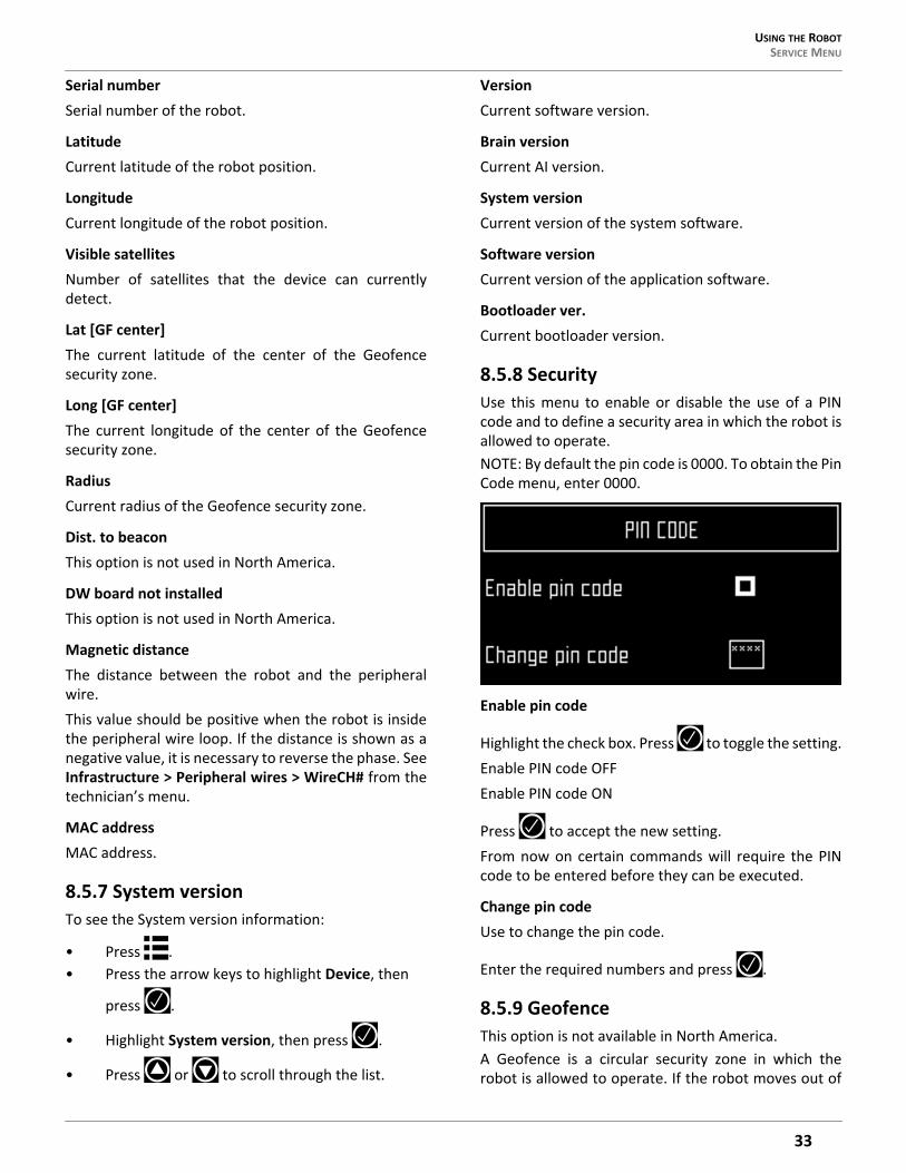
8.5.8 SecurityUse this menu to enable or disable the use of a PINcode and to define a security area in which the robot isallowed to operate.NOTE: By default the pin code is 0000. To obtain the PinCode menu, enter 0000.
Enable pin code
Highlight the check box. Press to toggle the setting.Enable PIN code OFFEnable PIN code ON
Press to accept the new setting.From now on certain commands will require the PINcode to be entered before they can be executed.
Change pin codeUse to change the pin code.
Enter the required numbers and press .
8.5.9 GeofenceThis option is not available in North America.A Geofence is a circular security zone in which therobot is allowed to operate. If the robot moves out of
33
USING THE ROBOTADVANCED PARAMETERS
this area, a security notification will be issued. Thecircular area is defined by its center and a radius.The current location of the center point can be viewedin the device settings menu.
To define and implement a security zone:1) Move the robot to the required center of the
security zone.
2) Press .
3) Press the arrow keys to highlight Security, then
press .
4) Press the arrow keys to highlight Geofence and
press .
5) Highlight Define current position. The latitudeand longitude of the current position isdisplayed.
6) Press to highlight Enable Geofence.
7) Make sure this option is checked on. Press totoggle the setting.
8) Use to highlight Radius value, then press
.
9) Use the numeric keypad to enter the requiredvalue.
10) Press to return to the main menu.
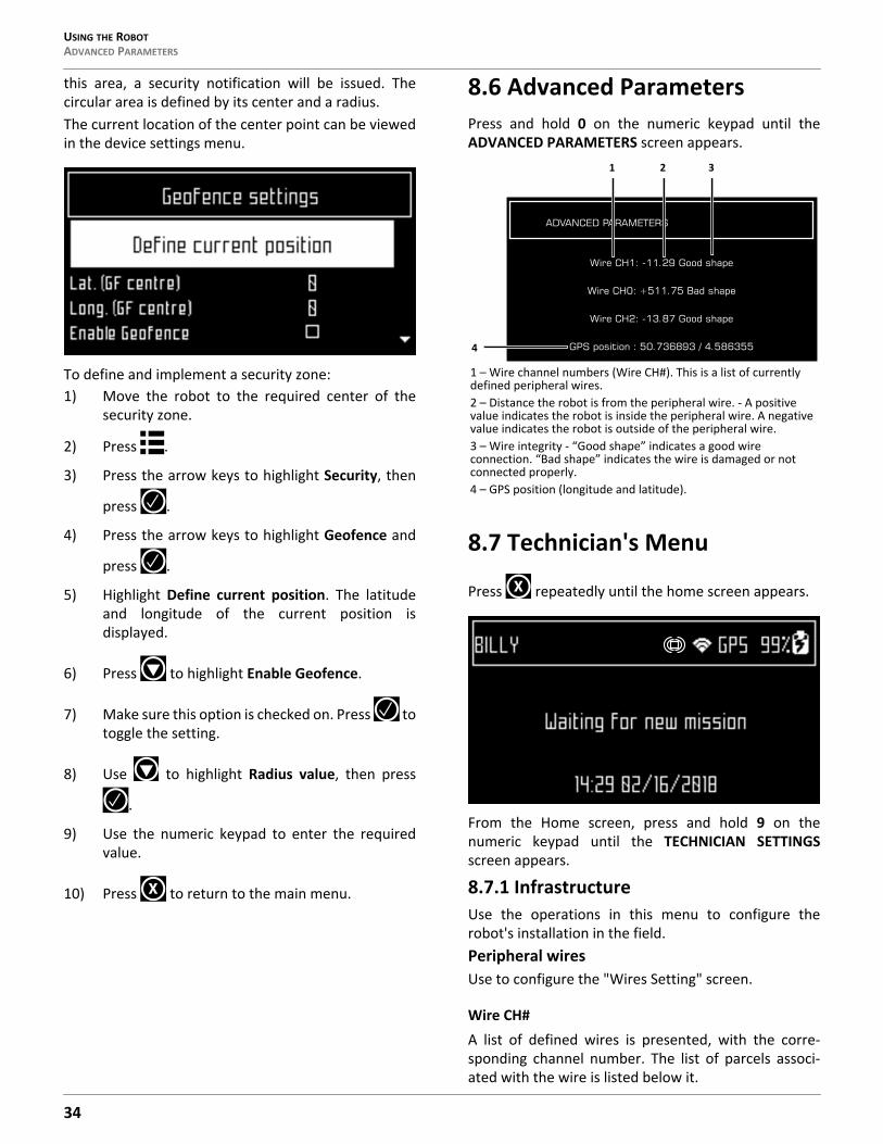
8.6 Advanced ParametersPress and hold 0 on the numeric keypad until theADVANCED PARAMETERS screen appears.
8.7 Technician's Menu
Press repeatedly until the home screen appears.
From the Home screen, press and hold 9 on thenumeric keypad until the TECHNICIAN SETTINGSscreen appears.
8.7.1 InfrastructureUse the operations in this menu to configure therobot's installation in the field.Peripheral wiresUse to configure the "Wires Setting" screen.
Wire CH#A list of defined wires is presented, with the corre-sponding channel number. The list of parcels associ-ated with the wire is listed below it.
X
1 – Wire channel numbers (Wire CH#). This is a list of currently defined peripheral wires.2 – Distance the robot is from the peripheral wire. - A positive value indicates the robot is inside the peripheral wire. A negative value indicates the robot is outside of the peripheral wire.3 – Wire integrity - “Good shape” indicates a good wire connection. “Bad shape” indicates the wire is damaged or not connected properly.4 – GPS position (longitude and latitude).
Wire CH1: -11.29 Good shape
Wire CH0: +511.75 Bad shape
Wire CH2: -13.87 Good shape
GPS position : 50.736893 / 4.586355
ADVANCED PARAMETERS
2 3
4
1
X
34

USING THE ROBOT TECHNICIAN'S MENU
Select a wire and press to see the wire properties.
Create new wireUse to Create a new wire.
Wire CH#
Wire id and magnetic distanceThe identification of the wire in terms of the associatedchannel is displayed. In addition the current value andsign of the magnetic distance between the robot andthe wire is indicated.
Signal channelThe signal (frequency) channel for the peripheral wire.This corresponds to the channel set using the rotatingswitch in the charging station. In the case of amulti-field installation, each wire used, must beassigned to a specific channel.
Reverse phaseThe sign of the phase on the inside of the field is oppo-site to that on the outside. This is how the robot candetect whether it has crossed the peripheral wire. Thephase should be positive inside the field.To determine if this is the case, examine the magneticdistance value shown at the top of the screen. If thevalue is positive the phase is correct. If it is negative,check this option to reverse the phase.
Delete Wire CH#This option only appears if there is more than one wiredefined. It allows the current wire to be deleted. NOTE:At least one wire must be defined.
Create New Wire1) Select Infrastructure > Peripheral wires > Create
new wire.2) Select OK to confirm that you want to create the
new wire.
3) The new wire and its associated parcel willappear in the wire settings list.
4) Select the new wire and click on .
5) Select the required channel number. StationLoop is always channel 0. Field 1 is alwayschannel 1. Field 2 is always channel 2
6) Check the sign of the magnetic distancedisplayed at the top of the screen. If this value isnegative, check the Reverse phase button ON.
7) Click to exit the menu.
The newly created wire will appear in the Wire settingsscreen.Peripheral Wires
Wire CH#A list of defined wires is presented, with the corre-sponding channel number. The list of parcels associ-ated with the wire is listed below it.
Select a wire and press to see the Wire properties.
Create new wireUse to Create a new wire.
Wire id and magnetic distanceThe identification of the wire in terms of the associatedchannel is displayed. In addition the current value andsign of the magnetic distance between the robot andthe wire is indicated.
Signal channelThe signal (frequency) channel for the peripheral wire.This corresponds to the channel set using the rotatingswitch in the charging station. In the case of amulti-field installation, each wire used, must beassigned to a specific channel.
Reverse phaseThe sign of the phase on the inside of the field is oppo-site to that on the outside. This is how the robot candetect whether it has crossed the peripheral wire. Thephase should be positive inside the field.To determine if this is the case, examine the magneticdistance value shown at the top of the screen. If thevalue is positive the phase is correct. If it is negative,check this option to reverse the phase.
Delete Wire CH#This option only appears if there is more than one wiredefined. It allows the current wire to be deleted. NOTE:At least one wire must be defined.
X
35
USING THE ROBOTTECHNICIAN'S MENU
Create a New Wire1) Select Infrastructure > Peripheral wires > Create
new wire.2) Select OK to confirm that you want to create the
new wire.
3) The new wire and its associated parcel willappear in the wire settings list.
4) Select the new wire and click on .
5) Select the required channel number. StationLoop is always channel 0. Field 1 is alwayschannel 1. Field 2 is always channel 2
6) Check the sign of the magnetic distancedisplayed at the top of the screen. If this value isnegative, check the Reverse phase button ON.
7) Click to exit the menu.
The newly created wire will appear in the Wire settingsscreen.
8.7.2 ParcelsThe Parcels menu lists the defined channels and theirassociated parcels. There is, by default, one parcelassociated with each wire.
For each parcel, the name and indication of the returndirection is shown.
Selecting a parcel and pressing displays the list ofparcel properties given below.Parcel properties
NameThe current name of the parcel. The name can beedited.
Return directionDefines the default direction (clockwise or counter-clockwise) in which the robot returns to its chargingstation following the wire.
Set the value of this parameter to ensure that the robotcan return to the charging station in the most efficientmanner. This is important if a problem has occurredand the robot does not know which parcel it is in.
The current return direction is indicated in the list ofparcels.
X
1 – Counterclockwise return direction2 – Clockwise return direction
1
2
3
2 1
36

USING THE ROBOT TECHNICIAN'S MENU
The following figure illustrates the advantage of settingdifferent return directions in different parcels to facili-tate the most efficient way for the robot to return tothe charging station.
Use trackborderThis parameter defines whether the robot uses thetrackborder when leaving or returning to the chargingstation.NOTE: This parameter value must be checked ON in allparcels which are not the station loop.This parameter can be checked OFF for the station loop
Trackbord. Min. / Trackbord. Max.The minimum and maximum values allowed for thetrackborder. The robot will select a random valuebetween the defined values.The default minimum value for Trackbord Min.is 2.6 ft.(0.8 m). The default maximum value for Trackbord.Max. is 9.8 ft. (3 m).
Min. Bounce Angle / Max. Bounce AngleThis is the angle through which the robot turns when itarrives at the peripheral wire. The range of values forthis parameter is typically between 60° and 120°.
PerimeterThis defines a distance the robot will travel along thetrackborder to return to the charging station. If therobot travels the distance defined by this parameterand does not find the station, it will issue an alarm.The recommended value of this parameter is thelength of the peripheral wire around the working area,the default value is 1000 m.
Neighboring parcelsIt is necessary to define how parcels are located rela-tive to each other so that the robot can determine theroute required to reach a particular parcel. Two parcels
1 – Parcel 1 (area inside station loop wire)2 – Parcel 23 – Parcel 3
2
1
3
2
1 – Peripheral wire2 – Min. Bounce Angle3 – Max. Bounce Angle
3 21
37
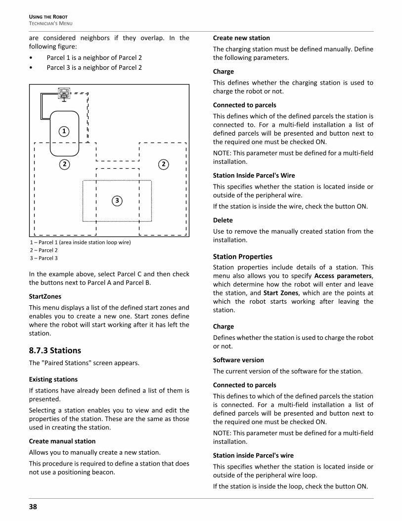
USING THE ROBOTTECHNICIAN'S MENU
are considered neighbors if they overlap. In thefollowing figure:• Parcel 1 is a neighbor of Parcel 2• Parcel 3 is a neighbor of Parcel 2
In the example above, select Parcel C and then checkthe buttons next to Parcel A and Parcel B.
StartZonesThis menu displays a list of the defined start zones andenables you to create a new one. Start zones definewhere the robot will start working after it has left thestation.
8.7.3 StationsThe "Paired Stations" screen appears.
Existing stationsIf stations have already been defined a list of them ispresented.Selecting a station enables you to view and edit theproperties of the station. These are the same as thoseused in creating the station.
Create manual stationAllows you to manually create a new station.This procedure is required to define a station that doesnot use a positioning beacon.
Create new stationThe charging station must be defined manually. Definethe following parameters.
ChargeThis defines whether the charging station is used tocharge the robot or not.
Connected to parcelsThis defines which of the defined parcels the station isconnected to. For a multi-field installation a list ofdefined parcels will be presented and button next tothe required one must be checked ON.NOTE: This parameter must be defined for a multi-fieldinstallation.
Station Inside Parcel's WireThis specifies whether the station is located inside oroutside of the peripheral wire.If the station is inside the wire, check the button ON.
DeleteUse to remove the manually created station from theinstallation.
Station PropertiesStation properties include details of a station. Thismenu also allows you to specify Access parameters,which determine how the robot will enter and leavethe station, and Start Zones, which are the points atwhich the robot starts working after leaving thestation.
ChargeDefines whether the station is used to charge the robotor not.
Software versionThe current version of the software for the station.
Connected to parcelsThis defines to which of the defined parcels the stationis connected. For a multi-field installation a list ofdefined parcels will be presented and button next tothe required one must be checked ON.NOTE: This parameter must be defined for a multi-fieldinstallation.
Station inside Parcel's wireThis specifies whether the station is located inside oroutside of the peripheral wire loop.If the station is inside the loop, check the button ON.
1 – Parcel 1 (area inside station loop wire)2 – Parcel 23 – Parcel 3
2
3
2
1
38
USING THE ROBOT TECHNICIAN'S MENU
Start ZonesThis menu displays a list of the defined start zones andenables you to create a new one. Start zones definewhere the robot will start working after it has left thestation.NOTE: A start zone defined here is only used for ainstallation that contains a single wire and a positioningbeacon.
8.7.4 Mobile ConnectionIn the absence of a wireless network, the robotcontains a SIM card that enables you to use 4G tech-nology in the field.
Select the Mobile connection in the list and press .
Mobile Connection Options
StatusDisplays the current mobile network status.
NetworkDisplays the name of the current network operator.
Network CarrierDisplays the name of the current network carrier.
APNDisplays the current id of the Access Point Name of theSIM card.
Radio3G/2G/UMTS/4G.
Signal StrengthSignal strength in dB.
Bit Error RateNumber of errors during transmission. Very standard inevery communication.
ICCIDIntegrated circuit card identifier.
IMEIInternational Mobile Equipment Identity.
IMSIInternational Mobile Subscriber Identity
PLMNPublic land mobile network.
MCCMobile Country Code. This code identifies the country.For example, in China MCC is equal to 460, in USA - 310,Hungary - 216, Belorussia - 257.
MNCMobile Network Code. This code identifies the mobileoperator.
LACLocation Area Code.
Cell IDA unique number used to identify each Base trans-ceiver station (BTS) or sector of a BTS within a Locationarea code.
8.7.5 DemonstrationCheck the option ON. Confirm you want to ignore theperipheral wire.Use this mode to demonstrate the performance of therobot before installation of the peripheral wire.
OPERATIONAL HAZARD
The robot will ignore the electromagnetic field gen-erated by the peripheral wire when operating indemonstration mode.
• Do not leave the robot unsupervised when it isoperating in demonstration mode.
8.7.6 ServiceCutting headsUse this option to calibrate the rotational speed of thecutting heads.1) If a cutting head has been modified, or if a new
cutting head has been installed, press to
select Calibrate now, then press .2) Close the lid.
3) The cutting heads will be rotated and the rota-tional speed evaluated.
4) When an audible beep is heard, open the lid andview the results.
5) If any of the heads display a NOK value that is notin line with the others, examine the heads andsee if there is any sort of blockage that ispreventing the head from rotating normally.
39
USING THE ROBOTTECHNICIAN'S MENU
Cutting heightThe cutting height values need to be calibrated if • erroneous values (negative) values are displayed• a cutting head has been replaced• the belt lifting the cutting heads has been modi-
fied or replaced
During the calibration procedure the cutting heads arelifted until they reach their maximum height. Theirposition during this movement is termed the "raw posi-tion" and when the maximum height is reached, it istermed the "homing position" and assigned a scalarvalue. When the homing position has been reached,the cutting heads can be lowered to the requiredheight.
1) To calibrate the cutting height, press to
select Calibrate now,then press .2) The robot will move the cutting heads up to the
maximum height. The cutting heads will then belowered to the required height.
3) When the value is OK, set the required cuttingheight.
4) If there is a problem, examine the cutting headsand see if there is anything blocking the move-ment over the complete range.
Information
Total distanceThis is the total distance (in meters) traveled by therobot to date. Use this information to decide whenmaintenance is required.
Bumper resistanceDisplays the current value of the bumper resistance.This should lie in the range 82-94 kΩ.
TestsThese tests are only to be run by an authorized ECHORobotics Technician.Use this menu to execute tests on a number of compo-nents. These tests will be carried out before the robotis delivered to a customer and at the end of a regularservice.To execute a test:
1) Press to select the test(s) you want toexecute.
2) Press to select the test.
3) Repeat this for all tests required.
4) Select Start and press .
5) The robot will start executing each of theselected tests. Follow the instructions given onthe screen.
Charge Test
This test checks if the:• robot can detect a charge• received charging current is sufficient
When this option is selected, the following informationis displayed:
X/Y CHARGE _LRX represents the current test in the current sequence.Y represents the total number of tests to be performedin the current sequence.Charge_LR is the name of the current test.
DetectThis displays whether the robot can detect a voltage onthe left and right sides.KO means it can not detect a voltage on the left or rightside. OK means that it can detect a voltage.
CurrentThis displays whether a sufficient charge current can bedetected (>7A).KO means it can not detect sufficient charge current onthe left or right side. OK means that it can detect suffi-cient charge current.
[value]The current on the connected side.
Discharge required for current testYou will see this message if the current battery level isabove 95%. It is best to perform this test when thebattery charge level is lower.
To test the charge:1) Connect one side of the robot to the charging
station.2) The result will be displayed.
3) Repeat this for the other side.
If the results of the test are KO, check the connectionsbetween the robot and the charge station arms.
40
USING THE ROBOT TECHNICIAN'S MENU
Bumper
This test checks that the electrical resistance of thebumper is within the correct range and that it respondsto pressure from an obstacle.The following information is shown.
X/Y BUMPER SENSORSX represents the current test in the current sequence.Y represents the total number of tests to be performedin the current sequence.BUMPER SENSORS is the name of the current test.
Activate sensorsThe sides of the bumper that need to be tested by acti-vating. (Bumper Left Bumper Right)
Disable SensorsThe sides of the bumper that need to be disabled(Bumper Left Bumper Right)
To test the Bumper1) Check that Bumper Left Bumper Right are listed
below Activate sensors.2) If these are listed under Disable Sensors, remove
any constrictions that are compressing thebumper.
3) Press your hand against the right or left side ofthe bumper.
4) If the resistance is modified sufficiently the itemwill be remove from the list.
5) Repeat this process on the other side of thebumper.
6) If an item remains in the list, the bumper is notfunctioning correctly and needs to be replaced.
Smartbox
This test checks all the functionality of the user inter-face panel.To test the Smartbox1) Follow each of the instructions as they appear on
the screen.
2) Press to answer Yes to a question and toanswer No.
3) If the item being tested is operating correctly itwill disappear from the list.
If there is a problem with any of the items, replace theSmartbox.
Lift Sensors
This checks whether each of the lift sensors isresponding correctly.
X/Y LIFT_SENSORSX represents the current test in the current sequence.Y represents the total number of tests to be performedin the current sequence.LIFT_SENSORS is the name of the current test.
Activate sensorsThe lift sensors that need to be tested by activating bylifting (Lift1, Lift2, Lift3, Lift4).
Disable SensorsThe lift sensors that need to be disabled by depressingthem (Lift1, Lift2, Lift3, Lift4).
To test the Lift Sensors1) Check which Lift sensors are listed below Acti-
vate sensors.2) Lift each of sensors in turn.
3) If the lift sensor is operating correctly, the itemwill be remove from the list.
4) Repeat for the remaining lift sensors.
5) If there are sensors listed under Disable Sensors,push down on the lift sensor to deactivate it.
6) When all the items have been removed from thelist the test is complete.
7) Any items that remain in the list are not func-tioning correctly and need to be replaced.
Backwards Sensors
This checks that the backwards sensors are operatingcorrectly.The following information is shown.
X/Y BACK_SENSORSX represents the current test in the current sequence.Y represents the total number of tests to be performedin the current sequence.BACK_SENSORS is the name of the current test.
Activate sensorsThe number of sensors that need to be tested by acti-vating them (CollisionLeft, CollisionRight).
X
41
USING THE ROBOTTECHNICIAN'S MENU
Disable SensorsThe number of sensors that need to be deactivated(CollisionLeft, CollisionRight).
To test the Back Sensors1) Check that CollisionLeft and CollisionRight are
listed below Activate sensors.2) If these are listed under Disable Sensors, remove
any constrictions activating them.
3) Push the body of the robot backwards on oneside so that it moves relative to the chassis.
4) If the backward sensor on this side is functioningcorrectly it will be removed from the list.
5) Repeat this on the other side.
6) If an item remains in the list, the backwardsensor is not functioning correctly. Visuallyinspect it to see if there is a constriction that isimpeding its function. If not, replace it if neces-sary.
Signal Sensors
This checks the functionality of the coil that is used todetect a signal on a peripheral wire.The following information is shown.
X/Y COIL0_CENTERX represents the current test in the current sequence.Y represents the total number of tests to be performedin the current sequence.COIL0_CENTER is the name of the current test.
Detecting wire < {value}{value} is the value of the "track value". If the result ofthe test is less than this value, the test is successful.
CH{A}:{result value}If the test result is greater than the defined "trackvalue", it will be listed here.Move the robot closer to the signal wire detected.When the value is less than the "track value", the itemshould be removed from the list.
If the robot is close to the wire and the displayed valuesare high (900 or more) it is an indication that the coilconnections are not good.
Drive Motor
This checks the function of the drive motor. It checksthat:
• the motor drives the wheel forward at 0.2 mph (0.1m/s)
• a current of 2.5 A is delivered to the motor
To test the Drive Motor
1) Press to start the test.2) Close the lid when requested.
3) The robot will move forward a short distancethen stop and beep.
4) Open the lid.
5) If the robot moved forward, answer Yes to the
question by clicking .
6) If the robot moved backwards answer No to the
question by clicking . If this is the case,reverse the connections on the drive motorcable.
If the robot did not move, or only one wheel moved,the test will fail, and the report will indicate theproblem. 1) Visually inspect the drive motors to see if there is
a blockage.2) Check the fuse and the cabling for the drive
motors.
Cutting Motor
This test rotates each of the cutting heads and verifiesthat their rotational speed is correct.If any of the heads display a NOK value that is not in linewith the others, you will need to examine those headsand see if there is any sort of blockage that ispreventing it from rotating normally.
Sonars System
This performs a test to verify that the sonar sensors areoperating correctly.If any of the sonar sensors are found to be defective,they need to be replaced. An indication of which sensorneeds to be replaced is given.
Lid
In order for the robot to be able to execute its missionsthe lid needs to be shut, and to form a closed circuitbetween magnets on the lid and relays on the body.This circuit needs to be open when the lid is open andwhen the lid is pressed down and acts as the stopbutton. This requires that all magnets and relays are
X
42
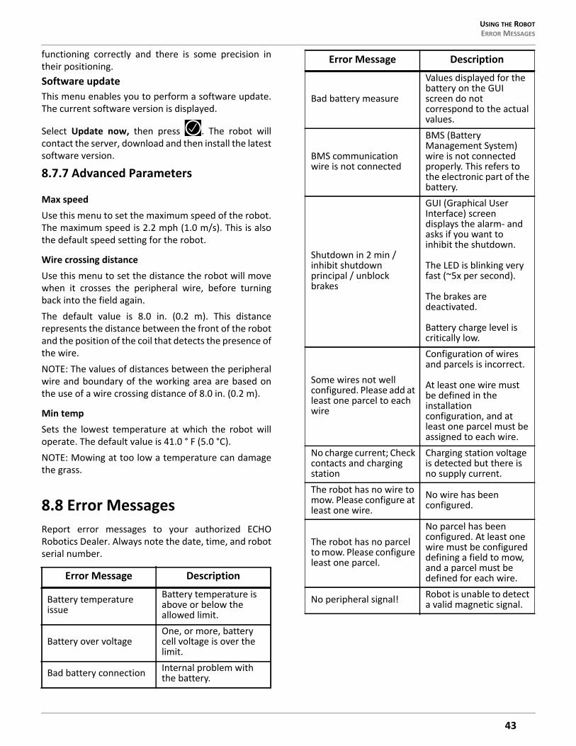
USING THE ROBOT ERROR MESSAGES
functioning correctly and there is some precision intheir positioning.Software updateThis menu enables you to perform a software update.The current software version is displayed.
Select Update now, then press . The robot willcontact the server, download and then install the latestsoftware version.
8.7.7 Advanced Parameters
Max speedUse this menu to set the maximum speed of the robot.The maximum speed is 2.2 mph (1.0 m/s). This is alsothe default speed setting for the robot.
Wire crossing distanceUse this menu to set the distance the robot will movewhen it crosses the peripheral wire, before turningback into the field again.The default value is 8.0 in. (0.2 m). This distancerepresents the distance between the front of the robotand the position of the coil that detects the presence ofthe wire.NOTE: The values of distances between the peripheralwire and boundary of the working area are based onthe use of a wire crossing distance of 8.0 in. (0.2 m).
Min tempSets the lowest temperature at which the robot willoperate. The default value is 41.0 ° F (5.0 °C).NOTE: Mowing at too low a temperature can damagethe grass.
8.8 Error MessagesReport error messages to your authorized ECHORobotics Dealer. Always note the date, time, and robotserial number.
Error Message Description
Battery temperature issue
Battery temperature is above or below the allowed limit.
Battery over voltageOne, or more, battery cell voltage is over the limit.
Bad battery connection Internal problem with the battery.
Bad battery measure
Values displayed for the battery on the GUI screen do not correspond to the actual values.
BMS communication wire is not connected
BMS (Battery Management System) wire is not connected properly. This refers to the electronic part of the battery.
Shutdown in 2 min / inhibit shutdown principal / unblock brakes
GUI (Graphical User Interface) screen displays the alarm- and asks if you want to inhibit the shutdown.
The LED is blinking very fast (~5x per second).
The brakes are deactivated.
Battery charge level is critically low.
Some wires not well configured. Please add at least one parcel to each wire
Configuration of wires and parcels is incorrect.
At least one wire must be defined in the installation configuration, and at least one parcel must be assigned to each wire.
No charge current; Check contacts and charging station
Charging station voltage is detected but there is no supply current.
The robot has no wire to mow. Please configure at least one wire.
No wire has been configured.
The robot has no parcel to mow. Please configure least one parcel.
No parcel has been configured. At least one wire must be configured defining a field to mow, and a parcel must be defined for each wire.
No peripheral signal! Robot is unable to detect a valid magnetic signal.
Error Message Description
43

USING THE ROBOTERROR MESSAGES
Station contact lost for {0}s!
Robot has reached the charging station and started to charge, but at a certain time the charging station contact is lost. If the contact loss lasts for more than one hour, this alarm is triggered.
Wrong wire and parcels Configuration
Robot has encountered a problem while mowing in a particular parcel. When the robot re-starts it is not sure in which parcel it is located, and where it should start mowing.
No station contact detected
The robot has executed the loopstep, but has not made contact with the charge arms after 29 m (by default).
Wire Lost during TrackWire!
Robot is following the trackwire and is then unable to detect a signal on the wire. When this happens the robot will rotate 360° in an attempt to detect a phase difference, and then issue this message.
Unlock system: bad pin code
"System blocking" is set and must be unblocked by entering a pin code. An incorrect code has been entered.
Unable to find the working area
The robot is unable to find a valid magnetic signal.
Failed to dock to stationRobot has tried to return to the charging station but failed.
Head {0} is blocked!Occurs when a cutting head should be spinning, but is not
Head {0} did not start!Cutting head should be spinning but it does not start.
Motor blocked when going {0} to {1}mm
A command to change the cutting height has been issued, but the cutting head can not move.
There is no 12V peripheral for {0}
12 V power supply does not work properly.
Error Message Description
There is no 5V for {0}. 5 V power supply does not work properly.
STOP button issue detected
Stop button is not operating correctly. The Stop button lid must be closed when the robot is operating.
The Stop button lid is determined to be closed by detecting a closed circuit between magnets on the lid and relays in the body. If these magnets are and relays are not connecting correctly the correct state of the lid can not be determined. This can arise due to wide temperature fluctuations.
Unexpected exit zone event
Robot did not exit from the charging station correctly, possibly turning in the wrong direction.
The {L/R} fuse is blown or the {L/R} motor is not connected
Robot can not detect any current in either the left or the right wheel motor.
Either a fuse or a connection is faulty.
Failed to consistently re-enter the zone
Robot has crossed the peripheral wire, but is not able to re-enter the field where it is mowing.
Possible reasons are a loss of signal or the robot is physically unable to re-enter the field because of mud or obstacles.
SelfTest failed to clear within 15s
When the robot starts up, it executes a self-test of a range of functions. This error occurs if a failure occurred on any of the functions tested.
Unhandled exit zone!A problem arises as the robot exits the charging station.
Error Message Description
44
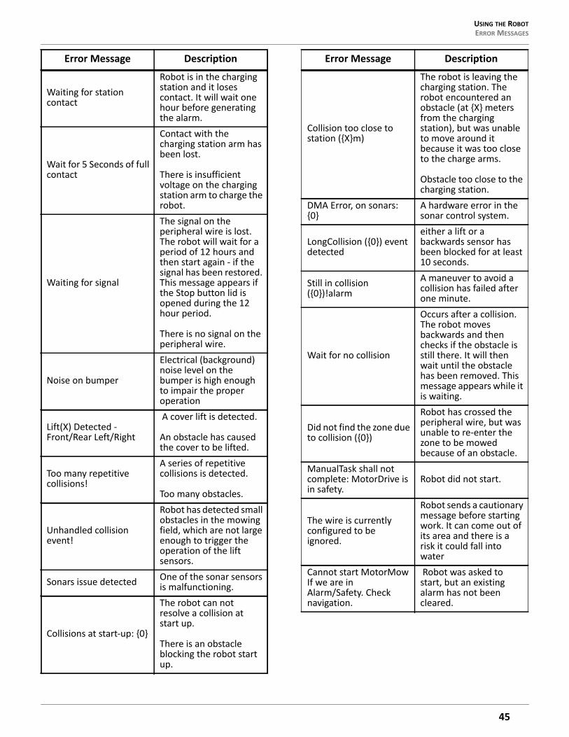
USING THE ROBOT ERROR MESSAGES
Waiting for station contact
Robot is in the charging station and it loses contact. It will wait one hour before generating the alarm.
Wait for 5 Seconds of full contact
Contact with the charging station arm has been lost.
There is insufficient voltage on the charging station arm to charge the robot.
Waiting for signal
The signal on the peripheral wire is lost. The robot will wait for a period of 12 hours and then start again - if the signal has been restored. This message appears if the Stop button lid is opened during the 12 hour period.
There is no signal on the peripheral wire.
Noise on bumper
Electrical (background) noise level on the bumper is high enough to impair the proper operation
Lift(X) Detected - Front/Rear Left/Right
A cover lift is detected.
An obstacle has caused the cover to be lifted.
Too many repetitive collisions!
A series of repetitive collisions is detected.
Too many obstacles.
Unhandled collision event!
Robot has detected small obstacles in the mowing field, which are not large enough to trigger the operation of the lift sensors.
Sonars issue detected One of the sonar sensors is malfunctioning.
Collisions at start-up: {0}
The robot can not resolve a collision at start up.
There is an obstacle blocking the robot start up.
Error Message Description
Collision too close to station ({X}m)
The robot is leaving the charging station. The robot encountered an obstacle (at {X} meters from the charging station), but was unable to move around it because it was too close to the charge arms.
Obstacle too close to the charging station.
DMA Error, on sonars: {0}
A hardware error in the sonar control system.
LongCollision ({0}) event detected
either a lift or a backwards sensor has been blocked for at least 10 seconds.
Still in collision ({0})!alarm
A maneuver to avoid a collision has failed after one minute.
Wait for no collision
Occurs after a collision. The robot moves backwards and then checks if the obstacle is still there. It will then wait until the obstacle has been removed. This message appears while it is waiting.
Did not find the zone due to collision ({0})
Robot has crossed the peripheral wire, but was unable to re-enter the zone to be mowed because of an obstacle.
ManualTask shall not complete: MotorDrive is in safety.
Robot did not start.
The wire is currently configured to be ignored.
Robot sends a cautionary message before starting work. It can come out of its area and there is a risk it could fall into water
Cannot start MotorMow If we are in Alarm/Safety. Check navigation.
Robot was asked to start, but an existing alarm has not been cleared.
Error Message Description
45
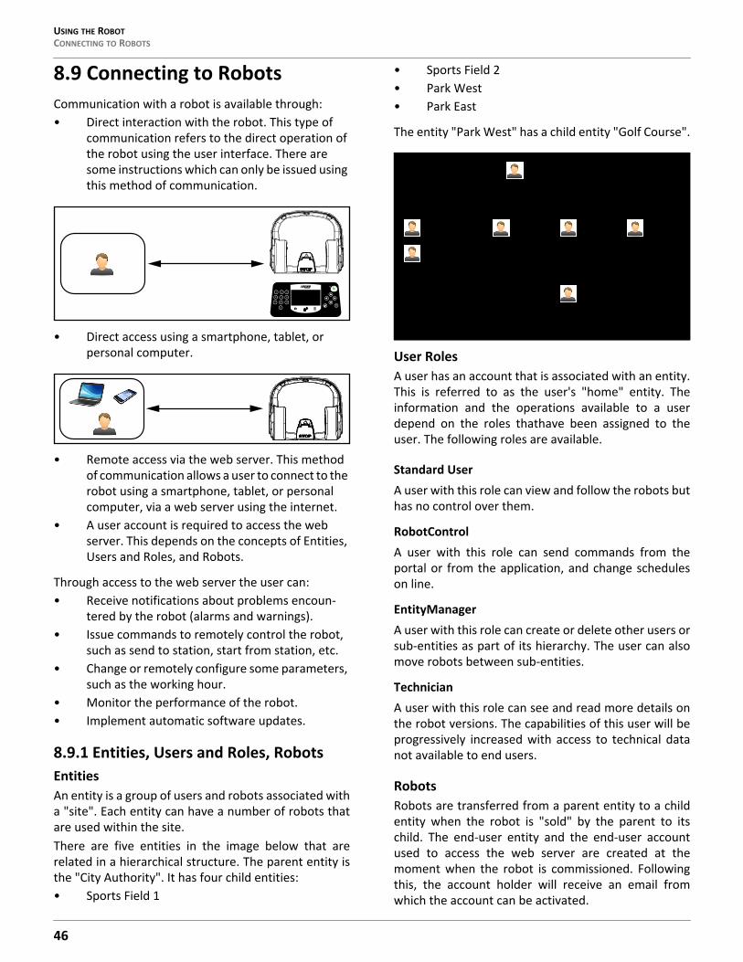
USING THE ROBOTCONNECTING TO ROBOTS
8.9 Connecting to RobotsCommunication with a robot is available through:• Direct interaction with the robot. This type of
communication refers to the direct operation of the robot using the user interface. There are some instructions which can only be issued using this method of communication.
• Direct access using a smartphone, tablet, or personal computer.
• Remote access via the web server. This method of communication allows a user to connect to the robot using a smartphone, tablet, or personal computer, via a web server using the internet.
• A user account is required to access the web server. This depends on the concepts of Entities, Users and Roles, and Robots.
Through access to the web server the user can:• Receive notifications about problems encoun-
tered by the robot (alarms and warnings).• Issue commands to remotely control the robot,
such as send to station, start from station, etc.• Change or remotely configure some parameters,
such as the working hour.• Monitor the performance of the robot.• Implement automatic software updates.
8.9.1 Entities, Users and Roles, RobotsEntitiesAn entity is a group of users and robots associated witha "site". Each entity can have a number of robots thatare used within the site.There are five entities in the image below that arerelated in a hierarchical structure. The parent entity isthe "City Authority". It has four child entities:• Sports Field 1
• Sports Field 2• Park West• Park East
The entity "Park West" has a child entity "Golf Course".
User RolesA user has an account that is associated with an entity.This is referred to as the user's "home" entity. Theinformation and the operations available to a userdepend on the roles thathave been assigned to theuser. The following roles are available.
Standard UserA user with this role can view and follow the robots buthas no control over them.
RobotControlA user with this role can send commands from theportal or from the application, and change scheduleson line.
EntityManagerA user with this role can create or delete other users orsub-entities as part of its hierarchy. The user can alsomove robots between sub-entities.
TechnicianA user with this role can see and read more details onthe robot versions. The capabilities of this user will beprogressively increased with access to technical datanot available to end users.
RobotsRobots are transferred from a parent entity to a childentity when the robot is "sold" by the parent to itschild. The end-user entity and the end-user accountused to access the web server are created at themoment when the robot is commissioned. Followingthis, the account holder will receive an email fromwhich the account can be activated.
31 2
6
8
0
4 5
7 9X
City Authority
User A
Sports Field 1User B
User C
Sports Field 2User D
Park WestUser E
Park EastUser G
Golf CourseUser F
46

USING THE ROBOT CONNECTING TO ROBOTS
In the case where an end-user purchases a robotdirectly, an account will be created using the informa-tion received on the registration card supplied with therobot.
8.9.2 Accessing the Web ServerNOTE: Before you can access the web server you needto have set up an account. See Creating Accounts.The web server can be accessed using a web browser,on a personal computer, or by using the applicationthat can be downloaded onto a smart phone or tablet.NOTE: This section refers to the use of the web-serverthrough a browser.To access the web server:1) Enter the URL https://myrobot.echoro-
botics.com in the browser.2) Enter the email address used to activate the
account.
3) Enter the password defined when you activatedthe account.
4) Click [Login].
You can then: • Modify your profile parameters.• Change your password.• See a list of your robots and information about
their activity, alarms, statistics and the map of the field they work in.
• Create and manage users and entities. This func-tionality is only available to users who have a suitable role.
• Specify the type of notifications you want to receive and how they will be delivered.
• Access documentation.
To Modify Your Profile1) Click on the gear wheel next to your user name.
2) Click on Profile.
3) Modify any of the settings.
4) Click [Register].
To Change Your PasswordThe password was set when you activated the account.1) Click on the gear wheel next to your user name.2) Click on Profile.
3) Scroll down to the Password panel.
4) Enter your current password. (If you haveforgotten the password, click on the gear wheel,and logout. Enter your email address and thenclick on "Forgotten password". An email will besent with a link which will allow you to enter anew password.
5) Enter the new password in the two fieldsprovided.
NOTE: There are no restrictions on the pass-word. Use a strong password which has at least 12 characters and includes numbers, symbols, and a mixture of upper and lower case letters.
6) Click [Register].
Your Name Here
Profile
Log out
47

USING THE ROBOTCONNECTING TO ROBOTS
8.9.3 My Robots
This page enables the user to:• search for a robot• add a robot to the favorites list• view the current status and issue a command• view the robot history• view the alarm history of a robot• view a map of the robot’s movement• view a robot’s statistics• view identification information for a robot
Search for a Robot1) Click on the Search tab.2) Enter the name or part of the name of the robot
you are searching for (there is no need to add anywild cards.)
3) Click on the search icon.
The list of robots that match the search criteria willappear.Add a Robot to the Favorites List1) Search for robots as described above.
2) Click on . The robot will be added to the listof Favorites.
3) Click on the Favorites tab to see the list of Favor-ites.
View the Current Status and Issue a Command1) Click on the robot in the Favorites list.2) Click on the "Report and Commands" tab.
3) Click on the required command.
View the Robot History1) Click on the robot in the Favorites list.2) Click on the "History" tab.
This page provides information on the activities andstatus of the selected robot over a period of time.The time period is shown in the period field. To adjustthe time period, use the up and down arrows to choose
the number of days and then click .
The information is provided in two formats: as a chart,or in a table.Viewing the History as a ChartThis shows the time the robot spent in various statesover a period of time. The number of days for which thedata is displayed is set using the period field. Select apart of this period by clicking on a button above thechart.You can also restrict the time period, by dragging thesliders at the bottom of the chart.A set of tools are available to manipulate the view ofthe chart. These will appear when the mouse ishovered on the top right side of the chart.In each case the function of the tool can be seen byhovering over it as shown above.Viewing the History In a TableSort the data in the table on any of the columns by
clicking or to select Ascending or Descendingorder.For some items you can filter the data displayed byselecting required content from the drop-down list.Different states are shown in different colors.To View the Alarm History of a RobotIf the robot is in an alarm state, this will be indicated inthe Favorites list.1) Click on the robot in the Favorites list.2) Click on the "Alarms" tab.
A list of alarms and the times when they occurred aswell a map showing where the alarm occurred will bedisplayed.To View a Map of a Robot's Movement1) Click on the robot in the Favorites list.2) Click on the "Map" tab.
3) Choose the time period for which the move-ments are required.
4) Click on the calender icon next to the date andchoose the start and end date required.
5) Click Set.
6) Click [Obtain Data].
NOTE: You can add a "Symbolic" map of the field whichimproves the visualization of the robot movements.To do this: 1) Go to http://geojson.io (Satellite/OSM views)2) Follow the instructions on their site.
3) Copy the contents of the generated file.
48
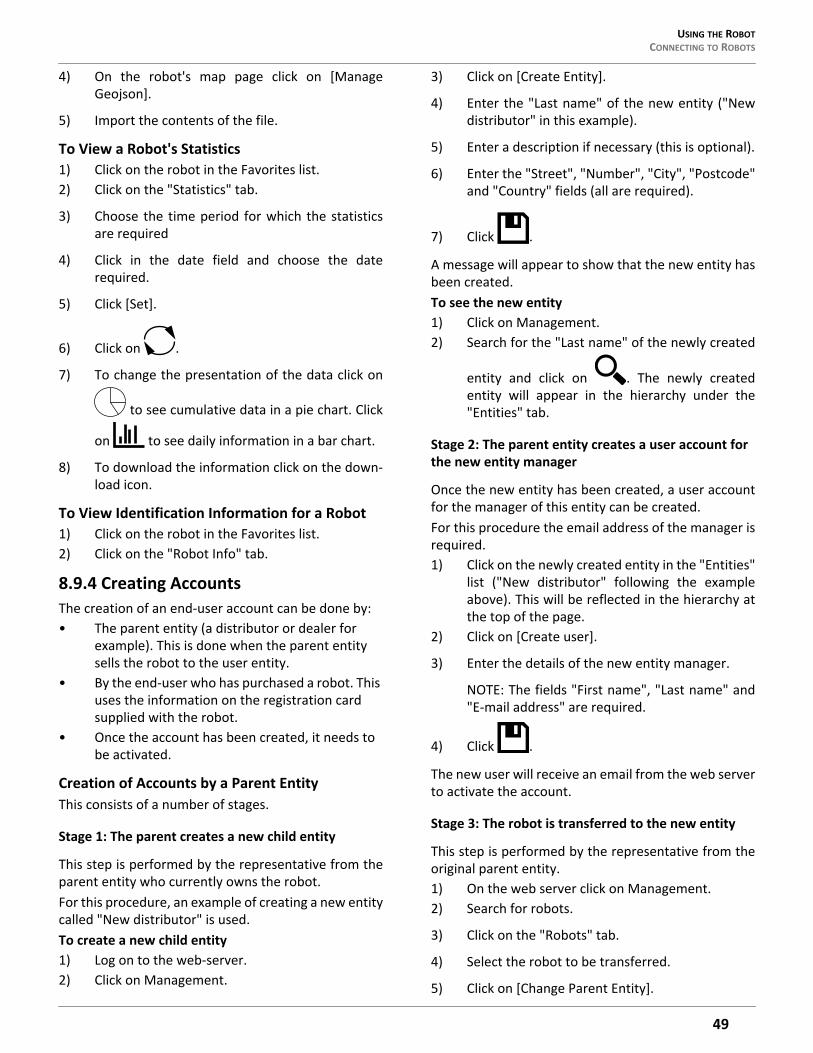
USING THE ROBOT CONNECTING TO ROBOTS
4) On the robot's map page click on [ManageGeojson].
5) Import the contents of the file.
To View a Robot's Statistics1) Click on the robot in the Favorites list.2) Click on the "Statistics" tab.
3) Choose the time period for which the statisticsare required
4) Click in the date field and choose the daterequired.
5) Click [Set].
6) Click on .
7) To change the presentation of the data click on
to see cumulative data in a pie chart. Click
on to see daily information in a bar chart.
8) To download the information click on the down-load icon.
To View Identification Information for a Robot1) Click on the robot in the Favorites list.2) Click on the "Robot Info" tab.
8.9.4 Creating AccountsThe creation of an end-user account can be done by:• The parent entity (a distributor or dealer for
example). This is done when the parent entity sells the robot to the user entity.
• By the end-user who has purchased a robot. This uses the information on the registration card supplied with the robot.
• Once the account has been created, it needs to be activated.
Creation of Accounts by a Parent EntityThis consists of a number of stages.
Stage 1: The parent creates a new child entity
This step is performed by the representative from theparent entity who currently owns the robot.For this procedure, an example of creating a new entitycalled "New distributor" is used.To create a new child entity1) Log on to the web-server.2) Click on Management.
3) Click on [Create Entity].
4) Enter the "Last name" of the new entity ("Newdistributor" in this example).
5) Enter a description if necessary (this is optional).
6) Enter the "Street", "Number", "City", "Postcode"and "Country" fields (all are required).
7) Click .
A message will appear to show that the new entity hasbeen created.To see the new entity1) Click on Management.2) Search for the "Last name" of the newly created
entity and click on . The newly createdentity will appear in the hierarchy under the"Entities" tab.
Stage 2: The parent entity creates a user account for the new entity manager
Once the new entity has been created, a user accountfor the manager of this entity can be created.For this procedure the email address of the manager isrequired.1) Click on the newly created entity in the "Entities"
list ("New distributor" following the exampleabove). This will be reflected in the hierarchy atthe top of the page.
2) Click on [Create user].
3) Enter the details of the new entity manager.
NOTE: The fields "First name", "Last name" and"E-mail address" are required.
4) Click .
The new user will receive an email from the web serverto activate the account.
Stage 3: The robot is transferred to the new entity
This step is performed by the representative from theoriginal parent entity.1) On the web server click on Management.2) Search for robots.
3) Click on the "Robots" tab.
4) Select the robot to be transferred.
5) Click on [Change Parent Entity].
49
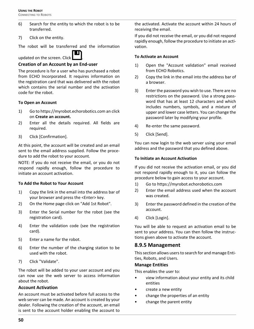
USING THE ROBOTCONNECTING TO ROBOTS
6) Search for the entity to which the robot is to betransferred.
7) Click on the entity.
The robot will be transferred and the information
updated on the screen. Click .Creation of an Account by an End-userThe procedure is for a user who has purchased a robotfrom ECHO Incorporated. It requires information onthe registration card that was delivered with the robotwhich contains the serial number and the activationcode for the robot.
To Open an Account
1) Go to https://myrobot.echorobotics.com an clickon Create an account.
2) Enter all the details required. All fields arerequired.
3) Click [Confirmation].
At this point, the account will be created and an emailsent to the email address supplied. Follow the proce-dure to add the robot to your account.NOTE: If you do not receive the email, or you do notrespond rapidly enough, follow the procedure toinitiate an account activation.
To Add the Robot to Your Account
1) Copy the link in the email into the address bar ofyour browser and press the <Enter> key.
2) On the Home page click on "Add 1st Robot".
3) Enter the Serial number for the robot (see theregistration card).
4) Enter the validation code (see the registrationcard).
5) Enter a name for the robot.
6) Enter the number of the charging station to beused with the robot.
7) Click "Validate".
The robot will be added to your user account and youcan now use the web server to access informationabout the robot.Account ActivationAn account must be activated before full access to theweb server can be made. An account is created by yourdealer. Following the creation of the account, an emailis sent to the account holder enabling the account to
the activated. Activate the account within 24 hours ofreceiving the email.If you did not receive the email, or you did not respondrapidly enough, follow the procedure to initiate an acti-vation.
To Activate an Account
1) Open the "Account validation" email receivedfrom ECHO Robotics.
2) Copy the link in the email into the address bar ofa browser.
3) Enter the password you wish to use. There are norestrictions on the password. Use a strong pass-word that has at least 12 characters and whichincludes numbers, symbols, and a mixture ofupper and lower case letters. You can change thepassword later by modifying your profile.
4) Re-enter the same password.
5) Click [Send].
You can now login to the web server using your emailaddress and the password that you defined above.
To Initiate an Account Activation
If you did not receive the activation email, or you didnot respond rapidly enough to it, you can follow theprocedure below to gain access to your account.1) Go to https://myrobot.echorobotics.com2) Enter the email address used when the account
was created.
3) Enter the password defined in the creation of theaccount.
4) Click [Login].
You will be able to request an activation email to besent to your address. You can then follow the instruc-tions given above to activate the account.
8.9.5 ManagementThis section allows users to search for and manage Enti-ties, Robots, and Users.Manage EntitiesThis enables the user to:• view information about your entity and its child
entities• create a new entity• change the properties of an entity• change the parent entity
50
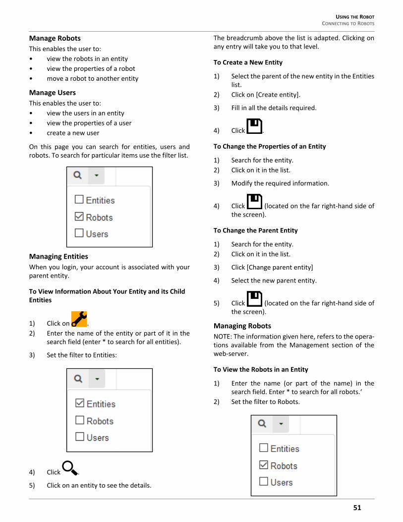
USING THE ROBOT CONNECTING TO ROBOTS
Manage RobotsThis enables the user to:• view the robots in an entity• view the properties of a robot• move a robot to another entity
Manage UsersThis enables the user to:• view the users in an entity• view the properties of a user• create a new user
On this page you can search for entities, users androbots. To search for particular items use the filter list.
Managing EntitiesWhen you login, your account is associated with yourparent entity.
To View Information About Your Entity and its Child Entities
1) Click on .2) Enter the name of the entity or part of it in the
search field (enter * to search for all entities).
3) Set the filter to Entities:
4) Click .
5) Click on an entity to see the details.
The breadcrumb above the list is adapted. Clicking onany entry will take you to that level.
To Create a New Entity
1) Select the parent of the new entity in the Entitieslist.
2) Click on [Create entity].
3) Fill in all the details required.
4) Click .
To Change the Properties of an Entity
1) Search for the entity.2) Click on it in the list.
3) Modify the required information.
4) Click (located on the far right-hand side ofthe screen).
To Change the Parent Entity
1) Search for the entity.2) Click on it in the list.
3) Click [Change parent entity]
4) Select the new parent entity.
5) Click (located on the far right-hand side ofthe screen).
Managing RobotsNOTE: The information given here, refers to the opera-tions available from the Management section of theweb-server.
To View the Robots in an Entity
1) Enter the name (or part of the name) in thesearch field. Enter * to search for all robots.‘
2) Set the filter to Robots.
51
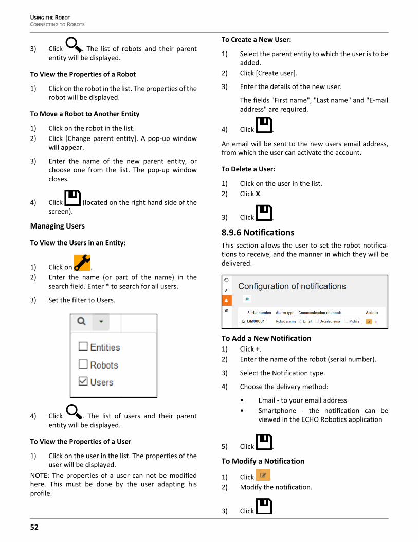
USING THE ROBOTCONNECTING TO ROBOTS
3) Click . The list of robots and their parententity will be displayed.
To View the Properties of a Robot
1) Click on the robot in the list. The properties of therobot will be displayed.
To Move a Robot to Another Entity
1) Click on the robot in the list.2) Click [Change parent entity]. A pop-up window
will appear.
3) Enter the name of the new parent entity, orchoose one from the list. The pop-up windowcloses.
4) Click (located on the right hand side of thescreen).
Managing Users
To View the Users in an Entity:
1) Click on .2) Enter the name (or part of the name) in the
search field. Enter * to search for all users.
3) Set the filter to Users.
4) Click . The list of users and their parententity will be displayed.
To View the Properties of a User
1) Click on the user in the list. The properties of theuser will be displayed.
NOTE: The properties of a user can not be modifiedhere. This must be done by the user adapting hisprofile.
To Create a New User:
1) Select the parent entity to which the user is to beadded.
2) Click [Create user].
3) Enter the details of the new user.
The fields "First name", "Last name" and "E-mailaddress" are required.
4) Click .
An email will be sent to the new users email address,from which the user can activate the account.
To Delete a User:
1) Click on the user in the list.2) Click X.
3) Click .
8.9.6 NotificationsThis section allows the user to set the robot notifica-tions to receive, and the manner in which they will bedelivered.
To Add a New Notification1) Click +.2) Enter the name of the robot (serial number).
3) Select the Notification type.
4) Choose the delivery method:
• Email - to your email address• Smartphone - the notification can be
viewed in the ECHO Robotics application
5) Click .
To Modify a Notification
1) Click .2) Modify the notification.
3) Click
52
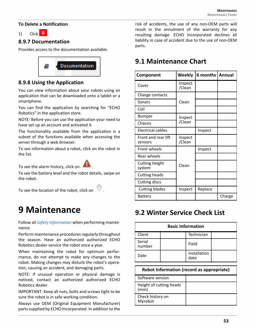
MAINTENANCE MAINTENANCE CHART
To Delete a Notification
1) Click .
8.9.7 DocumentationProvides access to the documentation available.
8.9.8 Using the ApplicationYou can view information about your robots using anapplication that can be downloaded onto a tablet or asmartphone.You can find the application by searching for "ECHORobotics" in the application store.NOTE: Before you can use the application your need tohave set up an account and activated it.The functionality available from the application is asubset of the functions available when accessing theserver through a web browser.To see information about a robot, click on the robot inthe list.
To see the alarm history, click on .To see the battery level and the robot details, swipe onthe robot.
To see the location of the robot, click on .
9 MaintenanceFollow all Safety Information when performing mainte-nance.Perform maintenance procedures regularly throughoutthe season. Have an authorized authorized ECHORobotics dealer service the robot once a year.When maintaining the robot for optimum perfor-mance, do not attempt to make any changes to therobot. Making changes may disturb the robot’s opera-tion, causing an accident, and damaging parts.NOTE: If unusual operation or physical damage isnoticed, contact an authorized authorized ECHORobotics dealer.IMPORTANT: Keep all nuts, bolts and screws tight to besure the robot is in safe working condition.Always use OEM (Original Equipment Manufacturer)parts supplied by ECHO Incorporated. In addition to the
risk of accidents, the use of any non-OEM parts willresult in the annulment of the warranty for anyresulting damage. ECHO Incorporated declines allliability in case of accident due to the use of non-OEMparts.
9.1 Maintenance Chart
9.2 Winter Service Check List
Component Weekly 6 months Annual
Cover Inspect /Clean
Charge contactsCleanSonars
CoilBumper Inspect
/CleanChassisElectrical cables InspectFront and rear lift sensors
Inspect /Clean
Front wheels
Clean
InspectRear wheelsCutting height systemCutting headsCutting discs Cutting blades Inspect ReplaceBattery Charge
Basic Information
Client TechnicianSerial number Field
Date Installation date
Robot Information (record as appropriate)
Software versionHeight of cutting heads (mm)Check history on Myrobot
53
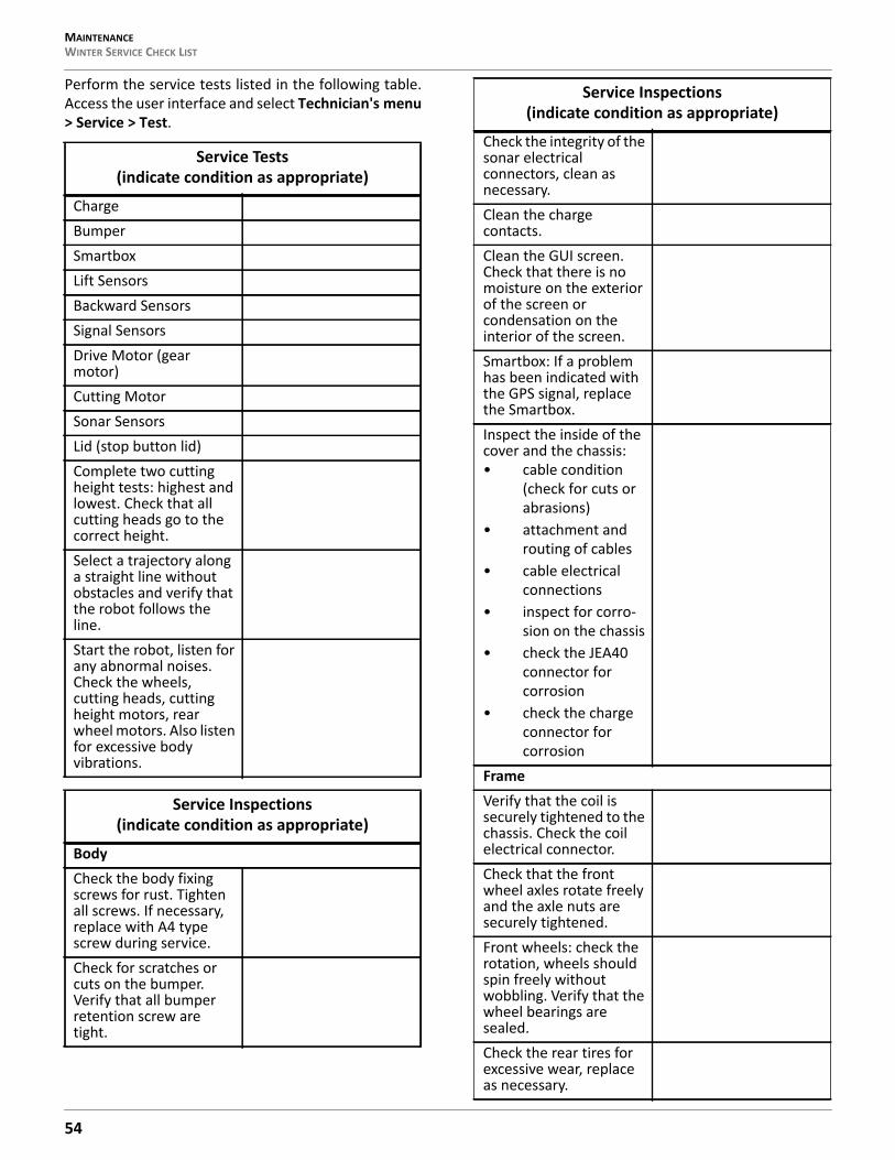
MAINTENANCEWINTER SERVICE CHECK LIST
Perform the service tests listed in the following table.Access the user interface and select Technician's menu> Service > Test.
Service Tests (indicate condition as appropriate)
ChargeBumperSmartboxLift SensorsBackward SensorsSignal SensorsDrive Motor (gear motor)Cutting MotorSonar SensorsLid (stop button lid)Complete two cutting height tests: highest and lowest. Check that all cutting heads go to the correct height.Select a trajectory along a straight line without obstacles and verify that the robot follows the line.Start the robot, listen for any abnormal noises. Check the wheels, cutting heads, cutting height motors, rear wheel motors. Also listen for excessive body vibrations.
Service Inspections (indicate condition as appropriate)
BodyCheck the body fixing screws for rust. Tighten all screws. If necessary, replace with A4 type screw during service. Check for scratches or cuts on the bumper. Verify that all bumper retention screw are tight.
Check the integrity of the sonar electrical connectors, clean as necessary.Clean the charge contacts.Clean the GUI screen. Check that there is no moisture on the exterior of the screen or condensation on the interior of the screen.Smartbox: If a problem has been indicated with the GPS signal, replace the Smartbox.Inspect the inside of the cover and the chassis: • cable condition
(check for cuts or abrasions)
• attachment and routing of cables
• cable electrical connections
• inspect for corro-sion on the chassis
• check the JEA40 connector for corrosion
• check the charge connector for corrosion
FrameVerify that the coil is securely tightened to the chassis. Check the coil electrical connector.Check that the front wheel axles rotate freely and the axle nuts are securely tightened.Front wheels: check the rotation, wheels should spin freely without wobbling. Verify that the wheel bearings are sealed.Check the rear tires for excessive wear, replace as necessary.
Service Inspections (indicate condition as appropriate)
54
MAINTENANCE MAINTENANCE PROCEDURES
9.3 Maintenance Procedures9.3.1 General Inspection and CleaningDuring periods of wet weather, perform inspection andcleaning once per day.1) Move the power switch to the OFF position.2) De-energize AC power at the mains (charging
station only).
3) Remove robot from charging station (ifrequired).
4) Visually inspect the unit, replace damagedcomponents.
5) Check all electrical connectors, reconnect ifnecessary.
6) Use a plastic scraper, nylon brush, compressedair, or a damp cloth to clean dirt, grass, sticks, orobstructions.
Front lift sensors: verify that the lift sensors move up and down with no resistance, lubricate as necessary.Check the front and rear silentblocs for cracking or splitting, replace as necessary. Replace the silentblocs once every two years regardless of their condition.
• Cutting heads and cutting system:
• cable condition (check for cuts or abrasions)
• check the lifting strap
• check for moisture in the interior of the cutting motor housing (always replace the top seal when servicing the cutting motor housing)
• check for excessive lateral movement of the cutting head upper and lower brackets
• verify that the cutting disc spins freely and does not wobble
• verify that the anti-friction disc spins freely (this disc must spin inde-pendently from the cutting disc).
Inspect the cutting blades, replace if dull, cracked, or chipped.Inspect the cutting head motor.Inspect the backwards sensors.
Service Inspections (indicate condition as appropriate)
Inspect all electrical cables for cuts or abrasions. Verify that all connectors are securely assembled. Replace damaged cables.Electrical box: check cable connections, inspect the interior for the presence of moisture.Drive motor: Lubricate the motors during every service. Check and replace the axle, bearing and the seal on the outlet of the gear unit if necessary.
Service Inspections (indicate condition as appropriate)
55
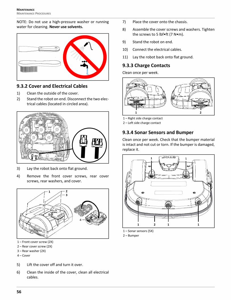
MAINTENANCEMAINTENANCE PROCEDURES
NOTE: Do not use a high-pressure washer or runningwater for cleaning. Never use solvents.
9.3.2 Cover and Electrical Cables1) Clean the outside of the cover.2) Stand the robot on end. Disconnect the two elec-
trical cables (located in circled area).
3) Lay the robot back onto flat ground.
4) Remove the front cover screws, rear coverscrews, rear washers, and cover.
5) Lift the cover off and turn it over.
6) Clean the inside of the cover, clean all electricalcables.
7) Place the cover onto the chassis.
8) Assemble the cover screws and washers. Tightenthe screws to 5 lbf•ft (7 N•m).
9) Stand the robot on end.
10) Connect the electrical cables.
11) Lay the robot back onto flat ground.
9.3.3 Charge ContactsClean once per week.
9.3.4 Sonar Sensors and BumperClean once per week. Check that the bumper materialis intact and not cut or torn. If the bumper is damaged,replace it.
1 – Front cover screw (2X)2 – Rear cover screw (2X)3 – Rear washer (2X)4 – Cover
1
4
23
1 – Right side charge contact2 – Left side charge contact
1 – Sonar sensors (5X)2 – Bumper
1 2
1 1
111 2
56

MAINTENANCE MAINTENANCE PROCEDURES
9.3.5 CoilClean once per week.1) Visually inspect the coil for damage.2) Inspect the cable. If there are exposed wires,
replace the cable.
9.3.6 ChassisClean the chassis once per week.
9.3.7 Front and Rear Lift SensorsClean once per week. Verify that the front lift sensorsmove up and down with no resistance.
1 – Lift sensor attachment point2 – Front lift sensor assembly3 – Rear lift sensor assembly
1
1
1
1
3
3
2
2 3
2
57
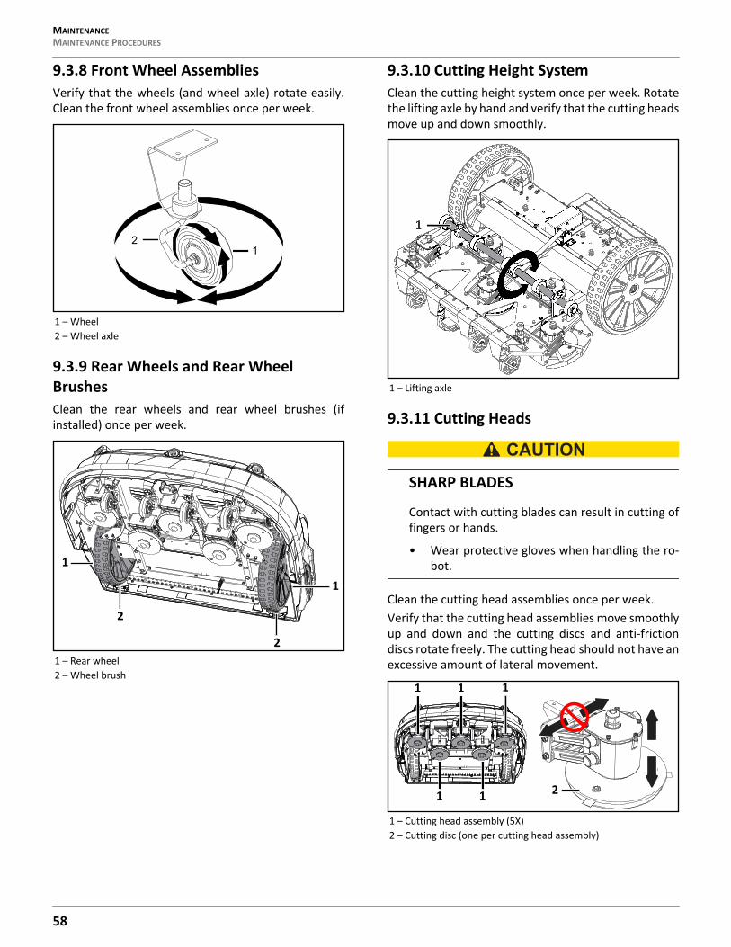
MAINTENANCEMAINTENANCE PROCEDURES
9.3.8 Front Wheel AssembliesVerify that the wheels (and wheel axle) rotate easily.Clean the front wheel assemblies once per week.
9.3.9 Rear Wheels and Rear Wheel BrushesClean the rear wheels and rear wheel brushes (ifinstalled) once per week.
9.3.10 Cutting Height SystemClean the cutting height system once per week. Rotatethe lifting axle by hand and verify that the cutting headsmove up and down smoothly.
9.3.11 Cutting Heads
SHARP BLADES
Contact with cutting blades can result in cutting offingers or hands.
• Wear protective gloves when handling the ro-bot.
Clean the cutting head assemblies once per week.Verify that the cutting head assemblies move smoothlyup and down and the cutting discs and anti-frictiondiscs rotate freely. The cutting head should not have anexcessive amount of lateral movement.
1 – Wheel2 – Wheel axle
1 – Rear wheel2 – Wheel brush
12
2
2
1
1
1 – Lifting axle
1 – Cutting head assembly (5X)2 – Cutting disc (one per cutting head assembly)
1
1 1 1
1 1 2
58
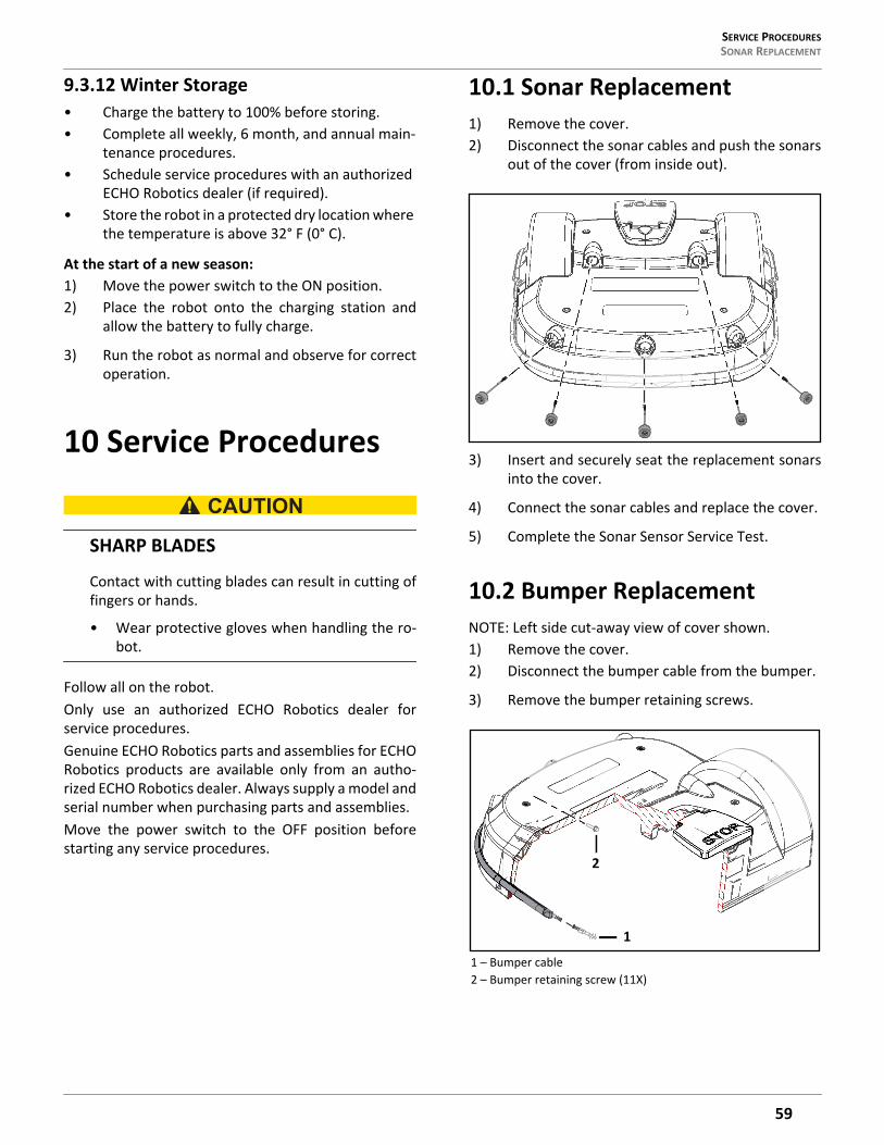
SERVICE PROCEDURES SONAR REPLACEMENT
9.3.12 Winter Storage• Charge the battery to 100% before storing.• Complete all weekly, 6 month, and annual main-
tenance procedures.• Schedule service procedures with an authorized
ECHO Robotics dealer (if required).• Store the robot in a protected dry location where
the temperature is above 32° F (0° C).
At the start of a new season:1) Move the power switch to the ON position.2) Place the robot onto the charging station and
allow the battery to fully charge.
3) Run the robot as normal and observe for correctoperation.
10 Service Procedures
SHARP BLADES
Contact with cutting blades can result in cutting offingers or hands.
• Wear protective gloves when handling the ro-bot.
Follow all on the robot.Only use an authorized ECHO Robotics dealer forservice procedures.Genuine ECHO Robotics parts and assemblies for ECHORobotics products are available only from an autho-rized ECHO Robotics dealer. Always supply a model andserial number when purchasing parts and assemblies.Move the power switch to the OFF position beforestarting any service procedures.
10.1 Sonar Replacement1) Remove the cover.2) Disconnect the sonar cables and push the sonars
out of the cover (from inside out).
3) Insert and securely seat the replacement sonarsinto the cover.
4) Connect the sonar cables and replace the cover.
5) Complete the Sonar Sensor Service Test.
10.2 Bumper ReplacementNOTE: Left side cut-away view of cover shown.1) Remove the cover.2) Disconnect the bumper cable from the bumper.
3) Remove the bumper retaining screws.
1 – Bumper cable2 – Bumper retaining screw (11X)
1
2
59
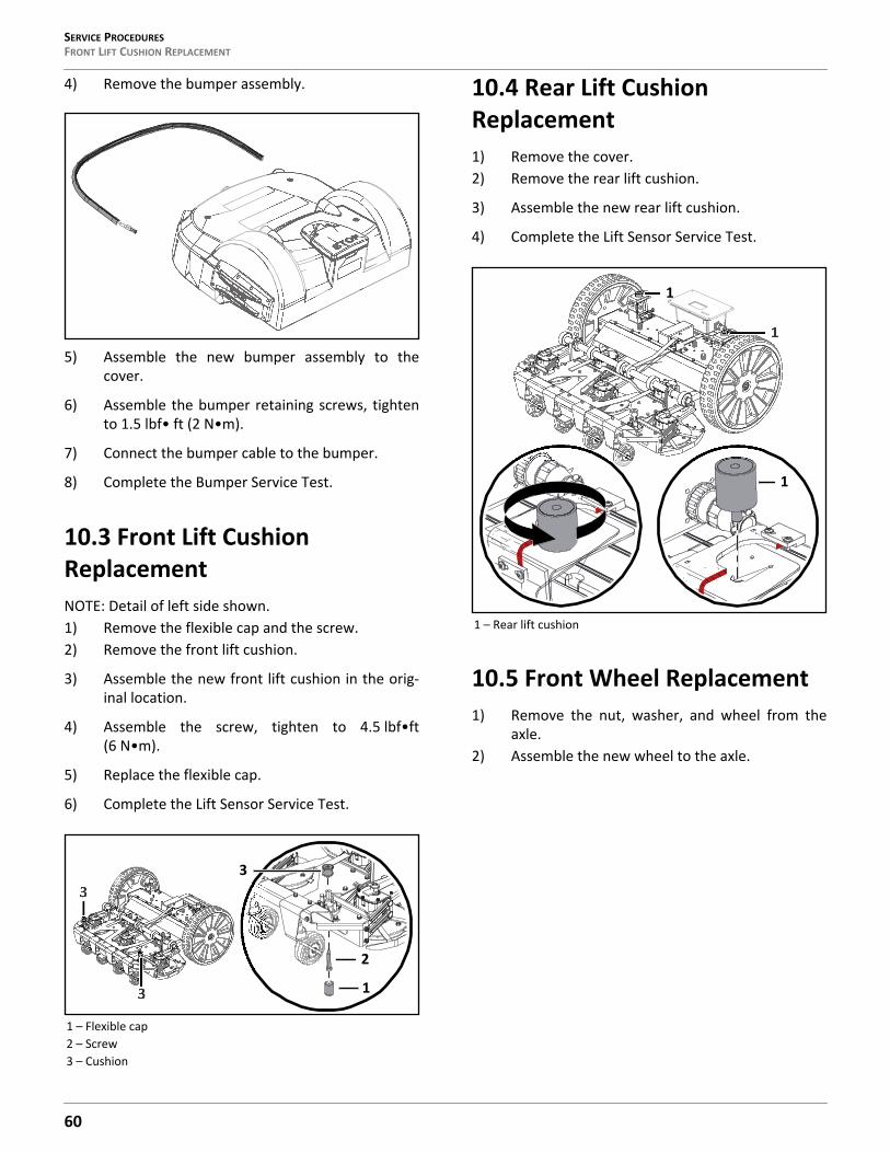
SERVICE PROCEDURESFRONT LIFT CUSHION REPLACEMENT
4) Remove the bumper assembly.
5) Assemble the new bumper assembly to thecover.
6) Assemble the bumper retaining screws, tightento 1.5 lbf• ft (2 N•m).
7) Connect the bumper cable to the bumper.
8) Complete the Bumper Service Test.
10.3 Front Lift Cushion ReplacementNOTE: Detail of left side shown.1) Remove the flexible cap and the screw.2) Remove the front lift cushion.
3) Assemble the new front lift cushion in the orig-inal location.
4) Assemble the screw, tighten to 4.5 lbf•ft(6 N•m).
5) Replace the flexible cap.
6) Complete the Lift Sensor Service Test.
10.4 Rear Lift Cushion Replacement1) Remove the cover.2) Remove the rear lift cushion.
3) Assemble the new rear lift cushion.
4) Complete the Lift Sensor Service Test.
10.5 Front Wheel Replacement1) Remove the nut, washer, and wheel from the
axle.2) Assemble the new wheel to the axle.
1 – Flexible cap2 – Screw3 – Cushion
3
3
2
1
3
1 – Rear lift cushion
1
1
1
60
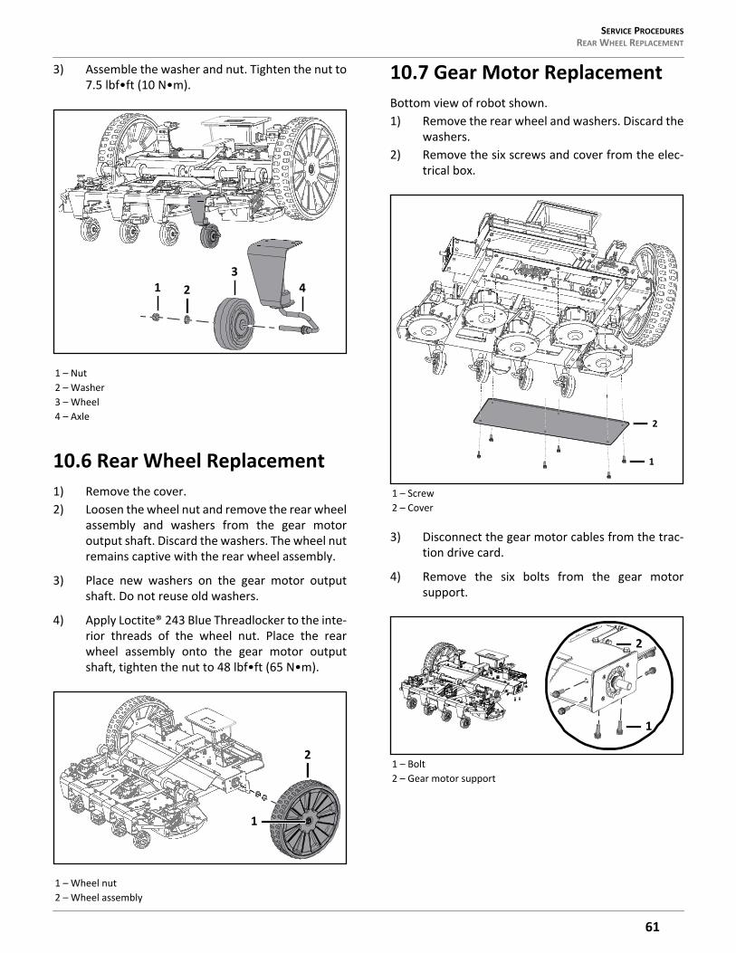
SERVICE PROCEDURES REAR WHEEL REPLACEMENT
3) Assemble the washer and nut. Tighten the nut to7.5 lbf•ft (10 N•m).
10.6 Rear Wheel Replacement1) Remove the cover.2) Loosen the wheel nut and remove the rear wheel
assembly and washers from the gear motoroutput shaft. Discard the washers. The wheel nutremains captive with the rear wheel assembly.
3) Place new washers on the gear motor outputshaft. Do not reuse old washers.
4) Apply Loctite® 243 Blue Threadlocker to the inte-rior threads of the wheel nut. Place the rearwheel assembly onto the gear motor outputshaft, tighten the nut to 48 lbf•ft (65 N•m).
10.7 Gear Motor ReplacementBottom view of robot shown.1) Remove the rear wheel and washers. Discard the
washers.2) Remove the six screws and cover from the elec-
trical box.
3) Disconnect the gear motor cables from the trac-tion drive card.
4) Remove the six bolts from the gear motorsupport.
1 – Nut2 – Washer3 – Wheel4 – Axle
1 – Wheel nut2 – Wheel assembly
1 23
4
2
1
1 – Screw2 – Cover
1 – Bolt2 – Gear motor support
1
2
2
1
61
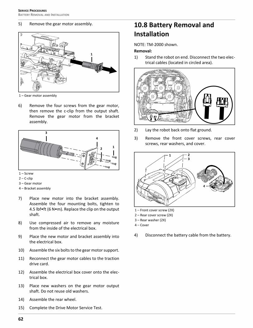
SERVICE PROCEDURESBATTERY REMOVAL AND INSTALLATION
5) Remove the gear motor assembly.
6) Remove the four screws from the gear motor,then remove the c-clip from the output shaft.Remove the gear motor from the bracketassembly.
7) Place new motor into the bracket assembly.Assemble the four mounting bolts, tighten to4.5 lbf•ft (6 N•m). Replace the clip on the outputshaft.
8) Use compressed air to remove any moisturefrom the inside of the electrical box.
9) Place the new motor and bracket assembly intothe electrical box.
10) Assemble the six bolts to the gear motor support.
11) Reconnect the gear motor cables to the tractiondrive card.
12) Assemble the electrical box cover onto the elec-trical box.
13) Place new washers on the gear motor outputshaft. Do not reuse old washers.
14) Assemble the rear wheel.
15) Complete the Drive Motor Service Test.
10.8 Battery Removal and InstallationNOTE: TM-2000 shown.Removal:1) Stand the robot on end. Disconnect the two elec-
trical cables (located in circled area).
2) Lay the robot back onto flat ground.
3) Remove the front cover screws, rear coverscrews, rear washers, and cover.
4) Disconnect the battery cable from the battery.
1 – Gear motor assembly
1 – Screw2 – C-clip3 – Gear motor4 – Bracket assembly
1
3
2
4
1
1 – Front cover screw (2X)2 – Rear cover screw (2X)3 – Rear washer (2X)4 – Cover
1
4
23
62
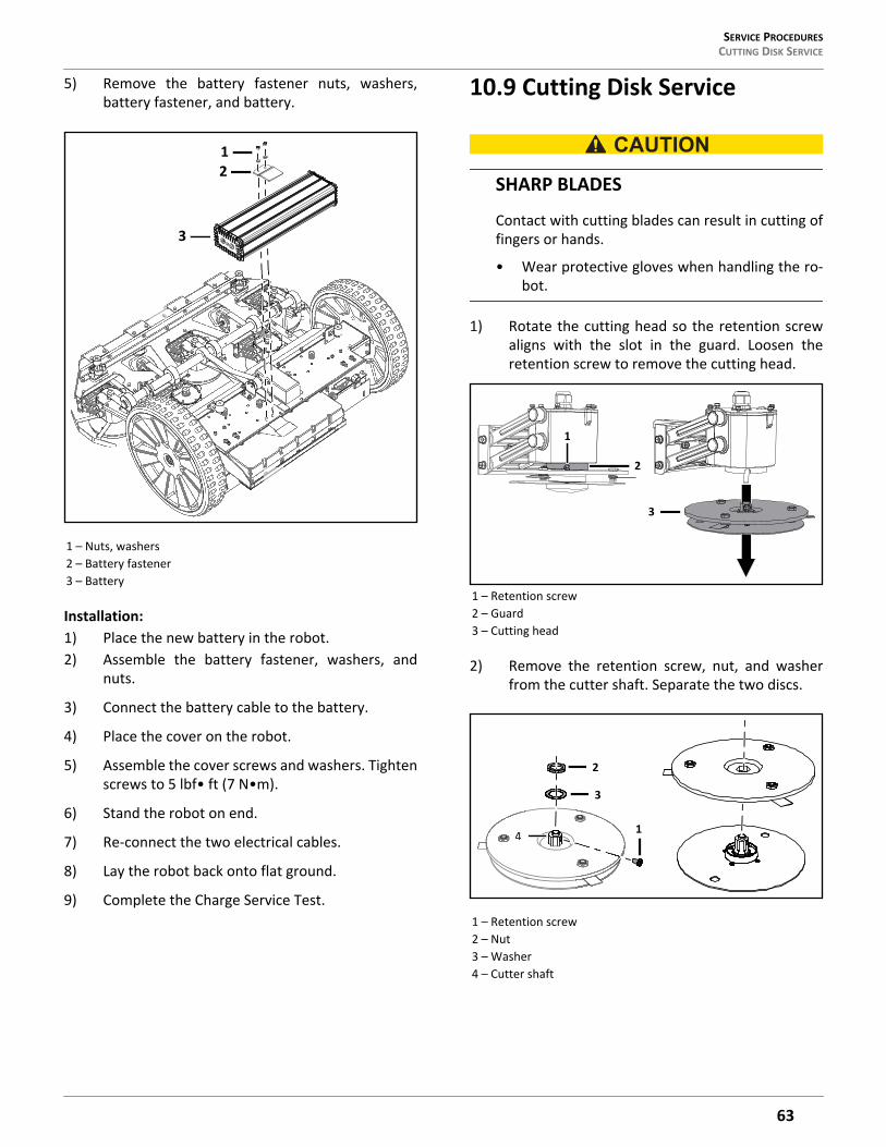
SERVICE PROCEDURES CUTTING DISK SERVICE
5) Remove the battery fastener nuts, washers,battery fastener, and battery.
Installation:1) Place the new battery in the robot.2) Assemble the battery fastener, washers, and
nuts.
3) Connect the battery cable to the battery.
4) Place the cover on the robot.
5) Assemble the cover screws and washers. Tightenscrews to 5 lbf• ft (7 N•m).
6) Stand the robot on end.
7) Re-connect the two electrical cables.
8) Lay the robot back onto flat ground.
9) Complete the Charge Service Test.
10.9 Cutting Disk Service
SHARP BLADES
Contact with cutting blades can result in cutting offingers or hands.
• Wear protective gloves when handling the ro-bot.
1) Rotate the cutting head so the retention screwaligns with the slot in the guard. Loosen theretention screw to remove the cutting head.
2) Remove the retention screw, nut, and washerfrom the cutter shaft. Separate the two discs.
1 – Nuts, washers2 – Battery fastener3 – Battery
1
3
2
1 – Retention screw2 – Guard3 – Cutting head
1 – Retention screw2 – Nut3 – Washer4 – Cutter shaft
1
2
3
1
2
3
4
63
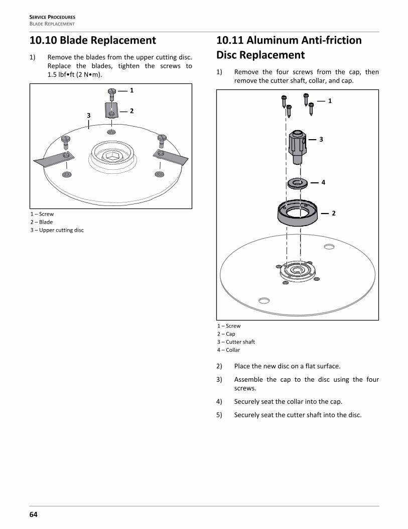
SERVICE PROCEDURESBLADE REPLACEMENT
10.10 Blade Replacement1) Remove the blades from the upper cutting disc.
Replace the blades, tighten the screws to1.5 lbf•ft (2 N•m).
10.11 Aluminum Anti-friction Disc Replacement1) Remove the four screws from the cap, then
remove the cutter shaft, collar, and cap.
2) Place the new disc on a flat surface.
3) Assemble the cap to the disc using the fourscrews.
4) Securely seat the collar into the cap.
5) Securely seat the cutter shaft into the disc.
1 – Screw2 – Blade3 – Upper cutting disc
1
23
1 – Screw2 – Cap3 – Cutter shaft4 – Collar
1
3
4
2
64
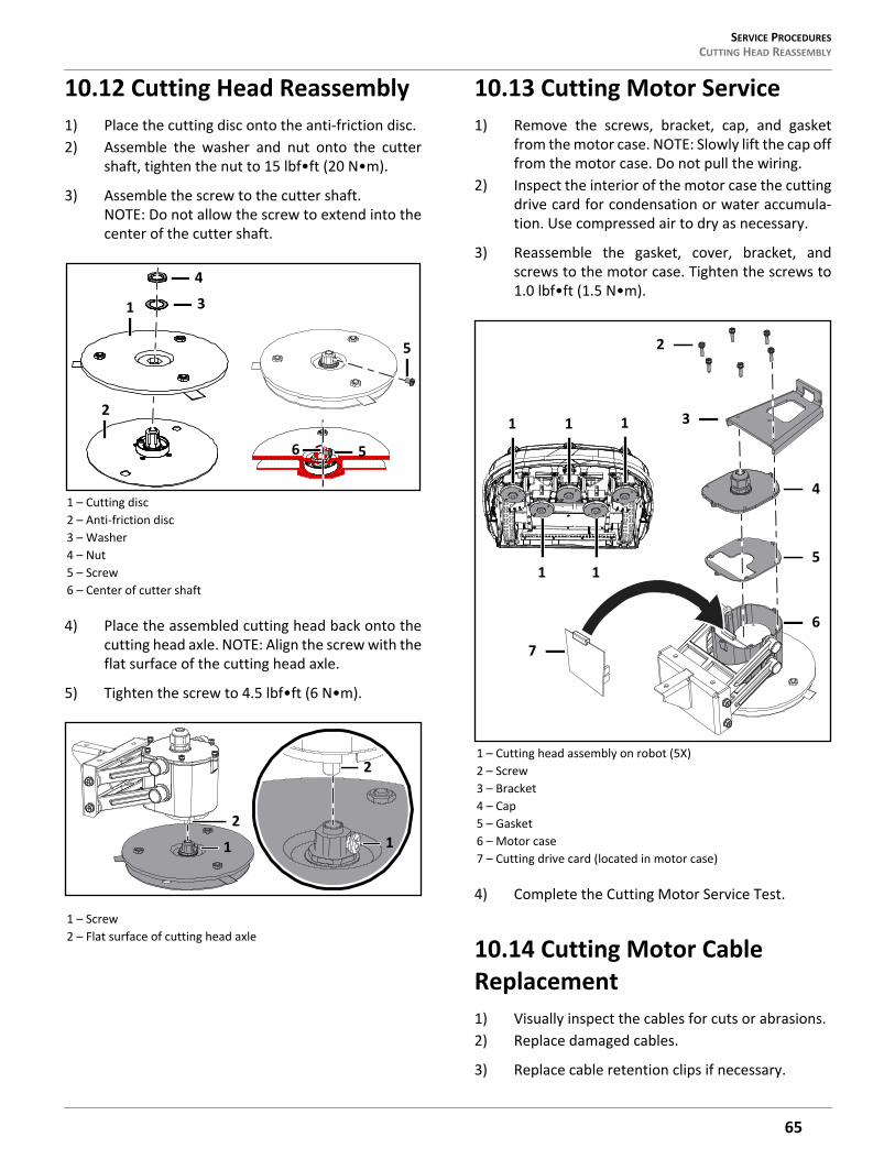
SERVICE PROCEDURES CUTTING HEAD REASSEMBLY
10.12 Cutting Head Reassembly1) Place the cutting disc onto the anti-friction disc.2) Assemble the washer and nut onto the cutter
shaft, tighten the nut to 15 lbf•ft (20 N•m).
3) Assemble the screw to the cutter shaft. NOTE: Do not allow the screw to extend into thecenter of the cutter shaft.
4) Place the assembled cutting head back onto thecutting head axle. NOTE: Align the screw with theflat surface of the cutting head axle.
5) Tighten the screw to 4.5 lbf•ft (6 N•m).
10.13 Cutting Motor Service1) Remove the screws, bracket, cap, and gasket
from the motor case. NOTE: Slowly lift the cap offfrom the motor case. Do not pull the wiring.
2) Inspect the interior of the motor case the cuttingdrive card for condensation or water accumula-tion. Use compressed air to dry as necessary.
3) Reassemble the gasket, cover, bracket, andscrews to the motor case. Tighten the screws to1.0 lbf•ft (1.5 N•m).
4) Complete the Cutting Motor Service Test.
10.14 Cutting Motor Cable Replacement1) Visually inspect the cables for cuts or abrasions.2) Replace damaged cables.
3) Replace cable retention clips if necessary.
1 – Cutting disc2 – Anti-friction disc3 – Washer4 – Nut5 – Screw6 – Center of cutter shaft
1 – Screw2 – Flat surface of cutting head axle
1
2
3
4
5
56
1
2
2
1
1 – Cutting head assembly on robot (5X)2 – Screw3 – Bracket4 – Cap5 – Gasket6 – Motor case7 – Cutting drive card (located in motor case)
2
3
4
5
6
1 1 1
1 1
7
65
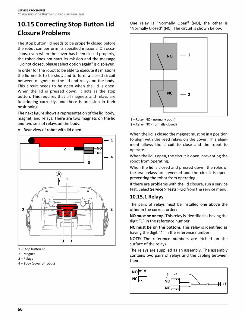
SERVICE PROCEDURESCORRECTING STOP BUTTON LID CLOSURE PROBLEMS
10.15 Correcting Stop Button Lid Closure ProblemsThe stop button lid needs to be properly closed beforethe robot can perform its specified missions. On occa-sions, even when the cover has been closed properly,the robot does not start its mission and the message"Lid not closed, please select option again" is displayed.In order for the robot to be able to execute its missionsthe lid needs to be shut, and to form a closed circuitbetween magnets on the lid and relays on the body.This circuit needs to be open when the lid is open.When the lid is pressed down, it acts as the stopbutton. This requires that all magnets and relays arefunctioning correctly, and there is precision in theirpositioning.The next figure shows a representation of the lid, body,magnet, and relays. There are two magnets on the lidand two sets of relays on the body.A - Rear view of robot with lid open.
One relay is "Normally Open" (NO), the other is"Normally Closed" (NC). The circuit is shown below.
When the lid is closed the magnet must be in a positionto align with the reed relays on the cover. This align-ment allows the circuit to close and the robot tooperate.When the lid is open, the circuit is open, preventing therobot from operating.When the lid is closed and pressed down, the roles ofthe two relays are reversed and the circuit is open,preventing the robot from operating.If there are problems with the lid closure, run a servicetest. Select Service > Tests > Lid from the service menu.
10.15.1 RelaysThe pairs of relays must be installed one above theother in the correct order: NO must be on top. This relay is identified as having thedigit “1” in the reference number.NC must be on the bottom. This relay is identified ashaving the digit “4” in the reference number.NOTE: The reference numbers are etched on thesurface of the relays.The relays are supplied as an assembly. The assemblycontains two pairs of relays and the cabling betweenthem.
1 – Stop button lid2 – Magnet3 – Relays4 – Body (cover of robot)
NONC
2
3
2 2
1
4
3 3
1
1 – Relay (NO - normally open)2 – Relay (NC - normally closed)
NO
NC
1
2
NONC NO
NC
66
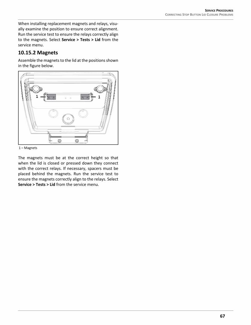
SERVICE PROCEDURES CORRECTING STOP BUTTON LID CLOSURE PROBLEMS
When installing replacement magnets and relays, visu-ally examine the position to ensure correct alignment.Run the service test to ensure the relays correctly alignto the magnets. Select Service > Tests > Lid from theservice menu.
10.15.2 MagnetsAssemble the magnets to the lid at the positions shownin the figure below.
The magnets must be at the correct height so thatwhen the lid is closed or pressed down they connectwith the correct relays. If necessary, spacers must beplaced behind the magnets. Run the service test toensure the magnets correctly align to the relays. SelectService > Tests > Lid from the service menu.
1 – Magnets
11
67
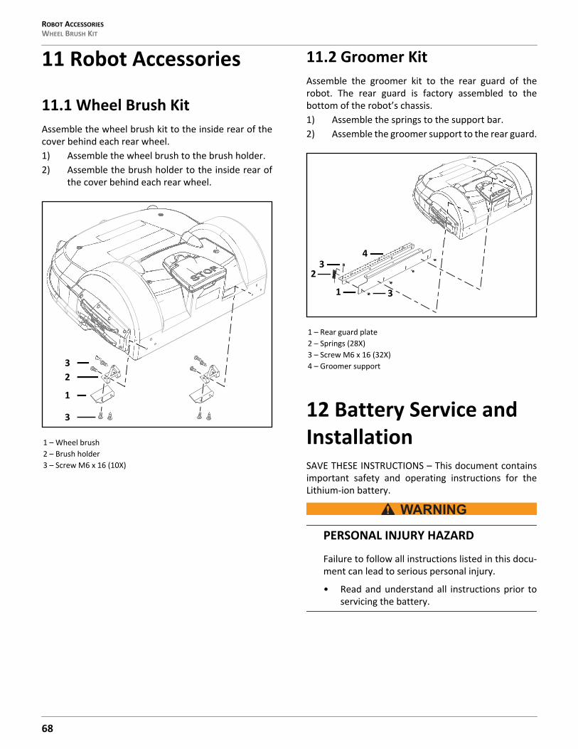
ROBOT ACCESSORIESWHEEL BRUSH KIT
11 Robot Accessories
11.1 Wheel Brush KitAssemble the wheel brush kit to the inside rear of thecover behind each rear wheel.1) Assemble the wheel brush to the brush holder.2) Assemble the brush holder to the inside rear of
the cover behind each rear wheel.
11.2 Groomer KitAssemble the groomer kit to the rear guard of therobot. The rear guard is factory assembled to thebottom of the robot’s chassis.1) Assemble the springs to the support bar.2) Assemble the groomer support to the rear guard.
12 Battery Service and InstallationSAVE THESE INSTRUCTIONS – This document containsimportant safety and operating instructions for theLithium-ion battery.
PERSONAL INJURY HAZARD
Failure to follow all instructions listed in this docu-ment can lead to serious personal injury.
• Read and understand all instructions prior toservicing the battery.
1 – Wheel brush2 – Brush holder3 – Screw M6 x 16 (10X)
1
23
3
1 – Rear guard plate2 – Springs (28X)3 – Screw M6 x 16 (32X)4 – Groomer support
1
23
3
4
68
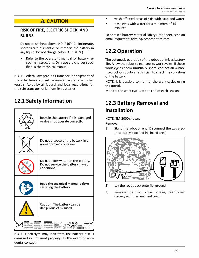
BATTERY SERVICE AND INSTALLATION SAFETY INFORMATION
RISK OF FIRE, ELECTRIC SHOCK, AND BURNS
Do not crush, heat above 140 °F (60 °C), incinerate,short circuit, dismantle, or immerse the battery inany liquid. Do not charge below 32 °F (0 °C).
• Refer to the operator’s manual for battery re-cycling instructions. Only use the charger spec-ified in the technical manual.
NOTE: Federal law prohibits transport or shipment ofthese batteries aboard passenger aircrafts or othervessels. Abide by all federal and local regulations forthe safe transport of Lithium-ion batteries.
12.1 Safety Information
NOTE: Electrolyte may leak from the battery if it isdamaged or not used properly. In the event of acci-dental contact:
• wash affected areas of skin with soap and water• rinse eyes with water for a minimum of 15
minutes
To obtain a battery Material Safety Data Sheet, send anemail request to: [email protected].
12.2 OperationThe automatic operation of the robot optimizes batterylife. Allow the robot to manage its work cycles. If thesework cycles seem unusually short, contact an autho-rized ECHO Robotics Technician to check the conditionof the battery.NOTE: It is possible to monitor the work cycles usingthe portal.Monitor the work cycles at the end of each season.
12.3 Battery Removal and InstallationNOTE: TM-2000 shown.Removal:1) Stand the robot on end. Disconnect the two elec-
trical cables (located in circled area).
2) Lay the robot back onto flat ground.
3) Remove the front cover screws, rear coverscrews, rear washers, and cover.
Recycle the battery if it is damaged or does not operate correctly.
Do not dispose of the battery in a non-approved container.
Do not allow water on the battery. Do not service the battery in wet conditions.
Read the technical manual before servicing the battery.
Caution: The battery can be dangerous of misused.
Li-Fe
69
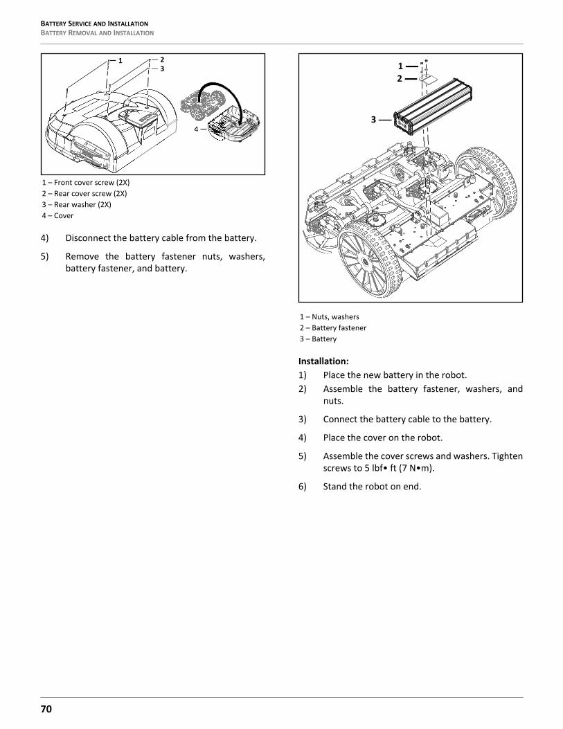
BATTERY SERVICE AND INSTALLATIONBATTERY REMOVAL AND INSTALLATION
4) Disconnect the battery cable from the battery.
5) Remove the battery fastener nuts, washers,battery fastener, and battery.
Installation:1) Place the new battery in the robot.2) Assemble the battery fastener, washers, and
nuts.
3) Connect the battery cable to the battery.
4) Place the cover on the robot.
5) Assemble the cover screws and washers. Tightenscrews to 5 lbf• ft (7 N•m).
6) Stand the robot on end.
1 – Front cover screw (2X)2 – Rear cover screw (2X)3 – Rear washer (2X)4 – Cover
1
4
23
1 – Nuts, washers2 – Battery fastener3 – Battery
1
3
2
70

TORQUE REFERENCES STORAGE
7) Re-connect the two electrical cables.
8) Lay the robot back onto flat ground.
9) Complete the Charge Service Test.
12.4 StoragePrior to storage:• Move the robot to the charging station, allow the
battery to completely charge.• Move the main power switch for the robot to the
OFF position.• Disconnect the battery cable from the battery.
12.5 Recycling
Recycle the battery if it is damaged ornon-operational.
Do not dispose of the battery in anon-approved container.If there are no accredited facilities available to recyclebatteries, check with your authorized ECHO RoboticsDealer or local government agency for proper batterydisposal procedures.
13 Torque ReferencesIMPORTANT: The values in the following table apply only when a specific torque for a fastener is not listed.
Li-Fe
Size lbf•ft N•m
No. 6 0.58 - 0.83 0.8 - 1.1No. 8 1.25 - 1.83 1.7 - 2.5No. 10 2.0- 3.0 2.7 - 4.0No. 12 3.0 - 4.0 4.0 - 5.4M3 1.25 - 1.83 1.7 - 2.5M4 2.0 - 2.9 2.7 - 4.0M5 2.9 - 5.0 4.0 - 6.8M6 7.0- 8.8 9.5 - 12.0M8 14.7 - 17.0 20.0 - 23.0M10 25.8 - 28.0 35.0 - 38.0
71
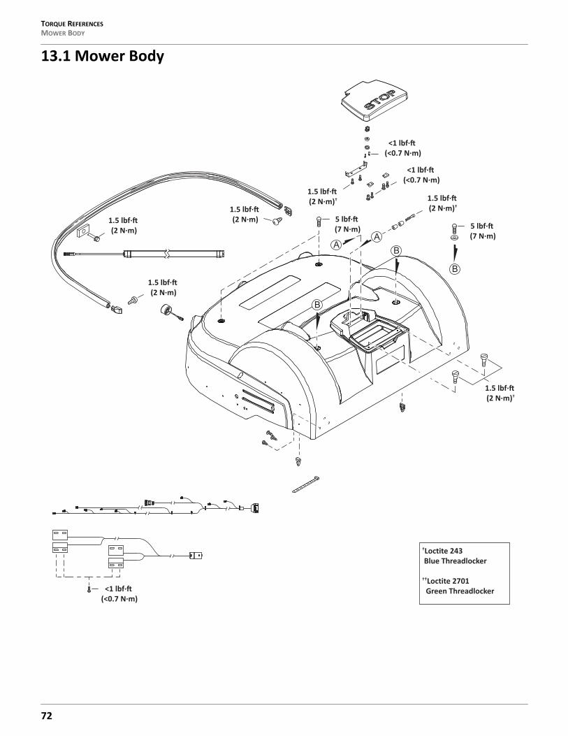
TORQUE REFERENCESMOWER BODY
13.1 Mower Body
†Loctite 243 Blue Threadlocker
††Loctite 2701 Green Threadlocker
1.5 lbf·(2 N·m)†
1.5 lbf·(2 N·m)†
5 lbf·(7 N·m)
1.5 lbf·(2 N·m)
1.5 lbf·(2 N·m)
1.5 lbf·(2 N·m)
1.5 lbf·(2 N·m)†
<1 lbf·(<0.7 N·m)
<1 lbf·(<0.7 N·m)
5 lbf·(7 N·m)
<1 lbf·(<0.7 N·m)
72
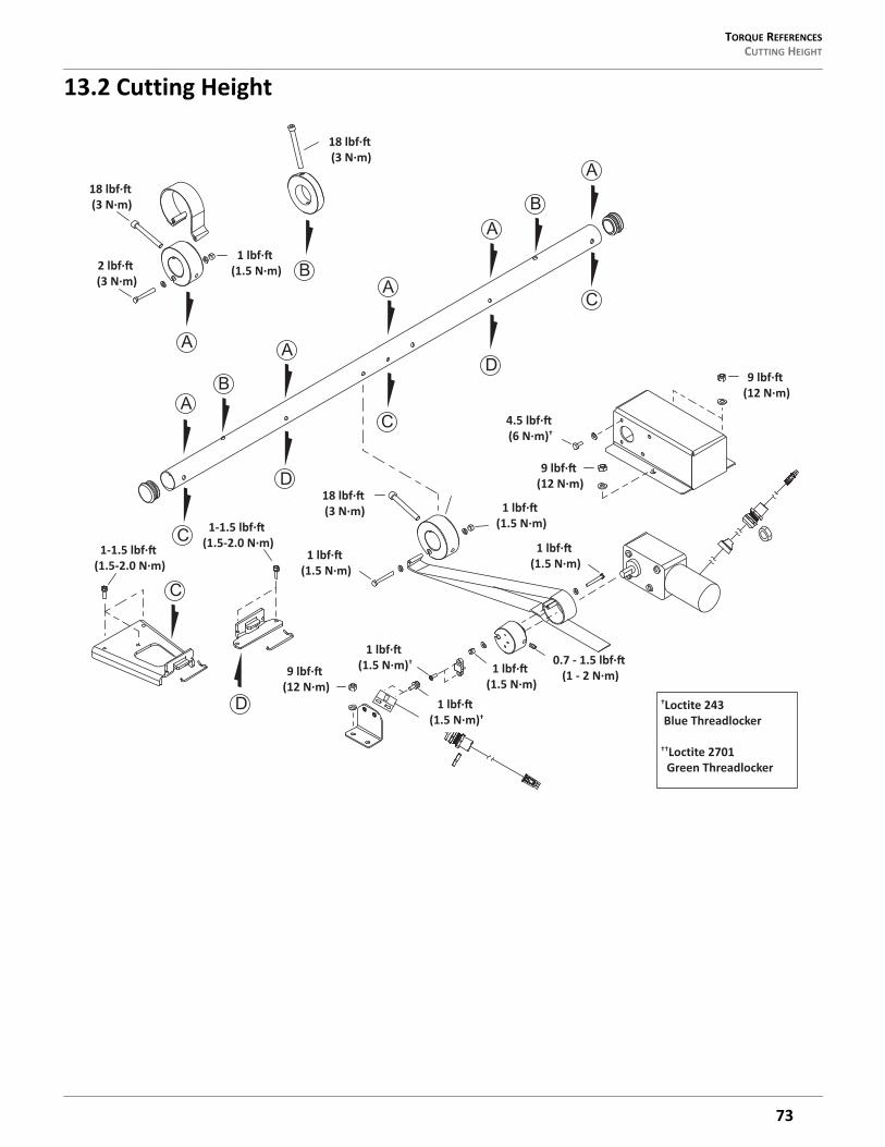
TORQUE REFERENCES CUTTING HEIGHT
13.2 Cutting Height
1 lbf·(1.5 N·m)
4.5 lbf·(6 N·m)†
9 lbf·(12 N·m)
9 lbf·(12 N·m)
1 lbf·(1.5 N·m)†
2 lbf·(3 N·m)
1 lbf·(1.5 N·m)
1 lbf·(1.5 N·m)
1 lbf·(1.5 N·m)
18 lbf·(3 N·m)
18 lbf·(3 N·m)
1 lbf·(1.5 N·m)
1 lbf·(1.5 N·m)† 0.7 - 1.5 lbf·
(1 - 2 N·m)9 lbf·(12 N·m)
†Loctite 243 Blue Threadlocker
††Loctite 2701 Green Threadlocker
1-1.5 lbf·(1.5-2.0 N·m)
1-1.5 lbf·(1.5-2.0 N·m)
18 lbf·(3 N·m)
73
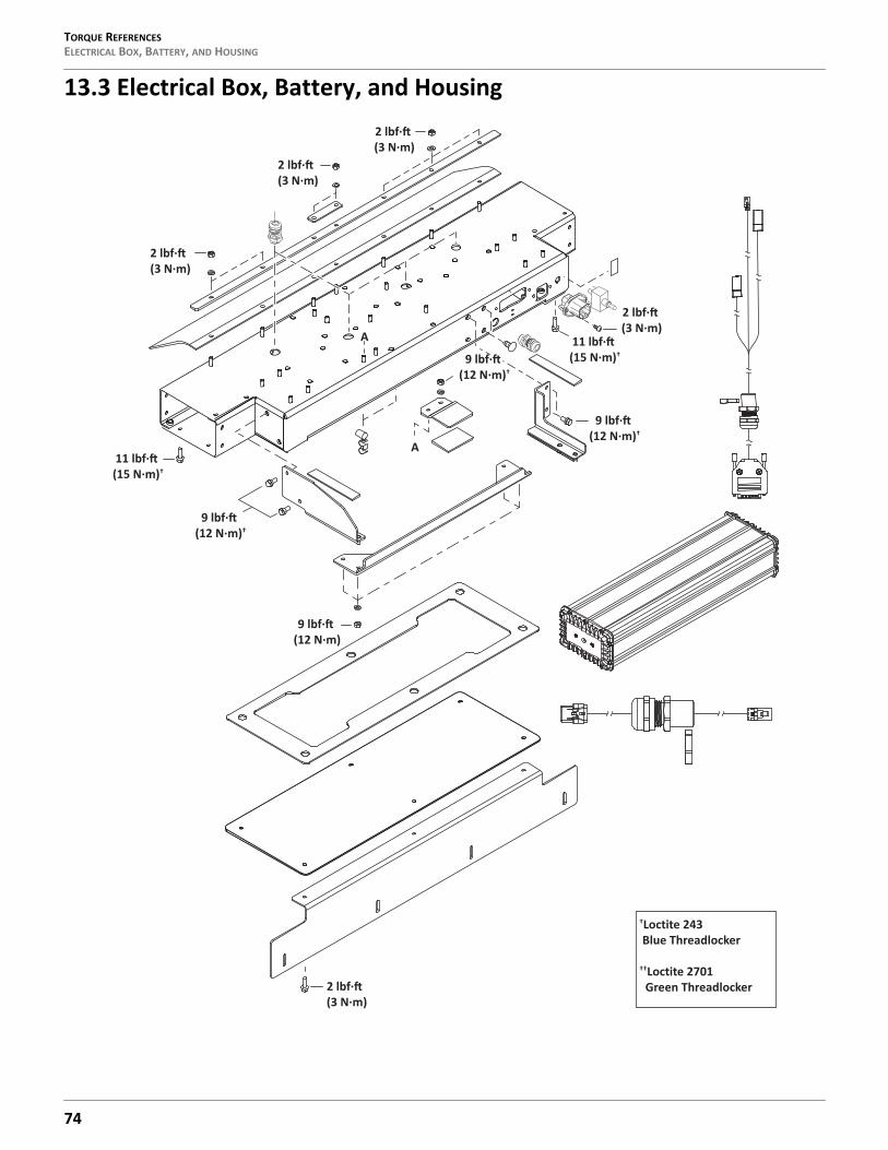
TORQUE REFERENCESELECTRICAL BOX, BATTERY, AND HOUSING
13.3 Electrical Box, Battery, and Housing
A
A 11 lbf·(15 N·m)†
2 lbf·(3 N·m)
11 lbf·(15 N·m)†
9 lbf·(12 N·m)†
9 lbf·(12 N·m)
2 lbf·(3 N·m)
2 lbf·(3 N·m)
2 lbf·(3 N·m)
2 lbf·(3 N·m)
9 lbf·(12 N·m)†
9 lbf·(12 N·m)†
†Loctite 243 Blue Threadlocker
††Loctite 2701 Green Threadlocker
74

TORQUE REFERENCES LIFT SENSORS
13.4 Lift Sensors
1 lbf ft (1.5 N †
4.5 lbf ft (6 N †
2 lbf ft (3 N †
2 lbf ft (3 N ††
1 lbf ft (1.5 N †
9 lbf ft (12 N
0.7-1.0 lbf ft (1-1.5 N †
0.7-1.0 lbf ft (1-1.5 N †
†Loctite 243 Blue Threadlocker
††Loctite 2701 Green Threadlocker
75

TORQUE REFERENCES WHEELS, MOTOR AND GEAR BOX
13.5 Wheels, Motor and Gear Box
7.5 lbf·(10 N·m)
7.5 lbf·(10 N·m)
7.5 lbf·(10 N·m)
9 lbf·(12 N·m)†
48 lbf·(65 N·m)
4.5 lbf·(6 N·m)†† 2 lbf·
(3 N·m)†
†Loctite 243 Blue Threadlocker
††Loctite 2701 Green Threadlocker
0.75 - 1.0 lbf·(1.0 - 1.5 N·m)
76

TORQUE REFERENCES CUTTING HEAD
13.6 Cutting Head
A
A
1.0-1.5 lbf·(1.5-2.0 N·m)
4.5-6.0 lbf·(6-8 N·m)
4.5-6.0 lbf·(6-8 N·m)†
4.5-6.0 lbf·(6-8 N·m)†
3.7-5.0 lbf·(5-7 N·m)†
9 lbf·(12 N·m)†
0.75-1.5 lbf·(1-2 N·m)
3.5-5.0 lbf·(5-7 N·m)†
15 lbf·(20 N·m)†
4.5 lbf·(6 N·m)†
1.5 lbf·(2 N·m)†
4.5 lbf·(6 N·m)††
1.5 lbf·(2 N·m)†
3.7-5.0 lbf·(5-7 N·m)†
†Loctite 243 Blue Threadlocker
††Loctite 2701 Green Threadlocker
77
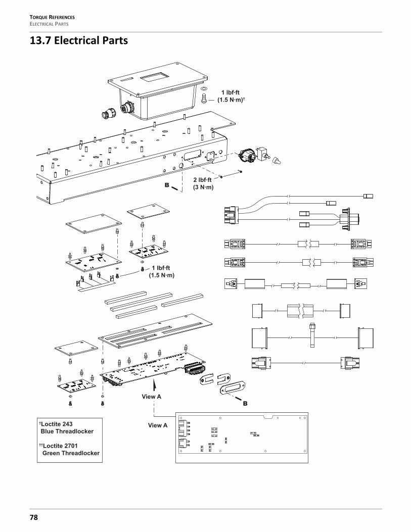
TORQUE REFERENCESELECTRICAL PARTS
13.7 Electrical Parts
View A
View AB
B2 lbf ft (3 N
1 lbf ft (1.5 N
1 lbf ft (1.5 N †
†Loctite 243 Blue Threadlocker
††Loctite 2701 Green Threadlocker
78
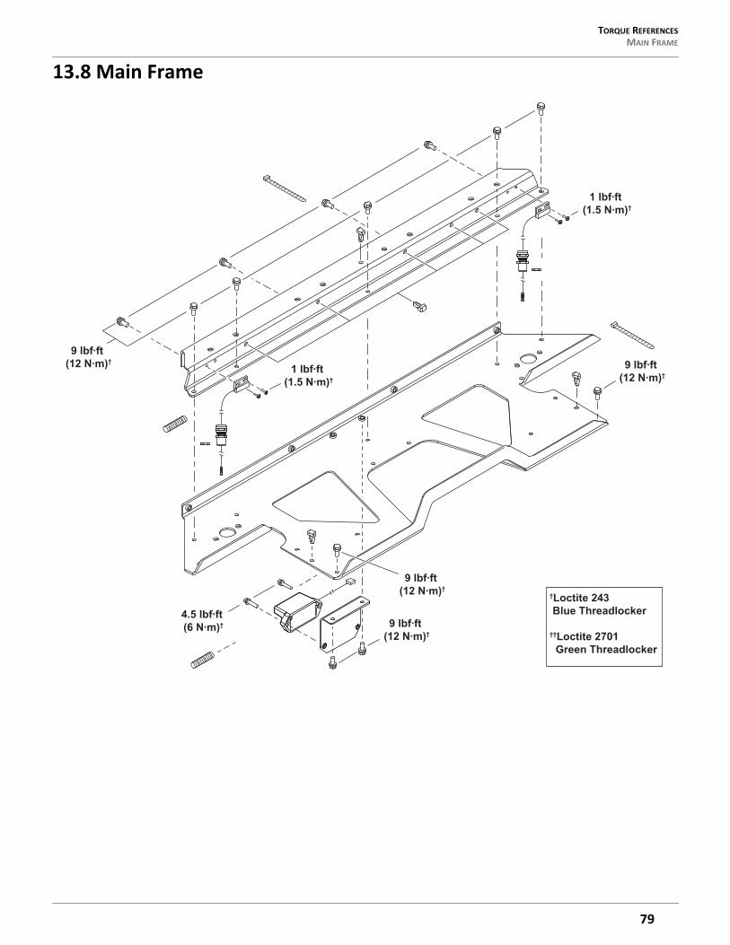
TORQUE REFERENCES MAIN FRAME
13.8 Main Frame
9 lbf ft (12 N †
9 lbf ft (12 N †
4.5 lbf ft (6 N † 9 lbf ft
(12 N †
9 lbf ft (12 N †
1 lbf ft (1.5 N †
1 lbf ft (1.5 N †
†Loctite 243 Blue Threadlocker
††Loctite 2701 Green Threadlocker
79
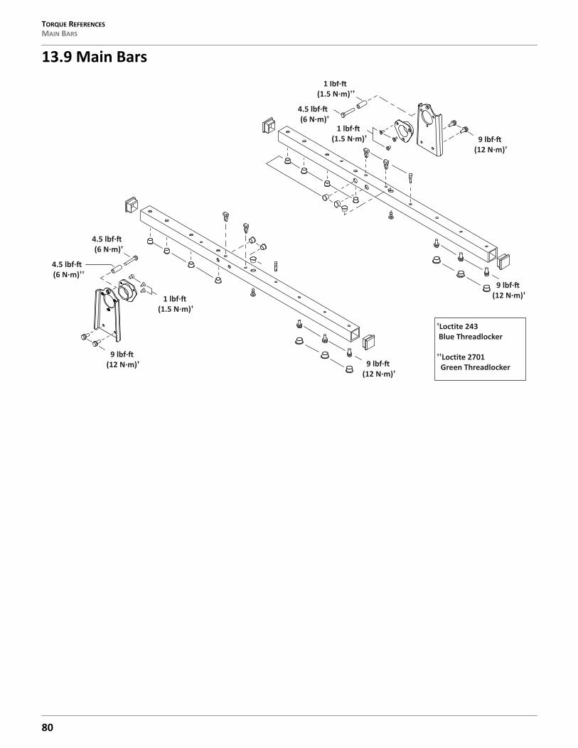
TORQUE REFERENCESMAIN BARS
13.9 Main Bars
9 lbf·(12 N·m)†
9 lbf·(12 N·m)†
1 lbf·(1.5 N·m)†
1 lbf·(1.5 N·m)††
4.5 lbf·(6 N·m)†
4.5 lbf·(6 N·m)†
9 lbf·(12 N·m)†
9 lbf·(12 N·m)†
1 lbf·(1.5 N·m)†
†Loctite 243 Blue Threadlocker
††Loctite 2701 Green Threadlocker
4.5 lbf·(6 N·m)††
80
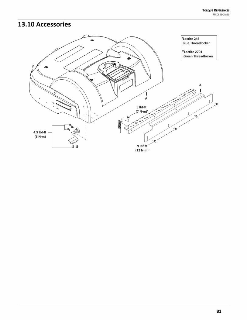
TORQUE REFERENCES ACCESSORIES
13.10 Accessories
A
A
4.5 lbf·(6 N·m)
5 lbf·(7 N·m)†
†Loctite 243 Blue Threadlocker
††Loctite 2701 Green Threadlocker
9 lbf·(12 N·m)†
81
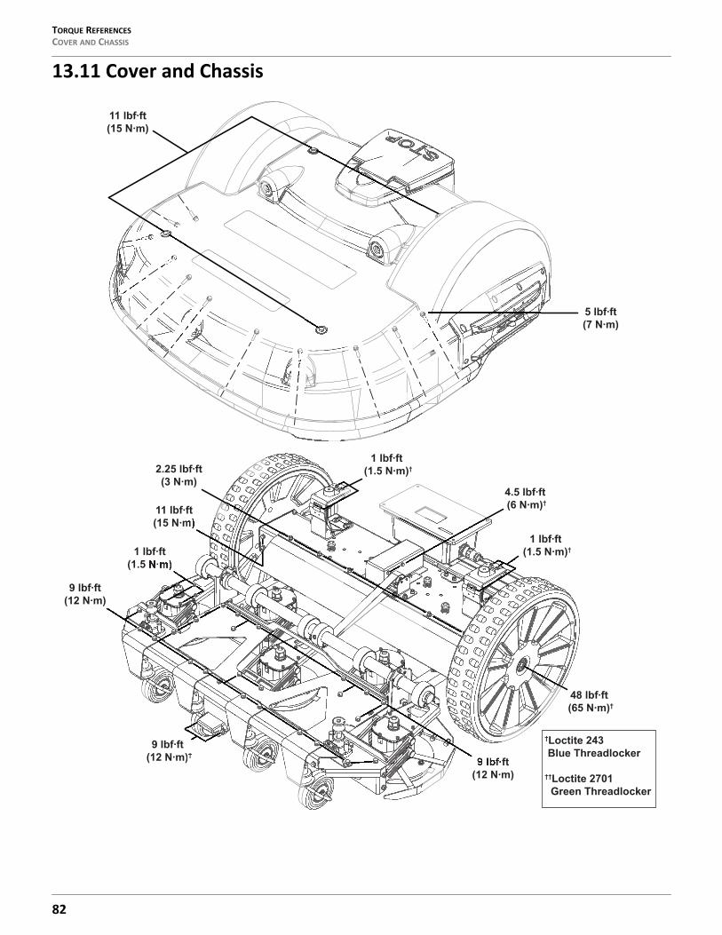
TORQUE REFERENCESCOVER AND CHASSIS
13.11 Cover and Chassis
9 lbf ft(12 N
1 lbf ft(1.5 N
9 lbf ft (12 N †
48 lbf ft (65 N †
1 lbf ft (1.5 N †
4.5 lbf ft (6 N †
2.25 lbf ft(3 N
11 lbf ft(15 N
9 lbf ft(12 N
11 lbf ft(15 N
5 lbf ft(7 N
1 lbf ft (1.5 N †
†Loctite 243 Blue Threadlocker
††Loctite 2701 Green Threadlocker
82
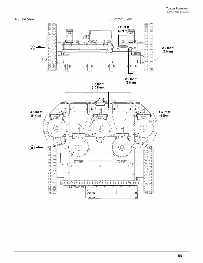
TORQUE REFERENCES COVER AND CHASSIS
A - Rear View B - Bottom View
2.2 lbf ft(3 N
2.2 lbf ft(3 N
2.2 lbf ft(3 N
4.5 lbf ft(6 N
4.5 lbf ft(6 N
7.5 lbf ft(10 N
A
B
83
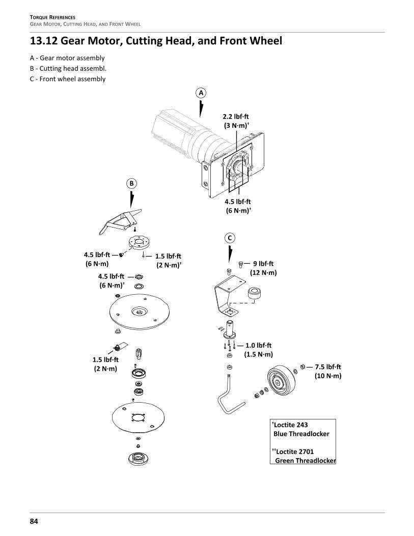
TORQUE REFERENCESGEAR MOTOR, CUTTING HEAD, AND FRONT WHEEL
13.12 Gear Motor, Cutting Head, and Front WheelA - Gear motor assemblyB - Cutting head assembl.C - Front wheel assembly
2.2 lbf·(3 N·m)†
4.5 lbf·(6 N·m)†
A
B
4.5 lbf·(6 N·m)
1.5 lbf·(2 N·m)†
4.5 lbf·(6 N·m)†
1.5 lbf·(2 N·m)
C
7.5 lbf·(10 N·m)
9 lbf·(12 N·m)
1.0 lbf·(1.5 N·m)
†Loctite 243 Blue Threadlocker
††Loctite 2701 Green Threadlocker
84
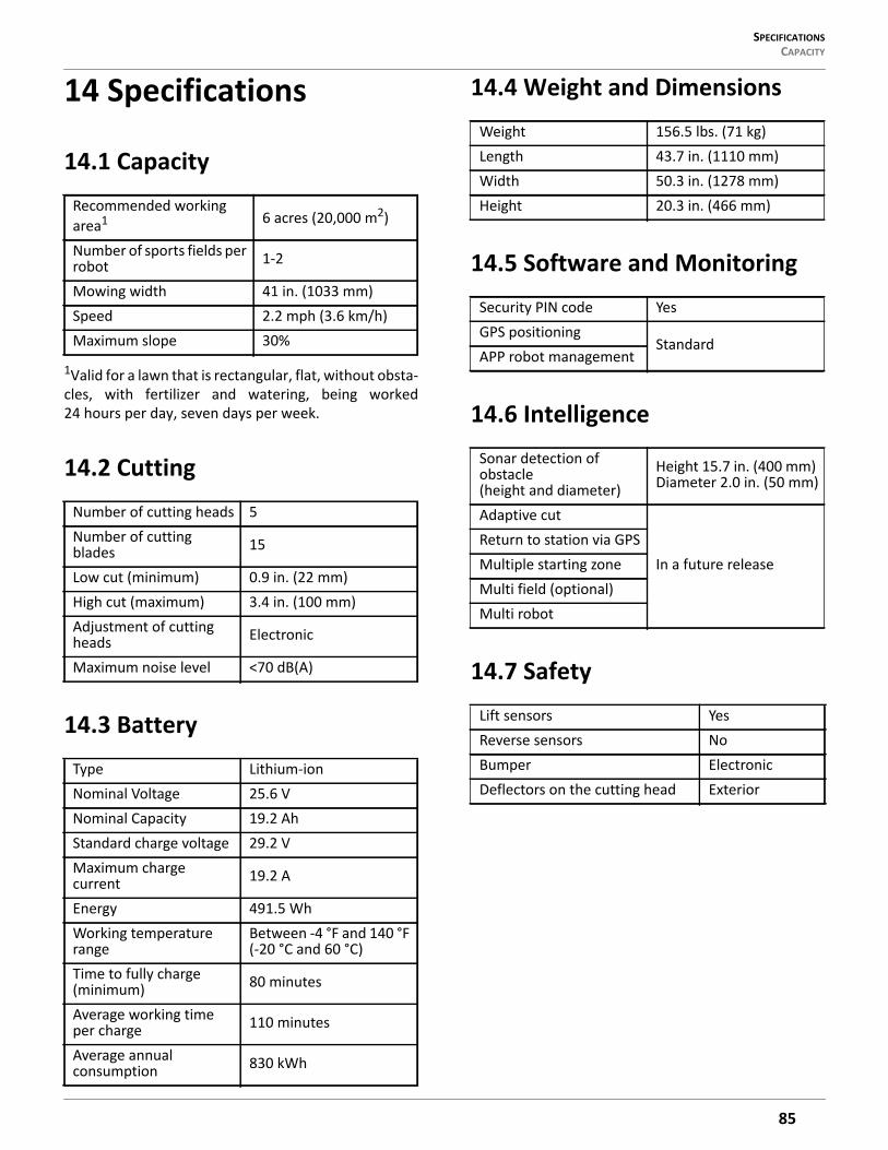
SPECIFICATIONS CAPACITY
14 Specifications
14.1 Capacity
1Valid for a lawn that is rectangular, flat, without obsta-cles, with fertilizer and watering, being worked24 hours per day, seven days per week.
14.2 Cutting
14.3 Battery
14.4 Weight and Dimensions
14.5 Software and Monitoring
14.6 Intelligence
14.7 Safety
Recommended working area1 6 acres (20,000 m2)
Number of sports fields per robot 1-2
Mowing width 41 in. (1033 mm)Speed 2.2 mph (3.6 km/h)Maximum slope 30%
Number of cutting heads 5Number of cutting blades 15
Low cut (minimum) 0.9 in. (22 mm)High cut (maximum) 3.4 in. (100 mm)Adjustment of cutting heads Electronic
Maximum noise level <70 dB(A)
Type Lithium-ionNominal Voltage 25.6 VNominal Capacity 19.2 AhStandard charge voltage 29.2 VMaximum charge current 19.2 A
Energy 491.5 WhWorking temperature range
Between -4 °F and 140 °F (-20 °C and 60 °C)
Time to fully charge (minimum) 80 minutes
Average working time per charge 110 minutes
Average annual consumption 830 kWh
Weight 156.5 lbs. (71 kg)Length 43.7 in. (1110 mm)Width 50.3 in. (1278 mm)Height 20.3 in. (466 mm)
Security PIN code YesGPS positioning
StandardAPP robot management
Sonar detection of obstacle (height and diameter)
Height 15.7 in. (400 mm) Diameter 2.0 in. (50 mm)
Adaptive cut
In a future releaseReturn to station via GPSMultiple starting zoneMulti field (optional)Multi robot
Lift sensors YesReverse sensors NoBumper ElectronicDeflectors on the cutting head Exterior
85
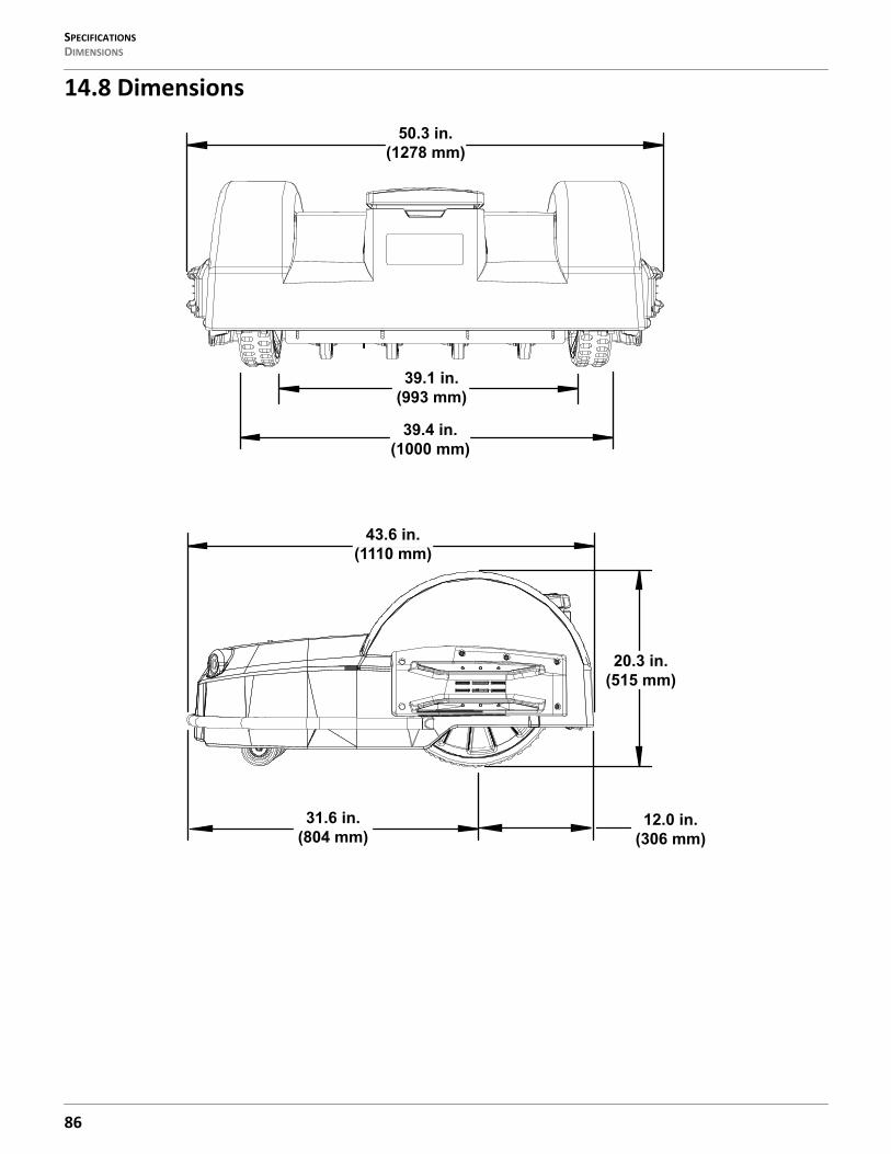
SPECIFICATIONSDIMENSIONS
14.8 Dimensions
50.3 in.(1278 mm)
39.1 in.(993 mm)
39.4 in.(1000 mm)
31.6 in.(804 mm)
12.0 in.(306 mm)
20.3 in.(515 mm)
43.6 in.(1110 mm)
86

ECHO Incorporated400 Oakwood Road
Lake Zurich, IL 600471-800-392-0329
www.echorobotics.com


