Embed Size (px)
Citation preview

Some Applications of FPGA in Custom Waveform
Generation and Triggering for Metrology
Department of Instrumentation and Control Engineering
Netaji Subhas Institute of Technology, New Delhi

Authors
Dr. K.P.S. Rana Dr. Vineet Kumar
Mr. Sumit Kumar Shakya
Mr. Nishant Mittra Mr. Neel Pramanik
Department of Instrumentation and Control Engineering Netaji Subhas Institute of Technology Sector-3, Dwarka, New Delhi -110078

Abstract
Precise custom triggering and waveform generation are necessities in several
metrological applications these days. With the advent of high speed computation and
precise electronics fabrication, it is now possible to generate customized triggering
and waveforms meeting precise timing and frequency standards with the help of FPGA
technology. These are reconfigurable real time devices available at relatively low costs.
FPGAs also have advantages over their counterparts as all of the logic can be
implemented in hardware alone thereby, gaining maximum processing speed.
Additionally, multiple tasks can be scheduled to run simultaneously because each task
will utilize a different set of logic on the FPGA hardware. FPGA finds potential
applications in real time control, signal processing, digital communication and custom
timing and triggering.

A LabVIEW based approach to custom waveform generation and triggering
applications of FPGA is demonstrated in this work. LabVIEW offers FPGA toolkit which
allows graphical programming of FPGA hardware for a desired application. Such an
interface allows the user to program FPGA hardware without necessary knowledge of
VHDL/Verilog. In this work, the logic for waveform generation and triggering were first
simulated using FPGA Simulation Toolkit of LabVIEW and the simulation results were
then verified with the hardware implementation. Testing of the generated waveforms
and triggers was performed with the help of a high bandwidth digital storage
oscilloscope. Some selected waveforms including arbitrary waveforms are presented
in this paper in addition to customized triggers. The results thus obtained
demonstrate that FPGAs can be used to generate precise waveforms and triggering.

Field Programmable Gate ArrayThe FPGA target used in the experiment is NI PXI 7833R . The device is
equipped with 3 million gates and is capable of delivering high-precision, real-
time applications such as custom waveform generation and triggering.
• C.P.U Independent Operation: FPGA can operate independently and
continue to run even if the host computer crashes thus serving as a
dedicated and reliable controller .
• Parallel operation: FPGA is capable of handling and executing multiple
tasks simultaneously without compromising speed or accuracy. This is
done by utilizing an entire different set of logic on the hardware for
different applications.
• High Clock Rate : High clock rate (40 MHz- 160 MHz) not only enhances
the speed and accuracy of operation but also widens the scope for
generating waveforms of considerably high frequencies .

• Real time applications : FPGAs are perfectly suitable for applications in
time-critical systems. In contrast to software based solutions with real
time operating systems, FPGAs provide real deterministic behavior. By
means of the featured flexibility even complex computations(limited to
fixed point mathematics) can be executed in extremely short periods.
• A user can configure the behavior of FPGA hardware to match the
requirements of a specific measurement and control application.
• Compiled VI (Virtual Instrument) is directly deployed onto the FPGA which
is executed independently by the target device while sharing only power
supply with the onboard C.P.U .
• Due to such advantages that FPGA offers , its applications in industry are
increasing constantly.

LabVIEW and FPGA Toolkit• The presented work has been developed on LabVIEW 8.6 platform using
its FPGA Toolkit and National Instruments’ NI PXI-7833R as the hardware
FPGA target.
• The Virtual Instrumentation approach offered by LabVIEW enables the
users to learn a variety of instrumentation techniques and control
applications through an easy and simple to understand graphical
programming approach.
• Such a flexible system allows user to deploy the LabVIEW code directly
onto the target device (7833R) which allows the output to meet precise
timing and frequency specifications as required in metrology.
• Overall, FPGA toolkit enables its user to perform many tasks in a rugged,
high-performance, and modular architecture without knowledge of low-
level EDA tools or hardware design.

Experimental Setup
1. PXI-1031 - M/S National Instruments
2. FPGA Module 7833R - M/S National Instruments
3. LabVIEW 8.6 with FPGA toolkit - M/S National
Instruments
4. Digital Storage Oscilloscope – TDS 2022 – M/S Tektronix
5. Arbitrary Waveform Generator – AFG 3022 - M/S
Tektronix
6. Connector(SCB-68) - M/S National Instruments

ArbitraryWaveform Generator
FPGA(NI PXI-7833R)
Digital Storage Oscilloscope
UserInterface
Experimental Layout


Case Studies

TRIGGER• Trigger is a precise clock of defined frequency which is used to initiate
an event or a sequence of events.
• Trigger can be of two types:
- Pre-defined: If an event is to be periodically initiated
after some interval of time.
- Initiated by some other waveform.
• In this work, a pre-defined trigger with a customizable duty cycle and
two other triggers of rising and falling edge types initiated by a high
frequency sinusoidal waveform have been presented.
• In case of a rising edge trigger, trigger is generated when sinusoidal
wave crosses the time axis with positive slope.
• In case of a falling edge trigger, trigger is generated when sinusoidal
wave crosses the time axis with negative slope.


Trigger (LabVIEW Code)

START
Increment the loop iteration variable i, of the while loop
Input the signal from the waveform generator through the input pin AI0
Subtract the new value of the signal from the old value (memory block)
If the value of the above subtraction is negative and signal
strength decreases below zero then Output High. Else output is Low
Output the value to the output pin AO0.
Go back to the starting point and repeat continuously


SQUARE WAVE GENERATOR
( With customizable duty cycle )

Square Wave Generator (LabVIEW Code)

START
Initialize the loop iteration variable i, of the inner for loop
Increment the value of i
For i <Duty Cycle, the output of the case structure is High. When i > Duty Cycle, the output of the case structure is Low.
The output is taken at the output pin AO0.
Go back to the starting point and continue to get a periodic wave

Front Panel


ARBITRARY WAVEFORM GENERATORS

Arbitrary Waveforms

SINE WAVE GENERATOR

Sine Wave Generator(LabVIEW Code)

START
Initialize and increment loop iteration variable i, of the internal for loop
Normalize the iteration variable i, between [-1, +1]
Input the normalized iteration variable to the sin (x) block
The output is taken at the output pin AO0
The for loop will run for n iterations giving one full cycle at the output
Go back to first step


SAWTOOTH WAVEFORMGENERATOR

Sawtooth Waveform Generator(LabVIEW Code)

START
Initialize the loop iteration variable i, of
the inner for loop
Scale i to give appropriate voltage at
output
Output the value to the output pin AO0
Keep incrementing for n iterations
Go back to starting point and continue so as to get
a periodic waveform


PARABOLIC WAVEFORM GENERATOR
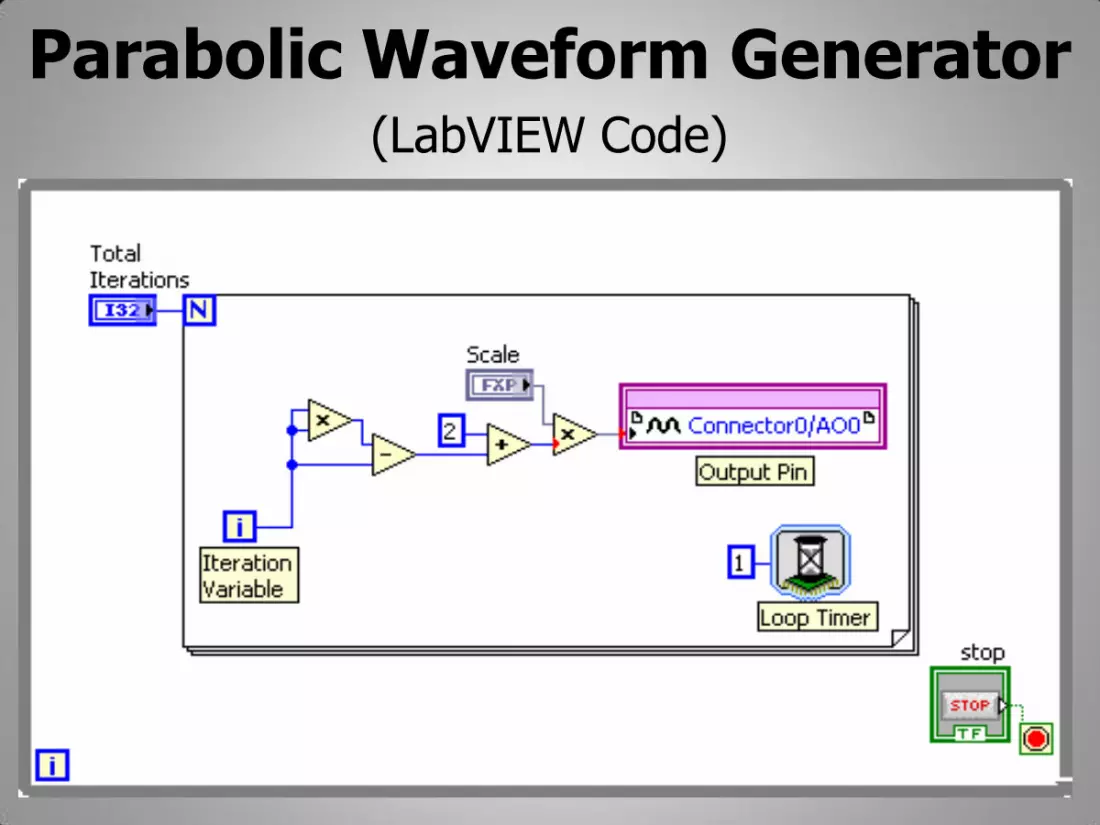
Parabolic Waveform Generator(LabVIEW Code)

START
Initialize the loop iteration variable i, of the
inner for loop
Square the iteration variable i
Scale the output after squaring by an
appropriate value
The output is taken at the output pin AO0.
Increment the iteration variable to generate rest
of the waveform
Go back to starting point and continue to generate
a periodic wave


Chirp


Sequence of sine, square and sawtooth


Conclusion
• Some selected standard and arbitrary waveforms and triggers were generated
using LabVIEW FPGA toolkit and PXI-7833R as the FPGA hardware target.
• The coherence between the expected and obtained results clearly suggests that
FPGA can be used for precise triggering and custom waveform generation.
• Unlike conventional techniques, the proposed method does not require any
complex hardware circuitry and also relieves the user from learning any hardware
description language.
• FPGA, being a real time target, along with its several merits can be easily
integrated in metrological applications.

References 1. Thomas Alpert, Marc Werz, Felix Lang, Damir Ferenci, Michelangelo Masini, Markus Grözing, Manfred Berroth, “Arbitrary
Waveform Generator Based on FPGA and High-Speed DAC with Real-Time Interface“, IEEE 8th Conference on Ph.D.
Research in Microelectronics and Electronics (PRIME), 12-15 June 2012, pp. 1-4.
2. Guohai Xiong, Lingli Zeng, Xuejun Gao, “Design of Multi-waveform Signal Generator”, IEEE Cross Strait Quad-Regional
Radio Science and Wireless Technology Conference, 26-30 July 2011, Vol. 2, pp. 1107 - 1110.
3. Min Xu, Jingyu Hu, Yinyin Gao, “FPGA-based Design and Implementation of Arbitrary Waveform Generator”, IEEE
International Conference on Control, Automation and Systems Engineering (CASE), 30-31 July 2011, pp. 1-4.
4. Matthew T. Hunter, Wasfy B. Mikhael, Tim J. Tocco, “Arbitrary Waveform Generators for Synthetic Instrumentation”, IEEE
AUTOTESTCON, 8-11 Sept., 2008, pp. 138-143.
5. Jen-Wei Hsieh, Guo-Ruey Tsai, Min-Chum Lin, “Using FPGA to Implement a N-channel Arbitrary Waveform Generator with
Various Add-on Functions”, IEEE International Conference on Field-Programmable Technology (FPT), 15-17 Dec , 2003, pp.
296 – 298.
6. Jeanne S. Falcon, Mike Trimborn, “Graphical Programming for Field Programmable Gate Arrays: Applications in Control
and Mechatronics”, IEEE American Control Conference, June 14-16, 2006.
7. Shakeb A. Khan, A. K. Agarwala, D.T. Shahani, “Implementation of Advance Oscilloscope Triggering Scheme on FPGA”, IEEE
Instrumentation and Measurement Technology Conference, 16-19 May, 2005, Vol. 1, pp. 407-411.
8. Falk Karstens, S. Trippel, “Programmable Trigger Logic Unit Based on FPGA Technology”, IEEE transactions on Nuclear
Science, Aug. 2005, Vol. 52, Issue 4, pp.1192 – 1195.

Thank You !!


