Embed Size (px)
Citation preview
Signal Relays
Catalogue2020

Panasonic Corporation Electromechanical Control Business Divisionindustrial.panasonic.com/ac/e/ ASCTB428E 202003Panasonic Corporation 2020
Signal relays line up 2
Signal relays(2A less) selector chart 4
Signal relays types(Part No, and electrical life, Packaging specification diagram, Notes) 8
Safety standards chart 26
Products conforming to EN/IEC standards 27
GUIDELINES FOR RELAY USAGE 28
INDEXSELECTION GUIDE FOR SIGNAL RELAYS(2A less)
– 1 –
P.8 P.10 P.12 P.14 P.16 P.18 P.20 P.22 P.24 P.25
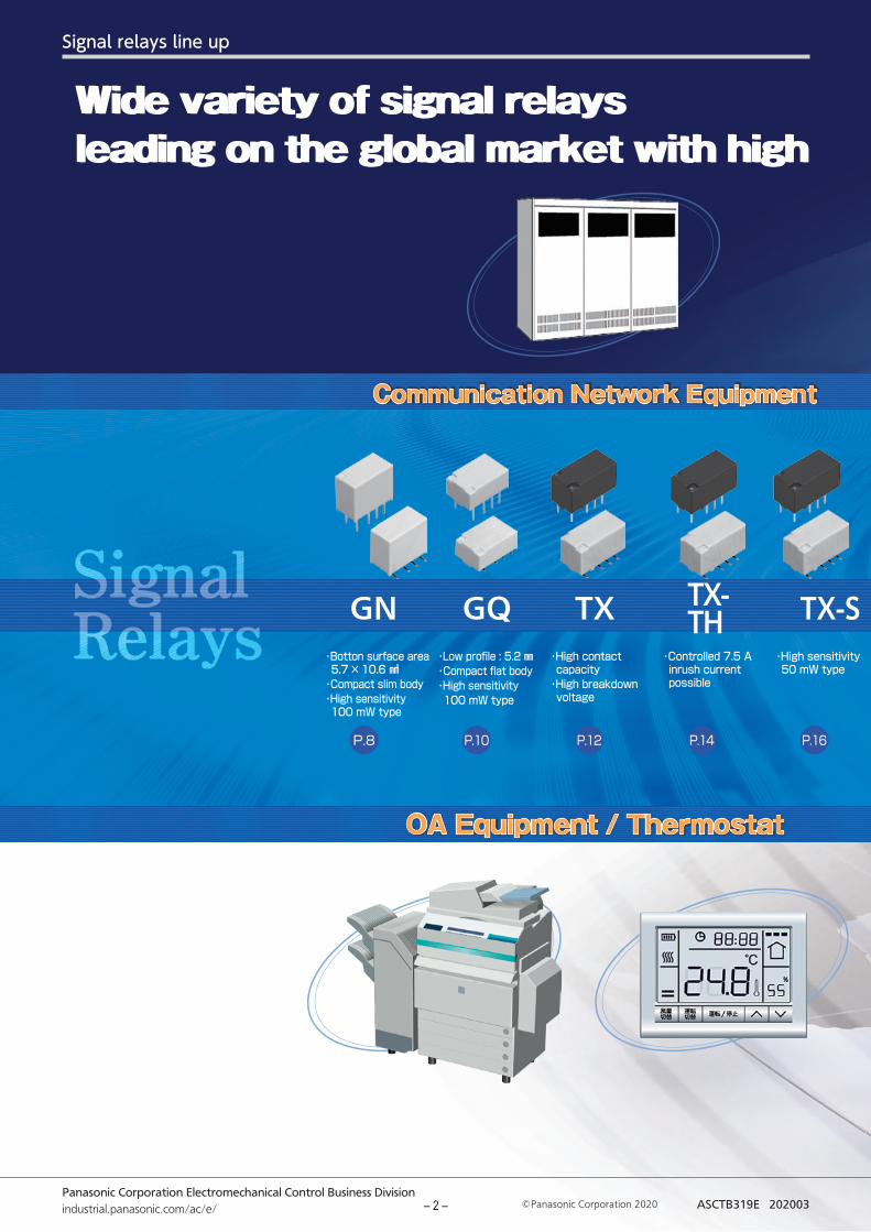
Wide variety of signal relays Wide variety of signal relays leading on the global market with high performance and qualityleading on the global market with high performance and quality
・Botton surface area 5.7 × 10.6 ㎟・Compact slim body・High sensitivity 100 mW type
・Low profile : 5.2 ㎜・Compact flat body・High sensitivity 100 mW type
・High contact capacity・High breakdown voltage
・Controlled 7.5 A inrush current possible
・High sensitivity 50 mW type
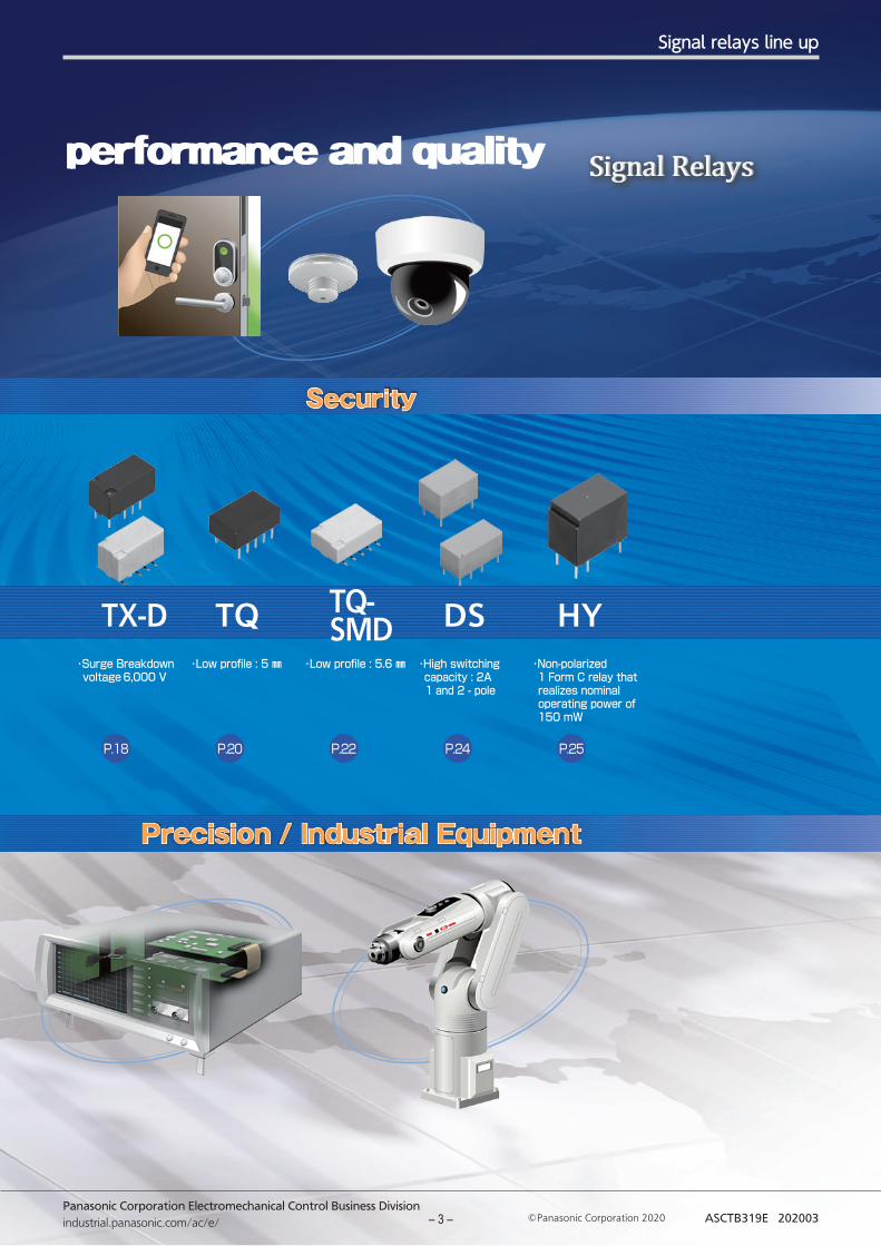
・Surge Breakdown voltage 6,000 V
・Low profile : 5 ㎜ ・Low profile : 5.6 ㎜ ・High switching capacity : 2A 1 and 2 - pole
・Non-polarized 1 Form C relay that realizes nominal operating power of 150 mW
Signal Relays
TXGQGN TX-TH TX-S TQ-
SMDTQTX-D DS HY
OA Equipment / ThermostatOA Equipment / Thermostat Precision / Industrial EquipmentPrecision / Industrial Equipment
Communication Network EquipmentCommunication Network Equipment SecuritySecurity
Panasonic Corporation Electromechanical Control Business Divisionindustrial.panasonic.com/ac/e/ ASCTB319E 202003Panasonic Corporation 2020– 2 –
Signal relays line up
P.8 P.10 P.12 P.14 P.16 P.18 P.20 P.22 P.24 P.25
Wide variety of signal relays Wide variety of signal relays leading on the global market with high performance and qualityleading on the global market with high performance and quality
・Botton surface area 5.7 × 10.6 ㎟・Compact slim body・High sensitivity 100 mW type
・Low profile : 5.2 ㎜・Compact flat body・High sensitivity 100 mW type
・High contact capacity・High breakdown voltage
・Controlled 7.5 A inrush current possible
・High sensitivity 50 mW type
・Surge Breakdown voltage 6,000 V
・Low profile : 5 ㎜ ・Low profile : 5.6 ㎜ ・High switching capacity : 2A 1 and 2 - pole
・Non-polarized 1 Form C relay that realizes nominal operating power of 150 mW
Signal Relays
TXGQGN TX-TH TX-S TQ-
SMDTQTX-D DS HY
OA Equipment / ThermostatOA Equipment / Thermostat Precision / Industrial EquipmentPrecision / Industrial Equipment
Communication Network EquipmentCommunication Network Equipment SecuritySecurity
Panasonic Corporation Electromechanical Control Business Divisionindustrial.panasonic.com/ac/e/ ASCTB319E 202003 Panasonic Corporation 2020– 3 –
Signal relays line up
Panasonic Corporation Electromechanical Control Business Divisionindustrial.panasonic.com/ac/e/ Panasonic Corporation 2020 ASCTB39E 202003
10.610.6
1010
5.75.7
10.610.6
99
5.75.7 10.610.6 7.27.2
5.25.2
10.610.6 7.27.2
5.45.4
7.47.41515
8.28.2
7.47.41515
8.48.4
3 .1
0.8
5.3
2.22.23.2
Surface-mount terminal A type
(TOP VIEW)
3 .2
2.22.23.2
φ0.85
PC board terminal
Surface-mount terminal A type
(TOP VIEW)
PC board terminal
2.66
2 .66
0.8
3.2
6.74
2.2 2.2
2.22.23.2
φ0.85
5.08
PC board terminal
5.08
2.54 2.545.08
φ1
3.16
1
5.08
7.24
2.54 2.54
Surface-mount terminal SA type
Single side stable(TOP VIEW)
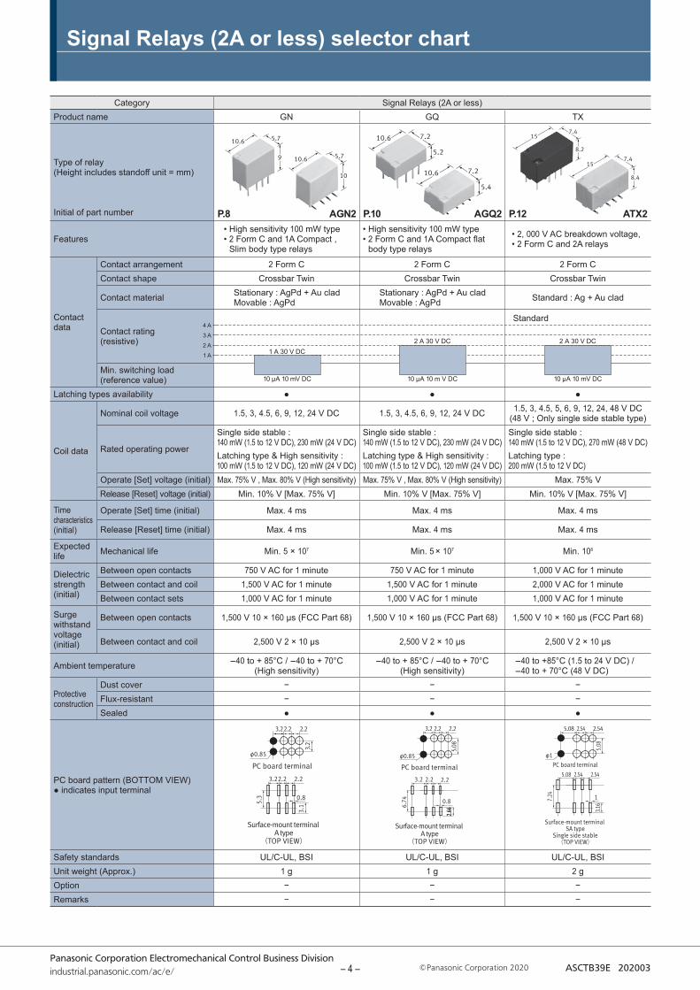
Category Signal Relays (2A or less)Product name GN GQ TX
Type of relay(Height includes standoff unit = mm)
Initial of part number
Features• High sensitivity 100 mW type • 2 Form C and 1A Compact ,
Slim body type relays
• High sensitivity 100 mW type • 2 Form C and 1A Compact flat
body type relays
• 2, 000 V AC breakdown voltage,• 2 Form C and 2A relays
Contact data
Contact arrangement 2 Form C 2 Form C 2 Form CContact shape Crossbar Twin Crossbar Twin Crossbar Twin
Contact material Stationary : AgPd + Au cladMovable : AgPd
Stationary : AgPd + Au cladMovable : AgPd Standard : Ag + Au clad
Contact rating (resistive)
Min. switching load (reference value)
Latching types availability ● ● ●
Coil data
Nominal coil voltage 1.5, 3, 4.5, 6, 9, 12, 24 V DC 1.5, 3, 4.5, 6, 9, 12, 24 V DC 1.5, 3, 4.5, 5, 6, 9, 12, 24, 48 V DC (48 V ; Only single side stable type)
Rated operating power
Single side stable : 140 mW (1.5 to 12 V DC), 230 mW (24 V DC)Latching type & High sensitivity : 100 mW (1.5 to 12 V DC), 120 mW (24 V DC)
Single side stable : 140 mW (1.5 to 12 V DC), 230 mW (24 V DC)Latching type & High sensitivity : 100 mW (1.5 to 12 V DC), 120 mW (24 V DC)
Single side stable : 140 mW (1.5 to 12 V DC), 270 mW (48 V DC)Latching type : 200 mW (1.5 to 12 V DC)
Operate [Set] voltage (initial) Max. 75% V , Max. 80% V (High sensitivity) Max. 75% V , Max. 80% V (High sensitivity) Max. 75% VRelease [Reset] voltage (initial) Min. 10% V [Max. 75% V] Min. 10% V [Max. 75% V] Min. 10% V [Max. 75% V]
Time characteristics (initial)
Operate [Set] time (initial) Max. 4 ms Max. 4 ms Max. 4 ms
Release [Reset] time (initial) Max. 4 ms Max. 4 ms Max. 4 ms
Expected life Mechanical life Min. 5 × 10⁷ Min. 5 × 10⁷ Min. 108
Dielectric strength (initial)
Between open contacts 750 V AC for 1 minute 750 V AC for 1 minute 1,000 V AC for 1 minuteBetween contact and coil 1,500 V AC for 1 minute 1,500 V AC for 1 minute 2,000 V AC for 1 minuteBetween contact sets 1,000 V AC for 1 minute 1,000 V AC for 1 minute 1,000 V AC for 1 minute
Surge withstand voltage (initial)
Between open contacts 1,500 V 10 × 160 μs (FCC Part 68) 1,500 V 10 × 160 μs (FCC Part 68) 1,500 V 10 × 160 μs (FCC Part 68)
Between contact and coil 2,500 V 2 × 10 μs 2,500 V 2 × 10 μs 2,500 V 2 × 10 μs
Ambient temperature -40 to + 85°C / -40 to + 70°C (High sensitivity)
-40 to + 85°C / -40 to + 70°C (High sensitivity)
-40 to +85°C (1.5 to 24 V DC) / -40 to + 70°C (48 V DC)
Protective construction
Dust cover − − −Flux-resistant − − −Sealed ● ● ●
PC board pattern (BOTTOM VIEW)● indicates input terminal
Safety standards UL/C-UL, BSI UL/C-UL, BSI UL/C-UL, BSIUnit weight (Approx.) 1 g 1 g 2 gOption − − −Remarks − − −
Signal Relays (2A or less) selector chart
1 A
2 A
3 A
4 A
1 A 30 V DC
10 μA 10 mV DC
AGN2P.8 AGQ2P.10 ATX2P.12
2 A 30 V DC
10 μA 10 m V DC
2 A 30 V DC
10 μA 10 mV DC
Standard
– 4 –
Signal Relays (2A or less) selector chart
Panasonic Corporation Electromechanical Control Business Divisionindustrial.panasonic.com/ac/e/ Panasonic Corporation 2020 ASCTB39E 202003
PC board terminal
5.08
2.54 2.545.08
φ1
3.16
1
5.08
7.24
2.54 2.54
Surface-mount terminal SA type
Single side stable(TOP VIEW)
PC board terminal
5.08
2.54 2.545.08
φ1
3.16
1
5.08
7.24
2.54 2.54
Surface-mount terminal SA type
Single side stable(TOP VIEW)
PC board terminal
5.08
2.54 2.545.08
φ1
3.16
1
5.08
7.24
2.54 2.54
Surface-mount terminal SA type
Single side stable(TOP VIEW)
7.47.41515
8.28.2
7.47.41515
8.48.4
7.47.41515
8.28.2
7.47.41515
8.48.4
7.47.41515
8.28.2
7.47.41515
8.48.4
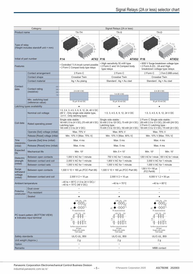
Category Signal Relays (2A or less)Product name TX-TH TX-S TX-D
Type of relay(Height includes standoff unit = mm)
Initial of part number
Features • Controlled 7.5 A inrush current possible • 2 Form C Compact body type relays
• High sensitivity 50 mW type • 2 Form C and 1A Compact body
type relays
• 6000 V Surge breakdown voltage type• 2 Form A (D) , 2A and High
breakdown voltage type relays
Contact data
Contact arrangement 2 Form C 2 Form C 2 Form C 2 Form D (MBB contact)Contact shape Crossbar Twin Crossbar Twin Crossbar TwinContact material Ag + Au plaing Standard : Ag + Au clad Standard : Ag + Au clad
Contact rating (resistive)
Min. switching load (reference value)
Latching types availability ● ● ●
Coil data
Nominal coil voltage1.5, 2.4, 3, 4.5, 5, 6, 9, 12, 24, 48 V DC ( 48 V ; Only single side stable type, 2.4 V ; Only latching type)
1.5, 3, 4.5, 6, 9, 12, 24 V DC 1.5, 3, 4.5, 6, 9, 12, 24 V DC
Rated operating power
Single side stable : 140 mW (1.5 to 24 V DC), 270 mW (48 V DC) Latching type : 140 mW (1.5 to 24 V DC)
Single side stable : 50 mW (1.5 to 12V DC), 70 mW (24 V DC)Latching type : 70 mW (1.5 to 12V DC), 150 mW (24 V DC)
2 Form C Single side stable : 200 mW (1.5 to 12 V DC), 230 mW (24V DC)2 Form C Latching type : 150 mW (1.5 to 12 V DC), 170 mW (24 V DC)
Operate [Set] voltage (initial) Max. 75% V Max. 80% V Max. 75% VRelease [Reset] voltage (initial) Min. 10% V [Max. 75% V] Min. 10% V [Max. 80% V] Min. 10% V [Max. 75% V]
Time characteristics (initial)
Operate [Set] time (initial) Max. 4 ms Max. 5 ms Max. 4 ms
Release [Reset] time (initial) Max. 4 ms Max. 5 ms Max. 4 ms
Expected life Mechanical life Min. 108 Min. 5 × 10⁷ Min. 108 Min. 107
Dielectric strength (initial)
Between open contacts 1,000 V AC for 1 minute 750 V AC for 1 minute 1,000 V AC for 1 minute 500 V AC for 1 minuteBetween contact and coil 2,000 V AC for 1 minute 1,800 V AC for 1 minute 3,000 V AC for 1 minuteBetween contact sets 1,000 V AC for 1 minute 1,000 V AC for 1 minute 1,000 V AC for 1 minute
Surge withstand voltage (initial)
Between open contacts 1,500 V 10 × 160 μs (FCC Part 68) 1,500 V 10 × 160 μs (FCC Part 68) 1,500 V 10 × 160 μs (FCC Part 68) −
Between contact and coil 2,500 V 2 × 10 μs 2,500 V 2 × 10 μs 6,000 V 1.2 × 50 μs
Ambient temperature -40 to + 85°C (1.5 to 24 V DC) / -40 to + 70°C (48 V DC) -40 to + 70°C -40 to + 85°C
Protective construction
Dust cover − − −Flux-resistant − − −Sealed ● ● ●
PC board pattern (BOTTOM VIEW)● indicates input terminal
Safety standards UL/C-UL, BSI UL/C-UL, BSI UL/C-UL, BSIUnit weight (Approx.) 2 g 2 g 2 gOption − − −Remarks − − MBB contact
1 A
2 A
3 A
4 A
ATX2P.14 ATXS2P.16 ATXD2P.18
2 A 30 V DC
10 μA 10 mV DC
2 A 30 V DC
10 μA 10 mV DC
1 A 30 V DC
10 μA 10 mV DC
– 5 –
Signal Relays (2A or less) selector chart
Panasonic Corporation Electromechanical Control Business Divisionindustrial.panasonic.com/ac/e/ Panasonic Corporation 2020 ASCTB39E 202003
99
55
1414 99
5.6
1414
9.99.9
20209.99.99.99.9
9.99.91515
PC board terminal
10.16
7.62
2.54
φ1Surface-mount
SA type(TOP VIEW)
10.16
2.94
1
2.54
9.56
7 .62
7.625.08 2.54
φ0.9
PC board terminal Single side stable 1c
PC board terminal Single side stable 2c
7.62
7.625.085.08
φ0.9
* Standard PC board terminal and self-clinching terminal.
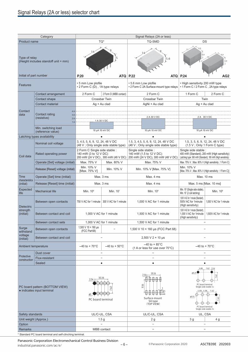
Category Signal Relays (2A or less)Product name TQ* TQ-SMD DS
Type of relay(Height includes standoff unit = mm)
Initial of part number
Features • 5 mm Low plofile• 2 Form C (D) , 1A type relays
• 5.6 mm Low plofile• 2 Form C 2A Surface-mount type relays
• High sensitivity 200 mW type• 1 Form C / 2 Form C , 2A type relays
Contact data
Contact arrangement 2 Form C 2 Form D (MBB contact) 2 Form C 1 Form C 2 Form CContact shape Crossbar Twin Crossbar Twin TwinContact material Ag + Au clad AgNi + Au clad Ag + Au clad
Contact rating (resistive)
Min. switching load (reference value)
Latching types availability ● ● ●
Coil data
Nominal coil voltage 3, 4.5, 5, 6, 9, 12, 24, 48 V DC(48 V ; Only single side stable type)
1.5, 3, 4.5, 5, 6, 9, 12, 24, 48 V DC(48 V ; Only single side stable type)
1.5, 3, 5, 6, 9, 12, 24, 48 V DC(1.5 V ; Only 1 Form C type)
Rated operating power2 Form C Single side stable : 140 mW (3 to 12 V DC)200 mW (24 V DC) , 300 mW (48 V DC)
Single side stable : 140 mW (1.5 to 12 V DC) 200 mW (24 V DC), 300 mW (48 V DC)
Single side stable : 400 mW (Standard), 200 mW (High sensitivity)Latching type :360 mW (Standard), 180 mW (High sensitivity)
Operate [Set] voltage (initial) Max. 75% V Max. 80% V Max. 75% V Max. 75% V , Max. 80% V (High sensitivity ; 1 Form C)
Release [Reset] voltage (initial) Min. 10% V[Max. 75% V] Min. 10% V Min. 10% V [Max. 75% V] Min. 10% V
[Max. 70% V , Max. 80% V (High sensitivity ; 1 Form C)]
Time characteristics (initial)
Operate [Set] time (initial) Max. 3 ms Max. 4 ms Max. 10 ms
Release [Reset] time (initial) Max. 3 ms Max. 4 ms Max. 5 ms [Max. 10 ms]
Expected life Mechanical life Min. 108 Min. 107 Min. 108 Min. 108 (Single side stable),
Min. 107 (2 coil latching) Min. 108
Dielectric strength (initial)
Between open contacts 750 V AC for 1 minute 300 V AC for 1 minute 1,000 V AC for 1 minute1,000 V AC for 1 minute (Standard), 500V AC for 1minute (High sensitivity)
1,000 V AC for 1 minute
Between contact and coil 1,000 V AC for 1 minute 1,500 V AC for 1 minute1,500 V AC for 1 minute (Standard), 1,000 V AC for 1minute (High sensitivity)
1,500V AC for 1 minute
Between contact sets 1,000 V AC for 1 minute 1,500 V AC for 1 minute −
Surge withstand voltage (initial)
Between open contacts 1,500 V 10 × 160 μs (FCC Part 68) − 1,500 V 10 × 160 μs (FCC Part 68) −
Between contact and coil − 2,500 V 2 × 10 μs −
Ambient temperature -40 to + 70°C -40 to + 50°C -40 to + 85°C (1 A or less for use over 70°C) -40 to + 70°C
Protective construction
Dust cover − − −Flux-resistant − − −Sealed ● ● ●
PC board pattern (BOTTOM VIEW)● indicates input terminal
Safety standards UL/C-UL, CSA UL/C-UL, CSA UL, CSAUnit weight (Approx.) 1.5 g 2 g 3 g 4 gOption − − −Remarks MBB contact − −
1 A
2 A
3 A
4 A
ATQP.20 ATQP.22 AG2P.24
2 A 30 V DC
10 μA 10 mV DC
2 A 30 V DC
10 μA 10 mV DC
1 A 30 V DC
10 μA 10 mV DC
– 6 –
Signal Relays (2A or less) selector chart
Panasonic Corporation Electromechanical Control Business Divisionindustrial.panasonic.com/ac/e/ Panasonic Corporation 2020 ASCTB39E 202003
7.47.4
10.110.1
1212
5 .08
7.622.54
φ1
PC board terminal (TOP VIEW)
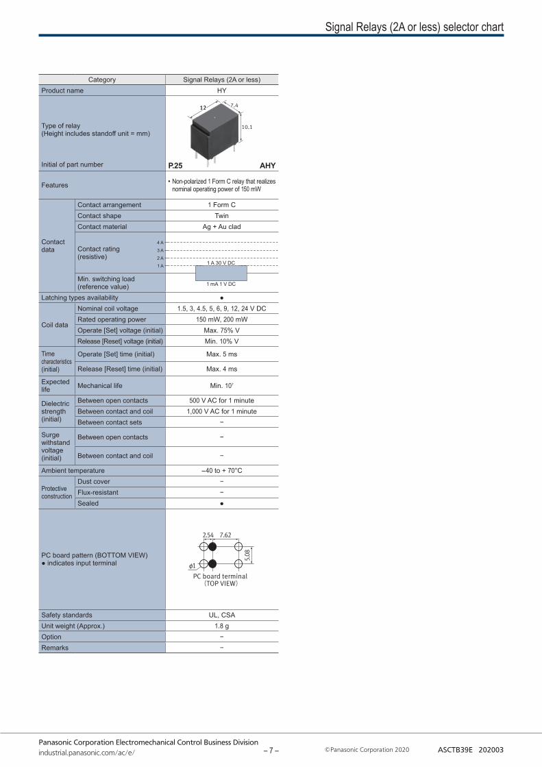
Category Signal Relays (2A or less)Product name HY
Type of relay(Height includes standoff unit = mm)
Initial of part number
Features • Non-polarized 1 Form C relay that realizes nominal operating power of 150 mW
Contact data
Contact arrangement 1 Form CContact shape TwinContact material Ag + Au clad
Contact rating (resistive)
Min. switching load (reference value)
Latching types availability ●
Coil data
Nominal coil voltage 1.5, 3, 4.5, 5, 6, 9, 12, 24 V DCRated operating power 150 mW, 200 mWOperate [Set] voltage (initial) Max. 75% VRelease [Reset] voltage (initial) Min. 10% V
Time characteristics (initial)
Operate [Set] time (initial) Max. 5 ms
Release [Reset] time (initial) Max. 4 ms
Expected life Mechanical life Min. 107
Dielectric strength (initial)
Between open contacts 500 V AC for 1 minuteBetween contact and coil 1,000 V AC for 1 minuteBetween contact sets −
Surge withstand voltage (initial)
Between open contacts −
Between contact and coil −
Ambient temperature -40 to + 70°C
Protective construction
Dust cover −Flux-resistant −Sealed ●
PC board pattern (BOTTOM VIEW)● indicates input terminal
Safety standards UL, CSAUnit weight (Approx.) 1.8 gOption −Remarks −
1 A
2 A
3 A
4 A
AHYP.25
1 A 30 V DC
1 mA 1 V DC
– 7 –
Panasonic Corporation Electromechanical Control Business Divisionindustrial.panasonic.com/ac/e/ Panasonic Corporation 2020 ASCTB431E 202003
TYPES
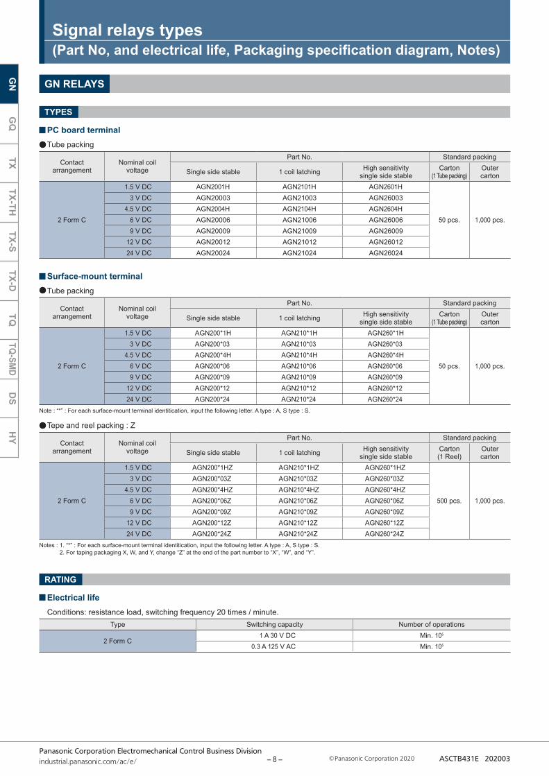
GN RELAYS
PC board terminalTube packing
Surface-mount terminalTube packing
Tepe and reel packing : Z
Note : “*” : For each surface-mount terminal identitication, input the following letter. A type : A, S type : S.
Signal relays types(Part No, and electrical life, Packaging specification diagram, Notes)
Notes : 1. “*” : For each surface-mount terminal identitication, input the following letter. A type : A, S type : S. 2. For taping packaging X, W, and Y, change “Z” at the end of the part number to “X”, “W”, and “Y”.
RATING
Electrical lifeConditions: resistance load, switching frequency 20 times / minute.
Contact arrangement
Nominal coil voltage
Part No. Standard packing
Single side stable 1 coil latching High sensitivity single side stable
Carton(1 Tube packing)
Outer carton
2 Form C
1.5 V DC AGN2001H AGN2101H AGN2601H
50 pcs. 1,000 pcs.
3 V DC AGN20003 AGN21003 AGN260034.5 V DC AGN2004H AGN2104H AGN2604H
6 V DC AGN20006 AGN21006 AGN260069 V DC AGN20009 AGN21009 AGN26009
12 V DC AGN20012 AGN21012 AGN2601224 V DC AGN20024 AGN21024 AGN26024
Contact arrangement
Nominal coil voltage
Part No. Standard packing
Single side stable 1 coil latching High sensitivity single side stable
Carton(1 Tube packing)
Outer carton
2 Form C
1.5 V DC AGN200*1H AGN210*1H AGN260*1H
50 pcs. 1,000 pcs.
3 V DC AGN200*03 AGN210*03 AGN260*034.5 V DC AGN200*4H AGN210*4H AGN260*4H
6 V DC AGN200*06 AGN210*06 AGN260*069 V DC AGN200*09 AGN210*09 AGN260*09
12 V DC AGN200*12 AGN210*12 AGN260*1224 V DC AGN200*24 AGN210*24 AGN260*24
Contact arrangement
Nominal coil voltage
Part No. Standard packing
Single side stable 1 coil latching High sensitivity single side stable
Carton(1 Reel)
Outer carton
2 Form C
1.5 V DC AGN200*1HZ AGN210*1HZ AGN260*1HZ
500 pcs. 1,000 pcs.
3 V DC AGN200*03Z AGN210*03Z AGN260*03Z4.5 V DC AGN200*4HZ AGN210*4HZ AGN260*4HZ
6 V DC AGN200*06Z AGN210*06Z AGN260*06Z9 V DC AGN200*09Z AGN210*09Z AGN260*09Z
12 V DC AGN200*12Z AGN210*12Z AGN260*12Z24 V DC AGN200*24Z AGN210*24Z AGN260*24Z
Type Switching capacity Number of operations
2 Form C1 A 30 V DC Min. 105
0.3 A 125 V AC Min. 105
GN
GQ
TXTX-TH
TX-STX-D
TQTQ-SM
DD
SH
Y
– 8 –
Panasonic Corporation Electromechanical Control Business Divisionindustrial.panasonic.com/ac/e/ Panasonic Corporation 2020 ASCTB431E 202003
Orientation (indicates PIN No.1) stripe
Stopper (green) Stopper (red)
565±2
Tape coming out direction
Relay polarity bar
GN relays
1.5 2 dia.dia. 4 0.4
1.75
11.5
11.1
10.7±0.2
24±
0 .3
2
16 8
+0.1 0
General tolerance :±0.1 mm
(Z type)
1 .75
11.5
11.1
24±
0 .3
Relay polarity bar
GN relays
1.5 2 dia.4 0.4
10.7±0.2
2
16 6.3
+0.1 0
General tolerance :±0.1 mm
Tape coming out direction
(Z type)dia.
380±
2 di
a.
80±
1 di
a.
24.4 2±0.2
2±0.52±0.5
13±0.2 dia.
21±0.8 dia.
+ 2 0
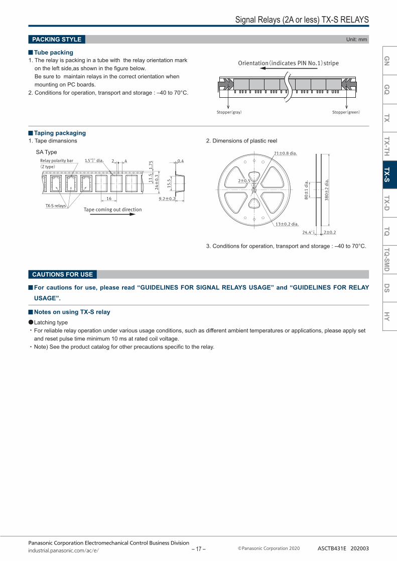
1. Tape dimansions 2. Dimensions of plastic reel
CAUTIONS FOR USE
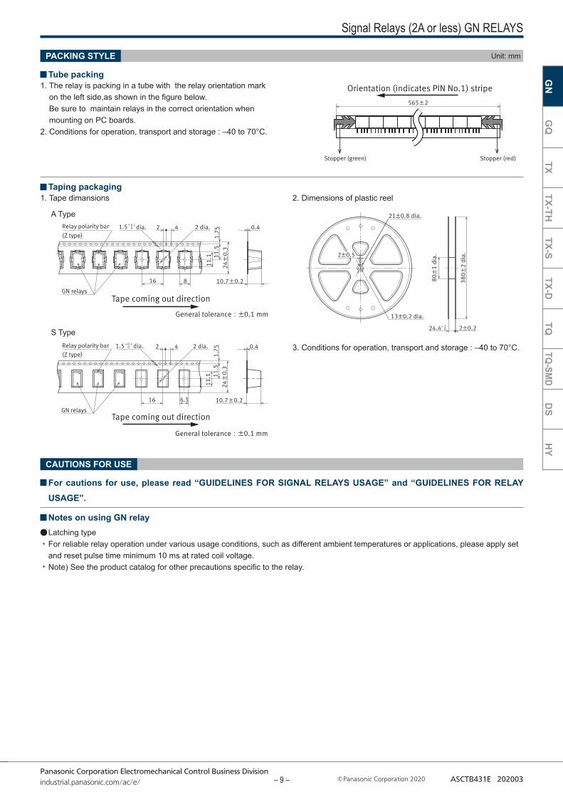
Signal Relays (2A or less) GN RELAYS
3. Conditions for operation, transport and storage : –40 to 70°C.
A Type
S Type
For cautions for use, please read “GUIDELINES FOR SIGNAL RELAYS USAGE” and “GUIDELINES FOR RELAY USAGE”.
Notes on using GN relayLatching type For reliable relay operation under various usage conditions, such as different ambient temperatures or applications, please apply set and reset pulse time minimum 10 ms at rated coil voltage.Note) See the product catalog for other precautions specific to the relay.
PACKING STYLE Unit: mm
1. The relay is packing in a tube with the relay orientation mark on the left side,as shown in the figure below. Be sure to maintain relays in the correct orientation when mounting on PC boards.
2. Conditions for operation, transport and storage : –40 to 70°C.
Tube packing
Taping packaging
GN
GQ
TXTX-TH
TX-STX-D
TQTQ-SM
DD
SH
Y
– 9 –

Panasonic Corporation Electromechanical Control Business Divisionindustrial.panasonic.com/ac/e/ Panasonic Corporation 2020 ASCTB431E 202003
GQ RELAYS
Signal Relays (2A or less) GQ RELAYS
TYPES
PC board terminalTube packing
Surface-mount terminalTube packing
Note : “*” : For each surface-mount terminal identitication, input the following letter. A type : A, S type : S.
Notes : 1.“*” : For each surface-mount terminal identitication, input the following letter. A type : A, S type : S. 2. For taping packaging X, W, and Y, change “Z” at the end of the part number to “X”, “W”, and “Y”.
Tepe and reel packing : Z
RATING
Electrical lifeConditions: resistance load, switching frequency 20 times / minute.
Contact arrangement
Nominal coil voltage
Part No. Standard packing
Single side stable 1 coil latching High sensitivity single side stable
Carton(1 Tube packing)
Outer carton
2 Form C
1.5 V DC AGQ2001H AGQ2101H AGQ2601H
50 pcs. 1,000 pcs.
3 V DC AGQ20003 AGQ21003 AGQ260034.5 V DC AGQ2004H AGQ2104H AGQ2604H
6 V DC AGQ20006 AGQ21006 AGQ260069 V DC AGQ20009 AGQ21009 AGQ26009
12 V DC AGQ20012 AGQ21012 AGQ2601224 V DC AGQ20024 AGQ21024 AGQ26024
Contact arrangement
Nominal coil voltage
Part No. Standard packing
Single side stable 1 coil latching High sensitivity single side stable
Carton(1 Tube packing)
Outer carton
2 Form C
1.5 V DC AGQ200*1H AGQ210*1H AGQ260*1H
50 pcs. 1,000 pcs.
3 V DC AGQ200*03 AGQ210*03 AGQ260*034.5 V DC AGQ200*4H AGQ210*4H AGQ260*4H
6 V DC AGQ200*06 AGQ210*06 AGQ260*069 V DC AGQ200*09 AGQ210*09 AGQ260*09
12 V DC AGQ200*12 AGQ210*12 AGQ260*1224 V DC AGQ200*24 AGQ210*24 AGQ260*24
Contact arrangement
Nominal coil voltage
Part No. Standard packing
Single side stable 1 coil latching High sensitivity single side stable
Carton(1 Reel)
Outer carton
2 Form C
1.5 V DC AGQ200*1HZ AGQ210*1HZ AGQ260*1HZ
900 pcs. 1,800 pcs.
3 V DC AGQ200*03Z AGQ210*03Z AGQ260*03Z4.5 V DC AGQ200*4HZ AGQ210*4HZ AGQ260*4HZ
6 V DC AGQ200*06Z AGQ210*06Z AGQ260*06Z9 V DC AGQ200*09Z AGQ210*09Z AGQ260*09Z
12 V DC AGQ200*12Z AGQ210*12Z AGQ260*12Z24 V DC AGQ200*24Z AGQ210*24Z AGQ260*24Z
Type Switching capacity Number of operations
2 Form C1 A 30 V DC Min. 105
0.3 A 125 V AC Min. 105
2 A 30 V DC Min. 5 x 10⁴
GN
GQ
TXTX-TH
TX-STX-D
TQTQ-SM
DD
SH
Y
– 10 –
Panasonic Corporation Electromechanical Control Business Divisionindustrial.panasonic.com/ac/e/ Panasonic Corporation 2020 ASCTB431E 202003
Orientation(indicates PIN No.1)stripe
Stopper(green) Stopper(red)
558±2
Tape coming out direction
Relay polarity bar(Z type)
GQ relays
1.5 dia 2 dia4 0.4
Max. 6.55
2
12 9
+0.1 0
General tolerance :±0.1
1.75
11.5
11.1
24±
0 .3
GQ relays
1.5 dia 2 dia4 0.42
12 7.8
+0.1 0
1.75
11.5
11.1
24±
0 .3
Max. 6.55
Relay polarity bar(Z type)
Tape coming out directionGeneral tolerance :±0.1
380±
2 di
a.
80±
1 di
a.
24.4 2±0.2
2±0.52±0.5
13±0.2 dia.
21±0.8 dia.
+ 2 0
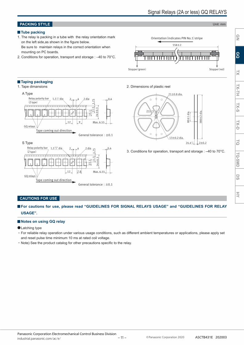
Signal Relays (2A or less) GQ RELAYS
3. Conditions for operation, transport and storage : –40 to 70°C.
A Type
S Type
CAUTIONS FOR USE
PACKING STYLE Unit: mm
Tube packing1. The relay is packing in a tube with the relay orientation mark
on the left side,as shown in the figure below. Be sure to maintain relays in the correct orientation when mounting on PC boards.
2. Conditions for operation, transport and storage : –40 to 70°C.
1. Tape dimansions 2. Dimensions of plastic reel Taping packaging
For cautions for use, please read “GUIDELINES FOR SIGNAL RELAYS USAGE” and “GUIDELINES FOR RELAY USAGE”.
Notes on using GQ relayLatching type For reliable relay operation under various usage conditions, such as different ambient temperatures or applications, please apply set and reset pulse time minimum 10 ms at rated coil voltage.Note) See the product catalog for other precautions specific to the relay.
GN
GQ
TXTX-TH
TX-STX-D
TQTQ-SM
DD
SH
Y
– 11 –
Panasonic Corporation Electromechanical Control Business Divisionindustrial.panasonic.com/ac/e/ Panasonic Corporation 2020 ASCTB431E 202003
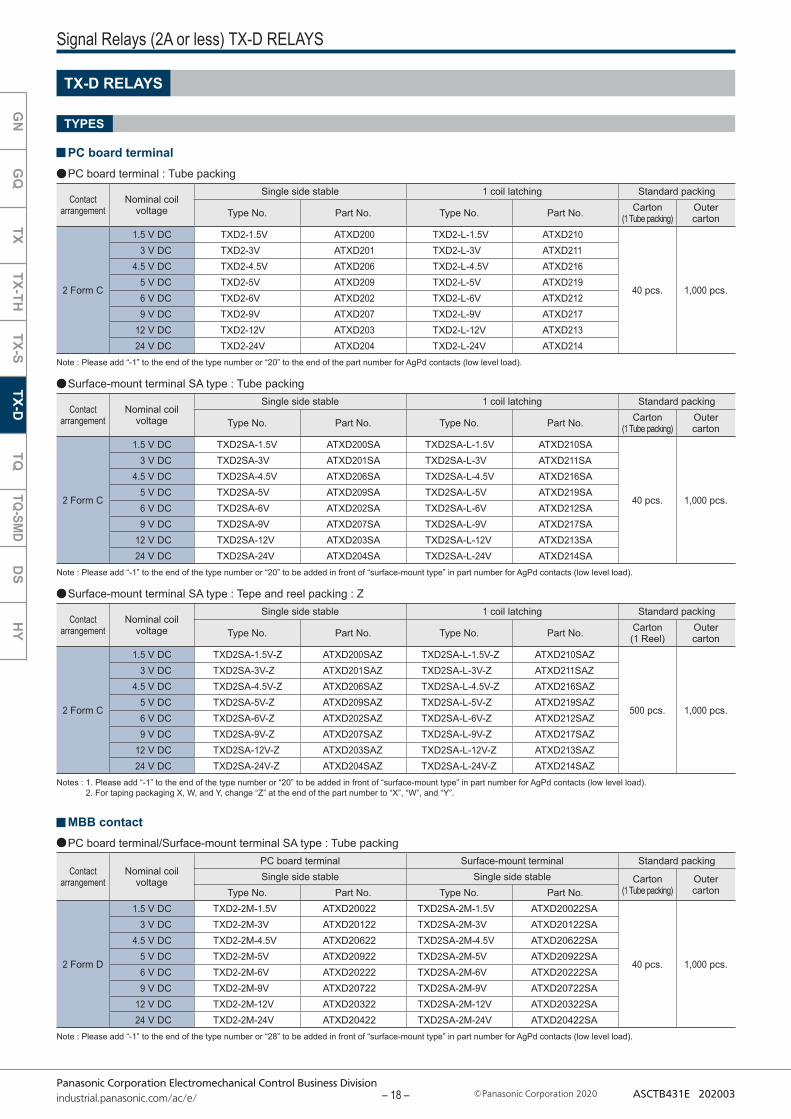
Notes : 1. Please add “-1” to the end of the type number or “20” to be added in front of “surface-mount type” in part number for AgPd contacts (low level load). 2. For taping packaging X, W, and Y, change “Z” at the end of the part number to “X”, “W”, and “Y”.
SA type : Tepe and reel packing : Z
Note : Please add “-1” to the end of the type number or “20” to be added in front of “surface-mount type” in part number for AgPd contacts (low level load).
Note: Please add “-1” to the end of the type number or “20” to the end of the part number for AgPd contacts (low level load).
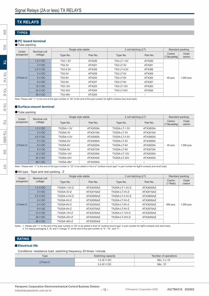
Signal Relays (2A or less) TX RELAYS
Surface-mount terminalTube packing
RATING
Electrical lifeConditions: resistance load, switching frequency 20 times / minute.
Contact arrangement
Nominal coil voltage
Single side stable 2 coil latching (LT) Standard packing
Type No. Part No. Type No. Part No. Carton(1 Tube packing)
Outer carton
2 Form C
1.5 V DC TX2SA-1.5V ATX200SA TX2SA-LT-1.5V ATX260SA
40 pcs. 1,000 pcs.
3 V DC TX2SA-3V ATX201SA TX2SA-LT-3V ATX261SA4.5 V DC TX2SA-4.5V ATX206SA TX2SA-LT-4.5V ATX266SA
5 V DC TX2SA-5V ATX209SA TX2SA-LT-5V ATX269SA6 V DC TX2SA-6V ATX202SA TX2SA-LT-6V ATX262SA9 V DC TX2SA-9V ATX207SA TX2SA-LT-9V ATX267SA
12 V DC TX2SA-12V ATX203SA TX2SA-LT-12V ATX263SA24 V DC TX2SA-24V ATX204SA TX2SA-LT-24V ATX264SA48 V DC TX2SA-48V ATX205SA – –
Contact arrangement
Nominal coil voltage
Single side stable 2 coil latching (LT) Standard packing
Type No. Part No. Type No. Part No. Carton(1 Tube packing)
Outer carton
2 Form C
1.5 V DC TX2-1.5V ATX200 TX2-LT-1.5V ATX260
40 pcs. 1,000 pcs.
3 V DC TX2-3V ATX201 TX2-LT-3V ATX2614.5 V DC TX2-4.5V ATX206 TX2-LT-4.5V ATX266
5 V DC TX2-5V ATX209 TX2-LT-5V ATX2696 V DC TX2-6V ATX202 TX2-LT-6V ATX2629 V DC TX2-9V ATX207 TX2-LT-9V ATX267
12 V DC TX2-12V ATX203 TX2-LT-12V ATX26324 V DC TX2-24V ATX204 TX2-LT-24V ATX26448 V DC TX2-48V ATX205 – –
Contact arrangement
Nominal coil voltage
Single side stable 2 coil latching (LT) Standard packing
Type No. Part No. Type No. Part No. Carton(1 Reel)
Outer carton
2 Form C
1.5 V DC TX2SA-1.5V-Z ATX200SAZ TX2SA-LT-1.5V-Z ATX260SAZ
500 pcs. 1,000 pcs.
3 V DC TX2SA-3V-Z ATX201SAZ TX2SA-LT-3V-Z ATX261SAZ4.5 V DC TX2SA-4.5V-Z ATX206SAZ TX2SA-LT-4.5V-Z ATX266SAZ
5 V DC TX2SA-5V-Z ATX209SAZ TX2SA-LT-5V-Z ATX269SAZ6 V DC TX2SA-6V-Z ATX202SAZ TX2SA-LT-6V-Z ATX262SAZ9 V DC TX2SA-9V-Z ATX207SAZ TX2SA-LT-9V-Z ATX267SAZ
12 V DC TX2SA-12V-Z ATX203SAZ TX2SA-LT-12V-Z ATX263SAZ24 V DC TX2SA-24V-Z ATX204SAZ TX2SA-LT-24V-Z ATX264SAZ48 V DC TX2SA-48V-Z ATX205SAZ – –
Type Switching capacity Number of operations
2 Form C1 A 30 V DC Min. 5 x 10⁵
2 A 30 V DC Min. 105
TX RELAYS
PC board terminalTube packing
TYPES
GN
GQ
TXTX-TH
TX-STX-D
TQTQ-SM
DD
SH
Y
– 12 –
Panasonic Corporation Electromechanical Control Business Divisionindustrial.panasonic.com/ac/e/ Panasonic Corporation 2020 ASCTB431E 202003
Relay polarity bar
TX relaysTape coming out direction
1.5 4 0.4
1.75
11.5
15.5
9.2±0.2
24±
0 .3
2
16
+0.1 0
(Z type)dia.
Stopper(gray)
Orientation(indicates PIN No.1)stripe
Stopper(green)
380±
2 di
a.
80±
1 di
a.
24.4 2±0.2
2±0.52±0.5
13±0.2 dia.
21±0.8 dia.
+ 2 0
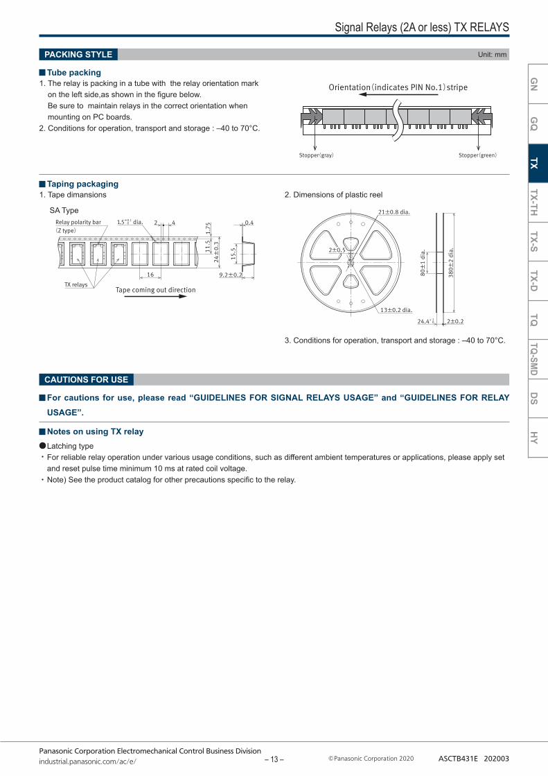
Signal Relays (2A or less) TX RELAYS
PACKING STYLE Unit: mm
Tube packing
SA Type
3. Conditions for operation, transport and storage : –40 to 70°C.
CAUTIONS FOR USE
GN
GQ
TXTX-TH
TX-STX-D
TQTQ-SM
DD
SH
Y
1. The relay is packing in a tube with the relay orientation mark on the left side,as shown in the figure below. Be sure to maintain relays in the correct orientation when mounting on PC boards.
2. Conditions for operation, transport and storage : –40 to 70°C.
1. Tape dimansions 2. Dimensions of plastic reel Taping packaging
For cautions for use, please read “GUIDELINES FOR SIGNAL RELAYS USAGE” and “GUIDELINES FOR RELAY USAGE”.
Notes on using TX relayLatching type For reliable relay operation under various usage conditions, such as different ambient temperatures or applications, please apply set and reset pulse time minimum 10 ms at rated coil voltage.Note) See the product catalog for other precautions specific to the relay.
GN
GQ
TXTX-TH
TX-STX-D
TQTQ-SM
DD
SH
Y
– 13 –

Panasonic Corporation Electromechanical Control Business Divisionindustrial.panasonic.com/ac/e/ Panasonic Corporation 2020 ASCTB431E 202003
*When using at 7.5 A, please refer to “GUIDELINES FOR USAGE, Max. switching current”.
Signal Relays (2A or less) TX-TH RELAYS
RATING
Electrical lifeConditions: resistance load, switching frequency 20 times / minute.
TX-TH RELAYS
PC board terminalTube packing
TYPES
SA type : Tepe and reel packing : Z
Surface-mount terminalSA type : Tube packing
Note : For taping packaging X, W, and Y, change “Z” at the end of the part number to “X”, “W”, and “Y”.
Contact arrangement
Nominal coil voltage
Single side stable 2 coil latching (LT) Standard packing
Type No. Part No. Type No. Part No. Carton(1 Tube packing)
Outer carton
2 Form C
1.5 V DC TX2-1.5V-TH ATX200TH TX2-LT-1.5V-TH ATX260TH
40 pcs. 1,000 pcs.
2.4 V DC – – TX2-LT-2.4V-TH ATX26ATH3 V DC TX2-3V-TH ATX201TH TX2-LT-3V-TH ATX261TH
4.5 V DC TX2-4.5V-TH ATX206TH TX2-LT-4.5V-TH ATX266TH5 V DC TX2-5V-TH ATX209TH TX2-LT-5V-TH ATX269TH6 V DC TX2-6V-TH ATX202TH TX2-LT-6V-TH ATX262TH9 V DC TX2-9V-TH ATX207TH TX2-LT-9V-TH ATX267TH
12 V DC TX2-12V-TH ATX203TH TX2-LT-12V-TH ATX263TH24 V DC TX2-24V-TH ATX204TH TX2-LT-24V-TH ATX264TH48 V DC TX2-48V-TH ATX205TH – –
Contact arrangement
Nominal coil voltage
Single side stable 2 coil latching (LT) Standard packing
Type No. Part No. Type No. Part No. Carton(1 Tube packing)
Outer carton
2 Form C
1.5 V DC TX2SA-1.5V-TH ATX200THSA TX2SA-LT-1.5V-TH ATX260THSA
40 pcs. 1,000 pcs.
2.4 V DC – – TX2SA-LT-2.4V-TH ATX26ATHSA
3 V DC TX2SA-3V-TH ATX201THSA TX2SA-LT-3V-TH ATX261THSA4.5 V DC TX2SA-4.5V-TH ATX206THSA TX2SA-LT-4.5V-TH ATX266THSA
5 V DC TX2SA-5V-TH ATX209THSA TX2SA-LT-5V-TH ATX269THSA6 V DC TX2SA-6V-TH ATX202THSA TX2SA-LT-6V-TH ATX262THSA9 V DC TX2SA-9V-TH ATX207THSA TX2SA-LT-9V-TH ATX267THSA
12 V DC TX2SA-12V-TH ATX203THSA TX2SA-LT-12V-TH ATX263THSA24 V DC TX2SA-24V-TH ATX204THSA TX2SA-LT-24V-TH ATX264THSA48 V DC TX2SA-48V-TH ATX205THSA – –
Contact arrangement
Nominal coil voltage
Single side stable 2 coil latching (LT) Standard packing
Type No. Part No. Type No. Part No. Carton(1 Reel)
Outer carton
2 Form C
1.5 V DC TX2SA-1.5V-TH-Z ATX200THSAZ TX2SA-LT-1.5V-TH-Z ATX260THSAZ
500 pcs. 1,000 pcs.
2.4 V DC – – TX2SA-LT-2.4V-TH-Z ATX26ATHSAZ3 V DC TX2SA-3V-TH-Z ATX201THSAZ TX2SA-LT-3V-TH-Z ATX261THSAZ
4.5 V DC TX2SA-4.5V-TH-Z ATX206THSAZ TX2SA-LT-4.5V-TH-Z ATX266THSAZ5 V DC TX2SA-5V-TH-Z ATX209THSAZ TX2SA-LT-5V-TH-Z ATX269THSAZ6 V DC TX2SA-6V-TH-Z ATX202THSAZ TX2SA-LT-6V-TH-Z ATX262THSAZ9 V DC TX2SA-9V-TH-Z ATX207THSAZ TX2SA-LT-9V-TH-Z ATX267THSAZ
12 V DC TX2SA-12V-TH-Z ATX203THSAZ TX2SA-LT-12V-TH-Z ATX263THSAZ24 V DC TX2SA-24V-TH-Z ATX204THSAZ TX2SA-LT-24V-TH-Z ATX264THSAZ48 V DC TX2SA-48V-TH-Z ATX205THSAZ – –
Type Load Switching capacity Number of operations
2 Form CResistive load
1 A 30 V DC Min. 5 x 10⁵
2 A 30 V DC Min. 105
0.5 A 125 V AC Min. 105
Inrush load* Inrush current : 7.5 A 30 V AC (250 ms time)Steady state current : 1.5 A 30 V AC (cosφ=0.4)
Min. 2 x 10⁵
(Switching frequency ON : OFF = 1s : 9s)
GN
GQ
TXTX-TH
TX-STX-D
TQTQ-SM
DD
SH
Y
– 14 –
Panasonic Corporation Electromechanical Control Business Divisionindustrial.panasonic.com/ac/e/ Panasonic Corporation 2020 ASCTB431E 202003
Stopper(gray)
Orientation(indicates PIN No.1)stripe
Stopper(green)
Relay polarity bar
TX relaysTH type
Tape coming out direction
1.5 4 0.4
1.75
11.5
15.5
9.2±0.2
24±
0 .3
2
16
+0.1 0
(Z type)dia.
380±
2 di
a.
80±
1 di
a.
24.4 2±0.2
2±0.52±0.5
13±0.2 dia.
21±0.8 dia.
+ 2 0
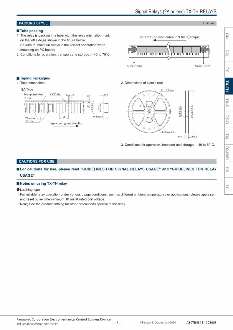
Signal Relays (2A or less) TX-TH RELAYS
PACKING STYLE Unit: mm
Tube packing
SA Type
CAUTIONS FOR USE
3. Conditions for operation, transport and storage : –40 to 70°C.
1. The relay is packing in a tube with the relay orientation mark on the left side,as shown in the figure below. Be sure to maintain relays in the correct orientation when mounting on PC boards.
2. Conditions for operation, transport and storage : –40 to 70°C.
1. Tape dimansions 2. Dimensions of plastic reel Taping packaging
For cautions for use, please read “GUIDELINES FOR SIGNAL RELAYS USAGE” and “GUIDELINES FOR RELAY USAGE”.
Notes on using TX-TH relayLatching type For reliable relay operation under various usage conditions, such as different ambient temperatures or applications, please apply set and reset pulse time minimum 10 ms at rated coil voltage.Note) See the product catalog for other precautions specific to the relay.
GN
GQ
TXTX-TH
TX-STX-D
TQTQ-SM
DD
SH
Y
– 15 –
Panasonic Corporation Electromechanical Control Business Divisionindustrial.panasonic.com/ac/e/ Panasonic Corporation 2020 ASCTB431E 202003
Notes : 1. Please add “-1” to the end of the type number or “20” to be added in front of “surface-mount type” in part number for AgPd contacts (low level load). 2. For taping packaging X, W, and Y, change “Z” at the end of the part number to “X”, “W”, and “Y”.
Note : Please add “-1” to the end of the type number or “20” to be added in front of “surface-mount type” in part number for AgPd contacts (low level load).
Note : Please add “-1” to the end of the type number or “20” to the end of the part number for AgPd contacts (low level load).
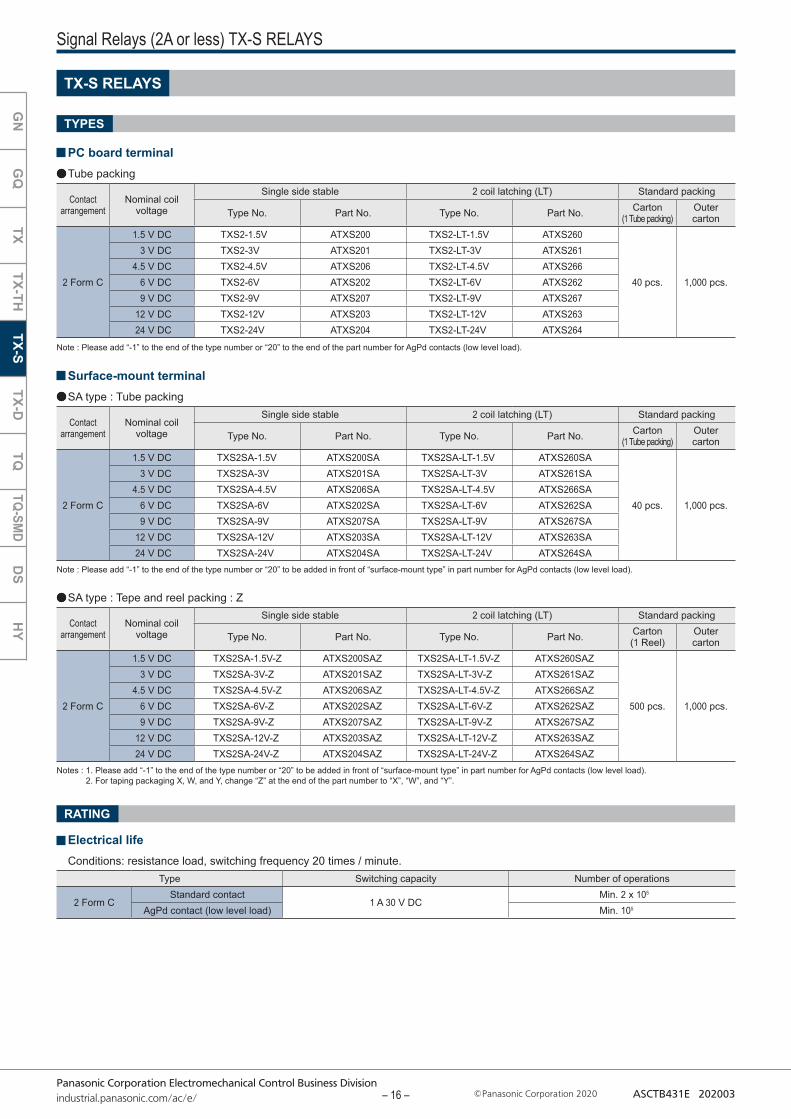
Signal Relays (2A or less) TX-S RELAYS
TX-S RELAYS
PC board terminalTube packing
TYPES
RATING
Electrical lifeConditions: resistance load, switching frequency 20 times / minute.
Surface-mount terminalSA type : Tube packing
SA type : Tepe and reel packing : Z
Contact arrangement
Nominal coil voltage
Single side stable 2 coil latching (LT) Standard packing
Type No. Part No. Type No. Part No. Carton(1 Tube packing)
Outer carton
2 Form C
1.5 V DC TXS2-1.5V ATXS200 TXS2-LT-1.5V ATXS260
40 pcs. 1,000 pcs.
3 V DC TXS2-3V ATXS201 TXS2-LT-3V ATXS2614.5 V DC TXS2-4.5V ATXS206 TXS2-LT-4.5V ATXS266
6 V DC TXS2-6V ATXS202 TXS2-LT-6V ATXS2629 V DC TXS2-9V ATXS207 TXS2-LT-9V ATXS267
12 V DC TXS2-12V ATXS203 TXS2-LT-12V ATXS26324 V DC TXS2-24V ATXS204 TXS2-LT-24V ATXS264
Contact arrangement
Nominal coil voltage
Single side stable 2 coil latching (LT) Standard packing
Type No. Part No. Type No. Part No. Carton(1 Tube packing)
Outer carton
2 Form C
1.5 V DC TXS2SA-1.5V ATXS200SA TXS2SA-LT-1.5V ATXS260SA
40 pcs. 1,000 pcs.
3 V DC TXS2SA-3V ATXS201SA TXS2SA-LT-3V ATXS261SA4.5 V DC TXS2SA-4.5V ATXS206SA TXS2SA-LT-4.5V ATXS266SA
6 V DC TXS2SA-6V ATXS202SA TXS2SA-LT-6V ATXS262SA9 V DC TXS2SA-9V ATXS207SA TXS2SA-LT-9V ATXS267SA
12 V DC TXS2SA-12V ATXS203SA TXS2SA-LT-12V ATXS263SA24 V DC TXS2SA-24V ATXS204SA TXS2SA-LT-24V ATXS264SA
Contact arrangement
Nominal coil voltage
Single side stable 2 coil latching (LT) Standard packing
Type No. Part No. Type No. Part No. Carton(1 Reel)
Outer carton
2 Form C
1.5 V DC TXS2SA-1.5V-Z ATXS200SAZ TXS2SA-LT-1.5V-Z ATXS260SAZ
500 pcs. 1,000 pcs.
3 V DC TXS2SA-3V-Z ATXS201SAZ TXS2SA-LT-3V-Z ATXS261SAZ4.5 V DC TXS2SA-4.5V-Z ATXS206SAZ TXS2SA-LT-4.5V-Z ATXS266SAZ
6 V DC TXS2SA-6V-Z ATXS202SAZ TXS2SA-LT-6V-Z ATXS262SAZ9 V DC TXS2SA-9V-Z ATXS207SAZ TXS2SA-LT-9V-Z ATXS267SAZ
12 V DC TXS2SA-12V-Z ATXS203SAZ TXS2SA-LT-12V-Z ATXS263SAZ24 V DC TXS2SA-24V-Z ATXS204SAZ TXS2SA-LT-24V-Z ATXS264SAZ
Type Switching capacity Number of operations
2 Form CStandard contact
1 A 30 V DCMin. 2 x 10⁵
AgPd contact (low level load) Min. 105
GN
GQ
TXTX-TH
TX-STX-D
TQTQ-SM
DD
SH
Y
– 16 –
Panasonic Corporation Electromechanical Control Business Divisionindustrial.panasonic.com/ac/e/ Panasonic Corporation 2020 ASCTB431E 202003
Stopper(gray)
Orientation(indicates PIN No.1)stripe
Stopper(green)
380±
2 di
a.
80±
1 di
a.
24.4 2±0.2
2±0.52±0.5
13±0.2 dia.
21±0.8 dia.
+ 2 0
Relay polarity bar
TX-S relaysTape coming out direction
1.5 4 0.4
1.75
11.5
15.5
9.2±0.2
24±
0 .3
2
16
+0.1 0
(Z type)dia.
Signal Relays (2A or less) TX-S RELAYS
PACKING STYLE Unit: mm
Tube packing
3. Conditions for operation, transport and storage : –40 to 70°C.
CAUTIONS FOR USE
SA Type
1. The relay is packing in a tube with the relay orientation mark on the left side,as shown in the figure below. Be sure to maintain relays in the correct orientation when mounting on PC boards.
2. Conditions for operation, transport and storage : –40 to 70°C.
1. Tape dimansions 2. Dimensions of plastic reel Taping packaging
For cautions for use, please read “GUIDELINES FOR SIGNAL RELAYS USAGE” and “GUIDELINES FOR RELAY USAGE”.
Notes on using TX-S relayLatching type For reliable relay operation under various usage conditions, such as different ambient temperatures or applications, please apply set and reset pulse time minimum 10 ms at rated coil voltage.Note) See the product catalog for other precautions specific to the relay.
GN
GQ
TXTX-TH
TX-STX-D
TQTQ-SM
DD
SH
Y
– 17 –
Panasonic Corporation Electromechanical Control Business Divisionindustrial.panasonic.com/ac/e/ Panasonic Corporation 2020 ASCTB431E 202003
Notes : 1. Please add “-1” to the end of the type number or “20” to be added in front of “surface-mount type” in part number for AgPd contacts (low level load). 2. For taping packaging X, W, and Y, change “Z” at the end of the part number to “X”, “W”, and “Y”.
Note : Please add “-1” to the end of the type number or “20” to be added in front of “surface-mount type” in part number for AgPd contacts (low level load).
Note : Please add “-1” to the end of the type number or “28” to be added in front of “surface-mount type” in part number for AgPd contacts (low level load).
Note : Please add “-1” to the end of the type number or “20” to the end of the part number for AgPd contacts (low level load).
Signal Relays (2A or less) TX-D RELAYS
TX-D RELAYS
PC board terminalPC board terminal : Tube packing
TYPES
MBB contactPC board terminal/Surface-mount terminal SA type : Tube packing
Surface-mount terminal SA type : Tube packing
Surface-mount terminal SA type : Tepe and reel packing : Z
Contact arrangement
Nominal coil voltage
Single side stable 1 coil latching Standard packing
Type No. Part No. Type No. Part No. Carton(1 Tube packing)
Outer carton
2 Form C
1.5 V DC TXD2-1.5V ATXD200 TXD2-L-1.5V ATXD210
40 pcs. 1,000 pcs.
3 V DC TXD2-3V ATXD201 TXD2-L-3V ATXD2114.5 V DC TXD2-4.5V ATXD206 TXD2-L-4.5V ATXD216
5 V DC TXD2-5V ATXD209 TXD2-L-5V ATXD2196 V DC TXD2-6V ATXD202 TXD2-L-6V ATXD2129 V DC TXD2-9V ATXD207 TXD2-L-9V ATXD217
12 V DC TXD2-12V ATXD203 TXD2-L-12V ATXD21324 V DC TXD2-24V ATXD204 TXD2-L-24V ATXD214
Contact arrangement
Nominal coil voltage
Single side stable 1 coil latching Standard packing
Type No. Part No. Type No. Part No. Carton(1 Tube packing)
Outer carton
2 Form C
1.5 V DC TXD2SA-1.5V ATXD200SA TXD2SA-L-1.5V ATXD210SA
40 pcs. 1,000 pcs.
3 V DC TXD2SA-3V ATXD201SA TXD2SA-L-3V ATXD211SA4.5 V DC TXD2SA-4.5V ATXD206SA TXD2SA-L-4.5V ATXD216SA
5 V DC TXD2SA-5V ATXD209SA TXD2SA-L-5V ATXD219SA6 V DC TXD2SA-6V ATXD202SA TXD2SA-L-6V ATXD212SA9 V DC TXD2SA-9V ATXD207SA TXD2SA-L-9V ATXD217SA
12 V DC TXD2SA-12V ATXD203SA TXD2SA-L-12V ATXD213SA24 V DC TXD2SA-24V ATXD204SA TXD2SA-L-24V ATXD214SA
Contact arrangement
Nominal coil voltage
Single side stable 1 coil latching Standard packing
Type No. Part No. Type No. Part No. Carton(1 Reel)
Outer carton
2 Form C
1.5 V DC TXD2SA-1.5V-Z ATXD200SAZ TXD2SA-L-1.5V-Z ATXD210SAZ
500 pcs. 1,000 pcs.
3 V DC TXD2SA-3V-Z ATXD201SAZ TXD2SA-L-3V-Z ATXD211SAZ4.5 V DC TXD2SA-4.5V-Z ATXD206SAZ TXD2SA-L-4.5V-Z ATXD216SAZ
5 V DC TXD2SA-5V-Z ATXD209SAZ TXD2SA-L-5V-Z ATXD219SAZ6 V DC TXD2SA-6V-Z ATXD202SAZ TXD2SA-L-6V-Z ATXD212SAZ9 V DC TXD2SA-9V-Z ATXD207SAZ TXD2SA-L-9V-Z ATXD217SAZ
12 V DC TXD2SA-12V-Z ATXD203SAZ TXD2SA-L-12V-Z ATXD213SAZ24 V DC TXD2SA-24V-Z ATXD204SAZ TXD2SA-L-24V-Z ATXD214SAZ
Contact arrangement
Nominal coil voltage
PC board terminal Surface-mount terminal Standard packingSingle side stable Single side stable Carton
(1 Tube packing)Outer cartonType No. Part No. Type No. Part No.
2 Form D
1.5 V DC TXD2-2M-1.5V ATXD20022 TXD2SA-2M-1.5V ATXD20022SA
40 pcs. 1,000 pcs.
3 V DC TXD2-2M-3V ATXD20122 TXD2SA-2M-3V ATXD20122SA4.5 V DC TXD2-2M-4.5V ATXD20622 TXD2SA-2M-4.5V ATXD20622SA
5 V DC TXD2-2M-5V ATXD20922 TXD2SA-2M-5V ATXD20922SA6 V DC TXD2-2M-6V ATXD20222 TXD2SA-2M-6V ATXD20222SA9 V DC TXD2-2M-9V ATXD20722 TXD2SA-2M-9V ATXD20722SA
12 V DC TXD2-2M-12V ATXD20322 TXD2SA-2M-12V ATXD20322SA24 V DC TXD2-2M-24V ATXD20422 TXD2SA-2M-24V ATXD20422SA
GN
GQ
TXTX-TH
TX-STX-D
TQTQ-SM
DD
SH
Y
– 18 –

Panasonic Corporation Electromechanical Control Business Divisionindustrial.panasonic.com/ac/e/ Panasonic Corporation 2020 ASCTB431E 202003
Relay polarity bar
TX relaysTape coming out direction
1.5 4 0.4
1.75
11.5
15.5
9.2±0.2
24±
0 .3
2
16
+0.1 0
(Z type)dia.
Stopper(gray)
Orientation(indicates PIN No.1)stripe
Stopper(green)
380±
2 di
a.
80±
1 di
a.
24.4 2±0.2
2±0.52±0.5
13±0.2 dia.
21±0.8 dia.
+ 2 0
Signal Relays (2A or less) TX-D RELAYS
Surface-mount terminal SA type : Tepe and reel packing : Z
RATING
Electrical lifeConditions: resistance load, switching frequency 20 times / minute.
PACKING STYLE Unit: mm
Tube packing
3. Conditions for operation, transport and storage : –40 to 70°C.
CAUTIONS FOR USE
SA Type
1. The relay is packing in a tube with the relay orientation mark on the left side,as shown in the figure below. Be sure to maintain relays in the correct orientation when mounting on PC boards.
2. Conditions for operation, transport and storage : –40 to 70°C.
1. Tape dimansions 2. Dimensions of plastic reel Taping packaging
For cautions for use, please read “GUIDELINES FOR SIGNAL RELAYS USAGE” and “GUIDELINES FOR RELAY USAGE”.
Notes on using TX-D relayLatching type For reliable relay operation under various usage conditions, such as different ambient temperatures or applications, please apply set and reset pulse time minimum 10 ms at rated coil voltage.Note) See the product catalog for other precautions specific to the relay.
Note : 1. Types designed to withstand strong vibration caused, for example, by the use of terminal cutters, can also be ordered. However, please contact us if you need parts for use in low level load. (Ex. ATXD***28)
2. For taping packaging X, W, and Y, change “Z” at the end of the part number to “X”, “W”, and “Y”.
Contact arrangement Nominal coil voltageSingle side stable Standard packing
Type No. Part No. Carton(1 Reel)
Outer carton
2 Form D
1.5 V DC TXD2SA-2M-1.5V-Z ATXD20022SAZ
500 pcs. 1,000 pcs.
3 V DC TXD2SA-2M-3V-Z ATXD20122SAZ4.5 V DC TXD2SA-2M-4.5V-Z ATXD20622SAZ
5 V DC TXD2SA-2M-5V-Z ATXD20922SAZ6 V DC TXD2SA-2M-6V-Z ATXD20222SAZ9 V DC TXD2SA-2M-9V-Z ATXD20722SAZ
12 V DC TXD2SA-2M-12V-Z ATXD20322SAZ24 V DC TXD2SA-2M-24V-Z ATXD20422SAZ
Type Switching capacity Number of operations
2 Form C1 A 30 V DC Min. 5 x 10⁵
2 A 30 V DC Min. 105
2 Form D (MBB contact) 1 A 30 V DC Min. 105
GN
GQ
TXTX-TH
TX-STX-D
TQTQ-SM
DD
SH
Y
– 19 –
Panasonic Corporation Electromechanical Control Business Divisionindustrial.panasonic.com/ac/e/ Panasonic Corporation 2020 ASCTB431E 202003
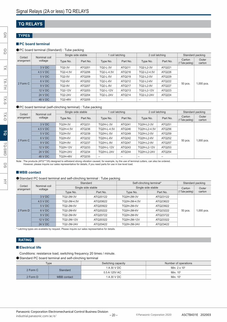
* Latching types are available by request. Please inquire our sales representative for details.
Note : The products (ATQ***25) designed to withstand strong vibration caused, for example, by the use of terminal cutters, can also be ordered. However, please inquire our sales representative for details, if you need parts for use in low level load.
Signal Relays (2A or less) TQ RELAYS
TQ RELAYS
PC board terminalPC board terminal (Standard) : Tube packing
PC board terminal (self-clinching terminal) : Tube packing
TYPES
MBB contactStandard PC board terminal and self-clinching terminal : Tube packing
RATING
Electrical lifeConditions: resistance load, switching frequency 20 times / minute.Standard PC board terminal and self-clinching terminal
Contact arrangement
Nominal coil voltage
Single side stable 1 coil latching 2 coil latching Standard packing
Type No. Part No. Type No. Part No. Type No. Part No. Carton(1 Tube packing)
Outer carton
2 Form C
3 V DC TQ2-3V ATQ201 TQ2-L-3V ATQ211 TQ2-L2-3V ATQ221
50 pcs. 1,000 pcs.
4.5 V DC TQ2-4.5V ATQ206 TQ2-L-4.5V ATQ216 TQ2-L2-4.5V ATQ2265 V DC TQ2-5V ATQ209 TQ2-L-5V ATQ219 TQ2-L2-5V ATQ2296 V DC TQ2-6V ATQ202 TQ2-L-6V ATQ212 TQ2-L2-6V ATQ2229 V DC TQ2-9V ATQ207 TQ2-L-9V ATQ217 TQ2-L2-9V ATQ227
12 V DC TQ2-12V ATQ203 TQ2-L-12V ATQ213 TQ2-L2-12V ATQ22324 V DC TQ2-24V ATQ204 TQ2-L-24V ATQ214 TQ2-L2-24V ATQ22448 V DC TQ2-48V ATQ205 – – – –
Contact arrangement
Nominal coil voltage
Single side stable 1 coil latching 2 coil latching Standard packing
Type No. Part No. Type No. Part No. Type No. Part No. Carton(1 Tube packing)
Outer carton
2 Form C
3 V DC TQ2H-3V ATQ231 TQ2H-L-3V ATQ241 TQ2H-L2-3V ATQ251
50 pcs. 1,000 pcs.
4.5 V DC TQ2H-4.5V ATQ236 TQ2H-L-4.5V ATQ246 TQ2H-L2-4.5V ATQ2565 V DC TQ2H-5V ATQ239 TQ2H-L-5V ATQ249 TQ2H-L2-5V ATQ2596 V DC TQ2H-6V ATQ232 TQ2H-L-6V ATQ242 TQ2H-L2-6V ATQ2529 V DC TQ2H-9V ATQ237 TQ2H-L-9V ATQ247 TQ2H-L2-9V ATQ257
12 V DC TQ2H-12V ATQ233 TQ2H-L-12V ATQ243 TQ2H-L2-12V ATQ25324 V DC TQ2H-24V ATQ234 TQ2H-L-24V ATQ244 TQ2H-L2-24V ATQ25448 V DC TQ2H-48V ATQ235 – – – –
Contact arrangement
Nominal coil voltage
Standard Self-clinching terminal* Standard packingSingle side stable Single side stable Carton
(1 Tube packing)Outer cartonType No. Part No. Type No. Part No.
2 Form D
3 V DC TQ2-2M-3V ATQ20122 TQ2H-2M-3V ATQ23122
50 pcs. 1,000 pcs.
4.5 V DC TQ2-2M-4.5V ATQ20622 TQ2H-2M-4.5V ATQ236225 V DC TQ2-2M-5V ATQ20922 TQ2H-2M-5V ATQ239226 V DC TQ2-2M-6V ATQ20222 TQ2H-2M-6V ATQ232229 V DC TQ2-2M-9V ATQ20722 TQ2H-2M-9V ATQ23722
12 V DC TQ2-2M-12V ATQ20322 TQ2H-2M-12V ATQ2332224 V DC TQ2-2M-24V ATQ20422 TQ2H-2M-24V ATQ23422
Type Switching capacity Number of operations
2 Form C Standard1 A 30 V DC Min. 2 x 10⁵
0.5 A 125V AC Min. 105
2 Form D MBB contact 1 A 30 V DC Min. 105
GN
GQ
TXTX-TH
TX-STX-D
TQTQ-SM
DD
SH
YG
NG
QTX
TX-THTX-S
TX-DTQ
TQ-SMD
DS
HY
– 20 –
Panasonic Corporation Electromechanical Control Business Divisionindustrial.panasonic.com/ac/e/ Panasonic Corporation 2020 ASCTB431E 202003
Stopper(gray)
Orientation(indicates PIN No.1)stripe
Stopper(green)
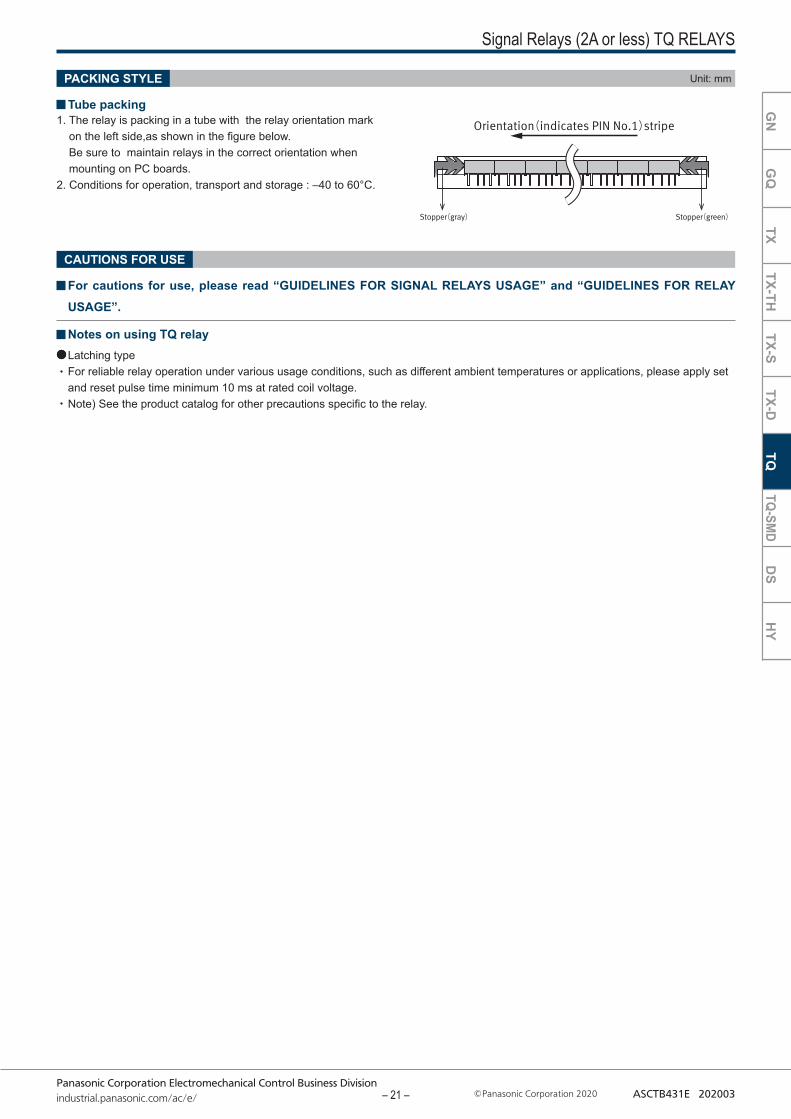
Signal Relays (2A or less) TQ RELAYS
PACKING STYLE Unit: mm
Tube packing
CAUTIONS FOR USE
1. The relay is packing in a tube with the relay orientation mark on the left side,as shown in the figure below. Be sure to maintain relays in the correct orientation when mounting on PC boards.
2. Conditions for operation, transport and storage : –40 to 60°C.
For cautions for use, please read “GUIDELINES FOR SIGNAL RELAYS USAGE” and “GUIDELINES FOR RELAY USAGE”.
Notes on using TQ relayLatching type For reliable relay operation under various usage conditions, such as different ambient temperatures or applications, please apply set and reset pulse time minimum 10 ms at rated coil voltage.Note) See the product catalog for other precautions specific to the relay.
GN
GQ
TXTX-TH
TX-STX-D
TQTQ-SM
DD
SH
YG
NG
QTX
TX-THTX-S
TX-DTQ
TQ-SMD
DS
HY
– 21 –
Panasonic Corporation Electromechanical Control Business Divisionindustrial.panasonic.com/ac/e/ Panasonic Corporation 2020 ASCTB431E 202003
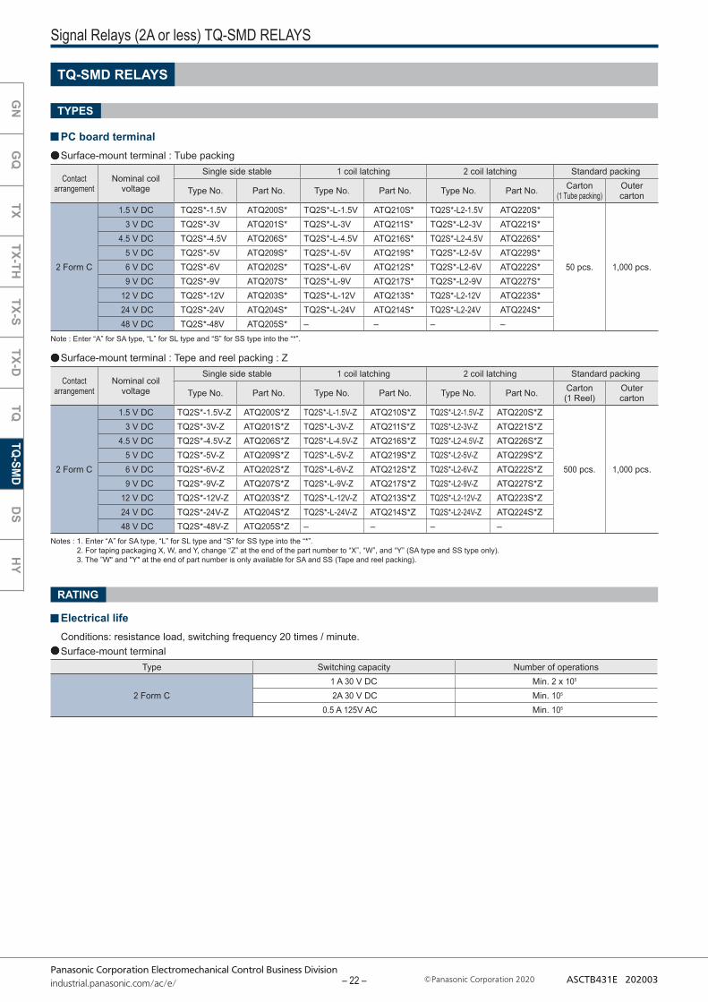
Notes : 1. Enter “A” for SA type, “L” for SL type and “S” for SS type into the “*”. 2. For taping packaging X, W, and Y, change “Z” at the end of the part number to “X”, “W”, and “Y” (SA type and SS type only). 3. The ”W" and "Y" at the end of part number is only available for SA and SS (Tape and reel packing).
Note : Enter “A” for SA type, “L” for SL type and “S” for SS type into the “*”.
Signal Relays (2A or less) TQ-SMD RELAYS
TQ-SMD RELAYS
PC board terminalSurface-mount terminal : Tube packing
TYPES
RATING
Electrical lifeConditions: resistance load, switching frequency 20 times / minute.Surface-mount terminal
Surface-mount terminal : Tepe and reel packing : Z
Contact arrangement
Nominal coil voltage
Single side stable 1 coil latching 2 coil latching Standard packing
Type No. Part No. Type No. Part No. Type No. Part No. Carton(1 Tube packing)
Outer carton
2 Form C
1.5 V DC TQ2S*-1.5V ATQ200S* TQ2S*-L-1.5V ATQ210S* TQ2S*-L2-1.5V ATQ220S*
50 pcs. 1,000 pcs.
3 V DC TQ2S*-3V ATQ201S* TQ2S*-L-3V ATQ211S* TQ2S*-L2-3V ATQ221S*4.5 V DC TQ2S*-4.5V ATQ206S* TQ2S*-L-4.5V ATQ216S* TQ2S*-L2-4.5V ATQ226S*
5 V DC TQ2S*-5V ATQ209S* TQ2S*-L-5V ATQ219S* TQ2S*-L2-5V ATQ229S*6 V DC TQ2S*-6V ATQ202S* TQ2S*-L-6V ATQ212S* TQ2S*-L2-6V ATQ222S*9 V DC TQ2S*-9V ATQ207S* TQ2S*-L-9V ATQ217S* TQ2S*-L2-9V ATQ227S*
12 V DC TQ2S*-12V ATQ203S* TQ2S*-L-12V ATQ213S* TQ2S*-L2-12V ATQ223S*24 V DC TQ2S*-24V ATQ204S* TQ2S*-L-24V ATQ214S* TQ2S*-L2-24V ATQ224S*48 V DC TQ2S*-48V ATQ205S* – – – –
Contact arrangement
Nominal coil voltage
Single side stable 1 coil latching 2 coil latching Standard packing
Type No. Part No. Type No. Part No. Type No. Part No. Carton(1 Reel)
Outer carton
2 Form C
1.5 V DC TQ2S*-1.5V-Z ATQ200S*Z TQ2S*-L-1.5V-Z ATQ210S*Z TQ2S*-L2-1.5V-Z ATQ220S*Z
500 pcs. 1,000 pcs.
3 V DC TQ2S*-3V-Z ATQ201S*Z TQ2S*-L-3V-Z ATQ211S*Z TQ2S*-L2-3V-Z ATQ221S*Z4.5 V DC TQ2S*-4.5V-Z ATQ206S*Z TQ2S*-L-4.5V-Z ATQ216S*Z TQ2S*-L2-4.5V-Z ATQ226S*Z
5 V DC TQ2S*-5V-Z ATQ209S*Z TQ2S*-L-5V-Z ATQ219S*Z TQ2S*-L2-5V-Z ATQ229S*Z6 V DC TQ2S*-6V-Z ATQ202S*Z TQ2S*-L-6V-Z ATQ212S*Z TQ2S*-L2-6V-Z ATQ222S*Z9 V DC TQ2S*-9V-Z ATQ207S*Z TQ2S*-L-9V-Z ATQ217S*Z TQ2S*-L2-9V-Z ATQ227S*Z
12 V DC TQ2S*-12V-Z ATQ203S*Z TQ2S*-L-12V-Z ATQ213S*Z TQ2S*-L2-12V-Z ATQ223S*Z24 V DC TQ2S*-24V-Z ATQ204S*Z TQ2S*-L-24V-Z ATQ214S*Z TQ2S*-L2-24V-Z ATQ224S*Z48 V DC TQ2S*-48V-Z ATQ205S*Z – – – –
Type Switching capacity Number of operations
2 Form C1 A 30 V DC Min. 2 x 10⁵
2A 30 V DC Min. 105
0.5 A 125V AC Min. 105
GN
GQ
TXTX-TH
TX-STX-D
TQTQ-SM
DD
SH
Y
– 22 –
Panasonic Corporation Electromechanical Control Business Divisionindustrial.panasonic.com/ac/e/ Panasonic Corporation 2020 ASCTB431E 202003
Stopper(gray)
Orientation(indicates PIN No.1)stripe
Stopper(green)
Relay polarity bar
TQ-SMD relays
1.5 2 dia.4 0.4
1.75
11.5
14.6
14.6
6.3±0.2
24±
0 .3
2
16 12.3
+0.1 0
Tolerance :±0.1Tape coming out direction
(Z type)dia.
Relay polarity bar
TQ-SMD relays
1.5 2 dia.4 0.4
1.75
11.5
14.6
14.6
7.8±0.2
24±
0 .3
2
16 12.3
+0.1 0
Tolerance:±0.1Tape coming out direction
(Z type)dia.
Relay polarity bar
TQ-SMD relays
1.5 2 dia.4 0.4
1.75
11.5
14.6
14.6
7.8±0.2
24±
0 .3
2
16 10.1
+0.1 0
(Z type)
Tolerance:±0.1Tape coming out direction
dia.
380±
2 di
a.
80±
1 di
a.
24.4 2±0.2
2±0.52±0.5
13±0.2 dia.
21±0.8 dia.
+ 2 0
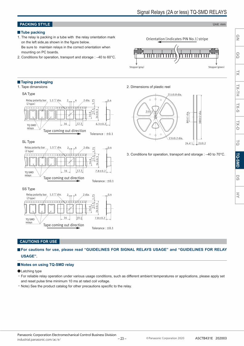
Signal Relays (2A or less) TQ-SMD RELAYS
PACKING STYLE Unit: mm
Tube packing
3. Conditions for operation, transport and storage : –40 to 70°C.
SA Type
SL Type
SS Type
CAUTIONS FOR USE
1. The relay is packing in a tube with the relay orientation mark on the left side,as shown in the figure below. Be sure to maintain relays in the correct orientation when mounting on PC boards.
2. Conditions for operation, transport and storage : –40 to 60°C.
1. Tape dimansions 2. Dimensions of plastic reel Taping packaging
For cautions for use, please read “GUIDELINES FOR SIGNAL RELAYS USAGE” and “GUIDELINES FOR RELAY USAGE”.
Notes on using TQ-SMD relayLatching type For reliable relay operation under various usage conditions, such as different ambient temperatures or applications, please apply set and reset pulse time minimum 10 ms at rated coil voltage.Note) See the product catalog for other precautions specific to the relay.
GN
GQ
TXTX-TH
TX-STX-D
TQTQ-SM
DD
SH
Y
– 23 –
Panasonic Corporation Electromechanical Control Business Divisionindustrial.panasonic.com/ac/e/ Panasonic Corporation 2020 ASCTB431E 202003
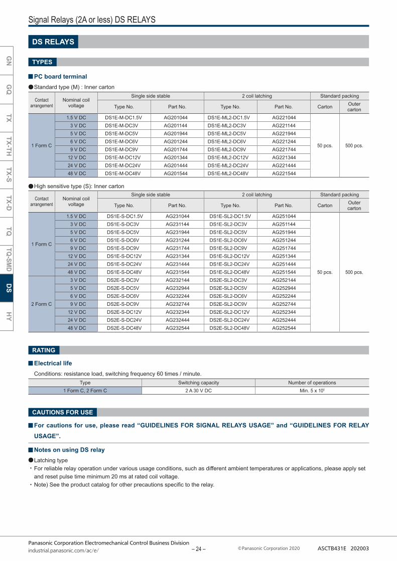
High sensitive type (S): Inner carton
Signal Relays (2A or less) DS RELAYS
DS RELAYS
PC board terminalStandard type (M) : Inner carton
TYPES
RATING
Electrical lifeConditions: resistance load, switching frequency 60 times / minute.
CAUTIONS FOR USE
For cautions for use, please read “GUIDELINES FOR SIGNAL RELAYS USAGE” and “GUIDELINES FOR RELAY USAGE”.
Notes on using DS relayLatching type For reliable relay operation under various usage conditions, such as different ambient temperatures or applications, please apply set and reset pulse time minimum 20 ms at rated coil voltage.Note) See the product catalog for other precautions specific to the relay.
Contact arrangement
Nominal coil voltage
Single side stable 2 coil latching Standard packing
Type No. Part No. Type No. Part No. Carton Outer carton
1 Form C
1.5 V DC DS1E-M-DC1.5V AG201044 DS1E-ML2-DC1.5V AG221044
50 pcs. 500 pcs.
3 V DC DS1E-M-DC3V AG201144 DS1E-ML2-DC3V AG2211445 V DC DS1E-M-DC5V AG201944 DS1E-ML2-DC5V AG2219446 V DC DS1E-M-DC6V AG201244 DS1E-ML2-DC6V AG2212449 V DC DS1E-M-DC9V AG201744 DS1E-ML2-DC9V AG221744
12 V DC DS1E-M-DC12V AG201344 DS1E-ML2-DC12V AG22134424 V DC DS1E-M-DC24V AG201444 DS1E-ML2-DC24V AG22144448 V DC DS1E-M-DC48V AG201544 DS1E-ML2-DC48V AG221544
Contact arrangement
Nominal coil voltage
Single side stable 2 coil latching Standard packing
Type No. Part No. Type No. Part No. Carton Outer carton
1 Form C
1.5 V DC DS1E-S-DC1.5V AG231044 DS1E-SL2-DC1.5V AG251044
50 pcs. 500 pcs.
3 V DC DS1E-S-DC3V AG231144 DS1E-SL2-DC3V AG2511445 V DC DS1E-S-DC5V AG231944 DS1E-SL2-DC5V AG2519446 V DC DS1E-S-DC6V AG231244 DS1E-SL2-DC6V AG2512449 V DC DS1E-S-DC9V AG231744 DS1E-SL2-DC9V AG251744
12 V DC DS1E-S-DC12V AG231344 DS1E-SL2-DC12V AG25134424 V DC DS1E-S-DC24V AG231444 DS1E-SL2-DC24V AG25144448 V DC DS1E-S-DC48V AG231544 DS1E-SL2-DC48V AG251544
2 Form C
3 V DC DS2E-S-DC3V AG232144 DS2E-SL2-DC3V AG2521445 V DC DS2E-S-DC5V AG232944 DS2E-SL2-DC5V AG2529446 V DC DS2E-S-DC6V AG232244 DS2E-SL2-DC6V AG2522449 V DC DS2E-S-DC9V AG232744 DS2E-SL2-DC9V AG252744
12 V DC DS2E-S-DC12V AG232344 DS2E-SL2-DC12V AG25234424 V DC DS2E-S-DC24V AG232444 DS2E-SL2-DC24V AG25244448 V DC DS2E-S-DC48V AG232544 DS2E-SL2-DC48V AG252544
Type Switching capacity Number of operations1 Form C, 2 Form C 2 A 30 V DC Min. 5 x 10⁵
GN
GQ
TXTX-TH
TX-STX-D
TQTQ-SM
DD
SH
Y
– 24 –
Panasonic Corporation Electromechanical Control Business Divisionindustrial.panasonic.com/ac/e/ Panasonic Corporation 2020 ASCTB431E 202003
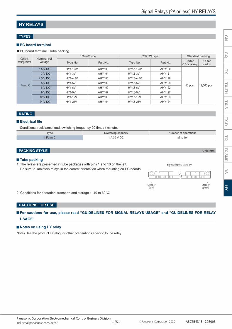
Side with pins 1 and 10.
Stopper(gray)
Stopper(green)
Signal Relays (2A or less) HY RELAYS
PACKING STYLE Unit: mm
TYPES
HY RELAYS
PC board terminalPC board terminal : Tube packing
1. The relays are presented in tube packages with pins 1 and 10 on the left. Be sure to maintain relays in the correct orientation when mounting on PC boards.
2. Conditions for operation, transport and storage : –40 to 60°C.
Tube packing
CAUTIONS FOR USE
For cautions for use, please read “GUIDELINES FOR SIGNAL RELAYS USAGE” and “GUIDELINES FOR RELAY USAGE”.
Notes on using HY relayNote) See the product catalog for other precautions specific to the relay.
Type Switching capacity Number of operations1 Form C 1 A 30 V DC Min. 105
Contact arrangement
Nominal coil voltage
150mW type 200mW type Standard packing
Type No. Part No. Type No. Part No. Carton(1 Tube packing)
Outer carton
1 Form C
1.5 V DC HY1-1.5V AHY100 HY1Z-1.5V AHY120
50 pcs. 2,000 pcs.
3 V DC HY1-3V AHY101 HY1Z-3V AHY1214.5 V DC HY1-4.5V AHY106 HY1Z-4.5V AHY126
5 V DC HY1-5V AHY109 HY1Z-5V AHY1296 V DC HY1-6V AHY102 HY1Z-6V AHY1229 V DC HY1-9V AHY107 HY1Z-9V AHY127
12 V DC HY1-12V AHY103 HY1Z-12V AHY12324 V DC HY1-24V AHY104 HY1Z-24V AHY124
RATING
Electrical lifeConditions: resistance load, switching frequency 20 times / minute.
GN
GQ
TXTX-TH
TX-STX-D
TQTQ-SM
DD
SH
Y
– 25 –

Panasonic Corporation Electromechanical Control Business Divisionindustrial.panasonic.com/ac/e/ Panasonic Corporation 2020 ASCTB48E 202003
Safety satndards chart
ItemUL/C-UL(Recognized) CSA(Certified) BSI
File No. Contact rating Cycles Temp. File No. Contact rating Cycles Temp. File No.
GN E43149
1 A 30 V DC General use 105
40°C CSA staandard certified by C-ULVC648944(Standard insulation)
0.3 A 110 V DC General use 3×10⁴
0.3 A 125 V AC Resistive 105
GQ E43149
2 A 30 V DC Resistive 5×10⁴
40°C
CSA staandard certified by C-ULVC667389(Standard insulation)
1 A 30 V DC Resistive 105
0.5 A 60 V DC Resistive* 6×10³ 85°C
0.3 A 110 V DC Resistive 3×10⁴
40°C0.3 A 125 V AC Resistive 105
TX E43149
2 A 30 V DC Resistive 105
40°C CSA staandard certified by C-ULVC659956(Standard insulation)
0.5 A 125 V AC Resistive 105
0.3 A 110 V DC Resistive 105
TX-TH E43149
2 A 30 V DC Resistive 105
40°C CSA staandard certified by C-ULVC659956(Standard insulation)
0.5 A 125 V AC Resistive 105
0.3 A 110 V DC Resistive 105
TX-S E43149
1 A 30 V DC Resistive 105
40°C CSA staandard certified by C-ULVC648943(Standard insulation)
0.5 A 125 V AC Resistive 105
0.3 A 110 V DC Resistive 3×10⁴
TX-D E43149
2 A 30 V DC Resistive 105
40°C CSA staandard certified by C-ULVC670289
(Supplementary insulation)
0.5 A 125 V AC Resistive 105
0.3 A 110 V DC Resistive 105
TQ E43149
1 A 30 V DC Resistive 105
40°C LR26550 etc
1 A 30 V DC 105
40°C
–
0.5 A 125 V AC General use 105 0.5 A 125 V AC 105
0.3 A 110 V DC Resistive 105 0.3 A 110 V DC 105
TQ-SMD E43149
2 A 30 V DC Resistive 105
40°C LR26550 etc
2 A 30 V DC 105
40°C0.5 A 125 V AC General use 105 0.5 A 125 V AC 105
0.3 A 110 V DC Resistive 105 0.3 A 110 V DC 105
DS E43149
2 A 30 V DC Resistive 105
40°C LR26550 etc
2 A 30 V DC 105
40°C –0.6 A 110 V DC Resistive 105 0.6 A 110 V DC 105
0.6 A 125 V AC General use 105 0.6 A 125 V AC 105
HY E43149 (UL only) 1 A 30 V DC General use 105 40°C LR26550 1 A 30 V DC 105 40°C –
* Only for single side stable (excluding high sensitivity) 1.5 to 12 V DC.
– 26 –
Panasonic Corporation Electromechanical Control Business Divisionindustrial.panasonic.com/ac/e/ Panasonic Corporation 2020 ASCTB49E 202003
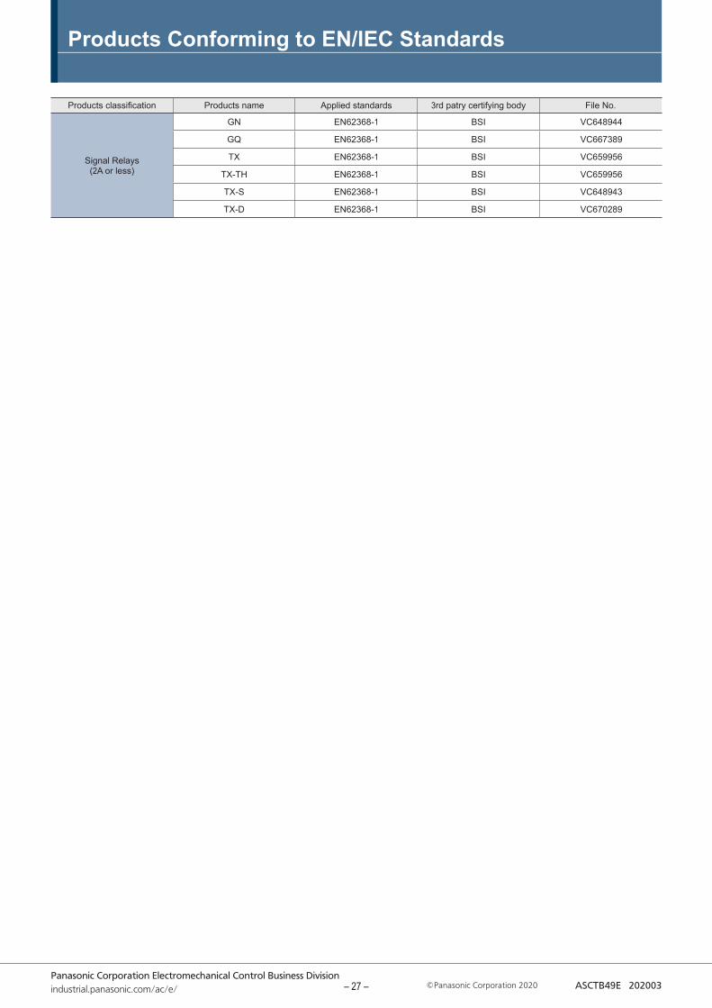
Products Conforming to EN/IEC Standards
Products classification Products name Applied standards 3rd patry certifying body File No.
Signal Relays (2A or less)
GN EN62368-1 BSI VC648944
GQ EN62368-1 BSI VC667389
TX EN62368-1 BSI VC659956
TX-TH EN62368-1 BSI VC659956
TX-S EN62368-1 BSI VC648943
TX-D EN62368-1 BSI VC670289
– 27 –
Panasonic Corporation Electromechanical Control Business Divisionindustrial.panasonic.com/ac/e/ Panasonic Corporation 2020 ASCTB414E 202003
ON : OFF = 1 : 1
Volta
ge
Time
GUIDELINES FOR RELAY USAGE
PRECAUTIONS FOR COIL INPUT
For cautions for use, please read "GUIDELINES FOR RELAY USAGE". https://industrial.panasonic.com/ac/e/control/relay/cautions_use/index.jsp
Long term current carryingA circuit that will be carrying a current continuously for long periods without relay switching operation. (circuits for emergency lamps, alarm devices and error inspection that, for example, revert only during malfunction and output warnings with form B contacts) Continuous,long-term current to the coil will facilitate deterioration of coil insulation and characteristics due to heating of the coil itself.For circuits such as these, please use a magnetic-hold type latching relay. If you need to use a single stable relay, use a sealed type relay that is not easily affected by ambient conditions and make a failsafe circuit design that considers the possibility of contact failure or disconnection.
DC Coil operating powerSteady state DC current should be applied to the coil. The wave form should be rectangular. If it includes ripple, the ripple factor should be less than 5%.However, please check with the actual circuit since the electricalcharacteristics may vary. The rated coil voltage should be applied to the coil and the set/reset pulse time of latching type relay differs for each relays, please refer to the relay's individual specifications.
Coil connectionWhen connecting coils of polarized relays, please check coil polarity(+,-) at the internal connection diagram (Schematic). If any wrong connection is made, it may cause unexpected malfunction, like abnormal heat, fire and so on, and circuit do not work.Avoid impressing voltages to the set coil and reset coil at the same time.
Maximum allowable voltage and temperature riseProper usage requires that the rated coil voltage be impressed on the coil.Note, however, that if a voltage greater than or equal to the maximum continuous voltage is impressed on the coil, the coil may burn or its layers short due to the temperature rise.Furthermore, do not exceed the usable ambient temperature range listed in the catalog.
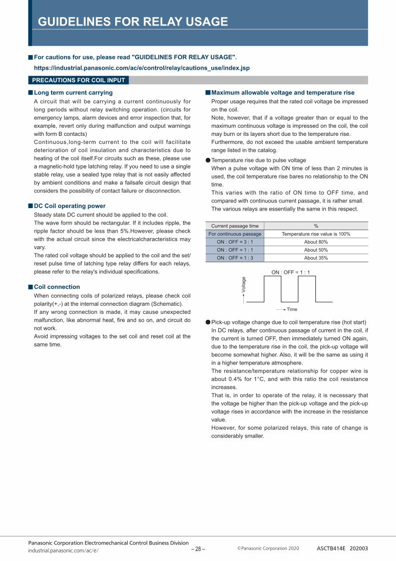
Temperature rise due to pulse voltageWhen a pulse voltage with ON time of less than 2 minutes is used, the coil temperature rise bares no relationship to the ON time. This varies with the ratio of ON time to OFF time, and compared with continuous current passage, it is rather small. The various relays are essentially the same in this respect.
Pick-up voltage change due to coil temperature rise (hot start)In DC relays, after continuous passage of current in the coil, if the current is turned OFF, then immediately turned ON again, due to the temperature rise in the coil, the pick-up voltage will become somewhat higher. Also, it will be the same as using it in a higher temperature atmosphere.The resistance/temperature relationship for copper wire is about 0.4% for 1°C, and with this ratio the coil resistance increases.That is, in order to operate of the relay, it is necessary that the voltage be higher than the pick-up voltage and the pick-up voltage rises in accordance with the increase in the resistance value.However, for some polarized relays, this rate of change is considerably smaller.
Current passage time %For continuous passage Temperature rise value is 100%
ON : OFF = 3 : 1 About 80%ON : OFF = 1 : 1 About 50%ON : OFF = 1 : 3 About 35%
– 28 –
GUIDELINES FOR RELAY USAGE
Panasonic Corporation Electromechanical Control Business Divisionindustrial.panasonic.com/ac/e/ Panasonic Corporation 2020 ASCTB414E 202003
5
85
Humidity(%RH)
Avoid icingwhen used attemperatureslower than 0°C
Avoid con-densation when used at tem-peratures higher than 0°C
Allowable range
Ambient temperature(℃) 0 85-40
NOTES
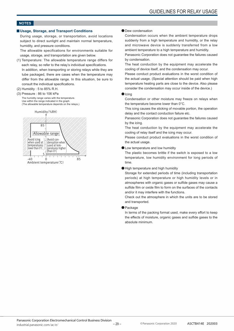
Usage, Storage, and Transport ConditionsDuring usage, storage, or transportation, avoid locations subject to direct sunlight and maintain normal temperature, humidity, and pressure conditions.The allowable specifications for environments suitable for usage, storage, and transportation are given below.
(1) Temperature: The allowable temperature range differs for each relay, so refer to the relay’s individual specifications.In addition, when transporting or storing relays while they are tube packaged, there are cases when the temperature may differ from the allowable range. In this situation, be sure to consult the individual specifications.
(2) Humidity : 5 to 85% R.H.(3) Pressure : 86 to 106 kPa
The humidity range varies with the temperature. Use within the range indicated in the graph. (The allowable temperature depends on the relays.)
Dew condensationCondensation occurs when the ambient temperature drops suddenly from a high temperature and humidity, or the relay and microwave device is suddenly transferred from a low ambient temperature to a high temperature and humidity.Panasonic Corporation does not guarantee the failures caused by condensation.The heat conduction by the equipment may accelerate the cooling of device itself, and the condensation may occur.Please conduct product evaluations in the worst condition of the actual usage. (Special attention should be paid when high temperature heating parts are close to the device. Also please consider the condensation may occur inside of the device.)
IcingCondensation or other moisture may freeze on relays when the temperature become lower than 0°C.This icing causes the sticking of movable portion, the operation delay and the contact conduction failure etc. Panasonic Corporation does not guarantee the failures caused by the icing.The heat conduction by the equipment may accelerate the cooling of relay itself and the icing may occur.Please conduct product evaluations in the worst condition of the actual usage.
Low temperature and low humidityThe plastic becomes brittle if the switch is exposed to a low temperature, low humidity environment for long periods of time.
High temperature and high humidityStorage for extended periods of time (including transportation periods) at high temperature or high humidity levels or in atmospheres with organic gases or sulfide gases may cause a sulfide film or oxide film to form on the surfaces of the contacts and/or it may interfere with the functions. Check out the atmosphere in which the units are to be stored and transported.
PackageIn terms of the packing format used, make every effort to keep the effects of moisture, organic gases and sulfide gases to the absolute minimum.
– 29 –

GUIDELINES FOR RELAY USAGE
Panasonic Corporation Electromechanical Control Business Divisionindustrial.panasonic.com/ac/e/ Panasonic Corporation 2020 ASCTB414E 202003
5% 10% 60%
Spot
Humidity indicator card
SiliconWhen a source of silicone substances (silicone rubber, silicone oil,silicone coating materials and silicone filling materials etc.) is used around the relay, the silicone gas (low molecular siloxane etc.) may be produced This silicone gas may penetrate into the inside of the relay. When the relay is kept and used in this condition, silicone compound may adhere to the relay contacts which may cause the contact failure. Do not use any sources of silicone gas around the relay (Including plastic seal types).
NOx GenerationWhen relay is used in an atmosphere high in humidity to switch a load which easily produces an arc, the NOx created by the arc and the water absorbed from outside the relay combine to produce nitric acid.This corrodes the internal metal parts and adversely affects operation.Avoid use at an ambient humidity of 85% RH or higher (at 20°C). If use at high humidity is unavoidable, please contact our sales representative.
5% 10% 60% Bake treatment necessity judgment
Ⅰ ● ● ● No need to bakeⅡ ○ ● ● No need to bakeⅢ ○ ○ ● Need to bakeⅣ ○ ○ ○ Need to bake
Storage requirementsSince the SMD type is sensitive to humidity it is packaged with tightly sealed anti-humidity packaging. However, when storing, please be careful of the following.
1) Please use promptly once the anti-humidity pack is opened.(within 72 hours, Max. 30°C / 70% R.H.). If left with the pack open, the relay will absorb moisture which will cause thermal stress when reflow mounting and thus cause the case to expand. As a result, the seal may break.
2) If relays will not be used within 72 hours, please store relays in a humidity controlled desiccator or in an anti-humidity bag to which silica gel has been added.* If the relay is to be soldered after it has been exposed to excessive humidity
atmosphere, cracks and leaks can occur. Be sure to mount the relay under the required mounting conditions.
3) When relays (which is packaged with humidity indicator and silica gel) meeting one of below criteria, please bake (dry) before use.
<Baking (Drying) conditions>With reel : 45°C, 96 hours or more.
Without reel (including relay only) : 60°C, 35 hours or more.
● : indicate brown, ○ : Other than brown (blueish color)
4) The following cautionary label is affixed to the anti-humidity
pack.
When the storage conditions specified in 1) are exceeded. When humidity indicator is in Ⅲ or Ⅳ status according to judgement standard.
<How to judge>Please check humidity indicator color and decide if baking is necessary or not.
– 30 –
GUIDELINES FOR RELAY USAGE
Panasonic Corporation Electromechanical Control Business Divisionindustrial.panasonic.com/ac/e/ Panasonic Corporation 2020 ASCTB414E 202003
OTHERS
Cleaning1) Although the environmentally sealed type relay (plastic sealed
type,etc.) can be cleaned, avoid immersing the relay into cold liquid (such as cleaning solvent) immediately after soldering. Doing so may deteriorate the sealing performance.
2) Surface mount terminal type relay is sealed type and it can be cleaned by immersion. Use pure water or alcohol-based cleaning solvent.
3) Cleaning with the boiling method is recommended (The temperature of cleaning liquid should be 40°C or lower).Avoid ultrasonic cleaning on relays. Use of ultrasonic cleaning may cause breaks in the coil or slight sticking of the contacts due to the ultrasonic energy.
Please refer to "the latest product specifications"when designing your product.•Requests to customers:https://industrial.panasonic.com/ac/e/salespolicies/
– 31 –
Panasonic Electric WorksPlease contact our Global Sales Companies in:
Europe
▸ Headquarters Panasonic Electric Works Europe AG Caroline-Herschel-Strasse 100, 85521 Ottobrunn, Tel. +49 89 45354-1000, Fax +49 89 45354-1550, www.panasonic-electric-works.com▸ Austria Panasonic Industry Austria GmbH Josef Madersperger Str. 2, 2362 Biedermannsdorf, Tel. +43 (0) 2236-26846, Fax +43 (0) 2236-46133
www.panasonic-electric-works.atPanasonic Industrial Devices Materials Europe GmbH
Ennshafenstraße 30, 4470 Enns, Tel. +43 (0) 7223 883, Fax +43 (0) 7223 88333, www.panasonic-electronic-materials.com
▸ Benelux Panasonic Electric WorksSales Western Europe B.V.
De Rijn 4, 5684 PJ Best, Netherlands, Tel. +31 (0) 499 372727, www.panasonic-electric-works.nl
▸ Czech Republic Panasonic Electric Works Europe AG,organizační složka
Administrative centre PLATINIUM, Veveř í 3163/111, 616 00 Brno, Tel. +420 541 217 001, Fax +420 541 217 101, www.panasonic-electric-works.cz
▸ France Panasonic Electric Works Sales Western Europe B.V.
Succursale française, 10, rue des petits ruisseaux, 91370 Verrières Le Buisson, Tél. +33 (0) 1 6013 5757, Fax +33 (0) 1 6013 5758, www.panasonic-electric-works.fr
▸ Germany Panasonic Electric Works Europe AG Caroline-Herschel-Strasse 100, 85521 Ottobrunn, Tel. +49 89 45354-1000, Fax +49 89 45354-2111, www.panasonic-electric-works.de▸ Hungary Panasonic Electric Works Europe AG Magyarországi Fióktelepe, 1117 Budapest, Alíz utca 4, Tel. +43 (0) 2236 26846 -25, Fax +43 (0) 2236 46133
www.panasonic-electric-works.hu▸ Ireland Panasonic Electric Works UK Ltd. Irish Branch Offi ce, Dublin, Tel. +353 (0) 14600969, Fax +353 (0) 14601131, www.panasonic-electric-works.co.uk▸ Italy Panasonic Industry Italia srl Via del Commercio 3-5 (Z.I. Ferlina), 37012 Bussolengo (VR), Tel. +39 0456752711, Fax +39 0456700444,
www.panasonic-electric-works.it▸ Nordic Countries Panasonic Electric Works Europe AG
Panasonic Fire & Security Europe ABFilial Nordic, Knarrarnäsgatan 15, 164 40 Kista, Sweden, Tel. +46 859476680, Fax +46 859476690, www.panasonic-electric-works.seJungmansgatan 12, 21119 Malmö, Tel. +46 40 697 7000, Fax +46 40 697 7099, www.panasonic-fi re-security.com
▸ Poland Panasonic Industry Poland sp. z o.o. Ul. Dowborczyków 25, 90-019 Lódź, Polska, Tel. +48 42 2309633, www.panasonic-electric-works.pl▸ Spain Panasonic Industry Iberia S.A. Barajas Park, San Severo 20, 28042 Madrid, Tel. +34 913293875, Fax +34 913292976, www.panasonic-electric-works.es▸ Switzerland Panasonic Industry Switzerland AG Grundstrasse 8, 6343 Rotkreuz, Tel. +41 (0) 41 7997050, Fax +41 (0) 41 7997055, www.panasonic-electric-works.ch▸ United Kingdom Panasonic Electric Works UK Ltd. Sunrise Parkway, Linford Wood, Milton Keynes, MK14 6 LF, Tel. +44 (0) 1908 231555, Fax +44 (0) 1908 231599,
www.panasonic-electric-works.co.uk
North & South America
▸ USA Panasonic Industrial Devices Sales Company of America
Two Riverfront Plaza, 7th Floor, Newark, NJ 07102-5490, Tel. 1-8003-442-112, www.pewa.panasonic.com
Asia Pacifi c / China / Japan
▸ China Panasonic Electric Works Sales (China) Co. Ltd. Tower C 3rd Floor, Offi ce Park, NO.5 Jinghua South Street, Chaoyang District, Beijing 100020, Tel. +86-10-5925-5988, Fax +86-10-5925-5980
▸ Hong Kong Panasonic Industrial Devices Sales (HK) Co., Ltd.
Suite 301, 3/F, Chinachem Golden Plaza, 77 Mody Road, TST East, Kowloon, Hong Kong, Tel. +852-2529-3956, Fax +852-2528-6991
▸ Japan Panasonic Corporation 1006, Oaza Kadoma, Kadoma-shi, Osaka 571-8501, Japan, Tel. +81-6-6908-1121, www.panasonic.net▸ Singapore Panasonic Industrial Devices
Automation Controls Sales Asia Pacifi cNo.3 Bedok South Road, Singapore 469269, Tel. +65-6299-9181, Fax +65-6390-3953
Global Network
Asia Pacific China JapanNorth America Europe
Global Network
1197euen 05/20