Embed Size (px)
Citation preview

SHIMADZU
TOC-V Series TOTAL ORGANIC CARBON
ANALYSER
Short-User Manual
TOC-V CPH/CPN
TOC-Control V
Version 2.00
Table of Content
I. TOC-Control V Main Menu
1. Measurement
1.1 Sample Table Editor
1.2 H/W Settings
1.3 Online Manual
2. Administration
2.1 System Administrator
2.2 Audit Trail
2.3 User Authentication
2.4 Others
II. Sample Table Editor
1. Create a calibration curve
2. Create a method
3. Create a sample run
4. Schedule File
4.1 Create a new schedule file
4.2 Export the sample table as schedule file
4.3 Insert a schedule
5. Vial Number
III. Analysis
1. Connect the system
2. Start the analysis
3. Sample Window
4. Edit Mode
5. Stop the analysis
:
:
:
:
:
:
:
:
:
:
:
:
:
:
:
:
:
:
:
:
:
:
:
:
:
3
3
3
3
5
6
6
6
6
7
8
9
13
15
18
18
18
18
19
20
20
20
21
22
22
TOCV-CP_IMshort_Control-ver-2_Rev07F Page 3 of 22 (Software version ≥ 2.00) effective date: September 2007
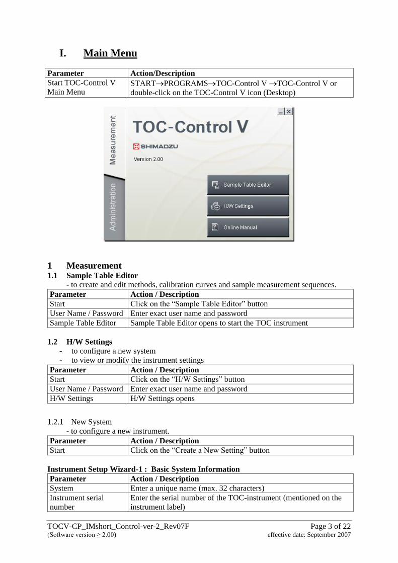
I. Main Menu
Parameter Action/Description
Start TOC-Control V
Main Menu STARTPROGRAMSTOC-Control V TOC-Control V or
double-click on the TOC-Control V icon (Desktop)
1 Measurement 1.1 Sample Table Editor
- to create and edit methods, calibration curves and sample measurement sequences.
Parameter Action / Description
Start Click on the “Sample Table Editor” button
User Name / Password Enter exact user name and password
Sample Table Editor Sample Table Editor opens to start the TOC instrument
1.2 H/W Settings
- to configure a new system
- to view or modify the instrument settings
Parameter Action / Description
Start Click on the “H/W Settings” button
User Name / Password Enter exact user name and password
H/W Settings H/W Settings opens
1.2.1 New System
- to configure a new instrument.
Parameter Action / Description
Start Click on the “Create a New Setting” button
Instrument Setup Wizard-1 : Basic System Information
Parameter Action / Description
System Enter a unique name (max. 32 characters)
Instrument serial
number
Enter the serial number of the TOC-instrument (mentioned on the
instrument label)
TOCV-CP_IMshort_Control-ver-2_Rev07F Page 4 of 22 (Software version ≥ 2.00) effective date: September 2007
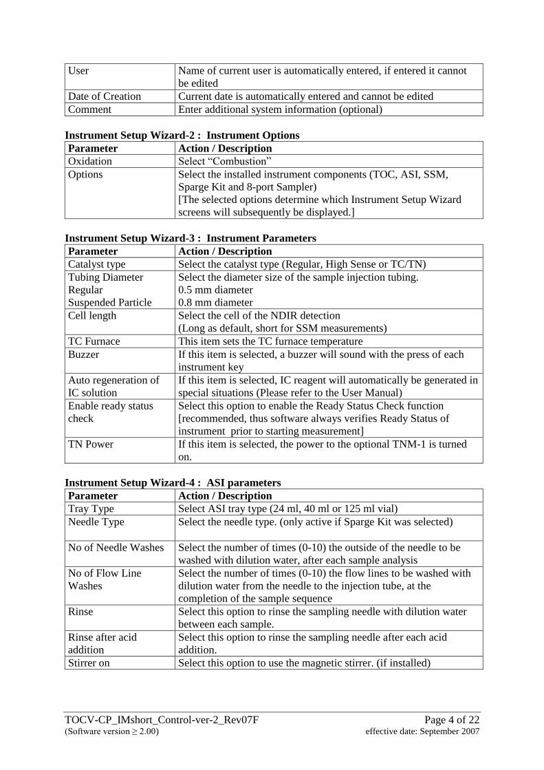
User Name of current user is automatically entered, if entered it cannot
be edited
Date of Creation Current date is automatically entered and cannot be edited
Comment Enter additional system information (optional)
Instrument Setup Wizard-2 : Instrument Options
Parameter Action / Description
Oxidation Select “Combustion”
Options Select the installed instrument components (TOC, ASI, SSM,
Sparge Kit and 8-port Sampler)
[The selected options determine which Instrument Setup Wizard
screens will subsequently be displayed.]
Instrument Setup Wizard-3 : Instrument Parameters
Parameter Action / Description
Catalyst type Select the catalyst type (Regular, High Sense or TC/TN)
Tubing Diameter
Regular
Suspended Particle
Select the diameter size of the sample injection tubing.
0.5 mm diameter
0.8 mm diameter
Cell length Select the cell of the NDIR detection
(Long as default, short for SSM measurements)
TC Furnace This item sets the TC furnace temperature
Buzzer If this item is selected, a buzzer will sound with the press of each
instrument key
Auto regeneration of
IC solution
If this item is selected, IC reagent will automatically be generated in
special situations (Please refer to the User Manual)
Enable ready status
check
Select this option to enable the Ready Status Check function
[recommended, thus software always verifies Ready Status of
instrument prior to starting measurement]
TN Power If this item is selected, the power to the optional TNM-1 is turned
on.
Instrument Setup Wizard-4 : ASI parameters
Parameter Action / Description
Tray Type Select ASI tray type (24 ml, 40 ml or 125 ml vial)
Needle Type Select the needle type. (only active if Sparge Kit was selected)
No of Needle Washes Select the number of times (0-10) the outside of the needle to be
washed with dilution water, after each sample analysis
No of Flow Line
Washes
Select the number of times (0-10) the flow lines to be washed with
dilution water from the needle to the injection tube, at the
completion of the sample sequence
Rinse Select this option to rinse the sampling needle with dilution water
between each sample.
Rinse after acid
addition
Select this option to rinse the sampling needle after each acid
addition.
Stirrer on Select this option to use the magnetic stirrer. (if installed)
TOCV-CP_IMshort_Control-ver-2_Rev07F Page 5 of 22 (Software version ≥ 2.00) effective date: September 2007
Instrument Setup Wizard-5 : SSM parameters
Parameter Action / Description
SSM TC Furnace ON Select this option to heat the TC furnace of SSM
SSM IC Furnace ON Select this option to heat the IC furnace of SSM
Instrument Setup Wizard-6 : Communication parameters
Parameter Action / Description
Com Port Select the communication port
Stop Bits and Parity Cannot be edited by the user .
[determined by the hardware, automatically set based on Com Port]
[Finish] Button The system configuration is created and the newly created system
configuration is displayed as an icon in the H/W Setting List
window.
1.2.2 H/W Setting List
- to view or modify instrument parameters of already defined systems
Parameter Action / Description
Open Select the “Instrument/System” icon and press “Open” to open the
instrument properties
Delete Select the “Instrument/System” icon and press “Delete” to delete the
instrument system
Close Press “Close” to close the H/W Setting List window.
1.3. Online Manual
- to open the user manual as PDF format
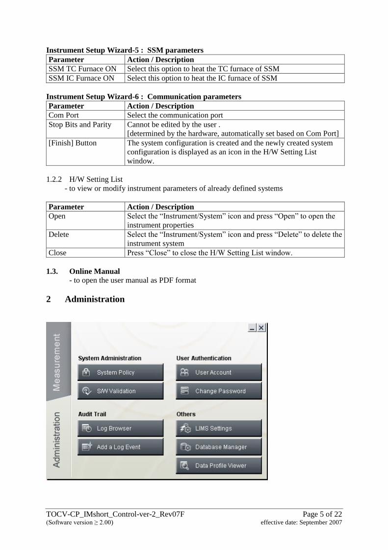
2 Administration
TOCV-CP_IMshort_Control-ver-2_Rev07F Page 6 of 22 (Software version ≥ 2.00) effective date: September 2007
2.1 System Administration
2.1.1 System Policy
- to check the security functions, activation of them is done during the installation
2.1.2 S/W Validation
- to verify that the TOC-Control V program files have not been modified since
installation
2.2 Audit Trail
2.2.1 Log Browser
- to open the audit trail database (please refer to the Administration Manual)
2.2.2 Add a Log Event
- to add an event to the Log Browser
2.3 User Authentication
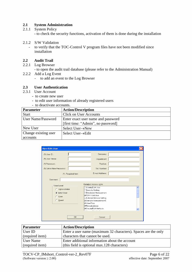
2.3.1 User Account
- to create new user
- to edit user information of already registered users
- to deactivate accounts.
Parameter Action/Description
Start Click on User Accounts
User Name/Password Enter exact user name and password
[first time: “Admin”, no password]
New User Select UserNew
Change existing user
accounts Select UserEdit
Parameter Action/Description
User ID
(required item)
Enter a user name (maximum 32 characters). Spaces are the only
characters that cannot be used.
User Name
(required item)
Enter additional information about the account
(this field is optional max.128 characters)
TOCV-CP_IMshort_Control-ver-2_Rev07F Page 7 of 22 (Software version ≥ 2.00) effective date: September 2007
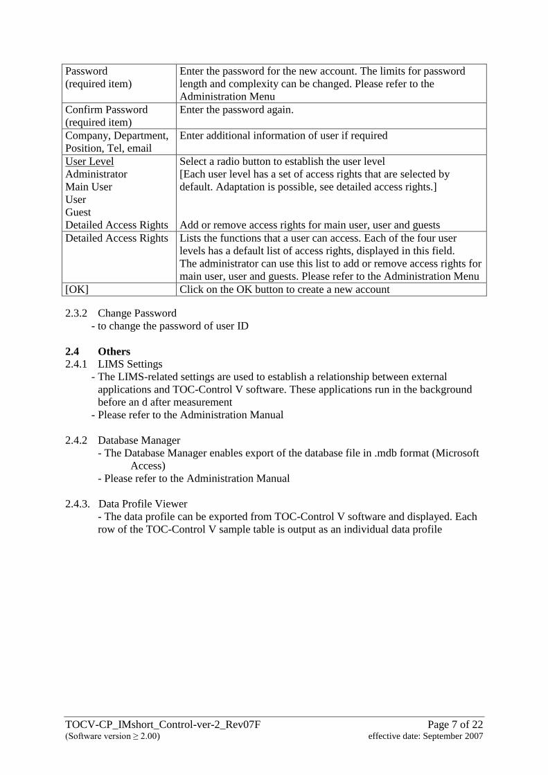
Password
(required item)
Enter the password for the new account. The limits for password
length and complexity can be changed. Please refer to the
Administration Menu
Confirm Password
(required item)
Enter the password again.
Company, Department,
Position, Tel, email
Enter additional information of user if required
User Level
Administrator
Main User
User
Guest
Detailed Access Rights
Select a radio button to establish the user level
[Each user level has a set of access rights that are selected by
default. Adaptation is possible, see detailed access rights.]
Add or remove access rights for main user, user and guests
Detailed Access Rights Lists the functions that a user can access. Each of the four user
levels has a default list of access rights, displayed in this field.
The administrator can use this list to add or remove access rights for
main user, user and guests. Please refer to the Administration Menu
[OK] Click on the OK button to create a new account
2.3.2 Change Password
- to change the password of user ID
2.4 Others
2.4.1 LIMS Settings
- The LIMS-related settings are used to establish a relationship between external
applications and TOC-Control V software. These applications run in the background
before an d after measurement
- Please refer to the Administration Manual
2.4.2 Database Manager
- The Database Manager enables export of the database file in .mdb format (Microsoft
Access)
- Please refer to the Administration Manual
2.4.3. Data Profile Viewer
- The data profile can be exported from TOC-Control V software and displayed. Each
row of the TOC-Control V sample table is output as an individual data profile
TOCV-CP_IMshort_Control-ver-2_Rev07F Page 8 of 22 (Software version ≥ 2.00) effective date: September 2007
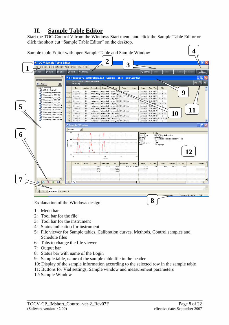
II. Sample Table Editor Start the TOC-Control V from the Windows Start menu, and click the Sample Table Editor or
click the short cut “Sample Table Editor” on the desktop.
Sample table Editor with open Sample Table and Sample Window
Explanation of the Windows design:
1: Menu bar
2: Tool bar for the file
3: Tool bar for the instrument
4: Status indication for instrument
5: File viewer for Sample tables, Calibration curves, Methods, Control samples and
Schedule files
6: Tabs to change the file viewer
7: Output bar
8: Status bar with name of the Login
9: Sample table, name of the sample table file in the header
10: Display of the sample information according to the selected row in the sample table
11: Buttons for Vial settings, Sample window and measurement parameters
12: Sample Window
1 3
1
4
5
6
7
2
8
9
10 11
12
TOCV-CP_IMshort_Control-ver-2_Rev07F Page 9 of 22 (Software version ≥ 2.00) effective date: September 2007
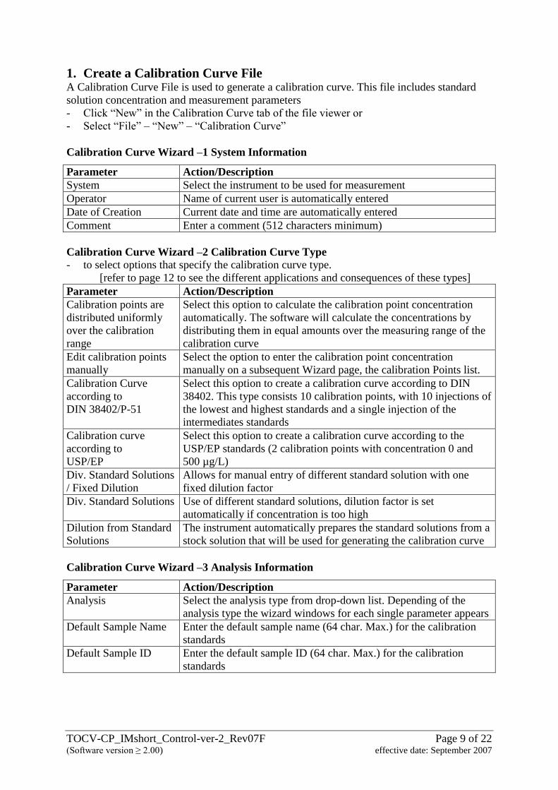
1. Create a Calibration Curve File
A Calibration Curve File is used to generate a calibration curve. This file includes standard
solution concentration and measurement parameters
- Click “New” in the Calibration Curve tab of the file viewer or
- Select “File” – “New” – “Calibration Curve”
Calibration Curve Wizard –1 System Information
Parameter Action/Description
System Select the instrument to be used for measurement
Operator Name of current user is automatically entered
Date of Creation Current date and time are automatically entered
Comment Enter a comment (512 characters minimum)
Calibration Curve Wizard –2 Calibration Curve Type - to select options that specify the calibration curve type.
[refer to page 12 to see the different applications and consequences of these types]
Parameter Action/Description
Calibration points are
distributed uniformly
over the calibration
range
Select this option to calculate the calibration point concentration
automatically. The software will calculate the concentrations by
distributing them in equal amounts over the measuring range of the
calibration curve
Edit calibration points
manually
Select the option to enter the calibration point concentration
manually on a subsequent Wizard page, the calibration Points list.
Calibration Curve
according to
DIN 38402/P-51
Select this option to create a calibration curve according to DIN
38402. This type consists 10 calibration points, with 10 injections of
the lowest and highest standards and a single injection of the
intermediates standards
Calibration curve
according to
USP/EP
Select this option to create a calibration curve according to the
USP/EP standards (2 calibration points with concentration 0 and
500 µg/L)
Div. Standard Solutions
/ Fixed Dilution
Allows for manual entry of different standard solution with one
fixed dilution factor
Div. Standard Solutions Use of different standard solutions, dilution factor is set
automatically if concentration is too high
Dilution from Standard
Solutions
The instrument automatically prepares the standard solutions from a
stock solution that will be used for generating the calibration curve
Calibration Curve Wizard –3 Analysis Information
Parameter Action/Description
Analysis
Select the analysis type from drop-down list. Depending of the
analysis type the wizard windows for each single parameter appears
Default Sample Name Enter the default sample name (64 char. Max.) for the calibration
standards
Default Sample ID Enter the default sample ID (64 char. Max.) for the calibration
standards
TOCV-CP_IMshort_Control-ver-2_Rev07F Page 10 of 22 (Software version ≥ 2.00) effective date: September 2007
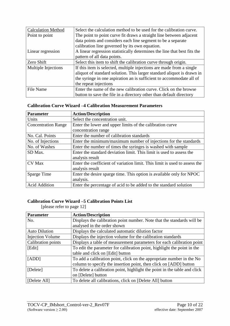
Calculation Method
Point to point
Linear regression
Select the calculation method to be used for the calibration curve.
The point to point curve fit draws a straight line between adjacent
data points and considers each line segment to be a separate
calibration line governed by its own equation.
A linear regression statistically determines the line that best fits the
pattern of all data points.
Zero Shift Select this item to shift the calibration curve through origin.
Multiple Injections If this item is selected, multiple injections are made from a single
aliquot of standard solution. This larger standard aliquot is drawn in
the syringe in one aspiration an is sufficient to accommodate all of
the repeat injections
File Name Enter the name of the new calibration curve. Click on the browse
button to save the file in a directory other than default directory
Calibration Curve Wizard –4 Calibration Measurement Parameters
Parameter Action/Description
Units Select the concentration unit.
Concentration Range Enter the lower and upper limits of the calibration curve
concentration range
No. Cal. Points Enter the number of calibration standards
No. of Injections Enter the minimum/maximum number of injections for the standards
No. of Washes Enter the number of times the syringes is washed with sample
SD Max. Enter the standard deviation limit. This limit is used to assess the
analysis result
CV Max Enter the coefficient of variation limit. This limit is used to assess the
analysis result
Sparge Time Enter the desire sparge time. This option is available only for NPOC
analysis.
Acid Addition Enter the percentage of acid to be added to the standard solution
Calibration Curve Wizard –5 Calibration Points List
[please refer to page 12]
Parameter Action/Description
No. Displays the calibration point number. Note that the standards will be
analysed in the order shown
Auto Dilution Displays the calculated automatic dilution factor
Injection Volume Displays the injection volume for the calibration standards
Calibration points Displays a table of measurement parameters for each calibration point
[Edit] To edit the parameter for calibration point, highlight the point in the
table and click on [Edit] button
[ADD] To add a calibration point, click on the appropriate number in the No
column to specify the insertion point, then click on [ADD] button
[Delete] To delete a calibration point, highlight the point in the table and click
on [Delete] button
[Delete All] To delete all calibrations, click on [Delete All] button
TOCV-CP_IMshort_Control-ver-2_Rev07F Page 11 of 22 (Software version ≥ 2.00) effective date: September 2007
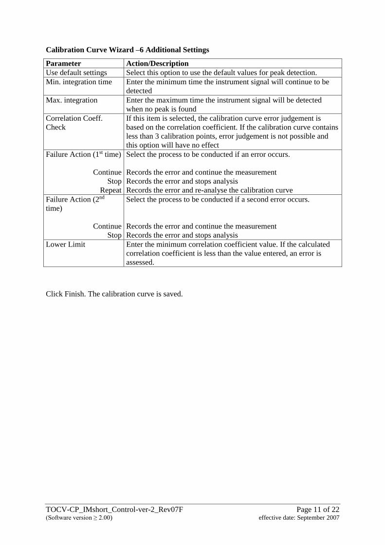
Calibration Curve Wizard –6 Additional Settings
Parameter Action/Description
Use default settings Select this option to use the default values for peak detection.
Min. integration time Enter the minimum time the instrument signal will continue to be
detected
Max. integration Enter the maximum time the instrument signal will be detected
when no peak is found
Correlation Coeff.
Check
If this item is selected, the calibration curve error judgement is
based on the correlation coefficient. If the calibration curve contains
less than 3 calibration points, error judgement is not possible and
this option will have no effect
Failure Action (1st time)
Continue
Stop
Repeat
Select the process to be conducted if an error occurs.
Records the error and continue the measurement
Records the error and stops analysis
Records the error and re-analyse the calibration curve
Failure Action (2nd
time)
Continue
Stop
Select the process to be conducted if a second error occurs.
Records the error and continue the measurement
Records the error and stops analysis
Lower Limit Enter the minimum correlation coefficient value. If the calculated
correlation coefficient is less than the value entered, an error is
assessed.
Click Finish. The calibration curve is saved.
TOCV-CP_IMshort_Control-ver-2_Rev07F Page 12 of 22 (Software version ≥ 2.00) effective date: September 2007
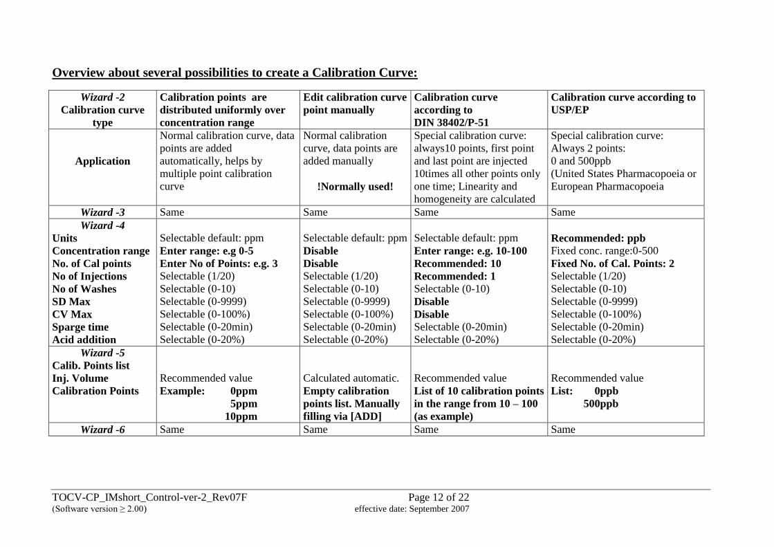
Overview about several possibilities to create a Calibration Curve:
Wizard -2
Calibration curve
type
Calibration points are
distributed uniformly over
concentration range
Edit calibration curve
point manually
Calibration curve
according to
DIN 38402/P-51
Calibration curve according to
USP/EP
Application
Normal calibration curve, data
points are added
automatically, helps by
multiple point calibration
curve
Normal calibration
curve, data points are
added manually
!Normally used!
Special calibration curve:
always10 points, first point
and last point are injected
10times all other points only
one time; Linearity and
homogeneity are calculated
Special calibration curve:
Always 2 points:
0 and 500ppb
(United States Pharmacopoeia or
European Pharmacopoeia
Wizard -3 Same Same Same Same
Wizard -4
Units
Concentration range
No. of Cal points
No of Injections
No of Washes
SD Max
CV Max
Sparge time
Acid addition
Selectable default: ppm
Enter range: e.g 0-5
Enter No of Points: e.g. 3 Selectable (1/20)
Selectable (0-10)
Selectable (0-9999)
Selectable (0-100%)
Selectable (0-20min)
Selectable (0-20%)
Selectable default: ppm
Disable
Disable
Selectable (1/20)
Selectable (0-10)
Selectable (0-9999)
Selectable (0-100%)
Selectable (0-20min)
Selectable (0-20%)
Selectable default: ppm
Enter range: e.g. 10-100
Recommended: 10
Recommended: 1 Selectable (0-10)
Disable
Disable Selectable (0-20min)
Selectable (0-20%)
Recommended: ppb
Fixed conc. range:0-500
Fixed No. of Cal. Points: 2
Selectable (1/20)
Selectable (0-10)
Selectable (0-9999)
Selectable (0-100%)
Selectable (0-20min)
Selectable (0-20%)
Wizard -5
Calib. Points list
Inj. Volume
Calibration Points
Recommended value
Example: 0ppm
5ppm
10ppm
Calculated automatic.
Empty calibration
points list. Manually
filling via [ADD]
Recommended value
List of 10 calibration points
in the range from 10 – 100
(as example)
Recommended value
List: 0ppb
500ppb
Wizard -6 Same Same Same Same
TOCV-CP_IMshort_Control-ver-2_Rev07F Page 13 of 22 (Software version ≥ 2.00) effective date: September 2007
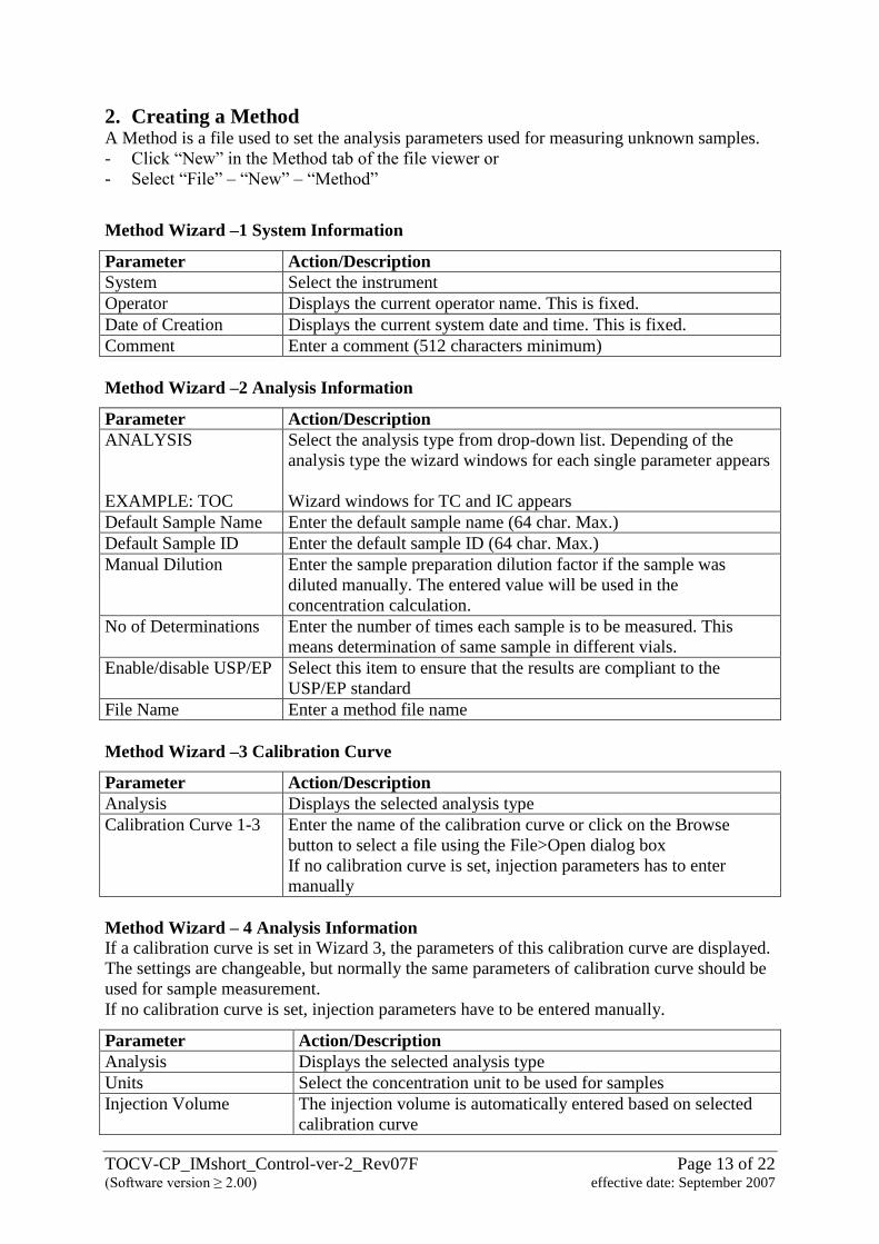
2. Creating a Method A Method is a file used to set the analysis parameters used for measuring unknown samples.
- Click “New” in the Method tab of the file viewer or
- Select “File” – “New” – “Method”
Method Wizard –1 System Information
Parameter Action/Description
System Select the instrument
Operator Displays the current operator name. This is fixed.
Date of Creation Displays the current system date and time. This is fixed.
Comment Enter a comment (512 characters minimum)
Method Wizard –2 Analysis Information
Parameter Action/Description
ANALYSIS
EXAMPLE: TOC
Select the analysis type from drop-down list. Depending of the
analysis type the wizard windows for each single parameter appears
Wizard windows for TC and IC appears
Default Sample Name Enter the default sample name (64 char. Max.)
Default Sample ID Enter the default sample ID (64 char. Max.)
Manual Dilution Enter the sample preparation dilution factor if the sample was
diluted manually. The entered value will be used in the
concentration calculation.
No of Determinations Enter the number of times each sample is to be measured. This
means determination of same sample in different vials.
Enable/disable USP/EP Select this item to ensure that the results are compliant to the
USP/EP standard
File Name Enter a method file name
Method Wizard –3 Calibration Curve
Parameter Action/Description
Analysis Displays the selected analysis type
Calibration Curve 1-3 Enter the name of the calibration curve or click on the Browse
button to select a file using the File>Open dialog box
If no calibration curve is set, injection parameters has to enter
manually
Method Wizard – 4 Analysis Information If a calibration curve is set in Wizard 3, the parameters of this calibration curve are displayed.
The settings are changeable, but normally the same parameters of calibration curve should be
used for sample measurement.
If no calibration curve is set, injection parameters have to be entered manually.
Parameter Action/Description
Analysis Displays the selected analysis type
Units Select the concentration unit to be used for samples
Injection Volume The injection volume is automatically entered based on selected
calibration curve
TOCV-CP_IMshort_Control-ver-2_Rev07F Page 14 of 22 (Software version ≥ 2.00) effective date: September 2007
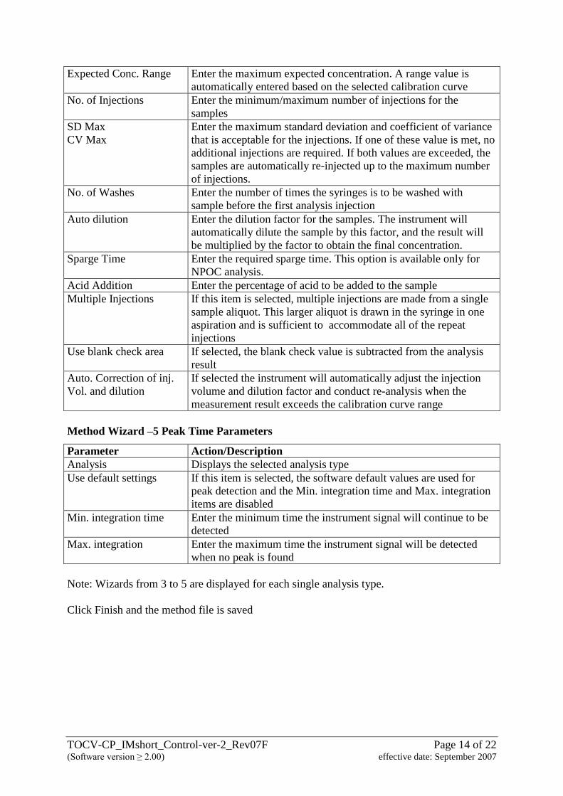
Expected Conc. Range Enter the maximum expected concentration. A range value is
automatically entered based on the selected calibration curve
No. of Injections Enter the minimum/maximum number of injections for the
samples
SD Max
CV Max
Enter the maximum standard deviation and coefficient of variance
that is acceptable for the injections. If one of these value is met, no
additional injections are required. If both values are exceeded, the
samples are automatically re-injected up to the maximum number
of injections.
No. of Washes Enter the number of times the syringes is to be washed with
sample before the first analysis injection
Auto dilution Enter the dilution factor for the samples. The instrument will
automatically dilute the sample by this factor, and the result will
be multiplied by the factor to obtain the final concentration.
Sparge Time Enter the required sparge time. This option is available only for
NPOC analysis.
Acid Addition Enter the percentage of acid to be added to the sample
Multiple Injections If this item is selected, multiple injections are made from a single
sample aliquot. This larger aliquot is drawn in the syringe in one
aspiration and is sufficient to accommodate all of the repeat
injections
Use blank check area If selected, the blank check value is subtracted from the analysis
result
Auto. Correction of inj.
Vol. and dilution
If selected the instrument will automatically adjust the injection
volume and dilution factor and conduct re-analysis when the
measurement result exceeds the calibration curve range
Method Wizard –5 Peak Time Parameters
Parameter Action/Description
Analysis Displays the selected analysis type
Use default settings If this item is selected, the software default values are used for
peak detection and the Min. integration time and Max. integration
items are disabled
Min. integration time Enter the minimum time the instrument signal will continue to be
detected
Max. integration Enter the maximum time the instrument signal will be detected
when no peak is found
Note: Wizards from 3 to 5 are displayed for each single analysis type.
Click Finish and the method file is saved
TOCV-CP_IMshort_Control-ver-2_Rev07F Page 15 of 22 (Software version ≥ 2.00) effective date: September 2007
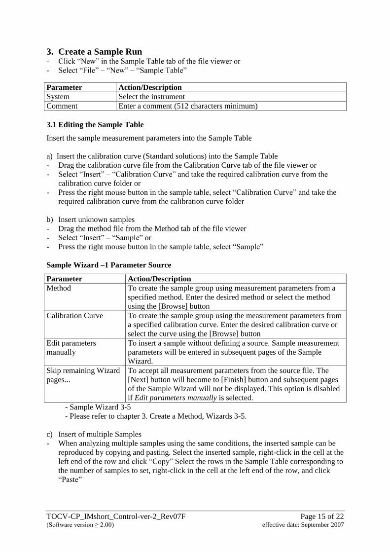
3. Create a Sample Run - Click “New” in the Sample Table tab of the file viewer or
- Select “File” – “New” – “Sample Table”
Parameter Action/Description
System Select the instrument
Comment Enter a comment (512 characters minimum)
3.1 Editing the Sample Table
Insert the sample measurement parameters into the Sample Table
a) Insert the calibration curve (Standard solutions) into the Sample Table
- Drag the calibration curve file from the Calibration Curve tab of the file viewer or
- Select “Insert” – “Calibration Curve” and take the required calibration curve from the
calibration curve folder or
- Press the right mouse button in the sample table, select “Calibration Curve” and take the
required calibration curve from the calibration curve folder
b) Insert unknown samples
- Drag the method file from the Method tab of the file viewer
- Select “Insert” – “Sample” or
- Press the right mouse button in the sample table, select “Sample”
Sample Wizard –1 Parameter Source
Parameter Action/Description
Method To create the sample group using measurement parameters from a
specified method. Enter the desired method or select the method
using the [Browse] button
Calibration Curve To create the sample group using the measurement parameters from
a specified calibration curve. Enter the desired calibration curve or
select the curve using the [Browse] button
Edit parameters
manually
To insert a sample without defining a source. Sample measurement
parameters will be entered in subsequent pages of the Sample
Wizard.
Skip remaining Wizard
pages...
To accept all measurement parameters from the source file. The
[Next] button will become to [Finish] button and subsequent pages
of the Sample Wizard will not be displayed. This option is disabled
if Edit parameters manually is selected.
- Sample Wizard 3-5
- Please refer to chapter 3. Create a Method, Wizards 3-5.
c) Insert of multiple Samples
- When analyzing multiple samples using the same conditions, the inserted sample can be
reproduced by copying and pasting. Select the inserted sample, right-click in the cell at the
left end of the row and click “Copy” Select the rows in the Sample Table corresponding to
the number of samples to set, right-click in the cell at the left end of the row, and click
“Paste”
TOCV-CP_IMshort_Control-ver-2_Rev07F Page 16 of 22 (Software version ≥ 2.00) effective date: September 2007
- Right-click in the left cell in the row where multiple samples are to be inserted. Select
“Insert” – “Multiple Samples”
Sample Group Wizard –1 Sample Source
- enter the parameter source for the sample
Parameter Action/Description
Method - to create the sample group using measurement parameters of an
existing method file
- Enter the desired method or select the method using the Browse
button
Calibration Curve - to create the sample group using the measurement parameters of an
existing calibration curve
- Enter the desired calibration curve or select the curve using the
Browse button
Sample Group Wizard –2 Sample Parameters
Parameter Action/Description
No of Samples Enter the number of samples in the group. (1-100.)
Start Vial Enter the starting vial position for the sample group. This field is
disabled if ASI is not supported by the system
Sample Name
Sample ID
The default designations for these fields are obtained from the method
or calibration curve identified in page 1. Enter other name if desired.
Index Start Select this option to start counting index. Each sample added receives
an increased counting index number.
Insert Cal. Curve /
Control Samples
Select this option to insert calibration curves and control samples alon
with the samples
Click Finish to insert the group of samples into the sample table
If “Insert Cal. Curve / Control Samples was selected, the Next button is displayed to enable
proceeding to the next step in the wizard
Sample Group Wizard –3 Calibration Curves
- to define the sequence of calibration
Parameter Action/Description
At the beginning of
the sample group
Select this item to insert a calibration curve before the sample analysis
Always, after
“number “ of
samples
Select this item to inert a calibration curve after every fixed number of
samples. Enter that number in the box
Calibration Curves Displays the information related to the added calibration curves. Up to
3 separate calibration curves may be added
[Add] Use this button to add a calibration curve
[Delete] Highlight a calibration curve listed in the window and click on the
Delete button to remove the curve from the sample group
TOCV-CP_IMshort_Control-ver-2_Rev07F Page 17 of 22 (Software version ≥ 2.00) effective date: September 2007
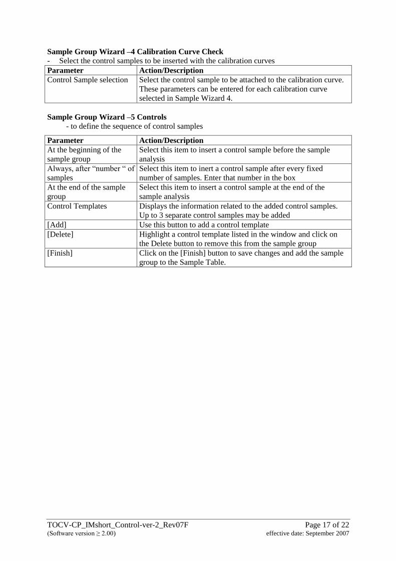
Sample Group Wizard –4 Calibration Curve Check
- Select the control samples to be inserted with the calibration curves
Parameter Action/Description
Control Sample selection Select the control sample to be attached to the calibration curve.
These parameters can be entered for each calibration curve
selected in Sample Wizard 4.
Sample Group Wizard –5 Controls
- to define the sequence of control samples
Parameter Action/Description
At the beginning of the
sample group
Select this item to insert a control sample before the sample
analysis
Always, after “number “ of
samples
Select this item to inert a control sample after every fixed
number of samples. Enter that number in the box
At the end of the sample
group
Select this item to insert a control sample at the end of the
sample analysis
Control Templates Displays the information related to the added control samples.
Up to 3 separate control samples may be added
[Add] Use this button to add a control template
[Delete] Highlight a control template listed in the window and click on
the Delete button to remove this from the sample group
[Finish] Click on the [Finish] button to save changes and add the sample
group to the Sample Table.
TOCV-CP_IMshort_Control-ver-2_Rev07F Page 18 of 22 (Software version ≥ 2.00) effective date: September 2007
4. Schedule File 4.1 Creating a new Schedule
- A schedule is a stored file which contains measurement parameters for multiple samples,
including the specific sequence of analyses. The saved content of the file can be called up
as desired, and loaded into a sample table.
- Editing of a schedule file in the format of a sample table is conducted using the same
operations as in a sample table.
- Click “New” in the Schedule tab of the file viewer
Parameter Action/Description
System Select the system to be used
Comment Enter a comment in the comment box, as necessary
A new schedule is created, and opens in the Sample Table Editor
- Enter information in the schedule in the same manner as in the Sample Table
- Enter the vial information, by clicking the button
- Save the Schedule file in the schedule folder
4.2 Export the Sample table as Schedule File
The Contents of a sample table can be exported as a Schedule file. The Schedule file can be
exported in either sample table format or text format
- Click “File” – “Export Schedule File”
- Select either Sample Table Format or ASCII Text Format
- Enter the file name and destination path and click Save
4.3 Insert a Schedule File
a) From the File Viewer
- The contents of a schedule can be inserted into the sample table by dragging the schedule
file from the viewer
b) From the Menu
- Select the row of the sample table where the schedule content is to be added
- Select “File” – “Import Schedule File”
- Select the schedule file form the “open” dialog box
- The schedule content is inserted into the sample table
TOCV-CP_IMshort_Control-ver-2_Rev07F Page 19 of 22 (Software version ≥ 2.00) effective date: September 2007
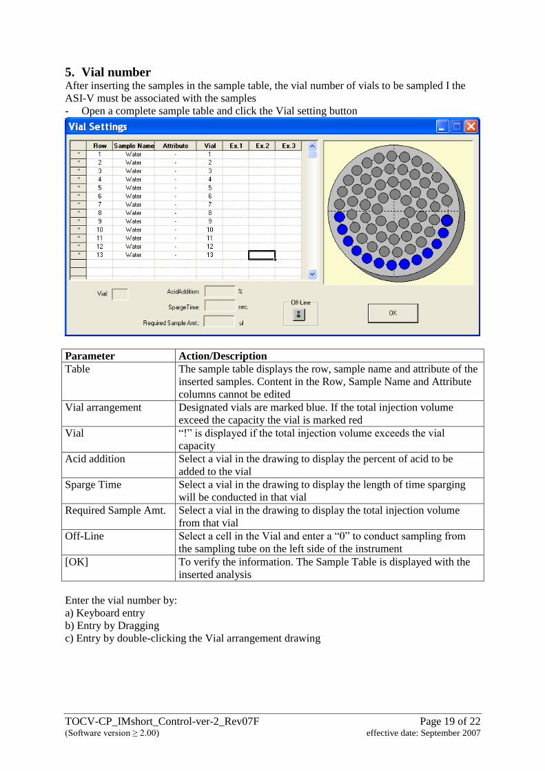
5. Vial number After inserting the samples in the sample table, the vial number of vials to be sampled I the
ASI-V must be associated with the samples
- Open a complete sample table and click the Vial setting button
Parameter Action/Description
Table The sample table displays the row, sample name and attribute of the
inserted samples. Content in the Row, Sample Name and Attribute
columns cannot be edited
Vial arrangement Designated vials are marked blue. If the total injection volume
exceed the capacity the vial is marked red
Vial “!” is displayed if the total injection volume exceeds the vial
capacity
Acid addition Select a vial in the drawing to display the percent of acid to be
added to the vial
Sparge Time Select a vial in the drawing to display the length of time sparging
will be conducted in that vial
Required Sample Amt. Select a vial in the drawing to display the total injection volume
from that vial
Off-Line Select a cell in the Vial and enter a “0” to conduct sampling from
the sampling tube on the left side of the instrument
[OK] To verify the information. The Sample Table is displayed with the
inserted analysis
Enter the vial number by:
a) Keyboard entry
b) Entry by Dragging
c) Entry by double-clicking the Vial arrangement drawing
TOCV-CP_IMshort_Control-ver-2_Rev07F Page 20 of 22 (Software version ≥ 2.00) effective date: September 2007
III. Analysis
1 Connecting to the Instrument - Open the Sample Table to be used and click the [Connect] button of the Tool bar
- Click “Use Settings on PC”
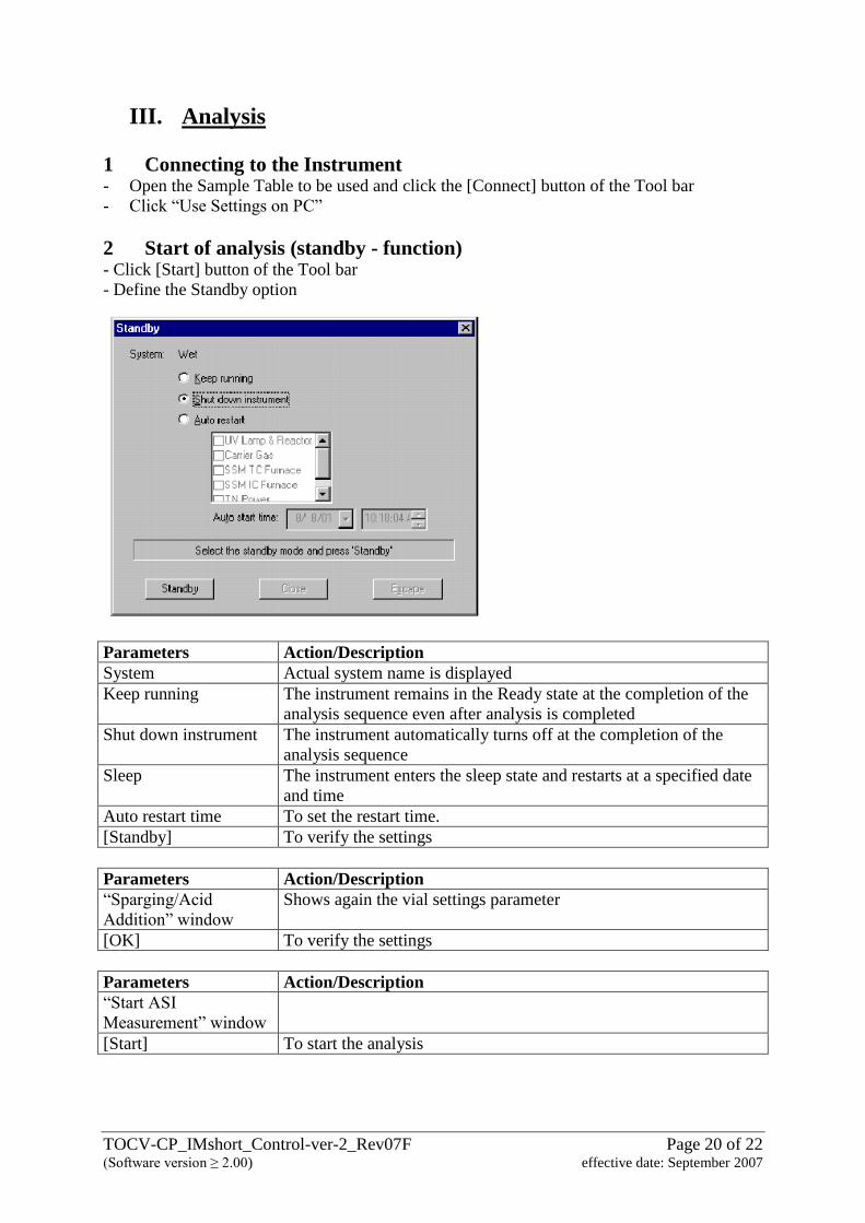
2 Start of analysis (standby - function) - Click [Start] button of the Tool bar
- Define the Standby option
Parameters Action/Description
System Actual system name is displayed
Keep running The instrument remains in the Ready state at the completion of the
analysis sequence even after analysis is completed
Shut down instrument The instrument automatically turns off at the completion of the
analysis sequence
Sleep The instrument enters the sleep state and restarts at a specified date
and time
Auto restart time To set the restart time.
[Standby] To verify the settings
Parameters Action/Description
“Sparging/Acid
Addition” window
Shows again the vial settings parameter
[OK] To verify the settings
Parameters Action/Description
“Start ASI
Measurement” window
[Start] To start the analysis
TOCV-CP_IMshort_Control-ver-2_Rev07F Page 21 of 22 (Software version ≥ 2.00) effective date: September 2007
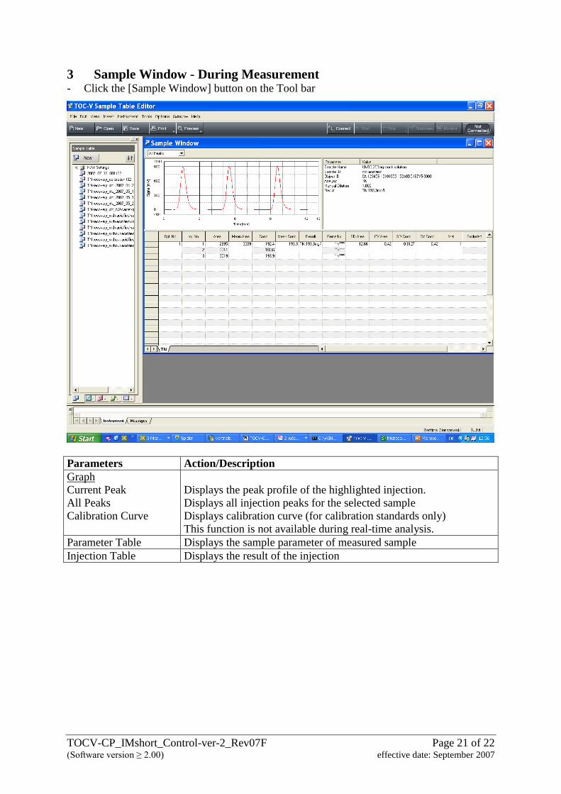
3 Sample Window - During Measurement - Click the [Sample Window] button on the Tool bar
Parameters Action/Description
Graph
Current Peak
All Peaks
Calibration Curve
Displays the peak profile of the highlighted injection.
Displays all injection peaks for the selected sample
Displays calibration curve (for calibration standards only)
This function is not available during real-time analysis.
Parameter Table Displays the sample parameter of measured sample
Injection Table Displays the result of the injection
TOCV-CP_IMshort_Control-ver-2_Rev07F Page 22 of 22 (Software version ≥ 2.00) effective date: September 2007
4 Editing the Sample Table during analysis The sample table can be edited during analysis by changing to the Edit Mode. This mode
allows the following operations to be conducted in the sample table in the same way as when
analysis is not being conducted
- During analysis, select “Instrument” – Edit Mode”
- The sample table is placed in the Edit Mode and following procedure can be conducted:
- Adding and deleting samples
- Changing analysis parameters and vial numbers
- Printing reports for samples that are already analysed
- Click [Start] button to cancel the Edit Mode and restart analysis
5 Stop of Measurement Parameters Action/Description
Stop of Measurement Select “Stop” in “Instrument” menu
Peak Stop This option interrupts processing of the current injection, and
analysis proceeds to the next injection measurement
Stop (after current
sample is completed)
This option stops analysis after all of the scheduled injections of the
current samples have been analysed
Stop (stop all processes
immediately)
This option immediately interrupts the current analysis
![Wie viele Sprachen spricht die Literatur? Deutschsprachige Gegenwartsliteratur aus Mittel- und Osteuropa [only ToC+info]](https://img.dokumen.tips/doc/110x75/631eeea8097e038f7c093b03/wie-viele-sprachen-spricht-die-literatur-deutschsprachige-gegenwartsliteratur-aus.jpg)