Embed Size (px)
Citation preview

V.1.07November 5, 2018

This page intentionally left blank.

Shark® Series MP200TM Metering System Installation and Operation Manual Version
1.07
Published by:
Electro Industries/GaugeTech
1800 Shames Drive
Westbury, NY 11590
All rights reserved. No part of this publication may be reproduced or transmitted in
any form or by any means, electronic or mechanical, including photocopying, record-
ing, or information storage or retrieval systems or any future forms of duplication, for
any purpose other than the purchaser's use, without the expressed written permission
of Electro Industries/GaugeTech.
© 2018 Electro Industries/GaugeTech
Shark® is a registered trademark of Electro Industries/GaugeTech. The distinctive
shapes, styles, and overall appearances of all Shark® devices are trademarks of
Electro Industries/GaugeTech. Communicator EXTTM and V-SwitchTM are trademarks of
Electro Industries/GaugeTech.
Microsoft® and Windows® are either registered trademarks or trademarks of Micro-
soft Corporation in the United States and/or other countries.
Doc# E166703 iElectro Industries/GaugeTechThe Leader In Power Monitoring and Smart Grid SolutionsElectro Industries/GaugeTechThe Leader In Power Monitoring and Smart Grid Solutions

Doc# E166703 iiElectro Industries/GaugeTechThe Leader In Power Monitoring and Smart Grid SolutionsElectro Industries/GaugeTechThe Leader In Power Monitoring and Smart Grid Solutions
This page intentionally left blank.

Customer Service and Support
Customer support is available 8:00 am to 8:00 pm, Eastern Standard Time, Monday
through Friday. Please have the model, serial number and a detailed problem descrip-
tion available. If the problem concerns a particular reading, please have all meter
readings available. When returning any merchandise to EIG, a return materials
authorization number is required. For customer or technical assistance, repair or
calibration, phone 516-334-0870 or fax 516-338-4741.
Product Warranty
Electro Industries/GaugeTech warrants all products to be free from defects in material
and workmanship for a period of four years from the date of shipment. During the
warranty period, we will, at our option, either repair or replace any product that
proves to be defective.
To exercise this warranty, fax or call our customer-support department. You will
receive prompt assistance and return instructions. Send the instrument, transporta-
tion prepaid, to EIG at 1800 Shames Drive, Westbury, NY 11590. Repairs will be made
and the instrument will be returned.
This warranty does not apply to defects resulting from unauthorized modification,
misuse, or use for any reason other than electrical power monitoring. The MP200 unit
is not a user-serviceable product.
THIS WARRANTY IS IN LIEU OF ALL OTHER WARRANTIES, EXPRESSED
OR IMPLIED, INCLUDING ANY IMPLIED WARRANTY OF MERCHANTABIL-
ITY OR FITNESS FOR A PARTICULAR PURPOSE. ELECTRO INDUSTRIES/
GAUGETECH SHALL NOT BE LIABLE FOR ANY INDIRECT, SPECIAL OR
CONSEQUENTIAL DAMAGES ARISING FROM ANY AUTHORIZED OR
UNAUTHORIZED USE OF ANY ELECTRO INDUSTRIES/GAUGETECH
PRODUCT. LIABILITY SHALL BE LIMITED TO THE ORIGINAL COST OF
THE PRODUCT SOLD.
Doc# E166703 iiiElectro Industries/GaugeTechThe Leader In Power Monitoring and Smart Grid SolutionsElectro Industries/GaugeTechThe Leader In Power Monitoring and Smart Grid Solutions

Use Of Product for Protection
Our products are not to be used for primary over-current protection. Any protection
feature in our products is to be used for alarm or secondary protection only.
Statement of Calibration
Our instruments are inspected and tested in accordance with specifications published
by Electro Industries/GaugeTech. The accuracy and a calibration of our instruments
are traceable to the National Institute of Standards and Technology through
equipment that is calibrated at planned intervals by comparison to certified standards.
For optimal performance, EIG recommends that any metering device, including those
manufactured by EIG, be verified for accuracy on a yearly interval using NIST trace-
able accuracy standards.
Disclaimer
The information presented in this publication has been carefully checked for
reliability; however, no responsibility is assumed for inaccuracies. The information
contained in this document is subject to change without notice.
Safety Symbols
In this manual, this symbol indicates that the operator must refer to
an important WARNING or CAUTION in the operating instructions.
Please see Chapter 4 for important safety information regarding
installation and hookup of the MP200 metering system.
Dans ce manuel, ce symbole indique que l’opérateur doit se référer à un important
AVERTISSEMENT ou une MISE EN GARDE dans les instructions opérationnelles.
Veuillez consulter le chapitre 4 pour des informations importantes relatives à l’instal-
lation et branchement du compteur.
The following safety symbols are used on the MP200 unit itself:
Les symboles de sécurité suivante peuvent être utilisés sur le compteur même:
This symbol alerts you to the presence of high voltage, which can
cause dangerous electrical shock.
Ce symbole vous indique la présence d’une haute tension qui peut
provoquer une décharge électrique dangereuse.
Doc# E166703 ivElectro Industries/GaugeTechThe Leader In Power Monitoring and Smart Grid SolutionsElectro Industries/GaugeTechThe Leader In Power Monitoring and Smart Grid Solutions

This symbol indicates the field wiring terminal that must be connected
to earth ground before operating the MP200 unit, which protects
against electrical shock in case of a fault condition.
Ce symbole indique que la borne de pose des canalisations in-situ qui doit être
branchée dans la mise à terre avant de faire fonctionner le compteur qui est protégé
contre une décharge électrique ou un état défectue
This symbol indicates that the user must refer to this manual for
specific WARNING or CAUTION information to avoid personal injury or
damage to the product.
Ce symbole indique que l'utilisateur doit se référer à ce manuel pour
AVERTISSEMENT ou MISE EN GARDE l'information pour éviter toute blessure ou tout
endommagement du produit.
About Electro Industries/GaugeTech (EIG)
Founded in 1975 by engineer and inventor Dr. Samuel Kagan, Electro Industries/
GaugeTech changed the face of power monitoring forever with its first breakthrough
innovation: an affordable, easy-to-use AC power meter.
More than forty years since its founding, Electro Industries/GaugeTech, the leader in
power monitoring and control, continues to revolutionize the industry with the highest
quality, cutting edge power monitoring and control technology on the market today.
An ISO 9001 certified company (view certificate at https://electroind.com/about-elec-
tro-industries/), EIG sets the industry standard for advanced power quality and
reporting, revenue metering and substation data acquisition and control. EIG products
can be found on site at mainly all of today's leading manufacturers, industrial giants
and utilities.
EIG products are primarily designed, manufactured, tested and calibrated at our facil-
ity in Westbury, New York.
Doc# E166703 vElectro Industries/GaugeTechThe Leader In Power Monitoring and Smart Grid SolutionsElectro Industries/GaugeTechThe Leader In Power Monitoring and Smart Grid Solutions

Revision History
The following table lists revision information for this manual, Doc #E166703, the
Shark® Series MP200 Metering System Installation and Operation Manual.
Version Number Revision Date Summary of Changes
V.1.01 5/1/2013 First release
V.1.02 7/3/2013 Optional display added
V.1.03 1/14/2014 French translation of safety warnings added
V.1.04 1/23/2015 Updated screen captures and Com3 information
V.1.05 7/10/2015 Minor edit Chapter 4
V.1.06 10/23/2015 Chapter 10 specifications minor edit
V.1.07 11/2/2018 Edits to chapters 2, 4, and 5 and minor edits throughout
Doc# E166703 viElectro Industries/GaugeTechThe Leader In Power Monitoring and Smart Grid SolutionsElectro Industries/GaugeTechThe Leader In Power Monitoring and Smart Grid Solutions

Table of Contents
Table of ContentsCustomer Service and Support iii
Product Warranty iii
Use Of Product for Protection iv
Statement of Calibration iv
Disclaimer iv
Safety Symbols iv
About Electro Industries/GaugeTech (EIG) v
Revision History vi
1: Three-Phase Power Measurement 1-1
1.1: Three-Phase System Configurations 1-1
1.1.1: Wye Connection 1-1
1.1.2: Delta Connection 1-4
1.1.3: Blondel’s Theorem and Three Phase Measurement 1-6
1.2: Power, Energy and Demand 1-8
1.3: Reactive Energy and Power Factor 1-12
1.4: Harmonic Distortion 1-14
1.5: Power Quality 1-17
2: MP200 Metering System Overview and
Specifications 2-1
2.1: Shark® Series MP200 Metering System Overview 2-1
2.1.1: Voltage and Current Inputs 2-3
2.1.2: Ordering Information 2-4
Doc# E166703 TOC-1Electro Industries/GaugeTechThe Leader In Power Monitoring and Smart Grid SolutionsElectro Industries/GaugeTechThe Leader In Power Monitoring and Smart Grid Solutions

Table of Contents
2.1.3: V-SwitchTM Key Technology 2-4
2.1.4: Measured Values 2-7
2.1.5: Utility Peak Demand 2-9
2.2: Specifications 2-10
2.3: Compliance 2-16
2.4: Accuracy 2-17
3: Mechanical Installation and Maintenance 3-1
3.1: MP200 Unit Dimensions 3-1
3.2: Mounting the MP200 Unit 3-2
3.3: Cleaning the MP200 Unit 3-3
4: Electrical Installation 4-1
4.1: Considerations When Installing the MP200 Metering System 4-1
4.2: Ground Connections 4-4
4.3: Voltage and Power Supply Connections 4-5
4.4: Voltage Fuses 4-5
4.6: Electrical Connection Diagrams 4-8
4.7: Removing the MP200 Unit From Service/Reinstalling the
MP200 Unit 4-16
4.7.1: Removing the MP200 Unit Using the EI SB-6TC
Shorting Block 4-17
4.7.1.1: Reinstalling the MP200 Unit Using the EI SB-6TC
Shorting Block 4-20
4.7.2: Removing the MP200 Unit Using a Shorting Block
Other than the EI SB-6TC 4-20
Doc# E166703 TOC-2Electro Industries/GaugeTechThe Leader In Power Monitoring and Smart Grid SolutionsElectro Industries/GaugeTechThe Leader In Power Monitoring and Smart Grid Solutions

Table of Contents
4.7.2.1: Reinstalling the MP200 Unit Using a Shorting Block
Other than the EI SB-6TC 4-21
5: Communicating with the Meter 5-1
5.1: MP200 Metering System Communication 5-1
5.1.1: RS485 / Ethernet or WiFi (Com 1) 5-2
5.1.2: RS485 Communication 5-2
5.1.2.1: Using the Unicom 2500 5-5
5.1.3: USB Port (Com 2) 5-6
5.1.4: RS485/Display Port (Com 3) 5-7
5.2: MP200 Metering System Communication and
Programming Overview 5-8
5.2.1: Connecting to the MP200 Unit through
Communicator EXTTM Software 5-8
5.2.1.1: Additional MP200 Unit Device Profile Settings 5-15
6: Using the MP200 Metering System’s Watt-Hour
Test Pulses 6-1
6.1: Overview 6-1
6.2: Performing Watt-Hour Accuracy Testing (Verification) 6-1
6.2.1: Examples 6-2
6.2.2: Kh Testing Procedure 6-4
7: Using the MP200 Metering System’s I/O 7-1
7.1: Overview 7-1
7.2: Digital Output (Relay Contact) / Digital Input Board 7-1
7.2.1: Wiring Diagram 7-2
8: Using Ethernet Communication (RJ45 and WiFi) 8-1
Doc# E166703 TOC-3Electro Industries/GaugeTechThe Leader In Power Monitoring and Smart Grid SolutionsElectro Industries/GaugeTechThe Leader In Power Monitoring and Smart Grid Solutions
Table of Contents
8.1: Overview 8-1
8.2: Factory Default Settings 8-2
8.2.1: Modbus/TCP to RTU Bridge Setup Default Settings 8-3
8.3: Configure Network Module 8-4
8.3.1: Configuration Requirements 8-4
8.3.2: Configuring the Ethernet Adapter 8-5
8.3.3: Detailed Configuration Parameters 8-8
8.3.4: Setup Details 8-9
8.4: Network Module Hardware Initialization 8-14
9: Data Logging 9-1
9.1: Overview 9-1
9.2: Available Logs 9-1
10: Using the Optional Display 10-1
10.2: Display Features 10-1
10.2.1: Contents of Display Kit 10-2
10.3: MDSN/MDLN Specifications 10-3
10.3.1: General Specifications 10-3
10.3.2: Communication Port Specifications 10-5
10.3.3: Important Safety and Product Usage Information 10-6
10.4: Display Dimensions 10-11
10.5: Display Installation 10-14
10.6: Display Configuration 10-16
10.6.1: RS485 Communication Configuration 10-19
Doc# E166703 TOC-4Electro Industries/GaugeTechThe Leader In Power Monitoring and Smart Grid SolutionsElectro Industries/GaugeTechThe Leader In Power Monitoring and Smart Grid Solutions
Table of Contents
10.6.2: RJ45 Ethernet Configuration 10-21
10.7: Display Screens 10-24
10.8: Offline Mode 10-38
10.8.1: Making Selections and Entering Information
in Offline Mode 10-40
10.8.2: Setting Communication through Offline Mode 10-41
10.9: Maintenance 10-46
10.10: Compliance Standards 10-47
A: Installing the USB Virtual COM Port A-1
A.1: Introduction A-1
A.2: Installing the Virtual Port's Driver A-1
A.3: Connecting to the Virtual Port A-2
B: Modbus Map Overview B-1
B.1: Introduction B-1
B.2: Modbus Register Map Sections B-1
B.3: Data Formats B-1
B.4: Floating Point Values B-2
B.5: Important Note Concerning the MP200 Unit's
Modbus Map B-3
B.5.1: Hex Representation B-3
B.5.2: Decimal Representation B-4
B.6: Modbus Register Maps and Retrieving Logs B-5
C: MP200-Y Three Phase Modbus Map C-1
D: MP200-S Single Phase Modbus Map D-1
Doc# E166703 TOC-5Electro Industries/GaugeTechThe Leader In Power Monitoring and Smart Grid SolutionsElectro Industries/GaugeTechThe Leader In Power Monitoring and Smart Grid Solutions

Table of Contents
E: Retrieving Logs Using the MP200 Metering
System's Modbus Map E-1
E.1: Overview E-1
E.2: Data Formats E-2
E.3: MP200 Metering System Logs E-2
E.4: Block Definitions E-4
E.5: Log Retrieval E-14
E.5.1: Auto-Increment E-14
E.5.2: Modbus Function Code 0x23 E-15
E.5.3: Log Retrieval Procedure E-17
E.5.4: Log Retrieval Example E-20
E.5.5: Log Record Interpretation E-29
E.6: Examples E-38
Doc# E166703 TOC-6Electro Industries/GaugeTechThe Leader In Power Monitoring and Smart Grid SolutionsElectro Industries/GaugeTechThe Leader In Power Monitoring and Smart Grid Solutions

1: Three-Phase Power Measurement
1: Three-Phase Power MeasurementThis introduction to three-phase power and power measurement is intended to
provide only a brief overview of the subject. The professional meter engineer or meter
technician should refer to more advanced documents such as the EEI Handbook for
Electricity Metering and the application standards for more in-depth and technical
coverage of the subject.
1.1: Three-Phase System Configurations
Three-phase power is most commonly used in situations where large amounts of
power will be used because it is a more effective way to transmit the power and
because it provides a smoother delivery of power to the end load. There are two
commonly used connections for three-phase power, a wye connection or a delta
connection. Each connection has several different manifestations in actual use.
When attempting to determine the type of connection in use, it is a good practice to
follow the circuit back to the transformer that is serving the circuit. It is often not
possible to conclusively determine the correct circuit connection simply by counting
the wires in the service or checking voltages. Checking the transformer connection
will provide conclusive evidence of the circuit connection and the relationships
between the phase voltages and ground.
1.1.1: Wye Connection
The wye connection is so called because when you look at the phase relationships and
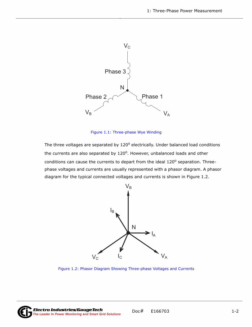
the winding relationships between the phases it looks like a Y. Figure 1.1 depicts the
winding relationships for a wye-connected service. In a wye service the neutral (or
center point of the wye) is typically grounded. This leads to common voltages of 208/
120 and 480/277 (where the first number represents the phase-to-phase voltage and
the second number represents the phase-to-ground voltage).
Electro Industries/GaugeTechThe Leader In Power Monitoring and Smart Grid Solutions
Doc# E166703 1-1
1: Three-Phase Power Measurement
Figure 1.1: Three-phase Wye Winding
The three voltages are separated by 120o electrically. Under balanced load conditions
the currents are also separated by 120o. However, unbalanced loads and other
conditions can cause the currents to depart from the ideal 120o separation. Three-
phase voltages and currents are usually represented with a phasor diagram. A phasor
diagram for the typical connected voltages and currents is shown in Figure 1.2.
Figure 1.2: Phasor Diagram Showing Three-phase Voltages and Currents
N
Phase 1
Phase 3
Phase 2
V C
V A V B
VA
VB
VC
N
IB
IA
IC
Electro Industries/GaugeTechThe Leader In Power Monitoring and Smart Grid Solutions
Doc# E166703 1-2

1: Three-Phase Power Measurement
The phasor diagram shows the 120o angular separation between the phase voltages.
The phase-to-phase voltage in a balanced three-phase wye system is 1.732 times the
phase-to-neutral voltage. The center point of the wye is tied together and is typically
grounded. Table 1.1 shows the common voltages used in the United States for wye-
connected systems.
Usually a wye-connected service will have four wires: three wires for the phases and
one for the neutral. The three-phase wires connect to the three phases (as shown in
Figure 1.1). The neutral wire is typically tied to the ground or center point of the wye.
In many industrial applications the facility will be fed with a four-wire wye service but
only three wires will be run to individual loads. The load is then often referred to as a
delta-connected load but the service to the facility is still a wye service; it contains
four wires if you trace the circuit back to its source (usually a transformer). In this
type of connection the phase to ground voltage will be the phase-to-ground voltage
indicated in Table 1, even though a neutral or ground wire is not physically present at
the load. The transformer is the best place to determine the circuit connection type
because this is a location where the voltage reference to ground can be conclusively
identified.
Phase to Ground Voltage Phase to Phase Voltage
120 volts 208 volts
277 volts 480 volts
2,400 volts 4,160 volts
7,200 volts 12,470 volts
7,620 volts 13,200 volts
Table 1: Common Phase Voltages on Wye Services
Electro Industries/GaugeTechThe Leader In Power Monitoring and Smart Grid Solutions
Doc# E166703 1-3
1: Three-Phase Power Measurement
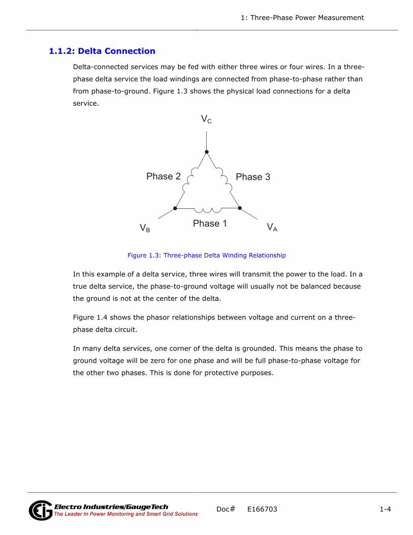
1.1.2: Delta Connection
Delta-connected services may be fed with either three wires or four wires. In a three-
phase delta service the load windings are connected from phase-to-phase rather than
from phase-to-ground. Figure 1.3 shows the physical load connections for a delta
service.
Figure 1.3: Three-phase Delta Winding Relationship
In this example of a delta service, three wires will transmit the power to the load. In a
true delta service, the phase-to-ground voltage will usually not be balanced because
the ground is not at the center of the delta.
Figure 1.4 shows the phasor relationships between voltage and current on a three-
phase delta circuit.
In many delta services, one corner of the delta is grounded. This means the phase to
ground voltage will be zero for one phase and will be full phase-to-phase voltage for
the other two phases. This is done for protective purposes.
V C
Phase 1
Phase 3 Phase 2
V A V B
Electro Industries/GaugeTechThe Leader In Power Monitoring and Smart Grid Solutions
Doc# E166703 1-4

1: Three-Phase Power Measurement
Figure 1.4: Phasor Diagram, Three-Phase Voltages and Currents, Delta-Connected
Another common delta connection is the four-wire, grounded delta used for lighting
loads. In this connection the center point of one winding is grounded. On a 120/240
volt, four-wire, grounded delta service the phase-to-ground voltage would be 120
volts on two phases and 208 volts on the third phase. Figure 1.5 shows the phasor
diagram for the voltages in a three-phase, four-wire delta system.
Figure 1.5: Phasor Diagram Showing Three-phase Four-Wire Delta-Connected System
IA
VCA
VAB
VBC IC
IB
VA
VC
VB
VCA
VAB
N VBC
Electro Industries/GaugeTechThe Leader In Power Monitoring and Smart Grid Solutions
Doc# E166703 1-5

1: Three-Phase Power Measurement
1.1.3: Blondel’s Theorem and Three Phase Measurement
In 1893 an engineer and mathematician named Andre E. Blondel set forth the first
scientific basis for polyphase metering. His theorem states:
If energy is supplied to any system of conductors through N wires, the total power in
the system is given by the algebraic sum of the readings of N wattmeters so arranged
that each of the N wires contains one current coil, the corresponding potential coil
being connected between that wire and some common point. If this common point is
on one of the N wires, the measurement may be made by the use of N-1 Wattmeters.
The theorem may be stated more simply, in modern language:
In a system of N conductors, N-1 meter elements will measure the power or energy
taken provided that all the potential coils have a common tie to the conductor in
which there is no current coil.
Three-phase power measurement is accomplished by measuring the three individual
phases and adding them together to obtain the total three phase value. In older ana-
log meters, this measurement was accomplished using up to three separate elements.
Each element combined the single-phase voltage and current to produce a torque on
the meter disk. All three elements were arranged around the disk so that the disk was
subjected to the combined torque of the three elements. As a result the disk would
turn at a higher speed and register power supplied by each of the three wires.
According to Blondel's Theorem, it was possible to reduce the number of elements
under certain conditions. For example, a three-phase, three-wire delta system could
be correctly measured with two elements (two potential coils and two current coils) if
the potential coils were connected between the three phases with one phase in com-
mon.
In a three-phase, four-wire wye system it is necessary to use three elements. Three
voltage coils are connected between the three phases and the common neutral con-
ductor. A current coil is required in each of the three phases.
In modern digital meters, Blondel's Theorem is still applied to obtain proper metering.
The difference in modern meters is that the digital meter measures each phase volt-
age and current and calculates the single-phase power for each phase. The meter
then sums the three phase powers to a single three-phase reading.
Electro Industries/GaugeTechThe Leader In Power Monitoring and Smart Grid Solutions
Doc# E166703 1-6
1: Three-Phase Power Measurement
Some digital meters measure the individual phase power values one phase at a time.
This means the meter samples the voltage and current on one phase and calculates a
power value. Then it samples the second phase and calculates the power for the sec-
ond phase. Finally, it samples the third phase and calculates that phase power. After
sampling all three phases, the meter adds the three readings to create the equivalent
three-phase power value. Using mathematical averaging techniques, this method can
derive a quite accurate measurement of three-phase power.
More advanced meters actually sample all three phases of voltage and current
simultaneously and calculate the individual phase and three-phase power values. The
advantage of simultaneous sampling is the reduction of error introduced due to the
difference in time when the samples were taken.
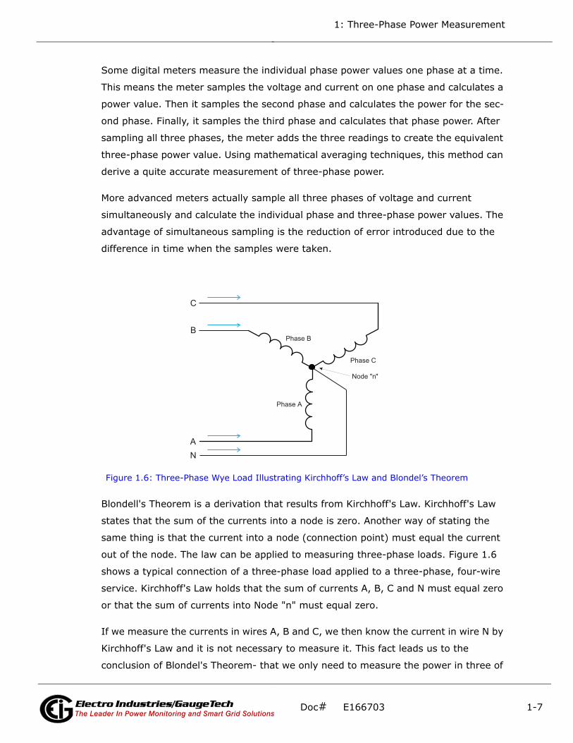
Figure 1.6: Three-Phase Wye Load Illustrating Kirchhoff’s Law and Blondel’s Theorem
Blondell's Theorem is a derivation that results from Kirchhoff's Law. Kirchhoff's Law
states that the sum of the currents into a node is zero. Another way of stating the
same thing is that the current into a node (connection point) must equal the current
out of the node. The law can be applied to measuring three-phase loads. Figure 1.6
shows a typical connection of a three-phase load applied to a three-phase, four-wire
service. Kirchhoff's Law holds that the sum of currents A, B, C and N must equal zero
or that the sum of currents into Node "n" must equal zero.
If we measure the currents in wires A, B and C, we then know the current in wire N by
Kirchhoff's Law and it is not necessary to measure it. This fact leads us to the
conclusion of Blondel's Theorem- that we only need to measure the power in three of
Phase B
Phase C
Phase A
A
B
C
N
Node "n"
Electro Industries/GaugeTechThe Leader In Power Monitoring and Smart Grid Solutions
Doc# E166703 1-7

1: Three-Phase Power Measurement
the four wires if they are connected by a common node. In the circuit of Figure 1.6 we
must measure the power flow in three wires. This will require three voltage coils and
three current coils (a three-element meter). Similar figures and conclusions could be
reached for other circuit configurations involving Delta-connected loads.
1.2: Power, Energy and Demand
It is quite common to exchange power, energy and demand without differentiating
between the three. Because this practice can lead to confusion, the differences
between these three measurements will be discussed.
Power is an instantaneous reading. The power reading provided by a meter is the
present flow of watts. Power is measured immediately just like current. In many
digital meters, the power value is actually measured and calculated over a one second
interval because it takes some amount of time to calculate the RMS values of voltage
and current. But this time interval is kept small to preserve the instantaneous nature
of power.
Energy is always based on some time increment; it is the integration of power over a
defined time increment. Energy is an important value because almost all electric bills
are based, in part, on the amount of energy used.
Typically, electrical energy is measured in units of kilowatt-hours (kWh). A kilowatt-
hour represents a constant load of one thousand watts (one kilowatt) for one hour.
Stated another way, if the power delivered (instantaneous watts) is measured as
1,000 watts and the load was served for a one hour time interval then the load would
have absorbed one kilowatt-hour of energy. A different load may have a constant
power requirement of 4,000 watts. If the load were served for one hour it would
absorb four kWh. If the load were served for 15 minutes it would absorb ¼ of that
total or one kWh.
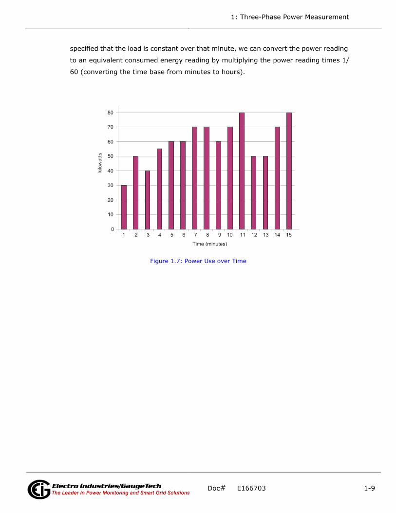
Figure 1.7 shows a graph of power and the resulting energy that would be transmitted
as a result of the illustrated power values. For this illustration, it is assumed that the
power level is held constant for each minute when a measurement is taken. Each bar
in the graph will represent the power load for the one-minute increment of time. In
real life the power value moves almost constantly.
The data from Figure 1.7 is reproduced in Table 2 to illustrate the calculation of
energy. Since the time increment of the measurement is one minute and since we
Electro Industries/GaugeTechThe Leader In Power Monitoring and Smart Grid Solutions
Doc# E166703 1-8
1: Three-Phase Power Measurement
specified that the load is constant over that minute, we can convert the power reading
to an equivalent consumed energy reading by multiplying the power reading times 1/
60 (converting the time base from minutes to hours).
Figure 1.7: Power Use over Time
0
10
20
30
40
50
60
70
80
1 2 3 4 5 6 7 8 9 10 11 12 13 14 15
Time (minutes)
sttawolik
Electro Industries/GaugeTechThe Leader In Power Monitoring and Smart Grid Solutions
Doc# E166703 1-9

1: Three-Phase Power Measurement
As in Table 1.2, the accumulated energy for the power load profile of Figure 1.7 is
14.92 kWh.
Demand is also a time-based value. The demand is the average rate of energy use
over time. The actual label for demand is kilowatt-hours/hour but this is normally
reduced to kilowatts. This makes it easy to confuse demand with power, but demand
is not an instantaneous value. To calculate demand it is necessary to accumulate the
energy readings (as illustrated in Figure 1.7) and adjust the energy reading to an
hourly value that constitutes the demand.
In the example, the accumulated energy is 14.92 kWh. But this measurement was
made over a 15-minute interval. To convert the reading to a demand value, it must be
normalized to a 60-minute interval. If the pattern were repeated for an additional
three 15-minute intervals the total energy would be four times the measured value or
Time Interval (minute)
Power (kW)
Energy (kWh)
Accumulated Energy (kWh)
1 30 0.50 0.50
2 50 0.83 1.33
3 40 0.67 2.00
4 55 0.92 2.92
5 60 1.00 3.92
6 60 1.00 4.92
7 70 1.17 6.09
8 70 1.17 7.26
9 60 1.00 8.26
10 70 1.17 9.43
11 80 1.33 10.76
12 50 0.83 12.42
13 50 0.83 12.42
14 70 1.17 13.59
15 80 1.33 14.92
Table 1.2: Power and Energy Relationship over Time
Electro Industries/GaugeTechThe Leader In Power Monitoring and Smart Grid Solutions
Doc# E166703 1-10
1: Three-Phase Power Measurement
59.68 kWh. The same process is applied to calculate the 15-minute demand value.
The demand value associated with the example load is 59.68 kWh/hr or 59.68 kWd.
Note that the peak instantaneous value of power is 80 kW, significantly more than the
demand value.
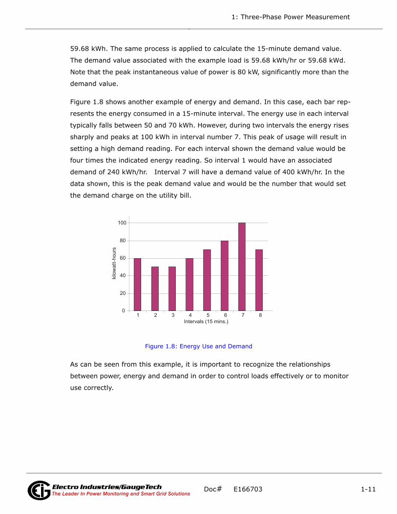
Figure 1.8 shows another example of energy and demand. In this case, each bar rep-
resents the energy consumed in a 15-minute interval. The energy use in each interval
typically falls between 50 and 70 kWh. However, during two intervals the energy rises
sharply and peaks at 100 kWh in interval number 7. This peak of usage will result in
setting a high demand reading. For each interval shown the demand value would be
four times the indicated energy reading. So interval 1 would have an associated
demand of 240 kWh/hr. Interval 7 will have a demand value of 400 kWh/hr. In the
data shown, this is the peak demand value and would be the number that would set
the demand charge on the utility bill.
Figure 1.8: Energy Use and Demand
As can be seen from this example, it is important to recognize the relationships
between power, energy and demand in order to control loads effectively or to monitor
use correctly.
0
20
40
60
80
100
1 2 3 4 5 6 7 8Intervals (15 mins.)
sruoh-ttawolik
Electro Industries/GaugeTechThe Leader In Power Monitoring and Smart Grid Solutions
Doc# E166703 1-11
1: Three-Phase Power Measurement
1.3: Reactive Energy and Power Factor
The real power and energy measurements discussed in the previous section relate to
the quantities that are most used in electrical systems. But it is often not sufficient to
only measure real power and energy. Reactive power is a critical component of the
total power picture because almost all real-life applications have an impact on reac-
tive power. Reactive power and power factor concepts relate to both load and genera-
tion applications. However, this discussion will be limited to analysis of reactive power
and power factor as they relate to loads. To simplify the discussion, generation will
not be considered.
Real power (and energy) is the component of power that is the combination of the
voltage and the value of corresponding current that is directly in phase with the volt-
age. However, in actual practice the total current is almost never in phase with the
voltage. Since the current is not in phase with the voltage, it is necessary to consider
both the inphase component and the component that is at quadrature (angularly
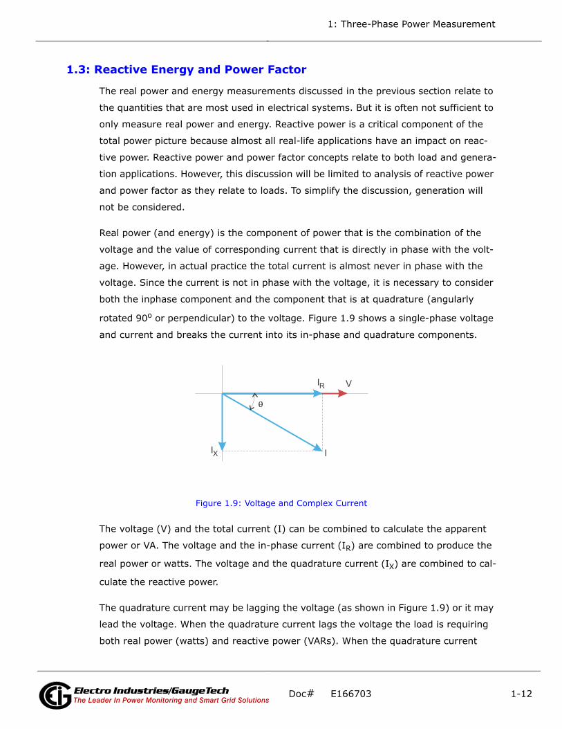
rotated 90o or perpendicular) to the voltage. Figure 1.9 shows a single-phase voltage
and current and breaks the current into its in-phase and quadrature components.
Figure 1.9: Voltage and Complex Current
The voltage (V) and the total current (I) can be combined to calculate the apparent
power or VA. The voltage and the in-phase current (IR) are combined to produce the
real power or watts. The voltage and the quadrature current (IX) are combined to cal-
culate the reactive power.
The quadrature current may be lagging the voltage (as shown in Figure 1.9) or it may
lead the voltage. When the quadrature current lags the voltage the load is requiring
both real power (watts) and reactive power (VARs). When the quadrature current
V
I
IR
IX
0
Electro Industries/GaugeTechThe Leader In Power Monitoring and Smart Grid Solutions
Doc# E166703 1-12

1: Three-Phase Power Measurement
leads the voltage the load is requiring real power (watts) but is delivering reactive
power (VARs) back into the system; that is VARs are flowing in the opposite direction
of the real power flow.
Reactive power (VARs) is required in all power systems. Any equipment that uses
magnetization to operate requires VARs. Usually the magnitude of VARs is relatively
low compared to the real power quantities. Utilities have an interest in maintaining
VAR requirements at the customer to a low value in order to maximize the return on
plant invested to deliver energy. When lines are carrying VARs, they cannot carry as
many watts. So keeping the VAR content low allows a line to carry its full capacity of
watts. In order to encourage customers to keep VAR requirements low, some utilities
impose a penalty if the VAR content of the load rises above a specified value.
A common method of measuring reactive power requirements is power factor. Power
factor can be defined in two different ways. The more common method of calculating
power factor is the ratio of the real power to the apparent power. This relationship is
expressed in the following formula:
Total PF = real power / apparent power = watts/VA
This formula calculates a power factor quantity known as Total Power Factor. It is
called Total PF because it is based on the ratios of the power delivered. The delivered
power quantities will include the impacts of any existing harmonic content. If the volt-
age or current includes high levels of harmonic distortion the power values will be
affected. By calculating power factor from the power values, the power factor will
include the impact of harmonic distortion. In many cases this is the preferred method
of calculation because the entire impact of the actual voltage and current are
included.
A second type of power factor is Displacement Power Factor. Displacement PF is based
on the angular relationship between the voltage and current. Displacement power fac-
tor does not consider the magnitudes of voltage, current or power. It is solely based
on the phase angle differences. As a result, it does not include the impact of harmonic
distortion. Displacement power factor is calculated using the following equation:
Displacement PF cos=
Electro Industries/GaugeTechThe Leader In Power Monitoring and Smart Grid Solutions
Doc# E166703 1-13
1: Three-Phase Power Measurement
where is the angle between the voltage and the current (see Fig. 1.9).
In applications where the voltage and current are not distorted, the Total Power Fac-
tor will equal the Displacement Power Factor. But if harmonic distortion is present, the
two power factors will not be equal.
1.4: Harmonic Distortion
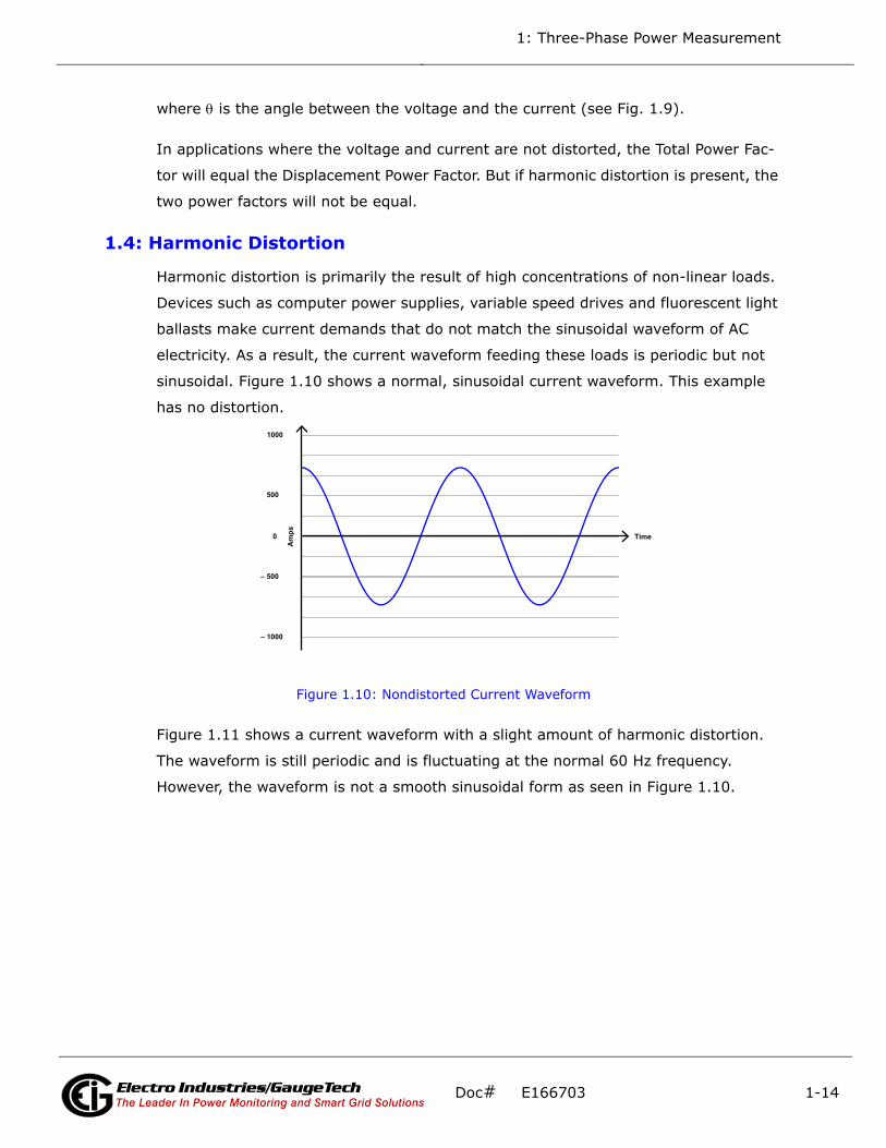
Harmonic distortion is primarily the result of high concentrations of non-linear loads.
Devices such as computer power supplies, variable speed drives and fluorescent light
ballasts make current demands that do not match the sinusoidal waveform of AC
electricity. As a result, the current waveform feeding these loads is periodic but not
sinusoidal. Figure 1.10 shows a normal, sinusoidal current waveform. This example
has no distortion.
Figure 1.10: Nondistorted Current Waveform
Figure 1.11 shows a current waveform with a slight amount of harmonic distortion.
The waveform is still periodic and is fluctuating at the normal 60 Hz frequency.
However, the waveform is not a smooth sinusoidal form as seen in Figure 1.10.
Time
Am
ps
– 1000
– 500
0
500
1000
Electro Industries/GaugeTechThe Leader In Power Monitoring and Smart Grid Solutions
Doc# E166703 1-14

1: Three-Phase Power Measurement
Figure 1.11: Distorted Current Waveform
The distortion observed in Figure 1.11 can be modeled as the sum of several sinusoi-
dal waveforms of frequencies that are multiples of the fundamental 60 Hz frequency.
This modeling is performed by mathematically disassembling the distorted waveform
into a collection of higher frequency waveforms.
These higher frequency waveforms are referred to as harmonics. Figure 1.12 shows
the content of the harmonic frequencies that make up the distortion portion of the
waveform in Figure 1.11.
Figure 1.12: Waveforms of the Harmonics
–1000
–500
0
500
1000
t)sp
ma( tnerr uC
a 2a
–1500
1500
Time
Am
ps
3rd harmonic5th harmonic7th harmonicTotalfundamental
– 500
0
500
1000
Electro Industries/GaugeTechThe Leader In Power Monitoring and Smart Grid Solutions
Doc# E166703 1-15
1: Three-Phase Power Measurement
The waveforms shown in Figure 1.12 are not smoothed but do provide an indication of
the impact of combining multiple harmonic frequencies together.
When harmonics are present it is important to remember that these quantities are
operating at higher frequencies. Therefore, they do not always respond in the same
manner as 60 Hz values.
Inductive and capacitive impedance are present in all power systems. We are accus-
tomed to thinking about these impedances as they perform at 60 Hz. However, these
impedances are subject to frequency variation.
XL = jL and
XC = 1/jC
At 60 Hz, = 377; but at 300 Hz (5th harmonic) = 1,885. As frequency changes
impedance changes and system impedance characteristics that are normal at 60 Hz
may behave entirely differently in the presence of higher order harmonic waveforms.
Traditionally, the most common harmonics have been the low order, odd frequencies,
such as the 3rd, 5th, 7th, and 9th. However newer, non-linear loads are introducing
significant quantities of higher order harmonics.
Since much voltage monitoring and almost all current monitoring is performed using
instrument transformers, the higher order harmonics are often not visible. Instrument
transformers are designed to pass 60 Hz quantities with high accuracy. These devices,
when designed for accuracy at low frequency, do not pass high frequencies with high
accuracy; at frequencies above about 1200 Hz they pass almost no information. So
when instrument transformers are used, they effectively filter out higher frequency
harmonic distortion making it impossible to see.
However, when monitors can be connected directly to the measured circuit (such as
direct connection to a 480 volt bus) the user may often see higher order harmonic
distortion. An important rule in any harmonics study is to evaluate the type of equip-
ment and connections before drawing a conclusion. Not being able to see harmonic
distortion is not the same as not having harmonic distortion.
It is common in advanced meters to perform a function commonly referred to as
waveform capture. Waveform capture is the ability of a meter to capture a present
picture of the voltage or current waveform for viewing and harmonic analysis.
Electro Industries/GaugeTechThe Leader In Power Monitoring and Smart Grid Solutions
Doc# E166703 1-16

1: Three-Phase Power Measurement
Typically a waveform capture will be one or two cycles in duration and can be viewed
as the actual waveform, as a spectral view of the harmonic content, or a tabular view
showing the magnitude and phase shift of each harmonic value. Data collected with
waveform capture is typically not saved to memory. Waveform capture is a real-time
data collection event.
Waveform capture should not be confused with waveform recording that is used to
record multiple cycles of all voltage and current waveforms in response to a transient
condition.
1.5: Power Quality
Power quality can mean several different things. The terms "power quality" and
"power quality problem" have been applied to all types of conditions. A simple defini-
tion of "power quality problem" is any voltage, current or frequency deviation that
results in mis-operation or failure of customer equipment or systems. The causes of
power quality problems vary widely and may originate in the customer equipment, in
an adjacent customer facility or with the utility.
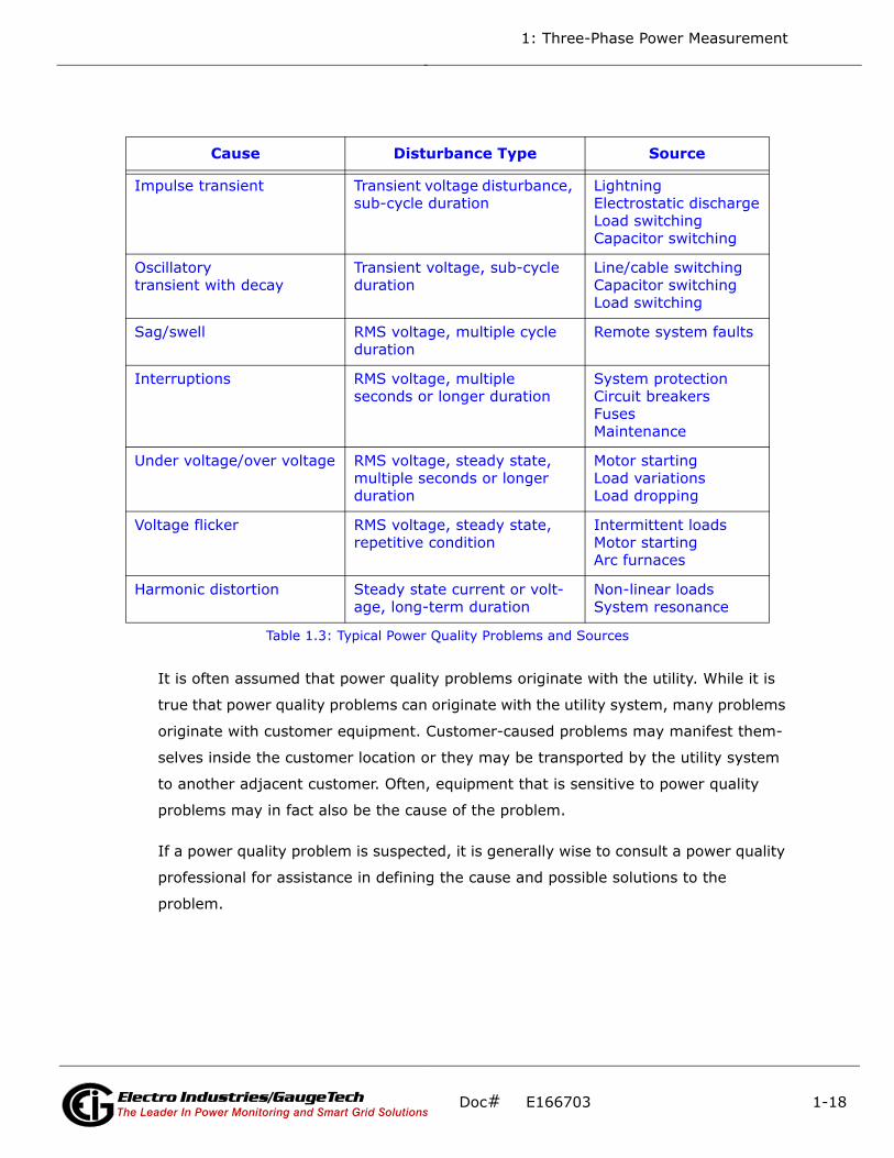
In his book Power Quality Primer, Barry Kennedy provided information on different
types of power quality problems. Some of that information is summarized in Table
1.3.
Electro Industries/GaugeTechThe Leader In Power Monitoring and Smart Grid Solutions
Doc# E166703 1-17
1: Three-Phase Power Measurement
It is often assumed that power quality problems originate with the utility. While it is
true that power quality problems can originate with the utility system, many problems
originate with customer equipment. Customer-caused problems may manifest them-
selves inside the customer location or they may be transported by the utility system
to another adjacent customer. Often, equipment that is sensitive to power quality
problems may in fact also be the cause of the problem.
If a power quality problem is suspected, it is generally wise to consult a power quality
professional for assistance in defining the cause and possible solutions to the
problem.
Cause Disturbance Type Source
Impulse transient Transient voltage disturbance, sub-cycle duration
LightningElectrostatic dischargeLoad switchingCapacitor switching
Oscillatory transient with decay
Transient voltage, sub-cycle duration
Line/cable switchingCapacitor switchingLoad switching
Sag/swell RMS voltage, multiple cycle duration
Remote system faults
Interruptions RMS voltage, multiple seconds or longer duration
System protectionCircuit breakersFusesMaintenance
Under voltage/over voltage RMS voltage, steady state, multiple seconds or longer duration
Motor startingLoad variationsLoad dropping
Voltage flicker RMS voltage, steady state, repetitive condition
Intermittent loadsMotor startingArc furnaces
Harmonic distortion Steady state current or volt-age, long-term duration
Non-linear loadsSystem resonance
Table 1.3: Typical Power Quality Problems and Sources
Electro Industries/GaugeTechThe Leader In Power Monitoring and Smart Grid Solutions
Doc# E166703 1-18

2: MP200 Metering System Overview and Specifications
2: MP200 Metering System Overview and Specifications
2.1: Shark® Series MP200 Metering System Overview
The Shark® Series MP200 unit is
a multi-port, high-density power
and energy metering system,
designed to be used in high-den-
sity metering environments such
as data centers, commercial high-
rise complexes, high-density
power distribution panels, and
branch circuits. The MP200 meter-
ing system provides 8 three phase
or 24 single phase meters served
by one central processing unit,
which delivers the measured data in multiple formats via RS485 serial communica-
tion, USB port communication, RJ45 Ethernet, or 802.11 WiFi Ethernet options. The
MP200 metering system also has data logging and load profiling capability to provide
historical data analysis.
The MP200 unit can be ordered as either an MP200-Y for three phase Wye/Delta sys-
tems or as an MP200-S for single phase systems. The MP200 unit is designed to be a
cost-effective instrument for high density metering. It is important to note that for
this design to function properly, all loads must be powered from a common voltage
(or three phase voltage) set.
Figure 2.1: Shark® MP200 Metering System
Doc# E166703 2-1Electro Industries/GaugeTechThe Leader In Power Monitoring and Smart Grid SolutionsElectro Industries/GaugeTech
The Leader In Power Monitoring and Smart Grid Solutions

2: MP200 Metering System Overview and Specifications
The MP200 metering system was designed using the following concept:
MP200-Y Unit Main Processing Module
MP200-S Unit Main Processing Module
The MP200 metering system offers up to 32 MegaBytes of non-volatile memory for
per-circuit Energy usage trending. The MP200 unit provides you with up to 5 logs: two
historical logs, a log of limit alarms, a log of I/O changes, and a sequence of events
log.
The MP200 metering system is designed with advanced measurement capabilities,
allowing it to achieve high performance accuracy. It is rated as a 0.5% Class accuracy
metering device, meeting ANSI C12.20 and IEC 62053-22 0.5% classes.
Additional features of the MP200 metering system include:
• Multifunction measurement including voltage, current, power, frequency, energy,
interval energy, etc.
Each Current Input Circuit is Considered a Meter
Each 3 Phase Current Input is Considered a Meter
Doc# E166703 2-2Electro Industries/GaugeTechThe Leader In Power Monitoring and Smart Grid SolutionsElectro Industries/GaugeTech
The Leader In Power Monitoring and Smart Grid Solutions

2: MP200 Metering System Overview and Specifications
• V-Switch™ Key technology - field upgradeable without removing installed MP200
unit.
• Alarm and Control - used to control load or alarm when over-load or other pro-
grammed conditions exist.
• Digital Inputs - designed to count pulses from other units, such as gas, water, and
condensate.
Optional Display
The MP200 unit offers an optional touch-screen color LED display. The display is avail-
able in two sizes: 3.5” (MDSN) and 5.7” (MDLN). The display lets you view readings
from all of the meters on the MP200 unit. See Chapter 10 for MDLN/MDSN display
details.
2.1.1: Voltage and Current Inputs
Universal Voltage Inputs
Voltage inputs allow measurement up to Nominal 480 V AC (Phase to Reference) and
600 V AC (Phase to Phase). The MP200 unit will perform to specification when directly
connected to 69 volt, 120 volt, 230 volt, 277 volt, and 347 volt power systems.
Higher voltages require the use of potential transformers (PTs). The MP200 unit is
programmable to any PT ratio needed.
Current Inputs
The MP200 unit can be ordered with either a 5 A or a 1 A secondary for current mea-
surements. Depending on the MP200 metering system model, there are either 8 three
phase current inputs, or 24 single phase current inputs. The current inputs are only to
be connected to external current transformers that are approved or certified.
The 5 A or 1 A secondary is an ordering option and as such it cannot be changed in
the field. The 5 A secondary model (-10) allows the unit to over-range to 10 A per
current circuit. The 1 A secondary model allows the unit to over-range to 2 A per cur-
rent circuit.
Doc# E166703 2-3Electro Industries/GaugeTechThe Leader In Power Monitoring and Smart Grid SolutionsElectro Industries/GaugeTech
The Leader In Power Monitoring and Smart Grid Solutions

2: MP200 Metering System Overview and Specifications
2.1.2: Ordering Information
*See Section 2.1.3 for more information and instructions on obtaining a V-SwitchTM
key.
Example:
MP200-Y-60-10-V2-X
(MP200 metering system with three phase circuit configuration, 60 Hz Frequency, 10
A Secondary, V-2 V-SwitchTM key, and RS485-only communication.)
NOTE on Frequency: It is important to specify the frequency to insure the highest
possible calibration accuracy from the factory.
2.1.3: V-SwitchTM Key Technology
The MP200 metering system is equipped with V-SwitchTM key technology, a virtual
firmware-based switch that lets you enable features through software communication.
V-SwitchTM key technology allows feature upgrades after installation without removal
from service.
Available V-SwitchTM key upgrades are as follows:
• V-SwitchTM key 1 (V1): Multifunction measurement
• V-SwitchTM key 2 (V2): Multifunction measurement and 2 MegaBytes* for data
logging
Model Circuit Configuration
Frequency CurrentClass
VswitchTM
Key Pack*Com
MP200-Y
Three Phase-60
60 Hz-1010 A
Secondary
-V1Transducer
-XRS485 Only
-SSingle Phase
-5050 Hz
-22 A
Secondary
-V2Basic
Logger
-WIFIEthernet
and WIFI
-V3Advanced
Logger
Doc# E166703 2-4Electro Industries/GaugeTechThe Leader In Power Monitoring and Smart Grid SolutionsElectro Industries/GaugeTech
The Leader In Power Monitoring and Smart Grid Solutions
2: MP200 Metering System Overview and Specifications
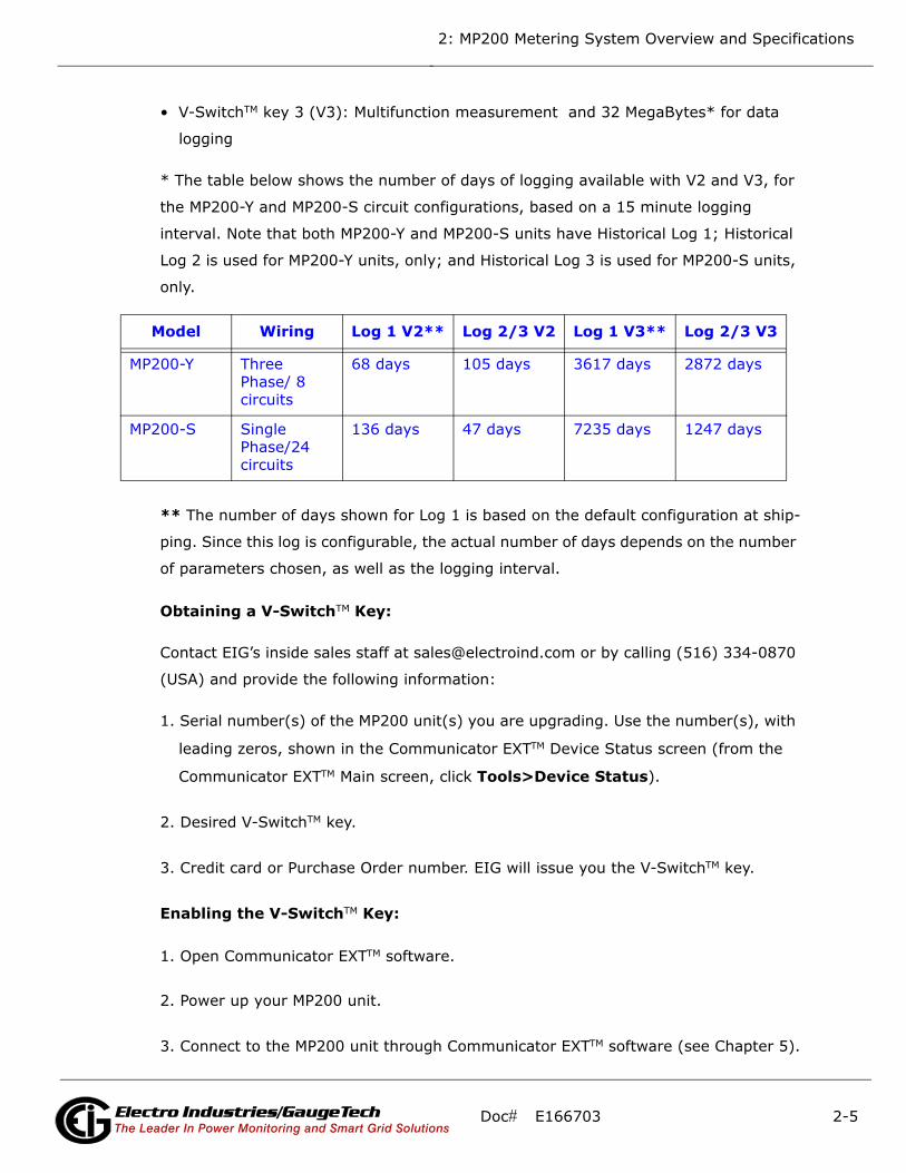
• V-SwitchTM key 3 (V3): Multifunction measurement and 32 MegaBytes* for data
logging
* The table below shows the number of days of logging available with V2 and V3, for
the MP200-Y and MP200-S circuit configurations, based on a 15 minute logging
interval. Note that both MP200-Y and MP200-S units have Historical Log 1; Historical
Log 2 is used for MP200-Y units, only; and Historical Log 3 is used for MP200-S units,
only.
** The number of days shown for Log 1 is based on the default configuration at ship-
ping. Since this log is configurable, the actual number of days depends on the number
of parameters chosen, as well as the logging interval.
Obtaining a V-SwitchTM Key:
Contact EIG’s inside sales staff at [email protected] or by calling (516) 334-0870
(USA) and provide the following information:
1. Serial number(s) of the MP200 unit(s) you are upgrading. Use the number(s), with
leading zeros, shown in the Communicator EXTTM Device Status screen (from the
Communicator EXTTM Main screen, click Tools>Device Status).
2. Desired V-SwitchTM key.
3. Credit card or Purchase Order number. EIG will issue you the V-SwitchTM key.
Enabling the V-SwitchTM Key:
1. Open Communicator EXTTM software.
2. Power up your MP200 unit.
3. Connect to the MP200 unit through Communicator EXTTM software (see Chapter 5).
Model Wiring Log 1 V2** Log 2/3 V2 Log 1 V3** Log 2/3 V3
MP200-Y Three Phase/ 8 circuits
68 days 105 days 3617 days 2872 days
MP200-S Single Phase/24 circuits
136 days 47 days 7235 days 1247 days
Doc# E166703 2-5Electro Industries/GaugeTechThe Leader In Power Monitoring and Smart Grid SolutionsElectro Industries/GaugeTech
The Leader In Power Monitoring and Smart Grid Solutions

2: MP200 Metering System Overview and Specifications
4. Click Tools>Change
V-Switch from the
Title Bar. A screen
opens, requesting
the encrypted key.
Enter the V-SwitchTM
key provided by EIG.
5. Click the OK button.
The V-SwitchTM key is
enabled and the MP200 unit resets.
NOTE: For more details on the MP200 unit’s software configuration, refer to Chapter
10 in the Communicator EXT 4.0 and MeterManager EXT Software User Manual. You
can download this manual at:
http://www.electroind.com/dl_page_software-downloads.html
Doc# E166703 2-6Electro Industries/GaugeTechThe Leader In Power Monitoring and Smart Grid SolutionsElectro Industries/GaugeTech
The Leader In Power Monitoring and Smart Grid Solutions
2: MP200 Metering System Overview and Specifications
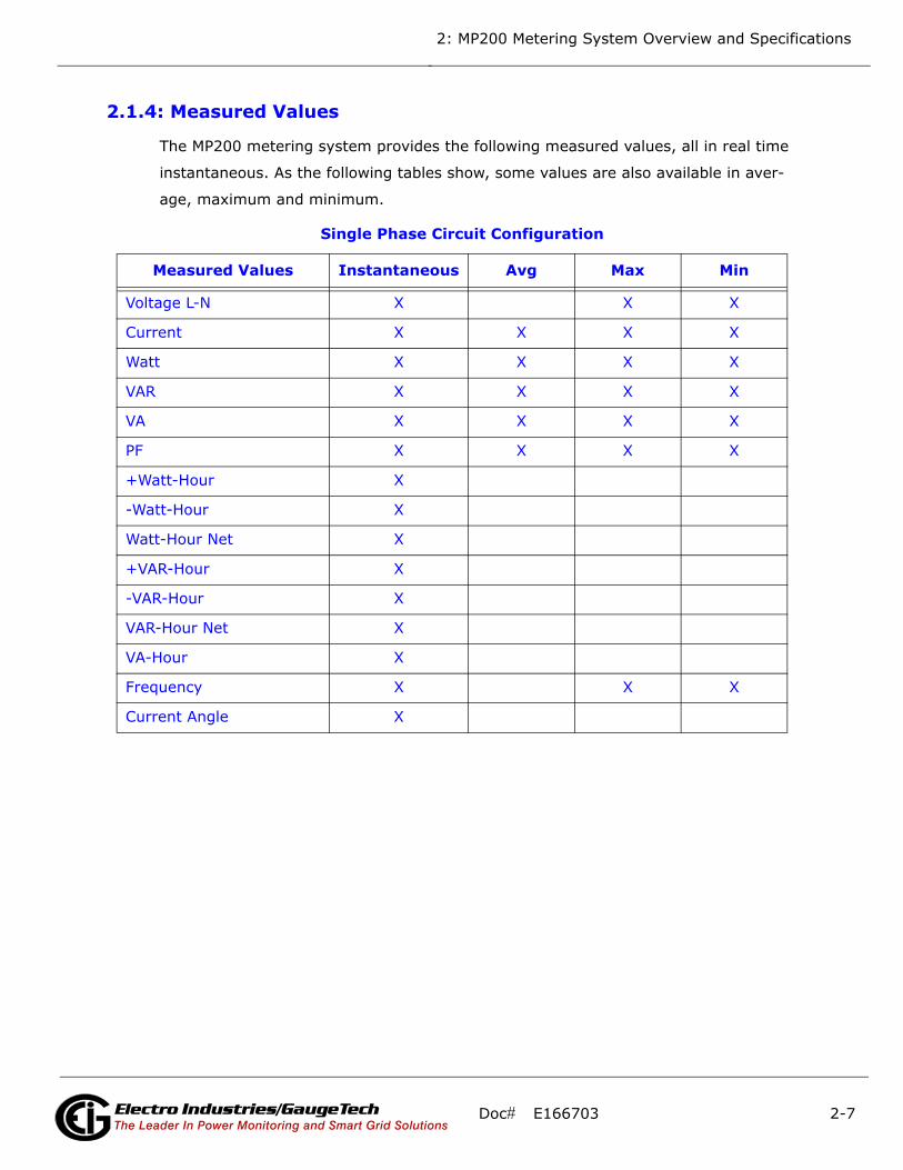
2.1.4: Measured Values
The MP200 metering system provides the following measured values, all in real time
instantaneous. As the following tables show, some values are also available in aver-
age, maximum and minimum.
Table 1: Single Phase Circuit ConfigurationThree
Measured Values Instantaneous Avg Max Min
Voltage L-N X X X
Current X X X X
Watt X X X X
VAR X X X X
VA X X X X
PF X X X X
+Watt-Hour X
-Watt-Hour X
Watt-Hour Net X
+VAR-Hour X
-VAR-Hour X
VAR-Hour Net X
VA-Hour X
Frequency X X X
Current Angle X
Doc# E166703 2-7Electro Industries/GaugeTechThe Leader In Power Monitoring and Smart Grid SolutionsElectro Industries/GaugeTech
The Leader In Power Monitoring and Smart Grid Solutions
2: MP200 Metering System Overview and Specifications
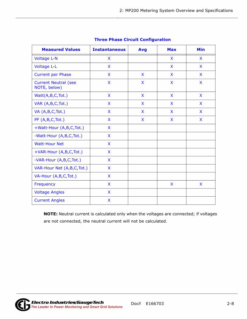
NOTE: Neutral current is calculated only when the voltages are connected; if voltages
are not connected, the neutral current will not be calculated.
Table 2: Three Phase Circuit Configuration
Measured Values Instantaneous Avg Max Min
Voltage L-N X X X
Voltage L-L X X X
Current per Phase X X X X
Current Neutral (see NOTE, below)
X X X X
Watt(A,B,C,Tot.) X X X X
VAR (A,B,C,Tot.) X X X X
VA (A,B,C,Tot.) X X X X
PF (A,B,C,Tot.) X X X X
+Watt-Hour (A,B,C,Tot.) X
-Watt-Hour (A,B,C,Tot.) X
Watt-Hour Net X
+VAR-Hour (A,B,C,Tot.) X
-VAR-Hour (A,B,C,Tot.) X
VAR-Hour Net (A,B,C,Tot.) X
VA-Hour (A,B,C,Tot.) X
Frequency X X X
Voltage Angles X
Current Angles X
Doc# E166703 2-8Electro Industries/GaugeTechThe Leader In Power Monitoring and Smart Grid SolutionsElectro Industries/GaugeTech
The Leader In Power Monitoring and Smart Grid Solutions

2: MP200 Metering System Overview and Specifications
2.1.5: Utility Peak Demand
The MP200 metering system provides user-configured Block (Fixed) window or Rolling
window Demand modes. This feature lets you set up a customized Demand profile.
Block window Demand mode records the average demand for time intervals you
define (usually 5, 15 or 30 minutes). Rolling window Demand mode functions like
multiple, overlapping Block windows. You define the subintervals at which an average
of Demand is calculated. An example of Rolling window Demand mode would be a 15-
minute Demand block using 5-minute subintervals, thus providing a new Demand
reading every 5 minutes, based on the last 15 minutes.
Utility Demand features can be used to calculate W, VAR, VA and PF readings. Voltage
provides an instantaneous Max and Min reading which displays the highest surge and
lowest sag seen by the meters. All other parameters offer Max and Min capability over
the user-selectable averaging period.
Doc# E166703 2-9Electro Industries/GaugeTechThe Leader In Power Monitoring and Smart Grid SolutionsElectro Industries/GaugeTech
The Leader In Power Monitoring and Smart Grid Solutions

2: MP200 Metering System Overview and Specifications
2.2: Specifications
Power Supply
Range: Universal, 90-300 V AC @50/60 Hz
or 150 V DC
Power Consumption: 18 VA, 12 W, Maximum
Voltage Inputs (Measurement Category III)
(For Accuracy specifications, see Section 2.4.)
Range: Universal, Auto-ranging up to
576 V AC L-N, 721 V AC L-L
Supported hookups: MP200-Y: 3 Element Wye; 2 CT
Delta
MP200-S: Single Phase, 2 wire, 3
wire
Input Impedance: 4.2 M Ohm/Phase
Burden: 0.09 VA/Phase Max at 600 V;
0.014 VA at 120 V
Pickup Voltage: 20 V AC
Connection: 7 Pin 0.400” Pluggable Terminal
Block
AWG#12 -26/ (0.08 -2.5) mm2
Fault Withstand: Meets IEEE C37.90.1
Reading: Programmable Full Scale to any PT
ratio
Doc# E166703 2-10Electro Industries/GaugeTechThe Leader In Power Monitoring and Smart Grid SolutionsElectro Industries/GaugeTech
The Leader In Power Monitoring and Smart Grid Solutions
2: MP200 Metering System Overview and Specifications
Current Inputs
(For Accuracy specifications, see Section 2.4.)
Class 10: 5 A Nominal, 10 A Maximum
Class 2: 1 A Nominal, 2 A Maximum
Burden: 0.005 VA Per Input Max at 11 A
Pickup Current: 0.1% of Nominal
Class 10: 5 mA
Class 2: 1 mA
Current Input Terminals: 8-32 Threaded Studs
Reading: Programmable Full Scale to any CT
ratio
Continuous Current Withstand: 20 A
Maximum Voltage across Current Inputs: 1 V AC
Maximum Voltage from Current Inputs
to Ground: 50 V AC
Doc# E166703 2-11Electro Industries/GaugeTechThe Leader In Power Monitoring and Smart Grid SolutionsElectro Industries/GaugeTech
The Leader In Power Monitoring and Smart Grid Solutions
2: MP200 Metering System Overview and Specifications
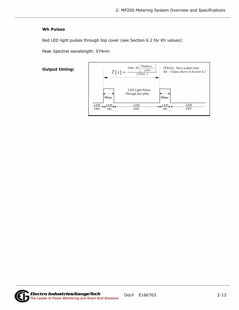
Wh Pulses
Red LED light pulses through top cover (see Section 6.2 for Kh values):
Peak Spectral wavelength: 574nm
Output timing:
90ms 90ms
][
3600
][
LED ON
LED ON
LED OFF
LED OFF
LED OFF
IR LED Light PulsesThrough face plate
[ ] - Not a scaled value – alues
Doc# E166703 2-12Electro Industries/GaugeTechThe Leader In Power Monitoring and Smart Grid SolutionsElectro Industries/GaugeTech
The Leader In Power Monitoring and Smart Grid Solutions
2: MP200 Metering System Overview and Specifications
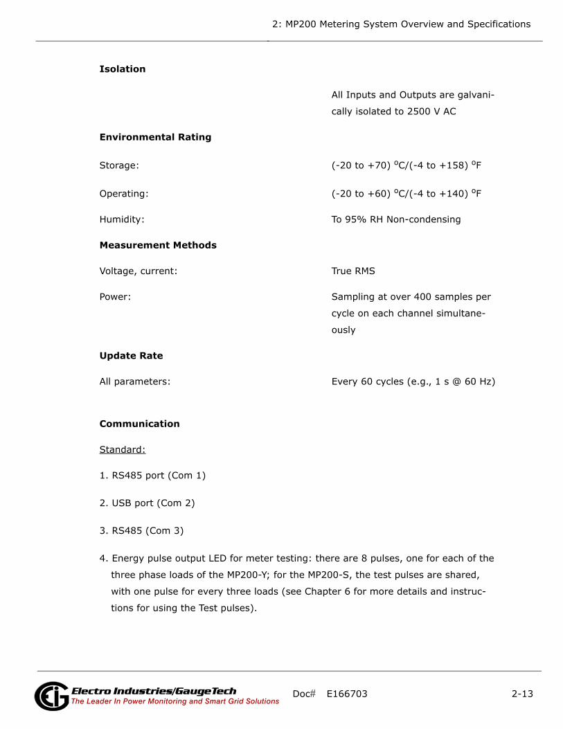
Isolation
All Inputs and Outputs are galvani-
cally isolated to 2500 V AC
Environmental Rating
Storage: (-20 to +70) oC/(-4 to +158) oF
Operating: (-20 to +60) oC/(-4 to +140) oF
Humidity: To 95% RH Non-condensing
Measurement Methods
Voltage, current: True RMS
Power: Sampling at over 400 samples per
cycle on each channel simultane-
ously
Update Rate
All parameters: Every 60 cycles (e.g., 1 s @ 60 Hz)
Communication
Standard:
1. RS485 port (Com 1)
2. USB port (Com 2)
3. RS485 (Com 3)
4. Energy pulse output LED for meter testing: there are 8 pulses, one for each of the
three phase loads of the MP200-Y; for the MP200-S, the test pulses are shared,
with one pulse for every three loads (see Chapter 6 for more details and instruc-
tions for using the Test pulses).
Doc# E166703 2-13Electro Industries/GaugeTechThe Leader In Power Monitoring and Smart Grid SolutionsElectro Industries/GaugeTech
The Leader In Power Monitoring and Smart Grid Solutions
2: MP200 Metering System Overview and Specifications
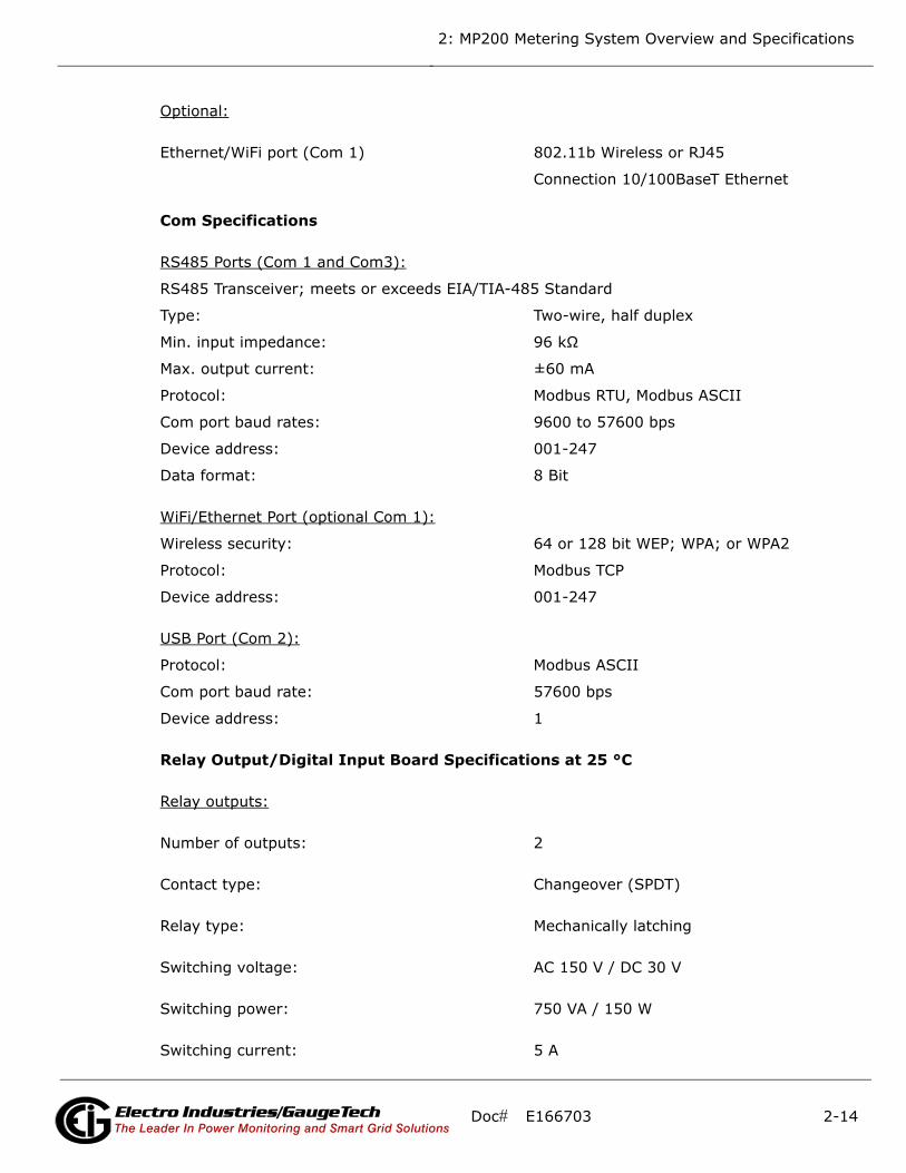
Optional:
Ethernet/WiFi port (Com 1) 802.11b Wireless or RJ45
Connection 10/100BaseT Ethernet
Com Specifications
RS485 Ports (Com 1 and Com3):
RS485 Transceiver; meets or exceeds EIA/TIA-485 Standard
Type: Two-wire, half duplex
Min. input impedance: 96 kΩ
Max. output current: ±60 mA
Protocol: Modbus RTU, Modbus ASCII
Com port baud rates: 9600 to 57600 bps
Device address: 001-247
Data format: 8 Bit
WiFi/Ethernet Port (optional Com 1):
Wireless security: 64 or 128 bit WEP; WPA; or WPA2
Protocol: Modbus TCP
Device address: 001-247
USB Port (Com 2):
Protocol: Modbus ASCII
Com port baud rate: 57600 bps
Device address: 1
Relay Output/Digital Input Board Specifications at 25 °C
Relay outputs:
Number of outputs: 2
Contact type: Changeover (SPDT)
Relay type: Mechanically latching
Switching voltage: AC 150 V / DC 30 V
Switching power: 750 VA / 150 W
Switching current: 5 A
Doc# E166703 2-14Electro Industries/GaugeTechThe Leader In Power Monitoring and Smart Grid SolutionsElectro Industries/GaugeTech
The Leader In Power Monitoring and Smart Grid Solutions
2: MP200 Metering System Overview and Specifications
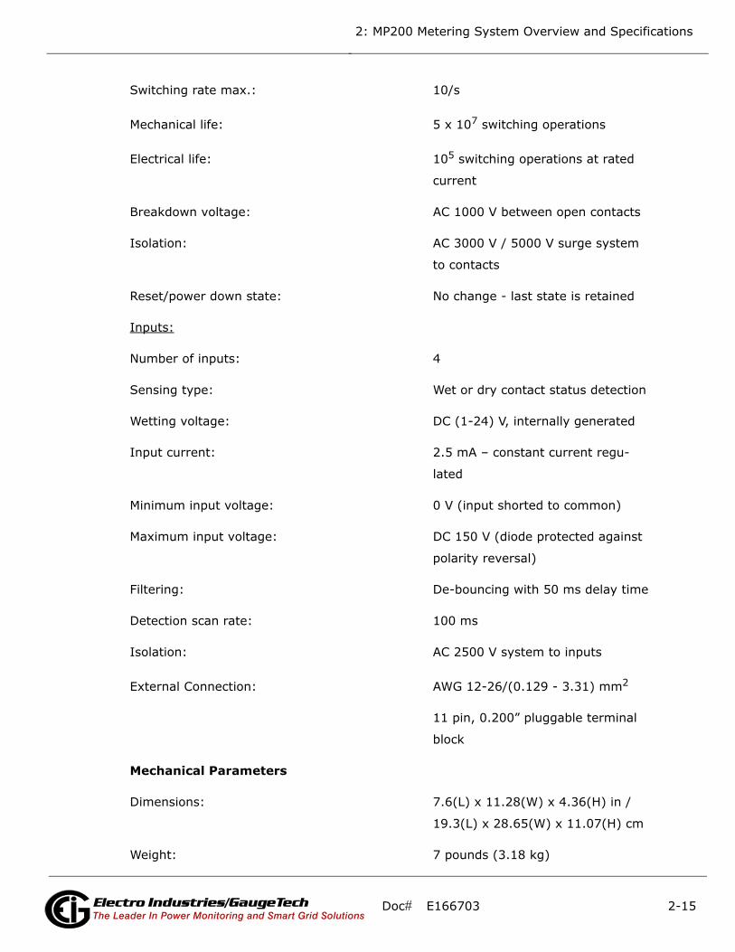
Switching rate max.: 10/s
Mechanical life: 5 x 10⁷ switching operations
Electrical life: 105 switching operations at rated
current
Breakdown voltage: AC 1000 V between open contacts
Isolation: AC 3000 V / 5000 V surge system
to contacts
Reset/power down state: No change - last state is retained
Inputs:
Number of inputs: 4
Sensing type: Wet or dry contact status detection
Wetting voltage: DC (1-24) V, internally generated
Input current: 2.5 mA – constant current regu-
lated
Minimum input voltage: 0 V (input shorted to common)
Maximum input voltage: DC 150 V (diode protected against
polarity reversal)
Filtering: De-bouncing with 50 ms delay time
Detection scan rate: 100 ms
Isolation: AC 2500 V system to inputs
External Connection: AWG 12-26/(0.129 - 3.31) mm2
11 pin, 0.200” pluggable terminal
block
Mechanical Parameters
Dimensions: 7.6(L) x 11.28(W) x 4.36(H) in /
19.3(L) x 28.65(W) x 11.07(H) cm
Weight: 7 pounds (3.18 kg)
Doc# E166703 2-15Electro Industries/GaugeTechThe Leader In Power Monitoring and Smart Grid SolutionsElectro Industries/GaugeTech
The Leader In Power Monitoring and Smart Grid Solutions

2: MP200 Metering System Overview and Specifications
2.3: Compliance
• UL listing: UL61010-1, CAN/CSA C22.2 No. 61010-1, UL file number E250818
• IEC 62053-22 (0.5% Class)
• ANSI C12.20 (0.5% Accuracy)
• ANSI (IEEE) C37.90.1 Surge Withstand
• ANSI C62.41 (Burst)
• EN61000-6-2 Immunity for Industrial Environments: 2005
• EN61000-6-4 Emission Standards for Industrial Environments: 2007
• EN61326 EMC Requirements: 2006
• CE marked
Doc# E166703 2-16Electro Industries/GaugeTechThe Leader In Power Monitoring and Smart Grid SolutionsElectro Industries/GaugeTech
The Leader In Power Monitoring and Smart Grid Solutions
2: MP200 Metering System Overview and Specifications
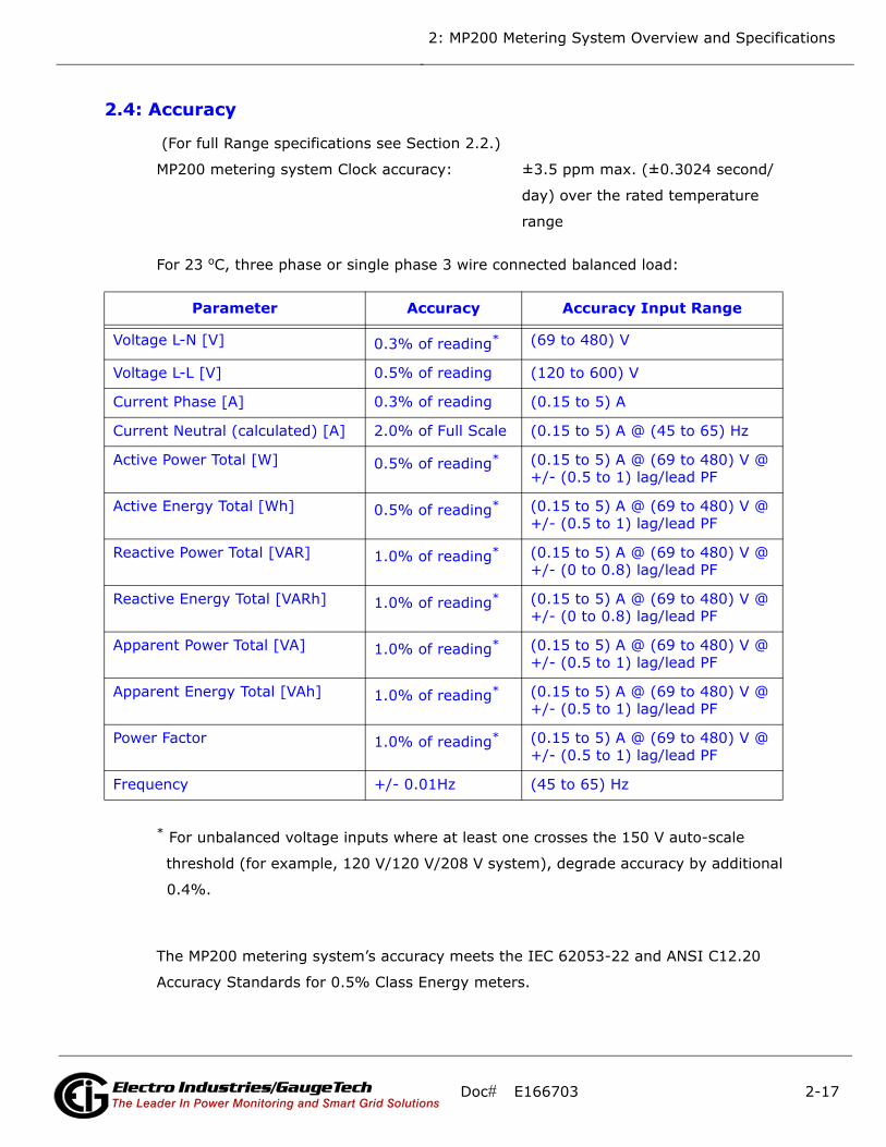
2.4: Accuracy
(For full Range specifications see Section 2.2.)
MP200 metering system Clock accuracy: ±3.5 ppm max. (±0.3024 second/
day) over the rated temperature
range
For 23 oC, three phase or single phase 3 wire connected balanced load:
* For unbalanced voltage inputs where at least one crosses the 150 V auto-scale
threshold (for example, 120 V/120 V/208 V system), degrade accuracy by additional
0.4%.
The MP200 metering system’s accuracy meets the IEC 62053-22 and ANSI C12.20
Accuracy Standards for 0.5% Class Energy meters.
Parameter Accuracy Accuracy Input Range
Voltage L-N [V] 0.3% of reading* (69 to 480) V
Voltage L-L [V] 0.5% of reading (120 to 600) V
Current Phase [A] 0.3% of reading (0.15 to 5) A
Current Neutral (calculated) [A] 2.0% of Full Scale (0.15 to 5) A @ (45 to 65) Hz
Active Power Total [W] 0.5% of reading* (0.15 to 5) A @ (69 to 480) V @ +/- (0.5 to 1) lag/lead PF
Active Energy Total [Wh] 0.5% of reading* (0.15 to 5) A @ (69 to 480) V @ +/- (0.5 to 1) lag/lead PF
Reactive Power Total [VAR] 1.0% of reading* (0.15 to 5) A @ (69 to 480) V @ +/- (0 to 0.8) lag/lead PF
Reactive Energy Total [VARh] 1.0% of reading* (0.15 to 5) A @ (69 to 480) V @ +/- (0 to 0.8) lag/lead PF
Apparent Power Total [VA] 1.0% of reading* (0.15 to 5) A @ (69 to 480) V @ +/- (0.5 to 1) lag/lead PF
Apparent Energy Total [VAh] 1.0% of reading* (0.15 to 5) A @ (69 to 480) V @ +/- (0.5 to 1) lag/lead PF
Power Factor 1.0% of reading* (0.15 to 5) A @ (69 to 480) V @ +/- (0.5 to 1) lag/lead PF
Frequency +/- 0.01Hz (45 to 65) Hz
Doc# E166703 2-17Electro Industries/GaugeTechThe Leader In Power Monitoring and Smart Grid SolutionsElectro Industries/GaugeTech
The Leader In Power Monitoring and Smart Grid Solutions

2: MP200 Metering System Overview and Specifications
This page intentionally left blank.
Doc# E166703 2-18Electro Industries/GaugeTechThe Leader In Power Monitoring and Smart Grid SolutionsElectro Industries/GaugeTech
The Leader In Power Monitoring and Smart Grid Solutions

3: Mechanical Installation and Maintenance
3: Mechanical Installation and Maintenance
3.1: MP200 Unit Dimensions
NOTE: The drawings shown below and on the next page give you the MP200 unit
dimensions in inches and millimeters [mm shown in brackets]. Tolerance is +/- 0.1”
[.25 cm].
Figure 3.1: MP200 Unit Front Dimensions
193.
1mm
286.5mm
0.28
in
0.80
in20
.4m
m
76.9
mm
7.60
in
11.28in
278.9mmcentered
3.03
in
7.2m
m
4.8m
m
10.98in
0.19
in
cent
ered
4.50
in11
4.3m
m
0.12
in2.
9mm
Doc# E166703 3-1Electro Industries/GaugeTechThe Leader In Power Monitoring and Smart Grid Solutions
Electro Industries/GaugeTechThe Leader In Power Monitoring and Smart Grid Solutions
3: Mechanical Installation and Maintenance
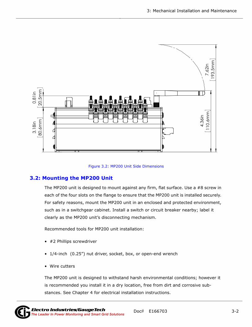
Figure 3.2: MP200 Unit Side Dimensions
3.2: Mounting the MP200 Unit
The MP200 unit is designed to mount against any firm, flat surface. Use a #8 screw in
each of the four slots on the flange to ensure that the MP200 unit is installed securely.
For safety reasons, mount the MP200 unit in an enclosed and protected environment,
such as in a switchgear cabinet. Install a switch or circuit breaker nearby; label it
clearly as the MP200 unit’s disconnecting mechanism.
Recommended tools for MP200 unit installation:
• #2 Phillips screwdriver
• 1/4-inch (0.25”) nut driver, socket, box, or open-end wrench
• Wire cutters
The MP200 unit is designed to withstand harsh environmental conditions; however it
is recommended you install it in a dry location, free from dirt and corrosive sub-
stances. See Chapter 4 for electrical installation instructions.
7.
62in
193.
5mm
4.36
in
80.6
mm
3.18
in
110.
6mm
0.
81in
20.5
mm
Doc# E166703 3-2Electro Industries/GaugeTechThe Leader In Power Monitoring and Smart Grid Solutions
Electro Industries/GaugeTechThe Leader In Power Monitoring and Smart Grid Solutions

3: Mechanical Installation and Maintenance
3.3: Cleaning the MP200 Unit
Do NOT clean with power applied. Disconnect power from the
MP200 metering system before following the cleaning procedure.
Ne PAS nettoyer lorsque le compteur est alimenté. Débranchez
l'alimentation du système de mesure MP200 avant d'entreprendre
la procédure de nettoyage.
1. Wipe the MP200 unit with a dry cloth. If stains or other material cannot be removed
with a dry cloth, slightly moisten a cloth with a consumer window cleaner and use
this to remove the stains or other material. Immediately wipe the unit down with a
dry cloth to eliminate remaining moisture. The unit must be completely dry before
being re-energized.
2. Dust may be blown off using room temperature compressed air at a maximum of
20 PSI.
Doc# E166703 3-3Electro Industries/GaugeTechThe Leader In Power Monitoring and Smart Grid Solutions
Electro Industries/GaugeTechThe Leader In Power Monitoring and Smart Grid Solutions

3: Mechanical Installation and Maintenance
This page intentionally left blank.
Doc# E166703 3-4Electro Industries/GaugeTechThe Leader In Power Monitoring and Smart Grid Solutions
Electro Industries/GaugeTechThe Leader In Power Monitoring and Smart Grid Solutions

4: Electrical Installation
4: Electrical Installation
4.1: Considerations When Installing the MP200 Metering System
Installation of the MP200 metering system must be performed only
by qualified personnel who follow standard safety precautions during
all procedures. Those personnel should have appropriate training
and experience with high voltage devices. Appropriate safety gloves,
safety glasses and protective clothing is recommended.
During normal operation of the MP200 unit, dangerous voltages are present in many
parts of the unit, including: terminals and any connected CTs (current transformers)
and PTs (potential transformers), all I/O Modules (inputs and outputs) and their cir-
cuits.
All Primary and Secondary circuits can, at times, produce lethal voltages and
currents. Avoid contact with any current-carrying surfaces.
Do not use the MP200 metering system or any I/O output device for primary
protection or in an energy-limiting capacity. The MP200 metering system can
only be used as secondary protection.
Do not use the MP200 unit for applications where failure of the MP200 unit may cause
harm or death.
Do not use the MP200 unit for any application where there may be a risk of fire.
All MP200 unit terminals should be inaccessible after installation.
Do not apply more than the maximum voltage the MP200 unit or any attached device
can withstand. Refer to MP200 unit and/or device labels and to the specifications for
all devices before applying voltages. Do not HIPOT/Dielectric test any outputs, inputs
or communication terminals.
Doc# E166703 4-1Electro Industries/GaugeTechThe Leader In Power Monitoring and Smart Grid SolutionsElectro Industries/GaugeTechThe Leader In Power Monitoring and Smart Grid SolutionsElectro Industries/GaugeTechThe Leader In Power Monitoring and Smart Grid Solutions

4: Electrical Installation
EIG recommends the use of fuses for voltage leads and power supply, and shorting
blocks to prevent hazardous voltage conditions or damage to CTs, if the MP200 unit
needs to be removed from service. One side of the CT must be grounded.
NOTE: The current inputs are only to be connected to external current transformers
provided by the installer. The CTs shall be Approved or Certified and rated for the cur-
rent of the meter used.
L'installation des compteurs de MP200 doit être effectuée seulement
par un personnel qualifié qui suit les normes relatives aux précau-
tions de sécurité pendant toute la procédure. Le personnel doit avoir
la formation appropriée et l'expérience avec les appareils de haute
tension. Des gants de sécurité, des verres et des vêtements de pro-
tection appropriés sont recommandés.
AVERTISSEMENT! Pendant le fonctionnement normal du compteur MP200 des ten-
sions dangereuses suivant de nombreuses pièces, notamment, les bornes et tous les
transformateurs de courant branchés, les transformateurs de tension, toutes les sor-
ties, les entrées et leurs circuits. Tous les circuits secondaires et primaires peu-
vent parfois produire des tensions de létal et des courants. Évitez le contact
avec les surfaces sous tensions. Avant de faire un travail dans le compteur,
assurez-vous d'éteindre l'alimentation et de mettre tous les circuits
branchés hors tension.
Ne pas utiliser les compteurs ou sorties d'appareil pour une protection pri-
maire ou capacité de limite d'énergie. Le compteur peut seulement être util-
isé comme une protection secondaire.
Ne pas utiliser le compteur pour application dans laquelle une panne de compteur
peut causer la mort ou des blessures graves.
Ne pas utiliser le compteur ou pour toute application dans laquelle un risque
d'incendie est susceptible.
Toutes les bornes de compteur doivent être inaccessibles après l'installation.
Ne pas appliquer plus que la tension maximale que le compteur ou appareil relatif
peut résister. Référez-vous au compteur ou aux étiquettes de l'appareil et les spécifi-
cations de tous les appareils avant d'appliquer les tensions. Ne pas faire de test
HIPOT/diélectrique, une sortie, une entrée ou un terminal de réseau.
Doc# E166703 4-2Electro Industries/GaugeTechThe Leader In Power Monitoring and Smart Grid SolutionsElectro Industries/GaugeTechThe Leader In Power Monitoring and Smart Grid SolutionsElectro Industries/GaugeTechThe Leader In Power Monitoring and Smart Grid Solutions

4: Electrical Installation
Les entrées actuelles doivent seulement être branchées aux transformateurs externes
actuels.
EIG recommande d'utiliser les fusibles pour les fils de tension et alimentations élec-
triques, ainsi que des coupe-circuits pour prévenir les tensions dangereuses ou
endommagements de transformateur de courant si l'unité MP200 doit être enlevée du
service. Un côté du transformateur de courant doit être mis à terre.
NOTE: les entrées actuelles doivent seulement être branchées dans le transformateur
externe actuel par l'installateur. Le transformateur de courant doit être approuvé ou
certifié et déterminé pour le compteur actuel utilisé.
IMPORTANT!
IF THE EQUIPMENT IS USED IN A MANNER NOT SPECIFIED
BY THE MANUFACTURER, THE PROTECTION PROVIDED BY
THE EQUIPMENT MAY BE IMPAIRED.
• THERE IS NO REQUIRED PREVENTIVE MAINTENANCE OR INSPEC-
TION NECESSARY FOR SAFETY. HOWEVER, ANY REPAIR OR MAIN-
TENANCE SHOULD BE PERFORMED BY THE FACTORY.
DISCONNECT DEVICE: The following part is considered the equip-
ment disconnect device. A SWITCH OR CIRCUIT-BREAKER SHALL BE
INCLUDED IN THE END-USE EQUIPMENT OR BUILDING INSTALLA-
TION. THE SWITCH SHALL BE IN CLOSE PROXIMITY TO THE EQUIP-
MENT AND WITHIN EASY REACH OF THE OPERATOR. THE SWITCH
SHALL BE MARKED AS THE DISCONNECTING DEVICE FOR THE
EQUIPMENT.
IMPORTANT! SI L'ÉQUIPEMENT EST UTILISÉ D'UNE FAÇON
NON SPÉCIFIÉE PAR LE FABRICANT, LA PROTECTION
FOURNIE PAR L'ÉQUIPEMENT PEUT ÊTRE ENDOMMAGÉE.
NOTE: Il N'Y A AUCUNE MAINTENANCE REQUISE POUR LA PRÉVENTION OU INSPEC-
TION NÉCESSAIRE POUR LA SÉCURITÉ. CEPENDANT, TOUTE RÉPARATION OU MAIN-
TENANCE DEVRAIT ÊTRE RÉALISÉE PAR LE FABRICANT.
Doc# E166703 4-3Electro Industries/GaugeTechThe Leader In Power Monitoring and Smart Grid SolutionsElectro Industries/GaugeTechThe Leader In Power Monitoring and Smart Grid SolutionsElectro Industries/GaugeTechThe Leader In Power Monitoring and Smart Grid Solutions
4: Electrical Installation
DÉBRANCHEMENT DE L'APPAREIL : la partie suivante est con-
sidérée l'appareil de débranchement de l'équipement.
UN INTERRUPTEUR OU UN DISJONCTEUR DEVRAIT ÊTRE INCLUS
DANS L'UTILISATION FINALE DE L'ÉQUIPEMENT OU L'INSTALLATION.
L'INTERRUPTEUR DOIT ÊTRE DANS UNE PROXIMITÉ PROCHE DE
L'ÉQUIPEMENT ET A LA PORTÉE DE L'OPÉRATEUR. L'INTERRUPTEUR DOIT AVOIR LA
MENTION DÉBRANCHEMENT DE L'APPAREIL POUR L'ÉQUIPEMENT.
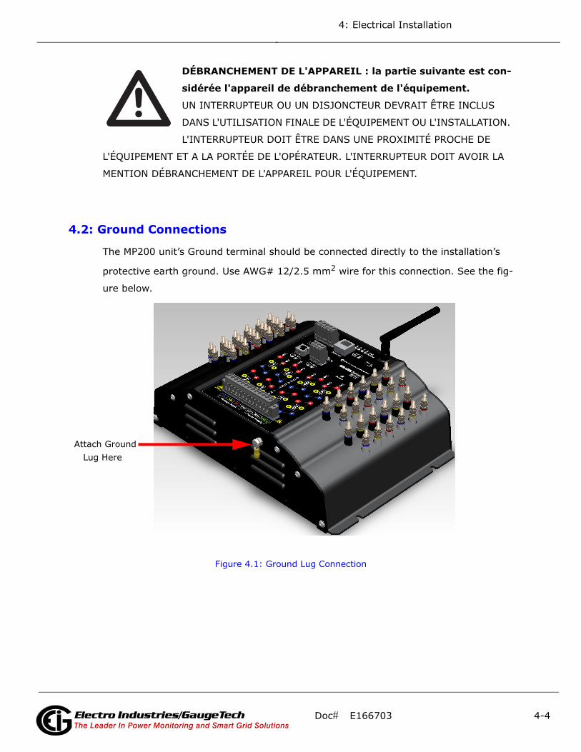
4.2: Ground Connections
The MP200 unit’s Ground terminal should be connected directly to the installation’s
protective earth ground. Use AWG# 12/2.5 mm2 wire for this connection. See the fig-
ure below.
Figure 4.1: Ground Lug Connection
Attach Ground Lug Here
Doc# E166703 4-4Electro Industries/GaugeTechThe Leader In Power Monitoring and Smart Grid SolutionsElectro Industries/GaugeTechThe Leader In Power Monitoring and Smart Grid SolutionsElectro Industries/GaugeTechThe Leader In Power Monitoring and Smart Grid Solutions

4: Electrical Installation
4.3: Voltage and Power Supply Connections
Voltage inputs are connected to the bottom of the MP200 unit via wire connectors.
The connectors accommodate AWG# 12 -26/ (0.129 - 3.31) mm2.
Figure 4.2: MP200 Unit Connections
4.4: Voltage Fuses
EIG recommends the use of fuses on each of the sense voltages and on the control
power, even though the wiring diagrams in this chapter do not show them.
• Use a 0.1 A fuse on each voltage input (rated for 600 volts).
• Use a 3 A Slow Blow fuse on the power supply (rated at 500 volts).
EIG offers the EI-CP Panel meter protective fuse kit, which can be ordered from EIG’s
website:
https://electroind.com/product/panel-meter-protective-fuse-kit/.
Earth Ground
Voltage Power Supply Inputs Inputs
Doc# E166703 4-5Electro Industries/GaugeTechThe Leader In Power Monitoring and Smart Grid SolutionsElectro Industries/GaugeTechThe Leader In Power Monitoring and Smart Grid SolutionsElectro Industries/GaugeTechThe Leader In Power Monitoring and Smart Grid Solutions
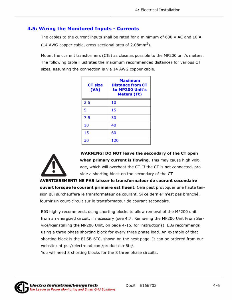
4: Electrical Installation
4.5: Wiring the Monitored Inputs - Currents
The cables to the current inputs shall be rated for a minimum of 600 V AC and 10 A
(14 AWG copper cable, cross sectional area of 2.08mm2).
Mount the current transformers (CTs) as close as possible to the MP200 unit’s meters.
The following table illustrates the maximum recommended distances for various CT
sizes, assuming the connection is via 14 AWG copper cable.
WARNING! DO NOT leave the secondary of the CT open
when primary current is flowing. This may cause high volt-
age, which will overheat the CT. If the CT is not connected, pro-
vide a shorting block on the secondary of the CT.
AVERTISSEMENT! NE PAS laisser le transformateur de courant secondaire
ouvert lorsque le courant primaire est fluent. Cela peut provoquer une haute ten-
sion qui surchauffera le transformateur de courant. Si ce dernier n'est pas branché,
fournir un court-circuit sur le transformateur de courant secondaire.
EIG highly recommends using shorting blocks to allow removal of the MP200 unit
from an energized circuit, if necessary (see 4.7: Removing the MP200 Unit From Ser-
vice/Reinstalling the MP200 Unit, on page 4-15, for instructions). EIG recommends
using a three phase shorting block for every three phase load. An example of that
shorting block is the EI SB-6TC, shown on the next page. It can be ordered from our
website: https://electroind.com/product/sb-6tc/.
You will need 8 shorting blocks for the 8 three phase circuits.
CT size (VA)
Maximum Distance from CT to MP200 Unit’s
Meters (Ft)
2.5 10
5 15
7.5 30
10 40
15 60
30 120
Doc# E166703 4-6Electro Industries/GaugeTechThe Leader In Power Monitoring and Smart Grid SolutionsElectro Industries/GaugeTechThe Leader In Power Monitoring and Smart Grid SolutionsElectro Industries/GaugeTechThe Leader In Power Monitoring and Smart Grid Solutions
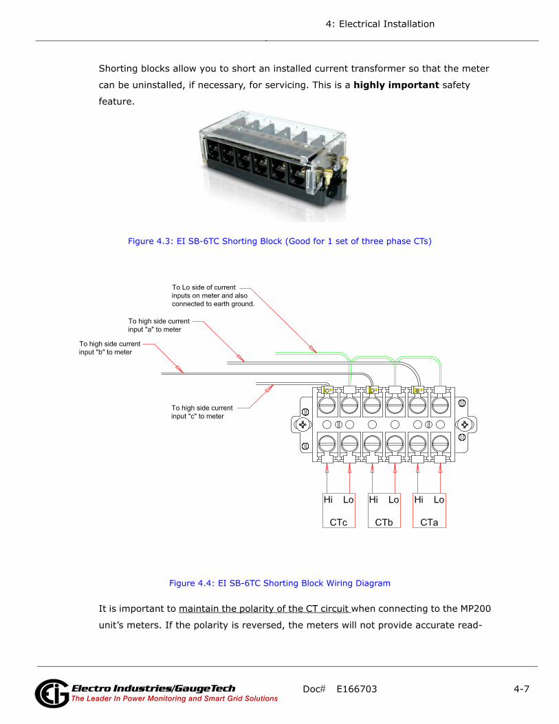
4: Electrical Installation
Shorting blocks allow you to short an installed current transformer so that the meter
can be uninstalled, if necessary, for servicing. This is a highly important safety
feature.
Figure 4.3: EI SB-6TC Shorting Block (Good for 1 set of three phase CTs)
Figure 4.4: EI SB-6TC Shorting Block Wiring Diagram
It is important to maintain the polarity of the CT circuit when connecting to the MP200
unit’s meters. If the polarity is reversed, the meters will not provide accurate read-
Doc# E166703 4-7Electro Industries/GaugeTechThe Leader In Power Monitoring and Smart Grid SolutionsElectro Industries/GaugeTechThe Leader In Power Monitoring and Smart Grid SolutionsElectro Industries/GaugeTechThe Leader In Power Monitoring and Smart Grid Solutions

4: Electrical Installation
ings. CT polarities are dependent upon correct connection of CT leads and the direc-
tion CTs are facing when clamped around the conductors.
EIG recommande fortement d'utiliser les blocs de court-circuit pour permettre le
retrait de l'unité MP200 d'un circuit sous tension, si nécessaire (voir Section 4.7 pour
les instructions). EIG recommande l'aide d'un bloc de court-circuit triphasé pour
chaque charge en trois phases. Un exemple de ce bloc de court-circuit est le EI SB-
6TC, figurant sur la page suivante. Il peut être commandé à partir de notre site Web :
www.electroind.com. Vous aurez besoin de huit blocs de court-circuit pour les huit cir-
cuits triphasés. Les blocs de court-circuit vous permettent de court-circuiter un trans-
formateur de courant installé de telle sorte que le compteur peut être désinstallé, si
nécessaire, pour l'entretien. C'est une fonction sécuritaire très importante.
4.6: Electrical Connection Diagrams
The following pages contain electrical connection diagrams for the MP200 unit’s
meters, which now support Delta connections as well as Wye. Choose the diagram
that best suits your application. Be sure to maintain the CT polarity when wiring.
The diagrams are presented in the following order:
1. Three Phase, 4-Wire Wye Service with Direct Voltage and 3 CT Connection for
Metering 8 Three Phase Loads (MP200-Y)
2. Three-Phase, 4-Wire Wye Service with 3 PT Voltage and 3 CT Connection for Meter-
ing 8 Three Phase Loads (MP200-Y)
3. Three-Phase, 3-Wire Delta Service with Direct Voltage and 2 CT Connection for
Metering 8 three Phase Loads (MP200-Y)
4. Single Phase, 2-Wire Service with Direct Voltage and 3 CT Connection for Metering
24 Single Phase Loads (MP200-S)
5. Single Phase, 3-Wire Service with Direct Voltage and 2 CT Connection for Metering
8 Single Phase Loads (MP200-S)
6. Single phase, 3-Wire Service with Direct Voltage and 1 CT Connection for Metering
24 Single Phase Loads(MP200-S)
IMPORTANT! Tous les transformateurs de courant doivent avoir un côté à la terre
pour réduire les risques de choc. EIG recommande fortement d'utiliser les blocs de
court-circuit comme le EI SB-6TC de sorte que le compteur peut être retiré de sa
fonction tandis que le transformateur de courant est sous tension.
Doc# E166703 4-8Electro Industries/GaugeTechThe Leader In Power Monitoring and Smart Grid SolutionsElectro Industries/GaugeTechThe Leader In Power Monitoring and Smart Grid SolutionsElectro Industries/GaugeTechThe Leader In Power Monitoring and Smart Grid Solutions
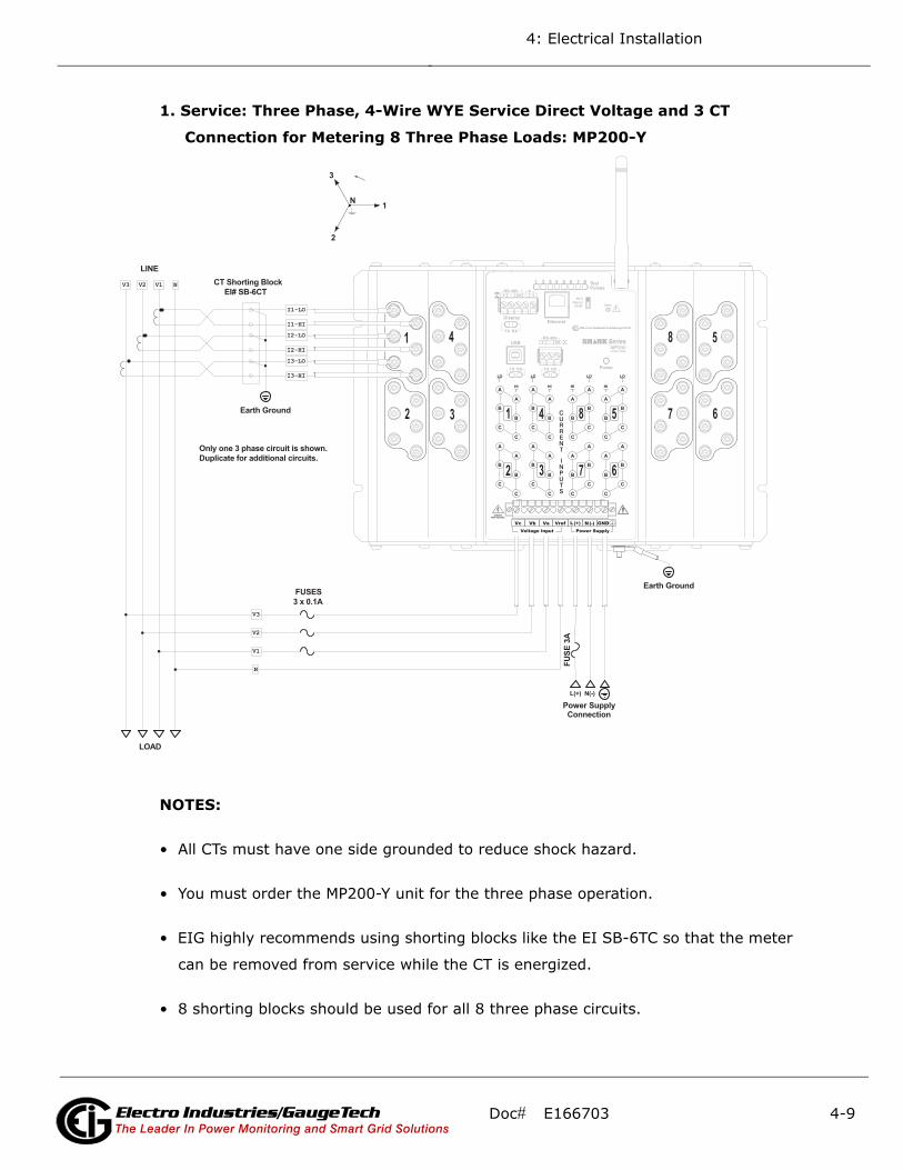
4: Electrical Installation
1. Service: Three Phase, 4-Wire WYE Service Direct Voltage and 3 CT
Connection for Metering 8 Three Phase Loads: MP200-Y
NOTES:
• All CTs must have one side grounded to reduce shock hazard.
• You must order the MP200-Y unit for the three phase operation.
• EIG highly recommends using shorting blocks like the EI SB-6TC so that the meter
can be removed from service while the CT is energized.
• 8 shorting blocks should be used for all 8 three phase circuits.
I1-LO
LOAD
V2 V1
LINE
N
I1-HI
V1
I3-HI
V3
V3
I2-HII2-LO
V2
N
I3-LO
SERVICES: WYE, 4 WIRE.
Power Supply Connection
CT Shorting Block EI# SB-6CT
Only one 3 phase circuit is shown. Duplicate for additional circuits.
Earth Ground
Earth Ground
FUSES3 x 0.1A
FU
SE 3
A
CONNECTION TYPE: Direct Voltage, CTs3
2
1N
L(+) N(-)
Doc# E166703 4-9Electro Industries/GaugeTechThe Leader In Power Monitoring and Smart Grid SolutionsElectro Industries/GaugeTechThe Leader In Power Monitoring and Smart Grid SolutionsElectro Industries/GaugeTechThe Leader In Power Monitoring and Smart Grid Solutions
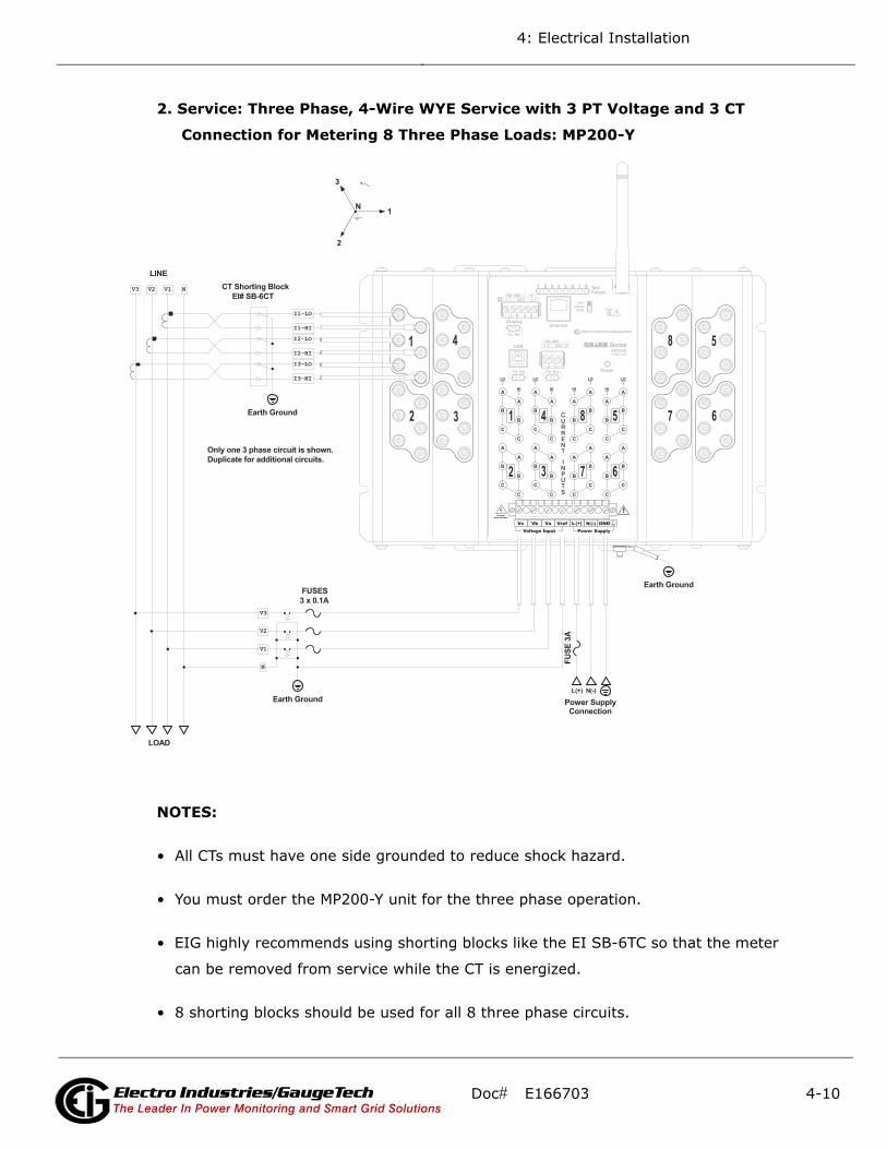
4: Electrical Installation
2. Service: Three Phase, 4-Wire WYE Service with 3 PT Voltage and 3 CT
Connection for Metering 8 Three Phase Loads: MP200-Y
NOTES:
• All CTs must have one side grounded to reduce shock hazard.
• You must order the MP200-Y unit for the three phase operation.
• EIG highly recommends using shorting blocks like the EI SB-6TC so that the meter
can be removed from service while the CT is energized.
• 8 shorting blocks should be used for all 8 three phase circuits.
3
2
I1-LO
LOAD
V2 V1
LINE
N
1
L(+) N(-)
I1-HI
V1
I3-HI
V3
V3
I2-HII2-LO
N
V2
N
I3-LO
SERVICES: WYE, 4 WIRE.
Power Supply Connection
CT Shorting Block EI# SB-6CT
Only one 3 phase circuit is shown. Duplicate for additional circuits.
Earth Ground
Earth Ground
FUSES3 x 0.1A
FU
SE 3
A
Earth Ground
CONNECTION TYPE: 3PTs, CTs
Doc# E166703 4-10Electro Industries/GaugeTechThe Leader In Power Monitoring and Smart Grid SolutionsElectro Industries/GaugeTechThe Leader In Power Monitoring and Smart Grid SolutionsElectro Industries/GaugeTechThe Leader In Power Monitoring and Smart Grid Solutions

4: Electrical Installation
3. Service: Three Phase, 3-Wire Delta Service with Direct Voltage and 2 CT
Connection for Metering 8 Three Phase Loads: MP200-Y
NOTES:
• All CTs must have one side grounded to reduce shock hazard.
• You must order the MP200-Y unit for the three phase operation.
• EIG highly recommends using shorting blocks like the EI SB-6TC so that the meter
can be removed from service while the CT is energized.
• 8 shorting blocks should be used for all 8 three phase circuits.
I1-LO
LOAD
V2 V1
LINE
I1-HI
V1
I3-HI
V3
V3
V2
I3-LO
SERVICES: DELTA, 3 WIRE.
Power Supply Connection
CT Shorting Block EI# SB-6CT
Only one 3 phase circuit is shown. Duplicate for additional circuits.
Earth Ground
Earth Ground
Earth Ground
FUSES2 x 0.1A
FU
SE 3
A
CONNECTION TYPE: NO PTs, 2 CTsC
B A
L(+) N(-)
Not connected to meter
Doc# E166703 4-11Electro Industries/GaugeTechThe Leader In Power Monitoring and Smart Grid SolutionsElectro Industries/GaugeTechThe Leader In Power Monitoring and Smart Grid SolutionsElectro Industries/GaugeTechThe Leader In Power Monitoring and Smart Grid Solutions

4: Electrical Installation
4. Single Phase, 2-Wire Service with Direct Voltage and 3 CT Connection for
Metering 24 Single Phase Loads: MP200-S
NOTES:
• All CTs must have one side grounded to reduce shock hazard.
• You must order the MP200-S unit for single phase 2-wire operation.
• EIG highly recommends using shorting blocks like the EI SB-6TC so that the meter
can be removed from service while the CT is energized.
I1-LO
LOADS
VL
LINE
N
1
L(+) N(-)
I1-HI
VL
I3-HI
I2-HII2-LO
N
N
I3-LO
SERVICES: SINGLE PHASE, 2-WIRE CONNECTION TYPE: Direct Voltage, CTs
Power Supply Connection
Only three circuits are shown. Duplicate for additional circuits.
Short Voltage inputs together
Earth Ground
CT Shorting Block EI# SB-6CT
Earth Ground
FU
SE 3
A
Doc# E166703 4-12Electro Industries/GaugeTechThe Leader In Power Monitoring and Smart Grid SolutionsElectro Industries/GaugeTechThe Leader In Power Monitoring and Smart Grid SolutionsElectro Industries/GaugeTechThe Leader In Power Monitoring and Smart Grid Solutions

4: Electrical Installation
5. Service: Single Phase, 3-Wire Service with Direct Voltage and 2 CT
Connection for Metering 8 Single Phase Loads: MP200-Y
NOTES:
• All CTs must have one side grounded to reduce shock hazard.
• You must order the MP200-Y unit for this operation.
• EIG highly recommends using shorting blocks like the EI SB-6TC so that the meter
can be removed from service while the CT is energized.
• A higher density connection is available using the single phase version of the meter.
The difference is that the higher density uses a single CT for both legs of a three
wire system.
2
I1-LO
LOAD
V2 V1
LINE
N
1
L(+) N(-)
I1-HI
V1
I2-HII2-LO
N
V2
N
SERVICES: SINGLE PHASE, 3-WIRE
Power Supply Connection
CT Shorting Block EI# SB-6CT
Only one circuit is shown. Duplicate for additional circuits.
Earth Ground
Earth Ground
FUSES2 x 0.1A
FU
SE 3
A
CONNECTION TYPE: Direct Voltage, CTs
Doc# E166703 4-13Electro Industries/GaugeTechThe Leader In Power Monitoring and Smart Grid SolutionsElectro Industries/GaugeTechThe Leader In Power Monitoring and Smart Grid SolutionsElectro Industries/GaugeTechThe Leader In Power Monitoring and Smart Grid Solutions
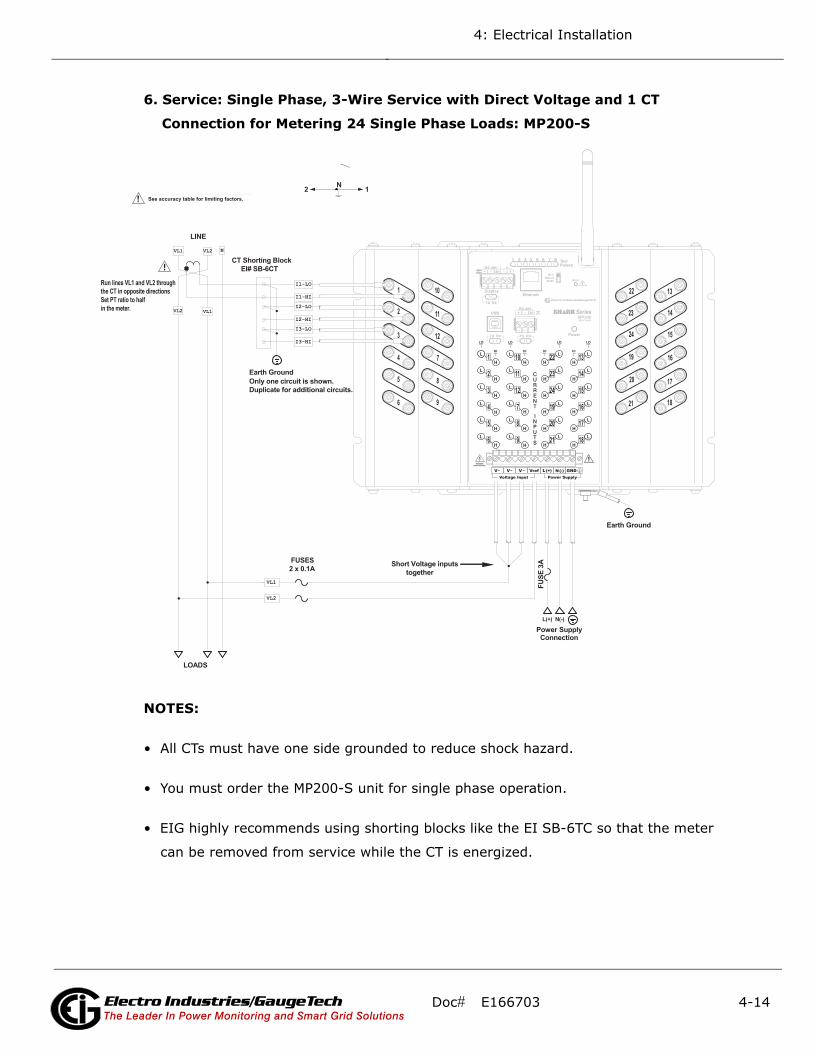
4: Electrical Installation
6. Service: Single Phase, 3-Wire Service with Direct Voltage and 1 CT
Connection for Metering 24 Single Phase Loads: MP200-S
NOTES:
• All CTs must have one side grounded to reduce shock hazard.
• You must order the MP200-S unit for single phase operation.
• EIG highly recommends using shorting blocks like the EI SB-6TC so that the meter
can be removed from service while the CT is energized.
I1-LO
LOADS
VL1
LINE
N
L(+) N(-)
I1-HI
VL1
I3-HI
I2-HII2-LO
VL2
I3-LO
SERVICE: SINGLE PHASE, 3-WIRE CONNECTION TYPE: Direct Voltage, CTsTo monitor 24 individual loads.See accuracy table for limiting factors.
Power Supply Connection
Only one circuit is shown. Duplicate for additional circuits.
Short Voltage inputs together
Earth Ground
CT Shorting Block EI# SB-6CT
Earth Ground
FU
SE 3
A
VL2
VL1VL2
2 1N
FUSES2 x 0.1A
Run lines VL1 and VL2 throughthe CT in opposite directionsSet PT ratio to halfin the meter.
Doc# E166703 4-14Electro Industries/GaugeTechThe Leader In Power Monitoring and Smart Grid SolutionsElectro Industries/GaugeTechThe Leader In Power Monitoring and Smart Grid SolutionsElectro Industries/GaugeTechThe Leader In Power Monitoring and Smart Grid Solutions

4: Electrical Installation
4.7: Removing the MP200 Unit From Service/Reinstalling the MP200 Unit
WARNINGS!
• Before attempting any work on the MP200 unit or associated
components, all power must be removed and all circuits
de-energized. Verify the de-energized status of all circuitry with
appropriate portable measuring equipment.
• If the MP200 unit was directly wired to the CTs without a shorting
block as disclosed in this manual, then all the electrical primary
circuits must be shut down prior to removing the meter. Failure to
do so could result in possible high voltage on the open CT terminals.
AVERTISSEMENT!
• Avant de tenter un travail sur l'unité MP200 ou sur les composants associés, toutes
les alimentations doivent être enlevées et tous les circuits mis hors tension. Vérifiez
le statut de mise hors tension de tous les circuits avec l'équipement de mesure por-
table approprié.
• Si l'unité MP200 a été directement branchée sur le transformateur de courant dans
un court-circuit comme indiqué dans ce manuel, alors tous les circuits électriques
primaires doivent être éteints avant d'enlever le compteur. Le non-respect de cette
indication pourrait résulter à une haute tension sur les bornes de transformateur de
courant ouvert.
Doc# E166703 4-15Electro Industries/GaugeTechThe Leader In Power Monitoring and Smart Grid SolutionsElectro Industries/GaugeTechThe Leader In Power Monitoring and Smart Grid SolutionsElectro Industries/GaugeTechThe Leader In Power Monitoring and Smart Grid Solutions

4: Electrical Installation
4.7.1: Removing the MP200 Unit Using the EI SB-6TC Shorting Block
NOTE: This procedure uses the EI SB-6TC shorting block. For shorting blocks other
than that, see the instructions in 4.7.2: Removing the MP200 Unit Using a Shorting
Block Other than the EI SB-6TC, on page 4-19.
1. Verify that all circuits are de-energized and locked out.
2. All shorting blocks shall be wired as per the wiring diagrams in this manual with
one side of each CT at ground potential. Refer to Figure 4.4: EI SB-6TC Shorting
Block Wiring Diagram, on page 4-7.
3. All shorting blocks are equipped with 4 brass shorting screws stored in the four
corners of the base. Refer to the figure below.
IMPORTANT! If all 4 brass shorting screws are not on the shorting blocks do not
continue until replacements are obtained.
IMPORTANT! Si toutes les quatre vis de court-circuit en laiton ne sont pas sur les
blocs de court-circuit, ne pas continuer jusqu'à ce que vous obteniez des
remplacements.
Figure 4.5: EI SB-6TC Shorting Block with Wiring Installed
4. Select one of the shorting blocks.
Doc# E166703 4-16Electro Industries/GaugeTechThe Leader In Power Monitoring and Smart Grid SolutionsElectro Industries/GaugeTechThe Leader In Power Monitoring and Smart Grid SolutionsElectro Industries/GaugeTechThe Leader In Power Monitoring and Smart Grid Solutions
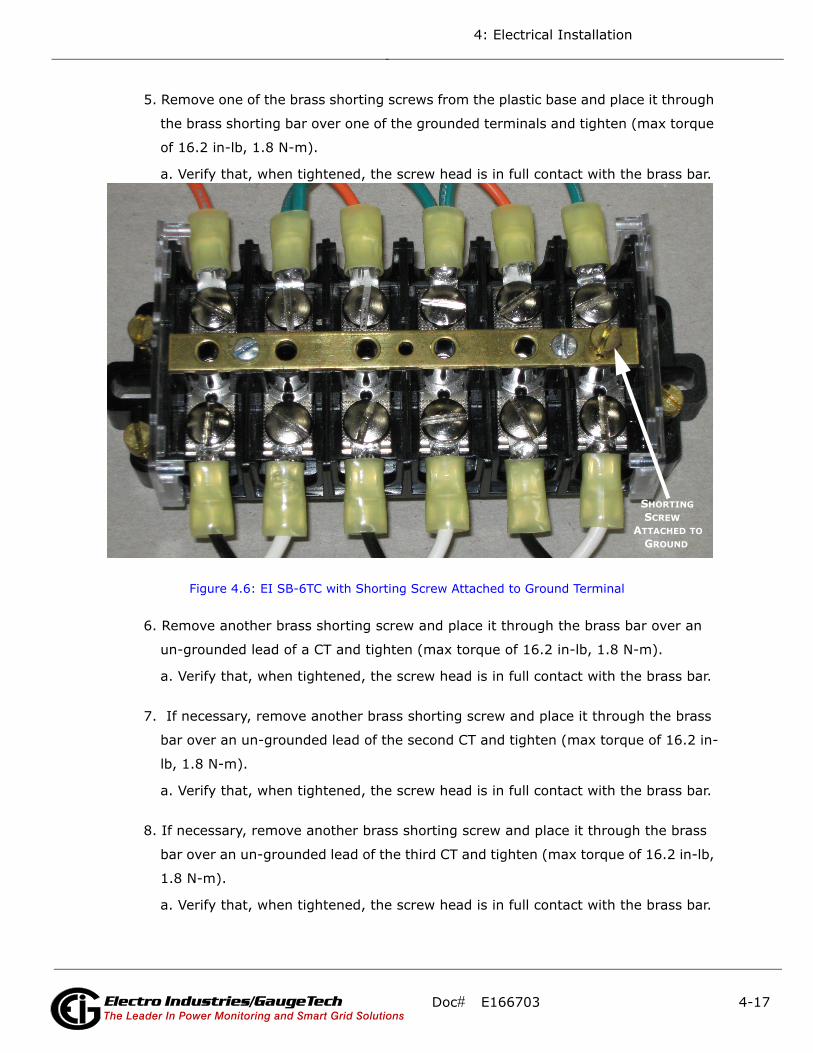
4: Electrical Installation
5. Remove one of the brass shorting screws from the plastic base and place it through
the brass shorting bar over one of the grounded terminals and tighten (max torque
of 16.2 in-lb, 1.8 N-m).
a. Verify that, when tightened, the screw head is in full contact with the brass bar.
Figure 4.6: EI SB-6TC with Shorting Screw Attached to Ground Terminal
6. Remove another brass shorting screw and place it through the brass bar over an
un-grounded lead of a CT and tighten (max torque of 16.2 in-lb, 1.8 N-m).
a. Verify that, when tightened, the screw head is in full contact with the brass bar.
7. If necessary, remove another brass shorting screw and place it through the brass
bar over an un-grounded lead of the second CT and tighten (max torque of 16.2 in-
lb, 1.8 N-m).
a. Verify that, when tightened, the screw head is in full contact with the brass bar.
8. If necessary, remove another brass shorting screw and place it through the brass
bar over an un-grounded lead of the third CT and tighten (max torque of 16.2 in-lb,
1.8 N-m).
a. Verify that, when tightened, the screw head is in full contact with the brass bar.
SHORTING SCREWATTACHED TO GROUND
Doc# E166703 4-17Electro Industries/GaugeTechThe Leader In Power Monitoring and Smart Grid SolutionsElectro Industries/GaugeTechThe Leader In Power Monitoring and Smart Grid SolutionsElectro Industries/GaugeTechThe Leader In Power Monitoring and Smart Grid Solutions

4: Electrical Installation
9. If necessary, repeat steps 4 through 8a until all CTs are shorted.
Figure 4.7: EI SB-6TC with All CTs Shorted Properly
10. Mark or record the location of the current input wires on the MP200 unit.
11. Disconnect all current input wires from the MP200 unit.
12. Remove all connectors from the MP200 unit.
13. Remove the Ground connection from the stud on the MP200 unit (see Figure 4.2:
MP200 Unit Connections, on page 4-5).
14. Remove the 4 mounting screws holding the MP200 unit in place.
15. Remove the MP200 unit.
Doc# E166703 4-18Electro Industries/GaugeTechThe Leader In Power Monitoring and Smart Grid SolutionsElectro Industries/GaugeTechThe Leader In Power Monitoring and Smart Grid SolutionsElectro Industries/GaugeTechThe Leader In Power Monitoring and Smart Grid Solutions

4: Electrical Installation
4.7.1.1: Reinstalling the MP200 Unit Using the EI SB-6TC Shorting Block
1. Place the MP200 unit in the desired location over the mounting holes.
2. Insert and tighten all 4 mounting screws.
3. Connect the Ground wire to the stud on the MP200 unit and tighten the nut to 8.8
in-lb (1 N-m) (see Figure 4.2: MP200 Unit Connections, on page 4-5).
4. Connect the current inputs to the MP200 unit as per the locations marked on the
wires or recorded. Refer to Figure 4.4: EI SB-6TC Shorting Block Wiring Diagram,
on page 4-7, and the wiring diagrams in this manual.
5. Tighten nuts to 8.8 in-lb (1 N-m).
6. Insert all connectors into the MP200 unit.
7. Select a shorting block and remove the screws shorting the un-grounded side of
the CTs and screw them into their storage locations in the corner of the block (max
torque of 1 in-lb, 0.11 N-m).
IMPORTANT! The screw that is grounding the brass bar should be removed last
and also stored on the block.
IMPORTANT! La vis qui met la barre en laiton à la terre doit être retirée en dernier
et également stocké sur le bloc.
8. If necessary, repeat step 7 until all shorting blocks are returned to their operating
configuration.
9. Apply power to the meter and energize all circuits.
10. Verify correct operation of the MP200 unit.
4.7.2: Removing the MP200 Unit Using a Shorting Block Other than the EI SB-6TC
1. Verify that all circuits are de-energized and locked out.
2. All shorting blocks shall be wired as per the wiring diagrams in this manual with
one side of each CT at ground potential.
3. Using the shorting blocks short the ungrounded side of all CTs to ground.
Doc# E166703 4-19Electro Industries/GaugeTechThe Leader In Power Monitoring and Smart Grid SolutionsElectro Industries/GaugeTechThe Leader In Power Monitoring and Smart Grid SolutionsElectro Industries/GaugeTechThe Leader In Power Monitoring and Smart Grid Solutions

4: Electrical Installation
4. Mark or record the location of the current input wires on the MP200 unit.
5. Disconnect all current input wires from the MP200 unit.
6. Remove all connectors from the MP200 unit.
7. Remove the Ground connection from the stud on the MP200 unit (see Figure 4.2:
MP200 Unit Connections, on page 4-5).
8. Remove the 4 mounting screws holding the MP200 unit in place.
4.7.2.1: Reinstalling the MP200 Unit Using a Shorting Block Other than the EI SB-6TC
1. Place the MP200 unit in the desired location over the mounting holes.
2. Insert and tighten all 4 mounting screws.
3. Connect the Ground wire to the stud on the MP200 unit and tighten the nut to 8.8
in-lb (1 N-m) (see Figure 4.2: MP200 Unit Connections, on page 4-5).
4. Connect the current inputs to the MP200 unit as per the locations marked on the
wires or recorded.
5. Tighten nuts to 8.8 in-lb (1 N-m).
6. Insert all connectors into the MP200 unit.
7. Remove the short from all the ungrounded sides of all the CTs.
8. Apply power to the meter and energize all circuits.
9. Verify correct operation of the MP200 unit.
Doc# E166703 4-20Electro Industries/GaugeTechThe Leader In Power Monitoring and Smart Grid SolutionsElectro Industries/GaugeTechThe Leader In Power Monitoring and Smart Grid SolutionsElectro Industries/GaugeTechThe Leader In Power Monitoring and Smart Grid Solutions

5: Communicating with the Meter
5: Communicating with the Meter
5.1: MP200 Metering System Communication
The MP200 metering system provides three independent Communication ports.
The first port, Com 1, is an RS485 port speaking Modbus ASCII or Modbus RTU. This
port also has an optional Ethernet/WiFi that supports both RJ45 and wireless Ethernet
and that uses Modbus TCP protocol. The MP200 unit has a switch that enables either
the standard RS485 or optional Ethernet for Port 1.
The second port, Com 2, provides USB serial connection.
The third port, Com3, is an RS485 port. It can be used for the optional display (see
Chapter10: Using the Optional Display, on page 10-1).
Figure 5.1: MP200 Unit Communication Ports
NOTE: If the installation requires that the WiFi antenna be remotely located, a 50
Ohm coaxial cable (approved for use at 2.4 GHz) with M/F SMA connectors shall be
used. Make the cable as short as possible (maximum 20 foot, 6.1 m) to avoid losing
too much power.
Com 3:RS485/ Display Port
Optional Com 1:WiFi/RJ45 Ethernet
Com 1:RS485 Com 2:USB Com 1 Port Switch:
switches between RS485 and Ethernet/WiFi
Doc# E166703 5-1Electro Industries/GaugeTechThe Leader In Power Monitoring and Smart Grid SolutionsElectro Industries/GaugeTechThe Leader In Power Monitoring and Smart Grid Solutions
Electro Industries/GaugeTechThe Leader In Power Monitoring and Smart Grid Solutions
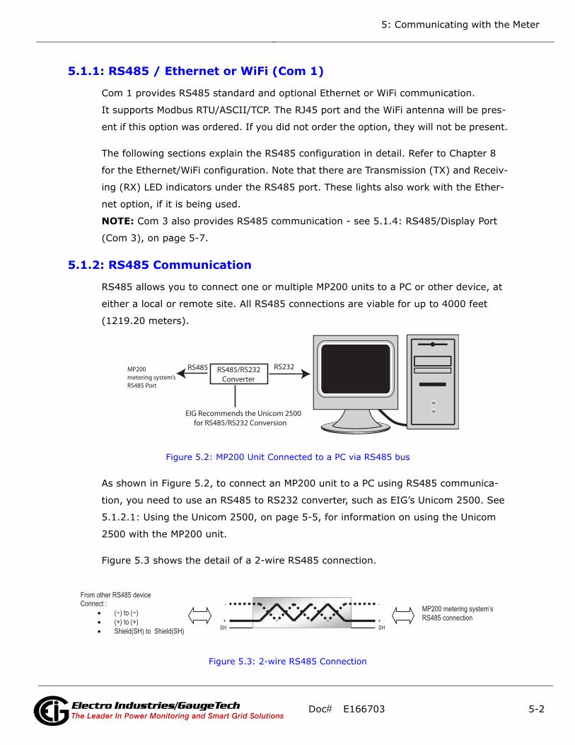
5: Communicating with the Meter
5.1.1: RS485 / Ethernet or WiFi (Com 1)
Com 1 provides RS485 standard and optional Ethernet or WiFi communication.
It supports Modbus RTU/ASCII/TCP. The RJ45 port and the WiFi antenna will be pres-
ent if this option was ordered. If you did not order the option, they will not be present.
The following sections explain the RS485 configuration in detail. Refer to Chapter 8
for the Ethernet/WiFi configuration. Note that there are Transmission (TX) and Receiv-
ing (RX) LED indicators under the RS485 port. These lights also work with the Ether-
net option, if it is being used.
NOTE: Com 3 also provides RS485 communication - see 5.1.4: RS485/Display Port
(Com 3), on page 5-7.
5.1.2: RS485 Communication
RS485 allows you to connect one or multiple MP200 units to a PC or other device, at
either a local or remote site. All RS485 connections are viable for up to 4000 feet
(1219.20 meters).
Figure 5.2: MP200 Unit Connected to a PC via RS485 bus
As shown in Figure 5.2, to connect an MP200 unit to a PC using RS485 communica-
tion, you need to use an RS485 to RS232 converter, such as EIG’s Unicom 2500. See
5.1.2.1: Using the Unicom 2500, on page 5-5, for information on using the Unicom
2500 with the MP200 unit.
Figure 5.3 shows the detail of a 2-wire RS485 connection.
Figure 5.3: 2-wire RS485 Connection
RS485/RS232 Converter
EIG Recommends the Unicom 2500 for RS485/RS232 Conversion
RS485 RS232 MP200 metering system’sRS485 Port
From other RS485 device Connect :
• ( − ) to ( − )
• (+) to (+)
• Shield(SH) to Shield(SH)
MP200 metering system’s
RS485 connection +
-
SH
+
-
SH
Doc# E166703 5-2Electro Industries/GaugeTechThe Leader In Power Monitoring and Smart Grid SolutionsElectro Industries/GaugeTechThe Leader In Power Monitoring and Smart Grid Solutions
Electro Industries/GaugeTechThe Leader In Power Monitoring and Smart Grid Solutions

5: Communicating with the Meter
NOTES:
For All RS485 Connections:
• Use a shielded twisted pair cable and ground the shield, preferably at one location
only.
• Establish point-to-point configurations for each device on an RS485 bus: connect
(+) terminals to (+) terminals; connect (-) terminals to (-) terminals.
• You may connect up to 31 devices on a single bus using RS485. Before assembling
the bus, each device must have a unique address: refer to Chapter 10 in the
Communicator EXT 4.0 and MeterManager EXT Software User Manual. You can
download this manual at:
http://www.electroind.com/dl_page_software-downloads.html
• Protect cables from sources of electrical noise.
• Avoid both “Star” and “Tee” connections (see Figure 5.5: Incorrect “T” and “Star”
Topologies, on page 5-4).
• No more than two cables should be connected at any one point on an RS485 net-
work, whether the connections are for devices, converters, or terminal strips.
• Include all segments when calculating the total cable length of a network. If you are
not using an RS485 repeater, the maximum length for cable connecting all devices
is 4000 feet (1219.20 meters).
• Connect shield to RS485 Master and individual devices as shown in Figure 5.4:
RS485 Daisy Chain Connection, on page 5-4. You may also connect the shield to
earth-ground at one point.
• Termination Resistors (RT) may be needed on both ends for longer length transmis-
sion lines. When they are used, the value of the Termination Resistors is deter-
mined by the electrical parameters of the cable.
Doc# E166703 5-3Electro Industries/GaugeTechThe Leader In Power Monitoring and Smart Grid SolutionsElectro Industries/GaugeTechThe Leader In Power Monitoring and Smart Grid Solutions
Electro Industries/GaugeTechThe Leader In Power Monitoring and Smart Grid Solutions

5: Communicating with the Meter
Figure 5.4 shows a representation of an RS485 Daisy Chain connection. Refer to
5.1.2.1: Using the Unicom 2500, on page 5-5 for details on RS485 connection for the
Unicom 2500.
Figure 5.4: RS485 Daisy Chain Connection
Figure 5.5: Incorrect “T” and “Star” Topologies
Twisted pair, shielded (SH) cable
RT
+ - SH
RT
+ - SH + - SH + - SH
Slave device 1 Slave device 2
Last Slave device N Master device
Earth Connection, preferably at
single location
Twisted pair, shielded (SH) cable Twisted pair, shielded (SH) cable
Twisted pair, shielded (SH) cable
+ - SH
+ - SH
+ - SH
Slave device 1
Slave device 2
Last Slave device N Master device
Earth Connection, preferably at
single location
Twisted pair, shielded (SH) cable Twisted pair, shielded (SH) cable
Twisted pair, shielded (SH) cable
+ -SH
Twisted pair, shielded (SH) cable
Twisted pair, shielded (SH) cable Twisted pair, shielded (SH) cable
+ - SH +- SH
+ - SH + -SH
Master device
Slave device 1 Slave device 2
Slave device 3 Slave device 4
RT RT
+ - SH
Long stub results “T” connection that can cause interference problem!
“STAR” connection can cause interference problem!
Doc# E166703 5-4Electro Industries/GaugeTechThe Leader In Power Monitoring and Smart Grid SolutionsElectro Industries/GaugeTechThe Leader In Power Monitoring and Smart Grid Solutions
Electro Industries/GaugeTechThe Leader In Power Monitoring and Smart Grid Solutions
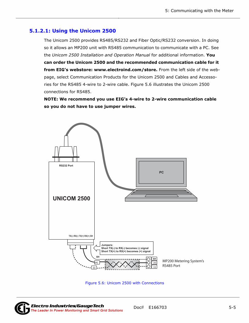
5: Communicating with the Meter
5.1.2.1: Using the Unicom 2500
The Unicom 2500 provides RS485/RS232 and Fiber Optic/RS232 conversion. In doing
so it allows an MP200 unit with RS485 communication to communicate with a PC. See
the Unicom 2500 Installation and Operation Manual for additional information. You
can order the Unicom 2500 and the recommended communication cable for it
from EIG’s webstore: www.electroind.com/store. From the left side of the web-
page, select Communication Products for the Unicom 2500 and Cables and Accesso-
ries for the RS485 4-wire to 2-wire cable. Figure 5.6 illustrates the Unicom 2500
connections for RS485.
NOTE: We recommend you use EIG’s 4-wire to 2-wire communication cable
so you do not have to use jumper wires.
Figure 5.6: Unicom 2500 with Connections
(+)
(-)
SH
(+)
(-)
SH
Jumpers: Short TX(-) to RX(-) becomes (-) signal Short TX(+) to RX(+) becomes (+) signal
TX(-) RX(-) TX(+) RX(+) SH
RS232 Port
UNICOM 2500
PC
MP200 Metering System’sRS485 Port
Doc# E166703 5-5Electro Industries/GaugeTechThe Leader In Power Monitoring and Smart Grid SolutionsElectro Industries/GaugeTechThe Leader In Power Monitoring and Smart Grid Solutions
Electro Industries/GaugeTechThe Leader In Power Monitoring and Smart Grid Solutions

5: Communicating with the Meter
The Unicom 2500 can be configured for either 4-
wire or 2-wire RS485 connections. Since the
MP200 unit uses a 2-wire connection, unless
you are using the RS485 4-wire to 2-wire
communication cable available from EIG’s
online store, you will need to add jumper wires
to convert the Unicom 2500 to the 2-wire config-
uration. As shown in Figure 5.6, you connect the
"RX-" and "TX-" terminals with a jumper wire to
make the "-" terminal, and connect the "RX+"
and "TX+" terminals with a jumper wire to make
the "+" terminal. See the figure on the right for Figure 5.7: Unicom 2500 Settings
the Unicom 2500’s settings. The Unicom’s baud rate must match the baud rate of the
MP200 unit’s RS485 port: you set the baud rate by turning the screw to point at the
rate you want.
5.1.3: USB Port (Com 2)
The MP200 unit’s Com 2 USB port allows it to communicate with a computer that has
a USB 1.1 or USB 2.0 Host port. The MP200 unit's USB port is configured to operate
as a virtual serial communication channel that the PC sees as a simple COM port. The
USB virtual serial communication channel:
• Is compatible with standard USB cables that terminate with a USB Type B plug (see
Figure 5.8)
• The maximum length of the USB cable is 5 meters. Greater lengths require hubs or
active extension cables (active repeaters).
Figure 5.8: USB Type B Plug
If you are using a PC with the Windows® 7 (or later) Operating System, connect the
USB cable from your PC to the unit’s USB port on the front panel. The Windows® 7
Operating System will install a driver for you. For earlier operating systems, EIG pro-
vides a driver for PC compatible computers. The driver configures the computer's USB
v
Set switch to DCESet the
baud rate
Set switch to HD
Doc# E166703 5-6Electro Industries/GaugeTechThe Leader In Power Monitoring and Smart Grid SolutionsElectro Industries/GaugeTechThe Leader In Power Monitoring and Smart Grid Solutions
Electro Industries/GaugeTechThe Leader In Power Monitoring and Smart Grid Solutions
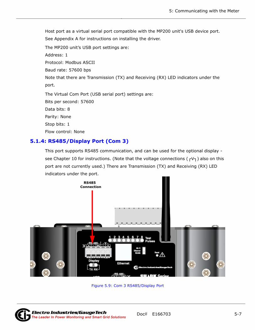
5: Communicating with the Meter
Host port as a virtual serial port compatible with the MP200 unit's USB device port.
See Appendix A for instructions on installing the driver.
The MP200 unit’s USB port settings are:
Address: 1
Protocol: Modbus ASCII
Baud rate: 57600 bps
Note that there are Transmission (TX) and Receiving (RX) LED indicators under the
port.
The Virtual Com Port (USB serial port) settings are:
Bits per second: 57600
Data bits: 8
Parity: None
Stop bits: 1
Flow control: None
5.1.4: RS485/Display Port (Com 3)
This port supports RS485 communication, and can be used for the optional display -
see Chapter 10 for instructions. (Note that the voltage connections (V) also on this
port are not currently used.) There are Transmission (TX) and Receiving (RX) LED
indicators under the port.
Figure 5.9: Com 3 RS485/Display Port
RS485 Connection
Doc# E166703 5-7Electro Industries/GaugeTechThe Leader In Power Monitoring and Smart Grid SolutionsElectro Industries/GaugeTechThe Leader In Power Monitoring and Smart Grid Solutions
Electro Industries/GaugeTechThe Leader In Power Monitoring and Smart Grid Solutions
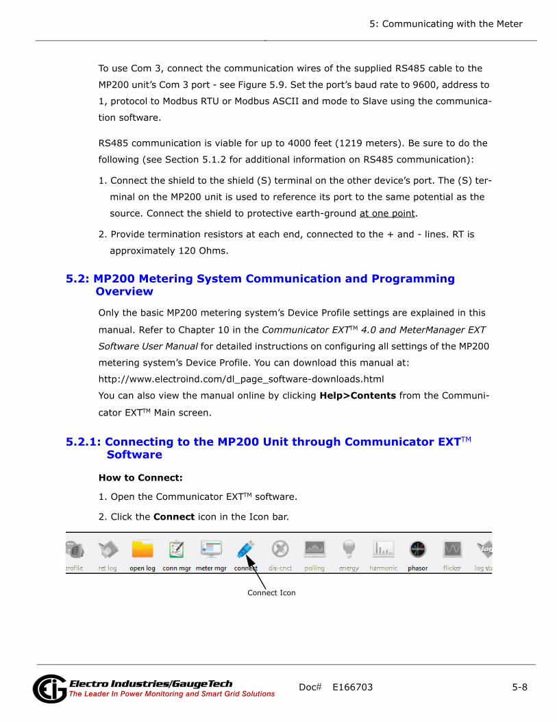
5: Communicating with the Meter
To use Com 3, connect the communication wires of the supplied RS485 cable to the
MP200 unit’s Com 3 port - see Figure 5.9. Set the port’s baud rate to 9600, address to
1, protocol to Modbus RTU or Modbus ASCII and mode to Slave using the communica-
tion software.
RS485 communication is viable for up to 4000 feet (1219 meters). Be sure to do the
following (see Section 5.1.2 for additional information on RS485 communication):
1. Connect the shield to the shield (S) terminal on the other device’s port. The (S) ter-
minal on the MP200 unit is used to reference its port to the same potential as the
source. Connect the shield to protective earth-ground at one point.
2. Provide termination resistors at each end, connected to the + and - lines. RT is
approximately 120 Ohms.
5.2: MP200 Metering System Communication and Programming Overview
Only the basic MP200 metering system’s Device Profile settings are explained in this
manual. Refer to Chapter 10 in the Communicator EXTTM 4.0 and MeterManager EXT
Software User Manual for detailed instructions on configuring all settings of the MP200
metering system’s Device Profile. You can download this manual at:
http://www.electroind.com/dl_page_software-downloads.html
You can also view the manual online by clicking Help>Contents from the Communi-
cator EXTTM Main screen.
5.2.1: Connecting to the MP200 Unit through Communicator EXTTM Software
How to Connect:
1. Open the Communicator EXTTM software.
2. Click the Connect icon in the Icon bar.
Connect Icon
Doc# E166703 5-8Electro Industries/GaugeTechThe Leader In Power Monitoring and Smart Grid SolutionsElectro Industries/GaugeTechThe Leader In Power Monitoring and Smart Grid Solutions
Electro Industries/GaugeTechThe Leader In Power Monitoring and Smart Grid Solutions

5: Communicating with the Meter
3. You can connect to the MP200 unit using RS485, Ethernet, or the USB port (for
Ethernet connection, the Ethernet/WiFi option must be installed). See the screens
below.
RS485connection
USB connection
Ethernetconnection
Doc# E166703 5-9Electro Industries/GaugeTechThe Leader In Power Monitoring and Smart Grid SolutionsElectro Industries/GaugeTechThe Leader In Power Monitoring and Smart Grid Solutions
Electro Industries/GaugeTechThe Leader In Power Monitoring and Smart Grid Solutions

5: Communicating with the Meter
4. Click the Connect button. You will see the Device Status screen, confirming con-
nection to the MP200 unit. Click OK.
The fields on the right of the screen give you information about the connected
MP200 unit:
• Boot: the version of the Boot firmware the meter currently has.
• Run: the version of the Runtime firmware the meter currently has.
• State: information about the meter, e.g., shown above Run Mode, Logging
Enabled, Battery OK means that the meter is running, logging is enabled for the
meter, and the meter battery has sufficient operating power.
• V-Switch: the number of the V-SwitchTM key currently installed in the meter.
• On Time: the date and time the meter was last powered on.
5. Click the Profile icon in the Title Bar.
6. You will see the MP200 metering system’s Device Profile screen. The menu on the
left side of the screen lets you navigate between Settings screens (see screens on
next page).
NOTE: The settings you see on the first screen depend on your MP200 unit’s circuit
configuration.
Doc# E166703 5-10Electro Industries/GaugeTechThe Leader In Power Monitoring and Smart Grid SolutionsElectro Industries/GaugeTechThe Leader In Power Monitoring and Smart Grid Solutions
Electro Industries/GaugeTechThe Leader In Power Monitoring and Smart Grid Solutions

5: Communicating with the Meter
Tree Menu
MP200 Unit with Three Phase Configuration - MP200-Y: 2 CT Delta
MP200 Unit with Three Phase Configuration - MP200-Y
Doc# E166703 5-11Electro Industries/GaugeTechThe Leader In Power Monitoring and Smart Grid SolutionsElectro Industries/GaugeTechThe Leader In Power Monitoring and Smart Grid Solutions
Electro Industries/GaugeTechThe Leader In Power Monitoring and Smart Grid Solutions

5: Communicating with the Meter
MP200 Unit with Single Phase Configuration - MP200-SNOTE: See 5.2.1.1: Additional MP200 Unit Device Profile Settings, on page 5-15, for instructions onusing the screens shown above and on the previous page.
Doc# E166703 5-12Electro Industries/GaugeTechThe Leader In Power Monitoring and Smart Grid SolutionsElectro Industries/GaugeTechThe Leader In Power Monitoring and Smart Grid Solutions
Electro Industries/GaugeTechThe Leader In Power Monitoring and Smart Grid Solutions

5: Communicating with the Meter
7. Click Communications. You will see the screen shown below. Use this screen to
enter communication settings for the MP200 unit's communications ports.
Valid Communication Settings are as follows:
COM 1: RS485/ Ethernet/WIFI (optional)
Address: 1-247
Baud Rate: 9600, 19200, 38400, 57600 (For WiFi/Ethernet, only 57600)
Protocol: Modbus RTU/ASCII (For WiFi/Ethernet, only Modbus RTU)
Response Delay: 0-750ms
Parity: Odd, Even or None
COM 2: USB port
Protocol: MODBUS ASCII
Baud Rate: 57600
Address: 1
Doc# E166703 5-13Electro Industries/GaugeTechThe Leader In Power Monitoring and Smart Grid SolutionsElectro Industries/GaugeTechThe Leader In Power Monitoring and Smart Grid Solutions
Electro Industries/GaugeTechThe Leader In Power Monitoring and Smart Grid Solutions
5: Communicating with the Meter
NOTE: The USB port settings are fixed, i.e., they cannot be changed.
COM 3: RS485/Display Port
Address: 1-247
Protocol: Modbus RTU/ASCII
Baud Rate: 9600, 19200, 38400, 57600
Response Delay: 0-750ms
NOTE: Click the (1)Default to Ethernet or (2)Default to Display button to set either
the (1)Ethernet settings for COM1 or (2)Display settings for COM3, to their default
values.
See Chapter 10 in the Communicator EXT 4.0 and MeterManager 4.0 Software
User Manual. You can download this manual at:
https://electroind.com/downloads/software-downloads/
8. When changes are complete, click the Update Device button to send a new profile
to the meter.
9. Click Exit to leave the Device Profile or click other menu items to change other
aspects of the Device Profile (see the following section for instructions).
Doc# E166703 5-14Electro Industries/GaugeTechThe Leader In Power Monitoring and Smart Grid SolutionsElectro Industries/GaugeTechThe Leader In Power Monitoring and Smart Grid Solutions
Electro Industries/GaugeTechThe Leader In Power Monitoring and Smart Grid Solutions
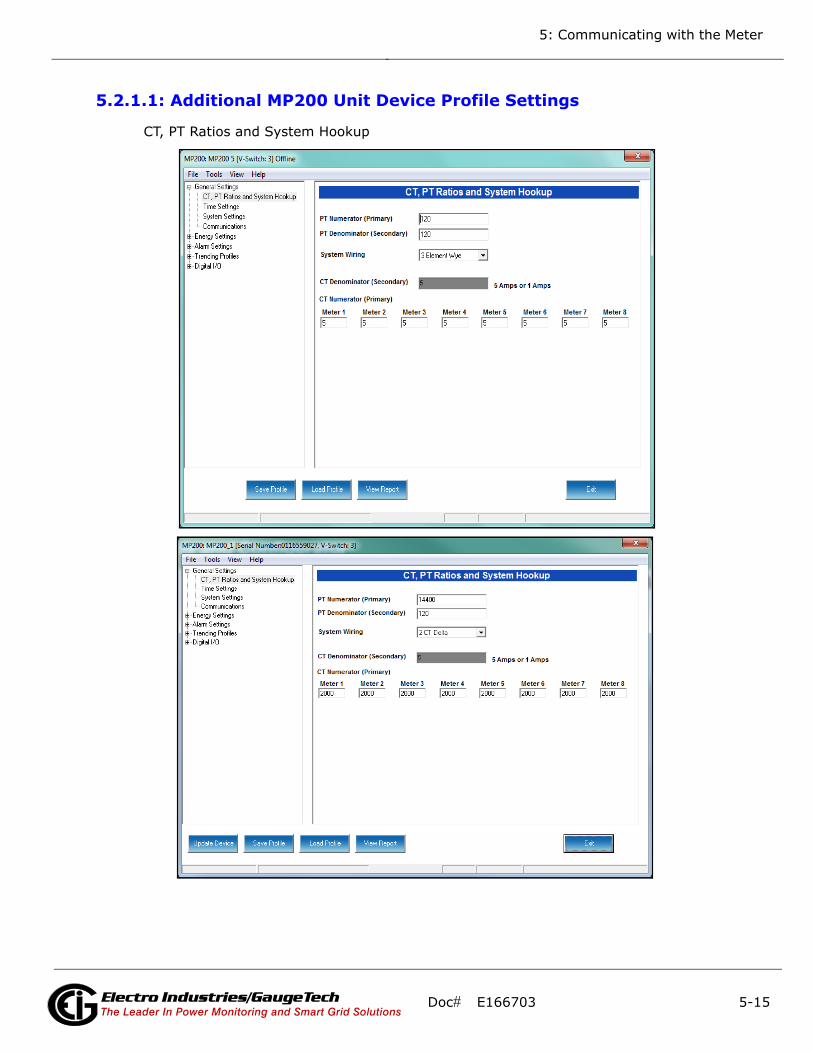
5: Communicating with the Meter
5.2.1.1: Additional MP200 Unit Device Profile Settings
CT, PT Ratios and System Hookup
Doc# E166703 5-15Electro Industries/GaugeTechThe Leader In Power Monitoring and Smart Grid SolutionsElectro Industries/GaugeTechThe Leader In Power Monitoring and Smart Grid Solutions
Electro Industries/GaugeTechThe Leader In Power Monitoring and Smart Grid Solutions

5: Communicating with the Meter
Note that the settings you see on the screen depend on your MP200 unit’s circuit con-
figuration. The top screen on the previous page is for an MP200 unit with the three
phase Wye circuit configuration; the bottom screen is for an MP200 unit with the three
phase 2 CT Delta circuit configuration, and the screen on this page is for an MP200
unit with the single phase circuit configuration.
The settings for this screen are as follows:
PT Ratios
PT Numerator (Primary): 1 - 99999999
PT Denominator (Secondary): 40 - 65535
System Wiring
3 Element Wye; Single Phase; 2 CT Delta
CT Ratios
CT Numerator (Primary): 1 - 65535
Doc# E166703 5-16Electro Industries/GaugeTechThe Leader In Power Monitoring and Smart Grid SolutionsElectro Industries/GaugeTechThe Leader In Power Monitoring and Smart Grid Solutions
Electro Industries/GaugeTechThe Leader In Power Monitoring and Smart Grid Solutions

5: Communicating with the Meter
CT Denominator (Secondary): 5 or 1 Amp, depending on the MP200 unit’s ordered
option. This field is display only - it cannot be changed.
Example Settings:
For a system that has 14400V primary with a 120V secondary line to neutral (PT Ratio
of 120:1), set the following PT Ratios in the entry fields:
PT Numerator (Primary): 14400
PT Denominator (Secondary): 120
For a CT of 2000/5A, set the following:
CT Numerator (Primary): 2000
Energy, Power Scaling, and Averaging Method
The screen fields and acceptable entries are as follows:
Energy Settings
Energy Digits: 5; 6; 7; 8
Doc# E166703 5-17Electro Industries/GaugeTechThe Leader In Power Monitoring and Smart Grid SolutionsElectro Industries/GaugeTechThe Leader In Power Monitoring and Smart Grid Solutions
Electro Industries/GaugeTechThe Leader In Power Monitoring and Smart Grid Solutions

5: Communicating with the Meter
Energy Decimal Places: 0 - 6
Energy Scale: unit; kilo (K); Mega (M)
Example: a reading for Digits: 8; Decimals: 3; Scale: K would be formatted as
00123.456k
Power Settings
Apparent Power (VA) Calculation Method: Arithmetic Sum; Vector Sum
Power Direction: View as Load; View as Generator
Flip Power Factor Sign: No; Yes
Watts Direction: Unidirectional; Bidirectional
Demand Averaging
Type: Block or Rolling
Interval (Block demand) or Sub-Interval (Rolling demand) in minutes: 5; 15; 30; 60
Number of Subintervals: 1; 2; 3; 4
Interval Window: This field is display only. It is the product of the values entered in
the Sub-Interval and Number of Subintervals fields.
NOTE: You will only see the Number of Subintervals and Interval Window fields if you
select Rolling Demand.
Doc# E166703 5-18Electro Industries/GaugeTechThe Leader In Power Monitoring and Smart Grid SolutionsElectro Industries/GaugeTechThe Leader In Power Monitoring and Smart Grid Solutions
Electro Industries/GaugeTechThe Leader In Power Monitoring and Smart Grid Solutions
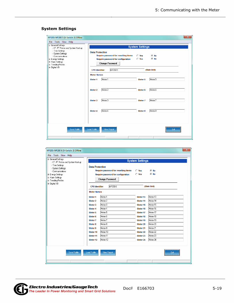
5: Communicating with the Meter
System Settings
Doc# E166703 5-19Electro Industries/GaugeTechThe Leader In Power Monitoring and Smart Grid SolutionsElectro Industries/GaugeTechThe Leader In Power Monitoring and Smart Grid Solutions
Electro Industries/GaugeTechThe Leader In Power Monitoring and Smart Grid Solutions
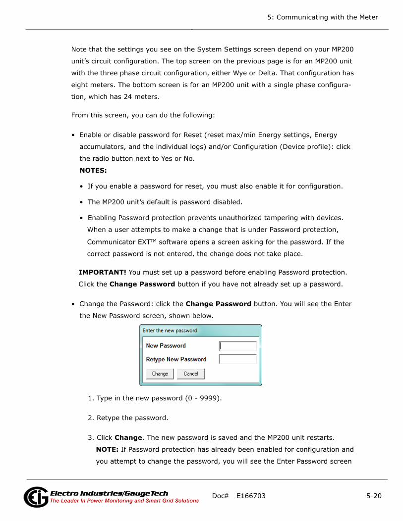
5: Communicating with the Meter
Note that the settings you see on the System Settings screen depend on your MP200
unit’s circuit configuration. The top screen on the previous page is for an MP200 unit
with the three phase circuit configuration, either Wye or Delta. That configuration has
eight meters. The bottom screen is for an MP200 unit with a single phase configura-
tion, which has 24 meters.
From this screen, you can do the following:
• Enable or disable password for Reset (reset max/min Energy settings, Energy
accumulators, and the individual logs) and/or Configuration (Device profile): click
the radio button next to Yes or No.
NOTES:
• If you enable a password for reset, you must also enable it for configuration.
• The MP200 unit’s default is password disabled.
• Enabling Password protection prevents unauthorized tampering with devices.
When a user attempts to make a change that is under Password protection,
Communicator EXTTM software opens a screen asking for the password. If the
correct password is not entered, the change does not take place.
IMPORTANT! You must set up a password before enabling Password protection.
Click the Change Password button if you have not already set up a password.
• Change the Password: click the Change Password button. You will see the Enter
the New Password screen, shown below.
1. Type in the new password (0 - 9999).
2. Retype the password.
3. Click Change. The new password is saved and the MP200 unit restarts.
NOTE: If Password protection has already been enabled for configuration and
you attempt to change the password, you will see the Enter Password screen
Doc# E166703 5-20Electro Industries/GaugeTechThe Leader In Power Monitoring and Smart Grid SolutionsElectro Industries/GaugeTechThe Leader In Power Monitoring and Smart Grid Solutions
Electro Industries/GaugeTechThe Leader In Power Monitoring and Smart Grid Solutions
5: Communicating with the Meter
after you click Change Password. Enter the old password and click OK to
proceed with the password change.
• Change the MP200 metering system’s identification label: input a new label for the
MP200 unit into the CPU Identifier field.
• Enter a name for the eight meters in a three phase circuit configuration, or the 24
meters in a single phase circuit configuration, so that you can easily identify each
meter’s information. These names are used throughout the software, e.g., in the
logging and polling screens.
For example, if you have a shopping mall with 8 stores, each having a three phase
system that is attached to the MP200-Y, you can name the meters Store 1 - Store
8, to identify each meter with its store. Then when you look at the polling screens
or logging screens, you can easily identify each store’s data, without needing to
check the circuit configuration.
Doc# E166703 5-21Electro Industries/GaugeTechThe Leader In Power Monitoring and Smart Grid SolutionsElectro Industries/GaugeTechThe Leader In Power Monitoring and Smart Grid Solutions
Electro Industries/GaugeTechThe Leader In Power Monitoring and Smart Grid Solutions
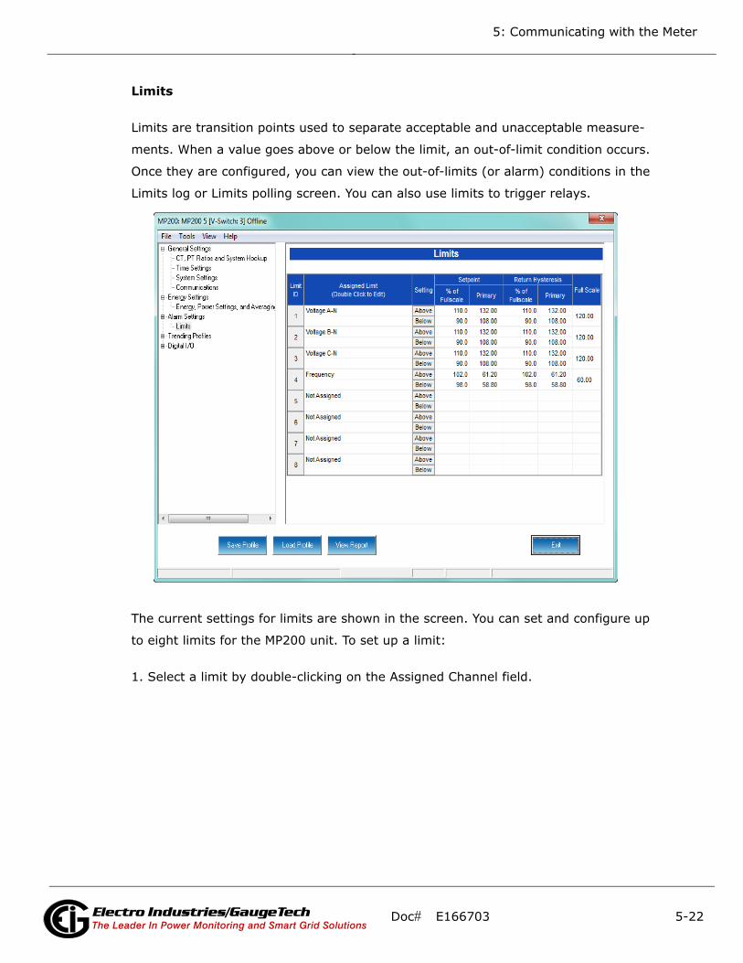
5: Communicating with the Meter
Limits
Limits are transition points used to separate acceptable and unacceptable measure-
ments. When a value goes above or below the limit, an out-of-limit condition occurs.
Once they are configured, you can view the out-of-limits (or alarm) conditions in the
Limits log or Limits polling screen. You can also use limits to trigger relays.
The current settings for limits are shown in the screen. You can set and configure up
to eight limits for the MP200 unit. To set up a limit:
1. Select a limit by double-clicking on the Assigned Channel field.
Doc# E166703 5-22Electro Industries/GaugeTechThe Leader In Power Monitoring and Smart Grid SolutionsElectro Industries/GaugeTechThe Leader In Power Monitoring and Smart Grid Solutions
Electro Industries/GaugeTechThe Leader In Power Monitoring and Smart Grid Solutions
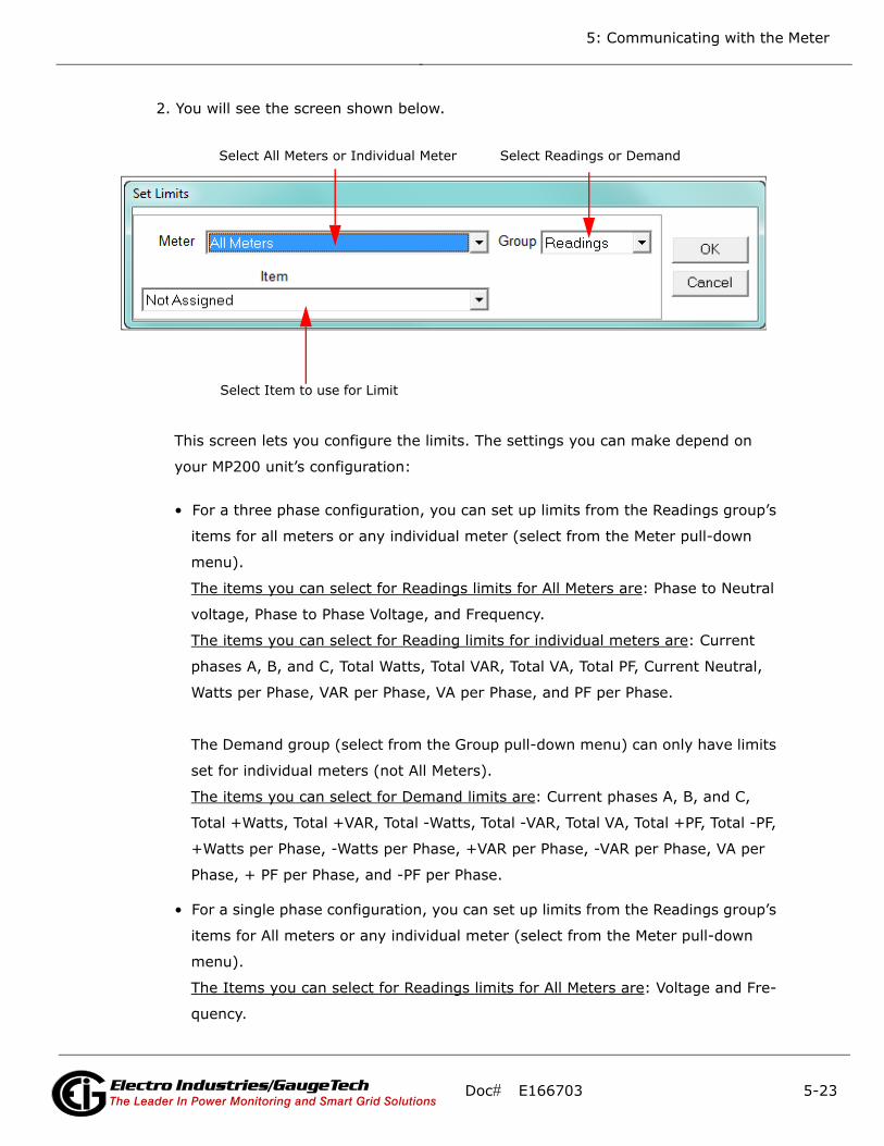
5: Communicating with the Meter
2. You will see the screen shown below.
This screen lets you configure the limits. The settings you can make depend on
your MP200 unit’s configuration:
• For a three phase configuration, you can set up limits from the Readings group’s
items for all meters or any individual meter (select from the Meter pull-down
menu).
The items you can select for Readings limits for All Meters are: Phase to Neutral
voltage, Phase to Phase Voltage, and Frequency.
The items you can select for Reading limits for individual meters are: Current
phases A, B, and C, Total Watts, Total VAR, Total VA, Total PF, Current Neutral,
Watts per Phase, VAR per Phase, VA per Phase, and PF per Phase.
The Demand group (select from the Group pull-down menu) can only have limits
set for individual meters (not All Meters).
The items you can select for Demand limits are: Current phases A, B, and C,
Total +Watts, Total +VAR, Total -Watts, Total -VAR, Total VA, Total +PF, Total -PF,
+Watts per Phase, -Watts per Phase, +VAR per Phase, -VAR per Phase, VA per
Phase, + PF per Phase, and -PF per Phase.
• For a single phase configuration, you can set up limits from the Readings group’s
items for All meters or any individual meter (select from the Meter pull-down
menu).
The Items you can select for Readings limits for All Meters are: Voltage and Fre-
quency.
Select All Meters or Individual Meter Select Readings or Demand
Select Item to use for Limit
Doc# E166703 5-23Electro Industries/GaugeTechThe Leader In Power Monitoring and Smart Grid SolutionsElectro Industries/GaugeTechThe Leader In Power Monitoring and Smart Grid Solutions
Electro Industries/GaugeTechThe Leader In Power Monitoring and Smart Grid Solutions
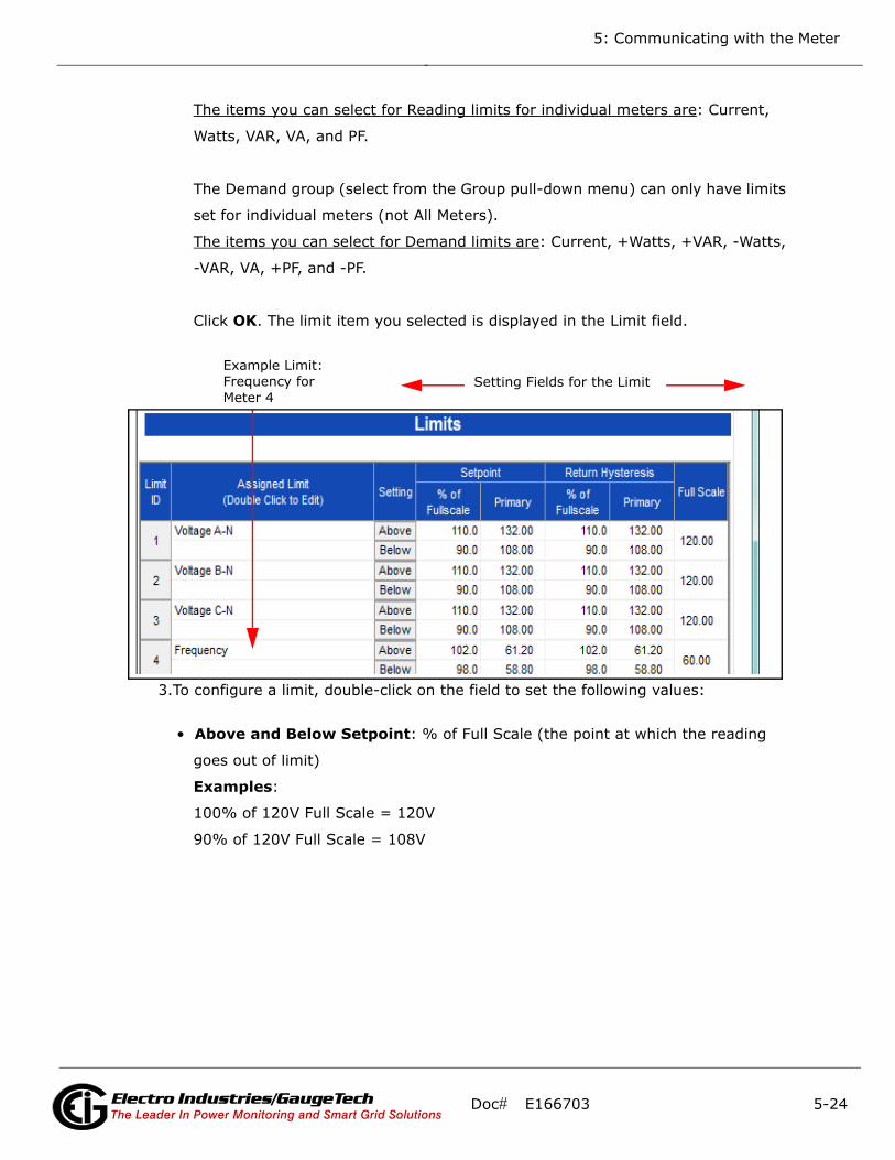
5: Communicating with the Meter
The items you can select for Reading limits for individual meters are: Current,
Watts, VAR, VA, and PF.
The Demand group (select from the Group pull-down menu) can only have limits
set for individual meters (not All Meters).
The items you can select for Demand limits are: Current, +Watts, +VAR, -Watts,
-VAR, VA, +PF, and -PF.
Click OK. The limit item you selected is displayed in the Limit field.
3.To configure a limit, double-click on the field to set the following values:
• Above and Below Setpoint: % of Full Scale (the point at which the reading
goes out of limit)
Examples:
100% of 120V Full Scale = 120V
90% of 120V Full Scale = 108V
Example Limit:Frequency for Meter 4
Setting Fields for the Limit
Doc# E166703 5-24Electro Industries/GaugeTechThe Leader In Power Monitoring and Smart Grid SolutionsElectro Industries/GaugeTechThe Leader In Power Monitoring and Smart Grid Solutions
Electro Industries/GaugeTechThe Leader In Power Monitoring and Smart Grid Solutions

5: Communicating with the Meter
• Above and Below Return Hysteresis: the point at which the reading goes
back within limit (see figure below)
Examples:
Above Setpoint = 110%; Below Setpoint = 90%
(Out of Limit above 132V);(Out of Limit below 108V)
Above Return Hysteresis = 105%; Below Return Hysteresis = 95%
(Stay out of Limit until below 126V)(Stay out of Limit until above 114V)
• Primary Fields: These fields are display only. They show what the setpoint and
return hysteresis value are for each limit.
NOTES:
• If you are entering negative limits, be aware that the negative value affects the way
the above and below limits function, since negative numbers are processed as
signed values.
• If the Above Return Hysteresis is greater than the Above Setpoint, the Above Limit
is Disabled; if the Below Return Hysteresis is less than the Below Setpoint, the
Below Limit is Disabled. You may want to use this feature to disable either Above or
Below Limit conditions for a reading.
TIME
Above Limit
condition
Below Limit
condition
Above Limit Trigger point
Return point from Above Limit condition
Below Limit Trigger point
Return point from Below Limit condition
HYSTERESIS
HYSTERESIS
- MEASURED VALUE
(if applicable)
+ MEASURED VALUE
0
Doc# E166703 5-25Electro Industries/GaugeTechThe Leader In Power Monitoring and Smart Grid SolutionsElectro Industries/GaugeTechThe Leader In Power Monitoring and Smart Grid Solutions
Electro Industries/GaugeTechThe Leader In Power Monitoring and Smart Grid Solutions
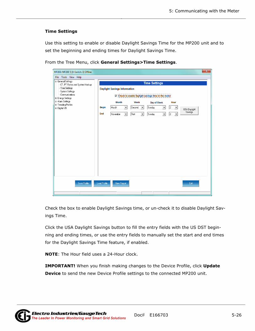
5: Communicating with the Meter
Time Settings
Use this setting to enable or disable Daylight Savings Time for the MP200 unit and to
set the beginning and ending times for Daylight Savings Time.
From the Tree Menu, click General Settings>Time Settings.
Check the box to enable Daylight Savings time, or un-check it to disable Daylight Sav-
ings Time.
Click the USA Daylight Savings button to fill the entry fields with the US DST begin-
ning and ending times, or use the entry fields to manually set the start and end times
for the Daylight Savings Time feature, if enabled.
NOTE: The Hour field uses a 24-Hour clock.
IMPORTANT! When you finish making changes to the Device Profile, click Update
Device to send the new Device Profile settings to the connected MP200 unit.
Doc# E166703 5-26Electro Industries/GaugeTechThe Leader In Power Monitoring and Smart Grid SolutionsElectro Industries/GaugeTechThe Leader In Power Monitoring and Smart Grid Solutions
Electro Industries/GaugeTechThe Leader In Power Monitoring and Smart Grid Solutions

5: Communicating with the Meter
NOTE: Refer to Chapter 10 in the Communicator EXT 4.0 and MeterManager EXT
Software User Manual. You can download this manual at:
https://electroind.com/product-info/communicator-ext-software-application/
Doc# E166703 5-27Electro Industries/GaugeTechThe Leader In Power Monitoring and Smart Grid SolutionsElectro Industries/GaugeTechThe Leader In Power Monitoring and Smart Grid Solutions
Electro Industries/GaugeTechThe Leader In Power Monitoring and Smart Grid Solutions

5: Communicating with the Meter
This page intentionally left blank.
Doc# E166703 5-28Electro Industries/GaugeTechThe Leader In Power Monitoring and Smart Grid SolutionsElectro Industries/GaugeTechThe Leader In Power Monitoring and Smart Grid Solutions
Electro Industries/GaugeTechThe Leader In Power Monitoring and Smart Grid Solutions
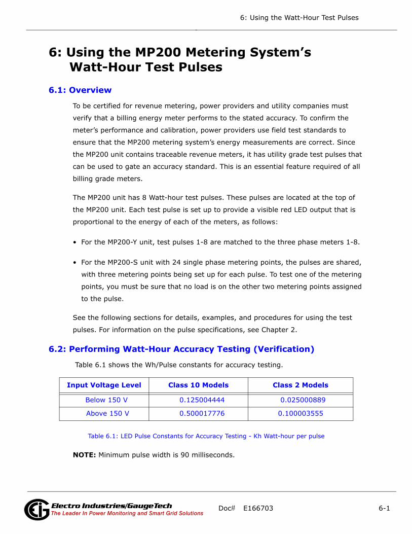
6: Using the Watt-Hour Test Pulses
6: Using the MP200 Metering System’s Watt-Hour Test Pulses
6.1: Overview
To be certified for revenue metering, power providers and utility companies must
verify that a billing energy meter performs to the stated accuracy. To confirm the
meter’s performance and calibration, power providers use field test standards to
ensure that the MP200 metering system’s energy measurements are correct. Since
the MP200 unit contains traceable revenue meters, it has utility grade test pulses that
can be used to gate an accuracy standard. This is an essential feature required of all
billing grade meters.
The MP200 unit has 8 Watt-hour test pulses. These pulses are located at the top of
the MP200 unit. Each test pulse is set up to provide a visible red LED output that is
proportional to the energy of each of the meters, as follows:
• For the MP200-Y unit, test pulses 1-8 are matched to the three phase meters 1-8.
• For the MP200-S unit with 24 single phase metering points, the pulses are shared,
with three metering points being set up for each pulse. To test one of the metering
points, you must be sure that no load is on the other two metering points assigned
to the pulse.
See the following sections for details, examples, and procedures for using the test
pulses. For information on the pulse specifications, see Chapter 2.
6.2: Performing Watt-Hour Accuracy Testing (Verification)
Table 6.1 shows the Wh/Pulse constants for accuracy testing.
Table 6.1: LED Pulse Constants for Accuracy Testing - Kh Watt-hour per pulse
NOTE: Minimum pulse width is 90 milliseconds.
Input Voltage Level Class 10 Models Class 2 Models
Below 150 V 0.125004444 0.025000889
Above 150 V 0.500017776 0.100003555
Doc# E166703 6-1Electro Industries/GaugeTechThe Leader In Power Monitoring and Smart Grid Solutions
Electro Industries/GaugeTechThe Leader In Power Monitoring and Smart Grid Solutions
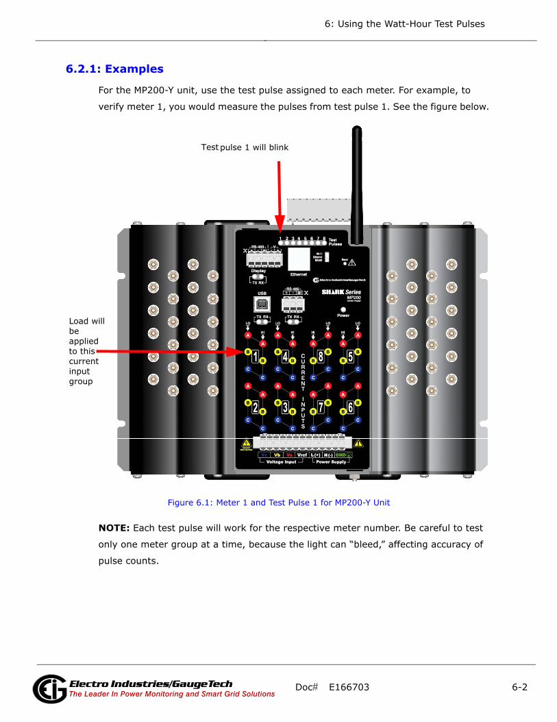
6: Using the Watt-Hour Test Pulses
6.2.1: Examples
For the MP200-Y unit, use the test pulse assigned to each meter. For example, to
verify meter 1, you would measure the pulses from test pulse 1. See the figure below.
Figure 6.1: Meter 1 and Test Pulse 1 for MP200-Y Unit
NOTE: Each test pulse will work for the respective meter number. Be careful to test
only one meter group at a time, because the light can “bleed,” affecting accuracy of
pulse counts.
Load will be applied to this current input group
pulse 1 will blink Test
Doc# E166703 6-2Electro Industries/GaugeTechThe Leader In Power Monitoring and Smart Grid Solutions
Electro Industries/GaugeTechThe Leader In Power Monitoring and Smart Grid Solutions
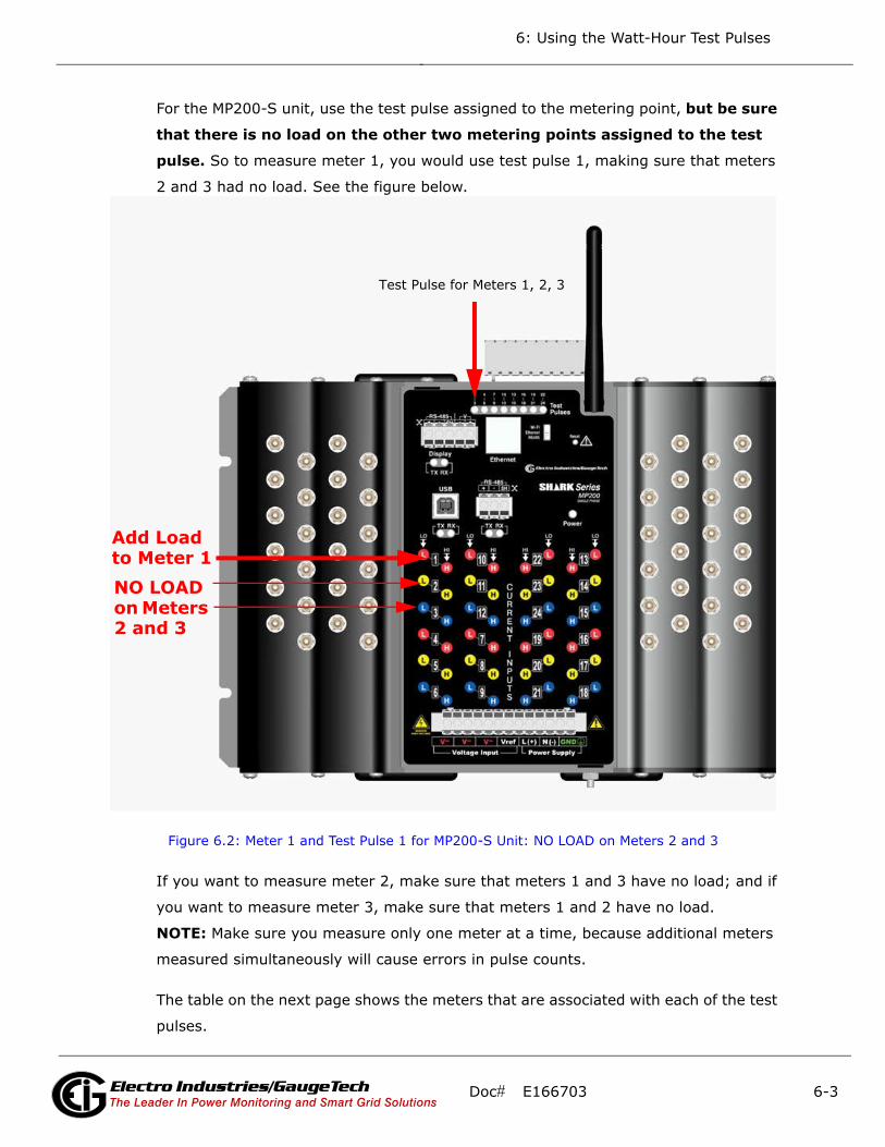
6: Using the Watt-Hour Test Pulses
For the MP200-S unit, use the test pulse assigned to the metering point, but be sure
that there is no load on the other two metering points assigned to the test
pulse. So to measure meter 1, you would use test pulse 1, making sure that meters
2 and 3 had no load. See the figure below.
Figure 6.2: Meter 1 and Test Pulse 1 for MP200-S Unit: NO LOAD on Meters 2 and 3
If you want to measure meter 2, make sure that meters 1 and 3 have no load; and if
you want to measure meter 3, make sure that meters 1 and 2 have no load.
NOTE: Make sure you measure only one meter at a time, because additional meters
measured simultaneously will cause errors in pulse counts.
The table on the next page shows the meters that are associated with each of the test
pulses.
NO LOAD on Meters 2 and 3
Test Pulse for Meters 1, 2, 3
Add Load to Meter 1
Doc# E166703 6-3Electro Industries/GaugeTechThe Leader In Power Monitoring and Smart Grid Solutions
Electro Industries/GaugeTechThe Leader In Power Monitoring and Smart Grid Solutions
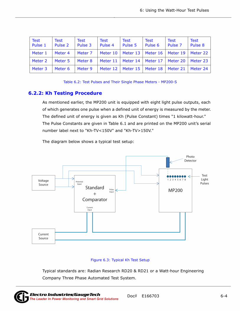
6: Using the Watt-Hour Test Pulses
Table 6.2: Test Pulses and Their Single Phase Meters - MP200-S
6.2.2: Kh Testing Procedure
As mentioned earlier, the MP200 unit is equipped with eight light pulse outputs, each
of which generates one pulse when a defined unit of energy is measured by the meter.
The defined unit of energy is given as Kh (Pulse Constant) times "1 kilowatt-hour."
The Pulse Constants are given in Table 6.1 and are printed on the MP200 unit’s serial
number label next to "Kh-TV<150V" and "Kh-TV>150V."
The diagram below shows a typical test setup:
Figure 6.3: Typical Kh Test Setup
Typical standards are: Radian Research RD20 & RD21 or a Watt-hour Engineering
Company Three Phase Automated Test System.
Test Pulse 1
Test Pulse 2
Test Pulse 3
Test Pulse 4
Test Pulse 5
Test Pulse 6
Test Pulse 7
Test Pulse 8
Meter 1 Meter 4 Meter 7 Meter 10 Meter 13 Meter 16 Meter 19 Meter 22
Meter 2 Meter 5 Meter 8 Meter 11 Meter 14 Meter 17 Meter 20 Meter 23
Meter 3 Meter 6 Meter 9 Meter 12 Meter 15 Meter 18 Meter 21 Meter 24
VoltageSource
CurrentSource
PhotoDetector
Standard+
Comparator
MP200
1 2 3 4 5 6 7 8
PulseInput
CurrentInput
PotentialInput
TestLight
Pulses
Doc# E166703 6-4Electro Industries/GaugeTechThe Leader In Power Monitoring and Smart Grid Solutions
Electro Industries/GaugeTechThe Leader In Power Monitoring and Smart Grid Solutions

6: Using the Watt-Hour Test Pulses
NOTE: Watt-hour Standards offer pulse inputs that take in the CPU's test pulses. The
accuracy is computed by ratio-metrically comparing the period of the meter's pulse to
the period of the Standard's internal pulse. You must program the test pulse value
(Kh) into the Standard for the results to be accurate.
The example test procedure that follows covers only the testing of the three phase
and single phase versions of the MP200 unit. The test procedure used for the Stan-
dard shall be determined by the manufacturer of the Standard used.
Three Phase Test Procedure
1. All circuits and equipment must be de-energized.
2. Connect the three phase potential input lines to "Va", "Vb", and "Vc" and the neu-
tral to "V-Ref" & "GND."
3. Connect power leads to the "L" and "N" connections.
4. Monitor the #1 test pulse by placing the photo detector over the #1 LED.
5. Connect the three phase current inputs to the current terminals associated with the
test pulse LED being monitored. There must be no other current inputs connected.
6. Energize the Standard and the MP200 unit. To assure accuracy, both must be on for
a minimum of 30 minutes.
7. Energize the sources and wait for the outputs to stabilize before starting the test.
8. Start the test as per the appropriate procedure for the Standard and/or comparator
used.
9. When the test is completed, de-energize the sources.
10. Place the photo detector over the next test pulse to be monitored.
11. Repeat steps 5 through 10 until all test pulses are checked.
12. De-energize all circuits and remove power from the Standard, sources, and the
MP200 unit.
13. Disconnect all connections from the MP200 unit.
Doc# E166703 6-5Electro Industries/GaugeTechThe Leader In Power Monitoring and Smart Grid Solutions
Electro Industries/GaugeTechThe Leader In Power Monitoring and Smart Grid Solutions

6: Using the Watt-Hour Test Pulses
Single Phase Test Procedure
NOTE: Unlike the three phase configuration, the single phase configuration uses each
test pulse LED to display the energy measured for three current inputs (see Table
6.2).
1. All circuits and equipment must be de-energized.
2. Connect one line of the potential source to the three "V~" inputs and connect the
other line to the "V-Ref" input and "GND."
3. Connect power to the "L" and "N" connections.
4. Monitor the #1 test pulse by placing the photo detector over the #1 LED.
5. Connect the current input to the first pair of current terminals associated with the
test pulse LED being monitored. Make sure that no other current inputs (refer to
Table 6.2) are connected.
6. Energize the Standard and the MP200 unit. To assure accuracy, both must be on for
a minimum of 30 minutes.
7. Energize the sources and wait for the outputs to stabilize before starting the test.
8. Start the test as per the appropriate procedure for the Standard used.
9. When the test is completed, de-energize the sources.
10. Remove the current connections to the MP200 unit and connect them to the sec-
ond current input pair for the test pulse LED being monitored.
11. Energize the sources and wait at least 5 seconds before starting of test.
12. Start the test as per the appropriate procedure for the Standard and/or compara-
tor used.
13. When the test is completed, de-energize the sources.
14. Remove the current connections from the MP200 unit and connect them to the
third current input pair for the test pulse LED being monitored.
15. Energize the sources and wait at least 5 seconds before starting of test.
Doc# E166703 6-6Electro Industries/GaugeTechThe Leader In Power Monitoring and Smart Grid Solutions
Electro Industries/GaugeTechThe Leader In Power Monitoring and Smart Grid Solutions

6: Using the Watt-Hour Test Pulses
16. Start the test as per the appropriate procedure for the Standard used.
17. When the test is completed, remove the current inputs from the meter.
18. Remove power from the sources.
19. Place the photo detector over the next test pulse LED to be monitored.
20. Repeat 5 through 19 until all current inputs and test pulses have been tested.
21. De-energize all circuits and remove power from the Standard, sources, and the
MP200 unit.
22. Disconnect all connections from the MP200 unit.
Doc# E166703 6-7Electro Industries/GaugeTechThe Leader In Power Monitoring and Smart Grid Solutions
Electro Industries/GaugeTechThe Leader In Power Monitoring and Smart Grid Solutions

6: Using the Watt-Hour Test Pulses
This page intentionally left blank.
Doc# E166703 6-8Electro Industries/GaugeTechThe Leader In Power Monitoring and Smart Grid Solutions
Electro Industries/GaugeTechThe Leader In Power Monitoring and Smart Grid Solutions

7: Using the MP200 CPU’s I/O
7: Using the MP200 Metering System’s I/O
7.1: Overview
The MP200 unit has an embedded relay outputs/digital inputs board.
Figure 7.1: Location of I/O Board
7.2: Digital Output (Relay Contact) / Digital Input Board
The Digital Output/Input card is a combination of relay contact outputs for load
switching or alarming and dry/wet contact sensing or KYZ pulse counting digital
inputs. The outputs are electrically isolated from the inputs and from any other inter-
nal circuits.
• The I/O board’s 2 relay outputs are used for control applications. This is an essen-
tial feature when looking to control equipment on alarm condition or to reduce peak
demand by shutting down equipment or generating a peak demand alarm. The
meter can be configured to trigger relay output when an alarm condition occurs. Up
to 16 limits can be assigned through Communicator EXTTM software - see Chapter 5
in this manual and Chapter 10 in the Communicator EXTTM 4.0 and MeterManager
EXT Software User Manual for instructions.
• The I/O board has 4 KYZ pulse counting inputs. These dry contact inputs are
designed to count pulses from other devices such as gas meters, water meters,
condensate (steam) meters or any other commodity meter that provides a pulse
output. This feature is ideal for a total energy management solution; the informa-
tion it provides can be used as part of a comprehensive energy usage reporting
system.
I/O
Connections
Doc# E166703 7-1Electro Industries/GaugeTechThe Leader In Power Monitoring and Smart Grid SolutionsElectro Industries/GaugeTechThe Leader In Power Monitoring and Smart Grid SolutionsElectro Industries/GaugeTechThe Leader In Power Monitoring and Smart Grid Solutions
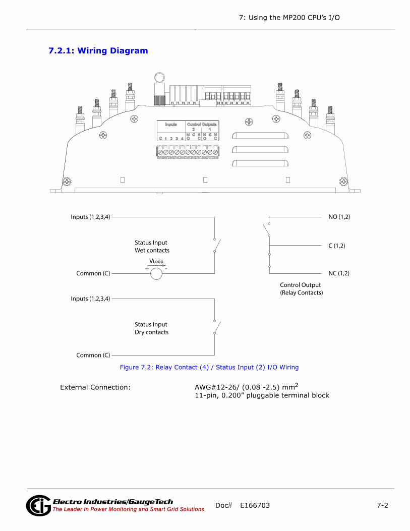
7: Using the MP200 CPU’s I/O
7.2.1: Wiring Diagram
VLoop
+ -
Inputs (1,2,3,4)
Common (C)
Status InputWet contacts
Inputs (1,2,3,4)
Common (C)
Status InputDry contacts
NO (1,2)
NC (1,2)
Control Output(Relay Contacts)
C (1,2)
Figure 7.2: Relay Contact (4) / Status Input (2) I/O Wiring
External Connection: AWG#12-26/ (0.08 -2.5) mm2 11-pin, 0.200” pluggable terminal block
Doc# E166703 7-2Electro Industries/GaugeTechThe Leader In Power Monitoring and Smart Grid SolutionsElectro Industries/GaugeTechThe Leader In Power Monitoring and Smart Grid SolutionsElectro Industries/GaugeTechThe Leader In Power Monitoring and Smart Grid Solutions

8: Using Ethernet Communication
8: Using Ethernet Communication (RJ45 and WiFi)
8.1: Overview
The Ethernet/WiFi option for the MP200 metering system gives Ethernet communica-
tion to Com 1 via either WiFi (Wireless) or RJ45 connections.
• The MP200 unit’s WiFi connection lets you set it up for use in a LAN (Local Area Net-
work), using standard WiFi base stations. Then you can access the MP200 unit to
perform functions directly through any computer on your LAN: the MP200 unit does
not need to be directly connected (wired) to these computers for it to be accessed.
• The MP200 unit’s RJ45 connection lets you use standard Ethernet cable to connect
the MP200 unit to a wired Ethernet network.
To enable Ethernet communication for Com 1, set the switch to WiFi/Ethernet - see
Figure 8.1.
Figure 8.1: Location of Com 1 Switch
Com 1 Switch
Doc# E166703 8-1Electro Industries/GaugeTechThe Leader In Power Monitoring and Smart Grid SolutionsElectro Industries/GaugeTechThe Leader In Power Monitoring and Smart Grid Solutions
Electro Industries/GaugeTechThe Leader In Power Monitoring and Smart Grid Solutions
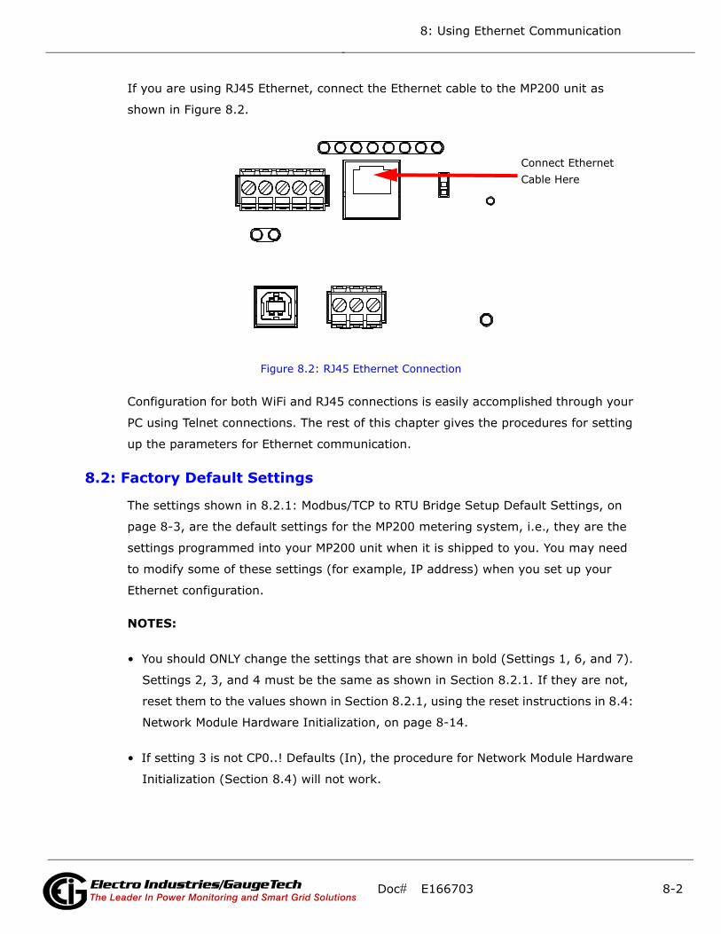
8: Using Ethernet Communication
If you are using RJ45 Ethernet, connect the Ethernet cable to the MP200 unit as
shown in Figure 8.2.
Figure 8.2: RJ45 Ethernet Connection
Configuration for both WiFi and RJ45 connections is easily accomplished through your
PC using Telnet connections. The rest of this chapter gives the procedures for setting
up the parameters for Ethernet communication.
8.2: Factory Default Settings
The settings shown in 8.2.1: Modbus/TCP to RTU Bridge Setup Default Settings, on
page 8-3, are the default settings for the MP200 metering system, i.e., they are the
settings programmed into your MP200 unit when it is shipped to you. You may need
to modify some of these settings (for example, IP address) when you set up your
Ethernet configuration.
NOTES:
• You should ONLY change the settings that are shown in bold (Settings 1, 6, and 7).
Settings 2, 3, and 4 must be the same as shown in Section 8.2.1. If they are not,
reset them to the values shown in Section 8.2.1, using the reset instructions in 8.4:
Network Module Hardware Initialization, on page 8-14.
• If setting 3 is not CP0..! Defaults (In), the procedure for Network Module Hardware
Initialization (Section 8.4) will not work.
Connect EthernetCable Here
Doc# E166703 8-2Electro Industries/GaugeTechThe Leader In Power Monitoring and Smart Grid SolutionsElectro Industries/GaugeTechThe Leader In Power Monitoring and Smart Grid Solutions
Electro Industries/GaugeTechThe Leader In Power Monitoring and Smart Grid Solutions
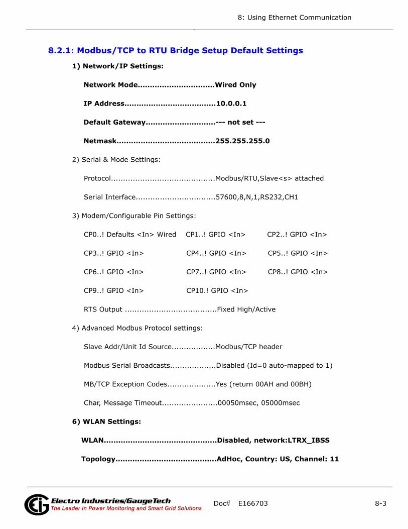
8: Using Ethernet Communication
8.2.1: Modbus/TCP to RTU Bridge Setup Default Settings
1) Network/IP Settings:
Network Mode................................Wired Only
IP Address......................................10.0.0.1
Default Gateway.............................--- not set ---
Netmask.........................................255.255.255.0
2) Serial & Mode Settings:
Protocol...........................................Modbus/RTU,Slave<s> attached
Serial Interface.................................57600,8,N,1,RS232,CH1
3) Modem/Configurable Pin Settings:
CP0..! Defaults <In> Wired CP1..! GPIO <In> CP2..! GPIO <In>
CP3..! GPIO <In> CP4..! GPIO <In> CP5..! GPIO <In>
CP6..! GPIO <In> CP7..! GPIO <In> CP8..! GPIO <In>
CP9..! GPIO <In> CP10.! GPIO <In>
RTS Output ......................................Fixed High/Active
4) Advanced Modbus Protocol settings:
Slave Addr/Unit Id Source..................Modbus/TCP header
Modbus Serial Broadcasts...................Disabled (Id=0 auto-mapped to 1)
MB/TCP Exception Codes....................Yes (return 00AH and 00BH)
Char, Message Timeout.......................00050msec, 05000msec
6) WLAN Settings:
WLAN...............................................Disabled, network:LTRX_IBSS
Topology..........................................AdHoc, Country: US, Channel: 11
Doc# E166703 8-3Electro Industries/GaugeTechThe Leader In Power Monitoring and Smart Grid SolutionsElectro Industries/GaugeTechThe Leader In Power Monitoring and Smart Grid Solutions
Electro Industries/GaugeTechThe Leader In Power Monitoring and Smart Grid Solutions
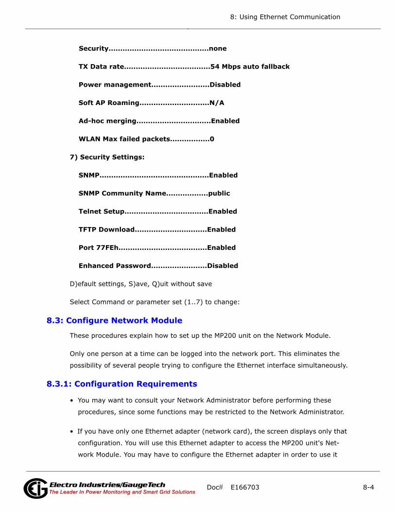
8: Using Ethernet Communication
Security...........................................none
TX Data rate.....................................54 Mbps auto fallback
Power management.........................Disabled
Soft AP Roaming..............................N/A
Ad-hoc merging................................Enabled
WLAN Max failed packets.................0
7) Security Settings:
SNMP...............................................Enabled
SNMP Community Name..................public
Telnet Setup....................................Enabled
TFTP Download...............................Enabled
Port 77FEh......................................Enabled
Enhanced Password........................Disabled
D)efault settings, S)ave, Q)uit without save
Select Command or parameter set (1..7) to change:
8.3: Configure Network Module
These procedures explain how to set up the MP200 unit on the Network Module.
Only one person at a time can be logged into the network port. This eliminates the
possibility of several people trying to configure the Ethernet interface simultaneously.
8.3.1: Configuration Requirements
• You may want to consult your Network Administrator before performing these
procedures, since some functions may be restricted to the Network Administrator.
• If you have only one Ethernet adapter (network card), the screen displays only that
configuration. You will use this Ethernet adapter to access the MP200 unit's Net-
work Module. You may have to configure the Ethernet adapter in order to use it
Doc# E166703 8-4Electro Industries/GaugeTechThe Leader In Power Monitoring and Smart Grid SolutionsElectro Industries/GaugeTechThe Leader In Power Monitoring and Smart Grid Solutions
Electro Industries/GaugeTechThe Leader In Power Monitoring and Smart Grid Solutions
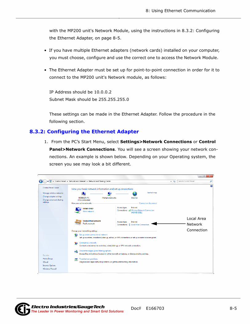
8: Using Ethernet Communication
with the MP200 unit's Network Module, using the instructions in 8.3.2: Configuring
the Ethernet Adapter, on page 8-5.
• If you have multiple Ethernet adapters (network cards) installed on your computer,
you must choose, configure and use the correct one to access the Network Module.
• The Ethernet Adapter must be set up for point-to-point connection in order for it to
connect to the MP200 unit's Network module, as follows:
IP Address should be 10.0.0.2
Subnet Mask should be 255.255.255.0
These settings can be made in the Ethernet Adapter. Follow the procedure in the
following section.
8.3.2: Configuring the Ethernet Adapter
1. From the PC’s Start Menu, select Settings>Network Connections or Control
Panel>Network Connections. You will see a screen showing your network con-
nections. An example is shown below. Depending on your Operating system, the
screen you see may look a bit different.
Local AreaNetworkConnection
Doc# E166703 8-5Electro Industries/GaugeTechThe Leader In Power Monitoring and Smart Grid SolutionsElectro Industries/GaugeTechThe Leader In Power Monitoring and Smart Grid Solutions
Electro Industries/GaugeTechThe Leader In Power Monitoring and Smart Grid Solutions

8: Using Ethernet Communication
2. Right click on the Local Area Network connection you will be using to connect to the
MP200 unit, and select Properties from the pull-down menu. You will see a screen
similar to the one shown below.
3. Select Internet Protocol [TCP/IP] from the middle of the screen and click the
Properties button. You will see the screen shown on the next page.
Doc# E166703 8-6Electro Industries/GaugeTechThe Leader In Power Monitoring and Smart Grid SolutionsElectro Industries/GaugeTechThe Leader In Power Monitoring and Smart Grid Solutions
Electro Industries/GaugeTechThe Leader In Power Monitoring and Smart Grid Solutions

8: Using Ethernet Communication
4. Click the Use the Following IP Address radio button. The screen changes to allow
you to enter the IP Address and Subnet Mask.
a. Enter 10.0.0.2 in the IP Address field.
b. Enter 255.255.255.0 in the Subnet Mask field.
3. Click the OK button.
4. You can now close the Local Area Connection Properties and Network Connection
windows.
Doc# E166703 8-7Electro Industries/GaugeTechThe Leader In Power Monitoring and Smart Grid SolutionsElectro Industries/GaugeTechThe Leader In Power Monitoring and Smart Grid Solutions
Electro Industries/GaugeTechThe Leader In Power Monitoring and Smart Grid Solutions
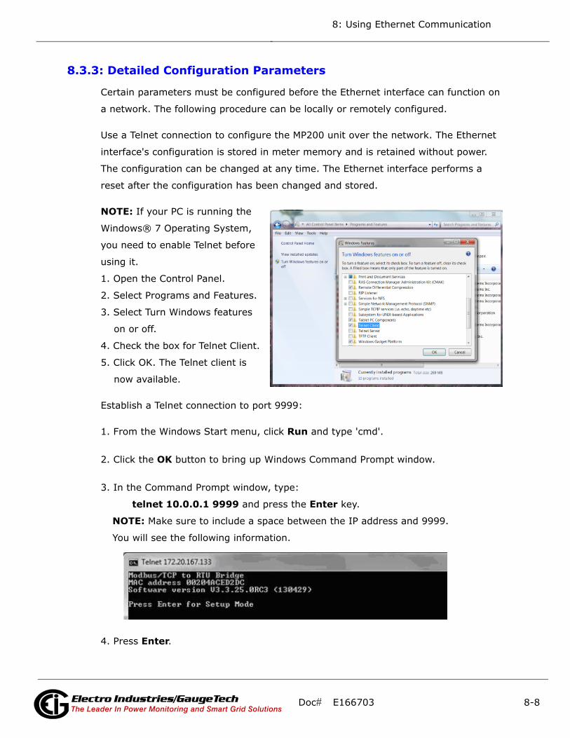
8: Using Ethernet Communication
8.3.3: Detailed Configuration Parameters
Certain parameters must be configured before the Ethernet interface can function on
a network. The following procedure can be locally or remotely configured.
Use a Telnet connection to configure the MP200 unit over the network. The Ethernet
interface's configuration is stored in meter memory and is retained without power.
The configuration can be changed at any time. The Ethernet interface performs a
reset after the configuration has been changed and stored.
NOTE: If your PC is running the
Windows® 7 Operating System,
you need to enable Telnet before
using it.
1. Open the Control Panel.
2. Select Programs and Features.
3. Select Turn Windows features
on or off.
4. Check the box for Telnet Client.
5. Click OK. The Telnet client is
now available.
Establish a Telnet connection to port 9999:
1. From the Windows Start menu, click Run and type 'cmd'.
2. Click the OK button to bring up Windows Command Prompt window.
3. In the Command Prompt window, type:
telnet 10.0.0.1 9999 and press the Enter key.
NOTE: Make sure to include a space between the IP address and 9999.
You will see the following information.
4. Press Enter.
Doc# E166703 8-8Electro Industries/GaugeTechThe Leader In Power Monitoring and Smart Grid SolutionsElectro Industries/GaugeTechThe Leader In Power Monitoring and Smart Grid Solutions
Electro Industries/GaugeTechThe Leader In Power Monitoring and Smart Grid Solutions
8: Using Ethernet Communication
5. You are now in Setup Mode. You can configure the parameters for the software you
are using by either:
• Keying a new value next to a setting and pressing Enter
• Keeping the default value (the value in brackets after a setting) by just pressing
Enter without keying in anything
6. Be sure to press “S” once you are finished, in order to store any new settings. The
Ethernet interface will then perform a power reset.
8.3.4: Setup Details
This section illustrates how each section of settings appears on the screen, when you
select the setting number (1, 6, or 7).
CAUTION! Change Settings 1, 6, and 7 ONLY. Settings 2, 3, and 4 MUST be the same
as shown in 8.2.1: Modbus/TCP to RTU Bridge Setup Default Settings, on page 8-3. If
they are not, reset them to the values shown in Section 8.2.1, using the reset instruc-
tions in 8.4: Network Module Hardware Initialization, on page 8-14.
Network IP Settings Detail (1) (Set device with static IP Address.)
Network Mode: 0=Wired only, 1=Wireless Only <0> ? Key 1 and press Enter for WiFi
mode.
IP Address <010> 192.<000> 168.<000> .<000> .<001> You can change the IP
address in this setting.
Set Gateway IP Address <N> ? Y (If you want to change the Gateway address.)
Gateway IP Address : <192> .<168> .<000> .<001> (You can change the Gateway
address in this setting.)
Set Netmask <N for default> <Y> ? Y (If you want to change the Netmask.)
<255> .<255> .<255> .<000> (You can change the Netmask in this setting.)
Change telnet config password <N> ? N
WLAN Settings Detail (6) (The settings shown are recommended by EIG for use
with the MP200 metering system. You will only be able to access these settings if you
have set Network Mode to “1” (to select Wireless mode) in the Network IP Settings
Detail, shown previously.)
Doc# E166703 8-9Electro Industries/GaugeTechThe Leader In Power Monitoring and Smart Grid SolutionsElectro Industries/GaugeTechThe Leader In Power Monitoring and Smart Grid Solutions
Electro Industries/GaugeTechThe Leader In Power Monitoring and Smart Grid Solutions
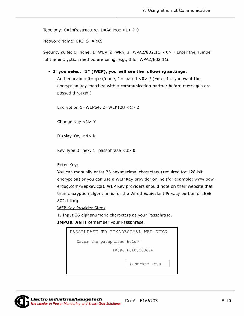
8: Using Ethernet Communication
Topology: 0=Infrastructure, 1=Ad-Hoc <1> ? 0
Network Name: EIG_SHARKS
Security suite: 0=none, 1=WEP, 2=WPA, 3=WPA2/802.11i <0> ? Enter the number
of the encryption method are using, e.g., 3 for WPA2/802.11i.
• If you select “1” (WEP), you will see the following settings:
Authentication 0=open/none, 1=shared <0> ? (Enter 1 if you want the
encryption key matched with a communication partner before messages are
passed through.)
Encryption 1=WEP64, 2=WEP128 <1> 2
Change Key <N> Y
Display Key <N> N
Key Type 0=hex, 1=passphrase <0> 0
Enter Key:
You can manually enter 26 hexadecimal characters (required for 128-bit
encryption) or you can use a WEP Key provider online (for example: www.pow-
erdog.com/wepkey.cgi). WEP Key providers should note on their website that
their encryption algorithm is for the Wired Equivalent Privacy portion of IEEE
802.11b/g.
WEP Key Provider Steps
1. Input 26 alphanumeric characters as your Passphrase.
IMPORTANT! Remember your Passphrase.
PASSPHRASE TO HEXADECIMAL WEP KEYS Enter the passphrase below. 1009egbck001036ab
Generate keys
Doc# E166703 8-10Electro Industries/GaugeTechThe Leader In Power Monitoring and Smart Grid SolutionsElectro Industries/GaugeTechThe Leader In Power Monitoring and Smart Grid Solutions
Electro Industries/GaugeTechThe Leader In Power Monitoring and Smart Grid Solutions
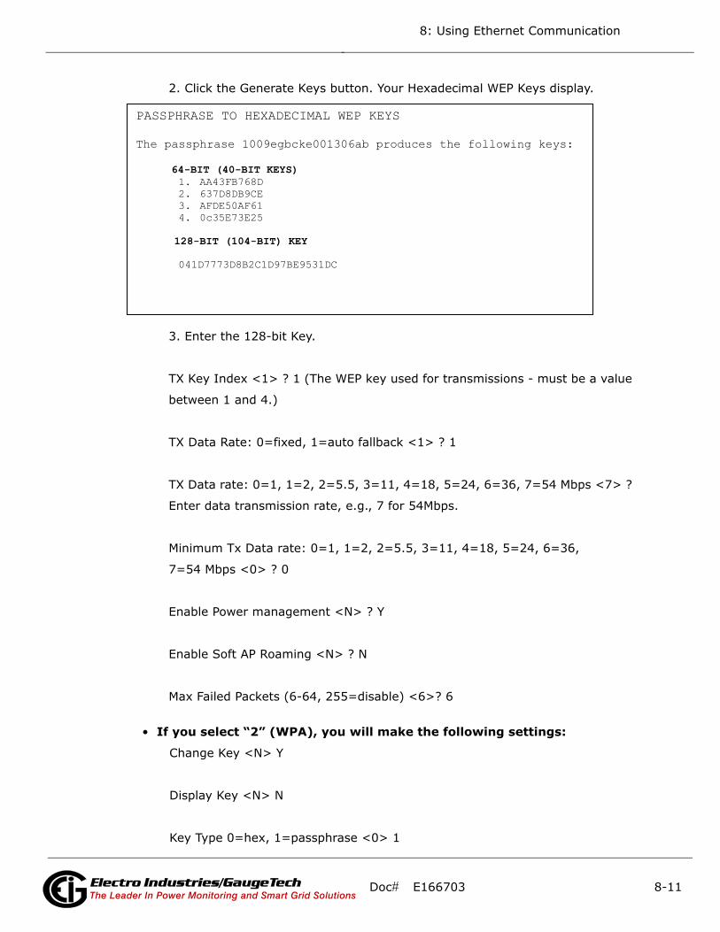
8: Using Ethernet Communication
2. Click the Generate Keys button. Your Hexadecimal WEP Keys display.
3. Enter the 128-bit Key.
TX Key Index <1> ? 1 (The WEP key used for transmissions - must be a value
between 1 and 4.)
TX Data Rate: 0=fixed, 1=auto fallback <1> ? 1
TX Data rate: 0=1, 1=2, 2=5.5, 3=11, 4=18, 5=24, 6=36, 7=54 Mbps <7> ?
Enter data transmission rate, e.g., 7 for 54Mbps.
Minimum Tx Data rate: 0=1, 1=2, 2=5.5, 3=11, 4=18, 5=24, 6=36,
7=54 Mbps <0> ? 0
Enable Power management <N> ? Y
Enable Soft AP Roaming <N> ? N
Max Failed Packets (6-64, 255=disable) <6>? 6
• If you select “2” (WPA), you will make the following settings:
Change Key <N> Y
Display Key <N> N
Key Type 0=hex, 1=passphrase <0> 1
PASSPHRASE TO HEXADECIMAL WEP KEYS The passphrase 1009egbcke001306ab produces the following keys: 64-BIT (40-BIT KEYS)
1. AA43FB768D 2. 637D8DB9CE 3. AFDE50AF61 4. 0c35E73E25
128-BIT (104-BIT) KEY 041D7773D8B2C1D97BE9531DC
Doc# E166703 8-11Electro Industries/GaugeTechThe Leader In Power Monitoring and Smart Grid SolutionsElectro Industries/GaugeTechThe Leader In Power Monitoring and Smart Grid Solutions
Electro Industries/GaugeTechThe Leader In Power Monitoring and Smart Grid Solutions
8: Using Ethernet Communication
Enter Key: (The maximum length of the passphrase is 63 characters. EIG rec-
ommends using a passphrase of 20 characters or more for maximum security.)
Encryption: 0=TKIP, 1=TKIP+WEP <0> ? Set the type to the minimum
required security level. The “+” sign indicates that the group (broadcast)
encryption method is different from the pairwise (unicast) encryption (WEP
and TKIP).
TX Data rate: 0=fixed, 1=auto fallback <1>? 1
TX Data rate: 0=1, 1=2, 2=5.5, 3=11, 4=18, 5=24, 6=36, 7=54 Mbps <7>?
Enter data transmission rate, e.g., 7 for 54Mbps.
Minimum Tx Data rate: 0=1, 1=2, 2=5.5, 3=11, 4=18, 5=24, 6=36,
7=54 Mbps <0>? 0
Enable Power management <N>? Y
Enable Soft AP Roaming <N>? N
Max Failed Packets (6-64, 255=disable) <6>? 6
• If you select “3” (WPA2/802.11i), you will make the following settings:
Change Key <N> Y
Display Key <N> N
Key Type 0=hex, 1=passphrase <0> 1
Enter Key: (The maximum length of the passphrase is 63 characters. EIG rec-
ommends using a passphrase of 20 characters or more for maximum security.)
Encryption: 0=CCMP, 1=CCMP+TKIP, 2=CCMP+WEP, 3=TKIP, 4=TKIP+WEP
<3>? (Set the type to the minimum required security level. The “+” sign indi-
cates that the group (broadcast) encryption method is different from the pair-
Doc# E166703 8-12Electro Industries/GaugeTechThe Leader In Power Monitoring and Smart Grid SolutionsElectro Industries/GaugeTechThe Leader In Power Monitoring and Smart Grid Solutions
Electro Industries/GaugeTechThe Leader In Power Monitoring and Smart Grid Solutions
8: Using Ethernet Communication
wise (unicast) encryption. For example, for CCMP+TKIP, CCMP is the pairwise
encryption and TKIP is the group encryption. CCMP is the default for WPA2.)
TX Data rate: 0=fixed, 1=auto fallback <1>? 1
TX Data rate: 0=1, 1=2, 2=5.5, 3=11, 4=18, 5=24, 6=36, 7=54 Mbps <7>?
Enter data transmission rate, e.g., 7 for 54Mbps.
Minimum Tx Data rate: 0=1, 1=2, 2=5.5, 3=11, 4=18, 5=24, 6=36,
7=54 Mbps <0>? 0
Enable Power management <N>? Y
Enable Soft AP Roaming <N>? N
Max Failed Packets (6-64, 255=disable) <6>? 6
Security Settings (7)
Disable SNMP <N>? N
SNMP Community Name <public>: (You can enter an SNMP community name here.)
Disable Telnet Setup <N>? N (If you change this setting to Y, you will not be able to
use Telnet to re-configure the Network card once you save the settings, without
resetting the Network card, as shown in Section 8.4. However, you may want to dis-
able Telnet setup and Port 77FEh to prevent users from accessing the setup from the
network.)
Disable TFTP Firmware Update <N>? N
Disable Port 77FEh <N>? N (For security purposes, you may want to disable Telnet
setup and Port 77FEh to prevent users from accessing the setup from the network.)
Enable Enhanced Password <N>? N
Exiting the screen
CAUTION! DO NOT PRESS 'D': that will restore the Default Settings.
Press 'S' to Save the settings you've entered.
Doc# E166703 8-13Electro Industries/GaugeTechThe Leader In Power Monitoring and Smart Grid SolutionsElectro Industries/GaugeTechThe Leader In Power Monitoring and Smart Grid Solutions
Electro Industries/GaugeTechThe Leader In Power Monitoring and Smart Grid Solutions
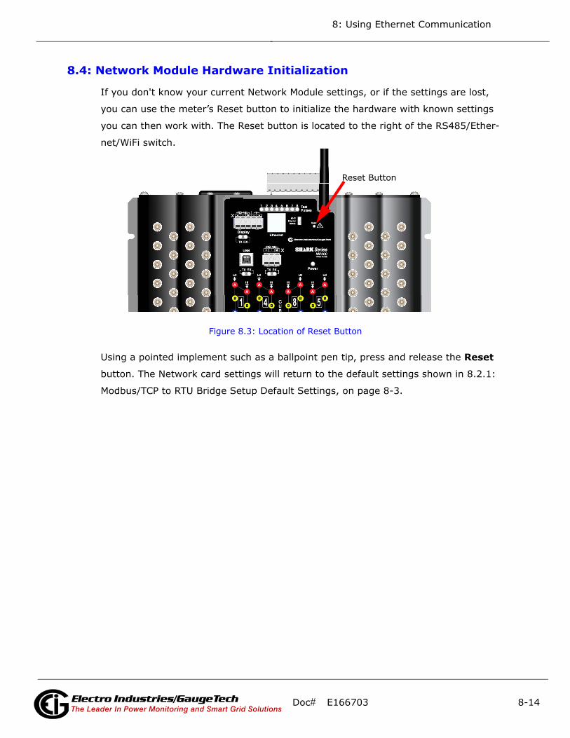
8: Using Ethernet Communication
8.4: Network Module Hardware Initialization
If you don't know your current Network Module settings, or if the settings are lost,
you can use the meter’s Reset button to initialize the hardware with known settings
you can then work with. The Reset button is located to the right of the RS485/Ether-
net/WiFi switch.
Figure 8.3: Location of Reset Button
Using a pointed implement such as a ballpoint pen tip, press and release the Reset
button. The Network card settings will return to the default settings shown in 8.2.1:
Modbus/TCP to RTU Bridge Setup Default Settings, on page 8-3.
Reset Button
Doc# E166703 8-14Electro Industries/GaugeTechThe Leader In Power Monitoring and Smart Grid SolutionsElectro Industries/GaugeTechThe Leader In Power Monitoring and Smart Grid Solutions
Electro Industries/GaugeTechThe Leader In Power Monitoring and Smart Grid Solutions

9: Data Logging
9: Data Logging
9.1: Overview
Optional V-Switch™ keys 2 and 3 (V2 and V3) give the MP200 metering system mem-
ory for data logging. The MP200 metering system can log historical trends, limit
alarms, I/O changes, and sequence of events. In addition, the MP200 unit has a real-
time clock that allows all events to be time-stamped when they occur. Refer to Chap-
ter 10 (Configuring MP200 Metering System) and Chapter 19 (Viewing Logs) in the
Communicator EXTTM 4.0 and MeterManager EXT Software User Manual for additional
information and instructions. You can download this manual at:
http://www.electroind.com/dl_page_software-downloads.html
9.2: Available Logs
The following logs are available for an MP200 unit equipped with V2 and V3. These
meters have 2 and 32 MB, respectively, of non-volatile memory for data logging.
• Historical logs: Each MP200 unit with V2 or V3 has two historical logs. Log 1 is con-
figurable through Communicator EXTTM software. Log 2 is pre-configured to log
energy usage for each metered circuit over time for the three phase meter model.
Log 3 is pre-configured to log energy usage for each metered circuit over time for
the single phase meter model. If your MP200 unit has the single phase configura-
tion it will have Historical logs 1 and 3; if it has the three phase configuration it will
have Historical logs 1 and 2.
Note that the meter is configured to automatically store logs and that the logs
default to a 15 minute interval, though the logging interval can be changed.
• For the MP200-Y unit, Historical log 1 records, as a factory default, readings for
Volts Line-to-Line and Line to Neutral, and Frequency; however, the data chan-
nels recorded can be changed using Communicator EXTTM software. Historical log
2 records readings for Watt-hours, Interval Energy for each of the eight meters,
and accumulator readings for the four digital inputs.
• For the MP200-S unit, Historical log 1 records, as a factory default, readings for
voltage and frequency; however, the data channels recorded can be changed
using Communicator EXTTM software. Historical log 2 records readings for Inter-
val Energy for each of the 24 meters, and accumulator readings for the four dig-
ital inputs.
Doc# E166703 9-1Electro Industries/GaugeTechThe Leader In Power Monitoring and Smart Grid SolutionsElectro Industries/GaugeTechThe Leader In Power Monitoring and Smart Grid SolutionsElectro Industries/GaugeTechThe Leader In Power Monitoring and Smart Grid Solutions
9: Data Logging
• Interval Energy is the amount of energy consumed during the storage
interval. For example, if you choose a 15 minute interval (the typical set-
ting), the meter profiles the load used during the 15 minute period for
each storage period. This lets you trend and graph an energy use profile
for each meter (circuit).
• The MP200 metering system’s logging capability works with EIG’s Communicator
EXTTM and E-Billing EXTTM software applications to enable you to create detailed
usage reports for analysis and to easily generate sub-tenant billing. The digital
input accumulators can be used to accumulate pulses from other than electrical
energy usage, e.g., gas or condensate (steam); to offer you a multi-commodity
billing solution.
• Limit/Alarm log: This log provides the magnitude and duration of alarms that fall
outside of configured acceptable limits. Time stamps and alarm value are provided
in the log. Up to 16,382 events can be logged.
• I/O Change log: This log provides a time-stamped record of the Relay Output/Digi-
tal Input board’s output or input status changes. Up to 16,382 events can be
logged.
• System Events log: In order to protect critical billing information, the MP200 unit
records and logs the following information with a timestamp:
• Demand resets
• Password requests
• System startup
• Energy resets
• Log resets
• Log reads
• Programmable settings changes
Doc# E166703 9-2Electro Industries/GaugeTechThe Leader In Power Monitoring and Smart Grid SolutionsElectro Industries/GaugeTechThe Leader In Power Monitoring and Smart Grid SolutionsElectro Industries/GaugeTechThe Leader In Power Monitoring and Smart Grid Solutions

9: Data Logging
All of the MP200 unit logs can be viewed through the EIG Log Viewer. Refer to Chapter
8 of the Communicator EXTTM User Manual for additional information and instructions
regarding logs and the Log Viewer.
See Appendix E for instructions on retrieving logs using the MP200 unit’s Modbus
map.
Doc# E166703 9-3Electro Industries/GaugeTechThe Leader In Power Monitoring and Smart Grid SolutionsElectro Industries/GaugeTechThe Leader In Power Monitoring and Smart Grid SolutionsElectro Industries/GaugeTechThe Leader In Power Monitoring and Smart Grid Solutions

9: Data Logging
This page intentionally left blank.
Doc# E166703 9-4Electro Industries/GaugeTechThe Leader In Power Monitoring and Smart Grid SolutionsElectro Industries/GaugeTechThe Leader In Power Monitoring and Smart Grid SolutionsElectro Industries/GaugeTechThe Leader In Power Monitoring and Smart Grid Solutions

10: Using the Optional Display
10: Using the Optional Display
10.1: Overview
This chapter describes the optional display for the MP200 metering unit. The display
lets you view meter readings remotely. The display come pre-configured, but you can
change the default settings, for example, the IP address, if necessary. There are two
available display models:
• The MDSN display has a 3.5” screen.
• The MDLN display has a 5.7” screen.
10.1: MDSN/MDLN Displays
The displays are touch-screen capable and offer both serial and Ethernet communica-
tion:
• Serial port configured for 2-wire RS485 communication
• RJ45 Ethernet Port for 10/100BaseT communication
10.2: Display Features
• Low power consumption - MDSN uses 6.5 W or less; MDLN uses 6.8 W or less
• Compact size
• Easy installation - fits in standard 22 mm/0.87 in. mounting hole
Doc# E166703 10-1Electro Industries/GaugeTechThe Leader In Power Monitoring and Smart Grid Solutions
Electro Industries/GaugeTechThe Leader In Power Monitoring and Smart Grid Solutions
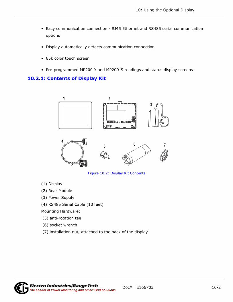
10: Using the Optional Display
• Easy communication connection - RJ45 Ethernet and RS485 serial communication
options
• Display automatically detects communication connection
• 65k color touch screen
• Pre-programmed MP200-Y and MP200-S readings and status display screens
10.2.1: Contents of Display Kit
Figure 10.2: Display Kit Contents
(1) Display
(2) Rear Module
(3) Power Supply
(4) RS485 Serial Cable (10 feet)
Mounting Hardware:
(5) anti-rotation tee
(6) socket wrench
(7) installation nut, attached to the back of the display
7 6 5 4
3 2 1
Doc# E166703 10-2Electro Industries/GaugeTechThe Leader In Power Monitoring and Smart Grid Solutions
Electro Industries/GaugeTechThe Leader In Power Monitoring and Smart Grid Solutions
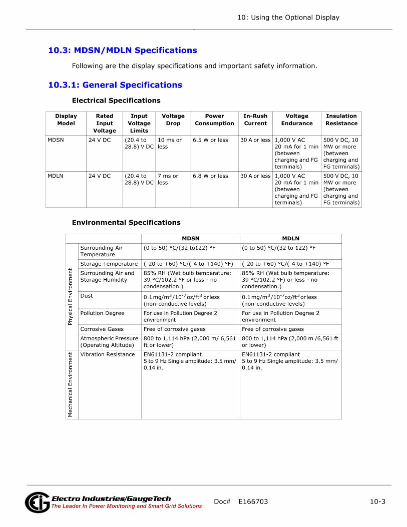
10: Using the Optional Display
10.3: MDSN/MDLN Specifications
Following are the display specifications and important safety information.
10.3.1: General Specifications
Electrical Specifications
Environmental Specifications
Display Model
Rated Input
Voltage
Input Voltage Limits
Voltage Drop
Power Consumption
In-Rush Current
Voltage Endurance
Insulation Resistance
MDSN 24 V DC (20.4 to28.8) V DC
10 ms or less
6.5 W or less 30 A or less 1,000 V AC 20 mA for 1 min(between charging and FG terminals)
500 V DC, 10 MW or more (between charging and FG terminals)
MDLN 24 V DC (20.4 to28.8) V DC
7 ms or less
6.8 W or less 30 A or less 1,000 V AC 20 mA for 1 min(between charging and FG terminals)
500 V DC, 10 MW or more (between charging and FG terminals)
MDSN MDLN
Phys
ical
Env
iron
men
t
Surrounding Air Temperature
(0 to 50) °C/(32 to122) °F (0 to 50) °C/(32 to 122) °F
Storage Temperature (-20 to +60) °C/(-4 to +140) °F) (-20 to +60) °C/(-4 to +140) °F
Surrounding Air and Storage Humidity
85% RH (Wet bulb temperature: 39 °C/102.2 °F or less - no condensation.)
85% RH (Wet bulb temperature: 39 °C/102.2 °F) or less - no condensation.)
Dust 0.1 mg/m3 /10-7 oz/ft3 or less (non-conductive levels)
0.1 mg/m3 /10-7oz/ft3 or less (non-conductive levels)
Pollution Degree For use in Pollution Degree 2 environment
For use in Pollution Degree 2 environment
Corrosive Gases Free of corrosive gases Free of corrosive gases
Atmospheric Pressure (Operating Altitude)
800 to 1,114 hPa (2,000 m/ 6,561 ft or lower)
800 to 1,114 hPa (2,000 m /6,561 ft or lower)
Mec
hani
cal E
nvir
onm
ent Vibration Resistance EN61131-2 compliant
5 to 9 Hz Single amplitude: 3.5 mm/ 0.14 in.
EN61131-2 compliant5 to 9 Hz Single amplitude: 3.5 mm/ 0.14 in.
Doc# E166703 10-3Electro Industries/GaugeTechThe Leader In Power Monitoring and Smart Grid Solutions
Electro Industries/GaugeTechThe Leader In Power Monitoring and Smart Grid Solutions
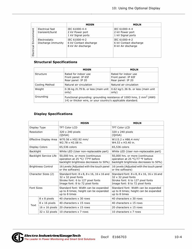
10: Using the Optional Display
Structural Specifications
Display Specifications
Elec
tric
al E
nviron
men
t Electrical fast transient/burst
IEC 61000-4-42 kV Power port 1 kV Signal ports
IEC 61000-4-42 kV Power port 1 kV Signal ports
Electrostatic Discharge Immunity
IEC 61000-4-26 kV Contact discharge8 kV Air discharge
IEC 61000-4-26 kV Contact discharge8 kV Air discharge
MDSN MDLN
Structure Rated for indoor useFront panel: IP 65fRear panel: IP 20
Rated for indoor useFront panel: IP 65fRear panel: IP 20
Cooling Method Natural air circulation Natural air circulation
Weight 0.36 kg /0.79 lb. or less (main unit only)
0.62 kg/1.36 lb. or less (main unit only)
Grounding Functional grounding: grounding resistance of 100O hms, 2 mm2 (AWG 14) or thicker wire, or your country's applicable standard.
MDSN MDLN
Display Type TFT Color LCD TFT Color LCD
Resolution 320 x 240 pixels(QVGA)
320 x 240 pixels(QVGA)
Effective Display Area W70.56 x H52.92 mm/W2.78 x H2.08 in.
W115.2 x H86.4 mm/W4.53 x H3.40 in.
Display Colors 65,536 colors 65,536 colors
Backlight White LED (User non-replaceable part) White LED (User non-replaceable part)
Backlight Service Life 50,000 hrs. or more (continuous operation at 25 °C/ 77°F before backlight brightness decreases to 50%)
50,000 hrs. or more (continuous operation at 25 °C/77 °F before backlight brightness decreases to 50%)
Brightness Control 16 Levels (Adjusted with the touch panel or the software)
16 Levels (Adjusted with the touch panel or the software)
Character Sizes (2) Standard font: 8 x 8, 8 x 16, 16 x 16 and 32 x 32 pixel fontsStroke font: 6 to 127 pixel fontsImage font: 8 to 72 pixel fonts
Standard font: 8 x 8, 8 x 16, 16 x 16 and 32 x 32 pixel fontsStroke font: 6 to 127 pixel fontsImage font: 8 to 72 pixel fonts
Font Sizes Standard font: Width can be expanded up to 8 times; height can be expanded up to 8 times
Standard font: Width can be expanded up to 8 times; height can be expanded up to 8 times
Text
8 x 8 pixels 40 characters x 30 rows 40 characters x 30 rows
8 x 16 pixels 40 characters x 15 rows 40 characters x 15 rows
16 x 16 pixels 20 characters x 15 rows 20 characters x 15 rows
32 x 32 pixels 10 characters x 7 rows 10 characters x 7 rows
MDSN MDLN
Doc# E166703 10-4Electro Industries/GaugeTechThe Leader In Power Monitoring and Smart Grid Solutions
Electro Industries/GaugeTechThe Leader In Power Monitoring and Smart Grid Solutions
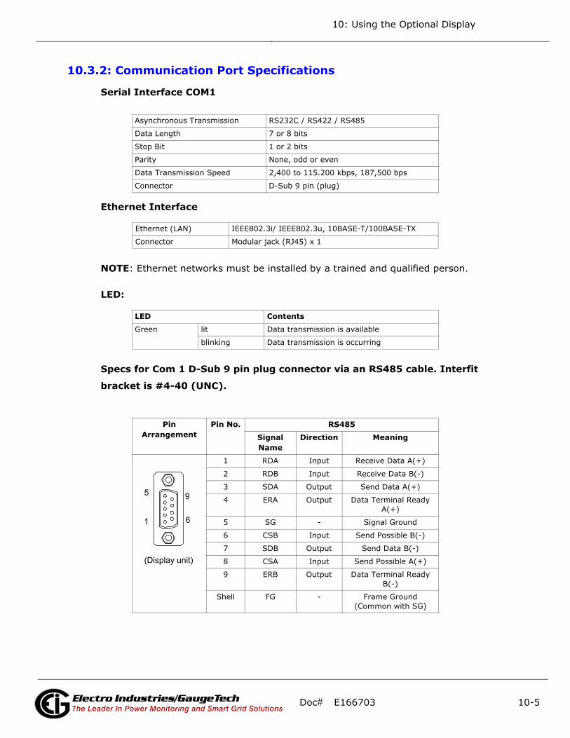
10: Using the Optional Display
10.3.2: Communication Port Specifications
Serial Interface COM1
Ethernet Interface
NOTE: Ethernet networks must be installed by a trained and qualified person.
LED:
Specs for Com 1 D-Sub 9 pin plug connector via an RS485 cable. Interfit
bracket is #4-40 (UNC).
Asynchronous Transmission RS232C / RS422 / RS485
Data Length 7 or 8 bits
Stop Bit 1 or 2 bits
Parity None, odd or even
Data Transmission Speed 2,400 to 115.200 kbps, 187,500 bps
Connector D-Sub 9 pin (plug)
Ethernet (LAN) IEEE802.3i/ IEEE802.3u, 10BASE-T/100BASE-TX
Connector Modular jack (RJ45) x 1
LED Contents
Green lit Data transmission is available
blinking Data transmission is occurring
Pin Arrangement
Pin No. RS485
Signal Name
Direction Meaning
1 RDA Input Receive Data A(+)
2 RDB Input Receive Data B(-)
3 SDA Output Send Data A(+)
4 ERA Output Data Terminal Ready A(+)
5 SG - Signal Ground
6 CSB Input Send Possible B(-)
7 SDB Output Send Data B(-)
8 CSA Input Send Possible A(+)
9 ERB Output Data Terminal Ready B(-)
Shell FG - Frame Ground(Common with SG)
9
6
5
1
(Display unit)
Doc# E166703 10-5Electro Industries/GaugeTechThe Leader In Power Monitoring and Smart Grid Solutions
Electro Industries/GaugeTechThe Leader In Power Monitoring and Smart Grid Solutions

10: Using the Optional Display
10.3.3: Important Safety and Product Usage Information
Handling the LCD Panel
The following characteristics are specific to the LCD unit and are considered normal
behavior:
• The LCD screen may show unevenness in the brightness of certain images or may
appear different when seen from outside the specified viewing angle. Extended
shadows, or cross-talk, may also appear on the sides of screen images.
• The LCD screen pixels may contain black and white colored spots and color display
may seem to have changed over time.
• When the same image is displayed on the screen for a long period, an afterimage
may appear when the image is changed.
NOTE: Do not display the same image for a long time: change the screen image
periodically.
WARNING! SERIOUS EYE AND SKIN INJURY
The liquid present in the LCD panel contains an irritant:
• Avoid direct skin contact with the liquid.
• Wear gloves when you handle a broken or leaking unit.
• Do not use sharp objects or tools in the vicinity of the LCD touch panel.
• Handle the LCD panel carefully to prevent puncture, bursting, or cracking of the
panel material.
• If the panel is damaged and any liquid comes in contact with your skin, immedi-
ately rinse the area with running water for at least 15 minutes.
• If the liquid gets in your eyes, immediately rinse your eyes with running water for
at least 15 minutes and consult a doctor.
Failure to follow these instructions can result in serious injury or equipment
damage.
Doc# E166703 10-6Electro Industries/GaugeTechThe Leader In Power Monitoring and Smart Grid Solutions
Electro Industries/GaugeTechThe Leader In Power Monitoring and Smart Grid Solutions

10: Using the Optional Display
AVERTISSEMENT! BLESSURES GRAVES DANS LES YEUX ET
SUR LA PEAU
Le liquide présent dans le panneau ACL contient des irritants:
• Évitez le contact direct avec la peau.
• Portez des gants lorsque vous fixez une unité endommagée ou une fuite
• N'utilisez pas des objets tranchants ou outils aux environs du panneau ACL
• Utilisez soigneusement le panneau ACL pour prévenir la crevaison, l'explosion ou le
cassage du matériel de panneau
• Si le panneau est endommagé et le liquide vient en contact avec votre peau, rincez
immédiatement l'endroit avec de l'eau pour au moins 15 minutes.
• Si le liquide entre en contact avec vos yeux, rincez immédiatement vos yeux avec
de l'eau pendant au moins 15 minutes ou consultez un médecin.
Le non-respect de ces instructions peut provoquer des blessures graves ou
un endommagement de l'appareil.
Using the Touch Panel Correctly
• Use only one finger to select an object on the touch panel.
• If the touch panel receives pressure at two or more points at the same time, an
unintended object could be selected.
CAUTION: UNINTENDED EQUIPMENT OPERATION
• Operate the display’s touch panel with only one finger.
• Do not activate two or more points of the touch panel
simultaneously.
Failure to follow these instructions can result in serious injury, or equipment
damage.
Doc# E166703 10-7Electro Industries/GaugeTechThe Leader In Power Monitoring and Smart Grid Solutions
Electro Industries/GaugeTechThe Leader In Power Monitoring and Smart Grid Solutions

10: Using the Optional Display
COM 1 Serial Port Warning and Cautions
WARNING! DANGER OF ELECTRIC SHOCK!The serial port is not isolated. The SG (signal ground) and the FG
(frame ground) terminals are connected inside the unit. When using the
SG terminal to connect an external device to the unit:
• Verify that a short-circuit loop is not created when you set up the system.
• Connect the #5 SG terminal to remote equipment when the host (PLC) unit is not
isolated. Connect the #5 SG terminal to a known reliable ground connection to
reduce the risk of damaging the RS485 circuit.
Failure to follow these instructions can result in death or serious injury.
Avertissement et mise en garde du port série COM 1Port
AVERTISSEMENT! RISQUE D'UNE DÉCHARGE ÉLECTRIQUE!
Le port série n'est pas isolé. Le retour commun du signal et de la
masse du châssis sont branchés dans l'unité. Lorsque vous utilisez le
retour commun du signal pour brancher un pareil externe dans l'unité:
• Vérifiez que la boucle de court-circuit n'est pas créée lorsque vous mettrez en place
le système.
• Branchez la borne no 5 SG pour utiliser l'équipement à distance lorsque que l'unité
hôte (PLC) n'est pas isolée. Branchez la borne no 5 SG dans un branchement de
mise à terre connue pour réduire le risque d'endommagement du circuit RS485.
Le non-respect de ces instructions peut provoquer la mort et des blessures
graves.
CAUTION: LOSS OF COMMUNICATION
• All connections to the communication ports must not put excessive
stress on the ports.
• Securely attach communication cables to the panel or cabinet.
Failure to follow these instructions can result in injury or equipment dam-
age.
Doc# E166703 10-8Electro Industries/GaugeTechThe Leader In Power Monitoring and Smart Grid Solutions
Electro Industries/GaugeTechThe Leader In Power Monitoring and Smart Grid Solutions

10: Using the Optional Display
Critical systems, Detected Alarms and Handling Requirements
Critical detected alarm indicators require independent and redundant protection hard-
ware and/or mechanical interlocks. If the display unit for any reason becomes inoper-
ative (for example, an inoperative backlight) it may be difficult or impossible to
identify an alarm condition. Alarms tied to critical functions, such as emergency stop,
must be provided independently of the display unit. The design of the control system
must take into account an inoperative unit (backlight) and that the operator is unable
to view alarms using the display unit.
When the power is cycled, wait at least 10 seconds before restoring the power to the
GP Unit. Switching the power OFF and ON quickly can damage the unit.
WARNING! LOSS OF CONTROL
Consider the potential failure modes of alarm notification, such as:
• The possibility of backlight failure
• Unanticipated link transmission delays or failures
• The operator being unable to operate the display correctly
• Provide a means to achieve a safe state during and after a path failure for critical
alarms.
• Provide separate or redundant control paths for critical alarms.
• Test individually and thoroughly each implementation of the display unit for correct
operation before service.
Failure to follow these instructions can result in serious injury or equipment
damage.
WARNING! UNINTENDED EQUIPMENT OPERATION
Do not use the unit as the only notification device for critical alarms,
such as device overheating or over-current.
Failure to follow this instruction can result in death, serious injury, or equip-
ment damage.
Doc# E166703 10-9Electro Industries/GaugeTechThe Leader In Power Monitoring and Smart Grid Solutions
Electro Industries/GaugeTechThe Leader In Power Monitoring and Smart Grid Solutions

10: Using the Optional Display
Exigences relatives aux systèmes importants, détections d'alarmes et manutentions
Les indicateurs importants d'alarmes détectés exigent un appareil de protection
redondant et indépendant ou un verrouillage mécanique. Si l'unité pour toute raison
devient inopérante (par exemple, un rétroéclairage lumineux inopérant), il peut être
difficile ou impossible d'identifier une situation d'alarme. Les alarmes ficelées aux
fonctions importantes comme arrêt d'urgence, doivent être fournis indépendamment
de l'unité d'affichage, le modèle du système de contrôle doivent rendre en compte
une unité inopérante (rétroéclairage) et que l'opérateur est incapable de voir les
alarmes utilisant l'unité d'affichage.
Lorsque l'alimentation est cyclé, attendre au moins 10 secondes avant de restaurer
l'alimentation de l'unité GP. Le fait d'allumer et d'éteindre rapidement l'alimentation
peut endommager l'unité.
AVERTISSEMENT! PERTE DE CONTRÔLE
Considérer des modes de panne potentielle de notification d'alarme
comme:
• La possibilité de panne de rétroéclairage
• Délai de lien de transmission non anticipé ou panne
• L'opérateur incapable de faire fonctionner l'affichage correctement
• Fournir un moyen d'achever un état de sécurité pendant et après la panne de voie
pour les alarmes critique.
• Fournir des voies de contrôles séparés ou redondants pour des larmes critiques.
• Testez individuellement et soigneusement chaque implantation de l'unité d'affi-
chage pour un fonctionnement correct avant le service.
Le non-respect de ces instructions peut provoquer des blessures graves ou
endommagements de l'équipement.
Doc# E166703 10-10Electro Industries/GaugeTechThe Leader In Power Monitoring and Smart Grid Solutions
Electro Industries/GaugeTechThe Leader In Power Monitoring and Smart Grid Solutions
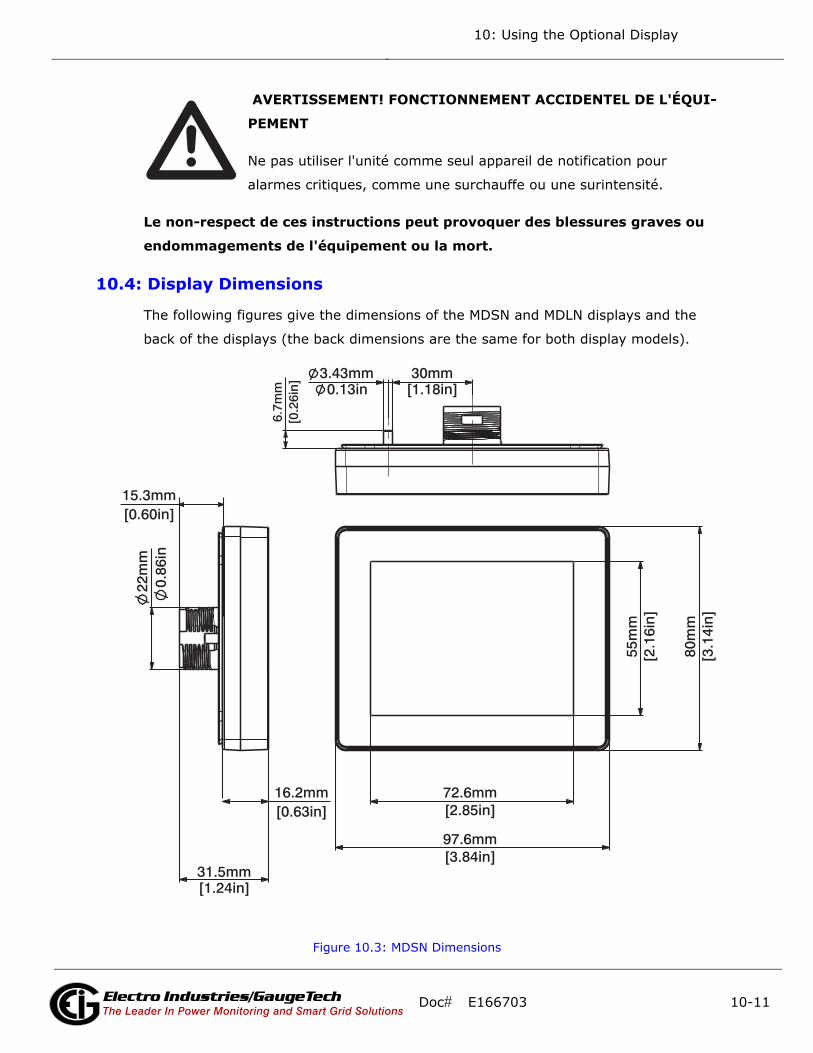
10: Using the Optional Display
AVERTISSEMENT! FONCTIONNEMENT ACCIDENTEL DE L'ÉQUI-
PEMENT
Ne pas utiliser l'unité comme seul appareil de notification pour
alarmes critiques, comme une surchauffe ou une surintensité.
Le non-respect de ces instructions peut provoquer des blessures graves ou
endommagements de l'équipement ou la mort.
10.4: Display Dimensions
The following figures give the dimensions of the MDSN and MDLN displays and the
back of the displays (the back dimensions are the same for both display models).
Figure 10.3: MDSN Dimensions
[1.18in]30mm3.43mm
0.13in
[0.2
6in]
6.7m
m
[0.63in]16.2mm
[0.60in]15.3mm
[1.24in]31.5mm
[2.85in]72.6mm
[3.84in]97.6mm
[2.1
6in]
55m
m
[3.1
4in]
80m
m
22m
m0.
86in
Doc# E166703 10-11Electro Industries/GaugeTechThe Leader In Power Monitoring and Smart Grid Solutions
Electro Industries/GaugeTechThe Leader In Power Monitoring and Smart Grid Solutions
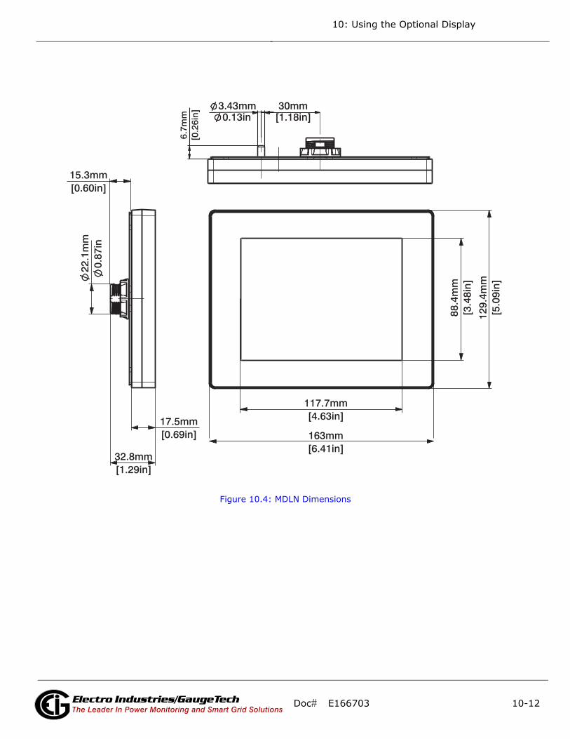
10: Using the Optional Display
Figure 10.4: MDLN Dimensions
[6.41in]163mm
[4.63in]117.7mm
[3.4
8in]
88.4
mm
[5.0
9in]
129.
4mm
22.1
mm
0.87
in
[0.60in]15.3mm
[0.69in]17.5mm
[1.29in]32.8mm
[1.18in]30mm3.43mm
0.13in
[0.2
6in]
6.7m
m
Doc# E166703 10-12Electro Industries/GaugeTechThe Leader In Power Monitoring and Smart Grid Solutions
Electro Industries/GaugeTechThe Leader In Power Monitoring and Smart Grid Solutions

10: Using the Optional Display
Figure 10.5: MDSN/MDLN Back Dimensions
[1.20in]30.6mm
[1.57in]40.1mm
[4.64in]118mm
[3 .8
6in]
98.1
mm
[ 0.6
7in]
17.2
mm
[0.37in]9.5mm
Doc# E166703 10-13Electro Industries/GaugeTechThe Leader In Power Monitoring and Smart Grid Solutions
Electro Industries/GaugeTechThe Leader In Power Monitoring and Smart Grid Solutions
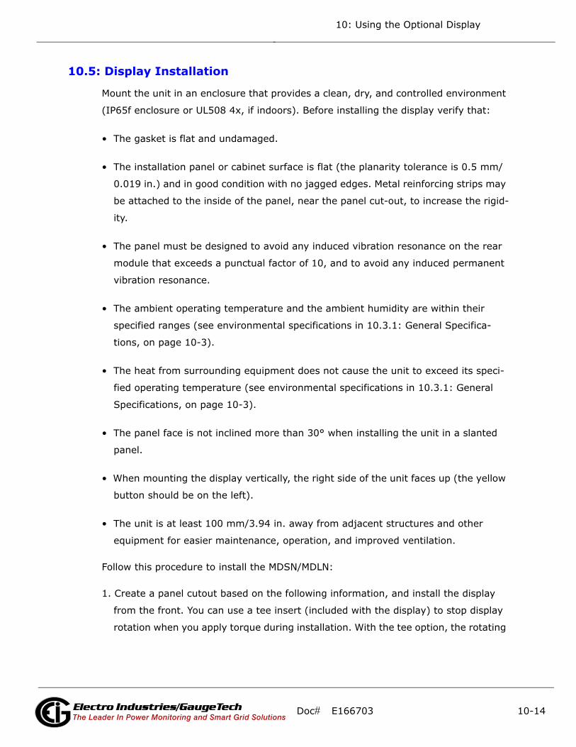
10: Using the Optional Display
10.5: Display Installation
Mount the unit in an enclosure that provides a clean, dry, and controlled environment
(IP65f enclosure or UL508 4x, if indoors). Before installing the display verify that:
• The gasket is flat and undamaged.
• The installation panel or cabinet surface is flat (the planarity tolerance is 0.5 mm/
0.019 in.) and in good condition with no jagged edges. Metal reinforcing strips may
be attached to the inside of the panel, near the panel cut-out, to increase the rigid-
ity.
• The panel must be designed to avoid any induced vibration resonance on the rear
module that exceeds a punctual factor of 10, and to avoid any induced permanent
vibration resonance.
• The ambient operating temperature and the ambient humidity are within their
specified ranges (see environmental specifications in 10.3.1: General Specifica-
tions, on page 10-3).
• The heat from surrounding equipment does not cause the unit to exceed its speci-
fied operating temperature (see environmental specifications in 10.3.1: General
Specifications, on page 10-3).
• The panel face is not inclined more than 30° when installing the unit in a slanted
panel.
• When mounting the display vertically, the right side of the unit faces up (the yellow
button should be on the left).
• The unit is at least 100 mm/3.94 in. away from adjacent structures and other
equipment for easier maintenance, operation, and improved ventilation.
Follow this procedure to install the MDSN/MDLN:
1. Create a panel cutout based on the following information, and install the display
from the front. You can use a tee insert (included with the display) to stop display
rotation when you apply torque during installation. With the tee option, the rotating
Doc# E166703 10-14Electro Industries/GaugeTechThe Leader In Power Monitoring and Smart Grid Solutions
Electro Industries/GaugeTechThe Leader In Power Monitoring and Smart Grid Solutions

10: Using the Optional Display
torque is 6 Nm/53.10 in-lb. Without the tee option the rotating torque is 2.5 Nm/
22.12 in-lb.
Figure 10.6: Cutout Dimensions without Tee Insert
Figure 10.7: Cutout Dimensions with Tee Insert
Unit A (mm) A (in.) B (mm) (1) B (in.) (1) B (mm) (2) B (in.) (2)MDSNMDLN
+022.50
-0.30
+00.88
-0.011.5 to 6 0.06 to 0.23 3 to 6 0.11 to
0.23
The Material of the panel(1) Steel sheet (2) Fiberglass (minimum GF30)
Unit C (mm) C (in.) D (mm) D (in.)MDSNMDLN
+030.00
-0.20
+01.18
-0.007
+04.00
-0.20
+00.15
-0.007
A
B
D
C
Doc# E166703 10-15Electro Industries/GaugeTechThe Leader In Power Monitoring and Smart Grid Solutions
Electro Industries/GaugeTechThe Leader In Power Monitoring and Smart Grid Solutions
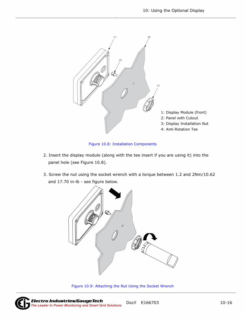
10: Using the Optional Display
Figure 10.8: Installation Components
2. Insert the display module (along with the tee insert if you are using it) into the
panel hole (see Figure 10.8).
3. Screw the nut using the socket wrench with a torque between 1.2 and 2Nm/10.62
and 17.70 in-lb - see figure below.
Figure 10.9: Attaching the Nut Using the Socket Wrench
(5)
(1) (8)
(7)
1: Display Module (front)2: Panel with Cutout3: Display Installation Nut4: Anti-Rotation Tee
Doc# E166703 10-16Electro Industries/GaugeTechThe Leader In Power Monitoring and Smart Grid Solutions
Electro Industries/GaugeTechThe Leader In Power Monitoring and Smart Grid Solutions
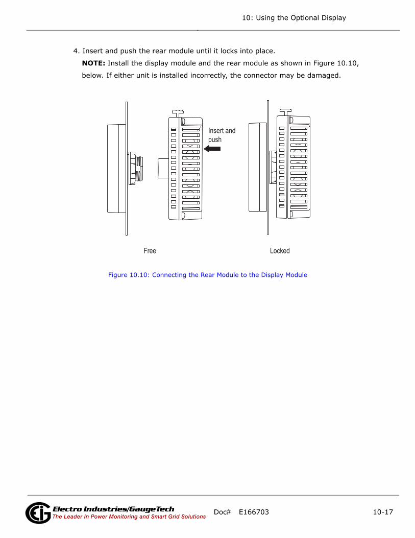
10: Using the Optional Display
4. Insert and push the rear module until it locks into place.
NOTE: Install the display module and the rear module as shown in Figure 10.10,
below. If either unit is installed incorrectly, the connector may be damaged.
Figure 10.10: Connecting the Rear Module to the Display Module
Insert andpush
Free Locked
Doc# E166703 10-17Electro Industries/GaugeTechThe Leader In Power Monitoring and Smart Grid Solutions
Electro Industries/GaugeTechThe Leader In Power Monitoring and Smart Grid Solutions

10: Using the Optional Display
To remove the rear module, press the yellow button to unlock it and pull the rear
module away from the display module.
Figure 10.11: Removing the Rear Module from the Display Module
10.6: Display Configuration
The optional display can communicate with the MP200 metering system through
either of two ways:
• RS485 serial communication through the MP200 unit’s Com 3 serial port
• RJ45 Ethernet through the MP200 unit’s optional Ethernet/WiFi on Com 1
Both the MP200 unit and the display need to have specific settings to enable their
communication. The display is pre-programmed to communicate with the MP200
metering system’s default IP address and RS485 Com port settings. If you have
changed the MP 200 unit’s IP address, follow the procedure in 10.8.2: Setting Com-
munication through Offline Mode, on page 10-41, to set a different, compatible IP
address for the display. Also, if you receive a communication error message, follow
the instructions in 10.8.2: Setting Communication through Offline Mode, on page 10-
41, to correct it.
Push
Pull
Locked Unlocked Free
Doc# E166703 10-18Electro Industries/GaugeTechThe Leader In Power Monitoring and Smart Grid Solutions
Electro Industries/GaugeTechThe Leader In Power Monitoring and Smart Grid Solutions
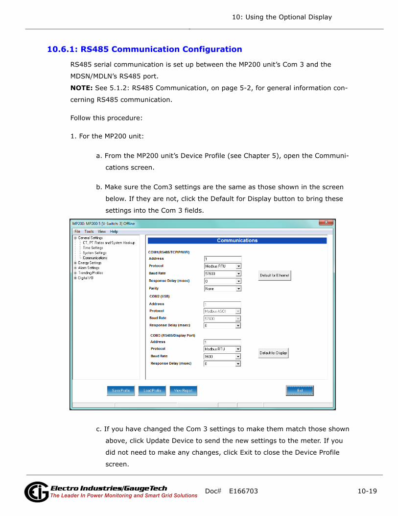
10: Using the Optional Display
10.6.1: RS485 Communication Configuration
RS485 serial communication is set up between the MP200 unit’s Com 3 and the
MDSN/MDLN’s RS485 port.
NOTE: See 5.1.2: RS485 Communication, on page 5-2, for general information con-
cerning RS485 communication.
Follow this procedure:
1. For the MP200 unit:
a. From the MP200 unit’s Device Profile (see Chapter 5), open the Communi-
cations screen.
b. Make sure the Com3 settings are the same as those shown in the screen
below. If they are not, click the Default for Display button to bring these
settings into the Com 3 fields.
c. If you have changed the Com 3 settings to make them match those shown
above, click Update Device to send the new settings to the meter. If you
did not need to make any changes, click Exit to close the Device Profile
screen.
Doc# E166703 10-19Electro Industries/GaugeTechThe Leader In Power Monitoring and Smart Grid Solutions
Electro Industries/GaugeTechThe Leader In Power Monitoring and Smart Grid Solutions
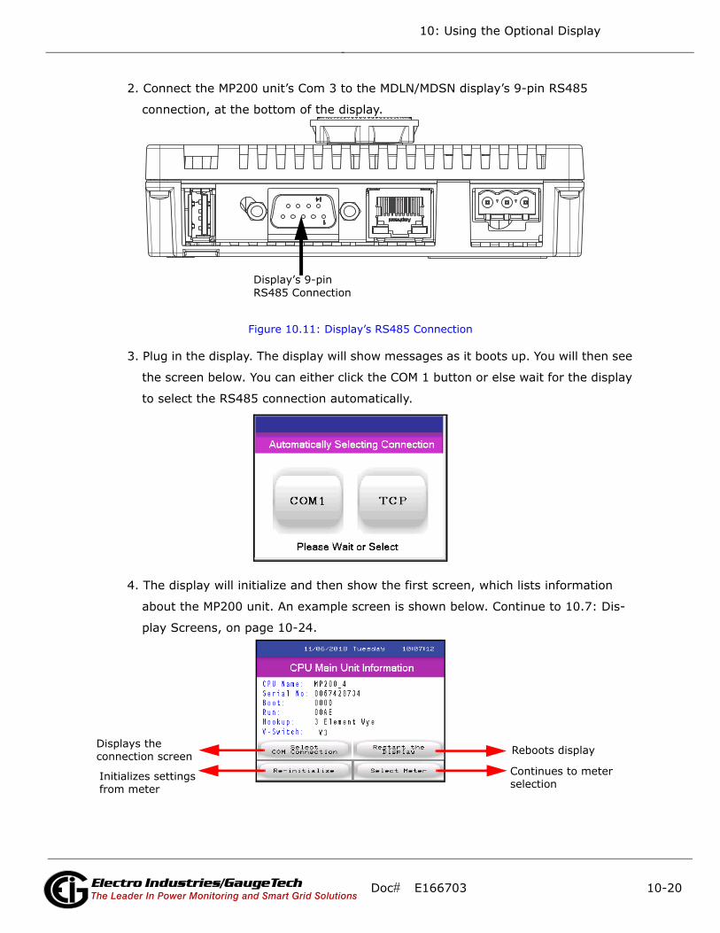
10: Using the Optional Display
2. Connect the MP200 unit’s Com 3 to the MDLN/MDSN display’s 9-pin RS485
connection, at the bottom of the display.
Figure 10.11: Display’s RS485 Connection
3. Plug in the display. The display will show messages as it boots up. You will then see
the screen below. You can either click the COM 1 button or else wait for the display
to select the RS485 connection automatically.
4. The display will initialize and then show the first screen, which lists information
about the MP200 unit. An example screen is shown below. Continue to 10.7: Dis-
play Screens, on page 10-24.
Display’s 9-pin RS485 Connection
Reboots display
Continues to meter
Displays the
selection
connection screen
Initializes settingsfrom meter
Doc# E166703 10-20Electro Industries/GaugeTechThe Leader In Power Monitoring and Smart Grid Solutions
Electro Industries/GaugeTechThe Leader In Power Monitoring and Smart Grid Solutions
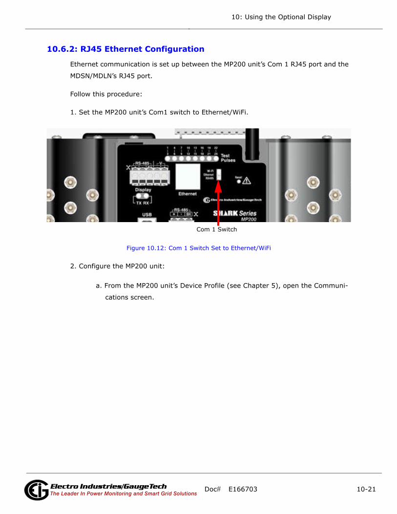
10: Using the Optional Display
10.6.2: RJ45 Ethernet Configuration
Ethernet communication is set up between the MP200 unit’s Com 1 RJ45 port and the
MDSN/MDLN’s RJ45 port.
Follow this procedure:
1. Set the MP200 unit’s Com1 switch to Ethernet/WiFi.
Figure 10.12: Com 1 Switch Set to Ethernet/WiFi
2. Configure the MP200 unit:
a. From the MP200 unit’s Device Profile (see Chapter 5), open the Communi-
cations screen.
Com 1 Switch
Doc# E166703 10-21Electro Industries/GaugeTechThe Leader In Power Monitoring and Smart Grid Solutions
Electro Industries/GaugeTechThe Leader In Power Monitoring and Smart Grid Solutions
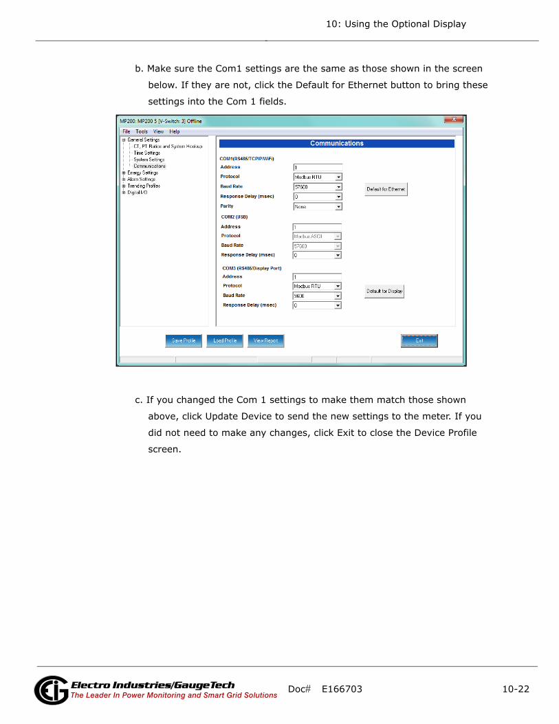
10: Using the Optional Display
b. Make sure the Com1 settings are the same as those shown in the screen
below. If they are not, click the Default for Ethernet button to bring these
settings into the Com 1 fields.
c. If you changed the Com 1 settings to make them match those shown
above, click Update Device to send the new settings to the meter. If you
did not need to make any changes, click Exit to close the Device Profile
screen.
Doc# E166703 10-22Electro Industries/GaugeTechThe Leader In Power Monitoring and Smart Grid Solutions
Electro Industries/GaugeTechThe Leader In Power Monitoring and Smart Grid Solutions
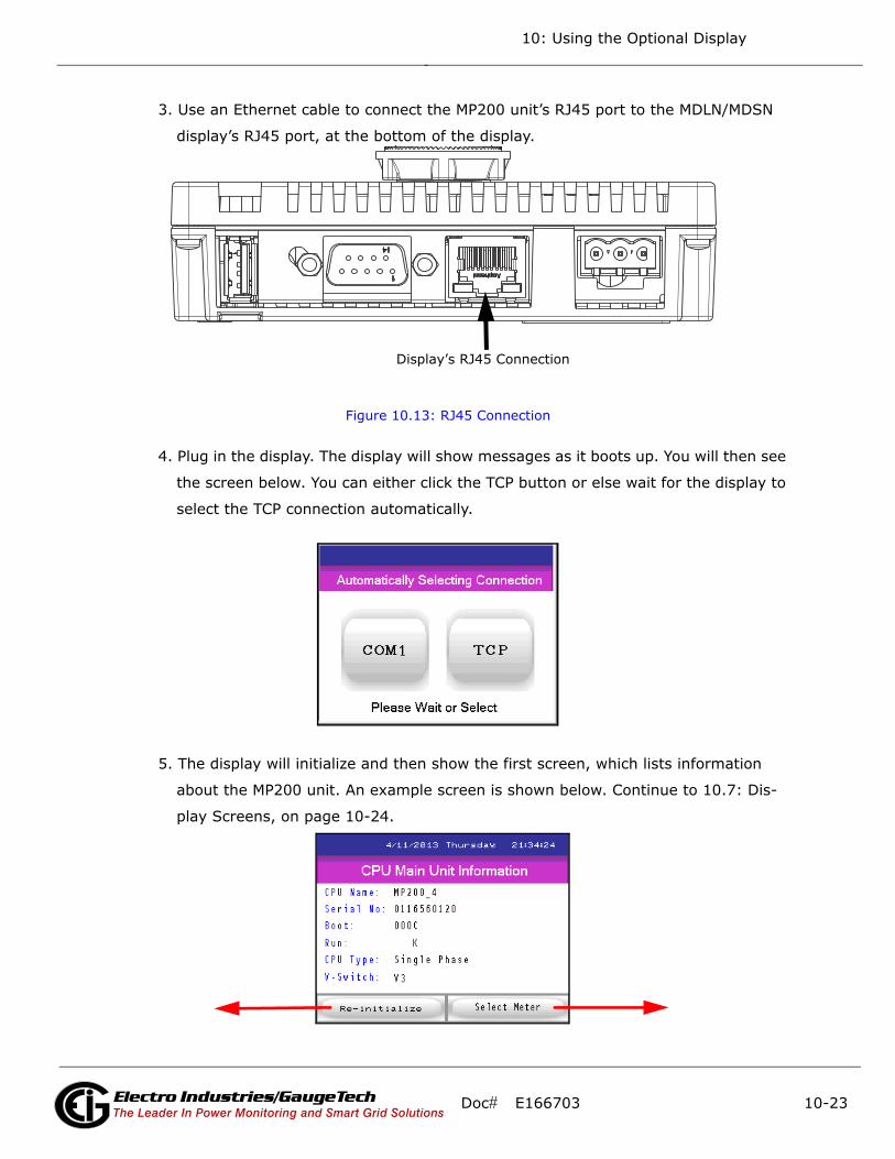
10: Using the Optional Display
3. Use an Ethernet cable to connect the MP200 unit’s RJ45 port to the MDLN/MDSN
display’s RJ45 port, at the bottom of the display.
Figure 10.13: RJ45 Connection
4. Plug in the display. The display will show messages as it boots up. You will then see
the screen below. You can either click the TCP button or else wait for the display to
select the TCP connection automatically.
5. The display will initialize and then show the first screen, which lists information
about the MP200 unit. An example screen is shown below. Continue to 10.7: Dis-
play Screens, on page 10-24.
Display’s RJ45 Connection
Doc# E166703 10-23Electro Industries/GaugeTechThe Leader In Power Monitoring and Smart Grid Solutions
Electro Industries/GaugeTechThe Leader In Power Monitoring and Smart Grid Solutions
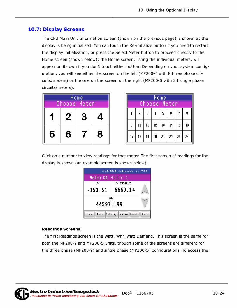
10: Using the Optional Display
10.7: Display Screens
The CPU Main Unit Information screen (shown on the previous page) is shown as the
display is being initialized. You can touch the Re-initialize button if you need to restart
the display initialization, or press the Select Meter button to proceed directly to the
Home screen (shown below); the Home screen, listing the individual meters, will
appear on its own if you don’t touch either button. Depending on your system config-
uration, you will see either the screen on the left (MP200-Y with 8 three phase cir-
cuits/meters) or the one on the screen on the right (MP200-S with 24 single phase
circuits/meters).
Click on a number to view readings for that meter. The first screen of readings for the
display is shown (an example screen is shown below).
Readings Screens
The first Readings screen is the Watt, Whr, Watt Demand. This screen is the same for
both the MP200-Y and MP200-S units, though some of the screens are different for
the three phase (MP200-Y) and single phase (MP200-S) configurations. To access the
Doc# E166703 10-24Electro Industries/GaugeTechThe Leader In Power Monitoring and Smart Grid Solutions
Electro Industries/GaugeTechThe Leader In Power Monitoring and Smart Grid Solutions

10: Using the Optional Display
next screen in sequence, either touch the down arrow button or the Next button. See
the figure below for an explanation of the arrow and button actions.
Following are example Readings screens, in the sequence they appear if you keep
touching the Next button or the Down arrow. The caption underneath the screen tells
you whether it is for the MP200-Y unit’s three phase configuration or the MP200-S
unit’s single phase configuration. Some screens are shared by both MP200 unit con-
figurations.
Three Phase Watts per Phase screen (Wye configuration only, not Delta configuration)
Press to go to theprevious screen
Press to go to thenext screen
Press for: Previous Next Settings Alarms Reset Meter Selection Screen Screen Screens Screen Screen Screen (Home)
Doc# E166703 10-25Electro Industries/GaugeTechThe Leader In Power Monitoring and Smart Grid Solutions
Electro Industries/GaugeTechThe Leader In Power Monitoring and Smart Grid Solutions

10: Using the Optional Display
Three Phase VAR per Phase screen (Wye configuration only, not Delta configuration)
Three Phase VA per Phase screen (Wye configuration only, not Delta configuration)
Single Phase KW, KVAR, KVA screen
Doc# E166703 10-26Electro Industries/GaugeTechThe Leader In Power Monitoring and Smart Grid Solutions
Electro Industries/GaugeTechThe Leader In Power Monitoring and Smart Grid Solutions
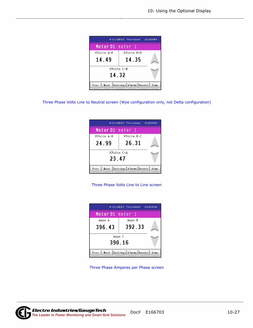
10: Using the Optional Display
Three Phase Volts Line to Neutral screen (Wye configuration only, not Delta configuration)
Three Phase Volts Line to Line screen
Three Phase Amperes per Phase screen
Doc# E166703 10-27Electro Industries/GaugeTechThe Leader In Power Monitoring and Smart Grid Solutions
Electro Industries/GaugeTechThe Leader In Power Monitoring and Smart Grid Solutions
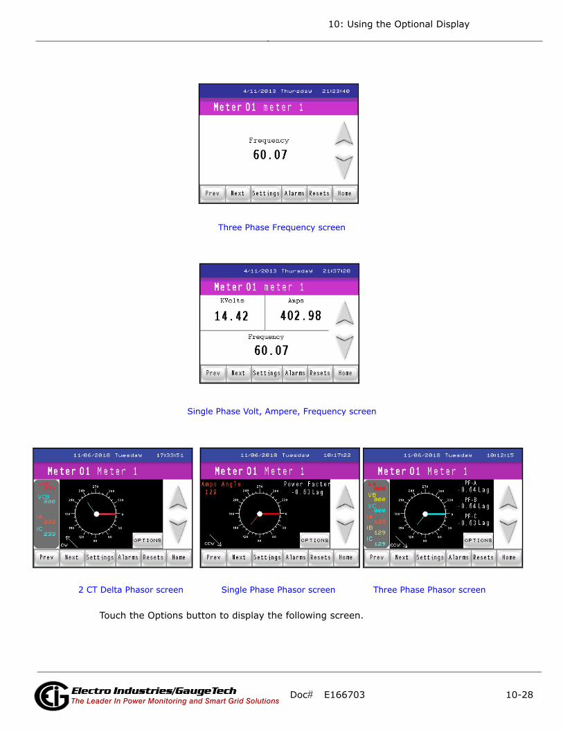
10: Using the Optional Display
Three Phase Frequency screen
Single Phase Volt, Ampere, Frequency screen
2 CT Delta Phasor screen Single Phase Phasor screen Three Phase Phasor screen
Touch the Options button to display the following screen.
Doc# E166703 10-28Electro Industries/GaugeTechThe Leader In Power Monitoring and Smart Grid Solutions
Electro Industries/GaugeTechThe Leader In Power Monitoring and Smart Grid Solutions
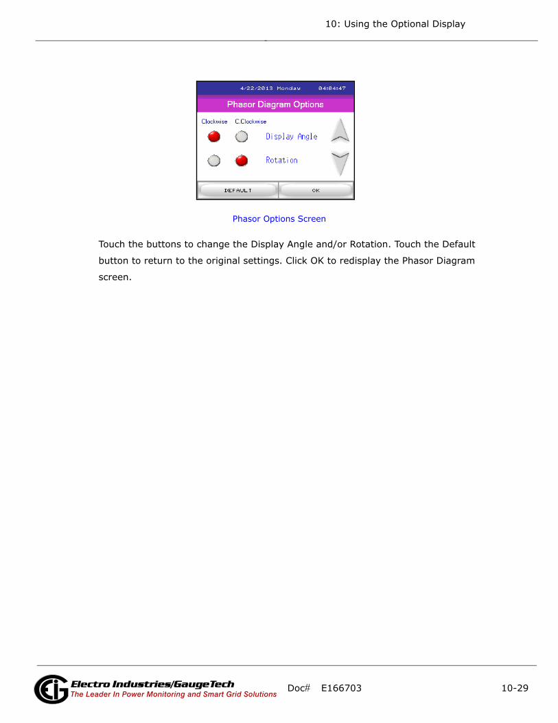
10: Using the Optional Display
Phasor Options Screen
Touch the buttons to change the Display Angle and/or Rotation. Touch the Default
button to return to the original settings. Click OK to redisplay the Phasor Diagram
screen.
Doc# E166703 10-29Electro Industries/GaugeTechThe Leader In Power Monitoring and Smart Grid Solutions
Electro Industries/GaugeTechThe Leader In Power Monitoring and Smart Grid Solutions
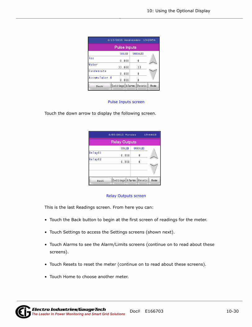
10: Using the Optional Display
Pulse Inputs screen
Touch the down arrow to display the following screen.
Relay Outputs screen
This is the last Readings screen. From here you can:
• Touch the Back button to begin at the first screen of readings for the meter.
• Touch Settings to access the Settings screens (shown next).
• Touch Alarms to see the Alarm/Limits screens (continue on to read about these
screens).
• Touch Resets to reset the meter (continue on to read about these screens).
• Touch Home to choose another meter.
Doc# E166703 10-30Electro Industries/GaugeTechThe Leader In Power Monitoring and Smart Grid Solutions
Electro Industries/GaugeTechThe Leader In Power Monitoring and Smart Grid Solutions
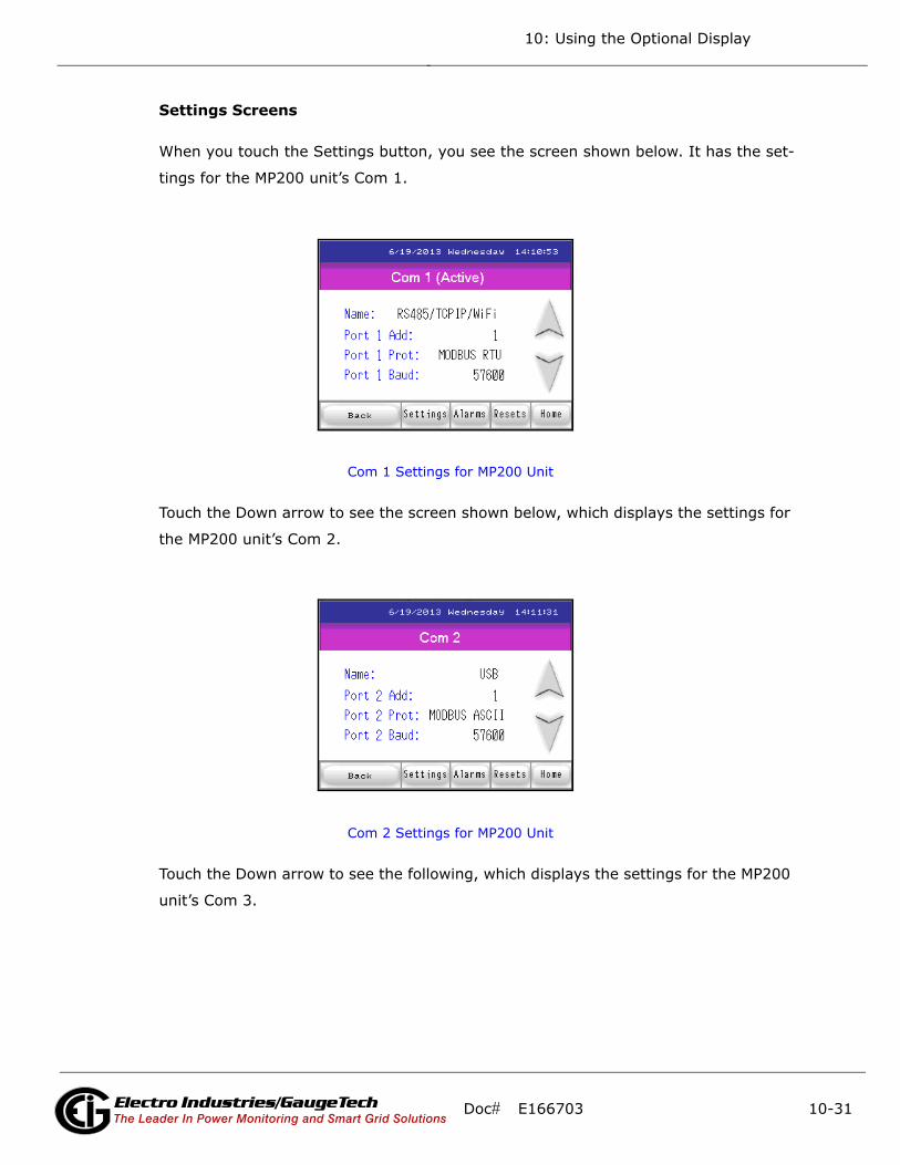
10: Using the Optional Display
Settings Screens
When you touch the Settings button, you see the screen shown below. It has the set-
tings for the MP200 unit’s Com 1.
Com 1 Settings for MP200 Unit
Touch the Down arrow to see the screen shown below, which displays the settings for
the MP200 unit’s Com 2.
Com 2 Settings for MP200 Unit
Touch the Down arrow to see the following, which displays the settings for the MP200
unit’s Com 3.
Doc# E166703 10-31Electro Industries/GaugeTechThe Leader In Power Monitoring and Smart Grid Solutions
Electro Industries/GaugeTechThe Leader In Power Monitoring and Smart Grid Solutions
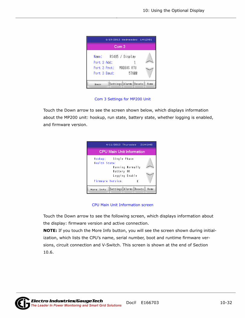
10: Using the Optional Display
Com 3 Settings for MP200 Unit
Touch the Down arrow to see the screen shown below, which displays information
about the MP200 unit: hookup, run state, battery state, whether logging is enabled,
and firmware version.
CPU Main Unit Information screen
Touch the Down arrow to see the following screen, which displays information about
the display: firmware version and active connection.
NOTE: If you touch the More Info button, you will see the screen shown during initial-
ization, which lists the CPU’s name, serial number, boot and runtime firmware ver-
sions, circuit connection and V-Switch. This screen is shown at the end of Section
10.6.
Doc# E166703 10-32Electro Industries/GaugeTechThe Leader In Power Monitoring and Smart Grid Solutions
Electro Industries/GaugeTechThe Leader In Power Monitoring and Smart Grid Solutions

10: Using the Optional Display
Display Information screen
This is the last Settings screen. From here you can:
• Touch the Offline button to access Offline mode (described in 10.8: Offline Mode, on
page 10-38).
• Touch Alarms to see the Alarm/Limits screens (described next).
• Touch Resets to reset the meter (continue on to read about these screens).
• Touch Home to choose another meter.
Doc# E166703 10-33Electro Industries/GaugeTechThe Leader In Power Monitoring and Smart Grid Solutions
Electro Industries/GaugeTechThe Leader In Power Monitoring and Smart Grid Solutions
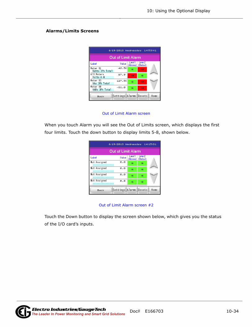
10: Using the Optional Display
Alarms/Limits Screens
Out of Limit Alarm screen
When you touch Alarm you will see the Out of Limits screen, which displays the first
four limits. Touch the down button to display limits 5-8, shown below.
Out of Limit Alarm screen #2
Touch the Down button to display the screen shown below, which gives you the status
of the I/O card’s inputs.
Doc# E166703 10-34Electro Industries/GaugeTechThe Leader In Power Monitoring and Smart Grid Solutions
Electro Industries/GaugeTechThe Leader In Power Monitoring and Smart Grid Solutions
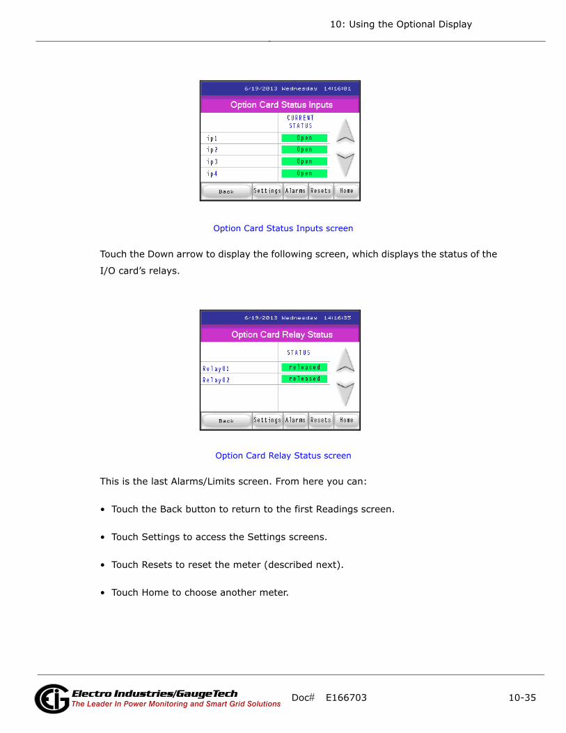
10: Using the Optional Display
Option Card Status Inputs screen
Touch the Down arrow to display the following screen, which displays the status of the
I/O card’s relays.
Option Card Relay Status screen
This is the last Alarms/Limits screen. From here you can:
• Touch the Back button to return to the first Readings screen.
• Touch Settings to access the Settings screens.
• Touch Resets to reset the meter (described next).
• Touch Home to choose another meter.
Doc# E166703 10-35Electro Industries/GaugeTechThe Leader In Power Monitoring and Smart Grid Solutions
Electro Industries/GaugeTechThe Leader In Power Monitoring and Smart Grid Solutions

10: Using the Optional Display
Reset Screens
Reset Device Information screen
When you touch the Resets button you see the screen shown above.
Touch either Reset option to reset either the Max/Min Demand and/or Max/Min Volt-
age and Frequency for all of the meters in the MP200 unit. Touch the Down arrow to
display the following screen.
Reset Demand screen
Doc# E166703 10-36Electro Industries/GaugeTechThe Leader In Power Monitoring and Smart Grid Solutions
Electro Industries/GaugeTechThe Leader In Power Monitoring and Smart Grid Solutions
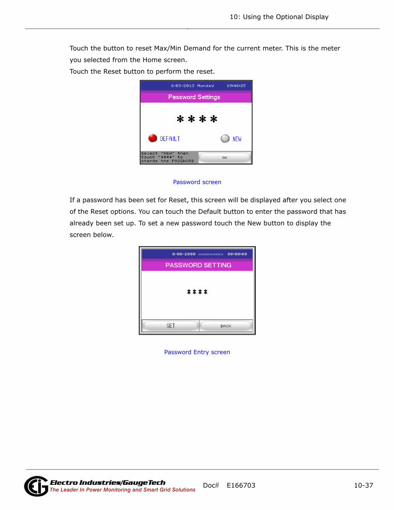
10: Using the Optional Display
Touch the button to reset Max/Min Demand for the current meter. This is the meter
you selected from the Home screen.
Touch the Reset button to perform the reset.
Password screen
If a password has been set for Reset, this screen will be displayed after you select one
of the Reset options. You can touch the Default button to enter the password that has
already been set up. To set a new password touch the New button to display the
screen below.
Password Entry screen
Doc# E166703 10-37Electro Industries/GaugeTechThe Leader In Power Monitoring and Smart Grid Solutions
Electro Industries/GaugeTechThe Leader In Power Monitoring and Smart Grid Solutions

10: Using the Optional Display
10.8: Offline Mode
The display’s Offline mode lets you can change settings for the display. To access
Offline mode, touch the Offline button from the Display Information screen: the dis-
play will beep and then will enter Offline mode.
The screen above is the Home screen, which is the first screen you will see in Offline
mode. It tells you information about the system and lets you select a language for
Offline mode (the choices are English and Japanese; English is the default). Press the
right arrow button at the bottom of the screen to see additional system information.
To access this screen from one of the other Offline screens, touch the Home tab at the
top of the screen.
The buttons at the bottom of the screen let you save any setting changes and stay in
Offline mode (Save), Exit Offline mode, with or without saving changes (Exit - you will
see a confirmation screen that asks if you want to save changes and exit, or exit with-
out saving changes), return settings to their previous state (Cancel).
NOTE: In this manual we only describe in detail the Offline screen’s whose settings
you may need to change when working with the MP200 metering system.
Main Unit tab
Touch the Main Unit tab to access the following setting:
• Screen settings
• Operation
• Display
• Menu and Error
Doc# E166703 10-38Electro Industries/GaugeTechThe Leader In Power Monitoring and Smart Grid Solutions
Electro Industries/GaugeTechThe Leader In Power Monitoring and Smart Grid Solutions

10: Using the Optional Display
• Window Settings
• System Area
• Ethernet (see 10.8.2: Setting Communication through Offline Mode, on page 10-
41, for information on this setting)
• Logic
• Extended
• Remote Viewer
To access a setting, touch its button. Other screens will display that will let you make
changes to the settings.
Peripheral Tab
Touch the Peripheral tab to access the following settings:
• Device/PLC Settings (see 10.8.2: Setting Communication through Offline Mode, on
page 10-41, for information on this setting)
• Printer Settings
• Bar Code Settings
• USB
• Script Settings
To access a setting, touch its button. Other settings screens will display.
Doc# E166703 10-39Electro Industries/GaugeTechThe Leader In Power Monitoring and Smart Grid Solutions
Electro Industries/GaugeTechThe Leader In Power Monitoring and Smart Grid Solutions
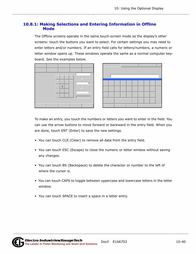
10: Using the Optional Display
10.8.1: Making Selections and Entering Information in Offline Mode
The Offline screens operate in the same touch-screen mode as the display’s other
screens: touch the buttons you want to select. For certain settings you may need to
enter letters and/or numbers. If an entry field calls for letters/numbers, a numeric or
letter window opens up. These windows operate the same as a normal computer key-
board. See the examples below.
To make an entry, you touch the numbers or letters you want to enter in the field. You
can use the arrow buttons to move forward or backward in the entry field. When you
are done, touch ENT (Enter) to save the new settings.
• You can touch CLR (Clear) to remove all data from the entry field.
• You can touch ESC (Escape) to close the numeric or letter window without saving
any changes.
• You can touch BS (Backspace) to delete the character or number to the left of
where the cursor is.
• You can touch CAPS to toggle between uppercase and lowercase letters in the letter
window.
• You can touch SPACE to insert a space in a letter entry.
Doc# E166703 10-40Electro Industries/GaugeTechThe Leader In Power Monitoring and Smart Grid Solutions
Electro Industries/GaugeTechThe Leader In Power Monitoring and Smart Grid Solutions

10: Using the Optional Display
10.8.2: Setting Communication through Offline Mode
If the display is not able to communicate with the MP200 metering system (for exam-
ple, if you have changed the default IP address of the MP200 unit), you will see an
error message similar to the one shown below, at the bottom of the display screen.
The exact message you see depends on whether an RS485 or RJ45 cable is displayed:
the message will say MP200_T: TCP for an RJ45 communication error and MP200_C:
Com1 for an RS485 communication error.
NOTE: Refer to 10.8.1: Making Selections and Entering Information in Offline Mode,
on page 10-40 for instructions on making entries in Offline mode.
1. Touch the black screen button at the bottom of the display.
2. The bottom of the screen will display the Offline and Reset buttons, as shown
below. Touch the Offline button.
Touch this button
Touch this button
Doc# E166703 10-41Electro Industries/GaugeTechThe Leader In Power Monitoring and Smart Grid Solutions
Electro Industries/GaugeTechThe Leader In Power Monitoring and Smart Grid Solutions

10: Using the Optional Display
3. From the Offline Home screen, touch the Peripheral tab.
4. From the Peripheral menu, touch the Device/PLC Settings button.
5. What you do now depends on your communication connection.
• If you are connecting via RS485:
a. Click the second button for Com1.
Touch this tab
Touch this button
Touch this button
Doc# E166703 10-42Electro Industries/GaugeTechThe Leader In Power Monitoring and Smart Grid Solutions
Electro Industries/GaugeTechThe Leader In Power Monitoring and Smart Grid Solutions
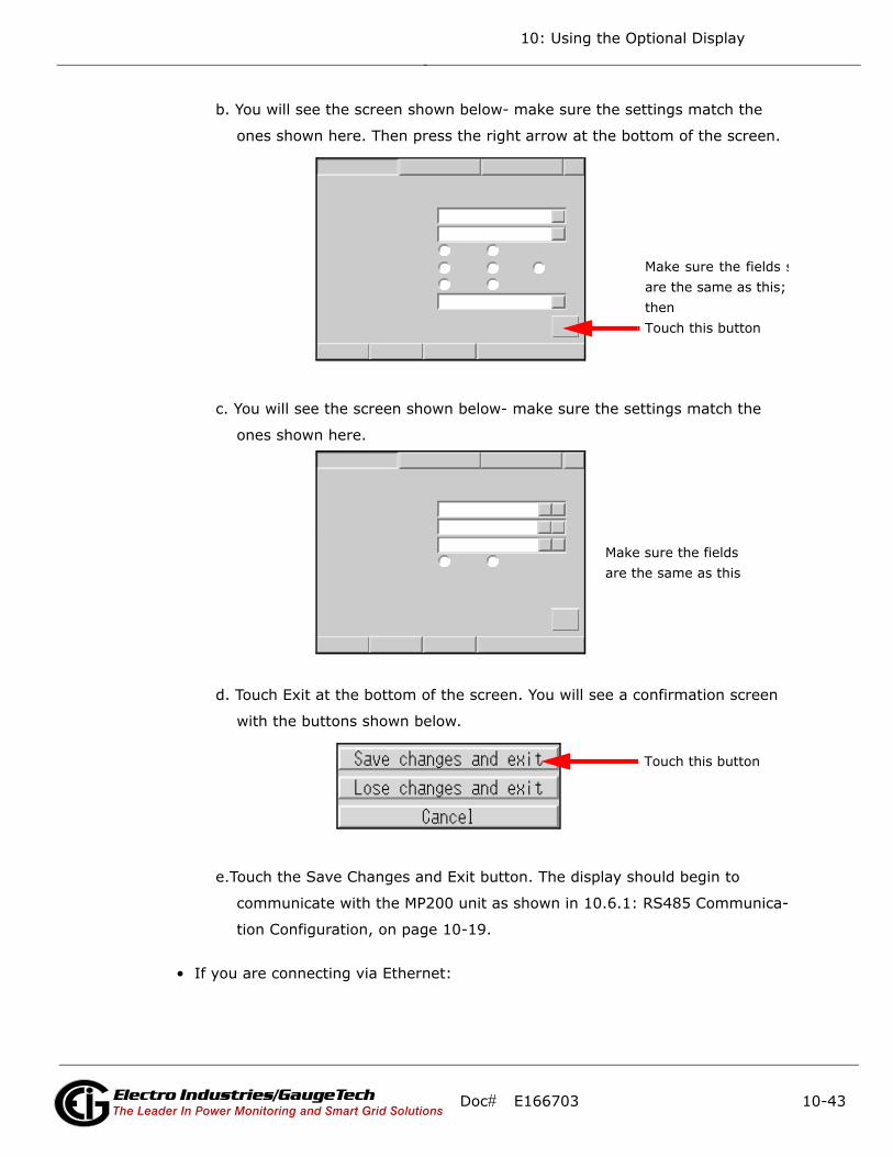
10: Using the Optional Display
b. You will see the screen shown below- make sure the settings match the
ones shown here. Then press the right arrow at the bottom of the screen.
c. You will see the screen shown below- make sure the settings match the
ones shown here.
d. Touch Exit at the bottom of the screen. You will see a confirmation screen
with the buttons shown below.
e.Touch the Save Changes and Exit button. The display should begin to
communicate with the MP200 unit as shown in 10.6.1: RS485 Communica-
tion Configuration, on page 10-19.
• If you are connecting via Ethernet:
Make sure the fields sare the same as this;then Touch this button
Make sure the fields are the same as this
Touch this button
Doc# E166703 10-43Electro Industries/GaugeTechThe Leader In Power Monitoring and Smart Grid Solutions
Electro Industries/GaugeTechThe Leader In Power Monitoring and Smart Grid Solutions
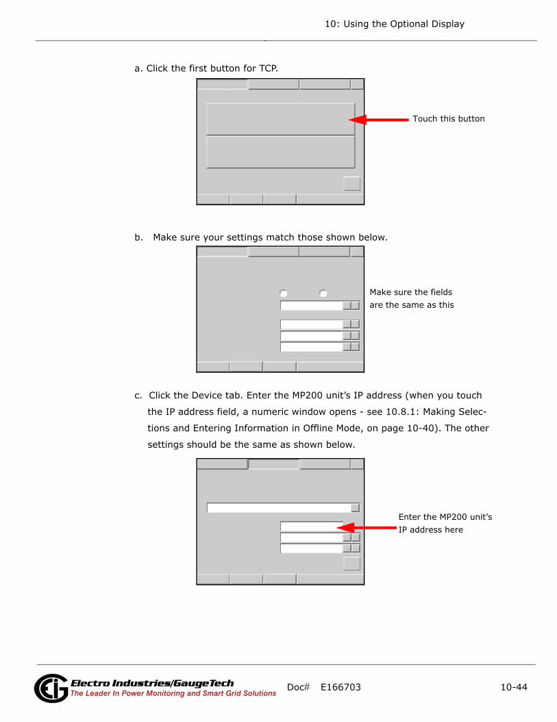
10: Using the Optional Display
a. Click the first button for TCP.
b. Make sure your settings match those shown below.
c. Click the Device tab. Enter the MP200 unit’s IP address (when you touch
the IP address field, a numeric window opens - see 10.8.1: Making Selec-
tions and Entering Information in Offline Mode, on page 10-40). The other
settings should be the same as shown below.
Touch this button
Make sure the fields are the same as this
Enter the MP200 unit’sIP address here
Doc# E166703 10-44Electro Industries/GaugeTechThe Leader In Power Monitoring and Smart Grid Solutions
Electro Industries/GaugeTechThe Leader In Power Monitoring and Smart Grid Solutions
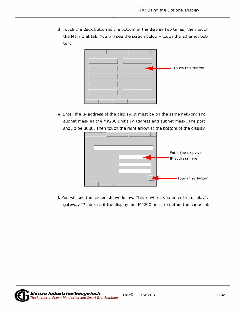
10: Using the Optional Display
d. Touch the Back button at the bottom of the display two times; then touch
the Main Unit tab. You will see the screen below - touch the Ethernet but-
ton.
e. Enter the IP address of the display. It must be on the same network and
subnet mask as the MP200 unit’s IP address and subnet mask. The port
should be 8000. Then touch the right arrow at the bottom of the display.
f. You will see the screen shown below. This is where you enter the display’s
gateway IP address if the display and MP200 unit are not on the same sub-
Touch this button
Touch this button
Enter the display’sIP address here
Doc# E166703 10-45Electro Industries/GaugeTechThe Leader In Power Monitoring and Smart Grid Solutions
Electro Industries/GaugeTechThe Leader In Power Monitoring and Smart Grid Solutions
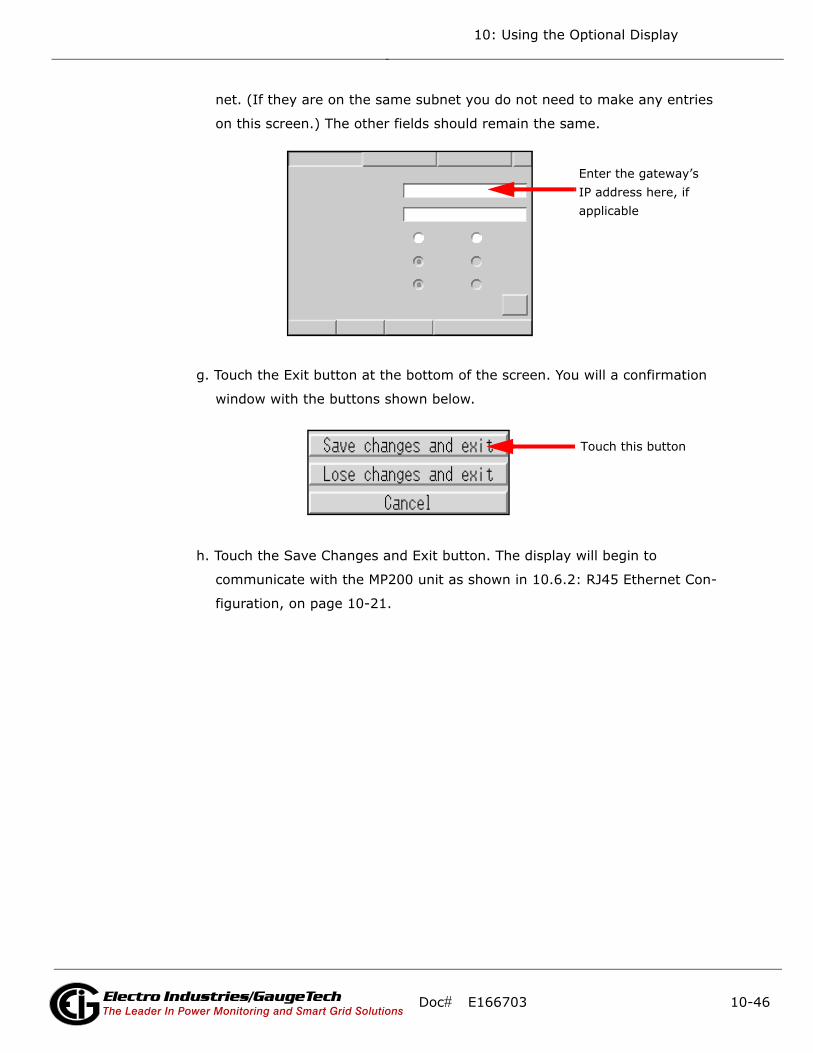
10: Using the Optional Display
net. (If they are on the same subnet you do not need to make any entries
on this screen.) The other fields should remain the same.
g. Touch the Exit button at the bottom of the screen. You will a confirmation
window with the buttons shown below.
h. Touch the Save Changes and Exit button. The display will begin to
communicate with the MP200 unit as shown in 10.6.2: RJ45 Ethernet Con-
figuration, on page 10-21.
Enter the gateway’sIP address here, if applicable
Touch this button
Doc# E166703 10-46Electro Industries/GaugeTechThe Leader In Power Monitoring and Smart Grid Solutions
Electro Industries/GaugeTechThe Leader In Power Monitoring and Smart Grid Solutions

10: Using the Optional Display
10.9: Maintenance
Cleaning the Display
CAUTION: EQUIPMENT DAMAGE
• Power off the unit before cleaning it.
• Do not use hard or pointed objects to operate the touch panel, since
it can damage the panel surface.
• Do not use paint thinner, organic solvents, or a strong acid
compound to clean the unit.
Failure to follow these instructions can result in equipment damage.
When the surface or the frame of the display gets dirty, soak a soft cloth in water with
a neutral detergent, wring the cloth tightly and wipe the display.
Periodic Checks
Operation Environment
Refer to the Environmental Specifications in 10.3.1: General Specifications, on
page 10-3.
Electrical Specifications
The input voltage must be within 20.4 to 28.8 VDC.
Related Items
• Are all power cords and cables connected properly? Are there any loose cables?
• Is the display installation nut holding the unit securely?
• Are there scratches or traces of dirt on the installation gasket?
NOTE: A gasket with scratches or dirt may have lost much of its water resistance.
Make sure to change the gasket for one with a water resistance equivalent to IP65f
when scratches or dirt become visible.
Doc# E166703 10-47Electro Industries/GaugeTechThe Leader In Power Monitoring and Smart Grid Solutions
Electro Industries/GaugeTechThe Leader In Power Monitoring and Smart Grid Solutions
10: Using the Optional Display
10.10: Compliance and Standards
• ANSI/UL 61010-1 / ANSI/UL 61010-2-201 for Programmable Controllers
• CSA C22.2 no. 142 for Industrial Control Equipment
• IEC 61010-1/IEC 610010-2-201 for Programmable Controllers
• ANSI/ISA 12.12.01 and CSA C22.2 no. 213 for Electrical Equipment for Use in Class
I, Division 2 Groups A, B, C and D Hazardous (classified) Locations Hazardous Sub-
stances
• WEEE, Directive 2012/19/EU
• RoHS, Directive 2011/65/EU and 2015/863/EU
• RoHS China, Standard (GB/T 26572)
UL Conditions of Acceptability and Handling Cautions for Unit:
The GP unit is suitable for use in hazardous locations in accordance with Class I,
Division 2 Groups A, B, C and D standards. All relevant local, state, and regional
codes must be followed.
CE Markings:
This product conforms to the necessary requirements of the following Directives for
applying the CE label:
• Directive 2014/35/EU (Low voltage)
• Directive 2014/30/EU (EMC)
This conformity is based on compliance with IEC 61131-2.
Doc# E166703 10-48Electro Industries/GaugeTechThe Leader In Power Monitoring and Smart Grid Solutions
Electro Industries/GaugeTechThe Leader In Power Monitoring and Smart Grid Solutions
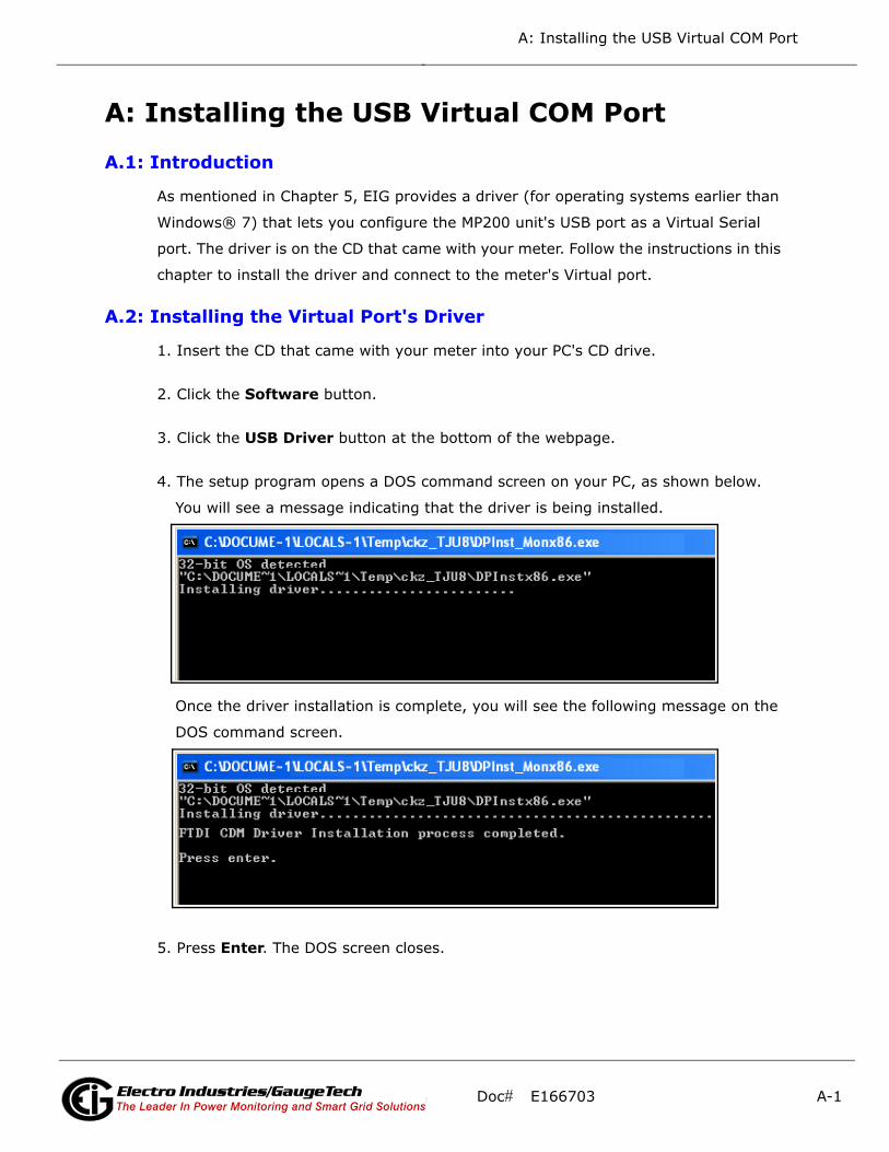
A: Installing the USB Virtual COM Port
A: Installing the USB Virtual COM Port
A.1: Introduction
As mentioned in Chapter 5, EIG provides a driver (for operating systems earlier than
Windows® 7) that lets you configure the MP200 unit's USB port as a Virtual Serial
port. The driver is on the CD that came with your meter. Follow the instructions in this
chapter to install the driver and connect to the meter's Virtual port.
A.2: Installing the Virtual Port's Driver
1. Insert the CD that came with your meter into your PC's CD drive.
2. Click the Software button.
3. Click the USB Driver button at the bottom of the webpage.
4. The setup program opens a DOS command screen on your PC, as shown below.
You will see a message indicating that the driver is being installed.
Once the driver installation is complete, you will see the following message on the
DOS command screen.
5. Press Enter. The DOS screen closes.
Doc# E166703 A-1Electro Industries/GaugeTechThe Leader In Power Monitoring and Smart Grid SolutionsElectro Industries/GaugeTechThe Leader In Power Monitoring and Smart Grid Solutions

A: Installing the USB Virtual COM Port
6. Plug a USB cable into your PC and the MP200 unit's USB port. You will see pop-up
message windows telling you that new hardware has been found and that it is
installed and ready to use.
A.3: Connecting to the Virtual Port
1. Open Communicator EXT.
2. Click the Connect icon. You will see the Connect screen, shown below.
3. Click the Serial Port and Available Ports radio buttons and select the Port
labelled as the USB Serial Port.
4. Click Connect.
Doc# E166703 A-2Electro Industries/GaugeTechThe Leader In Power Monitoring and Smart Grid SolutionsElectro Industries/GaugeTechThe Leader In Power Monitoring and Smart Grid Solutions

B: Modbus Map Overview
B: Modbus Map Overview
B.1: Introduction
The Modbus map for the MP200 metering system gives details and information about
its possible readings and its programming. The MP200 unit can be programmed using
Communicator EXTTM software. For a programming overview, see Section 5.2. For fur-
ther details see the Communicator EXTTM 4.0 and MeterManager EXT Software User
Manual.
B.2: Modbus Register Map Sections
The MP200 unit’s Modbus Register map includes the following sections:
Fixed Data Section, Registers 1- 37, details the MP200 unit's fixed information.
Meter Data Section, Registers 1000 - 12011, details the MP200 unit’s readings,
including Primary Readings, Energy Block, Demand Block, Phase Angle Block, Status
Block, Minimum and Maximum in Regular and Time Stamp Blocks, Interval Energy
Blocks, I/O Card Blocks, and Accumulators.
Commands Section, Registers 20000 - 26011, details the MP200 unit's Resets Block,
Privileged Commands Block and Encryption Block.
Programmable Settings Section, Registers 30000 - 32575, details all the settings you
can program to configure your MP200 unit.
Log Retrieval Section, Registers 49997 - 51095, details Log Retrieval Block and Log
Status Block. See Appendix E for instructions on retrieving logs using the Modbus reg-
isters.
B.3: Data Formats
ASCII: ASCII characters packed 2 per register in high,
low order and without any termination characters
SINT16/UINT16: 16-bit signed/unsigned integer
Doc# E166703 B-1Electro Industries/GaugeTechThe Leader In Power Monitoring and Smart Grid SolutionsElectro Industries/GaugeTechThe Leader In Power Monitoring and Smart Grid SolutionsElectro Industries/GaugeTechThe Leader In Power Monitoring and Smart Grid Solutions
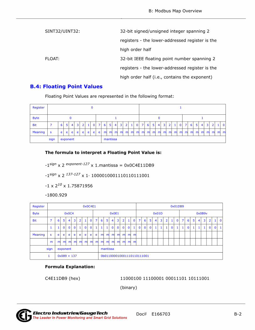
B: Modbus Map Overview
SINT32/UINT32: 32-bit signed/unsigned integer spanning 2
registers - the lower-addressed register is the
high order half
FLOAT: 32-bit IEEE floating point number spanning 2
registers - the lower-addressed register is the
high order half (i.e., contains the exponent)
B.4: Floating Point Values
Floating Point Values are represented in the following format:
The formula to interpret a Floating Point Value is:
-1sign x 2 exponent-127 x 1.mantissa = 0x0C4E11DB9
-1sign x 2 137-127 x 1· 1000010001110110111001
-1 x 210 x 1.75871956
-1800.929
Formula Explanation:
C4E11DB9 (hex) 11000100 11100001 00011101 10111001
(binary)
Register 0 1
Byte 0 1 0 1
Bit 7 6 5 4 3 2 1 0 7 6 5 4 3 2 1 0 7 6 5 4 3 2 1 0 7 6 5 4 3 2 1 0
Meaning s e e e e e e e e m m m m m m m m m m m m m m m m m m m m m m m
sign exponent mantissa
Register 0x0C4E1 0x01DB9
Byte 0x0C4 0x0E1 0x01D 0x0B9v
Bit 7 6 5 4 3 2 1 0 7 6 5 4 3 2 1 0 7 6 5 4 3 2 1 0 7 6 5 4 3 2 1 0
1 1 0 0 0 1 0 0 1 1 1 0 0 0 0 1 0 0 0 1 1 1 0 1 1 0 1 1 1 0 0 1
Meaning s e e e e e e e e m m m m m m m
m m m m m m m m m m m m m m m m
sign exponent mantissa
1 0x089 + 137 0b011000010001110110111001
Doc# E166703 B-2Electro Industries/GaugeTechThe Leader In Power Monitoring and Smart Grid SolutionsElectro Industries/GaugeTechThe Leader In Power Monitoring and Smart Grid SolutionsElectro Industries/GaugeTechThe Leader In Power Monitoring and Smart Grid Solutions
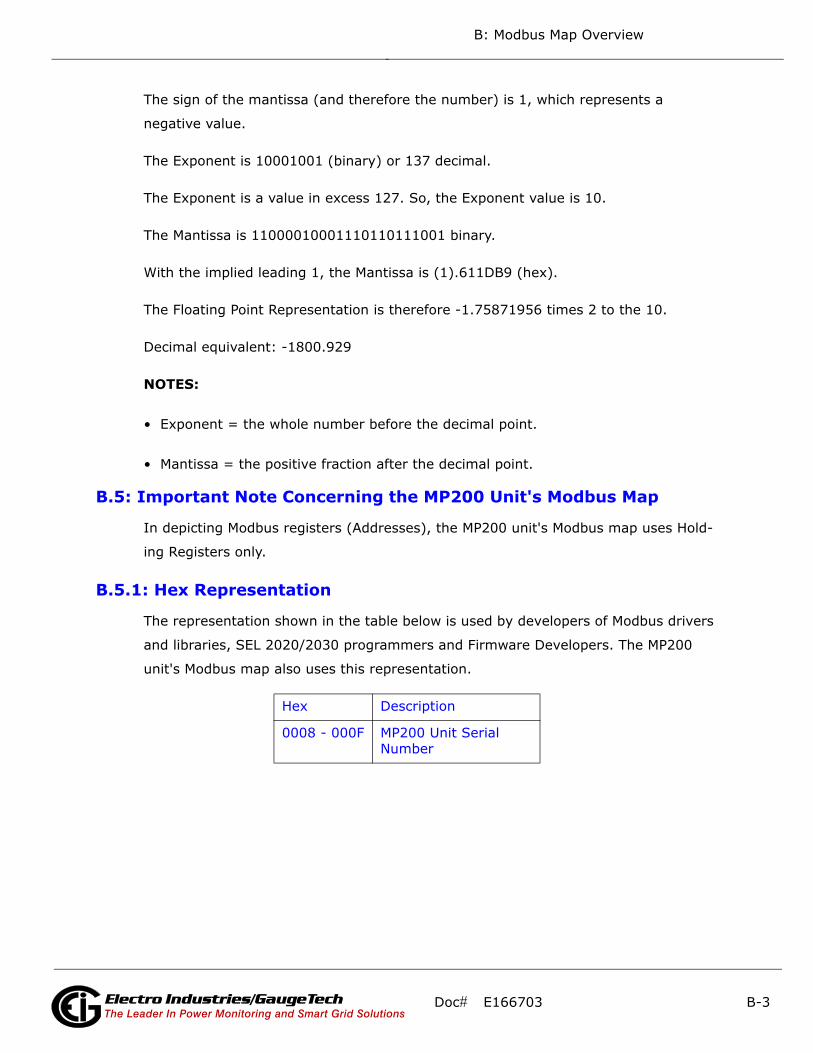
B: Modbus Map Overview
The sign of the mantissa (and therefore the number) is 1, which represents a
negative value.
The Exponent is 10001001 (binary) or 137 decimal.
The Exponent is a value in excess 127. So, the Exponent value is 10.
The Mantissa is 11000010001110110111001 binary.
With the implied leading 1, the Mantissa is (1).611DB9 (hex).
The Floating Point Representation is therefore -1.75871956 times 2 to the 10.
Decimal equivalent: -1800.929
NOTES:
• Exponent = the whole number before the decimal point.
• Mantissa = the positive fraction after the decimal point.
B.5: Important Note Concerning the MP200 Unit's Modbus Map
In depicting Modbus registers (Addresses), the MP200 unit's Modbus map uses Hold-
ing Registers only.
B.5.1: Hex Representation
The representation shown in the table below is used by developers of Modbus drivers
and libraries, SEL 2020/2030 programmers and Firmware Developers. The MP200
unit's Modbus map also uses this representation.
Hex Description
0008 - 000F MP200 Unit Serial Number
Doc# E166703 B-3Electro Industries/GaugeTechThe Leader In Power Monitoring and Smart Grid SolutionsElectro Industries/GaugeTechThe Leader In Power Monitoring and Smart Grid SolutionsElectro Industries/GaugeTechThe Leader In Power Monitoring and Smart Grid Solutions

B: Modbus Map Overview
B.5.2: Decimal Representation
The MP200 unit's Modbus map defines Holding Registers as (4X) registers. Many pop-
ular SCADA and HMI packages and their Modbus drivers have user interfaces that
require users to enter these Registers starting at 40001. So instead of entering two
separate values, one for register type and one for the actual register, they have been
combined into one number.
The MP200 unit's Modbus map uses a shorthand version to depict the decimal fields,
i.e., not all of the digits required for entry into the SCADA package UI are shown. For
example:
You need to display the MP200 unit's serial number in your SCADA application. The
MP200 unit's Modbus map shows the following information for MP200 unit serial
number:
In order to retrieve the MP200 unit’s serial number, enter 40009 into the SCADA UI as
the starting register, and 8 as the number of registers.
• In order to work with SCADA and Driver packages that use the 40001 to 49999
method for requesting holding registers, take 40000 and add the value of the regis-
ter (Address) in the decimal column of the Modbus map. Then enter the number
(e.g., 4009) into the UI as the starting register.
• For SCADA and Driver packages that use the 400001 to 465536 method for
requesting holding registers take 400000 and add the value of the register
(Address) in the decimal column of the Modbus map. Then enter the number (e.g.,
400009) into the UI as the starting register. The drivers for these packages strip off
the leading four and subtract 1 from the remaining value. This final value is used as
the starting register or register to be included when building the actual modbus
message.
Decimal Description
9 - 16 MP200 Unit Serial Number
Doc# E166703 B-4Electro Industries/GaugeTechThe Leader In Power Monitoring and Smart Grid SolutionsElectro Industries/GaugeTechThe Leader In Power Monitoring and Smart Grid SolutionsElectro Industries/GaugeTechThe Leader In Power Monitoring and Smart Grid Solutions

B: Modbus Map Overview
B.6: Modbus Register Maps and Retrieving Logs
• Appendix C contains the MP200-Y unit’s Modbus map.
• Appendix D contains the MP200-S unit’s Modbus map.
• Appendix E contains instructions on retrieving MP200 unit logs via the Modbus map.
Doc# E166703 B-5Electro Industries/GaugeTechThe Leader In Power Monitoring and Smart Grid SolutionsElectro Industries/GaugeTechThe Leader In Power Monitoring and Smart Grid SolutionsElectro Industries/GaugeTechThe Leader In Power Monitoring and Smart Grid Solutions

B: Modbus Map Overview
This page intentionally left blank.
Doc# E166703 B-6Electro Industries/GaugeTechThe Leader In Power Monitoring and Smart Grid SolutionsElectro Industries/GaugeTechThe Leader In Power Monitoring and Smart Grid SolutionsElectro Industries/GaugeTechThe Leader In Power Monitoring and Smart Grid Solutions

C: MP200-Y (Three Phase) Modbus Map
C-1
ents # Reg
ly
Doc# E166703 Electro Industries/GaugeTechThe Leader In Power Monitoring and Smart Grid Solutions
Description Format Range Units orResolution
Comm
read-on
-------mvvvvvvvv
-----ccc --ffffff
Identification Block
Modbus AddressHex Decimal
Fixed Data Section
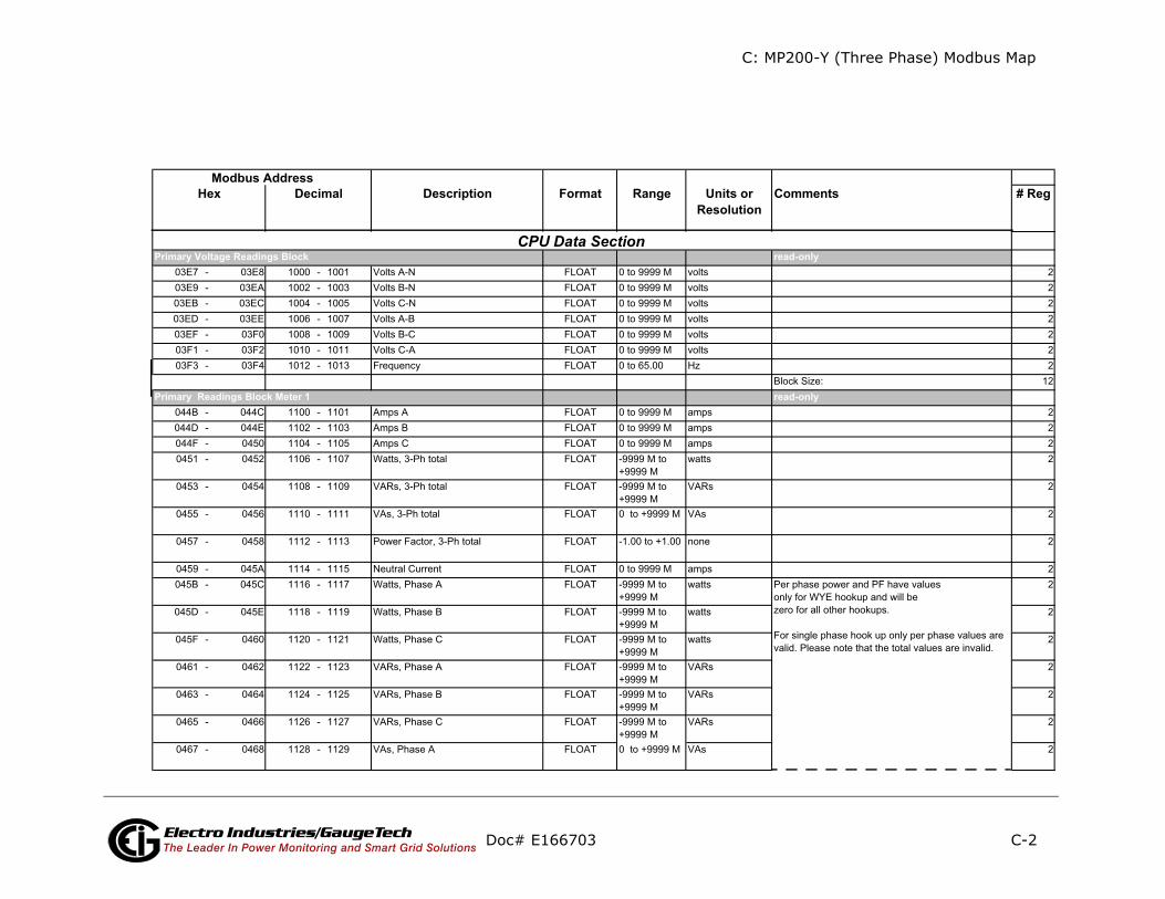
C: MP200-Y (Three Phase) Modbus Map
C-2
ents # Reg
ly
ly
Doc# E166703 Electro Industries/GaugeTechThe Leader In Power Monitoring and Smart Grid Solutions
Description Format Range Units orResolution
CommModbus Address
Hex Decimal
read-on
read-on
CPU Data Section Primary Voltage Readings Block
Primary Readings Block Meter 1

C: MP200-Y (Three Phase) Modbus Map
C-3
ents # Reg
ly
(Cont’d)
Doc# E166703 Electro Industries/GaugeTechThe Leader In Power Monitoring and Smart Grid Solutions
Description Format Range Units orResolution
CommModbus Address
Hex Decimal
read-onPrimary Readings Block Meter 2

C: MP200-Y (Three Phase) Modbus Map
C-4
ents # Reg
ly
(Cont’d)
Doc# E166703 Electro Industries/GaugeTechThe Leader In Power Monitoring and Smart Grid Solutions
Description Format Range Units orResolution
CommModbus Address
Hex Decimal
read-onPrimary Readings Block Meter 3
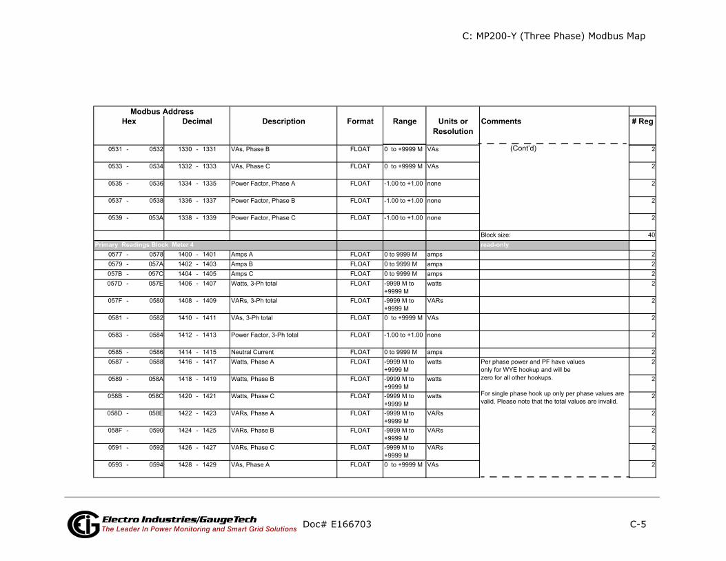
C: MP200-Y (Three Phase) Modbus Map
C-5
ents # Reg
ly
(Cont’d)
Doc# E166703 Electro Industries/GaugeTechThe Leader In Power Monitoring and Smart Grid Solutions
Description Format Range Units orResolution
CommModbus Address
Hex Decimal
read-onPrimary Readings Block Meter 4

C: MP200-Y (Three Phase) Modbus Map
C-6
ents # Reg
ly
(Cont’d)
Doc# E166703 Electro Industries/GaugeTechThe Leader In Power Monitoring and Smart Grid Solutions
Description Format Range Units orResolution
CommModbus Address
Hex Decimal
read-onPrimary Readings Block Meter 5

C: MP200-Y (Three Phase) Modbus Map
C-7
ents # Reg
ly
(Cont’d)
Doc# E166703 Electro Industries/GaugeTechThe Leader In Power Monitoring and Smart Grid Solutions
Description Format Range Units orResolution
CommModbus Address
Hex Decimal
read-onPrimary Readings Block Meter 6

C: MP200-Y (Three Phase) Modbus Map
C-8
ents # Reg
ly
(Cont’d)
Doc# E166703 Electro Industries/GaugeTechThe Leader In Power Monitoring and Smart Grid Solutions
Description Format Range Units orResolution
CommModbus Address
Hex Decimal
read-onPrimary Readings Block Meter 7
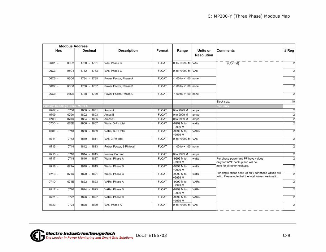
C: MP200-Y (Three Phase) Modbus Map
C-9
ents # Reg
ly
(Cont’d)
Doc# E166703 Electro Industries/GaugeTechThe Leader In Power Monitoring and Smart Grid Solutions
Description Format Range Units orResolution
CommModbus Address
Hex Decimal
read-onPrimary Readings Block Meter 8
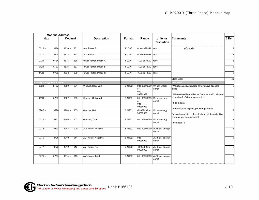
C: MP200-Y (Three Phase) Modbus Map
C-10
ents # Reg
ly
(Cont’d)
Doc# E166703 Electro Industries/GaugeTechThe Leader In Power Monitoring and Smart Grid Solutions
Description Format Range Units orResolution
CommModbus Address
Hex Decimal
read-onPrimary Energy Block Meter 1

C: MP200-Y (Three Phase) Modbus Map
C-11
ents # Reg
(Cont’d)
Doc# E166703 Electro Industries/GaugeTechThe Leader In Power Monitoring and Smart Grid Solutions
Description Format Range Units orResolution
CommModbus Address
Hex Decimal

C: MP200-Y (Three Phase) Modbus Map
C-12
ents # Reg
ont’d)
Doc# E166703 Electro Industries/GaugeTechThe Leader In Power Monitoring and Smart Grid Solutions
Description Format Range Units orResolution
CommModbus Address
Hex Decimal
(C

C: MP200-Y (Three Phase) Modbus Map
C-13
ents # Reg
ly
(Cont’d)
Doc# E166703 Electro Industries/GaugeTechThe Leader In Power Monitoring and Smart Grid Solutions
Description Format Range Units orResolution
CommModbus Address
Hex Decimal
read-onPrimary Energy Block Meter 2

C: MP200-Y (Three Phase) Modbus Map
C-14
ents # Reg
(Cont’d)
Doc# E166703 Electro Industries/GaugeTechThe Leader In Power Monitoring and Smart Grid Solutions
Description Format Range Units orResolution
CommModbus Address
Hex Decimal

C: MP200-Y (Three Phase) Modbus Map
C-15
ents # Reg
(Cont’d)
Doc# E166703 Electro Industries/GaugeTechThe Leader In Power Monitoring and Smart Grid Solutions
Description Format Range Units orResolution
CommModbus Address
Hex Decimal

C: MP200-Y (Three Phase) Modbus Map
C-16
ents # Reg
ly
(Cont’d)
Doc# E166703 Electro Industries/GaugeTechThe Leader In Power Monitoring and Smart Grid Solutions
Description Format Range Units orResolution
CommModbus Address
Hex Decimal
read-onPrimary Energy Block Meter 3
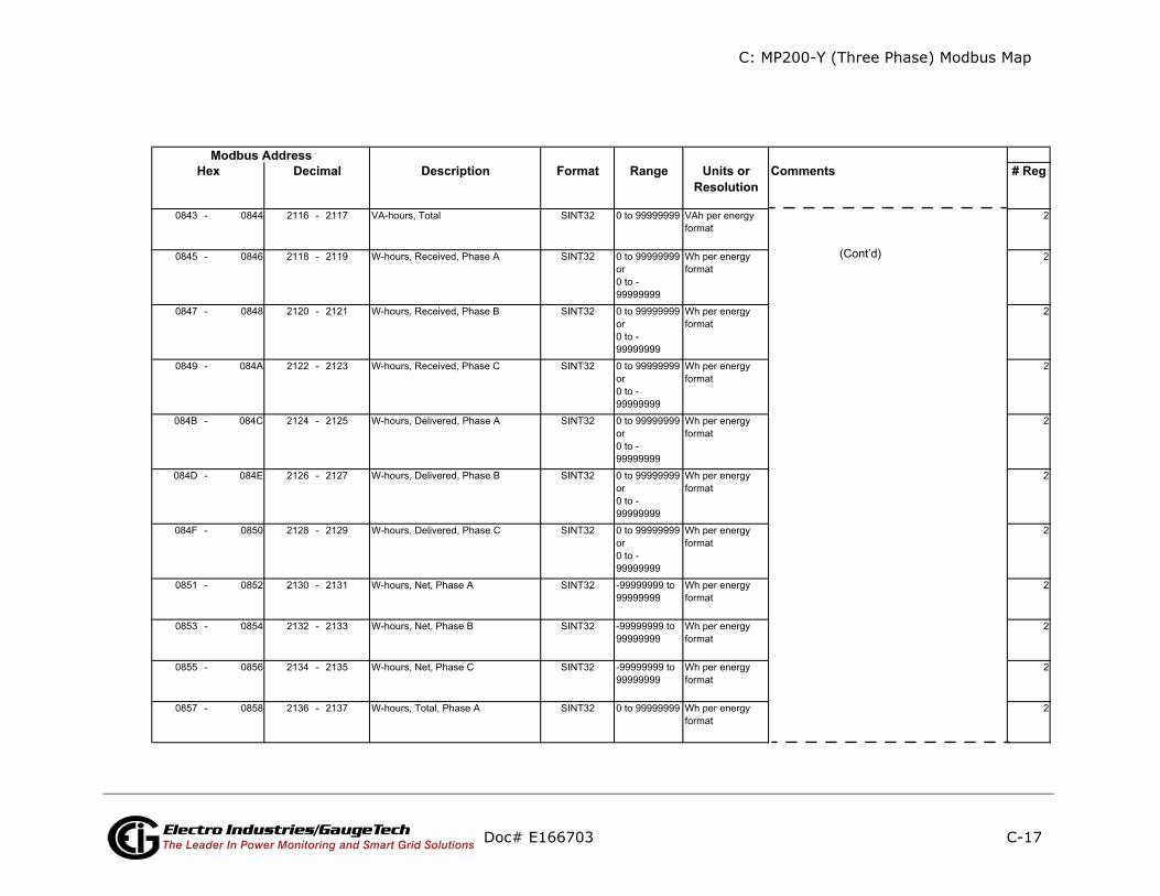
C: MP200-Y (Three Phase) Modbus Map
C-17
ents # Reg
(Cont’d)
Doc# E166703 Electro Industries/GaugeTechThe Leader In Power Monitoring and Smart Grid Solutions
Description Format Range Units orResolution
CommModbus Address
Hex Decimal

C: MP200-Y (Three Phase) Modbus Map
C-18
ents # Reg
(Cont’d)
Doc# E166703 Electro Industries/GaugeTechThe Leader In Power Monitoring and Smart Grid Solutions
Description Format Range Units orResolution
CommModbus Address
Hex Decimal
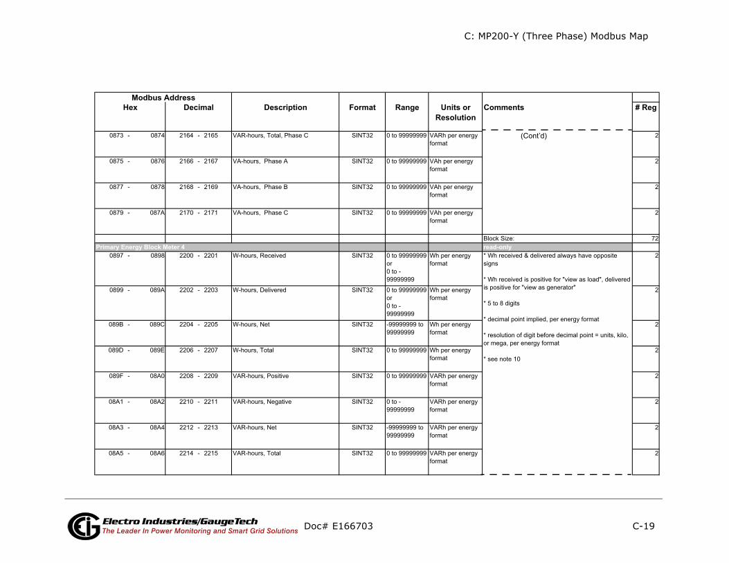
C: MP200-Y (Three Phase) Modbus Map
C-19
ents # Reg
ly
(Cont’d)
Doc# E166703 Electro Industries/GaugeTechThe Leader In Power Monitoring and Smart Grid Solutions
Description Format Range Units orResolution
CommModbus Address
Hex Decimal
read-onPrimary Energy Block Meter 4

C: MP200-Y (Three Phase) Modbus Map
C-20
ents # Reg
(Cont’d)
Three Phase Modbus Map
Doc# E166703 Electro Industries/GaugeTechThe Leader In Power Monitoring and Smart Grid Solutions
Description Format Range Units orResolution
CommModbus Address
Hex Decimal
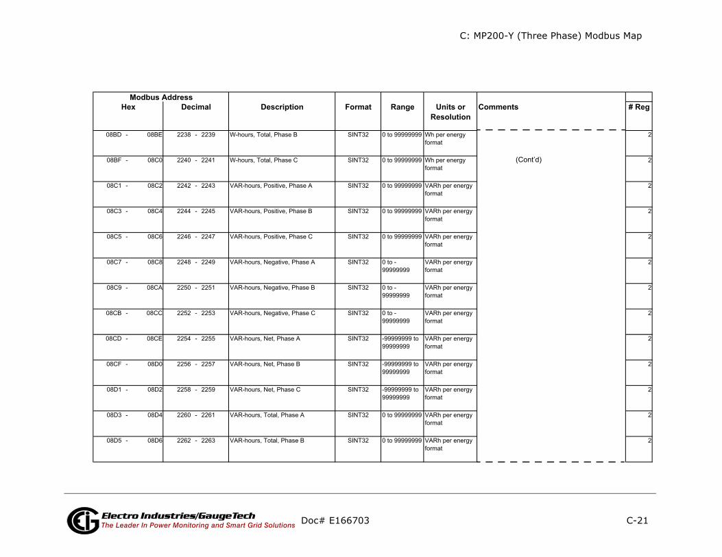
C: MP200-Y (Three Phase) Modbus Map
C-21
ents # Reg
(Cont’d)
Doc# E166703 Electro Industries/GaugeTechThe Leader In Power Monitoring and Smart Grid Solutions
Description Format Range Units orResolution
CommModbus Address
Hex Decimal

C: MP200-Y (Three Phase) Modbus Map
C-22
ents # Reg
ly
(Cont’d)
Doc# E166703 Electro Industries/GaugeTechThe Leader In Power Monitoring and Smart Grid Solutions
Description Format Range Units orResolution
CommModbus Address
Hex Decimal
read-onPrimary Energy Block Meter 5

C: MP200-Y (Three Phase) Modbus Map
C-23
ents # Reg
(Cont’d)
Doc# E166703 Electro Industries/GaugeTechThe Leader In Power Monitoring and Smart Grid Solutions
Description Format Range Units orResolution
CommModbus Address
Hex Decimal
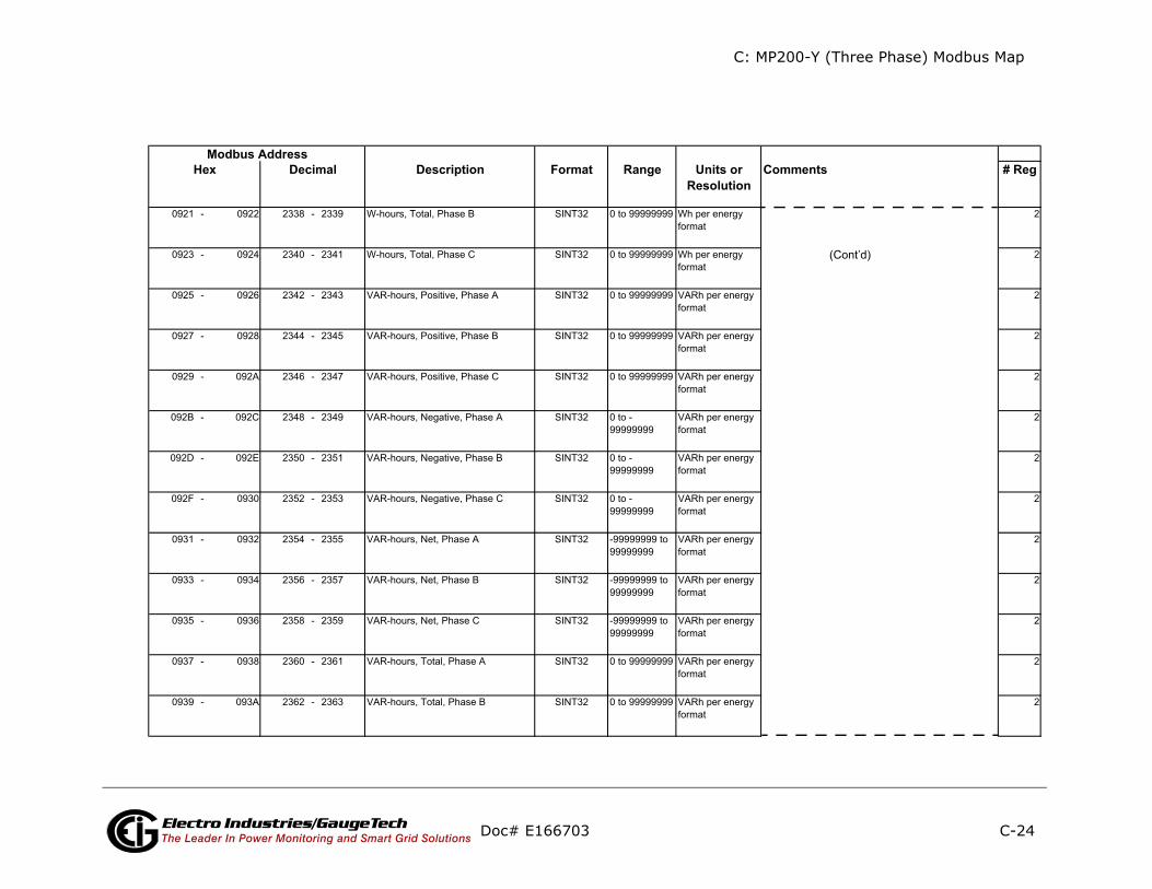
C: MP200-Y (Three Phase) Modbus Map
C-24
ents # Reg
(Cont’d)
Doc# E166703 Electro Industries/GaugeTechThe Leader In Power Monitoring and Smart Grid Solutions
Description Format Range Units orResolution
CommModbus Address
Hex Decimal

C: MP200-Y (Three Phase) Modbus Map
C-25
ents # Reg
ly
(Cont’d)
Doc# E166703 Electro Industries/GaugeTechThe Leader In Power Monitoring and Smart Grid Solutions
Description Format Range Units orResolution
CommModbus Address
Hex Decimal
read-onPrimary Energy Block Meter 6
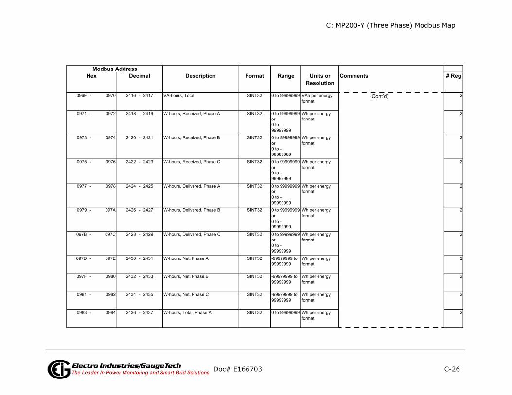
C: MP200-Y (Three Phase) Modbus Map
C-26
ents # Reg
(Cont’d)
Doc# E166703 Electro Industries/GaugeTechThe Leader In Power Monitoring and Smart Grid Solutions
Description Format Range Units orResolution
CommModbus Address
Hex Decimal

C: MP200-Y (Three Phase) Modbus Map
C-27
ents # Reg
(Cont’d)
Doc# E166703 Electro Industries/GaugeTechThe Leader In Power Monitoring and Smart Grid Solutions
Description Format Range Units orResolution
CommModbus Address
Hex Decimal

C: MP200-Y (Three Phase) Modbus Map
C-28
ents # Reg
ly
(Cont’d)
Doc# E166703 Electro Industries/GaugeTechThe Leader In Power Monitoring and Smart Grid Solutions
Description Format Range Units orResolution
CommModbus Address
Hex Decimal
read-onPrimary Energy Block Meter 7

C: MP200-Y (Three Phase) Modbus Map
C-29
ents # Reg
(Cont’d)
Doc# E166703 Electro Industries/GaugeTechThe Leader In Power Monitoring and Smart Grid Solutions
Description Format Range Units orResolution
CommModbus Address
Hex Decimal

C: MP200-Y (Three Phase) Modbus Map
C-30
ents # Reg
(Cont’d)
Doc# E166703 Electro Industries/GaugeTechThe Leader In Power Monitoring and Smart Grid Solutions
Description Format Range Units orResolution
CommModbus Address
Hex Decimal

C: MP200-Y (Three Phase) Modbus Map
C-31
ents # Reg
ly
(Cont’d)
Doc# E166703 Electro Industries/GaugeTechThe Leader In Power Monitoring and Smart Grid Solutions
Description Format Range Units orResolution
CommModbus Address
Hex Decimal
read-onPrimary Energy Block Meter 8

C: MP200-Y (Three Phase) Modbus Map
C-32
ents # Reg
(Cont’d)
Doc# E166703 Electro Industries/GaugeTechThe Leader In Power Monitoring and Smart Grid Solutions
Description Format Range Units orResolution
CommModbus Address
Hex Decimal

C: MP200-Y (Three Phase) Modbus Map
C-33
ents # Reg
(Cont’d)
Doc# E166703 Electro Industries/GaugeTechThe Leader In Power Monitoring and Smart Grid Solutions
Description Format Range Units orResolution
CommModbus Address
Hex Decimal
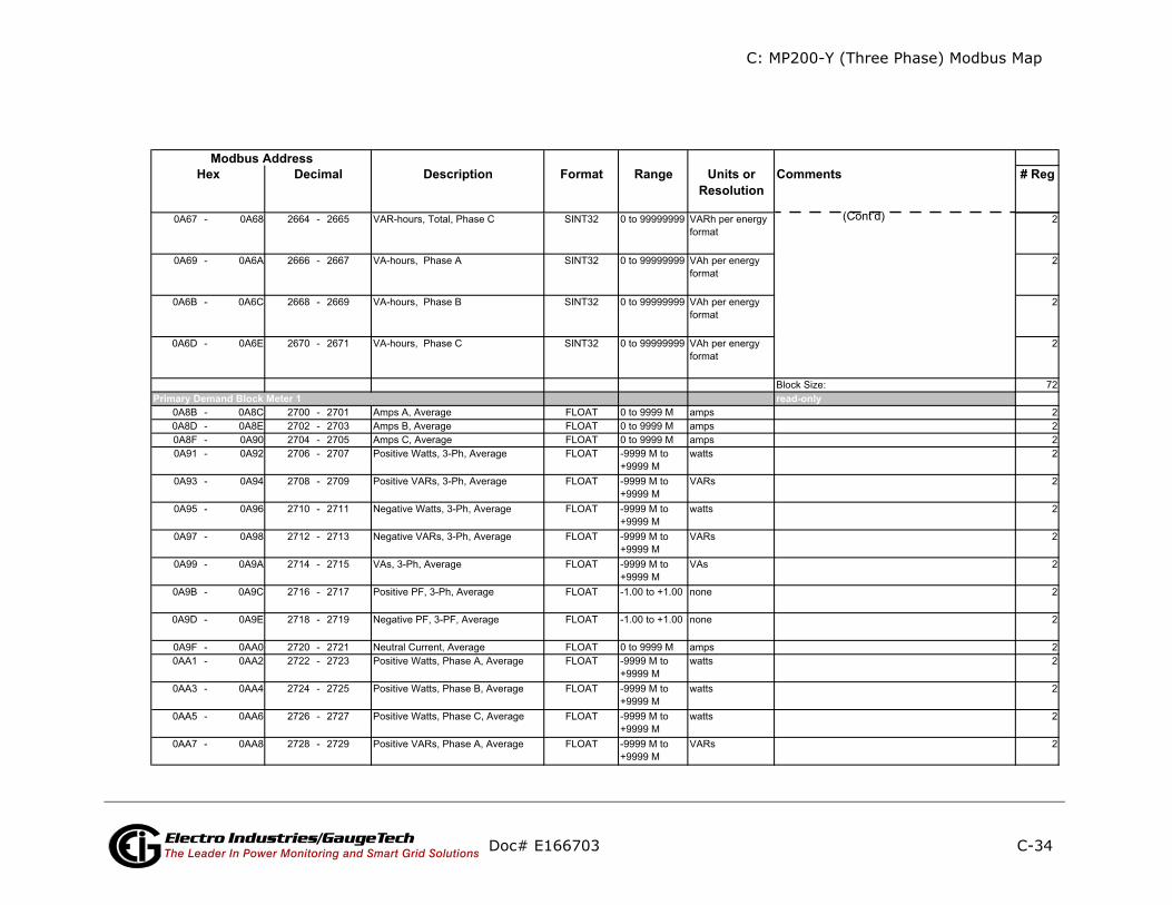
C: MP200-Y (Three Phase) Modbus Map
C-34
ents # Reg
ly
(Cont’d)
Doc# E166703 Electro Industries/GaugeTechThe Leader In Power Monitoring and Smart Grid Solutions
Description Format Range Units orResolution
CommModbus Address
Hex Decimal
read-onPrimary Demand Block Meter 1
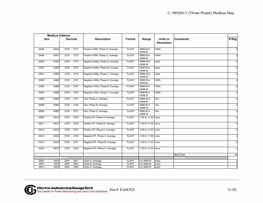
C: MP200-Y (Three Phase) Modbus Map
C-35
ents # Reg
ly
Doc# E166703 Electro Industries/GaugeTechThe Leader In Power Monitoring and Smart Grid Solutions
Description Format Range Units orResolution
CommModbus Address
Hex Decimal
read-onPrimary Demand Block Meter 2

C: MP200-Y (Three Phase) Modbus Map
C-36
ents # Reg
Doc# E166703 Electro Industries/GaugeTechThe Leader In Power Monitoring and Smart Grid Solutions
Description Format Range Units orResolution
CommModbus Address
Hex Decimal
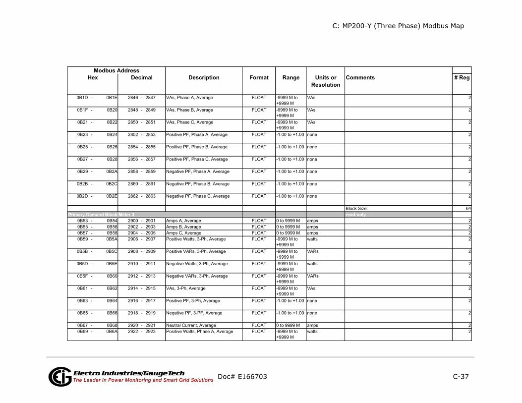
C: MP200-Y (Three Phase) Modbus Map
C-37
ents # Reg
ly
Doc# E166703 Electro Industries/GaugeTechThe Leader In Power Monitoring and Smart Grid Solutions
Description Format Range Units orResolution
CommModbus Address
Hex Decimal
read-onPrimary Demand Block Meter 3
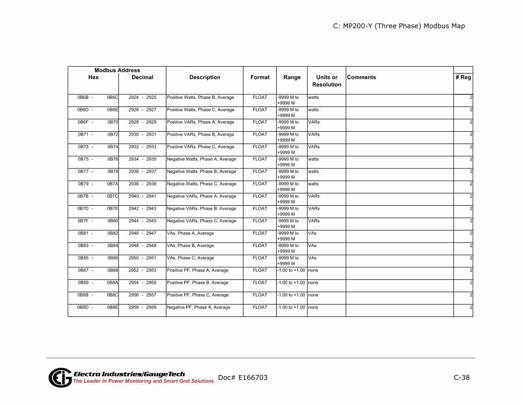
C: MP200-Y (Three Phase) Modbus Map
C-38
ents # Reg
Doc# E166703 Electro Industries/GaugeTechThe Leader In Power Monitoring and Smart Grid Solutions
Description Format Range Units orResolution
CommModbus Address
Hex Decimal
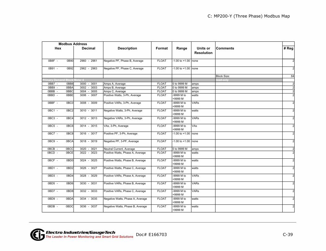
C: MP200-Y (Three Phase) Modbus Map
C-39
ents # Reg
ly
Doc# E166703 Electro Industries/GaugeTechThe Leader In Power Monitoring and Smart Grid Solutions
Description Format Range Units orResolution
CommModbus Address
Hex Decimal
read-onPrimary Demand Block Meter 4
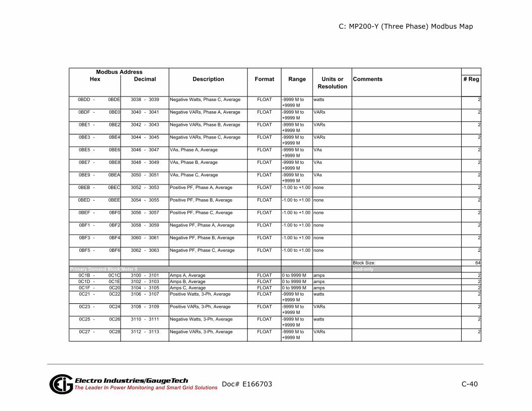
C: MP200-Y (Three Phase) Modbus Map
C-40
ents # Reg
ly
Doc# E166703 Electro Industries/GaugeTechThe Leader In Power Monitoring and Smart Grid Solutions
Description Format Range Units orResolution
CommModbus Address
Hex Decimal
read-onPrimary Demand Block Meter 5

C: MP200-Y (Three Phase) Modbus Map
C-41
ents # Reg
Doc# E166703 Electro Industries/GaugeTechThe Leader In Power Monitoring and Smart Grid Solutions
Description Format Range Units orResolution
CommModbus Address
Hex Decimal

C: MP200-Y (Three Phase) Modbus Map
C-42
ents # Reg
ly
Doc# E166703 Electro Industries/GaugeTechThe Leader In Power Monitoring and Smart Grid Solutions
Description Format Range Units orResolution
CommModbus Address
Hex Decimal
read-onPrimary Demand Block Meter 6
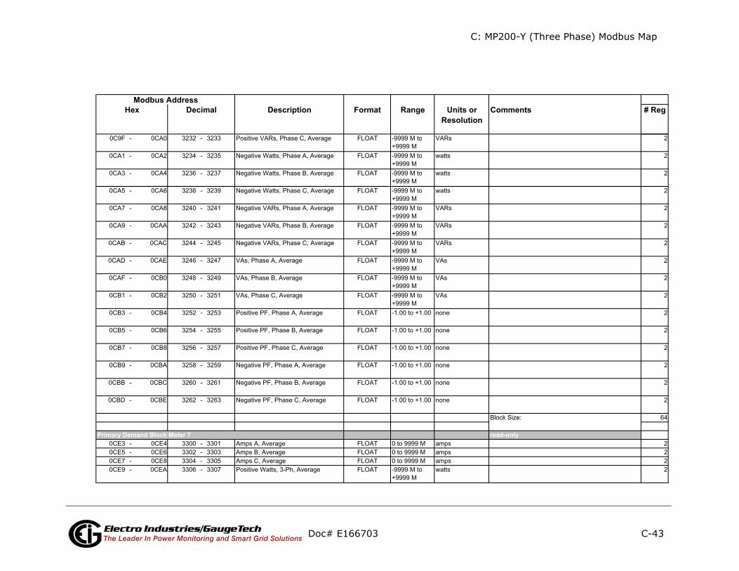
C: MP200-Y (Three Phase) Modbus Map
C-43
ents # Reg
ly
Doc# E166703 Electro Industries/GaugeTechThe Leader In Power Monitoring and Smart Grid Solutions
Description Format Range Units orResolution
CommModbus Address
Hex Decimal
read-onPrimary Demand Block Meter 7
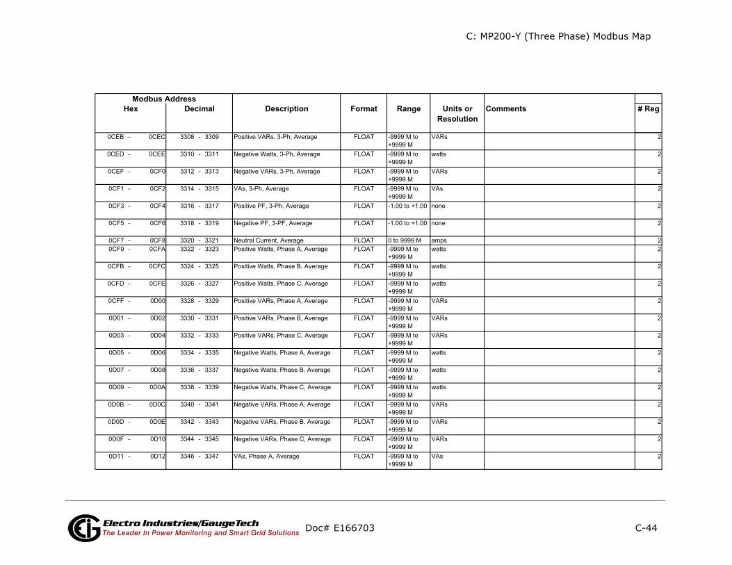
C: MP200-Y (Three Phase) Modbus Map
C-44
ents # Reg
Doc# E166703 Electro Industries/GaugeTechThe Leader In Power Monitoring and Smart Grid Solutions
Description Format Range Units orResolution
CommModbus Address
Hex Decimal

C: MP200-Y (Three Phase) Modbus Map
C-45
ents # Reg
ly
Doc# E166703 Electro Industries/GaugeTechThe Leader In Power Monitoring and Smart Grid Solutions
Description Format Range Units orResolution
CommModbus Address
Hex Decimal
read-onPrimary Demand Block Meter 8
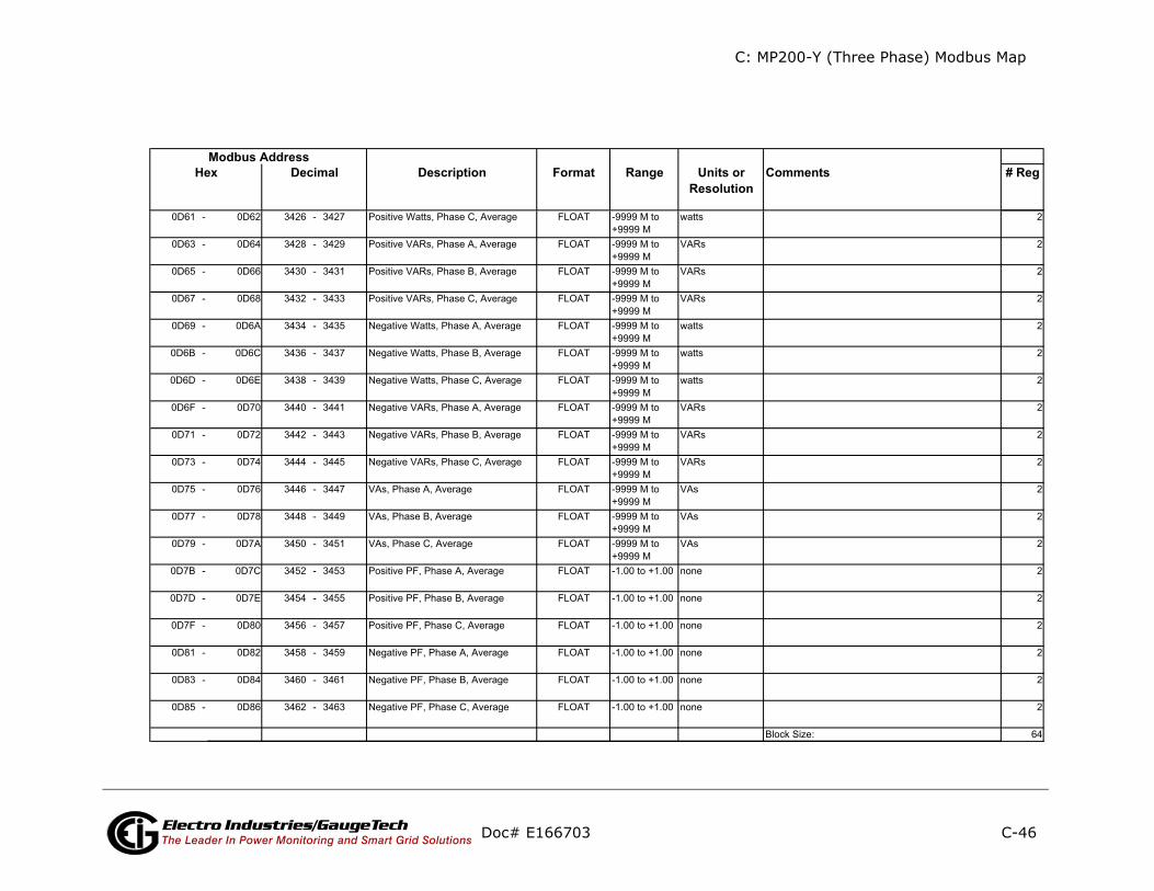
C: MP200-Y (Three Phase) Modbus Map
C-46
ents # Reg
Doc# E166703 Electro Industries/GaugeTechThe Leader In Power Monitoring and Smart Grid Solutions
Description Format Range Units orResolution
CommModbus Address
Hex Decimal

C: MP200-Y (Three Phase) Modbus Map
C-47
ents # Reg
ly
ly
ly
ly
ly
Doc# E166703 Electro Industries/GaugeTechThe Leader In Power Monitoring and Smart Grid Solutions
Description Format Range Units orResolution
CommModbus Address
Hex Decimal
read-on
read-on
read-on
read-on
read-on
Phase Angle Block (Current Meter 1)
Phase Angle Block (Current Meter 2)
Phase Angle Block (Current Meter 3)
Phase Angle Block (Current Meter 4)
Phase Angle Block (voltage)
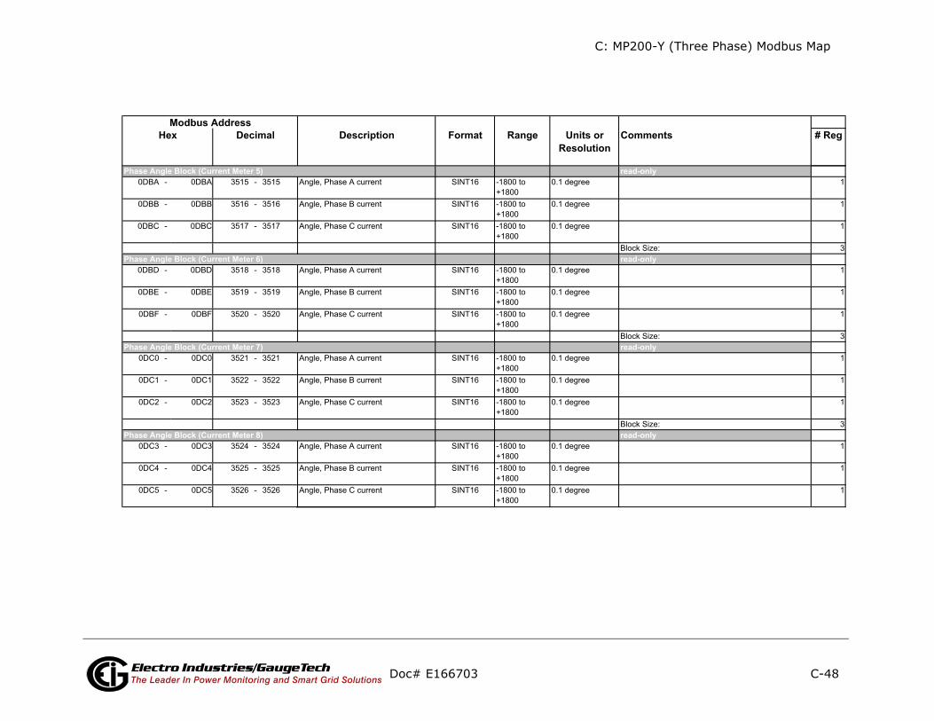
C: MP200-Y (Three Phase) Modbus Map
C-48
ents # Reg
ly
ly
ly
ly
Doc# E166703 Electro Industries/GaugeTechThe Leader In Power Monitoring and Smart Grid Solutions
Description Format Range Units orResolution
CommModbus Address
Hex Decimal
read-on
read-on
read-on
read-on
Phase Angle Block (Current Meter 5)
Phase Angle Block (Current Meter 6)
Phase Angle Block (Current Meter 7)
Phase Angle Block (Current Meter 8)
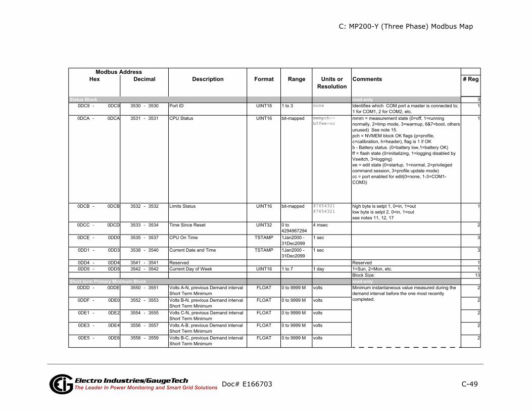
C: MP200-Y (Three Phase) Modbus Map
C-49
ents # Reg
ly
ly
Doc# E166703 Electro Industries/GaugeTechThe Leader In Power Monitoring and Smart Grid Solutions
Description Format Range Units orResolution
CommModbus Address
Hex Decimal
read-onnone
mmmpch--bffee-cc
8765432187654321
read-on
Status Block
Short term Primary Minimum Block
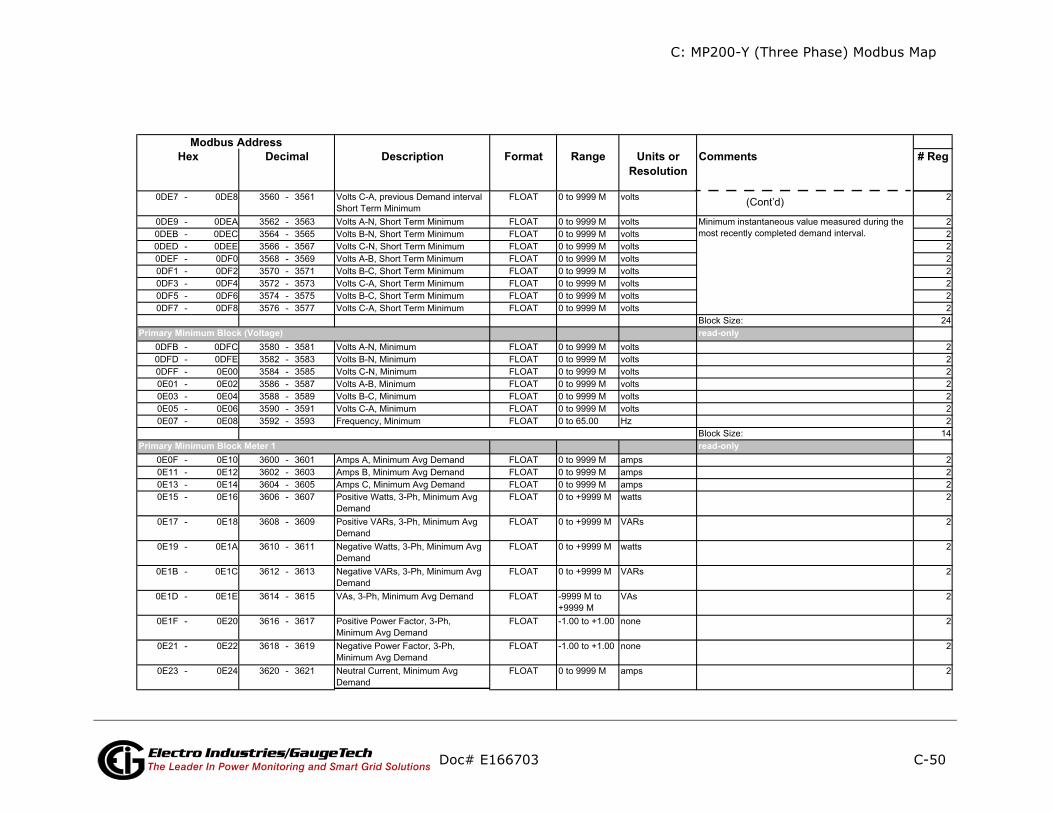
C: MP200-Y (Three Phase) Modbus Map
C-50
ents # Reg
ly
ly
(Cont’d)
Doc# E166703 Electro Industries/GaugeTechThe Leader In Power Monitoring and Smart Grid Solutions
Description Format Range Units orResolution
CommModbus Address
Hex Decimal
read-on
read-on
Primary Minimum Block (Voltage)
Primary Minimum Block Meter 1

C: MP200-Y (Three Phase) Modbus Map
C-51
ents # Reg
Doc# E166703 Electro Industries/GaugeTechThe Leader In Power Monitoring and Smart Grid Solutions
Description Format Range Units orResolution
CommModbus Address
Hex Decimal
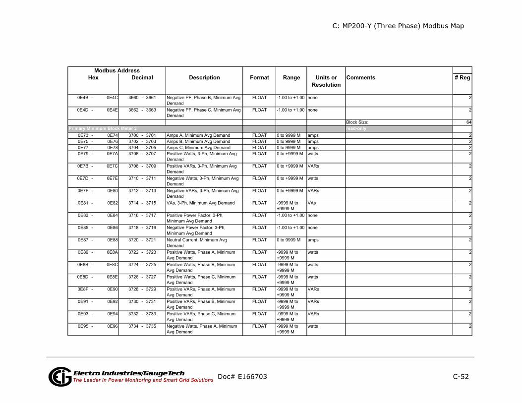
C: MP200-Y (Three Phase) Modbus Map
C-52
ents # Reg
ly
Doc# E166703 Electro Industries/GaugeTechThe Leader In Power Monitoring and Smart Grid Solutions
Description Format Range Units orResolution
CommModbus Address
Hex Decimal
read-onPrimary Minimum Block Meter 2
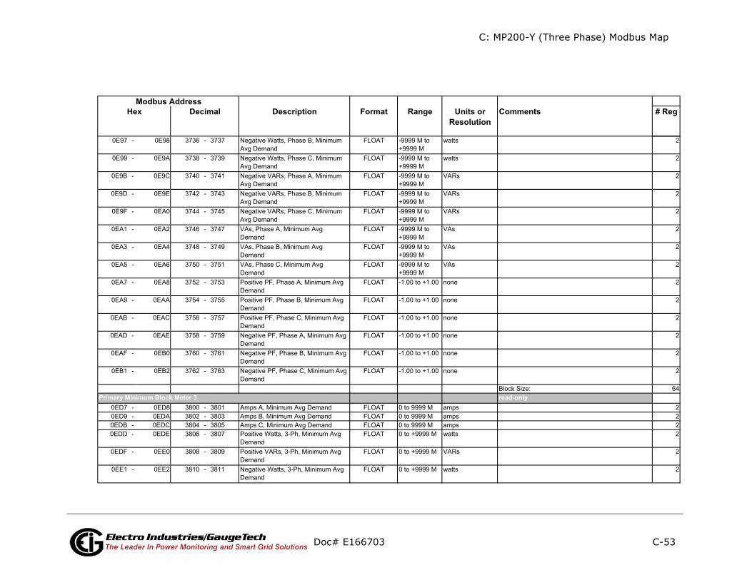
C: MP200-Y (Three Phase) Modbus Map
C-53
ents # Reg
ly
Doc# E166703 Electro Industries/GaugeTechThe Leader In Power Monitoring and Smart Grid Solutions
Description Format Range Units orResolution
CommModbus Address
Hex Decimal
read-onPrimary Minimum Block Meter 3
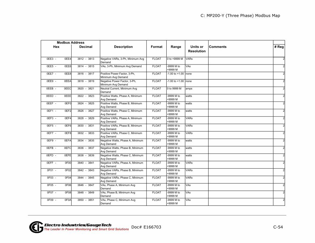
C: MP200-Y (Three Phase) Modbus Map
C-54
ents # Reg
Doc# E166703 Electro Industries/GaugeTechThe Leader In Power Monitoring and Smart Grid Solutions
Description Format Range Units orResolution
CommModbus Address
Hex Decimal
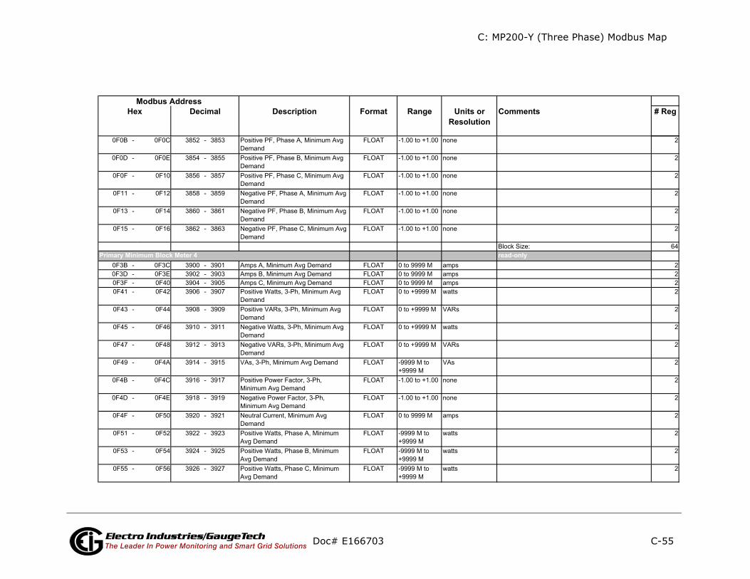
C: MP200-Y (Three Phase) Modbus Map
C-55
ents # Reg
ly
Doc# E166703 Electro Industries/GaugeTechThe Leader In Power Monitoring and Smart Grid Solutions
Description Format Range Units orResolution
CommModbus Address
Hex Decimal
read-onPrimary Minimum Block Meter 4

C: MP200-Y (Three Phase) Modbus Map
C-56
ents # Reg
Doc# E166703 Electro Industries/GaugeTechThe Leader In Power Monitoring and Smart Grid Solutions
Description Format Range Units orResolution
CommModbus Address
Hex Decimal
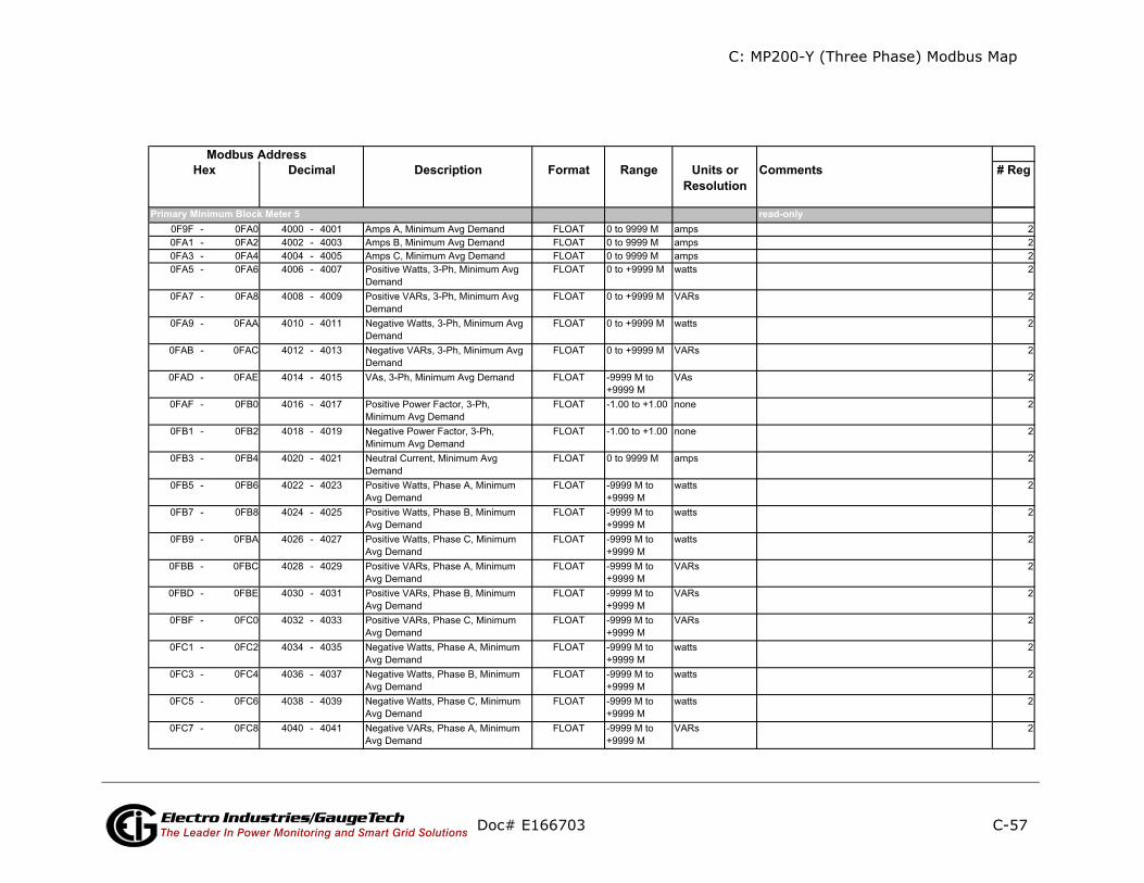
C: MP200-Y (Three Phase) Modbus Map
C-57
ents # Reg
ly
Doc# E166703 Electro Industries/GaugeTechThe Leader In Power Monitoring and Smart Grid Solutions
Description Format Range Units orResolution
CommModbus Address
Hex Decimal
read-onPrimary Minimum Block Meter 5

C: MP200-Y (Three Phase) Modbus Map
C-58
ents # Reg
ly
Doc# E166703 Electro Industries/GaugeTechThe Leader In Power Monitoring and Smart Grid Solutions
Description Format Range Units orResolution
CommModbus Address
Hex Decimal
read-onPrimary Minimum Block Meter 6

C: MP200-Y (Three Phase) Modbus Map
C-59
ents # Reg
Doc# E166703 Electro Industries/GaugeTechThe Leader In Power Monitoring and Smart Grid Solutions
Description Format Range Units orResolution
CommModbus Address
Hex Decimal
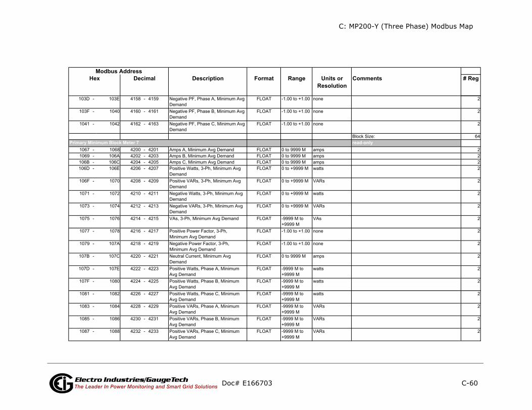
C: MP200-Y (Three Phase) Modbus Map
C-60
ents # Reg
ly
Doc# E166703 Electro Industries/GaugeTechThe Leader In Power Monitoring and Smart Grid Solutions
Description Format Range Units orResolution
CommModbus Address
Hex Decimal
read-onPrimary Minimum Block Meter 7

C: MP200-Y (Three Phase) Modbus Map
C-61
ents # Reg
ly
Doc# E166703 Electro Industries/GaugeTechThe Leader In Power Monitoring and Smart Grid Solutions
Description Format Range Units orResolution
CommModbus Address
Hex Decimal
read-onPrimary Minimum Block Meter 8

C: MP200-Y (Three Phase) Modbus Map
C-62
ents # Reg
Doc# E166703 Electro Industries/GaugeTechThe Leader In Power Monitoring and Smart Grid Solutions
Description Format Range Units orResolution
CommModbus Address
Hex Decimal
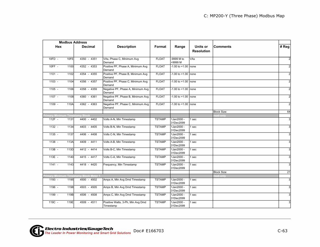
C: MP200-Y (Three Phase) Modbus Map
C-63
ents # Reg
ly
ly
Doc# E166703 Electro Industries/GaugeTechThe Leader In Power Monitoring and Smart Grid Solutions
Description Format Range Units orResolution
CommModbus Address
Hex Decimal
read-on
read-on
Primary Minimum Timestamp Block
Primary Minimum Timestamp Block Meter 1

C: MP200-Y (Three Phase) Modbus Map
C-64
ents # Reg
Doc# E166703 Electro Industries/GaugeTechThe Leader In Power Monitoring and Smart Grid Solutions
Description Format Range Units orResolution
CommModbus Address
Hex Decimal
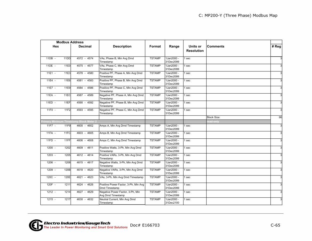
C: MP200-Y (Three Phase) Modbus Map
C-65
ents # Reg
ly
Doc# E166703 Electro Industries/GaugeTechThe Leader In Power Monitoring and Smart Grid Solutions
Description Format Range Units orResolution
CommModbus Address
Hex Decimal
read-onPrimary Minimum Timestamp Block Meter 2

C: MP200-Y (Three Phase) Modbus Map
C-66
ents # Reg
Doc# E166703 Electro Industries/GaugeTechThe Leader In Power Monitoring and Smart Grid Solutions
Description Format Range Units orResolution
CommModbus Address
Hex Decimal

C: MP200-Y (Three Phase) Modbus Map
C-67
ents # Reg
ly
Doc# E166703 Electro Industries/GaugeTechThe Leader In Power Monitoring and Smart Grid Solutions
Description Format Range Units orResolution
CommModbus Address
Hex Decimal
read-onPrimary Minimum Timestamp Block Meter 3
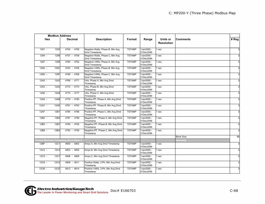
C: MP200-Y (Three Phase) Modbus Map
C-68
ents # Reg
ly
Doc# E166703 Electro Industries/GaugeTechThe Leader In Power Monitoring and Smart Grid Solutions
Description Format Range Units orResolution
CommModbus Address
Hex Decimal
read-onPrimary Minimum Timestamp Block Meter 4
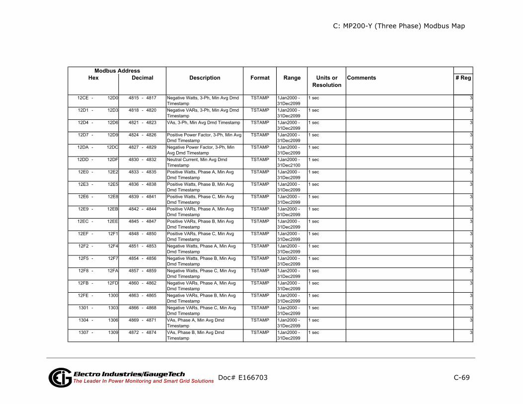
C: MP200-Y (Three Phase) Modbus Map
C-69
ents # Reg
Doc# E166703 Electro Industries/GaugeTechThe Leader In Power Monitoring and Smart Grid Solutions
Description Format Range Units orResolution
CommModbus Address
Hex Decimal
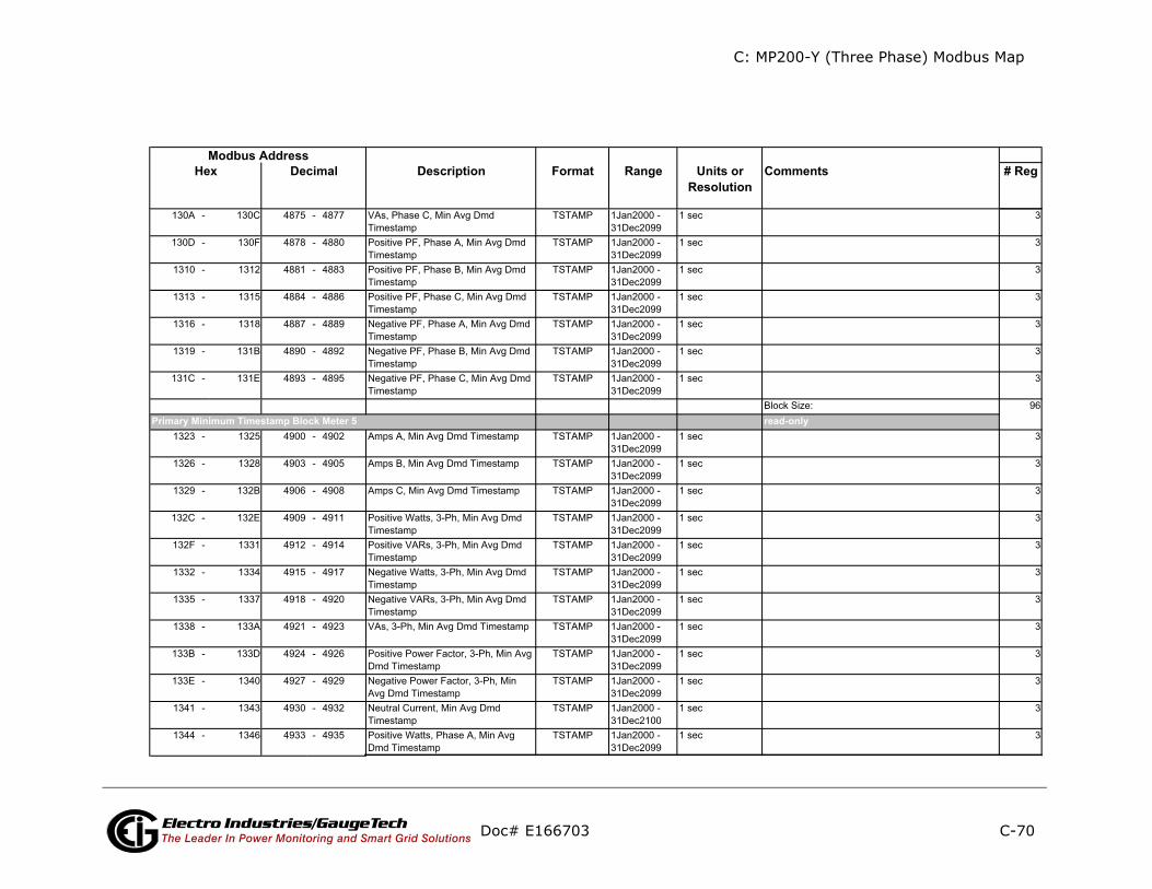
C: MP200-Y (Three Phase) Modbus Map
C-70
ents # Reg
ly
Doc# E166703 Electro Industries/GaugeTechThe Leader In Power Monitoring and Smart Grid Solutions
Description Format Range Units orResolution
CommModbus Address
Hex Decimal
read-onPrimary Minimum Timestamp Block Meter 5
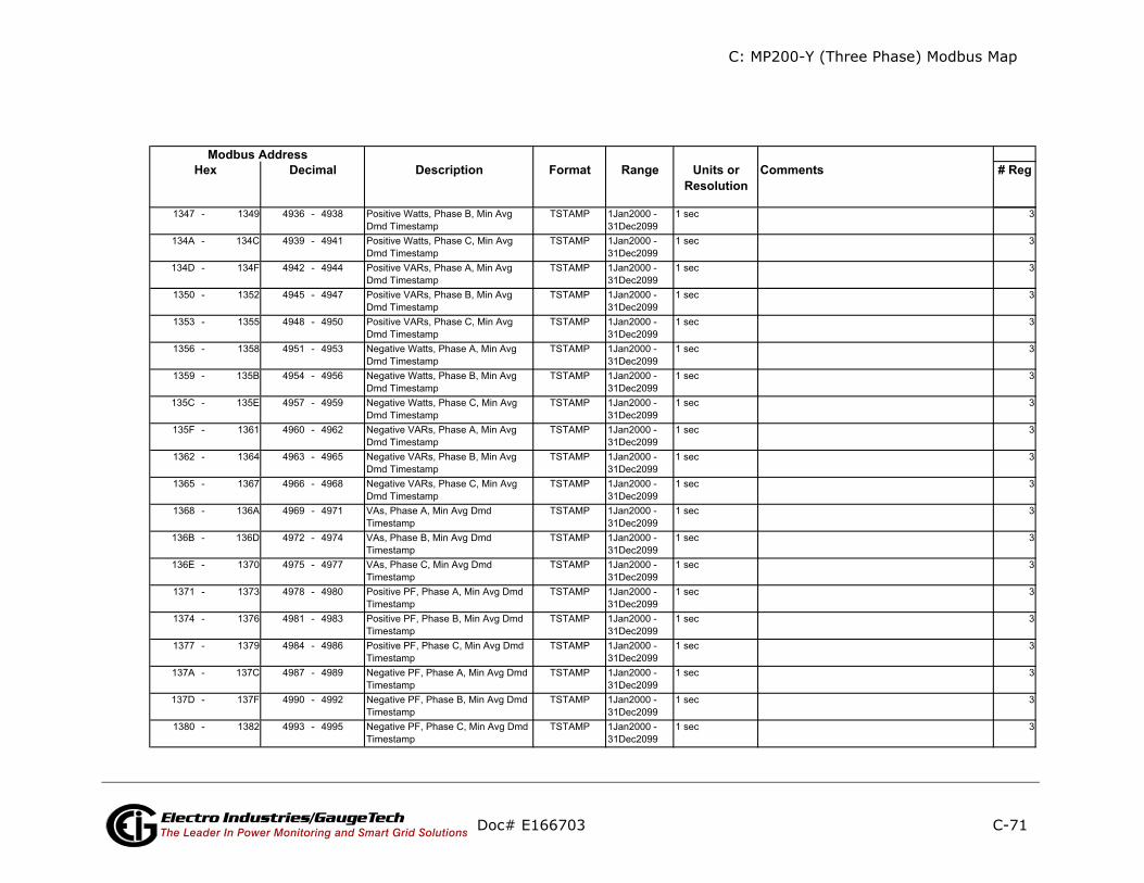
C: MP200-Y (Three Phase) Modbus Map
C-71
ents # Reg
Doc# E166703 Electro Industries/GaugeTechThe Leader In Power Monitoring and Smart Grid Solutions
Description Format Range Units orResolution
CommModbus Address
Hex Decimal

C: MP200-Y (Three Phase) Modbus Map
C-72
ents # Reg
ly
Doc# E166703 Electro Industries/GaugeTechThe Leader In Power Monitoring and Smart Grid Solutions
Description Format Range Units orResolution
CommModbus Address
Hex Decimal
read-onPrimary Minimum Timestamp Block Meter 6

C: MP200-Y (Three Phase) Modbus Map
C-73
ents # Reg
ly
Doc# E166703 Electro Industries/GaugeTechThe Leader In Power Monitoring and Smart Grid Solutions
Description Format Range Units orResolution
CommModbus Address
Hex Decimal
read-onPrimary Minimum Timestamp Block Meter 7
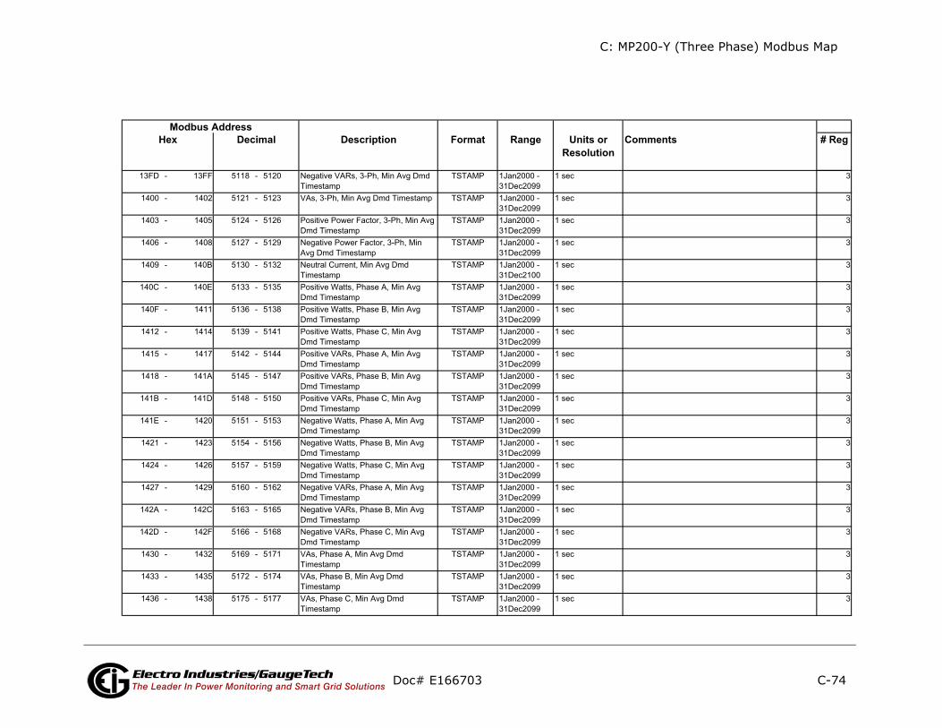
C: MP200-Y (Three Phase) Modbus Map
C-74
ents # Reg
Doc# E166703 Electro Industries/GaugeTechThe Leader In Power Monitoring and Smart Grid Solutions
Description Format Range Units orResolution
CommModbus Address
Hex Decimal

C: MP200-Y (Three Phase) Modbus Map
C-75
ents # Reg
ly
Doc# E166703 Electro Industries/GaugeTechThe Leader In Power Monitoring and Smart Grid Solutions
Description Format Range Units orResolution
CommModbus Address
Hex Decimal
read-onPrimary Minimum Timestamp Block Meter 8
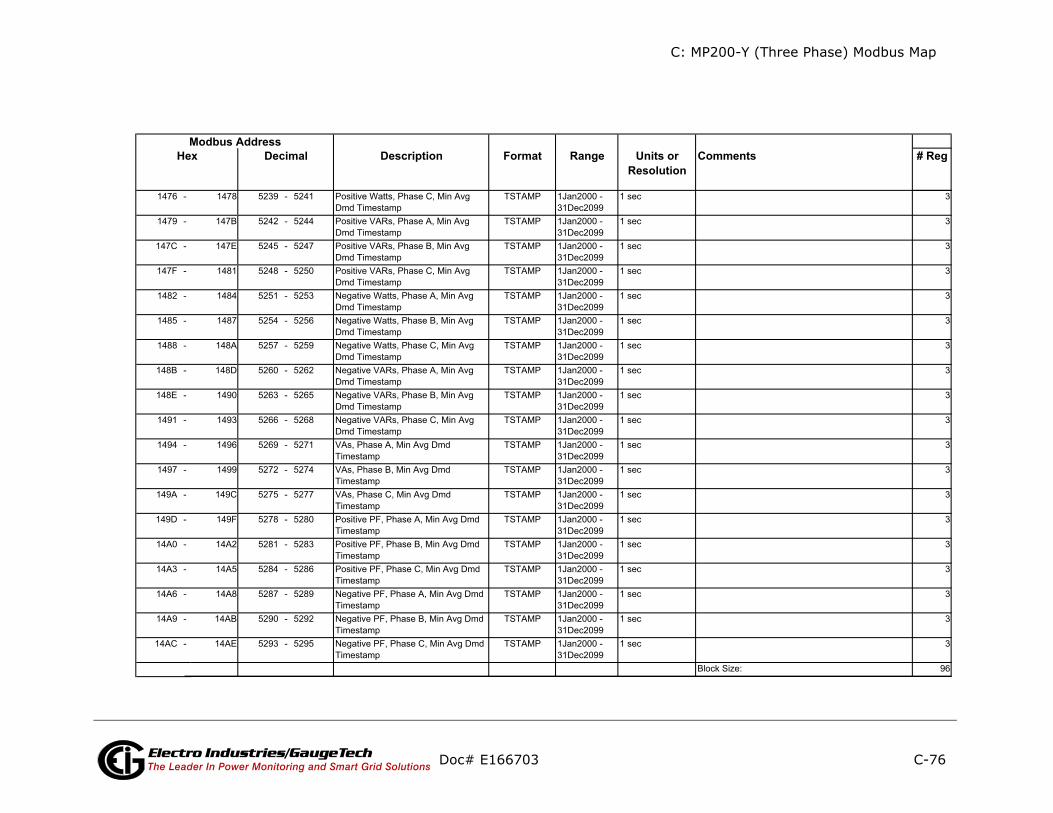
C: MP200-Y (Three Phase) Modbus Map
C-76
ents # Reg
Doc# E166703 Electro Industries/GaugeTechThe Leader In Power Monitoring and Smart Grid Solutions
Description Format Range Units orResolution
CommModbus Address
Hex Decimal
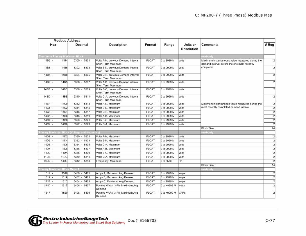
C: MP200-Y (Three Phase) Modbus Map
C-77
nts # Reg
Doc# E166703 Electro Industries/GaugeTechThe Leader In Power Monitoring and Smart Grid Solutions
Description Format Range Units orResolution
CommeModbus Address
Hex Decimal
read-only
read-only
read-only
Primary Maximum Block (Voltage and frequency)
Primary Maximum Block Meter 1
Short term Primary Maximum Block
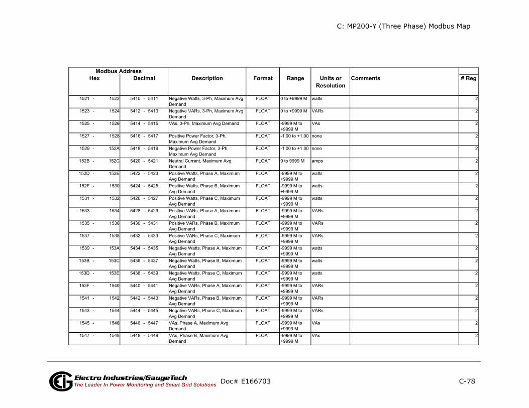
C: MP200-Y (Three Phase) Modbus Map
C-78
ents # Reg
Doc# E166703 Electro Industries/GaugeTechThe Leader In Power Monitoring and Smart Grid Solutions
Description Format Range Units orResolution
CommModbus Address
Hex Decimal

C: MP200-Y (Three Phase) Modbus Map
C-79
ents # Reg
ly
Doc# E166703 Electro Industries/GaugeTechThe Leader In Power Monitoring and Smart Grid Solutions
Description Format Range Units orResolution
CommModbus Address
Hex Decimal
read-onPrimary Maximum Block Meter 2

C: MP200-Y (Three Phase) Modbus Map
C-80
nts # Reg
Doc# E166703 Electro Industries/GaugeTechThe Leader In Power Monitoring and Smart Grid Solutions
Description Format Range Units orResolution
CommeModbus Address
Hex Decimal
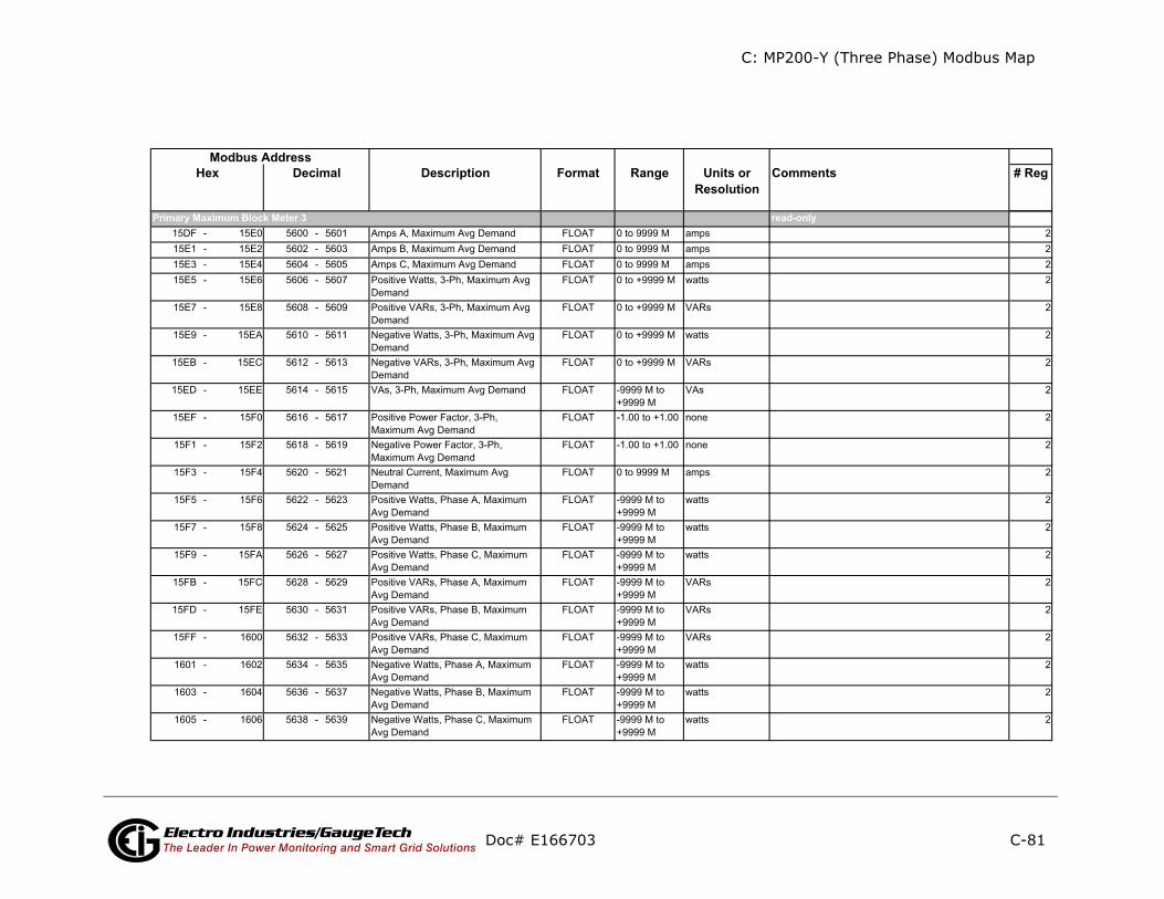
C: MP200-Y (Three Phase) Modbus Map
C-81
ents # Reg
ly
Doc# E166703 Electro Industries/GaugeTechThe Leader In Power Monitoring and Smart Grid Solutions
Description Format Range Units orResolution
CommModbus Address
Hex Decimal
read-onPrimary Maximum Block Meter 3

C: MP200-Y (Three Phase) Modbus Map
C-82
ts # Reg
Doc# E166703 Electro Industries/GaugeTechThe Leader In Power Monitoring and Smart Grid Solutions
Description Format Range Units orResolution
CommenModbus Address
Hex Decimal
read-onlyPrimary Maximum Block Meter 4
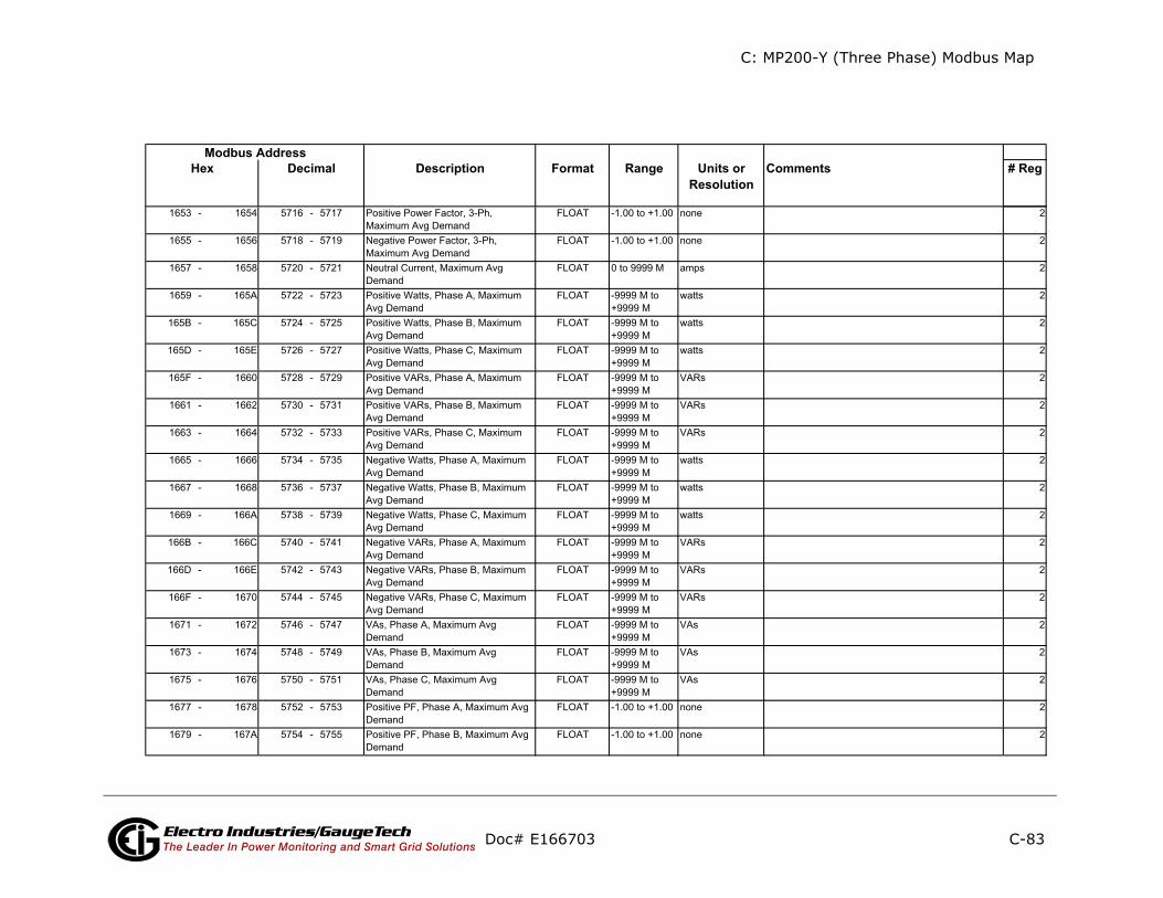
C: MP200-Y (Three Phase) Modbus Map
C-83
nts # Reg
Doc# E166703 Electro Industries/GaugeTechThe Leader In Power Monitoring and Smart Grid Solutions
Description Format Range Units orResolution
CommeModbus Address
Hex Decimal

C: MP200-Y (Three Phase) Modbus Map
C-84
ents # Reg
ly
Doc# E166703 Electro Industries/GaugeTechThe Leader In Power Monitoring and Smart Grid Solutions
Description Format Range Units orResolution
CommModbus Address
Hex Decimal
read-onPrimary Maximum Block Meter 5

C: MP200-Y (Three Phase) Modbus Map
C-85
ts # Reg
Doc# E166703 Electro Industries/GaugeTechThe Leader In Power Monitoring and Smart Grid Solutions
Description Format Range Units orResolution
CommenModbus Address
Hex Decimal
read-onlyPrimary Maximum Block Meter 6
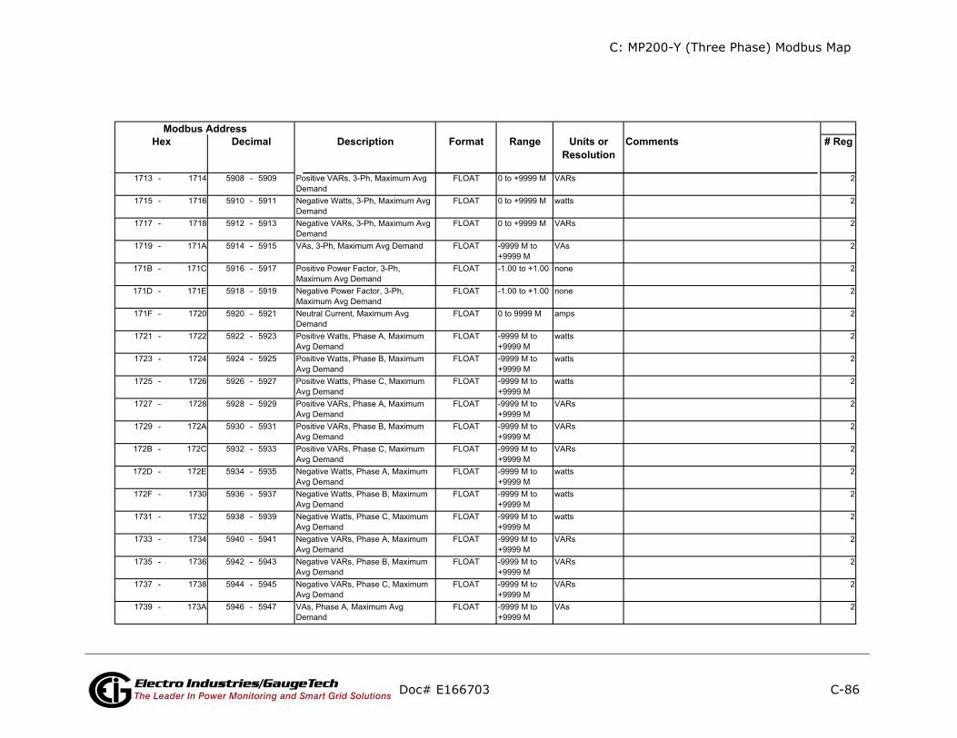
C: MP200-Y (Three Phase) Modbus Map
C-86
ts # Reg
Doc# E166703 Electro Industries/GaugeTechThe Leader In Power Monitoring and Smart Grid Solutions
Description Format Range Units orResolution
CommenModbus Address
Hex Decimal
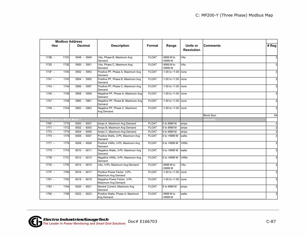
C: MP200-Y (Three Phase) Modbus Map
C-87
ents # Reg
ly
Doc# E166703 Electro Industries/GaugeTechThe Leader In Power Monitoring and Smart Grid Solutions
Description Format Range Units orResolution
CommModbus Address
Hex Decimal
read-onPrimary Maximum Block Meter 7
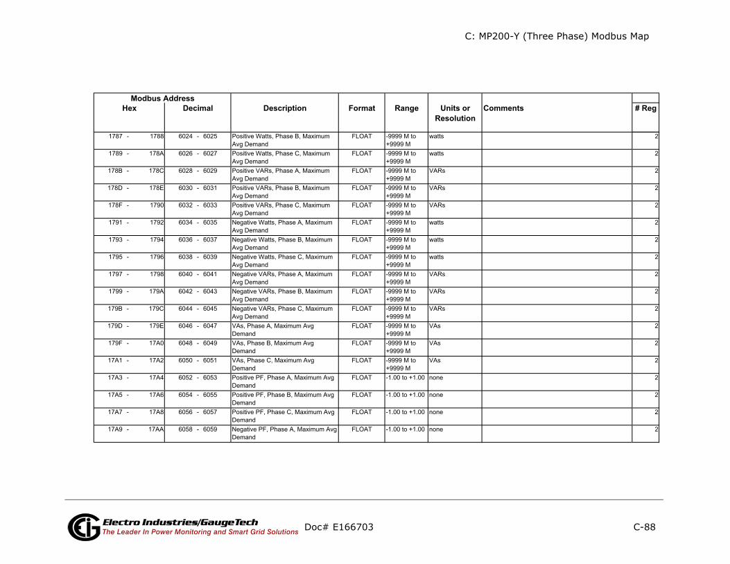
C: MP200-Y (Three Phase) Modbus Map
C-88
ents # Reg
Doc# E166703 Electro Industries/GaugeTechThe Leader In Power Monitoring and Smart Grid Solutions
Description Format Range Units orResolution
CommModbus Address
Hex Decimal

C: MP200-Y (Three Phase) Modbus Map
C-89
ents # Reg
ly
Doc# E166703 Electro Industries/GaugeTechThe Leader In Power Monitoring and Smart Grid Solutions
Description Format Range Units orResolution
CommModbus Address
Hex Decimal
read-onPrimary Maximum Block Meter 8

C: MP200-Y (Three Phase) Modbus Map
C-90
nts # Reg
Doc# E166703 Electro Industries/GaugeTechThe Leader In Power Monitoring and Smart Grid Solutions
Description Format Range Units orResolution
CommeModbus Address
Hex Decimal
read-onlyPrimary maximum Timestamp Block

C: MP200-Y (Three Phase) Modbus Map
C-91
ents # Reg
ly
Doc# E166703 Electro Industries/GaugeTechThe Leader In Power Monitoring and Smart Grid Solutions
Description Format Range Units orResolution
CommModbus Address
Hex Decimal
read-onPrimary maximum Timestamp Block Meter 1
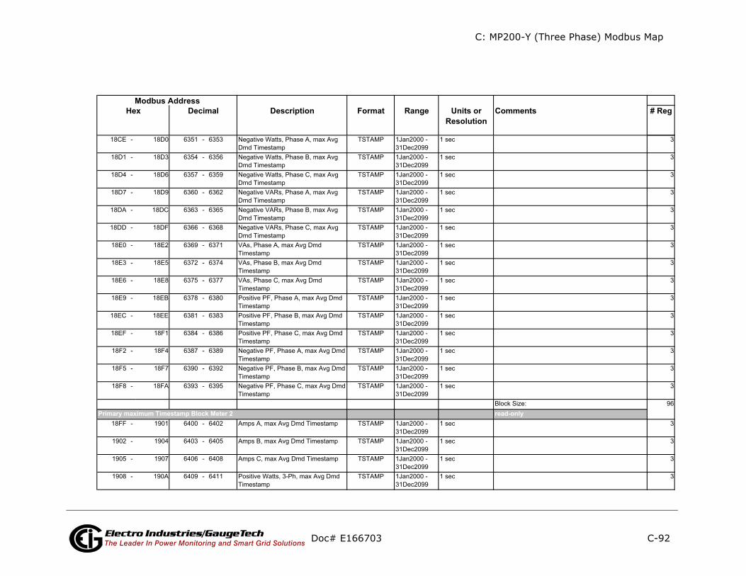
C: MP200-Y (Three Phase) Modbus Map
C-92
ents # Reg
ly
Doc# E166703 Electro Industries/GaugeTechThe Leader In Power Monitoring and Smart Grid Solutions
Description Format Range Units orResolution
CommModbus Address
Hex Decimal
read-onPrimary maximum Timestamp Block Meter 2
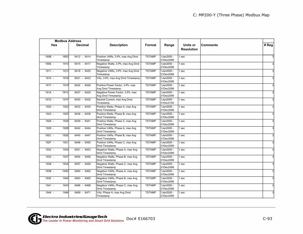
C: MP200-Y (Three Phase) Modbus Map
C-93
ents # Reg
Doc# E166703 Electro Industries/GaugeTechThe Leader In Power Monitoring and Smart Grid Solutions
Description Format Range Units orResolution
CommModbus Address
Hex Decimal

C: MP200-Y (Three Phase) Modbus Map
C-94
ents # Reg
ly
Doc# E166703 Electro Industries/GaugeTechThe Leader In Power Monitoring and Smart Grid Solutions
Description Format Range Units orResolution
CommModbus Address
Hex Decimal
read-onPrimary maximum Timestamp Block Meter 3
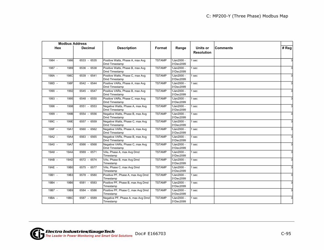
C: MP200-Y (Three Phase) Modbus Map
C-95
ents # Reg
Doc# E166703 Electro Industries/GaugeTechThe Leader In Power Monitoring and Smart Grid Solutions
Description Format Range Units orResolution
CommModbus Address
Hex Decimal

C: MP200-Y (Three Phase) Modbus Map
C-96
ents # Reg
ly
Doc# E166703 Electro Industries/GaugeTechThe Leader In Power Monitoring and Smart Grid Solutions
Description Format Range Units orResolution
CommModbus Address
Hex Decimal
read-onPrimary maximum Timestamp Block Meter 4
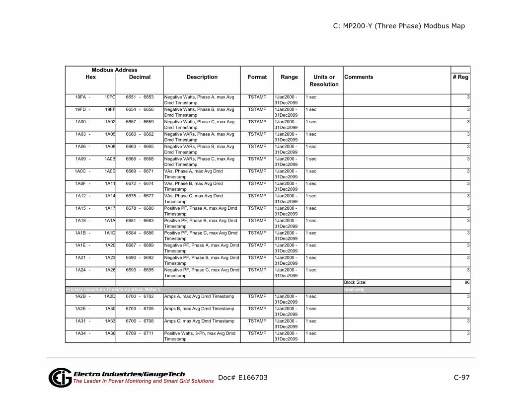
C: MP200-Y (Three Phase) Modbus Map
C-97
nts # Reg
Doc# E166703 Electro Industries/GaugeTechThe Leader In Power Monitoring and Smart Grid Solutions
Description Format Range Units orResolution
CommeModbus Address
Hex Decimal
read-onlyPrimary maximum Timestamp Block Meter 5
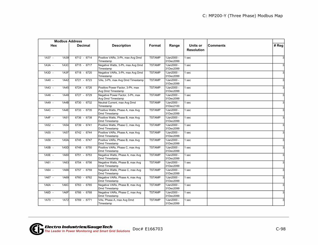
C: MP200-Y (Three Phase) Modbus Map
C-98
ts # Reg
Doc# E166703 Electro Industries/GaugeTechThe Leader In Power Monitoring and Smart Grid Solutions
Description Format Range Units orResolution
CommenModbus Address
Hex Decimal
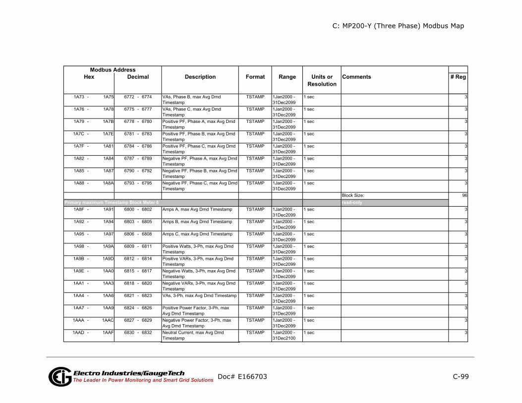
C: MP200-Y (Three Phase) Modbus Map
C-99
nts # Reg
Doc# E166703 Electro Industries/GaugeTechThe Leader In Power Monitoring and Smart Grid Solutions
Description Format Range Units orResolution
CommeModbus Address
Hex Decimal
read-onlyPrimary maximum Timestamp Block Meter 6
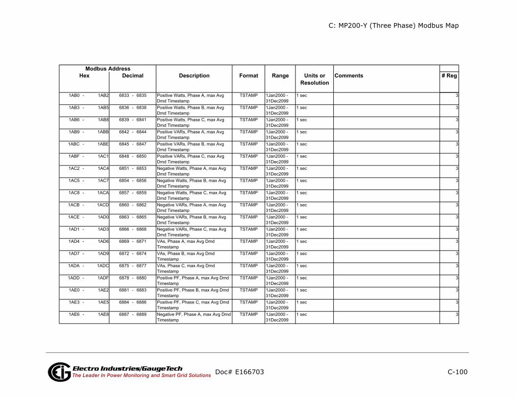
C: MP200-Y (Three Phase) Modbus Map
C-100
ts # Reg
Doc# E166703 Electro Industries/GaugeTechThe Leader In Power Monitoring and Smart Grid Solutions
Description Format Range Units orResolution
CommenModbus Address
Hex Decimal

C: MP200-Y (Three Phase) Modbus Map
C-101
nts # Reg
Doc# E166703 Electro Industries/GaugeTechThe Leader In Power Monitoring and Smart Grid Solutions
Description Format Range Units orResolution
CommeModbus Address
Hex Decimal
read-onlyPrimary maximum Timestamp Block Meter 7

C: MP200-Y (Three Phase) Modbus Map
C-102
ents # Reg
y
Doc# E166703 Electro Industries/GaugeTechThe Leader In Power Monitoring and Smart Grid Solutions
Description Format Range Units orResolution
CommModbus Address
Hex Decimal
read-onlPrimary maximum Timestamp Block Meter 8
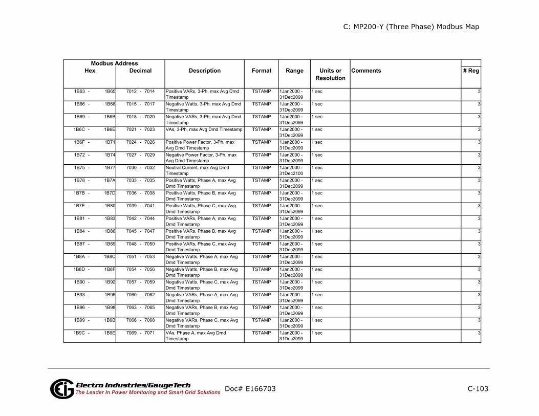
C: MP200-Y (Three Phase) Modbus Map
C-103
ts # Reg
Doc# E166703 Electro Industries/GaugeTechThe Leader In Power Monitoring and Smart Grid Solutions
Description Format Range Units orResolution
CommenModbus Address
Hex Decimal

C: MP200-Y (Three Phase) Modbus Map
C-104
ents # Reg
y
Doc# E166703 Electro Industries/GaugeTechThe Leader In Power Monitoring and Smart Grid Solutions
Description Format Range Units orResolution
CommModbus Address
Hex Decimal
read-onlInterval Energy Block Meter 1
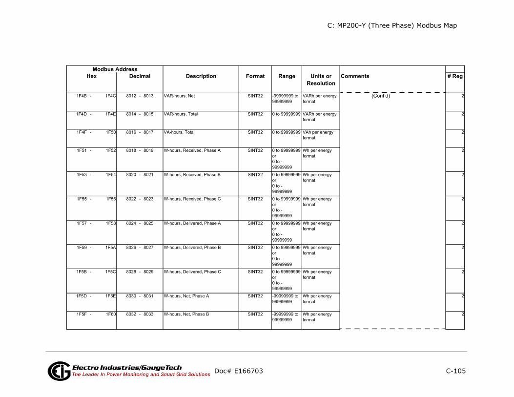
C: MP200-Y (Three Phase) Modbus Map
C-105
ents # Reg
(Cont’d)
Doc# E166703 Electro Industries/GaugeTechThe Leader In Power Monitoring and Smart Grid Solutions
Description Format Range Units orResolution
CommModbus Address
Hex Decimal
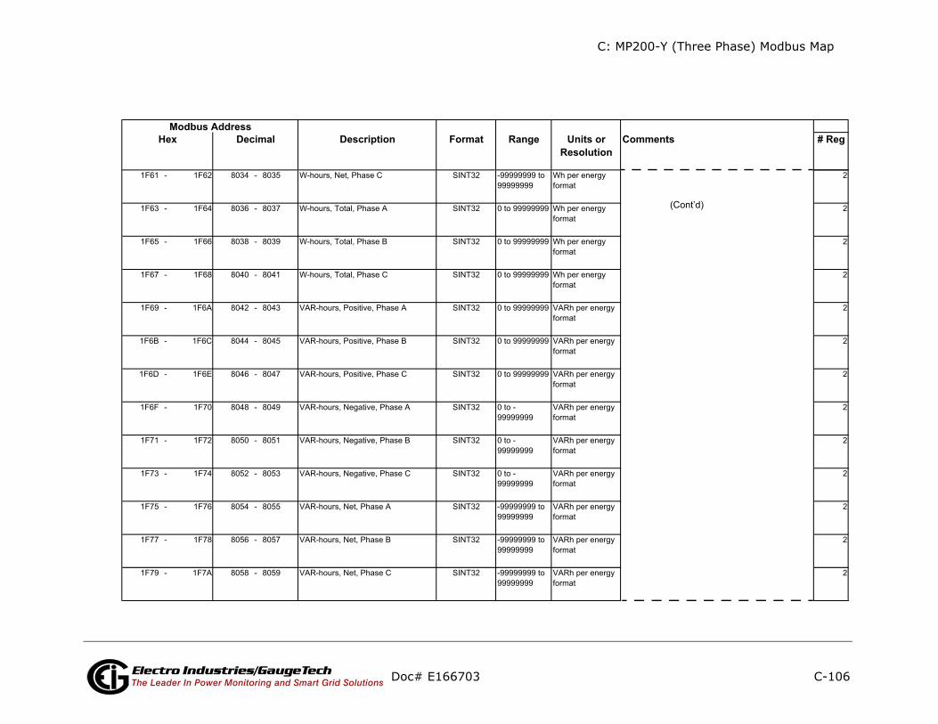
C: MP200-Y (Three Phase) Modbus Map
C-106
ents # Reg
(Cont’d)
Doc# E166703 Electro Industries/GaugeTechThe Leader In Power Monitoring and Smart Grid Solutions
Description Format Range Units orResolution
CommModbus Address
Hex Decimal

C: MP200-Y (Three Phase) Modbus Map
C-107
ents # Reg
ly
(Cont’d)
Doc# E166703 Electro Industries/GaugeTechThe Leader In Power Monitoring and Smart Grid Solutions
Description Format Range Units orResolution
CommModbus Address
Hex Decimal
read-onInterval Energy Block Meter 2
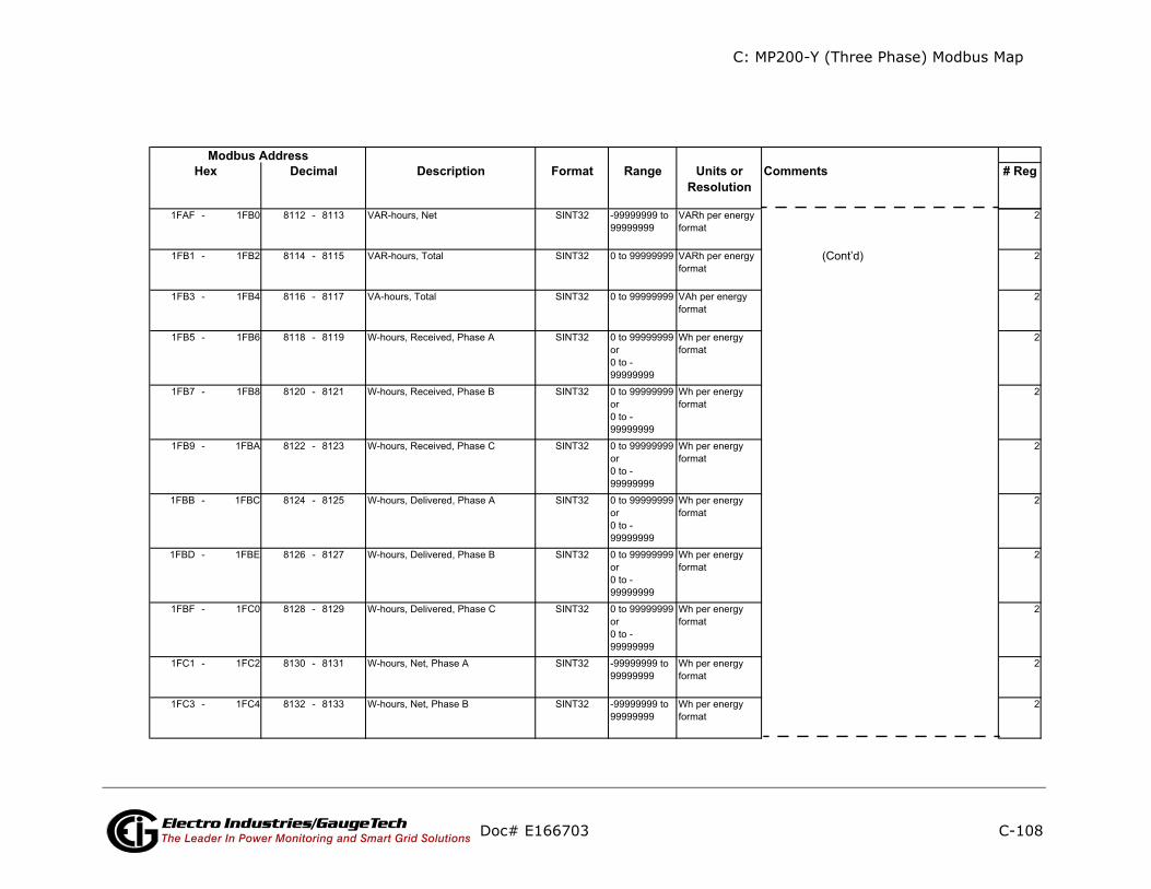
C: MP200-Y (Three Phase) Modbus Map
C-108
ents # Reg
(Cont’d)
Doc# E166703 Electro Industries/GaugeTechThe Leader In Power Monitoring and Smart Grid Solutions
Description Format Range Units orResolution
CommModbus Address
Hex Decimal
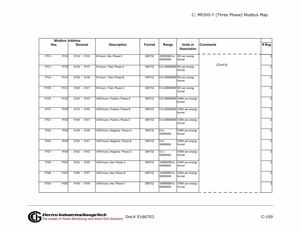
C: MP200-Y (Three Phase) Modbus Map
C-109
ents # Reg
(Cont’d)
Doc# E166703 Electro Industries/GaugeTechThe Leader In Power Monitoring and Smart Grid Solutions
Description Format Range Units orResolution
CommModbus Address
Hex Decimal

C: MP200-Y (Three Phase) Modbus Map
C-110
ents # Reg
ly
(Cont’d)
Doc# E166703 Electro Industries/GaugeTechThe Leader In Power Monitoring and Smart Grid Solutions
Description Format Range Units orResolution
CommModbus Address
Hex Decimal
read-onInterval Energy Block Meter 3

C: MP200-Y (Three Phase) Modbus Map
C-111
ents # Reg
(Cont’d)
Doc# E166703 Electro Industries/GaugeTechThe Leader In Power Monitoring and Smart Grid Solutions
Description Format Range Units orResolution
CommModbus Address
Hex Decimal

C: MP200-Y (Three Phase) Modbus Map
C-112
ents # Reg
(Cont’d)
Doc# E166703 Electro Industries/GaugeTechThe Leader In Power Monitoring and Smart Grid Solutions
Description Format Range Units orResolution
CommModbus Address
Hex Decimal

C: MP200-Y (Three Phase) Modbus Map
C-113
ents # Reg
ly
(Cont’d)
Doc# E166703 Electro Industries/GaugeTechThe Leader In Power Monitoring and Smart Grid Solutions
Description Format Range Units orResolution
CommModbus Address
Hex Decimal
read-onInterval Energy Block Meter 4
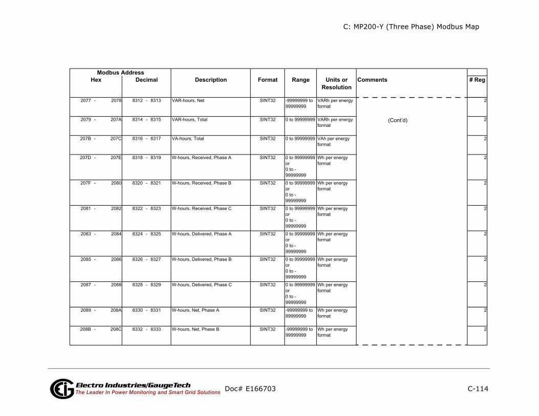
C: MP200-Y (Three Phase) Modbus Map
C-114
ents # Reg
(Cont’d)
Doc# E166703 Electro Industries/GaugeTechThe Leader In Power Monitoring and Smart Grid Solutions
Description Format Range Units orResolution
CommModbus Address
Hex Decimal

C: MP200-Y (Three Phase) Modbus Map
C-115
ents # Reg
(Cont’d)
Doc# E166703 Electro Industries/GaugeTechThe Leader In Power Monitoring and Smart Grid Solutions
Description Format Range Units orResolution
CommModbus Address
Hex Decimal

C: MP200-Y (Three Phase) Modbus Map
C-116
ents # Reg
ly
(Cont’d)
Doc# E166703 Electro Industries/GaugeTechThe Leader In Power Monitoring and Smart Grid Solutions
Description Format Range Units orResolution
CommModbus Address
Hex Decimal
read-onInterval Energy Block Meter 5

C: MP200-Y (Three Phase) Modbus Map
C-117
nts # Reg
(Cont’d)
Doc# E166703 Electro Industries/GaugeTechThe Leader In Power Monitoring and Smart Grid Solutions
Description Format Range Units orResolution
CommeModbus Address
Hex Decimal
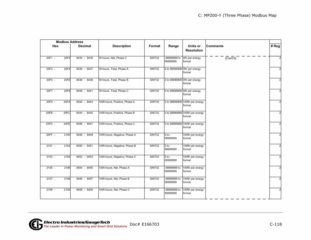
C: MP200-Y (Three Phase) Modbus Map
C-118
ents # Reg
(Cont’d)
Doc# E166703 Electro Industries/GaugeTechThe Leader In Power Monitoring and Smart Grid Solutions
Description Format Range Units orResolution
CommModbus Address
Hex Decimal

C: MP200-Y (Three Phase) Modbus Map
C-119
nts # Reg
(Cont’d)
Doc# E166703 Electro Industries/GaugeTechThe Leader In Power Monitoring and Smart Grid Solutions
Description Format Range Units orResolution
CommeModbus Address
Hex Decimal
read-onlyInterval Energy Block Meter 6
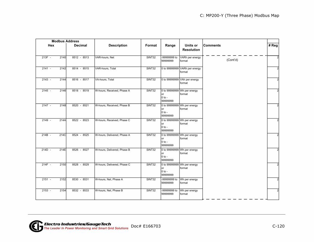
C: MP200-Y (Three Phase) Modbus Map
C-120
ts # Reg
(Cont’d)
Doc# E166703 Electro Industries/GaugeTechThe Leader In Power Monitoring and Smart Grid Solutions
Description Format Range Units orResolution
CommenModbus Address
Hex Decimal

C: MP200-Y (Three Phase) Modbus Map
C-121
ents # Reg
(Cont’d)
Doc# E166703 Electro Industries/GaugeTechThe Leader In Power Monitoring and Smart Grid Solutions
Description Format Range Units orResolution
CommModbus Address
Hex Decimal
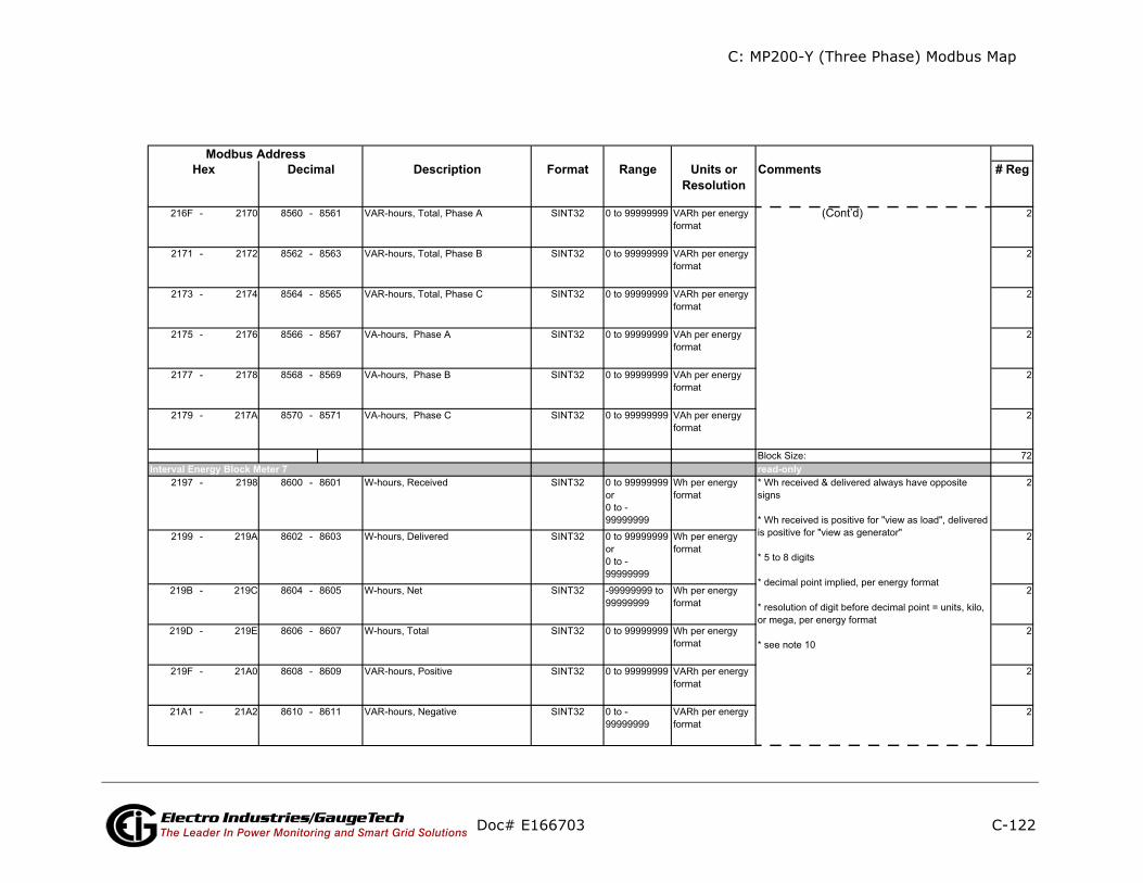
C: MP200-Y (Three Phase) Modbus Map
C-122
ents # Reg
ly
(Cont’d)
Doc# E166703 Electro Industries/GaugeTechThe Leader In Power Monitoring and Smart Grid Solutions
Description Format Range Units orResolution
CommModbus Address
Hex Decimal
read-onInterval Energy Block Meter 7

C: MP200-Y (Three Phase) Modbus Map
C-123
ts # Reg
(Cont’d)
Doc# E166703 Electro Industries/GaugeTechThe Leader In Power Monitoring and Smart Grid Solutions
Description Format Range Units orResolution
CommenModbus Address
Hex Decimal
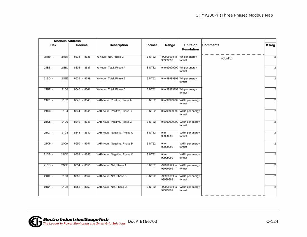
C: MP200-Y (Three Phase) Modbus Map
C-124
nts # Reg
(Cont’d)
Doc# E166703 Electro Industries/GaugeTechThe Leader In Power Monitoring and Smart Grid Solutions
Description Format Range Units orResolution
CommeModbus Address
Hex Decimal
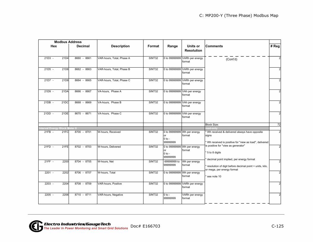
C: MP200-Y (Three Phase) Modbus Map
C-125
nts # Reg
(Cont’d)
Doc# E166703 Electro Industries/GaugeTechThe Leader In Power Monitoring and Smart Grid Solutions
Description Format Range Units orResolution
CommeModbus Address
Hex Decimal
read-onlyInterval Energy Block Meter 8

C: MP200-Y (Three Phase) Modbus Map
C-126
ts # Reg
(Cont’d)
Doc# E166703 Electro Industries/GaugeTechThe Leader In Power Monitoring and Smart Grid Solutions
Description Format Range Units orResolution
CommenModbus Address
Hex Decimal

C: MP200-Y (Three Phase) Modbus Map
C-127
nts # Reg
(Cont’d)
Doc# E166703 Electro Industries/GaugeTechThe Leader In Power Monitoring and Smart Grid Solutions
Description Format Range Units orResolution
CommeModbus Address
Hex Decimal
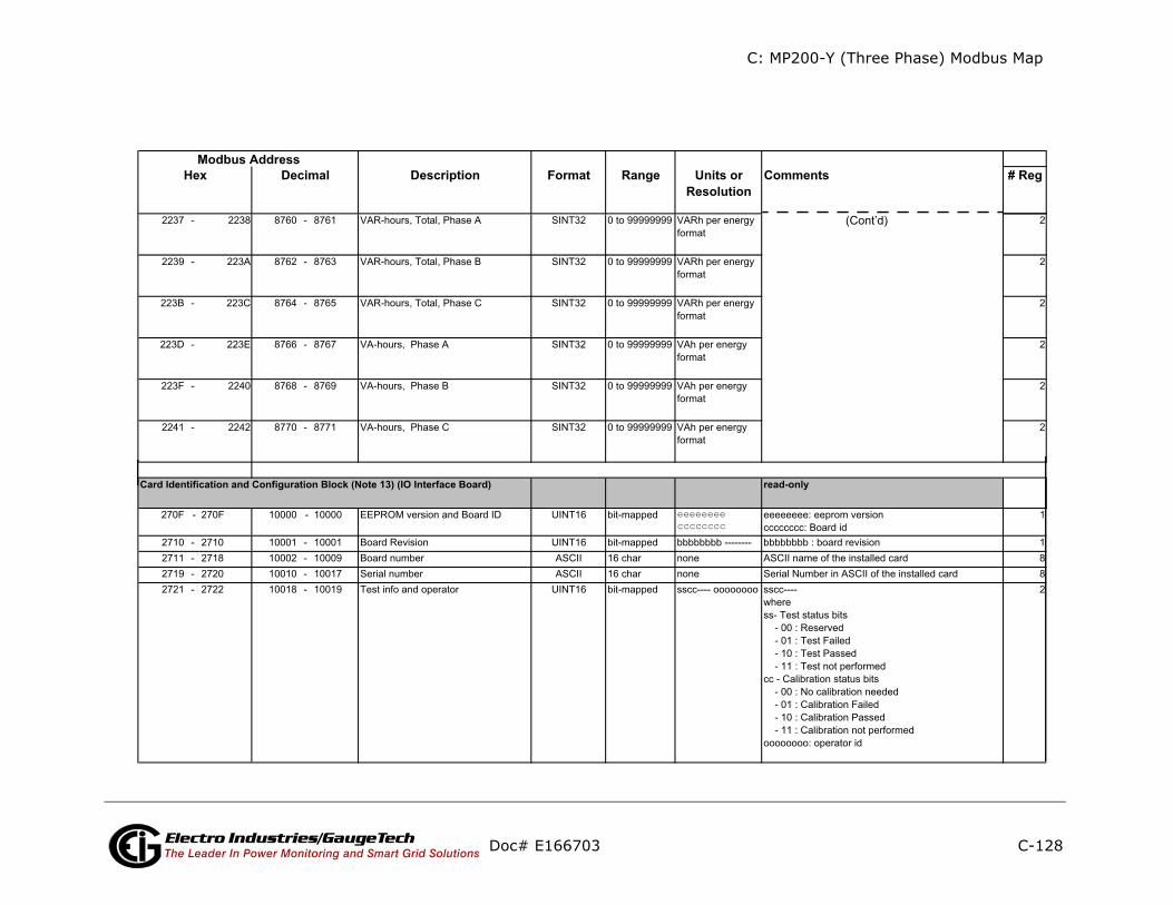
C: MP200-Y (Three Phase) Modbus Map
C-128
ts # Reg
(Cont’d)
Doc# E166703 Electro Industries/GaugeTechThe Leader In Power Monitoring and Smart Grid Solutions
Description Format Range Units orResolution
CommenModbus Address
Hex Decimal
read-only
eeeeeeeecccccccc
Card Identification and Configuration Block (Note 13) (IO Interface Board)
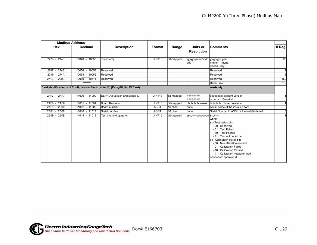
C: MP200-Y (Three Phase) Modbus Map
C-129
ents # Reg
ly
Doc# E166703 Electro Industries/GaugeTechThe Leader In Power Monitoring and Smart Grid Solutions
Description Format Range Units orResolution
CommModbus Address
Hex Decimal
read-on
eeeeeeeecccccccc
Card Identification and Configuration Block (Note 13) (Relay/Digital IO Card)
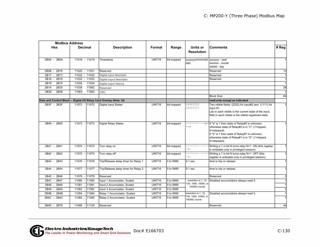
C: MP200-Y (Three Phase) Modbus Map
C-130
nts # Reg
except as indicated
Doc# E166703 Electro Industries/GaugeTechThe Leader In Power Monitoring and Smart Grid Solutions
Description Format Range Units orResolution
CommeModbus Address
Hex Decimal
read-only 4444333322221111
-------- --ab--cd
-------- ------21-------- ------21
Data and Control Block -- Digital I/O Relay Card Overlay (Note 14)

C: MP200-Y (Three Phase) Modbus Map
C-131
ents # Reg
ly
ly
Doc# E166703 Electro Industries/GaugeTechThe Leader In Power Monitoring and Smart Grid Solutions
Description Format Range Units orResolution
CommModbus Address
Hex Decimal
read-on
write-onResets Block (Note 9)
Accumulators Block
Commands Section (Note 4)
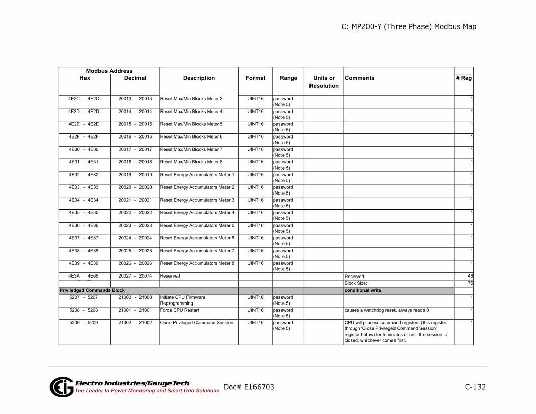
C: MP200-Y (Three Phase) Modbus Map
C-132
# Reg
rite
Doc# E166703 Electro Industries/GaugeTechThe Leader In Power Monitoring and Smart Grid Solutions
Description Format Range Units orResolution
CommentsModbus Address
Hex Decimal
conditional wPriviledged Commands Block

C: MP200-Y (Three Phase) Modbus Map
C-133
ents # Reg
ite
ly in PS update mode
Doc# E166703 Electro Industries/GaugeTechThe Leader In Power Monitoring and Smart Grid Solutions
Description Format Range Units orResolution
CommModbus Address
Hex Decimal
read/wr
write onnonenonenonenonenonenonenonenonenonenonenonenonenonenone
Programmable Settings SectionBasic Setups Block
Encryption Block

C: MP200-Y (Three Phase) Modbus Map
C-134
ents # Reg
(Cont’d)
Doc# E166703 Electro Industries/GaugeTechThe Leader In Power Monitoring and Smart Grid Solutions
Description Format Range Units orResolution
CommModbus Address
Hex Decimal
nonenonenonenonenonenonenonenonenonenonenone
-------- ----hhhh
--iiiiii b----sss
------nn -eee-ddd
hhhhhwww -dddmmmmhhhhhwww -dddmmmm
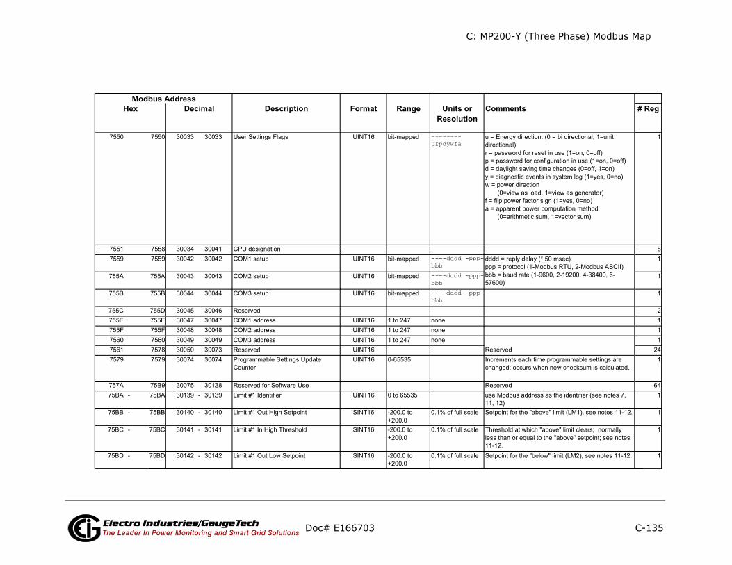
C: MP200-Y (Three Phase) Modbus Map
C-135
ents # Reg
Doc# E166703 Electro Industries/GaugeTechThe Leader In Power Monitoring and Smart Grid Solutions
Description Format Range Units orResolution
CommModbus Address
Hex Decimal
--------urpdywfa
----dddd -ppp-bbb----dddd -ppp-bbb----dddd -ppp-bbb

C: MP200-Y (Three Phase) Modbus Map
C-136
ents # Reg
Doc# E166703 Electro Industries/GaugeTechThe Leader In Power Monitoring and Smart Grid Solutions
Description Format Range Units orResolution
CommModbus Address
Hex Decimal
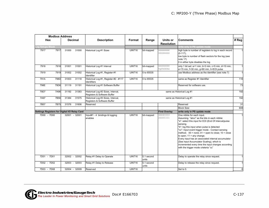
C: MP200-Y (Three Phase) Modbus Map
C-137
ents # Reg
ly in PS update mode
ly in PS update mode
Doc# E166703 Electro Industries/GaugeTechThe Leader In Power Monitoring and Smart Grid Solutions
Description Format Range Units orResolution
CommModbus Address
Hex Decimal
write oneeeeeeeessssssss
00000000hgfedcba
First Overlay write on4444333322221111
Settings Registers for Digital I/O Relay Card
Log Setups Block

C: MP200-Y (Three Phase) Modbus Map
C-138
ents # Reg
Doc# E166703 Electro Industries/GaugeTechThe Leader In Power Monitoring and Smart Grid Solutions
Description Format Range Units orResolution
CommModbus Address
Hex Decimal
44443333222211114444333322221111
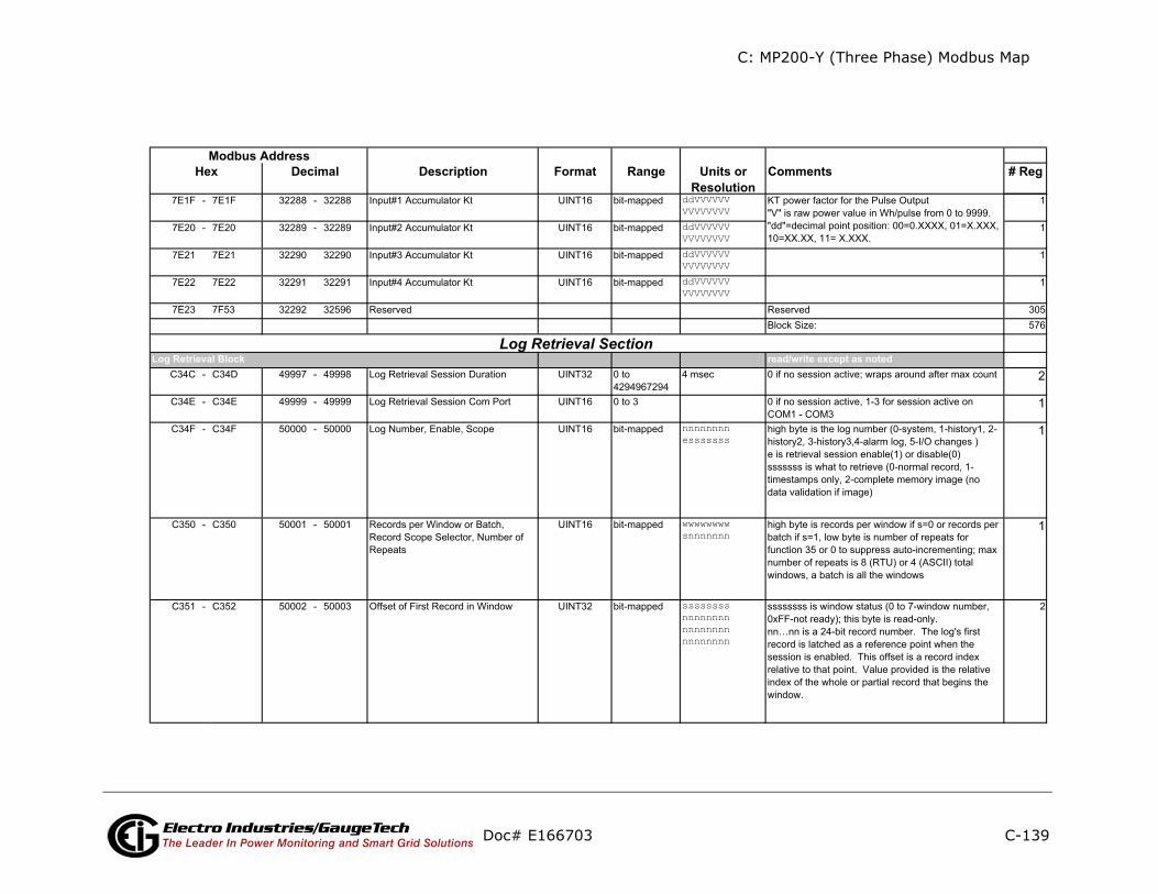
C: MP200-Y (Three Phase) Modbus Map
C-139
ents # Reg
te except as noted
Doc# E166703 Electro Industries/GaugeTechThe Leader In Power Monitoring and Smart Grid Solutions
Description Format Range Units orResolution
CommModbus Address
Hex Decimal
ddVVVVVVVVVVVVVVddVVVVVVVVVVVVVVddVVVVVVVVVVVVVVddVVVVVVVVVVVVVV
read/wri
nnnnnnnnesssssss
wwwwwwwwsnnnnnnn
ssssssssnnnnnnnnnnnnnnnnnnnnnnnn
Log Retrieval BlockLog Retrieval Section

C: MP200-Y (Three Phase) Modbus Map
C-140
ents # Reg
ly
Doc# E166703 Electro Industries/GaugeTechThe Leader In Power Monitoring and Smart Grid Solutions
Description Format Range Units orResolution
CommModbus Address
Hex Decimal
read onSystem Log Status Block
Historical Log 1 Status BlockHistorical Log 2 Status BlockHistorical Log 3 Status BlockAlarm Log Status BlockI/O Log Status Block
End of Map
Log Status Block
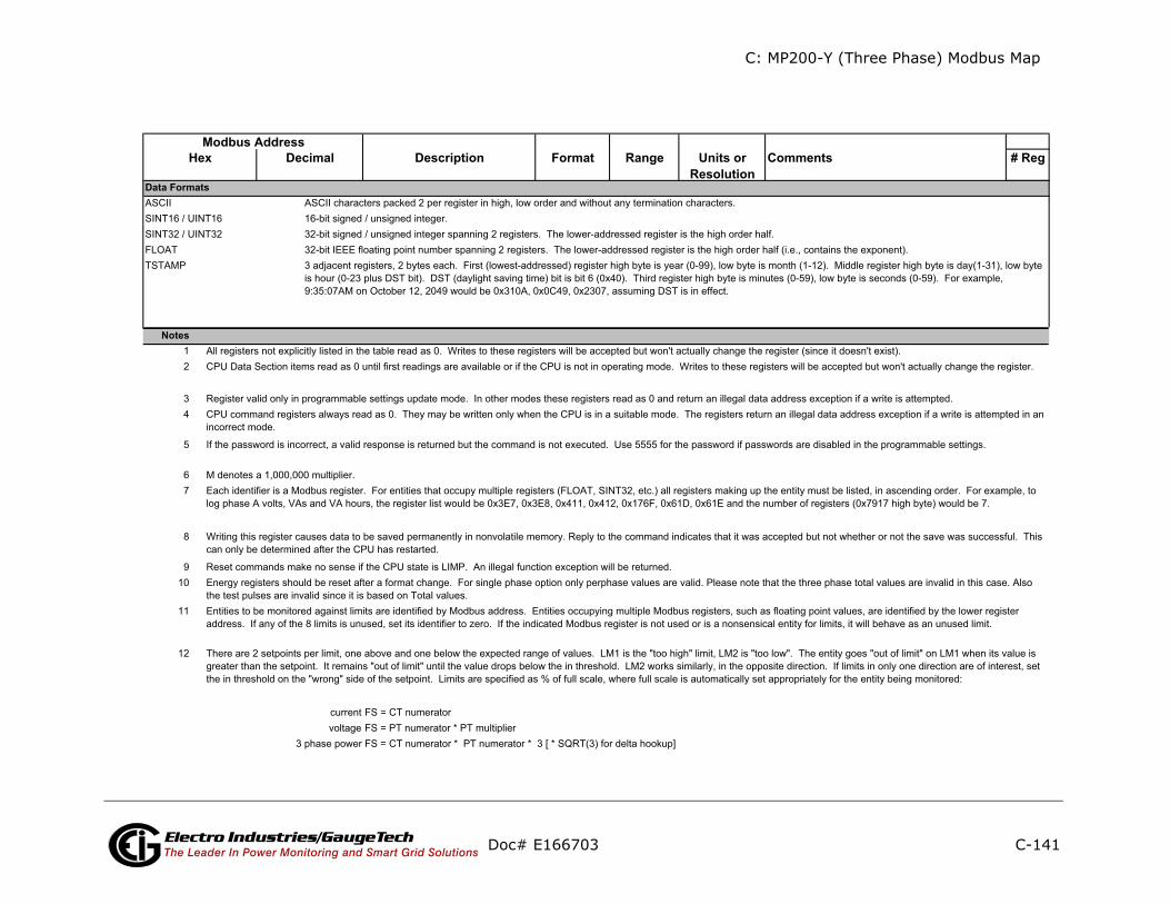
C: MP200-Y (Three Phase) Modbus Map
C-141
nts # Reg
Doc# E166703 Electro Industries/GaugeTechThe Leader In Power Monitoring and Smart Grid Solutions
Description Format Range Units orResolution
CommeModbus Address
Hex Decimal
Notes
Data Formats

C: MP200-Y (Three Phase) Modbus Map
C-142
Doc# E166703 Electro Industries/GaugeTechThe Leader In Power Monitoring and Smart Grid Solutions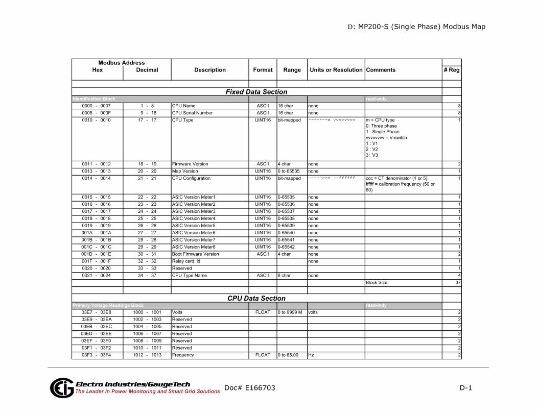
D: MP200-S (Single Phase) Modbus Map
D-1
mments # Reg
-only88
CPU typehree phaseingle Phasevvvv = V-switch123
1
21
= CT denominator (1 or 5), = calibration frequency (50 or
1
111111112114
k Size: 37
-only2222222
Doc# E166703 Electro Industries/GaugeTechThe Leader In Power Monitoring and Smart Grid Solutions
Description Format Range Units or Resolution Co
read0000 - 0007 1 - 8 CPU Name ASCII 16 char none0008 - 000F 9 - 16 CPU Serial Number ASCII 16 char none0010 - 0010 17 - 17 CPU Type UINT16 bit-mapped -------m vvvvvvvv m =
0: T1 : Svvvv1 : V2 : V3: V
0011 - 0012 18 - 19 Firmware Version ASCII 4 char none0013 - 0013 20 - 20 Map Version UINT16 0 to 65535 none0014 - 0014 21 - 21 CPU Configuration UINT16 bit-mapped -----ccc --ffffff ccc
ffffff60)
0015 - 0015 22 - 22 ASIC Version Meter1 UINT16 0-65535 none0016 - 0016 23 - 23 ASIC Version Meter2 UINT16 0-65536 none0017 - 0017 24 - 24 ASIC Version Meter3 UINT16 0-65537 none0018 - 0018 25 - 25 ASIC Version Meter4 UINT16 0-65538 none0019 - 0019 26 - 26 ASIC Version Meter5 UINT16 0-65539 none001A - 001A 27 - 27 ASIC Version Meter6 UINT16 0-65540 none001B - 001B 28 - 28 ASIC Version Meter7 UINT16 0-65541 none001C - 001C 29 - 29 ASIC Version Meter8 UINT16 0-65542 none001D - 001E 30 - 31 Boot Firmware Version ASCII 4 char none001F - 001F 32 - 32 Relay card id none0020 - 0020 33 - 33 Reserved0021 - 0024 34 - 37 CPU Type Name ASCII 8 char none
Bloc
read03E7 - 03E8 1000 - 1001 Volts FLOAT 0 to 9999 M volts03E9 - 03EA 1002 - 1003 Reserved03EB - 03EC 1004 - 1005 Reserved03ED - 03EE 1006 - 1007 Reserved03EF - 03F0 1008 - 1009 Reserved03F1 - 03F2 1010 - 1011 Reserved03F3 - 03F4 1012 - 1013 Frequency FLOAT 0 to 65.00 Hz
Identification Block
CPU Data Section Primary Voltage Readings Block
Modbus AddressHex Decimal
Fixed Data Section
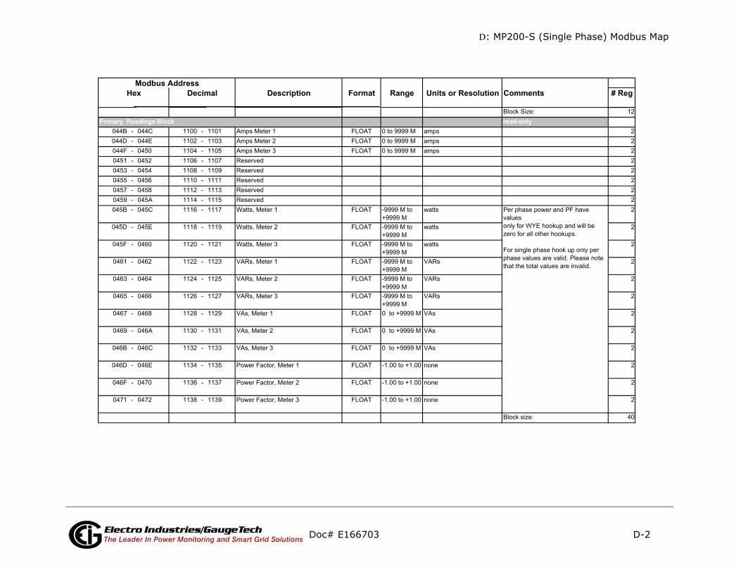
D: MP200-S (Single Phase) Modbus Map
D-2
mments # Reg
-only
Doc# E166703 Electro Industries/GaugeTechThe Leader In Power Monitoring and Smart Grid Solutions
Description Format Range Units or Resolution CoModbus Address
Hex Decimal
readPrimary Readings Block

D: MP200-S (Single Phase) Modbus Map
D-3
mments # Reg
Doc# E166703 Electro Industries/GaugeTechThe Leader In Power Monitoring and Smart Grid Solutions
Description Format Range Units or Resolution CoModbus Address
Hex Decimal

D: MP200-S (Single Phase) Modbus Map
D-4
mments # Reg
Doc# E166703 Electro Industries/GaugeTechThe Leader In Power Monitoring and Smart Grid Solutions
Description Format Range Units or Resolution CoModbus Address
Hex Decimal

D: MP200-S (Single Phase) Modbus Map
D-5
mments # Reg
Doc# E166703 Electro Industries/GaugeTechThe Leader In Power Monitoring and Smart Grid Solutions
Description Format Range Units or Resolution CoModbus Address
Hex Decimal

D: MP200-S (Single Phase) Modbus Map
D-6
mments # Reg
Doc# E166703 Electro Industries/GaugeTechThe Leader In Power Monitoring and Smart Grid Solutions
Description Format Range Units or Resolution CoModbus Address
Hex Decimal
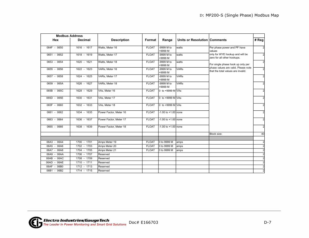
D: MP200-S (Single Phase) Modbus Map
D-7
ments # Reg
Doc# E166703 Electro Industries/GaugeTechThe Leader In Power Monitoring and Smart Grid Solutions
Description Format Range Units or Resolution ComModbus Address
Hex Decimal

D: MP200-S (Single Phase) Modbus Map
D-8
mments # Reg
Doc# E166703 Electro Industries/GaugeTechThe Leader In Power Monitoring and Smart Grid Solutions
Description Format Range Units or Resolution CoModbus Address
Hex Decimal
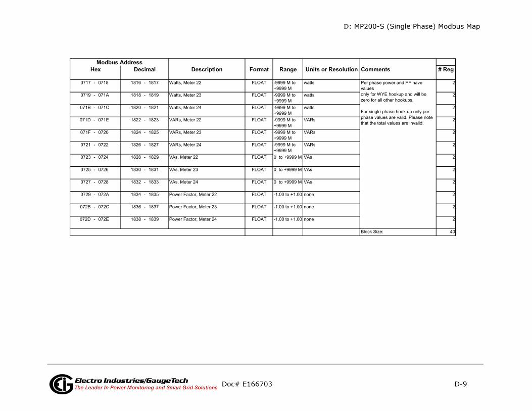
D: MP200-S (Single Phase) Modbus Map
D-9
ments # Reg
Doc# E166703 Electro Industries/GaugeTechThe Leader In Power Monitoring and Smart Grid Solutions
Description Format Range Units or Resolution ComModbus Address
Hex Decimal

D: MP200-S (Single Phase) Modbus Map
D-10
mments # Reg
Doc# E166703 Electro Industries/GaugeTechThe Leader In Power Monitoring and Smart Grid Solutions
Description Format Range Units or Resolution CoModbus Address
Hex Decimal
Primary Energy Block

D: MP200-S (Single Phase) Modbus Map
D-11
mments # Reg
(Cont’d)
Doc# E166703 Electro Industries/GaugeTechThe Leader In Power Monitoring and Smart Grid Solutions
Description Format Range Units or Resolution CoModbus Address
Hex Decimal

D: MP200-S (Single Phase) Modbus Map
D-12
mments # Reg
(Cont’d)
Doc# E166703 Electro Industries/GaugeTechThe Leader In Power Monitoring and Smart Grid Solutions
Description Format Range Units or Resolution CoModbus Address
Hex Decimal
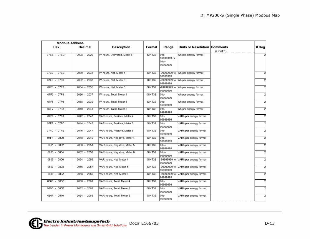
D: MP200-S (Single Phase) Modbus Map
D-13
mments # Reg(Cont’d)
Doc# E166703 Electro Industries/GaugeTechThe Leader In Power Monitoring and Smart Grid Solutions
Description Format Range Units or Resolution CoModbus Address
Hex Decimal
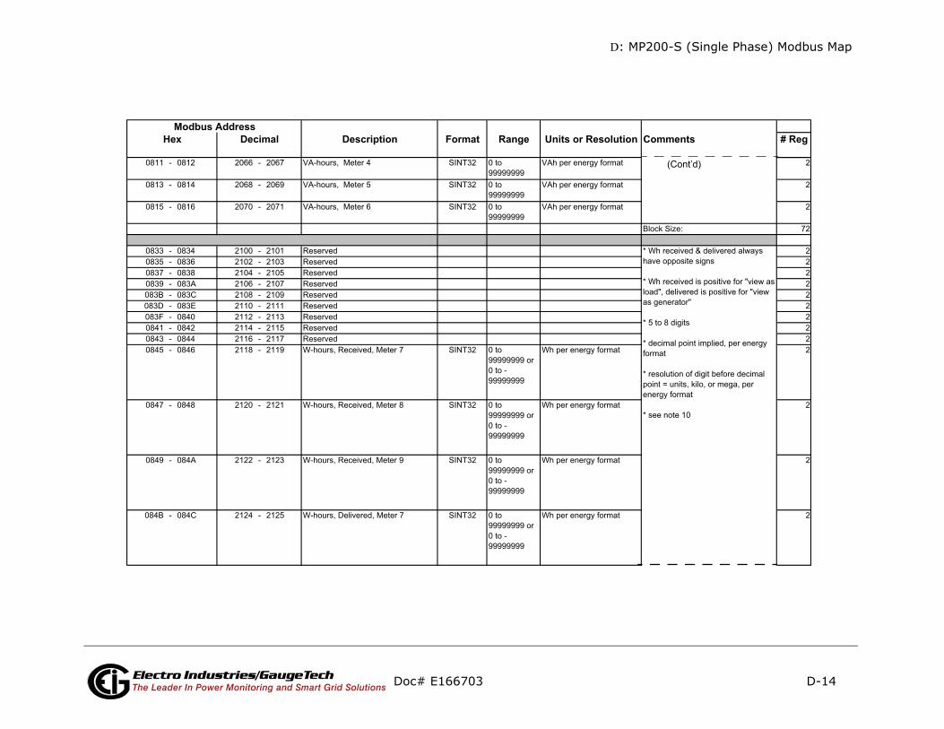
D: MP200-S (Single Phase) Modbus Map
D-14
mments # Reg
(Cont’d)
Doc# E166703 Electro Industries/GaugeTechThe Leader In Power Monitoring and Smart Grid Solutions
Description Format Range Units or Resolution CoModbus Address
Hex Decimal

D: MP200-S (Single Phase) Modbus Map
D-15
ments # Reg
Cont’d)
Doc# E166703 Electro Industries/GaugeTechThe Leader In Power Monitoring and Smart Grid Solutions
Description Format Range Units or Resolution ComModbus Address
Hex Decimal
(

D: MP200-S (Single Phase) Modbus Map
D-16
mments # Reg
(Cont’d)
Doc# E166703 Electro Industries/GaugeTechThe Leader In Power Monitoring and Smart Grid Solutions
Description Format Range Units or Resolution CoModbus Address
Hex Decimal
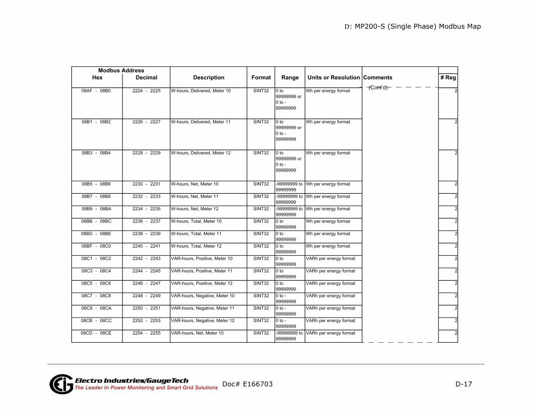
D: MP200-S (Single Phase) Modbus Map
D-17
mments # Reg
Cont’d)
Doc# E166703 Electro Industries/GaugeTechThe Leader In Power Monitoring and Smart Grid Solutions
Description Format Range Units or Resolution CoModbus Address
Hex Decimal
(

D: MP200-S (Single Phase) Modbus Map
D-18
mments # Reg
(Cont’d)
Doc# E166703 Electro Industries/GaugeTechThe Leader In Power Monitoring and Smart Grid Solutions
Description Format Range Units or Resolution CoModbus Address
Hex Decimal

D: MP200-S (Single Phase) Modbus Map
D-19
ments # RegCont’d)
Doc# E166703 Electro Industries/GaugeTechThe Leader In Power Monitoring and Smart Grid Solutions
Description Format Range Units or Resolution ComModbus Address
Hex Decimal(
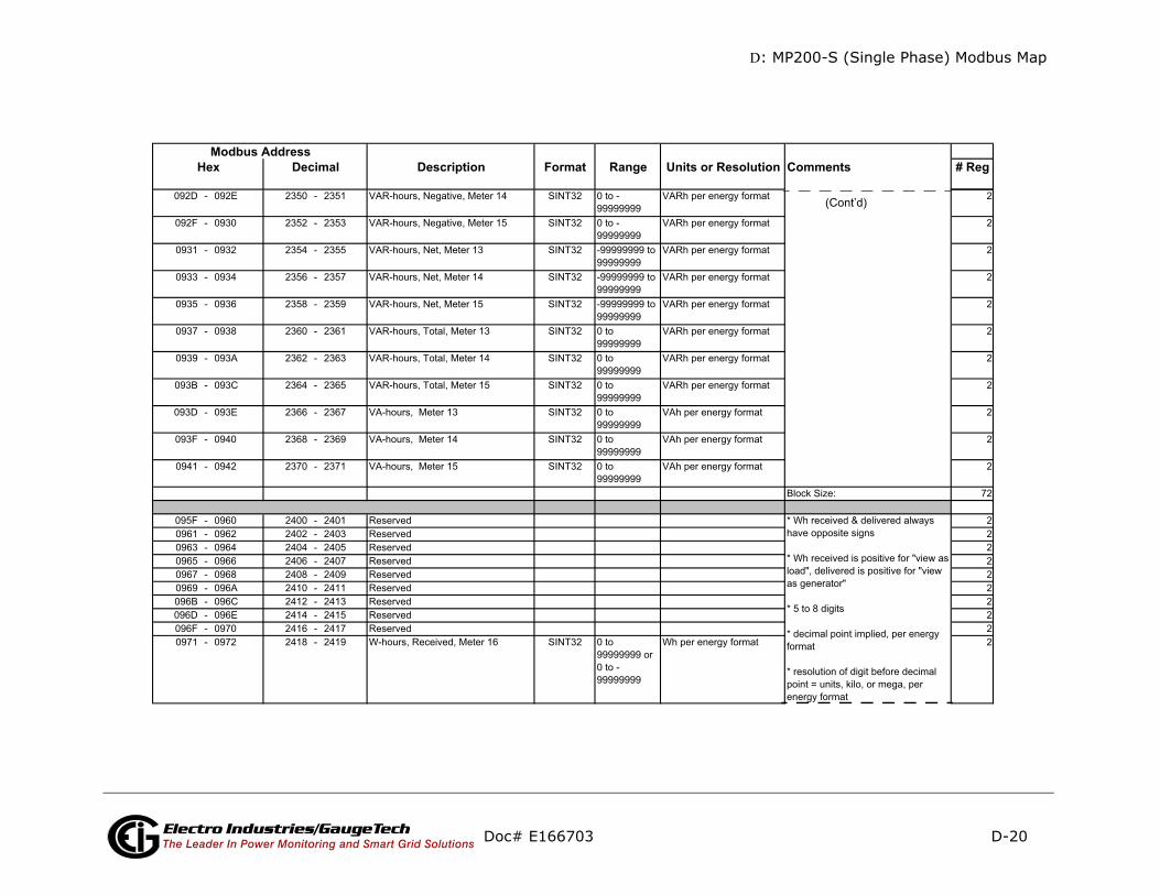
D: MP200-S (Single Phase) Modbus Map
D-20
ments # Reg
(Cont’d)
Doc# E166703 Electro Industries/GaugeTechThe Leader In Power Monitoring and Smart Grid Solutions
Description Format Range Units or Resolution ComModbus Address
Hex Decimal
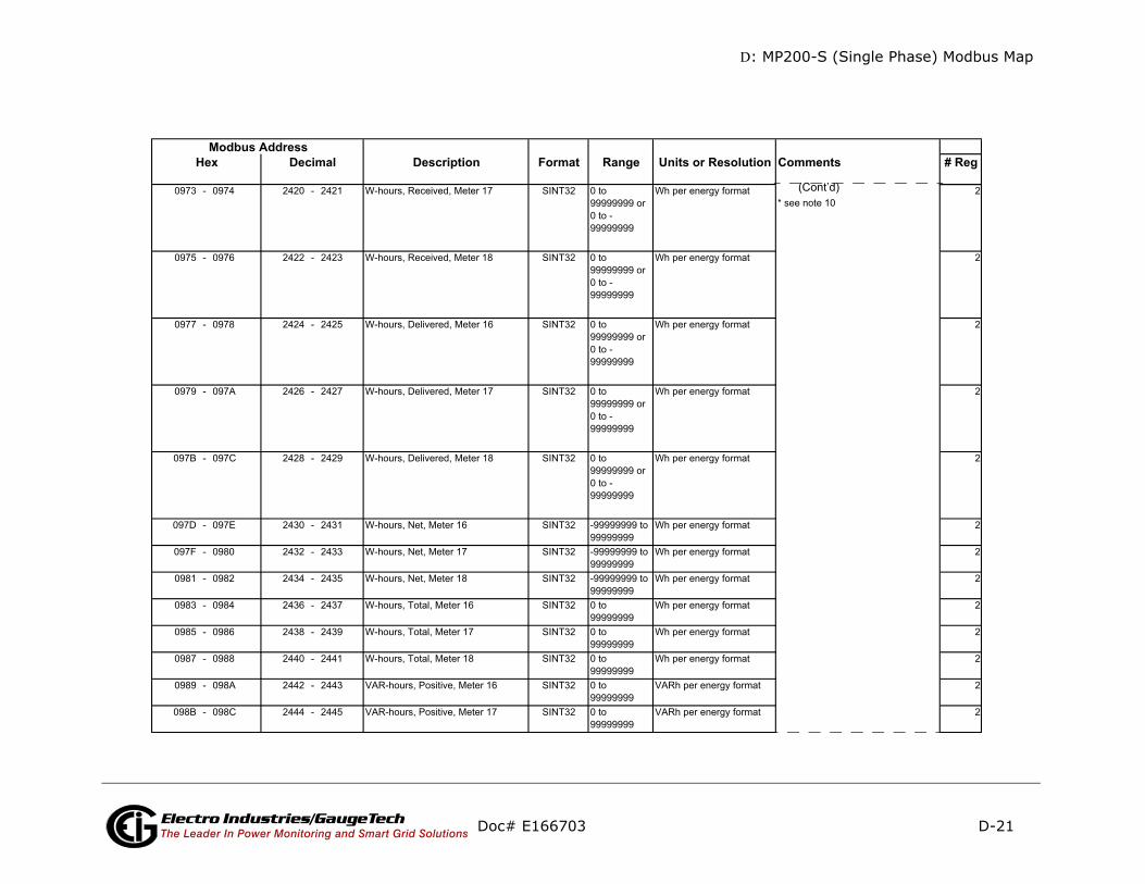
D: MP200-S (Single Phase) Modbus Map
D-21
mments # Reg
(Cont’d)
Doc# E166703 Electro Industries/GaugeTechThe Leader In Power Monitoring and Smart Grid Solutions
Description Format Range Units or Resolution CoModbus Address
Hex Decimal

D: MP200-S (Single Phase) Modbus Map
D-22
mments # Reg
(Cont’d)
Doc# E166703 Electro Industries/GaugeTechThe Leader In Power Monitoring and Smart Grid Solutions
Description Format Range Units or Resolution CoModbus Address
Hex Decimal

D: MP200-S (Single Phase) Modbus Map
D-23
mments # Reg
Doc# E166703 Electro Industries/GaugeTechThe Leader In Power Monitoring and Smart Grid Solutions
Description Format Range Units or Resolution CoModbus Address
Hex Decimal

D: MP200-S (Single Phase) Modbus Map
D-24
mments # Reg
Cont’d)
Doc# E166703 Electro Industries/GaugeTechThe Leader In Power Monitoring and Smart Grid Solutions
Description Format Range Units or Resolution CoModbus Address
Hex Decimal
(
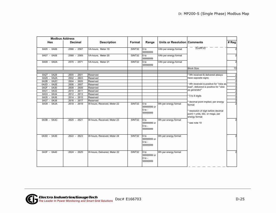
D: MP200-S (Single Phase) Modbus Map
D-25
mments # Reg
(Cont’d)
Doc# E166703 Electro Industries/GaugeTechThe Leader In Power Monitoring and Smart Grid Solutions
Description Format Range Units or Resolution CoModbus Address
Hex Decimal
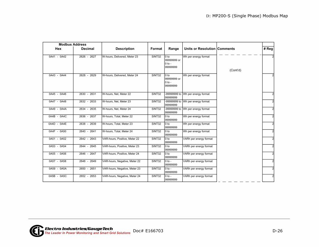
D: MP200-S (Single Phase) Modbus Map
D-26
mments # Reg
(Cont’d)
Doc# E166703 Electro Industries/GaugeTechThe Leader In Power Monitoring and Smart Grid Solutions
Description Format Range Units or Resolution CoModbus Address
Hex Decimal
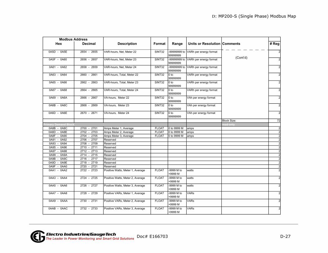
D: MP200-S (Single Phase) Modbus Map
D-27
ments # Reg
-only
(Cont’d)
Doc# E166703 Electro Industries/GaugeTechThe Leader In Power Monitoring and Smart Grid Solutions
Description Format Range Units or Resolution ComModbus Address
Hex Decimal
readPrimary Demand Block
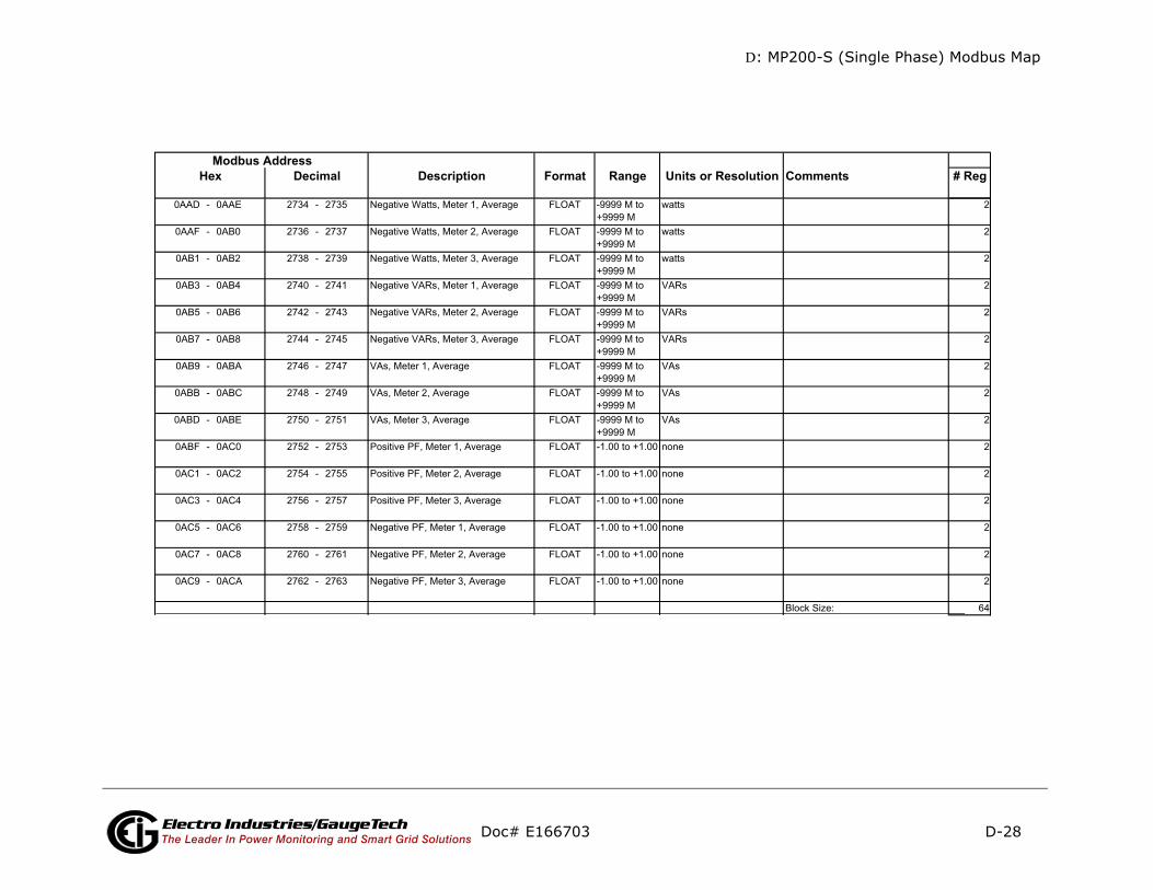
D: MP200-S (Single Phase) Modbus Map
D-28
mments # Reg
Doc# E166703 Electro Industries/GaugeTechThe Leader In Power Monitoring and Smart Grid Solutions
Description Format Range Units or Resolution CoModbus Address
Hex Decimal
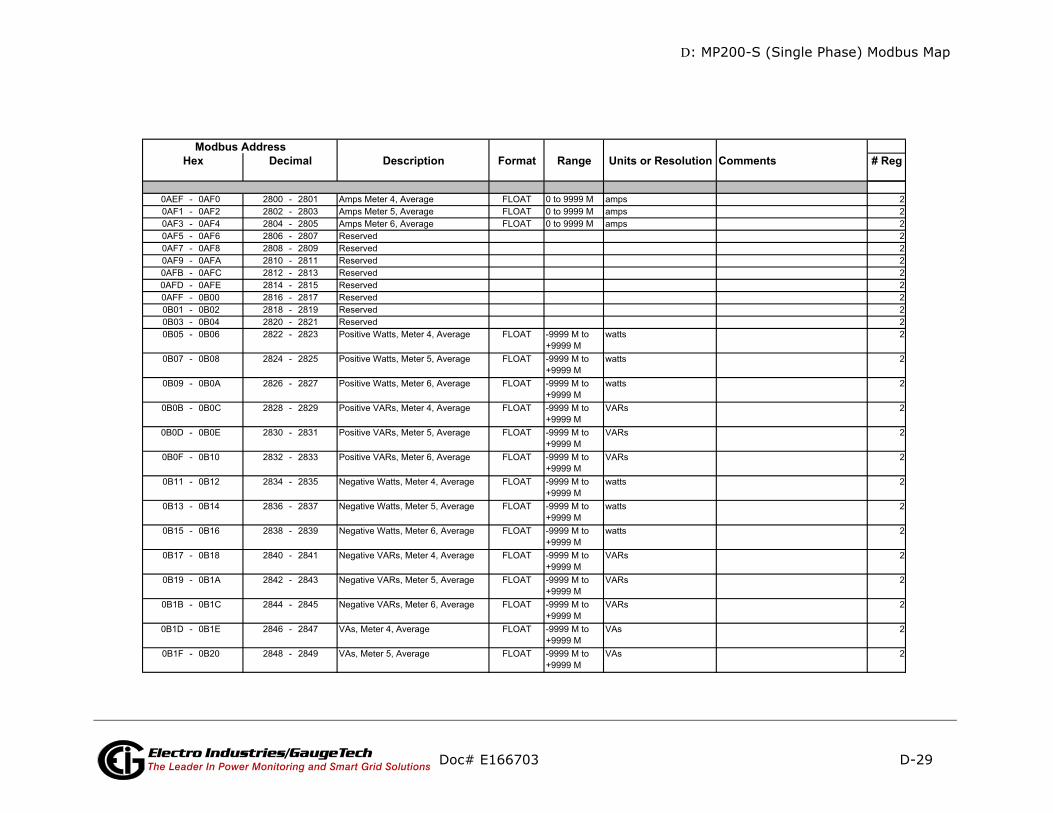
D: MP200-S (Single Phase) Modbus Map
D-29
mments # Reg
Doc# E166703 Electro Industries/GaugeTechThe Leader In Power Monitoring and Smart Grid Solutions
Description Format Range Units or Resolution CoModbus Address
Hex Decimal
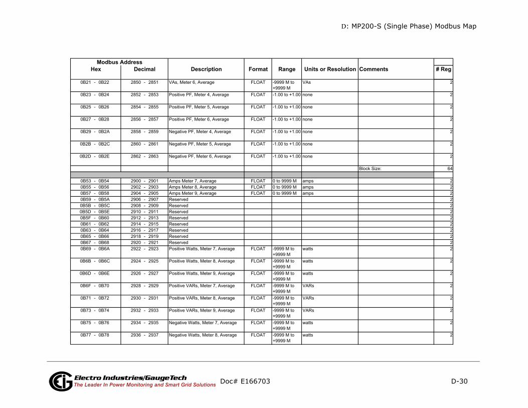
D: MP200-S (Single Phase) Modbus Map
D-30
mments # Reg
Doc# E166703 Electro Industries/GaugeTechThe Leader In Power Monitoring and Smart Grid Solutions
Description Format Range Units or Resolution CoModbus Address
Hex Decimal
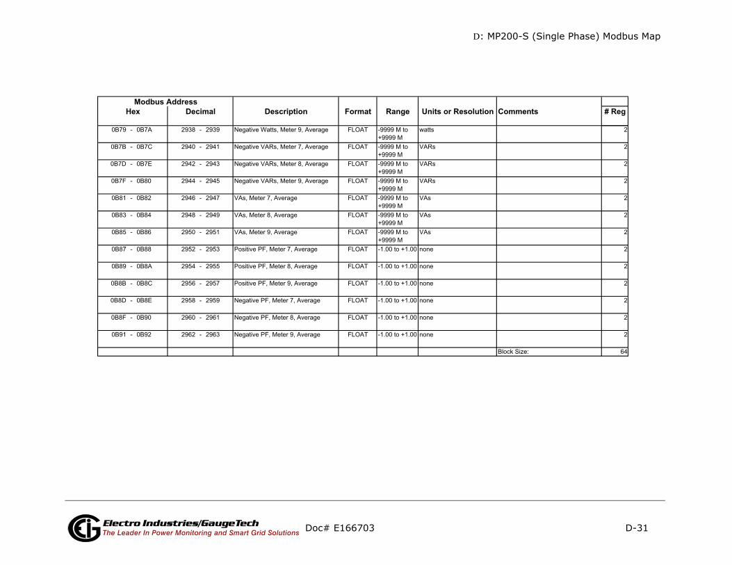
D: MP200-S (Single Phase) Modbus Map
D-31
s # Regmments # Reg
Doc# E166703 Electro Industries/GaugeTechThe Leader In Power Monitoring and Smart Grid Solutions
Description Format Range Units or Resolution CommentModbus Address
Hex DecimalDescription Format Range Units or Resolution Co
Modbus AddressHex Decimal

D: MP200-S (Single Phase) Modbus Map
D-32
mments # Reg
Doc# E166703 Electro Industries/GaugeTechThe Leader In Power Monitoring and Smart Grid Solutions
Description Format Range Units or Resolution CoModbus Address
Hex Decimal

D: MP200-S (Single Phase) Modbus Map
D-33
mments # Reg
Doc# E166703 Electro Industries/GaugeTechThe Leader In Power Monitoring and Smart Grid Solutions
Description Format Range Units or Resolution CoModbus Address
Hex Decimal

D: MP200-S (Single Phase) Modbus Map
D-34
mments # Reg
Doc# E166703 Electro Industries/GaugeTechThe Leader In Power Monitoring and Smart Grid Solutions
Description Format Range Units or Resolution CoModbus Address
Hex Decimal

D: MP200-S (Single Phase) Modbus Map
D-35
mments # Reg
Doc# E166703 Electro Industries/GaugeTechThe Leader In Power Monitoring and Smart Grid Solutions
Description Format Range Units or Resolution CoModbus Address
Hex Decimal
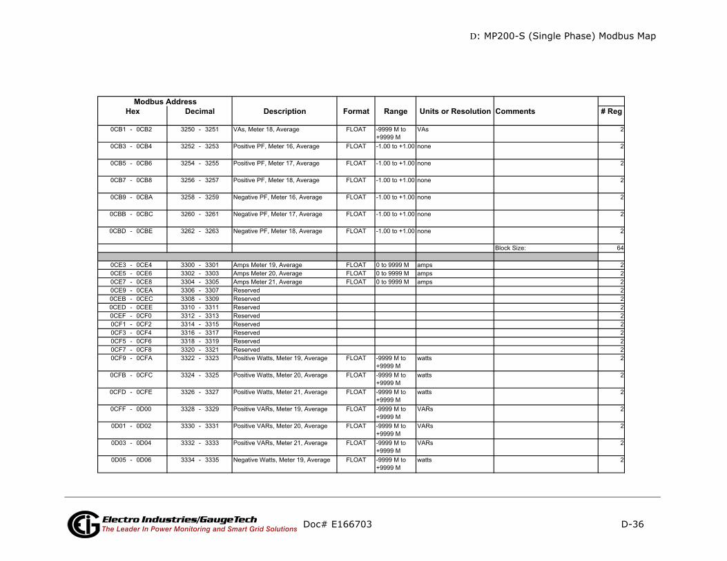
D: MP200-S (Single Phase) Modbus Map
D-36
mments # Reg
Doc# E166703 Electro Industries/GaugeTechThe Leader In Power Monitoring and Smart Grid Solutions
Description Format Range Units or Resolution CoModbus Address
Hex Decimal
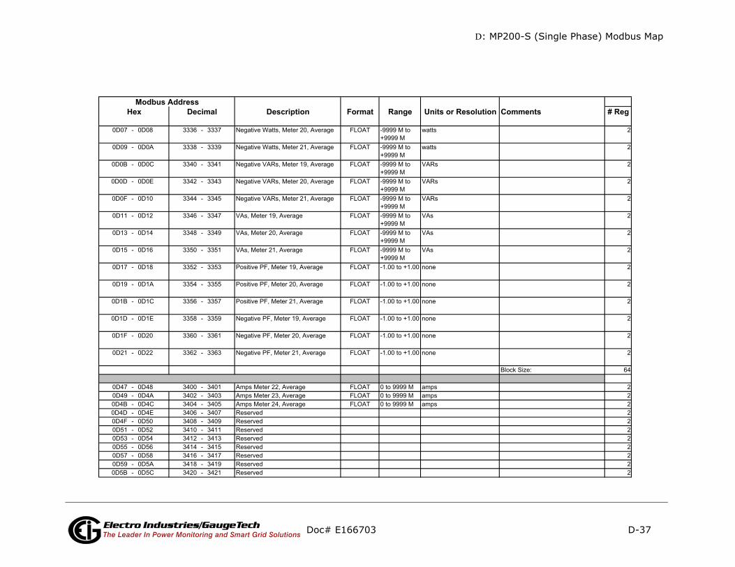
D: MP200-S (Single Phase) Modbus Map
D-37
mments # Reg
Doc# E166703 Electro Industries/GaugeTechThe Leader In Power Monitoring and Smart Grid Solutions
Description Format Range Units or Resolution CoModbus Address
Hex Decimal

D: MP200-S (Single Phase) Modbus Map
D-38
(Cont’d)
mments # Reg
Doc# E166703 Electro Industries/GaugeTechThe Leader In Power Monitoring and Smart Grid Solutions
Description Format Range Units or Resolution CoModbus Address
Hex Decimal
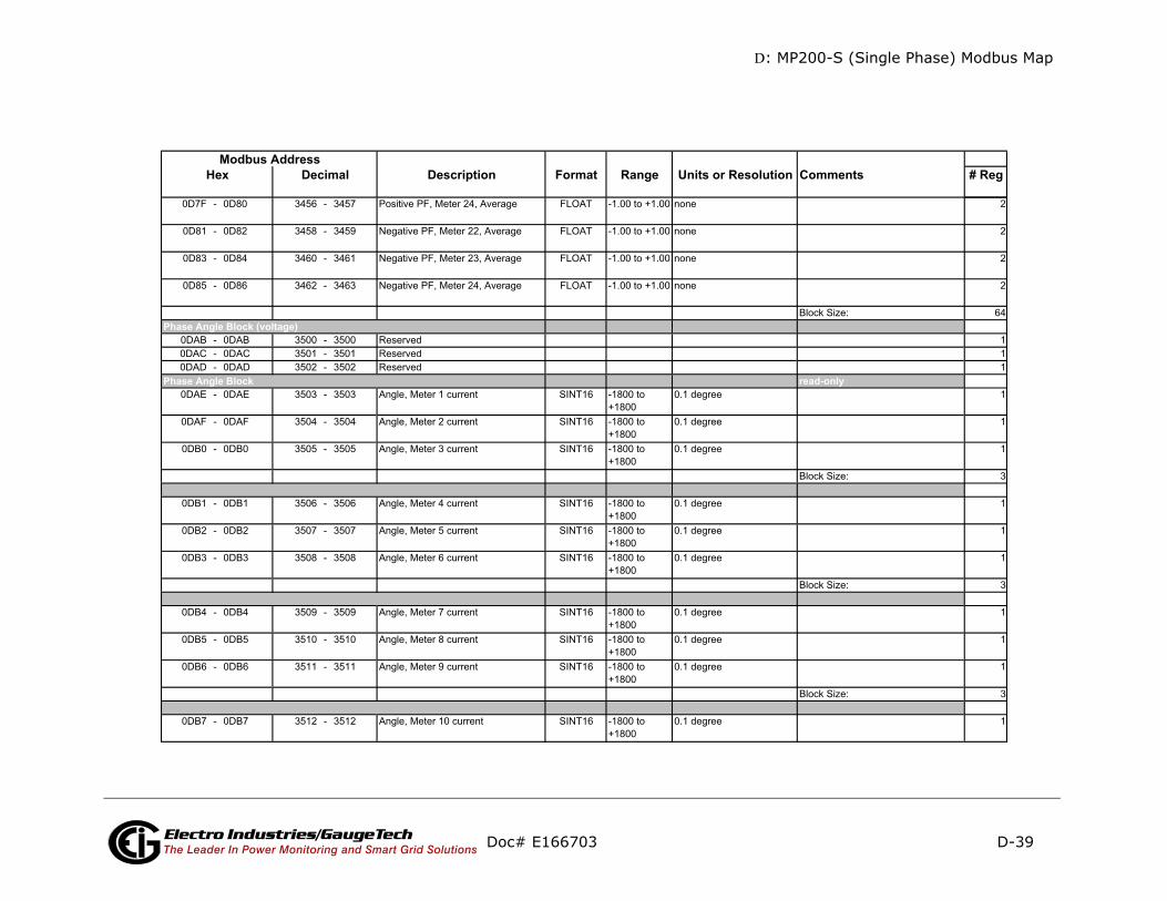
D: MP200-S (Single Phase) Modbus Map
D-39
mments # Reg
d-only
Doc# E166703 Electro Industries/GaugeTechThe Leader In Power Monitoring and Smart Grid Solutions
Description Format Range Units or Resolution CoModbus Address
Hex Decimal
reaPhase Angle Block
Phase Angle Block (voltage)
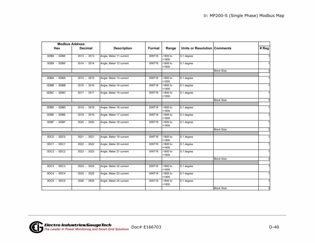
D: MP200-S (Single Phase) Modbus Map
D-40
mments # Reg
Doc# E166703 Electro Industries/GaugeTechThe Leader In Power Monitoring and Smart Grid Solutions
Description Format Range Units or Resolution CoModbus Address
Hex Decimal

D: MP200-S (Single Phase) Modbus Map
D-41
mments # Reg
-only
Doc# E166703 Electro Industries/GaugeTechThe Leader In Power Monitoring and Smart Grid Solutions
Description Format Range Units or Resolution CoModbus Address
Hex Decimal
readnone
mmmpch-- bffee-cc
87654321 87654321
Status Block
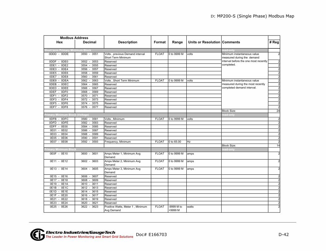
D: MP200-S (Single Phase) Modbus Map
D-42
mments # Reg
d-only
d-only
d-only
Doc# E166703 Electro Industries/GaugeTechThe Leader In Power Monitoring and Smart Grid Solutions
Description Format Range Units or Resolution CoModbus Address
Hex Decimal
rea
rea
rea
Primary Minimum Block (Voltage)
Primary Minimum Block
Short term Primary Minimum Block
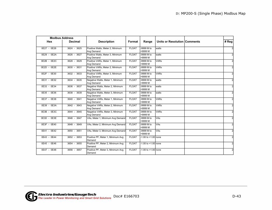
D: MP200-S (Single Phase) Modbus Map
D-43
mments # Reg
Doc# E166703 Electro Industries/GaugeTechThe Leader In Power Monitoring and Smart Grid Solutions
Description Format Range Units or Resolution CoModbus Address
Hex Decimal

D: MP200-S (Single Phase) Modbus Map
D-44
mments # Reg
Doc# E166703 Electro Industries/GaugeTechThe Leader In Power Monitoring and Smart Grid Solutions
Description Format Range Units or Resolution CoModbus Address
Hex Decimal

D: MP200-S (Single Phase) Modbus Map
D-45
mments # Reg
Doc# E166703 Electro Industries/GaugeTechThe Leader In Power Monitoring and Smart Grid Solutions
Description Format Range Units or Resolution CoModbus Address
Hex Decimal

D: MP200-S (Single Phase) Modbus Map
D-46
mments # Reg
Doc# E166703 Electro Industries/GaugeTechThe Leader In Power Monitoring and Smart Grid Solutions
Description Format Range Units or Resolution CoModbus Address
Hex Decimal
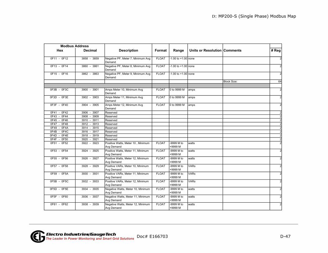
D: MP200-S (Single Phase) Modbus Map
D-47
mments # Reg
Doc# E166703 Electro Industries/GaugeTechThe Leader In Power Monitoring and Smart Grid Solutions
Description Format Range Units or Resolution CoModbus Address
Hex Decimal
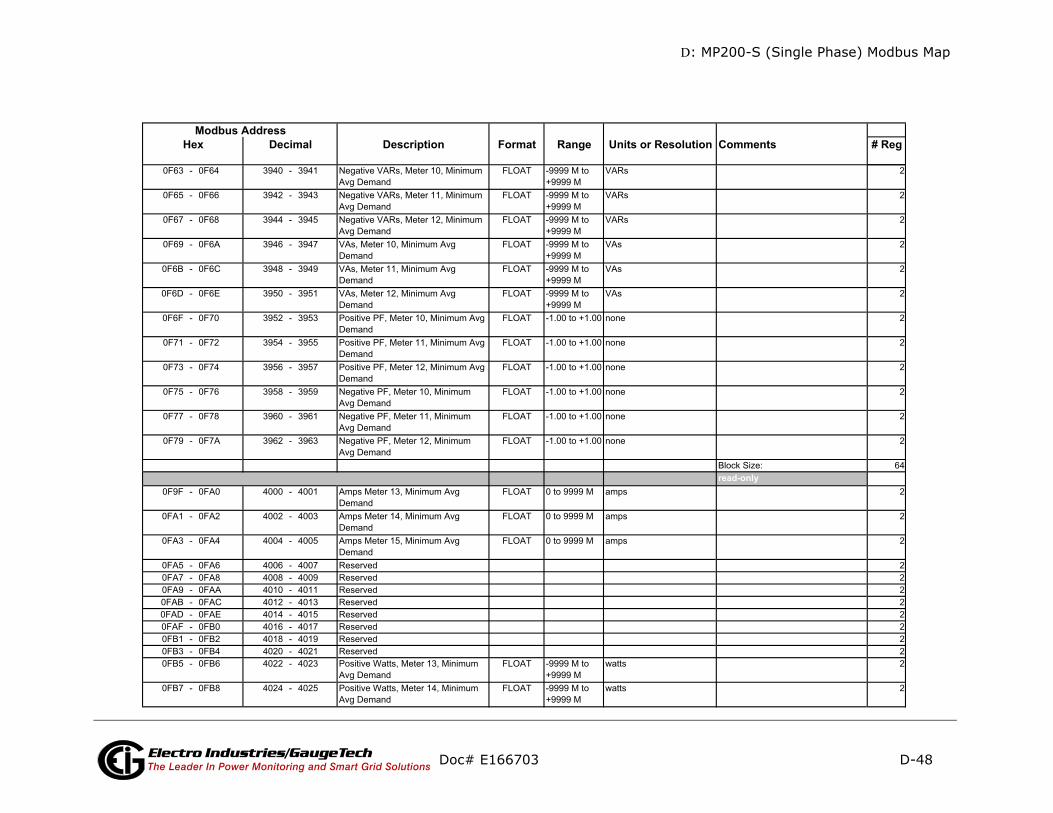
D: MP200-S (Single Phase) Modbus Map
D-48
mments # Reg
d-only
Doc# E166703 Electro Industries/GaugeTechThe Leader In Power Monitoring and Smart Grid Solutions
Description Format Range Units or Resolution CoModbus Address
Hex Decimal
rea
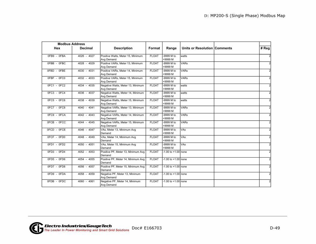
D: MP200-S (Single Phase) Modbus Map
D-49
mments # Reg
Doc# E166703 Electro Industries/GaugeTechThe Leader In Power Monitoring and Smart Grid Solutions
Description Format Range Units or Resolution CoModbus Address
Hex Decimal
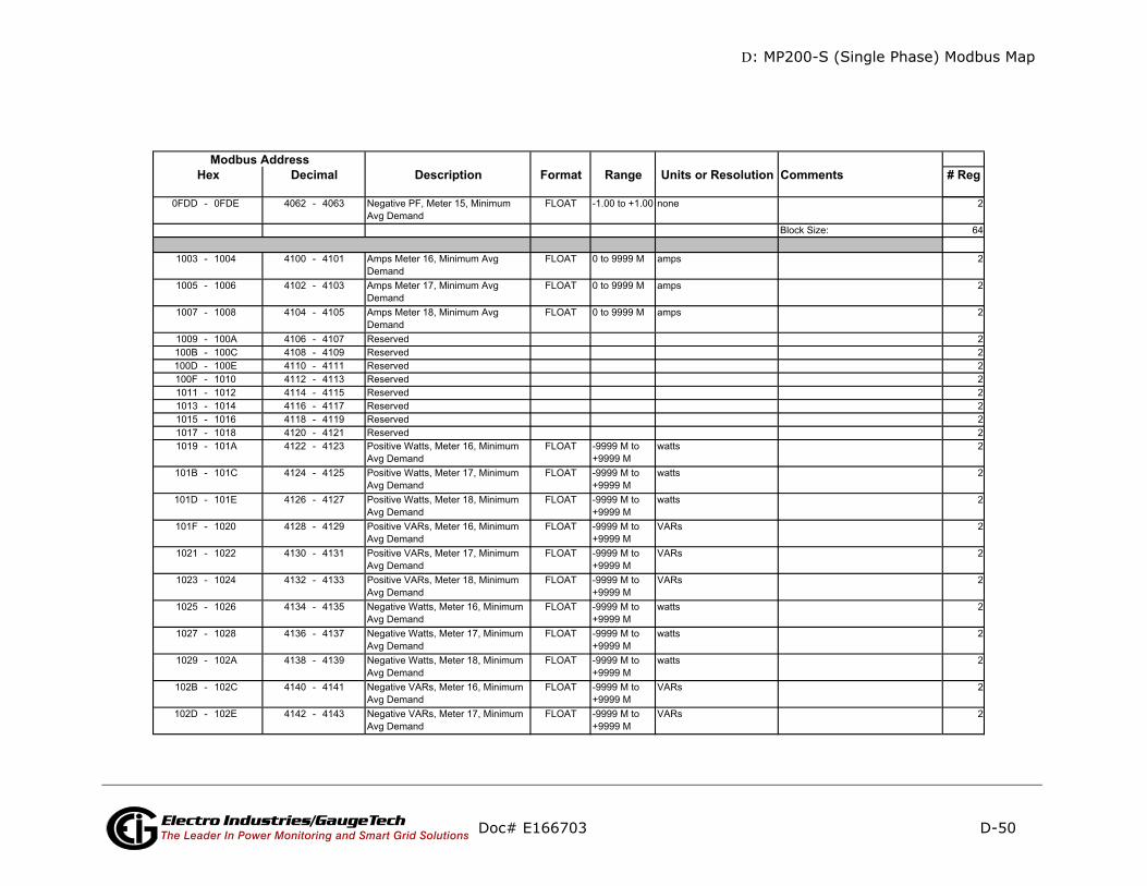
D: MP200-S (Single Phase) Modbus Map
D-50
mments # Reg
Doc# E166703 Electro Industries/GaugeTechThe Leader In Power Monitoring and Smart Grid Solutions
Description Format Range Units or Resolution CoModbus Address
Hex Decimal
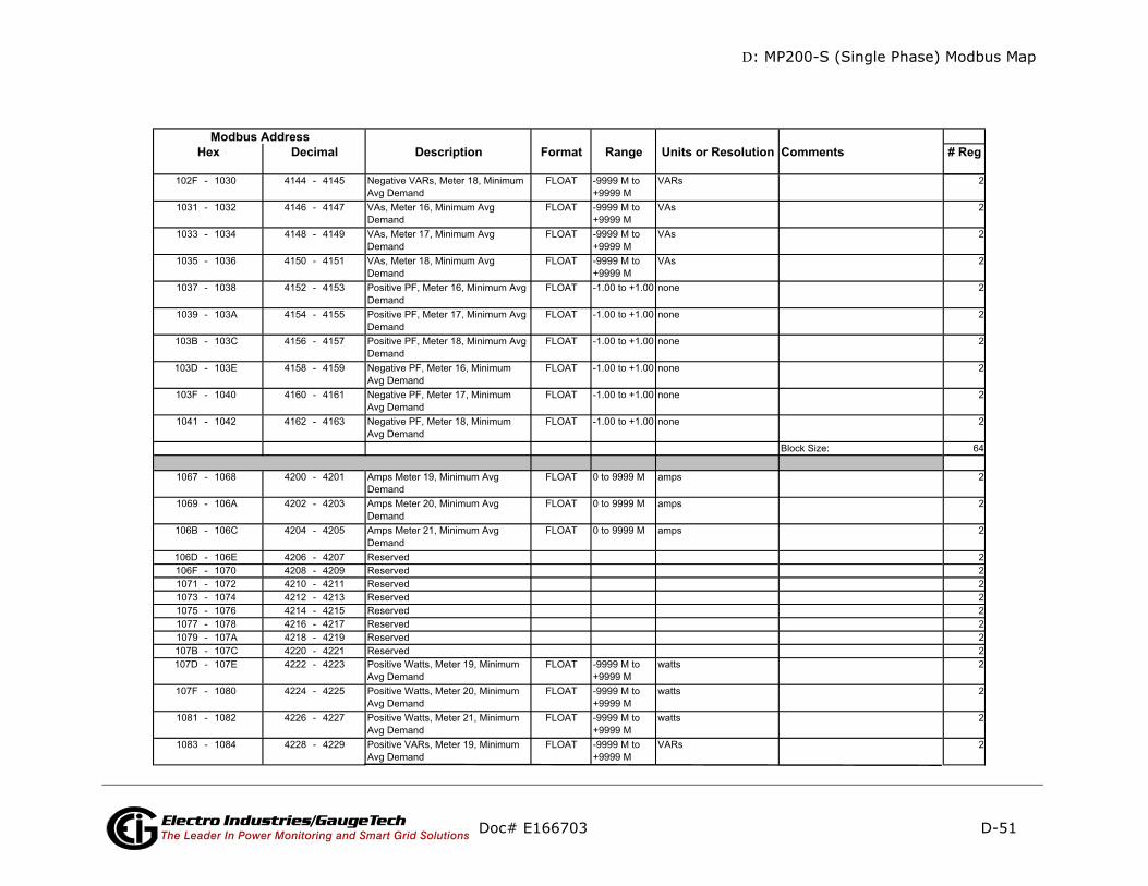
D: MP200-S (Single Phase) Modbus Map
D-51
mments # Reg
Doc# E166703 Electro Industries/GaugeTechThe Leader In Power Monitoring and Smart Grid Solutions
Description Format Range Units or Resolution CoModbus Address
Hex Decimal

D: MP200-S (Single Phase) Modbus Map
D-52
mments # Reg
Doc# E166703 Electro Industries/GaugeTechThe Leader In Power Monitoring and Smart Grid Solutions
Description Format Range Units or Resolution CoModbus Address
Hex Decimal

D: MP200-S (Single Phase) Modbus Map
D-53
mments # Reg
Doc# E166703 Electro Industries/GaugeTechThe Leader In Power Monitoring and Smart Grid Solutions
Description Format Range Units or Resolution CoModbus Address
Hex Decimal

D: MP200-S (Single Phase) Modbus Map
D-54
omments # Reg
ad-only
ad-only
Doc# E166703 Electro Industries/GaugeTechThe Leader In Power Monitoring and Smart Grid Solutions
Description Format Range Units or Resolution CModbus Address
Hex Decimal
re
re
Primary Minimum Timestamp Block
Primary Minimum Timestamp Block
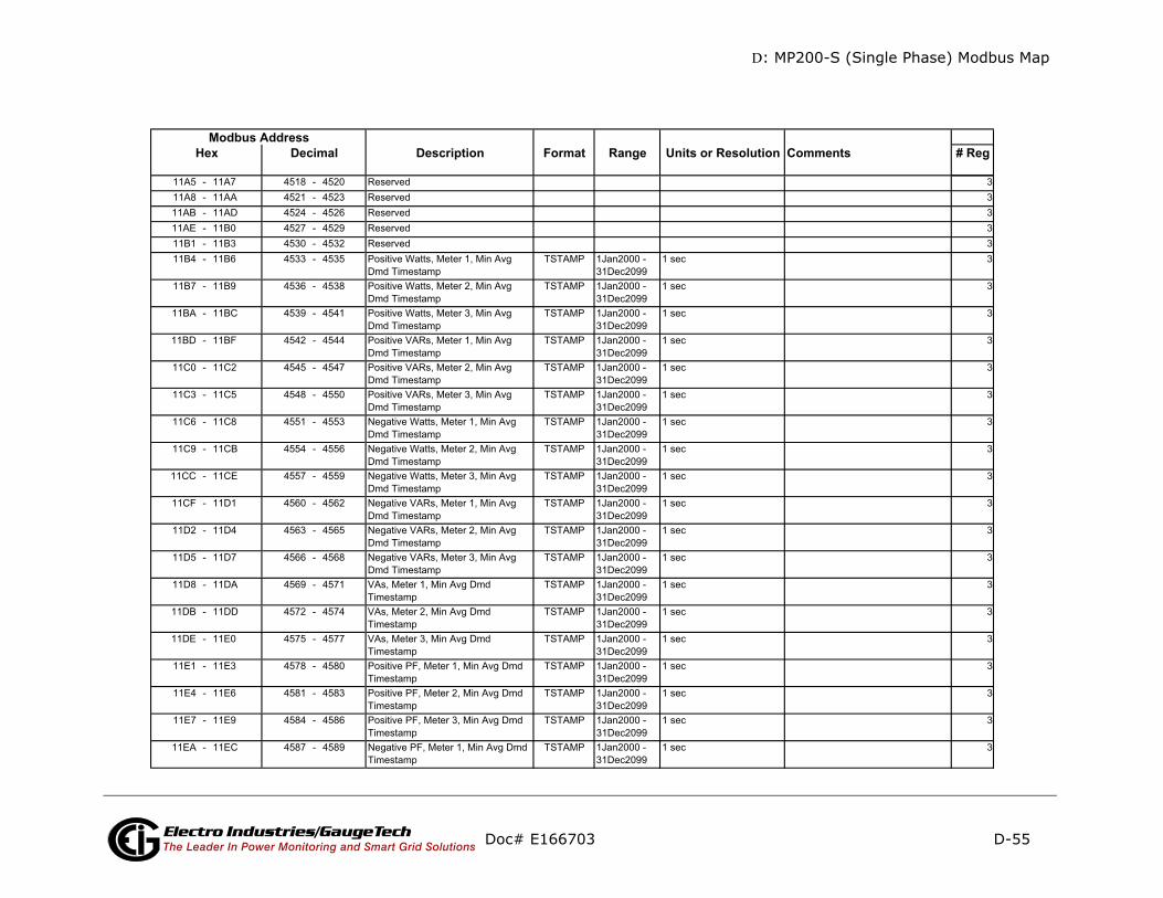
D: MP200-S (Single Phase) Modbus Map
D-55
ments # Reg
Doc# E166703 Electro Industries/GaugeTechThe Leader In Power Monitoring and Smart Grid Solutions
Description Format Range Units or Resolution ComModbus Address
Hex Decimal
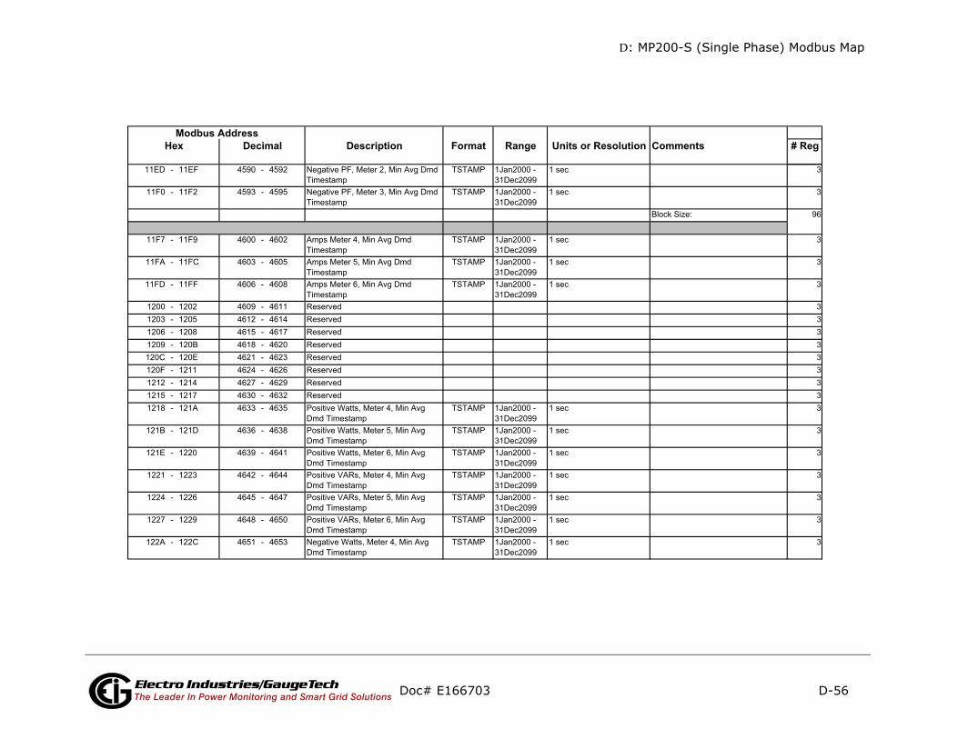
D: MP200-S (Single Phase) Modbus Map
D-56
mments # Reg
Doc# E166703 Electro Industries/GaugeTechThe Leader In Power Monitoring and Smart Grid Solutions
Description Format Range Units or Resolution CoModbus Address
Hex Decimal
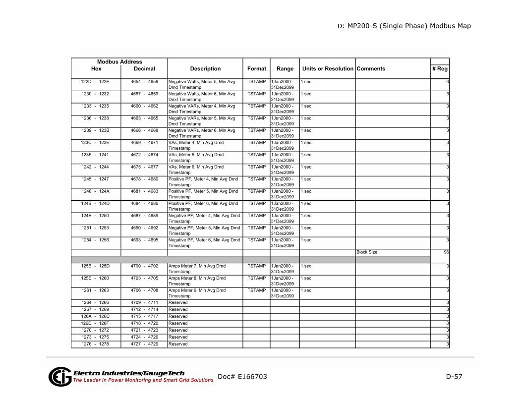
D: MP200-S (Single Phase) Modbus Map
D-57
mments # Reg
Doc# E166703 Electro Industries/GaugeTechThe Leader In Power Monitoring and Smart Grid Solutions
Description Format Range Units or Resolution CoModbus Address
Hex Decimal
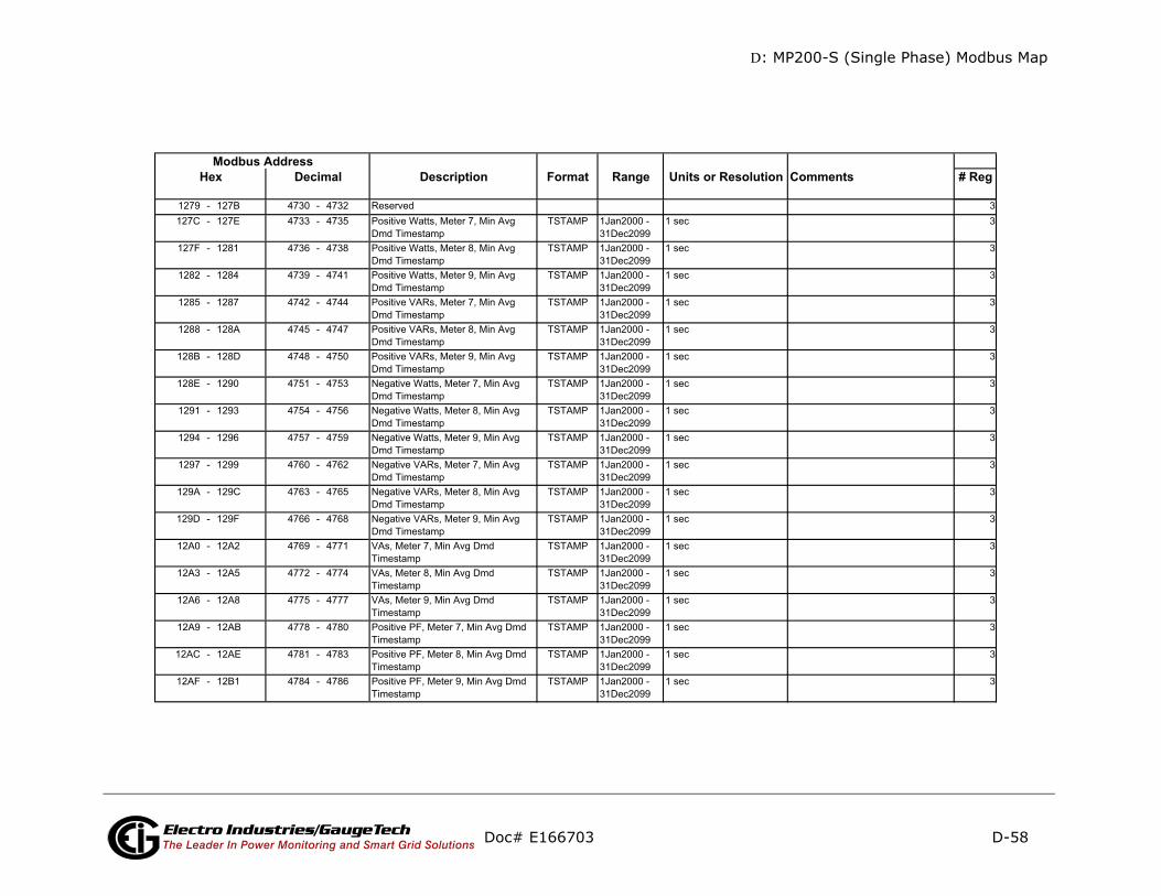
D: MP200-S (Single Phase) Modbus Map
D-58
mments # Reg
Doc# E166703 Electro Industries/GaugeTechThe Leader In Power Monitoring and Smart Grid Solutions
Description Format Range Units or Resolution CoModbus Address
Hex Decimal
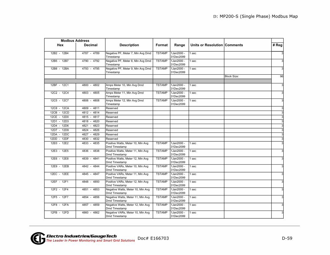
D: MP200-S (Single Phase) Modbus Map
D-59
mments # Reg
Doc# E166703 Electro Industries/GaugeTechThe Leader In Power Monitoring and Smart Grid Solutions
Description Format Range Units or Resolution CoModbus Address
Hex Decimal
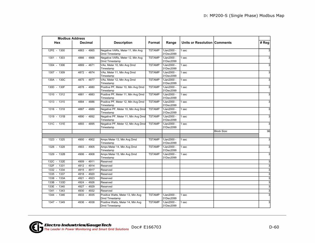
D: MP200-S (Single Phase) Modbus Map
D-60
mments # Reg
Doc# E166703 Electro Industries/GaugeTechThe Leader In Power Monitoring and Smart Grid Solutions
Description Format Range Units or Resolution CoModbus Address
Hex Decimal
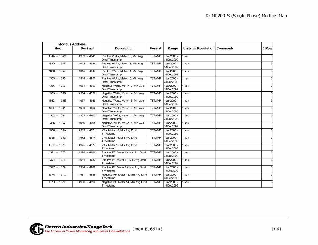
D: MP200-S (Single Phase) Modbus Map
D-61
mments # Reg
Doc# E166703 Electro Industries/GaugeTechThe Leader In Power Monitoring and Smart Grid Solutions
Description Format Range Units or Resolution CoModbus Address
Hex Decimal
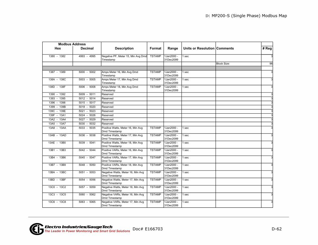
D: MP200-S (Single Phase) Modbus Map
D-62
mments # Reg
Doc# E166703 Electro Industries/GaugeTechThe Leader In Power Monitoring and Smart Grid Solutions
Description Format Range Units or Resolution CoModbus Address
Hex Decimal
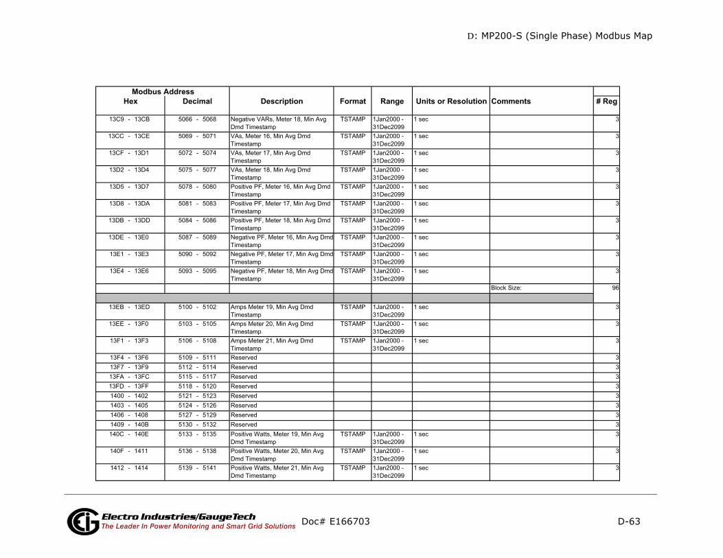
D: MP200-S (Single Phase) Modbus Map
D-63
mments # Reg
Doc# E166703 Electro Industries/GaugeTechThe Leader In Power Monitoring and Smart Grid Solutions
Description Format Range Units or Resolution CoModbus Address
Hex Decimal
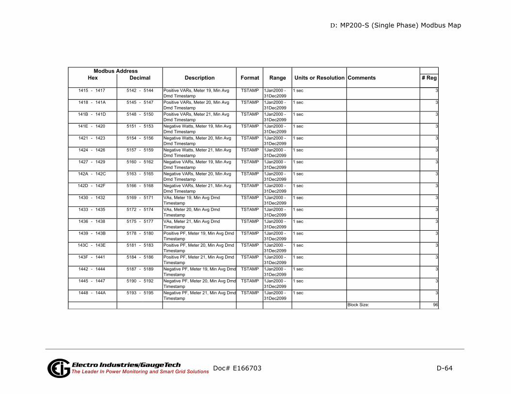
D: MP200-S (Single Phase) Modbus Map
D-64
mments # Reg
Doc# E166703 Electro Industries/GaugeTechThe Leader In Power Monitoring and Smart Grid Solutions
Description Format Range Units or Resolution CoModbus Address
Hex Decimal
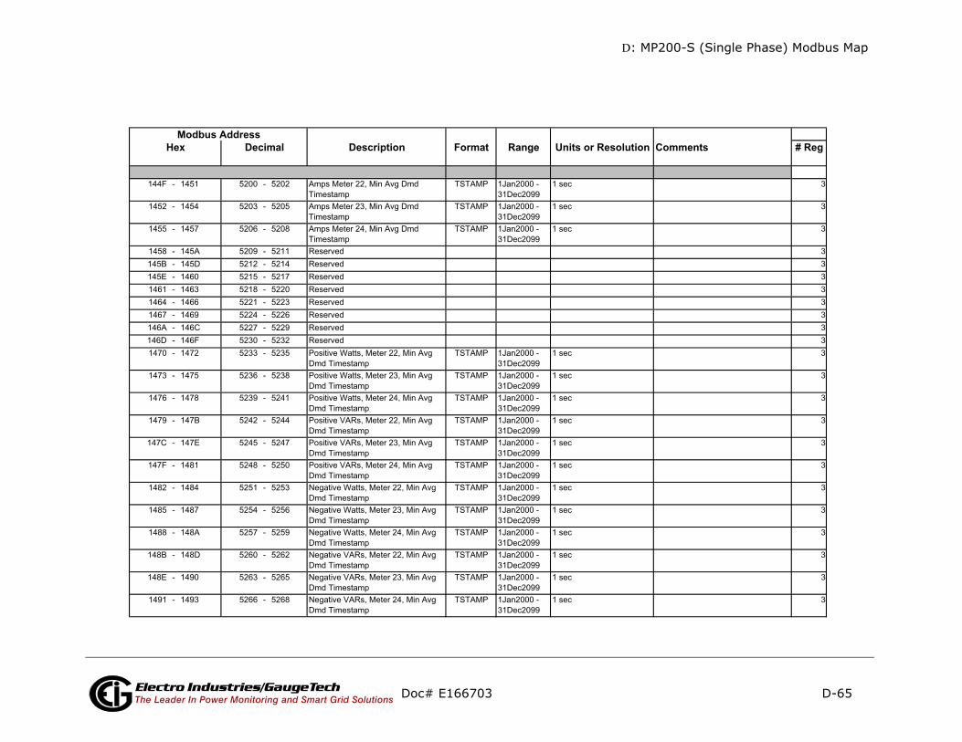
D: MP200-S (Single Phase) Modbus Map
D-65
mments # Reg
Doc# E166703 Electro Industries/GaugeTechThe Leader In Power Monitoring and Smart Grid Solutions
Description Format Range Units or Resolution CoModbus Address
Hex Decimal
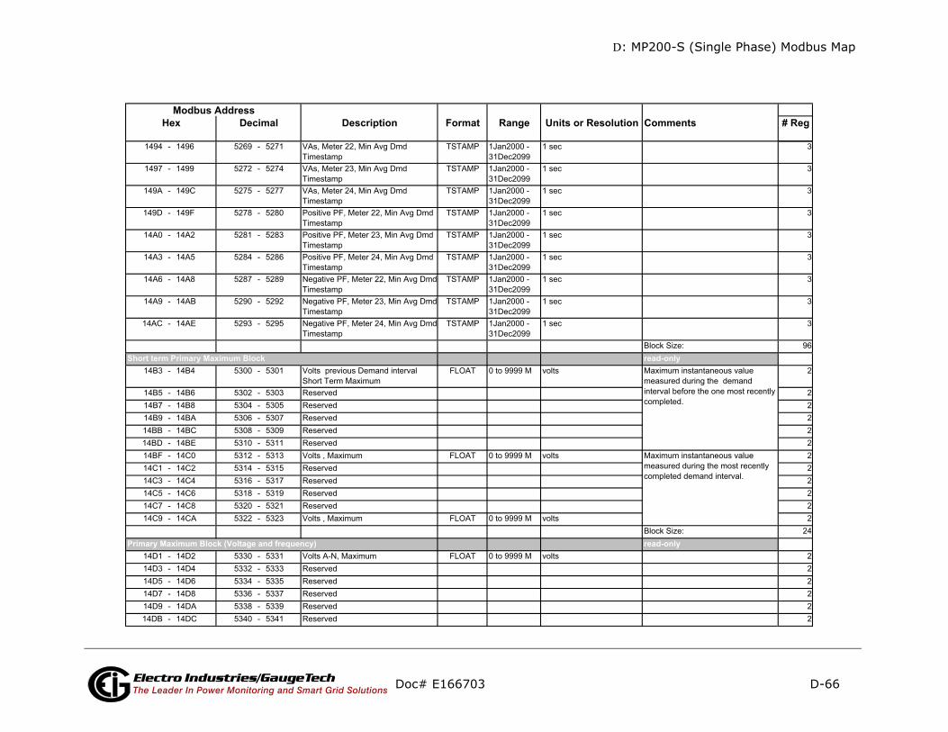
D: MP200-S (Single Phase) Modbus Map
D-66
mments # Reg
-only
-only
Doc# E166703 Electro Industries/GaugeTechThe Leader In Power Monitoring and Smart Grid Solutions
Description Format Range Units or Resolution CoModbus Address
Hex Decimal
read
readPrimary Maximum Block (Voltage and frequency)
Short term Primary Maximum Block
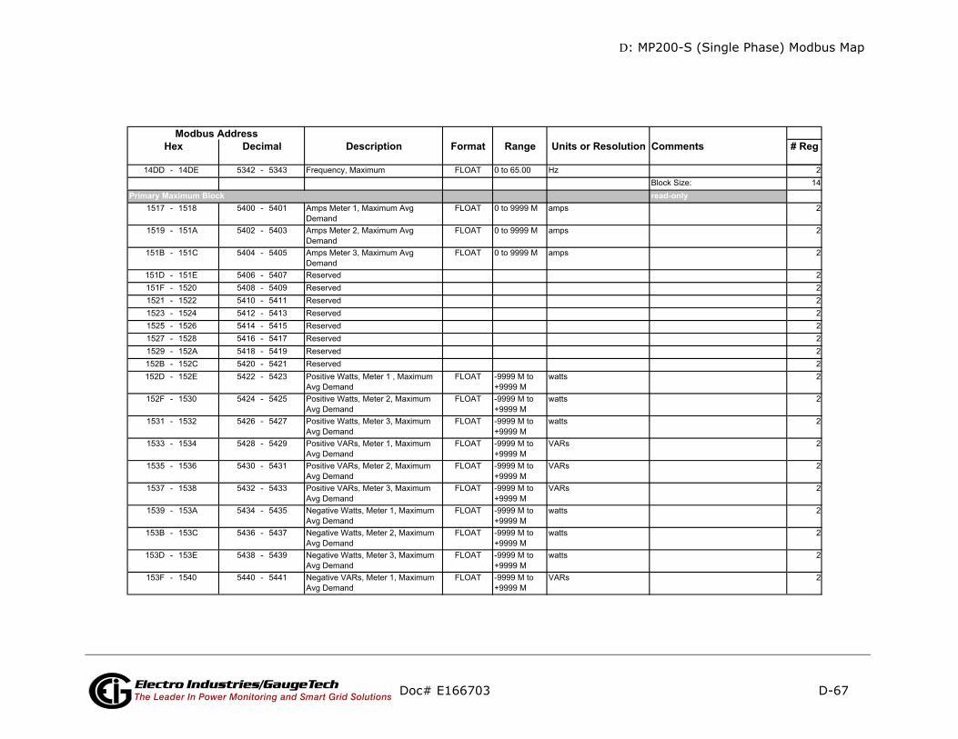
D: MP200-S (Single Phase) Modbus Map
D-67
mments # Reg
-only
Doc# E166703 Electro Industries/GaugeTechThe Leader In Power Monitoring and Smart Grid Solutions
Description Format Range Units or Resolution CoModbus Address
Hex Decimal
readPrimary Maximum Block
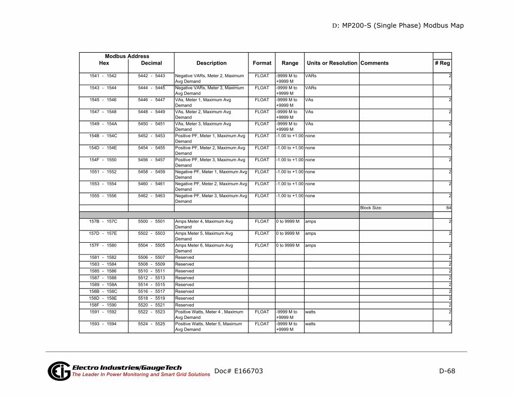
D: MP200-S (Single Phase) Modbus Map
D-68
Comments # Reg
Doc# E166703 Electro Industries/GaugeTechThe Leader In Power Monitoring and Smart Grid Solutions
Description Format Range Units or ResolutionModbus Address
Hex Decimal
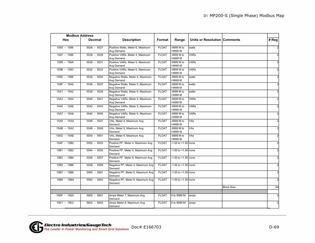
D: MP200-S (Single Phase) Modbus Map
D-69
n Comments # Reg
Doc# E166703 Electro Industries/GaugeTechThe Leader In Power Monitoring and Smart Grid Solutions
Description Format Range Units or ResolutioModbus Address
Hex Decimal
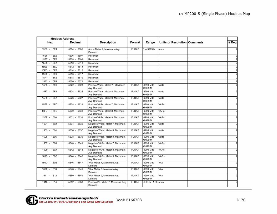
D: MP200-S (Single Phase) Modbus Map
D-70
mments # Reg
Doc# E166703 Electro Industries/GaugeTechThe Leader In Power Monitoring and Smart Grid Solutions
Description Format Range Units or Resolution CoModbus Address
Hex Decimal
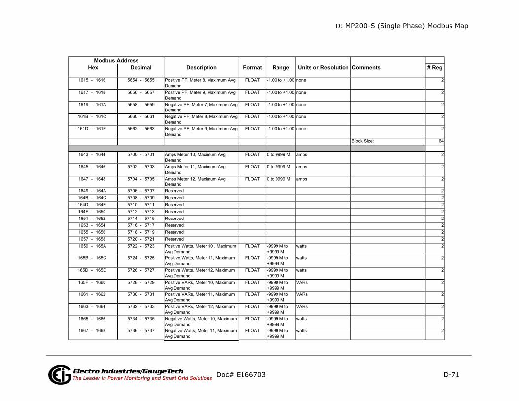
D: MP200-S (Single Phase) Modbus Map
D-71
ments # Reg
Doc# E166703 Electro Industries/GaugeTechThe Leader In Power Monitoring and Smart Grid Solutions
Description Format Range Units or Resolution ComModbus Address
Hex Decimal
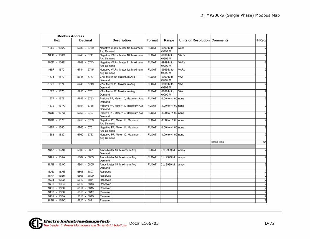
D: MP200-S (Single Phase) Modbus Map
D-72
mments # Reg
Doc# E166703 Electro Industries/GaugeTechThe Leader In Power Monitoring and Smart Grid Solutions
Description Format Range Units or Resolution CoModbus Address
Hex Decimal

D: MP200-S (Single Phase) Modbus Map
D-73
mments # Reg
Doc# E166703 Electro Industries/GaugeTechThe Leader In Power Monitoring and Smart Grid Solutions
Description Format Range Units or Resolution CoModbus Address
Hex Decimal

D: MP200-S (Single Phase) Modbus Map
D-74
mments # Reg
Doc# E166703 Electro Industries/GaugeTechThe Leader In Power Monitoring and Smart Grid Solutions
Description Format Range Units or Resolution CoModbus Address
Hex Decimal
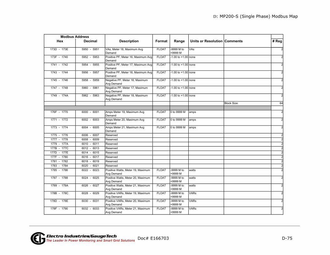
D: MP200-S (Single Phase) Modbus Map
D-75
mments # Reg
Doc# E166703 Electro Industries/GaugeTechThe Leader In Power Monitoring and Smart Grid Solutions
Description Format Range Units or Resolution CoModbus Address
Hex Decimal
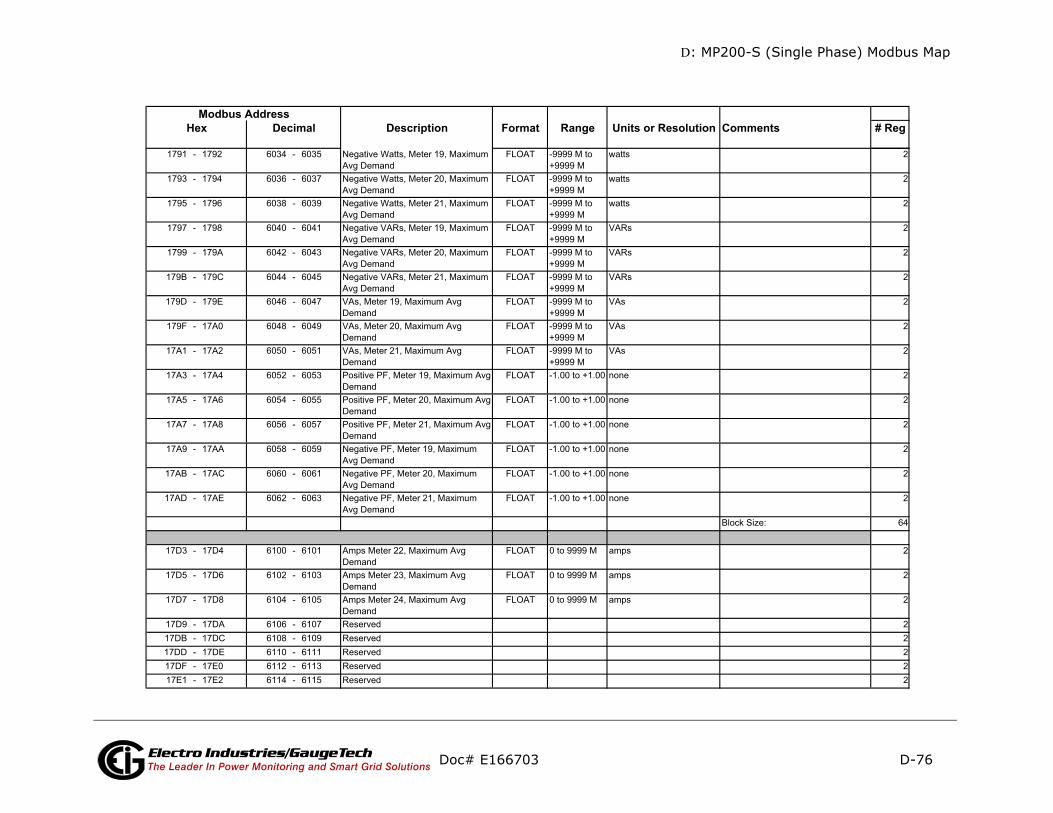
D: MP200-S (Single Phase) Modbus Map
D-76
mments # Reg
Doc# E166703 Electro Industries/GaugeTechThe Leader In Power Monitoring and Smart Grid Solutions
Description Format Range Units or Resolution CoModbus Address
Hex Decimal
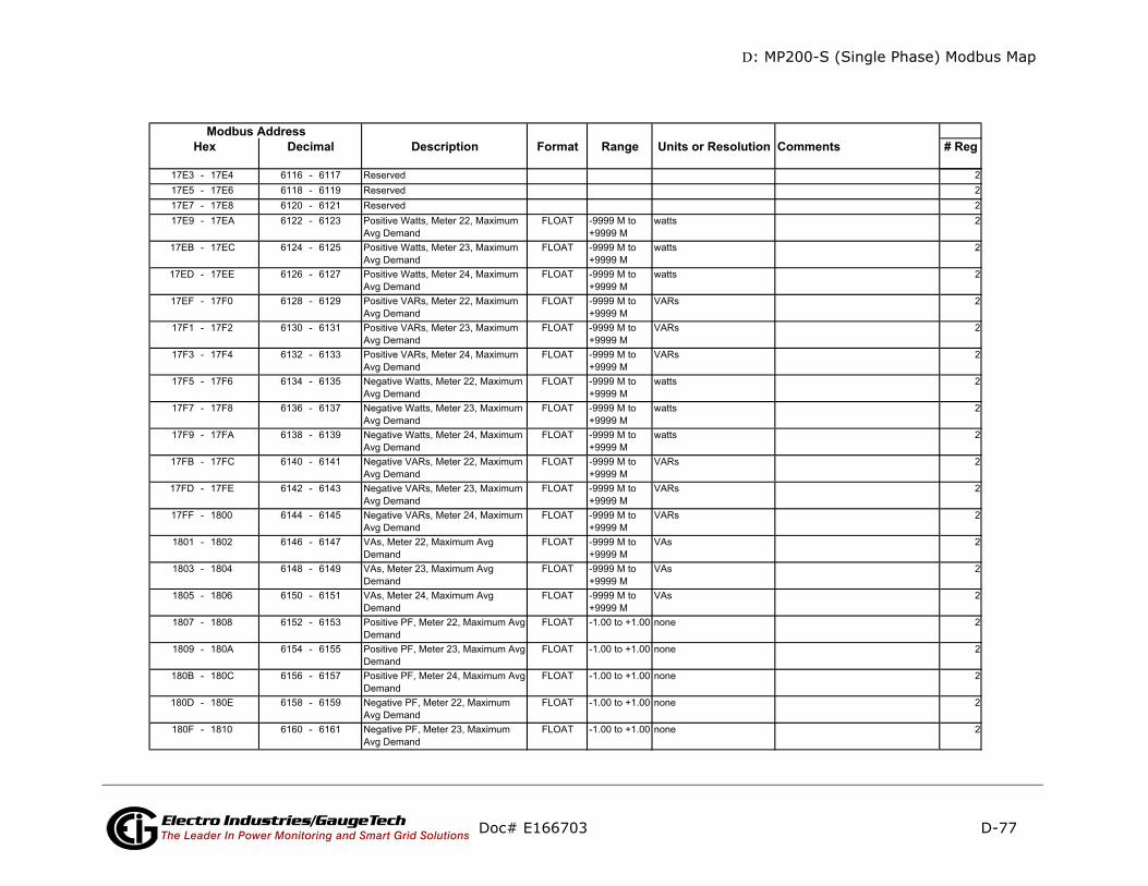
D: MP200-S (Single Phase) Modbus Map
D-77
ments # Reg
Doc# E166703 Electro Industries/GaugeTechThe Leader In Power Monitoring and Smart Grid Solutions
Description Format Range Units or Resolution ComModbus Address
Hex Decimal
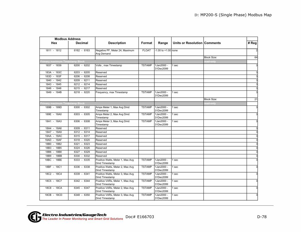
D: MP200-S (Single Phase) Modbus Map
D-78
ments # Reg
-only
-only
Doc# E166703 Electro Industries/GaugeTechThe Leader In Power Monitoring and Smart Grid Solutions
Description Format Range Units or Resolution ComModbus Address
Hex Decimal
read
read
Primary maximum Timestamp Block
Primary maximum Timestamp Block
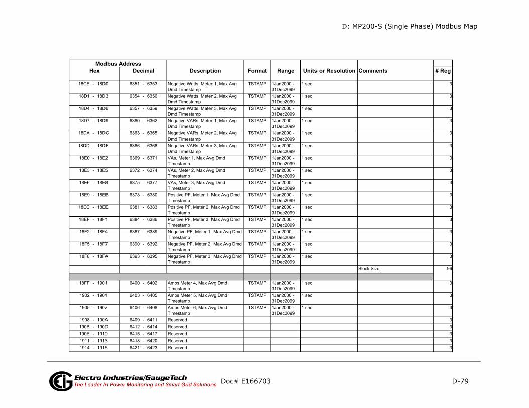
D: MP200-S (Single Phase) Modbus Map
D-79
ments # Reg
Doc# E166703 Electro Industries/GaugeTechThe Leader In Power Monitoring and Smart Grid Solutions
Description Format Range Units or Resolution ComModbus Address
Hex Decimal
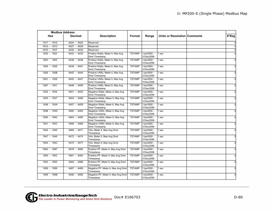
D: MP200-S (Single Phase) Modbus Map
D-80
mments # Reg
Doc# E166703 Electro Industries/GaugeTechThe Leader In Power Monitoring and Smart Grid Solutions
Description Format Range Units or Resolution CoModbus Address
Hex Decimal
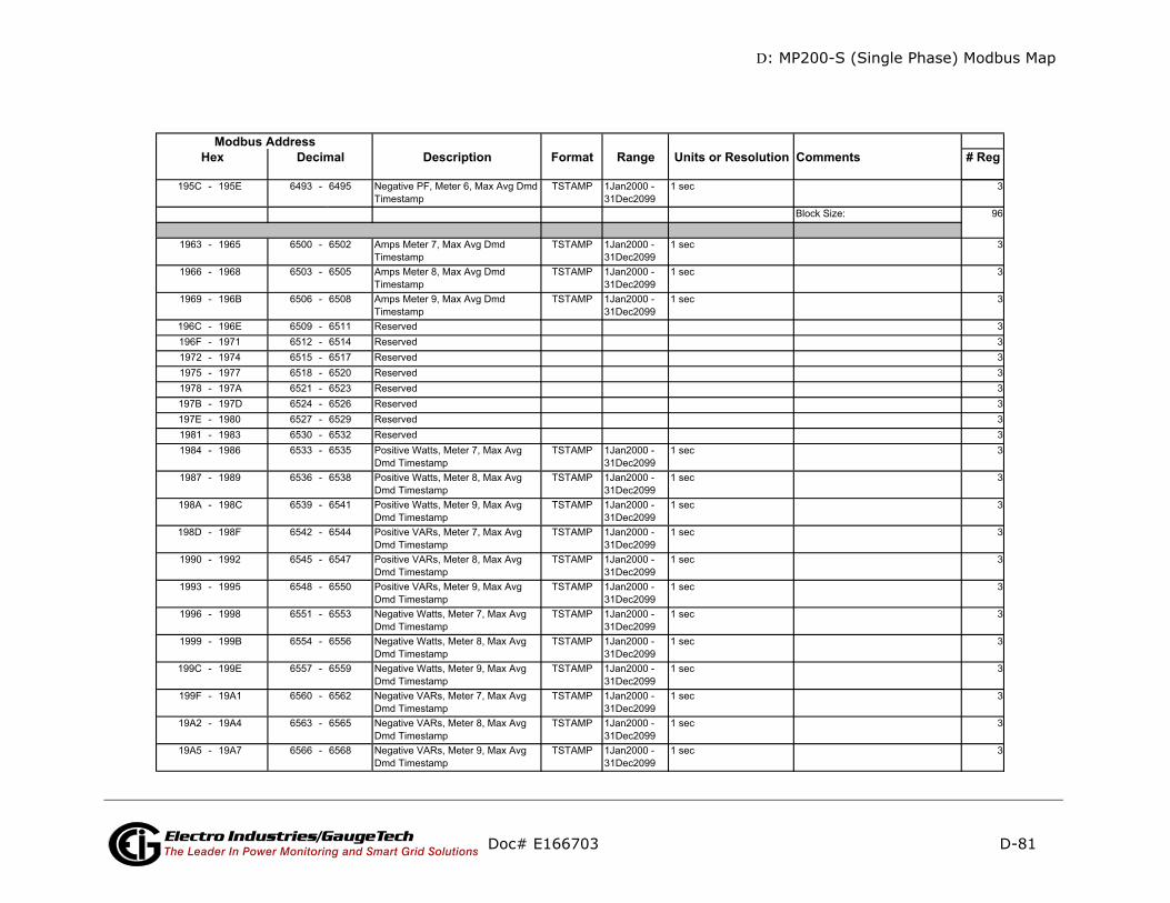
D: MP200-S (Single Phase) Modbus Map
D-81
mments # Reg
Doc# E166703 Electro Industries/GaugeTechThe Leader In Power Monitoring and Smart Grid Solutions
Description Format Range Units or Resolution CoModbus Address
Hex Decimal

D: MP200-S (Single Phase) Modbus Map
D-82
mments # Reg
Doc# E166703 Electro Industries/GaugeTechThe Leader In Power Monitoring and Smart Grid Solutions
Description Format Range Units or Resolution CoModbus Address
Hex Decimal
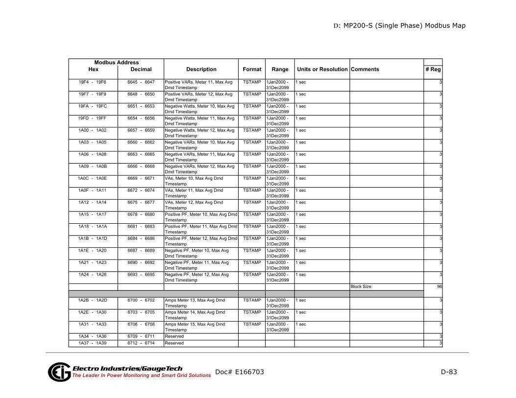
D: MP200-S (Single Phase) Modbus Map
D-83
mments # Reg
Doc# E166703 Electro Industries/GaugeTechThe Leader In Power Monitoring and Smart Grid Solutions
Description Format Range Units or Resolution CoModbus Address
Hex Decimal
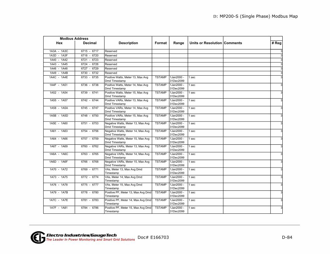
D: MP200-S (Single Phase) Modbus Map
D-84
ments # Reg
Doc# E166703 Electro Industries/GaugeTechThe Leader In Power Monitoring and Smart Grid Solutions
Description Format Range Units or Resolution ComModbus Address
Hex Decimal
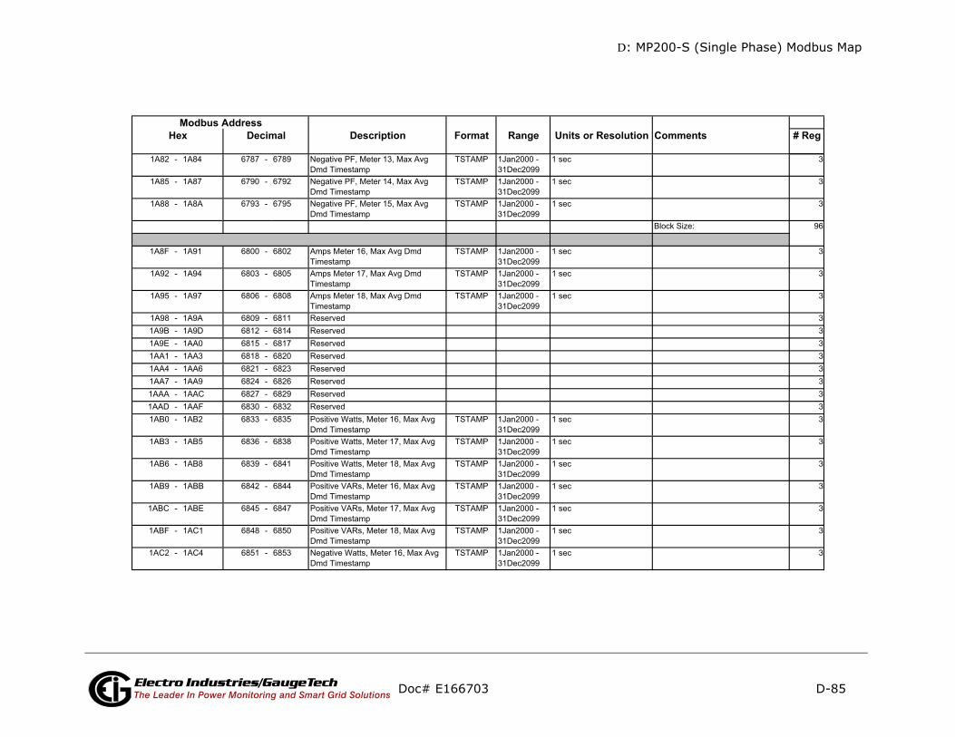
D: MP200-S (Single Phase) Modbus Map
D-85
mments # Reg
Doc# E166703 Electro Industries/GaugeTechThe Leader In Power Monitoring and Smart Grid Solutions
Description Format Range Units or Resolution CoModbus Address
Hex Decimal
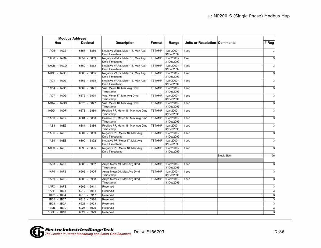
D: MP200-S (Single Phase) Modbus Map
D-86
ments # Reg
Doc# E166703 Electro Industries/GaugeTechThe Leader In Power Monitoring and Smart Grid Solutions
Description Format Range Units or Resolution ComModbus Address
Hex Decimal

D: MP200-S (Single Phase) Modbus Map
D-87
mments # Reg
Doc# E166703 Electro Industries/GaugeTechThe Leader In Power Monitoring and Smart Grid Solutions
Description Format Range Units or Resolution CoModbus Address
Hex Decimal
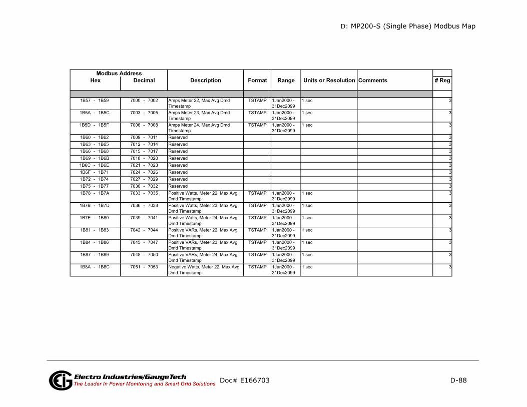
D: MP200-S (Single Phase) Modbus Map
D-88
mments # Reg
Doc# E166703 Electro Industries/GaugeTechThe Leader In Power Monitoring and Smart Grid Solutions
Description Format Range Units or Resolution CoModbus Address
Hex Decimal
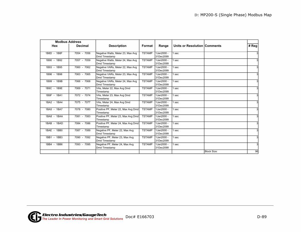
D: MP200-S (Single Phase) Modbus Map
D-89
mments # Reg
Doc# E166703 Electro Industries/GaugeTechThe Leader In Power Monitoring and Smart Grid Solutions
Description Format Range Units or Resolution CoModbus Address
Hex Decimal

D: MP200-S (Single Phase) Modbus Map
D-90
mments # Reg
-only
Doc# E166703 Electro Industries/GaugeTechThe Leader In Power Monitoring and Smart Grid Solutions
Description Format Range Units or Resolution CoModbus Address
Hex Decimal
readInterval Energy Block
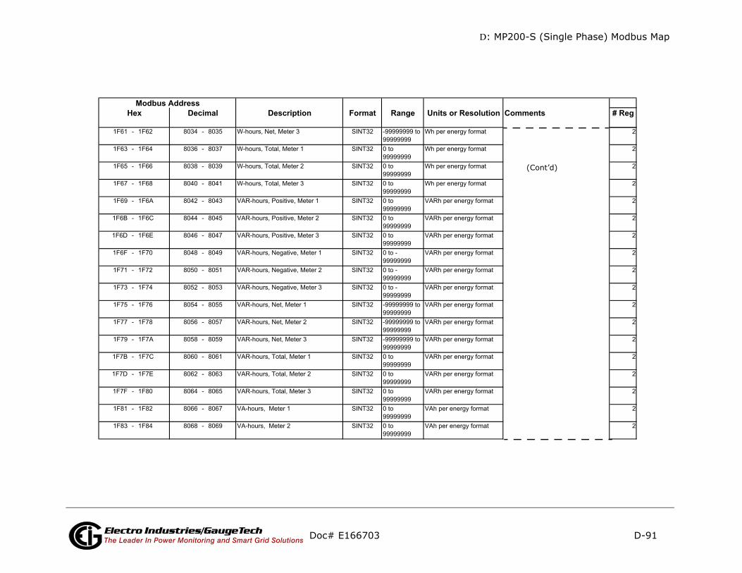
D: MP200-S (Single Phase) Modbus Map
D-91
mments # Reg
(Cont’d)
Doc# E166703 Electro Industries/GaugeTechThe Leader In Power Monitoring and Smart Grid Solutions
Description Format Range Units or Resolution CoModbus Address
Hex Decimal
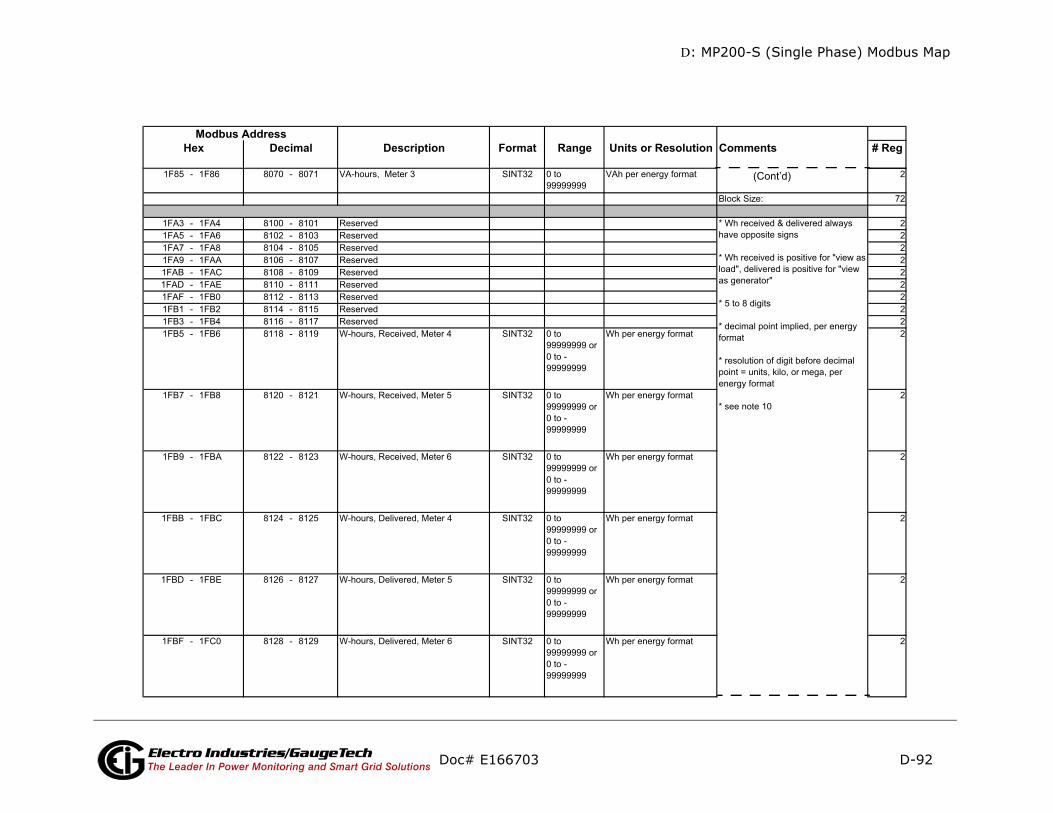
D: MP200-S (Single Phase) Modbus Map
D-92
mments # Reg
(Cont’d)
Doc# E166703 Electro Industries/GaugeTechThe Leader In Power Monitoring and Smart Grid Solutions
Description Format Range Units or Resolution CoModbus Address
Hex Decimal
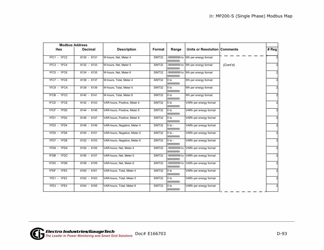
D: MP200-S (Single Phase) Modbus Map
D-93
mments # Reg
ont’d)
Doc# E166703 Electro Industries/GaugeTechThe Leader In Power Monitoring and Smart Grid Solutions
Description Format Range Units or Resolution CoModbus Address
Hex Decimal
(C
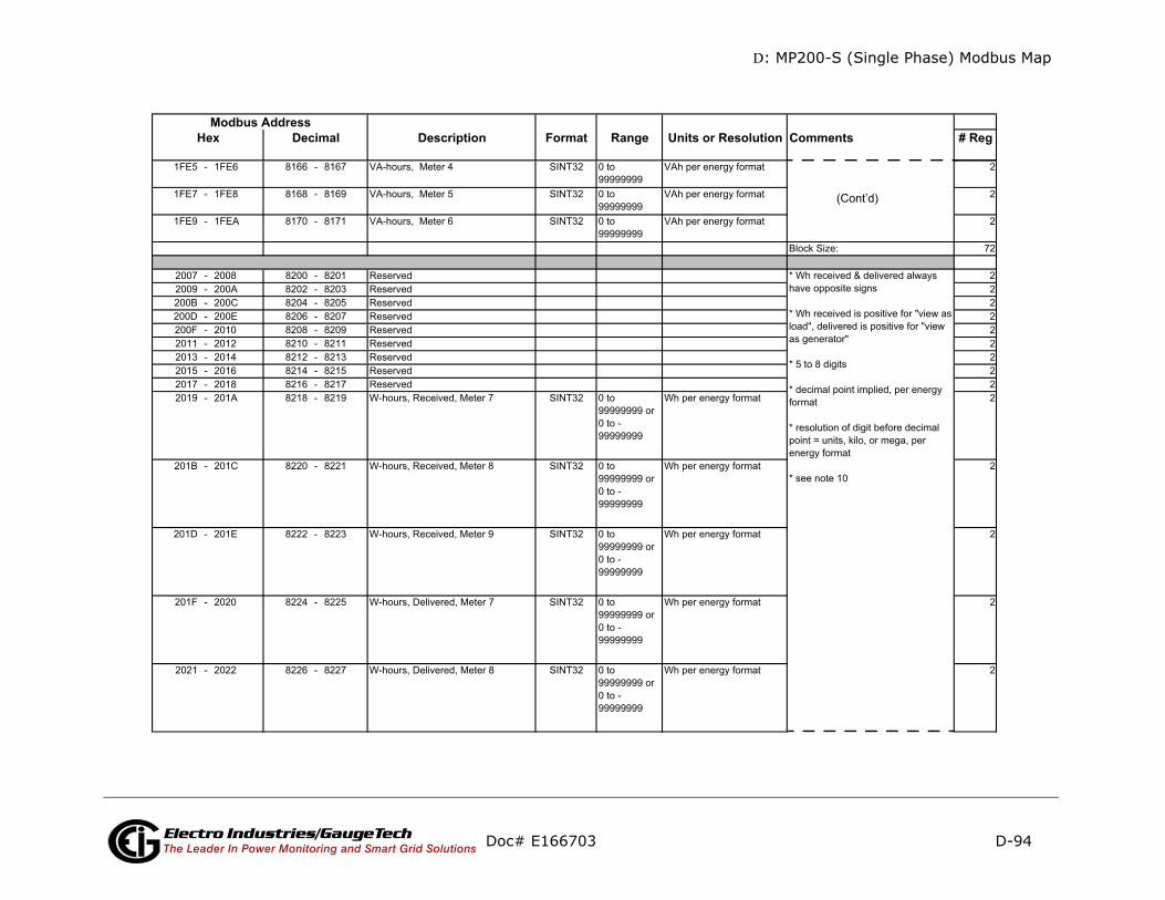
D: MP200-S (Single Phase) Modbus Map
D-94
ments # Reg
(Cont’d)
Doc# E166703 Electro Industries/GaugeTechThe Leader In Power Monitoring and Smart Grid Solutions
Description Format Range Units or Resolution ComModbus Address
Hex Decimal
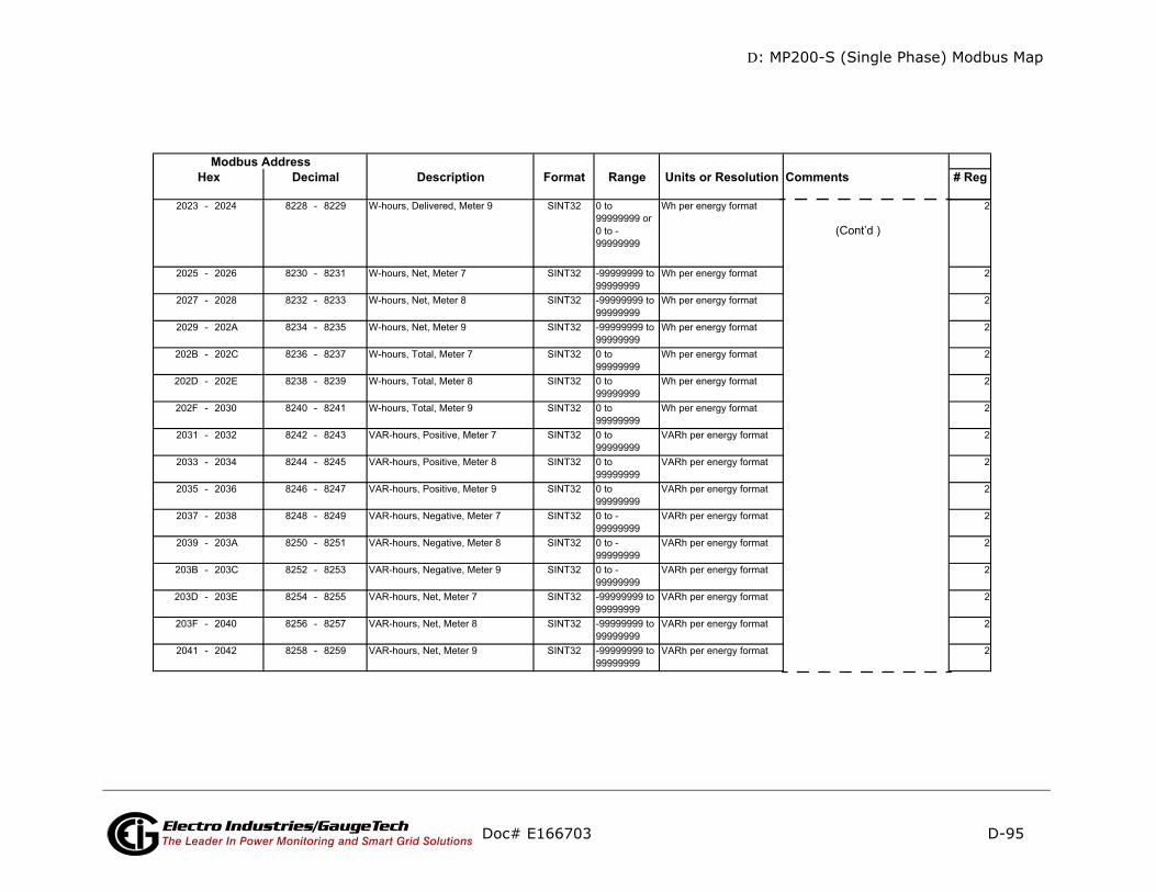
D: MP200-S (Single Phase) Modbus Map
D-95
mments # Reg
(Cont’d )
Doc# E166703 Electro Industries/GaugeTechThe Leader In Power Monitoring and Smart Grid Solutions
Description Format Range Units or Resolution CoModbus Address
Hex Decimal
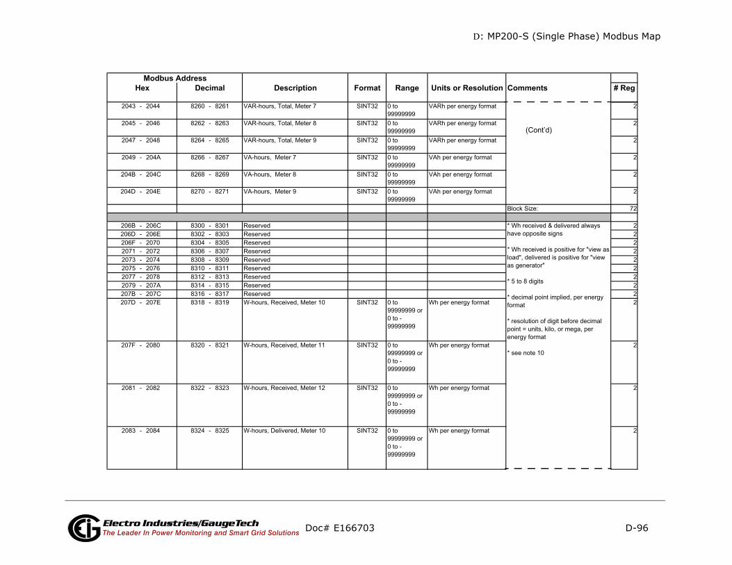
D: MP200-S (Single Phase) Modbus Map
D-96
omments # Reg
(Cont’d)
Doc# E166703 Electro Industries/GaugeTechThe Leader In Power Monitoring and Smart Grid Solutions
Description Format Range Units or Resolution CModbus Address
Hex Decimal
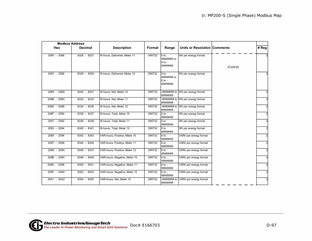
D: MP200-S (Single Phase) Modbus Map
D-97
mments # Reg
(Cont’d)
Doc# E166703 Electro Industries/GaugeTechThe Leader In Power Monitoring and Smart Grid Solutions
Description Format Range Units or Resolution CoModbus Address
Hex Decimal

D: MP200-S (Single Phase) Modbus Map
D-98
mments # Reg
(Cont’d)
Doc# E166703 Electro Industries/GaugeTechThe Leader In Power Monitoring and Smart Grid Solutions
Description Format Range Units or Resolution CoModbus Address
Hex Decimal

D: MP200-S (Single Phase) Modbus Map
D-99
mments # Reg
(Cont’d)
Doc# E166703 Electro Industries/GaugeTechThe Leader In Power Monitoring and Smart Grid Solutions
Description Format Range Units or Resolution CoModbus Address
Hex Decimal
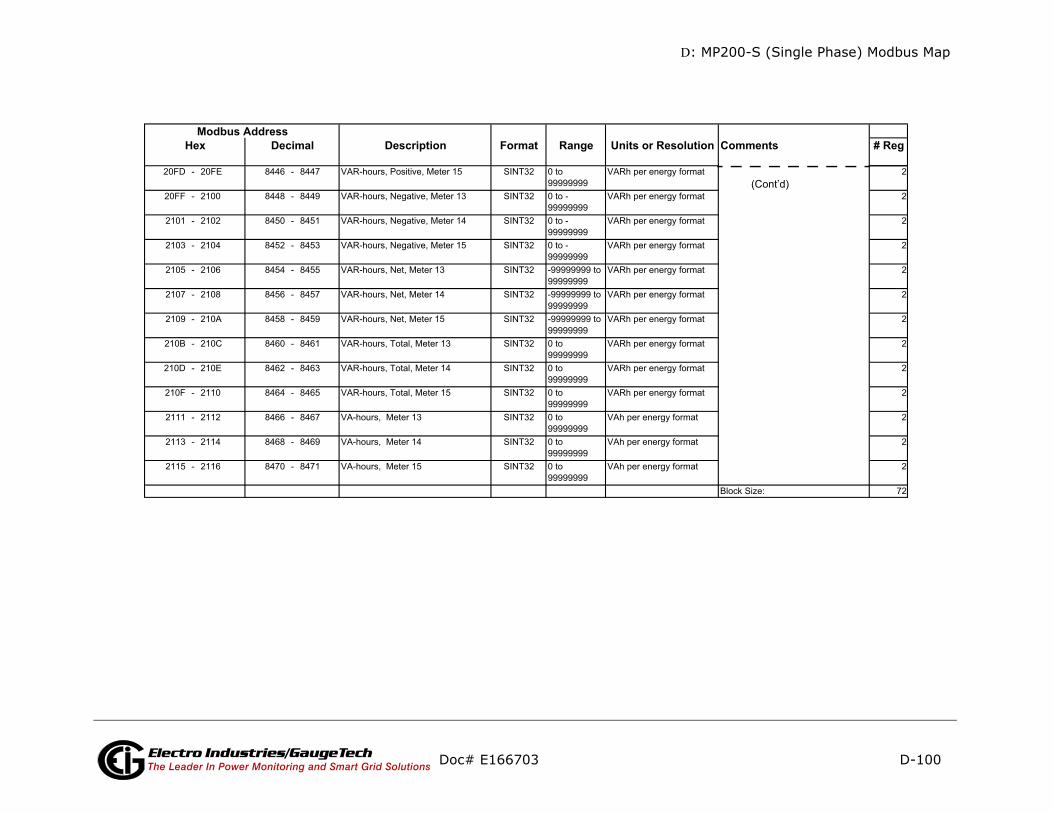
D: MP200-S (Single Phase) Modbus Map
D-100
mments # Reg
(Cont’d)
Doc# E166703 Electro Industries/GaugeTechThe Leader In Power Monitoring and Smart Grid Solutions
Description Format Range Units or Resolution CoModbus Address
Hex Decimal
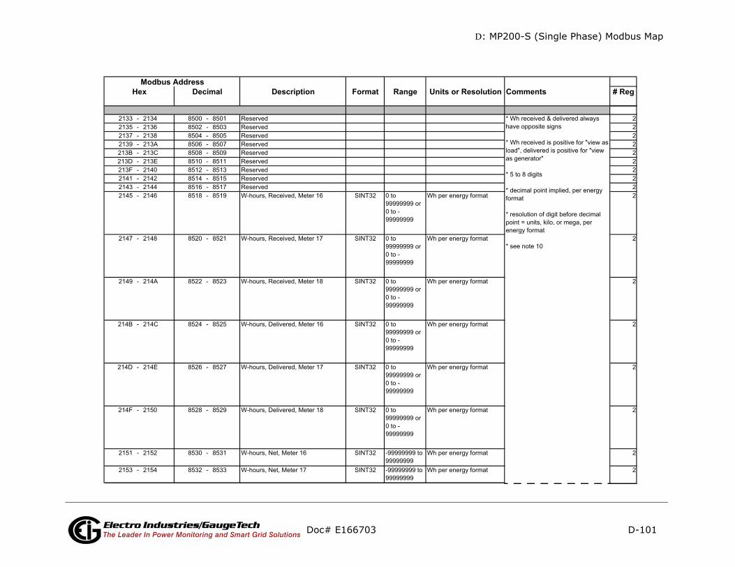
D: MP200-S (Single Phase) Modbus Map
D-101
omments # Reg
Doc# E166703 Electro Industries/GaugeTechThe Leader In Power Monitoring and Smart Grid Solutions
Description Format Range Units or Resolution CModbus Address
Hex Decimal

D: MP200-S (Single Phase) Modbus Map
D-102
omments # Reg
(Cont’d)
Doc# E166703 Electro Industries/GaugeTechThe Leader In Power Monitoring and Smart Grid Solutions
Description Format Range Units or Resolution CModbus Address
Hex Decimal

D: MP200-S (Single Phase) Modbus Map
D-103
mments # Reg
(Cont’d)
Doc# E166703 Electro Industries/GaugeTechThe Leader In Power Monitoring and Smart Grid Solutions
Description Format Range Units or Resolution CoModbus Address
Hex Decimal

D: MP200-S (Single Phase) Modbus Map
D-104
mments # Reg
(Cont’d)
Doc# E166703 Electro Industries/GaugeTechThe Leader In Power Monitoring and Smart Grid Solutions
Description Format Range Units or Resolution CoModbus Address
Hex Decimal
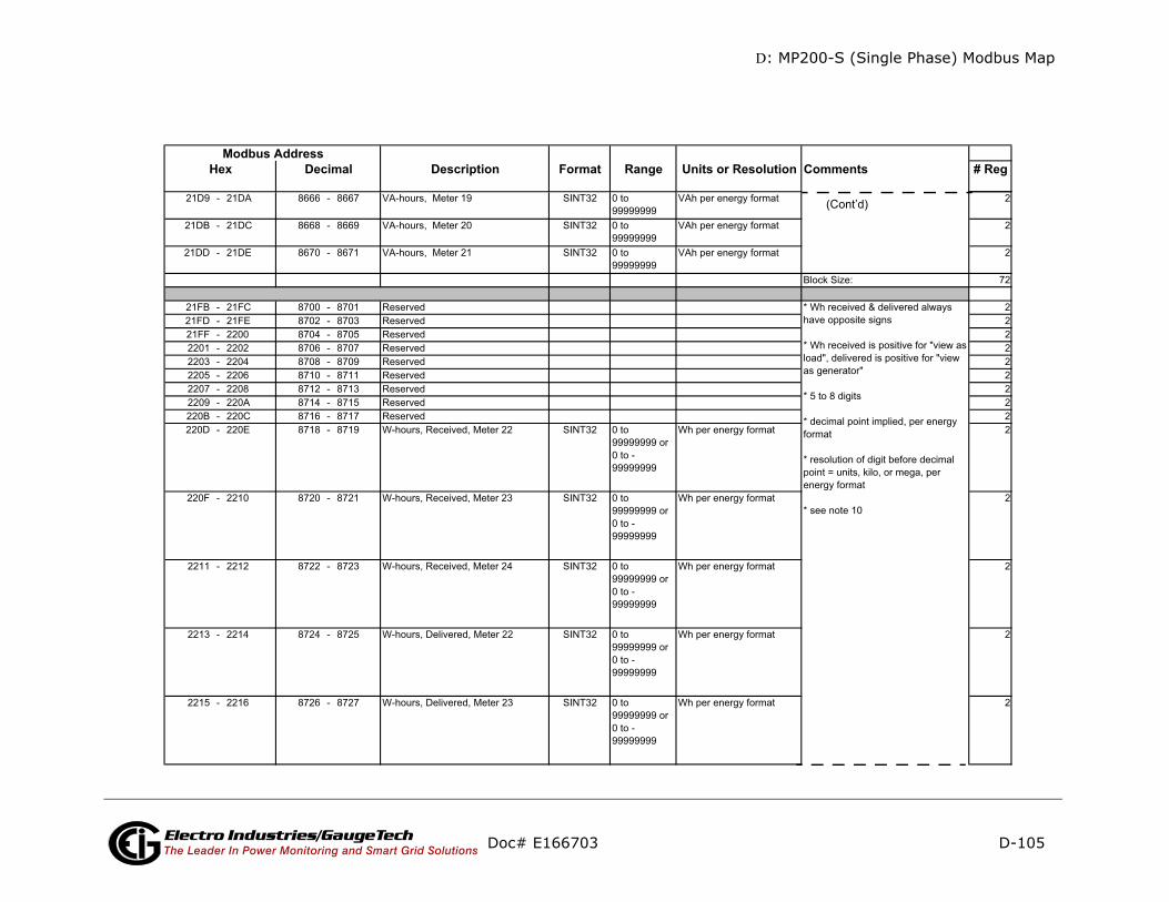
D: MP200-S (Single Phase) Modbus Map
D-105
omments # Reg
(Cont’d)
Doc# E166703 Electro Industries/GaugeTechThe Leader In Power Monitoring and Smart Grid Solutions
Description Format Range Units or Resolution CModbus Address
Hex Decimal
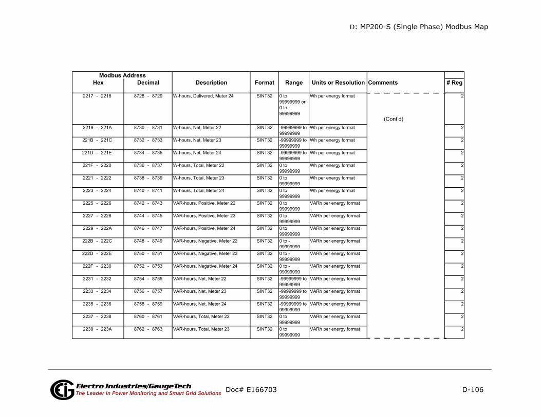
D: MP200-S (Single Phase) Modbus Map
D-106
mments # Reg
(Cont’d)
Doc# E166703 Electro Industries/GaugeTechThe Leader In Power Monitoring and Smart Grid Solutions
Description Format Range Units or Resolution CoModbus Address
Hex Decimal

D: MP200-S (Single Phase) Modbus Map
D-107
mments # Reg
-only
(Cont’d)
Doc# E166703 Electro Industries/GaugeTechThe Leader In Power Monitoring and Smart Grid Solutions
Description Format Range Units or Resolution CoModbus Address
Hex Decimal
read
eeeeeeee cccccccc
Card Identification and Configuration Block (Note 13) (IO Interface Board)
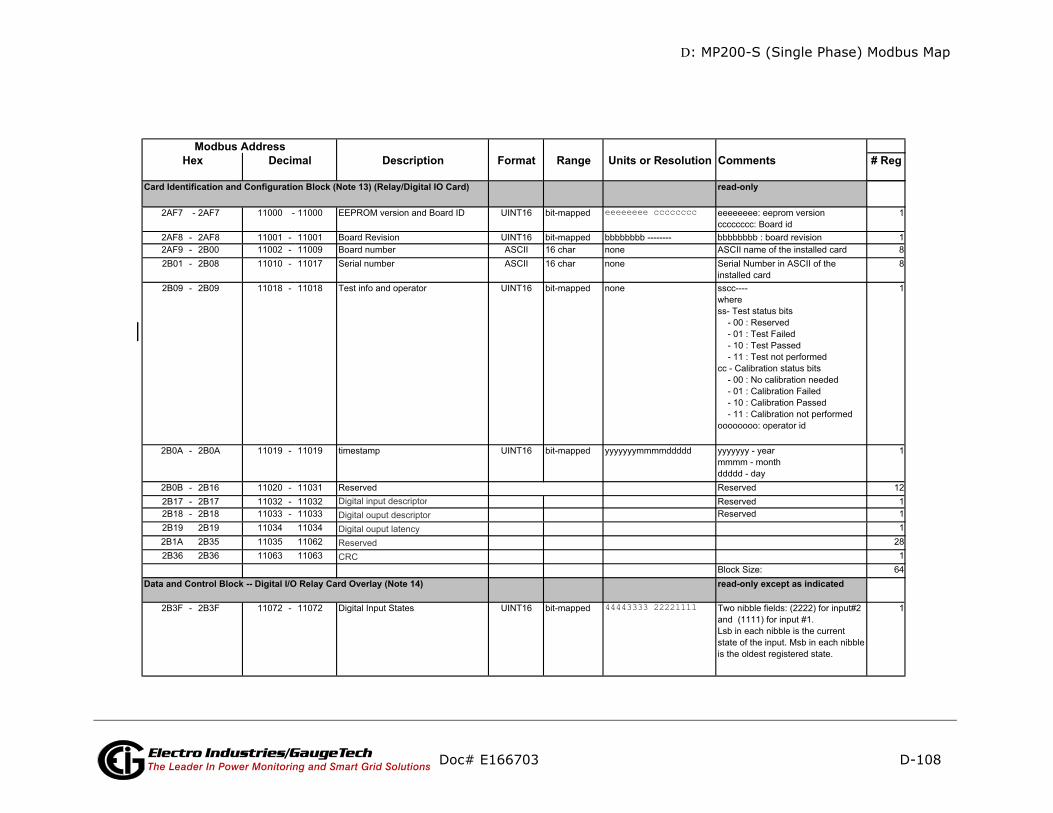
D: MP200-S (Single Phase) Modbus Map
D-108
mments # Reg
d-only
d-only except as indicated
Doc# E166703 Electro Industries/GaugeTechThe Leader In Power Monitoring and Smart Grid Solutions
Description Format Range Units or Resolution CoModbus Address
Hex Decimal
rea
eeeeeeee cccccccc
rea
44443333 22221111
Card Identification and Configuration Block (Note 13) (Relay/Digital IO Card)
Data and Control Block -- Digital I/O Relay Card Overlay (Note 14)
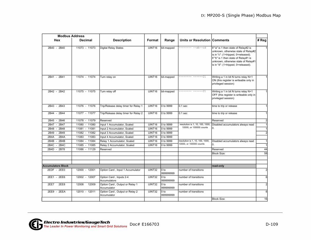
D: MP200-S (Single Phase) Modbus Map
D-109
mments # Reg
d-only
Doc# E166703 Electro Industries/GaugeTechThe Leader In Power Monitoring and Smart Grid Solutions
Description Format Range Units or Resolution CoModbus Address
Hex Decimal
-------- --ab--cd
-------- ------21
-------- ------21
reaAccumulators Block

D: MP200-S (Single Phase) Modbus Map
D-110
omments # Reg
ite-only
Doc# E166703 Electro Industries/GaugeTechThe Leader In Power Monitoring and Smart Grid Solutions
Description Format Range Units or Resolution CModbus Address
Hex Decimal
wrResets Block (Note 9)Commands Section (Note 4)
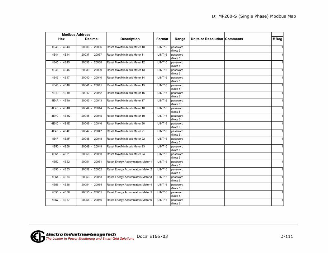
D: MP200-S (Single Phase) Modbus Map
D-111
omments # Reg
Doc# E166703 Electro Industries/GaugeTechThe Leader In Power Monitoring and Smart Grid Solutions
Description Format Range Units or Resolution CModbus Address
Hex Decimal
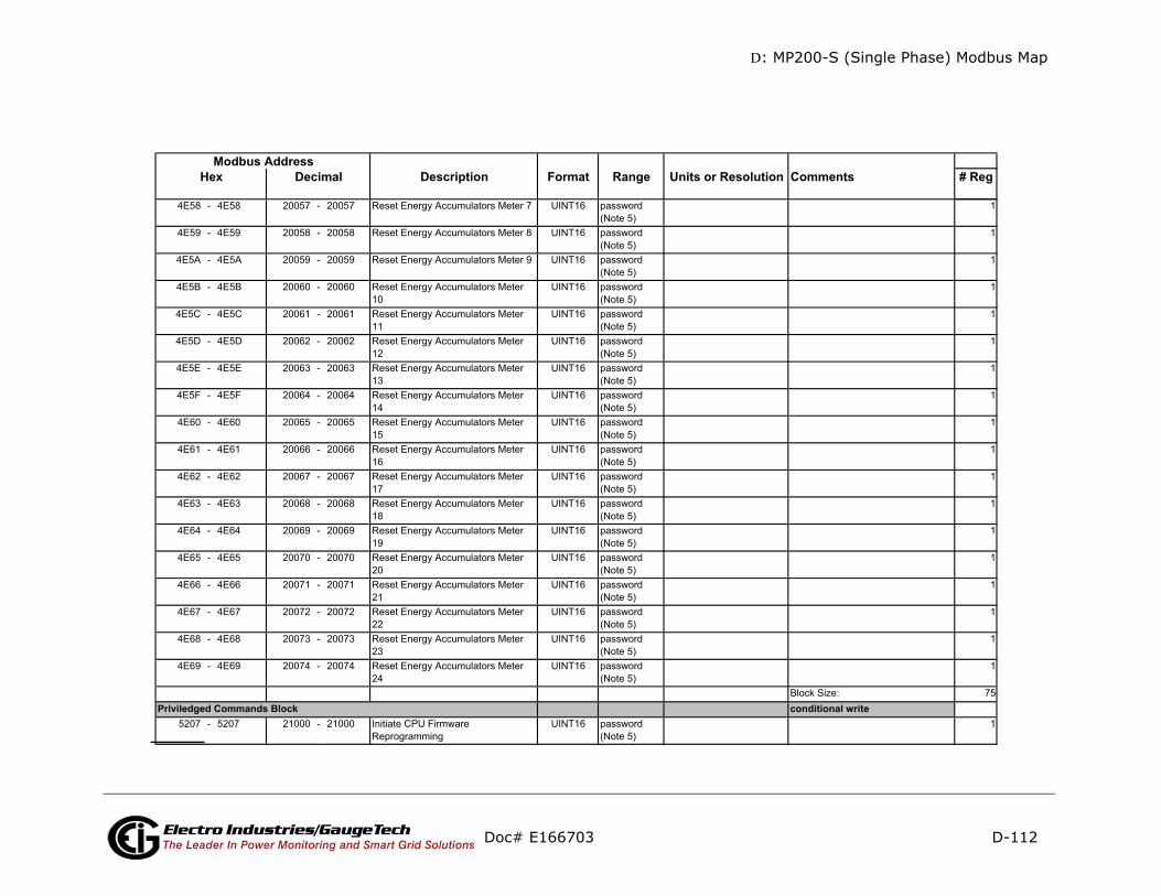
D: MP200-S (Single Phase) Modbus Map
D-112
mments # Reg
ditional write
Doc# E166703 Electro Industries/GaugeTechThe Leader In Power Monitoring and Smart Grid Solutions
Description Format Range Units or Resolution CoModbus Address
Hex Decimal
conPriviledged Commands Block

D: MP200-S (Single Phase) Modbus Map
D-113
mments # Reg
d/write
ite only in PS update mode
Doc# E166703 Electro Industries/GaugeTechThe Leader In Power Monitoring and Smart Grid Solutions
Description Format Range Units or Resolution CoModbus Address
Hex Decimal
rea
wr
nonenonenonenonenonenonenone
Programmable Settings SectionBasic Setups Block
Encryption Block
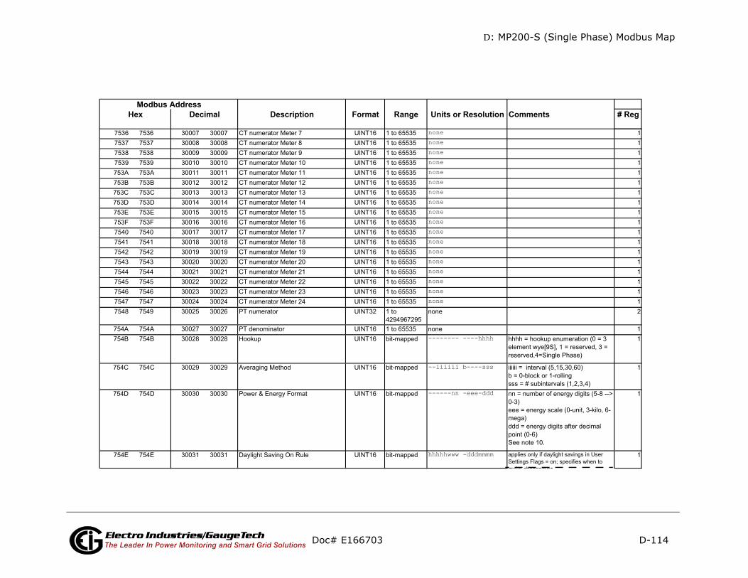
D: MP200-S (Single Phase) Modbus Map
D-114
mments # Reg
Doc# E166703 Electro Industries/GaugeTechThe Leader In Power Monitoring and Smart Grid Solutions
Description Format Range Units or Resolution CoModbus Address
Hex Decimal
nonenonenonenonenonenonenonenonenonenonenonenonenonenonenonenonenonenone
-------- ----hhhh
--iiiiii b----sss
------nn -eee-ddd
hhhhhwww -dddmmmm

D: MP200-S (Single Phase) Modbus Map
D-115
mments # Reg
Doc# E166703 Electro Industries/GaugeTechThe Leader In Power Monitoring and Smart Grid Solutions
Description Format Range Units or Resolution CoModbus Address
Hex Decimal
hhhhhwww -dddmmmm
-------- urpdywfa
----dddd -ppp-bbb
----dddd -ppp-bbb
----dddd -ppp-bbb
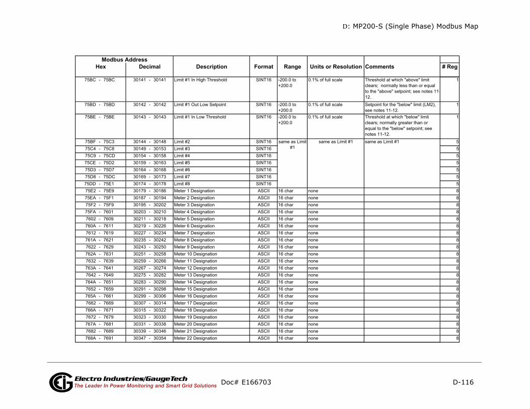
D: MP200-S (Single Phase) Modbus Map
D-116
omments # Reg
Doc# E166703 Electro Industries/GaugeTechThe Leader In Power Monitoring and Smart Grid Solutions
Description Format Range Units or Resolution CModbus Address
Hex Decimal

D: MP200-S (Single Phase) Modbus Map
D-117
mments # Reg
te only in PS update mode
Doc# E166703 Electro Industries/GaugeTechThe Leader In Power Monitoring and Smart Grid Solutions
Description Format Range Units or Resolution CoModbus Address
Hex Decimal
wri
eeeeeeee ssssssss
00000000 hgfedcba
Log Setups Block
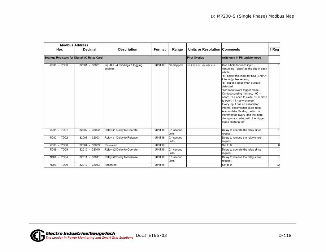
D: MP200-S (Single Phase) Modbus Map
D-118
mments # Reg
te only in PS update mode
nibble for each input.uming "abcc" as the bits in each le:
select this input for EOI (End Of rval)pulse sensing. log this input when pulse is cted: Input event trigger mode - tact sensing method; 00 = e; 01 = open to close; 10 = close pen; 11 = any change.ry input has an associated rnal accumulator (See input umulator Scaling), which is emented every time the input nges according with the trigger e crieteria “cc”
1
ay to operate the relay since est.
1
ay to release the relay since est.
1
to 0. 6ay to operate the relay since est.
1
ay to release the relay since uest.
1
to 0. 22
Doc# E166703 Electro Industries/GaugeTechThe Leader In Power Monitoring and Smart Grid Solutions
Description Format Range Units or Resolution CoModbus Address
Hex Decimal
First Overlay wri
7D00 - 7D00 32001 - 32001 Input#1 - 4 bindings & logging enables
UINT16 bit-mapped 44443333 22221111 OneAssnibb"a":Inte"b":dete"cc"Connonto oEveinteAccincrchamod
7D01 - 7D01 32002 - 32002 Relay #1 Delay to Operate UINT16 0.1 second units
Delrequ
7D02 - 7D02 32003 - 32003 Relay #1 Delay to Release UINT16 0.1 second units
Delrequ
7D03 - 7D08 32004 - 32009 Reserved UINT16 Set7D09 - 7D09 32010 - 32010 Relay #2 Delay to Operate UINT16 0.1 second
unitsDelrequ
7D0A - 7D0A 32011 - 32011 Relay #2 Delay to Release UINT16 0.1 second units
Delreq
7D0B - 7D20 32012 - 32033 Reserved UINT16 Set
Settings Registers for Digital I/O Relay Card

D: MP200-S (Single Phase) Modbus Map
D-119
ents # Reg
1
1
. 8888
242424888
24ed 48
88881
1
er factor for the Pulse Output w power value in Wh/pulse
to 9999. "dd"=decimal point : 00=0.XXXX, 01=X.XXX,
.XX, 11= X.XXX.
er input or output latorble informs what should be ling of the accumulator 0=no-, 1=0.1, 2=0.01, 3= 1m, , 5=0.01m, 6=1u, 7=0.1u; the 5 disable the accumulator.le: suppose that the internal ccumulator #1 is 12345, and esponding scaling setting is (3 decimal). Then, the lator will be read as: 3, means 1m or 0.001. accumulator = 12345 * 0.001 welve).
Doc# E166703 Electro Industries/GaugeTechThe Leader In Power Monitoring and Smart Grid Solutions
Description Format Range Units or Resolution CommModbus Address
Hex Decimal
7D21 - 7D21 32034 - 32034 Input Accumulators Scaling UINT16 bit-mapped 44443333 22221111
7D22 - 7D22 32035 - 32035 Relay Accumulators Scaling UINT16 bit-mapped 44443333 22221111
7D23 - 7D3E 32037 - 32063 Reserved Set to 07D3F - 7D46 32064 - 32071 Input#1 Label ASCII 16 char7D47 - 7D4E 32072 - 32079 Input#1 Low State Name ASCII 16 char7D4F - 7D56 32080 - 32087 Input#1 High State Name ASCII 16 char7D57 - 7D6E 32088 - 32111 Input#2 Label and State Names7D6F - 7D86 32112 - 32135 Input#3 Label and State Names7D87 - 7D9E 32136 - 32159 Input#4 Label and State Names7D9F - 7DA6 32160 - 32167 Relay#1 Label ASCII 16 char7DA7 - 7DAE 32168 - 32175 Relay#1 Open State Name ASCII 16 char7DAF - 7DB6 32176 - 32183 Relay#1 Closed State Name ASCII 16 char7DB7 - 7DCE 32184 - 32207 Relay#2 Label and State Names7DCF - 7DFE 32208 - 32255 Reserved Reserv7DFF - 7E06 32256 - 32263 Input#1 Accumulator Label ASCII 16 char7E07 - 7E0E 32264 - 32271 Input#2 Accumulator Label ASCII 16 char7E0F - 7E14 32272 - 32277 Input#3 Accumulator Label ASCII 16 char7E15 7E1E 32278 32287 Input#4 Accumulator Label ASCII 16 char7E1F - 7E1F 32288 - 32288 Input#1 Accumulator Kt UINT16 bit-mapped ddVVVVVV VVVVVVVV
7E20 7E20 32289 32289 Input#2 Accumulator Kt UINT16 bit-mapped ddVVVVVV VVVVVVVV
KT pow"V" is rafrom 0 position10=XX
same as Input#1same as Input#1same as Input#1
same as Relay#1
4 bits paccumuThe nibthe scascaling4=0.1mvalue 1Exampinput aits corr“0011” accumuScalingScaled= 12 (T

D: MP200-S (Single Phase) Modbus Map
D-120
ments # Reg
1
1
ved 305Size: 576
rite except as noted session active; wraps around ax count
2
session active, 1-3 for session on COM1 - COM3
1
yte is the log number (0-, 1-history1, 2-history2, 3-3,4-alarm log, 5-I/O changes )trieval session enable(1) or e(0)s is what to retrieve (0-normal , 1-timestamps only, 2-ete memory image (no data tion if image)
1
yte is records per window if records per batch if s=1, low number of repeats for n 35 or 0 to suppress auto-enting; max number of
ts is 8 (RTU) or 4 (ASCII) total ws, a batch is all the windows
1
ont’d)
Doc# E166703 Electro Industries/GaugeTechThe Leader In Power Monitoring and Smart Grid Solutions
Description Format Range Units or Resolution ComModbus Address
Hex Decimal
7E21 7E21 32290 32290 Input#3 Accumulator Kt UINT16 bit-mapped ddVVVVVV VVVVVVVV
7E22 7E22 32291 32291 Input#4 Accumulator Kt UINT16 bit-mapped ddVVVVVV VVVVVVVV
7E23 7F53 32292 32596 Reserved ReserBlock
read/wC34C - C34D 49997 - 49998 Log Retrieval Session Duration UINT32 0 to
42949672944 msec 0 if no
after mC34E - C34E 49999 - 49999 Log Retrieval Session Com Port UINT16 0 to 3 0 if no
activeC34F - C34F 50000 - 50000 Log Number, Enable, Scope UINT16 bit-mapped nnnnnnnn esssssss high b
systemhistorye is redisablssssssrecordcomplvalida
C350 - C350 50001 - 50001 Records per Window or Batch, Record Scope Selector, Number of Repeats
UINT16 bit-mapped wwwwwwww snnnnnnn high bs=0 orbyte isfunctioincremrepeawindo
Log Retrieval SectionLog Retrieval Block
(C

D: MP200-S (Single Phase) Modbus Map
D-121
mments # Reg
only
Doc# E166703 Electro Industries/GaugeTechThe Leader In Power Monitoring and Smart Grid Solutions
Description Format Range Units or Resolution CoModbus Address
Hex Decimal
ssssssss nnnnnnnnnnnnnnnn nnnnnnnn
readSystem Log Status Block
Historical Log 1 Status BlockHistorical Log 2 Status BlockHistorical Log 3 Status BlockAlarm Log Status BlockI/O Log Status Block
End of Map
Log Status Block

D: MP200-S (Single Phase) Modbus Map
D-122
Doc# E166703 Electro Industries/GaugeTechThe Leader In Power Monitoring and Smart Grid SolutionsNotes
Data Formats

D: MP200-S (Single Phase) Modbus Map
D-123
Doc# E166703 Electro Industries/GaugeTechThe Leader In Power Monitoring and Smart Grid Solutions
D: MP200-S (Single Phase) Modbus Map
D-124
Doc# E166703 Electro Industries/GaugeTechThe Leader In Power Monitoring and Smart Grid SolutionsThis page intentionally left blank.

E: Retrieving Logs
E: Retrieving Logs Using the MP200 Metering System's Modbus Map
E.1: Overview
This appendix describes the log interface system of the MP200 unit from a
programming point of view. It is intended for programmers implementing indepen-
dent drivers for log retrieval from the MP200 unit. It describes the meaning of the
MP200's Modbus Registers related to log retrieval and conversion, and details the
procedure for retrieving a log's records.
NOTES:
• All references assume the use of Modbus function codes 0x03, 0x06, and 0x10,
where each register is a 2 byte MSB (Most Significant Byte) word, except where
otherwise noted.
• The carat symbol (^) notation is used to indicate mathematical "power." For
example, 2^8 is 2 x 2 x 2 x 2 x 2 x 2 x 2 x 2, which equals 256.
Doc# E166703 E-1Electro Industries/GaugeTechThe Leader In Power Monitoring and Smart Grid SolutionsElectro Industries/GaugeTechThe Leader In Power Monitoring and Smart Grid Solutions

E: Retrieving Logs
E.2: Data Formats
Time stamp: Stores a date from 2000 to 2099. Time stamp has a Minimum resolution
of 1 second.
The high bits of each time stamp byte are used as flags to record MP200 unit state
information at the time of the time stamp. These bits should be masked out, unless
needed.
E.3: MP200 Metering System Logs
The MP200 unit has 6 logs: System Event, Alarm (Limits), 3 Historical, and I/O
Change. Each log is described below.
1. System Event (0): The System Event log is used to store events which happen in,
and to, the MP200 unit. Events include Startup, Reset Commands, Log Retrievals,
etc. The System Event Log Record takes 20 bytes, 14 bytes of which are available
when the log is retrieved.
NOTE: The complete Systems Events table is shown in Section E.5.5 on page E-29.
2. Alarm Log (1): The Alarm Log records the states of the 8 Limits programmed in
the MP200 unit.
• Whenever a limit goes out (above or below), a record is stored with the value
that caused the limit to go out.
• Whenever a limit returns within limit, a record is stored with the "most out of
limit" value for that limit while it was out of limit.
Byte 0 1 2 3 4 5
Value Year Month Day Hour Minute Second
Range 0-99 (+2000) 1-12 1-31 0-23 0-59 0-59
Mask 0x7F 0x0F 0x1F 0x1F 0x3F 0x3F
Byte 0 1 2 3 4 5 6 7 8 9 10 11 12 13
Value timestamp Group Event Mod Chan Param1 Param2 Param3 Param4
Doc# E166703 E-2Electro Industries/GaugeTechThe Leader In Power Monitoring and Smart Grid SolutionsElectro Industries/GaugeTechThe Leader In Power Monitoring and Smart Grid Solutions
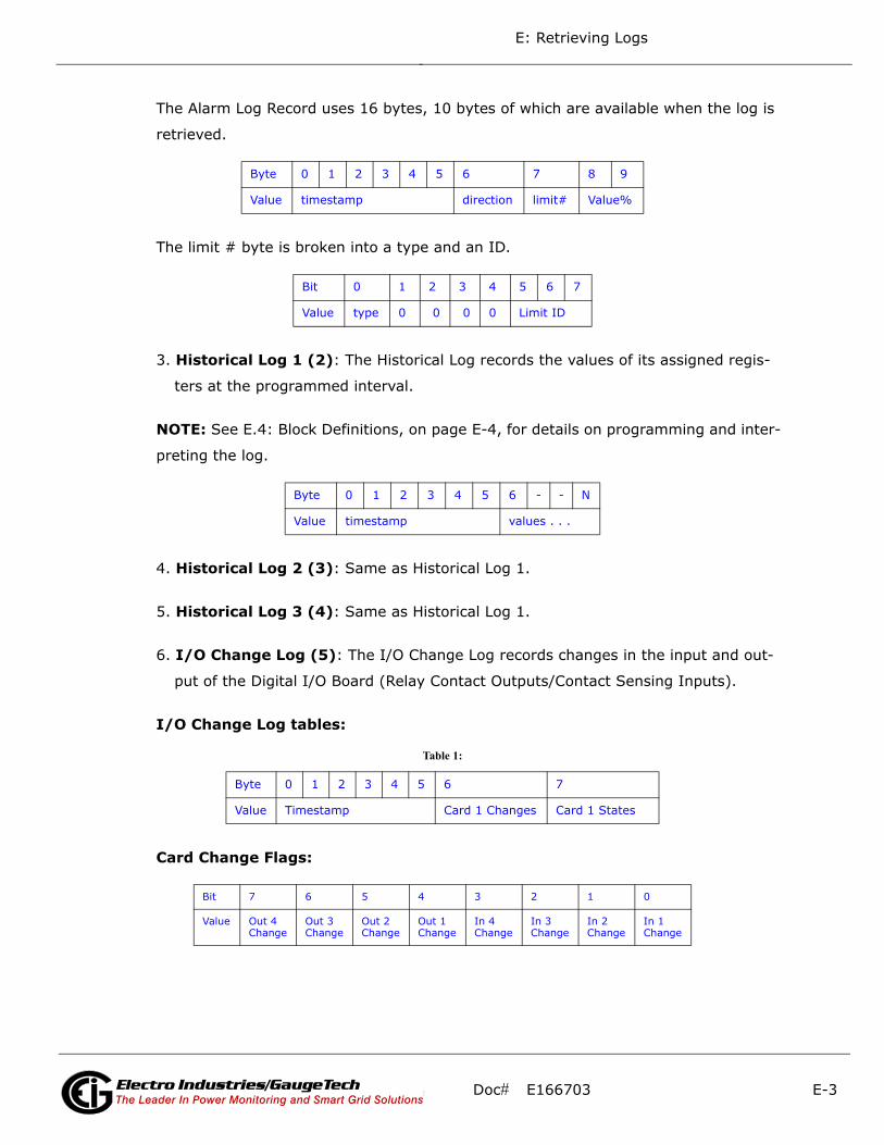
E: Retrieving Logs
The Alarm Log Record uses 16 bytes, 10 bytes of which are available when the log is
retrieved.
The limit # byte is broken into a type and an ID.
3. Historical Log 1 (2): The Historical Log records the values of its assigned regis-
ters at the programmed interval.
NOTE: See E.4: Block Definitions, on page E-4, for details on programming and inter-
preting the log.
4. Historical Log 2 (3): Same as Historical Log 1.
5. Historical Log 3 (4): Same as Historical Log 1.
6. I/O Change Log (5): The I/O Change Log records changes in the input and out-
put of the Digital I/O Board (Relay Contact Outputs/Contact Sensing Inputs).
I/O Change Log tables:
Card Change Flags:
Byte 0 1 2 3 4 5 6 7 8 9
Value timestamp direction limit# Value%
Bit 0 1 2 3 4 5 6 7
Value type 0 0 0 0 Limit ID
Byte 0 1 2 3 4 5 6 - - N
Value timestamp values . . .
Table 1:
Byte 0 1 2 3 4 5 6 7
Value Timestamp Card 1 Changes Card 1 States
Bit 7 6 5 4 3 2 1 0
Value Out 4 Change
Out 3 Change
Out 2 Change
Out 1 Change
In 4 Change
In 3 Change
In 2 Change
In 1 Change
Doc# E166703 E-3Electro Industries/GaugeTechThe Leader In Power Monitoring and Smart Grid SolutionsElectro Industries/GaugeTechThe Leader In Power Monitoring and Smart Grid Solutions

E: Retrieving Logs
Card Current States:
E.4: Block Definitions
This section describes the Modbus Registers involved in retrieving and interpreting an
MP200 unit Log. Other sections refer to certain 'values' contained in this section. See
the corresponding value in this section for details.
NOTES:
• “Register” is the Modbus Register Address in 0-based Hexadecimal notation. To
convert it to 1-based decimal notation, convert from hex16 to decimal10 and add
1. For example: 0x03E7 = 1000.
• “Size” is the number of Modbus Registers (2 byte) in a block of data.
Historical Log Programmable Settings:
The Historical Logs are programmed using a list of Modbus Registers that will be cop-
ied into the Historical Log record. In other words, Historical Log uses a direct copy of
the Modbus Registers to control what is recorded at the time of record capture.
To supplement this, the programmable settings for the Historical Logs contain a list of
descriptors, which group registers into items. Each item descriptor lists the data type
of the item, and the number of bytes for that item. By combining these two lists, the
Historical Log record can be interpreted.
For example: Registers 0x03E7 and 0x03E8 are programmed to be recorded by the
historical log. The matching descriptor gives the data type as float, and the size as 4
bytes. These registers program the log to record "Primary Readings Volts A-N."
Historical Log Blocks:
Start Register: 0x7917 (Historical Log 1)
0x79D7 (Historical Log 2)
0x7A97 (Historical Log 3)
Bit 7 6 5 4 3 2 1 0
Value Out 4 State
Out 3 State
Out 2 State
Out 1 State
In 4 State
In 3 State
In 2 State
In 1 State
Doc# E166703 E-4Electro Industries/GaugeTechThe Leader In Power Monitoring and Smart Grid SolutionsElectro Industries/GaugeTechThe Leader In Power Monitoring and Smart Grid Solutions

E: Retrieving Logs
Block Size: 192 registers per log (384 bytes)
The Historical Log programmable settings are comprised of 3 blocks, one for each log.
Each is identical to the others, so only Historical Log 1 is described here. All register
addresses in this section are given as the Historical Log 1 address (0x7917).
Each Historical Log Block is composed of 3 sections: The header, the list of registers to
log, and the list of item descriptors.
Header:
Registers: 0x7917 - 0x7918
Size: 2 registers
• # Registers: The number of registers to log in the record. The size of the record in
memory is [12 + (# Registers x 2)]. The size during normal log retrieval is [6 + (#
Registers x 2)]. If this value is 0, the log is disabled. Valid values are 0-117.
• # Sectors: The number of Flash Sectors allocated to this log. Each sector is 262114
bytes, minus a sector header of 20 bytes. 3 sectors for V-Switch key 2, and 111
sectors for V-Switch key 3, are available for allocation between Historical Logs 1, 2,
and 3. The sum of all Historical Logs may be less than 3 sectors for V-Switch key 2,
and 111 sectors for V-Switch key 3. If this value is 0, the log is disabled. Valid val-
ues are 0-111.
• Interval: The interval at which the Historical Log's Records are captured. This value
is an enumeration:
0x01 1 minute
0x02 3 minute
0x04 5 minute
0x08 10 minute
0x10 15 minute
Byte 0 1 2 3
Value # Registers # Sectors Interval
Doc# E166703 E-5Electro Industries/GaugeTechThe Leader In Power Monitoring and Smart Grid SolutionsElectro Industries/GaugeTechThe Leader In Power Monitoring and Smart Grid Solutions
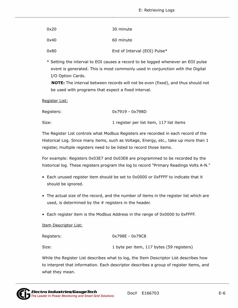
E: Retrieving Logs
0x20 30 minute
0x40 60 minute
0x80 End of Interval (EOI) Pulse*
* Setting the interval to EOI causes a record to be logged whenever an EOI pulse
event is generated. This is most commonly used in conjunction with the Digital
I/O Option Cards.
NOTE: The interval between records will not be even (fixed), and thus should not
be used with programs that expect a fixed interval.
Register List:
Registers: 0x7919 - 0x798D
Size: 1 register per list item, 117 list items
The Register List controls what Modbus Registers are recorded in each record of the
Historical Log. Since many items, such as Voltage, Energy, etc., take up more than 1
register, multiple registers need to be listed to record those items.
For example: Registers 0x03E7 and 0x03E8 are programmed to be recorded by the
historical log. These registers program the log to record "Primary Readings Volts A-N."
• Each unused register item should be set to 0x0000 or 0xFFFF to indicate that it
should be ignored.
• The actual size of the record, and the number of items in the register list which are
used, is determined by the # registers in the header.
• Each register item is the Modbus Address in the range of 0x0000 to 0xFFFF.
Item Descriptor List:
Registers: 0x798E - 0x79C8
Size: 1 byte per item, 117 bytes (59 registers)
While the Register List describes what to log, the Item Descriptor List describes how
to interpret that information. Each descriptor describes a group of register items, and
what they mean.
Doc# E166703 E-6Electro Industries/GaugeTechThe Leader In Power Monitoring and Smart Grid SolutionsElectro Industries/GaugeTechThe Leader In Power Monitoring and Smart Grid Solutions

E: Retrieving Logs
Each descriptor is composed of 2 parts:
• Type: The data type of this descriptor, such as signed integer, IEEE floating point,
etc. This is the high nibble of the descriptor byte, with a value in the range of 0-14.
If this value is 0xFF, the descriptor should be ignored.
0 ASCII: An ASCII string, or byte array
1 Bitmap: A collection of bit flags
2 Signed Integer: A 2's Complement integer
3 Float: An IEEE floating point
4 Energy: Special Signed Integer, where the value
is adjusted by the energy settings in the MP200
unit's Programmable Settings.
5 Unsigned Integer
6 Signed Integer 0.1 scale: Special Signed Integer,
where the value is divided by 10 to give a 0.1
scale.
7-14 Unused
15 Disabled: used as end list marker.
• Size: The size in bytes of the item described. This number is used to determine the
pairing of descriptors with register items.
For example: If the first descriptor is 4 bytes, and the second descriptor is 2 bytes,
then the first 2 register items belong to the 1st descriptor, and the 3rd register item
belongs to the 2nd descriptor.
NOTE: As can be seen from the example, above, there is not a 1-to-1 relation
between the register list and the descriptor list. A single descriptor may refer to
multiple register items.
Register Items Descriptors
0x03C7/ Float, 4 byte 0x03C8 0x1234 Signed Int, 2 byte
Doc# E166703 E-7Electro Industries/GaugeTechThe Leader In Power Monitoring and Smart Grid SolutionsElectro Industries/GaugeTechThe Leader In Power Monitoring and Smart Grid Solutions

E: Retrieving Logs
NOTE: The sum of all descriptor sizes must equal the number of bytes in the data
portion of the Historical Log record.
Log Status Block:
The Log Status Block describes the current status of the log in question. There is one
header block for each of the logs. Each log's header has the following base address:
Log Base Address
System: 0xC737
Historical 1: 0xC747
Historical 2: 0xC757
Historical 3: 0xC767
Alarm: 0xC777
I/O Change: 0xC787
• Max Records: The maximum number of records the log can hold given the record
size, and sector allocation. The data type is an unsigned integer from 0 - 2^32.
Bytes Value Type Range # Bytes
0-3 Max Records UINT32 0 to 4,294,967,294 4
4-7 Number of Records Used UINT32 1 to 4,294,967,294 4
8-9 Record Size in Bytes UINT16 4 to 250 2
10-11 Log Availability UINT16 2
12-17 Timestamp, First Record TSTAMP
1Jan2000 - 31Dec2099 6
18-23 Timestamp, Last Record TSTAMP
1Jan2000 - 31Dec2099 6
24-31 Reserved 8
Doc# E166703 E-8Electro Industries/GaugeTechThe Leader In Power Monitoring and Smart Grid SolutionsElectro Industries/GaugeTechThe Leader In Power Monitoring and Smart Grid Solutions

E: Retrieving Logs
• Records Used: The number of records stored in the log. This number will equal the
Max Records when the log has filled. This value will be set to 1 when the log is
reset. The data type is an unsigned integer from 1 - 2^32.
NOTE: The first record in every log before it has rolled over is a "dummy" record,
filled with all 0xFF's. When the log is filled and rolls over, this record is overwritten.
• Record Size: The number of bytes in this record, including the timestamp. The data
type is an unsigned integer in the range of 14 - 242.
• Log Availability: A flag indicating if the log is available for retrieval, or if it is in use
by another port.
0 Log Available for retrieval
1 In use by COM1 (RS485/Ethernet/WiFi)
2 In use by COM2 (USB)
3 In use by COM3 (RS485)
0xFFFF Log Not Available - the log cannot be retrieved.
This indicates that the log is disabled.
NOTE: To query the port by which you are currently connected, use the Port ID
register:
Register: 0x1193
Size: 1 register
Description: A value from 1-4, which enumerates the port that the requestor is
currently connected on.
NOTES:
• When Log Retrieval is engaged, the Log Availability value will be set to the port
that engaged the log. The Log Availability value will stay the same until either
the log has been disengaged, or 5 minutes have passed with no activity. It will
then reset to 0 (available).
• Each log can only be retrieved by one port at a time.
Doc# E166703 E-9Electro Industries/GaugeTechThe Leader In Power Monitoring and Smart Grid SolutionsElectro Industries/GaugeTechThe Leader In Power Monitoring and Smart Grid Solutions

E: Retrieving Logs
• Only one log at a time can be retrieved.
• First Timestamp: Timestamp of the oldest record.
• Last Timestamp: Timestamp of the newest record.
Log Retrieval Block:
The Log Retrieval Block is the main interface for retrieving logs. It is comprised of 2
parts: the header and the window. The header is used to program the particular data
the MP200 unit presents when a log window is requested. The window is a sliding
block of data that can be used to access any record in the specified log.
Session Com Port: The MP200 unit's Com Port which is currently retrieving logs.
Only one Com Port can retrieve logs at any one time.
Registers: 0xC34E - 0xC34E
Size: 1 register
0 No Session Active
1 COM1 (RS485/Ethernet/WiFi)
2 COM2 (USB)
3 COM3 (RS485)
To get the current Com Port, see the NOTE on querying the port, on the previous
page.
Doc# E166703 E-10Electro Industries/GaugeTechThe Leader In Power Monitoring and Smart Grid SolutionsElectro Industries/GaugeTechThe Leader In Power Monitoring and Smart Grid Solutions
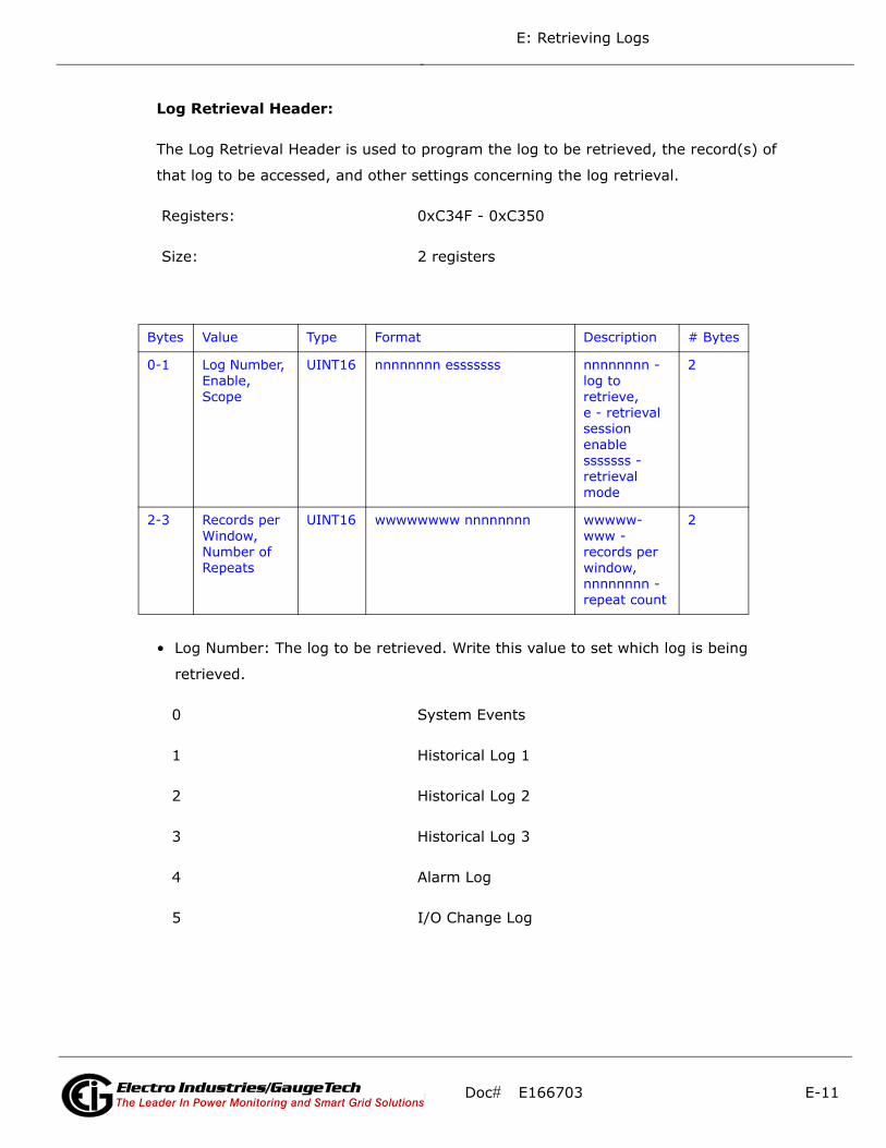
E: Retrieving Logs
Log Retrieval Header:
The Log Retrieval Header is used to program the log to be retrieved, the record(s) of
that log to be accessed, and other settings concerning the log retrieval.
Registers: 0xC34F - 0xC350
Size: 2 registers
• Log Number: The log to be retrieved. Write this value to set which log is being
retrieved.
0 System Events
1 Historical Log 1
2 Historical Log 2
3 Historical Log 3
4 Alarm Log
5 I/O Change Log
Bytes Value Type Format Description # Bytes
0-1 Log Number, Enable, Scope
UINT16 nnnnnnnn esssssss nnnnnnnn - log to retrieve, e - retrieval session enablesssssss - retrieval mode
2
2-3 Records per Window, Number of Repeats
UINT16 wwwwwwww nnnnnnnn wwwww-www - records per window, nnnnnnnn - repeat count
2
Doc# E166703 E-11Electro Industries/GaugeTechThe Leader In Power Monitoring and Smart Grid SolutionsElectro Industries/GaugeTechThe Leader In Power Monitoring and Smart Grid Solutions
E: Retrieving Logs
Enable: This value sets if a log retrieval session is engaged (locked for retrieval) or
disengaged (unlocked, read for another to engage). Write this value with 1(enable) to
begin log retrieval. Write this value with 0(disable) to end log retrieval.
0 Disable
1 Enable
• Scope: Sets the amount of data to be retrieved for each record. The default should
be 0 (normal).
0 Normal
1 Timestamp Only
2 Image
• Normal [0]: The default record. Contains a 6-byte timestamp at the beginning,
then N data bytes for the record data.
• Timestamp [1]: The record only contains the 6-byte timestamp. This is most
useful to determine a range of available data for non-interval based logs, such
as Alarms and System Events.
• Image [2]: The full record, as it is stored in memory. Contains a 2-byte check-
sum, 4-byte sequence number, 6-byte timestamp, and then N data bytes for the
record data.
• Records Per Window: The number of records that fit evenly into a window. This
value is set-able, as less than a full window may be used. This number tells the
retrieving program how many records to expect to find in the window.
NOTE: This must be set to 1 for waveform retrieval.
(RecPerWindow x RecSize) = #bytes used in the window.
This value should be ((123 x 2) \ recSize), rounded down.
For example, with a record size of 30, the RecPerWindow = ((123 x 2) \ 30) = 8.2
~= 8
Doc# E166703 E-12Electro Industries/GaugeTechThe Leader In Power Monitoring and Smart Grid SolutionsElectro Industries/GaugeTechThe Leader In Power Monitoring and Smart Grid Solutions

E: Retrieving Logs
• Number of Repeats: Specifies the number of repeats to use for the Modbus Func-
tion Code 0x23 (35). Since the MP200 unit must pre-build the response to each log
window request, this value must be set once, and each request must use the same
repeat count. Upon reading the last register in the specified window, the record
index will increment by the number of repeats, if auto-increment is enabled. Sec-
tion E.5.2 has additional information on Function Code 0x23.
0 Disables auto-increment
1 No Repeat count, each request will only get 1
window.
2-8 2-8 windows returned for each Function Code
0x23 request.
Log Retrieval Window Block:
The Log Retrieval Window block is used to program the data you want to retrieve from
the log. It also provides the interface used to retrieve that data.
Registers: 0xC351 - 0xC3CD
Size: 125 registers
• Window Status: The status of the current window. Since the time to prepare a win-
dow may exceed an acceptable modbus delay (1 second), this acts as a state flag,
signifying when the window is ready for retrieval. When this value indicates that
the window is not ready, the data in the window should be ignored. Window Status
is Read-only, any writes are ignored.
0 Window is Ready
Bytes Value Type Format Description # Bytes
0-3 Offset of First Record in Window
UINT32 ssssssss nnnnnnnn nnnnnnnn nnnnnnnn
ssssssss - window sta-tus nn…nn - 24-bit record index num-ber.
4
4-249 Log Retrieve Window
UINT16 246
Doc# E166703 E-13Electro Industries/GaugeTechThe Leader In Power Monitoring and Smart Grid SolutionsElectro Industries/GaugeTechThe Leader In Power Monitoring and Smart Grid Solutions

E: Retrieving Logs
0xFF Window is Not Ready
• Record Number: The record number of the first record in the data window. Setting
this value controls which records will be available in the data window.
• When the log is engaged, the first (oldest) record is "latched." This means that
record number 0 will always point to the oldest record at the time of latching,
until the log is disengaged (unlocked).
• To retrieve the entire log using auto-increment, set this value to 0, and retrieve
the window repeatedly, until all records have been retrieved.
NOTES:
• When auto-increment is enabled, this value will automatically increment
so that the window will "page" through the records, increasing by
RecordsPerWindow each time that the last register in the window is read.
• When auto-increment is not enabled, this value must be written-to
manually, for each window to be retrieved.
• Log Retrieval Data Window: The actual data of the records, arranged according to
the above settings.
E.5: Log Retrieval
Log Retrieval is accomplished in 3 basic steps:
1. Engage the log.
2. Retrieve each of the records.
3. Disengage the log.
E.5.1: Auto-Increment
In EIG's traditional Modbus retrieval system, you write the index of the block of data
to retrieve, then read that data from a buffer (window). To improve the speed of
retrieval, the index can be automatically incremented each time the buffer is read.
In the MP200 unit, when the last register in the data window is read, the record index
is incremented by the Records per Window.
Doc# E166703 E-14Electro Industries/GaugeTechThe Leader In Power Monitoring and Smart Grid SolutionsElectro Industries/GaugeTechThe Leader In Power Monitoring and Smart Grid Solutions

E: Retrieving Logs
E.5.2: Modbus Function Code 0x23
QUERY
Field Name Example (Hex)
Slave Address 01
Function 23
Starting Address Hi C3
Starting Address Lo 51
# Points Hi 00
# Points Lo 7D
Repeat Count 04
RESPONSE
Field Name Example (Hex)
Slave Address 01
Function 23
# Bytes Hi 03
# Bytes Lo E0
Data ...
Function Code 0x23 is a user defined Modbus function code, which has a format simi-
lar to Function Code 0x03, except for the inclusion of a "repeat count." The repeat
count (RC) is used to indicate that the same N registers should be read RC number of
times. (See the Number of Repeats bullet on page E-13.)
Doc# E166703 E-15Electro Industries/GaugeTechThe Leader In Power Monitoring and Smart Grid SolutionsElectro Industries/GaugeTechThe Leader In Power Monitoring and Smart Grid Solutions
E: Retrieving Logs
NOTES:
• By itself this feature would not provide any advantage, as the same data will be
returned RC times. However, when used with auto-incrementing, this function con-
denses up to 8 requests into 1 request, which decreases communication time, as
fewer transactions are being made.
• Keep in mind that the contents of the response data is the block of data you
requested, repeated N times. For example, when retrieving log windows, you
normally request both the window index, and the window data. This means that
the first couple of bytes of every repeated block will contain the index of that
window.
• In the MP200 unit repeat counts are limited to 8 times for Modbus RTU, and 4 times
for Modbus ASCII.
The response for Function Code 0x23 is the same as for Function Code 0x03, with the
data blocks in sequence.
IMPORTANT! Before using Function code 0x23, always check to see if the current
connection supports it. Some relay devices do not support user defined function
codes; if that is the case, the message will stall. Other devices don't support 8 repeat
counts.
Doc# E166703 E-16Electro Industries/GaugeTechThe Leader In Power Monitoring and Smart Grid SolutionsElectro Industries/GaugeTechThe Leader In Power Monitoring and Smart Grid Solutions
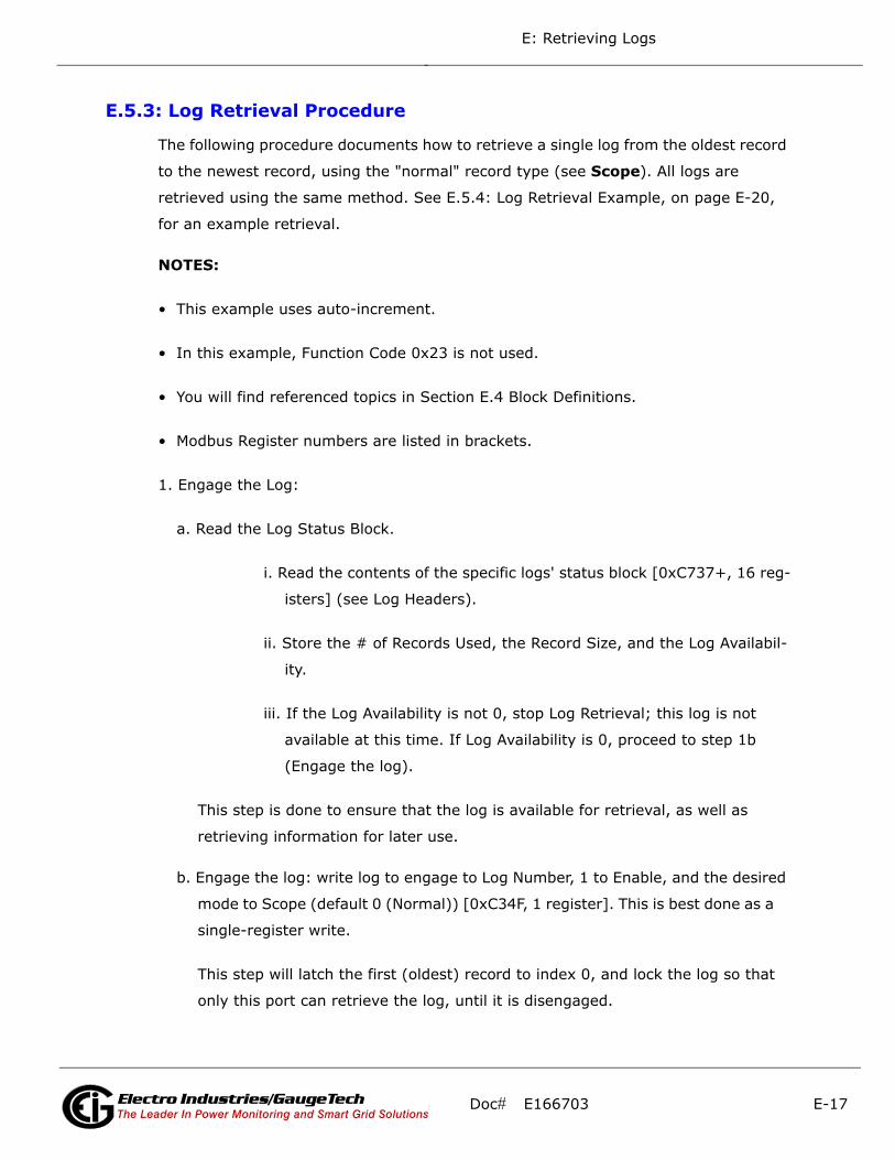
E: Retrieving Logs
E.5.3: Log Retrieval Procedure
The following procedure documents how to retrieve a single log from the oldest record
to the newest record, using the "normal" record type (see Scope). All logs are
retrieved using the same method. See E.5.4: Log Retrieval Example, on page E-20,
for an example retrieval.
NOTES:
• This example uses auto-increment.
• In this example, Function Code 0x23 is not used.
• You will find referenced topics in Section E.4 Block Definitions.
• Modbus Register numbers are listed in brackets.
1. Engage the Log:
a. Read the Log Status Block.
i. Read the contents of the specific logs' status block [0xC737+, 16 reg-
isters] (see Log Headers).
ii. Store the # of Records Used, the Record Size, and the Log Availabil-
ity.
iii. If the Log Availability is not 0, stop Log Retrieval; this log is not
available at this time. If Log Availability is 0, proceed to step 1b
(Engage the log).
This step is done to ensure that the log is available for retrieval, as well as
retrieving information for later use.
b. Engage the log: write log to engage to Log Number, 1 to Enable, and the desired
mode to Scope (default 0 (Normal)) [0xC34F, 1 register]. This is best done as a
single-register write.
This step will latch the first (oldest) record to index 0, and lock the log so that
only this port can retrieve the log, until it is disengaged.
Doc# E166703 E-17Electro Industries/GaugeTechThe Leader In Power Monitoring and Smart Grid SolutionsElectro Industries/GaugeTechThe Leader In Power Monitoring and Smart Grid Solutions

E: Retrieving Logs
c. Verify the log is engaged: read the contents of the specific logs' status block
[0xC737+, 16 registers] again to see if the log is engaged for the current port
(see Log Availability). If the Log is not engaged for the current port, repeat step
1b (Engage the log).
d. Write the retrieval information.
i. Compute the number of records per window, as follows:
RecordsPerWindow = (246 \ RecordSize)
• If using 0x23, set the repeat count to 2-8. Otherwise, set it to 1.
• Since we are starting from the beginning for retrieval, the first
record index is 0.
ii. Write the Records per window, the Number of repeats (1), and
Record Index (0) [0xC350, 3 registers].
This step tells the MP200 unit what data to return in the window.
2. Retrieve the records:
a. Read the record index and window: read the record index, and the data window
[0xC351, 125 registers].
• If the MP200 unit Returns a Slave Busy Exception, repeat the request.
• If the Window Status is 0xFF, repeat the request.
• If the Window Status is 0, go to step 2b (Verify record index).
NOTES:
• We read the index and window in 1 request to minimize communication
time, and to ensure that the record index matches the data in the data
window returned.
• Space in the window after the last specified record (RecordSize x Record-
PerWindow) is padded with 0xFF, and can be safely discarded.
Doc# E166703 E-18Electro Industries/GaugeTechThe Leader In Power Monitoring and Smart Grid SolutionsElectro Industries/GaugeTechThe Leader In Power Monitoring and Smart Grid Solutions
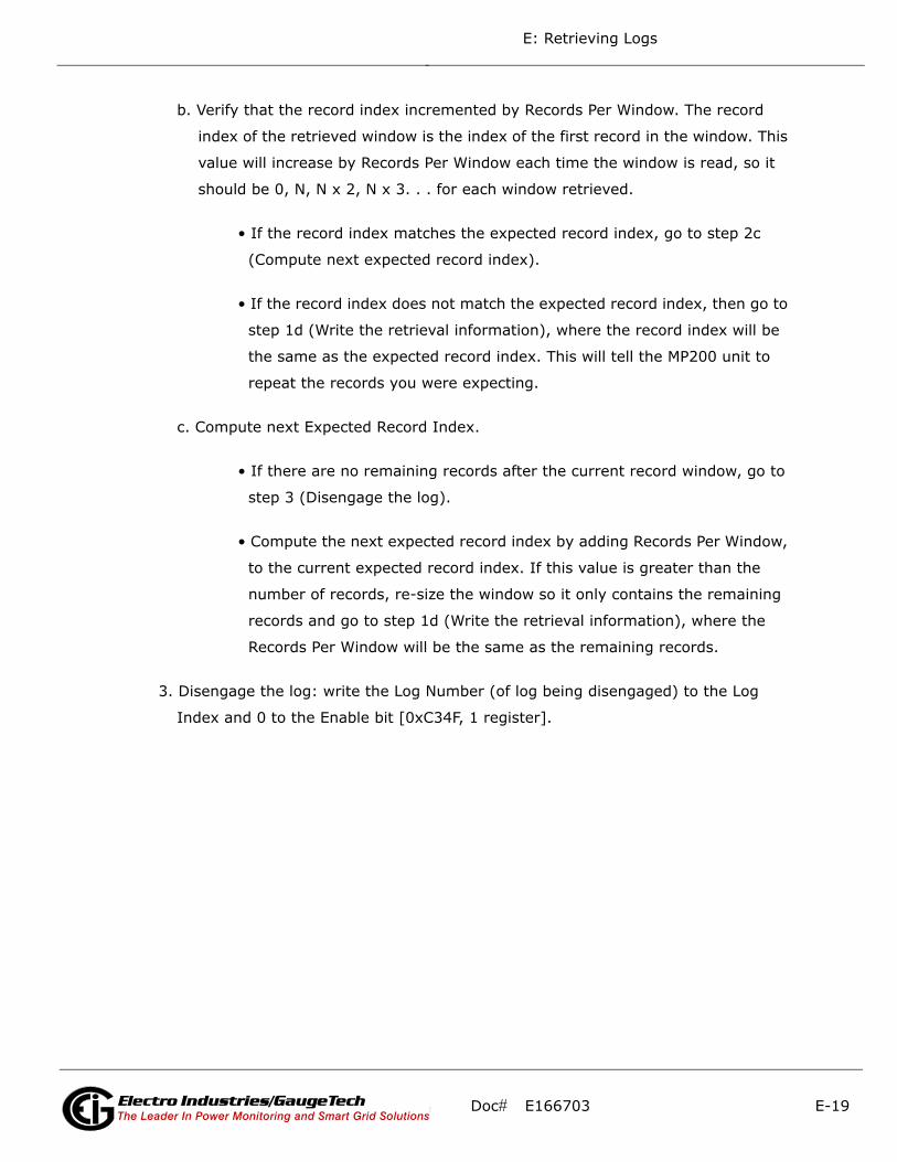
E: Retrieving Logs
b. Verify that the record index incremented by Records Per Window. The record
index of the retrieved window is the index of the first record in the window. This
value will increase by Records Per Window each time the window is read, so it
should be 0, N, N x 2, N x 3. . . for each window retrieved.
• If the record index matches the expected record index, go to step 2c
(Compute next expected record index).
• If the record index does not match the expected record index, then go to
step 1d (Write the retrieval information), where the record index will be
the same as the expected record index. This will tell the MP200 unit to
repeat the records you were expecting.
c. Compute next Expected Record Index.
• If there are no remaining records after the current record window, go to
step 3 (Disengage the log).
• Compute the next expected record index by adding Records Per Window,
to the current expected record index. If this value is greater than the
number of records, re-size the window so it only contains the remaining
records and go to step 1d (Write the retrieval information), where the
Records Per Window will be the same as the remaining records.
3. Disengage the log: write the Log Number (of log being disengaged) to the Log
Index and 0 to the Enable bit [0xC34F, 1 register].
Doc# E166703 E-19Electro Industries/GaugeTechThe Leader In Power Monitoring and Smart Grid SolutionsElectro Industries/GaugeTechThe Leader In Power Monitoring and Smart Grid Solutions

E: Retrieving Logs
E.5.4: Log Retrieval Example
The following example illustrates a log retrieval session. The example makes the
following assumptions:
• Log Retrieved is Historical Log 1 (Log Index 1).
• Auto-Incrementing is used.
• Function Code 0x23 is not used (Repeat Count of 1).
• The Log contains Volts-AN, Volts-BN, Volts-CN (12 bytes).
• 100 Records are available (0-99).
• COM Port 2 (USB) is being used (see Log Availability).
• There are no Errors.
• Retrieval is starting at Record Index 0 (oldest record).
• Protocol used is Modbus ASCII. The checksum is left off for simplicity.
• The MP200 unit is at device address 1.
• No new records are recorded to the log during the log retrieval process.
Doc# E166703 E-20Electro Industries/GaugeTechThe Leader In Power Monitoring and Smart Grid SolutionsElectro Industries/GaugeTechThe Leader In Power Monitoring and Smart Grid Solutions

E: Retrieving Logs
1. Read [0xC747, 16 registers], Historical Log 1 Header Block.
Send: 0103 C747 0010
Command:
Register Address: 0xC747
# Registers: 16
---------------------------------------------------
Receive: 010320 00000100 00000064 0012 0000
0C0717101511 0C0718101511***
0000000000000000
Data:
Max Records: 0x100 = 256 records maximum.
Num Records: 0x64 = 100 records currently logged.
Record Size: 0x12 = 18 bytes per record.
Log Availability: 0x00 = 0, not in use, available for retrieval.
First Timestamp: 0x0C0717101511 = July 23, 2012, 16:21:17
Last Timestamp: 0x0C0717101511 = July 24, 2012, 16:21:17
NOTE: This indicates that Historical Log 1 is available for retrieval.
2. Write 0x0180 -> [0xC34F, 1 register], Log Enable.
Send: 0106 C34F 0180
Command:
Register Address: 0xC34F
# Registers: 1 (Write Single Register Command)
Data:
Log Number: 1 (Historical Log 1)
Doc# E166703 E-21Electro Industries/GaugeTechThe Leader In Power Monitoring and Smart Grid SolutionsElectro Industries/GaugeTechThe Leader In Power Monitoring and Smart Grid Solutions
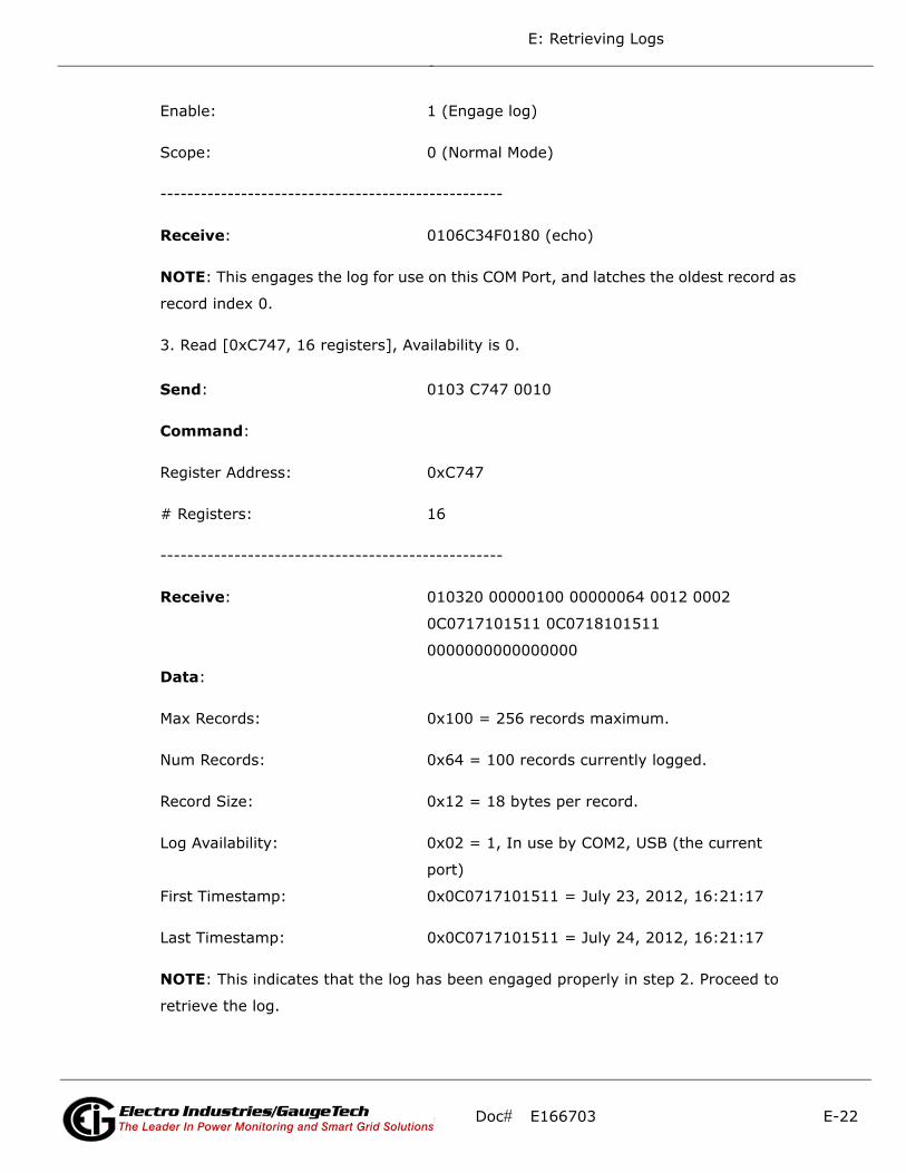
E: Retrieving Logs
Enable: 1 (Engage log)
Scope: 0 (Normal Mode)
---------------------------------------------------
Receive: 0106C34F0180 (echo)
NOTE: This engages the log for use on this COM Port, and latches the oldest record as
record index 0.
3. Read [0xC747, 16 registers], Availability is 0.
Send: 0103 C747 0010
Command:
Register Address: 0xC747
# Registers: 16
---------------------------------------------------
Receive: 010320 00000100 00000064 0012 0002
0C0717101511 0C0718101511
0000000000000000
Data:
Max Records: 0x100 = 256 records maximum.
Num Records: 0x64 = 100 records currently logged.
Record Size: 0x12 = 18 bytes per record.
Log Availability: 0x02 = 1, In use by COM2, USB (the current
port)
First Timestamp: 0x0C0717101511 = July 23, 2012, 16:21:17
Last Timestamp: 0x0C0717101511 = July 24, 2012, 16:21:17
NOTE: This indicates that the log has been engaged properly in step 2. Proceed to
retrieve the log.
Doc# E166703 E-22Electro Industries/GaugeTechThe Leader In Power Monitoring and Smart Grid SolutionsElectro Industries/GaugeTechThe Leader In Power Monitoring and Smart Grid Solutions

E: Retrieving Logs
4. Compute #RecPerWin as (246\18)=13. Write 0x0D01 0000 0000 -> [0xC350, 3
registers] Write Retrieval Info. Set Current Index as 0.
Send: 0110 C350 0003 06 0D01 00 000000
Command:
Register Address: 0xC350
# Registers: 3, 6 bytes
Data:
Records per Window: 13. Since the window is 246 bytes, and the record
is 18 bytes, 246\18 = 13.66, which means that
13 records evenly fit into a single window. This is
234 bytes, which means later on, we only need to
read 234 bytes (117 registers) of the window to
retrieve the records.
# of Repeats: 1. We are using auto-increment (so not 0), but
not function code 0x23.
Window Status: 0 (ignore)
Record Index: 0, start at the first record.
----------------------------------------------------
Receive: 0110C3500003 (command ok)
NOTES:
• This sets up the window for retrieval; now we can start retrieving the records.
• As noted above, we compute the records per window as 246\18 = 13.66, which is
rounded to 13 records per window. This allows the minimum number of requests to
be made to the MP200 unit, which increases retrieval speed.
Doc# E166703 E-23Electro Industries/GaugeTechThe Leader In Power Monitoring and Smart Grid SolutionsElectro Industries/GaugeTechThe Leader In Power Monitoring and Smart Grid Solutions
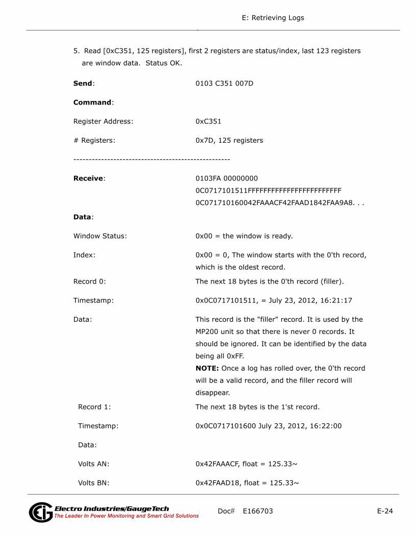
E: Retrieving Logs
5. Read [0xC351, 125 registers], first 2 registers are status/index, last 123 registers
are window data. Status OK.
Send: 0103 C351 007D
Command:
Register Address: 0xC351
# Registers: 0x7D, 125 registers
---------------------------------------------------
Receive: 0103FA 00000000
0C0717101511FFFFFFFFFFFFFFFFFFFFFFFF
0C071710160042FAAACF42FAAD1842FAA9A8. . .
Data:
Window Status: 0x00 = the window is ready.
Index: 0x00 = 0, The window starts with the 0'th record,
which is the oldest record.
Record 0: The next 18 bytes is the 0'th record (filler).
Timestamp: 0x0C0717101511, = July 23, 2012, 16:21:17
Data: This record is the "filler" record. It is used by the
MP200 unit so that there is never 0 records. It
should be ignored. It can be identified by the data
being all 0xFF.
NOTE: Once a log has rolled over, the 0'th record
will be a valid record, and the filler record will
disappear.
Record 1: The next 18 bytes is the 1'st record.
Timestamp: 0x0C0717101600 July 23, 2012, 16:22:00
Data:
Volts AN: 0x42FAAACF, float = 125.33~
Volts BN: 0x42FAAD18, float = 125.33~
Doc# E166703 E-24Electro Industries/GaugeTechThe Leader In Power Monitoring and Smart Grid SolutionsElectro Industries/GaugeTechThe Leader In Power Monitoring and Smart Grid Solutions

E: Retrieving Logs
Volts CN: 0x42FAA9A8, float = 125.33~
. . . 13 records
NOTES:
• This retrieves the actual window. Repeat this command as many times as necessary
to retrieve all of the records when auto-increment is enabled.
• Note the filler record. When a log is reset (cleared) in the MP200 unit, the MP200
unit always adds a first "filler" record, so that there is always at least 1 record in
the log. This "filler" record can be identified by the data being all 0xFF, and it being
index 0. If a record has all 0xFF for data, the timestamp is valid, and the index is
NOT 0, then the record is legitimate.
• When the "filler" record is logged, its timestamp may not be "on the interval." The
next record taken will be on the next "proper interval," adjusted to the hour. For
example, if the interval is 1 minute, the first "real" record will be taken on the next
minute (no seconds). If the interval is 15 minutes, the next record will be taken at
:15, :30, :45, or :00 - whichever of those values is next in sequence.
6. Compare the index with Current Index.
NOTES:
• The Current Index is 0 at this point, and the record index retrieved in step 5 is 0:
thus we go to step 8.
• If the Current Index and the record index do not match, go to step 7. The data that
was received in the window may be invalid, and should be discarded.
7. Write the Current Index to [0xC351, 2 registers].
Send: 0110 C351 0002 04 00 00000D
Command:
Register Address: 0xC351
# Registers: 2, 4 bytes
Doc# E166703 E-25Electro Industries/GaugeTechThe Leader In Power Monitoring and Smart Grid SolutionsElectro Industries/GaugeTechThe Leader In Power Monitoring and Smart Grid Solutions
E: Retrieving Logs
Data:
Window Status: 0 (ignore)
Record Index: 0x0D = 13, start at the 14th record.
----------------------------------------------------
Receive: 0110C3510002 (command ok)
NOTES:
• This step manually sets the record index, and is primarily used when an out-of-
order record index is returned on a read (step 6).
• The example assumes that the second window retrieval failed somehow, and we
need to recover by requesting the records starting at index 13 again.
8. For each record in the retrieved window, copy and save the data for later interpre-
tation.
9. Increment Current Index by RecordsPerWindow.
NOTES:
• This is the step that determines how much more of the log we need to retrieve.
• On the first N passes, Records Per Window should be 13 (as computed in step 4),
and the current index should be a multiple of that (0, 13, 26, . . .). This amount will
decrease when we reach the end (see step 10).
• If the current index is greater than or equal to the number of records (in this case
100), then all records have been retrieved; go to step 12. Otherwise, go to step 10
to check if we are nearing the end of the records.
10. If number records - current index < RecordsPerWindow, decrease to match.
NOTES:
• Here we bounds-check the current index, so we don't exceed the records available.
Doc# E166703 E-26Electro Industries/GaugeTechThe Leader In Power Monitoring and Smart Grid SolutionsElectro Industries/GaugeTechThe Leader In Power Monitoring and Smart Grid Solutions

E: Retrieving Logs
• If the number of remaining records (#records - current index) is less than the
Records per Window, then the next window is the last, and contains less than a full
window of records. Make records per window equal to remaining records
(#records-current index). In this example, this occurs when current index is 91
(the 8'th window). There are now 9 records available (100-91), so make Records
per Window equal 9.
11. Repeat steps 5 through 10.
NOTES:
• Go back to step 5, where a couple of values have changed.
Pass CurIndex FirstRecIndex RecPerWindow
0 0 0 13
1 13 13 13
2 26 26 13
3 39 39 13
4 52 52 13
5 65 65 13
6 78 78 13
7 91 91 9
8 100 ------ -------
• At pass 8, since Current Index is equal to the number of records (100), log retrieval
should stop; go to step 12 (see step 9 Notes).
12. No more records available, clean up.
Doc# E166703 E-27Electro Industries/GaugeTechThe Leader In Power Monitoring and Smart Grid SolutionsElectro Industries/GaugeTechThe Leader In Power Monitoring and Smart Grid Solutions

E: Retrieving Logs
13. Write 0x0000 -> [0xC34F, 1 register], disengage the log.
Send: 0106 C34F 0000
Command:
Register Address: 0xC34F
# Registers: 1 (Write Single Register Command)
Data:
Log Number: 0 (ignore)
Enable: 0 (Disengage log)
Scope: 0 (ignore)
----------------------------------------------------
Receive: 0106C34F0000 (echo)
NOTES:
• This disengages the log, allowing it to be retrieved by other COM ports.
• The log will automatically disengage if no log retrieval action is taken for 5 minutes.
Doc# E166703 E-28Electro Industries/GaugeTechThe Leader In Power Monitoring and Smart Grid SolutionsElectro Industries/GaugeTechThe Leader In Power Monitoring and Smart Grid Solutions
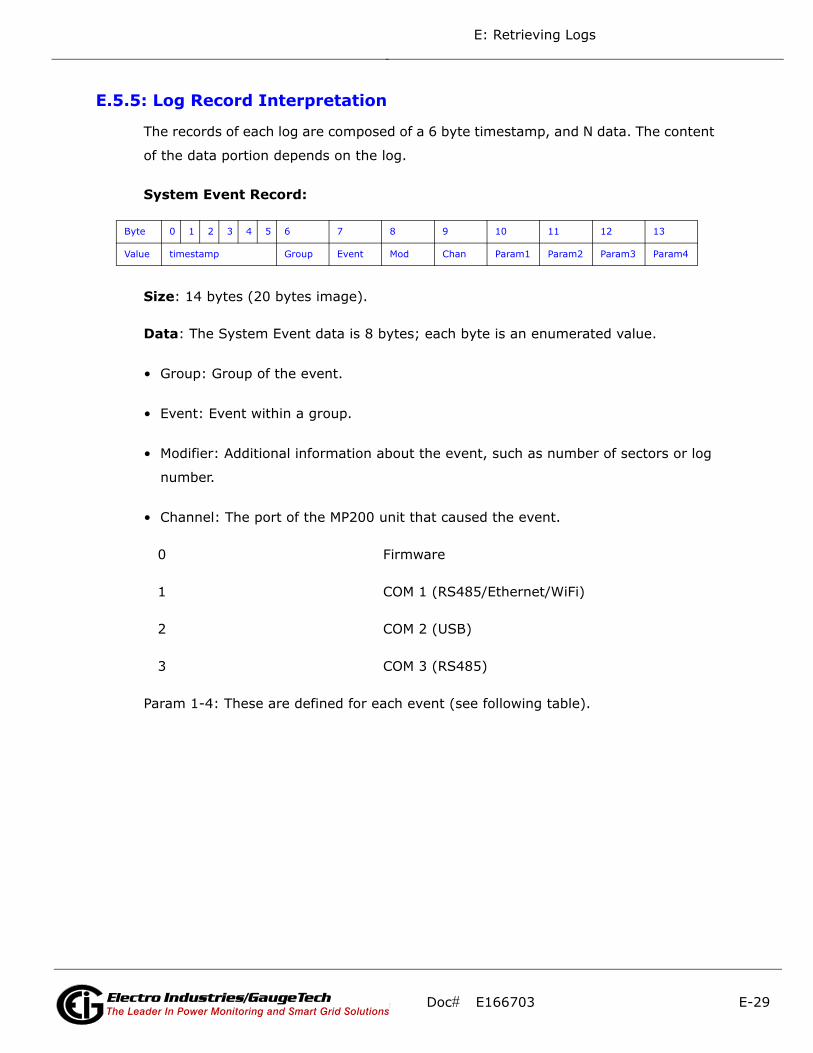
E: Retrieving Logs
E.5.5: Log Record Interpretation
The records of each log are composed of a 6 byte timestamp, and N data. The content
of the data portion depends on the log.
System Event Record:
Size: 14 bytes (20 bytes image).
Data: The System Event data is 8 bytes; each byte is an enumerated value.
• Group: Group of the event.
• Event: Event within a group.
• Modifier: Additional information about the event, such as number of sectors or log
number.
• Channel: The port of the MP200 unit that caused the event.
0 Firmware
1 COM 1 (RS485/Ethernet/WiFi)
2 COM 2 (USB)
3 COM 3 (RS485)
Param 1-4: These are defined for each event (see following table).
Byte 0 1 2 3 4 5 6 7 8 9 10 11 12 13
Value timestamp Group Event Mod Chan Param1 Param2 Param3 Param4
Doc# E166703 E-29Electro Industries/GaugeTechThe Leader In Power Monitoring and Smart Grid SolutionsElectro Industries/GaugeTechThe Leader In Power Monitoring and Smart Grid Solutions
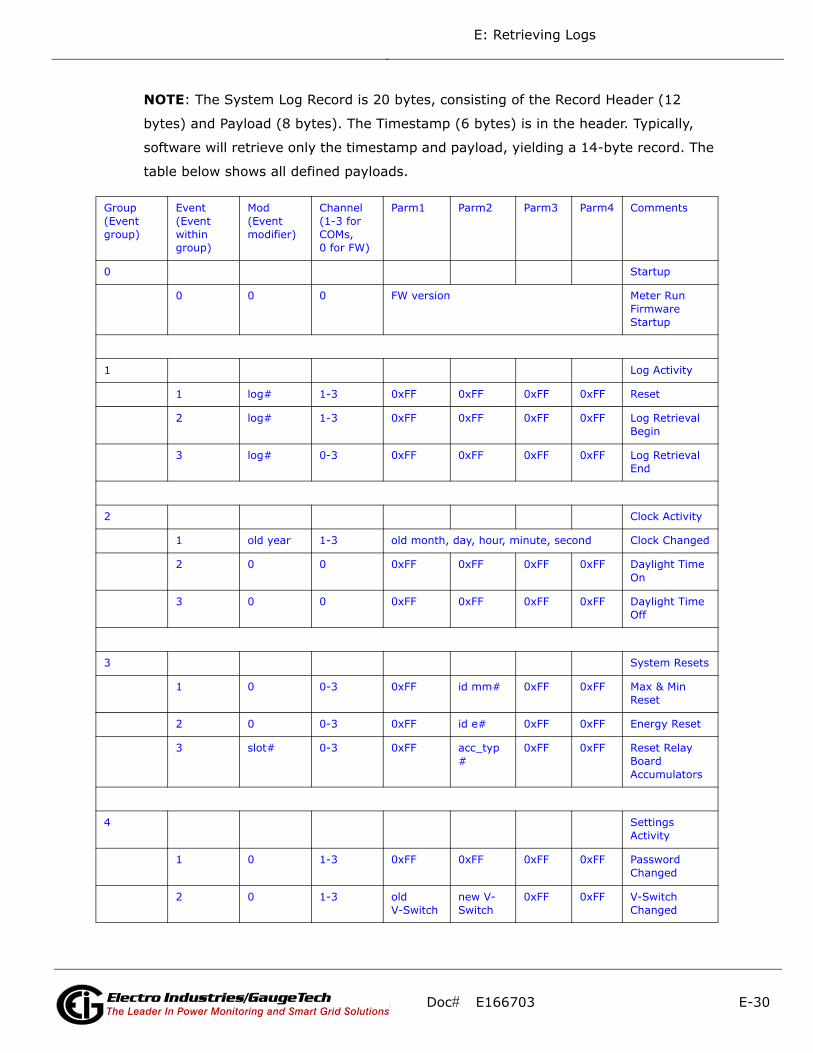
E: Retrieving Logs
NOTE: The System Log Record is 20 bytes, consisting of the Record Header (12
bytes) and Payload (8 bytes). The Timestamp (6 bytes) is in the header. Typically,
software will retrieve only the timestamp and payload, yielding a 14-byte record. The
table below shows all defined payloads.
Group (Event group)
Event (Event within group)
Mod (Event modifier)
Channel (1-3 for COMs, 0 for FW)
Parm1 Parm2 Parm3 Parm4 Comments
0 Startup
0 0 0 FW version Meter Run Firmware Startup
1 Log Activity
1 log# 1-3 0xFF 0xFF 0xFF 0xFF Reset
2 log# 1-3 0xFF 0xFF 0xFF 0xFF Log Retrieval Begin
3 log# 0-3 0xFF 0xFF 0xFF 0xFF Log Retrieval End
2 Clock Activity
1 old year 1-3 old month, day, hour, minute, second Clock Changed
2 0 0 0xFF 0xFF 0xFF 0xFF Daylight Time On
3 0 0 0xFF 0xFF 0xFF 0xFF Daylight Time Off
3 System Resets
1 0 0-3 0xFF id mm# 0xFF 0xFF Max & Min Reset
2 0 0-3 0xFF id e# 0xFF 0xFF Energy Reset
3 slot# 0-3 0xFF acc_typ#
0xFF 0xFF Reset Relay Board Accumulators
4 Settings Activity
1 0 1-3 0xFF 0xFF 0xFF 0xFF Password Changed
2 0 1-3 old V-Switch
new V-Switch
0xFF 0xFF V-Switch Changed
Doc# E166703 E-30Electro Industries/GaugeTechThe Leader In Power Monitoring and Smart Grid SolutionsElectro Industries/GaugeTechThe Leader In Power Monitoring and Smart Grid Solutions

E: Retrieving Logs
NOTES:
• log# values: 0 = system log, 1-3 = historical logs, 4 = alarm log, 5 = I/O change
log
• sector# values: 0-128
• slot# values: 1
3 0 1-3 0xFF 0xFF 0xFF 0xFF Programma-ble Settings Changed
4 0 1-3 0xFF 0xFF 0xFF 0xFF Measurement Stopped
5 Boot Activity
1 0 1-3 FW version Exit to Boot
6 Error Report-ing & Recovery
4 log # 0 0xFF 0xFF 0xFF 0xFF Log Babbling Detected
5 log # 0 # records discarded time in seconds Babbling Log Periodic Summary
6 log # 0 # records discarded time in seconds Log Babbling End Detected
7 sector# 0 error count stimulus Flash Sector Error
8 0 0 0xFF 0xFF 0xFF 0xFF Flash Error Counters Reset
9 0 0 0xFF 0xFF 0xFF 0xFF Flash Job Queue Overflow
0x88
1 sector# 0 log # 0xFF error count acquire sector
2 sector# 0 log # 0xFF 0xFF 0xFF release sector
3 sector# 0 erase count erase sector
4 log# 0 0xFF 0xFF 0xFF 0xFF write log start record
Doc# E166703 E-31Electro Industries/GaugeTechThe Leader In Power Monitoring and Smart Grid SolutionsElectro Industries/GaugeTechThe Leader In Power Monitoring and Smart Grid Solutions
E: Retrieving Logs
• The clock changed event shows the clock value just before the change in the Mod
and Parm bytes. Parms are bit-mapped:
• b31 - b28 month
• b27 - b23 day
• b22 daylight savings time flag
• b20 - b16 hour
• b13 - b8 minute
• b5 - b0 second
• unused bits are always 0
• Stimulus for a flash sector error indicates what the flash was doing when the error
occurred: 1 = acquire sector, 2 = startup, 3 = empty sector, 4 = release sector, 5 =
write data.
• Flash error counters are reset to zero in the unlikely event that both copies in
EEPROM are corrupted.
• The flash job queue is flushed (and log records are lost) in the unlikely event that
the queue runs out of space.
• A "babbling log" is one that is saving records faster than the MP200 unit can handle
long term. When babbling is detected, the log is frozen and no records are
appended until babbling ceases. For as long as babbling persists, a summary of
records discarded is logged every 60 minutes. Normal logging resumes when there
have been no new append attempts for 30 seconds. Onset of babbling occurs when
a log fills a flash sector in less than an hour (applies only to Alarm, I/O Change, and
Historical logs), when the log fills, or when a log grows so far beyond its normal
bounds that it is in danger of crashing the system. This applies to all logs except
the System log, which does not babble. It is possible for the other logs during an
extended log retrieval session.
• Logging of diagnostic records may be suppressed via a bit in programmable
settings.
Doc# E166703 E-32Electro Industries/GaugeTechThe Leader In Power Monitoring and Smart Grid SolutionsElectro Industries/GaugeTechThe Leader In Power Monitoring and Smart Grid Solutions
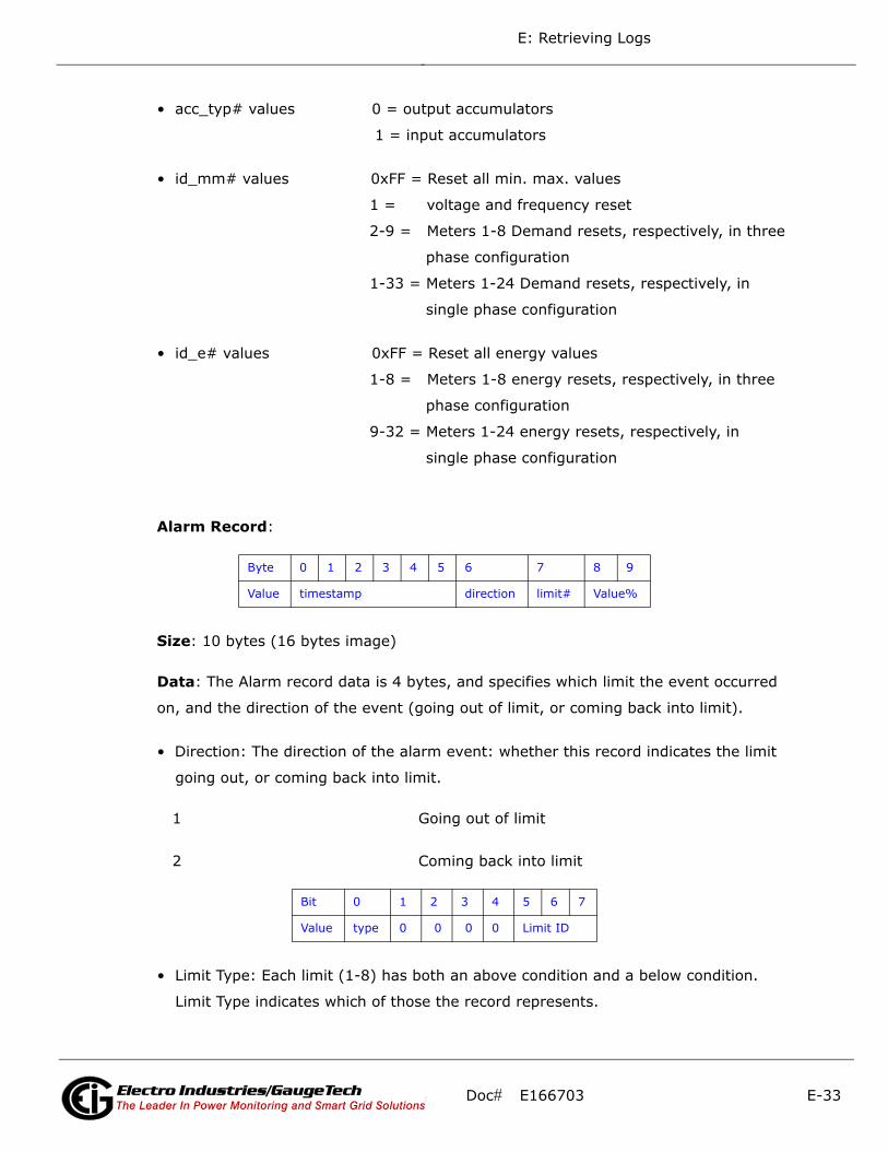
E: Retrieving Logs
• acc_typ# values 0 = output accumulators
1 = input accumulators
• id_mm# values 0xFF = Reset all min. max. values
1 = voltage and frequency reset
2-9 = Meters 1-8 Demand resets, respectively, in three
phase configuration
1-33 = Meters 1-24 Demand resets, respectively, in
single phase configuration
• id_e# values 0xFF = Reset all energy values
1-8 = Meters 1-8 energy resets, respectively, in three
phase configuration
9-32 = Meters 1-24 energy resets, respectively, in
single phase configuration
Alarm Record:
Size: 10 bytes (16 bytes image)
Data: The Alarm record data is 4 bytes, and specifies which limit the event occurred
on, and the direction of the event (going out of limit, or coming back into limit).
• Direction: The direction of the alarm event: whether this record indicates the limit
going out, or coming back into limit.
1 Going out of limit
2 Coming back into limit
• Limit Type: Each limit (1-8) has both an above condition and a below condition.
Limit Type indicates which of those the record represents.
Byte 0 1 2 3 4 5 6 7 8 9
Value timestamp direction limit# Value%
Bit 0 1 2 3 4 5 6 7
Value type 0 0 0 0 Limit ID
Doc# E166703 E-33Electro Industries/GaugeTechThe Leader In Power Monitoring and Smart Grid SolutionsElectro Industries/GaugeTechThe Leader In Power Monitoring and Smart Grid Solutions

E: Retrieving Logs
0 High Limit
1 Low Limit
• Limit ID: The specific limit this record represents. A value in the range 0-7, Limit ID
represents Limits 1-8. The specific details for this limit are stored in the program-
mable settings.
• Value: Depends on the Direction:
• If the record is "Going out of limit," this is the value of the limit when the "Out"
condition occurred.
• If the record is "Coming back into limit," this is the "worst" value of the limit dur-
ing the period of being "out": for High (above) limits, this is the highest value
during the "out" period; for Low (below) limits, this is the lowest value during
the “out" period.
Interpretation of Alarm Data:
To interpret the data from the alarm records, you need the limit data from the
Programmable Settings [0x754B, 40 registers].
There are 8 limits, each with an Above Setpoint, and a Below Setpoint. Each setpoint
also has a threshold (hysteresis), which is the value at which the limit returns "into"
limit after the setpoint has been exceeded. This prevents "babbling" limits, which can
be caused by the limit value fluttering over the setpoint, causing it to go in and out of
limit continuously.
• Identifier: The first modbus register of the value that is being watched by this limit.
While any modbus register is valid, only values that can have a Full Scale will be
used by the MP200 unit.
• Above Setpoint: The percent of the Full Scale above which the value for this limit
will be considered "out.”
Byte 0 1 2 3 4 5 6 7 8 9
Value Identifier Above Setpoint Above Hyst. Below Setpoint Below Hyst.
Doc# E166703 E-34Electro Industries/GaugeTechThe Leader In Power Monitoring and Smart Grid SolutionsElectro Industries/GaugeTechThe Leader In Power Monitoring and Smart Grid Solutions

E: Retrieving Logs
• Valid in the range of -200.0% to +200.0%
• Stored as an integer with 0.1 resolution. (Multiply % by 10 to get the integer,
divide integer by 10 to get %. For example, 105.2% = 1052.)
• Above Hysteresis: The percent of the Full Scale below which the limit will return
"into" limit, if it is out. If this value is above the Above Setpoint, this Above limit will
be disabled.
• Valid in the range of -200.0% to +200.0%.
• Stored as an integer with 0.1 resolution. (Multiply % by 10 to get the integer,
divide integer by 10 to get %. For example, 104.1% = 1041.)
• Below Setpoint: The percent of the Full Scale below which the value for this limit
will be considered "out."
• Valid in the range of -200.0% to +200.0%.
• Stored as an integer with 0.1 resolution. (Multiply % by 10 to get the integer,
divide integer by 10 to get %. For example, 93.5% = 935.)
• Below Hysteresis: The percent of the Full Scale above which the limit will return
"into" limit, if it is out. If this value is below the Below Setpoint, this Below limit will
be disabled.
• Valid in the range of -200.0% to +200.0%.
• Stored as an integer with 0.1 resolution. (Multiply % by 10 to get the integer,
divide integer by 10 to get %. For example, 94.9% = 949.)
NOTES:
• The Full Scale is the "nominal" value for each of the different types of readings. To
compute the Full Scale, use the following formulas:
Current [CT Numerator]
Voltage [PT Numerator]
Power 3-Phase (WYE) [CT Numerator] x [PT Numerator] x 3
Doc# E166703 E-35Electro Industries/GaugeTechThe Leader In Power Monitoring and Smart Grid SolutionsElectro Industries/GaugeTechThe Leader In Power Monitoring and Smart Grid Solutions

E: Retrieving Logs
Power 3-Phase (Delta) [CT Numerator] x [PT Numerator] x 3 x sqrt(3)
Power Single Phase (WYE) [CT Numerator] x [PT Numerator]
Power Single Phase (Delta) [CT Numerator] x [PT Numerator] x sqrt(3)
Frequency (Calibrated at 60 Hz) 60
Frequency (Calibrated at 50 Hz) 50
Power Factor 1.0
Angles 180°
• To interpret a limit alarm fully, you need both the start and end record (for dura-
tion).
• There are a few special conditions related to limits:
• When the MP200 unit powers up, it detects limits from scratch. This means that
multiple "out of limit" records can be in sequence with no "into limit" records.
Cross- reference the System Events for Power Up events.
• This also means that if a limit is "out," and it goes back in during the
power off condition, no "into limit" record will be recorded.
• The "worst" value of the "into limit" record follows the above restrictions;
it only represents the values since power up. Any values before the power
up condition are lost.
Doc# E166703 E-36Electro Industries/GaugeTechThe Leader In Power Monitoring and Smart Grid SolutionsElectro Industries/GaugeTechThe Leader In Power Monitoring and Smart Grid Solutions
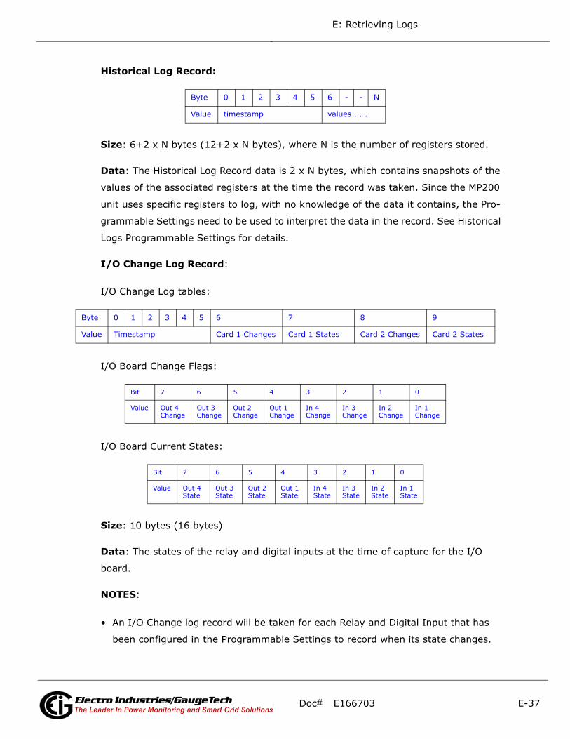
E: Retrieving Logs
Historical Log Record:
Size: 6+2 x N bytes (12+2 x N bytes), where N is the number of registers stored.
Data: The Historical Log Record data is 2 x N bytes, which contains snapshots of the
values of the associated registers at the time the record was taken. Since the MP200
unit uses specific registers to log, with no knowledge of the data it contains, the Pro-
grammable Settings need to be used to interpret the data in the record. See Historical
Logs Programmable Settings for details.
I/O Change Log Record:
I/O Change Log tables:
I/O Board Change Flags:
I/O Board Current States:
Size: 10 bytes (16 bytes)
Data: The states of the relay and digital inputs at the time of capture for the I/O
board.
NOTES:
• An I/O Change log record will be taken for each Relay and Digital Input that has
been configured in the Programmable Settings to record when its state changes.
Byte 0 1 2 3 4 5 6 - - N
Value timestamp values . . .
Byte 0 1 2 3 4 5 6 7 8 9
Value Timestamp Card 1 Changes Card 1 States Card 2 Changes Card 2 States
Bit 7 6 5 4 3 2 1 0
Value Out 4 Change
Out 3 Change
Out 2 Change
Out 1 Change
In 4 Change
In 3 Change
In 2 Change
In 1 Change
Bit 7 6 5 4 3 2 1 0
Value Out 4 State
Out 3 State
Out 2 State
Out 1 State
In 4 State
In 3 State
In 2 State
In 1 State
Doc# E166703 E-37Electro Industries/GaugeTechThe Leader In Power Monitoring and Smart Grid SolutionsElectro Industries/GaugeTechThe Leader In Power Monitoring and Smart Grid Solutions

E: Retrieving Logs
• When any one configured Relay or Digital Input changes, the values of all Relays
and Digital Inputs are recorded, even if they are not so configured.
E.6: Examples
Log Retrieval Section:
send: 01 03 75 51 00 08 - MP200 Unit Designation
recv: 01 03 10 4D 79 43 50 55 20 20 20 20 20 20 20 20 20 20 20 DE
send: 01 03 C7 47 00 10 - Historical Log 1 status block
recv: 01 03 20 00 05 7F DF 00 00 00 70 00 22 00 00 0D 01 15 10 10 56 0D 01
15 12 0C 00 00 00 00 00 00 00 00 00 0D
send: 01 03 79 17 00 40 - Historical Log 1 PS settings
recv: 01 03 80 0E 37 00 01 03 E7 03 E8 03 E9 03 EA 03 EB 03 EC 03 ED 03 EE
03 EF 03 F0 03 F1 03 F2 03 F3 03 F4 00 00 00 00 00 00 00 00 00 00 00
00 00 00 00 00 00 00 00 00 00 00 00 00 00 00 00 00 00 00 00 00 00 00
00 00 00 00 00 00 00 00 00 00 00 00 00 00 00 00 00 00 00 00 00 00 00 00
00 00 00 00 00 00 00 00 00 00 00 00 00 00 00 00 00 00 00 00 00 00 00 00
00 00 00 00 00 00 00 00 00 00 00 00 00 00 0F
send: 01 03 79 57 00 40 - ""
recv: 01 03 80 00 00 00 00 00 00 00 00 00 00 00 00 00 00 00 00 00 00 00 00 00
00 00 00 00 00 00 00 00 00 00 00 00 00 00 00 00 00 00 00 00 00 00 00 00
00 00 00 00 00 00 00 00 00 00 00 00 00 00 00 00 00 00 00 00 00 00 00 00
00 00 00 00 00 00 00 00 00 00 00 00 00 00 00 00 00 00 00 00 00 00 00 00
00 00 00 00 00 00 00 00 00 00 00 00 00 00 00 00 00 34 34 34 34 34 34 34
00 00 00 00 00 00 00 00 00 00 00 10
send: 01 03 75 4D 00 01 - Energy PS settings
recv: 01 03 02 20 30 AA
send: 01 03 0D C9 00 01 - Connected Port ID
recv: 01 03 02 00 02 F8
send: 01 03 C7 47 00 10 - Historical Log 1 status block
recv: 01 03 20 00 05 7F DF 00 00 00 A5 00 22 00 00 0D 01 15 10 10 56 0D 01
15 13 05 00 00 00 00 00 00 00 00 00 DE
Doc# E166703 E-38Electro Industries/GaugeTechThe Leader In Power Monitoring and Smart Grid SolutionsElectro Industries/GaugeTechThe Leader In Power Monitoring and Smart Grid Solutions

E: Retrieving Logs
send: 01 03 C3 4F 00 01 - Log Retrieval header
recv: 01 03 02 FF FF FC
send: 01 06 C3 4F 01 80 - Engage the log
recv: 01 06 C3 4F 01 80 66
send: 01 03 C7 47 00 10 - Historical Log 1 status block
recv: 01 03 20 00 05 7F DF 00 00 01 3D 00 22 00 00 0D 01 15 10 10 56 0D 01
16 0B 39 00 00 00 00 00 00 00 00 00 18
send: 01 10 C3 51 00 02 04 00 00 00 01 - Set the retrieval index
recv: 01 10 C3 51 00 02 D9
send: 01 23 C3 51 00 79 04 00 00 - Read the first Window
recv: 01 23 03 C8 00 00 00 01 0D 01 17 0D 17 00 00 00 00 00 00 00 00 00 00
00 00 00 00 00 00 00 00 00 00 00 00 00 00 00 00 00 00 00 0D 01 17 0D
18 00 00 00 00 00 00 00 00 00 00 00 00 00 00 00 00 00 00 00 00 00 00 00
00 00 00 00 00 00 0D 01 1B 00 00 00 00 00 00 00 00 00 00 00 00 00 00
00 00 00 00 00 00 00 00 00 00 00 00 00 00 00 0D 01 17 0D 1C 00 00 00
00 00 00 00 00 00 00 00 00 00 00 00 00 00 00 00 00 00 00 00 00 00 00 00
00 00 0D 01 17 0D 1D 00 00 00 00 00 00 00 00 00 00 00 00 00 00 00 00
00 00 00 00 00 00 00 00 00 00 00 00 00 0D 01 17 0D 1E 00 00 00 00 00
00 00 00 00 00 00 00 00 00 00 00 00 00 00 00 00 00 00 00 00 00 00 00 00
0D 01 17 0D 1F 00 00 00 00 00 00 00 00 00 00 00 00 00 00 00 00 00 00
00 00 00 00 00 00 00 00 00 00 00 0D 01 01 00 00 03 17 0D 19 00 00 00
00 00 00 00 00 00 00 00 00 00 00 00 00 00 00 00 00 00 00 00 00 00 00 00
00 00 0D 01 17 0D 1A 00 00 00 00 00 00 00 00 00 00 00 00 00 00 00 00
00 00 00 00 00 00 00 00 00 00 00 00 00 0D 01 17 0D 00 00 00 00 00 00
00 00 00 00 00 00 00 00 00 00 00 00 00 00 00 00 00 00 00 00 00 00 0D 01
17 0D 1E 00 00 00 00 00 00 00 00 00 00 00 00 00 00 00 00 00 00 00 00
00 00 00 00 00 00 00 00 00 0D 01 17 0D 1F 00 00 00 00 00 00 00 00 00
00 00 00 00 00 00 00 00 00 00 00 00 00 00 00 00 00 00 00 00 0D 01 17
0D 20 00 00 00 00 00 00 00 00 00 00 00 00 00 00 00 00 00 00 00 00 00 00
00 00 00 00 00 00 00 0D 01 17 0D 21 00 00 00 00 00 00 00 00 00 00 00
00 00 00 00 00 00 00 00 00 00 00 00 00 00 00 00 00 00 0D 01 17 0D 02
00 00 05 1B 00 00 00 00 00 00 00 00 00 00 00 00 00 00 00 00 00 00 00 00
00 00 00 00 00 00 00 00 00 0D 01 17 0D 1C 00 00 00 00 00 00 00 00 00
00 00 00 00 00 00 00 00 00 00 00 00 00 00 00 00 00 00 00 00 0D 01 17
Doc# E166703 E-39Electro Industries/GaugeTechThe Leader In Power Monitoring and Smart Grid SolutionsElectro Industries/GaugeTechThe Leader In Power Monitoring and Smart Grid Solutions
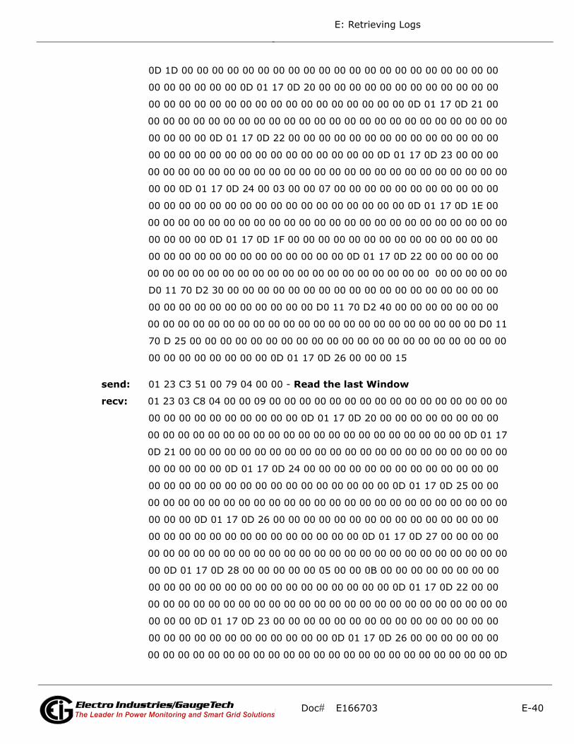
E: Retrieving Logs
0D 1D 00 00 00 00 00 00 00 00 00 00 00 00 00 00 00 00 00 00 00 00 00
00 00 00 00 00 00 0D 01 17 0D 20 00 00 00 00 00 00 00 00 00 00 00 00
00 00 00 00 00 00 00 00 00 00 00 00 00 00 00 00 00 0D 01 17 0D 21 00
00 00 00 00 00 00 00 00 00 00 00 00 00 00 00 00 00 00 00 00 00 00 00 00
00 00 00 00 0D 01 17 0D 22 00 00 00 00 00 00 00 00 00 00 00 00 00 00
00 00 00 00 00 00 00 00 00 00 00 00 00 00 00 0D 01 17 0D 23 00 00 00
00 00 00 00 00 00 00 00 00 00 00 00 00 00 00 00 00 00 00 00 00 00 00 00
00 00 0D 01 17 0D 24 00 03 00 00 07 00 00 00 00 00 00 00 00 00 00 00
00 00 00 00 00 00 00 00 00 00 00 00 00 00 00 00 00 0D 01 17 0D 1E 00
00 00 00 00 00 00 00 00 00 00 00 00 00 00 00 00 00 00 00 00 00 00 00 00
00 00 00 00 0D 01 17 0D 1F 00 00 00 00 00 00 00 00 00 00 00 00 00 00
00 00 00 00 00 00 00 00 00 00 00 00 00 0D 01 17 0D 22 00 00 00 00 00
00 00 00 00 00 00 00 00 00 00 00 00 00 00 00 00 00 00 00 00 00 00 00 00
D0 11 70 D2 30 00 00 00 00 00 00 00 00 00 00 00 00 00 00 00 00 00 00
00 00 00 00 00 00 00 00 00 00 00 D0 11 70 D2 40 00 00 00 00 00 00 00
00 00 00 00 00 00 00 00 00 00 00 00 00 00 00 00 00 00 00 00 00 00 D0 11
70 D 25 00 00 00 00 00 00 00 00 00 00 00 00 00 00 00 00 00 00 00 00 00
00 00 00 00 00 00 00 00 0D 01 17 0D 26 00 00 00 15
send: 01 23 C3 51 00 79 04 00 00 - Read the last Window
recv: 01 23 03 C8 04 00 00 09 00 00 00 00 00 00 00 00 00 00 00 00 00 00 00 00
00 00 00 00 00 00 00 00 00 00 0D 01 17 0D 20 00 00 00 00 00 00 00 00
00 00 00 00 00 00 00 00 00 00 00 00 00 00 00 00 00 00 00 00 00 0D 01 17
0D 21 00 00 00 00 00 00 00 00 00 00 00 00 00 00 00 00 00 00 00 00 00 00
00 00 00 00 00 0D 01 17 0D 24 00 00 00 00 00 00 00 00 00 00 00 00 00
00 00 00 00 00 00 00 00 00 00 00 00 00 00 00 00 0D 01 17 0D 25 00 00
00 00 00 00 00 00 00 00 00 00 00 00 00 00 00 00 00 00 00 00 00 00 00 00
00 00 00 0D 01 17 0D 26 00 00 00 00 00 00 00 00 00 00 00 00 00 00 00
00 00 00 00 00 00 00 00 00 00 00 00 00 00 0D 01 17 0D 27 00 00 00 00
00 00 00 00 00 00 00 00 00 00 00 00 00 00 00 00 00 00 00 00 00 00 00 00
00 0D 01 17 0D 28 00 00 00 00 00 05 00 00 0B 00 00 00 00 00 00 00 00
00 00 00 00 00 00 00 00 00 00 00 00 00 00 00 00 0D 01 17 0D 22 00 00
00 00 00 00 00 00 00 00 00 00 00 00 00 00 00 00 00 00 00 00 00 00 00 00
00 00 00 0D 01 17 0D 23 00 00 00 00 00 00 00 00 00 00 00 00 00 00 00
00 00 00 00 00 00 00 00 00 00 00 00 0D 01 17 0D 26 00 00 00 00 00 00
00 00 00 00 00 00 00 00 00 00 00 00 00 00 00 00 00 00 00 00 00 00 00 0D
Doc# E166703 E-40Electro Industries/GaugeTechThe Leader In Power Monitoring and Smart Grid SolutionsElectro Industries/GaugeTechThe Leader In Power Monitoring and Smart Grid Solutions
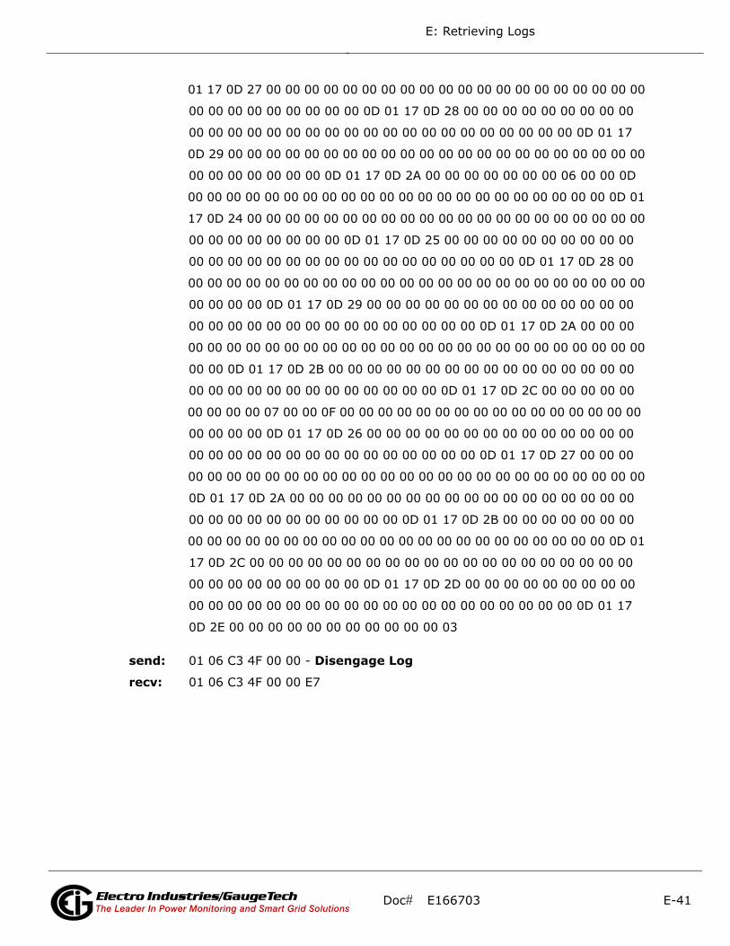
E: Retrieving Logs
01 17 0D 27 00 00 00 00 00 00 00 00 00 00 00 00 00 00 00 00 00 00 00 00
00 00 00 00 00 00 00 00 00 0D 01 17 0D 28 00 00 00 00 00 00 00 00 00
00 00 00 00 00 00 00 00 00 00 00 00 00 00 00 00 00 00 00 00 0D 01 17
0D 29 00 00 00 00 00 00 00 00 00 00 00 00 00 00 00 00 00 00 00 00 00 00
00 00 00 00 00 00 00 0D 01 17 0D 2A 00 00 00 00 00 00 00 06 00 00 0D
00 00 00 00 00 00 00 00 00 00 00 00 00 00 00 00 00 00 00 00 00 00 0D 01
17 0D 24 00 00 00 00 00 00 00 00 00 00 00 00 00 00 00 00 00 00 00 00 00
00 00 00 00 00 00 00 00 0D 01 17 0D 25 00 00 00 00 00 00 00 00 00 00
00 00 00 00 00 00 00 00 00 00 00 00 00 00 00 00 00 0D 01 17 0D 28 00
00 00 00 00 00 00 00 00 00 00 00 00 00 00 00 00 00 00 00 00 00 00 00 00
00 00 00 00 0D 01 17 0D 29 00 00 00 00 00 00 00 00 00 00 00 00 00 00
00 00 00 00 00 00 00 00 00 00 00 00 00 00 00 0D 01 17 0D 2A 00 00 00
00 00 00 00 00 00 00 00 00 00 00 00 00 00 00 00 00 00 00 00 00 00 00 00
00 00 0D 01 17 0D 2B 00 00 00 00 00 00 00 00 00 00 00 00 00 00 00 00
00 00 00 00 00 00 00 00 00 00 00 00 00 0D 01 17 0D 2C 00 00 00 00 00
00 00 00 00 07 00 00 0F 00 00 00 00 00 00 00 00 00 00 00 00 00 00 00 00
00 00 00 00 0D 01 17 0D 26 00 00 00 00 00 00 00 00 00 00 00 00 00 00
00 00 00 00 00 00 00 00 00 00 00 00 00 00 00 0D 01 17 0D 27 00 00 00
00 00 00 00 00 00 00 00 00 00 00 00 00 00 00 00 00 00 00 00 00 00 00 00
0D 01 17 0D 2A 00 00 00 00 00 00 00 00 00 00 00 00 00 00 00 00 00 00
00 00 00 00 00 00 00 00 00 00 00 0D 01 17 0D 2B 00 00 00 00 00 00 00
00 00 00 00 00 00 00 00 00 00 00 00 00 00 00 00 00 00 00 00 00 00 0D 01
17 0D 2C 00 00 00 00 00 00 00 00 00 00 00 00 00 00 00 00 00 00 00 00
00 00 00 00 00 00 00 00 00 0D 01 17 0D 2D 00 00 00 00 00 00 00 00 00
00 00 00 00 00 00 00 00 00 00 00 00 00 00 00 00 00 00 00 00 0D 01 17
0D 2E 00 00 00 00 00 00 00 00 00 00 00 03
send: 01 06 C3 4F 00 00 - Disengage Log
recv: 01 06 C3 4F 00 00 E7
Doc# E166703 E-41Electro Industries/GaugeTechThe Leader In Power Monitoring and Smart Grid SolutionsElectro Industries/GaugeTechThe Leader In Power Monitoring and Smart Grid Solutions
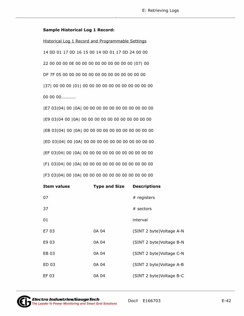
E: Retrieving Logs
Sample Historical Log 1 Record:
Historical Log 1 Record and Programmable Settings
14 0D 01 17 0D 16 15 00 14 0D 01 17 0D 24 00 00
22 00 00 00 0E 00 00 00 00 00 00 00 00 00 |07| 00
DF 7F 05 00 00 00 00 00 00 00 00 00 00 00 00 00
|37| 00 00 00 |01| 00 00 00 00 00 00 00 00 00 00 00
00 00 00..........
|E7 03|04| 00 |0A| 00 00 00 00 00 00 00 00 00 00 00
|E9 03|04 00 |0A| 00 00 00 00 00 00 00 00 00 00 00
|EB 03|04| 00 |0A| 00 00 00 00 00 00 00 00 00 00 00
|ED 03|04| 00 |0A| 00 00 00 00 00 00 00 00 00 00 00
|EF 03|04| 00 |0A| 00 00 00 00 00 00 00 00 00 00 00
|F1 03|04| 00 |0A| 00 00 00 00 00 00 00 00 00 00 00
|F3 03|04| 00 |0A| 00 00 00 00 00 00 00 00 00 00 00
Item values Type and Size Descriptions
07 # registers
37 # sectors
01 interval
E7 03 0A 04 (SINT 2 byte)Voltage A-N
E9 03 0A 04 (SINT 2 byte)Voltage B-N
EB 03 0A 04 (SINT 2 byte)Voltage C-N
ED 03 0A 04 (SINT 2 byte)Voltage A-B
EF 03 0A 04 (SINT 2 byte)Voltage B-C
Doc# E166703 E-42Electro Industries/GaugeTechThe Leader In Power Monitoring and Smart Grid SolutionsElectro Industries/GaugeTechThe Leader In Power Monitoring and Smart Grid Solutions

E: Retrieving Logs
F1 03 0A 04 (SINT 2 byte)Voltage C-A
F3 03 0A 04 (SINT 2 byte)Frequency
Sample Record
0D 01 18 0B 18 00|42 EF ED AB|42 EF ED 41|42 EF
EC 39|00 00 00 00|00 00 00 00|00 00 00 00|42 70
00 7D|....
0D 01 18 0B 18 00 2013 January,24 11:24:00
42 EF ED AB 119.9641 V
42 EF ED 41 119.9634 V
42 EF EC 39 119.9613 V
00 00 00 00 0 V
00 00 00 00 0 V
00 00 00 00 0 V
42 70 00 7D 60.0004 Hz
Doc# E166703 E-43Electro Industries/GaugeTechThe Leader In Power Monitoring and Smart Grid SolutionsElectro Industries/GaugeTechThe Leader In Power Monitoring and Smart Grid Solutions

E: Retrieving Logs
This page intentionally left blank.
Doc# E166703 E-44Electro Industries/GaugeTechThe Leader In Power Monitoring and Smart Grid SolutionsElectro Industries/GaugeTechThe Leader In Power Monitoring and Smart Grid Solutions