Embed Size (px)
Citation preview
Volume-III : Section-III
Technical Specifications for IPDS
1
IPDS/DHBVN/HARYANA
VOLUME-III: SECTION – III
TECHNICAL SPECIFICATIONS
FOR IPDS
Volume-III : Section-III
Technical Specifications for IPDS
2
IPDS/DHBVN/HARYANA
Contents................................................................................................................................................ 2
A. Technical Specification of 66/11 KV Sub-station:
1. 66/11 KV Power Transformers ................................................................................................ 4
2. 66 KV Circuit Breaker (Outdoor Type) ................................................................................... 19
3. 66KV Isolators ...................................................................................................................... 26
4. 66KV Instrument Transformers ............................................................................................. 30
5. 66KV Surge Arrestors............................................................................................................ 35
6. 66KV Cable and Accessories ................................................................................................. 38
7. 66KV Post Insulators ............................................................................................................. 41
8. Lighting ................................................................................................................................ 43
9. LT Switchgear & DBS ............................................................................................................ 43
10. Battery & Battery Charger .................................................................................................... 43
11. Control & Protection System for 66KV Sub-Station ............................................................... 44
12. Switchyard Auxiliary Items ................................................................................................... 56
13. 11 KV Switchgear ................................................................................................................. 62
14. 11KV Capacitor Bank ........................................................................................................... 83
15. Outdoor non Sealed Type Three Phase 11 kV/433V Station Transformers .......................... 88
16. ACSR Conductor .................................................................................................................. 88
17. Civil & Structural works……………………………………………………………………………………………………..…89
18. Installation…………………………………………………………………………………………………………………………103
B. 66 kV Gas Insulated Switchgear ................................................................................................. 113
C. 11 KV SF6 Ring Main Units .......................................................................................................... 170
D. 11 kV Sectionalizer ..................................................................................................................... 193
E. 3-phase 3 / 4 Wire CT/PT Operated Fully Static AMR Compatible Tri-Vector Energy Meters for Area
Ring Fencing, Substation Feeders, Distribution Transformers, HT (PT/CT) Consumers ....................... 199
Volume-III : Section-III
Technical Specifications for IPDS
3
IPDS/DHBVN/HARYANA
A.TECHNICAL SPECIFICATION
OF
66/11 KV SUBSTATION
Volume-III : Section-III
Technical Specifications for IPDS
4
IPDS/DHBVN/HARYANA
1) 66/11 KV POWER TRANSFORMER (15MVA/20MVA): To be customized by Utility
1. GENERAL
This specification covers the design, manufacture, assembly; shop testing, supply, delivery, installation works and field test of the Power Transformers complete with all accessories, fittings and auxiliary equipment for trouble free operation. The transformers shall be oil immersed and suitable for outdoor installation and shall comply with IEC 76/IS 2026.
2. DESIGN REQUIREMENTS
The transformers shall be connected to three phase 50 Hz system of 66 kV systems.
The transformer shall be installed outdoor. The transformer shall be oil immersed and designed for the cooling system as specified in Appendix-A.
The transformers shall be capable of operating continuously at its rated output without exceeding
the temperature rise limits as specified in Appendix-A.
The transformer windings shall be designed to withstand short circuit stresses at its terminal with
full voltage maintained behind it for a period as per IEC-76.
The transformer shall be capable of continuous operation at the rated output under the following
conditions:
a) The voltage varying ±10% of rated voltage.
b) Frequency varying ±5% of the rated frequency.
The transformer shall be capable of delivering its rated output at any tap position.
The transformer shall be free from annoying hum and vibration when in operation even at 10% higher voltage over the rated voltage. The noise level shall be in accordance with respective IEC standards.
The transformer shall be designed and constructed so as not to cause any undesirable
interference in radio or communication circuits.
The Transformer Secondary terminal shall be adequately designed for terminating two runs of 1CX800 sqmm cable (to be customized by utility) to it, with the help of appropriate size Outdoor Termination Kit. The cable shall be supported on a structure.
3. CONSTRUCTION FEATURES
3.1 Tank
The tank shall be of all welded construction and fabricated from sheet steel of adequate thickness. All seams shall be properly welded to withstand requisite impact during short circuit
Volume-III : Section-III
Technical Specifications for IPDS
5
IPDS/DHBVN/HARYANA
without distortion. All welding shall be stress relieved.
Stiffener of structural steel for general rigidity shall reinforce the tank wall. The tank shall have sufficient strength to withstand without any deformation by mechanical shock during transportation and vacuum filling in the field.
The tank cover shall be bolted on the tank with weather proof, hot oil resistant, resilient gasket in between for complete oil tightness. If gasket is compressible metallic stops shall be provided to prevent over compression. Bushings, turrets, cover of access holes and other devices shall be designed to prevent any leakage of water into or oil from the tank. The tank cover shall also be provided with two (2) nos. grounding pads and connected separately to tank grounding pads.
The transformer tank shall be provided with sets suitable transporting arrangement
All heavy removable parts shall be provided with eye bolts for ease of handling and necessary lugs and shackles shall be provided to enable the whole transformer to be lifted by a crane or other means. Manholes of sufficient size shall be provided for access to leads, windings, bottom terminals of bushings and taps.
3.2 Core & Coils
The transformer may be of core or shell type. The core shall be built up with interleaved grade non-ageing, low loss, high permeability, grain-oriented, cold rolled silicon steel lamination properly treated for core material. The coils shall be manufactured from electrolytic copper of suitable grade. They should be properly insulated and stacked.
All insulating material shall be of proven design. Coils shall be so insulated that impulse and
power frequency voltage stresses are at a minimum.
Insulating spacers and barriers shall suitably support coil assembly. Bracing and other insulations used in the assembly of the winding shall be arranged to ensure a free circulation of the oil and to reduce the hot spot of the winding.
All leads from the windings to the terminal board and bushings shall be rigidly supported to prevent injury from vibration or short circuit stresses. Guide tube shall be used where practicable.
The core and coil assembly shall be securely fixed in position so that no shifting or deformation occurs during movement of transformer of under short circuit stresses.
3.3 Tappings
Off load / on-load taps as specified in Appendices shall be provided on the high voltage winding
of the transformers.
The transformer shall be capable of operation at rated output at any tap position provided the primary voltage does not vary by more than ±10% of the rated voltage corresponding to the normal tap.
The winding, including the tapping arrangement, shall be designed to maintain the
electromagnetic balance between H.V. and L.V. winding at all voltage ratios.
3.4 On Load Tap Changer (OLTC)
The continuous current rating of the tap changer shall be based on connected winding rating and
Volume-III : Section-III
Technical Specifications for IPDS
6
IPDS/DHBVN/HARYANA
shall have liberal and ample margin. Lower rated tap changers connected in parallel are not acceptable.
The tap changing mechanism shall be located in an oil filled compartment separated from the main tank by a suitable oil tight barrier. The oil in OLTC compartment shall have its own separate oil preservation system complete with conservator, Buchholz relay/oil surge relay, breather, shut-off valves, oil level gauge, gas vent etc. However, one segregated compartment of the main conservator tank may be utilized for OLTC oil preservation.
3.5 Remote/local Tap Operation
The on-load tap changing equipment shall have the provision for mechanical and electrical control from a local position. For local mechanical operation, the operating handle shall be brought outside the tank for operation from floor level with provision to lock the handle in each tap position.
In driving mechanism cubicle
- “RAISE-LOWER” control switch
- Means for manual operation when power supply is lost
- Tap change operation counter
The OLTC should be designed to be controlled from the remote. The remote OLTC panel with the switching and control devices shall be provided in the switchgear room.
3.6 Insulating Oil
The insulating oil shall conform to the latest revision of IS 335/IEC publication 296, properly
inhibited for preventing of sludging.
The necessary first filling of oil shall be supplied for the transformer in non-returnable container suitable for outdoor storing. Ten percent (10%) excess oil shall also be provided to take wastage into account.
3.7 Oil Preservation System
Oil preservation shall be by a means of conservator tank or by a sealed tank system.
a) Conservator Tank System
1) The conservator tank shall be mounted on a bracket fixed on the tank.
2) The conservator tank shall be provided with two compartments, on for the main transformer tank while the other for the OLTC compartment. The partition barrier shall be provided so that OLTC oil shall not be mixed up with the transformers oil under any circumstances.
3) One compartment shall be connected with the main transformer tank by pipes
through double float Buchholz Relay (gas operated relay) with valves at both ends.
4) The other compartment shall be connected with the OLTC compartment by pipes through single float Buchholz Relay/Oil Surge Relay with valves at both ends.
Volume-III : Section-III
Technical Specifications for IPDS
7
IPDS/DHBVN/HARYANA
5) Contact of the oil in the compartment for the main tank with atmosphere shall be prohibited by using a flexible urethane air cell. The cell shall be vented in to the atmosphere through a silica gel breather and shall inflate or deflate as oil volume changes.
6) Both compartments shall be provided with their own breather, filler cap and drain
plug.
7) Each compartment of the conservator shall be provided with a dial type level
indicator visible from the ground level and fitted with a low oil level alarm contact.
Plain oil level gauge shall also be provided to each compartment.
3.8 Temperature Indicators
One set of winding temperature indicators shall be supplied and fitted locally so as to be readable at a standing height from ground level. Necessary current transformer and heating coil for obtaining thermal images of winding temperatures and a detector element shall be furnished and wired.
The above winding temperature indicator shall be provided with necessary contact to take care of
the following:
(a) Starting of cooling units with rise of temperature
(b) Alarm on high temperature
(c) Trip on higher temperature
One set of oil temperature indicator with maximum reading pointer and electrically separate sets of contacts for alarm and trip shall be mounted locally so as to be readable at a standing height from ground level
3.9 Buchholz relay (Gas operated relay) – (For conservator type of oil preservation)
The Buchholz relay shall be provided with two floats and two pairs of electrically separate
contacts – one pair for alarm and the other pair for tripping.
3.10 Transformer Bushings
Transformer bushing at 11 kV side should be so designed to accommodate two no. 800 sq.mm. aluminium (1C) cable (utility to customize based on actual requirement and rating of transformer) with secondary inter phase clearance. All bushings shall conform to the requirements of the latest revisions of IEC publication 137.
The bushings shall be located so as to provide minimum electrical clearances between phase and
ground as per relevant IS/IEC standards.
All bushings shall be porcelain type and shall be furnished complete with terminal connectors of adequate capacity. The porcelain used in bushings shall be homogeneous, nonporous, uniformly glazed to brown color and free blisters, burns and other defects.
Stresses due to expansion and contraction in any part of the bushing shall not lead to
deterioration.
Bushings rated 66 kV and above shall be of the oil-filled condenser type with a central tube and
Volume-III : Section-III
Technical Specifications for IPDS
8
IPDS/DHBVN/HARYANA
draw-in-conductor which shall be connected to the connector housed in the helmet of the bushings.
Liquid/oil-filled bushings shall be equipped with liquid level indicators and means for sampling and draining the liquid. The angle of inclination to vertical shall not exceed 30 deg. Oil in oil-filled bushings shall meet the requirements of the transformer oil standards specified.
3.11 Marshalling Box
A sheet, steel weatherproof marshalling box of IP-55 construction shall be provided. The box shall contain all auxiliary devices except those which must be located directly on the transformer. All terminal blocks for external cable connections shall be located in this box.
The marshalling box shall have the following but not limited to them:
a) Load disconnect switch for incoming power supply for auxiliaries.
b) AUTO-MANUAL selector switch and Local/Remote switch for OLTC
c) Wiring and termination individually of the following alarm contacts for remote trip and
alarm.
- Buchholz relay alarm for main tank (For conservator type).
- Buchholz/oil surge relay alarm for OLTC.
- Winding temperature high alarm.
- Oil temperature high alarm.
- Tank oil level low alarm.
- OLTC oil level low alarm.
- Tap change incomplete alarm.
d) Wiring and termination individually of the following trip contact for remote trip and trip
alarm.
- Winding temperature high trip.
- Oil temperature high trip.
- Buchholz relay trip or sudden gas and sudden oil pressure relay trip.
- Pressure relief device.
Cubicle illumination lamp with door switch and space heater with thermostat and ON-OFF switch
shall be provided.
3.12 11 kV Cable Termination
Adequate support structure with necessary cable support system shall be provided for
Volume-III : Section-III
Technical Specifications for IPDS
9
IPDS/DHBVN/HARYANA
termination of two (2) 800 sq.mm. XLPE cable/phase on the 11 kV bushings (utility may customize based on actual requirement and rating of transformer). Adequate interphase barrier to be provided between the bushings. Suitable arrangement shall be provided for installation of 11kv surge arrestor near the bushing termination.
3.13 Auxiliary Supply
All indications alarms and trip contacts provided shall be suitable for operation on a nominal 220V
DC system for 66 kV Class Transformers.
Tap changing gear shall be suitable for operation of 430V, 3 phase, 4 wire, 50 Hz systems.
Cooling fans shall be rated at 430 V, 3 phase, 50 Hz.
The tap changing and cooler control supply voltage shall be 230V, Single phase 50 Hz.
3.14 Current Transformers
The scope includes the supply and installation of neutral current transformers and all necessary wiring to terminal blocks at the transformer-marshalling kiosk. The specification of requirements for current transformers shall be established and co-coordinated with the 66 kV bay CT and 11 kV switchgear CT.
Neutral current transformers are to be mounted inside the transformer and shall be easily
accessible for testing.
3.15 Cooler Control Scheme
The bidder shall design and supply the required cooler control scheme with necessary fans and
control gear. One no fan shall be provided as stand by.
4. TESTS
The following tests shall be performed
i) Insulation resistance tests on bushings.
ii) Insulation resistance test at 500V between core and core clamping structure.
iii) Voltage withstand tests on insulating oil to BS:148.
iv) Voltage ratio. v) Phase relationship/Vector Group.
vi) Magnetisation characteristics of current transformers of winding temperature devices.
vii) Calibration of winding temperature devices.
viii) Tap selector and diverter switch alignment.
ix) Calibration of automatic voltage control equipment.
x) Proving tests as necessary on control schemes.
Volume-III : Section-III
Technical Specifications for IPDS
10
IPDS/DHBVN/HARYANA
xi) Proving tests of buchholz device by air injection.
xii) Impedance voltage at highest rated and lowest voltage tap.
xiii) Zero sequence impedance at rated voltage tap.
xiv) DC resistance at all voltage taps.
xv) Core balance test.
xvi) Tan delta-capacitance test on bushings (66kV).
xvii) Tan delta-capacitance test on transformer.
5. Losses at 75 deg Celsius at rated voltage shall be not higher than the values indicated below (IS2026 along with latest amendments if any):
a) No load losses (Iron losses): 15 MVA- 10 kW, 20 MVA -14.5 kW
b) Full load (Copper losses + stray losses) losses: 15 MVA-56 kW, 20 MVA- 73 kW
6. TENDER EVALUATION & CAPITALIZATION OF TRANSFORMER LOSSES
Conditions of contract at Volume-I may be referred for this. The minimum loss indicated by any of the bidder will be taken as a base for computing any Liquidated damages for non-performance of the equipment and LD shall be levied as per GCC clause 24.1, 24.2 and corresponding clause 11 and 12 at SCC.
7. PERFORMANCE GUARANTEE
The performance figures quoted on Technical Data Sheet shall be guaranteed within the tolerances permitted by standards IS 2026 & IEC 76 and will become a part of the successful Bidder’s Contract.
8. DRAWINGS, DATA & MANUALS
Submission of Drawings, Data & Manuals by the Bidder along with the tender Document and that
after the award of contract for approval shall be as follows:
a) The following drawings and details shall be furnished along with the Tender.
1) Bidder’s proposed typical general arrangement drawing showing constructional
features of:
- Tank including conservator, level gauge, etc.
- Bushing configuration arrangement
- Cable termination arrangement
- Wheel base dimension and detail
Volume-III : Section-III
Technical Specifications for IPDS
11
IPDS/DHBVN/HARYANA
- Head clearance required for detanking of coil assembly.
2) Test certificates of similar transformer as quoted.
3) Technical leaflets on accessories such as:
- Buchholz relay, sudden gas pressure/oil pressure relay - Temperature indicators - Tap changer - High/Low voltage bushings
b) After Award of Contract
After award of contract, the successful Bidder shall submit the required number of copies
of following data for approval.
1) Outline dimensional drawing showing the general arrangement, indicating the
space required for:
- Cable termination arrangement
- Wheel base dimension & detail
2) Head clearance required for detanking of core and coil assembly.
3) Foundation plan and loading.
4) Transport/shipping dimension with net weight and weights of various parts.
5) Final calculation of impedance for each transformer.
6) Schematic flow diagram of cooling system showing the number of cooling units, etc.
7) Technical details along with control schematic and wiring diagram for marshalling
box, remote tap changer control panel.
8) Short circuits withstand capacity design calculation.
Any other relevant data, drawing and information necessary for review of the items whether
specifically mentioned or not, shall be furnished along with this information.
The general arrangement drawing, the schematic wiring diagram showing the control scheme, cable termination arrangement, location of terminal blocks, etc., shall be submitted for comment/approval. The Employer/Engineer will return these drawings after their review with their comments and/or approval. The review and comments will generally be made on the schematic diagram drawing and the configuration and the arrangement of the accessories fitted on the transformer. The Bidder on receipt of their returned drawings, with comments from the Employer/Engineer, shall prepare final wiring diagram. The outgoing terminals of the wiring diagram shall be specifically indicated for different functions, such as closing, tripping, alarm, indication, etc. The responsibility for correctness of the wiring diagram shall lie with the Bidder.
Employer/Engineer will only check the final schematic diagram after submission. If any
modification, addition or alternation is considered necessary thereon to comply with the
Employer/Engineer approved schematic drawing stated hereinabove, the said modification,
Volume-III : Section-III
Technical Specifications for IPDS
12
IPDS/DHBVN/HARYANA
addition or alternation shall be carried out by the Bidder either in their works if it is before
delivery or at site after delivery at no cost to the Employer.
9. NAMEPLATE
Each transformer shall be provided with a nameplate of weather resistant material fitted in a
visible position showing but not limited to the following item:
a) Kind of transformer
b) Number of the specification
c) Manufacturer’s name
d) Year of manufacture
e) Manufacturer’s serial number
f) Number of phases and frequency
g) Rated power
h) Rated voltages and currents
i) Connection symbol
j) Impedance voltage at rated current
k) Type of cooling
l) Total weight
m) Weight of insulating oil
n) Class of insulation
o) Temperature rise
p) Connection diagram
q) Insulation levels
r) Weight of transportation and untanking
s) Details regarding tapping’s

Volume-III : Section-III
Technical Specifications for IPDS
13
IPDS/DHBVN/HARYANA
10. TRANSPORTATION
The core and coils shall be completely dried before shipment and assembled with tank and with oil or dry nitrogen depending upon the size of the transformers. In order to facilitate handling and shipping, as many external accessories as practical, including bushings shall be removed and replaced by special shipping covers.
Bushings, radiators and other accessories which may be affected by moisture shall be packed in
moisture proof containers.
CODES & STANDARDS (refer Volume III Section I Power Transformer Specification)
Volume-III : Section-III
Technical Specifications for IPDS
14
IPDS/DHBVN/HARYANA
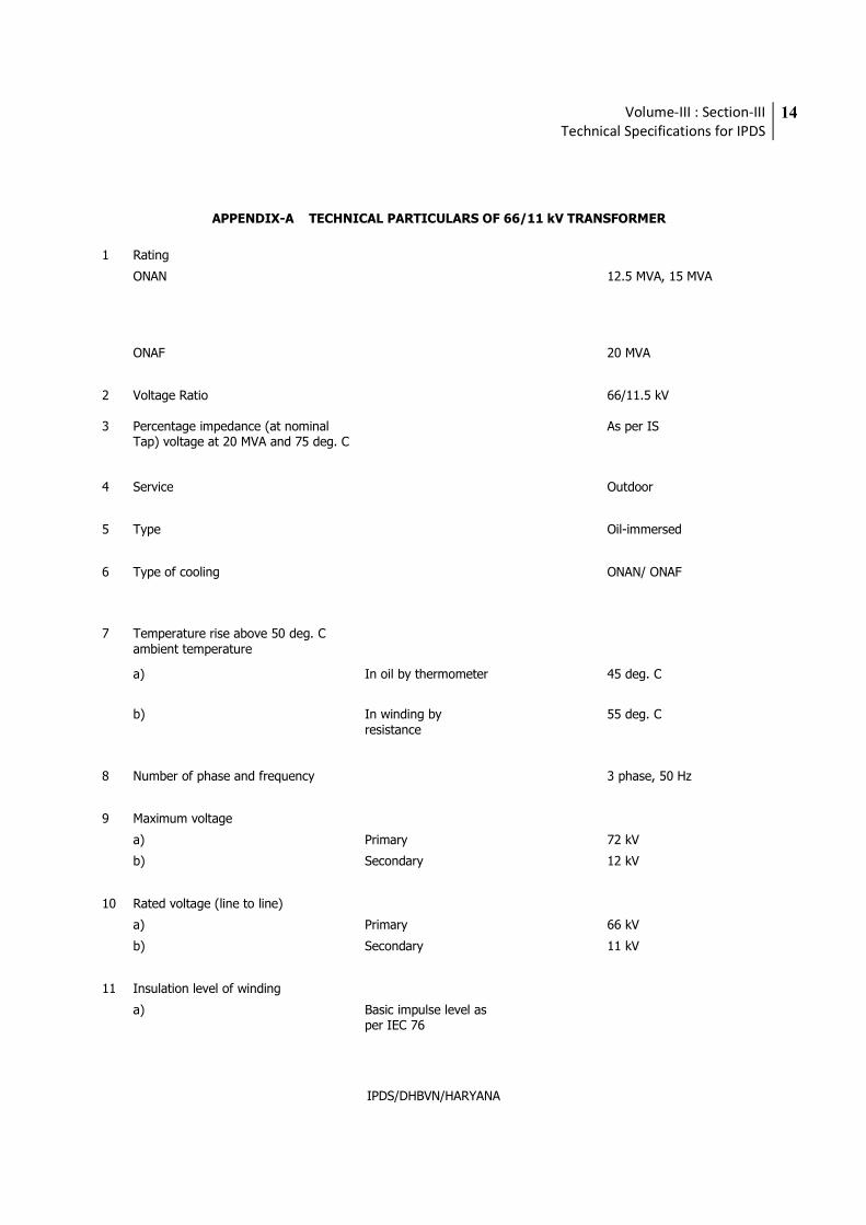
APPENDIX-A TECHNICAL PARTICULARS OF 66/11 kV TRANSFORMER
1 Rating
ONAN 12.5 MVA, 15 MVA
ONAF 20 MVA
2 Voltage Ratio 66/11.5 kV
3 Percentage impedance (at nominal Tap) voltage at 20 MVA and 75 deg. C
As per IS
4 Service Outdoor
5 Type Oil-immersed
6 Type of cooling ONAN/ ONAF
7 Temperature rise above 50 deg. C ambient temperature
a) In oil by thermometer 45 deg. C
b) In winding by resistance
55 deg. C
8 Number of phase and frequency 3 phase, 50 Hz
9 Maximum voltage
a) Primary 72 kV
b) Secondary 12 kV
10 Rated voltage (line to line)
a) Primary 66 kV
b) Secondary 11 kV
11 Insulation level of winding
a) Basic impulse level as per IEC 76
Volume-III : Section-III
Technical Specifications for IPDS
15
IPDS/DHBVN/HARYANA
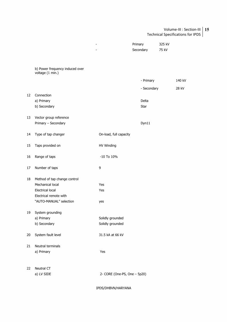
- Primary 325 kV
- Secondary 75 kV
b) Power frequency induced over voltage (1 min.)
- Primary 140 kV
- Secondary 28 kV
12 Connection
a) Primary Delta
b) Secondary Star
13 Vector group reference
Primary – Secondary Dyn11
14 Type of tap changer On-load, full capacity
15 Taps provided on HV Winding
16 Range of taps -10 To 10%
17 Number of taps 9
18 Method of tap change control
Mechanical local Yes
Electrical local Yes
Electrical remote with
“AUTO-MANUAL” selection yes
19 System grounding
a) Primary Solidly grounded
b) Secondary Solidly grounded
20 System fault level 31.5 kA at 66 kV
21 Neutral terminals
a) Primary Yes
22 Neutral CT
a) LV SIDE 2- CORE (One-PS, One – 5p20)

Volume-III : Section-III
Technical Specifications for IPDS
16
IPDS/DHBVN/HARYANA
Neutral CT Details
CT TYPE LV NEUTRAL CT
5P20 RATIO:1600/1
PS RATIO: 1600/1
Vk=800V
Rct+2Rl<10
Volume-III : Section-III
Technical Specifications for IPDS
17
IPDS/DHBVN/HARYANA
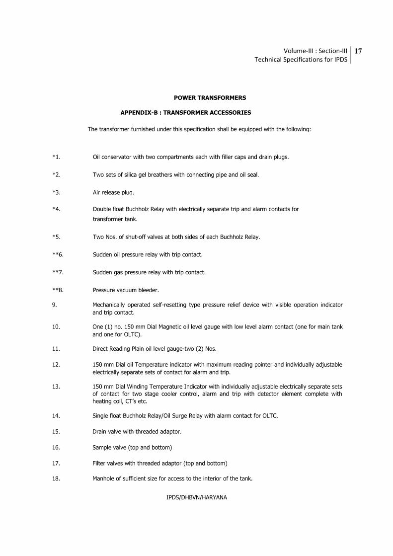
POWER TRANSFORMERS
APPENDIX-B : TRANSFORMER ACCESSORIES
The transformer furnished under this specification shall be equipped with the following:
*1. Oil conservator with two compartments each with filler caps and drain plugs.
*2. Two sets of silica gel breathers with connecting pipe and oil seal.
*3. Air release plug.
*4. Double float Buchholz Relay with electrically separate trip and alarm contacts for
transformer tank.
*5. Two Nos. of shut-off valves at both sides of each Buchholz Relay.
**6. Sudden oil pressure relay with trip contact.
**7. Sudden gas pressure relay with trip contact.
**8. Pressure vacuum bleeder.
9. Mechanically operated self-resetting type pressure relief device with visible operation indicator
and trip contact.
10. One (1) no. 150 mm Dial Magnetic oil level gauge with low level alarm contact (one for main tank
and one for OLTC).
11. Direct Reading Plain oil level gauge-two (2) Nos.
12. 150 mm Dial oil Temperature indicator with maximum reading pointer and individually adjustable
electrically separate sets of contact for alarm and trip.
13. 150 mm Dial Winding Temperature Indicator with individually adjustable electrically separate sets of contact for two stage cooler control, alarm and trip with detector element complete with heating coil, CT’s etc.
14. Single float Buchholz Relay/Oil Surge Relay with alarm contact for OLTC.
15. Drain valve with threaded adaptor.
16. Sample valve (top and bottom)
17. Filter valves with threaded adaptor (top and bottom)
18. Manhole of sufficient size for access to the interior of the tank.
Volume-III : Section-III
Technical Specifications for IPDS
18
IPDS/DHBVN/HARYANA
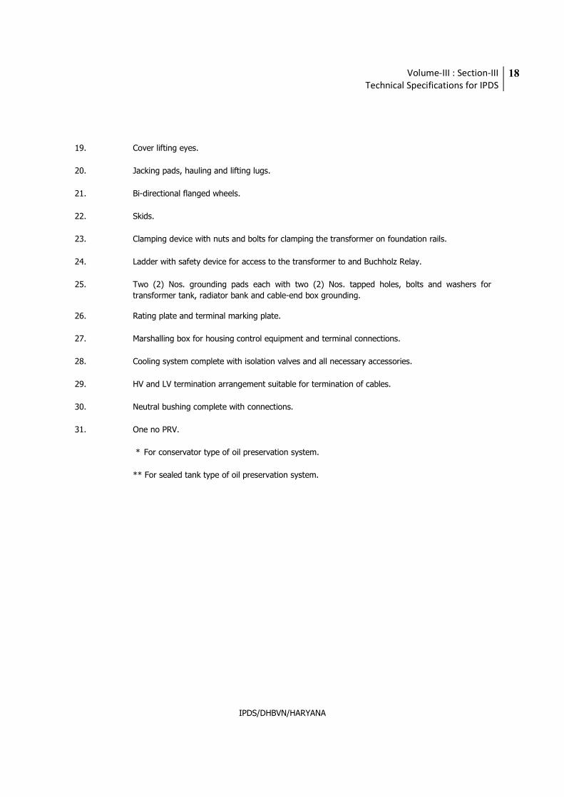
19. Cover lifting eyes.
20. Jacking pads, hauling and lifting lugs.
21. Bi-directional flanged wheels.
22. Skids.
23. Clamping device with nuts and bolts for clamping the transformer on foundation rails.
24. Ladder with safety device for access to the transformer to and Buchholz Relay.
25. Two (2) Nos. grounding pads each with two (2) Nos. tapped holes, bolts and washers for
transformer tank, radiator bank and cable-end box grounding.
26. Rating plate and terminal marking plate.
27. Marshalling box for housing control equipment and terminal connections.
28. Cooling system complete with isolation valves and all necessary accessories.
29. HV and LV termination arrangement suitable for termination of cables.
30. Neutral bushing complete with connections.
31. One no PRV.
* For conservator type of oil preservation system.
** For sealed tank type of oil preservation system.
Volume-III : Section-III
Technical Specifications for IPDS
19
IPDS/DHBVN/HARYANA
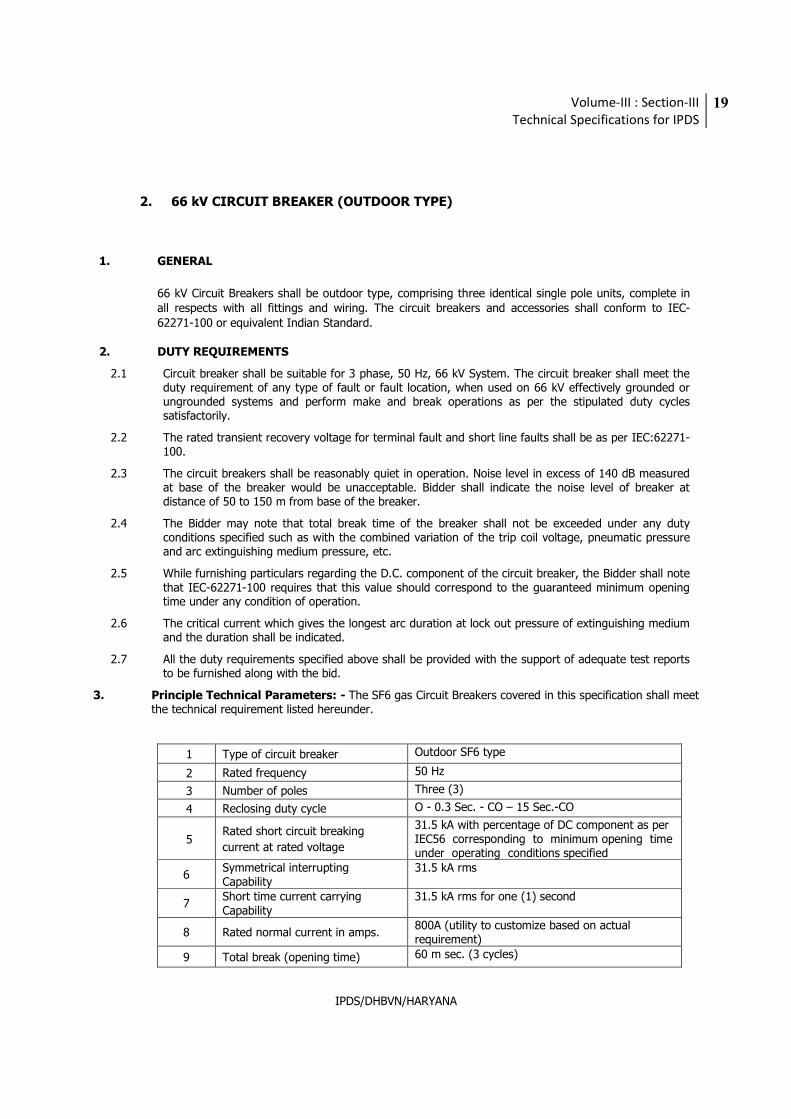
2. 66 kV CIRCUIT BREAKER (OUTDOOR TYPE)
1. GENERAL
66 kV Circuit Breakers shall be outdoor type, comprising three identical single pole units, complete in all respects with all fittings and wiring. The circuit breakers and accessories shall conform to IEC-62271-100 or equivalent Indian Standard.
2. DUTY REQUIREMENTS
2.1 Circuit breaker shall be suitable for 3 phase, 50 Hz, 66 kV System. The circuit breaker shall meet the duty requirement of any type of fault or fault location, when used on 66 kV effectively grounded or ungrounded systems and perform make and break operations as per the stipulated duty cycles satisfactorily.
2.2 The rated transient recovery voltage for terminal fault and short line faults shall be as per IEC:62271-100.
2.3 The circuit breakers shall be reasonably quiet in operation. Noise level in excess of 140 dB measured at base of the breaker would be unacceptable. Bidder shall indicate the noise level of breaker at distance of 50 to 150 m from base of the breaker.
2.4 The Bidder may note that total break time of the breaker shall not be exceeded under any duty conditions specified such as with the combined variation of the trip coil voltage, pneumatic pressure and arc extinguishing medium pressure, etc.
2.5 While furnishing particulars regarding the D.C. component of the circuit breaker, the Bidder shall note that IEC-62271-100 requires that this value should correspond to the guaranteed minimum opening time under any condition of operation.
2.6 The critical current which gives the longest arc duration at lock out pressure of extinguishing medium and the duration shall be indicated.
2.7 All the duty requirements specified above shall be provided with the support of adequate test reports to be furnished along with the bid.
3. Principle Technical Parameters: - The SF6 gas Circuit Breakers covered in this specification shall meet the technical requirement listed hereunder.
1 Type of circuit breaker Outdoor SF6 type
2 Rated frequency 50 Hz
3 Number of poles Three (3)
4 Reclosing duty cycle O - 0.3 Sec. - CO – 15 Sec.-CO
5 Rated short circuit breaking
current at rated voltage
31.5 kA with percentage of DC component as per IEC56 corresponding to minimum opening time under operating conditions specified
6 Symmetrical interrupting Capability
31.5 kA rms
7 Short time current carrying Capability
31.5 kA rms for one (1) second
8 Rated normal current in amps. 800A (utility to customize based on actual requirement)
9 Total break (opening time) 60 m sec. (3 cycles)
Volume-III : Section-III
Technical Specifications for IPDS
20
IPDS/DHBVN/HARYANA
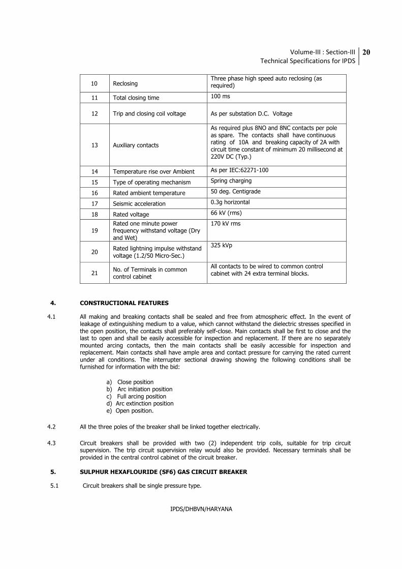
10 Reclosing Three phase high speed auto reclosing (as required)
11 Total closing time 100 ms
12 Trip and closing coil voltage As per substation D.C. Voltage
13 Auxiliary contacts
As required plus 8NO and 8NC contacts per pole as spare. The contacts shall have continuous rating of 10A and breaking capacity of 2A with circuit time constant of minimum 20 millisecond at 220V DC (Typ.)
14 Temperature rise over Ambient As per IEC:62271-100
15 Type of operating mechanism Spring charging
16 Rated ambient temperature 50 deg. Centigrade
17 Seismic acceleration 0.3g horizontal
18 Rated voltage 66 kV (rms)
19 Rated one minute power frequency withstand voltage (Dry and Wet)
170 kV rms
20 Rated lightning impulse withstand voltage (1.2/50 Micro-Sec.)
325 kVp
21 No. of Terminals in common control cabinet
All contacts to be wired to common control cabinet with 24 extra terminal blocks.
4. CONSTRUCTIONAL FEATURES
4.1 All making and breaking contacts shall be sealed and free from atmospheric effect. In the event of leakage of extinguishing medium to a value, which cannot withstand the dielectric stresses specified in the open position, the contacts shall preferably self-close. Main contacts shall be first to close and the last to open and shall be easily accessible for inspection and replacement. If there are no separately mounted arcing contacts, then the main contacts shall be easily accessible for inspection and replacement. Main contacts shall have ample area and contact pressure for carrying the rated current under all conditions. The interrupter sectional drawing showing the following conditions shall be furnished for information with the bid:
a) Close position b) Arc initiation position c) Full arcing position d) Arc extinction position e) Open position.
4.2 All the three poles of the breaker shall be linked together electrically.
4.3 Circuit breakers shall be provided with two (2) independent trip coils, suitable for trip circuit supervision. The trip circuit supervision relay would also be provided. Necessary terminals shall be provided in the central control cabinet of the circuit breaker.
5. SULPHUR HEXAFLOURIDE (SF6) GAS CIRCUIT BREAKER
5.1 Circuit breakers shall be single pressure type.
Volume-III : Section-III
Technical Specifications for IPDS
21
IPDS/DHBVN/HARYANA
5.2 Design and construction of the circuit breaker shall be such that there is minimum possibility of gas leakage and entry of moisture. There should not be any condensation of SF6 gas on insulated surfaces of the circuit breaker.
5.3 In the interrupter assembly, there shall be absorbing product box to eliminate SF6 decomposition
products and moisture. The details and operating experience with such filters shall be brought out in additional information schedule.
5.4 Each pole shall form an enclosure filled with SF6 gas independent of two other poles. Common
monitoring of SF6 gas can be provided for the three poles of circuit breaker having a common drive. The interconnecting pipes in this case shall be such that the SF6 gas from one pole could be removed for maintenance purposes.
5.5 Material used in the construction of circuit breakers shall be such as fully compatible with SF6. 5.6 The SF6 gas density monitor shall be adequately temperature compensated to model the density
changes due to variations in ambient temperature within the body of circuit breaker as a whole. It shall be possible to dismantle the monitor without removal of gas.
5.7 Sufficient SF6 gas shall be supplied to fill all the circuit breakers installed plus an additional 10% of the
quantity as spare. 6. OPERATING MECHANISM
6.1 Circuit breaker shall be operated by electrically spring charged mechanism. 6.2 The operating mechanism shall be anti-pumping and trip free (as per IEC definition) electrically and
either mechanically or pneumatically under every method of closing. The mechanism of the breaker shall be such that the position of the breaker is maintained even after the leakage of operating media and/or gas.
6.3 The operating mechanism shall be such that the failure of any auxiliary spring will not prevent tripping
and will not cause trip or closing operation of the power operated closing devices. A mechanical indicator shall be provided to show open and close positions of breaker. It shall be located in a position where it will be visible to a man standing on the ground with the mechanism housing door closed. An operation counter shall also be provided.
6.4 Closing coil shall operate correctly at all values of voltage between 85% and 110% of the rated voltage.
Shunt trip coils shall operate correctly under all operating conditions of the circuit breaker upto the rated breaking capacity of the circuit breaker and at all values of supply voltage between 70% and 110% of rated voltage. If additional elements are introduced in the trip coil circuit their successful operation for similar applications of outdoor breaker shall be clearly brought out in the bid.
6.5 Working parts of the mechanism shall be of corrosion resisting material. Bearings requiring grease, shall
be equipped with pressure type grease fittings. Bearing pin, bolts, nuts and other parts shall be adequately pinned or locked to prevent loosening or changing adjustment with repeated operation of the breaker.
6.6 Operating mechanism shall normally be operated by remote electrical control. Electrical tripping shall be
performed by shunt trip coil. Provision shall also be made for local electrical control. ‘Local/remote’ selector switches and closes & trip push buttons shall be provided in the breaker central control cabinet. Remote located push buttons and indicating lamps shall also be provided.
6.7 Operating mechanism and all accessories shall be in local control cabinet. A central control cabinet for the three poles of the breaker shall be provided along with supply of necessary tubing, cables, etc.
6.8 Provisions shall be made on breakers for attaching an operation analyser to perform speed tests after
Volume-III : Section-III
Technical Specifications for IPDS
22
IPDS/DHBVN/HARYANA
installation at site to record contact travel against time and measure opening time. 6.9 The Bidder shall furnish curve supported by test data indicating the opening time under close-open
operation with combined variation of trip coil and operating media along with the bid.
6.10 Spring Operated Mechanism
Spring operated mechanism shall be complete with motor, opening spring & closing spring with limit
switch for automatic charging and other necessary accessories to make the mechanism a complete
operating unit. Opening spring shall be supplied with limit switch for automatic charging and other
necessary accessories.
As long as power is available to the motor, a continuous sequence of closing and opening operations
shall be possible. The motor shall have adequate thermal rating for this duty. After failure of power
supply to the motor, one close-open operation shall be possible with the energy contained in the
operating mechanism.
Breaker operation shall be independent of the motor, which shall be used solely for compressing the
closing spring.
Motor ratings shall be such that it requires not more than 30 seconds for fully charging the closing
spring.
Closing action of the circuit breaker shall compress the opening spring ready for tripping.
When closing springs are discharged, after closing a breaker, closing springs shall automatically be
charged for the next operation and an indication of this shall be provided in the local and remote
control cabinet.
The spring operating mechanism shall have adequate energy stored in the operating spring to close
and latch the circuit breaker against the rated making current and also to provide the required energy
for the tripping mechanism in case the tripping energy is derived from the operating mechanism.
6.11 Fittings and Accessories
6.11.1 Following is list of some of the major fittings and accessories to be furnished as integral part of the breakers. Number and exact location of these parts shall be indicated in the bid.
6.11.2 Control unit/Central control cabinet shall be complete with:
a) Double compression type cable glands, lugs, ferrules, etc. b) Local/remote changeover switch
c) Operation counter
d) Fuses, as required
e) Anti-pumping relay/contactor
g)Rating and diagram plate in accordance with IEC including year of manufacture, etc.
h) Gauges for SF6 gas pressure.
i) Gas density monitor with alarm and lockout contacts
7. FITTINGS AND ACCESSORIES
7.1 Hollow insulator columns
All routine tests shall be conducted on the insulators as per relevant IEC. In addition the following
routine tests shall also be conducted on hollow column insulators:
Volume-III : Section-III
Technical Specifications for IPDS
23
IPDS/DHBVN/HARYANA
a. Ultrasonic test
b. Pressure test
c. Bending load test in 4 directions at 50% specified bending load.
d. Bending load test in 4 directions at 100% specified Bending load as a sample test.
e. Burst pressure test as a sample test.
7.2 Support Structures
The minimum height of equipment supports shall be 3050 mm. The height of center line shall be as
given elsewhere in the specification. 7.3 Terminal connectors
Compression joint type terminal connectors suitable for single or twin ACSR panther/zebra/Moose
conductor shall be supplied and they shall be suitable for both vertical and horizontal connections of the
Transmission line conductor or station bus bar. Suitable terminal earth connectors (two Nos.) for earthing
connections shall also be supplied. The drawings for these connectors shall be submitted.
The terminal connectors shall meet the following requirements:
a) Terminal connectors shall be manufactured and tested as per IS:5561.
b) All castings shall be free from blow holes, surface blisters, cracks and activities. All sharp edges & corners shall be blurred and rounded off.
c) No part of a clamp shall be less than 10 mm thick.
d) All ferrous parts shall be hot dip galvanised conforming to IS:2633.
e) For bimetallic connectors, copper alloy liner of minimum thickness of 2 mm shall be cast integral with aluminium body.
f) Flexible connectors shall be made from tinned copper/ aluminium sheets.
g) All current carrying parts shall be designed and manufactured to have minimum contact resistance.
h) Connectors shall be designed to be corona free in accordance with the requirements stipulated in IS:5561.
8. TESTS
8.1 Type Test
Each circuit breaker shall comply with the type test and shall be subjected to routine tests prescribed in
latest edition of IEC-62271/IEC-60694/IS-13118.
Reports of all type tests as stipulated in IEC-62271, IEC-60694 or IS-13118 and line charging current and
cable charging current and transformer charging & shunt capacitor switching current tests etc. as given
below carried out by internationally recognized test laboratories shall be furnished. Supply from those
original equipment manufacturers shall be accepted who are having type test certification for following test
in past 5 years and the type and design of the breakers then intend to supply are exactly similar. The type
test reports shall be produced in support of sub vender / vender of supply of breaker in quantity more than
25 the supplier shall conduct all following test free of charges in presence of Employer’s representative.
Volume-III : Section-III
Technical Specifications for IPDS
24
IPDS/DHBVN/HARYANA
In case some type tests are conducted at Manufacturer‘s own works, instead of at Govt. approved
laboratory, the type test reports for same shall be accepted only if tenderer undertakes to conduct this
type test free of charges in presence of Utility representative at time of inspection.
i) Impulse withstand voltage test
ii) Power frequency voltage withstand dry test on main circuit
iii) Short circuit withstand capability test
iv) Mechanical endurance test
v) Temperature rise test
vi) Radio interference voltage (RIV)
vii) Measurement of the resistance of main circuit
viii) Short time withstand current and peak withstand current test
ix) Out of phase making & breaking test
x) Shunt reactor current switching test
xi) Dielectric test
xii) IP-55 test on operating mechanism
xiii) Seismic test
xiv) Cable charging current switching test
xv) Line charging current switching test
xvi) Capacitor current switching test for isolated neutral capacitor banks.
xviii) Degree of protection test on cubicles
8.2 Routine Tests
Routine tests as per IEC-60056 on the complete breaker/ pole along with its own operating mechanism
and pole column shall be performed on all circuit breakers.
8.3 ACCEPTANCE TESTS:
The following acceptance tests as stipulated in the relevant ISS-13118 shall be carried out by the
Manufacturer in presence of employer representative, unless dispensed with in writing by the employer.
i) Power frequency voltage withstand dry test on main circuit
ii) Voltage withstand test on control and auxiliary circuits
iii) Measurement of resistance of the main circuit
iv) Mechanical operating test
v) Design and visual test
vi) Tightness Test
In addition to above, speed curves for each breaker shall be obtained with the help of a suitable operation
analyzer to determine the breaker contact movement during opening, closing, auto-re-closing and trip free
operations under normal as well as limiting operating conditions (of control voltage) The tests shall show
the speed of contacts directly at various stages of operation, travel of contacts, opening time, closing time,
shortest time between separation and meeting of contacts at make-break operation and dynamic contact
resistance measurement (DCRM) etc. Also, results obtained in type test analysis as stipulated in clause 8.1
Volume-III : Section-III
Technical Specifications for IPDS
25
IPDS/DHBVN/HARYANA
shall be examined for acceptance before release of dispatch clearance for the lot.
9. COMPLETENESS OF EQUIPMENT:
Any fittings, accessories or apparatus which may not have been specifically mentioned in this specification
but which are usually necessary for the satisfactory operation of the equipment, shall be deemed to have
been included in this specification.
10. PACKINGS:
All material shall be suitably packed for transport, direct to site and Manufacturer shall be responsible for
all damages/losses due to improper packing. All boxes shall be marked with signs indicating the up and
down sides of the boxes along with the unpacking instructions, if considered necessary by the
Manufacturers.
Volume-III : Section-III
Technical Specifications for IPDS
26
IPDS/DHBVN/HARYANA
3. 66KV ISOLATORS
1. GENERAL
The isolators and accessories shall conform in general to IEC-62271-102 except to the extent
explicitly modified in specification.
Earth switches shall be provided on isolators wherever called for.
The isolators and earth switches shall be manually operated.
Complete isolator with all the necessary items for successful operation shall be supplied.
Isolators shall be gang-operated, double break or centre break.
2. DUTY REQUIREMENTS
Isolators and earth switches shall be capable of withstanding the dynamic and thermal effects of the maximum possible short circuit current of the system in their closed position. They shall be constructed such that they do not open under influence of short circuit current and wind pressure together. The earth switches wherever provided shall be constructional interlocked so that the earth switches can be operated only when the isolator is open and vice-versa.
In addition to the constructional interlock, isolator and earth switches shall have provision to prevent their electrical and manual operation unless the associated and other interlocking conditions are met.
Castel lock type interlock mechanism shall be provided in addition to normal mechanical interlock for- (a) Breaker and isolator closing (b) Isolator and earth switch closing.
The isolator shall be capable for making/breaking normal currents when no significant change in voltage occurs across the terminals of each pole of the isolator on account of making/breaking operation.
3. CONSTRUCTIONAL FEATURES
The isolators shall be provided with high pressure current carrying contacts on the hinge/jaw ends and all contact surfaces shall be silver plated Copper alloy. The contacts shall be accurately machined and self-aligned. They shall be easily replaceable and shall have minimum movable parts and adjustments. The isolator shall be provided with a galvanized steel base provided with holes and designed for mounting on a lattice/pipe support structure. The base shall be rigid and self-supporting.
All metal parts shall be of non-rusting and non-corroding metal. Current carrying parts shall be from high conductivity electrolytic copper/aluminium. Bolts, screws and pins shall be provided with lock washers. Keys or equivalent locking facilities, if provided on current carrying parts, shall be made of copper alloy or equivalent. The live parts shall be designed to eliminate sharp joints, edges and other corona producing surfaces.
The isolators shall be so constructed that the switch blade will not fall to the closed position if the operating shaft gets disconnected. Isolators and earthing switches including their operating parts shall be such that they cannot be dislodged from their open or closed positions by gravity, wind pressure, vibrations shocks or accidental touching of the connecting rods of the operating
Volume-III : Section-III
Technical Specifications for IPDS
27
IPDS/DHBVN/HARYANA
mechanism. The switch shall be designed such that no lubrication of any part is required except at very infrequent intervals.
The insulator of the isolator shall conform to the requirements stipulated in relevant IS. Pressure due to the contact shall not be transferred to the insulators after the main blades close. The insulators shall be so arranged that leakage current will pass to earth and not between terminals of the same pole or between phases.
4. CLAMPS AND CONNECTORS The material of clamps and connectors shall be Aluminium alloy casting conforming to designation A6 of IS:617 for connecting to equipment terminals and conductors of aluminium. In case the terminals are of copper, the same clamps/connectors shall be used with 2mm thick bimetallic liner.
The material of clamps and connectors shall be Galvanised mild steel for connecting to shield
wire.
Bolts, nuts and plain washers shall be hot dip galvanised mild steel for sizes M12 and above. For sizes below M12, they shall be electro-galvanised mild steel. The spring washers shall be electro-galvanised mild steel.
All castings shall be free from blow holes, surface blisters, cracks and cavities. All sharp edges and corners shall be rounded off to meet specified corona and radio interference requirements.
They shall have same current rating as that of the connected equipment. All current carrying parts shall be at least 10 mm thick. The connectors shall be manufactured to have minimum contact resistance.
Flexible connectors, braids or laminated strips shall be made up of copper/aluminium.
Current rating and size of terminal/conductor for which connector is suitable shall be
embossed/punched on each component.
5. EARTHING SWITCHES
Where earthing switches are specified these shall include the complete operating mechanism and auxiliary contacts. The earthing switches shall form an integral part of the isolator and shall be mounted on the base frame of the isolator. Earthing switches shall be suitable for local operation only. The earthing switches shall be constructional interlocked with the isolator so that the earthing switches can be operated only when isolator is open and vice versa.
6. OPERATING MECHANISM AND CONTROL
The Manufacturer shall offer manual isolators and earth switches having padlock arrangement on
both ‘ON’ and ‘OFF’ positions.
Limit switches for control shall be fitted on the isolator/earth switch shaft, within the cabinet to
sense the open and close positions of the isolators and earth switches.
It shall not be possible, after final adjustment has been made for any part of the mechanism to
be displaced at any point in the travel sufficient enough to allow improper functioning of the
isolator when the isolator is opened or closed at any speed.
Control cabinet/operating mech. Box shall conform to requirements stipulated in IS: 5039/IS
8623/IEC 439.
7. OPERATION The design shall be such as to provide maximum reliability under all service conditions. All operating linkages carrying mechanical loads shall be designed for negligible deflection.
Volume-III : Section-III
Technical Specifications for IPDS
28
IPDS/DHBVN/HARYANA
The design of linkages and gears be such so as to allow one man to operate the handle with
ease for isolator and earth switch.
8. TESTS
In continuation to the requirements stipulated under Part-I the isolator along with operating mechanism shall conform to the type tests and shall be subjected to routine tests and acceptance tests in accordance with IEC- 62271-102. Minimum 50 nos. mechanical operations will be carried out on 1 (one) isolator assembled completely with all accessories as acceptance test. During final testing of isolator, closing/ opening of earth switch shall also be checked after isolator is fully open/close. Acceptance test shall be carried out with operating box.
The insulator shall conform to all the type tests as per IEC-60168. In addition to all type, routine and acceptance tests, as per IEC-60168, the following additional routine/ acceptance tests shall also be carried out:
a) Bending load test in four directions at 50% min. bending load guaranteed in all
insulators.
b) Bending load test in four directions at 100% min. bending load guaranteed on sample
insulators in a lot.
c) Torsional test on sample insulator of a lot.
The type test reports shall not be older than FIVE years and shall be valid up to expiry of
validity of offer. The above additional lists if not conducted earlier, shall be done under the subject project package at no extra cost.
9. Parameters 9.1. General (for General & 11 kV, refer Tech specification Volume III Section I)
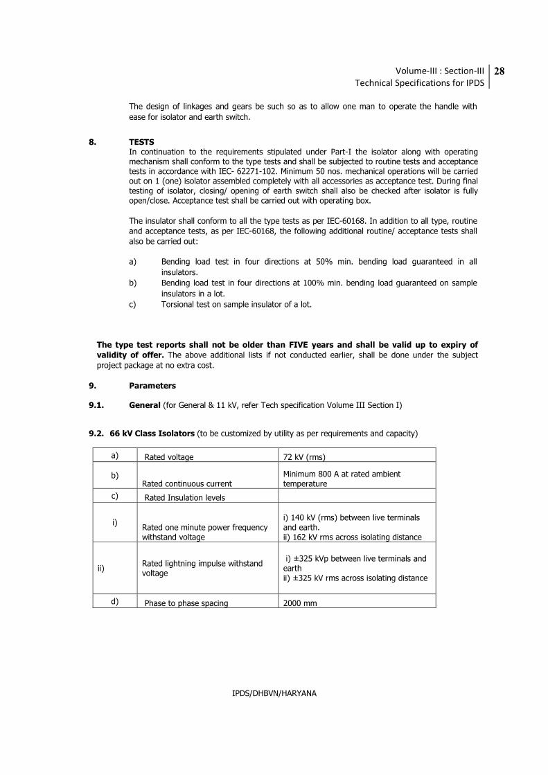
9.2. 66 kV Class Isolators (to be customized by utility as per requirements and capacity)
a) Rated voltage 72 kV (rms)
b) Rated continuous current
Minimum 800 A at rated ambient temperature
c) Rated Insulation levels
i) Rated one minute power frequency withstand voltage
i) 140 kV (rms) between live terminals and earth. ii) 162 kV rms across isolating distance
ii) Rated lightning impulse withstand voltage
i) ±325 kVp between live terminals and earth ii) ±325 kV rms across isolating distance
d) Phase to phase spacing 2000 mm
Volume-III : Section-III
Technical Specifications for IPDS
29
IPDS/DHBVN/HARYANA
10. COMPLETENESS OF EQUIPMENT:
Any fittings, accessories or apparatus which may not have been specifically mentioned in this
specification but which are usually necessary for the satisfactory operation of the equipment, shall be
deemed to have been included in this specification.
11. PACKINGS:
All material shall be suitably packed for transport, direct to site and Manufacturer shall be responsible
for all damages/losses due to improper packing. All boxes shall be marked with signs indicating the up
and down sides of the boxes along with the unpacking instructions, if considered necessary by the
Manufacturers.
Volume-III : Section-III
Technical Specifications for IPDS
30
IPDS/DHBVN/HARYANA
4. 66KV INSTRUMENT TRANSFORMERS (Utility to customize based on actual requirement)
1 CODES AND STANDARDS
i) Current Transformers IEC 60044, BS:3938, IS: 2705
ii) Voltage Transformers IEC 60186, IEC 186A, IEC 60358, IS:3156
iii) Insulating Oil IS:335
2 GENERAL REQUIREMENTS
The instrument transformers i.e. current and voltage transformers shall be single phase transformer units and shall be supplied with a common marshaling box for a set of three single phase units.
The instrument transformers shall be hermetically sealed units. The instrument transformers shall
be provided with filling and drain plugs.
Polarity marks shall indelibly be marked on each instrument transformer and at the lead
terminals at the associated terminal block.
The insulators shall have cantilever strength of more than 600 kgf.
3 CURRENT TRANSFORMERS (CTs)
3.1. The CTs shall have single primary of either ring type or hair pin type or bar type.
3.2. In case of "Bar Primary" inverted type CTs, the following requirements shall be met.
3.3. The secondaries shall be totally encased in metallic shielding providing a uniform equipotential surface for even electric field distribution.
3.4. The lowest part of insulation assembly shall be properly secured to avoid any risk of damage due
to transportation stresses.
3.5. The upper part of insulation assembly sealing on primary bar shall be properly secured to avoid any damage during transportation due to relative movement between insulation assembly and top dome.
3.6. The insulator shall be one piece without any metallic flange joint.
3.7. The CT shall be provided with oil sight glass.
3.8. The core lamination shall be of cold rolled grain oriented silicon steel or other equivalent alloys. The cores shall produce undistorted secondary current under transient conditions at all ratios with specified parameters.
3.9. Different ratios shall be achieved by secondary taps only, and primary reconnections shall not be
accepted.
3.10. The guaranteed burdens and accuracy class are to be intended as simultaneous for all cores.
Volume-III : Section-III
Technical Specifications for IPDS
31
IPDS/DHBVN/HARYANA
3.11. The instrument security factor at all ratios shall be less than five (5) for metering core. If any
auxiliary CT/reactor is used, then all parameters specified shall be met treating auxiliary CTs/reactors as integral part of CT. The auxiliary CT/reactor shall preferably be in-built construction of the CT. In case it is separate, it shall be mounted in secondary terminal box.
3.12. The physical disposition of protection secondary cores shall be in the same order as given under
CT requirement table(s) given below.
3.13. The CTs shall be suitable for high speed auto-reclosing.
3.14. The secondary terminals shall be terminated on stud type non-disconnecting terminal blocks inside the terminal box of degree of protection IP:55 at the bottom of CT.
3.15. The CTs shall be suitable for horizontal transportation.
4 VOLTAGE TRANSFORMERS (CVTs)
4.1. Voltage transformers shall be of capacitor voltage divider type with electromagnetic unit.
4.2. The CVTs shall be thermally and dielectrically safe when the secondary terminals are loaded with
guaranteed thermal burdens.
4.3. The electro-magnetic unit (EMU) shall comprise of compensating reactor, intermediate
transformer, and protective and damping devices. The oil level indicator of EMU with danger level
marking shall be clearly visible to maintenance personnel standing on ground.
4.4. The secondaries shall be protected by HRC cartridge type fuses for all windings. In addition fuses
shall also be provided for protection and metering windings for connection to fuse monitoring
scheme. The secondary terminals shall be terminated on stud type non-disconnecting terminal
blocks via the fuse inside the terminal box of degree of protection IP:55. The access to secondary
terminals shall be without the danger of access to high voltage circuit.
4.5. The damping device shall be permanently connected to one of the secondary winding and shall be
capable of suppressing ferro-resonance oscillations.
4.6. A protective surge arrester/spark gap shall preferably be provided to prevent break down of
insulation by incoming surges and to limit abnormal rise of terminal voltage of shunt capacitor,
tuning reactor, RF choke, etc. due to short circuit in transformer secondary. The details of this
arrangement (or alternative arrangement) shall be furnished by Bidder for Employer’s review.
4.7. The accuracy of metering core shall be maintained through the entire burden range upto 100VA
on all three windings without any adjustments during operations.
5 MARSHALLING BOX (CT/PT MB)
Marshaling box shall conform to all requirements as given in technical specification for LT Switchgear & DB. The wiring diagram for the interconnection of three phase instrument transformer shall be pasted inside the box in such a manner so that it is visible and it does not deteriorate with time. Terminal blocks in the marshaling box shall have facility for star/delta formation, short circuiting and grounding of secondary terminals. The box shall have enough terminals to wire all control circuits plus 20 spare terminals.
Volume-III : Section-III
Technical Specifications for IPDS
32
IPDS/DHBVN/HARYANA
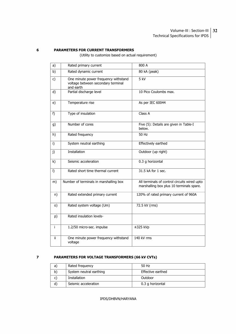
6 PARAMETERS FOR CURRENT TRANSFORMERS
(Utility to customize based on actual requirement)
a) Rated primary current 800 A
b) Rated dynamic current 80 kA (peak)
c) One minute power frequency withstand voltage between secondary terminal and earth
5 kV
d) Partial discharge level 10 Pico Coulombs max.
e) Temperature rise As per IEC 60044
f) Type of insulation Class A
g) Number of cores Five (5): Details are given in Table-I below.
h) Rated frequency 50 Hz
i) System neutral earthing Effectively earthed
j) Installation Outdoor (up right)
k) Seismic acceleration 0.3 g horizontal
l) Rated short time thermal current 31.5 kA for 1 sec.
m) Number of terminals in marshalling box
All terminals of control circuits wired upto marshalling box plus 10 terminals spare.
n) Rated extended primary current 120% of rated primary current of 960A
o) Rated system voltage (Um) 72.5 kV (rms)
p) Rated insulation levels-
i 1.2/50 micro-sec. impulse ±325 kVp
ii One minute power frequency withstand voltage
140 kV rms
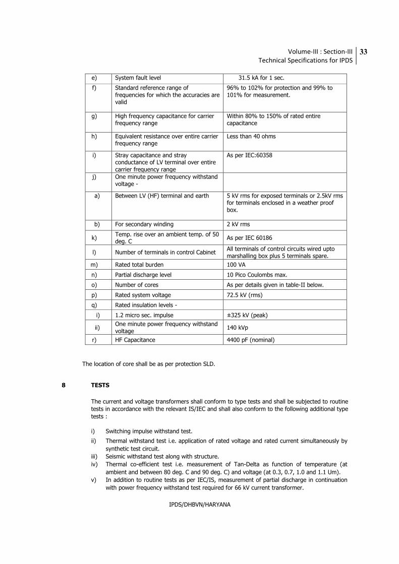
7 PARAMETERS FOR VOLTAGE TRANSFORMERS (66 kV CVTs)
a) Rated frequency 50 Hz
b) System neutral earthing Effective earthed
c) Installation Outdoor
d) Seismic acceleration 0.3 g horizontal
Volume-III : Section-III
Technical Specifications for IPDS
33
IPDS/DHBVN/HARYANA
e) System fault level 31.5 kA for 1 sec.
f) Standard reference range of frequencies for which the accuracies are valid
96% to 102% for protection and 99% to 101% for measurement.
g) High frequency capacitance for carrier frequency range
Within 80% to 150% of rated entire capacitance
h) Equivalent resistance over entire carrier frequency range
Less than 40 ohms
i) Stray capacitance and stray conductance of LV terminal over entire carrier frequency range
As per IEC:60358
j) One minute power frequency withstand voltage -
a) Between LV (HF) terminal and earth 5 kV rms for exposed terminals or 2.5kV rms for terminals enclosed in a weather proof box.
b) For secondary winding 2 kV rms
k) Temp. rise over an ambient temp. of 50 deg. C
As per IEC 60186
l) Number of terminals in control Cabinet All terminals of control circuits wired upto marshalling box plus 5 terminals spare.
m) Rated total burden 100 VA
n) Partial discharge level 10 Pico Coulombs max.
o) Number of cores As per details given in table-II below.
p) Rated system voltage 72.5 kV (rms)
q) Rated insulation levels -
i) 1.2 micro sec. impulse ±325 kV (peak)
ii) One minute power frequency withstand voltage
140 kVp
r) HF Capacitance 4400 pF (nominal)
The location of core shall be as per protection SLD.
8 TESTS
The current and voltage transformers shall conform to type tests and shall be subjected to routine tests in accordance with the relevant IS/IEC and shall also conform to the following additional type tests : i) Switching impulse withstand test. ii) Thermal withstand test i.e. application of rated voltage and rated current simultaneously by
synthetic test circuit.
iii) Seismic withstand test along with structure.
iv) Thermal co-efficient test i.e. measurement of Tan-Delta as function of temperature (at
ambient and between 80 deg. C and 90 deg. C) and voltage (at 0.3, 0.7, 1.0 and 1.1 Um).
v) In addition to routine tests as per IEC/IS, measurement of partial discharge in continuation
with power frequency withstand test required for 66 kV current transformer.
Volume-III : Section-III
Technical Specifications for IPDS
34
IPDS/DHBVN/HARYANA
The type test reports shall not be older than FIVE years and shall be valid up to expiry
of validity of offer. The above additional lists if not conducted earlier, shall be done under the subject project package at no extra cost.
9 COMPLETENESS OF EQUIPMENT:
Any fittings, accessories or apparatus which may not have been specifically mentioned in this
specification but which are usually necessary for the satisfactory operation of the equipment, shall
be deemed to have been included in this specification.
10 PACKINGS:
All material shall be suitably packed for transport, direct to site and Manufacturer shall be
responsible for all damages/losses due to improper packing. All boxes shall be marked with signs
indicating the up and down sides of the boxes along with the unpacking instructions, if considered
necessary by the Manufacturers.
Volume-III : Section-III
Technical Specifications for IPDS
35
IPDS/DHBVN/HARYANA
5. 66KV SURGE ARRESTORS
1. GENERAL (for 11 kV, refer Tech specification Volume III Section I)
The surge arrestors shall conform in general to IEC-60099-4 and IS:3070, Part-3 except to the extent modified in the specification and shall be in accordance with requirements under Part-I, shall be of Zno gapless type. Arrestors shall be hermetically sealed units, self-supporting construction, suitable for mounting on lattice type support structures.
2. DUTY REQUIREMENTS
The Surge Arresters (SAs) shall be capable of discharging over-voltages occurring due to switching of unloaded transformers and long lines. The reference current of SAs shall be high enough to eliminate the influence of grading and stray capacitance on the measured reference voltage. Values and calculations shall be furnished with offer. The SAs shall be fully stabilised thermally to give a life expectancy of thirty (30) years under site conditions and take care of effect of direct solar radiation. The SAs shall be suitable for circuit breaker duty cycle in the given system.
The SAs shall protect power transformers, circuit breakers, disconnecting switches, instrument transformers, etc. with insulation levels specified in this specification. The Bidder shall carry out the insulation coordination studies for deciding the rating and application of the SAs.
The SAs shall be capable of withstanding meteorological and short circuit forces under site conditions.
3. CONSTRUCTIONAL FEATURES
Each Surge Arrester (SA) shall be hermetically sealed single phase unit. The nonlinear blocks shall be sintered metal oxide material. The SA construction shall be robust with excellent mechanical and electrical properties. SAs shall have pressure relief devices and arc diverting ports suitable for preventing shattering of porcelain housing and to provide path for flow of rated fault currents in the event of SA failure. The SA shall not fail due to porcelain contamination. Seals shall be effectively maintained even when SA discharges rated lightning current.
Porcelain shall be so coordinated that external flashover will not occur due to application of any impulse or switching surge voltage upto maximum design value for SA.
The end fittings shall be non-magnetic and of corrosion proof material.
Volume-III : Section-III
Technical Specifications for IPDS
36
IPDS/DHBVN/HARYANA
The Bidder shall furnish the following:
a) V-I characteristics of the disc/block.
b) Metalizing coating thickness for reduced resistance between adjacent discs along with
procedure for checking the same.
c) Details of thermal stability test for uniform distribution of current on individual discs.
d) Detailed energy calculations to prove thermal capability of discs.
4. FITTINGS AND ACCESSORIES
Each SA shall be complete with insulating base for mounting on structure. SAs shall be provided with grading and/or corona rings as required.
Self-contained discharge counters, suitably enclosed for outdoor use (IP:55 degree of protection) and requiring no auxiliary or battery supply shall be fitted with each SA along with necessary connections to SA and earth. Suitable leakage current meters shall also be supplied in the same enclosure. The reading of milli-ammeter and counter shall be visible through an inspection glass panel to a man standing on ground. A pressure relief vent/suitable provision shall be made to prevent pressure build up.
5. PARAMETERS
5.1 General
a) System neutral earthing - Effectively earthed
b) Installation - Outdoor
c) Nominal discharge current - 10 kA of 8/20 microsec. wave
d) Rated frequency - 50 Hz
e) Long duration discharge class - 3
f) Current for pressure relief test - 31.5 kA rms
g) Prospective symmetrical fault - 31.5 kA rms for 1 second current
h) Low current long duration test value (2000 micro sec.) - As per IEC
i) Pressure relief class -Class A of Table VII of IS:3070
or equivalent IEC.
j) Partial discharge at 1.05 MCOV (Continuous operating voltage)- Not more than 50 deg C.
k) Siesmic acceleration - 0.3 g horizontal
l) Reference ambient temp. - 50 deg. C
Volume-III : Section-III
Technical Specifications for IPDS
37
IPDS/DHBVN/HARYANA
5.2 66 kV Class Surge Arrestor
a) Rated system voltage 66KV
b) Rated arrestor voltage 60 KV
c) Minimum discharge capability 8 kJ/kV or corresponding to minimum discharge characteristics given whichever is higher.
d) Continuous Operating Voltage 49 kV rms
(COV) at 50 deg. C
e) Max. switching surge 165 kVp maximum
residual voltage (1 kA)
f) Maximum residual voltage at
i) 10kA nominal discharge current 180 kVp
ii) 20kA nominal discharge current As per IEC
g) High current short duration test 100 kVp
value (4/10 microsec. wave)
h) Min. Total creepage distance 1850 mm
i) One minute dry/wet power
frequency withstand voltage of 140 kV (rms)
arrestor housing
j) Impulse withstand voltage of ± 325 kVp
arrestor Housing with 1.2/50
micro sec. wave.
k) RIV at 42 kV (rms) Less than 1000 micro volts
6. COMPLETENESS OF EQUIPMENT:
Any fittings, accessories or apparatus which may not have been specifically mentioned in this
specification but which are usually necessary for the satisfactory operation of the equipment, shall
be deemed to have been included in this specification.
7. PACKINGS:
All material shall be suitably packed for transport, direct to site and Manufacturer shall be
responsible for all damages/losses due to improper packing. All boxes shall be marked with signs
indicating the up and down sides of the boxes along with the unpacking instructions, if considered
necessary by the Manufacturers.
Volume-III : Section-III
Technical Specifications for IPDS
38
IPDS/DHBVN/HARYANA
6. 66 KV CABLE AND ACCESSORIES
1. SCOPE:
The scope under this section covers design, engineering, manufacture, testing, packing, supply of 66 KV, XLPE, insulated power cable for use with solidly grounded distribution systems. The XLPE cable and its accessories shall be complete with all fittings and components necessary for the satisfactory performance and ease of maintenance.
2. STANDARDS:
Unless otherwise specified, the cables shall conform, in all respects, to IEC-502, IEC-60840 and IS: 7098 (Part-III) / 1993 with latest amendment or latest edition for cross linked polyethylene insulated Thermoplastic High Density Polyethylene sheathed cable for working voltage of 66 KV.
3. CLIMATIC CONDITIONS:
The climatic conditions under which the cable shall operate satisfactorily are as follows: a) Maximum ambient temperature of air in shade 0C : 50 b) Minimum ambient temperature of air in shade 0C : 4 c) Maximum daily average ambient temperature 0C : 40 d) Maximum yearly average ambient temperature 0C : 30 e) Maximum relative humidity % : 95 f) Max. soil temp. at cable depth 0C : 40 g) Max. soil thermal resistivity ohm-cm : 100-120 Deg C cm/watt
4. PRINCIPAL PARAMETERS:
4.1 66 KV (E) grade XLPE single core power cable of single length, with H.D. aluminium conductor, shielded with extruded semi-conducting layer, insulated with dry gas cured cross linked polyethylene (XLPE) insulation, insulation screened with extruded semi-conducting layer followed by semi-conducting non-woven water swellable tape, insulated core copper-wire, screened ( suitable for 31.5KA for 1 sec) tapped with a combination of semi-conducting water swellable and poly aluminium laminated followed by black extruded Thermoplastic
HDPE (Poly-ethylene) inner sheath. Single H.D. aluminium wire armoured (suitable for 31.5KA for 1 sec) and graphite coating Thermoplastic HDPE outer sheathed overall cable, confirming to IEC-60840 for construction and also confirming to IS : 7098 (Part-III) / 1993 or any latest amendments thereof.
4.2 Outer sheathing should be designed to afford high degree of mechanical protection and should also be heat, oil chemicals and weather resistant. Common acid. Alkalis and saline solution should not have adverse effect on the Thermoplastic HDPE sheathing material used. 4.3 The cable should be suitable for laying in covered trenches and / or underground for outdoor.
4.4. CABLE PARAMETERS 66 KV (to be customized by utility as per requirements and capacity)
1 Voltage grade (Uo/U) KV 38/66
2 No. of cores Single
3 Size (mm2) 630
Volume-III : Section-III
Technical Specifications for IPDS
39
IPDS/DHBVN/HARYANA
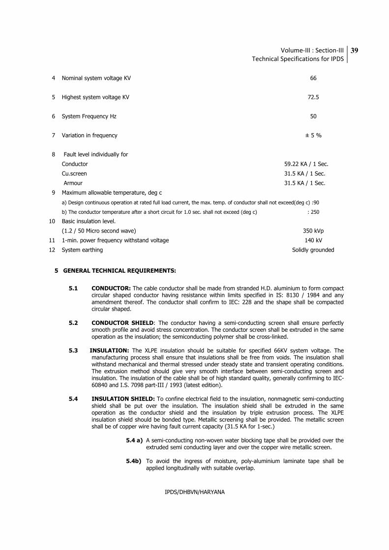
4 Nominal system voltage KV 66
5 Highest system voltage KV 72.5
6 System Frequency Hz 50
7 Variation in frequency ± 5 %
8 Fault level individually for
Conductor 59.22 KA / 1 Sec.
Cu.screen 31.5 KA / 1 Sec.
Armour 31.5 KA / 1 Sec.
9 Maximum allowable temperature, deg c
a) Design continuous operation at rated full load current, the max. temp. of conductor shall not exceed(deg c) :90
b) The conductor temperature after a short circuit for 1.0 sec. shall not exceed (deg c) : 250
10 Basic insulation level.
(1.2 / 50 Micro second wave) 350 kVp
11 1-min. power frequency withstand voltage 140 kV
12 System earthing Solidly grounded
5 GENERAL TECHNICAL REQUIREMENTS:
5.1 CONDUCTOR: The cable conductor shall be made from stranded H.D. aluminium to form compact circular shaped conductor having resistance within limits specified in IS: 8130 / 1984 and any amendment thereof. The conductor shall confirm to IEC: 228 and the shape shall be compacted circular shaped.
5.2 CONDUCTOR SHIELD: The conductor having a semi-conducting screen shall ensure perfectly
smooth profile and avoid stress concentration. The conductor screen shall be extruded in the same operation as the insulation; the semiconducting polymer shall be cross-linked.
5.3 INSULATION: The XLPE insulation should be suitable for specified 66KV system voltage. The
manufacturing process shall ensure that insulations shall be free from voids. The insulation shall withstand mechanical and thermal stressed under steady state and transient operating conditions. The extrusion method should give very smooth interface between semi-conducting screen and insulation. The insulation of the cable shall be of high standard quality, generally confirming to IEC-60840 and I.S. 7098 part-III / 1993 (latest edition).
5.4 INSULATION SHIELD: To confine electrical field to the insulation, nonmagnetic semi-conducting
shield shall be put over the insulation. The insulation shield shall be extruded in the same operation as the conductor shield and the insulation by triple extrusion process. The XLPE insulation shield should be bonded type. Metallic screening shall be provided. The metallic screen shall be of copper wire having fault current capacity (31.5 KA for 1-sec.)
5.4 a) A semi-conducting non-woven water blocking tape shall be provided over the
extruded semi conducting layer and over the copper wire metallic screen. 5.4b) To avoid the ingress of moisture, poly-aluminium laminate tape shall be
applied longitudinally with suitable overlap.
Volume-III : Section-III
Technical Specifications for IPDS
40
IPDS/DHBVN/HARYANA
5.5 INNER-SHEATH: The sheath shall be suitable to withstand the site conditions and the desired temperature. It should be of adequate thickness, consistent quality and free from all defects. The sheath shall be extruded and of black Thermoplastic H.D.P.E. (Poly-ethylene).
5.6 ARMOUR: Single H.D. Aluminium wire armouring shall be provided. The dimension of H.D.
Aluminium wire armouring shall be as per latest IS: 3975/19988. The armour shall be having fault current capacity (31.5 KA for 1- sec.)
5.7 OUTER SHEATH: Extruded Thermoplastic HDPE outer sheath confirming to IEC: 502/1983, shall
be applied over armouring with suitable additives to prevent attack by rodents and termites. The outer sheath shall be coated with graphite throughout the length of cable.
5.8 CONSTRUCTION:
5.8.1 All materials used in the manufacture of cable shall be new unused and of finest quality. All materials should comply with the applicable provision of the tests of the specification. IS, IEC, CEA regulations, Indian Electricity Act and any other applicable statutory provisions rules and regulations.
5.9 CURRENT RATING: The cable will have current ratings and derating factors as per relevant
standard IEC.
5.9.1 The one-second short circuit current rating values each for conductor, screen & armour shall be furnished and shall be subject to the purchaser's approval.
5.9.2 The current ratings shall be based on maximum conductor temperature of 90
deg. C with ambient site condition specified for continuous operation at the rated current.
5.10 OPERATION:
5.10.1 Cables shall be capable of satisfactory operation under a power supply system frequency variation of ±5% voltage variation of ±10 % and combined frequency voltage variation shall be +10 % & - 15%.
5.10.2 Cable shall be suitable for laying in ducts or burried under ground. 5.10.3 Cable shall have heat and moisture resistance properties. These shall be of type
and design with proven record on transmission network service.
5.11 INDENTIFICATION MARKING: Identification of cables shall be 'provided externally at three meters’ intervals to identify as under.
i) 'Name of manufacture' ii) ‘Per meter marking’ iii) 'Year of manufacture' iv) 'Voltage grade' to be printed / embossed at the interval of one meter-length. The identification, by printing or embossing shall be done only on the outer sheath. Name of the purchaser shall also be embossed.
6.0 TESTS: (refer Tech specification Volume III Section I).
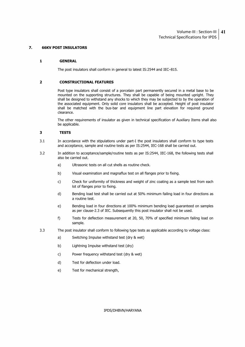
Volume-III : Section-III
Technical Specifications for IPDS
41
IPDS/DHBVN/HARYANA
7. 66KV POST INSULATORS
1 GENERAL
The post insulators shall conform in general to latest IS:2544 and IEC–815.
2 CONSTRUCTIONAL FEATURES
Post type insulators shall consist of a porcelain part permanently secured in a metal base to be mounted on the supporting structures. They shall be capable of being mounted upright. They shall be designed to withstand any shocks to which they may be subjected to by the operation of the associated equipment. Only solid core insulators shall be accepted. Height of post insulator shall be matched with the bus-bar and equipment line part elevation for required ground clearance.
The other requirements of insulator as given in technical specification of Auxiliary Items shall also be applicable.
3 TESTS
3.1 In accordance with the stipulations under part-I the post insulators shall conform to type tests
and acceptance, sample and routine tests as per IS:2544, IEC-168 shall be carried out.
3.2 In addition to acceptance/sample/routine tests as per IS:2544, IEC-168, the following tests shall also be carried out.
a) Ultrasonic tests on all cut shells as routine check.
b) Visual examination and magnaflux test on all flanges prior to fixing.
c) Check for uniformity of thickness and weight of zinc coating as a sample test from each
lot of flanges prior to fixing.
d) Bending load test shall be carried out at 50% minimum failing load in four directions as
a routine test.
e) Bending load in four directions at 100% minimum bending load guaranteed on samples as per clause-2.3 of IEC. Subsequently this post insulator shall not be used.
f) Tests for deflection measurement at 20, 50, 70% of specified minimum failing load on
sample.
3.3 The post insulator shall conform to following type tests as applicable according to voltage class:
a) Switching Impulse withstand test (dry & wet)
b) Lightning Impulse withstand test (dry)
c) Power frequency withstand test (dry & wet)
d) Test for deflection under load.
e) Test for mechanical strength,
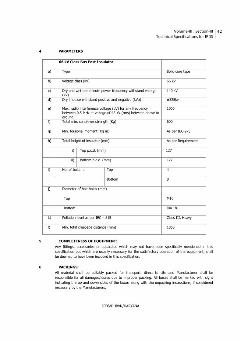
Volume-III : Section-III
Technical Specifications for IPDS
42
IPDS/DHBVN/HARYANA
4 PARAMETERS
66 kV Class Bus Post Insulator
a) Type Solid core type
b) Voltage class (kV) 66 kV
c) Dry and wet one minute power frequency withstand voltage (kV)
140 kV
d) Dry impulse withstand positive and negative (kVp) ±325kv
e) Max. radio interference voltage (pV) for any frequency between 0.5 MHz at voltage of 42 kV (rms) between phase to ground.
1000
f) Total min. cantilever strength (Kg) 600
g) Min. torsional moment (Kg m) As per IEC-273
h) Total height of insulator (mm) As per Requirement
i) Top p.c.d. (mm) 127
ii) Bottom p.c.d. (mm) 127
i) No. of bolts : Top 4
Bottom 8
j) Diameter of bolt holes (mm)
Top M16
Bottom Dia 18
k) Pollution level as per IEC – 815 Class III, Heavy
l) Min. total creepage distance (mm) 1850
5 COMPLETENESS OF EQUIPMENT:
Any fittings, accessories or apparatus which may not have been specifically mentioned in this
specification but which are usually necessary for the satisfactory operation of the equipment, shall
be deemed to have been included in this specification.
6 PACKINGS:
All material shall be suitably packed for transport, direct to site and Manufacturer shall be
responsible for all damages/losses due to improper packing. All boxes shall be marked with signs
indicating the up and down sides of the boxes along with the unpacking instructions, if considered
necessary by the Manufacturers.
Volume-III : Section-III
Technical Specifications for IPDS
43
IPDS/DHBVN/HARYANA
8. LIGHTING
(refer Volume III Section I for specifications)
9. LT SWITCHGEAR & DBS
(refer Volume III Section I for specifications)
10. BATTERY & BATTERY CHARGER
(refer Volume III Section I for specifications)
Volume-III : Section-III
Technical Specifications for IPDS
44
IPDS/DHBVN/HARYANA
11. CONTROL & PROTECTION SYSTEM FOR 66KV SUB-STATION
1 PREAMBLE
This specification is based on the understanding that the bidder shall supply and commission a completely integrated System for 66 kV Sub-station as-
1. Substation control system.
2. Substation protection system
3. Energy meters for 66 kV and 11 kV Switchgear
2 GENERAL REQUIREMENTS OF CONTROL SYSTEM
1. The Simplex panel shall be vertical and freestanding, floor mounted type with swinging
door at the back of the panel.
2. The height and width of the panel shall be as per standard practices.
3. One panel should accommodate two bay controlling facilities.
4. Each bay control shall comprise of,
a. One wattmeter, one voltmeter with selector switch and one ammeter with
selector switch, one varmeter.
b. One control switch having LED type red and green indication for breaker
control.
c. Red /green LED type indication lamp for isolator indication.
d. Semaphore indicator for earth switch.
e. One synchronizing switch with key and sockets.
f. The bay control panel for transformer shall also include cut out for one no
RWTI.
5. Annunciator with window type display shall be provided on each control panel for alarm
annunciation. The display shall be of standard size and shall accommodate minimum two alarms simultaneously. The annunciator shall have accept, reset and test facilities.
6. The panel shall have the required control wiring. The wire shall be 1.5sqmm cupper per
connection. For CT connection only 2.5sqmm size cable per connection shall be used.
7. Necessary space heater, lighting arrangements shall be provided.
8. Independent transducer shall be provided for varmeter and wattmeter. One extra output
Volume-III : Section-III
Technical Specifications for IPDS
45
IPDS/DHBVN/HARYANA
of 4-20ma shall be provided on the transducer for owner use. The accuracy of the transducer shall be 0.5%.
9. One of the panels should house the Check syn relay and Guard relay for
synchronization. The synchronizing bus shall be of 2.5sqmm cable. The inter-panel wiring with necessary connection to check syn switch shall form the syn bus.
10. Bidder shall provide the syn scheme as per approval.
3 PANEL CONFIGURATION
As per Sub-Station requirement (to be specified by Employer)
4 GENERAL REQUIREMENTS OF RELAYS
a. All relays and devices shall be of proven design and suitable make & type for the application satisfying the requirements specified elsewhere and shall be subject to the Employer’s approval. Relays shall have appropriate setting ranges, accuracy, resetting ratio, transient overreach and other characteristics to provide the required sensitivity to the satisfaction of the Employer.
b. Relays shall be suitable for efficient and reliable operation of the protection scheme. The
necessary auxiliary relays, trip relays, etc. required for complete scheme, interlocking, alarm, logging, etc. shall be provided. No control relay, which shall trip the circuit breaker when the relay is de-energized, shall be employed in the circuits.
c. Relays shall be provided with self-reset contacts except for the trip lockout, which shall
have contacts with a manual reset feature.
d. Suitable measures shall be provided to ensure that transients present in CT & VT
connections due to extraneous sources in the EHV system do not cause damage to relays. CT saturation shall not cause mal-operation of relays.
e. Only DC/DC converters shall be provided in solid state devices/relays wherever
necessary to provide a stable auxiliary supply for relay operation.
f. DC batteries in protective relays necessary for relay operation shall not be acceptable.
Equipment shall be protected against voltage spikes in the auxiliary DC supply.
g. The testing and commissioning protocols for the protection systems offered shall be
approved by the Employer before commissioning on site.
5 EHV LINE PROTECTION
Each 66 kV line shall be provided with the following protection:
i) 3-zone non-switched static distance protection (21) proven for EHV D/C line protection
application.
ii) Non directional 3-ph over current (51)-(Definite Time).
iii) Non directional earth fault (51N)- (Definite Time).
iv) Autoreclosing relay.
Volume-III : Section-III
Technical Specifications for IPDS
46
IPDS/DHBVN/HARYANA
v) Check syn relay.
6 BUS COUPLER PROTECTION
i) Non directional 3 ph over current (51)
ii) Non-directional delayed earth fault (51N)- (Definite Time).
7 66/11 kV TRANSFORMER PROTECTIONS
i) Static Biased differential protection. (87T) with 2nd harmonic resistant with high set.
Unit.
ii) High Impedance LV REF. (64)
iii) HV Directional over current (67/50/51)
iv) LV Back up Earth Fault (51N)
8 66 kV BUS PT
i) Bus PT fuse failure relay.
ii) 70% Bus under voltage relay.
9 PROTECTION PHILOSOPHY
i) The 66kv line distance protection shall be set to cover the line length as per the parallel
line distance protection philosophy.
ii) The over current and earth fault relay provided on bus coupler and line shall be coordinated in such a way that for a bus fault on any of the bus the bus coupler shall open first. Then after some time delay the corresponding line shall be tripped. This time shall be less than zone–2 times setting of the remote end distance protection.
iii) Fault between the 66/11 kV transformer and corresponding CT shall be cleared by the
corresponding directional earth fault relay.
iv) The distance relay offered by the bidder shall be suitable for 3-zone distance protection of 66kv and above line of length not more than 2 KM. The relay shall give reliable operation under all system contingencies. E/F element characteristics shall be reactive type to limit the mal operation and shall be reliable under high resistance fault.
v) The distance relay located at the both end of transmission line shall operate
independent of PLCC link.
vi) The LBB trip command shall be extended to bus coupler and same bus breakers by
appropriate isolators logic.
Volume-III : Section-III
Technical Specifications for IPDS
47
IPDS/DHBVN/HARYANA
10 AUTO-RECLOSE AND SYNCHRONIZING CHECK
Auto-reclose (AR) and Synchronizing Check (SC) functionality shall be provided in a separate device. The interfacing between S/S Controller and Protection Units for achieving the AR function logic shall be achieved at Bay Level using communication LAN as well as standby hard-wired logic. The AR function shall meet the following criteria:
- Be of single shot type
- Have three phase reclosing facilities. It shall have a user-selectable option of three
phase or non-auto reclosure mode.
- Incorporate a normal/delayed auto reclosure option with a time range of 1 to 60 s.
- Have a continuously variable three-phase and single-phase dead time of 0,1 to 5 s.
- Have a continuously variable reclaim time of 5 to 300 s.
- Incorporate the necessary auxiliary relays and timers to provide a comprehensive
reclosing and synchronizing scheme.
- Have facilities for selecting check synchronizing or dead line charging features. The user
shall have an option to change the required feature.
The built-in Synchronization Check feature shall determine the difference between the amplitudes, phase angles and frequencies of two voltage vectors. Checks shall be provided to detect a dead line or bus bar. The voltage difference, phase angle difference and slip frequency settings shall be adjustable.
11 66 kV CIRCUIT-BREAKER PROTECTION
Each circuit breaker in the 66 kV bay shall be provided with following protection functions:
i) Local Breaker Back up Protection Function: LBB protection function shall be provided for each circuit breaker in the 66 kV Sub-Station with following logic.
- Be three pole type having three single phase units
- Shall operate for stuck breaker conditions
- Have an operating/resetting time each of less than 15 ms.
- The LBB function shall be initiated by external trip contacts from the Protection Units and after a set time delay shall energize the trip bus coupler.
- Have a setting range of 5 to 80% of rated current
- Have a continuous thermal withstand of 2 times rated current irrespective of
the setting.
- Have time delay feature with a continuously adjustable setting range of 0,1 to
1 s.
Volume-III : Section-III
Technical Specifications for IPDS
48
IPDS/DHBVN/HARYANA
- Shall be an individual phase comprehensive scheme.
- Shall not operate during the single-phase auto-reclosing period.
ii) Trip Coil Supervision: A Trip Coil supervision function shall be provided for each lockout trip relay and each of the circuit-breaker trip coils. It shall incorporate both the pre-close and post-close supervision of trip coils and associated trip circuits. An audible alarm shall be given in the event of operation of trip coil supervision function. It shall have a time delay on drop-off of not less than 200ms.
12 ENERGY METERS
a) Shall carry out measurement of active energy (both import and export) and reactive energy (both import and export) by 3 phase, 4 wire principle suitable for balanced/ unbalanced 3 phase load.
b) Shall have an accuracy of energy measurement of at least Class 0.5 for active energy
and at least Class 1 for reactive energy according to IS 14697 and IEC 60687, and shall be connected to Class 0.5 CT cores and Class 0.5 VT windings.
c) The active and reactive energy shall be directly computed in CT & VT primary ratings.
The active energy shall be stored for each metering interval in two different registers as MWh (Export) and MWh (Import), along with a plus (+) sign for export and minus (-) sign for import. The reactive energy shall be stored for each metering interval in four different registers as MVARh (lag) when active export, MVARh (Lag) when active import, MVARh (lead) when active export, MVARh (Lead) when active import. In addition, two more registers shall be provided to record MVARH when system voltage is >103% and when system voltage is < 97%.
d) Shall accumulate the net MWh and MVARh during each successive 15-minute block
metering interval and store in the registers in non-volatile memory.
e) Shall continuously integrate the energy readings of each register up to the previous
metering interval.
f) Each energy meter shall have a display unit. It shall display the net MWh and MVARh during the previous metering interval; peak MWh demand since the last demand reset; accumulated total MWh and MVARh; date and time; and instantaneous current and voltages on each phase.
g) All the registers shall be stored in a non-volatile memory. Meter registers for each
metering interval, as well as accumulated totals, shall be downloadable.
h) At least last 40 days of data shall be stored before being over-written.
i) Shall have a built in clock and calendar with an accuracy of less than 15 seconds per month drift without assistance of external time synchronizing pulse.
j) Date/time shall be displayed on demand. Facility for synchronization of the clock by
external signal shall be there.
k) The voltage monitoring of all the three voltages shall be provided as well as alarm
contact to indicate meter healthy status. The meter shall normally operate with power
Volume-III : Section-III
Technical Specifications for IPDS
49
IPDS/DHBVN/HARYANA
drawn from the VT supplies. The burden of the meters shall be less than 2 VA.
l) The power supply to the meter shall be healthy even with a single-phase VT supply. An automatic backup, in the event of non-availability of voltage in all the phases, shall be provided by a built in long life battery and shall not need replacement for at least 10 years with a continuous VT interruption of at least 2 years. Date and time of VT interruption and restoration shall be automatically stored in a non-volatile memory.
m) Shall have an optical port as well as RS 485 port on the front of the meter for data
collection from either a hand held meter reading instrument (MRI) having a display for energy readings (to be supplied by the bidder) or through modem to central data center. The MRI shall be complete with optical interface unit required.
n) The meter shall be provided with signaling output on the front to test MWh and MVARh
accuracy and calibration at site in-situ and test terminal blocks shall be provided for the same.
13 PANELS
All panels shall be free standing, simplex type, floor mounting type and completely metal
enclosed. Cable entries shall be from the bottom. Panels shall be of IP 31 class or better.
Panels shall have removable gland plates with glands made of brass and shall be suitable
for armoured cables.
Panels shall be painted. The colour of paint for exterior of the panel shall be as follows:
a) Ends Powder coated smoke grey to shade : 692 of IS-5
(Semi Gloss)
b) Front and Rear -do-
c) Interior White
d) Base Black
14 Earthing
a) The panels shall be equipped with an earth bus of at least 50x6mm2 galvanized steel flat
bar or equivalent copper.
b) Earth buses of adjoining panels shall be connected for continuity. The continuous earth
bus so formed shall be connected to the main earth grid at one end only.
c) All metallic cases of the mounted equipment shall be separately connected to the earth bus by 2.5mm2 copper wire. No loops in the earth wiring shall be permitted.
d) CT/VT neutral secondary shall only be earthed at the terminal block of the panel through links, such that the earthing of one group may be removed without disturbing others.
Volume-III : Section-III
Technical Specifications for IPDS
50
IPDS/DHBVN/HARYANA
15 CONTROL CABLING PHILOSOPHY IN SUB-STATION
a) Each secondary core of each phase CT/CVT shall be brought to the equipment
marshalling box through independent cables.
b) Each three phase secondary core of each CT/CVT shall be brought to the associated
control/relay panel from the equipment marshalling box through independent cables.
c) Single cores with at least 2.5mm2 equivalent core cross-sectional area per connection shall be used for connection of all CT/CVT circuits.
d) VT leads used for tariff metering shall have an equivalent core cross-sectional area of at least 2.5 mm2 or equivalent per phase/neutral connection.
e) Duplicate channels of protection shall have independent cables for tripping, DC supply,
etc.
f) For the following applications multiple cores with at least 2.5 mm2 equivalent core cross - sectional area per connection shall be used:
i) DC supply to Bay Marshalling box
ii) DC supply to circuit-breaker cubicle
iii) DC looping for closing and tripping circuits of circuit-breaker
g) Spare cores shall be provided as per following norms:
Up to 3-core cable - Nil
5 Core Cable - Min. 1 core
7 to 14 core cables - Min. 2 cores
More than 14 core - Min. 3 cores
h) For various field input from the breaker, transformer etc. for alram, at least 1.5mmsq
equivalent cross section area per connection shall be used.
16 FACTORY ACCEPTANCE TESTS (FAT)
All equipment furnished under this specification shall be subject to test by authorized quality assurance personnel of the bidder and Employer’s representatives during manufacture, erection
and on completion. The approval of the Employer or passing such inspections or tests will not, however, prejudice the right of the Employer to reject the equipment if it does not comply with the specifications when erected or fails to give complete satisfaction in service. The detailed requirement of operational and pre-FAT tests as well as FAT test (Integrated Test) is given in this Section. The FAT shall be mutually agreed upon and approved by Employer during detailed engineering.

Volume-III : Section-III
Technical Specifications for IPDS
51
IPDS/DHBVN/HARYANA
17 Operational and Pre-FAT Tests
a) The authorized quality assurance personnel of the manufacturer shall conduct all tests as per the requirements and fully satisfy themselves regarding completeness of hardware, software and full compliance with specification requirements by all equipment/sub-systems and the system as a whole before sending notification for FAT to the Employer. Bidder shall maintain accurate records for all pre-FAT tests which shall be properly documented and duly certified documents shall be furnished to Employer at least two weeks prior to FAT tests, while giving inspection call.
b) Each individual item of equipment/sub-system furnished by the Bidder as well as the complete system as per this specification shall be inspected and tested by the Bidder in his works for full compliance with specification requirements, completeness, proper assembly, proper operation, cleanliness and state of physical condition as applicable.
c) The Bidder shall conduct a point by point wiring continuity check to every input and output and verify that the wiring connections agree with the documentation.
d) The pre-FAT report shall be in the format of FAT procedure as approved by the Employer. It shall be accompanied by a very detailed report, in a log form, of the performance of all pre-FAT Tests. These records shall list not only the successfully completed tests, but shall detail all system, test and component failures.
e) Bidder shall send notification regarding readiness for FAT and indicate the proposed date for commencement of FAT to enable the Employer to depute representatives for participating in these tests. The notification shall be sent to the Employer not less than one month prior to commencement of the FAT along with the copies of documents covering pre-FAT results.
f) The Bidder shall ensure that all hardware required for fully implementing the system as per requirements of this specification is available and the adequacy of hardware, system configuration, etc., is fully established during the pre-FAT Tests conducted by the Bidder. In case any deficiencies in hardware is noticed by the Bidder during the pre-FAT Tests, the Bidder shall make good all such deficiencies and re-conduct the required tests to fully satisfy himself regarding completeness of the system and full compliance with specification requirements before sending notification to the Employer regarding FAT Tests.
18 SITE / COMMISSIONING TESTS
Site tests shall include all tests to be carried out at site upon receipt of equipment. It shall include
but not be limited to testing calibration, configurations and pre-commissioning trials, startup tests, trial operation and performance and guarantee tests. The Bidder shall be responsible for all site / commissioning tests. The Bidder shall maintain all tests, calibration records in Employer approved formats, and these shall be countersigned by authorized quality assurance personnel of the Bidder supervising these works. The Bidder shall maintain master checklists to ensure that all tests and calibration for all equipment/devices furnished under these specifications are satisfactorily completed under the supervision of the authorized quality assurance personnel of the Bidder. The site / commissioning tests shall be categorized under following categories:
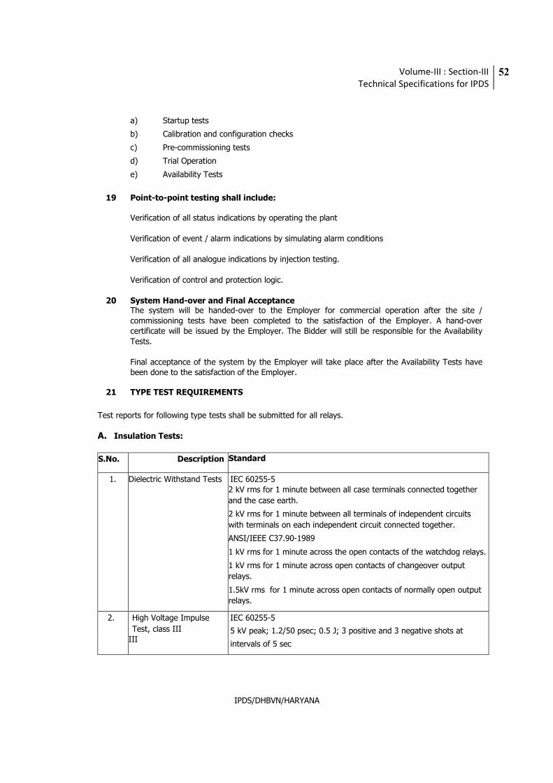
Volume-III : Section-III
Technical Specifications for IPDS
52
IPDS/DHBVN/HARYANA
a) Startup tests
b) Calibration and configuration checks
c) Pre-commissioning tests
d) Trial Operation
e) Availability Tests
19 Point-to-point testing shall include:
Verification of all status indications by operating the plant Verification of event / alarm indications by simulating alarm conditions Verification of all analogue indications by injection testing.
Verification of control and protection logic.
20 System Hand-over and Final Acceptance The system will be handed-over to the Employer for commercial operation after the site / commissioning tests have been completed to the satisfaction of the Employer. A hand-over certificate will be issued by the Employer. The Bidder will still be responsible for the Availability Tests. Final acceptance of the system by the Employer will take place after the Availability Tests have been done to the satisfaction of the Employer.
21 TYPE TEST REQUIREMENTS
Test reports for following type tests shall be submitted for all relays.
A. Insulation Tests:
S.No. Description Standard
1. Dielectric Withstand Tests IEC 60255-5 2 kV rms for 1 minute between all case terminals connected together
and the case earth.
2 kV rms for 1 minute between all terminals of independent circuits
with terminals on each independent circuit connected together.
ANSI/IEEE C37.90-1989
1 kV rms for 1 minute across the open contacts of the watchdog relays.
1 kV rms for 1 minute across open contacts of changeover output
relays.
1.5kV rms for 1 minute across open contacts of normally open output
relays.
2. High Voltage Impulse
Test, class III III
IEC 60255-5
5 kV peak; 1.2/50 psec; 0.5 J; 3 positive and 3 negative shots at
intervals of 5 sec
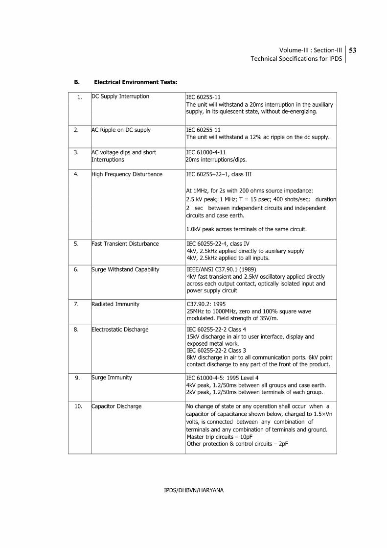
Volume-III : Section-III
Technical Specifications for IPDS
53
IPDS/DHBVN/HARYANA
B. Electrical Environment Tests:
1. DC Supply Interruption IEC 60255-11
The unit will withstand a 20ms interruption in the auxiliary supply, in its quiescent state, without de-energizing.
2. AC Ripple on DC supply IEC 60255-11 The unit will withstand a 12% ac ripple on the dc supply.
3. AC voltage dips and short Interruptions
IEC 61000-4-11 20ms interruptions/dips.
4. High Frequency Disturbance IEC 60255–22–1, class III
At 1MHz, for 2s with 200 ohms source impedance:
2.5 kV peak; 1 MHz; T = 15 psec; 400 shots/sec; duration
2 sec between independent circuits and independent
circuits and case earth. 1.0kV peak across terminals of the same circuit.
5. Fast Transient Disturbance IEC 60255-22-4, class IV 4kV, 2.5kHz applied directly to auxiliary supply 4kV, 2.5kHz applied to all inputs.
6. Surge Withstand Capability IEEE/ANSI C37.90.1 (1989) 4kV fast transient and 2.5kV oscillatory applied directly across each output contact, optically isolated input and power supply circuit
7. Radiated Immunity C37.90.2: 1995 25MHz to 1000MHz, zero and 100% square wave modulated. Field strength of 35V/m.
8. Electrostatic Discharge IEC 60255-22-2 Class 4 15kV discharge in air to user interface, display and exposed metal work. IEC 60255-22-2 Class 3 8kV discharge in air to all communication ports. 6kV point contact discharge to any part of the front of the product.
9. Surge Immunity IEC 61000-4-5: 1995 Level 4 4kV peak, 1.2/50ms between all groups and case earth. 2kV peak, 1.2/50ms between terminals of each group.
10. Capacitor Discharge No change of state or any operation shall occur when a
capacitor of capacitance shown below, charged to 1.5×Vn
volts, is connected between any combination of
terminals and any combination of terminals and ground. Master trip circuits – 10pF Other protection & control circuits – 2pF
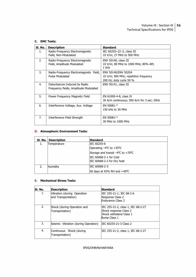
Volume-III : Section-III
Technical Specifications for IPDS
54
IPDS/DHBVN/HARYANA
C. EMC Tests:
Sl. No. Description Standard
1. Radio-Frequency Electromagnetic Field, Non-Modulated
IEC 60255–22–2, class III 10 V/m; 27 MHz to 500 MHz
2. Radio-Frequency Electromagnetic Field, Amplitude Modulated
ENV 50140, class III 10 V/m; 80 MHz to 1000 MHz; 80% AM; 1 kHz
3. Radio-Frequency Electromagnetic Field,
Pulse Modulated
ENV 50140/ENV 50204
10 V/m; 900 MHz; repetition frequency
200 Hz; duty cycle 50 %
4. Disturbances Induced by Radio
Frequency fields, Amplitude Modulated
ENV 50141, class III
5. Power Frequency Magnetic Field EN 61000-4-8, class IV
30 A/m continuous; 300 A/m for 3 sec; 50Hz
6. Interference Voltage, Aux. Voltage EN 50081-*
150 kHz to 30 MHz
7. Interference Field Strength EN 50081-*
30 MHz to 1000 MHz
D. Atmospheric Environment Tests:
Sl. No. Description Standard 1. Temperature IEC 60255-6
Operating –40C to +550C
Storage and transit –40C to +700C
IEC 60068-2-1 for Cold
IEC 60068-2-2 for Dry heat
2. Humidity IEC 60068-2-3
56 days at 93% RH and +400C
E. Mechanical Stress Tests:
Sl. No. Description Standard 1. Vibration (during Operation
and Transportation)
IEC 255-21-1; IEC 68-2-6
Response Class 2 Endurance Class 2
2. Shock (during Operation and
Transportation)
IEC 255-21-2, class 1, IEC 68-2-27 Shock response Class 2 Shock withstand Class 1 Bump Class 1
3. Seismic Vibration (during Operation) IEC 60255-21-3 Class 2
4. Continuous Shock (during
Transportation)
IEC 255-21-2, class 1, IEC 68-2-27
Volume-III : Section-III
Technical Specifications for IPDS
55
IPDS/DHBVN/HARYANA
22 SETTINGS
Fault levels will be provided to the Bidder by the Employer. The Bidder shall, based on this information, compile a complete and detailed report for the setting of the protection elements on all the protection equipment, to the approval of the Employer. Any additional information required to complete this exercise shall be timeously requested by the Bidder.
The bidder shall provide the Employer with a philosophy document clearly setting out the philosophy the bidder will use in determining setting levels. Each setting will have a brief description of the specific function or element. The setting calculation and formula will also be shown on the document. All relevant system parameters, line data, transformer data additionally used for calculating the setting will appear in the setting document. The bidder will conduct system studies in determining fault levels on different locations. These study results will also form part of the setting document. Any additional information required to complete this exercise shall be timeously requested by the Bidder.
The setting document will be presented and discussed with the Employer prior to final issue of the document. The final accepted setting document should be made available to the Employer in PDF format.
It is the Bidder’s responsibility to configure each protection relay to provide the protection and control facilities required. A full set of relay configuration and setting files shall be included in the design and documentation submissions. The bidder will issue three sets of setting documents once accepted by the client and consultant.
23 COMPLETENESS OF EQUIPMENT:
Any fittings, accessories or apparatus which may not have been specifically mentioned in this
specification but which are usually necessary for the satisfactory operation of the equipment, shall
be deemed to have been included in this specification.
24 PACKINGS:
All material shall be suitably packed for transport, direct to site and Manufacturer shall be
responsible for all damages/losses due to improper packing. All boxes shall be marked with signs
indicating the up and down sides of the boxes along with the unpacking instructions, if considered
necessary by the Manufacturers.
Volume-III : Section-III
Technical Specifications for IPDS
56
IPDS/DHBVN/HARYANA
12. SWITCHYARD AUXILIARY ITEMS
1. ACSR CONDUCTOR
a) Code and standard IS 398 (Part-II)
b) Name ACSR Equivalent to 261.5 sq.mm. area
conductor/Panther
c) Overall diameter 21.00 mm
d) Weight 974 kg/km
e) Ultimate tensile strength 89.67 kN minimum
f) Strands and wire diameter of
- Aluminium 30/3.00 mm
- Steel 7/3.00 mm
2. CLAMPS AND CONNECTORS
2.1 The material of clamps and connectors shall be Aluminium alloy casting conforming to designation A6 of IS:617 for connecting to equipment terminals and conductors of aluminium. In case the terminals are of copper, the same clamps/connectors shall be used with 2mm thick bimetallic liner.
2.2 The material of clamps and connectors shall be Galvanised mild steel for connecting to shield
wire.
2.3 Bolts, nuts and plain washers shall be hot dip galvanised mild steel for sizes M12 and above. For sizes below M12, they shall be electro-galvanised mild steel. The spring washers shall be electro-galvanised mild steel.
2.4 All castings shall be free from blow holes, surface blisters, cracks and cavities. All sharp edges
and corners shall be rounded off to meet specified corona and radio interference requirements.
2.5 They shall have same current rating as that of the connected equipment. All current carrying parts shall be at least 10 mm thick. The connectors shall be manufactured to have minimum contact resistance.
2.6 Flexible connectors, braids or laminated strips shall be made up of copper/aluminium.
2.7 Current rating and size of terminal/conductor for which connector is suitable shall be embossed/punched on each component.
Volume-III : Section-III
Technical Specifications for IPDS
57
IPDS/DHBVN/HARYANA
3. INSULATOR STRING HARDWARE
3.1 The insulator hardware shall be of bolted type and shall be of forged steel except for insulator cap, which can be of malleable cast iron. It shall also generally meet the requirements of clamps and connectors as specified above.
3.2 In one span, Tension string assembly at one end shall be supplied with suitable turn buckle.
3.3 Disc Insulator
The disc insulator shall meet the following parameters:
a) Type : Antifog type insulator
b) Size of insulator : 255x145
c) Electro mechanical strength : 120kN
d) Leakage distance (mm) : 430mm minimum or as required
to meet the total creepage.
e) Power frequency withstand voltage : 85 kV (dry), 50kV (wet)
4. EARTHING CONDUCTOR
4.1 The main conductor buried in earth shall be 40mm dia rod for main and auxiliary mat. The earthing conductors over the ground shall be of 75x12 mm GS flat. The earthing leads for columns and auxiliary structures, cable trenches shall be of 75x12 mm GS flat. The earthing of the lighting fixtures shall be carried out by 16 SWG wire.
4.2 All conductors above the ground level shall be galvanised steel.
4.3 Earthwire for Lightning Protection
a) Number of strands 7 of steel
b) Strand diameter 3.15 mm
c) Overall diameter 9.45 mm
d) Weight 431.80 kg/km approx.
e) Ultimate tensile strength 68.4 kN minimum
f) Total cross-sectional area 54.55 sq.mm.
g) Calculated DC resistance 3.375 ohms/km at 20 deg. C.
Volume-III : Section-III
Technical Specifications for IPDS
58
IPDS/DHBVN/HARYANA
h) Direction of lay of outer layer Right hand
i) Protective coating for storage Boiled linseed oil to avoid wet storage
stains (white rust)
4.4 Cable Support Structures & Accessories
4.4.1 The Bidder shall fabricate and install mounting arrangements for the support and installation of all the cables on angles in trenches. These mounting structures/cable racks shall be fabricated from structural steel members (channels, angles and flats) of the required size.
4.4.2 Cable supports shall be painted after installation. The painting shall be in conformity with
stipulated in Volume-III, Section-I. All welding works inclusive of the consumables required for fabrication and installation shall be in the scope of the Bidder.
5. BUSHINGS, HOLLOW COLUMN INSULATORS, SUPPORT INSULATORS, AND DISC
INSULATORS
5.1 Bushings shall be manufactured and tested in accordance with IS:2099 & IEC:137 while hollow column insulators shall be manufactured and tested in accordance with IEC 233/IS 5284. The support insulators shall be manufactured and tested as per IS:2544/IEC 168/IEC 273. The insulators shall also conform to IEC 815 as applicable.
5.2 Support insulators/bushings/hollow column insulators shall be designed to have ample insulation,
mechanical strength and rigidity for the conditions under which they will be used.
5.3 Porcelain used shall be homogenous, free from laminations, cavities and other flaws or imperfections that might affect the mechanical or dielectric quality and shall be thoroughly vitrified, tough and impervious to moisture. Hollow porcelain should be in one integral piece in green & fired stage.
5.4 Glazing of the porcelain shall be uniform brown in colour, free form blisters, burns and other
similar defects.
5.5 When operating at normal rated voltage there shall be no electric discharge between conductor and insulators which would cause corrosion or injury to conductors or when operating at normal rated voltage.
5.6 The design of the insulator shall be such that stresses due to expansion and contraction in any
part of the insulator shall be lead to deterioration. All ferrous parts shall be hot dip galvanised.
5.7 Bidder shall make available data on all the essential features of design including the method of assembly of shells and metal parts, number of shells per insulator, the manner in which mechanical stresses are transmitted through shells to adjacent parts, provision for meeting expansion stresses, results of corona and thermal shock tests, recommended working strength and any special design or arrangement employed to increase life under service conditions.
5.8 Post type insulators shall consist of a porcelain part permanently secured in metal base to be
mounted on supporting structures. They shall be capable of being mounted upright. They shall be designed to withstand all shocks to which they may be subjected to during operation of the associated equipment.
5.9 Bushing porcelain shall be robust and capable of withstanding the internal pressures likely to
occur in service. The design and location of clamps, the shape and the strength of the porcelain flange securing the bushing to the tank shall be such that there is no risk of fracture. All portions of the assembled porcelain enclosures and supports other than gaskets, which may in any way
Volume-III : Section-III
Technical Specifications for IPDS
59
IPDS/DHBVN/HARYANA
be exposed to the atmosphere shall be composed of completely non hygroscopic material such as metal or glazed porcelain.
5.10 All iron parts shall be hot dip galvanised and all joints shall be air tight. Surface of joints shall be
trued, porcelain parts by grinding and metal parts by machining. Insulator/ bushing design shall be such as to ensure a uniform compressive pressure on the joints.
5.11 Bushings, hollow column insulators and support insulators shall conform to type tests and shall
be subjected to routine tests and acceptance test/ sample test in accordance with relevant standards.
5.12 Insulator shall meet requirement of IEC - 815 as applicable, having alternate long & short sheds.
6. CABINETS, BOXES, KIOSKS AND PANELS, ETC.
6.1 All types of control cabinets, junction boxes, marshaling boxes, lighting panels, terminal boxes, operating mechanism boxes, etc. shall generally conform to IS:5039, IS:8623 and IEC:439 as applicable.
6.2 They shall be of painted sheet steel or aluminium. The thickness of sheet steel shall be 2mm cold
rolled or 2.5mm hot rolled. The thickness of aluminium shall be 3mm and shall provide rigidity. Top of the boxes shall be sloped towards rear of the box. The paint shall be of grey RAL 9002 on the outside and glossy white inside. However, the junction and switch boxes shall be of hot dip galvanised sheet steel of 1.6mm thickness.
6.3 The cabinets/boxes/kiosks/panels shall be free standing or wall mounting or pedestal mounting
type. They shall have hinged doors with padlocking arrangement. All doors, removable covers and plates shall be gasketed all around with neoprene gaskets.
6.4 The degree of protection of all the outdoor boxes shall not be less than IP 55 as per IS 2147.
6.5 The cable entry shall be from bottom, for which removable gasketed cable gland plates shall be
provided.
6.6 Suitable 240V, single phase, 50Hz ac heaters with thermostats controlled by switch and fuse shall be provided to maintain inside temperature 10deg. above the ambient.
6.7 The size of enclosure and the layout of equipment inside shall provide generous clearances. Each
cabinet/box/kiosk/panel shall be provided with a 15A, 240V ac, 2 pole, 3 pin industrial grade receptacle with switch. For incoming supply, MCB of suitable rating shall be provided. Illumination of each compartment shall be with door operated incandescent lamp. All control switches shall be of rotary switch type.
6.8 Each cabinet/box/kiosk/panel shall be provided with two earthing pads to receive 75mmx12mm
GS flat. The connection shall be bolted type with two bolts per pad. The hinged door shall be connected to body using flexible wire. The cabinets / boxes / kiosks / panels shall also be provided with danger plate, and internal wiring diagram pasted on inside of the door. The front label shall be on a 3mm thick plastic plate with white letters engraved on black background.
7. BAY MARSHALLING BOX
7.1 Three no. bay MBs shall be provided located at a convenient location to receive and distribute cables one marshalling box should be used for requirement of two bays. It shall meet all the requirements as specified for cabinets/boxes above.
Volume-III : Section-III
Technical Specifications for IPDS
60
IPDS/DHBVN/HARYANA
7.2 It shall have three separate distinct compartments for following purposes:
- To receive two incoming 415V, three phase, AC supplies controlled by 25A four pole MCBs, and to distribute five (5) three phase ac supplies controlled by 8A four pole MCBs.
- 80 nos. terminal blocks in vertical formation for interlocking facility.
8. TERMINAL BLOCKS
8.1 They shall be non-disconnecting stud type of extensible design equivalent to Elmex type CAT-M4.
8.2 The terminal blocks shall be of 650V grade, and rated to continuously carry maximum expected current. The conducting part shall be tinned or silver plated.
8.3 The terminals shall be provided with marking tags for wiring identification.
8.4 The terminal blocks for CT and VT secondary leads shall be provided with test links and isolating facilities. CT secondary leads shall also be provided with short circuiting and earthing facilities.
9. WIRING
9.1 All wiring shall be carried out with 1100 V grade stranded copper wires. The minimum size of the
stranded conductor used for internal wiring shall be as follows :
Wherever the cable size is specified that has to be used, otherwise,
a. All circuits except PT/CT circuits 1.5 sq.mm
b. PT/CT circuits 2.5 sq. mm.
9.2 All internal wiring shall be securely supported, neatly arranged readily accessible and connected
to equipment terminals and terminal blocks.
9.3 Wire terminations shall be made with solderless crimping type of tinned copper lugs which firmly
grip the conductor and insulation. Insulated sleeves shall be provided at all the wire terminations.
Engraved core identification plastic ferrules marked to correspond with the wiring diagram shall
be fitted at both ends of each wire. Ferrules shall fit tightly on the wires shall not fall off when
the wires and shall not fall off when the wire is disconnected from terminal blocks.
9.4 All wires directly connected to trip circuit breaker shall be distinguished by the addition of a red
coloured unlettered ferrule. Number 6 & 9 shall not be included for ferrules purposes.
9.5 All terminals including spare terminals of auxiliary equipment shall be wired upto terminal blocks.
Each equipment shall have its own central control cabinet in which all contacts including spare
contacts from all poles shall be wired out. Interpole cabling for all equipment’s shall be carried
out by the Bidder.
10. CABLE GLANDS AND LUGS
10.1 Cable glands shall be Double compression type, tinned/Nicked plated (coating thickness not less than 20 microns in case of tin and 10 to 15 microns in case of nickel) brass cable glands for all power and control cables. They shall provide dust and weather proof terminations. They shall comprise of heavy duty brass casting, machine finished and tinned to avoid corrosion and
Volume-III : Section-III
Technical Specifications for IPDS
61
IPDS/DHBVN/HARYANA
oxidation. Rubber components used in cable glands shall be neoprene and off tested quality. Required number of packing glands to close unused openings in gland plates shall also be provided.
10.2 The cable glands shall be tested as per BS:6121. The cable glands shall also be duly tested for dust proof and weather proof termination.
10.3 Cables lugs shall be tinned copper solder less crimping type conforming to IS:8309 and 8394
suitable for aluminum or copper conductor (as applicable). The cable lugs shall suit the type of terminals provided. The cable lugs shall be of Dowell make or equivalent.
11. CONDUITS, PIPES AND ACCESSORIES
11.1 The Bidder shall supply and install all rigid conduits, mild steel pipes, flexible conduits, hume pipes, etc. including all necessary sundry materials, such as tees, elbows, check nuts, bushing reduces, enlargers, wooden plugs, coupling caps, nipples, gland sealing fittings, pull boxes, etc.
11.2 Rigid conduits shall be flow-coat metal conduits of Nagarjuna Coated Tubes or equivalent make.
The outer surface of the conduits shall be coated with hot-dip zinc and chromate conversion coatings. The inner surface shall have silicone epoxy ester coating for easy cable pulling. Mild steel pipes shall be hot-dip galvanised. All rigid conduits/ pipes shall be of a reputed make.
11.3 Flexible conduits shall be heat-resistant lead coated steel, water-leak, fire and rust proof, and be
of PLICA make or equivalent.
12. AUXILIARY SWITCH
The auxiliary switch shall conform of following type tests:
a) Electrical endurance test - A minimum of 1000 operations for 2A. D.C. with a time constant greater than or equal to 20 milliseconds with a subsequent examination of mV drop/visual defects/temperature rise test.
b) Mechanical endurance test - A minimum of 5000 operations with a subsequent checking
of contact pressure test/visual examination
c) Heat run test on contacts
d) IR/HV test, etc.
13. TYPE TESTS All equipment with their terminal connectors, control cabinets, main protective relays, etc. as well as insulators, insulator strings with hardwares, clamps and connectors, marshalling boxes, etc., shall conform to type tests and shall be subjected to routine and acceptance tests in accordance with the requirements stipulated under respective equipment sections.
14. COMPLETENESS OF EQUIPMENT:
Any fittings, accessories or apparatus which may not have been specifically mentioned in this
specification but which are usually necessary for the satisfactory operation of the equipment, shall
be deemed to have been included in this specification.
15. PACKINGS:
All material shall be suitably packed for transport, direct to site and Manufacturer shall be
responsible for all damages/losses due to improper packing. All boxes shall be marked with signs
indicating the up and down sides of the boxes along with the unpacking instructions, if considered
necessary by the Manufacturers.
Volume-III : Section-III
Technical Specifications for IPDS
62
IPDS/DHBVN/HARYANA
13. 11 KV SWITCHGEAR
1. GENERAL
This section of specification covers the design, manufacture, assembly, shop testing/inspection before dispatch, packing, forwarding, transportation to site, insurance (during transit, storage and erection), storage, erection, supervision, site testing and commissioning of 11 kV, 3 phase 50 Hz air insulated metal clad indoor switchgear unit with horizontal draw out circuit breaker at 66/11 kV Substation.
The scope of supply shall also include necessary special tools and plants required for erection,
maintenance.
The switchgear panel should be complete in all respects with insulators, bimetallic connectors, interrupting chamber (vacuum circuit breaker), operating mechanisms control cabinet, interlocks, auxiliary switches indicating devices, supporting structures, accessories, etc., described herein and briefly listed in the schedule of requirements. The spares/attachments which are necessary for the smooth functioning of the equipment and specifically are not mentioned here shall be assumed to be included the scope of supply.
2. STANDARDS
2.1 The circuit Breaker shall confirm to the latest revision with amendment available of relevant standards, rules, and code. Some of which are listed herein for ready reference.
Sl. No. IS IEC Item
1. IS-13118 (1991) IEC-56 Specification of High Voltage AC Circuit Breaker
IS-12729 IEC-694 Common clauses for high voltages switchgear and
trol control gear standards
2. IS-2705 (1992) Current Transformer
3. IS-3156 (1992) Voltage Transformer
4. IS-3231 (1987) Relays
5. IS-1248 Ammeter & Voltmeter
6. IS-375 Arrangement of Breaker Busbars main connection and
auxiliary wring
7. CBIP REPORT NO.-88 (JULY) 1996
IEC-687 Static Energy Meter
8. IS-3072 Installation and maintenance of switchgear
9. IS : 9135 Guide for testing of circuit breakers with respect to
out of phase switching
10. IEC : 60 High voltage testing technique
11. IEC-17A Study Group Dec. 1981
Sealing of interrupters/breakers
12. IS-3427 Metal enclosed Switchgear and Control gear
13. IS-1554 IEC-227 PVC insulated cables upto and including 1000 volts
14. IS : 5 Colors for ready mixed paints and enamels
Volume-III : Section-III
Technical Specifications for IPDS
63
IPDS/DHBVN/HARYANA
15. IEC : 529 Degree of protection
16. IS : 996 IEC-34 Single phase Small AC and universal electrical motors
17. IS : 2629, 2633 Iso : 1460 Hot dip galvanising
2.2 Equipment confirming to other international standards will also be considered if they are ensure performance and constructional feature equivalent or superior to the standard listed above. Bidder shall clearly indicate the standard as adopted.
3. SERVICE CONDITONS
3.1 Climatic Conditions
The breakers and accessories to be supplied against this specification shall be suitable for satisfactory continuous operation under the tropical conditions.
4. CONFIGURATIONS OF DIFFERENT TYPE OF PANELS (to be customized by utility as per
capacity and requirement)
TYPE RATING NO.
Incomer 1600A 2
Bus Coupler 1600A 1
Bus PT 11000/√3/110/√3 2
11 kV Feeder
• CAPACITOR • 800A, SUITABLE • 4
FEEDER FOR 2500 KVAR
CAPACITOR
CHARGING DUTY.
• NORMAL FEEDER • 800A • 12
5. CONSTRUCTION
5.1 The 11 kV HT Switch board shall be totally enclosed dust and vermin proof, sheet metal clad, floor mounted, free standing, indoor type and shall house circuit breakers, busbars, control equipments, cable termination, current transformers, potential transformers, instruments, relays and other accessories. All HT panels shall be with fully draw out type breaker carriages, compartmentalized design with cold rolled sheet steel (thickness 2.0 mm for non load bearing and 3.0mm for load bearing parts) and with IP-4X class of enclosure. The Circuit Breaker compartment, Busbar compartment, Cable compartment and LT compartment shall have its own pressure relief flaps/vents with a view to release pressure which would develop in the unlikely event of fault. The vents shall not allow entry of vermin in any case. Bus bar, metering, circuit breaker chamber, cables and cable box chamber should have proper access for maintenance, proper interlocks should be provided. All instruments shall be non-draw out type and safe guard in every respect from damages and provided with mechanical indicator of connection and disconnection position. The switchgear shall be completed with all necessary wiring fuses, auxiliary contacts terminal boards etc.
5.2 For each of the incoming and outgoing cubicles, the cable connection, HT bus bars and all low
voltage control devices shall be housed in separate enclosures. These enclosures shall be necessarily isolated from that for main circuit breaker chamber to offer better safety and protection of working personnel. All doors other than cable chamber shall be of hinged and
Volume-III : Section-III
Technical Specifications for IPDS
64
IPDS/DHBVN/HARYANA
lockable type with Neoprene gaskets at all joints and the cable chamber shall be fixed with nuts and bolts. Additional wire mesh guards and gaskets shall be provided for cable chamber.
5.3 The arcing contacts and bus bar should be rated for 25ka for 1s Bus bars shall be capable of
connecting one switchgear panel to other through proper insulated arrangement, which does not decrease the insulation strength of the bus bar at the point of connection between two panels. The panels shall be modular in design.
5.4 The breakers should be able to be drawn out in horizontal position at ground level [with
vertical/horizontal isolation] when breaker is drawn out in horizontal position none of the live components inside the 11 KV switchgear panel should be accessible. The safety shutters shall be robust and shall automatically cover the live components when the breaker is drawn out. The switchgear shall have complete interlocking arrangements at the fully inserted and fully drawn out and test positions. Withdrawal of the breaker should not be possible in ON position, it should not be possible to close the circuit breaker in service unless the entire auxiliary and control circuit are connected.
5.5 Breaker should have three distinct positions inside the cubical; i.e. service, test and isolated.
5.6 The switchboard shall be suitable to handle full rated capacity in the naturally ventilated
atmosphere and it shall be able to control and contain the high short circuit energy under internal arc conditions and ensure safety of the operating personnel in case of faults.
5.7 The cubicle door can be fully shut with breaker in ‘ISOLATED’ position to stop ingress of dust and
vermin. All switching operations shall be performed with the door closed.
5.8 The VT/Relay compartments shall have degree of protective not less than IP52 in accordance with IS:13947. However remaining compartments can have IP 4X type sealing. All louvers if provided shall have very fine Brass or GI mesh screen.
5.9 Safety shutters complying with IEC-60298 shall be provided to cover up the fixed high voltage
contacts on busbar and cable sides when the truck is moved to ISOLATED position. The shutters shall move automatically, through a linkage with the movement of the truck. Preferably it shall however, be possible to open the shutters of busbar side and cable side individually against spring pressure for testing purpose after defeating the interlock with truck movement deliberately. It shall also be possible to padlock shutters individually. In case, insulating shutters are provided, these shall meet the requirements of Clause 3.102.1 Note –2 of IEC-60298 and necessary tests are per IEC –60298 Clause 5.103.1 shall be carried out. A clearly visible warning label “Isolate elsewhere before earthing” shall be provided on the shutters of incoming and tie connections which could be energized from other end.
5.10 The switchboard shall have the facility of extension on both sides. Adopter panels and dummy
panels required to meet the various busbar arrangement, cable / busduct termination and layouts shall be included in Bidder's scope of work.
5.11 Bus duct inter connection is also includes in the Bidder Scope of Work. The interconnection shall
be top entry type with required enclosure and bus duct site. Adequate support shall be provided for this inter-connection by higher from roof.
6. BUS BARS AND CONNECTORS AND INSULATORS
6.1 Bus bars and all other electrical connection between various components shall be made of high conductive aluminum alloy of rectangular cross sections. The bus bars shall be able to carry the rated current of 1600 Amp continuously without excessive heating and for adequately meeting the thermal and dynamic stresses in the case of short circuit in the system up to full SC rating specified.
6.2 All bus bars connections shall be firmly and rigidly mounted on suitable insulators to withstand
Volume-III : Section-III
Technical Specifications for IPDS
65
IPDS/DHBVN/HARYANA
short circuit stresses and vibrations.
6.3 Adequate clearance between 11 KV point and earth and between phases shall be provided to ensure safety as per provision in the relevant Indian standard specification/CEA regulations and the same shall be capable of withstanding the specified high voltage tests as per IS-13118/IEC-56 and amendment thereof.
6.4 Sharp edges and bends either in the bus bars or bus bar connections shall be avoided as far as
possible. Wherever such bends or edges are un-avoidable, suitable compound or any other insulation shall be supplied to prevent local ionization and consequent flashover.
6.5 Busbar cross-section shall be uniform throughout the length of switchgear. Busbars and other
high voltage connection shall be sufficiently corona free at maximum working voltage.
Busbar insulators shall be of arc and track resistant high strength, non-hygroscopic, non-combustible type and shall be suitable to withstand stresses due to over-voltages, and short circuit current. Busbar shall be supported on the insulators such that the conductor expansion and contraction are allowed without straining the insulators. In case of organic insulator partial discharge shall be limited to 100 pico coulomb at rated capacity.
7. CIRCUIT BREAKER
7.1 HT circuit breakers envisaged in the specification shall be designed to control and protect the power system. The circuit breaker shall conform to IS 13118: 1991, IS 3427: 1969, IEC 298, IEC : 694 and IEC publication 56.
7.2 All circuit breakers shall be of horizontal isolation & horizontal draw out type construction having
easy manufacturing facility with separate lockable doors over their compartment. The circuit breakers shall be fitted with necessary safety mechanical interlocks.
7.3 The moving carriage of circuit breaker shall be provided with earthing contacts continuously so
that the breaker remains positively earthed in “service” position and during withdrawal operation up to “test” position. The breaker shall have anti pumping features.
7.4 All circuit breakers shall have three operational positions such as “Service”, “Test” and “Isolated”
position with positive indication for each position. All circuit breakers of identical rating shall be physically & electrically interchangeable.
7.5 The HT breaker shall be provided with motor operated, spring charged independent closing
mechanism. The mechanism shall have one geared motor which will automatically recharge the mechanism as soon as breaker is closed. These breakers shall have electrical and mechanical trip free features and an emergency mechanical push to trip the same. All the features of the equipment shall ensure complete safety of the operation and shall be complete with approved safety devices to protect against potential hazards to operating personnel or to the equipment around. The breakers shall also have facilities for manual operation during emergency and servicing. Mechanism shall be simple, rugged and reliable with minimum number of linkages. No damage to parts shall take place in case of any inadvertent attempt for wrong operation.
7.6 All HT breakers shall be provided with at least 8 potential free Aux. contacts to be used for
interlocking / signaling purposes. Contact arrangement may be 4 NO + 4 NC and these shall be rated for 220 VDC, 6 Amp.
7.7 The circuit breakers shall be capable of rapid & smooth interruption of current under all
conditions completely suppressing all undesirable phenomenon even under most severe & persistent short circuit condition or when interrupting small leading or lagging reactive current.
7.8 The circuit breaker and panel should be completely type tested for 25 KA for 1 sec. and Test
Volume-III : Section-III
Technical Specifications for IPDS
66
IPDS/DHBVN/HARYANA
Certificate from independent authority should be submitted along with the Tender.
7.9 Facilities to check contact erosion shall be provided particularly.
7.10 Comprehensive interlocking system to prevent any dangerous or inadvertent operation shall be
provided. Isolation of circuit breaker from bus bar or insertion into bus bar shall only be possible when the breaker is in the open position.
7.11 Vacuum interrupter should have an expected life of 30000 operations at rated current and should
be capable for operating more than 100 times at rated short circuit current.
7.12 The switchgear should be designed for 2500 KVAR charging duty.
7.13 Mechanical indicators shall be provided on the breaker trucks to indicate OPEN / CLOSED conditions of the circuit breaker, and CHARGED/DISCHARGED conditions of the closing spring. An operation counter shall also be provided. These may be visible without opening the breaker compartment door.
8. Control and Interlocks
The circuit breaker will normally be controlled from local panels through closing and trip coils.
Facilities shall be provided for mechanical tripping of the breaker and for manual charging of the stored energy mechanism for a complete duty cycle, in an emergency. These facilities shall be accessible only after opening the compartment door.
Each panel shall have two separate limit switches, one for the Service position and the other for Isolated position. Each of these limit switches shall have at least four (4) contacts which shall close in the respective positions.
Auxiliary Contacts of breaker / contactor may be mounted in the fixed portion or in the withdrawable truck as per the standard practice of the manufacturer, and shall be directly operated by the breaker / contactor operating mechanism.
Circuit breaker shall be provided with inter pole barriers of insulating materials. The use of inflammable materials like Hylam shall not be acceptable.
9. PROTECTION RELAYS
9.1 All the switchgears shall be provided with protective relays designed to disconnect faulty circuit with speed and discrimination and shall confirm to IS-3231 (1987) or latest revision thereof regarding accuracy and other feature. Composite relay unit having S/C, O/C, E/F etc. shall be preferred.
9.2 All protective & auxiliary relays shall be in dust & vermin proof enclosure, flush mounted on front
side of metering compartment and shall be draw out type.
9.3 Insulation of relays should withstand 2.5 KV AC (rms) at 50 Hz for one second between all circuits and the case and between all circuits not intended to be connected together as per IS – 3231 : 1965.
9.4 Relays should be able to withstand Impulse and High Frequency Disturbance as per IS 8686:
1977.
9.5 All relays and timers shall be rated for control supply voltage as mentioned elsewhere and shall be capable of satisfactory continuous operation between 75-110% of the rated voltage.
Volume-III : Section-III
Technical Specifications for IPDS
67
IPDS/DHBVN/HARYANA
9.6 Bidder shall furnish in their offers the details of Relays (make, type, range etc.) considered by them for each feeder in a tabular form together with descriptive literature of the Relays offered.
a) All relays shall be draw out type confirming to all requirements as per IS:3231 and shall
be suitable for operation from CT secondaries as required. All static relays shall confirm to IS :8686 .
b) The protective relays, except for lock-out relays shall have self - reset contacts, and
shall be suitable for efficient and reliable operation of the protective schemes
c) All timers shall be either electromagnetic or static type.
d) All relays & timers shall be designed for satisfactory performance under specified
tropical and humid conditions.
e) The bidder shall include in his bid a list of installations where the relays offered
are in trouble free operation.
f) The relays and timer shall operate under extreme conditions of control voltage
variation.
g) They shall not have any inbuilt batteries, and shall operate on available DC supply. They shall be provided with hand-reset operation indicators (flags) or LEDs with pushbuttons for resetting and for analysing the cause of breaker operation.
h) Shall have built-in test facilities, or can be provided with necessary test blocks and test
switches. One testing plug shall be provided for each switchboard.
i) The auto reclose logic shall be generated from local panel. The logic shall be, with the tripping of the feeder breaker under faults after a time delay of 1000 ms. closing command shall be given to particular breaker. If the breaker close/trips then no further closing command shall be issued. However this shall not be used for, I/C, B/C and capacitor feeder.
j) Over voltage relay provided on bus PT shall be used as a backup.
k) The over voltage trip logic shall be extended only to capacitor feeder.
l) The protection relay should have potential free contacts as per the protection logic
requirement.
m) Reverse blocking principle for the feeders with incomer shall be provided.
n) Intertripping of incomer with upstream breaker shall be provided.
o) Automatic power factor control relay shall be provided one in each section for switching
on the capacitor
p) All equipment shall have necessary protections. However, following minimum
protections shall be provided.
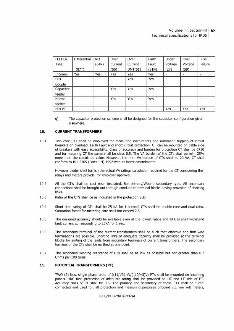
Volume-III : Section-III
Technical Specifications for IPDS
68
IPDS/DHBVN/HARYANA
FEEDER Differential REF Over Over Earth Under Over Fuse
TYPE (64R) Current Current Fault Voltage Voltage Failure
(87T) (50) DMT(51) (51N) (27) (59)
Incomer Yes Yes Yes Yes Yes - - -
Bus - - - Yes Yes - - -
Coupler
Capacitor - - Yes Yes Yes - - -
feeder
Normal - - Yes Yes Yes - - -
feeder
Bus PT - - - - - Yes Yes Yes
q) The capacitor protection scheme shall be designed for the capacitor configuration given
elsewhere.
10. CURRENT TRANSFORMERS
10.1 Two core CTs shall be employed for measuring instruments and automatic tripping of circuit breakers on overload, Earth Fault and short circuit protection. CT can be mounted on cable side of breakers with easy accessibility. Class of accuracy and burden for protection CT shall be 5P10 and for metering CT the same shall be class 0.5. The VA burden of the CTs shall be min. 25% more than the calculated value. However, the min. VA burden of CTs shall be 20 VA. CT shall conform to IS : 2705 (Parts 1-4) 1992 with its latest amendments.
However bidder shall furnish the actual VA ratings calculation required for the CT considering the
relays and meters provide, for employer approval.
10.2 All the CT’s shall be cast resin insulated, Bar primary/Wound secondary type. All secondary connections shall be brought out through conduits to terminal blocks having provision of shorting links.
10.3 Ratio of the CT’s shall be as indicated in the protection SLD.
10.4 Short time rating of CTs shall be 25 KA for 1 second. CTs shall be double core and dual ratio. Saturation factor for metering core shall not exceed 2.5.
10.5 The designed accuracy should be available even at the lowest ratios and all CTs shall withstand
fault current corresponding to 25KA for 1 sec.
10.6 The secondary terminal of the current transformers shall be such that effective and firm wire terminations are possible. Shorting links of adequate capacity shall be provided at the terminal blocks for sorting of the leads from secondary terminals of current transformers. The secondary terminal of the CTs shall be earthed at one point.
10.7 The secondary winding resistance of CTs shall be as low as possible but not greater than 0.2
Ohms per 100 turns.
11. POTENTIAL TRANSFORMERS (PT)
TWO (2) Nos. single phase units of ((11/√3) kV/(110/√3)V) PTs shall be mounted on incoming panels. HRC fuse protection of adequate rating shall be provided on HT and LT side of PT. Accuracy class of PT shall be 0.5. The primary and secondary of these PTs shall be “Star” connected and used for, all protection and measuring purposes onboard viz. line volt meters,
Volume-III : Section-III
Technical Specifications for IPDS
69
IPDS/DHBVN/HARYANA
energy meters etc. PTs shall conform to IS:3156 (Parts 1-4):1992 with its latest amendments.
Potential transformers shall be cast resin, draw out type. PT changeover scheme shall be
provided in the switchboard.
All PT should have suitable current limited fuse both at primary and secondary.
12. CABLE GLANDS AND CLAMPING ARRANGMENT FOR HOLDING SUITABLE CABLE BOXES
12.1 Two nos, brass-wiping glands for each incomer and one no. Brass wiping gland for each outgoing panel of adequate dimension for XLPE cable of 3 crores up to 400 sq. mm size (to be customized by utility) shall be supplied along with panels. For bus coupler no cable glands should be provided.
12.2 Suitable cable boxes as per requirement of cable shall be arranged by the bidder. The panel shall
however provide a flat of size 50x6 mm2 with suitable clamp made of 50x6 mm2 flat along with Nuts Bolts and Washers for holding the cable boxes. The flat should be fitted at a suitable height with allotted arrangement for adjustment of height from 300mm to 500mm at site. The clamp and flat shall have suitable stud type arrangement for earthing cable and cable box.
12.3 All control cable/wire entries shall be by means of suitable cable glands, such glands shall be of
brass and tinned.
13. AUXILIARY/CONTROL WIRING
All the secondary wiring in the panel shall have high quality PVC insulation and the same shall have conductor size of not less than 2.5 mm2 of copper Colors of the secondary/auxiliary wiring should confirm to IS 375/1963 and latest amendment thereof if any. All wiring shall be neatly run and group of wiring shall be securely fixed by clips so that wiring can be checked without necessity of removing the clamps. Wiring between fixed and moving portion of the panel shall be run in flexible tubes and the same shall be so mounted to avoid any damage to them due to mechanical movements. Ferrules with number shall be provided on both end of the wiring.
14. STATIC ENERGY METERS
14.1 Scope
This specification covers design, engineering, manufacture, inspection, testing at manufacturers works including type testing before dispatch, supply and delivery of three phase 4 wire tri-vector export with “Time of the Day” register, load profile data record “MD” register suitable for both unbalanced and balanced load.
Volume-III : Section-III
Technical Specifications for IPDS
70
IPDS/DHBVN/HARYANA
14.2 Applicable Standards
Sl. Standards Description
No.
1. IS : 14697 Specification for AC Static Transformer operated
Watt Hour & VAR-Hour meters, classes 0.2 S & 0.5 S
2. IEC : 60687 AC Static Watt-Hour Meters for Active Energy
(classes 0.2 S & 0.5 S)
3. IS: 15959 (including amendment 2)
Data Exchange for Electricity Meter Reading, Tariff and Load Control – Companion Specification
IEC : 62056-21 Data exchange for Meter Reading and Direct Local (Latest Version) Data Exchange
4.
IEC : 61000-4-5 For Electro Magnetic Compatibility – Testing and
(2001-04) Measurement techniques, Surge immunity test
6. IEC : 61358 Criteria for selection for tests LIKE Acceptance,
Inspection.
7. ANSI/IPC-A-610 Workmanship standard for Acceptability of Electronic
Assemblies (A standard developed by Institute for
Interconnecting and packaging Circuits).
14.3 General Requirements
14.3.1 Electrical Specifications
Class of Accuracy : 0.5 S
Supply Voltage : Suitable for operation from 110 Volts/63.5
Volts Ph-Ph/Ph-N, PT Secondary
Frequency : 50 Hz +/- 5%
Power Factor : 0.5 Lag – Unity-0.8 Lead
Basic Current Ib : 1A
Maximum continuous Current : 20 Ib
Minimum starting current : As per IS 4697
Impulse withstand Voltage (1.2/50m Sec): -
Volume-III : Section-III
Technical Specifications for IPDS
71
IPDS/DHBVN/HARYANA
14.4 Guarantee Period
The offered meters shall be guaranteed for normal operation for at least 5 years from the date of
receipt at site without any repair whatsoever.
14.5 Design and Constructional Features 14.5.1 Location & Mounting
The Energy meters shall be supplied suitable for indoor installation. Enclosure shall have IP-51 protection. All the feeder meters to be suitable for mounting on Simplex type Vertical Panel with rear door, Energy Meter flush mounted and clearly visible, with disconnecting type TBs, fully wired.
14.5.2 Design
Meter shall be designed with application specific integrated circuit (asic) or micro controller; shall have no moving part; electronic components shall be assembled on printed circuit board using surface mounting technology; factory calibration using high accuracy (0.1 class) software based test bench.
All components used shall be approved by reputed testing authority at national level or other
international recognized testing authority. 14.5.3 Manufacturing Process, Assembly and Testing
Meters shall be manufactured using latest and ‘state of the art’ technology and methods
prevalent in electronics industry.
All inward flow of major components and sub assembly parts (CT, PT, RTCs/Crystal, LCDs, LEDs, power circuit electronic components etc.) shall have batch and source identification.
Multilayer ‘PCB’ assembly with ‘PTH’ (Plated through Hole) using surface mounted component shall have adequate track clearance for power circuits. SMT component shall be assembled using automatic ‘pick-and-place’ machines with in process 7 stages, Reflow Soldering oven, for stabilized setting of the components on ‘PCB’.
For soldered PCBs, cleaning and washing of cards, after wave soldering process is to be carried
out as a standard practice.
Assembly line of the manufacturing system shall have provision for testing of sub-assembled
cards.
Manual placing of components and soldering, to be minimized to items, which cannot be handled
by automatic machine.
Handling of ‘PCB’ with ICs/C-MOS components, to be restricted to bare minimum and precautions
to prevent ‘ESD’ failure to be provided.
Complete assembled and soldered PCB should undergo functional testing using computerized
Automatic Test Equipment.
Fully assembled and finished meter shall undergo ‘burn-in’ test process for 24 Hours at 55 degree Celsius (Max. temperature to not exceed 60 degree Celsius) under base current (Ib) load condition.
Volume-III : Section-III
Technical Specifications for IPDS
72
IPDS/DHBVN/HARYANA
Test points should be provided to check the performance of each block/stage of the meter
circuitry.
Testing at intermediate and final stage to be carried out with testing instruments, duly calibrated
with reference standard, with traceability of source and date. 14.5.4 Displays
Displays tested shall be suitable for temperature withstand of 600 C;
7+1 digits (with ±indication), parameter identifier, backlit Liquid Crystal Display (LCD) of minimum 10 mm height, wide viewing angle. Auto display cycling push button required with persistence time of 12 Seconds. Sequence of display of various instantaneous electrical parameters shall be as desired by
Employer at the time of order.
Normal display shall be Active energy value, on release of push button, at any of the display
parameter during scrolling.
14.5.5 Calibration of Meter
Meters shall be factory calibrated using high accuracy test bench. Energy Meter shall have test output device, accessible from the front, and capable of being monitored with suitable testing equipment while in operation at site. Resolution of the device shall enable the starting current test in less than 10 minutes. Accuracy of test bench at works shall be as per the guidelines provided in IS: 14697.
14.5.6 Self-Diagnostic Features
The meter shall have self-diagnostic features to check its circuits for any malfunctioning. The
bidder shall furnish the details of the self-diagnostic features. 14.5.7 Construction
a) Meter Case and Cover
i) To ensure high reliability, long trouble free life, safety against electric shock, spread of fire
and effects of excessive temperature, the meter casing and cover shall be made of high quality industrial grade polycarbonate material having adequate strength, which is unbreakable, corrosion resistant & inert to chemicals, flame retardant, immune to ultra violet radiation and meet UV ageing test as per relevant ASTM standards.
ii) The bidder shall indicate hardness, melting temperature and tensile yield strength of the
material and necessary test certificate of the same shall be furnished.
iii) The polycarbonate material used shall conform to IS: 11731 (FH-1 category) besides meeting the test requirement of heat deflection test as per ISO: 75 and glow wire test as per the relevant Standard.
iv) The meter shall be provided with adequate shielding to withstand external magnetic
influence from all directions as per latest amendments of CBIP 88 report.
v) Meter cover shall be continuously ultra sonically welded with meter base from all sides. Suitable locking arrangement shall be provided between the base and cover of the meter.
14.5.8 Sealing Arrangement
Two sealing screws shall be provided for proper fixing of the meter cover so that access to the
Volume-III : Section-III
Technical Specifications for IPDS
73
IPDS/DHBVN/HARYANA
working part shall not be possible without breaking the seal.
14.5.9 Terminal Block and Cover
The terminal block shall have adequate insulating properties and mechanical strength. The terminal block shall be made from best quality non-hygroscopic, flame retardant polycarbonate material (capable of passing the flammability tests give in IS: 11731) with nickel-plated brass studs for connecting terminals.
The terminal block is to be enclosed in a metallic housing of steel plate of sufficient thickness to cover its back and sides and provide enough strength for the purpose of tightening of screws. Clamping screws should be provided inside the terminal cover and should have metallic sleeve moulded within the block to avoid damage during tightening of the screws.
The terminals in the terminal block shall be of long socket type suitable for connection of cables with aluminium conductors along with suitable lugs (lugs to be provided by the supplier) having cross sectional area, with adequate length. Double screw arrangement shall be provided to achieve adequate termination. All terminals and connecting screws and washers shall be of tinned / nickel plated brass material.
The terminal cover shall be transparent with minimum thickness 2.5 mm and the material shall be same as that of meter case. It shall be of extended type and accommodate, in addition to the terminal block, a suitable length of external cable along with its insulation.
14.5.10 Name Plate and Marking
Every meter shall have a nameplate clearly visible and indelible and distinctly marked in accordance with IS: 13779 (latest version). The following information shall appear on a nameplate preferably placed within the meter.
1. Manufacturer’s name & trade-mark and place of manufacture.
2. Serial number and year of manufacture.
3. Designation of type.
4. Number of phases and number of wires for which the meter is suitable.
5. Guarantee period.
6. Employer’s name & meter number.
7. Principal unit in which the meter records.
8. Reference voltage & frequency in Hz.
9. Basic current and rated maximum current.
10. Meter constant (pulse rate of testing signal).
11. Class index.
12. Project Name.
14.6 Fixing Arrangement
Every meter shall have three fixing holes one at the top and two at the bottom. The fixing holes shall be properly matched for mounting inside the meter compartment as per the drawing, and this specification.
14.7 Operational Requirements
14.7.1 Performance under Influence Quantities
Volume-III : Section-III
Technical Specifications for IPDS
74
IPDS/DHBVN/HARYANA
As per IS 14697.
Accuracy for measurement & display of instantaneous quantities shall conform to IS14697.
14.7.2 Additional Technical Features
a) Output Device
i) Energy Meter shall have test output, accessible from the front, and be capable of being
monitored with suitable testing equipment while in operation at site.
ii) Operation indicator must be visible from the front.
iii) Test output device shall be provided in the form of LED/LCD.
Resolution of the test output device shall be sufficient to enable the starting current test in less than 10 minutes. Nameplate shall indicate the ‘impulse/ Unit’ with appropriate resolution.
b) Cumulative Energy Register
Meter should have provision for automatic recording of cumulative kWh & MD KW at say 24.00 hours on the last day of the month for each of the past six calendar months and same to be stored in the register/memory.
c) Temperature Conditions
As per Is 14697;
Meter to perform satisfactorily under Non-Air Conditioned environment in HT sub-
station with Indoor switchgear in some of the locations.
14.7.3 Real Time Internal Clock (RTC) of Energy Meter
RTC shall be pre-programmed for 30 Years Day/date without any necessity for correction.
Maximum drift shall not exceed +/- 300 Seconds per year.
Time & date setting shall only be possible through one of the following: Common Meter Reading Instrument (CMRI) or Meter testing work bench and this shall need
password enabling for Consumer meter;
14.7.4 Clock Day/Date Synchronisation
Synchronisation of Energy Meter ‘RTC’ Time/Date shall be possible thro’ password/Key code enabled command from remote server or sub station ‘PC’ as per the arrangement. Master Clock reference shall be obtained from Main server or local ‘PC’. However the master clock, Main server and Local PC is not in scope of supply.
Synchronisation shall be carried only if the ‘RTC’ drift is within ±10 minutes.
Error log to be recorder by the system S/W if the ‘RTC’ time is out of range.
14.7.5 Quantities to be Measured & Displayed
Volume-III : Section-III
Technical Specifications for IPDS
75
IPDS/DHBVN/HARYANA
As per Appendix G of IS 14697.
a) TOD ‘time slot register’ wise export & Import (when asked) of kWh & kVARh, kVAh
energy;
b) Maximum kVA or kW demand with elapsed time.
c) Instantaneous kW, kVA, PHASE WISE kW & kVA, OVERALL pf, MD reset count,
frequency, time & date, RTC battery health;
In addition, present status of abnormality shall also be possible to be displayed.
Tamper details shall be stored in internal memory for retrieval by authorized personnel through
either of the following:
i) Common Meter Reading Instrument (CMRI) ii) AMR and this shall need password
enabling.
14.7.6 Demand Integration Period (DIP)
i) Energy Meter shall continuously monitor and calculate the average maximum demand for each demand interval time of 30 minutes and maximum of these in a calendar month shall be stored along with date and time when it occurred;
ii) It shall however be possible to change the demand integration period (DIP), from 30 to
15 minutes at site, with proper security;
iii) The Maximum demand of past six months shall be stored in the memory with date and
time.
iv) It shall be also possible to retrieve this data through communication port and MRI.
v) Media copy of software for downloading of meter data through MRI on to a PC shall be provided on a compact disc. This shall be suitable to window-based operating system. Installation and commissioning manual for the same shall also be provided.
14.7.7 Time of Day (TOD) Registers
6 different TOD energy registers as per clause G-8 of IS 14697 are required. Time block settings shall be advised to the supplier at least 4 weeks before commencing delivery. Change of time period for TOD metering shall be with password enabling from CMRI or from base computer.
14.7.8 Load Survey Data Registers
Storage in Non volatile memory for 40 days, 30 minute demand of any of the flow parameters of kW, kVA, kVAR (or Pf), Average of 3 voltages and phase currents shall be provided.
14.7.9 Indications
i) Meter healthy indicator must be visible from the front.
ii) Test output device shall be provided in the form of LED/LCD.
iii) Energy Meter shall have test output, accessible from the front, and be capable of being
monitored with suitable testing equipment while in operation at site.
Volume-III : Section-III
Technical Specifications for IPDS
76
IPDS/DHBVN/HARYANA
iv) Resolution of the test output device shall be sufficient to enable the starting current test
in less than 10 minutes. Nameplate shall indicate the ‘impulse/ Unit’ in appropriate resolution.
14.7.10 Communication Facilities & Standards
For data communication, the data structure adopted within the energy meter shall be on an internationally acceptable method. The data structure/coding details shall be furnished to the Employer. However minimum shall be provided.
a) Local communication port: Energy meter shall have a galvanically isolated optical
communication port as per IEC 62056-21 or any other internationally accepted port in front of the meter for data transfer to or from a hand held data Collection Device (Common Meter Reading Instrument ‘CMRI’ - conforming to CBIP technical report-111) with proper security and without error.
b) Meter shall be provided with ‘RS 485’ port. ‘RS485’ communication port shall be suitable
for interfacing multiple Energy Meters. It shall be possible to download stored meter data, on polling basis with the aid of a software schedule by addressing one meter at a time and downloading the stored data into the sub-station data logger/Central data center computer.
c) Energy Meter shall operate on industry standard ‘MODBUS’ protocol and shall be
individually addressable
14.7.11 Tamper & Fraud Monitoring and Recording
Meters shall at least be immune to tampers elaborated in IS 14697, ANNEX G-10.
All types of tampers for which meter is made immune, shall be listed by the bidder. These tampers records need not be recorded or stored in the meter memory. Further, compliance to these are to be demonstrated by the bidder during acceptance test by successful bidder.
The meter should have anti tamper features. These shall at least include:
i) Phase Sequence Reversal: Meter should work accurately irrespective of phase Sequence
of supply.
ii) Bypassing of Current Coil: Meter must have capability to record bypassing (shunting) of current coil(s) of one or any two phases with date, time and duration with normalisation time. Meter should not record tamper if load currents are unbalanced within specified limits permissible in the system.
iii) Current reversal in current coil: The meter shall register energy consumption correctly in
forward direction irrespective of the direction of current in the current coil/Coils with date and time of first occurrence and last restoration along with total number of such occurrences for all phases during the above period.
iv) Missing potential: Meter shall be capable of detecting and recording occurrences of
missing potential (One phase or two phases) and its restoration which can happen due to intentional/accidental disconnection of potential leads with date and time along with total number of such occurrences for all phases during the above period. This recording of tampering shall not be done when meter is without any load i.e. Current in all phases is Zero.
Volume-III : Section-III
Technical Specifications for IPDS
77
IPDS/DHBVN/HARYANA
v) Error recording shall include current unbalance beyond 30% in the phases, RTC clock
correction failures (when drift is beyond specified value etc);
vi) Missing Neutral: Meter shall continue to record accurately even if the neutral of
potential supply gets disconnected.
14.7.12 Accuracy
In case any drift is noticed in the accuracy of the meter, which is beyond the permissible limits, the concerned meter shall be with-drawn from service and Bidder shall supply a new meter without any extra cost as a replacement (with in one month of receipt from Employer), during the guarantee period.
14.8 Inspection, Testing and Despatch
14.8.1 Type Tests
The meter offered should have successfully passed all type tests described in the IS 14697 and IEC 61000 4-5 Type test certificate shall be submitted along with the offer and the same shall not be more than 36 months old on the date of opening tender. Make & type of major components used in the type-tested meter shall be indicated in the type test certificates.
14.8.2 Acceptance and Routine Tests
Criteria for selection for such tests and performance requirements shall be as per IS 14697, IEC
61358.
14.8.3 Quality Assurance Plan
The bidder (manufacturer) shall have a comprehensive quality assurance program at all stages of manufacture for ensuring products giving reliable, trouble free performance. The bidders (manufacturers) quality assurance plan shall be submitted along with bid document, which would be reviewed in detail by the Employer in case of award and accepted with modifications, as felt necessary. A sampler manufacturing quality plan document is enclosed in this specification.
The bidder’s quality assurance programme shall generally cover the following:
i) Bidder organization structure for the management and implementation of the
proposed quality assurance programme. ii) Quality System Manual. iii) Design Control System. iv) Documentation Control System. v) The procedure for purchase of materials, parts, components, source inspection,
incoming raw-material inspection, verification of materials purchased etc. vi) System for process controls and fabrication and assembly controls. vii) Inspection and test procedure both for manufacture and field activities. viii) Control of calibration and testing of measuring /testing equipments. ix) System for Quality Audits. x) System for handling storage and delivery.
The Bidder shall accordingly furnish along with the bid
i) A comprehensive quality assurance plan which is in practice (for both product & process).
Volume-III : Section-III
Technical Specifications for IPDS
78
IPDS/DHBVN/HARYANA
ii) A detailed list of bought out items with name of the manufacturer and details about in
coming quality control. iii) Quality assurance plan of bidders’ collaborators in case of foreign collaborators.
Employer reserves the right to carry out quality audit and quality surveillance of the systems
and procedure of the bidders’ quality management & control activities. The bidders shall provide
all necessary assistance to enable the Employer to carry out such audit & surveillance.
14.9 Manufacturing and Testing Facilities
14.9.1 The following Manufacturing and testing facilities shall be available.
The factory shall be completely dust proof.
The testing rooms shall be temperature and humidity controlled as per relevant Standards.
The testing and calibrating equipment should be automatic and all test equipment shall have their valid calibration certificates
Power supplies used in testing equipment shall be distortion free with sinusoidal waveforms and maintaining constant voltage current and frequency as per the relevant Standards.
14.9.2 During the manufacturing of the meters following minimum checks shall be carried out.
a. Meter frame dimension tolerance shall be minimum. b. The pressure coil shall be made totally encapsulated and care shall be taken to
avoid ingress of dust and moisture inside the coil. c. The assembly of parts shall be done with the help of jigs and fixtures so that
human errors are eliminated. d. The meters shall be batch tested on automatic, computerized test bench and the
results shall be printed directly without any human errors. e. The current coil shall be made with the help of jigs and fixtures. f. The potential coil shall be made with automatic computerized machine.
14.9.3 Mounting and Fixing Arrangement Drawings/Data Sheet
Manufacturer shall ensure following technical points:
i) Meter shall be mounted on the switchgear by providing suitable cutouts, and shall be
connected to suitable CT/PT.
ii) RS 485 Bus shall be formed by connecting the RS 485 port of all the meters in the switchgear. The external interphase point for this shall be provided in the Bus PT panel.
14.10 INSTRUMENTS AND METERS
Indicating instruments shall be flush mounted on panel front. The instruments shall be of at least 96 mm square size with 90 deg. scales, shall conform to IS : 1248 and shall have an accuracy class of 1.5 or better. The covers and cases of instruments and meters shall provide a dust and vermin proof construction.
Instruments shall have white dials with black numerals and lettering. Black knife edged pointer
with parallax free details will be preferred.
Volume-III : Section-III
Technical Specifications for IPDS
79
IPDS/DHBVN/HARYANA
Instruments and meters shall be factory calibrated to directly read the primary circuit quantities. Means shall be provided for zero adjustment without dismantling the instruments.
14.11 NAME PLATE AND DIAGRAM PLATES
All equipment shall have weather proof and non corrosive metal plates fixed in suitable position with full particulars engraved thereon with white letters against black background.
The firm shall affix a name plate on each Switchgear panel having following information:
a. Manufacturer’s name and trade mark.
b. Unique No.
c. Type of Panel.
d. CT Ratio.
e. Rated Voltage.
f. Rated Insulation Level
g. Rated Frequency
h. Rated Normal Current
i. Rated Short Circuit Breaking Current.
j. Weight
11. Specification No.
12. Order No. and Date
13. Year of supply.
15. PAINTING
All metallic surface [except enameled and bright parts] exposed to weather shall be given suitable primer coat and two coats of first quality paint of approved color. The supplier shall also supply adequate quantities of paints, Varnish etc. for use of finished cost and for use of patching up any scratches received during transport, handling erection testing and commissioning.
Instead of above proper powder coating after proper pre-treatment is acceptable and in that
case earlier condition will not applicable.
16. TESTS
The design of circuit breaker shall be proven through all the routine and type tests in accordance with IS 13118: 1991/IEC 56 and any amendment thereof. Photocopy of all the test reports must
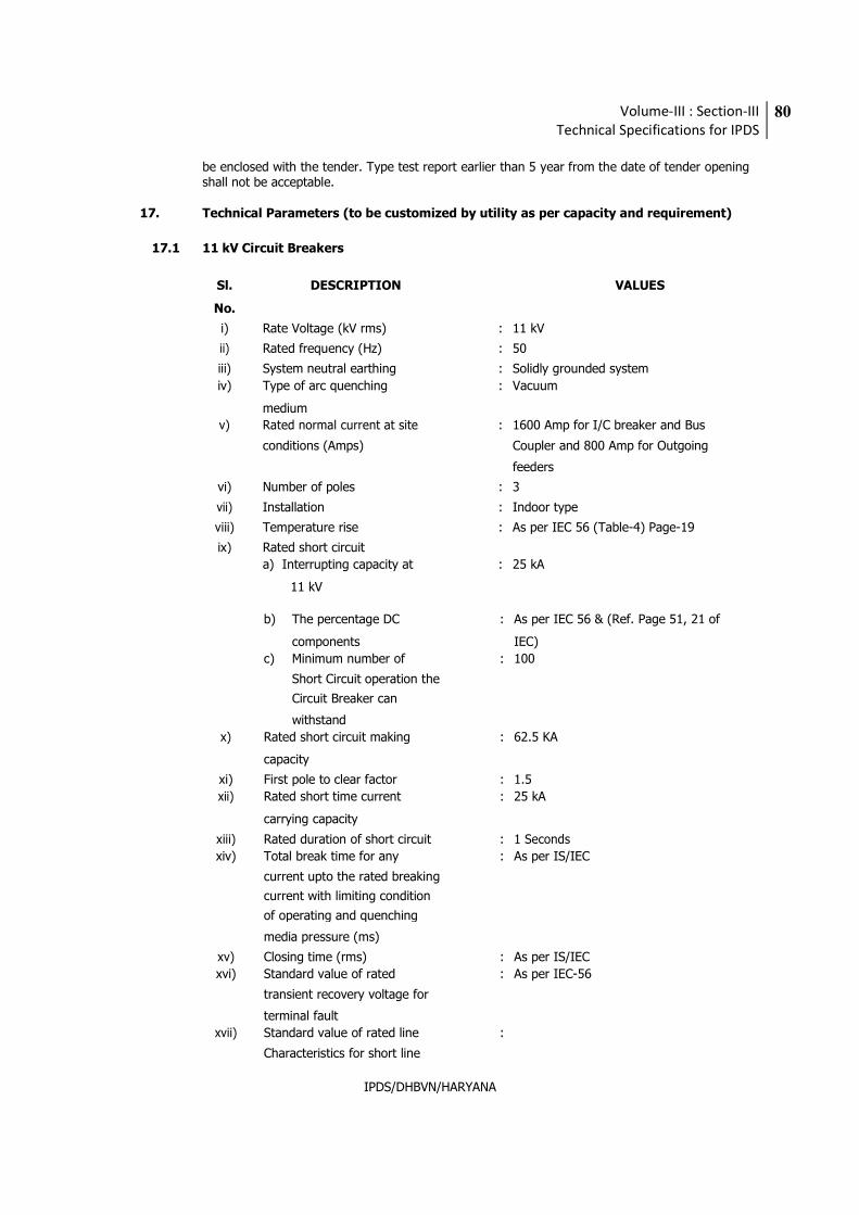
Volume-III : Section-III
Technical Specifications for IPDS
80
IPDS/DHBVN/HARYANA
be enclosed with the tender. Type test report earlier than 5 year from the date of tender opening shall not be acceptable.
17. Technical Parameters (to be customized by utility as per capacity and requirement)
17.1 11 kV Circuit Breakers
Sl. DESCRIPTION VALUES
No.
i) Rate Voltage (kV rms) : 11 kV
ii) Rated frequency (Hz) : 50
iii) System neutral earthing : Solidly grounded system
iv) Type of arc quenching : Vacuum
medium
v) Rated normal current at site : 1600 Amp for I/C breaker and Bus
conditions (Amps) Coupler and 800 Amp for Outgoing
feeders
vi) Number of poles : 3
vii) Installation : Indoor type
viii) Temperature rise : As per IEC 56 (Table-4) Page-19
ix) Rated short circuit
a) Interrupting capacity at : 25 kA
11 kV
b) The percentage DC : As per IEC 56 & (Ref. Page 51, 21 of
components IEC)
c) Minimum number of : 100
Short Circuit operation the
Circuit Breaker can
withstand
x) Rated short circuit making : 62.5 KA
capacity
xi) First pole to clear factor : 1.5
xii) Rated short time current : 25 kA
carrying capacity
xiii) Rated duration of short circuit : 1 Seconds
xiv) Total break time for any : As per IS/IEC
current upto the rated breaking
current with limiting condition
of operating and quenching
media pressure (ms)
xv) Closing time (rms) : As per IS/IEC
xvi) Standard value of rated : As per IEC-56
transient recovery voltage for
terminal fault
xvii) Standard value of rated line :
Characteristics for short line
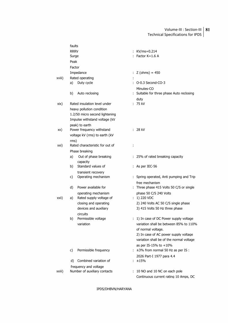
Volume-III : Section-III
Technical Specifications for IPDS
81
IPDS/DHBVN/HARYANA
faults
RRRV : KV/ms=0.214
Surge : Factor K=1.6 A
Peak
Factor
Impedance : Z (ohms) = 450
xviii) Rated operating :
a) Duty cycle : O-0.3 Second-CO-3
Minutes-CO
b) Auto reclosing : Suitable for three phase Auto reclosing
duty
xix) Rated insulation level under : 75 kV
heavy pollution condition
1.2/50 micro second lightening
Impulse withstand voltage (kV
peak) to earth
xx) Power frequency withstand : 28 kV
voltage kV (rms) to earth (kV
rms)
xxi) Rated characteristic for out of :
Phase breaking
a) Out of phase breaking : 25% of rated breaking capacity
capacity
b) Standard values of : As per IEC-56
transient recovery
c) Operating mechanism : Spring operated, Anti pumping and Trip
free mechanism
d) Power available for : Three phase 415 Volts 50 C/S or single
operating mechanism phase 50 C/S 240 Volts
xxii) a) Rated supply voltage of : 1) 220 VDC
closing and operating 2) 240 Volts AC 50 C/S single phase
devices and auxiliary 3) 415 Volts 50 Hz three phase
circuits
b) Permissible voltage : 1) In case of DC Power supply voltage
variation variation shall be between 85% to 110%
of normal voltage.
2) In case of AC power supply voltage
variation shall be of the normal voltage
as per IS-15% to +10%
c) Permissible frequency : ±3% from normal 50 Hz as per IS :
2026 Part-I 1977 para 4.4
d) Combined variation of : ±15%
frequency and voltage
xxiii) Number of auxiliary contacts : 10 NO and 10 NC on each pole
Continuous current rating 10 Amps, DC
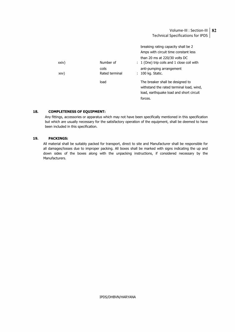
Volume-III : Section-III
Technical Specifications for IPDS
82
IPDS/DHBVN/HARYANA
breaking rating capacity shall be 2
Amps with circuit time constant less
than 20 ms at 220/30 volts DC
xxiv) Number of : 1 (One) trip coils and 1 close coil with
coils anti-pumping arrangement
xxv) Rated terminal : 100 kg. Static.
load The breaker shall be designed to
withstand the rated terminal load, wind,
load, earthquake load and short circuit
forces.
18. COMPLETENESS OF EQUIPMENT:
Any fittings, accessories or apparatus which may not have been specifically mentioned in this specification
but which are usually necessary for the satisfactory operation of the equipment, shall be deemed to have
been included in this specification.
19. PACKINGS:
All material shall be suitably packed for transport, direct to site and Manufacturer shall be responsible for
all damages/losses due to improper packing. All boxes shall be marked with signs indicating the up and
down sides of the boxes along with the unpacking instructions, if considered necessary by the
Manufacturers.
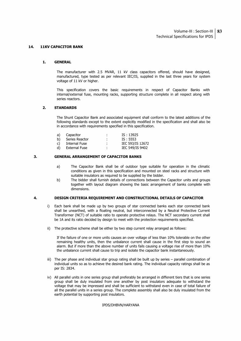
Volume-III : Section-III
Technical Specifications for IPDS
83
IPDS/DHBVN/HARYANA
14. 11KV CAPACITOR BANK
1. GENERAL
The manufacturer with 2.5 MVAR, 11 kV class capacitors offered, should have designed, manufactured, type tested as per relevant IEC/IS, supplied in the last three years for system voltage of 11 kV or higher.
This specification covers the basic requirements in respect of Capacitor Banks with internal/external fuse, mounting racks, supporting structure complete in all respect along with series reactors.
2. STANDARDS
The Shunt Capacitor Bank and associated equipment shall conform to the latest additions of the following standards except to the extent explicitly modified in the specification and shall also be in accordance with requirements specified in this specification.
a) Capacitor : IS : 13925 b) Series Reactor : IS : 5553 c) Internal Fuse : IEC 593/IS 12672 d) External Fuse : IEC 549/IS 9402
3. GENERAL ARRANGEMENT OF CAPACITOR BANKS
a) The Capacitor Bank shall be of outdoor type suitable for operation in the climatic conditions as given in this specification and mounted on steel racks and structure with suitable insulators as required to be supplied by the bidder.
b) The bidder shall furnish details of connections between the Capacitor units and groups together with layout diagram showing the basic arrangement of banks complete with dimensions.
4. DESIGN CRITERIA REQUIREMENT AND CONSTRUCTIONAL DETAILS OF CAPACITOR
i) Each bank shall be made up by two groups of star connected banks each star connected bank shall be unearthed, with a floating neutral, but interconnected by a Neutral Protective Current Transformer (NCT) of suitable ratio to operate protective relays. The NCT secondary current shall be 1A and its ratio decided by design to meet with the protection requirements specified.
ii) The protective scheme shall be either by two step current relay arranged as follows:
If the failure of one or more units causes an over voltage of less than 10% tolerable on the other remaining healthy units, then the unbalance current shall cause in the first step to sound an alarm. But if more than the above number of units fails causing a voltage rise of more than 10% the unbalance current shall cause to trip and isolate the capacitor bank instantaneously.
iii) The per phase and individual star group rating shall be built up by series – parallel combination of
individual units so as to achieve the desired bank rating. The individual capacity ratings shall be as per IS: 2834.
iv) All parallel units in one series group shall preferably be arranged in different tiers that is one series
group shall be duly insulated from one another by post insulators adequate to withstand the voltage that may be impressed and shall be sufficient to withstand even in case of total failure of all the parallel units in a series group. The complete assembly shall also be duly insulated from the earth potential by supporting post insulators.
Volume-III : Section-III
Technical Specifications for IPDS
84
IPDS/DHBVN/HARYANA
v) Although the tolerances in the output rating of each individual unit shall be as per IS:2834 yet it
shall be ensured that in a completely assembled bank, the departures from the nominal rating and within the specified tolerances values shall not cause nuisance alarm or tripping since such alarm or tripping shall be to meet only with the protective requirements specified.
vi) The tolerances in the output ratings shall not cause departures in the line currents by that value
specified in IS: 2834. Besides it shall also be ensured that these unsymmetrical currents shall not cause unsymmetrical voltage rises, whether for short periods or during prolonged operation.
vii) Individual units shall be designed to meet with the requirements of the permissible overloads as
specified as per IS: 2834. Each unit shall also be provided with internal discharge devices complying with the requirements of the IS.
viii) The voltage rating of the NCT shall be decided by the Bidder by taking into consideration the
voltage impressed on the NCT due to:
a) Voltage due to failure of one or more parallel units in a series bank.
b) Voltage impressed on the NCT when all the parallel units in one series bank fail simultaneously. The bidders shall furnish along with the bid design calculations for the same.
5. CAPACITOR UNITS
a) Each capacitor unit in the Bank shall be self-contained outdoor type having 2 bushing
suitably rating for series/parallel connections with other units to form the capacitor bank
of rated capacity at 50 Hz. The bushing shall be of porcelain and shall be joined to the
case by soldering or welding.
b) The capacitor unit shall be manufactured Hazy Polypropylene as dielectric using non PCB impregnation shall be carried out under high degree of vacuum and the unit shall be of totally sealed type.
c) Each capacitor unit shall be provided with a internal discharge resistor designed to drain
the phase voltage of the bank to 50 V or less within 5 minutes after disconnection from the supply.
d) Each capacitor unit shall be suitable for continuous operation at least 1.3 times the
rated current at rated voltage and frequency. This over current factor shall include the combined effect of presence of harmonics and over-voltage up to 1.1 times rated voltage.
e) The container of capacitor unit shall be of stainless steel or CRCA steel painted within
suitable anti-rust primer and two finishing coats of paint as per manufacturers’ standard practice. The container shall be made from sheet steel of suitable thickness designed to allow for expansion and contraction due to all ambient and loading conditions expected during the life of the unit.
f) In case of externally fused capacitors the rating of unit shall so chosen that failure of 2
units in a particular series group shall not cause over-voltage exceeding 10% on the other healthy unit in that same series group. Calculations on above showing the justification of the unit size shall be furnished by the bidder along with the offer.
g) The design of the internally fused capacitor unit shall be such that it shall permit up to
40% element failure in series group without passing more than 10% over voltage on
Volume-III : Section-III
Technical Specifications for IPDS
85
IPDS/DHBVN/HARYANA
the other healthy units.
h) Each capacitor unit shall be mounted so that it can be easily removed from the racks and replaced without removing other units, de-assembling any portion of the rack.
i) Protective fuses: the capacitor units shall be provided with either internal or external
fuses as per standard practice of the manufacturer.
A. Capacitor units with internal fuses
The internal fuses shall conform to IEC:593/IS:12672 and the Bidder shall furnish type test certificates for compliance with IEC/IS. The design of the internal fuse shall be same that residues from fuse operation(s) shall not cause deterioration of the impregnating fluid. The fuse assembly shall be distinct and separate from element packs and so constructed that operation of a fuse indoor worst condition does not affect the other healthy elements. The fuses shall not melt or deteriorate when subjected to inrush currents, which occur during the life of the bank. The design of the fuse shall be such that it shall isolate only the faulty element and the operation of the fuse shall not affect the other healthy elements.
B. Capacitor units with external fuses
The external fuses shall be of current limiting (HRC) type. The fuse system shall in any event be designed to ensure that the energy released into a faulty capacitor unit is less than the value that will cause rupture or bursting of the container. The fuses shall conform to IEC: 549/IS: 9402 and Bidder shall furnish type test certificate for compliance with IEC/IS. The characteristics of the fuse shall be such that it shall isolate the faulty unit only and prevent it from mechanical destruction due to internal faults. The capacitor unit together with external fuses shall be arranged in the bank by providing adequate clearance between the body of the capacitor units of a phase and the line terminal or the common bus for the units of the other phases to obviate the possibility of occurrence of bird faults. The fuse shall isolate the faulty capacitor unit only and the healthy capacitor units shall not be affected in any way by the isolation of faulty unit. The fuses shall not melt or deteriorate when subject to inrush currents which occur during the life of the bank. The external distance between two metal ends of the fuse shall comply with specified creepage distance (i.e. the length of the insulating part of the fuse shall be such that the specified creepage distance is achieved). The selection of fuse to the done in such a manner that characteristic of fuse shall match suitably with over current withstand characteristic of associated capacitor unit. The capacitor bank and protection shall be such that failure of one unit (i.e. one external fuse operation) does not cause tripping of the bank. The bidder shall furnish detailed calculations in evidence of above along with the Bid.
Metalised Polypropylene Type, self-healing design capacitor with internal safety design is also acceptable. Bidder shall explain the features and properties of the capacitor offered to meet the requirement described above. These shall have discharge resistance provided internally to eliminate stress in case of de-energisation.
6. MOUNTING RACKS
a) The mounting racks shall be hot dip galvanized steel sections. Each end of the rack shall have
provision to receive incoming line connection.
b) The racks shall be complete with rack insulators, foundation bolts or any other hardware etc. for
assembly into complete bank.
c) The height of the racks of capacitor banks shall be such that for making electrical connections with other equipment, proper electrical clearances are maintained.
d) The capacitor bank along with its mounting racks and series reactor and null CT shall be suitable for installation on the plinth and the enclosure shall be suitably fenced and interlocked as per safety requirements.
Volume-III : Section-III
Technical Specifications for IPDS
86
IPDS/DHBVN/HARYANA
7. TESTS
a) Type Tests – The equipment shall comply with the requirements of type test as per IS: 2834 and copies of these type test reports should be submitted along with offer. The capacitor offered must have been also endurance tested as per IEC: 871-2/IS: 13925 and copies of reports submitted along with offer. The capacitors under the type tested as per relevant IS/IEC.
b) Acceptance and routine tests – The equipment shall comply with all routine and acceptance tests as
per IS – 2834. Sampling to be done as per Appendix-E, IS-2834.
8. SERIES REACTORS
a) The series reactor of small size (as required) shall be used in the Capacitor banks for limiting the inrush current. The series reactor shall be outdoor type 50 Hz, air-cooled air core type and suitable for operation in climatic conditions specified.
b) Series reactors shall be capable of withstanding the specified short circuit currents.
c) The percentage series reactance shall preferably be 0.2%. However, the value of series reactance
shall be decided during detailed engineering. The Bidder shall furnish calculations justifying the value selected.
d) The series reactors shall conform to type tests and shall be subjected to routine tests as per IS.
9. TECHNICAL PARAMETERS OF CAPACITORS AND SERIES REACTORS
The capacitor units and series reactors and other equipments/materials covered in this
specification shall meet the technical requirements listed hereunder:
Capacitor Units (to be customized by utility)
S.No. ITEM SPECIFICATION
a) Nominal System Voltage (kV) 11
b)
MVAR Capacity required at nominal system
voltage (MVAR)
2.5
c) Rated voltage of this capacitor bank (kV) 12
d) Protection of Capacitor units Internal / External fuses
e) Type of connection Double Star
f) Unit Size
Option of the manufacturer to chose the
appropriate unit size and rating
g) Power loss (tan delta including loss in the fuse) Not to exceed 0.2 Watt per applicable standards.
h) Permissible overloads Max. permissible Overloads with reference to voltage current and reactive output shall conform to Applicable standards.
i) Type of grounding Ungrounded
j) Type of discharge Internally through Resistor provided within the
capacitor unit
k) Capacity to receive inrush current Not less than 100 times rated current
l) Temperature category The capacitors shall be suitable for maximum ambient temperature of 50 deg. C adequate care should be taken to protect the capacitors from direct sun radiations on account of Outdoor installations.
Volume-III : Section-III
Technical Specifications for IPDS
87
IPDS/DHBVN/HARYANA
10. SERIES REACTORS
S.No. ITEM SPECIFICATION
a) Rated Voltage (kV) 12
b) Type Air core
c) Rating of series reactors
0.2% of Capacitor bank rating to be connected on neutral end
d) Insulation levels Impulse withstand voltage(KVp)
75
e) Short time withstand capacity and duration
16 times of 130% rated current of capacitor bank for 3 seconds
f)
Linear characteristic Upto 1.5 pu
g) Continuous rating 130% of rated current of capacitor bank
11. COMPLETENESS OF EQUIPMENT:
Any fittings, accessories or apparatus which may not have been specifically mentioned in this specification
but which are usually necessary for the satisfactory operation of the equipment, shall be deemed to have
been included in this specification.
12. PACKINGS:
All material shall be suitably packed for transport, direct to site and Manufacturer shall be responsible for
all damages/losses due to improper packing. All boxes shall be marked with signs indicating the up and
down sides of the boxes along with the unpacking instructions, if considered necessary by the
Manufacturers.
Volume-III : Section-III
Technical Specifications for IPDS
88
IPDS/DHBVN/HARYANA
15. OUTDOOR NON SEALED TYPE THREE PHASE 11 KV/433V STATION TRANSFORMERS
(refer Volume III Section I for Tech Specification)
16. ACSR CONDUCTOR
(refer Volume III Section I for Tech Specification)
Volume-III : Section-III
Technical Specifications for IPDS
89
IPDS/DHBVN/HARYANA
17. CIVIL & STRUCTURAL WORKS
1. GENERAL REQUIREMENTS
1.1 This chapter includes the technical requirements for 66 kV Sub-station, including associated design and preparation of all civil & structural drawings and execution of all associated civil works. This Chapter deals mainly with technical specifications for the design, supervision and construction of complete civil & structural works Complete under the scope of this contract.
1.2 The specifications are intended for general description of work, quality and workmanship. The specifications are not however exhaustive to cover minute details and the work shall be executed according to relevant latest Indian Standards/IRC specifications. In the absence of the above, the work shall be executed according to the best prevailing practices in the trade, recommendations of relevant American or British Standards or to the instructions of Engineer. The IS standards/IRC specifications to be followed are mentioned in the technical specifications attached hereto. They shall be latest edition/version of the same issued 15 days prior to the date of opening of this tender. The Bidder is expected to get himself clarified on any doubts about the specifications etc. before bidding, and the discussions recorded in writing with the Employer in respect of interpretation of any portion of this document.
The Bidder shall take all necessary precautions to protect all the existing equipments, structures, facilities & buildings etc. from damage. In case any damage occurs due to the activities of the Bidder on account of negligence, ignorance, accidental or any other reason whatsoever, the damage shall be made good by the Bidder at his own cost to the satisfaction of the Engineer. The Bidder shall also take all necessary safety measures, at his own cost, to avoid any harm / injury to his workers and staff from the equipment & facilities of the power station.
During the progress of work, the Engineer will exercise supervision of the work to ensure that the technical provisions of the contract are being followed and the work is being executed accurately and properly. However, such supervision shall in no way relieve the Bidder of the responsibility for executing the work in accordance with the specifications.
Before submitting the bid, the Bidder shall inspect and examine the site and its surroundings and shall satisfy himself as to the nature of the ground and subsoil, the availability of materials necessary for completion of the work, means of access to site and in general shall himself obtain all necessary information as to risks, contingencies and other circumstances which may influence or affect his offer. No extra claim consequent on any misunderstanding or otherwise shall be allowed.
2. LAYOUT AND LEVELS
The layout and levels of all structures etc. shall be made by the Bidder at his own cost from the general grid of the plot and bench marks given by the Engineer. The Bidder shall give all help in instruments, material and men to the Engineer, at no extra cost, for checking the detailed layout & correctness of the layout and levels. However the Bidder shall be solely responsible for their correctness.
3. CODES AND STANDARDS All standards, specifications, acts and code of practice shall be followed. In case of conflict between this specification and those (IS standards, codes etc.) referred to
here - in, the former shall prevail.
Volume-III : Section-III
Technical Specifications for IPDS
90
IPDS/DHBVN/HARYANA
4. SUBMISSIONS
The following documents shall be submitted by the Bidder for approval of the Employer, prior to commencement of fabrication and erection / construction. This list is not exhaustive but indicative only. Final list of drawings shall be prepared with successful bidder during detail engineering.
i) Detailed Survey of the Area
ii) Geotechnical Investigation to decide type of foundation of different structures
iii) GA drawing showing Co-ordinates of various Gantry structures and facilities.
iv) Drawing showing underground facilities with co-ordinates of all facilities such as Gantry foundation, equipment foundation, R.C.C cable trench, cable ducts, drains, sumps, pits, culverts, other foundations etc.
v) Proposed erection/construction scheme for various structural and civil works envisaged
as per design requirement.
vi) Foundation design & drawing for Gantry structure & Lighting Mast.
vii) Foundation design & drawing for equipment supports, their control cubicles, bus post
supports and bay marshalling kiosks
viii) Details of RCC cable and pipe trenches with necessary precast RCC removable covers with lifting facility, sump pits, back-filling, cable tray supports,
ix) Design calculation, General arrangement drawings & detailed erection / construction
drawings including R/F drawings for sub-station control room building.
x) Design & drawing of roads and complete drainage system within Sub-Station including
crossings.
xi) Site preparation, soil sterilization / antiweed treatment including gravel filling, but
excluding major leveling.
xii) Complete fencing along with gate for the Sub-Station
xiii) Structural steel fabrication drawings and Reinforcement bar bending schedules for
reference.
xiv) Electronic soft copy of all the approved drawings/calculations in Cat-II/Cat-I.
5. SUB-STATION CONTROL ROOM BUILDINGS GENERAL REQUIREMENTS
5.1 General
The scope includes the design, engineering and construction including antitermite treatment of Buildings including sanitary, water supply, electrification etc. The building shall be of RCC framed structure of concrete grade M25.The Sub-Station control room shall include rooms as specified below:
Volume-III : Section-III
Technical Specifications for IPDS
91
IPDS/DHBVN/HARYANA
Sl. No. Facility
i. 66kv control/relay and 11 kV Switchgear room
ii. LT Switchgear Room
iii. Charger Room iv. Battery Room v. Store/Record Room vi. Miscellaneous
An open space of 1200 mm minimum shall be provided on the periphery of the rows of panel and equipment generally in order to allow easy operator movement and access as well as maintenance.
The building shall be aesthetically designed keeping in view the surrounding land scapes, proper architecture shall be used to design the exterior look and finish. The architectural drawing shall, be submitted for employers approval.
5.2 Design
a) The buildings shall be designed:
i) To the requirements of the national building code of India, and the standards
quoted there in.
ii) To adequately suit the requirements of the equipment and apparatus contained in the buildings and in all respects to be compatible with the intended use and occupancy.
iii) With a functional space arrangement.
iv) The building shall have framed super structure.
v) The building shall have minimum one brick thick wall cladding on exterior face. To allow for easy access to equipment and maintenance of the equipment. Wherever required, fire retarding materials for walls, ceilings and doors, which would prevent supporting or spreading of fire.
vi) With materials preventing dust accumulation.
Suitable expansion joints shall be provided in the longitudinal direction
wherever necessary with provision of twin columns.
b) Individual members of the building frame shall be designed for the worst combination of forces such as bending moment, axial force, shear force, torsion etc.
c) Permissible stresses for different load combinations shall be taken as per relevant is
codes.
Volume-III : Section-III
Technical Specifications for IPDS
92
IPDS/DHBVN/HARYANA
d) The building lighting shall be designed in accordance with the requirements of relevant
section.
e) The building auxiliary services like air conditioning and ventilation systems, fire protection and detection systems and all other miscellaneous services shall be designed in accordance with the requirements specified in relevant section or elsewhere in this specification.
f) Underdeck insulation shall be provided as per technical specification.
5.3 Design Loads
Building structures shall be designed for the most critical combinations of dead loads, super-imposed loads, equipment loads, crane load, wind loads, seismic loads, and temperature loads.
Dead loads shall include the weight of structures complete with finishes, fixtures and partitions
and should be taken as per IS: 1875.
Super-imposed loads in different areas shall include live loads, minor equipment load, cable trays, small pipe racks / hangers and erection, operation and maintenance loads. Equipment’s loads shall constitute, if applicable, all load of equipments to be supported on the building frame.
For crane loads an impact factor of 25% and lateral crane surge of 10% (of lifted weight + trolley weight) shall be considered in the analysis of frame according to provisions of IS : 875 (latest revision). The longitudinal crane surge shall be 5% of the static wheel load. The wind loads shall be computed as per standards, seismic forces shall be considered as specified in this specification. Response spectrum method shall be used for seismic analysis using at least first five modes of vibration for temperature loading, the total temperature variation shall be considered as 2/3 of the average maximum annual variation in temperature. The average maximum annual variation in temperature for the purpose shall be taken as the difference between the mean of daily minimum ambient temperature during the coldest month of the year and mean of daily max. Ambient temperature during the hottest month of the year.
The structure shall be designed to withstand stresses due to 50% of the total temperature variation. Wind and seismic forces shall not be considered to act simultaneously. Floors/slabs shall be designed to carry loads imposed by equipment, cables piping travel of maintenance trucks and equipment and other loads associated with building. Floors shall be designed for live loads as per relevant IS. Cable and piping loads not less than 5 KN/Sq.m hanging from the underside, shall also be considered additionally for floors where these loads are expected. In addition, beams shall be designed for incidental point loads of 20 KN to be applied at any point along the beams. The loads shall be subject to purchaser’s approval.
5.4 Submission
The following documents are to be submitted for review and approval to the Employer prior to
commencement of fabrication and erection/construction:
1. Schematic equipment layout
2. Detailed architectural drawings required for execution i.e. Detail floor plans, all elevation, section, stair case detail, toilet detail, finish schedule, colour scheme (both internal and external), door and window details, fixing details for doors and windows, false ceiling etc. Architectural facia and projection, miscellaneous architectural details,
Volume-III : Section-III
Technical Specifications for IPDS
93
IPDS/DHBVN/HARYANA
coping, flashing, khurras. Water proofing, fillet, surface drain around control room building, rain water down comers, sanitary, plumbing etc. and other details as per requirement.
3. Design intent document giving basis of design shall cover all aspects, parameters,
assumption, references, structural idealization/ mathematical model, loading faces, loading combination, analysis and design of control room building shall be furnished and got approved before commencement of detailed engineering.
4. Structural analysis, design calculation and drawings for foundations / substructure and
superstructure of building, facilities, services etc.
5. Analysis, design calculation and drawings for all underground facilities with coordinates and invert levels like buried pipes, buried cables, trenches, ducts, sewer drains, sumps, manholes, water supply and overhead water tank etc.
6. Copy of all tests / studies / investigation carried out by bidder as per scope.
7. All other designs, calculations, details, drawings or any other submission as indicated elsewhere in this specification and required by Employer time to time after award.
6. DESIGN PARAMETERS FOR SUB-STATION STRUCTURES Gantry structure, which consist of open web towers connected by girders. These shall be made of
structural steel conforming to IS: 2062 Grade and duly galvanized conforming to IS: 2629. All
joints shall be bolted connections. Nuts shall conform to I.S 1363(Part 3):1992 of property class 5
.Butt splice is used for splicing the main members and splice shall be located away from the node
point. IS: 802 - 1977 “Code of practice for use of structural steel in overhead transmission line
towers” shall be followed for design of structural supports. Wind pressure (for zone 4) up to
height of 30 m above existing ground level shall be considered as per IS:802,Part 1(1977) for
design of structures. Height & type of towers shall be established based on electrical
requirements. All structures of outgoing & incoming feeders shall be designed for angular
deviation of ± 30-degree angle of deviation of line in horizontal plane and ± 20 degree deviation
in vertical plane is considered and the resulting worst combination of forces shall be considered
for design. For all out going & incoming feeders, the conductor span shall be taken as 250 m for
design purpose. The specified clearances are to be achieved considering wind pressure and
structure height etc.
6.1 Loading Conditions
Towers and girders shall be designed for the following loading conditions:
a. Transverse load due to wind.
b. Longitudinal load due to unbalanced tension in conductor.
c. Transverse load due to deviation of conductor.
d. Torsion load due to unbalanced vertical and horizontal forces.
Volume-III : Section-III
Technical Specifications for IPDS
94
IPDS/DHBVN/HARYANA
e. Short circuit forces including ‘snatch’ in case of bundled conductor.
f. Temperature stress.
g. Earthquake forces as per IS: 1893.
The occurrence of earthquake and maximum wind pressure is unlikely to take place at the same time. The structure shall be designed for either of the two. However, temperature stresses can be ignored, as these towers are freestanding structure in open space.
Load Combinations and Factor of Safety
Simultaneous application of following loads shall be considered for the design of Sub-Station
structure:
a) Normal condition
1. Wind load on bus bars, shield wires, insulator strings, electrical equipment, structural
members etc.
2. Unbalanced load due to conductor/wire tension.
3. Dead load of wires/conductors, insulator, electrical equipment and structural members.
4. Load due to angle of deviation of the approach span.
5. Torsion loads due to unbalanced vertical & horizontal forces.
b) Abnormal conditions
1. Short-circuit forces
2. Seismic forces
Note:
1) Earthquake forces shall not be combined with wind forces.
2) Direction of wind shall be assumed such as to produce maximum stresses in any member for the combination of wind load with conductor tensions. The wind acting perpendicular and parallel to bus conductor and shield wire shall be considered separately.
3) The conductor tension shall be assumed as acting on only one side of the gantry for the
analysis and design of Sub-Station gantries.
Volume-III : Section-III
Technical Specifications for IPDS
95
IPDS/DHBVN/HARYANA
6.2 Factor of Safety
The factor of safety for the design of members for Sub-Station structures shall be considered as
2.0 for normal conditions & 1.5 for Abnormal Conditions
6.3 Minimum Thickness of Members & Galvanizing Thickness
All steel work used in construction of gantry structure should be galvanized and minimum section thickness should not be less than 4 mm. Weight of zinc coating shall be at least 0.610 kg/m2 & foundation bolts shall have heavier zinc coating at least 0.80 kg/m2
6.4 Special Design Consideration for Lightning Masts
Diagonal wind condition shall be considered for lightning masts. Provision of IS: 875(Part-III)-
1987 shall apply for inclined wind condition.
6.5 Design Consideration for Equipment Support
The supporting structure for B.P.I., LA, CVT, CT & Isolator equipment’s shall be comprised of lattice structural steel conforming to IS 2026 and shall be designed as per IS: 802.
7. SUB-STATION SURFACING
Entire area of sub-station shall be provided with broken stone filling which shall consist of 50 mm thick stone metal filling of 25 mm stone aggregate on the top and 75 mm thick filling of 20 mm stone aggregate below. Each layer shall be compacted by using half ton roller with 4-5 passes and suitable water sprinkling. Before laying the broken stone fill, the top layer of the soil shall be treated for anti-weed considering the type of weeds found in the vicinity. The antiweed – soil sterilization details such as manufacturer’s name, their specification, test certificate, etc. shall be furnished for Purchaser’s approval. Any modification if required in the proposed antiweed treatment chemical shall have to be done by the Bidder at no extra cost to the Employer.
8. SUB-STATION TRENCHES
Cable trenches shall be provided for routing of cables from control room to equipments through a common marshalling box for each 66 kV bays. Each cable trench shall cater to two bays on either side. The cable trench shall be of adequate size. The trenches located within sub-station shall project at least 150 mm above the finished formation level so that no storm water shall enter into the trench. The bottom of trench shall be provided with a longitudinal slope of 1:500. The downstream end of cable trenches shall be connected through pipe drains to the nearby RCC manholes (to convey water from trenches) of storm water drainage system. The precast covers shall not be more than 150 mm in width and shall not be more than 50 kg. Lifting hooks shall be provided in the precast covers. Trenches shall be given a slope of 1:50 in the direction perpendicular to the run of the trenches. PVC water stop shall be provided at all expansion joints of all trenches. Angle of size 50x50x6 mm (minimum) with lugs shall be provided in the edges of RCC cable trenches supporting cover, edges of manhole supporting, supporting edges of precast RCC cover and any other place where breakage of corners of concrete is expected. Section drawings of main and secondary trenches attached can be seen for reference.
Volume-III : Section-III
Technical Specifications for IPDS
96
IPDS/DHBVN/HARYANA
9. SUB-STATION DRAINAGE SYSTEM
Open storm water drains shall be provided on both sides of the road and shall be designed to drain the road services as well as all the free and covered areas, etc. Open RCC rectangular section shall be provided for all drains. The thickness of side wall and bottom slab of RCC drains shall be minimum 100 mm or as per design consideration whichever is higher. RCC box/precast RCC pipe culvert shall be provided for road and rail crossing.
10. SUB-STATION ROAD
Roads inside the area shall be of rigid reinforced concrete pavement (3.75m wide) along with 1.0 m wide shoulder on either side. The base and sub base of the road shall be of water bound macadam. Finished top of road shall be 300 mm above the surrounding ground level. There shall be as per the approved drawing of sub-station (area) General Layout Plan.
11. DESIGN CONSIDERATION FOR FOUNDATION
Detail design of foundation shall be as per IS: 4091 “code of practice for design and construction for transmission line tower and poles”. The F.O.S. for foundation shall be 10% more than factor of safety for supporting structure i.e. 2.2 for normal condition and 1.65 for abnormal condition
12. SEISMIC LOADS
All structures shall be designed for seismic forces adopting the site specific seismic information.
13. WIND LOAD
All structures shall be designed for wind forces in accordance with the IS: 875 (Part –3) and as
specified in this document.
14. INCREASE IN PERMISSIBLE STRESSES
The increase in permissible stress of materials and soil bearing pressure for different load combinations under wind, seismic and temperature loads shall be as per relevant IS Codes.
15. FENCING OF SUB-STATION (LIVE PART) AREA
The fence shall be of M.S. wire mesh welded intervals and kept under tension which in turn is attached to the fence post with security nuts and bolts. These wire mesh shall be parted with 2 coats red oxide paint and then with green colour enamel paint.
All nuts, bolts, fasteners, clamping strips, clamps, clips, etc. shall be hot dip galvanised.
All fence posts shall be 65x65x6 MS angles spaced at 2.5mC/C. All straining posts shall be 65x65x6 ms angles. All corner posts will have two stay posts and every tenth post will have
Volume-III : Section-III
Technical Specifications for IPDS
97
IPDS/DHBVN/HARYANA
transverse stay post suitable RCC foundations for the post and stays shall be provided based on the prevailing soil conditions.
Toe walls either of brick masonry with bricks of class designation 50 with minimum crushing strength 50 Kg / M2 or of hollow concrete block masonry shall be provided between the fence posts all along the run of the fence with suitable foundation. Toe wall shall be minimum 200 mm above the formation level with 50 thick PCC coping (1 : 2 : 4 ) and shall extend minimum 300 below formation level. Toe wall shall be plastered with cement sand mortar (1 : 6) on both sides and shall be painted with coats of texture cement paint (Sandtex matt or equivalent) of approved colour & make. Toe wall shall be provided with weep holes at appropriate spacings.
16. M.S. GATE
M.S. Gate of 3.0 M wide x 2.6 M height shall be provided to provide access through the fencing to the sub-station. It shall be made in two leaf, with locking arrangements. The gate shall be made with outer frame of 50 NB (Medium) M. S. Pipe, vertical & horizontal runners with 40x6 M.S. flat and weld mesh of opening size 50 x 25 mm and nominal size of mesh 4 mm dia. Hinges, al-drops and other accessories shall be provided for effective working of the gate.
17. MATERIALS AND GRADE OF CONCRETE
17.1 Concrete
a. Minimum grade of structural concrete shall be M25 conforming to IS:456.
b. Blinding concrete below foundations, cable trenches, shall be PCC of minimum grade M-
7.5,
c. Blinding concrete under brick foundations shall be minimum 150mm thick in PCC of
minimum grade M-10.
17.2 Cement
Cement shall be ordinary Portland cement conforming to IS:269, Portland slag cement conforming to IS:455, Fly ash based pozzolona cement conforming to IS:1489 (Part–I), or Portland pozzolona cement conforming to IS 1489 (Part–II). For miscellaneous concrete works, Fly ash based Portland pozzolona cement or Blast slag cement may be used as per the specifications if directed by the Project Manager. Ordinary Portland cement conforming to IS 269 shall be used for all structures requiring grade of concrete M – 25 or above. Supply of all types of cement shall be in Bidder’s scope.
17.3 Reinforcement Steel
HYSD bars (Fe 415) conforming to IS:1786 shall be used for all structures. Supply of
reinforcement steel shall be in bidder’s scope.
17.4 Structural Steel
Volume-III : Section-III
Technical Specifications for IPDS
98
IPDS/DHBVN/HARYANA
Structural steel shall be of tested quality and shall be of mild steel of Grade ‘A’ up to 20 mm thickness and of Grade ‘B’ with normalised steel for thickness above 20 mm and shall conform to IS : 2062. Chequered plates shall conform to IS : 3502 and MS pipes for handrail shall conform to medium grade of IS : 1161.
All gratings shall be electroforged type. Minimum thickness of the grating shall be 40mm. The opening size shall not be more than 30mm x 100mm.The minimum thickness of the main bearing bar shall be 3mm. All gratings located inside the building shall be sand blasted and provided with two coats of suitable primer and two coats of finish paint (black colour) as per approved painting system. All gratings located outside the building shall be hot double dip galvanised at the rate of 610 gms / Sq.M. Supply of all structural steel shall be in Bidder’s scope.
The Bidder shall keep sufficient stock of cement & steel at site at any point of time when the work is in progress (excluding what has been already incorporated in the works) so that any shortage, disruption / delay in availability of these materials during procurement will not affect the progress of work at site. The minimum quantity of such materials in stock at site shall not be less than the Requirement of one (1) month in case of Cement and Requirement of two (2) Consecutive months in case of Steel.
18. GEOTECHNICAL INVESTIGATION & FOUNDATION SYSTEM
Details pertaining to Geotechnical Investigation and Foundation system are specified at
ANNEXURE-I to this Section.
19. TESTS FOR MATERIAL / WORKMANSHIP
All tests required for various bought out items, materials, quality of workmanship or any other tests as desired by Project Manager and as specified in technical specification shall be carried out by the Bidder at his own cost in the presence of the authorized representative of the Engineer.
The quality assurance check lists are given at the end of respective chapters / sections of these specifications. The Bidder shall submit comprehensive Quality Assurance plan for all materials, equipment, workmanship, services etc. and get it approved from the Engineer. This shall include setting up a test laboratory at site. However, such check list shall in no way limit the liability and responsibility of the Bidder in regard to quality of workmanship as detailed out in the specifications.
20. DRAWINGS
The successful Bidder shall first submit the structural design calculations along with general arrangement drawings for approval. After the approval of the design calculations by the Employer, detailed construction drawings shall be prepared and submitted for Employer’s approval along with revised design calculations, if required, within 15 days. Required number of sets of design calculations, drawings and documents shall be submitted by the Bidder. All documents including design calculations shall be prepared in MS office and all drawings shall be drafted using AutoCAD (latest version). During every submission one soft copy of the document shall also be submitted. When final approval is obtained from the Employer the Bidder shall submit all the documents in TWO sets of CD ROM (One + One Back - up) together with minimum three sets of distribution prints well documented and page controlled with details of Employer’s approval marked thereon. Approval of drawings / documents shall not relieve the Bidder of the responsibility regarding the adequacy of design and correctness of drawings.
Volume-III : Section-III
Technical Specifications for IPDS
99
IPDS/DHBVN/HARYANA
21. ALTERATION IN SPECIFICATION AND DESIGN
The Project Manager shall have the power to make any alteration and omissions from, additions to or substitution for, the original specifications, drawings, designs and instructions that may appear to him to be necessary during the progress of the work, and the Bidder shall carry out the work in accordance with any instruction which may be given to him in writing signed by the Project Manager and such alterations, omissions, additions or substitutions shall not invalidate the contract and any altered, added or substituted work which the Bidder may be directed to do in the manner above specified as part of the work shall be carried out by the Bidder on the same conditions in all respects on which the Bidder agreed to do the original contract work. The time for completion of work shall be altered in the proportion that the altered, added or substituted work bears to the original contract work, and the certificate of the Project Manager shall be conclusive as to such proportion.
The rates for the altered items of work shall be worked out on the following basis and necessary
alternations in the total amount shall be made on that basis:
(a.) The rates to be reimbursed or recovered shall be taken as same as those given in CPWD-DSR (latest) for those items for which the rates are available in CPWD - DSR (latest). However, the premium as officially declared by CPWD’s official circulars, at the time of carrying out these works, the same shall also be applicable.
(b.) Rates for the items not covered under CPWD - DSR (latest) shall be derived from the rates of similar items of CPWD schedule of rates. However, the premium as officially declared by CPWD on the above DSR rates if existing or prevalent through CPWD’s official circulars, at the time of carrying out these works, the same shall be applicable.
(c.) In the event there is no similar class of work specified in the CPWD - DSR
(latest) the Bidder shall work on a rate for such an item on the basis of the prevalent market rates for materials / men / machines and submit the same together with the detailed analysis to the Project Manager within 7 days. The Project Manager shall thereafter review the correctness and then conduct necessary negotiations with the Bidder to arrive at a mutually agreeable rate. Engineer’s decision in regard to rates of such items shall be final and binding on the Bidder.
In case of conflict between this chapter and other Chapters of Technical Specifications,
provisions given in this chapter shall govern.
CIVIL & STRUCTURAL WORKS
FINISHING SCHEDULE
Sl. No. Location
Internal Walls
External Walls
Ceiling
Flooring
1. Substation Bldg. Acrylic emulsion Paint Stone cladding - -
2. Switchgear Room, ACDB+DCDB Room
Acrylic emulsion paint - -
3.
Battery Room
Acid resistant tiles up to 2.1 M. - Acid resistant Paint
25 mm Acid resistant tiles
Acid resistant paint above 2.1 M upto ceiling
4.
Entrance, Lobby, Corridor etc.
Oil bound distemper over pop
- Oil bound distemper
Kota Stone
5. Toilets Glazing tiles 2.1 m high - White Wash
Anti skid ceramic tiles
Volume-III : Section-III
Technical Specifications for IPDS
100
IPDS/DHBVN/HARYANA
ANNEXURE-I (GEO TECHNICAL INVESTIGATION)
1.0 GEOTECHNICAL INVESTIGATION
1.01 The Contractor shall perform a detailed soil investigation when specified under Scope of Work to
arrive at sufficiently accurate, general as well as specific information about the soil profile and the
necessary soil parameters of the site in order that the foundation of the various structures can be
designed and constructed safely and rationally. A report to the effect will be submitted by the
Contractor for Owner’s specific approval giving details regarding data proposed to be utilized for civil
structures design.
1.02 The Contractor should visit the site to ascertain the soil parameters before submitting the bid. The
may assess the topography requiring cutting and filling operations including slope stability and
protection measures (if slopes encountered). Any variation in soil data shall not constitute a valid
reason for any additional cost & shall not affect the terms & condition of the Contract. Tests must be
conducted under all the critical locations i.e. Control Room Building. Tower locations, transformer etc.
2.0 SCOPE OF WORK
This specification covers all the work required for detailed soil investigation and preparation of a detailed report. The
work shall include mobilization of necessary equipment, providing necessary engineering supervision and technical
personnel, skilled and unskilled labour etc. as required to carry out field investigation as well as, laboratory
investigation, analysis and interpretation of data and results, preparation of detailed Geo-technical report including
specific recommendations for the type of foundations and the allowable safe bearing capacity for different sizes of
foundations at different founding strata for the various structures of the substation. The Contractor shall make his
own arrangement for locating the co-ordinates and various test positions in field as per the information supplied to
him and also for determining the reduced level of these locations with respect to the benchmark indicated by the
Owner.
All the work shall be carried out as per latest edition of the corresponding Indian Standard Codes.
2.01 Bore Holes (by standard punctuation test)
Drilling of bore holes of 150 mm dia. in accordance with the provisions of IS: 1892 at the rate of minimum two
number of bore holes to 10 m depth or to refusal which ever occur earlier for the new bay or extension of existing
substation. (By refusal it shall mean that a standard penetration blow count (N) of 100 is recorded for 30 cm
penetration). However, for a new substation, minimum three bore-holes shall be done to find out the geological
profile of the area. If any unconformity encountered then more bore holes shall be drilled with the approval of
Engineer-in-charge for the new projects. However in case deep pile foundations are envisaged the depths have to be
regulated as per codel provisions. In cases where rock is encountered, coring in one borehole per bay shall be carried
out to 1.5 M in bedrock and continuous core recovery is achieved. Performing Standard Penetration Tests at
approximately 1.5 m interval in the borehole starting from 1.5 m below ground level onwards and at every change of
stratum. The disturbed samples from the standard penetrometer shall also be collected for necessary tests.
Collecting undisturbed samples of 100/75 mm diameter 450 mm long from the boreholes at intervals of 2.5 m and
every change of stratum starting from 1.0 m below ground level onwards in clayey strata.
The depth of Water table shall be recorded in each borehole. All samples, both disturbed and undisturbed, shall be
identified properly with the borehole number and depth from which they have been taken. The sample shall be
sealed at both ends of the sampling tubes with wax immediately after the sampling and shall be packed properly and
transported to the Contractor’s laboratory without any damage or loss.
The logging of the boreholes shall be compiled immediately after the boring is completed and a copy of the bore log shall be handed over to the Engineer-in-charge.
Volume-III : Section-III
Technical Specifications for IPDS
101
IPDS/DHBVN/HARYANA
2.02 Electrical Resistivity Test
This test shall be conducted to determine the Electrical resistivity of soil required for designing safe grounding system
for the entire station area. The specifications for the equipment and other accessories required for performing
electrical resistivity test, the test procedure, and reporting of field observations shall confirm to IS: 3043. The test
shall be conducted using Wagner’s four electrode method as specified in IS: 1892, Appendix-B2. Unless otherwise
specified at each test location, the test shall be conducted along two perpendicular lines parallel to the coordinate
axis. On each line a minimum of 8 to 10 readings shall be taken by changing the spacing of the electrodes from an
initial small value of 0.5 m upto a distance of 10.0 m.
2.03 Water Sample
Representative samples of ground water shall be taken when ground water is first encountered before the addition of
water to aid drilling of boreholes. The samples shall be of sufficient quantity for chemical analysis to be carried out
and shall be stored in airtight containers.
2.04 Back Filling of Bore Holes
On completion of each hole, the Contractor shall backfill all bore holes as directed by the Owner. The backfill material
can be the excavated material and shall be compacted properly.
2.05 Laboratory Test
1. The laboratory tests shall be carried out progressively during the field work after sufficient numbers of
samples have reached the laboratory in order that the test results of the initial bore holes can be made
use of in planning the later stages of the field investigation and quantum of laboratory tests.
2. All samples brought from field, whether disturbed or undisturbed shall be extracted/prepared and
examined by competent technical personnel, and the test shall be carried out as per the procedures laid
out in the relevant IS Codes. The following laboratory tests shall be carried out
a) Visual and Engineering Classification
b) Liquid limit, plastic limit and shrinkage limit for soils.
c) Natural moisture content, bulk density and specific gravity.
d) Grain size distribution.
e) Swell pressure and free swell index determination.
f) California bearing ratio.
g) Consolidated undrained test with pore pressure measurement.
h) Chemical tests on soil and water to determine the carbonates, sulphates, nitrates, chlorides, Ph value, and
organic matter and any other chemical harmful to the concrete foundation.
i) Rock quality designation (RQD), RMR in case of rock is Encountered
2.06 Test Results and Reports
2.06.01 The Contractor shall submit the detailed report in two (2) copies wherein information regarding the geological detail of the site, summarised observations and test data, bore logs, and conclusions and recommendations on the type of foundations with supporting calculations for the recommendations. Initially the report shall be submitted by the Contractor in draft form and after the draft report is approved, the final report in two (2) copies shall be submitted. The test data shall bear the signatures of the Investigation Agency, Vendor and also site representative of Utility.
2.06.02 The report shall include but not limited to the following:
a) A plan showing the locations of the exploration work i.e. bore holes, dynamic cone penetration
tests etc.
Volume-III : Section-III
Technical Specifications for IPDS
102
IPDS/DHBVN/HARYANA
b) Bore Logs: Bore logs of each bore holes clearly identifying the stratification and the type of soil
stratum with depth. The values of Standard Penetration Test (SPT) at the depths where the tests
were conducted on the samples collected at various depths shall be clearly shown against that
particular stratum.
Test results of field and laboratory tests shall be summarised strata wise as well in combined tabular form. All
relevant graphs, charts tables, diagrams and photographs, if any, shall be submitted along with report. Sample
illustrative reference calculations for settlement, bearing capacity, pile capacity shall be enclosed.
2.07 Recommendations
The report should contain specific recommendations for the type of foundation for the various structures envisaged
at site. The Contractor shall acquaint himself about the type of structures and their functions from the Owner. The
observations and recommendations shall include but not limited to the following:
a) Geological formation of the area, past observations or historical data, if available, for the area and for the
structures in the nearby area, fluctuations of water table etc. Slope stability characteristics and landslide
history of the area shall be specifically highlighted. Remedial measures to be adopted shall also be given.
b) Recommended type of foundations for various structures. If piles are recommended the type, size and
capacity of pile and groups of piles shall be given after comparing different types and sizes of piles and
pile groups.
c) Allowable bearing pressure on the soil at various depths for different sizes of the foundations based on
shear strength and settlement characteristics of soil with supporting calculations. Minimum factor of
safety for calculating net safe bearing capacity shall be taken as 3.0 (three). Recommendation of
liquefaction characteristics of soil shall be provided.
d) Recommendations regarding slope of excavations and dewatering schemes, if required. Required
protection measures for slope stability for cut & fill slopes of switchyard and approach road with stone
pitching/retaining walls shall be clearly spelt out. Calculation shall also be provided for stability adequacy.
e) Comments on the Chemical nature of soil and ground water with due regard to deleterious effects of the
same on concrete and steel and recommendations for protective measures.
f) If expansive soil is met with, recommendations on removal or retainment of the same under the
structure, road, drains, etc. shall be given. In the latter case detailed specification of any special
treatment required including specification or materials to be used, construction method, equipment to be
deployed etc. shall be furnished. Illustrative diagram of a symbolic foundation showing details shall be
furnished.
g) Recommendations for additional investigations beyond the scope of the present work, if considered such
investigation as necessary.
Volume-III : Section-III
Technical Specifications for IPDS
103
IPDS/DHBVN/HARYANA
18. INSTALLATION
1. EARTHING
The earthing shall be done in accordance with requirements. Earthing of panels shall be done in line with the requirements given in respective equipment section of this specification.
2. CIVIL WORKS
The civil works shall be done in accordance with requirements stipulated under Section-17 of this
specification.
3. STRUCTURAL STEEL WORKS
The structural steel works shall be done in accordance with requirements stipulated under Section-17
of this specification.
4. BAY EQUIPMENT
4.1 The disposition of equipment to be supplied is shown in enclosed single line diagrams and layout
drawings.
4.2 The Bidder shall prepare layout drawings and submit the same for approval of the EMPLOYER. The
approval of drg. shall not absolve Bidder from his responsibility regarding designing & engineering of
Sub-Station and Bidder shall be fully responsible for all works covered in the scope of this specification.
5. LIGHTNING PROTECTION
Detailed drawings shall be submitted for approved locations on Sub-Station towers provision of
lightning rod electrode at suitable Location.
5.1 Lightning protection System down conductors shall not be connected to other conductors above ground level. Also no intermediate earthing connection shall be made to Surge arrester, Voltage Transformer, earthing leads for which they shall be directly connected to rod electrode.
5.2 Every down conductor shall be provided with a test joint at about 150 mm above ground level. The
test joint shall be directly connected to the earthing system. 5.3 The lightning protection system shall not be in direct contact with underground metallic service ducts
and cables.
6. EQUIPMENT ERECTION NOTES
a. All support insulators, circuit breaker interrupters and other fragile equipment shall be handled with cranes with suitable booms and handling capacity.
b. Where, assemblies are supplied in more than one section, Bidder shall make all necessary
mechanical and electrical connections between sections including the connection between buses. Bidder shall also do necessary adjustments/alignments necessary for proper operation of circuit breakers, isolators and their operating mechanisms. All components shall be protected against damage during unloading, transportation, storage, installation, testing and commissioning. Any equipment damaged due to negligence or carelessness or otherwise shall be replaced by the Bidder at his own expense. The Bidder shall strictly follow manufacturer’s recommendations for
Volume-III : Section-III
Technical Specifications for IPDS
104
IPDS/DHBVN/HARYANA
handling and erection of equipment.
c. The slings shall be of sufficient length to avoid any damage to insulator due to excessive swing, scratching by sling ropes etc. Handling equipment, sling ropes etc. should be tested before erection and periodically thereafter for strength.
d. Bending of piping should be done by a bending machine and through cold bending only. Bending
shall be such that inner diameter of pipe is not reduced. The pipes shall be thoroughly cleaned before installation.
e. Cutting of the pipes wherever required shall be such as to avoid flaring of the ends. Hence only a
proper pipe cutting tool shall be used. Hack saw shall not be used.
f. For cleaning the inside and outside of hollow insulators only Muslin or leather cloth shall be used.
7. STORAGE OF EQUIPMENT
Bidder is responsible for the proper storage and maintenance of all materials/equipment to be supplied by him for the work. The Bidder shall provide & construct adequate storage shed for proper storage of equipment. Sensitive equipment shall be stored indoors. All equipment during storage shall be protected against damage due to acts of nature or accidents. Bidder shall take all required steps to carryout subsequent inspection of materials/equipment stored as well as erected until the same is taken over by the EMPLOYER. The storage instruction of the equipment manufacturers/ Engineer-in-Charge shall be strictly adhered to.
8. CABLING
8.1 Cabling shall be in trenches, excavated trenches for direct burial, pulled through pipes and conduits
run clamped on steel structures etc. 8.2 Cables inside the Sub-Station shall be laid on angle supports at 600mm spacing with separate tiers
for control and power cables.
8.3 All interpole cables (both power & control circuit) for equipments shall be laid in cable trenches/G.I.
Conduit Pipe of NB 50/100mm which shall be buried in the ground at a depth of 300mm.
9. CONDUITS, PIPES AND ACCESSORIES
9.1 The bidder shall supply and install all rigid conduits, mild steel pipes, flexible conduits, hume pipes etc. including all necessary sundry materials, such as tees, elbows, check nuts, bushings, reducers, enlargers, wooden plugs, coupling caps, nipples, gland sealing fittings, pull boxes etc. The size of the conduit/pipe shall be selected on the basis of maximum 40% fill criterion. All conduits/pipes shall have their ends closed by caps until cables are pulled. After cables are pulled, the ends of conduits/pipes shall be sealed in an approved manner, to prevent damage to threaded portion and entrance of moisture and foreign material.
9.2 Rigid conduits shall be flow-coat metal conduits of XXX (name) Coated Tubes or equivalent make.
The outer surface of the conduits shall be coated with hot-dip zinc and chromate coatings. The inner surface shall have silicone epoxy ester coating for easy cable pulling. Mild steel pipes shall be hot-dip galvanised. All rigid conduits/pipes shall be of a reputed make.
9.3 The hume pipes and accessories shall be of reinforced concrete conforming to class NP2 of IS: 458.
All tests on hume pipes shall be conducted as per IS: 458.
10. CABLE TAGS AND MARKER
10.1 Each cable and conduit run shall be tagged with numbers that appear in the cable and conduit
Volume-III : Section-III
Technical Specifications for IPDS
105
IPDS/DHBVN/HARYANA
schedule.
10.2 The tag shall be of aluminium with the number punched on it and securely attached to the cable
conduit by not less than two turns of 20 SWG GI wire conforming to IS:280. Cable tags shall be of
rectangular shape for power cables and of circular shape for control cables.
10.3 Location of cables laid directly underground shall be clearly indicated with cable marker made of
galvanised iron plate.
10.4 The marker shall project 150mm above ground and shall be spaced at an interval 30 meters and
at every change in direction. They shall be located on both sides of road and drain crossings.
10.5 Cable tags shall be provided on all cables at each end (just before entering the equipment
enclosure), on both sides of a wall or floor crossing, on each duct/conduit entry. Cable tags shall
be provided inside the switchgear, motor control centres, control and relay panels etc., wherever
required for cable identification, such as where a number of cables enter together through a gland
plate.
10.6 Specific requirements for cabling, wiring ferrules as covered in respective equipment section shall
also be complied with.
11. STORAGE AND HANDLING OF CABLE DRUMS
Cable drums shall be unloaded, handled and stored in an approved manner and rolling of drums shall be avoided as far as practicable. For short distances, the drums may be rolled provided they are rolled slowly and in proper direction as marked on the drum. In absence of any indication the drums may be rolled in the same direction it was rolled during taking up the cables.
12. CABLE SUPPORTS AND CABLE TRAY MOUNTING ARRANGEMENTS
12.1 In cases where no embedded steel inserts are available, the Bidder shall have to secure the supports on wall or floors by suitable anchoring at no extra cost to the Employer. Details of fixing steel plates by anchor fasteners shall be decided during detailed engineering stage.
12.2 The cable supports shall conform to the requirements of this Specification. 12.3 Insert plates will be provided at an interval of 600mm wherever cables are to be supported
without the use of cable trays, while at all other places these will be at an interval of 2000mm.
13. CABLE TERMINATIONS AND CONNECTIONS
13.1 The termination and connection of cables shall be done strictly in accordance with cable and termination kit manufacturer’s instructions, drawing and/or as directed by the Employer.
13.2 The work shall include all clamping, fittings, fixing, plumbing, soldering, drilling, cutting, taping,
heat shrinking, (where applicable), connecting to cable terminal, shorting and grounding as required to complete the job.
13.3 Cost of all consumable material shall be included in the erection rates quoted.
13.4 The equipment will be generally provided with undrilled gland plates for cables/conduit entry. The Bidder shall be responsible for drilling of gland plates, painting and touching up. Holes shall not be made by gas cutting.
Volume-III : Section-III
Technical Specifications for IPDS
106
IPDS/DHBVN/HARYANA
13.5 The Bidder shall tag/ferrule the control cable cores at all terminations, as instructed by the Employer. In panels where a large number of cables are to be terminated and cable identification may be difficult, each core ferrule may include the complete cable number as well.
13.6 Spare cores shall be similarly tagged with cable numbers and coiled up.
13.7 Control cables shall have stranded copper conductor. Bare portion of the solid conductors shall be
tinned after removing the insulation and shall be terminated directly without using cable lugs.
13.8 All cable entry points shall be sealed and made vermin and dust proof. Unused openings shall be
effectively closed.
13.9 If the cable end box or terminal enclosure provided on the equipment is found unsuitable and requires modification, the same shall be carried out by the Bidder as directed by the Employer.
14. Directly Buried Cables
The Bidder shall construct the cable trenches required for directly burried cables. The scope of work and unit rates for construction of cable trenches for cables shall include excavation, preparation of sand bedding, soil cover, supply and installation of brick or concrete protective covers, back filling and reaming, supply and installation of route markers and joint markers. The bidder shall ascertain the soil parameters prevailing at site, before quoting the unit rates. Laying the cable and providing protective covering shall be as per approved drawing.
15. Installation of Cables
15.1 Power and control cables shall be laid in separate tiers. The order of laying of various cables shall
be as follows, for cables other than directly buried.
a) Power cables on top tiers.
b) Control, instrumentation and other service cables in bottom tiers.
15.2 Single core cables in trefoil formation shall be laid with a distance of three times the diameter of cable between trefoil centre lines. All power cables shall be laid with a minimum centre to centre distance equal to twice the diameter of the cable.
15.3 Power and control cables shall be securely fixed to the supports. Trefoil clamps for single core
cables shall be pressure die-cast aluminium (LM-6), Nylon-6 or fibre glass and shall include necessary fixing GI nuts, bolts, washer, etc. these are required at every 2 metre of cable runs.
15.4 Cables shall not be bent below the minimum permissible limit. The permissible limits are as follows:
a) Type of cable & voltage grade Minimum bending radius
b) Power cable 12 D
c) Control cables 10 D
Where D is overall diameter of cable.
15.5 Where cables cross roads, drains and rail tracks, the cables shall be laid in reinforced spun
concrete or steel pipes, buried at not less than one metre depth. 15.6 In each cable run some extra length shall be kept at a suitable point to enable one (for LT Cables)
or two (for H.T cables) straight through joints to be made, should the cable develop fault at a later date.
Volume-III : Section-III
Technical Specifications for IPDS
107
IPDS/DHBVN/HARYANA
15.7 Selection of cable drums for each run shall be so planned as to avoid using straight through joints.
In case joints are necessary the same shall be supplied by the Bidder. Cable splices will not be permitted except where called for by the drawings, unavoidable or where permitted by the Employer.
15.8 Control cable terminations inside equipment enclosures shall have sufficient lengths so that
switching of termination in terminal blocks can be done without requiring any splicing. 15.9 Metal screen and armour of the cable shall be bonded to the earthing system of the station,
wherever required. 15.10 Rollers shall be used at intervals of about 2.0 metres, while pulling cables.
15.11 All due care shall be taken during unreeling, laying and termination of cable to avoid damage due
to twist, kink, sharp bends etc. 15.12 Cable ends shall be kept sealed to prevent damage.
15.13 Inspection on receipt, unloading and handling of cables shall generally be in accordance with IS:
1255 and other Indian Standard Codes of practices. 15.14 Wherever cables pass through floor or through wall openings or other partitions, wall sleeves with
bushes having a smooth curved internal surface so as not to damage the cables, shall be supplied, installed and properly sealed by the Bidder at no extra charges.
15.15 The erection work shall be carried out in a neat workmanlike manner and the areas of work shall
be cleaned of all scrap materials, etc. after the completion of work in each area every day. Bidder shall remove the RCC/steel bench covers before taking up the work and shall replace all the trench covers after the erection work in that particular area is completed or when further work is not likely to be taken up for some time.
15.16 Bidder shall furnish three copies of the report on work carried out in a particular week, such as
cable numbers and a date on which laid, actual length and route, testing carried out, along with
the marked up copy of the cable schedule and interconnection drawing wherever any
modifications are made. 15.17 In case the outer sheath of a cable is damaged during handling/installation, the Bidder shall repair
it at his own cost, and to the satisfaction of the Engineer-in-Charge. In case any other part of a cable is damaged, the same shall be replaced by a healthy cable, at no extra cost i.e. the Bidder shall not be paid for installation and removal of the damaged cable.
15.18 All cable terminations shall be appropriately tightened to ensure secure and reliable connections.
The Bidder shall cover the exposed part of all cable lugs whether supplied by him or not with insulating tape, sleeve or paint.
16. Conduits, Pipes Installation
16.1 Bidder shall supply all conduits, pipes and ducts as specified and to be shown in detailed engineering drawing. Flexible conduit should be used between fixed conduit and equipment terminal boxes. Where vibration is anticipated, the flexible conduit shall be as per the relevant IS.
16.2 Bidder shall have his own facility for bending, cutting and threading the conduits at site. Cold
bending should be used. All cuts & threaded ends shall be made smooth without leaving any sharp edges. Anti corrosive paint shall be applied at all field threaded portions. The Bidder shall supply and apply this protective material.
Volume-III : Section-III
Technical Specifications for IPDS
108
IPDS/DHBVN/HARYANA
16.3 All conduit/pipes shall be extended on both sides of wall/floor/openings. Exposed conduits/pipes
shall be adequately clamped at an interval of about 2m. The fabrication and installation of supports and the clamping shall be included in the scope of work by Bidder.
16.4 When two lengths of conduits are joined together through a coupling, running threads equal to
twice the length of coupling shall be provided on any length to facilitate easy dismantling of two conduits.
16.5 Conduit installation shall be permanently connected to earth by means of special approved type
of earthing clamps. G.I. Pull wire of adequate size shall be laid in all conduits before installation. 16.6 Each conduit run shall be painted with its designation as indicated on the drawings, such that it
can be identified at each end. 16.7 Embedded conduits shall have a minimum concrete cover of 50mm. Positioning and ensuring
proper alignment during concrete by other agencies shall be the responsibility of the Bidder. 16.8 Conduit runs sleeves shall be provided with the bushings at each end. 16.9 Metallic conduit runs at termination shall have two locknuts and a bushing for connection.
Flexible conduits shall also be suitably clamped at each end. Bushings shall have rounded edges so as not to damage the cables.
16.10 Where embedded conduits turn upwards from a slab or fill, the termination dimensions shown on
the drawings, if any, shall be taken to represent the position of the straight extension of the conduit external to and immediately following the bend. At least one half the arc length of the bend shall be embedded.
16.11 For underground runs, Bidder shall excavate and back fill as necessary.
Volume-III : Section-III
Technical Specifications for IPDS
109
IPDS/DHBVN/HARYANA
ANNEXURE-I : EARTHING NOTES
1. GENERAL
1.1 Neutral points of systems of different voltages, metallic enclosures and frame works associated with all current carrying equipments and extraneous metal works associated with electric system shall be connected to a single earthing system unless stipulated otherwise.
1.2 Earthing system installation shall be in strict accordance with the latest editions of Indian
Electricity Rules/CEA Regulations, relevant Indian Standards and Codes of practice and Regulations existing in the locality where the system is installed.
1.3 Bolts and nuts required for earthing all main equipment structures and for connecting with
earthing system shall be in the scope of the Bidder.
2. DETAILS OF EARTHING SYSTEM
Item Size Material
Main Earthing conductor Suitable for a system Mild Steel
current of 31.5 KA/1s as
per IS
Conductor above ground & To be submitted by the Galvanized
earthing leads the vendor as per above Steel
(for equipment)
Rod Electrode Suitable for a system Mild steel
current of 31.5 kA/ 1s as
per IS
G.I. Earthwire 7/8 SWG GI
3. EARTHING CONDUCTOR LAYOUT
3.1 Earthing conductors in outdoor areas shall be buried at least 600mm below finished grade level
unless stated otherwise. 3.2 Minimum 3000 mm spacing between rod electrodes shall be provided unless stipulated otherwise. 3.3 Wherever earthing conductors cross cable trenches, underground service ducts, pipes, tunnels,
railway tracks etc., it shall be laid at least 300 mm below them and shall be re-routed in case it fouls with equipment/structure foundations.
3.4 Tap connections from the earthing grid to the equipment/structure to be earthed, shall be
terminated on the earthing terminals of the equipment/structure, if the equipment is available at the time of laying the grid. Otherwise, “earth insert” with temporary wooden cover or “earth riser” shall be provided near the equipment foundation / pedestal for future connections to the equipment earthing terminals.
Volume-III : Section-III
Technical Specifications for IPDS
110
IPDS/DHBVN/HARYANA
3.5 Earthing conductor along their run on cable trench ladder columns, beams, walls, etc. shall be supported by suitable welding/cleating at intervals of 750 mm. Earthing conductors along cable trenches shall be on the wall nearer to the equipment. Wherever it passes through walls, floors etc. galvanized iron sleeves shall be provided for the passage of the conductor. Both ends of the sleeves shall be sealed to prevent the passage of water through the sleeves.
3.6 Earthing conductor around the building shall be buried in earth at a minimum distance of 1500mm
from the outer boundary of the building. In case high temperature is encountered at some location, the earthing conductor shall be laid minimum 1500mm away from such location.
3.7 In outdoor areas, tap connections shall be brought 300mm above ground level for making
connections in future, in case equipment is not available at the time of grid installations.
3.8 Earthing conductors crossing the road shall be either installed in hume pipes or laid at greater depth
to suit the site conditions.
3.9 Earthing conductors embedded in the concrete fibre shall have approximately 50mm concrete cover.
4. EQUIPMENT AND STRUCTURE EARTHING
4.1 The connection between earthing pads and the earthing grid shall be made by short and direct earthing leads free from kinks and splices. In case earthing pads are not provided on the item to be earthed, same shall be provided in consultation with engineer. The equipments shall be earthed at two distinctive points on panels.
4.2 Metallic pipes, conduits and cable tray sections for cable installation shall be bonded to ensure
electrical continuity and connected to earthing conductors at regular interval. Apart from intermediate connections, beginning points shall also be connected to earthing system.
4.3 Metallic conduits shall not be used as earth continuity conductor.
4.4 A separate earthing conductor shall be provided for earthing lighting fixtures, lighting poles,
receptacles, switches, junction boxes, lighting conduits, etc. 4.5 Wherever earthing conductor crosses or runs along metallic structures such as gas, water, steam,
conduits, etc. and steel reinforcement in concrete it shall be bonded to the same.
4.6 Cable and cable boxes/glands, lockout switches etc. shall be connected to the earthing conductor
running along with the supply cable which, in turn, shall be connected to earthing grid conductor at minimum two points, whether specifically shown or not.
4.7 Railway tracks within Sub-Station area shall be bonded across fish plates and connected to earthing
grid at several locations. 4.8 Earthing conductor shall be burried 2000mm outside the Sub-Station fence. Every post of the fence
and gates shall be connected to earthing loop by one lead. 4.9 Flexible earthing connectors shall be provided where flexible conduits are connected to rigid conduits
to ensure continuity.
5. JOINTING
5.1 Earthing connections with equipment earthing pads shall be of bolted type. Contact surfaces shall be free from scales, paint, enamel, grease, rust or dirt. Two bolts shall be provided for making each connection. Equipment bolted connections, after being checked and tested, shall be painted with anti-corrosive paint/compound.
Volume-III : Section-III
Technical Specifications for IPDS
111
IPDS/DHBVN/HARYANA
5.2 Connection between equipment earthing lead and between main earthing conductors shall be
welded/brazed type. For rust protections, the welds should be treated with red lead and afterwards thickly coated with bitumen compound to prevent corrosion.
5.3 Steel to copper connections shall be brazed type and shall be treated to prevent moisture
ingression. 5.4 Resistance of the joint shall not be more than the resistance of the equivalent length of the
conductor. 5.5 All ground connections shall be made by electric arc welding. All welded joints shall be allowed to
cool down gradually to atmospheric temperature before putting any load on it. Artificial cooling shall not be allowed.
5.6 Bending of large diameter rod/thick conductor shall be done preferably by gas heating. 5.7 All arc welding with large diameter conductors shall be done with low hydrogen content
electrodes.
6. POWER CABLE EARTHING
Metallic sheaths and armour of all multi core power cables shall be earthed at both equipment and switchgear end. Sheath and armour of single core power cables shall be earthed at switchgear end only.
7. SPECIFIC REQUIREMENT FOR EARTHING SYSTEMS
7.1 Earthing terminal of each surge arrester, capacitor voltage transformer and lightning down conductors shall be directly connected to rod electrode which in turn, shall be connected to station earthing grid.
7.2 Earthing mat comprising of closely spaced (300mm x 300mm) conductors shall be provided below
the operating handles of the isolators. 7.3 For specific requirements for earthing at panel refer to Section-Control and Relay Panel of this
specification.
8. SPECIFIC REQUIREMENTS FOR LIGHTNING PROTECTION SYSTEM
8.1 Conductors of the lightning protection system shall not be connected with the conductors of the
safety earthing system above ground level.
8.2 Down conductors shall be cleated on the structures at 2000mm interval.
8.3 Connection between each down conductor and rod electrodes shall be made via test joint located
approximately 150mm above ground level.
8.4 Lightning conductors shall not pass through or run inside G.I. conduits.
8.5 Lightning protection system installation shall be in strict accordance with the latest editions of
Indian Electricity Rules/CEA regulations, Indian Standards and Codes of practice and Regulations
existing in the locality where the system is installed.

Volume-III : Section-III
Technical Specifications for IPDS
112
IPDS/DHBVN/HARYANA
9. PROCEDURE FOR NON DESTRUCTIVE TESTING
A) LIQUID PENETRANT EXAMINATION OF WELDED JOINTS
a) Evaluation of indications – As per standard Test Procedure.
B) RADIOAGRAPHIC EXAMINATION OF WELDED JOINTS to be carried out as per standard
test procedure on 10% welded joint.
Volume-III : Section-III
Technical Specifications for IPDS
113
IPDS/DHBVN/HARYANA
B) TECHNICAL SPECIFICATIONS FOR 66 kV GAS
INSULATED SWITCHGEAR
1.1 General
The specification covers scope of design, engineering, fabrication, manufacturing, shop assembly, inspection
and testing before supply, transportation, delivery at destination, unloading & storage at site, site erection,
site testing, commissioning and putting in to successful operation complete with all materials, support
structures, anchoring bolts, accessories, commissioning spares & maintenance spares (utility to specify
requirements), special spanners, tools & tackles, any specific required ancillary services, SF6 Gas for first filling
& spare, etc., for efficient and trouble free operation along with for 66 kV metal (aluminum alloy)
encapsulated SF6 gas insulated switch-gear suitable for INDOOR installation.
The scope also covers provision of additional bays (without equipments) over and above bays shown in
SLD, with foundations & earthing arrangements so as to install the bay module as and when required
without any works pending except the procurement of the required bay module and other related
equipments.
1.2 Design Concept, construction & performance of SF6 GIS
1.2.1 It is understood that each manufacture has its own particular SF6 GIS design concept and it is not the purpose
of this specification to impose unreasonable restrictions. However, in the interest of safety, reliability and
serviceableness, the switch gear offered shall meet the following minimum requirements.
The station layout and equipment rating shall be based on the single line diagram and general layout
enclosed. The supplier has to work out an optimum layout and building size based on the specific features
of his product within the constraints of overall dimensions of the plot.
All equipment, accessories and wiring shall have tropical protection, involving special treatment of metal and
insulation against fungus, insects and corrosion.
Furthermore, no part of the enclosure, or any loose parts may fly off the switchgear in such an event, and
no holes may burn through the enclosure until the nearest protective relay has tripped. All grounding
connections must remain operational during and after an arc fault.
Proper grounding for mitigating over voltages during disconnector operation shall be included.
Viewing windows shall be provided at the Disconnectors and earthing switches to ensure that each contact
position can be inspected easily from the floor level. Each section shall have plug-in modules or easily
removable connection pieces to allow for easy replacement of any component with the minimum of
disturbance to the remainder of the equipment.
Volume-III : Section-III
Technical Specifications for IPDS
114
IPDS/DHBVN/HARYANA
The number of transport/shipping splits shall be minimized to keep installation time of GIS to a minimum.
The arrangement shall afford maximum flexibility for routine maintenance. Equipment removal and SF6
handling should be accomplished with ease.
The ease of operation shall be ensured.
In general the contours of energized metal parts of the GIS and any other accessory shall be
such as to eliminate areas or points of high electrostatic flux concentrations. Surfaces shall be
smooth with no projection or irregularities, which may cause corona.
1.2.2 Modular Design & Future extensions
The GIS switch gear shall be of modular design offering high degree of flexibility. Each module shall be
complete with SF6 gas circuit breaker, Disconnectors, Maintenance Grounding switches, fast Earthing
switches, Voltage transformers, Current transformers, bus & elbow sections, cable end enclosures, L.A.,
local control cubicle and all necessary components required for safe & reliable operation and maintenance.
All the three phases of the busbars and associated equipments like breakers, disconnectors, instrument
transformers & earthing switches etc., as detailed in enclosed single line diagram are to be encapsulated in
a single gas filled metallic enclosure.
The bus bars shall be sub-divided into compartments including the associated bus bar disconnector. Bus
bars are partitioned at each bay with an objective to isolate Busbar compartment for the purpose of
extension and at the same time avoid damage to adjacent bays in the event of fault.
1.2.2.1 Materials used in the manufacture of the switchgear equipment shall be of the type,
composition and physical properties best suited to their particular purposes and in accordance
with the latest engineering practices.
1.2.2.2 The switchgear shall be of the freestanding, self-supporting dead-front design, with all high-
voltage equipment installed inside gas-insulated, metallic grounded enclosures, and suitably
sub-divided into individual arc and gas-proof compartments.
1.2.2.3 Arc faults caused by external reasons shall be positively confined to the originating compartment and shall
not spread to other parts of the switchgear. In case of any internal arc fault in a busbar, busbar
disconnector or circuit breaker, of double bus system, repair works must be possible without shutting down
complete substation and at least one busbar and the undisturbed bays must remain in operation.
Where bus Coupler / sectionaliser is specified and in case of any internal arc fault in a busbar, busbar
disconnector or sectionaliser, repair work must be possible without shutting down the complete substation
and at least one half of the substation must remain in operation. Documents indicating sequence of repair
work steps and description of necessary restrictions during work shall be submitted with the technical bid.
Volume-III : Section-III
Technical Specifications for IPDS
115
IPDS/DHBVN/HARYANA
Each bay module should be equipped with suitable arrangement for easy dismantling and refitting during
maintenance without disturbing other units.
1.2.2.4 The maximum temperature in any part of the equipment at specified rating shall not exceed
the permissible limits as stipulated in the relevant standards.
1.2.2.5 There shall not be any kind of interference to the connected & nearby equipment and system,
when the equipment is operated at maximum service voltage.
1.2.3 Maintenance and repair of a circuit breaker
The positioning of the circuit breaker in the GIS shall be such that it shall be possible to access the circuit
breaker of any feeder from the front side for routine inspection, maintenance and repair without
interfering with the operation of the adjacent feeders.
The GIS shall be so designed that any component of the GIS can be removed easily. With
minimum flexibility in the layout arrangement it shall be possible to remove the circuit breaker
with both busbars remaining in service and it shall be possible to remove the disconnector of
the busbars, with one bus bar remaining in service.
1.2.4 Interchangeability
As much as possible, all the parts shall be of standard manufacture with similar parts and assemblies being
interchangeable.
1.2.5 Future Extension
The modular design of GIS switch gear shall be capable of extension in the future on either end by the
addition of extra feeders, bus couplers, busbars, circuit breakers, Disconnectors, and other switch gear
components without drilling, cutting, welding or dismantling any major part of the equipment. The
Vendor is required to demonstrate clearly in his submitted documents the suitability of the switchgear
design in this respect. The arrangement shall be such that expansion of the original installation
can be accomplished with minimum GIS down time. In case of extension, the interface shall
incorporate facilities for installation and testing of extension to limit the part of the existing
GIS to be re-tested and to allow for connection to the existing GIS without further dielectric
testing.
1.2.6 The SF6 GIS shall be of INDOOR type and suitable for the atmosphere of the location which is heavily
polluted, windy, sandy desert & service condition indicated at 2.1.
1.2.7 The required switchgear shall be capable of being supplied in a completely gas-insulated version in which
case all switchgear components including the bus-bars shall be of gas-insulated type.
Volume-III : Section-III
Technical Specifications for IPDS
116
IPDS/DHBVN/HARYANA
1.3 Specification requirements
The 66 kV GIS switch-gear shall be of a Double bus design having three-phase common enclosure concept,
and it shall consist of Line & transformer bays as indicated in attached Single line Diagram and General lay
out plan. This configuration shall meet within the given area indicated in layout plan.
1.4 Current Rating
The current rating of the switchgear should be assessed on the following requirements-
a) Capable of handling power to an extent of as to an ambient day-time mean temperature between – 5 deg
C and + 50 deg C
b) The switchgear described in this specification is intended for continuous duty at the specified ratings and
under all system operating conditions including sudden change of load and voltage within its
ratings and at specified ambient conditions 24 hours a day, 365 days a year unless indicated otherwise.
The installed capacity of the power transformers is given in SLD attached.
1.5 Electrical, Mechanical and Thermal Capability
The assembled equipment shall be capable of withstanding the electrical, mechanical and thermal ratings of
the specified system. All joints and connections shall be required to withstand the forces of expansion,
vibration, contraction, and specified seismic requirements without deformation or malfunction and
leakage. The apparatus shall be capable of withstanding the specified environment.
1.6 Insulation level
The switchgear and other equipment shall be designed for a maximum operating voltage and rated impulse
withstand voltage according as specified in cl. 2.3. The switchgear may require to be installed in an
unmanned distribution network with predominantly over head interconnection or EHV cable as the case may
be. Circuit breakers shall be capable of interrupting line, transformer & cable charging currents of the
magnitude indicated in the data schedules.
1.7 Physical arrangement
a) The layout shall be properly designed by the bidder to completely accommodate the present & future
requirements of the substation as per the furnished single line diagram and the enclosed site plan. They
may be adjusted as necessary to suit the manufacturer’s standard design and Utility need.
b) The arrangement of the switchgear offered must provide adequate access for checking and maintenance.
c) Optimized arrangements are required so as to reduce installation time, minimize maintenance
& repair cost, provide ease of operation and facilitate future expansions.
Volume-III : Section-III
Technical Specifications for IPDS
117
IPDS/DHBVN/HARYANA
1.8 Gas Sectionalisation
a) The switch-gear gas enclosures must be sectionlised, with gas tight barriers between sections or
compartments.
b) The sections shall be so designed as to minimize the extent of plant rendered inoperative when gas
pressure is reduced, ether by excessive leakage or for maintenance purposes, and to minimize the quantity
of gas that has to be evacuated and then recharged before and after maintaining any item of equipment.
c) The arrangement of gas sections or compartments shall be such that it is possible to extend existing bus-
bars without having to take out of service another section of the bus-bar at a time.
d) For limitation of any internal arc to the concerned bay and to reduce the extent of necessary gas works of
each section of the bus-bar must be sectionalized bay by bay.
e) Sectionalisation shall ensure that circuit breaker enclosure will not include any other
equipment in its gas compartment.
1.9 Expansion Joints and Flexible Connections
a) The layout shall sufficiently take care to the thermal expansion / contraction of the assembly by the
provision of expansion joints. Expansion joints shall be placed in between any bay section of the busbar. All
joint surfaces shall be machined, and all castings shall be spot faced for all bolt heads or nuts
and washers.
b) If necessary, the number and position of expansion joints or flexible connections are to be determined by
the manufacturer to ensure that the complete installation will not be subject to any expansion stresses
which could lead to distortion or premature failure of any piece of the SF6 equipment, support structures or
foundations.
Bracing shall be provided for all mechanical components against the effects of short circuit
currents specified under system parameter. The design of the equipment shall be such that the
agreed permitted movement of foundations or thermal effects does not impair the assigned
performance of the equipment.
The design calculations for all the supports shall be submitted to ensure care taken.
c) The continuity of service during thermal expansion / contraction and vibrations shall be ensured. Expansion
joints, flexible connections and adjustable mountings shall be provided to compensate for reasonable
manufacturing and construction tolerances in the associated equipment to which the GIS may be connected.
Required sliding plug-in contacts for conductors shall be provided. This is to ensure that
unreasonably excessive accuracy is not required when installing such equipment and constructing the
Volume-III : Section-III
Technical Specifications for IPDS
118
IPDS/DHBVN/HARYANA
associated foundations or support structures, e.g. transformers or the interconnection of isolated sections of
switch-gear by means of long GIS bus-bar or duct installations. Flexible joints may also be provided to allow
more efficient maintenance and future extensions of the GIS.
1.10 Barrier and Non-Barrier Insulators
a) Support insulators shall be used to maintain the conductors and enclosure in proper relation. These
support insulators may be of two types. Barrier insulators which are employed to isolate gas
compartments and non-barrier insulators which allow the gas pressure to equalize.
b) The gas barrier insulators sealing to the conductors and the enclosure wall shall be designed to
withstand the maximum pressure difference that could occur across the barrier, i.e. maximum operating
pressure at one side while a vacuum is drawn at the other side & in case of internal arc fault with a
safety factor of 2.
c) The support insulators and section barriers / insulators shall be manufactured from the highest quality
material. They shall be free from all voids and the design shall be such as to reduce the electrical
stresses in the insulators to a minimum. They shall also be of sufficient strength to ensure that the
conductor spacing and clearances are maintained when short circuit faults occurs.
d) Tests shall be carried out during the manufacture of the Switchgear to ensure that all parts of the
equipment are free of partial discharge with a partial discharge extinction voltage which is at least 10%
higher than the rated voltage.
1.11 Gas seals, Gas Density & pressure and other requirements.
a) Single sealing of O-ring type shall be used for sealing the connections between the switch-gear modules.
The leakage rates shall be kept to an absolute minimum under all normal pressure, temperature,
electrical load and fault conditions. The guaranteed leakage rate of each individual gas compartment and
between compartments must be less than 0.5% p.a. for the service life of equipment.
b) Piping and fittings for gas monitoring and gas supply shall be made of copper or brass. The gas monitor
device should be installed at each individual compartment of the module. Each gas compartment must
be independent, external gas pipe connections should be avoided to minimize leakage.
c) All gas compartments shall be fitted with filter material which absorbs the residual moisture and
moisture entering inside the High-voltage enclosure. Filters in gas compartments with switching devices
must also be capable to absorb the gas decomposition products resulting from the switching arc.
d) The rated pressure of the SF6 insulating gas in the metal-clad equipment shall be as low as is compatible
Volume-III : Section-III
Technical Specifications for IPDS
119
IPDS/DHBVN/HARYANA
with the requirements for electrical insulation and space limitations to reduce the effects of leaks.
e) The SF6 switch-gear shall be designed for use with SF6 gas complying with the recommendations of IEC
– 60376 at the time of the first charging with gas.
f) Connections including bolts and nuts shall be adequately protected from corrosion and easily accessible
with the proper tools.
g) All components shall be fire retardant and shall be tested in accordance with relevant standards. Gas
emissivity when the Material is heated shall be minimal.
1.12 Gas Treatment Requirements
Under normal operating conditions it shall not be necessary to treat the insulating SF6 gas between
major overhauls. In all gas compartments permanent efficient filters and desiccants shall be effective for
the duration of time between major overhauls. Notwithstanding this, the insulators in the circuit breaker
shall be made of epoxy resin composition that will resist decomposition products in contract with
moisture.
1.13 Gas Monitoring Devices
Gas density or pressure monitoring devices shall be provided for each gas compartment. The devices
shall provide continuous and automatic monitoring of the state of the gas. The SF6 gas monitoring
device shall have two supervision and alarm settings. These shall be set so that, an advanced warning
can be given that the gas density/pressure is reducing to an unacceptable level. After an urgent alarm,
operative measures can be taken to immediately isolate the particular compartment electrically by
tripping circuit breakers and opening disconnectors. It shall be ensured that there is no chance of
the gas liquefying at the lowest ambient temperature.
The gas monitoring device shall monitor at least the following, locally and on remote.
i) "Gas Refill" Level- This will be used to annunciate the need for gas refilling.
ii) "Breaker Block" Level- This is the minimum gas density at which the manufacturer will guarantee the
rated fault interrupting capability of the breaker. At this level the device contact shall trip the
breaker and block the closing circuits.
iii) Over pressure alarm level- This alarm level shall be provided to indicate abnormal pressure rise in
the gas compartment.
It shall be possible to test all gas monitoring relays without de-energizing the primary equipment
and without reducing pressure in the main section. Disconnecting type plugs and sockets shall be used for test
purposes; the pressure/density device shall be suitable for connecting to the male portion of the plug.
Volume-III : Section-III
Technical Specifications for IPDS
120
IPDS/DHBVN/HARYANA
Two potential free electrical contacts shall be provided with each and every alarm condition.
1.14 Conductors
The conductors shall be made of aluminum alloy suitable for specified voltage and current ratings. The
electrical connections between the various gas sections shall be made by means of multiple
contact connectors (plug-in type) so that electrical connection is automatically achieved
when bolting one section to another. Field welding of conductor is not acceptable. The
surface of the connector fingers and conductor on such connections shall be silver plated.
Both, the conductors as well as the contacts for the conductor connections must be designed for the
continuous rated current of the switch gear under the ambient conditions furnished, and shall not exceed
the permissible temperature rise.
1.15 Enclosures
1.15.1 The metal enclosures for the SF6 gas insulated equipment modules shall
be made from Aluminum alloy. Suitable anti corrosive paints shade 631
of IS:5, must be applied on the exterior of the enclosures. The enclosure shall be suitable for
three phases, i.e. Single Enclosure. The external fixtures should be made of corrosion-resistant
material and should be capped where required.
Bellow compensators shall be made of Stainless steel to preserve the mechanical strength of the
equipment at the connection portions to deal with the following problems:
a) Expansion and Contraction of outer enclosure and conductor due to temperature variations.
b) Mismatch in various components of GIS
c) Vibration of the transformer and switching equipment
d) Dimensional variations due to uneven settling of foundation
e) Seismic forces as mentioned in climatic condition.
1.15.2 Standard paint shade 631 of IS:5 shall be used with satin mat finish having high scratch resistance.
1.15.3 The gas-filled enclosures shall conform to the pressure vessel code applied in the country of
manufacturer. Gas section barriers including seals to the conductor and enclosure wall shall be gas-tight
and shall be capable of withstanding the maximum pressure differential that could occur across the
barrier, i.e., with a vacuum drawn on the one side of the barrier and on the other side, at least the
maximum gas pressure that can exist under normal operating or maintenance conditions and in case of
internal arc fault.
The finish of interior surfaces of the metal-clad enclosures shall facilitate cleaning and inspection. High
quality primer followed by two coats of anti corrosive paint of glossy white shade shall be
Volume-III : Section-III
Technical Specifications for IPDS
121
IPDS/DHBVN/HARYANA
used such that they will not deteriorate when exposed to the SF6 gas and other vapors, Arc products,
etc., which may present in the enclosures. They shall also not contain any substances which could
contaminate the enclosed gas or affect its insulating properties over a period of time.
1.16 General Finish and Cleaning
a) The equipment shall be manufactured and assembled at the manufacturer’s works under conditions
of the utmost cleanliness.
b) Very dusty / sandy conditions may exist at the site hence, whenever possible, the complete feeders
or major assembly of components should be shipped as transport units. Before the metal clad
enclosed sections are joined together and charged with the SF6 gas they must be thoroughly
cleaned.
c) Paints shall be carefully selected to withstand heat and weather conditions. The paint
shall not scale-off or crinkles or gets removed by abrasion due to normal handling.
d) Sufficient quantities of all paints and preservatives required for touching up at sites shall
be furnished with GIS.
1.17 Gas filling and Evacuating Plant/Gas reclaimer for 66 kV GIS unit.
a) All apparatus necessary for filling, evacuating, and recycling the SF6 gas into and from the switch-
gear equipment shall be supplied by the bidder to enable any maintenance work to be carried out.
b) Where any item of the filling and evacuating apparatus is of such a weight that it cannot easily be
carried by maintenance personnel, it shall be provided with facilities for lifting and moving with the
overhead cranes.
c) The apparatus for filling, evacuating and recycling all gases to be used shall be provided with all
necessary pipes, couplings flexible hoses, tubes and valves for coupling to the switch-gear
equipment.
d) The gas compartments shall preferably be fitted with permanent vacuum couplings through which
the gas is pumped into or evacuated from the compartments.
e) Details of the filling and evacuating apparatus that will be supplied, and also a description of the
filling, evacuating and recycling procedures, shall be provided with the bid.
f) The initial gas filling of the entire switch-gear including the usual losses during commissioning shall
be supplied over and above the required quantity of spare gas.
Volume-III : Section-III
Technical Specifications for IPDS
122
IPDS/DHBVN/HARYANA
g) An additional quantity of SF6 gas for compensation of possible losses during installation
and 10% extra quantity of SF6 gas for future uses shall be supplied. The quantity of
the same shall be indicated in GTP.
Such spare gas shall be supplied in sealed cylinders of uniform size, which shall be
decided during detailed engineering.
h) Gas reclaimer shall have gas storage facility of sufficient capacity.
i) SF6 Gas Processing Unit :
A. An SF6 gas-processing unit suitable for evacuating, liquefying, evaporating, filling, drying and
purifying SF6 gas during the initial installation, subsequent maintenance and future extension
of GIS shall be provided. The cart shall be equipped with rubber wheels and shall be easily
maneuverable within the GIS building.
B. A wheeled maintenance unit shall be supplied which shall be self-contained (except for
additional gas storage bottles and external power supply at 415 V AC, 3-phase, 50 Hz) and fully
equipped with an electric vacuum pump, gas compressor, gas drier, gas filter, refrigeration
unit, evaporator, gas storage tank, full instrumentation for measuring vacuum, compressor
inlet temperature, tank pressure and temperature, valving and piping to perform the following
operations as a minimum requirement:
i) Evacuation from a gas filled compartment using the vacuum pump,
ii) Transfer of SF6 gas from a system at some positive or negative pressure to the
storage tank via the gas drier and filter;
iii) Recirculation of SF6 gas in the storage tank through the drier,
iv) Recirculation of SF6 gas in any switchgear or bus duct compartment through
the drier and filter;
v) Evaporating and filling SF6 gas,
vi) Drawing off and liquefying SF6 gas,
vii) A combination operation of filling SF6 gas into a gas system and evacuating a second
gas system using the vacuum pump.
C. Adequate length of hoses with necessary adaptors shall be provided for filling of SF6 gas in any
of the gas compartment with the help of gas cart.
D. GA drawing and Schematic drawing for gas processing unit shall be submitted for approval.
Volume-III : Section-III
Technical Specifications for IPDS
123
IPDS/DHBVN/HARYANA
1.18 Support Structures
All supporting structures necessary for the support of the GIS equipment including associated parts such
as anchor bolts, beams etc. shall be supplied. Sufficient attachment points to the apparatus and concrete
foundations shall be furnished to ensure successful installation, with required clearances, while taking
into account thermal expansion and contraction. Earthquake requirements are also to be considered.
Any scaffolding or a movable platform, required for maintenance, shall also be supplied.
All steel structure members shall be hot-dip galvanized after fabrication. Minimum thickness
of Galvanizing shall be 610 grams per square meter. All field assembly joints shall be bolted.
Field welding shall not be acceptable.
Non-corrosive metal or plated steel shall be used for bolts and nuts throughout the work.
Manufacturer shall provide suitable foundation channels and anchor bolts to support the
switchgear assemblies. All mounting bolts, nuts and washers shall be provided to fasten the
switchgear base frames to the foundation channels.
Foundation channels and anchor bolts shall be installed in the civil works in accordance with
instructions provided by the manufacturer.
1.19 Auxiliary Equipment
The following items shall be included for a complete installation:
a) Control system including local control cabinets
b) Cable and wiring between individual items of supplied equipment.
c) Nameplates
d) All ladders, platforms, stairs, walkways, and supports necessary to operate and maintain all equipment
safely and efficiently.
e) Special tools and tackles for installation
f) Special tools and tackles for maintenance
1.20 Safety Precautions
1 The switch-gear must provide a maximum degree of safety for the operators and others in the
vicinity of the switch gear under all normal and fault conditions. The safety clearances of all live
parts of the equipment shall be as per relevant standards.
2 It must be made impossible to touch any live part of the switch-gear unwillingly, i.e. without use of
tools or brute force.
Volume-III : Section-III
Technical Specifications for IPDS
124
IPDS/DHBVN/HARYANA
3 An operator standing in the normal operating position should not be endangered by any moving
external part of the switch-gear.
4 INTERLOCKS:
Mechanical & electrical interlocks must be provided to ensure absolute and reliable protection against
potentially harmful Mal-operation of the switchgear. All interlocks that prevent potentially
dangerous mal-operations shall be so constructed such that they cannot be defeated easily
i.e. the operator must use tools and/or technique to over-ride them only in case of
emergency.
The following functions shall be provided:
1) The operator must be forced in to the only safe and logical sequence to actuate the
circuit breakers, disconnectors & earthing switches.
2) The actual, completely closed or completely opened position of all switching devices
must be checked before and after each move.
3) Implementation of logic checks and issuing the resultant signals Enabled or Blocked
for the switching device.
5 If in spite of all possible safety measures if any arc occurs, the following
is required.
i) The effects of an internal arcing fault must be limited to the related gas compartment.
ii) Each gas compartment must have its own automated external pressure relief device to
provide instant and safe discharge of accidental overpressure during internal arc. Rupture
diaphragms shall be preferably used as pressure relief mechanisms. The bursting
pressure of relief device should be effectively coordinated with the rated gas
pressure and the pressure rise due to arcing. PRD shall be positioned such that it
will not be below any circuit breaker or disconnector drive or LCC.
iii) All earthing connections must remain operational.
iv) The enclosure of the switch gear must withstand the thermal effects of an arc at the full
rated short circuit current until the nearest protective relay has acted and tripped the
breaker.
v) To limit the effects of an internal arc the switch gear shall be suitably subdivided into
individual arc and gas-proof compartments, at least for
• Bus-bar together with bus-bar isolator and earthing switch
Volume-III : Section-III
Technical Specifications for IPDS
125
IPDS/DHBVN/HARYANA
• Circuit breaker
• Line isolators and earthing switch, (Line, transformer)
• Instrument transformers.
6 The following requirements are to be followed.
i) The bracing/welding of all components subject to mechanical forces caused by short circuit
currents shall be capable so as to withstand the effects of at least 2.5 times the rated
symmetrical short time withstand current.
ii) The thermal rating for all current carrying parts and insulating materials shall be a minimum
of three seconds for the rated short time withstand current.
iii) All components of the switch gear which are on ground potential shall be electrically inter-
connected and effectively earthed.
1.21 Special tools, tackles and equipments
Special tools, tackles and equipment that are required to perform installation, commissioning, operation &
maintenance of the gas insulated switch gear shall be included in scope of supply. Minimum following
tools shall be supplied.
1 Dew point measurement meter
2 SF6 gas leakage detector
3 Precision pressure gauge
4 Gas-service carts
5 Any other special tool/tackle required.
The tools shall be shipped in separate containers, clearly marked with the name of the
equipment for which they are intended.
The requirement of HV testing during commissioning or repairing or replacement shall be fulfilled by successful bidder
by arranging the required HV testing equipment at no extra cost to Utility. No delay shall be permitted on account of
the non availability of the HV test equipments.
1.22 Grounding of GIS:
a) GIS will be housed on GIS floor. The bidder will provide under-ground mat below the
substation. The bidder shall also provide adequate number of Galvanized steel risers to be
connected to grounding mat, as per relevant standards and in consultation with Utility during
detailed engineering, in the event of an order.
b) The bidder shall supply entire material for ground bus of GIS such as conductor, clamps,
Volume-III : Section-III
Technical Specifications for IPDS
126
IPDS/DHBVN/HARYANA
joints, operating and safety platforms etc. to be laid / embedded in GIS floors. The bidder is
also required to supply all grounding connectors and associated hardware material for:
i) Connecting all GIS equipment, Bus duct, enclosures, control cabinets, supporting
structures etc. to the ground bus of GIS
ii) ii) Connecting ground bus of GIS to the ground mat risers.
c) The grounding arrangement of GIS shall ensure that touch and step voltages are limited to
safe values as per IEEE std. 80-2000. The enclosures of the GIS shall be grounded at several
points such that there shall be a grounded cage around all live parts. The ground continuity
between each enclosure shall be affected over flanges, with or without links or straps to
bridge the flanges. Copper/Aluminum straps shall however bridge the metallic expansion
bellows. The grounding switches shall be connected to ground through the enclosure.
Individual ground leads for the ground switches are not allowed. The inductive voltage against
ground in each part of the enclosure shall not be more than 65 Volts.
d) Where operating mechanism cabinets are mounted on the switchgear, the grounding shall be
made by separate conductor. Bay control cabinets shall be grounded through a separate
conductor.
e) All conduits and control cable sheaths shall be connected to the control cabinet grounding bus.
All steel structures shall be grounded.
f) Each removable section of catwalk shall be bolted to the support structure for ground
continuity.
g) The enclosure grounding system shall be designed to minimize circulating currents and to
ensure that the potential rise during an external or internal fault is kept to an acceptable level.
The guidelines of IEEE Std. 80-2000 on GIS grounding, especially the transient ground
potential rise caused by high frequency phenomena, shall be taken into consideration while
designing the grounding system for GIS.
h) The manufacturer shall furnish readily accessible connectors of sufficient mechanical strength
to withstand electromagnetic forces as well as capable of carrying the anticipated maximum
fault current without overheating by at least from two paths to ground from the main ground
bus.
i) Provisions of IEC 517 & 694 regarding safeguards in grounding of connected cables, testing
during maintenance and other safety measures shall be ensured.
j) Earthing conductors shall be designed to allow flow of short circuit current. Conductors with
copper bars are preferred over copper wires.
Volume-III : Section-III
Technical Specifications for IPDS
127
IPDS/DHBVN/HARYANA
2.0 SERVICE CONDITIONS:
2.1 Climatic Conditions:
The equipment and the accessories to be supplied against this technical specification shall be suitable for satisfactory
continuous operation under the following tropical conditions (to be customized by utility as per requirement).
Max ambient temperature : 50 deg C
Min. ambient temperature : -5 deg C
Max daily average ambient temperature : 38 deg C
Max relative Humidity (%) : As per IEC
Max altitude above M.S.L (meters) : < 1000
Average Annual Rainfall (mm) : 1000
Max wind pressure (kg./sq.mtr.) : 130
Isoceraunic level (days/yr) : 50
Average no. of rainy days / annum : 120
Condensation : Occasional
Induced electromagnetic disturbance : 1.6 kV
Pollution class / Creepage distance : III / 25 mm/kV
Seismic Zone : Zone V
Acceleration due to gravity, g : 0.5
2.2 System Particulars
2.2.1 Pole designation
2.2.1.1
Enclosure
2.2.1.1.1 Bus bar : Three Phase
2.2.1.1.2 Bay : Three Phase
2.2.1.1.3 Enclosure material : Aluminum Alloy
2.2.2 Standards
Common clauses for high voltage switchgear : IEC 60694 & control gear High voltage metal enclosed switchgear for : IEC 62271-203 72.5 KV & above Specification for acceptance of new Sulphur : IEC 60376 Hexa fluoride
Volume-III : Section-III
Technical Specifications for IPDS
128
IPDS/DHBVN/HARYANA
Guide to checking of Sulphur Hexa fluoride : IEC 60480 taken from Electrical equipment Surge Arresters : IEC 60099 Overhead line, Cable and Transformer Terminals : IEC 60137 Bushings for alternating voltages above 1000 V Cable connections for gas insulated metal : IEC 60859 enclosed Switchgear for rated voltages of
72.5 KV above
High voltage test techniques : IEC 60060
Insulation coordination : IEC 60071
Electrical Relays : IEC 60255
High voltage switches : IEC 60265
Partial discharge measurement : IEC 60270
Degree of protection : IEC 60529
Pollution levels : IEC 60815
EMC : IEC 61000
Use and handling of SF6 gas : IEC 61634
Standards for station grounding : IEC 60364/ 60479/
IEEE 80
Pressure vessel code : CENELEC/ SVDB
Recommendation for heat treated Aluminum alloy : IEC 60114
busbar material of the aluminum-magnesium-
silicon type
IEEE Guide for Gas-Insulated Substations : IEEE std C37.122.1-
1993
Seismic design : IEC 693
2.2.3.1 Instrument Transformers
Instrument transformers : IEC 60044
Current transformer : IEC 60185
Voltage transformer : IEC 60186
2.2.3.2 Circuit Breaker
High voltage Alternating current circuit : IEC 62271-100
breakers
Report on Synthetic testing of high voltage : IEC 60427
Alternating Current Circuit breakers
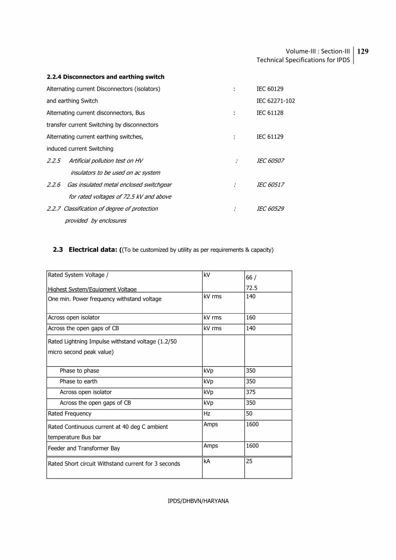
Volume-III : Section-III
Technical Specifications for IPDS
129
IPDS/DHBVN/HARYANA
2.2.4 Disconnectors and earthing switch
Alternating current Disconnectors (isolators) : IEC 60129
and earthing Switch IEC 62271-102
Alternating current disconnectors, Bus : IEC 61128
transfer current Switching by disconnectors
Alternating current earthing switches, : IEC 61129
induced current Switching
2.2.5 Artificial pollution test on HV : IEC 60507
insulators to be used on ac system
2.2.6 Gas insulated metal enclosed switchgear : IEC 60517
for rated voltages of 72.5 kV and above
2.2.7 Classification of degree of protection : IEC 60529
provided by enclosures
2.3 Electrical data: ((To be customized by utility as per requirements & capacity)
Rated System Voltage /
Highest System/Equipment Voltage
kV 66 /
72.5
One min. Power frequency withstand voltage kV rms 140
Across open isolator kV rms 160
Across the open gaps of CB kV rms 140
Rated Lightning Impulse withstand voltage (1.2/50
micro second peak value)
Phase to phase kVp 350
Phase to earth kVp 350
Across open isolator kVp 375
Across the open gaps of CB kVp 350
Rated Frequency Hz 50
Rated Continuous current at 40 deg C ambient
temperature Bus bar
Amps 1600
Feeder and Transformer Bay Amps 1600
Rated Short circuit Withstand current for 3 seconds kA 25
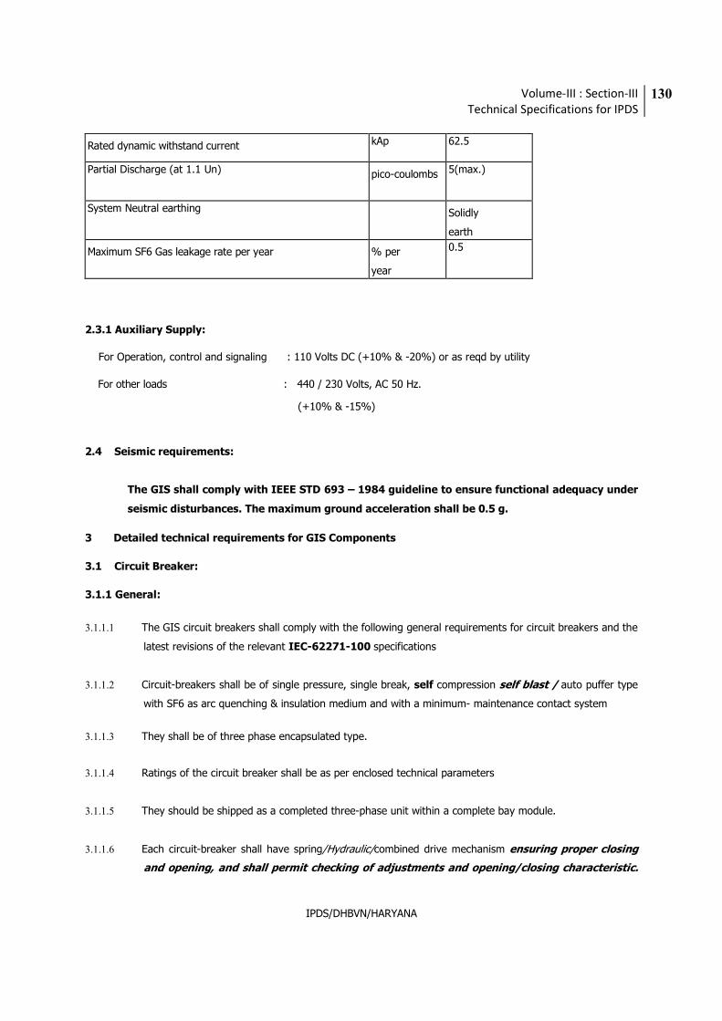
Volume-III : Section-III
Technical Specifications for IPDS
130
IPDS/DHBVN/HARYANA
Rated dynamic withstand current kAp 62.5
Partial Discharge (at 1.1 Un) pico-coulombs 5(max.)
System Neutral earthing Solidly
earth
Maximum SF6 Gas leakage rate per year % per
year
0.5
2.3.1 Auxiliary Supply:
For Operation, control and signaling : 110 Volts DC (+10% & -20%) or as reqd by utility
For other loads : 440 / 230 Volts, AC 50 Hz.
(+10% & -15%)
2.4 Seismic requirements:
The GIS shall comply with IEEE STD 693 – 1984 guideline to ensure functional adequacy under
seismic disturbances. The maximum ground acceleration shall be 0.5 g.
3 Detailed technical requirements for GIS Components
3.1 Circuit Breaker:
3.1.1 General:
3.1.1.1 The GIS circuit breakers shall comply with the following general requirements for circuit breakers and the
latest revisions of the relevant IEC-62271-100 specifications
3.1.1.2 Circuit-breakers shall be of single pressure, single break, self compression self blast / auto puffer type
with SF6 as arc quenching & insulation medium and with a minimum- maintenance contact system
3.1.1.3 They shall be of three phase encapsulated type.
3.1.1.4 Ratings of the circuit breaker shall be as per enclosed technical parameters
3.1.1.5 They should be shipped as a completed three-phase unit within a complete bay module.
3.1.1.6 Each circuit-breaker shall have spring/Hydraulic/combined drive mechanism ensuring proper closing
and opening, and shall permit checking of adjustments and opening/closing characteristic.
Volume-III : Section-III
Technical Specifications for IPDS
131
IPDS/DHBVN/HARYANA
The ON/OFF latches shall be mechanically interlocked with each other. The circuit breaker shall be
completely factory assembled, adjusted and tested.
3.1.1.7 The total break time from energizing the trip coil at rated control voltage to final arc extinction shall be as
short as possible, but in any event not greater than 3 cycles i.e. 60 ms.
3.1.1.8 The circuit breaker shall be capable of breaking all currents from zero up to the specified maximum fault
current in accordance with the relevant IEC recommendations.
3.1.1.9 The breakers are to be restrike-free.
3.1.1.10 The circuit-breakers shall be capable of tripping and re-closing (Auto reclose) according to the specified
duty cycle without derating: O-0.3 s – CO – 3 min. – CO.
Breaker shall be suitable for following switching duties:
• Terminal faults
• Short line faults
• Out of phase switching
• Interruption of small inductive current including transformer
• magnetizing inrush currents.
• Interruption of line and cable charging currents.
The circuit breaker shall meet all the double Circuit overhead transmission line and cable
characteristics for any type of fault or fault location, and also for line charging and
dropping when used on an effectively grounded system. Effect of second circuit in parallel
shall also be considered.
The circuit breakers shall be capable of being operated locally or from remote. Local
operation shall be by means of an open/close control switch located in the bay control
cabinet.
The minimum guaranteed nos. of maintenance free operations of complete GIS shall be
10000 nos. at rated capacity.
3.1.1.11 The Drive shall have sufficient stored energy for completing 2 CO with auxiliary power switched off.
3.1.1.12 Circuit breakers, being an arcing device, shall not house any passive device like current transformer
in its housing.
3.1.1.13 The breaker layout arrangement shall be vertical or horizontal but shall provide higher
mechanical stability and ease in maintenance. The operating principle of the breaker
shall ensure minimized dynamic floor loading. Low reaction forces on foundations
especially dynamically, are favorable and considered in the elevation.
Volume-III : Section-III
Technical Specifications for IPDS
132
IPDS/DHBVN/HARYANA
3.1.2 Closing Devices
3.1.2.1 The closing coils shall be suitable for operation at any voltage between 110% and 80% of the
nominal control voltage measured at the device terminals.
3.1.2.2 The breaker shall close correctly when an electrical closing pulse of 50 msec. duration is applied to
the closing coil.
3.1.3 Tripping Devices
3.1.3.1 All electrical tripping coils shall be suitable for operation at any voltage between 110% and 70%of the
nominal control voltage measured at the device terminals.
3.1.3.2 Each circuit-breaker shall be equipped with two shunt trip system. The one shunt trip system shall be
electrically separated from the other system.
3.1.3.3 An emergency hand tripping (mechanical) device shall be provided in the operating mechanism.
3.1.4 Anti-Pumping
The circuit-breaker mechanism shall be provided with means to prevent pumping while the closing circuit
remains energized, should the circuit breaker either fail to latch, or be tripped during closing due to the
operation of the protective relays.
3.1.5 Operating Mechanism
3.1.5.1 The breaker shall include suitable spring/Hydraulic/combined operating mechanism to assure proper
opening & closing operations. The provision shall be made for checking adjustments and opening
characteristics. The mechanism shall be capable of re-closing within the range specified in the applicable
standards. The mechanism shall include dual trip coils. Charging of opening mechanism shall be
possible in the event of failure of the motor drive.
Spring Operated Mechanism
a) Spring operated mechanism shall be complete with motor, opening spring, closing spring with limit switch for
automatic charging and all necessary accessories to make the mechanism a complete operating unit.
b) As long as power is available to the motor, a continuous sequence of closing and opening operations shall be
possible.
c) After failure of power supply to the motor, at least two close-open (C-O) operations of the circuit breaker
shall be possible.
d) Breaker operation shall be independent of the motor which shall be used solely for compressing the closing
Volume-III : Section-III
Technical Specifications for IPDS
133
IPDS/DHBVN/HARYANA
spring.
e) Motor rating shall be such that it requires only about 30 seconds for fully charging the closing spring.
f) Closing action of the circuit breaker shall compress the opening spring ready for tripping.
g) When closing springs are discharged after closing a breaker, closing
springs shall automatically be charged for the next operation.
Hydraulic Operated Mechanism
a) Hydraulic operated mechanism shall comprise self contained operating unit with power cylinder, control
valves, high and low pressure reservoir, motor, etc. A hand pump set shall also be provided for emergency
operation.
b) The oil pressure controlling the oil pump and pressure in the high pressure reservoir shall be continuously
monitored. Necessary hardware to achieve this, including the loose pressure gauge, instruments and
interconnecting piping etc shall form integral part of this mechanism.
c) The mechanism shall be suitable for at least two close-open operations after failure of AC supply to the
motor.
3.1.5.2 The mechanism shall be in a dust proof (IP55) box for this outdoor installation of Gas Insulated
Switchgear.
One vermin-proof, sheet steel cabinet of adequate size shall be provided for housing the operating
mechanism, aux relays, control and auxiliary equipment and for terminating all control, alarm and
auxiliary circuits in suitable terminal boxes. The control cabinet shall be provided with hinged doors with
provision for locking and removable cable gland plates for bottom cable entry. Viewing windows shall be
provided for observation of the instruments without opening the cabinet. Suitably engraved nameplates
shall be provided to identify all equipment in the control cabinet.
3.1.6 Auxiliary Switches
Each breaker shall have auxiliary switches with adequate number of NO and NC contacts all wired to
terminals located in the local control cabinet of the circuit breaker bay. 20 % spare contacts should be
provided.
3.1.7 Indicating Devices
3.1.7.1 Position indicators shall be provided to clearly indicate whether a circuit-breaker is open or closed.
3.1.7.2 Each circuit-breaker shall be provided with an operation counter to record the number of tripping
operations performed. The counter may be located at the local control cabinet.
3.1.7.3 All position indicators and counters shall be readable at a convenient elevation i.e. from the place of
operation.
Volume-III : Section-III
Technical Specifications for IPDS
134
IPDS/DHBVN/HARYANA
3.1.8 Gas Connections
Necessary valves and connections shall be provided to assure ease in handling the SF6 gas.
3.1.9 Timing Test
Timing tests are to be carried out after the switch gear has been completely charged with SF6 gas.
3.1.9.1 Testing instruments
_ Air / gas humidity tester,
_ Gas purity detector for SO2, H2O, CF4, AIR etc.,
_ Gas leakage tester,
_ Breaker timing measurement kit,
_ Set of equipment for pressure measurement and gas density meter.
3.1.9.2 TESTING FACILITIES:
Timing test facility shall be provided with switchgear such that it is not necessary to open up any gas
section to make test connections to the circuit breaker terminals. All details of test facilities to be
provided shall be submitted with technical bid.
3.1.10 PRINCIPLE PARAMETERS
The Circuit Breakers of GIS equipment shall confirm to the specific technical requirements given as
under.
Circuit Breaker (To be customized by utility as per requirements & capacity)
S. No Particulars 66 kV
1a) Enclosure Three Phase
1b) Enclosure material Aluminum Alloy
2) Rated voltage 72.5 kV
3) Rated current 1600A
4) Rated frequency 50 Hz
5) Rated short-circuit breaking current 25 kA rms, 3 sec
6) Rated break-time 3 cycle
7) Rated short-circuit making current 62.5 kA peak
8) Difference for simultaneity of 3 poles 4 ms (Max.)
Volume-III : Section-III
Technical Specifications for IPDS
135
IPDS/DHBVN/HARYANA
9) Rated insulation level under minimum SF6 gas pressure
a) Power frequency withstand voltage 140 kV rms
b) Lighting impulse withstand voltage 350 kV peak
c) Rated operating sequence O-0.3s-CO-3min-CO
10) Type of operating mechanism for circuit Breaker Spring – Spring/hydraulic
11) Rated control voltage
- Closing coil
110/220 VDC 110/220
VDC 12) Mechanical Endurance class M1
13) Electrical Endurance class E1
14) Restriking probability class C1
15) Rated line charging breaking current 10 A
16) Rated cable charging breaking current 125 A
17) Rated capacitor bank switching current 410 A
18) Rated out of phase making and breaking current
in % of rated short circuit breaking current
25
19) Characteristic for short line fault related to rated
short circuit breaking current
As per IEC 62271 - 100
20) TRV characteristics As per IEC 62271 - 100
21) Inductive current breaking capability Switching No Load current of transformer
22) First pole to clear factor As per IEC 62271 - 100
23) Opening time in ms Not more than 40
24) Closing time in ms Not more than 100
25) Noise level at the base of CB As per NEMA standard
26) No of tripping coils per breaker 2
27) No of closing coils per breaker 1
3.2 Disconnector Switches and Maintenance Grounding switches
3.2.1 General
a) The GIS disconnector switches and grounding switches shall comply with the following general
requirements of disconnect switches and the latest version of the relevant specifications IEC 60129,
61128, 61129, 61259.
Volume-III : Section-III
Technical Specifications for IPDS
136
IPDS/DHBVN/HARYANA
b) Disconnect switches shall be three phase encapsulated, group operated, no break, with one common
motor operated mechanism for all the three poles. They shall also have facilities for emergency manual
operation and necessary handles shall be provided.
c) Maintenance earthing switches shall be three phase encapsulated, group operated, no break, with one
common motor operated mechanism for all the three poles. They shall also have facilities for
emergency manual operation and necessary handles shall be provided.
d) Disconnect switches and grounding switches shall have electrical andMechanical interlocks to prevent
grounding switch from closing on an energized section.
Interlocks with other bays for bus transfer switching shall be done through bay control cabinets.
Actuation of the emergency manual operating device shall also disable the electrical control.
Disconnectors in open condition shall be secured against reclosure.
Disconnecting switches and adjacent safety grounding switches shall have electrical interlocks to
prevent closure of the grounding switches when the disconnecting switches are in the closed position
and to prevent closure of the disconnecting switch when the grounding switch is in the closed
position. The disconnector shall be pad lockable in the close & open position.
Interlocks
Interlocking devices must provide absolute and positive protection against potentially harmful mal-
operations of the switchgear. The following functions shall been assured:
i) Forcing the operator into the only safe and logic sequence to actuate breakers, switches,
isolators and grounding switches.
ii) Checking the actual fully closed or fully open position of all switching elements before and
after each move.
iii) Providing the logical checks and issuing the resulting PERMISSIVE or BLOCKED signals for
the switchgear.
iv) Indicating positively the absolute condition/position of the supervised equipment.
v) Local manual and remote electrical operation of all essential functions.
vi) Local emergency unlocking facilities via safety-key switches under the full responsibility of
the operator.
Intrabay and interbay interlocking shall be provided.
Electrical interlocking arrangement shall be fail-safe type.
Mechanical interlocks for isolator & Earthing Switch shall be fail-safe type.
Volume-III : Section-III
Technical Specifications for IPDS
137
IPDS/DHBVN/HARYANA
e) All main contacts, male and female, shall be silver plated.
f) Each disconnect switch and grounding switch shall open or close only due to motor driven or manual
operation independently. The switch contact shall not move due to gravity or other means, even if a
part fails. Once initiated, the motor mechanism shall complete an open or close operation without
requiring the initiating contact be held closed.
Operation of respective end position limit switches shall only disconnect the motor
mechanism. There should also be a pre-set timer in motor circuit for protection against
time over–run in case of inadvertent failure of drive mechanism in any intermediate
position of the disconnector travel path.
g) The disconnect switches and grounding switches shall be located as shown in the Single Line Diagram.
h) The disconnect switches shall be capable of interrupting the charging current of the connected GIS bus
& associated components.
i) Duty requirements:
The disconnecting switches shall have breaking capabilities as per IEC requirements. Contact shielding
shall be designed to prevent restrikes and high local stresses caused by the transient recovery voltages
when currents are interrupted.
The bus disconnecting switches shall reliably handle capacitive currents due to the making and breaking of
switchgear components as well as commutation currents due to bus bar reconfiguration.
The fast acting ground switches, used for overhead double circuit lines and underground cable feeders
shall be capable of switching induced current as per IEC requirement.
Short Circuit Requirements
The rated peak short-circuit current or the rated short time current carried by an isolator or earthing
switch for the rated maximum duration of short circuit shall not cause:
a) Mechanical damage to any part of the isolator or earthing switch.
b) Separation of the contacts or contact welding.
c) A temperature rise likely to damage insulation.
j) Access for maintenance and repair:
Suitable means of access should be provided in each disconnect-switch and grounding-switch
housing and mechanism for repair and/or maintenance of contacts.
Volume-III : Section-III
Technical Specifications for IPDS
138
IPDS/DHBVN/HARYANA
3.2.2 Operation Mechanism.
3.2.2.1 Mechanism shall be arranged mechanically, electrically, so that all three phases of any particular
disconnect switch or grounding switch operate simultaneously.
3.2.2.2 All mechanisms shall be suitable for electrical motor operation to achieve a fully automatic operation.
For emergency situations manual operation shall be possible. Handles or hand cranks shall be
provided, together with all necessary operation rods and rod guides. Manual operation shall be
prevented if the interlocking system does not allow the operation of the switch.
3.2.2.3 The auxiliary supply shall be electrically decoupled from the motor when the switch is operated
manually.
3.2.2.4 The mechanisms shall be arranged for locking in the open and in the closed position. Facility shall be
available to allow the switch to be padlocked in any position.
3.2.2.5 Disconnecting operating mechanism of all disconnector/ isolator & earth switches shall be at easy
operable height.
3.2.2.6 The isolator shall be provided with positive continuous control throughout the entire cycle of
operation.
The operating pipes and rods shall be sufficiently rigid to maintain positive control under most adverse conditions and when operated in tension or compression for isolator closing. They shall also be capable of withstanding all torsional and bending stresses due to operation of the isolator.
It shallnot be possible, after final adjustment has been made, for any part of the mechanism to be displaced at any point in the travel sufficiently to a low improper functioning of the isolator when the isolator is opened or closed at any speed.
The operating mechanism design shall be such that during the operation of the isolator (especially
manual operation), once the moving blades reach the sparking distance, springs shalltake over to give a quick, snap action closing so that the isolator closing is independent of manual efforts. Similarly, the springs must assist during the opening operation to give quick breaking feature.
Disconnector and high speed motor operated earthing switch mechanisms shall be provided with a
mechanism with stored energy to always assure completed operations.
3.2.3 Auxiliary Switches:
All disconnecting switches shall be provided with electrically independent auxiliary switch, directly driven
by the common operating shaft. Each disconnect switch and grounding switch shall furnished with
sufficient Nos. of NO – NC as per entire scheme requirement plus two (2) NO-NC electrically independent
Volume-III : Section-III
Technical Specifications for IPDS
139
IPDS/DHBVN/HARYANA
contacts terminated up to terminal board, at user’s disposal. The auxiliary switches shall indicate the
position of the switch contacts, and shall be independent of the motor operation.
3.2.4 Position Indicators
3.2.4.1 Mechanically connected position indicators shall be provided externally to permit observation of
close/open position of the disconnect switch and grounding switch. The place of Position Indicators
should be easily visible from the place of operation of respective equipment.
3.2.4.2 Visual verification shall be provided for each pole of each disconnect switch and grounding switch to
permit visual inspection of each switchblade position.
3.2.5 Technical Data Requirement: Disconnectors:
(To be customized by utility as per requirements & capacity)
Sr No. Particulars Parameters
1) Enclosure Three Phase
2) Enclosure material Aluminum Alloy
3) Rated voltage 72.5 kV
4) Rated current 1600 A
5) Rated short-time current 25 kA rms, 3 sec
6) Rated control and operating voltage 110/220 V DC
7) Type of operating mechanism Motor operated
8) Type Mechanically ganged operated
9) Rated insulation level
a) Power frequency withstand voltage
- phase to phase, between phases 140 kV rms
- Across the isolating distance 160 kV rms
b) Lightning impulse withstand voltage
- phase to phase, between phases 350 kV peak
- Across the isolating distance 375 kV peak
10) Mechanical Endurance Class M1
11) Bus transfer switching capability (% of rated current) 80
12) Rated bus charging current 0.1 A
3.2.6 Low-voltage test provision:
A low-voltage test provision may be supplied with a grounding switch to permit test voltages of up to
10kV (optional 2.5kV) and upto 200 A to be applied to the conductor without removing SF6 gas or other
components, except for ground shunt leads.
Volume-III : Section-III
Technical Specifications for IPDS
140
IPDS/DHBVN/HARYANA
3.3 Fast Acting Grounding Switches
3.3.1 General.
3.3.1.1 Fast acting grounding switches can be located at the terminal of HV/EHV overhead line/ cable. They
shall be able to switch safely load currents of overhead lines. They must have fault making capability
and be able to switch on a live line. Applicable standards are IEC 60129, 60517, 61129.
The fast acting grounding switches shall comply with the following general requirements of fast acting
grounding switches and the latest revision of the relevant IEC specifications.
3.3.1.2 Fast acting grounding switches shall be of three phase, encapsulated, three phase linkage group
operated by a maintenance-free self contained electrical motor. They shall also have facilities for
emergency manual operation and the necessary operating handles or hand cranks shall be supplied.
3.3.1.3 Fast acting grounding switches shall be electrically or mechanically interlocked with related
disconnector, to prevent the fast acting grounding switch from closing on an energized bus section.
3.3.1.4 All main contacts, male and female, shall either be silver plated or shall have silver inserts.
3.3.1.5 Each fast acting grounding switch shall open or close only due to motor-drive or manual operation but
shall be operable from local only. The switch contact shall not move due to gravity or other means,
even if a part fails. Once initiated, the motor mechanism shall complete an open or close operation
without requiring the initiating contact to be held closed.
3.3.1.6 Each fast acting grounding switch shall be fully insulated and connected to ground by a removable bolted
link in order that the grounding switch may be used for various test purposes. The insulation shallbe
capable of withstanding an applied power frequency voltage of 5 kV.
3.3.2 Operation Mechanism.
3.3.2.1 Mechanisms shall be coupled either mechanically or electrically or by both, so that all three phases
of any particular fast acting grounding switch operate simultaneously without any
discrimination.
3.3.2.2 All mechanisms shall be equipped with a motor suitable for operation from the auxiliary supply,
and a set of springs so arranged that energizing of the motor will cause the springs to be charged
and then released. The springs in turn shall close the fast acting grounding switch.
3.3.2.3 Motors shall be suitable for operation at any voltage between 80% and 110% of the rated auxiliary
voltage, measure at the motor terminals.
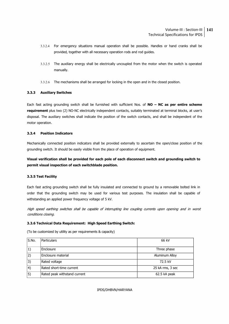
Volume-III : Section-III
Technical Specifications for IPDS
141
IPDS/DHBVN/HARYANA
3.3.2.4 For emergency situations manual operation shall be possible. Handles or hand cranks shall be
provided, together with all necessary operation rods and rod guides.
3.3.2.5 The auxiliary energy shall be electrically uncoupled from the motor when the switch is operated
manually.
3.3.2.6 The mechanisms shall be arranged for locking in the open and in the closed position.
3.3.3 Auxiliary Switches
Each fast acting grounding switch shall be furnished with sufficient Nos. of NO – NC as per entire scheme
requirement plus two (2) NO-NC electrically independent contacts, suitably terminated at terminal blocks, at user’s
disposal. The auxiliary switches shall indicate the position of the switch contacts, and shall be independent of the
motor operation.
3.3.4 Position Indicators
Mechanically connected position indicators shall be provided externally to ascertain the open/close position of the
grounding switch. It should be easily visible from the place of operation of equipment.
Visual verification shall be provided for each pole of each disconnect switch and grounding switch to
permit visual inspection of each switchblade position.
3.3.5 Test Facility
Each fast acting grounding switch shall be fully insulated and connected to ground by a removable bolted link in
order that the grounding switch may be used for various test purposes. The insulation shall be capable of
withstanding an applied power frequency voltage of 5 kV.
High speed earthing switches shall be capable of interrupting line coupling currents upon opening and in worst
conditions closing.
3.3.6 Technical Data Requirement: High Speed Earthing Switch:
(To be customized by utility as per requirements & capacity)
S.No.
Particulars 66 kV
1) Enclosure Three phase
2) Enclosure material Aluminum Alloy
3) Rated voltage 72.5 kV
4) Rated short-time current 25 kA rms, 3 sec
5) Rated peak withstand current 62.5 kA peak
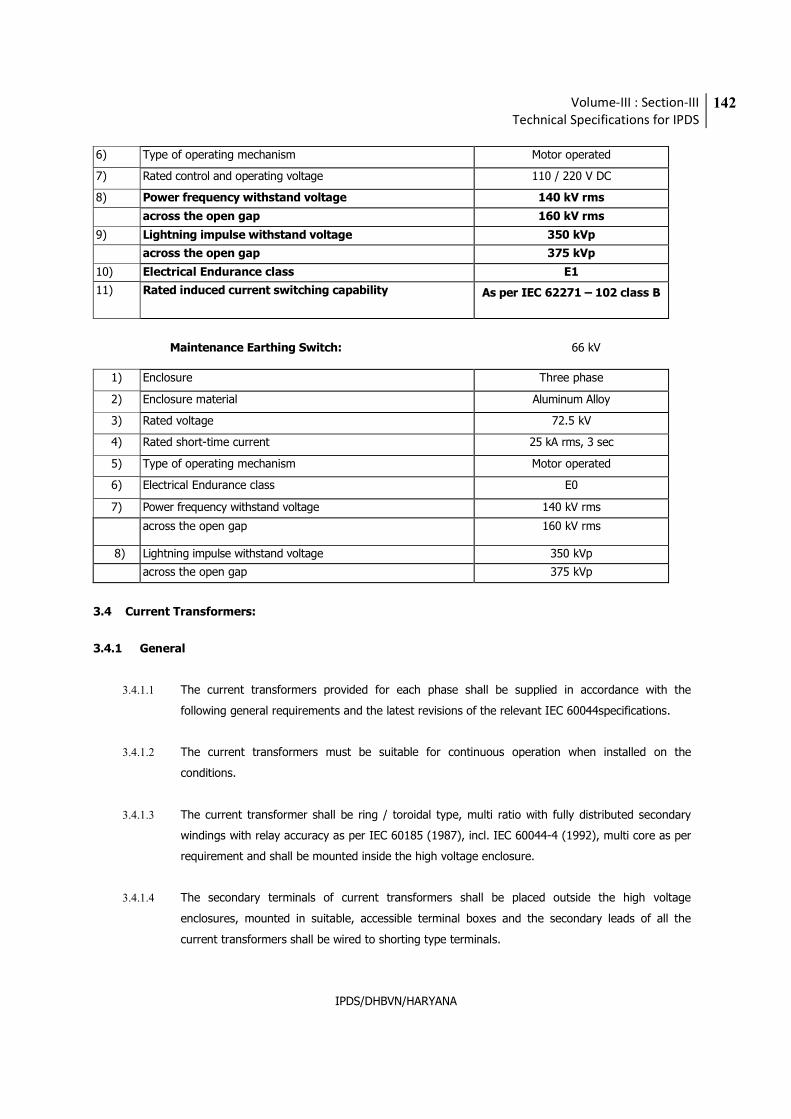
Volume-III : Section-III
Technical Specifications for IPDS
142
IPDS/DHBVN/HARYANA
6) Type of operating mechanism Motor operated
7) Rated control and operating voltage 110 / 220 V DC
8) Power frequency withstand voltage 140 kV rms
across the open gap 160 kV rms
9) Lightning impulse withstand voltage 350 kVp
across the open gap 375 kVp
10) Electrical Endurance class E1
11)
Rated induced current switching capability As per IEC 62271 – 102 class B
Maintenance Earthing Switch: 66 kV
1) Enclosure Three phase
2) Enclosure material Aluminum Alloy
3) Rated voltage 72.5 kV
4) Rated short-time current 25 kA rms, 3 sec
5) Type of operating mechanism Motor operated
6) Electrical Endurance class E0
7) Power frequency withstand voltage 140 kV rms
across the open gap 160 kV rms
8) Lightning impulse withstand voltage 350 kVp
across the open gap 375 kVp
3.4 Current Transformers:
3.4.1 General
3.4.1.1 The current transformers provided for each phase shall be supplied in accordance with the
following general requirements and the latest revisions of the relevant IEC 60044specifications.
3.4.1.2 The current transformers must be suitable for continuous operation when installed on the
conditions.
3.4.1.3 The current transformer shall be ring / toroidal type, multi ratio with fully distributed secondary
windings with relay accuracy as per IEC 60185 (1987), incl. IEC 60044-4 (1992), multi core as per
requirement and shall be mounted inside the high voltage enclosure.
3.4.1.4 The secondary terminals of current transformers shall be placed outside the high voltage
enclosures, mounted in suitable, accessible terminal boxes and the secondary leads of all the
current transformers shall be wired to shorting type terminals.
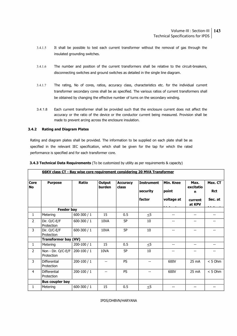
Volume-III : Section-III
Technical Specifications for IPDS
143
IPDS/DHBVN/HARYANA
3.4.1.5 It shall be possible to test each current transformer without the removal of gas through the
insulated grounding switches.
3.4.1.6 The number and position of the current transformers shall be relative to the circuit-breakers,
disconnecting switches and ground switches as detailed in the single line diagram.
3.4.1.7 The rating, No of cores, ratios, accuracy class, characteristics etc. for the individual current
transformer secondary cores shall be as specified. The various ratios of current transformers shall
be obtained by changing the effective number of turns on the secondary winding.
3.4.1.8 Each current transformer shall be provided such that the enclosure current does not affect the
accuracy or the ratio of the device or the conductor current being measured. Provision shall be
made to prevent arcing across the enclosure insulation.
3.4.2 Rating and Diagram Plates
Rating and diagram plates shall be provided. The information to be supplied on each plate shall be as
specified in the relevant IEC specification, which shall be given for the tap for which the rated
performance is specified and for each transformer core.
3.4.3 Technical Data Requirements (To be customized by utility as per requirements & capacity)
66KV class CT - Bay wise core requirement considering 20 MVA Transformer
Core
No
Purpose Ratio Output
burden Accuracy
class Instrument
security
factor
Min. Knee
point
voltage at
highest
Max.
excitatio
n
current
at KPV
Max. CT
Rct
Sec. at
highest Feeder bay
1 Metering 600-300 / 1 15 0.5 <5 -- -- --
2 Dir. O/C-E/F
Protection
600-300 / 1 10VA 5P 10 -- -- --
3 Dir. O/C-E/F
Protection
600-300 / 1 10VA 5P 10 -- -- --
Transformer bay (HV)
1 Metering 200-100 / 1 15 0.5 <5 -- -- --
2 Non - Dir. O/C-E/F Protection
200-100 / 1 10VA 5P 10 -- -- --
3 Differential Protection
200-100 / 1 -- PS -- 600V 25 mA < 5 Ohm
4 Differential
Protection
200-100 / 1 -- PS -- 600V 25 mA < 5 Ohm
Bus coupler bay
1 Metering 600-300 / 1 15 0.5 <5 -- -- --
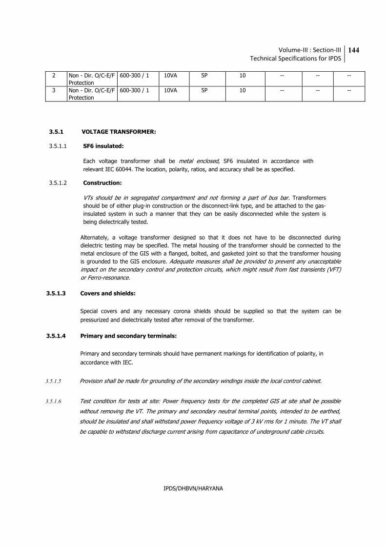
Volume-III : Section-III
Technical Specifications for IPDS
144
IPDS/DHBVN/HARYANA
2 Non - Dir. O/C-E/F
Protection
600-300 / 1 10VA 5P 10 -- -- --
3 Non - Dir. O/C-E/F
Protection
600-300 / 1 10VA 5P 10 -- -- --
3.5.1 VOLTAGE TRANSFORMER:
3.5.1.1 SF6 insulated:
Each voltage transformer shall be metal enclosed, SF6 insulated in accordance with
relevant IEC 60044. The location, polarity, ratios, and accuracy shall be as specified.
3.5.1.2 Construction:
VTs should be in segregated compartment and not forming a part of bus bar. Transformers
should be of either plug-in construction or the disconnect-link type, and be attached to the gas-
insulated system in such a manner that they can be easily disconnected while the system is
being dielectrically tested.
Alternately, a voltage transformer designed so that it does not have to be disconnected during
dielectric testing may be specified. The metal housing of the transformer should be connected to the
metal enclosure of the GIS with a flanged, bolted, and gasketed joint so that the transformer housing
is grounded to the GIS enclosure. Adequate measures shall be provided to prevent any unacceptable
impact on the secondary control and protection circuits, which might result from fast transients (VFT)
or Ferro-resonance.
3.5.1.3 Covers and shields:
Special covers and any necessary corona shields should be supplied so that the system can be
pressurized and dielectrically tested after removal of the transformer.
3.5.1.4 Primary and secondary terminals:
Primary and secondary terminals should have permanent markings for identification of polarity, in
accordance with IEC.
3.5.1.5 Provision shall be made for grounding of the secondary windings inside the local control cabinet.
3.5.1.6 Test condition for tests at site: Power frequency tests for the completed GIS at site shall be possible
without removing the VT. The primary and secondary neutral terminal points, intended to be earthed,
should be insulated and shall withstand power frequency voltage of 3 kV rms for 1 minute. The VT shall
be capable to withstand discharge current arising from capacitance of underground cable circuits.
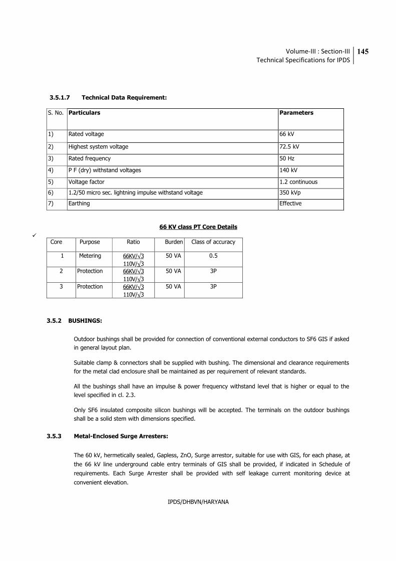
Volume-III : Section-III
Technical Specifications for IPDS
145
IPDS/DHBVN/HARYANA
3.5.1.7 Technical Data Requirement:
S. No. Particulars Parameters
1) Rated voltage 66 kV
2) Highest system voltage 72.5 kV
3) Rated frequency 50 Hz
4) P F (dry) withstand voltages 140 kV
5) Voltage factor 1.2 continuous
6) 1.2/50 micro sec. lightning impulse withstand voltage 350 kVp
7) Earthing Effective
66 KV class PT Core Details
� Core Purpose Ratio Burden Class of accuracy
1 Metering 66KV/√3
110V/√3
50 VA 0.5
2 Protection 66KV/√3
110V/√3
50 VA 3P
3 Protection 66KV/√3
110V/√3
50 VA 3P
3.5.2 BUSHINGS:
Outdoor bushings shall be provided for connection of conventional external conductors to SF6 GIS if asked
in general layout plan.
Suitable clamp & connectors shall be supplied with bushing. The dimensional and clearance requirements
for the metal clad enclosure shall be maintained as per requirement of relevant standards.
All the bushings shall have an impulse & power frequency withstand level that is higher or equal to the
level specified in cl. 2.3.
Only SF6 insulated composite silicon bushings will be accepted. The terminals on the outdoor bushings
shall be a solid stem with dimensions specified.
3.5.3 Metal-Enclosed Surge Arresters:
The 60 kV, hermetically sealed, Gapless, ZnO, Surge arrestor, suitable for use with GIS, for each phase, at
the 66 kV line underground cable entry terminals of GIS shall be provided, if indicated in Schedule of
requirements. Each Surge Arrester shall be provided with self leakage current monitoring device at
convenient elevation.
Volume-III : Section-III
Technical Specifications for IPDS
146
IPDS/DHBVN/HARYANA
They shall have adequate thermal discharge capacity for severe switching surges, long duration surges
and multiple strokes. The surge arresters when provided with pressure relief devices shall be capable of
withstanding the internal pressures developed during the above discharges without operation of the
pressure relief devices.
Surge Arresters, if any provided, shall be of either the “plug-in” construction or the disconnect-link type
and be attached to the gas-insulated system in such a manner that they can be readily disconnected from
the system while the system is being dielectrically tested. The metal housing of the arrester shall be
connected to the metal enclosure of the GIS with a flanged, bolted joint.
The ground connection shall be sized for the fault level of the GIS. It shall be insulated from the GIS-
enclosure and grounded externally to permit periodic maintenance and monitoring of the leakage current.
If the arresters are not equipped with removable links, special covers and any necessary corona shields
should be supplied so that the system can be pressurized and dielectrically tested after removal of the
arrester.
Access to the arrester ground connection, when it is provided with means for leakage current monitoring
should not be obstructed.
3.6 Insulating Gas and gas leakage rate
The GIS shall be furnished with sufficient sulfur hexa fluoride (SF6) gas to pressurize the complete system
in a sequential approach, one zone or compartment at a time to the rated nominal density. The
guaranteed leakage rate of each individual gas compartment and between compartments must be less
than 0.5% p.a. for the service life of equipment.
The quality of new filled-in SF6 gas shall meet the following requirements in line with IEC 60376.
SF6 > 99.90 % by weight
Air < 500 ppm by weight (0.25 vol.-%)
CF4 < 500 ppm by weight (0.1 vol.-%)
H2O < 15 ppm by weight (0.012 Vol-%)
Mineral oil < 10 ppm by weight
Acidity, in terms of HF < 0.3 ppm by weight
Hydrolysable fluorides,
In terms of HF < 1 ppm by weight
Volume-III : Section-III
Technical Specifications for IPDS
147
IPDS/DHBVN/HARYANA
3.7 Reuse or recycling of removed gas:
The supplier should provide guidelines or recommended practices for the reuse or recycling of SF6 gas
removed from the equipment. These guidelines should be consistent with current industry practices, as
they pertain to the effect of SF6 on global warming; i.e. SF6 gas should be reused and recycled whenever
possible and never be unnecessarily released into the atmosphere. Clear instructions shall be provided by
bidder about handling, recycling & treatment of new and used SF6 gas.
During commissioning dew point of SF6 gas shall be measured and documented.
Components may be filled with N2 for transportation and refilled with SF6 at site.
3.8 Gas sections
The GIS enclosures (one enclosure for all the three phases) shall be divided into several gas sections
separated by gas-tight barriers. Each section shall be provided with necessary valves to allow evacuation
and refill of gas without evacuation of any other section. Location of gas barrier insulators is to be
clearly discriminated outside the enclosure by a band of distinct colour normally used for
safety purposes.
The gas system proposed shall be shown on a “gas single line diagram” and submitted with the technical
bid. It should include the necessary valves, connections, density monitors, gas monitor
system and controls, indication, orifices, and isolation to prevent current circulation. Means of
calibrating density monitors without de-energizing the equipment should be specified by the
supplier.
For the purpose of gas monitoring and maintenance, the GIS shall be divided into various individual zones
in each bay. The CB gas zone shall be independent from all other gas compartments and shall
meet the requirement of relevant IEC.
Each gas zone shall be furnished with a gas monitoring system consisting of a gas density continuous
monitoring device provided with two electrically independent contacts which operate in two stages as
follows:
a) First alarm : At a gas density normally 5 to 10% below the nominal fill density.
b) Second alarm: Minimum gas density to achieve equipment ratings.
In special cases determined by the supplier, a third stage with a set of contacts may be
necessary in certain areas.
Provisions shall be made for connecting pressure gauges, service cart, and moisture test instrumentation
to any one of the gas sections.
Volume-III : Section-III
Technical Specifications for IPDS
148
IPDS/DHBVN/HARYANA
Permanent Gas Treatment Devices:
Means shall be provided inside each enclosure for treating the SF6 gas by the use of Desiccants, driers, filter, etc. to
remove impurities in the gas. All gas compartments shall be fitted with static filter material containers that will
absorb residual and entering moisture inside the high voltage enclosures. Filters inside the breaker compartment shall
also be capable of absorbing gas decomposition products resulting from the switching arc.
3.9 GIS Connection:
3.9.1 GIS to TRANSFORMER:
Transformers shall be connected to the GIS by termination of 66 kV XLPE power cable. The connection
between GIS and high voltage cable at GIS end shall be done through cable termination / cable sealing end.
For transformer end connection the cable termination on structure shall be provided outdoor, if specified in
schedule of requirements. The plug in cable sealing ends for XLPE cables shall consist of gas tight plug in
sockets and prefabricated plugs with grading elements of silicone rubber.
3.9.2 GIS to LINE:
The 66 kV line will be terminated to GIS by XLPE power cable
3.9.3 66 kV Power Cable connection:
The connection between GIS and high voltage cable at GIS end is done through cable termination / cable
sealing end. Plug in cable sealing ends for XLPE cables shall consist of gas tight plug in sockets, and prefabricated
plugs with grading elements of silicone rubber.
A separate cable basement is provided for cable entry, its distribution and installation.
The design of the cable end box shall fully comply with the IEC standard. The type and size of
cable is specified. All end cable modules shall be suitable for connecting single core, XLPE
specified cable.
Necessary provision for termination of specified nos. of such power cables shall be made in GIS. GIS supplier
shall either carry out the work of termination or coordinate with cable terminator for such connection as
specified in schedule of requirement. Provision shall be suitable for terminating cable size and type approved
by utility.
3.10 Local & Remote Control and Operation
3.10.1 General
One local control cabinet (LCC) for GIS shall be supplied for the local control and operation of each bay. Each LCC
shall contain the local control, interlocking, operation and indication devices for the associated GIS bay.
Volume-III : Section-III
Technical Specifications for IPDS
149
IPDS/DHBVN/HARYANA
The LCC shall be mounted on each GIS bay. The LCC’s shall be located with sufficient space for access and the
possibility to work at the equipment even when the LCC doors are open, or directly at the switch-gear in front of the
related circuit breaker.
The LCC’s shall be installed indoor and care must be taken with the design to ensure that all LCC’s are drip and splash
proof. The LCC’s shall also be dust and vermin proof. The control and operation circuits shall be well shielded and
with safety measures to protect operator from touching energized parts. Power frequency withstand of control
circuits shall be 2 kV for 1 minute.
The LCC should have required arrangement for control and operations of GIS from Remote i.e. from the control room
through SCADA compatible control and protection panel.
The LCC shall include all required functions for control and supervision of a complete GIS as well as the marshalling
of all connections to and from the GIS bays.
Safe station operation is ensured through following base functions.
i) Feeder & station interlocking, depending on the position of all high voltage components with their
blocking functionality.
ii) Blocking of commands when crank handle of disconnector or earthing switches is introduced.
iii) Extensive circuit breaker supervision through “Anti-Pumping”, pole discrepancy, Gas density and
position supervision of circuit breaker,
3.10.2 Required features for conventional local control cabinets
The LCC’s shall be provided with the following features:
a) A mimic diagram showing the single line diagram. Position indictors, on/off switches for the HV devices and
local / off / remote switches shall be installed on or adjacent to the various symbols of the mimic diagram.
The following devices shall be supplied as a minimum:
• Circuit breaker control switches with ON – OFF indicating lamps. – Circuit breaker “local-remote” selector
switch.
• Disconnect switch, control switch with ON – OFF indicating lamps.
• Grounding switch, control switch with ON – OFF indicating lamps.
• Mimic bus including symbols according to the single line diagram.
• Monitoring control of all high voltage switching devices in a bay.
• Digital display of current, voltage, active and reactive power, power factor etc.
b) Any interposing relays and control switches associated with the circuit breakers disconnect switches,
grounding switches etc.
c) The alarm and indication for devices specified e.g. gas, DC & AC supervision.
Volume-III : Section-III
Technical Specifications for IPDS
150
IPDS/DHBVN/HARYANA
d) Fuses and links. These shall be installed in the interior of the LCC’s
e) Terminal blocks for the terminating and marshalling of auxiliary supply circuits, control, interlocking, and
indication & alarm circuits from the GIS and for cable connections to the remote control room or the owner’s
control system.
f) Each LCC shall be furnished with a guarded resistance heater to prevent the internal equipment from
humidity deposit. The heater shall be rated 230 V AC and fed through a two pole fused disconnect switch.
g) A fluorescent lamp and a duplex convenience outlet rated 230 V AC, 15 amps with ground fault interrupter
shall be installed in each LCC.
h) The Local control cubicle shall be fitted with pre wired interface terminal blocks for connection to user’s
control & protection panels. The interface includes CT & PT inputs for protection & measuring system,
Protection trip 1 & 2 signals, Aux switch contacts etc.
3.10.3 Wiring Requirements
i) Each circuit breaker shall have control suitable for operation on 110 V DC with two electrically independent
trip circuits. The miniature circuit-breakers (MCB) shall be provided for the closing circuit and an
independent separate switch fuse unit of suitable rating shall be provided for the primary and back up trip
circuits.
ii) Wiring shall be complete in all respects to ensure proper functioning of the control, protection, and
monitoring and interlocking schemes.
iii) DC circuit for trip coil 1 & 2 shall be wired separately.
iv) Wiring shall be done with flexible 1100V grade, FRLS, PVC insulated, switchboard wires with 2.5 mm2
stranded copper conductor. The control wire in a grouped environment shall not convey flame, continue to burn. Wiring between equipment and control cubicle shall be routed through G.I. rigid conduits and shall be
done by PVC & screened cable only, with safety measures to protect operator from touching energized parts.
v) Each wire shall identify at both ends with permanent markers bearing wire numbers as per Contractor's
wiring diagram.
vi) Wire termination shall be done with crimping type connectors with insulating sleeves. Wires shall not be
spliced between terminals.
vii) All spare contacts of relays, push buttons, auxiliary switches etc. shall be wired up to terminal blocks in the
control cubicle.
viii) Terminal blocks shall be 1100V grade, stud type with engraved numbers suitable for termination of at least
two numbers of 2.5 mm2 stranded copper conductor. Terminal blocks for CT, PT, auxiliary AC & DC supply
shall be disconnecting link type.
ix) Not more than two wires shall be connected to any terminal. Spare terminals equal in number to 20% active
terminals shall be furnished.
x) Terminal blocks shall be located to allow easy access. Wiring shall be so arranged that individual wires of an
external cable can be connected to consecutive terminals.
xi) Terminal connectors that carry power supply should be shrouded from adjoining connectors.
xii) Manufacturer shall provide all control wiring and terminations internal to the switchgear, and connecting the
switchgear to the bay control cabinets.
xiii) All control cables shall be shielded. Cable shields shall be grounded. Grounding connections shall be as short
and direct as possible and shall terminate at the point of entry to cabinets or terminal boxes.
xiv) Co-axial type cable glands suitable for use with shielded cables shall be used at each termination.
xv) All control cables shall be installed and terminated in such a manner as to limit the effects of transient
electromagnetic voltages on the control conductors to an acceptable level.
xvi) Any cabling within GIS shall be supported on cable tray. No cable shall be in hanging position.
Volume-III : Section-III
Technical Specifications for IPDS
151
IPDS/DHBVN/HARYANA
xvii) Insulator cones shall be embedded in full return current carrying metal fixing rings in order to avoid
mechanical stresses to the cast resin part and to impart full conductivity across the flange connection.
Earthing of different gas compartments/enclosures is not allowed with cross bonding with any metal
strips.
3.10.4 Connections within the GIS and their LCC’s
All cable connections between the various GIS modules and the LCC’s shall be made by prefabricated multi-core
cables with multipoint plug in connections on both the ends. PTs & CTs circuit shall be wired with crimped type
copper lugs.
All cables shall be shielded and adequate for their application (indoor / outdoor). The cables shall be fire retardant
low smoke.
The length and the number of terminal points of control wiring & SF6 gas connections shall be minimized.
The electrical connections between the various gas sections shall preferably be made by means of multiple contact
connectors so that electrical connection is automatically achieved when bolting on section to another. The surface
of the connector fingers and conductor tubes on such connections shall be silver plated.
3.11 Name plates
Name plates of the following types shall be furnished in a convenient central location to provide information
for operation and maintenance.
a) Gas Single Line Diagram showing all HV devices in a single line diagram with the gas sectionalizing of
the GIS indicated. Also shown shall be the GIS nomenclature, a legend, Manufacturer’s type and serial
number and year of manufacture.
b) GIS Rating / Name plate:
Manufacturer’s name & address, type & designation, Sr. No, Maximum ambient temperature,
System frequency, Maximum continuous voltage, Maximum continuous current at 40oC ambient
temperature, Basic Impulse Level, Power Frequency one minute voltage, Short circuit current,
rms., symmetrical Short time (rms) current & duration, symmetrical Momentary current, peak,
Total weight of gas at rated density, Rated gas pressure at 20oC. Opening pressure of the
bursting disc, recommended moisture limits of insulation gas (PPMV), Auxiliary voltages,
Contract/Purchase Order numbers, Total weight of the equipment
c) Equipment nameplate containing nameplate rating information for all HV modules (like circuit
breaker, disconnect switches, current transformer, voltage transformer, surge arrester, etc.) as required
in relevant IEC.
Volume-III : Section-III
Technical Specifications for IPDS
152
IPDS/DHBVN/HARYANA
d) Nameplates showing serial numbers and similar data specific to individual components shall be
mounted on the components. Each instrument transformer must have its own rating plate mounted
adjacent to each terminal box cover, will all terminal and ratio markings. Each bay auxiliary control cubicle
must be identified with its designation to which it is assigned.
3.11.1 Bidder shall specify the number of skilled / semi-skilled / unskilled persons, supervisors and Engineers
required to be deputed for complete erection, testing, commissioning of GIS board.
3.12 Type Tests:
Following type test reports from NABL laboratory, as specified in IEC standard 62271 – 203 &62271-100 (amended
up to date) shall be submitted for the offered type, rating of GIS invariably with the technical bid. Bid without type
test reports will not be considered for evaluation. The type test reports shall not be older than FIVE years and shall
be valid up to expiry of validity of offer.
1. Tests to verify the insulation level (Lightning impulse, Switching impulse and ac withstand test with
PD) test on each GIS device (CB, Disconnector, bus, etc).
2. Dielectric tests on auxiliary circuits.
3. Tests to prove the radio interference voltage (RIV) level.
4. Tests to prove the temperature rise of any part of the equipment and measurement of the resistance
of the main circuit.
5. Tests to prove the ability of the main and earthing circuits to carry the rated peak and the rated short
time withstand current.
6. Tests to verify the making and breaking capacity of the included switching devices.
7. Tests to prove the satisfactory operation of the included switching devices.
8. Tests to prove the strength of enclosures.
9. Verification of the degree of protection of the enclosure.
10. Gas tightness tests
11. Electromagnetic compatibility tests (EMC).
12. Additional tests on auxiliary and control circuits.
13. Tests on partitions.
14. Tests to prove the satisfactory operation at limit temperatures.
15. Tests to prove performance under thermal cycling and gas tightness tests on insulators.
16. Corrosion test on earthing connections (if applicable).
17. Tests to assess the effects of arcing due to an internal fault.
18. Tests on solid dielectric components (operating rods, spacers, etc)
19. Seismic test
20. Test on Auxiliary switches (Electrical & Mechanical Endurance, Heat run, IR & HV test)
Important note for type tests: The type test report shall be submitted for the offered class and rating of GIS.
However, the type test report for higher class/rating can be accepted for scrutiny of technical bid but the same test/s
shall have to be carried out on the offered class/rating GIS. Bidder shall invariably confirm to carry out the required
type test/s, special tests, before commencement of supply, without affecting delivery schedule, free of cost, at NABL
approved laboratory, or at suppliers works in presence of Utility representative, in the event of order.
Volume-III : Section-III
Technical Specifications for IPDS
153
IPDS/DHBVN/HARYANA
3.13 Routine / Acceptance Testing:
During manufacture and on completion, all equipment shall be subjected to the Routine tests as laid down in IEC
Standard IEC 62271-203. All the acceptance tests shall be carried out in presence of Utility representative on offering
the material for inspection and testing by successful bidder. Tests shall include the following:
1. Dielectric test on the main circuit.
2. PD test
3. Tests on auxiliary and control circuits.
4. Measurement of the resistance of the main circuit.
5. Tightness test.
6. Design and visual checks.
7. Pressure tests of enclosures.
8. Functional tests
9. Tests on auxiliary circuits, equipment and interlocks in the control mechanism.
10. Pressure test on partitions.
3.14 Test Certificates:
a. Certified reports of all the tests carried out at the works shall be furnished in required number copies
for approval of the Owner.
b. The equipment shall be dispatched from works only after receipt of Owner/ Purchaser's written
dispatch clearance & approval of the test reports.
c. Routine test certificates of bought out components shall be furnished.
d. Type test certificate on any equipment or component if so desired by the Owner shall be furnished.
Otherwise the equipment shall have to be type tested, free of charge, to prove the design.
3.15 Tests after installation of complete GIS at Site:
After installation and before being put into service, the GIS shall be tested in order to check the correct
operation and dielectric integrity of the equipment as laid down in IEC 62271-203. The successful bidder
shall furnish a commissioning test plan and a statement method for the tests on site. Tests shall include the
following:
1. Dielectric tests on the main circuits.
2. Dielectric tests on auxiliary circuits.
3. Measurement of the resistance of the main circuit.
4. Gas tightness tests.
5. Checks and verifications.
6. Gas quality verifications.
7. On site power frequency voltage withstand test with PD test.
8. Tests as per IEEE C37.122.1 clause 4.10.5
9. Functional & interlock tests for all items
10. Demonstration of operational compatibility with SCADA, if installed
11. Visual inspection, checks & verifications.
12. Mechanical operation tests of circuit breakers, Disconnectors and earthing switches and high-speed
earthing switches
Volume-III : Section-III
Technical Specifications for IPDS
154
IPDS/DHBVN/HARYANA
13. Insulation resistance measurement
14. Tests on CTs and PTs
15. Tests on Surge Arresters
3.15.1 Required test equipment
During the onsite tests, the supplier shall provide all necessary test facilities and equipment for the switch-
gear power frequency tests, i.e. test bushing or test cable, test adapter, test transformer or resonant test set
etc.
3.16 SPARES:
Bidder shall submit a list and supply of following spares.
i) Recommended spare parts for three (3) years after guarantee period of satisfactory
and trouble-free operation.
ii) Commissioning spares
iii) Maintenance spares
iv) Special tools, tackles & spanner required during commissioning, operation and maintenance.
v) Viewing mechanism
vi) Spare GIS modules of CT, Breaker and Isolator & LA. All spares indicated in list for above shall be
considered in the scope of supply.
Each list shall be complete with specification, ratings, type, make, identification number, unit rate, quantity etc.
3.17 DRAWINGS, DATA & MANUALS:
Drawings, Data and Manuals shall be submitted in triplicate with the bid and in quantities and procedures as specified
in General Conditions on Contract and/or elsewhere in this specification for approval and subsequent distribution
after the issue of Letter of Intent.
To be submitted with the Bid:
1. Typical general arrangement drawings of the equipments indicating space requirement, room dimensions,
crane capacity etc.
2. Technical Specifications of equipment and special tools explaining construction features, principle of
operation, special features etc.
3. Comprehensive QAP, FQP, SLD, Gas Schematic diagram, Technical brochures, building requirements, Earth
mat design, List of recommended spares, special tools or fixtures, O&M manuals, environmental guide for
handling SF6 gas & decommissioning, estimated time schedule for installation & commissioning, bill of
materials, and any other documents required for successful commissioning & operation of complete GIS.
Volume-III : Section-III
Technical Specifications for IPDS
155
IPDS/DHBVN/HARYANA
4. Control and protection:
Block & principle diagram showing proposed scheme, layout & equipment arrangement drawings,
catalogues & brochures of offered devices.
Successful bidder shall submit 3 sets of spiral bound volume of following drawings & data for approval
before commencement of supply:
1. A comprehensive Manufacturing Quality assurance plan with effective quality assurance system.
2. Field Quality plan indicating instruction & procedures sequenced for storage, assemble, maintenance
and disassembly.
3. Assemble and maintenance clearance requirements.
4. Dimensional general arrangement drawing showing disposition of various fittings, name plates
indicating equipment ratings.
5. Structure Plan with details and loading
6. Foundation plan indicating loadings for all GIS equipment, supporting structure and anchor bolt
arrangements.
7. Assembly drawing for erection at site with part numbers and schedule of materials Transport/shipping
dimensions with weights.
8. Control schematic and wiring diagrams.
9. Gas schematic Diagram
10. Gas system installation procedures, gas handling procedures.
11. Grounding arrangement and ground bus details including Manufacturer’s recommendation on
Grounding of reinforcement bars of Column foundation.
12. Calculation of Voltage rise for GIS enclosure
13. Calculated point to point resistance for each assembly.
14. Calculation for Surge Protection
15. Design Calculations for Bus-bar sizing, Short circuit forces and vibration on Bus-bar & each equipment,
thermal stability and losses.
16. Any other relevant drawing or data necessary for satisfactory installation, operation and maintenance.
17. Operating instruction & manuals for GIS and its accessories
18. The manual shall clearly indicate method of installation, checkups and tests to be carried out before
commissioning of the equipment.
19. The bidder shall note that the approval of drawings & documents by the Owner does not relieve him of
his contractual obligation.
The bidder may note that the drawings, data and manuals listed herein are minimum required only. The bidder shall
ensure that all other necessary write-up etc. required to fully describe the equipment are to be submitted with the
bid.
All drawings shall be prepared by using AutoCAD and documents shall be generated using Electronic version. The
paper copy of the drawings & document shall be submitted for approval & reference. All final drawings and
documents shall be submitted in CD in AutoCAD and MS office format as applicable for Owner’s future reference. Also
AutoCAD version of Main GA drawings is to be submitted for Owner’s layout finalization.
Volume-III : Section-III
Technical Specifications for IPDS
156
IPDS/DHBVN/HARYANA
3.18 MAINTENANCE:
The operational integrity of the GIS switchgear shall not subject to external influences, such as pollution, moisture,
dust etc. As a consequence of this GIS switchgear should be practically maintenance free, however, the details of
inspection required at regular interval shall be indicated in the offer. Visual inspection shall be required not below 2
(two) years interval.
Inspection shall not be required often than every 10 years. During inspection it must not be necessary to open the
switchgear enclosures for interrupt operation of substation. Provision of functional testing of the close and trip coils,
auxiliary switches, pressure and control switches etc. shall be provided. Following minimum maintenance period shall
be accepted.
(a) Circuit breaker: 5000 closing and opening or 20 interruption at max rated current
(b) Disconnector: 5000 closing and opening operations.
(c) Fast acting earth switch: 2000 closing and opening operations or 2 making operations on to max rated
fault current.
The bidder shall provide the services of experienced persons, supervisors, engineers, experts, etc., for complete
specified work for satisfactory operation.
The bidder shall have dedicated localized after sales & service team which should be capable any activity to operate
complete GIS satisfactorily.
3.19 GIS Building
The GIS building, if it is a part of schedule of requirements, shall comply with the requirements of Civil
specifications.
The proposed arrangement of building and positions in which the switchgears shall be installed relative to
lines, transformers, cable circuit and any other switchgear of any other voltages will be indicated in general
arrangement layout. The overall height of building shall allow for overhead traveling crane.
3.20 Design information to be submitted by bidder.
The bidder shall provide complete floor plan detailing the fixing positions, levels and size of fixing bolt
pockets and foundation required for all equipments. Drawings giving similar details shall be provided.
All static and dynamic loads plus dimensional tolerances shall be given on these drawings.
3.21 Guaranteed and technical particulars as called for in attached SCHEDULE ‘A’ shall be furnished along
Volume-III : Section-III
Technical Specifications for IPDS
157
IPDS/DHBVN/HARYANA
with the technical bid.
3.22 Training:
Training to ……. (…) persons of Utility on construction, installation, commissioning and O&M shall be
imparted by bidder free of cost.
Duration of the complete training shall be 7 working days, covering minimum below specified curriculum.
Any other specific area may be brought to notice and included.
1. General Explanation for GIS
2. Layout and Architecture of GIS
3. Gas Sectionalisation of GIS
4. Construction of CB
5. Operating Mechanism of CB
6. Maintenance of CB
7. Overhaul of CB (Interrupting chamber)
8. Overhaul of CB (Operating Unit)
9. Construction of DS/ES
10. Maintenance of DS/ES
11. Overhaul of DS/ ES
12. Construction of Bus/ Cable head/ SF6 – air bushing
13. Maintenance of Bus/ Cable head/ SF6 – air bushing
14. Overhaul of Bus/ Cable head
15. Overhaul of various transformer connections
16. Operation of GIS with SCADA (if SCADA installed)
17. Construction & Maintenance of Lightning Arrester
18. Construction & Maintenance of VT/CT
19. Construction & Maintenance of Local control panel
20. Erection of GIS at site.
21. Installation & Testing of GIS at site
22. Type tests of GIS
23. Routine tests of GIS.
24. Faults simulation of GIS
25. Localization of GIS fault.
Bidder shall at his cost arrange for the above training facilities. The purchaser shall bear all TA/DA expenses of all
the trainees.
3.23 Shipment storage and installation:
All equipments shall be suitably packed and protected during shipment/transportation. Each shipping unit shall be
sealed in a clean dry condition with leak-tight shipping covers securely mounted for shipment. All covers to be
Volume-III : Section-III
Technical Specifications for IPDS
158
IPDS/DHBVN/HARYANA
removed during installation shall be clearly marked. Each shipping section shall be carefully sealed and filled with dry
gas to a slightly positive pressure to prevent the entrance of moisture and contamination.
The packing method for the GIS equipment shall be standard and it shall be guaranteed that each component of the
equipment will not be damaged, deformed or lost. The storage instructions shall be submitted by bidder for long term
storage. Component requiring indoor storage shall be so identified. Gas insulated switchgear (GIS) shall be properly
packed to protect during ocean shipment, inland transport, carriage at site and outdoor storage during transit and at
the site. Completely assembled bays (subject to transport limitations) of the GIS shall be transported as one shipment
unit.
Packing materials shall be dust and waterproof. All packages shall be clearly, legibly and durably marked with uniform
block letters on at least three sides. Fragile items like bushings, CTs, VTs, LAs and fully assembled bays shall be
securely packaged and shipped in containers. Silica gel or approved equivalent moisture absorbing material in small
cotton bags shall be placed and tied at various points on the equipment wherever necessary.
As far as possible, transshipment should be avoided.
Impact recorders (Accelerometers) shall be provided on the packages to confirm that GIS has not suffered any shocks
during shipment, transport, handling, etc. The impact recorders readings are to be noted on receipt of equipment at site
and reported to user & manufacturer, in case the readings are exceeding the permissible values. It shall be at discretion
of user to accept or reject the same.
3.24 QUALITY ASSURANCE
Superior quality control system shallbe adopted to assure high product quality. Raw materials of the best
commercial grade quality and high reliability shall be used in the manufacture of GIS. High reliability of
materials shallbe ensured so as to keep maintenance work to a minimum.
A quality assurance plan for major components such as breakers, disconnecting switches, lightning arrestors,
earth switches, etc. with in-process inspection methods, tests, records, etc. shall be submitted with the
technical bid. Customer hold points will also be included in the plan, which shall be mutually agreed by the
PURCHASER and MANUFACTURER, and approved.
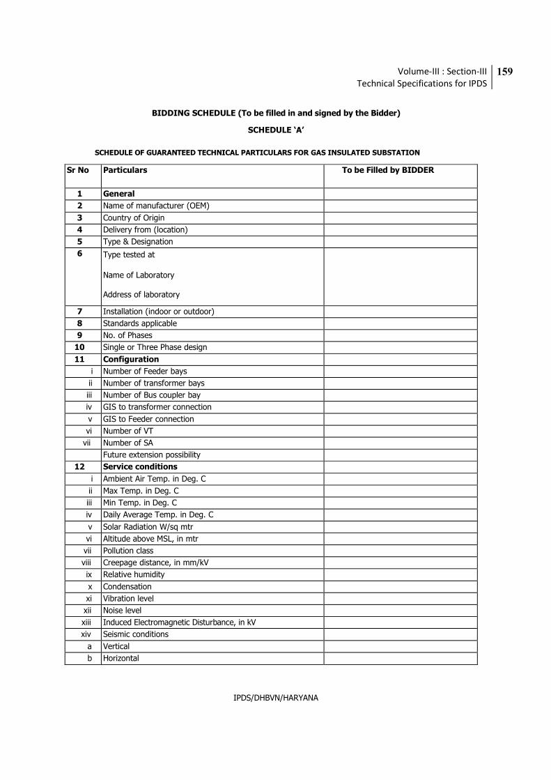
Volume-III : Section-III
Technical Specifications for IPDS
159
IPDS/DHBVN/HARYANA
BIDDING SCHEDULE (To be filled in and signed by the Bidder)
SCHEDULE ‘A’
SCHEDULE OF GUARANTEED TECHNICAL PARTICULARS FOR GAS INSULATED SUBSTATION
Sr No Particulars To be Filled by BIDDER
1 General
2 Name of manufacturer (OEM)
3 Country of Origin
4 Delivery from (location)
5 Type & Designation
6 Type tested at
Name of Laboratory
Address of laboratory
7 Installation (indoor or outdoor)
8 Standards applicable
9 No. of Phases
10 Single or Three Phase design
11 Configuration
i Number of Feeder bays
ii Number of transformer bays
iii Number of Bus coupler bay
iv GIS to transformer connection
v GIS to Feeder connection
vi Number of VT
vii Number of SA
Future extension possibility
12 Service conditions
i Ambient Air Temp. in Deg. C
ii Max Temp. in Deg. C
iii Min Temp. in Deg. C
iv Daily Average Temp. in Deg. C
v Solar Radiation W/sq mtr
vi Altitude above MSL, in mtr
vii Pollution class
viii Creepage distance, in mm/kV
ix Relative humidity
x Condensation
xi Vibration level
xii Noise level
xiii Induced Electromagnetic Disturbance, in kV
xiv Seismic conditions
a Vertical
b Horizontal
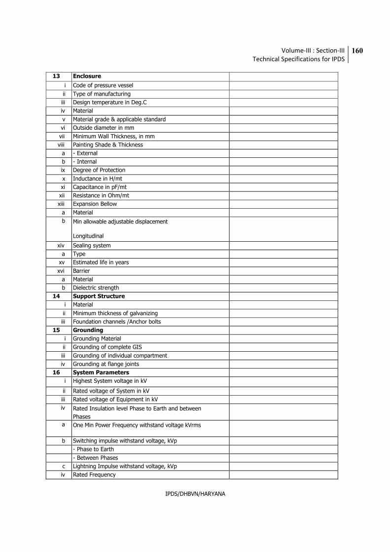
Volume-III : Section-III
Technical Specifications for IPDS
160
IPDS/DHBVN/HARYANA
13 Enclosure
i Code of pressure vessel
ii Type of manufacturing
iii Design temperature in Deg.C
iv Material
v Material grade & applicable standard
vi Outside diameter in mm
vii Minimum Wall Thickness, in mm
viii Painting Shade & Thickness
a - External
b - Internal
ix Degree of Protection
x Inductance in H/mt
xi Capacitance in pF/mt
xii Resistance in Ohm/mt
xiii Expansion Bellow
a Material
b Min allowable adjustable displacement
Longitudinal
xiv Sealing system
a Type
xv Estimated life in years
xvi Barrier
a Material
b Dielectric strength
14 Support Structure
i Material
ii Minimum thickness of galvanizing
iii Foundation channels /Anchor bolts
15 Grounding
i Grounding Material
ii Grounding of complete GIS
iii Grounding of individual compartment
iv Grounding at flange joints
16 System Parameters
i Highest System voltage in kV
ii Rated voltage of System in kV
iii Rated voltage of Equipment in kV
iv Rated Insulation level Phase to Earth and between
Phases
a One Min Power Frequency withstand voltage kVrms
b Switching impulse withstand voltage, kVp
- Phase to Earth
- Between Phases
c Lightning Impulse withstand voltage, kVp
iv Rated Frequency
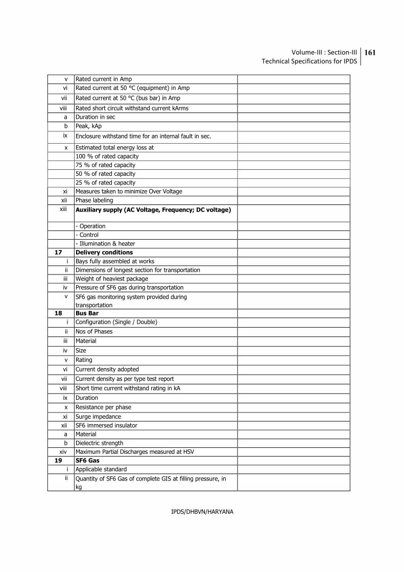
Volume-III : Section-III
Technical Specifications for IPDS
161
IPDS/DHBVN/HARYANA
v Rated current in Amp
vi Rated current at 50 °C (equipment) in Amp
vii Rated current at 50 °C (bus bar) in Amp
viii Rated short circuit withstand current kArms
a Duration in sec
b Peak, kAp
ix Enclosure withstand time for an internal fault in sec.
x Estimated total energy loss at
100 % of rated capacity
75 % of rated capacity
50 % of rated capacity
25 % of rated capacity
xi Measures taken to minimize Over Voltage
xii Phase labeling
xiii Auxiliary supply (AC Voltage, Frequency; DC voltage)
- Operation
- Control
- Illumination & heater
17 Delivery conditions
i Bays fully assembled at works
ii Dimensions of longest section for transportation
iii Weight of heaviest package
iv Pressure of SF6 gas during transportation
v SF6 gas monitoring system provided during
transportation
18 Bus Bar
i Configuration (Single / Double)
ii Nos of Phases
iii Material
iv Size
v Rating
vi Current density adopted
vii Current density as per type test report
viii Short time current withstand rating in kA
ix Duration
x Resistance per phase
xi Surge impedance
xii SF6 immersed insulator
a Material
b Dielectric strength
xiv Maximum Partial Discharges measured at HSV
19 SF6 Gas
i Applicable standard
ii Quantity of SF6 Gas of complete GIS at filling pressure, in
kg
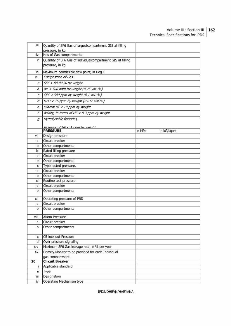
Volume-III : Section-III
Technical Specifications for IPDS
162
IPDS/DHBVN/HARYANA
iii Quantity of SF6 Gas of largestcompartment GIS at filling
pressure, in kg
iv Nos of Gas compartments
v Quantity of SF6 Gas of individualcompartment GIS at filling
pressure, in kg
vi Maximum permissible dew point, in Deg.C
vii Composition of Gas
a SF6 > 99.90 % by weight
b Air < 500 ppm by weight (0.25 vol.-%)
c CF4 < 500 ppm by weight (0.1 vol.-%)
d H2O < 15 ppm by weight (0.012 Vol-%)
e Mineral oil < 10 ppm by weight
f Acidity, in terms of HF < 0.3 ppm by weight
g Hydrolysable fluorides,
In terms of HF < 1 ppm by weight
PRESSURE in MPa in kG/sqcm
vii Design pressure
a Circuit breaker
b Other compartments
ix Rated filling pressure
a Circuit breaker
b Other compartments
x Type tested pressure.
a Circuit breaker
b Other compartments
xi Routine test pressure
a Circuit breaker
b Other compartments
xii Operating pressure of PRD
a Circuit breaker
b Other compartments
xiii Alarm Pressure
a Circuit breaker
b Other compartments
c CB lock out Pressure
d Over pressure signaling
xiv Maximum SF6 Gas leakage rate, in % per year
xv Density Monitor to be provided for each Individual
gas compartment.
20 Circuit Breaker
i Applicable standard
ii Type
iii Designation
iv Operating Mechanism type
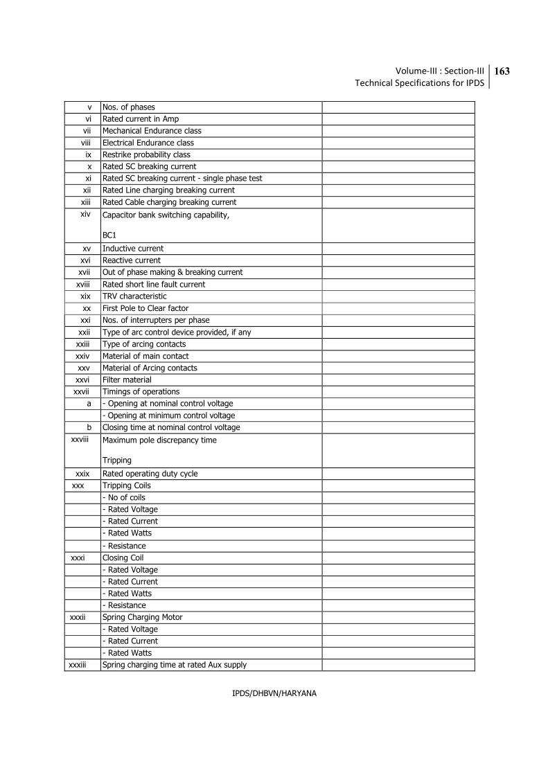
Volume-III : Section-III
Technical Specifications for IPDS
163
IPDS/DHBVN/HARYANA
v Nos. of phases
vi Rated current in Amp
vii Mechanical Endurance class
viii Electrical Endurance class
ix Restrike probability class
x Rated SC breaking current
xi Rated SC breaking current - single phase test
xii Rated Line charging breaking current
xiii Rated Cable charging breaking current
xiv Capacitor bank switching capability,
BC1
xv Inductive current
xvi Reactive current
xvii Out of phase making & breaking current
xviii Rated short line fault current
xix TRV characteristic
xx First Pole to Clear factor
xxi Nos. of interrupters per phase
xxii Type of arc control device provided, if any
xxiii Type of arcing contacts
xxiv Material of main contact
xxv Material of Arcing contacts
xxvi Filter material
xxvii Timings of operations
a - Opening at nominal control voltage
- Opening at minimum control voltage
b Closing time at nominal control voltage
xxviii Maximum pole discrepancy time
Tripping
xxix Rated operating duty cycle
xxx Tripping Coils
- No of coils
- Rated Voltage
- Rated Current
- Rated Watts
- Resistance
xxxi Closing Coil
- Rated Voltage
- Rated Current
- Rated Watts
- Resistance
xxxii Spring Charging Motor
- Rated Voltage
- Rated Current
- Rated Watts
xxxiii Spring charging time at rated Aux supply
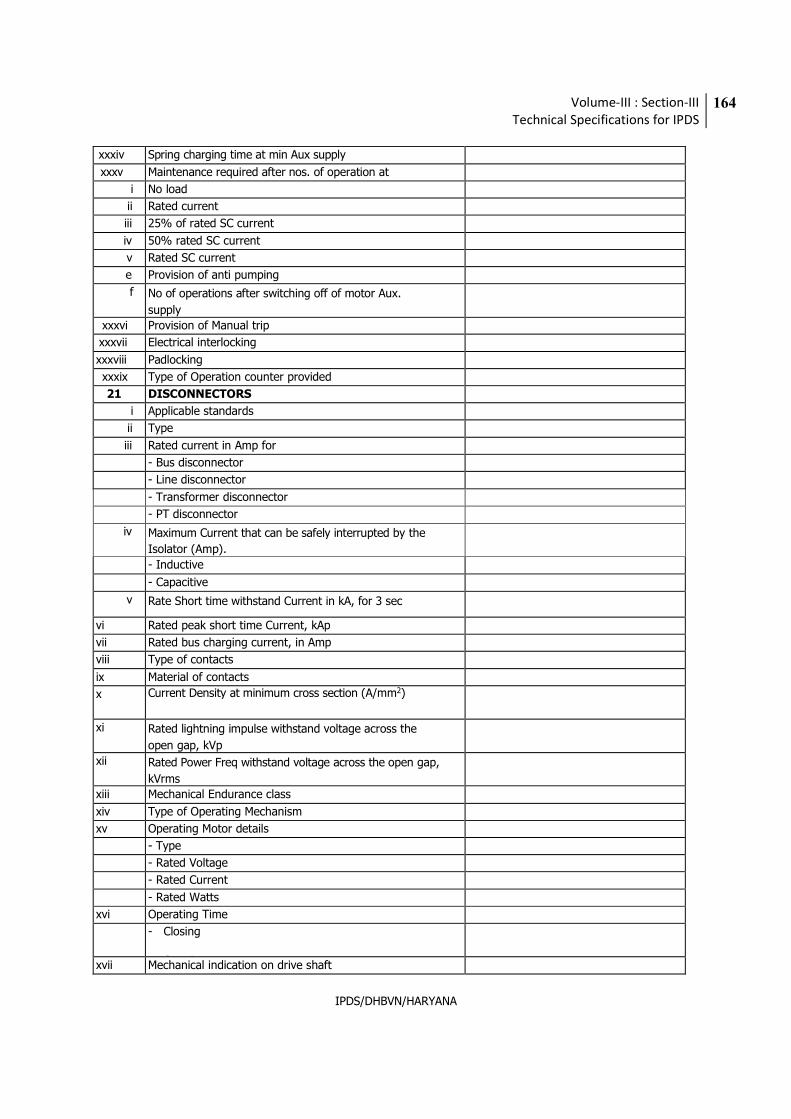
Volume-III : Section-III
Technical Specifications for IPDS
164
IPDS/DHBVN/HARYANA
xxxiv Spring charging time at min Aux supply
xxxv Maintenance required after nos. of operation at
i No load
ii Rated current
iii 25% of rated SC current
iv 50% rated SC current
v Rated SC current
e Provision of anti pumping
f No of operations after switching off of motor Aux.
supply
xxxvi Provision of Manual trip
xxxvii Electrical interlocking
xxxviii Padlocking
xxxix Type of Operation counter provided
21 DISCONNECTORS
i Applicable standards
ii Type
iii Rated current in Amp for
- Bus disconnector
- Line disconnector
- Transformer disconnector
- PT disconnector
iv Maximum Current that can be safely interrupted by the
Isolator (Amp).
- Inductive
- Capacitive
v Rate Short time withstand Current in kA, for 3 sec
vi Rated peak short time Current, kAp
vii Rated bus charging current, in Amp
viii Type of contacts
ix Material of contacts
x Current Density at minimum cross section (A/mm2)
xi Rated lightning impulse withstand voltage across the
open gap, kVp
xii Rated Power Freq withstand voltage across the open gap,
kVrms
xiii Mechanical Endurance class
xiv Type of Operating Mechanism
xv Operating Motor details
- Type
- Rated Voltage
- Rated Current
- Rated Watts
xvi Operating Time
- Closing
- Opening
xvii Mechanical indication on drive shaft
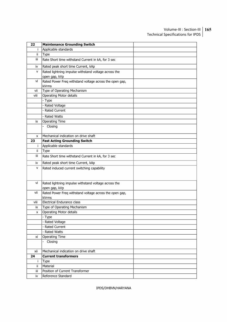
Volume-III : Section-III
Technical Specifications for IPDS
165
IPDS/DHBVN/HARYANA
22 Maintenance Grounding Switch
i Applicable standards
ii Type
iii Rate Short time withstand Current in kA, for 3 sec
iv Rated peak short time Current, kAp
v Rated lightning impulse withstand voltage across the
open gap, kVp
vi Rated Power Freq withstand voltage across the open gap,
kVrms
vii Type of Operating Mechanism
viii Operating Motor details
- Type
- Rated Voltage
- Rated Current
- Rated Watts
ix Operating Time
- Closing
- Opening
x Mechanical indication on drive shaft
23 Fast Acting Grounding Switch
i Applicable standards
ii Type
iii Rate Short time withstand Current in kA, for 3 sec
iv Rated peak short time Current, kAp
v Rated induced current switching capability
vi Rated lightning impulse withstand voltage across the
open gap, kVp
vii Rated Power Freq withstand voltage across the open gap,
kVrms
viii Electrical Endurance class
ix Type of Operating Mechanism
x Operating Motor details
- Type
- Rated Voltage
- Rated Current
- Rated Watts
xi Operating Time
- Closing
- Opening
xii Mechanical indication on drive shaft
24 Current transformers
i Type
ii Material
iii Position of Current Transformer
iv Reference Standard
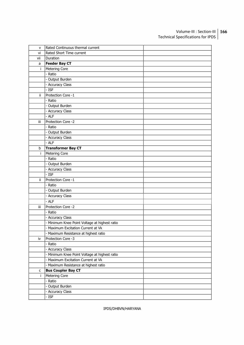
Volume-III : Section-III
Technical Specifications for IPDS
166
IPDS/DHBVN/HARYANA
v Rated Continuous thermal current
vi Rated Short Time current
vii Duration
a Feeder Bay CT
i Metering Core
- Ratio
- Output Burden
- Accuracy Class
- ISF
ii Protection Core -1
- Ratio
- Output Burden
- Accuracy Class
- ALF
iii Protection Core -2
- Ratio
- Output Burden
- Accuracy Class
- ALF
b Transformer Bay CT
i Metering Core
- Ratio
- Output Burden
- Accuracy Class
- ISF
ii Protection Core -1
- Ratio
- Output Burden
- Accuracy Class
- ALF
iii Protection Core -2
- Ratio
- Accuracy Class
- Minimum Knee Point Voltage at highest ratio
- Maximum Excitation Current at Vk
- Maximum Resistance at highest ratio
iv Protection Core -3
- Ratio
- Accuracy Class
- Minimum Knee Point Voltage at highest ratio
- Maximum Excitation Current at Vk
- Maximum Resistance at highest ratio
c Bus Coupler Bay CT
i Metering Core
- Ratio
- Output Burden
- Accuracy Class
- ISF
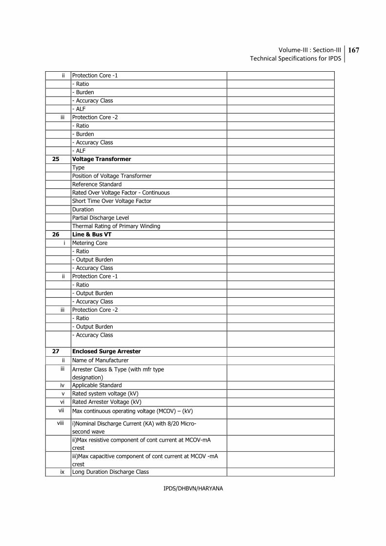
Volume-III : Section-III
Technical Specifications for IPDS
167
IPDS/DHBVN/HARYANA
ii Protection Core -1
- Ratio
- Burden
- Accuracy Class
- ALF
iii Protection Core -2
- Ratio
- Burden
- Accuracy Class
- ALF
25 Voltage Transformer
Type
Position of Voltage Transformer
Reference Standard
Rated Over Voltage Factor - Continuous
Short Time Over Voltage Factor
Duration
Partial Discharge Level
Thermal Rating of Primary Winding
26 Line & Bus VT
i Metering Core
- Ratio
- Output Burden
- Accuracy Class
ii Protection Core -1
- Ratio
- Output Burden
- Accuracy Class
iii Protection Core -2
- Ratio
- Output Burden
- Accuracy Class
27 Enclosed Surge Arrester
ii Name of Manufacturer
iii Arrester Class & Type (with mfr type
designation)
iv Applicable Standard
v Rated system voltage (kV)
vi Rated Arrester Voltage (kV)
vii Max continuous operating voltage (MCOV) – (kV)
viii i)Nominal Discharge Current (KA) with 8/20 Micro-
second wave
ii)Max resistive component of cont current at MCOV-mA
crest
iii)Max capacitive component of cont current at MCOV -mA
crest
ix Long Duration Discharge Class
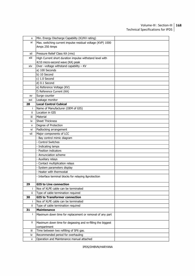
Volume-III : Section-III
Technical Specifications for IPDS
168
IPDS/DHBVN/HARYANA
x Min. Energy Discharge Capability (KJ/KV rating)
xi Max. switching current impulse residual voltage (KVP) 1000
Amps 250 Amps
xii Pressure Relief Class KA (rms)
xiii High Current short duration impulse withstand level with
4/10 micro-second wave (KA) peak
xiv Over –voltage withstand capability – KV
a) 100 Seconds
b) 10 Second
c) 1.0 Second
d) 0.1 Second
e) Reference Voltage (KV)
f) Reference Current (KA)
xv Surge counter
xvi Leakage monitor
28 Local Control Cubical
i Name of Manufacturer (OEM of GIS)
ii Location in GIS
iii Material
iv Sheet Thickness
v Degree of Protection
vi Padlocking arrangement
vii Major components of LCC
- Bay control mimic diagram
- Control Switches
- Indicating lamps
- Position indicators
- Annunciation scheme
- Auxiliary relays
- Contact multiplication relays
- System parameters display
- Heater with thermostat
- Interface terminal blocks for relaying &protection
29 GIS to Line connection
i Nos of XLPE cable can be terminated
ii Type of cable termination required
30 GIS to Transformer connection
i Nos of XLPE cable can be terminated
ii Type of cable termination required
31 Maintenance
i Maximum down time for replacement or removal of any part
ii Maximum down time for degassing and re-filling the biggest
compartment
iii Time between two refilling of SF6 gas.
iv Recommended period for overhauling
v Operation and Maintenance manual attached

Volume-III : Section-III
Technical Specifications for IPDS
169
IPDS/DHBVN/HARYANA
vi Nearest local service centre
vii Minimum time of availability of local service
viii Availability of spares at local service centre
ix List of recommended spares attached?
x List of recommended special tools, etc attached?
xi List of commission spares attached?
xii List of maintenance spares attached?
Volume-III : Section-III
Technical Specifications for IPDS
170
IPDS/DHBVN/HARYANA
C) 11 KV SF6 Ring Main Units (RMUs)
1.0 SCOPE:
The specification covers site survey, engineering, manufacturing, pre dispatch testing, supply, and
transportation, unloading at site complete erection, testing and commissioning of ….. feeders with 11KV
….way RMUs, (Manual /SCADA enabled) . as per the in ………….. AREA under IPDS funding and in
accordance with the specifications technical requirements mentioned in the specification, relevant standard,
code of operation. The scope also includes the handing over the complete installation after successful
commissioning.
11 kV ….. way RMU’s ( Manual ) : Nos.
11 kV ……way RMU’s (SCADA enabled) : Nos.
STANDARDS:
a) The equipment delivered shall be new and of high quality, suitable for the purpose it is intended for, free from defects and imperfections and of the classifications listed herein, or their equivalents, subject to acceptance by the ………Utility
b) Materials used in the manufacture of the specified equipment shall be of the kind, composition and physical properties best suited to their various purposes and in accordance with the best engineering practices.
c) The equipment design shall be suitable to render satisfactory operation under the conditions prevailing at site, and the equipment shall operate satisfactorily under normal load and voltage variations and frequency variations (50 Hz ± 3%) ensuring the safety, further include all necessary provisions ensuring the safety of the operating and maintenance personnel.
d) The applicable standards of various equipment for the DMS project is as specified here below:
2.1 11kV Ring Main unit
Description Standard
11kV Ring Main unit
AC metal enclosed switchgear and control gear for rated voltages
above 1 kV and up to and including 52 kV
IS 3427
Classification of degrees of protection provided by enclosures of
electrical equipment
IS 12063
High Voltage Switches IS 9920 (Parts 1 to 4)
Specification for AC disconnectors and earthing switches for voltages
above 1000 V
IS 9921 (Parts 1 to 5)
Volume-III : Section-III
Technical Specifications for IPDS
171
IPDS/DHBVN/HARYANA
HV AC Circuit Breakers IS 13118
Dimensions of terminals of HV Switchgear and Control gear IS 10601
General requirements of switchgear and control gear for voltages
exceeding 1000 V
IS 12729
High voltage/Low voltage prefabricated substations IEC 1330
Common clauses for MV switchgear standards IEC 62271-100/200
Monitoring and control IEC 6081
Current Transformers IS 2705
Voltage transformers IS 3156
Specification for Static Protective Relays IS 8686
Standards for high voltage metal clad switchgear up to 52 KV. IEC 62271-200
Wherever IEC standards are indicated, suitable equivalent IS standards may be considered
2.2 Key RMU Configurations of RING MAIN UNIT
� As a minimum, the RMUs shall be equipped with on-load break switches and a fault passage indicator
(FPI), circuit breakers, and numerical relays for the protection of transformer feeders, and provision for
wiring for multifunction transducer (MFT for monitoring voltage, current, power, energy, and power
factor readings and tripping and protection functionalities from the Communicable Numerical relay to be
provided on the RMU. The Load Break Switches and earthing switches shall be housed in SF6 and the
Circuit Breakers used in the RMU shall be vacuum interrupter type.
Key Configurations
� 3 WAY RMU – Both side extensible Two (2) Motor operated load break switches (LBSs) with Motor
operated earthing switches in SF6 and 1 vacuum circuit breaker with Electrical closing and tripping
along with disconnector and earthing switches WITH BUS PT metering module and base channel and
suitable space for mounting FRTU (For future Implemetation of SCADA by utility . In case of Mnaual
RMU space for fro FRTU is not required ) , battery charger , Auxiliary PT of suitable rating inside
metering cubical. The Battery charger along with batteries required for Electrical operations of RMU is
in the scope of the Bidder.
� 5 WAY RMU - Both side extensible Two (2) Motor operated load break switches (LBSs) with earthing
switches in SF6 and (3) vacuum circuit breakers with Electrical closing and tripping along with
disconnector and earthing switches WITH BUS PT metering module and base channel suitable space for
Volume-III : Section-III
Technical Specifications for IPDS
172
IPDS/DHBVN/HARYANA
mounting FRTU(For future Implemetation of SCADA by utility . In case of Mnaual RMU space for fro
FRTU is not required ), battery charger , Auxiliary PT of suitable rating inside metering cubical. The
Battery charger along with batteries required for Electrical operations of RMU is in the scope of the
Bidder.
Other configurations may also be adopted based on the requirement
CLIMATIC CONDITIONS OF THE INSTALLATIONS.
The equipment designed shall be capable of withstanding the following climatic conditions.
a. Maximum Ambient Air Température - …...°C
b. Average ambient Air température - …….C
c. Minimum ambient Air Temperature - …….C
c. Relative Humidity - …….%
d. Altitude - 0 to ……. Meters
e. Annual rain fall - ……. mm
f. Rainy Months - ……….
g. Average no. of Rainy Days - ……
h. Average no of Thunder Storms - ……
I. Average Wind speed - …… kmph
If the derating of the equipment is applicable for above climatic conditions same shall be specified by the
bidder.
2.3 RATINGS:
The Protection and control unit range shall be designed to accommodate the control power supply voltages of …….V
DC voltage.
3.0 Technical parameters
11 kV RMU
3.1 Scope of Work
� The Package scope of work shall include design, manufacture, testing, delivery installation commissioning
Ring Main Units capable of being monitored and controlled by the SCADA/DMS and also manually operated
RMUs. This also includes supply of relevant 11 kV cable termination kits including the jointing as per this
tender specification
Volume-III : Section-III
Technical Specifications for IPDS
173
IPDS/DHBVN/HARYANA
� Where relevant, the RMU scope of work shall be coordinated with the work to be carried out like providing
of UG cable under the project’s other construction packages.
� Each RMU shall include its own power supply unit (including auxiliary power transformer, batteries, and
battery charger), which shall provide a stable power source for the RMU. In case of remote operated RMUs,
the same will be connected to the FRTU including the power supply required will be procured by utility later.
� Each new RMU shall be equipped with main-line load break switches and a fault passage indicator (FPI).
Furthermore, to protect each of its lateral / transformer feeders, it shall be equipped with a corresponding
set of circuit breakers and self-powered numerical relays. The RMU shall include potential-free contacts so
as to connect to SCADA/DMS via FRTUs in case of remote operated RMUs, so as to:
� Monitor and control the open/closed status of the RMU circuit breakers and load break switches.
� Monitor the local/remote position of RMU manually-operated switches that can be used to enable and
disable remote monitoring.
� Monitor the health of the power supply, which will include battery failure and low voltage indications.
� Monitor the open/closed status of RMU earthing switches.
� Monitor for low SF6 gas pressure indication in case of SF6 Breaker .
� Monitor for circuit breaker relay operations.
� Monitor for indication of main-circuit fault detected by the RMU’s FPI.
� Power supply indications including battery failure and voltage alarms
� FPI reset control
� The civil works, foundations works including providing of Earth pits and earth flat and their
connectivity to earth pits for erection and commissioning of the RMU’s are in the scope of the Bidder.
� Any site/ equipment/ statutory approvals at site etc. required shall be in …….. Utility
scope.
RMU shall have local indications as minimum
1. Operation counter on Front / Inside , the RMU Panel to be provided for each LBS & CB with 4 digits , non
resettable type
2. Cable charge status for each LBS & CB - LED indication for each phase
3. Spring charge status in front for breaker
4. Earth switch close status for each LBS
5. LBS On/off indication – Green Off , Red On
6. Flag for CB Protection relay operated on Fault
Volume-III : Section-III
Technical Specifications for IPDS
174
IPDS/DHBVN/HARYANA
7. Flag for FPI on LBS
8. Battery charger fail indication
3.1.1 Environmental Conditions
All materials supplied shall be capable of operating under relevant environmental conditions are listed as follows:
� Maximum ambient air temperature: - ………ºC
� Minimum ambient air temperature: - ………ºC
� Average ambient air temperature : - …….. ºC
� Maximum relative humidity: - ………%
� Average thunder storm days per annum: - ……….
� Average rainfall per annum: - ……… mm
� Maximum wind speed: - ………km/hr
� Altitude above mean sea level: - …….. m
3.1.2 Distribution Network Electrical Parameters
The main parameters of the distribution network are as follows:
� Nominal system voltage: - 11 kV (rms)
� Highest system voltage: - 12 kV (rms)
� Number of phases: - 3
� Frequency: - 50 Hz
� Variation in frequency: - 50 ±3% Hz
� Type of earthing: - Solid
� Power frequency withstand voltage: - 28 kV rms
� Basic impulse withstand voltage: - 75 kV peak
3.1.3 Testing
The specified RMUs shall be subject to type tests, routine tests, and acceptance tests. Where applicable, these tests
shall be carried out as per the standards stated above. Prior to acceptance testing, the supplier shall prepare and
submit a detailed test plan for review and approval by the Utility.
3.1.4 11 kV RMU TECHNICAL PARAMETERS
• The scope of supply is supply 11 kV RMU suitable for outdoor application.
The RMU to be supplied shall be compact and shall meet the following requirements:
Volume-III : Section-III
Technical Specifications for IPDS
175
IPDS/DHBVN/HARYANA
• Easy to install
• Safe and easy to operate
• Compact
• Low maintenance
It shall include, within the same metal enclosure number of MV functional units required for connection,
• Power supply including the battery bank for controlling the LBS and breakers ,
• Load break switches,
• Earthing Switches
• Breakers
• Relays
• BUS PT metering module, FPI’s and other allied equipment.
• Dimensions of FRTU, Battery bank for powering the FRTU will be provided to the successful bidder.
• The cutouts for housing the FRTU and Battery bank will be provided by the utility to the successful bidder
for making the provision in the control panel.
• Equipment and material conforming to any other standard, which ensures equal or better quality, may be
accepted. In such case copies of English version of the standard adopted shall be submitted.
• The electrical installation shall meet the requirement of Indian Electricity Rules, 1956 as amended up to
date, relevant IS code of practice and Indian Electricity Act, 1977. The Electricity Act, 2003 and Amendment
if any shall also apply. In addition other rules and regulations applicable to the work shall be followed. In
case any discrepancy the most stringent and restrictive one shall be binding.
The high-tension switchgear offered shall in general comply with the latest issues including amendments of the
following standards but not restricted to them.
All design features of the proposed RMU, as described in the supplier’s bid and in the bid’s reference materials, shall
be fully supported by the equipment actually delivered. The key design features include those that relate to:
� Maintainability, expandability, and life span � Ability to operate in severe outdoor environmental conditions.
� Immunity to electrical stress and disturbance.
� Acceptable insulation properties.
� Convenient FRTU interconnection features.
� The Utility intends to be self-reliant for RMU maintenance. To this end, the Supplier shall provide the
support, documentation, and training necessary to operate and repair the RMU. The Utility will prefers
RMU designs that do not require periodic preventive maintenance and inspections. To facilitate
expansion and maintenance, the RMUs should be of modular type.
� The whole switchgear (RMU) should be suitable for extension on atleast one side either left or right.
� Each RMU shall have a design life of at least 20 years from the date of final acceptance. The Contractor
shall make available, at no cost to the Employer, the manufacturing drawings, wiring diagrams, bill of
Volume-III : Section-III
Technical Specifications for IPDS
176
IPDS/DHBVN/HARYANA
material, foundation detail drawings, unpacking and transportation instructions, operation &
maintenance manual, As-built drawings, installation and commissioning manual, and other relevant
documentation. The specific components of each component /sub-assembly shall be identified and
referenced in Supplier-supplied documentation.
� Each RMU shall include its own power supply, including battery and battery charger. In addition, RMU
should have a bus connected PT panel (air insulated), which shall serve as the power supply’s 230 V AC
input.
3.1.5 Outdoor Features
� The RMUs shall be designed specifically for outdoor installation with ingress protection degree of IP54.
They shall also be suitable for conditions in which they will be exposed to heavy industrial pollution, and
high levels of airborne dust.
� The Outdoor RMU shall be conformably coated to meet these climatic conditions. In this respect,
standards such as IEC 62271-200, covering equipment, systems, operating conditions, and
environmental conditions shall apply. In particular, the RMU equipment shall have been type tested for
IP54 from a national NABL aggregated laboratory. Failure to conform to this requirement shall
constitute grounds for rejection of the proposal
� In addition to the above, materials promoting the growth of fungus or susceptibility to corrosion and
heat degradation shall not be used, and steps shall be taken to provide rodent proofness.
� The main SF6 tank, housing the on-load break switches and the vacuum circuit breakers, should be of
no other material except 2.5 mm stainless steel tank so as to have high corrosion resistance and ensure
high longevity. This tank containing SF6 to a maximum pressure of 1.55 bars should be hermetically
welded and sealed for life, ensuring a leakage rate not more than 0.1 % per annum. Except for
stainless steel, all steel surfaces that are not galvanized shall be treated to protect against corrosion. As
a minimum, corrosion treatment shall include the following procedures:
� The surface shall be cleaned to bare material by mechanical or chemical means.
� Must be powder coated by means of seven tank process
� All outdoor metal enclosures shall be treated in 7 tank Pre-treatment process & should be
painted with UV Resistant Pure Polyester Powder coating. The powder coated sheet steel
fabrication to withstand tropical heat and extremes of weather.
Volume-III : Section-III
Technical Specifications for IPDS
177
IPDS/DHBVN/HARYANA
3.1.6 Immunity to Electrical Stress and Disturbance
The electrical and electronic components of the RMU shall conform to relevant standards concerning insulation,
isolation, and the product shall comply with IEC 60270 Immunity to electrical stress & disturbance. The ability to
meet these requirements shall be verified by type tests carried out by accredited test laboratories that are
independent of the bidder and/or the manufacturer of the RMU components. Certified copies of all available type
test certificates and test results shall be included as part of the bidder’s proposal.
3.1.7 Minimum Insulation of Equipment
� The RMUs shall be of SF6 gas-insulated type with a maximum gas operating pressure up to 1.2 BAR @
20 deg C.
3.1.8 Nameplate Information
RMU nameplate information shall be determined in agreement with the Employer. This information may include for
example:
� Name of manufacturer and country
� Type, design, and serial number
� Rated voltage and current
� Rated frequency
� Rated symmetrical breaking capacity
� Rated making capacity
� Rated short time current and its duration
� Rated lightning impulse withstand voltage
� Purchase Order number and date
� Month and year of supply
Each RMU shall also exhibit a Danger Board to indicate the presence of high voltage (11,000 V).
3.1.9 Interconnecting Cables, Wiring, Connectors, and Terminal Blocks
� The Contractor shall provide all interconnecting wires, cables, connectors, terminations and other wiring
accessories such as terminal blocks required by the RMU.
3.1.10 Metallic Cables
� All metallic cables and wiring shall be of required cross-section solid or multiple strands of round copper
conductors and have flame retardant insulation. All wiring shall be neatly laced and clamped.
Volume-III : Section-III
Technical Specifications for IPDS
178
IPDS/DHBVN/HARYANA
� All wire and cable connectors and terminators shall be permanently labeled for identification. All
connection points for external cables and wires shall be easily accessible for connection and
disconnection and shall be permanently labeled. Conductors in multi-conductor cables shall be
individually color-coded.
3.1.11 Connectors
� Plug-type connectors with captive fasteners shall be used for all interconnections. The connectors shall
be polarized to prevent improper assembly.
3.1.12 RMU-FRTU Connectors ( Only for SCADA enabled RMU and not for Manual RMU)
� For ease of installation and maintenance, the interconnection between the RMU and the FRTU (IF
remote communicable), (For future FRTU installation later by utility separately in a separate
enclosure shall be supported by having heavy-duty terminal blocks with screw type terminals shall be
provided by the supplier for necessary cable terminations. In using a terminal block, no more than two
cables or wires shall be connected to any of its individual terminals.
� Making strips shall be used to identify all external connection blocks. Marking tags shall be read
horizontally. All terminals to which battery or other high voltages are connected shall be provided with
fireproof covers.
� All individual status input, AC voltage input, and control output points shall be isolatable without the
need to remove wiring by means of individual terminal blocks of the removable link type. In order to
avoid open circuits on the secondary side of CTs, termination blocks with by-pass bridges shall be
provided for all AC current inputs.
� Terminal blocks shall comply with IEC 60947-7-1 (2009): Low-voltage Switchgear and Control Gear,
Part 7-1: Ancillary Equipment, Terminal Blocks for Copper Conductors.
� Each RMU shall be equipped with all necessary connectors, terminal blocks, and other accessories that
will allow it to be connected to the FRTU, which in-turn will send required indications and
measurements to the DMS via the communications system. (For SCADA enabler RMUs only)
3.1.13 Parameter Requirements
The RMUs shall be suitable for cable networks of 630 Amps and loop cable networks of 400 Amps. The minimum
design parameters to which their major components shall conform or exceed are summarized in the following tables.
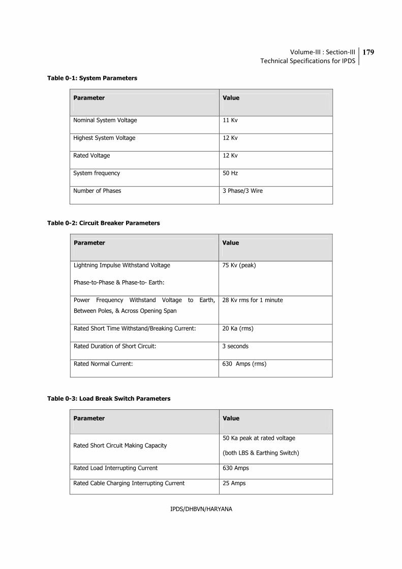
Volume-III : Section-III
Technical Specifications for IPDS
179
IPDS/DHBVN/HARYANA
Table 0-1: System Parameters
Parameter Value
Nominal System Voltage 11 Kv
Highest System Voltage 12 Kv
Rated Voltage 12 Kv
System frequency 50 Hz
Number of Phases 3 Phase/3 Wire
Table 0-2: Circuit Breaker Parameters
Parameter Value
Lightning Impulse Withstand Voltage
Phase-to-Phase & Phase-to- Earth:
75 Kv (peak)
Power Frequency Withstand Voltage to Earth,
Between Poles, & Across Opening Span
28 Kv rms for 1 minute
Rated Short Time Withstand/Breaking Current: 20 Ka (rms)
Rated Duration of Short Circuit: 3 seconds
Rated Normal Current: 630 Amps (rms)
Table 0-3: Load Break Switch Parameters
Parameter Value
Rated Short Circuit Making Capacity 50 Ka peak at rated voltage
(both LBS & Earthing Switch)
Rated Load Interrupting Current 630 Amps
Rated Cable Charging Interrupting Current 25 Amps
Volume-III : Section-III
Technical Specifications for IPDS
180
IPDS/DHBVN/HARYANA
The RMU switchgear shall be capable of withstanding the specified currents without damage in accordance with the
latest versions of IEC 60694 (Common Specifications for High-Voltage Switchgear and Control Gear Standards) and
IS 3427 (AC Metal Enclosed Switchgear and Control Gear for Rated Voltages above 1 Kv and up to and including 52
Kv).
The equipment offered shall be as per the standards specified in the bid specification and if the offered equipment is
tested with any other international standards which is superior to the standards specified they can also be considered
and the bidder has to submit the documentary evidence for the same to (Utilitiy Name) .
3.1.14 Design Details
� The RMU shall be designed to operate at the rated voltage of 12 kV.
� It shall include, within the same metal enclosure, On-load break switch, circuit breakers and earthing
switches for each Load Break Switch/Circuit Breaker.
� Suitable fool-proof interlocks shall be provided to the earthing switches to prevent inadvertent or
accidental closing when the circuit is live and the concerned Load Break Switch/Circuit Breaker is in its
closed position.
� The degree of protection required against prevailing environmental conditions, including splashing
water and dust, shall be not less than IP 54 as per IS 12063.
� The active parts of the switchgear shall be maintenance free. Otherwise, the RMU shall be of low-
maintenance type.
� The tank shall be made of minimum 2.5 mm thickness of stainless steel.
� The Stainless Steel tank should be completely welded so as to ensure IP 67 degree of protection and
shall be internal arc tested.
� The RMU shall be suitable for mounting on its connecting cable trench.
� For each RMU enclosure, a suitably sized nameplate clearly identifying the enclosure and the electrical
characteristics of the enclosed devices shall be provided.
� The access to the cable compartment should be from the front / Side /Rear of the switchgear only to
have minimum operating & maintenance space at site.
� The RMU design shall be such that access to live parts shall not be possible without the use of tools.
Volume-III : Section-III
Technical Specifications for IPDS
181
IPDS/DHBVN/HARYANA
� The design shall incorporate features that prevent any accidental opening of the earth switch when it is
in the closed position. Similarly, accidental closing of a Circuit Breaker or Load Break Switch shall be
prevented when the same is in an open position.
� The RMU tank must be equipped with a suitable pressure relief device. The pressure relief must ensure
that the escaping gases are dissipated to the rear / top of the switchgear.
� The complete RMU shall be tested in an accredited INDIAN or FOREIGN laboratory and designed for an
Internal Arc.
3.1.15 Earthing
� There shall be continuity between metallic parts of the RMUs and cables so that there is no dangerous
electric field in the surrounding air and the safety of personnel is ensured.
� The RMU frames shall be connected to the main earth bars, and the cables shall be earthed by an
Earthing Switch having the specified short circuit making capacity.
� The Earthing Switch shall be operable only when the main switch is open. In this respect, a suitable
mechanical fail-proof interlock shall be provided.
� The Earthing Switch shall be provided with a reliable earthing terminal for connection to an earthing
conductor having a clamping screw suitable for the specified earth fault conditions. The connection
point shall be marked with the earth symbol. The flexible connections between the earthing blade and
the frame shall have a cross-section of at least 50 mm2 copper or equivalent in GI
� The Earthing Switch shall be fitted with its own operating mechanism. In this respect, manual closing
shall be driven by a fast acting mechanism independent of the operator's action.
3.1.16 Incomer Load Break Switches
� The Load Break Switches shall be maintenance free. With outdoor canopy doors open, the position of
power contacts and earthing contacts shall be clearly visible from the front of the RMU through the
Mimic facia.
� The position indicator shall provide positive contact indication in accordance with IS 9920. In addition,
the manufacturer shall prove the reliability of indication in accordance with IS 9921. These switches
shall have three positions (or states), i.e., Open, Closed, and Earthed, and shall be constructed in such
a way that natural interlocking prevents unauthorized operations.
� The switches shall be fully assembled, tested, and inspected in the factory.
Volume-III : Section-III
Technical Specifications for IPDS
182
IPDS/DHBVN/HARYANA
� In case of Manual operation without motors, opening and closing shall be driven by a fast-acting
mechanism independent of manual operator action.
� The Load Break Switches shall be provided with a motorized operating mechanism suitable for SCADA
control.( Not required for Mnaual RMU)
� A facility shall be provided with an electrical operating mechanism allowing an operator at the RMU site
to operate the Load Break Switches without any modification of the operating mechanism and without
de-energizing the RMU.
� The switch and earthing switch mechanisms shall have a mechanical endurance of at least 1,000
operations.
3.1.17 Circuit Breakers
� The Circuit Breakers shall be maintenance free and, when standing in front of the RMU with outdoor
canopy doors open, their positions shall be clearly visible, through the Mimic facia. The position
indicator shall provide positive contact indication in accordance with IS 9920. The breakers shall have
three positions (or states), i.e., Open, Closed, and Earthed, and shall be constructed in such a way that
natural interlocking prevents unauthorized operations. They shall be fully assembled, tested, and
inspected in the factory.
� An operating mechanism shall be used to manually close the Circuit Breaker and charge the mechanism
in a single movement. It shall be fitted with a local system for manual tripping. There shall be no
automatic reclosing. The Circuit Breaker shall be capable of closing fully and latching against the rated
making current. Mechanical indication of the OPEN, CLOSED, and EARTHED positions of the Circuit
Breaker shall be provided.
� Each Circuit Breaker shall operate in conjunction with a suitable protection relay under transformer
feeder/ circuit phase and earth fault conditions. In addition, the Circuit Breaker shall be provided with a
motorized operating mechanism that can be remotely controlled by the SCADA (Not for Manaul RMU).
3.1.18 Cable Termination
� Bushings shall be conveniently located for working with the specified cables and shall allow for the
termination of these cables in accordance with the prevailing practice and guidelines of cable
manufacturers. The dimensions of the terminals shall be in accordance with IS 10601.
� A non Ferro-magnetic cable clamp arrangement shall be provided for each cable to be terminated in the
RMU.
Volume-III : Section-III
Technical Specifications for IPDS
183
IPDS/DHBVN/HARYANA
� A suitable arrangement for the Circuit Breakers, Earthing Switches, and Load Break Switches shall be
provided so that these devices can be padlocked in the "Open" and "Closed" positions.
� A permanent "Live Cable" indication as per IEC 61958 shall be provided for each cable using a capacitor
voltage divider.
� It shall be possible to test the core or sheath insulation of the cables without disconnecting the cables
in the cable compartment, after accessing the cable compartment. The cable end kits including the
supply and errection is in the scope of the successful bidder.
� Two earth pits of 10 ohms each shall be provided diagonally and earthing to the equipment shall be
done as detailed in the scope of supply.
� Cable termination can be either front or rear termination as per the requirements of the
site.
3.1.19 Safety of Equipment
� With respect to the RMU’s SF6-filled equipment, any accidental overpressure inside the sealed chamber
shall be limited by the opening of a pressure-limiting device in the enclosure so that the gas will be
released away from the operator and to the rear bottom or top of the tank without endangering the
operator or anyone else in the vicinity of the RMU.
� All manual / motorized operations, monitoring of open/close position of switches/breakers, live line
indicators, FPI indication, SF6 gas pressure indication and access to the cable compartment shall be
carried out from the front of the RMU only.
3.1.20 Current and Voltage Transformers.
� The RMU shall be provided with current and voltage transformers. These CTs & PTs shall meet the
electrical and mechanical ratings as per the relevant standards.
3.1.20.1 Current Transformers
� 3 Nos. ring type, single core CTs shall be provided in each incoming load break switch for metering
purposes. A similar arrangement shall be provided in each circuit breaker cable compartment to mount
a 3 Nos. single-core, ring type CT for protection purposes.
� The CTs shall conform to IS 2705. The design and construction shall be sufficiently robust to withstand
thermal and dynamic stresses during short circuits. Secondary terminals of CTs shall be brought out
suitably to a terminal block, which will be easily accessible for testing and terminal connections.
Volume-III : Section-III
Technical Specifications for IPDS
184
IPDS/DHBVN/HARYANA
� Further characteristics and features distinguishing CTs used for metering from CTs used for protection
are listed as follows:
CTs for Metering:
� Material : Epoxy resin cast/ Tape wound
� Burden : 2.5VA
� Ratio : 400-200-100/1 A
� Accuracy Class : 0.5
CTs for Protection:
• Material : Epoxy resin cast/ Tape wound
• Burden : 2.5VA
• Ratio : 400-200-100/1 A
• Accuracy Class : 5P10
• The RMU’s other CTs / sensors, i.e., those used by Fault Passage Indicators (FPIs), shall be supplied by
the FPI manufacturer. These CTs/sensors shall be an integral part of the FPI’s design to ensure that
they properly match the requirements of the FPI.
3.1.20.2 Voltage Transformers
• A 3 phase single or 3 nos. single phase potential transformers shall be provided. These should be
housed in a separate air insulated PT Panel, directly connected to the RMU through main bus. The
burden per transformer shall not be more than 50 VA and the voltage ratio shall be 11000/110 V or
230 V. The accuracy class shall be 0.5.
• HRC fuses shall be provided on the HV side.
• The PTs shall be of cast epoxy-resin construction, and they shall conform to IS 3156. Their design and
construction, in particular, shall be sufficiently robust to withstand the thermal and dynamic stresses
during short circuits.
Volume-III : Section-III
Technical Specifications for IPDS
185
IPDS/DHBVN/HARYANA
3.1.21 Fault Passage Indicator for RMU
• The FPI shall facilitate quick detection of faulty section of line. The fault indication may be on the basis of
monitoring fault current flow through the device. The FPI should be self-powered and should have internal
lithium battery for external indication and setting of FPI in the absence of current.
3.1.21.1 The FPIs shall include:
• Fault detection - Phase to phase and Phase to earth faults.
• One potential-free output contacts for hardwiring to FRTUs. On this basis, the SCADA/DMS will be able to
monitor phase / earth fault condition ( Not for Manual RMU).
• Local fault indications - LCD display on FPI front panel along with LED indication on front panel of RMU
enclosure.
• Multiple reset option –
• End of time delay (Adjustable from 2 to 16 Hrs)
• Remote reset (Via potential free input contact of FPI)
• Manual reset (Reset button on front panel of FPI)
• Automatic reset on current restoration.
3.1.21.2 The characteristics of the FPIs shall include:
• Phase fault thresholds configurable from at least 100 to 800 A
• Earth fault thresholds configurable from at least 20 to 200 A
• Multiple number of steps for adjusting phase and earth fault thresholds.
• Fault current duration range configurable from at least 40 ms to 100 ms in 20 ms steps and further 100 ms
to 300 ms in 50 ms steps.
• Variations with respect to these characteristics may be acceptable as long as they prove applicable and
provide the same or better flexibility.
3.1.22 Protection Relay
• The RMU shall be equipped with self-powered numerical relays(Communicable relays shall be with
auxiliary power which shall be given from battery but the tripping shall
Volume-III : Section-III
Technical Specifications for IPDS
186
IPDS/DHBVN/HARYANA
The Circuit Breaker in the RMU shall be fitted with a communicable-type, self-powered numerical relay,
i.e., one for each outgoing circuit breaker. The protection relay’s auxiliary contacts shall be provided for
hardwiring to the FRTU. The relay shall also interface with the FRTU via an RS 232/485 port in order to
send, as a minimum, real-time reading using the MODBUS /IEC 103 protocol. (Not for Manual RMUs)
The numerical relay shall be self-powered and should provide Inverse Definite Minimum Time (IDMT) and
Instantaneous protection characteristics. On this basis, the relay as a minimum shall provide:
� Phase Overcurrent Protection (50/51)
� Earth Fault Protection (50N/51N)
The relay shall be provided with an input for remote tripping, which shall be realized via an electric output
pulse even without presence of phase current. A flag indicator shall be installed for signaling the occurrence
of trip conditions.
3.1.23 Features and Characteristics
The numerical relay shall have the following minimal features and characteristics noting that variations may
be acceptable as long as they provide similar or better functionality and/or flexibility:
� It shall be housed in a flush mounting case and powered by the RMU power supply unit.
� It shall have three phase overcurrent elements and one earth fault element.
� IDMT trip current settings shall be 50-200% in steps of 1% for phase overcurrent and 10-80% in steps
of 1% for earth fault.
� Instantaneous trip current settings shall be 100-3000% in steps of 100% for phase overcurrent and
100-1200% in steps of 100% for earth fault.
� Selectable IDMT curves shall be provided to include, for example, Normal Inverse, Very Inverse,
Extreme Inverse, Long Time Inverse, and Definite Time. Separate curve settings for phase overcurrent
and earth fault shall be supported.
� For IDMT delay multiplication, the Time Multiplier Setting (TMS) shall be adjustable from 0.01 to 0.1 in
0.01 steps.
� The relay shall also be provided with:
- Alphanumeric Liquid Crystal Display (LCD) for relay setting.
- Communications via a MODBUS RS232/RS485 /IEC 103 port to provide the FRTU (and hence the
DMS) with phase current measurements. It is also desirable that this same means of
communication can be used by the FRTU to send setting and control commands to the relay.
- Parameter change capability that is password protected.
Volume-III : Section-III
Technical Specifications for IPDS
187
IPDS/DHBVN/HARYANA
3.1.24 Power Supply and auxiliary power transformer
Each RMU shall be fitted with a power supply, including batteries and battery charger, suitable for
operating the motors of the On-load Isolators and Circuit Breakers. On this basis, the following
operational specifications shall apply:
� The power supply unit shall conform to the following requirements:
- Input: 230 V AC nominal from the RMU’s auxiliary power transformer allowing for possible
variations from 190 to 300 V AC
- Output: Stable 24 V / 48.........DC.
- Batteries: 24 /48 / ……V DC
� The auxiliary power transformer shall be of suitable rating as per the load calculation and the Auxiliary
power transformer inputs shall be equipped with surge protection devices in accordance with IEC
62305.
� The 24 V /…….DC batteries shall have sufficient capacity to supply power to the following devices with
a nominal backup of 4 hours:
- RMU’s motors for a minimum of five (5) operations
- RMU’s trip coils, close coils, FPI.
� The batteries shall be of sealed lead acid VRLA or dry type and shall have a minimum life of five (5)
years at 25oC.
� The battery charger shall be fully temperature compensated.
� To prevent deep discharge of the batteries on loss of AC power source, the battery charger shall
automatically disconnect all circuitry fed by the batteries following a user-adjustable time period or
when the battery voltage falls below a preset value. If the battery voltage falls below the preset value,
the time to fully recharge all batteries shall not exceed twenty-four (24) hours.
� An automatic battery checking device shall be provided to check the battery’s health and initiate a
battery-failed alarm signal in case battery deterioration is detected. Such detection may be based on
comparing measurement values with set values (e.g., internal resistance, voltage, etc.).
� The battery charger shall be provided with an alarm displayed at the local control panel and remotely at
the DAS to account for any of the following conditions:
- Low battery voltage
- High battery voltage
- Battery failed
- Battery charger overvoltage
- Grounded battery/battery-charger
- Others according to manufacturer’s design
Volume-III : Section-III
Technical Specifications for IPDS
188
IPDS/DHBVN/HARYANA
3.1.25 Multi-Function Transducer (MFT)
� The RMU main incoming On-load switches circuits shall be equipped with Communicable Numeric relays
and the multi-function transducers for providing distribution system voltage, current, power factor,
power, and energy readings and is in the scope of the bidder.
Each MFT shall have the following minimum features:
• Measurement, display, and communications capability of up to 31 parameters
• THD measurement and power quality data
• True rms measurement
• Digital communications
• Simple menu driven interface
• High quality LED display
• Able to monitor:
• Voltage: line-to-line and line-to-neutral
• Current: phase and neutral
• Frequency
• Power factor
• Power (active, apparent, and reactive)
• Energy (active and reactive)
• Total harmonic distortion
3.1.26 Construction
• The RMU shall be sufficiently sturdy to withstand handling during shipment, installation, and start-up
without damage. The configuration for shipment shall adequately protect the RMU equipment from
scraping, banging, or any other damage.
3.1.27 Enclosures
• All supplied enclosures shall be sized to provide convenient access to all enclosed components. It shall
not be necessary to remove any component to gain access to another component for maintenance
purposes or any other reason.
• The enclosures shall also be designed to ensure that the enclosure remains rigid and retains its
structural integrity under all operating and service conditions with and without the enclosure door
closed.
• The thickness of all enclosure panels shall be at least 2 mm.
The appropriate corrosion treatment and finish requirements shall apply to both inside and outside
enclosure surfaces. Other required features are as follows:
Volume-III : Section-III
Technical Specifications for IPDS
189
IPDS/DHBVN/HARYANA
� Constructed of mild steel according to IEC 60529 with IP rating 54 or better. Must be grit/shot blasted,
thermally sprayed with Zinc alloy, phosphate, and subsequently painted with polyurethane based
powder paint, the overall paint layer thickness including Zinc spraying shall be of the order of 80 to 90
microns
� Means, such as insulated heat shields and/or air vents, to prevent high temperatures from damaging
the RMUs enclosed components. If air vents are installed, these vents shall in no way reduce the
effectiveness of the enclosure’s protective characteristics.
� A metal pocket attached to the inside of the front door to hold documentation, maintenance log sheets,
and other such information.
� Door opening mechanism with built-in key-lock facility suitable for padlocking. An opening mechanism
that is less prone to breaking than a projecting door handle is preferred, e.g., a push-button opening
mechanism.
� A grounding terminal including grounding bolt and lock washer for connecting a 50 mm2 copper or
galvanized steel grounding conductor. The grounding bolt and lock washer shall be made of stainless
steel.
� Means of preventing moisture from condensing on electronic components mounted inside the enclosure
proposed for housing the FRTU. If necessary, heaters providing adjustable thermostat-control within
the range 20 to 60 ºC shall be installed in the enclosure for this purpose.
� Means of protection against rain water, and high levels of airborne dust, should be provided.
� Means of enabling the SCADA to monitor the open/closed status of the enclosure door. A SCADA
equipment alarm shall be produced whenever the enclosure door is open. (Not for manual RMU )
� The outdoor RMU shall include having a minimum protection class of IP 54. It shall be tested in
accordance with the latest IEC 60529 standard.
� The outdoor canopy shall have a hinged front access door with a two-point latch locking system with a
latch operating lockable handle. The door shall be fitted with a perimeter flange and gasket (rubber or
neoprene) to prevent the entrance of water. In addition, a means of monitoring and indicating that the
door is open shall be provided.
3.1.28 Motors
� The RMU shall be fitted with spring charging motors of high insulation class allowing the circuit
breakers and load break switches to be operated without manual intervention.
Volume-III : Section-III
Technical Specifications for IPDS
190
IPDS/DHBVN/HARYANA
� In addition to allowing circuit breaker tripping by the RMU’s protection relays, the motorized operating
mechanism shall be suitable for remote control by the SCADA. (For SCADA enabled RMUs)
� The motors along with the supplied control card and push buttons shall allow Utility’s personnel to
electrically operate the circuit breakers and load break switches at site without any modification of the
operating mechanism and without de-energizing the RMU.
3.1.29 Inspection and Test
� Inspections and tests shall be performed to ensure RMU compliance with these Technical Specifications.
Responsibility for conducting the inspections and tests shall rest with the Supplier. The Utility
representatives will participate in the RMU inspections and will witness the testing as described in the
following sub-clauses.
3.1.29.1 Inspections
� Utility’s representatives shall be allowed access to supplier’s facility where the RMU or its parts are
being produced or tested. Such access will be used to verify by inspection that the RMUs are being or
have been fabricated and tested in accordance with the Technical Specifications.
� The supplier shall give the utility’s representatives 15 days notice in writing concerning the date and
place at which the equipment will be ready for inspection or testing. The supplier shall provide all the
necessary assistance and facilities to utility’s representatives to carry such inspections and test
witnessing.
� The supplier shall provide any and all documentation that is necessary to complete the inspections. The
representatives shall be allowed to inspect the supplier’s quality assurance standards, procedures, and
records. Inspections, as a minimum, shall include checks on inventory, general appearance, cabling,
drawing conformance, and labeling.
3.1.29.2 Test Procedures
� The supplier shall provide test plans and detailed procedures for all required testing. The plans and
procedures shall ensure that each test is comprehensive and verifies proper performance of the RMU
under test and, in this respect, shall be submitted for review and approval by the Utility.
� The test plans shall include all routine tests and acceptance tests as per relevant BIS/IEC standards and
shall describe the overall test process including the responsibilities of the test personnel and how the
test results will be documented.
� The test procedures shall describe the individual tests segments and the steps comprising each
segment, particularly the methods and processes to be followed.
Volume-III : Section-III
Technical Specifications for IPDS
191
IPDS/DHBVN/HARYANA
3.1.29.3 Test Reports
� The Tenderers should, along with the tender documents, submit copies of all Type test certificate of
their make in full shape as confirming to relevant IS/IEC of latest issue obtained from a
International/National Govt. Lab/Recognized laboratory.
� The above type test certificates should accompany the drawings for the materials duly signed by the
institution that has type test certificate.
� The supplier shall maintain complete records of all test results. The records shall be keyed to the test
procedures.
� Upon completion of each test, the supplier shall submit a test report summarizing the tests performed
and the results of the tests.
3.1.29.4 Factory Acceptance Test
� A formal factory acceptance test shall be conducted to ensure that the RMUs have been designed to
meet the utility’s functional requirements in all respects. Utility representatives shall witness the test on
a representative RMU, and the test shall be carried out in accordance with the supplier’s test plan and
procedures as approved by the Utility. Should the factory acceptance test prove unsatisfactory in any
way, the Utility reserves the right to have further tests conducted and, if applicable, request further
improvements in the supplier’s RMU design.
3.1.29.5 Routine Factory Tests
� These tests shall be carried out during RMU manufacture as a quality control measure, i.e., to ensure
each RMU to be delivered meets the Employer’s minimum requirements including all relevant standards.
Recording and reporting the routine test results shall be the responsibility of the Supplier.
� At the Utility’s discretion, Utility representatives will witness such testing. This may include requesting
the Supplier to perform tests on RMUs selected at random from each batch of RMUs that the Supplier
deems ready to be delivered to site. Should any such test prove unsatisfactory, the Utility reserves the
right to have further tests conducted and for delivery not to take place until a mutually agreed course
of action has been reached.
� Further for additional reliability of the manufactured RMU it is mandatory to have the complete
assembled tank tested for partial discharge.
3.1.30 Operating Manuals
� The Supplier shall submit, operating manuals for all RMU components including items such as FPI,
Relay, and other equipment provided by the bidder. These manuals shall be in English. They shall
Volume-III : Section-III
Technical Specifications for IPDS
192
IPDS/DHBVN/HARYANA
include the RMU operating instructions. Context sensitivity shall be used to go directly to the
appropriate place in the manual.
� The manuals shall be organized for quick access to each detailed description of the operator procedures
that are required to interact with the RMU functions. This shall include the procedures to define, build,
edit, and expand all data points provided with the RMU.
� The manuals shall present in a clear and concise manner all information that operators, including
maintenance personnel, need to know to understand and operate RMUs satisfactorily. The manuals
shall make abundant use of diagrams and/or photographs to illustrate the various procedures involved.
3.1.31 As-Built Documents and Drawings
The supplier shall submit as built documents including applicable drawings for review and approval. All
deliverable documents and drawings shall be revised by the supplier to reflect the as- built RMU components
including all the FPI, LLI & Relay. Any errors in or modifications to an RMU resulting from its factory and/or site
acceptance test shall be incorporated. Within this same context, all previously submitted documents that are
changed because of engineering changes, contract changes, errors, or omissions shall be resubmitted for
review and approval. The successful bidder has to provide his quality document to Utility.
Volume-III : Section-III
Technical Specifications for IPDS
193
IPDS/DHBVN/HARYANA
D) 11 KV SECTIONLIZER
1.1 Scope of Work
This Technical Specification determines the requirements that shall be satisfied for the supply of high-voltage three-
phase 11-kV class automatic circuit-Sectionalizer, as well as its accessories, for outdoor installation, entirely new and
without prior use, to be used in the overhead primary distribution.
The Sectionalizers should be provided with necessary take off terminal units for automations. Remote operation of
the Sectionalizers must be possible. It should provide the control and monitoring of networks from remote central
point. Location of problems and re-configuration is completed with minimum downtime & without manual
intervention.
1.2 Standards
The following standards contain provisions that, through reference in the text, constitute requirements of this
specification at the time of publication the revisions indicated were valid. All standards are subject to review and
parties to purchasing agreements based on this specification are encouraged to investigate the possibility of applying
the most recent revisions of the standards listed below.
• IEC 60265-1High Voltage Switches • IEC 60529:1989, Degrees of protection provided by enclosures (IP Code). • General Characteristics in accordance with the IEC standards
Degree of protection
- Enclosure IP 54
- Operating mechanism IP 2X
Site Condition
• Altitude - up to ….m ;(For altitudes above 1000m derate in accordance with ANSI C37.60) • Ambient temperature minimum ….C; • maximum -…… °C; • Maximum daily variation -…. °C; • relative humidity : ……. % • Average thunder storm days per annum : • Average rainfall per annum : ….. mm • Maximum wind speed : ……km/hr AC metal enclosed switchgear and control gear for rated voltages
above 1 kV and up to and including 52 kV
IS 3427
Classification of degrees of protection provided by enclosures of
electrical equipment
IS 12063
High Voltage Switches IS 9920 (Parts 1 to 4)
Volume-III : Section-III
Technical Specifications for IPDS
194
IPDS/DHBVN/HARYANA
Specification for AC disconnectors and earthing switches for voltages
above 1000 V
IS 9921 (Parts 1 to 5)
HV AC Circuit Breakers IS 13118
Dimensions of terminals of HV Switchgear and Control gear IS 10601
General requirements of switchgear and control gear for voltages
exceeding 1000 V
IS 12729
High voltage/Low voltage prefabricated substations IEC 1330
Common clauses for MV switchgear standards IEC 62271-100/200
Monitoring and control IEC 6081
Current Transformers IS 2705
Voltage transformers IS 3156
Specification for Static Protective Relays IS 8686
Standards for high voltage metal clad switchgear up to 52 KV. IEC 62271-200
• Pollution level -medium/heavy
1.3 Technical Descriptions
The Sectionalizer shall be three-phase, automatic, appropriate for pole installation. The Sectionalizer shall be supplied
with its respective pole-fixing support. All the requirements shall be taken into account in its design so that the
electrical operation of the Sectionalizer can be done from remote location using SCADA.
It shall also be self-sufficient in functioning of protection and control. The Sectionalizer shall have the following
electrical characteristics:
1.3.1 Distribution Network Electrical Parameters
The main parameters of the distribution network are as follows:
1) Nominal system voltage (U) (r.m.s.) - 11 kV;
2) Maximum system voltage (Um) (r.m.s.) - 12 kV;
3) Load current - 630A;
4) Short circuit-breaking capacity - 20kA;
5) Lightning Impulse Withstand Voltage (BIL) - 75 kVpeak
6) System frequency - 50 / 60Hz;
7) Number of phases - 3
Volume-III : Section-III
Technical Specifications for IPDS
195
IPDS/DHBVN/HARYANA
8) Interrupting medium - SF6
9) Insulation medium - SF6
10) Minimal number of rated load operations - 600
11) )Minimal number of no load mechanical operation - 3000
12) Operating Mechanism - LV motor , Manual
Typical features
• Type: Three pole, operated simultaneously by a common shaft • Arc interruption in dielectric medium SF6 gas • Local/Remote operation selector switch be provided • Motor rated voltage 24V / 48V DC • Emergency trip / open push button On panel front
1.3.2 Mounting
The sectionalizer shall be suitable for single pole mounting. It shall be fitted with an external M12 earthing stud,
complete with a nut, lock nut and spring washer. The earth stud shall be welded to the tank for optimal earthing
connection. A detailed drawing of the single pole sectionalizer mounting arrangement with surge arresters fitted shall
be provided. The minimum phase-to-earth clearances shall be indicated on the drawing.
1.3.3 Detection characteristics:
• The following detection elements shall be available: over-current (O/C), earth fault (E/F) and sensitive earth fault (SEF).
• Each of the detection elements is monitored with independent definite time settings and fault thresholds. • The ratio of drop-off current to pick-up current shall be at least 90% for all detection functions. • The SEF function shall be equipped with harmonic filtering to prevent operation when harmonics are present in
the primary residual earth currents. • A low pass filter with 3rd harmonic rejection > 28dB shall be supplied.
1.3.4 Over-current (O/C) element
• The over-current pick-up setting range shall be selectable from 10 A to 1260 A in the steps not greater than 10 A.
• The Definite Time for fault to persist setting range shall be selectable from 0.05 to 100.0 sec in the steps not greater than 0.1 sec.
A cold load pick-up (CLP) feature shall be provided that allows user selectable modification of detection element
characteristics under conditions of system power restoration. The pick-up current setting of the O/C element may be
modified with a settable factor to increase the pick-up current for the CLP duration.
The CLP function shall have the following characteristics:
• the CLP function shall not in any way interfere with any of the other functions elements' pick-up current settings except as mentioned above;
• the CLP functionality shall be such that the active duration of the CLP is selectable from 0 min to 200 min in 1 min steps
• the modification factor should be settable from 1 to 5 in steps of 0,1.
Volume-III : Section-III
Technical Specifications for IPDS
196
IPDS/DHBVN/HARYANA
1.3.5 Earth fault (E/F) element
• The earth fault setting range shall detect primary earth fault currents down to 20A. The earth fault pick-up setting range shall be selectable from 20A to 1260A in the steps not greater than 10A.
• The definite time for fault to persist setting range shall be selectable from 0.05 to 100.0 sec in the steps not greater than 0.1 sec.
1.3.6 Sensitive earth fault (SEF) element.
• A primary earth fault current of 4A to 20A in steps not exceeding 1A shall be detectable. The Definite time for fault to persist setting range shall be selectable from 0.05 to 100.0 sec in the steps not greater than 0.1 sc.
1.3.7 Current Transformer
• Current transformer ratio: 200-100/1-1A. • Number of cores: 2 • CT accuracy class 10P10 for protection core and 1 for metering core. • The VA burden of the CTs shall be sufficient to supply the energy required by the relay and the MFT.
1.3.8 Voltage Transformer
• Voltage ratio : Primary 11 KV (Phase to Phase) • Voltage ratio : Secondary 230 V ac or as per manufacturer controller requirement • Highest Service voltage : 12 KV • Insulation level : 12/28/75KVP • Voltage factor : 1.2 continuous and 1.9 for 8 hrs. • Winding wires of PT shall be of grade 3 doubled enameled • THE HV terminal shall be adequately long from the bushing epoxy material such that the connecting lug shall
not rest directly on the bushing epoxy • Voltage transformer shall be provided for metering purpose • The VA burden of Voltage transformer should be sufficient to provide auxiliary supply for battery charging and
operation of MFT.
1.3.9 Requirements of sealed housing live parts
• Enclosure Stainless steel enclosure suitable for IP67 • SF6 gas pressure low alarm • Provision for SF6 gas pressure indication Manometer with non return valve • Arc interruption method for SF6 breaker: Puffer type / rotating arc type
1.3.10 Indication & signals (for SCADA / Local)
• Spring charge status indication on front of Sectionalizer • Sectionalizer On/OFF indication Green for OFF / Red for ON • Protection relay operated on fault Flag • Status signals to SCADA- to be wired to marshalling terminal block • Battery charger Fail potential free contacts • Sectionalizer CB close / open potential free contacts • Protection relay operated potential free contacts • SF6 gas pressure low potential free contacts • Spring charge Status indication potential free contacts • Local/Remote potential free contacts
Volume-III : Section-III
Technical Specifications for IPDS
197
IPDS/DHBVN/HARYANA
• Commands from SCADA- to be wired to terminal block CB Close Open • Provision for local electrical and manual control should be given. • Metering core of both CT and PT should be wired upto TB for SCADA metering. • Relay auxiliary contacts for remote indication. Potential free contact 1NO + 1NC wired to terminal block
1.4 Earthing Arrangement
All Sectionalizer should have a special earth bar with a sectional area of not less than 100 mm² run along the whole
of metal enclosed switch structure, each end being connected to the main earthing system where metal cases are
used on instruments these shall be connected to this bar by conductors of not less than 16 mm² section.
• It should be easily possible to test the cables by a simple earthing arrangement. • Equipment earthing of GI / Copper strips of adequate size be provided.
1.5 Voltage Indicator Lamps and Phase Comparators
The Sectionalizer shall be equipped with a voltage indication. It shall be possible for the each of the function of the
Sectionalizer to be equipped with a permanent voltage indication as per IEC 601958 to indicate whether or not there
is voltage on the cables.
1.6. POWER SUPPLIES
The Sectionalizer system shall provide power for the electronics, operation of the Sectionalizer and Controller
operation (Future FRTU and Modem ) shall be capable of supplying at least 45VA or higher suitable for self-
operation of Sectionalizer and Modem.
Primary supply: Preference will be given to the ability to obtain primary power directly from the HV power system
requiring no additional primary supply connection.
Test supply: The LBS shall accept an external AC 230 V 50 Hz supply. Optional supply: the LBS shall accept an
external DC 110 V supply.
Auxiliary supply: An auxiliary supply with the following minimum characteristics shall be provided
One battery and constant voltage charger with current limiting shall be part of the Sectionalizer.
Battery standby time shall not be less than 24 hours and shall allow for a minimum of ten (10) sequences of LRC
trip-close operations and a transmit/receive standby duty cycle of 10/90 percent with respect to the GPRS modem.
The battery shall recharge to 80 % of its capacity in a maximum of 15 h. The total number of circuit-breaker
operations under the above communications scenario shall be at least 10 Sectionalizer operations preventing closing
if the battery will not have enough stored energy to open the circuit- breaker for a protection trip condition. Batteries
shall be disconnected at the manufacturer's specified minimum voltage. Battery Low' indication shall be available
locally and remotely and shall include a battery test. The indication of "Battery Low" status shall allow for a further
ten LBS operations.The minimum battery life expectancy shall be 5 years. Details of the guaranteed life expectancy
of the battery shall be stated in the tender documentation.
Volume-III : Section-III
Technical Specifications for IPDS
198
IPDS/DHBVN/HARYANA
1.7 Tests
1.7.1 Type Tests
The load break switch/sectionaliser shall have been type tested in accordance with, and found to comply with, the
requirements of IEC 60265-1 for the following, and the appropriate values shall be stated in the tender
documentation:
• Operating duty. • Making current. • Insulation (dielectric tests). • Temperature rise. • Mechanical operations • Control equipment surge withstand capability , Electromagnetic Compatibility, Immunity Requirements. The LBS / Sectionaliser shall have been type tested in accordance with, and found to comply with, the requirements
of either IS or IEC/ANSI/IEEE C37.63-2005 for the following, and the appropriate. Values shall be stated.
Test records (on identical equipment) in the form of validated copies of test certificates issued by a recognized
testing authority shall be submitted with the tender documentation.
1.7.2 Routine tests
Routine tests, as required in the relevant standards, shall be carried out as a normal requirement of the contract and,
unless otherwise agreed upon, shall be witnessed by the purchaser or by his appointed representative. No additional
charge shall be levied for such tests or for the production or presentation of documentation related to routine tests.
Duplicate copies of routine test certificates shall be supplied together with the equipment when the latter is delivered
to the final destination stated in the order.
1.7.3 Packing/ Documentation
o All equipment shall be carefully packed to prevent damage or deterioration during normal transportation, handling and storage.
o Each container shall bear the following information on the outside of the container:
o The address of the destination
o The gross mass, in kilograms
o The name of the manufacturer
Volume-III : Section-III
Technical Specifications for IPDS
199
IPDS/DHBVN/HARYANA
E) 3PHASE 3 / 4 WIRE CT/PT OPERATED FULLY STATIC AMR COMPATIBLE TRI-VECTOR ENERGY
METERS FOR AREA RING FENCING, SUBSTATION FEEDERS, DISTRIBUTION TRANSFORMERS, HT (PT/CT) & LT (CT) CONSUMERS
1.0 SCOPE
Design, manufacturing, testing, supply and delivery of AC, 3 Phase, 3 / 4 Wire, CT/PT operated fully Static and AMR compatible Tri-Vector Energy Meters for measurement of different electrical parameters listed elsewhere in the document including Active Energy (KWH), Reactive Energy (KVARH), Apparent Energy (KVAH) etc. The detail scope is given below.
2.0 APPLICATION
a) As Boundary Meters for Ring fencing of an Area, b) In Substation on incoming/Outgoing HT feeders, c) On Distribution Transformers LT side, d) HT (PT/CT) & LT (CT) Consumers 3.0 STANDARDS TO WHICH METERS SHALL COMPLY
IS: 15959 (including amendment 2): Data Exchange for Electricity Meter Reading, Tariff and Load Control – Companion Specification IS: 14697 /1999 (reaffirmed 2004) Specification for AC Static Transformer operated Watt Hour & VAR-Hour meters (class 0.5S); IS-15707 Specification for Testing, evaluation, installation & maintenance of AC Electricity Meters-Code of Practice The equipment meeting with the requirements of other authoritative standards, which ensure equal or better quality than the standard mentioned above, also shall be considered; in case of conflict related with communication protocol, IS: 15959 (including amendment 2) shall prevail upon. For conflict related with other parts of the specification, the order of priority shall be – i) This technical specification ii) IS: 14697 /1999 (reaffirmed 2004).
4.0 GENERAL TECHNICAL REQUIREMENTS
1 TYPE AMR Compatible Static, 3 Ph, 3 / 4 Wire Tri-Vector Energy Meter (Export/Import type for Boundary/ring fencing/interface meters)
2 FREQUENCY 50 Hz ±5% 3 ACCURACY CLASS 0.5S 4 STD REFERENCE
VOLTAGE i) For CT/PT operated HT Meters- Suitable for operation from 110V Ph-
Ph or 63.5V Ph-N ii) For Distribution Transformer , other LTCT operated Meters- Suitable
for operation from 415 Volts Ph-Ph /or 240 Volts Ph-N 5 BASIC CURRENT
(Ib) -/1 Amps or -/5 Amps as per existing CT for -feeders
6 MAXIMUM
CONTINUOUS CURRENT
2.0 Ib; Starting and Short time current shall be as per IS-14697
7 POWER CONSUMPTION
i) The active and apparent power consumption, in each voltage circuit, at reference voltage, reference temperature and reference frequency shall not exceed 1. 5 W and 8 VA.
ii) The apparent power taken by each current circuit, at basic current, reference frequency and reference temperature shall not exceed 1.0 VA
8 POWER FACTOR 0.0 Lag -Unity- 0.0 Lead
Volume-III : Section-III
Technical Specifications for IPDS
200
IPDS/DHBVN/HARYANA
9 DESIGN Meter shall be designed with application specific integrated circuit (ASIC) or micro controller; shall have no moving part; electronic components shall be assembled on printed circuit board using surface mounting technology; factory calibration using high accuracy (0.05 class) software based test bench.
5.0 CONSTRUCTIONAL REQUIREMENT/ METER COVER & SEALING ARRANGEMENT
The utilities may add their specific sealing requirements and meter COVER constructions required. Wherever poly carbonate cover is specified, it shall conform to IS 11731 (FH-1category) besides meeting the test requirement of heat deflection test as per ISO 75, glow wire test as per the IS:11000 (part 2/SEC-1) 1984 OR IEC PUB,60695-2-12, Ball pressure test as per IEC--60695-10-2 and Flammability Test as per UL 94 or as per IS 11731(Part-2) 1986.
6.0 WORKING ENVIRONMENT
As per IS 14697-1999 (reaffirmed 2004). Meter to perform satisfactorily under Non-Air Conditioned environment (within stipulations of IS) Meter body will conform to IP51 degree of protection. For outdoor use meter shall be installed in sealed enclosure conforming to IP 55. The meter shall be suitable designed for satisfactory operation under the hot and hazardous tropical climate conditions and shall be dust and vermin proof. All the parts and surface, which are subject to corrosion, shall either be made of such material or shall be provided with such protective finish, which provided suitable protection to them from any injurious effect of excessive humidity.
7.0 MANUFACTURING PROCESS, ASSEMBLY AND TESTING
Meters shall be manufactured using latest and ‘state of the art’ technology and methods prevalent in electronics industry. The meter shall be made from high accuracy and reliable surface mount technology (SMT) components. All inward flow of major components and sub assembly parts (CT, PT, RTCs/Crystal, LCDs, LEDs, power circuit electronic components etc.) shall have batch and source identification. Multilayer ‘PCB’ assembly with ‘PTH’ (Plated through Hole) using surface mounted component shall have adequate track clearance for power circuits. SMT component shall be assembled using automatic ‘pick-and-place’ machines, Reflow Soldering oven, for stabilized setting of the components on ‘PCB’. For soldered PCBs, cleaning and washing of cards, after wave soldering process is to be carried out as a standard practice. Assembly line of the manufacturing system shall have provision for testing of sub-assembled cards. Manual placing of components and soldering to be minimized for items, which cannot be handled by automatic machine. Handling of ‘PCB’ with ICs/C-MOS components, to be restricted to bare minimum and precautions to prevent ‘ESD’ failure to be provided. Complete assembled and soldered PCB should undergo functional testing using computerized Automatic Test Equipment. Fully assembled and finished meter shall undergo ‘burn-in’ test process for 12 hrs at 55 degree Celsius (Max. temperature not to exceed 60 degree Celsius) under base current (Ib) load condition. Test points should be provided to check the performance of each block/stage of the meter circuitry. RTC shall be synchronized with NPL time at the time of manufacture. Meters testing at intermediate and final stage shall be carried out with testing instruments, duly calibrated with reference standard, with traceability of source and date.
Volume-III : Section-III
Technical Specifications for IPDS
201
IPDS/DHBVN/HARYANA
8.0 DISPLAYS
The meter shall have 7 digits (with ±indication), parameter identifier, backlit Liquid Crystal Display (LCD) of minimum 10 mm height, wide viewing angle. Auto display cycling push button required with persistence time of 10 Seconds. LCD shall be suitable for temperature withstand of 70 deg C; Sequence of display of various instantaneous electrical parameters shall be as desired by Purchaser at the time of order. The data stored in the meters shall not be lost in the event of power failure. The meter shall have Non Volatile Memory (NVM), which does not need any battery backup. The NVM shall have a minimum retention period of 10 years.
9.0 PERFORMANCE UNDER INFLUENCE QUANTITIES
The meters performance under influence quantities shall be governed by IS 14697-1999 (reaffirmed 2004). The accuracy of meter shall not exceed the permissible limits of accuracy as per standard IS: 14697 (latest version).
10.0 OUTPUT DEVICE
Energy Meter shall have test output, accessible from the front, and be capable of being monitored with suitable testing equipment while in operation at site. The operation indicator must be visible from the front and test output device shall be provided in the form of LED. Resolution of the test output device shall be sufficient to enable the starting current test in less than 10 minutes.
11.0 REAL TIME INTERNAL CLOCK (RTC)
RTC shall be pre-programmed for 30 Years Day/date without any necessity for correction. The maximum drift shall not exceed +/- 300 Seconds per year. The clock day/date setting and synchronization shall only be possible through password/Key code command from one of the following:
a) Hand Held Unit (HHU) or Meter testing work bench and this shall need password enabling for meter; b) From remote server through suitable communication network or Sub-station data logger ‘PC’.
12.0 QUANTITIES TO BE MEASURED & DISPLAYED
The meter shall be capable of measuring and displaying the following electrical quantities within specified accuracy limits for polyphase balanced or unbalanced loads:
a) Instantaneous Parameters such as phase and line voltages, currents, power factors, overall kVA, kW, kVAr, power factor, frequency etc as per IS: 15959 (including amendment 2).
b) Block Load Profile Parameters such as kVAh/kWh/kVArh (lag/lead)/Maximum Demand (MD) in kW/kVA/power factor/phase and line voltages/currents etc as per IS: 15959 (including amendment 2).
c) Daily Load Profile Parameters such as cumulative energy kWh (import/export)/cumulative kVAh (while kW- import/export)/cumulative energy kVArh (quadrant-1/2/3/4)/reactive energy high (V>103%)/low (V<97%), etc as per IS: 15959 (including amendment 2).
d) Billing Profile Parameters such as cumulative energy kWh/ cumulative energy kWh, Cumulative Energy kVARh – Lag/Lead/ cumulative energy kVAh/ cumulative energy kVAh/MD – kW/kVA, etc as per IS: 15959 (including amendment 2).
In addition to above the meter shall also record the Name plate details, programmable parameters (readable as profile), occurrence and restoration of tamper events along with the parameters. Detail of category wise parameters requirement suitable for specific location such as feeder/DT metering, interface points/boundary points is given in following table (based on IS: 15959 (including amendment 2)):
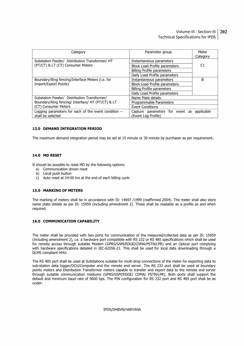
Volume-III : Section-III
Technical Specifications for IPDS
202
IPDS/DHBVN/HARYANA
Category Parameter group Meter
Category Substation Feeder/ Distribution Transformer/ HT (PT/CT) & LT (CT) Consumer Meters
Instantaneous parameters C1 Block Load Profile parameters
Billing Profile parameters Daily Load Profile parameters
Boundary/Ring fencing/Interface Meters (i.e. for Import/Export Points)
Instantaneous parameters B Block Load Profile parameters Billing Profile parameters Daily Load Profile parameters
Substation Feeder/ Distribution Transformer/ Boundary/Ring fencing/ Interface/ HT (PT/CT) & LT (CT) Consumer Meters
Name Plate details Programmable Parameters Event Conditions
Logging parameters for each of the event condition – shall be selected
Capture parameters for event as applicable (Event Log Profile)
13.0 DEMAND INTEGRATION PERIOD
The maximum demand integration period may be set at 15 minute or 30 minute by purchaser as per requirement.
14.0 MD RESET
It should be possible to reset MD by the following options:
a) Communication driven reset b) Local push button c) Auto reset at 24:00 hrs at the end of each billing cycle
15.0 MARKING OF METERS
The marking of meters shall be in accordance with IS: 14697 /1999 (reaffirmed 2004). The meter shall also store name plate details as per IS: 15959 (including amendment 2). These shall be readable as a profile as and when required.
16.0 COMMUNICATION CAPABILITY
The meter shall be provided with two ports for communication of the measured/collected data as per IS: 15959 (including amendment 2), i.e. a hardware port compatible with RS 232 or RS 485 specifications which shall be used for remote access through suitable Modem (GPRS/GSM/EDGE/CDMA/PSTN/LPR) and an Optical port complying with hardware specifications detailed in IEC-62056-21. This shall be used for local data downloading through a DLMS compliant HHU. The RS 485 port shall be used at Substations suitable for multi-drop connections of the meter for exporting data to sub-station data logger/DCU/Computer and the remote end server. The RS 232 port shall be used at boundary points meters and Distribution Transformer meters capable to transfer and export data to the remote end server through suitable communication mediums (GPRS/GSM/EDGE/ CDMA/ PSTN/LPR). Both ports shall support the default and minimum baud rate of 9600 bps. The PIN configuration for RS 232 port and RS 485 port shall be as under:
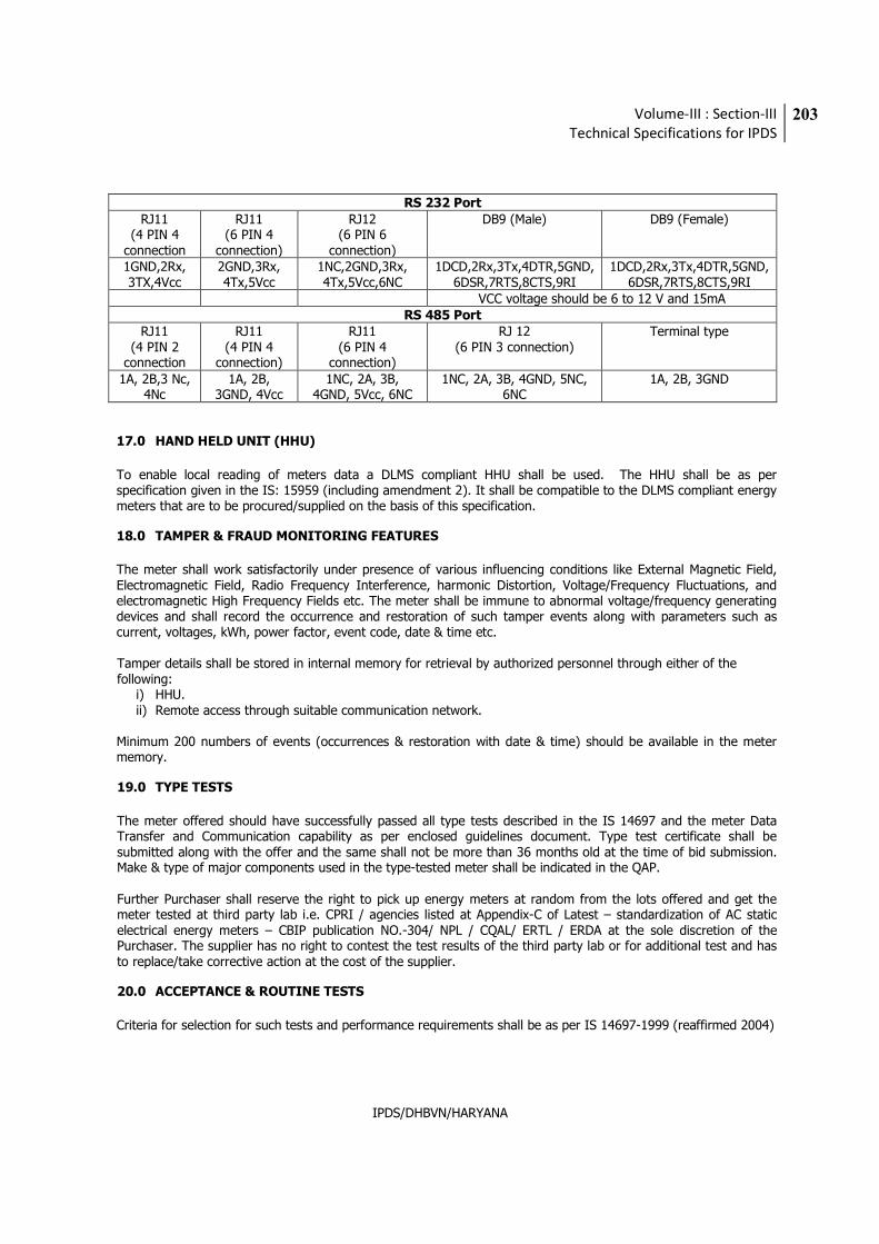
Volume-III : Section-III
Technical Specifications for IPDS
203
IPDS/DHBVN/HARYANA
RS 232 Port
RJ11 (4 PIN 4
connection
RJ11 (6 PIN 4
connection)
RJ12 (6 PIN 6
connection)
DB9 (Male)
DB9 (Female)
1GND,2Rx, 3TX,4Vcc
2GND,3Rx, 4Tx,5Vcc
1NC,2GND,3Rx, 4Tx,5Vcc,6NC
1DCD,2Rx,3Tx,4DTR,5GND,6DSR,7RTS,8CTS,9RI
1DCD,2Rx,3Tx,4DTR,5GND, 6DSR,7RTS,8CTS,9RI
VCC voltage should be 6 to 12 V and 15mA RS 485 Port
RJ11 (4 PIN 2
connection
RJ11 (4 PIN 4
connection)
RJ11 (6 PIN 4
connection)
RJ 12 (6 PIN 3 connection)
Terminal type
1A, 2B,3 Nc, 4Nc
1A, 2B, 3GND, 4Vcc
1NC, 2A, 3B, 4GND, 5Vcc, 6NC
1NC, 2A, 3B, 4GND, 5NC, 6NC
1A, 2B, 3GND
17.0 HAND HELD UNIT (HHU)
To enable local reading of meters data a DLMS compliant HHU shall be used. The HHU shall be as per specification given in the IS: 15959 (including amendment 2). It shall be compatible to the DLMS compliant energy meters that are to be procured/supplied on the basis of this specification.
18.0 TAMPER & FRAUD MONITORING FEATURES
The meter shall work satisfactorily under presence of various influencing conditions like External Magnetic Field, Electromagnetic Field, Radio Frequency Interference, harmonic Distortion, Voltage/Frequency Fluctuations, and electromagnetic High Frequency Fields etc. The meter shall be immune to abnormal voltage/frequency generating devices and shall record the occurrence and restoration of such tamper events along with parameters such as current, voltages, kWh, power factor, event code, date & time etc. Tamper details shall be stored in internal memory for retrieval by authorized personnel through either of the following:
i) HHU. ii) Remote access through suitable communication network.
Minimum 200 numbers of events (occurrences & restoration with date & time) should be available in the meter memory.
19.0 TYPE TESTS
The meter offered should have successfully passed all type tests described in the IS 14697 and the meter Data Transfer and Communication capability as per enclosed guidelines document. Type test certificate shall be submitted along with the offer and the same shall not be more than 36 months old at the time of bid submission. Make & type of major components used in the type-tested meter shall be indicated in the QAP. Further Purchaser shall reserve the right to pick up energy meters at random from the lots offered and get the meter tested at third party lab i.e. CPRI / agencies listed at Appendix-C of Latest – standardization of AC static electrical energy meters – CBIP publication NO.-304/ NPL / CQAL/ ERTL / ERDA at the sole discretion of the Purchaser. The supplier has no right to contest the test results of the third party lab or for additional test and has to replace/take corrective action at the cost of the supplier.
20.0 ACCEPTANCE & ROUTINE TESTS
Criteria for selection for such tests and performance requirements shall be as per IS 14697-1999 (reaffirmed 2004)
Volume-III : Section-III
Technical Specifications for IPDS
204
IPDS/DHBVN/HARYANA
Additional acceptance shall include Surge withstand (SWC) for 6 kVp as per IEC 62052-11, Lightning impulse test and HF disturbance test as per IS 14697. One sample meter per order from one of the offered lot shall be subjected to these specific tests. Meters subjected to these tests shall not be used after tests. Accuracy tests shall be performed at the beginning and at the end of the acceptance tests specified.
21.0 FIXING & CONNECTION ARRANGEMENT
Manufacturer shall ensure following technical points:
i) Meter shall be suitable for mounting on Simplex type vertical panel with front door; CAT-M4 disconnecting type TBs to be used for Current circuit; Panel wiring to be properly dressed and harnessed; External cables to enter panel from bottom gland plate using double compression glands.
ii) Meter installation & Inter-connection from existing CT/PT connections to energy meters in the panel shall be in the scope of contractor/bidder. The external cabling from existing CT/PT to Energy Meter panel shall be in the scope of purchaser.
iii) Energy Meter terminals block shall be adequately sized with regard to maximum conductor dimension, commensurate with current rating of Energy Meter.
Application Guide for users of this specification
1. The specification does not contain constructional details and methods of sealing of the meter COVER and the
terminal sizes required for the Purchasers incomer cables. These may be added suitably as per the requirements of individual users. Quantities of meters required with / without meter COVER needs to be specified in the Bill of Quantities in the NIT specifications.