Embed Size (px)
Citation preview
16010 - 1 of 4
SECTION 16010
BASIC ELECTRICAL REQUIREMENTS PART 1 - GENERAL 1.01 SUMMARY
A. General Division of Work 1. In general, the Division 16 contractor shall provide and install all control and power
conductors and conduit in accordance with the plans and specifications. The Division 16 contractor shall terminate and identify both ends of all control and power cable and wiring. Specialty cable required by equipment supplied under Division 13 (any communication wiring other than twisted shielded pair) shall be provided and installed as required by the Division 13 contractor and in accordance with the equipment vendor.
1.02 RELATED DOCUMENTS
A. Drawings and general provisions of Contract, including General and Supplementary Conditions and Division 1 Specification Sections, apply to this and the other sections of Division 16.
1.03 SUMMARY
A. This Section includes general administrative and procedural requirements for electrical installations. The following administrative and procedural requirements are included in this Section to expand the requirements specified in Division 1: 1. Submittals. 2. Coordination drawings. 3. Record documents. 4. Maintenance manuals. 5. Rough-ins. 6. Electrical installations. 7. Cutting and patching.
B. Related Sections: The following sections contain requirements that relate to this section:
1. Division 15 Section "ELECTRICAL REQUIREMENTS FOR MECHANICAL EQUIPMENT," for factory-installed motors, controllers, accessories, and connections.
1.04 SUBMITTALS
A. General: Follow the procedures specified in Division 1 Section "SHOP DRAWINGS AND SUBMITTALS."
B. Increase, by the quantity listed below, the number of electrical related shop drawings, product
data, and samples submitted, to allow for required distribution plus two copies of each submittal required, which will be retained by the Electrical Consulting Engineer.
16010 - 2 of 4
1. Shop Drawings - Initial Submittal: 1 additional blue- or black-line prints. 2. Shop Drawings - Final Submittal: 1 additional blue- or black-line prints. 3. Product Data: 1 additional copy of each item. 4. Samples: 1 addition as set.
C. Additional copies may be required by individual sections of these Specifications.
1.05 COORDINATION DRAWINGS
A. Prepare coordination drawings in accordance with Division 1 Section "PROJECT COORDINATION," to a scale of 1/4"=1'-0" or larger; detailing major elements, components, and systems of electrical equipment and materials in relationship with other systems, installations, and building components. Indicate locations where space is limited for installation and access and where sequencing and coordination of installations are of importance to the efficient flow of the Work, including (but not necessarily limited to) the following: 1. Indicate the proposed locations of major raceway systems, equipment, and materials.
Include the following: a. Clearances for servicing equipment, including space for equipment disassembly required
for periodic maintenance. b. Exterior wall and foundation penetrations. c. Fire-rated wall and floor penetrations. d. Equipment connections and support details. e. Sizes and location of required concrete pads and bases.
2. Indicate scheduling, sequencing, movement, and positioning of large equipment into the building during construction.
3. Prepare floor plans, elevations, and details to indicate penetrations in floors, walls, and ceilings and their relationship to other penetrations and installations.
4. Prepare reflected ceiling plans to coordinate and integrate installations, air outlets and inlets, light fixtures, communications systems components, sprinklers, and other ceiling-mounted devices.
1.06 RECORD DOCUMENTS
A. Prepare record documents in accordance with the requirements in Division 1 Section
"CONTRACT CLOSEOUT." In addition to the requirements specified in Division 1, indicate installed conditions for: 1. Major raceway systems, size and location, for both exterior and interior; locations of control
devices; distribution and branch electrical circuitry; and fuse and circuit breaker size and arrangements.
2. Equipment locations (exposed and concealed), dimensioned from prominent building lines. 3. Approved substitutions, Contract Modifications, and actual equipment and materials
installed. 1.07 MAINTENANCE MANUALS
A. Prepare maintenance manuals in accordance with Division 1 Section "CONTRACT CLOSEOUT." In addition to the requirements specified in Division 1, include the following information for equipment items: 1. Description of function, normal operating characteristics and limitations, performance
16010 - 3 of 4
curves, engineering data and tests, and complete nomenclature and commercial numbers of replacement parts.
2. Manufacturer's printed operating procedures to include start-up, break-in, and routine and normal operating instructions; regulation, control, stopping, shutdown, and emergency instructions; and summer and winter operating instructions.
3. Maintenance procedures for routine preventative maintenance and troubleshooting; disassembly, repair, and reassembly; aligning and adjusting instructions.
4. Servicing instructions and lubrication charts and schedules. 1.08 DELIVERY, STORAGE, AND HANDLING
A. Deliver products to the project properly identified with names, model numbers, types, grades, compliance labels, and other information needed for identification.
PART 2 - PRODUCTS (Not Applicable) PART 3 - EXECUTION 3.01 ROUGH-IN
A. Verify final locations for rough-ins with field measurements and with the requirements of the actual equipment to be connected.
B. Refer to equipment specifications in Divisions 2 through 16 for rough-in requirements.
3.02 ELECTRICAL INSTALLATIONS
A. General: Sequence, coordinate, and integrate the various elements of electrical systems, materials, and equipment. Comply with the following requirements: 1. Coordinate electrical systems, equipment, and materials installation with other building
components. 2. Verify all dimensions by field measurements. 3. Arrange for chases, slots, and openings in other building components during progress of
construction, to allow for electrical installations. 4. Coordinate the installation of required supporting devices and sleeves to be set in
poured-in-place concrete and other structural components, as they are constructed. 5. Sequence, coordinate, and integrate installations of electrical materials and equipment for
efficient flow of the Work. Give particular attention to large equipment requiring positioning prior to closing in the building.
6. Where mounting heights are not detailed or dimensioned, install systems, materials, and equipment to provide the maximum headroom possible.
7. Coordinate connection of electrical systems with exterior underground and overhead utilities and services. Comply with requirements of governing regulations, franchised service companies, and controlling agencies. Provide required connection for each service.
8. Install systems, materials, and equipment to conform with approved submittal data, including coordination drawings, to greatest extent possible. Conform to arrangements indicated by the Contract Documents, recognizing that portions of the Work are shown only in diagrammatic form. Where coordination requirements conflict with individual system
16010 - 4 of 4
requirements, refer conflict to the Engineer. 9. Install systems, materials, and equipment level and plumb, parallel and perpendicular to
other building systems and components, where installed exposed in finished spaces. 10. Install electrical equipment to facilitate servicing, maintenance, and repair or replacement of
equipment components. As much as practical, connect equipment for ease of disconnecting, with minimum of interference with other installations.
11. Install access panel or doors where units are concealed behind finished surfaces. 12. Install systems, materials, and equipment giving right-of-way priority to systems required to
be installed at a specified slope. 3.03 CUTTING AND PATCHING
A. General: In addition to the requirements specified in Division 1, the following requirements apply: 1. Perform cutting, fitting, and patching of electrical equipment and materials required to:
a. Uncover Work to provide for installation of ill-timed Work. b. Remove and replace defective Work. c. Remove and replace Work not conforming to requirements of the Contract Documents. d. Remove samples of installed Work as specified for testing. e. Install equipment and materials in existing structures. f. Upon written instructions from the Architect, uncover and restore Work to provide for
Architect observation of concealed Work. 2. Cut, remove, and legally dispose of selected electrical equipment, components, and
materials as indicated, including but not limited to removal of electrical items indicated to be removed and items made obsolete by the new Work.
3. Protect the structure, furnishings, finishes, and adjacent materials not indicated or scheduled to be removed.
4. Provide and maintain temporary partitions or dust barriers adequate to prevent the spread of dust and dirt to adjacent areas.
5. Protection of Installed Work: During cutting and patching operations, protect adjacent installations.
6. Patch finished surfaces and building components using new materials specified for the original installation and experienced Installers. Installers' qualifications refer to the materials and methods required for the surface and building components being patched.
END OF SECTION
16050 - 1 of 6
SECTION 16050
BASIC ELECTRICAL MATERIALS AND METHODS PART 1 - GENERAL 1.01 RELATED DOCUMENTS
A. Drawings and general provisions of the Contract, including General and Supplementary Conditions and Division 1 Specification Sections, apply to this Section.
1.02 SUMMARY
A. This Section includes the following electrical materials and methods: 1. Supporting devices for electrical components. 2. Concrete equipment bases.
1.03 SUBMITTALS
A. General: Submit each item in this Article according to the Conditions of the Contract and Division 1 Specification Sections.
B. Product Data for each type of product specified. C. Shop Drawings detailing fabrication and installation of supports and anchorage for electrical
items. 1.04 QUALITY ASSURANCE
A. Comply with NFPA 70 for components and installation. B. Listing and Labeling: Provide products specified in this Section that are listed and labeled.
1. The Terms "Listed and Labeled": As defined in the National Electrical Code, Article 100. 2. Listing and Labeling Agency Qualifications: A "Nationally Recognized Testing Laboratory"
(NRTL) as defined in OSHA Regulation 1910.7. 1.05 SEQUENCING AND SCHEDULING
A. Coordinate electrical equipment installation with other building components. B. Arrange for chases, slots, and openings in building structure during progress of construction to
allow for electrical installations. C. Coordinate installing required supporting devices and set sleeves in poured-in-place concrete
and other structural components as they are constructed.
16050 - 2 of 6
D. Sequence, coordinate, and integrate installing electrical materials and equipment for efficient flow of the Work. Coordinate installing large equipment requiring positioning prior to closing in the building.
E. Coordinate connecting electrical service to components furnished under other Sections. F. Coordinate connecting electrical systems with exterior underground and overhead utilities and
services. Comply with requirements of governing regulations, franchised service companies, and controlling agencies.
G. Coordinate requirements for access panels and doors where electrical items requiring access are
concealed by finished surfaces. H. Coordinate installing electrical identification after completion of finishing where identification
is applied to field-finished surfaces. I. Coordinate installing electrical identifying devices and markings prior to installing acoustical
ceilings and similar finishes that conceal such items. PART 2 - PRODUCTS 2.01 SUPPORTING DEVICES
A. Channel and angle support systems, hangers, anchors, sleeves, brackets, fabricated items, and fasteners are designed to provide secure support from the building structure for electrical components. 1. Material: 316 stainless steel all outdoor locations and unconditioned spaces, except in
chemical areas, use non-metallic. 2. Fitting and Accessory Material: Same as channels and angles, except metal items may be
stainless steel.
B. 316 stainless steel channel supports have 9/16-inch (14-mm) diameter holes at a maximum of 8 inches (203 mm) o.c., in at least 1 surface. 1. Fittings and accessories mate and match with channels and are from the same manufacturer.
C. Nonmetallic Channel and Angle Systems: Structural-grade, factory-formed, fiberglass-resin channels and angles with 9/16-inch (14-mm) diameter holes at a maximum of 8-inches (203-mm) o.c., in at least 1 surface. 1. Fittings and accessories mate and match with channels or angles and are from the same
manufacturer. 2. Fitting and Accessory Material: Same as channels and angles, except metal items may be
stainless steel.
D. Raceway and Cable Supports: Manufactured clevis hangers, riser clamps, straps, threaded C-clamps with retainers, ceiling trapeze hangers, wall brackets, and "click"- type hangers. 1. Materials: 316 stainless steel.
16050 - 3 of 6
E. Cable Supports for Vertical Conduit: Factory-fabricated assembly consisting of threaded body and insulating wedging plug for non-armored electrical cables in riser conduits. Plugs have number and size of conductor gripping holes as required to suit individual risers.
F. Expansion Anchors: 316 stainless steel wedge or sleeve type. G. Toggle Bolts: 316 stainless steel springhead type. H. Powder-Driven Threaded Studs: 316 stainless steel.
PART 3 - EXECUTION 3.01 EQUIPMENT INSTALLATION REQUIREMENTS
A. Install components and equipment to provide the maximum possible headroom where mounting heights or other location criteria are not indicated.
B. Install items level, plumb, and parallel and perpendicular to other building systems and
components, except where otherwise indicated. C. Install equipment to facilitate service, maintenance, and repair or replacement of components.
Connect for ease of disconnecting, with minimum interference with other installations. 3.02 ELECTRICAL SUPPORTING METHODS
A. Damp Locations and Outdoors: 316 stainless steel materials, U-channel system components. B. Dry Locations: 316 stainless steel materials. C. Support Clamps for Raceways: 316 stainless steel clamp system. D. Conform to manufacturer's recommendations for selecting supports. E. Strength of Supports: Adequate to carry all present and future loads, times a safety factor of at
least 4; 200-lb- (90-kg-) minimum design load. 3.03 INSTALLATION
A. Install devices to securely and permanently fasten and support electrical components. B. Raceway Supports: Comply with NFPA 70 and the following requirements:
1. Conform to manufacturer's recommendations for selecting and installing supports. 2. Install individual and multiple raceway hangers and riser clamps to support raceways.
Provide U bolts, clamps, attachments, and other hardware necessary for hanger assembly and for securing hanger rods and conduits.
3. Support parallel runs of horizontal raceways together on trapeze- or bracket-type hangers. 4. Spare Capacity: Size supports for multiple conduits so capacity can be increased by a 25
percent minimum in the future.
16050 - 4 of 6
5. Support individual horizontal raceways with separate, pipe hangers or clamps. 6. Hanger Rods: 1/4-inch (6-mm) diameter or larger threaded, except as otherwise indicated. 7. In vertical runs, arrange support so the load produced by the weight of the raceway and the
enclosed conductors is carried entirely by the conduit supports, with no weight load on raceway terminals.
C. Vertical Conductor Supports: Install simultaneously with conductors. D. Miscellaneous Supports: Install metal channel racks for mounting cabinets, panelboards,
disconnects, control enclosures, pull boxes, junction boxes, transformers, and other devices except where components are mounted directly to structural features of adequate strength.
E. In open overhead spaces, cast boxes threaded to raceways need not be separately supported,
except where used for fixture support; support sheet-metal boxes directly from the building structure or by bar hangers. Where bar hangers are used, attach the bar to raceways on opposite sides of the box and support the raceway with an approved fastener not more than 24-inches (610-mm) from the box.
F. Sleeves: Install for cable and raceway penetrations of concrete slabs and walls, except where
core-drilled holes are used. Install for cable and raceway penetrations of masonry and fire-rated gypsum walls and of all other fire-rated floor and wall assemblies. Install sleeves during erection of concrete and masonry walls.
G. Firestopping: Apply to cable and raceway penetrations of fire-rated floor and wall assemblies.
Perform firestopping as specified in Division 7 Section "Firestopping" to reestablish the original fire-resistance rating of the assembly at the penetration.
H. Fastening: Unless otherwise indicated, securely fasten electrical items and their supporting
hardware to the building structure. Perform fastening according to the following: 1. Fasten by means of wood screws or screw-type nails on wood; toggle bolts on hollow
masonry units; concrete inserts or expansion bolts on concrete or solid masonry; and by machine screws, welded threaded studs, or spring-tension clamps on steel.
2. Threaded studs driven by a powder charge and provided with lock washers and nuts may be used instead of expansion bolts, machine screws, or wood screws.
3. Welding to steel structure may be used only for threaded studs, not for conduits, pipe straps, or any other items.
4. In partitions of light steel construction use sheet-metal screws. 5. Drill holes in concrete beams so holes more than 1-1/2-inches (38-mm) deep do not cut
main reinforcing bars. 6. Drill holes in concrete so holes more than 3/4 -inch (19-mm) deep do not cut main
reinforcing bars. 7. Fill and seal holes drilled in concrete and not used. 8. Select fasteners so the load applied to any fastener does not exceed 25 percent of the proof-
test load.
I. Install concrete pads and bases according to requirements of Division 3 Section "Cast-in-Place Concrete."
16050 - 5 of 6
J. Install utility-metering equipment according to utility company's written requirements. Provide grounding and empty conduits as required by company.
K. All conduits in contact with concrete shall be painted with two coats of bitumastic paint. Paint
12 inches above grade.
END OF SECTION

16050 - 6 of 6
THIS PAGE LEFT BLANK INTENTIONALLY
16060 - 1 of 6
SECTION 16060
POWER DISTRIBUTION SYSTEM COORDINATION STUDY
PART 1 - GENERAL
1.01 DESCRIPTION
A. Scope: 1. CONTRACTOR shall provide all labor, materials, equipment, services and incidentals
required to perform Power System Studies and distribution system field testing.
B. The Power System Studies shall include a Short Circuit Study, a Protective Device Evaluation Study, Arc Flash Study and a Protective Device Coordination Study for a completely coordinated Power Distribution System.
C. The Power System Studies shall be performed on three (3) complete power systems
including all existing facilities. Oak Meadows WTP 1. Furnish as study as specified. Western Regional Plant. 1. Existing power system studies are available for use under this by Eaton Powering
#GOSOR00516809, software is SKM.
1.02 REFERENCES
A. Standards referenced in this Section are listed below: 1. American National Standards Institute, (ANSI). a. ANSI C37.04, Rating Structure for AC High-Voltage Circuit Breakers Rated on a
Symmetrical Current Basis. b. ANSI C37.010, Application Guide for AC High Voltage Circuit Breakers Rated on
a Symmetrical Basis. 2. Institute of Electrical and Electronics Engineers, (IEEE). a. IEEE 141, Electric Power Distribution in Industrial Plants. b. IEEE 399, Recommended Practice for Industrial and Commercial Power System
Analysis. 3. National Electrical Code, (NEC).
16060 - 2 of 6
1.03 QUALITY ASSURANCE
A. Source Quality Control: 1. Retain the services of a Registered Professional Engineer, to perform the Power
System Studies and field services. The Registered Professional Engineer shall be from an independent consulting firm. Services by manufacturer of the power distribution equipment are not acceptable.
2. Coordinate with the Engineer performing the studies and assist him in the collection of all information necessary to complete the studies specified.
3. All information pertaining to the existing system necessary to perform the studies shall be obtained in advance prior to performing the studies.
4. All motor starting and transformer information shall be based upon the equipment actually installed distribution system. The Field Engineer shall be from the manufacturer of the power distribution equipment.
B. All test equipment and instrument calibration shall be in accordance with the latest
edition of the accuracy standard of the U.S. National Institute of Standards and Technology.
1.04 SUBMITTALS
A. Shop Drawings: Submit the following: 1. Copies of calculations and results of the Short Circuit Study, Protective Device
Evaluation and Coordination Studies in a report format. The report shall be stamped and signed by the Registered Professional Engineer.
2. Work sequence for the field testing shall be submitted in advance prior to performing tests. The sequence shall indicate the schedule of work, time frame and downtime for the equipment.
3. Time current curves for all protective devices included within the power system studies.
B. Reports:
1. Field test report shall be submitted. PART 2 – PRODUCTS
2.01 POWER SYSTEM STUDIES A. General:
1. Provide a current and complete Short Circuit Study, Protective Device Evaluation Study, and a Protective Device Coordination Study for the Electrical Distribution System.
2. The studies shall include all portions of the high and low voltage electrical distribution system from the normal and alternate sources of power through the low- voltage
16060 - 3 of 6
distribution system. Normal system operating method, alternate operation, and operations which could result in maximum fault conditions shall be thoroughly covered in the study.
3. Problem areas or equipment inadequacies shall be promptly brought to the ENGINEER'S attention.
4. Studies shall include all scenarios related to tie breakers, multiple generators, and manual transfer switches.
B. Short Circuit Study:
1. The Short Circuit Study shall be performed with the aid of a computer program, SKM or Easy Power, working files shall be provided to the Owner.
2. The study input data shall include the utility company's short circuit, single and three phase contributions, with the X/R ratio, the resistance and reactance components of and all other applicable circuit parameters.
3. Short-circuit momentary duties and interrupting duties shall be calculated on the basis of maximum available fault current at each switchgear bus, switchboard, motor control center, distribution panelboard, pertinent branch circuit panelboards, and other significant locations through the system.
4. The short circuit tabulations shall include symmetrical fault currents, and X/R ratios. For each fault location, the total duty on the bus, as well as the individual contribution from each connected branch, including motor back EMF current contributions shall be listed with its respective X/R ratio.
C. Protective Device Evaluation Study:
1. A Protective Device Evaluation Study shall be performed to determine the adequacy of circuit breakers, controllers, surge arresters, busways, switches, and fuses by tabulating and comparing the short-circuit ratings of these devices with the available fault currents.
2. Appropriate multiplying factors based upon system X/R ratios and protective device rating standards shall be applied.
D. Protective Device Coordination Study:
1. A Protective Device Coordination Study shall be performed to select or to check the selections of the power fuse ratings, protective relay characteristics and settings, ratios and characteristics of associated voltage and current transformers, and low- voltage breaker trip characteristics and setting.
2. The overcurrent device settings computed in the Protective Device Coordination Study shall provide complete 100 percent selectivity. The system shall be selectively coordinated such that only the device nearest a fault will operate to remove the faulted circuit. System selectively shall be based on both the magnitude and the duration of a fault current.
3. The Protective Device Coordination Study shall include all voltage classes of equipment starting at the utility's incoming line protective device down to and including each of the medium and low voltage equipment. The phase and ground
16060 - 4 of 6
overcurrent and the phase and ground fault protection shall be included, as well as settings for all other adjustable protective devices.
4. The time-current characteristics of the installed protective devices shall be plotted on the appropriate log-log paper. Reasonable coordination intervals and separation of characteristic curves shall be maintained. The coordination plots for phase and ground protective devices shall be provided on a complete system basis. Sufficient curves shall be used to clearly indicate selective coordination achieved through the utility main breaker, power distribution feeder breakers, and the overcurrent devices at each major load center.
5. There shall be a maximum of eight protective devices per plot. Each plot shall be appropriately titled. Plots shall include the following information as required for the circuits shown: a. Representative one-line diagram, legends and types of protective devices
selected. b. Power company's relays or fuse characteristics. c. Significant motor starting characteristics. d. Parameters of transformers, ANSI magnetizing inrush and withstand curves. e. Operating bands of low voltage circuit breaker trip curves, and fuse curves. f. Relay taps, time dial and instantaneous trip settings. g. Cable damage curves. h. Symmetrical and asymmetrical fault currents.
6. The selection and settings of the protective devices shall be provided separately in a tabulated form listing circuit identification, IEEE device number, current transformer ratios, manufacturer, type, range of adjustment, and recommended settings. A tabulation of the recommended power fuse selection shall be provided for all fuses in the system.
D. Arc Flash Hazard Study:
1. An Arc Flash Hazard Study shall be performed for the electrical distribution system shown on the one line drawings. The intent of the Arc Flash Hazard Study is to determine hazards that exist at each major piece of electrical equipment shown on the one line drawing. This includes switchgear, switchboards, panelboards, motor control centers and transformers. The study shall include creation of Arc Flash Hazard Warning Labels listing all items. The Contractor will furnish and install the labels. The arc flash hazard study shall consider all operating scenarios during normal conditions alternate operations, emergency power conditions, and any other operations, which could result in maximum arc flash hazard
2.02 STUDY REPORT
A. The results of the Power Distribution System Coordination Study shall be summarized in a final typewritten report. The report shall include the following Sections: 1. Description, purpose, basis, written scope, and a single-line diagram of the
PowerDistribution System which is included within the scope of the study.
16060 - 5 of 6
2. Tabulations of circuit breaker, fuses, and other equipment ratings versus calculated short-circuit duties, and commentary regarding same.
3. Protective device time versus current coordination curves, tabulations of relay and circuit breaker trip settings, fuse selection, and commentary regarding same.
4. Fault current tabulation including a definition of terms and a guide for interpretation. 5. Tabulation of appropriate tap settings for relay seal-in units. 6. Tabulation of equipment survey information.
PART 3 – EXECUTION 3.01 FIELD SERVICES
A. The Registered Professional Engineer shall conduct an equipment survey of devices and
information necessary to perform the Power System Studies.
B. The survey shall include the following information to the extent applicable: 1. Manufacturer, type and size of each power fuse. 2. Manufacturer, type, model and settings for each protective relay, trip unit and circuit
breaker. 3. Current transformer ratios for each protective relay. 4. Appropriate data of motors and transformers included with the study.
C. The Registered Professional Engineer, as part of the field service Work, shall collect all
data and coordinate with the equipment vendors to establish the proper settings for the actual devices provided.
3.02 FIELD TESTING
A. Provide field testing of the distribution system in accordance with the manu-facturer’s
recommendations. All field testing shall be performed by the Field Engineer, after the completion and approval of the Power System Studies. The field testing results shall be documented within a report, with the final settings of all protective devices.
B. The Field Engineer with necessary tools and equipment shall adjust, set, calibrate and test
all protective devices. All protective relays and meters in the medium and low voltage equipment shall be set, adjusted, calibrated and tested in accordance with the manufacturer's recommendations, the coordination study and best industry practice.
C. Proper operation of all equipment associated with the device under test and its
compartment, shall be verified, as well as complete resistance, continuity and polarity tests of power, protective and metering circuits. Any minor adjustments, repairs and lubrication necessary to achieve proper operation shall be considered part of this Contract.
16060 - 6 of 6
D. All solid state trip devices shall be set including all required programming necessary for
the protection required. The devices shall be checked and tested for setting and operation. Circuit breakers and/or contactors associated with the trip devices shall be tested for trip and close function with their protective device.
3.02 MAINTENANCE OF OPERATIONS
A. Since the field testing work specified may require that certain pieces of equipment be
taken out of service, CONTRACTOR shall perform the Work with due regard to maintenance of operations and construction staging. All testing procedures and schedules must be scheduled in advance prior to any work beginning.
END OF SECTION
16100 - 1 of 10
SECTION 16100
RACEWAYS, BOXES, AND CABINETS PART 1 - GENERAL 1.01 RELATED DOCUMENTS
A. Drawings and general provisions of the Contract, including General and Supplementary Conditions and Division 1 Specification Sections, apply to this Section.
1.02 SUMMARY
A. This Section includes raceways, fittings, boxes, enclosures, and cabinets for electrical wiring. B. Raceways include the following:
1. Rigid metal conduit 2. Electrical metallic tubing (EMT) 3. Flexible metal conduit 4. Liquid-tight flexible conduit 5. Rigid nonmetallic conduit 6. Wireway 7. Surface raceways 8. Concrete-encased duct banks.
C. Boxes, enclosures, and cabinets include the following:
1. Device boxes 2. Floor boxes 3. Outlet boxes 4. Pull and junction boxes 5. Cabinets and hinged cover enclosures.
D. Related Sections: The following Sections contain requirements that relate to this Section:
1. Division 16 Section 16050 for raceway and box supports. 2. Division 16 Section "Wiring Devices" for devices installed in boxes and floor box service
fittings. 1.03 SUBMITTALS
A. General: Submit the following according to the Conditions of the Contract and Division 1 Specification Sections.
B. Product data for surface raceway, wireway and fittings, floor boxes, hinged cover enclosures,
and cabinets. C. Shop drawings for nonstandard boxes, enclosures, and cabinets. Include layout drawings
showing components and wiring.
16100 - 2 of 10
1.04 QUALITY ASSURANCE
A. Comply with NFPA 70 "National Electrical Code" for components and installation. B. Listing and Labeling: Provide products specified in this Section that are listed and labeled.
1. The Terms "Listed and Labeled": As defined in the "National Electrical Code," Article 100. 2. Listing and Labeling Agency Qualifications: A "Nationally Recognized Testing Laboratory"
(NRTL) as defined in OSHA Regulation 1910.7.
C. Comply with NECA "Standard of Installation." D. Coordinate layout and installation of raceway and boxes with other construction elements to
ensure adequate headroom, working clearance, and access. PART 2 - PRODUCTS 2.01 MANUFACTURERS
A. Manufacturers: Subject to compliance with requirements, provide Products by of one of the following: 1. Metal Conduit and Tubing:
a. Monogram Co., AFC. b. Alflex Corp. c. Allied Tube and Conduit, Grinnell Co. d. Anamet, Inc., Anaconda Metal Hose. e. Anixter Brothers, Inc. f. Carol Cable Co., Inc. g. Cole-Flex Corp. h. Flexcon, Inc., Coleman Cable Systems, Inc. i. Spiraduct, Inc. j. Triangle PWC, Inc. k. Wheatland Tube Co.
2. Nonmetallic Tubing and Conduit: a. Anamet, Inc., Anaconda Metal Hose. b. Arnco Corp. c. Breeze-Illinois, Inc. d. Can-Tex Industries, Harsco Corp. e. Carlon. f. Certainteed Corp, Pipe & Plastics Group. g. Cole-Flex Corp. h. Condux International, Electrical Products. i. Electri-Flex Co. j. George-Ingraham Corp. k. Hubbell, Inc., Raco, Inc. l. R&G Sloan Manufacturing Co., Inc. m. Spiraduct, Inc. n. Thomas & Betts Corp.
3. Conduit Bodies and Fittings: a. Scott Fetzer Company, Adalet-PLM.
16100 - 3 of 10
b. American Electric, Construction Materials Group. c. Emerson Electric Co., Appleton Electric Co. d. Carlon. e. Hubbell, Inc., Killark Electric Manufacturing Co. f. General Signal, O-Z/Gedney Unit. g. Spring City Electrical Manufacturing Co.
4. Wireway: a. Hoffman Engineering Co. b. Keystone/Rees, Inc. c. Square D Co.
5. Surface Metal Raceway: a. Airey-Thompson Co., Inc., A-T Power Systems. b. American Electric, Construction Materials Group. c. Butler Manufacturing Co., Walker Division. d. The Wiremold Co., Electrical Sales Division.
6. Surface Nonmetallic Raceway: a. Anixter Brothers, Inc. b. Butler Manufacturing Co., Walker Division. c. Hubbell, Inc., Wiring Device Division. d. JBC Enterprises, Inc., Enduro Fiberglass Systems. e. Panduit Corp. f. United Telecom, Premier Telecom Products, Inc. g. Thermotools Co. h. The Wiremold Co., Electrical Sales Division.
7. Boxes, Enclosures, and Cabinets: a. Scott Fetzer Company, Adalet-PLM. b. Butler Manufacturing Co., Walker Division. c. Cooper Industries, Midwest Electric. d. Electric Panelboard Co., Inc. e. Erickson Electrical Equipment Co. f. American Electric, FL Industries. g. Hoffman Engineering Co., Federal-Hoffman, Inc. h. Hubbell Inc., Killark Electric Manufacturing Co. i. General Signal, O-Z/Gedney. j. Parker Electrical Manufacturing Co. k. Raco, Inc., Hubbell Inc. l. Robroy Industries, Inc., Electrical Division. m. Spring City Electrical Manufacturing Co. n. Square D Co. o. Thomas & Betts Corp. p. Woodhead Industries, Inc., Daniel Woodhead Co.
2.02 METAL CONDUIT AND TUBING
A. Rigid Steel Conduit: ANSI C80.1.
B. Rigid Aluminum Conduit: ANSI C80.5.
C. Electrical Metallic Tubing and Fittings: ANSI C80.3 with compression-type fittings.
16100 - 4 of 10
D. Flexible Metal Conduit: Aluminum. E. Flexible Metal Conduit: Zinc-coated steel. F. Liquidtight Flexible Metal Conduit: Flexible steel conduit with PVC jacket. G. Fittings: NEMA FB 1, compatible with conduit/tubing materials.
2.03 NONMETALLIC CONDUIT AND TUBING
A. Rigid Nonmetallic Conduit (RNC): NEMA TC 2, Schedule 40 or 80 PVC. B. PVC Conduit and Tubing Fittings: NEMA TC 3; match to conduit or conduit/tubing type and
material. 2.04 WIREWAYS
A. Material: Sheet metal sized and shaped as indicated. B. Fittings and Accessories: Include couplings, offsets, elbows, expansion joints, adapters,
hold-down straps, end caps, and other fittings to match and mate with wireway as required for complete system.
C. Select features where not otherwise indicated, as required to complete wiring system and to comply with NEC.
D. Wireway Covers: Hinged type. E. Finish: Manufacturer's standard enamel finish.
2.05 SURFACE RACEWAY
A. Types, sizes, and channels as indicated and required for each application, with fittings that match and mate with raceway.
B. Surface Metal Raceway: Galvanized steel with snap-on covers. Finish with manufacturer's
standard prime coating suitable for painting. C. Surface Nonmetallic Raceway: 2-piece construction, manufactured of rigid PVC compound
with matte texture and manufacturer's standard color.
2.06 OUTLET AND DEVICE BOXES
A. Cast Metal Boxes: NEMA FB 1, type FD, cast feralloy box with gasketed cover. B. Nonmetallic Boxes: NEMA OS 2.
16100 - 5 of 10
2.07 FLOOR BOXES
A. Floor Box: Cast metal, fully adjustable, rectangular with escutcheon plate/appropriate for floor finish.
2.08 PULL AND JUNCTION BOXES
A. Cast Metal Boxes: NEMA FB 1, cast aluminum with gasketed cover. 2.09 CABINETS AND ENCLOSURES
A. Hinged Cover Enclosures: NEMA 250, steel enclosure with continuous hinge cover and flush latch. Finish inside and out with manufacturer's standard enamel.
B. Cabinets: NEMA 250, type 1, galvanized steel box with removable interior panel and
removable front, finished inside and out with manufacturer's standard enamel. Hinged door in front cover with flush latch and concealed hinge. Key latch-to-match panelboards. Include metal barriers to separate wiring of different systems and voltage, and include accessory feet where required for freestanding equipment.
2.10 CONCRETE-ENCASED DUCT BANKS
A. Concrete: Use 3000-psi-(20.7-MPa-) minimum, 28-day compressive strength and 3/8-inch (10-mm) maximum aggregate size. Concrete and reinforcement are specified in Division 3 Section “Cast-in-Place Concrete”. 1. Color: Red dye added to concrete during batching.
B. Accessories: 1. Duct Spacers: Rigid PVC interlocking spacers, selected to provide minimum duct spacings
and cover depths indicated while supporting ducts during concreting and backfilling, produced by the same manufacturer as the ducts.
2. Grounding Materials: Comply with Division 16 Section “Grounding and Bonding” 3. Warning Tape: Underground-line warning tape specified in Division 16 Section “Electrical
Identification”. PART 3 - EXECUTION 3.01 EXAMINATION
A. Examine surfaces to receive raceways, boxes, enclosures, and cabinets for compliance with installation tolerances and other conditions affecting performance of the raceway system. Do not proceed with installation until unsatisfactory conditions have been corrected.
3.02 WIRING METHODS
A. Outdoors: Use the following wiring methods: 1. Exposed: Rigid aluminum metal conduit. 2. Concealed: Rigid aluminum metal conduit. 3. Underground, Single Run: Rigid aluminum, painted.
16100 - 6 of 10
4. Underground, Grouped: Rigid aluminum, painted 5. Connection to Vibrating Equipment (including transformers and hydraulic, pneumatic, or
electric solenoid or motor-driven equipment): Liquidtight flexible metal aluminum conduit. 6. Boxes and Enclosures: NEMA Type 4X 316 stainless steel.
B. Indoors: Use the following wiring methods:
1. Connection to Vibrating Equipment (including transformers and hydraulic, pneumatic, or electric solenoid or motor-driven equipment): Flexible metal conduit, except in wet or damp locations use liquidtight flexible metal aluminum conduit.
2. Damp or Wet Locations: Aluminum conduit. 3. Exposed: Rigid aluminum 4. Corrosive Areas: Not Applicable 5. Concealed: Rigid aluminum 6. Boxes and Enclosures: NEMA Type 4X, 316 stainless steel.
3.03 INSTALLATION
A. Install raceways, boxes, enclosures, and cabinets as indicated, according to manufacturer's written instructions.
B. Conceal conduit, unless otherwise indicated, within finished walls, ceilings, and floors. C. Keep raceways at least 6 inches (150 mm) away from parallel runs of flues and steam or hot
water pipes. Install horizontal raceway runs above water and steam piping. D. Install raceways level and square and at proper elevations. Provide adequate headroom. E. Complete raceway installation before starting conductor installation. F. Support raceway as specified in Division 16 Section 16050. G. Use temporary closures to prevent foreign matter from entering raceway. H. Protect stub-ups from damage where conduits rise through floor slabs. Arrange so curved
portion of bends is not visible above the finished slab. I. Make bends and offsets so the inside diameter is not reduced. Unless otherwise indicated, keep
the legs of a bend in the same plane and the straight legs of offsets parallel. J. Use raceway fittings compatible with raceway and suitable for use and location. For
intermediate steel conduit, use threaded rigid steel conduit fittings, except as otherwise indicated.
K. Run concealed raceways with a minimum of bends in the shortest practical distance considering
the type of building construction and obstructions, except as otherwise indicated. L. Raceways Embedded in Slabs: Install in middle third of the slab thickness where practical, and
leave at least 1-inch (25 mm) concrete cover.
16100 - 7 of 10
1. Secure raceways to reinforcing rods to prevent sagging or shifting during concrete placement.
2. Space raceways laterally to prevent voids in the concrete. 3. Run conduit larger than 1-inch trade size parallel to or at right angles to main reinforcement.
When at right angles to reinforcement, place conduit close to slab support.
M. Install exposed raceways parallel to or at right angles to nearby surfaces or structural members, and follow the surface contours as much as practical. 1. Run parallel or banked raceways together, on common supports where practical. 2. Make bends in parallel or banked runs from same centerline to make bends parallel. Use
factory elbows only where they can be installed parallel; otherwise, provide field bends for parallel raceways.
N. Join raceways with fittings designed and approved for the purpose and make joints tight.
1. Make raceway terminations tight. Use bonding bushings or wedges at connections subject to vibration. Use bonding jumpers where joints cannot be made tight.
2. Use insulating bushings to protect conductors.
O. Tighten setscrews of threadless fittings with suitable tool. P. Terminations: Where raceways are terminated with locknuts and bushings, align the raceway to
enter squarely, and install the locknuts with dished part against the box. Where terminations cannot be made secure with one locknut, use two locknuts, one inside and one outside the box.
Q. Where terminating in threaded hubs, screw the raceway or fitting tight into the hub so the end
bears against the wire protection shoulder. Where chase nipples are used, align the raceway so the coupling is square to the box, and tighten the chase nipple so no threads are exposed.
R. Install pull wires in empty raceways. Use No. 14 AWG zinc-coated steel or monofilament
plastic line having not less than 200-lb (90 kg) tensile strength. Leave not less than 12 inches (300 mm) of slack at each end of the pull wire.
S. Telephone and Signal System Raceways 2-Inch Trade Size and Smaller: In addition to the
above requirements, install in maximum lengths of 150-feet and with a maximum of two 90-deg bends or equivalent. Install pull or junction boxes where necessary to comply with these requirements.
T. Install raceway-sealing fittings according to the manufacturer's written instructions. Locate
fittings at suitable, approved, accessible locations and fill them with UL-listed sealing compound. For concealed raceways, install each fitting in a flush steel box with a blank cover plate having a finish similar to that of adjacent plates or surfaces. Install raceway-sealing fittings at the following points and elsewhere as indicated: 1. Where conduits enter or leave hazardous locations. 2. Where conduits pass from warm locations to cold locations, such as the boundaries of
refrigerated spaces and air-conditioned spaces. 3. Where otherwise required by the NEC.
U. Stub-Up Connections: Extend conduits through concrete floor for connection to freestanding
equipment with an adjustable top or coupling threaded inside for plugs, and set flush with the

16100 - 8 of 10
finished floor. Extend conductors to equipment with rigid steel conduit; flexible conduit may be used 6-inches (150-mm) above the floor. Where equipment connections are not made under this Contract, install screwdriver-operated threaded flush plugs flush with floor.
V. Flexible Connections: Use maximum of 6-feet (1830-mm) of flexible conduit for recessed and
semi-recessed lighting fixtures; for equipment subject to vibration, noise transmission, or movement; and for all motors. Use liquidtight flexible conduit in wet or damp locations. Install separate ground conductor across flexible connections.
W. Install nonferrous conduit or tubing for circuits operating above 60 Hz. Where aluminum raceway is installed for such circuits and it passes through concrete, install in a nonmetallic sleeve.
X. Do not install aluminum conduit embedded in or in contact with concrete. Y. Set floor boxes level and adjust to floor surface. Z. Install hinged cover enclosures and cabinets plumb. Support at each corner. AA. Provide grounding connections for raceway, boxes, and components as indicated and
instructed by manufacturer. Tighten connectors and terminals, including screws and bolts, according to equipment manufacturer's published torque-tightening values for equipment connectors. Where manufacturer's torquing requirements are not indicated, tighten connectors and terminals according to tightening torques specified in UL Standard 486A.
3.04 CONCRETE-ENCASED DUCT INSTALLATION
A. Slope: Pitch ducts a minimum slope of 1:300 down toward manholes and handholes and away
from buildings and equipment. Slope ducts from a high point in runs between two manholes to drain in both directions.
B. Curves and Bends: Use manufactured elbows for stub-ups at equipment and at building
entrances. Use manufactured long sweep bends with a minimum radius of 25 feet , both horizontally and vertically, at other locations.
C. Use solvent-cement joints in ducts and fittings and make watertight according to manufacturer's
written instructions. Stagger couplings so those of adjacent ducts do not lie in the same plane. D. Duct Entrances to Manholes and Handholes: Space end bells approximately 10 inches o.c. for
5-inch ducts and vary proportionately for other duct sizes. Change from regular spacing to end-bell spacing 10 feet from the end bell without reducing duct line slope and without forming a trap in the line. Grout end bells into manhole walls from both sides to provide watertight entrances.
E. Building Entrances: Make a transition from underground duct to conduit at least 10 feet (3 m)
outside the building wall. Use fittings manufactured for this purpose. Follow the appropriate installation instructions below: 1. Concrete-Encased Ducts: Install reinforcement in duct banks passing through disturbed
earth near buildings and other excavations. Coordinate duct bank with structural design to support duct bank at wall without reducing structural or watertight integrity of building wall.
16100 - 9 of 10
2. Waterproofed Wall and Floor Penetrations: Install a watertight entrance-sealing device with sealing gland assembly on the inside. Anchor device into masonry construction with one or more integral flanges. Secure membrane waterproofing to the device to make permanently watertight.
F. Concrete-Encased, Nonmetallic Ducts: Support ducts on duct spacers, spaced as recommended
by manufacturer and coordinated with duct size, duct spacing, and outdoor temperature. Install as follows: 1. Separator Installation: Space separators close enough to prevent sagging and deforming of
ducts and secure separators to earth and to ducts to prevent floating during concreting. Stagger spacers approximately 6 inches (150 mm) between tiers. Tie entire assembly together using fabric straps; do not use tie wires or reinforcing steel that may form conductive or magnetic loops around ducts or duct groups.
2. Concreting: Spade concrete carefully during pours to prevent voids under and between conduits and at exterior surface of envelope. Do not allow a heavy mass of concrete to fall directly onto ducts. Use a plank to direct concrete down sides of bank assembly to trench bottom. Allow concrete to flow to center of bank and rise up in middle, uniformly filling all open spaces. Do not use power-driven agitating equipment unless specifically designed for duct-bank application. Pour each run of envelope between manholes or other terminations in one continuous operation. If more than one pour is necessary, terminate each pour in a vertical plane and install 3/4-inch reinforcing rod dowels extending 18 inches into concrete on both sides of joint near corners of envelope.
3. Reinforcement: Reinforce duct banks where they cross disturbed earth and where indicated. 4. Forms: Use walls of trench to form sidewalls of duct bank where soil is self-supporting and
concrete envelope can be poured without soil inclusions; otherwise, use forms. 5. Minimum Clearances between Ducts: 3 inches between ducts and exterior envelope wall, 2
inches between ducts for like services, and 4 inches between power and signal ducts. 6. Depth: Install top of duct bank at least 24 inches below finished grade in non-traffic areas
and at least 30 inches below finished grade in vehicular traffic areas, unless otherwise indicated.
G. Warning Tape: Bury warning tape approximately 12 inches above all concrete-encased duct
banks. Align tape parallel to and within 3 inches of the centerline of duct bank. H. Sealing: Provide temporary closure at terminations of ducts that have cables pulled. Seal spare
ducts at terminations. Use sealing compound and plugs to withstand at least 15-psig hydrostatic pressure.
I. Pulling Cord: Install 100-lbf- test nylon cord in ducts, including spares.
3.05 PROTECTION
A. Provide final protection and maintain conditions, in a manner acceptable to manufacturer and Installer, to ensure that coatings, finishes, and cabinets are without damage or deterioration at Substantial Completion. 1. Repair damage to galvanized finishes with zinc-rich paint recommended by manufacturer. 2. Repair damage to PVC or paint finishes with matching touch-up coating recommended by
the manufacturer.
16100 - 10 of 10
3.06 CLEANING
A. Upon completion of installation of system, including outlet fittings and devices, inspect exposed finish. Remove burrs, dirt, and construction debris and repair damaged finish, including chips, scratches, and abrasions.
END OF SECTION
16120 - 1 of 4
SECTION 16120
WIRES AND CABLES PART 1 - GENERAL 1.01 RELATED DOCUMENTS A. Drawings and general provisions of the Contract, including General and Supplementary
Conditions and Division 1 Specification Sections, apply to this Section. 1.02 SUMMARY A. This Section includes building wires and cables and associated splices, connectors, and
terminations for wiring systems rated 600 volts and less. 1.03 SUBMITTALS A. General: Submit the following according to the Conditions of the Contract and Division 1
Specification Sections. 1.04 QUALITY ASSURANCE
A. Comply with NFPA 70 "National Electrical Code" for components and installation. B. Listing and Labeling: Provide products specified in this Section that are listed and labeled.
1. The Terms "Listed and Labeled": As defined in the "National Electrical Code," Article 100.
2. Listing and Labeling Agency Qualifications: A "Nationally Recognized Testing Laboratory" (NRTL) as defined in OSHA Regulation 1910.7.
1.05 SEQUENCING AND SCHEDULING A. Coordination: Coordinate layout and installation of cable with other installations.
1. Revise locations and elevations from those indicated as required to suit field conditions and as approved by the Architect.
1.06 DELIVERY, STORAGE, AND HANDLING
A. Deliver wire and cable according to NEMA WC-26. PART 2 - PRODUCTS 2.01 MANUFACTURERS
16120 - 2 of 4
A. Available Manufacturers: Subject to compliance with requirements, manufacturers offering
products that may be incorporated in the Work include, but are not limited to, the following: 1. Wires and Cables:
a. American Insulated Wire Corporation, Leviton Manufacturing Co. b. Brand-Rex Cable Systems, Brintec Corp. c. Carol Cable Company, Inc. d. Senator Wire & Cable Co. e. Southwire Co. 2. Connectors for Wires and Cables: a. AFC, Monogram Co. b. AMP, Inc. c. Anderson, Square D Co. d. Electrical Products Division, 3M Co. e. O-Z/Gedney Unit, General Signal.
2.02 BUILDING WIRES AND CABLES
A. UL-listed building wires and cables with conductor material, insulation type, cable construction, and rating as specified in Part 3 "Applications" Article.
B. Rubber Insulation: Conform to NEMA WC 3. C. Thermoplastic Insulation: Conform to NEMA WC 5. D. Cross-Linked Polyethylene Insulation: Conform to NEMA WC 7. E. Ethylene Propylene Rubber Insulation: Conform to NEMA WC 8. F. Solid conductor for 10 AWG and smaller; stranded conductor for larger than 10 AWG.
2.03 CONNECTORS AND SPLICES
A. UL-listed factory-fabricated wiring connectors of size, ampacity rating, material, and type and class for application and for service indicated. Select to comply with Project's installation requirements and as specified in Part 3 "Applications" Article.
PART 3 - EXECUTION 3.01 EXAMINATION
A. Examine raceways and building finishes to receive wires and cables for compliance with installation tolerances and other conditions. Do not proceed with installation until unsatisfactory conditions have been corrected.
16120 - 3 of 4
3.02 APPLICATIONS
A. Service Entrance: Type RHW or THWN, copper conductor, in raceway. B. Feeders: Type THHN/THWN, copper conductor, in raceway. C. Branch Circuits: Type THHN/THWN, copper conductor, in raceway. D. Control Circuits:
1. Single Conductor Shielded Pair or Triad. Conductors shall be 16 AWG minimum. Wires shall have uniform twists with a minimum of 6 twists per foot. Each pair or triad shall be provided with a continuous foil or metalized plastic shield providing 100 percent coverage. Each pair or triad shall contain a tinned copper drain wire in continuous contact with the shield. Each pair shall have a black and white wire; each triad shall have a black, white, and red wire. Insulated conductors shall meet the requirements of UL 62 for type TFN. Assembly jacket shall meet the requirements of UL 1277. Cable shall meet the vertical flame test requirements of UL 1277 and shall be rated type TC and shall be UL listed.
2. Multiconductor Shielded Pair or Triad. Conductors shall be 18 AWG minimum. Wires shall have uniform twists with a minimum of 6 twists per foot. Each pair or triad and cable assembly shall be provided with a continuous foil or metalized plastic shield providing 100 percent coverage and total shield isolation from all other pair or triad shields. Each pair shall have a black and white wire; each triad shall have a black, white, and red wire. Each pair or triad shall contain a tinned copper drain wire in continuous contact with the shield. Insulated conductors shall meet the requirements of UL 62 for type TFN. Assembly jacket shall meet the requirements of UL 1277. Cable shall meet the vertical flame test requirements of UL 1277 and shall be rated type TC and shall be UL listed.
3.03 INSTALLATION
A. Install wires and cables as indicated, according to manufacturer's written instructions and the NECA "Standard of Installation."
B. Remove existing wire from raceway before pulling in new wire and cable. C. Pull conductors into raceway simultaneously where more than one is being installed in same
raceway. 1. Use pulling compound or lubricant where necessary; compound used must not deteriorate
conductor or insulation. 2. Use pulling means, including fish tape, cable, rope, and basket-weave wire/cable grips
that will not damage cables or raceway.
D. Install exposed cable, parallel and perpendicular to surfaces or exposed structural members, and follow surface contours where possible.
16120 - 4 of 4
E. Conductor Splices: Not allowed F. Wiring at Outlets: Install with at least 12 inches (300 mm) of slack conductor at each outlet. G. Connect outlets and components to wiring and to ground as indicated and instructed by
manufacturer. Tighten connectors and terminals, including screws and bolts, according to equipment manufacturer's published torque-tightening values for equipment connectors. Where manufacturer's torquing requirements are not indicated, tighten connectors and terminals according to tightening torques specified in UL Standard 486A.
3.04 FIELD QUALITY CONTROL
A. Testing: Perform specified field quality-control testing. 1. Procedures: Perform each visual and mechanical inspection and electrical test stated in
NETA Standard ATS, Section 7.3.1. Certify compliance with test parameters.
B. Correct malfunctioning products at site, where possible, and retest to demonstrate compliance; otherwise, remove and replace with new units, and retest.
END OF SECTION
16122-1 of 6
SECTION 16122 5 KV CABLE PART 1 - GENERAL 1.01 DESCRIPTION
A. Scope: CONTRACTOR shall provide all labor, materials, equipment and incidentals as shown, specified and required to furnish and install 5 KV cable and shall retain the services of an independent testing firm to perform acceptance testing of the cable installation.
1.02 QUALITY ASSURANCE
A. Requirements of Regulatory Agencies: 1. Codes: Install cable in accordance with the current standards and recommendations of
the National Electrical Code and with any applicable local codes. Where discrepancies arise between codes, the most restrictive regulation shall apply.
2. Tests by Independent Regulatory Agencies: Cable shall bear the label of the Underwriters' Laboratories, Incorporated.
B. Reference Standards: Comply with applicable provisions and recommendations of the
following except where otherwise shown or specified: 1. National Electrical Code. 2. ASTM B 3, Uncoated Annealed Copper Conductors. 3. ASTM B 8, Specification for Concentric Lay Stranded Copper Conductors. 4. ASTM B 33, Tin Coated Conductors. 5. ASTM B 189, Lead or Alloy Coated Conductors. 6. ICEA S-68-516, Ethylene-Propylene-Rubber-Insulated Wire and Cable for Transmission
and Distribution of Electrical Energy. 7. AEIC CS6-87, Ethylene-Propylene-Rubber-Insulated Shielded Power Cables. 8. UL 1072, Revised Outline of Requirements for Medium Voltage Cables. 9. ANSI C2, National Electrical Safety Code. 10. NETA, InterNational Electrical Testing Association. 11. IEEE 48, Standard Test Procedures and Requirements for Alternating-Current Cable
Terminations 2.5kv through 765kv. 12. IEEE 404, Standard for Cable Joints for use with Extruded Dielectric Cable Rated 5000-
138,000 V and Cable Joints for use with Laminated Dielectric Cable Rated 2500-500,000 V.
C. Factory Production Tests:
1. Conductors shall meet the electrical resistance requirements of ICEA-69-516 Section 2.5. 2. Insulation Resistance test shall be performed in accordance with the requirements of
ICEA S-68-516, Part 6.28. Each cable shall have an insulation resistance not less than
16122-2 of 6
that corresponding to the insulation resistance constant of 20,000 megohms-1000 ft. at 15.6C.
3. A high voltage AC and DC test shall be performed in accordance with Part 6.27 of ICEA S-68-516. The AC and DC test voltages shall be in accordance with Section B of AEIC CS6.
4. Shield resistance shall be measured and recorded from end to end on the completed cable.
5. Corona Test: Each reel of completed shield power cable shall be partial discharge tested in accordance with Sections E and F of AEIC CS6.
D. Testing Firm Qualifications: The testing firm shall have experience in the inspection and
testing of cables of the type specified and shall be NETA certified. 1.03 SUBMITTALS
A. Shop Drawings: Submit for approval the following: 1. Manufacturer's catalog cuts and technical information indicating compliance with this
Specification. Any exceptions shall be stated and completely explained. 2. Literature identifying the methods and materials which CONTRACTOR proposes to use
to make splices and terminations. Submittal shall consist of manufacturers' literature evidencing compatibility of the conductor insulation, shield and jacket of the cable with the splicing or terminating materials and methods which CONTRACTOR proposes to use.
3. Listing of cable sizes to be furnished. 4. Listing of locations where splices are proposed. 5. Qualifications of splicing and termination personnel and testing firm.
B. Test Reports: Submit for approval copies of factory tests and field acceptance testing.
Acceptance testing procedures shall be submitted in advance prior to actual testing. Test reports shall indicate results of all testing.
C. Record Drawings: Include the actual location and routing of all installations of 5 KV cables
on record drawings. PART 2 - PRODUCTS 2.01 MATERIALS
A. General: Cable furnished under this Specification shall be rated for an insulation level of 133 percent at 5. Cable insulation shall be thermosetting rubber based suitable for normal installation, indoors or outdoors, in conduit, in air, and intermittent or continuous submersion in water. Cable shall be single conductor bearing UL label "MV 90" and comply with or exceed ICEA S-68-516 and AEIC CS6-87.

16122-3 of 6
B. Materials: 1. Conductor: All conductors shall be soft or annealed copper with concentric-lay Class B
round stranding in accordance with the current ASTM Standards B 8, and either B 33 or B 189.
2. Insulation System: The cable insulation system shall include two separate shield layers and the primary insulation. a. Conductor shield shall consist of an extruded inner layer of non-conducting energy
suppression or semiconducting material. b. Primary Insulation shall be a high quality ozone resistant ethylene-propylene rubber
based compound. The insulation system shall be suitable for use at conductor temperatures not exceeding 90 C for normal operation, 130 C for emergency overload conditions, and 250 C for short circuit conditions. Minimum average thickness of the insulation system at any point of the cable shall not be less than 115 mils. The minimum thickness at any part of the cable shall not be less than 90 percent of the specified average.
c. Insulation shield shall be an outer layer of semi-conducting material consisting of a 5 mil copper tape applied helically with a minimum 12-1/2 percent overlap.
3. Jacket: A continuous jacket of moisture, heat, oil resistant black polyvinyl chloride shall be applied over the insulation and shielding system. The average minimum thickness of the jacket at any point of the cable shall be in accordance with ICEA S-68-516 table 4-3.
C. Manufacturer: Provide one of the following:
1. Kerite Company. 2. The Okonite Company. 3. Pirelli Cable Corporation. 4. Rome Cable Corporation. 5. Or equal.
D. Cable Connectors:
1. All connectors shall be copper, tin-plated, long barrel compression type. Suitable for voltage applications up to 35 KV.
2. For sizes 250 MCM and larger, connectors shall be two hole mount type with provisions for two bolts for joining to apparatus terminal.
3. Product and Manufacturer: Provide one of the following: a. Burndy Hylug. b. T&B Connectors. c. Or equal.
E. Cable Terminations:
1. All cable terminations shall meet Class 1 requirements of IEEE 48. 2. Terminations shall be of the molded elastomer, wet-process porcelain or heat-shrinkable
types with grounding, provisions for the cable shielding. 3. Product and Manufacturer: Provide one of the following:
a. Elastimold. b. G&W Electric Co.
16122-4 of 6
c. Raychem Corporation. d. 3M Co. e. Or equal.
F. Cable Splices:
1. All cable splices shall be made using standard splice kits which reinstate the cable's insulation and jacket, and continue the metallic shielding through the entire cable joint.
2. Splices shall be premolded, conventional tape or heat-shrinkable type. 3. Product and Manufacturer: Provide one of the following:
a. Elastimold. b. G&W Electric Co. c. Raychem Corporation. d. 3M Co. e. Or equal.
PART 3 - EXECUTION 3.01 INSTALLATION
A. Install all cables complete with proper terminations at both ends. Check for proper phase sequence and proper motor rotation.
B. Splice and terminate all 5 KV cables in strict accordance with the cable manufacturer's
recommendations. 1. Use experienced personnel familiar with the materials and procedures to be employed. 2. Make splices watertight in all cases below grade and submersible in all manholes and
handholes.
C. Pulling: 1. Use insulating types of pulling compounds containing no mineral oil. 2. Limit pulling tension within values recommended by the cable manufacturer. 3. Use a dynamometer where mechanical means are used. 4. Cut off section subject to mechanical means.
D. Bending Radius: Limit to 12 times cable overall diameter. E. Slack: Provide maximum slack at terminal points and in manholes. F. Wrap cables located within manholes, handholes and boxes with fireproofing tape for their
entire length on an individual cable basis. Tape shall be 30 mils thick of self-extinguishing material which will not support combustion. Tape shall not deteriorate when subjected to water, salt, sewage or fungus and shall be secured with glass cloth tape. Fireproof cables in accordance with the cable manufacturer's recommendations and then cover with tape extending at least one inch into any duct.
16122-5 of 6
G. Identification: Identify all conductors by circuit number and phase at each terminal and splice location.
H. Color code cables by applying general purpose, flame retardant tape, wrapped in overlapping
turns covering an area of at least 2 inches. Colors shall be as follows: 1. Grounded Neutral: White. 2. Phase A: Brown. 3. Phase B: Orange. 4. Phase C: Yellow.
I. Install in conformance with National Electrical Code and National Electrical Safety Code.
3.02 TESTING
A. Perform acceptance testing of the 5KV cable system. Each 5KV cable circuit shall be inspected and tested on an individual per phase basis. All testing and inspection shall be performed by the testing firm.
B. Visual and Mechanical Inspection: Perform inspection of each power cable installation in
accordance with the latest NETA acceptable testing specifications. All splices and terminations shall be inspected.
C. Electrical Tests: Perform electrical testing of each power cable in accordance with the latest
NETA testing procedures. Testing shall include the following: 1. Shield continuity test. 2. DC high potential test. 3. Adhere to following procedures before performing dc over potential tests:
a. Disconnect all equipment including but not limited to transformers, switches, motors, circuit breakers and surge arrestors, from cable circuit to prevent test interruptions due to flashovers or trip outs resulting from excessive leakage current.
b. Establish adequate clearance between the circuit test ends and any grounded object and to other equipment not under test.
c. Ground all circuit conductors not under test, all cables shields and nearby equipment. d. Clean insulation surfaces. e. Keep cable ends dry.
4. Apply high-potential slowly in 8 to 10 equal steps to 80 percent of the manufacturer's test value. Record the leakage current at each test voltage and plot the curve on graph paper.
5. Stop test if the leakage current increases excessively or a "knee" appears in the curve before reaching maximum test voltage.
6. Upon reaching the specified maximum test voltage, maintain the voltage for 15 minutes, record the leakage current at 30 seconds and one minute and at one-minute intervals thereafter. Plot leakage current versus time on the same graph as the step voltage curve.
7. Reduce conductor test potential to zero and measure residual voltage at discrete intervals. 8. Apply ground for a time period adequate to drain charges stored in the insulation. 9. Repair or replace and retest new cable failing tests.
16122-6 of 6
10. The test curves shall be signed by the individual who performed the tests, and sent to ENGINEER for review.
D. Where existing cables are spliced to cables provided under this Contract, the new cables shall
be DC high-potential tested prior to splicing. After approval of the new cable test, the splicing shall be made and the entire cable shall be insulation-resistance tested. A shield continuity test shall also be performed. When these tests prove positive, a DC high-potential test shall be performed. Test voltage and procedures shall be in accordance with the latest NETA recommendations. Any cable failure shall be brought to the ENGINEER'S attention.
END OF SECTION
16140 - 1 of 6
SECTION 16140
WIRING DEVICES PART 1 - GENERAL 1.01 RELATED DOCUMENTS
A. Drawings and general provisions of the Contract, including General and Supplementary Conditions and Division 1 Specification Sections, apply to this Section.
1.02 SUMMARY
A. This Section includes various types of receptacles, connectors, switches, and finish plates. 1.03 SUBMITTALS
A. Submit the following according to the Conditions of the Contract and Division 1 Specification Sections.
B. Product data for each product specified. C. Samples of devices and device plates for color selection and evaluation of technical features. D. Operation and maintenance data for materials and products specified in this Section to
include in the "Operating and Maintenance Manual" specified in Division 1. 1.04 QUALITY ASSURANCE
A. Comply with NFPA 70 "National Electrical Code" for devices and installation. B. Listing and Labeling: Provide products that are listed and labeled for their applications and
installation conditions and for the environments in which installed.
1. The Terms "Listed" and "Labeled": As defined in the "National Electrical Code," Article 100.
2. Listing and Labeling Agency Qualifications: A "Nationally Recognized Testing Laboratory" (NRTL) as defined in OSHA Regulation 1910.7.
1.05 COORDINATION
A. Wiring Devices for Owner Furnished Equipment: Match devices to plug connectors for Owner-furnished equipment.
B. Cord and Plug Sets: Match cord and plug sets to equipment requirements.
16140 - 2 of 6
PART 2 - PRODUCTS 2.01 MANUFACTURERS
A. Available Manufacturers: Subject to compliance with requirements, manufacturers offering products that may be incorporated in the Work include, but are not limited to, the following: 1. Wiring Devices:
a. Arrow Hart Div., Cooper Industries. b. Bryant Electric, Inc. c. Challenger Electrical Equipment Co. d. Eagle Electric Mfg. Co., Inc. e. General Electric Co. f. Hubbell Inc. g. Killark Electrical Mfg. Co. h. Leviton Mfg. Co., Inc. i. Pass & Seymour/Legrand. j. Pyle-National Co. k. Slater Electric, Inc.
2. Wiring Devices for Hazardous (Classified) Locations: a. Crouse-Hinds Electrical Construction. b. Killark Electrical Mfg. Co. c. Pyle-National Co.
3. Multi-Outlet Assemblies: a. Airey-Thompson Co., Inc. b. Dual-Lite. c. Isoduct Energy Systems. d. Kellems Div., Hubbell, Inc. e. Wiremold Co.
2.02 WIRING DEVICES
A. Comply with NEMA Standard WD 1, "General Purpose Wiring Devices." B. Enclosures: NEMA 1 equivalent, except as otherwise indicated. C. Color: White except as otherwise indicated or required by Code. D. Receptacles, Straight-Blade and Locking Type: Comply with UL Standard 498, "Electrical
Attachment Plugs and Receptacles," heavy-duty grade except as otherwise indicated. E. Receptacles, Straight-Blade and Locking Type: Except as otherwise indicated, comply with
Federal Specification W-C-596 and heavy-duty grade of UL Standard 498, "Electrical Attachment Plugs and Receptacles." Provide NRTL labeling of devices to verify these compliances.
16140 - 3 of 6
F. Receptacles, Straight-Blade, Special Features: Comply with the basic requirements specified
above for straight-blade receptacles of the class and type indicted, and with the following additional requirements: 1. Ground-Fault Circuit Interrupter (GFCI) Receptacles: UL Standard 943, "Ground Fault
Circuit Interrupters," feed-through type, with integral NEMA 5-20R duplex receptacle arranged to protect connected downstream receptacles on the same circuit. Design units for installation in a 2-3/4-inch (70-mm) deep outlet box without an adapter.
2. Isolated Ground Receptacles: Equipment grounding contacts are connected only to the green grounding screw terminal of the device and have inherent electrical isolation from the mounting strap. a. Devices: Listed and labeled as isolated ground receptacles. b. Isolation Method: Integral to the receptacle construction and not dependent on
removable parts.
G. Receptacles, Industrial Heavy-Duty: Conform to NEMA Standard PK 4 "Plugs, Receptacles, and Cable Connectors of the Pin and Sleeve Type for Industrial Use."
H. Receptacles in Hazardous (Classified) Locations: Comply with NEMA Standard FB 11
"Plugs, Receptacles, and Connectors of the Pin and Sleeve Type for Hazardous Locations" and UL Standard 1010 "Receptacle-Plug Combinations for Use in Hazardous (Classified) Locations."
I. Pendant Cord/Connector Devices: Matching, locking type, plug and plug receptacle body
connector, NEMA L5-20P and L5-20R, heavy-duty grade. 1. Bodies: Nylon with screw-open cable-gripping jaws and provision for attaching external
cable grip. 2. External Cable Grip: Woven wire mesh type made of high-strength galvanized-steel wire
strand and matched to cable diameter and with attachment provision designed for the corresponding connector.
J. Cord and Plug Sets: Match voltage and current ratings and number of conductors to
requirements of the equipment being connected. 1. Cord: Rubber-insulated, stranded copper conductors, with type SOW-A jacket.
Grounding conductor has green insulation. Ampacity is equipment rating plus 30 percent minimum.
2. Plug: Male configuration with nylon body and integral cable-clamping jaws. Match to cord and to receptacle type intended for connection.
K. Snap Switches: Quiet-type a.c. switches, NRTL listed and labeled as complying with UL
Standard 20 "General Use Snap Switches," and with Federal Specification W-S-896. L. Combination Switch and Receptacle: Both devices in a single gang unit with plaster ears and
removable tab connector that permits separate or common feed connection.
16140 - 4 of 6
1. Switch: 20 ampere, 120-277 V a.c. 2. Receptacle: NEMA configuration 5-15R.
M. Wall Plates: Single and combination types that mate and match with corresponding wiring
devices. Features include the following: 1. Color: Matches wiring device except as otherwise indicated. 2. Plate-Securing Screws: Metal with heads colored to match plate finish. 3. Material for Finished Spaces: Steel with wrinkled finish, white baked enamel, suitable
for field painting, except as otherwise indicated. 4. Material for Unfinished Spaces: Stainless steel C type 304.
2.03 FLOOR SERVICE OUTLET ASSEMBLIES
A. Types: Modular, flush with floor, dual-service units suitable for the wiring method used. B. Compartmentation: Barrier separates power and signal compartments. C. Housing Material: Die-cast aluminum, satin finished. D. Power Receptacles: NEMA configuration 5-20R, gray finish, except as otherwise indicated. E. Signal Outlet: Blank cover with bushed cable opening, except as otherwise indicated.
PART 3 - EXECUTION 3.01 INSTALLATION
A. Install devices and assemblies plumb and secure. B. Install wall plates when painting is complete. C. Arrangement of Devices: Except as otherwise indicated, mount flush, with long dimension
vertical, and grounding terminal of receptacles on top. Group adjacent switches under single, multigang wall plates.
D. Protect devices and assemblies during painting. E. Adjust locations at which floor service outlets and telephone/power service poles are
installed to suit the indicated arrangement of partitions and furnishings. 3.02 IDENTIFICATION
A. Comply with Division 16 Section "Electrical Identification." 1. Switches: Where 3 or more switches are ganged, and elsewhere where indicated, identify
each switch with approved legend engraved on wall plate.
16140 - 5 of 6
2. Receptacles: Identify the panelboard and circuit number from which served. Use machine-printed, pressure-sensitive, abrasion-resistant label tape on face of plate and durable wire markers or tags within outlet boxes.
3.03 FIELD QUALITY CONTROL
A. Testing: Test wiring devices for proper polarity and ground continuity. Operate each operable device at least 6 times.
B. Check TVSS receptacle indicating lights for normal indication. C. Test ground-fault circuit interrupter operation with both local and remote fault simulations
according to manufacturer recommendations. D. Replace damaged or defective components.
3.04 CLEANING
A. General: Internally clean devices, device outlet boxes, and enclosures. Replace stained or improperly painted wall plates or devices.
END OF SECTION

16140 - 6 of 6
THIS PAGE LEFT BLANK INTENTIONALLY
16195 - 1 of 6
SECTION 16195
ELECTRICAL IDENTIFICATION PART 1 - GENERAL 1.01 RELATED DOCUMENTS
A. Drawings and general provisions of the Contract, including General and Supplementary Conditions and Division 1 Specification Sections, apply to this Section.
1.02 SUMMARY
A. This Section includes identification of electrical materials, equipment, and installations. 1.03 SUBMITTALS
A. General: Submit each item in this Article according to the Conditions of the Contract and Division 1 Specification Sections.
B. Product Data for each type of product specified. C. Schedule of identification nomenclature to be used for identification signs and labels. D. Samples for each color, lettering style, and other graphic representation required for
identification materials; samples of labels and signs. 1.04 QUALITY ASSURANCE
A. Comply with NFPA 70. B. Comply with ANSI C2.
1.05 SEQUENCING AND SCHEDULING
A. Coordinate installing electrical identification after completion of finishing where
identification is applied to field-finished surfaces. B. Coordinate installing electrical identifying devices and markings prior to installing acoustical
ceilings and similar finishes that conceal such items.
16195 - 2 of 6
PART 2 - PRODUCTS 2.01 MANUFACTURERS
A. Available Manufacturers: Subject to compliance with requirements, manufacturers offering products that may be incorporated in the Work include, but are not limited to, the following: 1. American Labelmark Co.; Labelmaster Subsidiary. 2. Brady USA, Inc.; Industrial Products Div. 3. Calpico, Inc. 4. Carlton Industries, Inc. 5. Champion American, Inc. 6. Cole-Flex Corp. 7. D&G Sign and Label. 8. EMED Co., Inc. 9. George-Ingraham Corp. (The). 10. Grimco, Inc. 11. Ideal Industries, Inc. 12. Kraftbilt. 13. LEM Products, Inc. 14. Markal Corp. 15. National Band & Tag Co. 16. Panduit Corp. 17. Radar Engineers. 18. Ready Made Sign Co.; Cornerstone Direct Corp. Div. 19. Seton Name Plate Co. 20. Standard Signs, Inc.
2.02 RACEWAY AND CABLE LABELS
A. Manufacturer's Standard Products: Where more than one type is listed for a specified application, selection is Installer's option, but provide single type for each application category. Use colors prescribed by ANSI A13.1, NFPA 70, and these Specifications.
B. Conform to ANSI A13.1, Table 3, for minimum size of letters for legend and minimum
length of color field for each raceway or cable size. 1. Color: Black legend on orange field. 2. Legend: Indicates voltage. 3. Legend: Indicates voltage and service.
C. Adhesive Labels: Preprinted, flexible, self-adhesive vinyl. Legend is overlaminated with a
clear, weather- and chemical-resistant coating. D. Colored Adhesive Tape: Self-adhesive vinyl tape not less than 3 mils thick by 1 to 2 inches
wide (0.08 mm thick by 25 to 51 mm wide).
16195 - 3 of 6
E. Underground Line Warning Tape: Permanent, bright-colored, continuous-printed, vinyl tape with the following features: 1. Size: Not less than 6 inches wide by 4 mils thick (152 mm wide by 0.102 mm thick). 2. Compounded for permanent direct-burial service. 3. Printed Legend: Indicates type of underground line.
F. Tape Markers: Vinyl or vinyl-cloth, self-adhesive, wraparound type with preprinted numbers
and letters. G. Aluminum, Wraparound Marker Bands: Bands cut from 0.014-inch- (0.4-mm-) thick
aluminum sheet, with stamped or embossed legend, and fitted with slots or ears for permanently securing around wire or cable jacket or around groups of conductors.
H. Plasticized Card-Stock Tags: Vinyl cloth with preprinted and field-printed legends. Orange
background, except as otherwise indicated, with eyelet for fastener. I. Aluminum-Faced Card-Stock Tags: Weather-resistant, 18-point minimum card stock faced
on both sides with embossable aluminum sheet, 0.002 inch (0.05 mm) thick, laminated with moisture-resistant acrylic adhesive, and punched for the fastener. Preprinted legends suit each application.
J. Brass or Aluminum Tags: Metal tags with stamped legend, punched for fastener.
Dimensions: 2 by 2 inches (51 by 51 mm) by 0.05 inch (1.3 mm). 2.03 ENGRAVED NAMEPLATES AND SIGNS
A. Manufacturer's Standard Products: Where more than one type is listed for a specified application, selection is Installer's option, but provide single type for each application category. Use colors prescribed by ANSI A13.1, NFPA 70, and these Specifications.
B. Engraving stock, melamine plastic laminate, 1/16-inch (1.6-mm) minimum thick for signs up
to 20 sq. in. (129 sq. cm), 1/8 inch (3.2 mm) thick for larger sizes. 1. Engraved Legend: Black letters on white face. 2. Punched for mechanical fasteners.
C. Baked-Enamel Signs for Interior Use: Preprinted aluminum signs, punched for fasteners,
with colors, legend, and size as indicated or as otherwise required for the application. 1/4-inch (6.4-mm) grommets in corners for mounting.
D. Exterior, Metal-Backed, Butyrate Signs: Weather-resistant, nonfading, preprinted, cellulose acetate butyrate signs with 0.0396-inch (1-mm), galvanized steel backing, with colors, legend, and size appropriate to the application. 1/4-inch (6.4-mm) grommets in corners for mounting.
E. Fasteners for Plastic-Laminated and Metal Signs: Self-tapping stainless-steel screws or
No. 10/32 stainless-steel machine screws with nuts and flat and lock washers.
16195 - 4 of 6
2.04 MISCELLANEOUS IDENTIFICATION PRODUCTS
A. Cable Ties: Fungus-inert, self-extinguishing, 1-piece, self-locking, Type 6/6 nylon cable ties with the following features: 1. Minimum Width: 3/16 inch (5 mm). 2. Tensile Strength: 50 lb (22.3 kg) minimum. 3. Temperature Range: Minus 40 to 185 deg F (Minus 4 to 85 deg C). 4. Color: As indicated where used for color-coding.
B. Paint: Alkyd-urethane enamel over primer as recommended by enamel manufacturer.
PART 3 - EXECUTION 3.01 INSTALLATION
A. Install identification devices according to manufacturer's written instructions. B. Install labels where indicated and at locations for best convenience of viewing without
interference with operation and maintenance of equipment. C. Lettering, Colors, and Graphics: Coordinate names, abbreviations, colors, and other
designations used for electrical identification with corresponding designations used in the Contract Documents or required by codes and standards. Use consistent designations throughout the Project.
D. Sequence of Work: Where identification is to be applied to surfaces that require finish,
install identification after completion of finish work. E. Self-Adhesive Identification Products: Clean surfaces of dust, loose material, and oily films
before applying. F. Install painted identification as follows:
1. Clean surfaces of dust, loose material, and oily films before painting. 2. Prime Surfaces: For galvanized metal, use single-component, acrylic vehicle coating
formulated for galvanized surfaces. For concrete masonry units, use heavy-duty, acrylic-resin block filler. For concrete surfaces, use clear, alkali-resistant, alkyd binder-type sealer.
3. Apply one intermediate and one finish coat of silicone alkyd enamel. 4. Apply primer and finish materials according to manufacturer's instructions.
G. Install Circuit Identification Labels on Boxes: Label externally as follows:
1. Exposed Boxes: Pressure-sensitive, self-adhesive plastic label on cover. 2. Concealed Boxes: Plasticized card-stock tags.
16195 - 5 of 6
3. Labeling Legend: Permanent, waterproof listing of panel and circuit number or equivalent.
H. Identify Paths of Underground Electrical Lines: During trench backfilling, for exterior
underground power, control, signal, and communications lines, install continuous underground plastic line marker located directly above line 12-inches (150- to 200-mm) below finished grade. Where multiple lines installed in a common trench or concrete envelope do not exceed an overall width of 16-inches (400-mm), use a single line marker. 1. Install line marker for underground wiring, both direct buried and in raceway.
I. Color-Code Conductors: Secondary service, feeder, and branch circuit conductors
throughout the secondary electrical system. 1. 208/120-V System: As follows:
a. Phase A: Black. b. Phase B: Red. c. Phase C: Blue. d. Neutral: White. e. Ground: Green.
2. 480/277-V System: As follows: a. Phase A: Brown. b. Phase B: Orange. c. Phase C: Yellow. d. Neutral: Gray. e. Ground: Green.
3. Factory-apply color the entire length of the conductors, except the following field-applied, color-coding methods may be used in lieu of factory-coded wire for sizes larger than No. 10 AWG. a. Colored, pressure-sensitive plastic tape in half-lapped turns for a distance of 6-inches
(150-mm) from terminal points and in boxes where splices or taps are made. Apply the last 2 turns of tape with no tension to prevent possible unwinding. Use 1-inch- (25-mm-) wide tape in colors as specified. Adjust tape bands to avoid obscuring cable identification markings.
J. Power Circuit Identification: Use metal tags or aluminum wraparound marker bands for
cables, feeders, and power circuits in vaults, pull boxes, junction boxes, manholes, and switchboard rooms. 1. Legend: 1/4-inch- (6.4-mm-) steel letter and number stamping or embossing with legend
corresponding to indicated circuit designations. 2. Fasten tags with nylon cable ties; fasten bands using integral ears.
K. Apply identification to conductors as follows:
1. Conductors to Be Extended in the Future: Indicate source and circuit numbers. 2. Multiple Power or Lighting Circuits in the Same Enclosure: Identify each conductor with
source, voltage, circuit number, and phase. Use color-coding for voltage and phase indication of secondary circuit.
16195 - 6 of 6
3. Control and Communication Circuits: Identify each conductor by its system, circuit, and wire designation. Coordinate and use system, circuit, and wire designation to match approved wiring submittals from SCADA system integrator. Standardize on one type/manufacturer of labeling system and materials. All labels shall by printed by machine, handwritten labels are not acceptable.
L. Apply warning, caution, and instruction signs and stencils as follows:
1. Install warning, caution, and instruction signs where indicated or required to ensure safe operation and maintenance of electrical systems and of items to which they connect. Install engraved, plastic-laminated instruction signs with approved legend where instructions or explanations are needed for system or equipment operation. Install butyrate signs with metal backing for outdoor items.
2. Emergency-Operating Signs: Install engraved laminate signs with white legend on red background with minimum 3/8-inch (9-mm) high lettering for emergency instructions on power transfer, load shedding, and other emergency operations.
M. Install identification as follows:
1. Apply equipment identification labels of engraved plastic laminate on each major unit of equipment, including central or master unit of each system. This includes communication, signal, and alarm systems, unless units are specified with their own self-explanatory identification. Except as otherwise indicated, provide a single line of text with 1/2-inch (13-mm) high lettering on 1-1/2-inch (38-mm) high label; where 2 lines of text are required, use lettering 2-inches (51-mm) high. Use white lettering on black field. Apply labels for each unit of the following categories of equipment. a. Panelboards, electrical cabinets, and enclosures. b. Access doors and panels for concealed electrical items. c. Electrical switchgear and switchboards. d. Motor control centers. e. Motor starters. f. Push-button stations. g. Power transfer equipment. h. Contactors. i. Control devices. j. Transformers.
2. Apply designation labels of engraved plastic laminate for disconnect switches, breakers, push buttons, pilot lights, motor control centers, and similar items for power distribution and control components above, except panelboards and alarm/signal components where labeling is specified elsewhere. For panelboards, provide framed, typed circuit schedules with explicit description and identification of items controlled by each individual breaker.
END OF SECTION
16452 - 1 of 8
SECTION 16452
GROUNDING PART 1 - GENERAL 1.01 RELATED DOCUMENTS
A. Drawings and general provisions of Contract, including General and Supplementary Conditions and Division 1 Specification Sections, apply to this Section.
B. Requirements of the following Division 16 Sections apply to this Section:
1. "Basic Electrical Requirements." 1.02 SUMMARY
A. This Section includes solid grounding of electrical systems and equipment. It includes basic requirements for grounding for protection of life, equipment, circuits, and systems. Grounding requirements specified in this Section may be supplemented in other sections of these Specifications.
B. Related Sections: The following sections contain requirements that relate to this Section:
1. Division 16 Section "Wire and Cable." 1.03 SUBMITTALS
A. General: Submit the following in accordance with Conditions of Contract and Division 1 Specification Sections.
B. Product data for ground rods, connectors and connection materials, and grounding fittings. C. Report of field tests and observations.
1.04 QUALITY ASSURANCE
A. Listing and Labeling: Provide products specified in this Section that are listed and labeled. The terms "listed" and "labeled" shall be defined as they are in the National Electrical Code, Article 100. 1. Listing and Labeling Agency Qualifications: A "Nationally Recognized Testing
Laboratory" (NRTL) as defined in OSHA Regulation 1910.7. 2. Field-Testing Organization Qualifications: To qualify for acceptance, the independent
testing organization must demonstrate, based on evaluation of organization-submitted criteria conforming to ASTM E 699, that it has the experience and capability to conduct satisfactorily the testing indicated.
16452 - 2 of 8
B. Electrical Component Standard: Components and installation shall comply with NFPA 70, "National Electrical Code" (NEC).
C. UL Standard: Comply with UL 467, "Grounding and Bonding Equipment.
PART 2 - PRODUCTS 2.01 MANUFACTURERS
A. Available Manufacturers: Subject to compliance with requirements, manufacturers offering products that may be incorporated in the Work include, but are not limited to, the following: 1. Anixter Bros., Inc. 2. Bashlin Industries, Inc. 3. Buckingham Mfg. Co. 4. A.B. Chance Co. 5. Dossert Corp. 6. Engineered Products Co. 7. Erico Products, Inc. 8. Galvan Industries, Inc 9. GB Electrical, Inc. 10. General Machine Products Co., Inc. 11. Hastings Fiber Glass Products, Inc. 12. Ideal Industries, Inc. 13. Kearney-National. 14. McGill Mfg. 15. O-Z/Gedney Co. 16. Raco, Inc 17. Thomas & Betts Corp. 18. W. H. Salisbury & Co 19. Utilco Co.
2.02 GROUNDING AND BONDING PRODUCTS
A. Products: Of types indicated and of sizes and ratings to comply with NEC. Where types, sizes, ratings, and quantities indicated are in excess of NEC requirements, the more stringent requirements and the greater size, rating, and quantity indications govern.
B. Conductor Materials: Copper. 1. Where aluminum conductors are used for power wiring, use aluminum for grounding
system conductors (except provide copper for those insulated and un-insulated conductors in direct contact with earth, concrete, or crushed stone).
2.03 WIRE AND CABLE CONDUCTORS
A. General: Comply with Division 16 Section "Wire and Cable." Conform to NEC Table 8, except as otherwise indicated, for conductor properties, including stranding.
16452 - 3 of 8
B. Equipment Grounding Conductor: Green insulated. C. Grounding Electrode Conductor: Stranded cable. D. Bare Copper Conductors: Conform to the following:
1. Solid Conductors: ASTM B 2. Assembly of Stranded Conductors: ASTM B 3. Tinned Conductors: ASTM B
2.04 MISCELLANEOUS CONDUCTORS
A. Ground Bus: Bare annealed copper bars of rectangular cross section. B. Braided Bonding Jumpers: Copper tape, braided No. 30-gage bare copper wire, terminated
with copper ferrules. C. Bonding Strap Conductor/Connector: Soft copper, 0.05-inch thick and 2 inches wide, except
as indicated. 2.05 CONNECTOR PRODUCTS
A. General: Listed and labeled as grounding connectors for the materials used. B. Pressure Connectors: High-conductivity-plated units C. Bolted Clamps: Heavy-duty units listed for the application. D. Exothermic Welded Connections: Provided in kit form and selected for the specific types,
sizes, and combinations of conductors and other items to be connected E. Aluminum-To-Copper Connections: Bimetallic type, conforming to UL 96, Lighting
Protection Components, or UL 467. 2.06 GROUNDING ELECTRODES
A. Ground Rods: Copper-clad steel with high-strength steel core and electrolytic-grade copper outer sheath, molten welded to core. 1. Size: 3/4 inch by 20-feet except as otherwise indicted on plans.
PART 3 - EXECUTION 3.01 APPLICATION
A. Equipment Grounding Conductor Application: Comply with NEC Article 250 for sizes and quantities of equipment grounding conductors, except where larger sizes or more conductors are indicated.
16452 - 4 of 8
1. Install separate insulated equipment grounding conductors with circuit conductors for the following in addition to those locations where required by Code: a. Feeders and branch circuits b. Lighting circuits. c. Receptacle Circuits d. Single-phase motor or appliance circuits
2. Computer Panel Circuits: Install separate insulated equipment ground wire in branch circuits from computer area power panels.
3. Nonmetallic Raceways: Install an insulated equipment ground conductor in nonmetallic raceways unless they are designated for telephone or data cables.
B. Underground Conductors: Bare, tinned, stranded copper except as otherwise indicated. C. Signal and Communications: For telephone, alarm, and communication systems, provide a
#4 AWG minimum green insulated copper conductor in raceway from the grounding electrode system to each terminal cabinet or central equipment location.
D. Separately derived systems required by NEC to be grounded shall be grounded in accordance
with NEC paragraph 250-26. E. Metal Poles Supporting Outdoor Lighting Fixtures: Ground poles to a grounding electrode as
indicated in addition to separate equipment grounding conductor run with supply branch circuit.
F. Common Ground Bonding With Lightning Protection System: Bond electric power system
ground directly to lightning protection system grounding conductor at closest point to electric service grounding electrode. Use bonding conductor sized same as system ground conductor and installed in conduit.
3.02 INSTALLATION
A. General: Ground electrical systems and equipment in accordance with NEC requirements except where the Drawings or Specifications exceed NEC requirements.
B. Electrical Room Ground Bus: Size, location, and arrangement as indicated. Space 1 inch
from wall and support from wall 6 inches above finished floor, except as otherwise indicated. C. Ground Rods: Locate a minimum of one-rod length from each other and at least the same
distance from any other grounding electrode. Interconnect ground rods with bare conductors buried at least 24-inches below grade. Connect bare-cable ground conductors to ground rods by means of exothermic welds except as otherwise indicated. Make these connections without damaging the copper coating or exposing the steel. Use 3/4-inch by 20-foot ground rods except as otherwise indicated. Drive rods until tops are 6-inches below finished floor or final grade except as otherwise indicated.
16452 - 5 of 8
D. Route grounding conductors along the shortest and straightest paths possible without obstructing access or placing conductors where they may be subjected to strain, impact, or damage, except as indicated.
E. Bond interior metal piping systems and metal air ducts to equipment ground conductors of
pumps, fans, electric heaters, and air cleaners serving individual systems. 3.03 CONNECTIONS
A. General: Make connections in such a manner as to minimize possibility of galvanic action or electrolysis. Select connectors, connection hardware, conductors, and connection methods so metals in direct contact will be galvanically compatible. 1. Use electroplated or hot-tin-coated materials to assure high conductivity and make
contact points closer in order of galvanic series. 2. Make connections with clean bare metal at points of contact. 3. Aluminum to steel connections shall be with stainless steel separators and mechanical
clamps. 4. Aluminum to galvanized steel connections shall be with tin-plated copper jumpers and
mechanical clamps 5. Coat and seal connections involving dissimilar metals with inert material such as red lead
paint to prevent future penetration of moisture to contact surfaces.
B. Exothermic Welded Connections: Use for connections to structural steel and for underground connections except those at test wells. Install at connections to ground rods and plate electrodes. Comply with manufacturer's written recommendations. Welds that are puffed up or that show convex surfaces indicating improper cleaning are not acceptable.
C. Terminate insulated equipment grounding conductors for feeders and branch circuits with
pressure-type grounding lugs. Where metallic raceways terminate at metallic housings without mechanical and electrical connection to the housing, terminate each conduit with a grounding bushing. Connect grounding bushings with a bare grounding conductor to the ground bus in the housing. Bond electrically non-continuous conduits at both entrances and exits with grounding bushings and bare grounding conductors.
D. Tighten grounding and bonding connectors and terminals, including screws and bolts, in
accordance with manufacturer's published torque tightening values for connectors and bolts. Where manufacturer's torquing requirements are not indicated, tighten connections to comply with torque tightening values specified in UL 486A and UL 486B
E. Compression-Type Connections: Use hydraulic compression tools to provide the correct
circumferential pressure for compression connectors. Use tools and dies recommended by the manufacturer of the connectors. Provide embossing die code or other standard method to make a visible indication that a connector has been adequately compressed on the ground conductor.
16452 - 6 of 8
F. Moisture Protection: Where insulated ground conductors are connected to ground rods or ground buses, insulate the entire area of the connection and seal against moisture penetration of the insulation and cable.
G. Proposed grounding system will connect to existing grounding system with exothermic
welds. 3.04 UNDERGROUND DISTRIBUTION SYSTEM GROUNDING
A. Manholes and handholes: install a 3/4-inch by 20-foot driven ground rod close to the wall and set the rod depth such that 4 inches will extend above the finished floor. Where necessary, install ground rod before the manhole is placed and provide a No. 1/0 bare tinned-copper conductor from the ground rod into the manhole through a waterproof sleeve in the manhole wall. Protect ground rods passing through concrete floor with a double wrapping of pressure-sensitive tape or heat-shrunk insulating sleeve from 2 inches above to 6 inches below the concrete. Seal floor opening with waterproof non-shrink grout.
B. Connections at Manholes: Connect exposed metal parts, such as inserts, cable racks, pulling
irons, ladders, and cable shields within each manhole or handle to the ground rod or ground conductor. Make connections with minimum No. 4 AWG stranded hard-drawn copper wire. Train conductors plumb or level around corners and fasten to manhole walls. Connect to cable armor and cable shields by means of tinned terminals soldered to the armor or shield, or as recommended by manufacturer of splicing and termination kits.
C. Grounding System: Ground non-current-carrying metallic items associated with manholes,
substations, and pad-mounted equipment by connecting them to bare underground cable and grounding electrodes arranged as indicated.
3.05 FIELD QUALITY CONTROL
A. Tests: Subject the completed grounding system to a megger test at each location where a maximum ground resistance level is specified, at service disconnect enclosure ground terminal, and at ground test wells. Measure ground resistance without the soil being moistened by any means other than natural precipitation or natural drainage or seepage and without chemical treatment or other artificial means of reducing natural ground resistance. Perform tests by the 2-point method in accordance with Section 9.03 of IEEE 81, “Guide for Measuring Earth Resistivity, Ground Impedance and Earth Surface Potentials of a Grounding System.”
B. Ground/resistance maximum values shall be as follows:
1. Equipment rated 500 kVA and less: 10 Ohms 2. Equipment rated 500 kVA to 1000 kVA: 5 Ohms 3. Equipment rated over 1000 kVA: 3 Ohms 4. Unfenced substations and pad-mounted equipment: 5 Ohms 5. Manhole grounds: 10 Ohms
16452 - 7 of 8
C. Deficiencies: Where ground resistances exceed specified values, and if directed, modify the grounding system to reduce resistance values. Where measures are directed that exceed those indicated the provisions of the Contract, covering changes will apply.
D. Report: Prepare test reports of the ground resistance at each test location. Include
observations of weather and other phenomena that may affect test results. Describe measures taken to improve test results.
3.06 CLEANING AND ADJUSTING
A. Restore surface features at areas disturbed by excavation and reestablish original grades except as otherwise indicated. Where sod has been removed, replace it as soon as possible after backfilling is completed. Restore areas disturbed by trenching, storing of dirt, capable of laying, and other Work to their original condition. Include necessary topsoiling, fertilizing, liming, seeding, sodding, sprigging, or mulching. Perform such Work in accordance with Division 2 Section Landscape Work. Maintain disturbed surfaces. Restore vegetation in accordance with Section Landscape Work. Restore disturbed paving as indicated.
END OF SECTION

16452 - 8 of 8
THIS PAGE LEFT BLANK INTENTIONALLY
16460 - 1 of 6
SECTION 16460
TRANSFORMERS PART 1 - GENERAL 1.01 RELATED DOCUMENTS
A. Drawings and general provisions of the Contract, including General and Supplementary Conditions and Division 1 Specification Sections, apply to this Section.
1.02 SUMMARY
A. This Section includes general-purpose and specialty dry-type transformers and voltage regulators with windings rated 600 V or less.
1.03 SUBMITTALS
A. General: Submit the following according to the Conditions of the Contract and Division 1 Specification Sections.
B. Product data for each product specified, including dimensioned plans, sections, and
elevations. Show minimum clearances and installed features and devices. C. Wiring diagrams of products differentiating between manufacturer-installed and
field-installed wiring. D. Product certificates signed by manufacturers certifying that their products comply with the
specified requirements. E. Qualification data for firms and persons specified in the "Quality Assurance" Article to
demonstrate their capabilities and experience. Include a list of relevant completed projects with project names and addresses, and names and addresses of the respective Architects and Owners.
F. Product Test Reports: Certified copies of manufacturer's design and routine factory tests
required by the referenced standards. G. Sound Level Test Reports: Certified copies of manufacturer's sound level tests applicable to
equipment for this Project. H. Operation and maintenance data for materials and products to include in the "Operating and
Maintenance Manual" specified in Division 1.
16460 - 2 of 6
I. Field test reports of tests and inspections conducted according to Part 3 of this Section. 1.04 QUALITY ASSURANCE
A. Manufacturer Qualifications: A firm experienced in manufacturing components that comply with the requirements of these Specifications and that have a record of successful in-service performance.
B. Comply with NFPA 70 "National Electrical Code." C. Comply with IEEE C2 "National Electrical Safety Code." D. Listing and Labeling: Products are listed and labeled.
1. The Terms "Listed" and "Labeled": As defined in the "National Electrical Code," Article 100.
2. Listing and Labeling Agency Qualifications: A "Nationally Recognized Testing Laboratory" (NRTL) as defined in OSHA Regulation 1910.7.
PART 2 - PRODUCTS 2.01 MANUFACTURERS
A. Available Manufacturers: Subject to compliance with requirements, manufacturers offering products that may be incorporated in the Work include, but are not limited to, the following: 1. Transformers:
a. Acme Electric Corp. b. Square D Co. c. Cutler-Hammer
2.02 TRANSFORMERS, GENERAL
A. Transformers: Factory-assembled and -tested, air-cooled units of types specified, designed for 60-Hz service.
B. Cores: Grain-oriented, non-aging silicon steel. C. Coils: Continuous windings without splices except for taps. D. Internal Coil Connections: Brazed or pressure type.
2.03 GENERAL-PURPOSE, DRY-TYPE TRANSFORMERS
A. Comply with NEMA Standard ST-20 "Dry-Type Transformers for General Applications."
16460 - 3 of 6
B. Transformers: Two-winding type, 3-phase units using 1 coil per phase in primary and secondary.
C. Windings: All copper. D. Features and Ratings: As follows:
1. Enclosure: Suitable for the location where installed.
E. Insulation Class: 185 deg C class for transformers 15 kVA or smaller; 220 deg C class for transformers larger than 15 kVA. 1. Insulation Temperature Rise: 150 deg C maximum rise above 40 deg C, for 220 deg C
class insulation; 115 deg C maximum rise for 185 deg C class insulation.
F. Taps: For transformers 3 kVA and larger, full capacity taps in high-voltage winding are as follows: 1. 15 kVA through 500 kVA: Six 2.5-percent taps, 2 above and 4 below rated high voltage.
G. Accessories: The following accessory items are required where indicated:
1. Wall-Mounting Brackets: Manufacturer's standard brackets for transformers up to 75 kVA.
2.04 CONTROL AND SIGNAL TRANSFORMERS
A. Comply with NEMA Standard ST 1, "Specialty Transformers," and UL Standard 506, "Specialty Transformers."
B. Ratings: Continuous duty. Where ratings is not indicated, provide capacity exceeding peak
load by 50 percent minimum. C. Type: Self-cooled, 2-winding, dry type. D. Enclosure: Suitable for the location where installed.
2.05 FINISHES
A. Indoor Units: Manufacturer's standard paint over corrosion-resistant pretreatment and primer.
2.06 SOURCE QUALITY CONTROL
A. Factory Tests: Design and routine tests conform to referenced standards.
16460 - 4 of 6
PART 3 - EXECUTION 3.01 INSTALLATION
A. Arrange equipment to provide adequate spacing for access and for cooling air circulation. B. Identify transformers and install warning signs according to Division 16 Section "Electrical
Identification." C. Tighten electrical connectors and terminals according to manufacturer's published
torque-tightening values. Where manufacturer's torque values are not furnished, use those specified in UL 486A and UL 486B.
3.02 GROUNDING
A. Ground transformers and systems served by transformers according to Division 16 Section "Grounding."
3.03 FIELD QUALITY CONTROL
A. Test Objectives: To ensure transformer installation is operational within industry and manufacturer's tolerances, install according to Contract Documents, and suitable for energizing.
B. Tests: Include the following minimum inspections and tests according to the manufacturer's
instructions. Conform to IEEE Standard Test Code C57.12.91 for dry-type units, test method, and data correction factors. 1. Inspect accessible components for cleanliness, mechanical, and electrical integrity, for
presence of damage or deterioration, and to ensure removal of temporary shipping bracing. Do not proceed with tests until deficiencies are corrected. a. Include internal inspection through access panels and covers. b. Inspect bolted electrical connections for tightness according to manufacturer's
published torque values or, where not available, those of UL standards 486A and 486B.
2. Insulation Resistance: Perform megohm meter test of primary and secondary winding-to-winding and winding-to-ground. Use a minimum test voltage of 1,000 V d.c. Minimum insulation resistance is 500 megohms.
3. Duration of Each Test: 10 minutes. 4. Temperature Correction: Correct results for test temperature deviation from 20
deg C standard.
C. Test Failures: Correct deficiencies identified by tests and retest. Verify that equipment meets the specified requirements.
16460 - 5 of 6
3.04 ADJUSTING
A. After completing installation, cleaning, and testing, touch up scratches and mars on finish to match original finish.
B. Adjust transformer taps to provide optimum voltage conditions at utilization equipment
throughout the normal operating cycle of the facility. Record voltages and tap settings to submit with test results.
END OF SECTION

16460 - 6 of 6
THIS PAGE LEFT BLANK INTENTIONALLY
16470 - 1 of 6
SECTION 16470
PANELBOARDS PART 1 - GENERAL 1.01 RELATED DOCUMENTS
A. Drawings and general provisions of Contract, including General and Supplementary Conditions and Division 1 Specification Sections, apply to this Section.
B. Requirements of the following Division 16 Sections apply to this Section:
1. "Basic Electrical Requirements." 1.02 SUMMARY
A. This Section includes lighting and power panelboards and associated auxiliary equipment rated 600 V or less.
B. Related Sections: The following Division 16 Sections contain requirements that relate to this
Section: 1. "Disconnect and Circuit Breakers" for circuit breakers, fusible switches, fuses, and other
devices used in panelboards. 2. "Motor Controllers" for combination starters installed in panelboards.
1.03 DEFINITIONS
A. Load Center: A panelboard with thermal magnetic circuit-breaker branches, primarily of the plug-in type, designed for residential and light commercial projects, operating at 240 V and below, available in both single and 3-phase versions, and equipped with combination flush/surface mounting trim.
B. Overcurrent Protective Device (OCPD): A device operative on excessive current that causes
and maintains the interruption of power in the circuit it protects. 1.04 SUBMITTALS
A. General: Submit the following in accordance with Conditions of Contract and Division 1 Specification Sections.
B. Product data for each type panelboard, accessory item, and component specified. C. Shop drawings from manufacturers of panelboards including dimensioned plans, sections,
and elevations. Show tabulations of installed devices, major features, and voltage rating.
16470 - 2 of 6
Include the following: 1. Enclosure type with details for types other than NEMA Type 1. 2. Bus configuration and current ratings. 3. Short-circuit current rating of panelboard. 4. Features, characteristics, ratings, and factory settings of individual protective devices and
auxiliary components.
D. Wiring diagrams detailing schematic diagram including control wiring, and differentiating between manufacturer-installed and field-installed wiring.
E. Report of field tests and observations. F. Panel schedules for installation in panelboards. Submit final versions after load balancing. G. Maintenance data for panelboard components, for inclusion in Operating and Maintenance
Manual specified in Division 1 and in Division 16 Section "Basic Electrical Requirements." Include instructions for testing circuit breakers.
1.05 QUALITY ASSURANCE
A. Listing and Labeling: Provide products specified in this Section that are listed and labeled. 1. The terms "listed" and "labeled" shall be defined as they are in the National Electrical
Code, Article 100. 2. Listing and Labeling Agency Qualifications: A "Nationally Recognized Testing
Laboratory" (NRTL) as defined in OSHA Regulation 1910.7.
B. Electrical Component Standard: Components and installation shall comply with NFPA 70, "National Electrical Code."
C. NEMA Standard: Comply with NEMA PB1, "Panelboards." D. UL Standards: Comply with UL 61, "Panelboards," and UL 50, "Cabinets and Boxes."
1.06 EXTRA MATERIALS
A. Keys: Furnish six spares of each type for panelboard cabinet locks. B. Touch-up Paint for surface-mounted panelboards: One half-pint container.
PART 2 - PRODUCTS 2.01 MANUFACTURERS
A. Manufacturers: Subject to compliance with requirements, provide products by the following:
16470 - 3 of 6
1. Eaton Corp. 2. General Electric Co. 3. Square D Co.
2.02 PANELBOARDS, GENERAL REQUIREMENTS
A. Overcurrent Protective Devices (OCPDs): Provide type, rating, and features as indicated. Comply with Division 16 Section "Disconnects and Circuit Breakers," with OCPDs adapted to panelboard installation. Tandem circuit breakers shall not be used. Multipole breakers shall have common trip.
B. Enclosures: Cabinets, flush or surface mounted as indicted. NEMA Type 1 enclosure,
except where the following enclosure requirements are indicated. 1. NEMA 3R: Raintight. 2. NEMA 3S: Raintight and dust tight. 3. NEMA 4X: Corrosion-resistant fiberglass enclosure, watertight, dust tight, and resistant
to oil and coolant seepage. 4. NEMA 12: Dust tight, drip-proof, and resistant to oil and coolant seepage.
C. Front: Secured to box with concealed trim clamps except as indicated. Front for
surface-mounted panels shall be same dimensions as box. Fronts for flush panels shall overlap box except as otherwise specified.
D. Directory Frame: Metal, mounted inside each panel door. E. Bus: Hard drawn copper of 98 percent conductivity. F. Main and Neutral Lugs: Compression type. G. Equipment Ground Bus: Adequate for feeder and branch-circuit equipment ground
conductors. Bonded to box. H. Service Equipment Approval: Listed for use as service equipment for panelboards having
main service disconnect. I. Provision for Future Devices: Equip with mounting brackets, bus connections, and necessary
appurtenances, for the OCPD ampere ratings indicated for future installation of devices. 2.03 LOAD CENTERS
A. Provide load-center-type panelboards only where specifically indicated. 1. General: Conform to above article "Panelboards, General Requirements" except as
follows:
B. OCPDs: Plug-in full module (nominal 1-inch width) circuit breaker.
16470 - 4 of 6
C. Circuit Breakers for Equipment Marked HCAR Type: Indicated HCAR type. D. Interiors: Provide physical means to prevent installation of more OCPDs than the quantity
for which the enclosure was listed. E. Main, Neutral, and Ground Lugs and Buses: Have mechanical connectors for conductors.
2.04 LIGHTING AND APPLIANCE BRANCH CIRCUIT PANELBOARDS
A. Branch OCPDs: Bolt-on circuit breakers, replaceable without disturbing adjacent units. B. Double-Width Panels: Where more than 42 poles are indicated or where otherwise indicated,
provide two panelboards under single front. C. Doors: In panel front, with concealed hinges. Secure with flush catch and tumbler lock, all
keyed alike. 2.05 DISTRIBUTION PANELBOARDS
A. Doors: In panel front, omit single panelboard door in cabinet front for fusible switch panelboards except as indicated. Secure with vault-type with tumbler lock, all keyed alike.
B. Branch-Circuit Breakers: Where OCPDs are indicated to be circuit breakers, use bolt-on
breakers except circuit breakers 225-ampere frame size and greater may be plug-in type where individual positive locking device requires mechanical release for removal.
2.06 IDENTIFICATION
A. General: Refer to Division 16 Section "Electrical Identification" for labeling materials. B. Panelboard Nameplates: Engraved laminated plastic or metal nameplate for each panelboard
mounted with epoxy or industrial cement or industrial adhesive. PART 3 - EXECUTION 3.01 INSTALLATION
A. General: Install panelboards and accessory items in accordance with NEMA PB 1.1, "General Instructions for Proper Installation, Operation and Maintenance of Panelboards Rated 600 Volts or Less" and manufacturers' written installation instructions.
B. Mounting Heights: Top of trim 6'-2" above finished floor, except as indicated. C. Mounting: Plumb and rigid without distortion of box. Mount flush panels uniformly flush
with wall finish.
16470 - 5 of 6
D. Circuit Directory: Typed and reflective of final circuit changes required to balance panel
loads. Obtain approval before installing. E. Install filler plates in unused spaces. F. Wiring in Panel Gutters: Train conductors neatly in groups, bundle, and wrap with wire ties
after completion of load balancing. 3.02 IDENTIFICATION
A. Identify field-installed wiring and components and provide warning signs in accordance with Division 16 Section "Electrical Identification."
3.03 GROUNDING
A. Connections: Make equipment grounding connections for panelboards as indicated. B. Provide ground continuity to main electrical ground bus indicated.
3.04 CONNECTIONS
A. Tighten electrical connectors and terminals, including grounding connections, in accordance with manufacturer's published torque-tightening values. Where manufacturer's torque values are not indicated, use those specified in UL 486A and UL 486B.
3.05 FIELD QUALITY CONTROL
A. Pretesting: Upon completing installation of the system, perform the following preparations for tests:
1. Make insulation resistance tests of panelboard buses, components, and connecting supply, feeder, and control circuits.
2. Make continuity tests of circuits. 3. Provide set of Contract Documents to test organization. Include full updating on final system
configuration and parameters where they supplement or differ from those indicated in original Contract Documents.
B. Visual and Mechanical Inspection: Include the following inspections and related work:
1. Inspect for defects and physical damage, labeling, and nameplate compliance with requirements of up-to-date drawings and panelboard schedules.
2. Exercise and perform of operational tests of all mechanical components and other operable devices in accordance with manufacturer's instruction manual.
3. Check panelboard mounting, area clearances, and alignment and fit of components. 4. Check tightness of bolted electrical connections with calibrated torque wrench. Refer to
manufacturer's instructions for proper torque values.
16470 - 6 of 6
5. Perform visual and mechanical inspection and related work for overcurrent protective devices as specified in Division 16 Section "Disconnects and Circuit Breakers."
C. Electrical tests: Include the following items performed in accordance with manufacturer's
instruction: 1. Insulation resistance test of buses and portions of control wiring that disconnected from
solid-state devices. Insulation resistance less than 100 megohms is not acceptable. 2. Ground resistance test on system and equipment ground connections. 3. Test main and subfeed overcurrent protective devices in accordance with Section
"Disconnects and Circuit Breakers."
D. Retest: Correct deficiencies identified by tests and observations and provide retesting of panelboards by testing organization. Verify by the system tests that the total assembly meets specified requirements.
3.06 CLEANING
A. Upon completion of installation, inspect interior and exterior of panelboards. Remove paint splatters and other spots, dirt, and debris. Touch up scratches and mars of finish to match original finish.
3.07 COMMISSIONING
A. Balancing Loads: After Substantial Completion, but not more than two months after Final Acceptance, conduct load-balancing measurements and circuit changes as follows: 1. Perform measurements during period of normal working load as advised by the Owner. 2. Perform load-balancing circuit changes outside the normal occupancy/working schedule of
the facility. Make special arrangements with Owner to avoid disrupting critical 24-hour services such as FAX machines and on-line data processing, computing, transmitting, and receiving equipment.
3. Recheck loads after circuit changes during normal load period. Record all load readings before and after changes and submit test records.
4. Tolerance: Difference between phase loads exceeding 20 percent at any one panelboard is not acceptable. Rebalance and recheck as required to meet this minimum requirement.
END OF SECTION
16476 - 1 of 4
SECTION 16476
DISCONNECTS AND CIRCUIT BREAKERS PART 1 - GENERAL 1.01 RELATED DOCUMENTS
A. Drawings and general provisions of the Contract, including General and Supplementary Conditions and Division 1 Specification Sections, apply to this Section.
1.02 SUMMARY
A. This Section includes the following: 1. Service disconnects. 2. Feeder and equipment disconnects. 3. Enclosed circuit breakers.
1.03 SUBMITTALS
A. General: Submit the following according to the Conditions of the Contract and Division 1 Specification Sections.
B. Product data for switches, circuit breakers, and accessories specified in this Section. C. Descriptive data and time-current curves for protective devices and let-through current
curves for those devices with current-limiting characteristics. Include coordination charts and tables, and related data.
D. Wiring diagrams detailing power and control wiring and differentiating clearly between
manufacturer-installed wiring and field-installed wiring. E. Qualification data for firms and persons specified in the "Quality Assurance" Article to
demonstrate their capabilities and experience. Include a list of completed projects with project names, addresses, names of Architects and Owners, and other information specified.
F. Field test reports indicating and interpreting test results. G. Maintenance data for tripping devices to include in the "Operation and Maintenance Data"
specified in Division 1. 1.04 QUALITY ASSURANCE
A. Testing comply with NFPA 70 "National Electrical Code" for components and installation.
16476 - 2 of 4
B. Listing and Labeling: Provide products specified in this Section that are listed and labeled. 1. The Terms "Listed" and "Labeled": As defined in the "National Electrical Code," Article
100. 2. Listing and Labeling Agency Qualifications: A "Nationally Recognized Testing
Laboratory" (NRTL) as defined in OSHA Regulation 1910.7.
C. Single-Source Responsibility: All enclosed switches and circuit breakers shall be the product of a single manufacturer.
PART 2 - PRODUCTS 2.01 MANUFACTURERS
A. Available Manufacturers: Subject to compliance with requirements, manufacturers offering enclosed switches and circuit breakers that may be incorporated in the Work include, but are not limited to, the following: 1. Fusible Switches:
a. Allen-Bradley Co. b. Cutler-Hammer Products; Eaton Corp. c. Electrical Distribution and Control; General Electric Co. d. Siemens Energy & Automation, Inc. e. Square D Co.
2. Fused Power Circuit Devices: a. Electrical Distribution and Control; General Electric Co. b. Square D Co.
3. Molded-Case Circuit Breakers: a. Cutler-Hammer Products; Eaton Corp. b. Electrical Distribution and Control; General Electric Co. c. Siemens Energy & Automation, Inc. d. Square D Co.
4. Combination Circuit Breaker and Ground Fault Trip: a. Electrical Distribution and Control; General Electric Co. b. Square D Co.
5. Molded-Case Current-Limiting Circuit Breakers: a. Distribution and Control (formerly Westinghouse Electric Co.). b. Electrical Distribution and Control; General Electric Co. c. Square D Co.
6. Integrally Fused Molded-Case Circuit Breakers: a. Distribution and Control (formerly Westinghouse Electric Co.). b. Electrical Distribution and Control; General Electric Co.
2.02 ENCLOSED SWITCHES
A. Enclosed Fusible Switch, 800 Amperes and Smaller: NEMA KS 1, Type HD, clips to accommodate specified fuses, enclosure consistent with environment where located, handle lockable with 2 padlocks, and interlocked with cover in CLOSED position.
16476 - 3 of 4
B. Enclosure: NEMA KS 1, Type 1, unless specified or required otherwise to meet
environmental conditions of installed location. 1. Outdoor Locations: Type 4X. 2. Other Wet or Damp Indoor Locations: Type 4X. 3. Indoor Locations: Type 4X.
2.03 ENCLOSED CIRCUIT BREAKERS
A. Enclosed Molded-Case Circuit Breaker: NEMA AB 1, handle lockable with 2 padlocks. B. Characteristics: Frame size, trip rating, number of poles, and auxiliary devices as indicated;
interrupting capacity rating to meet available fault current, 10,000 symmetrical RMS amperes minimum; with appropriate application listing when used for switching fluorescent lighting loads or heating, air conditioning, and refrigeration equipment.
C. Interchangeable Trips: Circuit breakers, 200 amperes and larger, with trip units
interchangeable within frame size. D. Field-Adjustable Trips: Circuit breakers, 400 amperes and larger, with adjustable short time
and continuous current settings. E. Current-Limiting Trips: Where indicated, let-through ratings less than NEMA FU 1, Class
RK-5. F. Current Limiters: Where indicated, integral fuse listed for circuit breaker. G. Molded-Case Switch: Where indicated, molded-case circuit breaker without trip units. H. Lugs: Mechanical lugs and power-distribution connectors for number, size, and material of
conductors indicated. I. Shunt Trip: Where indicated, 120-volts, 60-Hz. J. Accessories: As indicated. K. Enclosure: NEMA AB 1, Type 1, unless specified or required otherwise to meet
environmental conditions of installed location. 1. Outdoor Locations: Type 4X. 2. Other Wet or Damp Indoor Locations: Type 4X.
PART 3 - EXECUTION 3.01 INSTALLATION
A. Install enclosed switches and circuit breakers in locations as indicated, according to manufacturer's written instructions.
16476 - 4 of 4
B. Install enclosed switches and circuit breakers level and plumb. C. Install wiring between enclosed switches and circuit breakers and control/indication devices. D. Connect enclosed switches and circuit breakers and components to wiring system and to
ground as indicated and instructed by manufacturer. Tighten connectors and terminals, including screws and bolts according to equipment manufacturer's published torque tightening values for equipment connectors. Where manufacturer's torquing requirements are not indicated, tighten connectors and terminals according to tightening torques specified in UL Standard 486A.
3.02 FIELD QUALITY CONTROL
A. Testing: After installing enclosed switches and circuit breakers and after electrical circuitry has been energized, demonstrate product capability and compliance with requirements. 1. Procedures: Perform each visual and mechanical inspection and electrical test stated in
NETA Standard ATS, Section 7.5 for enclosed switches and Section 7.6 for molded-case circuit breakers. Certify compliance with test parameters.
B. Correct malfunctioning units at site, where possible, and retest to demonstrate compliance;
otherwise, remove and replace with new units, and retest.
3.03 ADJUSTING
A. Set field-adjustable enclosed switches and circuit breaker trip ranges as indicated. 3.04 CLEANING
A. After completing system installation, including outlet fittings and devices, inspect exposed finish. Remove burrs, dirt, and construction debris and repair damaged finish including chips, scratches, and abrasions.
3.05 DEMONSTRATION
A. Train Owner's maintenance personnel on procedures and schedules for startup and shutdown, troubleshooting, servicing, and preventive maintenance.
B. Review data in the "Operation and Maintenance Data." Refer to Division 1 Section "Contract
Closeout."
C. Schedule training with Owner through the Architect with at least 7 days' advance notice.
END OF SECTION
16480-1 of 6
SECTION 16480 MOTOR CONTROL CENTERS PART 1 - GENERAL 1.01 DESCRIPTION
A. Scope: CONTRACTOR shall provide all labor, materials, equipment and incidentals as shown, specified and required to furnish and install motor control centers.
B. Coordination: Obtain motor nameplate data on equipment being furnished for properly
sizing circuit breakers, starters and overloads.
C. Related Sections:
1. Section 16495, Automatic Transfer Switches. 1.02 QUALITY ASSURANCE
A. Reference Standards: Comply with applicable provisions and recommendations of the following except where otherwise shown or specified: 1. UL Standard #845, Electric Motor Control Centers. 2. NEMA ICS2-322, AC General Purpose Motor Control Centers. 3. National Electrical Code.
1.03 SUBMITTALS
A. Shop Drawings: Submit for approval the following: 1. Manufacturer's technical information for motor control centers proposed for use. 2. Outline and summary sheets with schedules of equipment in each unit. 3. Unit control schematic and elementary wiring diagrams showing numbered terminal
points and interconnections to other units. PART 2 - PRODUCTS 2.01 MATERIALS
A. General: Motor control center lineups shall be provided as shown on the Drawings. 1. Service: Voltage rating and number of wires shall be as shown on the Drawings. MCC
shall operate from a 3 phase, 60 Hertz system. 2. Wiring: NEMA Class II, Type B. 3. Enclosure: NEMA 12.
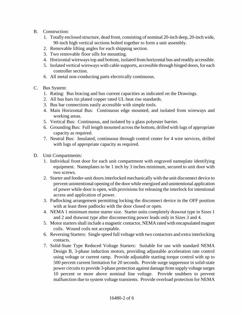
16480-2 of 6
B. Construction: 1. Totally enclosed structure, dead front, consisting of nominal 20-inch deep, 20-inch wide,
90-inch high vertical sections bolted together to form a unit assembly. 2. Removable lifting angles for each shipping section. 3. Two removable floor sills for mounting. 4. Horizontal wireways top and bottom, isolated from horizontal bus and readily accessible. 5. Isolated vertical wireways with cable supports, accessible through hinged doors, for each
controller section. 6. All metal non-conducting parts electrically continuous.
C. Bus System:
1. Rating: Bus bracing and bus current capacities as indicated on the Drawings. 2. All bus bars tin plated copper rated UL heat rise standards. 3. Bus bar connections easily accessible with simple tools. 4. Main Horizontal Bus: Continuous edge mounted, and isolated from wireways and
working areas. 5. Vertical Bus: Continuous, and isolated by a glass polyester barrier. 6. Grounding Bus: Full length mounted across the bottom, drilled with lugs of appropriate
capacity as required. 7. Neutral Bus: Insulated, continuous through control center for 4 wire services, drilled
with lugs of appropriate capacity as required.
D. Unit Compartments: 1. Individual front door for each unit compartment with engraved nameplate identifying
equipment. Nameplates to be 1 inch by 3 inches minimum, secured to unit door with two screws.
2. Starter and feeder-unit doors interlocked mechanically with the unit disconnect device to prevent unintentional opening of the door while energized and unintentional application of power while door is open, with provisions for releasing the interlock for intentional access and application of power.
3. Padlocking arrangement permitting locking the disconnect device in the OFF position with at least three padlocks with the door closed or open.
4. NEMA 1 minimum motor starter size. Starter units completely drawout type in Sizes 1 and 2 and drawout type after disconnecting power leads only in Sizes 3 and 4.
5. Motor starters shall include a magnetic contactor, NEMA rated with encapsulated magnet coils. Wound coils not acceptable.
6. Reversing Starters: Single speed full voltage with two contactors and extra interlocking contacts.
7. Solid-State Type Reduced Voltage Starters: Suitable for use with standard NEMA Design B, 3-phase induction motors, providing adjustable acceleration rate control using voltage or current ramp. Provide adjustable starting torque control with up to 500 percent current limitation for 20 seconds. Provide surge suppressor in solid-state power circuits to provide 3-phase protection against damage from supply voltage surges 10 percent or more above nominal line voltage. Provide snubbers to prevent malfunction due to system voltage transients. Provide overload protection for NEMA
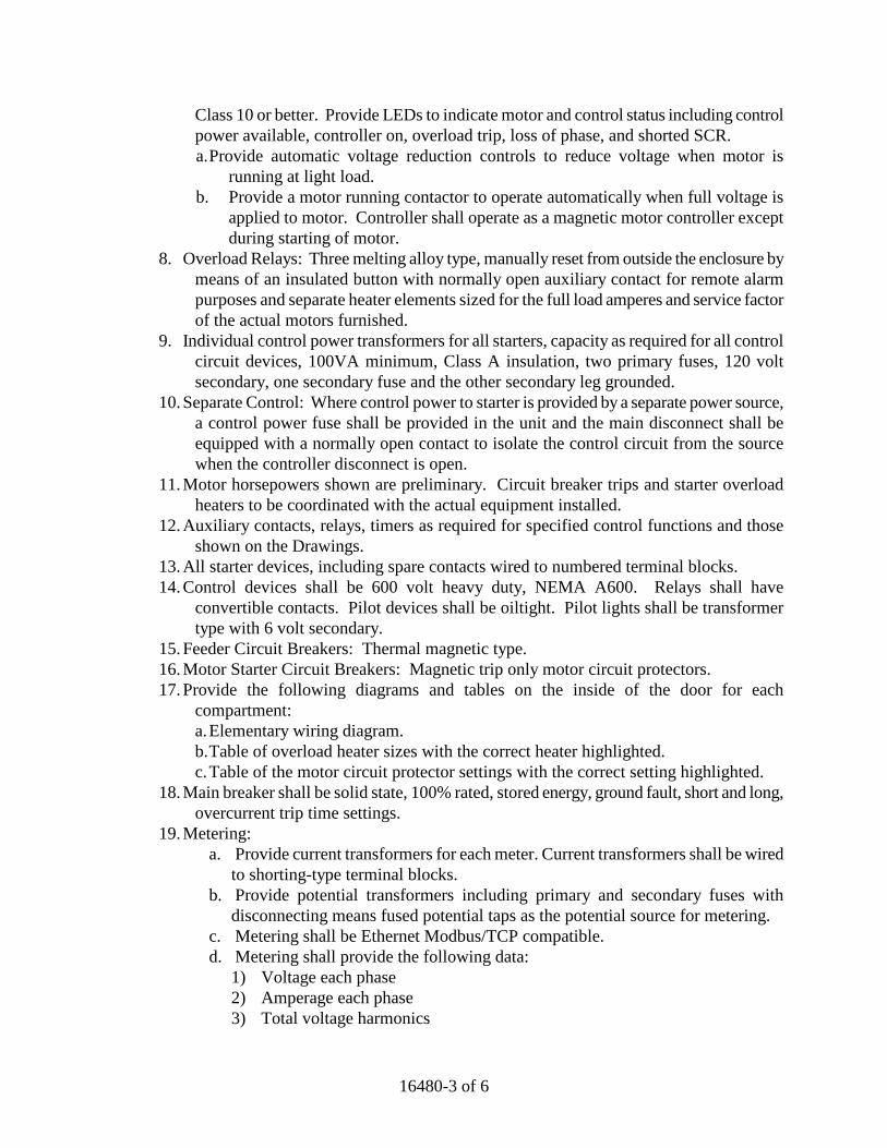
16480-3 of 6
Class 10 or better. Provide LEDs to indicate motor and control status including control power available, controller on, overload trip, loss of phase, and shorted SCR. a. Provide automatic voltage reduction controls to reduce voltage when motor is
running at light load. b. Provide a motor running contactor to operate automatically when full voltage is
applied to motor. Controller shall operate as a magnetic motor controller except during starting of motor.
8. Overload Relays: Three melting alloy type, manually reset from outside the enclosure by means of an insulated button with normally open auxiliary contact for remote alarm purposes and separate heater elements sized for the full load amperes and service factor of the actual motors furnished.
9. Individual control power transformers for all starters, capacity as required for all control circuit devices, 100VA minimum, Class A insulation, two primary fuses, 120 volt secondary, one secondary fuse and the other secondary leg grounded.
10. Separate Control: Where control power to starter is provided by a separate power source, a control power fuse shall be provided in the unit and the main disconnect shall be equipped with a normally open contact to isolate the control circuit from the source when the controller disconnect is open.
11. Motor horsepowers shown are preliminary. Circuit breaker trips and starter overload heaters to be coordinated with the actual equipment installed.
12. Auxiliary contacts, relays, timers as required for specified control functions and those shown on the Drawings.
13. All starter devices, including spare contacts wired to numbered terminal blocks. 14. Control devices shall be 600 volt heavy duty, NEMA A600. Relays shall have
convertible contacts. Pilot devices shall be oiltight. Pilot lights shall be transformer type with 6 volt secondary.
15. Feeder Circuit Breakers: Thermal magnetic type. 16. Motor Starter Circuit Breakers: Magnetic trip only motor circuit protectors. 17. Provide the following diagrams and tables on the inside of the door for each
compartment: a. Elementary wiring diagram. b. Table of overload heater sizes with the correct heater highlighted. c. Table of the motor circuit protector settings with the correct setting highlighted.
18. Main breaker shall be solid state, 100% rated, stored energy, ground fault, short and long, overcurrent trip time settings.
19. Metering: a. Provide current transformers for each meter. Current transformers shall be wired
to shorting-type terminal blocks. b. Provide potential transformers including primary and secondary fuses with
disconnecting means fused potential taps as the potential source for metering. c. Metering shall be Ethernet Modbus/TCP compatible. d. Metering shall provide the following data:
1) Voltage each phase 2) Amperage each phase 3) Total voltage harmonics
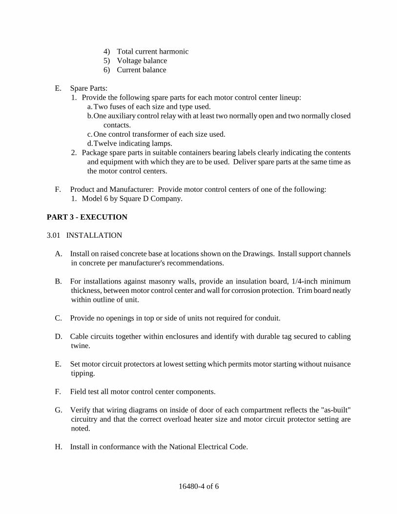
16480-4 of 6
4) Total current harmonic 5) Voltage balance 6) Current balance
E. Spare Parts:
1. Provide the following spare parts for each motor control center lineup: a. Two fuses of each size and type used. b. One auxiliary control relay with at least two normally open and two normally closed
contacts. c. One control transformer of each size used. d. Twelve indicating lamps.
2. Package spare parts in suitable containers bearing labels clearly indicating the contents and equipment with which they are to be used. Deliver spare parts at the same time as the motor control centers.
F. Product and Manufacturer: Provide motor control centers of one of the following:
1. Model 6 by Square D Company. PART 3 - EXECUTION 3.01 INSTALLATION
A. Install on raised concrete base at locations shown on the Drawings. Install support channels in concrete per manufacturer's recommendations.
B. For installations against masonry walls, provide an insulation board, 1/4-inch minimum
thickness, between motor control center and wall for corrosion protection. Trim board neatly within outline of unit.
C. Provide no openings in top or side of units not required for conduit.
D. Cable circuits together within enclosures and identify with durable tag secured to cabling
twine.
E. Set motor circuit protectors at lowest setting which permits motor starting without nuisance tipping.
F. Field test all motor control center components.
G. Verify that wiring diagrams on inside of door of each compartment reflects the "as-built"
circuitry and that the correct overload heater size and motor circuit protector setting are noted.
H. Install in conformance with the National Electrical Code.

16480-5 of 6
3.02 MANUFACTURER TRAINING SERVICES
A. CONTRACTOR shall furnish the services of qualified factory trained specialists from the manufacturer to instruct OWNER'S operations and maintenance personnel in the recommended operation and maintenance of this equipment.
END OF SECTION

16480-6 of 6
THIS PAGE LEFT BLANK INTENTIONALLY
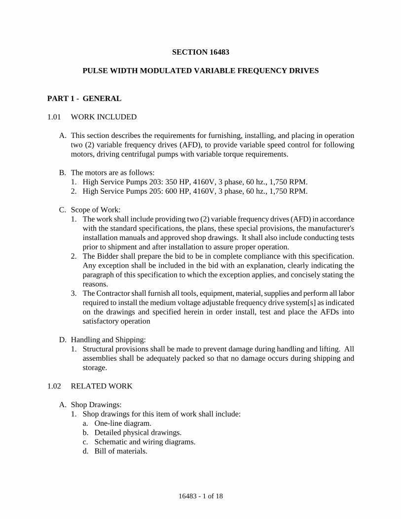
16483 - 1 of 18
SECTION 16483
PULSE WIDTH MODULATED VARIABLE FREQUENCY DRIVES PART 1 - GENERAL 1.01 WORK INCLUDED
A. This section describes the requirements for furnishing, installing, and placing in operation two (2) variable frequency drives (AFD), to provide variable speed control for following motors, driving centrifugal pumps with variable torque requirements.
B. The motors are as follows:
1. High Service Pumps 203: 350 HP, 4160V, 3 phase, 60 hz., 1,750 RPM. 2. High Service Pumps 205: 600 HP, 4160V, 3 phase, 60 hz., 1,750 RPM.
C. Scope of Work:
1. The work shall include providing two (2) variable frequency drives (AFD) in accordance with the standard specifications, the plans, these special provisions, the manufacturer's installation manuals and approved shop drawings. It shall also include conducting tests prior to shipment and after installation to assure proper operation.
2. The Bidder shall prepare the bid to be in complete compliance with this specification. Any exception shall be included in the bid with an explanation, clearly indicating the paragraph of this specification to which the exception applies, and concisely stating the reasons.
3. The Contractor shall furnish all tools, equipment, material, supplies and perform all labor required to install the medium voltage adjustable frequency drive system[s] as indicated on the drawings and specified herein in order install, test and place the AFDs into satisfactory operation
D. Handling and Shipping:
1. Structural provisions shall be made to prevent damage during handling and lifting. All assemblies shall be adequately packed so that no damage occurs during shipping and storage.
1.02 RELATED WORK
A. Shop Drawings: 1. Shop drawings for this item of work shall include:
a. One-line diagram. b. Detailed physical drawings. c. Schematic and wiring diagrams. d. Bill of materials.
16483 - 2 of 18
e. Calculations for harmonic voltage and current distortion for the conditions specified.
f. Test data demonstrating energy efficiency.
B. Submittals: 1. The Contractor's operation and maintenance manual shall specifically include the
following items: a. AFD characteristics. b. Safety precautions. c. Schematic and wiring diagrams. d. Troubleshooting procedures with symptom/cause-effect and corrective actions. e. Harmonic analysis report. f. Parts lists and recommended spare parts. g. AFD checkout procedure. h. AFD protective and control adjustment procedure. i. A hard copy of the AFD software and configuration. j. Dimensional outline and plan arrangement drawings including clearance
requirements, foundation details and weights. k. Conduit entry/exit locations. l. Assembly ratings m. Major component ratings n. Cable terminal sizes o. Descriptive bulletins p. The Manufacturer shall provide overall efficiency data at 25%, 50%, 75% and 100%
speed for all components. q. The AFD manufacturer shall provide system total power factor data at 25%, 50%,
75% and 100% load. r. Provide harmonic calculations to the 49th harmonic The calculations shall show
total harmonic voltage and current distortion at the Point of Common Coupling (PCC) which will be at the utility.
1.03 DRIVE MANUFACTURES’S RESPONSIBILITIES
A. The AFD manufacturer shall be responsible for the installation, testing and start-up of each drive.
B. The AFD manufacturer shall be responsible for the coordination of the drive with their
respective motor(s) specified in other Section(s) of this specification. C. The AFD manufacturer shall be, at no additional cost to the Owner, responsible for
mitigating any harmonic, and/or all RF and/or EMI and/or any other electrical type noise created by the drive which adversely affects the proper operation of any and all electronic and/or electrical power and/or mechanical devices on this project. The AFD manufacturer shall repair all damages due the drive misapplication.
16483 - 3 of 18
D. The AFD manufacturer shall provide input and/or output filters and/or other accessories on each drive to mitigate the transient to a limit which is not detrimental to the motor winding regardless of the motor lead length and/or type of conduit and wire.
E. The AFD manufacturer shall be responsible for all additional materials and labor related to
the installation of the drive that is above and beyond the scope of work as shown on the electrical drawings and specification.
1.04 REFERENCES
A. IEEE 519 Guide for Harmonic Control and Reactive Compensation of Static Power Converters
B. IEEE 1100 – Powering and Grounding Sensitive Electronic Equipment C. National Electrical Manufacturers Association (NEMA) D. NEMA ICS 6 – Industrial Control and Systems Enclosures E. NEMA ICS 7 – Industrial Control Systems Adjustable Speed Drives F. NPFA 70 – National Electrical Code (NEC) G. UL 347A – Medium Voltage Power Conversion Equipment
1.05 CERTIFICATIONS
A. ANSI / NEMA Standards B. UL (certified) C. CSA
1.06 STORAGE
A. Equipment shall be stored indoors with condensation control in accordance with manufacturer’s instructions. One (1) copy of these instructions shall be included with the equipment at time of shipment.
PART 2 - PRODUCTS 2.01 ACCEPTABLE MANUFACTURERS
A. The variable frequency drives described in this specification shall be as manufactured by one of the following:
16483 - 4 of 18
1. Cutler Hammer 2. Square-D
2.02 SYSTEM DESCRIPTION
A. The system shall consist of the following main components: one medium voltage adjustable frequency drive (AFD), fused isolation switch, isolation contactor, drive isolation/phase shifting transformers with minimum 24 pulse rectification, DC bus pre-charge circuit, output harmonic filter as necessary.
B. The integrated dedicated fused contactor with isolation switch shall be rated to protect the
AFD from specified short-circuit levels. The minimum interrupting rating of the input contactor shall be 8500A @ 400A and 12,500A @ 800A. The AFD enclosure doors shall be interlocked to prevent opening when main power is available.
C. The DC bus capacitors shall be charged before application of main power to limit inrush
current to the main rectifier/converter bridge devices by use of a DC bus pre charge circuit. When the proper DC bus voltage is attained, the main contactor is closed and the pre-charge circuit shall be turned off.
D. Use of electrolytic capacitors in the drive assembly is not acceptable. E. The AFD shall meet the requirements of IEEE 519 with the point of analysis (POA) at the
input terminals of the VFD, and the requirements shall be met without an input filter. The point of common coupling shall be located at the utility. The harmonic current distortion shall not exceed the limits listed in table 10.3 of IEEE 519 at the POA. The harmonic voltage distortion shall not exceed the limits listed in table 11.1 of IEEE 519 at the POA.
F. Drive shall operate with a +/-10 % input voltage variation. G. The AFD shall be rated for 60kV BIL and 50kA short circuit. H. Auxiliary power 480V, 3-phase, 60 Hz shall be provided internal to the integrated Drive.
External auxiliary supply voltage sources will not be acceptable. I. The drive will be suitable for the motor(s) rated 4160V, 3-phase, 60 Hz, J. For variable torque applications the overload capacity shall be 110% of rated current for 1
minute repeated every 10 minutes. For constant torque applications the overload capacity shall be 150% of rated current for 1 minute repeated every 10 minutes.
K. The AFD shall be suitable for use with an existing standard non-inverter rated squirrel cage
motor with 1.15 service factor and standard medium-voltage insulation.
16483 - 5 of 18
2.03 INVERTER DESIGN
A. The AFD inverter shall be of the pulse width modulated (PWM) neutral point clamp (NPC) type. The output devices shall be insulated gate bipolar transistors (IGBT’s) with a voltage rating of 3300V for 2400V outputs and 6500V for 4160V outputs. Use of lower voltage rated devices is unacceptable. The inverter shall be one three- phase inverter up to 3500hp and two in parallel for up to 6000hp capable. Inverters shall be of the roll- in / roll- out design to minimize downtime in the event of inverter failure. Multiple single-phase inverters will not be acceptable.
B. The AFD inverter shall be constructed using six individual power poles installed on a roll-
in/roll-out inverter. All power components associated with the power pole shall be encapsulated. All inverter mounted printed circuit boards shall be conformal coated.
C. Drive shall be capable of running with an inverter with larger devices to minimize the
number of spare inverters that will be stocked at the County site. D. Oil filled power capacitors must be used, electrolytic devices are not acceptable.
2.04 INTEGRATED INPUT ISOLATION TRANSFORMER AND RECTIFIER
A. The AFD shall contain an incoming isolation transformer with primary voltage as specified on the data sheet.
B. The transformer shall contain 12 three phase secondary windings that provide the proper
phase shifting to develop a 24-pulse rectification to reduce harmonic currents and voltages reflected to the primary power system. Anything less than 24-pulse is not acceptable. Transformer shall have a 220 degree C insulation rating.
C. The transformer and rectifier shall be an integral part of the AFD assembly along with
primary isolation switch, power fuses, and input vacuum contactor eliminating the need for separate components, field installation, or wiring.
D. The rectifier shall be a diode bridge design with fast acting current limiting semi-conductor
fuses to protect the bridge. E. A drive isolation transformer shall be integrated in the AFD enclosure to provide power
conversion from the line voltage to the required AFD voltage and to isolate the line from harmonics and common mode voltages. The transformer shall conform to ANSI/IEEE C57 or to corresponding IEC standards
F. The transformer shall be designed to withstand a short circuit. It shall maintain
electromagnetic symmetry when only one secondary winding is in short circuit in order to minimize the resulting short circuit forces. The transformer shall be capable of thermally withstanding a short circuit for 2 seconds.
16483 - 6 of 18
G. Transformers shall be of a high efficiency type with full load losses of no greater than 2%. H. Suitable vibration dampers shall be provided with the transformer and its enclosure in order
to attenuate mechanical resonance and to reduce the operational sound level. I. The transformer shall include electrostatic shielding between the windings to carry high
frequency capacitive currents to ground. J. Transformer designs shall be open type mounted. K. The transformer shall be of the air-cooled type and be forced ventilated. L. Only rectifier grade K-factor transformers shall be utilized, with K-Factor of 6 for diode
rectifiers. AFD manufacturers providing SCR type rectifiers shall include K 12 transformers for variable torque applications and K 20 for constant torque applications.
2.05 RELIABILITY
A. The manufacturer shall list any control or power components that require recommended maintenance or replacement before 50,000 hours of operation. Information must be available in the manufacturer's maintenance manual and available for submittal.
B. All components of the AFD shall be considered for MTBF calculations using Failure in Time
(FIT) analysis. C. The Mean Time Between Failure (MTBF) of the current carrying devices of the AFD shall be
98,000 hours or greater D. The AFD shall be capable of continuous operation (“ride-through”) in the event of a power
loss of up to 5 cycles. E. The AFD shall be able to safely operate, without tripping, with up to 30% voltage sag on the
rated input voltage. F. All power semiconductors and passive power components in both the rectifier and inverter
sections shall be medium voltage rated components. Low voltage components are not acceptable in the power sections.
16483 - 7 of 18
2.06 INPUT POWER QUALITY
A. The AFD total harmonic voltage distortion (THD) contribution at each point of common coupling between the drives and other loads within the facility (Load PCC) shall not exceed the 5% THD limit recommended for General Systems as listed in Table 11.1 of IEEE 519, throughout the speed range.
B. The AFD fundamental power factor shall be > 0.97. The total power factor at the VFD input
shall be > 0.95, for the load range of 20 to 100%. The AFD manufacturer shall provide a power factor correction filter if the AFD does not meet this requirement. The AFD including power factor correction and/or harmonic filter shall never have a leading power factor.
C. For any AFD employing capacitors on the input side, such capacitors shall be rated 12.47kV
or higher to avoid harmonic transient resonance. 2.07 OUTPUT POWER QUALITY
A. Output waveform switching transients and harmonic content shall have a negligible contribution to motor heating, acoustical noise in the motor, torsional stress in the power train, and motor insulation.
B. Common mode voltages on the AFD output shall be isolated from the motor. C. Motor cable voltage reflections and the resulting restrictions on motor cable length shall be
taken into consideration and the drive shall be properly applied to the motor. D. All AFD manufacturers shall incorporate output filtering.
2.08 CONTROL FUNCTIONS
A. Frequently accessed AFD programmable parameters shall be adjustable from a digital operator keypad located on the front of the AFD. The AFD’s shall have a three line alphanumeric programmable display with status indicators. Keypads must use plain English words for parameters, status, and diagnostic messages. Keypads that are difficult to read or understand are not acceptable, particularly those that use alphanumeric codes and tables. Keypads shall be adjustable for contrast with large characters easily visible in normal ambient light.
B. The keypad shall include a local/remote pushbutton selection. Both start/ stop source and
speed reference shall be independently programmable for keypad, remote I/O, or field-bus. C. The keypad shall have copy/paste capability. D. Upon initial power up of the AFD, the keypad shall display a startup guide that will sequence
all the necessary parameter adjustments for general start up.
16483 - 8 of 18
E. Standard advanced programming and trouble-shooting functions shall be available by using a
personal computer’s RS-232 port and Windows™ based software. In addition the software shall permit control and monitoring via the AFD’s RS232 port. The manufacturer shall supply the required software. An easily understood instruction manual and software help screens shall also be provided. The computer software shall be used for modifying the drive setup and reviewing diagnostic and trend information as outlined in this specifications.
F. The operator shall be able to scroll through the keypad menu to choose between the
following: 1. Monitor 2. Operate 3. Parameter setup 4. Actual parameter values 5. Active faults 6. Fault history 7. LCD contrast adjustment 8. Information to indicate the standard software and optional features software loaded.
G. The following setups and adjustments, at a minimum, are to be available: 1. Start command from keypad, remote or communications port 2. Speed command from keypad, remote or communications port 3. Motor direction selection 4. Maximum and minimum speed limits 5. Acceleration and deceleration times, two settable ranges 6. Critical (skip) frequency avoidance 7. Torque limit 8. Multiple attempt restart function 9. Multiple preset speeds adjustment 10. Catch a spinning motor start or normal start selection 11. Programmable analog output 12. DC brake current magnitude and time 13. PID process controller
2.09 THE AFD SHALL HAVE THE FOLLOWING SYSTEM INTERFACES:
A. Inputs — A minimum of six (6) programmable digital inputs, two (2) Analog inputs and serial communications interface shall be provided with the following available as a minimum: 1. Remote manual/auto 2. Remote start/stop 3. Remote forward/reverse 4. Remote preset speeds 5. Remote external trip 6. Remote fault reset
16483 - 9 of 18
7. Process control speed reference interface, 4-20mAdc 8. Potentiometer and 1-10Vdc speed reference interface 9. RS232 programming and operation interface port Serial communications port. 10. Modbus/Ethernet
B. Outputs — A minimum of two (2) discrete programmable digital outputs, one (1)
programmable open collector output, and one (1) programmable analog output shall be provided, with the following available at minimum. 1. Programmable relay outputs with one (1) set of Form C contacts for each, selectable with
the following available at minimum: a. Fault b. Run c. Ready d. Reversed e. Jogging f. At speed g. Torque Limit Supervision h. Motor rotation direction opposite of commanded i. Over-temperature
2. Programmable open collector output with available 24 Vdc power supply and selectable
with the following available at minimum: a. Fault b. Run c. Ready d. Reversed e. Jogging f. At speed g. Torque Limit Supervision h. Motor rotation direction opposite of commanded i. Over temperature
3. Programmable analog output signal, selectable with the following available at minimum: a. Motor current b. Output frequency c. Frequency reference d. Motor speed e. Motor torque f. Motor power g. Motor voltage h. Dc-bus voltage i. Analog Output 1 to match Analog Input 1 j. Analog Output 2 to match Analog Input 2 k. PT100 temperature l. Jog speed

16483 - 10 of 18
C. Monitoring and Displays 1. The AFD display shall be a LCD type capable of displaying three (3) lines of text and the
following thirteen (13) status indicators: a. Run b. Forward c. Reverse d. Stop e. Ready f. Alarm g. Fault h. I/O terminal i. Keypad j. Bus/Comm k. Local (LED) l. Remote (LED) m. Fault (LED)
2. The AFD keypad shall be capable of displaying the following monitoring functions at a minimum: a. Output frequency b. Frequency reference c. Motor speed d. Motor current e. Motor torque f. Motor power g. Motor voltage h. Dc-bus voltage i. Unit temperature j. Calculated motor temperature k. Voltage level of analog input l. Current level of analog input m. Digital inputs status n. Digital and relay outputs status o. Analog out
D. Protective Functions
1. The AFD shall include the following protective features at minimum: a. Over current b. Over voltage c. Inverter fault d. Under voltage e. Input phase loss f. Output phase loss g. Under temperature h. Over temperature i. Motor stalled
16483 - 11 of 18
j. Motor over temperature k. Motor under load l. Logic voltage failure m. Microprocessor failure
2. The AFD shall provide ground fault protection during power-up, starting, and running. AFD’s with no ground fault protection during running are not acceptable.
E. Diagnostic Features
1. Fault History 2. Record and log faults 3. Indicate the most recent first, and store up to 30 faults. 4. An Emergency-stop (E-Stop) shall be provided on the AFD door in addition to inputs for
remote supplied E-Stop command. 2.10 CONTROL POWER TRANSFORMERS (CPT’S)
A. A control power transformer (CPT) shall be provided within the enclosure. B. The kilovolt-ampere rating of the CPT shall be determined by the manufacturer and shall
have a minimum of 25% spare capacity. C. The CPT secondary voltage shall be 120 Vac. D. The CPT primary shall be fused with current limiting fuses with an interrupting rating no less
than 50,000 amperes. E. The CPT secondary shall be fused and have one terminal grounded.
2.11 INTEGRATED MAIN POWER TOP BUS
A. When specified, a top mounted bus will be an integral part of the AFD design to be configured as a part of a motor control center or switchgear.
B. Top-mounted bus shall allow provisions for adding motor control components such as
AFD’s, various starter types, circuit breakers and load-break switches. Top-mounted bus allows for future installation of various motor control components via bus splice kit. Inter-connecting cabling shall not be acceptable.
C. Top-mounted bus ratings shall be as follows: 7.2KV at 3000 Amps, 15KV at 2000 Amps. D. Bus bars shall be braced to withstand short circuit currents at a minimum of 50k AIC.
16483 - 12 of 18
2.12 INTEGRATED INPUT ISOLATION SWITCHGEAR
A. Each AFD shall include a fused manually operated isolation switch with visible blades, current limiting power fuses, and a removable vacuum contactor to feed the isolation/phase shifting transformer. These components shall be provided to safely isolate the drive from the power source. The vacuum contactor shall carry the same ratings as full voltage vacuum contactors designed for MV motor starting duty. The fault rating of the vacuum contactor shall be a minimum of 8500A.
2.13 SYNCHRONOUS TRANSFER (OPTIONAL)
A. The synchronous transfer system shall be capable of controlling multiple loads via an integrally designed AFD/Controller.
B. The synchronous transfer system shall adjust the AFD output voltage, frequency, and phase
to match the utility and provide “bump-less” transfer from drive output to utility bus C. All power components in the synchronous transfer system shall be hard copper-bus
connected and provided by the same manufacturer. Cable bus is not acceptable. 2.14 HARMONIC FILTERS AND POWER FACTOR CORRECTION
A. Power factor correction equipment shall be provided if necessary to maintain a constant input power factor of 0.95 lagging throughout the entire load range.
B. Filters shall be contained and mounted in the AFD enclosure. Freestanding filters will not be
acceptable. C. Capacitors shall be environmentally safe. Discharge resistors and a method of shorting the
phases shall be provided. D. Inductors may be air or iron core. Inductors shall have Class F insulation with Class B
temperature rise. E. There shall be annunciation of output filter failure.
2.15 EFFICIENCY
A. Overall efficiency of the AFD shall include the drive isolation transformer, AFD and all AFD auxiliaries, output filter, power factor correction and harmonic filter.
B. AFD system efficiency calculations shall be in accordance with IEEE 995. C. The overall efficiency shall be not less than 96% at full load, full speed.
16483 - 13 of 18
2.16 MOTOR/BEARING PROTECTION RELAYS
A. RTD Module and Display accepting up to 8 inputs (3 wire 100 ohm platinum RTD’s (PT100)) and 3 relay outputs, similar to NT-538.
B. Utilize the Eaton EMR4000 with RTD module and Modbus TCP/Ethernet interface with
existing SCADA system. 2.17 AUXILIARY DEVICES
A. For stand-alone AFD’s, provide fixed mounted potential transformers, fused-type, of the quantity and ratings indicated on the contract drawings.
B. Provide window-type current transformers of the quantity and current rating as indicated on
the contract drawings. Current transformer accuracy shall be suitable for the connected burden.
C. Provide an auxiliary control power transformer of the quantity and kVA rating as indicated
on the contract drawings. D. Provide a 120V remote input source for the specific use of testing low voltage controls when
main power is off.
2.18 ENVIRONMENTAL CONDITIONS
A. The AFD shall operate in an ambient temperature range of 0° C to 40° C (32° F to 104° F) with a relative humidity of up to 95% (non-condensing), unless specified otherwise.
B. The equipment shall be capable of being stored in an environment with an ambient
temperature range of -40° C to 70° C. C. The equipment shall operate at altitudes from 0 to 1000m (3,300 ft.) above sea level, without
de-rating. 2.19 ENCLOSURES
A. Indoor enclosures shall be NEMA 1A with gasket and filters. B. The AFD shall require front access only. Designs requiring rear or side access are not
acceptable. C. The AFD enclosure doors shall include an interlocking system with the isolation switch. D. A safety grounding device shall be provided for grounding the positive, and negative buses to
ensure all stored AFD energy is discharged.
16483 - 14 of 18
E. Enclosures shall be configurable separately or in a continuous line-up. AFD’s shall be
capable of being integrated with conventional motor starters, load break switches, circuit breakers, and reduced voltage starters into a continuous control-gear assembly.
F. The drive isolation transformer, fused input contactor, isolation switch, ac pre-charge circuit
contactor, output filter if required, and input harmonic filter and power factor correction filter if required shall be factory mounted wired by the manufacturer and integrated into the AFD enclosure.
G. All painted surfaces shall be ANSI 61 Gray. H. The enclosure must be designed to avoid harmonic and inductive heating and eliminate radio
frequency interference. I. The AFD enclosure shall comply with UL 347 standards suitable for installation in an indoor,
unclassified area. J. All enclosure openings exceeding 0.25 inch (6 mm) in, width shall be provided with screens
to prevent the entrance of snakes, rodents, etc. The maximum screen mesh opening width shall be 0.25 inch (6 mm).
K. Air filters shall be of a reusable type that can be easily cleaned. All doors or front panels will
be fully gasketed. Air exhaust from cooling fans will be at the top of the enclosure and direct exhaust airflow away from personnel in front of the equipment.
L. The AFD shall be designed for harsh environments, including encapsulated power
components. All exposed copper components shall be tin-plated or epoxy-coated. All printed circuit cards shall be conformal coated.
2.20 COOLING
A. A “loss of cooling” fault shutdown shall be furnished with forced-cooled equipment. In the event of clogged filters or fan failure, the drive will shut down safely without electronic component failure.
B. Fan motors shall be protected by an input circuit breaker. Metal squirrel cage ball bearing
460V three phase fan motors with 50,000 hour life are to be used in the drive design. Plastic muffin fans are not acceptable. As specified on the data sheet, fan power will be obtained from the primary 2400/4160V power through a 480V, 3-phase, 60 Hz internal auxiliary power supply. In the event of a fault or opening of the main contactor feeding the drive, the fans will continue to run for a time to allow for sufficient cooling of the drive. Convection cooling in the case of fault or main contactor opening is unacceptable as a method to ensure proper cooling of the drive.
16483 - 15 of 18
D. The AFD shall have internal fans to ensure proper operation in the above referenced ambient. When specified furnish additional redundant fan(s) to ensure operation in the event of primary fan failure.
2.21 SPACE HEATERS
A. AFD Enclosure Space Heaters 1. When specified, space heaters shall be supplied. 2. The space heater circuit shall turn on automatically when the drive is not operating. 3. A circuit breaker for space heater circuit shall be provided for overload protection and as
a disconnecting means. 4. When specified, a meter and a test circuit shall be provided on the enclosure door for
indication that space heater power is available. 5. Space heater elements shall be rated 240 Vac and operated at 120 Vac, single-phase.
B. AC Motor Space Heaters
1. Motor space heater control shall be provided. The space heater circuit shall turn on automatically when the motor is not operating.
2.22 NAMEPLATES
A. Nameplates shall be 2-inch high x 2-1/2 inch wide, laminated black with white with core. B. Unit nameplate and device marker lettering shall be 3/16-inch high.
2.23 FINISH
A. The finish for internal and external parts shall consist of a coat of ANSI 61 (gray) thermosetting, polyester, powder paint applied electrostatically to pre-cleaned phosphatized steel and aluminum surfaces.
2.24 ACCESSORIES
A. Provide a portable lifting device for transporting contactor outside its compartment. B. Provide an auxiliary and portable Ampgard Remote Operator (ARO) shall be used to enable
users to open or close the AFD input isolation switch through the use of a pushbutton station operated up to 30 feet away from the door. Users can mount the ARO on the front of the door, plug it into any available 120 Vac source, and operate the isolation switch from outside the arc flash boundary.
16483 - 16 of 18
PART 3 - EXECUTION 3.01 INSTALLATION
A. The AFD shall be installed by the Contractor in accordance with specifications, plans, and the manufacturer's recommendations.
B. After all of the AFD's have been placed, wiring connections shall be examined to make sure
they have not been loosened or damaged during shipment or installation. All power and control wiring to the motors, switches, control panel, instrumentation racks, etc., shall be checked.
C. AFD's shall be functionally checked in the field with the following adjustments made:
1. Starting current limit - 110 percent. 2. Normal current limit - 110 percent. 3. Overload trip - 110 percent at 60 seconds (inverse time). 4. Maximum frequency limit - 63 Hz. 5. Minimum frequency limit - 12 Hz. 6. Speed reference, remote 4-20 mA.
D. The Engineer will approve all field adjustments and functional/protective test.
E. Following confirmation that all wiring and functional/protective checks are correct, the
AFD's shall be started up, tested, and placed into operation by an authorized representative. The manufacturer's manuals shall be used as a basis for all testing and commissioning work.
F. A harmonic analysis shall be performed by the AC drive manufacturer based on the provided
system documentation consisting of but not limited to one-line diagrams and specific transformer information consisting of X/R, %Z and KVA rating.
G. Installation, Start-Up and Testing Services: A qualified manufacturer's representative shall
supervise the installation, testing and start-up of the AC drives for a minimum of three person days.
H. Training: Upon acceptance, the AC drive manufacturer's representative shall provide a
minimum of 8 hours of training for the operators. The training shall be scheduled with at least 72 hours advance notice.
3.02 SERVICE AND SUPPORT
A. The AFD vendor shall maintain an inventory of spare/replacement parts within 100-miles of the installation site. These shall be available for immediate shipment to replace an inoperable device or module with the AFD.
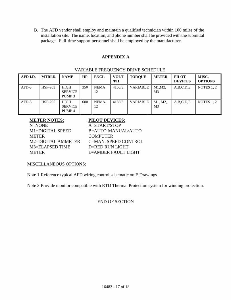
16483 - 17 of 18
B. The AFD vendor shall employ and maintain a qualified technician within 100 miles of the installation site. The name, location, and phone number shall be provided with the submittal package. Full-time support personnel shall be employed by the manufacturer.
APPENDIX A
VARIABLE FREQUENCY DRIVE SCHEDULE AFD I.D. MTRI.D. NAME HP ENCL VOLT
/PH TORQUE METER PILOT
DEVICES MISC. OPTIONS
AFD-3 HSP-203 HIGH SERVICE PUMP 3
350 NEMA 12
4160/3 VARIABLE M1,M2, M3
A,B,C,D,E NOTES 1, 2
AFD-5 HSP-205 HIGH SERVICE PUMP 4
600 NEMA-12
4160/3 VARIABLE M1, M2, M3
A,B,C,D,E NOTES 1, 2
METER NOTES: N=NONE M1=DIGITAL SPEED METER M2=DIGITAL AMMETER M3=ELAPSED TIME METER
PILOT DEVICES: A=START/STOP B=AUTO-MANUAL/AUTO-COMPUTER C=MAN. SPEED CONTROL D=RED RUN LIGHT E=AMBER FAULT LIGHT
MISCELLANEOUS OPTIONS: Note 1. Reference typical AFD wiring control schematic on E Drawings. Note 2: Provide monitor compatible with RTD Thermal Protection system for winding protection.
END OF SECTION

16483 - 18 of 18
THIS PAGE LEFT BLANK INTENTIONALLY
16495 - 1 of 8
SECTION 16495
AUTOMATIC TRANSFER SWITCH PART 1 - GENERAL 1.01 RELATED DOCUMENTS
A. Drawings and general provisions of the Contract, including General and Supplementary Conditions and Division 1 Specification Sections, apply to this Section.
1.02 SUMMARY
A. This Section includes transfer switches rated 600 V and less. It includes the following items: 1. Automatic closed transition transfer switch (ATS): The closed transition switch shall
transfer the load in a parallel mode, thus momentarily connecting both sources of power. A closed transition transfer shall occur only when both sources are available and within specified limits. The maximum interconnect time is 100 milliseconds. The transfer switch shall operate in an "open transition" mode (break before make" when the power source servicing the load fails. In the "open transition" mode, the transfer switch shall incorporate a "neutral" position or "delayed transition" feature so all motor loads decay. Passive devices such as phase monitors or motor disconnects are not acceptable.
B. Related Sections: The following Sections contain requirements that relate to this Section:
1. Conductors for hard-wired connections between transfer switches and remote equipment are specified in Division 16 Section "Wires and Cables."
2. SECTION 16480 MOTOR CONTROL CENTERS 1.03 REMOTE ANNUNCIATION AND CONTROL SYSTEM DESCRIPTION
A. Functional Description: Provide the functions listed below at indicated transfer switches for monitoring: 1. Sources-available indication (as defined by actual pick-up and drop-out settings of transfer
switch controls). 2. Switch position indication. 3. Switch in test mode indication. 4. Control of switch test initiation. 5. Control of switch operation in either direction.
B. Malfunction of the annunciator unit or communication link does not affect functions of the ATS. In the event of a failure of the communication link the ATS automatically reverts to stand-alone, self-contained operation. No ATS sensing, controlling, or operating function depends on the remote panel for proper operation.
1.04 SUBMITTALS
A. General: Submit the following according to Conditions of Contract and Division 1 Specification Sections.

16495 - 2 of 8
B. Shop drawings or published product data for each transfer switch, including dimensioned plans, sections, and elevations showing minimum clearances; conductor entry provisions; gutter space; installed features and devices; and materials lists.
C. Wiring diagrams, elementary or schematic, differentiating between manufacturer-installed and
field-installed wiring. D. Single-line diagrams of transfer switch units showing connections between automatic transfer
switch, power source, and load, plus interlocking provisions. E. Operation and maintenance data for each type of product, for inclusion in Operating and
Maintenance Manual specified in Division 1. Include all features and operating sequences, both automatic and manual. List all factory settings of relays and provide relay setting and calibration instructions.
F. Manufacturer's certificate of compliance to the referenced standards and tested short-circuit
closing and withstand ratings applicable to the protective devices and current ratings used in this Project, as indicated and as specified in paragraph "Tested Fault Current Ratings."
1.05 QUALITY ASSURANCE
A. Manufacturer's Qualifications: Firms are experienced in manufacturing equipment of the types and capacities indicated and have a record of successful in-service performance.
B. Emergency Service: Manufacturer maintains a service center capable of providing emergency
maintenance and repairs at the Project site with an 8-hour maximum response time. C. Comply with NFPA 70, "National Electrical Code," for components and installation. D. Comply with NEMA ICS 1, "General Standards for Industrial Control," ICS 2, "Industrial
Control Devices, Controllers and Assemblies," and ICS 6, "Enclosures for Industrial Controls and Systems."
E. Nationally Recognized Testing Laboratory Listing (NRTL) and Labeling: Items furnished under
this Section are listed and labeled by a NRTL for emergency service under UL Standard 1008. 1. Terms "Listed" and "Labeled": As defined in the "National Electrical Code," Article 100. 2. Listing and Labeling Agency Qualifications: A "Nationally Recognized Testing Laboratory"
(NRTL) as defined in OSHA Regulation 1910.7.
F. UL Compliance: Comply with UL Standard 1008, "Automatic Transfer Switches," except where requirements of these Specifications are stricter.
PART 2 - PRODUCTS 2.01 MANUFACTURERS
A. Available Manufacturers: Subject to compliance with requirements, manufacturers offering products that may be incorporated in the Work include, but are not limited to, the following: 1. Automatic Switch Co. 2. GE Zenith Controls, Inc. 3. Russelectric
16495 - 3 of 8
2.02 TRANSFER SWITCH PRODUCTS, GENERAL
A. Number of Poles and Current and Voltage Ratings: As indicated. 1. Units 1200 amperes, 4 pole and larger have current ratings that apply to all mixtures of
loads.
B. Tested Fault-Current Ratings: Closing and withstand ratings exceed the indicated available rms symmetrical fault current at the equipment terminals based on testing according to UL Standard 1008, conducted at full-rated system voltage and 20 percent power factor. Rate each product for withstand duration time as follows when tested for rated short-circuit current correlated with the actual type of circuit protective device indicated for transfer switches for this Project: 1. Main Contacts: 3 closing and withstand duration cycles. 2. Power Circuit Breakers: 10 closing and withstand duration cycles. 3. Current-Limiting Fuses: 0.5 (nominal) closing and withstand duration cycles.
C. Annunciation and Control Interface Components: Devices at transfer switches for communicating with remote annunciators or annunciator/control panels have communications capability matched with the remote device.
D. Solid-State Controls: Repetitive accuracy of all settings is plus or minus 2 percent or better over
an operating temperature range of minus 20o C to 70o C. E. Resistance to Damage by Voltage Transients: Components meet or exceed voltage surge
withstand capability requirements when tested according to ANSI C37.90.1, IEEE Guide for Surge Withstand Capability (SWC) Tests. Components meet or exceed voltage impulse withstand test of NEMA ICS 1.
F. Enclosures: General-purpose NEMA 1, conforming to UL Standard 508, "Electric Industrial
Control Equipment," except as otherwise indicated. G. Factory Wiring: Train and bundle factory wiring and identify consistently with shop drawings,
either by color-code or by numbered or lettered wire and cable tape markers at terminations. 1. Designated terminals accommodate field wiring. 2. Power Terminals Arrangement and Field Wiring Space: Suitable for top, side, or bottom
entrance of feeder conductors as indicated. 3. Terminals: Pressure-type, suitable for copper or aluminum conductors of sizes indicated. 4. Control Wiring: Equipped with lugs suitable for connection to terminal strips.
H. Electrical Operation: Where indicated, accomplish by a non-fused, momentarily energized
solenoid or electric motor-operated mechanism, mechanically and electrically interlocked in both directions. Switches using components of molded-case circuit breakers or contactors not designed for continuous-duty, repetitive switching between active power sources is not acceptable.
I. Switch Contacts: Use silver composition for switching load current. Units rated 225 amperes
and more have separate arcing contacts. J. Overcurrent devices are not part of switch products. K. The automatic transfer switch shall be an integral component of the motor control center
specified in Section 16480.
16495 - 4 of 8
2.03 AUTOMATIC TRANSFER SWITCH SEQUENCE OF OPERATION
A. When the voltage on any phase of the normal source is reduced to 85% of rated voltage for .5-6
seconds (adjustable), a pilot contact shall close to initiate starting of the standby plant. B. When the standby plant is delivering not less than 90% of rated voltage and 95% of rated
frequency, the load shall be transferred to the emergency source. During test or other source-to-source transfer, 95% voltage and frequency, phase rotation and angle shall be verified.
C. When the normal source has been restored to not less than 95% and not more than 105% of
nominal voltage on all phases, proper phase rotation is verified, and after a time delay of 0 to 30 minutes (adjustable), the load shall be transferred to the normal source in a closed transition operation. The standby plant shall run unloaded for 5 minutes and then shut down. The genset shall be ready for automatic operation upon the next failure of the normal source.
D. If the standby plant should fail while carrying the load, open transition retransfer to the normal
source shall be made instantaneously upon restoration of proper voltage (90%) of the normal source.
E. A synch-check relay (in-phase monitor) shall be provided for closed transition operation. The
monitor shall control transfer and retransfer between live sources and operate by sensing the zero voltage point. It shall be factory set to accomplish transfer within 5 electrical degrees and +/- 5% voltage differential. An alarm shall be provided to indicate if closed transition transfer is not accomplished within a preset time period due to a failure to meet operational parameters. An automatic synchronizer (active type) shall be provided for closed transition operation. This device automatically adjusts for voltage and frequency, allowing a faster transition between both sources and eliminates inherent problem in standard passive type synchronizers. Provide an automatic synchronizer pilot light.
F. Closed transition transfer in conjunction with over/under voltage, phase rotation and angle
sensing shall be accomplished when both sources are within specified parameters without any power interruption and without altering the speed or actively controlling the standby plant.
G. During closed transition operation, the control circuit shall monitor interconnect time. Should
connection exceed 100MS, the set of power contacts just closed shall be reopened and an alarm circuit shall be energized. If the main contacts fail to open, the control system shall energize a 24VDC shunt trip circuit to the standby feeder breaker to disconnect this source and the alarm circuit shall be closed. VDC from the engine batteries shall be supplied for the shunt trip and alarm backup circuits.
2.04 AUTOMATIC TRANSFER SWITCH FEATURES
A. The closed transition transfer switch shall be operated by two solenoids momentarily energized. B. The contact structure shall consist of a main current carrying contact, which is a silver alloy with
a minimum of 50% silver content. The current carrying contacts shall be protected by silver tungsten arcing contacts on all sizes.
C. A dielectric test at the conclusion of the withstand and closing tests shall be performed.
16495 - 5 of 8
D. During open transition operation, the transfer switch manufacturer shall certify arc interrupting capabilities for 50 cycles of operation between a normal and emergency source that are 120 degrees out of phase at 480 volts, 600% of rated current at .50 power factor. This certification is to ensure that there will be no current flow between the two isolated sources during switching.
E. Temperature rise tests in accordance with UL-1008 shall have been conducted after the overload
and endurance tests to confirm the ability of the units to carry their rated currents within the allowable temperature limits.
F. All relays shall be continuous duty industrial type with wiping contacts. Customer interface
contacts shall be rated 10 amperes minimum. Coils, relays, timers and accessories shall be front accessible. The control panel and power section shall be interconnected with a harness and keyed disconnect plugs for maintenance.
G. Main and arcing contacts shall be visible without major disassembly to facilitate inspection and
maintenance. H. A manual handle shall be provided for maintenance purposes. An operator disconnect switch
shall be provided to defeat automatic operation during maintenance, inspection or manual operation.
I. The switch shall be mounted in NEMA 1 enclosure unless otherwise indicated on the plans. J. Switches constructed from molded case breakers, contactors or components thereof no
specifically designed, as an automatic transfer switch will not be acceptable. K. The closed transition transfer switches shall include the following standard equipment:
1. Auxiliary contact closed in emergency position. 2. Auxiliary contact closed in normal position. 3. Engine start contact, 1 N.O., 1 N.C. 4. Pilot light to indicate switch in emergency position. 5. Pilot light to indicate emergency source availability. 6. Pilot light to indicate switch in normal position. 7. Pilot light to indicate normal source availability. 8. Pilot light to indicate sources in sync. 9. Adjustable time delay on retransfer to normal, 0-30 minutes. 10. Adjustable time delay on transfer to emergency, 0-30 minutes. 11. Adjustable time delay for engine cool down, 0-30 minutes. 12. Load test switch. 13. Transition mode selector switch to allow open or closed transition transfer. 14. Auxiliary contact for alarm. 15. Alarm and shunt trip circuit with diagnostic indicators. 16. Extended parallel electrical operator reversal safety circuit and lockout. 17. Close differential over/under voltage, phase rotation and angle sensing for closed transition
operation.
L. The automatic transfer switch shall be protected by two (2) year warranty on parts and labor or the equivalent.
16495 - 6 of 8
2.07 FINISHES
A. Enclosures: Manufacturer's standard enamel over corrosion-resistant pretreatment and primer. 2.08 SOURCE QUALITY CONTROL
A. Factory test components, assembled switches, and associated equipment to ensure proper operation. Check transfer time and voltage, frequency, and time-delay settings for conformance with specified requirements. Perform dielectric strength test conforming to NEMA ICS 1.
PART 3 - EXECUTION 3.01 INSTALLATION
A. Floor Mounting of Transfer Switches: Level and anchor the unit to the floor. B. Identify components according to Division 16 Section "Electrical Identification."
3.02 WIRING TO REMOTE COMPONENTS
A. Match the type and number of cables and conductors to the control and communications requirements of the transfer switches used. Increase raceway sizes at no additional cost to the owner if necessary to accommodate required wiring.
3.03 CONNECTIONS
A. Tighten factory-made connections, including connectors, terminals, bus joints, mountings, and grounding. Tighten field-connected connectors and terminals, including screws and bolts, according to equipment manufacturer's published torque tightening values. When manufacturer's torquing requirements are not indicated, tighten connectors and terminals to comply with tightening torques specified in UL Standards 486A and 486B.
3.04 GROUNDING
A. Make equipment-grounding connections for transfer switch units as indicated and as required by the NEC.
3.05 FIELD QUALITY CONTROL
A. Manufacturer's Field Services: Provide services of a factory-authorized service representative to supervise field tests.
B. Preliminary Tests: Perform electrical tests as recommended by the manufacturer and as follows:
1. Measure phase-to-phase and phase-to-ground insulation resistance levels with insulation resistance tester, including external annunciator and control circuits. Use test voltages and procedure recommended by the manufacturer. Meet manufacturer's specified minimum resistance.
2. Check for electrical continuity of circuits and for short circuits.
C. Field Tests: Give 7-day advance notice of the tests and perform tests in presence of owner's representative.
16495 - 7 of 8
D. Coordinate tests with tests of generator plant and run them concurrently. E. Tests: As recommended by the manufacturer and as follows:
1. Contact Resistance Test: Measure resistance of power contacts for ATSs, NATSs, and BP/ISs. Resolve values in excess of 500 micro-ohms and differences between adjacent poles exceeding 50 percent.
2. Ground Fault Tests: Coordinate with testing specified in Division 16 Section "Overcurrent Protective Devices" to ensure sensors are properly selected and located to optimize ground-fault protection where power is being delivered from either source. a. Verify grounding points and sensor ratings and locations. b. Apply simulated fault current at the sensors and observe reaction of circuit interrupting
devices. 3. Operational Tests: Demonstrate interlock, sequence, and operational function for each
switch at least 3 times. a. Simulate power failures of normal source to ATSs and of emergency source with normal
source available. b. Simulate low phase-to-ground voltage for each phase of normal source of ATSs. c. Verify time-delay settings and pick-up and drop-out voltages.
F. Test Failures: Correct deficiencies identified by tests and prepare for retest. Verify that
equipment meets the specified requirements. G. Reports: Maintain a written record of observations and tests. Report defective materials and
workmanship and retest corrected items. Record adjustable relay settings and measured insulation and contact resistances and time delays. Attach a label or tag to each tested component indicating satisfactory completion of tests.
H. Warranty: Automatic transfer switch to be warranted against defective workmanship for a
period of at least two years, defective material for at least five years and defective contacts for at least ten years.
3.06 DEMONSTRATION
A. Training: Furnish the services of a factory-authorized service representative to instruct Owner's personnel in the operation, maintenance, and adjustment of transfer switches and related equipment. Provide a minimum of 4 hours of instruction scheduled 7 days in advance.
END OF SECTION

16495 - 8 of 8
THIS PAGE LEFT BLANK INTENTIONALLY
16525 - 1 of 8
SECTION 16525
EXTERIOR LIGHTING PART 1 - GENERAL 1.01 RELATED DOCUMENTS
A. Drawings and general provisions of the Contract, including General and Supplementary Conditions and Division 1 Specification Sections, apply to this Section.
1.02 SUMMARY
A. This Section includes exterior lighting fixtures, lamps, ballasts, pole standards, and accessories.
B. Related Sections: The following Sections contain requirements that relate to this Section:
1. Division 16 Section "Interior Lighting" for interior fixtures, lamps, ballasts, emergency lighting units, and accessories; also for exterior fixtures normally mounted on buildings.
1.03 DEFINITIONS
A. Fixture: A complete lighting device. Fixtures include a lamp or lamps and parts required to distribute light, position and protect lamps, and connect lamps to power supply.
B. Lighting Unit: A fixture or an assembly of fixtures with a common support, including a pole
or bracket plus mounting and support accessories. C. Luminaire: A fixture.
1.04 SUBMITTALS
A. General: Submit each item in this Article according to the Conditions of the Contract and Division 1 Specification Sections.
B. Product Data describing fixtures, lamps, ballasts, poles, and accessories. Arrange Product
Data for fixtures in order of fixture designation. Include data on features, poles, accessories, finishes, and the following: 1. Outline drawings indicating dimensions and principal features of fixtures and poles. 2. Electrical Ratings and Photometric Data: Certified results of independent laboratory tests
for fixtures and lamps.
C. Wind Resistance Calculations: Certified by a registered professional engineer. D. Shop Drawings detailing nonstandard fixtures and poles and indicating dimensions, weights,
method of field assembly, components, and accessories.
16525 - 2 of 8
E. Wiring diagrams detailing wiring for control system showing both factory-installed and field-
installed wiring for specific system of this Project, and differentiating between factory-installed and field-installed wiring.
F. Anchor-Bolt Templates: Keyed to specific poles and certified by manufacturer. G. Product certificates signed by manufacturers of lighting units certifying that their products
comply with specified requirements. H. Field test reports indicating and interpreting test results specified in Part 3 of this Section. I. Maintenance data for products to include in the operation and maintenance manual specified
in Division 1.
1.05 QUALITY ASSURANCE
A. Electrical Component Standard: Provide components that comply with NFPA 70 and that are listed and labeled by UL where available.
B. Comply with ANSI C2. C. Listing and Labeling: Provide fixtures and accessories specified in this Section that are listed
and labeled for their indicated use and installation conditions on Project. 1. The Terms "Listed" and "Labeled": As defined in the National Electrical Code, Article
100. 2. Listing and Labeling Agency Qualifications: A "Nationally Recognized Testing
Laboratory" (NRTL) as defined in OSHA Regulation 1910.7. 1.06 STORAGE AND HANDLING OF POLES
A. General: Store poles on decay-resistant treated skids at least 12-inches (300-mm) above grade and vegetation. Support pole to prevent distortion and arrange to provide free air circulation.
B. Metal Poles: Retain factory-applied pole wrappings until just before pole installation. For
poles with nonmetallic finishes, handle with web fabric straps. 1.07 WARRANTY
A. General Warranty: The special warranty specified in this Article shall not deprive the Owner of other rights the Owner may have under other provisions of the Contract Documents and shall be in addition to, and run concurrent with, other warranties made by the Contractor under requirements of the Contract Documents.
16525 - 3 of 8
B. Special Warranty: Submit a written warranty signed by manufacturer and Installer agreeing to replace external parts of lighting fixtures exhibiting a failure of finish as specified below. This warranty is in addition to, and not a limitation of, other rights and remedies the Owner may have under the Contract Documents. 1. Protection of Metal from Corrosion: Warranty against perforation or erosion of finish
due to weathering. 2. Color Retention: Warranty against fading, staining, and chalking due to effects of
weather and solar radiation. 3. Special Warranty Period: 5 years from date of Substantial Completion.
1.08 EXTRA MATERIALS
A. Furnish extra materials described below that match products installed, are packaged with protective covering for storage, and are identified with labels describing contents. 1. Lamps: 10 lamps for every 100 of each type and rating installed. Furnish at least one of
each type. 2. Glass and Plastic Lenses, Covers, and Other Optical Parts: 1 for every 100 of each type
and rating installed. Furnish at least one of each type. 3. Ballasts: 1 for every 100 of each type and rating installed. Furnish at least one of each
type. 4. Globes and Guards: 1 for every 20 of each type and rating installed. Furnish at least one
of each type. PART 2. PRODUCTS 2.01 MANUFACTURERS
A. Available Products: Subject to compliance with requirements, fixtures that may be incorporated in the Work include, but are not limited to, the products specified in the Lighting Schedule.
2.02 FIXTURES AND FIXTURE COMPONENTS, GENERAL
A. Metal Parts: Free from burrs, sharp edges, and corners. B. Sheet Metal Components: Corrosion-resistant aluminum, except as otherwise indicated.
Form and support to prevent warping and sagging. C. Housings: Rigidly formed, weather- and light-tight enclosures that will not warp, sag, or
deform in use. Provide filter/breather for enclosed fixtures. D. Doors, Frames, and Other Internal Access: Smooth operating, free from light leakage under
operating conditions, and arranged to permit relamping without use of tools. Arrange doors, frames, lenses, diffusers, and other pieces to prevent accidental falling during relamping and when secured in operating position. Provide for door removal for cleaning or replacing lens. Arrange for door opening to disconnect ballast.
16525 - 4 of 8
E. Exposed Hardware Material: Stainless steel. F. Reflecting Surfaces: Minimum reflectances as follows, except as otherwise indicated:
1. White Surfaces: 85 percent. 2. Specular Surfaces: 83 percent. 3. Diffusing Specular Surfaces: 75 percent.
G. Plastic Parts: High resistance to yellowing and other changes due to aging, exposure to heat,
and UV radiation.
H. Lenses and Refractors: Materials as indicated. Use heat- and aging-resistant, resilient gaskets to seal and cushion lens and refractor mounting in fixture doors.
I. Photoelectric Relays: Conform to UL 773.
1. Contact Relays: Single throw, arranged to fail in the ON position and factory set to turn light unit on at 1.5-to 3- foot-candles (16 to 32 lux) and off at 4.5 to 10 foot-candles (48 to 108 lux) with 15-second minimum time delay.
J. Fluorescent Fixtures: Conform to UL 1570. K. Fluorescent Ballasts: Class P, low-temperature, electromagnetic type, compatible with the
lamps and lamp combinations to which connected. 1. Certification by Electrical Testing Laboratory (ETL). 2. Labeling by Certified Ballast Manufacturers Association (CBM). 3. Sound Rating: "A" rating, except as otherwise indicated. 4. Voltage: Match connected circuits. 5. Minimum Power Factor: 90 percent. 6. Total Harmonic Distortion (THD) of Ballast Current: Less than 10 percent. 7. Conform to FCC Regulations Part 15, Subpart J for electromagnetic interference. 8. Conform to IEEE C62.41, Category A, for resistance to voltage surges for normal and
common modes. 9. Minimum Starting Temperature: Minus 20 C.
L. High-Intensity-Discharge (HID) Fixtures: Conform to UL 1572. M. HID Ballasts: Conform to UL 1029, and ANSI C82.4. Constant wattage autotransformer
(CWA) or regulating high-power-factor type, unless otherwise indicated. 1. Ballast Fuses: One in each ungrounded supply conductor. Voltage and current ratings as
recommended by ballast manufacturer. 2. Operating Voltage: Match system voltage. 3. Single-Lamp Ballasts: Minimum-starting temperature of minus 30 C. 4. Open circuit operation will not reduce average life. 5. High-Pressure Sodium (HPS) Ballasts: Equip with a solid-state igniter/starter having an
average life in pulsing mode of 10,000 hours at an igniter/starter case temperature of 90 C.
6. Noise: Uniformly quiet operation, with a noise rating of B or better.
16525 - 5 of 8
N. Lamps: Comply with ANSI C78 series that is applicable to each type of lamp. Provide
fixtures with indicated lamps of designated type, characteristics, and wattage. Where a lamp is not indicated for a fixture, provide medium wattage lamp recommended by manufacturer.
O. LED Fixtures
1. Construction: low-copper aluminum, single-piece die cast housing. Provide a metallic screen to cover the top of the housing, preventing debris build-up with air-flow and natural cleaning of the light engine heat sink. The LED driver and electronics shall be thermally isolated from the heat-generating light engine. Housing shall be completely sealed against moisture and environmental contaminants.
2. Finish: Exterior parts shall be protected by a zinc-infused TGIC thermoset powder coat finish. Provide 3 mm thickness for a without cracking or peeling. dark bronze.
3. Optics: Precision-molded acrylic lenses for luminaire spacing and uniformity. Type III, optical system controls light above 90 degrees.
4. High-efficiency 4000K, 65 CRI LEDs mounted to a metal-core circuit board and aluminum heat sink, ensuring thermal management and long life (L85 60,000 hrs, 25°C ambient). Standard and dimming drivers are available in 120-277V and 347-480V; 50/60 Hz. Drivers shall have power factor >90% and THD <20%. Thermal isolation results in expected driver life of over 100,000 hours. Replaceable surge protection device is tested in accordance with IEEE/ANSI C62.41.2 meeting Category C Low.
5. Listing: CSA certified to U.S. and Canadian standards. Light engine is IP66 rated. Luminaire is IP65 rated. U.S. Patent No. D632830
2.03 FIXTURE SUPPORT COMPONENTS
A. Pole-Mounted Fixtures: Conform to AASHTO LTS-3. B. Wind-load strength of total support assembly, including pole, arms, appurtenances, base, and
anchorage, is adequate to carry itself plus fixtures indicated at indicated heights above grade without failure, permanent deflection, or whipping in steady winds as required by local codes with a gust factor of 1.3.
C. Arm, Bracket, and Tenon Mount Materials: Match poles' finish. D. Mountings, Fastenings, and Appurtenances: Corrosion-resistant items compatible with
support components. Use materials that will not cause galvanic action at contact points. Use mountings that correctly position luminaire to provide indicated light distribution.
E. Pole Shafts: Round, tapered. F. Pole Bases: Anchor type with galvanized steel hold-down or anchor bolts, leveling nuts, and
bolt covers. G. Aluminum Poles: ASTM B 429, 6063-T6 alloy. Provide access handhole in pole wall.
16525 - 6 of 8
H. Aluminum Poles: ASTM B 209 (ASTM B 209M), 5052-H34 alloy. Provide access handhole in pole wall.
I. Metal Pole Grounding Provisions: Welded 1/2-inch (12-mm) threaded lug, accessible
through handhole. J. Aluminum Mast Arms: Tapered oval arms continuously welded to pole attachment plate
with span and rise as indicated. K. Metal Pole Brackets: Designed to match pole metal. Provide cantilever brackets without
underbrace, in sizes and styles indicated, with straight tubular end section to accommodate fixture.
L. Pole-Top Tenons: Fabricated to support fixture or fixtures and brackets indicated and
securely fastened to pole top. M. Concrete for Pole Foundations: Comply with Division 3 Section "Cast-in-Place Concrete."
Use 3000-psig (20.7-MPa) strength, 28-day concrete. 2.04 FINISHES
A. Metal Parts: Manufacturer's standard finish, except as otherwise indicated, applied over corrosion-resistant primer, free of streaks, runs, holidays, stains, blisters, and similar defects.
B. Other Parts: Manufacturer's standard finish, except as otherwise indicated.
PART 3 - EXECUTION 3.01 INSTALLATION
A. Set units plumb, square, level, and secure according to manufacturer's written instructions and approved Shop Drawings.
B. Concrete Foundations: Construct according to Division 3 Section "Cast-in-Place Concrete."
1. Comply with details and manufacturer's recommendations for reinforcing, anchor bolts, nuts, and washers. Verify anchor-bolt templates by comparing with actual pole bases furnished.
2. Finish: Trowel and rub smooth parts exposed to view. C. Pole Installation: Use web fabric slings (not chain or cable) to raise and set poles. D. Fixture Attachment: Fasten to indicated structural supports. E. Fixture Attachment with Adjustable Features or Aiming: Attach fixtures and supports to
allow aiming for indicated light distribution.
16525 - 7 of 8
F. Lamp fixtures with indicated lamps according to manufacturer's written instructions. Replace malfunctioning lamps.
3.02 GROUNDING
A. Ground fixtures and metal poles according to Division 16 Section "Grounding." 1. Poles: Install 20-foot (3-m) driven ground rod at each pole.
3.03 FIELD QUALITY CONTROL
A. Inspect each installed unit for damage. Replace damaged fixtures and components. B. Give advance notice of dates and times for field tests. C. Provide instruments to make and record test results. D. Tests and Observations: Verify normal operation of lighting units after installing fixtures
and energizing circuits with normal power source. E. Replace or repair damaged and malfunctioning units, make necessary adjustments, and retest.
Repeat procedure until all units operate properly. 3.04 ADJUSTING AND CLEANING
A. Clean units after installation. Use methods and materials recommended by manufacturer. B. Adjust aimable fixtures to provide required light intensities.
3.05 EXTERIOR LIGHTING UNIT SCHEDULE
A. See Contract Drawings
END OF SECTION

16525 - 8 of 8
THIS PAGE LEFT BLANK INTENTIONALLY
16620 - 1 of 16
SECTION 16620
PACKAGED ENGINE GENERATOR SYSTEMS PART 1 - GENERAL 1.01 RELATED DOCUMENTS
A. Drawings and general provisions of the Contract, including General and Supplementary Conditions and Division 1 Specification Sections, apply to this Section.
1.02 SUMMARY
A. This Section includes a packaged diesel engine generator system including engine generator set, cooling system, fuel system, combustion air intake and engine exhaust systems, starting system, and the following additional features:
1.03 DEFINITIONS
A. Emergency or Standby Rating: Power output rating equal to the power the generator set delivers continuously under normally varying load factors for the duration of a power outage.
B. Operational Bandwidth: The total variation from the lowest to the highest value of a
parameter over the range of conditions indicated, expressed as a percentage of the nominal value of the parameter.
C. Power Output Rating: Gross electrical power output of generator set minus total power
requirements of electric motor-driven accessories normally constituting part of the engine assembly.
D. Steady-State Voltage Modulation: The uniform cyclical variation of voltage within the
operational bandwidth, expressed in volts. 1.04 SYSTEM DESCRIPTION
A. System Includes: Standby-rated, automatically started diesel engine coupled to an a.c. generator unit. Engine and generator are factory-mounted and -aligned on a structural steel skid in a weatherproof, sound attenuated enclosure. Subsystems and auxiliary components and equipment are as indicated.
B. Functional Description: When the mode selector switch on the control and monitoring panel
is in the "automatic" position, remote control contacts in one or more separate automatic transfer switches initiate the starting and stopping of the generator set. When the mode selector switch is placed in the "on" position, the generator set starts manually. The "off" position of the same switch initiates shutdown of the generator set. When the unit is running,
16620 - 2 of 16
specified system or equipment failures or derangements automatically shut the unit down and initiate alarms. Operation of a remote emergency stop switch also shuts down the unit. Automatic transfer switches are specified in another Section of these Specifications.
1.05 SUBMITTALS
A. General: Submit the following according to Conditions of Contract and Division 1 Specification Sections.
B. Product data for products specified in this Section. Include data on features, components,
ratings, and performance. Include dimensioned outline plan and elevation drawings of engine generator set and other system components.
C. Maintenance data for system and components for inclusion in Operating and Maintenance
Manual specified in Division 1. Include the following: 0. Lists: Tools, test equipment, spare parts, and replacement items recommended to be
stored at the site for ready access. Include part and drawing numbers, current unit prices, and source of supply.
1. Detailed Operating Instructions: Cover operation under both normal and abnormal conditions.
D. Shop Drawings: Detail fabrication, piping, wiring, and installation of the field-installed
portions of the system. Include general arrangement drawings showing locations of auxiliary components in relation to the engine generator set and duct, piping, and wiring connections between the generator set and the auxiliary equipment. Show connections, mounting, and support provisions and access and working space requirements.
E. Wiring Diagrams for System: Show power and control connections and distinguish between
factory-installed and field-installed wiring. F. Qualification Data for Manufacturer: Include capabilities and experience data required to
demonstrate qualifications specified in Quality Assurance Article. Include list of completed projects with project names and addresses and names of Engineers and Owners, plus other information specified. Include separate data for each of the following items: 1. Engine Generator System. 2. Engine Generator Weatherproof, Sound Attenuated Enclosure. 3. Remote Radiator. 4. Load Banks.
G. Certified Summary of Prototype Unit Test Report: Submit certified copies of actual
prototype unit test report if subsequently requested. H. Certified Test Reports of Components and Accessories: Submit for devices that are
equivalent, but not identical, to those tested on prototype unit. I. Exhaust Emissions Test Report.
16620 - 3 of 16
J. Certification of Torsional Vibration Compatibility: Conform to NFPA 110. K. Factory Test Reports: For units to be shipped for this Project showing evidence of
compliance with specified requirements. Certified test report shall verify that unit has been load tested at 100% load, 0.8 power factor.
L. Field Test Report: Record of tests specified in Part 3. M. Submit generator sizing calculations for review.
1.06 QUALITY ASSURANCE
A. Manufacturer Qualifications: Firms experienced in manufacturing equipment of the types and capacities indicated that have a record of successful in-service performance. 1. Emergency Service: System manufacturer maintains a service center capable of
providing training, parts, and emergency maintenance and repairs at the Project site with 4 hours maximum response time.
B. Comply with NFPA 70, "National Electrical Code." C. Comply with NFPA 110, "Standard for Emergency and Standby Power Systems," for
requirements for a Level 1 emergency power supply system. D. NRTL Listing: System components of types and ratings for which NRTL listing or labeling
service is established and components are listed and labeled. 1. The Terms "Listed" and "Labeled": As defined in the "National Electrical Code," Article
100. 2. Listing and Labeling Agency Qualifications: A "Nationally Recognized Testing
Laboratory" (NRTL) as defined in OSHA Regulation 1910.7.
E. Engine Exhaust Emissions: Comply with applicable Federal, State, and local government requirements.
F. Single-Source Responsibility: Obtain engine generator system components from a single
manufacturer with responsibility for entire system. Unit shall be a representative product built from components that have proven compatibility and reliability and are coordinated to operate as a unit as evidenced by records of prototype testing.
1.07 DELIVERY, STORAGE, AND HANDLING
A. Deliver engine generator set and system components to their final locations in protective wrappings, containers, and other protection that will exclude dirt and moisture and prevent damage from construction operations. Remove protection only after equipment is made safe from such hazards.
16620 - 4 of 16
1.08 EXTRA MATERIALS
A. Furnish extra materials matching products installed, as described below, packaged with protective covering for storage, and identified with labels describing contents. Deliver extra materials to the Owner. 1. Fuses: 1 for every 10 of each type and rating, but not less than 1 of each. 2. Pilot Lights: 2 for every 6 of each type used, but not less than 2 of each. 3. Filters: 1 set each of lubricating oil, fuel, and combustion air filters.
PART 2 - PRODUCTS 2.01 MANUFACTURERS
A. Manufacturers: Subject to compliance with requirements, provide products by one of the following: 1. Engine Generator Sets:
a. Caterpillar, Inc. b. Cummins
2. Storage Batteries: a. Caterpillar, Inc. b. Exide Corp. c. NIFE, Inc., NIFE, AB d. SAFT America, Inc., Advanced Battery Systems Div. e. Yuasa Battery (American), Inc.
3. Battery Chargers: a. LaMarche Mfg. Co. b. Sens
2.02 SYSTEM SERVICE CONDITIONS
A. Environmental Conditions: Engine generator system withstands the following environmental conditions without mechanical or electrical damage or degradation of performance capability: 1. Ambient Temperature: Minus 15 deg C to plus 40 deg C. 2. Relative Humidity: 0 to 95 percent. 3. Altitude: Sea level to 1000 feet (300 m).
2.03 ENGINE GENERATOR SYSTEM
A. General: System is a coordinated assembly of compatible components. B. Ratings: Voltage, frequency, and power output ratings of the system are as indicated. C. Output Connections: 3-phase, 4-wire.
16620 - 5 of 16
D. Safety Standard: Comply with ASME B15.1, "Safety Standard for Mechanical Power Transmission Apparatus."
E. Nameplates: Each major system component is equipped with a conspicuous nameplate of the
component manufacturer. Nameplate identifies manufacturer of origin and address, and the model and serial number of the item.
F. Limiting dimensions indicated for system components are not exceeded. G. Generator subtransient reactance X"d shall not exceed .14 per unit at 100% of standby rating. H. SKVA for 30% voltage dip shall not be less than 5,174 skva.
2.04 SYSTEM PERFORMANCE
A. Steady-State Voltage Operational Bandwidth: 4 percent of rated output voltage from no load to full load.
B. Steady-State Voltage Modulation: +/- .5 Hz. C. Transient Voltage Performance: Not more than 10 percent variation for a rated load increase
or decrease. Voltage recovers to remain within the steady-state operating band within 5 seconds, less than 2 seconds with a 300 kW step-load increase. These values shall be measured using the actual diesel generator set, not prototype tests of the alternator driven by a synchronous driver.
D. Steady-State Frequency Operational Bandwidth: 0.5 percent of rated frequency from no load
to full load. E. Steady-State Frequency Stability: When the system is operating at any constant load within
the rated load, there are no random speed variations outside the steady-state operational band and no regular or cyclical hunting or surging of speed.
F. Transient Frequency Performance: Less than 6 Hz variation for a 50 percent step-load
increase or decrease. Frequency recovers to remain within the steady-state-operating band within 5 seconds.
G. Output Waveform: At no load, the harmonic content measured line-to-line or line-to-neutral
does not exceed 5 percent total and 3 percent for single harmonics. The telephone influence factor determined according to NEMA MG1, "Motors and Generators," does not exceed 50.
H. Sustained Short-Circuit Current: For a 3-phase bolted short circuit at the system output
terminals, the system will supply a minimum of 300 percent of rated full-load current for not less than 10 seconds and then clear the fault automatically, without damage to any generator system component.
16620 - 6 of 16
I. Temperature Rise of Generator: 130 degree temperature rise. J. Nonlinear Load Performance: System performance is not degraded from that specified in
this Article by continuous operation, with the load current having a minimum total harmonic content of 15 percent rms, and minimum single harmonic content of 10 percent rms.
K. Starting Time: Maximum total time period for a cold start, with ambient temperature at the
low end of the specified range, is 8-10 seconds. Time period includes output voltage and frequency settlement within specified steady-state bands.
2.05 ENGINE GENERATOR SET
A. Power Output Rating: Nominal ratings as indicated, with capacity as required to operate as a unit as evidenced by records of prototype testing.
B. Skid: Adequate strength and rigidity to maintain alignment of the mounted components
without dependence on a concrete foundation. Skid is free from sharp edges and corners. Lifting attachments are arranged to facilitate lifting with slings without damaging any components.
C. Rigging Diagram: Inscribed on a metal plate permanently attached to the skid. Diagram
indicates location and lifting capacity of each lifting attachment and location of the center of gravity.
2.06 ENGINE
A. Comply with NFPA 37, "Stationary Combustion Engines and Gas Turbines." B. Fuel: Diesel fuel oil grade DF-2. C. Maximum Speeds: Engine - 1800 rpm. Piston speed for 4-cycle engines - 2250 feet per
minute. Two-cycle engines will not be permitted. D. Lubrication System: Pressurized by a positive displacement pump driven from the engine
crankshaft. The following items are mounted on the engine or skid: 1. Filter and Strainer: Rated to remove 90 percent of particles 5 microns and smaller while
passing full flow. 2. Oil Cooler: Maintains lubricating oil at the manufacturer's recommended optimum
temperature throughout 2 hours of operation of the generator set at 110 percent of system power output rating.
3. Thermostatic Control Valve: Controls flow in the system to maintain optimum oil temperature. Unit is capable of full flow and is designed to be fail-safe.
4. Crankcase Drain: Arranged for complete gravity drainage to an easily removable container with no disassembly and without the use of pumps or siphons or special tools or appliances.
16620 - 7 of 16
E. Engine Fuel System: Comply with NFPA 30, "Flammable and Combustible Liquids."
System includes: 1. Integral Injection Pumps: Driven by the engine camshaft. Pumps are adjustable for
timing and cylinder pressure balancing. 2. Main Fuel Pump: Mounted on the engine. Pump ensures adequate primary fuel flow
under starting and load conditions. 3. Parallel Fuel Oil Filters: Ahead of the injection pumps. Changeover valves are located
on water separator. 4. Relief/Bypass Valve: Automatically regulates pressure in the fuel line and returns excess
fuel to the source.
F. Jacket Coolant Heater: Electric 6 kw heaters, factory-installed in the jacket coolant system. Unit is rated and thermostatically controlled to maintain an engine temperature of 25 deg C at the low end of the ambient temperature range specified under "Environmental Conditions" above. Heaters shall operate on 208 or 240 VAC single-phase power.
G. Speed Governor: Adjustable isochronous type, with speed sensing.
2.07 ENGINE COOLING SYSTEM
A. Description: Closed-loop, liquid-cooled, with radiator factory-mounted on engine generator set skid and integral engine-driven coolant pumping.
B. Radiator: Factory-piped and -rated for specified coolant. C. Coolant: Solution of 30 percent ethylene glycol and 70 percent water. D. Expansion Tank: Constructed of welded steel plate and equipped with gage glass and
petcock. Capacity is as indicated. Low coolant level alarm switch shall be installed and shut down the generator set if activated.
E. Temperature Control: Self-contained thermostatic control valve modulates coolant flow
automatically to maintain optimum constant coolant temperature as recommended by the engine manufacturer. Features include: 1. Thermostatic Elements: Interchangeable and nonadjustable. 2. Actuator Design: Normally-open valves to return to open position when actuator fails.
F. Coolant Hose: Flexible assembly with nonporous rubber inside surface and aging,
ultraviolet, and abrasion-resistant fabric outer covering. 1. Rating: 50 psi (345 kPa) maximum working pressure with 180oF (82oC) coolant, and
non-collapsible under vacuum. 2. End Fittings: Flanges or steel pipe nipples with clamps to suit piping and equipment
connections.
16620 - 8 of 16
2.08 FUEL SUPPLY SYSTEM
A. System complies with NFPA 30, "Flammable and Combustible Liquids Code," and NFPA 37, "Standard for Stationary Combustion Engines and Gas Turbines." 1. Furnish solenoid valve and unions for fuel supply line.
2.09 ENGINE EXHAUST SYSTEM
A. Muffler: Critical grade type, sized as recommended by the engine manufacturer. Measured sound level, according to the "DEMA Test Code for the Measurement of Sound from Heavy-Duty Reciprocating Engines" at a distance of 10 feet from the exhaust discharge, is 85 dB "A" or less.
B. Connections from Engine to Exhaust System: Flexible fitting of corrugated stainless steel
pipe for vibration isolation. No other flexible piping allowed. C. Connection from Exhaust Pipe to Muffler: Stainless-steel expansion joint with liners. D. Supports for Muffler and Exhaust Piping: Vibration isolating-type specified in Division 15
Section "Vibration Control." 2.10 STARTING SYSTEM
A. Description: 24 V electric with negative ground and including the following items: 1. Components: Sized so they will not be damaged during a full engine-cranking cycle with
the ambient temperature at the maximum specified in paragraph "Environmental Conditions."
2. Cranking Motor: Heavy-duty unit that automatically engages and releases from the engine flywheel without binding.
3. Cranking Cycle: Programmable. 4. Battery complies with SAE J537, "Storage Batteries," and has adequate capacity within
the ambient temperature range specified in paragraph "Environmental Conditions" to provide the specified cranking cycle series at least twice without recharging.
5. Battery Cable: Size as recommended by the generator set manufacturer for the cable length indicated. Include required interconnecting conductors and connection accessories.
6. Battery Rack: Factory-fabricated of metal with acid-resistant finish and wood tray, floor standing.
7. Battery Charger: Current limiting, automatic equalizing and float charging-type designed for operation from a 120 V 60 Hz supply source. Unit complies with UL 508, "Electrical Industrial Control Equipment," and includes the following features: a. Operation: Equalizing charging rate of 10 amperes is initiated automatically after the
battery has lost charge until an adjustable equalizing voltage is achieved at the battery terminals. The unit then automatically switches to a lower float-charging mode, and continues operating in that mode until the battery is discharged again.
16620 - 9 of 16
b. Automatic Temperature Compensation: Adjusts the float and equalizes voltages for variations in the ambient temperature from minus 40 deg C to plus 60 deg C to prevent overcharging at high temperatures and undercharging at low temperatures.
c. Automatic Voltage Regulation: Maintains output voltage constant regardless of input voltage variations up to plus or minus 10 percent.
d. Ammeter and Voltmeter: Flush mounted in door. Meters indicate charging rates. e. Safety Functions: Include sensing of abnormally low battery voltage arranged to
close contacts providing "low battery voltage" indication on control and monitoring panel. Also include sensing of high battery voltage and loss of a.c. input or d.c. output of battery charger. Either of these conditions closes contacts that provide "battery charger malfunction" indication at system control and monitoring panel.
f. Enclosure and Mounting: NEMA Class 1 wall-mounted cabinet. g. Fused input and output.
2.11 CONTROL AND MONITORING
A. Configuration: Operating and safety indications, protective devices, basic system controls, and engine gages are mounted in the generator set enclosure. Mounting method isolates the control panel from generator set vibration. 1. Generator Circuit Breaker: Low-voltage, insulated case-type, conforming to Division 16
Section "Overcurrent Protective Devices" mounted in generator enclosure. 2. Shunt Trip Device: For generator breaker, connected to trip breaker when generator set
is shut down by protective devices. 24VDC shall be supplied to shunt trip operator from engine batteries.
3. Current and Potential Transformers: Instrument accuracy class. 4. Ground fault relay with Type "C" dry contacts.
B. Indicating and Protective Devices, and Controls: Include the following:
1. A.C. Voltmeter. 2. A.C. Ammeter. 3. A.C. Frequency Meter. 4. D.C. Voltmeter. 5. Engine Coolant Temperature Gage. 6. Engine-Lubricating Oil Pressure Gage. 7. Running Time Meter. 8. Ammeter/Voltmeter Phase Selector Switch or Switches. 9. Generator Voltage-Adjusting Rheostat. 10. Start-Stop Switch. 11. Overspeed Shutdown Device. 12. High Coolant-Temperature Shutdown Device. 13. Low Coolant-Level Shutdown Device. 14. Low Oil Pressure Shutdown Device. 15. Fuel Tank Derangement Alarm. 16. High Fuel Tank Level-Shutdown of Fuel Supply Alarm. 17. Generator speed adjust potentiometer.
16620 - 10 of 16
18. Approaching low oil pressure pre-alarm. 19. Approaching high coolant temperature pre-alarm. 20. Low battery voltage alarm. 21. Battery charger malfunction alarm. 22. Low fuel main tank. 23. Low fuel day tank. 24. High fuel day tank.
C. Supporting Items: Include sensors, transducers, terminals, relays, and other devices, and
wiring required to support specified items. Locate sensors and other supporting items on engine, generator, or elsewhere as indicated. Where not indicated, locate to suit manufacturer's standard.
D. Provide Modbus Ethernet communication port capable of providing operational run data and
statistics back to SCADA. E. Remote Emergency Stop Switch: Flush wall-mounted except as otherwise indicated and
prominently labeled. Pushbutton is protected from accidental operation. House in NEMA 3R enclosure.
2.12 GENERATOR, EXCITER, AND VOLTAGE REGULATOR
A. Alternator shall be 500 kw, 625 kva, 80 degree C temperature rise. Comply with NEMA MG 1, "Motors and Generators," and specified performance requirements.
B. Drive: Generator is two bearing design connected to the engine shaft with flexible coupling.
Exciter is rotated integrally with generator rotor. C. Electrical Insulation: Class H. D. Stator Windings: Form wound. Random wound is not acceptable. Include coastal insulation
protection. E. Station Winding Leads: Brought out to terminal box. F. Construction prevents mechanical, electrical, and thermal damage due to vibration,
overspeed up to 125 percent of rating, and heat during operation at 110 percent of rated capacity.
G. Excitation uses no-slip or collector rings, or brushes, and is arranged to sustain generator
output under short circuit conditions as specified. H. Enclosure: Walk-in type of aluminum construction with a load center and step down
transformer, complete with AC and DC lighting.
16620 - 11 of 16
I. Instrument Transformers: Mounted within generator enclosure. J. Voltage Regulator: Solid-state-type, separate from exciter, providing performance as
specified. 1. Adjusting rheostat on control and monitoring panel provides plus or minus 5 percent
adjustment of output voltage operating band. 2. Powered by permanent magnet exciter.
K. Governor: Provide isochronous governor compatible with closed transition transfer switch
requirements. L. Surge Protection: Conform to UL 1449, "Transient Voltage Surge Suppressors." Mount
suppressors in generator enclosure and connect to load terminals. M. Strip Heater: Thermostatically controlled unit arranged to maintain stator windings above
the dew point. Operate on 120 VAC single-phase power. N. Generator temperature rise 80 degree C, double oversized generator with starting capabilities
of 5,164 skva at 30% voltage dip for plant motor loads. 2.133 ENCLOSURE
A. One aluminum insulated weatherproof, walk-in style enclosure shall be provided to weatherproof a generator set complete in every detail and require no additional in field modification or assembly. The enclosure is to be accurately dimensioned so as to be in compliance with the National Electrical Code (NEC), and the National Fire Protection Association (NFPA) for clearance of all applicable fire codes for a structure and application of this type as assembled by Phoenix Products.
B. Construction:
1. The enclosure shall consist of a roof, two sidewalls and two end walls of pre-painted, aluminum, stressed skin, semi-monocoque construction. The roof shall be a one piece cambered sheet of .125 inch thick aluminum with 3/16 inch thick extruded aluminum recessed side and end rails with cast aluminum recessed side and end rails with cast aluminum corners. The entire assembly shall be suitable to withstand 140 MPH winds with a 1.3 gust factor or as directed by local codes.
2. Enclosure dimensions shall be 184 inches long x 112 inches wide x 96 inches height,
with end of the unit as walking clearance for maintenance and operating personnel. 3. All doors on the enclosure shall be strategically located in areas as to allow ease of
maintenance on the generator set and allow good access to and visibility of instruments, controls, engine gauges, etc. The doorframes shall be aluminum consisting of forged aluminum bolted to the side panels. Forged aluminum hinges with stainless steel pins and nylon bushings shall also be provided. Personnel doors shall be manufactured from
16620 - 12 of 16
aluminum and be fully gasketed to form a weather-tight perimeter seal. A three-point latching assembly with interior latch release and exterior padlocking provisions shall also be provided on these doors.
4. Intake shall have sufficient free area to allow for 120 percent of the total engine/generator
cooling air requirements used in this application. Intake shall be of all aluminum construction and shall be provided with bird screens. The radiator end of the enclosure shall be fitted air deflector plates, stainless steel exhaust deflectors and discharge plenum.
5. The manufacturer of the enclosure shall provide mounting brackets for the exhaust
silencer(s) specified. In addition, a tail pipe extension(s) and rain cap to prevent the entrance of rainwater shall also be provided. Further, a stainless steel, seamless bellows, flexible exhaust tube(s) and all necessary bolts, flanges, and gaskets to mate with the engine and exhaust silencer(s) shall be provided.
6. Upon final assembly of the enclosure, it shall be prime painted with a minimum of two
coats of aluminum primer. The final finish painting shall be a minimum of two coats of paint (color to be specified by the Owner).
7. All wiring within the enclosure shall be installed in EMT raceways. All connections to
the generator set shall be flexible. 8. A battery operated light deriving its power from the engine cranking batteries shall be
installed in a strategic location within the enclosure and shall be controlled by a switch located by one of the entrance doors. The lights shall be large enough to provide illumination in an emergency situation, yet not such that an overburdening drain will be placed on the starting batteries. The switch controlling this light shall be a wind-up timer type which automatically shuts off after a preset interval not to exceed one hour.
9. Six (6), forty-eight inch, dual-tube LED vaportight lights shall be installed within the
enclosure and strategically located on either side of the generator set. They shall be ceiling mounted and parallel to the length of the unit. Their AC power source shall be taken from the commercial power supply at the job site and wired-in by way of the 120/208-volt, 3 phase, 4 wire load center located within the enclosure. The light switch box, located by one of the entrance doors, shall have its own-grounded duplex receptacle mounted therein for use by maintenance personnel.
10. The enclosure shall be equipped with a 10 kVA 480-120-208 volt, 3-phase, 4 wire load
center as a single entry point for commercial power supply conduits and wiring by the installing contractor for the battery charger, jacket water heater(s), 4 feet LED lighting, receptacles, etc., as specified and as shown on the drawings. The load center shall be mounted within the enclosure and allow for site condition conduit entry from below. The placement of this load center shall be shown on the submittal drawings. All internal wiring and conduit runs to the various ancillary equipment supplied with the package shall be pre-wired at the factory in accordance with all governing codes pursuant to this
16620 - 13 of 16
application. The load center shall be considered as part of the emergency load and shall derive its power source downstream from the load transfer switch specified elsewhere.
C. Enclosure design shall be sign and sealed by a Florida registered structural engineer.
2.144 FINISHES
A. Indoor Enclosures and Components: Manufacturer's standard enamel over corrosion-resistant pretreatment and primer.
B. Outdoor Enclosures: Pre-painted aluminum.
2.155 SOURCE QUALITY CONTROL
A. Factory Tests: Include prototype testing and Project-specific equipment tests (equipment manufactured specifically for this Project).
B Prototype Testing: Performed on a separate engine generator set using the same engine
model, constructed of identical or equivalent components and equipped with identical or equivalent accessories. 1. Tests: Conform to those required for Level 1 energy converters in paragraphs 3.2.1,
3.2.1.1, and 3.2.1.2 of NFPA 110. 2. Exhaust Emission Test: Conform to applicable government test criteria. 3. Components and Accessories: Items furnished with installed unit that are not identical to
those on tested prototype have been acceptably tested to demonstrate compatibility and reliability.
C. Project-Specific Equipment Tests: Test engine generator set and other system components
and accessories prior to shipment. Test items individually and assembled and connected as a complete system at the factory in a manner equivalent to that required at the Project site. Record and report test data. Conform to SAE 8528, "Engine Power Test Code-Spark Ignition and Diesel," and the following: 1. Test Equipment: Use instruments calibrated within the previous 12 months and with
accuracy directly traceable to the National Institute of Standards and Technology (NIST). 2. Hydrostatic Test: Perform on radiator and engine water jacket. 3. Generator Tests: Conform to IEEE 115, "Test Procedures for Synchronous Machines." 4. Complete System Performance Tests: Include the following to demonstrate conformance
to specified performance requirements: a. Load Test: Use variable load bank capable of simulating kVA, kW, and power factor
of load for which unit is rated. Run unit at 100 percent for at least 1 hour. Make the 100 percent load run at 80 percent power factor. Record voltage, frequency, load current, battery-charging current, power output, oil pressure, and coolant temperature periodically during the test.
5. Report test results within 10 days of completion of test.
16620 - 14 of 16
2.16 FUEL PIPING
A. Fuel Piping and Fittings: 1. Black iron pipe and fittings shall be used for all fuel piping. The fittings shall be black
pattern malleable iron threaded and shall conform to ANSI B-16.3 standard weight and NFPA-30 and 37.
2. All pipe shall be above grade painted red.
PART 3 - EXECUTION 3.01 INSTALLATION
A. Anchor generator set and other system components on concrete bases conforming to Division 3 Section "Cast-In-Place Concrete" and as indicated. Provide anchorage according to manufacturer's recommendations.
B. Field Installation of Piping and Ductwork: As specified in Division 15 Sections "Basic
Mechanical Materials and Methods" and "Hydronic Piping." C. Maintain minimum working space around components according to manufacturer's shop
drawings and NEC. D. Manufacturer's Field Services: Arrange and pay for the services of a factory-authorized
service representative to supervise the installing, connecting, testing, and adjusting of the unit.
3.02 IDENTIFICATION
A. Identify system components according to Division 15 Section "Mechanical Identification" and Division 16 Section "Electrical Identification."
3.03 FIELD QUALITY CONTROL
A. Supervised Adjusting and Pretesting: Under supervision of factory-authorized service representative, pretest all system functions, operations, and protective features. Provide all instruments and equipment required for tests. Adjust to ensure operation is according to Specifications. Load system using a resistive load bank simulating kW of loads for which unit is rated.
B. Tests: Use instruments bearing records of calibration within the last 12 months, traceable to
NIST standards, and adequate for making positive observation of test results. Include the following tests:
16620 - 15 of 16
1. Battery Tests: Measure charging voltage and voltages between available battery terminals for full-charging and float-charging conditions. Check electrolyte level and specific gravity under both conditions. Test for contact integrity of all connectors. Perform an integrity load test and a capacity load test for the battery. Verify acceptance of charge for each element of battery after discharge. Verify measurements are within manufacturer's specifications.
2. Battery Charger Tests: Verify specified rates of charge for both equalizing and float-charging conditions.
3. System Integrity Tests: Methodically verify proper installation, connection, and integrity of each element of engine generator system before and during system operation. Check for air, exhaust, and fluid leaks.
4. Simulation of malfunctions to verify proper operation of local and remote protective, alarm, and monitoring devices.
5. Load Test: Use variable load bank capable of simulating kW of load for which unit is rated. Run unit at 25, 50, and 75 percent of rated capacity for 30 minutes each, and at 100 percent for 3 hours. Record voltage, frequency, load current, battery-charging current, power output, oil pressure, and coolant temperature every 15 minutes.
6. Exhaust System Back-Pressure Test: Use a manometer with a scale exceeding 40 inches of water. Connect to the exhaust line close to the engine exhaust manifold. Verify that backpressure at full-rated load is within manufacturer's published allowable limits for the engine.
7. Voltage and Frequency Transient Stability Tests: Use recording oscilloscope to measure voltage and frequency transients for 50-percent and 100-percent step-load increases and decreases and verify that performance is as specified.
8. Harmonic Content Tests: Measure harmonic content of input and output current under 25 percent and at 100 percent of rated linear load. Verify that harmonic content is within specified limits.
C. Retest: Correct deficiencies identified by tests and observations and retest until specified
requirements are met. 3.04 CLEANING
A. Upon completion of installation, inspect system components. Remove paint splatters and other spots, dirt, and debris. Touch up scratches and mars of finish to match original finish. Clean components internally using methods and materials recommended by manufacturer.
3.05 DEMONSTRATION
A. Training: Arrange and pay for the services of a factory-authorized service representative to demonstrate adjustment, operation, and maintenance of the system and to train Owner's personnel.
B. Conduct a minimum of 8 hours of training as specified under Instructions to Owner's
Employees in the Project Closeout Section of these Specifications.
16620 - 16 of 16
C. Schedule training with at least 7-day advance notice.
3.06 COMMISSIONING
A. Battery Equalization: Equalize charging of battery cells according to manufacturer's instructions. Record individual cell voltages. Provide all fuel for testing.
B. Furnish five copies of operation and maintenance manuals specific to this installation on
Compact Disc.
END OF SECTION
16670 - 1 of 4
SECTION 16670
LIGHTNING PROTECTION SYSTEMS PART 1 - GENERAL 1.01 RELATED DOCUMENTS
A. Drawings and general provisions of the Contract, including General and Supplementary Conditions and Division 1 Specification Sections, apply to this Section.
B. Structures to include protection as follows:
1. Light poles at Western Entrance 2. Guard House at Western 3. Oak Meadows Generator Enclosure
1.02 SUMMARY
A. This Section includes lightning protection systems for guard house building and generator structures and includes requirements for lightning protection systems components.
B. Related Sections: The following Sections contain requirements that relate to this Section:
1. Division 16 Section "Raceway, Boxes & Cabinets" for raceways enclosing lightning protection system conductors.
2. Division 16 Section "Transient Voltage Surge Suppressors" for supplemental surge protection of electrical service.
1.03 SYSTEM DESCRIPTION
A. Protect entire building, including roof projections, and roof-mounted equipment. 1. Building Construction: Metal-framed building less than 75 feet (23 m) in height with
single-ply membrane roof. 2. Building Occupancy: Commercial.
1.04 SUBMITTALS
A. General: Submit the following according to Conditions of Contract and Division 1 Specification Sections.
B. Product data for each component. Include data for roof adhesive when used. Submit
accurate pictorial views of decorative air terminal components. C. Shop drawings detailing lightning protection system including, but not limited to, air
terminal locations, conductor routing, and connections and grounding.
16670 - 2 of 4
D. Qualification data for firms and persons specified in "Quality Assurance" Article to demonstrate their capabilities and experience. Include list of completed projects with project names, addresses, names of Architects and Owners, and other information specified.
E. Field inspection reports indicating compliance with specified requirements.
1.05 QUALITY ASSURANCE
A. Installer Qualifications: Engage an experienced Installer to install lightning protection system.
B. Listing and Labeling: Provide products specified in this Section that are listed and labeled by
an organization concerned with product evaluations, and that can determine compliance with appropriate standards for the current production of listed items. 1. Listing and Labeling Agency Qualifications: A "Nationally Recognized Testing
Laboratory" (NRTL) as defined in OSHA Regulation 1910.7.
C. Conform to NFPA 780 and contract drawings. D. Conform to the most stringent requirements when more than 1 standard is specified for
products or installation. 1.06 SEQUENCING AND SCHEDULING
A. Coordinate installation of lightning protection system with the installation of other building systems and components, including electrical wiring, supporting structures and building materials, metal bodies requiring bonding to lightning protection systems, and building finishes.
PART 2 - PRODUCTS 2.01 MANUFACTURERS
A. Manufacturers: Subject to compliance with requirements, provide lightning protection components by of one of the following: 1. East Coast Lightning Equipment. 2. Harger Lightning Protection, Inc. 3. Heary Bros. Lightning Protection. 4. Robbins Lightning, Inc. 5. Thompson Lightning Protection Co.
2.02 LIGHTNING PROTECTION SYSTEM COMPONENTS
A. Lightning Protection System Products: Manufactured to LPI-176 and UL 96. B. System Materials: Copper, with solid air terminals.
16670 - 3 of 4
C. System Materials: Aluminum, with solid air terminals (on ground storage tanks with cascade
aeration due to hydrogen sulfide.) D. Air Terminals for Single-Ply Roof Mounting: Units with bases especially designed for
single-ply roof materials. E. Ground Rods: Copper clad steel with a minimum of 27 percent of the rod weight in the
copper cladding. 1. Diameter: 3/4 inch (16 mm). 2. Length: 20 feet (3 m).
PART 3 - EXECUTION 3.01 EXAMINATION
A. Examine surfaces and conditions, with Installer present, for compliance with installation tolerances and other conditions affecting performance of the lightning protection system. Do not proceed with installation until unsatisfactory conditions have been corrected.
3.02 INSTALLATION
A. Install lightning protection systems as indicated, according to manufacturer's written instructions.
B. Install components according to LPI-175, UL 96A, and NFPA 780. C. Install conductors with direct paths from air terminals to ground connections. Avoid sharp
bends and narrow loops. Where indicated, run conductors in nonmetallic raceway, Schedule 40, minimum.
D. Conceal all down conductors. E. Conceal conductors from normal view from exterior. No exceptions. F. Notify Architect at least 24 hours before concealing lightning protection system components. G. Cable Connections: Use approved exothermic-welded connections for all conductor splices
and connections between conductors and other components, except those above single-ply membrane roofing.
H. Air Terminals on Single-Ply Roofing: Use adhesive recommended by manufacturer of air
terminals and approved by manufacturer of roofing material. Comply with adhesive manufacturer's installation instructions.
I. Bond extremities of vertical metal bodies exceeding 60 feet (18 m) in length to the lightning
protection system.
16670 - 4 of 4
J. Bond ground terminals with counterpoise conductor located below grade. K. Bond grounded media on building within 12 feet (4 m) of ground with counterpoise
conductor located as indicated. L. Bond grounded media on building within 12 feet (4 m) of roof with counterpoise conductor. M. Bond grounded media on building within 12 feet (4 m) of roof with interconnecting loop at
eave level or above. N. Bond lightning protection system to grounded media on building at every 60 feet (18 m) with
intermediate-level interconnection loop conductors. 3.03 CORROSION PROTECTION
A. Use no combination of materials to form an electrolytic couple that will accelerate corrosion in the presence of moisture, unless moisture is permanently excluded from the junction of such materials.
B. Use conductors with suitable protective coatings where conditions would cause deterioration
or corrosion of conductors. 3.04 FIELD QUALITY CONTROL
A. Periodic Inspection: Provide the services of a qualified inspector to perform periodic inspection according to LPI-177.
END OF SECTION
OCU Master CIP Technical Specifications rev: August, 2012
APPENDIX A
ORANGE COUNTY UTILITIES Standards and Construction Specification Manual
LIST OF APPROVED PRODUCTS
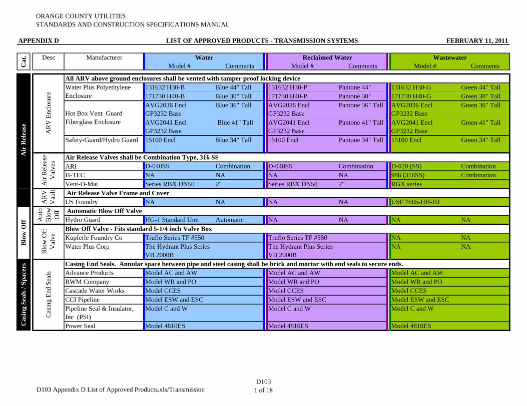
ORANGE COUNTY UTILITIESSTANDARDS AND CONSTRUCTION SPECIFICATIONS MANUAL
APPENDIX D LIST OF APPROVED PRODUCTS - TRANSMISSION SYSTEMS FEBRUARY 11, 2011
Desc Manufacturer Water Reclaimed Water WastewaterModel # Comments Model # Comments Model # Comments
131632 H30-B Blue 44" Tall 131632 H30-P Pantone 44" 131632 H30-G Green 44" Tall171730 H40-B Blue 30" Tall 171730 H40-P Pantone 30" 171730 H40-G Green 30" TallAVG2036 EnclGP3232 Base
Blue 36" Tall AVG2036 EnclGP3232 Base
Pantone 36" Tall AVG2036 EnclGP3232 Base
Green 36" Tall
AVG2041 Encl GP3232 Base
Blue 41" Tall AVG2041 Encl GP3232 Base
Pantone 41" Tall AVG2041 Encl GP3232 Base
Green 41" Tall
Safety-Guard/Hydro Guard 15100 Encl Blue 34" Tall 15100 Encl Pantone 34" Tall 15100 Encl Green 34" Tall
ARI D-040SS Combination D-040SS Combination D-020 (SS) CombinationH-TEC NA NA NA NA 986 (316SS) CombinationVent-O-Mat Series RBX DN50 2" Series RBX DN50 2" RGX series
US Foundry NA NA NA NA USF 7665-HH-HJ
Hydro Guard HG-1 Standard Unit Automatic NA NA NA NA
Kupferle Foundry Co Truflo Series TF #550 Truflo Series TF #550 NA NAWater Plus Corp The Hydrant Plus Series
VB 2000BThe Hydrant Plus Series VB 2000B
NA NA
Advance Products Model AC and AW Model AC and AW Model AC and AWBWM Company Model WR and PO Model WR and PO Model WR and POCascade Water Works Model CCES Model CCES Model CCESCCI Pipeline Model ESW and ESC Model ESW and ESC Model ESW and ESCPipeline Seal & Insulator, Inc (PSI)
Model C and W Model C and W Model C and W
Power Seal Model 4810ES Model 4810ES Model 4810ES
Cat
.A
ir R
elea
se
AR
V E
nclo
sure
All ARV above ground enclosures shall be vented with tamper proof locking deviceWater Plus Polyethylene Enclosure
Hot Box Vent Guard Fiberglass Enclosure
Air
Rel
ease
V
alve
s Air Release Valves shall be Combination Type, 316 SS
AR
V
Vau
lt Air Release Valve Frame and Cover
Blo
w O
ff Aut
o B
low
O
ff Automatic Blow Off Valve
Blo
w O
ff
Val
ve
Blow Off Valve - Fits standard 5-1/4 inch Valve Box
Cas
ing
End
Seal
s
Casing End Seals. Annular space between pipe and steel casing shall be brick and mortar with end seals to secure ends.
Cas
ing
Seal
s / S
pace
rs
D103 Appendix D List of Approved Products.xls/TransmissionD103
1 of 18
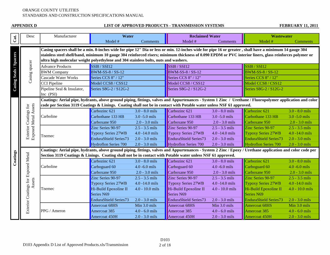
ORANGE COUNTY UTILITIESSTANDARDS AND CONSTRUCTION SPECIFICATIONS MANUAL
APPENDIX D LIST OF APPROVED PRODUCTS - TRANSMISSION SYSTEMS FEBRUARY 11, 2011
Desc Manufacturer Water Reclaimed Water WastewaterModel # Comments Model # Comments Model # CommentsC
at.
Advance Products SSI8 / SSI12 SSI8 / SSI12 SSI8 / SSI12BWM Company BWM-SS-8 / SS-12 BWM-SS-8 / SS-12 BWM-SS-8 / SS-12Cascade Water Works Series CCS 8" / 12" Series CCS 8" / 12" Series CCS 8" / 12"CCI Pipeline Model CCS8 / CSS12 Model CCS8 / CSS12 Model CCS8 / CSS12Pipeline Seal & Insulator, Inc (PSI)
Series S8G-2 / S12G-2 Series S8G-2 / S12G-2 Series S8G-2 / S12G-2
Carbozinc 621 3.0 - 8.0 mils Carbozinc 621 3.0 - 8.0 mils Carbozinc 621 3.0 - 8.0 milsCarbothane 133 HB 3.0 -5.0 mils Carbothane 133 HB 3.0 -5.0 mils Carbothane 133 HB 3.0 -5.0 milsCarboxane 950 2.0 - 3.0 mils Carboxane 950 2.0 - 3.0 mils Carboxane 950 2.0 - 3.0 milsZinc Series 90-97 Typoxy Series 27WB
2.5 - 3.5 mils 4.0 -14.0 mils
Zinc Series 90-97 Typoxy Series 27WB
2.5 - 3.5 mils 4.0 -14.0 mils
Zinc Series 90-97 Typoxy Series 27WB
2.5 - 3.5 mils 4.0 -14.0 mils
EnduraShield Series73 2.0 - 3.0 mils EnduraShield Series73 2.0 - 3.0 mils EnduraShield Series73 2.0 - 3.0 milsHydroflon Series 700 2.0 - 3.0 mils Hydroflon Series 700 2.0 - 3.0 mils Hydroflon Series 700 2.0 - 3.0 mils
Carbozinc 621 3.0 - 8.0 mils Carbozinc 621 3.0 - 8.0 mils Carbozinc 621 3.0 - 8.0 milsCarboguard 60 4.0 -6.0 mils Carboguard 60 4.0 -6.0 mils Carboguard 60 4.0 -6.0 milsCarboxane 950 2.0 - 3.0 mils Carboxane 950 2.0 - 3.0 mils Carboxane 950 2.0 - 3.0 milsZinc Series 90-97 Typoxy Series 27WB
2.5 - 3.5 mils 4.0 -14.0 mils
Zinc Series 90-97 Typoxy Series 27WB
2.5 - 3.5 mils 4.0 -14.0 mils
Zinc Series 90-97 Typoxy Series 27WB
2.5 - 3.5 mils 4.0 -14.0 mils
Hi-Build Epoxoline II Series N69
4.0 - 10.0 mils Hi-Build Epoxoline II Series N69
4.0 - 10.0 mils Hi-Build Epoxoline II Series N69
4.0 - 10.0 mils
EnduraShield Series73 2.0 - 3.0 mils EnduraShield Series73 2.0 - 3.0 mils EnduraShield Series73 2.0 - 3.0 milsAmercoat 68HS Min 3.0 mils Amercoat 68HS Min 3.0 mils Amercoat 68HS Min 3.0 milsAmercoat 385 4.0 - 6.0 mils Amercoat 385 4.0 - 6.0 mils Amercoat 385 4.0 - 6.0 milsAmercoat 450H 2.0 - 3.0 mils Amercoat 450H 2.0 - 3.0 mils Amercoat 450H 2.0 - 3.0 mils
Casing spacers shall be a min. 8-inches wide for pipe 12" Dia or less or min. 12-inches wide for pipe 16 or greater , shall have a minimum 14 gauge 304 stainless steel shell/band, minimum 10 gauge 304 reinforced risers; minimum thickness of 0.090 EPDM or PVC interior liners, glass reinforces polymer or ultra high molecular weight polyethylene and 304 stainless bolts, nuts and washers.
Cas
ing
spac
er
PPG / Ameron
Cas
ing
Seal
s / S
pace
rsC
oatin
gs
Exte
rior C
oatin
gs fo
r Ex
pose
d M
etal
Ass
ets
Coatings: Aerial pipe, hydrants, above ground piping, fittings, valves and Appurtenances - System 1 Zinc / Urethane / Fluoropolymer application and color code per Section 3119 Coatings & Linings. Coating shall not be in contact with Potable water unless NSF 61 approved.
Carboline
Tnemec
Exte
rior C
oatin
gs fo
r Exp
osed
Met
al
Ass
ets
Coatings: Aerial pipe, hydrants, above ground piping, fittings, valves and Appurtenances - System 2 Zinc / Epoxy / Urethane application and color code per Section 3119 Coatings & Linings. Coating shall not be in contact with Potable water unless NSF 61 approved.
Carboline
Tnemec
D103 Appendix D List of Approved Products.xls/TransmissionD103
2 of 18
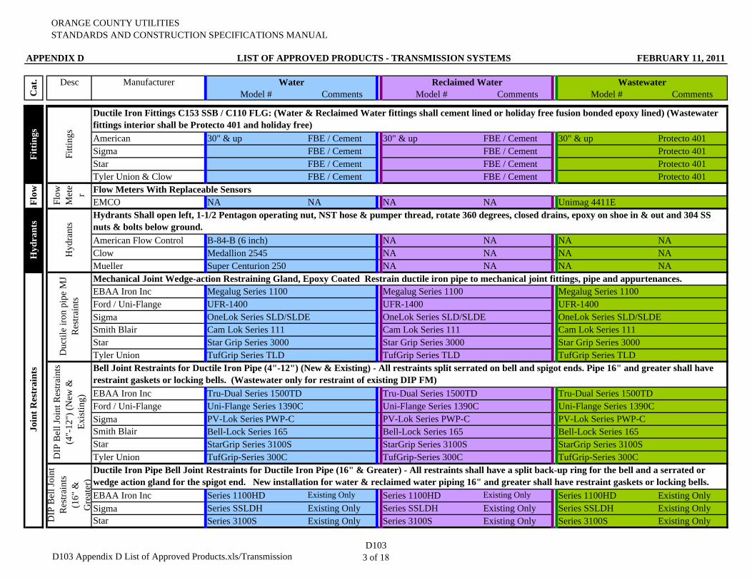
ORANGE COUNTY UTILITIESSTANDARDS AND CONSTRUCTION SPECIFICATIONS MANUAL
APPENDIX D LIST OF APPROVED PRODUCTS - TRANSMISSION SYSTEMS FEBRUARY 11, 2011
Desc Manufacturer Water Reclaimed Water WastewaterModel # Comments Model # Comments Model # CommentsC
at.
American 30" & up FBE / Cement 30" & up FBE / Cement 30" & up Protecto 401Sigma FBE / Cement FBE / Cement Protecto 401Star FBE / Cement FBE / Cement Protecto 401Tyler Union & Clow FBE / Cement FBE / Cement Protecto 401
EMCO NA NA NA NA Unimag 4411E
American Flow Control B-84-B (6 inch) NA NA NA NAClow Medallion 2545 NA NA NA NAMueller Super Centurion 250 NA NA NA NA
EBAA Iron Inc Megalug Series 1100 Megalug Series 1100 Megalug Series 1100Ford / Uni-Flange UFR-1400 UFR-1400 UFR-1400 Sigma OneLok Series SLD/SLDE OneLok Series SLD/SLDE OneLok Series SLD/SLDE Smith Blair Cam Lok Series 111 Cam Lok Series 111 Cam Lok Series 111Star Star Grip Series 3000 Star Grip Series 3000 Star Grip Series 3000 Tyler Union TufGrip Series TLD TufGrip Series TLD TufGrip Series TLD
EBAA Iron Inc Tru-Dual Series 1500TD Tru-Dual Series 1500TD Tru-Dual Series 1500TDFord / Uni-Flange Uni-Flange Series 1390C Uni-Flange Series 1390C Uni-Flange Series 1390CSigma PV-Lok Series PWP-C PV-Lok Series PWP-C PV-Lok Series PWP-C Smith Blair Bell-Lock Series 165 Bell-Lock Series 165 Bell-Lock Series 165Star StarGrip Series 3100S StarGrip Series 3100S StarGrip Series 3100STyler Union TufGrip-Series 300C TufGrip-Series 300C TufGrip-Series 300C
EBAA Iron Inc Series 1100HD Existing Only Series 1100HD Existing Only Series 1100HD Existing OnlySigma Series SSLDH Existing Only Series SSLDH Existing Only Series SSLDH Existing OnlyStar Series 3100S Existing Only Series 3100S Existing Only Series 3100S Existing Only
Hyd
rant
s
Hyd
rant
s
Hydrants Shall open left, 1-1/2 Pentagon operating nut, NST hose & pumper thread, rotate 360 degrees, closed drains, epoxy on shoe in & out and 304 SS nuts & bolts below ground.
Join
t Res
trai
nts
Fitt
ings
Fitti
ngs
Ductile Iron Fittings C153 SSB / C110 FLG: (Water & Reclaimed Water fittings shall cement lined or holiday free fusion bonded epoxy lined) (Wastewater fittings interior shall be Protecto 401 and holiday free)
Flow
Flow
M
ete
r Flow Meters With Replaceable Sensors
DIP
Bel
l Joi
nt
Res
train
ts
(16"
&
Gre
ater
)
Ductile Iron Pipe Bell Joint Restraints for Ductile Iron Pipe (16" & Greater) - All restraints shall have a split back-up ring for the bell and a serrated or wedge action gland for the spigot end. New installation for water & reclaimed water piping 16" and greater shall have restraint gaskets or locking bells.
Duc
tile
iron
pipe
MJ
Res
train
ts
Mechanical Joint Wedge-action Restraining Gland, Epoxy Coated Restrain ductile iron pipe to mechanical joint fittings, pipe and appurtenances.
DIP
Bel
l Joi
nt R
estra
ints
(4
"-12
") (N
ew &
Ex
istin
g)
Bell Joint Restraints for Ductile Iron Pipe (4"-12") (New & Existing) - All restraints split serrated on bell and spigot ends. Pipe 16" and greater shall have restraint gaskets or locking bells. (Wastewater only for restraint of existing DIP FM)
D103 Appendix D List of Approved Products.xls/TransmissionD103
3 of 18
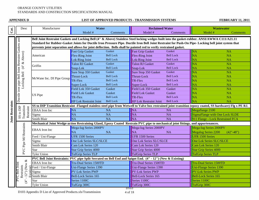
ORANGE COUNTY UTILITIESSTANDARDS AND CONSTRUCTION SPECIFICATIONS MANUAL
APPENDIX D LIST OF APPROVED PRODUCTS - TRANSMISSION SYSTEMS FEBRUARY 11, 2011
Desc Manufacturer Water Reclaimed Water WastewaterModel # Comments Model # Comments Model # CommentsC
at.
Fast Grip Gasket Gasket Fast Grip Gasket Gasket NA NAFlex-Ring Joint Bell Lock Flex-Ring Joint Bell Lock NA NALok-Ring Joint Bell Lock Lok-Ring Joint Bell Lock NA NATalon RJ Gasket Gasket Talon RJ Gasket Gasket NA NASnap-Lok Bell Lock Snap-Lok Bell Lock NA NASure Stop 350 Gasket Gasket Sure Stop 350 Gasket Gasket NA NAThrust-Lock Bell Lock Thrust-Lock Bell Lock NA NATR-Flex Bell Lock TR-Flex Bell Lock NA NASuper-Lock Bell Lock Super-Lock Bell Lock NA NAField Lok 350 Gasket Gasket Field Lok 350 Gasket Gasket NA NAField Lok Gasket Gasket Field Lok Gasket Gasket NA NATR-Flex Bell Lock TR-Flex Bell Lock NA NAHP Lok Restraint Joint Bell Lock HP Lok Restraint Joint Bell Lock NA NA
EBAA Iron Inc NA NA NA NA Megaflange 2100Sigma NA NA NA NA SigmaFlange with One Lock SLDESmith Blair NA NA NA NA 911 Flange - Lock Restrained FCA
Mega-lug Series 2000PV Mega-lug Series 2000PV Mega-lug Series 2000PVNA NA NA NA Megalug Series 2200 (42"-48")
Ford / Uni-Flange UFR 1500 Series UFR 1500 Series UFR 1500 SeriesSigma One Lok Series SLC/SLCE One Lok Series SLC/SLCE One Lok Series SLC/SLCE Smith Blair Cam Lok Series 120 Cam Lok Series 120 Cam Lok Series 120Star Star Grip Series 4000 Star Grip Series 4000 Star Grip Series 4000 Tyler Union TufGrip Series TLP TufGrip Series TLP TufGrip Series TLP
EBAA Iron Inc Tru-Dual Series 1500TD Tru-Dual Series 1500TD Tru-Dual Series 1500TDFord / Uni-Flange Uni-Flange Series 1390 Uni-Flange Series 1390 Uni-Flange Series 1390Sigma PV-Lok Series PWP PV-Lok Series PWP PV-Lok Series PWP Smith Blair Bell-Lock Series 165 Bell-Lock Series 165 Bell-Lock Series 165Star Series 1100C Series 1100C Series 1100CTyler Union TufGrip 300C TufGrip 300C TufGrip 300C
PVC Bell Joint Restraints: PVC pipe Split Serrated on Bell End and Spigot End. (4" - 12") (New & Existing)
PVC
Bel
l Joi
nt
Res
train
ts(4
" - 1
2") (
New
&
Exis
ting)
SS to
DIP
Tr
ansi
tion
Res
train
t SS to DIP Transition Restraint -Flanged stainless steel pipe from Wetwell to Valve box restrained joint transition (epoxy coated, SS hardware) Flg x PE RJ.
PVC
Pip
e M
J Res
train
ts Mechanical Joint Wedge-action Restraining Gland, Epoxy Coated Restrain PVC pipe to mechanical joint fittings, and appurtenances.
EBAA Iron Inc
Join
t Res
trai
nts D
uctil
e iro
n pi
pe B
ell J
oint
Res
train
t Gas
kets
and
Lo
ckin
g B
ell
(4"
& A
bove
)
Bell Joint Restraint Gaskets and Locking Bell (4" & Above) Stainless Steel locking wedges built into the gasket-rubber. ANSI/AWWA C111/A21.11 Standard for Rubber-Gasket Joints for Ductile Iron Pressure Pipe. Ductile Iron Bell Joint Restraint for Push-On Pipe- Locking bell joint system that prevents joint separation and allows for joint deflection. Bells shall be painted red to verify restrained gasket.
McWane Inc. DI Pipe Group
US Pipe
American
Griffin
D103 Appendix D List of Approved Products.xls/TransmissionD103
4 of 18
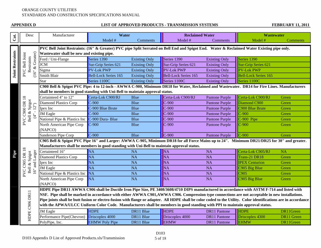
ORANGE COUNTY UTILITIESSTANDARDS AND CONSTRUCTION SPECIFICATIONS MANUAL
APPENDIX D LIST OF APPROVED PRODUCTS - TRANSMISSION SYSTEMS FEBRUARY 11, 2011
Desc Manufacturer Water Reclaimed Water WastewaterModel # Comments Model # Comments Model # CommentsC
at.
Ford / Uni-Flange Series 1390 Existing Only Series 1390 Existing Only Series 1390JCM Sur-Grip Series 621 Existing Only Sur-Grip Series 621 Existing Only Sur-Grip Series 621Sigma PV-Lok PWP Existing Only PV-Lok PWP Existing Only PV-Lok PWPSmith Blair Bell-Lock Series 165 Existing Only Bell-Lock Series 165 Existing Only Bell-Lock Series 165Star Series 1100C Existing Only Series 1100C Existing Only Series 1100C
Certainteed 4" to 12" Certa-Lok C900/RJ Blue Certa-Lok C900/RJ Pantone Purple Certa-Lok C900/RJ GreenDiamond Plastics Corp C-900 Blue C-900 Pantone Purple Diamond C900 GreenIpex Inc C-900 Blue Brute Blue C-900 Pantone Purple C900 Blue Brute GreenJM Eagle C-900 Blue C-900 Pantone Purple C-900 GreenNational Pipe & Plastics Inc C-900 Dura- Blue Blue C-900 Pantone Purple C-900 Pipe GreenNorth American Pipe Corp (NAPCO)
C-900 Blue C-900 Pantone Purple C-900 Green
Sanderson Pipe Corp C-900 Blue C-900 Pantone Purple C-900 Green
Certainteed 16" NA NA NA NA Certa-Lok C905/RJ NADiamond Plastics Corp NA NA NA NA Trans-21 DR18 GreenIpex Inc NA NA NA NA IPEX Centurion GreenJM Eagle NA NA NA NA C905 Big Blue GreenNational Pipe & Plastics Inc NA NA NA NA C905 GreenNorth American Pipe Corp (NAPCO)
NA NA NA NA C905 Big Blue Green
JM Eagle HDPE DR11 Blue HDPE DR11 Pantone HDPE DR11GreenPerformance Pipe(Chevron) Driscoplex 4000 DR11 Blue Driscoplex 4000 DR11 Pantone Driscoplex 4300 DR11 GreenPolyPipe, Inc. EHMW Poly Pipe DR11 Blue EHMW DR11 Pantone EHMW DR11Green
Pipe
Join
t Res
trai
nts
PVC
C90
0 D
R 1
8B
ell &
Spi
got
(4"
- 12"
)
C900 Bell & Spigot PVC Pipe: 4 to 12-inch - AWWA C-900, Minimum DR18 for Water, Reclaimed and Wastewater. DR14 for Fire Lines. Manufacturers shall be members in good standing with Uni-Bell to maintain approval status.
PVC
C90
5 D
R 1
8B
ell &
Spi
got
16"
and
Larg
er
C905 Bell & Spigot PVC Pipe 16" and Larger: AWWA C-905, Minimum DR18 for all Force Mains up to 24". Minimum DR21/DR25 for 30" and greater. Manufacturers shall be members in good standing with Uni-Bell to maintain approval status.
HD
PE C
906
DR
11
HDPE Pipe DR11 AWWA C906 shall be Ductile Iron Pipe Size, PE 3408/3608/4710 DIPS manufactured in accordance with ASTM F-714 and listed with NSF. Pipe shall be marked in accordance with either AWWA C901,AWWA C906. Compression type connections are not acceptable in new installations. Pipe joints shall be butt fusion or electro-fusion with flange or adapter. All HDPE shall be color coded to the Utility. Color identifications are in accordance with the APWA/ULCC Uniform Color Code. Manufacturers shall be members in good standing with PPI to maintain approval status.
PVC
Bel
l Joi
nt
Res
train
ts
(1
6" &
Gre
ater
)
PVC Bell Joint Restraints: (16" & Greater) PVC pipe Split Serrated on Bell End and Spigot End. Water & Reclaimed Water Existing pipe only. Wastewater shall be new and existing pipe.
D103 Appendix D List of Approved Products.xls/TransmissionD103
5 of 18
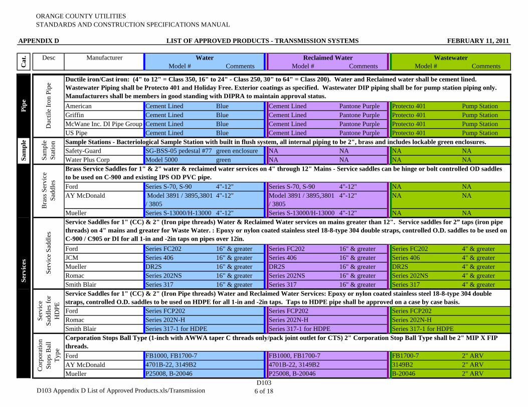
ORANGE COUNTY UTILITIESSTANDARDS AND CONSTRUCTION SPECIFICATIONS MANUAL
APPENDIX D LIST OF APPROVED PRODUCTS - TRANSMISSION SYSTEMS FEBRUARY 11, 2011
Desc Manufacturer Water Reclaimed Water WastewaterModel # Comments Model # Comments Model # CommentsC
at.
American Cement Lined Blue Cement Lined Pantone Purple Protecto 401 Pump StationGriffin Cement Lined Blue Cement Lined Pantone Purple Protecto 401 Pump StationMcWane Inc. DI Pipe Group Cement Lined Blue Cement Lined Pantone Purple Protecto 401 Pump StationUS Pipe Cement Lined Blue Cement Lined Pantone Purple Protecto 401 Pump Station
Safety-Guard SG-BSS-05 pedestal #77 green enclosure NA NA NA NAWater Plus Corp Model 5000 green NA NA NA NA
Ford Series S-70, S-90 4"-12" Series S-70, S-90 4"-12" NA NAAY McDonald Model 3891 / 3895,3801
/ 38054"-12" Model 3891 / 3895,3801
/ 38054"-12" NA NA
Mueller Series S-13000/H-13000 4"-12" Series S-13000/H-13000 4"-12" NA NA
Ford Series FC202 16" & greater Series FC202 16" & greater Series FC202 4" & greaterJCM Series 406 16" & greater Series 406 16" & greater Series 406 4" & greaterMueller DR2S 16" & greater DR2S 16" & greater DR2S 4" & greaterRomac Series 202NS 16" & greater Series 202NS 16" & greater Series 202NS 4" & greaterSmith Blair Series 317 16" & greater Series 317 16" & greater Series 317 4" & greater
Ford Series FCP202 Series FCP202 Series FCP202Romac Series 202N-H Series 202N-H Series 202N-HSmith Blair Series 317-1 for HDPE Series 317-1 for HDPE Series 317-1 for HDPE
Ford FB1000, FB1700-7 FB1000, FB1700-7 FB1700-7 2" ARVAY McDonald 4701B-22, 3149B2 4701B-22, 3149B2 3149B2 2" ARVMueller P25008, B-20046 P25008, B-20046 B-20046 2" ARV
Bra
ss S
ervi
ce
Sadd
les
Brass Service Saddles for 1" & 2" water & reclaimed water services on 4" through 12" Mains - Service saddles can be hinge or bolt controlled OD saddles to be used on C-900 and existing IPS OD PVC pipe.
Service Saddles for 1" (CC) & 2" (Iron pipe threads) Water & Reclaimed Water services on mains greater than 12". Service saddles for 2” taps (iron pipe threads) on 4" mains and greater for Waste Water. : Epoxy or nylon coated stainless steel 18-8-type 304 double straps, controlled O.D. saddles to be used on C-900 / C905 or DI for all 1-in and -2in taps on pipes over 12in.
Serv
ices
Duc
tile
Iron
Pip
e Ductile iron/Cast iron: (4" to 12" = Class 350, 16" to 24" - Class 250, 30" to 64" = Class 200). Water and Reclaimed water shall be cement lined. Wastewater Piping shall be Protecto 401 and Holiday Free. Exterior coatings as specified. Wastewater DIP piping shall be for pump station piping only. Manufacturers shall be members in good standing with DIPRA to maintain approval status.
Sam
ple
Sam
ple
Stat
ion Sample Stations - Bacteriological Sample Station with built in flush system, all internal piping to be 2", brass and includes lockable green enclosures.
Pipe
Serv
ice
Sadd
les
Serv
ice
Sadd
les f
or
HD
PE
Service Saddles for 1" (CC) & 2" (Iron Pipe threads) Water and Reclaimed Water Services: Epoxy or nylon coated stainless steel 18-8-type 304 double straps, controlled O.D. saddles to be used on HDPE for all 1-in and -2in taps. Taps to HDPE pipe shall be approved on a case by case basis.
Cor
pora
tion
Stop
s Bal
l Ty
pe
Corporation Stops Ball Type (1-inch with AWWA taper C threads only/pack joint outlet for CTS) 2" Corporation Stop Ball Type shall be 2" MIP X FIP threads.
D103 Appendix D List of Approved Products.xls/TransmissionD103
6 of 18
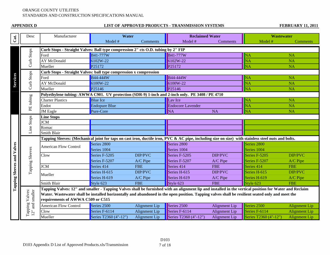
ORANGE COUNTY UTILITIESSTANDARDS AND CONSTRUCTION SPECIFICATIONS MANUAL
APPENDIX D LIST OF APPROVED PRODUCTS - TRANSMISSION SYSTEMS FEBRUARY 11, 2011
Desc Manufacturer Water Reclaimed Water WastewaterModel # Comments Model # Comments Model # CommentsC
at.
Ford B41-777W B41-777W NA NAAY McDonald 6102W-22 6102W-22 NA NAMueller P25172 P25172 NA NA
Ford B44-444W B44-444W NA NAAY McDonald 6100W-22 6100W-22 NA NAMueller P25146 P25146 NA NA
Charter Plastics Blue Ice Lav Ice NA NAEndot Endopure Blue Endocore Lavender NA NAJM Eagle Pure-Core NA NA NA NA
JCMRomacSmith Blair
Series 2800 Series 2800 Series 2800Series 1004 Series 1004 Series 1004Series F-5205 DIP/PVC Series F-5205 DIP/PVC Series F-5205 DIP/PVCSeries F-5207 A/C Pipe Series F-5207 A/C Pipe Series F-5207 A/C Pipe
JCM Series 414 FBE Series 414 FBE Series 414 FBESeries H-615 DIP/PVC Series H-615 DIP/PVC Series H-615 DIP/PVCSeries H-619 A/C Pipe Series H-619 A/C Pipe Series H-619 A/C Pipe
Smith Blair Style 623 FBE Style 623 FBE Style 623 FBE
American Flow Control Series 2500 Alignment Lip Series 2500 Alignment Lip Series 2500 Alignment LipClow Series F-6114 Alignment Lip Series F-6114 Alignment Lip Series F-6114 Alignment LipMueller Series T2360 (4"-12") Alignment Lip Series T2360 (4"-12") Alignment Lip Series T2360 (4"-12") Alignment Lip
Cur
b St
ops Curb Stops - Straight Valves: Ball type compression 2" cts O.D. tubing by 2" FIP
Cur
b St
ops
PE tu
bing Polyethylene tubing: AWWA C901. UV protection (SDR-9) 1-inch and 2-inch only. PE 3408 / PE 4710
Line
Sto
ps Line Stops
Tapping Sleeves: (Mechanical joint for taps on cast iron, ductile iron, PVC & AC pipe, including size on size) with stainless steel nuts and bolts.
Tapping Valves: 12" and smaller - Tapping Valves shall be furnished with an alignment lip and installed in the vertical position for Water and Reclaim Water. Wastewater shall be installed horizontally and abandoned in the open position. Tapping valves shall be resilient seated only and meet the requirements of AWWA C509 or C515
Curb Stops - Straight Valves: ball type compression x compression
Serv
ices
Tapp
ing
Slee
ves American Flow Control
Clow
Mueller
Tapp
ing
Val
ves:
12
" an
d sm
alle
rTap
ping
Sle
eves
and
Val
ves
D103 Appendix D List of Approved Products.xls/TransmissionD103
7 of 18
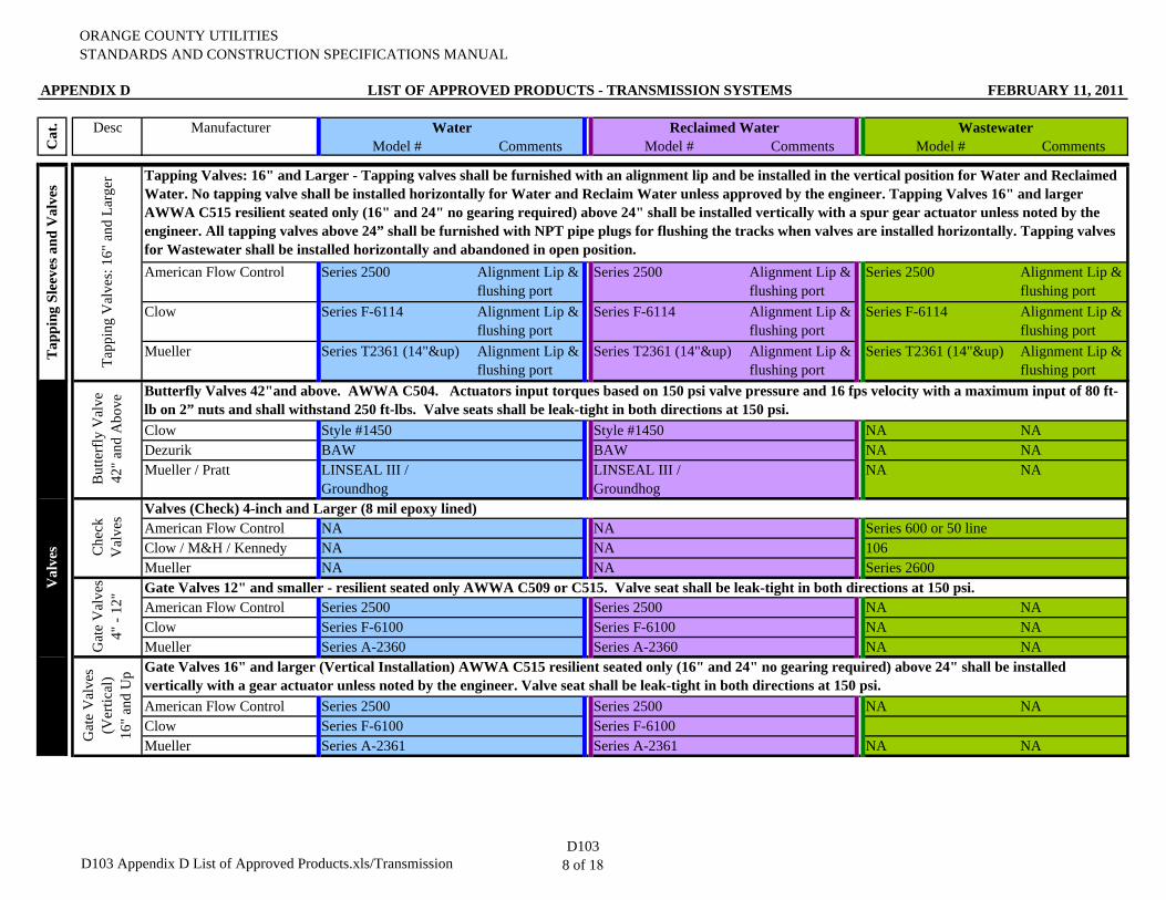
ORANGE COUNTY UTILITIESSTANDARDS AND CONSTRUCTION SPECIFICATIONS MANUAL
APPENDIX D LIST OF APPROVED PRODUCTS - TRANSMISSION SYSTEMS FEBRUARY 11, 2011
Desc Manufacturer Water Reclaimed Water WastewaterModel # Comments Model # Comments Model # CommentsC
at.
American Flow Control Series 2500 Alignment Lip & flushing port
Series 2500 Alignment Lip & flushing port
Series 2500 Alignment Lip & flushing port
Clow Series F-6114 Alignment Lip & flushing port
Series F-6114 Alignment Lip & flushing port
Series F-6114 Alignment Lip & flushing port
Mueller Series T2361 (14"&up) Alignment Lip & flushing port
Series T2361 (14"&up) Alignment Lip & flushing port
Series T2361 (14"&up) Alignment Lip & flushing port
Clow Style #1450 Style #1450 NA NADezurik BAW BAW NA NAMueller / Pratt LINSEAL III /
GroundhogLINSEAL III / Groundhog
NA NA
American Flow Control NA NA Series 600 or 50 lineClow / M&H / Kennedy NA NA 106Mueller NA NA Series 2600
American Flow Control Series 2500 Series 2500 NA NAClow Series F-6100 Series F-6100 NA NAMueller Series A-2360 Series A-2360 NA NA
American Flow Control Series 2500 Series 2500 NA NAClow Series F-6100 Series F-6100Mueller Series A-2361 Series A-2361 NA NA
Tapp
ing
Val
ves:
16"
and
Lar
ger Tapping Valves: 16" and Larger - Tapping valves shall be furnished with an alignment lip and be installed in the vertical position for Water and Reclaimed
Water. No tapping valve shall be installed horizontally for Water and Reclaim Water unless approved by the engineer. Tapping Valves 16" and larger AWWA C515 resilient seated only (16" and 24" no gearing required) above 24" shall be installed vertically with a spur gear actuator unless noted by the engineer. All tapping valves above 24” shall be furnished with NPT pipe plugs for flushing the tracks when valves are installed horizontally. Tapping valves for Wastewater shall be installed horizontally and abandoned in open position.
Gat
e V
alve
s 4"
- 12
"
Gat
e V
alve
s
(Ver
tical
)
16
" an
d U
p
Gate Valves 12" and smaller - resilient seated only AWWA C509 or C515. Valve seat shall be leak-tight in both directions at 150 psi.
Gate Valves 16" and larger (Vertical Installation) AWWA C515 resilient seated only (16" and 24" no gearing required) above 24" shall be installed vertically with a gear actuator unless noted by the engineer. Valve seat shall be leak-tight in both directions at 150 psi.
Butterfly Valves 42"and above. AWWA C504. Actuators input torques based on 150 psi valve pressure and 16 fps velocity with a maximum input of 80 ft-lb on 2” nuts and shall withstand 250 ft-lbs. Valve seats shall be leak-tight in both directions at 150 psi.
Valves (Check) 4-inch and Larger (8 mil epoxy lined)
But
terf
ly V
alve
42
" an
d A
bove
C
heck
V
alve
s
Val
ves
Tap
ping
Sle
eves
and
Val
ves
D103 Appendix D List of Approved Products.xls/TransmissionD103
8 of 18
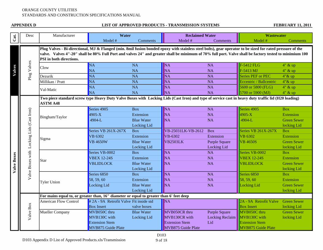
ORANGE COUNTY UTILITIESSTANDARDS AND CONSTRUCTION SPECIFICATIONS MANUAL
APPENDIX D LIST OF APPROVED PRODUCTS - TRANSMISSION SYSTEMS FEBRUARY 11, 2011
Desc Manufacturer Water Reclaimed Water WastewaterModel # Comments Model # Comments Model # CommentsC
at.
NA NA NA NA F-5412 FLG 4" & upNA NA NA NA F-5413 MJ 4" & up
Dezurik NA NA NA NA Series PEF or PEC 4"& upMillikan / Pratt NA NA NA NA Eccentric / Ballcentric 4"& up
NA NA NA NA 5600 or 5800 (FLG) 4" & upNA NA NA NA 5700 or 5900 (MJ) 4" & up
Series 4905 Box NA NA Series 4905 Box4905-X Extension NA NA 4905-X Extension 4904-L Blue Water
Locking LidNA NA 4904-L Green Sewer
locking LidSeries VB 261X-267X Box VB-25031LK-VB-2612 Box Series VB 261X-267X BoxVB 6302 Extension VB-6302 Extension VB 6302 ExtensionVB 4650W Blue Water
Locking LidVB2503LK Purple Square
Locking LidVB 4650S Green Sewer
locking LidSeries VB-0002 Box NA NA Series VB-0002 BoxVBEX 12-24S Extension NA NA VBEX 12-24S ExtensionVBLIDLOCK Blue Water
Locking LidNA NA VBLIDLOCK Green Sewer
locking LidSeries 6850 Box NA NA Series 6850 Box58, 59, 60 Extension NA NA 58, 59, 60 ExtensionLocking Lid Blue Water
Locking LidNA NA Locking Lid Green Sewer
locking Lid
American Flow Control # 2A - 9A Retrofit Valve Box Insert
Fit inside std valve boxes
NA 2A - 9A Retrofit Valve Box Insert
Green Sewer locking Lid
Mueller Company MVB050C thru MVB130C with Extension StemMVB875 Guide Plate
Blue Water Locking Lid
MVB050CR thru MVB130CR with Extension StemMVB875 Guide Plate
Purple Square Locking Reclaim Lid
MVB050C thru MVB130C with Extension StemMVB875 Guide Plate
Green Sewer locking Lid
Plug
Val
ves
Clow
Plug Valves - Bi-directional, MJ & Flanged (min. 8mil fusion bonded epoxy with stainless steel bolts), gear operator to be sized for rated pressure of the valve. Valves 4"-20" shall be 80% Full Port and valves 24" and greater shall be minimum of 70% full port. Valve shall be factory tested to minimium 100 PSI in both directions.
Val
ve B
ox
Star
Tyler Union
For mains equal to, or greater than, 16" diameter or equal to greater than 6' feet deep
Bingham/Taylor
Sigma
Val-Matic
Val
ves
Val
ve B
oxes
Val
ve B
oxes
with
Loc
king
Lid
s (C
ast I
ron)
Two piece standard screw type Heavy Duty Valve Boxes with Locking Lids (Cast Iron) and type of service cast in heavy duty traffic lid (H20 loading) ASTM A48
D103 Appendix D List of Approved Products.xls/TransmissionD103
9 of 18
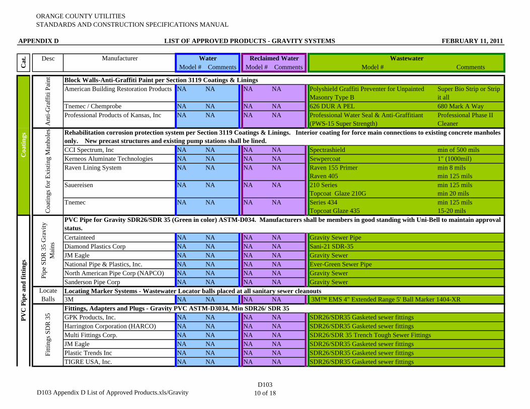
ORANGE COUNTY UTILITIESSTANDARDS AND CONSTRUCTION SPECIFICATIONS MANUAL
APPENDIX D LIST OF APPROVED PRODUCTS - GRAVITY SYSTEMS FEBRUARY 11, 2011
Desc Manufacturer Water Reclaimed Water WastewaterModel # Comments Model # Comments Model # Comments
American Building Restoration Products NA NA NA NA Polyshield Graffiti Preventer for Unpainted Masonry Type B
Super Bio Strip or Strip it all
Tnemec / Chemprobe NA NA NA NA 626 DUR A PEL 680 Mark A WayProfessional Products of Kansas, Inc NA NA NA NA Professional Water Seal & Anti-Graffitiant
(PWS-15 Super Strength)Professional Phase II Cleaner
CCI Spectrum, Inc NA NA NA NA Spectrashield min of 500 milsKerneos Aluminate Technologies NA NA NA NA Sewpercoat 1" (1000mil)Raven Lining System NA NA NA NA Raven 155 Primer
Raven 405min 8 milsmin 125 mils
Sauereisen NA NA NA NA 210 SeriesTopcoat Glaze 210G
min 125 milsmin 20 mils
Tnemec NA NA NA NA Series 434 Topcoat Glaze 435
min 125 mils15-20 mils
Certainteed NA NA NA NA Gravity Sewer Pipe Diamond Plastics Corp NA NA NA NA Sani-21 SDR-35JM Eagle NA NA NA NA Gravity SewerNational Pipe & Plastics, Inc. NA NA NA NA Ever-Green Sewer PipeNorth American Pipe Corp (NAPCO) NA NA NA NA Gravity SewerSanderson Pipe Corp NA NA NA NA Gravity Sewer
3M NA NA NA NA
GPK Products, Inc. NA NA NA NA SDR26/SDR35 Gasketed sewer fittingsHarrington Corporation (HARCO) NA NA NA NA SDR26/SDR35 Gasketed sewer fittingsMulti Fittings Corp. NA NA NA NAJM Eagle NA NA NA NA SDR26/SDR35 Gasketed sewer fittingsPlastic Trends Inc NA NA NA NA SDR26/SDR35 Gasketed sewer fittingsTIGRE USA, Inc. NA NA NA NA SDR26/SDR35 Gasketed sewer fittings
PVC
Pip
e an
d fit
tings
Ant
i-Gra
ffiti
Pain
tC
oatin
gs fo
r Exi
stin
g M
anho
les Rehabilitation corrosion protection system per Section 3119 Coatings & Linings. Interior coating for force main connections to existing concrete manholes
only. New precast structures and existing pump stations shall be lined.
Fitti
ngs S
DR
35
SDR26/SDR 35 Trench Tough Sewer Fittings
Cat
.
Block Walls-Anti-Graffiti Paint per Section 3119 Coatings & Linings
Coa
tings
Pipe
SD
R 3
5 G
ravi
ty
Mai
ns
Locate Balls
Locating Marker Systems - Wastewater Locator balls placed at all sanitary sewer cleanouts 3M™ EMS 4" Extended Range 5' Ball Marker 1404-XR
Fittings, Adapters and Plugs - Gravity PVC ASTM-D3034, Min SDR26/ SDR 35
PVC Pipe for Gravity SDR26/SDR 35 (Green in color) ASTM-D034. Manufacturers shall be members in good standing with Uni-Bell to maintain approval status.
D103 Appendix D List of Approved Products.xls/GravityD103
10 of 18
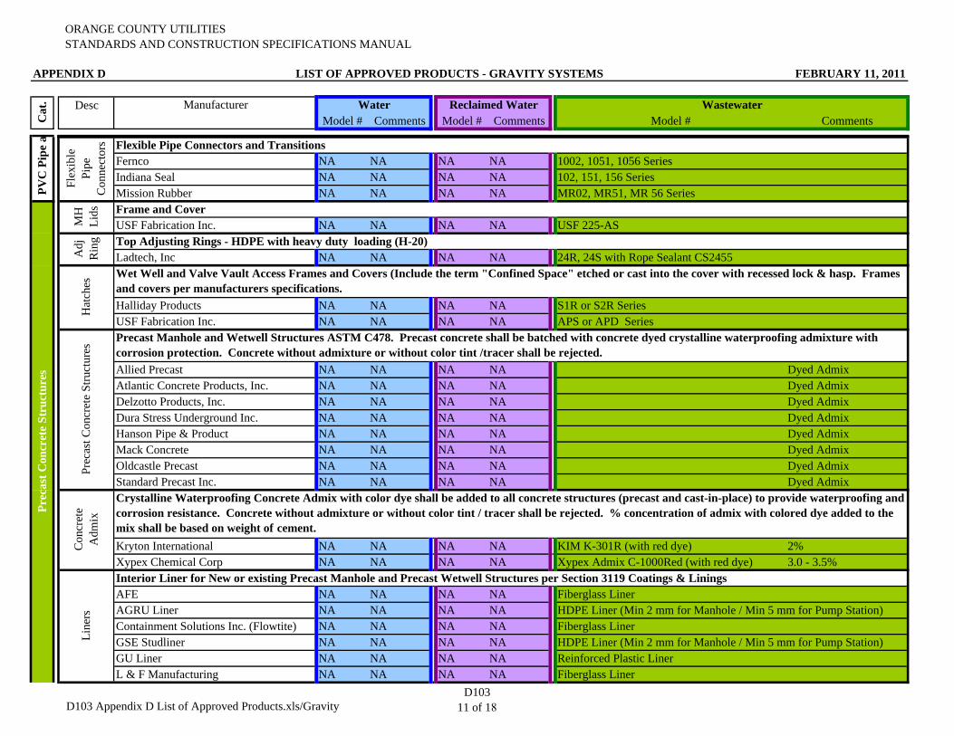
ORANGE COUNTY UTILITIESSTANDARDS AND CONSTRUCTION SPECIFICATIONS MANUAL
APPENDIX D LIST OF APPROVED PRODUCTS - GRAVITY SYSTEMS FEBRUARY 11, 2011
Desc Manufacturer Water Reclaimed Water WastewaterModel # Comments Model # Comments Model # CommentsC
at.
Fernco NA NA NA NA 1002, 1051, 1056 SeriesIndiana Seal NA NA NA NA 102, 151, 156 SeriesMission Rubber NA NA NA NA MR02, MR51, MR 56 Series
USF Fabrication Inc. NA NA NA NA USF 225-AS
Ladtech, Inc NA NA NA NA 24R, 24S with Rope Sealant CS2455
Halliday Products NA NA NA NA S1R or S2R SeriesUSF Fabrication Inc. NA NA NA NA APS or APD Series
Allied Precast NA NA NA NA Dyed AdmixAtlantic Concrete Products, Inc. NA NA NA NA Dyed AdmixDelzotto Products, Inc. NA NA NA NA Dyed AdmixDura Stress Underground Inc. NA NA NA NA Dyed AdmixHanson Pipe & Product NA NA NA NA Dyed AdmixMack Concrete NA NA NA NA Dyed AdmixOldcastle Precast NA NA NA NA Dyed AdmixStandard Precast Inc. NA NA NA NA Dyed Admix
Kryton International NA NA NA NA KIM K-301R (with red dye) 2%Xypex Chemical Corp NA NA NA NA Xypex Admix C-1000Red (with red dye) 3.0 - 3.5%
AFE NA NA NA NA Fiberglass LinerAGRU Liner NA NA NA NA HDPE Liner (Min 2 mm for Manhole / Min 5 mm for Pump Station)Containment Solutions Inc. (Flowtite) NA NA NA NA Fiberglass LinerGSE Studliner NA NA NA NA HDPE Liner (Min 2 mm for Manhole / Min 5 mm for Pump Station)GU Liner NA NA NA NA Reinforced Plastic LinerL & F Manufacturing NA NA NA NA Fiberglass Liner
PVC
Pip
e a
Prec
ast C
oncr
ete
Stru
ctur
es
Interior Liner for New or existing Precast Manhole and Precast Wetwell Structures per Section 3119 Coatings & Linings
Line
rsPr
ecas
t Con
cret
e St
ruct
ures
Con
cret
e A
dmix
Crystalline Waterproofing Concrete Admix with color dye shall be added to all concrete structures (precast and cast-in-place) to provide waterproofing and corrosion resistance. Concrete without admixture or without color tint / tracer shall be rejected. % concentration of admix with colored dye added to the mix shall be based on weight of cement.
MH
Li
ds Frame and Cover
Adj
Rin
g Top Adjusting Rings - HDPE with heavy duty loading (H-20)
Hat
ches
Wet Well and Valve Vault Access Frames and Covers (Include the term "Confined Space" etched or cast into the cover with recessed lock & hasp. Frames and covers per manufacturers specifications.
Precast Manhole and Wetwell Structures ASTM C478. Precast concrete shall be batched with concrete dyed crystalline waterproofing admixture with corrosion protection. Concrete without admixture or without color tint /tracer shall be rejected.
Flex
ible
Pi
pe
Con
nect
ors Flexible Pipe Connectors and Transitions
D103 Appendix D List of Approved Products.xls/GravityD103
11 of 18
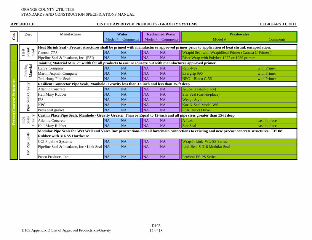
ORANGE COUNTY UTILITIESSTANDARDS AND CONSTRUCTION SPECIFICATIONS MANUAL
APPENDIX D LIST OF APPROVED PRODUCTS - GRAVITY SYSTEMS FEBRUARY 11, 2011
Desc Manufacturer Water Reclaimed Water WastewaterModel # Comments Model # Comments Model # CommentsC
at.
Canusa-CPS NA NA NA NAPipeline Seal & Insulator, Inc (PSI) NA NA NA NA
Henry Company NA NA NA NA Ram-Nek with PrimerMartin Asphalt Company NA NA NA NA Evergrip 990 with PrimerTrelleborg Pipe Seals NA NA NA NA NPC – Bidco C-56 with Primer
Atlantic Concrete NA NA NA NA A-Lok (cast-in-place)Hail Mary Rubber NA NA NA NA Star Seal (cast-in-place)IPS NA NA NA NA Wedge StyleNPC NA NA NA NA Kor-N-Seal Model WSPress seal gasket NA NA NA NA PSX Direct Drive
Atlantic Concrete NA NA NA NA A-Lok cast in placeHail Mary Rubber NA NA NA NA Star Seal cast in place
CCI Pipeline Systems NA NA NA NA Wrap-It Link WL-SS SeriesPipeline Seal & Insulator, Inc / Link Seal NA NA NA NA Link-Seal S-316 Modular Seal
Proco Products, Inc NA NA NA NA PenSeal ES-PS Series
Heat Shrink Seal - Precast structures shall be primed with manufacturer approved primer prior to application of heat shrunk encapsulation.
Cast in Place Pipe Seals, Manhole - Gravity Greater Than or Equal to 12-inch and all pipe sizes greater than 15-ft deep
Prec
ast C
oncr
ete
Stru
ctur
es
Hea
t Sh
rink
Seal
Riser Wrap with Polyken 1027 or 1039 primer
Join
ting
Mat
eria
l Jointing Material Min. 2" width for all products to ensure squeeze out with manufacturer approved primer.
Wrapid Seal with WrapidSeal Primer (Canusa G Primer )
Pipe
Se
als
Gra
vity
FM P
ipe
Seal
s Modular Pipe Seals for Wet Well and Valve Box penetrations and all forcemain connections to existing and new precast concrete structures. EPDM Rubber with 316 SS Hardware
Pipe
Sea
ls G
ravi
ty Resilient Connector Pipe Seals, Manhole - Gravity less than 12-inch and less than 15-ft deep
D103 Appendix D List of Approved Products.xls/GravityD103
12 of 18
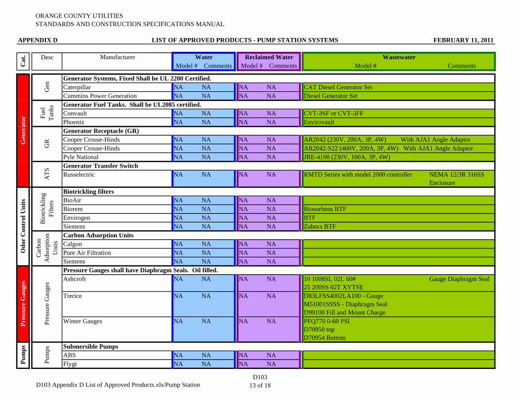
ORANGE COUNTY UTILITIESSTANDARDS AND CONSTRUCTION SPECIFICATIONS MANUAL
APPENDIX D LIST OF APPROVED PRODUCTS - PUMP STATION SYSTEMS FEBRUARY 11, 2011
Desc Manufacturer Water Reclaimed Water WastewaterModel # Comments Model # Comments Model # Comments
Caterpillar NA NA NA NA CAT Diesel Generator SetCummins Power Generation NA NA NA NA Diesel Generator Set
Convault NA NA NA NA CVT-3SF or CVT-3FFPhoenix NA NA NA NA Envirovault
Cooper Crouse-Hinds NA NA NA NA AR2042 (230V, 200A, 3P, 4W) With AJA1 Angle AdaptorCooper Crouse-Hinds NA NA NA NA AR2042-S22 (460V, 200A, 3P, 4W) With AJA1 Angle AdaptorPyle National NA NA NA NA JRE-4100 (230V, 100A, 3P, 4W)
Russelectric NA NA NA NA RMTD Series with model 2000 controller NEMA 12/3R 316SS Enclosure
BioAir NA NA NA NABiorem NA NA NA NA Biosorbens BTFEnvirogen NA NA NA NA BTFSiemens NA NA NA NA Zabocs BTF
Calgon NA NA NA NAPure Air Filtration NA NA NA NASiemens NA NA NA NA
Ashcroft NA NA NA NA 10 1008SL 02L 60# 25 200SS 02T XYTSE
Gauge Diaphragm Seal
Trerice NA NA NA NA D83LFSS4002LA100 - GaugeM51001SSSS - Diaphragm SealD99100 Fill and Mount Charge
Winter Gauges NA NA NA NA PFQ770 0-60 PSI D70950 topD70954 Bottom
ABS NA NA NA NAFlygt NA NA NA NAPu
mps
Bio
trick
ling
Filte
rs
Biotrickling filters
Car
bon
Ads
orpt
ion
Uni
ts
Generator Transfer Switch
Carbon Adsorption Units
Pres
sure
Gau
ges
Pressure Gauges shall have Diaphragm Seals. Oil filled.
Pum
ps Submersible Pumps
Gen
erat
orPr
essu
re G
auge
sO
dor
Con
trol
Uni
tsC
at.
Generator Systems, Fixed Shall be UL 2200 Certified.
Gen
Fuel
Ta
nks Generator Fuel Tanks. Shall be UL2085 certified.
GR
Generator Receptacle (GR)
ATS
D103 Appendix D List of Approved Products.xls/Pump StationD103
13 of 18
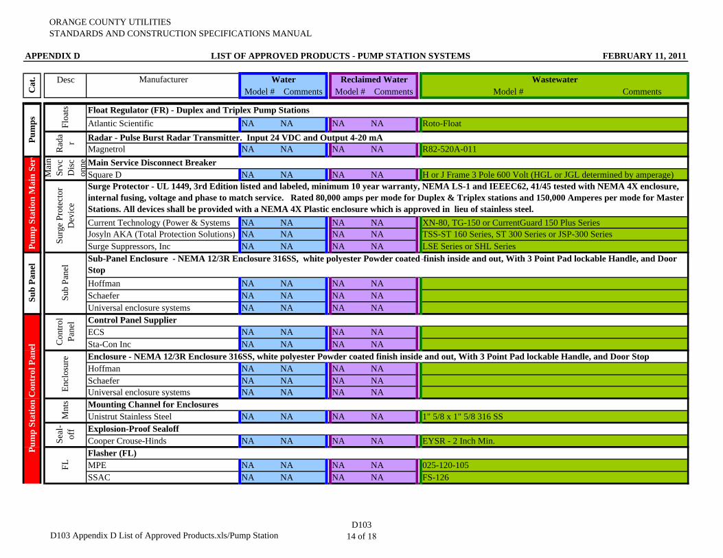
ORANGE COUNTY UTILITIESSTANDARDS AND CONSTRUCTION SPECIFICATIONS MANUAL
APPENDIX D LIST OF APPROVED PRODUCTS - PUMP STATION SYSTEMS FEBRUARY 11, 2011
Desc Manufacturer Water Reclaimed Water WastewaterModel # Comments Model # Comments Model # CommentsC
at.
Atlantic Scientific NA NA NA NA Roto-Float
Magnetrol NA NA NA NA R82-520A-011
Square D NA NA NA NA H or J Frame 3 Pole 600 Volt (HGL or JGL determined by amperage)
Current Technology (Power & Systems NA NA NA NAJosyln AKA (Total Protection Solutions) NA NA NA NASurge Suppressors, Inc NA NA NA NA
Hoffman NA NA NA NASchaefer NA NA NA NAUniversal enclosure systems NA NA NA NA
ECS NA NA NA NASta-Con Inc NA NA NA NA
Hoffman NA NA NA NASchaefer NA NA NA NAUniversal enclosure systems NA NA NA NA
Unistrut Stainless Steel NA NA NA NA 1" 5/8 x 1" 5/8 316 SS
Cooper Crouse-Hinds NA NA NA NA EYSR - 2 Inch Min.
MPE NA NA NA NA 025-120-105SSAC NA NA NA NA FS-126
Sub
Pane
l
Sub
Pane
l Sub-Panel Enclosure - NEMA 12/3R Enclosure 316SS, white polyester Powder coated finish inside and out, With 3 Point Pad lockable Handle, and Door Stop
Pum
p St
atio
n M
ain
Serv
Mai
n Sr
vc
Dis
con
ne Main Service Disconnect Breaker
Surg
e Pr
otec
tor
Dev
ice
Surge Protector - UL 1449, 3rd Edition listed and labeled, minimum 10 year warranty, NEMA LS-1 and IEEEC62, 41/45 tested with NEMA 4X enclosure, internal fusing, voltage and phase to match service. Rated 80,000 amps per mode for Duplex & Triplex stations and 150,000 Amperes per mode for Master Stations. All devices shall be provided with a NEMA 4X Plastic enclosure which is approved in lieu of stainless steel.
XN-80, TG-150 or CurrentGuard 150 Plus SeriesTSS-ST 160 Series, ST 300 Series or JSP-300 SeriesLSE Series or SHL Series
Floa
ts Float Regulator (FR) - Duplex and Triplex Pump Stations
Rad
ar Radar - Pulse Burst Radar Transmitter. Input 24 VDC and Output 4-20 mA
Con
trol
Pane
l Control Panel Supplier
Encl
osur
eM
nts
Explosion-Proof Sealoff
Pum
p St
atio
n C
ontr
ol P
anel
Flasher (FL)
FL
Pum
ps
Mounting Channel for Enclosures
Seal
-of
f
Enclosure - NEMA 12/3R Enclosure 316SS, white polyester Powder coated finish inside and out, With 3 Point Pad lockable Handle, and Door Stop
D103 Appendix D List of Approved Products.xls/Pump StationD103
14 of 18
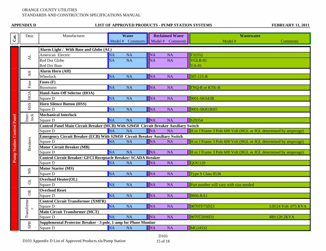
ORANGE COUNTY UTILITIESSTANDARDS AND CONSTRUCTION SPECIFICATIONS MANUAL
APPENDIX D LIST OF APPROVED PRODUCTS - PUMP STATION SYSTEMS FEBRUARY 11, 2011
Desc Manufacturer Water Reclaimed Water WastewaterModel # Comments Model # Comments Model # CommentsC
at.
American Electric NA NA NA NA F32552Red Dot GlobeRed Dot Base
NA NA NA NA VGLR-01VA-01
Wheelock NA NA NA NA 3IT-115-R
Bussmann NA NA NA NA FNQ-R or KTK-R
Square D NA NA NA NA 9001-SKS43B
Square D NA NA NA NA 9001-SKR1RH5
Square D NA NA NA NA S29354
Square D NA NA NA NA H or J Frame 3 Pole 600 Volt (HGL or JGL determined by amperage)
Square D NA NA NA NA H or J Frame 3 Pole 600 Volt (HGL or JGL determined by amperage)
Square D NA NA NA NA H or J Frame 3 Pole 600 Volt (HGL or JGL determined by amperage)
Square D NA NA NA NA QOU120
Square D NA NA NA NA Type S Class 8536
Square D NA NA NA NA
Square D NA NA NA NA 9066-RA1
Square D NA NA NA NA 9070TF75D23 120/24 Volt .075 KVA
Square D NA NA NA NA 9070T2000D1 480/120 2KVA
Square D NA NA NA NA MG24532Supplemental Protector Breaker - 3 pole, 1-amp for Phase Monitor
SPB
Emergency Circuit Breaker (ECB) With S29450 Circuit Breaker Auxiliary Switch
Motor Circuit Breaker (MB)
OR
Tran
sfor
me
r
Control Circuit Transformer (XMFR)
Main Circuit Transformer (MCT)
MS
OL Overload Heater(OL)
Part number will vary with size needed
Fuse Fuses (F)
HO
A Hand-Auto-Off Selector (HOA)
HSS
Inte
r-lo
ck Mechanical Interlock
Bre
aker
s
Control Panel Main Circuit Breaker (MCB) With S29450 Circuit Breaker Auxiliary Switch
Control Circuit Breaker/ GFCI Receptacle Breaker/ SCADA Breaker
Motor Starter (MS)
Horn Silence Button (HSS)
Pum
p St
atio
n C
ontr
ol P
anel
AL
AH Alarm Horn (AH)
Overload Reset
Alarm Light / With Base and Globe (AL)
D103 Appendix D List of Approved Products.xls/Pump StationD103
15 of 18
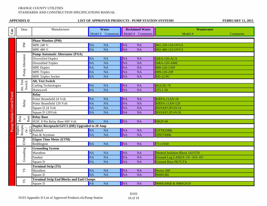
ORANGE COUNTY UTILITIESSTANDARDS AND CONSTRUCTION SPECIFICATIONS MANUAL
APPENDIX D LIST OF APPROVED PRODUCTS - PUMP STATION SYSTEMS FEBRUARY 11, 2011
Desc Manufacturer Water Reclaimed Water WastewaterModel # Comments Model # Comments Model # CommentsC
at.
MPE 240 V. NA NA NA NA 001-230-118-OVG5MPE 480 V. NA NA NA NA 002-480-123-OVG5
Diversified Duplex NA NA NA NA ARA-120-ACADiversified Triplex NA NA NA NA ARA-120-AMEMPE Duplex NA NA NA NA 008-120-13SPMPE Triplex NA NA NA NA 009-120-23PMPE Triplex Socket NA NA NA NA SD-12-PC
Carling Technologies NA NA NA NA 6GG5E-78Honeywell NA NA NA NA 2TL1-50
Potter Brumfield 24 Volt NA NA NA NA KRPA-11AN-24Potter Brumfield 120 Volt NA NA NA NA KRPA-11AN-120Square D 24 Volt NA NA NA NA 8501KP12P14V14Square D 120Volt NA NA NA NA 8501KP12P14V20
IEDC 8 Pin Relay Base 600 Volt NA NA NA NA SR2P-06
Hubbell NA NA NA NA GFTR20BKPass & Seymour NA NA NA NA 2095TRBK
Reddington NA NA NA NA 711-0160
Marathon NA NA NA NA Neutral Isolation Block 1421570Panduit NA NA NA NA Ground Lug LAM2A 1/0 - 014 -6YSquare D NA NA NA NA Ground Buss PK7GTA
Marathon NA NA NA NA Series 200Square D NA NA NA NA 9080GR6
Square D NA NA NA NA 9080GM6B & 9080GH10TS
Terminal Strip End Blocks and End Clamps
Gro
undi
ng Grounding System
TS
Terminal Strip (TS)
Rel
ay
Relay
Rel
ay
Bas
e Relay Base
Dup
lex
Rec
epta
cle
/ G
FCI Duplex Receptacle/GFCI (DR) Upgraded to 20 Amp
ETM Elapse Time Meter (ETM)
Pum
p A
ltern
ator
Alt.
Tes
t Sw
itch Alt. Test Switch
Pump Automatic Alternator (PAA)
Pum
p St
atio
n C
ontr
ol P
anel
PM
Phase Monitor (PM)
D103 Appendix D List of Approved Products.xls/Pump StationD103
16 of 18
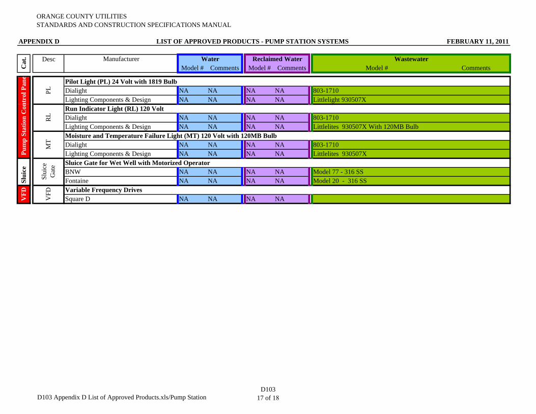
ORANGE COUNTY UTILITIESSTANDARDS AND CONSTRUCTION SPECIFICATIONS MANUAL
APPENDIX D LIST OF APPROVED PRODUCTS - PUMP STATION SYSTEMS FEBRUARY 11, 2011
Desc Manufacturer Water Reclaimed Water WastewaterModel # Comments Model # Comments Model # CommentsC
at.
Dialight NA NA NA NA 803-1710Lighting Components & Design NA NA NA NA Littlelight 930507X
Dialight NA NA NA NA 803-1710Lighting Components & Design NA NA NA NA Littlelites 930507X With 120MB Bulb
Dialight NA NA NA NA 803-1710Lighting Components & Design NA NA NA NA Littlelites 930507X
BNW NA NA NA NA Model 77 - 316 SSFontaine NA NA NA NA Model 20 - 316 SS
Square D NA NA NA NAVFD
VFD Variable Frequency Drives
Slui
ce
Slui
ce
Gat
e Sluice Gate for Wet Well with Motorized Operator
RL
Run Indicator Light (RL) 120 Volt
MT
Moisture and Temperature Failure Light (MT) 120 Volt with 120MB Bulb
PL
Pilot Light (PL) 24 Volt with 1819 Bulb
Pum
p St
atio
n C
ontr
ol P
ane
D103 Appendix D List of Approved Products.xls/Pump StationD103
17 of 18

THIS PAGE INTENTIONALLY LEFT BLANK
APPENDIX B
ORANGE COUNTY UTILITIES
GENERAL ACCESS AND SECURITY GUIDELINES
WATER SUPPLY FACILITIES
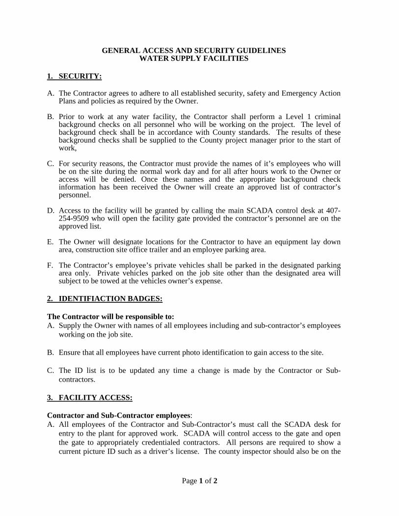
Page 1 of 2
GENERAL ACCESS AND SECURITY GUIDELINES WATER SUPPLY FACILITIES
1. SECURITY: A. The Contractor agrees to adhere to all established security, safety and Emergency Action
Plans and policies as required by the Owner.
B. Prior to work at any water facility, the Contractor shall perform a Level 1 criminal background checks on all personnel who will be working on the project. The level of background check shall be in accordance with County standards. The results of these background checks shall be supplied to the County project manager prior to the start of work,
C. For security reasons, the Contractor must provide the names of it’s employees who will be on the site during the normal work day and for all after hours work to the Owner or access will be denied. Once these names and the appropriate background check information has been received the Owner will create an approved list of contractor’s personnel.
D. Access to the facility will be granted by calling the main SCADA control desk at 407-254-9509 who will open the facility gate provided the contractor’s personnel are on the approved list.
E. The Owner will designate locations for the Contractor to have an equipment lay down area, construction site office trailer and an employee parking area.
F. The Contractor’s employee’s private vehicles shall be parked in the designated parking area only. Private vehicles parked on the job site other than the designated area will subject to be towed at the vehicles owner’s expense.
2. IDENTIFIACTION BADGES: The Contractor will be responsible to: A. Supply the Owner with names of all employees including and sub-contractor’s employees
working on the job site.
B. Ensure that all employees have current photo identification to gain access to the site.
C. The ID list is to be updated any time a change is made by the Contractor or Sub-contractors.
3. FACILITY ACCESS: Contractor and Sub-Contractor employees: A. All employees of the Contractor and Sub-Contractor’s must call the SCADA desk for
entry to the plant for approved work. SCADA will control access to the gate and open the gate to appropriately credentialed contractors. All persons are required to show a current picture ID such as a driver’s license. The county inspector should also be on the
Page 2 of 2
site to oversee the work. The gate is to be closed at all times except when taking deliveries or at the start or end of the work day.
Visitors, Vendors and Deliveries: A. All vendors and deliveries must call the SCADA dest for entry to the plant for approved
work. SCADA will control access to the gate and open the gate to appropriately credentialed vendors and Contractor deliveries. The Contractor’s staff shall be available to accept the delivery and ensure it is properly stowed in the area designated by the owner’s on-site inspector.
B. The Contractor will notify SCADA and provide the name and company name of Vendors
or Contractor representatives that are not listed on the Access listing and when they have a scheduled visitor.
C. Prior to facility access, SCADA will contact the Contractor to verify a visitor. D. Visitors, vendors or deliveries that can not be identified and approved for entry, even
persons with a Contractor I.D that is not on the ID list, will not be allowed access to the facility.
E. The Owner’s employees will not accept deliveries designated for the Contractor.
Contractor will be required to establish a separate project address for deliveries to the site. The Owner will not be responsible for lost or misplaced deliveries.
4. EMERGENCY ACTION PLAN: A. The Owner has a well-defined and approved Emergency Action Plan for each Facility.
The Plan covers known emergencies that may occur on the facility. Including the most hazardous, a chlorine leak or chemical spill. The Owner will provide to the Contractor the most updated Emergency Action Plan.
B. The Owner shall provide to the Contractor and the Contractor’s initial employees, a
training session for the Emergency Action Plan. The Facility’s Safety Officer or the Division Safety Section staff will conduct this training. All Employees given this training will be required to sign the training class roster.
C. After the initial training, the Contractor must provide new employee assigned to the
Project this training and provide to the Owner training document for every employee trained by the Contractor.
This document may be revised to ensure that the Project progresses, to monitor and maintain communications, safety and security per the Contract, Local, State and Federal laws and ordinances.