Embed Size (px)
Citation preview
2.1 Introduction
To perform its function of supporting abuilding in response to whatever loads may beapplied to it, a structure must possess fourproperties: it must be capable of achieving astate of equilibrium, it must be stable, it musthave adequate strength and it must haveadequate rigidity. The meanings of these termsare explained in this chapter. The influence ofstructural requirements on the forms which areadopted for structures is also discussed. Thetreatment is presented in a non-mathematicalway and the definitions which are given are notthose of the theoretical physicist; they aresimply statements which are sufficientlyprecise to allow the significance of theconcepts to structural design to beappreciated.
2.2 Equilibrium
Structures must be capable of achieving astate of equilibrium under the action ofapplied load. This requires that the internalconfiguration of the structure together withthe means by which it is connected to itsfoundations must be such that all appliedloads are balanced exactly by reactionsgenerated at its foundations. Thewheelbarrow provides a simple demonstrationof the principles involved. When thewheelbarrow is at rest it is in a state of staticequilibrium. The gravitational forcesgenerated by its self weight and that of itscontents act vertically downwards and areexactly balanced by reacting forces acting atthe wheel and other supports. When a
horizontal force is applied to the wheelbarrowby its operator it moves horizontally and isnot therefore in a state of static equilibrium.This occurs because the interface between thewheelbarrow and the ground is incapable ofgenerating horizontal reacting forces. Thewheelbarrow is both a structure and amachine: it is a structure under the action ofgravitational load and a machine under theaction of horizontal load.
Despite the famous statement by onecelebrated commentator, buildings are notmachines1. Architectural structures must,therefore, be capable of achieving equilibriumunder all directions of load.
2.3 Geometric stability
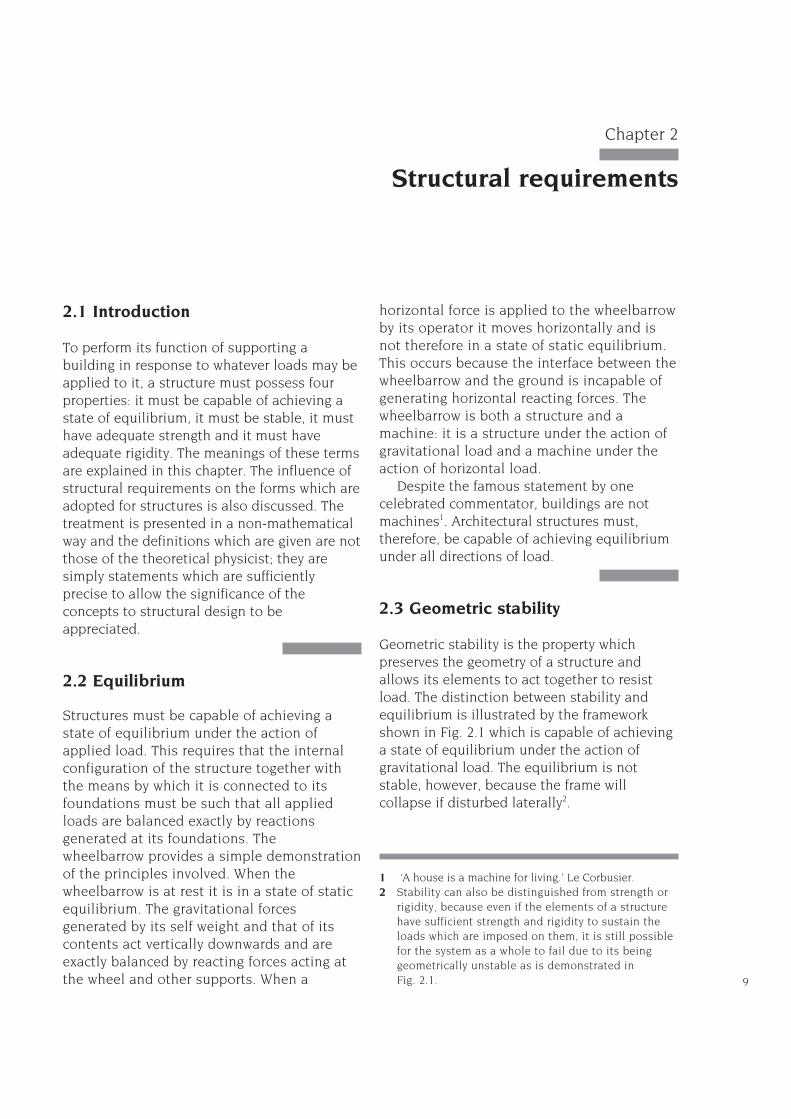
Geometric stability is the property whichpreserves the geometry of a structure andallows its elements to act together to resistload. The distinction between stability andequilibrium is illustrated by the frameworkshown in Fig. 2.1 which is capable of achievinga state of equilibrium under the action ofgravitational load. The equilibrium is notstable, however, because the frame willcollapse if disturbed laterally2.
9
Chapter 2
Structural requirements
1 ‘A house is a machine for living.’ Le Corbusier.2 Stability can also be distinguished from strength or
rigidity, because even if the elements of a structurehave sufficient strength and rigidity to sustain theloads which are imposed on them, it is still possiblefor the system as a whole to fail due to its beinggeometrically unstable as is demonstrated in Fig. 2.1.
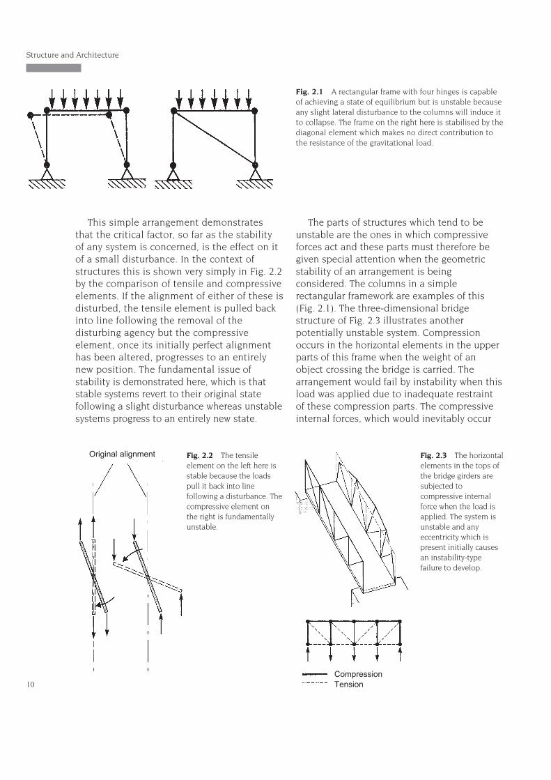
This simple arrangement demonstratesthat the critical factor, so far as the stabilityof any system is concerned, is the effect on itof a small disturbance. In the context ofstructures this is shown very simply in Fig. 2.2by the comparison of tensile and compressiveelements. If the alignment of either of these isdisturbed, the tensile element is pulled backinto line following the removal of thedisturbing agency but the compressiveelement, once its initially perfect alignmenthas been altered, progresses to an entirelynew position. The fundamental issue ofstability is demonstrated here, which is thatstable systems revert to their original statefollowing a slight disturbance whereas unstablesystems progress to an entirely new state.
The parts of structures which tend to beunstable are the ones in which compressiveforces act and these parts must therefore begiven special attention when the geometricstability of an arrangement is beingconsidered. The columns in a simplerectangular framework are examples of this(Fig. 2.1). The three-dimensional bridgestructure of Fig. 2.3 illustrates anotherpotentially unstable system. Compressionoccurs in the horizontal elements in the upperparts of this frame when the weight of anobject crossing the bridge is carried. Thearrangement would fail by instability when thisload was applied due to inadequate restraintof these compression parts. The compressiveinternal forces, which would inevitably occur
Structure and Architecture
10
Fig. 2.1 A rectangular frame with four hinges is capableof achieving a state of equilibrium but is unstable becauseany slight lateral disturbance to the columns will induce itto collapse. The frame on the right here is stabilised by thediagonal element which makes no direct contribution tothe resistance of the gravitational load.
Fig. 2.2 The tensileelement on the left here isstable because the loadspull it back into linefollowing a disturbance. Thecompressive element onthe right is fundamentallyunstable.
Original alignment Fig. 2.3 The horizontalelements in the tops ofthe bridge girders aresubjected tocompressive internalforce when the load isapplied. The system isunstable and anyeccentricity which ispresent initially causesan instability-typefailure to develop.
CompressionTension
with some degree of eccentricity, would pushthe upper elements out of alignment andcause the whole structure to collapse.
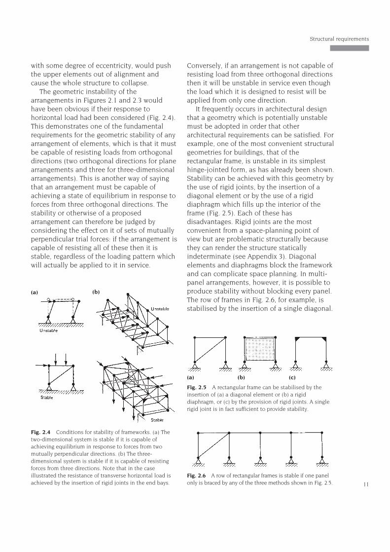
The geometric instability of thearrangements in Figures 2.1 and 2.3 wouldhave been obvious if their response tohorizontal load had been considered (Fig. 2.4).This demonstrates one of the fundamentalrequirements for the geometric stability of anyarrangement of elements, which is that it mustbe capable of resisting loads from orthogonaldirections (two orthogonal directions for planearrangements and three for three-dimensionalarrangements). This is another way of sayingthat an arrangement must be capable ofachieving a state of equilibrium in response toforces from three orthogonal directions. Thestability or otherwise of a proposedarrangement can therefore be judged byconsidering the effect on it of sets of mutuallyperpendicular trial forces: if the arrangement iscapable of resisting all of these then it isstable, regardless of the loading pattern whichwill actually be applied to it in service.
Conversely, if an arrangement is not capable ofresisting load from three orthogonal directionsthen it will be unstable in service even thoughthe load which it is designed to resist will beapplied from only one direction.
It frequently occurs in architectural designthat a geometry which is potentially unstablemust be adopted in order that otherarchitectural requirements can be satisfied. Forexample, one of the most convenient structuralgeometries for buildings, that of therectangular frame, is unstable in its simplesthinge-jointed form, as has already been shown.Stability can be achieved with this geometry bythe use of rigid joints, by the insertion of adiagonal element or by the use of a rigiddiaphragm which fills up the interior of theframe (Fig. 2.5). Each of these hasdisadvantages. Rigid joints are the mostconvenient from a space-planning point ofview but are problematic structurally becausethey can render the structure staticallyindeterminate (see Appendix 3). Diagonalelements and diaphragms block the frameworkand can complicate space planning. In multi-panel arrangements, however, it is possible toproduce stability without blocking every panel.The row of frames in Fig. 2.6, for example, isstabilised by the insertion of a single diagonal.
11
Structural requirements
Fig. 2.4 Conditions for stability of frameworks. (a) Thetwo-dimensional system is stable if it is capable ofachieving equilibrium in response to forces from twomutually perpendicular directions. (b) The three-dimensional system is stable if it is capable of resistingforces from three directions. Note that in the caseillustrated the resistance of transverse horizontal load isachieved by the insertion of rigid joints in the end bays.
(a) (b)
Fig. 2.5 A rectangular frame can be stabilised by theinsertion of (a) a diagonal element or (b) a rigiddiaphragm, or (c) by the provision of rigid joints. A singlerigid joint is in fact sufficient to provide stability.
Fig. 2.6 A row of rectangular frames is stable if one panelonly is braced by any of the three methods shown in Fig. 2.5.
(a) (b) (c)
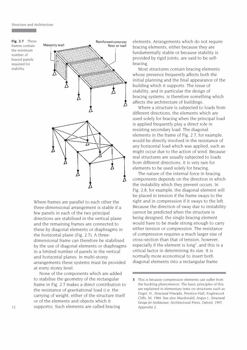
Where frames are parallel to each other thethree-dimensional arrangement is stable if afew panels in each of the two principaldirections are stabilised in the vertical planeand the remaining frames are connected tothese by diagonal elements or diaphragms inthe horizontal plane (Fig. 2.7). A three-dimensional frame can therefore be stabilisedby the use of diagonal elements or diaphragmsin a limited number of panels in the verticaland horizontal planes. In multi-storeyarrangements these systems must be providedat every storey level.
None of the components which are addedto stabilise the geometry of the rectangularframe in Fig. 2.7 makes a direct contribution tothe resistance of gravitational load (i.e. thecarrying of weight, either of the structure itselfor of the elements and objects which itsupports). Such elements are called bracing
elements. Arrangements which do not requirebracing elements, either because they arefundamentally stable or because stability isprovided by rigid joints, are said to be self-bracing.
Most structures contain bracing elementswhose presence frequently affects both theinitial planning and the final appearance of thebuilding which it supports. The issue ofstability, and in particular the design ofbracing systems, is therefore something whichaffects the architecture of buildings.
Where a structure is subjected to loads fromdifferent directions, the elements which areused solely for bracing when the principal loadis applied frequently play a direct role inresisting secondary load. The diagonalelements in the frame of Fig. 2.7, for example,would be directly involved in the resistance ofany horizontal load which was applied, such asmight occur due to the action of wind. Becausereal structures are usually subjected to loadsfrom different directions, it is very rare forelements to be used solely for bracing.
The nature of the internal force in bracingcomponents depends on the direction in whichthe instability which they prevent occurs. InFig. 2.8, for example, the diagonal element willbe placed in tension if the frame sways to theright and in compression if it sways to the left.Because the direction of sway due to instabilitycannot be predicted when the structure isbeing designed, the single bracing elementwould have to be made strong enough to carryeither tension or compression. The resistanceof compression requires a much larger size ofcross-section than that of tension, however,especially if the element is long3, and this is acritical factor in determining its size. It isnormally more economical to insert bothdiagonal elements into a rectangular frame
Structure and Architecture
12
Fig. 2.7 Theseframes containthe minimumnumber ofbraced panelsrequired forstability.
3 This is because compression elements can suffer fromthe buckling phenomenon. The basic principles of thisare explained in elementary texts on structures such asEngel, H., Structural Principles, Prentice-Hall, EnglewoodCliffs, NJ, 1984. See also Macdonald, Angus J., StructuralDesign for Architecture, Architectural Press, Oxford, 1997,Appendix 2.
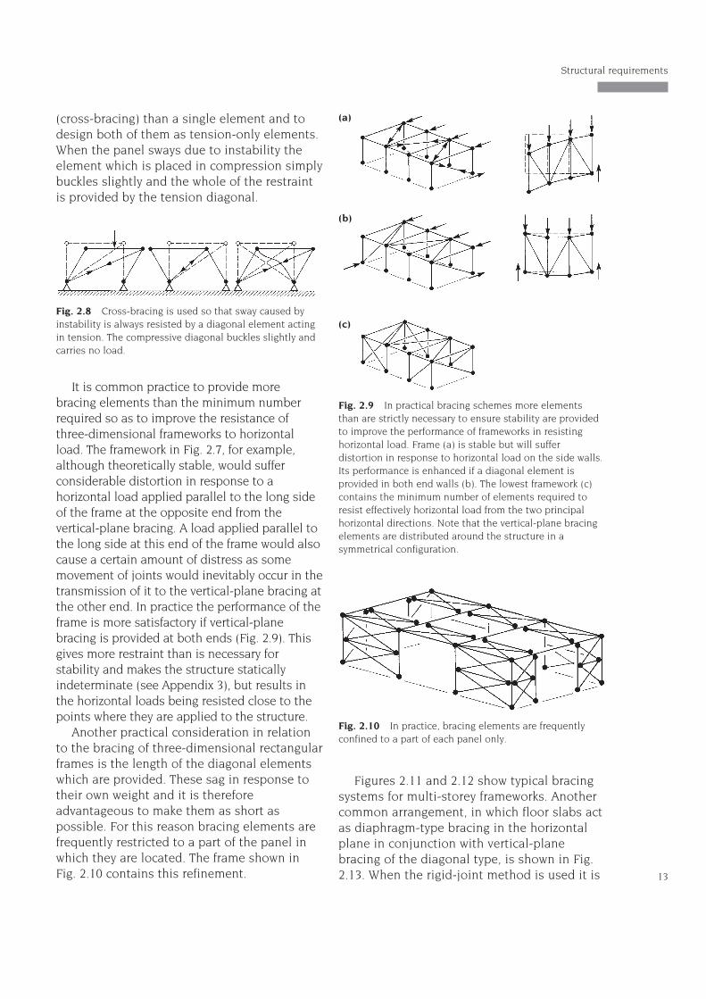
(cross-bracing) than a single element and todesign both of them as tension-only elements.When the panel sways due to instability theelement which is placed in compression simplybuckles slightly and the whole of the restraintis provided by the tension diagonal.
It is common practice to provide morebracing elements than the minimum numberrequired so as to improve the resistance ofthree-dimensional frameworks to horizontalload. The framework in Fig. 2.7, for example,although theoretically stable, would sufferconsiderable distortion in response to ahorizontal load applied parallel to the long sideof the frame at the opposite end from thevertical-plane bracing. A load applied parallel tothe long side at this end of the frame would alsocause a certain amount of distress as somemovement of joints would inevitably occur in thetransmission of it to the vertical-plane bracing atthe other end. In practice the performance of theframe is more satisfactory if vertical-planebracing is provided at both ends (Fig. 2.9). Thisgives more restraint than is necessary forstability and makes the structure staticallyindeterminate (see Appendix 3), but results inthe horizontal loads being resisted close to thepoints where they are applied to the structure.
Another practical consideration in relationto the bracing of three-dimensional rectangularframes is the length of the diagonal elementswhich are provided. These sag in response totheir own weight and it is thereforeadvantageous to make them as short aspossible. For this reason bracing elements arefrequently restricted to a part of the panel inwhich they are located. The frame shown inFig. 2.10 contains this refinement.
Figures 2.11 and 2.12 show typical bracingsystems for multi-storey frameworks. Anothercommon arrangement, in which floor slabs actas diaphragm-type bracing in the horizontalplane in conjunction with vertical-planebracing of the diagonal type, is shown in Fig.2.13. When the rigid-joint method is used it is 13
Structural requirements
Fig. 2.8 Cross-bracing is used so that sway caused byinstability is always resisted by a diagonal element actingin tension. The compressive diagonal buckles slightly andcarries no load.
Fig. 2.9 In practical bracing schemes more elementsthan are strictly necessary to ensure stability are providedto improve the performance of frameworks in resistinghorizontal load. Frame (a) is stable but will sufferdistortion in response to horizontal load on the side walls.Its performance is enhanced if a diagonal element isprovided in both end walls (b). The lowest framework (c)contains the minimum number of elements required toresist effectively horizontal load from the two principalhorizontal directions. Note that the vertical-plane bracingelements are distributed around the structure in asymmetrical configuration.
(a)
(b)
(c)
Fig. 2.10 In practice, bracing elements are frequentlyconfined to a part of each panel only.
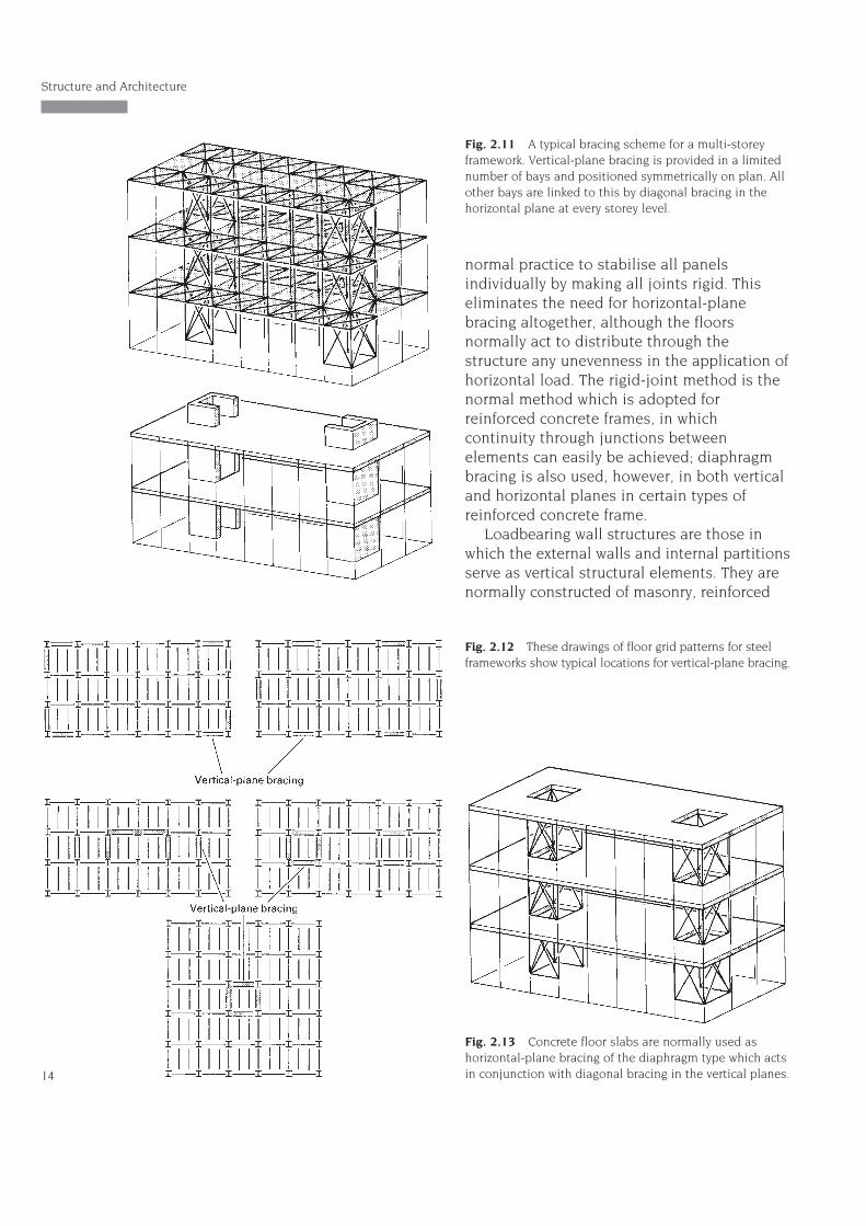
normal practice to stabilise all panelsindividually by making all joints rigid. Thiseliminates the need for horizontal-planebracing altogether, although the floorsnormally act to distribute through thestructure any unevenness in the application ofhorizontal load. The rigid-joint method is thenormal method which is adopted forreinforced concrete frames, in whichcontinuity through junctions betweenelements can easily be achieved; diaphragmbracing is also used, however, in both verticaland horizontal planes in certain types ofreinforced concrete frame.
Loadbearing wall structures are those inwhich the external walls and internal partitionsserve as vertical structural elements. They arenormally constructed of masonry, reinforced
Structure and Architecture
14
Fig. 2.13 Concrete floor slabs are normally used ashorizontal-plane bracing of the diaphragm type which actsin conjunction with diagonal bracing in the vertical planes.
Fig. 2.12 These drawings of floor grid patterns for steelframeworks show typical locations for vertical-plane bracing.
Fig. 2.11 A typical bracing scheme for a multi-storeyframework. Vertical-plane bracing is provided in a limitednumber of bays and positioned symmetrically on plan. Allother bays are linked to this by diagonal bracing in thehorizontal plane at every storey level.
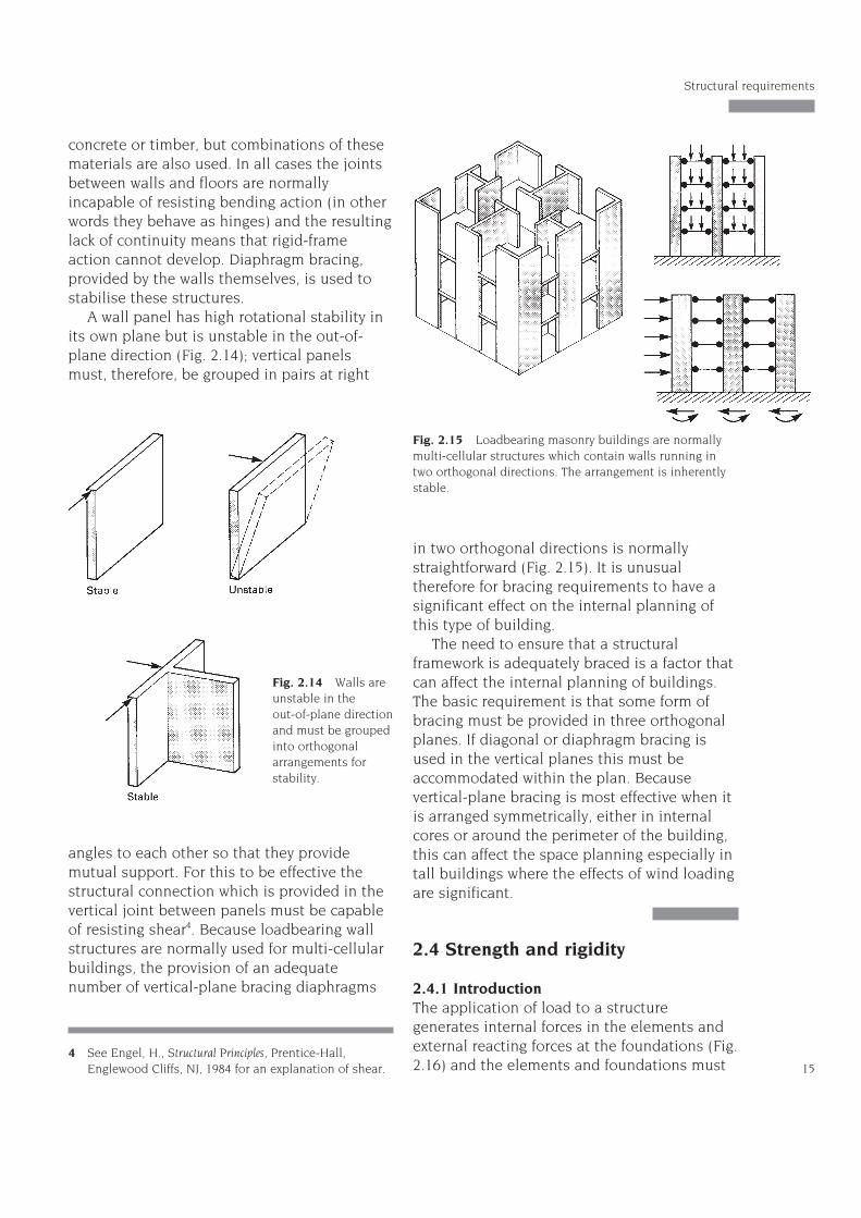
concrete or timber, but combinations of thesematerials are also used. In all cases the jointsbetween walls and floors are normallyincapable of resisting bending action (in otherwords they behave as hinges) and the resultinglack of continuity means that rigid-frameaction cannot develop. Diaphragm bracing,provided by the walls themselves, is used tostabilise these structures.
A wall panel has high rotational stability inits own plane but is unstable in the out-of-plane direction (Fig. 2.14); vertical panelsmust, therefore, be grouped in pairs at right
angles to each other so that they providemutual support. For this to be effective thestructural connection which is provided in thevertical joint between panels must be capableof resisting shear4. Because loadbearing wallstructures are normally used for multi-cellularbuildings, the provision of an adequatenumber of vertical-plane bracing diaphragms
in two orthogonal directions is normallystraightforward (Fig. 2.15). It is unusualtherefore for bracing requirements to have asignificant effect on the internal planning ofthis type of building.
The need to ensure that a structuralframework is adequately braced is a factor thatcan affect the internal planning of buildings.The basic requirement is that some form ofbracing must be provided in three orthogonalplanes. If diagonal or diaphragm bracing isused in the vertical planes this must beaccommodated within the plan. Becausevertical-plane bracing is most effective when itis arranged symmetrically, either in internalcores or around the perimeter of the building,this can affect the space planning especially intall buildings where the effects of wind loadingare significant.
2.4 Strength and rigidity
2.4.1 IntroductionThe application of load to a structuregenerates internal forces in the elements andexternal reacting forces at the foundations (Fig.2.16) and the elements and foundations must 15
Structural requirements
4 See Engel, H., Structural Principles, Prentice-Hall,Englewood Cliffs, NJ, 1984 for an explanation of shear.
Fig. 2.14 Walls areunstable in the out-of-plane directionand must be groupedinto orthogonalarrangements forstability.
Fig. 2.15 Loadbearing masonry buildings are normallymulti-cellular structures which contain walls running intwo orthogonal directions. The arrangement is inherentlystable.
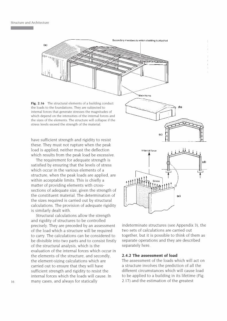
have sufficient strength and rigidity to resistthese. They must not rupture when the peakload is applied; neither must the deflectionwhich results from the peak load be excessive.
The requirement for adequate strength issatisfied by ensuring that the levels of stresswhich occur in the various elements of astructure, when the peak loads are applied, arewithin acceptable limits. This is chiefly amatter of providing elements with cross-sections of adequate size, given the strength ofthe constituent material. The determination ofthe sizes required is carried out by structuralcalculations. The provision of adequate rigidityis similarly dealt with.
Structural calculations allow the strengthand rigidity of structures to be controlledprecisely. They are preceded by an assessmentof the load which a structure will be requiredto carry. The calculations can be considered tobe divisible into two parts and to consist firstlyof the structural analysis, which is theevaluation of the internal forces which occur inthe elements of the structure, and secondly,the element-sizing calculations which arecarried out to ensure that they will havesufficient strength and rigidity to resist theinternal forces which the loads will cause. Inmany cases, and always for statically
indeterminate structures (see Appendix 3), thetwo sets of calculations are carried outtogether, but it is possible to think of them asseparate operations and they are describedseparately here.
2.4.2 The assessment of loadThe assessment of the loads which will act ona structure involves the prediction of all thedifferent circumstances which will cause loadto be applied to a building in its lifetime (Fig.2.17) and the estimation of the greatest
Structure and Architecture
16
Fig. 2.16 The structural elements of a building conductthe loads to the foundations. They are subjected tointernal forces that generate stresses the magnitudes ofwhich depend on the intensities of the internal forces andthe sizes of the elements. The structure will collapse if thestress levels exceed the strength of the material.
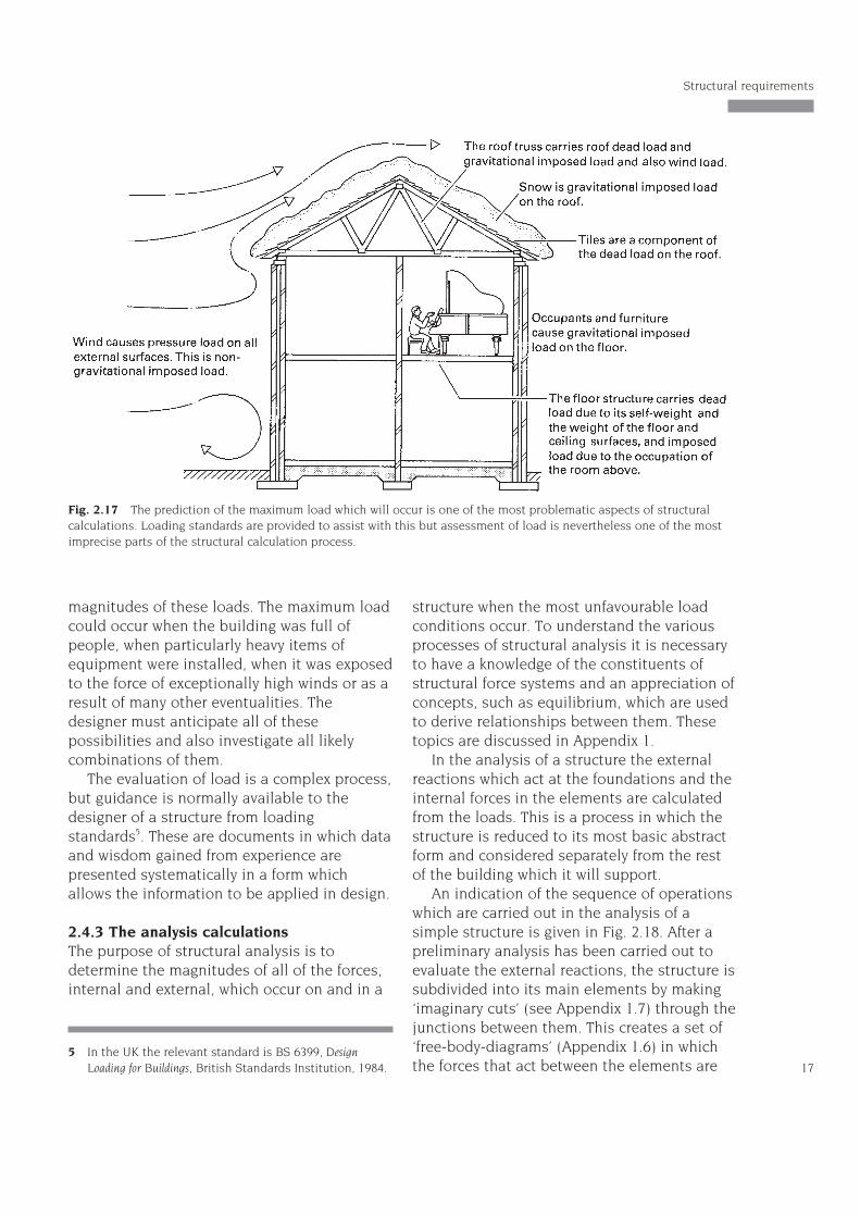
magnitudes of these loads. The maximum loadcould occur when the building was full ofpeople, when particularly heavy items ofequipment were installed, when it was exposedto the force of exceptionally high winds or as aresult of many other eventualities. Thedesigner must anticipate all of thesepossibilities and also investigate all likelycombinations of them.
The evaluation of load is a complex process,but guidance is normally available to thedesigner of a structure from loadingstandards5. These are documents in which dataand wisdom gained from experience arepresented systematically in a form whichallows the information to be applied in design.
2.4.3 The analysis calculationsThe purpose of structural analysis is todetermine the magnitudes of all of the forces,internal and external, which occur on and in a
structure when the most unfavourable loadconditions occur. To understand the variousprocesses of structural analysis it is necessaryto have a knowledge of the constituents ofstructural force systems and an appreciation ofconcepts, such as equilibrium, which are usedto derive relationships between them. Thesetopics are discussed in Appendix 1.
In the analysis of a structure the externalreactions which act at the foundations and theinternal forces in the elements are calculatedfrom the loads. This is a process in which thestructure is reduced to its most basic abstractform and considered separately from the restof the building which it will support.
An indication of the sequence of operationswhich are carried out in the analysis of asimple structure is given in Fig. 2.18. After apreliminary analysis has been carried out toevaluate the external reactions, the structure issubdivided into its main elements by making‘imaginary cuts’ (see Appendix 1.7) through thejunctions between them. This creates a set of‘free-body-diagrams’ (Appendix 1.6) in whichthe forces that act between the elements are 17
Structural requirements
5 In the UK the relevant standard is BS 6399, DesignLoading for Buildings, British Standards Institution, 1984.
Fig. 2.17 The prediction of the maximum load which will occur is one of the most problematic aspects of structuralcalculations. Loading standards are provided to assist with this but assessment of load is nevertheless one of the mostimprecise parts of the structural calculation process.
exposed. Following the evaluation of theseinter-element forces the individual elementsare analysed separately for their internal forcesby further applications of the ‘imaginary cut’technique. In this way all of the internal forcesin the structure are determined.
In large, complex, statically indeterminatestructures the magnitudes of the internalforces are affected by the sizes and shapes ofthe element cross-sections and the propertiesof the constituent materials, as well as by themagnitudes of the loads and the overall
geometry of the structure. The reason for thisis explained in Appendix 3. In thesecircumstances the analysis and element-sizingcalculations are carried out together in a trialand error process which is only feasible in thecontext of computer-aided design.
The different types of internal force whichcan occur in a structural element are shown inFig. 2.19. As these have a very significantinfluence on the sizes and shapes which arespecified for elements they will be describedbriefly here.
In Fig. 2.19 an element is cut through at aparticular cross-section. In Fig. 2.19(a) theforces which are external to one of the
Structure and Architecture
18
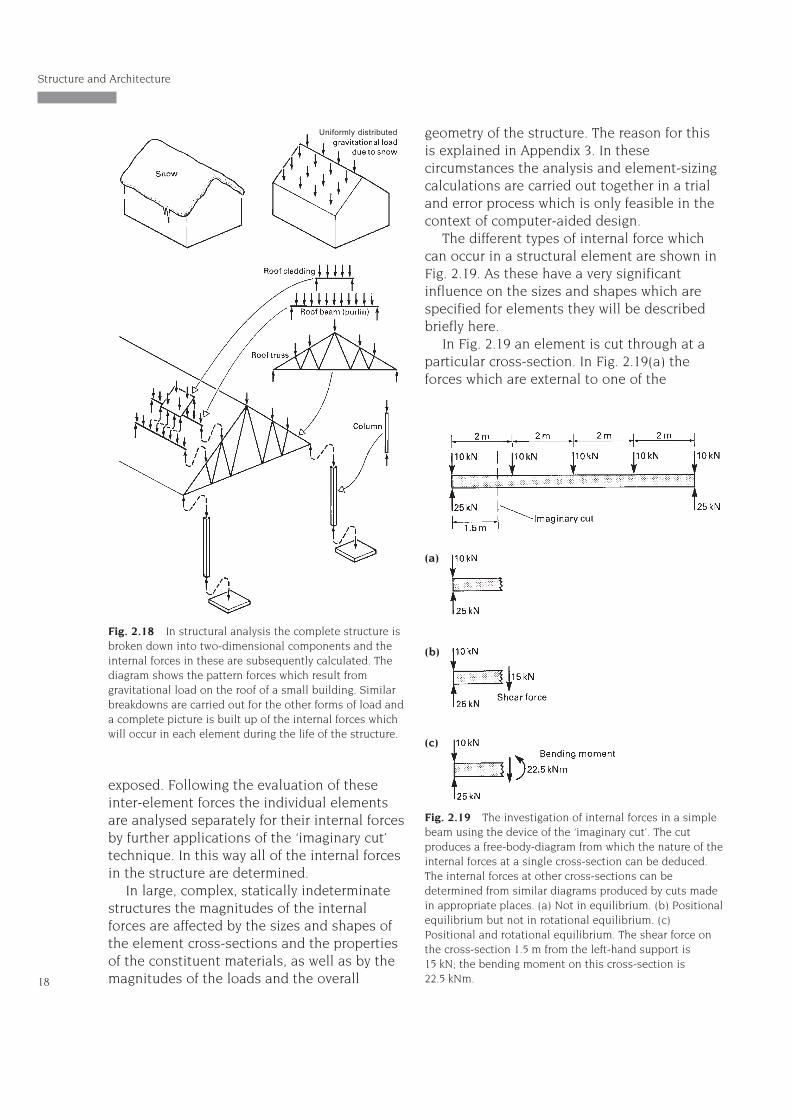
Fig. 2.18 In structural analysis the complete structure isbroken down into two-dimensional components and theinternal forces in these are subsequently calculated. Thediagram shows the pattern forces which result fromgravitational load on the roof of a small building. Similarbreakdowns are carried out for the other forms of load anda complete picture is built up of the internal forces whichwill occur in each element during the life of the structure.
Uniformly distributed
Fig. 2.19 The investigation of internal forces in a simplebeam using the device of the ‘imaginary cut’. The cutproduces a free-body-diagram from which the nature of theinternal forces at a single cross-section can be deduced.The internal forces at other cross-sections can bedetermined from similar diagrams produced by cuts madein appropriate places. (a) Not in equilibrium. (b) Positionalequilibrium but not in rotational equilibrium. (c)Positional and rotational equilibrium. The shear force onthe cross-section 1.5 m from the left-hand support is15 kN; the bending moment on this cross-section is22.5 kNm.
(a)
(b)
(c)
resulting sub-elements are marked. If thesewere indeed the only forces which acted on thesub-element it would not be in a state ofequilibrium. For equilibrium the forces mustbalance and this is clearly not the case here;an additional vertical force is required forequilibrium. As no other external forces arepresent on this part of the element the extraforce must act on the cross-section where thecut occurred. Although this force is external tothe sub-element it is an internal force so far asthe complete element is concerned and iscalled the ‘shear force’. Its magnitude at thecross-section where the cut was made issimply the difference between the externalforces which occur to one side of the cross-section, i.e. to the left of the cut.
Once the shear force is added to thediagram the question of the equilibrium ofthe sub-element can once more beexamined. In fact it is still not in a state ofequilibrium because the set of forces nowacting will produce a turning effect on thesub-element which will cause it to rotate in aclockwise sense. For equilibrium an anti-clockwise moment is required and as beforethis must act on the cross-section at the cutbecause no other external forces are present.The moment which acts at the cut and whichis required to establish rotationalequilibrium is called the bending moment atthe cross-section of the cut. Its magnitude isobtained from the moment equation ofequilibrium for the free-body-diagram. Oncethis is added to the diagram the system is ina state of static equilibrium, because all theconditions for equilibrium are now satisfied(see Appendix 1).
Shear force and bending moment are forceswhich occur inside structural elements andthey can be defined as follows. The shear forceat any location is the amount by which theexternal forces acting on the element, to oneside of that location, do not balance when theyare resolved perpendicular to the axis of theelement. The bending moment at a location inan element is the amount by which themoments of the external forces acting to oneside of the location, about any point in their
plane, do not balance. Shear force and bendingmoment occur in structural elements which arebent by the action of the applied load. Beamsand slabs are examples of such elements.
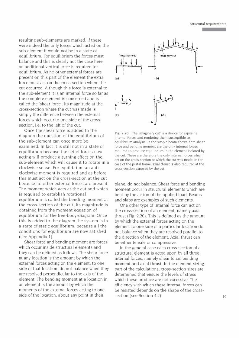
One other type of internal force can act onthe cross-section of an element, namely axialthrust (Fig. 2.20). This is defined as the amountby which the external forces acting on theelement to one side of a particular location donot balance when they are resolved parallel tothe direction of the element. Axial thrust canbe either tensile or compressive.
In the general case each cross-section of astructural element is acted upon by all threeinternal forces, namely shear force, bendingmoment and axial thrust. In the element-sizingpart of the calculations, cross-section sizes aredetermined that ensure the levels of stresswhich these produce are not excessive. Theefficiency with which these internal forces canbe resisted depends on the shape of the cross-section (see Section 4.2). 19
Structural requirements
Fig. 2.20 The ‘imaginary cut’ is a device for exposinginternal forces and rendering them susceptible toequilibrium analysis. In the simple beam shown here shearforce and bending moment are the only internal forcesrequired to produce equilibrium in the element isolated bythe cut. These are therefore the only internal forces whichact on the cross-section at which the cut was made. In thecase of the portal frame, axial thrust is also required at thecross-section exposed by the cut.
(a) (b)
(c) (d)
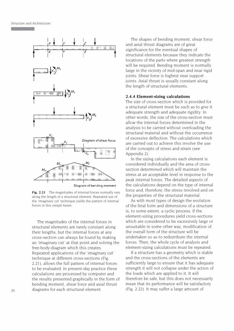
The magnitudes of the internal forces instructural elements are rarely constant alongtheir lengths, but the internal forces at anycross-section can always be found by makingan ‘imaginary cut’ at that point and solving thefree-body-diagram which this creates.Repeated applications of the ‘imaginary cut’technique at different cross-sections (Fig.2.21), allows the full pattern of internal forcesto be evaluated. In present-day practice thesecalculations are processed by computer andthe results presented graphically in the form ofbending moment, shear force and axial thrustdiagrams for each structural element.
The shapes of bending moment, shear forceand axial thrust diagrams are of greatsignificance for the eventual shapes ofstructural elements because they indicate thelocations of the parts where greatest strengthwill be required. Bending moment is normallylarge in the vicinity of mid-span and near rigidjoints. Shear force is highest near supportjoints. Axial thrust is usually constant alongthe length of structural elements.
2.4.4 Element-sizing calculationsThe size of cross-section which is provided fora structural element must be such as to give itadequate strength and adequate rigidity. Inother words, the size of the cross-section mustallow the internal forces determined in theanalysis to be carried without overloading thestructural material and without the occurrenceof excessive deflection. The calculations whichare carried out to achieve this involve the useof the concepts of stress and strain (seeAppendix 2).
In the sizing calculations each element isconsidered individually and the area of cross-section determined which will maintain thestress at an acceptable level in response to thepeak internal forces. The detailed aspects ofthe calculations depend on the type of internalforce and, therefore, the stress involved and onthe properties of the structural material.
As with most types of design the evolutionof the final form and dimensions of a structureis, to some extent, a cyclic process. If theelement-sizing procedures yield cross-sectionswhich are considered to be excessively large orunsuitable in some other way, modification ofthe overall form of the structure will beundertaken so as to redistribute the internalforces. Then, the whole cycle of analysis andelement-sizing calculations must be repeated.
If a structure has a geometry which is stableand the cross-sections of the elements aresufficiently large to ensure that it has adequatestrength it will not collapse under the action ofthe loads which are applied to it. It willtherefore be safe, but this does not necessarilymean that its performance will be satisfactory(Fig. 2.22). It may suffer a large amount of
Structure and Architecture
20
Fig. 2.21 The magnitudes of internal forces normally varyalong the length of a structural element. Repeated use ofthe ‘imaginary cut’ technique yields the pattern of internalforces in this simple beam.
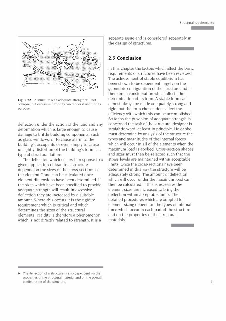
deflection under the action of the load and anydeformation which is large enough to causedamage to brittle building components, suchas glass windows, or to cause alarm to thebuilding’s occupants or even simply to causeunsightly distortion of the building’s form is atype of structural failure.
The deflection which occurs in response to agiven application of load to a structuredepends on the sizes of the cross-sections ofthe elements6 and can be calculated onceelement dimensions have been determined. Ifthe sizes which have been specified to provideadequate strength will result in excessivedeflection they are increased by a suitableamount. Where this occurs it is the rigidityrequirement which is critical and whichdetermines the sizes of the structuralelements. Rigidity is therefore a phenomenonwhich is not directly related to strength; it is a
separate issue and is considered separately inthe design of structures.
2.5 Conclusion
In this chapter the factors which affect the basicrequirements of structures have been reviewed.The achievement of stable equilibrium hasbeen shown to be dependent largely on thegeometric configuration of the structure and istherefore a consideration which affects thedetermination of its form. A stable form canalmost always be made adequately strong andrigid, but the form chosen does affect theefficiency with which this can be accomplished.So far as the provision of adequate strength isconcerned the task of the structural designer isstraightforward, at least in principle. He or shemust determine by analysis of the structure thetypes and magnitudes of the internal forceswhich will occur in all of the elements when themaximum load is applied. Cross-section shapesand sizes must then be selected such that thestress levels are maintained within acceptablelimits. Once the cross-sections have beendetermined in this way the structure will beadequately strong. The amount of deflectionwhich will occur under the maximum load canthen be calculated. If this is excessive theelement sizes are increased to bring thedeflection within acceptable limits. Thedetailed procedures which are adopted forelement sizing depend on the types of internalforce which occur in each part of the structureand on the properties of the structuralmaterials.
21
Structural requirements
6 The deflection of a structure is also dependent on theproperties of the structural material and on the overallconfiguration of the structure.
Fig. 2.22 A structure with adequate strength will notcollapse, but excessive flexibility can render it unfit for itspurpose.


