Embed Size (px)
Citation preview
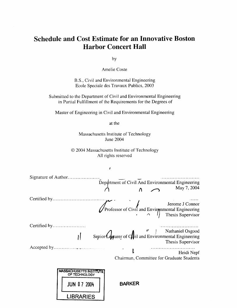
Schedule and Cost Estimate for an Innovative BostonHarbor Concert Hall
by
Amelie Coste
B.S., Civil and Environmental EngineeringEcole Speciale des Travaux Publics, 2003
Submitted to the Department of Civil and Environmental Engineeringin Partial Fulfillment of the Requirements for the Degrees of
Master of Engineering in Civil and Environmental Engineering
at the
Massachusetts Institute of TechnologyJune 2004
© 2004 Massachusetts Institute of TechnologyAll rights reserved
Signature of A uthor..................... ........................Deplrtment of Civil And Environmental Engineering
n May 7, 2004
Certified by...........................
Professor of
Certified by.....................
IA
Accepted by ..............
MASSACHUSETTS INSOF TECHNOLOG
JUN 0 7 200
LIBRARIE
Jerome J ConnorCivil and Envir nmental Engineering
Thesis Supervisor
.........................ACA ' 1 Nathaniel Osgood
Sepior4urer of il and Environmental EngineeringThesis Supervisor
............................Heidi Nepf
Chairman, Committee for Graduate Students
Y
4] BARKER
S
Schedule and Cost Estimate for an Innovative BostonHarbor Concert Hall
By
Amelie Coste
Submitted to the Department of Civil and Environmental Engineeringon May 7, 2004 in partial fulfillment of the
requirements for the Degree of Master of Engineering inCivil and Environmental Engineering
ABSTRACT
This thesis formulates a cost estimate and schedule for constructing the Boston ConcertHall, an innovative hypothetical building composed of two concert halls and a restaurant.Concert Halls are complex and expensive structures due to steep design requirementsreflecting their status as signature buildings and because they require extensivefurnishing. Restaurants are not as complex but require the same kind of attention in theirinterior furnishing as well as in the choice of their kitchen equipment. Because thestructure houses two complicated entities, feasibility analysis required a careful cost andschedule estimation.On the basis of several assumptions, a rough estimate of the cost and schedule of theentire structure has been developed along with a more detailed estimate of the twoauditoriums and the restaurant. The study suggests that the interior finishing of suchunique buildings represent a large fraction of their overall costs and construction time.
Thesis Supervisor: Nathaniel Osgood
Title: Senior Lecturer of Civil and Environmental Engineering
ACKNOWLEDGMENTS
I would like to thank God for His love and comfort to me during the year. Since I became
His child by faith in Jesus Christ His son, He has always guided me in His ways and I
couldn't have come here without Him.
I would like to thank all my family who has always helped me. I couldn't have come here
without their support and I thank them for having guided me in the ways of the Lord
Jesus Christ for so many years.
I would also like to thank Doctor Connor, who has been of great advice this year when
choosing my classes and always of good support.
I would also like to thank Doctor Osgood who helped me so much to put this thesis
together. He guided me very diligently when trying to find information, gave me some
really good piece of advice and was of great support when it came to editing and
formatting.
Finally, I would like to thank my sweet roommates, my classmates at MIT, my
classmates in France and my three dear churches in St-Denis, Houston and Brockton.
They have encouraged me by so many emails and comforting words all along the year.
It has been a great year!
3
TABLE OF CONTENTS
C PR O JEC T O V ERVIEW ........................................................................................ 8
1.1 THE ARCHITECTURAL CONCEPT ......................................................................... 9
1.1.1 A ship ....................................................................................................... 9
1.1.2 A signature building............................................................................... 10
1.2 THE STRUCTURE................................................................................................. 10
1.2.1 The concept ............................................................................................. 10
1.2.2 The different elem ents ............................................................................. 10
1.3 THE SITE ............................................................................................................ 12
1.4 M OTIVATION.................................................................................................... 12
2 ESTIM A TIN G ...................................................................................................... 15
2.1 THE CONCEPT..................................................................................................... 15
2.2 COST ESTIM ATING........................................................................................... 16
2.2.1 Approximate estimate............................................................................. 17
2.2.2 D etailed estim ates ................................................................................. 17
2.2.3 O rganization of estimates ...................................................................... 22
2.3 SCHEDULING ...................................................................................................... 23
2.3.1 G ood and poor scheduling .................................................................... 23
2.3.2 D ifferent actors ...................................................................................... 24
2.3.3 Scheduling lim itations........................................................................... 24
2.3.4 D ifferent types of schedules ................................................................... 25
3 CONCERT HALL COST ESTIMATION ........................................................ 28
3.1 A N INNOVATIVE STRUCTURE............................................................................ 28
3.2 THE TECHNIQUES USED ...................................................................................... 28
3.2.1 Existing Projects ................................................................................... 29
4
3.2.2 H arbor building characteristics ............................................................ 34
3.2.3 Boston H arbor Concert Hall cost estim ation ........................................ 38
3.2.4 Auditorium cost estimation ................................................................... 41
3.2.5 Restaurant cost estimation.................................................................... 47
3.2.6 Other items cost estim ation.................................................................... 51
3.2.7 Final cost ............................................................................................... 52
4 CO N CER T H A LL SCH EDU LE ........................................................................ 56
4.1 THE FIRST ESTIMATE ........................................................................................ 57
4.1.1 The auditorium ...................................................................................... 61
4.1.2 The restaurant ........................................................................................ 62
4.1.3 Critique ................................................................................................. 62
4.2 D ETAILED SCHEDULE ...................................................................................... 64
4.2.1 Auditorium detailed estim ate ................................................................. 64
4.2.2 Restaurant detailed estimate................................................................. 70
5 C O N CLU SIO N ................................................................................................... 73
6 REFERE N CES...................................................................................................... 75
5
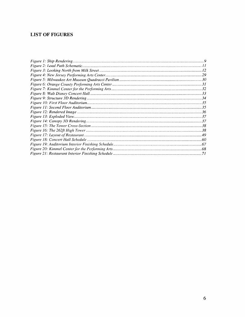
LIST OF FIGURES
Figure 1: Ship Rendering ................................................................................................................................ 9Figure 2: Load Path Schem atic.....................................................................................................................11Figure 3: Looking North from M ilk Street .................................................................................................... 12Figure 4: New Jersey Perform ing Arts Center.......................................................................................... 29Figure 5: M ilwaukee Art M useum Quadracci Pavilion ........................................................................... 30Figure 6: Orange County Perform ing Arts Center ................................................................................... 31Figure 7: Kim m el Center for the Perform ing Arts.................................................................................... 32Figure 8: W alt D isney Concert Hall ............................................................................................................. 33Figure 9: Structure 3D Rendering ................................................................................................................ 34Figure 10: First Floor Auditorium ................................................................................................................ 35Figure 11: Second Floor Auditorium ............................................................................................................ 35Figure 12: Rendered Im age .......................................................................................................................... 36Figure 13: Exploded View.............................................................................................................................37Figure 14: Canopy 3D Rendering.................................................................................................................37Figure 15: The Tower Cross-Section ............................................................................................................ 38Figure 16: The 262ft H igh Tower ................................................................................................................. 38Figure 17: Layout of Restaurant ................................................................................................................... 49Figure 18: Concert H all Schedule ................................................................................................................ 60Figure 19: Auditorium Interior Finishing Schedule......................................................................................67Figure 20: Kim m el Center for the Perform ing Arts................................................................................. 68Figure 21: Restaurant Interior Finishing Schedule ................................................................................... 71
6
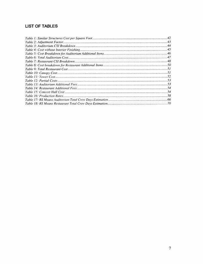
LIST OF TABLES
Table 1: Sim ilar Structures Cost per Square Foot.................................................................................... 42
Table 2: Adjustm ent Factor...........................................................................................................................43Table 3: Auditorium CSI Breakdown ............................................................................................................ 44Table 4: Cost without Interior Finishing.......................................................................................................45Table 5: Cost Breakdown for Auditorium Additional Items...................................................................... 46Table 6: Total Auditorium Cost.....................................................................................................................47Table 7: Restaurant CSI Breakdown.............................................................................................................48Table 8: Cost breakdown for Restaurant Additional Items ........................................................................ 50Table 9: Total Restaurant Cost ..................................................................................................................... 51Table 10: Canopy Cost..................................................................................................................................51Table ] : Tower Cost....................................................................................................................................52Table 12: Partia l Costs ................................................................................................................................. 53Table 13: Auditorium Additional Fees..........................................................................................................53Table 14: Restaurant Additional Fees...........................................................................................................54Table 15: Concert H all Cost ......................................................................................................................... 54Table 16: Production Rates...........................................................................................................................58Table 17: RS M eans Auditorium Total Crew Days Estimation.................................................................. 66Table 18: RS M eans Restaurant Total Crew Days Estimation.................................................................. 70
7
1 PROJECT OVERVIEW
This thesis formulates a cost estimate and schedule for constructing the Boston Concert
Hall, an innovative hypothetical building composed of two concert halls and a restaurant.
Concert Halls are complex and expensive structures due to steep design requirements
reflecting their status as signature buildings and because they require extensive
furnishing. Restaurants are not as complex but require the same kind of attention in their
interior furnishing as well as in the choice of their kitchen equipment. Because the
structure houses two complicated entities, feasibility analysis required a careful cost and
schedule estimation.
This section reviews the central elements of the structural design of the facility whose
cost and schedule is estimated by this thesis. The section first examines the architectural
concept underlying the structure, then turns to a discussion of the structure and finally
examines the motivations behind the project.
8
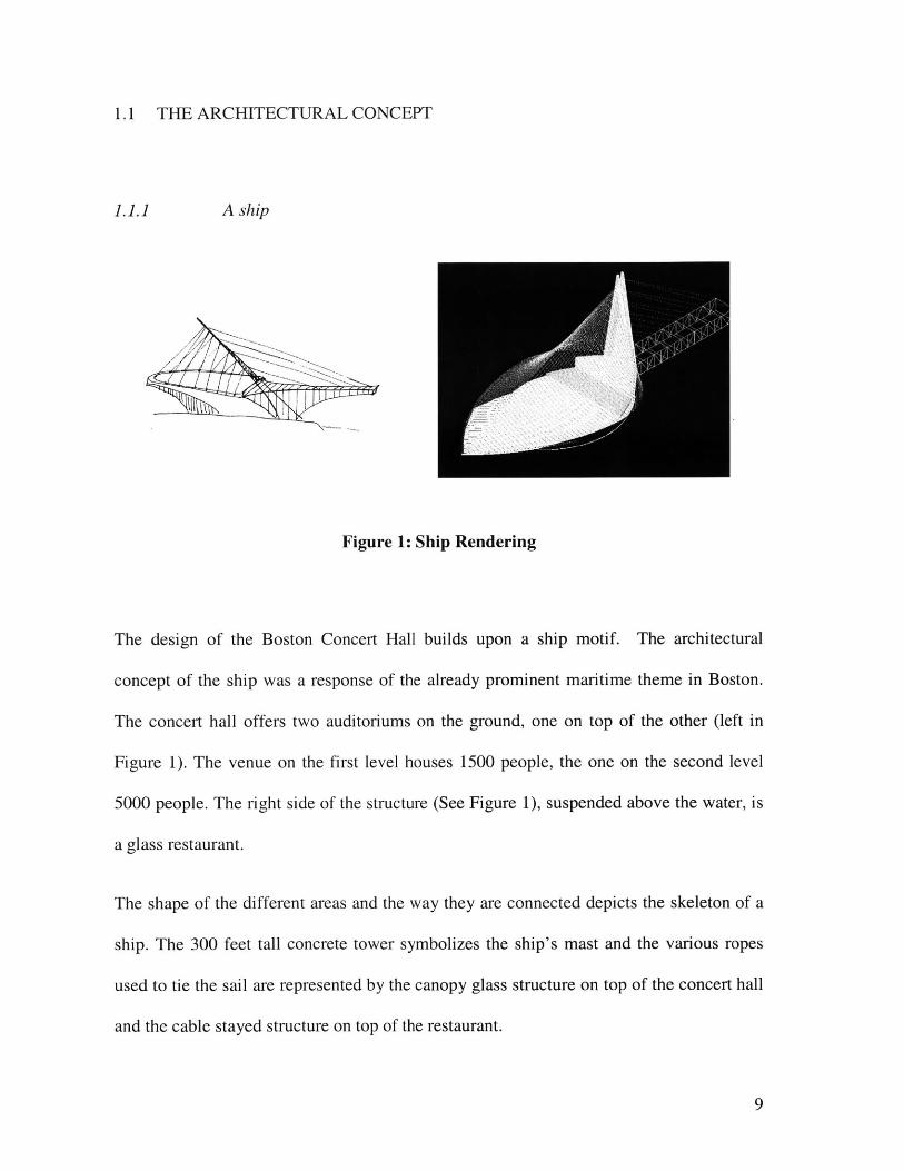
1.1 THE ARCHITECTURAL CONCEPT
1.1.1 A ship
Figure 1: Ship Rendering
The design of the Boston Concert Hall builds upon a ship motif. The architectural
concept of the ship was a response of the already prominent maritime theme in Boston.
The concert hall offers two auditoriums on the ground, one on top of the other (left in
Figure 1). The venue on the first level houses 1500 people, the one on the second level
5000 people. The right side of the structure (See Figure 1), suspended above the water, is
a glass restaurant.
The shape of the different areas and the way they are connected depicts the skeleton of a
ship. The 300 feet tall concrete tower symbolizes the ship's mast and the various ropes
used to tie the sail are represented by the canopy glass structure on top of the concert hall
and the cable stayed structure on top of the restaurant.
9
1.1.2 A signature building
The designers anticipated that because of Boston history and location, the ship structure
would soon become one of the city's signature buildings. This 30,000 sf elliptical base
would sit on a 200, 000 sf green space facing the water. The cable stay structure would
remind the viewer of the Zakim Bridge and the canopy glass structure the Eden Project in
England. This concert hall would succeed the Fleet Pavilion on the waterfront by virtue
of its size and elegance.
1.2 THE STRUCTURE
1.2.1 The concept
The primary concern in this design was the interdependence of the different structural
systems.
1.2.2 The different elements
The structure presents four different structural items that work together as an integrated
whole:
* The truss box restaurant
" The concert hall steel frame
" The cable-stayed tower
" The glass canopy
10
Following is a SAP drawing that will help us better understand the importance of the
interdependence between the different elements:
Figure 2: Load Path Schematic
Starting on the left side of the drawing (See Figure 2), the gravity loads of the restaurant
are transferred to the cable-stayed system. At the same time, on the right side of the
drawing, the gravity loads in the concert hall roof are taken by the tensile roof and act on
the tower and the steel frame structure. Both of these actions - tension in the cables and
in the canopy - are transferred to the tower. The steel frame acts both as a cantilever for
the tensile roof and as a usual load transfer system. Indeed, the gravity loads in the
concert hall structure are transferred to the ground by a more commonly used load path:
the forces are taken by the second floor, transferred downward via the columns and
directed to the foundations.
11
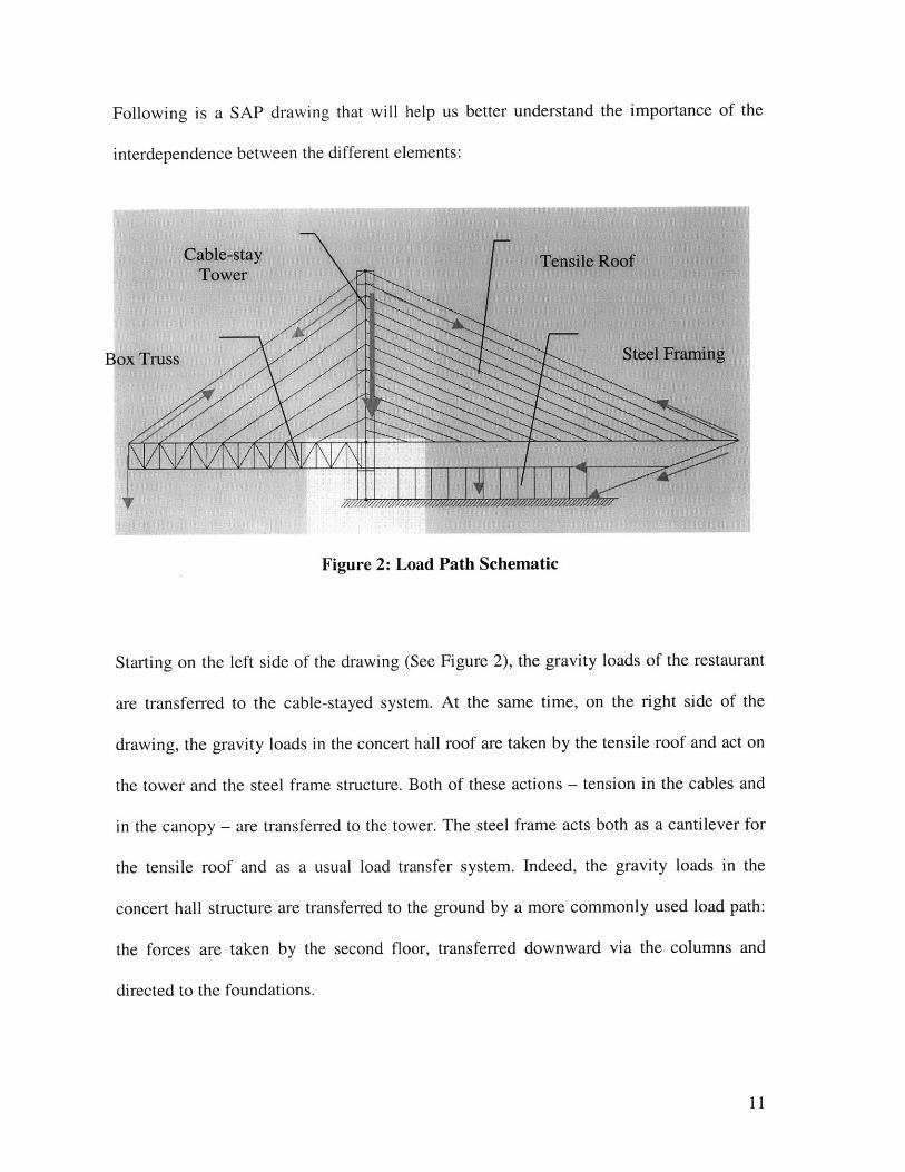
1.3 THE SITE
The structure is located on Columbus Park. The following rendering shows the site and
its surrounding area.'
Columbus Park
Parcels
Figure 3: Looking North from Milk Street
1.4 MOTIVATION
From what have been discussed above, the concert hall is clearly a complex structure.
This complexity reflects both the design and the structure itself.
The project is complex because the structure itself is designed to be a signature building
in Boston. This design implies an expensive structure, with quality materials and
12
workmanship and the use of a skilled labor force. Because the structure is located
downtown, near the Boston Aquarium and Quincy Market, the concert hall will be easily
visible by the community and Boston's large tourist population. Because the building will
house a significant amount of people, fire safety is a strong concern, and demands well-
designed fireproofing and fire and smoke detection systems.
The structure adds further complexity to the project. The four structural items listed
earlier (the truss box restaurant, the concert hall steel frame, the cable-stayed tower and
the glass canopy) are interconnected. This means that each one of them relies on the other
to stand. Such interdependence requires a careful and elaborate construction schedule.
Access to the site has to be predetermined in advance (by ground or by water) and the
pieces of equipment have to arrive in a coordinated fashion. In addition to their
interdependence, many structural elements are elaborate in themselves. The glass canopy
will require skilled labor to assemble and erect, the steel beams of the shell structure have
to be manufactured ahead of time, and the restaurant, as well as the auditorium, have to
be fully equipped before the building can open. Erecting such an impressive structure will
require high amounts of labor and cannot be accomplished in a reasonable amount of
time if a detailed schedule is not in place before construction starts.
The section above has highlighted the need to estimate the schedule of the Boston Harbor
Concert Hall. An estimate of project costs must accompany such a schedule in order to
estimate the size of the necessary financing and to plan the disbursement of funds to site
contractors. Indeed, in a project this size, money and time can be easily wasted because
of a poor estimation. This thesis will provide some cost and schedule calculations to
evaluate the price of the concert hall and the time required to build it. I will develop a full
13
first rough estimate of the cost of the building and then focus on some items expected to
impose particularly high costs. In terms of scheduling, I will give a first estimation of the
project length and give a detailed estimate of the interior finishing.
As noted above, there are four main structural items in the building. In this thesis, when I
develop a detailed cost breakdown and the detailed schedule, I will only focus on the
concert hall and the restaurant. The glass canopy and the cable-stay tower cost and
schedule won't be developed in great detail. Part of this choice comes from the fact the
auditorium and the restaurant are unconventional commercial buildings that require
specific interior finishing. Such elements held greater research interest than limiting
myself to the structure construction process. Moreover, RS Means Square Foot Cost and
RS Means Building Construction Cost contained very detailed information on the interior
items required of a restaurant and auditorium. Finally, attention to these two
unconventional buildings offered a good opportunity to discover the complexity of such
buildings.
14
2 ESTIMATING
2.1 THE CONCEPT
Estimating is a technique widely used in construction projects. "The purpose of
estimating is to forecast costs required to complete a project in accordance with the
contract plans and specifications"2 . Estimating has great advantages but also has some
drawbacks. The preliminary estimate will help in deciding if a project is feasible and is
very useful for rapid iterations of design plans. Eventually, estimation will form the basis
for a fair-price bid on the part of the owner and for bid prices for contractors.
While essential, there is a risk that estimation will not reflect accurately the true project
costs. Changes in productivity and technology can occur over time, and are particularly
important components in the costs of a highly innovative structure. For instance, in a
revamp/restart project on a chemical plant, pieces of equipment can be discovered along
the way and items can turn out to be more difficult to refurbish then expected. In an
innovative structure, there are different sorts of unknowns that must be faced, such as
components that will require experimenting with innovative construction techniques. The
costs extending from these activities can be greatly underestimated if not taken into
account.
15
This thesis uses two main handbooks to estimate the cost and schedule of the Boston
Concert Hall:
" RS Means Square Foot Cost: This book gives cost information on the major types
of buildings (commercial, industrial, institutional and so on) using the CSI cost
breakdown structure.
* RS Means Building Construction Cost Data: This book goes in much more detail
than the previous book, giving very detailed information such as the cost of the
equipment and material for a very important number of structural or non structural
elements.
2.2 COST ESTIMATING
Cost estimating is a critical component of Project Management. The three actors - the
owner, the designer and the contractor - involved in a project look for different kinds of
cost estimates. The owner's primary concern is to know if he can pay for the project, and
how the financing should be arranged. He then needs an approximate cost estimate to
select the design, and more detailed cost estimates as the design is finalized. The designer
has to be able to calculate the cost of design alternatives and the contractor wants to know
how much he will be paid for throughout the project. There are two broad types of
estimates:
0 Approximate estimate
16
* Detailed estimate
2.2.1 Approximate estimate
The approximate estimate of a project is typically conducted in the context of a feasibility
study and an economic analysis to evaluate his profit/return on investment. In order to
derive this estimate, the designer has to evaluate the cost of the project per square foot of
floor or cubic meters of concrete. This is a difficult task and requires a lot of experience
due to uncertainties with regard to several factors (such as the quality, uncertainties about
myriad design details, skill level and productivity of the labor force or the location of the
project) that can influence the cost of a structure. This estimate is acceptable to be
presented to the owner for the sake of feasibility analysis and a decision to proceed with
design development but not to bid. If the owner wants to bid before all the construction
documents are issued, the contractor calculates an estimate the best way he can with the
information he has and both the owner and the contractor negotiate a reasonable
compensation scheme - frequently including some elements of flexibility to reflect the
attendant uncertainties. It is clear that this strategy typically requires that both the owner
and the contractor have previous experience in the type of project bided.
2.2.2 Detailed estimates
Detailed estimates are prepared for the bidding process and represent the sum of several
factors:
* Direct costs (materials, labor and equipment)
" Overhead (indirect cost required to build the project)
17
" Contingencies (a catch-all cost category to reflect the likely cost of modifications
or other risks during construction)
* Profit (to compensate the contractor for the work)
Different steps have to be followed to prepare a detailed estimate'.
1. Review the scope of the project:
The contractor takes into account the location of the project, the basic design parameters
as specified by the owner, the surrounding area in terms of security, traffic and existing
above or underground structures. He can do so by visiting the site and gathering
information on it.
For the Boston Harbor Concert Hall, the scope of the project was delineated at the
beginning of the thesis. The author visited the site and took pictures of the surrounding
area, researched information on the internet on accessibility and parking spacing in the
area, and obtained information on the transformations the Big Dig impose on nearby
roads. This information has not been developed in the thesis because my main focus is on
cost and scheduling, and because the components will impact mostly procurement, which
is not examined in this thesis. Two important aspects can be mentioned:
1 R.L. Peurifoy, and G. D. Oberlender (1989) Estimating Construction Costs, Mc Graw Hill, Fourth Edition
18
" The site is downtown: Access to site will have to be carefully planned so that it
doesn't interfere with current traffic flow.
" The site is on the water: Access to the site will be possible via water.
Hence, the cost of delivering material would have to be estimated taking into account
those two transportation considerations.
2. Determine quantities:
The contractor does a quantity takeoff of all the project items. To do so, he evaluates the
quantity of material needed on the project by reviewing all the construction drawings.
The takeoff consists of a list of the different items quantity with their units.
For this structure, the drawings available were not detailed enough to generate a detailed
take-off but were extremely useful to give basic structure parameters (e.g. perimeters and
square footage) of the main parts of the building. This allowed me to use RS Means
Square Foot handbook to calculate a lower bound of the building cost.
3. Price material:
Material cost = Quantity*Unit price
This formula will be used throughout the whole cost section.
4. Price labor:
(Quantity/Labor production rate)*Labor rate
19
Price of labor is already included in RS Means Square Foot Cost and RS Means Building
Construction Cost Data, so this formula is only implicitly used.
5. Price equipment:
(Quantity/Equipment production rate)*Equipment rate
Price of equipment is also included in RS Means Square Foot Cost and RS Means
Building Construction Cost Data, so this formula is again only implicitly used.
6. Obtain specialty contractor's bid and supplier's bid
7. Estimate Overhead costs
Overhead costs include job overhead costs and general costs. Job overhead costs are
specific to a project and refer consists of the salaries, the cost of the utilities, the
insurance and so on. The general overhead consists of the cost at the general office such
as rent, taxes and so on.
Overhead is included in RS Means Square Foot Cost and RS Means Building
Construction Cost Data and will be reflected in the estimates drawn from these sources.
8. Estimate necessary Contingency
Contingencies refer to the unknown changes that can occur in a project. For example, in
revamp/restart projects, old pieces of equipment can be discovered while installing new
pieces of equipment, some items can turn out to be much more time consuming then
expected because of their poor condition and so on. Establishing contingency costs is
then very difficult but also critical. Indeed, for a contractor underestimating them will
20
reduce the company profit, and overestimating them won't allow the contractor to submit
a competitive bid.
Contingency will not be taken into account in the estimate. The estimate that will be
developed will then be a lower bound of the actual building cost.
9. Profit
The profit derived by a contractor depends on several factors:
" The project
o Its type (size, complexity, ... )
o Its location (number of surrounding construction projects, ... )
" The actors
o The contractor availability
o The terms of any financing required by a contractor to carry over between
payments by the owner.
o The competition
0 The bid documents (accurate, complete, ... )
The profit commonly varies from approximately from 5% to 30%. A low profit will be
chosen for large projects whereas a large profit is seen in small or risky projects.
121
Profit is included in included in RS Means Square Foot Cost and RS Means Building
Construction Cost Data. But if I had to include it, because the project is risky -
innovative techniques used, confined site, expensive building - I would choose between
15% and 20% of profit.
2.2.3 Organization of estimates
To prepare an estimate, a project is typically decomposed into different coded categories.
In this thesis, we will characterize costs according to the categories specified by the CSI
(Construction Specification Institute), which represents a breakdown common for
building construction projects
The CSI method divides the project into 16 different categories, categories that are each
broken down into 10 to 20 items. This list is useful for the quantity takeoff, the changes
in cost or the final cost. Following is the list of the 16 items:
1. General requirement
2. Sitework
3. Concrete
4. Masonry
5. Metals
6. Wood and plastics
7. Thermal and moisture
8. Doors and windows
9. Finishes
10. Specialties
11. Equipment
12. Furnishings
13. Special construction
14. Conveying systems
15. Mechanical
16. Electrical
2.3 SCHEDULING
Projects are difficult to manage. They can have hundreds of different activities that have
to be executed in a coordinated fashion so that the design and construction can be
finished on time. Scheduling can identify ahead of time the most critical items in a
project and save a lot of time later. It reduces the chance of delay and assists in
recovering from delay. It can also assist in identifying resource levels required to execute
the project in a timely fashion.
2.3.1 Good and poor scheduling
Good scheduling increases the probability of finishing the project on time. Indeed, on a
project, the main issue is time. It is critical that the workers are kept busy and that the
equipment arrives on time on site. Developing a schedule ahead of time is important for
managing the hours available each day and decreasing the risk of having resources and
labor idled due to late procurement. Poor schedules can result if one fails to accurately
reflect the realities of work in the field, doesn't coordinate the activity or schedules in
such a fashion that it doesn't keep the workers active. Such schedules can considerably
delay the overall project length and can disadvantage the owner who wants to use the
facilities as soon as possible.
2.3.2 Different actors
The different actors involved in a construction project react differently when it comes to
the use of a schedule. Owners, generally, require a detail schedule. They want to be able
to follow the job. Indeed, the schedule can be used on a construction site to make sure the
different activities are happening on time. It is also used after the completion of a project
to compare the actual activities sequence to the planned succession of tasks. It is useful
then to determine who is responsible for the project delays.
On the other hand, a lot of field supervisors are not fond of global project schedules.
They don't believe in following them and find the critical path method more burdensome
than anything else. They frequently work by making their own short-term schedule in
such a fashion as to keep their crews busy within some window of time. This strategy can
result in a good management of the site but can also result in situations where long-term
needs are not carefully coordinated and where material or equipment won't arrive on
time.
2.3.3 Scheduling limitations
With the widespread use of computers, schedules are now much easier to generate and
you will see construction supervisors carrying their laptops on the sites. To take
advantage of schedules, the managers have to understand that schedules are very useful,
especially on projects where there is dozens of activities, but they have their limitations.
24
While necessary for good management ol a large project, formal scheduling tools are are
not by themselves sufficient for managing schedules on such projects. A good scheduler
is one who anticipates, plans for, and actively manages unpredicted or unpredictable
situations. For example, bad weather conditions can shut down the site for a few days,
discoveries can be made on the site as underground objects are discovered and
engineering drawings are changed or construction during construction. Those
modifications have to be included in the schedule in the course of the project so that the
schedule reflects the ongoing work on the project. Not including such deviations from the
planned schedule can be very dangerous. Other downfalls of scheduling come from its
rigid use, failure to update the schedule during project changes, or lack of buy-in by key
site personnel. A schedule can be established too early in the design phase or discarded
later on. In some cases, schedules can remain with the Construction Manager instead of
being propagated from him to the owner and contractor site staff.
2.3.4 Different types of schedules
There are two levels of scheduling:
" Definition stage: this is when the engineering schedule is elaborated
" The execution stage: this is when a more detailed schedule is built
Schedules can be distinguished by their orientation. Some schedules are "resource
oriented" will other ones are "time oriented". Most scheduling software is time oriented.
In resource oriented schedules, the scheduler wants to make sure the equipment is used at
its full capacity at all time. For example, this is critical with the crane on the construction
of a tall building. The cranes have to delixer the pieces of equipment on time to the
workers on the higher levels so that the pace of the work can be kept.
Time oriented schedules focus on the time progression of the project - particularly on the
date on which the project is likely to be completed.
In reality, resources and scheduling are intimately related because the project durations
used as the basis of CPM scheduling assume resources will be available while in many
cases the availability of the resources depends on the results of that scheduling. This
mutual dependency highlights the complexity of generating a schedule. A lot of
parameters have to be taken into account as delays for reviewing and approval,
procurement, changes, coordination on site and among the designers in the office.
There are different types of schedules:
" Gantt Charts
" Critical Path Method (CPM)
The Gantt Chart schedule is useful in terms of communication but doesn't represent the
dependencies between activities and is limited to a simple schedules, with a smaller
number of activities.
Once viewed as a novel technique, the CPM schedule is now widely used. Dependencies
between activities can be shown. They reflect constraints arising from regulations,
physical considerations, safety procedures, environmental limitations, managerial
decisions, resource limitations and so on. Through the use of scheduling algorithms, this
,-0
technique allows identificatiun o1 the project critcal path. The critical path is a sequence
of activity that is very sensitive to modifications. Any extension in duration on this path
will delay the overall schedule. The other activities have a float which the owner and the
contractor perceive differently. The owner pushes the contractors on tight schedules
whereas the contractor wants to be flexible.
.-).7
3 CONCERT HALL COST ESTIMATION3
The previous sections provided background on project scheduling and cost estimation.
With those techniques in mind, I will now examine the cost of the Boston Harbor Concert
Hall.
3.1 AN INNOVATIVE STRUCTURE
Because the structural design is very innovative - the canopy glass roof is used in only a
few structures around the world - several assumptions were made to estimate the cost and
the schedule of the concert hall. The auditorium is itself a complex structure as well.
Numerous pieces of equipment have to be put in place and verified. This includes the
HVAC system, the light and audio system, the seats (6500 in this case), electrical
systems, acoustic finishing and so on. Such pieces of equipment will have to be
considered in the cost, along with the structural items.
3.2 THE TECHNIQUES USED
To estimate the price of the concert hall, I used two different approaches. First, I looked
for similar projects and secondly, I used a published source of cost data (RS Means). RS
28
Means Square Foot Costs enabled me to roughly estimate the cost of the structure. With
RS Means Building Construction Cost, I could detail the cost breakdown of major items.
3.2.1 Existing Projects
As the first part of this project, I researched similar structures, in terms of their function -
a concert hall - their structure and their architectural features. Five different designs were
judged relevant and gave me a range of representative costs:
" New Jersey Performing Arts Center: $80 million
" Milwaukee Art Museum: more than $120 million
" Orange County Performing Arts Center: $200 million
" Kimmel Center for the Performing Arts: $ 265 million
" Walt Disney Concert Hall: $274 million
The current section briefly surveys each of
enumerated above.
New Jersey Performing Arts Center4
these projects in the order they were
Figure 4: New Jersey Performing Arts Center
~) ()
LocationClient
Newark, NJNew Jersey Performing Arts Center
Program 2750-seat Multipurpose Hall, 5 14-seatTheatre
Architect Barton Myers Associates
Engineer Ove Arup and PartnersSubcontractor (Acoustician) ArtecBuilding size 250,000 gsfCompletion 1997Cost $80 million
The Boston Harbor Concert Hall is almost a duplicate of this smaller Center for
Performing Arts in Newark with respect to its purpose and its facilities. New Jersey
Performing Arts Center (See Figure 4) was created to revitalize downtown Newark by
offering to venues, restaurants, offices and shops to the Newark community. It is located
downtown, and has a view on both the town and the Passaic River waterfront.
Milwaukee Art Museum Quadracci Pavilion5
Figure 5: Milwaukee Art Museum Quadracci Pavilion
i.
Client Milwaukee Art Museum, Inc.
Program MuseumArchitect Santiago Calatrava Valls
Engineer CG Schmidt ConstructionSubcontractor (formwork) PERI GmbHBuilding size Length: 134 m
Width: 37 mProject Construction Time 1994-2001Cost More than $120 million
The Milwaukee Art Museum (See Figure 5) is one of the city's signature structures. As
for the Boston Harbor Concert Hall, a close reflection was done to make the structure and
the architecture evolve together. The result of this effort is a remarkable lakefront birdlike
structure made of 72 steel fins resting upon a glass reception hall. The city is linked to
the museum by a cable stay pedestrian bridge.
Orange County Performing Arts Center6
Figure 6: Orange County Performing Arts Center
31
Location Costa Mesa, CAProgram Over 3000-seatCost $200 million
IMilwaukee, WILocation
The Orange CoUnty Performing Arts Center (See Figure 6) is a massive red granite
structure. Located near the megacenter South Coast Plaza, the five story building presents
an interesting bird type metallic sculpture flying in the middle of its front arch.
Kimmel Center for the Performing Arts7
Figure 7: Kimmel Center for the Performing Arts
Location Philadelphia, PAClient Project Leadership Willard G. Rouse III,
Chairman, RPACTom Ridge, Governor of PennsylvaniaJohn Street, Mayor of PhiladelphiaEdward G. Rendell, former Mayor ofPhiladelphia
Program 2,500-seat concert hall, Verizon Hall anda flexible, 650-seat recital theater,Perelman Theater
Architect Rafael Vifioly, AIAEngineer Dewhurst Macfarlane and PartnersSubcontractor (Acoustician) Russell Johnson, FASA
Artec Consultants Inc.Building size Footprint: 100,075 sf
Gross program area: 429,085 sfCompletion 1998-2001Cost $265 million
This project (See Figure 7) also presents similarities with the Boston Harbor Concert
Hall. It is meant to be a Philadelphia signature building, the "centerpiece of
Philadelphia's Avenue of the Arts". The theaters also present curved and even polygonal
exterior glass, steel and brick facades. The building is covered by a giant glass-and-steel
barrel vault roof.
Walt Disney Concert Hall8
Figure 8: Walt Disney Concert Hall
Location Los Angeles, CAClient Walt Disney Concert Hall CommitteeProgram 2390-seat Concert HallArchitect Frank Owen GehryBuilding size 200,000 square feetCompletion 1999-2002Cost $274 million
The Walt Disney Concert Hall (See Figure 8), as the precedent structures, is one of the
signature buildings of its host city, "a symbol of renewal for downtown L.A.". It features
two outdoor amphitheaters, an indoor theater, an art gallery, a public garden. The concert
hall distinguishes itself by its outstanding acoustics.
3.2.2 Harbor building characteris NCS
To provide a second level of detail into likely project costs, I used the RS Means Square
Foot Costs. I chose to focus on the major items of the structure to estimate the concert
hall. I considered four major items (See Figure 9):
" The auditorium (term used to refer to the two performance halls)
" The restaurant
* The roof (this includes the glass canopy and the cable-stayed structure)
* The tower
Figure 9: Structure 3D Rendering
34
Following are the major characteristics of the auditorium, restaurant, canopy and tower.
This includes the square footage of each item and the length and weight of particular
elements such as the canopy cables or the concrete.
Auditorium characteristics
The auditorium item groups two performance halls. The first one, on the first floor (See
Figure 10), is 30,705sf. On top of it is a bigger auditorium (See Figure 11), with a square
footage of 46,874. The total height of the two auditoriums is 185 ft.
The bottom auditorium will be a simple flat venue housing 1,500 people. The top one will
house 5,000 people and its shape will follow the curvature of the ship, and offers a series
of balconies in the back of the performance hall.
Figure 10: First Floor Auditorium
NkN
no o$ noaU n U22 npan
U a 3 12 = 4 n o a n o n 1:'
Figure 11: Second Floor Auditorium
Restaurant characteristics
The restaurant will house 1,500 people in a rectangle box truss suspended above water by
a cable stay-structure. . It is designed to be an entirely glass structure (surrounded by steel
members), so that the customers will actually have a maritime experience while eating. It
is a square footage of 12,000 and is 24 ft high. The advantage of having a suspended
restaurant is that it will require no earth work.
The kitchen will have to be fully sized and equipped to supply peak customer demand.
Canopy characteristics
The cable-stayed canopy is composed of 14 cables, 200 ft long each. It has 62
longitudinal cables, ranging from 8.5 ft to 477.5ft and 63 lateral cables, ranging from 11
ft to 385 ft, both made of galvanized high-tensile steel. This cable grid is filled with 2885
4" by 8" silicate glass panels, connected to the cables by 11,540 stainless steel clips, thus
forming a 92,320sf tent type structure (See Figure 12 and Figure 13).
Figure 12: Rendered Image
3 6
e
Figure 13: Exploded View
Figure 14: Canopy 3D Rendering
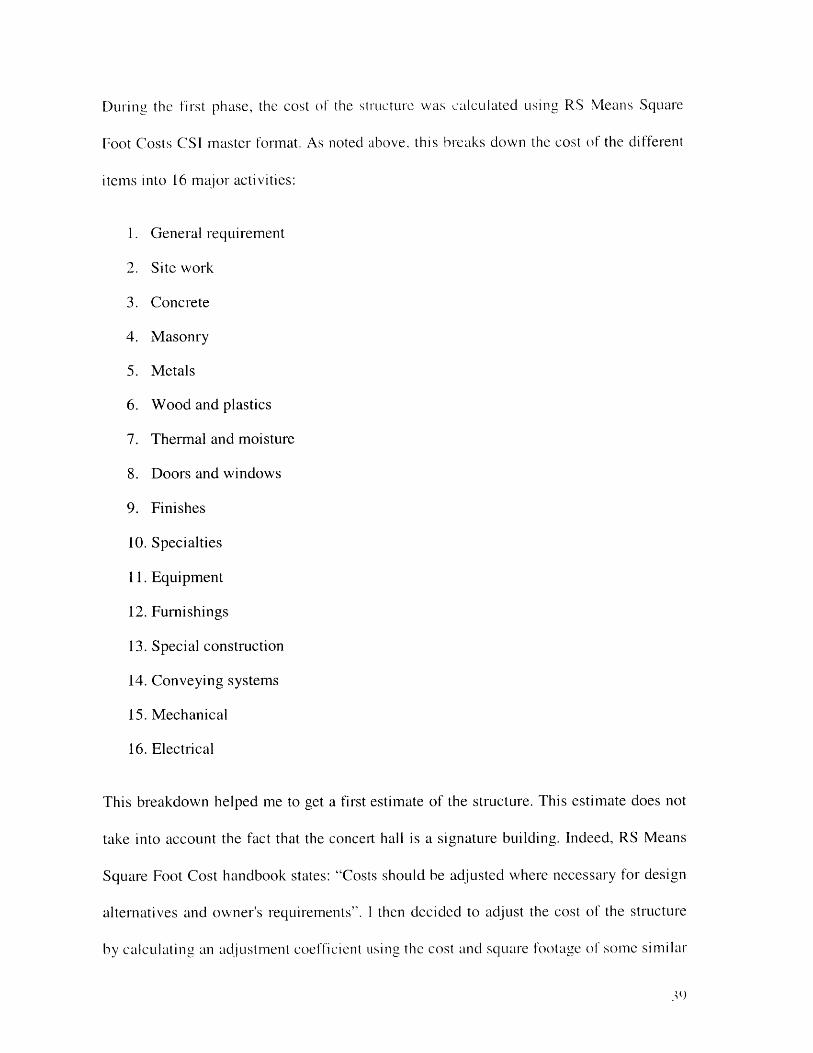
Tower characteristics
The tower is composed of different items, among which are the reinforced steel, the
concrete and the pylon. To build the tower, 571,7271b of reinforced steel will be needed,
along with 77,786 ft3 of concrete and 37,812ft2 of formwork. One pylon is needed.
37
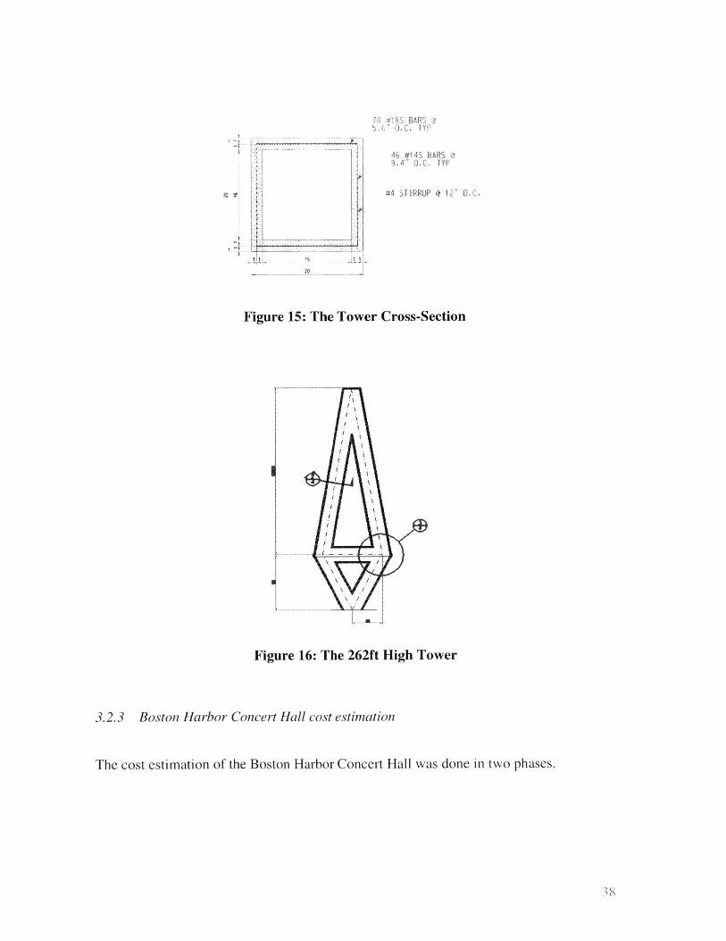
T #8 BW BARS @.6" 0.C. TYP
46 #14S BARS @9.4" OC. TYP
#4 STIRRUP @ 12 MC.
Lft
Figure 15: The Tower Cross-Section
....... ...
Figure 16: The 262ft High Tower
3.2.3 Boston Harbor Concert Hall cost estimation
The cost estimation of the Boston Harbor Concert Hall was done in two phases.
38
During the first phase, the cost of the strIcture was calculated using RS Neans Square
Foot Costs CSI master format. As noted above, this breaks down the cost of the different
items into 16 major activities:
1. General requirement
2. Site work
3. Concrete
4. Masonry
5. Metals
6. Wood and plastics
7. Thermal and moisture
8. Doors and windows
9. Finishes
10. Specialties
11. Equipment
12. Furnishings
13. Special construction
14. Conveying systems
15. Mechanical
16. Electrical
This breakdown helped me to get a first estimate of the structure. This estimate does not
take into account the fact that the concert hall is a signature building. Indeed, RS Means
Square Foot Cost handbook states: "Costs should be adjusted where necessary for design
alternatives and owner's requirements". I then decided to adjust the cost of the structure
by calculating an adjustment coefficient using the cost and square footage of some similar
structures (See Section 3.2.1). Also, RS Nleans cost estimates are for conventional
structures and not signature buildings as the Boston Concert Hall.
For my second phase of calculations, I considered that the cost of the interior finishing
was greatly underestimated in RS Means Square Foot Costs. Indeed, it doesn't take into
account special items as seats, special covering and so on. I decided then to subtract this
generic interior finishing cost from my total rough cost, recalculate the structure with the
adjustment coefficient noted above, and use RS detailed per-component estimates drawn
from Means Building Construction Cost Data to calculate the cost of the interior
finishing.
This is how it would be in an equation (See Equation 1):
. Total Cost: TCSquare Foot Costs
. Interior Finishing Cost: IFC Square Foot Costs
* Adjustment factor: AF
. New Interior Finishing Costs: NITCBuilding Construction Cost Data
* Final Cost: FC
FC = (TCSquare Foot Costs - IFCSquare Foot Costs)*AF + NITCBilding Construction Cost Data
Equation 1: Final AuditoriumCost Estimation
40
I Could do this completely for the auditorium. Using the adjustment coefficicnt and
recalculating the interior finishing cost increased the estimated cost of the auditorium by
a factor of almost ten. I couldn't calculate an adjustment factor for the restaurant because
I didn't have existing projects examples on which to draw. But I still subtracted the rough
cost of the interior finishing for conventional structures specified by RS Means Square
Foot Costs and calculated a more accurate one using RS Means Building Cost Data. For
the tower and the canopy, the cost is mainly the cost of material.
The final cost that I will have is a lower bound because:
" The steel work is greatly underestimated
* The interior finishing is roughly estimated, using only partial design details. A
full design would very likely specify more extensive furnishings.
" Labor and equipment are almost not taken into account for the canopy and the
tower
3.2.4 Auditorium cost estimation
The basics of the auditorium cost estimation were explained in the previous section. I
first calculated the cost of the structure with RS Means Square Foot Costs only. This gave
me a first extreme lower bound of 6,294,377 dollars. This represented only the costs for a
conventional auditorium (such as might be present in a school or library), and requires
adjustment to represent the greater technical demands and quality required of a signature
building.
4 1
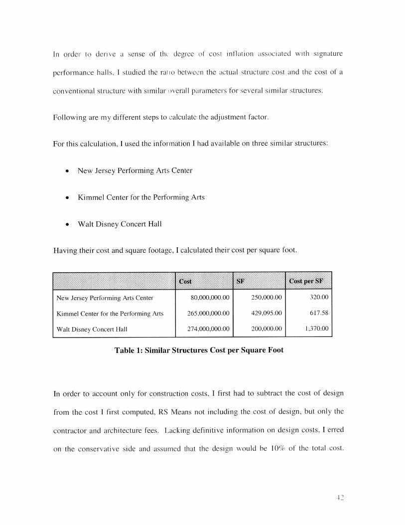
In order to derive a sense of thu degree of cost inflation associated with signature
performance halls, I studied the ratio between the actual structure cost and the cost of a
conventional structure with similar overall parameters for several similar structures.
Following are my different steps to calculate the adjustment factor.
For this calculation, I used the information I had available on three similar structures:
" New Jersey Performing Arts Center
* Kimmel Center for the Performing Arts
* Walt Disney Concert Hall
Having their cost and square footage, I calculated their cost per square foot.
Cost SF Cost per SF
New Jersey Performing Arts Center 80,000,000.00 250,000.00 320.00
Kimmel Center for the Performing Arts 265,000,000.00 429,095.00 617.58
Walt Disney Concert Hall 274,000,000.00 200,000.00 1,370.00
Table 1: Similar Structures Cost per Square Foot
In order to account only for construction costs, I first had to subtract the cost of design
from the cost I first computed, RS Means not including the cost of design, but only the
contractor and architecture fees. Lacking definitive information on design costs, I erred
on the conservative side and assumed that the design would be 10% of the total cost.
4?)
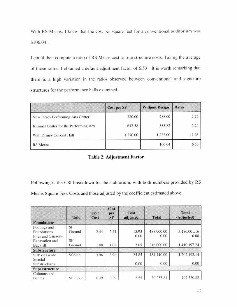
With RS Means, I knew that the cost per square feet for a conventional auditorium was
$106.04.
I could then compute a ratio of RS Means cost to true structure costs. Taking the average
of those ratios, I obtained a default adjustment factor of 6.53 It is worth remarking that
there is a high variation in the ratios observed between conventional and signature
structures for the performance halls examined.
New Jersey Performing Arts Center
Kimmel Center for the Performing Arts
Walt Disney Concert Hall
320.00
617.58
1,370.00
288.00
555.82
1,233.00
2.72
5.24
11.63
RS Means 106.04 6.53
Table 2: Adjustment Factor
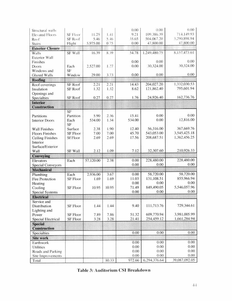
Following is the CSI breakdown for the auditorium, with both numbers provided by RS
Means Square Foot Costs and those adjusted by the coefficient estimated above.
tootngs anaFoundationsPiles and CaissonsExcavation andBackfill
Ground
SFGround
2.44
1.08
2.44
1.08
15.930.00
7.05
488,000.000.00
216,000.00
3,186,001.160.00
1,410,197.24
SubstructureSlab on Grade Sf Slab 3.96 3.96 25.85 184,140.00 1,202,193.14Special
Subsrucure 0.00 __0.00 0.00
Superstructure _____ ____ __________ ______________
Columns andBeams SF Floor 0.39 1 0.39 2.55 30,255.81 197.530.83
4.),
Structural wallsElevated FloorsRoo fStair's
SF FloorSF RoofFlight
11.255.46
,975.00
1.415.460.75
0.009.21
35.650.00
0.00109,386.39504,067.20
47,800.00
0.00714,149.93
',290,898.9447,800.00
*Exterior io u e Closure________
Walls SF Wall 16.39 8.39 54.78 1,249,480.75 8,157,473.61Exterior WallFinishes 0.00 0.00 0.00Doors Each 2,527.00 1.27 0.00 30,324.00 30,324.00Windows and SFGlazed Walls Window 29.00 3.73 0.00 0.00 0.00
Roof coverings SF Roof 2.21 2.21 14.43 204,027.20 1,332,030.53Insulation SF Roof 1.32 1.32 8.62 121,862.40 795,601.94
Openings and
Specialties SF Roof 0.27 0.27 1.76 24,926.40 162,736.76Inter"o
SFPartitions Partition 5.90 2.36 15.41 0.00 0.00Interior Doors Each 534.00 1.34 534.00 0.00 12,816.00
SFWall Finishes Surface 2.38 1.90 12.40 56,316.00 367,669.76Floors Finishes SF Floor 7.00 7.00 45.70 543,053.00 3,545,425.18Ceiling Finishes Sf Floor 2.69 2.69 17.56 208,687.51 1,362,456.25InteriorSurface/ExteriorWall SF Wall 2.12 1.09 7.12 32,307.60 210,926.33
Elevators Each 57,120.00 2.38 0.00 228,480.00 228,480.00Special Conveyors 0.00 0.00 0.00
Plumbing Each 2,936.00 3.67 0.00 58,720.00 58,720.00Fire Protection SF Floor 1.69 1.69 11.03 131,108.51 855,966.94Heating 0.00 0.00 0.00Cooling SF Floor 10.95 10.95 71.49 849,490.05 5,546,057.96Special Systems 0.00 0.00 0.00
Service andDistribution SF Floor 1.44 1.44 9.40 111,713.76 729,344.61Lighting andPower SF Floor 7.89 7.86 51.32 609,770.94 3,981,005.99Special Electrical SF Floor 3.28 3.28 21.41 254,459.12 1,661,284.94
SpecialConstructionSpecialties 0.00 0.00 0.00
Site workEarthwork 0.00 0.00 0.00Utilities 0.00 0.00 0.00Roads and Parking 0.00 0.00 0.00Site Improvements 0.00 0.00 0.00Total 80.33 972.66 6,294,376.64 39,087,092.05
Table 3: Auditorium CSI Breakdown
4-1-
The cost of the auditorium with the adjustment factor is estimated above as 6 times
greater then the first estimate.
The estimates above include only a rough breakdown of the interior items for the design.
Because the design includes specification of a large number of expensive items got for
the interior work, I then decided to make a more detailed the cost estimate of the interior
finishing using RS Means Building Construction Cost Data.
In order to start with an estimated cost for the non-interior construction, I subtracted the
cost of the "conventional" interior finishing from the total construction estimate:
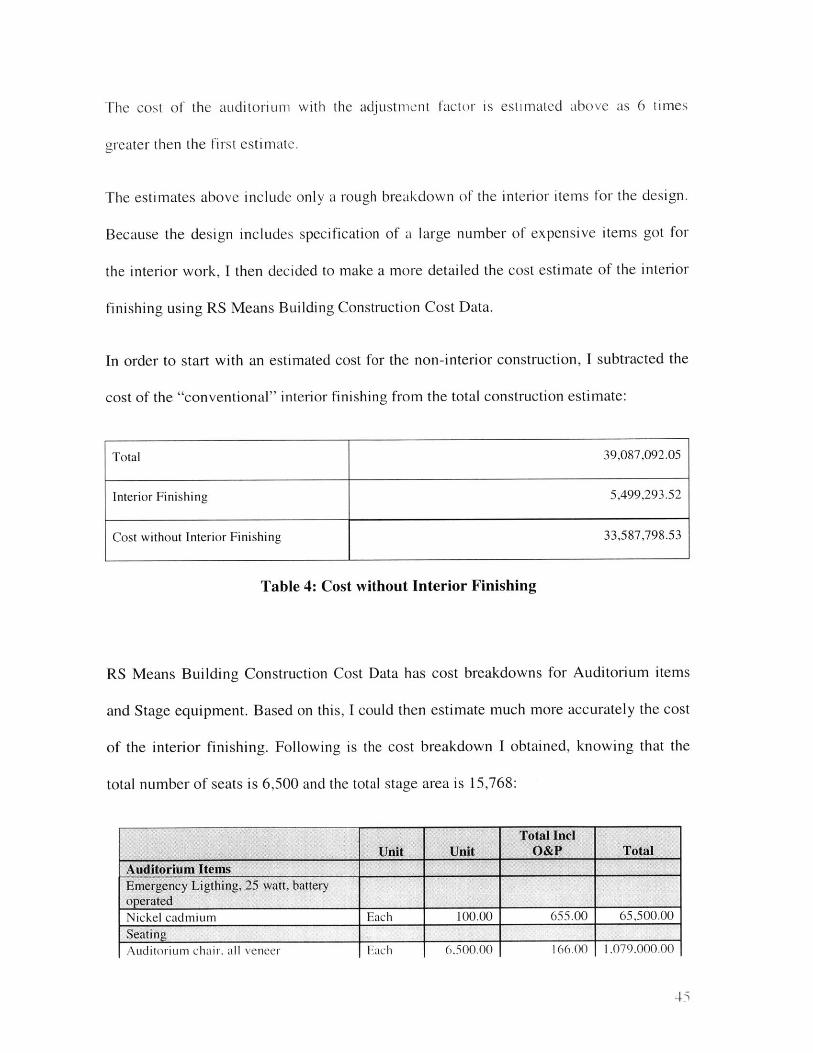
Total 39,087,092.05
Interior Finishing 5,499,293.52
Cost without Interior Finishing 33,587,798.53
Table 4: Cost without Interior Finishing
RS Means Building Construction Cost Data has cost breakdowns for Auditorium items
and Stage equipment. Based on this, I could then estimate much more accurately the cost
of the interior finishing. Following is the cost breakdown I obtained, knowing that the
total number of seats is 6,500 and the total stage area is 15,768:
Total InclUnit Unit O&P Total
Auditorium ItemsEmergency Ligthing, 25 watt, batteryoperatedNickel cadmium Each 100.00 655.00 65,500.00SeatingAuditoriun chair, all veneer Each 6.500.00 166.00 1.079.000.00
45
Smoke detectors ____________
Ceiling ( typJe Each 100.00 149.00 14,900.00
Sound SystemAmplifier, 250 wattsSpeaker, ceiling or wall Each 100.00 145.00 14,500.00
Stage EquipmentControl boards with dimmers andbreakers, max Each 100.00 79,000.00 7,900,000.00
Curtain track, straight, heavy duty LF 322.00 82.00 26,404.00
Silica based yarn, fireproof SF 15,768.00 28.00 441,504.00
Cart to carry 225 SF of flooring lights,border, quartz, Each 100.00 335.00 33,500.00reflector, ventedStrobe light, I to 15 flashes per second,quartz Each 100.00 730.00 73,000.00Telescoping platforms, extruded alum.,straight, SF Stg. 700.00 65.50 45,850.00pie-shaped, maxChair for above, self-storing, max Each 100.00 155.00 15,500.00
Rule of thumb: total equipment, max SF Stg. 15,768.00 500.00 7,884,000.00
Total 1 9,709,658.00
Other itesp Unit Unit Cost TotalInterior cladding (auditorium woodpanels) SF 148,925.00 4.13 615,060.25Carpenting SF 77,579.00 8.31 644,681.49Acoustical treatment (auditorium) SF 148,925.00 13.35 1,988,148.75
Exterior cladding (audiorium ceramicpanels) SF 148,925.00 10.70 1,593,497.50Toilets Each 76.00 1,175.00 89,300.00Total _4,930,687.99
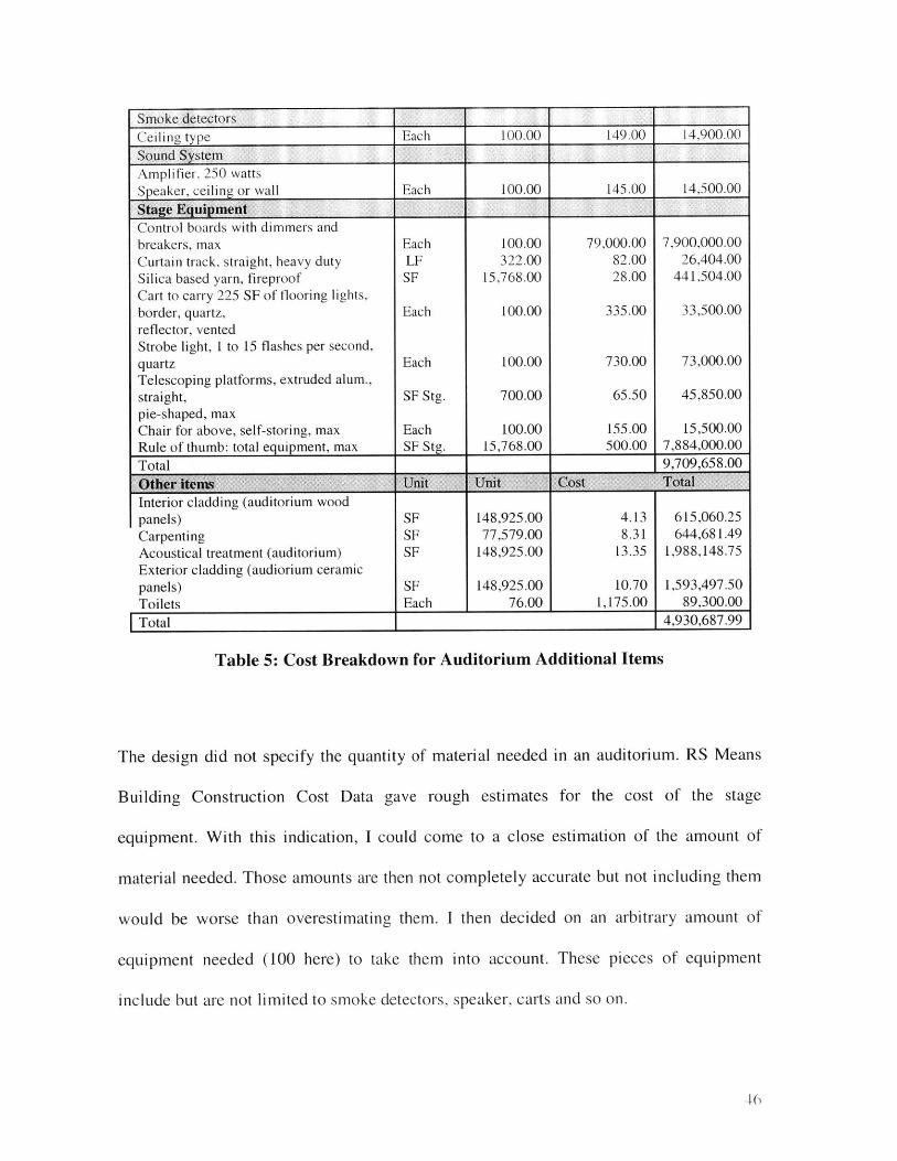
Table 5: Cost Breakdown for Auditorium Additional Items
The design did not specify the quantity of material needed in an auditorium. RS Means
Building Construction Cost Data gave rough estimates for the cost of the stage
equipment. With this indication, I could come to a close estimation of the amount of
material needed. Those amounts are then not completely accurate but not including them
would be worse than overestimating them. I then decided on an arbitrary amount of
equipment needed (100 here) to take them into account. These pieces of equipment
include but are not limited to smoke detectors, speaker, carts and so on.
46
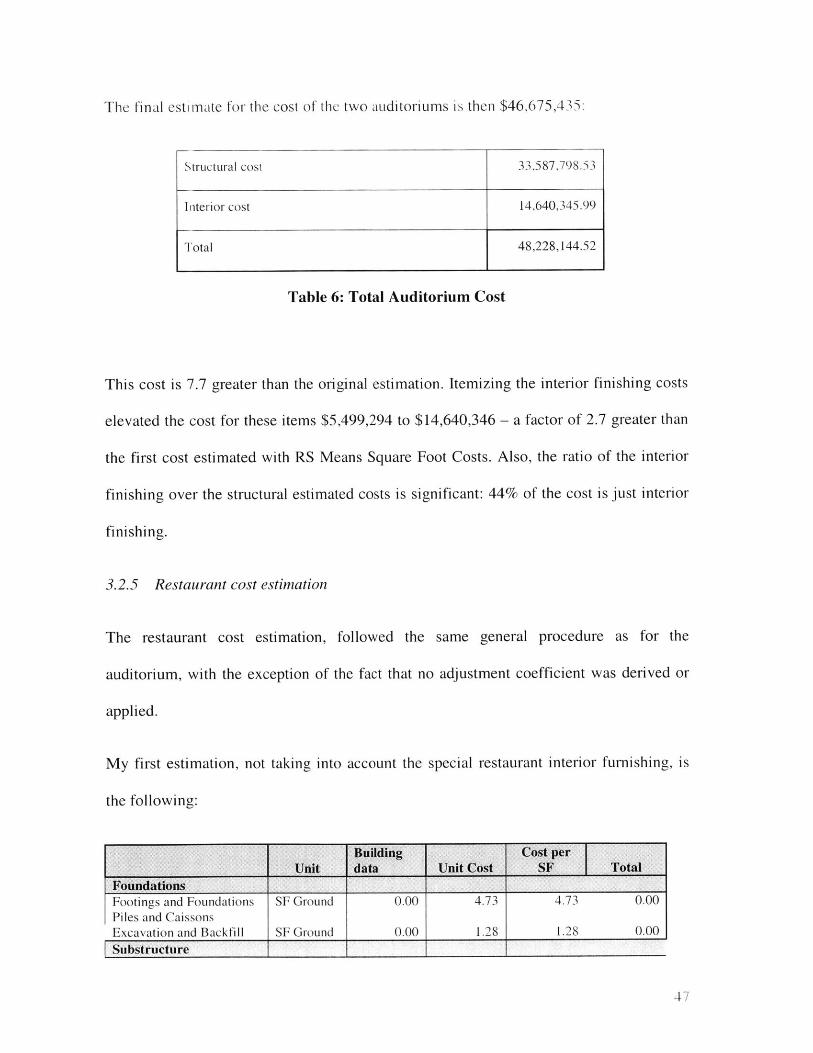
The final estimate for the cost of the two auditoriums is then $46,675,435:
Table 6: Total Auditorium Cost
This cost is 7.7 greater than the original estimation. Itemizing the interior finishing costs
elevated the cost for these items $5,499,294 to $14,640,346 - a factor of 2.7 greater than
the first cost estimated with RS Means Square Foot Costs. Also, the ratio of the interior
finishing over the structural estimated costs is significant: 44% of the cost is just interior
finishing.
3.2.5 Restaurant cost estimation
The restaurant cost estimation, followed the same general procedure as for the
auditorium, with the exception of the fact that no adjustment coefficient was derived or
applied.
My first estimation, not taking into account the special restaurant interior furnishing, is
the following:
Building Cost perUnit data Unit Cost SF Total
FoundationsFootings and Foundations SF Ground 0.00 4.73 4.73 0.00Piles and CaissonsExcavation and Backfill SF Ground 0.00 1.28 1.28 0.00Substructure I I I I
47
33.587,798.53Structural cost
I terior cost 14,640,345.99
Total 48,228,144.52
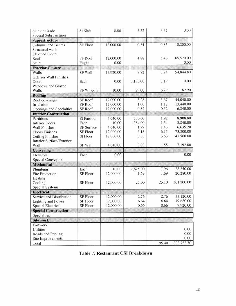
Table 7: Restaurant CSI Breakdown
48
0.00Slab on (JradeQ i I Q b, t - t
V3jJLJ% i Ct LIJ3 1L W LAI%,a
SuperstructureColumns and Beams SF Floor 12,000.00 0.34 0.85 10,200.00Structural wallsElevated FloorsRoof SF Roof 12,000.00 4.88 5.46 65,520.00Stairs Flight 0.00 0.00Exterior ClosureWalls SF Wall 13,920.00 7.82 3.94 54,844.80Exterior Wall FinishesDoors Each 0.00 3,185.00 3.19 0.00Windows and GlazedWalls SF Window 10.00 29.00 6.29 62.90RoofigRoof coverings SF Roof 12,000.00 3.28 3.67 44,040.00Insulation SF Roof 12,000.00 1.00 1.12 13,440.00Openings and Specialties SF Roof 12,000.00 0.52 0.52 6,240.00fnte~riqr ConstructionPartitions Sf Partition 4,640.00 730.00 1.92 8,908.80Interior Doors Each 10.00 384.00 1.54 3,840.00
Wall Finishes SF Surface 4,640.00 1.79 1.43 6,635.20Floors Finishes SF Floor 12,000.00 6.15 6.15 73,800.00Ceiling Finishes Sf Floor 12,000.00 3.63 3.63 43,560.00Interior Surface/ExteriorWall SF Wall 4,640.00 3.08 1.55 7,192.00ComvtyingElevators Each 0.00 0.00Special Conveyors
MechanicalPlumbing Each 10.00 2,825.00 7.96 28,250.00Fire Protection SF Floor 12,000.00 1.69 1.69 20,280.00HeatingCooling SF Floor 12,000.00 25.00 25.10 301,200.00Special Systems
E__Ica.Service and Distribution SF Floor 12,000.00 2.76 2.76 33,120.00Lighting and Power SF Floor 12,000.00 6.64 6.64 79,680.00Special Electrical SF Floor 12,000.00 0.66 0.66 7,920.00
$pca CNstucion
SpecialtiesSite workEartworkUtilities 0.00Roads and Parking 0.00Site Improvements 0.00Total 95.40 808,733.70
0.00Sf .Slab
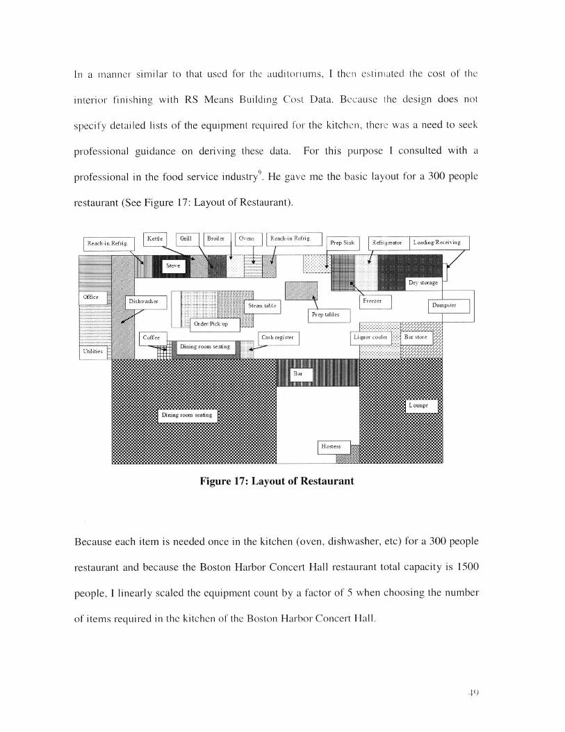
In a manner similar to that used for the auditoriums, I then estimated the cost of the
interior finishing with RS Means Building Cost Data. Because the design does not
specify detailed lists of the equipment required for the kitchen, there was a need to seek
professional guidance on deriving these data. For this purpose I consulted with a
professional in the food service industry9 . He gave me the basic layout for a 300 people
restaurant (See Figure 17: Layout of Restaurant).
Re ach-in Refrig. Kettle Grill ril er Ov R each-in Refri g. P pSik R efri gerator T oading R eceivin g
Dry storage
Ofice
Beca hits oe iSti s tabe F er e)r3pster
Prep tables
Coffee Cash regi ster Liquor cooler Bar store
Dining room se ating---
Uti7ities
Ba
Dining roorm stating
Hostess
Figure 17: Layout of Restaurant
Because each item is needed once in the kitchen (oven, dishwasher, etc) for a 300 people
restaurant and because the Boston Harbor Concert Hall restaurant total capacity is 1500
people, I linearly scaled the equipment count by a factor of 5 when choosing the number
of items required in the kitchen of the Boston Harbor Concert Hall.
4()
BuildingDescription Unit data Cost Total
Bar
Front bar LF 30.00 285.00 8,550.00
Back bar LF 30.00 227.00 6,810.00
Emergency lighting, 25 watt, battery
operated
Nickel cadmium Each 10.00 655.00 6,550.00
Kitchen equipment
Broiler Each 5.00 4,050.00 20,250.00
Coffee urn, twin 6 gallon Each 5.00 6,975.00 34,875.00
Cooler, 6 ft, long Each 5.00 3,200.00 16,000.00
Dishwasher, 10-12 racks per hr Each 5.00 3,050.00 15,250.00
Food warmer, counter, 1.2 KW Each 5.00 715.00 3,575.00
Freezer, 44 C.F., reach-in Each 5.00 8,325.00 41,625.00
Ice cube maker, 50 lb. per day Each 5.00 1,800.00 9,000.00
Range with I oven Each 5.00 2,400.00 12,000.00
Refrigerators, Prefabricated, walk-in
12'*20' SF 12,000.00 73.00 876,000.00
Total 1,050,485.00
-Additional itemis
Chairs Each 1,500.00 95.50 143,250.00
Tables Each 1,500.00 1,500.00 2,250,000.00
PC-trEci.c0 _ 2, __ ,___ .__
PC Each 5.00 2,000.00 10,000.00
Software Each 5.00 8,000.00 40,000.00
Glass floor (restaurant) SF 12,000.00 1158.00 1,380,000.00
Total 3,823,250.00
Table 8: Cost breakdown for Restaurant Additional Items
On the basis of the above, a conservative estimate for cost of the restaurant is then the
following:
821766.80
Table 9: Total Restaurant Cost
I believe that this estimate represents a lower bound on the cost of the restaurant. Indeed,
only the glass floor was taken into account but the box truss was not closely estimated. It
was just assumed to be counted in the "Superstructure" CSI category under "Columns
and beams" when the structure is actually a steel box truss system.
3.2.6 Other items cost estimation
Sections above have provided estimates for two important components of the structure:
The auditorium and restaurant. The two items remaining are the canopy and the tower. I
included the cost of the cable-stay cables in the canopy cost estimation.
0 Canopy and cable-stay cost' 0
Restaurant sideConcert hall sidegalvanised high-tensile steel
Lateral cables
Longitudinal cables
LF
LF
LF
200.00198.00
243.00
14.0062.00
63.00
0.500.95
0.95
1,400.0011,662.20
14,543.55
Glass Type of glass
Concert hall side silicate glass (4*8) Each 2,885.00 213.00 614,505.00
Connections
Concert hall side stainless steel clips Each 11,540.00 10.00 115,400.00
Total 757,510.75
Table 10: Canopy Cost
SI
Interior finishing 4,871.735.00
Final Restaurant cost 5,697,501.80
StruLCtUral total
In this cost breakdown, only the cost of the cables, glass panels and connections is
considered. The cost of labor and equipment is greatly underestimated because RS Means
Building Construction Cost Data assumes simple structures. This is not the case here, the
glass canopy being a very innovative structure. The workers will have to install the
structure being almost 300 feet above the ground. This estimate is then a lower bound.
. Tower cost"
Reinf. Steel lb
Concrete ft
Formwork ft2
Pylon
571,727.03 0.45 0.5777,785.99 3.96 5.0237,812.63 1.02 1.29
1.00 60,397.00 76,626.16
Total 753,025.05
Table 11: Tower Cost
The same comments for the glass canopy are applicable to the tower. Concrete for the
tower will have to be poured continually, what implies the use of very special pieces of
equipment.
3.2.7 Final cost
On the basis of the cost estimates above, the final cost of the structure could be
computed. The following is the data I could compute so far:
2 Pollallis. Spiro. (converted Units)
0.514.491.16
68,511.58
291,580.78349,259.10
43,673.5968,511.58.
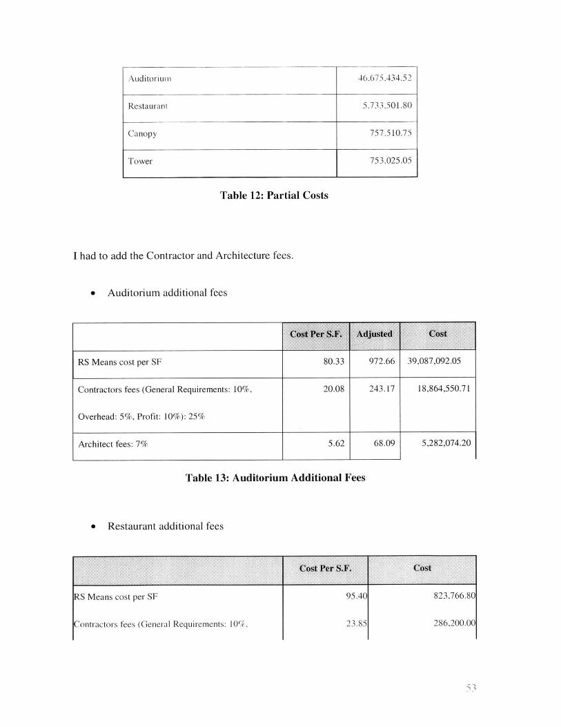
Auditori LII4 3
Table 12: Partial Costs
I had to add the Contractor and Architecture fees.
0 Auditorium additional fees
RS Means cost per SF 80.33 972.66 39,087,092.05
Contractors fees (General Requirements: 10%, 20.08 243.17 18,864,550.71
Overhead: 5%, Profit: 10%): 25%
Architect fees: 7% 5.62 68.09 5,282,074.20
Table 13: Auditorium Additional Fees
* Restaurant additional fees
Cost Per S.F. Cost
RS Means cost per SF
Contractors fees (General Requirements: 10/,
95.40
23.85
823,766.80
286,200.00
Restaurant 5.733.501.80
Canopy 757,510.75
Tower 753,025.05
46,675.434.52
53
Overhead: 5(/, Profit: 10'1): 2
Architect fees: 7% 6.68 go,136.00
Table 14: Restaurant Additional Fees
Also, "cost shown in Mean cost data publications are based on National Averages for
materials and installation. To adjust the costs to a specific location, simply multiply the
base cost by the factor for that city." 3 Boston coefficient is 1.15. Finally, I had to add the
cost of Engineering, which is assumed to be 10% of the final cost.
Auditorium
Restaurant
Canopy
Tower
Contractor fees
Architect fees
Boston Coefficient
Partial total
Engineering
Final
46,675,434.52
5,733,501.80
757,510.75
753,025.05
19,150,750.71
5,362,210.20
1.15
90,197,297.99
9,019,729.80
99,217,027.78
Table 15: Concert Hall Cost
3 RS Means Company (2000) RS Means Square Foot Costs, RS Means, 2 2nd Annual Edition
54
The final estimate for the cost of the structure is then 99,217,028 dollars. This cost is a
reasonable lower bound for the structure, knowing that the similar structures costs were
ranging from 80 million dollars to 274 million dollars and knowing that some items were
not taken into account in the cost calculation. Those items include:
" The steel work
" The interior finishing
" Labor and equipment for the canopy and the tower
S.::1
4 CONCERT HALL SCHEDULE
The previous chapter described the cost estimation for the concert hall. This chapter
turns to focus on the derivation of the schedule for that structure. As for the concert hall
cost, I established the concert hall schedule in different steps, going from an initial rough
estimate to a more detailed one.
For the initial approximate estimate, I first identified the major activities. Using a rough
estimate of the productivity for each activity, I then derived an upper bound for the
construction time length. For the detailed estimate, I chose to focus on some particular
items, drawing productivity estimates from RS Means Building Construction Cost Data.
Using this technique could break down some major activities using the daily-output and
labor hours given for each piece of equipment.
It is important to note that the schedule formulated only accounts for steps in the on-site
construction process. As such, it ignores other time-critical activities that must be
carefully coordinated with the construction process, such as procurement. The innovative
nature of the concert hall design and its heavy reliance on steel design makes it likely that
there will be a lengthy procurement process for many site components.
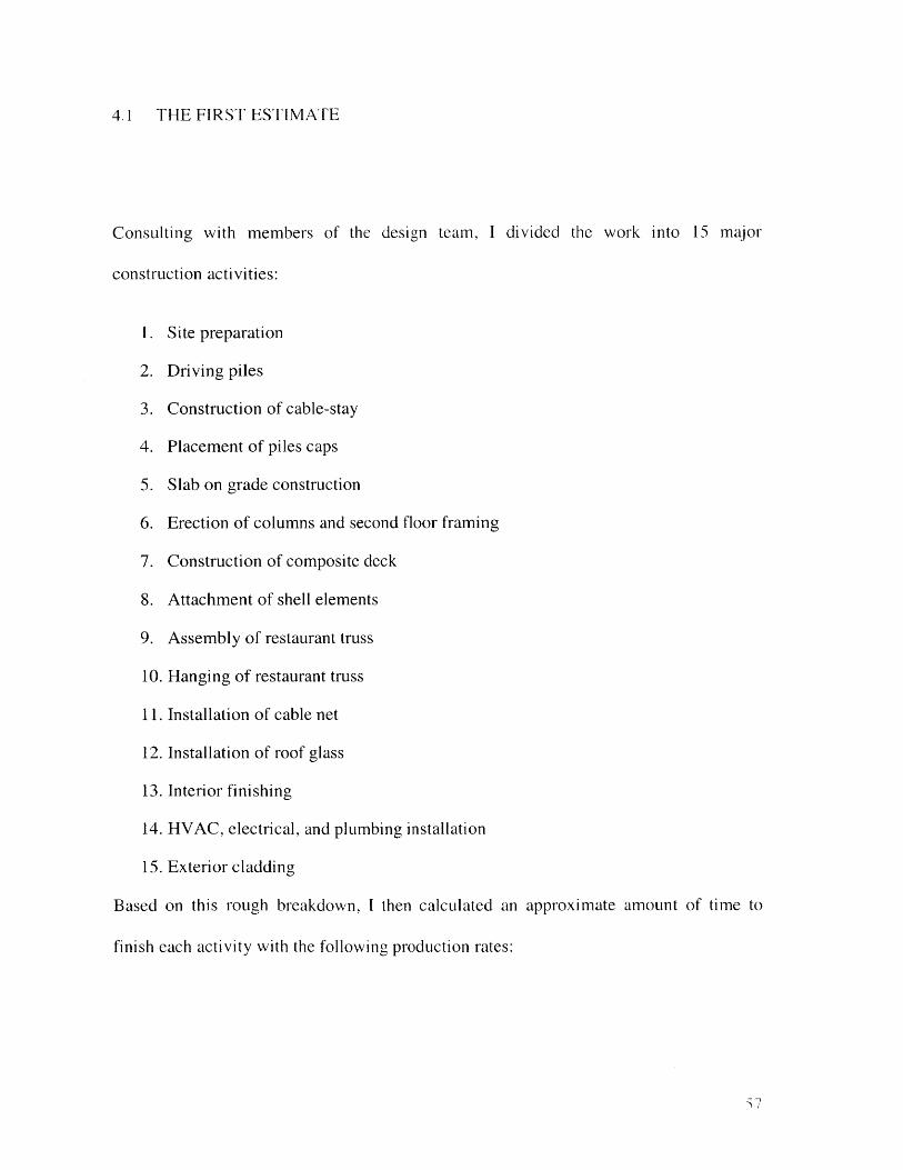
4.1 THE FIRST ESTIMATE
Consulting with members of the design team, I divided the work into 15 major
construction activities:
1. Site preparation
2. Driving piles
3. Construction of cable-stay
4. Placement of piles caps
5. Slab on grade construction
6. Erection of columns and second floor framing
7. Construction of composite deck
8. Attachment of shell elements
9. Assembly of restaurant truss
10. Hanging of restaurant truss
11. Installation of cable net
12. Installation of roof glass
13. Interior finishing
14. HVAC, electrical, and plumbing installation
15. Exterior cladding
Based on this rough breakdown, I then calculated an approximate amount of time to
finish each activity with the following production rates:
Activity Production rate Duration (months)Site preparation Assumed 2
Driving piles 5 piles/day 3
Construction of cable-stay 1.5 weeks/10 ft lift 10Placement of piles caps 2-3 pile caps/day/crew ISlab on grade construction 10000ft2/day/crew I
Erection of columns and second I member/hr/crew 3floor framingConstruction of composite deck Assumed I
Attachment of shell elements 3 elements/day 2
Assembly of restaurant truss Assumed 2
Hanging of restaurant truss I cable/day/crew 2
Installation of cable net I cable/day/crew 2
Installation of roof glass 2 panels/hr/crew 2
Interior finishing Assumed 8
HVAC, electrical, and plumbing Assumed 3installationExterior cladding Assumed 5
Table 16: Production Rates
Production rates -- the number of units of work performed by a unit of equipment or a
person in a unit of time -- are essential to determine the time an activity will take on a
project. Those rates depend on many different factors such as the job complexity, the
management conditions and the equipment conditions. These rates can be found in
tables. 12
In the context of this thesis, data was collected from the previous project on which three
students and I were working. MIT Lecturer Lisa Grebner could inform us of most of the
production rates found above. One of the teammates had some previous experience in
construction and estimated the remaining production rates based on the knowledge she
gained on construction sites. The Primavera scheduling package was used to create a
Critical Path Method schedule using the aggregate activities specified above (See Figure
18). For the purpose of this thesis, I assumed that the construction will start in late
December 2003. The construction of the Boston Harbor Conccrt Hall will then take 20
months and finish in Early September 2005.
The durations for the aggregate activities specified suggested a total project duration
estimate of 20 months. The completion time of the projects described in a previous
section included the whole construction of the project and clustered around three years.
The estimated project length for the Boston Harbor Concert Hall based on these
aggregate estimates is then within a reasonable range.
z ()
-t 102FEB04 MonActivity Activity Orig Rem % Early Early 2004 2005 2006 2007
ID Description Dur Dur Start Finish " 111 "" MJ111L J11I L1 JIU LU U11LU
S Site Preparation 8 8 0 29DEC03 22FEB04 O ste i eparato
2 riving Piles 12 12 0 26JAN04 18APRO4 WD win g Pi e
3 Construction of Cabe-Stay 40 40 0 23FE-04 o8NOV4C s of Cap
4 Placement of Piles Caps 4 4 0 22MAR04 18APR04 Piaeme it f es Cal_
S Slab on Grade Construction 4 4 0 19APR04 16MAY04 W ajn Gra~i4 QCzonsrsin
6 Erection of Columns and 12 12 0 19APR04 11JUL04 l___ joEr etii -of 9o nis S4opd Io9rFF aipc
7 onstruction of Composite 4 4 0 12JUL04 08AUG04 S C nsati ction of C6 pu!ite Deck
9 Assembly of restaurant Truss 8 8 0 040CT04 28NOV04 Oss bi yo r44a r _ s
10 Hanging of Restaurant Truss 4 4 0 29NOV04 26DEC04 ngiig fRsta I r
8 Attachment of Shell Elements 8 8 0 29NOV04 23JAN05 Utaneii t Sbe ln et
11 Installation of Cable Net 8 8 0 24JAN05 20MAR05 Isa laiion Of i C e13 Interior Finishing 32 32 0 24JAN05 04SEP05 nterier Fini if15 Exterior Cladding 20 20 0 24JAN05 12JUN05 t xtei i6t Clawding
14 HVAC, Electrical, and Plumbing 112 12 0 21FEB05 15MAY05 A Ellcc, and Phti hlng lnalt j1,;12 Installation of Roof Glass 8 8 0 21MAR05 15MAY05 f oof Glas
00
Cr
C
ON
Primavera's scheduling algorithm identified the critical path for the project. The critical
path includes the site preparation, driving the piles, the construction of the tower, the
placement of the piles caps, the slab on grade construction, the erection of columns and
second floor framing, the construction of the composite deck, the assembly of the
restaurant truss, the hanging of the restaurant truss, the installation of the cable net and
the interior finishing. The most time consuming activities are the construction of the
cable-stay and the interior finishing. This was expected because:
* The whole structural system relies on the tower
" As the building is composed of two auditoriums and a large restaurant, furnishing
them and getting the concert hall ready for visitors will be a detail-intensive and
time-consuming work.
4.1.1 The auditorium
Structurally, the construction of the auditorium is relatively standard. As a steel shell
structure, the fabrication will be done before construction starts. While this necessitates a
long procurement time, this will save considerable site time and will allow for tighter
construction tolerances than would be possible with a field erected structures (such as
those made of cast-in-place concrete). Most of the connections are bolt connection,
except the connection of the second floor to the truss shell structure, which are welded.
Such bolted connections require less labor to assemble than if they were welded,
permitting a faster assembly.
61
The construction of the shell is also constrained by the construction of the tower, as well
as the erection of the second floor.
4.1.2 The restaurant
As the restaurant is also a steel structure, the manufacturing and fabrication of the trusses
will take place off site. The trusses will then be shipped to the construction site.
The construction of the restaurant trusses will take place on the barges, while the tower is
erected. Once the tower is built, the restaurant trusses can be hung, one section at a time.
Having installed the steel structure, the glass floor, walls and roof of the restaurant will be
constructed. The finishing of the restaurant will consist of fully equipping the kitchen
with the appropriate machines and putting in place the exterior cladding. A more detailed
breakdown of the restaurant interior finishing will be explored in the next section.
4.1.3 Critique
From the previous discussion and from the Primavera bar chart, one can recognize that
the construction of the concert hall will be a complex task. The need for a detailed
schedule appears to be critical and good management and coordination of the different
activities is essential in such construction, in order to deliver the building in a reasonable
amount of time.
Additional complications in the construction process will come from the construction site
location and size, and from the logistics of materials transport and coordination of the
cranes involved in erection. While cranes are needed to transport the steel elements and
then glass panels to their appropriate location on the construction site, the site's
62
downtown location limits accessibility to the building for transportation of procured
materials and imposes constraints on the the space for storage of such materials. Clearing
of the streets at specific times of the day will have to be carefully planned in order to
receive material easily.
On the other hand, the coastal location does provide some benefits. The proximity of the
site to the harbor will allow workers to install a barge on the shore and thus expand the
construction space. Some pieces of equipment will be received via water as well. At the
same time, the close proximity to the harbor will constrain the movement of larger mobile
pieces of equipment on the site.
As noted above, having a steel structure will allow the manufacturing facilities to begin
fabrication of the steel elements before construction starts. This will fit well into the
construction schedule because the arrival such pieces of equipment can be roughly
coordinated with the progression of the construction process, although some off-site
storage will likely be required to lower risk of delays. Even after foundations are in place,
the erection of the tower will be the main concern, and needs to be started first, leaving
some time to the steel suppliers to finish the manufacturing and fabrication of the
restaurant truss and shell elements. Such elements will be needed on site 9 months after
construction starts. Having four definite loci of activity also simplifies the construction
sequence. Work can be started on the concert hall and the tower while the steel trusses are
assembled on the barges. Different crews will have to be coordinated on the site, but if
this coordination is well prepared, the work on the site can be very productive.
63
4.2 DETAILED SCHEDULE
As is typical for building construction, one of the activities on the critical path is the
finishing of the interior. As noted in previous chapters, RS Means Building Construction
Cost Data provides detailed breakdown of the auditorium and restaurant interior items,
with their labor-hours and daily output. Based on this, I decided to calculate the time it
will take to equip the interiors of the two auditoriums and the restaurant with major items.
4.2.1 Auditorium detailed estimate
A first estimate was done, assuming the activities were not done in parallel. This
assumption was abandoned because while it had the advantage of allowing the work to be
done by a smaller set of people, the auditorium alone required 20 months to equip-too
long to realistically contemplate.
A second estimate was formulated using the Primavera scheduling package. The goal in
this second estimate was to allow activities to proceed concurrently as much as possible.
To include this constraint in the schedule, I used the start to start relationship, with a zero
time float. The critical path of the auditorium construction appeared to be the installation
of the seats. Indeed, because 6,500 seats have to be arranged in the theater and because it
takes 45 minutes to put in place each seat, the entire set of work requires close to 5,000
person-hours. I then chose to have two crews working in parallel. This significantly
diminished the time to furnish the auditorium. Fireproofing was also an issue. The
estimate includes the use of three crews for that purpose as well. I had to put several
64
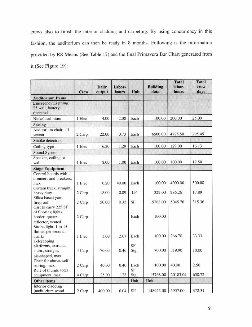
crews also to finish the interior cladding and carpeting. By using concurrency in this
fashion, the auditorium can then be ready in 8 months. Following is the information
provided by RS Means (See Table 17) and the final Primavera Bar Chart generated from
it (See Figure 19):
Nickel cadmium 1 Elec 4.00 2.00 Each 100.00 200.00 25.00
SeatingAuditorium chair, allveneer 2 Carp 22.00 0.73 Each 6500.00 4725.50 295.45
Smoke detectors
Ceiling type 1 Elec 6.20 1.29 Each 100.00 129.00 16.13
Sound SystemSpeaker, ceiling orwall 1 Elec 8.00 1.00 Each 100.00 100.00 12.50
Stage EquipmentControl boards withdimmers and breakers,max 1 Elec 0.20 40.00 Each 100.00 4000.00 500.00Curtain track, straight,heavy duty 2 Carp 18.00 0.89 LF 322.00 286.26 17.89Silica based yarn,fireproof 2 Carp 50.00 0.32 SF 15768.00 5045.76 315.36Cart to carry 225 SFof flooring lights,border, quartz, 2 Carp Each 100.00reflector, ventedStrobe light, 1 to 15flashes per second,quartz 1 Elec 3.00 2.67 Each 100.00 266.70 33.33Telescopingplatforms, extruded SFalum., straight, 4 Carp 70.00 0.46 Stg. 700.00 319.90 10.00pie-shaped, maxChair for above, self-storing, max 2 Carp 40.00 0.40 Each 100.00 40.00 2.50Rule of thumb: total SFequipment, max 4 Carp 25.00 1.28 Stg. 15768.00 20183.04 630.72
Other items I 1_____n Unit Unit I IInterior cladding(auditorium wood 2 Carp 400.00 0.04 SF 148925.00 5957.00 372.31
65
panels)
Carpeting 1 Tilf 8.33 0.01 SF 77579.00 922.33 9309.48Acoustical treatment(auditorium) 1 Carp 100.00 0.08 SF 148925.00 11914.00 1489.25
Toilets 2 Marb 3.00 5.33 Each 76.00 405.08 25.33
Total 54494.57 13055.26
Table 17: RS Means Auditorium Total Crew Days Estimation
66
i±i 25AUG5 OFEB05 TueActivity Activity Orig Rem Early Early 2005.1 J | FEB | MAR I APR | MAY | JUH JUL AUG | SEP 0OID Description ii D iii:Du Start fiih 24,31. 7.14 .21 .28, .114 .21 28.4 ill 18,25,.2 9 16,.23,30,6 .13.20.27,.4 11 .18,25,1 A8 .15,22.29 .5 .12 .19 ,263
2 Chairs 148 148 07FEB05 31AUG05 2hair
5 Control boards 125 125 07FEB05 29JUL05 Control boards3 Smoke detectors 17 17 01AUG05 23AUG05 _______-' Smoke detetoi
1 Nickel Cadmium 25 25 07FEB05 11MAR05 2. b7 V ilel Cadmium4 Speaker 13 13 07FEB05 23FEB05 V Speaker8 Strobe light 34 34 07FEB05 24MAR05 V Strobe light
7 Fireproof 106 106 21FEB05 18JUL05 - 7 v Fireproof
9 Platform 10 10 07FEB05 18FEB05V Plaforn6 Curtain 18 18 19JUL05 11AUG05Cutain
10 Chairs for above 3 3 19JUL05 21JUL05 Chairs for at ov
13 Acousticaltreatment 149 149 07FEB05 01SEP0512 Carperting 144 144 07FEB05 28JUL05 Carpenting11 Interior cladding 94 94 21_MAR05 2JLinterior ladin
15 Toilets 26 26 07FEB05 14MAR05 4 -W Toilets
WI
Os
0
ftWI
0WI
0
Os
ft
One has to bear in mind that certain elements of the interior finishing were not taken into
account. Because of the central role played by the auditoriums in the structure, the
interior finishing is expected to be of the foremost quality, and we would expect proper
finishing to be a time-intensive activity. As was the cost for the costs, the absence of
certain interior finishing in the estimate thus reflects only the fact that the design did not
provide sufficient to estimate this component of the work rather than any lack of
importance of this activity in the schedule.
Figure 20: Kimmel Center for the Performing Arts
An auditorium is a highly intricate structure. More than being able to host an important
crowd of spectators, it requires an elaborate sound system and is carefully decorated.
Using RS Means data allowed me to estimate the amount of time to install the major
pieces of typical of an auditoriums, such as seats, basic stage components, electrical and
control items and fireproofing. Most of the descriptions of these items were relatively
68
opaque, lacking details on what they included. This limited the reasoning about how the
costs and time would have to be scaled for the concert hall. As was noted for the cost
estimate, a rough count has been attributed to each of them so as to be able to take them
into account. Hence, the estimation is not completely accurate, but gives a good lower
bound estimate of the construction length. When the activities seemed to be much too
long, I used a high number of crews to stay in the 8 months period imparted for the
interior finishing activity.
Following are some elements that can also counterbalance the lack of accuracy in the
estimate:
" In contrast to many theaters, the 1,500 people venue will not have balconies,
which will save an important amount of time. It is a simple flat auditorium, and it
is than expected to be easier to furnish than elaborate theaters.
* The inclusion of two performance halls within the structure will allow crews to
work in parallel. Assuming a construction start date of December 29, 2003, the
structure will be done by the end of December 2004 and will allow the workers to
start the interior finishing by the beginning of the year 2005. Because the concert
halls are one on top of one another, coordination can be planned between the
different crews (electrical, mechanical and so on) in order for them to efficiently
perform cable-pulling, duct routing and other roughing-in in parallel.
69
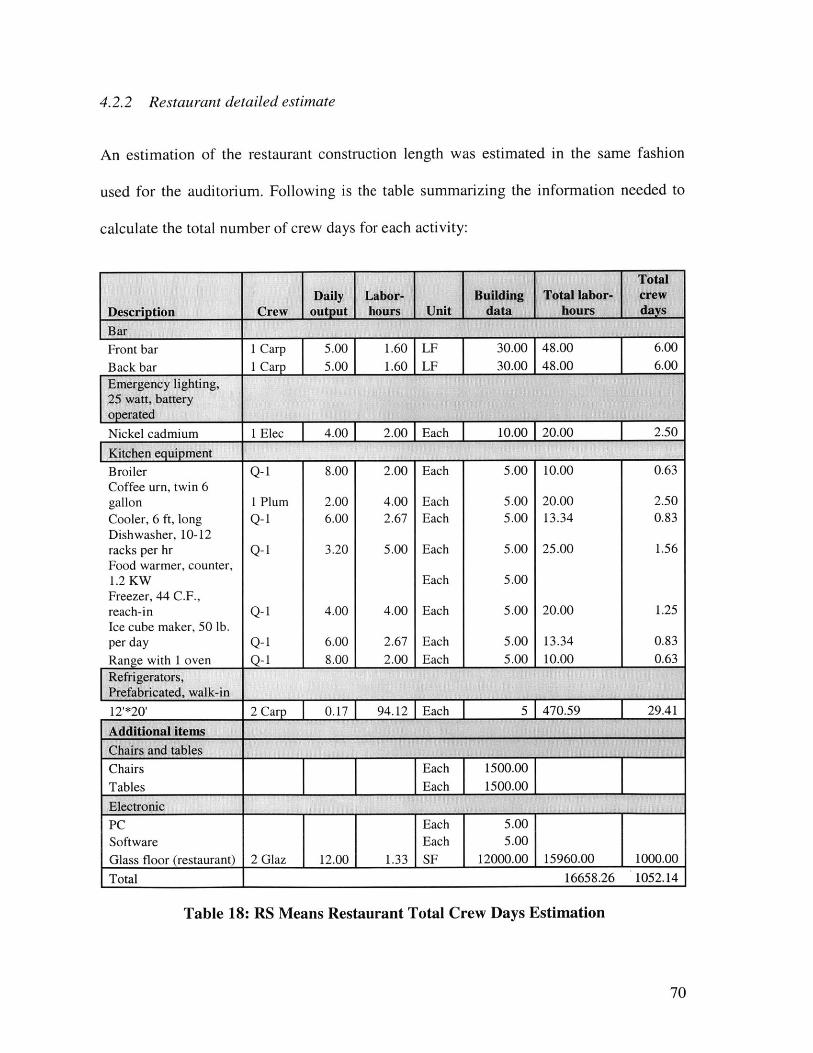
4.2.2 Restaurant detailed estimate
An estimation of the restaurant construction length was estimated in the same fashion
used for the auditorium. Following is the table summarizing the information needed to
calculate the total number of crew days for each activity:
Front barD - I---
1 Carp 5.00 1.60 1 LF 30.00 48.001 Can) 5.00 1.60 LF 30.00 48.00
6.00A nn
Nickel cadmium 1 Elec 1 4.00 1 2.00 1 Each I 10.00 1 20.00 1 2.50
Kitchen equipment
Broiler Q-1 8.00 2.00 Each 5.00 10.00 0.63Coffee urn, twin 6gallon 1 Plum 2.00 4.00 Each 5.00 20.00 2.50Cooler, 6 ft, long Q-1 6.00 2.67 Each 5.00 13.34 0.83Dishwasher, 10-12racks per hr Q-1 3.20 5.00 Each 5.00 25.00 1.56Food warmer, counter,1.2 KW Each 5.00Freezer, 44 C.F.,reach-in Q-1 4.00 4.00 Each 5.00 20.00 1.25Ice cube maker, 50 lb.per day Q-1 6.00 2.67 Each 5.00 13.34 0.83Range with I oven Q-1 8.00 2.00 Each 5.00 10.00 0.63Refrigerators,Prefabricated, walk-in
12'*20' 2 Ca 0.17 94.12 Each 5 470.59
Additional itemsChairs and tables
Chairs Each 1500.00Tables Each 1500.00
Electronic
PC Each 5.00Software Each 5.00Glass floor (restaurant) 2 Glaz 12.00 1.33 1 SF 12000.00 15960.00 1000.00
Total 16658.26 1052.14
Table 18: RS Means Restaurant Total Crew Days Estimation
70
I
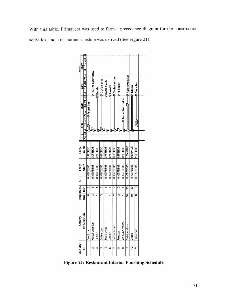
Early
Ea
rlyS
tart
F
iish
IUW
OJ
FEB
MA
R
APR
|
MAY
.24
31
.7
.14
.21
2 .7
.1
4 .2
1 .2
3 .4
.11
.13
.76 .2
.9
.16 .
23I
1 Fr
ont
bar
6 6
0 07
FEB
05
14FE
B05
Fro
nt b
ar3
Nic
kel c
adm
ium
3
3 0
07FE
B05
09
FEB
05
icke
l ca(
Imm
4 Br
oile
r 1
1 0
07FE
B05
07
FEB
05
Bro
iler
5 C
ofee
urn
3
3 0
07FE
B05
09
FEB
05
V C
ofee
urn
10
Bac
k ov
en
1 1
0 07
FEB0
5 07
FEB0
5 Ba
ck o
ven
6 C
oole
r 1
1 0
07FE
B05
07
FEB
05
Coo
ler
7 D
ishw
ashe
r 2
2 0
07FE
B05
08
FEB
05
Dis
hwas
her
8 Fr
eeze
r 2
2 0
07FE
B05
08
FEB0
5 F
reez
er9
Ice
cube
mak
er
1 1
0 07
FEB
05
07FE
B05
1lc
cu
be m
aker
11
Ref
riger
atio
n 30
30
0
07FE
B05
18
MAR
05
Ref
riger
atio
n12
G
lass
40
40
0
07FE
B05
01
APR
05
Gla
ss2
Bac
k ba
r 6
6 0
15FE
B05
22
FEB
05
Bac
k ba
r
Cr Ct Os S 5 Ct
Act
ivity
IDA
ctiv
ityD
escr
iptio
nO
rig
Rem
Our
Du
r
CD
0
CDC CD
D
CD S CD
S
CD
CD
0%

The schedule above suggests that the interior finishing restaurant can be done in two
months.
72
5 CONCLUSION
The Boston Harbor Concert Hall presents an interesting case study for schedule and cost
analysis for several reasons:
" It is structurally and architecturally elegant
" It is composed of different structural entities
" It houses two elaborate commercial type buildings
RS Means Square Foot Costs and RS Means Building Construction Cost Data are very
helpful books to generate a first cost estimation, but their cost estimation applies much
better to "simple" structures. When it comes to estimate the cost of structurally and
architecturally elegant buildings as the Boston Concert Hall, composed of different
structural entities and housing two elaborate commercial type buildings, RS Means data
is limited. It can provide a lower bound of the cost but a detailed quantity take off will
have to be done to give a much closer cost and schedule estimation.
Also, the cost of interior finishing shouldn't be underestimated in structures, especially
when it houses buildings where very specific type of equipment has to be installed. This
was seen here, where for the auditorium, the cost of the interior finishing is more than
40% of the total cost.
73
In terms of scheduling, RS Means documentation can give estimate of hour spent on an
activity but other documents and experience is needed to create a schedule for a structure.
The Boston Harbor Concert Hall had the advantage of having four separate entities that
could almost be examined separately, but when it came to the schedule of the auditorium
interior finishing, a great experience in electrical and mechanical engineering was
required more than time estimation.
74
6 REFERENCES
1 Massachusetts Turnpike Authority (2000) Central Artery/Tunnel Project, fromwww.bigdig.com
2 R.L. Peurifoy, and G. D. Oberlender (1989) Estimating Construction Costs, Mc GrawHill, Fourth Edition
3 RS Means Company (2000) RS Means Building Construction Cost Data, RS Means,59th Annual Edition
RS Means Company (2000) RS Means Square Foot Costs, RS Means, 22 AnnualEdition
4 Fisher Dachs Associates (2001) New Jersey Performing Art Center - Prudential Hall,from http://www.fda-online.com/projects/prudential.html
5 Arcspace (1999) Santiago Calatrava The Milwaukee Arthttp://www.arcsDace.com/architects/calatrava/milwaukee art museum/
Museum, from
ASCE (2002) Winged Victory, fromhttD://www.pubs.asce.org/ceonline/ceonline02/0102feat.htm
Nicolas Janberg's Structurae (1998-2004) Milwaukee Art Museum Quadracci Pavilion,from httD://www.structurae.de/en/structures/data/str03308.DhD
75
The McGraw-Hill Companies, Inc. (2004) Milwaukee Art Museum Expansion, fromhttp://archrecord.construction.com/projects/portfolio/archives/0203MAM-2.asp
6 Gary Wayne (2003) The Orange County Performing Arts Center, fromhttp://www.seeing-stars.com/OnStage/OCPerforming.shtml
7 Greater Philadelphia Tourism Marketing Corporation (2003) World class theaterforworld-class artists, from http://www.gophila.com/culturefiles/popularvenues/kimmel/
John Fischer (2004) The Kimmel Center for the Performing Arts, Architectural FactSheet, from http://philadelphia.about.com/library/weekiy/aa121701c.htm
Philadelphia Symphony Orchestra, fromhttp://www.philadex.com/philadelphia/theater/kimmel center.asp
Rafael Vinoly (2004) Kimmel Center for the Performing Arts, fromhttp://www.europaconcorsi.com/db/pub/scheda.php?id= 1121
The Philadelphia Orchestra (2004) The Kimmel Center for the Performing Arts, fromhttp://www.philorch.org/styles/poaO2e/www/kimmelcntrperformarts.html
8 Arcspace (2002) Frank 0. Gehry & PartnersWalt Disney Concert Hall, from http://www.arcspace.com/architects/gehry/disney2/
Frank Gehry Architect (1987) Walt Disney Concert Hall, fromhttp://www.guggenheim.org/exhibitions/past exhibitions/gehry/disney 09.html
76
Nicolas Janberg's Structurae (1998-2004) Walt Disney Concert Hall, fromhttp://www.structurae.de/en/structures/data/str01502.php
The Los Angeles Philharmonic Inaugurates Walt Disney Concert Hall, fromhttp://www.pbs.org/wnet/gperf/shows/disneyhall/disneyhall.html
9 James Gubata, Operations Director of the Lobdell Food Court
10 Occidental Chemical Corporation (1997 - 2003) Silicates, fromhttp://www.oxychem.com/products/silicates/PriceBook-Glass.html
" Pollallis, Spiro.
1 R.L. Peurifoy, and G. D. Oberlender (1989) Estimating Construction Costs, Mc GrawHill, Fourth Edition
77