Embed Size (px)
Citation preview
W--5039-e99071
Sartorius AG, Weighing Technology
Sartorius Analytical Balanceswith the Monolithic Weighing SystemService Manual for BP, GP, and LA Models
including Service Specifications

Contents
3
Page
General Information 4General Instructions 4Overview of Balance Models 4Accompanying Literature 4Auxiliary Service Tools and Equipment 4
Opening the Balance 5BP/GP Balances 5LA Balances 5
Motorized Calibration Weight 6Replacing the Motorized Calibration Weight 7
Cleaning the Magnet 8
Cleaning the Pan Stop 8
Replacing the Pan Adapter 9
Adjusting the Off-center Load 9BP/GP Balances 9LA Balances 9
Service Specifications 10Specifications Sheet 1 10Specifications Sheet 2 11
Spare part list 12GP Models 12BP Models 13LA - Exploded-View Diagram 1 14LA Models 1xx 15LA - Exploded-View Diagram 2 16LA Models 2xx 17
4
General Information
Service and repair work on monolithic weighing systems requires experiencein working with analytical balances. Mechanical pressure on the springelements (linkage, springs and guides) must be avoided, as it could causemechanical defects. Mechanical defects are not covered under the warranty.Repair work should be limited to:– repair of the draft shield;– adjustment of the off-center load and the linearity, including overwriting the
internal weight values if necessary;– repair of the motorized calibration weight, and– replacement of the PCBs.
If there is a defect in the weighing system, replace the entire weighing systemand notify the Sartorius Service Center in Goettingen.
General Instructions
– Always use the e key to turn off the balance; then wait approximately5 seconds before disconnecting the balance from power.
– Make sure that the balance is not disconnected and moved during aninternal adjustment operation (such as the isoCAL function); otherwise, theinternal weights may slip from the guides and damage the weighingsystem.
– Do not connect or disconnect cable while the balance is carrying current;always disconnect the balance from power (after turning it off; see above)before connecting or disconnecting cables to or from the balance.
Overview of Balance Models
The monolithic weighing system is installed in the following Sartorius balancemodels (as of January 1999):
LA 120S BP 61S GP 603S130S-F 121S 603P230S 161P 1503S230P 200S 1503P310S 221S
301S 211D (Semi-microbalance)
Accompanying Literature
Service Manual for BP/GP balancesService Manual for LP/LA balances
Auxiliary Service Tools and Equipment
In addition to standard tools, you will need the following special tools andequipment to work on Sartorius monolithic balances:
Qty. Designation Order no.2 Lifting screws, 3x25 mm (or longer)
(see illustration on page 8)
For performing adjustments:1 Sartorius service software for PCs (SARTOCAS) 6740-331 RS-232 connecting cable, balance <-> PC 7357312or PSION Server with CAS program, version 4.7 or later
SARTORIUS Monolith
5
BP_F_18a.TIF
BPM_01.TIF
Aut1312a.JPG
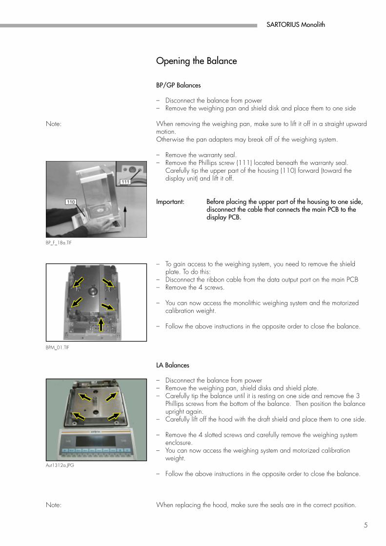
Opening the Balance
BP/GP Balances
– Disconnect the balance from power– Remove the weighing pan and shield disk and place them to one side
Note: When removing the weighing pan, make sure to lift it off in a straight upwardmotion.Otherwise the pan adapters may break off of the weighing system.
– Remove the warranty seal.– Remove the Phillips screw (111) located beneath the warranty seal.
Carefully tip the upper part of the housing (110) forward (toward thedisplay unit) and lift it off.
Important: Before placing the upper part of the housing to one side,disconnect the cable that connects the main PCB to thedisplay PCB.
– To gain access to the weighing system, you need to remove the shieldplate. To do this:
– Disconnect the ribbon cable from the data output port on the main PCB– Remove the 4 screws.
– You can now access the monolithic weighing system and the motorizedcalibration weight.
– Follow the above instructions in the opposite order to close the balance.
LA Balances
– Disconnect the balance from power– Remove the weighing pan, shield disks and shield plate.– Carefully tip the balance until it is resting on one side and remove the 3
Phillips screws from the bottom of the balance. Then position the balanceupright again.
– Carefully lift off the hood with the draft shield and place them to one side.
– Remove the 4 slotted screws and carefully remove the weighing systemenclosure.
– You can now access the weighing system and motorized calibrationweight.
– Follow the above instructions in the opposite order to close the balance.
Note: When replacing the hood, make sure the seals are in the correct position.
6
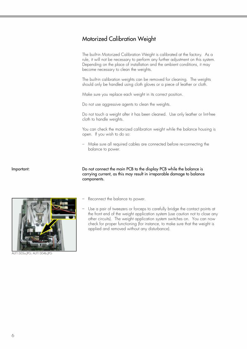
AUT1305a.JPG; AUT1304b.JPG
Motorized Calibration Weight
The built-in Motorized Calibration Weight is calibrated at the factory. As arule, it will not be necessary to perform any further adjustment on this system.Depending on the place of installation and the ambient conditions, it maybecome necessary to clean the weights.
The built-in calibration weights can be removed for cleaning. The weightsshould only be handled using cloth gloves or a piece of leather or cloth.
Make sure you replace each weight in its correct position.
Do not use aggressive agents to clean the weights.
Do not touch a weight after it has been cleaned. Use only leather or lint-freecloth to handle weights.
You can check the motorized calibration weight while the balance housing isopen. If you wish to do so:
– Make sure all required cables are connected before re-connecting thebalance to power.
Important: Do not connect the main PCB to the display PCB while the balance iscarrying current, as this may result in irreparable damage to balancecomponents.
– Reconnect the balance to power.
– Use a pair of tweezers or forceps to carefully bridge the contact points atthe front end of the weight application system (use caution not to close anyother circuits). The weight application system switches on. You can nowcheck for proper functioning (for instance, to make sure that the weight isapplied and removed without any disturbance).
SARTORIUS Monolith
7
A B
C
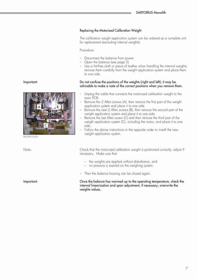
PIC00010.JPG
Replacing the Motorized Calibration Weight
The calibration weight application system can be ordered as a complete unitfor replacement (excluding internal weights).
Procedure:
– Disconnect the balance from power– Open the balance (see page 5)– Use a lint-free cloth or piece of leather when handling the internal weights;
remove them carefully from the weight application system and place themto one side.
Important: Do not confuse the positions of the weights (right and left); it may beadvisable to make a note of the correct positions when you remove them.
– Unplug the cable that connects the motorized calibration weight to themain PCB.
– Remove the 2 Allen screws (A), then remove the first part of the weightapplication system and place it to one side.
– Remove the next 2 Allen screws (B), then remove the second part of theweight application system and place it to one side.
– Remove the last Allen screw (C) and then remove the third part of theweight application system (C), including the motor, and place it to oneside.
– Follow the above instructions in the opposite order to install the newweight application system.
Note: Check that the motorized calibration weight is positioned correctly; adjust ifnecessary. Make sure that
– the weights are applied without disturbance, and– no pressure is exerted on the weighing system.
– Then the balance housing can be closed again.
Important: Once the balance has warmed up to the operating temperature, check theinternal linearization and span adjustment; if necessary, overwrite theweights values.
8
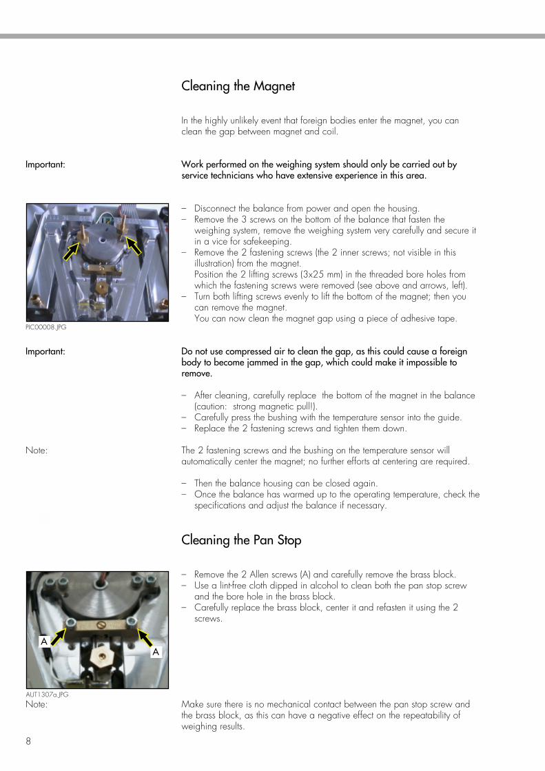
PIC00008.JPG
A
Cleaning the Magnet
In the highly unlikely event that foreign bodies enter the magnet, you canclean the gap between magnet and coil.
Important: Work performed on the weighing system should only be carried out byservice technicians who have extensive experience in this area.
– Disconnect the balance from power and open the housing.– Remove the 3 screws on the bottom of the balance that fasten the
weighing system, remove the weighing system very carefully and secure itin a vice for safekeeping.
– Remove the 2 fastening screws (the 2 inner screws; not visible in thisillustration) from the magnet.Position the 2 lifting screws (3x25 mm) in the threaded bore holes fromwhich the fastening screws were removed (see above and arrows, left).
– Turn both lifting screws evenly to lift the bottom of the magnet; then youcan remove the magnet.You can now clean the magnet gap using a piece of adhesive tape.
Important: Do not use compressed air to clean the gap, as this could cause a foreignbody to become jammed in the gap, which could make it impossible toremove.
– After cleaning, carefully replace the bottom of the magnet in the balance(caution: strong magnetic pull!).
– Carefully press the bushing with the temperature sensor into the guide.– Replace the 2 fastening screws and tighten them down.
Note: The 2 fastening screws and the bushing on the temperature sensor willautomatically center the magnet; no further efforts at centering are required.
– Then the balance housing can be closed again.– Once the balance has warmed up to the operating temperature, check the
specifications and adjust the balance if necessary.
Cleaning the Pan Stop
– Remove the 2 Allen screws (A) and carefully remove the brass block.– Use a lint-free cloth dipped in alcohol to clean both the pan stop screw
and the bore hole in the brass block.– Carefully replace the brass block, center it and refasten it using the 2
screws.
Note: Make sure there is no mechanical contact between the pan stop screw andthe brass block, as this can have a negative effect on the repeatability ofweighing results.
AUT1307a.JPG
A
SARTORIUS Monolith
9
A
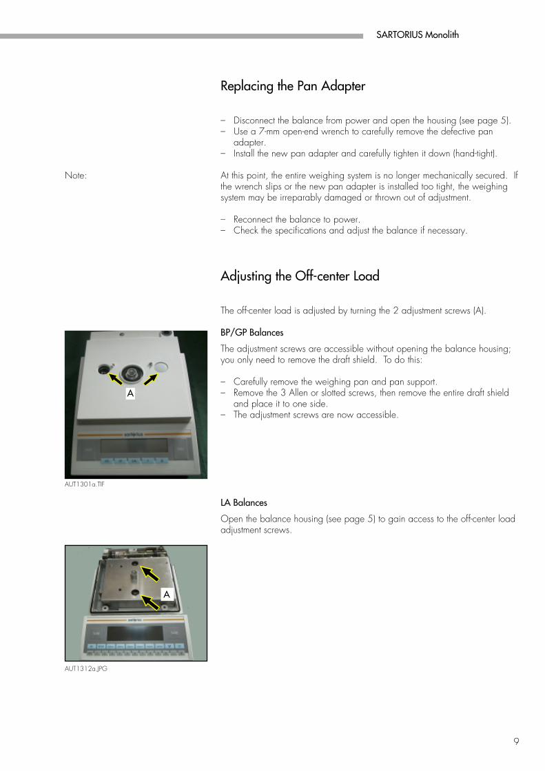
AUT1301a.TIF
AUT1312a.JPG
A
Replacing the Pan Adapter
– Disconnect the balance from power and open the housing (see page 5).– Use a 7-mm open-end wrench to carefully remove the defective pan
adapter.– Install the new pan adapter and carefully tighten it down (hand-tight).
Note: At this point, the entire weighing system is no longer mechanically secured. Ifthe wrench slips or the new pan adapter is installed too tight, the weighingsystem may be irreparably damaged or thrown out of adjustment.
– Reconnect the balance to power.– Check the specifications and adjust the balance if necessary.
Adjusting the Off-center Load
The off-center load is adjusted by turning the 2 adjustment screws (A).
BP/GP Balances
The adjustment screws are accessible without opening the balance housing;you only need to remove the draft shield. To do this:
– Carefully remove the weighing pan and pan support.– Remove the 3 Allen or slotted screws, then remove the entire draft shield
and place it to one side.– The adjustment screws are now accessible.
LA Balances
Open the balance housing (see page 5) to gain access to the off-center loadadjustment screws.
10
Just_Mon.XLS
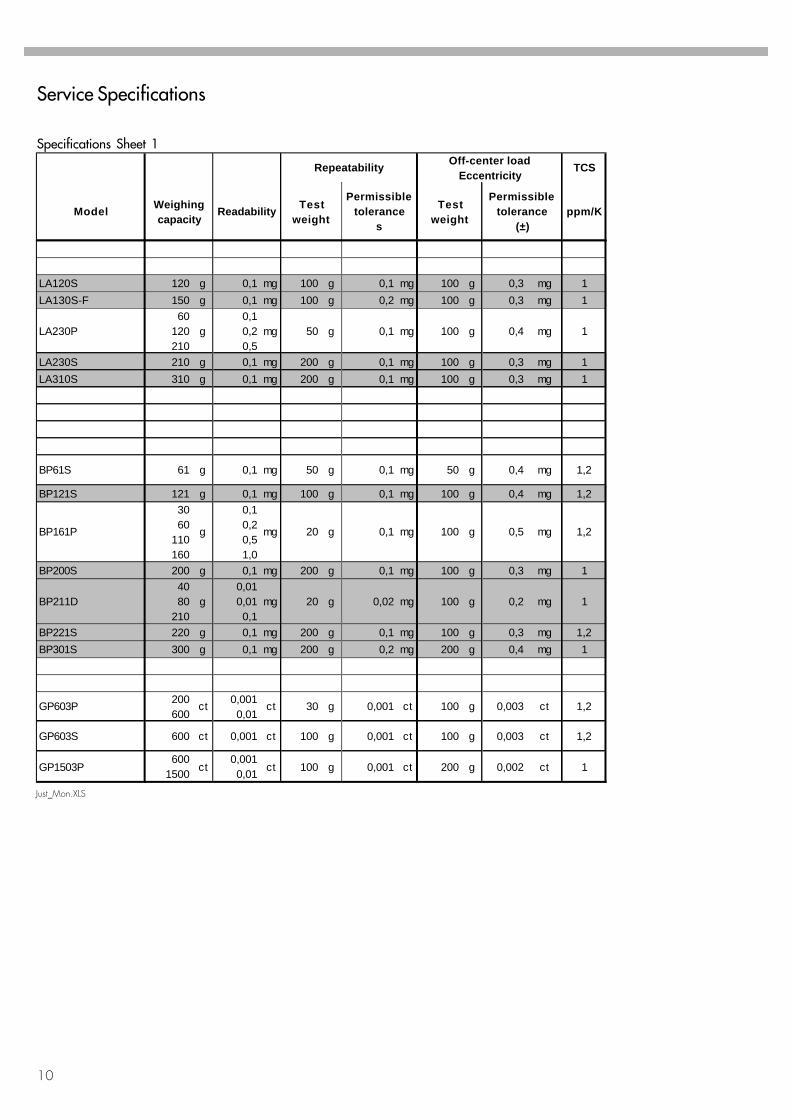
LA120S 120 g 0,1 mg 100 g 0,1 mg 100 g 0,3 mg 1LA130S-F 150 g 0,1 mg 100 g 0,2 mg 100 g 0,3 mg 1
LA230P60
120210
g0,10,20,5
mg 50 g 0,1 mg 100 g 0,4 mg 1
LA230S 210 g 0,1 mg 200 g 0,1 mg 100 g 0,3 mg 1LA310S 310 g 0,1 mg 200 g 0,1 mg 100 g 0,3 mg 1
BP61S 61 g 0,1 mg 50 g 0,1 mg 50 g 0,4 mg 1,2
BP121S 121 g 0,1 mg 100 g 0,1 mg 100 g 0,4 mg 1,2
BP161P
3060
110160
g
0,10,20,51,0
mg 20 g 0,1 mg 100 g 0,5 mg 1,2
BP200S 200 g 0,1 mg 200 g 0,1 mg 100 g 0,3 mg 1
BP211D4080
210g
0,010,010,1
mg 20 g 0,02 mg 100 g 0,2 mg 1
BP221S 220 g 0,1 mg 200 g 0,1 mg 100 g 0,3 mg 1,2BP301S 300 g 0,1 mg 200 g 0,2 mg 200 g 0,4 mg 1
GP603P 200600
ct 0,0010,01
ct 30 g 0,001 ct 100 g 0,003 ct 1,2
GP603S 600 ct 0,001 ct 100 g 0,001 ct 100 g 0,003 ct 1,2
GP1503P600
1500 ct0,0010,01 ct 100 g 0,001 ct 200 g 0,002 ct 1
Repeatability Off-center loadEccentricity
TCS
Model Weighingcapacity
Readability Testweight
Permissibletolerance
s
Testweight
Permissibletolerance
(±)ppm/K
Service Specifications
Specifications Sheet 1
SARTORIUS Monolith
11
Just_Mon.XLS
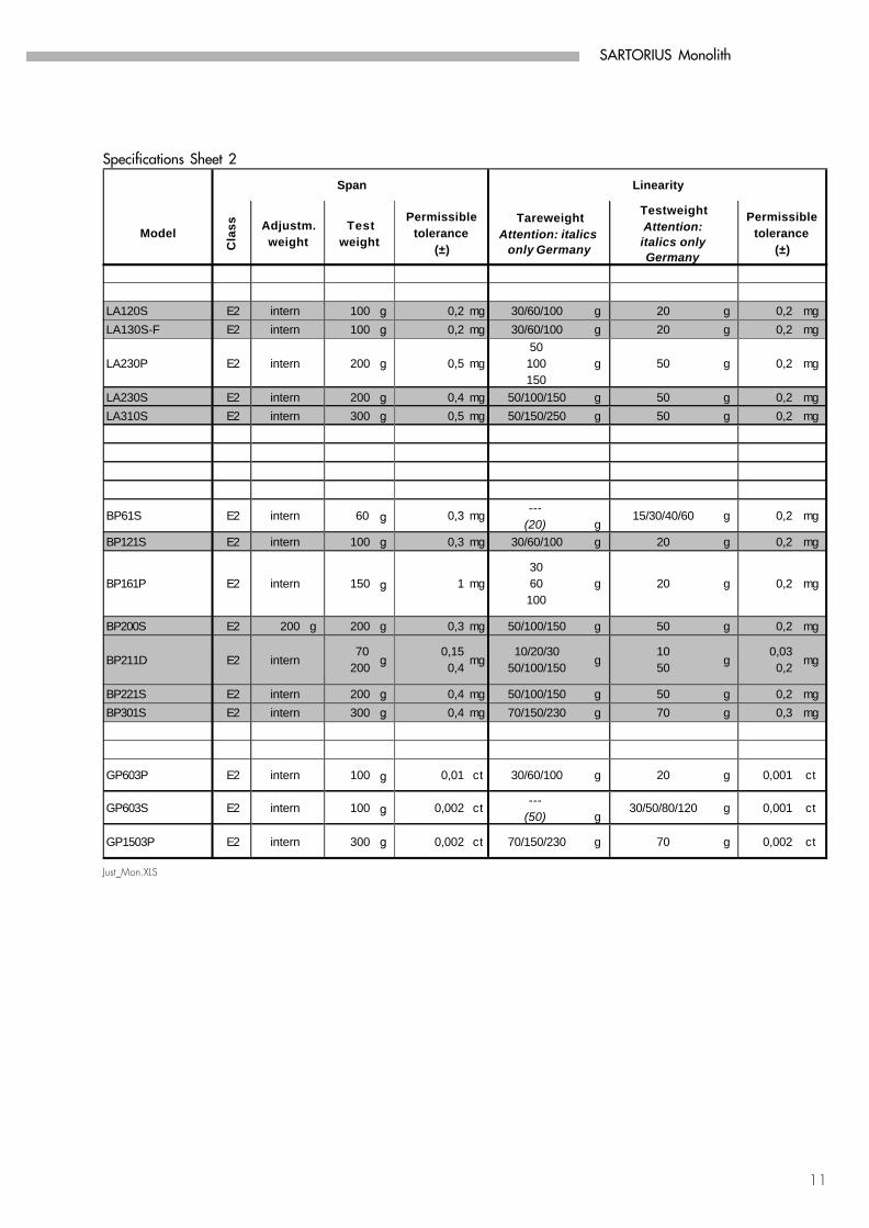
LA120S E2 intern 100 g 0,2 mg 30/60/100 g 20 g 0,2 mgLA130S-F E2 intern 100 g 0,2 mg 30/60/100 g 20 g 0,2 mg
LA230P E2 intern 200 g 0,5 mg50100150
g 50 g 0,2 mg
LA230S E2 intern 200 g 0,4 mg 50/100/150 g 50 g 0,2 mgLA310S E2 intern 300 g 0,5 mg 50/150/250 g 50 g 0,2 mg
BP61S E2 intern 60 g 0,3 mg ---(20) g
15/30/40/60 g 0,2 mg
BP121S E2 intern 100 g 0,3 mg 30/60/100 g 20 g 0,2 mg
BP161P E2 intern 150 g 1 mg3060100
g 20 g 0,2 mg
BP200S E2 200 g 200 g 0,3 mg 50/100/150 g 50 g 0,2 mg
BP211D E2 intern70
200 g0,150,4 mg
10/20/3050/100/150 g
1050 g
0,030,2 mg
BP221S E2 intern 200 g 0,4 mg 50/100/150 g 50 g 0,2 mgBP301S E2 intern 300 g 0,4 mg 70/150/230 g 70 g 0,3 mg
GP603P E2 intern 100 g 0,01 ct 30/60/100 g 20 g 0,001 ct
GP603S E2 intern 100 g 0,002 ct ---(50) g
30/50/80/120 g 0,001 ct
GP1503P E2 intern 300 g 0,002 ct 70/150/230 g 70 g 0,002 ct
Span Linearity
ModelC
lass Adjustm.
weightTest
weight
Permissibletolerance
(±)
TareweightAttention: italics
only Germany
TestweightAttention:italics only Germany
Permissibletolerance
(±)
Specifications Sheet 2
12
Gp-m.XLS
GP
1503
P
GP
1503
S-0
CE
GP
603P
GP
603S
1 1 1 11 1 1 11 1 1 11 1 1 11 1 1 1
1 1 1 11 1 1 11 1 1 1
1 1 1 11 1 1 11 1 1 11 1 1 11 1 1 11 1 1 11 1 1 11 1 1 1
1 1 1 11 1 1 11 1 1 11 1 1 11 1 1 11 1
1 1
1 1 1 11 1 1 11 1 1 11 1 1 11 1 1 11 1 1 1
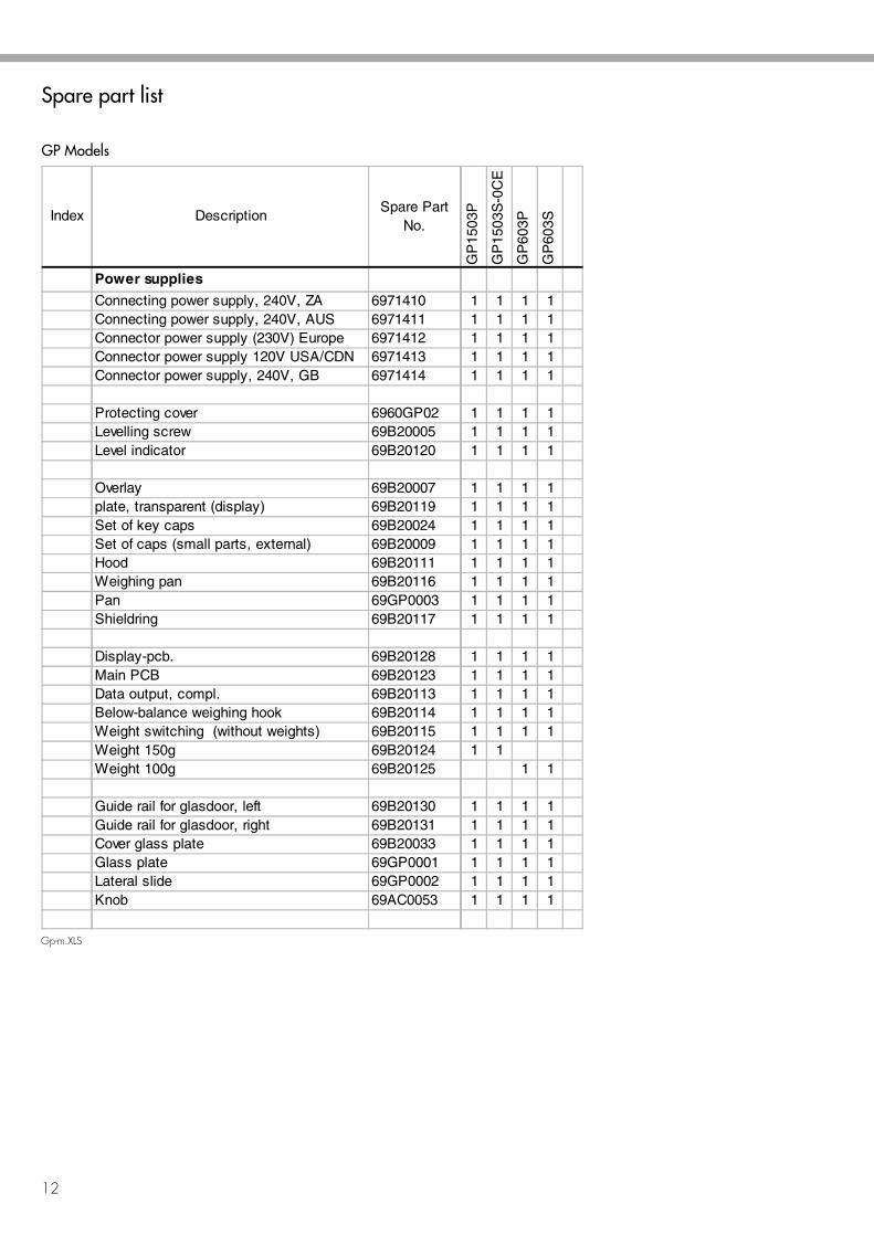
Spare part list
GP Models
Index DescriptionSpare Part
No.
Power supplies
Connecting power supply, 240V, ZA 6971410Connecting power supply, 240V, AUS 6971411Connector power supply (230V) Europe 6971412Connector power supply 120V USA/CDN 6971413Connector power supply, 240V, GB 6971414
Protecting cover 6960GP02Levelling screw 69B20005Level indicator 69B20120
Overlay 69B20007plate, transparent (display) 69B20119Set of key caps 69B20024Set of caps (small parts, external) 69B20009Hood 69B20111Weighing pan 69B20116Pan 69GP0003Shieldring 69B20117
Display-pcb. 69B20128Main PCB 69B20123Data output, compl. 69B20113Below-balance weighing hook 69B20114Weight switching (without weights) 69B20115Weight 150g 69B20124Weight 100g 69B20125
Guide rail for glasdoor, left 69B20130Guide rail for glasdoor, right 69B20131Cover glass plate 69B20033Glass plate 69GP0001Lateral slide 69GP0002Knob 69AC0053
SARTORIUS Monolith
13
Bp-m-neu.XLS
Index
BP
121S
BP
161P
BP
200S
BP
221S
BP
301S
BP
61S
BP
211D
1 1 1 1 1 1 11 1 1 1 1 1 11 1 1 1 1 1 11 1 1 1 1 1 11 1 1 1 1 1 1
1 1 1 1 1 1 11 1 1 1 1 1 11 1 1 1 1 1 1
1 1 1 1 1 1 11 1 1 1 1 1 11 1 1 1 1 1 11 1 1 1 1 1 11 1 1 1 1 1 11 1 1 1 1 1 11 1 1 1 1 1 1
11
1 1 1 1 1 1 11
1 1 1 1 1 11 1 1 1 1 1 1
11
1 1 1 1 1 1 11 1 1 1 1 1
11 1 1 1 1
1 1 1 1 1 1 11 1 1 1 1 1 11 1 1 1 1 1 11 1 1 1 1 1 11 1 1 1 1 1 11 1 1 1 1 1 1
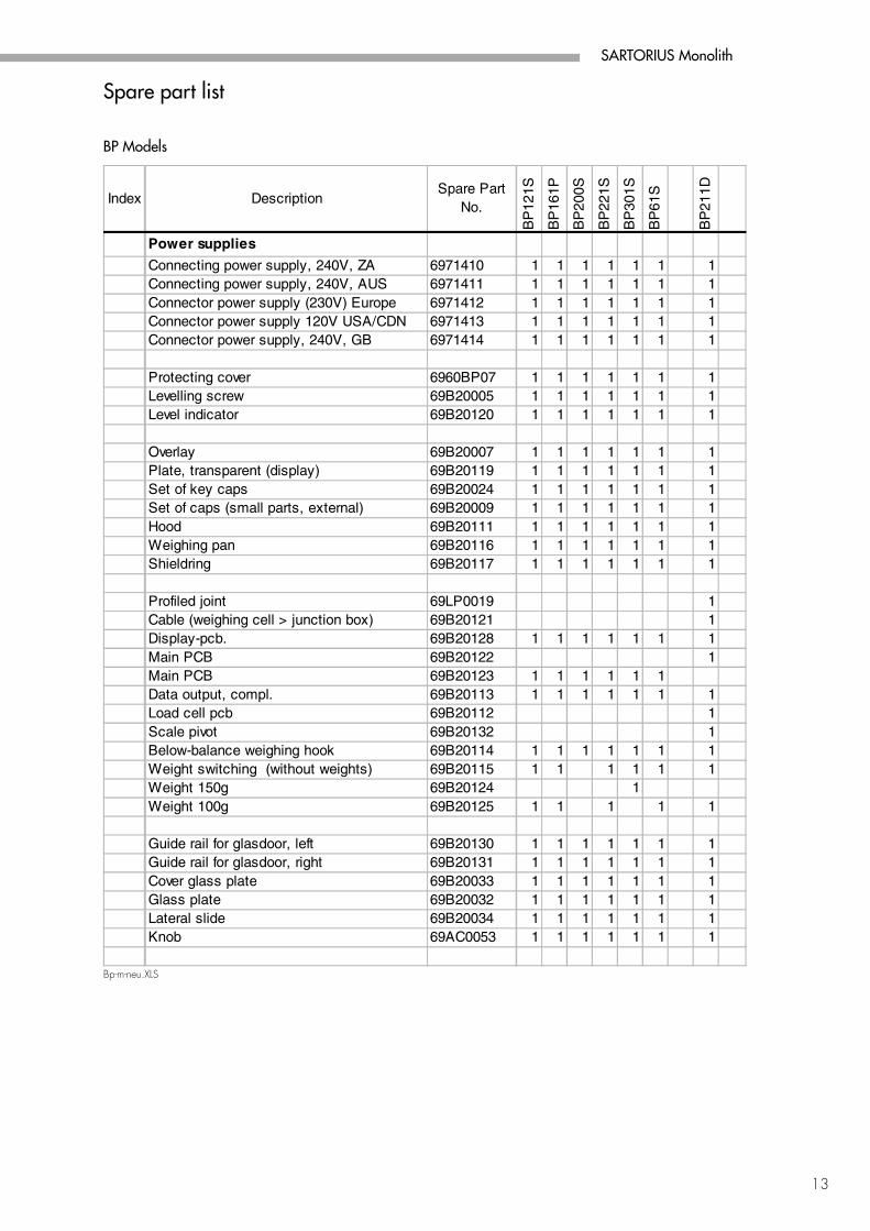
DescriptionSpare Part
No.
Power supplies
Connecting power supply, 240V, ZA 6971410Connecting power supply, 240V, AUS 6971411Connector power supply (230V) Europe 6971412Connector power supply 120V USA/CDN 6971413Connector power supply, 240V, GB 6971414
Protecting cover 6960BP07Levelling screw 69B20005Level indicator 69B20120
Overlay 69B20007Plate, transparent (display) 69B20119Set of key caps 69B20024Set of caps (small parts, external) 69B20009Hood 69B20111Weighing pan 69B20116Shieldring 69B20117
Profiled joint 69LP0019Cable (weighing cell > junction box) 69B20121Display-pcb. 69B20128Main PCB 69B20122Main PCB 69B20123Data output, compl. 69B20113Load cell pcb 69B20112Scale pivot 69B20132Below-balance weighing hook 69B20114Weight switching (without weights) 69B20115Weight 150g 69B20124Weight 100g 69B20125
Guide rail for glasdoor, left 69B20130Guide rail for glasdoor, right 69B20131Cover glass plate 69B20033Glass plate 69B20032Lateral slide 69B20034Knob 69AC0053
Spare part list
BP Models
14
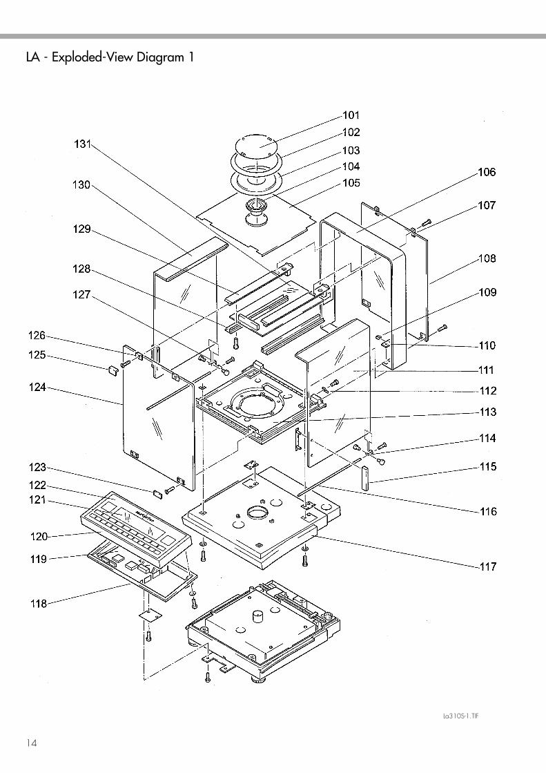
LA - Exploded-View Diagram 1
La310S-1.TIF
SARTORIUS Monolith
15
LA12
0S
LA23
0P
LA23
0S
LA31
0S
LA13
0S-F
1 1 1 1 11 1 1 1 11 1 1 1 1
11 1 1 12 2 2 2 21 1 1 1 11 1 1 11 1 1 11 1 1 11 1 1 11 1 1 11 1 1 11 1 1 11 1 1 11 1 1 11 1 1 11 1 1 11 1 1 11 1 1 11 1 1 11 1 1 11 1 1 11 1 1 11 1 1 1 11 1 1 1 11 1 1 1 11 1 1 1 11 1 1 1 11 1 1 1 11 1 1 1 11 1 1 1 11 1 1 11 1 1 11 1 1 11 1 1 11 1 1 11 1 1 11 1 1 11 1 1 11 1 1 11 1 1 1 11 1 1 11 1 1 1 11 1 1 11 1 1 1
Index
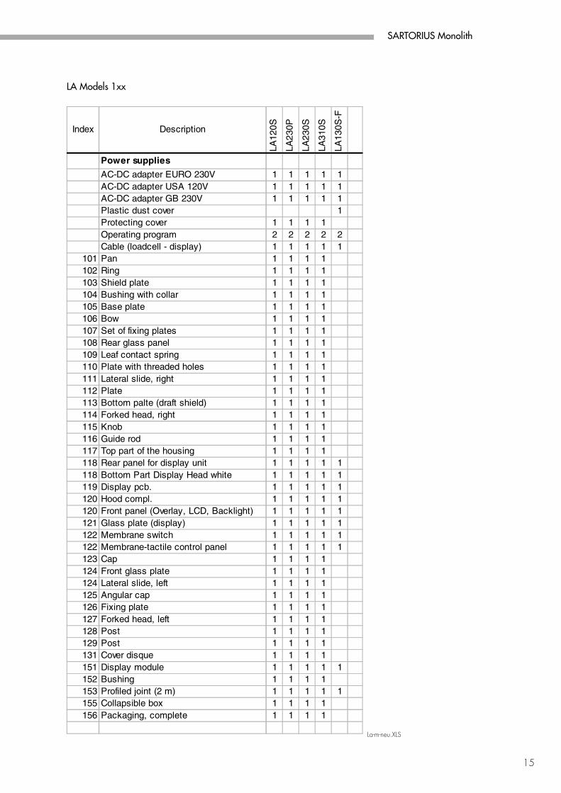
101102103104105106107108109110111112113114115116117118118119120120121122122123124124125126127128129131151152153155156
Description
Power supplies
AC-DC adapter EURO 230VAC-DC adapter USA 120VAC-DC adapter GB 230VPlastic dust cover Protecting cover Operating program Cable (loadcell - display) Pan Ring Shield plate Bushing with collarBase plate Bow Set of fixing platesRear glass panel Leaf contact spring Plate with threaded holes Lateral slide, right Plate Bottom palte (draft shield)Forked head, right Knob Guide rod Top part of the housing Rear panel for display unit Bottom Part Display Head white Display pcb. Hood compl. Front panel (Overlay, LCD, Backlight) Glass plate (display) Membrane switch Membrane-tactile control panel Cap Front glass plate Lateral slide, left Angular cap Fixing plate Forked head, left Post Post Cover disque Display module Bushing Profiled joint (2 m)Collapsible box Packaging, complete
La-m-neu.XLS
LA Models 1xx
16
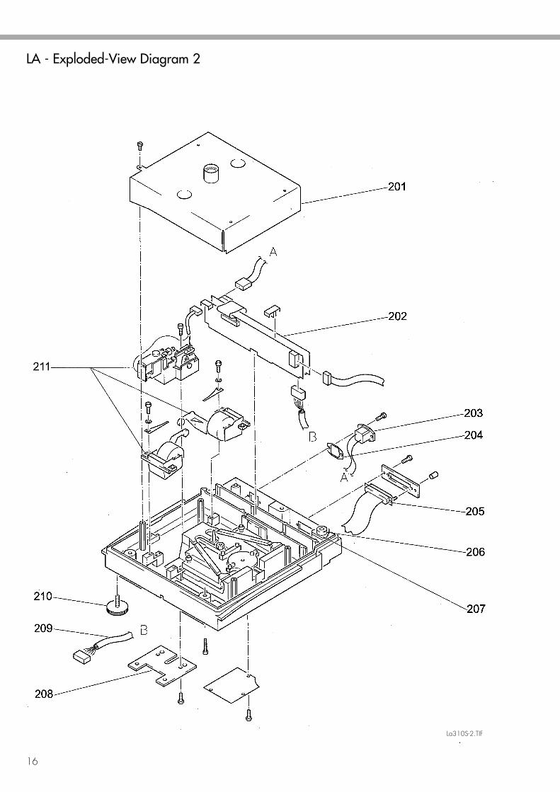
LA - Exploded-View Diagram 2
La310S-2.TIF
SARTORIUS Monolith
17
LA12
0S
LA23
0P
LA23
0S
LA31
0S
LA13
0S-F
1 1 1 1 11 1 1 1 11 1 1 1 11 1 1 1 11 1 1 1 11 1 1 1 11 1 1 1 11 1 1 11 1 1 1 11 1 1 1 11 1 1 1 1
1111
Index
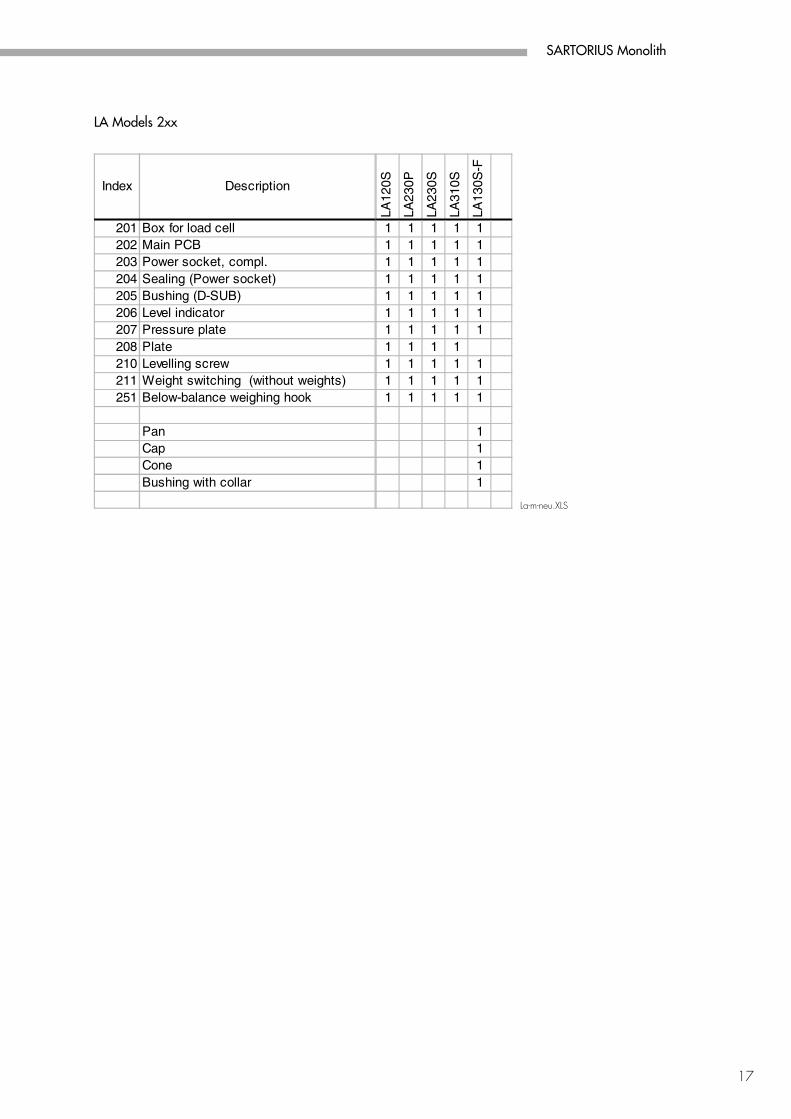
201202203204205206207208210211251
Description
Box for load cellMain PCB Power socket, compl. Sealing (Power socket) Bushing (D-SUB) Level indicator Pressure plate Plate Levelling screw Weight switching (without weights) Below-balance weighing hook
Pan Cap Cone Bushing with collar
La-m-neu.XLS
LA Models 2xx
Sartorius AG 37070 Goettingen, Germany Weender Landstrasse 94–108, 37075 Goettingen, Germany (+49/551) 308-0, (+49/551) 308-935
Internet: http://www.sartorius.comE-Mail: [email protected]
Copyright by Sartorius AG, Goettingen, Germany.All rights reserved. No part of this publicationmay be reprinted or translated in any form or by any meanswithout the prior written permission of Sartorius AG.
The status of the information, specifications andillustrations in this manual is indicated by the dategiven below. Sartorius AG reserves the right tomake changes to the technology, features,specifications and design of the equipmentwithout notice.
Status: July 1999 Sartorius AG, Goettingen, Germany
Printed in Germany on paper that has been bleached without any use of chlorine · I.K.· MPublication No.: W- -5039e99071


