Embed Size (px)
Citation preview

RTA-RTE V6.8.0User Guide
RTA-RTE V6.8.0User Guide
Copyright
The data in this document may not be altered or amended without special notificationfrom ETAS GmbH. ETAS GmbH undertakes no further obligation in relation to this doc-ument. The software described in it can only be used if the customer is in possessionof a general license agreement or single license. Using and copying is only allowed inconcurrence with the specifications stipulated in the contract. Under no circumstancesmay any part of this document be copied, reproduced, transmitted, stored in a retrievalsystem or translated into another language without the express written permission ofETAS GmbH.
©Copyright 2019 ETAS GmbH, Stuttgart.
The names and designations used in this document are trademarks or brands belongingto the respective owners.
Document: 10756-UG-001 EN - 05-2019
Revision: 92501 [RTA-RTE 6.8.0]
This product described in this document includes software developed by the ApacheSoftware Foundation (http://www.apache.org/).
2 Copyright
RTA-RTE V6.8.0User Guide
Contents
1 About this Manual 71.1 Document Conventions . . . . . . . . . . . . . . . . . . . . . . . . . 91.2 Acronyms and Abbreviations . . . . . . . . . . . . . . . . . . . . . . 9
I Introduction and Overview 11
2 Introduction to the RTE 122.1 What is a Run-Time Environment (RTE)? . . . . . . . . . . . . . . . . 132.2 Software Components . . . . . . . . . . . . . . . . . . . . . . . . . . 142.3 Interfaces . . . . . . . . . . . . . . . . . . . . . . . . . . . . . . . . . 182.4 Software Component Behavior . . . . . . . . . . . . . . . . . . . . . 212.5 Services . . . . . . . . . . . . . . . . . . . . . . . . . . . . . . . . . . 25
3 Introduction to RTE Configuration 263.1 Understanding XML . . . . . . . . . . . . . . . . . . . . . . . . . . . 263.2 Understanding AUTOSAR XML . . . . . . . . . . . . . . . . . . . . . 273.3 ECU Configuration Description . . . . . . . . . . . . . . . . . . . . . 33
4 Working with the RTE Generator 364.1 Contract Phase . . . . . . . . . . . . . . . . . . . . . . . . . . . . . . 374.2 RTE Phase . . . . . . . . . . . . . . . . . . . . . . . . . . . . . . . . . 394.3 Basic Software Phase . . . . . . . . . . . . . . . . . . . . . . . . . . 414.4 The Development Process . . . . . . . . . . . . . . . . . . . . . . . . 424.5 Samples . . . . . . . . . . . . . . . . . . . . . . . . . . . . . . . . . . 42
II Developing Software Components 45
5 Type System 465.1 Application Data Types . . . . . . . . . . . . . . . . . . . . . . . . . 465.2 Base Types . . . . . . . . . . . . . . . . . . . . . . . . . . . . . . . . 505.3 Implementation Data Types . . . . . . . . . . . . . . . . . . . . . . . 515.4 Type Mappings . . . . . . . . . . . . . . . . . . . . . . . . . . . . . . 605.5 Application Types And Numerical Representations . . . . . . . . . . 615.6 Expressing Values in Physical Units or Numerical Representation . . 66
6 Interfaces 696.1 Sender-Receiver . . . . . . . . . . . . . . . . . . . . . . . . . . . . . 696.2 Nv-Data . . . . . . . . . . . . . . . . . . . . . . . . . . . . . . . . . . 706.3 Mode-Switch . . . . . . . . . . . . . . . . . . . . . . . . . . . . . . . 716.4 Client-Server . . . . . . . . . . . . . . . . . . . . . . . . . . . . . . . 726.5 Calibration . . . . . . . . . . . . . . . . . . . . . . . . . . . . . . . . 736.6 Trigger . . . . . . . . . . . . . . . . . . . . . . . . . . . . . . . . . . 74
7 Software Component Types 757.1 Ports . . . . . . . . . . . . . . . . . . . . . . . . . . . . . . . . . . . . 767.2 Communication Specifications . . . . . . . . . . . . . . . . . . . . . 77
Contents 3
RTA-RTE V6.8.0User Guide
8 Internal Behavior 838.1 RTE Events . . . . . . . . . . . . . . . . . . . . . . . . . . . . . . . . 848.2 Runnable Entities . . . . . . . . . . . . . . . . . . . . . . . . . . . . 868.3 Responding to Periodic Events . . . . . . . . . . . . . . . . . . . . . 878.4 Sending to a Port . . . . . . . . . . . . . . . . . . . . . . . . . . . . . 888.5 Receiving from a Port . . . . . . . . . . . . . . . . . . . . . . . . . . 908.6 Responding to a Server Request on a Port . . . . . . . . . . . . . . . 948.7 Making a Client Request on a Port . . . . . . . . . . . . . . . . . . . 958.8 Direct Trigger of a Runnable Entity . . . . . . . . . . . . . . . . . . . 1008.9 Exclusive Areas . . . . . . . . . . . . . . . . . . . . . . . . . . . . . . 1028.10 Inter-Runnable Variables . . . . . . . . . . . . . . . . . . . . . . . . . 1068.11 Accessing Modes . . . . . . . . . . . . . . . . . . . . . . . . . . . . . 1078.12 Per-instance Memory . . . . . . . . . . . . . . . . . . . . . . . . . . 1078.13 Port Options . . . . . . . . . . . . . . . . . . . . . . . . . . . . . . . 1088.14 Supporting Multiple Instantiation . . . . . . . . . . . . . . . . . . . . 1098.15 Memory Allocation . . . . . . . . . . . . . . . . . . . . . . . . . . . . 110
9 Modes 1119.1 Defining Modes . . . . . . . . . . . . . . . . . . . . . . . . . . . . . . 1119.2 Mode Communication . . . . . . . . . . . . . . . . . . . . . . . . . . 1119.3 Using Modes . . . . . . . . . . . . . . . . . . . . . . . . . . . . . . . 1159.4 Understanding Mode Instances . . . . . . . . . . . . . . . . . . . . . 1189.5 Fast Init . . . . . . . . . . . . . . . . . . . . . . . . . . . . . . . . . . 1199.6 Synchronizing Modes . . . . . . . . . . . . . . . . . . . . . . . . . . 1209.7 Non-AUTOSAR Functionality . . . . . . . . . . . . . . . . . . . . . . . 120
10Implementing Software Components 12210.1 Basic Concepts . . . . . . . . . . . . . . . . . . . . . . . . . . . . . . 12210.2 Application Source Code . . . . . . . . . . . . . . . . . . . . . . . . . 12410.3 Single and Multiple Instances . . . . . . . . . . . . . . . . . . . . . . 12510.4 Runnable Entities . . . . . . . . . . . . . . . . . . . . . . . . . . . . 12610.5 Sender-Receiver Communication . . . . . . . . . . . . . . . . . . . . 13210.6 Client-Server Communication . . . . . . . . . . . . . . . . . . . . . . 13510.7 Using Inter-Runnable Variables . . . . . . . . . . . . . . . . . . . . . 13610.8 Accessing Parameters . . . . . . . . . . . . . . . . . . . . . . . . . . 13610.9 Accessing Per Instance Memory . . . . . . . . . . . . . . . . . . . . 13710.10 Concurrency Control with Exclusive Areas . . . . . . . . . . . . . . . 13710.11 Starting and Stopping the RTE . . . . . . . . . . . . . . . . . . . . . 139
11NVRAM 14011.1 NV-Block Software Component Types . . . . . . . . . . . . . . . . . 14011.2 Interaction with Application SWC . . . . . . . . . . . . . . . . . . . . 14311.3 Interaction with the NVRAM Manager . . . . . . . . . . . . . . . . . 143
III Developing Basic Software 145
12Basic Software 14612.1 Basic Software Modules . . . . . . . . . . . . . . . . . . . . . . . . . 146
4 Contents
RTA-RTE V6.8.0User Guide
12.2 Interaction with the RTE . . . . . . . . . . . . . . . . . . . . . . . . . 14712.3 API . . . . . . . . . . . . . . . . . . . . . . . . . . . . . . . . . . . . . 152
IV Composition 154
13Composing Software Components 15513.1 Composition Type Definition . . . . . . . . . . . . . . . . . . . . . . 15513.2 Component Instances . . . . . . . . . . . . . . . . . . . . . . . . . . 15613.3 Connector Prototypes . . . . . . . . . . . . . . . . . . . . . . . . . . 15613.4 FlatMaps . . . . . . . . . . . . . . . . . . . . . . . . . . . . . . . . . 16713.5 Data Conversion . . . . . . . . . . . . . . . . . . . . . . . . . . . . . 173
14Composing Basic Software 18014.1 Instantiation . . . . . . . . . . . . . . . . . . . . . . . . . . . . . . . 18014.2 BSW Scheduler . . . . . . . . . . . . . . . . . . . . . . . . . . . . . . 18114.3 Connections . . . . . . . . . . . . . . . . . . . . . . . . . . . . . . . 181
15Synchronizing BSW and SWC 18315.1 Configuration . . . . . . . . . . . . . . . . . . . . . . . . . . . . . . . 18315.2 Synchronized Mode Groups . . . . . . . . . . . . . . . . . . . . . . . 18515.3 Synchronized Triggers . . . . . . . . . . . . . . . . . . . . . . . . . . 18615.4 Synchronized Runnable Entities . . . . . . . . . . . . . . . . . . . . 187
16Accessing NVRAM 18916.1 Configuration . . . . . . . . . . . . . . . . . . . . . . . . . . . . . . . 18916.2 Access from Application SWCs . . . . . . . . . . . . . . . . . . . . . 19116.3 Access from the NVRAM manager . . . . . . . . . . . . . . . . . . . 193
V Deployment 196
17Defining the ECUs and the Networks 19717.1 ECU Type Definition . . . . . . . . . . . . . . . . . . . . . . . . . . . 19817.2 ECU Instances . . . . . . . . . . . . . . . . . . . . . . . . . . . . . . 199
18Mapping Software Components to ECUs 20018.1 Mapping Component Prototypes . . . . . . . . . . . . . . . . . . . . 20018.2 SWC Implementation Selection . . . . . . . . . . . . . . . . . . . . . 20118.3 Configuring Service Components on an ECU . . . . . . . . . . . . . 20218.4 Mapping Runnable Entities to Tasks . . . . . . . . . . . . . . . . . . 20318.5 How Runnables get activated . . . . . . . . . . . . . . . . . . . . . . 205
19Inter-ECU Communication 21019.1 System Communications . . . . . . . . . . . . . . . . . . . . . . . . 21019.2 Inter-ECU Sender-Receiver Communication . . . . . . . . . . . . . . 21519.3 Inter-ECU Client-Server Communication . . . . . . . . . . . . . . . . 218
20Using the OS and COM Configurations 22320.1 Operating System Configuration . . . . . . . . . . . . . . . . . . . . 22420.2 Communication Stack Configuration . . . . . . . . . . . . . . . . . . 226
Contents 5
RTA-RTE V6.8.0User Guide
21Debugging Implementations with VFB Tracing 22821.1 Enabling Tracing . . . . . . . . . . . . . . . . . . . . . . . . . . . . . 22821.2 Supported Trace Events . . . . . . . . . . . . . . . . . . . . . . . . . 22821.3 Configuration . . . . . . . . . . . . . . . . . . . . . . . . . . . . . . . 23121.4 Trace Event Header File . . . . . . . . . . . . . . . . . . . . . . . . . 23121.5 Implementing Hook Functions . . . . . . . . . . . . . . . . . . . . . 231
22Data Transformation 23322.1 Extent of support . . . . . . . . . . . . . . . . . . . . . . . . . . . . . 23322.2 Enabling data transformation in an input configuration . . . . . . . 23622.3 Working with data transformation . . . . . . . . . . . . . . . . . . . 23922.4 Working with the COM-based transformer . . . . . . . . . . . . . . . 240
VI Advanced Concepts 241
23RTE Generation 24223.1 Identifier length . . . . . . . . . . . . . . . . . . . . . . . . . . . . . 242
24Operating System Considerations 24324.1 OS Trigger Selection . . . . . . . . . . . . . . . . . . . . . . . . . . . 24324.2 Task Recurrence . . . . . . . . . . . . . . . . . . . . . . . . . . . . . 24324.3 Schedule Points . . . . . . . . . . . . . . . . . . . . . . . . . . . . . 24424.4 Basic and Extended Tasks . . . . . . . . . . . . . . . . . . . . . . . . 24524.5 Forced-basic semantics . . . . . . . . . . . . . . . . . . . . . . . . . 246
25Understanding Deployment Choices 24925.1 Intra-task . . . . . . . . . . . . . . . . . . . . . . . . . . . . . . . . . 24925.2 Inter-task . . . . . . . . . . . . . . . . . . . . . . . . . . . . . . . . . 25125.3 Inter-task Client-Server . . . . . . . . . . . . . . . . . . . . . . . . . 25325.4 Inter-ECU . . . . . . . . . . . . . . . . . . . . . . . . . . . . . . . . . 254
26Optimization 26126.1 Buffers for Inter-ECU Reception . . . . . . . . . . . . . . . . . . . . . 26126.2 Direct invocation of the RTE API . . . . . . . . . . . . . . . . . . . . 26126.3 Sender-Receiver Communication . . . . . . . . . . . . . . . . . . . . 26226.4 Client-Server Communication . . . . . . . . . . . . . . . . . . . . . . 26326.5 Function Elision . . . . . . . . . . . . . . . . . . . . . . . . . . . . . . 26426.6 Init Runnables . . . . . . . . . . . . . . . . . . . . . . . . . . . . . . 26526.7 Data Consistency . . . . . . . . . . . . . . . . . . . . . . . . . . . . 26626.8 Tips . . . . . . . . . . . . . . . . . . . . . . . . . . . . . . . . . . . . 267
27RTE Architecture 26827.1 Component Data Structure . . . . . . . . . . . . . . . . . . . . . . . 26827.2 Component Instance Handle . . . . . . . . . . . . . . . . . . . . . . 26927.3 The RTE API Implementation . . . . . . . . . . . . . . . . . . . . . . 270
VII Support 273
28Contact, Support and Problem Reporting 274
6 Contents
RTA-RTE V6.8.0User Guide
1 About this Manual
The RTA-RTE User Guide describes how to install the ETAS AUTOSAR Run-Time Environ-ment (RTE) generation tools and how to configure, build and deploy RTE-based softwarecomponents on electronic control units.
The RTA-RTE User Guide is structured along the lines of a top-down development usingthe RTE, taking users from software component configuration and development withthe RTE, through system configuration and software component deployment to finalintegration of an RTE-based ECU.
• Part I, Introduction and Overview
• Chapter 2 introduces the fundamental building blocks for applications designedfor the AUTOSAR software architecture. The chapter explains how the RTE pro-vides the environment by which AUTOSAR applications run, interact and ex-change data at runtime.
• Chapter 3 outlines the key aspects of the RTA-RTE configuration language.
• Chapter 4 explains the wider scope of an AUTOSAR development process andhow RTA-RTE supports the process.
• Part II, Developing Software Components presents a guide to the RTE for SoftwareComponent Engineers.
• Chapter 5 explains the AUTOSAR type system and how implementation andapplication types interact.
• Chapter 6 explains how to define sender-receiver and client-server interfacesthat use the data types and can be used by software components to communi-cate.
• Chapter 7 describes how to define the external view of a software component.
• Chapter 8 shows how to define the threads of control, called runnable entities,that will be executed to trigger or respond to RTE communication.
• Chapter 9 explains how to use the RTA-RTE provided support for AUTOSARapplication modes and how software components can trigger activity when amode changes.
• Chapter 10 shows how to write code to interface with the RTE, use the RTE APIin application code to communicate with other applications, build in run-timefault tolerance and protect critical data.
• Chapter 11 shows how to write code to create non-volatile data and to interfacewith the AUTOSAR NVRAM manager module.
• Part III, Developing Basic Software presents a guide to the development of BasicSoftware using RTA-RTE.
• Chapter 12 explains how to create Basic Software modules for use with theRTA-RTE.
About this Manual 7
RTA-RTE V6.8.0User Guide
• Part IV, Composition presents a guide to the RTE for Software System Integrators.
• Chapter 13, Composing Software Components explains how to create instancesof software components, configure instance attributes like the number ofqueued data elements that can be received and compose the instances of soft-ware components to create a logical software system.
• Chapter 14, Composing Basic Software explains how to create basic softwaremodule instances and how to configure their connections.
• Chapter 15, Synchronizing Basic Software explains how to synchronizerunnables, modes and triggers between basic software module instances andSWC instances.
• Chapter 16, Accessing NVRAM explains how to access non-volatile data fromapplication software.
• Part V, Deployment presents a guide to the RTE for ECU and Vehicle Integrators.
• Chapter 17 shows how to define the types of ECU, protocol and communicationframes that will be present in your system.
• Chapter 18 describes how to map the software architecture created duringthe composition stage onto the hardware architecture created in the previ-ous chapter and how to map the runnables of a software component into tasksprovided by the AUTOSAR OS.
• Chapter 19 describe how to map sender-receiver and client-server communica-tion between software components located on different ECUs onto the underly-ing AUTOSAR COM communication basic software module.
• Chapter 20 shows how to use the generated OS and COM configuration files inyour application.
• Chapter 21 explains how to use the hook calls embedded within a generatedRTE to trace RTE events and communication.
• Chapter 22 explains how to serialize and transform communication betweensoftware components.
• Part VI, Advanced Concepts
• Chapter 23 explains additional configuration options for generation of RTEs us-ing RTA-RTE.
• Chapter 24 explains Basic and Extended tasks, and how the RTE interacts withthese OS features.
• Chapter 25 explains how the RTE API calls work when software components aremapped to the same task, the same ECU or different ECUs.
• Chapter 26 explains how the RTA-RTE optimizes the generated RTE and howapplication mapping can affect the scope for optimization.
• Chapter 27 explains how the RTE application specific headers provide the ab-stractions that make the RTE work and how they encapsulate optimizations.
• Part VII, Support
8 About this Manual
RTA-RTE V6.8.0User Guide
• Chapter 28 explains how to contact ETAS to obtain technical support for RTA-RTE.
1.0.1 Related Documents
The RTA-RTE Reference Manual provides a complete reference for the RTE including:
• The syntax of the RTE configuration language.
• The features and functionality of the RTE Generation tool.
• The RTE naming conventions.
• A complete RTE API call reference.
• Dependencies on AUTOSAR Basic Software Modules.
1.0.2 Who Should Read this Manual?
You should read the RTA-RTE User Guide if you need to configure, generate or use a run-time environment for an embedded electronic control unit (ECU). Basic familiarity withthe concepts of the AUTOSAR software architecture and knowledge of C programmingare assumed.
Readers of this document are assumed to be familiar with the RTA-RTE Getting StartedGuide.
First time users of the RTE should read this document for a detailed description of whatfeatures and facilities the RTE provides to software components.
1.1 Document Conventions
Notes that appear like this contain important information that you need tobe aware of. Make sure that you read them carefully and that you follow anyinstructions that you are given.
Notes that appear like this describe things that you will need to know if youwant to write code that will work on any target processor.
In this guide you’ll see that program code, header file names, C type names, C functionsand API call names all appear in the monospaced typeface. When the name of an objectis made available to the programmer the name also appears in the courier typeface,suitably modified in accordance with the RTE naming conventions. So, for example, arunnable called Runnable1 appears as a handle called Runnable1.
1.2 Acronyms and Abbreviations
About this Manual 9
RTA-RTE V6.8.0User Guide
AUTOSAR AUTomotive Open System ARchitecture - a standard-ized software architecture targeted at automotive ap-plications aimed at fostering the reuse of applica-tion software over multiple vehicle platforms. Seehttp://www.autosar.org.
BSW AUTOSAR Basic Software, see Chapter 12.
C/S Client-server communication, see Section 6.4.
ECUC AUTOSAR ECU Configuration
IOC Inter-OsApplication Communication
RTA-OS An AUTOSAR SC1-SC4 and OSEK 2.2.3 compatible operat-ing system from ETAS GmbH.
RTA-OSEK An AUTOSAR SC1 and OSEK 2.2.3 compatible operatingsystem from ETAS GmbH.
RTE AUTOSAR Run-Time Environment. See “Introduction to theRTE” (Chapter 2) for further details.
RTA-RTE The ETAS AUTOSAR RTE Generator Product. This includesthe AUTOSAR RTE Generator Tool responsible for readingthe AUTOSAR XML configuration and generating the RTEand associated C header files. RTA-RTE distributions alsoinclude the RTE library, all user documentation and an ex-ample application.
SchM BSW Scheduler (a BSW module defined by AUTOSAR).
S/R Sender-receiver communication, see Section 6.1.
SWC An AUTOSAR Software component, see Chapter 7.
VFB Virtual Function Bus. See “Introduction to the RTE” (Chap-ter 2) for further details.
XML eXtensible Markup Language used to describe AUTOSARconfigurations. RTA-RTE processes the input configurationto generate the required RTE
10 About this Manual
RTA-RTE V6.8.0User Guide
Part I
Introduction and Overview
11
RTA-RTE V6.8.0User Guide
2 Introduction to the RTE
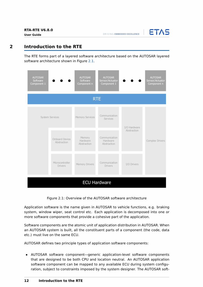
The RTE forms part of a layered software architecture based on the AUTOSAR layeredsoftware architecture shown in Figure 2.1.
AUTOSAR Software
Component 1
AUTOSAR Software
Component n
AUTOSAR Sensor/Actuator Component 1
AUTOSAR Sensor/Actuator Component n
RTE
Memory ServicesCommunication
Services
I/O Hardware Abstraction
Complex DriversOnboard Device
Abstraction
Memory Hardware
Abstraction
Communication Hardware
Abstraction
Microcontroller Drivers
Memory DriversCommunication
DriversI/O Drivers
ECU Hardware
System Services
Figure 2.1: Overview of the AUTOSAR software architecture
Application software is the name given in AUTOSAR to vehicle functions, e.g. brakingsystem, window wiper, seat control etc. Each application is decomposed into one ormore software components that provide a cohesive part of the application.
Software components are the atomic unit of application distribution in AUTOSAR. Whenan AUTOSAR system is built, all the constituent parts of a component (the code, dataetc.) must live on the same ECU.
AUTOSAR defines two principle types of application software components:
• AUTOSAR software component—generic application-level software componentsthat are designed to be both CPU and location neutral. An AUTOSAR applicationsoftware component can be mapped to any available ECU during system configu-ration, subject to constraints imposed by the system designer. The AUTOSAR soft-
12 Introduction to the RTE
RTA-RTE V6.8.0User Guide
ware component is therefore the atomic unit of distribution in an AUTOSAR system.
• AUTOSAR Sensor/Actuator component—software components that are closely cou-pled to some aspect of ECU hardware and are therefore typically not re-locatable(onto a different ECU) due to their high degree of dependence on features of aspecific ECU.
In an AUTOSAR system, software component interaction is designed against a VirtualFunction Bus (VFB). The VFB provides a design abstraction that allows interacting soft-ware components to be specified and built without detailed knowledge about whichECU they will be allocated at integration time, how ECUs in the vehicle network com-municate, the vehicle network topology etc.
In the VFB model, software components interact though ports which are typed by in-terfaces. The interface controls what can be communicated and the semantics of com-munication. The port provides the software component access to the interface. Thecombination of port and interface is known as an AUTOSAR interface. Software compo-nents are characterized by component type attributes that define how the componentsinteract with a interface over a port. Attributes might allow you to specify things like:
• A software component waits for data to be provided on a port.
• A software component polls a port for new data periodically.
• Acknowledgment of receipt of a sent message is required.
The VFB provides sufficient information about the logical interaction of software compo-nents to allow software systems to be integrated and tested before system integratorshave decided on the allocation of software components to ECUs. This means that theentire functional behavior of a system can be prototyped before the electrical architec-ture of a vehicle, in terms of ECUs on networks, is known.
The next stage in development is system integration where software components areallocated to ECUs and the abstract notions of communication embedded in their VFBdesign are mapped to signals sent over the vehicle network. Software componentsmust also be bound onto the computing platform, for example, integrated into tasksfor scheduling by an operating system.
2.1 What is a Run-Time Environment (RTE)?
The VFB provides the abstraction that allows components to be reusable. The RTEencapsulates the mechanisms required to make the VFB abstraction work at runtime.The RTE is therefore, in the simplest case, an implementation of the VFB. However,the RTE must provide the necessary interfacing and infrastructure to allow softwarecomponents to:
1. be implemented without reference to an ECU (the VFB model); and
Introduction to the RTE 13
RTA-RTE V6.8.0User Guide
2. be integrated with the ECU and the wider vehicle network once this is known (theSystems Integration Model) without changing the application software itself.
More specifically, the RTE must:
• Provide a communication infrastructure for software components.
This includes both communication between software components on the same ECU(intra-ECU ) and communication between software components located on differentECUs (inter-ECU).
• Arrange for real-time scheduling of software components.
This typically means mapping software components onto tasks provided by an op-erating system according to timeliness constraints specified at design time.
Application software components have no direct access to the basic software belowthe abstraction implemented by the RTE. This means that components cannot, for ex-ample, directly access operating system or communication services. So, the RTE mustpresent an abstraction over such services that remains consistent irrespective of wherethe software components are located. All interaction between software componentstherefore happens through standardized RTE interface calls.
The RTE also binds the software component architecture onto one or more ECUs. Tomake the RTE efficient, this binding is done statically at build time. The standardizedRTE interfaces are automatically implemented by an RTE generation tool that makessure that interface behaves in the correct way for the specified component interactionand the specified component allocation.
For example, if two software components reside on the same ECU they can use internalECU communication, but if one is moved to a different ECU, communication now needsto occur across the vehicle network.
The generated RTE therefore encapsulates the variability in the software that arisesfrom different mappings of components to ECUs by:
• Presenting a consistent interface to the software components so they can bereused—they can be designed and written once but used multiple times.
• Binding that interface onto the underlying AUTOSAR basic software implement theVFB design abstraction.
2.2 Software Components
Within the two broad types outlined above, AUTOSAR defines multiple sub-types ofsoftware component:
• Application software components.
14 Introduction to the RTE
RTA-RTE V6.8.0User Guide
• Sensor/actuator software components.
• Service components.
• Complex device driver components.
• ECU abstraction components.
From the perspective of the RTE, however, the multiple types are largely identical andhence, for reasons of brevity, the term “software component” is used to refer to alltypes.
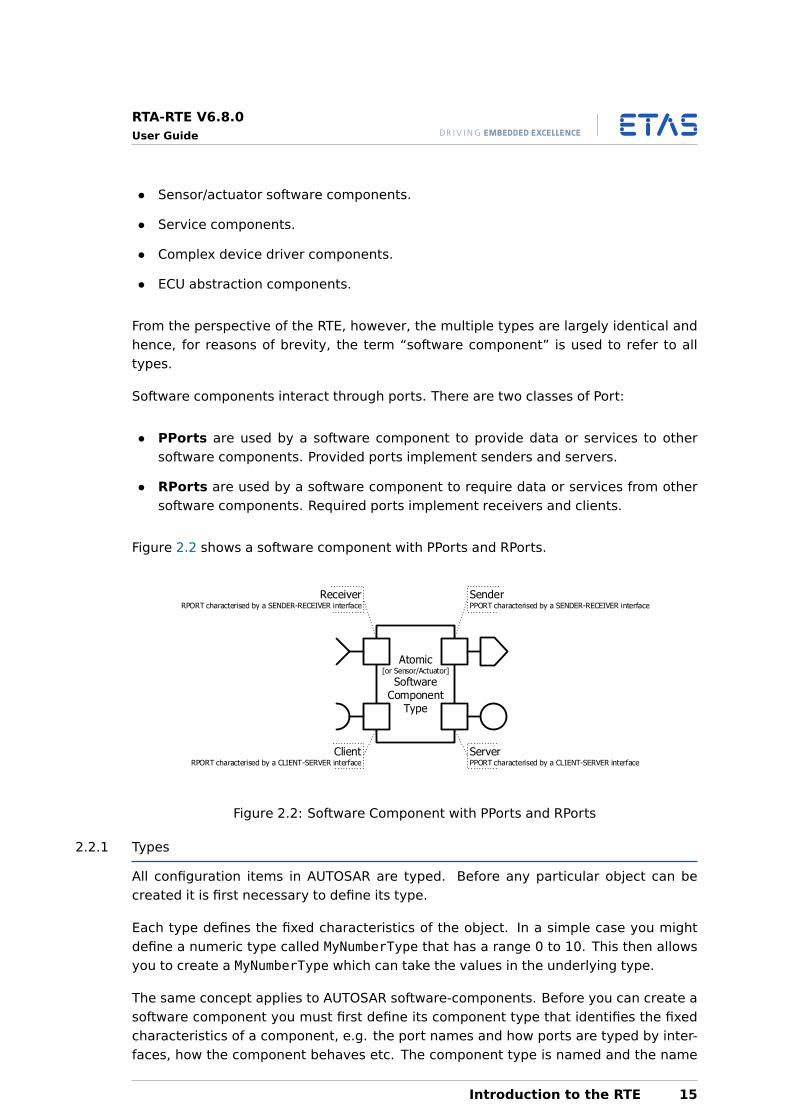
Software components interact through ports. There are two classes of Port:
• PPorts are used by a software component to provide data or services to othersoftware components. Provided ports implement senders and servers.
• RPorts are used by a software component to require data or services from othersoftware components. Required ports implement receivers and clients.
Figure 2.2 shows a software component with PPorts and RPorts.
Atomic[or Sensor/Actuator]
SoftwareComponent
Type
SenderPPORT characterised by a SENDER-RECEIVER interface
ReceiverRPORT characterised by a SENDER-RECEIVER interface
ClientRPORT characterised by a CLIENT-SERVER interface
ServerPPORT characterised by a CLIENT-SERVER interface
Figure 2.2: Software Component with PPorts and RPorts
2.2.1 Types
All configuration items in AUTOSAR are typed. Before any particular object can becreated it is first necessary to define its type.
Each type defines the fixed characteristics of the object. In a simple case you mightdefine a numeric type called MyNumberType that has a range 0 to 10. This then allowsyou to create a MyNumberType which can take the values in the underlying type.
The same concept applies to AUTOSAR software-components. Before you can create asoftware component you must first define its component type that identifies the fixedcharacteristics of a component, e.g. the port names and how ports are typed by inter-faces, how the component behaves etc. The component type is named and the name
Introduction to the RTE 15
RTA-RTE V6.8.0User Guide
must be unique within the system. Component type names are typically assigned whenyou create components.
2.2.2 Component Types and Instances
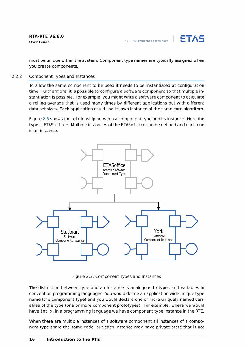
To allow the same component to be used it needs to be instantiated at configurationtime. Furthermore, it is possible to configure a software component so that multiple in-stantiation is possible. For example, you might write a software component to calculatea rolling average that is used many times by different applications but with differentdata set sizes. Each application could use its own instance of the same core algorithm.
Figure 2.3 shows the relationship between a component type and its instance. Here thetype is ETASoffice. Multiple instances of the ETASoffice can be defined and each oneis an instance.
ETASofficeAtomic SoftwareComponent Type
StuttgartSoftware
Component Instance
YorkSoftware
Component Instance
Figure 2.3: Component Types and Instances
The distinction between type and an instance is analogous to types and variables inconvention programming languages. You would define an application wide unique typename (the component type) and you would declare one or more uniquely named vari-ables of the type (one or more component prototypes). For example, where we wouldhave int x, in a programming language we have component type instance in the RTE.
When there are multiple instances of a software component all instances of a compo-nent type share the same code, but each instance may have private state that is not
16 Introduction to the RTE
RTA-RTE V6.8.0User Guide
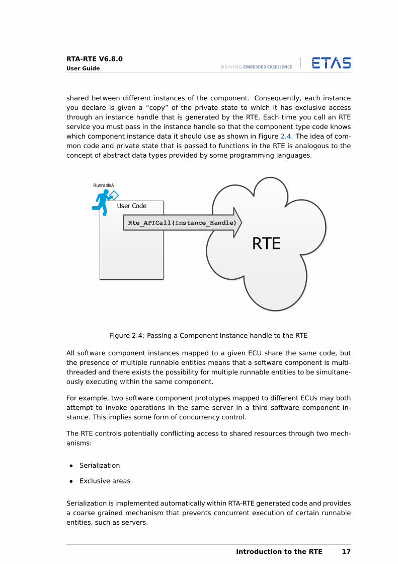
shared between different instances of the component. Consequently, each instanceyou declare is given a “copy” of the private state to which it has exclusive accessthrough an instance handle that is generated by the RTE. Each time you call an RTEservice you must pass in the instance handle so that the component type code knowswhich component instance data it should use as shown in Figure 2.4. The idea of com-mon code and private state that is passed to functions in the RTE is analogous to theconcept of abstract data types provided by some programming languages.
User Code
RTE
Rte_APICall(Instance_Handle)
RunnableA
Figure 2.4: Passing a Component Instance handle to the RTE
All software component instances mapped to a given ECU share the same code, butthe presence of multiple runnable entities means that a software component is multi-threaded and there exists the possibility for multiple runnable entities to be simultane-ously executing within the same component.
For example, two software component prototypes mapped to different ECUs may bothattempt to invoke operations in the same server in a third software component in-stance. This implies some form of concurrency control.
The RTE controls potentially conflicting access to shared resources through two mech-anisms:
• Serialization
• Exclusive areas
Serialization is implemented automatically within RTA-RTE generated code and providesa coarse grained mechanism that prevents concurrent execution of certain runnableentities, such as servers.
Introduction to the RTE 17
RTA-RTE V6.8.0User Guide
Exclusive areas provide a mechanism that allows users to have fine control over con-currency. All exclusive areas must be defined at configuration time and are either:
• Explicitly entered and exited in user code using an RTE API; or,
• Implicitly entered and exited in RTA-RTE generated code.
The scope of exclusive areas is the component instance and they cannot therefore beused to control concurrency between different instances of the same component typeor between instances of different component types. Consequently, exclusive areascannot be used to prevent concurrent access to a non-AUTOSAR resource on an ECU. Ifsuch a mechanism is required, then a complex device driver should be implemented.
2.3 Interfaces
When an application consists of multiple software components, it may be necessaryfor the software components to communicate, either to exchange data or to triggersome function. Software components from different applications may also need tocommunicate, for example a climate control system will need to communicate withan engine management system to set the engine idle speed sufficiently high that theengine does not stall when the air conditioning compressor is switched on.
Communication between AUTOSAR application software components is designed interms of ports and interfaces. The following interface types are available:
1. Sender-receiver (signal passing)
2. Client-Server (function invocation)
3. Calibration
4. Trigger
These communication models are known as interfaces in AUTOSAR. Each port on asoftware component type must define the type of interface it provides or requires.
Software-component types can define individual attributes, for example the maximumnumber of data elements buffered on a receiver interface, so the same interface mayhave different behavior for each port in which it is used.
When a system is composed from component instances, the ports of component in-stances are connected with an assembly connector. The assembly connector mustconnect a sender to a receiver and a client to a server. Each assembly connector canalso specify attributes for the behavior between two components.
2.3.1 Sender-Receiver
Sender-receiver communication involves the transmission and reception of signals con-sisting of atomic data elements sent by one component and received by one or morecomponents.
18 Introduction to the RTE
RTA-RTE V6.8.0User Guide
An AUTOSAR configuration can define multiple sender-receiver interfaces and a soft-ware component can reference a different interface from each port.
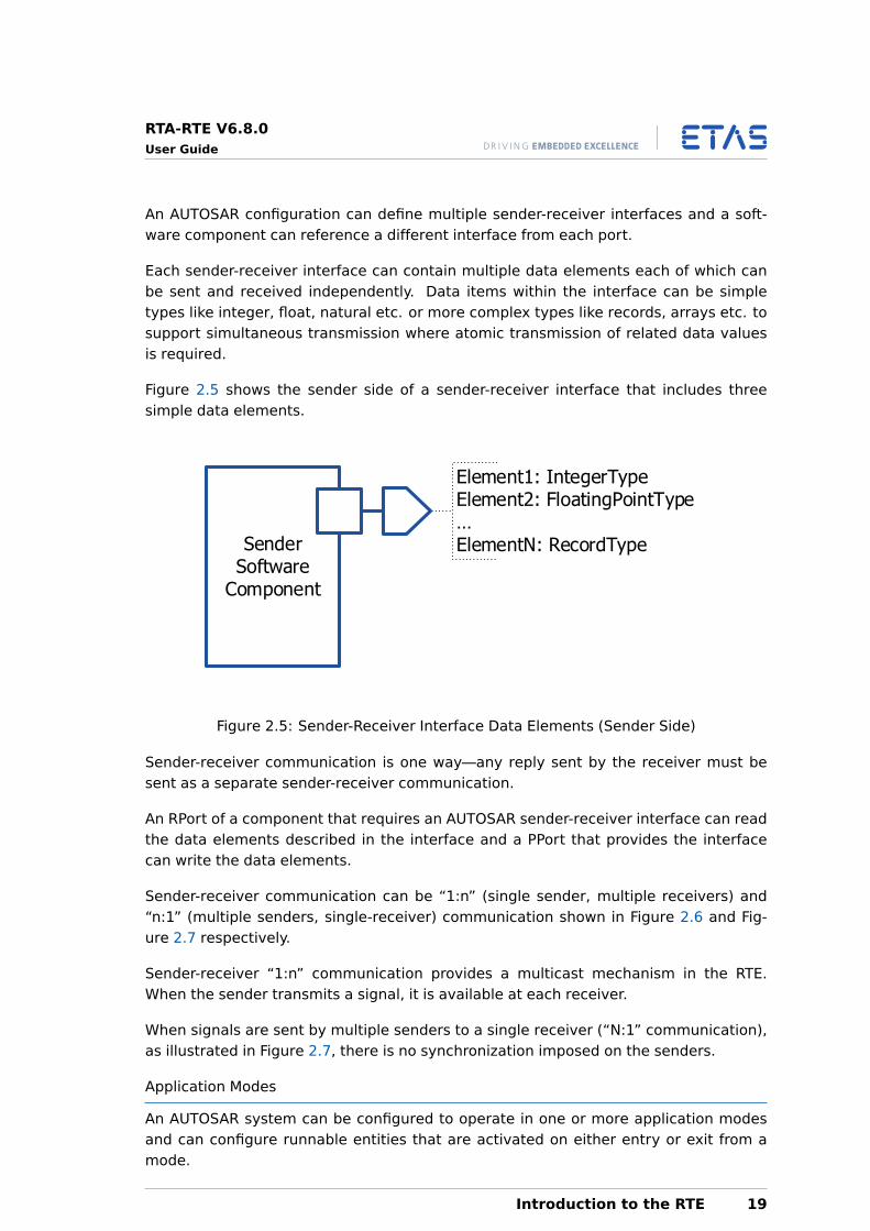
Each sender-receiver interface can contain multiple data elements each of which canbe sent and received independently. Data items within the interface can be simpletypes like integer, float, natural etc. or more complex types like records, arrays etc. tosupport simultaneous transmission where atomic transmission of related data valuesis required.
Figure 2.5 shows the sender side of a sender-receiver interface that includes threesimple data elements.
SenderSoftware
Component
Element1: IntegerType Element2: FloatingPointType ElementN: RecordType
Figure 2.5: Sender-Receiver Interface Data Elements (Sender Side)
Sender-receiver communication is one way—any reply sent by the receiver must besent as a separate sender-receiver communication.
An RPort of a component that requires an AUTOSAR sender-receiver interface can readthe data elements described in the interface and a PPort that provides the interfacecan write the data elements.
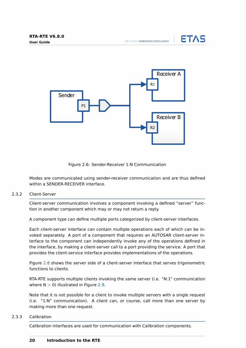
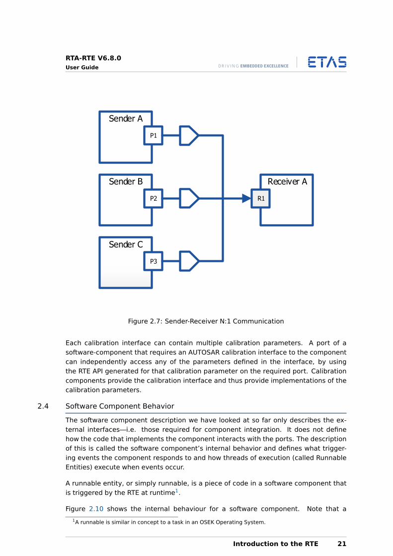
Sender-receiver communication can be “1:n” (single sender, multiple receivers) and“n:1” (multiple senders, single-receiver) communication shown in Figure 2.6 and Fig-ure 2.7 respectively.
Sender-receiver “1:n” communication provides a multicast mechanism in the RTE.When the sender transmits a signal, it is available at each receiver.
When signals are sent by multiple senders to a single receiver (“N:1” communication),as illustrated in Figure 2.7, there is no synchronization imposed on the senders.
Application Modes
An AUTOSAR system can be configured to operate in one or more application modesand can configure runnable entities that are activated on either entry or exit from amode.
Introduction to the RTE 19
RTA-RTE V6.8.0User Guide
Sender
P1
Receiver A
R1
Receiver B
R2
Figure 2.6: Sender-Receiver 1:N Communication
Modes are communicated using sender-receiver communication and are thus definedwithin a SENDER-RECEIVER interface.
2.3.2 Client-Server
Client-server communication involves a component invoking a defined “server” func-tion in another component which may or may not return a reply.
A component type can define multiple ports categorized by client-server interfaces.
Each client-server interface can contain multiple operations each of which can be in-voked separately. A port of a component that requires an AUTOSAR client-server in-terface to the component can independently invoke any of the operations defined inthe interface, by making a client-server call to a port providing the service. A port thatprovides the client-service interface provides implementations of the operations.
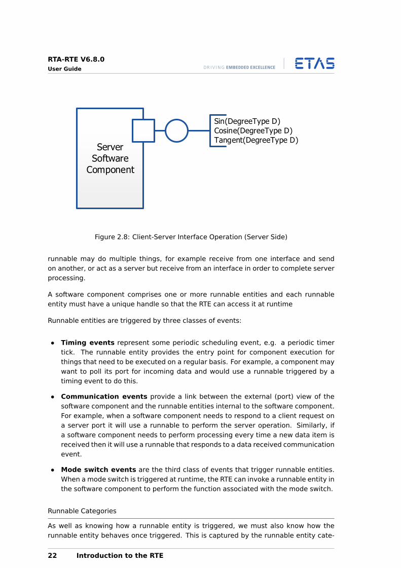
Figure 2.8 shows the server side of a client-server interface that serves trigonometricfunctions to clients.
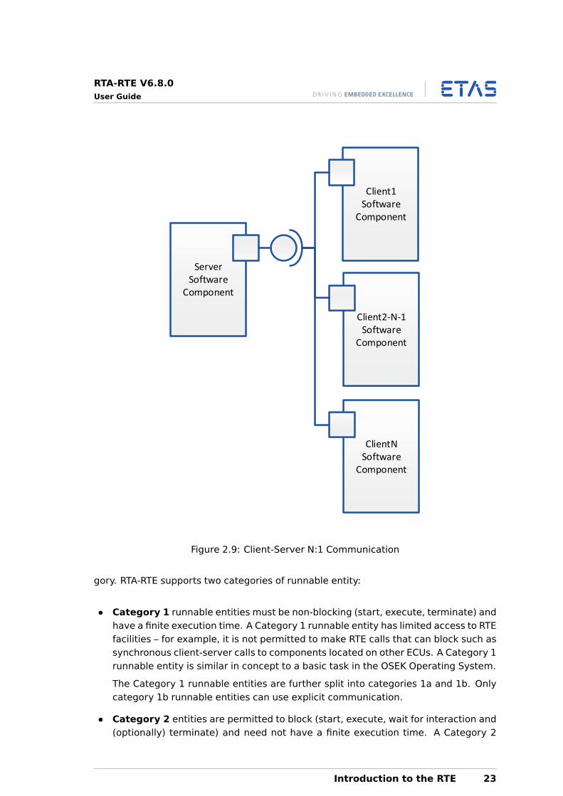
RTA-RTE supports multiple clients invoking the same server (i.e. “N:1” communicationwhere N > 0) illustrated in Figure 2.9.
Note that it is not possible for a client to invoke multiple servers with a single request(i.e. “1:N” communication). A client can, or course, call more than one server bymaking more than one request.
2.3.3 Calibration
Calibration interfaces are used for communication with Calibration components.
20 Introduction to the RTE
RTA-RTE V6.8.0User Guide
Sender A
P1
Receiver A
R1
Sender B
P2
Sender C
P3
Figure 2.7: Sender-Receiver N:1 Communication
Each calibration interface can contain multiple calibration parameters. A port of asoftware-component that requires an AUTOSAR calibration interface to the componentcan independently access any of the parameters defined in the interface, by usingthe RTE API generated for that calibration parameter on the required port. Calibrationcomponents provide the calibration interface and thus provide implementations of thecalibration parameters.
2.4 Software Component Behavior
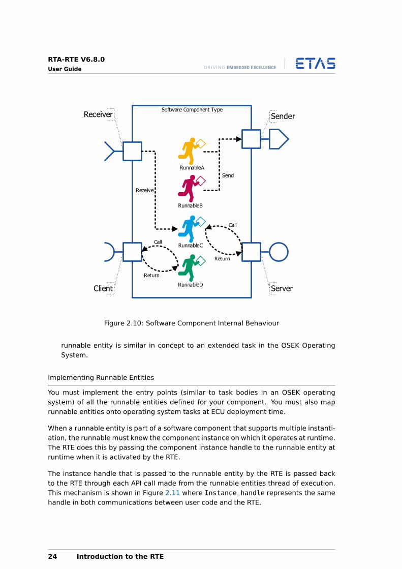
The software component description we have looked at so far only describes the ex-ternal interfaces—i.e. those required for component integration. It does not definehow the code that implements the component interacts with the ports. The descriptionof this is called the software component’s internal behavior and defines what trigger-ing events the component responds to and how threads of execution (called RunnableEntities) execute when events occur.
A runnable entity, or simply runnable, is a piece of code in a software component thatis triggered by the RTE at runtime1.
Figure 2.10 shows the internal behaviour for a software component. Note that a
1A runnable is similar in concept to a task in an OSEK Operating System.
Introduction to the RTE 21
RTA-RTE V6.8.0User Guide
ServerSoftware
Component
Sin(DegreeType D)
Cosine(DegreeType D)
Tangent(DegreeType D)
Figure 2.8: Client-Server Interface Operation (Server Side)
runnable may do multiple things, for example receive from one interface and sendon another, or act as a server but receive from an interface in order to complete serverprocessing.
A software component comprises one or more runnable entities and each runnableentity must have a unique handle so that the RTE can access it at runtime
Runnable entities are triggered by three classes of events:
• Timing events represent some periodic scheduling event, e.g. a periodic timertick. The runnable entity provides the entry point for component execution forthings that need to be executed on a regular basis. For example, a component maywant to poll its port for incoming data and would use a runnable triggered by atiming event to do this.
• Communication events provide a link between the external (port) view of thesoftware component and the runnable entities internal to the software component.For example, when a software component needs to respond to a client request ona server port it will use a runnable to perform the server operation. Similarly, ifa software component needs to perform processing every time a new data item isreceived then it will use a runnable that responds to a data received communicationevent.
• Mode switch events are the third class of events that trigger runnable entities.When a mode switch is triggered at runtime, the RTE can invoke a runnable entity inthe software component to perform the function associated with the mode switch.
Runnable Categories
As well as knowing how a runnable entity is triggered, we must also know how therunnable entity behaves once triggered. This is captured by the runnable entity cate-
22 Introduction to the RTE
RTA-RTE V6.8.0User Guide
Client1Software
Component
ServerSoftware
Component
ClientNSoftware
Component
Client2-N-1Software
Component
Figure 2.9: Client-Server N:1 Communication
gory. RTA-RTE supports two categories of runnable entity:
• Category 1 runnable entities must be non-blocking (start, execute, terminate) andhave a finite execution time. A Category 1 runnable entity has limited access to RTEfacilities – for example, it is not permitted to make RTE calls that can block such assynchronous client-server calls to components located on other ECUs. A Category 1runnable entity is similar in concept to a basic task in the OSEK Operating System.
The Category 1 runnable entities are further split into categories 1a and 1b. Onlycategory 1b runnable entities can use explicit communication.
• Category 2 entities are permitted to block (start, execute, wait for interaction and(optionally) terminate) and need not have a finite execution time. A Category 2
Introduction to the RTE 23
RTA-RTE V6.8.0User Guide
Software Component Type
Receive
Receiver
Client
Sender
Server
RunnableA
RunnableB
RunnableC
RunnableD
Send
Figure 2.10: Software Component Internal Behaviour
runnable entity is similar in concept to an extended task in the OSEK OperatingSystem.
Implementing Runnable Entities
You must implement the entry points (similar to task bodies in an OSEK operatingsystem) of all the runnable entities defined for your component. You must also maprunnable entities onto operating system tasks at ECU deployment time.
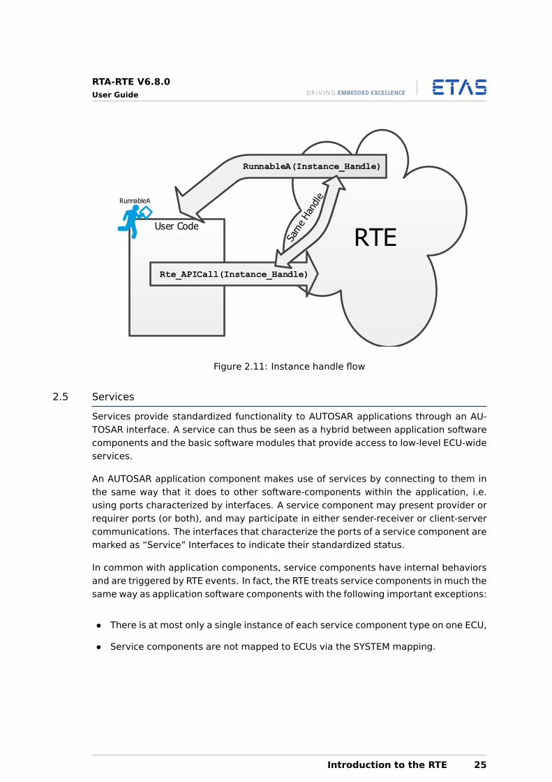
When a runnable entity is part of a software component that supports multiple instanti-ation, the runnable must know the component instance on which it operates at runtime.The RTE does this by passing the component instance handle to the runnable entity atruntime when it is activated by the RTE.
The instance handle that is passed to the runnable entity by the RTE is passed backto the RTE through each API call made from the runnable entities thread of execution.This mechanism is shown in Figure 2.11 where Instance_handle represents the samehandle in both communications between user code and the RTE.
24 Introduction to the RTE
RTA-RTE V6.8.0User Guide
User Code
RTE
Rte_APICall(Instance_Handle)
RunnableA(Instance_Handle)
RunnableA
Figure 2.11: Instance handle flow
2.5 Services
Services provide standardized functionality to AUTOSAR applications through an AU-TOSAR interface. A service can thus be seen as a hybrid between application softwarecomponents and the basic software modules that provide access to low-level ECU-wideservices.
An AUTOSAR application component makes use of services by connecting to them inthe same way that it does to other software-components within the application, i.e.using ports characterized by interfaces. A service component may present provider orrequirer ports (or both), and may participate in either sender-receiver or client-servercommunications. The interfaces that characterize the ports of a service component aremarked as “Service” Interfaces to indicate their standardized status.
In common with application components, service components have internal behaviorsand are triggered by RTE events. In fact, the RTE treats service components in much thesame way as application software components with the following important exceptions:
• There is at most only a single instance of each service component type on one ECU,
• Service components are not mapped to ECUs via the SYSTEM mapping.
Introduction to the RTE 25
RTA-RTE V6.8.0User Guide
3 Introduction to RTE Configuration
The RTE generator generates the RTE from one or more XML files that define the entirerequired behaviour. The structure of the XML files is standardized by AUTOSAR.
This chapter gives a short overview of XML in general and then a description of the keyconcepts in AUTOSAR XML that you will need to understand to write RTE configurationfiles.
3.1 Understanding XML
XML is a mark-up language for documents that uses a series of tags to convey struc-tured information.
XML does not define either the name of the tags or the semantics of the data enclosedby the tags. Instead, the names and structure of the tags is defined in by an XMLschema.
Each XML document you write needs to specify the schema that is used for processingthe remaining file content.
With schema definitions it is possible to define a namespace for the tags which allowsyou to create a single XML file that references configuration from multiple schemas.
There are basically three types of mark-up that you need to understand to work withAUTOSAR configuration:
• Elements
• Attributes
• Comments
3.1.1 Elements
An element is delimited using angle brackets and is the most common construct you willsee. For elements that contain content, including sub-elements, the general structureis:
<ELEMENT-TAG>...
</ELEMENT-TAG>
An element can be empty which means that it has no content, this is represented usingthe following shorthand:
<EMPTY-ELEMENT-TAG/>
3.1.2 Attributes
An attribute is a name-value pair that occurs inside start-tags after the element name.For example,
26 Introduction to RTE Configuration
RTA-RTE V6.8.0User Guide
<ELEMENT-TAG SOME-ATTRIBUTE="some value">
All attribute values must be quoted.
3.1.3 Comments
Sometimes you will need to add comments to your XML document. Comments beginwith <!-- and end with --> and can contain any data except the literal string “––”.You can place comments between mark-up anywhere in your document.
<!-- This is a comment in XML -->
Comments are not part of the textual content of an XML document and are ignored bythe XML processor.
3.2 Understanding AUTOSAR XML
AUTOSAR defines the tags and their semantics using an XML schema definition.
3.2.1 Namespace declaration
AUTOSAR XML descriptions (XML files describing all or part of an AUTOSAR configura-tion) must declare the AUTOSAR namespace as the default namespace. A namespaceis declared using an xmlns attribute on the root element of an XML file.
The AUTOSAR namespace for all AUTOSAR releases in the 4.x series ishttp://autosar.org/schema/r4.0.
RTA-RTE will reject a configuration if any of its input files do not declare theAUTOSAR 4.x namespace.
3.2.2 Schema Validation
RTA-RTE validates each XML input file that declares the AUTOSAR 4.x namespaceagainst an AUTOSAR XML schema.
Each 4.x schema from AUTOSAR is a superset of all previous 4.x schemas, allowing allinstance documents to be validated against the latest schema. Due to the relaxation ofsome constraints, configurations that would have been rejected when validated againstearlier AUTOSAR schema versions may be accepted when validated against a laterversion.
The schema version used by RTA-RTE for input validation is AUTOSAR 4.4.0
RTA-RTE will reject a configuration if any of its input files fail to validateagainst the supplied AUTOSAR 4.4.0 schema.
Validating against a newer AUTOSAR revision than supported
If you are using a schema newer than RTA-RTE’s current supported schema, input filesmay not validate against the supported AUTOSAR 4.4.0 schema. If you do not require
Introduction to RTE Configuration 27
RTA-RTE V6.8.0User Guide
the use of RTE-relevant features from the new schema version, you can override theschema RTA-RTE uses for validation, allowing these files to be accepted.
Overriding the schema used for validation may cause RTA-RTE to raise un-expected errors, or may cause errors in the generated RTE source code. Theschema must only be overridden during the development stage of a project.The code produced using an overridden validation schema must never beused in production.
To override the validation schema, you must edit the RTEGen.ini file to supply thelocation of the new schema file. For more details see Overriding the validation schemain the RTA-RTE Reference Manual.
3.2.3 Object Names
All objects are named using the <SHORT-NAME> tag:
<SHORT-NAME>ThisIsMyNamedObject</SHORT-NAME>
The names allocated in the configuration for software component prototypes, ports,runnable entities, interfaces etc. are used by the RTE generator to generate objecthandles and customized API calls for use at runtime. This means that names you giveobjects in the RTE configuration must be valid C identifiers.
The AUTOSAR schema restricts the maximum permitted length of shortnames to 127 characters. A short name may only begin with an alphabeticcharacter (a-z and A-Z).
3.2.4 Packages
The <AUTOSAR> element is a container for exactly one top level packages<AR-PACKAGES> element. The top-level packages element represents the root of anXML object tree from which all objects in all configuration files can be accessed.
The top-level packages itself then contains one or more packages each defined with the<AR-PACKAGE> element. Each <AR-PACKAGE> defines a group of AUTOSAR elements.
A package definition is named using the <SHORT-NAME> element. Each package shouldhave a unique name so that the elements contained within the package can be refer-enced by other packages, for example:
<AUTOSAR><AR-PACKAGES><AR-PACKAGE><SHORT-NAME>MyPackage</SHORT-NAME><DESC>This is one of my packages</DESC>
</AR-PACKAGE>...<AR-PACKAGE><SHORT-NAME>MyOtherPackage</SHORT-NAME><DESC>This is another</DESC>
</AR-PACKAGE>
28 Introduction to RTE Configuration
RTA-RTE V6.8.0User Guide
</AR-PACKAGES></AUTOSAR>
The <AR-PACKAGE> element is used to define the package name as well as acting as acontainer for the <ELEMENTS> descriptions. <ELEMENTS> is a container for the compo-nents of an AUTOSAR configuration including:
• The definition of atomic software component types
• The description of component internal behavior
• The composition descriptions including software component prototype instantia-tion
• The definition of ECU types
• The system description including ECU instantiation
The <SUB-PACKAGES> element permits a hierarchical arrangement of packages to beformed:
<AUTOSAR><AR-PACKAGES><AR-PACKAGE><SHORT-NAME>MyPackage</SHORT-NAME><DESC>This is one of my packages</DESC><SUB-PACKAGES><AR-PACKAGE><SHORT-NAME>SWCs</SHORT-NAME>...
</AR-PACKAGE><AR-PACKAGE><SHORT-NAME>Interfaces</SHORT-NAME>...
</AR-PACKAGE>...
AUTOSAR does not permit an arbitrary split of XML definitions between files. Instead,files can only be split at the top-level packages level. When you need to work withmultiple XML files you must therefore split them at the top-level packages level.
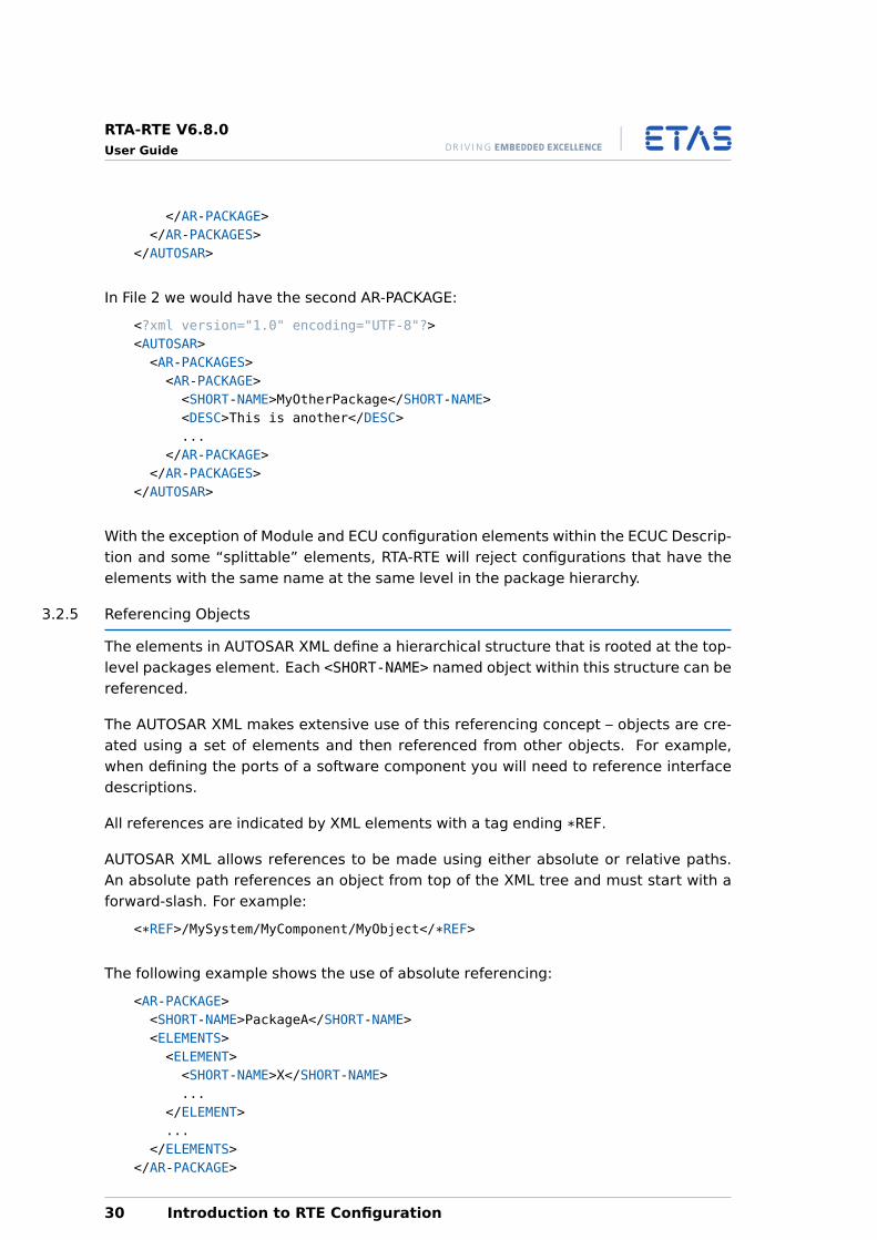
In the previous example, we might have decided to split this file into two different files,in which case in File 1 we would have:
<?xml version="1.0" encoding="UTF-8"?><AUTOSAR><AR-PACKAGES><AR-PACKAGE><SHORT-NAME>MyPackage</SHORT-NAME><DESC>This is one of my packages</DESC>...
Introduction to RTE Configuration 29
RTA-RTE V6.8.0User Guide
</AR-PACKAGE></AR-PACKAGES>
</AUTOSAR>
In File 2 we would have the second AR-PACKAGE:
<?xml version="1.0" encoding="UTF-8"?><AUTOSAR><AR-PACKAGES><AR-PACKAGE><SHORT-NAME>MyOtherPackage</SHORT-NAME><DESC>This is another</DESC>...
</AR-PACKAGE></AR-PACKAGES>
</AUTOSAR>
With the exception of Module and ECU configuration elements within the ECUC Descrip-tion and some “splittable” elements, RTA-RTE will reject configurations that have theelements with the same name at the same level in the package hierarchy.
3.2.5 Referencing Objects
The elements in AUTOSAR XML define a hierarchical structure that is rooted at the top-level packages element. Each <SHORT-NAME> named object within this structure can bereferenced.
The AUTOSAR XML makes extensive use of this referencing concept – objects are cre-ated using a set of elements and then referenced from other objects. For example,when defining the ports of a software component you will need to reference interfacedescriptions.
All references are indicated by XML elements with a tag ending *REF.
AUTOSAR XML allows references to be made using either absolute or relative paths.An absolute path references an object from top of the XML tree and must start with aforward-slash. For example:
<*REF>/MySystem/MyComponent/MyObject</*REF>
The following example shows the use of absolute referencing:
<AR-PACKAGE><SHORT-NAME>PackageA</SHORT-NAME><ELEMENTS><ELEMENT><SHORT-NAME>X</SHORT-NAME>...
</ELEMENT>...
</ELEMENTS></AR-PACKAGE>
30 Introduction to RTE Configuration
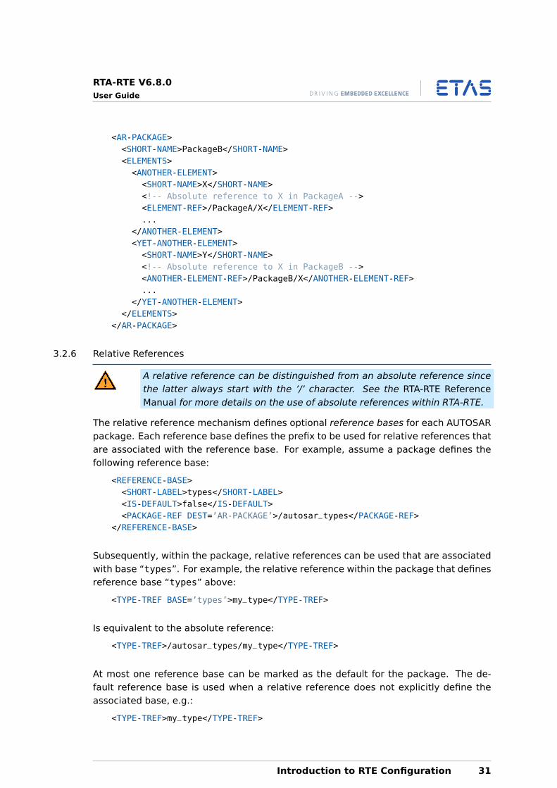
RTA-RTE V6.8.0User Guide
<AR-PACKAGE><SHORT-NAME>PackageB</SHORT-NAME><ELEMENTS><ANOTHER-ELEMENT><SHORT-NAME>X</SHORT-NAME><!-- Absolute reference to X in PackageA --><ELEMENT-REF>/PackageA/X</ELEMENT-REF>...
</ANOTHER-ELEMENT><YET-ANOTHER-ELEMENT><SHORT-NAME>Y</SHORT-NAME><!-- Absolute reference to X in PackageB --><ANOTHER-ELEMENT-REF>/PackageB/X</ANOTHER-ELEMENT-REF>...
</YET-ANOTHER-ELEMENT></ELEMENTS>
</AR-PACKAGE>
3.2.6 Relative References
A relative reference can be distinguished from an absolute reference sincethe latter always start with the ’/’ character. See the RTA-RTE ReferenceManual for more details on the use of absolute references within RTA-RTE.
The relative reference mechanism defines optional reference bases for each AUTOSARpackage. Each reference base defines the prefix to be used for relative references thatare associated with the reference base. For example, assume a package defines thefollowing reference base:
<REFERENCE-BASE><SHORT-LABEL>types</SHORT-LABEL><IS-DEFAULT>false</IS-DEFAULT><PACKAGE-REF DEST=’AR-PACKAGE’>/autosar_types</PACKAGE-REF>
</REFERENCE-BASE>
Subsequently, within the package, relative references can be used that are associatedwith base “types”. For example, the relative reference within the package that definesreference base “types” above:
<TYPE-TREF BASE=’types’>my_type</TYPE-TREF>
Is equivalent to the absolute reference:
<TYPE-TREF>/autosar_types/my_type</TYPE-TREF>
At most one reference base can be marked as the default for the package. The de-fault reference base is used when a relative reference does not explicitly define theassociated base, e.g.:
<TYPE-TREF>my_type</TYPE-TREF>
Introduction to RTE Configuration 31
RTA-RTE V6.8.0User Guide
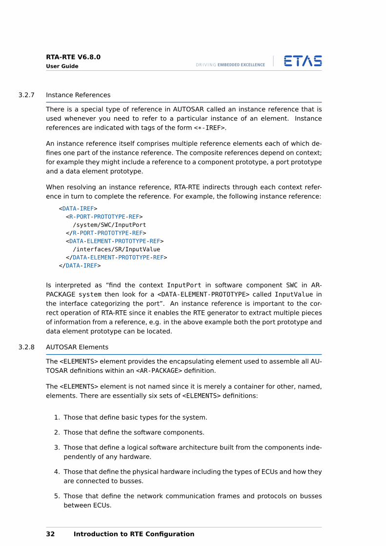
3.2.7 Instance References
There is a special type of reference in AUTOSAR called an instance reference that isused whenever you need to refer to a particular instance of an element. Instancereferences are indicated with tags of the form <*-IREF>.
An instance reference itself comprises multiple reference elements each of which de-fines one part of the instance reference. The composite references depend on context;for example they might include a reference to a component prototype, a port prototypeand a data element prototype.
When resolving an instance reference, RTA-RTE indirects through each context refer-ence in turn to complete the reference. For example, the following instance reference:
<DATA-IREF><R-PORT-PROTOTYPE-REF>/system/SWC/InputPort
</R-PORT-PROTOTYPE-REF><DATA-ELEMENT-PROTOTYPE-REF>/interfaces/SR/InputValue
</DATA-ELEMENT-PROTOTYPE-REF></DATA-IREF>
Is interpreted as “find the context InputPort in software component SWC in AR-PACKAGE system then look for a <DATA-ELEMENT-PROTOTYPE> called InputValue inthe interface categorizing the port”. An instance reference is important to the cor-rect operation of RTA-RTE since it enables the RTE generator to extract multiple piecesof information from a reference, e.g. in the above example both the port prototype anddata element prototype can be located.
3.2.8 AUTOSAR Elements
The <ELEMENTS> element provides the encapsulating element used to assemble all AU-TOSAR definitions within an <AR-PACKAGE> definition.
The <ELEMENTS> element is not named since it is merely a container for other, named,elements. There are essentially six sets of <ELEMENTS> definitions:
1. Those that define basic types for the system.
2. Those that define the software components.
3. Those that define a logical software architecture built from the components inde-pendently of any hardware.
4. Those that define the physical hardware including the types of ECUs and how theyare connected to busses.
5. Those that define the network communication frames and protocols on bussesbetween ECUs.
32 Introduction to RTE Configuration
RTA-RTE V6.8.0User Guide
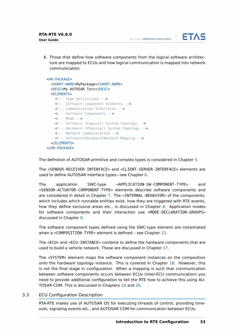
6. Those that define how software components from the logical software architec-ture are mapped to ECUs and how logical communication is mapped into networkcommunication.
<AR-PACKAGE><SHORT-NAME>MyPackage</SHORT-NAME><DESC>My AUTOSAR Test</DESC><ELEMENTS><!-- Type definitions --><!-- Software component elements --><!-- Communication Interfaces --><!-- Software Components --><!-- Mode --><!-- Software (Logical) System Topology --><!-- Hardware (Physical) System Topology --><!-- Network Communication --><!-- Software/Hardware/Network Mapping -->
</ELEMENTS></AR-PACKAGE>
The definition of AUTOSAR primitive and complex types is considered in Chapter 5.
The <SENDER-RECEIVER-INTERFACE> and <CLIENT-SERVER-INTERFACE> elements areused to define AUTOSAR interface types—see Chapter 6.
The application SWC-type <APPLICATION-SW-COMPONENT-TYPE> and<SENSOR-ACTUATOR-COMPONENT-TYPE> elements describe software components andare considered in detail in Chapter 7. The <INTERNAL-BEHAVIOR> of the components,which includes which runnable entities exist, how they are triggered with RTE events,how they define exclusive areas etc., is discussed in Chapter 8. Application modesfor software components and their interaction use <MODE-DECLARATION-GROUPS>discussed in Chapter 9.
The software component types defined using the SWC-type element are instantiatedwhen a <COMPOSITION-TYPE> element is defined – see Chapter 13.
The <ECU> and <ECU-INSTANCE> combine to define the hardware components that areused to build a vehicle network. These are discussed in Chapter 17.
The <SYSTEM> element maps the software component instances on the compositiononto the hardware topology instance. This is covered in Chapter 18. However, thisis not the final stage in configuration. When a mapping is such that communicationbetween software components occurs between ECUs (inter-ECU communication) youneed to provide additional configuration to tell the RTE how to achieve this using AU-TOSAR COM. This is discussed in Chapters 19 and 20.
3.3 ECU Configuration Description
RTA-RTE makes use of AUTOSAR OS for executing threads of control, providing time-outs, signaling events etc., and AUTOSAR COM for communication between ECUs.
Introduction to RTE Configuration 33
RTA-RTE V6.8.0User Guide
For the RTE to be generated, RTA-RTE needs to know a small set of configuration datafor these AUTOSAR basic software modules.
AUTOSAR basic software uses a different configuration concept from the rest of AU-TOSAR that is held in the ECU configuration description file. This file is also an XML file,but the use of XML is significantly different from the rest of AUTOSAR configuration.
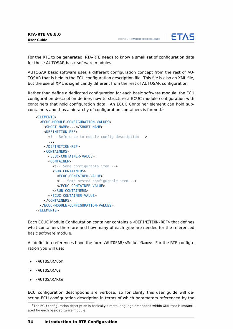
Rather than define a dedicated configuration for each basic software module, the ECUconfiguration description defines how to structure a ECUC module configuration withcontainers that hold configuration data. An ECUC Container element can hold sub-containers and thus a hierarchy of configuration containers is formed.1
<ELEMENTS><ECUC-MODULE-CONFIGURATION-VALUES><SHORT-NAME>...</SHORT-NAME><DEFINITION-REF><!-- Reference to module config description -->...
</DEFINITION-REF><CONTAINERS><ECUC-CONTAINER-VALUE><CONTAINER><!-- Some configurable item --><SUB-CONTAINERS><ECUC-CONTAINER-VALUE><!-- Some nested configurable item --></ECUC-CONTAINER-VALUE>
</SUB-CONTAINERS></ECUC-CONTAINER-VALUE>
</CONTAINERS></ECUC-MODULE-CONFIGURATION-VALUES>
</ELEMENTS>
Each ECUC Module Configutation container contains a <DEFINITION-REF> that defineswhat containers there are and how many of each type are needed for the referencedbasic software module.
All definition references have the form /AUTOSAR/<ModuleName>. For the RTE configu-ration you will use:
• /AUTOSAR/Com
• /AUTOSAR/Os
• /AUTOSAR/Rte
ECU configuration descriptions are verbose, so for clarity this user guide will de-scribe ECU configuration description in terms of which parameters referenced by the
1The ECU configuration description is basically a meta-language embedded within XML that is instanti-ated for each basic software module.
34 Introduction to RTE Configuration
RTA-RTE V6.8.0User Guide
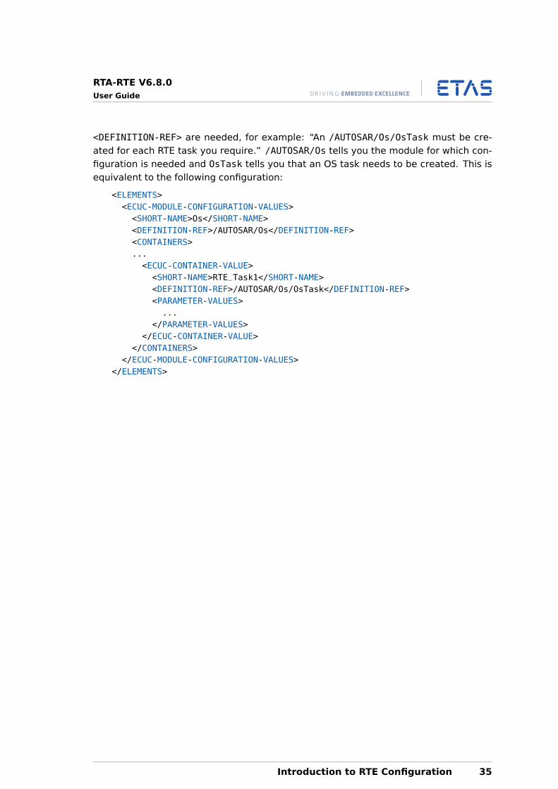
<DEFINITION-REF> are needed, for example: “An /AUTOSAR/Os/OsTask must be cre-ated for each RTE task you require.” /AUTOSAR/Os tells you the module for which con-figuration is needed and OsTask tells you that an OS task needs to be created. This isequivalent to the following configuration:
<ELEMENTS><ECUC-MODULE-CONFIGURATION-VALUES><SHORT-NAME>Os</SHORT-NAME><DEFINITION-REF>/AUTOSAR/Os</DEFINITION-REF><CONTAINERS>...<ECUC-CONTAINER-VALUE><SHORT-NAME>RTE_Task1</SHORT-NAME><DEFINITION-REF>/AUTOSAR/Os/OsTask</DEFINITION-REF><PARAMETER-VALUES>...
</PARAMETER-VALUES></ECUC-CONTAINER-VALUE>
</CONTAINERS></ECUC-MODULE-CONFIGURATION-VALUES>
</ELEMENTS>
Introduction to RTE Configuration 35
RTA-RTE V6.8.0User Guide
4 Working with the RTE Generator
The separation of the development and integration phases in AUTOSAR is reflected ina two-phase software component development process:
1. Software Component Development: the specification, design and implementationof software components; then
2. Software Component Deployment: the allocation of components to ECUs and theintegration of components with the basic software on the ECU.
The two phases of operation allow for initial software component configurations to bemade and integrated onto the VFB (through some auxiliary design and developmentprocess) then the RTE interface to be generated so that the software components canbe implemented before the prototypes are defined and their particular allocation ontoan ECU are known.
AUTOSAR R4.0 also defines a third development phase for integration of basic softwareinto an ECU. The basic software phase enables the creation of a “Basic Software Sched-uler” that invokes multiple basic software modules at the correct time and integratestheir execution with application software components.
The phased development process means that there can be some time between thedevelopment of a component type and the allocation of its component prototypes toan ECU. A component could be developed once and re-used multiple times over manygenerations of vehicles. The component could also be supplied to an integrator inbinary form for integration in an ECU with other components that have not yet beenwritten.
The RTE generator supports the phased process by allowing the interface to the RTEto be generated before the component prototype/ECU allocation has been decided.Given a software component description, the RTE generator has enough informationto generate interface definition files, allowing engineers to start developing softwarecomponents. The interface defines the contract between the RTE and the component,that is, what that component must provide if future integration work is to happen easily.This is known as contract phase.
When the system is integrated, and the mapping of software components to ECUs isknown, the RTE itself can be generated. However, we now know how many instancesof a software component exist, where runnable entities are executing, which commu-nication is local to an ECU and which must be routed across the network etc. The RTEgenerator can use this information to re-generate the interface definition files to includeoptimizations based on this additional context. This is known as “RTE phase”.
The following sections discuss the contract and RTE phases in more detail.
36 Working with the RTE Generator
RTA-RTE V6.8.0User Guide
4.1 Contract Phase
In AUTOSAR, the interface to a software component is captured in a “software compo-nent description” written in XML.
The component description is a promise that a software component will have certainproperties, for example:
• It will provide a set of ports.
• The ports are typed by defined interfaces.
• It will provide a set of runnable entities.
• It will respond to certain RTE events.
The software component description also contains obligations for the ECU integrator,that is, the person who will create instances of the software component prototype andintegrate those prototypes with the basic software on an ECU. For example:
• RTE events must be scheduled at the specified rates.
• Only ports that use the same, compatible, or convertible interfaces can be con-nected.
The software component description must contain enough information to generate anRTE interface that encapsulates the functional aspects of the contract.
The component descriptions are generated early in the process and can be used withthe RTE generation tools to build a framework for developing the components. The“Software Component Descriptions” form the input to the first part of the RTE genera-tion process where the interface contracts, in the form of C header files, can be gener-ated without reference to the final system or to the allocation of specific componentsto ECUs.
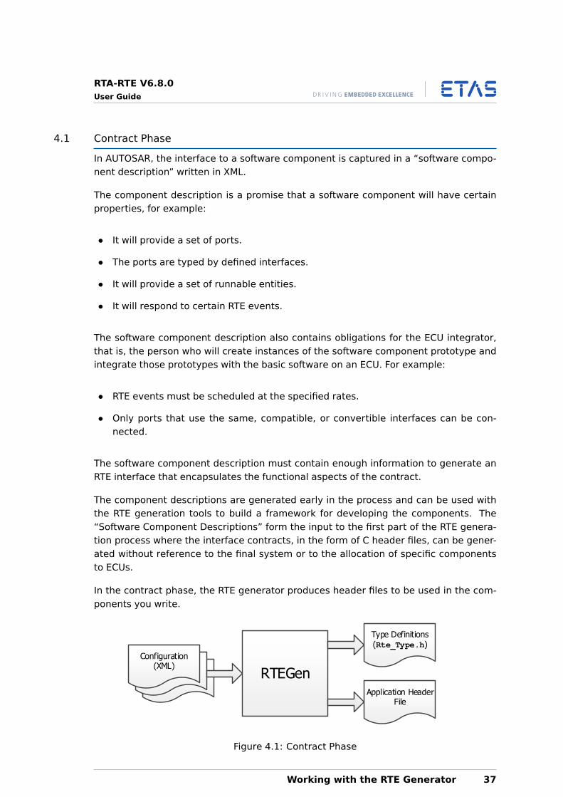
In the contract phase, the RTE generator produces header files to be used in the com-ponents you write.
Type Definitions (Rte_Type.h)
Configuration(XML)
RTEGenApplication Header
File
Figure 4.1: Contract Phase
Working with the RTE Generator 37
RTA-RTE V6.8.0User Guide
4.1.1 Generation
In contract phase, RTA-RTE generates software component-specific application headerfiles in their most general form. The header files define the contract between the com-ponent and the system as a whole, and are suitable for both binary-code and source-code components. When running in the contract phase, the RTE generator only needsaccess to the software component description file(s). It is not necessary to have anyinformation about system deployment.
During contract phase, the RTE is generated for a named software component with thefollowing command line:
RTEGen -c <component> [options] <files>.arxml
Where <component> must be an absolute reference to a software-component type de-fined in the input. For details on additional options please see the RTA-RTE ReferenceManual.
Each execution of the RTE generator in contract phase produces the application headerfile for a single component.
4.1.2 Software Component-Specific Header Files
Access to the RTE API for each declared component type is provided by a componenttype-specific “application header file”. This file will be generated twice during yoursystem development process:
1. During the contract phase where a generic version of the file is generated.
2. During the RTE phase where an optimized version is generated.
The name of the application header file is derived from the component type nameassigned by the vendor, rather than the name assigned by the system integrator to thecomponent prototype during deployment.
The header file names have the following format:
Rte_<ComponentTypeName>.h
The component type name is used for two reasons:
1. The same component code is used for all component prototypes.
2. Object-code software components may be compiled before the number, ornames, of all the component prototypes used in the ECU are known.
The definitions in the XML file are used to define the APIs, so only valid runnable entitiesmay be declared without an error occurring when the component is compiled.
38 Working with the RTE Generator
RTA-RTE V6.8.0User Guide
The RTE generator also generates an “application types file” that defines types specificto a particular SW-C type. The name of this file is
Rte_<ComponentTypeName>_Type.h
Component Type & Instance Declarations
For each component type declaration, the RTE generator creates a component datastructure type. The definition of this type is unique for each component and is writtento the component type header file.
When the RTE generator is run in the RTE phase, the RTE implementation includesoptimizations that can reduce the run-time cost of the instance handle to zero. Forexample, when only one prototype of a component is mapped to an ECU, the instancehandle is not needed and can be elided.
4.1.3 Object-code Support
The RTE supports both application software components where the source is available(“source-code software components”) and application software components whereonly the object code (“object-code software components”) is available.
The header files generated in contract phase contain sufficient detail to allow a com-ponent to be developed and shipped as object files to the ECU integrator.
The only effect of shipping components in object-code format is that they cannot makeuse of the optimizations that the RTE generator may make when the allocation of com-ponent instances to ECU instances is known.
4.2 RTE Phase
Before using RTA-RTE in RTE phase, a significant amount of system engineering will beneeded. The AUTOSAR development process assumes that there are several inputs tothe system engineering process:
• “Software component descriptions” that define the software components, theirports, internal behaviors, implementation characteristics, and the interfaces pro-vided and required by their ports. These are the same descriptions as used incontract phase.
• “ECU resource descriptions” that define the ECU hardware characteristics (e.g.communication ports).
• A “System constraint description” that defines aspects of the system (e.g. commu-nication protocols).
To build an AUTOSAR system (i.e. a set of software components mapped to ECUs thatcommunicate over a network) you must define:
• “ECU configuration description” that defines which software components aremapped to which ECUs, the resources available on the ECU, and so on.
Working with the RTE Generator 39
RTA-RTE V6.8.0User Guide
• “System configuration description” that defines the network topology, how inter-ECU communication is mapped to the physical network, and so on.
• “ECU Configuration” that defines the mapping between elements; for example, themapping of runnable entities to AUTOSAR Operating System tasks and the mappingof AUTOSAR signals to AUTOSAR COM signals.
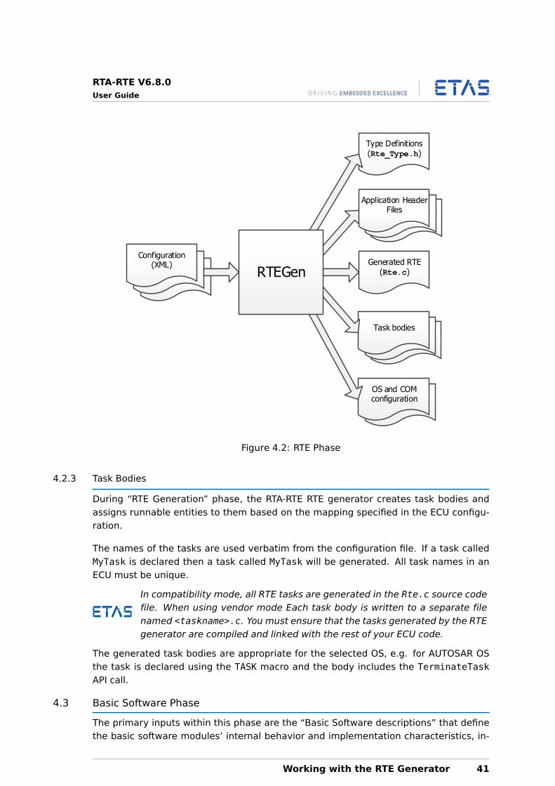
Once you have configured your AUTOSAR system with an allocation of component pro-totypes to ECU instances the RTE generator is used in “RTE Generation” phase to create:
1. The implementation of the RTE itself, Rte.c, and the generated library Rte_lib.c.
2. Optimized component header files that exploit mapping knowledge provided byyour configuration.
3. Operating system tasks that package your runnable entities.
4. (optional) An operating system configuration file for the RTE- generated objectsand required behavior.
5. (optional) A communication stack configuration file for inter-ECU communicationconfiguration.
Figure 4.2 illustrates the basic process.
The AUTOSAR configuration process includes tools for the generation ofRTE and generation/configuration of the OS and the communication stack.Within RTA-RTE all three steps are integrated into the single RTE generator.
4.2.1 Generation
In RTE phase, the RTA-RTE generator generates optimized application header files suit-able for compiling source-code components and, optionally, configuration files for thecommunication stack and operating system. When running in RTE phase, the RTE gen-erator needs access to all system deployment information.
For RTE phase, the RTE is generated for a named ECU instance with the following com-mand line:
RTEGen -r <ecu instance> [options] <files>.arxml
The RTE is generated for each software component and each ECU specified in the con-figuration file using the command-line RTE generator tool. Each execution of the RTEgenerator in RTE phase produces the generated RTE for a single ECU instance.
4.2.2 RTE Implementation File
The RTE is generated as one or more C modules. Each module must be compiled ac-cording to the dependency information created by the RTE.
The module Rte.c contains the core of the generated RTE and, when the RTE generatoris operating in compatibility mode, the generated task bodies.
40 Working with the RTE Generator
RTA-RTE V6.8.0User Guide
Type Definitions (Rte_Type.h)
Configuration(XML)
Application Header Files
Generated RTE(Rte.c)
Task bodies
OS and COM configuration
RTEGen
Figure 4.2: RTE Phase
4.2.3 Task Bodies
During “RTE Generation” phase, the RTA-RTE RTE generator creates task bodies andassigns runnable entities to them based on the mapping specified in the ECU configu-ration.
The names of the tasks are used verbatim from the configuration file. If a task calledMyTask is declared then a task called MyTask will be generated. All task names in anECU must be unique.
In compatibility mode, all RTE tasks are generated in the Rte.c source codefile. When using vendor mode Each task body is written to a separate filenamed <taskname>.c. You must ensure that the tasks generated by the RTEgenerator are compiled and linked with the rest of your ECU code.
The generated task bodies are appropriate for the selected OS, e.g. for AUTOSAR OSthe task is declared using the TASK macro and the body includes the TerminateTaskAPI call.
4.3 Basic Software Phase
The primary inputs within this phase are the “Basic Software descriptions” that definethe basic software modules’ internal behavior and implementation characteristics, in-
Working with the RTE Generator 41
RTA-RTE V6.8.0User Guide
cluding the interfaces provided and required by the module.
The Basic Software Phase generates the APIs and code to support BSW code only. Ifthe input XML contains Software Component configuration then the configuration isrejected by RTEGen.
4.4 The Development Process
Figure 4.3 shows the five key stages in the generation of an RTE-based ECU:
1. The initial “contract” phase of RTE generation defines the interface (component-specific “application header” files) for each software component based on infor-mation from the software component descriptions. A software component com-piled with a contract phase application header can be delivered to the integratoras object-code.
2. The “RTE” phase generates an RTE for a specific ECU, configured from the “ECUExtract”. The ECU Extract is a slice of the System Configuration Description, con-taining only information related to a single ECU. This can be distributed to thedevelopers of the ECU without the risk of disseminating confidential informationabout other ECUs.
A software component compiled with an RTE phase application header can bedelivered to the integrator as source-code.
3. The RTE generator (optionally) creates configuration files for the ECU, includingOS configuration and dependency information for the creation of “makefiles” orbuild scripts for building the RTE.
4. The generated RTE is compiled along with application software components usingbuild information created by the RTE generator.
5. The RTE library file is compiled and linked with the other application code to formthe executable ECU image.
4.5 Samples
RTA-RTE can generate sample application source files using the --samples=swccommand-line option. The name of the generated sample file is Rte_<swc>.c whereswc is the software component’s short name.
The generated sample file contains an empty function for each runnable entity. Forexample, given a software component swcA that supports multiple instantiation andcontains a single time triggered runnable with entry point swcA_re_te1, the generatedsample file would contain:
/** @file Rte_swcA.c
** @brief RTE Sample SWC implementation skeleton file
*/
42 Working with the RTE Generator
RTA-RTE V6.8.0User Guide
#include "Rte_swcA.h"
FUNC(void, RTE_APPL_CODE) swcA_re_te1(CONSTP2CONST(Rte_CDS_swcA,AUTOMATIC, RTE_CONST) self)
{/* ... */
}
The --samples=swc option is most useful in contract phase before starting implemen-tation of a software component.
Working with the RTE Generator 43
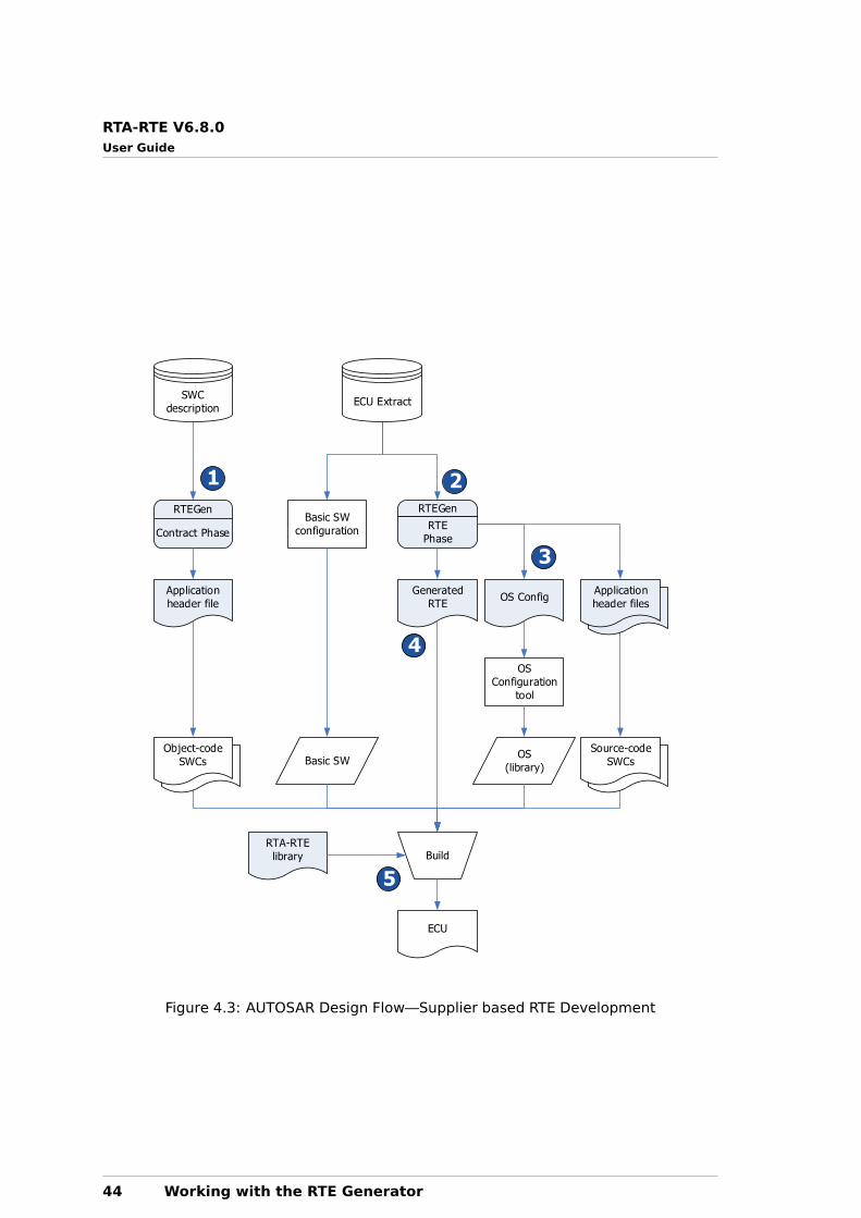
RTA-RTE V6.8.0User Guide
Basic SW
configuration
OS Config
RTEGen
Contract Phase
RTEGen
RTE
Phase
SWC
descriptionECU Extract
OS
Configuration
tool
OS
(library)
Application
header files
Source-code
SWCs
Generated
RTE
Application
header file
Object-code
SWCs Basic SW
BuildRTA-RTE
library
ECU
1 2
3
4
5
Figure 4.3: AUTOSAR Design Flow—Supplier based RTE Development
44 Working with the RTE Generator
RTA-RTE V6.8.0User Guide
Part II
Developing SoftwareComponents
45

RTA-RTE V6.8.0User Guide
5 Type System
AUTOSAR defines three layers of data type abstraction as illustrated in Figure 5.1.
Application Types
Implementation Types
Base Types
Figure 5.1: Abstraction Levels for Describing Data Types
ApplicationDataTypes are defined in physical terms, i.e. by reference to someCompuMethod, Unit and PhysicalDimension. This allows Application authors to cre-ate Software Components without deciding the C data type too early in the lifecycle.ApplicationDataTypes also support automatic conversion of values from one Unit toanother. (See section 5.5 and section 13.5 for more information.)
ImplementationDataTypes model C types in the generated code. AUTOSAR specifiesa set of common ImplementationDataTypes known as the Platform Types, to makeplatform-independent modeling and design easier.
Finally, Base Types describe the hardware-specific aspect of the data type, e.g. thewidth, the alignment and the encoding. In particular, the shortName of the SwBaseTypeelement does not appear in the generated code.
The following sections expand these topics.
5.1 Application Data Types
Application data types are defined in physical terms, i.e. by reference to some Unitwhich, in turn, references some PhysicalDimension. It is recommended to modelVariableDataPrototypes by referencing ApplicationDataTypes:
• Using ApplicationDataTypes allows the System Integrator to choose theImplementationDataType later in the development cycle,
• RTE supports data conversion of values between different ApplicationDataTypes(Section 5.5, section 13.5),
• ApplicationDataTypes contain the necessary information to support measure-ment and calibration tools.
The shortName of an ApplicationDataType is only used within the scope of aSoftwareComponentType, so it is supported to have multiple ApplicationDataTypeswith the same name when integrating several SWCTs on a single ECU (but not within asingle SWCT).
46 Type System
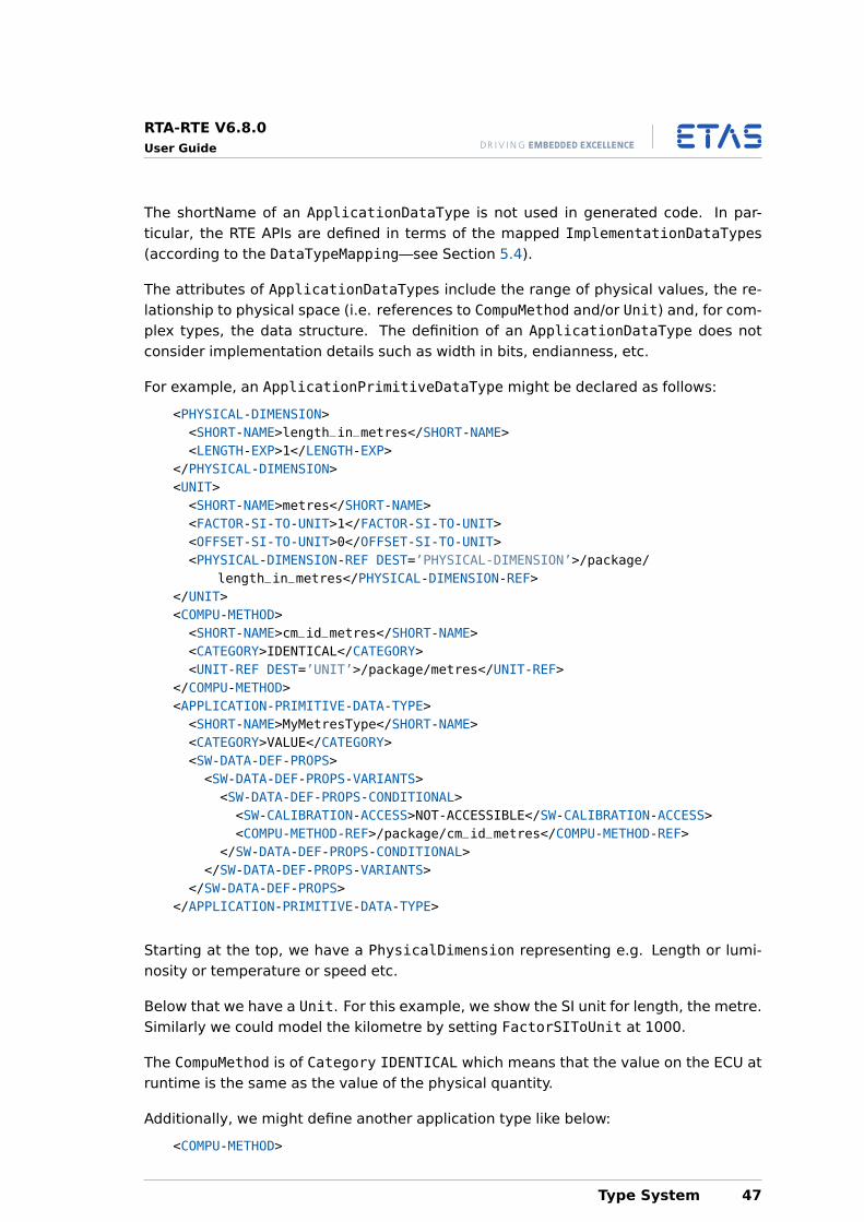
RTA-RTE V6.8.0User Guide
The shortName of an ApplicationDataType is not used in generated code. In par-ticular, the RTE APIs are defined in terms of the mapped ImplementationDataTypes(according to the DataTypeMapping—see Section 5.4).
The attributes of ApplicationDataTypes include the range of physical values, the re-lationship to physical space (i.e. references to CompuMethod and/or Unit) and, for com-plex types, the data structure. The definition of an ApplicationDataType does notconsider implementation details such as width in bits, endianness, etc.
For example, an ApplicationPrimitiveDataType might be declared as follows:
<PHYSICAL-DIMENSION><SHORT-NAME>length_in_metres</SHORT-NAME><LENGTH-EXP>1</LENGTH-EXP>
</PHYSICAL-DIMENSION><UNIT><SHORT-NAME>metres</SHORT-NAME><FACTOR-SI-TO-UNIT>1</FACTOR-SI-TO-UNIT><OFFSET-SI-TO-UNIT>0</OFFSET-SI-TO-UNIT><PHYSICAL-DIMENSION-REF DEST=’PHYSICAL-DIMENSION’>/package/
length_in_metres</PHYSICAL-DIMENSION-REF></UNIT><COMPU-METHOD><SHORT-NAME>cm_id_metres</SHORT-NAME><CATEGORY>IDENTICAL</CATEGORY><UNIT-REF DEST=’UNIT’>/package/metres</UNIT-REF>
</COMPU-METHOD><APPLICATION-PRIMITIVE-DATA-TYPE><SHORT-NAME>MyMetresType</SHORT-NAME><CATEGORY>VALUE</CATEGORY><SW-DATA-DEF-PROPS><SW-DATA-DEF-PROPS-VARIANTS><SW-DATA-DEF-PROPS-CONDITIONAL><SW-CALIBRATION-ACCESS>NOT-ACCESSIBLE</SW-CALIBRATION-ACCESS><COMPU-METHOD-REF>/package/cm_id_metres</COMPU-METHOD-REF>
</SW-DATA-DEF-PROPS-CONDITIONAL></SW-DATA-DEF-PROPS-VARIANTS>
</SW-DATA-DEF-PROPS></APPLICATION-PRIMITIVE-DATA-TYPE>
Starting at the top, we have a PhysicalDimension representing e.g. Length or lumi-nosity or temperature or speed etc.
Below that we have a Unit. For this example, we show the SI unit for length, the metre.Similarly we could model the kilometre by setting FactorSIToUnit at 1000.
The CompuMethod is of Category IDENTICAL which means that the value on the ECU atruntime is the same as the value of the physical quantity.
Additionally, we might define another application type like below:
<COMPU-METHOD>
Type System 47
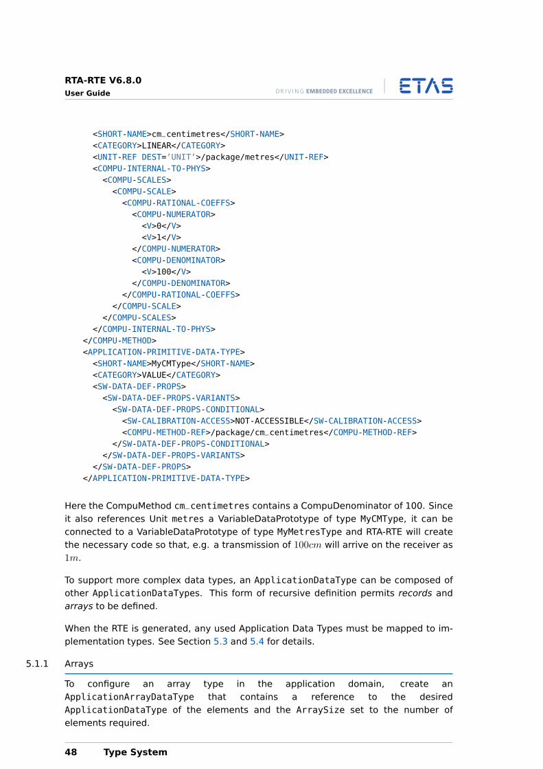
RTA-RTE V6.8.0User Guide
<SHORT-NAME>cm_centimetres</SHORT-NAME><CATEGORY>LINEAR</CATEGORY><UNIT-REF DEST=’UNIT’>/package/metres</UNIT-REF><COMPU-INTERNAL-TO-PHYS><COMPU-SCALES><COMPU-SCALE><COMPU-RATIONAL-COEFFS><COMPU-NUMERATOR><V>0</V><V>1</V>
</COMPU-NUMERATOR><COMPU-DENOMINATOR><V>100</V>
</COMPU-DENOMINATOR></COMPU-RATIONAL-COEFFS>
</COMPU-SCALE></COMPU-SCALES>
</COMPU-INTERNAL-TO-PHYS></COMPU-METHOD><APPLICATION-PRIMITIVE-DATA-TYPE><SHORT-NAME>MyCMType</SHORT-NAME><CATEGORY>VALUE</CATEGORY><SW-DATA-DEF-PROPS><SW-DATA-DEF-PROPS-VARIANTS><SW-DATA-DEF-PROPS-CONDITIONAL><SW-CALIBRATION-ACCESS>NOT-ACCESSIBLE</SW-CALIBRATION-ACCESS><COMPU-METHOD-REF>/package/cm_centimetres</COMPU-METHOD-REF>
</SW-DATA-DEF-PROPS-CONDITIONAL></SW-DATA-DEF-PROPS-VARIANTS>
</SW-DATA-DEF-PROPS></APPLICATION-PRIMITIVE-DATA-TYPE>
Here the CompuMethod cm_centimetres contains a CompuDenominator of 100. Sinceit also references Unit metres a VariableDataPrototype of type MyCMType, it can beconnected to a VariableDataPrototype of type MyMetresType and RTA-RTE will createthe necessary code so that, e.g. a transmission of 100cm will arrive on the receiver as1m.
To support more complex data types, an ApplicationDataType can be composed ofother ApplicationDataTypes. This form of recursive definition permits records andarrays to be defined.
When the RTE is generated, any used Application Data Types must be mapped to im-plementation types. See Section 5.3 and 5.4 for details.
5.1.1 Arrays
To configure an array type in the application domain, create anApplicationArrayDataType that contains a reference to the desiredApplicationDataType of the elements and the ArraySize set to the number ofelements required.
48 Type System
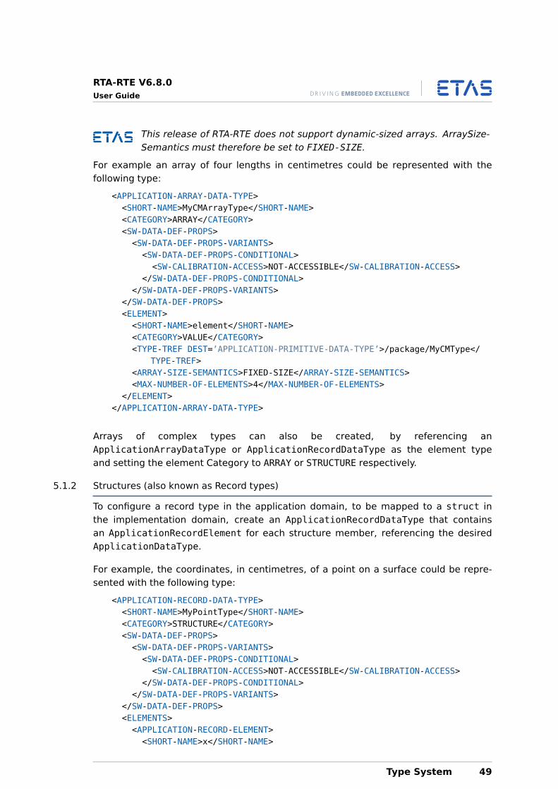
RTA-RTE V6.8.0User Guide
This release of RTA-RTE does not support dynamic-sized arrays. ArraySize-Semantics must therefore be set to FIXED-SIZE.
For example an array of four lengths in centimetres could be represented with thefollowing type:
<APPLICATION-ARRAY-DATA-TYPE><SHORT-NAME>MyCMArrayType</SHORT-NAME><CATEGORY>ARRAY</CATEGORY><SW-DATA-DEF-PROPS><SW-DATA-DEF-PROPS-VARIANTS><SW-DATA-DEF-PROPS-CONDITIONAL><SW-CALIBRATION-ACCESS>NOT-ACCESSIBLE</SW-CALIBRATION-ACCESS>
</SW-DATA-DEF-PROPS-CONDITIONAL></SW-DATA-DEF-PROPS-VARIANTS>
</SW-DATA-DEF-PROPS><ELEMENT><SHORT-NAME>element</SHORT-NAME><CATEGORY>VALUE</CATEGORY><TYPE-TREF DEST=’APPLICATION-PRIMITIVE-DATA-TYPE’>/package/MyCMType</
TYPE-TREF><ARRAY-SIZE-SEMANTICS>FIXED-SIZE</ARRAY-SIZE-SEMANTICS><MAX-NUMBER-OF-ELEMENTS>4</MAX-NUMBER-OF-ELEMENTS>
</ELEMENT></APPLICATION-ARRAY-DATA-TYPE>
Arrays of complex types can also be created, by referencing anApplicationArrayDataType or ApplicationRecordDataType as the element typeand setting the element Category to ARRAY or STRUCTURE respectively.
5.1.2 Structures (also known as Record types)
To configure a record type in the application domain, to be mapped to a struct inthe implementation domain, create an ApplicationRecordDataType that containsan ApplicationRecordElement for each structure member, referencing the desiredApplicationDataType.
For example, the coordinates, in centimetres, of a point on a surface could be repre-sented with the following type:
<APPLICATION-RECORD-DATA-TYPE><SHORT-NAME>MyPointType</SHORT-NAME><CATEGORY>STRUCTURE</CATEGORY><SW-DATA-DEF-PROPS><SW-DATA-DEF-PROPS-VARIANTS><SW-DATA-DEF-PROPS-CONDITIONAL><SW-CALIBRATION-ACCESS>NOT-ACCESSIBLE</SW-CALIBRATION-ACCESS>
</SW-DATA-DEF-PROPS-CONDITIONAL></SW-DATA-DEF-PROPS-VARIANTS>
</SW-DATA-DEF-PROPS><ELEMENTS><APPLICATION-RECORD-ELEMENT><SHORT-NAME>x</SHORT-NAME>
Type System 49
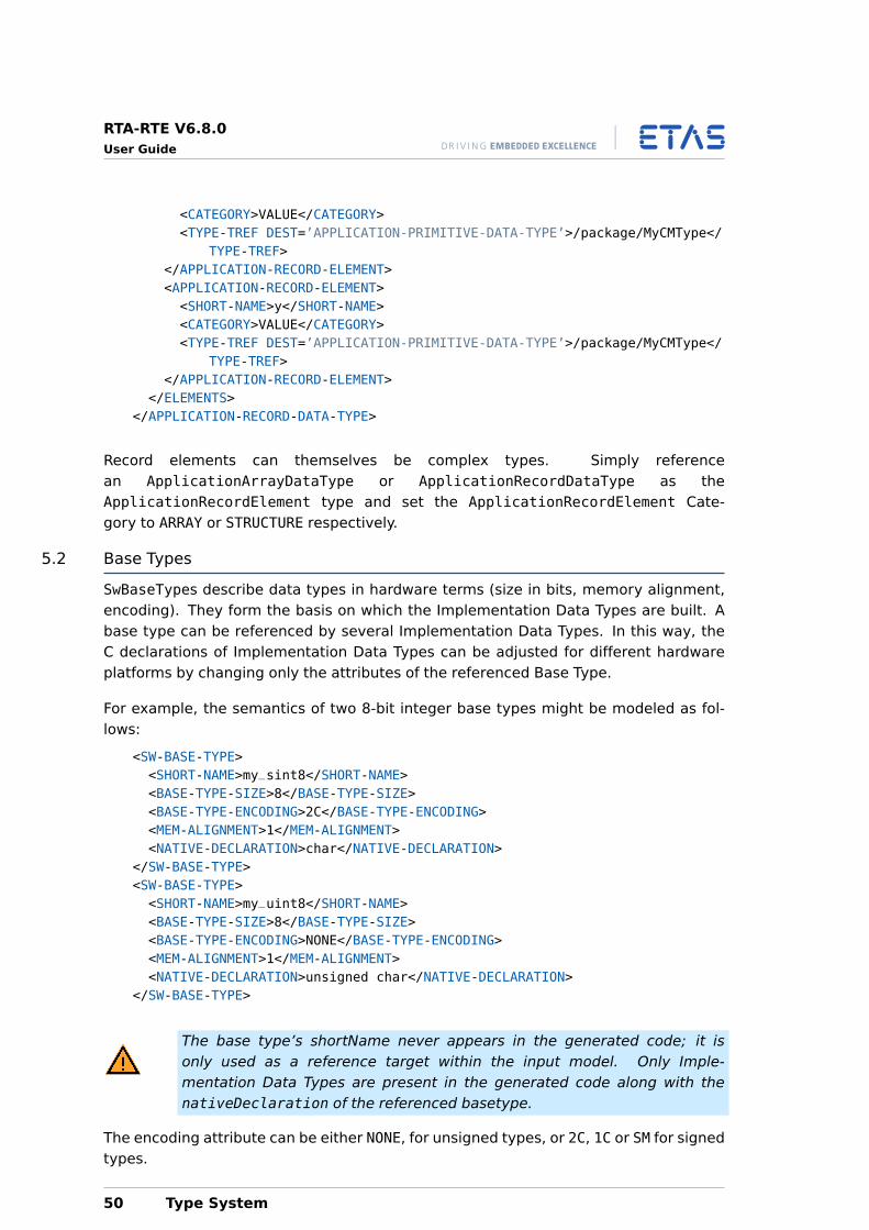
RTA-RTE V6.8.0User Guide
<CATEGORY>VALUE</CATEGORY><TYPE-TREF DEST=’APPLICATION-PRIMITIVE-DATA-TYPE’>/package/MyCMType</
TYPE-TREF></APPLICATION-RECORD-ELEMENT><APPLICATION-RECORD-ELEMENT><SHORT-NAME>y</SHORT-NAME><CATEGORY>VALUE</CATEGORY><TYPE-TREF DEST=’APPLICATION-PRIMITIVE-DATA-TYPE’>/package/MyCMType</
TYPE-TREF></APPLICATION-RECORD-ELEMENT>
</ELEMENTS></APPLICATION-RECORD-DATA-TYPE>
Record elements can themselves be complex types. Simply referencean ApplicationArrayDataType or ApplicationRecordDataType as theApplicationRecordElement type and set the ApplicationRecordElement Cate-gory to ARRAY or STRUCTURE respectively.
5.2 Base Types
SwBaseTypes describe data types in hardware terms (size in bits, memory alignment,encoding). They form the basis on which the Implementation Data Types are built. Abase type can be referenced by several Implementation Data Types. In this way, theC declarations of Implementation Data Types can be adjusted for different hardwareplatforms by changing only the attributes of the referenced Base Type.
For example, the semantics of two 8-bit integer base types might be modeled as fol-lows:
<SW-BASE-TYPE><SHORT-NAME>my_sint8</SHORT-NAME><BASE-TYPE-SIZE>8</BASE-TYPE-SIZE><BASE-TYPE-ENCODING>2C</BASE-TYPE-ENCODING><MEM-ALIGNMENT>1</MEM-ALIGNMENT><NATIVE-DECLARATION>char</NATIVE-DECLARATION>
</SW-BASE-TYPE><SW-BASE-TYPE><SHORT-NAME>my_uint8</SHORT-NAME><BASE-TYPE-SIZE>8</BASE-TYPE-SIZE><BASE-TYPE-ENCODING>NONE</BASE-TYPE-ENCODING><MEM-ALIGNMENT>1</MEM-ALIGNMENT><NATIVE-DECLARATION>unsigned char</NATIVE-DECLARATION>
</SW-BASE-TYPE>
The base type’s shortName never appears in the generated code; it isonly used as a reference target within the input model. Only Imple-mentation Data Types are present in the generated code along with thenativeDeclaration of the referenced basetype.
The encoding attribute can be either NONE, for unsigned types, or 2C, 1C or SM for signedtypes.
50 Type System
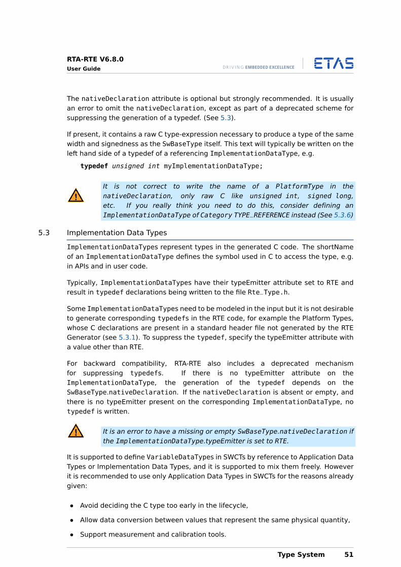
RTA-RTE V6.8.0User Guide
The nativeDeclaration attribute is optional but strongly recommended. It is usuallyan error to omit the nativeDeclaration, except as part of a deprecated scheme forsuppressing the generation of a typedef. (See 5.3).
If present, it contains a raw C type-expression necessary to produce a type of the samewidth and signedness as the SwBaseType itself. This text will typically be written on theleft hand side of a typedef of a referencing ImplementationDataType, e.g.
typedef unsigned int myImplementationDataType;
It is not correct to write the name of a PlatformType in thenativeDeclaration, only raw C like unsigned int, signed long,etc. If you really think you need to do this, consider defining anImplementationDataType of Category TYPE_REFERENCE instead (See 5.3.6)
5.3 Implementation Data Types
ImplementationDataTypes represent types in the generated C code. The shortNameof an ImplementationDataType defines the symbol used in C to access the type, e.g.in APIs and in user code.
Typically, ImplementationDataTypes have their typeEmitter attribute set to RTE andresult in typedef declarations being written to the file Rte_Type.h.
Some ImplementationDataTypes need to be modeled in the input but it is not desirableto generate corresponding typedefs in the RTE code, for example the Platform Types,whose C declarations are present in a standard header file not generated by the RTEGenerator (see 5.3.1). To suppress the typedef, specify the typeEmitter attribute witha value other than RTE.
For backward compatibility, RTA-RTE also includes a deprecated mechanismfor suppressing typedefs. If there is no typeEmitter attribute on theImplementationDataType, the generation of the typedef depends on theSwBaseType.nativeDeclaration. If the nativeDeclaration is absent or empty, andthere is no typeEmitter present on the corresponding ImplementationDataType, notypedef is written.
It is an error to have a missing or empty SwBaseType.nativeDeclaration ifthe ImplementationDataType.typeEmitter is set to RTE.
It is supported to define VariableDataTypes in SWCTs by reference to Application DataTypes or Implementation Data Types, and it is supported to mix them freely. Howeverit is recommended to use only Application Data Types in SWCTs for the reasons alreadygiven:
• Avoid deciding the C type too early in the lifecycle,
• Allow data conversion between values that represent the same physical quantity,
• Support measurement and calibration tools.
Type System 51
RTA-RTE V6.8.0User Guide
RTA-RTE always uses Implementation Data Types in generated APIs. If the correspond-ing VariableDataPrototype is defined by reference to an ApplicationDataType, themapped ImplementationDataType is used in the API signature.
AUTOSAR data types must be declared in the XML input configuration if theyare to be used in Interfaces, ARTypedPerInstanceMemorys, etc. In addition, allPlatformTypes must be declared on the input regardless of whether they are usedin the input model. This is because RTA-RTE depends on PlatformTypes to create itsinternal types.
It is supported that multiple ImplementationDataTypes in the input XML have the samename, provided that the resulting definitions in the generated code are identical. Thismakes it easier to integrate packages from different third parties, which may for exam-ple include (re)definitions of Platform Types.
This section explains how to configure RTA-RTE to make types available to the C pro-gram and to the rest of the configuration input.
5.3.1 Platform Types
AUTOSAR specifies a set of platform types for use in C code. These areImplementationDataTypes whose purpose is to provide a set of types with the samesemantics across different target hardware. RTA-RTE uses PlatformTypes when itneeds to create types for internal variables.
Unlike most ImplementationDataTypes, the PlatformTypes are also defined in C lan-guage in the file PlatformTypes.h. To support this, they reference SwBaseTypes withempty or missing nativeDeclaration attributes (See 5.2).
AUTOSAR (from R4.0.3) also specifies the correct definitions and pack-age name of the Platform Types. RTA-RTE expects to find the packageAUTOSAR_Platform/ImplementationDataTypes on the input, and it will look inthat package for any Platform Types that it needs. RTA-RTE will reject the configurationif it does not include such a package.
RTA-RTE ships with a suitable Platform Types package (in the fileExternal/AUTOSAR/AUTOSAR_MOD_PlatformTypes.arxml). Note thatthe corresponding SwBaseTypes are defined in a separate fileExternal/AUTOSAR/AUTOSAR_MOD_PlatformBaseTypes.arxml.
The Platform Types defined in AUTOSAR Specification of Platform Types and in the stan-dard header file Platform_Types.h are:
• sint8 – 8-bit signed integer.
• uint8 – 8-bit unsigned integer.
• sint16 – 16-bit signed integer.
• uint16 – 16-bit unsigned integer.
52 Type System
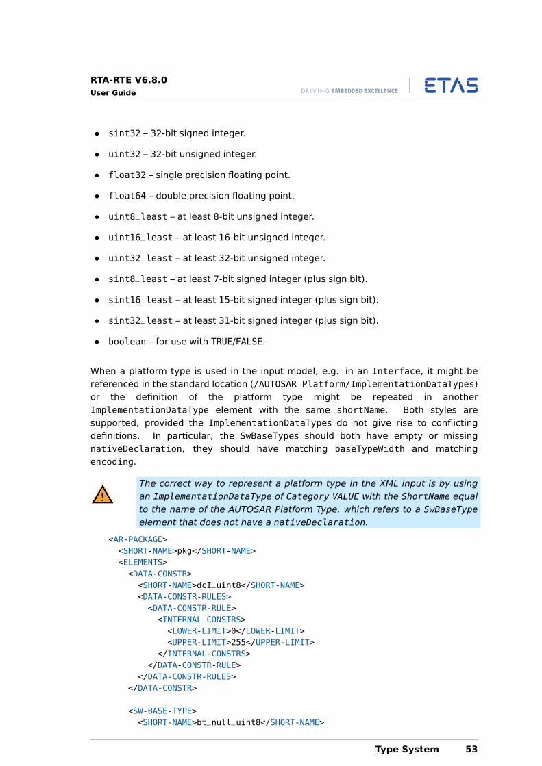
RTA-RTE V6.8.0User Guide
• sint32 – 32-bit signed integer.
• uint32 – 32-bit unsigned integer.
• float32 – single precision floating point.
• float64 – double precision floating point.
• uint8_least – at least 8-bit unsigned integer.
• uint16_least – at least 16-bit unsigned integer.
• uint32_least – at least 32-bit unsigned integer.
• sint8_least – at least 7-bit signed integer (plus sign bit).
• sint16_least – at least 15-bit signed integer (plus sign bit).
• sint32_least – at least 31-bit signed integer (plus sign bit).
• boolean – for use with TRUE/FALSE.
When a platform type is used in the input model, e.g. in an Interface, it might bereferenced in the standard location (/AUTOSAR_Platform/ImplementationDataTypes)or the definition of the platform type might be repeated in anotherImplementationDataType element with the same shortName. Both styles aresupported, provided the ImplementationDataTypes do not give rise to conflictingdefinitions. In particular, the SwBaseTypes should both have empty or missingnativeDeclaration, they should have matching baseTypeWidth and matchingencoding.
The correct way to represent a platform type in the XML input is by usingan ImplementationDataType of Category VALUE with the ShortName equalto the name of the AUTOSAR Platform Type, which refers to a SwBaseTypeelement that does not have a nativeDeclaration.
<AR-PACKAGE><SHORT-NAME>pkg</SHORT-NAME><ELEMENTS><DATA-CONSTR><SHORT-NAME>dcI_uint8</SHORT-NAME><DATA-CONSTR-RULES><DATA-CONSTR-RULE><INTERNAL-CONSTRS><LOWER-LIMIT>0</LOWER-LIMIT><UPPER-LIMIT>255</UPPER-LIMIT>
</INTERNAL-CONSTRS></DATA-CONSTR-RULE>
</DATA-CONSTR-RULES></DATA-CONSTR>
<SW-BASE-TYPE><SHORT-NAME>bt_null_uint8</SHORT-NAME>
Type System 53
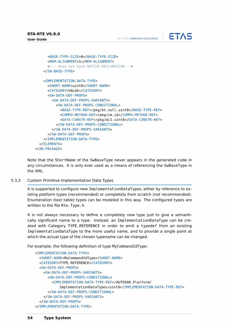
RTA-RTE V6.8.0User Guide
<BASE-TYPE-SIZE>8</BASE-TYPE-SIZE><MEM-ALIGNMENT>1</MEM-ALIGNMENT><!-- does not have NATIVE-DECLARATION -->
</SW-BASE-TYPE>
<IMPLEMENTATION-DATA-TYPE><SHORT-NAME>uint8</SHORT-NAME><CATEGORY>VALUE</CATEGORY><SW-DATA-DEF-PROPS><SW-DATA-DEF-PROPS-VARIANTS><SW-DATA-DEF-PROPS-CONDITIONAL><BASE-TYPE-REF>/pkg/bt_null_uint8</BASE-TYPE-REF><COMPU-METHOD-REF>/pkg/cm_id</COMPU-METHOD-REF><DATA-CONSTR-REF>/pkg/dcI_uint8</DATA-CONSTR-REF>
</SW-DATA-DEF-PROPS-CONDITIONAL></SW-DATA-DEF-PROPS-VARIANTS>
</SW-DATA-DEF-PROPS></IMPLEMENTATION-DATA-TYPE>
</ELEMENTS></AR-PACKAGE>
Note that the ShortName of the SwBaseType never appears in the generated code inany circumstances. It is only ever used as a means of referencing the SwBaseType inthe XML.
5.3.2 Custom Primitive Implementation Data Types
It is supported to configure new ImplementationDataTypes, either by reference to ex-isting platform types (recommended) or completely from scratch (not recommended).Enumeration (text table) types can be modeled in this way. The configured types arewritten to the file Rte_Type.h.
It is not always necessary to define a completely new type just to give a semanti-cally significant name to a type. Instead, an ImplementationDataType can be cre-ated with Category TYPE_REFERENCE in order to emit a typedef from an existingImplementationDataType to the more useful name, and to provide a single point atwhich the actual type of the chosen typename can be changed.
For example, the following definition of type MyCommandIdType:
<IMPLEMENTATION-DATA-TYPE><SHORT-NAME>MyCommandIdType</SHORT-NAME><CATEGORY>TYPE_REFERENCE</CATEGORY><SW-DATA-DEF-PROPS><SW-DATA-DEF-PROPS-VARIANTS><SW-DATA-DEF-PROPS-CONDITIONAL><IMPLEMENTATION-DATA-TYPE-REF>/AUTOSAR_Platform/
ImplementationDataTypes/uint8</IMPLEMENTATION-DATA-TYPE-REF></SW-DATA-DEF-PROPS-CONDITIONAL>
</SW-DATA-DEF-PROPS-VARIANTS></SW-DATA-DEF-PROPS>
</IMPLEMENTATION-DATA-TYPE>
54 Type System
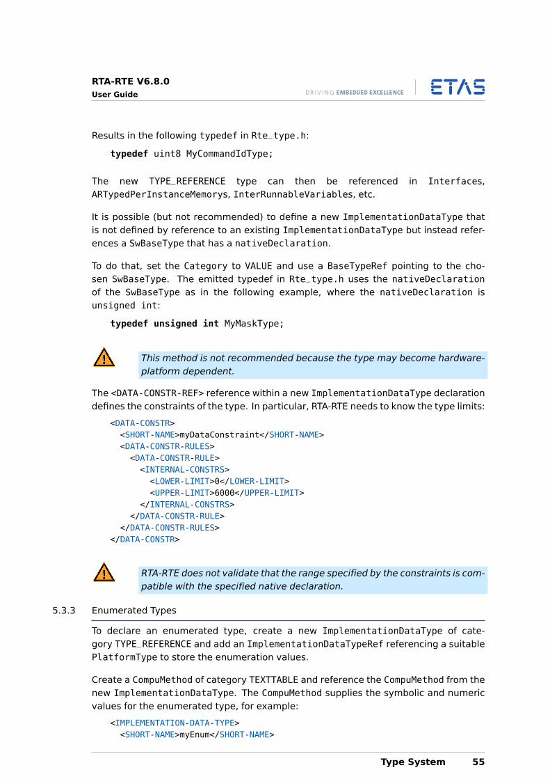
RTA-RTE V6.8.0User Guide
Results in the following typedef in Rte_type.h:
typedef uint8 MyCommandIdType;
The new TYPE_REFERENCE type can then be referenced in Interfaces,ARTypedPerInstanceMemorys, InterRunnableVariables, etc.
It is possible (but not recommended) to define a new ImplementationDataType thatis not defined by reference to an existing ImplementationDataType but instead refer-ences a SwBaseType that has a nativeDeclaration.
To do that, set the Category to VALUE and use a BaseTypeRef pointing to the cho-sen SwBaseType. The emitted typedef in Rte_type.h uses the nativeDeclarationof the SwBaseType as in the following example, where the nativeDeclaration isunsigned int:
typedef unsigned int MyMaskType;
This method is not recommended because the type may become hardware-platform dependent.
The <DATA-CONSTR-REF> reference within a new ImplementationDataType declarationdefines the constraints of the type. In particular, RTA-RTE needs to know the type limits:
<DATA-CONSTR><SHORT-NAME>myDataConstraint</SHORT-NAME><DATA-CONSTR-RULES><DATA-CONSTR-RULE><INTERNAL-CONSTRS><LOWER-LIMIT>0</LOWER-LIMIT><UPPER-LIMIT>6000</UPPER-LIMIT>
</INTERNAL-CONSTRS></DATA-CONSTR-RULE>
</DATA-CONSTR-RULES></DATA-CONSTR>
RTA-RTE does not validate that the range specified by the constraints is com-patible with the specified native declaration.
5.3.3 Enumerated Types
To declare an enumerated type, create a new ImplementationDataType of cate-gory TYPE_REFERENCE and add an ImplementationDataTypeRef referencing a suitablePlatformType to store the enumeration values.
Create a CompuMethod of category TEXTTABLE and reference the CompuMethod from thenew ImplementationDataType. The CompuMethod supplies the symbolic and numericvalues for the enumerated type, for example:
<IMPLEMENTATION-DATA-TYPE><SHORT-NAME>myEnum</SHORT-NAME>
Type System 55
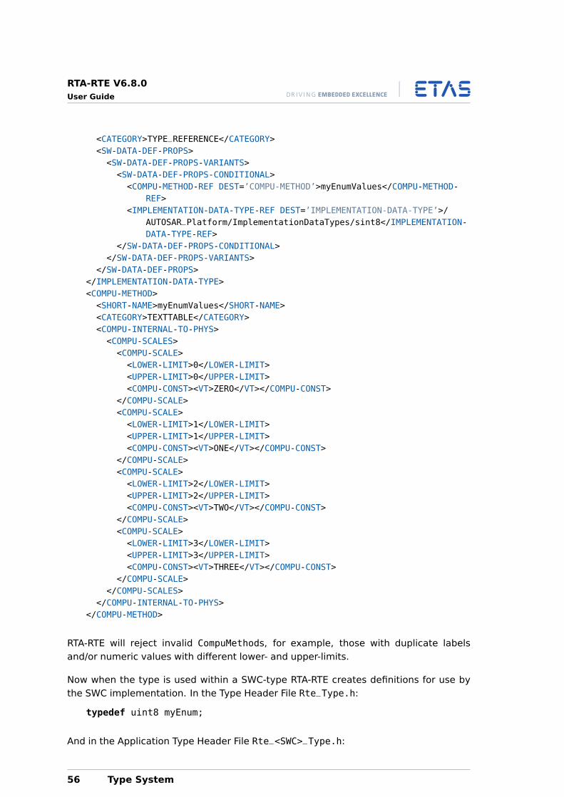
RTA-RTE V6.8.0User Guide
<CATEGORY>TYPE_REFERENCE</CATEGORY><SW-DATA-DEF-PROPS><SW-DATA-DEF-PROPS-VARIANTS><SW-DATA-DEF-PROPS-CONDITIONAL><COMPU-METHOD-REF DEST=’COMPU-METHOD’>myEnumValues</COMPU-METHOD-
REF><IMPLEMENTATION-DATA-TYPE-REF DEST=’IMPLEMENTATION-DATA-TYPE’>/
AUTOSAR_Platform/ImplementationDataTypes/sint8</IMPLEMENTATION-DATA-TYPE-REF>
</SW-DATA-DEF-PROPS-CONDITIONAL></SW-DATA-DEF-PROPS-VARIANTS>
</SW-DATA-DEF-PROPS></IMPLEMENTATION-DATA-TYPE><COMPU-METHOD><SHORT-NAME>myEnumValues</SHORT-NAME><CATEGORY>TEXTTABLE</CATEGORY><COMPU-INTERNAL-TO-PHYS><COMPU-SCALES><COMPU-SCALE><LOWER-LIMIT>0</LOWER-LIMIT><UPPER-LIMIT>0</UPPER-LIMIT><COMPU-CONST><VT>ZERO</VT></COMPU-CONST>
</COMPU-SCALE><COMPU-SCALE><LOWER-LIMIT>1</LOWER-LIMIT><UPPER-LIMIT>1</UPPER-LIMIT><COMPU-CONST><VT>ONE</VT></COMPU-CONST>
</COMPU-SCALE><COMPU-SCALE><LOWER-LIMIT>2</LOWER-LIMIT><UPPER-LIMIT>2</UPPER-LIMIT><COMPU-CONST><VT>TWO</VT></COMPU-CONST>
</COMPU-SCALE><COMPU-SCALE><LOWER-LIMIT>3</LOWER-LIMIT><UPPER-LIMIT>3</UPPER-LIMIT><COMPU-CONST><VT>THREE</VT></COMPU-CONST>
</COMPU-SCALE></COMPU-SCALES>
</COMPU-INTERNAL-TO-PHYS></COMPU-METHOD>
RTA-RTE will reject invalid CompuMethods, for example, those with duplicate labelsand/or numeric values with different lower- and upper-limits.
Now when the type is used within a SWC-type RTA-RTE creates definitions for use bythe SWC implementation. In the Type Header File Rte_Type.h:
typedef uint8 myEnum;
And in the Application Type Header File Rte_<SWC>_Type.h:
56 Type System
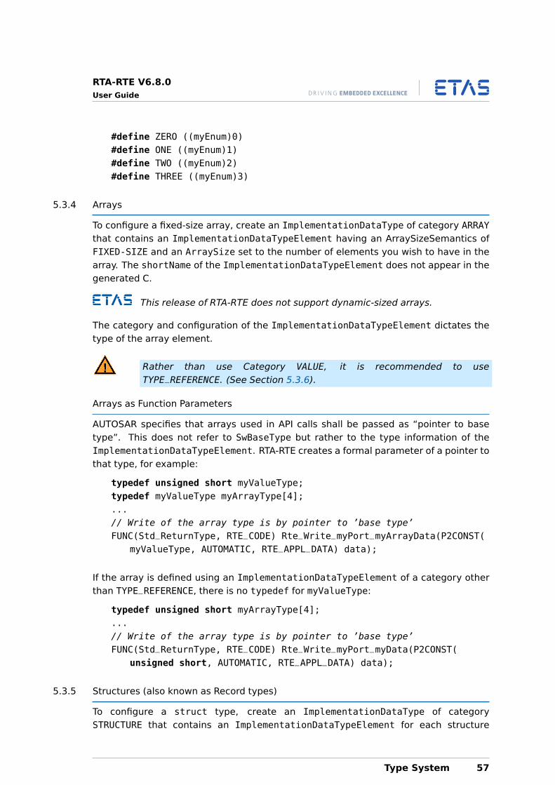
RTA-RTE V6.8.0User Guide
#define ZERO ((myEnum)0)#define ONE ((myEnum)1)#define TWO ((myEnum)2)#define THREE ((myEnum)3)
5.3.4 Arrays
To configure a fixed-size array, create an ImplementationDataType of category ARRAYthat contains an ImplementationDataTypeElement having an ArraySizeSemantics ofFIXED-SIZE and an ArraySize set to the number of elements you wish to have in thearray. The shortName of the ImplementationDataTypeElement does not appear in thegenerated C.
This release of RTA-RTE does not support dynamic-sized arrays.
The category and configuration of the ImplementationDataTypeElement dictates thetype of the array element.
Rather than use Category VALUE, it is recommended to useTYPE_REFERENCE. (See Section 5.3.6).
Arrays as Function Parameters
AUTOSAR specifies that arrays used in API calls shall be passed as “pointer to basetype”. This does not refer to SwBaseType but rather to the type information of theImplementationDataTypeElement. RTA-RTE creates a formal parameter of a pointer tothat type, for example:
typedef unsigned short myValueType;typedef myValueType myArrayType[4];...// Write of the array type is by pointer to ’base type’FUNC(Std_ReturnType, RTE_CODE) Rte_Write_myPort_myArrayData(P2CONST(
myValueType, AUTOMATIC, RTE_APPL_DATA) data);
If the array is defined using an ImplementationDataTypeElement of a category otherthan TYPE_REFERENCE, there is no typedef for myValueType:
typedef unsigned short myArrayType[4];...// Write of the array type is by pointer to ’base type’FUNC(Std_ReturnType, RTE_CODE) Rte_Write_myPort_myData(P2CONST(
unsigned short, AUTOMATIC, RTE_APPL_DATA) data);
5.3.5 Structures (also known as Record types)
To configure a struct type, create an ImplementationDataType of categorySTRUCTURE that contains an ImplementationDataTypeElement for each structure
Type System 57
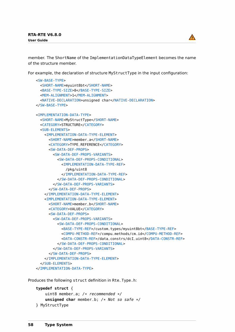
RTA-RTE V6.8.0User Guide
member. The ShortName of the ImplementationDataTypeElement becomes the nameof the structure member.
For example, the declaration of structure MyStructType in the input configuration:
<SW-BASE-TYPE><SHORT-NAME>myuint8bt</SHORT-NAME><BASE-TYPE-SIZE>8</BASE-TYPE-SIZE><MEM-ALIGNMENT>1</MEM-ALIGNMENT><NATIVE-DECLARATION>unsigned char</NATIVE-DECLARATION>
</SW-BASE-TYPE>
<IMPLEMENTATION-DATA-TYPE><SHORT-NAME>MyStructType</SHORT-NAME><CATEGORY>STRUCTURE</CATEGORY><SUB-ELEMENTS><IMPLEMENTATION-DATA-TYPE-ELEMENT><SHORT-NAME>member_a</SHORT-NAME><CATEGORY>TYPE_REFERENCE</CATEGORY><SW-DATA-DEF-PROPS><SW-DATA-DEF-PROPS-VARIANTS><SW-DATA-DEF-PROPS-CONDITIONAL><IMPLEMENTATION-DATA-TYPE-REF>/pkg/uint8
</IMPLEMENTATION-DATA-TYPE-REF></SW-DATA-DEF-PROPS-CONDITIONAL>
</SW-DATA-DEF-PROPS-VARIANTS></SW-DATA-DEF-PROPS>
</IMPLEMENTATION-DATA-TYPE-ELEMENT><IMPLEMENTATION-DATA-TYPE-ELEMENT><SHORT-NAME>member_b</SHORT-NAME><CATEGORY>VALUE</CATEGORY><SW-DATA-DEF-PROPS><SW-DATA-DEF-PROPS-VARIANTS><SW-DATA-DEF-PROPS-CONDITIONAL><BASE-TYPE-REF>/custom_types/myuint8bt</BASE-TYPE-REF><COMPU-METHOD-REF>/compu_methods/cm_id</COMPU-METHOD-REF><DATA-CONSTR-REF>/data_constrs/dcI_uint8</DATA-CONSTR-REF>
</SW-DATA-DEF-PROPS-CONDITIONAL></SW-DATA-DEF-PROPS-VARIANTS>
</SW-DATA-DEF-PROPS></IMPLEMENTATION-DATA-TYPE-ELEMENT>
</SUB-ELEMENTS></IMPLEMENTATION-DATA-TYPE>
Produces the following struct definition in Rte_Type.h:
typedef struct {uint8 member_a; /* recommended */unsigned char member_b; /* Not so safe */
} MyStructType
58 Type System
RTA-RTE V6.8.0User Guide
The category and configuration of each ImplementationDataTypeElement dictates thetype of the corresponding member.
Rather than use Category VALUE, it is recommended to useTYPE_REFERENCE. (See Section 5.3.6).
5.3.6 Declaring the elements of Complex Types
The category of an ImplementationDataTypeElement can be any of TYPE_REFERENCE,STRUCTURE, UNION or ARRAY. VALUE, HOST, DATA_REFERENCE and FUNCTION_REFERENCEare also allowed according to the AUTOSAR specification, but are not recommended asnoted in the following subsections.
TYPE_REFERENCE This is the recommended category forImplementationDataTypeElement instead of VALUE or HOST. By creating aseparate ImplementationDataType for the VALUE or HOST type, and referencingit from the ImplementationDataTypeElement, you create a shortname that isused in the declaration and therefore makes the definition clear.
typedef uint8 MyElementType;typedef MyElementType MyArrayType[4];
STRUCTURE / UNION / ARRAY By declaring an ImplementationDataTypeElementthat is itself of a complex type, you can create nested complex types, e.g. anarray of structs, a struct containing an array and a union, etc. This nesting canbe continued without limitation, but remember that using a TYPE_REFERENCE canhelp to keep the configuration clearer.
VALUE / HOST An ImplementationDataTypeElement of category VALUE or HOST cre-ates the element anonymously, i.e. there is no named type that char-acterizes the element. If the ImplementationDateTypeElement refers to aSwBaseType with a nativeDeclaration, the native declaration is written tothe generated C. This approach is not recommended because it carries arisk of becoming hardware-dependent. Instead it is recommended to use anImplementationDataTypeElement of category TYPE_REFERENCE and refer to anamed, platform-safe ImplementationDataType.
If an ImplementationDataTypeElement references a SwBaseType with nonativeDeclaration, the configuration is rejected because there is not enoughinformation to create the declaration in C. (Remember that the ShortName of aSwBaseType never appears in the C as the name of a type, only the short namesof ImplementationDataTypes or the native declarations of SwBaseTypes.)
DATA_REFERENCE / FUNCTION_REFERENCE These result in pointer types. It is gen-erally dangerous and forbidden to use a pointer for any communication betweenSWCs or Runnables within a SWC. It is not recommended to use DATA_REFERENCEor FUNCTION_REFERENCE for communication.
Type System 59
RTA-RTE V6.8.0User Guide
5.4 Type Mappings
5.4.1 Data types
A SWC-specific data type mapping is used to map application types onto implemen-tation types. The use of a separate mapping means that different SWC types canuse different implementations of the same application type and permits, for exam-ple, changing data type characteristics if a SWC is moved to a new hardware platformwithout changing the SWC itself.
RTA-RTE requires a data type mapping for each application type that is usedin the model in order to be able to generate the RTE.
The data type mapping for a SWC is held within a data type mapping set element:
<DATA-TYPE-MAPPING-SET><SHORT-NAME>dts1</SHORT-NAME><DATA-TYPE-MAPS>...
</DATA-TYPE-MAPS></DATA-TYPE-MAPPING-SET>
The data type mapping is associated with a SWC type via a reference to the mappingset from the SWC’s internal behavior. If required, one type mapping could be reusedfor multiple SWCs, or the mapping could be modified without modifying the SWC itself.
A data type mapping contains one or more data type maps. Each map references asingle application data type and a single implementation data type.
<DATA-TYPE-MAP><APPLICATION-DATA-TYPE-REF>/pkg/ApplType1
</APPLICATION-DATA-TYPE-REF><IMPLEMENTATION-DATA-TYPE-REF>/pkg/SInt16
</IMPLEMENTATION-DATA-TYPE-REF></DATA-TYPE-MAP>
As well as mappings within an individual SWC-type, RTA-RTE also supports a data typemapping for the root composition SWC-type. This means that mappings for a configu-ration can be specified, and changed, without modification of the individual SWCs.
5.4.2 Mode types
Mode type mappings are used to map mode declaration groups onto implementationtypes.
RTA-RTE requires a mode type mapping for each used mode declarationgroup in order to be able to generate the RTE.
As with data type mappings, a mode type mapping is contained within a data type
60 Type System
RTA-RTE V6.8.0User Guide
mapping set element:
<DATA-TYPE-MAPPING-SET><SHORT-NAME>dts1</SHORT-NAME><MODE-REQUEST-TYPE-MAPS>...
</MODE-REQUEST-TYPE-MAPS></DATA-TYPE-MAPPING-SET>
The mode type mapping is associated with a SWC type via a reference to the mappingset from the SWC’s internal behavior.
A mode type mapping contains one or more mode request type maps. Each map refer-ences a single implementation data type and a single mode declaration group.
<MODE-REQUEST-TYPE-MAP><IMPLEMENTATION-DATA-TYPE-REF>/pkg/SInt16
</IMPLEMENTATION-DATA-TYPE-REF><MODE-GROUP-REF>/pkg/mdg1
</MODE-GROUP-REF></MODE-REQUEST-TYPE-MAP>
Multiple mode type mapping elements can reference the same implementation datatype.
5.5 Application Types And Numerical Representations
5.5.1 Concepts
RTA-RTE Supports AUTOSAR Data Conversion (see 13.5), where a connection may bemade between data items (or the sub-elements of complex-typed data items) of dif-ferent, but related, ApplicationPrimitiveDataTypes. This depends on the correctmodelling of ApplicationPrimitiveDataTypes and how their numerical values relateto physical quantities.
Linear Data Conversion
When DataPrototypes with incompatible, but related,ApplicationPrimitiveDataTypes are explicitly connected via aPortInterfaceMapping (see section 13.3.4), RTA-RTE seeks to generate a lin-ear conversion (rescaling and offset) of values between them. It evaluates theCompuMethods and Units for both DataPrototypes, or for the primitive sub-elements ifthe DataPrototypes have complex type, to derive what data transformation is needed.
Linear data conversion is also attempted between the primitive sub-elements ofDataPrototypes with complex ApplicationDataTypes, provided that they are shape-compatible.
Conceptually, the data conversion function is a functional composition of the individ-ual transformations from the transmitted value x, through the Physical representation,
Type System 61
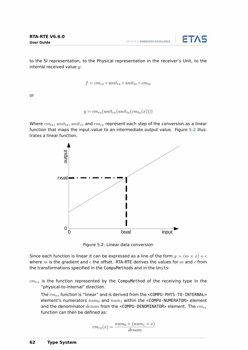
RTA-RTE V6.8.0User Guide
to the SI representation, to the Physical representation in the receiver’s Unit, to theinternal received value y:
f = cmrx ◦ unitrx ◦ unittx ◦ cmtx
or
y = cmrx(unitrx(unittx(cmtx(x))))
Where cmtx, unittx, unitrx and cmrx represent each step of the conversion as a linearfunction that maps the input value to an intermediate output value. Figure 5.2 illus-trates a linear function.
00 input
outp
ut
txval
rxval
Figure 5.2: Linear data conversion
Since each function is linear it can be expressed as a line of the form y = (m × x) + c
where m is the gradient and c the offset. RTA-RTE derives the values for m and c fromthe transformations specified in the CompuMethods and in the Units:
cmrx is the function represented by the CompuMethod of the receiving type in the“physical-to-internal” direction.
The cmrx function is “linear” and is derived from the <COMPU-PHYS-TO-INTERNAL>element’s numerators num0 and num1 within the <COMPU-NUMERATOR> elementand the denominator denom from the <COMPU-DENOMINATOR> element. The cmrx
function can then be defined as:
cmrx(x) =num0 + (num1 × x)
denom
62 Type System
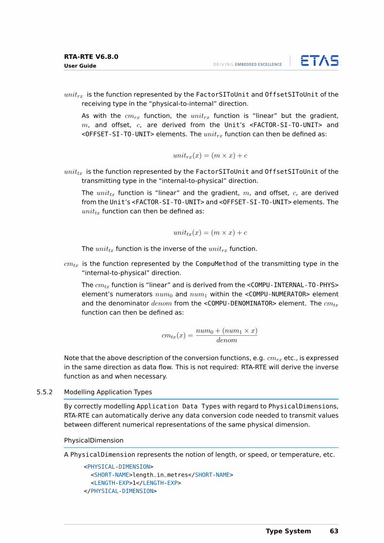
RTA-RTE V6.8.0User Guide
unitrx is the function represented by the FactorSIToUnit and OffsetSIToUnit of thereceiving type in the “physical-to-internal” direction.
As with the cmrx function, the unitrx function is “linear” but the gradient,m, and offset, c, are derived from the Unit’s <FACTOR-SI-TO-UNIT> and<OFFSET-SI-TO-UNIT> elements. The unitrx function can then be defined as:
unitrx(x) = (m× x) + c
unittx is the function represented by the FactorSIToUnit and OffsetSIToUnit of thetransmitting type in the “internal-to-physical” direction.
The unittx function is “linear” and the gradient, m, and offset, c, are derivedfrom the Unit’s <FACTOR-SI-TO-UNIT> and <OFFSET-SI-TO-UNIT> elements. Theunittx function can then be defined as:
unittx(x) = (m× x) + c
The unittx function is the inverse of the unitrx function.
cmtx is the function represented by the CompuMethod of the transmitting type in the“internal-to-physical” direction.
The cmtx function is “linear” and is derived from the <COMPU-INTERNAL-TO-PHYS>element’s numerators num0 and num1 within the <COMPU-NUMERATOR> elementand the denominator denom from the <COMPU-DENOMINATOR> element. The cmtx
function can then be defined as:
cmtx(x) =num0 + (num1 × x)
denom
Note that the above description of the conversion functions, e.g. cmrx etc., is expressedin the same direction as data flow. This is not required: RTA-RTE will derive the inversefunction as and when necessary.
5.5.2 Modelling Application Types
By correctly modelling Application Data Types with regard to PhysicalDimensions,RTA-RTE can automatically derive any data conversion code needed to transmit valuesbetween different numerical representations of the same physical dimension.
PhysicalDimension
A PhysicalDimension represents the notion of length, or speed, or temperature, etc.
<PHYSICAL-DIMENSION><SHORT-NAME>length_in_metres</SHORT-NAME><LENGTH-EXP>1</LENGTH-EXP>
</PHYSICAL-DIMENSION>
Type System 63
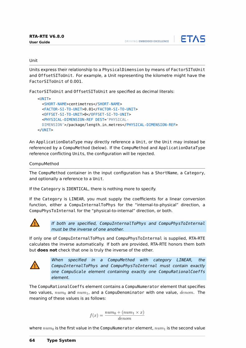
RTA-RTE V6.8.0User Guide
Unit
Units express their relationship to a PhysicalDimension by means of FactorSIToUnitand OffsetSIToUnit. For example, a Unit representing the kilometre might have theFactorSIToUnit of 0.001.
FactorSIToUnit and OffsetSIToUnit are specified as decimal literals:
<UNIT><SHORT-NAME>centimetres</SHORT-NAME><FACTOR-SI-TO-UNIT>0.01</FACTOR-SI-TO-UNIT><OFFSET-SI-TO-UNIT>0</OFFSET-SI-TO-UNIT><PHYSICAL-DIMENSION-REF DEST=’PHYSICAL-DIMENSION’>/package/length_in_metres</PHYSICAL-DIMENSION-REF>
</UNIT>
An ApplicationDataType may directly reference a Unit, or the Unit may instead bereferenced by a CompuMethod (below). If the CompuMethod and ApplicationDataTypereference conflicting Units, the configuration will be rejected.
CompuMethod
The CompuMethod container in the input configuration has a ShortName, a Category,and optionally a reference to a Unit.
If the Category is IDENTICAL, there is nothing more to specify.
If the Category is LINEAR, you must supply the coefficients for a linear conversionfunction, either a CompuInternalToPhys for the “internal-to-physical” direction, aCompuPhysToInternal for the “physical-to-internal” direction, or both.
If both are specified, CompuInternalToPhys and CompuPhysToInternalmust be the inverse of one another.
If only one of CompuInternalToPhys and CompuPhysToInternal is supplied, RTA-RTEcalculates the inverse automatically. If both are provided, RTA-RTE honors them bothbut does not check that one is truly the inverse of the other.
When specified in a CompuMethod with category LINEAR, theCompuInternalToPhys and CompuPhysToInternal must contain exactlyone CompuScale element containing exactly one CompuRationalCoeffselement.
The CompuRationalCoeffs element contains a CompuNumerator element that specifiestwo values, num0 and num1, and a CompuDenominator with one value, denom. Themeaning of these values is as follows:
f(x) =num0 + (num1 × x)
denom
where num0 is the first value in the CompuNumerator element, num1 is the second value
64 Type System

RTA-RTE V6.8.0User Guide
in the CompuNumerator element, and denom is the value in the CompuDenominator.
All numerators and denominators in CompuRationalCoeffs must be integers. For ex-ample, to represent (0.5 + x) use coefficients 1, 2, 2 which give the mathematically-equivalent 1+2x
2 .
As an example, consider the conversion of centimetres to metres:
<COMPU-METHOD><SHORT-NAME>compuMethod_centimetres</SHORT-NAME><CATEGORY>LINEAR</CATEGORY><UNIT-REF DEST=’UNIT’>/package/metres</UNIT-REF><COMPU-INTERNAL-TO-PHYS><COMPU-SCALES><COMPU-SCALE><COMPU-RATIONAL-COEFFS><COMPU-NUMERATOR><V>0</V><V>1</V>
</COMPU-NUMERATOR><COMPU-DENOMINATOR><V>100</V>
</COMPU-DENOMINATOR></COMPU-RATIONAL-COEFFS>
</COMPU-SCALE></COMPU-SCALES>
</COMPU-INTERNAL-TO-PHYS></COMPU-METHOD>
The above XML expresses the relationship metres(cm) = 0+(1×cm)100 , or more simply,
metres(cm) = cm100 .
Alternatively, the relationship can be expressed in the “physical-to-internal” direction:
<COMPU-METHOD><SHORT-NAME>compuMethod_centimetres</SHORT-NAME><CATEGORY>LINEAR</CATEGORY><UNIT-REF DEST=’UNIT’>/package/metres</UNIT-REF><COMPU-PHYS-TO-INTERNAL><COMPU-SCALES><COMPU-SCALE><COMPU-RATIONAL-COEFFS><COMPU-NUMERATOR><V>0</V><V>100</V>
</COMPU-NUMERATOR><COMPU-DENOMINATOR><V>1</V>
</COMPU-DENOMINATOR></COMPU-RATIONAL-COEFFS>
</COMPU-SCALE></COMPU-SCALES>
</COMPU-INTERNAL-TO-PHYS>
Type System 65
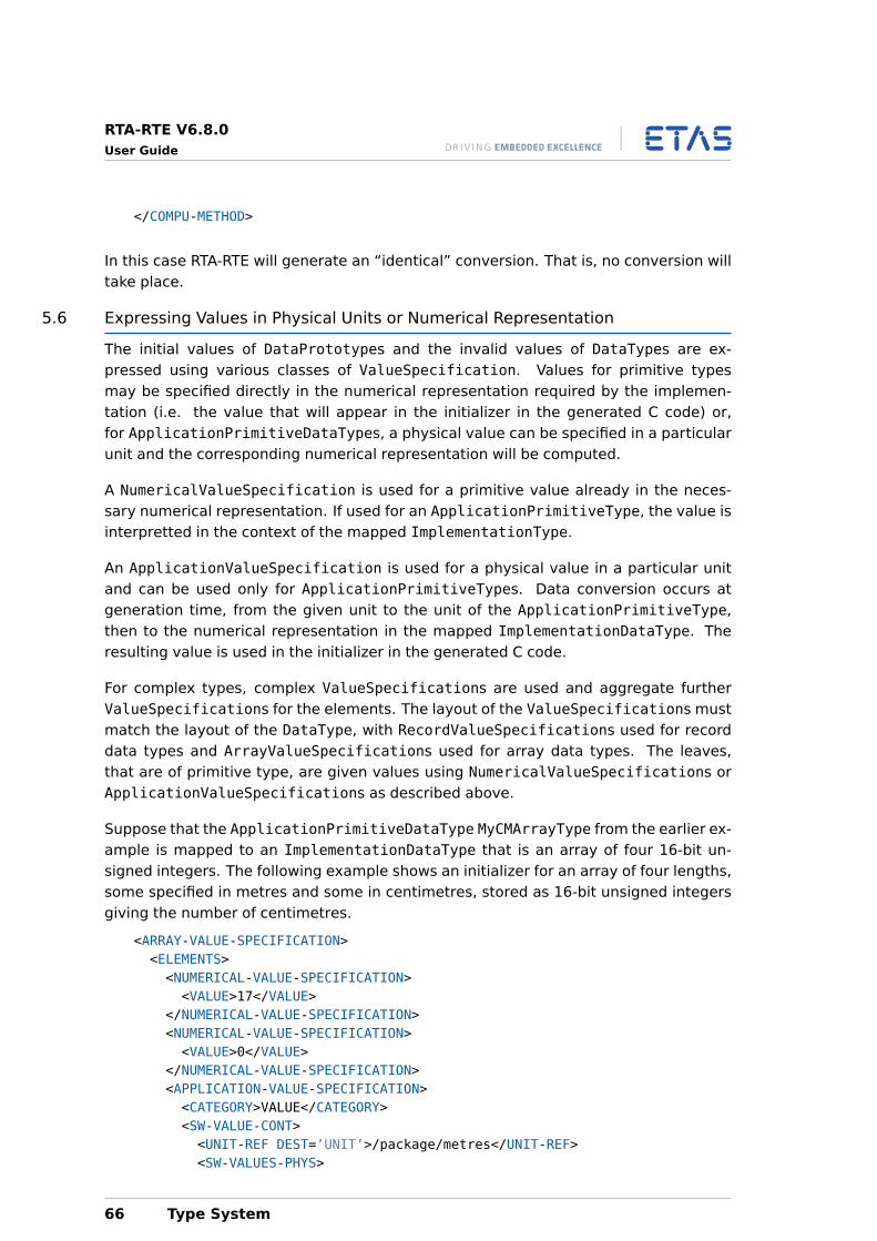
RTA-RTE V6.8.0User Guide
</COMPU-METHOD>
In this case RTA-RTE will generate an “identical” conversion. That is, no conversion willtake place.
5.6 Expressing Values in Physical Units or Numerical Representation
The initial values of DataPrototypes and the invalid values of DataTypes are ex-pressed using various classes of ValueSpecification. Values for primitive typesmay be specified directly in the numerical representation required by the implemen-tation (i.e. the value that will appear in the initializer in the generated C code) or,for ApplicationPrimitiveDataTypes, a physical value can be specified in a particularunit and the corresponding numerical representation will be computed.
A NumericalValueSpecification is used for a primitive value already in the neces-sary numerical representation. If used for an ApplicationPrimitiveType, the value isinterpretted in the context of the mapped ImplementationType.
An ApplicationValueSpecification is used for a physical value in a particular unitand can be used only for ApplicationPrimitiveTypes. Data conversion occurs atgeneration time, from the given unit to the unit of the ApplicationPrimitiveType,then to the numerical representation in the mapped ImplementationDataType. Theresulting value is used in the initializer in the generated C code.
For complex types, complex ValueSpecifications are used and aggregate furtherValueSpecifications for the elements. The layout of the ValueSpecifications mustmatch the layout of the DataType, with RecordValueSpecifications used for recorddata types and ArrayValueSpecifications used for array data types. The leaves,that are of primitive type, are given values using NumericalValueSpecifications orApplicationValueSpecifications as described above.
Suppose that the ApplicationPrimitiveDataType MyCMArrayType from the earlier ex-ample is mapped to an ImplementationDataType that is an array of four 16-bit un-signed integers. The following example shows an initializer for an array of four lengths,some specified in metres and some in centimetres, stored as 16-bit unsigned integersgiving the number of centimetres.
<ARRAY-VALUE-SPECIFICATION><ELEMENTS><NUMERICAL-VALUE-SPECIFICATION><VALUE>17</VALUE>
</NUMERICAL-VALUE-SPECIFICATION><NUMERICAL-VALUE-SPECIFICATION><VALUE>0</VALUE>
</NUMERICAL-VALUE-SPECIFICATION><APPLICATION-VALUE-SPECIFICATION><CATEGORY>VALUE</CATEGORY><SW-VALUE-CONT><UNIT-REF DEST=’UNIT’>/package/metres</UNIT-REF><SW-VALUES-PHYS>
66 Type System
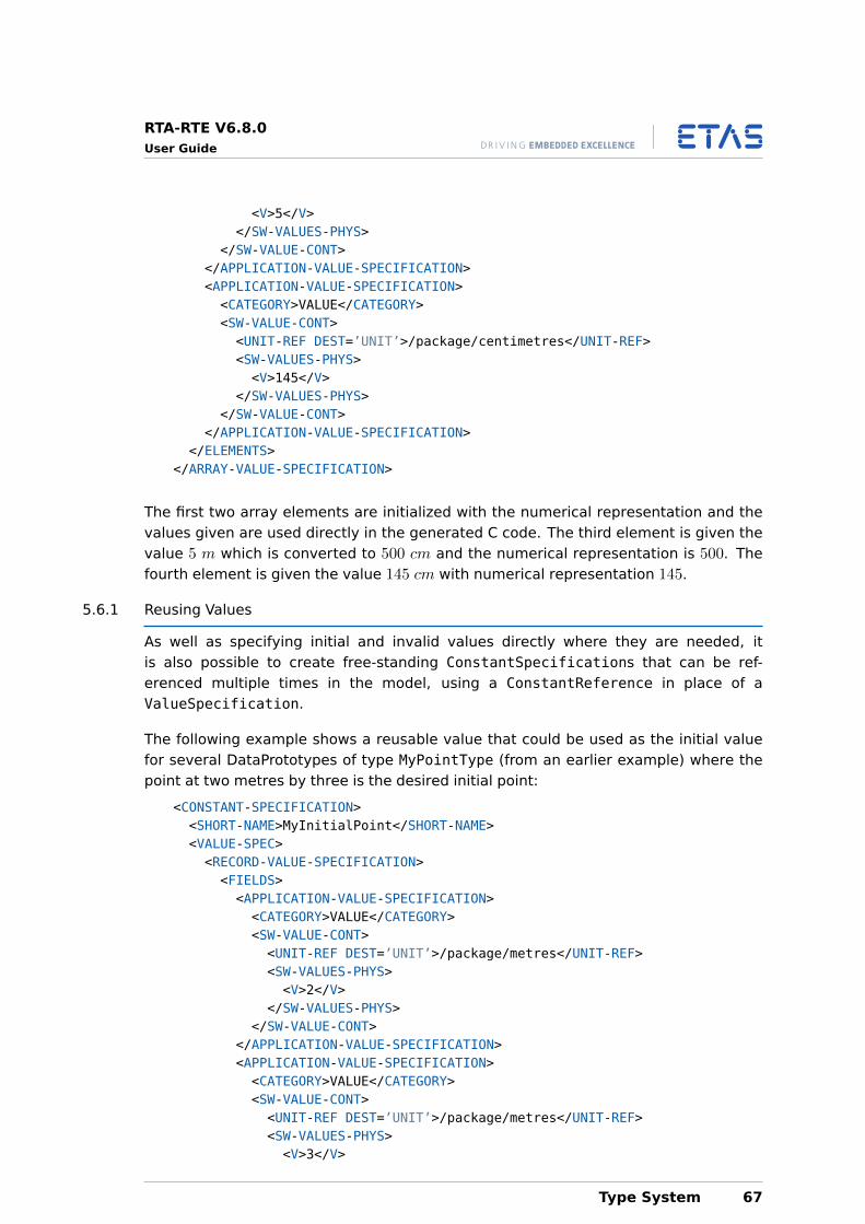
RTA-RTE V6.8.0User Guide
<V>5</V></SW-VALUES-PHYS>
</SW-VALUE-CONT></APPLICATION-VALUE-SPECIFICATION><APPLICATION-VALUE-SPECIFICATION><CATEGORY>VALUE</CATEGORY><SW-VALUE-CONT><UNIT-REF DEST=’UNIT’>/package/centimetres</UNIT-REF><SW-VALUES-PHYS><V>145</V>
</SW-VALUES-PHYS></SW-VALUE-CONT>
</APPLICATION-VALUE-SPECIFICATION></ELEMENTS>
</ARRAY-VALUE-SPECIFICATION>
The first two array elements are initialized with the numerical representation and thevalues given are used directly in the generated C code. The third element is given thevalue 5 m which is converted to 500 cm and the numerical representation is 500. Thefourth element is given the value 145 cm with numerical representation 145.
5.6.1 Reusing Values
As well as specifying initial and invalid values directly where they are needed, itis also possible to create free-standing ConstantSpecifications that can be ref-erenced multiple times in the model, using a ConstantReference in place of aValueSpecification.
The following example shows a reusable value that could be used as the initial valuefor several DataPrototypes of type MyPointType (from an earlier example) where thepoint at two metres by three is the desired initial point:
<CONSTANT-SPECIFICATION><SHORT-NAME>MyInitialPoint</SHORT-NAME><VALUE-SPEC><RECORD-VALUE-SPECIFICATION><FIELDS><APPLICATION-VALUE-SPECIFICATION><CATEGORY>VALUE</CATEGORY><SW-VALUE-CONT><UNIT-REF DEST=’UNIT’>/package/metres</UNIT-REF><SW-VALUES-PHYS><V>2</V>
</SW-VALUES-PHYS></SW-VALUE-CONT>
</APPLICATION-VALUE-SPECIFICATION><APPLICATION-VALUE-SPECIFICATION><CATEGORY>VALUE</CATEGORY><SW-VALUE-CONT><UNIT-REF DEST=’UNIT’>/package/metres</UNIT-REF><SW-VALUES-PHYS><V>3</V>
Type System 67

RTA-RTE V6.8.0User Guide
</SW-VALUES-PHYS></SW-VALUE-CONT>
</APPLICATION-VALUE-SPECIFICATION></FIELDS>
</RECORD-VALUE-SPECIFICATION></VALUE-SPEC>
</CONSTANT-SPECIFICATION>
This can be referenced as follows, either for a DataPrototype in its entirety or for anelement of a complex type by placing within a complex ValueSpecification:
<CONSTANT-REFERENCE><CONSTANT-REF DEST=’CONSTANT-SPECIFICATION’>/package/MyInitialPoint</
CONSTANT-REF></CONSTANT-REFERENCE>
Since ValueSpecifications are not directly tied to data types it is even possible toreuse ConstantSpecifications for different types, provided they are compatible. Forexample, a numerical value of 7 can be used to initialize a signed 8-bit integer typeand an unsigned 16-bit integer type, but a value of 1000 cannot be used to initializea signed 8-bit integer type. Similarly a RecordValueSpecification containing thenumerical values 1 and 2 can be used to initialize any record type with two elementsof some integer type, regardless of the names of the elements, but cannot be used toinitialize a record type with three elements, for example.
68 Type System
RTA-RTE V6.8.0User Guide
6 Interfaces
All ports of a software component (whether a provided or a required port) are typed bya specific interface. The definition of interfaces is considered in detail in this section.
Note that how the software component interacts with the interface is defined by the<INTERNAL-BEHAVIOR> element that references a software component. This is dis-cussed in Chapter 8.
6.1 Sender-Receiver
The <SENDER-RECEIVER-INTERFACE> element is used to define a sender-receiver inter-face as follows:
<SENDER-RECEIVER-INTERFACE><SHORT-NAME>SRInterface</SHORT-NAME>...<DATA-ELEMENTS>...
</DATA-ELEMENTS></SENDER-RECEIVER-INTERFACE>
The name of the sender-receiver interface definition is given by the <SHORT-NAME>.The name is used within other elements that need to reference the interface type,for example a software component may specify that it uses sender-receiver interfaceSRInterface.
The short-name of a sender-receiver interface should be a valid C identifier.
A sender-receiver interface can be used to communicate data (using data element pro-totypes within the <DATA-ELEMENTS> element) or modes (using mode declaration groupprototypes within the <MODE-GROUPS> element).
6.1.1 Data Element Prototypes
Each sender-receiver interface can specify zero or more data elements that constitutethe AUTOSAR signals communicated over the interface. Each data item defines a pro-totype of a specific type and can be a primitive data type, a RECORD or an ARRAY type.See Chapter 5 for details of defining data types.
The declaration of data elements within a sender-receiver interface definition has thefollowing structure:
<VARIABLE-DATA-PROTOTYPE><SHORT-NAME>Speed</SHORT-NAME><SW-DATA-DEF-PROPS><SW-DATA-DEF-PROPS-VARIANTS><SW-DATA-DEF-PROPS-CONDITIONAL><SW-IMPL-POLICY>QUEUED</SW-IMPL-POLICY>
</SW-DATA-DEF-PROPS-CONDITIONAL></SW-DATA-DEF-PROPS-VARIANTS>
</SW-DATA-DEF-PROPS><TYPE-TREF>/types/SInt16</TYPE-TREF>
Interfaces 69
RTA-RTE V6.8.0User Guide
</VARIABLE-DATA-PROTOTYPE>
A data element is defined using either a <DATA-ELEMENT-PROTOTYPE> or<VARIABLE-DATA-PROTOTYPE> element and all elements must be defined withinan encapsulating <DATA-ELEMENTS> element.
Each data element must specify:
• The <SHORT-NAME> that you will use to refer to the item.
• A <TYPE-TREF> reference to the type of the data item.
• The <SW-IMPL-POLICY> is specified for queued communication and omitted for un-queued.
Unqueued communication means that a newly received value over-writes the pre-vious value of the data item. If a value is sent multiple times before it is receivedthen the receiver can only access the last transmitted value.
Queued communication means that the sender-receiver interface queues arrivalsof the data item on the receiver side.
6.2 Nv-Data
<NV-DATA-INTERFACE> elements are used to define an interface used by an Nv-blocksoftware component type (see Chapter 11). Each interface contains one or more Nv-Data elements as follows:
<NV-DATA-INTERFACE><SHORT-NAME>NVInterface</SHORT-NAME>...<NV-DATAS>...
</NV-DATAS></NV-DATA-INTERFACE>
The name of the Nv-Data interface definition is given by the <SHORT-NAME>. The nameis used within other elements that need to reference the interface type, for example anNv-Block software component may specify that it uses Nv-Data interface NVInterface.
The short-name of a Nv-Data interface should be a valid C identifier.
6.2.1 Nv-Data Elements
Each Nv-Data interface can specify zero or more Nv-data elements that constitute theAUTOSAR signals communicated over the interface. Each Nv-data item defines a pro-totype of a specific type and can be a primitive data type, a RECORD or an ARRAY type.
The declaration of data elements within a Nv-Data interface definition has the followingstructure:
70 Interfaces
RTA-RTE V6.8.0User Guide
<VARIABLE-DATA-PROTOTYPE><SHORT-NAME>DTC</SHORT-NAME><TYPE-TREF>/types/SInt16</TYPE-TREF>
</VARIABLE-DATA-PROTOTYPE>
An Nv-data element is defined using a <VARIABLE-DATA-PROTOTYPE> element and allelements must be defined within an encapsulating <NV-DATAS> element.
Each Nv-data element must specify:
• The <SHORT-NAME> that you will use to refer to the item.
• A <TYPE-TREF> reference to the type of the data item.
6.3 Mode-Switch
The <MODE-SWITCH-INTERFACE> element is used to define a mode-switch interface in aconfiguration as follows:
<MODE-SWITCH-INTERFACE><SHORT-NAME>SRInterface</SHORT-NAME>...<MODE-GROUP>...
</MODE-GROUP></MODE-SWITCH-INTERFACE>
The name of the mode-switch interface definition is given by the <SHORT-NAME>. Thename is used within other elements that need to reference the interface type.
The short-name of a mode-switch interface should be a valid C identifier.
A mode-switch interface can contain exactly one mode group.
6.3.1 Mode Groups
Each mode-switch interface can specify exactly one mode group that defines applica-tion modes.
The declaration of each mode group prototype within a mode-switch interface definitionhas the following structure:
<MODE-GROUP><SHORT-NAME>Speed</SHORT-NAME><TYPE-TREF>/autosar/mg1</TYPE-TREF>
</MODE-GROUP>
A mode group prototype is defined using the <MODE-GROUP> element. Each mode groupprototype must specify:
• the <SHORT-NAME> that you will use to refer to the item.
Interfaces 71
RTA-RTE V6.8.0User Guide
• the <TYPE-TREF> reference to mode declaration group.
The declaration of mode group prototypes and the use of mode declaration prototypeswithin interfaces is considered in detail in Chapter 9.
6.4 Client-Server
The <CLIENT-SERVER-INTERFACE> element is used to define a client-server interfaceas follows:
<CLIENT-SERVER-INTERFACE><SHORT-NAME>CSInterface</SHORT-NAME><OPERATIONS>...
</OPERATIONS></CLIENT-SERVER-INTERFACE>
A client-server interface is named using the <SHORT-NAME> element. The name is usedwithin other elements that need to reference the interface type. The short-name of aclient-server interface should be a valid C identifier.
A client-server interface consists of one or more operations defined using the<OPERATIONS> container element.
6.4.1 Operations
The <OPERATIONS> element encapsulates one or more <CLIENT-SERVER-OPERATION>elements each of which defines a single operation in the client-server interface.
<OPERATIONS><CLIENT-SERVER-OPERATION><SHORT-NAME>MaximumValue</SHORT-NAME><ARGUMENTS>...</ARGUMENTS>
</CLIENT-SERVER-OPERATION></OPERATIONS>
Each operation is named using the <SHORT-NAME> element. The name you specify herewill form part of the name used by the RTE to refer to the operation in your code.
The <ARGUMENTS> element encapsulates one or more argument prototypes using<ARGUMENT-DATA-PROTOTYPE> elements that define each argument (parameter) of theoperation.
Each argument prototype definition must define:
• the <SHORT-NAME> of the parameter.
• a <TYPE-TREF> reference to the type of the parameter. The referenced type mustcorrespond to a defined type – see Chapter 5.
72 Interfaces
RTA-RTE V6.8.0User Guide
• the <DIRECTION> of the parameter as “IN” (read only), “OUT” (write only) or “IN-OUT” readable and writable by the component.
The following XML definition shows the arguments for our MaximumValue operation thatwe assume takes two parameters of type SInt16 and returns the maximum of the twoparameters in an out parameter called result:
<ARGUMENTS><ARGUMENT-DATA-PROTOTYPE><SHORT-NAME>InputA</SHORT-NAME><TYPE-TREF>/types/SInt16</TYPE-TREF><DIRECTION>IN</DIRECTION>
</ARGUMENT-DATA-PROTOTYPE><ARGUMENT-DATA-PROTOTYPE><SHORT-NAME>InputB</SHORT-NAME><TYPE-TREF>/types/SInt16</TYPE-TREF><DIRECTION>IN</DIRECTION>
</ARGUMENT-DATA-PROTOTYPE><ARGUMENT-DATA-PROTOTYPE><SHORT-NAME>OutputMaximum</SHORT-NAME><TYPE-TREF>/types/SInt16</TYPE-TREF><DIRECTION>OUT</DIRECTION>
</ARGUMENT-DATA-PROTOTYPE></ARGUMENTS>
6.5 Calibration
The <PARAMETER-INTERFACE> element is used to define a calibration interface as fol-lows:
<PARAMETER-INTERFACE><SHORT-NAME>if1</SHORT-NAME><PARAMETERS>...
</PARAMETERS></PARAMETER-INTERFACE>
The name of the calibration interface definition is given by the <SHORT-NAME>. Thename is used within other elements that need to reference the interface type.
The short-name of a calibration interface should be a valid C identifier.
6.5.1 Calibration Prototypes
Each calibration interface can specify zero or more calibration prototypes that con-stitute the AUTOSAR parameters communicated over the interface. Each calibrationprototype defines a prototype of a specific type.
The declaration of calibration prototypes within a calibration interface definition hasthe following structure:
<PARAMETER-DATA-PROTOTYPE>
Interfaces 73
RTA-RTE V6.8.0User Guide
<SHORT-NAME>Speed</SHORT-NAME><CATEGORY>VALUE</CATEGORY><TYPE-TREF>/types/SInt16</TYPE-TREF>
</PARAMETER-DATA-PROTOTYPE>
6.6 Trigger
A trigger interface is defined with the <TRIGGER-INTERFACE> element as follows:
<TRIGGER-INTERFACE><SHORT-NAME>ifSingle</SHORT-NAME><TRIGGERS>...
</TRIGGERS></TRIGGER-INTERFACE>
Each trigger interface can specify one or more triggers. The declaration of triggerswithin a trigger interface definition has the following structure:
<TRIGGER><SHORT-NAME>Name</SHORT-NAME>
</TRIGGER>
A trigger is defined using only its name; no other information is necessary.
74 Interfaces
RTA-RTE V6.8.0User Guide
7 Software Component Types
Each software component you want to use must have its component type declared inthe RTE generator’s configuration. The component type makes the component avail-able for composition into a larger software system
An atomic software component type is defined using the<APPLICATION-SW-COMPONENT-TYPE> element:
<*-TYPE><SHORT-NAME>AtomicSoftwareComponent</SHORT-NAME><PORTS>...
</PORTS></*-TYPE>
Additional component types are also possible. For example, a sensor-actuator compo-nent types uses the <SENSOR-ACTUATOR-SW-COMPONENT-TYPE> element:
<SENSOR-ACTUATOR-SW-COMPONENT-TYPE><SHORT-NAME>SensorActuatorComponent</SHORT-NAME><PORTS>...
</PORTS></SENSOR-ACTUATOR-SW-COMPONENT-TYPE>
Whatever the component type it must be named using the <SHORT-NAME> element. Thename must be system-wide unique and is used within other elements to reference thesoftware component type.
The short-name of a software-component should be a valid C identifier.
7.0.1 Service Components
In order for a service to be used by application components, “service component” typesmust also be declared.
Service components are defined using the <SERVICE-SW-COMPONENT-TYPE> element:
<SERVICE-SW-COMPONENT-TYPE><SHORT-NAME>ServiceComponent</SHORT-NAME><PORTS>...
</PORTS></SERVICE-SW-COMPONENT-TYPE>
7.0.2 NVRAM
AUTOSAR makes NVRAM blocks visible to to application components and to the AU-TOSAR NVRAM manager through instances of “NV Block software component” types.
NV Block components are defined using the <NV-BLOCK-SW-COMPONENT-TYPE>:
<NV-BLOCK-SW-COMPONENT-TYPE>
Software Component Types 75
RTA-RTE V6.8.0User Guide
<SHORT-NAME>nv1</SHORT-NAME><PORTS>...
</PORTS></NV-BLOCK-SW-COMPONENT-TYPE>
Each Nv-Block software component declares one or more Nv-blocks. See Chapter 11for more details.
7.1 Ports
The ports of a software component are defined within the <PORTS> element, for exam-ple:
<PORTS><*-PORT-PROTOTYPE>...
</*-PORT-PROTOTYPE></PORTS>
Within the <PORTS> element, the <P-PORT-PROTOTYPE> and the <R-PORT-PROTOTYPE>elements are used to define provided and required ports respectively.
7.1.1 Provided Ports
A provided port within a software component type definition is named using the<SHORT-NAME> element. The name is used within other elements to reference the soft-ware component type.
The short-name of a provided port should be a valid C identifier.
Each provided port definition must specify the interface type over which it will commu-nicate with other ports using the <PROVIDED-INTERFACE-TREF>:
<P-PORT-PROTOTYPE><SHORT-NAME>Sender</SHORT-NAME><PROVIDED-INTERFACE-TREF>/interfaces/SRInterface</PROVIDED-INTERFACE-TREF>
</P-PORT-PROTOTYPE>
This <PROVIDED-INTERFACE-TREF> element must identify the required interface – seeChapter 6.
7.1.2 Required Ports
The definition of a required port takes the same form as that of a provided port withthe exception that the <R-PORT-PROTOTYPE> element is used.
A required port within a software component type definition must be named using the<SHORT-NAME> element. The name is used within other elements to reference the soft-ware component type.
76 Software Component Types
RTA-RTE V6.8.0User Guide
The short-name of a required port should be a valid C identifier.
The required port definition must reference an interface definition defined using the<REQUIRED-INTERFACE-TREF> element:
<R-PORT-PROTOTYPE><SHORT-NAME>Receiver</SHORT-NAME><REQUIRED-INTERFACE-TREF>/interfaces/SRInterface
</REQUIRED-INTERFACE-TREF></R-PORT-PROTOTYPE>
In the simplest scenario, the provided and required ports at the endpoints of a con-nection reference the same interface definition – this guarantees that they are com-patible. However, it is also possible to connect a require port to a provide portwhose Interface is a superset of the require port Interface, or to connect ports withInterfaces that are compatible except for differing names for the interface elementsusing PortInterfaceMappings (see section 13.3.4) to explicitly specify the connec-tions and furthermore to connect data items that are not directly compatible via DataConversion – see Section 13.5.
7.1.3 Service Components
All the ports of a service component must be characterized by interfaces with the ser-vice flag set:
<R-PORT-PROTOTYPE><SHORT-NAME>ServiceReceiver</SHORT-NAME><REQUIRED-INTERFACE-TREF>/interfaces/ServiceSRInterface
</REQUIRED-INTERFACE-TREF></R-PORT-PROTOTYPE>...<SENDER-RECEIVER-INTERFACE><SHORT-NAME>ServiceSRInterface</SHORT-NAME>...<IS-SERVICE>true</IS-SERVICE>
</SENDER-RECEIVER-INTERFACE>
7.2 Communication Specifications
When a port prototype is created it can optionally define attributes that control how theport will behave. Provided port prototypes define attributes in <PROVIDED-COM-SPECS>element whereas required ports use a <REQUIRED-COM-SPECS> element.
<!-- Providing...--><P-PORT-PROTOTYPE><SHORT-NAME>name</SHORT-NAME><PROVIDED-COM-SPECS>...</PROVIDED-COM-SPECS><PROVIDED-INTERFACE-TREF ...
Software Component Types 77
RTA-RTE V6.8.0User Guide
</P-PORT-PROTOTYPE>
<!-- Requiring...--><R-PORT-PROTOTYPE><SHORT-NAME>name</SHORT-NAME><REQUIRED-COM-SPECS>...</REQUIRED-COM-SPECS><REQUIRED-INTERFACE-TREF ...
</R-PORT-PROTOTYPE>
7.2.1 Sender-Receiver
Acknowledgment Request
A sender (the provider of a sender-receiver interface) can optionally request that re-ceivers acknowledge the transmission for one or more of the data elements commu-nicated on the interface. The configuration depends on whether the data element isqueued or not.
<P-PORT-PROTOTYPE><SHORT-NAME>pa</SHORT-NAME><PROVIDED-COM-SPECS><!-- Enable TxAck --><UNQUEUED-SENDER-COM-SPEC><DATA-ELEMENT-IREF><P-PORT-PROTOTYPE-REF ...<DATA-ELEMENT-PROTOTYPE-REF ...
</DATA-ELEMENT-IREF><TRANSMISSION-ACKNOWLEDGE><TIMEOUT>0.5</TIMEOUT>
</TRANSMISSION-ACKNOWLEDGE></UNQUEUED-SENDER-COM-SPEC>
</PROVIDED-COM-SPECS><PROVIDED-INTERFACE-TREF ...
</P-PORT-PROTOTYPE>
Acknowledgment is enabled if the timeout is greater than zero.
For a sender, the only acknowledgment that can be requested is on transmission. It isnot possible to request acknowledgement on reception by the receiver since there maybe multiple receivers of the data item and it would be impossible to determine whatthe semantics of successful reception were (would it be one receiver has received, allreceivers have received, some receivers have received etc.)
When a software component sends data over a port and acknowledgment requests aredefined then your application code can request transmission acknowledgment. This isdone by requesting feedback from the RTE with the following API call:
Rte_StatusTypeRte_Feedback_<Port>_<Data/Event>(Rte_Instance Self)
78 Software Component Types
RTA-RTE V6.8.0User Guide
The call can be made irrespective of whether the receiving software component is lo-cated locally on the same ECU as the sender or on a remote ECU.
The call will block for <TIMEOUT> seconds if a <WAIT-POINT> in the calling runnableentity references a <DATA-SEND-COMPLETED-EVENT>, otherwise it will not block.
The following code shows how to request feedback for a transmission assuming that ablocking variant is configured:
FUNC(void, RTE_APPL_CODE)Runnable(Rte_Instance self){Rte_StatusType status;
status = Rte_Send_Port_Value(self, 42);if (status != RTE_E_OK){// Handle error
}else{status = Rte_Feedback_Port_Value(self);// Call blocks for up to TIMEOUT secondsswitch (status) {case RTE_E_TRANSMIT_ACK:// COM service transmitted data...
case RTE_E_TIMEOUT:// Transmission request timedout
}}
}
Rte_Feedback applies only to writes/sends that use the “explicit” form of thesender-receiver communication API. Furthermore, when multiple transmis-sions are made then it is not possible to determine which is acknowledgedfirst. You should serialize calls and check each individually if you need thisbehavior.
There is also an additional form of the feedback API, Rte_IFeedback, that applies tothe “implicit” form of sender-receiver communication. This API will never block.
Initial Values
Non-queued data elements can optionally specify whether they have an initial valuethat is used when a receiver attempts a receive operation on a software componentthat has not yet made its first send or when the sender has invalidated the signal.
<R-PORT-PROTOTYPE><SHORT-NAME>ra</SHORT-NAME>
Software Component Types 79
RTA-RTE V6.8.0User Guide
<REQUIRED-COM-SPECS><NONQUEUED-RECEIVER-COM-SPEC><DATA-ELEMENT-REF>...</DATA-ELEMENT-REF><INIT-VALUE><CONSTANT-REFERENCE><CONSTANT-REF>/pkg/constant_857</CONSTANT-REF>
</CONSTANT-REFERENCE></INIT-VALUE>
</NONQUEUED-RECEIVER-COM-SPEC></REQUIRED-COM-SPECS><REQUIRED-INTERFACE-TREF ...
</R-PORT-PROTOTYPE>
Invalidation
Non-queued data elements can optionally enable invalidation so that a sender can senda data item that has an invalidated value.
Invalidation is enabled through the interface’s invalidation policy element. This ensuresthat all uses of the interface have the same invalidation state.
<INVALIDATION-POLICYS><INVALIDATION-POLICY><DATA-ELEMENT-REF>/pkg/if/element</DATA-ELEMENT-REF><HANDLE-INVALID>KEEP</HANDLE-INVALID>
</INVALIDATION-POLICY>...
</INVALIDATION-POLICYS>
Invalidation is used to indicate whether a data item is invalid on transmission. Whenthe attribute is set at a sender, RTE API calls generated for that can be used by thesender to set a signal value as invalid. There are two types of invalidation:
• Implicit communication invalidation using the Rte_IInvalidate API.
• Explicit Communication Invalidation using the Rte_Invalidate API.
Setting invalidity can only be made at the point of transmission – once the data item issent, the invalidate attribute cannot be modified. The receiver of an invalidated valuereceives the specified initial value.
Queued Data Buffering
Recall that the RTE allows data to be queued and this is specified on the interface. Datais always queued on the receiver software component. To avoid unnecessary use ofbuffer space, the number of elements queued can be configured.
<R-PORT-PROTOTYPE><SHORT-NAME>ra</SHORT-NAME><REQUIRED-COM-SPECS><QUEUED-RECEIVER-COM-SPEC>
80 Software Component Types
RTA-RTE V6.8.0User Guide
<DATA-ELEMENT-REF>...</DATA-ELEMENT-REF><QUEUE-LENGTH>3</QUEUE-LENGTH>
</QUEUED-RECEIVER-COM-SPEC></REQUIRED-COM-SPECS><REQUIRED-INTERFACE-TREF ...
</R-PORT-PROTOTYPE>
Only data elements that are specified as <IS-QUEUED> can be buffered.
Alive Timeout
When communication is between ECUs it can be useful to know whether a sender isstill alive and sending data. This is configured using an alive timeout that specifies themaximum time between receives that the receiver considers to indicate the sender isnot alive.
If the alive timeout is exceeded then the receiver is informed through a<DATA-RECEIVE-ERROR-EVENT>. Therefore, the internal behavior of a software com-ponent that wishes to use the alive timeout must ensure that a runnable entity thatresponds to a <DATA-RECEIVE-ERROR-EVENT> is configured.
The alive timeout is specified in seconds.
<REQUIRED-COM-SPECS><NONQUEUED-RECEIVER-COM-SPEC><DATA-ELEMENT-REF>...</DATA-ELEMENT-IREF><ALIVE-TIMEOUT>1.5</ALIVE-TIMEOUT>
</NONQUEUED-RECEIVER-COM-SPEC></REQUIRED-COM-SPECS>
Filter
In some cases a receiver may only want to receive a value when the sent datahas a specific property, for example the value has changed. This is especiallyuseful for reducing the load in systems where runnable entities are triggered by<DATA-RECEIVED-EVENTS> since filtering can reduce the number of events that getpassed to the receiver and therefore the amount of time consumed processing signalsthat are not deemed useful.
<NONQUEUED-RECEIVER-COM-SPEC><DATA-ELEMENT-REF>...</DATA-ELEMENT-REF><FILTER>...</FILTER>
</NONQUEUED-RECEIVER-COM-SPEC>
The valid filter specifications are described in the RTA-RTE Reference Manual.
7.2.2 Client-Server
Buffering for the server side of client-server communication is configured using the<SERVER-COM-SPEC> element.
<P-PORT-PROTOTYPE>
Software Component Types 81
RTA-RTE V6.8.0User Guide
<SHORT-NAME>Server</SHORT-NAME><PROVIDED-COM-SPECS><SERVER-COM-SPEC><OPERATION-REF>...</OPERATION-REF><QUEUE-LENGTH>2</QUEUE-LENGTH>
</SERVER-COM-SPEC></PROVIDED-COM-SPECS><PROVIDED-INTERFACE-TREF ...
</P-PORT-PROTOTYPE>
7.2.3 Client Component Instance Attributes
This release of RTA-RTE does not use the <CLIENT-COM-SPEC>.
82 Software Component Types
RTA-RTE V6.8.0User Guide
8 Internal Behavior
In Chapter 6 you saw how to define the external interface of a software component. Inthis chapter you will see how to configure the internal behavior of the component.
Internal behavior elements are used to define how the software component will interactwith the RTE at runtime.
The internal behavior of a software component specifies many aspects of how it be-haves, including:
• The runnable entities that belong to the software component and how they interact(if at all) with the ports of the software component
• The events that cause runnable entities to be activated at runtime.
• The exclusive areas that exist so runnable entities can execute all or part of theircode in mutual exclusion from other runnable entities.
• Variables that belong to the software component that are accessed by multiplerunnable entities.
• Port argument lists for accessing AUTOSAR Basic Software Modules.
The following example illustrates the internal behavior description for software compo-nent “SoftwareComponent”:
<INTERNAL-BEHAVIOR><SHORT-NAME>behavior</SHORT-NAME><COMPONENT-REF>SoftwareComponent</COMPONENT-REF>
<!-- Events that cause runnable activation --><EVENTS>...
</EVENTS>
<!-- Specification of mutual exclusion areas --><EXCLUSIVE-AREAS>...
</EXCLUSIVE-AREAS>
<!-- Variables shared by multiple runnable entities --><INTER-RUNNABLE-VARIABLES>...
</INTER-RUNNABLE-VARIABLES>
<!-- Variables unique to SW-C instance --><PER-INSTANCE-MEMORYS>...
</PER-INSTANCE-MEMORYS>
<!-- Arguments for accessing BSW modules -->
Internal Behavior 83
RTA-RTE V6.8.0User Guide
<PORT-ARGUMENT-LISTS>...
</PORT-ARGUMENT-LISTS>
<!-- Runnable entities --><runnable entities>...
</runnable entities>
<!-- Flag; if true SW-C can exist more than once --><SUPPORTS-MULTIPLE-INSTANTIATION>...
</SUPPORTS-MULTIPLE-INSTANTIATION></INTERNAL-BEHAVIOR>
An internal behavior must be named using the <SHORT-NAME> element. The name isused within other elements to reference the behavior.
The short-name of an internal behavior does not need to be a valid C identifier (but itmust pass the syntactic checks enforced by the XML Schema).
The way in which the configuration of RTE events within the <EVENTS> element andrunnable entities defines the receive mode communication attributes is shown in Sec-tion 8.5. The following sections first outline the basic framework for RTE events andrunnable entities before showing how to configure the RTE to achieve different types ofrunnable entity/interface interaction.
8.1 RTE Events
Events control how runnable entities are triggered by the generated RTE at runtime.These events are termed RTE Events to distinguish them from OS events.
RTA-RTE supports the following RTE Event types:
• TIMING-EVENT – activate a runnable entity periodically. The TIMING-EVENT allowsyou to execute a runnable entity to poll an RPort to check if data has been received,periodically call a server (ie be a client), periodically send data on a PPort or simplyto execute some internal software component functionality. Runnable entities thatare activated in response to a timing event are said to be “time-triggered”.
• DATA-RECEIVED-EVENT – activate a runnable entity when data is received on aRPort/data element. Runnable entities that are activated in response to a datareceived event are “event-triggered”.
• DATA-RECEIVE-ERROR-EVENT – activate a runnable entity when either invalidateddata is received or an “alive timeout” has failed.
• ASYNCHRONOUS-SERVER-CALL-RETURNS-EVENT – activate a runnable entity whenthe result from an earlier call to a server is available.
84 Internal Behavior
RTA-RTE V6.8.0User Guide
• OPERATION-INVOKED-EVENT – activate a runnable entity to handle a server call foran operation on a provided port characterized by a client-server interface.
• DATA-SEND-COMPLETED-EVENT – activate a runnable entity when a transmission ac-knowledgement is available (explicit communication).
• DATA-WRITE-COMPLETED-EVENT – activate a runnable entity when a transmissionacknowledgement is available (implicit communication).
• MODE-SWITCH-EVENT – activate a runnable entity on either entry to, or exit from anapplication mode. AUTOSAR also permits mode switch events to be triggered onthe transition between two application modes.
• MODE-SWITCHED-ACK-EVENT – activate a runnable when a mode switch transition iscomplete.
• BACKGROUND-EVENT – activate a runnable within the “idle” task.
• INTERNAL-TRIGGER-OCCURRED-EVENT – activate a runnable within the SW-C, possi-bly by direct function call, without passing data.
• EXTERNAL-TRIGGER-OCCURRED-EVENT – activate a runnable within the SW-C by anexternal entity without passing data.
A <TIMING-EVENT> is used to indicate that a runnable entity will be activated periodi-cally by the Operating System. The RTE generator will use this information to generatean appropriate schedule table that must be ticked from application code.
The <DATA-RECEIVED-EVENT> and <ASYNCHRONOUS-SERVER-CALL-RETURNS-EVENT> el-ements implicitly provide the XML configuration of the RECEIVE_MODE VFB communica-tion attribute.
The structure for specifying RTE events is:
<EVENTS><*-EVENT><!-- Elements for event/runnable relationship -->
</*-EVENT></EVENTS>
The <EVENTS> element can encapsulate any number of RTE events. RTE events can belisted in any order.
An RTE event can be used to activate a runnable entity when the event oc-curs. The <ASYNCHRONOUS-SERVER-CALL-RETURNS-EVENT>, <DATA-RECEIVED-EVENT>and <DATA-SEND-COMPLETED-EVENT> can also be waited upon by a runnable entity.
An RTE event references the runnable entity that is to be activated when the eventoccurs. Similarly, when a runnable entity waits on one of the RTE events, the runnableentity must reference the event(s) upon which it waits. Each of the RTE events can beused in both ways and by more than one runnable entity but it is not possible for thesame event to simultaneously activate a runnable entity and to be waited upon.
Internal Behavior 85
RTA-RTE V6.8.0User Guide
8.2 Runnable Entities
Each software component will require at least one runnable entity. All runnable entitiesmust be defined within the runnable entities definition in a <SWC-INTERNAL-BEHAVIOR>element.
<runnable entities><RUNNABLE-ENTITY><SHORT-NAME>RunnableEntity</SHORT-NAME><!-- Elements defining behavior of entity --><SYMBOL>CFunctionName</SYMBOL>
</RUNNABLE-ENTITY></runnable entities>
A <RUNNABLE-ENTITY> must be named using the <SHORT-NAME> element. The name isused within other elements to reference the runnable entity.
The <SHORT-NAME> denotes the name of the runnable entity in the XML namespace,but it does not tell the RTE what the associated function body you will provide in yourcode is called. This information is provided by the <SYMBOL> declaration that linksthe runnable entity to the C function name you will use in your implementation. The<SYMBOL> element defines the name of the function that implements the runnable en-tity. The <SYMBOL> name must be a valid C identifier.
This declaration is sufficient if your runnable entity does not need to interact with thesoftware component’s ports. However, if a runnable entity needs to interact then youwill need to specify additional information that allows the RTE generator to generateAPIs to allow interaction to take place, for example:
1. What data items the runnable entity can send.
2. What data items the runnable entity can receive.
3. What mode instances the runnable entity can switch.
4. What RTE events the runnable entity waits upon.
5. Which servers the runnable entity calls and how it expects the result to be re-turned.
You can use the same runnable entity to receive data on one interface and send dataon another interface, or to receive data on a port and then call a server port to processthe received data. For example, you may create a runnable entity that reads an integervalue from an RPort, multiplies it by two and sends it out on a PPort.
8.2.1 Specifying Maximum Arrival Rate
AUTOSAR permits the specification of the minimum time between executions by specif-ing a minimum start interval to place a limit on the rate at which activations can occur.RTA-RTE manages runnable activation to ensure that the minimum start interval is notviolated.
86 Internal Behavior
RTA-RTE V6.8.0User Guide
A minimum start interval cannot be specified for a runnable entity that is invoked byan OperationInvokedEvent.
The RTE API function Rte_MainFunction must be invoked when minimumstart intervals are used. The period at which the function will be invoked isspecified by a command-line option.
8.3 Responding to Periodic Events
If your software component includes runnable entities that are not triggered by com-munication through the ports of the component you need to make sure that therunnable entities are executed at runtime. This is achieved by associating them with a<TIMING-EVENT> or <BACKGROUND-EVENT> that specifies how the runnable entity shouldexecute.
8.3.1 Timing events
Each <TIMING-EVENT> element specifies the <PERIOD> of occurrence in seconds andmust reference a runnable entity defined in the component’s internal behavior using a<START-ON-EVENT-REF> element. A period of zero is illegal.
The runnable entity declaration itself needs only to declare a name for the runnableentity.
The following example shows how to configure the RTE to activate a runnable entityevery second.
<EVENTS><TIMING-EVENT><SHORT-NAME>EverySecond</SHORT-NAME><!-- Runnable to activate --><START-ON-EVENT-REF>/pkg/ib/RunnableEntity
</START-ON-EVENT-REF><PERIOD>1.0</PERIOD> <!-- Every second -->
</TIMING-EVENT></EVENTS>
<RUNNABLE-ENTITY><SHORT-NAME>RunnableEntity</SHORT-NAME><SYMBOL>MyFunctionName</SYMBOL>
</RUNNABLE-ENTITY>
A timing event must be named using the <SHORT-NAME> element. The name is usedwithin other elements to reference the timing event. The short-name of a timing eventdoes not need to be a valid C identifier.
8.3.2 Background events
RTA-RTE also supports Background events. These events are similar to TimingEventsin that they are recurring but unlike timing events have no fixed period.
Internal Behavior 87
RTA-RTE V6.8.0User Guide
RTA-RTE supports two mechanisms for activating background events:
• Via invocation from an “idle” task.
• Via an external OsAlarm or schedule table (see Section 24.1).
When all events mapped to a task are background events and no event has an exter-nally declared OsAlarm or OsScheduleTable reference then RTA-RTE generates a taskbody that uses ChainTask instead of TerminateTask.
In accordance with AUTOSAR requirements, RTA-RTE rejects configura-tions where a background triggered event is not triggerend by an externalOsAlarm or schedule table and is not mapped to the lowest priority task inthe system (the “idle” task).
8.4 Sending to a Port
If your software component provides a sender-receiver interface then you should defineat least one runnable entity that sends data over the interface.
The runnable can send data in two ways:
Explicitly – The RTE generates an explicit API call (that may be optimized to a macro).The sent data item may be either queued or unqueued by the receiver.
Implicitly – The RTE generates an implicit API call that will be optimized to a macro.The sent data item must not be queued.
8.4.1 Explicit Communication
Runnable entities that send data must define a <DATA-SEND-POINT> that each of whichspecifies the data item that will be sent for a given interface.
The <DATA-SEND-POINT> specifies the port and data element using<P-PORT-PROTOTYPE-REF> and <DATA-ELEMENT-PROTOTYPE-REF> elements:
<RUNNABLE-ENTITY><SHORT-NAME>Sender</SHORT-NAME><DATA-SEND-POINTS><DATA-SEND-POINT><SHORT-NAME>SendPoint</SHORT-NAME><DATA-ELEMENT-IREF><P-PORT-PROTOTYPE-REF ...<DATA-ELEMENT-PROTOTYPE-REF ...
</DATA-ELEMENT-IREF></DATA-SEND-POINT>
</DATA-SEND-POINTS></RUNNABLE-ENTITY>
88 Internal Behavior
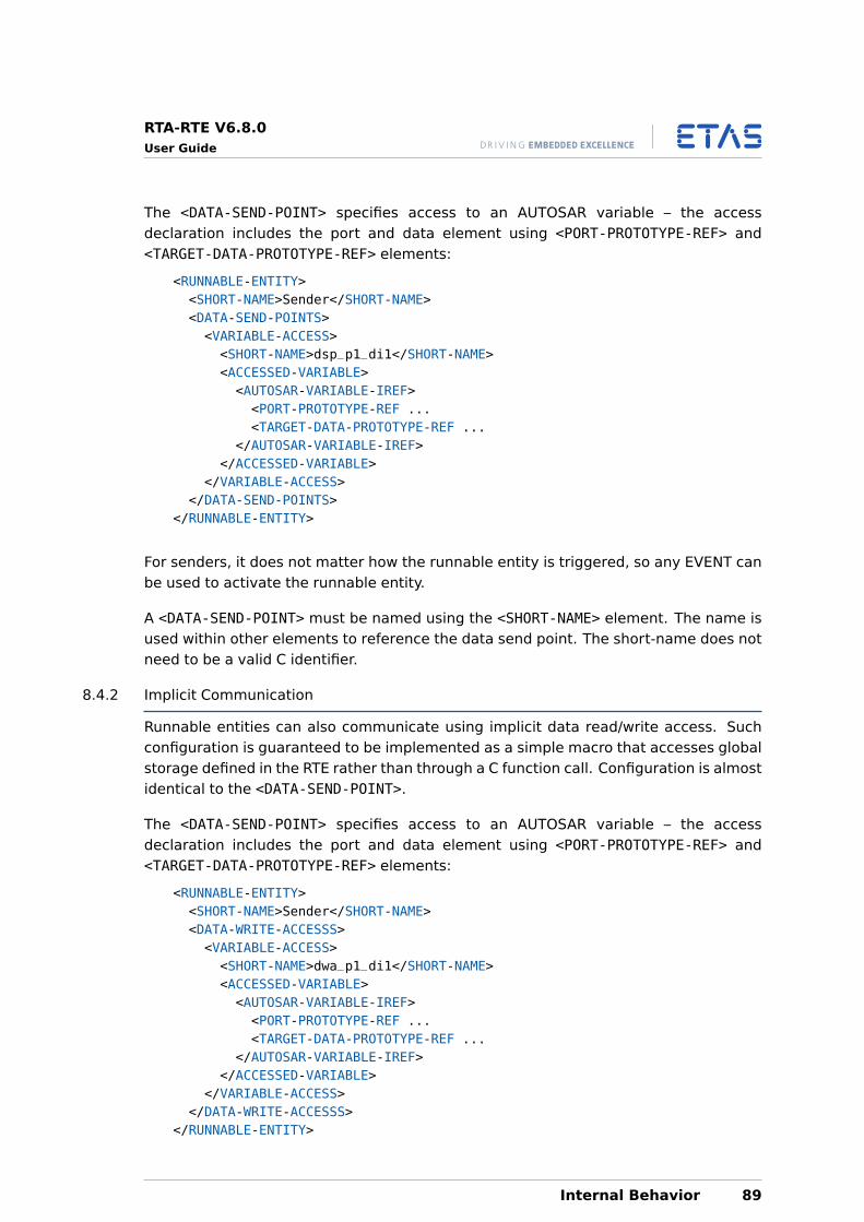
RTA-RTE V6.8.0User Guide
The <DATA-SEND-POINT> specifies access to an AUTOSAR variable – the accessdeclaration includes the port and data element using <PORT-PROTOTYPE-REF> and<TARGET-DATA-PROTOTYPE-REF> elements:
<RUNNABLE-ENTITY><SHORT-NAME>Sender</SHORT-NAME><DATA-SEND-POINTS><VARIABLE-ACCESS><SHORT-NAME>dsp_p1_di1</SHORT-NAME><ACCESSED-VARIABLE><AUTOSAR-VARIABLE-IREF><PORT-PROTOTYPE-REF ...<TARGET-DATA-PROTOTYPE-REF ...
</AUTOSAR-VARIABLE-IREF></ACCESSED-VARIABLE>
</VARIABLE-ACCESS></DATA-SEND-POINTS>
</RUNNABLE-ENTITY>
For senders, it does not matter how the runnable entity is triggered, so any EVENT canbe used to activate the runnable entity.
A <DATA-SEND-POINT> must be named using the <SHORT-NAME> element. The name isused within other elements to reference the data send point. The short-name does notneed to be a valid C identifier.
8.4.2 Implicit Communication
Runnable entities can also communicate using implicit data read/write access. Suchconfiguration is guaranteed to be implemented as a simple macro that accesses globalstorage defined in the RTE rather than through a C function call. Configuration is almostidentical to the <DATA-SEND-POINT>.
The <DATA-SEND-POINT> specifies access to an AUTOSAR variable – the accessdeclaration includes the port and data element using <PORT-PROTOTYPE-REF> and<TARGET-DATA-PROTOTYPE-REF> elements:
<RUNNABLE-ENTITY><SHORT-NAME>Sender</SHORT-NAME><DATA-WRITE-ACCESSS><VARIABLE-ACCESS><SHORT-NAME>dwa_p1_di1</SHORT-NAME><ACCESSED-VARIABLE><AUTOSAR-VARIABLE-IREF><PORT-PROTOTYPE-REF ...<TARGET-DATA-PROTOTYPE-REF ...
</AUTOSAR-VARIABLE-IREF></ACCESSED-VARIABLE>
</VARIABLE-ACCESS></DATA-WRITE-ACCESSS>
</RUNNABLE-ENTITY>
Internal Behavior 89
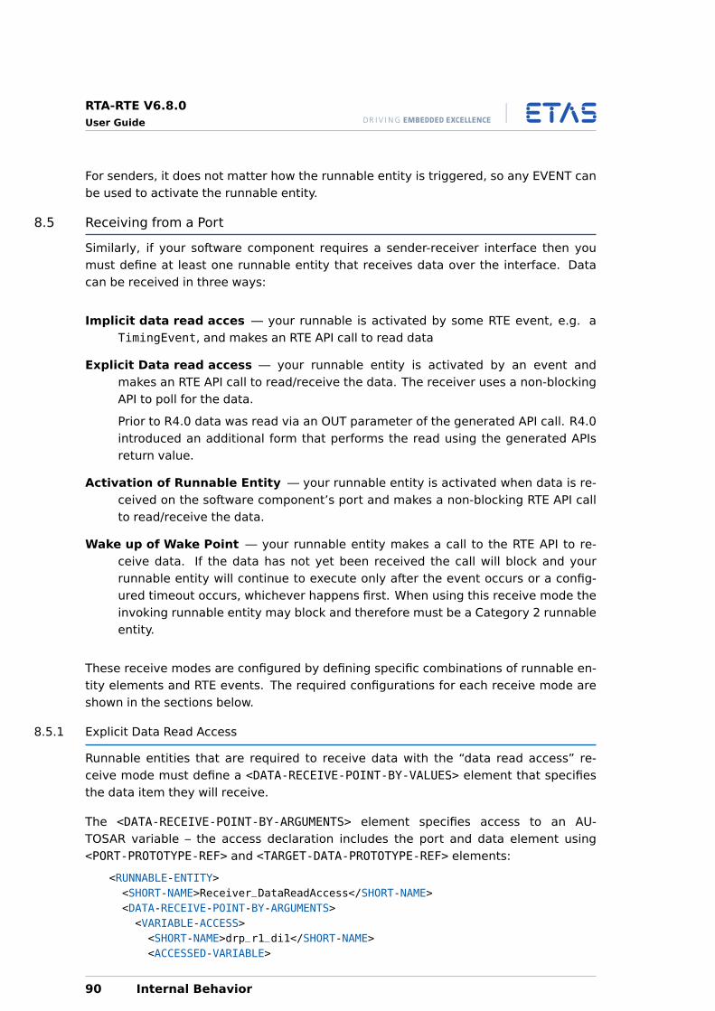
RTA-RTE V6.8.0User Guide
For senders, it does not matter how the runnable entity is triggered, so any EVENT canbe used to activate the runnable entity.
8.5 Receiving from a Port
Similarly, if your software component requires a sender-receiver interface then youmust define at least one runnable entity that receives data over the interface. Datacan be received in three ways:
Implicit data read acces — your runnable is activated by some RTE event, e.g. aTimingEvent, and makes an RTE API call to read data
Explicit Data read access — your runnable entity is activated by an event andmakes an RTE API call to read/receive the data. The receiver uses a non-blockingAPI to poll for the data.
Prior to R4.0 data was read via an OUT parameter of the generated API call. R4.0introduced an additional form that performs the read using the generated APIsreturn value.
Activation of Runnable Entity — your runnable entity is activated when data is re-ceived on the software component’s port and makes a non-blocking RTE API callto read/receive the data.
Wake up of Wake Point — your runnable entity makes a call to the RTE API to re-ceive data. If the data has not yet been received the call will block and yourrunnable entity will continue to execute only after the event occurs or a config-ured timeout occurs, whichever happens first. When using this receive mode theinvoking runnable entity may block and therefore must be a Category 2 runnableentity.
These receive modes are configured by defining specific combinations of runnable en-tity elements and RTE events. The required configurations for each receive mode areshown in the sections below.
8.5.1 Explicit Data Read Access
Runnable entities that are required to receive data with the “data read access” re-ceive mode must define a <DATA-RECEIVE-POINT-BY-VALUES> element that specifiesthe data item they will receive.
The <DATA-RECEIVE-POINT-BY-ARGUMENTS> element specifies access to an AU-TOSAR variable – the access declaration includes the port and data element using<PORT-PROTOTYPE-REF> and <TARGET-DATA-PROTOTYPE-REF> elements:
<RUNNABLE-ENTITY><SHORT-NAME>Receiver_DataReadAccess</SHORT-NAME><DATA-RECEIVE-POINT-BY-ARGUMENTS><VARIABLE-ACCESS><SHORT-NAME>drp_r1_di1</SHORT-NAME><ACCESSED-VARIABLE>
90 Internal Behavior
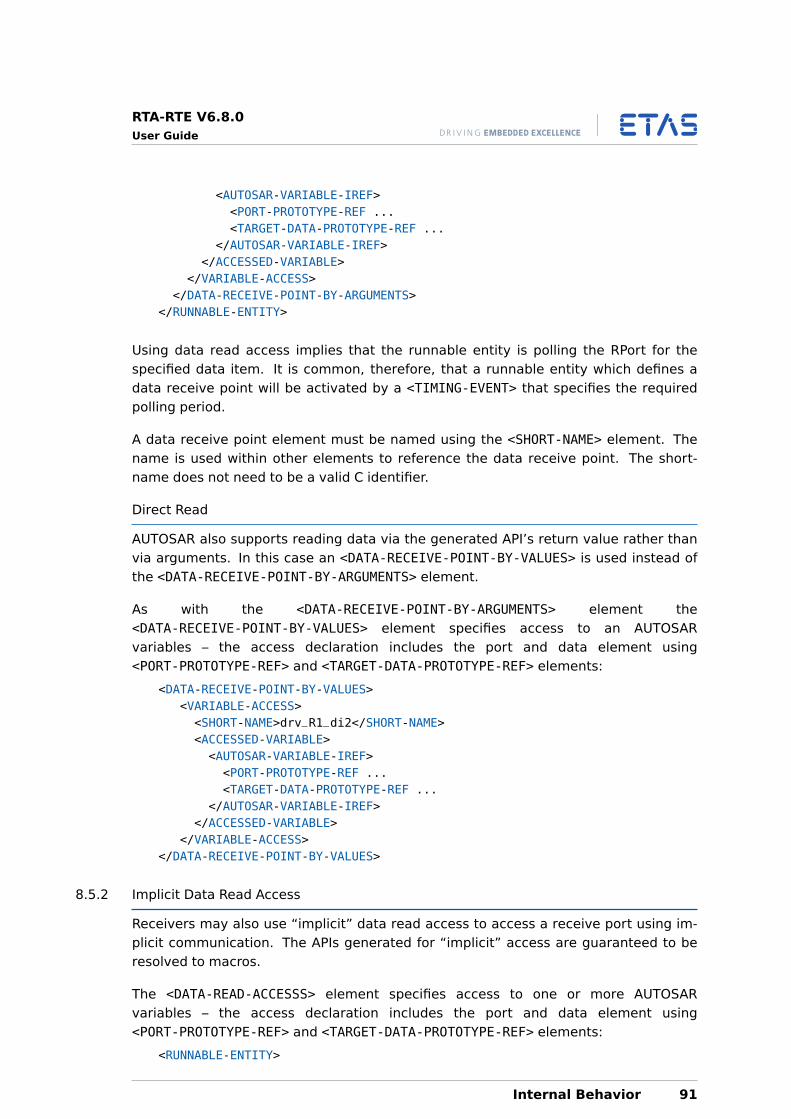
RTA-RTE V6.8.0User Guide
<AUTOSAR-VARIABLE-IREF><PORT-PROTOTYPE-REF ...<TARGET-DATA-PROTOTYPE-REF ...
</AUTOSAR-VARIABLE-IREF></ACCESSED-VARIABLE>
</VARIABLE-ACCESS></DATA-RECEIVE-POINT-BY-ARGUMENTS>
</RUNNABLE-ENTITY>
Using data read access implies that the runnable entity is polling the RPort for thespecified data item. It is common, therefore, that a runnable entity which defines adata receive point will be activated by a <TIMING-EVENT> that specifies the requiredpolling period.
A data receive point element must be named using the <SHORT-NAME> element. Thename is used within other elements to reference the data receive point. The short-name does not need to be a valid C identifier.
Direct Read
AUTOSAR also supports reading data via the generated API’s return value rather thanvia arguments. In this case an <DATA-RECEIVE-POINT-BY-VALUES> is used instead ofthe <DATA-RECEIVE-POINT-BY-ARGUMENTS> element.
As with the <DATA-RECEIVE-POINT-BY-ARGUMENTS> element the<DATA-RECEIVE-POINT-BY-VALUES> element specifies access to an AUTOSARvariables – the access declaration includes the port and data element using<PORT-PROTOTYPE-REF> and <TARGET-DATA-PROTOTYPE-REF> elements:
<DATA-RECEIVE-POINT-BY-VALUES><VARIABLE-ACCESS><SHORT-NAME>drv_R1_di2</SHORT-NAME><ACCESSED-VARIABLE><AUTOSAR-VARIABLE-IREF><PORT-PROTOTYPE-REF ...<TARGET-DATA-PROTOTYPE-REF ...
</AUTOSAR-VARIABLE-IREF></ACCESSED-VARIABLE>
</VARIABLE-ACCESS></DATA-RECEIVE-POINT-BY-VALUES>
8.5.2 Implicit Data Read Access
Receivers may also use “implicit” data read access to access a receive port using im-plicit communication. The APIs generated for “implicit” access are guaranteed to beresolved to macros.
The <DATA-READ-ACCESSS> element specifies access to one or more AUTOSARvariables – the access declaration includes the port and data element using<PORT-PROTOTYPE-REF> and <TARGET-DATA-PROTOTYPE-REF> elements:
<RUNNABLE-ENTITY>
Internal Behavior 91
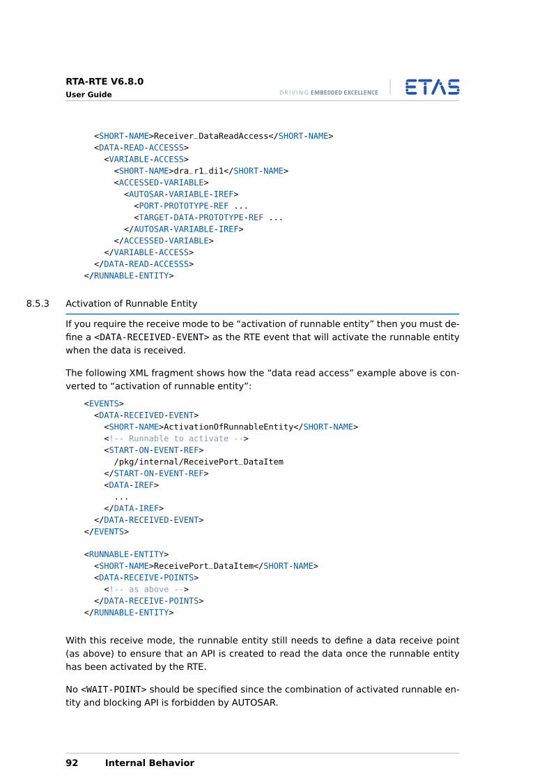
RTA-RTE V6.8.0User Guide
<SHORT-NAME>Receiver_DataReadAccess</SHORT-NAME><DATA-READ-ACCESSS><VARIABLE-ACCESS><SHORT-NAME>dra_r1_di1</SHORT-NAME><ACCESSED-VARIABLE><AUTOSAR-VARIABLE-IREF><PORT-PROTOTYPE-REF ...<TARGET-DATA-PROTOTYPE-REF ...
</AUTOSAR-VARIABLE-IREF></ACCESSED-VARIABLE>
</VARIABLE-ACCESS></DATA-READ-ACCESSS>
</RUNNABLE-ENTITY>
8.5.3 Activation of Runnable Entity
If you require the receive mode to be “activation of runnable entity” then you must de-fine a <DATA-RECEIVED-EVENT> as the RTE event that will activate the runnable entitywhen the data is received.
The following XML fragment shows how the “data read access” example above is con-verted to “activation of runnable entity”:
<EVENTS><DATA-RECEIVED-EVENT><SHORT-NAME>ActivationOfRunnableEntity</SHORT-NAME><!-- Runnable to activate --><START-ON-EVENT-REF>/pkg/internal/ReceivePort_DataItem
</START-ON-EVENT-REF><DATA-IREF>...
</DATA-IREF></DATA-RECEIVED-EVENT>
</EVENTS>
<RUNNABLE-ENTITY><SHORT-NAME>ReceivePort_DataItem</SHORT-NAME><DATA-RECEIVE-POINTS><!-- as above -->
</DATA-RECEIVE-POINTS></RUNNABLE-ENTITY>
With this receive mode, the runnable entity still needs to define a data receive point(as above) to ensure that an API is created to read the data once the runnable entityhas been activated by the RTE.
No <WAIT-POINT> should be specified since the combination of activated runnable en-tity and blocking API is forbidden by AUTOSAR.
92 Internal Behavior
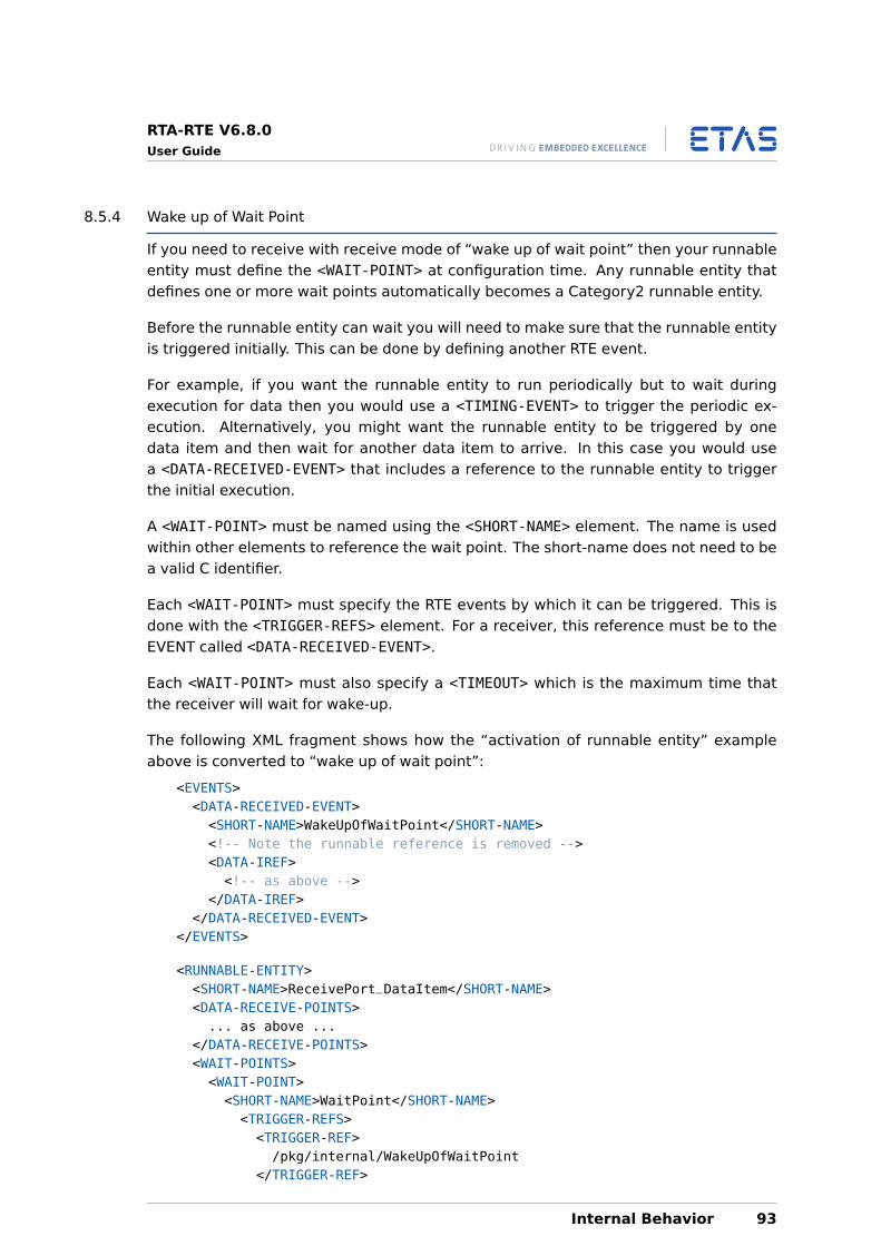
RTA-RTE V6.8.0User Guide
8.5.4 Wake up of Wait Point
If you need to receive with receive mode of “wake up of wait point” then your runnableentity must define the <WAIT-POINT> at configuration time. Any runnable entity thatdefines one or more wait points automatically becomes a Category2 runnable entity.
Before the runnable entity can wait you will need to make sure that the runnable entityis triggered initially. This can be done by defining another RTE event.
For example, if you want the runnable entity to run periodically but to wait duringexecution for data then you would use a <TIMING-EVENT> to trigger the periodic ex-ecution. Alternatively, you might want the runnable entity to be triggered by onedata item and then wait for another data item to arrive. In this case you would usea <DATA-RECEIVED-EVENT> that includes a reference to the runnable entity to triggerthe initial execution.
A <WAIT-POINT> must be named using the <SHORT-NAME> element. The name is usedwithin other elements to reference the wait point. The short-name does not need to bea valid C identifier.
Each <WAIT-POINT> must specify the RTE events by which it can be triggered. This isdone with the <TRIGGER-REFS> element. For a receiver, this reference must be to theEVENT called <DATA-RECEIVED-EVENT>.
Each <WAIT-POINT> must also specify a <TIMEOUT> which is the maximum time thatthe receiver will wait for wake-up.
The following XML fragment shows how the “activation of runnable entity” exampleabove is converted to “wake up of wait point”:
<EVENTS><DATA-RECEIVED-EVENT><SHORT-NAME>WakeUpOfWaitPoint</SHORT-NAME><!-- Note the runnable reference is removed --><DATA-IREF><!-- as above -->
</DATA-IREF></DATA-RECEIVED-EVENT>
</EVENTS>
<RUNNABLE-ENTITY><SHORT-NAME>ReceivePort_DataItem</SHORT-NAME><DATA-RECEIVE-POINTS>... as above ...
</DATA-RECEIVE-POINTS><WAIT-POINTS><WAIT-POINT><SHORT-NAME>WaitPoint</SHORT-NAME><TRIGGER-REFS><TRIGGER-REF>/pkg/internal/WakeUpOfWaitPoint
</TRIGGER-REF>
Internal Behavior 93
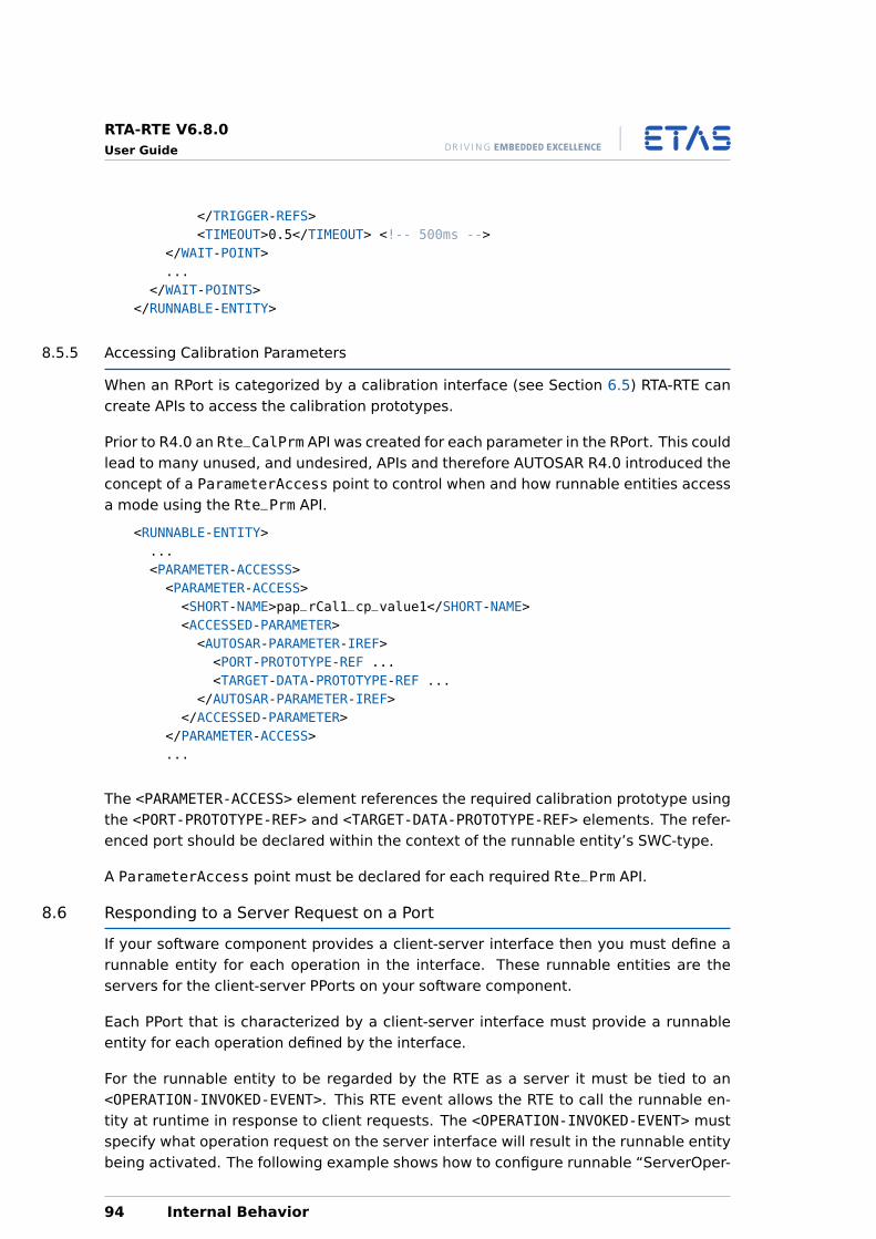
RTA-RTE V6.8.0User Guide
</TRIGGER-REFS><TIMEOUT>0.5</TIMEOUT> <!-- 500ms -->
</WAIT-POINT>...
</WAIT-POINTS></RUNNABLE-ENTITY>
8.5.5 Accessing Calibration Parameters
When an RPort is categorized by a calibration interface (see Section 6.5) RTA-RTE cancreate APIs to access the calibration prototypes.
Prior to R4.0 an Rte_CalPrm API was created for each parameter in the RPort. This couldlead to many unused, and undesired, APIs and therefore AUTOSAR R4.0 introduced theconcept of a ParameterAccess point to control when and how runnable entities accessa mode using the Rte_Prm API.
<RUNNABLE-ENTITY>...<PARAMETER-ACCESSS><PARAMETER-ACCESS><SHORT-NAME>pap_rCal1_cp_value1</SHORT-NAME><ACCESSED-PARAMETER><AUTOSAR-PARAMETER-IREF><PORT-PROTOTYPE-REF ...<TARGET-DATA-PROTOTYPE-REF ...
</AUTOSAR-PARAMETER-IREF></ACCESSED-PARAMETER>
</PARAMETER-ACCESS>...
The <PARAMETER-ACCESS> element references the required calibration prototype usingthe <PORT-PROTOTYPE-REF> and <TARGET-DATA-PROTOTYPE-REF> elements. The refer-enced port should be declared within the context of the runnable entity’s SWC-type.
A ParameterAccess point must be declared for each required Rte_Prm API.
8.6 Responding to a Server Request on a Port
If your software component provides a client-server interface then you must define arunnable entity for each operation in the interface. These runnable entities are theservers for the client-server PPorts on your software component.
Each PPort that is characterized by a client-server interface must provide a runnableentity for each operation defined by the interface.
For the runnable entity to be regarded by the RTE as a server it must be tied to an<OPERATION-INVOKED-EVENT>. This RTE event allows the RTE to call the runnable en-tity at runtime in response to client requests. The <OPERATION-INVOKED-EVENT> mustspecify what operation request on the server interface will result in the runnable entitybeing activated. The following example shows how to configure runnable “ServerOper-
94 Internal Behavior
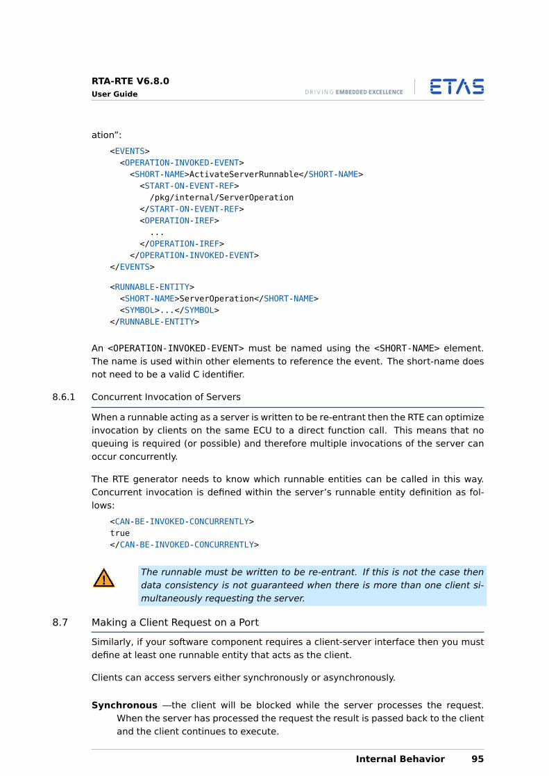
RTA-RTE V6.8.0User Guide
ation”:
<EVENTS><OPERATION-INVOKED-EVENT><SHORT-NAME>ActivateServerRunnable</SHORT-NAME><START-ON-EVENT-REF>/pkg/internal/ServerOperation
</START-ON-EVENT-REF><OPERATION-IREF>...
</OPERATION-IREF></OPERATION-INVOKED-EVENT>
</EVENTS>
<RUNNABLE-ENTITY><SHORT-NAME>ServerOperation</SHORT-NAME><SYMBOL>...</SYMBOL>
</RUNNABLE-ENTITY>
An <OPERATION-INVOKED-EVENT> must be named using the <SHORT-NAME> element.The name is used within other elements to reference the event. The short-name doesnot need to be a valid C identifier.
8.6.1 Concurrent Invocation of Servers
When a runnable acting as a server is written to be re-entrant then the RTE can optimizeinvocation by clients on the same ECU to a direct function call. This means that noqueuing is required (or possible) and therefore multiple invocations of the server canoccur concurrently.
The RTE generator needs to know which runnable entities can be called in this way.Concurrent invocation is defined within the server’s runnable entity definition as fol-lows:
<CAN-BE-INVOKED-CONCURRENTLY>true</CAN-BE-INVOKED-CONCURRENTLY>
The runnable must be written to be re-entrant. If this is not the case thendata consistency is not guaranteed when there is more than one client si-multaneously requesting the server.
8.7 Making a Client Request on a Port
Similarly, if your software component requires a client-server interface then you mustdefine at least one runnable entity that acts as the client.
Clients can access servers either synchronously or asynchronously.
Synchronous —the client will be blocked while the server processes the request.When the server has processed the request the result is passed back to the clientand the client continues to execute.
Internal Behavior 95
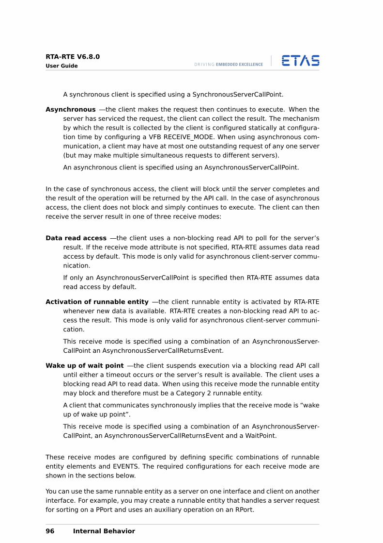
RTA-RTE V6.8.0User Guide
A synchronous client is specified using a SynchronousServerCallPoint.
Asynchronous —the client makes the request then continues to execute. When theserver has serviced the request, the client can collect the result. The mechanismby which the result is collected by the client is configured statically at configura-tion time by configuring a VFB RECEIVE_MODE. When using asynchronous com-munication, a client may have at most one outstanding request of any one server(but may make multiple simultaneous requests to different servers).
An asynchronous client is specified using an AsynchronousServerCallPoint.
In the case of synchronous access, the client will block until the server completes andthe result of the operation will be returned by the API call. In the case of asynchronousaccess, the client does not block and simply continues to execute. The client can thenreceive the server result in one of three receive modes:
Data read access —the client uses a non-blocking read API to poll for the server’sresult. If the receive mode attribute is not specified, RTA-RTE assumes data readaccess by default. This mode is only valid for asynchronous client-server commu-nication.
If only an AsynchronousServerCallPoint is specified then RTA-RTE assumes dataread access by default.
Activation of runnable entity —the client runnable entity is activated by RTA-RTEwhenever new data is available. RTA-RTE creates a non-blocking read API to ac-cess the result. This mode is only valid for asynchronous client-server communi-cation.
This receive mode is specified using a combination of an AsynchronousServer-CallPoint an AsynchronousServerCallReturnsEvent.
Wake up of wait point —the client suspends execution via a blocking read API calluntil either a timeout occurs or the server’s result is available. The client uses ablocking read API to read data. When using this receive mode the runnable entitymay block and therefore must be a Category 2 runnable entity.
A client that communicates synchronously implies that the receive mode is “wakeup of wake up point”.
This receive mode is specified using a combination of an AsynchronousServer-CallPoint, an AsynchronousServerCallReturnsEvent and a WaitPoint.
These receive modes are configured by defining specific combinations of runnableentity elements and EVENTS. The required configurations for each receive mode areshown in the sections below.
You can use the same runnable entity as a server on one interface and client on anotherinterface. For example, you may create a runnable entity that handles a server requestfor sorting on a PPort and uses an auxiliary operation on an RPort.
96 Internal Behavior
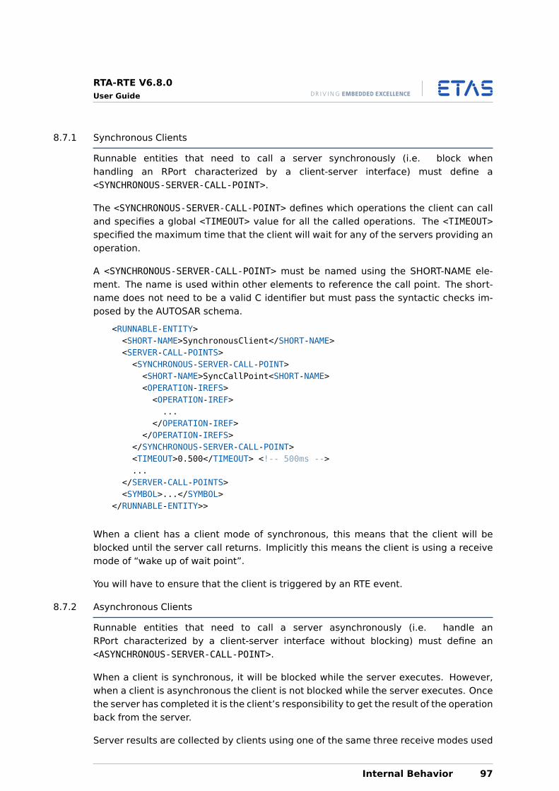
RTA-RTE V6.8.0User Guide
8.7.1 Synchronous Clients
Runnable entities that need to call a server synchronously (i.e. block whenhandling an RPort characterized by a client-server interface) must define a<SYNCHRONOUS-SERVER-CALL-POINT>.
The <SYNCHRONOUS-SERVER-CALL-POINT> defines which operations the client can calland specifies a global <TIMEOUT> value for all the called operations. The <TIMEOUT>specified the maximum time that the client will wait for any of the servers providing anoperation.
A <SYNCHRONOUS-SERVER-CALL-POINT> must be named using the SHORT-NAME ele-ment. The name is used within other elements to reference the call point. The short-name does not need to be a valid C identifier but must pass the syntactic checks im-posed by the AUTOSAR schema.
<RUNNABLE-ENTITY><SHORT-NAME>SynchronousClient</SHORT-NAME><SERVER-CALL-POINTS><SYNCHRONOUS-SERVER-CALL-POINT><SHORT-NAME>SyncCallPoint<SHORT-NAME><OPERATION-IREFS><OPERATION-IREF>...
</OPERATION-IREF></OPERATION-IREFS>
</SYNCHRONOUS-SERVER-CALL-POINT><TIMEOUT>0.500</TIMEOUT> <!-- 500ms -->...
</SERVER-CALL-POINTS><SYMBOL>...</SYMBOL>
</RUNNABLE-ENTITY>>
When a client has a client mode of synchronous, this means that the client will beblocked until the server call returns. Implicitly this means the client is using a receivemode of “wake up of wait point”.
You will have to ensure that the client is triggered by an RTE event.
8.7.2 Asynchronous Clients
Runnable entities that need to call a server asynchronously (i.e. handle anRPort characterized by a client-server interface without blocking) must define an<ASYNCHRONOUS-SERVER-CALL-POINT>.
When a client is synchronous, it will be blocked while the server executes. However,when a client is asynchronous the client is not blocked while the server executes. Oncethe server has completed it is the client’s responsibility to get the result of the operationback from the server.
Server results are collected by clients using one of the same three receive modes used
Internal Behavior 97
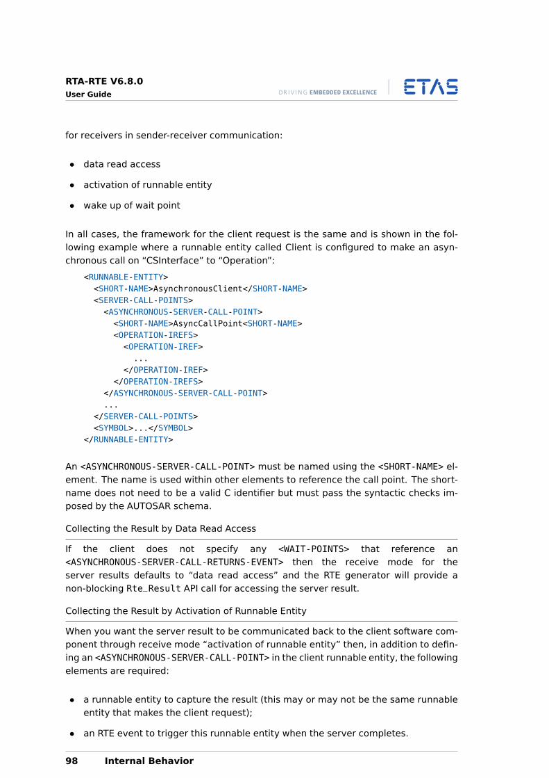
RTA-RTE V6.8.0User Guide
for receivers in sender-receiver communication:
• data read access
• activation of runnable entity
• wake up of wait point
In all cases, the framework for the client request is the same and is shown in the fol-lowing example where a runnable entity called Client is configured to make an asyn-chronous call on “CSInterface” to “Operation”:
<RUNNABLE-ENTITY><SHORT-NAME>AsynchronousClient</SHORT-NAME><SERVER-CALL-POINTS><ASYNCHRONOUS-SERVER-CALL-POINT><SHORT-NAME>AsyncCallPoint<SHORT-NAME><OPERATION-IREFS><OPERATION-IREF>...
</OPERATION-IREF></OPERATION-IREFS>
</ASYNCHRONOUS-SERVER-CALL-POINT>...
</SERVER-CALL-POINTS><SYMBOL>...</SYMBOL>
</RUNNABLE-ENTITY>
An <ASYNCHRONOUS-SERVER-CALL-POINT> must be named using the <SHORT-NAME> el-ement. The name is used within other elements to reference the call point. The short-name does not need to be a valid C identifier but must pass the syntactic checks im-posed by the AUTOSAR schema.
Collecting the Result by Data Read Access
If the client does not specify any <WAIT-POINTS> that reference an<ASYNCHRONOUS-SERVER-CALL-RETURNS-EVENT> then the receive mode for theserver results defaults to “data read access” and the RTE generator will provide anon-blocking Rte_Result API call for accessing the server result.
Collecting the Result by Activation of Runnable Entity
When you want the server result to be communicated back to the client software com-ponent through receive mode “activation of runnable entity” then, in addition to defin-ing an <ASYNCHRONOUS-SERVER-CALL-POINT> in the client runnable entity, the followingelements are required:
• a runnable entity to capture the result (this may or may not be the same runnableentity that makes the client request);
• an RTE event to trigger this runnable entity when the server completes.
98 Internal Behavior
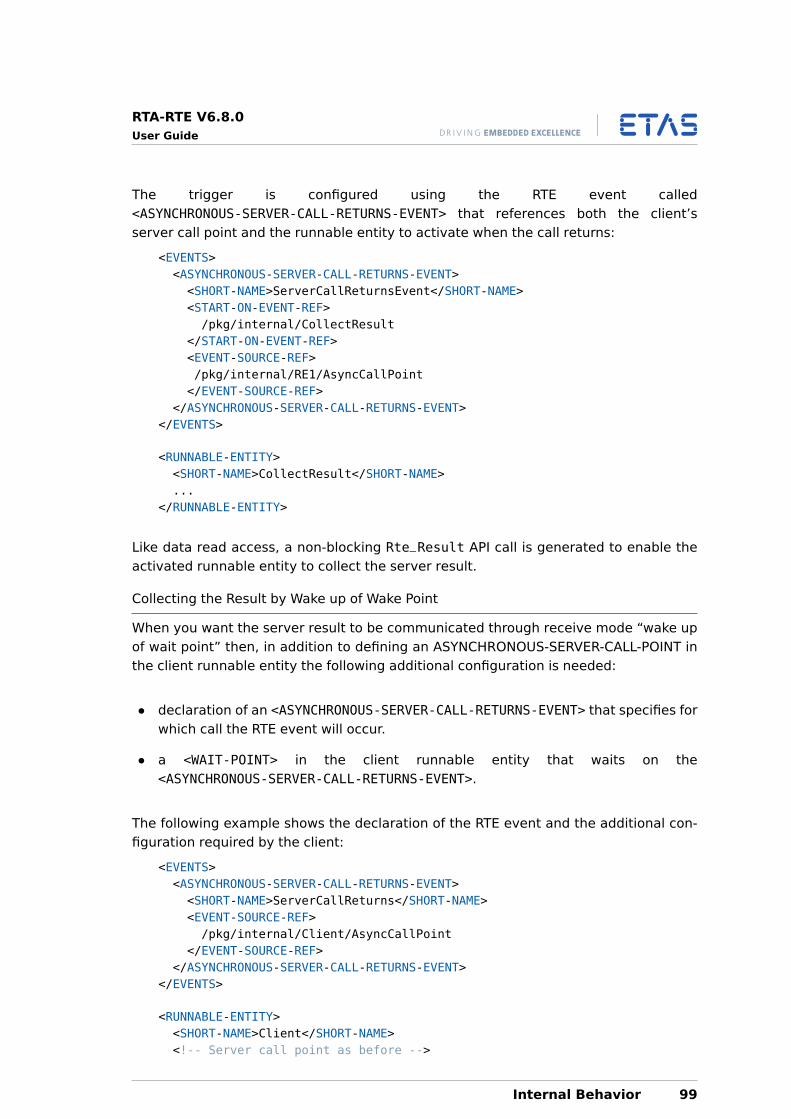
RTA-RTE V6.8.0User Guide
The trigger is configured using the RTE event called<ASYNCHRONOUS-SERVER-CALL-RETURNS-EVENT> that references both the client’sserver call point and the runnable entity to activate when the call returns:
<EVENTS><ASYNCHRONOUS-SERVER-CALL-RETURNS-EVENT><SHORT-NAME>ServerCallReturnsEvent</SHORT-NAME><START-ON-EVENT-REF>/pkg/internal/CollectResult
</START-ON-EVENT-REF><EVENT-SOURCE-REF>/pkg/internal/RE1/AsyncCallPoint</EVENT-SOURCE-REF>
</ASYNCHRONOUS-SERVER-CALL-RETURNS-EVENT></EVENTS>
<RUNNABLE-ENTITY><SHORT-NAME>CollectResult</SHORT-NAME>...
</RUNNABLE-ENTITY>
Like data read access, a non-blocking Rte_Result API call is generated to enable theactivated runnable entity to collect the server result.
Collecting the Result by Wake up of Wake Point
When you want the server result to be communicated through receive mode “wake upof wait point” then, in addition to defining an ASYNCHRONOUS-SERVER-CALL-POINT inthe client runnable entity the following additional configuration is needed:
• declaration of an <ASYNCHRONOUS-SERVER-CALL-RETURNS-EVENT> that specifies forwhich call the RTE event will occur.
• a <WAIT-POINT> in the client runnable entity that waits on the<ASYNCHRONOUS-SERVER-CALL-RETURNS-EVENT>.
The following example shows the declaration of the RTE event and the additional con-figuration required by the client:
<EVENTS><ASYNCHRONOUS-SERVER-CALL-RETURNS-EVENT><SHORT-NAME>ServerCallReturns</SHORT-NAME><EVENT-SOURCE-REF>/pkg/internal/Client/AsyncCallPoint
</EVENT-SOURCE-REF></ASYNCHRONOUS-SERVER-CALL-RETURNS-EVENT>
</EVENTS>
<RUNNABLE-ENTITY><SHORT-NAME>Client</SHORT-NAME><!-- Server call point as before -->
Internal Behavior 99
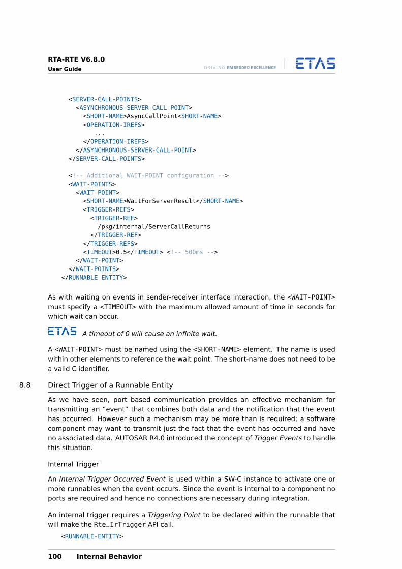
RTA-RTE V6.8.0User Guide
<SERVER-CALL-POINTS><ASYNCHRONOUS-SERVER-CALL-POINT><SHORT-NAME>AsyncCallPoint<SHORT-NAME><OPERATION-IREFS>
...</OPERATION-IREFS>
</ASYNCHRONOUS-SERVER-CALL-POINT></SERVER-CALL-POINTS>
<!-- Additional WAIT-POINT configuration --><WAIT-POINTS><WAIT-POINT><SHORT-NAME>WaitForServerResult</SHORT-NAME><TRIGGER-REFS><TRIGGER-REF>/pkg/internal/ServerCallReturns
</TRIGGER-REF></TRIGGER-REFS><TIMEOUT>0.5</TIMEOUT> <!-- 500ms -->
</WAIT-POINT></WAIT-POINTS>
</RUNNABLE-ENTITY>
As with waiting on events in sender-receiver interface interaction, the <WAIT-POINT>must specify a <TIMEOUT> with the maximum allowed amount of time in seconds forwhich wait can occur.
A timeout of 0 will cause an infinite wait.
A <WAIT-POINT> must be named using the <SHORT-NAME> element. The name is usedwithin other elements to reference the wait point. The short-name does not need to bea valid C identifier.
8.8 Direct Trigger of a Runnable Entity
As we have seen, port based communication provides an effective mechanism fortransmitting an “event” that combines both data and the notification that the eventhas occurred. However such a mechanism may be more than is required; a softwarecomponent may want to transmit just the fact that the event has occurred and haveno associated data. AUTOSAR R4.0 introduced the concept of Trigger Events to handlethis situation.
Internal Trigger
An Internal Trigger Occurred Event is used within a SW-C instance to activate one ormore runnables when the event occurs. Since the event is internal to a component noports are required and hence no connections are necessary during integration.
An internal trigger requires a Triggering Point to be declared within the runnable thatwill make the Rte_IrTrigger API call.
<RUNNABLE-ENTITY>
100 Internal Behavior
RTA-RTE V6.8.0User Guide
<SHORT-NAME>re_te1</SHORT-NAME>...<INTERNAL-TRIGGERING-POINTS><INTERNAL-TRIGGERING-POINT><SHORT-NAME>itp3</SHORT-NAME>
</INTERNAL-TRIGGERING-POINT>...
Then RTA-RTE will create Rte_IrTrigger_re1_itp3 API based on the short name of thetriggering point. The short name is also used to identify the internal trigger point asthe event source within an Internal Trigger Occurred Event element:
<INTERNAL-TRIGGER-OCCURRED-EVENT><SHORT-NAME>itp3</SHORT-NAME><START-ON-EVENT-REF ...<EVENT-SOURCE-REF>/pkg/swc/ib/re_te1/itp3</EVENT-SOURCE-REF>
</INTERNAL-TRIGGER-OCCURRED-EVENT>
Multiple Internal Trigger Occurred events can reference the same triggering point andthus one internal trigger API can start multiple runnables. The runnables to be startedare specified by in response to an internal triggering event are specified using one ormore Internal Trigger Occurred Event elements.
When a SW-C indicates the event has occurred by invoking the Rte_IrTrigger APIcreated for the internal triggering point RTA-RTE activates all runnables specified byInternal Trigger Occurred events that reference the triggering point. For runnableswithout a minimum start inteval and without a task referenced in the event’sRteEventMapping this activation is by a direct function call.
External Trigger
In contrast to internal triggering, External Trigger Occurred Event is used by entitiesexternal to a SW-C instance to activate runnables. Since the event is external to acomponent ports categorized by a trigger interface are used hence must be connectedduring integration.
An external trigger requires a port categorized by a Trigger Interface (see Section 6.6)to be declared within the SW-C. For SW-Cs that indicate the event has occurred byinvoking the Rte_Trigger API call a provided port is necessary whereas SW-Cs thatrespond to the event use a required port.
<R-PORT-PROTOTYPE><SHORT-NAME>r2</SHORT-NAME><REQUIRED-INTERFACE-TREF>/pkg/itf</REQUIRED-INTERFACE-TREF>
</R-PORT-PROTOTYPE>
Where itf is a trigger interface, for example:
<TRIGGER-INTERFACE><SHORT-NAME>itf</SHORT-NAME><TRIGGERS>
Internal Behavior 101
RTA-RTE V6.8.0User Guide
<TRIGGER><SHORT-NAME>trig1</SHORT-NAME>
</TRIGGER><TRIGGER><SHORT-NAME>trig2</SHORT-NAME>
</TRIGGER></TRIGGERS>
</TRIGGER-INTERFACE>
The short name of the port and the short name of the trigger within the interface areused to form the name of the Rte_Trigger API. Within a SW-C, multiple External TriggerOccurred Events can reference the same port/trigger and thus one external trigger APIcan start multiple runnables. The provided port can be connected to multiple ports indifferent SW-Cs.
<EXTERNAL-TRIGGER-OCCURRED-EVENT><SHORT-NAME>etp2</SHORT-NAME><START-ON-EVENT-REF>/pkg/swc/IB/re</START-ON-EVENT-REF><TRIGGER-IREF><CONTEXT-R-PORT-REF>/pkg/swc/rPort</CONTEXT-R-PORT-REF><TARGET-TRIGGER-REF>/pkg/itf/trig1</TARGET-TRIGGER-REF>
</TRIGGER-IREF></EXTERNAL-TRIGGER-OCCURRED-EVENT>
When a SW-C with a provide trigger port indicates the event has occurred by invokingthe Rte_Trigger API created for the external trigger RTA-RTE activates all runnablesspecified by connected External Trigger Occurred events that reference the triggeringport/trigger. For runnables without a minimum start inteval and without a task refer-enced in the event’s RteEventMapping this activation is by a direct function call.
8.9 Exclusive Areas
Software components that need to provide mutual exclusion over data shared by two(or more) of their runnable entities do so by configuring exclusive areas
The RTE generator uses exclusive area configuration to create operating system con-figuration files and to optimize exclusive areas. For example, if the only componentsthat access a region are mapped to the same task then the entire region can be elided.
Exclusive areas are defined in the XML configuration and are associated with therunnable entities that use them.
8.9.1 Configuration
Each <SWC-INTERNAL-BEHAVIOR> element must name the <EXCLUSIVE-AREAS> it uses.Note that this means that the scope of any exclusive areas that you define is the soft-ware component instance. It is not possible to define exclusive areas that cross soft-ware component boundaries1.
1Data that is shared between multiple software-component instances which can potentially be accessedconcurrently should be encapsulated in its own component and then normal Sender-Receiver or Client-
102 Internal Behavior
RTA-RTE V6.8.0User Guide
Each exclusive-area defined within an internal behavior definition must be named usingthe <SHORT-NAME> element. The name is used within other elements to reference thesoftware component type and to form the “handle” by which the exclusive area is ac-cessed at run-time. The short-name of an exclusive area should be a valid C identifier.
<INTERNAL-BEHAVIOR><EXCLUSIVE-AREAS><EXCLUSIVE-AREA><SHORT-NAME>ExclusiveArea</SHORT-NAME>
</EXCLUSIVE-AREA>...
</EXCLUSIVE-AREAS><INTERNAL-BEHAVIOR>
RTA-RTE can be informed how to implement the exclusive area with anRteExclusiveAreaImplementation element within the ECUC description.
You should create an exclusive area implementation element for each ex-clusive area. If omitted RTA-RTE defaults to “OS resource” implementationstrategy.
A different exclusive area implementation method can be set for each exclusive areaand SWC instance.
The InterruptBlocking method will cause all OS interrupts to be blockedin the worst case for the longest execution time of the protected criticalsection.
8.9.2 Usage
Each runnable entity in your <INTERNAL-BEHAVIOR> section can declare if it uses oneof your named exclusive areas and how it uses the area at runtime with the followingelements:
• Explicit access—a <RUNNABLE-ENTITY-CAN-ENTER-EXCLUSIVE-AREA> elementdefines exclusive areas accessed using an explicit API. The area’s name forms partof the generated API (explicit access is similar to a standard resource in OSEK OS).
• Implicit access—a <RUNNABLE-ENTITY-RUNS-IN-EXCLUSIVE-AREA> element de-fines an exclusive area that is locked automatically before the runnable entity exe-cutes and is released when the runnable entity terminates or waits for an RTE event(similar to an internal resource in OSEK OS). In this case there is no user accessibleway of explicitly entering and leaving the defined exclusive area.
The configuration of both types of the exclusive area is shown below:
<RUNNABLE-ENTITY><SHORT-NAME>NeedsExclusiveAreas</SHORT-NAME><RUNNABLE-ENTITY-CAN-ENTER-EXCLUSIVE-AREAS>
Server communication used to access the data.
Internal Behavior 103
RTA-RTE V6.8.0User Guide
<RUNNABLE-ENTITY-CAN-ENTER-EXCLUSIVE-AREA><EXCLUSIVE-AREA-REF>/pkg/internal/ExclusiveArea
</EXCLUSIVE-AREA-REF></RUNNABLE-ENTITY-CAN-ENTER-EXCLUSIVE-AREA>
</RUNNABLE-ENTITY-CAN-ENTER-EXCLUSIVE-AREAS><RUNNABLE-ENTITY-RUNS-IN-EXCLUSIVE-AREAS><RUNNABLE-ENTITY-RUNS-IN-EXCLUSIVE-AREA><EXCLUSIVE-AREA-REF>
/pkg/internal/AnotherExclusiveArea</EXCLUSIVE-AREA-REF>
</RUNNABLE-ENTITY-RUNS-IN-EXCLUSIVE-AREA></RUNNABLE-ENTITY-RUNS-IN-EXCLUSIVE-AREAS>
<RUNNABLE-ENTITY>
8.9.3 Implementation Methods
RTA-RTE supports the following implementation mechanisms for exclusive areas:
• OS resource locking.
• OS interrupt blocking.
• All interrupt blocking.
• Cooperative Runnable Placement.
OS Resource
When the OS resource implementation method is selected for an exclusive area in-stance RTA-RTE will attempt to use an OS resource is used to implement the exclusivearea.
If an exclusive area implementation element explicitly references an OsResource in theinput then RTA-RTE will use that resource unless access can be optimized. However if noOsResource is selected then RTA-RTE will create a suitable standard/internal resource.The naming of this resource is described in the RTA-RTE Reference Manual.
When using OS resources RTA-RTE will attempt to optimize the implementation ofRte_Enter and Rte_Exit APIs to try and eliminate use of the resource entirely. Thisoptimization is possible when RTA-RTE observes that data consistency is guaranteed byother means, namely:
• All accessors are located in the same task, or
• All accessing tasks are non-preemptive, or
• All accessing tasks have the same priority, or
• All accessing tasks are declared in the input as accessing the same internal re-source.
104 Internal Behavior
RTA-RTE V6.8.0User Guide
When an accessing runnable is declared as having implicit (“run inside”) access tothe exclusive area RTA-RTE will insert resource access around runnable calls in thegenerated task body or use an internal resource if all accessors use implicit access andno other runnables are mapped to the relevant tasks.
OS Interrupt Blocking
When the OS interrupt implementation method is selected for an exclusive area in-stance RTA-RTE will use suspend/resume of OS interrupts to implement the exclusivearea.
When using OS interrupt blocking RTA-RTE optimizes the APIs to null access if datainconsistency cannot occur.
Avoid using any RTE APIs when OS interrupts are blocked. Failure to adhereto this restriction may result in context switches not being recognized by theOS when interrupt handling is resumed.
All Interrupt Blocking
AUTOSAR allows an exclusive area to block all interrupts, not just OS interrupts, Whenthe All interrupt implementation method is selected for an exclusive area instance.
When using all interrupt blocking RTA-RTE will optimize API calls to null access if datainconsistency cannot occur.
Avoid using any RTE APIs when OS interrupts are blocked. Failure to adhereto this restriction may result in context switches not being recognized by theOS when interrupt handling is resumed.
Non-preemptive Tasks
When the non-preemptive task implementation method is selected for an exclusivearea instance RTA-RTE assumes that data consistency is guaranteed by external meansand that therefore all access to the exclusive area can be optimized to null access.
Cooperative Runnable Placement
When the cooperative runnable placement implementation method is selected for anexclusive area instance RTA-RTE ensures that tasks containing runnables accessing anexclusive area with implementation method cooperative runnable placement cannotpreempt other tasks with runnables accessing the same exclusive area instance whena runnable is active. Unlike the non-preemptive tasks implementation method preemp-tion is allowed when runnables are not running, e.g. between runnables.
If required to implement data consistency and no OsResource is explicit selected withinan EA implementation element in the ECUC then RTA-RTE will create a suitable stan-dard/internal resource. The naming of this resource is described in the RTA-RTE Refer-ence Manual.
Internal Behavior 105
RTA-RTE V6.8.0User Guide
When using cooperative runnable placement RTA-RTE will optimize the implementation,e.g. when all accessors are located in the same task or all accessing tasks are non-preemptive, to null access since data consistency is then assured by external means.The decision on whether to optimize is the same as for the OS resource implementationmethod.
The cooperative runnable placement is best used when the accessing runnables aredeclared as having implicit (“run inside”) access the exclusive area since RTA-RTE willthen insert resource access around runnable calls in the generated task body or useinternal resources as appropriate. If accessing runnables are declared as explicit access(“can enter”) the exclusive area, i.e. will use the Rte_Enter API, then RTA-RTE cannotuse an internal resource to implement cooperative runnable placement since this wouldblock access for the entire runnable.
8.10 Inter-Runnable Variables
The RTE allows the configuration of inter-runnable variables that provide a way forrunnable entities to communicate between themselves. While this is possible throughuser code and shared variable access (protected by exclusive areas - see Section 8.9)this can be inefficient when handling primitive data types since the exclusive area APIcalls are typically mapped onto the underlying Operating System’s resource controlmechanism.
Therefore, the RTE provides lightweight mechanisms for inter-runnable communicationthat is equivalent in semantics to implicit/explicit sender-receiver communication butwithin the scope of the software component instance.
8.10.1 Defining Variables
Each software component can define a number of variables at the scope of the com-ponent and how access is provided to the variable at runtime, either using explicit orimplicit communication:
8.10.2 Declaring Read and Write Access
Each runnable must explicitly specify whether it reads or writes a variable at runtime.Access is declared using <READ-LOCAL-VARIABLES> and <WRITTEN-LOCAL-VARIABLES>elements that reference an inter-runnable variable defined within the SWC-type, forexample:
<WRITTEN-LOCAL-VARIABLES><VARIABLE-ACCESS><SHORT-NAME>xx</SHORT-NAME><ACCESSED-VARIABLE><LOCAL-VARIABLE-REF>/pkg/swc/IB/irvex1</LOCAL-VARIABLE-REF>
</ACCESSED-VARIABLE></VARIABLE-ACCESS>
</WRITTEN-LOCAL-VARIABLES>
106 Internal Behavior
RTA-RTE V6.8.0User Guide
8.11 Accessing Modes
A mode user/manager can query the current application mode for a mode instabceusing the Rte_Mode API as well as have runnable entities activated as a result of amode switch event.
Prior to R4.0 a Rte_Mode API was created by RTA-RTE for all possible mode accesses.This could lead to many unused, and undesired, APIs and therefore in R4.0 AUTOSAR in-troduced the concept of a ModeAccessPoint to control when and how runnable entitiesaccess a mode using the Rte_Mode API.
A ModeAccessPoint is declared using the <MODE-ACCESS-POINT> element within thecontext of the runnable that will invoke the API:
<MODE-ACCESS-POINTS><MODE-ACCESS-POINT><MODE-GROUP-IREF><R-MODE-GROUP-IN-ATOMIC-SWC-INSTANCE-REF><CONTEXT-R-PORT-REF>/pkg/swc/r1</CONTEXT-R-PORT-REF><TARGET-MODE-GROUP-REF>/pkg/if/mdgp1</TARGET-MODE-GROUP-REF>
</R-MODE-GROUP-IN-ATOMIC-SWC-INSTANCE-REF></MODE-GROUP-IREF>
</MODE-ACCESS-POINT></MODE-ACCESS-POINTS>
A ModeAccessPoint must be declared for each required Rte_Mode API. The access pointcan reference either required or provided mode groups.
8.12 Per-instance Memory
Software component instances may have state that has a lifetime that is longer thanthe execution of any of its constituent runnable entities. Global variables cannot beused for maintaining state because more than one instance of a software componentmay be integrated onto the same ECU and there is no concurrency control mechanismbetween instances of software components.
Per-instance memory allows software components to define one or more typed regionsof memory that can be accessed by the runnable entities at runtime.
The configuration of a per-instance memory section is shown below:
<INTERNAL-BEHAVIOR>...<PER-INSTANCE-MEMORYS><PER-INSTANCE-MEMORY><SHORT-NAME>VAL</SHORT-NAME><TYPE>dataType</TYPE><TYPE-DEFINITION>uint8</TYPE-DEFINITION>
</PER-INSTANCE-MEMORY></PER-INSTANCE-MEMORYS>...
</INTERNAL-BEHAVIOR>
Internal Behavior 107
RTA-RTE V6.8.0User Guide
Each per-instance memory must be named using the <SHORT-NAME> element. Thename allocated at configuration is the same name you will use to access the per-instance memory in your code. The short-name of a per-instance memory should be avalid C identifier.
The <TYPE> and <TYPE-DEFINITION> elements are used to, respectively, name anddefine the data type created by RTA-RTE for the per-instance memory. The short-nameof a per-instance memory should be a valid C identifier. The type definition must be avalid C type definition suitable for direct inclusion in a type definition as follows:
typedef ...TYPE-DEFINITION... ...TYPE...;
The example per-instance memory definition results on the following type definition:
typedef uint8 dataType;
Within the generated RTE, RTA-RTE allocates RAM for each per-instance memory. If theECUC specifies an NVRamAllocation container that references a per-instance mem-ory then the name is the RamBlockLocationSymbol. Otherwise, RTA-RTE constructs aunique name.
8.13 Port Options
The port options element permits:
• Enable/disable indirect API for a port.
• Port-defined arguments to be specified for client-server communication.
• Enabling application code to take the “address” of RTE API functions generated fora port.
8.13.1 Indirect API
If the indirect API generated is not required for a port it can be disabled through “portoptions” within the internal behavior:
<PORT-API-OPTIONS><PORT-API-OPTION><INDIRECT-API>false</INDIRECT-API><PORT-REF DEST="...">/pkg/component/port</PORT-REF>
</PORT-API-OPTION><PORT-API-OPTIONS>
Disabling the indirect API can reduce the size of the component data structure (andhence save ROM) when a SWC does not support multiple instances.
8.13.2 Port-defined Arguments
When the same runnable is used as the server for multiple ports it is necessary to beable to identify which is the port that has caused the server invocation. Port-defined
108 Internal Behavior
RTA-RTE V6.8.0User Guide
arguments permit a server to be supplied with default arguments based on the portthrough which it is invoked.
<PORT-API-OPTIONS><PORT-API-OPTION><PORT-ARG-VALUES><INTEGER-LITERAL><SHORT-NAME>pdav_1</SHORT-NAME><TYPE-TREF DEST="...">/pkg/SInt16</TYPE-TREF><VALUE>1</VALUE>
</INTEGER-LITERAL>...
</PORT-ARG-VALUES><PORT-REF DEST="...">/pkg/component/pport</PORT-REF>
</PORT-API-OPTION>...
8.13.3 Enable “Take Address”
A port option can be used to ensure that RTE APIs are generated in a way that theiraddress can be taken at run-time:
<PORT-API-OPTIONS><PORT-API-OPTION><ENABLE-TAKE-ADDRESS>true</ENABLE-TAKE-ADDRESS><PORT-REF DEST="...">/pkg/component/port</PORT-REF>
</PORT-API-OPTION><PORT-API-OPTIONS>
If not specified, RTA-RTE assumes that <ENABLE-TAKE-ADDRESS> is false.
8.14 Supporting Multiple Instantiation
By default, software components will only support the creation of a single softwarecomponent instance. If you want to support multiple instantiation then this must bedeclared in the <INTERNAL-BEHAVIOR> clause:
<SUPPORTS-MULTIPLE-INSTANTIATION>true
</SUPPORTS-MULTIPLE-INSTANTIATION>
The element takes the values of “true” indicating that multiple instantiation is sup-ported or “false” indicting that multiple instantiation is not supported.
If the <SUPPORTS-MULTIPLE-INSTANTIATION> element is omitted, RTA-RTE assumesthat the software-component does not support multiple instantiation.
The AUTOSAR 4.x feature of STATIC-MEMORYS is only available in Internal-Behaviors that are single-instantated. See errors 2469 and 2470 for moreinformation.
Internal Behavior 109
RTA-RTE V6.8.0User Guide
8.15 Memory Allocation
RTA-RTE uses the AUTOSAR memory abstraction scheme when declaringRunnableEntitys. A Memory Allocation Keyword is chosen according to theSwAddrMethod for the RunnableEntity. If the RunnableEntity on the input ref-erences a swAddrMethod then its shortName is used for the Memory AllocationKeyword; otherwise RTA-RTE uses the AUTOSAR specified SwAddrMethod CODE.
For example:
<RUNNABLE-ENTITY><SHORT-NAME>re2</SHORT-NAME><SW-ADDR-METHOD-REF>/pkg/METHOD1</SW-ADDR-METHOD-REF><SYMBOL>swcA_re1</SYMBOL>...
The resultant definition of the runnable generated by RTA-RTE in the SWC type’s appli-cation header file then uses the appropriate section start/stop definitions:
#define swcA_START_SEC_METHOD1#include "swcA_MemMap.h"FUNC(void, swcA_METHOD1) swcA_re1(void);#define swcA_STOP_SEC_METHOD1#include "swcA_MemMap.h"
This applies to ASW only; this behaviour is not specified for BSW.
110 Internal Behavior
RTA-RTE V6.8.0User Guide
9 Modes
The previous chapters have explored how an AUTOSAR software-component type canbe defined and configured. In this chapter you will learn how to define applicationmodes that can be used by software-components to control the execution of runnableentities.
9.1 Defining Modes
Modes are declared within a <MODE-DECLARATION-GROUP> contained within an<AR-PACKAGE> element.
<AR-PACKAGE><SHORT-NAME>MyModes</SHORT-NAME><ELEMENTS><MODE-DECLARATION-GROUP>...
</MODE-DECLARATION-GROUP></ELEMENTS>
</AR-PACKAGE>
The <MODE-DECLARATION-GROUP> element is used to declare one or more modes thatare subsequently used by interface declarations.
<MODE-DECLARATION-GROUP><SHORT-NAME>Modes</SHORT-NAME><INITIAL-MODE-REF>/pkg/Modes/iMode</INITIAL-MODE-REF><MODE-DECLARATIONS><MODE-DECLARATION><SHORT-NAME>iMode</SHORT-NAME>
</MODE-DECLARATION><MODE-DECLARATION><SHORT-NAME>runMode</SHORT-NAME>
</MODE-DECLARATION></MODE-DECLARATIONS>
</MODE-DECLARATION-GROUP>
One mode within a <MODE-DECLARATION-GROUP> element is marked as the group’s ini-tial mode through the <INITIAL-MODE-REF>. Mode switch events that are attached tothe ENTRY of an initial mode are triggered by RTA-RTE when the RTE is started usingRte_Start.
A <MODE-DECLARATION-GROUP> can be used (referenced) by multiple sender-receiverinterfaces and therefore inherently used by multiple software-components.
9.2 Mode Communication
Modes are communicated using mode-switch interfaces. Each mode-switch interfacecan specify exactly one mode declaration group prototype that defines the AUTOSARmodes communicated over the interface.
<MODE-SWITCH-INTERFACE><SHORT-NAME>ModeInterface</SHORT-NAME>
Modes 111
RTA-RTE V6.8.0User Guide
<MODE-GROUP><SHORT-NAME>mdg1</SHORT-NAME><TYPE-TREF DEST="...">/MyModes/Modes</TYPE-TREF>
</MODE-GROUP>...
<MODE-SWITCH-INTERFACE>
A mode-switch interface can contain exactly one mode declaration group prototypedefined using the <MODE_GROUP> element.
Each <MODE-DECLARATION-GROUP-PROTOTYPE> or <MODE_GROUP> element must specify:
• the <SHORT-NAME> that you will use to refer to the item within references from otherelements.
• a <TYPE-TREF> reference to the mode declaration group.
9.2.1 Mode Managers and Mode Users
A software-component can be either1 a mode manager responsible for requesting aswitch to a new mode or a mode user activated in response to a mode switch.
A software-component declares itself as a mode manager by providing a port catego-rized by a sender-receiver interface containing a mode declaration group prototype anddeclaring a mode switch point. The software-component can then use the Rte_SwitchAPI to request that a mode switch occurs as well as have runnable entities activated asa result of a mode switch event.
A software-component declares itself as a mode user by requiring a port categorizedby a sender-receiver interface containing a mode declaration group prototype.
A mode manager is connected, using assembly connectors, to the mode users.
9.2.2 Mode Queues
When a mode manager initiates a mode switch RTA-RTE will being processing the re-quest immediately as long as no mode switch is currently in progress for the modeinstance. However if the switch cannot begin then is is placed in a queue of modeswitch requests and handled when the current switch is complete.
RTA-RTE eliminates queues when they are not required; for example if noModeSwitchEvents are defined for the mode instance.
The length of the queue can be defined for each mode manager. For SWCs the lengthis defined by the provided port’s com-spec element, for example to specify a queuelength of three entries:
<PROVIDED-COM-SPECS><MODE-SWITCH-SENDER-COM-SPEC>
1It possible for the same software-component to be simultaneously a mode manager and a mode userif it contains both provided and required ports.
112 Modes
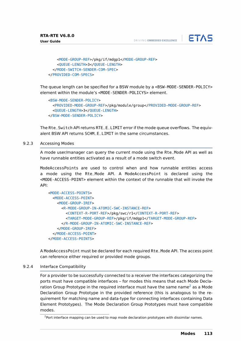
RTA-RTE V6.8.0User Guide
<MODE-GROUP-REF>/pkg/if/mdgp1</MODE-GROUP-REF><QUEUE-LENGTH>3</QUEUE-LENGTH>
</MODE-SWITCH-SENDER-COM-SPEC></PROVIDED-COM-SPECS>
The queue length can be specified for a BSW module by a <BSW-MODE-SENDER-POLICY>element within the module’s <MODE-SENDER-POLICYS> element.
<BSW-MODE-SENDER-POLICY><PROVIDED-MODE-GROUP-REF>/pkg/module/group</PROVIDED-MODE-GROUP-REF><QUEUE-LENGTH>3</QUEUE-LENGTH>
</BSW-MODE-SENDER-POLICY>
The Rte_Switch API returns RTE_E_LIMIT error if the mode queue overflows. The equiv-alent BSW API returns SCHM_E_LIMIT in the same circumstances.
9.2.3 Accessing Modes
A mode user/manager can query the current mode using the Rte_Mode API as well ashave runnable entities activated as a result of a mode switch event.
ModeAccessPoints are used to control when and how runnable entities accessa mode using the Rte_Mode API. A ModeAccessPoint is declared using the<MODE-ACCESS-POINT> element within the context of the runnable that will invoke theAPI:
<MODE-ACCESS-POINTS><MODE-ACCESS-POINT><MODE-GROUP-IREF><R-MODE-GROUP-IN-ATOMIC-SWC-INSTANCE-REF><CONTEXT-R-PORT-REF>/pkg/swc/r1</CONTEXT-R-PORT-REF><TARGET-MODE-GROUP-REF>/pkg/if/mdgp1</TARGET-MODE-GROUP-REF>
</R-MODE-GROUP-IN-ATOMIC-SWC-INSTANCE-REF></MODE-GROUP-IREF>
</MODE-ACCESS-POINT></MODE-ACCESS-POINTS>
A ModeAccessPoint must be declared for each required Rte_Mode API. The access pointcan reference either required or provided mode groups.
9.2.4 Interface Compatibility
For a provider to be successfully connected to a receiver the interfaces categorizing theports must have compatible interfaces – for modes this means that each Mode Decla-ration Group Prototype in the required interface must have the same name2 as a ModeDeclaration Group Prototype in the provided reference (this is analogous to the re-quirement for matching name and data-type for connecting interfaces containing DataElement Prototypes). The Mode Declaration Group Prototypes must have compatiblemodes.
2Port interface mapping can be used to map mode declaration prototypes with dissimilar names.
Modes 113
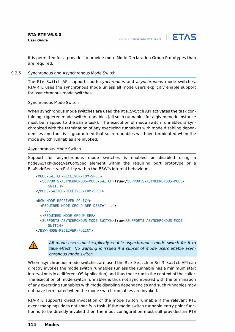
RTA-RTE V6.8.0User Guide
It is permitted for a provider to provide more Mode Declaration Group Prototypes thanare required.
9.2.5 Synchronous and Asynchronous Mode Switch
The Rte_Switch API supports both synchronous and asynchronous mode switches.RTA-RTE uses the synchronous mode unless all mode users explicitly enable supportfor asynchronous mode switches.
Synchronous Mode Switch
When synchronous mode switches are used the Rte_Switch API activates the task con-taining triggered mode switch runnables (all such runnables for a given mode instancemust be mapped to the same task). The execution of mode switch runnables is syn-chronized with the termination of any executing runnables with mode disabling depen-dencies and thus is is guaranteed that such runnables will have terminated when themode switch runnables are invoked.
Asynchronous Mode Switch
Support for asynchronous mode switches is enabled or disabled using aModeSwitchReceiverComSpec element within the requiring port prototype or aBswModeReceiverPolicy within the BSW’s internal behaviour.
<MODE-SWITCH-RECEIVER-COM-SPEC><SUPPORTS-ASYNCHRONOUS-MODE-SWITCH>true</SUPPORTS-ASYNCHRONOUS-MODE-
SWITCH></MODE-SWITCH-RECEIVER-COM-SPEC>
<BSW-MODE-RECEIVER-POLICY><REQUIRED-MODE-GROUP-REF DEST="...">...
</REQUIRED-MODE-GROUP-REF><SUPPORTS-ASYNCHRONOUS-MODE-SWITCH>true</SUPPORTS-ASYNCHRONOUS-MODE-
SWITCH></BSW-MODE-RECEIVER-POLICY>
All mode users must explicitly enable asynchronous mode switch for it totake effect. No warning is issued if a subset of mode users enable asyn-chronous mode switch.
When asynchronous mode switches are used the Rte_Switch or SchM_Switch API candirectly invokes the mode switch runnables (unless the runnable has a minimum startinterval or is in a different OS Application) and thus these run in the context of the caller.The execution of mode switch runnables is thus not synchronized with the terminationof any executing runnables with mode disabling dependencies and such runnables maynot have terminated when the mode switch runnables are invoked.
RTA-RTE supports direct invocation of the mode switch runnable if the relevant RTEevent mappings does not specify a task. If the mode switch runnable entry point func-tion is to be directly invoked then the input configuration must still provided an RTE
114 Modes
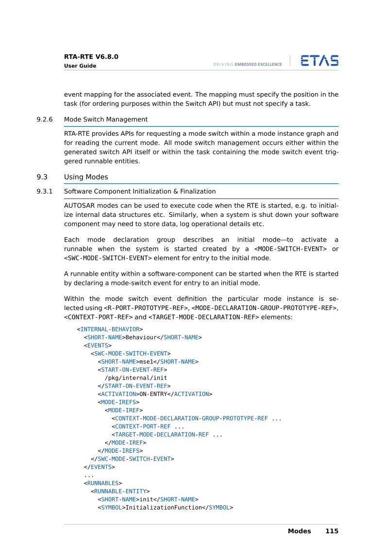
RTA-RTE V6.8.0User Guide
event mapping for the associated event. The mapping must specify the position in thetask (for ordering purposes within the Switch API) but must not specify a task.
9.2.6 Mode Switch Management
RTA-RTE provides APIs for requesting a mode switch within a mode instance graph andfor reading the current mode. All mode switch management occurs either within thegenerated switch API itself or within the task containing the mode switch event trig-gered runnable entities.
9.3 Using Modes
9.3.1 Software Component Initialization & Finalization
AUTOSAR modes can be used to execute code when the RTE is started, e.g. to initial-ize internal data structures etc. Similarly, when a system is shut down your softwarecomponent may need to store data, log operational details etc.
Each mode declaration group describes an initial mode—to activate arunnable when the system is started created by a <MODE-SWITCH-EVENT> or<SWC-MODE-SWITCH-EVENT> element for entry to the initial mode.
A runnable entity within a software-component can be started when the RTE is startedby declaring a mode-switch event for entry to an initial mode.
Within the mode switch event definition the particular mode instance is se-lected using <R-PORT-PROTOTYPE-REF>, <MODE-DECLARATION-GROUP-PROTOTYPE-REF>,<CONTEXT-PORT-REF> and <TARGET-MODE-DECLARATION-REF> elements:
<INTERNAL-BEHAVIOR><SHORT-NAME>Behaviour</SHORT-NAME><EVENTS><SWC-MODE-SWITCH-EVENT><SHORT-NAME>mse1</SHORT-NAME><START-ON-EVENT-REF>/pkg/internal/init
</START-ON-EVENT-REF><ACTIVATION>ON-ENTRY</ACTIVATION><MODE-IREFS><MODE-IREF><CONTEXT-MODE-DECLARATION-GROUP-PROTOTYPE-REF ...<CONTEXT-PORT-REF ...<TARGET-MODE-DECLARATION-REF ...
</MODE-IREF></MODE-IREFS>
</SWC-MODE-SWITCH-EVENT></EVENTS>...<RUNNABLES><RUNNABLE-ENTITY><SHORT-NAME>init</SHORT-NAME><SYMBOL>InitializationFunction</SYMBOL>
Modes 115
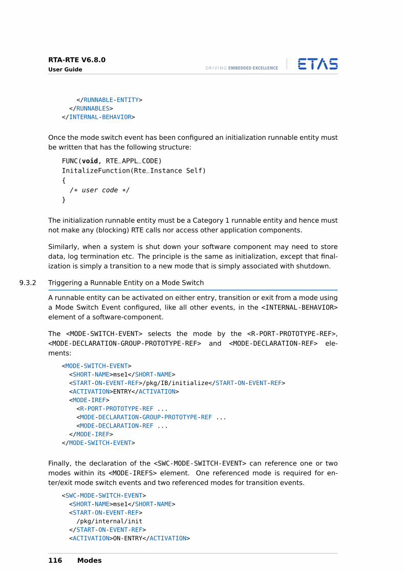
RTA-RTE V6.8.0User Guide
</RUNNABLE-ENTITY></RUNNABLES>
</INTERNAL-BEHAVIOR>
Once the mode switch event has been configured an initialization runnable entity mustbe written that has the following structure:
FUNC(void, RTE_APPL_CODE)InitalizeFunction(Rte_Instance Self){/* user code */
}
The initialization runnable entity must be a Category 1 runnable entity and hence mustnot make any (blocking) RTE calls nor access other application components.
Similarly, when a system is shut down your software component may need to storedata, log termination etc. The principle is the same as initialization, except that final-ization is simply a transition to a new mode that is simply associated with shutdown.
9.3.2 Triggering a Runnable Entity on a Mode Switch
A runnable entity can be activated on either entry, transition or exit from a mode usinga Mode Switch Event configured, like all other events, in the <INTERNAL-BEHAVIOR>element of a software-component.
The <MODE-SWITCH-EVENT> selects the mode by the <R-PORT-PROTOTYPE-REF>,<MODE-DECLARATION-GROUP-PROTOTYPE-REF> and <MODE-DECLARATION-REF> ele-ments:
<MODE-SWITCH-EVENT><SHORT-NAME>mse1</SHORT-NAME><START-ON-EVENT-REF>/pkg/IB/initialize</START-ON-EVENT-REF><ACTIVATION>ENTRY</ACTIVATION><MODE-IREF><R-PORT-PROTOTYPE-REF ...<MODE-DECLARATION-GROUP-PROTOTYPE-REF ...<MODE-DECLARATION-REF ...
</MODE-IREF></MODE-SWITCH-EVENT>
Finally, the declaration of the <SWC-MODE-SWITCH-EVENT> can reference one or twomodes within its <MODE-IREFS> element. One referenced mode is required for en-ter/exit mode switch events and two referenced modes for transition events.
<SWC-MODE-SWITCH-EVENT><SHORT-NAME>mse1</SHORT-NAME><START-ON-EVENT-REF>/pkg/internal/init
</START-ON-EVENT-REF><ACTIVATION>ON-ENTRY</ACTIVATION>
116 Modes
RTA-RTE V6.8.0User Guide
<MODE-IREFS><MODE-IREF><CONTEXT-MODE-DECLARATION-GROUP-PROTOTYPE-REF ...<CONTEXT-PORT-REF ...<TARGET-MODE-DECLARATION-REF ...
</MODE-IREF></MODE-IREFS>
</SWC-MODE-SWITCH-EVENT>
A mode-switch event element defines three things:
1. The <START-ON-EVENT-REF> element defines the runnable entity to activate. Thereference must be to a runnable entity within the same software-component type.
2. The <ACTIVATION> element defines the activation for the mode switch event, i.e.when the runnable entity is triggered. A Mode Switch Event can apply to oneactivation condition. If multiple activation conditions are required for a runnablethen more than one Mode Switch Event should be defined.
RTA-RTE supports “ENTRY”, “EXIT” or “ON-TRANSITION” activation conditions. Amode switch event with one of these activation conditions is triggered wheneverthe referenced mode is entered or exited.
Mode switch events using “ON-TRANSITION” activation are triggered by RTA-RTEwhen the mode instance moves from the first referenced mode to the secondreferenced mode.
3. The <MODE-IREF> defines the mode associated with the mode switch event. The<MODE-IREF> element must contain three references (the port prototype, themode declaration group prototype and the mode declaration group that typesthe declaration group prototype).
A mode switch event with an “ON-TRANSITION” activation condition requires twomodes to be referenced from the mode switch event’s <MODE-IREFS> element.Both referenced modes must be within the same mode instance.
One mode within a <MODE-DECLARATION-GROUP> element is marked as the group’s ini-tial mode. Any mode switch events that are attached to the “ENTRY” of an initial modewithin any group are triggered by RTA-RTE when the RTE is started using Rte_Start.
The order of execution of runnable entities when more than one runnableentity is triggered by the same mode entry (or exit) is not defined by theSWC-type. For portability, therefore, a system should not rely on a particularexecution order since it may be redefined in the runnable to task mapping(see Section 18.4.4).
9.3.3 Disabling RTE Events
A <MODE-DEPENDENCY> permits the behavior of an RTE event to be different in differ-ent modes. This allows such use-cases as the activation of a runnable entity to besuppressed when a certain mode is active.
Modes 117
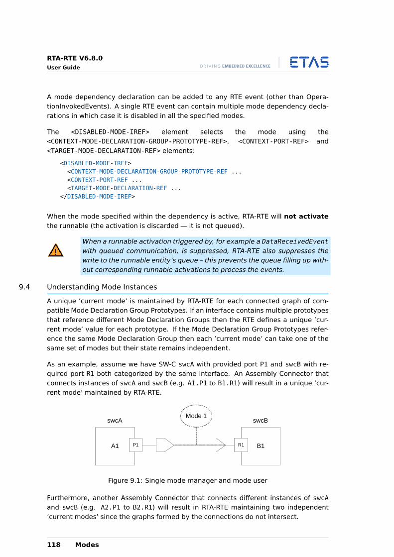
RTA-RTE V6.8.0User Guide
A mode dependency declaration can be added to any RTE event (other than Opera-tionInvokedEvents). A single RTE event can contain multiple mode dependency decla-rations in which case it is disabled in all the specified modes.
The <DISABLED-MODE-IREF> element selects the mode using the<CONTEXT-MODE-DECLARATION-GROUP-PROTOTYPE-REF>, <CONTEXT-PORT-REF> and<TARGET-MODE-DECLARATION-REF> elements:
<DISABLED-MODE-IREF><CONTEXT-MODE-DECLARATION-GROUP-PROTOTYPE-REF ...<CONTEXT-PORT-REF ...<TARGET-MODE-DECLARATION-REF ...
</DISABLED-MODE-IREF>
When the mode specified within the dependency is active, RTA-RTE will not activatethe runnable (the activation is discarded — it is not queued).
When a runnable activation triggered by, for example a DataReceivedEventwith queued communication, is suppressed, RTA-RTE also suppresses thewrite to the runnable entity’s queue – this prevents the queue filling up with-out corresponding runnable activations to process the events.
9.4 Understanding Mode Instances
A unique ’current mode’ is maintained by RTA-RTE for each connected graph of com-patible Mode Declaration Group Prototypes. If an interface contains multiple prototypesthat reference different Mode Declaration Groups then the RTE defines a unique ’cur-rent mode’ value for each prototype. If the Mode Declaration Group Prototypes refer-ence the same Mode Declaration Group then each ’current mode’ can take one of thesame set of modes but their state remains independent.
As an example, assume we have SW-C swcA with provided port P1 and swcB with re-quired port R1 both categorized by the same interface. An Assembly Connector thatconnects instances of swcA and swcB (e.g. A1.P1 to B1.R1) will result in a unique ’cur-rent mode’ maintained by RTA-RTE.
A1 P1 B1R1
Mode 1swcA swcB
Figure 9.1: Single mode manager and mode user
Furthermore, another Assembly Connector that connects different instances of swcAand swcB (e.g. A2.P1 to B2.R1) will result in RTA-RTE maintaining two independent’current modes’ since the graphs formed by the connections do not intersect.
118 Modes
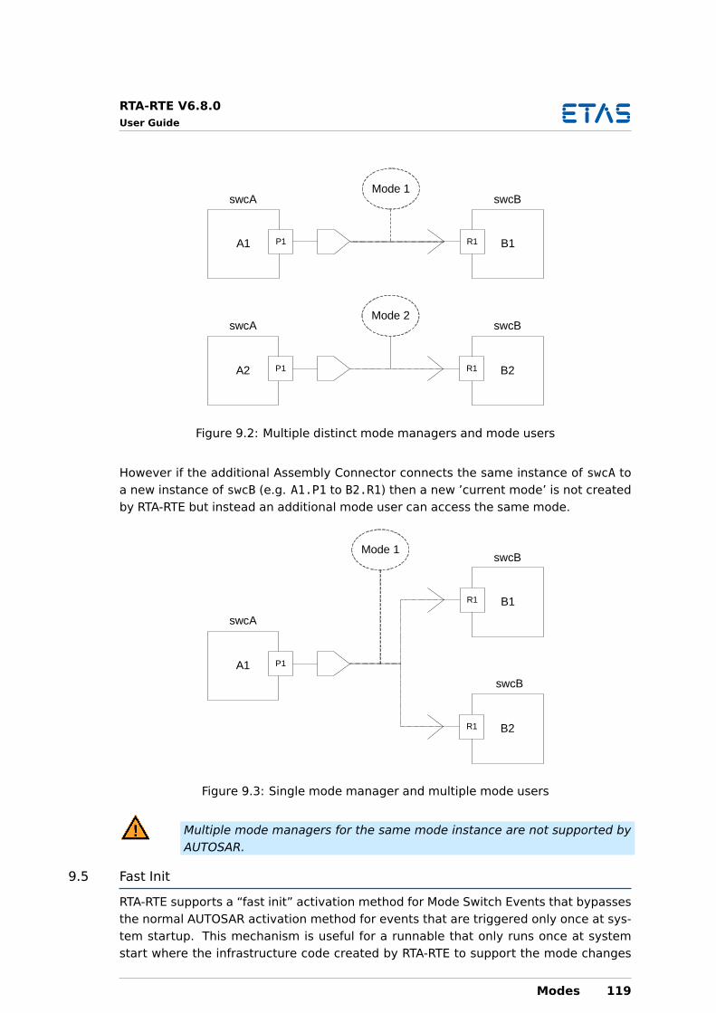
RTA-RTE V6.8.0User Guide
A1 P1 B1R1
Mode 1
A2 P1 B2R1
Mode 2swcA
swcA swcB
swcB
Figure 9.2: Multiple distinct mode managers and mode users
However if the additional Assembly Connector connects the same instance of swcA toa new instance of swcB (e.g. A1.P1 to B2.R1) then a new ’current mode’ is not createdby RTA-RTE but instead an additional mode user can access the same mode.
B1R1
Mode 1
B2R1
swcB
swcB
A1
swcA
P1
Figure 9.3: Single mode manager and multiple mode users
Multiple mode managers for the same mode instance are not supported byAUTOSAR.
9.5 Fast Init
RTA-RTE supports a “fast init” activation method for Mode Switch Events that bypassesthe normal AUTOSAR activation method for events that are triggered only once at sys-tem startup. This mechanism is useful for a runnable that only runs once at systemstart where the infrastructure code created by RTA-RTE to support the mode changes
Modes 119
RTA-RTE V6.8.0User Guide
at run-time is superfluous.
The “fast init” activation method is unique to RTA-RTE and therefore non-portable.
An individual ModeSwitchEvent is made subject to “fast init” activation through acommand-line option (see RTA-RTE Reference Manual). It is also possible to make allModeSwitchEvents for a SWC subject to “fast init” through the same command-lineoption.
When a ModeSwitchEvent is “fast init” then the implementation created by RTA-RTEwithin the task is a simple function call — the use of a FastInit task both simplifiesthe activation code necessary for the runnable associated with the event as well asremoving the normal infrastructure code created by RTA-RTE to support the AUTOSARmode mechanism.
It is the user’s responsibility to ensure that all FastInit tasks are activated at the appro-propriate time.
An event that is specified as FastInit will not be activated by RTA-RTE duringa user-triggered mode switch. Instead the FastInit task must be activatedby user code at the appriopriate time.
9.6 Synchronizing Modes
RTA-RTE supports the synchronization of modes between SWC components and BSWmodules. Synchronizing mode groups permits both events in both AUTOSAR softwarecomponents and basic software modules to be triggered by a single mode manager.RTA-RTE supports synchronization where the referenced BSW provides or releases (re-quires) the mode group.
The synchronization of mode groups is covered in detail in Chapter 15.
9.7 Non-AUTOSAR Functionality
9.7.1 Shared Mode Queues
When enabled with the --deviate-shared-mode-queue command-line option a sharedmode queue means that all mode instances mapped to a task share a single (common)queue.
Shared mode queues do not support timeouts for ModeSwitchAck eventsnor can they be mixed with distributed mode users.
A Shared Mode Queue results in a more predicable mode transition than is possiblewith AUTOSAR compliant mechanisms since for mode instances assigned to the task itis guaranteed that the transition for one mode instance will be complete before anotheris started.
120 Modes
RTA-RTE V6.8.0User Guide
9.7.2 Distributed Mode Users
When enabled with the --mode-policy command-line option different mode switchevents for a mode instance can be mapped to different tasks.
Dequeue Synchronization
When multiple mode switch tasks exist for a single mode instance then any taskcan be responsible for performing the dequeue. RTA-RTE provides a callback,Rte_ModeDequeueCbk_<index>, for each mode instance that controls within which taskthe dequeue occurs.
The callback is called from each mode switch task after the mode switch has completedfor the calling task. When it returns TRUE the generated code dequeues the modeswitch.
The callback is only invoked when a mode switch instance is in a transition.
During each transition the callback must return TRUE for exactly one of the mode switchtasks but which task is selected may vary between transitions. For example the call-back might return TRUE for the last task to finish the mode switch and enter the call-back, which could be timing-dependent, especially if the tasks run on different cores.
The name of the callback includes the mode instance index “<index>”. RTA-RTE makesthis index available within the Rte_Const.h generated header file for each providemode port (i.e. mode manager) using the RTE_DMU macro:
#define RTE_DMU_<swci>_<port>_<modegroup> ...
Where “<swci>” is the SWC instance name (which can be set using a flatmap, seeSection 13.4), “<port>” is the name of the provided mode port and “<modegroup>” isthe name of the mode declaration prototype within the mode interface categorizing theport.
The “RTE_DMU_...” macro can be used with the C-preprocessor to construct the nameof the callback function.
Modes 121
RTA-RTE V6.8.0User Guide
10 Implementing Software Components
This section shows how to write software components so that the objects required bythe RTE are declared and how to use the RTE API generated by the RTE generator.
10.1 Basic Concepts
10.1.1 Namespace
All RTE symbols (e.g. function names, global variables etc.) that are visible in the globalnamespace use either the prefix Rte_ or the prefix RTE_.
You must not create symbols that use either the prefix Rte_ or the prefixRTE_ to remove the possibility of namespace clashes.
10.1.2 Runnable Naming Convention
RTE generator generates code that activates your runnable entities. To do this, theRTE’s internal mechanisms need to be able to access your code through defined inter-faces.
Each of the named runnable entities defined in your runnable entity <SYMBOL> declara-tions must be implemented. Failure to define all runnable entities will be detected atcompile time when your application is linked to form the ECU’s executable image. Thelinker error message will reference the missing runnable entity entry point.
Runnable entities are executed by RTE generated code when required. The functionproviding an entry point for a runnable entity should not be invoked directly by anapplication software-component.
10.1.3 API Naming Convention
The RTE API calls are generated for each software component using names derivedfrom the the RTE generator’s input. The RTE API provides a consistent interface to eachsoftware component but allows the RTE generator to provide different implementationsof the API functionality.
Each API call name is formed from:
• An AUTOSAR defined prefix. For RTE API functions this is “Rte_” and, for BSWfunctions, “SchM_”.
• The call functionality (Read, Write, etc.).
• Either
• The port name and data item name (sender-receiver) or operation name (client-server) through which the API operates.
• The name of the object (e.g. trigger, exclusive area, per-instance memory etc)upon which the API operates.
122 Implementing Software Components
RTA-RTE V6.8.0User Guide
Thus RTE API calls involving communication through ports have the format:
Rte_StatusTypeRte_<API call name>_<port>_<dataitem/operation>
Whereas other RTE APIs have the format:
Rte_StatusTypeRte_<API call name>_<object name>
10.1.4 API Parameter Passing Mechanisms
RTE API calls and runnable entities may be invoked from multiple component proto-types. In both cases, the RTE expects that the first parameter to an API call or to arunnable entity to indicate the prototype upon which the function operates.
Every RTE API call or runnable entity that can operate on different proto-types of a component must pass in the instance handle as the first formalparameter.
The second and subsequent API parameters (if any) fall into one of three classes:
“In” Parameters —All “in” parameters that are AUTOSAR primitive data types (withthe exception of a string) are passed by value. Strings and other “in” parametersthat are a complex data type (i.e. a record or an array) are passed by reference.
Note that while AUTOSAR defines a string as a primitive data type, its inherentsize makes it inefficient to pass by value and is therefore treated the same as acomplex data type.
“In” parameters are strictly read-only.
“Out” Parameters —All “out” parameters are passed to RTE API functions by refer-ence. This is required to ensure that the API functions can modify the parameter.
“Out” parameters are strictly write-only.
“In/Out” Parameters —‘All “in/out” parameters are passed to the RTE API functionsby reference except for an asynchronous client-server call when primitive datatypes (other than strings) are passed by value to Rte_Call and by reference toRte_Result.
“In/out” parameters can be read and written by the API function being called.
10.1.5 API Forms
RTA-RTE supports two forms of API; direct and indirect. The direct API form includesthe instance handle as the first parameter of all API calls whereas the indirect formoperates through a port handle. The direct form is subject to a higher potential levelof optimization than the indirect form but the latter supports iteration over ports typedby the same interface.
Implementing Software Components 123
RTA-RTE V6.8.0User Guide
Both direct and indirect forms of the RTE API are equivalent and result in the samegenerated RTA-RTE function being invoked. The direct and indirect forms of the RTE APIcan be mixed within a program – even within the same software-component.
Direct API
The direct API form is the most efficient mechanism for invoking RTA-RTE generatedfunctions since, depending on the configuration, RTA-RTE is capable of optimizing theAPI form to bypass the component data structure to produce direct invocation of gen-erated functions. Furthermore, for source-code components the direct API form canpotentially be further optimized to elide the RTA-RTE generated function completely.
Indirect API
The indirect API form of API invocation that uses indirection through a port handle toinvoke RTA-RTE API functions.
The indirect form is less efficient than the direct form since the indirection cannot beoptimized away but supports iteration over ports typed by a similar interface. For ex-ample, when using the indirect API, an array of port handles of the same interface andprovide/require direction is provided by RTE and the same RTE API can be invoked formultiple ports by iterating over the array.
If the indirect API generated is not required for a port it can be disabled through “portoptions” within the internal behaviour:
<PORT-API-OPTIONS><PORT-API-OPTION><INDIRECT-API>false</INDIRECT-API><PORT-REF DEST="...">/pkg/component/port</PORT-REF>
</PORT-API-OPTION><PORT-API-OPTIONS>
10.2 Application Source Code
10.2.1 Supported Programming Languages
RTA-RTE supports components written in C and C++. The same application header filecan be used for C and C++.
The generated RTE is independent of the programming language used to create thecomponents since an individual RTE may be required to simultaneously support com-ponents written in different languages. RTA-RTE always generates the RTE in C.
10.2.2 Application Header Files
Each component you write must reside in its own C or C++ source code file(s) and includethe relevant application header file created during RTE configuration.
#include "Rte_ComponentName.h"
/* Component Implementation for "ComponentName" */
124 Implementing Software Components
RTA-RTE V6.8.0User Guide
The RTE API is specific to each software component type and therefore youmust include only the component’s application header file for each sourcecode file defines a component (whether completely or partially).
A single source module must not include multiple application header files as the APImappings they contain may be different for different software-components. The headerfiles generated by the RTE generator protect against such multiple file inclusion.
The component type specific header file defines the component’s RTE API and providesaccess to the type definition through a component instance handle that is used to iden-tify particular prototypes of a component.
10.3 Single and Multiple Instances
When a software component is configured to support a single instance it is known atintegration time that there will only be one instance of each software component type.
However, it is possible to configure a software component to support multiple in-stances. When this is configured, the RTE provides an instance handle for each compo-nent instance.
The instance handle is passed to a software component as the first parameter of thecomponent’s runnable entity (or entities).
Each time an API is made from the runnable entity then you must pass the same in-stance handle back to the RTE as the first parameter of API calls.
If a software component type supports only a single instance then an instance handleis not passed to runnable entities and therefore cannot be passed back to API calls.
The following code example assumes a single instance:
#include Rte_Component.h’’
FUNC(void, RTE_APPL_CODE)RunnableEntity(void){UInt16 Result = 0;
// ...Rte_Send_FromPort_MyData(42};// ...Result = SomeOtherFunction(42);// ...
}
Now, if the same example is re-written for a software component that supports multipleinstances we get:
#include Rte_Component.h’’
Implementing Software Components 125
RTA-RTE V6.8.0User Guide
FUNC(void, RTE_APPL_CODE)RunnableEntity(Rte_Instance Self){UInt16 Result = 0;
...Rte_Send_FromPort_MyData(Self, 42};...Result = SomeOtherFunction(42);...
}
Note that if runnable entities need take different actions for different instances thenper-instance calibration parameters can be used to identify each instance—the in-stance name/handle is not visible to the component (i.e. there is information hiding)and hence is not suitable. Access to the state of an instance is only possible throughthe Rte_Pim API call (see Section 10.9).
The following sections all show examples with multiple instance support configured,however the conversion to single instance is trivial (as shown above).
10.4 Runnable Entities
You are responsible for providing the implementations of all the runnable entities re-quired to make a software component work at runtime.
You must provide an entry point (i.e. a C function) for each <RUNNABLE-ENTITY> youhave declared in the component description. It is possible for multiple runnable entitiesto share the same entry point function.
If the software component supports multiple instantiation, all its runnable entities arepassed the instance handle as a function parameter when it is activated by the RTE sothe code you write must expect an instance handle as its first parameter. If the runnableentity is triggered by an <OPERATION-INVOKED-EVENT> then additional parameters cor-responding to the configuration of the client-server operation may be required.
RTA-RTE supports components written in C++. However, the generated RTE, includingthe generated task bodies, is created in C and therefore all runnable entity entry pointfunctions must be exported with C linkage:
extern "C"FUNC(void, RTE_APPL_CODE)re_entry_point(Rte_Instance self){...
}
126 Implementing Software Components
RTA-RTE V6.8.0User Guide
10.4.1 Entry Point Signature
With the exception of a runnable entity invoked as a result of an “Operation Invoked”RTE event, the signature of a runnable entity entry point function must follow the fol-lowing implementation rules:
• There is a single formal parameter (the instance handle) only if the internal be-haviour of the software component supports multiple instantiation.
• There are no user-defined parameters.
• There is no return value (i.e. a return type of void must be specified) unless aserver specifies application errors in which case Std_ReturnType is used.
The signature of a runnable entity that responds to an “Operation Invoked” RTE eventmust conform to the following additional rules:
• Formal parameters in addition to the instance handle are the operations IN, IN/OUTand OUT parameters. These parameters are passed by value or reference depend-ing on the type.
10.4.2 Sample Runnable Implementations
RTA-RTE can generate sample application source files using the --samples=swccommand-line option. The name of the generated sample file is Rte_<swc>.c whereswc is the software component’s short name.
The generated file contains an empty function for each runnable entity.
The --samples=swc option is most useful in contract phase before starting implemen-tation of a software component.
10.4.3 Examples
The following examples present the configurations and resultant obligations onsoftware-component implementation of different RTE events triggering runnable en-tities.
Basic Configuration
All RTE events other than “Operation Invoked” RTE events use the same basic signa-ture for runnable entity entry points irrespective of the event that actually triggers therunnable entity.
For example, given the following declaration of two runnable entities in the XML config-uration file for software-component Component:
<SWC-INTERNAL-BEHAVIOR><SHORT-NAME>Behaviour</SHORT-NAME><RUNNABLES>
Implementing Software Components 127
RTA-RTE V6.8.0User Guide
<RUNNABLE-ENTITY><SHORT-NAME>A</SHORT-NAME><SYMBOL>Runnable_A</SYMBOL>
</RUNNABLE-ENTITY><RUNNABLE-ENTITY><SHORT-NAME>B</SHORT-NAME><SYMBOL>Runnable_B</SYMBOL>
</RUNNABLE-ENTITY></RUNNABLES>
</SWC-INTERNAL-BEHAVIOR>
Then, following the rules defined above, the following runnable entry point functionswould be required:
#include Rte_Component.h’’
FUNC(void, RTE_APPL_CODE)Runnable_A(Rte_Instance Self){/* Implementation of Runnable A */
}
FUNC(void, RTE_APPL_CODE)Runnable_B(Rte_Instance Self){/* Implementation of Runnable B */
}
Data Receiver
A sender-receiver receiver runnable entity will be invoked by RTA-RTE when a port re-ceives data (or events) and a <DATA-RECEIVED-EVENT> is specified that references arunnable entity.
The signature of the runnable entity must conform to the rules defined above, i.e.:
• There must be no return value.
• The first and only parameter is the instance handle
• The memory class must be RTE_APPL_CODE (this can be modified, see Section 8.15).
Server Operation
A runnable entity will be invoked by RTA-RTE each time a request is made for an oper-ation on the server’s port. Each component that defines a port that uses an interfacewith the type SERVER must implement this type of runnable entity.
The signature of the runnable entity must conform to the rules defined above, i.e.:
128 Implementing Software Components
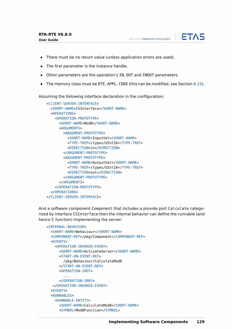
RTA-RTE V6.8.0User Guide
• There must be no return value (unless application errors are used).
• The first parameter is the instance handle.
• Other parameters are the operation’s IN, OUT and INOUT parameters.
• The memory class must be RTE_APPL_CODE (this can be modified, see Section 8.15).
Assuming the following interface declaration in the configuration:
<CLIENT-SERVER-INTERFACE><SHORT-NAME>CSInterface</SHORT-NAME><OPERATIONS><OPERATION-PROTOTYPE><SHORT-NAME>Mod8</SHORT-NAME><ARGUMENTS><ARGUMENT-PROTOTYPE><SHORT-NAME>InputVal</SHORT-NAME><TYPE-TREF>/types/UInt16</TYPE-TREF><DIRECTION>in</DIRECTION>
</ARGUMENT-PROTOTYPE><ARGUMENT-PROTOTYPE><SHORT-NAME>OutputVal</SHORT-NAME><TYPE-TREF>/types/UInt16</TYPE-TREF><DIRECTION>out</DIRECTION>
</ARGUMENT-PROTOTYPE></ARGUMENTS>
</OPERATION-PROTOTYPE></OPERATIONS>
</CLIENT-SERVER-INTERFACE>
And a software component Component that includes a provide port Calculate catego-rized by interface CSInterface then the internal behavior can define the runnable (andhence C function) implementing the server:
<INTERNAL-BEHAVIOR><SHORT-NAME>Behaviour</SHORT-NAME><COMPONENT-REF>/pkg/Component</COMPONENT-REF><EVENTS><OPERATION-INVOKED-EVENT><SHORT-NAME>ActivateServer</SHORT-NAME><START-ON-EVENT-REF>/pkg/Behaviour/CalculateMod8
</START-ON-EVENT-REF><OPERATION-IREF>...
</OPERATION-IREF></OPERATION-INVOKED-EVENT><EVENTS><RUNNABLES><RUNNABLE-ENTITY><SHORT-NAME>CalculateMod8</SHORT-NAME><SYMBOL>Mod8Function</SYMBOL>
Implementing Software Components 129
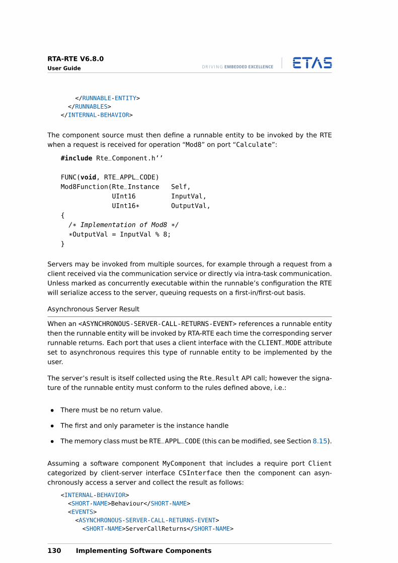
RTA-RTE V6.8.0User Guide
</RUNNABLE-ENTITY></RUNNABLES>
</INTERNAL-BEHAVIOR>
The component source must then define a runnable entity to be invoked by the RTEwhen a request is received for operation “Mod8” on port “Calculate”:
#include Rte_Component.h’’
FUNC(void, RTE_APPL_CODE)Mod8Function(Rte_Instance Self,
UInt16 InputVal,UInt16* OutputVal,
{/* Implementation of Mod8 */
*OutputVal = InputVal % 8;}
Servers may be invoked from multiple sources, for example through a request from aclient received via the communication service or directly via intra-task communication.Unless marked as concurrently executable within the runnable’s configuration the RTEwill serialize access to the server, queuing requests on a first-in/first-out basis.
Asynchronous Server Result
When an <ASYNCHRONOUS-SERVER-CALL-RETURNS-EVENT> references a runnable entitythen the runnable entity will be invoked by RTA-RTE each time the corresponding serverrunnable returns. Each port that uses a client interface with the CLIENT_MODE attributeset to asynchronous requires this type of runnable entity to be implemented by theuser.
The server’s result is itself collected using the Rte_Result API call; however the signa-ture of the runnable entity must conform to the rules defined above, i.e.:
• There must be no return value.
• The first and only parameter is the instance handle
• The memory class must be RTE_APPL_CODE (this can be modified, see Section 8.15).
Assuming a software component MyComponent that includes a require port Clientcategorized by client-server interface CSInterface then the component can asyn-chronously access a server and collect the result as follows:
<INTERNAL-BEHAVIOR><SHORT-NAME>Behaviour</SHORT-NAME><EVENTS><ASYNCHRONOUS-SERVER-CALL-RETURNS-EVENT><SHORT-NAME>ServerCallReturns</SHORT-NAME>
130 Implementing Software Components
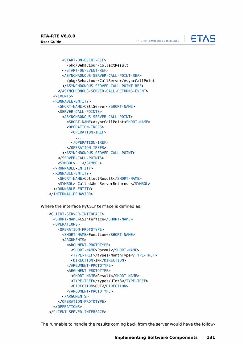
RTA-RTE V6.8.0User Guide
<START-ON-EVENT-REF>/pkg/Behaviour/CollectResult
</START-ON-EVENT-REF><ASYNCHRONOUS-SERVER-CALL-POINT-REF>/pkg/Behaviour/CallServer/AsyncCallPoint
</ASYNCHRONOUS-SERVER-CALL-POINT-REF></ASYNCHRONOUS-SERVER-CALL-RETURNS-EVENT>
</EVENTS><RUNNABLE-ENTITY><SHORT-NAME>CallServer</SHORT-NAME><SERVER-CALL-POINTS><ASYNCHRONOUS-SERVER-CALL-POINT><SHORT-NAME>AsyncCallPoint<SHORT-NAME><OPERATION-IREFS><OPERATION-IREF>...
</OPERATION-IREF></OPERATION-IREFS>
</ASYNCHRONOUS-SERVER-CALL-POINT></SERVER-CALL-POINTS><SYMBOL>...</SYMBOL>
</RUNNABLE-ENTITY><RUNNABLE-ENTITY><SHORT-NAME>CollectResult</SHORT-NAME><SYMBOL> CalledWhenServerReturns </SYMBOL>
</RUNNABLE-ENTITY></INTERNAL-BEHAVIOR>
Where the interface MyCSInterface is defined as:
<CLIENT-SERVER-INTERFACE><SHORT-NAME>CSInterface</SHORT-NAME><OPERATIONS><OPERATION-PROTOTYPE><SHORT-NAME>Function</SHORT-NAME><ARGUMENTS><ARGUMENT-PROTOTYPE><SHORT-NAME>Param1</SHORT-NAME><TYPE-TREF>/types/MonthType</TYPE-TREF><DIRECTION>IN</DIRECTION>
</ARGUMENT-PROTOTYPE><ARGUMENT-PROTOTYPE><SHORT-NAME>Result</SHORT-NAME><TYPE-TREF>/types/UInt8</TYPE-TREF><DIRECTION>OUT</DIRECTION>
</ARGUMENT-PROTOTYPE></ARGUMENTS>
</OPERATION-PROTOTYPE></OPERATIONS>
</CLIENT-SERVER-INTERFACE>
The runnable to handle the results coming back from the server would have the follow-
Implementing Software Components 131
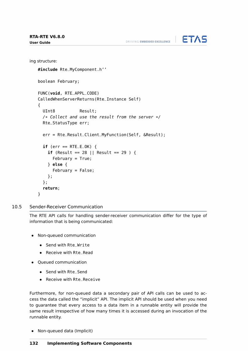
RTA-RTE V6.8.0User Guide
ing structure:
#include Rte_MyComponent.h’’
boolean February;
FUNC(void, RTE_APPL_CODE)CalledWhenServerReturns(Rte_Instance Self){UInt8 Result;/* Collect and use the result from the server */Rte_StatusType err;
err = Rte_Result_Client_MyFunction(Self, &Result);
if (err == RTE_E_OK) {if (Result == 28 || Result == 29 ) {February = True;
} else {February = False;
};};return;
}
10.5 Sender-Receiver Communication
The RTE API calls for handling sender-receiver communication differ for the type ofinformation that is being communicated:
• Non-queued communication
• Send with Rte_Write
• Receive with Rte_Read
• Queued communication
• Send with Rte_Send
• Receive with Rte_Receive
Furthermore, for non-queued data a secondary pair of API calls can be used to ac-cess the data called the “implicit” API. The implicit API should be used when you needto guarantee that every access to a data item in a runnable entity will provide thesame result irrespective of how many times it is accessed during an invocation of therunnable entity.
• Non-queued data (Implicit)
132 Implementing Software Components
RTA-RTE V6.8.0User Guide
• Send with Rte_IWrite
• Read with Rte_IRead
The following sections show how to use these calls in your application.
10.5.1 Non-Queued Communication
Explicit API
Components communicate data to other components using the Rte_Write call. Thecall is defined per port and interface data item for each component and therefore hasthe following signature:
Rte_StatusTypeRte_Write_<Port>_<DataItem>(Rte_Instance Self,
DataItemType Data)
Similarly, components receive communicated data items from other components usingthe Rte_Read call:
Rte_StatusTypeRte_Read_<Port>_<DataItem>(Rte_Instance Self,
DataItemType* Data)
The runtime behaviour of Rte_Read depends on how you have configured the internalbehaviour:
• Data Read Access: Rte_Read is non-blocking even if no data is present to read.If no data is present, the return value from the call is RTE_E_NO_DATA.
• Activation of runnable entity: The RTE activates the specified runnable entityand generates a non-blocking Rte_Read.
• Wake up of wait point: This combination is not permitted.
Implicit API
The implicit API uses a locally cached copy of data to preserve consistency over acalling runnable entity invocation. Data is read into a global cache before the runnableentity starts executing and is written from the global cache after the runnable entityterminates. Data writes are done once, no matter how many times it is written.
The RTE guarantees cached data does not change during execution of the runnableentity.
The implicit API includes a reference to the runnable entity that is declared as accessingthe data in the API name. Care should be taken when writing a runnable entity to invokethe correct API. The Rte_IRead API reads data:
Implementing Software Components 133
RTA-RTE V6.8.0User Guide
DataItemTypeRte_IRead_<Runnable>_<Port>_<DataItem>(Rte_Instance Self)
The Rte_IWrite API writes data
Rte_StatusTypeRte_IWrite_<Runnable>_<Port>_<DataItem>(Rte_Instance Self,
DataItemType Data)
As explained above, the implicit API calls access a cached copy of the data. The cacheis updated before the runnable entity starts and therefore within a single executionof a runnable entity the value returned by Rte_IRead is guaranteed not to change.Likewise, Rte_IWrite writes data to a cached copy and changes are only made visibleafter the runnable entity terminates irrespective of the number of times the data iswritten.
10.5.2 Queued Communication
Components communicate events to other components using the Rte_Send call. Thecall is defined per port and interface data item for each component type and thereforehas the following signature:
Rte_StatusTypeRte_Send_<Port>_<DataItem>(Rte_Instance Self,
EventType Event)
Similarly, component prototypes receive events that are communicated from othercomponents using the Rte_Receive call:
Rte_StatusTypeRte_Receive_<Port>_<DataItem>(Rte_Instance Self,
EventType Event)
The behaviour of the Rte_Receive API depends on how you configured theRECEIVE_MODE interface attributes:
• Data Read Access: Rte_Receive is non-blocking even if no data is present toread. If no data is present, the return value from the call is RTE_E_NO_DATA.
• Activation of runnable entity The RTE activates the specified runnable entityand generates a non-blocking Rte_Receive.
• Wake up of wait point: Rte_Receive blocks if no data is available. If no datais received within the specified timeout value, the return value from the call isRTE_E_TIMEOUT.
134 Implementing Software Components
RTA-RTE V6.8.0User Guide
10.6 Client-Server Communication
Client-server communication is initiated using the Rte_Call API call. There are twoforms that the call can take depending on the configuration of the CLIENT_MODE at-tribute.
If CLIENT_MODE is set to synchronous then Rte_Call returns after the operation hasbeen completed by the server. This means that your code will not continue to executeuntil the server returns the result. Once the result has been computed it is passed backto the component by the return value of the Rte_Call.
Rte_StatusTypeRte_Call_<Port>_<Operation>(Rte_Instance Self,
InParam1Type InParam1,InParam2Type InParam1,...InParamNType InParamN,OutParam1Type OutParam1,OutParam2Type OutParam2,...OutParamNType OutParamN)
If CLIENT_MODE is asynchronous then Rte_Call needs only specify the in and inoutparameters.
Rte_StatusTypeRte_Call_<Port>_<Operation>(Rte_Instance Self,
InParam1Type InParam1,InParam2Type InParam1,...InParamNType InParamN)
The result(s) of the server operation are accessed using the asynchronousclient result runnable entity that you define (see Section 8.7.2) or theRte_Result_<port>_<operation> API call.
The behaviour of the call returns depends on whether the<ASYNCHRONOUS-SERVER-CALL-RETURNS-EVENT> is referenced by a <WAIT-POINT>or not. If there is no wait point then the call returns immediately, otherwise the call willblock until the server returns
Rte_StatusTypeRte_Result_<Port>_<Operation>(Rte_Instance Self,
OutParam1Type OutParam1,OutParam2Type OutParam1,...OutParamNType OutParamN)
Implementing Software Components 135
RTA-RTE V6.8.0User Guide
10.6.1 Client-Server Serialization
The targets of client-server communications (i.e. the runnable entities that are invokedto produce the required result) are serialized. A serialized server only accepts andprocesses requests atomically and thus avoids the potential for conflicting concurrentaccess.
10.7 Using Inter-Runnable Variables
Runnable entities in software components that use inter-runnable variables access thevariable through an API call. Since the API calls are generated in the software compo-nent’s header file each API call must include the name of the runnable itself.
The type of API call generated depends on whether the variable is declared as implicitor explict. Implicit variables are accessed through an API of the form:
Rte_IrvI[Read|Write]_<Runnable>_<Variable>(...);
Explicit variables are accessed with an API call of the form:
Rte_Irv[Read|Write]_<Runnable>_<Variable>(...);
The following code example illustrates usage:
FUNC(void, RTE_APPL_CODE)RunnableA(Rte_Instance self){Unit16 ExplictlyRead = 0;Unit32 ImplicitlyRead = 0;Sint8 ExplicitlyWritten = 42;Boolean ImplicitlyWritten = True;
/* Read inter-runnable variables */ExplicitlyRead = Rte_IrvRead_RunnableA_VarP(self);ImplicitlyRead = Rte_IrvIRead_RunnableA_VarQ(self);
/* Write inter-runnable variables */Rte_IrvWrite_RunnableA_VarR(self, ExplicitlyWritten);Rte_IrvIWrite_RunnableA_VarS(self, ImplicitlyWritten);
}
10.8 Accessing Parameters
A software component declares calibration parameters (whether sharedor per-instance) then each parameter is accessed at runtime using theRte_CData_<calprm_name> API call. The call returns either the calibration data(primitive types) or a pointer to the data (complex types).
As the data is specific to each software component instance, the instance handle mustbe supplied to each call if multiple instantiation is configured.
136 Implementing Software Components
RTA-RTE V6.8.0User Guide
FUNC(void, RTE_APPL_CODE)YourRunnable(Rte_Instance Self){uint8* configconfig = Rte_CData_TrimValue(Self);/* user code */
}
10.9 Accessing Per Instance Memory
Component types are standard programs. The RTE only interacts with componentsthrough ports at runtime by the activation of associated runnable entities. Ports arehandled by defined runnable entities, so as a minimum an implementation of a softwarecomponent must include an implementation of all runnable entities for the softwarecomponent.
All instances of an application software component share the same code, but eachinstance may have private state that is not shared with other instances. Consequently,each software component instance has a “copy” of the private state to which it hasexclusive access.
The Rte_Pim API is used to access the component state for a particular instance and,like all RTE API calls, takes the component instance handle as its first parameter.
The function returns a handle to a per-instance memory section. The type of the returnvalue depends on the per-instance memory declaration.
The Rte_Pim call has the signature:
Rte_Pim_<name>(Rte_Instance Self)
The state information returned by Rte_Pim can be used by a component instance tostore information with a lifetime greater than that of any one runnable entity. Youshould not use “traditional” global variables since these are shared by all prototypes ofthe component mapped to the ECU.
The Rte_Pim API does not impose concurrency control on a component’s prototypestate and therefore concurrent write access to prototype state may result in inconsis-tent state information.
10.10 Concurrency Control with Exclusive Areas
Where a component has multiple runnable entities that require concurrent write accessto the same prototype state then the Rte_Enter and Rte_Exit API calls must be usedto ensure that data consistency is maintained.
A component includes multiple runnable entities each of which can be active simultane-ously. The potential exists for concurrent access to private global data (e.g. elementsin the data memory sections) and/or non-reentrant functions.
Implementing Software Components 137
RTA-RTE V6.8.0User Guide
Operating system concurrency control mechanisms are hidden from components. How-ever the RTE API implements explicit access to exclusive areas by exposing an appro-priate OS mechanism to components:
• Rte_Enter_<exclusive area name> enters an exclusive area.
• Rte_Exit_<exclusive area name> exits an exclusive area.
Where components declare exclusive areas, the generated RTE API for the componentincludes these API calls to allow you to control concurrent access to shared data.
A component can use the Rte_Enter and Rte_Exit API calls for any exclusive area IDyou define at configuration time.
For example, assuming the following configuration:
<INTERNAL-BEHAVIOR><EXCLUSIVE-AREAS><EXCLUSIVE-AREA>MyExclusiveArea</EXCLUSIVE-AREA>
</EXCLUSIVE-AREAS><INTERNAL-BEHAVIOR>
The following code shows how the calls are used:
Rte_Enter_MyExclusiveArea();/* Code protected from concurrent execution */Rte_Exit_MyExclusiveArea();
It is not permitted to place RTE API calls between a call to Rte_Enter and its corre-sponding call to Rte_Exit.
Attempting RTE API calls while an exclusive area is locked may result indelayed response to task activations by the OS.
Software components must use the Rte_Enter and Rte_Exit calls in a strictly nestedmanner. Exclusive areas must be exited in the reverse order in which they were enteredas shown below:
Rte_Enter_Outer();/* Code protected by Outer */Rte_Enter_Inner();/* Code protected by Inner & Outer */
Rte_Exit_Inner();/* Code protected by Outer */
Rte_Exit_Outer();
138 Implementing Software Components
RTA-RTE V6.8.0User Guide
The scope of an exclusive area is the software component prototype andnot the software component type or system wide and hence exclusive areasonly provide concurrency control within a software component. Wider scopecan be achieved using an AUTOSAR component to control access to shareddata.
10.11 Starting and Stopping the RTE
The RTE itself is started using the Rte_Start API call. You must not make this call froma software component.
Rte_Start is typically called from the idle task since this ensures that runnable entitiestriggered on entry to the initial mode are activated and dispatched (based on the taskpriority to which they are mapped) before the API returns. For example:
OS_MAIN(){/* Initialize hardware */StartOS(OSDEFAULTAPPMODE);
/* RTA-OSEK: OS_MAIN is now the idle task */Rte_Start();for (;;}{/* Do background processing */
}}
The Rte_Start call returns to the callee once the RTE is initialized.
The RTE must not be started before the operating system. If not using theECU state manager, the recommended start order is to initialize/start thelowest elements of the AUTOSAR architecture (e.g. OS) first and then pro-ceed “upwards” (i.e. communication drivers, PDU Router, COM and finallyRTE).
The RTE is stopped by calling the Rte_Stop API call. This API call stops any operat-ing system schedules that release time-triggered runnable entities and then calls anysoftware component finalization runnable entities that you have defined.
The RTE must be stopped before the operating system. The recommendedshutdown order is to stop the higher elements of the AUTOSAR architecture(e.g. RTE) first and then proceed “downwards” (i.e. RTE, COM, PDU Router,communication drivers and finally OS).
Implementing Software Components 139
RTA-RTE V6.8.0User Guide
11 NVRAM
11.1 NV-Block Software Component Types
In Chapter 7 we discussed how AUTOSAR application software is partitioned using AU-TOSAR software components. The use of NVRAM within AUTOSAR adds another soft-ware component type to the list of supported types, an NvBlock software componenttype, that can declare ports used for NVRAM communication.
An Nv-Block software component type is described using a<NV-BLOCK-SW-COMPONENT-TYPE> element. This element describes the componenttype name, its ports and Nv-blocks, for example:
<NV-BLOCK-SW-COMPONENT-TYPE><SHORT-NAME>nv1</SHORT-NAME><PORTS>...
</PORTS><NV-BLOCK-DESCRIPTORS>...
</NV-BLOCK-DESCRIPTORS><INTERNAL-BEHAVIORS>...
</INTERNAL-BEHAVIORS></NV-BLOCK-SW-COMPONENT-TYPE>
11.1.1 Ports
Like an application software component, an NvBlock software component type declaresports for communication with other component instances. However, unlike a generalapplication SWC, ports within an NvBlock SWC can only be categorized by the followinginterface types:
Nv-Data – permits read and/or write access by application software components to aram-block within a Nv-block. A block mapping (see below) is used to associatethe port and the ram-block.
Client-Server – permits notifications from the NVRAM manager to application SWCsand for the invocation of NVRAM manager API functions by application SWCs.
RTA-RTE will raise an error if any other interface types is used to categorize a portdeclared by an Nv-Block software component type.
11.1.2 Nv-Blocks
A Nv-Block software component type declares one or more Nv-Blocks using the<NV-BLOCK-DESCRIPTOR> element. Each block declares a RAM-based mirror of non-volatile data.
<NV-BLOCK-DESCRIPTOR><SHORT-NAME>block1</SHORT-NAME>
140 NVRAM
RTA-RTE V6.8.0User Guide
<CLIENT-SERVER-PORTS>...
</CLIENT-SERVER-PORTS><NV-BLOCK-DATA-MAPPINGS>
...</NV-BLOCK-DATA-MAPPINGS><RAM-BLOCK><SHORT-NAME>myRamBlock2</SHORT-NAME>...
</RAM-BLOCK></NV-BLOCK-DESCRIPTOR>
Each NvBlock descriptor must declare:
1. Exactly one ram-block element. The ram-block is instantiated by RTA-RTE andacts as the mirror of the NVRAM data that is read and/or written by applicationSWC.
2. Zero or more NvBlock Data Mappings that connect ports categorized by Nv-Datainterfaces with the ram-block.
3. Zero or more Client-Server Ports that connect ports categorized by client-serverinterfaces, the ram-block and the NVRAM manager.
In addition, an Nv-block descriptor can optionally describe a ROM initializer for the ram-block.
ROM initializers are partially supported by this release of RTA-RTE. Therom-block is optionally used by RTA-RTE to initialize the ram-block duringRte_Start.
11.1.3 NVRAM Mirrors
Each Nv-block descriptor within an Nv-Block SWC declares exactly one ram-block. Theram-block forms the data that is read and/or written by application SWC through portsdecalred by the Nv-Block SWC.
RTA-RTE provides APIs for the NVRAM manager to initially set the mirror data before theRTE is started and to get the final mirror state after the RTE is terminated.
The ram-block instance is created by the RTE generator. The ram-block instance nameis based on the ram-block name and therefore each block must have a unique namewithin the context of the NvBlock software component type.‘
11.1.4 Port Mappings
A port within an Nv-Block SWC categorized by an Nv-Data interface (see Section 6.2)can be connected to a ram-block so that it can be read/written through the port. Thisconnection is achieved through Nv-Data mappings declared within the Nv-block de-scriptor:
NVRAM 141
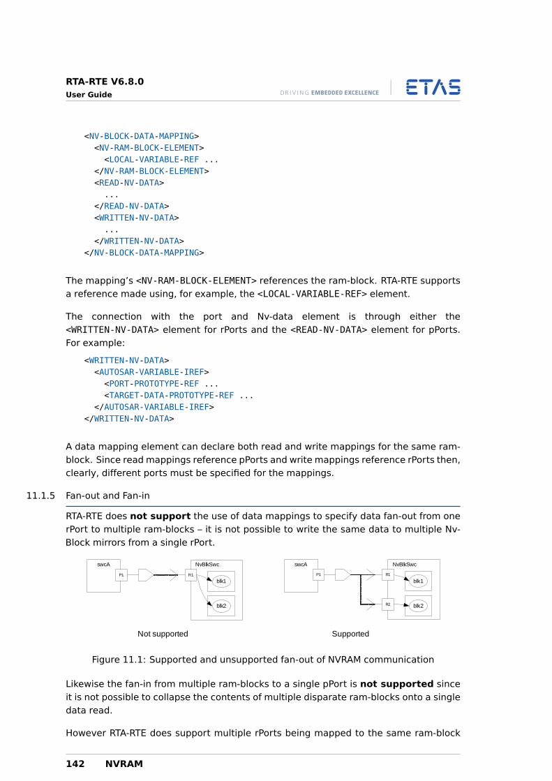
RTA-RTE V6.8.0User Guide
<NV-BLOCK-DATA-MAPPING><NV-RAM-BLOCK-ELEMENT><LOCAL-VARIABLE-REF ...
</NV-RAM-BLOCK-ELEMENT><READ-NV-DATA>...
</READ-NV-DATA><WRITTEN-NV-DATA>...
</WRITTEN-NV-DATA></NV-BLOCK-DATA-MAPPING>
The mapping’s <NV-RAM-BLOCK-ELEMENT> references the ram-block. RTA-RTE supportsa reference made using, for example, the <LOCAL-VARIABLE-REF> element.
The connection with the port and Nv-data element is through either the<WRITTEN-NV-DATA> element for rPorts and the <READ-NV-DATA> element for pPorts.For example:
<WRITTEN-NV-DATA><AUTOSAR-VARIABLE-IREF><PORT-PROTOTYPE-REF ...<TARGET-DATA-PROTOTYPE-REF ...
</AUTOSAR-VARIABLE-IREF></WRITTEN-NV-DATA>
A data mapping element can declare both read and write mappings for the same ram-block. Since read mappings reference pPorts and write mappings reference rPorts then,clearly, different ports must be specified for the mappings.
11.1.5 Fan-out and Fan-in
RTA-RTE does not support the use of data mappings to specify data fan-out from onerPort to multiple ram-blocks – it is not possible to write the same data to multiple Nv-Block mirrors from a single rPort.
R1
NvBlkSwcswcA
P1
blk1
blk2
R1
NvBlkSwcswcA
P1
blk1
blk2R2
Not supported Supported
Figure 11.1: Supported and unsupported fan-out of NVRAM communication
Likewise the fan-in from multiple ram-blocks to a single pPort is not supported sinceit is not possible to collapse the contents of multiple disparate ram-blocks onto a singledata read.
However RTA-RTE does support multiple rPorts being mapped to the same ram-block
142 NVRAM
RTA-RTE V6.8.0User Guide
(sub-element) and hence being written simultaneously by multiple sources. This isrequired to support the mapping of a port to an element of a ram-block when the latteruses a complex (record or array) type.
11.2 Interaction with Application SWC
Having created an Nv-Block software component type with a declared Nv-block anddata mappings it needs to be accessed by application SWC. This access occurs betweenports within the SWCs:
• An application SWC writes data to an Nv-block by declaring a Sender-receiver orNv-data pPort (with an appropriate interface) and connecting it to an rPort on theNv-Block SWC categorized by an Nv-Data interface.
• An application SWC reads data from an Nv-block by declaring a Sender-receiver orNv-data rPort (with an appropriate interface) and connecting it to a pPort on theNv-Block SWC categorized by an Nv-Data interface.
Accessing NVRAM from application SWC is considered in detail in Chapter 16.
11.3 Interaction with the NVRAM Manager
The NVRAM manager can interact with an NvBlock SWC, and hence with applicationSWCs, via API functions and runnable entity bodies generated by RTA-RTE.
Two API functions are generated by RTA-RTE for each NvBlock descriptor:
Rte_GetMirror – Generated for each NvBlock descriptor and enables the NVRAM man-ager to read the contents of the ram-block.
Rte_SetMirror – Generated for each NvBlock descriptor and enables the NVRAM man-ager to write the contents of the ram-block.
In addition to the Rte_GetMirror and Rte_SetMirror APIs, RTA-RTE can also gener-ate additional APIs and runnable entity bodies based on declared role based port as-signments depending on whether the assignment references a provided or requiredclient-server port:
Require port – RTA-RTE generates an API to be invoked by the NVRAM manager. Thename of the API is based on the declared role, the NvBlock SWC component pro-totype name and the NvBlock descriptor name.
The generated API invokes the server through the referenced require port. Ifmultiple role based assignments have the same “role” then the generated APIaggregates invocation of all referenced servers.
The generated API invokes servers synchronously. To avoid use of OsEvents in thegenerated code it is strongly recommended to use direct function invocation byomitting the task reference the relevant RTE event mapping.
NVRAM 143
RTA-RTE V6.8.0User Guide
Provide port – RTA-RTE generates the runnable entity body for all connected provideports that have a configured OperationInvokedEvent.
The generated runnable entity body uses the symbol name from the runnableentity declaration – this must therefore be globally unique. The formal argumentlist consists of three elements:
1. An optional instance handle (included only when the NvBlock SWC is de-clared as supporting multiple instances, see Section 8.14).
2. The port-defined arguments (for the referenced server port, see Sec-tion 8.13.2).
3. The operation arguments from the operation in the server’s ports interfacewith the same name as the “role”.
The generated body for the runnable invokes the C-based API of the NVRAM man-ager based on the declared “role”. All runnable parameters, apart from the in-stance handle, are passed directly to the invoked NVRAM API.
144 NVRAM
RTA-RTE V6.8.0User Guide
Part III
Developing Basic Software
145
RTA-RTE V6.8.0User Guide
12 Basic Software
12.1 Basic Software Modules
In Chapter 7 we discussed how application software is partitioned using AUTOSAR soft-ware components. Similarly, AUTOSAR basic software (BSW) is partitioned into BSWmodules.
A BSW module is closely related to a software component, and, just like a softwarecomponent, has both an internal behaviour and an implementation. The module isdescribed using a <BSW-MODULE-DESCRIPTION> element. This element describes themodule name and its internal behaviour, for example:
<BSW-MODULE-DESCRIPTION><SHORT-NAME>Can</SHORT-NAME><MODULE-ID>23</MODULE-ID><INTERNAL-BEHAVIORS><BSW-INTERNAL-BEHAVIOR>
...</BSW-INTERNAL-BEHAVIOR>
</INTERNAL-BEHAVIORS></BSW-MODULE-DESCRIPTION>
The module’s name and, optionally the BSW implementation’s <VENDOR-ID> and<VENDOR-API-INFOX>, are used when RTA-RTE generates API names for the module.The combination ensures that each module instance receives unique generated APIs.
AUTOSAR configurations can specify multiple internal behaviors for a BSWmodule and then select the appropriate behavior using pre-build variability.This release of RTA-RTE does not support pre-build variability and thereforeat most one internal behavior can be specified.
12.1.1 Internal Behaviour
A basic software module’s internal behaviour is similar to the SWC’s internal behaviordescribed in Chapter 8 however reflecting the differing requirements different XML tagsare used so specifying conceptually similar elements.
The internal behavior describes one or more <BSW-SCHEDULABLE-ENTITY>s which areanalogous to runnable entities in a SWC and one or more BSW events that are analo-gous to RTE events. RTA-RTE supports the following BSW events:
BSW-TIMING-EVENT – Specifies a periodic activity within a basic software module.
BSW-BACKGROUND-EVENT
BSW-EXTERNAL-TRIGGER-OCCURRED-EVENT – permits triggering of a schedulableentity by an external SWC or BSW instance. RTA-RTE supports synchronization ofBSW and SWC trigger instances enabling either SWCs to activate schedulableentities or BSWs to activate runnable entities in response to a external triggeroccurred event.
146 Basic Software
RTA-RTE V6.8.0User Guide
BSW-INTERNAL-TRIGGER-OCCURRED-EVENT – permits triggering of a schedulableentity by the same BSW instance.
BSW-MODE-SWITCH-EVENT – enables BSW schedule entities to be activated in re-sponse to a mode switch. RTA-RTE supports synchronization of BSW and SWCmode instances enabling either SWCs to activate schedulable entities or BSWs toactivate runnable entities in response to a mode switch event.
BSW-MODE-SWITCHED-ACK-EVENT – enables a BSW schedule entity to be acti-vated when a mode switch is complete.
These events and the interaction of basic software modules with the RTE are discussedin this chapter.
12.2 Interaction with the RTE
The mechanisms by which BSW modules interact with the RTE and through it with otherapplication elements are closely related to the facilities that are available for softwarecomponents. In fact, apart from not possessing ports, many of the RTE features forsoftware components have direct analogues in BSW modules.
This section explains the facilities RTA-RTE provides for BSW modules.
12.2.1 Schedulable Entity
A BSW schedulable entity is closely related to a software component’s runnable entitysince they are both representations of an entry point within the application softwarethat can be started executing by the RTE.
<BSW-SCHEDULABLE-ENTITY><SHORT-NAME>BSWTicked</SHORT-NAME><IMPLEMENTED-ENTRY-REF DEST=’...’>/pkg/Ticked</IMPLEMENTED-ENTRY-REF>
</BSW-SCHEDULABLE-ENTITY>
The <IMPLEMENTED-ENTRY-REF> references a <BSW-MODULE-ENTRY> that defines the en-try point for the BSW schedulable entity. For example:
<BSW-MODULE-ENTRY><SHORT-NAME>Ticked</SHORT-NAME><IS-REENTRANT>true</IS-REENTRANT><IS-SYNCHRONOUS>true</IS-SYNCHRONOUS><CALL-TYPE>SCHEDULED</CALL-TYPE><EXECUTION-CONTEXT>TASK</EXECUTION-CONTEXT><SW-SERVICE-IMPL-POLICY>STANDARD</SW-SERVICE-IMPL-POLICY>
</BSW-MODULE-ENTRY>
The BSW module entry defines the execution context of the schedulable entity whichshould be TASK. BSW module entries are not defined within the context of the BSWmodule description and thus can be in a different AUTOSAR package if necessary.
Multiple BSW modules can reference the same BSW module entry, e.g. multiple mod-ules can each reference the same MainFunction module entry. RTA-RTE will use the
Basic Software 147
RTA-RTE V6.8.0User Guide
defined BSW module name, vendor API infix and module ID to ensure that each moduleimplementation receives a unique API.
A BSW schedulable entity is started by the RTE triggering a BSW event. RTA-RTEsupports multiple event types for BSW schedulable entities including time and modeswitches.
12.2.2 Periodic Events
A BSW schedulable entity is started periodically using a <BSW-TIMING-EVENT>. Similarlyto an SW-C’s <TIMING-EVENT> the BSW event defines a period (in seconds) and anoptional minimum start interval (also in seconds).
<BSW-TIMING-EVENT><SHORT-NAME>BSWTick</SHORT-NAME><STARTS-ON-EVENT-REF DEST=’...’>/pkg/mod/ib/entity</STARTS-ON-EVENT-REF><PERIOD>1.0</PERIOD>
</BSW-TIMING-EVENT>
The <STARTS-ON-EVENT-REF> references the schedule entity to be started when thetrigger occurs. It must therefore reference an entity within the basic software moduledescription. For clarity the DEST attribute has been omitted in the example above butwould normally have the value BSW-SCHEDULABLE-ENTITY.
12.2.3 Background Events
RTA-RTE supports BSW background events. As with <BSW-TIMING-EVENT>s theseevents are directly analogous to an SW-C’s <BACKGROUND-EVENT>.
12.2.4 External Trigger Events
Section 8.8 covered the configuration of internal and external trigger events for SW-Cs.BSW modules can trigger such events and also define responses that are triggered byeither SW-Cs or by other BSW modules.
A basic software module declares an external trigger event using the<BSW-EXTERNAL-TRIGGER-OCCURRED-EVENT> event:
<BSW-EXTERNAL-TRIGGER-OCCURRED-EVENT><SHORT-NAME>BSWTrigger</SHORT-NAME><STARTS-ON-EVENT-REF DEST=’...’>/pkg/bsw/ib/entity</STARTS-ON-EVENT-REF><TRIGGER-REF DEST=’...’>/pkg/bsw/trigger</TRIGGER-REF>
</BSW-EXTERNAL-TRIGGER-OCCURRED-EVENT>
The short name of the external trigger event is only significant for referencing and doesnot form part of the generated API.
The <STARTS-ON-EVENT-REF> references the schedule entity to be started when thetrigger occurs. It must therefore reference an entity within the basic software moduledescription. For clarity the DEST attribute has been omitted in the example above butwould normally have the value BSW-SCHEDULABLE-ENTITY.
148 Basic Software
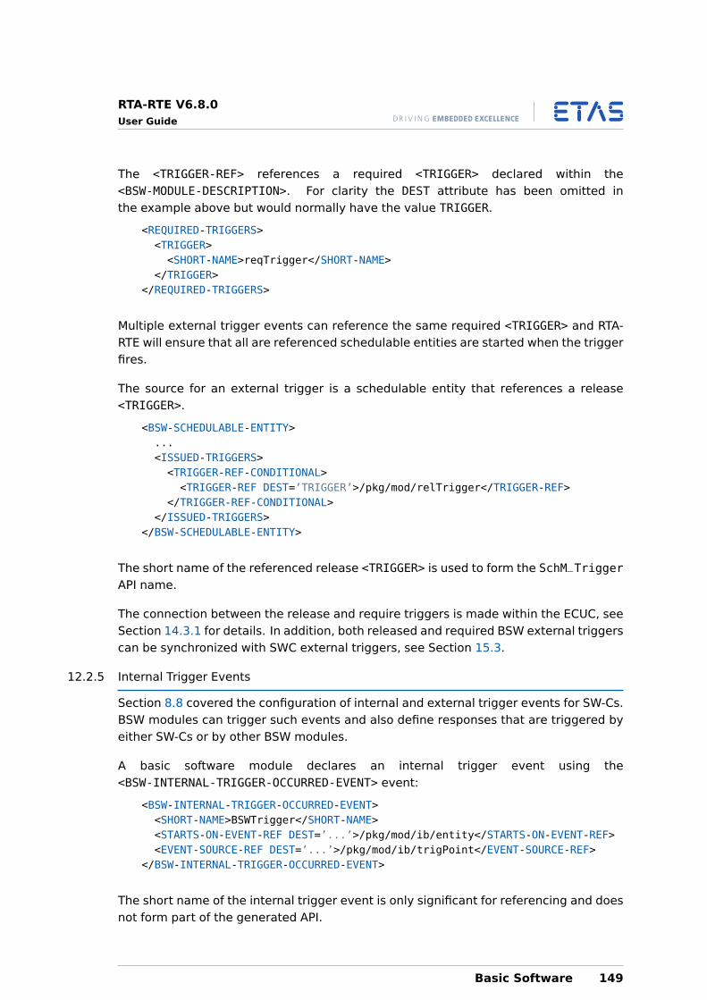
RTA-RTE V6.8.0User Guide
The <TRIGGER-REF> references a required <TRIGGER> declared within the<BSW-MODULE-DESCRIPTION>. For clarity the DEST attribute has been omitted inthe example above but would normally have the value TRIGGER.
<REQUIRED-TRIGGERS><TRIGGER><SHORT-NAME>reqTrigger</SHORT-NAME>
</TRIGGER></REQUIRED-TRIGGERS>
Multiple external trigger events can reference the same required <TRIGGER> and RTA-RTE will ensure that all are referenced schedulable entities are started when the triggerfires.
The source for an external trigger is a schedulable entity that references a release<TRIGGER>.
<BSW-SCHEDULABLE-ENTITY>...<ISSUED-TRIGGERS><TRIGGER-REF-CONDITIONAL><TRIGGER-REF DEST=’TRIGGER’>/pkg/mod/relTrigger</TRIGGER-REF>
</TRIGGER-REF-CONDITIONAL></ISSUED-TRIGGERS>
</BSW-SCHEDULABLE-ENTITY>
The short name of the referenced release <TRIGGER> is used to form the SchM_TriggerAPI name.
The connection between the release and require triggers is made within the ECUC, seeSection 14.3.1 for details. In addition, both released and required BSW external triggerscan be synchronized with SWC external triggers, see Section 15.3.
12.2.5 Internal Trigger Events
Section 8.8 covered the configuration of internal and external trigger events for SW-Cs.BSW modules can trigger such events and also define responses that are triggered byeither SW-Cs or by other BSW modules.
A basic software module declares an internal trigger event using the<BSW-INTERNAL-TRIGGER-OCCURRED-EVENT> event:
<BSW-INTERNAL-TRIGGER-OCCURRED-EVENT><SHORT-NAME>BSWTrigger</SHORT-NAME><STARTS-ON-EVENT-REF DEST=’...’>/pkg/mod/ib/entity</STARTS-ON-EVENT-REF><EVENT-SOURCE-REF DEST=’...’>/pkg/mod/ib/trigPoint</EVENT-SOURCE-REF>
</BSW-INTERNAL-TRIGGER-OCCURRED-EVENT>
The short name of the internal trigger event is only significant for referencing and doesnot form part of the generated API.
Basic Software 149
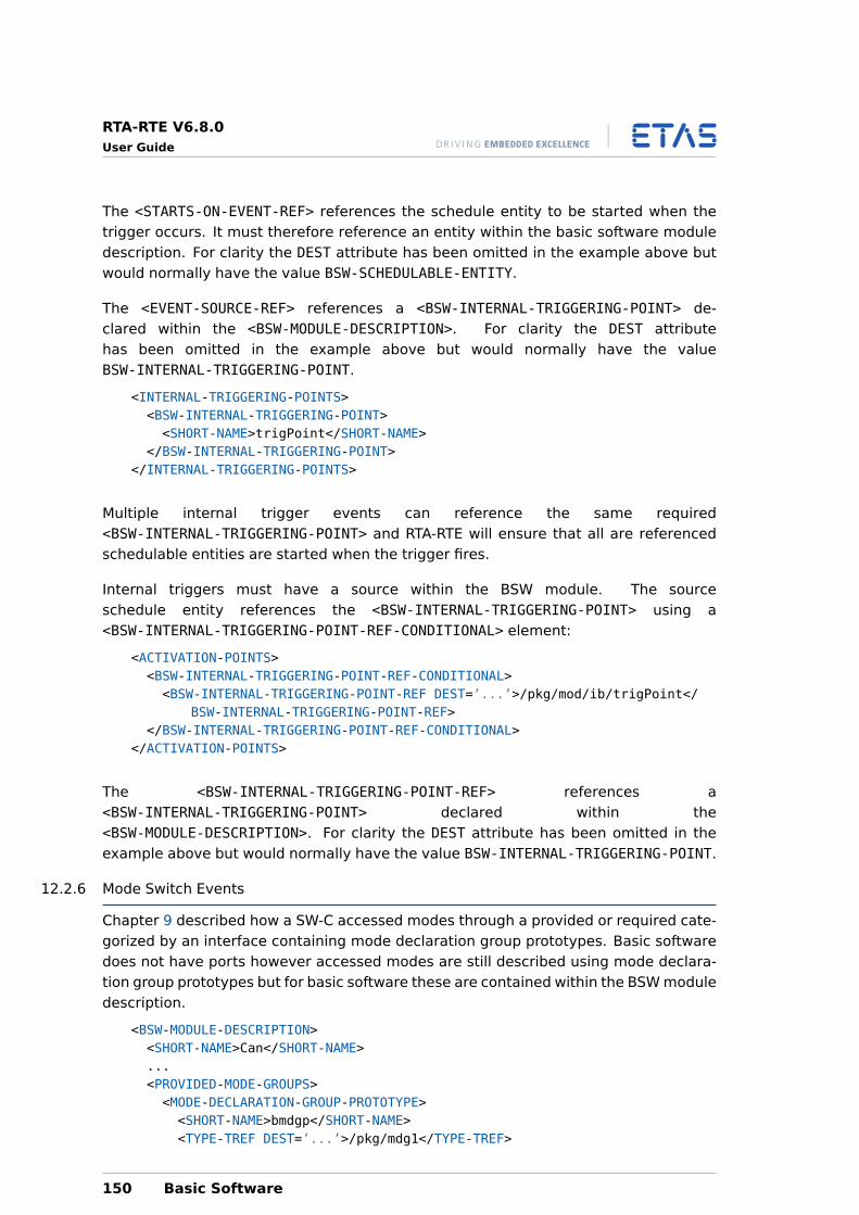
RTA-RTE V6.8.0User Guide
The <STARTS-ON-EVENT-REF> references the schedule entity to be started when thetrigger occurs. It must therefore reference an entity within the basic software moduledescription. For clarity the DEST attribute has been omitted in the example above butwould normally have the value BSW-SCHEDULABLE-ENTITY.
The <EVENT-SOURCE-REF> references a <BSW-INTERNAL-TRIGGERING-POINT> de-clared within the <BSW-MODULE-DESCRIPTION>. For clarity the DEST attributehas been omitted in the example above but would normally have the valueBSW-INTERNAL-TRIGGERING-POINT.
<INTERNAL-TRIGGERING-POINTS><BSW-INTERNAL-TRIGGERING-POINT><SHORT-NAME>trigPoint</SHORT-NAME>
</BSW-INTERNAL-TRIGGERING-POINT></INTERNAL-TRIGGERING-POINTS>
Multiple internal trigger events can reference the same required<BSW-INTERNAL-TRIGGERING-POINT> and RTA-RTE will ensure that all are referencedschedulable entities are started when the trigger fires.
Internal triggers must have a source within the BSW module. The sourceschedule entity references the <BSW-INTERNAL-TRIGGERING-POINT> using a<BSW-INTERNAL-TRIGGERING-POINT-REF-CONDITIONAL> element:
<ACTIVATION-POINTS><BSW-INTERNAL-TRIGGERING-POINT-REF-CONDITIONAL><BSW-INTERNAL-TRIGGERING-POINT-REF DEST=’...’>/pkg/mod/ib/trigPoint</
BSW-INTERNAL-TRIGGERING-POINT-REF></BSW-INTERNAL-TRIGGERING-POINT-REF-CONDITIONAL>
</ACTIVATION-POINTS>
The <BSW-INTERNAL-TRIGGERING-POINT-REF> references a<BSW-INTERNAL-TRIGGERING-POINT> declared within the<BSW-MODULE-DESCRIPTION>. For clarity the DEST attribute has been omitted in theexample above but would normally have the value BSW-INTERNAL-TRIGGERING-POINT.
12.2.6 Mode Switch Events
Chapter 9 described how a SW-C accessed modes through a provided or required cate-gorized by an interface containing mode declaration group prototypes. Basic softwaredoes not have ports however accessed modes are still described using mode declara-tion group prototypes but for basic software these are contained within the BSW moduledescription.
<BSW-MODULE-DESCRIPTION><SHORT-NAME>Can</SHORT-NAME>...<PROVIDED-MODE-GROUPS><MODE-DECLARATION-GROUP-PROTOTYPE><SHORT-NAME>bmdgp</SHORT-NAME><TYPE-TREF DEST=’...’>/pkg/mdg1</TYPE-TREF>
150 Basic Software
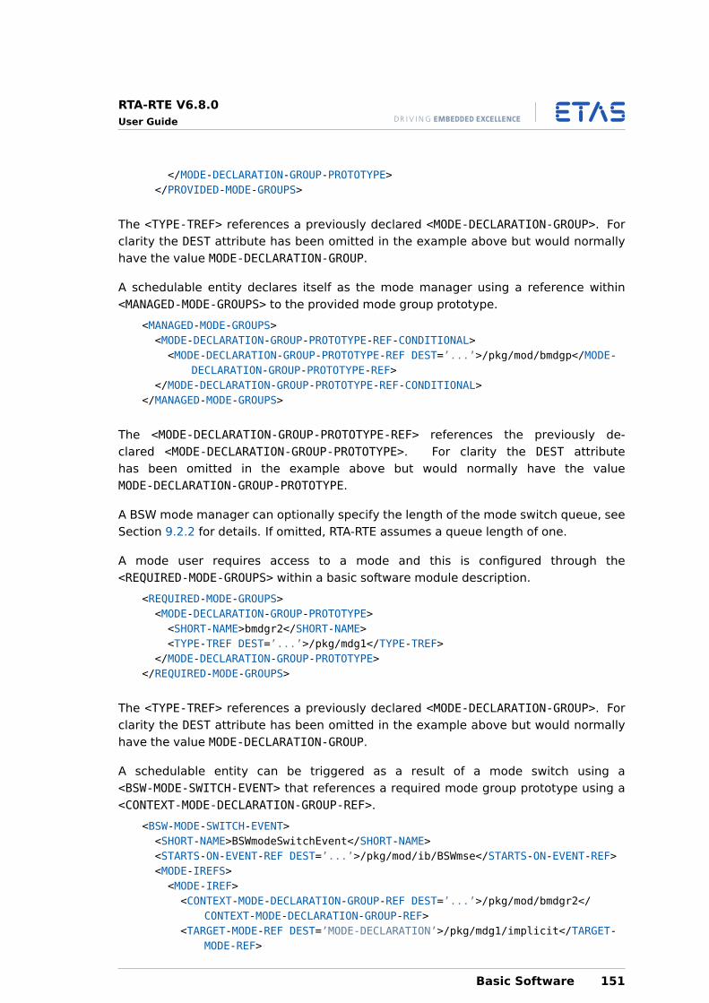
RTA-RTE V6.8.0User Guide
</MODE-DECLARATION-GROUP-PROTOTYPE></PROVIDED-MODE-GROUPS>
The <TYPE-TREF> references a previously declared <MODE-DECLARATION-GROUP>. Forclarity the DEST attribute has been omitted in the example above but would normallyhave the value MODE-DECLARATION-GROUP.
A schedulable entity declares itself as the mode manager using a reference within<MANAGED-MODE-GROUPS> to the provided mode group prototype.
<MANAGED-MODE-GROUPS><MODE-DECLARATION-GROUP-PROTOTYPE-REF-CONDITIONAL><MODE-DECLARATION-GROUP-PROTOTYPE-REF DEST=’...’>/pkg/mod/bmdgp</MODE-
DECLARATION-GROUP-PROTOTYPE-REF></MODE-DECLARATION-GROUP-PROTOTYPE-REF-CONDITIONAL>
</MANAGED-MODE-GROUPS>
The <MODE-DECLARATION-GROUP-PROTOTYPE-REF> references the previously de-clared <MODE-DECLARATION-GROUP-PROTOTYPE>. For clarity the DEST attributehas been omitted in the example above but would normally have the valueMODE-DECLARATION-GROUP-PROTOTYPE.
A BSW mode manager can optionally specify the length of the mode switch queue, seeSection 9.2.2 for details. If omitted, RTA-RTE assumes a queue length of one.
A mode user requires access to a mode and this is configured through the<REQUIRED-MODE-GROUPS> within a basic software module description.
<REQUIRED-MODE-GROUPS><MODE-DECLARATION-GROUP-PROTOTYPE><SHORT-NAME>bmdgr2</SHORT-NAME><TYPE-TREF DEST=’...’>/pkg/mdg1</TYPE-TREF>
</MODE-DECLARATION-GROUP-PROTOTYPE></REQUIRED-MODE-GROUPS>
The <TYPE-TREF> references a previously declared <MODE-DECLARATION-GROUP>. Forclarity the DEST attribute has been omitted in the example above but would normallyhave the value MODE-DECLARATION-GROUP.
A schedulable entity can be triggered as a result of a mode switch using a<BSW-MODE-SWITCH-EVENT> that references a required mode group prototype using a<CONTEXT-MODE-DECLARATION-GROUP-REF>.
<BSW-MODE-SWITCH-EVENT><SHORT-NAME>BSWmodeSwitchEvent</SHORT-NAME><STARTS-ON-EVENT-REF DEST=’...’>/pkg/mod/ib/BSWmse</STARTS-ON-EVENT-REF><MODE-IREFS><MODE-IREF><CONTEXT-MODE-DECLARATION-GROUP-REF DEST=’...’>/pkg/mod/bmdgr2</
CONTEXT-MODE-DECLARATION-GROUP-REF><TARGET-MODE-REF DEST=’MODE-DECLARATION’>/pkg/mdg1/implicit</TARGET-
MODE-REF>
Basic Software 151
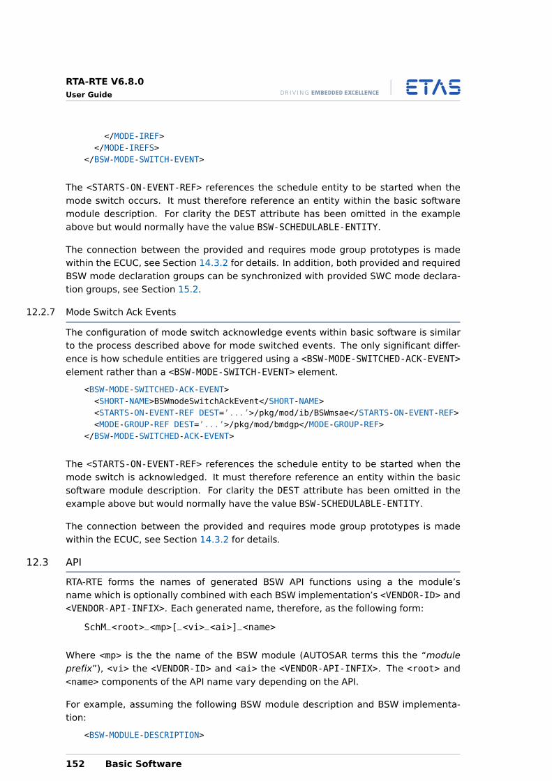
RTA-RTE V6.8.0User Guide
</MODE-IREF></MODE-IREFS>
</BSW-MODE-SWITCH-EVENT>
The <STARTS-ON-EVENT-REF> references the schedule entity to be started when themode switch occurs. It must therefore reference an entity within the basic softwaremodule description. For clarity the DEST attribute has been omitted in the exampleabove but would normally have the value BSW-SCHEDULABLE-ENTITY.
The connection between the provided and requires mode group prototypes is madewithin the ECUC, see Section 14.3.2 for details. In addition, both provided and requiredBSW mode declaration groups can be synchronized with provided SWC mode declara-tion groups, see Section 15.2.
12.2.7 Mode Switch Ack Events
The configuration of mode switch acknowledge events within basic software is similarto the process described above for mode switched events. The only significant differ-ence is how schedule entities are triggered using a <BSW-MODE-SWITCHED-ACK-EVENT>element rather than a <BSW-MODE-SWITCH-EVENT> element.
<BSW-MODE-SWITCHED-ACK-EVENT><SHORT-NAME>BSWmodeSwitchAckEvent</SHORT-NAME><STARTS-ON-EVENT-REF DEST=’...’>/pkg/mod/ib/BSWmsae</STARTS-ON-EVENT-REF><MODE-GROUP-REF DEST=’...’>/pkg/mod/bmdgp</MODE-GROUP-REF>
</BSW-MODE-SWITCHED-ACK-EVENT>
The <STARTS-ON-EVENT-REF> references the schedule entity to be started when themode switch is acknowledged. It must therefore reference an entity within the basicsoftware module description. For clarity the DEST attribute has been omitted in theexample above but would normally have the value BSW-SCHEDULABLE-ENTITY.
The connection between the provided and requires mode group prototypes is madewithin the ECUC, see Section 14.3.2 for details.
12.3 API
RTA-RTE forms the names of generated BSW API functions using a the module’sname which is optionally combined with each BSW implementation’s <VENDOR-ID> and<VENDOR-API-INFIX>. Each generated name, therefore, as the following form:
SchM_<root>_<mp>[_<vi>_<ai>]_<name>
Where <mp> is the the name of the BSW module (AUTOSAR terms this the “moduleprefix”), <vi> the <VENDOR-ID> and <ai> the <VENDOR-API-INFIX>. The <root> and<name> components of the API name vary depending on the API.
For example, assuming the following BSW module description and BSW implementa-tion:
<BSW-MODULE-DESCRIPTION>
152 Basic Software
RTA-RTE V6.8.0User Guide
<SHORT-NAME>Can</SHORT-NAME>...
</BSW-MODULE-DESCRIPTION>
<BSW-IMPLEMENTATION><SHORT-NAME>MyCanDrv</SHORT-NAME><VENDOR-ID>25</VENDOR-ID>...<VENDOR-API-INFIX>Dev0815</VENDOR-API-INFIX>
</BSW-IMPLEMENTATION>
RTA-RTE would generate API names of the form SchM_<root>_Can_25_Dev0815_<name>.
The specification of the <VENDOR-ID> and <VENDOR-API-INFIX> elements are op-tional. AUTOSAR defines that if the <VENDOR-API-INFIX> is omitted then both the<VENDOR-ID> and <VENDOR-API-INFIX> elements are omitted from the generatednames.
Basic Software 153

RTA-RTE V6.8.0User Guide
Part IV
Composition
154
RTA-RTE V6.8.0User Guide
13 Composing Software Components
In Part II you saw how to define software components, their internal behaviour andtheir implementation characteristics. In this chapter you will see how to assemble,or compose, applications from the components you have defined (or that have beendefined for you).
AUTOSAR uses a <COMPOSITION-TYPE> to define which prototypes, of which softwarecomponent types, you will have in your system and how their ports are connected at theabstract level. Each composition therefore represents a logical assembly of interactingsoftware components.
Each composition creates a logical software system for deployment on one or moreECUs. Every system that you need to deploy will have at least one “master” com-position that defines how all software component prototypes are connected as shownbelow.
However, it may be the case you need to define one or more compositions to logicallypartition your vehicle system. For example, you might define compositions for body,chassis and powertrain. This will allow you to define how these groups of componentprototypes are deployed if you need to allocate components from some applicationsonto specific ECUs.
13.1 Composition Type Definition
All composition information is contained in an <AR-PACKAGE> element.
<AR-PACKAGE><SHORT-NAME>MyComposition</SHORT-NAME><ELEMENTS><COMPOSITION-TYPE>...
</COMPOSITION-TYPE></ELEMENTS>
</AR-PACKAGE>
The <COMPOSITION-TYPE> element is used to instantiate one or more software compo-nent types and the connections between the component prototypes.
<COMPOSITION-TYPE><SHORT-NAME>MyComposition</SHORT-NAME><PORTS>...
</PORTS><COMPONENTS>...
</COMPONENTS><CONNECTORS>...
</CONNECTORS></COMPOSITION-TYPE>
Composing Software Components 155
RTA-RTE V6.8.0User Guide
The <COMPONENTS> element is used to instantiate one or more SWC-type definitions.The <CONNECTORS> element is used to create connections between ports defined oncomponent prototypes. The <PORTS> element is used to create ports for use with dele-gation connectors.
A composition defines a group of connected software component prototypes and pro-vides a mechanism for hierarchical composition of systems. However, the individualcomponent prototypes within the composition can be allocated onto different ECU in-stances at system definition time (see Section 17.1).
13.2 Component Instances
The <COMPONENTS> element within a <COMPOSITION-TYPE> is used to instantiate one ormore SWC-type definitions.
Each component type can be instantiated multiple times, but each instance must begiven a unique name.
The <SW-COMPONENT-PROTOTYPE> element provides a name for the component instanceand provides a reference to the type description. The following description:
<COMPONENTS><SW-COMPONENT-PROTOTYPE><SHORT-NAME>John</SHORT-NAME><TYPE-TREF>/pkg/PersonType</TYPE-TREF>
</SW-COMPONENT-PROTOTYPE>
<SW-COMPONENT-PROTOTYPE><SHORT-NAME>Jane</SHORT-NAME><TYPE-TREF>/pkg/PersonType</TYPE-TREF>
</SW-COMPONENT-PROTOTYPE>
<SW-COMPONENT-PROTOTYPE><SHORT-NAME>Cafe</SHORT-NAME><TYPE-TREF>/pkg/BusinessType</TYPE-TREF>
</SW-COMPONENT-PROTOTYPE></COMPONENTS>
Creates the instances shown in Figure 13.1.
13.3 Connector Prototypes
As well as defining component prototypes, a <COMPOSITION-TYPE> element includesthe <ASSEMBLY-CONNECTOR> definitions that connect ports between component proto-types and the <DELEGATION-CONNECTOR> elements that connect ports within a compo-sition to elements outside the composition.
13.3.1 Assembly Connectors
An assembly connector is used to connect provided and required ports within a com-position.
<CONNECTORS>
156 Composing Software Components
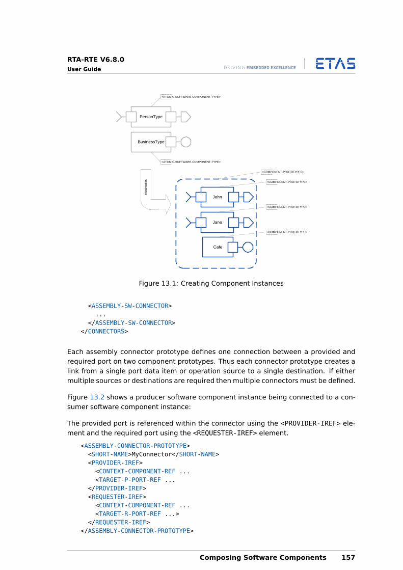
RTA-RTE V6.8.0User Guide
PersonType
John
Jane
<ATOMIC-SOFTWARE-COMPONENT-TYPE>
<COMPONENT-PROTOTYPES>
BusinessType
<ATOMIC-SOFTWARE-COMPONENT-TYPE>
Cafe
<COMPONENT-PROTOTYPE>
<COMPONENT-PROTOTYPE>
<COMPONENT-PROTOTYPE>
Inst
antia
tion
Figure 13.1: Creating Component Instances
<ASSEMBLY-SW-CONNECTOR>...
</ASSEMBLY-SW-CONNECTOR></CONNECTORS>
Each assembly connector prototype defines one connection between a provided andrequired port on two component prototypes. Thus each connector prototype creates alink from a single port data item or operation source to a single destination. If eithermultiple sources or destinations are required then multiple connectors must be defined.
Figure 13.2 shows a producer software component instance being connected to a con-sumer software component instance:
The provided port is referenced within the connector using the <PROVIDER-IREF> ele-ment and the required port using the <REQUESTER-IREF> element.
<ASSEMBLY-CONNECTOR-PROTOTYPE><SHORT-NAME>MyConnector</SHORT-NAME><PROVIDER-IREF><CONTEXT-COMPONENT-REF ...<TARGET-P-PORT-REF ...
</PROVIDER-IREF><REQUESTER-IREF><CONTEXT-COMPONENT-REF ...<TARGET-R-PORT-REF ...>
</REQUESTER-IREF></ASSEMBLY-CONNECTOR-PROTOTYPE>
Composing Software Components 157
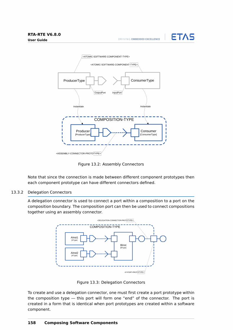
RTA-RTE V6.8.0User Guide
COMPOSITION-TYPE
Consumer[ConsumerType]
ProducerType
Producer[ProducerType]
ConsumerType
Instantiate
<ASSEMBLY-CONNECTOR-PROTOTYPE>
<ATOMIC-SOFTWARE-COMPONENT-TYPE>
<ATOMIC-SOFTWARE-COMPONENT-TYPE>
OutputPort InputPort
Instantiate
Figure 13.2: Assembly Connectors
Note that since the connection is made between different component prototypes theneach component prototype can have different connectors defined.
13.3.2 Delegation Connectors
A delegation connector is used to connect a port within a composition to a port on thecomposition boundary. The composition port can then be used to connect compositionstogether using an assembly connector.
AInst2[AType]
BInst[BType]
AInst1[AType]
COMPOSITION-TYPE
<DELEGATION-CONNECTOR-PROTOTYPE>
<P-PORT-PROTOTYPE>
Figure 13.3: Delegation Connectors
To create and use a delegation connector, one must first create a port prototype withinthe composition type — this port will form one “end” of the connector. The port iscreated in a form that is identical when port prototypes are created within a softwarecomponent.
158 Composing Software Components
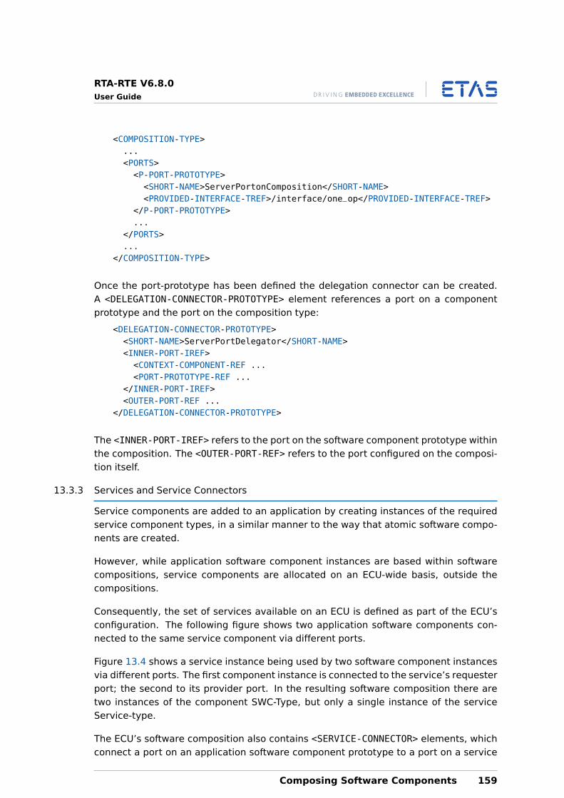
RTA-RTE V6.8.0User Guide
<COMPOSITION-TYPE>...<PORTS><P-PORT-PROTOTYPE><SHORT-NAME>ServerPortonComposition</SHORT-NAME><PROVIDED-INTERFACE-TREF>/interface/one_op</PROVIDED-INTERFACE-TREF>
</P-PORT-PROTOTYPE>...
</PORTS>...
</COMPOSITION-TYPE>
Once the port-prototype has been defined the delegation connector can be created.A <DELEGATION-CONNECTOR-PROTOTYPE> element references a port on a componentprototype and the port on the composition type:
<DELEGATION-CONNECTOR-PROTOTYPE><SHORT-NAME>ServerPortDelegator</SHORT-NAME><INNER-PORT-IREF><CONTEXT-COMPONENT-REF ...<PORT-PROTOTYPE-REF ...
</INNER-PORT-IREF><OUTER-PORT-REF ...
</DELEGATION-CONNECTOR-PROTOTYPE>
The <INNER-PORT-IREF> refers to the port on the software component prototype withinthe composition. The <OUTER-PORT-REF> refers to the port configured on the composi-tion itself.
13.3.3 Services and Service Connectors
Service components are added to an application by creating instances of the requiredservice component types, in a similar manner to the way that atomic software compo-nents are created.
However, while application software component instances are based within softwarecompositions, service components are allocated on an ECU-wide basis, outside thecompositions.
Consequently, the set of services available on an ECU is defined as part of the ECU’sconfiguration. The following figure shows two application software components con-nected to the same service component via different ports.
Figure 13.4 shows a service instance being used by two software component instancesvia different ports. The first component instance is connected to the service’s requesterport; the second to its provider port. In the resulting software composition there aretwo instances of the component SWC-Type, but only a single instance of the serviceService-type.
The ECU’s software composition also contains <SERVICE-CONNECTOR> elements, whichconnect a port on an application software component prototype to a port on a service
Composing Software Components 159
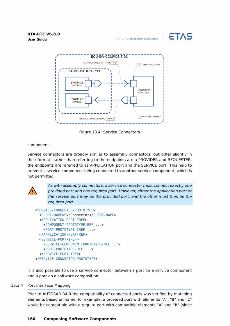
RTA-RTE V6.8.0User Guide
SWCInst2[SWCType]
ServiceInst[ServiceType]
SWCInst1[SWCType]
COMPOSITION-TYPE
<SERVICE-CONNECTOR-PROTOTYPE><R-PORT-PROTOTYPE>
<P-PORT-PROTOTYPE>
ECU-SW-COMPOSITION
<SERVICE-CONNECTOR-PROTOTYPE>
Figure 13.4: Service Connectors
component.
Service connectors are broadly similar to assembly connectors, but differ slightly intheir format: rather than referring to the endpoints are a PROVIDER and REQUESTER,the endpoints are referred to as APPLICATION port and the SERVICE port. This help toprevent a service component being connected to another service component, which isnot permitted.
As with assembly connectors, a service connector must connect exactly oneprovided port and one required port. However, either the application port orthe service port may be the provided port, and the other must then be therequired port.
<SERVICE-CONNECTOR-PROTOTYPE><SHORT-NAME>SvcConnector</SHORT-NAME><APPLICATION-PORT-IREF><COMPONENT-PROTOTYPE-REF ...><PORT-PROTOTYPE-IREF ...>
</APPLICATION-PORT-REF><SERVICE-PORT-IREF><SERVICE-COMPONENT-PROTOTYPE-REF ...><PORT-PROTOTYPE-REF ...>
</SERVICE-PORT-IREF></SERVICE-CONNECTOR-PROTOTYPE>
It is also possible to use a service connector between a port on a service componentand a port on a software composition.
13.3.4 Port Interface Mapping
Prior to AUTOSAR R4.0 the compatibility of connected ports was verified by matchingelements based on name, for example, a provided port with elements “A”, “B” and “C”would be compatible with a require port with compatible elements “A” and “B” (since
160 Composing Software Components
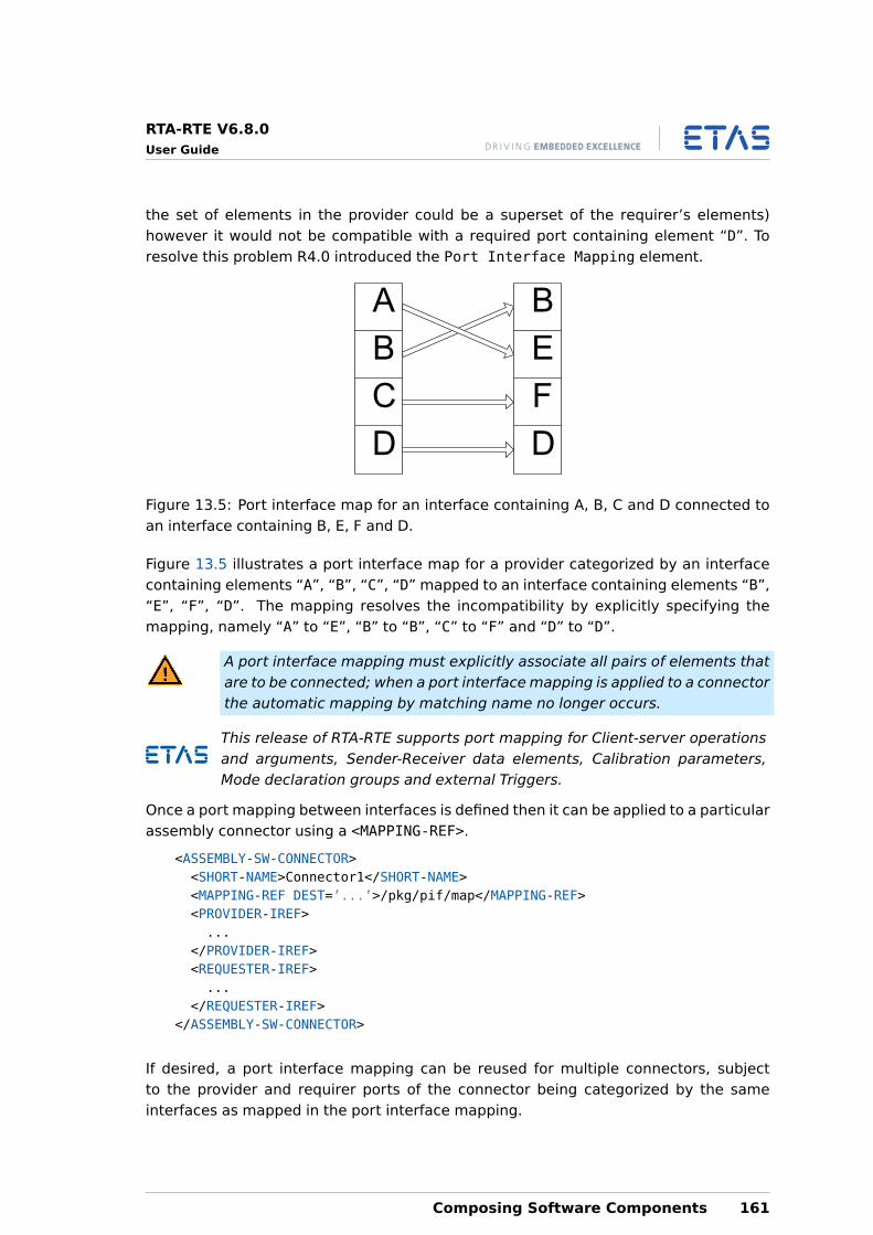
RTA-RTE V6.8.0User Guide
the set of elements in the provider could be a superset of the requirer’s elements)however it would not be compatible with a required port containing element “D”. Toresolve this problem R4.0 introduced the Port Interface Mapping element.
B
D
C
B
D
F
E
A
Figure 13.5: Port interface map for an interface containing A, B, C and D connected toan interface containing B, E, F and D.
Figure 13.5 illustrates a port interface map for a provider categorized by an interfacecontaining elements “A”, “B”, “C”, “D” mapped to an interface containing elements “B”,“E”, “F”, “D”. The mapping resolves the incompatibility by explicitly specifying themapping, namely “A” to “E”, “B” to “B”, “C” to “F” and “D” to “D”.
A port interface mapping must explicitly associate all pairs of elements thatare to be connected; when a port interface mapping is applied to a connectorthe automatic mapping by matching name no longer occurs.
This release of RTA-RTE supports port mapping for Client-server operationsand arguments, Sender-Receiver data elements, Calibration parameters,Mode declaration groups and external Triggers.
Once a port mapping between interfaces is defined then it can be applied to a particularassembly connector using a <MAPPING-REF>.
<ASSEMBLY-SW-CONNECTOR><SHORT-NAME>Connector1</SHORT-NAME><MAPPING-REF DEST=’...’>/pkg/pif/map</MAPPING-REF><PROVIDER-IREF>...
</PROVIDER-IREF><REQUESTER-IREF>...
</REQUESTER-IREF></ASSEMBLY-SW-CONNECTOR>
If desired, a port interface mapping can be reused for multiple connectors, subjectto the provider and requirer ports of the connector being categorized by the sameinterfaces as mapped in the port interface mapping.
Composing Software Components 161
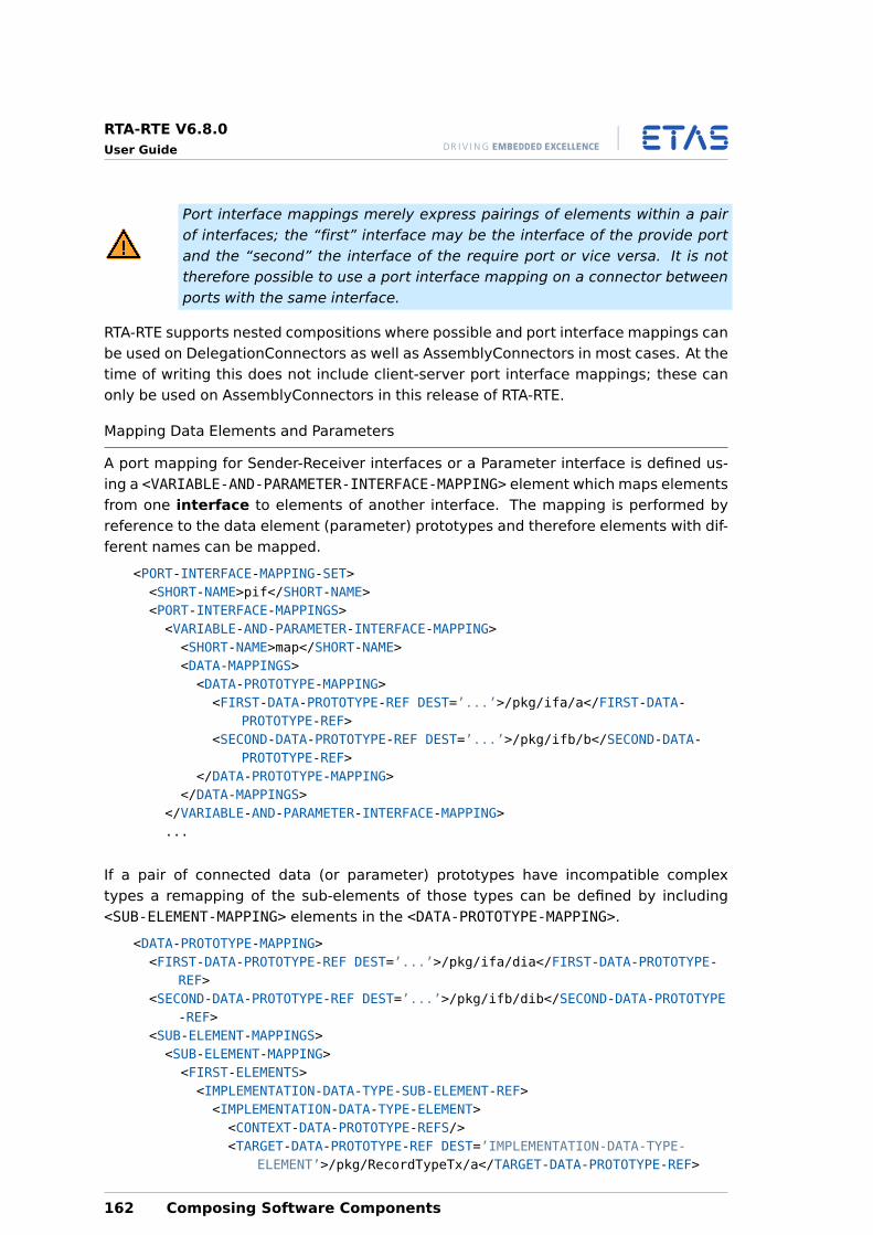
RTA-RTE V6.8.0User Guide
Port interface mappings merely express pairings of elements within a pairof interfaces; the “first” interface may be the interface of the provide portand the “second” the interface of the require port or vice versa. It is nottherefore possible to use a port interface mapping on a connector betweenports with the same interface.
RTA-RTE supports nested compositions where possible and port interface mappings canbe used on DelegationConnectors as well as AssemblyConnectors in most cases. At thetime of writing this does not include client-server port interface mappings; these canonly be used on AssemblyConnectors in this release of RTA-RTE.
Mapping Data Elements and Parameters
A port mapping for Sender-Receiver interfaces or a Parameter interface is defined us-ing a <VARIABLE-AND-PARAMETER-INTERFACE-MAPPING> element which maps elementsfrom one interface to elements of another interface. The mapping is performed byreference to the data element (parameter) prototypes and therefore elements with dif-ferent names can be mapped.
<PORT-INTERFACE-MAPPING-SET><SHORT-NAME>pif</SHORT-NAME><PORT-INTERFACE-MAPPINGS><VARIABLE-AND-PARAMETER-INTERFACE-MAPPING><SHORT-NAME>map</SHORT-NAME><DATA-MAPPINGS><DATA-PROTOTYPE-MAPPING><FIRST-DATA-PROTOTYPE-REF DEST=’...’>/pkg/ifa/a</FIRST-DATA-
PROTOTYPE-REF><SECOND-DATA-PROTOTYPE-REF DEST=’...’>/pkg/ifb/b</SECOND-DATA-
PROTOTYPE-REF></DATA-PROTOTYPE-MAPPING>
</DATA-MAPPINGS></VARIABLE-AND-PARAMETER-INTERFACE-MAPPING>...
If a pair of connected data (or parameter) prototypes have incompatible complextypes a remapping of the sub-elements of those types can be defined by including<SUB-ELEMENT-MAPPING> elements in the <DATA-PROTOTYPE-MAPPING>.
<DATA-PROTOTYPE-MAPPING><FIRST-DATA-PROTOTYPE-REF DEST=’...’>/pkg/ifa/dia</FIRST-DATA-PROTOTYPE-
REF><SECOND-DATA-PROTOTYPE-REF DEST=’...’>/pkg/ifb/dib</SECOND-DATA-PROTOTYPE
-REF><SUB-ELEMENT-MAPPINGS><SUB-ELEMENT-MAPPING><FIRST-ELEMENTS><IMPLEMENTATION-DATA-TYPE-SUB-ELEMENT-REF><IMPLEMENTATION-DATA-TYPE-ELEMENT><CONTEXT-DATA-PROTOTYPE-REFS/><TARGET-DATA-PROTOTYPE-REF DEST=’IMPLEMENTATION-DATA-TYPE-
ELEMENT’>/pkg/RecordTypeTx/a</TARGET-DATA-PROTOTYPE-REF>
162 Composing Software Components
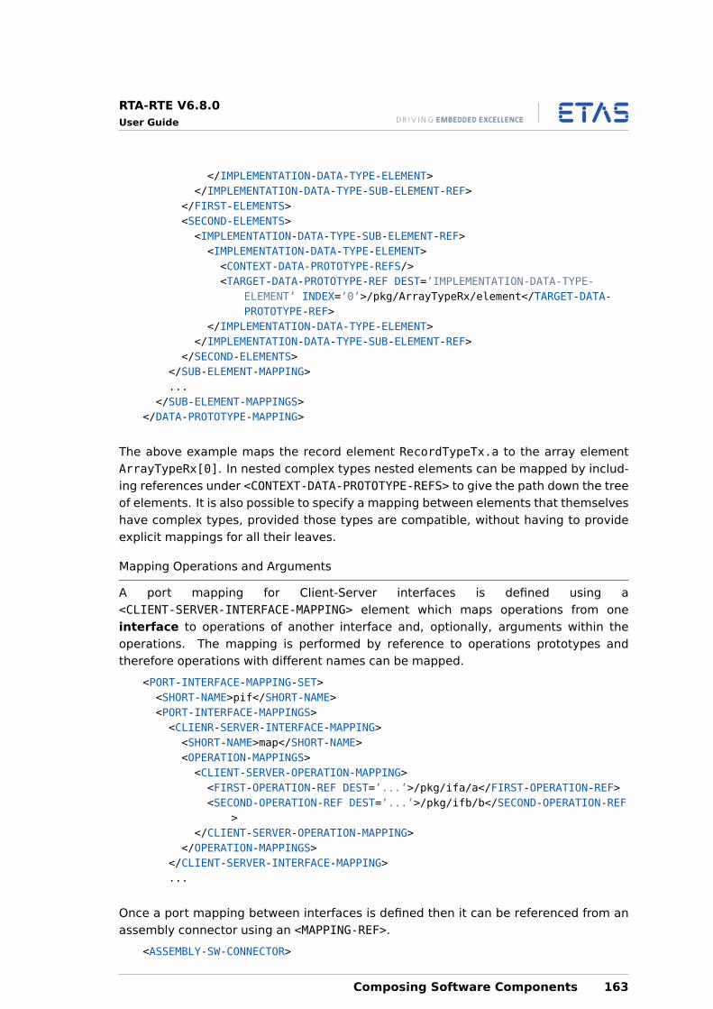
RTA-RTE V6.8.0User Guide
</IMPLEMENTATION-DATA-TYPE-ELEMENT></IMPLEMENTATION-DATA-TYPE-SUB-ELEMENT-REF>
</FIRST-ELEMENTS><SECOND-ELEMENTS><IMPLEMENTATION-DATA-TYPE-SUB-ELEMENT-REF><IMPLEMENTATION-DATA-TYPE-ELEMENT><CONTEXT-DATA-PROTOTYPE-REFS/><TARGET-DATA-PROTOTYPE-REF DEST=’IMPLEMENTATION-DATA-TYPE-
ELEMENT’ INDEX=’0’>/pkg/ArrayTypeRx/element</TARGET-DATA-PROTOTYPE-REF>
</IMPLEMENTATION-DATA-TYPE-ELEMENT></IMPLEMENTATION-DATA-TYPE-SUB-ELEMENT-REF>
</SECOND-ELEMENTS></SUB-ELEMENT-MAPPING>...
</SUB-ELEMENT-MAPPINGS></DATA-PROTOTYPE-MAPPING>
The above example maps the record element RecordTypeTx.a to the array elementArrayTypeRx[0]. In nested complex types nested elements can be mapped by includ-ing references under <CONTEXT-DATA-PROTOTYPE-REFS> to give the path down the treeof elements. It is also possible to specify a mapping between elements that themselveshave complex types, provided those types are compatible, without having to provideexplicit mappings for all their leaves.
Mapping Operations and Arguments
A port mapping for Client-Server interfaces is defined using a<CLIENT-SERVER-INTERFACE-MAPPING> element which maps operations from oneinterface to operations of another interface and, optionally, arguments within theoperations. The mapping is performed by reference to operations prototypes andtherefore operations with different names can be mapped.
<PORT-INTERFACE-MAPPING-SET><SHORT-NAME>pif</SHORT-NAME><PORT-INTERFACE-MAPPINGS><CLIENR-SERVER-INTERFACE-MAPPING><SHORT-NAME>map</SHORT-NAME><OPERATION-MAPPINGS><CLIENT-SERVER-OPERATION-MAPPING><FIRST-OPERATION-REF DEST=’...’>/pkg/ifa/a</FIRST-OPERATION-REF><SECOND-OPERATION-REF DEST=’...’>/pkg/ifb/b</SECOND-OPERATION-REF
></CLIENT-SERVER-OPERATION-MAPPING>
</OPERATION-MAPPINGS></CLIENT-SERVER-INTERFACE-MAPPING>...
Once a port mapping between interfaces is defined then it can be referenced from anassembly connector using an <MAPPING-REF>.
<ASSEMBLY-SW-CONNECTOR>
Composing Software Components 163
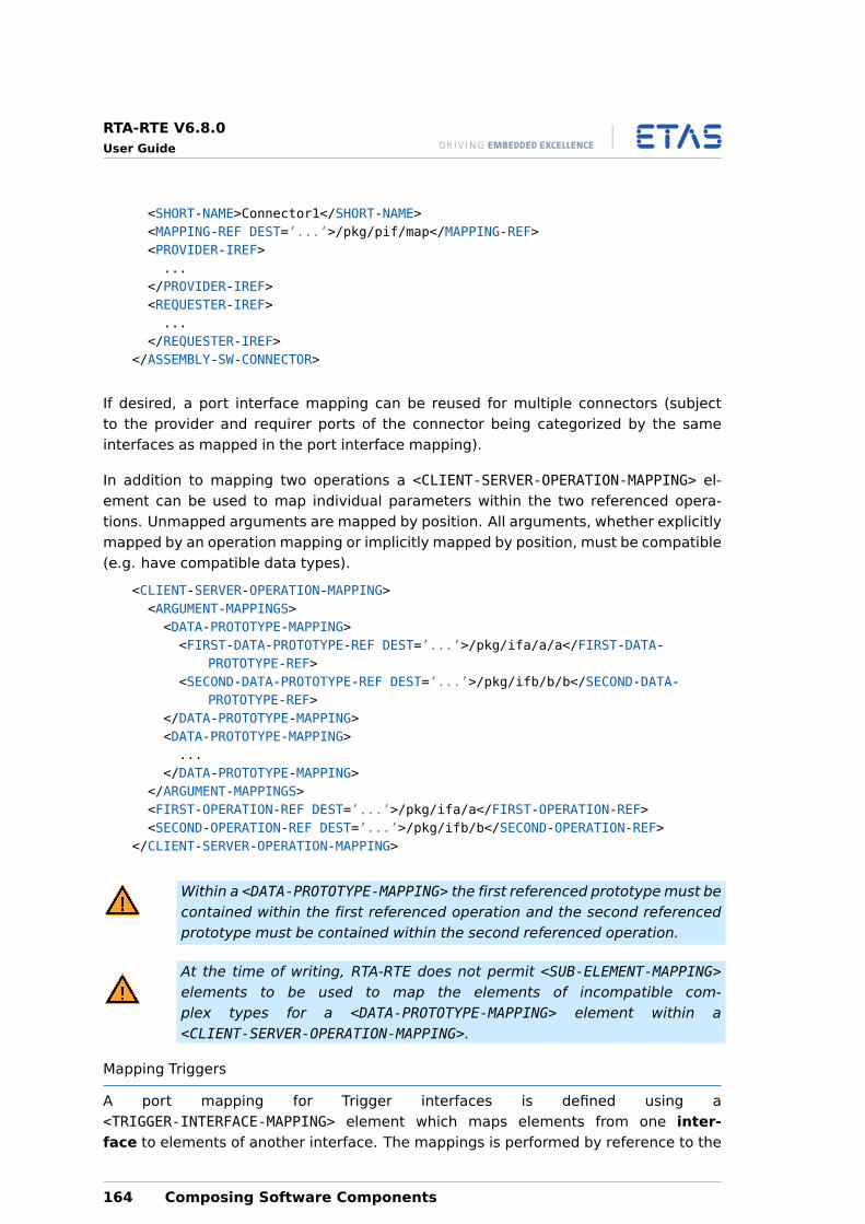
RTA-RTE V6.8.0User Guide
<SHORT-NAME>Connector1</SHORT-NAME><MAPPING-REF DEST=’...’>/pkg/pif/map</MAPPING-REF><PROVIDER-IREF>...
</PROVIDER-IREF><REQUESTER-IREF>...
</REQUESTER-IREF></ASSEMBLY-SW-CONNECTOR>
If desired, a port interface mapping can be reused for multiple connectors (subjectto the provider and requirer ports of the connector being categorized by the sameinterfaces as mapped in the port interface mapping).
In addition to mapping two operations a <CLIENT-SERVER-OPERATION-MAPPING> el-ement can be used to map individual parameters within the two referenced opera-tions. Unmapped arguments are mapped by position. All arguments, whether explicitlymapped by an operation mapping or implicitly mapped by position, must be compatible(e.g. have compatible data types).
<CLIENT-SERVER-OPERATION-MAPPING><ARGUMENT-MAPPINGS><DATA-PROTOTYPE-MAPPING><FIRST-DATA-PROTOTYPE-REF DEST=’...’>/pkg/ifa/a/a</FIRST-DATA-
PROTOTYPE-REF><SECOND-DATA-PROTOTYPE-REF DEST=’...’>/pkg/ifb/b/b</SECOND-DATA-
PROTOTYPE-REF></DATA-PROTOTYPE-MAPPING><DATA-PROTOTYPE-MAPPING>...
</DATA-PROTOTYPE-MAPPING></ARGUMENT-MAPPINGS><FIRST-OPERATION-REF DEST=’...’>/pkg/ifa/a</FIRST-OPERATION-REF><SECOND-OPERATION-REF DEST=’...’>/pkg/ifb/b</SECOND-OPERATION-REF>
</CLIENT-SERVER-OPERATION-MAPPING>
Within a <DATA-PROTOTYPE-MAPPING> the first referenced prototype must becontained within the first referenced operation and the second referencedprototype must be contained within the second referenced operation.
At the time of writing, RTA-RTE does not permit <SUB-ELEMENT-MAPPING>elements to be used to map the elements of incompatible com-plex types for a <DATA-PROTOTYPE-MAPPING> element within a<CLIENT-SERVER-OPERATION-MAPPING>.
Mapping Triggers
A port mapping for Trigger interfaces is defined using a<TRIGGER-INTERFACE-MAPPING> element which maps elements from one inter-face to elements of another interface. The mappings is performed by reference to the
164 Composing Software Components
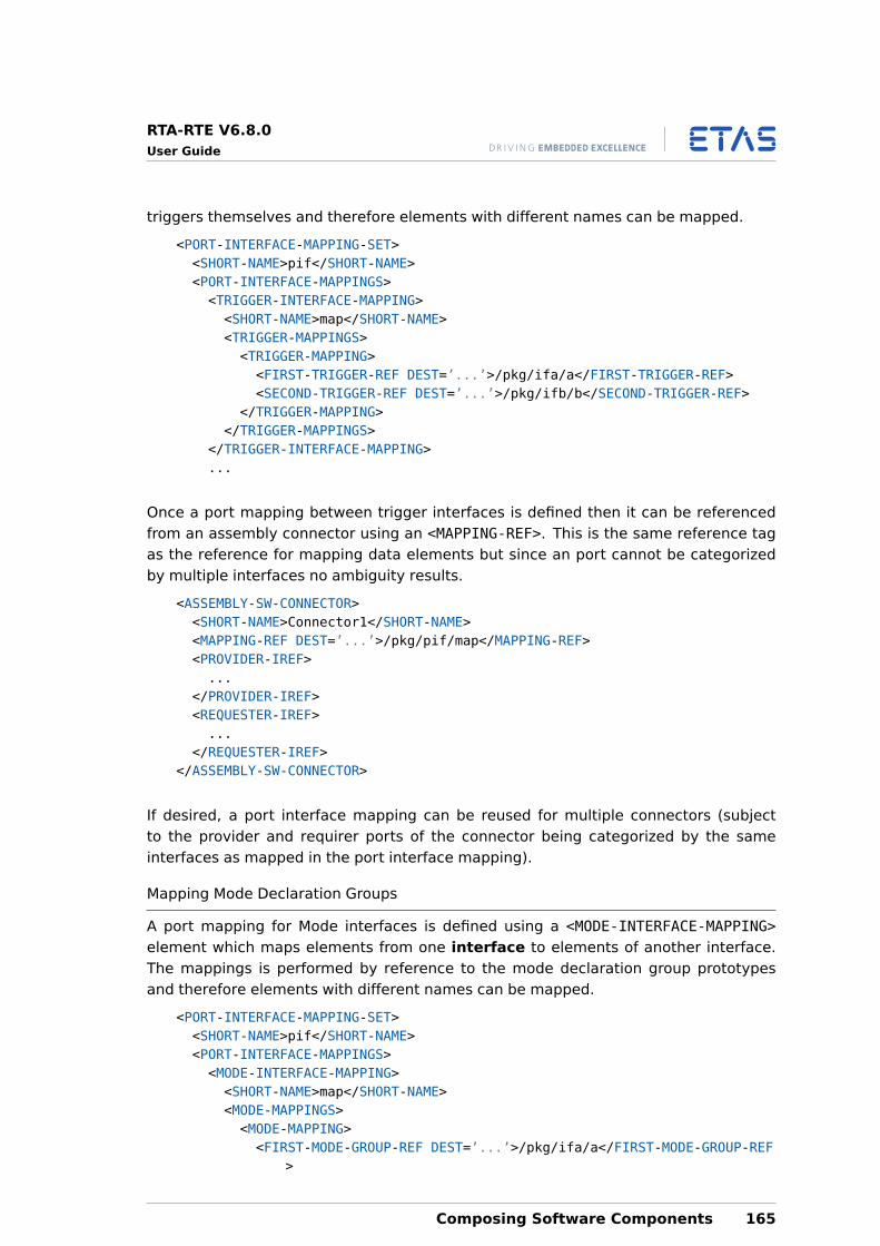
RTA-RTE V6.8.0User Guide
triggers themselves and therefore elements with different names can be mapped.
<PORT-INTERFACE-MAPPING-SET><SHORT-NAME>pif</SHORT-NAME><PORT-INTERFACE-MAPPINGS><TRIGGER-INTERFACE-MAPPING><SHORT-NAME>map</SHORT-NAME><TRIGGER-MAPPINGS><TRIGGER-MAPPING><FIRST-TRIGGER-REF DEST=’...’>/pkg/ifa/a</FIRST-TRIGGER-REF><SECOND-TRIGGER-REF DEST=’...’>/pkg/ifb/b</SECOND-TRIGGER-REF>
</TRIGGER-MAPPING></TRIGGER-MAPPINGS>
</TRIGGER-INTERFACE-MAPPING>...
Once a port mapping between trigger interfaces is defined then it can be referencedfrom an assembly connector using an <MAPPING-REF>. This is the same reference tagas the reference for mapping data elements but since an port cannot be categorizedby multiple interfaces no ambiguity results.
<ASSEMBLY-SW-CONNECTOR><SHORT-NAME>Connector1</SHORT-NAME><MAPPING-REF DEST=’...’>/pkg/pif/map</MAPPING-REF><PROVIDER-IREF>...
</PROVIDER-IREF><REQUESTER-IREF>...
</REQUESTER-IREF></ASSEMBLY-SW-CONNECTOR>
If desired, a port interface mapping can be reused for multiple connectors (subjectto the provider and requirer ports of the connector being categorized by the sameinterfaces as mapped in the port interface mapping).
Mapping Mode Declaration Groups
A port mapping for Mode interfaces is defined using a <MODE-INTERFACE-MAPPING>element which maps elements from one interface to elements of another interface.The mappings is performed by reference to the mode declaration group prototypesand therefore elements with different names can be mapped.
<PORT-INTERFACE-MAPPING-SET><SHORT-NAME>pif</SHORT-NAME><PORT-INTERFACE-MAPPINGS><MODE-INTERFACE-MAPPING><SHORT-NAME>map</SHORT-NAME><MODE-MAPPINGS><MODE-MAPPING><FIRST-MODE-GROUP-REF DEST=’...’>/pkg/ifa/a</FIRST-MODE-GROUP-REF
>
Composing Software Components 165
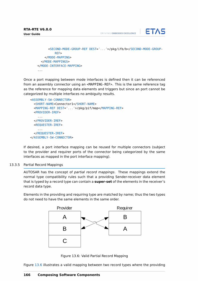
RTA-RTE V6.8.0User Guide
<SECOND-MODE-GROUP-REF DEST=’...’>/pkg/ifb/b</SECOND-MODE-GROUP-REF>
</MODE-MAPPING></MODE-MAPPINGS>
</MODE-INTERFACE-MAPPING>...
Once a port mapping between mode interfaces is defined then it can be referencedfrom an assembly connector using an <MAPPING-REF>. This is the same reference tagas the reference for mapping data elements and triggers but since an port cannot becategorized by multiple interfaces no ambiguity results.
<ASSEMBLY-SW-CONNECTOR><SHORT-NAME>Connector1</SHORT-NAME><MAPPING-REF DEST=’...’>/pkg/pif/map</MAPPING-REF><PROVIDER-IREF>...
</PROVIDER-IREF><REQUESTER-IREF>...
</REQUESTER-IREF></ASSEMBLY-SW-CONNECTOR>
If desired, a port interface mapping can be reused for multiple connectors (subjectto the provider and requirer ports of the connector being categorized by the sameinterfaces as mapped in the port interface mapping).
13.3.5 Partial Record Mappings
AUTOSAR has the concept of partial record mappings. These mappings extend thenormal type compatibility rules such that a providing Sender-receiver data elementthat is typed by a record type can contain a super-set of the elements in the receiver’srecord data type.
Elements in the providing and requiring type are matched by name; thus the two typesdo not need to have the same elements in the same order.
A
A
C
B
B
Provider Requirer
Figure 13.6: Valid Partial Record Mapping
Figure 13.6 illustrates a valid mapping between two record types where the providing
166 Composing Software Components
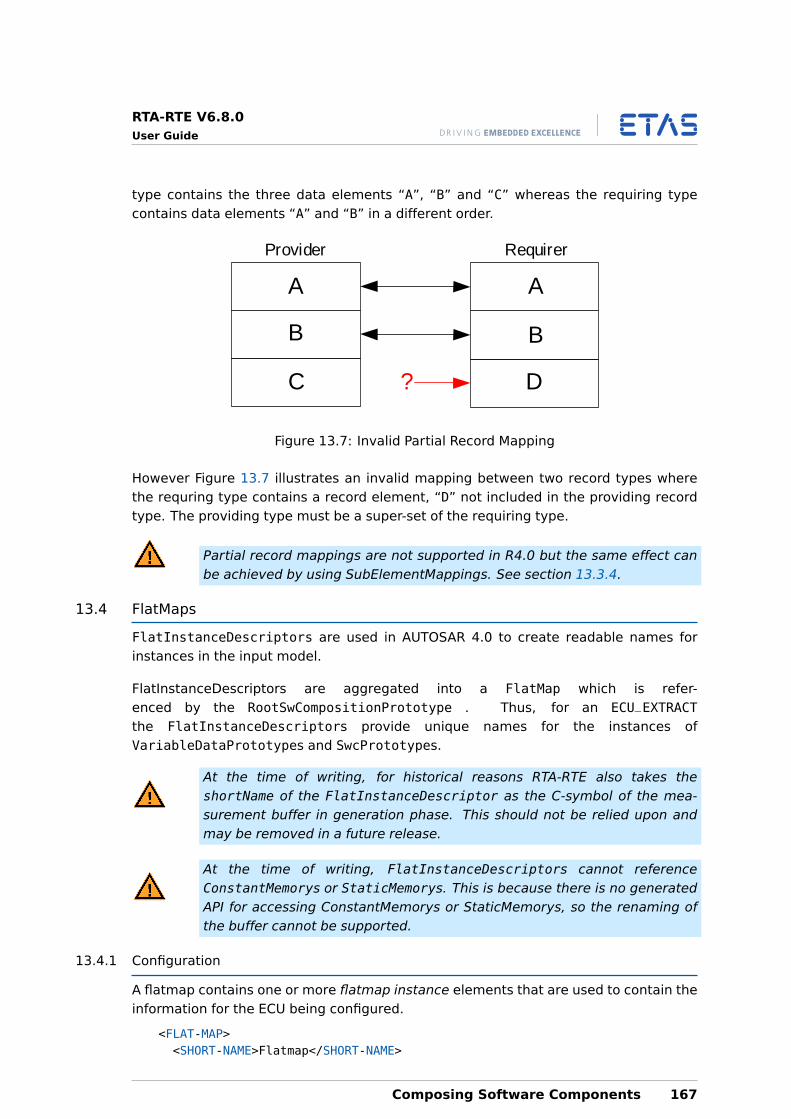
RTA-RTE V6.8.0User Guide
type contains the three data elements “A”, “B” and “C” whereas the requiring typecontains data elements “A” and “B” in a different order.
A
DC
B B
Provider Requirer
A
?
Figure 13.7: Invalid Partial Record Mapping
However Figure 13.7 illustrates an invalid mapping between two record types wherethe requring type contains a record element, “D” not included in the providing recordtype. The providing type must be a super-set of the requiring type.
Partial record mappings are not supported in R4.0 but the same effect canbe achieved by using SubElementMappings. See section 13.3.4.
13.4 FlatMaps
FlatInstanceDescriptors are used in AUTOSAR 4.0 to create readable names forinstances in the input model.
FlatInstanceDescriptors are aggregated into a FlatMap which is refer-enced by the RootSwCompositionPrototype . Thus, for an ECU_EXTRACTthe FlatInstanceDescriptors provide unique names for the instances ofVariableDataPrototypes and SwcPrototypes.
At the time of writing, for historical reasons RTA-RTE also takes theshortName of the FlatInstanceDescriptor as the C-symbol of the mea-surement buffer in generation phase. This should not be relied upon andmay be removed in a future release.
At the time of writing, FlatInstanceDescriptors cannot referenceConstantMemorys or StaticMemorys. This is because there is no generatedAPI for accessing ConstantMemorys or StaticMemorys, so the renaming ofthe buffer cannot be supported.
13.4.1 Configuration
A flatmap contains one or more flatmap instance elements that are used to contain theinformation for the ECU being configured.
<FLAT-MAP><SHORT-NAME>Flatmap</SHORT-NAME>
Composing Software Components 167
RTA-RTE V6.8.0User Guide
<INSTANCES><FLAT-INSTANCE-DESCRIPTOR>...
</FLAT-INSTANCE-DESCRIPTOR></INSTANCES>
</FLAT-MAP>
A flatmap instance contain an instance references, the “ecu-extract” reference to theassociated element (data element, inter-runnable variable, etc.) instance.
<FLAT-INSTANCE-DESCRIPTOR><SHORT-NAME>my_argument_buffer</SHORT-NAME><ECU-EXTRACT-REFERENCE-IREF>...
</ECU-EXTRACT-REFERENCE-IREF></FLAT-INSTANCE-DESCRIPTOR>
The ECU extract instance reference within a flatmap instance may require multipleCONTEXT nodes to identify the correct element. For example, when referencing a dataelement as well as the component prototype reference an additional two referencesare required to specify the port prototype and the data element.
A flatmap is associated with the ECU extract by a reference defined within the<ROOT-SW-COMPOSITION-PROTOTYPE> element:
<ROOT-SW-COMPOSITION-PROTOTYPE><SHORT-NAME>mySWComp</SHORT-NAME>...<FLAT-MAP-REF>/pkg/flatmap</FLAT-MAP-REF>...
</ROOT-SW-COMPOSITION-PROTOTYPE>
All flatmap instances must exist within the same flatmap since the root compositionelement only contains a single element. However the flatmap element is splittable andtherefore RTA-RTE allows it to be distributed across multiple files.
13.4.2 Renaming a SW-C instance
Within RTA-RTE the second reference, to the associated system element, is optional.When omitted RTA-RTE uses the name of the flatmap instance as the internal name ofthe SW-C instance.
All internal names must be unique. RTA-RTE will raise an error if this con-straint is violated by, for example, using a flatmap to assign a duplicatename to a SW-C instance.
The following flatmap instance renames the internal name of SW-C component proto-type /pkg/Compo/swcA1 to “swcAinst”.
<FLAT-INSTANCE-DESCRIPTOR><SHORT-NAME>swcAInst</SHORT-NAME><ECU-EXTRACT-REFERENCE-IREF>
168 Composing Software Components
RTA-RTE V6.8.0User Guide
<TARGET-REF DEST=’SW-COMPONENT-PROTOTYPE’>/pkg/Compo/swcA1</TARGET-REF></ECU-EXTRACT-REFERENCE-IREF>
</FLAT-INSTANCE-DESCRIPTOR>
When referencing a SW-C prototype the ECU extract reference <TARGET-REF> must usea DEST attribute of SW-COMPONENT-PROTOTYPE.
13.4.3 Measurement Buffers
As well as renaming a SW-C instance a flatmap instance can also be used to set thename used for a measurement buffer. When specified the short name of the flatmapinstance is used instead of the RTE generated name.
The following flatmap instance renames the measurement buffer of data element “di1”in port prototype “swcA/ra” for SW-C instance “swcA1” to “my_measurement_buffer”.
<FLAT-INSTANCE-DESCRIPTOR><SHORT-NAME>my_measurement_buffer</SHORT-NAME><ECU-EXTRACT-REFERENCE-IREF><CONTEXT-ELEMENT-REF DEST=’SW-COMPONENT-PROTOTYPE’>/pkg/Compo/swcA1</
CONTEXT-ELEMENT-REF><CONTEXT-ELEMENT-REF DEST=’R-PORT-PROTOTYPE’>/pkg/swcA/ra</CONTEXT-
ELEMENT-REF><TARGET-REF DEST=’VARIABLE-DATA-PROTOTYPE’>/pkg/if1/di1</TARGET-REF>
</ECU-EXTRACT-REFERENCE-IREF></FLAT-INSTANCE-DESCRIPTOR>
In the example the ECU extract reference contains three elements:
1. The first <CONTEXT-ELEMENT-REF> element uses a DEST attribute ofSW-COMPONENT-PROTOTYPE since it references the component prototype. Thisattribute is required by RTA-RTE.
2. The second <CONTEXT-ELEMENT-REF> element uses a DEST attribute ofR-PORT-PROTOTYPE since it references the port prototype.
3. The final <TARGET-REF> uses a DEST attribute of VARIABLE-DATA-PROTOTYPE sinceit references the data element.
13.4.4 Receive Buffers
To minimize RAM usage RTA-RTE will use an assigned measurement buffer name forthe receive buffer where possible. This renaming occurs even if measurement is notenabled for the data element and thus a flatmap instance can be used to give the RTE’sreceive buffer a meaningful name.
Care must be taken to ensure that names assigned using flatmap instancesare unique and do not conflict with names used for parameters within RTEAPI calls (“data”) or return values (“rtn”).
Composing Software Components 169
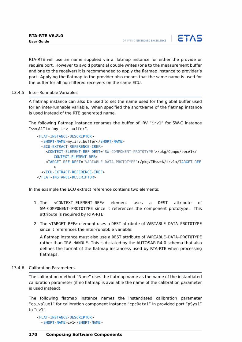
RTA-RTE V6.8.0User Guide
RTA-RTE will use an name supplied via a flatmap instance for either the provide orrequire port. However to avoid potential double writes (one to the measurement bufferand one to the receiver) it is recommended to apply the flatmap instance to provider’sport. Applying the flatmap to the provider also means that the same name is used forthe buffer for all non-filtered receivers on the same ECU.
13.4.5 Inter-Runnable Variables
A flatmap instance can also be used to set the name used for the global buffer usedfor an inter-runnable variable. When specified the shortName of the flatmap instanceis used instead of the RTE generated name.
The following flatmap instance renames the buffer of IRV “irv1” for SW-C instance“swcA1” to “my_irv_buffer”.
<FLAT-INSTANCE-DESCRIPTOR><SHORT-NAME>my_irv_buffer</SHORT-NAME><ECU-EXTRACT-REFERENCE-IREF><CONTEXT-ELEMENT-REF DEST=’SW-COMPONENT-PROTOTYPE’>/pkg/Compo/swcA1</
CONTEXT-ELEMENT-REF><TARGET-REF DEST=’VARIABLE-DATA-PROTOTYPE’>/pkg/IBswcA/irv1</TARGET-REF
></ECU-EXTRACT-REFERENCE-IREF>
</FLAT-INSTANCE-DESCRIPTOR>
In the example the ECU extract reference contains two elements:
1. The <CONTEXT-ELEMENT-REF> element uses a DEST attribute ofSW-COMPONENT-PROTOTYPE since it references the component prototype. Thisattribute is required by RTA-RTE.
2. The <TARGET-REF> element uses a DEST attribute of VARIABLE-DATA-PROTOTYPEsince it references the inter-runabble variable.
A flatmap instance must also use a DEST attribute of VARIABLE-DATA-PROTOTYPErather than IRV-HANDLE. This is dictated by the AUTOSAR R4.0 schema that alsodefines the format of the flatmap instancess used by RTA-RTE when processingflatmaps.
13.4.6 Calibration Parameters
The calibration method “None” uses the flatmap name as the name of the instantiatedcalibration parameter (if no flatmap is available the name of the calibration parameteris used instead).
The following flatmap instance names the instantiated calibration parameter“cp_value1” for calibration component instance “cpcData1” in provided port “pSys1”to “cv1”.
<FLAT-INSTANCE-DESCRIPTOR><SHORT-NAME>cv1</SHORT-NAME>
170 Composing Software Components
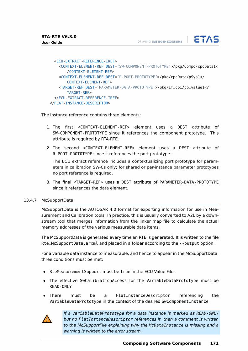
RTA-RTE V6.8.0User Guide
<ECU-EXTRACT-REFERENCE-IREF><CONTEXT-ELEMENT-REF DEST=’SW-COMPONENT-PROTOTYPE’>/pkg/Compo/cpcData1<
/CONTEXT-ELEMENT-REF><CONTEXT-ELEMENT-REF DEST=’P-PORT-PROTOTYPE’>/pkg/cpcData/pSys1</
CONTEXT-ELEMENT-REF><TARGET-REF DEST=’PARAMETER-DATA-PROTOTYPE’>/pkg/if_cp1/cp_value1</
TARGET-REF></ECU-EXTRACT-REFERENCE-IREF>
</FLAT-INSTANCE-DESCRIPTOR>
The instance reference contains three elements:
1. The first <CONTEXT-ELEMENT-REF> element uses a DEST attribute ofSW-COMPONENT-PROTOTYPE since it references the component prototype. Thisattribute is required by RTA-RTE.
2. The second <CONTEXT-ELEMENT-REF> element uses a DEST attribute ofR-PORT-PROTOTYPE since it references the port prototype.
The ECU extract reference includes a contextualizing port prototype for param-eters in calibration SW-Cs only; for shared or per-instance parameter prototypesno port reference is required.
3. The final <TARGET-REF> uses a DEST attribute of PARAMETER-DATA-PROTOTYPEsince it references the data element.
13.4.7 McSupportData
McSupportData is the AUTOSAR 4.0 format for exporting information for use in Mea-surement and Calibration tools. In practice, this is usually converted to A2L by a down-stream tool that merges information from the linker map file to calculate the actualmemory addresses of the various measurable data items.
The McSupportData is generated every time an RTE is generated. It is written to the fileRte_McSupportData.arxml and placed in a folder according to the --output option.
For a variable data instance to measurable, and hence to appear in the McSupportData,three conditions must be met:
• RteMeasurementSupport must be true in the ECU Value File.
• The effective SwCalibrationAccess for the VariableDataPrototype must beREAD-ONLY
• There must be a FlatInstanceDescriptor referencing theVariableDataPrototype in the context of the desired SwComponentInstance
If a VariableDataPrototype for a data instance is marked as READ-ONLYbut no FlatInstanceDescriptor references it, then a comment is writtento the McSupportFile explaining why the McDataInstance is missing and awarning is written to the error stream.
Composing Software Components 171
RTA-RTE V6.8.0User Guide
McSupportData Structure
The generated McSupportData file is structured according to the AUTOSARGeneric Structure Template, that is, elements are placed in subpackages ac-cording to their tag. The subpackages are placed in top-level packageAUTOSAR_Rte. For example, the BswImplementation element is placed in subpack-age /AUTOSAR_Rte/BswImplementations, and SwBaseType elements are placed in sub-package /AUTOSAR_Rte/SwBaseTypes).
Measurables appear in the McSupportData in the form of a <MC-DATA- INSTANCE> ele-ment having at least the following children:
• <SHORT-NAME>
• <CATEGORY>
• <FLAT-MAP-ENTRY-REF>
• <SYMBOL>
<SYMBOL> matches the C identifier used in the generated RTE, which may be used toquery the compiler’s map file to find the memory location of the measurable or char-acteristic.
In the case of a simple measurable value (<CATEGORY> is VALUE), then there will be aResultingProperties container containing references to the SwBaseType, DataConstr,CompuMethod, Unit etc. giving the size, encoding, and relation to the physical worldrequired for extraction and display of the data instance.
In the case of a complex measurable value of Category STRUCT, the McDataIn-stance contains a <SUB-ELEMENTS> container containing a further McDataInstancefor each structure member. If the member is itself a STRUCT, then this break-down continues recursively until the leaf items of Category VALUE are reached. The<FLAT-MAP-ENTRY-REF> is at the top level, since the structure itself is the actual mea-surable / characteristic.
In the case of Calibration Parameters (characteristics in A2L), these are placed intogroups in AUTOSAR, according to their addressing method. RTA-RTE achieves thisgrouping by creating the individual characteristics as members of a C struct repre-senting the group. In the McSupportData, this is represented by a McDataInstancerepresenting the group, having a SubElements container, which contains the individualcharacteristics. Note that the <FLAT-MAP-ENTRY-REF> in this case does not appear atthe top level, since the actual characteristics are one level deeper. The <SYMBOL> how-ever DOES appear at the top level, as this is the item that will appear in the mapfile.Calculating the exact offset of each characteristic is outside the scope of AUTOSAR andRTA-RTE. The downstream custom tooling must use knowledge of the particular com-piler along with the information in the SwBaseTypes of the McSupportData to calculatethe offsets.
172 Composing Software Components
RTA-RTE V6.8.0User Guide
Limits of Implementation
AUTOSAR specifies how and where type-information (’Effective DataDefProps’) shouldbe gathered. RTA-RTE currently implements the following (the list describes the orderin which containers are interrogated for the given information - earlier containers takeprecedence over later containers):
BaseTypeRef – ImplementationDataType.
DataConstr – ImplementationDataType; ApplicationDataType.
CompuMethod – ImplementationDataType; ApplicationDataType.
Unit – ApplicationDataType.
SwCalibrationAccess – DataPrototype.
SwDataDefProps not mentioned above are not implemented.
13.5 Data Conversion
13.5.1 Purpose
Data Conversion allows the system integrator to connect Ports of Software Compo-nents with different but “convertible” data types by means of a PortInterfaceMapping(see section 13.3.4). RTA-RTE generates the C code to convert values from one numer-ical space to the other.
PortInterfaceMappings allow the connection of Ports typed by Interfaces thatare not “AUTOSAR Compatible” by specifying how the incompatibility is to be re-solved. The explicit connection of a pair of DataPrototypes in the Interfaces bya DataPrototypeMapping within a PortInterfaceMapping causes RTA-RTE to seekto generate a runtime conversion if their types are not “AUTOSAR Compatible”.PortInterfaceMappings must therefore be used when data conversion is necessary.
Data Conversion is attempted for ApplicationPrimitiveDataTypes and for the prim-itive sub-elements of complex ApplicationDataTypes. The necessary conversioncode is automatically generated from the configured relationships between the im-plementation representation and the physical quantity or semantic meaning for theApplicationPrimitiveDataTypes involved; see section 5.5.
AUTOSAR R4.0 and RTA-RTE support two types of Data Conversion: TextTable and Lin-ear.
13.5.2 TextTable
Purpose
TextTable Data Conversion allows DataPrototypes of enumerated type (or of complextype with primitive elements of enumerated type) to be connected when they have thesame or similar semantics but different numerical and/or symbolic representations ofthose semantics.
Composing Software Components 173
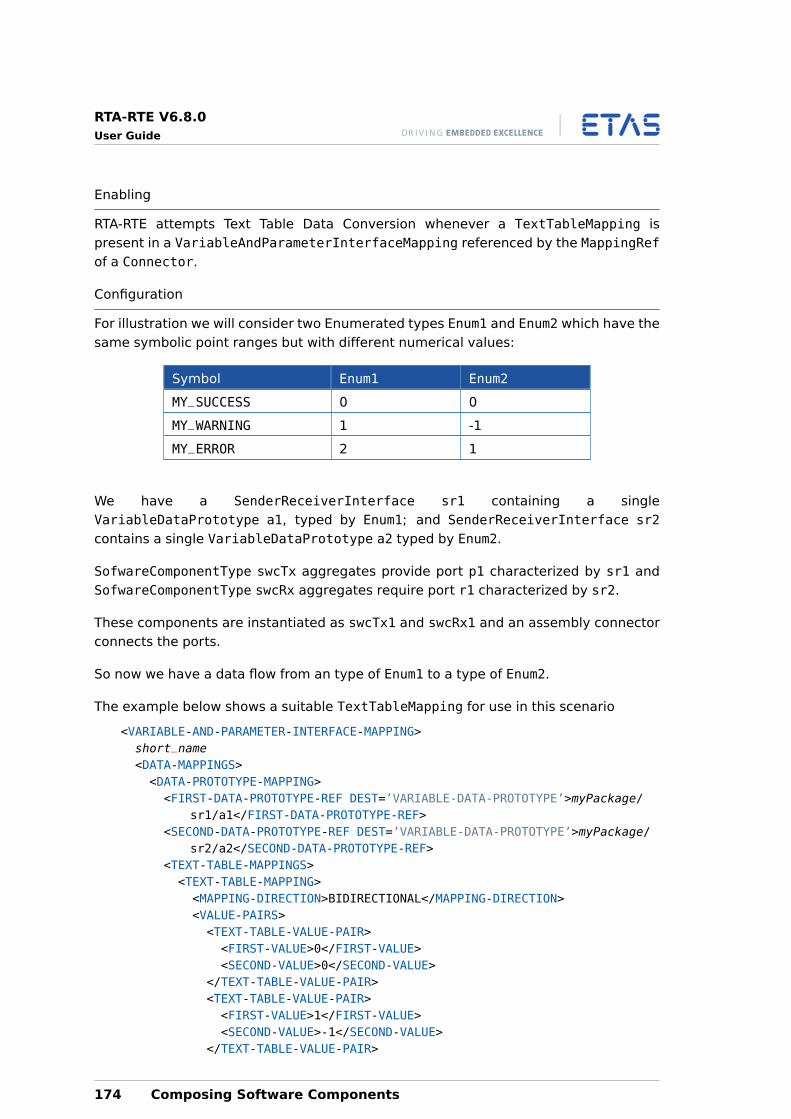
RTA-RTE V6.8.0User Guide
Enabling
RTA-RTE attempts Text Table Data Conversion whenever a TextTableMapping ispresent in a VariableAndParameterInterfaceMapping referenced by the MappingRefof a Connector.
Configuration
For illustration we will consider two Enumerated types Enum1 and Enum2 which have thesame symbolic point ranges but with different numerical values:
Symbol Enum1 Enum2
MY_SUCCESS 0 0
MY_WARNING 1 -1
MY_ERROR 2 1
We have a SenderReceiverInterface sr1 containing a singleVariableDataPrototype a1, typed by Enum1; and SenderReceiverInterface sr2contains a single VariableDataPrototype a2 typed by Enum2.
SofwareComponentType swcTx aggregates provide port p1 characterized by sr1 andSofwareComponentType swcRx aggregates require port r1 characterized by sr2.
These components are instantiated as swcTx1 and swcRx1 and an assembly connectorconnects the ports.
So now we have a data flow from an type of Enum1 to a type of Enum2.
The example below shows a suitable TextTableMapping for use in this scenario
<VARIABLE-AND-PARAMETER-INTERFACE-MAPPING>short_name<DATA-MAPPINGS><DATA-PROTOTYPE-MAPPING><FIRST-DATA-PROTOTYPE-REF DEST=’VARIABLE-DATA-PROTOTYPE’>myPackage/
sr1/a1</FIRST-DATA-PROTOTYPE-REF><SECOND-DATA-PROTOTYPE-REF DEST=’VARIABLE-DATA-PROTOTYPE’>myPackage/
sr2/a2</SECOND-DATA-PROTOTYPE-REF><TEXT-TABLE-MAPPINGS><TEXT-TABLE-MAPPING><MAPPING-DIRECTION>BIDIRECTIONAL</MAPPING-DIRECTION><VALUE-PAIRS><TEXT-TABLE-VALUE-PAIR><FIRST-VALUE>0</FIRST-VALUE><SECOND-VALUE>0</SECOND-VALUE>
</TEXT-TABLE-VALUE-PAIR><TEXT-TABLE-VALUE-PAIR><FIRST-VALUE>1</FIRST-VALUE><SECOND-VALUE>-1</SECOND-VALUE>
</TEXT-TABLE-VALUE-PAIR>
174 Composing Software Components
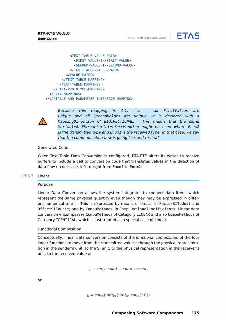
RTA-RTE V6.8.0User Guide
<TEXT-TABLE-VALUE-PAIR><FIRST-VALUE>2</FIRST-VALUE><SECOND-VALUE>1</SECOND-VALUE>
</TEXT-TABLE-VALUE-PAIR></VALUE-PAIRS>
</TEXT-TABLE-MAPPING></TEXT-TABLE-MAPPINGS>
</DATA-PROTOTYPE-MAPPING></DATA-MAPPINGS>
</VARIABLE-AND-PARAMETER-INTERFACE-MAPPING>
Because this mapping is 1:1, i.e. all FirstValues areunique and all SecondValues are unique, it is declared with aMappingDirection of BIDIRECTIONAL. This means that the sameVariableAndParameterInterfaceMapping might be used where Enum2is the transmitted type and Enum1 is the received type. In that case, we saythat the communication flow is going “second-to-first”.
Generated Code
When Text Table Data Conversion is configured, RTA-RTE alters its writes to receivebuffers to include a call to conversion code that translates values in the direction ofdata flow (in our case, left-to-right from Enum1 to Enum2.
13.5.3 Linear
Purpose
Linear Data Conversion allows the system integrator to connect data items whichrepresent the same physical quantity even though they may be expressed in differ-ent numerical terms. This is expressed by means of Units, in FactorSIToUnit andOffsetSIToUnit; and by CompuMethods, in CompuRationalCoefficients. Linear dataconversion encompasses CompuMethods of Category LINEAR and also CompuMethods ofCategory IDENTICAL, which is just treated as a special case of Linear.
Functional Composition
Conceptually, linear data conversion consists of the functional composition of the fourlinear functions to move from the transmitted value x through the physical representa-tion in the sender’s unit, to the SI unit, to the physical representation in the receiver’sunit, to the received value y:
f = cmrx ◦ unitrx ◦ unittx ◦ cmtx
or
y = cmrx(unitrx(unittx(cmtx(x))))
Composing Software Components 175
RTA-RTE V6.8.0User Guide
Where cmtx, unittx, unitrx and cmrx represent each step of the conversion as a lin-ear function that maps the input value to an intermediate output value. See sec-tion 5.5 for more details about configuring the numerical and physical representationsof ApplicationPrimitiveDataTypes.
Functional composition means that RTA-RTE only writes one expression in the gener-ated code rather than nesting function calls corresponding to each of the four potentialtransformations. Even in the worst case, an entire data transformation of four appliedtransformations results in a single expression that performs one multiplication, one ad-dition, and one division. In the best case, data conversion is optimized away to a simpleassignment.
In addition, RTA-RTE simplifies the terms in the data conversion to remove highest com-mon factors. This step simpifies the resultant expression and can mean that terms areeliminated entirely and avoid needlessly large intermediate values.
Enabling
RTA-RTE attempts to configure Linear Data Conversion whenever aPortInterfaceMapping connects DataPrototypes that are typed byApplicationPrimitiveDataTypes which are not “AUTOSAR Compatible” or com-plex ApplicationDataTypes that are shape compatible but whose primitive elementsare not “AUTOSAR Compatible”.
For each primitive value subject to Linear Data Conversion, RTA-RTE extracts from theconfiguration the data conversions expressed by the transmitter’s CompuMethod, thetransmitter’s Unit, the receiver’s Unit and the Receiver’s CompuMethod. It then com-bines the four conversion functions using functional composition to arrive at one con-version to be expressed in C.
Configuration
Configuration of Linear Data Conversion is achieved by expressing eachApplicationPrimitiveDataType’s relationship to some PhysicalDimension. Then,when data flows from one DataPrototype to another, RTA-RTE automatically in-serts the necessary code to convert one numerical representation of a physicalquantity to another. See section 5.5 to read about the correct declaration ofApplicationPrimitiveDataTypes.
The decision of whether an application data type is convertible to another applicationdata type is based on their CompuMethods, Units, and PhysicalDimensions:
• Every data type, CompuMethod, Unit, or PhysicalDimension is compatible withitself.
• A PhysicalDimension is compatible with another PhysicalDimension if the Short-Name and all the exponents match.
• A Unit is compatible with another Unit if both units reference a compatiblePhysicalDimension.
176 Composing Software Components
RTA-RTE V6.8.0User Guide
If the physical dimension referenced by two units is compatible, then a conversionbetween them is possible.
• A CompuMethod is “Linear” if its Category is LINEAR. A CompuMethod is also “Linear”if its Category is IDENTICAL.
A CompuMethod is compatible with another CompuMethod if, either:
• Both CompuMethods are Linear and they reference compatible Units, or,
• Both CompuMethods are Linear and neither of them references a Unit.
• A CompuMethod of Category TEXTTABLE is also convertible with the input configura-tion supplying a mapping between numeric values.
• An ApplicationDataType is convertible to another ApplicationDataType if thetypes have compatible CompuMethods.
Generated Code
Linear Data Conversion code is inlined near to the receiver-buffer write in generatedcode. Zero-effect operations are elided, e.g. division-by-one and add-zero result inno code being generated. So in the extreme case, if the transmitter and receiver’sconversion functions match then no conversion takes place and no conversion code isvisible.
RTA-RTE also performs worst-case calculations to determine the potential size ofthe intermediate values in the generated C expression. If no Platform Type islarge enough to hold some intermediate value then an error is raised (but see--have-64bit-int-types).
13.5.4 Rational Functions
The ASAM documents, which informed a portion of the AUTOSAR design, include manyother categories of CompuMethod besides IDENTICAL, LINEAR and TEXTTABLE, for ex-ample RATFUNC.
AUTOSAR does not support data conversion via these categories of CompuMethod andneither does RTA-RTE. However RTA-RTE does accept models that may contain othercategories of CompuMethod provided they conform with “AUTOSAR Compatibility” rules.That is, before attempting any Data Conversion, RTA-RTE performs a comparison of theUnits and CompuMethods referenced by the sender and receiver, and if they matchaccording to the AUTOSAR 4.0.3 rules, then the IDENTITY transformation is selected,i.e. no conversion code is written.
RTA-RTE cannot ignore “AUTOSAR Compatible” CompuMethods in a datapath where the references Units are not “AUTOSAR Compatible”. An un-supported Category of CompuMethod in that case would cause the inputmodel to be rejected.
Composing Software Components 177
RTA-RTE V6.8.0User Guide
13.5.5 Implementation Details
13.5.6 Internal Precision
Any data conversion represented by a CompuPhysToInternal, CompuInternalToPhys,or Unit (FactorSiToUnit and OffsetSiToUnit) is stored internally as three 64-bitsigned integers.
When the data conversions are combined due to data flow through more than one Unitor CompuMethod, a functional composition takes place resulting in a composite dataconversion, which is itself linear. This is also stored as three 64-bit signed integers.This is simplified using Highest Common Factor analysis to avoid unnecessarily largenumbers being handled internall or appearing on the target hardware.
In the case of a Unit, the configuration input is expressed in two decimal numbersrather than three integers. RTA-RTE represents the two numbers internally as rationals,expressed in the same manner as for CompuMethods. This avoids the need for floating-point arithmetic internally or on the target. For example, a FactorSIToUnit of 0.01 resultsin an internal DataConversion object with num0 = 0, num1 = 1 and denom = 100, giving0+(1∗x)
100 .
The conversion of decimals to 64-bit signed integers places a limit of 18 decimal placeson the FactorSiToUnit and OffsetSiToUnit, as well as a limit of 18 significant figures.
13.5.7 In Generated Code
When generating the C functions to perform Data Conversion, RTA-RTE tracks the min-imum (closest to negative infinity) and maximum (closest to infinity) values that canbe represented by the incoming type, by each constant, and by the result of each op-eration. For each operation, RTA-RTE chooses a suitable Platform Type and casts thearguments to each operation to that type. This ensures that the C compiler allows asufficiently large working location for each operation and truncation will not happen onthe target.
For example, consider the following C extract:
uint16 argument;...uint16 result = ( ( 65534 * argument ) / 65532 );
The result of this will rarely be correct, since C only allows a uint16 for the intermediatevalue. To overcome this, RTA-RTE uses casts like in the following example:
uint16 argument;...uint16 result = ( ( (uint32)65534 * argument ) / 65532 );
In fact, RTA-RTE generates many more casts than this, as a way of ensuring that C’spromotion rules do not introduce any counterintuitive effects.
178 Composing Software Components
RTA-RTE V6.8.0User Guide
If the intermediate value requires 64 bits, then the configuration is rejected, sinceAUTOSAR does not provide a 64-bit type. If you wish to use 64 bit integers, thenspecify --have-64bit-int-types on the command line and provide definitions inPlatform_Types.h for uint64 and sint64.
13.5.8 Composition and Delegated Ports
In a configuration containing a nested heirarchy of composition software componentsthe connection between the provide port of one atomic software component instanceand the require port of another may consist of a number of DelegationConnectorsfrom the inner provide port to delegated ports on the enclosing compositions, anAssemblyConnector and a number of DelegationConnectors from delegated requireports on compositions down to the inner require port. In this case a functional compo-sition of the notional data conversion steps along each Connector between the innerprovide port and the inner require port occurs; the intermediate representations in thetypes for the intermediate delegated ports are not explicitly calculated at runtime butrather the overall conversion is performed in one step.
Composing Software Components 179
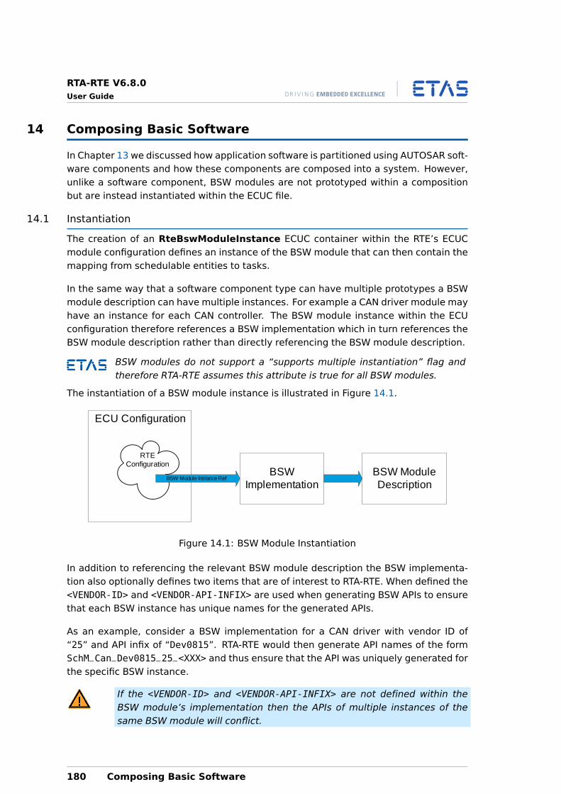
RTA-RTE V6.8.0User Guide
14 Composing Basic Software
In Chapter 13 we discussed how application software is partitioned using AUTOSAR soft-ware components and how these components are composed into a system. However,unlike a software component, BSW modules are not prototyped within a compositionbut are instead instantiated within the ECUC file.
14.1 Instantiation
The creation of an RteBswModuleInstance ECUC container within the RTE’s ECUCmodule configuration defines an instance of the BSW module that can then contain themapping from schedulable entities to tasks.
In the same way that a software component type can have multiple prototypes a BSWmodule description can have multiple instances. For example a CAN driver module mayhave an instance for each CAN controller. The BSW module instance within the ECUconfiguration therefore references a BSW implementation which in turn references theBSW module description rather than directly referencing the BSW module description.
BSW modules do not support a “supports multiple instantiation” flag andtherefore RTA-RTE assumes this attribute is true for all BSW modules.
The instantiation of a BSW module instance is illustrated in Figure 14.1.
ECU Configuration
RTEConfiguration
BSW Module Instance RefBSW
ImplementationBSW Module Description
Figure 14.1: BSW Module Instantiation
In addition to referencing the relevant BSW module description the BSW implementa-tion also optionally defines two items that are of interest to RTA-RTE. When defined the<VENDOR-ID> and <VENDOR-API-INFIX> are used when generating BSW APIs to ensurethat each BSW instance has unique names for the generated APIs.
As an example, consider a BSW implementation for a CAN driver with vendor ID of“25” and API infix of “Dev0815”. RTA-RTE would then generate API names of the formSchM_Can_Dev0815_25_<XXX> and thus ensure that the API was uniquely generated forthe specific BSW instance.
If the <VENDOR-ID> and <VENDOR-API-INFIX> are not defined within theBSW module’s implementation then the APIs of multiple instances of thesame BSW module will conflict.
180 Composing Basic Software
RTA-RTE V6.8.0User Guide
14.2 BSW Scheduler
Starting with AUTOSAR R4.0, the generation of a scheduler for basic software has beenintegrated into RTE generation rather than being available as a separate module as inprevious releases. The basic software scheduler is reponsible for ensuring that codewithin BSW modules runs at the correct times and that APIs for ensuring data consis-tency across multiple BSW modules are available.
RTA-RTE supports generation of a common task framework; BSW schedulable entitiescan be freely mixed with runnable entities from software components and the RTE gen-erator will create the appropriate glue code to ensure that all are executed at the righttime.
This release of RTA-RTE does not support the generation of shared exclusiveareas and thus the SchM_Enter and SchM_Exit APIs are not supported.
14.2.1 Task Mapping
A BSW module instance within the ECU configuration can contains zero or more RteB-swEventToTaskMapping sub-containers that define the task and position of theschedulable entity associated with a BSW event. As with SW-C runnable entities allBSW events that can start a schedulable entity must have a defined task mapping.
RTA-RTE supports the mixing of BSW schedulable entities and SW-C runnable entitieswithin the same task. This support includes the creation of basic or extended tasksas necessary; if extended tasks are to be avoided then the the same precautions de-scribed in Section 24.4 apply.
14.3 Connections
BSW triggers and modes are not related to ports and therefore cannot be connectedin the same way as the analogous entities within SWCs. Instead the connections aremade within the ECUC using specific containers.
14.3.1 Triggers
An external trigger used by a BSW module must have the “release” and “required” trig-gers connected using a RteBswRequiredTriggerConnection element in the ECUCfile.
Each RteBswRequiredTriggerConnection element includes three references:
1. A RteBswReleasedTriggerModInstRef that references the BSW module in-stance.
2. A RteBswReleasedTriggerRef that references the released trigger. When com-bined with the RteBswReleasedTriggerModInstRef reference this uniquelyidentifies the released trigger.
3. A RteBswRequiredTriggerRef that references the required trigger.
Composing Basic Software 181
RTA-RTE V6.8.0User Guide
14.3.2 Modes
An mode used by a BSW module must have the “provided” and “required” mode dec-laration group prototypes connected using a RteBswRequiredModeGroupConnec-tion element in the ECUC file.
Each RteBswRequiredModeGroupConnection element includes three references:
1. A RteBswProvidedModeGrpModInstRef that references the BSW module in-stance.
2. A RteBswProvidedModeGroupRef that references the provided mode decla-ration group prototype. When combined with the RteBswProvidedModeGrp-ModInstRef reference this uniquely identifies the providing mode instance.
3. A RteBswRequiredModeGroupRef that references the required mode declara-tion group prototype.
182 Composing Basic Software
RTA-RTE V6.8.0User Guide
15 Synchronizing BSW and SWC
The previous chapter introduced BSW components. This chapter covers how RTA-RTEsupports the synchronization of BSW and SWC instances.
15.1 Configuration
Synchronization configuration consists of two steps: first, one or more SwcBswMappingelements must be defined that associate elements in the SWC and BSW together, andsecond, the created mappings must be associated with SWC/BSW instances.
15.1.1 SWC to BSW Mapping
The SwcBswMapping element defines the synchronized elements of a SWC type anda BSW module description. The element “associates” elements of two internal be-haviors; we’ll see later how the mapping is subsequently referenced from either aSwcImplementation or a BswImplementation and thus associated with SWC or BSWinstances.
The simplest SwcBswMapping element simply refers to the two internal behaviors, e.g.:
<SWC-BSW-MAPPING><SHORT-NAME>sbm1</SHORT-NAME><BSW-BEHAVIOR-REF DEST=’BSW-INTERNAL-BEHAVIOR’>...
</BSW-BEHAVIOR-REF><RUNNABLE-MAPPINGS/><SWC-BEHAVIOR-REF DEST=’SWC-INTERNAL-BEHAVIOR’>...
</SWC-BEHAVIOR-REF><SYNCHRONIZED-MODE-GROUPS/><SYNCHRONIZED-TRIGGERS/>
</SWC-BSW-MAPPING>
One of the referenced internal behaviors must belong to a SWC and one to a BSWmodule. It is not possible to synchronize two SWCs or two BSW modules with aSwcBswMapping element. Within the SwcBswMapping element one can list synchronizedrunnable entities, mode groups and (external) triggers.
The <RUNNABLE-MAPPINGS> element encapsulates zero or more runnable-entity toexecutable-entity mappings, e.g.:
<RUNNABLE-MAPPINGS><SWC-BSW-RUNNABLE-MAPPING><BSW-ENTITY-REF DEST=’BSW-SCHEDULABLE-ENTITY’>...
</BSW-ENTITY-REF><SWC-RUNNABLE-REF DEST=’RUNNABLE-ENTITY’>...
</SWC-RUNNABLE-REF></SWC-BSW-RUNNABLE-MAPPING>
</RUNNABLE-MAPPINGS>
Synchronizing BSW and SWC 183
RTA-RTE V6.8.0User Guide
Each <SWC-BSW-RUNNABLE-MAPPING> synchronizes a SWC runnable entity with a BSWexecutable entity (either a <BSW-SCHEDULABLE-ENTITY>, <BSW-INTERRUPT-ENTITY> or<BSW-CALLED-ENTITY>). The referenced runnable or executable entity must be de-clared within the referenced internal behaviors.
AUTOSAR forbids the synchronization of an SWC’s runnable entity with acategory 1 interrupt entity (or with a called entity invoked by a category 1interrupt entity).
The <SYNCHRONIZED-MODE-GROUPS> element encapsulates zero or more synchronizedmode group declarations, e.g.:
<SYNCHRONIZED-MODE-GROUPS><SWC-BSW-SYNCHRONIZED-MODE-GROUP-PROTOTYPE><BSW-MODE-GROUP-REF DEST=’MODE-DECLARATION-GROUP-PROTOTYPE’>...
</BSW-MODE-GROUP-REF><SWC-MODE-GROUP-IREF><CONTEXT-P-PORT-REF DEST=’P-PORT-PROTOTYPE’>...
</CONTEXT-P-PORT-REF><TARGET-MODE-GROUP-REF DEST=’MODE-DECLARATION-GROUP-PROTOTYPE’>...
</TARGET-MODE-GROUP-REF></SWC-MODE-GROUP-IREF>
</SWC-BSW-SYNCHRONIZED-MODE-GROUP-PROTOTYPE></SYNCHRONIZED-MODE-GROUPS>
Each <SWC-BSW-SYNCHRONIZED-MODE-GROUP-PROTOTYPE> synchronizes a provided orrequired BSW mode declaration group with a particular provided SWC mode decla-ration group. The referenced BSW mode declaration group must be declared within theBSW type of the referenced BSW internal behavior and the referenced port prototypewithin the SWC type of the referenced SWC internal behavior.
The <SYNCHRONIZED-TRIGGERS> element encapsulates zero or mode synchronized trig-ger declarations, e.g.:
<SYNCHRONIZED-TRIGGERS><SWC-BSW-SYNCHRONIZED-TRIGGER><BSW-TRIGGER-REF DEST=’TRIGGER’>...
</BSW-TRIGGER-REF><SWC-TRIGGER-IREF><CONTEXT-P-PORT-REF DEST=’P-PORT-PROTOTYPE’>
...</CONTEXT-P-PORT-REF><TARGET-TRIGGER-REF DEST=’TRIGGER’>
...</TARGET-TRIGGER-REF>
</SWC-TRIGGER-IREF></SWC-BSW-SYNCHRONIZED-TRIGGER>
</SYNCHRONIZED-TRIGGERS>
184 Synchronizing BSW and SWC
RTA-RTE V6.8.0User Guide
Each <SWC-BSW-SYNCHRONIZED-TRIGGER> synchronizes a released or required BSWtrigger with a particular provided SWC trigger. The referenced BSW trigger must bedeclared within the BSW type of the referenced BSW internal behavior and the refer-enced port prototype within the SWC type of the referenced SWC internal behavior.
Neither a synchronized mode group element nor a synchronized trigger can referencea required mode declaration group in the SWC. However as we’ll see in the followingsections this restrictions does not affect the expressive power – it’s still possible tocreate associations that enable either the SWC or the BSW to be the mode managerand to trigger events in either (or both) the SWC and BSW module.
15.1.2 Associating a Mapping and an Instance
When a SwcBswMapping has been defined mapping it is associated with SWC/BSW typesvia the referenced internal behaviors. However the mapping must also be associatedwith instances of the SWC and BSW via one or more implementation references.
The SwcImplementation or BswImplementation elements can include a reference to amapping, e.g.:
<SWC-IMPLEMENTATION>...<SWC-BSW-MAPPING-REF DEST=’SWC-BSW-MAPPING’>...
</SWC-BSW-MAPPING-REF>...
</SWC-IMPLEMENTATION>
If an SWC/BSW’s implementation does not include a mapping reference then RTA-RTEattempts to infer the affected instance from the referenced internal behaviors. Thisinference is only possible if the SWC/BSW’s are instantiated exactly once and thereforewhen multiple instantiation is used the SwcBswMapping references within the imple-mentations are mandatory.
15.2 Synchronized Mode Groups
Synchronizing mode groups permits both events in both AUTOSAR software compo-nents and basic software modules to be triggered by a single mode manager. RTA-RTEsupports synchronization where the referenced BSW provides or requires the modedeclaration group.
15.2.1 Mode Users
Synchronizing a required BSW mode group with a provided SWC mode group resultsin the BSW attaching to the mode instance defined by the SWC as a mode user. AnyBSW events (e.g. ModeSwitchEvents) attached to the required BSW mode group will betriggered when the SWC mode manager changes mode.
The synchronized mode group element within the SwcBswMapping element referencesa provided port/mode group in the SWC. RTA-RTE supports supports synchronizationconfigurations where RTE events are triggered as a result of the mode switch as well as
Synchronizing BSW and SWC 185
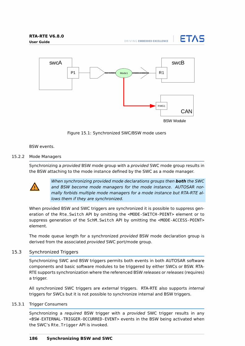
RTA-RTE V6.8.0User Guide
R1
swcBswcA
P1
CAN
BSW Module
Mode1
RMG1
Figure 15.1: Synchronized SWC/BSW mode users
BSW events.
15.2.2 Mode Managers
Synchronizing a provided BSW mode group with a provided SWC mode group results inthe BSW attaching to the mode instance defined by the SWC as a mode manager.
When synchronizing provided mode declarations groups then both the SWCand BSW become mode managers for the mode instance. AUTOSAR nor-mally forbids multiple mode managers for a mode instance but RTA-RTE al-lows them if they are synchronized.
When provided BSW and SWC triggers are synchronized it is possible to suppress gen-eration of the Rte_Switch API by omitting the <MODE-SWITCH-POINT> element or tosuppress generation of the SchM_Switch API by omitting the <MODE-ACCESS-POINT>element.
The mode queue length for a synchronized provided BSW mode declaration group isderived from the associated provided SWC port/mode group.
15.3 Synchronized Triggers
Synchronizing SWC and BSW triggers permits both events in both AUTOSAR softwarecomponents and basic software modules to be triggered by either SWCs or BSW. RTA-RTE supports synchronization where the referenced BSW releases or releases (requires)a trigger.
All synchronized SWC triggers are external triggers. RTA-RTE also supports internaltriggers for SWCs but it is not possible to synchronize internal and BSW triggers.
15.3.1 Trigger Consumers
Synchronizing a required BSW trigger with a provided SWC trigger results in any<BSW-EXTERNAL-TRIGGER-OCCURRED-EVENT> events in the BSW being activated whenthe SWC’s Rte_Trigger API is invoked.
186 Synchronizing BSW and SWC
RTA-RTE V6.8.0User Guide
The synchronized trigger element within the SwcBswMapping element references a pro-vided port/trigger in the SWC.
15.3.2 Trigger Producers
Synchronizing a provided BSW trigger with a provided SWC trigger results in the gen-erated BSW SchM_Trigger activating the same events as the Rte_Trigger API.
When provided BSW and SWC triggers are synchronized it is possible to suppress gener-ation of the Rte_Trigger API by omitting the <EXTERNAL-TRIGGERING-POINT> element.
If the SWC includes an ExternalTriggeringPoint for the provided triggerthen both the SWC’s Rte_Trigger and the BSW’s SchM_Trigger APIs arecreated. AUTOSAR normally forbids multiple trigger providers but RTA-RTEallows them if they are synchronized.
15.4 Synchronized Runnable Entities
Synchronizing a SWC runnable entity to a BSW executable entity allows the executableentity to use SWC-API calls such as those related to port-based communication. TheSWC is also able to use BSW-API calls.
15.4.1 Sender/Receiver
RTA-RTE supports the synchronization of both Sender and Receiver runnable entityswith an executable entity, thus an executable entity will be able to make calls to theSender/Receiver APIs (e.g. Rte_Write/Rte_Read).
Since it is not possible to associate an executable entity with a<DATA-RECEIVED-EVENT>, a receiver executable entity must be started us-ing another event type.
15.4.2 Client/Server
RTA-RTE supports synchronization of executable entities with client runnables only(Synchronizing an executable entity with a server runnable makes no sense as there isno way for the executable entity to gain access to the server arguments). A synchro-nized executable entity can therefore call the client API available to the synchronizedclient runnable.
15.4.3 Exclusive Areas
RTA-RTE supports the synchronization of SWC runnable entities that access an exclusivearea with executable entities. When synchronized the executable entity will be able tomake calls to the Enter/Exit APIs (e.g. Rte_Enter/Rte_Exit) and thus “share” accessto the same shared data.
Figure 15.2 illustrates a runnable Re2 that both accesses exclusive area EA and issynchronized with schedulable entity SE. RTA-RTE will generate Rte_Enter_EA andRte_Exit_EA that can be used to control access to the shared data governed by “EA” –depending on the selected implementation mechanism for the exclusive area and the
Synchronizing BSW and SWC 187
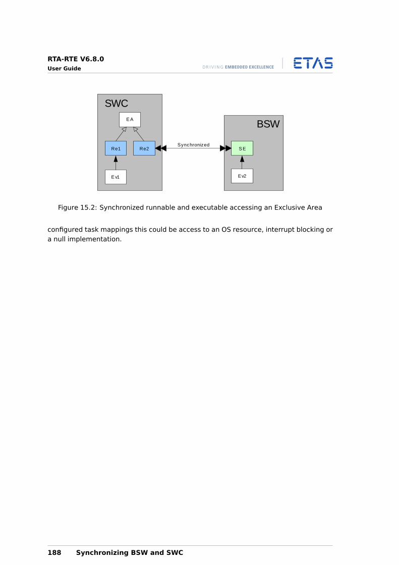
RTA-RTE V6.8.0User Guide
BSW
SWC
S ERe2
E A
Re1
E v1 Ev2
Synchronized
Figure 15.2: Synchronized runnable and executable accessing an Exclusive Area
configured task mappings this could be access to an OS resource, interrupt blocking ora null implementation.
188 Synchronizing BSW and SWC
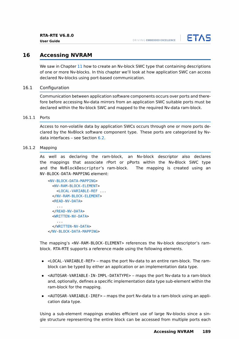
RTA-RTE V6.8.0User Guide
16 Accessing NVRAM
We saw in Chapter 11 how to create an Nv-block SWC type that containing descriptionsof one or more Nv-blocks. In this chapter we’ll look at how application SWC can accessdeclared Nv-blocks using port-based communication.
16.1 Configuration
Communication between application software components occurs over ports and there-fore before accessing Nv-data mirrors from an application SWC suitable ports must bedeclared within the Nv-block SWC and mapped to the required Nv-data ram-block.
16.1.1 Ports
Access to non-volatile data by application SWCs occurs through one or more ports de-clared by the NvBlock software component type. These ports are categorized by Nv-data interfaces – see Section 6.2.
16.1.2 Mapping
As well as declaring the ram-block, an Nv-block descriptor also declaresthe mappings that associate rPort or pPorts within the Nv-Block SWC typeand the NvBlockDescriptor’s ram-block. The mapping is created using anNV-BLOCK-DATA-MAPPING element:
<NV-BLOCK-DATA-MAPPING><NV-RAM-BLOCK-ELEMENT><LOCAL-VARIABLE-REF ...
</NV-RAM-BLOCK-ELEMENT><READ-NV-DATA>...
</READ-NV-DATA><WRITTEN-NV-DATA>...
</WRITTEN-NV-DATA></NV-BLOCK-DATA-MAPPING>
The mapping’s <NV-RAM-BLOCK-ELEMENT> references the Nv-block descriptor’s ram-block. RTA-RTE supports a reference made using the following elements.
• <LOCAL-VARIABLE-REF> – maps the port Nv-data to an entire ram-block. The ram-block can be typed by either an application or an implementation data type.
• <AUTOSAR-VARIABLE-IN-IMPL-DATATYPE> – maps the port Nv-data to a ram-blockand, optionally, defines a specific implementation data type sub-element within theram-block for the mapping.
• <AUTOSAR-VARIABLE-IREF> – maps the port Nv-data to a ram-block using an appli-cation data type.
Using a sub-element mappings enables efficient use of large Nv-blocks since a sin-gle structure representing the entire block can be accessed from multiple ports each
Accessing NVRAM 189
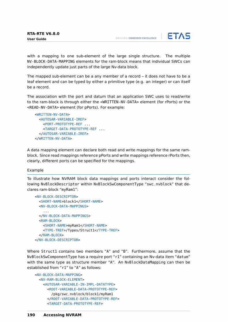
RTA-RTE V6.8.0User Guide
with a mapping to one sub-element of the large single structure. The multipleNV-BLOCK-DATA-MAPPING elements for the ram-block means that individual SWCs canindependently update just parts of the large Nv-data block.
The mapped sub-element can be a any member of a record – it does not have to be aleaf element and can be typed by either a primitive type (e.g. an integer) or can itselfbe a record.
The association with the port and datum that an application SWC uses to read/writeto the ram-block is through either the <WRITTEN-NV-DATA> element (for rPorts) or the<READ-NV-DATA> element (for pPorts). For example:
<WRITTEN-NV-DATA><AUTOSAR-VARIABLE-IREF><PORT-PROTOTYPE-REF ...<TARGET-DATA-PROTOTYPE-REF ...
</AUTOSAR-VARIABLE-IREF></WRITTEN-NV-DATA>
A data mapping element can declare both read and write mappings for the same ram-block. Since read mappings reference pPorts and write mappings reference rPorts then,clearly, different ports can be specified for the mappings.
Example
To illustrate how NVRAM block data mappings and ports interact consider the fol-lowing NvBlockDescriptor within NvBlockSwComponentType “swc_nvblock” that de-clares ram-block “myRam1”:
<NV-BLOCK-DESCRIPTOR><SHORT-NAME>block1</SHORT-NAME><NV-BLOCK-DATA-MAPPINGS>...
</NV-BLOCK-DATA-MAPPINGS><RAM-BLOCK><SHORT-NAME>myRam1</SHORT-NAME><TYPE-TREF>/Types/Struct1</TYPE-TREF>
</RAM-BLOCK></NV-BLOCK-DESCRIPTOR>
Where Struct1 contains two members “A” and “B”. Furthermore, assume that theNvBlockSwComponentType has a require port “r1” containing an Nv-data item “datum”with the same type as structure member “A”. An NvBlockDataMapping can then beestablished from “r1” to “A” as follows:
<NV-BLOCK-DATA-MAPPING><NV-RAM-BLOCK-ELEMENT><AUTOSAR-VARIABLE-IN-IMPL-DATATYPE><ROOT-VARIABLE-DATA-PROTOTYPE-REF>/pkg/swc_nvblock/block1/myRam1
</ROOT-VARIABLE-DATA-PROTOTYPE-REF><TARGET-DATA-PROTOTYPE-REF>
190 Accessing NVRAM
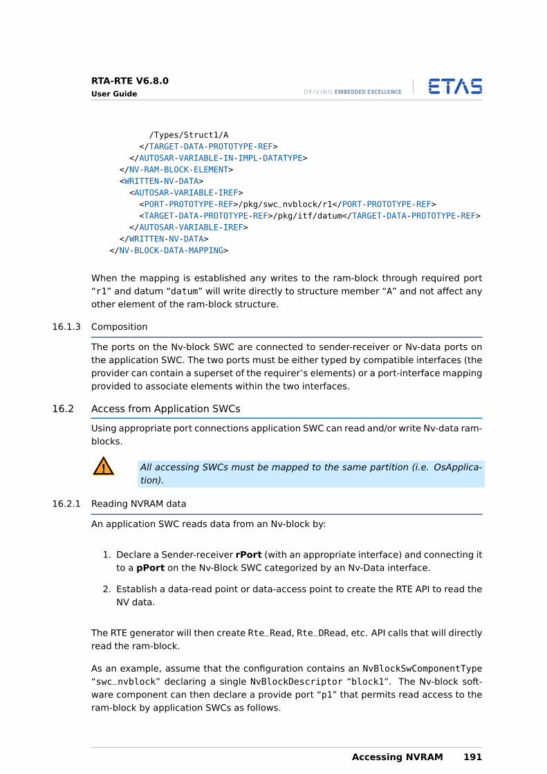
RTA-RTE V6.8.0User Guide
/Types/Struct1/A</TARGET-DATA-PROTOTYPE-REF>
</AUTOSAR-VARIABLE-IN-IMPL-DATATYPE></NV-RAM-BLOCK-ELEMENT><WRITTEN-NV-DATA><AUTOSAR-VARIABLE-IREF><PORT-PROTOTYPE-REF>/pkg/swc_nvblock/r1</PORT-PROTOTYPE-REF><TARGET-DATA-PROTOTYPE-REF>/pkg/itf/datum</TARGET-DATA-PROTOTYPE-REF>
</AUTOSAR-VARIABLE-IREF></WRITTEN-NV-DATA>
</NV-BLOCK-DATA-MAPPING>
When the mapping is established any writes to the ram-block through required port“r1” and datum “datum” will write directly to structure member “A” and not affect anyother element of the ram-block structure.
16.1.3 Composition
The ports on the Nv-block SWC are connected to sender-receiver or Nv-data ports onthe application SWC. The two ports must be either typed by compatible interfaces (theprovider can contain a superset of the requirer’s elements) or a port-interface mappingprovided to associate elements within the two interfaces.
16.2 Access from Application SWCs
Using appropriate port connections application SWC can read and/or write Nv-data ram-blocks.
All accessing SWCs must be mapped to the same partition (i.e. OsApplica-tion).
16.2.1 Reading NVRAM data
An application SWC reads data from an Nv-block by:
1. Declare a Sender-receiver rPort (with an appropriate interface) and connecting itto a pPort on the Nv-Block SWC categorized by an Nv-Data interface.
2. Establish a data-read point or data-access point to create the RTE API to read theNV data.
The RTE generator will then create Rte_Read, Rte_DRead, etc. API calls that will directlyread the ram-block.
As an example, assume that the configuration contains an NvBlockSwComponentType“swc_nvblock” declaring a single NvBlockDescriptor “block1”. The Nv-block soft-ware component can then declare a provide port “p1” that permits read access to theram-block by application SWCs as follows.
Accessing NVRAM 191
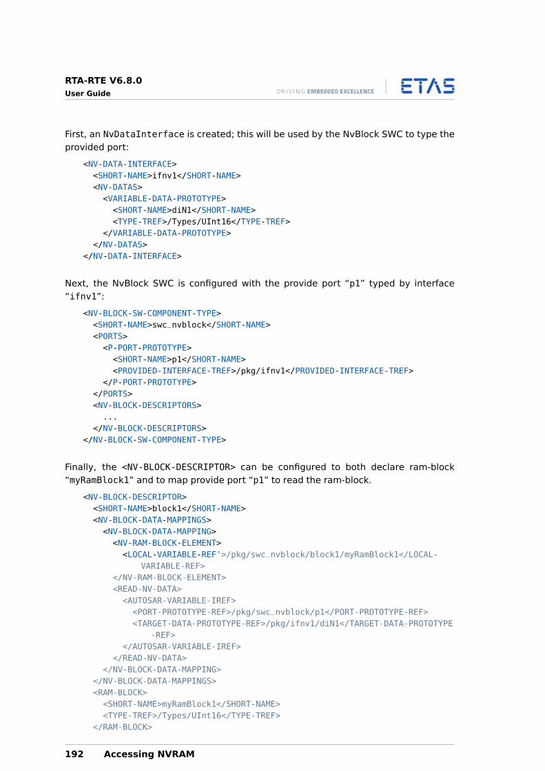
RTA-RTE V6.8.0User Guide
First, an NvDataInterface is created; this will be used by the NvBlock SWC to type theprovided port:
<NV-DATA-INTERFACE><SHORT-NAME>ifnv1</SHORT-NAME><NV-DATAS><VARIABLE-DATA-PROTOTYPE><SHORT-NAME>diN1</SHORT-NAME><TYPE-TREF>/Types/UInt16</TYPE-TREF>
</VARIABLE-DATA-PROTOTYPE></NV-DATAS>
</NV-DATA-INTERFACE>
Next, the NvBlock SWC is configured with the provide port “p1” typed by interface“ifnv1”:
<NV-BLOCK-SW-COMPONENT-TYPE><SHORT-NAME>swc_nvblock</SHORT-NAME><PORTS><P-PORT-PROTOTYPE><SHORT-NAME>p1</SHORT-NAME><PROVIDED-INTERFACE-TREF>/pkg/ifnv1</PROVIDED-INTERFACE-TREF>
</P-PORT-PROTOTYPE></PORTS><NV-BLOCK-DESCRIPTORS>...
</NV-BLOCK-DESCRIPTORS></NV-BLOCK-SW-COMPONENT-TYPE>
Finally, the <NV-BLOCK-DESCRIPTOR> can be configured to both declare ram-block“myRamBlock1” and to map provide port “p1” to read the ram-block.
<NV-BLOCK-DESCRIPTOR><SHORT-NAME>block1</SHORT-NAME><NV-BLOCK-DATA-MAPPINGS><NV-BLOCK-DATA-MAPPING><NV-RAM-BLOCK-ELEMENT><LOCAL-VARIABLE-REF’>/pkg/swc_nvblock/block1/myRamBlock1</LOCAL-
VARIABLE-REF></NV-RAM-BLOCK-ELEMENT><READ-NV-DATA><AUTOSAR-VARIABLE-IREF><PORT-PROTOTYPE-REF>/pkg/swc_nvblock/p1</PORT-PROTOTYPE-REF><TARGET-DATA-PROTOTYPE-REF>/pkg/ifnv1/diN1</TARGET-DATA-PROTOTYPE
-REF></AUTOSAR-VARIABLE-IREF>
</READ-NV-DATA></NV-BLOCK-DATA-MAPPING>
</NV-BLOCK-DATA-MAPPINGS><RAM-BLOCK><SHORT-NAME>myRamBlock1</SHORT-NAME><TYPE-TREF>/Types/UInt16</TYPE-TREF>
</RAM-BLOCK>
192 Accessing NVRAM
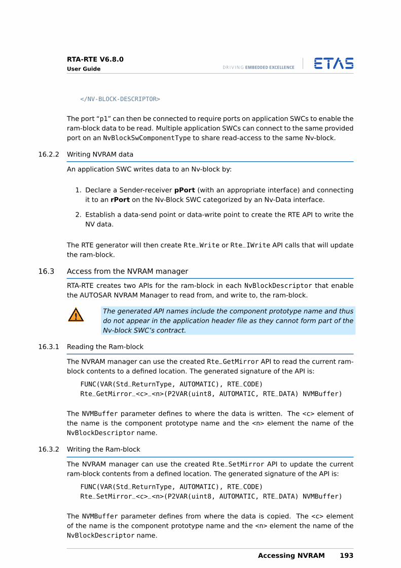
RTA-RTE V6.8.0User Guide
</NV-BLOCK-DESCRIPTOR>
The port “p1” can then be connected to require ports on application SWCs to enable theram-block data to be read. Multiple application SWCs can connect to the same providedport on an NvBlockSwComponentType to share read-access to the same Nv-block.
16.2.2 Writing NVRAM data
An application SWC writes data to an Nv-block by:
1. Declare a Sender-receiver pPort (with an appropriate interface) and connectingit to an rPort on the Nv-Block SWC categorized by an Nv-Data interface.
2. Establish a data-send point or data-write point to create the RTE API to write theNV data.
The RTE generator will then create Rte_Write or Rte_IWrite API calls that will updatethe ram-block.
16.3 Access from the NVRAM manager
RTA-RTE creates two APIs for the ram-block in each NvBlockDescriptor that enablethe AUTOSAR NVRAM Manager to read from, and write to, the ram-block.
The generated API names include the component prototype name and thusdo not appear in the application header file as they cannot form part of theNv-block SWC’s contract.
16.3.1 Reading the Ram-block
The NVRAM manager can use the created Rte_GetMirror API to read the current ram-block contents to a defined location. The generated signature of the API is:
FUNC(VAR(Std_ReturnType, AUTOMATIC), RTE_CODE)Rte_GetMirror_<c>_<n>(P2VAR(uint8, AUTOMATIC, RTE_DATA) NVMBuffer)
The NVMBuffer parameter defines to where the data is written. The <c> element ofthe name is the component prototype name and the <n> element the name of theNvBlockDescriptor name.
16.3.2 Writing the Ram-block
The NVRAM manager can use the created Rte_SetMirror API to update the currentram-block contents from a defined location. The generated signature of the API is:
FUNC(VAR(Std_ReturnType, AUTOMATIC), RTE_CODE)Rte_SetMirror_<c>_<n>(P2VAR(uint8, AUTOMATIC, RTE_DATA) NVMBuffer)
The NVMBuffer parameter defines from where the data is copied. The <c> elementof the name is the component prototype name and the <n> element the name of theNvBlockDescriptor name.
Accessing NVRAM 193
RTA-RTE V6.8.0User Guide
16.3.3 Notifications from the NVRAM Manager
In addition to the Rte_GetMirror and Rte_SetMirror APIs, RTA-RTE can also generateadditional APIs used by the NVRAM manager to pass notifications to applications SWCs.
The APIs are generated in response to declared role based port assignments for re-quired client-server ports. For each such assignment, RTA-RTE generates an API to beinvoked by the NVRAM manager. The name of the API is based on the declared role, theNvBlock SWC component prototype name and the NvBlockDescriptor name.
FUNC(VAR(Std_ReturnType, AUTOMATIC), RTE_CODE)Rte_<role>_<c>_<n>(<args>);
The <role> element of the API name is declared within the role based assignment. The<c> element of the name is the component prototype name and the <n> element thename of the NvBlockDescriptor name.
The API’s formal argument list, <args>, is derived from the first operation inthe interface referenced by the require port with the exception of the rolesNvMNotifyJobFinished and NvMNotifyInitBlock in which case the formal argumentlist is standardized by AUTOSAR.
The generated role API invokes the server through the referenced require client-serverport. If multiple role based assignments have the same “role” then the generated APIaggregates invocation of all referenced servers.
The generated API invokes all servers synchronously. To avoid use ofOsEvents it is strongly recommended to use direct function invocation byomitting the task reference the relevant RTE event mapping.
The generated API takes no action if the RTE is not started or if the RTE has beenstopped.
16.3.4 Invocations of the NVRAM Manager by SWCS
As well as the APIs for passing notifications from the NVRAM manager to applica-tion SWCs, RTA-RTE also supports the invocation of NVRAM manager APIs from SWCsthrough generated server runnables for provided client-server ports..
RTA-RTE generates the runnable entity body for all connected provide ports that havea configured OperationInvokedEvent. The generated runnable entity body uses thesymbol name from the runnable entity declaration – this must therefore be globallyunique. The formal argument list consists of three elements:
1. An optional instance handle (included only when the NvBlock SWC is declared assupporting multiple instances, see Section 8.14).
2. The port-defined arguments (for the referenced server port, see Section 8.13.2).
3. The operation arguments from the operation in the server’s ports interface withthe same name as the “role”.
194 Accessing NVRAM
RTA-RTE V6.8.0User Guide
The generated body for the runnable invokes the C-based API of the NVRAM managerbased on the declared “role”. All runnable parameters, apart from the instance handle,are passed directly to the invoked NVRAM API.
Accessing NVRAM 195
RTA-RTE V6.8.0User Guide
Part V
Deployment
196
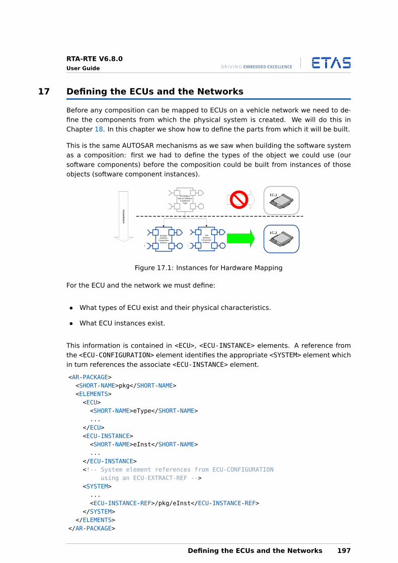
RTA-RTE V6.8.0User Guide
17 Defining the ECUs and the Networks
Before any composition can be mapped to ECUs on a vehicle network we need to de-fine the components from which the physical system is created. We will do this inChapter 18. In this chapter we show how to define the parts from which it will be built.
This is the same AUTOSAR mechanisms as we saw when building the software systemas a composition: first we had to define the types of the object we could use (oursoftware components) before the composition could be built from instances of thoseobjects (software component instances).
ETASofficeAtomic Software
Component Type
StuttgartSoftware
Component Instance
YorkSoftware
Component Instance
Instantiation
Figure 17.1: Instances for Hardware Mapping
For the ECU and the network we must define:
• What types of ECU exist and their physical characteristics.
• What ECU instances exist.
This information is contained in <ECU>, <ECU-INSTANCE> elements. A reference fromthe <ECU-CONFIGURATION> element identifies the appropriate <SYSTEM> element whichin turn references the associate <ECU-INSTANCE> element.
<AR-PACKAGE><SHORT-NAME>pkg</SHORT-NAME><ELEMENTS><ECU><SHORT-NAME>eType</SHORT-NAME>...
</ECU><ECU-INSTANCE><SHORT-NAME>eInst</SHORT-NAME>...
</ECU-INSTANCE><!-- System element references from ECU-CONFIGURATION
using an ECU-EXTRACT-REF --><SYSTEM>...<ECU-INSTANCE-REF>/pkg/eInst</ECU-INSTANCE-REF>
</SYSTEM></ELEMENTS>
</AR-PACKAGE>
Defining the ECUs and the Networks 197
RTA-RTE V6.8.0User Guide
While it possible to put software component configurations and system deploymentelements in the same AUTOSAR XML file, it is more common to separate the distinctaspects of system engineering into (at least) two separate files. This means that mul-tiple different software component allocations can be managed easily from a single“repository” of software components.
17.1 ECU Type Definition
Every configuration you make will need to define at least one ECU type. An ECU is con-ceptually similar to an SWC-type in that it defines the general properties of an abstractECU. Similarly, it is an instance of the ECU onto which software component prototypesare allocated.
The definition provides a name for the ECU type so that it can be referenced fromthe <SYSTEM> description as well as including a reference to a <COMPOSITION-TYPE>definition that indicates the mapped software component prototypes and their types.
<ECU><SHORT-NAME>ECUType</SHORT-NAME><PORTS>...
</PORTS></ECU>
17.1.1 Communication Ports
When the ECU is not stand alone it must provide the opportunity to create instancesof communication ports. <PORTS> element allows the specification of the physi-cal ECU interface(s) provided by the ECU, for example, <ECU-COMMUNICATION-PORT>,<PERIPHERAL-HW-PORT> etc.
Only the <ECU-COMMUNICATION-PORT> definitions are relevant for RTE configuration asthey provide the definition of which physical communication interfaces exist on theECU.
Note that the communication port does not specify that an ECU has a port. The declara-tion simply states that an instance of the ECU can be created that can create instancesof the defined port. In this regards, the communication port is analogous to a type.
It is only necessary to define an <ECU-COMMUNICATION-PORT> for each different classof communication port on the ECU. For example, if your ECU has 4 CAN channelsbut all the channels have the same properties then you would only define a single<ECU-COMMUNICATION-PORT>.
Each communication port is named and defined the <NUMBER>, <SIZE> and <TYPE> ofthe physical buffers as well as their <DIRECTION>. These are not required for the RTEbut are mandatory in the ECU configuration description XML so must be provided. Thefollowing example shows the general configuration:
<ECU-COMMUNICATION-PORT><SHORT-NAME>CANPortType</SHORT-NAME>
198 Defining the ECUs and the Networks
RTA-RTE V6.8.0User Guide
<!-- Remaining configuration mandatorybut not used by RTE -->
<DIRECTION>IN</DIRECTION><BUFFERS><BUFFER><NUMBER>1</NUMBER><SIZE>5</SIZE><TYPE>input</TYPE>
</BUFFER></BUFFERS>
</ECU-COMMUNICATION-PORT>
It is outside the scope of this user document to describe how additional ECUhardware is defined in XML.
17.2 ECU Instances
The <ECU-INSTANCE> element instantiates an ECU type (defined within the ECUdescription—see Section 17.1):
<ECU-INSTANCE><SHORT-NAME>ECUI</SHORT-NAME><CONNECTORS><COMMUNICATION-CONNECTOR><SHORT-NAME>comCon1</SHORT-NAME><ECU-COMM-PORT-INSTANCES/>
</COMMUNICATION-CONNECTOR></CONNECTORS>
</ECU-INSTANCE>
Although this is documented in the AUTOSAR Specification, it does not refer to an ECUtype, and RTA-RTE does not attempt to process this element.
Defining the ECUs and the Networks 199
RTA-RTE V6.8.0User Guide
18 Mapping Software Components to ECUs
A <SYSTEM> element is used to map the software component model defined by a<COMPOSITION-SW-COMPONENT-TYPE> onto the physical system defined by the refer-enced <ECU-INSTANCE>.
RTA-RTE does not provide support for determining an appropriate systemdefinition. This information must be known by the ECU Integrator before theRTE Generation phase.
The <SYSTEM> specifies how component prototypes in the<COMPOSITION-SW-COMPONENT-TYPE> are mapped into an <ECU-INSTANCE>.
<SYSTEM><SHORT-NAME>MySystem</SHORT-NAME><MAPPING><SHORT-NAME>MyMapping</SHORT-NAME><DATA-MAPPINGS /><SW-MAPPINGS><SWC-TO-ECU-MAPPING><SHORT-NAME>map_ECU1</SHORT-NAME><COMPONENT-IREFS>
<!-- component instances are mapped to the ECU here --></COMPONENT-IREFS><ECU-INSTANCE-REF DEST=’ECU-INSTANCE’>/MyPackage/ECUInstance1</ECU-
INSTANCE-REF></SWC-TO-ECU-MAPPING>
</SW-MAPPINGS></MAPPING><ROOT-SOFTWARE-COMPOSITION><SHORT-NAME>MyCompositionInstance</SHORT-NAME><SOFTWARE-COMPOSITION-TREF DEST=’COMPOSITION-SW-COMPONENT-TYPE’>/MyPackage
/MyCompositionType</SOFTWARE-COMPOSITION-TREF></ROOT-SOFTWARE-COMPOSITION>
</SYSTEM>
Note that the <SYSTEM> element contains a <ROOT-SOFTWARE-COMPOSITION> el-ement, which represents an instance of the CompositionType refered to in its<SOFTWARE-COMPOSITION-TREF>.
18.1 Mapping Component Prototypes
The <SYSTEM-MAPPING> element encapsulates one or more <SWC-TO-ECU MAPPING> el-ements. Each <SWC-TO-ECU MAPPING> element defines a mapping of software compo-nent prototypes to an ECU instance. For a particular RTE generation phase there is onlyone relevant ECU instance.
<SWC-TO-ECU-MAPPING><SHORT-NAME>map_ECU1</SHORT-NAME><!-- Map these component instances...--><COMPONENT-IREFS><COMPONENT-IREF>
200 Mapping Software Components to ECUs
RTA-RTE V6.8.0User Guide
<CONTEXT-COMPOSITION-REF DEST=’SOFTWARE-COMPOSITION’>/MyPackage/MyCompositionInstance</CONTEX-COMPOSITION-REF>
<TARGET-COMPONENT-REF DEST=’COMPONENT-PROTOTYPE’>/MyPackage/MyCompositionType/SenderPrototype</TARGET-COMPONENT-REF>
</COMPONENT-IREF><COMPONENT-IREF><CONTEXT-COMPOSITION-REF DEST=’SOFTWARE-COMPOSITION’>/MyPackage/
MyCompositionInstance</CONTEXT-COMPOSITION-REF><TARGET-COMPONENT-REF DEST=’COMPONENT-PROTOTYPE’>/MyPackage/
MyCompositionType/ReceiverPrototype</TARGET-COMPONENT-REF></COMPONENT-IREF>
</COMPONENT-IREFS><!-- Onto this ECU instance --><ECU-INSTANCE-REF DEST=’ECU-INSTANCE’>/MyPackage/ECUInstance1</ECU-INSTANCE-
REF></SWC-TO-ECU-MAPPING>
A <COMPONENT-IREF> specifies an atomic software component prototype in the full con-text of the (possibly nested) software composition.
An atomic software component prototype is one whose type is not a soft-ware composition, i.e. its <TYPE-TREF> indicates an application softwarecomponent type.
The first element within a <COMPONENT-IREF> is the <CONTEXT-COMPOSITION-REF>,which points to the top-level software composition—the<ROOT-SOFTWARE-COMPOSITION> element within the <SYSTEM>. Each of the fol-lowing elements is a reference to a component prototype within the composition typecorresponding to the previous reference.
If the composition is nested, it may be necessary to insert one or more<CONTEXT-COMPONENT-REF> elements. Each component prototype ref specifies acomponent prototype which is itself an instance of a composition type. One such<CONTEXT-COMPONENT-REF> is needed for each level of nesting until we reach the com-position type containing the atomic software component instance.
Finally there must be a <TARGET-COMPONENT-REF>. This refers to the component pro-totype that is an instance of an application software component type. This completelyspecifies the software component instance and completes the <COMPONENT-IREF>.
The <ECU-INSTANCE-REF> references the <ECU-CONFIGURATION> element to which themapping applies.
18.2 SWC Implementation Selection
RTA-RTE supports the SwcToImplMapping element to choose which (of potentiallymany) implementations applies to a SW-C type.
Each SW-C to implememtation mapping selects an implementation for one or moreSW-C instances and hence, indirectly, for the SW-C type. For example, to select im-
Mapping Software Components to ECUs 201
RTA-RTE V6.8.0User Guide
plementation “impl” for instance “swcA” one could use:
<SWC-TO-IMPL-MAPPING><SHORT-NAME>impl_A</SHORT-NAME><COMPONENT-IMPLEMENTATION-REF>/pkh/impl</COMPONENT-IMPLEMENTATION-REF><COMPONENT-IREFS><COMPONENT-IREF><CONTEXT-COMPOSITION-REF>/pkg/sys/SWComp</CONTEXT-COMPOSITION-REF><TARGET-COMPONENT-REF>/pkg/Compo/swcA</TARGET-COMPONENT-REF>
</COMPONENT-IREF></COMPONENT-IREFS>
</SWC-TO-IMPL-MAPPING>
The SW-C to implememtation mappings are contained within the System Mapping ele-ment. See Section 18.1 for detailed information on mapping SW-C prototypes to ECUs.
18.3 Configuring Service Components on an ECU
Application software components are mapped to ECUs, as described above, usingthe <SW-MAPPINGS> element. In contrast, service components are assigned to ECUsas part of the ECU configuration process. This is done using the XML element<ECU-SW-COMPOSITION>, which is referenced from the ECU configuration itself.
<ECU-CONFIGURATION><SHORT-NAME>ECU1Config</SHORT-NAME><ECU-EXTRACT-REF>/autosar/system1 </ECU-EXTRACT-REF><ECU-SW-COMPOSITION-REF>/pkg/ECU1SwComp</ECU-SW-COMPOSITION-REF>...
</ECU-CONFIGURATION>
<ECU-SW-COMPOSITION><SHORT-NAME>ECU1SwComp</SHORT-NAME><COMPONENTS>...
</COMPONENTS><CONNECTORS>...
</CONNECTORS></ECU-SW-COMPOSITION>
The <ECU-SW-COMPOSITION> element is very similar to the<ROOT-SOFTWARE-COMPOSITION> described in Section 13.1, except that it only containsthe service components and service connectors.
<COMPONENTS><SERVICE-COMPONENT-PROTOTYPE><SHORT-NAME>myService</SHORT-NAME><SERVICE-COMPONENT-TREF>/pkg/svcType</SERVICE-COMPONENT-TREF>
</SERVICE-COMPONENT-PROTOTYPE></COMPONENTS>
A connection between a service component prototype and an application componentprototype is established using a <SERVICE-CONNECTOR-PROTOTYPE> element.
202 Mapping Software Components to ECUs
RTA-RTE V6.8.0User Guide
<CONNECTORS><SERVICE-CONNECTOR-PROTOTYPE><SHORT-NAME>serviceConnector1</SHORT-NAME><APPLICATION-PORT-IREF.../><SERVICE-PORT-IREF.../>
</SERVICE-CONNECTOR-PROTOTYPE></CONNECTORS>
This <ECU-SW-COMPOSITION> element of the ECU configuration is used by RTA-RTE todetermine which services are required in an application, and to establish the connec-tions between these services and the application software components.
18.4 Mapping Runnable Entities to Tasks
Mapping software component instances to ECU instances does not provide sufficientinformation for the ECU to be integrated. Recall that a software component is multi-threaded because it can contain multiple runnables.
The model of concurrency represented by runnable entities in software componentsneeds to be mapped to the model of concurrency supported by the ECU. In AUTOSAR,this means that runnable entities must be mapped to tasks in the AUTOSAR OS.
The RTE generator uses the mapping information in the ECU configuration descriptionto map runnable entities into named tasks which are then created automatically byRTA-RTE.
The process involves three parts:
1. Defining the Os tasks within the Os module configuration and their mutual con-currency.
2. Mapping the runnable entities into the defined tasks. This is done in the Rtemodule configuration.
3. Defining any supporting Os objects that the RTE needs as a consequence of themapping. For example it may need Os objects to schedule the tasks, to executeonly the activated runnables in each task execution and to serialize access toapplication / BSW module code and/or internal state. RTA-RTE optionally providesthis additional OS configuration as an output, see Chapter 20.
18.4.1 Task Definition
RTA-RTE uses the OS module configuration within your ECU-Configuration descriptionto determine the available tasks. Tasks into which runnable entities are mapped willhave their bodies generated by the RTA-RTE RTE generator.
Each task is declared in the ECU configuration description for the OS within an instanceof the container type:
/AUTOSAR/Os/OsTask
Mapping Software Components to ECUs 203
RTA-RTE V6.8.0User Guide
You can create as many tasks as required for the RTE, up to a maximum of 256 or thelimit imposed by your AUTOSAR OS whichever is the smaller.
18.4.2 Configuration
The mapping of a runnable entity instance to an OS tasks occurs within an instance ofthe container type:
/AUTOSAR/EcucDefs/Rte/RteSwComponentInstance/RteEventToTaskMapping
.
The runnable entity mapping container defines the parameters related to the mappingand references the appropriate runnable entity:
• PositionInTask—The position of the runnable entity within the task (this must bespecified as an unsigned integer).
• RTEEventRef—The RTE Event responsible for activating the runnable entity name.This must be specified as a single, absolute, target reference to the RTE Eventwithin the SW-C internal behaviour definition.
• MappedToTaskRef—The OS task to which the runnable entity is mapped (this mustbe specified as an absolute reference to the OS Task definition within the OS con-figuration container).
A single task may execute one or more runnable entities.
The relevant SoftwareComponentInstanceRef is taken from the/AUTOSAR/EcucDefs/Rte/RteSwComponentInstance that encapsulates the runnableentity mapping.
To avoid ambiguity, all runnable entities mapped to a task must have unique positionswithin the task. The positions specified for runnable entities within a task need not becontiguous.
18.4.3 Hints for Mapping
Multiple Category 1 (Basic) runnable entities can be mapped to the same task as theycannot block and have a finite execution time. It is assumed that an AUTOSAR appli-cation will contain multiple tasks, each of which is dedicated to running several basicrunnable entities.
Mapping multiple Category 2 (Extended) runnable entities to a single task is not rec-ommended since they can block and therefore significantly affect the timing (jitter) ofsubsequent runnable entities mapped to the task. For this reason it is recommendedto map each Category 2 runnable entity to a single OS task.
A single task may perform multiple roles; e.g. executing different event-triggeredrunnable entities or executing several runnable entities in sequence.
204 Mapping Software Components to ECUs
RTA-RTE V6.8.0User Guide
When defining the mapping of runnable entities to tasks the following rules should befollowed:
• Category 1 runnable entities can be mapped to either “basic” or “extended” tasks.
• There should be a 1:1 mapping between Category 2 runnable entities and “ex-tended” tasks.
• To minimize RTE generated code within task bodies, time-triggered runnable enti-ties with different periods should be mapped to different tasks and time-triggeredand communication-triggered runnable should be mapped to different tasks.
• All tasks should be mapped to the same OS application.
18.4.4 Mode Switch events
AUTOSAR requires that all runnables triggered by ModeSwitchEvents for the samemode instance must be mapped to the same task. The runnables must be positionedwithin the task such that all “on-exit” runnables are occur first, followed by all “on-transition” runnables, and finally all “on-exit” runnables.
The order in which ModeSwitchEvent triggered runnables are mapped totasks defines the order in which they are invoked at run-time.
18.4.5 Avoiding Category 2 (Extended) Tasks
The RTE generator is required to generate task bodies that contain the invocations ofrunnable entities. Depending on the runnable placement within tasks the generatedbody can use OS events which mean that the task is an “extended” task.
It may be desired to avoid the creation of extended tasks. These can be avoided by:
• Do not use WaitPoints within runnable entities.
• Do not use synchronous inter-task or inter-ECU client-server calls.
• Do not map runnable entities triggered by timing events and runnable entities trig-gered by other events (other than OperationInvokedEvent when the client is in thesame task) to the same task. When such a mapping exists, the RTA-RTE RTE gener-ator uses extended tasks and OS events to ensure the correct runnable is executedin response to each RTE event.
• Do not map multiple alarm-triggered runnable entities to the same task.
18.5 How Runnables get activated
There are subtle differences between how task activation works in the AUTOSAR OS andhow runnable-entity activation works in AUTOSAR RTE and ETAS RTA-RTE. This sectionexplains the issues.
Mapping Software Components to ECUs 205
RTA-RTE V6.8.0User Guide
18.5.1 Task Activation in AUTOSAR OS
AUTOSAR OS specifies a counted, limited task-activation scheme where theActivateTask API increments an activation counter (up to a pre-configured limit) andthe counters are used to decide what task should be executed next whenever a Dis-patch Point is encountered (e.g. call to certain OS APIs, termination of a Task). Impor-tantly, the activation count is not decremented until the task has run to termination.
In particular:
• If the activation limit for a task is set to 1, then an attempt to activate a task whileit is already running will fail with E_OS_LIMIT.
• If the activation limit for the task is set to n, then effectively the activations arequeued up to n activations. Note that while the task is executing that executionoccupies one of these ‘queue’ positions.
18.5.2 Runnable Activation in AUTOSAR RTE 4.0.3
Runnable activation is complicated by the fact that an activation should not be lost if itoccurs during execution of the runnable [AR 4.0.3 SWS_RTE Figure 4.17]. Additionally,multiple runnables can be mapped to a single task and AUTOSAR 4.0.3 specifies thateach RteEvent has an independent state-machine [AR4.0.3 SWS_RTE Page 113].
General Case: Sender-receiver, etc.
Aside from the special cases of OperationInvokedEvent and ModeSwitchEvent (seebelow), AUTOSAR 4.0.3 specifies an uncounted runnable-activation scheme wherebya runnable becomes eligible to run when any of the relevant configured events oc-curs. Notionally, a flag is set when the RteEvent occurs, then tested-and-reset in Rte-generated task body before calling the C-function that implements the runnable.
In particular:
• If a runnable is activated multiple times before it enters, it is entered once.
• If a runnable is activated while it is executing, the activation is not lost, and therunnable is eligible to run again.
Special Case: OperationInvokedEvent
Server runnables (i.e. those started by OperationInvokedEvent) participate in a queuedactivation scheme [AR 4.0.3 SWS_RTE Page 113]. Here, subsequent client calls can bemade before previous calls are resolved, and RTE will activate the server runnablemultiple times, once per client request (subject to the configured queue length).
Special Case: ModeSwitchEvent
ModeSwitchEvents participate in a batched activation scheme [AR 4.0.3 SWS_RTE Sec-tion 4.4.4] whereby all the runnables configured for a particular mode transition (in-
206 Mapping Software Components to ECUs
RTA-RTE V6.8.0User Guide
cluding OnExit, OnTransition or OnEnter) are executed in strict PositionInTask orderafter the mode transition conditions are met.
In particular:
• If a mode transition is initiated when a task containing the relevant Mode Switchrunnables is already executing and has passed the point of checking the conditionsfor some runnable relevant to that transition, no runnable for that transition will beexecuted on that pass through the task body. The task body will be re-executedwhen the outstanding mode transition is detected and the runnables will all beexecuted in that execution.
Activation Flags may still be required for ModeSwitchEvents to support Min-imumStartInterval or ModeDisablingDependencies.
Special Case: Queued Sender-Receiver
In fact, queued sender-receiver is activated in the same pattern as the general case,that is, Activation is not queued. It is expected that the code within the runnable itselfwill loop until the queue is empty [AR 4.0.3 SWS_RTE Section 4.4.4].
18.5.3 Runnable Activation in ETAS RTA-RTE
Depending on the nature of the RteEvents mapped to a given OsTask, ETAS RTA-RTEmay employ a variety of mechanisms in the task glue code to ensure that the runnablesare activated correctly.
When all Mapped RteEvents are Periodic
In this case the OsTask need only be Basic with an Activation Limit of 1. If the periodsof the mapped runnables differ then prescalers are implemented as necessary.
When Periodic and Sporadic RteEvents are mapped or some Category 2 runnable ismapped
In this case the OsTask must be Extended and auto-started at OS start-up. The gluecode does not terminate and the notional Activation Flags are implemented by OsEv-ents.
Sporadic RteEvents only
When only category 1 runnables started by sporadic events are mapped to a task,the OsTask need only be Basic and RTA-RTE uses a system of Activation Flags to keeptrack of what runnables are eligible to run. When the task to which an RteEvent hasbeen mapped executes, RTE glue code in the task body tests and resets the flag beforeexecuting the runnable body. Even in the case where exactly one RteEvent is mappedto the task, the flag is necessary to support the case where the runnable is activatedwhile it is executing [AR 4.0.3 SWS_RTE Figure 4.17].
• When this scheme is used, RTA-RTE requires that the Activation Limit of the OsTask
Mapping Software Components to ECUs 207
RTA-RTE V6.8.0User Guide
is 2, and will write a warning message if the OS configuration does not satisfy this.
The Activation limit of 2 is used so that a task activation is not lost if the runnable isactivated during the task’s execution. If the task is executing and has passed the pointof testing the runnable’s entry conditions, then a runnable activation results in settingthe runnable activation flag in the RTE, and incrementing the Task’s Activation Count inthe OS (remember, the Activation Count is already 1 if the Task is executing). When theTask terminates, the Activation Count becomes 1, and the task will be executed againat the first opportunity according to its priority.
Advantage:
• If a runnable is activated again soon after it already began executing, then it isentered again with minimum delay.
Disadvantage:
• If a runnable is activated multiple times before the entry condition test in the taskbody, then the runnable will correctly be executed once, but after the runnable iscompleted and the task has terminated the Activation Count in the OS will still be1. So the Task will enter again at the first opportunity, even though there may benothing to do. (“Empty Execution Problem”)
Variant Case: –deviate-prefer-no-empty-executions
In the case where all the runnables in the Task have the same entry conditions, thenan optimization can be made that eliminates the Empty Execution Problem.
If the option --deviate-prefer-no-empty-executions=on is supplied and all therunnables in the Task have the same entry conditions, then the optimization is madeand the OsTask’s Activation Limit must be 1. RTA-RTE will warn if the Os configurationdoes not conform.
Advantages:
• Tasks satisfying the conditions above will not execute when there is nothing to do(no Empty Execution Problem).
• RTA-RTE will avoid generating the Activation Flag(s) and supporting code for taskssatisfying the conditions above.
Disadvantage:
• A runnable activation occurring soon after the runnable is started may be lost.
208 Mapping Software Components to ECUs
RTA-RTE V6.8.0User Guide
This is because, now that the Activation Flag has been removed, runnable activationbehaves exactly the same as Task Activation (documented above). If the runnableactivation occurs during the Task execution, the corresponding task activation is lost(because Activation Count remains at 1 during the Task execution). The Task will notbe activated until the RteEvent occurs again after Task termination.
Activation Limit and error hook
It is required to set the Activation Limit according to the messages written by RTA-RTEin order to preserve the documented activation semantics.
Regardless of the Activation Limit, a burst of RteEvents can exceed the limit. This iscorrect, designed behavior of RTA-RTE. When the Activation Limit is exceeded, RTA-RTEwill ignore the E_OS_LIMIT return status from the OS ActivateTask API, and will managethe entry of runnables by means of generated flags.
• If you have configured ErrorHook in the OS then it may be executed as a result ofRTE’s attempts to activate tasks over their limit. Make sure that your ErrorHookhandles E_OS_LIMIT, at least from ActivateTask.
• It is a mistake to increase the Activation Limit to avoid E_OS_LIMIT because thiswill make the Empty Execution Problem worse.
Mapping Software Components to ECUs 209
RTA-RTE V6.8.0User Guide
19 Inter-ECU Communication
Once software components are mapped to ECUs, and their runnables are mapped totasks, you know which inter-Software Component communication is local to an ECU andwhich is remote.
For remote (inter-ECU) communication you need to map the data items communicatedbetween software components (which will be data elements for sender-receiver com-munications or parameter values for client-server operations) into system signals com-municated by the AUTOSAR COM and the sub-COM communication stack.
This chapter first describes how to set up the general framework for inter-ECU com-munications, and then describes how to configure data mappings for sender-receivercommunication and for client-server operations.
19.1 System Communications
Inter-ECU sender-receiver or client-server communication requires the XML configura-tion for the RTE to include the entire network configuration for inter-ECU communica-tion. This means you will need to configure:
• <SYSTEM-SIGNAL> and <SYSTEM-SIGNAL-GROUP> elements that hold data that iscommunicated between ECUs. These are abstract representations of AUTOSARCOM signals and signal groups in the AUTOSAR system description.
• <I-SIGNAL-I-PDU> elements which indicate how one or more signals may bepacked into a single PDU for concurrent transmission.
There are different types of PDU corresponding to the different layers of the com-munication network, but only the I-PDU (Interaction Layer Protocol Data Unit) typeis relevant to the RTE, as IPDUs are the units of data used by COM.
• A bus-specific frame element is used to transmit data between ECUs in a communi-cation channel and is composed of one or more PDUs, which in turn are composedof individual signals.
Communications based on the CAN or LIN protocols a frame is limited to containingonly a single PDU.
Figure 19.1 illustrates the RTE relevant elements of the mapping of an AUTOSAR sender-receiver signal to an IPdu.
19.1.1 Signals and Signal Groups
A signal, or message, is the basic unit of communication between ECUs, usually car-rying a single logical item of data, such as a value representing engine temperature.AUTOSAR distinguishes between three kinds of signal: system signals, interaction layersignals (i-signals) and COM signals, all of which may refer to the same data item. To un-derstand inter-ECU communication within RTA-RTE, it is important to understand whatis referred to by the different types of signal.
210 Inter-ECU Communication
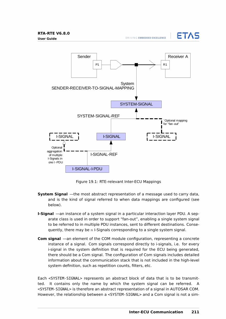
RTA-RTE V6.8.0User Guide
Sender
P1
Receiver A
R1
SYSTEM-SIGNAL
I-SIGNAL I-SIGNAL
`Optional mapping for “fan -out”
SYSTEM-SIGNAL-REF
I-SIGNAL
I-SIGNAL-I-PDU
Optional aggregation
of multiple I-Signals inone I -PDU
I-SIGNAL-REF
SystemSENDER-RECEIVER-TO-SIGNAL-MAPPING
Figure 19.1: RTE-relevant Inter-ECU Mappings
System Signal —the most abstract representation of a message used to carry data,and is the kind of signal referred to when data mappings are configured (seebelow).
I-Signal —an instance of a system signal in a particular interaction layer PDU. A sep-arate class is used in order to support “fan-out”, enabling a single system signalto be referred to in multiple PDU instances, sent to different destinations. Conse-quently, there may be n I-Signals corresponding to a single system signal.
Com signal —an element of the COM module configuration, representing a concreteinstance of a signal. Com signals correspond directly to i-signals, i.e. for everyi-signal in the system definition that is required for the ECU being generated,there should be a Com signal. The configuration of Com signals includes detailedinformation about the communication stack that is not included in the high-levelsystem definition, such as repetition counts, filters, etc.
Each <SYSTEM-SIGNAL> represents an abstract block of data that is to be transmit-ted. It contains only the name by which the system signal can be referred. A<SYSTEM-SIGNAL> is therefore an abstract representation of a signal in AUTOSAR COM.However, the relationship between a <SYSTEM-SIGNAL> and a Com signal is not a sim-
Inter-ECU Communication 211
RTA-RTE V6.8.0User Guide
ple one-to-one mapping, as system signal may be included in multiple frames each ofwhich will require separate COM signals.
<SYSTEM-SIGNAL><SHORT-NAME>Signal_gen_pa_rec_speed</SHORT-NAME>
</SYSTEM-SIGNAL>
An <I-SIGNAL> is an instance of a system signal in a particular interaction layer PDU.The <I-SIGNAL> refers to a system signal.
<I-SYSTEM><SHORT-NAME>isig</SHORT-NAME><SYSTEM-SIGNAL-REF>/signals/sig1</SYSTEM-SIGNAL-REF>
</I-SYSTEM>
Several signals can be collected into a signal group to ensure their simultaneoustransmission. This technique is used to map complex data types into signals for com-munication. A signal group contains only a name and a list of references to basic systemsignals.
The following example maps multiple system signals into a signal group. Note that thepacking of signals within the group into IPDUs is not specified as part of the signal groupspecification.
<SYSTEM-SIGNAL-GROUP><SHORT-NAME>SignalGroup_gen_pa_rec</SHORT-NAME><SYSTEM-SIGNALS-REFS><SYSTEM-SIGNAL-REF DEST="SYSTEM-SIGNAL">/signals/Signal_gen_pa_rec_speed
</SYSTEM-SIGNAL-REF><SYSTEM-SIGNAL-REF DEST="SYSTEM-SIGNAL">/signals/Signal_gen_pa_rec_freq
</SYSTEM-SIGNAL-REF>...
</SYSTEM-SIGNALS-REFS></SYSTEM-SIGNAL-GROUP>
An <I-SIGNAL=GROUP> is an instance of a system signal group in a particular interactionlayer PDU. The <I-SIGNAL-GROUP> refers to a system signal group.
<I-SYSTEM-GROUP><SHORT-NAME>isig</SHORT-NAME><SYSTEM-SIGNAL-GROUP-REF DEST="SYSTEM-SIGNAL-GROUP">/signals/sigGroup1
</SYSTEM-SIGNAL-GROUP-REF></I-SYSTEM-GROUP>
19.1.2 PDU Types
An <I-SIGNAL-I-PDU> element represents a collection of (system) signals for transferbetween nodes in a communications network via references to I-Signals.
212 Inter-ECU Communication
RTA-RTE V6.8.0User Guide
There are different types of PDU corresponding to the different layers of the com-munication network, but only the I-PDU (Interaction Layer Protocol Data Unit) type isrelevant to the RTE, as IPDUs are the units of data used by COM. Specifically, only<I-SIGNAL-I-PDUs> are considered, as these carry application data between softwarecomponents. (The terms “IPDU” hereafter refers to a I-Signal IPDUs).
As with other AUTOSAR elements, PDUs use a “type” and “prototype” method wherean <I-SIGNAL-I-PDU> element defines a PDU structure and instances of the type areused as the <PDU-TO-FRAME-MAPPING> element.
An <I-SIGNAL-I-PDU> element defines the overall length (in bits) and contains one ormore references to its included I-Signals and their mapped bit position.
<I-SIGNAL-I-PDU><SHORT-NAME>IPdu_p2m_value</SHORT-NAME><LENGTH>16</LENGTH><SIGNAL-TO-PDU-MAPPINGS><I-SIGNAL-TO-I-PDU-MAPPING><SHORT-NAME>is2ipdu_p2m_value</SHORT-NAME><I-SIGNAL-REF DEST=’I-SIGNAL’>/TOptimizeRTE/isig_p2m_value</I-SIGNAL-
REF><PACKING-BYTE-ORDER>MOST-SIGNIFICANT-BYTE-LAST</PACKING-BYTE-ORDER><START-POSITION>0</START-POSITION>
</I-SIGNAL-TO-I-PDU-MAPPING>...
</SIGNAL-TO-PDU-MAPPINGS></SIGNAL-I-PDU>
The <LENGTH> element defines tha size of the I-PDU in bits. Note that the length of thePDU can be greater that the sum of the included signal lengths.
The <I-SIGNAL-I-PDU> element is independent of the physical bus over which datamay be transferred.
19.1.3 Communication Clusters
A communication describes a set of physical channels used to connect ECUs and hubs.An ECU belongs to a communication cluster if one of its communications ports is con-nected to one of the physical channels of the cluster. The content of a communicationcluster depends of the type of bus used for a system; for example, it may just containa description of a CAN bus.
The separate communication cluster types are used for different bus types, for exam-ple, a <CAN-CLUSTER> might define:.
<CAN-CLUSTER><SHORT-NAME>bob</SHORT-NAME><CAN-CLUSTER-VARIANTS><CAN-CLUSTER-CONDITIONAL><PHYSICAL-CHANNELS><CAN-PHYSICAL-CHANNEL><SHORT-NAME>CHAN0</SHORT-NAME>
Inter-ECU Communication 213
RTA-RTE V6.8.0User Guide
<FRAME-TRIGGERINGS><CAN-FRAME-TRIGGERING><SHORT-NAME>trig0</SHORT-NAME><FRAME-REF DEST="CAN-FRAME">/pkg/frame</FRAME-REF><CAN-ADDRESSING-MODE>EXTENDED</CAN-ADDRESSING-MODE><IDENTIFIER>456</IDENTIFIER>
</CAN-FRAME-TRIGGERING></FRAME-TRIGGERINGS>
</CAN-PHYSICAL-CHANNEL></PHYSICAL-CHANNELS><SPEED>500000</SPEED></CAN-CLUSTER-CONDITIONAL></CAN-CLUSTER-VARIANTS>
</CAN-CLUSTER>
RTA-RTE does not use information present in communication clusters.
19.1.4 Frames
Each frame represents a communication protocol independent assembly of PDUs (andhence system signals) that will be transmitted across the network. A frame is thereforethe AUTOSAR XML equivalent of an IPDU in AUTOSAR COM.
Each frame has a length and a set of <PDU-TO-FRAME-MAPPINGS>. Different bus typeshave different frame definitions, for example, a CAN frame might be defined as:
<CAN-FRAME><SHORT-NAME>frame0</SHORT-NAME><FRAME-LENGTH>4</FRAME-LENGTH><PDU-TO-FRAME-MAPPINGS><PDU-TO-FRAME-MAPPING><SHORT-NAME>f1</SHORT-NAME><PDU-REF DEST="I-SIGNAL-I-PDU">/signals/ipdu1</PDU-REF><START-POSITION>0</START-POSITION>
</PDU-TO-FRAME-MAPPING></PDU-TO-FRAME-MAPPINGS>
</CAN-FRAME>
The <FRAME-LENGTH> specifies the length of the frame in bytes. The length can be ofarbitrary size1, but you must be aware that the decision of which signals are locatedin which frames and their corresponding length will be influenced by the physical com-munication system you use between ECUs.
19.1.5 COM OIL Generation
The RTE generator uses information from the system description to generate the COMAPI calls used to initiate communication and to respond to communication events indi-cated by COM.
For compatibility with previous AUTOSAR releases versions of the COM stack, the
1AUTOSAR currently restricts frame lengths to 8 bytes.
214 Inter-ECU Communication
RTA-RTE V6.8.0User Guide
RTE generator can optionally also output a COM OIL configuration file suitable fora COM generator. This maps objects in the system description into the MESSAGEs,NETWORKMESSAGEs and IPDUs understood by COM.
The generation of COM configuration is not part of the AUTOSAR RTE speci-fication. RTA-RTE supports generation of a COM 1.0 OIL configuration.
The generation of COM OIL in this release of RTA-RTE is limited to simple configurationsfeaturing one-off, triggered transmission only, and does not take into account morecomplex features like cyclic timing or repetition counters. For more complex configura-tions it is necessary to configure the COM stack separately.
19.2 Inter-ECU Sender-Receiver Communication
For remote (inter-ECU) sender-receiver communication you need to map the data ele-ment prototypes transferred between software components into system signals com-municated by the AUTOSAR COM and the sub-COM communication stack. This is donein the <DATA-MAPPINGS> section of the system mapping (see Section 18) element.
<SYSTEM><SHORT-NAME>MySystem</SHORT-NAME><MAPPINGS><SYSTEM-MAPPING><SHORT-NAME>mapping</SHORT-NAME><DATA-MAPPINGS><!-- Map data prototypes to signals -->...
</DATA-MAPPINGS>...
</MAPPING><!-- Other SYSTEM elements -->
</SYSTEM>
Primitive data types are mapped to a single signal using a SenderReceiverToSignalMap-ping; complex data types are mapped to several signals in a signal group using aSenderReceiverToSignalGroupMapping.
Whether an AUTOSAR signal is primitive or complex depends on the Category of theImplementationDataType used to represent the signal:
• VALUE — primitive. Use SenderReceiverToSignalMapping and see 19.2.1
• STRUCTURE — complex. Use SenderReceiverToSignalGroupMapping and see19.2.2
• ARRAY — either. If the array is fixed-length and is small enough to fit in a singlesignal then it may be treated as primitive and mapped to a single signal. In anycase it is permitted to treat an array as complex and map it to multiple, groupedsignals.
• TYPE_REFERENCE — effectively has the same category as the referenced type.
Inter-ECU Communication 215
RTA-RTE V6.8.0User Guide
In a full system description, data mappings are described for provider (sender) portsonly; the connectors in the software composition indicate which receiver ports are con-nected to these, which allows the mapping of received data elements to signals tobe inferred also. In an ECU extract of a system description, in which only the softwarecomponents relevant to a given ECU are included, it may be necessary to describe map-pings for a requirer port. For example, the receiver side data mappings are needed ifthe corresponding provider port is not included in the ECU extract.
Both primitive and complex mapping element types follow the same basic pattern; aninstance reference to a data element prototype that specifies the data to be sent inter-ECU and a mapping that specifies the system signal(s) used to carry the data.
19.2.1 Primitive Types
VariableDataPrototypes mapped to primitive ImplementationDataTypes are mappedusing the SenderReceiverToSignalMapping element. One element must be configuredfor each AUTOSAR signal.
<SENDER-RECEIVER-TO-SIGNAL-MAPPING><DATA-ELEMENT-IREF><CONTEXT-COMPONENT-REF ... >/pkg/composition/producer
</CONTEXT-COMPONENT-REF><CONTEXT-PORT-REF ...>/pkg/swctype/pa
</CONTEXT-PORT-REF><TARGET-DATA-PROTOTYPE-REF ... >/pkg/interface/value
</TARGET-DATA-PROTOTYPE-REF></DATA-ELEMENT-IREF><SYSTEM-SIGNAL-REF ... >/signals/Signal_gen_pa
</SYSTEM-SIGNAL-REF></SENDER-RECEIVER-TO-SIGNAL-MAPPING>
The SenderReceiverToSignalMapping’s <DATA-ELEMENT-IREF> specifies the componentinstance, port and data element from which the communication originates. If you usehierarchical composition, i.e. with delegation connectors, then you will need to ref-erence each level in the hierarchy using multiple <COMPONENT-PROTOTYPE-REF> ele-ments.
19.2.2 Complex Types
Complex types, which may be either records or arrays, are mapped using the Sender-ReceiverToSignalGroupMapping element. One element must be configured for eachcomplex AUTOSAR signal. All signals for a single complex type are mapped to a signalgroup and therefore benefit from atomic transmission.
The SenderReceiverToSignalGroupMapping is similar to the mapping element for primi-tive types in that it contains a DATA-ELEMENT-IREF to select the AUTOSAR signal. How-ever, unlike the primitive mapping the selection of system signals is more involved
216 Inter-ECU Communication
RTA-RTE V6.8.0User Guide
since a recursive mapping of the record/array elements to system signals is required.
<SENDER-RECEIVER-TO-SIGNAL-GROUP-MAPPING><DATA-ELEMENT-IREF><CONTEXT-COMPONENT-REF ... >/pkg/composition/producer
</CONTEXT-COMPONENT-REF><CONTEXT-PORT-REF ...>/pkg/swctype/pa
</CONTEXT-PORT-REF><TARGET-DATA-PROTOTYPE-REF ... >/pkg/interface/value
</TARGET-DATA-PROTOTYPE-REF></DATA-ELEMENT-IREF><SIGNAL-GROUP-REF ... >/signals/SignalGroup
</SIGNAL-GROUP-REF><TYPE-MAPPING>...
</TYPE-MAPPING></SENDER-RECEIVER-TO-SIGNAL-GROUP-MAPPING>
As with the mapping for primitive types, the <DATA-ELEMENT-IREF> specifies the com-ponent instance, port and data element from which the communication originates. Ifyou use hierarchical composition, i.e. with delegation connectors, then you will needto reference each level in the hierarchy using multiple <CONTEXT-COMPONENT-REF> ele-ments.
A group mapping includes the <TYPE-MAPPING> element that is the root forthe recursive mapping of system signals within the signal group referenced by<SIGNAL-GROUP-REF>. The example will map the following C structure R1 to signalswhere R1 is defined as:
struct R1 {UInt8 Speed;UInt8 Freq;
};
As explained above, the mapping of a complex type can be recursive since complexdata types can themselves be defined recursively; for example, a structure R2 couldbe defined in terms of structure R1 as well as additional primitive data elements. Therecursive mapping can produce very large, very complex, mappings and therefore toease understanding the type mapping for R1 uses a flat definition only.
<TYPE-MAPPING><SENDER-REC-RECORD-TYPE-MAPPING><RECORD-ELEMENT-MAPPINGS><!-- Mapping for member Speed’’ --><!-- Mapping for member Freq’’ -->
</RECORD-ELEMENT-MAPPINGS></SENDER-REC-RECORD-TYPE-MAPPING>
Inter-ECU Communication 217
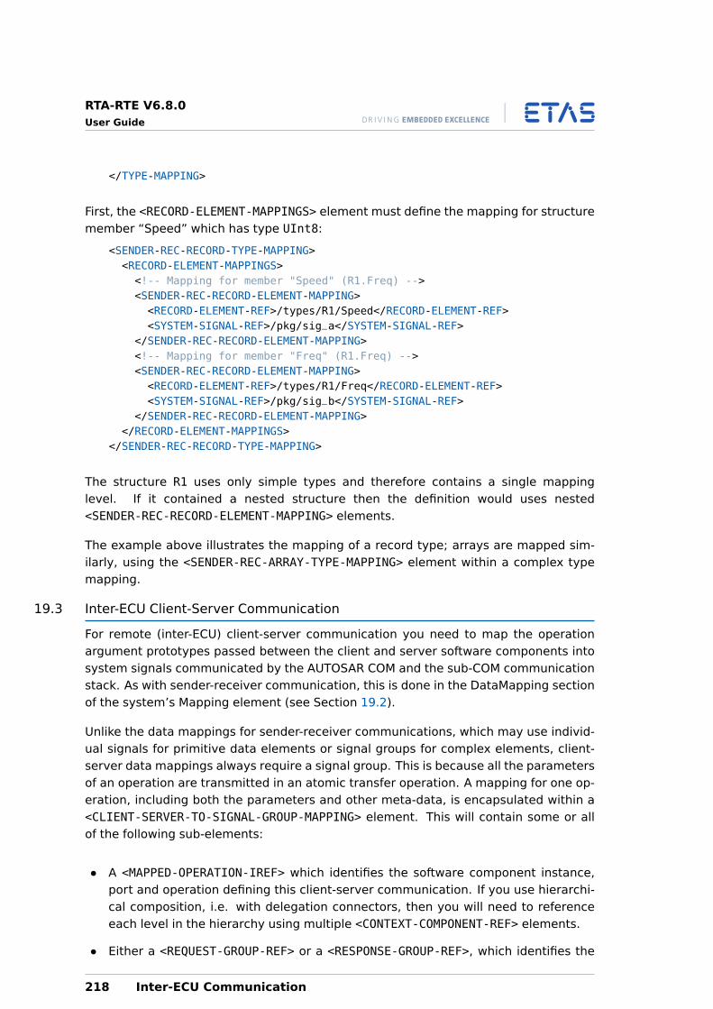
RTA-RTE V6.8.0User Guide
</TYPE-MAPPING>
First, the <RECORD-ELEMENT-MAPPINGS> element must define the mapping for structuremember “Speed” which has type UInt8:
<SENDER-REC-RECORD-TYPE-MAPPING><RECORD-ELEMENT-MAPPINGS><!-- Mapping for member "Speed" (R1.Freq) --><SENDER-REC-RECORD-ELEMENT-MAPPING><RECORD-ELEMENT-REF>/types/R1/Speed</RECORD-ELEMENT-REF><SYSTEM-SIGNAL-REF>/pkg/sig_a</SYSTEM-SIGNAL-REF>
</SENDER-REC-RECORD-ELEMENT-MAPPING><!-- Mapping for member "Freq" (R1.Freq) --><SENDER-REC-RECORD-ELEMENT-MAPPING><RECORD-ELEMENT-REF>/types/R1/Freq</RECORD-ELEMENT-REF><SYSTEM-SIGNAL-REF>/pkg/sig_b</SYSTEM-SIGNAL-REF>
</SENDER-REC-RECORD-ELEMENT-MAPPING></RECORD-ELEMENT-MAPPINGS>
</SENDER-REC-RECORD-TYPE-MAPPING>
The structure R1 uses only simple types and therefore contains a single mappinglevel. If it contained a nested structure then the definition would uses nested<SENDER-REC-RECORD-ELEMENT-MAPPING> elements.
The example above illustrates the mapping of a record type; arrays are mapped sim-ilarly, using the <SENDER-REC-ARRAY-TYPE-MAPPING> element within a complex typemapping.
19.3 Inter-ECU Client-Server Communication
For remote (inter-ECU) client-server communication you need to map the operationargument prototypes passed between the client and server software components intosystem signals communicated by the AUTOSAR COM and the sub-COM communicationstack. As with sender-receiver communication, this is done in the DataMapping sectionof the system’s Mapping element (see Section 19.2).
Unlike the data mappings for sender-receiver communications, which may use individ-ual signals for primitive data elements or signal groups for complex elements, client-server data mappings always require a signal group. This is because all the parametersof an operation are transmitted in an atomic transfer operation. A mapping for one op-eration, including both the parameters and other meta-data, is encapsulated within a<CLIENT-SERVER-TO-SIGNAL-GROUP-MAPPING> element. This will contain some or allof the following sub-elements:
• A <MAPPED-OPERATION-IREF> which identifies the software component instance,port and operation defining this client-server communication. If you use hierarchi-cal composition, i.e. with delegation connectors, then you will need to referenceeach level in the hierarchy using multiple <CONTEXT-COMPONENT-REF> elements.
• Either a <REQUEST-GROUP-REF> or a <RESPONSE-GROUP-REF>, which identifies the
218 Inter-ECU Communication
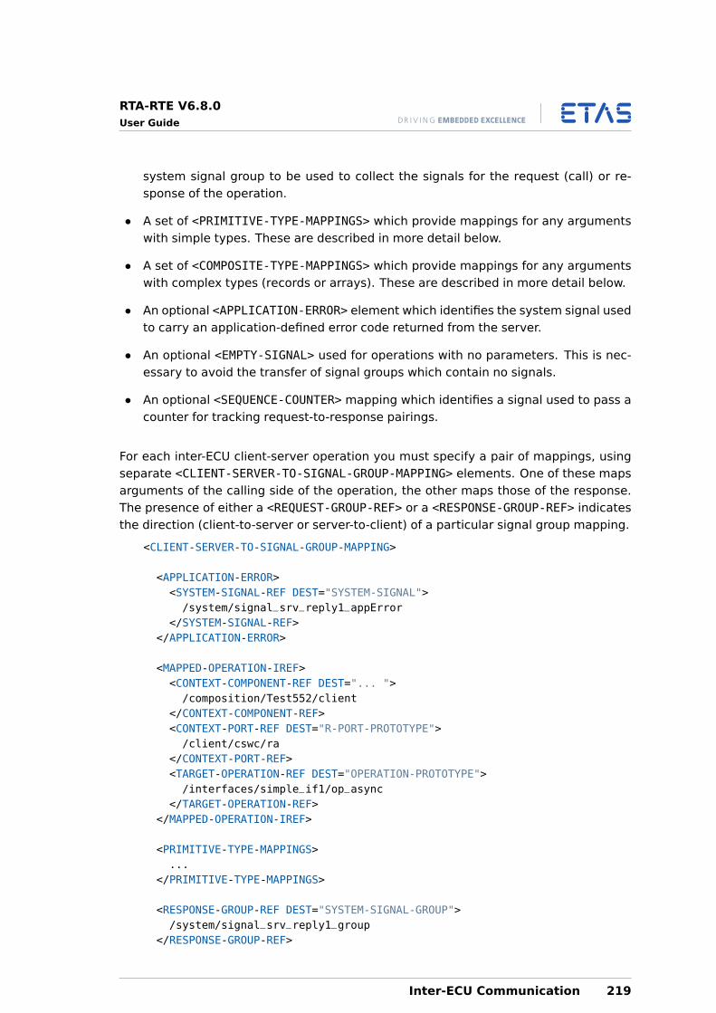
RTA-RTE V6.8.0User Guide
system signal group to be used to collect the signals for the request (call) or re-sponse of the operation.
• A set of <PRIMITIVE-TYPE-MAPPINGS> which provide mappings for any argumentswith simple types. These are described in more detail below.
• A set of <COMPOSITE-TYPE-MAPPINGS> which provide mappings for any argumentswith complex types (records or arrays). These are described in more detail below.
• An optional <APPLICATION-ERROR> element which identifies the system signal usedto carry an application-defined error code returned from the server.
• An optional <EMPTY-SIGNAL> used for operations with no parameters. This is nec-essary to avoid the transfer of signal groups which contain no signals.
• An optional <SEQUENCE-COUNTER> mapping which identifies a signal used to pass acounter for tracking request-to-response pairings.
For each inter-ECU client-server operation you must specify a pair of mappings, usingseparate <CLIENT-SERVER-TO-SIGNAL-GROUP-MAPPING> elements. One of these mapsarguments of the calling side of the operation, the other maps those of the response.The presence of either a <REQUEST-GROUP-REF> or a <RESPONSE-GROUP-REF> indicatesthe direction (client-to-server or server-to-client) of a particular signal group mapping.
<CLIENT-SERVER-TO-SIGNAL-GROUP-MAPPING>
<APPLICATION-ERROR><SYSTEM-SIGNAL-REF DEST="SYSTEM-SIGNAL">/system/signal_srv_reply1_appError
</SYSTEM-SIGNAL-REF></APPLICATION-ERROR>
<MAPPED-OPERATION-IREF><CONTEXT-COMPONENT-REF DEST="... ">/composition/Test552/client
</CONTEXT-COMPONENT-REF><CONTEXT-PORT-REF DEST="R-PORT-PROTOTYPE">/client/cswc/ra
</CONTEXT-PORT-REF><TARGET-OPERATION-REF DEST="OPERATION-PROTOTYPE">/interfaces/simple_if1/op_async
</TARGET-OPERATION-REF></MAPPED-OPERATION-IREF>
<PRIMITIVE-TYPE-MAPPINGS>...
</PRIMITIVE-TYPE-MAPPINGS>
<RESPONSE-GROUP-REF DEST="SYSTEM-SIGNAL-GROUP">/system/signal_srv_reply1_group
</RESPONSE-GROUP-REF>
Inter-ECU Communication 219
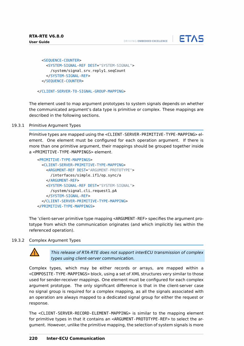
RTA-RTE V6.8.0User Guide
<SEQUENCE-COUNTER><SYSTEM-SIGNAL-REF DEST="SYSTEM-SIGNAL">/system/signal_srv_reply1_seqCount
</SYSTEM-SIGNAL-REF></SEQUENCE-COUNTER>
</CLIENT-SERVER-TO-SIGNAL-GROUP-MAPPING>
The element used to map argument prototypes to system signals depends on whetherthe communicated argument’s data type is primitive or complex. These mappings aredescribed in the following sections.
19.3.1 Primitive Argument Types
Primitive types are mapped using the <CLIENT-SERVER-PRIMITIVE-TYPE-MAPPING> el-ement. One element must be configured for each operation argument. If there ismore than one primitive argument, their mappings should be grouped together insidea <PRIMITIVE-TYPE-MAPPINGS> element.
<PRIMITIVE-TYPE-MAPPINGS><CLIENT-SERVER-PRIMITIVE-TYPE-MAPPING><ARGUMENT-REF DEST="ARGUMENT-PROTOTYPE">/interfaces/simple_if1/op_sync/a
</ARGUMENT-REF><SYSTEM-SIGNAL-REF DEST="SYSTEM-SIGNAL">/system/signal_cli_request1_pA
</SYSTEM-SIGNAL-REF></CLIENT-SERVER-PRIMITIVE-TYPE-MAPPING>
</PRIMITIVE-TYPE-MAPPINGS>
The ‘client-server primitive type mapping <ARGUMENT-REF> specifies the argument pro-totype from which the communication originates (and which implicitly lies within thereferenced operation).
19.3.2 Complex Argument Types
This release of RTA-RTE does not support interECU transmission of complextypes using client-server communication.
Complex types, which may be either records or arrays, are mapped within a<COMPOSITE-TYPE-MAPPINGS> block, using a set of XML structures very similar to thoseused for sender-receiver mappings. One element must be configured for each complexargument prototype. The only significant difference is that in the client-server caseno signal group is required for a complex mapping, as all the signals associated withan operation are always mapped to a dedicated signal group for either the request orresponse.
The <CLIENT-SERVER-RECORD-ELEMENT-MAPPING> is similar to the mapping elementfor primitive types in that it contains an <ARGUMENT-PROTOTYPE-REF> to select the ar-gument. However, unlike the primitive mapping, the selection of system signals is more
220 Inter-ECU Communication
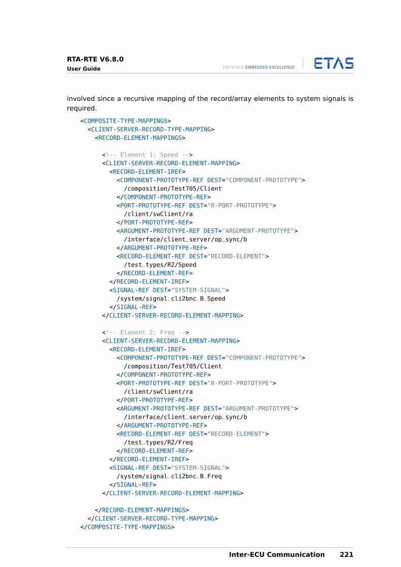
RTA-RTE V6.8.0User Guide
involved since a recursive mapping of the record/array elements to system signals isrequired.
<COMPOSITE-TYPE-MAPPINGS><CLIENT-SERVER-RECORD-TYPE-MAPPING><RECORD-ELEMENT-MAPPINGS>
<!-- Element 1: Speed --><CLIENT-SERVER-RECORD-ELEMENT-MAPPING><RECORD-ELEMENT-IREF><COMPONENT-PROTOTYPE-REF DEST="COMPONENT-PROTOTYPE">/composition/Test705/Client
</COMPONENT-PROTOTYPE-REF><PORT-PROTOTYPE-REF DEST="R-PORT-PROTOTYPE">/client/swClient/ra
</PORT-PROTOTYPE-REF><ARGUMENT-PROTOTYPE-REF DEST="ARGUMENT-PROTOTYPE">/interface/client_server/op_sync/b
</ARGUMENT-PROTOTYPE-REF><RECORD-ELEMENT-REF DEST="RECORD-ELEMENT">/test_types/R2/Speed
</RECORD-ELEMENT-REF></RECORD-ELEMENT-IREF><SIGNAL-REF DEST="SYSTEM-SIGNAL">/system/signal_cli2bnc_B_Speed
</SIGNAL-REF></CLIENT-SERVER-RECORD-ELEMENT-MAPPING>
<!-- Element 2: Freq --><CLIENT-SERVER-RECORD-ELEMENT-MAPPING><RECORD-ELEMENT-IREF><COMPONENT-PROTOTYPE-REF DEST="COMPONENT-PROTOTYPE">/composition/Test705/Client
</COMPONENT-PROTOTYPE-REF><PORT-PROTOTYPE-REF DEST="R-PORT-PROTOTYPE">/client/swClient/ra
</PORT-PROTOTYPE-REF><ARGUMENT-PROTOTYPE-REF DEST="ARGUMENT-PROTOTYPE">/interface/client_server/op_sync/b
</ARGUMENT-PROTOTYPE-REF><RECORD-ELEMENT-REF DEST="RECORD-ELEMENT">/test_types/R2/Freq
</RECORD-ELEMENT-REF></RECORD-ELEMENT-IREF><SIGNAL-REF DEST="SYSTEM-SIGNAL">/system/signal_cli2bnc_B_Freq
</SIGNAL-REF></CLIENT-SERVER-RECORD-ELEMENT-MAPPING>
</RECORD-ELEMENT-MAPPINGS></CLIENT-SERVER-RECORD-TYPE-MAPPING>
</COMPOSITE-TYPE-MAPPINGS>
Inter-ECU Communication 221

RTA-RTE V6.8.0User Guide
The mapping of an array argument prototype is similar to the record type shown here,but uses the <CLIENT-SERVER-ARRAY-ELEMENT-MAPPING> element. As with inter-ECUsender-receiver communications, nested types can also be mapped, again with theexception that arrays of arrays are currently not supported.
222 Inter-ECU Communication
RTA-RTE V6.8.0User Guide
20 Using the OS and COM Configurations
The OS and COM modules for a particular ECU must provide the RTE for that ECU withall the services it requires in order to fulfil the requirements of the software componentsand BSW modules on the ECU. For instance the RTE may require particular OsResourcesfor serialization of access to application / BSW module code and/or internal state andmay require particular COM signals for communication with software components onother ECUs. The configurations of the OS and COM modules must therefore eventuallycontain all the required configuration objects for the RTE, in addition to configurationfor the ECU environment (e.g. OS target) and Os objects for other BSW modules.
As mentioned in section 18.4 the RTE generator in RTE phase uses part of the OS con-figuration to determine the execution contexts of runnables, the concurrency model forthe system and the task bodies it must generate. It is possible to supply just this part ofthe OS configuration at RTE generation time and subsequently add the other requiredconfiguration before the OS generation or configuration step. Similarly it is possibleto supply just part of the COM configuration at RTE generation time and add the restbefore generating or configuring COM.
The RTE generator optionally outputs two configuration files that can be useful whentaking this approach:
1. An Operating System configuration file containing both additional configurationfor Os objects that were in the input configuration but need particular proper-ties for the RTE to function correctly and additional Os objects required for thescheduling and serialization of the Os tasks by the RTE. Depending on the se-lected OS (RTE option --operating-system) this could be an AUTOSAR XML fileor a legacy OIL file. The default name of the file depends on the OS used; forexample, for the AUTOSAR R4.0 OS plug-in it is osNeeds.arxml, for the AUTOSARR1.0 plug-in it is rta-osek.oil, for the OSEK v2.2.3 plug-in it is osek.oil. Thename can be changed using the command-line option --os-file.
2. A COM v1.0 configuration file called rta-com.oil.
These configuration files are not complete; they must be combined with other config-uration files, not generated by RTA-RTE, before being passed to the operating systemand communication service configuration tools.
These files contain partial configuration information for the respective mod-ules. The scope of the generated configuration data are those parts of con-figuration necessary for the RTE to work, namely Os tasks and supportingOs objects and COM signals and signal groups. If additional OS/COM config-uration is provided as input to the RTE generator then this is ignored.
The output of OS and COM configuration can be ignored if not required ornot suitable. The plug-ins should not be removed from the the RTE generatorconfiguration file.
Using the OS and COM Configurations 223
RTA-RTE V6.8.0User Guide
It is possible and sometimes necessary to supply more than the minimum OS con-figuration on the input to the RTE generator. In particular, in a partitioned system itis necessary to supply the OsApplications and the mapping of tasks to them; in thiscase the additional OS configuration for the RTE that is generated by the RTE gener-ator does not place the additional Os objects in OsApplications and cannot be useddirectly. For R4.0 it is possible to disable the generation of additional OS configurationand have the RTE generator check that the supplied configuration is sufficient, usingthe --strict-config-check option.
When the OS and/or COM configuration output by the RTE generator is ig-nored (and the strict configuration check is not enabled) it is important thatall the Os and COM objects that the generated RTE uses are configured withthe expected names, at latest by the OS and COM generation or configura-tion step, otherwise compilation or link errors will result. It is also importantto ensure that all Os tasks and ISRs in which RTE code may execute are con-figured as accessing the necessary Os objects used by the RTE, otherwiseruntime errors may occur. Details of the Os objects typically required by theRTE may be found in the OS Configuration section of the RTA-RTE ReferenceManual.
20.1 Operating System Configuration
All AUTOSAR application software components’ access to the OS occurs via the RTE.The RTE insulates application software components from the need to access OS APIcalls directly and hence RTA-RTE provides no mechanism for them to do so.
20.1.1 Scheduling Policy
By default, all runnable entities are scheduled pre-emptively based on priorities speci-fied during configuration.
Runnable entities that must guard against access to an exclusive area at runtime canuse the RTE concurrency control API to force non-preemption by declaring an exclusivearea around relevant code regions. All runnable entities in a prototype of a componentthat specify the same explicit exclusive area are scheduled non pre-emptively.
20.1.2 OS Counters
The generated RTE uses OS objects, either periodic alarms or schedule tables, to trig-ger runnable entities activated by timing events. The alarm/table is driven by a counterRte_Tick_Counter. The rate at which the counter must be driven depends on config-ured timing events – for convenience the output file Rte_Const.h contains the requiredperiod (in microseconds) as RTE_PERIODIC_COUNTER_TICK_INTERVAL_US.
The generated RTE uses OS alarms for sporadic events such as timeouts. If such alarmsare required then the counter Rte_TOut_Counter is created in the OS configuration.To avoid unacceptable jitter on timeouts the Rte_TOut_Counter is always ticked at1ms. For convenience the output file Rte_Const.h contains the required period (inmicroseconds) as RTE_ALARM_COUNTER_TICK_INTERVAL_US.
224 Using the OS and COM Configurations
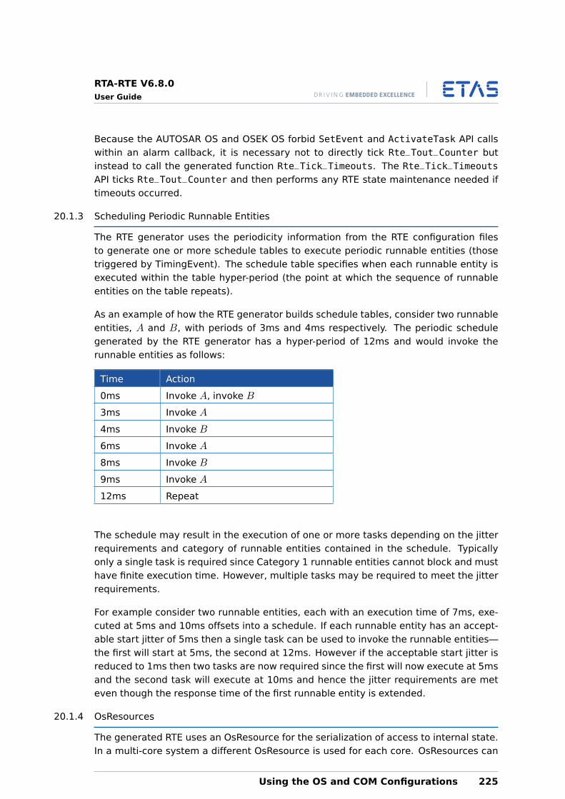
RTA-RTE V6.8.0User Guide
Because the AUTOSAR OS and OSEK OS forbid SetEvent and ActivateTask API callswithin an alarm callback, it is necessary not to directly tick Rte_Tout_Counter butinstead to call the generated function Rte_Tick_Timeouts. The Rte_Tick_TimeoutsAPI ticks Rte_Tout_Counter and then performs any RTE state maintenance needed iftimeouts occurred.
20.1.3 Scheduling Periodic Runnable Entities
The RTE generator uses the periodicity information from the RTE configuration filesto generate one or more schedule tables to execute periodic runnable entities (thosetriggered by TimingEvent). The schedule table specifies when each runnable entity isexecuted within the table hyper-period (the point at which the sequence of runnableentities on the table repeats).
As an example of how the RTE generator builds schedule tables, consider two runnableentities, A and B, with periods of 3ms and 4ms respectively. The periodic schedulegenerated by the RTE generator has a hyper-period of 12ms and would invoke therunnable entities as follows:
Time Action
0ms Invoke A, invoke B
3ms Invoke A
4ms Invoke B
6ms Invoke A
8ms Invoke B
9ms Invoke A
12ms Repeat
The schedule may result in the execution of one or more tasks depending on the jitterrequirements and category of runnable entities contained in the schedule. Typicallyonly a single task is required since Category 1 runnable entities cannot block and musthave finite execution time. However, multiple tasks may be required to meet the jitterrequirements.
For example consider two runnable entities, each with an execution time of 7ms, exe-cuted at 5ms and 10ms offsets into a schedule. If each runnable entity has an accept-able start jitter of 5ms then a single task can be used to invoke the runnable entities—the first will start at 5ms, the second at 12ms. However if the acceptable start jitter isreduced to 1ms then two tasks are now required since the first will now execute at 5msand the second task will execute at 10ms and hence the jitter requirements are meteven though the response time of the first runnable entity is extended.
20.1.4 OsResources
The generated RTE uses an OsResource for the serialization of access to internal state.In a multi-core system a different OsResource is used for each core. OsResources can
Using the OS and COM Configurations 225
RTA-RTE V6.8.0User Guide
also be used to serialize access to application / BSW module code, depending on theconfigured protection requirements and the possible concurrency of runnables impliedby the task mappings and task configuration.
Any task or ISR in whose context RTE code may run must be marked as locking theRTE-internal OsResource, or the RTE-internal OsResource for the core on which it exe-cutes in a multi-core system. This includes tasks whose bodies are generated by theRTE generator, i.e. that have runnable entities and/or schedulable entities mapped tothem, and tasks and ISRs from which BSW modules may call RTE generated notificationfunctions, such as COM reception notifications for example.
Similarly, tasks and ISRs in whose context protected application / BSW module codeexecutes must be marked as locking the corresponding OsResources used by the RTEto provide the protection.
See the OS Configuration section of the RTA-RTE Reference Manual for details.
20.1.5 Using the OS Configuration
The OS configuration generated by the RTE generator contains only the task configu-ration for the tasks you defined at system deployment time, the schedule tables forrunnable entities triggered with periodic TimingEvents and OsResources needed forserializing access to application code or internal state. You will need to include thegenerated XML / OIL file with the other XML / OIL files that define other aspects of yoursystem, for example:
• message/task mappings generated by the COM configuration process
• a driver interrupt for the schedule table
• other interrupt handlers
• other tasks for non-RTE managed ECU functionality
• additional counters, alarms etc.
For OIL configuration files you can use the #include mechanisms to integrate the RTEOS configuration with your other OS configuration files. You should consult your OSdocumentation for further information or for details of how to merge XML configurationfiles.
20.2 Communication Stack Configuration
When component prototypes that communicate are allocated to different ECU in-stances, the RTE generator will generate an OIL configuration file for the communi-cation stack.
20.2.1 Using the COM Configuration
The rta-com.oil configuration file generated by the RTE generator contains the mes-sages and network messages (messages packed into COM IPDUs) and the IPDU frame
226 Using the OS and COM Configurations
RTA-RTE V6.8.0User Guide
types. The configuration also contains the declaration of which OS tasks access thespecified messages.
You will need to include the rta-com.oil file with any additional configuration you mighthave. The following example shows the general structure:
CPU MyECU {OS dummyOS {};
COM Somename {COMTIMEBASE = 0.001;COMAPPMODE = "COMAppMode1";COMSTATUS = COMEXTENDED;
};
#include "rta-com.oil"};
The COM configuration should be processed with the COM configuration tool to gener-ate the data structures for the communication layer. Please consult your COM docu-mentation for details.
The configuration of the COM layer does not include configuration of the net-work drivers (e.g. CAN drivers, FlexRay drivers etc.) or the PDU Router. Thismust be done independently using your AUTOSAR XML files and networkdriver configuration tools.
Using the OS and COM Configurations 227
RTA-RTE V6.8.0User Guide
21 Debugging Implementations with VFB Tracing
Virtual Function Bus (VFB) Tracing permits the monitoring of AUTOSAR signals as theyare sent and received across the VFB.
VFB tracing is implemented as a series of hook functions that are invoked automaticallyby the generated RTE when interesting events within the RTE occur. Each hook func-tion corresponds to a single trace event, for example task dispatch or runnable entityinvocation.
The trace events supported by RTA-RTE are defined in Section 21.2. RTA-RTE provides ameans by which VFB tracing can either be globally enabled or disabled (if disabled, VFBtracing has no run-time effect) as well as the enabling or disabling of individual traceevents. Configuration of VFB tracing for RTA-RTE is described in Section 21.3.
21.1 Enabling Tracing
The creation of VFB Tracing hook calls within the generated code is controlled by eithera command-line option or an RTE configuration parameter within the ECUC.
If VFB Tracing is disabled then no hook calls are created in the generated code.
Even if hook calls are generated they will have no runtime effect unlessdefinitions in Rte_Cfg.h are in place to globally enable VFB tracing to enablethe required individual hook calls.
21.2 Supported Trace Events
RTA-RTE supports the following VFB Trace events:
• RTE API call start and return.
• Inter-ECU signal transmission, reception and reception notification.
• Runnable entity invocation and termination.
• OS Event set, wait and return.
• OS Task activation and dispatch.
21.2.1 RTE API Start
RTE API Start is invoked by the RTA-RTE when an API call is made by a software compo-nent. The hook function must have the name:
Rte_<api>Hook_<swc>_<ap>_Start
Where <api> is the API root name (Write, Call, Feedback, etc.), <swc> the software-component type name and <ap> the access point (combination of port name and dataitem name/operation name separated by an underscore).
228 Debugging Implementations with VFB Tracing
RTA-RTE V6.8.0User Guide
21.2.2 RTE API Return
RTE API Return is invoked by the RTA-RTE just before an API call returns control to acomponent. The hook function must have the name:
Rte_<api>Hook_<swc>_<ap>_Return
Where <api> is the API root name (Write, Call, Feedback, etc.), <swc> the software-component type name and <ap> the access point (combination of port name and dataitem name/operation name separated by an underscore).
21.2.3 COM Signal Transmission
A trace event indicating a transmission request of an Inter-ECU signal or signal groupby the RTE. The hook function is invoked by the RTA-RTE just before Com_SendSignalor Com_SendSignalGroup is invoked. The hook function must have the name:
Rte_ComHook_<signal>_SigTx
Where <signal> is the system signal name.
21.2.4 COM Signal Reception
A trace event indicating an attempt to read Inter-ECU signal by the RTE. The hookfunction is invoked by the RTA-RTE after successful return from Com_ReceiveSignal.The hook function must have the name:
Rte_ComHook_<signal>_SigRx
Where <signal> is the system signal name.
21.2.5 COM Notification
A trace event indicating the start of a COM notification. Invoked by RTA-RTE generatedcode on entry to the COM call-back. The hook function must have the name:
Rte_ComHook_<signal>
Where <signal> is the system signal name.
21.2.6 OS Task Activation
A trace event invoked by RTA-RTE generated code immediately before activating thespecified task. The hook function must have the name:
Rte_Task_Activate
The Rte_Task_Activate hook is passed the task handle of the activated task.
21.2.7 OS Task Dispatch
A trace event invoked by the RTA-RTE immediately on dispatch of the specified gen-erated task (provided it contains runnable entities). The hook function must have thename:
Debugging Implementations with VFB Tracing 229
RTA-RTE V6.8.0User Guide
Rte_Task_Dispatch
The Rte_Task_Dispatch hook is passed the task handle of the activated task.
21.2.8 OS Task Set Event
A trace event invoked immediately before generated RTA-RTE code attempts to set anOS Event. The hook function must have the name:
Rte_Task_SetEvent
The parameters of the hook call define the task for which the event is being set and theevent mask.
21.2.9 OS Task Wait Event
A trace event invoked immediately before generated RTA-RTE code attempts to wait foran OS Event. The hook function must have the name:
Rte_Task_WaitEvent
The parameters of the hook call define the task waiting for the event and the eventmask.
21.2.10 OS Task Wait Event Return
A trace event invoked immediately before generated RTE code returns from waiting foran OS Event. The hook function must have the name:
Rte_Task_WaitEventRet
The parameters of the hook call define the task returning from the wait and the eventmask.
21.2.11 Runnable Entity Invocation
A trace event invoked by the RTE just before execution of a runnable entry starts viaits entry point. This trace event occurs after any copies of data elements are made tosupport the Rte_IRead API Call. The hook function must have the name:
Rte_Runnable_<swc>_<reName>_Start
Where <swc> is the software-component type name and <reName> the runnable entityname.
21.2.12 Runnable Entity Termination
A trace event invoked by the RTE immediately after execution returns to RTE code froma runnable entity. This trace event occurs before write-back of data elements is madeto support the Rte_IWrite API Call. The hook function must have the name:
Rte_Runnable_<swc>_<reName>_Return
230 Debugging Implementations with VFB Tracing
RTA-RTE V6.8.0User Guide
Where <swc> is the software-component type name and <reName> the runnable entityname.
21.3 Configuration
When generation of VFB trace hooks is enabled, RTA-RTE always places hook calls in thegenerated RTE. However unless both VFB Tracing is globally enabled and the individualtrace event(s) enabled the generated hooks will have no run-time effect.
The RTE configuration header file, Rte_Cfg.h, contains user definitions that globallyenable or disable VFB tracing and enable individual trace events.
21.3.1 Enabling VFB Tracing
VFB Tracing is globally enabled when the RTE configuration header file definesRTE_VFB_TRACE as a non-zero integer, for example:
#define RTE_VFB_TRACE (1)
If RTE_VFB_TRACE is not defined in the RTE configuration header file VFB Tracing isglobally disabled.
21.3.2 Enabling VFB Trace Events
Using definitions in the RTE configuration header file it is possible to enable or disableindividual trace events, for example, it is possible to enable just “Task dispatch” eventsand to ignore all others.
Individually enabled trace events have no effect if VFB tracing is globallydisabled.
An individual trace event is enabled when there is a #define in the RTE configurationheader file for the hook function name. The following example enables VFB Tracing for“Task Dispatch” events
#define Rte_Task_Dispatch (1)
The name of the #define must be the same as the hook name.
21.4 Trace Event Header File
RTA-RTE creates a header file, Rte_Hook.h, that defines the signature of each hookfunction and is responsible for disabling the trace event so that its hook call has norun-time effect if the hook function name is not defined in the RTE configuration headerfile.
21.5 Implementing Hook Functions
For each enabled trace event RTA-RTE will invoke a hook function. The implementationof the function is not provided by RTA-RTE but instead must be supplied by the user.The implementation is free to perform any actions required within the hook function,e.g. log the invocation.
Debugging Implementations with VFB Tracing 231
RTA-RTE V6.8.0User Guide
The Rte_Hook.h header file should be included in any user code that implements hookfunctions. Additional header files, such as Rte_Type.h, may be necessary depending onthe enabled trace events and the data types used within the program.
The following example implements a hook function for “Task Dispatch”:
#include <Os.h>#include "Rte.h"#include "Rte_Hook.h"
FUNC(void, RTE_APPL_CODE)Rte_Task_Dispatch(TaskType t){
if ( t == taskA ){
/* Log dispatch of taskA */}
}
232 Debugging Implementations with VFB Tracing
RTA-RTE V6.8.0User Guide
22 Data Transformation
RTA-RTE supports data transformation, introduced in AUTOSAR 4.2, for sender/receivercommunications. When data transformation is requested for a signal, RTA-RTE willtransform any data items that are sent or received via the Rte_Write and Rte_ReadAPIs associated with that signal.
On the transmission side of a communication, the generated Rte_Write API calls theconfigured sequence of BswModuleEntrys to convert the port data to a byte array (ar-ray of uint8) and passes the resulting array to COM_SendSignal for transmission.
On the reception side of a communication, the data is received from COM as a bytearray (array of uint8), and the generated Rte_Read API calls the configured sequenceof BswModuleEntrys to convert the byte array back into port data.
22.1 Extent of support
Data transformation in RTA-RTE is based on the specification in AUTOSAR version 4.2.2.The scenarios supported are described in Section 22.1.1.
RTA-RTE does not support the complete AUTOSAR specification for data transformation.Section 22.1.2 outlines the limitations in the support for data transformation in thecurrent implementation.
There are a number of differences between the implementation of data transforma-tion in RTA-RTE and the published AUTOSAR 4.2.2 specification. These differences arehighlighted in Section 22.1.3.
22.1.1 Supported scenarios
The following are supported by RTA-RTE:
Configurations supplied as an ECU_EXTRACT: RTA-RTE supports data transforma-tion for configurations containing an AUTOSAR System of category ECU_EXTRACT,where signals are mapped to delegation ports on the RootSwComposition.
Explicit unqueued sender/receiver communications: RTA-RTE supports datatransformation for explicit sender/receiver communications using the Rte_Readand Rte_Write APIs.
Serialization with SOME/IP plus optional end-to-end protection: RTA-RTE sup-ports serialization of the input data using the SOME/IP transformer, optionallyfollowed by end-to-end protection using the E2E transformer.
Serialization with the COM-based transformer plus optional end-to-end protection:RTA-RTE supports serialization of the input data using the COM-based trans-former, optionally followed by end-to-end protection using the E2E transformer(support for the COM-based transformer in RTA-RTE requires an additional ARXMLpreprocessing step before RTEGen is executed - see section 22.4 for details.)
Data Transformation 233
RTA-RTE V6.8.0User Guide
Out-of-place buffering: RTA-RTE supports the use of the E2E transformer when it isconfigured for out-of-place buffering.
Reporting of transformer errors to calling SWC: RTA-RTE supports extending theRte_Read and Rte_Write APIs with the optional transformerError parameter toprovide transformer error information to the calling SWC.
22.1.2 Limitations
RTA-RTE does not currently support data transformation for these configurations, whichwill be rejected with an error:
• Transformer chains (DataTransformations) of length 3 or more
• Transformer chains containing TransformationTechnologys of SECURITY orCUSTOM classes
• Transformers using in-place buffering (where BufferProperties.inPlace is TRUE)
• Transformers requiring access to the original data (where the needsOriginalDataattribute is TRUE)
The --xfrm-ignore-inplace option prevents RTA-RTE from raising an errorif a configuration requires the use of in-place buffering, but does not enablefull support for in-place buffering. The use of this option causes in-placetransformers to be treated as if they used out-of-place buffering, and as aresult the generated RTE code creates separate input and output buffersand calls transformer functions using the out-of-place API format.
RTA-RTE does not currently support data transformation for these types of communica-tion:
• Implicit sender/receiver communication (Rte_IWrite and Rte_IRead APIs)
• Queued sender/receiver communication (Rte_Send and Rte_Receive APIs)
• Client/server communication (Rte_Call and Rte_Result APIs)
• External trigger communication (Rte_Trigger API)
• Any form of intra-ECU communication
RTA-RTE does not currently support transformation in the following APIs used for un-queued explicit sender/receiver communication:
• Rte_Invalidate
• Rte_DRead
234 Data Transformation
RTA-RTE V6.8.0User Guide
• Rte_Feedback
RTA-RTE does not support the use of data transformation for any inter-ECU communica-tion where the same data element is sent or received via multiple signals. This includesconfigurations where multiple SystemSignals or SystemSignalGroups are mapped tothe same data element, as well as signal fan-in and fan-out as a result of multipleISignals referencing the same SystemSignal.
22.1.3 Deviations from AUTOSAR
The implementation of data transformation in RTA-RTE deviates from the AUTOSARspecification in the following ways:
Buffer Size
To eliminate problems caused by different interpretations of the AUTOSAR stan-dard, and to minimize the cost of corrections to the configuration, RTA-RTEdoes not attempt to calculate the buffer size from the input type size and thebufferProperties.BufferComputation.
Instead, RTA-RTE requires that an XfrmBufferSizeInBytes be supplied for eachXfrmImplementationMapping. This specifies the size of the buffer for the transformeddata, i.e. the output buffer on the sending side and the input buffer on the receiv-ing side. The specified buffer size must include an allowance for any header that thetransformer function may add.
XfrmBufferSizeInBytes is a mandatory integer parameter that must be between 1and 65535, since the C-type of bufferLength in the calling protocol is uint16. If anyXfrmImplementationMapping does not contain a parameter XfrmBufferSizeInBytes,RTA-RTE raises error 2968.
Prototypes for transformer functions
When a transformer function is called, RTA-RTE forward declares the function by writ-ing the function prototype to Rte.c. The declaration is generated without the use ofcompiler abstraction macros (FUNC, CONSTP2VAR etc.).
Version 4.2.2 of the AUTOSAR specification is ambiguous as to how transformer func-tions should be declared. According to SWS_Rte 07283, the declaration should be gen-erated in the Module Interlink Header File (MIHF), however there is no requirement toinclude MIHFs in Rte.c, nor any mechanism to know what MIHFs might be appropriatefor a given transformer (given only a reference to a BswModuleEntry, RTA-RTE does notknow which BSW Module’s ExecutableEntity it belongs to).
RTA-RTE does not currently implement RfC 73044 (adopted in AUTOSAR ver-sions 4.3.0 and later), which adds a new attribute to bswModuleEntrys todetermine whether or not RTE is responsible for generating the function pro-totype in the MIHF.
Data Transformation 235
RTA-RTE V6.8.0User Guide
22.1.4 Unsupported feature combinations
When data transformation is in use, the use of these features is not supported:
• Data conversion
• Signal fan-in and fan-out
• MEMORY optimization strategy
The use of these features combined with data transformation may result in RTA-RTEexiting with an error, or other unexpected behaviour.
22.2 Enabling data transformation in an input configuration
The information in this section relates to data transformation where serial-ization uses a transformer other than the COM-based transformer. Using theCOM-based transformer with RTA-RTE requires additional processing steps.These are described in section 22.4.
To enable data transformation, the input configuration must contain the following ele-ments:
• An AUTOSAR system of category ECU_EXTRACT with signals mapped via delegationports (section 22.2.1)
• System model elements associated with transformation (section 22.2.2)
• Mappings to transformer implementation functions(section 22.2.3)
• BSW entries corresponding to transformer functions (section 22.2.4)
• COM signals to send the transformed data (section 22.2.5)
22.2.1 System category and signal mapping
RTA-RTE only supports data transformation for AUTOSAR Systems that are of cate-gory ECU_EXTRACT. The use of any System category other than ECU_EXTRACT when-ever XfrmImplementationMappings are present in the input configuration (see sec-tion 22.2.3) will cause RTA-RTE to exit with an error.
The signals that transport transformed data must be mapped to delegation ports onthe RootSwComposition. RTA-RTE will exit with an error if transformation is enabledfor a signal that is mapped directly to an inner port on a SWC contained within theRootSwComposition.
Each delegation port to which a transformed signal is mapped must be connected toa single port on an atomic SWC. RTA-RTE will raise errors if a delegation port on theRootSwComposition that is ultimately associated with a transforming ISignal is refer-enced by multiple DelegationSwConnectors or if the inner port is a delegation port ona CompositionSwComponentType
236 Data Transformation
RTA-RTE V6.8.0User Guide
The port interfaces through which transformed data is communicated must bedirectly compatible so that the DelegationSwConnector does not reference aPortInterfaceMapping - RTA-RTE does not support the use of data conversionin combination with data transformation. RTA-RTE will raise an error when aDelegationSwConnector that is ultimately associated with a transforming ISignal ref-erences a PortInterfaceMapping.
RTA-RTE does not support the mapping of multiple SystemSignals to a data element ina port interface when transformation is in use for that data element. RTA-RTE will raisean error when multiple SystemSignals are mapped to the same data element across adelegation port or a connected inner port and any of those signals are associated witha transforming ISignal .
RTA-RTE does not support the use of signal fan-in or fan-out (by referencing the sameSystemSignal from multiple ISignals) when transformation is in use. RTA-RTE willraise an error if multiple ISignals reference the same SystemSignal and any of thoseISignals reference a DataTransformation .
22.2.2 System model elements
For each transformation, the input model must contain the required model elements:
• A DataTransformation referencing the required TransformationTechnologys
• TransformationTechnologys, each referencing a BufferProperties
Data transformation is enabled on an ISignal-by-ISignal basis. To enable data trans-formation for an ISignal, it must reference a DataTransformation which in turn mustreference at least one TransformationTechnology.
Each TransformationTechnology referenced from a DataTransformation mustin turn reference a valid BufferProperties. RTA-RTE does not require thebufferComputation attribute to be present inside BufferProperties as it uses thealternative XfrmBufferSizeInBytes to determine the transformer buffer size. RTA-RTEignores any bufferComputation that may be present.
If the requested DataTransformations or TransformationTechnologys are invalid orare not found in the input model, RTA-RTE will reject the configuration with an error.
RTA-RTE will not raise errors when a configuration containsDataTransformations or TransformationTechnologys that are invalidor missing if they are not referenced from any ISignal (and so are notrequired to perform data transformation).
22.2.3 Mapping in the ECU Value File
When transformation is enabled for an ISignal, the input configurationmust contain XfrmImplementationMappings referencing that ISignal and theTransformationTechnologys aggregated by the requested DataTransformation.
Data Transformation 237
RTA-RTE V6.8.0User Guide
Zero or more XfrmImplementationMappings are provided in anEcucModuleConfigurationValues with DefinitionRef Xfrm. EachXfrmImplementationMapping identifies the BswModuleEntry that will implementsa single TransformationTechnology on the data transported by an ISignal.
An XfrmImplementationMapping can contain two references to BswModuleEntrys -one for the sending-side transformer implementation and one for the receiving sideinverse transformer implementation. In cases where the same ISignal is both sentand received on the same ECU and so both references are required, these must besupplied in the same XfrmImplementationMapping container. Supplying separateXfrmImplementationMappings for the same ISignal and TransformationTechnologypair will cause RTA-RTE to raise an error.
Each XfrmImplementationMapping must include an XfrmBufferSizeInBytesparameter that specifies the size of the transformer buffer for thatISignal/TransformationTechnology combination. RTA-RTE will raise an errorwhen an input configuration contains an XfrmImplementationMapping that does notinclude the XfrmBufferSizeInBytes parameter.
RTA-RTE will issue a warning if an input configuration contains anyXfrmImplementationMappings that are not required to perform data trans-formation. To prevent this warning, you should remove all unusedXfrmImplementationMappings from the ECU value file.
RTA-RTE will reject a configuration with an error if it detects an invalidXfrmImplementationMapping, even if that XfrmImplementationMapping isnot required to perform transformation in the system. To prevent this,you should remove all invalid XfrmImplementationMappings from the ECUvalue file.
22.2.4 BSW module entries for transformer functions
The functions that are called to perform transformation must be defined asBswModuleEntrys. RTA-RTE uses the BswModuleEntry.shortName as the name of thefunction that it calls to perform the transformation.
RTA-RTE calls transformer functions based entirely on theBswModuleEntry.shortName. It does check for compliance with thenaming scheme detailed in AUTOSAR requirement [SWS_Xfrm_00062].
Prototypes for the transformer functions are declared in the generated Rte.c file beforethey are used.
RTA-RTE raises error 2972 when a configuration requires it to generate mul-tiple incompatible function prototypes for a C function that is used as atransformer implementation.
238 Data Transformation
RTA-RTE V6.8.0User Guide
22.2.5 COM signals
The COM configuration changes when data transformation is used, as data is transmit-ted in the form of a byte array regardless of its underlying data type. When transformeddata is transmitted or received via a ‘ComSignal‘, the user must configure that signalas type UINT8_N, not the original data type.
The length of the COM signal must be sufficient to convey the data in its transformedformat. On the sending side of a communication, the COM signal must be the same sizeas the transformed data produced by the the last transformer in the chain (by executionorder). On the receiving side, the signal must be the same size as the transformed datathat is provided to the first transformer in the chain (by execution order).
In both cases, the size of the COM signal will be the same value that is supplied for theXfrmBufferSizeInBytes in the XfrmImplementationMapping that references both thefinal TransformationTechnology in the chain and the associated ISignal.
22.3 Working with data transformation
22.3.1 Serialization and data types
Data transformation is used to serialize complex data into, which simplifies the processof transmitting it via COM. The first transformer in a chain (on the sender side) is alwaysof class SERIALIZER, and it produces output as a byte array. Subseqent transformers inthe chain (such as the E2E transformer) perform further transformation on the serializeddata in this byte-array form before it is sent via COM.
RTA-RTE supports serialization of primitive, array and struct data, each of whichmay be typed by an ApplicationDataType or an ImplementationDataType. Datato be serialized is passed to the serializing transformer function as a pointer to theImplementationDataType associated with the VariableDataPrototype. The type ofthe pointer is determined either directly from its typeTRef or via the DataTypeMappingassociated with its ApplicationDataType.
With array data, the data to be transformed is passed to the transformer function as anarray reference, i.e. as a pointer to the ImplementationDataType of the array element.When serializing arrays whose element type is an array or struct, RTA-RTE must beable to declare an argument to the transformer function of a type that is a pointerto that element type. The array element must therefore be defined as a separateImplementationDataType, and then used in an ImplementationDataTypeElement ofcategory TYPE_REFERENCE.
RTA-RTE will reject any configuration where data transformation is used withan array if the ImplementationDataTypeElement is not a TYPE_REFERENCE.
22.3.2 Transformer error reporting
RTA-RTE can provide detailed transformer error feedback to callers of Rte_Read andRte_Write APIs, enabling them to react to specific failures of individual transformers in
Data Transformation 239
RTA-RTE V6.8.0User Guide
a chain. The error information is transmitted by extending these APIs with an additionalOUT parameter named transformerError.
The Rte_Read and Rte_Write APIs are extended for a port whenever its PortPrototypeis referenced by a PortAPIOption that has the attribute errorHandling set toTRANSFORMER-ERROR-HANDLING.
The APIs are extended even when transformation is not requested for anyof the data elements provided or required by that port, in which case, theerror information provided always indicates that no transformation error oc-curred.
If the APIs are not extended, RTA-RTE provides basic notification that a transformererror has occurred to the callers of the Rte_Read and Rte_Write APIs via the returncodes for those APIs, but detailed information is not be available.
22.4 Working with the COM-based transformer
RTA-RTE supports configurations that use the COM-based transformer to serialize thetransmitted data, although RTEGen uses a non-AUTOSAR approach to the identificationof the COM-based transformer.
RTEGen identifies that a DataTransformation uses the the COM-based transformerwhen its first TransformationTechnology has transformerClass SERIALIZER andprotocol COMBased. When the COM-based transformer is in use, the generted RTEpasses the transformed data to COM by calling Com_SendSignalGroupArray instead ofCom_SendSignal.
Configurations that use the AUTOSAR approach to enable COM-based transformationmust be preprocessed using the supplied ComXf2Xf tool before RTEGen is executed.ComXf2Xf rewrites parts of the input configuration so that the COM-based transforma-tion appears in the same way to RTEGen as a regular data transformation.
The ComXf2Xf tool is included in the RTA-RTE installation, and can normally be foundin C:\ETAS\RTA-RTE\Tools. The tool is provided with documentation, which containsinformation about using the tool and describes the processing that it performs.
240 Data Transformation
RTA-RTE V6.8.0User Guide
Part VI
Advanced Concepts
241
RTA-RTE V6.8.0User Guide
23 RTE Generation
23.1 Identifier length
AUTOSAR R4.0 increased the maximum identifier length to 127 characters from the 31characters allowed in previous releases.
Additionally a new RTE generation parameter can be defined in the ECU configurationthat sets the maximum number of characters that are significant from the perspectiveof the toolchain. If two identifiers generated by RTA-RTE are not distinguishable withinthe specified limit then a warning is issued.
The default value of the RteToolChainSignificantCharacters parameters is 31. Thedefault can be changed using either the --toolchain-significant-len or via theRteToolChainSignificantCharacters parameter within the ECUC file.
242 RTE Generation
RTA-RTE V6.8.0User Guide
24 Operating System Considerations
24.1 OS Trigger Selection
By default RTA-RTE creates OS objects, e.g. a schedule table or alarms, to implementperiodic events. In case this is not desired, RTA-RTE supports the AUTOSAR OS Inter-action mechanism where the ECU configuration can define an existing OS object toschedule periodic RTE and BSW events.
24.1.1 Alarms
To use an existing OsAlarm to schedule a periodic event the ECU configuration must ref-erence the alarm in the event’s task mapping (see Section 18.4 for details on runnableto task mapping).
If the task mapping also specifies an OsEvent to use then the generated RTE code willuse the OS event to trigger the RTE event.
If the task mapping also specifies an OsEvent then the alarm expiry mustactually set the event!
RTA-RTE’s use of an existing alarm is subject to the following constraints:
• The alarm expiry must either activate the task containing the runnable or set anOS event in the task. RTA-RTE does not explicitly check this – if the alarm fails toactivate the task or set the event then the RTE event will not be triggered.
• The alarm period must be the same as the periodic event’s period.
If multiple timing events with the same period are mapped to the same task and all aretriggered by the same OsAlarm then RTA-RTE will optimize the generated task body.The level of optimization possible depends on whether or not expiry of an alarm setsan event or activates a task. In the best case when all runnables are Category 1 and allare activated by the same alarm then RTA-RTE will add no additional code to the taskbody.
24.1.2 Schedule Table
One or more AUTOSAR schedule tables can also be used to trigger runnables. As withOS alarms the runnable’s task mapping must specify the schedule table entry whicheither activates the runnables task or sets an event.
24.2 Task Recurrence
RTA-RTE can construct Os mechanisms, typically either periodic alarms or scheduletables, to activate periodic runnables. If this is not the desired behaviour and you wantto use alarms or schedule tables that already exist in your wider OS configuration thenthe --task-recurrence command-line option can be used to both disable RTA-RTE’sgeneration of OS-based mechanism and to specify the recurrence rate for each task orOsEvent used for periodic runnables.
Operating System Considerations 243
RTA-RTE V6.8.0User Guide
RTA-RTE does not validate that the specified task or OsEvent occurs at therate specified using the --task-recurrence command-line option.
As an example, assume that task taskA contains two mapped RTE events with periods10ms and 20ms. The --task-recurrence command-line option can be used to specifythe rate (in seconds) at which the task will be activated as follows:
--task-recurrence taskA=0.01
When given the above option RTA-RTE can accept runnable mappings whose period isan integral multiple of 0.01s. If this constraint is violated, for example with an RteEventtriggering a runnable with a period of 0.005s, then a build-time error is raised.
If Os events are required to schedule runnables within a task (e.g. when periodic andsporadically triggered runnables are mixed in a task) then the --task-recurrencecommand-line option can be used to specify the recurrence rate for an individual event.For example, assuming a 10ms RteEvent is triggered by OsEvent evA in taskA one coulduse:
--task-recurrence taskA.evA=0.01
When the --task-recurrence command-line option is used once then it disables RTA-RTE’s generation of OS-based mechanisms for all periodic runnables and therefore theoption should give a recurrence rate for all tasks that contain periodic runnables. Thiscan be either by specifying the option multiple times or by specifying the option’s pa-rameter as a comma-separated list of task/rate pairs, for example:
--task-recurrence taskA.evA=0.01,taskA.evB=0.01
24.3 Schedule Points
RTA-RTE supports the specification of schedule points within generated tasks. When aschedule point is reached execution of a non-preemptive task is suspended if there is ahigher priority non-preemptive task waiting. Schedule points can be specified for eachinstance of an RTE event; thus it is possible to have a schedule point only within certaintasks when runnables from different SW-C instances are mapped to different tasks.
As with the selection of use OS alarm the configuration of a schedule point occurswithin the ECU configuration’s runnable to task mapping. The mapping has an extraparameter, RteOsSchedulePoint, that defines whether the schedule point is omitted(NONE) or included (CONDITIONAL or UNCONDITIONAL).
A conditional schedule point only occurs if the runnable is executed. An unconditionalschedule point is always inserted after the runnable’s position within the task.
The addition of task schedule points is RTA-RTE specific .
244 Operating System Considerations
RTA-RTE V6.8.0User Guide
24.4 Basic and Extended Tasks
The RTE generator generates the task bodies based on the RunnableEntityMappings inthe ECU description file. The RTE generator creates “glue” code in the task bodies toensure that the correct runnable is executed only in the correct conditions, e.g. if twoTimingEvents with different periods are mapped to the same task, then pre-scalers areimplemented so that the runnables do not enter every time the task enters.
In OS Terminology, a task that may wait on an event is an Extended Task . The RTEmust use an extended task when a Runnable Entity may wait, e.g. there is a WaitPointconfigured in the configuration file, or the RunnableEntity is a synchronous client.
If all the RunnableEntityMappings for a given task refer only to periodic RTEEvents(TimingEvents), then the RTE Generator configures an efficient periodic activation ofthe task, e.g. by Schedule Table or Alarms.
If all the RunnableEntityMappings for a given task refer only to sporadic RTEEvents(events that are not TimingEvents) then the task is activated by the RTE when theconditions are detected, e.g. in the COM callback for received data.
If the RunnableEntityMappings for a given task refer to a mixture of periodic and spo-radic RTE Events, then the RTE generator uses OS Events to handle the independentactivation of the Runnables, and the task becoms an Extended Task, regardless ofwhether or not a Runnable contains a WaitPoint.
For some projects it might not be possible to use extended tasks; e.g. your chosenOperating System does not support them. To prevent the RTE generator from using OSevents in generated code the following steps should be taken:
• Do not map periodic and sporadic runnable entities to the same task.
When such a mapping exists, the RTE generator uses extended tasks and OS eventsto ensure the correct runnable is executed in response to each RTE event (but see24.5 below). This restriction does not apply to server runnables that are pure sinceRTA-RTE simply uses a direct function call.
• Do not use WaitPoints (i.e. blocking RTE API calls).
The implementation of a WaitPoint requires the use of OS Events and therefore anytask to which the runnable is mapped becomes an extended task.
• Avoid synchronous inter-task client-server communication unless the server ismarked as subject to concurrent execution.
The implementation of synchronous inter-task client-server communication usesan OS Event so that the client can wait for the server’s reply therefore the client’stask becomes an extended task. This restriction does not apply if the server is puresince RTA-RTE simply uses a direct function call.
The efficiency of generated tasks can be maximized by adhering to the following map-ping suggestions:
Operating System Considerations 245
RTA-RTE V6.8.0User Guide
• Do not map runnable entities triggered by timing events with different periods tothe same task.
While the RTE generator supports arbitrary mapping of runnable entities triggeredby timing events to the same tasks it does this by implementing counters withinthe glue code so that slower triggered runnable entities are executed at the correctrate. If all runnable entities mapped to the task have the same period then thesecounters are not required.
Note that the period of the task is related to the greatest common divisor of theperiod of the mapped runnables, e.g. runnables at 200ms and 100ms may result inthe task being activated every 100ms, but runnables at 200ms and 180ms resultin the task being activated every 20ms.
If a task contains only periodic runnables and those runnables all have the same pe-riod, the the task is activated at that period and the Runnables are unconditionallyentered—no counters are required.
• Avoid explicitly associating an OS event with an RTE Event mapping for aTimingEvent in the ECU configuration.
When the creation of OS event for TimingEvent mappings is entirely within thedomain of RTA-RTE then it can optimize the event usage for events with the sameperiod. This can reduce the number of OS events compared to the one-OS-event-per-mapping approach of the ECU configuration.
24.5 Forced-basic semantics
This is a vendor-specific feature not present in the AUTOSAR standards
To support users who cannot use extended tasks, e.g. because their selected OS doesnot support them, RTA-RTE supports forced-basic semantics. This allows the mixtureof periodic and sporadic runnables on the same task without the use of OS Events bymeans of a special Runnable activation scheme.
This feature does not allow Runnables with WaitPoints to be mapped to basictasks. A Category 2 Runnable still requires an Extended Task.
The configuration of forced-basic semantics can be set for specific tasks using vendor-specific configuration items in the RTE Module Configuration, or set globally for all taskson the command line (see RTA-RTE Reference Manual).
When a task is marked with forced-basic semantics, and it contains a mixture of peri-odic and sporadic runnables, then the task’s activation policy is the same as if it onlycontained periodic runnables. The sporadic runnables are placed in the task guarded byactivation flags, which are set by the RTE when a Runnable becomes due for activation.
As an example, assume that a task contains two runnable entities, a sporadic (e.g.DataReceivedEvent) and periodic (TimingEvent) runnable entity, where the periodicrunnable is mapped at position 1 within the task. Figure 24.1 shows conventional
246 Operating System Considerations
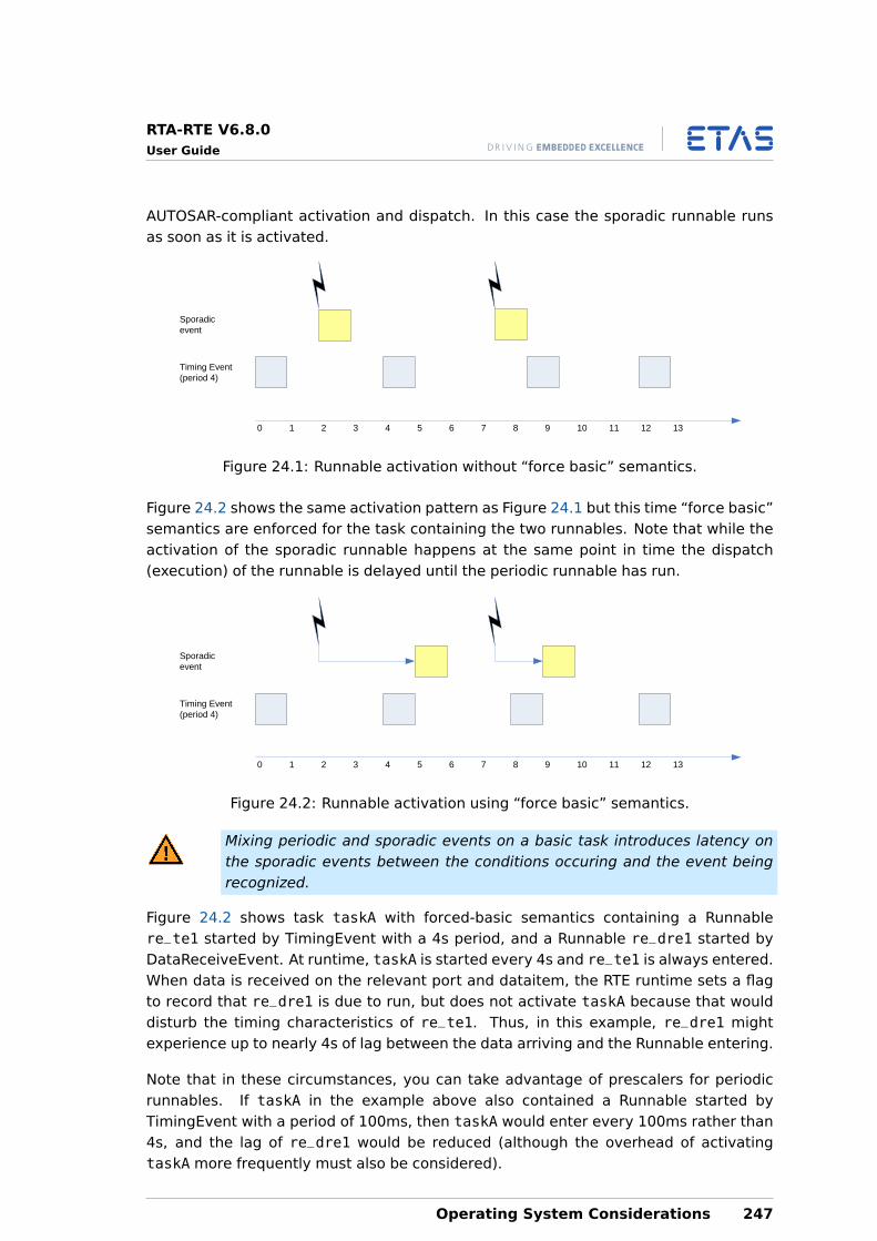
RTA-RTE V6.8.0User Guide
AUTOSAR-compliant activation and dispatch. In this case the sporadic runnable runsas soon as it is activated.
0 1 2 3 4 5 6 7 8 9 10 11 12 13
Timing Event(period 4)
Sporadic event
Figure 24.1: Runnable activation without “force basic” semantics.
Figure 24.2 shows the same activation pattern as Figure 24.1 but this time “force basic”semantics are enforced for the task containing the two runnables. Note that while theactivation of the sporadic runnable happens at the same point in time the dispatch(execution) of the runnable is delayed until the periodic runnable has run.
0 1 2 3 4 5 6 7 8 9 10 11 12 13
Timing Event(period 4)
Sporadic event
Figure 24.2: Runnable activation using “force basic” semantics.
Mixing periodic and sporadic events on a basic task introduces latency onthe sporadic events between the conditions occuring and the event beingrecognized.
Figure 24.2 shows task taskA with forced-basic semantics containing a Runnablere_te1 started by TimingEvent with a 4s period, and a Runnable re_dre1 started byDataReceiveEvent. At runtime, taskA is started every 4s and re_te1 is always entered.When data is received on the relevant port and dataitem, the RTE runtime sets a flagto record that re_dre1 is due to run, but does not activate taskA because that woulddisturb the timing characteristics of re_te1. Thus, in this example, re_dre1 mightexperience up to nearly 4s of lag between the data arriving and the Runnable entering.
Note that in these circumstances, you can take advantage of prescalers for periodicrunnables. If taskA in the example above also contained a Runnable started byTimingEvent with a period of 100ms, then taskA would enter every 100ms rather than4s, and the lag of re_dre1 would be reduced (although the overhead of activatingtaskA more frequently must also be considered).
Operating System Considerations 247

RTA-RTE V6.8.0User Guide
It is not recommended to use forced-basic semantics if your OS supports ExtendedTasks.
248 Operating System Considerations
RTA-RTE V6.8.0User Guide
25 Understanding Deployment Choices
Your choice of component deployment at ECU integration time can have a large effecton overall vehicle system performance. In this chapter you will learn what effects yourchoices have on the behaviour of the RTE generator when it creates task bodies and onthe behaviour of the RTE API for users.
Communicating components may be distributed across a physical network or co-located on the same ECU. There are three possible distribution patterns:
• Intra-task — communication occurs between components executed by the sametask (and is therefore serialized).
• Inter-task — communication occurs between notionally concurrent tasks in thesame ECU.
• Inter-ECU — communication occurs between concurrently executing componentslocated on physically distinct ECUs.
In all cases, RTA-RTE is responsible for managing the communication between softwarecomponents.
The following sections describe, in terms of message sequence charts, how RTA-RTEmanages the communication for each of the allocations and each communicationparadigm.
25.1 Intra-task
Intra-task communication occurs between runnable entities executed by the same task.There is low overhead and it is easy to reason about the sequence of execution.
25.1.1 Intra-task Sender-Receiver
RTA-RTE implements intra-ECU communication itself—COM is only used when the des-tination is located on a remote ECU. This means that:
Requests received from local and remote components are combined into a single queueso starvation of either local or remote requests cannot occur.
The implementation of intra-ECU communication is more efficient since it avoids theexpense of passing signals to COM only for COM to return the signal to the RTE as it isfor a local destination.
Figure 25.1 illustrates the sequence of steps the thread of control executing a runnableentity in an application software component takes when performing intra-task sender-receiver communication.
In detail, the steps illustrated in Figure 25.1 are:
1. The sending component initiates communication via the RTE API call Rte_Send (orRte_Write API call if the data is unqueued).
Understanding Deployment Choices 249
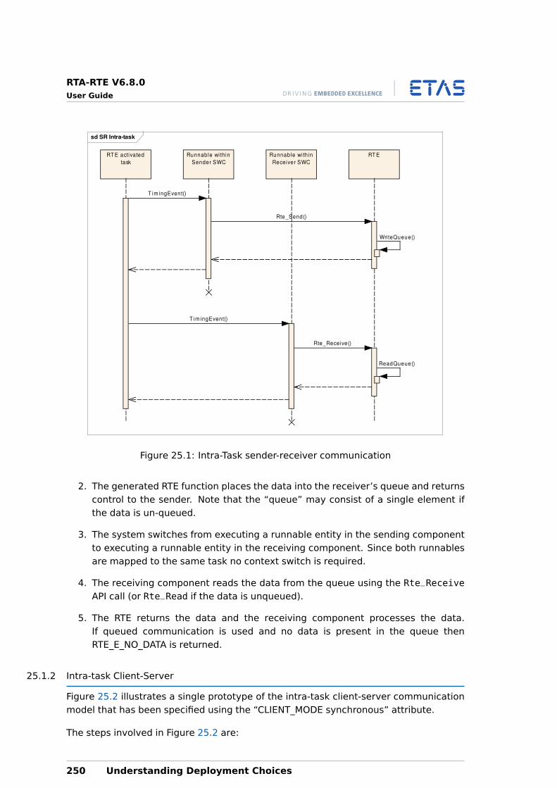
RTA-RTE V6.8.0User Guide
sd SR Intra-task
RT ERunnable wi thin
Sender SWC
Runnable wi thin
Receiver SWC
RT E activated
task
T im ingEvent()
Rte_Send()
Wri teQueue()
T im ingEvent()
Rte_Receive()
ReadQueue()
Figure 25.1: Intra-Task sender-receiver communication
2. The generated RTE function places the data into the receiver’s queue and returnscontrol to the sender. Note that the “queue” may consist of a single element ifthe data is un-queued.
3. The system switches from executing a runnable entity in the sending componentto executing a runnable entity in the receiving component. Since both runnablesare mapped to the same task no context switch is required.
4. The receiving component reads the data from the queue using the Rte_ReceiveAPI call (or Rte_Read if the data is unqueued).
5. The RTE returns the data and the receiving component processes the data.If queued communication is used and no data is present in the queue thenRTE_E_NO_DATA is returned.
25.1.2 Intra-task Client-Server
Figure 25.2 illustrates a single prototype of the intra-task client-server communicationmodel that has been specified using the “CLIENT_MODE synchronous” attribute.
The steps involved in Figure 25.2 are:
250 Understanding Deployment Choices
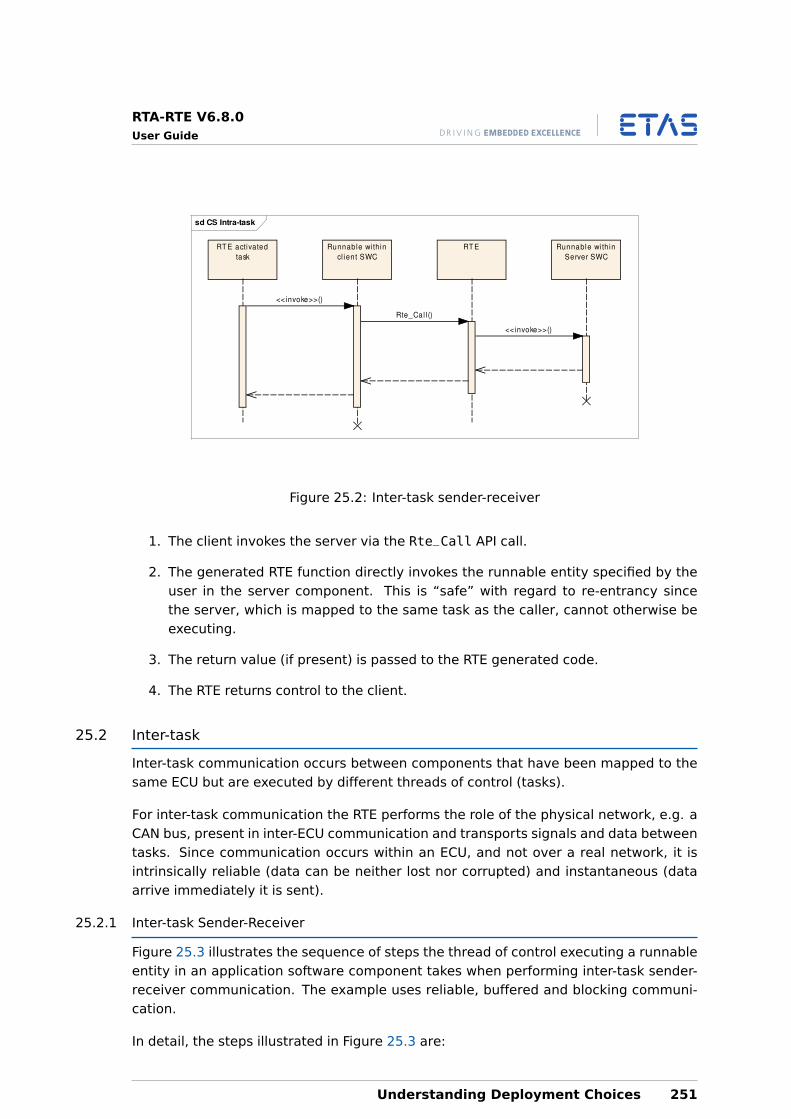
RTA-RTE V6.8.0User Guide
sd CS Intra-task
RT E activated
task
Runnable wi thin
cl ient SWC
RT E Runnable wi th in
Server SWC
<<invoke>>()
Rte_Cal l ()
<<invoke>>()
Figure 25.2: Inter-task sender-receiver
1. The client invokes the server via the Rte_Call API call.
2. The generated RTE function directly invokes the runnable entity specified by theuser in the server component. This is “safe” with regard to re-entrancy sincethe server, which is mapped to the same task as the caller, cannot otherwise beexecuting.
3. The return value (if present) is passed to the RTE generated code.
4. The RTE returns control to the client.
25.2 Inter-task
Inter-task communication occurs between components that have been mapped to thesame ECU but are executed by different threads of control (tasks).
For inter-task communication the RTE performs the role of the physical network, e.g. aCAN bus, present in inter-ECU communication and transports signals and data betweentasks. Since communication occurs within an ECU, and not over a real network, it isintrinsically reliable (data can be neither lost nor corrupted) and instantaneous (dataarrive immediately it is sent).
25.2.1 Inter-task Sender-Receiver
Figure 25.3 illustrates the sequence of steps the thread of control executing a runnableentity in an application software component takes when performing inter-task sender-receiver communication. The example uses reliable, buffered and blocking communi-cation.
In detail, the steps illustrated in Figure 25.3 are:
Understanding Deployment Choices 251
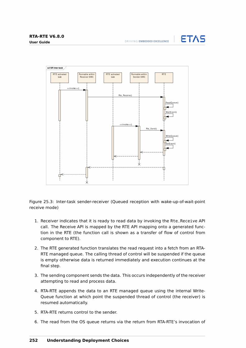
RTA-RTE V6.8.0User Guide
sd SR Inter-task
RT ERT E activa ted
task
RT E activa ted
task
Runnable wi th in
Sender SWC
Runnable wi th in
Receiver SWC
<<invoke>>()
Rte_Receive()
ReadQueue()
Wa itEven t()
<<invoke>>()
Rte_Send()
Wri teQueue()
SetEvent()
Figure 25.3: Inter-task sender-receiver (Queued reception with wake-up-of-wait-pointreceive mode)
1. Receiver indicates that it is ready to read data by invoking the Rte_Receive APIcall. The Receive API is mapped by the RTE API mapping onto a generated func-tion in the RTE (the function call is shown as a transfer of flow of control fromcomponent to RTE).
2. The RTE generated function translates the read request into a fetch from an RTA-RTE managed queue. The calling thread of control will be suspended if the queueis empty otherwise data is returned immediately and execution continues at thefinal step.
3. The sending component sends the data. This occurs independently of the receiverattempting to read and process data.
4. RTA-RTE appends the data to an RTE managed queue using the internal Write-Queue function at which point the suspended thread of control (the receiver) isresumed automatically.
5. RTA-RTE returns control to the sender.
6. The read from the OS queue returns via the return from RTA-RTE’s invocation of
252 Understanding Deployment Choices
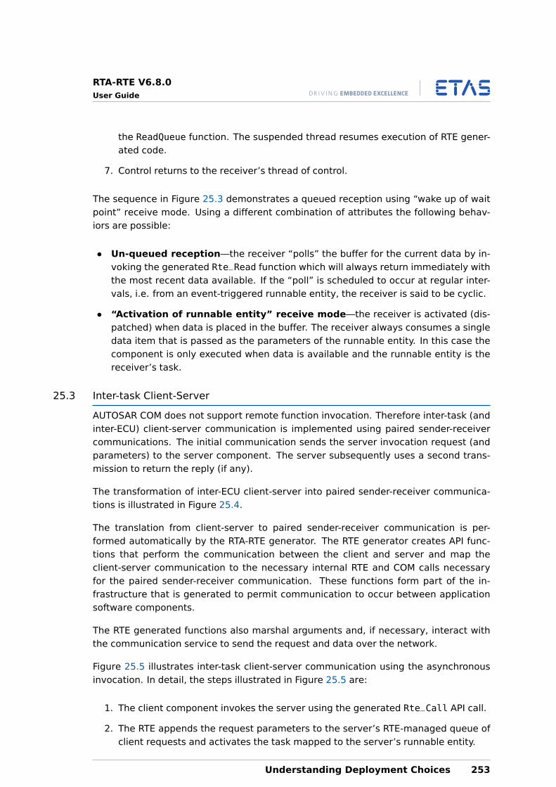
RTA-RTE V6.8.0User Guide
the ReadQueue function. The suspended thread resumes execution of RTE gener-ated code.
7. Control returns to the receiver’s thread of control.
The sequence in Figure 25.3 demonstrates a queued reception using “wake up of waitpoint” receive mode. Using a different combination of attributes the following behav-iors are possible:
• Un-queued reception—the receiver “polls” the buffer for the current data by in-voking the generated Rte_Read function which will always return immediately withthe most recent data available. If the “poll” is scheduled to occur at regular inter-vals, i.e. from an event-triggered runnable entity, the receiver is said to be cyclic.
• “Activation of runnable entity” receive mode—the receiver is activated (dis-patched) when data is placed in the buffer. The receiver always consumes a singledata item that is passed as the parameters of the runnable entity. In this case thecomponent is only executed when data is available and the runnable entity is thereceiver’s task.
25.3 Inter-task Client-Server
AUTOSAR COM does not support remote function invocation. Therefore inter-task (andinter-ECU) client-server communication is implemented using paired sender-receivercommunications. The initial communication sends the server invocation request (andparameters) to the server component. The server subsequently uses a second trans-mission to return the reply (if any).
The transformation of inter-ECU client-server into paired sender-receiver communica-tions is illustrated in Figure 25.4.
The translation from client-server to paired sender-receiver communication is per-formed automatically by the RTA-RTE generator. The RTE generator creates API func-tions that perform the communication between the client and server and map theclient-server communication to the necessary internal RTE and COM calls necessaryfor the paired sender-receiver communication. These functions form part of the in-frastructure that is generated to permit communication to occur between applicationsoftware components.
The RTE generated functions also marshal arguments and, if necessary, interact withthe communication service to send the request and data over the network.
Figure 25.5 illustrates inter-task client-server communication using the asynchronousinvocation. In detail, the steps illustrated in Figure 25.5 are:
1. The client component invokes the server using the generated Rte_Call API call.
2. The RTE appends the request parameters to the server’s RTE-managed queue ofclient requests and activates the task mapped to the server’s runnable entity.
Understanding Deployment Choices 253
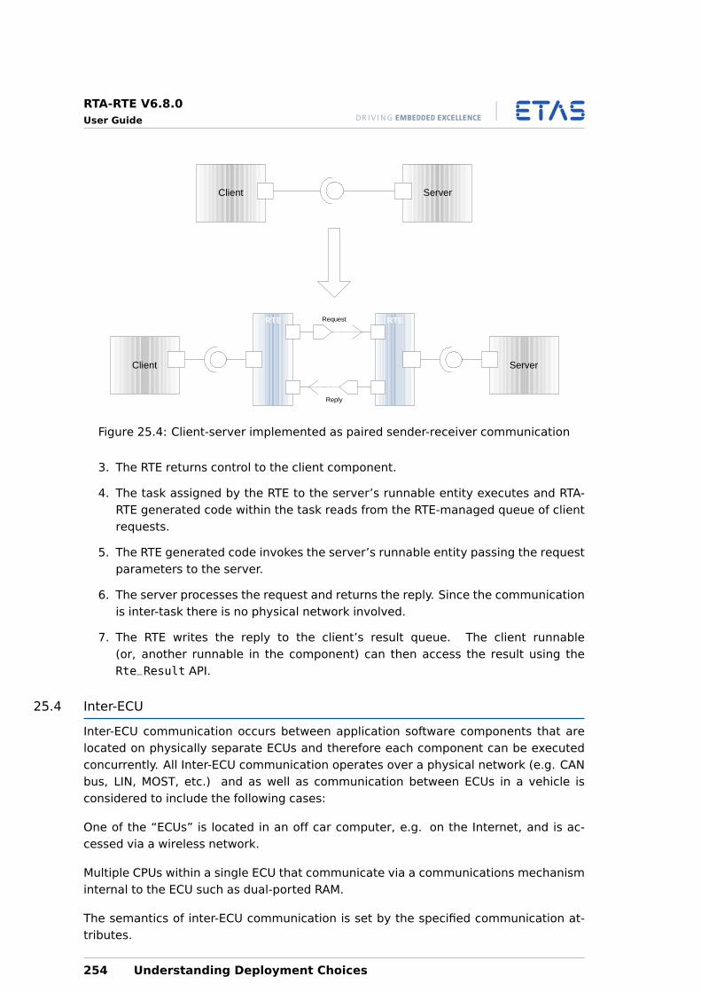
RTA-RTE V6.8.0User Guide
RTERTE
ServerClient
Client Server
Request
Reply
Figure 25.4: Client-server implemented as paired sender-receiver communication
3. The RTE returns control to the client component.
4. The task assigned by the RTE to the server’s runnable entity executes and RTA-RTE generated code within the task reads from the RTE-managed queue of clientrequests.
5. The RTE generated code invokes the server’s runnable entity passing the requestparameters to the server.
6. The server processes the request and returns the reply. Since the communicationis inter-task there is no physical network involved.
7. The RTE writes the reply to the client’s result queue. The client runnable(or, another runnable in the component) can then access the result using theRte_Result API.
25.4 Inter-ECU
Inter-ECU communication occurs between application software components that arelocated on physically separate ECUs and therefore each component can be executedconcurrently. All Inter-ECU communication operates over a physical network (e.g. CANbus, LIN, MOST, etc.) and as well as communication between ECUs in a vehicle isconsidered to include the following cases:
One of the “ECUs” is located in an off car computer, e.g. on the Internet, and is ac-cessed via a wireless network.
Multiple CPUs within a single ECU that communicate via a communications mechanisminternal to the ECU such as dual-ported RAM.
The semantics of inter-ECU communication is set by the specified communication at-tributes.
254 Understanding Deployment Choices
RTA-RTE V6.8.0User Guide
sd CS Inter-task Async
RT E activa ted
task
RT E activa ted
task
Runnable wi th in
cl ien t SWC
Runnable wi th in
Server SWC
RT E
Rte_Cal l ()
Wri teQueue()
ReadQueue()
<<invoke>>()
Wri teQueue()
Figure 25.5: Inter-task asynchronous client-server communication
25.4.1 Inter-ECU Sender
The sequence of steps the thread of control executing a runnable entity in an applica-tion software component takes when it initiates a sender-receiver Inter-ECU communi-cation using reliable asynchronous communication is illustrated in Figure 25.6.
In detail, the steps illustrated in Figure 25.6 are:
1. The sending component sends a signal using the Rte_Send (or Rte_Write API callif data is un-queued). The send is mapped by the RTE generator onto a generatedRTE API function.
2. The RTE invokes the communication service to queue the data from the signal.The communications layer queues the data for transmission over the networkand returns.
3. The generated RTE function returns control to the software component. Note thatat this stage transmission is neither necessarily complete nor acknowledged.
4. The COM module’s MainFunction performs the network transmission and invokesa callback defined within the RTE to indicate successful transmission.
5. The RTE’s callback activates the runnable entity defined within the SW-C’s RTEevent definition.
Understanding Deployment Choices 255
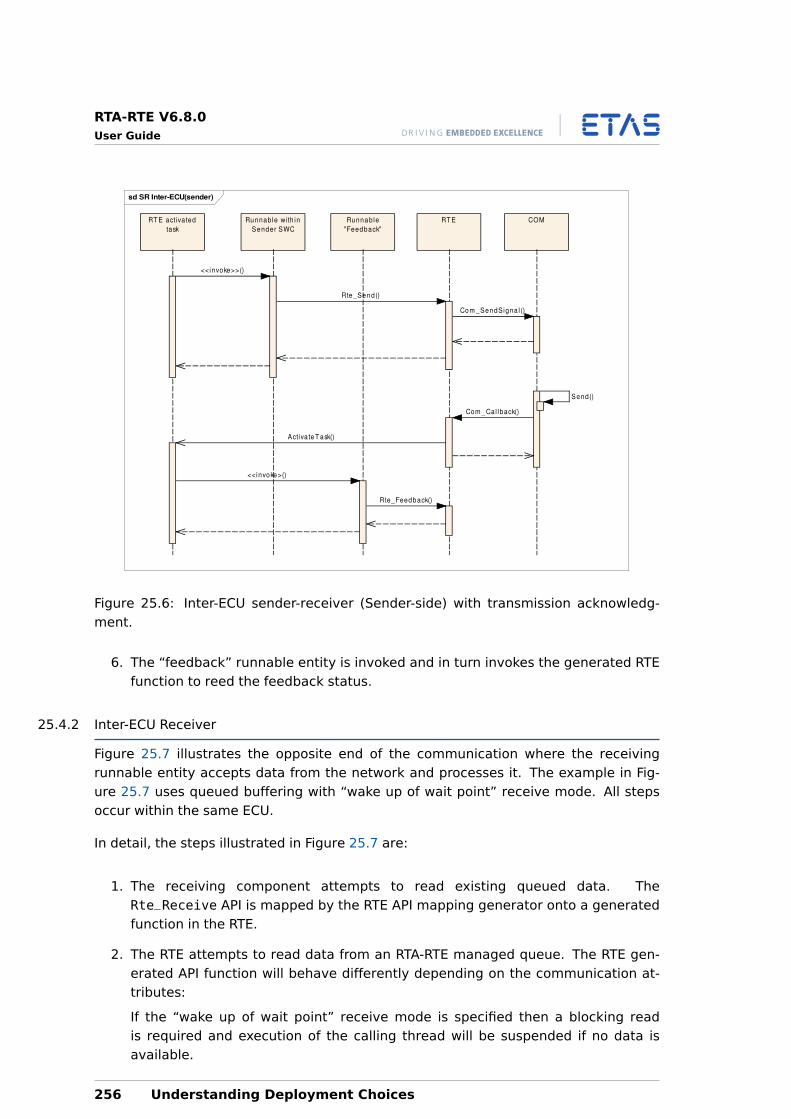
RTA-RTE V6.8.0User Guide
sd SR Inter-ECU(sender)
RT E activa ted
task
Runnable with in
Sender SWC
Runnable
"Feedback"
RT E COM
<<invoke>>()
Rte_Send()
Com _SendSigna l ()
Send()
Com _Cal lback()
Activa teT ask()
<<invoke>()
Rte_Feedback()
Figure 25.6: Inter-ECU sender-receiver (Sender-side) with transmission acknowledg-ment.
6. The “feedback” runnable entity is invoked and in turn invokes the generated RTEfunction to reed the feedback status.
25.4.2 Inter-ECU Receiver
Figure 25.7 illustrates the opposite end of the communication where the receivingrunnable entity accepts data from the network and processes it. The example in Fig-ure 25.7 uses queued buffering with “wake up of wait point” receive mode. All stepsoccur within the same ECU.
In detail, the steps illustrated in Figure 25.7 are:
1. The receiving component attempts to read existing queued data. TheRte_Receive API is mapped by the RTE API mapping generator onto a generatedfunction in the RTE.
2. The RTE attempts to read data from an RTA-RTE managed queue. The RTE gen-erated API function will behave differently depending on the communication at-tributes:
If the “wake up of wait point” receive mode is specified then a blocking readis required and execution of the calling thread will be suspended if no data isavailable.
256 Understanding Deployment Choices
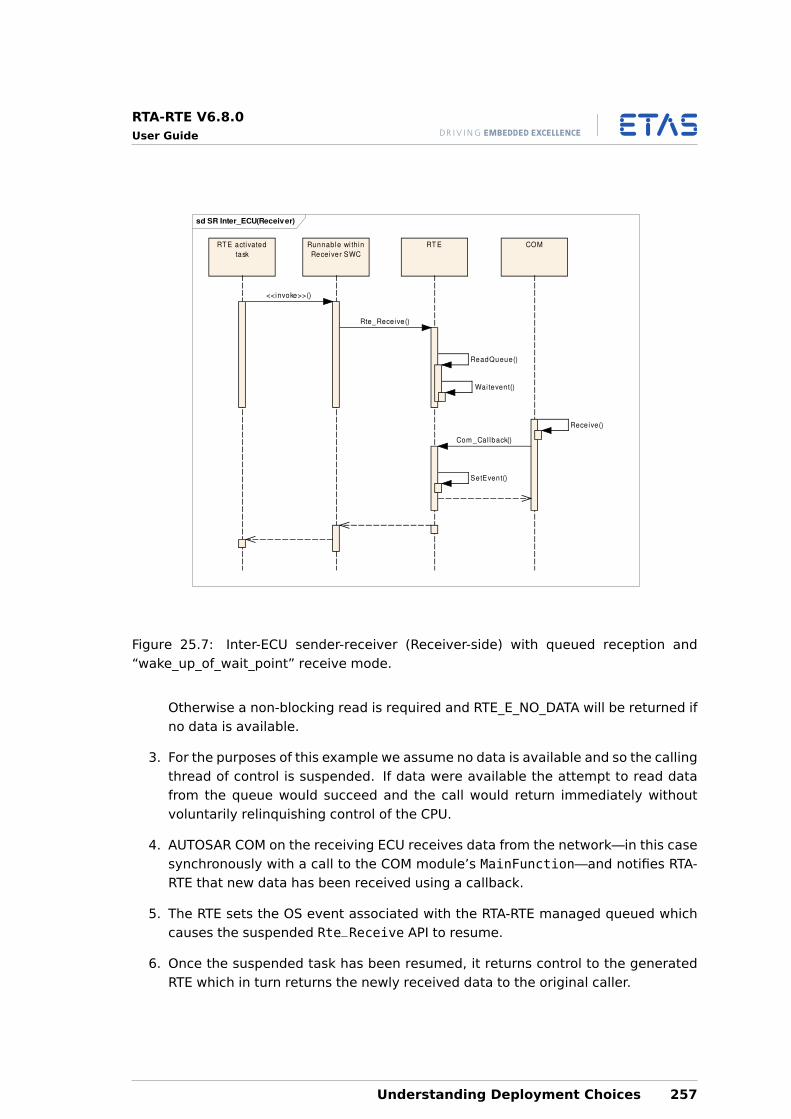
RTA-RTE V6.8.0User Guide
sd SR Inter_ECU(Receiver)
RT E activated
task
Runnable wi thin
Receiver SWC
RT E COM
<<invoke>>()
Rte_Receive()
ReadQueue()
Waitevent()
Receive()
Com _Cal lback()
SetEvent()
Figure 25.7: Inter-ECU sender-receiver (Receiver-side) with queued reception and“wake_up_of_wait_point” receive mode.
Otherwise a non-blocking read is required and RTE_E_NO_DATA will be returned ifno data is available.
3. For the purposes of this example we assume no data is available and so the callingthread of control is suspended. If data were available the attempt to read datafrom the queue would succeed and the call would return immediately withoutvoluntarily relinquishing control of the CPU.
4. AUTOSAR COM on the receiving ECU receives data from the network—in this casesynchronously with a call to the COM module’s MainFunction—and notifies RTA-RTE that new data has been received using a callback.
5. The RTE sets the OS event associated with the RTA-RTE managed queued whichcauses the suspended Rte_Receive API to resume.
6. Once the suspended task has been resumed, it returns control to the generatedRTE which in turn returns the newly received data to the original caller.
Understanding Deployment Choices 257
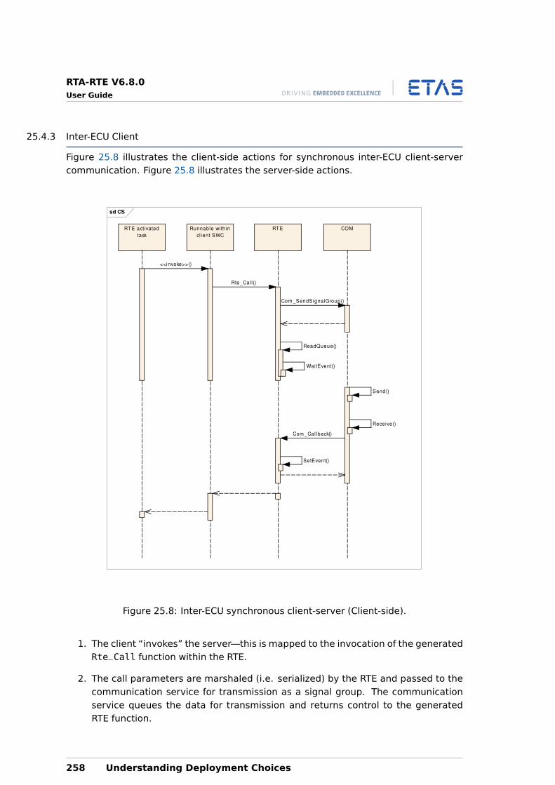
RTA-RTE V6.8.0User Guide
25.4.3 Inter-ECU Client
Figure 25.8 illustrates the client-side actions for synchronous inter-ECU client-servercommunication. Figure 25.8 illustrates the server-side actions.
sd CS
RT E activated
task
Runnable wi th in
cl ient SWC
RT E COM
<<invoke>>()
Rte_Cal l ()
Com_SendSignalGroup()
ReadQueue()
Wai tEvent()
Send()
Receive()
Com _Cal lback()
SetEvent()
Figure 25.8: Inter-ECU synchronous client-server (Client-side).
1. The client “invokes” the server—this is mapped to the invocation of the generatedRte_Call function within the RTE.
2. The call parameters are marshaled (i.e. serialized) by the RTE and passed to thecommunication service for transmission as a signal group. The communicationservice queues the data for transmission and returns control to the generatedRTE function.
258 Understanding Deployment Choices
RTA-RTE V6.8.0User Guide
3. The RTE attempts to immediately read the server’s reply. However since the replyis not available the task is suspended.
4. The COM main function is invoked and transmits the client’s request.
5. At some point in the future, COM detects reception of the server’s reply and in-vokes the appropriate callback in the RTE. The callback sets the OS event associ-ated with the client’s reply queue and returns control to COM.
6. The suspended task resumes and returns the server’s reply to the caller.
25.4.4 Inter-ECU Server
Figure 25.9 illustrates the server-side actions for synchronous inter-ECU client-servercommunication.
1. The server’s COM receives the request and invokes an RTE generated callback.
2. The RTE callback reads the client request and writes the data to a queue managedby the RTE. The callback then activates the task mapped by the RTE to triggerthe server’s runnable entity. The RTE then returns control to the communicationservice.
3. The task assigned by the RTE to the server’s runnable entity starts, reads therequest from the queue and executes the server runnable entity.
4. The reply from the server runnable entity is collected. The reply from the serverrunnable entity is sent to the client using COM. The task mapped to the server’srunnable entity terminates.
The above examples uses synchronous communication so an OS event is used to blockthe client until the return value is available. The RTE also supports asynchronous com-munication these require only minor changes to the sequence, for example:
• The wait on the OS event does not occur and hence the caller is resumed immedi-ately after the client’s request has been passed to COM.
• The setting of the OS event when the server’s reply is available may not occur de-pending on the configuration of the client’s AsynchronousServerCallReturn event.For example, configuration of activation of the runnable entity receive mode mayrequire the RTE to activate a task instead.
Understanding Deployment Choices 259
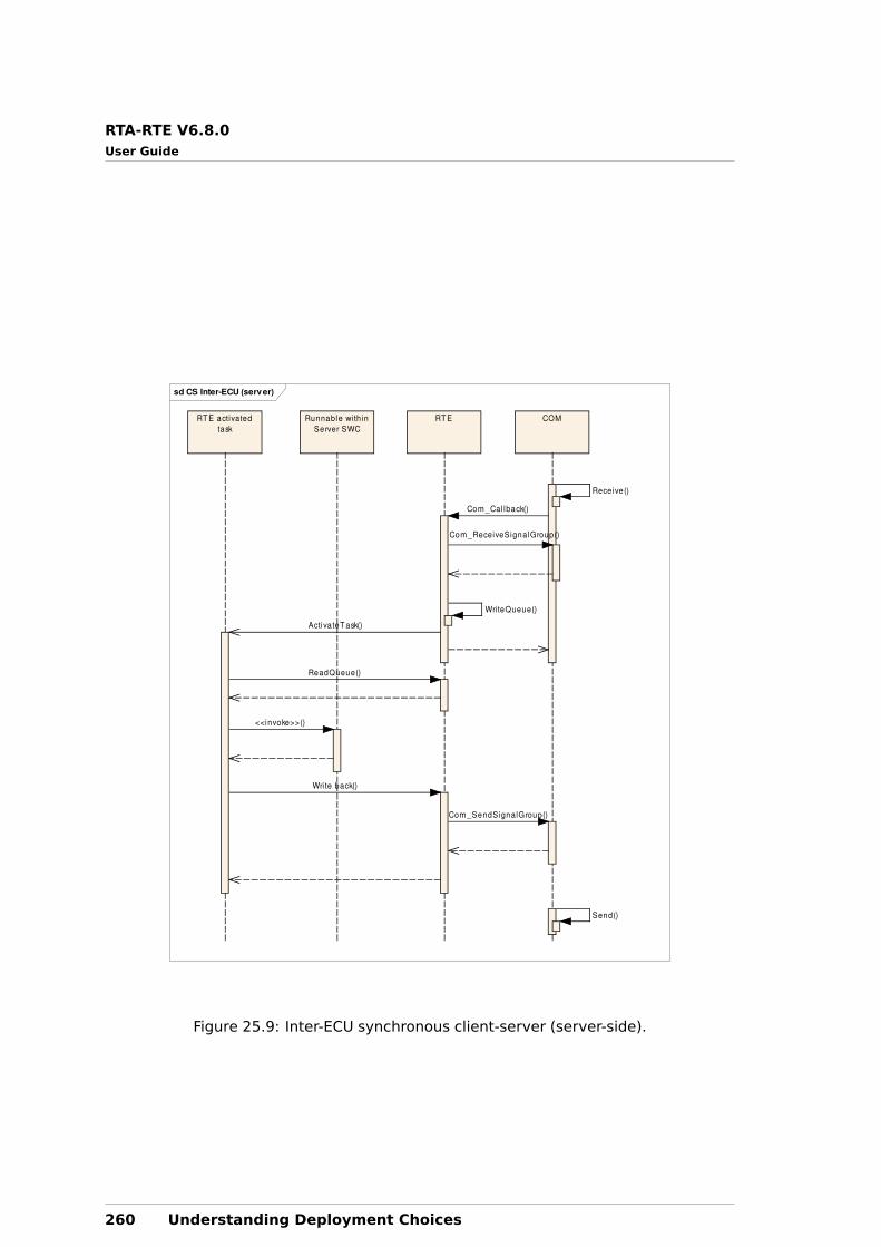
RTA-RTE V6.8.0User Guide
sd CS Inter-ECU (server)
RT E activated
task
Runnable wi th in
Server SWC
RT E COM
Receive()
Com _Cal lback()
Com_ReceiveSignalGroup()
Wri teQueue()
ActivateT ask()
ReadQueue()
<<invoke>>()
Wri te back()
Com _SendSignalGroup()
Send()
Figure 25.9: Inter-ECU synchronous client-server (server-side).
260 Understanding Deployment Choices
RTA-RTE V6.8.0User Guide
26 Optimization
Several optimizations are possible to influence the memory usage and runtime of thegenerated RTE.
26.1 Buffers for Inter-ECU Reception
The --optimize option tunes RTE generation for runtime or memory use.
--optimize=speed (the default) generates an RTE that uses RTE-managed buffers forinter-ECU communication. This is faster when there are multiple readers, but requiresa separate memory allocation.
--optimize=size generates an RTE that invokes the COM API each time the value isread by the application. This is slower when there are multiple readers, but but reducesRAM usage and, if the value is only accessed once, code size.
For any individual data element, direct access to COM is enabled if all of the followingare true:
• The data element prototype is unqueued (a queued data element requires an RTEmanaged queue).
• Reception is explicit (implicit reception requires an RTE managed buffer).
• There are no intra-ECU transmitters (an inter-ECU transmitter requires an RTE man-aged buffer into which the data is written and to ensure that inter-ECU and intra-ECU data is coordinated then the former must use the same buffer).
• Transmission is 1:1.
Direct access to COM for a data item is disabled if:
• The data element has “keep” invalidation policy, the invalid value is equal to theinitial value and “handle never received” is false, or
• The data item has “handle never received” enabled.
The optimize option has no effect on Contract phase execution of RTA-RTE.
26.2 Direct invocation of the RTE API
The API mapping created in the application header file will directly invoke the generatedRTE API functions if the software-component is known not to be multiply instantiated(see Section 8.14).
For example, consider a simple Rte_Write API:
Std_ReturnType Rte_SWCa_Write_p1_d1(uint8 data){
Rte_000000 = data;
Optimization 261
RTA-RTE V6.8.0User Guide
return RTE_E_OK;}
RTA-RTE can inline the API to a C comma-expression within the SWC’s applicationheader file and thus avoid the function call overhead:
extern uint8 Rte_000000;#define Rte_Write_p1_d1(data) ( ( Rte_00000 = (data) ), RTE_E_OK )
The inline comma-expression can be used in the same way as a call to the generatedRTE function but without the overhead of the function call.
This optimization occurs in both Contract and RTE generation phases.
In addition to examining the input XML, in RTE generation phase RTA-RTE also countsthe number of actual instances on the ECU for which the RTE is being generated andif this is one applies the optimization even if the software-component is potentiallymultiply instantiated.
26.3 Sender-Receiver Communication
26.3.1 Direct Read and Write
Direct invocation of the RTE API does not eliminate the function call overhead of theRTE API. Therefore RTA-RTE includes an additional optimization in RTE phase that in-lines the generated functions for explicit sender-receiver communication and explicitinter-runnable variable access into the RTE API mapping.
The optimization occurs if RTA-RTE judges that the generated API function is sufficientlysimple for in-lining to be beneficial; the function body must consist of a simple assign-ment with or without concurrency control. Optimization is therefore dependent on:
• Communication uses primitive types.
• The number of destination components; ideally one.
• The runnable to task mapping of the sender and receiver. RTA-RTE eliminates ex-plicit data consistency mechanism if the task mapping guarantees protection. Thusideally the sender and receiver will be in the same task or mapped to tasks at thesame priority.
Optimization to direct read/write occurs in both vendor and compatibility operatingmodes
26.3.2 Implicit Communication
AUTOSAR requires task-specific copies of the data read/written by implicit communica-tion to ensure that values remain stable during the execution of a runnable entity andto ensure that they are not visible to other runnables until after the writing runnablehas terminated.
262 Optimization
RTA-RTE V6.8.0User Guide
The task-specific copies consume RAM and therefore RTA-RTE includes the--implicit-use-global-buffers command-line option to directly use global bufferswhere possible.
When enabled (option parameter ‘1’ or ’2’) the global buffer is accessed directly by theImplicit API calls provided all of the following constraints are met:
• A shared buffer is required (if separate buffers for reader and writer are requiredthen optimization to use global buffers will occur for readers only).
• No “status” information is required.
• There are no COM mappings for the data instance. This restriction is required toensure data stablity – if COM mappings exist then COM can preempt the runnableand disturb the global buffer during runnable execution.
• There is a single destination buffer – i.e. one global buffer shared by all receivers.For intra-ECU communication this will typically be the case unless filters are appliedby one or more receivers. This restriction is necessary to ensure that the generatedimplicit API macros have a single value to write.
In addition one of the following constraints must also be met:
• All events in the task are ’fast init’. Such events are executed once only before theperiodic runnables hence there can be no conflict so global buffers can be directlyaccessed.
• Receivers can directly access the global buffer if the provider cannot preeemptany receiver (in which case the receiver’s data cannot be changed by the providerduring its execution and the required data stability during runnable execution ispreserved).
• The provider can directly access the global buffer if no requirer can preeempt (andno receiver will see the value written to the global until the provider runnable ter-minates and thus the require implicit semantics are preserved).
26.4 Client-Server Communication
26.4.1 Direct Function Invocation
RTA-RTE includes an additional optimization in RTE phase that inlines the invocation ofserver runnable entities.
The optimization to direct invocation only occurs if the generated API function is suit-able for in-lining. Optimization is therefore dependent on:
• All client-server communication with the server must be synchronous.
Optimization 263
RTA-RTE V6.8.0User Guide
• The server is mapped as “pure” (see Section 8.6.1), or the client and server aremapped to the same task.
Optimization to direct function invocation occurs in RTE phase in both vendor and com-patibility operating modes.
26.5 Function Elision
The application of the above optimizations is automatic when the RTE is generated—there are no specific optimizations to enable or disable optimizations. However in-liningfunctions does not, in itself, reduce the code size of the generated RTE since RTA-RTE isrequired to emit the functions to support object-code delivery of software-components.
Therefore to enable elision of function bodies from the generated RTE:
• Ensure the SWC is delivered as source code.
• Disable indirect API for all ports of the software-component.
• Disable ’take address’ for the ports of the software-component.
26.5.1 Return Code Optimization
Many AUTOSAR RTE API functions return an Std_ReturnType status using the functionreturn value. When RTA-RTE optimizes the API to an inline macro it uses a C comma-expression to both perform the function’s actions and to set the return value as thefinal value in the expression.
If we again consider the simple simple Rte_Write API:
Std_ReturnType Rte_SWCa_Write_p1_d1(uint8 data){
Rte_000000 = data;return RTE_E_OK;
}
However now assume that port “p1” is unconnected and therefore the Write API isdefined as discarding the data. The generated API function is now simply:
Std_ReturnType Rte_SWCa_Write_p1_d1(uint8 data){
return RTE_E_OK;}
The RTE generator can still inline the function but now uses a simpler comma-expression containing a single element:
#define Rte_Write_p1_d1(data) ( (Std_ReturnType)RTE_E_OK )
264 Optimization
RTA-RTE V6.8.0User Guide
The inline comma-expression can again be used in the same way as a call to the gen-erated RTE function but without the overhead of the function call. However when themacro replacement occurs the statement is now a C null-statement and the compilermay now complain about a “...statement has no effect.”. To disable this warning/errorfrom the compiler ensure that one of the following occurs:
1. The return value is assigned to a variable.
2. The return value is tested (e.g. for equality) in a condition.
3. The return value is cast to void if not used.
For example, if the caller is not interested in the return value use a cast to void:
(void)Rte_Write_p1_d1(5u);
26.6 Init Runnables
The AUTOSAR mode mechanism provides ModeSwitchEvents that can be used to trig-ger runnable execution when an application mode is entered. This feature can be usedto provide “init” runnables that are executed when the RTE starts and perform neces-sary initialization for a SWC instance.
However for a runnable that only runs once at system start the infrastructure code cre-ated by RTA-RTE to support the AUTOSAR mode mechanism is superfluous. ThereforeRTA-RTE provides a mechanism to optimize activation for specified ModeSwitchEventsby mapping them to specified FastInit tasks. The use of a FastInit task both simplifiesthe activation code necessary for the runnable associated with the event as well asremoving the normal infrastructure code created by RTA-RTE to support the AUTOSARmode mechanism.
An event that is specified as FastInit will not be activated by RTA-RTE duringa user-triggered mode switch. Instead the FastInit task must be activatedby user code at the appriopriate time.
The command-line option --fast-init specifies an absolute reference to either a SWCtype or to a ModeSwitchEvent within an internal behaviour. A reference to a Mod-eSwitchEvent causes that event to be activated by a non-AUTOSAR compliant mecha-nism (a function call from a task body where the task is activated externally from theRTE). This avoids the complexity inherent in AUTOSAR compliant activation for modeswitch activations. A reference to an SWC type causes all ModeSwitchEvents in thetype to be subject to FastInit.
The command-line option --fast-init can be specifed multiple times to apply FastInitto multiple ModeSwitchEvents.
RTA-RTE places no restrictions on the mapping of ModeSwitchEvents within FastInittasks other than events subject to normal AUTOSAR-compliant activation cannot bemapped to the same task. As a consequence it is possible to map all “init” runnablesfrom all mode instances to the same FastInit task.
Optimization 265
RTA-RTE V6.8.0User Guide
It is permitted to map ModeSwitchEvents for different mode transitions (e.g.both entry to “init_mode” and entry to “run_mode”) to the same FastInittask. When this is done care must be taken since all runnables will be acti-vated when the task is dispatched irrespective of the current mode.
26.7 Data Consistency
The RTE generator uses RTE_ATOMICxxx macros to apply data consistency mechanismsto ensure that assignments are atomic. Since the RTE generator has no knowledgeof target capabilities it is not possible for it to exploit platform specific knowledge toeliminate use of RTE_ATOMICxxx macros. However the RTE generator supports twomechanisms where the integrator can apply such knowledge to improve efficiency ofgenerated core.
26.7.1 Atomic assignments
The --atomic-assign can be used to specify one or more platform types that arealways subject to atomic assignment. When specified the RTE generator will not gener-ate RTE_ATOMICxxx macros for the types which can then subsequently enable furtheroptimizations of the API mapping.
The following types can be specified with the -aa option:
• uint8, uint16 and uint32 (includes the AUTOSAR char and opaque metatypes andthe Std_ReturnType).
• sint8, sint16 and sint32.
• boolean.
• float32 and float64
26.7.2 Macro elision
After RTE generation individual RTE_ATOMICxxx macros can be elided by appropriatedefinitions when compiling RTE generated code (including application header file).
For example, defining RTE_16BIT_ATOMIC forces the RTE_ATOMIC16 macro to have norun-time effect.
For more information on eliminating the effect of RTE_ATOMIC macros please consultthe RTA-RTE Toolchain Integration Guide.
26.7.3 Inline Functions
RTA-RTE can use either an OS resource or interrupt blocking to implement an exclusivearea. RTA-RTE can optimize access to the OS resource or the locking of interrupts in theRTE Enter/Exit API call by inlining the API mapping in the application header file. Whenthis inlining occurs the applications access to exclusive area is as efficient as possiblesince RTA-RTE imposes no run-time overhead.
266 Optimization
RTA-RTE V6.8.0User Guide
However the inlining of the access to the OS resource or the locking of interrupts meansthat the application header file now includes OS API calls within the API mapping andtherefore the SWC application code must include Os.h.
When an Enter/Exit API call is inlined within the API mapping the SWC imple-mentation must include Os.h.
26.8 Tips
The optimization potential of the generated RTE is maximized by:
• Use 1:1 sender-receiver communication.
• Use primitive types for explicit sender-receiver communication.
• Map provider and requirer to the same task or to tasks that cannot preempt.
• Use source-code delivery with disabled indirect API when possible.
• Wherever possible, mark a server as “pure”.
• Avoid software-components delivered as object-code.
• Where possible uses single-instantiated software-components.
Optimization 267
RTA-RTE V6.8.0User Guide
27 RTE Architecture
The RTE itself is a passive entity and thus does not have any of its own threadsof control. RTE code is only executed when an external entity—such as a softwarecomponent—invokes generated code in the RTE.
Software components are given access to API calls through the software component’sapplication header file which is custom generated for each software component type.All API calls use the form:
Rte_<Call_Name>_<Discriminator>(instance, args)
Where <Discriminator> can be either the port and data item/operation name or,where this is not approproate, an identifier extracted from the input. The applicationheader file performs an important role for the RTE because it binds the API call namesonto specific implementations depending on how component prototypes are mappedto an ECU.
The implementations of the RTE API calls themselves are custom generated by the RTEgenerator for each software component. The functionality of the RTE is provided mainlyby the code written to the Rte.c file at generation time.
The RTE API has been designed so that calls can be made efficiently at runtime. Thisis achieved by providing an API mapping for each software component that binds thecomponent’s API to permit the direct invocation or even mapping calls to managedreads and writes to global data.
The following sections outline how these mechanisms work.
27.1 Component Data Structure
The component data structure defines the RTE API calls that a particular componentinstance can invoke based on the component type’s declaration (i.e. ports) and internalbehavior (per-instance memories, exclusive areas, etc.).
The declaration of the component data structure data type is created by the RTE gen-erator and is internal to the RTE—application software should only access memberswithin the structure via RTA API definitions in the component’s application header file.
The component data structure data type is the same for all instances of a compo-nent type. Hence the structure can be uniquely named using only the name of thecomponent type irrespective of the number of times the component is actually instan-tiated, e.g. for SWC type MyComponent the component data structure data would beRte_CDS_MyComponent.
typedef struct{
/* Structure definition for MyComponent */} Rte_CDS_MyComponent;
268 RTE Architecture
RTA-RTE V6.8.0User Guide
The component data structure includes all information necessary for the generated RTEAPI mapping within the application header file to invoke the correct function for the par-ticular instance. Information within the component data structure includes a functiontable used for indirect invocation of generated custom functions and definitions of statethat is not shared between component prototypes.
The component data structure function table is used for indirect invocation of gener-ated custom functions (see Section 27.3) for details of the API mapping).
When an instance of the component data structure is declared in software componentheader file, the generated function table is initialized to point to the correct generatedcustom functions for the component. The functions themselves and the instance of thecomponent data structure are generated by RTA-RTE in the Rte.c file.
The component data structure is instantiated within Rte.c once for each componentinstance that is mapped to the ECU instance for which the RTE is being generated. Fora software-component that can be multiple instantiated, the component data structureinstances are named using an RTA-RTE generated instance name as follows:
Rte_Instance_<InternalComponentInstanceName>
However, for a software-component that can only be instantiated once per ECU in-stance, AUTOSAR requires that the single instance of the component data structurecreated within Rte.c is named as follows:
Rte_Inst_<SWCTypeName>
The names of software-component types must be globally unique to avoid type conflictswithin the generated code.
27.2 Component Instance Handle
When multiple prototypes of the same software component type are mapped to thesame ECU, then the RTE must be able to disambiguate access to their individual state.When the RTE is generated in the RTE phase, each prototype is assigned a unique RTEinstance handle that is used to identify the component prototype data structure.
Each component prototype that is mapped to an ECU instance has an instance of thecomponent data structure written to Rte.c.
All activity within a software component is handled by runnable entities and in eachcase the RTE can identify the correct instance of the relevant component data structureand pass the appropriate handle to the runnable entity when it is activated.
When runnable entities make calls back to the RTE they pass in their “self” parameterthat identifies the prototype (i.e. the current Rte_Instance handle) to the generatedRTE API functions. The handle identifies the instance to the RTE and enables selectionof the correct functionality.
RTE Architecture 269
RTA-RTE V6.8.0User Guide
27.3 The RTE API Implementation
The Rte.c file contains the implementations of all custom RTE API calls required bycomponent instances mapped to the ECU instance. Each call takes the form:
Rte_<call>_<prototype>_<port>_<data/op>(<args>)
Where <call> is an RTE API name (e.g. Call, Send), <prototype> is the componentprototype, <port> is the port on which the call operates and <args> are the interfacearguments.
27.3.1 API Mapping
The RTE API names are based on a root names, such as Rte_Call, combined with boththe port name and data item or operation name as suffixes. The RTE API names do notinclude the component type or instance name. This omission permits the componentto be developed before its deployed (and hence the instance name) is known.
Two different components can define identically named ports (as well as identicallynamed operations or data items) and thus have the same RTE API names for accessingthe data items or operations. However, the generated RTE API functions for the differ-ent components must be unique since they can be radically different, for example, onemay be intra-ECU and highly optimized whereas another may be inter-ECU and use thecommunication service. The RTE API functions are created during the “RTE” phase ofRTE generation at which point the component deployment, and hence instance name,as been determined. The RTE generator can therefore use the component instancename to ensure that generated functions can be uniquely identified.
Since the RTE API name as seen by the location neutral software component and thegenerated API function are different the RTE generator defines an API mapping in thecomponent’s application header file from the RTE API to the names of the generatedAPI functions defined in the RTE module.
The API mapping written to the component’s application header file is cre-ated automatically by the RTE generator—the same RTE API is thereforeavailable to a component irrespective of the number of instances deployedand whether or not source-code is available.
All RTE API call names are formed from a root name and the port name and operation/-data item name as a suffixes. The RTE API mapping is responsible for mapping the RTEAPI name to the correct implementation of the RTE function in Rte.c. The API mappingpermits an RTE generator to include targeted optimization as well as removing the needto implement functions that act as de-multiplexers from generic API calls to particularfunctions within the generated RTE.
The API mapping is implemented as a set of macros. The API mapping is uniquelygenerated for each component and written to the component header file.
There are typically two kinds of mappings:
270 RTE Architecture
RTA-RTE V6.8.0User Guide
• Indirect mappings
• Direct mappings
27.3.2 Indirect Mapping
Indirect is the most general form and is implemented in the API mapping by the RTEgenerator when optimizations cannot be applied; for example the instance name of acomponent is not known or a component may be multiple instantiated.
The RTE API mapping from API name to generated function is defined in the applicationheader files that are created during the first “contract” phase of RTE generation willalways invoke the generated API functions via the component’s instance handle. Thisprovides the necessary level of indirection to support binary-code software componentsas well as supporting multiple component instances.
When indirect invocation is used, execution of the generated API functions occurs viathe appropriate entry in the function table defined in the component data structure (seeSection 20.1). The fields within the function table are initialized by the RTE generator.
Indirect invocation permits both binary-code software components and multiple in-stances of components to be supported since the component instance name does notneed to be fixed when the component is compiled and the RTE can initialize a differentfunction table for each instance therefore invoking different generated API functionsfor each instance.
An indirect mapping is used when only a multiple prototypes of a software componentare mapped to a single ECU instance. The basic form of the mapping in this case is:
#define Rte_<Call>_<p>_<d/op> (self, data) \((self)-><Call>_<p>_<d/op>(data))
Where <Call> is the RTE API call type (Call, Send, Write etc.), <p> the port name and<d/op> is the port data item/operation name.
27.3.3 Direct Mapping
It is possible to perform a number of optimizations on the API mapping that can elimi-nate the run-time costs of indirect invocation when both the component instance nameis known and it is known a priori that only a single instance of the component will bemapped to an ECU. Direct invocation also requires that the component is available insource-code form since the optimization can only be applied after component deploy-ment has occurred.
With direct invocation it is possible to completely elide the instance handle and there-fore impose zero run-time overhead. However, it remains in the RTE API signature forcompatibility with the requirements of indirect invocation.
A direct mapping is used when only a single (source code) prototype of a softwarecomponent is mapped to an ECU instance. The basic form of the mapping in this case
RTE Architecture 271
RTA-RTE V6.8.0User Guide
is:
#define Rte_<call>_<p>_<d/op>(self,data) \Rte_<call>_<c>_<p>_<d/op>(data)
Where <call> is the RTE API call type (Call, Send, Write etc.), <p> the port name and<d/op> is the port data item/operation name
Note in the direct case that the call through the instance handle self has been elidedsince only a single instance is in use.
For intra-task communication made by “source-code” components the call may be fur-ther mapped to a direct write to an OS-managed queue or global data item.
272 RTE Architecture
RTA-RTE V6.8.0User Guide
Part VII
Support
273
RTA-RTE V6.8.0User Guide
28 Contact, Support and Problem Reporting
For details of your local sales office as well as your local technical support team andproduct hotlines, take a look at the ETAS website:
ETAS subsidiaries www.etas.com/en/contact.php
ETAS technical support www.etas.com/en/hotlines.php
The RTA hotline is available to all RTA-RTE users with a valid support contract.
[email protected]+44 (0)1904 562624. (0900-1730 GMT/BST)
Please provide support with the following information:
• Your support contract number.
• Your AUTOSAR XML and/or OS configuration files.
• The command line that results in an error message.
• The version of the ETAS tools you are using.
274 Contact, Support and Problem Reporting
RTA-RTE V6.8.0User Guide
IndexSymbolsC++, 124--atomic-assign, 266--deviate-shared-mode-queue, 120--fast-init, 265--have-64bit-int-types, 177, 179--implicit-use-global-buffers, 263--mode-policy, 121--operating-system, 223--optimize, 261--os-file, 223--output, 171--strict-config-check, 224--task-recurrence, 243, 244--toolchain-significant-len, 242--xfrm-ignore-inplace, 234
AA2L, see also McSupportData, 171Acknowledgement request, 78Activation of Runnable Entity, 92Alive timeout, 81API
Direct, 124, 271Explicit, 133Implicit, 133Indirect, 108, 109, 124, 271Mapping, 270Parameter passing, 123
Application Header, 124API Mapping, 270Contract Phase, 38
ApplicationArrayDataTypeExample of, 49
ApplicationPrimitiveDataTypeExample of, 47, 48
ApplicationRecordDataTypeExample of, 50
ApplicationValueSpecificationExample of, 67
Array TypeAs function parameter, 57
ArrayValueSpecificationExample of, 67
Assembly Connectors, 156Port Mapping, 160
Index 275
RTA-RTE V6.8.0User Guide
Asynchronous Server Call Returns Event, 84, 99, 130Atomic Assignment, 266AUTOSAR, 10
Basic Software, 146Data Types, 46Development Process, 42Element, 32NVRAM, 140Package, 28
BBackground Event, 85Background event, 87Base type
Native Declaration, 53BSW, 10
API Name generation, 152Background event, 148Connections, 181External Trigger event, 148Instantiation, 180Internal Trigger event, 149Mode Sender Policy, 113Mode Switch Ack event, 152Mode Switch event, 150Modules, 146Periodic event, 148Schedulable Entity, 147Scheduler, 181Task Mapping, 181
BSW Phase, 41
CC, 124C/S, 10Calibration, 136
Access Point, 94export in McSupportData, 171Interface, 73Parameters, 170Prototype, 73
CategoryARRAY, 59DATA_REFERENCE, 59FUNCTION_REFERENCE, 59HOST, 59STRUCTURE, 59
276 Index
RTA-RTE V6.8.0User Guide
TYPE_REFERENCE, 59UNION, 59VALUE, 59
Characteristic, see also Calibration ParameterClient
Asynchronous, 97, 130Synchronous, 97
COMModule configuration, 34, 226
Command-line optionsamples, 42, 127
CommunicationCalibration, 20Client-server, 20, 135, 218, 250Explicit, 88Implicit, 89Inter-ECU, 210Modes, 111Sender-receiver, 18, 78, 81, 215, 249
Complex TypeInter-ECU, 216
Component Data Structure, 268Component Instance Handle, 17, 269Composition
BSW, 180Connectors, 156Instantiation, 156SWCs, 155Type, 155
CompuMethodExample of, 47, 48, 65, 66
CompuRationalCoeffs, 65Precision of, 65
ConstantReferenceExample of, 68
ConstantSpecificationExample of, 68
Contract Phase, 37Conventions, 9
DData Conversion
Compatible versus Convertible, 176Concepts, 61, 173Modelling Application Types, 61Precision of, 178
Index 277
RTA-RTE V6.8.0User Guide
Data Element, 69Data Receive Error Event, 84Data Received Event, 84, 128Data Send Completed Event, 85Data Write Completed Event, 85Delegation Connector, 158Development Process, 42
EECU
Instantiation, 199Mapping Services, 202Mapping SWCs, 200Ports, 198Type, 198
ECUC, 10ECUC Description, 33Exclusive Area, 102, 137
Configuration, 102Explicit, 103Implementation Method, 104Implicit, 103
extended task, 245External Trigger Occurred Event, 85, 101
FFactorSIToUnit, 63FactorSiToUnit
Precision of, 178Fast Init, 265Filter, 81FlatInstanceDescriptor, 167FlatMap, 167Flatmap, 167forced-basic semantics, 246
IIdentifier Length, 242Initial Value, 79Inline functions, 261, 266Inter-ECU
Behavior, 254Configuration, 210Signal Mapping, 215, 218
Inter-runnable Variable, 106, 136Interface, 18, 69
Calibration, 73
278 Index
RTA-RTE V6.8.0User Guide
Client-server, 72Mode group, 71, 113Mode-Switch, 71Nv-Data, 70Sender-receiver, 69Trigger, 74
Internal Behavior, 83Events, 84Exclusive Area, 102Inter-runnable Variable, 106
Internal Trigger Occurred Event, 85, 100Invalidation, 80IOC, 10
MMcSupportData, 171
Structure of, 172McSupportFile
Location of, 171Measurement
export in McSupportData, 171Memory Abstraction
Runnable, 110Minimum Start Interval, 86Mode
Access Point, 107, 113Mode Dependency, 117Mode Graph, 118Mode Instance, 118Mode Manager, 112Mode Switch
Asynchronous, 114Synchronous, 114
Mode Switch Event, 85, 116Mode Switched Ack Event, 85Mode USer, 112Modes, 111
Configuration, 111Distributed Mode Users, 121Fast init, 119Queue length, 112Shared Mode Queue, 120Switch management, 115
NNamespace, 122NumericalValueSpecification
Index 279
RTA-RTE V6.8.0User Guide
Example of, 67Nv-Block, 140Nv-Data Element, 70NVRAM
Configuration, 189GetMirror, 193NvMNotifyInitBlock, 194NvMNotifyJobFinished, 194SetMirror, 193
NVRAM mirror, 141
OObject-code delivery, 39OffsetSIToUnit, 63OffsetSiToUnit
Precision of, 178Operation, 72
Call, 95Inter-ECU, 218
Operation Invoked Event, 85, 94, 128Optimization, 261OS
Category 2 Tasks, 205, 245Counters, 224Module configuration, 34, 224Schedule Table, 225Tasks, 41, 203
Os InteractionAlarm, 243Schedule Point, 244Schedule Table, 243Task Recurrence, 243
PPackage, 28
Merge, 29Partial Record Mappings, 166PDU
Instantiation, 214Type, 212
Per-instance Memory, 137periodic RteEvents, 245PhysicalDimension
Example of, 63Port
Defined Arguments, 108Options, 108
280 Index
RTA-RTE V6.8.0User Guide
Port Mapping, 160pre-scalers, 245Precision
CompuRationalCoeffs, 65FactorSiToUnit, 178OffsetSiToUnit, 178Unit, 178
Primitive TypeInter-ECU, 216
Provided Port, 76, 88
QQueue
Configuration, 80
RRecordValueSpecification
Example of, 68References, 30
Absolute, 30Instance, 32Relative, 31
Required Port, 76, 90ResultingProperties, 172Role
NvMNotifyInitBlock, 194NvMNotifyJobFinished, 194
RootSwCompositionPrototype, 167RTA-OS, 10RTA-OSEK, 10RTE, 10
Architecture, 268Module configuration, 34Namespace, 122Output, 40Start, 139Stop, 139
RTE Phase, 39RteEvents
periodic, 245sporadic, 245
Runnable entity, 86Activation, 92Arrival rate, 86Category, 22Configuration, 127Direct Trigger, 100
Index 281
RTA-RTE V6.8.0User Guide
Implementation, 24, 126Initialization, 115, 265Sample, 42, 127Symbol, 86, 127Task Mapping, 203
SS/R, 10SchM, 10Server
Concurrent, 95Invocation by client, 95
Service Connector, 159Services, 25
Mapping, 202sporadic RteEvents, 245SWC
Behavior, 21, 83Implementation, 122Implementation selection, 201Initialization, 115, 265Instantiation, 16, 39, 109, 125, 156Mapping to ECUs, 200NvBlock, 75, 140Type, 14, 75
SynchronizationConfiguration, 183Mode Groups, 185Runnable Entities, 187Triggers, 186
System Signal, 210
Ttask
bodies, 245extended vs basic, 245
TEXTTABLE, 55Timing Event, 84, 87, 225Types
Application, 46Arrays, 48, 57Base, 50Conversion between, 173Enumerated, 55Implementation, 51Mapping, 60PhysicalDimension, 63
282 Index
RTA-RTE V6.8.0User Guide
Platform, 52Records, 49, 57Reference, 54Structures, 49, 57
Types, modeling with CompuMethod, 64Types, modeling with Unit, 64
UUnit
Example of, 64
VVFB, 10, 13VFB Tracing, 228
Enable, 228, 231Events, 228
WWake up of Wait Point, 93, 99
XXML, 10, 26
Index 283


![EcZa]V eR]Rb _`h TcZ^Z_R] RTe - Daily Pioneer](https://img.dokumen.tips/doc/110x75/631d4fd8b8a98572c10d4d6e/eczav-errb-h-tczzr-rte-daily-pioneer.jpg)


