Embed Size (px)
Citation preview
0018-9294 (c) 2013 IEEE. Personal use is permitted, but republication/redistribution requires IEEE permission. Seehttp://www.ieee.org/publications_standards/publications/rights/index.html for more information.
This article has been accepted for publication in a future issue of this journal, but has not been fully edited. Content may change prior to final publication. Citation information: DOI10.1109/TBME.2014.2367233, IEEE Transactions on Biomedical Engineering
TRANSACTIONS ON BIOMEDICAL ENGINEERING, DECEMBER 2014 1
Robotic System for MRI-GuidedStereotactic Neurosurgery
Gang Li†, Student Member, IEEE, Hao Su†∗, Member, IEEE, Gregory A. Cole, Member, IEEE,Weijian Shang, Student Member, IEEE, Kevin Harrington, Alex Camilo, Julie G. Pilitsis,
Gregory S. Fischer, Member, IEEE
Abstract—Stereotaxy is a neurosurgical technique that can takeseveral hours to reach a specific target, typically utilizing a me-chanical frame and guided by preoperative imaging. An error inany one of the numerous steps or deviations of the target anatomyfrom the preoperative plan such as brain shift (up to 20 mm), mayaffect the targeting accuracy and thus the treatment effectiveness.Moreover, because the procedure is typically performed througha small burr hole opening in the skull that prevents tissuevisualization, the intervention is basically “blind” for the operatorwith limited means of intraoperative confirmation that mayresult in reduced accuracy and safety. The presented system isintended to address the clinical needs for enhanced efficiency,accuracy, and safety of image-guided stereotactic neurosurgeryfor Deep Brain Stimulation (DBS) lead placement. The work de-scribes a magnetic resonance imaging (MRI)-guided, roboticallyactuated stereotactic neural intervention system for deep brainstimulation procedure, which offers the potential of reducingprocedure duration while improving targeting accuracy andenhancing safety. This is achieved through simultaneous roboticmanipulation of the instrument and interactively updated in situMRI guidance that enables visualization of the anatomy andinterventional instrument. During simultaneous actuation andimaging, the system has demonstrated less than 15% signal-to-noise ratio (SNR) variation and less than 0.20% geometricdistortion artifact without affecting the imaging usability tovisualize and guide the procedure. Optical tracking and MRIphantom experiments streamline the clinical workflow of theprototype system, corroborating targeting accuracy with 3-axisroot mean square error 1.38 ± 0.45 mm in tip position and2.03± 0.58◦ in insertion angle.
Index Terms—MRI-compatible robotics, robot-assistedsurgery, image-guided therapy, stereotactic neurosurgery, deepbrain stimulation.
I. INTRODUCTION
STEREOTACTIC neurosurgery enables surgeons to targetand treat diseases affecting deep structures of the brain,
such as through stereotactic electrode placement for deepbrain stimulation (DBS). However, the procedure is still verychallenging and often results in non-optimal outcomes. Thisprocedure is very time-consuming, and may takes 5− 6 hourswith hundreds of steps. It follows a complicated workflow in-cluding preoperative MRI (typically days before the surgery),preoperative Computed Tomography (CT), and intraoperativeMRI-guided intervention (where available). The procedure
G. Li, W. Shang, K. Harrington, A. Camilo, and G.S. Fischer are with theAutomation and Interventional Medicine Laboratory, Worcester PolytechnicInstitute, Worcester, MA, USA. ([email protected])
H. Su and G.A. Cole are with Philips Research North America, NY,USA and were with the Automation and Interventional Medicine Laboratory,Worcester Polytechnic Institute, MA, USA. ([email protected])
J.G. Pilitsis is with the Neurosurgery Group, Albany Medical Center,Albany, NY, USA.† indicates shared first authorship. ∗ indicates corresponding author.
suffers from tool placement inaccuracy that is related to errorsin one or more steps in the procedure, or is due to brain shiftthat occurs intraoperatively. According to [1], the surface ofthe brain is deformed by up to 20 mm after the skull is openedduring neurosurgery, and not necessarily in the direction ofgravity. The lack of interactively updated intraoperative imageguidance and confirmation of instrument location renders thisprocedure nearly “blind” without any image-based feedback.
DBS, the clinical focus of this paper, is a surgical implantprocedure that utilizes a device to electrically stimulate specificstructures. DBS is commonly used to treat the symptoms ofmotion disorders such as Parkinson’s disease, and has showneffective for various other disorders including obsessive-compulsive disorder and severe depression. Unilateral leadis implanted to the subthalamic nucleus (STN) or globuspallidus interna (GPi) for Parkinson’s disease and dystonia.While bilateral leads are implanted to the ventral intermediatenucleus of the thalamus (VIM). Recently, improvement inintervention accuracy has been achieved through direct MRguidance in conjunction with manual frames such as theNexFrame (Medtronic, Inc, USA) [2] and Clearpoint (MRIInterventions, Inc., USA) [3] for DBS. However, four chal-lenges are still not addressed. First, manual adjustment ofthe position and orientation of the frame is non-intuitive andtime-consuming. Moreover, the clinician needs to mentallysolve the inverse kinematics to align the needle. Second,manually-operated frames have limited positioning accuracy,inferior to a motorized closed-loop control system. Third, theoperational ergonomics, especially the hand-eye coordination,is awkward during the procedure (the operator has to reachabout 1 meter inside the scanner) while observing the MRIdisplay (outside of the scanner). Fourth, most importantly, real-time confirmation of the instrument position is still lacking.
To address these issues, robotic assistants, especially thatare compatible inside MRI environment have been studied.Non-MRI compatible NeuroMate robot (Renishaw Inc., UnitedKingdom) had a reported accuracy of 1.7 mm for DBSelectrode placement in 51 patients, although many casesrequired several insertion attempts and errors due to brainshift led to sufficient accuracy in only 37 of 50 targets[4]. Masamune et al. [5] designed an MRI-guided robotfor neurosurgery with ultrasonic motors (USR30-N4, ShinseiCorporation, Japan) inside low field strength scanners (0.5Tesla) in 1995. Yet, stereotaxy requires high-field MRI (1.5−3Tesla) to achieve adequate precision. Sutherland et al. [6]developed NeuroArm robot, a manipulator consisting of dualdexterous arms driven by piezoelectric motors (HR2-1N-3,Nanomotion Ltd, Israel) for operation under MR guidance.
0018-9294 (c) 2013 IEEE. Personal use is permitted, but republication/redistribution requires IEEE permission. Seehttp://www.ieee.org/publications_standards/publications/rights/index.html for more information.
This article has been accepted for publication in a future issue of this journal, but has not been fully edited. Content may change prior to final publication. Citation information: DOI10.1109/TBME.2014.2367233, IEEE Transactions on Biomedical Engineering
TRANSACTIONS ON BIOMEDICAL ENGINEERING, DECEMBER 2014 2
Since this general purpose neurosurgery robot aims to performboth stereotaxy and microsurgery with a number of tools,the cost could be formidably high. Ho et al. [7] developeda shape-memory-alloy driven finger-like neurosurgery robot.This technology shows promise, however, it is still in theearly development and requires high temperature intracraniallywith very limited bandwidth. Comber et al. [8] presenteda pneumatically actuated concentric tube robot for MRI-guided neurosurgery. However, the inherent nonlinearity andpositioning limitation of pneumatic actuation, as demonstratedin [9], present significant design challenge. Augmented realityhas also been shown effectiveness to improve the MRI-guidedinterventions by Liao et al. [10] and Hirai et al. [11].
There is a critical unmet need for an alternative approachthat is more efficient, more accurate, and safer than traditionalstereotactic neurosurgery or manual MR-guided approaches.A robotic solution can increase the accuracy over the manualapproach, however its inability to visualize the anatomy andinstrument during intervention due to incompatibility with theMR scanner limits the safety and accuracy. Simultaneous pre-cision intervention and interactively updated imaging is criticalto guide the procedure either for brain shift compensation ortarget confirmation. However, there have been great challengesin developing actuation approaches appropriate for use in theMRI environment. Piezoelectric and pneumatic actuators arethe mainstay approaches for robotic manipulation inside MRI.Piezoelectric actuators can offer nanometer level accuracywithout overshooting, but typically cause 26 − 80% SNRloss with commercial off-the-shelf motor driver during motoroperation even with motor shielding [12]. Pneumatic actuators,either customized pneumatic cylinders from our group [13] ornovel pneumatic steppers [14] tends to be difficult to control,especially in a dynamic manner. The one developed by Yanget al. [9] demonstrated 2.5 − 5 mm steady state error due tooscillations for a single axis motion. Reviews of MRI-guidedrobotics about piezoelectric and pneumatic actuation can befound in [15], [16], and [17].
To address these unmet clinical needs, this paper proposes apiezoelectrically-actuated cannula placement robotic assistantthat allows simultaneous imaging and intervention withoutnegatively impacting MR image quality for neurosurgery,specifically for DBS lead placement. In previous publications,the mechanism concept of this robot was explored [18],[19], whereas the detailed mechanical design of the robot,electrical design of the motor control system, control softwareor accuracy evaluation was not developed. This paper presentsthe complete electromechanical design, system integration,MRI compatibility and accuracy evaluation of a fully func-tional prototype system. The mechanism is the first roboticembodiment that is kinematically equivalent to traditionallyused manual stereotactic frames such as the Leksell frame(Elekta AB, Sweden). The primary contributions of the paperinclude: 1) a novel design of an MRI-guided robot that iskinematically equivalent to a Leksell frame; 2) a piezoelectricmotor control system that allows simultaneous robot motionand imaging without affecting the imaging usability to vi-sualize and guide the procedure; 3) robot-assisted workflowanalysis demonstrating the potential to reduce procedure time,
and 4) imaging quality and accuracy evaluation of the roboticsystem.
II. CLINICAL WORKFLOW OFMRI-GUIDED ROBOTIC NEUROSURGERY
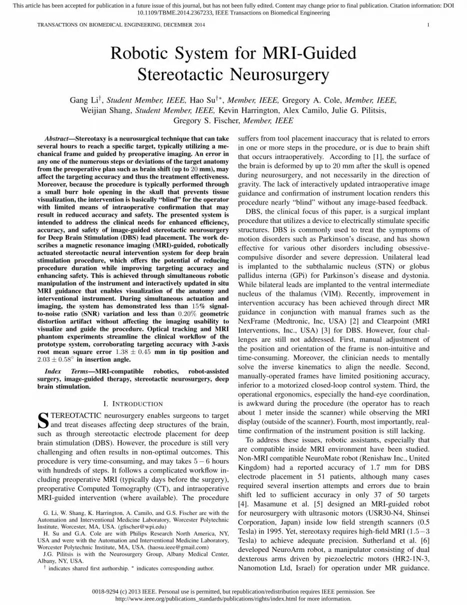
The current typical workflow for DBS stereotactic neuro-surgery involves numerous steps. The following list describesthe major steps as illustrated in Fig. 1 (a):
1) Acquire MR images prior to day of surgery;2) Perform preoperative surgical planning;3) Surgically attach fiducial frame;4) Interrupt procedure to acquire CT images;5) Fuse preoperative MRI-based plan to preoperative CT;6) Use stereotactic frame to align the cannula guide and
place the cannula.7) Optionally confirm placement with non-visual approach
such as microelectrode recording (MER, a method thatuses electrical signals in the brain to localize the surgicalsite) and/or visual approach such as fluoroscopy whichcan localize the instrument but not the target anatomy.
Acquire MR images prior to day of surgery
Attach fiducial frame on day of surgery & Acquire
CT and fuse images
Create burr hole & insert cannula guide & MER
Electrode placement & close burr hole
Perform preoperative planning
Yes
Acquire MR images prior to day of surgery
Position robot on day of surgery
Create burr hole & align robotic cannula guide
under real-time MR
Electrode placement & close burr hole
Perform preoperative planning
Cannula reached target
Yes
No
(a) (b)
Typical Time
60min
20min
130min
120min
Cannula reached target No
Estimated Time
60min
20min
40min
60min
Register fiducial frame 20min
Fig. 1. Workflow comparison of manual frame-based approach and MRI-guided robotic approach for unilateral DBS lead placement. (a) Workflow ofa typical lead placement with measured average time per step. (b) Workflowof an MRI-guided robotic lead placement with estimated time per step.
During the workflow, there are hundreds of points whereerrors could be introduced, these errors are categorized asthree main subtypes : 1) those associated with planning, 2)with the frame, and 3) with execution of the procedure. Ourapproach, especially the new workflow, as shown in Fig.1 (b), addresses all these three errors. First, error due todiscrepancies between the preoperative plan and the actualanatomy (because of brain shift) may be attenuated throughthe use of intraoperative MR imaging. Second, closed-loopcontrolled robotic needle alignment eliminates the mentalregistration between image and actual anatomy, while providesprecise motion control in contrast to the inaccurate manualframe alignment. Third, errors that arise with execution wouldbe compensated with intraoperative interactively updated MRimage feedback. To sum up, by attenuating all three errorsources, these advantages enabled by the robotic system couldpotentially improve interventional accuracy and outcomes.

0018-9294 (c) 2013 IEEE. Personal use is permitted, but republication/redistribution requires IEEE permission. Seehttp://www.ieee.org/publications_standards/publications/rights/index.html for more information.
This article has been accepted for publication in a future issue of this journal, but has not been fully edited. Content may change prior to final publication. Citation information: DOI10.1109/TBME.2014.2367233, IEEE Transactions on Biomedical Engineering
TRANSACTIONS ON BIOMEDICAL ENGINEERING, DECEMBER 2014 3
The procedure duration is potentially reduced significantlyfrom two aspects: 1) avoiding a CT imaging session andcorresponding image fusion and registration, and 2) usingdirect image guidance instead of requiring additional stepsusing MER. As shown in Fig. 1 (b) : 1) The proposed approachcompletely removes the additional perioperative CT imagingsession potentially saving about one hour of procedure timeand the complex logistics of breaking up the surgical procedurefor CT imaging. 2) During the electrode placement, the currentguidance and confirmation method relies on microelectroderecording, a one-dimensional signal to indirectly localize thetarget. MER localization takes about 40 minutes in an optimalscenario, and could take one hour more if not. In contrastto the indirect, iterative approach with MER, the proposedsystem utilizes MR imaging to directly visualize placement.Eliminating the need for MER may reduce about one hour ofprocedure time per electrode, and in the typical DBS procedurewith bilateral insertion this would result in a benefit of twohours. Therefore, for a bilateral insertion the benefit in reducedintraoperative time could potentially be as great as three hours,on top of the benefits of improved planning and accurateexecution of that plan.
III. ELECTROMECHANICAL SYSTEM DESIGN
This section presents the electromechanical design of therobotic system. The configuration of this system in the MRscanner suite is illustrated in Fig.2. Planning is performed onpre-procedure MR images or preoperative images registered tothe intra-operative images. The needle trajectories required toreach these desired targets are evaluated, subject to anatomicalconstraints, as well as constraints of the needle placementmechanism. The desired targets selected in the navigationsoftware 3D Slicer [20] are sent to the robot control softwarethrough OpenIGTLink communication protocol [21], whereinresolved to the motion commands of individual joints viakinematics. The commands are then sent to the custom MRIrobot controller, which can provide high precision closed-loopcontrol of piezoelectric motors, to drive the motors and movethe robot to the desired target positions. The actual needleposition is fed back to the navigation software in image spacefor verification and visualization.
To increase clinician comfort operating the device, as wellas limiting the system’s complexity, cost and training requiredto operate and maintain the equipment, the robot mechanism isdesigned to be kinematically equivalent to the clinically usedmanual stereotactic device Leksell stereotactic surgical frame.Electrically, some research groups have utilized methods toreduce MRI artifact by avoiding operating electromechanicalactuation during live imaging, such as interleaving robotmotion and MR imaging as demonstrated by Krieger et al.[12], or utilizing less precise but reliable pneumatic actuationmethods demonstrated by Fischer et al. [22]. In contrast tothese approaches, we have developed a custom piezoelectricmotor control system that induces no visually observableimage artifact.
Interface Box
3D Slicer Robot Control Software
MRI Robot Controller
Robot
Fiber optic Communication
MRI Console
Fig. 2. Configuration of the MRI-guided robotic neurosurgery system. Thestereotactic manipulator is placed within the scanner bore and the MRI robotcontroller resides inside the scanner room. The robot controller communicateswith the control computer within the Interface Box through a fiber optic link.The robot control software running on the control computer communicateswith 3D Slicer navigation software through OpenIGTLink.
A. Actuators and Sensors for Applications in MRI Environ-ment
As has been discussed earlier, the harsh electromagneticenvironment of the scanner bore poses a great challenge tothe construction of MRI compatible robotic systems. AmericanSociety for Testing and Materials (ASTM) and U.S. Food andDrug Administration (FDA) defined that “MR Safe” as anitem that poses no known hazard in all MRI environments.“MR Safe” items are non-conducting, non-metallic, and non-magnetic. This definition is about safety, while neither imageartifact nor proper functioning of a device is covered. Fromthe perspective of interventional mechatronics, the term “MRI-compatibility” is defined [23] such that all components insidescanner room have been demonstrated
(1) not to pose any known hazards in its intended con-figuration (corresponding to the ASTM definition of MRConditional),
(2) not to have its intended functions deteriorated by theMRI system,
(3) not to significantly affect the quality of the diagnosticinformation,in the context of a defined application, imaging sequence andconfiguration within a specified MRI environment.
The interference of a robotic system with the MR scanneris attributed to its mechanical (primarily material) and elec-trical properties. From a materials perspective, ferromagneticmaterials must be avoided entirely, though non-ferrous metalssuch as aluminum, brass, nitinol and titanium, or compositematerials can be used with caution. In this robot, all electricaland metallic components are isolated from the patient’s body.Non-conductive materials are utilized to build the majorityof the components of the mechanism, i.e. base structure aremade of 3D printed plastic materials and linkages are madeout of high strength, bio-compatible plastics including Ultemand PEEK.
From an electrical perspective, conductors passing throughthe patch panel or wave guide could act as antennas, intro-ducing stray RF noise into scanner room and thus result-ing in image quality degradation. For this reason, the robot
0018-9294 (c) 2013 IEEE. Personal use is permitted, but republication/redistribution requires IEEE permission. Seehttp://www.ieee.org/publications_standards/publications/rights/index.html for more information.
This article has been accepted for publication in a future issue of this journal, but has not been fully edited. Content may change prior to final publication. Citation information: DOI10.1109/TBME.2014.2367233, IEEE Transactions on Biomedical Engineering
TRANSACTIONS ON BIOMEDICAL ENGINEERING, DECEMBER 2014 4
controller is designed to be placed inside scanner room andcommunicate with a computer in the console room throughfiber optic medium. Even in this configuration, however, elec-trical interference from the motors’ drive system can inducesignificant image quality degradation including SNR loss.There are two primary types of piezoelectric motors, harmonicand non-harmonic. Harmonic motors, such as Nanomotionmotors (Nanomotion Ltd., Israel) and Shinsei motors (ShinseiCorporation, Japan), are generally driven with fixed frequencysinusoidal signal. Non-harmonic motors, such as PiezoLegsmotors (PiezoMotor AB, Sweden), require a complex shapedwaveform on four channels generated with high precision atfixed amplitude. Both have been demonstrated to cause inter-ference within the scanner bore with commercially availabledrive systems. The SNR reduction is up to 80% [12] and 26%[24] for harmonic and non-harmonic motors respectively.
In this presented system, non-harmonic PiezoLegs motorshave been selected. PiezoLegs motor has the required torque(50 mNm) but with small footprint (� 23 × 34 mm). NanoMo-tion (HR2-1-N-10, Nanomotion Ltd., Israel) only offers linearmotor with large footprint (40.5 mm × 25.7 mm × 12.7mm) that has to be used in opposing pairs [12] for eitherlinear or rotary motion. Shinsei motors (USR60-E3N, ShinseiCorporation, Japan) has bulky footprint (� 67× 45 mm) withtorque 0.1 Nm.
Optical encoders (US Digital, Vancouver, WA) EM1-0-500-I linear (0.0127 mm/count) and EM1-1-1250-I rotary(0.072◦/count) encoder modules are used. The encoders areplaced on the joint actuators and reside in the scanner bore.Differential signal drivers sit on the encoder module, and thesignals are transmitted via shielded twisted pairs cables tothe controller. The encoders have been incorporated into therobotic device and perform without any evidence of stray ormissed counts.
B. Mechanism Design
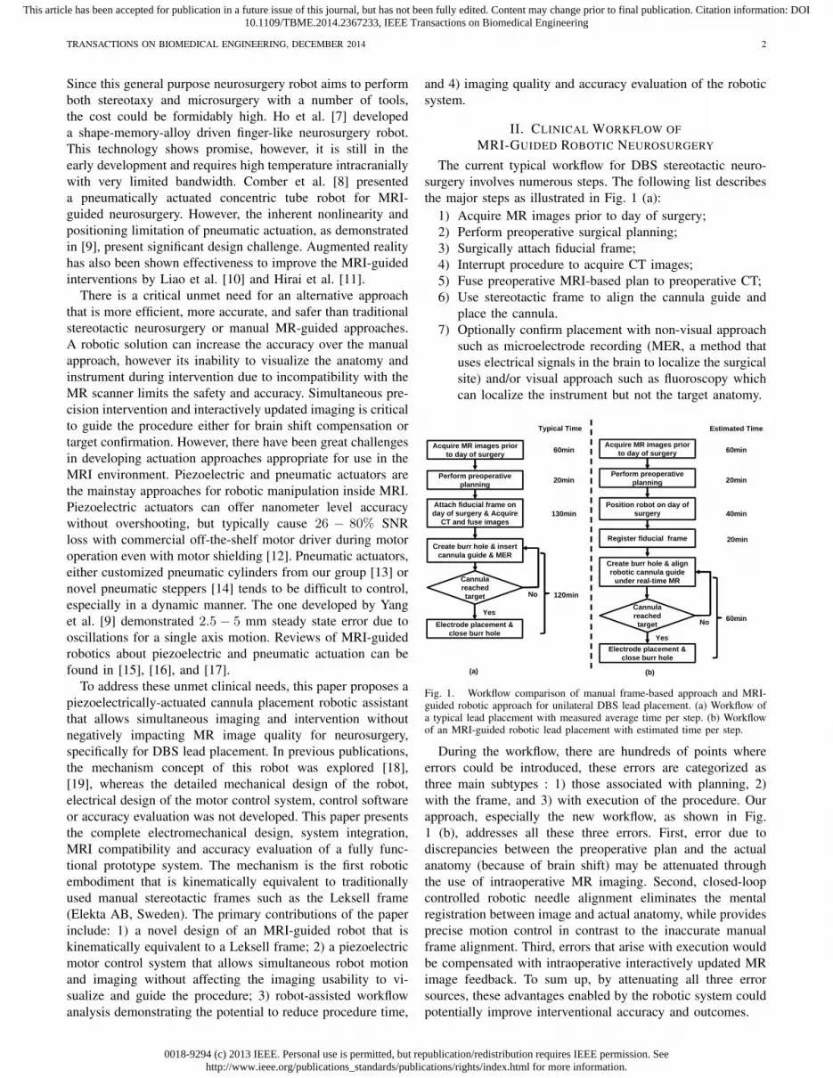
The robotic manipulator is designed to be kinematicallyequivalent to the commonly used Leksell stereotactic frame,and configured to place an electrode within a confined standard3 Tesla Philips Achieva scanner bore with 60 cm diameter. Themanual frame’s x, y and z axis set the target position, andθ4 and θ5 align the orientation of the electrode as shown inFig. 3 (left). A preliminary design for the robotic manipulatorbased upon these requirements is described in our early work[18] where neither the actuator, motion transmission nor theencoder design was covered. The current work presents thefirst fully-developed functional prototype of this robot that has5-axis motorized and encoded motion.
To mimic the functionality and kinematic structure of themanual stereotactic frame, a combination of a 3-DOF pris-matic Cartesian motion base module and a 2-DOF remotecenter of motion (RCM) mechanism module are employed,as shown in Fig. 3 (right). The robot provides three prismaticmotions for Cartesian positioning (DOF#1 – DOF#3), tworotary motions corresponding to the arc angles (DOF#4and DOF#5), and a manual cannula guide (DOF#6). Tomaintain good stiffness of the robot in spite of the plastic
3
2
1 5
4 6
2
1
3
6 5
4
RCM Mechanism
Cartesian Base
RCM Mechanism
Cartesian Base
Fig. 3. Equivalence of the degrees of freedom of a traditional manualstereotactic frame (left) and the proposed robotic system (right). TranslationDOF in red, rotational DOF in green.
material structure, three approaches have been implemented.1) Parallel mechanism is used for the RCM linkage and Scott-Russell vertical motion linkages to take advantage of theenhanced stiffness due to the closed-chain structure; 2) Highstrength plastic Ultem (stiffness 1,300,000 pounds per squareinch (PSI)) is machined to construct the RCM linkage. TheCartesian motion module base is primarily made of 3D printedABS plastic (stiffness 304,000 PSI); 3) Non-ferrous aluminumlinear rails constitutes mechanical backbone to maintain goodstructural rigidity.
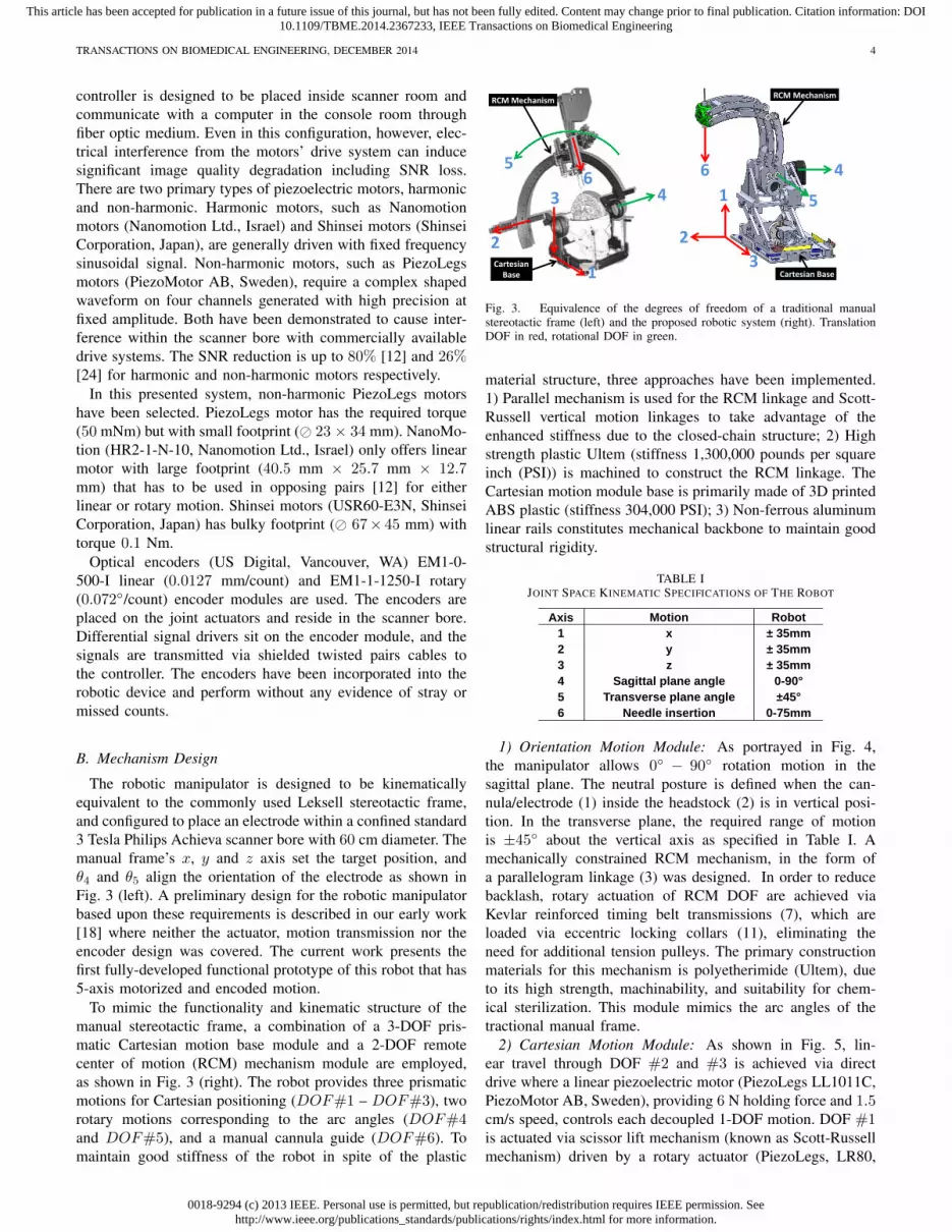
TABLE IJOINT SPACE KINEMATIC SPECIFICATIONS OF THE ROBOT
Axis Motion Robot1 x ± 35mm 2 y ± 35mm3 z ± 35mm 4 Sagittal plane angle 0-90°5 Transverse plane angle ±45°6 Needle insertion 0-75mm
1) Orientation Motion Module: As portrayed in Fig. 4,the manipulator allows 0◦ − 90◦ rotation motion in thesagittal plane. The neutral posture is defined when the can-nula/electrode (1) inside the headstock (2) is in vertical posi-tion. In the transverse plane, the required range of motionis ±45◦ about the vertical axis as specified in Table I. Amechanically constrained RCM mechanism, in the form ofa parallelogram linkage (3) was designed. In order to reducebacklash, rotary actuation of RCM DOF are achieved viaKevlar reinforced timing belt transmissions (7), which areloaded via eccentric locking collars (11), eliminating theneed for additional tension pulleys. The primary constructionmaterials for this mechanism is polyetherimide (Ultem), dueto its high strength, machinability, and suitability for chem-ical sterilization. This module mimics the arc angles of thetractional manual frame.
2) Cartesian Motion Module: As shown in Fig. 5, lin-ear travel through DOF #2 and #3 is achieved via directdrive where a linear piezoelectric motor (PiezoLegs LL1011C,PiezoMotor AB, Sweden), providing 6 N holding force and 1.5cm/s speed, controls each decoupled 1-DOF motion. DOF #1is actuated via scissor lift mechanism (known as Scott-Russellmechanism) driven by a rotary actuator (PiezoLegs, LR80,
0018-9294 (c) 2013 IEEE. Personal use is permitted, but republication/redistribution requires IEEE permission. Seehttp://www.ieee.org/publications_standards/publications/rights/index.html for more information.
This article has been accepted for publication in a future issue of this journal, but has not been fully edited. Content may change prior to final publication. Citation information: DOI10.1109/TBME.2014.2367233, IEEE Transactions on Biomedical Engineering
TRANSACTIONS ON BIOMEDICAL ENGINEERING, DECEMBER 2014 5
2
1
3
9865 74
68
10 12
1111 1012
13
4
Fig. 4. Exploded view of the RCM orientation module, showing (1)instrument/electrode, (2) headstock with cannula guide, (3) parallel linkagemechanism, (4) manipulator base frame, (5) flange bearings, (6) pulleys, (7)timing belts, (8) rotary encoders, (9) encoder housings, (10) pulleys, (11)eccentric locking collars, (12) rotary piezoelectric motors, (13) manipulatorbase.
PiezoMotor AB, Sweden) and an aluminum anodized leadscrew (2 mm pitch). This mechanism is compact and attenuatesstructural flexibility due to plastic linkages and bearings.
14
23
22
15 16 8 1812
17
19
20
21
Fig. 5. Exploded view of the Cartesian motion module, showing (14) Scott-Russell scissor mechanism, (15) lead-screw, (16) nut, (17) motor coupler, (18)motor housing, (19) linear encoder, (20) linear piezoelectric motor, (21) linearguide, (22) horizontal motion stage, (23) lateral motion stage.
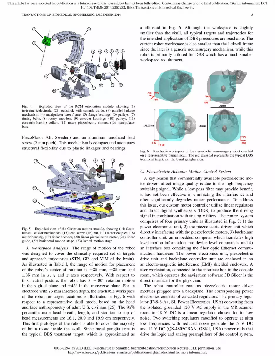
3) Workspace Analysis: The range of motion of the robotwas designed to cover the clinically required set of targetsand approach trajectories (STN, GPi and VIM of the brain).As illustrated in Table I, the range of motion for placementof the robot’s center of rotation is ±35 mm, ±35 mm and±35 mm in x, y and z axes respectively. With respect tothis neutral posture, the robot has 0◦ − 90◦ rotation motionin the sagittal plane and ±45◦ in the transverse plane. For anelectrode with 75 mm insertion depth, the reachable workspaceof the robot for target locations is illustrated in Fig. 6 withrespect to a representative skull model based on the headand face anthropometry of adult U.S. civilians [25]. The 95%percentile male head breath, length, and stomion to top ofhead measurements are 16.1, 20.9 and 19.9 cm respectively.This first prototype of the robot is able to cover the majorityof brain tissue inside the skull. Since basal ganglia area isthe typical DBS treatment target, which is approximated as
a ellipsoid in Fig. 6. Although the workspace is slightlysmaller than the skull, all typical targets and trajectories forthe intended application of DBS procedures are reachable. Thecurrent robot workspace is also smaller than the Leksell framesince the later is a generic neurosurgery mechanism, while thisrobot is primarily tailored for DBS which has a much smallerworkspace requirement.
X (R)
Y(A)Z (S)Y(A)
Z(S)
X (R)Z (S)
Y (A)
X(R)
145mm
176.07mm 145mm
Fig. 6. Reachable workspace of the stereotactic neurosurgery robot overlaidon a representative human skull. The red ellipsoid represents the typical DBStreatment target, i.e. the basal ganglia area.
C. Piezoelectric Actuator Motion Control System
A key reason that commercially available piezoelectric mo-tor drivers affect image quality is due to the high frequencyswitching signal. While a low-pass filter may provide benefit,it has not been effective in eliminating the interference andoften significantly degrades motor performance. To addressthis issue, our custom motor controller utilize linear regulatorsand direct digital synthesizers (DDS) to produce the drivingsignal in combination with analog π filters. The control systemcomprises of four primary units as illustrated in Fig. 7: 1) thepower electronics unit, 2) the piezoelectric driver unit whichdirectly interfacing with the piezoelectric motors, 3) backplanecontroller unit, an embedded computer which translates highlevel motion information into device level commands, and 4)an interface box containing the fiber optic Ethernet commu-nication hardware. The power electronics unit, piezoelectricdrive unit and backplane controller unit are enclosed in anan electro-magnetic interference (EMI) shielded enclosure. Auser workstation, connected to the interface box in the consoleroom, which operates the navigation software 3D Slicer is thedirect interface for the physician.
The robot controller contains piezoelectric motor drivermodules plugged into a backplane. The corresponding powerelectronics consists of cascaded regulators. The primary regu-lator (F48-6-A+, SL Power Electronics, USA) converting fromthe isolated, grounded 120 V AC supply in the MR scannerroom to 48 V DC is a linear regulator chosen for its lownoise. Two switching regulators modified to operate at ultralow frequencies with reduced noise generate the 5 V DCand 12 V DC (QS-4805CBAN, OSKJ, USA) power rails thatdrive the logic and analog preamplifiers of the control system,
0018-9294 (c) 2013 IEEE. Personal use is permitted, but republication/redistribution requires IEEE permission. Seehttp://www.ieee.org/publications_standards/publications/rights/index.html for more information.
This article has been accepted for publication in a future issue of this journal, but has not been fully edited. Content may change prior to final publication. Citation information: DOI10.1109/TBME.2014.2367233, IEEE Transactions on Biomedical Engineering
TRANSACTIONS ON BIOMEDICAL ENGINEERING, DECEMBER 2014 6
respectively. The 48 V DC from the linear regulator directlyfeeds the linear power amplifiers for the motor drive signals(through a safety circuit).
48VLow Noise
Linear Regulator120V AC
5V Switching
Supply
12VSwitching
Supply
Current & Voltage MonitoringPower Switching
Backplane Controller
Piezoelectric Axis CardPiezoelectric Axis CardPiezoelectric Axis CardPiezoelectric Driver Card
Piezoelectric Axis CardPiezoelectric Axis CardPiezoelectric Axis CardPiezoelectric Driver Card
SPIPiezoMotor
Fiber opticto EthernetConverter
Fiber Optic Cable
SPIPiezoMotor
Fig. 7. Block diagram of the MRI robot control system. The power electronicsand piezoelectric actuator drivers are contained in a shielded enclosure andconnected to an interface unit in the console room through a fiber opticEthernet connection.
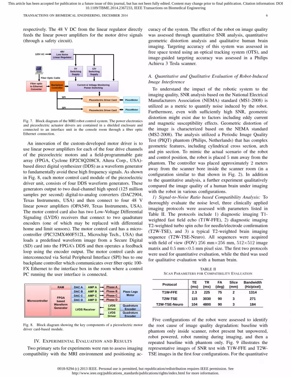
An innovation of the custom-developed motor driver is touse linear power amplifiers for each of the four drive channelsof the piezoelectric motors and a field-programmable gatearray (FPGA, Cyclone EP2C8Q208C8, Altera Corp., USA)-based direct digital synthesizer (DDS) as a waveform generatorto fundamentally avoid these high frequency signals. As shownin Fig. 8, each motor control card module of the piezoelectricdriver unit, consists of four DDS waveform generators. Thesegenerators output to two dual-channel high speed (125 millionsamples per second) digital-to-analog converters (DAC2904,Texas Instruments, USA) and then connect to four 48 Vlinear power amplifiers (OPA549, Texas Instruments, USA).The motor control card also has two Low-Voltage DifferentialSignaling (LVDS) receivers that connect to two quadratureencoders (one of which may be replaced with differentialhome and limit sensors). The motor control card has a micro-controller (PIC32MX460F512L, Microchip Tech., USA) thatloads a predefined waveform image from a Secure Digital(SD) card into the FPGA’s DDS and then operates a feedbackloop using the encoder output. The motor control cards areinterconnected via Serial Peripheral Interface (SPI) bus to onebackplane controller which communicates over fiber optic 100-FX Ethernet to the interface box in the room where a controlPC running the user interface is connected.
FPGA based
Waveform Generator
DAC ADAC BDAC CDAC D
RAM AMP AAMP BAMP CAMP DMicrocontroller
Piezo LegsMotor
Phase APhase BPhase CPhase D
LVDS DriverLVDS ReceiverLVDS Driver
QuadratureEncoder
QuadratureEncoder
Fig. 8. Block diagram showing the key components of a piezoelectric motordriver card-based module.
IV. EXPERIMENTAL EVALUATION AND RESULTS
Two primary sets for experiments were run to assess imagingcompatibility with the MRI environment and positioning ac-
curacy of the system. The effect of the robot on image qualitywas assessed through quantitative SNR analysis, quantitativegeometric distortion analysis and qualitative human brainimaging. Targeting accuracy of this system was assessed infree space tested using an optical tracking system (OTS), andimage-guided targeting accuracy was assessed in a PhilipsAchieva 3 Tesla scanner.
A. Quantitative and Qualitative Evaluation of Robot-InducedImage Interference
To understand the impact of the robotic system to theimaging quality, SNR analysis based on the National ElectricalManufacturers Association (NEMA) standard (MS1-2008) isutilized as a metric to quantify noise induced by the robot.Furthermore, even with sufficiently high SNR, geometricdistortion might exist due to factors including eddy currentand magnetic susceptibility effects. Geometric distortion ofthe image is characterized based on the NEMA standard(MS2-2008). The analysis utilized a Periodic Image QualityTest (PIQT) phantom (Philips, Netherlands) that has complexgeometric features, including cylindrical cross section, archand pin section. To mimic the actual scenario of the robotand control position, the robot is placed 5 mm away from thephantom. The controller was placed approximately 2 metersaway from the scanner bore inside the scanner room (in aconfiguration similar to that shown in Fig. 2). In additionto the quantitative analysis, a further experiment qualitativelycompared the image quality of a human brain under imagingwith the robot in various configurations.
1) Signal-to-Noise Ratio based Compatibility Analysis: Tothoroughly evaluate the noise level, three clinically appliedimaging protocols were assessed with parameters listed inTable II. The protocols include 1) diagnostic imaging T1-weighted fast field echo (T1W-FFE), 2) diagnostic imagingT2-weighted turbo spin echo for needle/electrode confirmation(T2W-TSE), and 3) a typical T2-weighted brain imagingsequence (T2W-TSE-Neuro). All sequences were acquiredwith field of view (FOV) 256 mm×256 mm, 512×512 imagematrix and 0.5 mm×0.5 mm pixel size. The first two protocolswere used for quantitative evaluation, while the third was usedfor qualitative evaluation with a human brain.
TABLE IISCAN PARAMETERS FOR COMPATIBILITY EVALUATION
Protocol TE(ms)
TR(ms)
FA(deg)
Slice(mm)
Bandwidth (Hz/pixel)
T1W-FFE 2.3 225 75 2 1314
T2W-TSE-Planning 90 4800 90 3 239T2W-TSE-Diagnosis 115 3030 90 3 271
T2W-TSE-Neuro 104 4800 90 3 184
Protocol TE(ms)
TR(ms)
FA(deg)
Slice(mm)
Bandwidth (Hz/pixel)
T1W-FFE 2.3 225 75 2 1314
T2W-TSE 115 3030 90 3 271T2W-TSE-Neuro 104 4800 90 3 184
Five configurations of the robot were assessed to identifythe root cause of image quality degradation: baseline withphantom only inside scanner, robot present but unpowered,robot powered, robot running during imaging, and then arepeated baseline with phantom only. Fig. 9 illustrates therepresentative images of SNR test with T1W-FFE and T2W-TSE images in the first four configurations. For the quantitative

0018-9294 (c) 2013 IEEE. Personal use is permitted, but republication/redistribution requires IEEE permission. Seehttp://www.ieee.org/publications_standards/publications/rights/index.html for more information.
This article has been accepted for publication in a future issue of this journal, but has not been fully edited. Content may change prior to final publication. Citation information: DOI10.1109/TBME.2014.2367233, IEEE Transactions on Biomedical Engineering
TRANSACTIONS ON BIOMEDICAL ENGINEERING, DECEMBER 2014 7
Baseline
T1W
T2W
Robot Power Off Robot Powered Robot Running
Fig. 9. MRI of the homogeneous section of the phantom in four configura-tions with two imaging protocols demonstrating visually unobservable imageartifacts.
analysis, SNR is calculated as the mean signal in the centerof the phantom divided by the noise outside the phantom.Mean signal is defined as the mean pixel intensity in the regionof interest. The noise is defined as the average mean signalintensity in the four corners divided by 1.25 [26]. Fig. 10shows the boxplot of the SNR for five robot configurationsunder these two scan protocols. The results from this plotare indicative of three primary potential sources of imageartifact, namely materials of the robot (difference betweenbaseline and robot present but unpowered), power systemand wiring (difference between robot present but unpoweredand robot powered), and drive electronics (difference betweenrobot powered and robot running). The mean SNR reductionfrom baseline for these three differences are 2.78%, 6.30%,and 13.64% for T1W-FFE and 2.56%, 8.02% and 12.54%for T2W-TSE, respectively. Note that Fig. 9 shows this corre-sponding to visually unobservable image artifacts.
Elhawary et al. [24] demonstrated that SNR reduction forthe same PiezoLegs motor (non-harmonic motor) using acommercially available driver is 26% with visually observableartifact. In terms of harmonic piezoelectric motors, Krieger etal. [12] showed that the mean SNR of baseline and robot mo-tion using NanoMotion motors under T1W imaging reducedapproximately from 250 to 50 (80%) with striking artifact.Though the focus of this paper is on the use of non-harmonicPiezoLegs motors for this application, we also demonstratedthe control system capable of generating less than 15% SNRreduction for NanoMotion motors in our previous work [27].Our system shows significant improvement with PiezoLegsmotor over commercially available motor drivers when therobot is in motion. Even though there is no specific standardabout SNR and image usability, the visually unobservableimage artifact in our system is a key differentiator with that of[24] which used the same motors but still showed significantvisual artifact.
2) Geometric Distortion based Compatibility Analysis: TheNEMA standard (MS2-2008) defines 2D geometric distortionas the maximum percent difference between measured dis-tances in an image and the actual corresponding phantomdimensions. Eight pairs of radial measurements (i.e. betweenpoints spanning the center of the phantom), are used tocharacterize the geometric distortion as shown in Fig. 11 forT1W-FFE and T2W-TSE protocols.
With the known geometry of the pins inside the phantom,
0
5
10
15
20
25
Baseline Robot Powered Running Baselineagain
SNR
T1W FFE
0
10
20
30
40
50
60
Baseline Robot Powered Running Baselineagain
SNR
T2W TSE
Fig. 10. Boxplots showing the range of SNR values for each of fiverobot configurations evaluated in two clinically appropriate neuro imagingprotocols (T1W FFE & T2W TSE). The configurations include Baseline (norobotic system components present in room), Robot (robot presented but notpowered), Powered (Robot connected to power on controller), Running (Robotmoving during imaging), and a repeated baseline with no robotic systemcomponents present.
the actual pin distance is readily available. The distance ismeasured on the image, and then are compared to the actualcorresponding distances in the phantom as shown in Table.III for T1W-FFE protocol. The maximum difference betweenbaseline image acquired with no robot and actual distance isless than 0.31% as shown in the third column of the table.The measured maximum distortion percentage for imagesacquired while the robot was running was 0.20%. This analysisdemonstrates negligible geometric distortion of the acquiredimages due to the robot running during imaging.
TABLE IIIGEOMETRIC DISTORTION EVALUATIONS UNDER SCAN PROTOCOL T1W.
Line segment Actual distance (mm) Measured distance (difference %) Baseline Robot running
ai 158.11 158.46(0.22) 158.39(0.17)bj 150.00 150.46(0.31) 150.24(0.16)ck 158.11 158.48(0.23) 158.03(0.05)dl 141.42 141.51(0.07) 141.14(0.20)
em 158.11 157.97(0.09) 157.85(0.17)fn 150.00 149.92(0.05) 149.89(0.07)go 158.11 158.16(0.03) 158.24(0.08)hp 141.42 141.65(0.16) 141.65(0.16)
Baseline with AX‐T1 protocol, all measured data are maximum values among three images
Moving with AX‐T1 protocol, all measured data are maximum values among three images
3) Qualitative Imaging Evaluation: In light of the quan-titative SNR results of the robot system, the image qualityis further evaluated qualitatively by comparing brain imagesacquired with three different configurations under the pre-
0018-9294 (c) 2013 IEEE. Personal use is permitted, but republication/redistribution requires IEEE permission. Seehttp://www.ieee.org/publications_standards/publications/rights/index.html for more information.
This article has been accepted for publication in a future issue of this journal, but has not been fully edited. Content may change prior to final publication. Citation information: DOI10.1109/TBME.2014.2367233, IEEE Transactions on Biomedical Engineering
TRANSACTIONS ON BIOMEDICAL ENGINEERING, DECEMBER 2014 8
T1W
T2W
Baseline Robot running
ab
c
de
f
gh
ij
kl
m
n
op
Fig. 11. Geometric patterns of the non-homogeneous section of the phantomfilled with pins and arches for the two extreme robot configurations and thesame two imaging protocols. The overlaid red line segments indicates themeasured distance for geometric distortion evaluation.
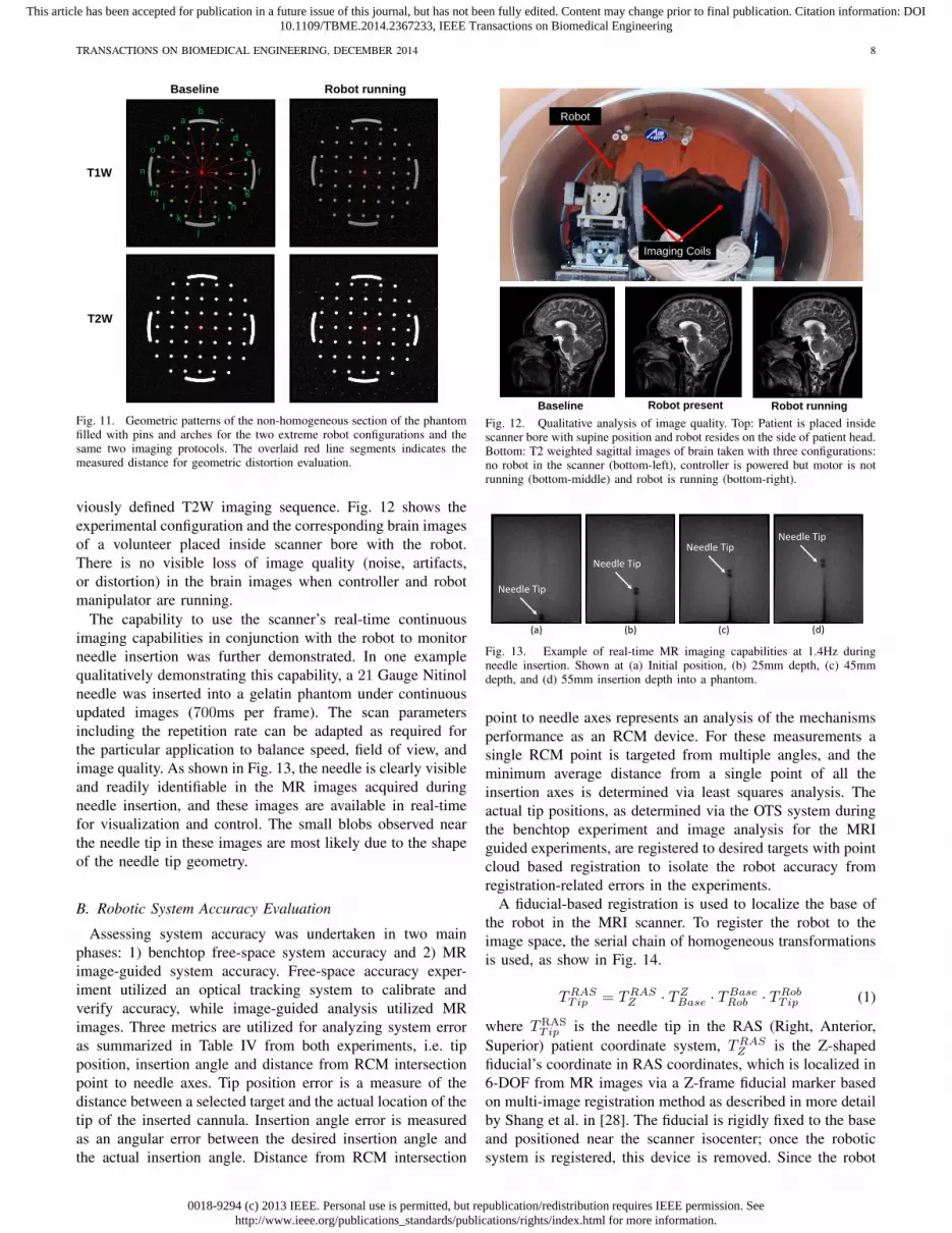
viously defined T2W imaging sequence. Fig. 12 shows theexperimental configuration and the corresponding brain imagesof a volunteer placed inside scanner bore with the robot.There is no visible loss of image quality (noise, artifacts,or distortion) in the brain images when controller and robotmanipulator are running.
The capability to use the scanner’s real-time continuousimaging capabilities in conjunction with the robot to monitorneedle insertion was further demonstrated. In one examplequalitatively demonstrating this capability, a 21 Gauge Nitinolneedle was inserted into a gelatin phantom under continuousupdated images (700ms per frame). The scan parametersincluding the repetition rate can be adapted as required forthe particular application to balance speed, field of view, andimage quality. As shown in Fig. 13, the needle is clearly visibleand readily identifiable in the MR images acquired duringneedle insertion, and these images are available in real-timefor visualization and control. The small blobs observed nearthe needle tip in these images are most likely due to the shapeof the needle tip geometry.
B. Robotic System Accuracy Evaluation
Assessing system accuracy was undertaken in two mainphases: 1) benchtop free-space system accuracy and 2) MRimage-guided system accuracy. Free-space accuracy exper-iment utilized an optical tracking system to calibrate andverify accuracy, while image-guided analysis utilized MRimages. Three metrics are utilized for analyzing system erroras summarized in Table IV from both experiments, i.e. tipposition, insertion angle and distance from RCM intersectionpoint to needle axes. Tip position error is a measure of thedistance between a selected target and the actual location of thetip of the inserted cannula. Insertion angle error is measuredas an angular error between the desired insertion angle andthe actual insertion angle. Distance from RCM intersection
Robot
Imaging Coils
Baseline Robot present Robot runningFig. 12. Qualitative analysis of image quality. Top: Patient is placed insidescanner bore with supine position and robot resides on the side of patient head.Bottom: T2 weighted sagittal images of brain taken with three configurations:no robot in the scanner (bottom-left), controller is powered but motor is notrunning (bottom-middle) and robot is running (bottom-right).
25mm45mm 55mm
5mm
(a) (d)(c)(b)
Needle TipNeedle Tip
Needle Tip
Needle Tip
Fig. 13. Example of real-time MR imaging capabilities at 1.4Hz duringneedle insertion. Shown at (a) Initial position, (b) 25mm depth, (c) 45mmdepth, and (d) 55mm insertion depth into a phantom.
point to needle axes represents an analysis of the mechanismsperformance as an RCM device. For these measurements asingle RCM point is targeted from multiple angles, and theminimum average distance from a single point of all theinsertion axes is determined via least squares analysis. Theactual tip positions, as determined via the OTS system duringthe benchtop experiment and image analysis for the MRIguided experiments, are registered to desired targets with pointcloud based registration to isolate the robot accuracy fromregistration-related errors in the experiments.
A fiducial-based registration is used to localize the base ofthe robot in the MRI scanner. To register the robot to theimage space, the serial chain of homogeneous transformationsis used, as show in Fig. 14.
TRASTip = TRAS
Z · TZBase · TBase
Rob · TRobTip (1)
where TRASTip is the needle tip in the RAS (Right, Anterior,
Superior) patient coordinate system, TRASZ is the Z-shaped
fiducial’s coordinate in RAS coordinates, which is localized in6-DOF from MR images via a Z-frame fiducial marker basedon multi-image registration method as described in more detailby Shang et al. in [28]. The fiducial is rigidly fixed to the baseand positioned near the scanner isocenter; once the roboticsystem is registered, this device is removed. Since the robot
0018-9294 (c) 2013 IEEE. Personal use is permitted, but republication/redistribution requires IEEE permission. Seehttp://www.ieee.org/publications_standards/publications/rights/index.html for more information.
This article has been accepted for publication in a future issue of this journal, but has not been fully edited. Content may change prior to final publication. Citation information: DOI10.1109/TBME.2014.2367233, IEEE Transactions on Biomedical Engineering
TRANSACTIONS ON BIOMEDICAL ENGINEERING, DECEMBER 2014 9
base is fixed in scanner coordinates, this registration is onlynecessary once. TZ
Base is is a fixed calibration of the robotbase with respect to the fiducial frame, TBase
Rob is the constantoffset between robot origin and a frame defined on the robotbase, and TRob
Tip is the needle tip position with respect to therobot origin, which is obtained via the robot kinematics.
x
y
z x
yz
x
yzzx
yFTip
x
y
zFBase
FZ
FRob
Axis 0 (z) Axis 1 (x)
Axis 2 (y)
Axis 4 (z) Axis 3 (x)FRAS
RASZT
ZBaseT
BaseRobT
RASTipT
RobTipT
Fig. 14. Coordinate frames of the robotic system for registration of robot toMR image space
1) Robot Accuracy Evaluation with Optical Tracking Sys-tem: A Polaris optical tracking system (Northern Digital Inc,Canada) is utilized, with a passive 6-DOF tracking frameattached to the robot base, and an active tracking tool mountedon the end-effector.
The experiment is a two step procedure, consisting of robotRCM mechanism calibration and robot end-effector position-ing evaluation. The first procedure was performed by movingthe mechanism through multiple orientations while keepingthe Cartesian base fixed, and performing a pivot calibration todetermine tool tip offset (RMS error of this indicates RCMaccuracy). After successfully calibrating the RCM linkage,the robot is moved to six targets locations, with each targetconsisting of five different orientations. Three groups of datawere recorded: desired needle tip transformation, reportedneedle transformation as calculated with kinematics based onoptical encoders readings, and measured needle transforma-tion from OTS. Analysis of experimental data indicates thatthe tip position error (1.09 ± 0.28 mm), orientation error(2.06 ± 0.76◦), and the error from RCM intersection pointto needle axes (0.33± 0.05 mm) as can be seen in Table IV.
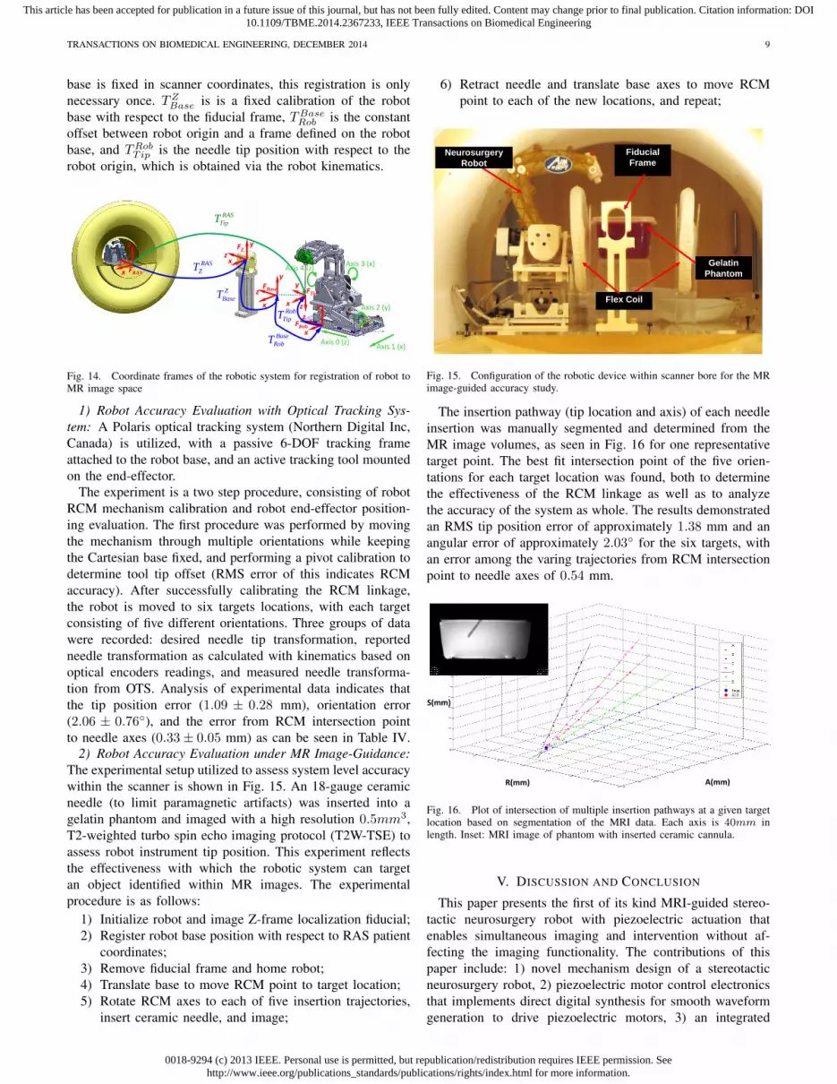
2) Robot Accuracy Evaluation under MR Image-Guidance:The experimental setup utilized to assess system level accuracywithin the scanner is shown in Fig. 15. An 18-gauge ceramicneedle (to limit paramagnetic artifacts) was inserted into agelatin phantom and imaged with a high resolution 0.5mm3,T2-weighted turbo spin echo imaging protocol (T2W-TSE) toassess robot instrument tip position. This experiment reflectsthe effectiveness with which the robotic system can targetan object identified within MR images. The experimentalprocedure is as follows:
1) Initialize robot and image Z-frame localization fiducial;2) Register robot base position with respect to RAS patient
coordinates;3) Remove fiducial frame and home robot;4) Translate base to move RCM point to target location;5) Rotate RCM axes to each of five insertion trajectories,
insert ceramic needle, and image;
6) Retract needle and translate base axes to move RCMpoint to each of the new locations, and repeat;
Flex Coil
Fiducial Frame
Gelatin Phantom
Neurosurgery Robot
Fig. 15. Configuration of the robotic device within scanner bore for the MRimage-guided accuracy study.
The insertion pathway (tip location and axis) of each needleinsertion was manually segmented and determined from theMR image volumes, as seen in Fig. 16 for one representativetarget point. The best fit intersection point of the five orien-tations for each target location was found, both to determinethe effectiveness of the RCM linkage as well as to analyzethe accuracy of the system as whole. The results demonstratedan RMS tip position error of approximately 1.38 mm and anangular error of approximately 2.03◦ for the six targets, withan error among the varing trajectories from RCM intersectionpoint to needle axes of 0.54 mm.
R(mm) A(mm)
S(mm)
Fig. 16. Plot of intersection of multiple insertion pathways at a given targetlocation based on segmentation of the MRI data. Each axis is 40mm inlength. Inset: MRI image of phantom with inserted ceramic cannula.
V. DISCUSSION AND CONCLUSION
This paper presents the first of its kind MRI-guided stereo-tactic neurosurgery robot with piezoelectric actuation thatenables simultaneous imaging and intervention without af-fecting the imaging functionality. The contributions of thispaper include: 1) novel mechanism design of a stereotacticneurosurgery robot, 2) piezoelectric motor control electronicsthat implements direct digital synthesis for smooth waveformgeneration to drive piezoelectric motors, 3) an integrated

0018-9294 (c) 2013 IEEE. Personal use is permitted, but republication/redistribution requires IEEE permission. Seehttp://www.ieee.org/publications_standards/publications/rights/index.html for more information.
This article has been accepted for publication in a future issue of this journal, but has not been fully edited. Content may change prior to final publication. Citation information: DOI10.1109/TBME.2014.2367233, IEEE Transactions on Biomedical Engineering
TRANSACTIONS ON BIOMEDICAL ENGINEERING, DECEMBER 2014 10
TABLE IVANALYSIS OF OTS AND IMAGE-GUIDED ACCURACY STUDIES
Tip Position (mm) Distance from Needle Axes(mm) Insertion Angle (Degree)
Maximum Error 1.56 0.44 3.07
Minimum Error 0.48 0.22 0.90
RMS Error 1.09 0.33 2.06
Standard Deviation 0.28 0.05 0.76
Maximum Error 2.13 0.59 2.79
Minimum 0.51 0.47 0.85
RMS Error 1.38 0.54 2.03
Standard Deviation 0.45 0.05 0.58
Optical Tracker
MRI‐Guide
d
actuation, control, sensing and navigation system for MRI-guided piezoelectric robotic interventions, 4) image qualitybenchmark evaluation of the robotic system, and 5) targetingaccuracy evaluation of the system in free space and under MRguidance.
Evaluation of the compatibility of the robot with the MRIenvironment in a typical diagnostic 3T MRI scanner demon-strates the capability of the system of introducing less than15% SNR variation during simultaneous imaging and robotmotion with no visually observable image artifact. This indi-cates the capability to visualize the tissue and target when therobot operates inside MRI scanner bore, and enables futurefully-actuated system to control insertion depth and rotationwhile acquiring real-time images. Geometric distortion anal-ysis demonstrated less than 0.20% image distortion whichwas no worse than that of baseline images without the robotpresent.
Targeting accuracy was evaluated in free space throughbenchtop studies and in a gelatin phantom under live MRI-guidance. The plastic material and manufacturing-inducederrors result in the axes not being in perfect alignment relativeto each other, and thus resulting in system error. 3D printedmaterials utilized in the construction of this device are veryuseful to rapidly create a mechanism for initial analysis,though upon disassembly, plastic deformation of the pivotlocations for the parallelogram linkage were observed, andthought to have added to system inaccuracies; these partswould be machined from PEEK or Ultem in the clinicalversion of this system to improve stiffness and precision. Inaddition, large transmission distances on the two belt driveaxes may be associated with angular inaccuracies.
This work aims to address three unmet clinical needs,namely efficiency, accuracy and safety. In terms of the ef-ficiency, we compared the workflow of the current manual-frame approach and the MRI-guided robotic approach, reveal-ing the potential to save 2-3 hours by avoiding an additionalCT imaging session with associated CT-MRI fusion andthe time-consuming localization method (i.e. microelectroderecording). In terms of the accuracy, MRI-guided needle place-ment accuracy experiment demonstrated 3-axis RMS error1.38 ± 0.45 mm. The accuracy of traditional frame-basedstereotaxy DBS with MRI guidance is 3.1 ± 1.41 mm for76 stimulators implantation in human [2]. It is premature tocorroborate the accuracy advantage of robotic approach dueto the lack of clinical human trials. However, it shows thepotential of the robotic approach to improve accuracy, by
postulating that motorized solution is superior to the manualmethod. In terms of the safety, since the intraoperative brainanatomy, targets, and interventional tool are all visible withMR during the intervention, this enables compensation forbrain shift and complete visualization of the interventionalsite during the procedure. Qualitatively, image-guidance isempowered with the obvious advantages over the indirectmethod (i.e. microelectrode recording) which is iterative, time-consuming, and unable to visualize any anatomy.
The currently intended application of the system is forDBS electrode placement. But as a generic MRI-compatiblemotion control system, this platform has the capability tobe extended for other neurosurgical procedures (e.g. braintumor biopsy and ablation) with different interventional tools.Further experiments include validation of the procedure timeand targeting errors with cadaver and animal studies, aimingto improve the patient outcome as the final goal.
VI. ACKNOWLEDGMENTS
This work is supported in part by the National Institutesof Health (NIH) R01CA166379 and Congressionally DirectedMedical Research Program (CDMRP) W81XWH-09-1-0191.The content is solely the responsibility of the authors and doesnot necessarily represent the official views of NIH or CDMRP.
REFERENCES
[1] T. Hartkens, D. Hill, A. Castellano-Smith, D. Hawkes, C. Maurer,A. Martin, H. Liu, and C. Truwit, “Measurement and analysis of braindeformation during neurosurgery,” Medical Imaging, IEEE Transactionson, vol. 22, pp. 82–92, 2003.
[2] P. A. Starr, A. J. Martin, J. L. Ostrem, P. Talke, N. Levesque, andP. S. Larson, “Subthalamic nucleus deep brain stimulator placementusing high-field interventional magnetic resonance imaging and a skull-mounted aiming device: technique and application accuracy,” Journal ofNeurosurgery, vol. 112, no. 3, pp. 479–490, 2010.
[3] P. Larson, P. A. Starr, J. L. Ostrem, N. Galifianakis, M. S. L. Palenzuela,and A. Martin, “203 application accuracy of a second generationinterventional MRI stereotactic platform: initial experience in 101 DBSelectrode implantations,” Neurosurgery, vol. 60, p. 187, 2013.
[4] T. Varma, P. Eldridge, A. Forster, S. Fox, N. Fletcher, M. Steiger,P. Littlechild, P. Byrne, A. Sinnott, K. Tyler, et al., “Use of theNeuroMate stereotactic robot in a frameless mode for movement disordersurgery,” Stereotactic and functional neurosurgery, vol. 80, no. 1-4,pp. 132–135, 2004.
[5] K. Masamune, E. Kobayashi, Y. Masutani, M. Suzuki, T. Dohi, H. Iseki,and K. Takakura, “Development of an MRI-compatible needle insertionmanipulator for stereotactic neurosurgery,” Journal of Image GuidedSurgery, vol. 4, pp. 242–248, 1995.
[6] M. Lang, A. Greer, and G. Sutherland, “Intra-operative robotics: Neu-roArm,” Intraoperative Imaging, vol. 109, pp. 231–236, 2011.
[7] M. Ho, A. McMillan, J. Simard, R. Gullapalli, and J. Desai, “To-ward a meso-scale SMA-actuated MRI-compatible neurosurgical robot,”Robotics, IEEE Transactions on, vol. 28, pp. 213 –222, Feb. 2012.
[8] D. B. Comber, E. J. Barth, and R. J. Webster, “Design and control ofan magnetic resonance compatible precision pneumatic active cannularobot,” Journal of Medical Devices, vol. 8, no. 1, p. 011003, 2014.
[9] B. Yang, U.-X. Tan, A. McMillan, R. Gullapalli, and J. Desai, “Designand control of a 1-dof MRI-compatible pneumatically actuated robotwith long transmission lines,” Mechatronics, IEEE/ASME Transactionson, vol. 16, no. 6, pp. 1040 –1048, 2011.
[10] H. Liao, T. Inomata, I. Sakuma, and T. Dohi, “3-D augmented realityfor MRI-guided surgery using integral videography autostereoscopicimage overlay,” Biomedical Engineering, IEEE Transactions on, vol. 57,pp. 1476–1486, June 2010.
[11] N. Hirai, A. Kosaka, T. Kawamata, T. Hori, and H. Iseki, “Image-guidedneurosurgery system integrating AR-based navigation and open-MRImonitoring,” Computer Aided Surgery, vol. 10, no. 2, pp. 59–72, 2005.

0018-9294 (c) 2013 IEEE. Personal use is permitted, but republication/redistribution requires IEEE permission. Seehttp://www.ieee.org/publications_standards/publications/rights/index.html for more information.
This article has been accepted for publication in a future issue of this journal, but has not been fully edited. Content may change prior to final publication. Citation information: DOI10.1109/TBME.2014.2367233, IEEE Transactions on Biomedical Engineering
TRANSACTIONS ON BIOMEDICAL ENGINEERING, DECEMBER 2014 11
[12] A. Krieger, S.-E. Song, N. Cho, I. Iordachita, P. Guion, G. Fichtinger,and L. Whitcomb, “Development and evaluation of an actuated MRI-compatible robotic system for MRI-guided prostate intervention,”Mechatronics, IEEE/ASME Transactions on, vol. 18, no. 1, pp. 273–284, 2013.
[13] G. S. Fischer, I. Iordachita, C. Csoma, J. Tokuda, S. P. DiMaio, C. M.Tempany, N. Hata, and G. Fichtinger, “MRI-compatible pneumatic robotfor transperineal prostate needle placement,” Mechatronics, IEEE/ASMETransactions, vol. 13, no. 3, pp. 295–305, 2008.
[14] D. Stoianovici, C. Kim, G. Srimathveeravalli, P. Sebrecht, D. Petrisor,J. Coleman, S. Solomon, and H. Hricak, “MRI-safe robot for endorectalprostate biopsy,” Mechatronics, IEEE/ASME Transactions on, vol. PP,no. 99, pp. 1–11, 2014.
[15] K. Chinzei and K. Miller, “MRI guided surgical robot,” in AustralianConference on Robotics and Automation, pp. 50–55, 2001.
[16] N. Tsekos, A. Khanicheh, E. Christoforou, and C. Mavroidis, “Magneticresonance-compatible robotic and mechatronics systems for image-guided interventions and rehabilitation: a review study,” Annual Reviewof Biomedical Engineering, vol. 9, pp. 351–387, 2007.
[17] R. Gassert, E. Burdet, and K. Chinzei, “Opportunities and challenges inMR-compatible robotics,” Engineering in Medicine and Biology, vol. 3,pp. 15–22, 2008.
[18] G. A. Cole, J. G. Pilitsis, and G. S. Fischer, “Design of a robotic systemfor MRI-guided deep brain stimulation electrode placement,” in IEEEInt Conf on Robotics and Automation, May 2009.
[19] G. Cole, K. Harrington, H. Su, A. Camilo, J. Pilitsis, and G. Fischer,“Closed-loop actuated surgical system utilizing real-time in-situ MRIguidance,” in International Symposium on Experimental Robotics, 2010.
[20] N. Hata, S. Piper, F. A. Jolesz, C. M. Tempany, P. M. Black,S. Morikawa, H. Iseki, M. Hashizume, and R. Kikinis, “Applicationof open source image guided therapy software in MR-guided therapies,”International Conference on Medical Image Computing and ComputerAssisted Intervention (MICCAI), vol. 10, pp. 491–498, 2007.
[21] J. Tokuda, G. S. Fischer, X. Papademetris, Z. Yaniv, L. Ibanez, P. Cheng,H. Liu, J. Blevins, J. Arata, A. J. Golby, et al., “Openigtlink: an open net-work protocol for image-guided therapy environment,” The InternationalJournal of Medical Robotics and Computer Assisted Surgery, vol. 5,no. 4, pp. 423–434, 2009.
[22] G. Fischer, I. Iordachita, C. Csoma, J. Tokuda, S. DiMaio, C. Tempany,N. Hata, and G. Fitchinger, “MRI-compatible pneumatic robot fortransperineal prostate needle placement,” Mechatronics, IEEE/ASMETransactions on, vol. 13, pp. 295–305, 2008.
[23] N. Yu, R. Gassert, and R. Riener, “Mutual interferences and designprinciples for mechatronic devices in magnetic resonance imaging,”International Journal of Computer Assisted Radiology and Surgery,vol. 6, no. 4, pp. 473–488, 2011.
[24] H. Elhawary, A. Zivanovic, M. Rea, B. Davies, C. Besant, D. McRobbie,N. de Souza, I. Young, and M. Lamprth, “The feasibility of MR-image guided prostate biopsy using piezoceramic motors inside ornear to the magnet isocentre,” International Conference on MedicalImage Computing and Computer Assisted Intervention (MICCAI), vol. 9,pp. 519–526, 2006.
[25] J. W. Young, “Head and face anthropometry of adult US civilians,”Technical Information Center Document, 1993.
[26] Determination of Signal-to-Noise Ratio (SNR) in Diagnostic MagneticResonance Imaging, NEMA Standard Publication MS 1-2008. The As-sociation of Electrical and Medical Imaging Equipment Manufacturers,2008.
[27] G. Fischer, G. Cole, and H. Su, “Approaches to creating and controllingmotion in MRI,” in Engineering in Medicine and Biology Society,EMBC, Annual International Conference of the IEEE, pp. 6687–6690,2011.
[28] W. Shang and G. S. Fischer, “A high accuracy multi-image registrationmethod for tracking MRI-guided robots,” in SPIE Medical Imaging,February 2012.
Gang Li received the B.S. degree and M.S. degreein Mechanical Engineering from Harbin Instituteof Technology, Harbin, China, in 2008 and 2011,respectively. He is currently a Doctoral Candidatein the Department of Mechanical Engineering atWorcester Polytechnic Institute, Worcester, MA. Hisresearch interests include medical robotics, robotmechanism design, MRI-guided percutaneous inter-vention, and needle steering.
Hao Su received the B.S. degree from the HarbinInstitute of Technology and M.S. degree from theState University of New York University at Buffalo,and Ph.D. degree from the Worcester PolytechnicInstitute. He was a recipient of the Link FoundationFellowship and Dr. Richard Schlesinger Award fromAmerican Society for Quality. His current researchinterests include surgical robotics and haptics. Cur-rently, he is a research scientist at Philips ResearchNorth America, Briarcliff Manor, NY.
Gregory Cole received his B.S. and M.S. degreein Mechanical Engineering, Ph.D. degree in RoboticEngineering, all from Worcester Polytechnic Insti-tute. He was a George I. Alden Research Fellow atWorcester Polytechnic Institute in the Automationand Interventional Medicine Laboratory. Currently,he is a research scientist at Philips Research NorthAmerica, Briarcliff Manor, NY.
Weijian Shang received his B.S. degree in me-chanical engineering from Tsinghua University in2009 in Beijing. He also received his M.S. degree inmechanical engineering from Worcester PolytechnicInstitute in 2012. He is currently a Graduate Re-search Assistant in Automation and InterventionalMedicine Laboratory and is working towards hisPh.D. degree in mechanical engineering. He focuseson development of teleoperated MRI guided medicalrobot, force sensing and registration method.
Kevin Harrington received his B.S. degree inRobotic Engineering from Worcester PolytechnicInstitute. His research interests include embeddedsystems, software system architecture, and program-ming.
Alex Camilo received the B.S. degree in Elec-trical and Computer Engineering from WorcesterPolytechnic Institute of Technology, Worcester, MA,in 2010. His research interests include embeddedcommunications protocols, MRI-guided robot, andPCB Design.
Julie Pilitsis MD, PhD graduated from AlbanyMedical College. She completed her residency atWayn State University, during which time she alsoobtained a PhD in neurophysiology. She then servedas director of functional neurosurgery at UMassMemorial Medical Center, but has recently returnedto Albany Medical College as an associate professor.Her research focuses on Functional Neurosurgery,including DBS for chronic pain.
Gregory Fischer PhD is an Associate Professorof Mechanical Engineering with appointments inBiomedical Engineering and Robotics Engineeringat Worcester Polytechnic Institute. He received B.S.degrees in Electrical Engineering and MechanicalEngineering from Rensselaer Polytechnic Institute,Troy, NY, in 2002 and an M.S.E. degree in Elec-trical Engineering from Johns Hopkins University,Baltimore, MD, in 2004. He received his Ph.D.degree in Mechanical Engineering from The JohnsHopkins University in 2008. Dr. Fischer is Director
of the WPI Automation and Interventional Medicine Laboratory, where hisresearch interests include development of robotic systems for image-guidedsurgery, haptics and teleoperation, robot mechanism design, surgical deviceinstrumentation, and MRI-compatible robotic systems.


