Embed Size (px)
Citation preview

Belim
o Pr
ojec
t: Ba
nk o
f Am
eric
a Bu
ildin
g, S
an F
ranc
isco
, CA
Retrofit Solutions Technical DocumentationEffective October 2010
®

800-543-9038 USA 866-805-7089 CANADA 203-791-8396 LATIN AMERICA
1
Valves and actuators are responsible for ensuring reliable functioning hydronic and air control HVAC systems all over theworld. With innovative technology, verified quality and easy handling during installations and operation, they boost theperformance and efficiency of integrated building technology.
Are you in need of a solution for a broken linkage, leaky hydraulic actuator, non-functioning electric or pneumaticactuator? Do you have a need for replacing a non-functioning application within a day or so?
Belimo provides airside and waterside retrofit application solutions, with direct coupled or remote access linkages, andefficient actuators.
Damaged linkages and/or actuators resulting in non-functioning HVAC system applications, used to mean a loss ofproperly functioning systems leading to a degradation of energy efficiency, consumer comfort, time, and labor. Replacinga valve along with the actuator, or trying to determine how to fix an airside linkage, is not always a sensible solution.Taking a system off-line to replace various components is not only laborious, it’s expensive. Facilities can lose thousandsof dollars a day during maintenance shut-down. With retrofit solutions, this problem simply goes away. Valves andDamper applications can be quickly and conveniently restored without any interruption in service. In fact, entire systemscan often be updated in a day. A poorly functioning or even non-functioning system can be transformed into a highfunctioning, more efficient system.
Belimo provides many retrofits that are compatible with all major control systems, so there is no need to replace othersystem controls. MFT Technology is also available and can be re-programmed to suit your controller needs with just oneMFT model actuator.
In addition, Belimo’s design team is ready and willing to customize a solution for non-standard retrofit solutions. Asalways, please call Belimo at 800-543-9038 for assistance in fulfilling your retrofit application requirements.
M40
045
- 10/
10 -
SUBJ
ECT
TO C
HANG
E. ©
BEL
IMO
AIRC
ONTR
OLS
(USA
), IN
C.
Assisi Heights The Problem
The Solution
Why Retrofi tting Makes Sense
Th S l ti

800-543-9038 USA 866-805-7089 CANADA 203-791-8396 LATIN AMERICA
2
M40
045
- 10/
10 -
SUBJ
ECT
TO C
HANG
E. ©
BEL
IMO
AIRC
ONTR
OLS
(USA
), IN
C.
Damper Actuator Retrofits
Contents
How to Select an Actuator........................................................ pg 3
Solutions for Specific Actuator Manufacturer and Part Numbers
Discontinued Belimo Products ................................................. pg 5Replacement of Competitor Fire & Smoke Actuators .............. pg 8Honeywell .............................................................................. pg 10Siebe - Invensys - Barber Colman ........................................ pg 13Johnson Controls .................................................................. pg 16Siemens - Landis - Powers .................................................... pg 19Retrofit Solutions, Non-Direct Coupled .................................. pg 22Retrofit Solutions, Economizer Actuators............................... pg 26
800-543-9038 USA 866-805-7089 CANADA 203-791-8396 LATIN AMERICA
3
M40
045
- 10/
10 -
SUBJ
ECT
TO C
HANG
E. ©
BEL
IMO
AIRC
ONTR
OLS
(USA
), IN
C.
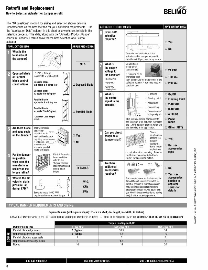
The “10 questions” method for sizing and selection shown below isrecommended as the best method for your actuation requirements. Usethe “Application Data” column in this chart as a worksheet to help in the selection process. This data, along with the “Actuator Product Range”charts in Sections 1 thru 3 allow for the best selection of a Belimoactuator.
Retrofit and ReplacementHow to Select an Actuator for damper retrofit
APPLICATION INFO APPLICATION DATA
1 What is the total area of the damper?
sq.ft.
2 Opposed blade or Parallel blade control construction?
L” x W” = Total sq inches/144 = total sq feet
Opposed Bladew/o seals 3 in-lb/sq feet*
Opposed Bladew/ seals 5 in-lb/sq feet
Parallel Bladew/o seals 4 in-lb/sq feet
Parallel Bladew/ seals 7 in-lb/sq feet
*Less than 1,000 feet perminute
❑ Opposed Blade
❑ Parallel Blade
3 Are there blade and edge sealson the damper?
This will impactthe properselection as theseals add resistancerequiring more torque.If unknown, usea worst casescenario, parallelblade with seals.
e
e.e
❑ Yes
❑ No
4 For the damperin question, what does themanufacturer specify as the torque rating?
If this informationis not availablerefer to the “typical damperrequirements andsizing” chartbelow.
in-lb/sq.ft.
5 What is the airvelocity, static pressure, or design CFM?
Systems above 1,000 FPMrequire additional actuator torque
_______W.G.
_______CFM
_______FPM
ACTUATOR REQUIREMENTS APPLICATION DATA
6 Is fail-safe actuationrequired?
Consider the application. Is theactuator and/or damper exposed tooutside air? If yes, use spring return.
❑ Yes
❑ No
7 What is the supply voltage to the actuator?• 24 VAC/DC
• 120 VAC
• 230 VACsingle phase
Do you needa step downtransformer?
If replacing an oilimmersed geartrain actuator, is the transformer in thedefective actuator? You may need topurchase one.
❑ 24 VAC
❑ 120 VAC
❑ 230 VAC
8 What is the control signal to the actuator?
• 2 position
• Floating point
• Modulating
• Sequencing
• “Non-standard” voltage signals
❑ On/Off
❑ Floating Point
❑ 2-10 VDC
❑ 0-10 VDC
❑ 4-20 mA
❑ PWM____range
❑ Other (MFT)
This will be a critical component to the selection of an actuator. Considerthe …MFT actuator product range andthe flexibility of its application.
9 Can you direct couple to a damper shaft?
Direct-coupling hasbecome theindustry standard. Some retrofitapplications
do not allow direct coupling. Refer tothe Belimo “Mounting & MethodsGuide” for application details.
❑ Yes
❑ No, seeaccessoriespage
10 Are there additional accessories required?
PA… SA…
KH-AF USKH-AF-1 US
K4-2 US
For example, some applications require the addition of an auxiliary switch forproof of position; a retrofit application may require an additional mounting bracket and linkage kit. We advise that you identify these needs prior to leaving the job site or ordering products.
❑ No
❑ Yes, seeaccessoriessection oractuatorseries fordetails
TYPICAL DAMPER REQUIREMENTS AND SIZING
Square Damper (with square shape): ft2 = h x w /144; (h= height, w= width, in inches)
EXAMPLE: Damper Area (8 ft2) x Rated Torque Loading of Damper (4 in-lb/ft2) = Total in-lb Required (32 in-lb) Belimo LF 35 in-lb/ LM 45 in-lb actuators
Torque Loading in-lb/ft2
Damper Blade Type < 1000 FPM 1000-2500 FPM 2500-3500 FPM
SQUA
RE
Parallel blade/edge seals 7 (Typical) 10.5 14Opposed blade/edge seals 5 (Typical) 7.5 10Parallel blade/no edge seals 4 6 8Opposed blade/no edge seals 3 4.5 6Round 10 14 20
800-543-9038 USA 866-805-7089 CANADA 203-791-8396 LATIN AMERICA
4
M40
045
- 10/
10 -
SUBJ
ECT
TO C
HANG
E. ©
BEL
IMO
AIRC
ONTR
OLS
(USA
), IN
C.
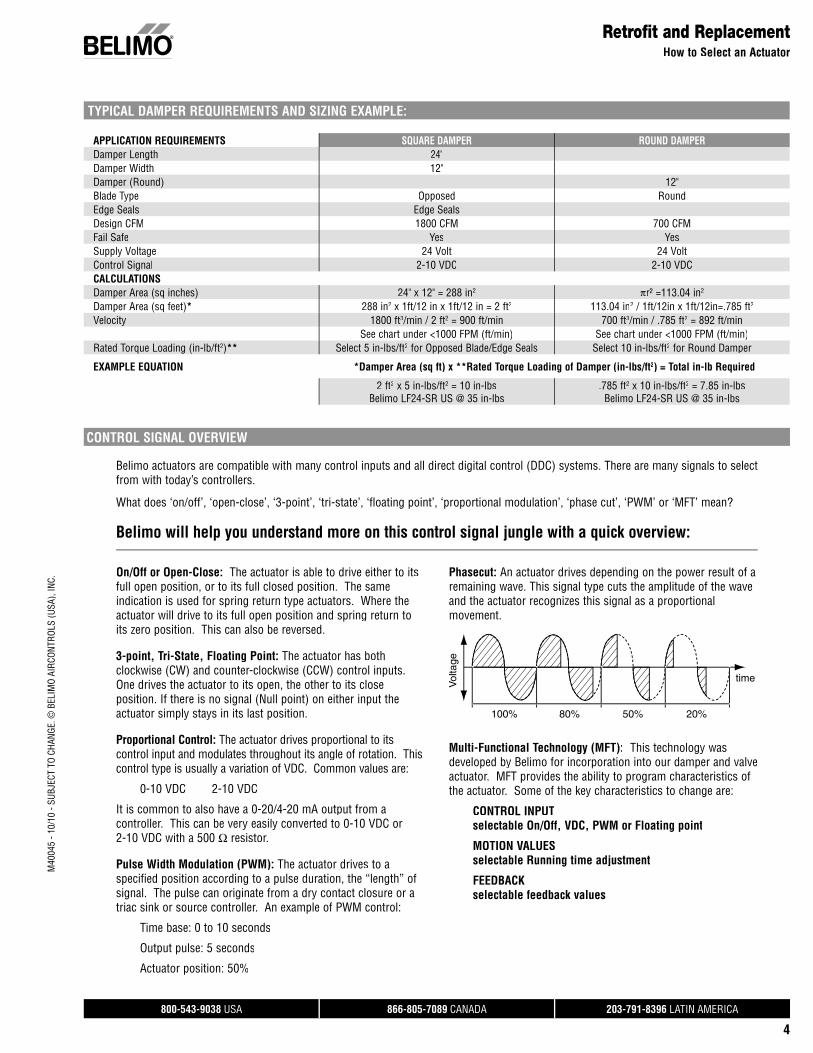
CONTROL SIGNAL OVERVIEW
Belimo actuators are compatible with many control inputs and all direct digital control (DDC) systems. There are many signals to selectfrom with today’s controllers.
What does ‘on/off’, ‘open-close’, ‘3-point’, ‘tri-state’, ‘floating point’, ‘proportional modulation’, ‘phase cut’, ‘PWM’ or ‘MFT’ mean?
Belimo will help you understand more on this control signal jungle with a quick overview:
On/Off or Open-Close: The actuator is able to drive either to itsfull open position, or to its full closed position. The sameindication is used for spring return type actuators. Where the actuator will drive to its full open position and spring return to its zero position. This can also be reversed.
3-point, Tri-State, Floating Point: The actuator has bothclockwise (CW) and counter-clockwise (CCW) control inputs. One drives the actuator to its open, the other to its closeposition. If there is no signal (Null point) on either input the actuator simply stays in its last position.
Proportional Control: The actuator drives proportional to itscontrol input and modulates throughout its angle of rotation. This control type is usually a variation of VDC. Common values are:
0-10 VDC 2-10 VDC
It is common to also have a 0-20/4-20 mA output from acontroller. This can be very easily converted to 0-10 VDC or 2-10 VDC with a 500 Ω resistor.
Pulse Width Modulation (PWM): The actuator drives to aspecified position according to a pulse duration, the “length” of signal. The pulse can originate from a dry contact closure or a triac sink or source controller. An example of PWM control:
Time base: 0 to 10 seconds
Output pulse: 5 seconds
Actuator position: 50%
Phasecut: An actuator drives depending on the power result of aremaining wave. This signal type cuts the amplitude of the waveand the actuator recognizes this signal as a proportional movement.
Multi-Functional Technology (MFT): This technology wasdeveloped by Belimo for incorporation into our damper and valve actuator. MFT provides the ability to program characteristics ofthe actuator. Some of the key characteristics to change are:
CONTROL INPUT selectable On/Off, VDC, PWM or Floating point
MOTION VALUES selectable Running time adjustment
FEEDBACK selectable feedback values
Retrofit and ReplacementHow to Select an Actuator
TYPICAL DAMPER REQUIREMENTS AND SIZING EXAMPLE:
APPLICATION REQUIREMENTS SQUARE DAMPER ROUND DAMPERDamper Length 24"Damper Width 12"Damper (Round) 12"Blade Type Opposed Round Edge Seals Edge SealsDesign CFM 1800 CFM 700 CFMFail Safe Yes YesSupply Voltage 24 Volt 24 VoltControl Signal 2-10 VDC 2-10 VDCCALCULATIONSDamper Area (sq inches) 24" x 12" = 288 in2 πr² =113.04 in2 Damper Area (sq feet)* 288 in2 x 1ft/12 in x 1ft/12 in = 2 ft2 113.04 in2 / 1ft/12in x 1ft/12in=.785 ft2
Velocity 1800 ft3/min / 2 ft2 = 900 ft/min 700 ft3/min / .785 ft2 = 892 ft/minSee chart under <1000 FPM (ft/min) See chart under <1000 FPM (ft/min)
Rated Torque Loading (in-lb/ft2)** Select 5 in-lbs/ft2 for Opposed Blade/Edge Seals Select 10 in-lbs/ft2 for Round Damper
EXAMPLE EQUATION *Damper Area (sq ft) x **Rated Torque Loading of Damper (in-lbs/ft2) = Total in-lb Required
2 ft2 x 5 in-lbs/ft2 = 10 in-lbsBelimo LF24-SR US @ 35 in-lbs
.785 ft2 x 10 in-lbs/ft2 = 7.85 in-lbsBelimo LF24-SR US @ 35 in-lbs
800-543-9038 USA 866-805-7089 CANADA 203-791-8396 LATIN AMERICA
5
M40
045
- 10/
10 -
SUBJ
ECT
TO C
HANG
E. ©
BEL
IMO
AIRC
ONTR
OLS
(USA
), IN
C.
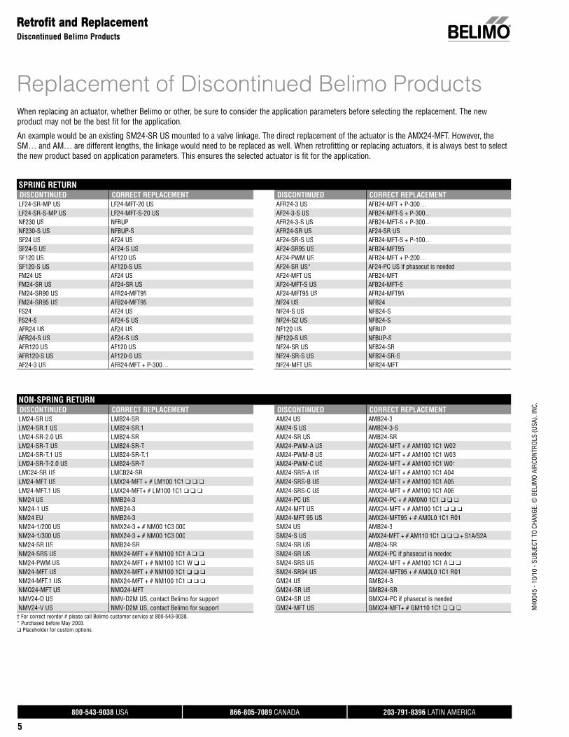
Retrofit and ReplacementDiscontinued Belimo Products
When replacing an actuator, whether Belimo or other, be sure to consider the application parameters before selecting the replacement. The new product may not be the best fit for the application.
An example would be an existing SM24-SR US mounted to a valve linkage. The direct replacement of the actuator is the AMX24-MFT. However, the SM… and AM… are different lengths, the linkage would need to be replaced as well. When retrofitting or replacing actuators, it is always best to selectthe new product based on application parameters. This ensures the selected actuator is fit for the application.
Replacement of Discontinued Belimo Products
SPRING RETURNDISCONTINUED CORRECT REPLACEMENT DISCONTINUED CORRECT REPLACEMENTLF24-SR-MP US LF24-MFT-20 US AFR24-3 US AFB24-MFT + P-300…LF24-SR-S-MP US LF24-MFT-S-20 US AF24-3-S US AFB24-MFT-S + P-300…NF230 US NFBUP AFR24-3-S US AFB24-MFT-S + P-300…NF230-S US NFBUP-S AFR24-SR US AF24-SR USSF24 US AF24 US AF24-SR-S US AFB24-MFT-S + P-100…SF24-S US AF24-S US AF24-SR95 US AFB24-MFT95SF120 US AF120 US AF24-PWM US AFB24-MFT + P-200…SF120-S US AF120-S US AF24-SR US* AF24-PC US if phasecut is neededFM24 US AF24 US AF24-MFT US AFB24-MFTFM24-SR US AF24-SR US AF24-MFT-S US AFB24-MFT-SFM24-SR90 US AFB24-MFT95 AF24-MFT95 US AFB24-MFT95FM24-SR95 US AFB24-MFT95 NF24 US NFB24FS24 AF24 US NF24-S US NFB24-SFS24-S AF24-S US NF24-S2 US NFB24-SAFR24 US AF24 US NF120 US NFBUPAFR24-S US AF24-S US NF120-S US NFBUP-SAFR120 US AF120 US NF24-SR US NFB24-SRAFR120-S US AF120-S US NF24-SR-S US NFB24-SR-SAF24-3 US AFB24-MFT + P-300… NF24-MFT US NFB24-MFT
NON-SPRING RETURNDISCONTINUED CORRECT REPLACEMENT DISCONTINUED CORRECT REPLACEMENTLM24-SR US LMB24-SR AM24 US AMB24-3LM24-SR.1 US LMB24-SR.1 AM24-S US AMB24-3-SLM24-SR-2.0 US LMB24-SR AM24-SR US AMB24-SRLM24-SR-T US LMB24-SR-T AM24-PWM-A US AMX24-MFT + # AM100 1C1 W02LM24-SR-T.1 US LMB24-SR-T.1 AM24-PWM-B US AMX24-MFT + # AM100 1C1 W03LM24-SR-T-2.0 US LMB24-SR-T AM24-PWM-C US AMX24-MFT + # AM100 1C1 W01LMC24-SR US LMCB24-SR AM24-SRS-A US AMX24-MFT + # AM100 1C1 A04LM24-MFT US LMX24-MFT + # LM100 1C1 ❑ ❑ ❑ AM24-SRS-B US AMX24-MFT + # AM100 1C1 A05LM24-MFT.1 US LMX24-MFT+ # LM100 1C1 ❑ ❑ ❑ AM24-SRS-C US AMX24-MFT + # AM100 1C1 A06NM24 US NMB24-3 AM24-PC US AMX24-PC + # AM0N0 1C1 ❑ ❑ ❑
NM24-1 US NMB24-3 AM24-MFT US AMX24-MFT + # AM100 1C1 ❑ ❑ ❑
NM24 EU NMB24-3 AM24-MFT 95 US AMX24-MFT95 + # AM0L0 1C1 R01NM24-1/200 US NMX24-3 + # NM00 1C3 000 SM24 US AMB24-3NM24-1/300 US NMX24-3 + # NM00 1C3 000 SM24-S US AMX24-MFT + # AM110 1C1 ❑ ❑ ❑ + S1A/S2ANM24-SR US NMB24-SR SM24-SR US AMB24-SRNM24-SRS US NMX24-MFT + # NM100 1C1 A ❑ ❑ SM24-SR US AMX24-PC if phasecut is neededNM24-PWM US NMX24-MFT + # NM100 1C1 W ❑ ❑ SM24-SRS US AMX24-MFT + # AM100 1C1 A ❑ ❑
NM24-MFT US NMX24-MFT + # NM100 1C1 ❑ ❑ ❑ SM24-SR94 US AMX24-MFT95 + # AM0L0 1C1 R01NM24-MFT.1 US NMX24-MFT + # NM100 1C1 ❑ ❑ ❑ GM24 US GMB24-3NMQ24-MFT US NMQ24-MFT GM24-SR US GMB24-SRNMV24-D US NMV-D2M US, contact Belimo for support GM24-SR US GMX24-PC if phasecut is neededNMV24-V US NMV-D2M US, contact Belimo for support GM24-MFT US GMX24-MFT+ # GM110 1C1 ❑ ❑ ❑
† For correct reorder # please call Belimo customer service at 800-543-9038.* Purchased before May 2003.❑ Placeholder for custom options.
800-543-9038 USA 866-805-7089 CANADA 203-791-8396 LATIN AMERICA
6
M40
045
- 10/
10 -
SUBJ
ECT
TO C
HANG
E. ©
BEL
IMO
AIRC
ONTR
OLS
(USA
), IN
C.
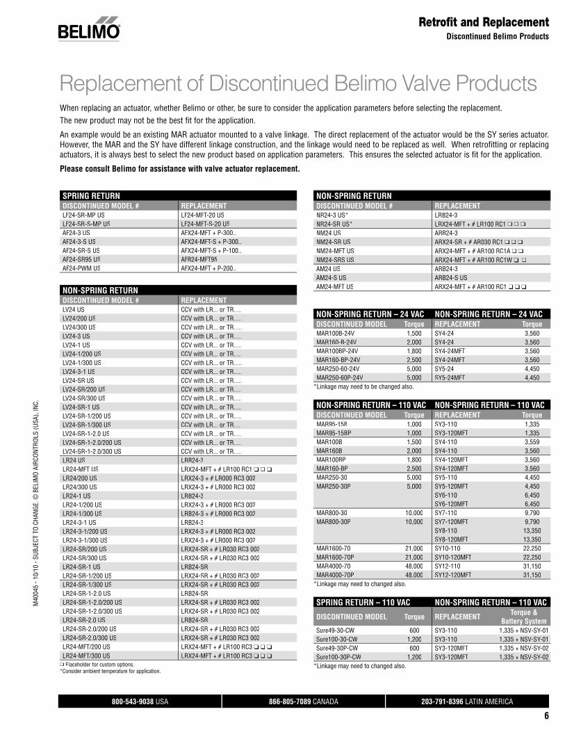
Retrofit and ReplacementDiscontinued Belimo Products
When replacing an actuator, whether Belimo or other, be sure to consider the application parameters before selecting the replacement. The new product may not be the best fit for the application.
An example would be an existing MAR actuator mounted to a valve linkage. The direct replacement of the actuator would be the SY series actuator. However, the MAR and the SY have different linkage construction, and the linkage would need to be replaced as well. When retrofitting or replacingactuators, it is always best to select the new product based on application parameters. This ensures the selected actuator is fit for the application.
Please consult Belimo for assistance with valve actuator replacement.
Replacement of Discontinued Belimo Valve Products
SPRING RETURNDISCONTINUED MODEL # REPLACEMENTLF24-SR-MP US LF24-MFT-20 USLF24-SR-S-MP US LF24-MFT-S-20 USAF24-3 US AFX24-MFT + P-300..AF24-3-S US AFX24-MFT-S + P-300..AF24-SR-S US AFX24-MFT-S + P-100..AF24-SR95 US AFB24-MFT95AF24-PWM US AFX24-MFT + P-200..
NON-SPRING RETURNDISCONTINUED MODEL # REPLACEMENTLV24 US CCV with LR... or TR….LV24/200 US CCV with LR... or TR….LV24/300 US CCV with LR... or TR….LV24-3 US CCV with LR... or TR….LV24-1 US CCV with LR... or TR….LV24-1/200 US CCV with LR... or TR….LV24-1/300 US CCV with LR... or TR….LV24-3-1 US CCV with LR... or TR….LV24-SR US CCV with LR... or TR….LV24-SR/200 US CCV with LR... or TR….LV24-SR/300 US CCV with LR... or TR….LV24-SR-1 US CCV with LR... or TR….LV24-SR-1/200 US CCV with LR... or TR….LV24-SR-1/300 US CCV with LR... or TR….LV24-SR-1-2.0 US CCV with LR... or TR….LV24-SR-1-2.0/200 US CCV with LR... or TR….LV24-SR-1-2.0/300 US CCV with LR... or TR….LR24 US LRB24-3LR24-MFT US LRX24-MFT + # LR100 RC1 ❑ ❑ ❑
LR24/200 US LRX24-3 + # LR000 RC3 002LR24/300 US LRX24-3 + # LR000 RC3 002LR24-1 US LRB24-3LR24-1/200 US LRX24-3 + # LR000 RC3 002LR24-1/300 US LRB24-3 + # LR000 RC3 002LR24-3-1 US LRB24-3LR24-3-1/200 US LRX24-3 + # LR000 RC3 002LR24-3-1/300 US LRX24-3 + # LR000 RC3 002LR24-SR/200 US LRX24-SR + # LR030 RC3 002LR24-SR/300 US LRX24-SR + # LR030 RC3 002LR24-SR-1 US LRB24-SRLR24-SR-1/200 US LRX24-SR + # LR030 RC3 002LR24-SR-1/300 US LRX24-SR + # LR030 RC3 002LR24-SR-1-2.0 US LRB24-SRLR24-SR-1-2.0/200 US LRX24-SR + # LR030 RC3 002LR24-SR-1-2.0/300 US LRX24-SR + # LR030 RC3 002LR24-SR-2.0 US LRB24-SRLR24-SR-2.0/200 US LRX24-SR + # LR030 RC3 002LR24-SR-2.0/300 US LRX24-SR + # LR030 RC3 002LR24-MFT/200 US LRX24-MFT + # LR100 RC3 ❑ ❑ ❑
LR24-MFT/300 US LRX24-MFT + # LR100 RC3 ❑ ❑ ❑
❑ Placeholder for custom options.*Consider ambient temperature for application.
NON-SPRING RETURNDISCONTINUED MODEL # REPLACEMENTNR24-3 US* LRB24-3NR24-SR US* LRX24-MFT + # LR100 RC1 ❑ ❑ ❑
NM24 US ARB24-3NM24-SR US ARX24-SR + # AR030 RC1 ❑ ❑ ❑
NM24-MFT US ARX24-MFT + # AR100 RC1A ❑ ❑
NM24-SRS US ARX24-MFT + # AR100 RC1W ❑ ❑AM24 US ARB24-3AM24-S US ARB24-S USAM24-MFT US ARX24-MFT + # AR100 RC1 ❑ ❑ ❑
NON-SPRING RETURN – 24 VAC NON-SPRING RETURN – 24 VACDISCONTINUED MODEL Torque REPLACEMENT TorqueMAR100B-24V 1,500 SY4-24 3,560MAR160-B-24V 2,000 SY4-24 3,560MAR100BP-24V 1,800 SY4-24MFT 3,560MAR160-BP-24V 2,500 SY4-24MFT 3,560MAR250-60-24V 5,000 SY5-24 4,450MAR250-60P-24V 5,000 SY5-24MFT 4,450
*Linkage may need to be changed also.
NON-SPRING RETURN – 110 VAC NON-SPRING RETURN – 110 VACDISCONTINUED MODEL Torque REPLACEMENT TorqueMAR95-15B 1,000 SY3-110 1,335MAR95-15BP 1,000 SY3-120MFT 1,335MAR100B 1,500 SY4-110 3,559MAR160B 2,000 SY4-110 3,560MAR100BP 1,800 SY4-120MFT 3,560MAR160-BP 2,500 SY4-120MFT 3,560MAR250-30 5,000 SY5-110 4,450MAR250-30P 5,000 SY5-120MFT 4,450
SY6-110 6,450SY6-120MFT 6,450
MAR800-30 10,000 SY7-110 9,790MAR800-30P 10,000 SY7-120MFT 9,790
SY8-110 13,350SY8-120MFT 13,350
MAR1600-70 21,000 SY10-110 22,250MAR1600-70P 21,000 SY10-120MFT 22,250MAR4000-70 48,000 SY12-110 31,150MAR4000-70P 48,000 SY12-120MFT 31,150
*Linkage may need to changed also.
SPRING RETURN – 110 VAC NON-SPRING RETURN – 110 VAC
DISCONTINUED MODEL Torque REPLACEMENT Torque &Battery System
Sure49-30-CW 600 SY3-110 1,335 + NSV-SY-01Sure100-30-CW 1,200 SY3-110 1,335 + NSV-SY-01Sure49-30P-CW 600 SY3-120MFT 1,335 + NSV-SY-02Sure100-30P-CW 1,200 SY3-120MFT 1,335 + NSV-SY-02
*Linkage may need to changed also.
800-543-9038 USA 866-805-7089 CANADA 203-791-8396 LATIN AMERICA
7
M40
045
- 10/
10 -
SUBJ
ECT
TO C
HANG
E. ©
BEL
IMO
AIRC
ONTR
OLS
(USA
), IN
C.
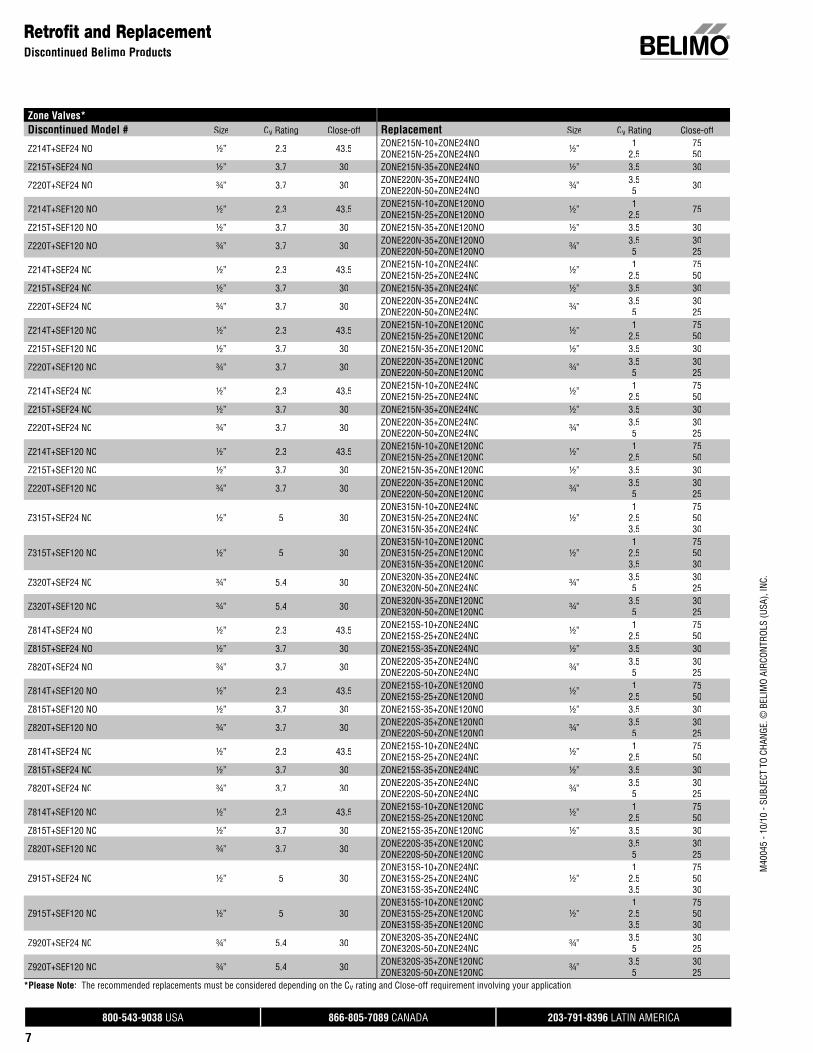
Retrofit and ReplacementDiscontinued Belimo Products
Zone Valves* Discontinued Model # Size Cv Rating Close-off Replacement Size Cv Rating Close-off
Z214T+SEF24 NO ½” 2.3 43.5 ZONE215N-10+ZONE24NOZONE215N-25+ZONE24NO ½” 1
2.57550
Z215T+SEF24 NO ½” 3.7 30 ZONE215N-35+ZONE24NO ½” 3.5 30
Z220T+SEF24 NO ¾” 3.7 30 ZONE220N-35+ZONE24NOZONE220N-50+ZONE24NO ¾” 3.5
5 30
Z214T+SEF120 NO ½” 2.3 43.5 ZONE215N-10+ZONE120NOZONE215N-25+ZONE120NO ½” 1
2.5 75
Z215T+SEF120 NO ½” 3.7 30 ZONE215N-35+ZONE120NO ½” 3.5 30
Z220T+SEF120 NO ¾” 3.7 30 ZONE220N-35+ZONE120NOZONE220N-50+ZONE120NO ¾” 3.5
53025
Z214T+SEF24 NC ½” 2.3 43.5 ZONE215N-10+ZONE24NCZONE215N-25+ZONE24NC ½” 1
2.57550
Z215T+SEF24 NC ½” 3.7 30 ZONE215N-35+ZONE24NC ½” 3.5 30
Z220T+SEF24 NC ¾” 3.7 30 ZONE220N-35+ZONE24NCZONE220N-50+ZONE24NC ¾” 3.5
53025
Z214T+SEF120 NC ½” 2.3 43.5 ZONE215N-10+ZONE120NCZONE215N-25+ZONE120NC ½” 1
2.57550
Z215T+SEF120 NC ½” 3.7 30 ZONE215N-35+ZONE120NC ½” 3.5 30
Z220T+SEF120 NC ¾” 3.7 30 ZONE220N-35+ZONE120NCZONE220N-50+ZONE120NC ¾” 3.5
53025
Z315T+SEF24 NC ½” 5 30ZONE315N-10+ZONE24NCZONE315N-25+ZONE24NCZONE315N-35+ZONE24NC
½”1
2.53.5
755030
Z315T+SEF120 NC ½” 5 30ZONE315N-10+ZONE120NCZONE315N-25+ZONE120NCZONE315N-35+ZONE120NC
½”1
2.53.5
755030
Z320T+SEF24 NC ¾” 5.4 30 ZONE320N-35+ZONE24NCZONE320N-50+ZONE24NC ¾” 3.5
53025
Z320T+SEF120 NC ¾” 5.4 30 ZONE320N-35+ZONE120NCZONE320N-50+ZONE120NC ¾” 3.5
53025
Z814T+SEF24 NO ½” 2.3 43.5 ZONE215S-10+ZONE24NCZONE215S-25+ZONE24NC ½” 1
2.57550
Z815T+SEF24 NO ½” 3.7 30 ZONE215S-35+ZONE24NO ½” 3.5 30
Z820T+SEF24 NO ¾” 3.7 30 ZONE220S-35+ZONE24NOZONE220S-50+ZONE24NO ¾” 3.5
53025
Z814T+SEF120 NO ½” 2.3 43.5 ZONE215S-10+ZONE120NOZONE215S-25+ZONE120NO ½” 1
2.57550
Z815T+SEF120 NO ½” 3.7 30 ZONE215S-35+ZONE120NO ½” 3.5 30
Z820T+SEF120 NO ¾” 3.7 30 ZONE220S-35+ZONE120NOZONE220S-50+ZONE120NO ¾” 3.5
53025
Z814T+SEF24 NC ½” 2.3 43.5 ZONE215S-10+ZONE24NCZONE215S-25+ZONE24NC ½” 1
2.57550
Z815T+SEF24 NC ½” 3.7 30 ZONE215S-35+ZONE24NC ½” 3.5 30
Z820T+SEF24 NC ¾” 3.7 30 ZONE220S-35+ZONE24NCZONE220S-50+ZONE24NC ¾” 3.5
53025
Z814T+SEF120 NC ½” 2.3 43.5 ZONE215S-10+ZONE120NCZONE215S-25+ZONE120NC ½” 1
2.57550
Z815T+SEF120 NC ½” 3.7 30 ZONE215S-35+ZONE120NC ½” 3.5 30
Z820T+SEF120 NC ¾” 3.7 30 ZONE220S-35+ZONE120NCZONE220S-50+ZONE120NC
3.55
3025
Z915T+SEF24 NC ½” 5 30ZONE315S-10+ZONE24NCZONE315S-25+ZONE24NCZONE315S-35+ZONE24NC
½”1
2.53.5
755030
Z915T+SEF120 NC ½” 5 30ZONE315S-10+ZONE120NCZONE315S-25+ZONE120NCZONE315S-35+ZONE120NC
½”1
2.53.5
755030
Z920T+SEF24 NC ¾” 5.4 30 ZONE320S-35+ZONE24NCZONE320S-50+ZONE24NC ¾” 3.5
53025
Z920T+SEF120 NC ¾” 5.4 30 ZONE320S-35+ZONE120NCZONE320S-50+ZONE120NC ¾” 3.5
53025
*Please Note: The recommended replacements must be considered depending on the Cv rating and Close-off requirement involving your application.
800-543-9038 USA 866-805-7089 CANADA 203-791-8396 LATIN AMERICA
8
M40
045
- 10/
10 -
SUBJ
ECT
TO C
HANG
E. ©
BEL
IMO
AIRC
ONTR
OLS
(USA
), IN
C.
Use FSNF for dampers >4 sq.ft. ML4105A1000 FSLF120 Yes Yes On/Off 120 120 30 30 14, 25, 75 15
All HW 50 in-lb passed UL555S samedamper sizes as FSLF. Torque ratingswere changed.
ML4105B1009 FSLF120 Yes Yes On/Off 120 120 30 30 14, 25, 75 15M4105C1008 FSLF230 Yes Yes On/Off 230 230 30 30 14, 25, 75 15
ML4105D1007 FSLF230 Yes Yes On/Off 230 230 30 30 14, 25, 75 15ML4115A1009 FSLF120 Yes Yes On/Off 120 120 30 30 18 15ML4115B1008 FSLF120 Yes Yes On/Off 120 120 30 30 18 15
ML4115C FSLF230 Yes Yes On/Off 230 230 30 30 18 15ML4115D FSLF230 Yes Yes On/Off 230 230 30 30 18 15ML4115H FSLF120 Yes Yes On/Off 120 120 30 30 18 15ML4115J FSLF120 Yes Yes On/Off 120 120 30 30 18 15ML4202 FSLF120 Yes Yes On/Off 120 120 20 30 25 15ML4302 FSLF120 Yes Yes On/Off 120 120 20 30 25 15ML4702 FSLF230 Yes Yes On/Off 230 230 20 30 25 15ML4802 FSLF230 Yes Yes On/Off 230 230 20 30 25 15
ML8105A1006 FSLF24 Yes Yes On/Off 24 24 30 30 25 15ML8105B1005 FSLF24 Yes Yes On/Off 24 24 30 30 25 15ML8115A1005 FSLF24 Yes Yes On/Off 24 24 30 30 18 15ML8115B1004 FSLF24 Yes Yes On/Off 24 24 30 30 18 15
ML8115H FSLF24 Yes Yes On/Off 24 24 30 30 22 15ML8115J FSLF24 Yes Yes On/Off 24 24 30 30 22 15ML8202 FSLF24 Yes Yes On/Off 24 24 20 30 25 15ML8302 FSLF24 Yes Yes On/Off 24 24 20 30 25 15
Single FSAF is limited to 12 sq.ft. &250ºF. If fast speed needed, use FSNF.
MS4120F1006 FSAF120 Yes Yes On/Off 120 120 175 133 15 <75/20MS4120F1204 FSAF120-S Yes Yes On/Off 120 120 175 133 15 <75/20
UL555S listing of FSNF is 8 sq.ft. 350ºFfor Ruskin. 12 sq.ft. for others 350ºF.
MS4209F FSNF120 Yes Yes On/Off 120 120 80 70 14, 25, 75 15MS4309F FSNF120 Yes Yes On/Off 120 120 80 70 14, 25, 75 15
Single FSAF is limited to 12 sq.ft. &250ºF. If fast speed needed, use FSNF.
MS4620F1005 FSAF230 Yes Yes On/Off 230 230 175 133 15 <75/20MS4620F1203 FSAF230-S Yes Yes On/Off 230 230 175 133 15 <75/20
UL555S listing of FSNF is 8 sq.ft. 350ºFfor Ruskin. 12 sq.ft. for others 350ºF.
MS4709F FSNF230 Yes Yes On/Off 230 230 80 70 14, 25, 75 15MS4809F FSNF230 Yes Yes On/Off 230 230 80 70 14, 25, 75 15
Single FSAF is limited to 12 sq.ft. &250ºF. If fast speed needed, use FSNF.
MS8120F1002 FSAF24 Yes Yes On/Off 24 24 175 133 15 <75/20MS8120F1200 FSAF24-S Yes Yes On/Off 24 24 175 133 15 <75/20
UL555S listing of FSNF is 8 sq.ft. 350ºFfor Ruskin. 12 sq.ft. for others 350ºF.
MS8209F FSNF24 Yes Yes On/Off 24 24 80 70 14, 25, 75 15MS8309F FSNF24 Yes Yes On/Off 24 24 80 70 14, 25, 75 15
Auxiliary switch packages 32003532-002 AuxSwitch Package
Use Belimo -Smodels N/A N/A N/A N/A N/A N/A N/A N/A N/A
Model Numbers
NOTES HONEYWELL BELIMO SpringReturn Control Signal Power Torque (in-lb) Timing (seconds) Timing Drive/Spring
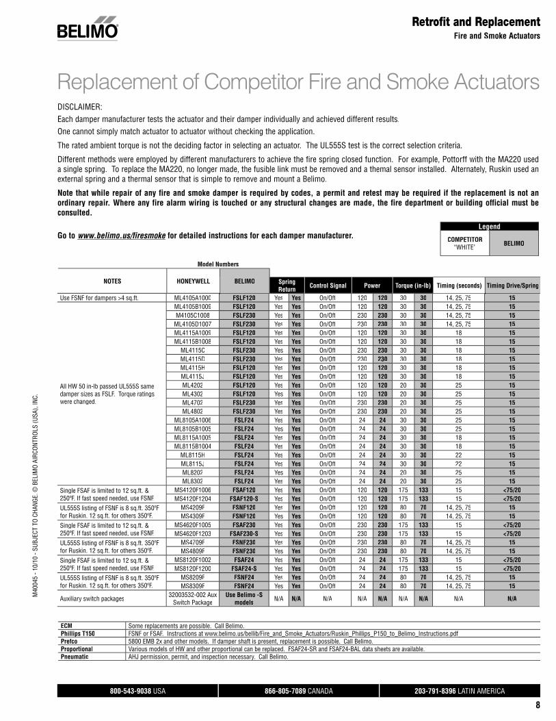
DISCLAIMER:Each damper manufacturer tests the actuator and their damper individually and achieved different results.One cannot simply match actuator to actuator without checking the application.
The rated ambient torque is not the deciding factor in selecting an actuator. The UL555S test is the correct selection criteria.
Different methods were employed by different manufacturers to achieve the fire spring closed function. For example, Pottorff with the MA220 useda single spring. To replace the MA220, no longer made, the fusible link must be removed and a themal sensor installed. Alternately, Ruskin used anexternal spring and a thermal sensor that is simple to remove and mount a Belimo.
Note that while repair of any fire and smoke damper is required by codes, a permit and retest may be required if the replacement is not anordinary repair. Where any fire alarm wiring is touched or any structural changes are made, the fire department or building official must be consulted.
Go to www.belimo.us/firesmoke/ for detailed instructions for each damper manufacturer.e
Replacement of Competitor Fire and Smoke Actuators
Retrofit and ReplacementFire and Smoke Actuators
Legend
COMPETITOR“WHITE” BELIMO
ECM Some replacements are possible. Call Belimo. p pPhillips T150p FSNF or FSAF. Instructions at www.belimo.us/bellib/Fire_and_Smoke_Actuators/Ruskin_Phillips_P150_to_Belimo_Instructions.pdfp pPrefco 5800 EMB 2x and other models. If damper shaft is present, replacement is possible. Call Belimo.p p p pProportionalp Various models of HW and other proportional can be replaced. FSAF24-SR and FSAF24-BAL data sheets are available.p p pPneumatic AHJ permission, permit, and inspection necessary. Call Belimo.p p p y
800-543-9038 USA 866-805-7089 CANADA 203-791-8396 LATIN AMERICA
9
M40
045
- 10/
10 -
SUBJ
ECT
TO C
HANG
E. ©
BEL
IMO
AIRC
ONTR
OLS
(USA
), IN
C.
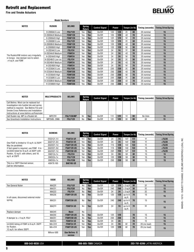
The Ruskin/HW motors vary irregularlyin torque. Use damper size to select.>4 sq.ft. use FSNF.
H-2000A/3 Low FSLF120 Yes Yes On/Off 120 120 20 30 25 nominal 15H-2000A/6 Medium FSNF120 Yes Yes On/Off 120 120 42 70 25 nominal 15
H-2000A/8 High FSNF120 Yes Yes On/Off 120 120 56 70 25 nominal 15H-2000B/3 Low FSLF120 Yes Yes On/Off 120 120 20 30 25 nominal 15
H-2000B/6 Medium FSNF120 Yes Yes On/Off 120 120 42 30 25 nominal 15H-2000B/8 High FSNF120 Yes Yes On/Off 120 120 56 30 25 nominal 15H-2024A/3 Low FSLF24 Yes Yes On/Off 24 24 20 30 25 nominal 15
H-2024A/6 Medium FSNF24 Yes Yes On/Off 24 24 42 70 25 nominal 15H-2024A/8 High FSNF24 Yes Yes On/Off 24 24 56 70 25 nominal 15
H-2024B/3 Low cw FSLF24 Yes Yes On/Off 24 24 20 30 25 nominal 15H-2024B/6 Medium FSNF24 Yes Yes On/Off 24 24 42 70 25 nominal 15
H-2024B/8 High FSNF24 Yes Yes On/Off 24 24 56 70 25 nominal 15H-2230A/3 Low FSLF230 Yes Yes On/Off 230 230 20 30 25 nominal 15
H-2230A/6 Medium FSNF230 Yes Yes On/Off 230 230 42 70 25 nominal 15H-2230A/8 High FSNF230 Yes Yes On/Off 230 230 56 70 25 nominal 15H-2230B/3 Low FSLF230 Yes Yes On/Off 230 230 20 30 25 nominal 15
H-2230B/6 Medium FSNF230 Yes Yes On/Off 230 230 42 70 25 nominal 15H-2230B/8 High FSNF230 Yes Yes On/Off 230 230 56 70 25 nominal 15
Call Belimo. Most can be replaced butinvestigation into fusible link and springmethod is required. See Belimo Fire andSmoke Cross Reference and InstallationInstructions at www.belimo.us/fi resmokeCall Ruskin rep. MP is a Ruskin kit. MP2781 FSLF120/MP No Yes On/Off 115 120 10 30 No Data 15See Greenheck Installation Instructions MP2585, 2986 FSLF120 No Yes On/Off 120 120 30 30 30 15
One FSAF is limited to 12 sq.ft. & 250ºF. May be paralleled.If fast speed is required, use FSNF. It isUL555S listed for 8 sq.ft. at 350ºF withRuskin, 12 sq.ft. with others, and 16sq.ft. at 250ºF.
GGD121.1U FSAF24 US Yes Yes On/Off 24 24 142 133 15 <75/20GGD121.3U FSAF24 US Yes Yes On/Off 24 24 142 133 15 <75/20GGD221.1U FSAF120 US Yes Yes On/Off 115 120 142 133 15 <75/20GGD221.3U FSAF120 US Yes Yes On/Off 115 120 142 133 15 <75/20GGD321.1U FSAF230 US Yes Yes On/Off 230 230 142 133 15 <75/20GND12x.1x FSLF24 Yes Yes On/Off 24 24 50 30 15 15GND22x.1x FSLF120 Yes Yes On/Off 120 120 50 30 15 15GND32x.1x FSLF230 Yes Yes On/Off 230 230 50 30 15 15
This is a 165ºF thermal sensor. Call for information.
ASK79.165 BAE165 US
See General Notes MA220 FSLF120 No Yes On/Off 120 120 < 3 sq.ft 30 20 15
In all cases, disconnect external motorspring.
MA221 FSLF230 No Yes On/Off 240 240 < 3 sq.ft 30 20 15MA223 FSLF24 No Yes On/Off 24 24 < 3 sq.ft 30 20 15MA230 FSNF120 US No Yes On/Off 120 120 up to 8
sq.ft.70 15 15
MA231 FSNF230 US No Yes On/Off 240 240 up to 8sq.ft.
70 15 15
MA233 FSNF24 US No Yes On/Off 24 24 up to 8sq.ft.
70 30 15
Replace damper MA240 None No
If damper is < 4 sq.ft. FSLFMA250 FSNF120 US No Yes On/Off 120 120 70 15 15MA251 FSNF230 US No Yes On/Off 230 230 70 15 15MA253 FSNF24 US No Yes On/Off 24 24 70 15 15
UL555S listing of FSNF is 8 sq.ft. 350ºFfor Ruskin.12 sq.ft. for others 350ºF.
MA-318 FSNF24 US Yes Yes On/Off 24 24 60 70 20 (no load) 15MA-418 FSNF120 US Yes Yes On/Off 120 120 60 70 20 (no load) 15
MAxxx-500 Use Belimo -Sversion
Retrofit and ReplacementFire and Smoke Actuators
Model Numbers
NOTES RUSKIN BELIMO SpringReturn Control Signal Power Torque (in-lb) Timing (seconds) Timing Drive/Spring
NOTES MULTIPRODUCTS BELIMO SpringReturn Control Signal Power Torque (in-lb) Timing (seconds) Timing Drive/Spring
NOTES SIEMENS BELIMO SpringReturn Control Signal Power Torque (in-lb) Timing (seconds) Timing Drive/Spring
NOTES SIEBE BELIMO SpringReturn Control Signal Power Torque (in-lb) Timing (seconds) Timing Drive/Spring
800-543-9038 USA 866-805-7089 CANADA 203-791-8396 LATIN AMERICA
10
M40
045
- 10/
10 -
SUBJ
ECT
TO C
HANG
E. ©
BEL
IMO
AIRC
ONTR
OLS
(USA
), IN
C.
Model Numbers
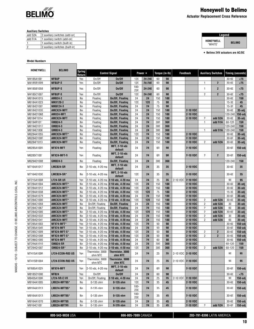
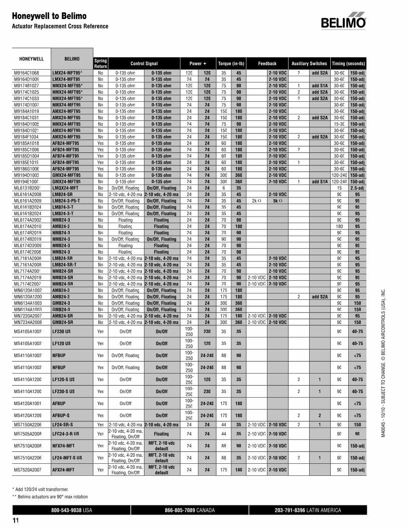
HONEYWELL BELIMO SpringReturn Control Signal Power Torque (in-lb) Feedback Auxiliary Switches Timing (seconds)
M4185A1001 NFBUP Yes On/Off On/Off 120 24-240 60 90 30-60 <75M4185B1009 NFBUP-S Yes On/Off On/Off 120 24-240 60 90 1 2 30-60 <75
M4185B1058 NFBUP-S Yes On/Off On/Off 100-230 24-240 60 90 1 2 30-60 <75
M4185C1007 NFBUP-S Yes On/Off On/Off 120 24-240 60 90 2 2 30-60 <75M6184A1015 AMB24-3 No Floating On/Off, Floating 24 24 150 180 30-60 150M6184A1023 NMX120-3 No Floating On/Off, Floating 120 120 75 90 15-30 45M6184D1001 NMBC24-3 No Floating On/Off, Floating 24 24 75 90 15-30 45M6184D1035 AMCX24-MFT No Floating On/Off, Floating 24 24 150 180 2-10 VDC 30-60 35-adjM6184D1068 AMX24-MFT No Floating On/Off, Floating 24 24 150 180 2-10 VDC 120-240 150-adjM6184F1014 AMCX24-MFT No Floating On/Off, Floating 24 24 150 180 2-10 VDC 2 add S2A 30-60 35-adjM6194B1011 GMB24-3 No Floating On/Off, Floating 24 24 300 360 1 add S1A 60-120 150M6194D1017 GMB24-3 No Floating On/Off, Floating 24 24 300 360 120-240 150M6194E1006 GMB24-3 No Floating On/Off, Floating 24 24 300 360 1 add S1A 120-240 150M6284A1055 AMCX24-MFT* No Floating On/Off, Floating 120 24 150 180 2-10 VDC 30-60 35-adjM6284D1000 AMCX24-MFT No Floating On/Off, Floating 24 24 150 180 2-10 VDC 30-60 35-adjM6284F1013 AMCX24-MFT No Floating On/Off, Floating 24 24 150 180 2-10 VDC 2 add S2A 30-60 35-adj
M6285A1005 NFX24-MFT Yes Floating MFT, 2-10 vdc default 24 24 60 90 2-10 VDC 30-60 150-adj
M6285C1001 NFX24-MFT-S Yes Floating MFT, 2-10 vdc default 24 24 60 90 2-10 VDC 2 2 30-60 150-adj
M6294D1008 GMB24-3 No Floating On/Off, Floating 24 24 300 360 120-240 150
M7164A1017 LMCB24-SR No 2-10 vdc, 4-20 ma MFT, 2-10 vdc default 24 24 35 35 2-10 VDC 30-60 35
M7164G1030 LMCB24-SR* No 2-10 vdc, 4-20 ma MFT, 2-10 vdc default 120 24 35 35 2-10 VDC 30-60 35
M7215A1008 LF24-SR US Yes 2-10 vdc, 4-20 ma 2-10 vdc, 4-20 ma 24 24 25 35 2-10 VDC 2-10 VDC 90 95M7284A1004 AMCX24-MFT* No 2-10 vdc, 4-20 ma 2-10 vdc, 4-20 ma 120 24 150 180 2-10 VDC 30-60 35-adjM7284A1012 AMCX24-MFT* No 2-10 vdc, 4-20 ma 2-10 vdc, 4-20 ma 120 24 150 180 2-10 VDC 30-60 35-adjM7284A1038 AMCX24-MFT* No 2-10 vdc, 4-20 ma 2-10 vdc, 4-20 ma 120 120 75 180 2-10 VDC 15-30 35-adjM7284A1079 AMCX24-MFT No 2-10 vdc, 4-20 ma 2-10 vdc, 4-20 ma 24 24 150 180 2-10 VDC 30-60 35-adjM7284C1000 AMCX24-MFT* No 2-10 vdc, 4-20 ma 2-10 vdc, 4-20 ma 120 120 150 180 2-10 VDC 2 add S2A 30-60 35-adjM7284C1059 AMCX24-MFT No On/Off, Floating On/Off, Floating 24 24 150 180 2-10 VDC 2 add S2A 30 35-adjM7284C1067 AMCX24-MFT No On/Off, Floating On/Off, Floating 24 24 150 180 2-10 VDC 2 add S2A 60 35-adjM7284Q1009 AMCX24-MFT* No 2-10 vdc, 4-20 ma 2-10 vdc, 4-20 ma 120 120 150 180 2-10 VDC 2 add S2A 30-60 35-adjM7284Q1033 AMCX24-MFT No 2-10 vdc, 4-20 ma 2-10 vdc, 4-20 ma 24 24 150 180 2-10 VDC 2 add S2A 30 35-adjM7284Q1041 AMCX24-MFT No 2-10 vdc, 4-20 ma 2-10 vdc, 4-20 ma 24 24 150 180 2-10 VDC 2 add S2A 60 35-adjM7285A1003 NFX24-MFT* Yes 2-10 vdc, 4-20 ma 2-10 vdc, 4-20 ma 120 24 50 90 2-10 VDC 30-60 150-adjM7285A1045 NFX24-MFT Yes 2-10 vdc, 4-20 ma 2-10 vdc, 4-20 ma 24 24 50 90 2-10 VDC 30-60 150-adjM7285C1009 NFX24-MFT-S* Yes 2-10 vdc, 4-20 ma 2-10 vdc, 4-20 ma 120 24 50 90 2-10 VDC 2 2 30-60 150-adjM7285Q1008 NFX24-MFT-S* Yes 2-10 vdc, 4-20 ma 2-10 vdc, 4-20 ma 120 24 50 90 2-10 VDC 2 2 30-60 150-adjM7286G1009 NFX24-MFT Yes 2-10 vdc, 4-20 ma 2-10 vdc, 4-20 ma 24 24 60 90 2-10 VDC 30-60 150-adjM7294A1010 GMB24-SR No 2-10 vdc, 4-20 ma 2-10 vdc, 4-20 ma 24 24 300 360 2-10 VDC 60-120 150M7294Q1007 GMB24-SR* No 2-10 vdc, 4-20 ma 2-10 vdc, 4-20 ma 120 24 300 360 2-10 VDC 2 add S2A 60-120 150
M7415A1006 LF24-ECON-R03 US Yes Thermistor, 3000 ohm NTC
Thermistor, 3000ohm NTC 24 24 25 35 2-10 VDC 2-10 VDC 90 95
M7415B1004 LF24-ECON-R03 US Yes Thermistor, 3000 ohm NTC
Thermistor, 3000ohm NTC 24 24 25 35 2-10 VDC 2-10 VDC 90 95
M7685A1025 NFX24-MFT Yes 2-10 vdc, 4-20 ma MFT, 2-10 vdc default 24 24 60 90 2-10 VDC 30-60 150-adj
M8185D1006 NFB24 Yes On/Off On/Off 24 24 60 90 30-60 <75M8405A1006 LF24-SR-E US Yes On/Off, Floating 2-10 vdc, 4-20 ma 24 24 25 35 2-10 VDC 2-10 VDC 90 150-adjM9164A1005 LMX24-MFT95* No 0-135 ohm 0-135 ohm 120 24 35 45 2-10 VDC 30-60 150-adj
M9164A1013 LMX24-MFT95* No 0-135 ohm 0-135 ohm 100-230 24 35 45 2-10 VDC 30-60 150-adj
M9164A1013 LMX24-MFT95* No 0-135 ohm 0-135 ohm 100-230 24 35 45 2-10 VDC 30-60 150-adj
M9164A1070 LMX24-MFT95 No 0-135 ohm 0-135 ohm 24 24 35 45 2-10 VDC 30-60 150-adjM9164C1001 LMX24-MFT95 No 0-135 ohm 0-135 ohm 24 24 35 45 2-10 VDC 2 add S2A 30-60 150-adj
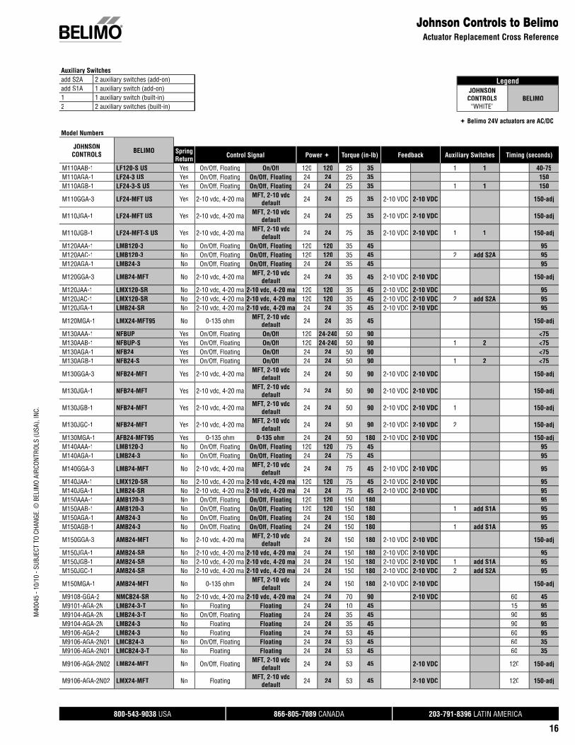
Auxiliary Switchesadd S2A 2 auxiliary switches (add-on)add S1A 1 auxiliary switch (add-on)1 1 auxiliary switch (built-in)2 2 auxiliary switches (built-in)
Legend
HONEYWELL“WHITE” BELIMO
Belimo 24V actuators are AC/DC
Honeywell to BelimoActuator Replacement Cross Reference
800-543-9038 USA 866-805-7089 CANADA 203-791-8396 LATIN AMERICA
11
M40
045
- 10/
10 -
SUBJ
ECT
TO C
HANG
E. ©
BEL
IMO
AIRC
ONTR
OLS
(USA
), IN
C.
Honeywell to BelimoActuator Replacement Cross Reference
M9164C1068 LMX24-MFT95* No 0-135 ohm 0-135 ohm 120 120 35 45 2-10 VDC 2 add S2A 30-60 150-adjM9164D1009 LMX24-MFT95 No 0-135 ohm 0-135 ohm 24 24 35 45 2-10 VDC 30-60 150-adjM9174B1027 NMX24-MFT95* No 0-135 ohm 0-135 ohm 120 120 75 90 2-10 VDC 1 add S1A 30-60 150-adjM9174C1025 NMX24-MFT95* No 0-135 ohm 0-135 ohm 120 120 75 90 2-10 VDC 2 add S2A 30-60 150-adjM9174C1033 NMX24-MFT95* No 0-135 ohm 0-135 ohm 120 120 75 90 2-10 VDC 2 add S2A 30-60 150-adjM9174D1007 NMX24-MFT95 No 0-135 ohm 0-135 ohm 24 24 75 90 2-10 VDC 30-60 150-adjM9184A1019 AMX24-MFT95 No 0-135 ohm 0-135 ohm 24 24 150 180 2-10 VDC 30-60 150-adjM9184C1031 AMX24-MFT95 No 0-135 ohm 0-135 ohm 24 24 150 180 2-10 VDC 2 add S2A 30-60 150-adjM9184D1005 NMX24-MFT95 No 0-135 ohm 0-135 ohm 24 24 75 90 2-10 VDC 15-30 150-adjM9184D1021 AMX24-MFT95 No 0-135 ohm 0-135 ohm 24 24 150 180 2-10 VDC 30-60 150-adjM9184F1034 AMX24-MFT95 No 0-135 ohm 0-135 ohm 24 24 150 180 2-10 VDC 2 add S2A 30-60 150-adjM9185A1018 AFB24-MFT95 Yes 0-135 ohm 0-135 ohm 24 24 60 180 2-10 VDC 30-60 150-adjM9185C1006 AFB24-MFT95 Yes 0-135 ohm 0-135 ohm 24 24 60 180 2-10 VDC 2 30-60 150-adjM9185D1004 AFB24-MFT95 Yes 0-135 ohm 0-135 ohm 24 24 60 180 2-10 VDC 30-60 150-adjM9185E1019 AFB24-MFT95 Yes 0-135 ohm 0-135 ohm 24 24 60 180 2-10 VDC 1 30-60 150-adjM9186G1006 AFB24-MFT95 Yes 0-135 ohm 0-135 ohm 24 24 60 180 2-10 VDC 30-60 150-adjM9194D1003 GMX24-MFT95 No 0-135 ohm 0-135 ohm 24 24 300 360 2-10 VDC 120-240 150-adjM9194E1000 GMX24-MFT95 No 0-135 ohm 0-135 ohm 24 24 300 360 2-10 VDC 1 add S1A 120-240 150-adjML6131B2001 LMQX24-MFT No On/Off, Floating On/Off, Floating 24 24 6 35 15 2.5-adjML6161A2008 LMB24-SR No 2-10 vdc, 4-20 ma 2-10 vdc, 4-20 ma 24 24 35 45 2-10 VDC 90 95ML6161A2009 LMB24-3-P5-T No On/Off, Floating On/Off, Floating 24 24 35 45 2k Ω 5k Ω 90 95ML6161B2024 LMB24-3-T No On/Off, Floating On/Off, Floating 24 24 35 45 90 95ML6161B2024 LMB24-3-T No On/Off, Floating On/Off, Floating 24 24 35 45 90 95ML6174A2002 NMB24-3 No Floating Floating 24 24 70 90 90 95ML6174A2010 AMB24-3 No Floating Floating 24 24 70 180 180 95ML6174B2019 NMB24-3 No Floating Floating 24 24 70 90 90 95ML6174B2019 NMB24-3 No On/Off, Floating On/Off, Floating 24 24 90 90 90 95ML6174D2009 NMB24-3 No Floating Floating 24 24 70 90 90 95ML6174E2008 NMB24-3 No Floating Floating 24 24 70 90 90 95ML7161A2008 LMB24-SR No 2-10 vdc, 4-20 ma 2-10 vdc, 4-20 ma 24 24 35 45 2-10 VDC 90 95ML7161A2008 LMB24-SR-T No 2-10 vdc, 4-20 ma 2-10 vdc, 4-20 ma 24 24 35 45 2-10 VDC 90 95ML7174A2001 NMB24-SR No 2-10 vdc, 4-20 ma 2-10 vdc, 4-20 ma 24 24 70 90 2-10 VDC 90 95ML7174A2019 NMB24-SR No 2-10 vdc, 4-20 ma 2-10 vdc, 4-20 ma 24 24 70 90 2-10 VDC 2-10 VDC 90 95ML7174E2007 NMB24-SR No 2-10 vdc, 4-20 ma 2-10 vdc, 4-20 ma 24 24 70 90 2-10 VDC 2-10 VDC 90 95MN6120A1002 AMB24-3 No On/Off, Floating On/Off, Floating 24 24 175 180 90 95MN6120A1200 AMB24-3 No On/Off, Floating On/Off, Floating 24 24 175 180 2 add S2A 90 95MN6134A1003 GMB24-3 No On/Off, Floating On/Off, Floating 24 24 300 360 90 150MN6134A1003 GMB24-3 No On/Off, Floating On/Off, Floating 24 24 300 360 90 150MN7220A2007 AMB24-SR No 2-10 vdc, 4-20 ma 2-10 vdc, 4-20 ma 24 24 175 180 2-10 VDC 2-10 VDC 90 95MN7234A2008 GMB24-SR No 2-10 vdc, 4-20 ma 2-10 vdc, 4-20 ma 24 24 300 360 2-10 VDC 2-10 VDC 90 150
MS4105A1002 LF230 US Yes On/Off On/Off 100-250 230 35 35 90 40-75
MS4105A1002 LF120 US Yes On/Off On/Off 100-250 120 35 35 90 40-75
MS4110A1002 NFBUP Yes On/Off, Floating On/Off 100-250 24-240 88 90 90 <75
MS4110A1002 NFBUP Yes On/Off, Floating On/Off 100-250 24-240 88 90 90 <75
MS4110A1200 LF120-S US Yes On/Off On/Off 100-250 120 35 35 2 1 90 40-75
MS4110A1200 LF230-S US Yes On/Off On/Off 100-250 230 35 35 2 1 90 40-75
MS4120A1001 AFBUP Yes On/Off On/Off 100-250 24-240 175 180 90 <75
MS4120A1209 AFBUP-S Yes On/Off On/Off 100-250 24-240 175 180 2 2 90 <75
MS7150A2206 LF24-SR-S Yes 2-10 vdc, 4-20 ma 2-10 vdc, 4-20 ma 24 24 44 35 2-10 VDC 2-10 VDC 2 1 90 150
MS7505A2008 LFC24-3-R US Yes 2-10 vdc, 4-20 ma, Floating, On/Off Floating 24 24 44 35 2-10 VDC 2-10 VDC 90 90
MS7510A2008 NFX24-MFT Yes 2-10 vdc, 4-20 ma, Floating, On/Off
MFT, 2-10 vdc default 24 24 88 90 2-10 VDC 2-10 VDC 90 150-adj
MS7510A2206 LF24-MFT-S US Yes 2-10 vdc, 4-20 ma, Floating, On/Off
MFT, 2-10 vdc default 24 24 88 35 2-10 VDC 2-10 VDC 2 1 90 150-adj
MS7520A2007 AFX24-MFT Yes 2-10 vdc, 4-20 ma, Floating, On/Off
MFT, 2-10 vdc default 24 24 175 180 2-10 VDC 2-10 VDC 90 150-adj
HONEYWELL BELIMO SpringReturn Control Signal Power Torque (in-lb) Feedback Auxiliary Switches Timing (seconds)
* Add 120/24 volt transformer.
** Belimo actuators are 90° max rotation.
800-543-9038 USA 866-805-7089 CANADA 203-791-8396 LATIN AMERICA
12
M40
045
- 10/
10 -
SUBJ
ECT
TO C
HANG
E. ©
BEL
IMO
AIRC
ONTR
OLS
(USA
), IN
C.
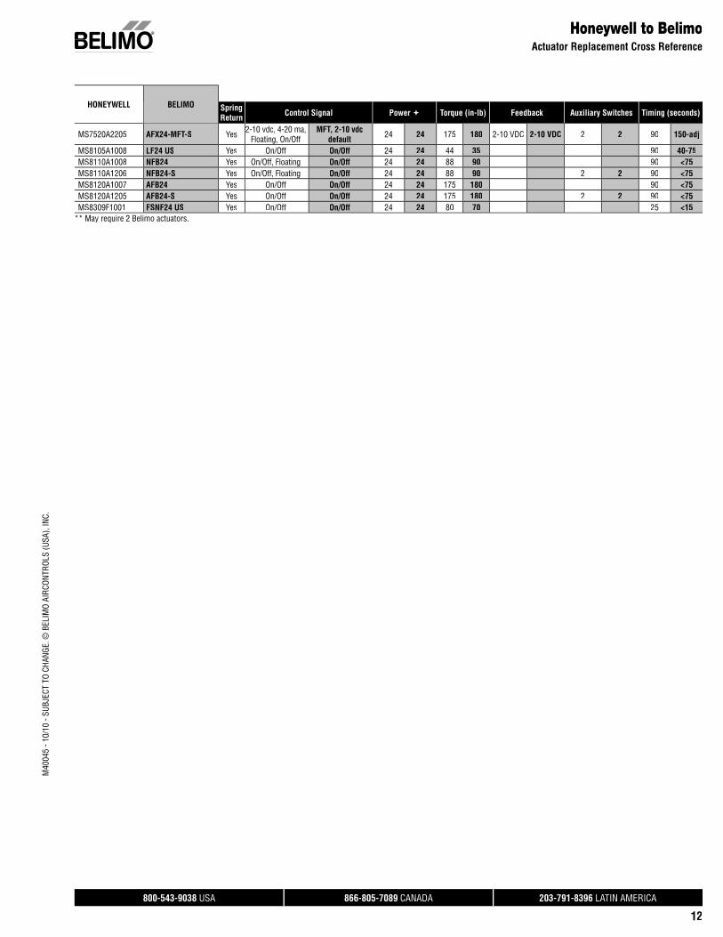
Honeywell to BelimoActuator Replacement Cross Reference
MS7520A2205 AFX24-MFT-S Yes 2-10 vdc, 4-20 ma, Floating, On/Off
MFT, 2-10 vdc default 24 24 175 180 2-10 VDC 2-10 VDC 2 2 90 150-adj
MS8105A1008 LF24 US Yes On/Off On/Off 24 24 44 35 90 40-75MS8110A1008 NFB24 Yes On/Off, Floating On/Off 24 24 88 90 90 <75MS8110A1206 NFB24-S Yes On/Off, Floating On/Off 24 24 88 90 2 2 90 <75MS8120A1007 AFB24 Yes On/Off On/Off 24 24 175 180 90 <75MS8120A1205 AFB24-S Yes On/Off On/Off 24 24 175 180 2 2 90 <75MS8309F1001 FSNF24 US Yes On/Off On/Off 24 24 80 70 25 <15
** May require 2 Belimo actuators.
HONEYWELL BELIMO SpringReturn Control Signal Power Torque (in-lb) Feedback Auxiliary Switches Timing (seconds)
800-543-9038 USA 866-805-7089 CANADA 203-791-8396 LATIN AMERICA
13
M40
045
- 10/
10 -
SUBJ
ECT
TO C
HANG
E. ©
BEL
IMO
AIRC
ONTR
OLS
(USA
), IN
C.
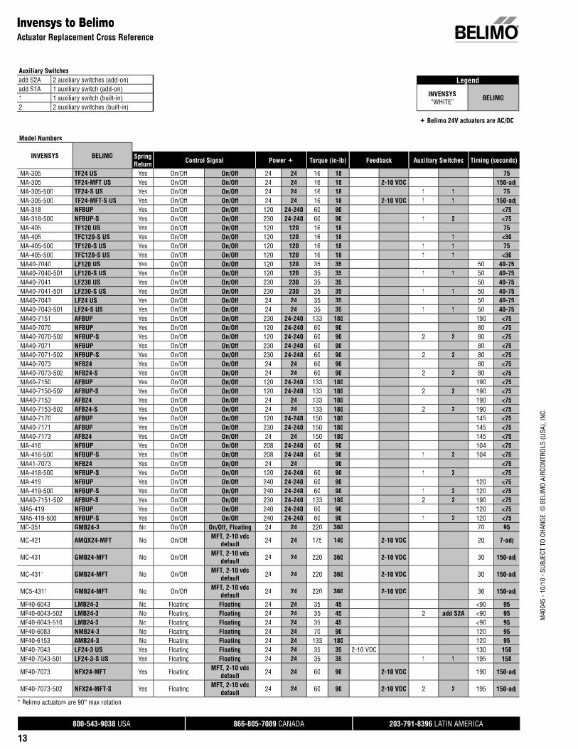
Legend
INVENSYS“WHITE” BELIMO
Belimo 24V actuators are AC/DC
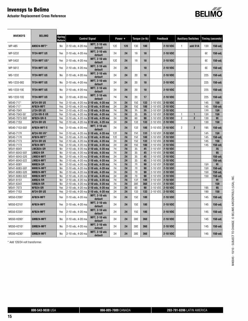
Invensys to BelimoActuator Replacement Cross Reference
Model Numbers
INVENSYS BELIMO SpringReturn Control Signal Power Torque (in-lb) Feedback Auxiliary Switches Timing (seconds)
MA-305 TF24 US Yes On/Off On/Off 24 24 16 18 75MA-305 TF24-MFT US Yes On/Off On/Off 24 24 16 18 2-10 VDC 150-adjMA-305-500 TF24-S US Yes On/Off On/Off 24 24 16 18 1 1 75MA-305-500 TF24-MFT-S US Yes On/Off On/Off 24 24 16 18 2-10 VDC 1 1 150-adjMA-318 NFBUP Yes On/Off On/Off 120 24-240 60 90 <75MA-318-500 NFBUP-S Yes On/Off On/Off 230 24-240 60 90 1 2 <75MA-405 TF120 US Yes On/Off On/Off 120 120 16 18 75MA-405 TFC120-S US Yes On/Off On/Off 120 120 16 18 1 <30MA-405-500 TF120-S US Yes On/Off On/Off 120 120 16 18 1 1 75MA-405-500 TFC120-S US Yes On/Off On/Off 120 120 16 18 1 1 <30MA40-7040 LF120 US Yes On/Off On/Off 120 120 35 35 50 40-75MA40-7040-501 LF120-S US Yes On/Off On/Off 120 120 35 35 1 1 50 40-75MA40-7041 LF230 US Yes On/Off On/Off 230 230 35 35 50 40-75MA40-7041-501 LF230-S US Yes On/Off On/Off 230 230 35 35 1 1 50 40-75MA40-7043 LF24 US Yes On/Off On/Off 24 24 35 35 50 40-75MA40-7043-501 LF24-S US Yes On/Off On/Off 24 24 35 35 1 1 50 40-75MA40-7151 AFBUP Yes On/Off On/Off 230 24-240 133 180 190 <75MA40-7070 NFBUP Yes On/Off On/Off 120 24-240 60 90 80 <75MA40-7070-502 NFBUP-S Yes On/Off On/Off 120 24-240 60 90 2 2 80 <75MA40-7071 NFBUP Yes On/Off On/Off 230 24-240 60 90 80 <75MA40-7071-502 NFBUP-S Yes On/Off On/Off 230 24-240 60 90 2 2 80 <75MA40-7073 NFB24 Yes On/Off On/Off 24 24 60 90 80 <75MA40-7073-502 NFB24-S Yes On/Off On/Off 24 24 60 90 2 2 80 <75MA40-7150 AFBUP Yes On/Off On/Off 120 24-240 133 180 190 <75MA40-7150-502 AFBUP-S Yes On/Off On/Off 120 24-240 133 180 2 2 190 <75MA40-7153 AFB24 Yes On/Off On/Off 24 24 133 180 190 <75MA40-7153-502 AFB24-S Yes On/Off On/Off 24 24 133 180 2 2 190 <75MA40-7170 AFBUP Yes On/Off On/Off 120 24-240 150 180 145 <75MA40-7171 AFBUP Yes On/Off On/Off 230 24-240 150 180 145 <75MA40-7173 AFB24 Yes On/Off On/Off 24 24 150 180 145 <75MA-416 NFBUP Yes On/Off On/Off 208 24-240 60 90 104 <75MA-416-500 NFBUP-S Yes On/Off On/Off 208 24-240 60 90 1 2 104 <75MA41-7073 NFB24 Yes On/Off On/Off 24 24 90 <75MA-418-500 NFBUP-S Yes On/Off On/Off 120 24-240 60 90 1 2 <75MA-419 NFBUP Yes On/Off On/Off 240 24-240 60 90 120 <75MA-419-500 NFBUP-S Yes On/Off On/Off 240 24-240 60 90 1 2 120 <75MA40-7151-502 AFBUP-S Yes On/Off On/Off 230 24-240 133 180 2 2 190 <75MA5-419 NFBUP Yes On/Off On/Off 240 24-240 60 90 120 <75MA5-419-500 NFBUP-S Yes On/Off On/Off 240 24-240 60 90 1 2 120 <75MC-351 GMB24-3 No On/Off On/Off, Floating 24 24 220 360 70 95
MC-421 AMQX24-MFT No On/Off MFT, 2-10 vdcdefault 24 24 175 140 2-10 VDC 20 7-adj
MC-431 GMB24-MFT No On/Off MFT, 2-10 vdcdefault 24 24 220 360 2-10 VDC 30 150-adj
MC-4311 GMB24-MFT No On/Off MFT, 2-10 vdcdefault 24 24 220 360 2-10 VDC 30 150-adj
MC5-4311 GMB24-MFT No On/Off MFT, 2-10 vdcdefault 24 24 220 360 2-10 VDC 36 150-adj
MF40-6043 LMB24-3 No Floating Floating 24 24 35 45 <90 95MF40-6043-502 LMB24-3 No Floating Floating 24 24 35 45 2 add S2A <90 95MF40-6043-510 LMB24-3 No Floating Floating 24 24 35 45 <90 95MF40-6083 NMB24-3 No Floating Floating 24 24 70 90 120 95MF40-6153 AMB24-3 No Floating Floating 24 24 133 180 120 95MF40-7043 LF24-3 US Yes Floating Floating 24 24 35 35 2-10 VDC 130 150MF40-7043-501 LF24-3-S US Yes Floating Floating 24 24 35 35 1 1 195 150
MF40-7073 NFX24-MFT Yes Floating MFT, 2-10 vdcdefault 24 24 60 90 2-10 VDC 190 150-adj
MF40-7073-502 NFX24-MFT-S Yes Floating MFT, 2-10 vdcdefault 24 24 60 90 2-10 VDC 2 2 195 150-adj
Auxiliary Switchesadd S2A 2 auxiliary switches (add-on)add S1A 1 auxiliary switch (add-on)1 1 auxiliary switch (built-in)2 2 auxiliary switches (built-in)
* Belimo actuators are 90° max rotation.
800-543-9038 USA 866-805-7089 CANADA 203-791-8396 LATIN AMERICA
14
M40
045
- 10/
10 -
SUBJ
ECT
TO C
HANG
E. ©
BEL
IMO
AIRC
ONTR
OLS
(USA
), IN
C.
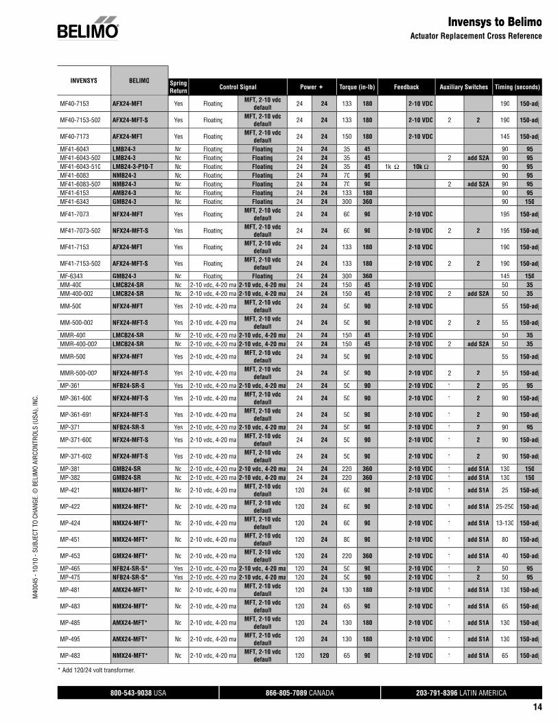
MF40-7153 AFX24-MFT Yes Floating MFT, 2-10 vdcdefault 24 24 133 180 2-10 VDC 190 150-adj
MF40-7153-502 AFX24-MFT-S Yes Floating MFT, 2-10 vdcdefault 24 24 133 180 2-10 VDC 2 2 190 150-adj
MF40-7173 AFX24-MFT Yes Floating MFT, 2-10 vdcdefault 24 24 150 180 2-10 VDC 145 150-adj
MF41-6043 LMB24-3 No Floating Floating 24 24 35 45 90 95MF41-6043-502 LMB24-3 No Floating Floating 24 24 35 45 2 add S2A 90 95MF41-6043-510 LMB24-3-P10-T No Floating Floating 24 24 35 45 1k Ω 10k Ω 90 95MF41-6083 NMB24-3 No Floating Floating 24 24 70 90 90 95MF41-6083-502 NMB24-3 No Floating Floating 24 24 70 90 2 add S2A 90 95MF41-6153 AMB24-3 No Floating Floating 24 24 133 180 90 95MF41-6343 GMB24-3 No Floating Floating 24 24 300 360 90 150
MF41-7073 NFX24-MFT Yes Floating MFT, 2-10 vdcdefault 24 24 60 90 2-10 VDC 195 150-adj
MF41-7073-502 NFX24-MFT-S Yes Floating MFT, 2-10 vdcdefault 24 24 60 90 2-10 VDC 2 2 195 150-adj
MF41-7153 AFX24-MFT Yes Floating MFT, 2-10 vdcdefault 24 24 133 180 2-10 VDC 190 150-adj
MF41-7153-502 AFX24-MFT-S Yes Floating MFT, 2-10 vdcdefault 24 24 133 180 2-10 VDC 2 2 190 150-adj
MF-6343 GMB24-3 No Floating Floating 24 24 300 360 145 150MM-400 LMCB24-SR No 2-10 vdc, 4-20 ma 2-10 vdc, 4-20 ma 24 24 150 45 2-10 VDC 50 35MM-400-002 LMCB24-SR No 2-10 vdc, 4-20 ma 2-10 vdc, 4-20 ma 24 24 150 45 2-10 VDC 2 add S2A 50 35
MM-500 NFX24-MFT Yes 2-10 vdc, 4-20 ma MFT, 2-10 vdcdefault 24 24 50 90 2-10 VDC 55 150-adj
MM-500-002 NFX24-MFT-S Yes 2-10 vdc, 4-20 ma MFT, 2-10 vdcdefault 24 24 50 90 2-10 VDC 2 2 55 150-adj
MMR-400 LMCB24-SR No 2-10 vdc, 4-20 ma 2-10 vdc, 4-20 ma 24 24 150 45 2-10 VDC 50 35MMR-400-002 LMCB24-SR No 2-10 vdc, 4-20 ma 2-10 vdc, 4-20 ma 24 24 150 45 2-10 VDC 2 add S2A 50 35
MMR-500 NFX24-MFT Yes 2-10 vdc, 4-20 ma MFT, 2-10 vdcdefault 24 24 50 90 2-10 VDC 55 150-adj
MMR-500-002 NFX24-MFT-S Yes 2-10 vdc, 4-20 ma MFT, 2-10 vdcdefault 24 24 50 90 2-10 VDC 2 2 55 150-adj
MP-361 NFB24-SR-S Yes 2-10 vdc, 4-20 ma 2-10 vdc, 4-20 ma 24 24 50 90 2-10 VDC 1 2 95 95
MP-361-600 NFX24-MFT-S Yes 2-10 vdc, 4-20 ma MFT, 2-10 vdcdefault 24 24 50 90 2-10 VDC 1 2 90 150-adj
MP-361-691 NFX24-MFT-S Yes 2-10 vdc, 4-20 ma MFT, 2-10 vdcdefault 24 24 50 90 2-10 VDC 1 2 90 150-adj
MP-371 NFB24-SR-S Yes 2-10 vdc, 4-20 ma 2-10 vdc, 4-20 ma 24 24 50 90 2-10 VDC 1 2 90 95
MP-371-600 NFX24-MFT-S Yes 2-10 vdc, 4-20 ma MFT, 2-10 vdcdefault 24 24 50 90 2-10 VDC 1 2 90 150-adj
MP-371-602 NFX24-MFT-S Yes 2-10 vdc, 4-20 ma MFT, 2-10 vdcdefault 24 24 50 90 2-10 VDC 1 2 90 150-adj
MP-381 GMB24-SR No 2-10 vdc, 4-20 ma 2-10 vdc, 4-20 ma 24 24 220 360 2-10 VDC 1 add S1A 130 150MP-382 GMB24-SR No 2-10 vdc, 4-20 ma 2-10 vdc, 4-20 ma 24 24 220 360 2-10 VDC 1 add S1A 130 150
MP-421 NMX24-MFT* No 2-10 vdc, 4-20 ma MFT, 2-10 vdcdefault 120 24 60 90 2-10 VDC 1 add S1A 25 150-adj
MP-422 NMX24-MFT* No 2-10 vdc, 4-20 ma MFT, 2-10 vdcdefault 120 24 60 90 2-10 VDC 1 add S1A 25-250 150-adj
MP-424 NMX24-MFT* No 2-10 vdc, 4-20 ma MFT, 2-10 vdcdefault 120 24 60 90 2-10 VDC 1 add S1A 13-130 150-adj
MP-451 NMX24-MFT* No 2-10 vdc, 4-20 ma MFT, 2-10 vdcdefault 120 24 80 90 2-10 VDC 1 add S1A 80 150-adj
MP-453 GMX24-MFT* No 2-10 vdc, 4-20 ma MFT, 2-10 vdcdefault 120 24 220 360 2-10 VDC 1 add S1A 40 150-adj
MP-465 NFB24-SR-S* Yes 2-10 vdc, 4-20 ma 2-10 vdc, 4-20 ma 120 24 50 90 2-10 VDC 1 2 50 95MP-475 NFB24-SR-S* Yes 2-10 vdc, 4-20 ma 2-10 vdc, 4-20 ma 120 24 50 90 2-10 VDC 1 2 50 95
MP-481 AMX24-MFT* No 2-10 vdc, 4-20 ma MFT, 2-10 vdcdefault 120 24 130 180 2-10 VDC 1 add S1A 130 150-adj
MP-483 NMX24-MFT* No 2-10 vdc, 4-20 ma MFT, 2-10 vdcdefault 120 24 65 90 2-10 VDC 1 add S1A 65 150-adj
MP-485 AMX24-MFT* No 2-10 vdc, 4-20 ma MFT, 2-10 vdcdefault 120 24 130 180 2-10 VDC 1 add S1A 130 150-adj
MP-495 AMX24-MFT* No 2-10 vdc, 4-20 ma MFT, 2-10 vdcdefault 120 24 130 180 2-10 VDC 1 add S1A 130 150-adj
MP-483 NMX24-MFT* No 2-10 vdc, 4-20 ma MFT, 2-10 vdcdefault 120 120 65 90 2-10 VDC 1 add S1A 65 150-adj
Invensys to BelimoActuator Replacement Cross Reference
INVENSYS BELIMO SpringReturn Control Signal Power Torque (in-lb) Feedback Auxiliary Switches Timing (seconds)
* Add 120/24 volt transformer.
800-543-9038 USA 866-805-7089 CANADA 203-791-8396 LATIN AMERICA
15
M40
045
- 10/
10 -
SUBJ
ECT
TO C
HANG
E. ©
BEL
IMO
AIRC
ONTR
OLS
(USA
), IN
C.
MP-485 AMX24-MFT* No 2-10 vdc, 4-20 ma MFT, 2-10 vdcdefault 120 120 130 180 2-10 VDC 1 add S1A 130 150-adj
MP-5233 TF24-MFT US Yes 2-10 vdc, 4-20 ma MFT, 2-10 vdcdefault 24 24 19 18 2-10 VDC 60 150-adj
MP-5433 TF24-MFT US* Yes 2-10 vdc, 4-20 ma MFT, 2-10 vdcdefault 120 24 19 18 2-10 VDC 60 150-adj
MP-5613 TF24-MFT US Yes 2-10 vdc, 4-20 ma MFT, 2-10 vdcdefault 24 24 18 2-10 VDC 60 150-adj
MS-1233 TF24-MFT US No 2-10 vdc, 4-20 ma MFT, 2-10 vdcdefault 24 24 20 18 2-10 VDC 225 150-adj
MS-1233-002 TF24-MFT US No 2-10 vdc, 4-20 ma MFT, 2-10 vdcdefault 24 24 20 18 2-10 VDC 225 150-adj
MS-1233-100 TF24-MFT US No 2-10 vdc, 4-20 ma MFT, 2-10 vdcdefault 24 24 20 18 2-10 VDC 225 150-adj
MS-1233-102 TF24-MFT US No 2-10 vdc, 4-20 ma MFT, 2-10 vdcdefault 24 24 20 17 2-10 VDC 225 150-adj
MS40-7171 AF24-SR US Yes 2-10 vdc, 4-20 ma 2-10 vdc, 4-20 ma 24 24 150 133 2-10 VDC 2-10 VDC 145 150MS40-7171 AFB24-MFT Yes 2-10 vdc, 4-20 ma 2-10 vdc, 4-20 ma 24 24 150 180 2-10 VDC 2-10 VDC 145 150-adjMS40-7043 LF24-SR US Yes 2-10 vdc, 4-20 ma 2-10 vdc, 4-20 ma 24 24 35 35 2-10 VDC 2-10 VDC 130 150MS40-7043-501 LF24-SR-S US Yes 2-10 vdc, 4-20 ma 2-10 vdc, 4-20 ma 24 24 35 35 2-10 VDC 2-10 VDC 1 1 130 150MS40-7073-502 NFB24-SR-S Yes 2-10 vdc, 4-20 ma 2-10 vdc, 4-20 ma 24 24 60 90 2-10 VDC 2-10 VDC 2 2 130 95MS40-7153 AF24-SR US Yes 2-10 vdc, 4-20 ma 2-10 vdc, 4-20 ma 24 24 133 133 2-10 VDC 2-10 VDC 130 150
MS40-7153-502 AFB24-MFT-S Yes 2-10 vdc, 4-20 ma MFT, 2-10 vdcdefault 24 24 133 180 2-10 VDC 2-10 VDC 2 2 195 150-adj
MS40-7170 AF24-SR US* Yes 2-10 vdc, 4-20 ma 2-10 vdc, 4-20 ma 120 24 150 133 2-10 VDC 2-10 VDC 145 150MS40-7170 AFB24-MFT* Yes 2-10 vdc, 4-20 ma 2-10 vdc, 4-20 ma 120 24 150 180 2-10 VDC 2-10 VDC 145 150-adjMS40-7173 AF24-SR US Yes 2-10 vdc, 4-20 ma 2-10 vdc, 4-20 ma 24 24 150 133 2-10 VDC 2-10 VDC 145 150MS40-7173 AFB24-MFT Yes 2-10 vdc, 4-20 ma 2-10 vdc, 4-20 ma 24 24 150 180 2-10 VDC 2-10 VDC 145 150-adjMS41-6043 LMCB24-SR No 2-10 vdc, 4-20 ma 2-10 vdc, 4-20 ma 24 24 35 45 2-10 VDC 2-10 VDC 35MS41-6043-502 LMB24-SR No 2-10 vdc, 4-20 ma 2-10 vdc, 4-20 ma 24 24 35 45 2-10 VDC 2-10 VDC 95MS41-6043-520 LMB24-MFT No 2-10 vdc, 4-20 ma 2-10 vdc, 4-20 ma 24 24 35 45 2-10 VDC 2-10 VDC 150-adjMS41-6043-522 LMB24-MFT No 2-10 vdc, 4-20 ma 2-10 vdc, 4-20 ma 24 24 35 45 2-10 VDC 2-10 VDC 150-adjMS41-6083 NMB24-SR No 2-10 vdc, 4-20 ma 2-10 vdc, 4-20 ma 24 24 70 90 2-10 VDC 2-10 VDC 150 95MS41-6083-502 NMB24-MFT No 2-10 vdc, 4-20 ma 2-10 vdc, 4-20 ma 24 24 70 90 2-10 VDC 2-10 VDC 150 150-adjMS41-6083-520 NMB24-MFT No 2-10 vdc, 4-20 ma 2-10 vdc, 4-20 ma 24 24 70 90 2-10 VDC 2-10 VDC 150 150-adjMS41-6083-522 NMB24-MFT No 2-10 vdc, 4-20 ma 2-10 vdc, 4-20 ma 24 24 70 90 2-10 VDC 2-10 VDC 150 150-adjMS41-6153 AMB24-SR No 2-10 vdc, 4-20 ma 2-10 vdc, 4-20 ma 24 24 133 180 2-10 VDC 2-10 VDC 95MS41-6343 GMB24-SR No 2-10 vdc, 4-20 ma 2-10 vdc, 4-20 ma 24 24 300 360 2-10 VDC 2-10 VDC 150MS41-7073 NFB24-SR Yes 2-10 vdc, 4-20 ma 2-10 vdc, 4-20 ma 24 24 60 90 2-10 VDC 2-10 VDC 195 95MS41-7153 AF24-SR US Yes 2-10 vdc, 4-20 ma 2-10 vdc, 4-20 ma 24 24 133 133 2-10 VDC 2-10 VDC 190 150
MS50-E2001 AFB24-MFT Yes 2-10 vdc, 4-20 ma MFT, 2-10 vdcdefault 24 24 150 180 2-10 VDC 145 150-adj
MS50-E2101 AFB24-MFT Yes 2-10 vdc, 4-20 ma MFT, 2-10 vdcdefault 24 24 150 180 2-10 VDC 145 150-adj
MS50-E2301 AFB24-MFT Yes 2-10 vdc, 4-20 ma MFT, 2-10 vdcdefault 24 24 150 180 2-10 VDC 145 150-adj
MS50-H2001 GMB24-MFT No 2-10 vdc, 4-20 ma MFT, 2-10 vdcdefault 24 24 300 360 2-10 VDC 145 150-adj
MS50-H2101 GMB24-MFT No 2-10 vdc, 4-20 ma MFT, 2-10 vdcdefault 24 24 300 360 2-10 VDC 145 150-adj
MS50-H2301 GMB24-MFT No 2-10 vdc, 4-20 ma MFT, 2-10 vdcdefault 24 24 300 360 2-10 VDC 145 150-adj
Invensys to BelimoActuator Replacement Cross Reference
INVENSYS BELIMO SpringReturn Control Signal Power Torque (in-lb) Feedback Auxiliary Switches Timing (seconds)
* Add 120/24 volt transformer.
800-543-9038 USA 866-805-7089 CANADA 203-791-8396 LATIN AMERICA
16
M40
045
- 10/
10 -
SUBJ
ECT
TO C
HANG
E. ©
BEL
IMO
AIRC
ONTR
OLS
(USA
), IN
C.
LegendJOHNSON
CONTROLS“WHITE”
BELIMO
Belimo 24V actuators are AC/DC
Johnson Controls to BelimoActuator Replacement Cross Reference
Model Numbers
JOHNSONCONTROLS BELIMO Spring
Return Control Signal Power Torque (in-lb) Feedback Auxiliary Switches Timing (seconds)
M110AAB-1 LF120-S US Yes On/Off, Floating On/Off 120 120 25 35 1 1 40-75M110AGA-1 LF24-3 US Yes On/Off, Floating On/Off, Floating 24 24 25 35 150M110AGB-1 LF24-3-S US Yes On/Off, Floating On/Off, Floating 24 24 25 35 1 1 150
M110GGA-3 LF24-MFT US Yes 2-10 vdc, 4-20 ma MFT, 2-10 vdcdefault 24 24 25 35 2-10 VDC 2-10 VDC 150-adj
M110JGA-1 LF24-MFT US Yes 2-10 vdc, 4-20 ma MFT, 2-10 vdcdefault 24 24 25 35 2-10 VDC 2-10 VDC 150-adj
M110JGB-1 LF24-MFT-S US Yes 2-10 vdc, 4-20 ma MFT, 2-10 vdcdefault 24 24 25 35 2-10 VDC 2-10 VDC 1 1 150-adj
M120AAA-1 LMB120-3 No On/Off, Floating On/Off, Floating 120 120 35 45 95M120AAC-1 LMB120-3 No On/Off, Floating On/Off, Floating 120 120 35 45 2 add S2A 95M120AGA-1 LMB24-3 No On/Off, Floating On/Off, Floating 24 24 35 45 95
M120GGA-3 LMB24-MFT No 2-10 vdc, 4-20 ma MFT, 2-10 vdcdefault 24 24 35 45 2-10 VDC 2-10 VDC 150-adj
M120JAA-1 LMX120-SR No 2-10 vdc, 4-20 ma 2-10 vdc, 4-20 ma 120 120 35 45 2-10 VDC 2-10 VDC 95M120JAC-1 LMX120-SR No 2-10 vdc, 4-20 ma 2-10 vdc, 4-20 ma 120 120 35 45 2-10 VDC 2-10 VDC 2 add S2A 95M120JGA-1 LMB24-SR No 2-10 vdc, 4-20 ma 2-10 vdc, 4-20 ma 24 24 35 45 2-10 VDC 2-10 VDC 95
M120MGA-1 LMX24-MFT95 No 0-135 ohm MFT, 2-10 vdcdefault 24 24 35 45 150-adj
M130AAA-1 NFBUP Yes On/Off, Floating On/Off 120 24-240 50 90 <75M130AAB-1 NFBUP-S Yes On/Off, Floating On/Off 120 24-240 50 90 1 2 <75M130AGA-1 NFB24 Yes On/Off, Floating On/Off 24 24 50 90 <75M130AGB-1 NFB24-S Yes On/Off, Floating On/Off 24 24 50 90 1 2 <75
M130GGA-3 NFB24-MFT Yes 2-10 vdc, 4-20 ma MFT, 2-10 vdcdefault 24 24 50 90 2-10 VDC 2-10 VDC 150-adj
M130JGA-1 NFB24-MFT Yes 2-10 vdc, 4-20 ma MFT, 2-10 vdcdefault 24 24 50 90 2-10 VDC 2-10 VDC 150-adj
M130JGB-1 NFB24-MFT Yes 2-10 vdc, 4-20 ma MFT, 2-10 vdcdefault 24 24 50 90 2-10 VDC 2-10 VDC 1 150-adj
M130JGC-1 NFB24-MFT Yes 2-10 vdc, 4-20 ma MFT, 2-10 vdcdefault 24 24 50 90 2-10 VDC 2-10 VDC 2 150-adj
M130MGA-1 AFB24-MFT95 Yes 0-135 ohm 0-135 ohm 24 24 50 180 2-10 VDC 2-10 VDC 150-adjM140AAA-1 LMB120-3 No On/Off, Floating On/Off, Floating 120 120 75 45 95M140AGA-1 LMB24-3 No On/Off, Floating On/Off, Floating 24 24 75 45 95
M140GGA-3 LMB24-MFT No 2-10 vdc, 4-20 ma MFT, 2-10 vdcdefault 24 24 75 45 2-10 VDC 2-10 VDC 95
M140JAA-1 LMX120-SR No 2-10 vdc, 4-20 ma 2-10 vdc, 4-20 ma 120 120 75 45 2-10 VDC 2-10 VDC 95M140JGA-1 LMB24-SR No 2-10 vdc, 4-20 ma 2-10 vdc, 4-20 ma 24 24 75 45 2-10 VDC 2-10 VDC 95M150AAA-1 AMB120-3 No On/Off, Floating On/Off, Floating 120 120 150 180 95M150AAB-1 AMB120-3 No On/Off, Floating On/Off, Floating 120 120 150 180 1 add S1A 95M150AGA-1 AMB24-3 No On/Off, Floating On/Off, Floating 24 24 150 180 95M150AGB-1 AMB24-3 No On/Off, Floating On/Off, Floating 24 24 150 180 1 add S1A 95
M150GGA-3 AMB24-MFT No 2-10 vdc, 4-20 ma MFT, 2-10 vdcdefault 24 24 150 180 2-10 VDC 2-10 VDC 150-adj
M150JGA-1 AMB24-SR No 2-10 vdc, 4-20 ma 2-10 vdc, 4-20 ma 24 24 150 180 2-10 VDC 2-10 VDC 95M150JGB-1 AMB24-SR No 2-10 vdc, 4-20 ma 2-10 vdc, 4-20 ma 24 24 150 180 2-10 VDC 2-10 VDC 1 add S1A 95M150JGC-1 AMB24-SR No 2-10 vdc, 4-20 ma 2-10 vdc, 4-20 ma 24 24 150 180 2-10 VDC 2-10 VDC 2 add S2A 95
M150MGA-1 AMB24-MFT No 0-135 ohm MFT, 2-10 vdcdefault 24 24 150 180 2-10 VDC 2-10 VDC 150-adj
M9108-GGA-2 NMCB24-SR No 2-10 vdc, 4-20 ma 2-10 vdc, 4-20 ma 24 24 70 90 2-10 VDC 60 45M9101-AGA-2N LMB24-3-T No Floating Floating 24 24 10 45 15 95M9104-AGA-2N LMB24-3-T No On/Off, Floating Floating 24 24 35 45 90 95M9104-AGA-2N LMB24-3 No Floating Floating 24 24 35 45 90 95M9106-AGA-2 LMB24-3 No Floating Floating 24 24 53 45 60 95M9106-AGA-2N01 LMCB24-3 No On/Off, Floating Floating 24 24 53 45 60 35M9106-AGA-2N01 LMCB24-3-T No Floating Floating 24 24 53 45 60 35
M9106-AGA-2N02 LMB24-MFT No On/Off, Floating MFT, 2-10 vdcdefault 24 24 53 45 2-10 VDC 120 150-adj
M9106-AGA-2N02 LMX24-MFT No Floating MFT, 2-10 vdcdefault 24 24 53 45 2-10 VDC 120 150-adj
Auxiliary Switchesadd S2A 2 auxiliary switches (add-on)add S1A 1 auxiliary switch (add-on)1 1 auxiliary switch (built-in)2 2 auxiliary switches (built-in)
800-543-9038 USA 866-805-7089 CANADA 203-791-8396 LATIN AMERICA
17
M40
045
- 10/
10 -
SUBJ
ECT
TO C
HANG
E. ©
BEL
IMO
AIRC
ONTR
OLS
(USA
), IN
C.
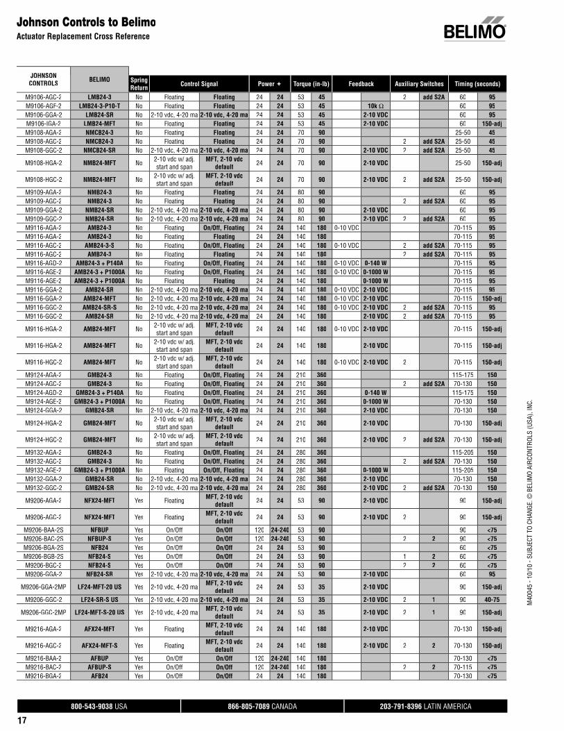
Johnson Controls to BelimoActuator Replacement Cross Reference
JOHNSONCONTROLS BELIMO Spring
Return Control Signal Power Torque (in-lb) Feedback Auxiliary Switches Timing (seconds)
M9106-AGC-2 LMB24-3 No Floating Floating 24 24 53 45 2 add S2A 60 95M9106-AGF-2 LMB24-3-P10-T No Floating Floating 24 24 53 45 10k Ω 60 95M9106-GGA-2 LMB24-SR No 2-10 vdc, 4-20 ma 2-10 vdc, 4-20 ma 24 24 53 45 2-10 VDC 60 95M9106-IGA-2 LMB24-MFT No Floating Floating 24 24 53 45 2-10 VDC 60 150-adjM9108-AGA-2 NMCB24-3 No Floating Floating 24 24 70 90 25-50 45M9108-AGC-2 NMCB24-3 No Floating Floating 24 24 70 90 2 add S2A 25-50 45M9108-GGC-2 NMCB24-SR No 2-10 vdc, 4-20 ma 2-10 vdc, 4-20 ma 24 24 70 90 2-10 VDC 2 add S2A 25-50 45
M9108-HGA-2 NMB24-MFT No 2-10 vdc w/ adj.start and span
MFT, 2-10 vdcdefault 24 24 70 90 2-10 VDC 25-50 150-adj
M9108-HGC-2 NMB24-MFT No 2-10 vdc w/ adj.start and span
MFT, 2-10 vdcdefault 24 24 70 90 2-10 VDC 2 add S2A 25-50 150-adj
M9109-AGA-2 NMB24-3 No Floating Floating 24 24 80 90 60 95M9109-AGC-2 NMB24-3 No Floating Floating 24 24 80 90 2 add S2A 60 95M9109-GGA-2 NMB24-SR No 2-10 vdc, 4-20 ma 2-10 vdc, 4-20 ma 24 24 80 90 2-10 VDC 60 95M9109-GGC-2 NMB24-SR No 2-10 vdc, 4-20 ma 2-10 vdc, 4-20 ma 24 24 80 90 2-10 VDC 2 add S2A 60 95M9116-AGA-2 AMB24-3 No Floating On/Off, Floating 24 24 140 180 0-10 VDC 70-115 95M9116-AGA-2 AMB24-3 No Floating Floating 24 24 140 180 70-115 95M9116-AGC-2 AMB24-3-S No Floating On/Off, Floating 24 24 140 180 0-10 VDC 2 add S2A 70-115 95M9116-AGC-2 AMB24-3 No Floating Floating 24 24 140 180 2 add S2A 70-115 95M9116-AGD-2 AMB24-3 + P140A No Floating On/Off, Floating 24 24 140 180 0-10 VDC 0-140 W 70-115 95M9116-AGE-2 AMB24-3 + P1000A No Floating On/Off, Floating 24 24 140 180 0-10 VDC 0-1000 W 70-115 95M9116-AGE-2 AMB24-3 + P1000A No Floating Floating 24 24 140 180 0-1000 W 70-115 95M9116-GGA-2 AMB24-SR No 2-10 vdc, 4-20 ma 2-10 vdc, 4-20 ma 24 24 140 180 0-10 VDC 2-10 VDC 70-115 95M9116-GGA-2 AMB24-MFT No 2-10 vdc, 4-20 ma 2-10 vdc, 4-20 ma 24 24 140 180 0-10 VDC 2-10 VDC 70-115 150-adjM9116-GGC-2 AMB24-SR-S No 2-10 vdc, 4-20 ma 2-10 vdc, 4-20 ma 24 24 140 180 0-10 VDC 2-10 VDC 2 add S2A 70-115 95M9116-GGC-2 AMB24-SR No 2-10 vdc, 4-20 ma 2-10 vdc, 4-20 ma 24 24 140 180 2-10 VDC 2 add S2A 70-115 95
M9116-HGA-2 AMB24-MFT No 2-10 vdc w/ adj.start and span
MFT, 2-10 vdcdefault 24 24 140 180 0-10 VDC 2-10 VDC 70-115 150-adj
M9116-HGA-2 AMB24-MFT No 2-10 vdc w/ adj.start and span
MFT, 2-10 vdcdefault 24 24 140 180 2-10 VDC 70-115 150-adj
M9116-HGC-2 AMB24-MFT No 2-10 vdc w/ adj.start and span
MFT, 2-10 vdcdefault 24 24 140 180 0-10 VDC 2-10 VDC 2 70-115 150-adj
M9124-AGA-2 GMB24-3 No Floating On/Off, Floating 24 24 210 360 115-175 150M9124-AGC-2 GMB24-3 No Floating On/Off, Floating 24 24 210 360 2 add S2A 70-130 150M9124-AGD-2 GMB24-3 + P140A No Floating On/Off, Floating 24 24 210 360 0-140 W 115-175 150M9124-AGE-2 GMB24-3 + P1000A No Floating On/Off, Floating 24 24 210 360 0-1000 W 70-130 150M9124-GGA-2 GMB24-SR No 2-10 vdc, 4-20 ma 2-10 vdc, 4-20 ma 24 24 210 360 2-10 VDC 70-130 150
M9124-HGA-2 GMB24-MFT No 2-10 vdc w/ adj.start and span
MFT, 2-10 vdcdefault 24 24 210 360 2-10 VDC 70-130 150-adj
M9124-HGC-2 GMB24-MFT No 2-10 vdc w/ adj.start and span
MFT, 2-10 vdcdefault 24 24 210 360 2-10 VDC 2 add S2A 70-130 150-adj
M9132-AGA-2 GMB24-3 No Floating On/Off, Floating 24 24 280 360 115-205 150M9132-AGC-2 GMB24-3 No Floating On/Off, Floating 24 24 280 360 2 add S2A 70-130 150M9132-AGE-2 GMB24-3 + P1000A No Floating On/Off, Floating 24 24 280 360 0-1000 W 115-205 150M9132-GGA-2 GMB24-SR No 2-10 vdc, 4-20 ma 2-10 vdc, 4-20 ma 24 24 280 360 2-10 VDC 70-130 150M9132-GGC-2 GMB24-SR No 2-10 vdc, 4-20 ma 2-10 vdc, 4-20 ma 24 24 280 360 2-10 VDC 2 add S2A 70-130 150
M9206-AGA-2 NFX24-MFT Yes Floating MFT, 2-10 vdcdefault 24 24 53 90 2-10 VDC 90 150-adj
M9206-AGC-2 NFX24-MFT Yes Floating MFT, 2-10 vdcdefault 24 24 53 90 2-10 VDC 2 90 150-adj
M9206-BAA-2S NFBUP Yes On/Off On/Off 120 24-240 53 90 90 <75M9206-BAC-2S NFBUP-S Yes On/Off On/Off 120 24-240 53 90 2 2 90 <75M9206-BGA-2S NFB24 Yes On/Off On/Off 24 24 53 90 60 <75M9206-BGB-2S NFB24-S Yes On/Off On/Off 24 24 53 90 1 2 60 <75M9206-BGC-2 NFB24-S Yes On/Off On/Off 24 24 53 90 2 2 60 <75M9206-GGA-2 NFB24-SR Yes 2-10 vdc, 4-20 ma 2-10 vdc, 4-20 ma 24 24 53 90 2-10 VDC 60 95
M9206-GGA-2MP LF24-MFT-20 US Yes 2-10 vdc, 4-20 ma MFT, 2-10 vdcdefault 24 24 53 35 2-10 VDC 90 150-adj
M9206-GGC-2 LF24-SR-S US Yes 2-10 vdc, 4-20 ma 2-10 vdc, 4-20 ma 24 24 53 35 2-10 VDC 2 1 90 40-75
M9206-GGC-2MP LF24-MFT-S-20 US Yes 2-10 vdc, 4-20 ma MFT, 2-10 vdcdefault 24 24 53 35 2-10 VDC 2 1 90 150-adj
M9216-AGA-2 AFX24-MFT Yes Floating MFT, 2-10 vdcdefault 24 24 140 180 2-10 VDC 70-130 150-adj
M9216-AGC-2 AFX24-MFT-S Yes Floating MFT, 2-10 vdcdefault 24 24 140 180 2-10 VDC 2 2 70-130 150-adj
M9216-BAA-2 AFBUP Yes On/Off On/Off 120 24-240 140 180 70-130 <75M9216-BAC-2 AFBUP-S Yes On/Off On/Off 120 24-240 140 180 2 2 70-115 <75M9216-BGA-2 AFB24 Yes On/Off On/Off 24 24 140 180 70-130 <75
800-543-9038 USA 866-805-7089 CANADA 203-791-8396 LATIN AMERICA
18
M40
045
- 10/
10 -
SUBJ
ECT
TO C
HANG
E. ©
BEL
IMO
AIRC
ONTR
OLS
(USA
), IN
C.
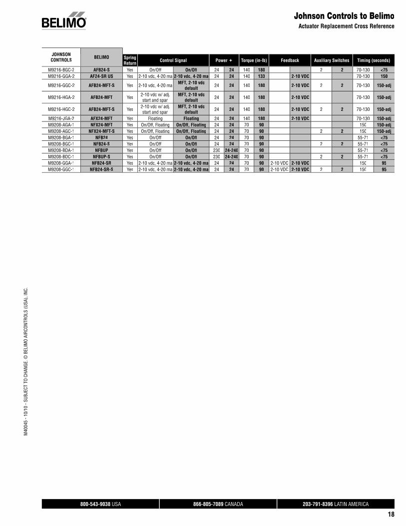
JOHNSONCONTROLS BELIMO Spring
Return Control Signal Power Torque (in-lb) Feedback Auxiliary Switches Timing (seconds)
Johnson Controls to BelimoActuator Replacement Cross Reference
M9216-BGC-2 AFB24-S Yes On/Off On/Off 24 24 140 180 2 2 70-130 <75M9216-GGA-2 AF24-SR US Yes 2-10 vdc, 4-20 ma 2-10 vdc, 4-20 ma 24 24 140 133 2-10 VDC 70-130 150
M9216-GGC-2 AFB24-MFT-S Yes 2-10 vdc, 4-20 ma MFT, 2-10 vdcdefault 24 24 140 180 2-10 VDC 2 2 70-130 150-adj
M9216-HGA-2 AFB24-MFT Yes 2-10 vdc w/ adj.start and span
MFT, 2-10 vdcdefault 24 24 140 180 2-10 VDC 70-130 150-adj
M9216-HGC-2 AFB24-MFT-S Yes 2-10 vdc w/ adj.start and span
MFT, 2-10 vdcdefault 24 24 140 180 2-10 VDC 2 2 70-130 150-adj
M9216-JGA-2 AFX24-MFT Yes Floating Floating 24 24 140 180 2-10 VDC 70-130 150-adjM9208-AGA-1 NFX24-MFT Yes On/Off, Floating On/Off, Floating 24 24 70 90 150 150-adjM9208-AGC-1 NFX24-MFT-S Yes On/Off, Floating On/Off, Floating 24 24 70 90 2 2 150 150-adjM9208-BGA-1 NFB24 Yes On/Off On/Off 24 24 70 90 55-71 <75M9208-BGC-1 NFB24-S Yes On/Off On/Off 24 24 70 90 2 2 55-71 <75M9208-BDA-1 NFBUP Yes On/Off On/Off 230 24-240 70 90 55-71 <75M9208-BDC-1 NFBUP-S Yes On/Off On/Off 230 24-240 70 90 2 2 55-71 <75M9208-GGA-1 NFB24-SR Yes 2-10 vdc, 4-20 ma 2-10 vdc, 4-20 ma 24 24 70 90 2-10 VDC 2-10 VDC 150 95M9208-GGC-1 NFB24-SR-S Yes 2-10 vdc, 4-20 ma 2-10 vdc, 4-20 ma 24 24 70 90 2-10 VDC 2-10 VDC 2 2 150 95

800-543-9038 USA 866-805-7089 CANADA 203-791-8396 LATIN AMERICA
19
M40
045
- 10/
10 -
SUBJ
ECT
TO C
HANG
E. ©
BEL
IMO
AIRC
ONTR
OLS
(USA
), IN
C.
Legend
SIEMENS“WHITE” BELIMO
Belimo 24V actuators are AC/DC
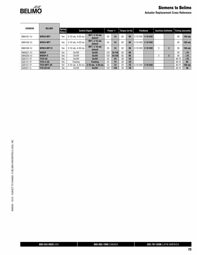
Siemens to BelimoActuator Replacement Cross Reference
Model Numbers
SIEMENS BELIMO SpringReturn Control Signal Power Torque (in-lb) Feedback Auxiliary Switches Timing (seconds)
GBB151.1U AMB24-SR No 2-10 vdc, 4-20 ma 2-10 vdc, 4-20 ma 24 24 177 180 2-10 VDC 150 95GBB156.1U AMB24-SR No On/Off 2-10 vdc, 4-20 ma 24 24 177 180 2-10 VDC 2 add S2A 150 95GBB161.1U AMB24-SR No 2-10 vdc, 4-20 ma 2-10 vdc, 4-20 ma 24 24 177 180 2-10 VDC 2-10 VDC 150 95
GBB163.1U AMB24-MFT No 2-10 vdc w/ adj.start and span
MFT, 2-10 vdcdefault 24 24 177 180 2-10 VDC 2-10 VDC 150 150-adj
GBB164.1U AMB24-MFT No 2-10 vdc w/ adj.start and span
MFT, 2-10 vdcdefault 24 24 177 180 2-10 VDC 2-10 VDC add S2A 150 150-adj
GBB166.1U AMB24-SR No 2-10 vdc, 4-20 ma 2-10 vdc, 4-20 ma 24 24 177 180 2-10 VDC 2-10 VDC 2 150 95GBB171.1U AMB24-3 No On/Off On/Off, Floating 24 24 177 180 150 95GBB175.1U AMB24-SR No On/Off 2-10 vdc, 4-20 ma 24 24 177 180 2-10 VDC 150 95GCA121.1U AFB24 Yes On/Off On/Off 24 24 160 180 90 <75GCA126.1U AFB24-S Yes On/Off On/Off 24 24 160 180 2 2 90 <75GCA131.1P AFB24 Yes On/Off On/Off 24 24 160 180 90 <75GCA135.1U AFB24-S Yes On/Off On/Off 24 24 160 180 2 2 90 <75
GCA151.1U AFB24-MFT Yes 4-20 ma MFT, 2-10 vdcdefault 24 24 160 180 2-10 VDC 90 150-adj
GCA156.1U AFB24-MFT-S Yes 4-20 ma MFT, 2-10 vdcdefault 24 24 160 180 2-10 VDC 2 2 90 150-adj
GCA161.1U AFB24-MFT Yes 2-10 vdc, 4-20 ma MFT, 2-10 vdcdefault 24 24 160 180 2-10 VDC 2-10 VDC 90 150-adj
GCA163.1U AFB24-MFT Yes 2-10 vdc, 4-20 ma MFT, 2-10 vdcdefault 24 24 160 180 2-10 VDC 2-10 VDC 90 150-adj
GCA164.1U AFB24-MFT-S Yes 2-10 vdc, 4-20 ma MFT, 2-10 vdcdefault 24 24 160 180 2-10 VDC 2-10 VDC 2 2 90 150-adj
GCA166.1U AFB24-MFT-S Yes 2-10 vdc, 4-20 ma MFT, 2-10 vdcdefault 24 24 160 180 2-10 VDC 2-10 VDC 2 2 90 150-adj
GCA166.1U AFB24-MFT Yes 2-10 vdc, 4-20 ma 2-10 vdc, 4-20 ma 24 24 160 180 2-10 VDC 2-10 VDC 2 2 90 150-adjGCA221.1U AFBUP Yes On/Off On/Off 120 120 160 180 90 <75GCA226.1U AFBUP-S Yes On/Off On/Off 120 120 160 180 2 2 90 <75GDE131.1P LMB24-SR No 3 position 2-10 vdc, 4-20 ma 24 24 44 45 2-10 VDC 90 95GDE136.1P LMB24-3 No 3 position On/Off, Floating 24 24 44 45 2 add S2A 90 95GDE161.1P LMB24-SR No 2-10 vdc, 4-20 ma 2-10 vdc, 4-20 ma 24 24 44 45 2-10 VDC 90 95GDE163.1P LMB24-SR No 2-10 vdc, 4-20 ma 2-10 vdc, 4-20 ma 24 24 44 45 2-10 VDC 90 95GDE164.1P LMB24-SR No 2-10 vdc, 4-20 ma 2-10 vdc, 4-20 ma 24 24 44 45 2-10 VDC 2 add S2A 90 95GDE166.1P LMB24-SR No 2-10 vdc, 4-20 ma 2-10 vdc, 4-20 ma 24 24 44 45 2-10 VDC 2 add S2A 90 95GEB131.1U LMB24-3 No 3 position On/Off, Floating 24 24 44 45 90 95GIB151.1U GMB24-SR No 4-20 ma 2-10 vdc, 4-20 ma 24 24 310 360 2-10 VDC 150 150GIB156.1U GMB24-SR No 4-20 ma 2-10 vdc, 4-20 ma 24 24 310 360 2-10 VDC 2 add S2A 150 150GIB161.1U GMB24-SR No 2-10 vdc, 4-20 ma 2-10 vdc, 4-20 ma 24 24 310 360 2-10 VDC 2-10 VDC 150 150
GIB163.1U GMB24-MFT No 2-10 vdc, 4-20 ma MFT, 2-10 vdcdefault 24 24 310 360 2-10 VDC 2-10 VDC 150 150-adj
GIB164.1U GMB24-MFT No 2-10 vdc, 4-20 ma MFT, 2-10 vdcdefault 24 24 310 360 2-10 VDC 2-10 VDC 2 add S2A 150 150-adj
GIB166.1U GMB24-SR No 2-10 vdc, 4-20 ma 2-10 vdc, 4-20 ma 24 24 310 360 2-10 VDC 2-10 VDC 2 add S2A 150 150GIB171.1U GMB24-3 No On/Off, Floating On/Off, Floating 24 24 310 360 150 150GIB171.1U GMB24-3 No On/Off, Floating On/Off, Floating 24 24 310 360 150 150GIB175.1U GMB24-3 No On/Off, Floating On/Off, Floating 24 24 310 360 2 add S2A 150 150GLB131.1P NMB24-3 No 3 position On/Off, Floating 24 24 88 90 150 150GLB136.1P NMB24-3 No 3 position On/Off, Floating 24 24 88 90 2 add S2A 150 150GLB161.1P NMB24-SR No 2-10 vdc, 4-20 ma 2-10 vdc, 4-20 ma 24 24 88 90 2-10 VDC 2-10 VDC 150 150
GLB163.1P NMB24-MFT No 2-10 vdc, 4-20 ma MFT, 2-10 vdcdefault 24 24 88 90 2-10 VDC 2-10 VDC 150 150-adj
GLB164.1P NMB24-SR No 2-10 vdc, 4-20 ma 2-10 vdc, 4-20 ma 24 24 88 90 2-10 VDC 2-10 VDC 2 add S2A 150 150GLB166.1P NMB24-SR No 2-10 vdc, 4-20 ma 2-10 vdc, 4-20 ma 24 24 88 90 2-10 VDC 2-10 VDC 2 add S2A 150 150GMA121.1U NFB24 Yes On/Off On/Off 24 24 62 90 90 <75GMA126.1U NFB24-S Yes On/Off On/Off 24 24 62 90 2 2 90 <75
GMA131.1U NFX24-MFT Yes 3 position MFT, 2-10 vdcdefault 24 24 62 90 2-10 VDC 90 150-adj
GMA136.1U NFX24-MFT-S Yes 3 position MFT, 2-10 vdcdefault 24 24 62 90 2-10 VDC 2 2 90 150-adj
Auxiliary Switchesadd S2A 2 auxiliary switches (add-on)add S1A 1 auxiliary switch (add-on)1 1 auxiliary switch (built-in)2 2 auxiliary switches (built-in)
800-543-9038 USA 866-805-7089 CANADA 203-791-8396 LATIN AMERICA
20
M40
045
- 10/
10 -
SUBJ
ECT
TO C
HANG
E. ©
BEL
IMO
AIRC
ONTR
OLS
(USA
), IN
C.
Siemens to BelimoActuator Replacement Cross Reference
GMA161.1U NFB24-MFT Yes 2-10 vdc, 4-20 ma MFT, 2-10 vdcdefault 24 24 62 90 2-10 VDC 2-10 VDC 90 150-adj
GMA163.1U NFB24-MFT Yes 2-10 vdc, 4-20 ma MFT, 2-10 vdcdefault 24 24 62 90 2-10 VDC 2-10 VDC 90 150-adj
GMA166.1U NFB24-MFT-S Yes 2-10 vdc, 4-20 ma MFT, 2-10 vdcdefault 24 24 62 90 2-10 VDC 2-10 VDC 2 2 90 150-adj
GMA221.1U NFBUP Yes On/Off On/Off 120 24-240 62 90 90 <75GMA226.1U NFBUP-S Yes On/Off On/Off 120 24-240 62 90 2 2 90 <75GQD121.1P TF24 US Yes On/Off On/Off 24 24 20 18 40-75 <75GQD131.1P TF24-3 US Yes Floating Floating 24 24 20 18 40-75 95GQD151.1P TF24-MFT US Yes 2-10 vdc, 4-20 ma 2-10 vdc, 4-20 ma 24 24 20 18 2-10 VDC 2-10 VDC 40-75 150-adjGQD221.1U TFC120 US Yes On/Off On/Off 120 120 20 18 40-75 30
SIEMENS BELIMO SpringReturn Control Signal Power Torque (in-lb) Feedback Auxiliary Switches Timing (seconds)
800-543-9038 USA 866-805-7089 CANADA 203-791-8396 LATIN AMERICA
21
M40
045
- 10/
10 -
SUBJ
ECT
TO C
HANG
E. ©
BEL
IMO
AIRC
ONTR
OLS
(USA
), IN
C.
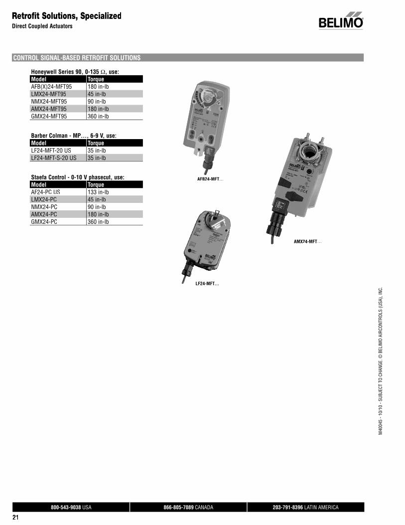
CONTROL SIGNAL-BASED RETROFIT SOLUTIONS
Honeywell Series 90, 0-135 Ω, use:Model TorqueAFB(X)24-MFT95 180 in-lbLMX24-MFT95 45 in-lbNMX24-MFT95 90 in-lbAMX24-MFT95 180 in-lbGMX24-MFT95 360 in-lb
Barber Colman - MP…, 6-9 V, use:Model TorqueLF24-MFT-20 US 35 in-lbLF24-MFT-S-20 US 35 in-lb
Staefa Control - 0-10 V phasecut, use:Model TorqueAF24-PC US 133 in-lbLMX24-PC 45 in-lbNMX24-PC 90 in-lbAMX24-PC 180 in-lbGMX24-PC 360 in-lb
Retrofit Solutions, SpecializedDirect Coupled Actuators
AFB24-MFT…AFB24-MFT
LF24-MFT…
AMX24-MFT…
800-543-9038 USA 866-805-7089 CANADA 203-791-8396 LATIN AMERICA
22
M40
045
- 10/
10 -
SUBJ
ECT
TO C
HANG
E. ©
BEL
IMO
AIRC
ONTR
OLS
(USA
), IN
C.
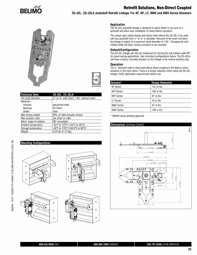
Retrofi t Solutions, Non-Direct CoupledZG-JSL, ZG-JSLA Jackshaft Retrofi t Linkage For AF, NF, LF, NMX and AMX Series Actuators
ApplicationThe ZG-JSL jackshaft linkage is designed to easily attach to any part of a jackshaft and allow easy installation of select Belimo actuators.
The unique open ended design and clamp insert allows the ZG-JSL to be used with any jackshaft from ½” to ¾” in diameter. Removal of the insert will allow the linkage to attach to a maximum shaft diameter of 1.05”. Changing the anti-rotation plate will allow various actuators to be mounted.
Default/ConfigurationThe ZG-JSL linkage can also be configured by moving the anti-rotation plate 90° for space saving applications. See mounting configurations below. The ZG-JSLA will have a factory mounted actuator on the linkage in the vertical position only.
OperationThe ¾” diameter built-in steel shaft allows direct coupling to the Belimo series actuators in the chart below. There is a torque reduction when using the ZG-JSL linkage. Verify application requirements before use.
Actuator* Torque ReductionAF Series 123 in-lbs
AFX Series 166 in-lbs
NFX Series 87 in-lbs
LF Series 33 in-lbs
NMX Series 87 in-lbs
AMX Series 166 in-lbs
* GM/GK series pending approval.
Dimensions (Inches [mm])
4.76
” [12
1]
8.74” [222]
14.05” [357]
10.16” [258]
4.13” [105] 1.93” [49]
3.86” [98]
4.41” [112]
4.65
” [11
8]
6.42
” [16
3]
10.3
1” [2
62]
D31
4
Technical Data ZG-JSL, ZG-JSLAFits shaft diameter ½” to ¾” with insert, 1.05” without insertMaterials: Housing galvanized steel Bearings GF Delrin Shafts steelMax torque output 90% of rated actuator torqueMax actuator yield see chart on rightMech. angle of rotation 90° mountableAmbient temperature -22°F to 122°F [-33°C to 50°C]Storage temperature -40°F to 176°F [148.9°C to 80°C]Weight 3.25 lbs [1.47 kg]
Mounting Configurations

800-543-9038 USA 866-805-7089 CANADA 203-791-8396 LATIN AMERICA
23
M40
045
- 10/
10 -
SUBJ
ECT
TO C
HANG
E. ©
BEL
IMO
AIRC
ONTR
OLS
(USA
), IN
C.
The best replacement solution for non-direct products is to replace the existing product with a direct coupled solution.If direct coupling is not possible, Belimo offers specific retrofit solutions.
ZG-AFB118 Crankarm Adaptor Kit
ZG-AFB Crankarm Adaptor Kit
ZG-118 Universal Mounting Brackets
The ZG-118 is provided with hole patterns to mount the NFB and AFB series actuators in either a horizontal orvertical position to meet space requirements.
The KH-AFB crankarm is required to fully convert the NFB and AFB for crankarm operation.rm operation.
The ZG-118 is designed to mount the NFB and AFB series actuators in the same mounting locations as common footmounted, crankarm style actuators. Hole patterns in the base match common Honeywell™, Siebe™ (Barber Colman™), andJohnson Controls™ actuators for easy retrofit.The ZG-118 is designed to place the KH-AFB crankarm in thesame relative position as the Honeywell™ Mod IV and Mod IIIactuators.Use the ZG-118 when replacing these actuators:Honeywell Mod III Mod IV M91… M945… M955… M965… M975… M8…
Retrofit Solutions, Non-Direct CoupledCrankarm Adaptor Kits and Universal Mounting
KH-AFB CrankarmStandoff Brackets and Mounting FeetMounting HardwareKG8 Ball Joints
The following Universal Mounting Brackets are needed to fullyconvert to crankarm operation:
ZG-100 ZG-101
The ZG-100 and ZG-101 Universal Mounting Brackets are designed for applications where the actuator cannot be mounted directly to the shaft, and no proper mounting surface is available. It may be used for outside or inside the duct mounting, fastened to the ductwork or directly to the damper assembly. It may also be used to mount toother surfaces rather than the duct.The ZG-100 and ZG-101 are provided with pre-punched hole patternsfor the AM, GM, NFB, and AFB series actuators. The ZG-100 hole pattern layout allows mounting these actuators in three different, mounting orientations.
The ZG-AFB118 Mounting Bracket is designed to mount the NF and AF series actuator in the same mounting locations as common foot mounted, crankarm style actuators. Hole patterns in the base matchcommon Honeywell™, Siebe™ (Barber Colman™), and Johnson Controls™ actuators for easy retrofit.
Use when replacing these actuators:Honeywell M91… M945… M955… M965… M975… M8…
Johnson M110… M140… M120… M150… M130…
Barber Colman MA3… MA4… MA5…
The ZG-AFB118 is provided with hole patterns to mount the NFB and AFB series actuators in either a horizontal or vertical position to meet space requirements.The ZG-AFB118 Crankarm Adaptor Kit includes: ZG-118 Mounting Bracket KH-AFB Crankarm with Retaining Ring Mounting HardwareNote: May require crankarmand ball joints.
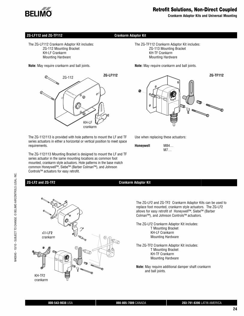
800-543-9038 USA 866-805-7089 CANADA 203-791-8396 LATIN AMERICA
24
M40
045
- 10/
10 -
SUBJ
ECT
TO C
HANG
E. ©
BEL
IMO
AIRC
ONTR
OLS
(USA
), IN
C.
Retrofit Solutions, Non-Direct CoupledCrankarm Adaptor Kits and Universal Mounting
ZG-LF112 and ZG-TF112 Crankarm Adaptor Kit
The ZG-LF112 Crankarm Adaptor Kit includes: ZG-112 Mounting Bracket KH-LF Crankarm Mounting Hardware
Note: May require crankarm and ball joints.
ZG-112
KH-LFcrankarm
ZG LF112ZG-LF112
The ZG-112/113 is provided with hole patterns to mount the LF and TFseries actuators in either a horizontal or vertical position to meet spacerequirements.
The ZG-112/113 Mounting Bracket is designed to mount the LF and TFseries actuator in the same mounting locations as common foot mounted, crankarm style actuators. Hole patterns in the base matchcommon Honeywell™, Siebe™ (Barber Colman™), and JohnsonControls™ actuators for easy retrofit.
The ZG-TF112 Crankarm Adaptor Kit includes: ZG-113 Mounting Bracket KH-TF Crankarm Mounting Hardware
Note: May require crankarm and ball joints.
ZG TF112ZG-TF112
Use when replacing these actuators:
Honeywell M84… M7…
ZG-LF2 and ZG-TF2 Crankarm Adaptor Kit
crankarm
KH-TF2crankarm
The ZG-LF2 and ZG-TF2 Crankarm Adaptor Kits can be used toreplace foot mounted, crankarm style actuators. The ZG-LF2 allows for easy retrofit of Honeywell™, Siebe™ (BarberColman™), and Johnson Controls™ actuators.
The ZG-LF2 Crankarm Adaptor Kit includes: T Mounting Bracket KH-LF Crankarm Mounting Hardware
The ZG-TF2 Crankarm Adaptor Kit includes: T Mounting Bracket KH-TF Crankarm Mounting Hardware
Note: May require additional damper shaft crankarmand ball joints.
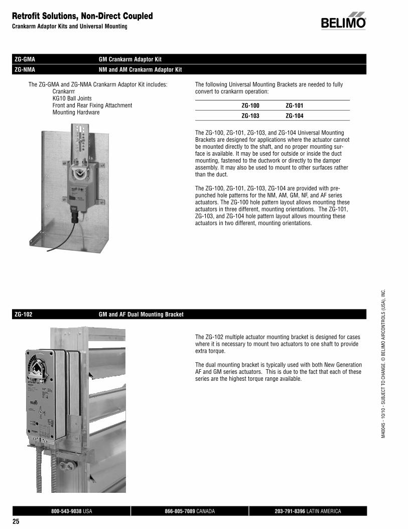
800-543-9038 USA 866-805-7089 CANADA 203-791-8396 LATIN AMERICA
25
M40
045
- 10/
10 -
SUBJ
ECT
TO C
HANG
E. ©
BEL
IMO
AIRC
ONTR
OLS
(USA
), IN
C.
Retrofit Solutions, Non-Direct CoupledCrankarm Adaptor Kits and Universal Mounting
ZG-GMA GM Crankarm Adaptor Kit
ZG-NMA NM and AM Crankarm Adaptor Kit
The ZG-GMA and ZG-NMA Crankarm Adaptor Kit includes: Crankarm KG10 Ball Joints Front and Rear Fixing Attachment Mounting Hardware
The following Universal Mounting Brackets are needed to fully convert to crankarm operation:
ZG-100 ZG-101
ZG-103 ZG-104
The ZG-100, ZG-101, ZG-103, and ZG-104 Universal Mounting Brackets are designed for applications where the actuator cannot be mounted directly to the shaft, and no proper mounting sur-face is available. It may be used for outside or inside the ductmounting, fastened to the ductwork or directly to the damper assembly. It may also be used to mount to other surfaces rather than the duct.
The ZG-100, ZG-101, ZG-103, ZG-104 are provided with pre-punched hole patterns for the NM, AM, GM, NF, and AF series actuators. The ZG-100 hole pattern layout allows mounting these actuators in three different, mounting orientations. The ZG-101,ZG-103, and ZG-104 hole pattern layout allows mounting these actuators in two different, mounting orientations.
ZG-102 GM and AF Dual Mounting Bracket
The ZG-102 multiple actuator mounting bracket is designed for caseswhere it is necessary to mount two actuators to one shaft to provideextra torque.
The dual mounting bracket is typically used with both New Generation AF and GM series actuators. This is due to the fact that each of theseseries are the highest torque range available.

800-543-9038 USA 866-805-7089 CANADA 203-791-8396 LATIN AMERICA
26
M40
045
- 10/
10 -
SUBJ
ECT
TO C
HANG
E. ©
BEL
IMO
AIRC
ONTR
OLS
(USA
), IN
C.
Retrofit Solutions, Economizer Actuators
When replacing an existing actuator in an economizer unit be sure to consider the application parameters before selecting the replacement. Use thechart below for reference. Belimo offers many direct coupled and non-direct replacement solutions. Start with your current model and controller type,and follow the diagram to the appropriate Belimo kit and actuator option. Detailed information on these kits is available in the following section.
Please contact Belimo Customer Service for more possible solutions.
ACTUATOR CONTROLLER BELIMORETROFIT KITS
BELIMO RETROFITACTUATOR OPTIONS
W7459A, D
HWM7415
HWM8405
HWM7215
HWML7275A
(DMA)
ZG-ECON1LF24-ECON-R03 US
W7460
W7210
W7459C
W7212
W7210A, D
W7215A, B
ZG-ECON2
ZG-ECON2
ZG-ECON1
ZG-ECON1
FEMALE SPADES
LF24-SR US
LF24-SR-E US
LF24-SR US
LF24-SR US
Honeywell to Belimo Economizer Solutions

800-543-9038 USA 866-805-7089 CANADA 203-791-8396 LATIN AMERICA
27
M40
045
- 10/
10 -
SUBJ
ECT
TO C
HANG
E. ©
BEL
IMO
AIRC
ONTR
OLS
(USA
), IN
C.
M7415 Economizer Actuator Retrofit
M7415
W7459
Mounting
KH-LFCrankarm
Logic Module Bracket
ZG-112
For proportional control of mixed air set point on economizer dampers in HVAC systems. Actuator sizing should be done in accordance with the damper manufacturer’s specifications.
The actuator is mounted directly to a damper shaft from 3/8” upto ½” in diameter by means of its universal clamp, ½” shaft centered at delivery. For shafts up to ¾” use K6-1 accessory. Acrank arm and several mounting brackets are available for applications where the actuator cannot be direct coupled to the damper shaft.
The actuator operates in response to 3 kΩ or 10 kΩ thermistor,which allows the LF24-ECON... to retrofit or replace Honeywell®
M7415 actuators.
LF24-ECON-R03 US
ZG-ECON1 (Includes ZG-112, KH-LF and 20477-00001)
ZG-112
KH-LF
20477-00001
Wiring Diagrams
Retrofit Solutions, Economizer Actuators
W7459A(D) W7459A(D)
Blk (1) Common
Red (2) + Hot
Wht (3) Y1 3k NTC
Or (4) Y2 Min-pos, 0-10 V
Grn (5) U Output, 2 to 10V
LF24-ECON-R03 US
DefaultCW CCW
0
.2.4 .6
.8
1
MIN
(1)
(2)
(3)
Field installed maleconnectors on actuators (provided with kit ZG-ECON1)
TR
TR124 V
ACSe
nsor
Min
Pos
T
T1
P
P1
TR1TR
+S0
+SR
5
51
43
T1T
P1P
Enthalpy Sensorconnects to S & +
for differentialenthalpy
Connects to RoomController & RTUTerminal Blocks
Mixed/Discharge Air Temperature Sensor
LineVolts W
221_
A
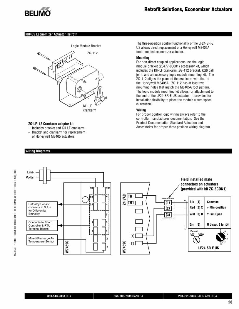
800-543-9038 USA 866-805-7089 CANADA 203-791-8396 LATIN AMERICA
28
M40
045
- 10/
10 -
SUBJ
ECT
TO C
HANG
E. ©
BEL
IMO
AIRC
ONTR
OLS
(USA
), IN
C.
M8405 Economizer Actuator Retrofit
Wiring Diagrams
Retrofit Solutions, Economizer Actuators
The three-position control functionality of the LF24-SR-E US allows direct replacement of a Honeywell M8405Afoot mounted economizer actuator.
MountingFor non-direct coupled applications use the logicmodule bracket (20477-00001) accessory kit, which includes the KH-LF crankarm, ZG-112 bracket, KG6 ball joint, and an accessory logic module mounting kit. The ZG-112 aligns the plane of the crankarm with that of the Honeywell M8405A. ZG-112 has at least two mounting holes that match the M8405A foot pattern. The logic module mounting kit allows for attachment to the end of the LF24-SR-E US actuator. It provides for installation flexibility to place the module where space is available.
WiringFor proper control logic wiring always refer to the controller manufactures documentation. See theProduct Documentation Standard Actuation and Accessories for proper three position wiring diagram.
W74
59C
W74
59C
Blk (1) Common
Red (2) X + Min-position
Wht (3) D Y Full Open
Grn (5) U Output, 2 to 10V
LF24-SR-E US
DefaultCW CCW
0
.2
.4
.6
.81
(1)
(2)
(3)
Field installed maleconnectors on actuators (provided with kit ZG-ECON1)
TR
TR124 V
AC
TR1TR
+S0
+SR
5
51
43
X
D
Enthalpy Sensorconnects to S & +for DifferentialEnthalpy
Connects to RoomController & RTUTerminal Blocks
Mixed/Discharge Air Temperature Sensor
Line
Volts
X
D
ZG-112
Logic Module Bracket
KH-LFcrankarm
ZG-LF112 Crankarm adaptor kit– Includes bracket and KH-LF crankarm.– Bracket and crankarm for replacement
of Honeywell M8405 actuators.
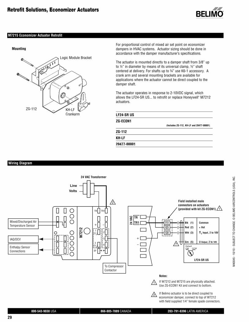
800-543-9038 USA 866-805-7089 CANADA 203-791-8396 LATIN AMERICA
29
M40
045
- 10/
10 -
SUBJ
ECT
TO C
HANG
E. ©
BEL
IMO
AIRC
ONTR
OLS
(USA
), IN
C.
Retrofit Solutions, Economizer Actuators
M7215 Economizer Actuator Retrofit
Line
Volts
Blk (1) Common
Red (2) + Hot
Wht (3) Y1 Input, 2 to 10V
Grn (5) U Output, 2 to 10V
LF24-SR US
DefaultCW CCW
(1)
(2)
(3)
Field installed maleconnectors on actuators (provided with kit ZG-ECON1)
If W7212 and M7215 are physically attached.Use ZG-ECON1 Kit and connect to bottom.
If Belimo actuator is to be direct coupled toeconomizer damper, connect to top of W7212with field supplied 1/4” female spade connectors.
Notes:
TR
TR124 V
AC
+
–
24 VAC Transformer
2
2
1
1
7
Mixed/Discharged AirTemperature Sensor
IAQ/DCV
Enthalpy SensorConnections
TR TR1
+ –
2
5
4
(Y1)
(Y2)
EF
1
3
To CompressorContactor
W72
12
Wiring Diagram
Mounting
KH-LFCrankarm
Logic Module Bracket
ZG-112
For proportional control of mixed air set point on economizer dampers in HVAC systems. Actuator sizing should be done inaccordance with the damper manufacturer’s specifications.
The actuator is mounted directly to a damper shaft from 3/8” upto ½” in diameter by means of its universal clamp, ½” shaft centered at delivery. For shafts up to ¾” use K6-1 accessory. A crank arm and several mounting brackets are available for applications where the actuator cannot be direct coupled to the damper shaft.
The actuator operates in response to 2-10VDC signal, which allows the LF24-SR US... to retrofit or replace Honeywell® M7212 actuators.
LF24-SR US
ZG-ECON1 (Includes ZG-112, KH-LF and 20477-00001)
ZG-112
KH-LF
20477-00001
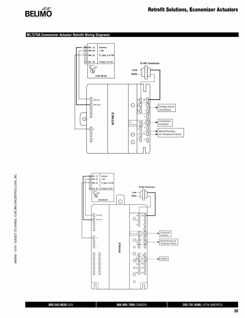
800-543-9038 USA 866-805-7089 CANADA 203-791-8396 LATIN AMERICA
30
M40
045
- 10/
10 -
SUBJ
ECT
TO C
HANG
E. ©
BEL
IMO
AIRC
ONTR
OLS
(USA
), IN
C.
Retrofit Solutions, Economizer Actuators
ML7275A Economizer Actuator Retrofit Wiring Diagrams
Line
Volts
24 VAC Transformer
Blk (1) Common
Red (2) + Hot
Wht (3) Y1 Input, 2 to 10V
Grn (5) U Output, 2 to 10V
LF24-SR US
DefaultCW CCW
+
–
TR
SO
SR
+
TR1
5
Thermostat
3
2
4
T
P
T1
P1
24V Hot
24V Com
CompressorConnector
Enthalpy SensorConnections
Mixed/Discharge Air Temperature Sensor
+
1Y1 W72
10A,
D
Line
Volts
24 VAC Transformer
Blk (1) Common
Red (2) + Hot
Wht (3) Y1 Input, 2 to 10V
Grn (5) U Output, 2 to 10V
LF24-SR US
DefaultCW CCW
24 V Hot
24V Com
+
–
TR
SO
SR
+
+
TR1
5
Y1 Thermostat1
4
7
1
T
P
Q
AQ
SD2
AC1
PG1
Q2
AQ1
SD
AC
PG
CompressorConnector
Mixed/Discharge AirTemperature Sensor
IAQ/DCV
2
W72
15A,
B
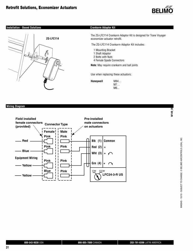
800-543-9038 USA 866-805-7089 CANADA 203-791-8396 LATIN AMERICA
31
M40
045
- 10/
10 -
SUBJ
ECT
TO C
HANG
E. ©
BEL
IMO
AIRC
ONTR
OLS
(USA
), IN
C.
Installation - Based Solutions Crankarm Adaptor Kit
Retrofit Solutions, Economizer Actuators
The ZG-LFC114 Crankarm Adaptor Kit is designed for Trane Voyager economizer actuator retrofit.
The ZG-LFC114 Crankarm Adaptor Kit includes:
1 Mounting Bracket1 Shaft Adaptor2 Bolts with Nuts4 Female Spade Connectors
Note: May require crankarm and ball joints
ZG-LFC114
Wiring Diagram
W14
9_09
Use when replacing these actuators:
Honeywell M84… M7… M6...
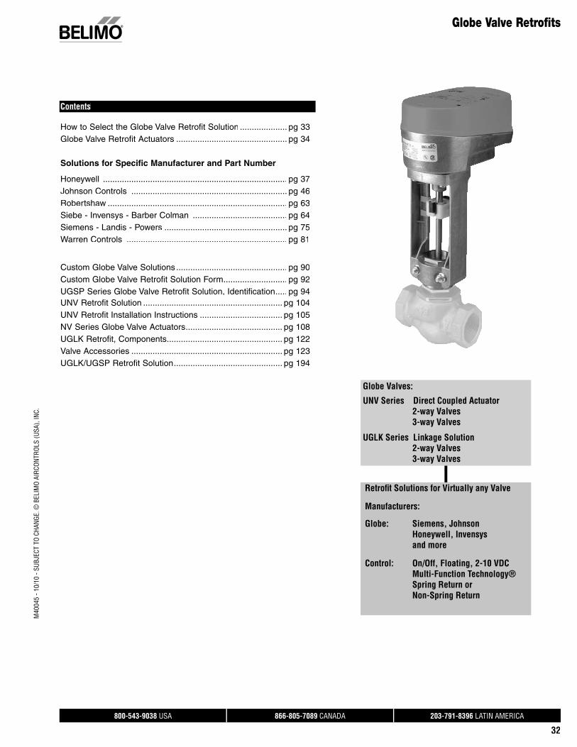
800-543-9038 USA 866-805-7089 CANADA 203-791-8396 LATIN AMERICA
32
M40
045
- 10/
10 -
SUBJ
ECT
TO C
HANG
E. ©
BEL
IMO
AIRC
ONTR
OLS
(USA
), IN
C.
Globe Valve Retrofits
Contents
How to Select the Globe Valve Retrofit Solution .................... pg 33Globe Valve Retrofit Actuators ............................................... pg 34
Solutions for Specific Manufacturer and Part Number
Honeywell .............................................................................. pg 37Johnson Controls .................................................................. pg 46Robertshaw ............................................................................ pg 63Siebe - Invensys - Barber Colman ........................................ pg 64Siemens - Landis - Powers .................................................... pg 75Warren Controls .................................................................... pg 81
Custom Globe Valve Solutions ............................................... pg 90Custom Globe Valve Retrofit Solution Form ........................... pg 92UGSP Series Globe Valve Retrofit Solution, Identification ..... pg 94UNV Retrofit Solution ........................................................... pg 104UNV Retrofit Installation Instructions ................................... pg 105 NV Series Globe Valve Actuators ......................................... pg 108UGLK Retrofit, Components ................................................. pg 122Valve Accessories ................................................................ pg 123UGLK/UGSP Retrofit Solution .............................................. pg 194
Retrofi t Solutions for Virtually any Valve
Manufacturers:
Globe: Siemens, Johnson Honeywell, Invensys and more
Control: On/Off, Floating, 2-10 VDC Multi-Function Technology® Spring Return or Non-Spring Return
Globe Valves:
UNV Series Direct Coupled Actuator 2-way Valves 3-way Valves
UGLK Series Linkage Solution 2-way Valves 3-way Valves
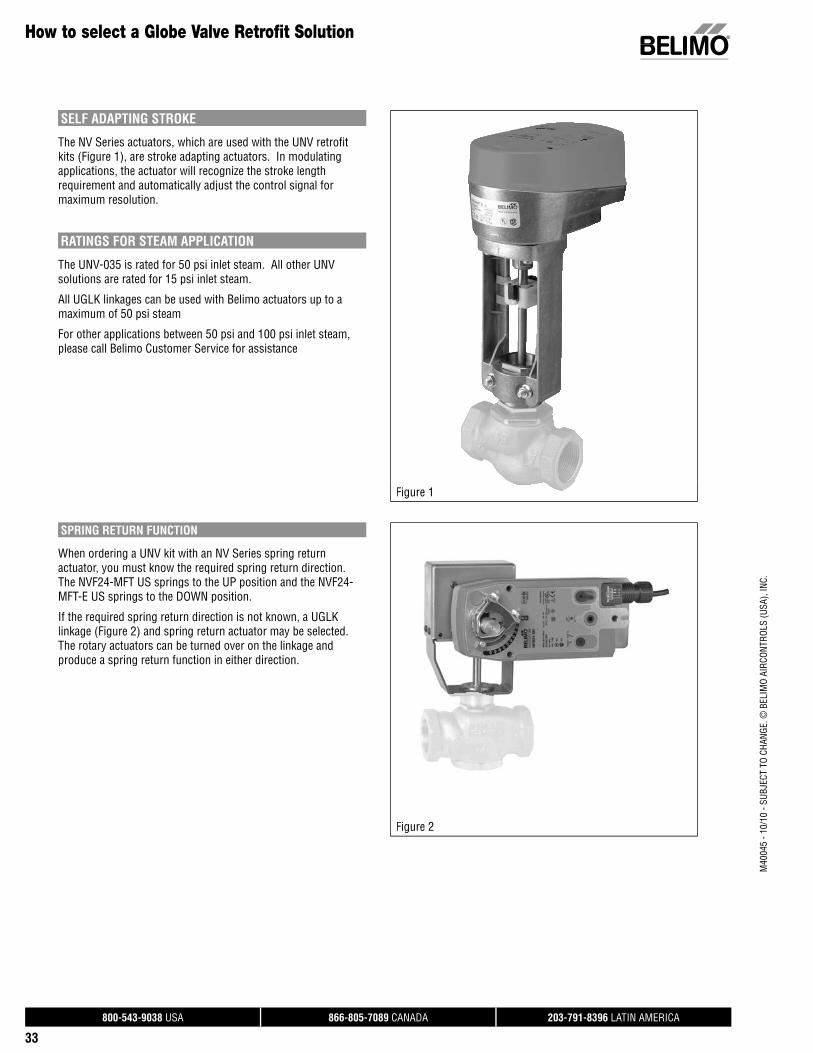
800-543-9038 USA 866-805-7089 CANADA 203-791-8396 LATIN AMERICA
33
M40
045
- 10/
10 -
SUBJ
ECT
TO C
HANG
E. ©
BEL
IMO
AIRC
ONTR
OLS
(USA
), IN
C.
How to select a Globe Valve Retrofit Solution
SELF ADAPTING STROKE
The NV Series actuators, which are used with the UNV retrofit kits (Figure 1), are stroke adapting actuators. In modulating applications, the actuator will recognize the stroke length requirement and automatically adjust the control signal for maximum resolution.
RATINGS FOR STEAM APPLICATION
The UNV-035 is rated for 50 psi inlet steam. All other UNV solutions are rated for 15 psi inlet steam.
All UGLK linkages can be used with Belimo actuators up to a maximum of 50 psi steam
For other applications between 50 psi and 100 psi inlet steam, please call Belimo Customer Service for assistance
Figure 1
SPRING RETURN FUNCTION
When ordering a UNV kit with an NV Series spring return actuator, you must know the required spring return direction. The NVF24-MFT US springs to the UP position and the NVF24-MFT-E US springs to the DOWN position.
If the required spring return direction is not known, a UGLK linkage (Figure 2) and spring return actuator may be selected. The rotary actuators can be turned over on the linkage and produce a spring return function in either direction.
Figure 2

800-543-9038 USA 866-805-7089 CANADA 203-791-8396 LATIN AMERICA
34
M40
045
- 10/
10 -
SUBJ
ECT
TO C
HANG
E. ©
BEL
IMO
AIRC
ONTR
OLS
(USA
), IN
C.
Tips for Choosing a Globe Valve Retrofit Solution
MAXIMUM DIMENSIONS – UNV with NV Series Actuators
D033
8.75" [222]
7.05" [179] 4.35" [110]
in inches (numbers in brackets are metric)
D034
10" [254]
7.05" [179] 4.35" [110]
UNV-003-UNV-040 Dimensions in inches (numbers in brackets are metric)
MAXIMUM DIMENSIONS – UGLK Linkages with Rotary Actuators
A
B C
H1
H2
D
Linkages Taking 1 Actuator
A
B C
H2
H1
D
UGLK1150 and UGLK1550
A
C D
Linkages Taking 2 Actuators
MAXIMUM DIMENSIONS
Linkages Taking 1 ActuatorA 7”-14” [356] D 5” [127]B 3” [76] H1 9.5” [241]C 9” [229][ ] H2 9.5”
Linkages Taking 2 ActuatorsA 19” [483] D 5” [127]B 3” [76]C 9” [229][ ]
UGLK1150 and UGLK1550A 6.5” [165] D 4.0” [102]B 1.5” [33] H1 4.0” [102]C 5.0” [127][ ] H2 3.5" [89][ ]
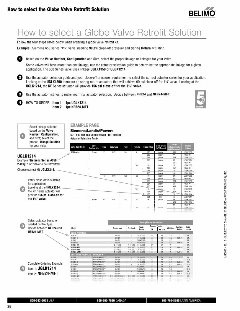
800-543-9038 USA 866-805-7089 CANADA 203-791-8396 LATIN AMERICA
35
M40
045
- 10/
10 -
SUBJ
ECT
TO C
HANG
E. ©
BEL
IMO
AIRC
ONTR
OLS
(USA
), IN
C.
EXAMPLE PAGESiemens\Landis\Powers591, 599 and 658 Series Valves - NPT BodiesActuator Selection Guide
Valve Body Model ValveConfi guration Size Body Type Flow Failsafe Close-Off psi Close-Off psi
(AFX Series)
BelimoActuator Series
(Sold Separately)
BelimoLinkage
658 Series 2-way 1” NPT N/a No 120 (blank) LM UGLK1350229 (blank) NV UNV-004244 (blank) NM UGLK1350250 (blank) AM UGLK1214
NVG UNV-004Yes 95 (blank) LF UGLK1350
183 (blank) NVF UNV-004244 (blank) NF UGLK1214250 (blank) AF UGLK1214
1¼” NPT N/a No 78 (blank) LM UGLK1350147 (blank) NV UNV-004156 (blank) NM UGLK1350235 (blank) NVG UNV-004250 (blank) AM UGLK1214
Yes 61 (blank) LF UGLK1350117 (blank) NVF UNV-004156 (blank) NF UGLK1214231 250 AF UGLK1214
3-way ½” NPT N/a No 250 (blank) LM UGLK1350AM UGLK1214NV UNV-004
YYesYesYesYes 250250250250250 (bl(bla(bla(bla(bla( k)nk)nk)nk)nk)) LFLFLFLFLF UGLKUGLKUGLKUGLKUGLK13501350135013501350NFNFNFNF UGLKUGLKUGLKUGLK1214121412141214
NVFNVFNVF UNVUNV-UNV 004004004
How to select a Globe Valve Retrofit SolutionFollow the four steps listed below when ordering a globe valve retrofit kit.
Example: Siemens 658 series, 1¼” valve, needing 90 psi close-off pressure and Spring Return actuation.
1 Based on the Valve Number, Configuration and Size, select the proper linkage or linkages for your valve.
Some valves will have more than one linkage, use the actuator selection guide to determine the appropriate linkage for a given application. The 658 Series valve uses linkage UGLK1350 or UGLK1214.
2 Use the actuator selection guide and your close-off pressure requirement to select the correct actuator series for your application. Looking at the UGLK1350 there are no spring return actuators that will achieve 90 psi close-off for 1¼" valve. Looking at the UGLK1214, the NF Series actuator will provide 156 psi close-off for the 1¼” valve.
3 Use the actuator listings to make your final actuator selection. Decide between NFB24 and NFB24-MFT.
4 HOW TO ORDER: Item 1 1pc UGLK1214 Item 2 1pc NFB24-MFT
1
Select linkage solution based on the Valve Number, Confi guration, and Size; select theproper Linkage Solutionfor your valve.
UGLK1214Example: Siemens Series #658, 2-Way, 1¼” valve to be retrofi tted.
Choose correct kit UGLK1214.
2
Verify close-off is suitablefor application.Looking at the UGLK1214, the NF Series actuator will provide 156 psi close-off forthe 1¼” valve.
3Select actuator based on needed control type.Decide between NFB24 and NFB24-MFT.
4Complete Ordering Example:
Item 1: UGLK1214Item 2: NFB24-MFT
How to select the Globe Valve Retrofit Solution
Spring Return Actuators
ModelModeode Control Input Feedback PowerSupply
Running Time(s)VA Rating Auxiliary
Switch CableLength
BASIC PRODUCTSNFB24 On/Off - 24 VAC/DC <75 20 8.5 - 3 ft.NFB24-S On/Off - 24 VAC/DC <75 20 8.5 Built-In 3 ft.NFBUP On/Off - 24-240 VACu <75 20 9.5 - 3 ft.NFBUP-S On/Off - 24-240 VACu <75 20 9.5 Built-In 3 ft.NFB24-SR 2-10 VDC 2-10 VDC 24 VAC/DC 95 <20 6 - 3 ft.NFB24-SR-S 2-10 VDC 2-10 VDC 24 VAC/DC 95 <20 6 Built-In 3 ft.NFB24-MFT 2-10 VDC 2-10 VDC 24 VAC/DC 150 <20 9 - 3 ft.NFB24-MFT-S 2-10 VDC 2-10 VDC 24 VAC/DC 150 <20 9 Built-In 3 ft.CUSTOMIZE PRODUCTS REORDER #NFX24 NF200 1A1 003** On/Off - 24 VAC/DC <75 20 8.5 - 3 ft.NFX24 NF200 1A3 003** On/Off - 24 VAC/DC <75 20 8.5 - 10 ft.NFX24-S NF220 1A1 003** On/Off - 24 VAC/DC <75 20 8.5 Built-In 3 ft.NFX24-S NF220 1A3 003** On/Off - 24 VAC/DC <75 20 8.5 Built-In 10 ft.NFXUP NF000 1A1 003** On/Off - 24-240 VACu <75 20 9.5 - 3 ft.NFXUP NF000 1A3 003** On/Off - 24-240 VACu <75 20 9.5 - 10 ft.NFXUP-S NF000 1A1 003** On/Off - 24-240 VACu <75 20 9.5 Built-In 3 ft.NFXUPNFNNNNN -S NF000NF000NF000NF000F000F000F000 1A3 1A3 1A3 1A3 1A3 1A3 1A3 003**003**003**003**003**003003 On/OfOn/OfOn/On/On/On/On/ f f --- - 24-2424-224-224-224-224-224 2 0 VACVACVACVACVACCCuuuuu <75<<<< 20 9.59 59 59.59 59 59.5 BuiltBuiltBuiltBuiltBuiltBuilBuil -In-In -In-In InInIn 10 ft.NFX24NFX24NFX24NFX24NFX24NNFX24NNFX24N SRSRSR-SR-SR-SR SR NF400NF400NF400NF400NF40000NF400NF400F400F400 1A1 1A1 1A11A11A11A11 1A1 1A1 1A1 H01**H01H010H01**H01**H01**H01**H01H01 2-10 2 102 102 102-102-102-10 2-102-10 2 10 VDC (VDC (VDC (VDC (VDC (VDC ((VDC (VDC (VDC VDC 4 204-20m4 20m4-20m4-20m4-20mm4-20mmmA*)A*)A*)A*)A*)A*)))A*)))) 2-10 2-102 102 102-102 102-10 2-102-10 2 10 VDC VDCVDCVDCVDCVDCVDCVDC VDC VDC 4 VA24 VA24 V24 VA24 VA24 VA24 VA V V C/DCC/DCC/DCC/DCC/DC/DC C/DC/DC /DC C 959595959595 <<202020<20<20<20 6666666666 ---- 3 f3 ft3 ft3 ft3 ft.3 ft.NFX24NFX24NFX24NFNFX24NNFX24N SRSR-SR-SR -SR SR NF400NF4000NF400NF400NF400NF400F400 1A31A31A31A3 1A3 1A3 1A3 H01**H01H01**H01**H01H01**H01 2-1022 102-102-102-10 2-10 2 10 VDC (VDC (VDC (VDC (VDC (VDC (VDC VDC 4-20m4 24-20m4-20m4-20m4-20mmm )A*)A*)A*)A*)A*)*)) 2-102-1022 102-102-10 2-10 2 10 VDCVDCVDCVDCVDCVDC VDC VDC 24 VA24 V24 VA24 VA24 VA4 VA V C/DC/DCC/DCC/DCC/DC/DC /DC C 95959595 <20<202<<20<20 66666666 --- -- 10 ft10 ft10 ft10 ft.NFX24NFX24NFX24N SR S-SR-S-SR-S NF420NF420NF420NF420 1A1 1A1 1A1 1A1 H01**H01H01**H01** 2-10 2 102-102-10 VDC (VDC (VDC ((VDC (4 20m4-20m4-20mmA*)A*) A*))A*) ) 2-10 2-102 102-10 VDC VDCVDCVDC 24 VA24 VA24 VA V C/DCC/DCC/DC /DC 959595 <20<20<20 6666 BuiltBuiltBuiltBuilt In-In-In -In 3 ft3 ft3 ft3 ft.NFX24NFX24-SR-S-SR-S NF420NF420 1A5 1A5 H01**H01 2-102-10 VDC (VDC (4-20m4-20mA*)A*) 2-102-10 VDCVDC 24 VA24 VAC/DCC/DC 95 se95 secondsconds <20<20 66 BuiltBuilt-In-In 16 ft16 ft.

800-543-9038 USA 866-805-7089 CANADA 203-791-8396 LATIN AMERICA
36
Globe Valve Retrofi t ActuatorsActuator Suggestion Guide
LINEAR ACTUATORS
SERIES MODEL Spring Return Control Input Feedback Position
PowerSupply
StandardRunning Time
NVF SeriesNVF24-MFT US spring UP Variable with MFT
(VDC, PWM, Floating Pt., On/Off) variable VDC 24 VAC/DC 150 seconds
NVF24-MFT-E US spring DOWN Variable with MFT(VDC, PWM, Floating Pt., On/Off) variable VDC 24 VAC/DC 150 seconds
NV SeriesNV24-3 US Floating Pt., On/Off 24 VAC/DC 150 seconds
NV24-MFT US Variable with MFT(VDC, PWM, Floating Pt., On/Off) variable VDC 24 VAC/DC 150 seconds
NVG Series NVG24-MFT US Variable with MFT(VDC, PWM, Floating Pt., On/Off) variable VDC 24 VAC/DC 150 seconds
ROTARY ACTUATORS SUGGESTION
SERIES MODEL Spring Return
ElectronicFail Safe
Control Input Feedback Position
PowerSupply
StandardRunning Time
LF Series*LF24 US • 24 VAC/DC 24 VAC/DC
Cons
ult S
peci
fi cat
ions
LF24-MFT US • Variable with MFT(VDC, PWM, Floating Pt., On/Off) variable VDC 24 VAC/DC
NF Series*NFBUP-X1 • 24 VAC/DC 24 VAC/DC
NFX24-MFT-X1 • Variable with MFT(VDC, PWM, Floating Pt., On/Off) variable VDC 24 VAC/DC
AF Series*AF24 US, AFB24 • 24 VAC/DC 24 VAC/DC
AFX24-MFT-X1 • Variable with MFT(VDC, PWM, Floating Pt., On/Off) variable VDC 24 VAC/DC
LM Series*LMB24-3-X1 Floating Pt., On/Off 24 VAC/DC
LMX24-MFT-X1 Variable with MFT(VDC, PWM, Floating Pt., On/Off) variable VDC 24 VAC/DC
NM Series*NMB24-3-X1 24 VAC/DC 24 VAC/DC
NMX24-MFT-X1 Variable with MFT(VDC, PWM, Floating Pt., On/Off) variable VDC 24 VAC/DC
AM Series*AMB24-3-X1 24 VAC/DC 24 VAC/DC
AMX24-MFT-X1 Variable with MFT(VDC, PWM, Floating Pt., On/Off) variable VDC 24 VAC/DC
GM Series*GMB24-3-X1 24 VAC/DC 24 VAC/DC
GMX24-MFT-X1 Variable with MFT(VDC, PWM, Floating Pt., On/Off) variable VDC 24 VAC/DC
GK Series*GKB24-3-X1 • 24 VAC/DC 24 VAC/DC
GKX24-MFT-X1 • Variable with MFT(VDC, PWM, Floating Pt., On/Off) variable VDC 24 VAC/DC
*Please consult the Damper sections for a full list of product offerings. Standard run times should be considered in the selection. All air side products are applicable for retrofi t kits. Select “X1” actuators come with a handle.
MULTI-FUNCTION TECHNOLOGYP-CODE Control Input Running Time Built-in Feedback
NV C
ODES
V-10001 N01
ROTA
RY A
CTUA
TOR
CODE
S P-10001 A01 2-10 VDC 150 seconds 2-10 VDCV-10002 N02 P-10002 A02 0-10 VDC 150 seconds 0-10 VDCV-10028 N1E P-10028 A28 0-10 VDC 150 seconds 0-10 VDCV-10063 N1K P-10063 A63 0.5-4.5 VDC 150 seconds 0.5-4.5 VDCV-10064 N1L P-10064 A64 5.5-10 VDC 150 seconds 5.5-10 VDCV-20002 N1U P-20002 W02 0.02-5.00 seconds PWM 150 seconds 2-10 VDCV-20003 N1V P-20003 W03 0.10-25.5 seconds PWM 150 seconds 2-10 VDCV-30001 N24 P-30001 F01 Floating Pt. 150 seconds 2-10 VDCV-40002 N29 P-40002 J02 On/Off 150 seconds 2-10 VDC
Note: V-codes used for NV…Series actuator. All other MFT actuators use P-codes.
M40
045
- 10/
10 -
SUBJ
ECT
TO C
HANG
E. ©
BEL
IMO
AIRC
ONTR
OLS
(USA
), IN
C.
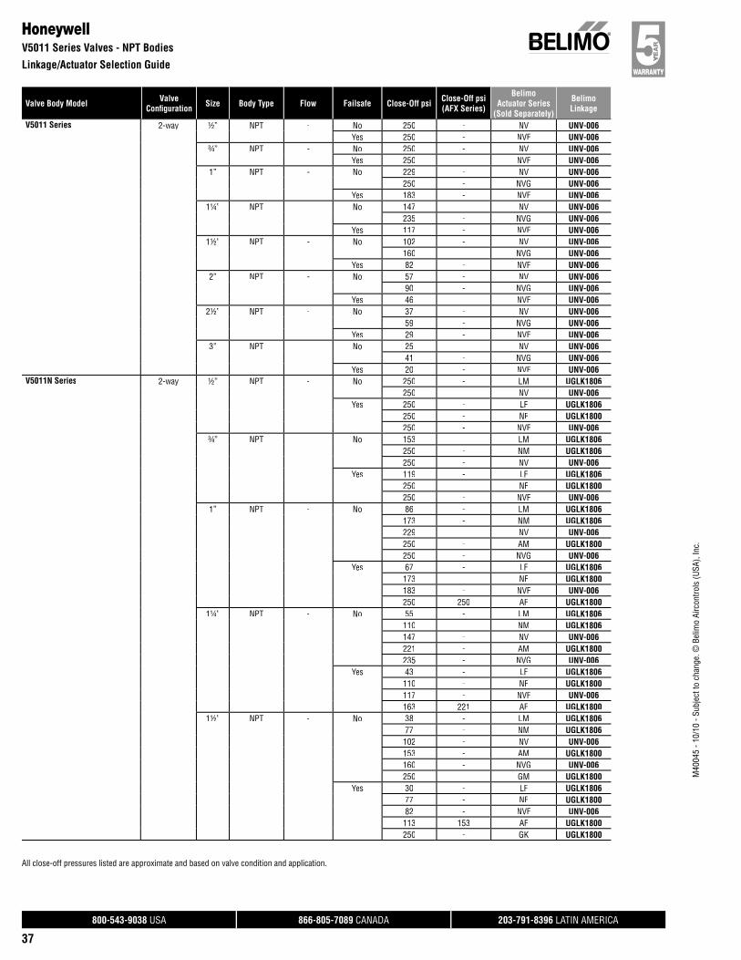
800-543-9038 USA 866-805-7089 CANADA 203-791-8396 LATIN AMERICA
37
Valve Body Model ValveConfi guration Size Body Type Flow Failsafe Close-Off psi Close-Off psi
(AFX Series)
BelimoActuator Series
(Sold Separately)
BelimoLinkage
M40
045
- 10/
10 -
Subj
ect t
o ch
ange
. © B
elim
o Ai
rcon
trols
(USA
), In
c.
All close-off pressures listed are approximate and based on valve condition and application.
HoneywellV5011 Series Valves - NPT Bodies
Linkage/Actuator Selection Guide
V5011 Series 2-way ½” NPT - No 250 - NV UNV-006Yes 250 - NVF UNV-006
¾” NPT - No 250 - NV UNV-006Yes 250 - NVF UNV-006
1” NPT - No 229 - NV UNV-006250 - NVG UNV-006
Yes 183 - NVF UNV-0061¼” NPT - No 147 - NV UNV-006
235 - NVG UNV-006Yes 117 - NVF UNV-006
1½” NPT - No 102 - NV UNV-006160 - NVG UNV-006
Yes 82 - NVF UNV-0062” NPT - No 57 - NV UNV-006
90 - NVG UNV-006Yes 46 - NVF UNV-006
2½” NPT - No 37 - NV UNV-00659 - NVG UNV-006
Yes 29 - NVF UNV-0063” NPT - No 25 - NV UNV-006
41 - NVG UNV-006Yes 20 - NVF UNV-006
V5011N Series 2-way ½” NPT - No 250 - LM UGLK1806250 - NV UNV-006
Yes 250 - LF UGLK1806250 - NF UGLK1800250 - NVF UNV-006
¾” NPT - No 153 - LM UGLK1806250 - NM UGLK1806250 - NV UNV-006
Yes 119 - LF UGLK1806250 - NF UGLK1800250 - NVF UNV-006
1” NPT - No 86 - LM UGLK1806173 - NM UGLK1806229 - NV UNV-006250 - AM UGLK1800250 - NVG UNV-006
Yes 67 - LF UGLK1806173 - NF UGLK1800183 - NVF UNV-006250 250 AF UGLK1800
1¼” NPT - No 55 - LM UGLK1806110 - NM UGLK1806147 - NV UNV-006221 - AM UGLK1800235 - NVG UNV-006
Yes 43 - LF UGLK1806110 - NF UGLK1800117 - NVF UNV-006163 221 AF UGLK1800
1½” NPT - No 38 - LM UGLK180677 - NM UGLK1806102 - NV UNV-006153 - AM UGLK1800160 - NVG UNV-006250 - GM UGLK1800
Yes 30 - LF UGLK180677 - NF UGLK180082 - NVF UNV-006113 153 AF UGLK1800250 - GK UGLK1800
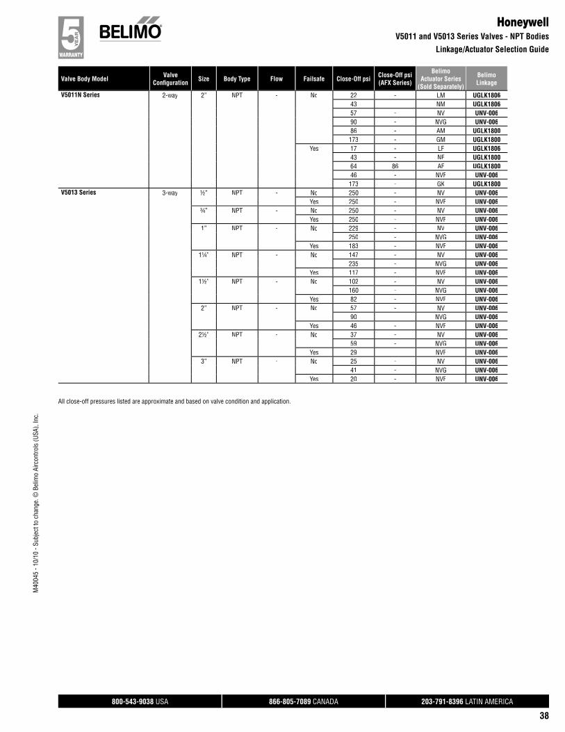
800-543-9038 USA 866-805-7089 CANADA 203-791-8396 LATIN AMERICA
38
Valve Body Model ValveConfi guration Size Body Type Flow Failsafe Close-Off psi Close-Off psi
(AFX Series)
BelimoActuator Series
(Sold Separately)
BelimoLinkage
M40
045
- 10/
10 -
Subj
ect t
o ch
ange
. © B
elim
o Ai
rcon
trols
(USA
), In
c.
All close-off pressures listed are approximate and based on valve condition and application.
HoneywellV5011 and V5013 Series Valves - NPT Bodies
Linkage/Actuator Selection Guide
V5011N Series 2-way 2” NPT - No 22 - LM UGLK180643 - NM UGLK180657 - NV UNV-00690 - NVG UNV-00686 - AM UGLK1800173 - GM UGLK1800
Yes 17 - LF UGLK180643 - NF UGLK180064 86 AF UGLK180046 - NVF UNV-006173 - GK UGLK1800
V5013 Series 3-way ½” NPT - No 250 - NV UNV-006Yes 250 - NVF UNV-006
¾” NPT - No 250 - NV UNV-006Yes 250 - NVF UNV-006
1” NPT - No 229 - NV UNV-006250 - NVG UNV-006
Yes 183 - NVF UNV-0061¼” NPT - No 147 - NV UNV-006
235 - NVG UNV-006Yes 117 - NVF UNV-006
1½” NPT - No 102 - NV UNV-006160 - NVG UNV-006
Yes 82 - NVF UNV-0062” NPT - No 57 - NV UNV-006
90 - NVG UNV-006Yes 46 - NVF UNV-006
2½” NPT - No 37 - NV UNV-00659 - NVG UNV-006
Yes 29 - NVF UNV-0063” NPT - No 25 - NV UNV-006
41 - NVG UNV-006Yes 20 - NVF UNV-006
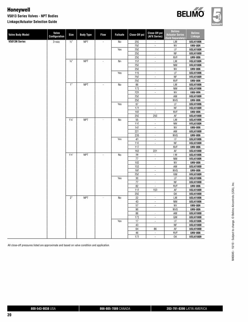
800-543-9038 USA 866-805-7089 CANADA 203-791-8396 LATIN AMERICA
39
Valve Body Model ValveConfi guration Size Body Type Flow Failsafe Close-Off psi Close-Off psi
(AFX Series)
BelimoActuator Series
(Sold Separately)
BelimoLinkage
M40
045
- 10/
10 -
Subj
ect t
o ch
ange
. © B
elim
o Ai
rcon
trols
(USA
), In
c.
All close-off pressures listed are approximate and based on valve condition and application.
HoneywellV5013 Series Valves - NPT Bodies
Linkage/Actuator Selection Guide
( p y)V5013N Series 3-way ½” NPT - No 250 - LM UGLK1806
250 - NV UNV-006Yes 250 - LF UGLK1806
250 - NF UGLK1800250 - NVF UNV-006
¾” NPT - No 153 - LM UGLK1806250 - NM UGLK1806250 - NV UNV-006
Yes 119 - LF UGLK1806250 - NF UGLK1800250 - NVF UNV-006
1” NPT - No 86 - LM UGLK1806173 - NM UGLK1806229 - NV UNV-006250 - AM UGLK1800250 - NVG UNV-006
Yes 67 - LF UGLK1806173 - NF UGLK1800183 - NVF UNV-006250 250 AF UGLK1800
1¼” NPT - No 55 - LM UGLK1806110 - NM UGLK1806147 - NV UNV-006221 - AM UGLK1800235 - NVG UNV-006
Yes 43 - LF UGLK1806110 - NF UGLK1800117 - NVF UNV-006163 221 AF UGLK1800
1½” NPT - No 38 - LM UGLK180677 - NM UGLK1806102 - NV UNV-006153 - AM UGLK1800160 - NVG UNV-006250 - GM UGLK1800
Yes 30 - LF UGLK180677 - NF UGLK180082 - NVF UNV-006113 153 AF UGLK1800250 - GK UGLK1800
2” NPT - No 22 - LM UGLK180643 - NM UGLK180657 - NV UNV-00690 - NVG UNV-00686 - AM UGLK1800173 - GM UGLK1800
Yes 17 - LF UGLK180643 - NF UGLK180064 86 AF UGLK180046 - NVF UNV-006173 - GK UGLK1800
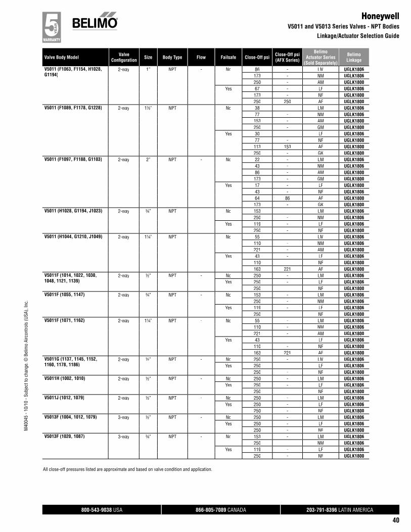
800-543-9038 USA 866-805-7089 CANADA 203-791-8396 LATIN AMERICA
40
Valve Body Model ValveConfi guration Size Body Type Flow Failsafe Close-Off psi Close-Off psi
(AFX Series)
BelimoActuator Series
(Sold Separately)
BelimoLinkage
M40
045
- 10/
10 -
Subj
ect t
o ch
ange
. © B
elim
o Ai
rcon
trols
(USA
), In
c.
All close-off pressures listed are approximate and based on valve condition and application.
HoneywellV5011 and V5013 Series Valves - NPT Bodies
Linkage/Actuator Selection Guide
V5011 (F1063, F1154, H1028,G1194)
2-way 1” NPT - No 86 - LM UGLK1806173 - NM UGLK1806250 - AM UGLK1800
Yes 67 - LF UGLK1806173 - NF UGLK1800250 250 AF UGLK1800
V5011 (F1089, F1178, G1228) 2-way 1½” NPT - No 38 - LM UGLK180677 - NM UGLK1806153 - AM UGLK1800250 - GM UGLK1800
Yes 30 - LF UGLK180677 - NF UGLK1800113 153 AF UGLK1800250 - GK UGLK1800
V5011 (F1097, F1188, G1103) 2-way 2” NPT - No 22 - LM UGLK180643 - NM UGLK180686 - AM UGLK1800173 - GM UGLK1800
Yes 17 - LF UGLK180043 - NF UGLK180664 86 AF UGLK1800173 - GK UGLK1800
V5011 (H1028, G1194, J1023) 2-way ¾” NPT - No 153 - LM UGLK1806250 - NM UGLK1806
Yes 119 - LF UGLK1806250 - NF UGLK1800
V5011 (H1044, G1210, J1049) 2-way 1¼” NPT - No 55 - LM UGLK1806110 - NM UGLK1806221 - AM UGLK1800
Yes 43 - LF UGLK1806110 - NF UGLK1800163 221 AF UGLK1800
V5011F (1014, 1022, 1030,1048, 1121, 1139)
2-way ½” NPT - No 250 - LM UGLK1806Yes 250 - LF UGLK1806
250 - NF UGLK1800V5011F (1055, 1147) 2-way ¾” NPT - No 153 - LM UGLK1806
250 - NM UGLK1806Yes 119 - LF UGLK1806
250 - NF UGLK1800V5011F (1071, 1162) 2-way 1¼” NPT - No 55 - LM UGLK1806
110 - NM UGLK1806221 - AM UGLK1800
Yes 43 - LF UGLK1806110 - NF UGLK1800163 221 AF UGLK1800
V5011G (1137, 1145, 1152,1160, 1178, 1186)
2-way ½” NPT - No 250 - LM UGLK1806Yes 250 - LF UGLK1806
250 - NF UGLK1800V5011H (1002, 1010) 2-way ½” NPT - No 250 - LM UGLK1806
Yes 250 - LF UGLK1806250 - NF UGLK1800
V5011J (1012, 1079) 2-way ½” NPT - No 250 - LM UGLK1806Yes 250 - LF UGLK1806
250 - NF UGLK1800V5013F (1004, 1012, 1079) 3-way ½” NPT - No 250 - LM UGLK1806
Yes 250 - LF UGLK1806250 - NF UGLK1800
V5013F (1020, 1087) 3-way ¾” NPT - No 153 - LM UGLK1806250 - NM UGLK1806
Yes 119 - LF UGLK1806250 - NF UGLK1800
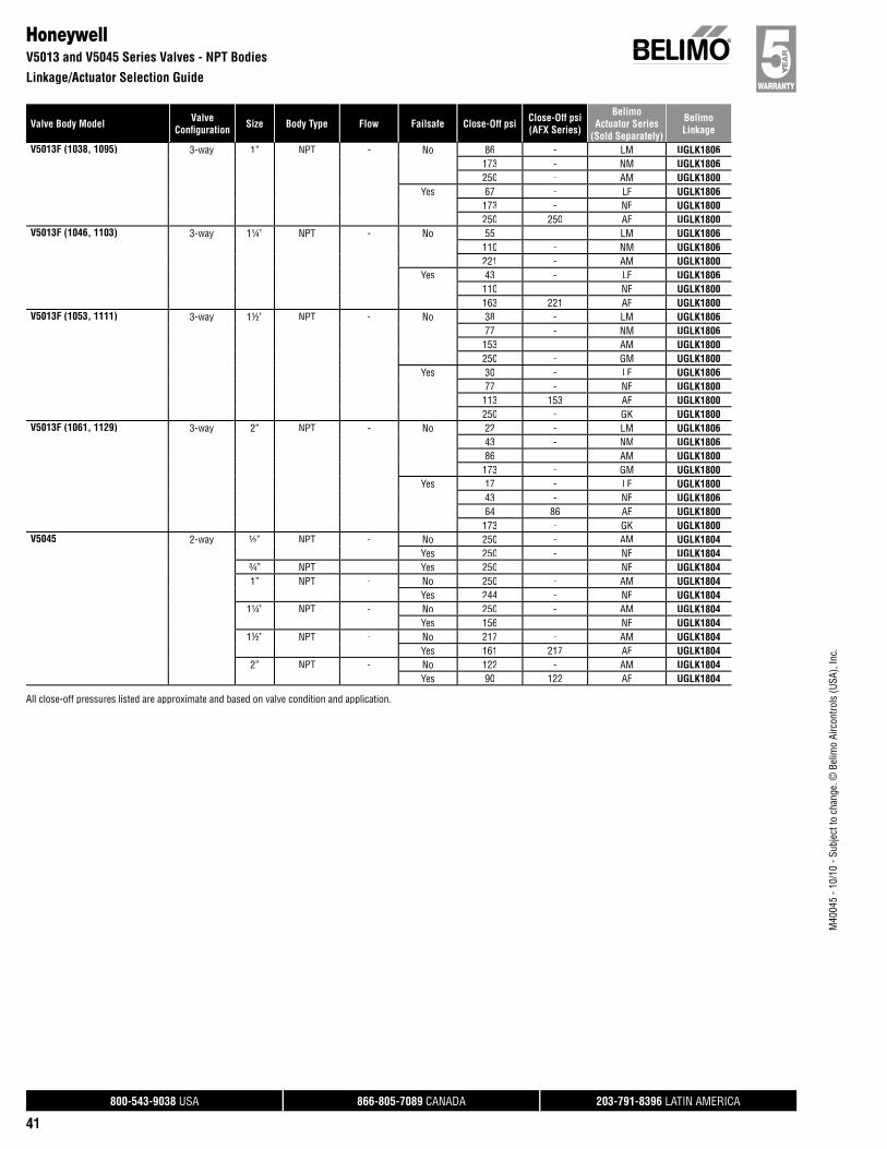
800-543-9038 USA 866-805-7089 CANADA 203-791-8396 LATIN AMERICA
41
Valve Body Model ValveConfi guration Size Body Type Flow Failsafe Close-Off psi Close-Off psi
(AFX Series)
BelimoActuator Series
(Sold Separately)
BelimoLinkage
M40
045
- 10/
10 -
Subj
ect t
o ch
ange
. © B
elim
o Ai
rcon
trols
(USA
), In
c.
All close-off pressures listed are approximate and based on valve condition and application.
HoneywellV5013 and V5045 Series Valves - NPT Bodies
Linkage/Actuator Selection Guide
V5013F (1038, 1095) 3-way 1” NPT - No 86 - LM UGLK1806173 - NM UGLK1806250 - AM UGLK1800
Yes 67 - LF UGLK1806173 - NF UGLK1800250 250 AF UGLK1800
V5013F (1046, 1103) 3-way 1¼” NPT - No 55 - LM UGLK1806110 - NM UGLK1806221 - AM UGLK1800
Yes 43 - LF UGLK1806110 - NF UGLK1800163 221 AF UGLK1800
V5013F (1053, 1111) 3-way 1½” NPT - No 38 - LM UGLK180677 - NM UGLK1806153 - AM UGLK1800250 - GM UGLK1800
Yes 30 - LF UGLK180677 - NF UGLK1800113 153 AF UGLK1800250 - GK UGLK1800
V5013F (1061, 1129) 3-way 2” NPT - No 22 - LM UGLK180643 - NM UGLK180686 - AM UGLK1800173 - GM UGLK1800
Yes 17 - LF UGLK180043 - NF UGLK180664 86 AF UGLK1800173 - GK UGLK1800
V5045 2-way ½” NPT - No 250 - AM UGLK1804Yes 250 - NF UGLK1804
¾” NPT - Yes 250 - NF UGLK18041” NPT - No 250 - AM UGLK1804
Yes 244 - NF UGLK18041¼” NPT - No 250 - AM UGLK1804
Yes 156 - NF UGLK18041½” NPT - No 217 - AM UGLK1804
Yes 161 217 AF UGLK18042” NPT - No 122 - AM UGLK1804
Yes 90 122 AF UGLK1804
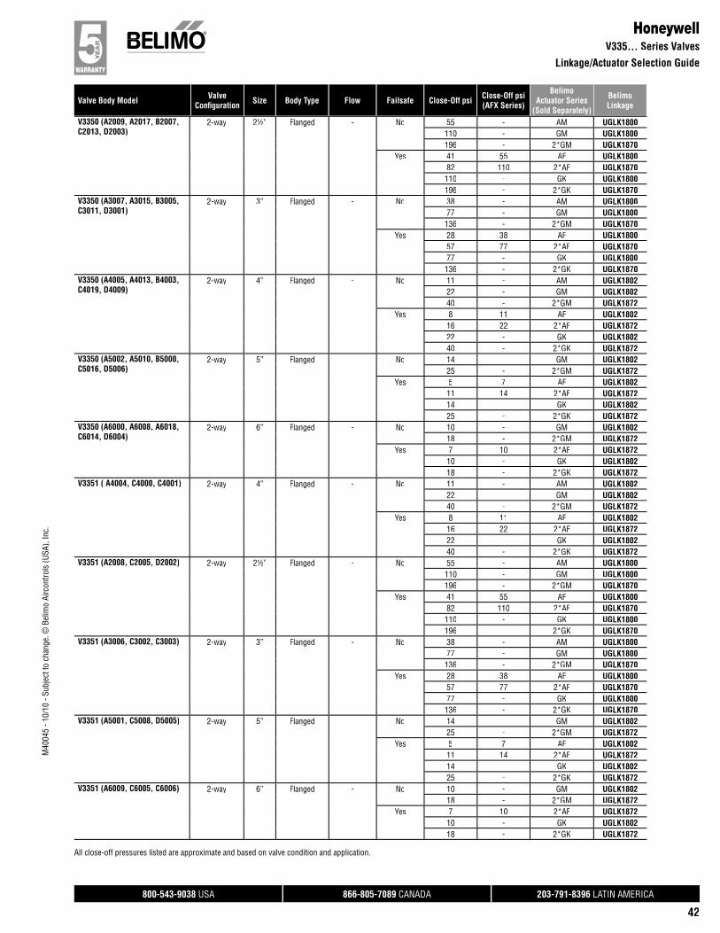
800-543-9038 USA 866-805-7089 CANADA 203-791-8396 LATIN AMERICA
42
Valve Body Model ValveConfi guration Size Body Type Flow Failsafe Close-Off psi Close-Off psi
(AFX Series)
BelimoActuator Series
(Sold Separately)
BelimoLinkage
M40
045
- 10/
10 -
Subj
ect t
o ch
ange
. © B
elim
o Ai
rcon
trols
(USA
), In
c.
HoneywellV335… Series Valves
Linkage/Actuator Selection Guide
V3350 (A2009, A2017, B2007,C2013, D2003)
2-way 2½” Flanged - No 55 - AM UGLK1800110 - GM UGLK1800196 - 2*GM UGLK1870
Yes 41 55 AF UGLK180082 110 2*AF UGLK1870110 - GK UGLK1800196 - 2*GK UGLK1870
V3350 (A3007, A3015, B3005,C3011, D3001)
2-way 3” Flanged - No 38 - AM UGLK180077 - GM UGLK1800136 - 2*GM UGLK1870
Yes 28 38 AF UGLK180057 77 2*AF UGLK187077 - GK UGLK1800136 - 2*GK UGLK1870
V3350 (A4005, A4013, B4003,C4019, D4009)
2-way 4” Flanged - No 11 - AM UGLK180222 - GM UGLK180240 - 2*GM UGLK1872
Yes 8 11 AF UGLK180216 22 2*AF UGLK187222 - GK UGLK180240 - 2*GK UGLK1872
V3350 (A5002, A5010, B5000,C5016, D5006)
2-way 5” Flanged - No 14 - GM UGLK180225 - 2*GM UGLK1872
Yes 5 7 AF UGLK180211 14 2*AF UGLK187214 - GK UGLK180225 - 2*GK UGLK1872
V3350 (A6000, A6008, A6018,C6014, D6004)
2-way 6” Flanged - No 10 - GM UGLK180218 - 2*GM UGLK1872
Yes 7 10 2*AF UGLK187210 - GK UGLK180218 - 2*GK UGLK1872
V3351 ( A4004, C4000, C4001) 2-way 4” Flanged - No 11 - AM UGLK180222 - GM UGLK180240 - 2*GM UGLK1872
Yes 8 11 AF UGLK180216 22 2*AF UGLK187222 - GK UGLK180240 - 2*GK UGLK1872
V3351 (A2008, C2005, D2002) 2-way 2½” Flanged - No 55 - AM UGLK1800110 - GM UGLK1800196 - 2*GM UGLK1870
Yes 41 55 AF UGLK180082 110 2*AF UGLK1870110 - GK UGLK1800196 - 2*GK UGLK1870
V3351 (A3006, C3002, C3003) 2-way 3” Flanged - No 38 - AM UGLK180077 - GM UGLK1800136 - 2*GM UGLK1870
Yes 28 38 AF UGLK180057 77 2*AF UGLK187077 - GK UGLK1800136 - 2*GK UGLK1870
V3351 (A5001, C5008, D5005) 2-way 5” Flanged - No 14 - GM UGLK180225 - 2*GM UGLK1872
Yes 5 7 AF UGLK180211 14 2*AF UGLK187214 - GK UGLK180225 - 2*GK UGLK1872
V3351 (A6009, C6005, C6006) 2-way 6” Flanged - No 10 - GM UGLK180218 - 2*GM UGLK1872
Yes 7 10 2*AF UGLK187210 - GK UGLK180218 - 2*GK UGLK1872
All close-off pressures listed are approximate and based on valve condition and application.
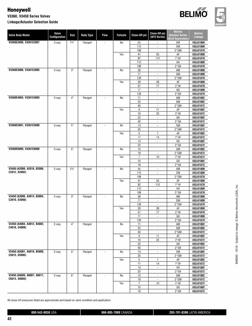
800-543-9038 USA 866-805-7089 CANADA 203-791-8396 LATIN AMERICA
43
Valve Body Model ValveConfi guration Size Body Type Flow Failsafe Close-Off psi Close-Off psi
(AFX Series)
BelimoActuator Series
(Sold Separately)
BelimoLinkage
M40
045
- 10/
10 -
Subj
ect t
o ch
ange
. © B
elim
o Ai
rcon
trols
(USA
), In
c.
All close-off pressures listed are approximate and based on valve condition and application.
HoneywellV3360, V3450 Series Valves
Linkage/Actuator Selection Guide
V3360E2008, V3361E2007 3-way 2½” Flanged - No 55 - AM UGLK1800110 - GM UGLK1800196 - 2*GM UGLK1870
Yes 41 55 AF UGLK180082 110 2*AF UGLK1870110 - GK UGLK1800196 - 2*GK UGLK1870
V3360E3006, V3361E3005 3-way 3” Flanged - No 38 - AM UGLK180077 - GM UGLK1800136 - 2*GM UGLK1870
Yes 28 38 AF UGLK180057 77 2*AF UGLK187077 - GK UGLK1800136 - 2*GK UGLK1870
V3360E4004, V3361E4003 3-way 4” Flanged - No 11 - AM UGLK180222 - GM UGLK180240 - 2*GM UGLK1872
Yes 8 11 AF UGLK180216 22 2*AF UGLK187222 - GK UGLK180240 - 2*GK UGLK1872
V3360E5001, V3361E5000 3-way 5” Flanged - No 14 - GM UGLK180225 - 2*GM UGLK1872
Yes 5 7 AF UGLK180211 14 2*AF UGLK187214 - GK UGLK180225 - 2*GK UGLK1872
V3360E6009, V3361E6008 3-way 6” Flanged - No 10 - GM UGLK180218 - 2*GM UGLK1872
Yes 7 10 2*AF UGLK187210 - GK UGLK180218 - 2*GK UGLK1872
V3450 (A2008, A2016, B2006,C2012, D2002)
2-way 2½” Flanged - No 55 - AM UGLK1800110 - GM UGLK1800196 - 2*GM UGLK1870
Yes 41 55 AF UGLK180082 110 2*AF UGLK1870110 - GK UGLK1800196 - 2*GK UGLK1870
V3450 (A3006, A3014, B3004,C3010, D3000)
2-way 3” Flanged - No 38 - AM UGLK180077 - GM UGLK1800136 - 2*GM UGLK1870
Yes 28 38 AF UGLK180057 77 2*AF UGLK187077 - GK UGLK1800136 - 2*GK UGLK1870
V3450 (A4004, A4012, B4002,C4018, D4008)
2-way 4” Flanged - No 11 - AM UGLK180222 - GM UGLK180240 - 2*GM UGLK1872
Yes 8 11 AF UGLK180216 22 2*AF UGLK187222 - GK UGLK180240 - 2*GK UGLK1872
V3450 (A5001, A5019, B5009,C5015, D5005)
2-way 5” Flanged - No 14 - GM UGLK180225 - 2*GM UGLK1872
Yes 5 7 AF UGLK180211 14 2*AF UGLK187214 - GK UGLK180225 - 2*GK UGLK1872
V3450 (A6009, A6007, A6017,C6013, D6003)
2-way 6” Flanged - No 10 - GM UGLK180218 - 2*GM UGLK1872
Yes 7 10 2*AF UGLK187210 - GK UGLK180218 - 2*GK UGLK1872
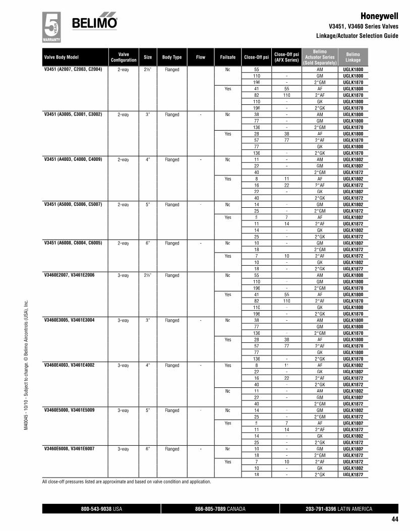
800-543-9038 USA 866-805-7089 CANADA 203-791-8396 LATIN AMERICA
44
Valve Body Model ValveConfi guration Size Body Type Flow Failsafe Close-Off psi Close-Off psi
(AFX Series)
BelimoActuator Series
(Sold Separately)
BelimoLinkage
M40
045
- 10/
10 -
Subj
ect t
o ch
ange
. © B
elim
o Ai
rcon
trols
(USA
), In
c.
All close-off pressures listed are approximate and based on valve condition and application.
HoneywellV3451, V3460 Series Valves
Linkage/Actuator Selection Guide
V3451 (A2007, C2003, C2004) 2-way 2½” Flanged - No 55 - AM UGLK1800110 - GM UGLK1800196 - 2*GM UGLK1870
Yes 41 55 AF UGLK180082 110 2*AF UGLK1870110 - GK UGLK1800196 - 2*GK UGLK1870
V3451 (A3005, C3001, C3002) 2-way 3” Flanged - No 38 - AM UGLK180077 - GM UGLK1800136 - 2*GM UGLK1870
Yes 28 38 AF UGLK180057 77 2*AF UGLK187077 - GK UGLK1800136 - 2*GK UGLK1870
V3451 (A4003, C4000, C4009) 2-way 4” Flanged - No 11 - AM UGLK180222 - GM UGLK180240 - 2*GM UGLK1872
Yes 8 11 AF UGLK180216 22 2*AF UGLK187222 - GK UGLK180240 - 2*GK UGLK1872
V3451 (A5000, C5006, C5007) 2-way 5” Flanged - No 14 - GM UGLK180225 - 2*GM UGLK1872
Yes 5 7 AF UGLK180211 14 2*AF UGLK187214 - GK UGLK180225 - 2*GK UGLK1872
V3451 (A6008, C6004, C6005) 2-way 6” Flanged - No 10 - GM UGLK180218 - 2*GM UGLK1872
Yes 7 10 2*AF UGLK187210 - GK UGLK180218 - 2*GK UGLK1872
V3460E2007, V3461E2006 3-way 2½” Flanged - No 55 - AM UGLK1800110 - GM UGLK1800196 - 2*GM UGLK1870
Yes 41 55 AF UGLK180082 110 2*AF UGLK1870110 - GK UGLK1800196 - 2*GK UGLK1870
V3460E3005, V3461E3004 3-way 3” Flanged - No 38 - AM UGLK180077 - GM UGLK1800136 - 2*GM UGLK1870
Yes 28 38 AF UGLK180057 77 2*AF UGLK187077 - GK UGLK1800136 - 2*GK UGLK1870
V3460E4003, V3461E4002 3-way 4” Flanged - Yes 8 11 AF UGLK180222 - GK UGLK180216 22 2*AF UGLK187240 - 2*GK UGLK1872
No 11 - AM UGLK180222 - GM UGLK180240 - 2*GM UGLK1872
V3460E5000, V3461E5009 3-way 5” Flanged - No 14 - GM UGLK180225 - 2*GM UGLK1872
Yes 5 7 AF UGLK180211 14 2*AF UGLK187214 - GK UGLK180225 - 2*GK UGLK1872
V3460E6008, V3461E6007 3-way 6” Flanged - No 10 - GM UGLK180218 - 2*GM UGLK1872
Yes 7 10 2*AF UGLK187210 - GK UGLK180218 - 2*GK UGLK1872
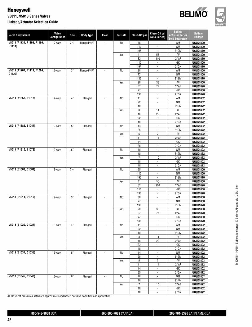
800-543-9038 USA 866-805-7089 CANADA 203-791-8396 LATIN AMERICA
45
Valve Body Model ValveConfi guration Size Body Type Flow Failsafe Close-Off psi Close-Off psi
(AFX Series)
BelimoActuator Series
(Sold Separately)
BelimoLinkage
M40
045
- 10/
10 -
Subj
ect t
o ch
ange
. © B
elim
o Ai
rcon
trols
(USA
), In
c.
All close-off pressures listed are approximate and based on valve condition and application.
HoneywellV5011, V5013 Series Valves
Linkage/Actuator Selection Guide
V5011 (A1734, F1105, F1196,G1111)
2-way 2½” Flanged/NPT - No 55 - AM UGLK1800110 - GM UGLK1800196 - 2*GM UGLK1870
Yes 41 55 AF UGLK180082 110 2*AF UGLK1870110 - GK UGLK1800196 - 2*GK UGLK1870
V5011 (A1767, F1113, F1204,G1129)
2-way 3” Flanged/NPT - No 38 - AM UGLK180077 - GM UGLK1800136 - 2*GM UGLK1870
Yes 28 38 AF UGLK180057 77 2*AF UGLK187077 - GK UGLK1800136 - 2*GK UGLK1870
V5011 (A1858, B1013) 2-way 4” Flanged - No 11 - AM UGLK180222 - GM UGLK180240 - 2*GM UGLK1872
Yes 8 11 AF UGLK180216 22 2*AF UGLK187222 - GK UGLK180240 - 2*GK UGLK1872
V5011 (A1882, B1047) 2-way 5” Flanged - No 14 - GM UGLK180225 - 2*GM UGLK1872
Yes 5 7 AF UGLK180211 14 2*AF UGLK187214 - GK UGLK180225 - 2*GK UGLK1872
V5011 (A1916, B1078) 2-way 6” Flanged - No 10 - GM UGLK180218 - 2*GM UGLK1872
Yes 7 10 2*AF UGLK187210 - GK UGLK180218 - 2*GK UGLK1872
V5013 (B1003, C1001) 3-way 2½” Flanged - No 55 - AM UGLK1800110 - GM UGLK1800196 - 2*GM UGLK1870
Yes 41 55 AF UGLK180082 110 2*AF UGLK1870110 - GK UGLK1800196 - 2*GK UGLK1870
V5013 (B1011, C1019) 2-way 3” Flanged - No 38 - AM UGLK180077 - GM UGLK1800136 - 2*GM UGLK1870
Yes 28 38 AF UGLK180057 77 2*AF UGLK187077 - GK UGLK1800136 - 2*GK UGLK1870
V5013 (B1029, C1027) 3-way 4” Flanged - No 11 - AM UGLK180222 - GM UGLK180240 - 2*GM UGLK1872
Yes 8 11 AF UGLK180216 22 2*AF UGLK187222 - GK UGLK180240 - 2*GK UGLK1872
V5013 (B1037, C1035) 3-way 5” Flanged - No 14 - GM UGLK180225 - 2*GM UGLK1872
Yes 5 7 AF UGLK180211 14 2*AF UGLK187214 - GK UGLK180225 - 2*GK UGLK1872
V5013 (B1045, C1043) 3-way 6” Flanged - No 10 - GM UGLK180218 - 2*GM UGLK1872
Yes 7 10 2*AF UGLK187210 - GK UGLK180218 - 2*GK UGLK1872
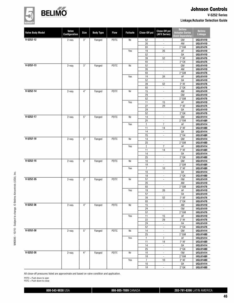
800-543-9038 USA 866-805-7089 CANADA 203-791-8396 LATIN AMERICA
46
Valve Body Model ValveConfi guration Size Body Type Flow Failsafe Close-Off psi Close-Off psi
(AFX Series)
BelimoActuator Series
(Sold Separately)
BelimoLinkage
M40
045
- 10/
10 -
Subj
ect t
o ch
ange
. © B
elim
o Ai
rcon
trols
(USA
), In
c.
Johnson ControlsV-5252 Series
Linkage/Actuator Selection Guide
V-5252-12 2-way 3” Flanged PDTC No 52 - GM UGLK141026 - AM UGLK141093 - 2*GM UGLK1476
Yes 19 26 AF UGLK141052 - GK UGLK141039 52 2*AF UGLK147693 - 2*GK UGLK1476
V-5252-13 2-way 3” Flanged PDTC No 52 - GM UGLK141026 - AM UGLK141093 - 2*GM UGLK1476
Yes 19 26 AF UGLK141052 - GK UGLK141039 52 2*AF UGLK147693 - 2*GK UGLK1476
V-5252-14 2-way 4” Flanged PDTC No 15 - AM UGLK141029 - GM UGLK141052 - 2*GM UGLK1476
Yes 11 15 AF UGLK141022 29 2*AF UGLK147629 - GK UGLK141052 - 2*GK UGLK1476
V-5252-17 2-way 5” Flanged PDTC No 14 - GM UGLK141425 - 2*GM UGLK1480
Yes 5 7 AF UGLK141411 14 2*AF UGLK148014 - GK UGLK141425 - 2*GK UGLK1480
V-5252-18 2-way 5” Flanged PDTC No 14 - GM UGLK141425 - 2*GM UGLK1480
Yes 5 7 AF UGLK141411 14 2*AF UGLK148014 - GK UGLK141425 - 2*GK UGLK1480
V-5252-19 2-way 6” Flanged PDTC No 10 - GM UGLK141418 - 2*GM UGLK1480
Yes 7 10 2*AF UGLK148010 - GK UGLK141418 - 2*GK UGLK1480
V-5252-35 2-way 3” Flanged PDTC No 52 - GM UGLK141026 - AM UGLK141093 - 2*GM UGLK1476
Yes 19 26 AF UGLK141052 - GK UGLK141039 52 2*AF UGLK147693 - 2*GK UGLK1476
V-5252-36 2-way 4” Flanged PDTC No 15 - AM UGLK141029 - GM UGLK141052 - 2*GM UGLK1476
Yes 11 15 AF UGLK141022 29 2*AF UGLK147629 - GK UGLK141052 - 2*GK UGLK1476
V-5252-38 2-way 5” Flanged PDTC No 14 - GM UGLK141425 - 2*GM UGLK1480
Yes 5 7 AF UGLK141411 14 2*AF UGLK148014 - GK UGLK141425 - 2*GK UGLK1480
V-5252-39 2-way 6” Flanged PDTC No 10 - GM UGLK141418 - 2*GM UGLK1480
Yes 7 10 2*AF UGLK148010 - GK UGLK141418 - 2*GK UGLK1480
All close-off pressures listed are approximate and based on valve condition and application.
PDTO = Push down to openPDTC = Push down to close
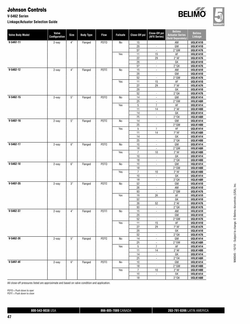
800-543-9038 USA 866-805-7089 CANADA 203-791-8396 LATIN AMERICA
47
Valve Body Model ValveConfi guration Size Body Type Flow Failsafe Close-Off psi Close-Off psi
(AFX Series)
BelimoActuator Series
(Sold Separately)
BelimoLinkage
M40
045
- 10/
10 -
Subj
ect t
o ch
ange
. © B
elim
o Ai
rcon
trols
(USA
), In
c.
Johnson ControlsV-5462 Series
Linkage/Actuator Selection Guide
V-5462-11 2-way 4” Flanged PDTO No 15 - AM UGLK141029 - GM UGLK141052 - 2*GM UGLK1476
Yes 11 15 AF UGLK141022 29 2*AF UGLK147629 - GK UGLK141052 - 2*GK UGLK1476
V-5462-12 2-way 4” Flanged PDTO No 15 - AM UGLK141029 - GM UGLK141052 - 2*GM UGLK1476
Yes 11 15 AF UGLK141022 29 2*AF UGLK147629 - GK UGLK141052 - 2*GK UGLK1476
V-5462-15 2-way 5” Flanged PDTO No 14 - GM UGLK141425 - 2*GM UGLK1480
Yes 5 7 AF UGLK141411 14 2*AF UGLK148014 - GK UGLK141425 - 2*GK UGLK1480
V-5462-16 2-way 5” Flanged PDTO No 14 - GM UGLK141425 - 2*GM UGLK1480
Yes 5 7 AF UGLK141411 14 2*AF UGLK148014 - GK UGLK141425 - 2*GK UGLK1480
V-5462-17 2-way 6” Flanged PDTO No 10 - GM UGLK141418 - 2*GM UGLK1480
Yes 7 10 2*AF UGLK148010 - GK UGLK141418 - 2*GK UGLK1480
V-5462-18 2-way 6” Flanged PDTO No 10 - GM UGLK141418 - 2*GM UGLK1480
Yes 7 10 2*AF UGLK148010 - GK UGLK141418 - 2*GK UGLK1480
V-5462-35 2-way 3” Flanged PDTO No 52 - GM UGLK141026 - AM UGLK141093 - 2*GM UGLK1476
Yes 19 26 AF UGLK141052 - GK UGLK141039 52 2*AF UGLK147693 - 2*GK UGLK1476
V-5462-37 2-way 4” Flanged PDTO No 15 - AM UGLK141029 - GM UGLK141052 - 2*GM UGLK1476
Yes 11 15 AF UGLK141022 29 2*AF UGLK147629 - GK UGLK141052 - 2*GK UGLK1476
V-5462-39 2-way 5” Flanged PDTO No 14 - GM UGLK141425 - 2*GM UGLK1480
Yes 5 7 AF UGLK141411 14 2*AF UGLK148014 - GK UGLK141425 - 2*GK UGLK1480
V-5462-40 2-way 6” Flanged PDTO No 10 - GM UGLK141418 - 2*GM UGLK1480
Yes 7 10 2*AF UGLK148010 - GK UGLK141418 - 2*GK UGLK1480
All close-off pressures listed are approximate and based on valve condition and application.
PDTO = Push down to openPDTC = Push down to close
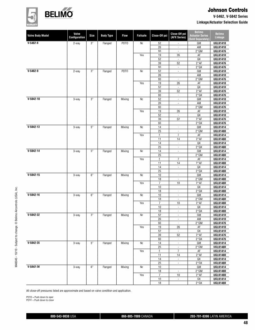
800-543-9038 USA 866-805-7089 CANADA 203-791-8396 LATIN AMERICA
48
Valve Body Model ValveConfi guration Size Body Type Flow Failsafe Close-Off psi Close-Off psi
(AFX Series)
BelimoActuator Series
(Sold Separately)
BelimoLinkage
M40
045
- 10/
10 -
Subj
ect t
o ch
ange
. © B
elim
o Ai
rcon
trols
(USA
), In
c.
Johnson ControlsV-5462, V-5842 Series
Linkage/Actuator Selection Guide
V-5462-8 2-way 3” Flanged PDTO No 52 - GM UGLK141026 - AM UGLK141093 - 2*GM UGLK1476
Yes 19 26 AF UGLK141052 - GK UGLK141039 52 2*AF UGLK147693 - 2*GK UGLK1476
V-5462-9 2-way 3” Flanged PDTO No 52 - GM UGLK141026 - AM UGLK141093 - 2*GM UGLK1476
Yes 19 26 AF UGLK141052 - GK UGLK141039 52 2*AF UGLK147693 - 2*GK UGLK1476
V-5842-10 3-way 3” Flanged Mixing No 52 - GM UGLK141026 - AM UGLK141093 - 2*GM UGLK1476
Yes 19 26 AF UGLK141052 - GK UGLK141039 52 2*AF UGLK147693 - 2*GK UGLK1476
V-5842-13 3-way 5” Flanged Mixing No 14 - GM UGLK141425 - 2*GM UGLK1480
Yes 5 7 AF UGLK141411 14 2*AF UGLK148014 - GK UGLK141425 - 2*GK UGLK1480
V-5842-14 3-way 5” Flanged Mixing No 14 - GM UGLK141425 - 2*GM UGLK1480
Yes 5 7 AF UGLK141411 14 2*AF UGLK148014 - GK UGLK141425 - 2*GK UGLK1480
V-5842-15 3-way 6” Flanged Mixing No 10 - GM UGLK141418 - 2*GM UGLK1480
Yes 7 10 2*AF UGLK148010 - GK UGLK141418 - 2*GK UGLK1480
V-5842-16 3-way 6” Flanged Mixing No 10 - GM UGLK141418 - 2*GM UGLK1480
Yes 7 10 2*AF UGLK148010 - GK UGLK141418 - 2*GK UGLK1480
V-5842-32 3-way 3” Flanged Mixing No 52 - GM UGLK141026 - AM UGLK141093 - 2*GM UGLK1476
Yes 19 26 AF UGLK141052 - GK UGLK141039 52 2*AF UGLK147693 - 2*GK UGLK1476
V-5842-35 3-way 5” Flanged Mixing No 14 - GM UGLK141425 - 2*GM UGLK1480
Yes 5 7 AF UGLK141411 14 2*AF UGLK148014 - GK UGLK141425 - 2*GK UGLK1480
V-5842-36 3-way 6” Flanged Mixing No 10 - GM UGLK141418 - 2*GM UGLK1480
Yes 7 10 2*AF UGLK148010 - GK UGLK141418 - 2*GK UGLK1480
All close-off pressures listed are approximate and based on valve condition and application.
PDTO = Push down to openPDTC = Push down to close
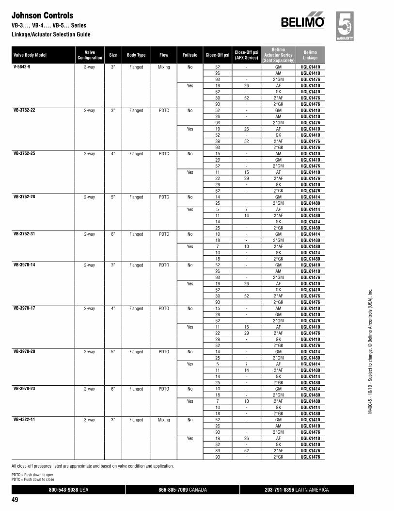
800-543-9038 USA 866-805-7089 CANADA 203-791-8396 LATIN AMERICA
49
Valve Body Model ValveConfi guration Size Body Type Flow Failsafe Close-Off psi Close-Off psi
(AFX Series)
BelimoActuator Series
(Sold Separately)
BelimoLinkage
M40
045
- 10/
10 -
Subj
ect t
o ch
ange
. © B
elim
o Ai
rcon
trols
(USA
), In
c.
Johnson ControlsVB-3…, VB-4…, VB-5… Series
Linkage/Actuator Selection Guide
V-5842-9 3-way 3” Flanged Mixing No 52 - GM UGLK141026 - AM UGLK141093 - 2*GM UGLK1476
Yes 19 26 AF UGLK141052 - GK UGLK141039 52 2*AF UGLK147693 - 2*GK UGLK1476
VB-3752-22 2-way 3” Flanged PDTC No 52 - GM UGLK141026 - AM UGLK141093 - 2*GM UGLK1476
Yes 19 26 AF UGLK141052 - GK UGLK141039 52 2*AF UGLK147693 - 2*GK UGLK1476
VB-3752-25 2-way 4” Flanged PDTC No 15 - AM UGLK141029 - GM UGLK141052 - 2*GM UGLK1476
Yes 11 15 AF UGLK141022 29 2*AF UGLK147629 - GK UGLK141052 - 2*GK UGLK1476
VB-3752-28 2-way 5” Flanged PDTC No 14 - GM UGLK141425 - 2*GM UGLK1480
Yes 5 7 AF UGLK141411 14 2*AF UGLK148014 - GK UGLK141425 - 2*GK UGLK1480
VB-3752-31 2-way 6” Flanged PDTC No 10 - GM UGLK141418 - 2*GM UGLK1480
Yes 7 10 2*AF UGLK148010 - GK UGLK141418 - 2*GK UGLK1480
VB-3970-14 2-way 3” Flanged PDTO No 52 - GM UGLK141026 - AM UGLK141093 - 2*GM UGLK1476
Yes 19 26 AF UGLK141052 - GK UGLK141039 52 2*AF UGLK147693 - 2*GK UGLK1476
VB-3970-17 2-way 4” Flanged PDTO No 15 - AM UGLK141029 - GM UGLK141052 - 2*GM UGLK1476
Yes 11 15 AF UGLK141022 29 2*AF UGLK147629 - GK UGLK141052 - 2*GK UGLK1476
VB-3970-20 2-way 5” Flanged PDTO No 14 - GM UGLK141425 - 2*GM UGLK1480
Yes 5 7 AF UGLK141411 14 2*AF UGLK148014 - GK UGLK141425 - 2*GK UGLK1480
VB-3970-23 2-way 6” Flanged PDTO No 10 - GM UGLK141418 - 2*GM UGLK1480
Yes 7 10 2*AF UGLK148010 - GK UGLK141418 - 2*GK UGLK1480
VB-4322-11 3-way 3” Flanged Mixing No 52 - GM UGLK141026 - AM UGLK141093 - 2*GM UGLK1476
Yes 19 26 AF UGLK141052 - GK UGLK141039 52 2*AF UGLK147693 - 2*GK UGLK1476
All close-off pressures listed are approximate and based on valve condition and application.
PDTO = Push down to openPDTC = Push down to close

800-543-9038 USA 866-805-7089 CANADA 203-791-8396 LATIN AMERICA
50
Valve Body Model ValveConfi guration Size Body Type Flow Failsafe Close-Off psi Close-Off psi
(AFX Series)
BelimoActuator Series
(Sold Separately)
BelimoLinkage
M40
045
- 10/
10 -
Subj
ect t
o ch
ange
. © B
elim
o Ai
rcon
trols
(USA
), In
c.
Johnson ControlsVB-4…, VG2… Series
Linkage/Actuator Selection Guide
VB-4322-13 3-way 4” Flanged Mixing No 15 - AM UGLK141029 - GM UGLK141052 - 2*GM UGLK1476
Yes 11 15 AF UGLK141022 29 2*AF UGLK147629 - GK UGLK141052 - 2*GK UGLK1476
VB-4322-18 3-way 6” Flanged Mixing No 10 - GM UGLK141418 - 2*GM UGLK1480
Yes 7 10 2*AF UGLK148010 - GK UGLK141418 - 2*GK UGLK1480
VB-4322-19 3-way 5” Flanged Mixing No 14 - GM UGLK141425 - 2*GM UGLK1480
Yes 5 7 AF UGLK141411 14 2*AF UGLK148014 - GK UGLK141425 - 2*GK UGLK1480
VG2231 UM 2-way 3” Flanged PDTC No 52 - GM UGLK141026 - AM UGLK141093 - 2*GM UGLK1476
Yes 19 26 AF UGLK141052 - GK UGLK141039 52 2*AF UGLK147693 - 2*GK UGLK1476
VG2231 VM 2-way 4” Flanged PDTC No 15 - AM UGLK141029 - GM UGLK141052 - 2*GM UGLK1476
Yes 11 15 AF UGLK141022 29 2*AF UGLK147629 - GK UGLK141052 - 2*GK UGLK1476
VG2231 WN 2-way 5” Flanged PDTC No 14 - GM UGLK141425 - 2*GM UGLK1480
Yes 5 7 AF UGLK141411 14 2*AF UGLK148014 - GK UGLK141425 - 2*GK UGLK1480
VG2231 YN 2-way 6” Flanged PDTC No 10 - GM UGLK141418 - 2*GM UGLK1480
Yes 7 10 2*AF UGLK148010 - GK UGLK141418 - 2*GK UGLK1480
VG2431 UM 2-way 3” Flanged PDTO No 52 - GM UGLK141026 - AM UGLK141093 - 2*GM UGLK1476
Yes 19 26 AF UGLK141052 - GK UGLK141039 52 2*AF UGLK147693 - 2*GK UGLK1476
VG2431 VM 2-way 4” Flanged PDTO No 15 - AM UGLK141029 - GM UGLK141052 - 2*GM UGLK1476
Yes 11 15 AF UGLK141022 29 2*AF UGLK147629 - GK UGLK141052 - 2*GK UGLK1476
VG2431 WN 2-way 5” Flanged PDTO No 14 - GM UGLK141425 - 2*GM UGLK1480
Yes 5 7 AF UGLK141411 14 2*AF UGLK148014 - GK UGLK141425 - 2*GK UGLK1480
All close-off pressures listed are approximate and based on valve condition and application.
PDTO = Push down to openPDTC = Push down to close
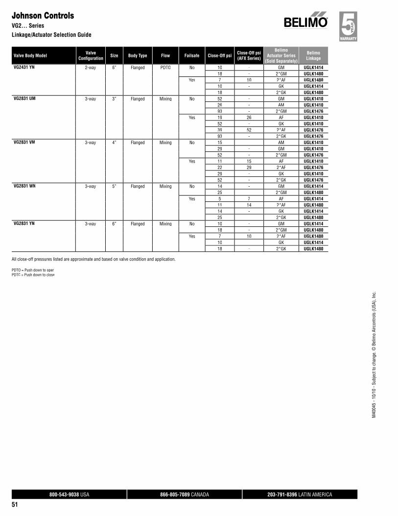
800-543-9038 USA 866-805-7089 CANADA 203-791-8396 LATIN AMERICA
51
Valve Body Model ValveConfi guration Size Body Type Flow Failsafe Close-Off psi Close-Off psi
(AFX Series)
BelimoActuator Series
(Sold Separately)
BelimoLinkage
M40
045
- 10/
10 -
Subj
ect t
o ch
ange
. © B
elim
o Ai
rcon
trols
(USA
), In
c.
Johnson ControlsVG2… Series
Linkage/Actuator Selection Guide
VG2431 YN 2-way 6” Flanged PDTO No 10 - GM UGLK141418 - 2*GM UGLK1480
Yes 7 10 2*AF UGLK148010 - GK UGLK141418 - 2*GK UGLK1480
VG2831 UM 3-way 3” Flanged Mixing No 52 - GM UGLK141026 - AM UGLK141093 - 2*GM UGLK1476
Yes 19 26 AF UGLK141052 - GK UGLK141039 52 2*AF UGLK147693 - 2*GK UGLK1476
VG2831 VM 3-way 4” Flanged Mixing No 15 - AM UGLK141029 - GM UGLK141052 - 2*GM UGLK1476
Yes 11 15 AF UGLK141022 29 2*AF UGLK147629 - GK UGLK141052 - 2*GK UGLK1476
VG2831 WN 3-way 5” Flanged Mixing No 14 - GM UGLK141425 - 2*GM UGLK1480
Yes 5 7 AF UGLK141411 14 2*AF UGLK148014 - GK UGLK141425 - 2*GK UGLK1480
VG2831 YN 3-way 6” Flanged Mixing No 10 - GM UGLK141418 - 2*GM UGLK1480
Yes 7 10 2*AF UGLK148010 - GK UGLK141418 - 2*GK UGLK1480
All close-off pressures listed are approximate and based on valve condition and application.
PDTO = Push down to openPDTC = Push down to close
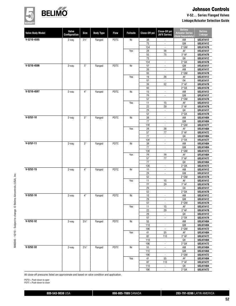
800-543-9038 USA 866-805-7089 CANADA 203-791-8396 LATIN AMERICA
52
Valve Body Model ValveConfi guration Size Body Type Flow Failsafe Close-Off psi Close-Off psi
(AFX Series)
BelimoActuator Series
(Sold Separately)
BelimoLinkage
M40
045
- 10/
10 -
Subj
ect t
o ch
ange
. © B
elim
o Ai
rcon
trols
(USA
), In
c.
Johnson ControlsV-52… Series Flanged Valves
Linkage/Actuator Selection Guide
( y)V-5210-4595 2-way 2½” Flanged PDTC No 38 - AM UGLK1412
75 - GM UGLK1412134 - 2*GM UGLK1478
Yes 28 38 AF UGLK141255 75 2*AF UGLK147875 - GK UGLK1412134 - 2*GK UGLK1478
V-5210-4596 2-way 3” Flanged PDTC No 52 - GM UGLK141226 - AM UGLK141293 - 2*GM UGLK1478
Yes 19 26 AF UGLK141252 - GK UGLK141239 52 2*AF UGLK147893 - 2*GK UGLK1478
V-5210-4597 2-way 4” Flanged PDTC No 15 - AM UGLK141229 - GM UGLK141252 - 2*GM UGLK1478
Yes 11 15 AF UGLK141222 29 2*AF UGLK147829 - GK UGLK141252 - 2*GK UGLK1478
V-5252-10 2-way 3” Flanged PDTC No 38 - AM UGLK140477 - GM UGLK1404136 - 2*GM UGLK1472
Yes 28 38 AF UGLK140457 77 2*AF UGLK147277 - GK UGLK1404136 - 2*GK UGLK1472
V-5252-11 2-way 3” Flanged PDTC No 38 - AM UGLK140477 - GM UGLK1404136 - 2*GM UGLK1472
Yes 28 38 AF UGLK140457 77 2*AF UGLK147277 - GK UGLK1404136 - 2*GK UGLK1472
V-5252-15 2-way 4” Flanged PDTC No 15 - AM UGLK141229 - GM UGLK141252 - 2*GM UGLK1478
Yes 11 15 AF UGLK141222 29 2*AF UGLK147829 - GK UGLK141252 - 2*GK UGLK1478
V-5252-16 2-way 4” Flanged PDTC No 15 - AM UGLK141229 - GM UGLK141252 - 2*GM UGLK1478
Yes 11 15 AF UGLK141222 29 2*AF UGLK147829 - GK UGLK141252 - 2*GK UGLK1478
V-5252-32 2-way 2½” Flanged PDTC No 55 - AM UGLK1404110 - GM UGLK1404196 - 2*GM UGLK1472
Yes 41 55 AF UGLK140482 110 2*AF UGLK1472110 - GK UGLK1404196 - 2*GK UGLK1472
V-5252-33 2-way 2½” Flanged PDTC No 55 - AM UGLK1404110 - GM UGLK1404196 - 2*GM UGLK1472
Yes 41 55 AF UGLK140482 110 2*AF UGLK1472110 - GK UGLK1404196 - 2*GK UGLK1472
All close-off pressures listed are approximate and based on valve condition and application.
PDTO = Push down to openPDTC = Push down to close
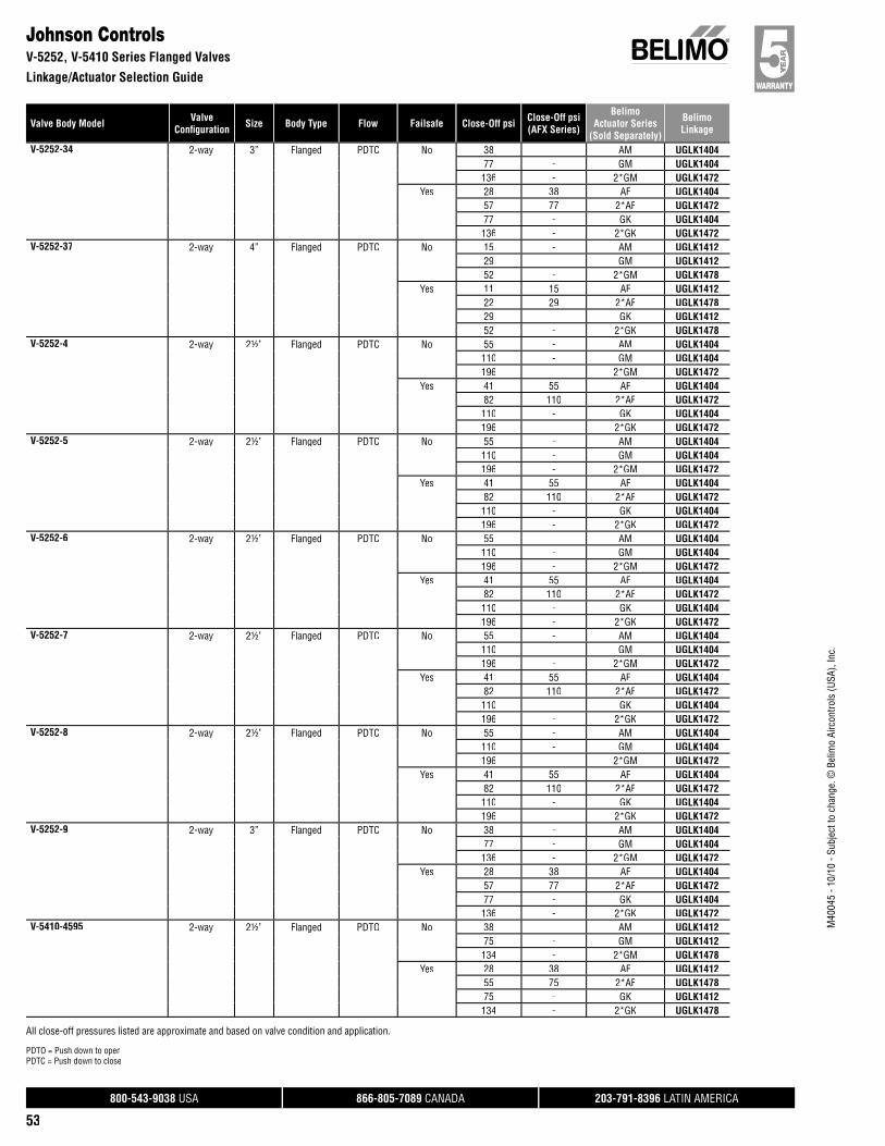
800-543-9038 USA 866-805-7089 CANADA 203-791-8396 LATIN AMERICA
53
Valve Body Model ValveConfi guration Size Body Type Flow Failsafe Close-Off psi Close-Off psi
(AFX Series)
BelimoActuator Series
(Sold Separately)
BelimoLinkage
M40
045
- 10/
10 -
Subj
ect t
o ch
ange
. © B
elim
o Ai
rcon
trols
(USA
), In
c.
Johnson ControlsV-5252, V-5410 Series Flanged Valves
Linkage/Actuator Selection Guide
V-5252-34 2-way 3” Flanged PDTC No 38 - AM UGLK140477 - GM UGLK1404136 - 2*GM UGLK1472
Yes 28 38 AF UGLK140457 77 2*AF UGLK147277 - GK UGLK1404136 - 2*GK UGLK1472
V-5252-37 2-way 4” Flanged PDTC No 15 - AM UGLK141229 - GM UGLK141252 - 2*GM UGLK1478
Yes 11 15 AF UGLK141222 29 2*AF UGLK147829 - GK UGLK141252 - 2*GK UGLK1478
V-5252-4 2-way 2½” Flanged PDTC No 55 - AM UGLK1404110 - GM UGLK1404196 - 2*GM UGLK1472
Yes 41 55 AF UGLK140482 110 2*AF UGLK1472110 - GK UGLK1404196 - 2*GK UGLK1472
V-5252-5 2-way 2½” Flanged PDTC No 55 - AM UGLK1404110 - GM UGLK1404196 - 2*GM UGLK1472
Yes 41 55 AF UGLK140482 110 2*AF UGLK1472110 - GK UGLK1404196 - 2*GK UGLK1472
V-5252-6 2-way 2½” Flanged PDTC No 55 - AM UGLK1404110 - GM UGLK1404196 - 2*GM UGLK1472
Yes 41 55 AF UGLK140482 110 2*AF UGLK1472110 - GK UGLK1404196 - 2*GK UGLK1472
V-5252-7 2-way 2½” Flanged PDTC No 55 - AM UGLK1404110 - GM UGLK1404196 - 2*GM UGLK1472
Yes 41 55 AF UGLK140482 110 2*AF UGLK1472110 - GK UGLK1404196 - 2*GK UGLK1472
V-5252-8 2-way 2½” Flanged PDTC No 55 - AM UGLK1404110 - GM UGLK1404196 - 2*GM UGLK1472
Yes 41 55 AF UGLK140482 110 2*AF UGLK1472110 - GK UGLK1404196 - 2*GK UGLK1472
V-5252-9 2-way 3” Flanged PDTC No 38 - AM UGLK140477 - GM UGLK1404136 - 2*GM UGLK1472
Yes 28 38 AF UGLK140457 77 2*AF UGLK147277 - GK UGLK1404136 - 2*GK UGLK1472
V-5410-4595 2-way 2½” Flanged PDTO No 38 - AM UGLK141275 - GM UGLK1412134 - 2*GM UGLK1478
Yes 28 38 AF UGLK141255 75 2*AF UGLK147875 - GK UGLK1412134 - 2*GK UGLK1478
All close-off pressures listed are approximate and based on valve condition and application.
PDTO = Push down to openPDTC = Push down to close
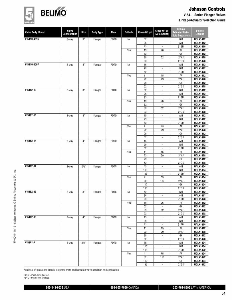
800-543-9038 USA 866-805-7089 CANADA 203-791-8396 LATIN AMERICA
54
Valve Body Model ValveConfi guration Size Body Type Flow Failsafe Close-Off psi Close-Off psi
(AFX Series)
BelimoActuator Series
(Sold Separately)
BelimoLinkage
M40
045
- 10/
10 -
Subj
ect t
o ch
ange
. © B
elim
o Ai
rcon
trols
(USA
), In
c.
Johnson ControlsV-54… Series Flanged Valves
Linkage/Actuator Selection Guide
V-5410-4596 2-way 3” Flanged PDTO No 52 - GM UGLK141226 - AM UGLK141293 - 2*GM UGLK1478
Yes 19 26 AF UGLK141252 - GK UGLK141239 52 2*AF UGLK147893 - 2*GK UGLK1478
V-5410-4597 2-way 4” Flanged PDTO No 15 - AM UGLK141229 - GM UGLK141252 - 2*GM UGLK1478
Yes 11 15 AF UGLK141222 29 2*AF UGLK147829 - GK UGLK141252 - 2*GK UGLK1478
V-5462-10 2-way 3” Flanged PDTC No 52 - GM UGLK141226 - AM UGLK141293 - 2*GM UGLK1478
Yes 19 26 AF UGLK141252 - GK UGLK141239 52 2*AF UGLK147893 - 2*GK UGLK1478
V-5462-13 2-way 4” Flanged PDTO No 15 - AM UGLK141229 - GM UGLK141252 - 2*GM UGLK1478
Yes 11 15 AF UGLK141222 29 2*AF UGLK147829 - GK UGLK141252 - 2*GK UGLK1478
V-5462-14 2-way 4” Flanged PDTO No 15 - AM UGLK141229 - GM UGLK141252 - 2*GM UGLK1478
Yes 11 15 AF UGLK141222 29 2*AF UGLK147829 - GK UGLK141252 - 2*GK UGLK1478
V-5462-34 2-way 2½” Flanged PDTO No 55 - AM UGLK1404110 - GM UGLK1404196 - 2*GM UGLK1472
Yes 41 55 AF UGLK140482 110 2*AF UGLK1472110 - GK UGLK1404196 - 2*GK UGLK1472
V-5462-36 2-way 3” Flanged PDTC No 52 - GM UGLK141226 - AM UGLK141293 - 2*GM UGLK1478
Yes 19 26 AF UGLK141252 - GK UGLK141239 52 2*AF UGLK147893 - 2*GK UGLK1478
V-5462-38 2-way 4” Flanged PDTO No 15 - AM UGLK141229 - GM UGLK141252 - 2*GM UGLK1478
Yes 11 15 AF UGLK141222 29 2*AF UGLK147829 - GK UGLK141252 - 2*GK UGLK1478
V-5462-6 2-way 2½” Flanged PDTO No 55 - AM UGLK1404110 - GM UGLK1404196 - 2*GM UGLK1472
Yes 41 55 AF UGLK140482 110 2*AF UGLK1472110 - GK UGLK1404196 - 2*GK UGLK1472
All close-off pressures listed are approximate and based on valve condition and application.
PDTO = Push down to openPDTC = Push down to close

800-543-9038 USA 866-805-7089 CANADA 203-791-8396 LATIN AMERICA
55
Valve Body Model ValveConfi guration Size Body Type Flow Failsafe Close-Off psi Close-Off psi
(AFX Series)
BelimoActuator Series
(Sold Separately)
BelimoLinkage
M40
045
- 10/
10 -
Subj
ect t
o ch
ange
. © B
elim
o Ai
rcon
trols
(USA
), In
c.
Johnson ControlsV-54… and V-58... Series Flanged Valves
Linkage/Actuator Selection Guide
V-5462-7 2-way 2½” Flanged PDTO No 55 - AM UGLK1404110 - GM UGLK1404196 - 2*GM UGLK1472
Yes 41 55 AF UGLK140482 110 2*AF UGLK1472110 - GK UGLK1404196 - 2*GK UGLK1472
V-5842-11 3-way 4” Flanged Mixing No 15 - AM UGLK141229 - GM UGLK141252 - 2*GM UGLK1478
Yes 11 15 AF UGLK141222 29 2*AF UGLK147829 - GK UGLK141252 - 2*GK UGLK1478
V-5842-12 3-way 4” Flanged Mixing No 15 - AM UGLK141229 - GM UGLK141252 - 2*GM UGLK1478
Yes 11 15 AF UGLK141222 29 2*AF UGLK147829 - GK UGLK141252 - 2*GK UGLK1478
V-5842-17 3-way 3” Flanged Mixing No 52 - GM UGLK141226 - AM UGLK141293 - 2*GM UGLK1478
Yes 19 26 AF UGLK141252 - GK UGLK141239 52 2*AF UGLK147893 - 2*GK UGLK1478
V-5842-18 3-way 3” Flanged Mixing No 52 - GM UGLK141226 - AM UGLK141293 - 2*GM UGLK1478
Yes 19 26 AF UGLK141252 - GK UGLK141239 52 2*AF UGLK147893 - 2*GK UGLK1478
V-5842-31 3-way 2½” Flanged Mixing No 55 - AM UGLK1404110 - GM UGLK1404196 - 2*GM UGLK1472
Yes 41 55 AF UGLK140482 110 2*AF UGLK1472110 - GK UGLK1404196 - 2*GK UGLK1472
V-5842-33 3-way 3” Flanged Mixing No 52 - GM UGLK141226 - AM UGLK141293 - 2*GM UGLK1478
Yes 19 26 AF UGLK141252 - GK UGLK141239 52 2*AF UGLK147893 - 2*GK UGLK1478
V-5842-34 3-way 4” Flanged Mixing No 15 - AM UGLK141229 - GM UGLK141252 - 2*GM UGLK1478
Yes 11 15 AF UGLK141222 29 2*AF UGLK147829 - GK UGLK141252 - 2*GK UGLK1478
V-5842-7 3-way 2½” Flanged Mixing No 55 - AM UGLK1404110 - GM UGLK1404196 - 2*GM UGLK1472
Yes 41 55 AF UGLK140482 110 2*AF UGLK1472110 - GK UGLK1404196 - 2*GK UGLK1472
All close-off pressures listed are approximate and based on valve condition and application.
PDTO = Push down to openPDTC = Push down to close
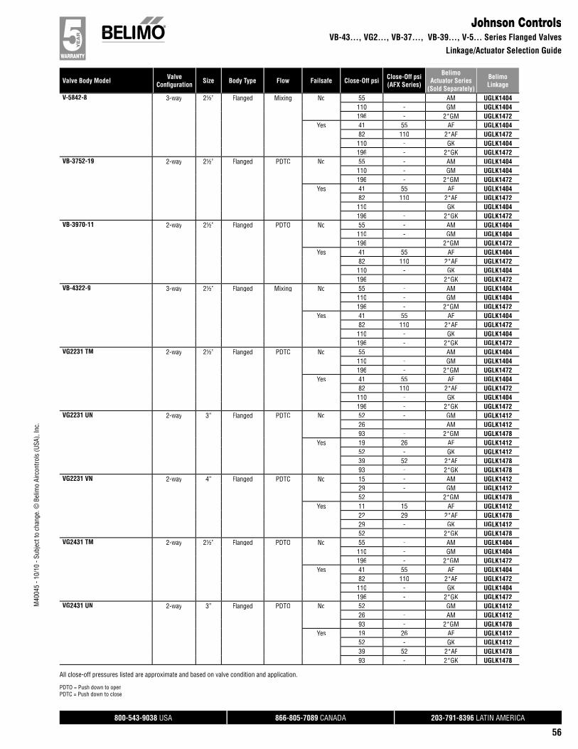
800-543-9038 USA 866-805-7089 CANADA 203-791-8396 LATIN AMERICA
56
Valve Body Model ValveConfi guration Size Body Type Flow Failsafe Close-Off psi Close-Off psi
(AFX Series)
BelimoActuator Series
(Sold Separately)
BelimoLinkage
M40
045
- 10/
10 -
Subj
ect t
o ch
ange
. © B
elim
o Ai
rcon
trols
(USA
), In
c.
Johnson ControlsVB-43…, VG2…, VB-37…, VB-39…, V-5… Series Flanged Valves
Linkage/Actuator Selection Guide
V-5842-8 3-way 2½” Flanged Mixing No 55 - AM UGLK1404110 - GM UGLK1404196 - 2*GM UGLK1472
Yes 41 55 AF UGLK140482 110 2*AF UGLK1472110 - GK UGLK1404196 - 2*GK UGLK1472
VB-3752-19 2-way 2½” Flanged PDTC No 55 - AM UGLK1404110 - GM UGLK1404196 - 2*GM UGLK1472
Yes 41 55 AF UGLK140482 110 2*AF UGLK1472110 - GK UGLK1404196 - 2*GK UGLK1472
VB-3970-11 2-way 2½” Flanged PDTO No 55 - AM UGLK1404110 - GM UGLK1404196 - 2*GM UGLK1472
Yes 41 55 AF UGLK140482 110 2*AF UGLK1472110 - GK UGLK1404196 - 2*GK UGLK1472
VB-4322-9 3-way 2½” Flanged Mixing No 55 - AM UGLK1404110 - GM UGLK1404196 - 2*GM UGLK1472
Yes 41 55 AF UGLK140482 110 2*AF UGLK1472110 - GK UGLK1404196 - 2*GK UGLK1472
VG2231 TM 2-way 2½” Flanged PDTC No 55 - AM UGLK1404110 - GM UGLK1404196 - 2*GM UGLK1472
Yes 41 55 AF UGLK140482 110 2*AF UGLK1472110 - GK UGLK1404196 - 2*GK UGLK1472
VG2231 UN 2-way 3” Flanged PDTC No 52 - GM UGLK141226 - AM UGLK141293 - 2*GM UGLK1478
Yes 19 26 AF UGLK141252 - GK UGLK141239 52 2*AF UGLK147893 - 2*GK UGLK1478
VG2231 VN 2-way 4” Flanged PDTC No 15 - AM UGLK141229 - GM UGLK141252 - 2*GM UGLK1478
Yes 11 15 AF UGLK141222 29 2*AF UGLK147829 - GK UGLK141252 - 2*GK UGLK1478
VG2431 TM 2-way 2½” Flanged PDTO No 55 - AM UGLK1404110 - GM UGLK1404196 - 2*GM UGLK1472
Yes 41 55 AF UGLK140482 110 2*AF UGLK1472110 - GK UGLK1404196 - 2*GK UGLK1472
VG2431 UN 2-way 3” Flanged PDTO No 52 - GM UGLK141226 - AM UGLK141293 - 2*GM UGLK1478
Yes 19 26 AF UGLK141252 - GK UGLK141239 52 2*AF UGLK147893 - 2*GK UGLK1478
All close-off pressures listed are approximate and based on valve condition and application.
PDTO = Push down to openPDTC = Push down to close

800-543-9038 USA 866-805-7089 CANADA 203-791-8396 LATIN AMERICA
57
Valve Body Model ValveConfi guration Size Body Type Flow Failsafe Close-Off psi Close-Off psi
(AFX Series)
BelimoActuator Series
(Sold Separately)
BelimoLinkage
M40
045
- 10/
10 -
Subj
ect t
o ch
ange
. © B
elim
o Ai
rcon
trols
(USA
), In
c.
Johnson ControlsVG-2… Series Flanged Valves
Linkage/Actuator Selection Guide
VG2431 VN 2-way 4” Flanged PDTO No 15 - AM UGLK141229 - GM UGLK141252 - 2*GM UGLK1478
Yes 11 15 AF UGLK141222 29 2*AF UGLK147829 - GK UGLK141252 - 2*GK UGLK1478
VG2831 TM 3-way 2½” Flanged Mixing No 55 - AM UGLK1404110 - GM UGLK1404196 - 2*GM UGLK1472
Yes 41 55 AF UGLK140482 110 2*AF UGLK1472110 - GK UGLK1404196 - 2*GK UGLK1472
VG2831 UN 3-way 3” Flanged Mixing No 52 - GM UGLK141226 - AM UGLK141293 - 2*GM UGLK1478
Yes 19 26 AF UGLK141252 - GK UGLK141239 52 2*AF UGLK147893 - 2*GK UGLK1478
VG2831 VN 3-way 4” Flanged Mixing No 15 - AM UGLK141229 - GM UGLK141252 - 2*GM UGLK1478
Yes 11 15 AF UGLK141222 29 2*AF UGLK147829 - GK UGLK141252 - 2*GK UGLK1478
All close-off pressures listed are approximate and based on valve condition and application.
PDTO = Push down to openPDTC = Push down to close
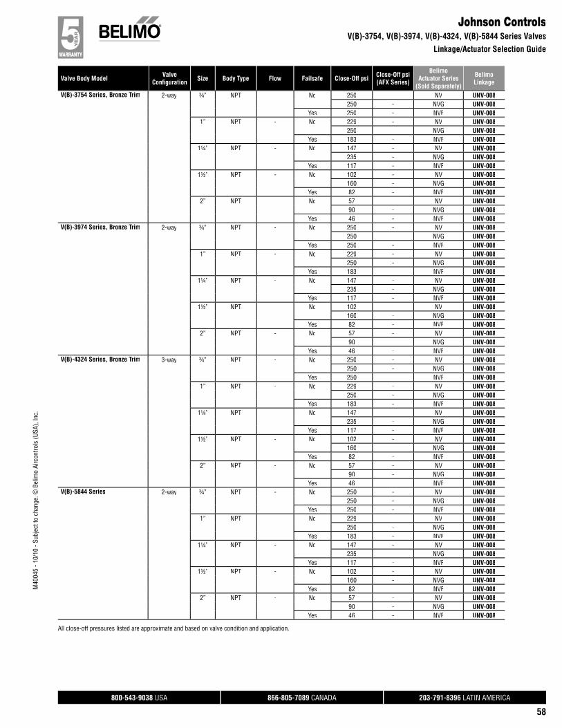
800-543-9038 USA 866-805-7089 CANADA 203-791-8396 LATIN AMERICA
58
Valve Body Model ValveConfi guration Size Body Type Flow Failsafe Close-Off psi Close-Off psi
(AFX Series)
BelimoActuator Series
(Sold Separately)
BelimoLinkage
M40
045
- 10/
10 -
Subj
ect t
o ch
ange
. © B
elim
o Ai
rcon
trols
(USA
), In
c.
Johnson ControlsV(B)-3754, V(B)-3974, V(B)-4324, V(B)-5844 Series Valves
Linkage/Actuator Selection Guide
V(B)-3754 Series, Bronze Trim 2-way ¾” NPT - No 250 - NV UNV-008250 - NVG UNV-008
Yes 250 - NVF UNV-0081” NPT - No 229 - NV UNV-008
250 - NVG UNV-008Yes 183 - NVF UNV-008
1¼” NPT - No 147 - NV UNV-008235 - NVG UNV-008
Yes 117 - NVF UNV-0081½” NPT - No 102 - NV UNV-008
160 - NVG UNV-008Yes 82 - NVF UNV-008
2” NPT - No 57 - NV UNV-00890 - NVG UNV-008
Yes 46 - NVF UNV-008V(B)-3974 Series, Bronze Trim 2-way ¾” NPT - No 250 - NV UNV-008
250 - NVG UNV-008Yes 250 - NVF UNV-008
1” NPT - No 229 - NV UNV-008250 - NVG UNV-008
Yes 183 - NVF UNV-0081¼” NPT - No 147 - NV UNV-008
235 - NVG UNV-008Yes 117 - NVF UNV-008
1½” NPT - No 102 - NV UNV-008160 - NVG UNV-008
Yes 82 - NVF UNV-0082” NPT - No 57 - NV UNV-008
90 - NVG UNV-008Yes 46 - NVF UNV-008
V(B)-4324 Series, Bronze Trim 3-way ¾” NPT - No 250 - NV UNV-008250 - NVG UNV-008
Yes 250 - NVF UNV-0081” NPT - No 229 - NV UNV-008
250 - NVG UNV-008Yes 183 - NVF UNV-008
1¼” NPT - No 147 - NV UNV-008235 - NVG UNV-008
Yes 117 - NVF UNV-0081½” NPT - No 102 - NV UNV-008
160 - NVG UNV-008Yes 82 - NVF UNV-008
2” NPT - No 57 - NV UNV-00890 - NVG UNV-008
Yes 46 - NVF UNV-008V(B)-5844 Series 2-way ¾” NPT - No 250 - NV UNV-008
250 - NVG UNV-008Yes 250 - NVF UNV-008
1” NPT - No 229 - NV UNV-008250 - NVG UNV-008
Yes 183 - NVF UNV-0081¼” NPT - No 147 - NV UNV-008
235 - NVG UNV-008Yes 117 - NVF UNV-008
1½” NPT - No 102 - NV UNV-008160 - NVG UNV-008
Yes 82 - NVF UNV-0082” NPT - No 57 - NV UNV-008
90 - NVG UNV-008Yes 46 - NVF UNV-008
All close-off pressures listed are approximate and based on valve condition and application.
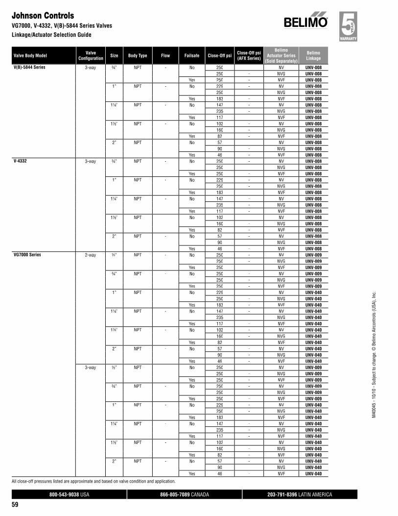
800-543-9038 USA 866-805-7089 CANADA 203-791-8396 LATIN AMERICA
59
Valve Body Model ValveConfi guration Size Body Type Flow Failsafe Close-Off psi Close-Off psi
(AFX Series)
BelimoActuator Series
(Sold Separately)
BelimoLinkage
M40
045
- 10/
10 -
Subj
ect t
o ch
ange
. © B
elim
o Ai
rcon
trols
(USA
), In
c.
Johnson ControlsVG7000, V-4332, V(B)-5844 Series Valves
Linkage/Actuator Selection Guide
V(B)-5844 Series 3-way ¾” NPT - No 250 - NV UNV-008250 - NVG UNV-008
Yes 250 - NVF UNV-0081” NPT - No 229 - NV UNV-008
250 - NVG UNV-008Yes 183 - NVF UNV-008
1¼” NPT - No 147 - NV UNV-008235 - NVG UNV-008
Yes 117 - NVF UNV-0081½” NPT - No 102 - NV UNV-008
160 - NVG UNV-008Yes 82 - NVF UNV-008
2” NPT - No 57 - NV UNV-00890 - NVG UNV-008
Yes 46 - NVF UNV-008V-4332 3-way ¾” NPT - No 250 - NV UNV-008
250 - NVG UNV-008Yes 250 - NVF UNV-008
1” NPT - No 229 - NV UNV-008250 - NVG UNV-008
Yes 183 - NVF UNV-0081¼” NPT - No 147 - NV UNV-008
235 - NVG UNV-008Yes 117 - NVF UNV-008
1½” NPT - No 102 - NV UNV-008160 - NVG UNV-008
Yes 82 - NVF UNV-0082” NPT - No 57 - NV UNV-008
90 - NVG UNV-008Yes 46 - NVF UNV-008
VG7000 Series 2-way ½” NPT - No 250 - NV UNV-009250 - NVG UNV-009
Yes 250 - NVF UNV-009¾” NPT - No 250 - NV UNV-009
250 - NVG UNV-009Yes 250 - NVF UNV-009
1” NPT - No 229 - NV UNV-040250 - NVG UNV-040
Yes 183 - NVF UNV-0401¼” NPT - No 147 - NV UNV-040
235 - NVG UNV-040Yes 117 - NVF UNV-040
1½” NPT - No 102 - NV UNV-040160 - NVG UNV-040
Yes 82 - NVF UNV-0402” NPT - No 57 - NV UNV-040
90 - NVG UNV-040Yes 46 - NVF UNV-040
3-way ½” NPT - No 250 - NV UNV-009250 - NVG UNV-009
Yes 250 - NVF UNV-009¾” NPT - No 250 - NV UNV-009
250 - NVG UNV-009Yes 250 - NVF UNV-009
1” NPT - No 229 - NV UNV-040250 - NVG UNV-040
Yes 183 - NVF UNV-0401¼” NPT - No 147 - NV UNV-040
235 - NVG UNV-040Yes 117 - NVF UNV-040
1½” NPT - No 102 - NV UNV-040160 - NVG UNV-040
Yes 82 - NVF UNV-0402” NPT - No 57 - NV UNV-040
90 - NVG UNV-040Yes 46 - NVF UNV-040
All close-off pressures listed are approximate and based on valve condition and application.
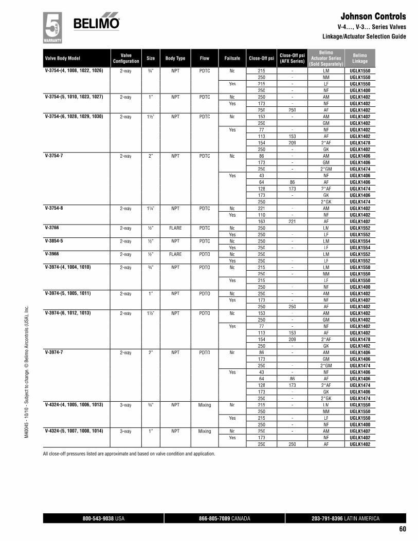
800-543-9038 USA 866-805-7089 CANADA 203-791-8396 LATIN AMERICA
60
Valve Body Model ValveConfi guration Size Body Type Flow Failsafe Close-Off psi Close-Off psi
(AFX Series)
BelimoActuator Series
(Sold Separately)
BelimoLinkage
M40
045
- 10/
10 -
Subj
ect t
o ch
ange
. © B
elim
o Ai
rcon
trols
(USA
), In
c.
Johnson ControlsV-4…, V-3… Series Valves
Linkage/Actuator Selection Guide
V-3754-(4, 1008, 1022, 1026) 2-way ¾” NPT PDTC No 215 - LM UGLK1550250 - NM UGLK1550
Yes 215 - LF UGLK1550250 - NF UGLK1400
V-3754-(5, 1010, 1023, 1027) 2-way 1” NPT PDTC No 250 - AM UGLK1402Yes 173 - NF UGLK1402
250 250 AF UGLK1402V-3754-(6, 1028, 1029, 1030) 2-way 1½” NPT PDTC No 153 - AM UGLK1402
250 - GM UGLK1402Yes 77 - NF UGLK1402
113 153 AF UGLK1402154 209 2*AF UGLK1478250 - GK UGLK1402
V-3754-7 2-way 2” NPT PDTC No 86 - AM UGLK1406173 - GM UGLK1406250 - 2*GM UGLK1474
Yes 43 - NF UGLK140664 86 AF UGLK1406128 173 2*AF UGLK1474173 - GK UGLK1406250 - 2*GK UGLK1474
V-3754-8 2-way 1¼” NPT PDTC No 221 - AM UGLK1402Yes 110 - NF UGLK1402
163 221 AF UGLK1402V-3766 2-way ½” FLARE PDTC No 250 - LM UGLK1552
Yes 250 - LF UGLK1552V-3854-5 2-way ½” NPT PDTC No 250 - LM UGLK1554
Yes 250 - LF UGLK1554V-3966 2-way ½” FLARE PDTO No 250 - LM UGLK1552
Yes 250 - LF UGLK1552V-3974-(4, 1004, 1010) 2-way ¾” NPT PDTO No 215 - LM UGLK1550
250 - NM UGLK1550Yes 215 - LF UGLK1550
250 - NF UGLK1400V-3974-(5, 1005, 1011) 2-way 1” NPT PDTO No 250 - AM UGLK1402
Yes 173 - NF UGLK1402250 250 AF UGLK1402
V-3974-(6, 1012, 1013) 2-way 1½” NPT PDTO No 153 - AM UGLK1402250 - GM UGLK1402
Yes 77 - NF UGLK1402113 153 AF UGLK1402154 209 2*AF UGLK1478250 - GK UGLK1402
V-3974-7 2-way 2” NPT PDTO No 86 - AM UGLK1406173 - GM UGLK1406250 - 2*GM UGLK1474
Yes 43 - NF UGLK140664 86 AF UGLK1406128 173 2*AF UGLK1474173 - GK UGLK1406250 - 2*GK UGLK1474
V-4324-(4, 1005, 1006, 1013) 3-way ¾” NPT Mixing No 215 - LM UGLK1550250 - NM UGLK1550
Yes 215 - LF UGLK1550250 - NF UGLK1400
V-4324-(5, 1007, 1008, 1014) 3-way 1” NPT Mixing No 250 - AM UGLK1402Yes 173 - NF UGLK1402
250 250 AF UGLK1402
All close-off pressures listed are approximate and based on valve condition and application.

800-543-9038 USA 866-805-7089 CANADA 203-791-8396 LATIN AMERICA
61
Valve Body Model ValveConfi guration Size Body Type Flow Failsafe Close-Off psi Close-Off psi
(AFX Series)
BelimoActuator Series
(Sold Separately)
BelimoLinkage
M40
045
- 10/
10 -
Subj
ect t
o ch
ange
. © B
elim
o Ai
rcon
trols
(USA
), In
c.
Johnson ControlsVG7800, V-4…, V-3…, V-5… Series Valves
Linkage/Actuator Selection Guide
V-4324-(6,1015, 1016, 1017) 3-way 1½” NPT Mixing No 153 - AM UGLK1402250 - GM UGLK1402
Yes 77 - NF UGLK1402113 153 AF UGLK1402154 209 2*AF UGLK1478250 - GK UGLK1402
V-4324-7 3-way 2” NPT Mixing No 86 - AM UGLK1406173 - GM UGLK1406250 - 2*GM UGLK1474
Yes 43 - NF UGLK140664 86 AF UGLK1406128 173 2*AF UGLK1474173 - GK UGLK1406250 - 2*GK UGLK1474
V-4324-8 3-way 1¼” NPT Mixing No 221 - AM UGLK1402Yes 110 - NF UGLK1402
163 221 AF UGLK1402V-4332 3-way ½” FLARE PDTC No 250 - LM UGLK1552
Yes 250 - LF UGLK1552V-5254-(1, 2, 3, 11) 2-way 1½” NPT PDTC No 153 - AM UGLK1404
250 - GM UGLK1404Yes 77 - NF UGLK1404
113 153 AF UGLK1404227 250 2*AF UGLK1472250 - GK UGLK1404
V-5254-(4, 5, 6, 12) 2-way 2” NPT PDTC No 86 - AM UGLK1406173 - GM UGLK1406250 - 2*GM UGLK1474
Yes 43 - NF UGLK140664 86 AF UGLK1406128 173 2*AF UGLK1474173 - GK UGLK1406250 - 2*GK UGLK1474
V-5464-(1, 2, 11) 2-way 1½” NPT PDTO No 153 - AM UGLK1404250 - GM UGLK1404
Yes 77 - NF UGLK1404113 153 AF UGLK1404227 250 2*AF UGLK1472250 - GK UGLK1404
V-5464-(3, 4, 12) 2-way 2” NPT PDTO No 86 - AM UGLK1406173 - GM UGLK1406250 - 2*GM UGLK1474
Yes 43 - NF UGLK140664 86 AF UGLK1406128 173 2*AF UGLK1474173 - GK UGLK1406250 - 2*GK UGLK1474
V-5844-(1, 2, 3, 11) 3-way 1½” NPT Mixing No 153 - AM UGLK1404250 - GM UGLK1404
Yes 77 - NF UGLK1404113 153 AF UGLK1404227 250 2*AF UGLK1472250 - GK UGLK1404
V-5844-(4, 5, 6, 12) 3-way 2” NPT Mixing No 86 - AM UGLK1406173 - GM UGLK1406250 - 2*GM UGLK1474
Yes 43 - NF UGLK140664 86 AF UGLK1406128 173 2*AF UGLK1474173 - GK UGLK1406250 - 2*GK UGLK1474
All close-off pressures listed are approximate and based on valve condition and application.
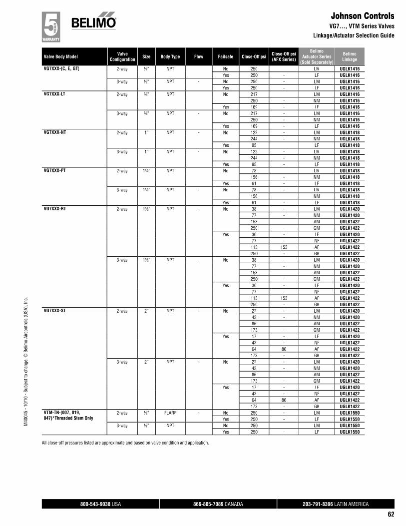
800-543-9038 USA 866-805-7089 CANADA 203-791-8396 LATIN AMERICA
62
Valve Body Model ValveConfi guration Size Body Type Flow Failsafe Close-Off psi Close-Off psi
(AFX Series)
BelimoActuator Series
(Sold Separately)
BelimoLinkage
M40
045
- 10/
10 -
Subj
ect t
o ch
ange
. © B
elim
o Ai
rcon
trols
(USA
), In
c.
Johnson ControlsVG7…, VTM Series Valves
Linkage/Actuator Selection Guide
VG7XXX-(C, E, GT) 2-way ½” NPT - No 250 - LM UGLK1416Yes 250 - LF UGLK1416
3-way ½” NPT - No 250 - LM UGLK1416Yes 250 - LF UGLK1416
VG7XXX-LT 2-way ¾” NPT - No 217 - LM UGLK1416250 - NM UGLK1416
Yes 169 - LF UGLK14163-way ¾” NPT - No 217 - LM UGLK1416
250 - NM UGLK1416Yes 169 - LF UGLK1416
VG7XXX-NT 2-way 1” NPT - No 122 - LM UGLK1418244 - NM UGLK1418
Yes 95 - LF UGLK14183-way 1” NPT - No 122 - LM UGLK1418
244 - NM UGLK1418Yes 95 - LF UGLK1418
VG7XXX-PT 2-way 1¼” NPT - No 78 - LM UGLK1418156 - NM UGLK1418
Yes 61 - LF UGLK14183-way 1¼” NPT - No 78 - LM UGLK1418
156 - NM UGLK1418Yes 61 - LF UGLK1418
VG7XXX-RT 2-way 1½” NPT - No 38 - LM UGLK142077 - NM UGLK1420153 - AM UGLK1422250 - GM UGLK1422
Yes 30 - LF UGLK142077 - NF UGLK1422113 153 AF UGLK1422250 - GK UGLK1422
3-way 1½” NPT - No 38 - LM UGLK142077 - NM UGLK1420153 - AM UGLK1422250 - GM UGLK1422
Yes 30 - LF UGLK142077 - NF UGLK1422113 153 AF UGLK1422250 - GK UGLK1422
VG7XXX-ST 2-way 2” NPT - No 22 - LM UGLK142043 - NM UGLK142086 - AM UGLK1422173 - GM UGLK1422
Yes 17 - LF UGLK142043 - NF UGLK142264 86 AF UGLK1422173 - GK UGLK1422
3-way 2” NPT - No 22 - LM UGLK142043 - NM UGLK142086 - AM UGLK1422173 - GM UGLK1422
Yes 17 - LF UGLK142043 - NF UGLK142264 86 AF UGLK1422173 - GK UGLK1422
VTM-TN-(007, 019,047)*Threaded Stem Only
2-way ½” FLARE - No 250 - LM UGLK1550Yes 250 - LF UGLK1550
3-way ½” NPT - No 250 - LM UGLK1550Yes 250 - LF UGLK1550
All close-off pressures listed are approximate and based on valve condition and application.
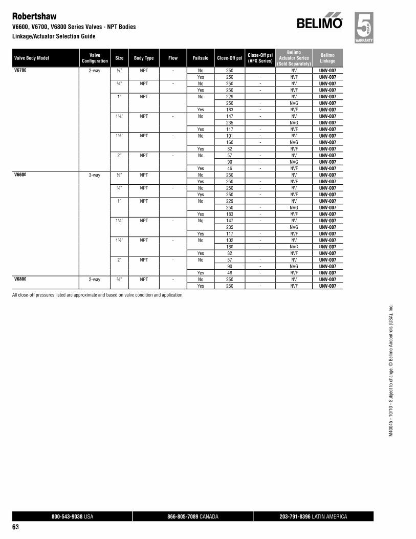
800-543-9038 USA 866-805-7089 CANADA 203-791-8396 LATIN AMERICA
63
Valve Body Model ValveConfi guration Size Body Type Flow Failsafe Close-Off psi Close-Off psi
(AFX Series)
BelimoActuator Series
(Sold Separately)
BelimoLinkage
M40
045
- 10/
10 -
Subj
ect t
o ch
ange
. © B
elim
o Ai
rcon
trols
(USA
), In
c.
RobertshawV6600, V6700, V6800 Series Valves - NPT Bodies
Linkage/Actuator Selection Guide
V6700 2-way ½” NPT - No 250 - NV UNV-007Yes 250 - NVF UNV-007
¾” NPT - No 250 - NV UNV-007Yes 250 - NVF UNV-007
1” NPT - No 229 - NV UNV-007250 - NVG UNV-007
Yes 183 - NVF UNV-0071¼” NPT - No 147 - NV UNV-007
235 - NVG UNV-007Yes 117 - NVF UNV-007
1½” NPT - No 101 - NV UNV-007160 - NVG UNV-007
Yes 82 - NVF UNV-0072” NPT - No 57 - NV UNV-007
90 - NVG UNV-007Yes 46 - NVF UNV-007
V6600 3-way ½” NPT - No 250 - NV UNV-007Yes 250 - NVF UNV-007
¾” NPT - No 250 - NV UNV-007Yes 250 - NVF UNV-007
1” NPT - No 229 - NV UNV-007250 - NVG UNV-007
Yes 183 - NVF UNV-0071¼” NPT - No 147 - NV UNV-007
235 - NVG UNV-007Yes 117 - NVF UNV-007
1½” NPT - No 102 - NV UNV-007160 - NVG UNV-007
Yes 82 - NVF UNV-0072” NPT - No 57 - NV UNV-007
90 - NVG UNV-007Yes 46 - NVF UNV-007
V6800 2-way ¾” NPT - No 250 - NV UNV-007Yes 250 - NVF UNV-007
All close-off pressures listed are approximate and based on valve condition and application.
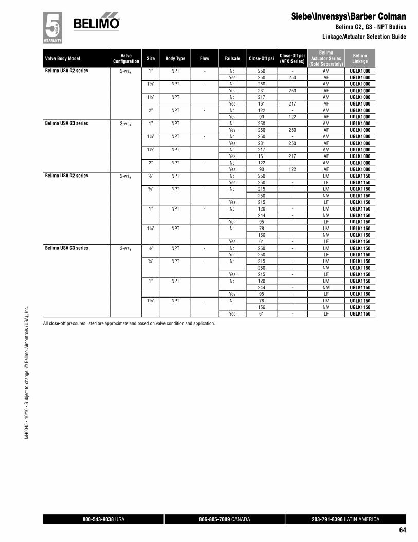
800-543-9038 USA 866-805-7089 CANADA 203-791-8396 LATIN AMERICA
64
Valve Body Model ValveConfi guration Size Body Type Flow Failsafe Close-Off psi Close-Off psi
(AFX Series)
BelimoActuator Series
(Sold Separately)
BelimoLinkage
M40
045
- 10/
10 -
Subj
ect t
o ch
ange
. © B
elim
o Ai
rcon
trols
(USA
), In
c.
Siebe\Invensys\Barber ColmanBelimo G2, G3 - NPT Bodies
Linkage/Actuator Selection Guide
Belimo USA G2 series 2-way 1” NPT - No 250 - AM UGLK1000Yes 250 250 AF UGLK1000
1¼” NPT - No 250 - AM UGLK1000Yes 231 250 AF UGLK1000
1½” NPT - No 217 - AM UGLK1000Yes 161 217 AF UGLK1000
2” NPT - No 122 - AM UGLK1000Yes 90 122 AF UGLK1000
Belimo USA G3 series 3-way 1” NPT - No 250 - AM UGLK1000Yes 250 250 AF UGLK1000
1¼” NPT - No 250 - AM UGLK1000Yes 231 250 AF UGLK1000
1½” NPT - No 217 - AM UGLK1000Yes 161 217 AF UGLK1000
2” NPT - No 122 - AM UGLK1000Yes 90 122 AF UGLK1000
Belimo USA G2 series 2-way ½” NPT - No 250 - LM UGLK1150Yes 250 - LF UGLK1150
¾” NPT - No 215 - LM UGLK1150250 - NM UGLK1150
Yes 215 - LF UGLK11501” NPT - No 120 - LM UGLK1150
244 - NM UGLK1150Yes 95 - LF UGLK1150
1¼” NPT - No 78 - LM UGLK1150156 - NM UGLK1150
Yes 61 - LF UGLK1150Belimo USA G3 series 3-way ½” NPT - No 250 - LM UGLK1150
Yes 250 - LF UGLK1150¾” NPT - No 215 - LM UGLK1150
250 - NM UGLK1150Yes 215 - LF UGLK1150
1” NPT - No 120 - LM UGLK1150244 - NM UGLK1150
Yes 95 - LF UGLK11501¼” NPT - No 78 - LM UGLK1150
156 - NM UGLK1150Yes 61 - LF UGLK1150
All close-off pressures listed are approximate and based on valve condition and application.
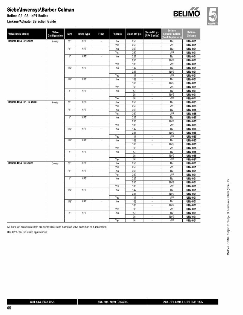
800-543-9038 USA 866-805-7089 CANADA 203-791-8396 LATIN AMERICA
65
Valve Body Model ValveConfi guration Size Body Type Flow Failsafe Close-Off psi Close-Off psi
(AFX Series)
BelimoActuator Series
(Sold Separately)
BelimoLinkage
M40
045
- 10/
10 -
Subj
ect t
o ch
ange
. © B
elim
o Ai
rcon
trols
(USA
), In
c.
Belimo USA G2 series 2-way ½” NPT - No 250 - NV UNV-001Yes 250 - NVF UNV-001
¾” NPT - No 250 - NV UNV-001Yes 250 - NVF UNV-001
1” NPT - No 229 - NV UNV-001250 - NVG UNV-001
Yes 183 - NVF UNV-0011¼” NPT - No 147 - NV UNV-001
235 - NVG UNV-001Yes 117 - NVF UNV-001
1½” NPT - No 102 - NV UNV-001160 - NVG UNV-001
Yes 82 - NVF UNV-0012” NPT - No 57 - NV UNV-001
90 - NVG UNV-001Yes 46 - NVF UNV-001
Belimo USA G2…S series 2-way ½” NPT - No 250 - NV UNV-035Yes 250 - NVF UNV-035
¾” NPT - No 250 - NV UNV-035Yes 250 - NVF UNV-035
1” NPT - No 229 - NV UNV-035250 - NVG UNV-035
Yes 183 - NVF UNV-0351¼” NPT - No 147 - NV UNV-035
235 - NVG UNV-035Yes 117 - NVF UNV-035
1½” NPT - No 102 - NV UNV-035160 - NVG UNV-035
Yes 82 - NVF UNV-0352” NPT - No 57 - NV UNV-035
90 - NVG UNV-035Yes 46 - NVF UNV-035
Belimo USA G3 series 3-way ½” NPT - No 250 - NV UNV-001Yes 250 - NVF UNV-001
¾” NPT - No 250 - NV UNV-001Yes 250 - NVF UNV-001
1” NPT - No 229 - NV UNV-001250 - NVG UNV-001
Yes 183 - NVF UNV-0011¼” NPT - No 147 - NV UNV-001
235 - NVG UNV-001Yes 117 - NVF UNV-001
1½” NPT - No 102 - NV UNV-001160 - NVG UNV-001
Yes 82 - NVF UNV-0012” NPT - No 57 - NV UNV-001
90 - NVG UNV-001Yes 46 - NVF UNV-001
Siebe\Invensys\Barber ColmanBelimo G2, G3 - NPT Bodies
Linkage/Actuator Selection Guide
All close-off pressures listed are approximate and based on valve condition and application.
Use UNV-035 for steam applications.
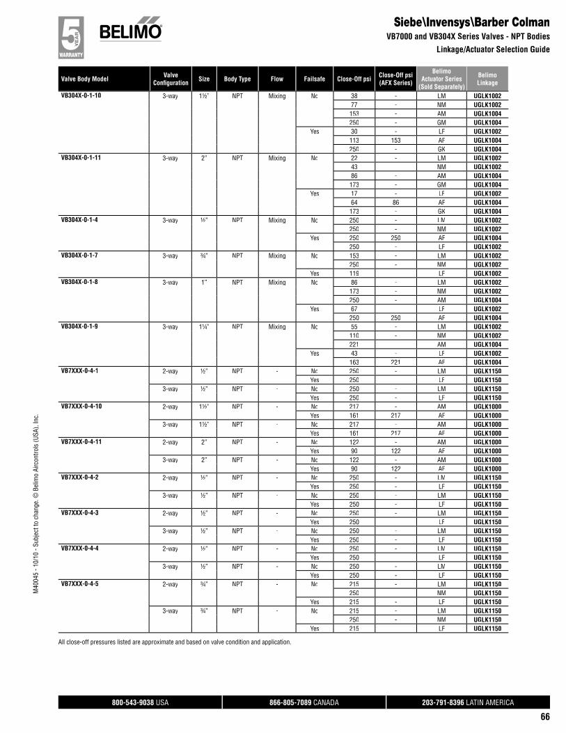
800-543-9038 USA 866-805-7089 CANADA 203-791-8396 LATIN AMERICA
66
Valve Body Model ValveConfi guration Size Body Type Flow Failsafe Close-Off psi Close-Off psi
(AFX Series)
BelimoActuator Series
(Sold Separately)
BelimoLinkage
M40
045
- 10/
10 -
Subj
ect t
o ch
ange
. © B
elim
o Ai
rcon
trols
(USA
), In
c.
Siebe\Invensys\Barber ColmanVB7000 and VB304X Series Valves - NPT Bodies
Linkage/Actuator Selection Guide
VB304X-0-1-10 3-way 1½” NPT Mixing No 38 - LM UGLK100277 - NM UGLK1002153 - AM UGLK1004250 - GM UGLK1004
Yes 30 - LF UGLK1002113 153 AF UGLK1004250 - GK UGLK1004
VB304X-0-1-11 3-way 2” NPT Mixing No 22 - LM UGLK100243 - NM UGLK100286 - AM UGLK1004173 - GM UGLK1004
Yes 17 - LF UGLK100264 86 AF UGLK1004173 - GK UGLK1004
VB304X-0-1-4 3-way ½” NPT Mixing No 250 - LM UGLK1002250 - NM UGLK1002
Yes 250 250 AF UGLK1004250 - LF UGLK1002
VB304X-0-1-7 3-way ¾” NPT Mixing No 153 - LM UGLK1002250 - NM UGLK1002
Yes 119 - LF UGLK1002VB304X-0-1-8 3-way 1” NPT Mixing No 86 - LM UGLK1002
173 - NM UGLK1002250 - AM UGLK1004
Yes 67 - LF UGLK1002250 250 AF UGLK1004
VB304X-0-1-9 3-way 1¼” NPT Mixing No 55 - LM UGLK1002110 - NM UGLK1002221 - AM UGLK1004
Yes 43 - LF UGLK1002163 221 AF UGLK1004
VB7XXX-0-4-1 2-way ½” NPT - No 250 - LM UGLK1150Yes 250 - LF UGLK1150
3-way ½” NPT - No 250 - LM UGLK1150Yes 250 - LF UGLK1150
VB7XXX-0-4-10 2-way 1½” NPT - No 217 - AM UGLK1000Yes 161 217 AF UGLK1000
3-way 1½” NPT - No 217 - AM UGLK1000Yes 161 217 AF UGLK1000
VB7XXX-0-4-11 2-way 2” NPT - No 122 - AM UGLK1000Yes 90 122 AF UGLK1000
3-way 2” NPT - No 122 - AM UGLK1000Yes 90 122 AF UGLK1000
VB7XXX-0-4-2 2-way ½” NPT - No 250 - LM UGLK1150Yes 250 - LF UGLK1150
3-way ½” NPT - No 250 - LM UGLK1150Yes 250 - LF UGLK1150
VB7XXX-0-4-3 2-way ½” NPT - No 250 - LM UGLK1150Yes 250 - LF UGLK1150
3-way ½” NPT - No 250 - LM UGLK1150Yes 250 - LF UGLK1150
VB7XXX-0-4-4 2-way ½” NPT - No 250 - LM UGLK1150Yes 250 - LF UGLK1150
3-way ½” NPT - No 250 - LM UGLK1150Yes 250 - LF UGLK1150
VB7XXX-0-4-5 2-way ¾” NPT - No 215 - LM UGLK1150250 - NM UGLK1150
Yes 215 - LF UGLK11503-way ¾” NPT - No 215 - LM UGLK1150
250 - NM UGLK1150Yes 215 - LF UGLK1150
All close-off pressures listed are approximate and based on valve condition and application.
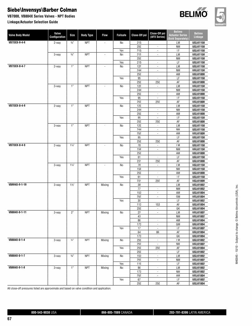
800-543-9038 USA 866-805-7089 CANADA 203-791-8396 LATIN AMERICA
67
Valve Body Model ValveConfi guration Size Body Type Flow Failsafe Close-Off psi Close-Off psi
(AFX Series)
BelimoActuator Series
(Sold Separately)
BelimoLinkage
M40
045
- 10/
10 -
Subj
ect t
o ch
ange
. © B
elim
o Ai
rcon
trols
(USA
), In
c.
Siebe\Invensys\Barber ColmanVB7000, VB804X Series Valves - NPT Bodies
Linkage/Actuator Selection Guide
VB7XXX-0-4-6 2-way ¾” NPT - No 215 - LM UGLK1150250 - NM UGLK1150
Yes 215 - LF UGLK11503-way ¾” NPT - No 215 - LM UGLK1150
250 - NM UGLK1150Yes 215 - LF UGLK1150
VB7XXX-0-4-7 2-way 1” NPT - No 120 - LM UGLK1150244 - NM UGLK1150250 - AM UGLK1000
Yes 95 - LF UGLK1150250 250 AF UGLK1000
3-way 1” NPT - No 120 - LM UGLK1150244 - NM UGLK1150250 - AM UGLK1000
Yes 95 - LF UGLK1150250 250 AF UGLK1000
VB7XXX-0-4-8 2-way 1” NPT - No 120 - LM UGLK1150244 - NM UGLK1150250 - AM UGLK1000
Yes 95 - LF UGLK1150250 250 AF UGLK1000
3-way 1” NPT - No 120 - LM UGLK1150244 - NM UGLK1150250 - AM UGLK1000
Yes 95 - LF UGLK1150250 250 AF UGLK1000
VB7XXX-0-4-9 2-way 1¼” NPT - No 78 - LM UGLK1150156 - NM UGLK1150250 - AM UGLK1000
Yes 61 - LF UGLK1150231 250 AF UGLK1000
3-way 1¼” NPT - No 78 - LM UGLK1150156 - NM UGLK1150250 - AM UGLK1000
Yes 61 - LF UGLK1150231 250 AF UGLK1000
VB804X-0-1-10 3-way 1½” NPT Mixing No 38 - LM UGLK100277 - NM UGLK1002153 - AM UGLK1004250 - GM UGLK1004
Yes 30 - LF UGLK1002113 153 AF UGLK1004250 - GK UGLK1004
VB804X-0-1-11 3-way 2” NPT Mixing No 22 - LM UGLK100243 - NM UGLK100286 - AM UGLK1004173 - GM UGLK1004
Yes 17 - LF UGLK100264 86 AF UGLK1004173 - GK UGLK1004
VB804X-0-1-4 3-way ½” NPT Mixing No 250 - LM UGLK1002250 - NM UGLK1002
Yes 250 250 AF UGLK1004250 - LF UGLK1002
VB804X-0-1-7 3-way ¾” NPT Mixing No 153 - LM UGLK1002250 - NM UGLK1002
Yes 119 - LF UGLK1002VB804X-0-1-8 3-way 1” NPT Mixing No 86 - LM UGLK1002
173 - NM UGLK1002250 - AM UGLK1004
Yes 67 - LF UGLK1002250 250 AF UGLK1004
All close-off pressures listed are approximate and based on valve condition and application.
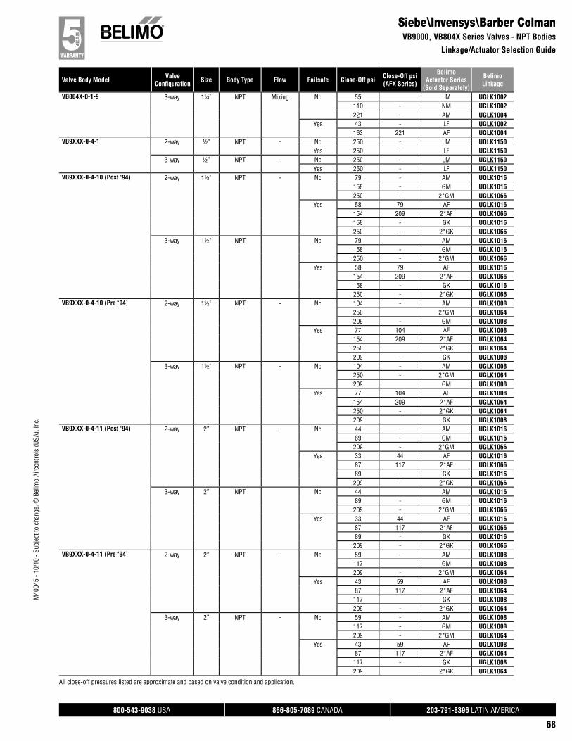
800-543-9038 USA 866-805-7089 CANADA 203-791-8396 LATIN AMERICA
68
Valve Body Model ValveConfi guration Size Body Type Flow Failsafe Close-Off psi Close-Off psi
(AFX Series)
BelimoActuator Series
(Sold Separately)
BelimoLinkage
M40
045
- 10/
10 -
Subj
ect t
o ch
ange
. © B
elim
o Ai
rcon
trols
(USA
), In
c.
Siebe\Invensys\Barber ColmanVB9000, VB804X Series Valves - NPT Bodies
Linkage/Actuator Selection Guide
VB804X-0-1-9 3-way 1¼” NPT Mixing No 55 - LM UGLK1002110 - NM UGLK1002221 - AM UGLK1004
Yes 43 - LF UGLK1002163 221 AF UGLK1004
VB9XXX-0-4-1 2-way ½” NPT - No 250 - LM UGLK1150Yes 250 - LF UGLK1150
3-way ½” NPT - No 250 - LM UGLK1150Yes 250 - LF UGLK1150
VB9XXX-0-4-10 (Post ‘94) 2-way 1½” NPT - No 79 - AM UGLK1016158 - GM UGLK1016250 - 2*GM UGLK1066
Yes 58 79 AF UGLK1016154 209 2*AF UGLK1066158 - GK UGLK1016250 - 2*GK UGLK1066
3-way 1½” NPT - No 79 - AM UGLK1016158 - GM UGLK1016250 - 2*GM UGLK1066
Yes 58 79 AF UGLK1016154 209 2*AF UGLK1066158 - GK UGLK1016250 - 2*GK UGLK1066
VB9XXX-0-4-10 (Pre ‘94) 2-way 1½” NPT - No 104 - AM UGLK1008250 - 2*GM UGLK1064209 - GM UGLK1008
Yes 77 104 AF UGLK1008154 209 2*AF UGLK1064250 - 2*GK UGLK1064209 - GK UGLK1008
3-way 1½” NPT - No 104 - AM UGLK1008250 - 2*GM UGLK1064209 - GM UGLK1008
Yes 77 104 AF UGLK1008154 209 2*AF UGLK1064250 - 2*GK UGLK1064209 - GK UGLK1008
VB9XXX-0-4-11 (Post ‘94) 2-way 2” NPT - No 44 - AM UGLK101689 - GM UGLK1016209 - 2*GM UGLK1066
Yes 33 44 AF UGLK101687 117 2*AF UGLK106689 - GK UGLK1016209 - 2*GK UGLK1066
3-way 2” NPT - No 44 - AM UGLK101689 - GM UGLK1016209 - 2*GM UGLK1066
Yes 33 44 AF UGLK101687 117 2*AF UGLK106689 - GK UGLK1016209 - 2*GK UGLK1066
VB9XXX-0-4-11 (Pre ‘94) 2-way 2” NPT - No 59 - AM UGLK1008117 - GM UGLK1008209 - 2*GM UGLK1064
Yes 43 59 AF UGLK100887 117 2*AF UGLK1064117 - GK UGLK1008209 - 2*GK UGLK1064
3-way 2” NPT - No 59 - AM UGLK1008117 - GM UGLK1008209 - 2*GM UGLK1064
Yes 43 59 AF UGLK100887 117 2*AF UGLK1064117 - GK UGLK1008209 - 2*GK UGLK1064
All close-off pressures listed are approximate and based on valve condition and application.
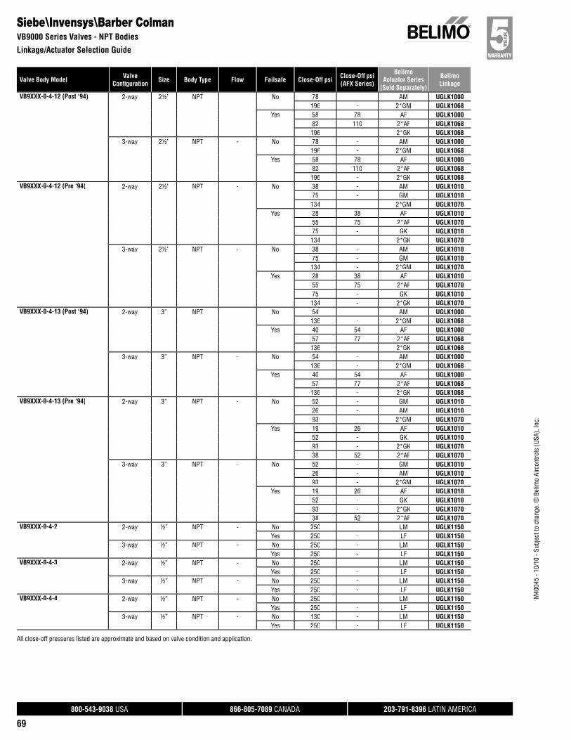
800-543-9038 USA 866-805-7089 CANADA 203-791-8396 LATIN AMERICA
69
Valve Body Model ValveConfi guration Size Body Type Flow Failsafe Close-Off psi Close-Off psi
(AFX Series)
BelimoActuator Series
(Sold Separately)
BelimoLinkage
M40
045
- 10/
10 -
Subj
ect t
o ch
ange
. © B
elim
o Ai
rcon
trols
(USA
), In
c.
Siebe\Invensys\Barber ColmanVB9000 Series Valves - NPT Bodies
Linkage/Actuator Selection Guide
VB9XXX-0-4-12 (Post ‘94) 2-way 2½” NPT - No 78 - AM UGLK1000196 - 2*GM UGLK1068
Yes 58 78 AF UGLK100082 110 2*AF UGLK1068196 - 2*GK UGLK1068
3-way 2½” NPT - No 78 - AM UGLK1000196 - 2*GM UGLK1068
Yes 58 78 AF UGLK100082 110 2*AF UGLK1068196 - 2*GK UGLK1068
VB9XXX-0-4-12 (Pre ‘94) 2-way 2½” NPT - No 38 - AM UGLK101075 - GM UGLK1010134 - 2*GM UGLK1070
Yes 28 38 AF UGLK101055 75 2*AF UGLK107075 - GK UGLK1010134 - 2*GK UGLK1070
3-way 2½” NPT - No 38 - AM UGLK101075 - GM UGLK1010134 - 2*GM UGLK1070
Yes 28 38 AF UGLK101055 75 2*AF UGLK107075 - GK UGLK1010134 - 2*GK UGLK1070
VB9XXX-0-4-13 (Post ‘94) 2-way 3” NPT - No 54 - AM UGLK1000136 - 2*GM UGLK1068
Yes 40 54 AF UGLK100057 77 2*AF UGLK1068136 - 2*GK UGLK1068
3-way 3” NPT - No 54 - AM UGLK1000136 - 2*GM UGLK1068
Yes 40 54 AF UGLK100057 77 2*AF UGLK1068136 - 2*GK UGLK1068
VB9XXX-0-4-13 (Pre ‘94) 2-way 3” NPT - No 52 - GM UGLK101026 - AM UGLK101093 - 2*GM UGLK1070
Yes 19 26 AF UGLK101052 - GK UGLK101093 - 2*GK UGLK107038 52 2*AF UGLK1070
3-way 3” NPT - No 52 - GM UGLK101026 - AM UGLK101093 - 2*GM UGLK1070
Yes 19 26 AF UGLK101052 - GK UGLK101093 - 2*GK UGLK107038 52 2*AF UGLK1070
VB9XXX-0-4-2 2-way ½” NPT - No 250 - LM UGLK1150Yes 250 - LF UGLK1150
3-way ½” NPT - No 250 - LM UGLK1150Yes 250 - LF UGLK1150
VB9XXX-0-4-3 2-way ½” NPT - No 250 - LM UGLK1150Yes 250 - LF UGLK1150
3-way ½” NPT - No 250 - LM UGLK1150Yes 250 - LF UGLK1150
VB9XXX-0-4-4 2-way ½” NPT - No 250 - LM UGLK1150Yes 250 - LF UGLK1150
3-way ½” NPT - No 130 - LM UGLK1150Yes 250 - LF UGLK1150
All close-off pressures listed are approximate and based on valve condition and application.
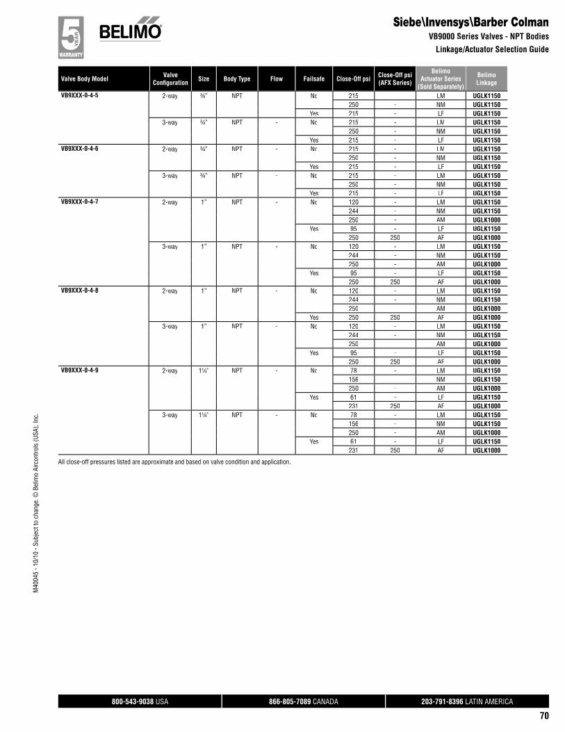
800-543-9038 USA 866-805-7089 CANADA 203-791-8396 LATIN AMERICA
70
Valve Body Model ValveConfi guration Size Body Type Flow Failsafe Close-Off psi Close-Off psi
(AFX Series)
BelimoActuator Series
(Sold Separately)
BelimoLinkage
M40
045
- 10/
10 -
Subj
ect t
o ch
ange
. © B
elim
o Ai
rcon
trols
(USA
), In
c.
Siebe\Invensys\Barber ColmanVB9000 Series Valves - NPT Bodies
Linkage/Actuator Selection Guide
VB9XXX-0-4-5 2-way ¾” NPT - No 215 - LM UGLK1150250 - NM UGLK1150
Yes 215 - LF UGLK11503-way ¾” NPT - No 215 - LM UGLK1150
250 - NM UGLK1150Yes 215 - LF UGLK1150
VB9XXX-0-4-6 2-way ¾” NPT - No 215 - LM UGLK1150250 - NM UGLK1150
Yes 215 - LF UGLK11503-way ¾” NPT - No 215 - LM UGLK1150
250 - NM UGLK1150Yes 215 - LF UGLK1150
VB9XXX-0-4-7 2-way 1” NPT - No 120 - LM UGLK1150244 - NM UGLK1150250 - AM UGLK1000
Yes 95 - LF UGLK1150250 250 AF UGLK1000
3-way 1” NPT - No 120 - LM UGLK1150244 - NM UGLK1150250 - AM UGLK1000
Yes 95 - LF UGLK1150250 250 AF UGLK1000
VB9XXX-0-4-8 2-way 1” NPT - No 120 - LM UGLK1150244 - NM UGLK1150250 - AM UGLK1000
Yes 250 250 AF UGLK10003-way 1” NPT - No 120 - LM UGLK1150
244 - NM UGLK1150250 - AM UGLK1000
Yes 95 - LF UGLK1150250 250 AF UGLK1000
VB9XXX-0-4-9 2-way 1¼” NPT - No 78 - LM UGLK1150156 - NM UGLK1150250 - AM UGLK1000
Yes 61 - LF UGLK1150231 250 AF UGLK1000
3-way 1¼” NPT - No 78 - LM UGLK1150156 - NM UGLK1150250 - AM UGLK1000
Yes 61 - LF UGLK1150231 250 AF UGLK1000
All close-off pressures listed are approximate and based on valve condition and application.
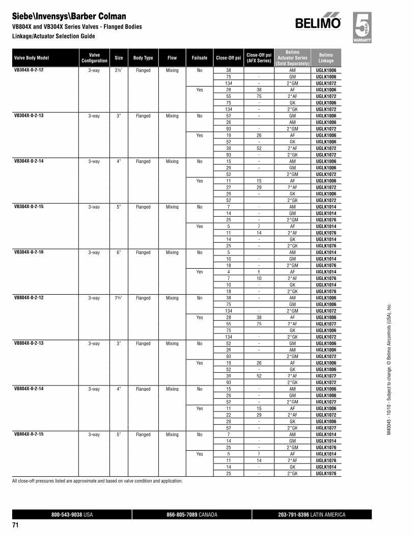
800-543-9038 USA 866-805-7089 CANADA 203-791-8396 LATIN AMERICA
71
Valve Body Model ValveConfi guration Size Body Type Flow Failsafe Close-Off psi Close-Off psi
(AFX Series)
BelimoActuator Series
(Sold Separately)
BelimoLinkage
M40
045
- 10/
10 -
Subj
ect t
o ch
ange
. © B
elim
o Ai
rcon
trols
(USA
), In
c.
Siebe\Invensys\Barber ColmanVB804X and VB304X Series Valves - Flanged Bodies
Linkage/Actuator Selection Guide
VB304X-0-2-12 3-way 2½” Flanged Mixing No 38 - AM UGLK100675 - GM UGLK1006134 - 2*GM UGLK1072
Yes 28 38 AF UGLK100655 75 2*AF UGLK107275 - GK UGLK1006134 - 2*GK UGLK1072
VB304X-0-2-13 3-way 3” Flanged Mixing No 52 - GM UGLK100626 - AM UGLK100693 - 2*GM UGLK1072
Yes 19 26 AF UGLK100652 - GK UGLK100639 52 2*AF UGLK107293 - 2*GK UGLK1072
VB304X-0-2-14 3-way 4” Flanged Mixing No 15 - AM UGLK100629 - GM UGLK100652 - 2*GM UGLK1072
Yes 11 15 AF UGLK100622 29 2*AF UGLK107229 - GK UGLK100652 - 2*GK UGLK1072
VB304X-0-2-15 3-way 5” Flanged Mixing No 7 - AM UGLK101414 - GM UGLK101425 - 2*GM UGLK1076
Yes 5 7 AF UGLK101411 14 2*AF UGLK107614 - GK UGLK101425 - 2*GK UGLK1076
VB304X-0-2-16 3-way 6” Flanged Mixing No 5 - AM UGLK101410 - GM UGLK101418 - 2*GM UGLK1076
Yes 4 5 AF UGLK10147 10 2*AF UGLK107610 - GK UGLK101418 - 2*GK UGLK1076
VB804X-0-2-12 3-way 2½” Flanged Mixing No 38 - AM UGLK100675 - GM UGLK1006134 - 2*GM UGLK1072
Yes 28 38 AF UGLK100655 75 2*AF UGLK107275 - GK UGLK1006134 - 2*GK UGLK1072
VB804X-0-2-13 3-way 3” Flanged Mixing No 52 - GM UGLK100626 - AM UGLK100693 - 2*GM UGLK1072
Yes 19 26 AF UGLK100652 - GK UGLK100639 52 2*AF UGLK107293 - 2*GK UGLK1072
VB804X-0-2-14 3-way 4” Flanged Mixing No 15 - AM UGLK100629 - GM UGLK100652 - 2*GM UGLK1072
Yes 11 15 AF UGLK100622 29 2*AF UGLK107229 - GK UGLK100652 - 2*GK UGLK1072
VB804X-0-2-15 3-way 5” Flanged Mixing No 7 - AM UGLK101414 - GM UGLK101425 - 2*GM UGLK1076
Yes 5 7 AF UGLK101411 14 2*AF UGLK107614 - GK UGLK101425 - 2*GK UGLK1076
All close-off pressures listed are approximate and based on valve condition and application.

800-543-9038 USA 866-805-7089 CANADA 203-791-8396 LATIN AMERICA
72
Valve Body Model ValveConfi guration Size Body Type Flow Failsafe Close-Off psi Close-Off psi
(AFX Series)
BelimoActuator Series
(Sold Separately)
BelimoLinkage
M40
045
- 10/
10 -
Subj
ect t
o ch
ange
. © B
elim
o Ai
rcon
trols
(USA
), In
c.
Siebe\Invensys\Barber ColmanVB9000, VB804X Series Valves - Flanged Bodies
Linkage/Actuator Selection Guide
VB804X-0-2-16 3-way 6” Flanged Mixing No 5 - AM UGLK101410 - GM UGLK101418 - 2*GM UGLK1076
Yes 4 5 AF UGLK10147 10 2*AF UGLK107610 - GK UGLK101418 - 2*GK UGLK1076
VB9XXX-0-5-12 2-way 2½” Flanged - No 38 - AM UGLK101075 - GM UGLK1010134 - 2*GM UGLK1070
Yes 28 38 AF UGLK101055 75 2*AF UGLK107075 - GK UGLK1010134 - 2*GK UGLK1070
3-way 2½” Flanged - No 38 - AM UGLK101075 - GM UGLK1010134 - 2*GM UGLK1070
Yes 28 38 AF UGLK101055 75 2*AF UGLK107075 - GK UGLK1010134 - 2*GK UGLK1070
VB9XXX-0-5-13 2-way 3” Flanged - No 52 - GM UGLK101026 - AM UGLK101093 - 2*GM UGLK1070
Yes 19 26 AF UGLK101052 - GK UGLK101093 - 2*GK UGLK107038 52 2*AF UGLK1070
3-way 3” Flanged - No 52 - GM UGLK101026 - AM UGLK101093 - 2*GM UGLK1070
Yes 19 26 AF UGLK101052 - GK UGLK101093 - 2*GK UGLK107038 52 2*AF UGLK1070
VB9XXX-0-5-14 2-way 4” Flanged - No 11 - AM UGLK101222 - GM UGLK101240 - 2*GM UGLK1074
Yes 8 11 AF UGLK101216 22 2*AF UGLK107422 - GK UGLK101240 - 2*GK UGLK1074
3-way 4” Flanged - No 11 - AM UGLK101222 - GM UGLK101240 - 2*GM UGLK1074
Yes 8 11 AF UGLK101216 22 2*AF UGLK107422 - GK UGLK101240 - 2*GK UGLK1074
All close-off pressures listed are approximate and based on valve condition and application.
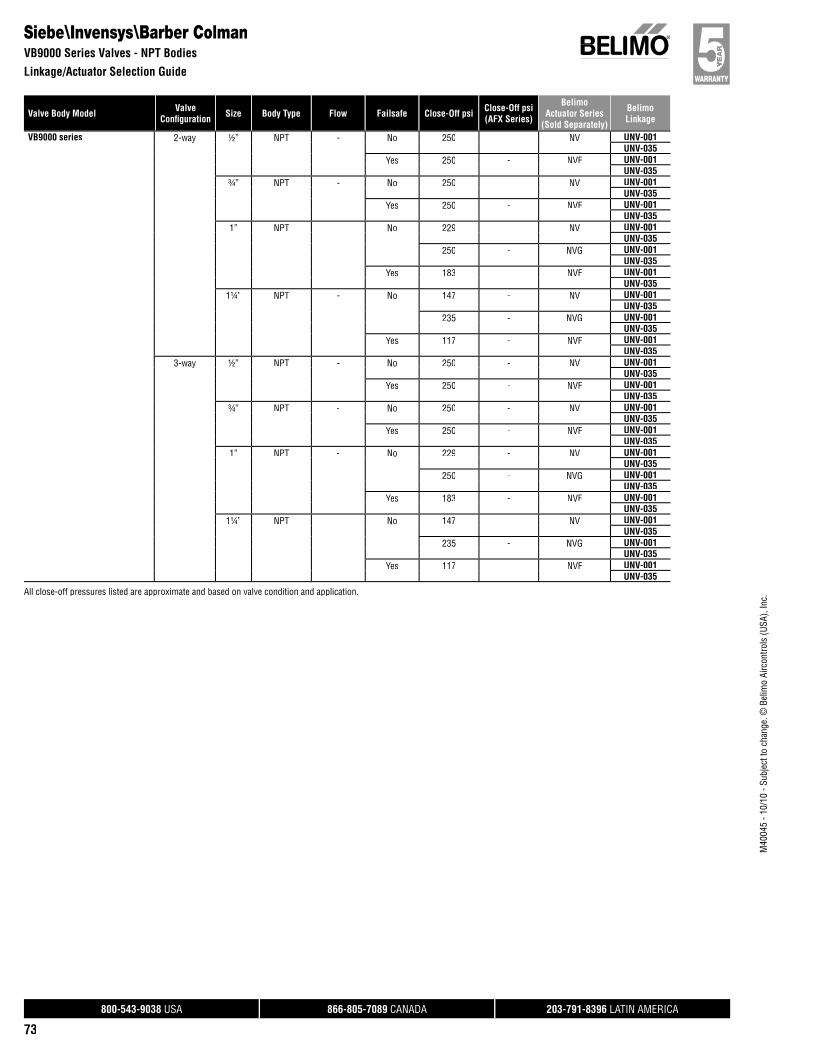
800-543-9038 USA 866-805-7089 CANADA 203-791-8396 LATIN AMERICA
73
Valve Body Model ValveConfi guration Size Body Type Flow Failsafe Close-Off psi Close-Off psi
(AFX Series)
BelimoActuator Series
(Sold Separately)
BelimoLinkage
M40
045
- 10/
10 -
Subj
ect t
o ch
ange
. © B
elim
o Ai
rcon
trols
(USA
), In
c.
VB9000 series 2-way ½” NPT - No 250 - NV UNV-001UNV-035
Yes 250 - NVF UNV-001UNV-035
¾” NPT - No 250 - NV UNV-001UNV-035
Yes 250 - NVF UNV-001UNV-035
1” NPT - No 229 - NV UNV-001UNV-035
250 - NVG UNV-001UNV-035
Yes 183 - NVF UNV-001UNV-035
1¼” NPT - No 147 - NV UNV-001UNV-035
235 - NVG UNV-001UNV-035
Yes 117 - NVF UNV-001UNV-035
3-way ½” NPT - No 250 - NV UNV-001UNV-035
Yes 250 - NVF UNV-001UNV-035
¾” NPT - No 250 - NV UNV-001UNV-035
Yes 250 - NVF UNV-001UNV-035
1” NPT - No 229 - NV UNV-001UNV-035
250 - NVG UNV-001UNV-035
Yes 183 - NVF UNV-001UNV-035
1¼” NPT - No 147 - NV UNV-001UNV-035
235 - NVG UNV-001UNV-035
Yes 117 - NVF UNV-001UNV-035
Siebe\Invensys\Barber ColmanVB9000 Series Valves - NPT Bodies
Linkage/Actuator Selection Guide
All close-off pressures listed are approximate and based on valve condition and application.
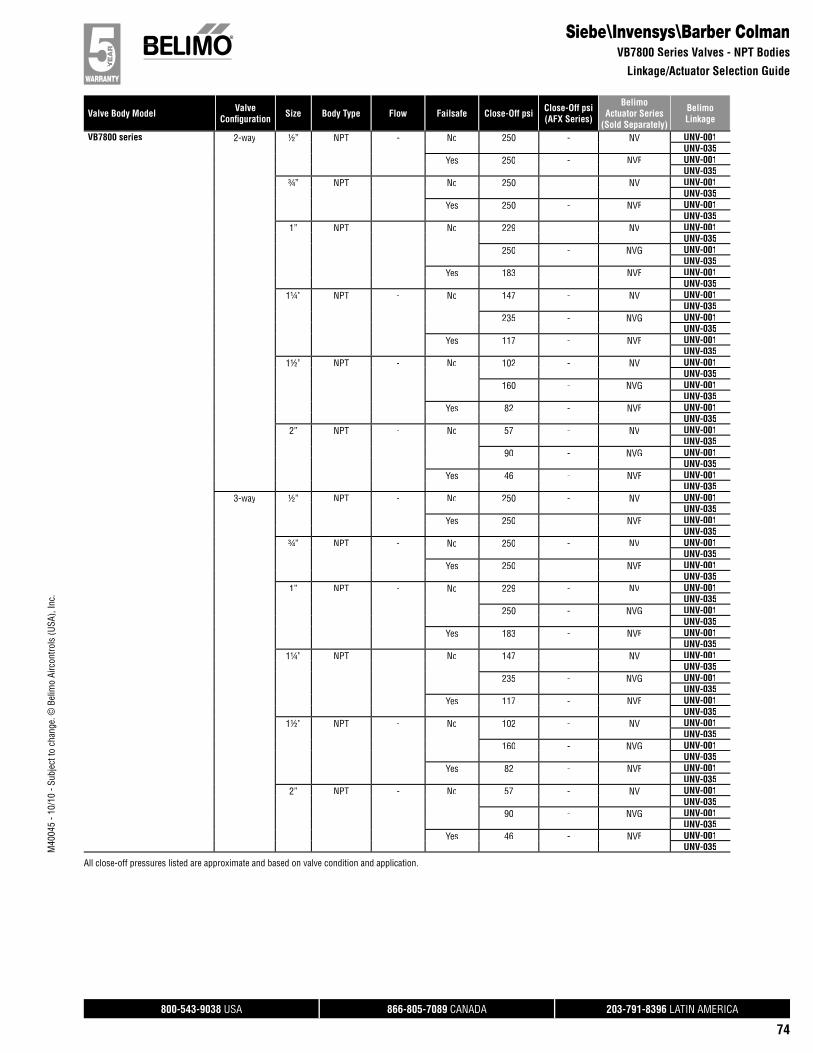
800-543-9038 USA 866-805-7089 CANADA 203-791-8396 LATIN AMERICA
74
Valve Body Model ValveConfi guration Size Body Type Flow Failsafe Close-Off psi Close-Off psi
(AFX Series)
BelimoActuator Series
(Sold Separately)
BelimoLinkage
M40
045
- 10/
10 -
Subj
ect t
o ch
ange
. © B
elim
o Ai
rcon
trols
(USA
), In
c.
VB7800 series 2-way ½” NPT - No 250 - NV UNV-001UNV-035
Yes 250 - NVF UNV-001UNV-035
¾” NPT - No 250 - NV UNV-001UNV-035
Yes 250 - NVF UNV-001UNV-035
1” NPT - No 229 - NV UNV-001UNV-035
250 - NVG UNV-001UNV-035
Yes 183 - NVF UNV-001UNV-035
1¼” NPT - No 147 - NV UNV-001UNV-035
235 - NVG UNV-001UNV-035
Yes 117 - NVF UNV-001UNV-035
1½” NPT - No 102 - NV UNV-001UNV-035
160 - NVG UNV-001UNV-035
Yes 82 - NVF UNV-001UNV-035
2” NPT - No 57 - NV UNV-001UNV-035
90 - NVG UNV-001UNV-035
Yes 46 - NVF UNV-001UNV-035
3-way ½” NPT - No 250 - NV UNV-001UNV-035
Yes 250 - NVF UNV-001UNV-035
¾” NPT - No 250 - NV UNV-001UNV-035
Yes 250 - NVF UNV-001UNV-035
1” NPT - No 229 - NV UNV-001UNV-035
250 - NVG UNV-001UNV-035
Yes 183 - NVF UNV-001UNV-035
1¼” NPT - No 147 - NV UNV-001UNV-035
235 - NVG UNV-001UNV-035
Yes 117 - NVF UNV-001UNV-035
1½” NPT - No 102 - NV UNV-001UNV-035
160 - NVG UNV-001UNV-035
Yes 82 - NVF UNV-001UNV-035
2” NPT - No 57 - NV UNV-001UNV-035
90 - NVG UNV-001UNV-035
Yes 46 - NVF UNV-001UNV-035
Siebe\Invensys\Barber ColmanVB7800 Series Valves - NPT Bodies
Linkage/Actuator Selection Guide
All close-off pressures listed are approximate and based on valve condition and application.
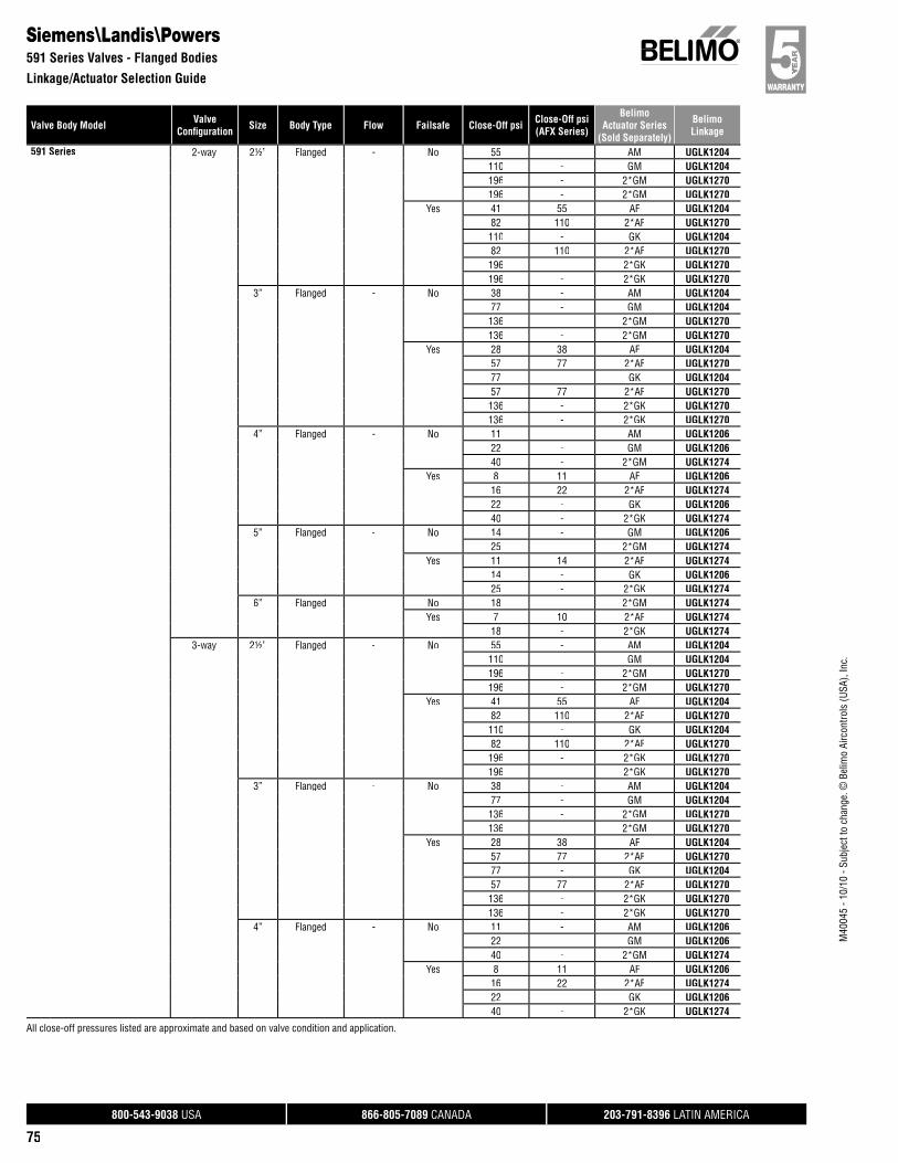
800-543-9038 USA 866-805-7089 CANADA 203-791-8396 LATIN AMERICA
75
Valve Body Model ValveConfi guration Size Body Type Flow Failsafe Close-Off psi Close-Off psi
(AFX Series)
BelimoActuator Series
(Sold Separately)
BelimoLinkage
M40
045
- 10/
10 -
Subj
ect t
o ch
ange
. © B
elim
o Ai
rcon
trols
(USA
), In
c.
Siemens\Landis\Powers591 Series Valves - Flanged Bodies
Linkage/Actuator Selection Guide
591 Series 2-way 2½” Flanged - No 55 - AM UGLK1204110 - GM UGLK1204196 - 2*GM UGLK1270196 - 2*GM UGLK1270
Yes 41 55 AF UGLK120482 110 2*AF UGLK1270110 - GK UGLK120482 110 2*AF UGLK1270196 - 2*GK UGLK1270196 - 2*GK UGLK1270
3” Flanged - No 38 - AM UGLK120477 - GM UGLK1204136 - 2*GM UGLK1270136 - 2*GM UGLK1270
Yes 28 38 AF UGLK120457 77 2*AF UGLK127077 - GK UGLK120457 77 2*AF UGLK1270136 - 2*GK UGLK1270136 - 2*GK UGLK1270
4” Flanged - No 11 - AM UGLK120622 - GM UGLK120640 - 2*GM UGLK1274
Yes 8 11 AF UGLK120616 22 2*AF UGLK127422 - GK UGLK120640 - 2*GK UGLK1274
5” Flanged - No 14 - GM UGLK120625 - 2*GM UGLK1274
Yes 11 14 2*AF UGLK127414 - GK UGLK120625 - 2*GK UGLK1274
6” Flanged - No 18 - 2*GM UGLK1274Yes 7 10 2*AF UGLK1274
18 - 2*GK UGLK12743-way 2½” Flanged - No 55 - AM UGLK1204
110 - GM UGLK1204196 - 2*GM UGLK1270196 - 2*GM UGLK1270
Yes 41 55 AF UGLK120482 110 2*AF UGLK1270110 - GK UGLK120482 110 2*AF UGLK1270196 - 2*GK UGLK1270196 - 2*GK UGLK1270
3” Flanged - No 38 - AM UGLK120477 - GM UGLK1204136 - 2*GM UGLK1270136 - 2*GM UGLK1270
Yes 28 38 AF UGLK120457 77 2*AF UGLK127077 - GK UGLK120457 77 2*AF UGLK1270136 - 2*GK UGLK1270136 - 2*GK UGLK1270
4” Flanged - No 11 - AM UGLK120622 - GM UGLK120640 - 2*GM UGLK1274
Yes 8 11 AF UGLK120616 22 2*AF UGLK127422 - GK UGLK120640 - 2*GK UGLK1274
All close-off pressures listed are approximate and based on valve condition and application.

800-543-9038 USA 866-805-7089 CANADA 203-791-8396 LATIN AMERICA
76
Valve Body Model ValveConfi guration Size Body Type Flow Failsafe Close-Off psi Close-Off psi
(AFX Series)
BelimoActuator Series
(Sold Separately)
BelimoLinkage
M40
045
- 10/
10 -
Subj
ect t
o ch
ange
. © B
elim
o Ai
rcon
trols
(USA
), In
c.
Siemens\Landis\Powers591 and 599 Series Valves - Flanged Bodies
Linkage/Actuator Selection Guide
591 Series 3-way 5” Flanged - No 14 - GM UGLK120625 - 2*GM UGLK1274
Yes 11 14 2*AF UGLK127414 - GK UGLK120625 - 2*GK UGLK1274
6” Flanged - No 18 - 2*GM UGLK1274Yes 7 10 2*AF UGLK1274
18 - 2*GK UGLK1274599 Flowrite 2-way 2½” Flanged - No 55 - AM UGLK1210
110 - GM UGLK1210196 - 2*GM UGLK1272
Yes 41 55 AF UGLK121082 110 2*AF UGLK1272110 - GK UGLK1210196 - 2*GK UGLK1272
3” Flanged - No 38 - AM UGLK121077 - GM UGLK1210136 - 2*GM UGLK1272
Yes 28 38 AF UGLK121057 77 2*AF UGLK127277 - GK UGLK1210136 - 2*GK UGLK1272
4” Flanged - No 11 - AM UGLK121222 - GM UGLK121240 - 2*GM UGLK1276
Yes 8 11 AF UGLK121216 22 2*AF UGLK127622 - GK UGLK121240 - 2*GK UGLK1276
5” Flanged - No 14 - GM UGLK121225 - 2*GM UGLK1276
Yes 11 14 2*AF UGLK127614 - GK UGLK121225 - 2*GK UGLK1276
3-way 2½” Flanged - No 55 - AM UGLK1210110 - GM UGLK1210196 - 2*GM UGLK1272
Yes 41 55 AF UGLK121082 110 2*AF UGLK1272110 - GK UGLK1210196 - 2*GK UGLK1272
3” Flanged - No 38 - AM UGLK121077 - GM UGLK1210136 - 2*GM UGLK1272
Yes 28 38 AF UGLK121057 77 2*AF UGLK127277 - GK UGLK1210136 - 2*GK UGLK1272
4” Flanged - No 11 - AM UGLK121222 - GM UGLK121240 - 2*GM UGLK1276
Yes 8 11 AF UGLK121216 22 2*AF UGLK127622 - GK UGLK121240 - 2*GK UGLK1276
5” Flanged - No 14 - GM UGLK121225 - 2*GM UGLK1276
Yes 11 14 2*AF UGLK127614 - GK UGLK121225 - 2*GK UGLK1276
All close-off pressures listed are approximate and based on valve condition and application.

800-543-9038 USA 866-805-7089 CANADA 203-791-8396 LATIN AMERICA
77
Valve Body Model ValveConfi guration Size Body Type Flow Failsafe Close-Off psi Close-Off psi
(AFX Series)
BelimoActuator Series
(Sold Separately)
BelimoLinkage
M40
045
- 10/
10 -
Subj
ect t
o ch
ange
. © B
elim
o Ai
rcon
trols
(USA
), In
c.
Siemens\Landis\Powers591 Series Valves - NPT Bodies
Linkage/Actuator Selection Guide
591 Series 2-way ½” NPT - No 250 - AM UGLK1200250 - NV UNV-005
Yes 250 - NF UGLK1200250 - NVF UNV-005
¾” NPT - No 250 - NV UNV-005Yes 250 - NF UGLK1200
250 - NVF UNV-0051” NPT - No 229 - NV UNV-005
250 - AM UGLK1200250 - NVG UNV-005
Yes 183 - NVF UNV-005244 - NF UGLK1200250 250 AF UGLK1200
1¼” NPT - No 147 - NV UNV-005250 - AM UGLK1200235 - NVG UNV-005
Yes 117 - NVF UNV-005156 - NF UGLK1200231 250 AF UGLK1200
1½” NPT - No 104 - AM UGLK1202209 - GM UGLK1202
Yes 52 - NF UGLK120277 104 AF UGLK1202209 - GK UGLK1202
2” NPT - No 59 - AM UGLK1202117 - GM UGLK1202
Yes 29 - NF UGLK120243 59 AF UGLK1202117 - GK UGLK1202
3-way ½” NPT - No 250 - AM UGLK1200250 - NV UNV-005
Yes 250 - NF UGLK1200250 - NVF UNV-005
¾” NPT - No 250 - NV UNV-005Yes 250 - NF UGLK1200
250 - NVF UNV-0051” NPT - No 229 - NV UNV-005
250 - AM UGLK1200250 - NVG UNV-005
Yes 183 - NVF UNV-005244 - NF UGLK1200250 250 AF UGLK1200
1¼” NPT - No 147 - NV UNV-005250 - AM UGLK1200235 - NVG UNV-005
Yes 117 - NVF UNV-005156 - NF UGLK1200231 250 AF UGLK1200
1½” NPT - No 217 - AM UGLK1200250 - GM UGLK1200
Yes 109 - NF UGLK1200161 217 AF UGLK1200250 - GK UGLK1200
2” NPT - No 57 - NV UNV-00590 - NVG UNV-005122 - AM UGLK1200244 - GM UGLK1200
Yes 61 - NF UGLK120046 - NVF UNV-00590 122 AF UGLK1200244 - GK UGLK1200
All close-off pressures listed are approximate and based on valve condition and application.
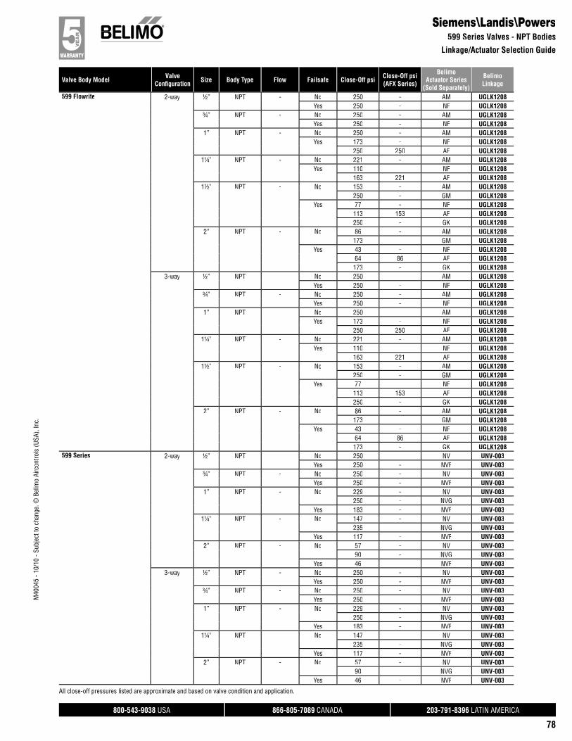
800-543-9038 USA 866-805-7089 CANADA 203-791-8396 LATIN AMERICA
78
Valve Body Model ValveConfi guration Size Body Type Flow Failsafe Close-Off psi Close-Off psi
(AFX Series)
BelimoActuator Series
(Sold Separately)
BelimoLinkage
M40
045
- 10/
10 -
Subj
ect t
o ch
ange
. © B
elim
o Ai
rcon
trols
(USA
), In
c.
Siemens\Landis\Powers599 Series Valves - NPT Bodies
Linkage/Actuator Selection Guide
599 Flowrite 2-way ½” NPT - No 250 - AM UGLK1208Yes 250 - NF UGLK1208
¾” NPT - No 250 - AM UGLK1208Yes 250 - NF UGLK1208
1” NPT - No 250 - AM UGLK1208Yes 173 - NF UGLK1208
250 250 AF UGLK12081¼” NPT - No 221 - AM UGLK1208
Yes 110 - NF UGLK1208163 221 AF UGLK1208
1½” NPT - No 153 - AM UGLK1208250 - GM UGLK1208
Yes 77 - NF UGLK1208113 153 AF UGLK1208250 - GK UGLK1208
2” NPT - No 86 - AM UGLK1208173 - GM UGLK1208
Yes 43 - NF UGLK120864 86 AF UGLK1208173 - GK UGLK1208
3-way ½” NPT - No 250 - AM UGLK1208Yes 250 - NF UGLK1208
¾” NPT - No 250 - AM UGLK1208Yes 250 - NF UGLK1208
1” NPT - No 250 - AM UGLK1208Yes 173 - NF UGLK1208
250 250 AF UGLK12081¼” NPT - No 221 - AM UGLK1208
Yes 110 - NF UGLK1208163 221 AF UGLK1208
1½” NPT - No 153 - AM UGLK1208250 - GM UGLK1208
Yes 77 - NF UGLK1208113 153 AF UGLK1208250 - GK UGLK1208
2” NPT - No 86 - AM UGLK1208173 - GM UGLK1208
Yes 43 - NF UGLK120864 86 AF UGLK1208173 - GK UGLK1208
599 Series 2-way ½” NPT - No 250 - NV UNV-003Yes 250 - NVF UNV-003
¾” NPT - No 250 - NV UNV-003Yes 250 - NVF UNV-003
1” NPT - No 229 - NV UNV-003250 - NVG UNV-003
Yes 183 - NVF UNV-0031¼” NPT - No 147 - NV UNV-003
235 - NVG UNV-003Yes 117 - NVF UNV-003
2” NPT - No 57 - NV UNV-00390 - NVG UNV-003
Yes 46 - NVF UNV-0033-way ½” NPT - No 250 - NV UNV-003
Yes 250 - NVF UNV-003¾” NPT - No 250 - NV UNV-003
Yes 250 - NVF UNV-0031” NPT - No 229 - NV UNV-003
250 - NVG UNV-003Yes 183 - NVF UNV-003
1¼” NPT - No 147 - NV UNV-003235 - NVG UNV-003
Yes 117 - NVF UNV-0032” NPT - No 57 - NV UNV-003
90 - NVG UNV-003Yes 46 - NVF UNV-003
All close-off pressures listed are approximate and based on valve condition and application.
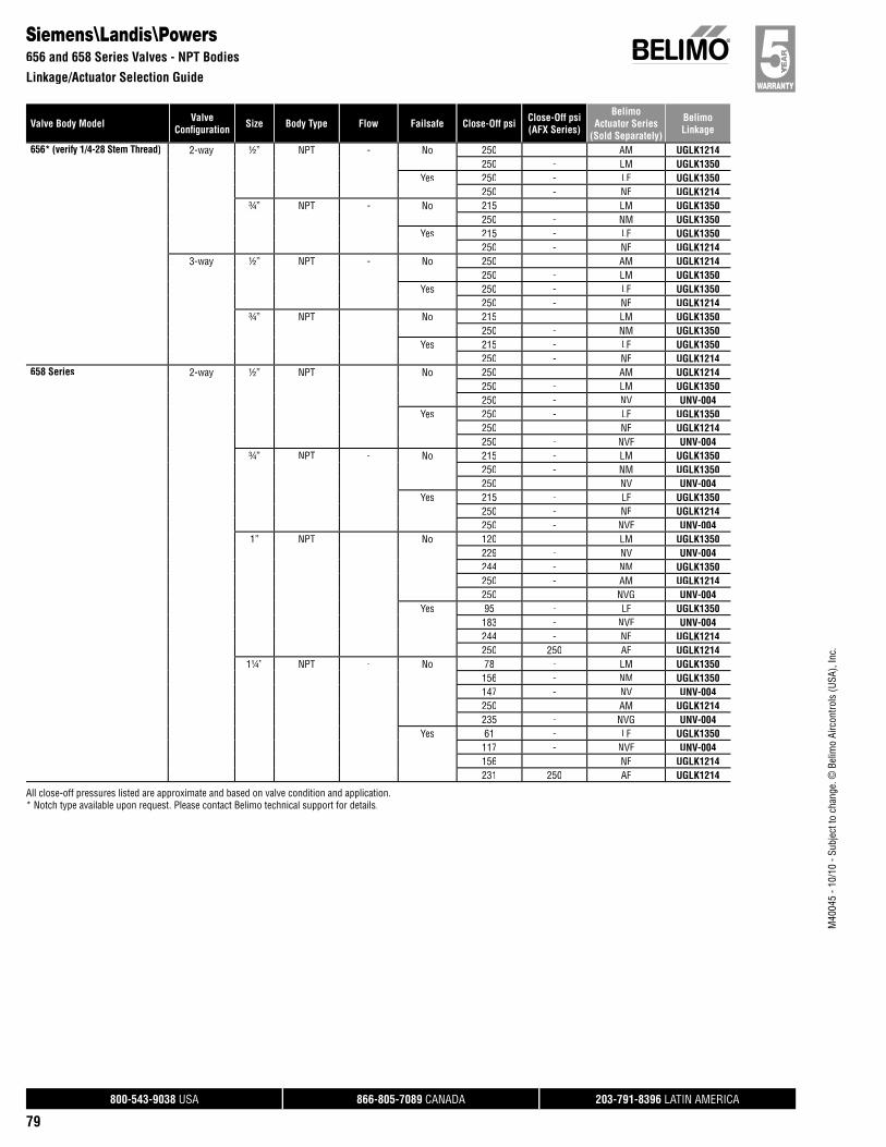
800-543-9038 USA 866-805-7089 CANADA 203-791-8396 LATIN AMERICA
79
Valve Body Model ValveConfi guration Size Body Type Flow Failsafe Close-Off psi Close-Off psi
(AFX Series)
BelimoActuator Series
(Sold Separately)
BelimoLinkage
M40
045
- 10/
10 -
Subj
ect t
o ch
ange
. © B
elim
o Ai
rcon
trols
(USA
), In
c.
Siemens\Landis\Powers656 and 658 Series Valves - NPT Bodies
Linkage/Actuator Selection Guide
656* (verify 1/4-28 Stem Thread) 2-way ½” NPT - No 250 - AM UGLK1214250 - LM UGLK1350
Yes 250 - LF UGLK1350250 - NF UGLK1214
¾” NPT - No 215 - LM UGLK1350250 - NM UGLK1350
Yes 215 - LF UGLK1350250 - NF UGLK1214
3-way ½” NPT - No 250 - AM UGLK1214250 - LM UGLK1350
Yes 250 - LF UGLK1350250 - NF UGLK1214
¾” NPT - No 215 - LM UGLK1350250 - NM UGLK1350
Yes 215 - LF UGLK1350250 - NF UGLK1214
658 Series 2-way ½” NPT - No 250 - AM UGLK1214250 - LM UGLK1350250 - NV UNV-004
Yes 250 - LF UGLK1350250 - NF UGLK1214250 - NVF UNV-004
¾” NPT - No 215 - LM UGLK1350250 - NM UGLK1350250 - NV UNV-004
Yes 215 - LF UGLK1350250 - NF UGLK1214250 - NVF UNV-004
1” NPT - No 120 - LM UGLK1350229 - NV UNV-004244 - NM UGLK1350250 - AM UGLK1214250 - NVG UNV-004
Yes 95 - LF UGLK1350183 - NVF UNV-004244 - NF UGLK1214250 250 AF UGLK1214
1¼” NPT - No 78 - LM UGLK1350156 - NM UGLK1350147 - NV UNV-004250 - AM UGLK1214235 - NVG UNV-004
Yes 61 - LF UGLK1350117 - NVF UNV-004156 - NF UGLK1214231 250 AF UGLK1214
All close-off pressures listed are approximate and based on valve condition and application.* Notch type available upon request. Please contact Belimo technical support for details.
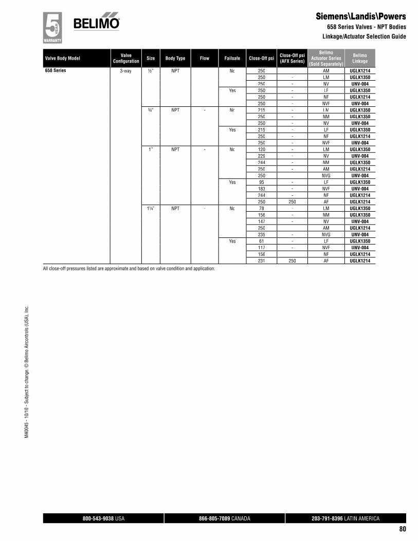
800-543-9038 USA 866-805-7089 CANADA 203-791-8396 LATIN AMERICA
80
Valve Body Model ValveConfi guration Size Body Type Flow Failsafe Close-Off psi Close-Off psi
(AFX Series)
BelimoActuator Series
(Sold Separately)
BelimoLinkage
M40
045
- 10/
10 -
Subj
ect t
o ch
ange
. © B
elim
o Ai
rcon
trols
(USA
), In
c.
658 Series 3-way ½” NPT - No 250 - AM UGLK1214250 - LM UGLK1350250 - NV UNV-004
Yes 250 - LF UGLK1350250 - NF UGLK1214250 - NVF UNV-004
¾” NPT - No 215 - LM UGLK1350250 - NM UGLK1350250 - NV UNV-004
Yes 215 - LF UGLK1350250 - NF UGLK1214250 - NVF UNV-004
1” NPT - No 120 - LM UGLK1350229 - NV UNV-004244 - NM UGLK1350250 - AM UGLK1214250 - NVG UNV-004
Yes 95 - LF UGLK1350183 - NVF UNV-004244 - NF UGLK1214250 250 AF UGLK1214
1¼” NPT - No 78 - LM UGLK1350156 - NM UGLK1350147 - NV UNV-004250 - AM UGLK1214235 - NVG UNV-004
Yes 61 - LF UGLK1350117 - NVF UNV-004156 - NF UGLK1214231 250 AF UGLK1214
Siemens\Landis\Powers658 Series Valves - NPT Bodies
Linkage/Actuator Selection Guide
All close-off pressures listed are approximate and based on valve condition and application.

800-543-9038 USA 866-805-7089 CANADA 203-791-8396 LATIN AMERICA
81
Valve Body Model ValveConfi guration Size Body Type Flow Failsafe Close-Off psi Close-Off psi
(AFX Series)
BelimoActuator Series
(Sold Separately)
BelimoLinkage
M40
045
- 10/
10 -
Subj
ect t
o ch
ange
. © B
elim
o Ai
rcon
trols
(USA
), In
c.
Warren ControlsType 100 Sgl Seat
Linkage/Actuator Selection Guide
100 SGL SEAT 2-way 2½” Flanged - No 28 - AM UGLK220257 - GM UGLK2202101 - 2*GM UGLK2272
Yes 14 - NF UGLK220221 28 AF UGLK220242 57 2*AF UGLK227257 - GK UGLK2202101 - 2*GK UGLK2272
3” Flanged - No 20 - AM UGLK220240 - GM UGLK220270 - 2*GM UGLK2272
Yes 10 - NF UGLK220215 20 AF UGLK220229 40 2*AF UGLK227240 - GK UGLK220270 - 2*GK UGLK2272
4” Flanged - No 11 - AM UGLK220222 - GM UGLK220240 - 2*GM UGLK2272
Yes 8 11 AF UGLK220216 22 2*AF UGLK227222 - GK UGLK220240 - 2*GK UGLK2272
5” Flanged - No 14 - GM UGLK220225 - 2*GM UGLK2272
Yes 5 7 AF UGLK220211 14 2*AF UGLK227214 - GK UGLK220225 - 2*GK UGLK2272
6” Flanged - No 10 - GM UGLK220218 - 2*GM UGLK2272
Yes 4 5 AF UGLK22027 10 2*AF UGLK227210 - GK UGLK220218 - 2*GK UGLK2272
All close-off pressures listed are approximate and based on valve condition and application.

800-543-9038 USA 866-805-7089 CANADA 203-791-8396 LATIN AMERICA
82
Valve Body Model ValveConfi guration Size Body Type Flow Failsafe Close-Off psi Close-Off psi
(AFX Series)
BelimoActuator Series
(Sold Separately)
BelimoLinkage
M40
045
- 10/
10 -
Subj
ect t
o ch
ange
. © B
elim
o Ai
rcon
trols
(USA
), In
c.
Warren ControlsType 1800
Linkage/Actuator Selection Guide//
1800 3W DIV 3-way 2½” Flanged Diverting No 28 - AM UGLK220257 - GM UGLK2202101 - 2*GM UGLK2272
Yes 14 - NF UGLK220221 28 AF UGLK220242 57 2*AF UGLK227257 - GK UGLK2202101 - 2*GK UGLK2272
3” Flanged Diverting No 20 - AM UGLK220240 - GM UGLK220270 - 2*GM UGLK2272
Yes 10 - NF UGLK220215 20 AF UGLK220229 40 2*AF UGLK227240 - GK UGLK220270 - 2*GK UGLK2272
4” Flanged Diverting No 11 - AM UGLK220222 - GM UGLK220240 - 2*GM UGLK2272
Yes 8 11 AF UGLK220216 22 2*AF UGLK227222 - GK UGLK220240 - 2*GK UGLK2272
5” Flanged Diverting No 14 - GM UGLK220225 - 2*GM UGLK2272
Yes 5 7 AF UGLK220211 14 2*AF UGLK227214 - GK UGLK220225 - 2*GK UGLK2272
6” Flanged Diverting No 10 - GM UGLK220218 - 2*GM UGLK2272
Yes 4 5 AF UGLK22027 10 2*AF UGLK227210 - GK UGLK220218 - 2*GK UGLK2272
All close-off pressures listed are approximate and based on valve condition and application.
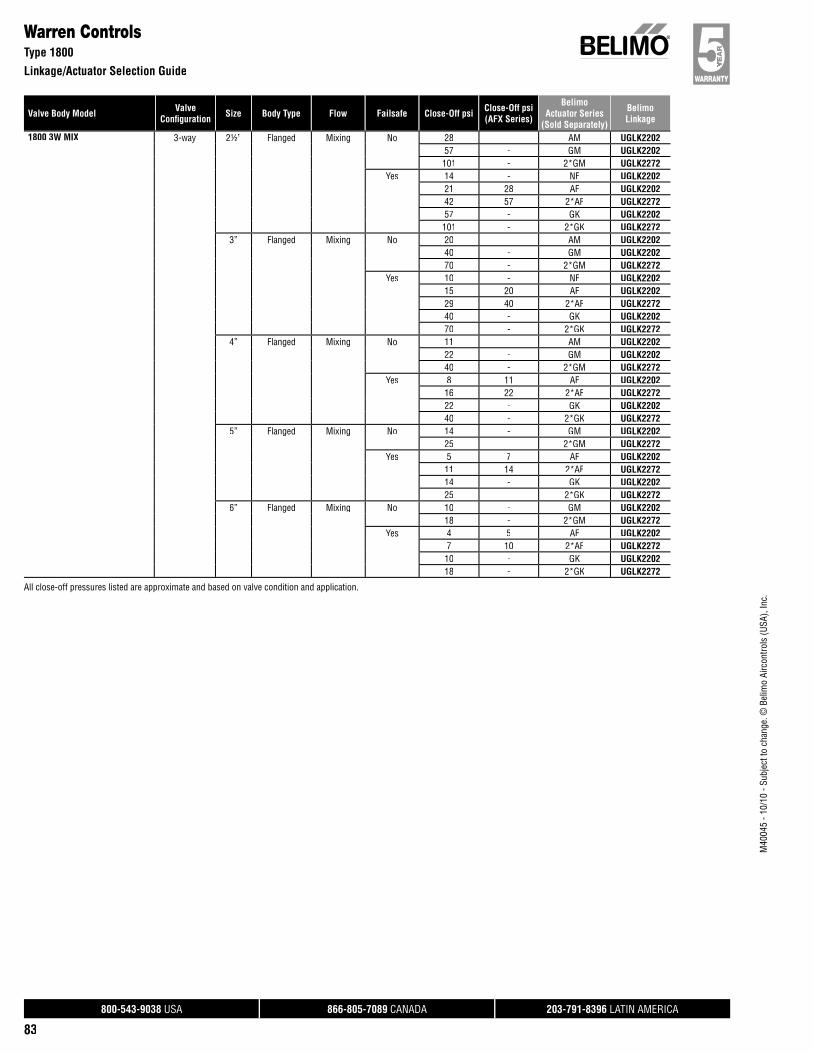
800-543-9038 USA 866-805-7089 CANADA 203-791-8396 LATIN AMERICA
83
Valve Body Model ValveConfi guration Size Body Type Flow Failsafe Close-Off psi Close-Off psi
(AFX Series)
BelimoActuator Series
(Sold Separately)
BelimoLinkage
M40
045
- 10/
10 -
Subj
ect t
o ch
ange
. © B
elim
o Ai
rcon
trols
(USA
), In
c.
Warren ControlsType 1800
Linkage/Actuator Selection Guide
1800 3W MIX 3-way 2½” Flanged Mixing No 28 - AM UGLK220257 - GM UGLK2202101 - 2*GM UGLK2272
Yes 14 - NF UGLK220221 28 AF UGLK220242 57 2*AF UGLK227257 - GK UGLK2202101 - 2*GK UGLK2272
3” Flanged Mixing No 20 - AM UGLK220240 - GM UGLK220270 - 2*GM UGLK2272
Yes 10 - NF UGLK220215 20 AF UGLK220229 40 2*AF UGLK227240 - GK UGLK220270 - 2*GK UGLK2272
4” Flanged Mixing No 11 - AM UGLK220222 - GM UGLK220240 - 2*GM UGLK2272
Yes 8 11 AF UGLK220216 22 2*AF UGLK227222 - GK UGLK220240 - 2*GK UGLK2272
5” Flanged Mixing No 14 - GM UGLK220225 - 2*GM UGLK2272
Yes 5 7 AF UGLK220211 14 2*AF UGLK227214 - GK UGLK220225 - 2*GK UGLK2272
6” Flanged Mixing No 10 - GM UGLK220218 - 2*GM UGLK2272
Yes 4 5 AF UGLK22027 10 2*AF UGLK227210 - GK UGLK220218 - 2*GK UGLK2272
All close-off pressures listed are approximate and based on valve condition and application.
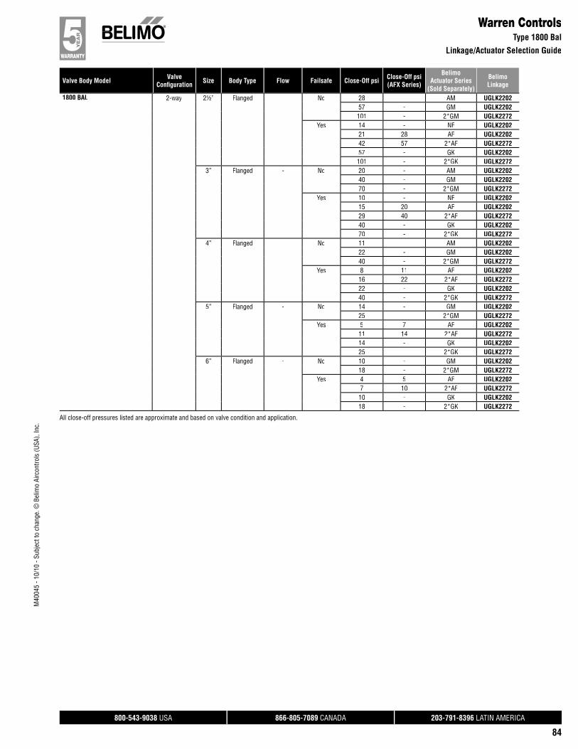
800-543-9038 USA 866-805-7089 CANADA 203-791-8396 LATIN AMERICA
84
Valve Body Model ValveConfi guration Size Body Type Flow Failsafe Close-Off psi Close-Off psi
(AFX Series)
BelimoActuator Series
(Sold Separately)
BelimoLinkage
M40
045
- 10/
10 -
Subj
ect t
o ch
ange
. © B
elim
o Ai
rcon
trols
(USA
), In
c.
Warren ControlsType 1800 Bal
Linkage/Actuator Selection Guide//
1800 BAL 2-way 2½” Flanged - No 28 - AM UGLK220257 - GM UGLK2202101 - 2*GM UGLK2272
Yes 14 - NF UGLK220221 28 AF UGLK220242 57 2*AF UGLK227257 - GK UGLK2202101 - 2*GK UGLK2272
3” Flanged - No 20 - AM UGLK220240 - GM UGLK220270 - 2*GM UGLK2272
Yes 10 - NF UGLK220215 20 AF UGLK220229 40 2*AF UGLK227240 - GK UGLK220270 - 2*GK UGLK2272
4” Flanged - No 11 - AM UGLK220222 - GM UGLK220240 - 2*GM UGLK2272
Yes 8 11 AF UGLK220216 22 2*AF UGLK227222 - GK UGLK220240 - 2*GK UGLK2272
5” Flanged - No 14 - GM UGLK220225 - 2*GM UGLK2272
Yes 5 7 AF UGLK220211 14 2*AF UGLK227214 - GK UGLK220225 - 2*GK UGLK2272
6” Flanged - No 10 - GM UGLK220218 - 2*GM UGLK2272
Yes 4 5 AF UGLK22027 10 2*AF UGLK227210 - GK UGLK220218 - 2*GK UGLK2272
All close-off pressures listed are approximate and based on valve condition and application.

800-543-9038 USA 866-805-7089 CANADA 203-791-8396 LATIN AMERICA
85
Valve Body Model ValveConfi guration Size Body Type Flow Failsafe Close-Off psi Close-Off psi
(AFX Series)
BelimoActuator Series
(Sold Separately)
BelimoLinkage
M40
045
- 10/
10 -
Subj
ect t
o ch
ange
. © B
elim
o Ai
rcon
trols
(USA
), In
c.
Warren ControlsType 20
Linkage/Actuator Selection Guide
Type 20 2-way 2½” Flanged - No 55 - AM UGLK220069 - NVG UNV-051110 - GM UGLK2200196 - 2*GM UGLK2270196 - 2*GM UGLK2270
Yes 28 - NF UGLK220041 55 AF UGLK220082 110 2*AF UGLK2270110 - GK UGLK220082 110 2*AF UGLK2270196 - 2*GK UGLK2270196 - 2*GK UGLK2270
3” Flanged - No 38 - AM UGLK220048 - NVG UNV-05177 - GM UGLK2200136 - 2*GM UGLK2270136 - 2*GM UGLK2270
Yes 19 - NF UGLK220028 38 AF UGLK220057 77 2*AF UGLK227077 - GK UGLK220057 77 2*AF UGLK2270136 - 2*GK UGLK2270136 - 2*GK UGLK2270
4” Flanged - No 11 - AM UGLK220222 - GM UGLK220240 - 2*GM UGLK2272
Yes 8 11 AF UGLK220216 22 2*AF UGLK227222 - GK UGLK220240 - 2*GK UGLK2272
5” Flanged - No 14 - GM UGLK220225 - 2*GM UGLK2272
Yes 5 7 AF UGLK220211 14 2*AF UGLK227214 - GK UGLK220225 - 2*GK UGLK2272
6” Flanged - No 10 - GM UGLK220218 - 2*GM UGLK2272
Yes 4 5 AF UGLK22027 10 2*AF UGLK227210 - GK UGLK220218 - 2*GK UGLK2272
All close-off pressures listed are approximate and based on valve condition and application.
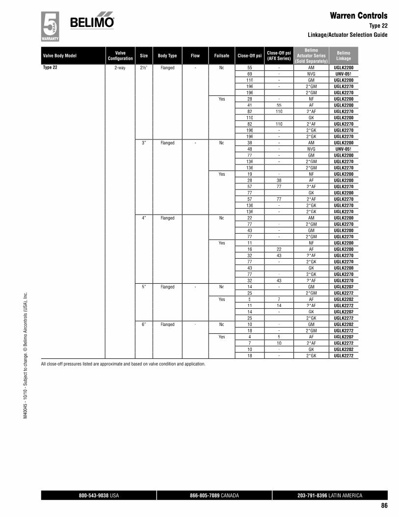
800-543-9038 USA 866-805-7089 CANADA 203-791-8396 LATIN AMERICA
86
Valve Body Model ValveConfi guration Size Body Type Flow Failsafe Close-Off psi Close-Off psi
(AFX Series)
BelimoActuator Series
(Sold Separately)
BelimoLinkage
M40
045
- 10/
10 -
Subj
ect t
o ch
ange
. © B
elim
o Ai
rcon
trols
(USA
), In
c.
Warren ControlsType 22
Linkage/Actuator Selection Guide//
Type 22 2-way 2½” Flanged - No 55 - AM UGLK220069 - NVG UNV-051110 - GM UGLK2200196 - 2*GM UGLK2270196 - 2*GM UGLK2270
Yes 28 - NF UGLK220041 55 AF UGLK220082 110 2*AF UGLK2270110 - GK UGLK220082 110 2*AF UGLK2270196 - 2*GK UGLK2270196 - 2*GK UGLK2270
3” Flanged - No 38 - AM UGLK220048 - NVG UNV-05177 - GM UGLK2200136 - 2*GM UGLK2270136 - 2*GM UGLK2270
Yes 19 - NF UGLK220028 38 AF UGLK220057 77 2*AF UGLK227077 - GK UGLK220057 77 2*AF UGLK2270136 - 2*GK UGLK2270136 - 2*GK UGLK2270
4” Flanged - No 22 - AM UGLK220077 - 2*GM UGLK227043 - GM UGLK220077 - 2*GM UGLK2270
Yes 11 - NF UGLK220016 22 AF UGLK220032 43 2*AF UGLK227077 - 2*GK UGLK227043 - GK UGLK220077 - 2*GK UGLK227032 43 2*AF UGLK2270
5” Flanged - No 14 - GM UGLK220225 - 2*GM UGLK2272
Yes 5 7 AF UGLK220211 14 2*AF UGLK227214 - GK UGLK220225 - 2*GK UGLK2272
6” Flanged - No 10 - GM UGLK220218 - 2*GM UGLK2272
Yes 4 5 AF UGLK22027 10 2*AF UGLK227210 - GK UGLK220218 - 2*GK UGLK2272
All close-off pressures listed are approximate and based on valve condition and application.
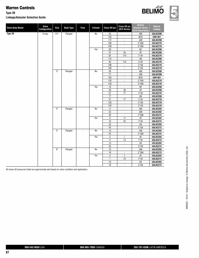
800-543-9038 USA 866-805-7089 CANADA 203-791-8396 LATIN AMERICA
87
Valve Body Model ValveConfi guration Size Body Type Flow Failsafe Close-Off psi Close-Off psi
(AFX Series)
BelimoActuator Series
(Sold Separately)
BelimoLinkage
M40
045
- 10/
10 -
Subj
ect t
o ch
ange
. © B
elim
o Ai
rcon
trols
(USA
), In
c.
Warren ControlsType 30
Linkage/Actuator Selection Guide
Type 30 3-way 2½” Flanged - No 55 - AM UGLK2200100 - NVG UNV-051110 - GM UGLK2200196 - 2*GM UGLK2270196 - 2*GM UGLK2270
Yes 28 - NF UGLK220041 55 AF UGLK220082 110 2*AF UGLK2270110 - GK UGLK220082 110 2*AF UGLK2270196 - 2*GK UGLK2270196 - 2*GK UGLK2270
3” Flanged - No 38 - AM UGLK220077 - GM UGLK2200100 - NVG UNV-051136 - 2*GM UGLK2270136 - 2*GM UGLK2270
Yes 19 - NF UGLK220028 38 AF UGLK220057 77 2*AF UGLK227077 - GK UGLK220057 77 2*AF UGLK2270136 - 2*GK UGLK2270136 - 2*GK UGLK2270
4” Flanged - No 11 - AM UGLK220222 - GM UGLK220240 - 2*GM UGLK2272
Yes 8 11 AF UGLK220216 22 2*AF UGLK227222 - GK UGLK220240 - 2*GK UGLK2272
5” Flanged - No 14 - GM UGLK220225 - 2*GM UGLK2272
Yes 5 7 AF UGLK220211 14 2*AF UGLK227214 - GK UGLK220225 - 2*GK UGLK2272
6” Flanged - No 10 - GM UGLK220218 - 2*GM UGLK2272
Yes 4 5 AF UGLK22027 10 2*AF UGLK227210 - GK UGLK220218 - 2*GK UGLK2272
All close-off pressures listed are approximate and based on valve condition and application.
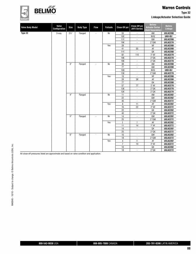
800-543-9038 USA 866-805-7089 CANADA 203-791-8396 LATIN AMERICA
88
Valve Body Model ValveConfi guration Size Body Type Flow Failsafe Close-Off psi Close-Off psi
(AFX Series)
BelimoActuator Series
(Sold Separately)
BelimoLinkage
M40
045
- 10/
10 -
Subj
ect t
o ch
ange
. © B
elim
o Ai
rcon
trols
(USA
), In
c.
Type 32 3-way 2½” Flanged - No 55 - AM UGLK2200100 - NVG UNV-051110 - GM UGLK2200196 - 2*GM UGLK2270
Yes 28 - NF UGLK220041 55 AF UGLK2200110 - GK UGLK220082 110 2*AF UGLK2270196 - 2*GK UGLK2270196 - 2*GK UGLK2270
3” Flanged - No 38 - AM UGLK220077 - GM UGLK2200100 - NVG UNV-051136 - 2*GM UGLK2270
Yes 19 - NF UGLK220028 38 AF UGLK220077 - GK UGLK220057 77 2*AF UGLK2270136 - 2*GK UGLK2270136 - 2*GK UGLK2270
4” Flanged - No 11 - AM UGLK220222 - GM UGLK220240 - 2*GM UGLK2272
Yes 8 11 AF UGLK220216 22 2*AF UGLK227222 - GK UGLK220240 - 2*GK UGLK2272
5” Flanged - No 14 - GM UGLK220225 - 2*GM UGLK2272
Yes 5 7 AF UGLK220211 14 2*AF UGLK227214 - GK UGLK220225 - 2*GK UGLK2272
6” Flanged - No 10 - GM UGLK220218 - 2*GM UGLK2272
Yes 4 5 AF UGLK22027 10 2*AF UGLK227210 - GK UGLK220218 - 2*GK UGLK2272
Warren ControlsType 32
Linkage/Actuator Selection Guide//
All close-off pressures listed are approximate and based on valve condition and application.
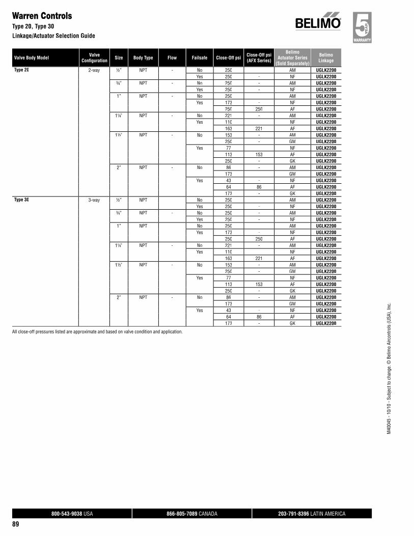
800-543-9038 USA 866-805-7089 CANADA 203-791-8396 LATIN AMERICA
89
Valve Body Model ValveConfi guration Size Body Type Flow Failsafe Close-Off psi Close-Off psi
(AFX Series)
BelimoActuator Series
(Sold Separately)
BelimoLinkage
M40
045
- 10/
10 -
Subj
ect t
o ch
ange
. © B
elim
o Ai
rcon
trols
(USA
), In
c.
Warren ControlsType 20, Type 30
Linkage/Actuator Selection Guide
Type 20 2-way ½” NPT - No 250 - AM UGLK2200Yes 250 - NF UGLK2200
¾” NPT - No 250 - AM UGLK2200Yes 250 - NF UGLK2200
1” NPT - No 250 - AM UGLK2200Yes 173 - NF UGLK2200
250 250 AF UGLK22001¼” NPT - No 221 - AM UGLK2200
Yes 110 - NF UGLK2200163 221 AF UGLK2200
1½” NPT - No 153 - AM UGLK2200250 - GM UGLK2200
Yes 77 - NF UGLK2200113 153 AF UGLK2200250 - GK UGLK2200
2” NPT - No 86 - AM UGLK2200173 - GM UGLK2200
Yes 43 - NF UGLK220064 86 AF UGLK2200173 - GK UGLK2200
Type 30 3-way ½” NPT - No 250 - AM UGLK2200Yes 250 - NF UGLK2200
¾” NPT - No 250 - AM UGLK2200Yes 250 - NF UGLK2200
1” NPT - No 250 - AM UGLK2200Yes 173 - NF UGLK2200
250 250 AF UGLK22001¼” NPT - No 221 - AM UGLK2200
Yes 110 - NF UGLK2200163 221 AF UGLK2200
1½” NPT - No 153 - AM UGLK2200250 - GM UGLK2200
Yes 77 - NF UGLK2200113 153 AF UGLK2200250 - GK UGLK2200
2” NPT - No 86 - AM UGLK2200173 - GM UGLK2200
Yes 43 - NF UGLK220064 86 AF UGLK2200173 - GK UGLK2200
All close-off pressures listed are approximate and based on valve condition and application.

800-543-9038 USA 866-805-7089 CANADA 203-791-8396 LATIN AMERICA
90
Custom Globe Valve SolutionsUGSP Series Globe Valve Retrofit System
Where globe valves which cannot be matched to one of the Belimo UGLK part numbers,p , for quotation only, please use p/n UGSP0000 forvalves requiring single actuation, and UGSP0002 for valves requiring dual actuation. These part numbers have no Bill of Materials (BOM) associated with them, and therefore cannot be produced and shipped. When these two part numbers are quoted, sold and ordersprocessed, the “Globe Valve Retrofit” form must be completed and will accompany the order. Our engineering department will thendetermine the correct UGSP linkage number for production. Please keep in mind that UGSP0000 and UGSP0002 will NOT show up on final paperwork and will be replaced with the correct UGSP part number once such has been determined.
UGSP0000
A
B C
H1
H2
D
UGSP0002
A
C D
The single actuated globe retrofit linkage (shown left) depicts the MINIMUM and MAXIMUM dimensional data for use in determining the space required to mount the linkage. These dimensions do NOT include VALVE dimensions which will affectcombined height requirements.
Dims H1 & H2 are used only when override handles are utilized on the linkage system, and are not required for proper operation of the linkage system.
Dim A 7.5” [190] min to
14” [356] max
Dim H1 9.5” [242]
Dim B 3” [76] Dim H2 9.5” [242]Dim C 9” [229]Dim D 5” [127]
The dual MINIMUM and MAXIMUM actuated globe retrofit linkage shown left depicts the MAXIMUM dimensional data for use in determining the space required to mount the linkage. These dimensions do NOT include VALVE dimensions which will affect combined height requirements.
Dim A 9.5” [241] min. to 19” [483] max.Dim B 3” [76]Dim C 9” [229]Dim D 5” [127]
Custom kits are designed to your unique specifi cation and are not returnable.
M40
045
- 10/
10 -
SUBJ
ECT
TO C
HANG
E. ©
BEL
IMO
AIRC
ONTR
OLS
(USA
), IN
C.

800-543-9038 USA 866-805-7089 CANADA 203-791-8396 LATIN AMERICA
91
M40
045
- 10/
10 -
SUBJ
ECT
TO C
HANG
E. ©
BEL
IMO
AIRC
ONTR
OLS
(USA
), IN
C.
This PageIntentionally Left Blank
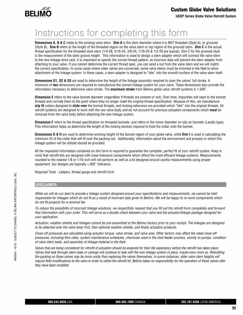
800-543-9038 USA 866-805-7089 CANADA 203-791-8396 LATIN AMERICA
92
Custom Globe Valve SolutionsUGSP Series Globe Valve Retrofit System
Instructions for completing this formDimensions A, B & C relate to the existing valve stem. Dim A is the stem diameter where it is NOT threaded (Style A), or grooved (Style B). Dim B refers to the length of the threaded region on the valve stem or top region of the grooved stem. Dim C is the actual thread specification for the threaded style stem (1/4-28, 5/16-24, 3/8-24, 7/16-20 & 1/2-20 are typical). Dim C for the grooved styleis the measurement of the stem groove height. This information is used to design a stem adapter which will connect the valve stem to the new linkage drive rack. It is important to specify the correct thread pattern, as incorrect data will prevent the stem adapter from attaching to your valve. If you cannot determine the correct thread spec, you can send a nut from the valve stem and we will match the correct specification. In some cases where older valves are concerned, some valve stems must be trimmed in the field to allow attachment of the linkage system. In these cases, a stem adapter is designed to “bite” into the smooth surface of the valve stem itself.
Dimensions D1, D2 & D3 are used to determine the height of the linkage assembly required to clear the valves’ full stroke. A minimum of two dimensions are required to manufacture the correct linkage system for your valve. These dimensions also provide the information necessary to determine valve stroke. The maximum stroke from Belimo globe valve retrofit systems is 1.500”.
Dimension E refers to the valve bonnet diameter (regardless if threads are present or not). Over time, impurities will react to the bonnet threads and corrode them to the point where they no longer meet the original thread specification. Because of this, we manufactureslip fit collars designed to slide over the bonnet threads, and locking setscrews are provided which “bite” into the original threads. All retrofit systems are designed to work with the raw valve body and do not account for previous actuation components which must beremoved from the valve body before attaching the new linkage system.
Dimension F refers to the thread specification on threaded bonnets, and refers to the minor diameter on slip on bonnets (Landis type). This information helps us determine the length of the locking devices required to hold the collar onto the bonnet.
Dimensions G & H are used to determine working height of the bonnet region of your globe valve, while Dim I is used in calculating the minimum ID of the collar that will fit over the packing nut. Additionally, information about the environment and process in which this linkage system will be utilized should be provided.
All the requested information contained on this form is required to guarantee the complete, perfect fit of your retrofit system. Keep in mind that retrofit kits are designed with close-tolerance components which afford the most efficient linkage systems. Measurements rounded to the nearest 1/8 or 1/16 inch will not perform as well as a kit designed around careful measurements using proper equipment. Our designs are typically +.005” tolerance.
Required Tools - calipers, thread gauge and retrofit form
DISCLAIMER:
While we will do our best to provide a linkage system designed around your specifications and measurements, we cannot be held responsible for linkages which do not fit as a result of incorrect data given to Belimo. We will be happy to re-work components which do not fit properly for a nominal fee.
To reduce the possibility of incorrect linkage solutions, we respectfully request that you fill out the retrofit form completely and forward that information with your order. This will serve as a double check between your valve and the actuator/linkage package designed for your application.
Actuation, weather shields and linkages cannot be pre-assembled at the Belimo factory prior to your receipt. The linkages are designed to be attached onto the valve body first, then optional weather shields, and finally actuation products.
Close-off pressures are calculated using actuator torque, valve stroke, and valve area. Other factors may affect the rated close-off pressures, including flow rates, system maintenance schedules, chemicals used in the shot feeder process, vicinity to pumps, condition of valve stem seals, and assembly of linkage material in the field.
Valves that are being considered for retrofit of actuation should be analyzed for their life expectancy before the retrofit has taken place. Valves that leak through stem seals or casings will continue to leak with the new linkage system in place, maybe even more so. Rebuilding the packing on these valves may be more costly than replacing the valves themselves. In some instances, older valve stem heights will require field modifications to the valve in order to utilize the retrofit kit. Belimo takes no responsibility for the operation of these valves after they have been modified.
M40
045
- 10/
10 -
SUBJ
ECT
TO C
HANG
E. ©
BEL
IMO
AIRC
ONTR
OLS
(USA
), IN
C.
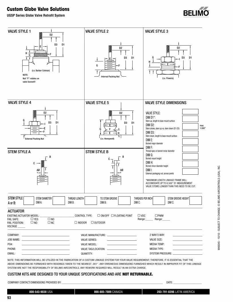
800-543-9038 USA 866-805-7089 CANADA 203-791-8396 LATIN AMERICA
93
Custom Globe Valve SolutionsUGSP Series Globe Valve Retrofit System
EXISTING ACTUATOR MODEL: _______________________ CONTROL TYPE: ON/OFF FLOATING POINT VDC PWM FAIL SAFE: YES NOFAIL POSITION: NO NC VOLTAGE _____
ACTUATOR
STEM STYLE A STEM STYLE B
VALVE STYLE 1 VALVE STYLE 2 VALVE STYLE 3
VALVE STYLE 4
STEM DIAMETERDIM A:
STEM STYLEA or B:
2 WAY/3 WAY:
VALVE SIZE:
MEDIA TEMP:
MEDIA TYPE:
SYSTEM PRESSURE:
VALVE MANUFACTURE:
VALVE SERIES:
VALVE MODEL:
VALVE TAG/LOCATION:
QUANTITY:
Range:_____
COMPANY:
JOB NAME:
PO#:
PHONE:
EMAIL:
NOTE: THIS INFORMATION WILL BE UTILIZED IN THE FABRICATION OF A CUSTOM LINKAGE SYSTEM FOR YOUR VALVE REQUIREMENT; THEREFORE, IT IS ESSENTIAL THAT THE
ABOVE DIMENSIONS BE FURNISHED WITH READINGS TAKEN TO THE NEAREST .001". ANY ERRONEOUS DIMENSIONS FURNISHED WHICH RESULT IN IMPROPER FIT OF THIS LINKAGE
SYSTEM ARE NOT THE RESPONSIBILITY OF BELIMO AIRCONTROLS. ANY REWORK REQUIRED WILL RESULT IN AN EXTRA CHARGE.
CUSTOM KITS ARE DESIGNED TO YOUR UNIQUE SPECIFICATIONS AND ARE NOT RETURNABLE. COMPANY CONTACT/DIMENSIONS PROVIDED BY: ____________________________________________________________________ DATE: ___________________
INDOOR OUTDOOR
VALVE STYLE 5
Range:_____
D3 D1
(i.e. Barber Colman)
HG
E
F
Nut "F" rotates onvalve bonnet!!
NOTE:
D2
Internal Packing Nut
G
E
F
D3 D1
D2
(i.e. Powers)
H
GI
EF
D3 D1
D2
External Packing Nut
GI
EF
D3 D1
D2
(i.e. Honeywell)
G
EFE
H
D3 D1
D2 VALVE STYLE:DIM D1*: Stem up, length to base mount surface
DIM D2: Stem stroke, stem up vs. stem down (D1-D3)
DIM D3: Stem down, length to base mount surface
DIM E: Bonnet major diameter
DIM F: Thread spec or bonnet minor diameter
DIM G: Bonnet mount height
DIM H: Bonnet minor diameter height
DIM I: External packaging nut, across points
VALVE STYLE DIMENSIONS
AØ
C
B
AØ
BC
THREAD LENGTHDIM B:
TO STEM GROOVEDIM B:
STEM GROOVE HEIGHTDIM C:
THREADS PER INCHDIM C:
*MAXIMUM LENGTH LINKAGE FRAME WILL ACCOMODATE UP TO 6.500” D1 MEASUREMENT VALVE STEMS LONGER THAN THIS NEED TO BE CUT.
max.1.500”
M40
045
- 10/
10 -
SUBJ
ECT
TO C
HANG
E. ©
BEL
IMO
AIRC
ONTR
OLS
(USA
), IN
C.
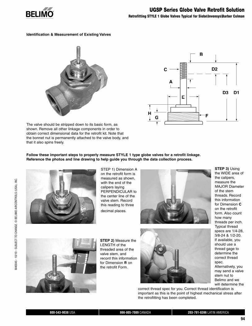
800-543-9038 USA 866-805-7089 CANADA 203-791-8396 LATIN AMERICA
94
M40
045
- 10/
10 -
SUBJ
ECT
TO C
HANG
E. ©
BEL
IMO
AIRC
ONTR
OLS
(USA
), IN
C.
UGSP Series Globe Valve Retrofit SolutionRetrofitting STYLE 1 Globe Valves Typical for Siebe\Invensys\Barber Colman
STEP 1) Dimension A on the retrofit form is measured as shown, with the end of the calipers laying PERPENDICULAR to the center line of the valve stem. Recordthis reading to three
decimal places.
STEP 2) Measure theLENGTH of the threaded area of the valve stem, andrecord this information for Dimension B onthe retrofit Form.
Identification & Measurement of Existing Valves
GH
A
C
F
D1D3
D2
B
Follow these important steps to properly measure STYLE 1 type globe valves for a retrofit linkage.Reference the photos and line drawing to help guide you through the data collection process.
The valve should be stripped down to its basic form, asshown. Remove all other linkage components in order toobtain correct dimensional data for the retrofit kit. Note thatthe bonnet nut is permanently attached to the valve body, and that it also spins freely.
STEP 3) Usingthe WIDE area of the calipers,measure the MAJOR Diameter of the stem threads. Recordthis information for Dimension Con the retrofit form. Also counthow many threads per inch. Typical thread specs are 1/4-28, 3/8-24 & 1/2-20.If available, youshould use a thread gage to determine thecorrect thread spec. Alternatively, youmay send a valvestem nut toBelimo and we will determine the
correct thread spec for you. Correct thread identification isimportant as this is the point of highest mechanical stress after the retrofitting has been completed.
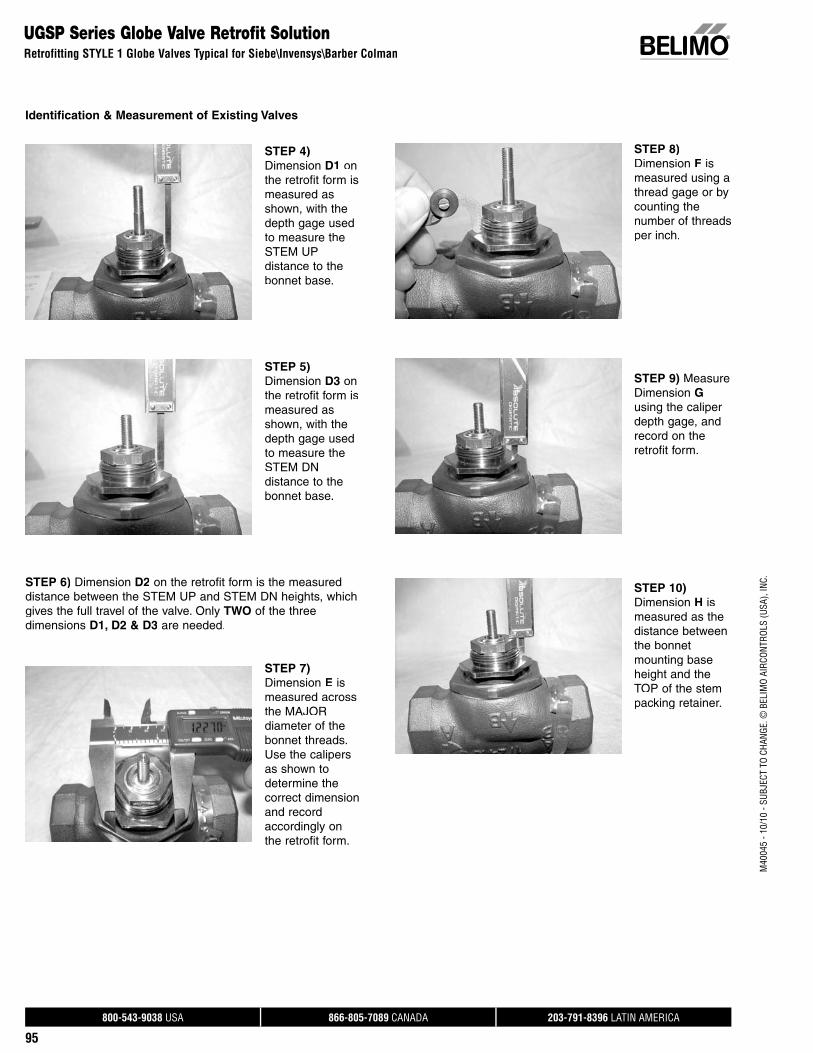
800-543-9038 USA 866-805-7089 CANADA 203-791-8396 LATIN AMERICA
95
M40
045
- 10/
10 -
SUBJ
ECT
TO C
HANG
E. ©
BEL
IMO
AIRC
ONTR
OLS
(USA
), IN
C.
UGSP Series Globe Valve Retrofit SolutionRetrofitting STYLE 1 Globe Valves Typical for Siebe\Invensys\Barber Colman
Identification & Measurement of Existing Valves
STEP 4)Dimension D1 onthe retrofit form is measured as shown, with the depth gage used to measure the STEM UP distance to the bonnet base.
STEP 5)Dimension D3 onthe retrofit form is measured as shown, with the depth gage used to measure the STEM DN distance to the bonnet base.
STEP 6) Dimension D2 on the retrofit form is the measureddistance between the STEM UP and STEM DN heights, which gives the full travel of the valve. Only TWO of the three dimensions D1, D2 & D3 are needed.
STEP 7)Dimension E ismeasured across the MAJOR diameter of the bonnet threads.Use the calipers as shown to determine the correct dimension and record accordingly on the retrofit form.
STEP 8)Dimension F ismeasured using athread gage or bycounting the number of threads per inch.
STEP 9) MeasureDimension Gusing the caliper depth gage, andrecord on the retrofit form.
STEP 10)Dimension H ismeasured as the distance between the bonnet mounting base height and the TOP of the stem packing retainer.

800-543-9038 USA 866-805-7089 CANADA 203-791-8396 LATIN AMERICA
96
M40
045
- 10/
10 -
SUBJ
ECT
TO C
HANG
E. ©
BEL
IMO
AIRC
ONTR
OLS
(USA
), IN
C.
UGSP Series Globe Valve Retrofit SolutionRetrofitting STYLE 2 Globe Valves Typical for Internal Packing Nut Type Valves
Identification & Measurement of Existing Valves
STEP 1)Dimension A onthe retrofit form is measured as shown, with the end of the calipers layingPERPENDICULAR to the center line of the valve stem.Record thisreading to three decimal places.
STEP 2) Measurethe LENGTH of the threaded area of the valve stem,and record this information for Dimension B onthe retrofit Form.
STEP 3) Usingthe WIDE area of the calipers, measure the MAJOR Diameter of the stem threads. Recordthis information for Dimension Con the retrofit form. Also count how many threads per inch. Typical thread specs are 1/4-28, 3/8-24 & 1/2-20.If available, youshould use a thread gage to determine the correct thread spec. Alternatively, youmay send a valvestem nut toBelimo and we will determine the
correct thread spec for you. Correct thread identification isimportant as this is the point of highest mechanical stress after the retrofitting has been completed.
G
E
A
C
D3
F
D2
D1
B
Follow these important steps to properly measure STYLE 2 type globe valves for a retrofit linkage.Reference the photos and line drawing to help guide you through the data collection process.
The valve should be stripped down to its basic form, asshown. Remove all other linkage components in order toobtain correct dimensional data for the retrofit kit. Note thatthe packing nut is inside the bonnet, and does NOT interfere with the bonnet threads.
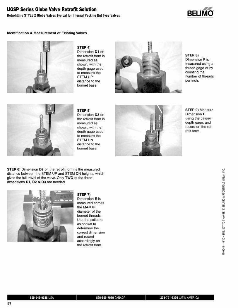
800-543-9038 USA 866-805-7089 CANADA 203-791-8396 LATIN AMERICA
97
M40
045
- 10/
10 -
SUBJ
ECT
TO C
HANG
E. ©
BEL
IMO
AIRC
ONTR
OLS
(USA
), IN
C.
UGSP Series Globe Valve Retrofit SolutionRetrofitting STYLE 2 Globe Valves Typical for Internal Packing Nut Type Valves
Identification & Measurement of Existing Valves
STEP 4)Dimension D1 on the retrofit form is measured as shown, with the depth gage used to measure the STEM UP distance to the bonnet base.
STEP 5)Dimension D3 on the retrofit form is measured as shown, with the depth gage used to measure the STEM DN distance to the bonnet base.
STEP 6) Dimension D2 on the retrofit form is the measureddistance between the STEM UP and STEM DN heights, which gives the full travel of the valve. Only TWO of the three dimensions D1, D2 & D3 are needed.
STEP 7)Dimension E ismeasured across the MAJOR diameter of the bonnet threads.Use the calipers as shown to determine the correct dimension and record accordingly on the retrofit form.
STEP 8)DImension F ismeasured using a thread gage or bycounting the number of threads per inch.
STEP 9) MeasureDimension Gusing the caliper depth gage, and record on the ret-rofit form.

800-543-9038 USA 866-805-7089 CANADA 203-791-8396 LATIN AMERICA
98
M40
045
- 10/
10 -
SUBJ
ECT
TO C
HANG
E. ©
BEL
IMO
AIRC
ONTR
OLS
(USA
), IN
C.
UGSP Series Globe Valve Retrofit SolutionRetrofitting STYLE 3 Globe Valves Typical for Powers 599 Series
and Other Non-Threaded, Non-Tapered Bonnet Valves
STEP 1) Dimension A on the retrofitform is measured as shown, with the end of the calipers laying PERPENDICULAR to the center line of the valve stem. Record this reading to three decimal places.
STEP 2) Measurethe LENGTH of the threaded area of the valve stem, andrecord this information forDimension B on theretrofit Form.
STEP 3) Using the WIDE area of the calipers, measure the MAJOR Diameter of the stem threads. Recordthis information for Dimension Con the retrofitform. Also counthow many threads per inch. Typical thread specs are 1/4-28, 3/8-24 & 1/2-20. Ifavailable, you should use a thread gage to determinethe correct thread spec. Alternatively, youmay send a valve stem nut toBelimo and we will determine the
correct thread spec for you. Correct thread identification isimportant as this is the point of highest mechanical stress after the retrofitting has been completed.
H
G
A
C
E
B
D3I
D1
D2
Follow these important steps to properly measure STYLE 3 type globe valves for a retrofit linkage.Reference the photos and line drawing to help guide you through the data collection process.
The valve should be stripped down to its basic form, as shown. Remove all other linkage components in order toobtain correct dimensional data for the retrofit kit. Note thatthere are no threads on the bonnet. The packing nut is smallerthat the diameter of the bonnet. There is a groove in the bon-net used to secure the retrofit collar to the valve.
Identification & Measurement of Existing Valves
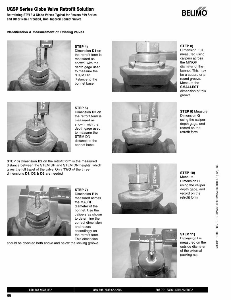
800-543-9038 USA 866-805-7089 CANADA 203-791-8396 LATIN AMERICA
99
M40
045
- 10/
10 -
SUBJ
ECT
TO C
HANG
E. ©
BEL
IMO
AIRC
ONTR
OLS
(USA
), IN
C.
UGSP Series Globe Valve Retrofit SolutionRetrofitting STYLE 3 Globe Valves Typical for Powers 599 Seriesand Other Non-Threaded, Non-Tapered Bonnet Valves
Identification & Measurement of Existing Valves
STEP 4)Dimension D1 onthe retrofit form is measured as shown, with the depth gage used to measure the STEM UP distance to the bonnet base.
STEP 5)Dimension D3 onthe retrofit form is measured as shown, with the depth gage used to measure the STEM DN distance to the bonnet base.
STEP 6) Dimension D2 on the retrofit form is the measureddistance between the STEM UP and STEM DN heights, which gives the full travel of the valve. Only TWO of the three dimensions D1, D2 & D3 are needed.
STEP 7)Dimension E ismeasured across the MAJOR diameter of the bonnet. Use thecalipers as shown to determine the correct dimension and record accordingly on the retrofit form. This dimension
should be checked both above and below the locking groove.
STEP 8)DImension F ismeasured using calipers across the MINOR diameter of the bonnet. This may be a square or around groove.Measure the SMALLESTdimension of this groove.
STEP 9) Measure Dimension Gusing the caliper depth gage, andrecord on the retrofit form.
STEP 10)Measure Dimension Husing the caliper depth gage, andrecord on the retrofit form.
STEP 11)Dimension I ismeasured on the outside diameter of the external packing nut.
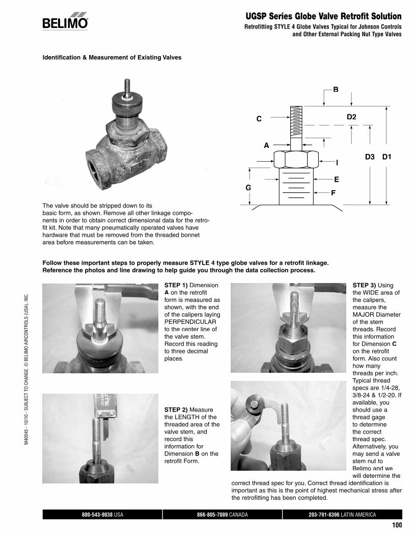
800-543-9038 USA 866-805-7089 CANADA 203-791-8396 LATIN AMERICA
100
M40
045
- 10/
10 -
SUBJ
ECT
TO C
HANG
E. ©
BEL
IMO
AIRC
ONTR
OLS
(USA
), IN
C.
UGSP Series Globe Valve Retrofit SolutionRetrofitting STYLE 4 Globe Valves Typical for Johnson Controls
and Other External Packing Nut Type Valves
Identification & Measurement of Existing Valves
STEP 1) DimensionA on the retrofitform is measured asshown, with the end of the calipers laying PERPENDICULAR to the center line of the valve stem.Record this reading to three decimal places.
STEP 2) Measurethe LENGTH of the threaded area of the valve stem, andrecord this information for Dimension B on theretrofit Form.
STEP 3) Using the WIDE area of the calipers, measure the MAJOR Diameter of the stem threads. Recordthis information for Dimension Con the retrofit form. Also counthow manythreads per inch. Typical thread specs are 1/4-28, 3/8-24 & 1/2-20. Ifavailable, youshould use athread gage to determine the correct thread spec. Alternatively, you may send a valvestem nut toBelimo and we will determine the
correct thread spec for you. Correct thread identification isimportant as this is the point of highest mechanical stress after the retrofitting has been completed.
C
G
A
D2
E
F
ID3 D1
B
Follow these important steps to properly measure STYLE 4 type globe valves for a retrofit linkage.Reference the photos and line drawing to help guide you through the data collection process.
The valve should be stripped down to its basic form, as shown. Remove all other linkage compo-nents in order to obtain correct dimensional data for the retro-fit kit. Note that many pneumatically operated valves havehardware that must be removed from the threaded bonnet area before measurements can be taken.

800-543-9038 USA 866-805-7089 CANADA 203-791-8396 LATIN AMERICA
101
M40
045
- 10/
10 -
SUBJ
ECT
TO C
HANG
E. ©
BEL
IMO
AIRC
ONTR
OLS
(USA
), IN
C.
UGSP Series Globe Valve Retrofit SolutionRetrofitting STYLE 4 Globe Valves Typical for Johnson Controlsand Other External Packing Nut Type Valves
Identification & Measurement of Existing Valves
STEP 4) Dimension D1 on the retrofitform is measured as shown, with the depth gage used to measure the STEM UP distance to the bonnet base.
STEP 5) Dimension D3 on the retrofitform is measured as shown, with the depth gage used to measure the STEM DN distance to the bonnet base.
STEP 6) Dimension D2 on the retrofit form is the measureddistance between the STEM UP and STEM DN heights, which gives the full travel of the valve. Only TWO of the three dimensions D1, D2 & D3 are needed.
STEP 7) Dimension E is measuredacross the MAJOR diameter of the bonnet. Use thecalipers as shown to determine the correct dimension and record accordingly on the retrofit form. Do NOT measure thediameter of the packing nut forthis dimension.
STEP 8) DImension F is measured using a thread gage or bycounting the number of threads per inch. It is easier to use athread gage with the external packing nut removed.
STEP 9) Measure Dimension Gusing the caliper depth gage to measure the distance between the bottom on the packing nut andthe valve collarseating surface.
STEP 10)Dimension I ismeasured on the outside diameter or pointof the externalpacking nut.
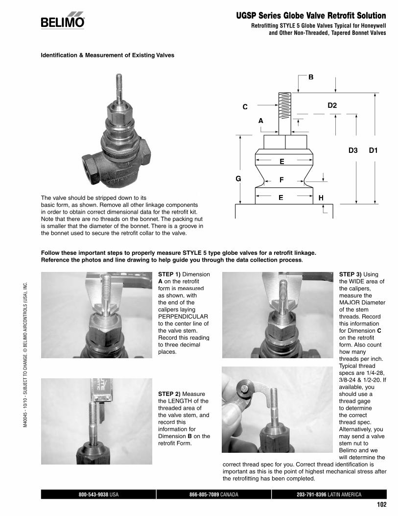
800-543-9038 USA 866-805-7089 CANADA 203-791-8396 LATIN AMERICA
102
M40
045
- 10/
10 -
SUBJ
ECT
TO C
HANG
E. ©
BEL
IMO
AIRC
ONTR
OLS
(USA
), IN
C.
UGSP Series Globe Valve Retrofit SolutionRetrofitting STYLE 5 Globe Valves Typical for Honeywell
and Other Non-Threaded, Tapered Bonnet Valves
Identification & Measurement of Existing Valves
STEP 1) Dimension A on the retrofit form is measured as shown, with the end of the calipers laying PERPENDICULAR to the center line of the valve stem.Record this reading to three decimal places.
STEP 2) Measurethe LENGTH of the threaded area of the valve stem, and record this information for Dimension B on theretrofit Form.
STEP 3) Usingthe WIDE area of the calipers,measure the MAJOR Diameter of the stem threads. Recordthis information for Dimension Con the retrofit form. Also counthow many threads per inch. Typical thread specs are 1/4-28, 3/8-24 & 1/2-20. Ifavailable, youshould use a thread gage to determine the correct thread spec. Alternatively, youmay send a valvestem nut toBelimo and we will determine the
correct thread spec for you. Correct thread identification isimportant as this is the point of highest mechanical stress after the retrofitting has been completed.
G F
E
E
A
C
H
D3
D2
B
D1
Follow these important steps to properly measure STYLE 5 type globe valves for a retrofit linkage.Reference the photos and line drawing to help guide you through the data collection process.
The valve should be stripped down to its basic form, as shown. Remove all other linkage componentsin order to obtain correct dimensional data for the retrofit kit. Note that there are no threads on the bonnet. The packing nut is smaller that the diameter of the bonnet. There is a groove in the bonnet used to secure the retrofit collar to the valve.
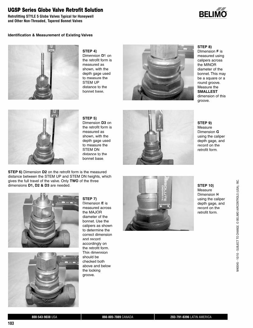
800-543-9038 USA 866-805-7089 CANADA 203-791-8396 LATIN AMERICA
103
M40
045
- 10/
10 -
SUBJ
ECT
TO C
HANG
E. ©
BEL
IMO
AIRC
ONTR
OLS
(USA
), IN
C.
UGSP Series Globe Valve Retrofit SolutionRetrofitting STYLE 5 Globe Valves Typical for Honeywell and Other Non-Threaded, Tapered Bonnet Valves
Identification & Measurement of Existing Valves
STEP 4)Dimension D1 onthe retrofit form is measured as shown, with the depth gage used to measure theSTEM UPdistance to the bonnet base.
STEP 5)Dimension D3 onthe retrofit form is measured as shown, with the depth gage used to measure theSTEM DN distance to the bonnet base.
STEP 6) Dimension D2 on the retrofit form is the measureddistance between the STEM UP and STEM DN heights, whichgives the full travel of the valve. Only TWO of the three dimensions D1, D2 & D3 are needed.
STEP 7)Dimension E ismeasured across the MAJOR diameter of thebonnet. Use thecalipers as shown to determine the correct dimension and record accordingly on the retrofit form. This dimension should be checked bothabove and belowthe locking groove.
STEP 8)DImension F ismeasured usingcalipers across the MINOR diameter of the bonnet. This may be a square or a round groove.Measure the SMALLESTdimension of thisgroove.
STEP 9)Measure Dimension Gusing the caliper depth gage, andrecord on the retrofit form.
STEP 10)Measure Dimension Husing the caliper depth gage, andrecord on the retrofit form.

800-543-9038 USA 866-805-7089 CANADA 203-791-8396 LATIN AMERICA
104
M40
045
- 10/
10 -
SUBJ
ECT
TO C
HANG
E. ©
BEL
IMO
AIRC
ONTR
OLS
(USA
), IN
C.
UNV Retrofit SolutionComponents
UNV Multi-box Kit Components
Part No. Description
UNV-BKT-001 SIEBE bracket (UNV-001)( )UNV-BKT-002 Universal bracket
(UNV-003 through UNV-035)( g )UNV-COL-004 Collar-004 and set screwsUNV-COL-005 Collar-005UNV-COL-006 Collar-006 and set screwsUNV-COL-007 Collar-007UNV-COL-008 Collar-008UNV-COL-009 Collar-009UNV-COL-035 Collar-035UNV-COL-040 Collar-040UNV-STEM-001-SET Stem Adaptor-001,005p ,UNV-STEM-003 Stem Adaptor-003pUNV-STEM-004-SET Stem Adaptor-004,008,009p , ,
Part No. Description
UNV-STEM-006 Stem Adaptor-006pUNV-STEM-007 Stem Adaptor-007pUNV-STEM-035 Stem Adaptor-035pUNV-STEM-040 Stem Adaptor-040pUNV-NUT-001 1/4”-28 Locking Nut (UNV-001,
004, 005, 006, 008, 009, 035), , , , , )UNV-NUT-007 1/4”-32 Locking Nut (UNV-007)g ( )UNV-BOLT Kit of U-bolt, Nuts for U-bolt,UNV-SCREW Kit of ScrewsUNV-STROKE IND Kit of Stroke indicatorsUNV-CPL Couplingp gUNV-CPL-10 Coupling-10 pc setp g pUNV-Override NV Manual Override
Actuator
Adaptor Bracket
actuator)Plunger (part of
Coupling
Stem Adaptor
Locking Nut
Scrrews(4 used to
mount braacket)
Stroke Indicaators
Coollar
U-Bolt Assemmbly
UNV-Box-Kit
Multi Box Starter Kit for UNV
Refillable with below items.
UNV Dimensional Details
DimensionalData UNV-001 UNV-003 UNV-004 UNV-005 UNV-006 UNV-007 UNV-008 UNV-009 UNV-035 UNV-040 UNV-051
Length ofStem Adaptor 1 7/16” 2” 2 1/8” 1 7/16” 1 1/8” 2 1/8” 2 1/8” 2 1/8” 3 7/16” 2 1/8” 1-1/4”
Stem AdaptorDiameter 1/4” 3/8” 1/4” 1/4” 1/4” 1/4” 1/4” 1/4” 1/4” 1/4” 3/8”
Stem Adaptor-Threads Per In. 28 N/A 28 28 28 32 28 28 28 28 24
Locking Nut 1/4”-28 N/A 1/4”-28 1/4”-28 1/4”-28 1/4”-32 1/4”-28 1/4”-28 1/4”-28 1/4”-28 3/8”-24
CollarMolded into
Bracket N/A
YES1/4”-20
set screws YES
YES1/4”-20
set screws YES YES YES YES-303 SS YES YES
U-Bolt N/A YES YES YES YES YES YES YES YES YES YES
Adaptor Bracket UNV-BKT-001 UNV-BKT-002 UNV-BKT-002 UNV-BKT-002 UNV-BKT-002 UNV-BKT-002 UNV-BKT-002 UNV-BKT-002 UNV-BKT-002 UNV-BKT-002 UNV-BKT-002
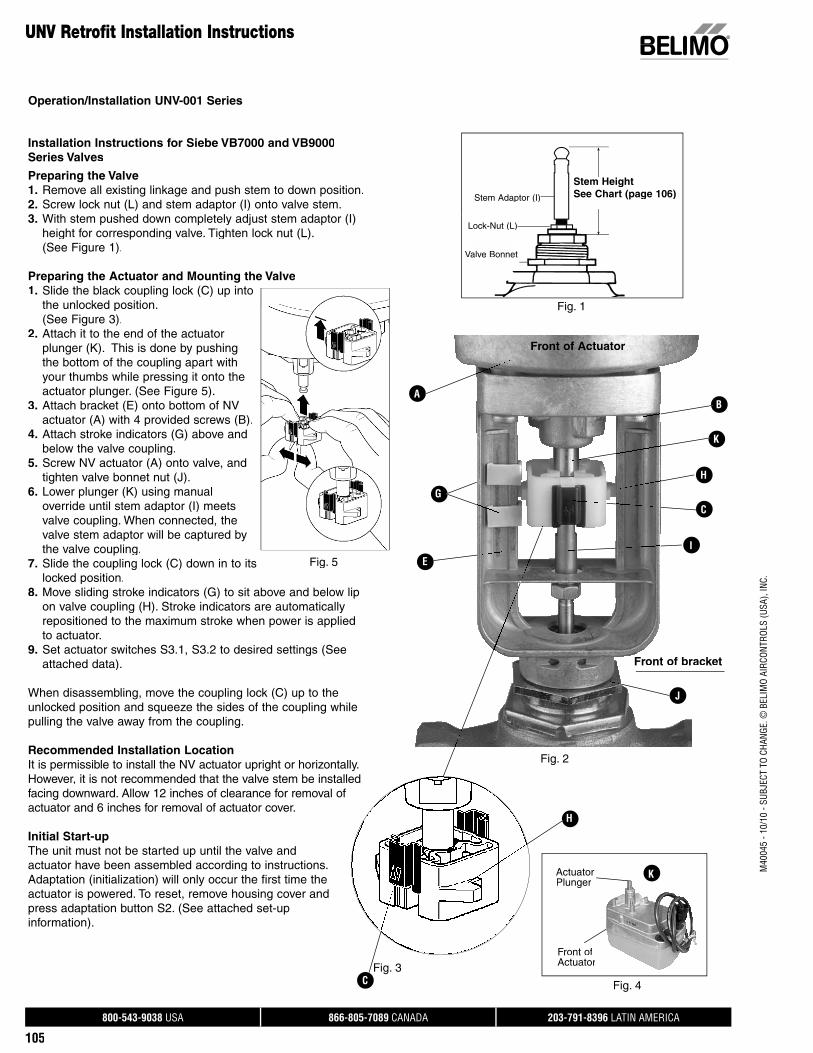
800-543-9038 USA 866-805-7089 CANADA 203-791-8396 LATIN AMERICA
105
M40
045
- 10/
10 -
SUBJ
ECT
TO C
HANG
E. ©
BEL
IMO
AIRC
ONTR
OLS
(USA
), IN
C.
Installation Instructions for Siebe VB7000 and VB9000Series Valves
Preparing the Valve1. Remove all existing linkage and push stem to down position.2. Screw lock nut (L) and stem adaptor (I) onto valve stem.3. With stem pushed down completely adjust stem adaptor (I)
height for corresponding valve. Tighten lock nut (L). (See Figure 1).
Preparing the Actuator and Mounting the Valve1. Slide the black coupling lock (C) up into
the unlocked position. (See Figure 3).2. Attach it to the end of the actuator
plunger (K). This is done by pushing the bottom of the coupling apart withyour thumbs while pressing it onto theactuator plunger. (See Figure 5).
3. Attach bracket (E) onto bottom of NV actuator (A) with 4 provided screws (B).
4. Attach stroke indicators (G) above and below the valve coupling.
5. Screw NV actuator (A) onto valve, and tighten valve bonnet nut (J).
6. Lower plunger (K) using manualoverride until stem adaptor (I) meetsvalve coupling. When connected, thevalve stem adaptor will be captured by the valve coupling.
7. Slide the coupling lock (C) down in to itslocked position.
8. Move sliding stroke indicators (G) to sit above and below lip on valve coupling (H). Stroke indicators are automaticallyrepositioned to the maximum stroke when power is appliedto actuator.
9. Set actuator switches S3.1, S3.2 to desired settings (See attached data).
When disassembling, move the coupling lock (C) up to the unlocked position and squeeze the sides of the coupling while pulling the valve away from the coupling.
Recommended Installation LocationIt is permissible to install the NV actuator upright or horizontally. However, it is not recommended that the valve stem be installedfacing downward. Allow 12 inches of clearance for removal ofactuator and 6 inches for removal of actuator cover.
Initial Start-upThe unit must not be started up until the valve andactuator have been assembled according to instructions. Adaptation (initialization) will only occur the first time the actuator is powered. To reset, remove housing cover andpress adaptation button S2. (See attached set-up information).
UNV Retrofit Installation Instructions
A
K
E
G
H
B
C
t
Fig. 1
I
J
Fig. 4
H
Stem HeightSee Chart (page 106)
Front of Actuator
Front of bracket
Stem Adaptor (I)
Lock-Nut (L)
ActuatorPlunger
K
Front of Actuator
Operation/Installation UNV-001 Series
Fig. 2
Fig. 5
CFig. 3
Valve Bonnet
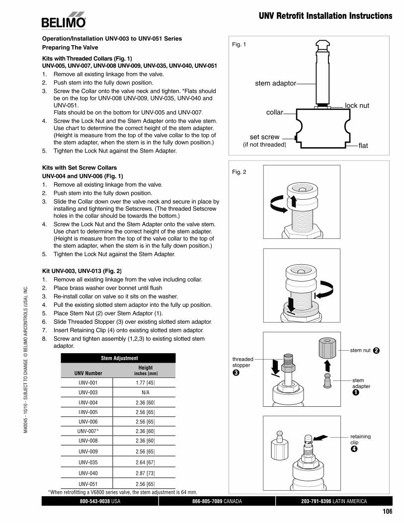
800-543-9038 USA 866-805-7089 CANADA 203-791-8396 LATIN AMERICA
106
M40
045
- 10/
10 -
SUBJ
ECT
TO C
HANG
E. ©
BEL
IMO
AIRC
ONTR
OLS
(USA
), IN
C.
UNV Retrofit Installation Instructions
Preparing The Valve
Kits with Threaded Collars (Fig. 1)UNV-005, UNV-007, UNV-008 UNV-009, UNV-035, UNV-040, UNV-051 1. Remove all existing linkage from the valve.2. Push stem into the fully down position.3. Screw the Collar onto the valve neck and tighten. *Flats should
be on the top for UNV-008 UNV-009, UNV-035, UNV-040 andUNV-051.Flats should be on the bottom for UNV-005 and UNV-007.
4. Screw the Lock Nut and the Stem Adapter onto the valve stem.Use chart to determine the correct height of the stem adapter.(Height is measure from the top of the valve collar to the top ofthe stem adapter, when the stem is in the fully down position.)
5. Tighten the Lock Nut against the Stem Adapter.
Kits with Set Screw CollarsUNV-004 and UNV-006 (Fig. 1)1. Remove all existing linkage from the valve.2. Push stem into the fully down position.3. Slide the Collar down over the valve neck and secure in place by
installing and tightening the Setscrews. (The threaded Setscrewholes in the collar should be towards the bottom.)
4. Screw the Lock Nut and the Stem Adapter onto the valve stem.Use chart to determine the correct height of the stem adapter.(Height is measure from the top of the valve collar to the top ofthe stem adapter, when the stem is in the fully down position.)
5. Tighten the Lock Nut against the Stem Adapter.
Kit UNV-003, UNV-013 (Fig. 2)1. Remove all existing linkage from the valve including collar.2. Place brass washer over bonnet until flush3. Re-install collar on valve so it sits on the washer.4. Pull the existing slotted stem adaptor into the fully up position.5. Place Stem Nut (2) over Stem Adaptor (1).6. Slide Threaded Stopper (3) over existing slotted stem adaptor.7. Insert Retaining Clip (4) onto existing slotted stem adaptor.8. Screw and tighten assembly (1,2,3) to existing slotted stem
adaptor.
Operation/Installation UNV-003 to UNV-051 Series
stem nut
stem adapter
retainingclip
threaded stopper
1
2
3
4
Stem Adjustment
UNV NumberHeight
inches [mm]
UNV-001 1.77 [45]
UNV-003 N/A
UNV-004 2.36 [60]
UNV-005 2.56 [65]
UNV-006 2.56 [65]
UNV-007* 2.36 [60]
UNV-008 2.36 [60]
UNV-009 2.56 [65]
UNV-035 2.64 [67]
UNV-040 2.87 [73]
UNV-051 2.56 [65]*When retrofi tting a V6800 series valve, the stem adjustment is 64 mm.
collar
stem adaptor
flat
lock nut
set screw(if not threaded)
Fig. 1
Fig. 2

800-543-9038 USA 866-805-7089 CANADA 203-791-8396 LATIN AMERICA
107
M40
045
- 10/
10 -
SUBJ
ECT
TO C
HANG
E. ©
BEL
IMO
AIRC
ONTR
OLS
(USA
), IN
C.
A
UNV Retrofit Installation Instructions
Preparing the Actuator and Mounting the ValveAll UNV Kits excluding UNV-001
1. Slide the black coupling lock (C) up into theunlocked position. (See Figure 3).
2. Attach Valve Coupling (D) to Actuator Plunger (H). This is done by pushing the bottom of thecoupling apart with your thumbs while pressing it on to the actuator plunger. (See Figure 1).
3. Slide the Bracket (E) over the Valve Couplingand the 4 standoffs on the actuator base.
4. Attach the Bracket to the Actuator (A) using 4Screws (B).
5. Attach Stroke Indicators (G) above and belowthe valve coupling.
6. Push the valve stem in to the fully down position7. Use the U-bolt (F) and secure the valve into the
bracket, tighten using a 10 mm wrench. (U-boltwill fit into the groove in the collar, or the valve neck in the case of UNV-003).
8. Lower plunger (H) using manual override untilstem adaptor (I) meets valve coupling. Whenconnected, the valve stem adaptor with be captured by the valve coupling.
9. Slide the coupling lock (C) down in to its locked position.10. Move Stroke Indicators (G) so that they are directly above
and below the valve coupling. They will be automaticallyrepositioned to the maximum stroke when power is appliedto the actuator.
11. Set Actuator switches S3.1 and S3.2 to desired setting.
When disassembling, move the coupling lock (C) up to the unlocked position and squeeze the sides of the coupling while pulling the valve away from the coupling.
Recommended installation locationIt is permissible to install the NV actuator upright or horizontally. However, it is not recommended that the valve stem be installed facing downward. Allow 12 inches of clearance for removal ofactuator and 6 inches for removal of actuator cover.
Initial start-upThe unit must not be started up until the valve and actuator have been assembled according to instructions. Adaptation(initialization) will only occur the first time the actuator is powered.To reset, remove housing cover and press adaptation button S2.(See attached set-up information).
Fig. 4
Fig. 3
D
B
D
H
C
F
G
E
I
L
Operation/Installation UNV-003 to UNV-051 Series
Fig. 2
ActuatorPlunger
Front of Actuator
Fig. 1
Front of bracket
Front of actuator

800-543-9038 USA 866-805-7089 CANADA 203-791-8396 LATIN AMERICA
108
M40
045
- 10/
10 -
SUBJ
ECT
TO C
HANG
E. ©
BEL
IMO
AIRC
ONTR
OLS
(USA
), IN
C.
NV Series Globe Valve Actuators
Operation/Installation
S1.2
S1.1
Functional Descriptionp
Use Switches S1.1 and S1.2 to set the run timeand select the valve closing point
S1.1 Actuating time
Off position 50s/.25” [7.5s/mm]
(Default)
On position Deactivated not used
S1.2 Selecting the Valve closing point is with the closing point closing point actuator plunger
extended or retracted
Off position Valve closing point is with the actuator plunger retracted
On position Valve closing point is with the actuator plunger extended
Note: NV24-3 US and NVD24-3 US do not contain test or adaptation functional switches. Adaptation is not necessary forthe NV24-3 US and NVD24-3 US actuators.
Set-Up of NV24-3 US Actuators during Installation
GeneralBeneath the cover of the actuator are the terminals for thecable connection and the S1 switch.The floating point signal is processed in the microprocessor and conveyed to the motor.
GND / OV
24V AC/DC Y1
24V AC/DC Y2

800-543-9038 USA 866-805-7089 CANADA 203-791-8396 LATIN AMERICA
109
M40
045
- 10/
10 -
SUBJ
ECT
TO C
HANG
E. ©
BEL
IMO
AIRC
ONTR
OLS
(USA
), IN
C.
GeneralBeneath the cover of the actuator are the terminals for the cableconnection, the S1 and S2 buttons, S3 switch, and the LEDstatus display H1.The setting signal is processed in the microprocessor, andconveyed to the motor via drivers. By setting the slide switch S3or pressing the buttons S1 and S2, the actuator can easily be configured on site to the requirements, if there are changesfrom the factory settings.
MFT and Spring Return Actuators
LED operating display H1Green steady light Actuator working properlyGreen flashing light Test run or adaptation with
synchronization in progressRed steady light Fault; repeat adaptationRed flashing light After power interruption (>2 sec.).
By the next closing movement the valve will be automatically synchronized in the chosen closing point. The LED indicatorwill change from a red flashinginto green steady light.
Alternating red/green light Master control system being addressed and operation of the adaptation button S2 in progress
Operation of Switches/LED
The NV and NVF actuators are maintenance-free. The two-color LED display is located beneath the cover of the actuator. This display allows immediate recognition of the functional stateof the actuator. In addition, it permits simple set-up if thefactory settings need to be changed.
Set-Up of NV Series MFT Actuators during Installation
NV…MFT USNVF…MFT USNVF…US
S1
H1
Status
S2Adaptation
S3Value
GND / OV (-)
24V AC/DC (+)
Signal (Y)
Feedback/Communication (UMP)
1
2
3
5
Operation/Installation
NV Series Globe Valve Actuators
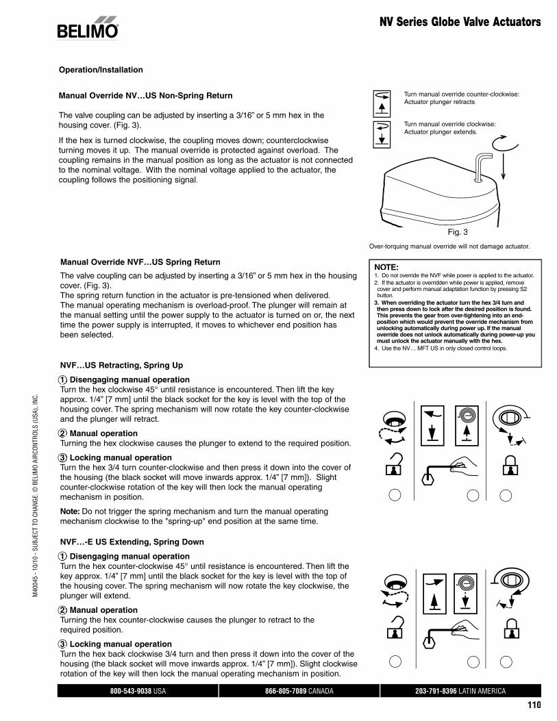
800-543-9038 USA 866-805-7089 CANADA 203-791-8396 LATIN AMERICA
110
M40
045
- 10/
10 -
SUBJ
ECT
TO C
HANG
E. ©
BEL
IMO
AIRC
ONTR
OLS
(USA
), IN
C.
Manual Override NV…US Non-Spring Return
The valve coupling can be adjusted by inserting a 3/16” or 5 mm hex in the housing cover. (Fig. 3).
If the hex is turned clockwise, the coupling moves down; counterclockwise turning moves it up. The manual override is protected against overload. Thecoupling remains in the manual position as long as the actuator is not connected to the nominal voltage. With the nominal voltage applied to the actuator, thecoupling follows the positioning signal.
Turn manual override counter-clockwise:Actuator plunger retracts.
Turn manual override clockwise:Actuator plunger extends.
Over-torquing manual override will not damage actuator.
Fig. 3
The valve coupling can be adjusted by inserting a 3/16” or 5 mm hex in the housing cover. (Fig. 3).The spring return function in the actuator is pre-tensioned when delivered.The manual operating mechanism is overload-proof. The plunger will remain at the manual setting until the power supply to the actuator is turned on or, the next time the power supply is interrupted, it moves to whichever end position has been selected.
NVF…US Retracting, Spring Up
1 Disengaging manual operation Turn the hex clockwise 45° until resistance is encountered. Then lift the keyapprox. 1/4” [7 mm] until the black socket for the key is level with the top of the housing cover. The spring mechanism will now rotate the key counter-clockwise and the plunger will retract.
2 Manual operationTurning the hex clockwise causes the plunger to extend to the required position.
3 Locking manual operationTurn the hex 3/4 turn counter-clockwise and then press it down into the cover of the housing (the black socket will move inwards approx. 1/4” [7 mm]). Slight counter-clockwise rotation of the key will then lock the manual operating mechanism in position.
Note: Do not trigger the spring mechanism and turn the manual operating mechanism clockwise to the "spring-up" end position at the same time.
NVF…-E US Extending, Spring Down
1 Disengaging manual operation Turn the hex counter-clockwise 45° until resistance is encountered. Then lift the key approx. 1/4” [7 mm] until the black socket for the key is level with the top ofthe housing cover. The spring mechanism will now rotate the key clockwise, theplunger will extend.
2 Manual operationTurning the hex counter-clockwise causes the plunger to retract to therequired position.
3 Locking manual operationTurn the hex back clockwise 3/4 turn and then press it down into the cover of the housing (the black socket will move inwards approx. 1/4” [7 mm]). Slight clockwise rotation of the key will then lock the manual operating mechanism in position.
Manual Override NVF…US Spring Return
1
2
3
1
2
3
NOTE: 1. Do not override the NVF while power is applied to the actuator.2. If the actuator is overridden while power is applied, remove cover and perform manual adaptation function by pressing S2button.
3. When overriding the actuator turn the hex 3/4 turn and then press down to lock after the desired position is found.This prevents the gear from over-tightening into an end-position which would prevent the override mechanism fromunlocking automatically during power up. If the manualoverride does not unlock automatically during power-up youmust unlock the actuator manually with the hex.
4. Use the NV… MFT US in only closed control loops.
Operation/Installation
NV Series Globe Valve Actuators
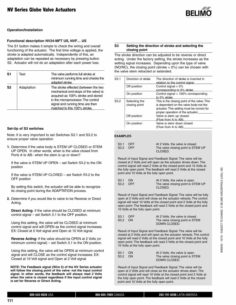
800-543-9038 USA 866-805-7089 CANADA 203-791-8396 LATIN AMERICA
111
M40
045
- 10/
10 -
SUBJ
ECT
TO C
HANG
E. ©
BEL
IMO
AIRC
ONTR
OLS
(USA
), IN
C.
NV Series Globe Valve Actuators
S1 Test The valve performs full stroke atminimum running time and checks theadapted stroke.p
S2 Adaptation The stroke effected (between the two mechanical end-stops of the valve) isacquired as 100% stroke and stored in the microprocessor. The controlsignal and running time are thenmatched to this 100% stroke.
S3 Setting the direction of stroke and selecting the closing point
The S1 button makes it simple to check the wiring and overallfunctioning of the actuator. The first time voltage is applied, thestroke is adapted automatically. Independently of this, anadaptation can be repeated as necessary by pressing button S2. Actuator will not do an adaptation after each power loss.
Functional description NV24-MFT US, NVF… US
Note: It is very important to set Switches S3.1 and S3.2 toensure proper valve operation.
1. Determine if the valve body is STEM UP CLOSED or STEMUP OPEN. In other words, when is the valve closed fromPorts A to AB– when the stem is up or down?
If the valve is STEM UP OPEN – set Switch S3.2 to the ONposition
If the valve is STEM UP CLOSED – set Switch S3.2 to theOFF position
By setting this switch, the actuator will be able to recognize its closing point during the ADAPTATION process.
2. Determine if you would like to valve to be Reverse or Direct Acting.
Direct Acting: if the valve should be CLOSED at minimumcontrol signal – set Switch 3.1 to the OFF position.
Using this setting, the valve will be CLOSED at minimum control signal and will OPEN as the control signal increases. EX: Closed at 0 Volt signal and Open at 10 Volt signal.
Reverse Acting: if the valve should be OPEN at 2 Volts (orminimum control signal) – set Switch 3.1 to the ON position.
Using this setting, the valve will be OPEN at minimum controlsignal and will CLOSE as the control signal increases. EX:Closed at 10 Volt signal and Open at 2 Volt signal.
NOTE: The Feedback signal (Wire 5) of the NV Series actuator will follow the closing point of the valve- not the input control signal. In other words, the feedback will always read 2 Volts when the valve is closed regardless if the input control signal is set for Reverse or Direct Acting.
EXAMPLES
S3.1 OFF At 2 Volts, the valve is closed S3.2 OFF The valve closing point is STEM UP
CLOSED.
Result of Input Signal and Feedback Signal: The valve will be closed at 2 Volts and will open as the actuator drives down. Thecontrol signal will read 2 Volts at the closed point and 10 Volts atthe fully open point. The feedback will read 2 Volts at the closedpoint and 10 Volts at the fully open point.
S3.1 ON At 2 Volts, the valve is open. S3.2 OFF The valve closing point is STEM UP
CLOSED.
Result of Input Signal and Feedback Signal: The valve will be fullyopen at 2 Volts and will close as the actuator retracts. The controlsignal will read 10 Volts at the closed point and 2 Volts at the fully open point. The feedback will read 2 Volts at the closed point and 10 Volts at the fully open point.
S3.1 OFF At 2 Volts, the valve is closed S3.2 ON The valve closing point is STEM
DOWN CLOSED.
Result of Input Signal and Feedback Signal: The valve will be closed at 2 Volts and will open as the actuator retracts. The controlsignal will read 2 Volts at the closed point and 10 Volts at the fullyopen point. The feedback will read 2 Volts at the closed point and 10 Volts at the fully open point.
S3.1 ON At 2 Volts, the valve is open. S3.2 ON The valve closing point is STEM
DOWN CLOSED.
Result of Input Signal and Feedback Signal: The valve will be open at 2 Volts and will close as the actuator drives down. Thecontrol signal will read 10 Volts at the closed point and 2 Volts at the fully open point. The feedback will read 2 Volts at the closedpoint and 10 Volts at the fully open point.
Set-Up of S3 switches
Operation/Installation
The stroke direction can be adjusted to be reverse or directacting. Under the factory setting, the stroke increases as the setting signal increases. Depending upon the type of valve(NO/NC), the closing point (stroke = 0%) can be chosen with the valve stem retracted or extended.
S3.1 Direction of stroke The direction ofe stroke is inverted in erelation to the control signalrelation to the control signal
Off position Control signal = 0% corresponding to 0% corresponding to 0% strokestroke On position Control signal = 100% corresponding
to 0% to 0% strokestrokeS3.2 Selecting the This is the closing point of the valve. This closing point is dependent on the valve body-not the actuator. This setting must be correct for proper operation of the actuator. proper operation of the actuator. Off position Valve is stem up closed. (Flow from A to AB). (Flow from A to AB). On position Valve is stem down closed. (Flow from A to AB). (Flow from A to AB).

800-543-9038 USA 866-805-7089 CANADA 203-791-8396 LATIN AMERICA
112
M40
045
- 10/
10 -
SUBJ
ECT
TO C
HANG
E. ©
BEL
IMO
AIRC
ONTR
OLS
(USA
), IN
C.
Assembly Sequence for Existing Valves
UGLK/UGSP Series Globe Valve Retrofit SolutionRetrofitting STYLE 1 Globe Valves Typical for Siebe\Invensys\Barber Colman
A
C
D
F
B
E
Follow these steps to properly assemble STYLE 1 type globe valves to the retrofit linkage. Reference the step-by-step photos to help guide you through the assembly process.
The valve should be stripped down to its basic form, asshown. The linkage components have been designed to attachto the valve in this state, rather than to any existing hardware.Note that this style valve has a permanently attached bonnet nut which rotates freely, but does not come off the valve itself.
STEP 1) Assemble the supplied stem nut (E) to the valve stem, and thread at least 10 - 12 turns down onto the stem.
STEP 2) Attach the rack assembly (F), which may or may notinclude an extension or adapter, onto the valve stem. Threadthe assembly as far down onto the valve stem as possible,until you contact the previously attached valve stem nut.
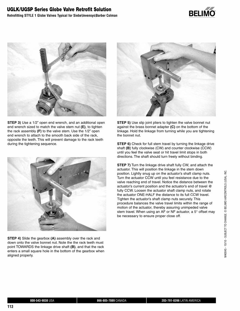
800-543-9038 USA 866-805-7089 CANADA 203-791-8396 LATIN AMERICA
113
M40
045
- 10/
10 -
SUBJ
ECT
TO C
HANG
E. ©
BEL
IMO
AIRC
ONTR
OLS
(USA
), IN
C.
STEP 3) Use a 1/2” open end wrench, and an additional openend wrench sized to match the valve stem nut (E), to tighten the rack assembly (F) to the valve stem. Use the 1/2” open end wrench to attach to the smooth back side of the rack, opposite the teeth. This will prevent damage to the rack teethduring the tightening sequence.
STEP 4) Slide the gearbox (A) assembly over the rack anddown onto the valve bonnet nut. Note the the rack teeth mustpoint TOWARDS the linkage drive shaft (B), and that the rack enters a small square hole in the bottom of the gearbox whenaligned properly.
STEP 5) Use slip joint pliers to tighten the valve bonnet nutagainst the brass bonnet adapter (C) on the bottom of the linkage. Hold the linkage from turning while you are tighteningthe bonnet nut.
STEP 6) Check for full stem travel by turning the linkage driveshaft (B) fully clockwise (CW) and counter clockwise (CCW) until you feel the valve seat or hit travel limit stops in both directions. The shaft should turn freely without binding.
STEP 7) Turn the linkage drive shaft fully CW, and attach theactuator. This will position the linkage in the stem down position. Lightly snug up on the actuator’s shaft clamp nuts. Turn the actuator CCW until you feel resistance due to thevalve reaching end of travel. Notice the distance between the actuator’s current position and the actuator’s end of travel @ fully CCW. Loosen the actuator shaft clamp nuts, and rotatethe actuator ONE-HALF the distance to its full CCW travel. Tighten the actuator’s shaft clamp nuts securely. Thisprocedure balances the valve travel limits within the range ofmotion of the actuator, thereby assuring unimpeded valvestem travel. When using an AF or NF actuator, a 5° offset maybe necessary to ensure proper close off.
UGLK/UGSP Series Globe Valve Retrofit SolutionRetrofitting STYLE 1 Globe Valves Typical for Siebe\Invensys\Barber Colman
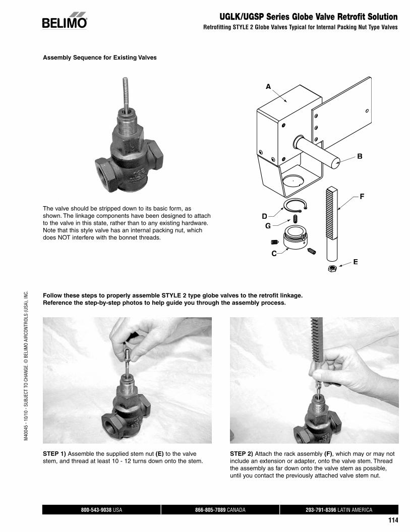
800-543-9038 USA 866-805-7089 CANADA 203-791-8396 LATIN AMERICA
114
M40
045
- 10/
10 -
SUBJ
ECT
TO C
HANG
E. ©
BEL
IMO
AIRC
ONTR
OLS
(USA
), IN
C.
UGLK/UGSP Series Globe Valve Retrofit SolutionRetrofitting STYLE 2 Globe Valves Typical for Internal Packing Nut Type Valves
Assembly Sequence for Existing Valves
Follow these steps to properly assemble STYLE 2 type globe valves to the retrofit linkage. Reference the step-by-step photos to help guide you through the assembly process.
STEP 1) Assemble the supplied stem nut (E) to the valve stem, and thread at least 10 - 12 turns down onto the stem.
STEP 2) Attach the rack assembly (F), which may or may notinclude an extension or adapter, onto the valve stem. Threadthe assembly as far down onto the valve stem as possible,until you contact the previously attached valve stem nut.
The valve should be stripped down to its basic form, asshown. The linkage components have been designed to attachto the valve in this state, rather than to any existing hardware.Note that this style valve has an internal packing nut, which does NOT interfere with the bonnet threads.
A
CC
D
F
B
E
G
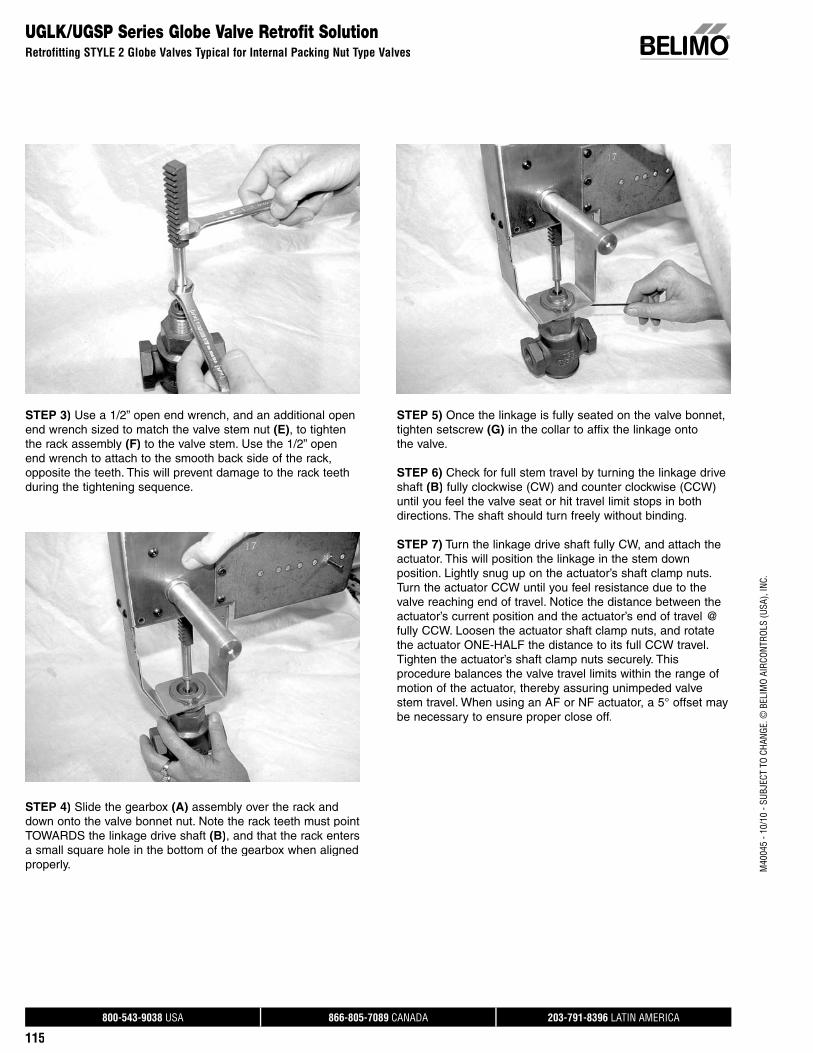
800-543-9038 USA 866-805-7089 CANADA 203-791-8396 LATIN AMERICA
115
M40
045
- 10/
10 -
SUBJ
ECT
TO C
HANG
E. ©
BEL
IMO
AIRC
ONTR
OLS
(USA
), IN
C.
UGLK/UGSP Series Globe Valve Retrofit SolutionRetrofitting STYLE 2 Globe Valves Typical for Internal Packing Nut Type Valves
STEP 3) Use a 1/2” open end wrench, and an additional openend wrench sized to match the valve stem nut (E), to tighten the rack assembly (F) to the valve stem. Use the 1/2” open end wrench to attach to the smooth back side of the rack, opposite the teeth. This will prevent damage to the rack teethduring the tightening sequence.
STEP 4) Slide the gearbox (A) assembly over the rack anddown onto the valve bonnet nut. Note the rack teeth must pointTOWARDS the linkage drive shaft (B), and that the rack enters a small square hole in the bottom of the gearbox when alignedproperly.
STEP 5) Once the linkage is fully seated on the valve bonnet, tighten setscrew (G) in the collar to affix the linkage onto the valve.
STEP 6) Check for full stem travel by turning the linkage driveshaft (B) fully clockwise (CW) and counter clockwise (CCW) until you feel the valve seat or hit travel limit stops in both directions. The shaft should turn freely without binding.
STEP 7) Turn the linkage drive shaft fully CW, and attach theactuator. This will position the linkage in the stem down position. Lightly snug up on the actuator’s shaft clamp nuts. Turn the actuator CCW until you feel resistance due to thevalve reaching end of travel. Notice the distance between the actuator’s current position and the actuator’s end of travel @ fully CCW. Loosen the actuator shaft clamp nuts, and rotatethe actuator ONE-HALF the distance to its full CCW travel. Tighten the actuator’s shaft clamp nuts securely. Thisprocedure balances the valve travel limits within the range ofmotion of the actuator, thereby assuring unimpeded valvestem travel. When using an AF or NF actuator, a 5° offset maybe necessary to ensure proper close off.
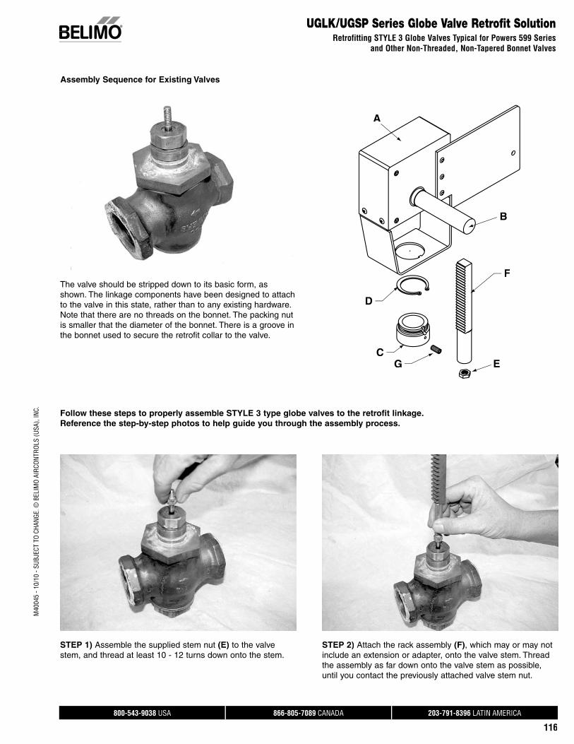
800-543-9038 USA 866-805-7089 CANADA 203-791-8396 LATIN AMERICA
116
M40
045
- 10/
10 -
SUBJ
ECT
TO C
HANG
E. ©
BEL
IMO
AIRC
ONTR
OLS
(USA
), IN
C.
UGLK/UGSP Series Globe Valve Retrofit SolutionRetrofitting STYLE 3 Globe Valves Typical for Powers 599 Series
and Other Non-Threaded, Non-Tapered Bonnet Valves
Assembly Sequence for Existing Valves
The valve should be stripped down to its basic form, asshown. The linkage components have been designed to attachto the valve in this state, rather than to any existing hardware.Note that there are no threads on the bonnet. The packing nut is smaller that the diameter of the bonnet. There is a groove inthe bonnet used to secure the retrofit collar to the valve.
Follow these steps to properly assemble STYLE 3 type globe valves to the retrofit linkage. Reference the step-by-step photos to help guide you through the assembly process.
A
C
D
F
B
EG
STEP 1) Assemble the supplied stem nut (E) to the valve stem, and thread at least 10 - 12 turns down onto the stem.
STEP 2) Attach the rack assembly (F), which may or may notinclude an extension or adapter, onto the valve stem. Threadthe assembly as far down onto the valve stem as possible,until you contact the previously attached valve stem nut.
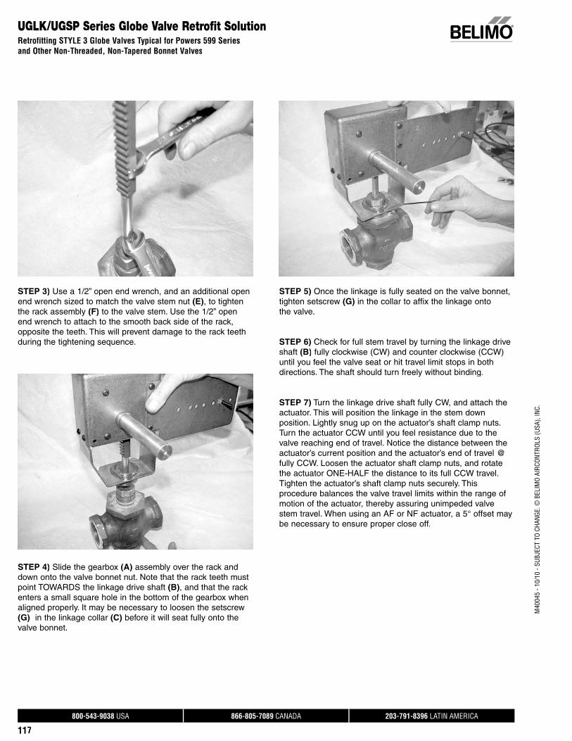
800-543-9038 USA 866-805-7089 CANADA 203-791-8396 LATIN AMERICA
117
M40
045
- 10/
10 -
SUBJ
ECT
TO C
HANG
E. ©
BEL
IMO
AIRC
ONTR
OLS
(USA
), IN
C.
UGLK/UGSP Series Globe Valve Retrofit SolutionRetrofitting STYLE 3 Globe Valves Typical for Powers 599 Seriesand Other Non-Threaded, Non-Tapered Bonnet Valves
STEP 3) Use a 1/2” open end wrench, and an additional openend wrench sized to match the valve stem nut (E), to tightenthe rack assembly (F) to the valve stem. Use the 1/2” open end wrench to attach to the smooth back side of the rack, opposite the teeth. This will prevent damage to the rack teethduring the tightening sequence.
STEP 4) Slide the gearbox (A) assembly over the rack anddown onto the valve bonnet nut. Note that the rack teeth mustpoint TOWARDS the linkage drive shaft (B), and that the rack enters a small square hole in the bottom of the gearbox whenaligned properly. It may be necessary to loosen the setscrew(G) in the linkage collar (C) before it will seat fully onto the valve bonnet.
STEP 5) Once the linkage is fully seated on the valve bonnet, tighten setscrew (G) in the collar to affix the linkage onto the valve.
STEP 6) Check for full stem travel by turning the linkage driveshaft (B) fully clockwise (CW) and counter clockwise (CCW) until you feel the valve seat or hit travel limit stops in both directions. The shaft should turn freely without binding.
STEP 7) Turn the linkage drive shaft fully CW, and attach theactuator. This will position the linkage in the stem down position. Lightly snug up on the actuator’s shaft clamp nuts.Turn the actuator CCW until you feel resistance due to thevalve reaching end of travel. Notice the distance between theactuator’s current position and the actuator’s end of travel @ fully CCW. Loosen the actuator shaft clamp nuts, and rotatethe actuator ONE-HALF the distance to its full CCW travel. Tighten the actuator’s shaft clamp nuts securely. Thisprocedure balances the valve travel limits within the range ofmotion of the actuator, thereby assuring unimpeded valvestem travel. When using an AF or NF actuator, a 5° offset maybe necessary to ensure proper close off.
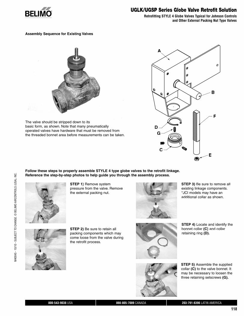
800-543-9038 USA 866-805-7089 CANADA 203-791-8396 LATIN AMERICA
118
M40
045
- 10/
10 -
SUBJ
ECT
TO C
HANG
E. ©
BEL
IMO
AIRC
ONTR
OLS
(USA
), IN
C.
UGLK/UGSP Series Globe Valve Retrofit SolutionRetrofitting STYLE 4 Globe Valves Typical for Johnson Controls
and Other External Packing Nut Type Valves
Assembly Sequence for Existing Valves
A
C
D
F
B
E
G
Follow these steps to properly assemble STYLE 4 type globe valves to the retrofit linkage.Reference the step-by-step photos to help guide you through the assembly process.
The valve should be stripped down to itsbasic form, as shown. Note that many pneumaticallyoperated valves have hardware that must be removed fromthe threaded bonnet area before measurements can be taken.
STEP 1) Remove systempressure from the valve. Removethe external packing nut.
STEP 2) Be sure to retain allpacking components which may come loose from the valve during the retrofit process.
STEP 3) Be sure to remove allexisting linkage components. *JCI models may have anadditional collar as shown.
STEP 4) Locate and identify the bonnet collar (C) and collarretaining ring (D).
STEP 5) Assemble the supplied collar (C) to the valve bonnet. Itmay be necessary to loosen thethree retaining setscrews (G).
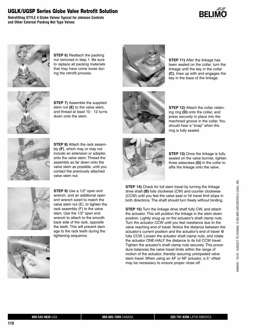
800-543-9038 USA 866-805-7089 CANADA 203-791-8396 LATIN AMERICA
119
M40
045
- 10/
10 -
SUBJ
ECT
TO C
HANG
E. ©
BEL
IMO
AIRC
ONTR
OLS
(USA
), IN
C.
STEP 11) After the linkage hasbeen seated on the collar, turn thelinkage until the key in the collar (C), lines up with and engages the key in the base of the linkage.
STEP 12) Attach the collar retain-ing ring (D) onto the collar, and press securely in place into themachined groove in the collar. You should hear a “snap” when the ring is fully seated.
STEP 13) Once the linkage is fullyseated on the valve bonnet, tighten three setscrews (G) in the collar toaffix the linkage onto the valve.
STEP 14) Check for full stem travel by turning the linkage drive shaft (B) fully clockwise (CW) and counter clockwise (CCW) until you feel the valve seat or hit travel limit stops in both directions. The shaft should turn freely without binding.
STEP 15) Turn the linkage drive shaft fully CW, and attach the actuator. This will position the linkage in the stem down position. Lightly snug up on the actuator’s shaft clamp nuts.Turn the actuator CCW until you feel resistance due to the valve reaching end of travel. Notice the distance between theactuator’s current position and the actuator’s end of travel @fully CCW. Loosen the actuator shaft clamp nuts, and rotatethe actuator ONE-HALF the distance to its full CCW travel.Tighten the actuator’s shaft clamp nuts securely. This proce-dure balances the valve travel limits within the range of motion of the actuator, thereby assuring unimpeded valve stem travel. When using an AF or NF actuator, a 5° offsetmay be necessary to ensure proper close off.
UGLK/UGSP Series Globe Valve Retrofit SolutionRetrofitting STYLE 4 Globe Valves Typical for Johnson Controlsand Other External Packing Nut Type Valves
STEP 6) Reattach the packing nut removed in step 1. Be sureto replace all packing materialsthat may have come loose dur-ing the retrofit process.
STEP 7) Assemble the suppliedstem nut (E) to the valve stem, and thread at least 10 - 12 turnsdown onto the stem.
STEP 8) Attach the rack assem-bly (F), which may or may not include an extension or adapter, onto the valve stem. Thread the assembly as far down onto the valve stem as possible, until you contact the previously attached valve stem nut.
STEP 9) Use a 1/2” open end wrench, and an additional open end wrench sized to match the valve stem nut (E), to tighten the rack assembly (F) to the valve stem. Use the 1/2” open end wrench to attach to the smooth back side of the rack, opposite the teeth. This will prevent dam-age to the rack teeth during the tightening sequence.

800-543-9038 USA 866-805-7089 CANADA 203-791-8396 LATIN AMERICA
120
M40
045
- 10/
10 -
SUBJ
ECT
TO C
HANG
E. ©
BEL
IMO
AIRC
ONTR
OLS
(USA
), IN
C.
UGLK/UGSP Series Globe Valve Retrofit SolutionRetrofitting STYLE 5 Globe Valves Typical for Honeywell
and Other Non-Threaded, Tapered Bonnet Valves
Assembly Sequence for Existing Valves
The valve should be stripped down to its basic form, asshown. Note that there are no threads on the bonnet. The packing nut is smaller that the diameter of the bonnet. Thereis a groove in the bonnet used to secure the retrofit collar to the valve.
Follow these steps to properly assemble STYLE 5 type globe valves to the retrofit linkage. Reference the step-by-step photos to help guide you through the assembly process.
A
C
D
F
B
EG
STEP 1) Assemble the supplied stem nut (E) to the valve stem, and thread at least 10 - 12 turns down onto the stem.
STEP 2) Attach the rack assembly (F), which may or may notinclude an extension or adapter, onto the valve stem. Threadthe assembly as far down onto the valve stem as possible,until you contact the previously attached valve stem nut.
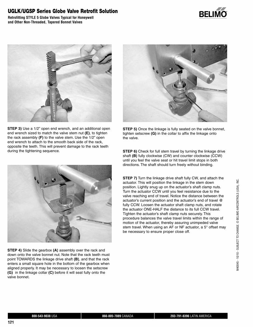
800-543-9038 USA 866-805-7089 CANADA 203-791-8396 LATIN AMERICA
121
M40
045
- 10/
10 -
SUBJ
ECT
TO C
HANG
E. ©
BEL
IMO
AIRC
ONTR
OLS
(USA
), IN
C.
UGLK/UGSP Series Globe Valve Retrofit SolutionRetrofitting STYLE 5 Globe Valves Typical for Honeywelland Other Non-Threaded, Tapered Bonnet Valves
STEP 3) Use a 1/2” open end wrench, and an additional openend wrench sized to match the valve stem nut (E), to tightenthe rack assembly (F) to the valve stem. Use the 1/2” open end wrench to attach to the smooth back side of the rack, opposite the teeth. This will prevent damage to the rack teethduring the tightening sequence.
STEP 4) Slide the gearbox (A) assembly over the rack anddown onto the valve bonnet nut. Note that the rack teeth mustpoint TOWARDS the linkage drive shaft (B), and that the rack enters a small square hole in the bottom of the gearbox whenaligned properly. It may be necessary to loosen the setscrew(G) in the linkage collar (C) before it will seat fully onto thevalve bonnet.
STEP 5) Once the linkage is fully seated on the valve bonnet,tighten setscrew (G) in the collar to affix the linkage onto the valve.
STEP 6) Check for full stem travel by turning the linkage driveshaft (B) fully clockwise (CW) and counter clockwise (CCW)until you feel the valve seat or hit travel limit stops in bothdirections. The shaft should turn freely without binding.
STEP 7) Turn the linkage drive shaft fully CW, and attach theactuator. This will position the linkage in the stem downposition. Lightly snug up on the actuator’s shaft clamp nuts.Turn the actuator CCW until you feel resistance due to thevalve reaching end of travel. Notice the distance between theactuator’s current position and the actuator’s end of travel @fully CCW. Loosen the actuator shaft clamp nuts, and rotatethe actuator ONE-HALF the distance to its full CCW travel. Tighten the actuator’s shaft clamp nuts securely. This procedure balances the valve travel limits within the range of motion of the actuator, thereby assuring unimpeded valve stem travel. When using an AF or NF actuator, a 5° offset may be necessary to ensure proper close off.
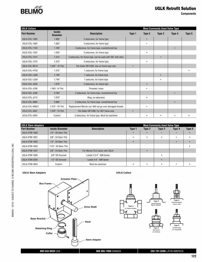
800-543-9038 USA 866-805-7089 CANADA 203-791-8396 LATIN AMERICA
122
M40
045
- 10/
10 -
SUBJ
ECT
TO C
HANG
E. ©
BEL
IMO
AIRC
ONTR
OLS
(USA
), IN
C.
UGLK Collars Most Commonly Used Valve Type
Part Number Inside Diameter Description Type 1 Type 2 Type 3 Type 4 Type 5
UGLK-COL-1005 1.000” 3 setscrews, for frame type •
UGLK-COL-1063 1.063” 3 setscrews, for frame type •
UGLK-COL-1100 1.100” 3 setscrews, for frame type, counterbored top •
UGLK-COL-1255 1.250” 3 setscrews, for frame type •
UGLK-COL-1315 1.315” 3 setscrews, for frame type, can be used with VB7 with shim •
UGLK-COL-1375 1.375” 3 setscrews, for frame type •
UGLK-COL-BC10 1.250”- 16 Thd. Fits Siebe VB7/VB9. Use on frame type only •
UGLK-COL-HY02 1.375” 1 setscrew, for frame type •
UGLK-COL-LG02 1.740” 1 setscrew, for frame type •
UGLK-COL-LG04 1.740” 1 setscrew, for frame type •
UGLK-COL-JC05 1.070” 3 setscrews, for frame type •
UGLK-COL-JC06 1.562- 14 Thd. Threaded, brass •
UGLK-COL-JC08 0.760” 3 setscrews, for frame type, counterbored top •
UGLK-COL-JC15 1.070” Ring, no setscrews •
UGLK-COL-0880 0.880” 3 setscrews, for frame type, counterbored top •
UGLK-COL-WNUT 1.375”- 20 Thd. Replacement Warren nut. Will not go over damaged threads •
UGLK-COL-AD01 1.250”- 16 Thd. Fits Siebe VB7/VB9. For VB7 frame only •
UGLK-COL-UNIV Custom 3 setscrews, for frame type. Must be machined • • • •
UGLK Retrofi t SolutionComponents
UGLK Stem Adapters Most Commonly Used Valve TypePart Number Inside Diameter Description TypeTT 1 TypeTT 2 TypeTT 3 TypeTT 4 TypeTT 5UGLK-STM-1800 1/4”- 28 Stem Thd. • • • • •
UGLK-STM-1801 3/8”- 24 Stem Thd. • • • • •
UGLK-STM-1802 1/2”- 20 Stem Thd. • • •
UGLK-STM-1803 7/16”- 20 Stem Thd. •
UGLK-STM-1501 3/8”- 24 Stem Thd. For Warren FLG valves with UGLK •
UGLK-STM-1805 3/8” OD Grooved Landis 2.5-3” -599 Series •
UGLK-STM-2305 1/2” OD Grooved Landis 4-6” -599 Series •
UGLK-STM-UNIV Custom Must be machined • • • • •
Drive Shaft
Box Frame
Retaining Ring
Collar
Stem Adapter
RackBase Bracket
Actuator Plate
(i.e. Barber Colman)
Type 1
Type 3
Type 2 Type 4
Type 5
Nut (i.e. Warren)Internal Packing
Slip Groove
External Packing
Inverted Taper
(i.e. Powers)
Nut (i.e. JCI)
(i.e. Honeywell)
UGLK Part Overview UGLK Collar InterfacesUGLK Stem Adapters UGLK Collars
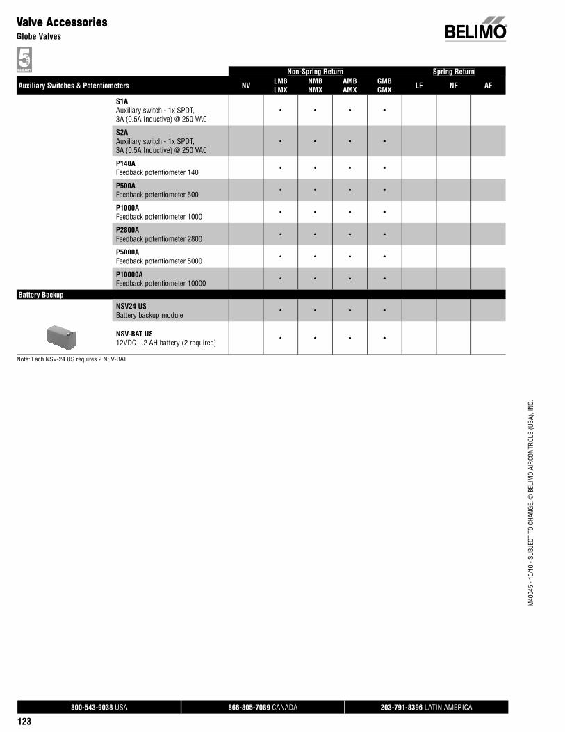
800-543-9038 USA 866-805-7089 CANADA 203-791-8396 LATIN AMERICA
123
Non-Spring Return Spring Return
Auxiliary Switches & Potentiometers NV LMBLMX
NMBNMX
AMBAMX
GMBGMX LF NF AF
S1AAuxiliary switch - 1x SPDT,3A (0.5A Inductive) @ 250 VAC
• • • •
S2AAuxiliary switch - 1x SPDT,3A (0.5A Inductive) @ 250 VAC
• • • •
P140AFeedback potentiometer 140 • • • •
P500AFeedback potentiometer 500 • • • •
P1000AFeedback potentiometer 1000 • • • •
P2800AFeedback potentiometer 2800 • • • •
P5000AFeedback potentiometer 5000 • • • •
P10000AFeedback potentiometer 10000 • • • •
Battery BackupNSV24 USBattery backup module • • • •
NSV-BAT US12VDC 1.2 AH battery (2 required) • • • •
Note: Each NSV-24 US requires 2 NSV-BAT.
Valve AccessoriesGlobe Valves
M40
045
- 10/
10 -
SUBJ
ECT
TO C
HANG
E. ©
BEL
IMO
AIRC
ONTR
OLS
(USA
), IN
C.
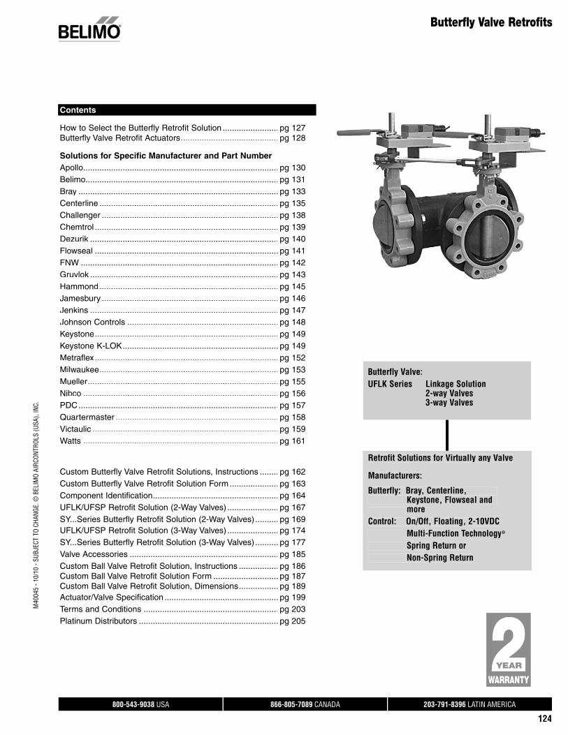
800-543-9038 USA 866-805-7089 CANADA 203-791-8396 LATIN AMERICA
124
Butterfly Valve Retrofits
Butterfly Valve:UFLK Series Linkage Solution 2-way Valves 3-way Valves
Contents
How to Select the Butterfly Retrofit Solution ........................ pg 127Butterfly Valve Retrofit Actuators .......................................... pg 128
Solutions for Specific Manufacturer and Part NumberApollo .................................................................................... pg 130Belimo ................................................................................... pg 131Bray ...................................................................................... pg 133Centerline ............................................................................. pg 135Challenger ............................................................................ pg 138Chemtrol ............................................................................... pg 139Dezurik .................................................................................k pg 140Flowseal ............................................................................... pg 141FNW ..................................................................................... pg 142Gruvlok .................................................................................k pg 143Hammond ............................................................................. pg 145Jamesbury ............................................................................ pg 146Jenkins ................................................................................. pg 147Johnson Controls ................................................................. pg 148Keystone ............................................................................... pg 149Keystone K-LOK................................................................... pg 149Metraflex ............................................................................... pg 152Milwaukee ............................................................................. pg 153Mueller.................................................................................. pg 155Nibco .................................................................................... pg 156PDC...................................................................................... pg 157Quartermaster ...................................................................... pg 158Victaulic ................................................................................ pg 159Watts .................................................................................... pg 161
Custom Butterfly Valve Retrofit Solutions, Instructions ........ pg 162Custom Butterfly Valve Retrofit Solution Form ..................... pg 163Component Identification...................................................... pg 164UFLK/UFSP Retrofit Solution (2-Way Valves) ...................... pg 167SY...Series Butterfly Retrofit Solution (2-Way Valves).......... pg 169UFLK/UFSP Retrofit Solution (3-Way Valves) ...................... pg 174SY...Series Butterfly Retrofit Solution (3-Way Valves).......... pg 177Valve Accessories ................................................................ pg 185Custom Ball Valve Retrofit Solution, Instructions ................. pg 186Custom Ball Valve Retrofit Solution Form ............................ pg 187Custom Ball Valve Retrofit Solution, Dimensions ................. pg 189Actuator/Valve Specification ................................................. pg 199Terms and Conditions .......................................................... pg 203Platinum Distributors ............................................................ pg 205
Retrofit Solutions for Virtually any Valve
Manufacturers:
Butterfly: Bray, Centerline, Keystone, Flowseal and moreControl: On/Off, Floating, 2-10VDC Multi-Function Technology®
Spring Return or Non-Spring Return
M40
045
- 10/
10 -
SUBJ
ECT
TO C
HANG
E. ©
BEL
IMO
AIRC
ONTR
OLS
(USA
), IN
C.
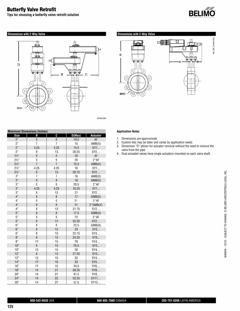
800-543-9038 USA 866-805-7089 CANADA 203-791-8396 LATIN AMERICA
125
Butterfl y Valve Retrofi tTips for choosing a butterfly valve retrofit solution
Maximum Dimensions (Inches)Size B C D(Max) Actuator2” 9 9 19.5 AF2” 7 7 15 AMB(X)2” 4.25 4.25 15.5 SY1...2” 8 13 20.25 SY2…
2½” 9 9 20 AF2½” 9 9 20 2*AF2½” 7 7 15.5 AMB(X)2½” 4.25 4.25 16 SY1...2½” 8 13 20.75 SY2…3” 7 7 16 AMB(X)3” 8 8 16 GMB(X)3” 9 9 20.5 2*AF3” 4.25 4.25 16.25 SY1...3” 8 13 21 SY2…4” 8 8 17 GMB(X)4” 9 9 21 2*AF4” 8 8 21 2*GMB(X)4” 8 13 21.75 SY2…5” 8 8 17.5 GMB(X)5” 9 9 22 2*AF5” 8 13 22.25 SY2…6” 8 8 22.5 GMB(X)6” 8 13 23 SY2...6” 8 13 22.75 SY3…8” 8 13 24.25 SY3...8” 12 15 29 SY4…10” 8 13 25.5 SY3...10” 12 15 30 SY4…12” 8 13 27.25 SY3...12” 12 15 32 SY4…14” 12 15 33 SY5…16” 12 15 34.5 SY6…18” 14 21 39.25 SY8…20” 14 21 41.5 SY8…24” 14 22 53.25 SY11…30” 14 22 57.5 SY12…
Dimensions with 2-Way Valve
AM_G
M_L
ineR
evis
ed
D
BC
A
BHC
Dimensions with 2-Way Valve
BF2WUDIM
D
BHC
B C
Application Notes
1. Dimensions are approximate2. Custom kits may be taller and varies by application needs3. Dimension “D” allows for actuator removal without the need to remove the
valve from the pipe.4. Dual actuated valves have single actuators mounted on each valve shaft.
M40
045
- 10/
10 -
SUBJ
ECT
TO C
HANG
E. ©
BEL
IMO
AIRC
ONTR
OLS
(USA
), IN
C.
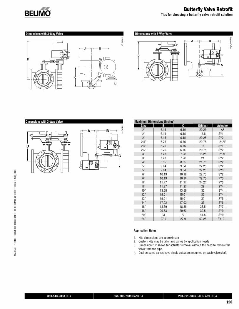
800-543-9038 USA 866-805-7089 CANADA 203-791-8396 LATIN AMERICA
126
Butterfl y Valve Retrofi tTips for choosing a butterfly valve retrofit solution
Maximum Dimensions (Inches)Size B C D(Max) Actuator2” 6.15 6.15 20.25 AF2” 6.15 6.15 15.5 SY1…2” 6.15 6.15 20.25 SY2…
2½” 6.76 6.76 20.75 2*AF2½” 6.76 6.76 16 SY1…2½” 6.76 6.76 20.75 SY2…3” 7.28 7.28 16.25 2*AF3” 7.28 7.28 21 SY2…4” 8.55 8.55 21.75 SY2…5” 9.64 9.64 22.25 SY2…5” 9.64 9.64 22.25 SY3…6” 10.19 10.19 22.75 SY2…6” 10.19 10.19 22.75 SY3…8” 11.37 11.37 24.25 SY3…8” 11.37 11.37 29 SY4…
10” 13.58 13.58 30 SY4…12” 15.01 15.01 32 SY4…12” 15.01 15.01 32 SY5…14” 17.02 17.02 33 SY6…16” 18.39 18.39 38.5 SY7…18” 20.63 20.63 39.5 SY9…20” 23 23 41.5 SY9…24” 27.9 27.9 53.25 SY12…
Dimensions with 3-Way Valve
Sing
le_B
utte
rfly
Application Notes
1. Kits dimensions are approximate2. Custom kits may be taller and varies by application needs3. Dimension “D” allows for actuator removal without the need to remove the valve from the pipe.4. Dual actuated valves have single actuators mounted on each valve shaft.
Dimensions with 3-Way Valve10 0
10 0
D
A B
C
HS D
WG1
1S
0
S
D
A B
CC
Dimensions with 3-Way Valve
HS D
WG1
5
10D
A B
C
M40
045
- 10/
10 -
SUBJ
ECT
TO C
HANG
E. ©
BEL
IMO
AIRC
ONTR
OLS
(USA
), IN
C.
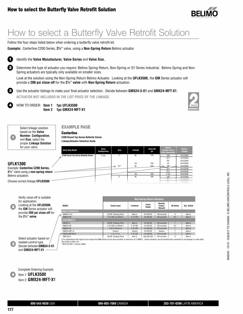
800-543-9038 USA 866-805-7089 CANADA 203-791-8396 LATIN AMERICA
127
M40
045
- 10/
10 -
SUBJ
ECT
TO C
HANG
E. ©
BEL
IMO
AIRC
ONTR
OLS
(USA
), IN
C.
C200 Round Top Series Butterfl y Valves 2-way 2” No 200 AM UFLK3500SY1 UFLK3538SY2 UFLK3540
Yes 200 AF UFLK35002½” No 200 GM UFLK3500
SY1 UFLK3538SY2 UFLK3540
Yes 200 2*AF UFLK35023”33 NoNoNo 200200200 GMGMGM UFLKUFLKUFLK350035003500
SY1SY1SY1SY1SY1S UFLKUFLKUFLKUFLKUFLKU 3 3835383538353835383538SY2SY2SY2SY2 UFLKUFLKUFLKUFLK3540354035403540
YesYes 200200 2*AF2*AF UFLKUFLK35023502
Valve Body Model ValveConfi guration Size Failsafe Close-Off
psi
BelimoActuator Series
(Sold Separately)
BelimoLinkage
EXAMPLE PAGECenterlineC200 Round Top Series Butterfly Valves
Linkage/Actuator Selection Guide
Non-Spring Return Actuators
MODEL Control Input Feedback PowerSupply
RunningTime(s)[Default]
VA Rating Aux. Switch
BASIC PRODUCTSGMB24-3-X1 On/Off, Floating Point Add-on 24 VAC/DC 150 seconds 6 Add-onGMB24-SR 2-10 VDC (4-20mA*) 2-10 VDC 24 VAC/DC 150 seconds 6.5 Add-on
CUSTOMIZE ITGMX24-3 On/Off, Floating Point Add on 24 VAC/DC 150 seconds 7 Add-onGMX24-SR 2-10 VDC (4-20mA*) 2-10 VDC 24 VAC/DC 150 seconds 6.5 Add-onGMX24-PC 0-20 V Phasecut 2-10 VDC 24 VAC/DC 150 seconds 7 Add-onGMX24-MFT-X1 Various Various 24 VAC/DC Various 7 Add-onGMX24-MFT95-X1 0 to 135 Ω 2-10 VDC 24 VAC/DC 150 seconds 7 Add-onGMX120-3 On/Off, Floating Point Add on 100-240 VAC 150 seconds 9 Add-on
‡ For applications that require more torque the GMB Series can be dual mounted. A maximum of 2 GMB/X... Series actuators can be mechanically connected to one damper or valve shaft. The torque is 640 in-lb.*With the 500 Ω resistor added.
How to select the Butterfl y Valve Retrofi t Solution
How to select a Butterfly Valve Retrofit SolutionFollow the four steps listed below when ordering a butterfly valve retrofit kit.
Example: Centerline C200 Series, 2½” valve, using a Non-Spring Return Belimo actuator.
1 Identify the Valve Manufacturer, Valve Series and Valve Size.
2 Determine the type of actuator you require: Belimo Spring Return, Non-Spring or SY Series Industrial. Belimo Spring and Non-Spring actuators are typically only available on smaller sizes.
Look at the solution using the Non-Spring Return Belimo Actuator. Looking at the UFLK3500, the GM Series actuator will provide a 200 psi close-off for the 2½” valve with Non-Spring Return actuation.
3 Use the actuator listings to make your final actuator selection. Decide between GMX24-3-X1 and GMX24-MFT-X1.
ACTUATOR NOT INCLUDED IN THE LIST PRICE OF THE LINKAGE.
4 HOW TO ORDER: Item 1 1pc UFLK3500 Item 2 1pc GMX24-MFT-X1
1
Select linkage solutionbased on the Valve Number, Confi guration, and Size; select theproper Linkage Solutionfor your valve.
UFLK1300Example: Centerline C200 Series,2½” valve using a non-spring returnBelimo actuation.
Choose correct linkage UFLK3500.
2
Verify close-off is suitablefor application.Looking at the UFLK3500, the GM Series actuator will provide 200 psi close-off forthe 2½” valve.
3Select actuator based on needed control type.Decide between GMB24-3-X1 and GMX24-MFT-X1.
4Complete Ordering Example:
Item 1: UFLK3500Item 2: GMX24-MFT-X1
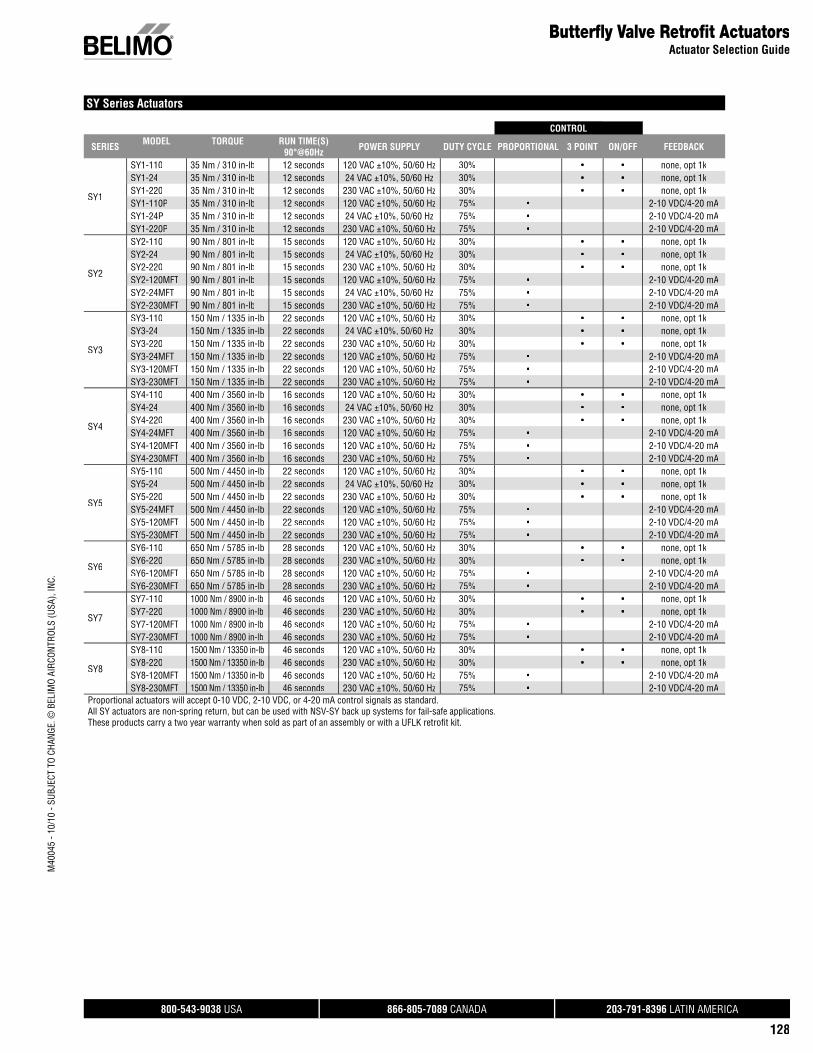
800-543-9038 USA 866-805-7089 CANADA 203-791-8396 LATIN AMERICA
128
Butterfl y Valve Retrofi t ActuatorsActuator Selection Guide
SY Series Actuators
CONTROL
SERIES MODEL TORQUE RUN TIME(S) 90°@60Hz POWER SUPPLY DUTY CYCLE PROPORTIONAL 3 POINT ON/OFF FEEDBACK
SY1
SY1-110 35 Nm / 310 in-lb 12 seconds 120 VAC ±10%, 50/60 Hz 30% • • none, opt 1kSY1-24 35 Nm / 310 in-lb 12 seconds 24 VAC ±10%, 50/60 Hz 30% • • none, opt 1kSY1-220 35 Nm / 310 in-lb 12 seconds 230 VAC ±10%, 50/60 Hz 30% • • none, opt 1kSY1-110P 35 Nm / 310 in-lb 12 seconds 120 VAC ±10%, 50/60 Hz 75% • 2-10 VDC/4-20 mASY1-24P 35 Nm / 310 in-lb 12 seconds 24 VAC ±10%, 50/60 Hz 75% • 2-10 VDC/4-20 mASY1-220P 35 Nm / 310 in-lb 12 seconds 230 VAC ±10%, 50/60 Hz 75% • 2-10 VDC/4-20 mA
SY2
SY2-110 90 Nm / 801 in-lb 15 seconds 120 VAC ±10%, 50/60 Hz 30% • • none, opt 1kSY2-24 90 Nm / 801 in-lb 15 seconds 24 VAC ±10%, 50/60 Hz 30% • • none, opt 1kSY2-220 90 Nm / 801 in-lb 15 seconds 230 VAC ±10%, 50/60 Hz 30% • • none, opt 1kSY2-120MFT 90 Nm / 801 in-lb 15 seconds 120 VAC ±10%, 50/60 Hz 75% • 2-10 VDC/4-20 mASY2-24MFT 90 Nm / 801 in-lb 15 seconds 24 VAC ±10%, 50/60 Hz 75% • 2-10 VDC/4-20 mASY2-230MFT 90 Nm / 801 in-lb 15 seconds 230 VAC ±10%, 50/60 Hz 75% • 2-10 VDC/4-20 mA
SY3
SY3-110 150 Nm / 1335 in-lb 22 seconds 120 VAC ±10%, 50/60 Hz 30% • • none, opt 1kSY3-24 150 Nm / 1335 in-lb 22 seconds 24 VAC ±10%, 50/60 Hz 30% • • none, opt 1kSY3-220 150 Nm / 1335 in-lb 22 seconds 230 VAC ±10%, 50/60 Hz 30% • • none, opt 1kSY3-24MFT 150 Nm / 1335 in-lb 22 seconds 120 VAC ±10%, 50/60 Hz 75% • 2-10 VDC/4-20 mASY3-120MFT 150 Nm / 1335 in-lb 22 seconds 120 VAC ±10%, 50/60 Hz 75% • 2-10 VDC/4-20 mASY3-230MFT 150 Nm / 1335 in-lb 22 seconds 230 VAC ±10%, 50/60 Hz 75% • 2-10 VDC/4-20 mA
SY4
SY4-110 400 Nm / 3560 in-lb 16 seconds 120 VAC ±10%, 50/60 Hz 30% • • none, opt 1kSY4-24 400 Nm / 3560 in-lb 16 seconds 24 VAC ±10%, 50/60 Hz 30% • • none, opt 1kSY4-220 400 Nm / 3560 in-lb 16 seconds 230 VAC ±10%, 50/60 Hz 30% • • none, opt 1kSY4-24MFT 400 Nm / 3560 in-lb 16 seconds 120 VAC ±10%, 50/60 Hz 75% • 2-10 VDC/4-20 mASY4-120MFT 400 Nm / 3560 in-lb 16 seconds 120 VAC ±10%, 50/60 Hz 75% • 2-10 VDC/4-20 mASY4-230MFT 400 Nm / 3560 in-lb 16 seconds 230 VAC ±10%, 50/60 Hz 75% • 2-10 VDC/4-20 mA
SY5
SY5-110 500 Nm / 4450 in-lb 22 seconds 120 VAC ±10%, 50/60 Hz 30% • • none, opt 1kSY5-24 500 Nm / 4450 in-lb 22 seconds 24 VAC ±10%, 50/60 Hz 30% • • none, opt 1kSY5-220 500 Nm / 4450 in-lb 22 seconds 230 VAC ±10%, 50/60 Hz 30% • • none, opt 1kSY5-24MFT 500 Nm / 4450 in-lb 22 seconds 120 VAC ±10%, 50/60 Hz 75% • 2-10 VDC/4-20 mASY5-120MFT 500 Nm / 4450 in-lb 22 seconds 120 VAC ±10%, 50/60 Hz 75% • 2-10 VDC/4-20 mASY5-230MFT 500 Nm / 4450 in-lb 22 seconds 230 VAC ±10%, 50/60 Hz 75% • 2-10 VDC/4-20 mA
SY6
SY6-110 650 Nm / 5785 in-lb 28 seconds 120 VAC ±10%, 50/60 Hz 30% • • none, opt 1kSY6-220 650 Nm / 5785 in-lb 28 seconds 230 VAC ±10%, 50/60 Hz 30% • • none, opt 1kSY6-120MFT 650 Nm / 5785 in-lb 28 seconds 120 VAC ±10%, 50/60 Hz 75% • 2-10 VDC/4-20 mASY6-230MFT 650 Nm / 5785 in-lb 28 seconds 230 VAC ±10%, 50/60 Hz 75% • 2-10 VDC/4-20 mA
SY7
SY7-110 1000 Nm / 8900 in-lb 46 seconds 120 VAC ±10%, 50/60 Hz 30% • • none, opt 1kSY7-220 1000 Nm / 8900 in-lb 46 seconds 230 VAC ±10%, 50/60 Hz 30% • • none, opt 1kSY7-120MFT 1000 Nm / 8900 in-lb 46 seconds 120 VAC ±10%, 50/60 Hz 75% • 2-10 VDC/4-20 mASY7-230MFT 1000 Nm / 8900 in-lb 46 seconds 230 VAC ±10%, 50/60 Hz 75% • 2-10 VDC/4-20 mA
SY8
SY8-110 1500 Nm / 13350 in-lb 46 seconds 120 VAC ±10%, 50/60 Hz 30% • • none, opt 1kSY8-220 1500 Nm / 13350 in-lb 46 seconds 230 VAC ±10%, 50/60 Hz 30% • • none, opt 1kSY8-120MFT 1500 Nm / 13350 in-lb 46 seconds 120 VAC ±10%, 50/60 Hz 75% • 2-10 VDC/4-20 mASY8-230MFT 1500 Nm / 13350 in-lb 46 seconds 230 VAC ±10%, 50/60 Hz 75% • 2-10 VDC/4-20 mA
Proportional actuators will accept 0-10 VDC, 2-10 VDC, or 4-20 mA control signals as standard.All SY actuators are non-spring return, but can be used with NSV-SY back up systems for fail-safe applications.These products carry a two year warranty when sold as part of an assembly or with a UFLK retrofi t kit.
M40
045
- 10/
10 -
SUBJ
ECT
TO C
HANG
E. ©
BEL
IMO
AIRC
ONTR
OLS
(USA
), IN
C.
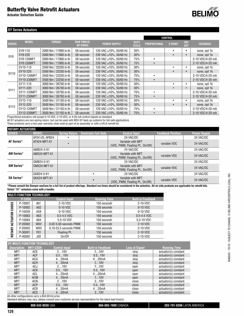
800-543-9038 USA 866-805-7089 CANADA 203-791-8396 LATIN AMERICA
129
SY Series Actuators
CONTROL
SERIESMODEL TORQUE RUN TIME(S)
90°@60Hz POWER SUPPLY DUTY CYCLE PROPORTIONAL 3 POINT ON/
OFF FEEDBACK
SY9
SY9-110 2000 Nm / 17800 in-lb 58 seconds 120 VAC ±10%, 50/60 Hz 30% • • none, opt 1kSY9-220 2000 Nm / 17800 in-lb 58 seconds 230 VAC ±10%, 50/60 Hz 30% • • none, opt 1kSY9-120MFT 2000 Nm / 17800 in-lb 58 seconds 120 VAC ±10%, 50/60 Hz 75% • 2-10 VDC/4-20 mASY9-230MFT 2000 Nm / 17800 in-lb 58 seconds 230 VAC ±10%, 50/60 Hz 75% • 2-10 VDC/4-20 mA
SY10
SY10-110 2500 Nm / 22250 in-lb 58 seconds 120 VAC ±10%, 50/60 Hz 30% • • none, opt 1kSY10-220 2500 Nm / 22250 in-lb 58 seconds 230 VAC ±10%, 50/60 Hz 30% • • none, opt 1kSY10-120MFT 2500 Nm / 22250 in-lb 58 seconds 120 VAC ±10%, 50/60 Hz 75% • 2-10 VDC/4-20 mASY10-230MFT 2500 Nm / 22250 in-lb 58 seconds 230 VAC ±10%, 50/60 Hz 75% • 2-10 VDC/4-20 mA
SY11
SY11-110 3000 Nm / 26700 in-lb 58 seconds 120 VAC ±10%, 50/60 Hz 30% • • none, opt 1kSY11-220 3000 Nm / 26700 in-lb 58 seconds 230 VAC ±10%, 50/60 Hz 30% • • none, opt 1kSY11-120MFT 3000 Nm / 26700 in-lb 58 seconds 120 VAC ±10%, 50/60 Hz 75% • 2-10 VDC/4-20 mASY11-230MFT 3000 Nm / 26700 in-lb 58 seconds 230 VAC ±10%, 50/60 Hz 75% • 2-10 VDC/4-20 mA
SY12
SY12-110 3500 Nm / 31150 in-lb 58 seconds 120 VAC ±10%, 50/60 Hz 30% • • none, opt 1kSY12-220 3500 Nm / 31150 in-lb 58 seconds 230 VAC ±10%, 50/60 Hz 30% • • none, opt 1kSY12-120MFT 3500 Nm / 31150 in-lb 58 seconds 120 VAC ±10%, 50/60 Hz 75% • 2-10 VDC/4-20 mASY12-230MFT 3500 Nm / 31150 in-lb 58 seconds 230 VAC ±10%, 50/60 Hz 75% • 2-10 VDC/4-20 mA
Proportional actuators will accept 0-10 VDC, 2-10 VDC, or 4-20 mA control signals as standard.All SY actuators are non-spring return, but can be used with NSV-SY back up systems for fail-safe applications.These products carry a two year warranty when sold as part of an assembly or with a UFLK retrofi t kit.
Butterfl y Valve Retrofi t ActuatorsActuator Selection Guide
ROTARY ACTUATORSSERIES MODEL Spring Return Electronic Fail Safe Control Input Feedback Position Power Supply
AF Series*AF24 US, AFB24 • 24 VAC/DC 24 VAC/DCAFX24-MFT-X1 • Variable with MFT
(VDC, PWM, Floating Pt., On/Off) variable VDC 24 VAC/DC
AM Series*AMB24-3-X1 24 VAC/DC 24 VAC/DCAMX24-MFT-X1 Variable with MFT
(VDC, PWM, Floating Pt., On/Off) variable VDC 24 VAC/DC
GM Series*GMB24-3-X1 24 VAC/DC 24 VAC/DCGMX24-MFT-X1 Variable with MFT
(VDC, PWM, Floating Pt., On/Off) variable VDC 24 VAC/DC
GK Series*GKB24-3-X1 • 24 VAC/DC 24 VAC/DCGKX24-MFT-X1 • Variable with MFT
(VDC, PWM, Floating Pt., On/Off) variable VDC 24 VAC/DC
*Please consult the Damper sections for a full list of product offerings. Standard run times should be considered in the selection. All air side products are applicable for retrofi t kits. Select “X1” actuators come with a handle.
MULTI-FUNCTION TECHNOLOGYP-CODE Control Input Running Time Built-in Feedback
ROTA
RY A
CTUA
TOR
CODE
S P-10001 A01 2-10 VDC 150 seconds 2-10 VDCP-10002 A02 0-10 VDC 150 seconds 0-10 VDCP-10028 A28 0-10 VDC 150 seconds 0-10 VDCP-10063 A63 0.5-4.5 VDC 150 seconds 0.5-4.5 VDCP-10064 A64 5.5-10 VDC 150 seconds 5.5-10 VDCP-20002 W02 0.02-5.00 seconds PWM 150 seconds 2-10 VDCP-20003 W03 0.10-25.5 seconds PWM 150 seconds 2-10 VDCP-30001 F01 Floating Pt. 150 seconds 2-10 VDCP-40002 J02 On/Off 150 seconds 2-10 VDC
SY MULTI-FUNCTION TECHNOLOGYDescription MFT-CODE Control Input Built-in Feedback Loss of Signal Running Time
MFT ACE 2…10V 2...10V stopp actuator(s) constant( )MFT ACF 0.5…10V 0.5...10V pstop ( )actuator(s) constantMFT ACG 4…20mA 4…20mA stopp actuator(s) constant( )MFT ACH 4…20mA 2...10V pstop ( )actuator(s) constantMFT ACJ 2…10V 2...10V openp actuator(s) constant( )MFT ACK 0.5…10V 0.5...10V popen ( )actuator(s) constantMFT ACL 4…20mA 4…20mA openp actuator(s) constant( )MFT ACM 4…20mA 2...10V popen ( )actuator(s) constantMFT ACN 2…10V 2...10V close actuator(s) constant( )MFT ACP 0.5…10V 0.5...10V close ( )actuator(s) constantMFT ACR 4…20mA 4…20mA close actuator(s) constant( )MFT ACS 4…20mA 2...10V close ( )actuator(s) constant( )( )
All other confi gurations carry a $34.00 list price.Standard delivery may vary, please consult your customer service representative for the latest lead time(s).
M40
045
- 10/
10 -
SUBJ
ECT
TO C
HANG
E. ©
BEL
IMO
AIRC
ONTR
OLS
(USA
), IN
C.
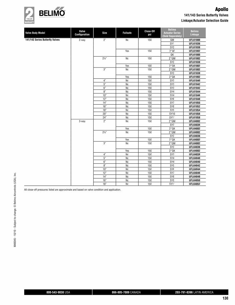
Valve Body Model ValveConfi guration Size Failsafe Close-Off
psi
BelimoActuator Series
(Sold Separately)
BelimoLinkage
800-543-9038 USA 866-805-7089 CANADA 203-791-8396 LATIN AMERICA
130
M40
045
- 10/
10 -
Subj
ect t
o ch
ange
. © B
elim
o Ai
rcon
trols
(USA
), In
c.
Apollo141/143 Series Butterfly Valves
Linkage/Actuator Selection Guide
141/143 Series Butterfl y Valves 2-way 2” No 150 GM UFLK1000SY1 UFLK1036SY2 UFLK1038
Yes 150 2*AF UFLK1002GK UFLK1000
2½” No 150 2*GM UFLK1002SY2 UFLK1038
Yes 150 2*GK UFLK10023” No 150 2*GM UFLK1002
SY2 UFLK1038Yes 150 2*GK UFLK1002
4” No 150 SY2 UFLK10405” No 150 SY3 UFLK10426” No 150 SY3 UFLK10428” No 150 SY4 UFLK104410” No 150 SY4 UFLK104612” No 150 SY6 UFLK104814” No 150 SY7 UFLK105016” No 150 SY8 UFLK105218” No 150 SY9 UFLK105420” No 150 SY10 UFLK105624” No 150 SY11 UFLK1058
3-way 2” No 150 2*GM UFLK4002SY2 UFLK4036
Yes 150 2*GK UFLK40022½” No 150 2*GM UFLK4002
SY2 UFLK4036Yes 150 2*GK UFLK4002
3” No 150 2*GM UFLK4002SY2 UFLK4036
Yes 150 2*GK UFLK40024” No 150 SY3 UFLK40385” No 150 SY4 UFLK40406” No 150 SY4 UFLK40408” No 150 SY5 UFLK404210” No 150 SY6 UFLK404412” No 150 SY7 UFLK404614” No 150 SY8 UFLK404816” No 150 SY9 UFLK405018” No 150 SY11 UFLK4052
All close-off pressures listed are approximate and based on valve condition and application.

Valve Body Model ValveConfi guration Size Failsafe Close-Off
psi
BelimoActuator Series
(Sold Separately)
BelimoLinkage
800-543-9038 USA 866-805-7089 CANADA 203-791-8396 LATIN AMERICA
131
M40
045
- 10/
10 -
Subj
ect t
o ch
ange
. © B
elim
o Ai
rcon
trols
(USA
), In
c.
BelimoHS Series Butterfly Valves
Linkage/Actuator Selection Guide
HS Series Butterfl y Valves 2-way 2” No 200 AM UFLK3900SY2 UFLK3918
Yes 200 AF UFLK39302½” No 200 AM UFLK3900
SY2 UFLK3918Yes 200 2*AF UFLK3936
3” No 200 GM UFLK3900SY2 UFLK3918
Yes 200 2*AF UFLK3936GK UFLK3900
4” No 200 2*GM UFLK3908SY2 UFLK3920
Yes 200 2*GK UFLK39085” No 200 SY2 UFLK39226” No 200 SY3 UFLK39228” No 200 SY4 UFLK397010” No 200 SY4 UFLK397012” No 200 SY4 UFLK392814” No 150 SY5 UFLK392816” No 150 SY6 UFLK397618” No 150 SY8 UFLK397820” No 150 SY8 UFLK398024” No 150 SY11 UFLK3982
3-way 2” No 200 AM UFLK6900SY2 UFLK6910
Yes 200 AF UFLK69502½” No 200 2*GM UFLK6902
SY2 UFLK6910Yes 200 2*AF UFLK6952
3” No 200 2*GM UFLK6902SY2 UFLK6910
Yes 200 2*GK UFLK69024” No 200 SY2 UFLK69125” No 200 SY3 UFLK69146” No 200 SY3 UFLK69148” No 200 SY4 UFLK692010” No 200 SY4 UFLK692012” No 200 SY5 UFLK692214” No 150 SY6 UFLK701816” No 150 SY7 UFLK702018” No 150 SY8 UFLK702220” No 150 SY9 UFLK702424” No 150 SY12 UFLK7026
All close-off pressures listed are approximate and based on valve condition and application.
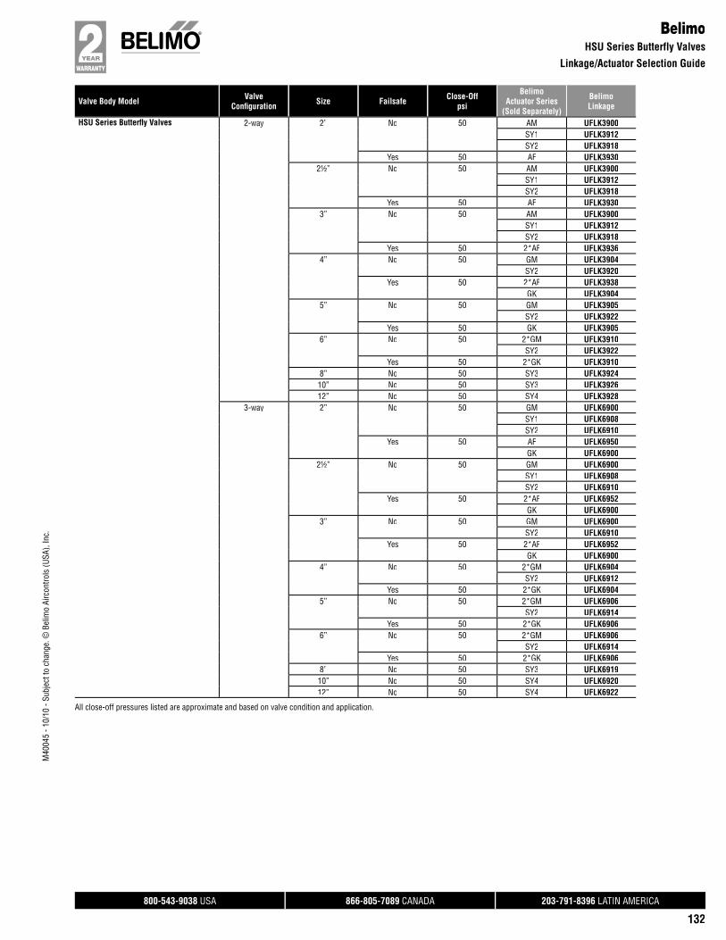
Valve Body Model ValveConfi guration Size Failsafe Close-Off
psi
BelimoActuator Series
(Sold Separately)
BelimoLinkage
800-543-9038 USA 866-805-7089 CANADA 203-791-8396 LATIN AMERICA
132
M40
045
- 10/
10 -
Subj
ect t
o ch
ange
. © B
elim
o Ai
rcon
trols
(USA
), In
c.
BelimoHSU Series Butterfly Valves
Linkage/Actuator Selection Guide
HSU Series Butterfl y Valves 2-way 2” No 50 AM UFLK3900SY1 UFLK3912SY2 UFLK3918
Yes 50 AF UFLK39302½” No 50 AM UFLK3900
SY1 UFLK3912SY2 UFLK3918
Yes 50 AF UFLK39303” No 50 AM UFLK3900
SY1 UFLK3912SY2 UFLK3918
Yes 50 2*AF UFLK39364” No 50 GM UFLK3904
SY2 UFLK3920Yes 50 2*AF UFLK3938
GK UFLK39045” No 50 GM UFLK3905
SY2 UFLK3922Yes 50 GK UFLK3905
6” No 50 2*GM UFLK3910SY2 UFLK3922
Yes 50 2*GK UFLK39108” No 50 SY3 UFLK392410” No 50 SY3 UFLK392612” No 50 SY4 UFLK3928
3-way 2” No 50 GM UFLK6900SY1 UFLK6908SY2 UFLK6910
Yes 50 AF UFLK6950GK UFLK6900
2½” No 50 GM UFLK6900SY1 UFLK6908SY2 UFLK6910
Yes 50 2*AF UFLK6952GK UFLK6900
3” No 50 GM UFLK6900SY2 UFLK6910
Yes 50 2*AF UFLK6952GK UFLK6900
4” No 50 2*GM UFLK6904SY2 UFLK6912
Yes 50 2*GK UFLK69045” No 50 2*GM UFLK6906
SY2 UFLK6914Yes 50 2*GK UFLK6906
6” No 50 2*GM UFLK6906SY2 UFLK6914
Yes 50 2*GK UFLK69068” No 50 SY3 UFLK691910” No 50 SY4 UFLK692012” No 50 SY4 UFLK6922
All close-off pressures listed are approximate and based on valve condition and application.
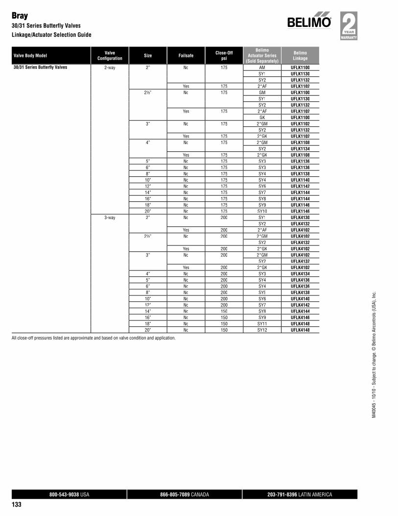
Valve Body Model ValveConfi guration Size Failsafe Close-Off
psi
BelimoActuator Series
(Sold Separately)
BelimoLinkage
800-543-9038 USA 866-805-7089 CANADA 203-791-8396 LATIN AMERICA
133
M40
045
- 10/
10 -
Subj
ect t
o ch
ange
. © B
elim
o Ai
rcon
trols
(USA
), In
c.
Bray30/31 Series Butterfly Valves
Linkage/Actuator Selection Guide
30/31 Series Butterfl y Valves 2-way 2” No 175 AM UFLK1100SY1 UFLK1130SY2 UFLK1132
Yes 175 2*AF UFLK11022½” No 175 GM UFLK1100
SY1 UFLK1130SY2 UFLK1132
Yes 175 2*AF UFLK1102GK UFLK1100
3” No 175 2*GM UFLK1102SY2 UFLK1132
Yes 175 2*GK UFLK11024” No 175 2*GM UFLK1108
SY2 UFLK1134Yes 175 2*GK UFLK1108
5” No 175 SY3 UFLK11366” No 175 SY3 UFLK11368” No 175 SY4 UFLK113810” No 175 SY4 UFLK114012” No 175 SY6 UFLK114214” No 175 SY7 UFLK114416” No 175 SY8 UFLK114418” No 175 SY9 UFLK114620” No 175 SY10 UFLK1146
3-way 2” No 200 SY1 UFLK4130SY2 UFLK4132
Yes 200 2*AF UFLK41022½” No 200 2*GM UFLK4102
SY2 UFLK4132Yes 200 2*GK UFLK4102
3” No 200 2*GM UFLK4102SY2 UFLK4132
Yes 200 2*GK UFLK41024” No 200 SY3 UFLK41345” No 200 SY4 UFLK41366” No 200 SY4 UFLK41368” No 200 SY5 UFLK413810” No 200 SY6 UFLK414012” No 200 SY7 UFLK414214” No 150 SY8 UFLK414416” No 150 SY9 UFLK414618” No 150 SY11 UFLK414820” No 150 SY12 UFLK4148
All close-off pressures listed are approximate and based on valve condition and application.

Valve Body Model ValveConfi guration Size Failsafe Close-Off
psi
BelimoActuator Series
(Sold Separately)
BelimoLinkage
800-543-9038 USA 866-805-7089 CANADA 203-791-8396 LATIN AMERICA
134
M40
045
- 10/
10 -
Subj
ect t
o ch
ange
. © B
elim
o Ai
rcon
trols
(USA
), In
c.
Bray40/41 Series Butterfly Valves
Linkage/Actuator Selection Guide
40/41 Series Butterfl y Valves 2-way 2½” No 285 2*GM UFLK1200SY2 UFLK1224
Yes 285 2*GK UFLK12003” No 285 2*GM UFLK1200
SY2 UFLK1224Yes 285 2*GK UFLK1200
4” No 285 2*GM UFLK1200SY2 UFLK1224
Yes 285 2*GK UFLK12005” No 285 SY3 UFLK12266” No 285 SY4 UFLK12288” No 285 SY4 UFLK123010” No 285 SY6 UFLK123212” No 285 SY7 UFLK123414” No 285 SY8 UFLK123616” No 285 SY9 UFLK123818” No 285 SY11 UFLK124020” No 285 SY12 UFLK1242
3-way 2½” No 285 2*GM UFLK4200SY2 UFLK4222
Yes 285 2*GK UFLK42003” No 285 2*GM UFLK4200
SY2 UFLK4222Yes 285 2*GK UFLK4200
4” No 285 SY3 UFLK42225” No 285 SY4 UFLK42246” No 285 SY4 UFLK42248” No 285 SY5 UFLK422610” No 285 SY7 UFLK422812” No 285 SY8 UFLK423014” No 285 SY10 UFLK423216” No 285 SY12 UFLK4234
All close-off pressures listed are approximate and based on valve condition and application.
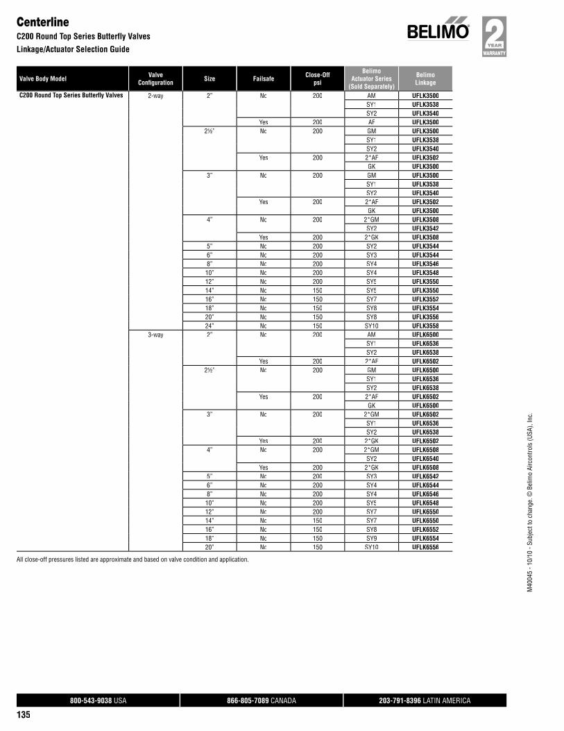
Valve Body Model ValveConfi guration Size Failsafe Close-Off
psi
BelimoActuator Series
(Sold Separately)
BelimoLinkage
800-543-9038 USA 866-805-7089 CANADA 203-791-8396 LATIN AMERICA
135
M40
045
- 10/
10 -
Subj
ect t
o ch
ange
. © B
elim
o Ai
rcon
trols
(USA
), In
c.
CenterlineC200 Round Top Series Butterfly Valves
Linkage/Actuator Selection Guide
C200 Round Top Series Butterfl y Valves 2-way 2” No 200 AM UFLK3500SY1 UFLK3538SY2 UFLK3540
Yes 200 AF UFLK35002½” No 200 GM UFLK3500
SY1 UFLK3538SY2 UFLK3540
Yes 200 2*AF UFLK3502GK UFLK3500
3” No 200 GM UFLK3500SY1 UFLK3538SY2 UFLK3540
Yes 200 2*AF UFLK3502GK UFLK3500
4” No 200 2*GM UFLK3508SY2 UFLK3542
Yes 200 2*GK UFLK35085” No 200 SY2 UFLK35446” No 200 SY3 UFLK35448” No 200 SY4 UFLK354610” No 200 SY4 UFLK354812” No 200 SY5 UFLK355014” No 150 SY5 UFLK355016” No 150 SY7 UFLK355218” No 150 SY8 UFLK355420” No 150 SY8 UFLK355624” No 150 SY10 UFLK3558
3-way 2” No 200 AM UFLK6500SY1 UFLK6536SY2 UFLK6538
Yes 200 2*AF UFLK65022½” No 200 GM UFLK6500
SY1 UFLK6536SY2 UFLK6538
Yes 200 2*AF UFLK6502GK UFLK6500
3” No 200 2*GM UFLK6502SY1 UFLK6536SY2 UFLK6538
Yes 200 2*GK UFLK65024” No 200 2*GM UFLK6508
SY2 UFLK6540Yes 200 2*GK UFLK6508
5” No 200 SY3 UFLK65426” No 200 SY4 UFLK65448” No 200 SY4 UFLK654610” No 200 SY5 UFLK654812” No 200 SY7 UFLK655014” No 150 SY7 UFLK655016” No 150 SY8 UFLK655218” No 150 SY9 UFLK655420” No 150 SY10 UFLK6556
All close-off pressures listed are approximate and based on valve condition and application.
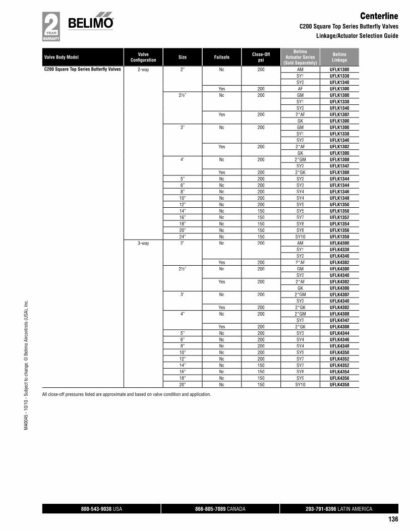
Valve Body Model ValveConfi guration Size Failsafe Close-Off
psi
BelimoActuator Series
(Sold Separately)
BelimoLinkage
800-543-9038 USA 866-805-7089 CANADA 203-791-8396 LATIN AMERICA
136
M40
045
- 10/
10 -
Subj
ect t
o ch
ange
. © B
elim
o Ai
rcon
trols
(USA
), In
c.
CenterlineC200 Square Top Series Butterfly Valves
Linkage/Actuator Selection Guide
C200 Square Top Series Butterfl y Valves 2-way 2” No 200 AM UFLK1300SY1 UFLK1338SY2 UFLK1340
Yes 200 AF UFLK13002½” No 200 GM UFLK1300
SY1 UFLK1338SY2 UFLK1340
Yes 200 2*AF UFLK1302GK UFLK1300
3” No 200 GM UFLK1300SY1 UFLK1338SY2 UFLK1340
Yes 200 2*AF UFLK1302GK UFLK1300
4” No 200 2*GM UFLK1308SY2 UFLK1342
Yes 200 2*GK UFLK13085” No 200 SY2 UFLK13446” No 200 SY3 UFLK13448” No 200 SY4 UFLK134610” No 200 SY4 UFLK134812” No 200 SY5 UFLK135014” No 150 SY5 UFLK135016” No 150 SY7 UFLK135218” No 150 SY8 UFLK135420” No 150 SY8 UFLK135624” No 150 SY10 UFLK1358
3-way 2” No 200 AM UFLK4300SY1 UFLK4338SY2 UFLK4340
Yes 200 2*AF UFLK43022½” No 200 GM UFLK4300
SY2 UFLK4340Yes 200 2*AF UFLK4302
GK UFLK43003” No 200 2*GM UFLK4302
SY2 UFLK4340Yes 200 2*GK UFLK4302
4” No 200 2*GM UFLK4308SY2 UFLK4342
Yes 200 2*GK UFLK43085” No 200 SY3 UFLK43446” No 200 SY4 UFLK43468” No 200 SY4 UFLK434810” No 200 SY5 UFLK435012” No 200 SY7 UFLK435214” No 150 SY7 UFLK435216” No 150 SY8 UFLK435418” No 150 SY9 UFLK435620” No 150 SY10 UFLK4358
All close-off pressures listed are approximate and based on valve condition and application.
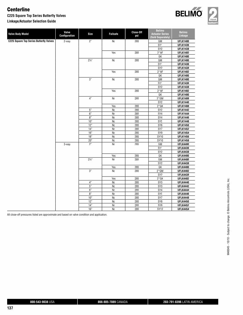
Valve Body Model ValveConfi guration Size Failsafe Close-Off
psi
BelimoActuator Series
(Sold Separately)
BelimoLinkage
800-543-9038 USA 866-805-7089 CANADA 203-791-8396 LATIN AMERICA
137
M40
045
- 10/
10 -
Subj
ect t
o ch
ange
. © B
elim
o Ai
rcon
trols
(USA
), In
c.
CenterlineC225 Square Top Series Butterfly Valves
Linkage/Actuator Selection Guide
C225 Square Top Series Butterfl y Valves 2-way 2” No 285 GM UFLK1400SY1 UFLK1436SY2 UFLK1438
Yes 285 2*AF UFLK1402GK UFLK1400
2½” No 285 GM UFLK1400SY1 UFLK1436SY2 UFLK1438
Yes 285 2*AF UFLK1402GK UFLK1400
3” No 285 GM UFLK1400SY1 UFLK1436SY2 UFLK1438
Yes 285 2*AF UFLK1402GK UFLK1400
4” No 285 2*GM UFLK1408SY2 UFLK1440
Yes 285 2*GK UFLK14085” No 285 SY2 UFLK14426” No 285 SY4 UFLK14448” No 285 SY4 UFLK144610” No 285 SY5 UFLK144812” No 285 SY6 UFLK145014” No 285 SY7 UFLK145216” No 285 SY9 UFLK145418” No 285 SY10 UFLK145620” No 285 SY10 UFLK1458
3-way 2” No 285 GM UFLK4400SY1 UFLK4436SY2 UFLK4438
Yes 285 GK UFLK44002½” No 285 GM UFLK4400
SY2 UFLK4438Yes 285 GK UFLK4400
3” No 285 2*GM UFLK4402SY2 UFLK4438
Yes 285 2*GK UFLK44024” No 285 SY3 UFLK44405” No 285 SY3 UFLK44426” No 285 SY4 UFLK44448” No 285 SY5 UFLK444610” No 285 SY7 UFLK444812” No 285 SY8 UFLK445014” No 285 SY8 UFLK445216” No 285 SY12 UFLK4454
All close-off pressures listed are approximate and based on valve condition and application.

Valve Body Model ValveConfi guration Size Failsafe Close-Off
psi
BelimoActuator Series
(Sold Separately)
BelimoLinkage
800-543-9038 USA 866-805-7089 CANADA 203-791-8396 LATIN AMERICA
138
M40
045
- 10/
10 -
Subj
ect t
o ch
ange
. © B
elim
o Ai
rcon
trols
(USA
), In
c.
ChallengerCH100 Series Butterfly Valves
Linkage/Actuator Selection Guide
CH100 Series Butterfl y Valves 2-way 2” No 200 AM UFLK3600SY1 UFLK3622SY2 UFLK3624
Yes 200 2*AF UFLK36022½” No 200 GM UFLK3600
SY1 UFLK3622SY2 UFLK3624
Yes 200 2*AF UFLK3602GK UFLK3600
3” No 200 GM UFLK3600SY1 UFLK3622SY2 UFLK3624
Yes 200 2*AF UFLK3602GK UFLK3600
4” No 200 2*GM UFLK3608SY2 UFLK3626
Yes 200 2*GK UFLK36085” No 200 SY2 UFLK36266” No 200 SY3 UFLK36288” No 200 SY4 UFLK363010” No 200 SY4 UFLK363212” No 200 SY5 UFLK3634
3-way 2” No 200 GM UFLK6600SY1 UFLK6624SY2 UFLK6626
Yes 200 2*AF UFLK6602GK UFLK6600
2½” No 200 GM UFLK6600SY2 UFLK6626
Yes 200 2*AF UFLK6602GK UFLK6600
3” No 200 2*GM UFLK6602SY2 UFLK6626
Yes 200 2*GK UFLK66024” No 200 SY2 UFLK66285” No 200 SY3 UFLK66286” No 200 SY4 UFLK66308” No 200 SY4 UFLK663210” No 200 SY5 UFLK663412” No 200 SY7 UFLK6636
All close-off pressures listed are approximate and based on valve condition and application.
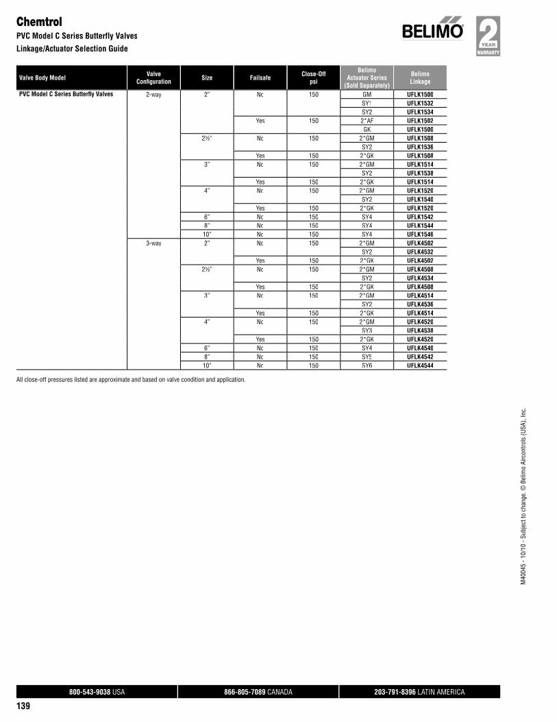
Valve Body Model ValveConfi guration Size Failsafe Close-Off
psi
BelimoActuator Series
(Sold Separately)
BelimoLinkage
800-543-9038 USA 866-805-7089 CANADA 203-791-8396 LATIN AMERICA
139
M40
045
- 10/
10 -
Subj
ect t
o ch
ange
. © B
elim
o Ai
rcon
trols
(USA
), In
c.
ChemtrolPVC Model C Series Butterfly Valves
Linkage/Actuator Selection Guide
PVC Model C Series Butterfl y Valves 2-way 2” No 150 GM UFLK1500SY1 UFLK1532SY2 UFLK1534
Yes 150 2*AF UFLK1502GK UFLK1500
2½” No 150 2*GM UFLK1508SY2 UFLK1536
Yes 150 2*GK UFLK15083” No 150 2*GM UFLK1514
SY2 UFLK1538Yes 150 2*GK UFLK1514
4” No 150 2*GM UFLK1520SY2 UFLK1540
Yes 150 2*GK UFLK15206” No 150 SY4 UFLK15428” No 150 SY4 UFLK154410” No 150 SY4 UFLK1546
3-way 2” No 150 2*GM UFLK4502SY2 UFLK4532
Yes 150 2*GK UFLK45022½” No 150 2*GM UFLK4508
SY2 UFLK4534Yes 150 2*GK UFLK4508
3” No 150 2*GM UFLK4514SY2 UFLK4536
Yes 150 2*GK UFLK45144” No 150 2*GM UFLK4520
SY3 UFLK4538Yes 150 2*GK UFLK4520
6” No 150 SY4 UFLK45408” No 150 SY5 UFLK454210” No 150 SY6 UFLK4544
All close-off pressures listed are approximate and based on valve condition and application.
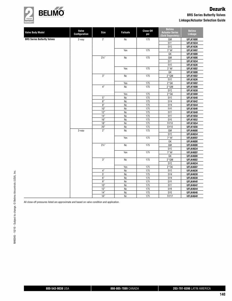
Valve Body Model ValveConfi guration Size Failsafe Close-Off
psi
BelimoActuator Series
(Sold Separately)
BelimoLinkage
800-543-9038 USA 866-805-7089 CANADA 203-791-8396 LATIN AMERICA
140
M40
045
- 10/
10 -
Subj
ect t
o ch
ange
. © B
elim
o Ai
rcon
trols
(USA
), In
c.
DezurikBRS Series Butterfly Valves
Linkage/Actuator Selection Guide
BRS Series Butterfl y Valves 2-way 2” No 175 GM UFLK1600SY1 UFLK1634SY2 UFLK1636
Yes 175 2*AF UFLK1602GK UFLK1600
2½” No 175 GM UFLK1600SY1 UFLK1634SY2 UFLK1636
Yes 175 2*AF UFLK1602GK UFLK1600
3” No 175 2*GM UFLK1602SY2 UFLK1636
Yes 175 2*GK UFLK16024” No 175 2*GM UFLK1608
SY2 UFLK1638Yes 175 2*GK UFLK1608
5” No 175 SY3 UFLK16406” No 175 SY4 UFLK16428” No 175 SY4 UFLK164410” No 175 SY5 UFLK164612” No 175 SY7 UFLK164814” No 175 SY7 UFLK165016” No 175 SY9 UFLK165218” No 175 SY10 UFLK165420” No 175 SY10 UFLK1656
3-way 2” No 175 GM UFLK4600SY2 UFLK4634
Yes 175 2*AF UFLK4602GK UFLK4600
2½” No 175 GM UFLK4600SY2 UFLK4634
Yes 175 2*AF UFLK4602GK UFLK4600
3” No 175 2*GM UFLK4602SY2 UFLK4634
Yes 175 2*GK UFLK46024” No 175 SY3 UFLK46365” No 175 SY4 UFLK46386” No 175 SY4 UFLK46388” No 175 SY5 UFLK464010” No 175 SY7 UFLK464212” No 175 SY8 UFLK464414” No 175 SY9 UFLK464616” No 175 SY12 UFLK4648
All close-off pressures listed are approximate and based on valve condition and application.
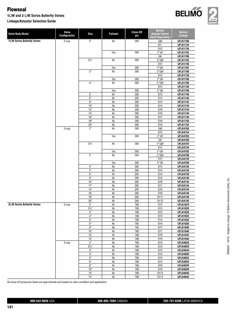
Valve Body Model ValveConfi guration Size Failsafe Close-Off
psi
BelimoActuator Series
(Sold Separately)
BelimoLinkage
800-543-9038 USA 866-805-7089 CANADA 203-791-8396 LATIN AMERICA
141
M40
045
- 10/
10 -
Subj
ect t
o ch
ange
. © B
elim
o Ai
rcon
trols
(USA
), In
c.
Flowseal1L/W and 3 L/W Series Butterfly Valves
Linkage/Actuator Selection Guide
1L/W Series Butterfl y Valves 2-way 2” No 285 GM UFLK1700SY1 UFLK1734SY2 UFLK1736
Yes 285 2*AF UFLK1702GK UFLK1700
2½” No 285 2*GM UFLK1702SY2 UFLK1736
Yes 285 2*GK UFLK17023” No 285 2*GM UFLK1708
SY2 UFLK1738Yes 285 2*GK UFLK1708
4” No 285 2*GM UFLK1708SY2 UFLK1738
Yes 285 2*GK UFLK17085” No 285 SY3 UFLK17406” No 285 SY3 UFLK17408” No 285 SY4 UFLK174210” No 285 SY4 UFLK174412” No 285 SY6 UFLK174414” No 285 SY6 UFLK174616” No 285 SY7 UFLK174818” No 285 SY9 UFLK175020” No 285 SY9 UFLK1752
3-way 2” No 285 GM UFLK4700SY2 UFLK4734
Yes 285 2*AF UFLK4702GK UFLK4700
2½” No 285 2*GM UFLK4702SY2 UFLK4734
Yes 285 2*GK UFLK47023” No 285 2*GM UFLK4708
SY2 UFLK4736Yes 285 2*GK UFLK4708
4” No 285 SY3 UFLK47365” No 285 SY4 UFLK47386” No 285 SY4 UFLK47388” No 285 SY4 UFLK474010” No 285 SY6 UFLK474212” No 285 SY7 UFLK474414” No 285 SY8 UFLK474416” No 285 SY9 UFLK474618” No 285 SY11 UFLK474820” No 285 SY12 UFLK4750
3L/W Series Butterfl y Valves 2-way 2” No 780 SY3 UFLK18282½” No 780 SY3 UFLK18283” No 780 SY3 UFLK18304” No 780 SY4 UFLK18325” No 780 SY4 UFLK18346” No 780 SY4 UFLK18368” No 780 SY7 UFLK183810” No 780 SY7 UFLK184012” No 780 SY9 UFLK184214” No 780 SY9 UFLK1844
3-way 2” No 780 SY3 UFLK48282½” No 780 SY3 UFLK48283” No 780 SY3 UFLK48444” No 780 SY4 UFLK48305” No 780 SY4 UFLK48326” No 780 SY4 UFLK48348” No 780 SY8 UFLK483610” No 780 SY8 UFLK483812” No 780 SY12 UFLK484014” No 780 SY12 UFLK4842
All close-off pressures listed are approximate and based on valve condition and application.

Valve Body Model ValveConfi guration Size Failsafe Close-Off
psi
BelimoActuator Series
(Sold Separately)
BelimoLinkage
800-543-9038 USA 866-805-7089 CANADA 203-791-8396 LATIN AMERICA
142
M40
045
- 10/
10 -
Subj
ect t
o ch
ange
. © B
elim
o Ai
rcon
trols
(USA
), In
c.
FNWFigure 1000/2000 Series Butterfly Valves
Linkage/Actuator Selection Guide
Figure 1000/2000 Series Butterfl yValves
2-way 2” No 150 GM UFLK1900SY1 UFLK1936SY2 UFLK1938
Yes 150 2*AF UFLK1902GK UFLK1900
2½” No 150 GM UFLK1900SY1 UFLK1936SY2 UFLK1938
Yes 150 2*AF UFLK1902GK UFLK1900
3” No 150 GM UFLK1900SY1 UFLK1936SY2 UFLK1938
Yes 150 2*AF UFLK1902GK UFLK1900
4” No 150 2*GM UFLK1908SY2 UFLK1940
Yes 150 2*GK UFLK19085” No 150 SY3 UFLK19426” No 150 SY4 UFLK19568” No 150 SY4 UFLK194410” No 150 SY5 UFLK194612” No 150 SY7 UFLK194814” No 150 SY7 UFLK194816” No 150 SY9 UFLK195018” No 150 SY10 UFLK195220” No 150 SY10 UFLK1954
3-way 2” No 150 GM UFLK4900SY2 UFLK4936
Yes 150 2*AF UFLK4902GK UFLK4900
2½” No 150 GM UFLK4900SY2 UFLK4936
Yes 150 2*AF UFLK4902GK UFLK4900
3” No 150 2*GM UFLK4902SY2 UFLK4936
Yes 150 2*GK UFLK49024” No 150 SY3 UFLK49385” No 150 SY4 UFLK49406” No 150 SY4 UFLK49408” No 150 SY5 UFLK494210” No 150 SY7 UFLK494412” No 150 SY8 UFLK494614” No 150 SY9 UFLK494816” No 150 SY11 UFLK4950
All close-off pressures listed are approximate and based on valve condition and application.

Valve Body Model ValveConfi guration Size Failsafe Close-Off
psi
BelimoActuator Series
(Sold Separately)
BelimoLinkage
800-543-9038 USA 866-805-7089 CANADA 203-791-8396 LATIN AMERICA
143
M40
045
- 10/
10 -
Subj
ect t
o ch
ange
. © B
elim
o Ai
rcon
trols
(USA
), In
c.
GruvlokFigure 7700 (Double D Shaft 2003 and Newer) Series Butterfly Valves
Linkage/Actuator Selection Guide
Figure 7700 (Double D Shaft 2003 andNewer) Series Butterfl y Valves
2-way 2” No 300 GM UFLK3740SY1 UFLK3744SY2 UFLK3746
Yes 300 2*AF UFLK3742GK UFLK3740
2½” No 300 2*GM UFLK3742SY1 UFLK3744SY2 UFLK3746
Yes 300 2*GK UFLK37423” No 300 2*GM UFLK3742
SY2 UFLK3746Yes 300 2*GK UFLK3742
4” No 300 2*GM UFLK3742SY2 UFLK3746
Yes 300 2*GK UFLK37425” No 300 SY3 UFLK37486” No 300 SY4 UFLK37508” No 300 SY4 UFLK375210” No 300 SY5 UFLK375412” No 300 SY7 UFLK3756
3-way 2” No 300 2*GM UFLK6740SY2 UFLK6742
Yes 300 2*GK UFLK67402½” No 300 SY2 UFLK67423” No 300 SY2 UFLK67424” No 300 SY3 UFLK67425” No 300 SY4 UFLK67446” No 300 SY4 UFLK67448” No 300 SY5 UFLK674610” No 300 SY7 UFLK674812” No 300 SY9 UFLK6750
All close-off pressures listed are approximate and based on valve condition and application.

Valve Body Model ValveConfi guration Size Failsafe Close-Off
psi
BelimoActuator Series
(Sold Separately)
BelimoLinkage
800-543-9038 USA 866-805-7089 CANADA 203-791-8396 LATIN AMERICA
144
M40
045
- 10/
10 -
Subj
ect t
o ch
ange
. © B
elim
o Ai
rcon
trols
(USA
), In
c.
GruvlokFigure 7700 (Sheared Pin Shaft Pre 2003) Series Butterfly Valves
Linkage/Actuator Selection Guide
Figure 7700 (Sheared Pin Shaft Pre2003) Series Butterfl y Valves
2-way 2” No 200 GM UFLK3700SY1 UFLK3726SY2 UFLK3728
Yes 200 2*AF UFLK3702GK UFLK3700
2½” No 200 GM UFLK3700SY1 UFLK3726SY2 UFLK3728
Yes 200 2*AF UFLK3702GK UFLK3700
3” No 200 2*GM UFLK3702SY1 UFLK3726SY2 UFLK3728
Yes 200 2*GK UFLK37024” No 200 2*GM UFLK3708
SY2 UFLK3730Yes 200 2*GK UFLK3708
5” No 200 SY3 UFLK37326” No 200 SY4 UFLK37348” No 200 SY4 UFLK373610” No 200 SY5 UFLK373612” No 200 SY7 UFLK3738
3-way 2” No 200 GM UFLK6700SY2 UFLK6726
Yes 200 2*AF UFLK6702GK UFLK6700
2½” No 200 GM UFLK6700SY2 UFLK6726
Yes 200 2*AF UFLK6702GK UFLK6700
3” No 200 2*GM UFLK6702SY2 UFLK6726
Yes 200 2*GK UFLK67024” No 200 SY3 UFLK67285” No 200 SY4 UFLK67306” No 200 SY4 UFLK67328” No 200 SY5 UFLK673410” No 200 SY7 UFLK673612” No 200 SY8 UFLK6738
All close-off pressures listed are approximate and based on valve condition and application.
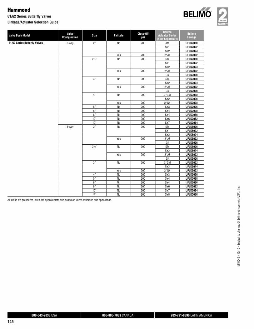
Valve Body Model ValveConfi guration Size Failsafe Close-Off
psi
BelimoActuator Series
(Sold Separately)
BelimoLinkage
800-543-9038 USA 866-805-7089 CANADA 203-791-8396 LATIN AMERICA
145
M40
045
- 10/
10 -
Subj
ect t
o ch
ange
. © B
elim
o Ai
rcon
trols
(USA
), In
c.
Hammond61/62 Series Butterfly Valves
Linkage/Actuator Selection Guide
61/62 Series Butterfl y Valves 2-way 2” No 200 AM UFLK2000SY1 UFLK2022SY2 UFLK2024
Yes 200 2*AF UFLK20022½” No 200 GM UFLK2000
SY1 UFLK2022SY2 UFLK2024
Yes 200 2*AF UFLK2002GK UFLK2000
3” No 200 GM UFLK2000SY2 UFLK2024
Yes 200 2*AF UFLK2002GK UFLK2000
4” No 200 2*GM UFLK2008SY2 UFLK2026
Yes 200 2*GK UFLK20085” No 200 SY3 UFLK20266” No 200 SY4 UFLK20288” No 200 SY4 UFLK203010” No 200 SY6 UFLK203212” No 200 SY7 UFLK2034
3-way 2” No 200 GM UFLK5000SY1 UFLK5022SY2 UFLK5024
Yes 200 2*AF UFLK5002GK UFLK5000
2½” No 200 GM UFLK5000SY2 UFLK5024
Yes 200 2*AF UFLK5002GK UFLK5000
3” No 200 2*GM UFLK5002SY2 UFLK5024
Yes 200 2*GK UFLK50024” No 200 SY3 UFLK50265” No 200 SY4 UFLK50286” No 200 SY4 UFLK50308” No 200 SY6 UFLK503210” No 200 SY7 UFLK503412” No 200 SY8 UFLK5036
All close-off pressures listed are approximate and based on valve condition and application.
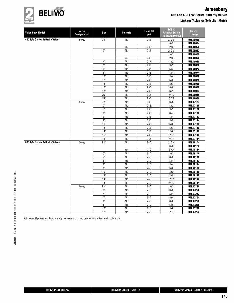
Valve Body Model ValveConfi guration Size Failsafe Close-Off
psi
BelimoActuator Series
(Sold Separately)
BelimoLinkage
800-543-9038 USA 866-805-7089 CANADA 203-791-8396 LATIN AMERICA
146
M40
045
- 10/
10 -
Subj
ect t
o ch
ange
. © B
elim
o Ai
rcon
trols
(USA
), In
c.
Jamesbury815 and 830 L/W Series Butterfly Valves
Linkage/Actuator Selection Guide
815 L/W Series Butterfl y Valves 2-way 2½” No 285 2*GM UFLK8060SY2 UFLK8064
Yes 285 2*GK UFLK80603” No 285 2*GM UFLK8062
SY2 UFLK8066Yes 285 2*GK UFLK8062
4” No 285 SY2 UFLK80685” No 285 SY3 UFLK80706” No 285 SY3 UFLK80728” No 285 SY4 UFLK807410” No 285 SY4 UFLK807612” No 285 SY6 UFLK807814” No 285 SY7 UFLK808016” No 285 SY8 UFLK808218” No 285 SY9 UFLK808420” No 285 SY10 UFLK808624” No 285 SY12 UFLK8088
3-way 2½” No 285 SY2 UFLK71243” No 285 SY2 UFLK71264” No 285 SY3 UFLK71285” No 285 SY4 UFLK71306” No 285 SY4 UFLK71328” No 285 SY5 UFLK713410” No 285 SY6 UFLK713612” No 285 SY7 UFLK713814” No 285 SY9 UFLK714016” No 285 SY10 UFLK714218” No 285 SY11 UFLK7144
830 L/W Series Butterfl y Valves 2-way 2½” No 740 2*GM UFLK8124SY2 UFLK8126
Yes 740 2*GK UFLK81243” No 740 SY2 UFLK81284” No 740 SY3 UFLK81305” No 740 SY4 UFLK81326” No 740 SY4 UFLK81348” No 740 SY6 UFLK813610” No 740 SY8 UFLK813812” No 740 SY8 UFLK814014” No 740 SY11 UFLK814216” No 740 SY12 UFLK8144
3-way 2½” No 740 SY3 UFLK72483” No 740 SY3 UFLK72504” No 740 SY4 UFLK72525” No 740 SY4 UFLK72546” No 740 SY6 UFLK72568” No 740 SY8 UFLK725810” No 740 SY9 UFLK726012” No 740 SY10 UFLK7262
All close-off pressures listed are approximate and based on valve condition and application.
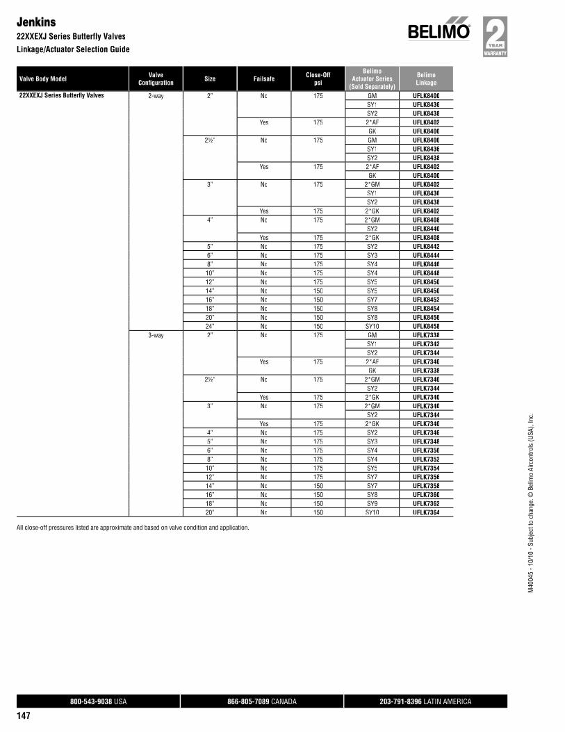
Valve Body Model ValveConfi guration Size Failsafe Close-Off
psi
BelimoActuator Series
(Sold Separately)
BelimoLinkage
800-543-9038 USA 866-805-7089 CANADA 203-791-8396 LATIN AMERICA
147
M40
045
- 10/
10 -
Subj
ect t
o ch
ange
. © B
elim
o Ai
rcon
trols
(USA
), In
c.
Jenkins22XXEXJ Series Butterfly Valves
Linkage/Actuator Selection Guide
22XXEXJ Series Butterfl y Valves 2-way 2” No 175 GM UFLK8400SY1 UFLK8436SY2 UFLK8438
Yes 175 2*AF UFLK8402GK UFLK8400
2½” No 175 GM UFLK8400SY1 UFLK8436SY2 UFLK8438
Yes 175 2*AF UFLK8402GK UFLK8400
3” No 175 2*GM UFLK8402SY1 UFLK8436SY2 UFLK8438
Yes 175 2*GK UFLK84024” No 175 2*GM UFLK8408
SY2 UFLK8440Yes 175 2*GK UFLK8408
5” No 175 SY2 UFLK84426” No 175 SY3 UFLK84448” No 175 SY4 UFLK844610” No 175 SY4 UFLK844812” No 175 SY5 UFLK845014” No 150 SY5 UFLK845016” No 150 SY7 UFLK845218” No 150 SY8 UFLK845420” No 150 SY8 UFLK845624” No 150 SY10 UFLK8458
3-way 2” No 175 GM UFLK7338SY1 UFLK7342SY2 UFLK7344
Yes 175 2*AF UFLK7340GK UFLK7338
2½” No 175 2*GM UFLK7340SY2 UFLK7344
Yes 175 2*GK UFLK73403” No 175 2*GM UFLK7340
SY2 UFLK7344Yes 175 2*GK UFLK7340
4” No 175 SY2 UFLK73465” No 175 SY3 UFLK73486” No 175 SY4 UFLK73508” No 175 SY4 UFLK735210” No 175 SY5 UFLK735412” No 175 SY7 UFLK735614” No 150 SY7 UFLK735816” No 150 SY8 UFLK736018” No 150 SY9 UFLK736220” No 150 SY10 UFLK7364
All close-off pressures listed are approximate and based on valve condition and application.
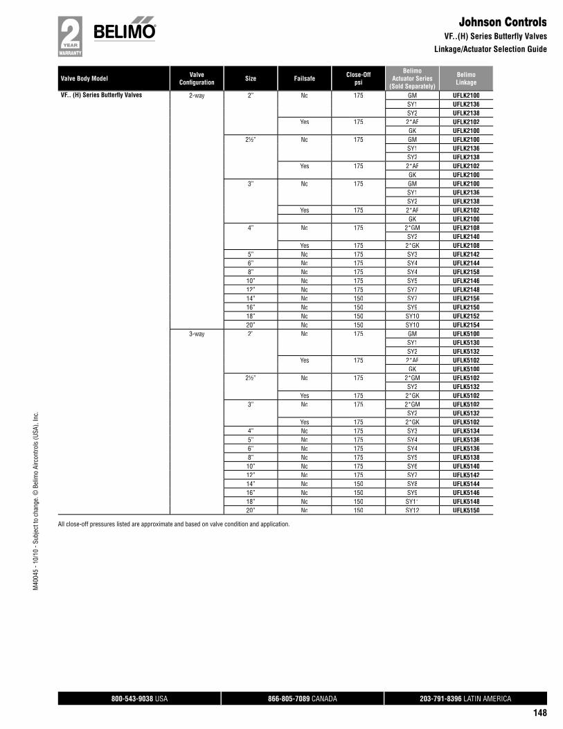
Valve Body Model ValveConfi guration Size Failsafe Close-Off
psi
BelimoActuator Series
(Sold Separately)
BelimoLinkage
800-543-9038 USA 866-805-7089 CANADA 203-791-8396 LATIN AMERICA
148
M40
045
- 10/
10 -
Subj
ect t
o ch
ange
. © B
elim
o Ai
rcon
trols
(USA
), In
c.
Johnson ControlsVF..(H) Series Butterfly Valves
Linkage/Actuator Selection Guide
VF.. (H) Series Butterfl y Valves 2-way 2” No 175 GM UFLK2100SY1 UFLK2136SY2 UFLK2138
Yes 175 2*AF UFLK2102GK UFLK2100
2½” No 175 GM UFLK2100SY1 UFLK2136SY2 UFLK2138
Yes 175 2*AF UFLK2102GK UFLK2100
3” No 175 GM UFLK2100SY1 UFLK2136SY2 UFLK2138
Yes 175 2*AF UFLK2102GK UFLK2100
4” No 175 2*GM UFLK2108SY2 UFLK2140
Yes 175 2*GK UFLK21085” No 175 SY3 UFLK21426” No 175 SY4 UFLK21448” No 175 SY4 UFLK215810” No 175 SY5 UFLK214612” No 175 SY7 UFLK214814” No 150 SY7 UFLK215616” No 150 SY9 UFLK215018” No 150 SY10 UFLK215220” No 150 SY10 UFLK2154
3-way 2” No 175 GM UFLK5100SY1 UFLK5130SY2 UFLK5132
Yes 175 2*AF UFLK5102GK UFLK5100
2½” No 175 2*GM UFLK5102SY2 UFLK5132
Yes 175 2*GK UFLK51023” No 175 2*GM UFLK5102
SY2 UFLK5132Yes 175 2*GK UFLK5102
4” No 175 SY3 UFLK51345” No 175 SY4 UFLK51366” No 175 SY4 UFLK51368” No 175 SY5 UFLK513810” No 175 SY6 UFLK514012” No 175 SY7 UFLK514214” No 150 SY8 UFLK514416” No 150 SY9 UFLK514618” No 150 SY11 UFLK514820” No 150 SY12 UFLK5150
All close-off pressures listed are approximate and based on valve condition and application.
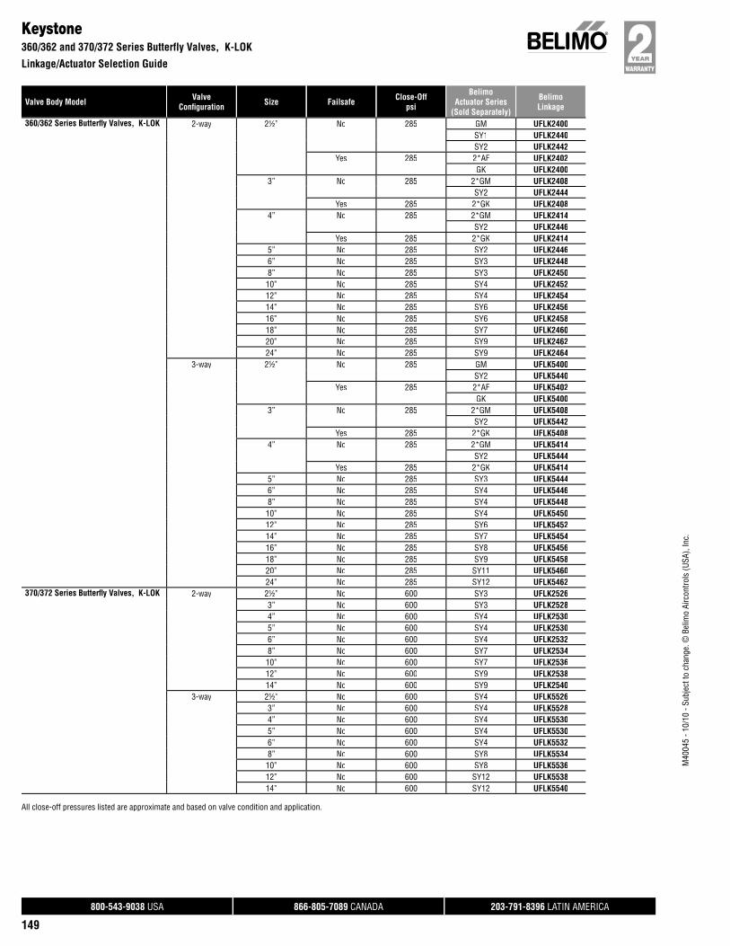
Valve Body Model ValveConfi guration Size Failsafe Close-Off
psi
BelimoActuator Series
(Sold Separately)
BelimoLinkage
800-543-9038 USA 866-805-7089 CANADA 203-791-8396 LATIN AMERICA
149
M40
045
- 10/
10 -
Subj
ect t
o ch
ange
. © B
elim
o Ai
rcon
trols
(USA
), In
c.
Keystone360/362 and 370/372 Series Butterfly Valves, K-LOK
Linkage/Actuator Selection Guide
360/362 Series Butterfl y Valves, K-LOK 2-way 2½” No 285 GM UFLK2400SY1 UFLK2440SY2 UFLK2442
Yes 285 2*AF UFLK2402GK UFLK2400
3” No 285 2*GM UFLK2408SY2 UFLK2444
Yes 285 2*GK UFLK24084” No 285 2*GM UFLK2414
SY2 UFLK2446Yes 285 2*GK UFLK2414
5” No 285 SY2 UFLK24466” No 285 SY3 UFLK24488” No 285 SY3 UFLK245010” No 285 SY4 UFLK245212” No 285 SY4 UFLK245414” No 285 SY6 UFLK245616” No 285 SY6 UFLK245818” No 285 SY7 UFLK246020” No 285 SY9 UFLK246224” No 285 SY9 UFLK2464
3-way 2½” No 285 GM UFLK5400SY2 UFLK5440
Yes 285 2*AF UFLK5402GK UFLK5400
3” No 285 2*GM UFLK5408SY2 UFLK5442
Yes 285 2*GK UFLK54084” No 285 2*GM UFLK5414
SY2 UFLK5444Yes 285 2*GK UFLK5414
5” No 285 SY3 UFLK54446” No 285 SY4 UFLK54468” No 285 SY4 UFLK544810” No 285 SY4 UFLK545012” No 285 SY6 UFLK545214” No 285 SY7 UFLK545416” No 285 SY8 UFLK545618” No 285 SY9 UFLK545820” No 285 SY11 UFLK546024” No 285 SY12 UFLK5462
370/372 Series Butterfl y Valves, K-LOK 2-way 2½” No 600 SY3 UFLK25263” No 600 SY3 UFLK25284” No 600 SY4 UFLK25305” No 600 SY4 UFLK25306” No 600 SY4 UFLK25328” No 600 SY7 UFLK253410” No 600 SY7 UFLK253612” No 600 SY9 UFLK253814” No 600 SY9 UFLK2540
3-way 2½” No 600 SY4 UFLK55263” No 600 SY4 UFLK55284” No 600 SY4 UFLK55305” No 600 SY4 UFLK55306” No 600 SY4 UFLK55328” No 600 SY8 UFLK553410” No 600 SY8 UFLK553612” No 600 SY12 UFLK553814” No 600 SY12 UFLK5540
All close-off pressures listed are approximate and based on valve condition and application.

Valve Body Model ValveConfi guration Size Failsafe Close-Off
psi
BelimoActuator Series
(Sold Separately)
BelimoLinkage
800-543-9038 USA 866-805-7089 CANADA 203-791-8396 LATIN AMERICA
150
M40
045
- 10/
10 -
Subj
ect t
o ch
ange
. © B
elim
o Ai
rcon
trols
(USA
), In
c.
KeystoneAR1/AR2 Series Butterfly Valves
Linkage/Actuator Selection Guide
AR1/AR2 Series Butterfl y Valves 2-way 2” No 175 GM UFLK2300SY1 UFLK2334SY2 UFLK2336
Yes 175 2*AF UFLK2302GK UFLK2300
2½” No 175 GM UFLK2300SY1 UFLK2334SY2 UFLK2336
Yes 175 2*AF UFLK2302GK UFLK2300
3” No 175 GM UFLK2300SY1 UFLK2334SY2 UFLK2336
Yes 175 2*AF UFLK2302GK UFLK2300
4” No 175 2*GM UFLK2308SY2 UFLK2338
Yes 175 2*GK UFLK23085” No 175 SY3 UFLK23406” No 175 SY4 UFLK23568” No 175 SY4 UFLK234210” No 175 SY5 UFLK234412” No 175 SY7 UFLK234614” No 150 SY7 UFLK234816” No 150 SY9 UFLK235018” No 150 SY10 UFLK235220” No 150 SY11 UFLK235224” No 150 SY12 UFLK2354
3-way 2” No 175 GM UFLK5300SY1 UFLK5332SY2 UFLK5334
Yes 175 2*AF UFLK5302GK UFLK5300
2½” No 175 GM UFLK5300SY2 UFLK5334
Yes 175 2*AF UFLK5302GK UFLK5300
3” No 175 2*GM UFLK5302SY2 UFLK5334
Yes 175 2*GK UFLK53024” No 175 SY3 UFLK53365” No 175 SY4 UFLK53386” No 175 SY4 UFLK53388” No 175 SY5 UFLK534010” No 175 SY7 UFLK534212” No 175 SY8 UFLK534414” No 150 SY9 UFLK534616” No 150 SY10 UFLK534818” No 150 SY12 UFLK5350
All close-off pressures listed are approximate and based on valve condition and application.
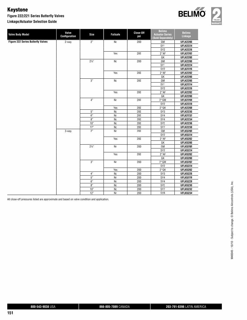
Valve Body Model ValveConfi guration Size Failsafe Close-Off
psi
BelimoActuator Series
(Sold Separately)
BelimoLinkage
800-543-9038 USA 866-805-7089 CANADA 203-791-8396 LATIN AMERICA
151
M40
045
- 10/
10 -
Subj
ect t
o ch
ange
. © B
elim
o Ai
rcon
trols
(USA
), In
c.
KeystoneFigure 222/221 Series Butterfly Valves
Linkage/Actuator Selection Guide
Figure 222 Series Butterfl y Valves 2-way 2” No 200 GM UFLK2200SY1 UFLK2224SY2 UFLK2226
Yes 200 2*AF UFLK2202GK UFLK2200
2½” No 200 GM UFLK2200SY1 UFLK2224SY2 UFLK2226
Yes 200 2*AF UFLK2202GK UFLK2200
3” No 200 GM UFLK2200SY1 UFLK2224SY2 UFLK2226
Yes 200 2*AF UFLK2202GK UFLK2200
4” No 200 2*GM UFLK2208SY2 UFLK2228
Yes 200 2*GK UFLK22085” No 200 SY3 UFLK22306” No 200 SY4 UFLK22328” No 200 SY4 UFLK223410” No 200 SY5 UFLK223612” No 200 SY7 UFLK2238
3-way 2” No 200 GM UFLK5200SY2 UFLK5224
Yes 200 2*AF UFLK5202GK UFLK5200
2½” No 200 GM UFLK5200SY2 UFLK5224
Yes 200 2*AF UFLK5202GK UFLK5200
3” No 200 2*GM UFLK5202SY2 UFLK5224
Yes 200 2*GK UFLK52024” No 200 SY3 UFLK52265” No 200 SY4 UFLK52286” No 200 SY4 UFLK52288” No 200 SY5 UFLK523010” No 200 SY7 UFLK523212” No 200 SY8 UFLK5234
All close-off pressures listed are approximate and based on valve condition and application.
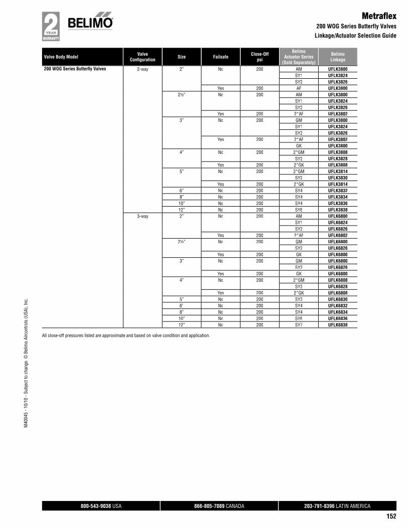
Valve Body Model ValveConfi guration Size Failsafe Close-Off
psi
BelimoActuator Series
(Sold Separately)
BelimoLinkage
800-543-9038 USA 866-805-7089 CANADA 203-791-8396 LATIN AMERICA
152
M40
045
- 10/
10 -
Subj
ect t
o ch
ange
. © B
elim
o Ai
rcon
trols
(USA
), In
c.
Metrafl ex200 WOG Series Butterfly Valves
Linkage/Actuator Selection Guide
200 WOG Series Butterfl y Valves 2-way 2” No 200 AM UFLK3800SY1 UFLK3824SY2 UFLK3826
Yes 200 AF UFLK38002½” No 200 AM UFLK3800
SY1 UFLK3824SY2 UFLK3826
Yes 200 2*AF UFLK38023” No 200 GM UFLK3800
SY1 UFLK3824SY2 UFLK3826
Yes 200 2*AF UFLK3802GK UFLK3800
4” No 200 2*GM UFLK3808SY2 UFLK3828
Yes 200 2*GK UFLK38085” No 200 2*GM UFLK3814
SY2 UFLK3830Yes 200 2*GK UFLK3814
6” No 200 SY4 UFLK38328” No 200 SY4 UFLK383410” No 200 SY4 UFLK383612” No 200 SY6 UFLK3838
3-way 2” No 200 AM UFLK6800SY1 UFLK6824SY2 UFLK6826
Yes 200 2*AF UFLK68022½” No 200 GM UFLK6800
SY2 UFLK6826Yes 200 GK UFLK6800
3” No 200 GM UFLK6800SY2 UFLK6826
Yes 200 GK UFLK68004” No 200 2*GM UFLK6808
SY3 UFLK6828Yes 200 2*GK UFLK6808
5” No 200 SY3 UFLK68306” No 200 SY4 UFLK68328” No 200 SY4 UFLK683410” No 200 SY6 UFLK683612” No 200 SY7 UFLK6838
All close-off pressures listed are approximate and based on valve condition and application.
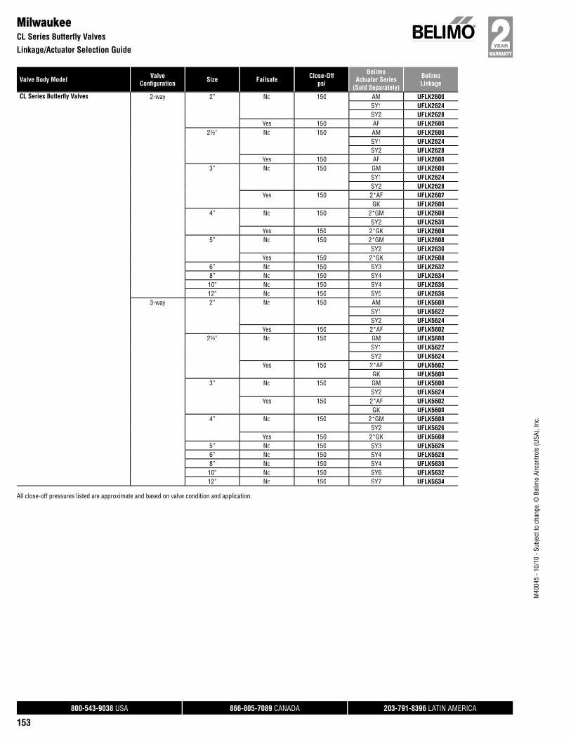
Valve Body Model ValveConfi guration Size Failsafe Close-Off
psi
BelimoActuator Series
(Sold Separately)
BelimoLinkage
800-543-9038 USA 866-805-7089 CANADA 203-791-8396 LATIN AMERICA
153
M40
045
- 10/
10 -
Subj
ect t
o ch
ange
. © B
elim
o Ai
rcon
trols
(USA
), In
c.
MilwaukeeCL Series Butterfly Valves
Linkage/Actuator Selection Guide
CL Series Butterfl y Valves 2-way 2” No 150 AM UFLK2600SY1 UFLK2624SY2 UFLK2628
Yes 150 AF UFLK26002½” No 150 AM UFLK2600
SY1 UFLK2624SY2 UFLK2628
Yes 150 AF UFLK26003” No 150 GM UFLK2600
SY1 UFLK2624SY2 UFLK2628
Yes 150 2*AF UFLK2602GK UFLK2600
4” No 150 2*GM UFLK2608SY2 UFLK2630
Yes 150 2*GK UFLK26085” No 150 2*GM UFLK2608
SY2 UFLK2630Yes 150 2*GK UFLK2608
6” No 150 SY3 UFLK26328” No 150 SY4 UFLK263410” No 150 SY4 UFLK263612” No 150 SY5 UFLK2636
3-way 2” No 150 AM UFLK5600SY1 UFLK5622SY2 UFLK5624
Yes 150 2*AF UFLK56022½” No 150 GM UFLK5600
SY1 UFLK5622SY2 UFLK5624
Yes 150 2*AF UFLK5602GK UFLK5600
3” No 150 GM UFLK5600SY2 UFLK5624
Yes 150 2*AF UFLK5602GK UFLK5600
4” No 150 2*GM UFLK5608SY2 UFLK5626
Yes 150 2*GK UFLK56085” No 150 SY3 UFLK56266” No 150 SY4 UFLK56288” No 150 SY4 UFLK563010” No 150 SY6 UFLK563212” No 150 SY7 UFLK5634
All close-off pressures listed are approximate and based on valve condition and application.

Valve Body Model ValveConfi guration Size Failsafe Close-Off
psi
BelimoActuator Series
(Sold Separately)
BelimoLinkage
800-543-9038 USA 866-805-7089 CANADA 203-791-8396 LATIN AMERICA
154
M40
045
- 10/
10 -
Subj
ect t
o ch
ange
. © B
elim
o Ai
rcon
trols
(USA
), In
c.
MilwaukeeML Series Butterfly Valves
Linkage/Actuator Selection Guide
ML Series Butterfl y Valves 2-way 2” No 150 AM UFLK2700SY1 UFLK2732SY2 UFLK2734
Yes 150 AF UFLK27002½” No 150 AM UFLK2700
SY1 UFLK2732SY2 UFLK2734
Yes 150 AF UFLK27003” No 150 GM UFLK2700
SY1 UFLK2732SY2 UFLK2734
Yes 150 2*AF UFLK2702GK UFLK2700
4” No 150 2*GM UFLK2708SY2 UFLK2736
Yes 150 2*GK UFLK27085” No 150 2*GM UFLK2708
SY2 UFLK2736Yes 150 2*GK UFLK2708
6” No 150 SY3 UFLK27388” No 150 SY4 UFLK274010” No 150 SY4 UFLK274212” No 150 SY5 UFLK274214” No 150 SY7 UFLK274416” No 150 SY7 UFLK274418” No 150 SY8 UFLK274620” No 150 SY9 UFLK274824” No 150 SY10 UFLK2750
3-way 2” No 150 AM UFLK5700SY1 UFLK5732SY2 UFLK5734
Yes 150 2*AF UFLK57022½” No 150 AM UFLK5700
SY1 UFLK5732SY2 UFLK5734
Yes 150 2*AF UFLK57023” No 150 GM UFLK5700
SY2 UFLK5734Yes 150 2*AF UFLK5702
GK UFLK57004” No 150 2*GM UFLK5708
SY2 UFLK5736Yes 150 2*GK UFLK5708
5” No 150 SY3 UFLK57366” No 150 SY4 UFLK57388” No 150 SY4 UFLK574010” No 150 SY6 UFLK574212” No 150 SY7 UFLK574414” No 150 SY8 UFLK574616” No 150 SY9 UFLK574818” No 150 SY10 UFLK575020” No 150 SY11 UFLK5750
All close-off pressures listed are approximate and based on valve condition and application.

Valve Body Model ValveConfi guration Size Failsafe Close-Off
psi
BelimoActuator Series
(Sold Separately)
BelimoLinkage
800-543-9038 USA 866-805-7089 CANADA 203-791-8396 LATIN AMERICA
155
M40
045
- 10/
10 -
Subj
ect t
o ch
ange
. © B
elim
o Ai
rcon
trols
(USA
), In
c.
Mueller65/66 Series Butterfly Valves
Linkage/Actuator Selection Guide
65/66 Series Butterfl y Valves 2-way 2” No 150 GM UFLK2800SY1 UFLK2834SY2 UFLK2836
Yes 150 2*AF UFLK2802GK UFLK2800
2½” No 150 GM UFLK2800SY1 UFLK2834SY2 UFLK2836
Yes 150 GK UFLK28003” No 150 2*GM UFLK2802
SY2 UFLK2836Yes 150 2*GK UFLK2802
4” No 150 2*GM UFLK2808SY2 UFLK2838
Yes 150 2*GK UFLK28085” No 150 SY3 UFLK28406” No 150 SY4 UFLK28428” No 150 SY4 UFLK284410” No 150 SY5 UFLK284612” No 150 SY7 UFLK284814” No 150 SY7 UFLK285024” No 150 SY12 UFLK2856
3-way 2” No 150 2*GM UFLK5800SY2 UFLK5834
Yes 150 2*AF UFLK58022½” No 150 GM UFLK5800
SY2 UFLK5834Yes 150 GK UFLK5800
3” No 150 2*GM UFLK5802SY2 UFLK5834
Yes 150 2*GK UFLK58024” No 150 SY3 UFLK58365” No 150 SY4 UFLK58386” No 150 SY4 UFLK58388” No 150 SY5 UFLK584010” No 150 SY7 UFLK584212” No 150 SY8 UFLK584414” No 150 SY9 UFLK5846
All close-off pressures listed are approximate and based on valve condition and application.
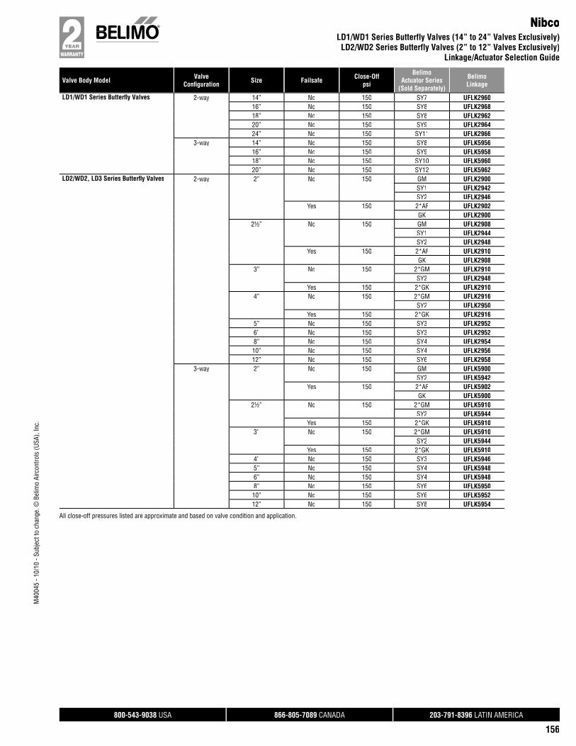
Valve Body Model ValveConfi guration Size Failsafe Close-Off
psi
BelimoActuator Series
(Sold Separately)
BelimoLinkage
800-543-9038 USA 866-805-7089 CANADA 203-791-8396 LATIN AMERICA
156
M40
045
- 10/
10 -
Subj
ect t
o ch
ange
. © B
elim
o Ai
rcon
trols
(USA
), In
c.
NibcoLD1/WD1 Series Butterfly Valves (14” to 24” Valves Exclusively)LD2/WD2 Series Butterfly Valves (2” to 12” Valves Exclusively)
Linkage/Actuator Selection Guide
LD1/WD1 Series Butterfl y Valves 2-way 14” No 150 SY7 UFLK296016” No 150 SY8 UFLK296818” No 150 SY8 UFLK296220” No 150 SY9 UFLK296424” No 150 SY11 UFLK2966
3-way 14” No 150 SY8 UFLK595616” No 150 SY9 UFLK595818” No 150 SY10 UFLK596020” No 150 SY12 UFLK5962
LD2/WD2, LD3 Series Butterfl y Valves 2-way 2” No 150 GM UFLK2900SY1 UFLK2942SY2 UFLK2946
Yes 150 2*AF UFLK2902GK UFLK2900
2½” No 150 GM UFLK2908SY1 UFLK2944SY2 UFLK2948
Yes 150 2*AF UFLK2910GK UFLK2908
3” No 150 2*GM UFLK2910SY2 UFLK2948
Yes 150 2*GK UFLK29104” No 150 2*GM UFLK2916
SY2 UFLK2950Yes 150 2*GK UFLK2916
5” No 150 SY3 UFLK29526” No 150 SY3 UFLK29528” No 150 SY4 UFLK295410” No 150 SY4 UFLK295612” No 150 SY6 UFLK2958
3-way 2” No 150 GM UFLK5900SY2 UFLK5942
Yes 150 2*AF UFLK5902GK UFLK5900
2½” No 150 2*GM UFLK5910SY2 UFLK5944
Yes 150 2*GK UFLK59103” No 150 2*GM UFLK5910
SY2 UFLK5944Yes 150 2*GK UFLK5910
4” No 150 SY3 UFLK59465” No 150 SY4 UFLK59486” No 150 SY4 UFLK59488” No 150 SY6 UFLK595010” No 150 SY6 UFLK595212” No 150 SY8 UFLK5954
All close-off pressures listed are approximate and based on valve condition and application.
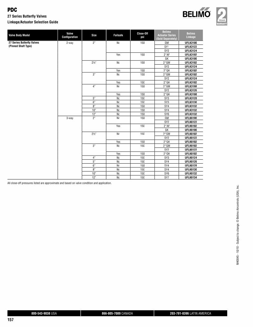
Valve Body Model ValveConfi guration Size Failsafe Close-Off
psi
BelimoActuator Series
(Sold Separately)
BelimoLinkage
800-543-9038 USA 866-805-7089 CANADA 203-791-8396 LATIN AMERICA
157
M40
045
- 10/
10 -
Subj
ect t
o ch
ange
. © B
elim
o Ai
rcon
trols
(USA
), In
c.
PDC27 Series Butterfly Valves
Linkage/Actuator Selection Guide
27 Series Butterfl y Valves(Pinned Shaft Type)
2-way 2” No 150 GM UFLK3100SY1 UFLK3122SY2 UFLK3124
Yes 150 2*AF UFLK3102GK UFLK3100
2½” No 150 2*GM UFLK3102SY2 UFLK3124
Yes 150 2*GK UFLK31023” No 150 2*GM UFLK3102
SY2 UFLK3124Yes 150 2*GK UFLK3102
4” No 150 2*GM UFLK3108SY2 UFLK3126
Yes 150 2*GK UFLK31085” No 150 SY3 UFLK31286” No 150 SY3 UFLK31308” No 150 SY4 UFLK313210” No 150 SY4 UFLK313212” No 150 SY6 UFLK3132
3-way 2” No 150 GM UFLK6100SY2 UFLK6122
Yes 150 2*AF UFLK6102GK UFLK6100
2½” No 150 2*GM UFLK6102SY2 UFLK6122
Yes 150 2*GK UFLK61023” No 150 2*GM UFLK6102
SY2 UFLK6122Yes 150 2*GK UFLK6102
4” No 150 SY3 UFLK61245” No 150 SY4 UFLK61266” No 150 SY4 UFLK61288” No 150 SY4 UFLK613010” No 150 SY6 UFLK613212” No 150 SY7 UFLK6134
All close-off pressures listed are approximate and based on valve condition and application.
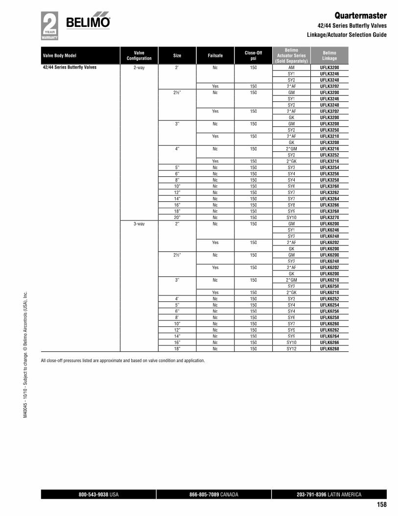
Valve Body Model ValveConfi guration Size Failsafe Close-Off
psi
BelimoActuator Series
(Sold Separately)
BelimoLinkage
800-543-9038 USA 866-805-7089 CANADA 203-791-8396 LATIN AMERICA
158
M40
045
- 10/
10 -
Subj
ect t
o ch
ange
. © B
elim
o Ai
rcon
trols
(USA
), In
c.
Quartermaster42/44 Series Butterfly Valves
Linkage/Actuator Selection Guide
42/44 Series Butterfl y Valves 2-way 2” No 150 AM UFLK3200SY1 UFLK3246SY2 UFLK3248
Yes 150 2*AF UFLK32022½” No 150 GM UFLK3200
SY1 UFLK3246SY2 UFLK3248
Yes 150 2*AF UFLK3202GK UFLK3200
3” No 150 GM UFLK3208SY2 UFLK3250
Yes 150 2*AF UFLK3210GK UFLK3208
4” No 150 2*GM UFLK3216SY2 UFLK3252
Yes 150 2*GK UFLK32165” No 150 SY3 UFLK32546” No 150 SY4 UFLK32568” No 150 SY4 UFLK325810” No 150 SY6 UFLK326012” No 150 SY7 UFLK326214” No 150 SY7 UFLK326416” No 150 SY8 UFLK326618” No 150 SY9 UFLK326820” No 150 SY10 UFLK3270
3-way 2” No 150 GM UFLK6200SY1 UFLK6246SY2 UFLK6248
Yes 150 2*AF UFLK6202GK UFLK6200
2½” No 150 GM UFLK6200SY2 UFLK6248
Yes 150 2*AF UFLK6202GK UFLK6200
3” No 150 2*GM UFLK6210SY2 UFLK6250
Yes 150 2*GK UFLK62104” No 150 SY3 UFLK62525” No 150 SY4 UFLK62546” No 150 SY4 UFLK62568” No 150 SY6 UFLK625810” No 150 SY7 UFLK626012” No 150 SY9 UFLK626214” No 150 SY9 UFLK626416” No 150 SY10 UFLK626618” No 150 SY12 UFLK6268
All close-off pressures listed are approximate and based on valve condition and application.
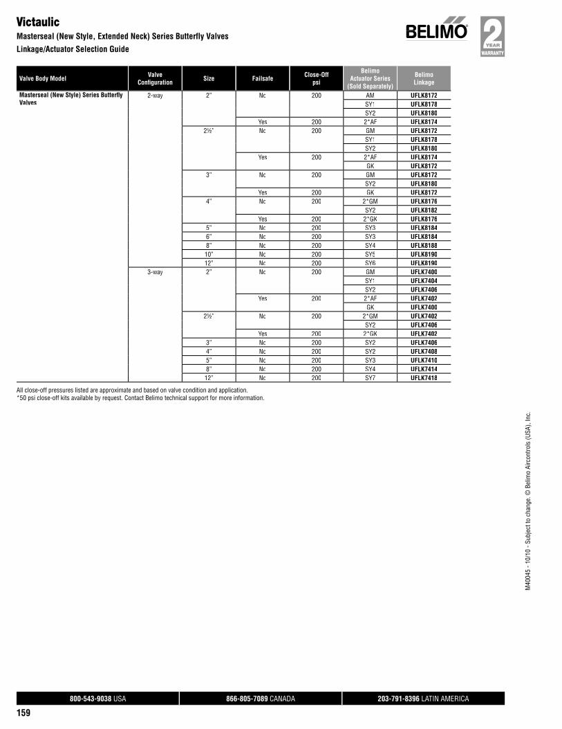
Valve Body Model ValveConfi guration Size Failsafe Close-Off
psi
BelimoActuator Series
(Sold Separately)
BelimoLinkage
800-543-9038 USA 866-805-7089 CANADA 203-791-8396 LATIN AMERICA
159
M40
045
- 10/
10 -
Subj
ect t
o ch
ange
. © B
elim
o Ai
rcon
trols
(USA
), In
c.
VictaulicMasterseal (New Style, Extended Neck) Series Butterfly Valves
Linkage/Actuator Selection Guide
Masterseal (New Style) Series Butterfl yValves
2-way 2” No 200 AM UFLK8172SY1 UFLK8178SY2 UFLK8180
Yes 200 2*AF UFLK81742½” No 200 GM UFLK8172
SY1 UFLK8178SY2 UFLK8180
Yes 200 2*AF UFLK8174GK UFLK8172
3” No 200 GM UFLK8172SY2 UFLK8180
Yes 200 GK UFLK81724” No 200 2*GM UFLK8176
SY2 UFLK8182Yes 200 2*GK UFLK8176
5” No 200 SY3 UFLK81846” No 200 SY3 UFLK81848” No 200 SY4 UFLK818810” No 200 SY5 UFLK819012” No 200 SY6 UFLK8190
3-way 2” No 200 GM UFLK7400SY1 UFLK7404SY2 UFLK7406
Yes 200 2*AF UFLK7402GK UFLK7400
2½” No 200 2*GM UFLK7402SY2 UFLK7406
Yes 200 2*GK UFLK74023” No 200 SY2 UFLK74064” No 200 SY2 UFLK74085” No 200 SY3 UFLK74108” No 200 SY4 UFLK741412” No 200 SY7 UFLK7418
All close-off pressures listed are approximate and based on valve condition and application.*50 psi close-off kits available by request. Contact Belimo technical support for more information.

Valve Body Model ValveConfi guration Size Failsafe Close-Off
psi
BelimoActuator Series
(Sold Separately)
BelimoLinkage
800-543-9038 USA 866-805-7089 CANADA 203-791-8396 LATIN AMERICA
160
M40
045
- 10/
10 -
Subj
ect t
o ch
ange
. © B
elim
o Ai
rcon
trols
(USA
), In
c.
VictaulicVic300 (Old Style) Series Butterfly Valves
Linkage/Actuator Selection Guide
Vic300 (Old Style) Series Butterfl y Valves
2-way 2” No 300 AM UFLK3300SY1 UFLK3338SY2 UFLK3342
Yes 300 AF UFLK33002½” No 300 AM UFLK3308
SY1 UFLK3340SY2 UFLK3344
Yes 300 AF UFLK33083” No 300 GM UFLK3308
SY1 UFLK3340SY2 UFLK3344
Yes 300 2*AF UFLK3310GK UFLK3308
4” No 300 2*GM UFLK3316SY2 UFLK3346
Yes 300 2*GK UFLK33165” No 300 SY2 UFLK33486” No 300 SY3 UFLK33508” No 300 SY4 UFLK335210” No 300 SY4 UFLK335412” No 300 SY4 UFLK3356
3-way 2” No 300 GM UFLK6300SY1 UFLK6336SY2 UFLK6340
Yes 300 AF UFLK6300GK UFLK6300
2½” No 300 GM UFLK6308SY1 UFLK6338SY2 UFLK6342
Yes 300 2*AF UFLK6310GK UFLK6308
3” No 300 SY2 UFLK63424” No 300 SY3 UFLK63445” No 300 SY3 UFLK63466” No 300 SY4 UFLK63488” No 300 SY4 UFLK635010” No 300 SY5 UFLK635212” No 300 SY6 UFLK6354
All close-off pressures listed are approximate and based on valve condition and application.
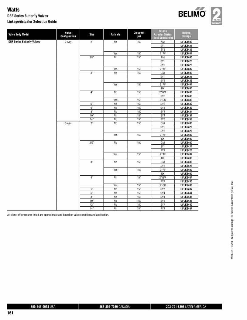
Valve Body Model ValveConfi guration Size Failsafe Close-Off
psi
BelimoActuator Series
(Sold Separately)
BelimoLinkage
800-543-9038 USA 866-805-7089 CANADA 203-791-8396 LATIN AMERICA
161
M40
045
- 10/
10 -
Subj
ect t
o ch
ange
. © B
elim
o Ai
rcon
trols
(USA
), In
c.
WattsDBF Series Butterfly Valves
Linkage/Actuator Selection Guide
DBF Series Butterfl y Valves 2-way 2” No 150 AM UFLK3400SY1 UFLK3426SY2 UFLK3428
Yes 150 2*AF UFLK34022½” No 150 AM UFLK3400
SY1 UFLK3426SY2 UFLK3428
Yes 150 2*AF UFLK34023” No 150 GM UFLK3400
SY1 UFLK3426SY2 UFLK3428
Yes 150 2*AF UFLK3402GK UFLK3400
4” No 150 2*GM UFLK3408SY2 UFLK3430
Yes 150 2*GK UFLK34085” No 150 SY2 UFLK34326” No 150 SY3 UFLK34328” No 150 SY4 UFLK343410” No 150 SY4 UFLK343614” No 150 SY6 UFLK3438
3-way 2” No 150 GM UFLK6400SY1 UFLK6426SY2 UFLK6428
Yes 150 2*AF UFLK6402GK UFLK6400
2½” No 150 GM UFLK6400SY1 UFLK6426SY2 UFLK6428
Yes 150 2*AF UFLK6402GK UFLK6400
3” No 150 GM UFLK6400SY2 UFLK6428
Yes 150 2*AF UFLK6402GK UFLK6400
4” No 150 2*GM UFLK6408SY2 UFLK6430
Yes 150 2*GK UFLK64085” No 150 SY3 UFLK64326” No 150 SY4 UFLK64348” No 150 SY4 UFLK643610” No 150 SY6 UFLK643812” No 150 SY7 UFLK644014” No 150 SY8 UFLK6442
All close-off pressures listed are approximate and based on valve condition and application.
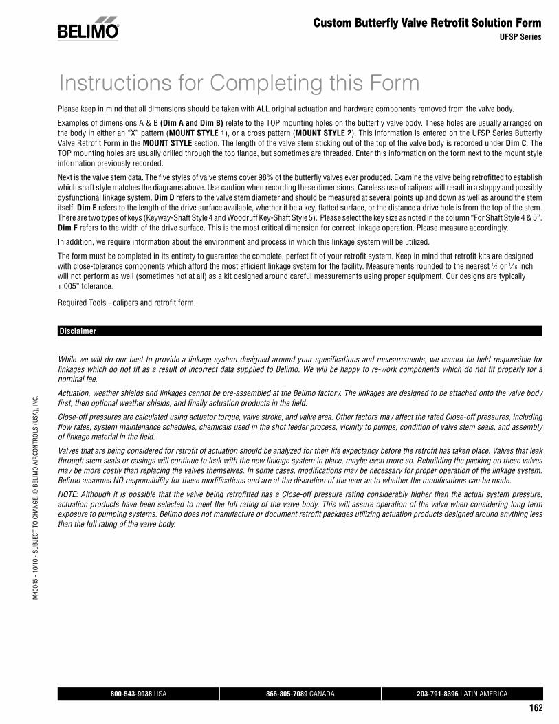
800-543-9038 USA 866-805-7089 CANADA 203-791-8396 LATIN AMERICA
162
Please keep in mind that all dimensions should be taken with ALL original actuation and hardware components removed from the valve body.
Examples of dimensions A & B (Dim A and Dim B) relate to the TOP mounting holes on the butterfl y valve body. These holes are usually arranged onthe body in either an “X” pattern (MOUNT STYLE 1), or a cross pattern (MOUNT STYLE 2). This information is entered on the UFSP Series Butterfl y Valve Retrofi t Form in the MOUNT STYLE section. The length of the valve stem sticking out of the top of the valve body is recorded under Dim C. TheTOP mounting holes are usually drilled through the top fl ange, but sometimes are threaded. Enter this information on the form next to the mount styleinformation previously recorded.
Next is the valve stem data. The fi ve styles of valve stems cover 98% of the butterfl y valves ever produced. Examine the valve being retrofi tted to establishwhich shaft style matches the diagrams above. Use caution when recording these dimensions. Careless use of calipers will result in a sloppy and possibly dysfunctional linkage system. Dim D refers to the valve stem diameter and should be measured at several points up and down as well as around the stemitself. Dim E refers to the length of the drive surface available, whether it be a key, fl atted surface, or the distance a drive hole is from the top of the stem. There are two types of keys (Keyway-Shaft Style 4 and Woodruff Key-Shaft Style 5). Please select the key size as noted in the column “For Shaft Style 4 & 5”.Dim F refers to the width of the drive surface. This is the most critical dimension for correct linkage operation. Please measure accordingly.
In addition, we require information about the environment and process in which this linkage system will be utilized.
The form must be completed in its entirety to guarantee the complete, perfect fi t of your retrofi t system. Keep in mind that retrofi t kits are designed with close-tolerance components which afford the most effi cient linkage system for the facility. Measurements rounded to the nearest 1/8// or 1/16// inch will not perform as well (sometimes not at all) as a kit designed around careful measurements using proper equipment. Our designs are typically+.005” tolerance.
Required Tools - calipers and retrofi t form.
Disclaimer
While we will do our best to provide a linkage system designed around your specifi cations and measurements, we cannot be held responsible for linkages which do not fi t as a result of incorrect data supplied to Belimo. We will be happy to re-work components which do not fi t properly for a nominal fee.
Actuation, weather shields and linkages cannot be pre-assembled at the Belimo factory. The linkages are designed to be attached onto the valve body fi rst, then optional weather shields, and fi nally actuation products in the fi eld.
Close-off pressures are calculated using actuator torque, valve stroke, and valve area. Other factors may affect the rated Close-off pressures, including fl ow rates, system maintenance schedules, chemicals used in the shot feeder process, vicinity to pumps, condition of valve stem seals, and assembly of linkage material in the fi eld.
Valves that are being considered for retrofi t of actuation should be analyzed for their life expectancy before the retrofi t has taken place. Valves that leak through stem seals or casings will continue to leak with the new linkage system in place, maybe even more so. Rebuilding the packing on these valves may be more costly than replacing the valves themselves. In some cases, modifi cations may be necessary for proper operation of the linkage system.Belimo assumes NO responsibility for these modifi cations and are at the discretion of the user as to whether the modifi cations can be made.
NOTE: Although it is possible that the valve being retrofi tted has a Close-off pressure rating considerably higher than the actual system pressure, :actuation products have been selected to meet the full rating of the valve body. This will assure operation of the valve when considering long term exposure to pumping systems. Belimo does not manufacture or document retrofi t packages utilizing actuation products designed around anything less than the full rating of the valve body.
Custom Butterfl y Valve Retrofi t Solution FormUFSP Series
Instructions for Completing this Form
M40
045
- 10/
10 -
SUBJ
ECT
TO C
HANG
E. ©
BEL
IMO
AIRC
ONTR
OLS
(USA
), IN
C.
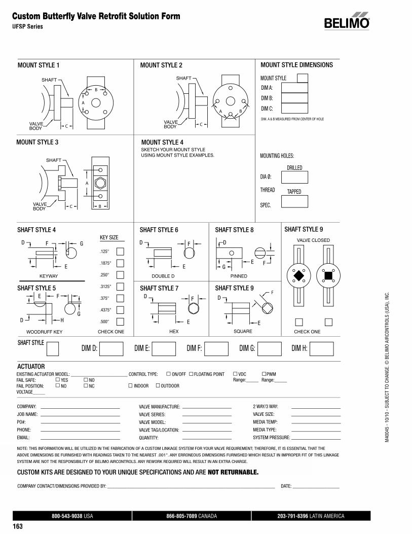
800-543-9038 USA 866-805-7089 CANADA 203-791-8396 LATIN AMERICA
163
Custom Butterfl y Valve Retrofi t Solution FormUFSP Series
EXISTING ACTUATOR MODEL: _______________________ CONTROL TYPE: ON/OFF FLOATING POINT VDC PWM FAIL SAFE: YES NOFAIL POSITION: NO NC VOLTAGE_____
ACTUATOR
MOUNT STYLE 1 MOUNT STYLE 2
MOUNT STYLE 3
DIM F:DIM E:DIM D:SHAFT STYLE
DIM G: DIM H:
2 WAY/3 WAY:
VALVE SIZE:
MEDIA TEMP:
MEDIA TYPE:
SYSTEM PRESSURE:
VALVE MANUFACTURE:
VALVE SERIES:
VALVE MODEL:
VALVE TAG/LOCATION:
QUANTITY:
Range:_____
COMPANY:
JOB NAME:
PO#:
PHONE:
EMAIL:
NOTE: THIS INFORMATION WILL BE UTILIZED IN THE FABRICATION OF A CUSTOM LINKAGE SYSTEM FOR YOUR VALVE REQUIREMENT; THEREFORE, IT IS ESSENTIAL THAT THE
ABOVE DIMENSIONS BE FURNISHED WITH READINGS TAKEN TO THE NEAREST .001". ANY ERRONEOUS DIMENSIONS FURNISHED WHICH RESULT IN IMPROPER FIT OF THIS LINKAGE
SYSTEM ARE NOT THE RESPONSIBILITY OF BELIMO AIRCONTROLS. ANY REWORK REQUIRED WILL RESULT IN AN EXTRA CHARGE.
CUSTOM KITS ARE DESIGNED TO YOUR UNIQUE SPECIFICATIONS AND ARE NOT RETURNABLE. COMPANY CONTACT/DIMENSIONS PROVIDED BY: ____________________________________________________________________ DATE: ___________________
INDOOR OUTDOORRange:_____
VALVE
B
A
SHAFT
CBODY
B
A
SHAFT
VALVEBODY C
BA
CBODYVALVE
SHAFT
SHAFT STYLE 9
VALVE CLOSED
CHECK ONE
FG
PINNED
SHAFT STYLE 8
E
DFD
E
SHAFT STYLE 6
DOUBLE DKEYWAY
SHAFT STYLE 4
GF
E
D
D
E
SHAFT STYLE 9
SQUARE
F
KEY SIZE
.125"
.1875"
.250"
.3125"
.375"
.4375"
.500"H
E
D
F
G
SHAFT STYLE 5
WOODRUFF KEY
F
E
SHAFT STYLE 7
HEXCHECK ONE
DIA Ø:
DRILLED
MOUNTING HOLES:
MOUNT STYLE
DIM C:
DIM B:
DIM A:
THREAD
SPEC.
DIM. A & B MEASURED FROM CENTER OF HOLE
TAPPED
MOUNT STYLE DIMENSIONS
MOUNT STYLE 4 SKETCH YOUR MOUNT STYLE USING MOUNT STYLE EXAMPLES.
D
M40
045
- 10/
10 -
SUBJ
ECT
TO C
HANG
E. ©
BEL
IMO
AIRC
ONTR
OLS
(USA
), IN
C.
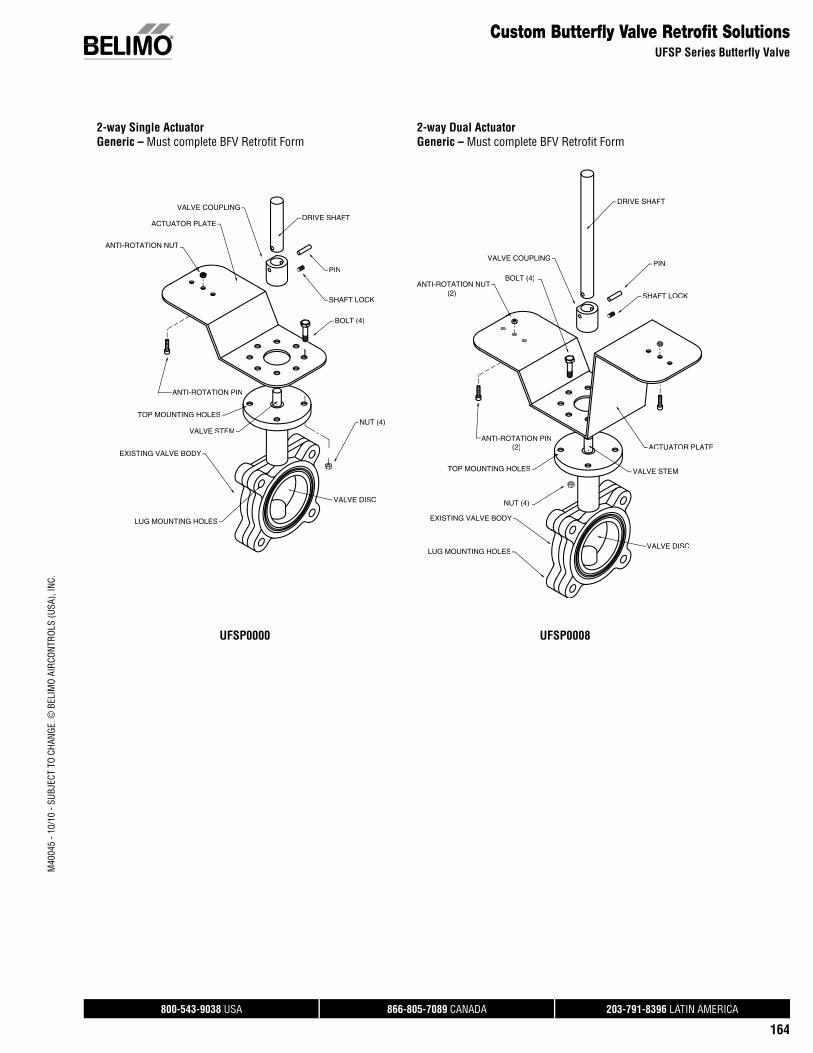
800-543-9038 USA 866-805-7089 CANADA 203-791-8396 LATIN AMERICA
164
M40
045
- 10/
10 -
SUBJ
ECT
TO C
HANG
E. ©
BEL
IMO
AIRC
ONTR
OLS
(USA
), IN
C.
Custom Butterfly Valve Retrofit SolutionsUFSP Series Butterfly Valve
2-way Single ActuatorGeneric – Must complete BFV Retrofit Form
2-way Dual ActuatorGeneric – Must complete BFV Retrofit Form
DRIVE SHAFT
PIN
SHAFT LOCK
ANTI-ROTATION NUT
ANTI-ROTATION PIN
ACTUATOR PLATE
BOLT (4)
NUT (4)
EXISTING VALVE BODY
VALVE STEM
TOP MOUNTING HOLES
VALVE DISC
LUG MOUNTING HOLES
VALVE COUPLING
EXISTING VALVE BODY
LUG MOUNTING HOLESVALVE DISC
TOP MOUNTING HOLES
ANTI-ROTATION PIN
NUT (4)
ANTI-ROTATION NUTBOLT (4)
VALVE STEM
ACTUATOR PLATE
SHAFT LOCK
PIN
DRIVE SHAFT
VALVE COUPLING
(2)
(2)
UFSP0000 UFSP0008
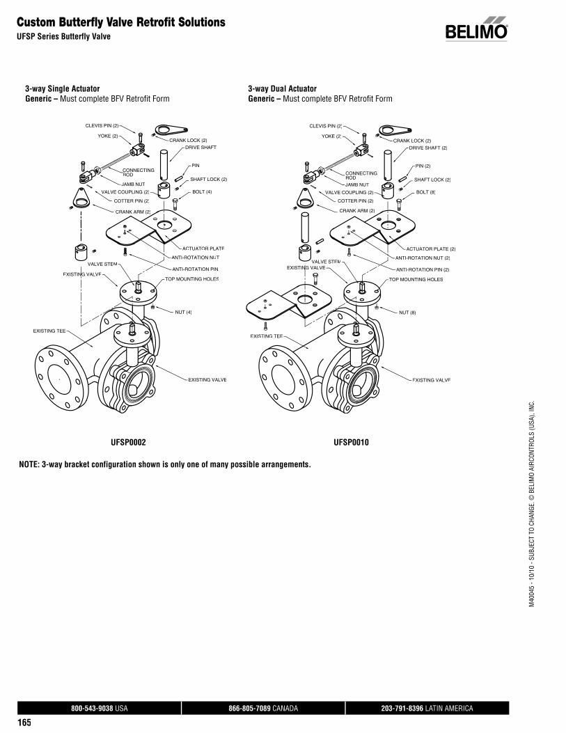
800-543-9038 USA 866-805-7089 CANADA 203-791-8396 LATIN AMERICA
165
M40
045
- 10/
10 -
SUBJ
ECT
TO C
HANG
E. ©
BEL
IMO
AIRC
ONTR
OLS
(USA
), IN
C.
Custom Butterfly Valve Retrofit SolutionsUFSP Series Butterfly Valve
3-way Single ActuatorGeneric – Must complete BFV Retrofit Form
3-way Dual ActuatorGeneric – Must complete BFV Retrofit Form
EXISTING VALVE
CRANK ARM (2)
COTTER PIN (2)
CONNECTINGROD
EXISTING VALVE
EXISTING TEE
ANTI-ROTATION NUT
NUT (4)
TOP MOUNTING HOLES
ANTI-ROTATION PIN
ACTUATOR PLATE
BOLT (4)
SHAFT LOCK (2)
PIN
CLEVIS PIN (2)
YOKE (2)
DRIVE SHAFT
CRANK LOCK (2)
JAMB NUT
VALVE COUPLING (2)
VALVE STEM
EXISTING VALVE
NUT (8)
EXISTING VALVEN
TOP MOUNTING HOLES
ANTI-ROTATION PIN (2)
ANTI-ROTATION NUT (2)
ACTUATOR PLATE (2)
CRANK ARM (2)
COTTER PIN (2)
CONNECTINGROD
YOKE (2)
DRIVE SHAFT (2)
PIN (2)
SHAFT LOCK (2)
BOLT (8)
CLEVIS PIN (2)
EXISTING TEE
CRANK LOCK (2)
VALVE STEM
VALVE COUPLING (2)
JAMB NUT
UFSP0002 UFSP0010
NOTE: 3-way bracket configuration shown is only one of many possible arrangements.
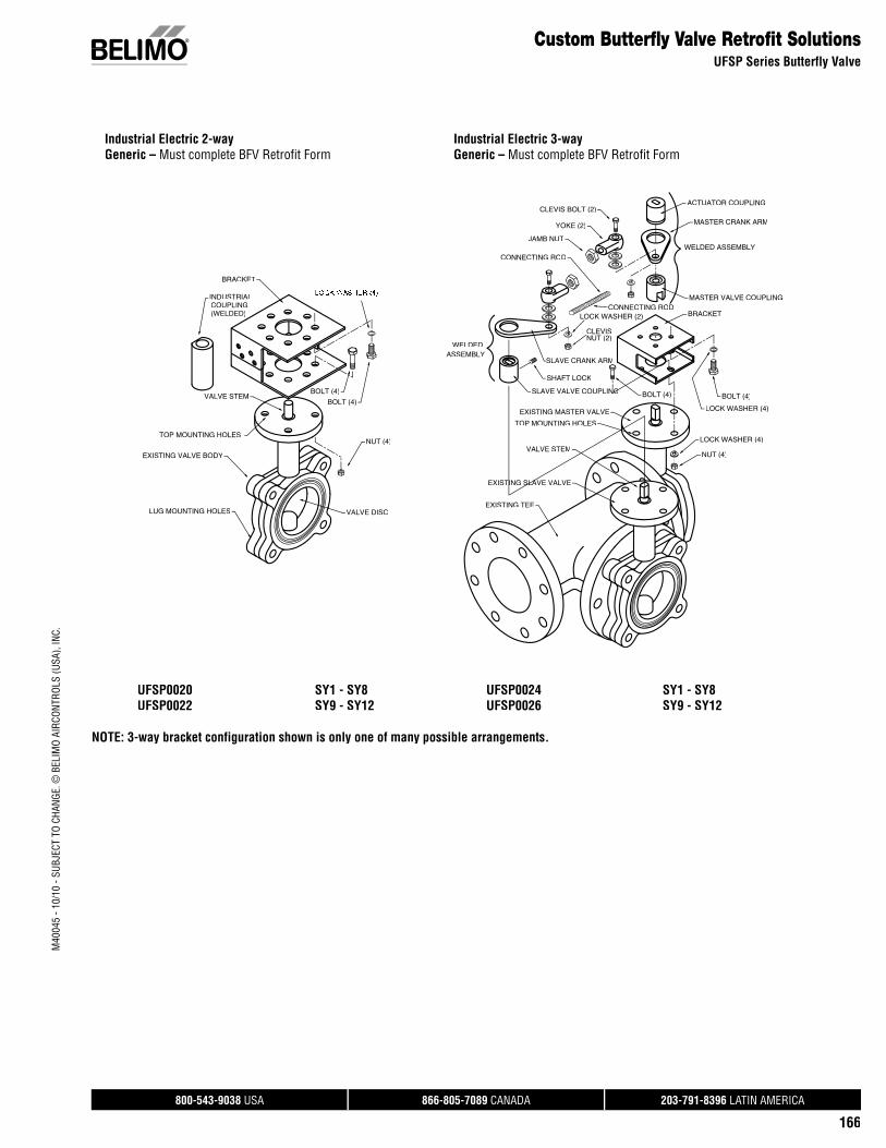
800-543-9038 USA 866-805-7089 CANADA 203-791-8396 LATIN AMERICA
166
M40
045
- 10/
10 -
SUBJ
ECT
TO C
HANG
E. ©
BEL
IMO
AIRC
ONTR
OLS
(USA
), IN
C.Custom Butterfly Valve Retrofit Solutions
UFSP Series Butterfly Valve
Industrial Electric 2-wayGeneric – Must complete BFV Retrofit Form
Industrial Electric 3-way Generic – Must complete BFV Retrofit Form
LUG MOUNTING HOLES VALVE DISC
TOP MOUNTING HOLES
EXISTING VALVE BODY
VALVE STEM
COUPLING(WELDED)
INDUSTRIAL
BRACKET
BOLT (4)
BOLT (4)
NUT (4)
MASTER VALVE COUPLING
ACTUATOR COUPLING
MASTER CRANK ARM
WELDED ASSEMBLY
BRACKET
YOKE (2)
JAMB NUT
CONNECTING ROD
CONNECTING ROD
SLAVE CRANK ARM
SLAVE VALVE COUPLINGN
SHAFT LOCK
CLEVIS BOLT (2)
LOCK WASHER (2)
CLEVISNUT (2)
BOLT (4)
LOCK WASHER (4)
NUT (4)
EXISTING TEE
EXISTING SLAVE VALVE
EXISTING MASTER VALVE
VALVE STEM
TOP MOUNTING HOLES
BOLT (4)
LOCK WASHER (4)
WELDEDASSEMBLY
UFSP0020 SY1 - SY8 UFSP0022 SY9 - SY12
UFSP0024 SY1 - SY8UFSP0026 SY9 - SY12
NOTE: 3-way bracket configuration shown is only one of many possible arrangements.
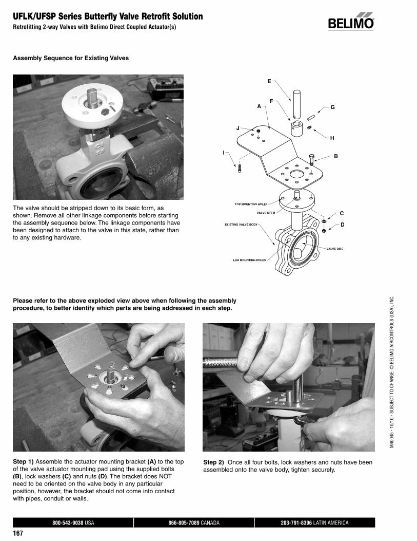
800-543-9038 USA 866-805-7089 CANADA 203-791-8396 LATIN AMERICA
167
M40
045
- 10/
10 -
SUBJ
ECT
TO C
HANG
E. ©
BEL
IMO
AIRC
ONTR
OLS
(USA
), IN
C.
Assembly Sequence for Existing Valves
UFLK/UFSP Series Butterfly Valve Retrofit SolutionRetrofitting 2-way Valves with Belimo Direct Coupled Actuator(s)
EXISTING VALVE BODY
VALVE STEM
TOP MOUNTING HOLES
VALVE DISC
LUG MOUNTING HOLES
A
B
C
D
E
FG
H
I
J
Please refer to the above exploded view above when following the assemblyprocedure, to better identify which parts are being addressed in each step.
The valve should be stripped down to its basic form, asshown. Remove all other linkage components before startingthe assembly sequence below. The linkage components have been designed to attach to the valve in this state, rather than to any existing hardware.
Step 1) Assemble the actuator mounting bracket (A) to the topof the valve actuator mounting pad using the supplied bolts(B), lock washers (C) and nuts (D). The bracket does NOT need to be oriented on the valve body in any particularposition, however, the bracket should not come into contactwith pipes, conduit or walls.
Step 2) Once all four bolts, lock washers and nuts have beenassembled onto the valve body, tighten securely.
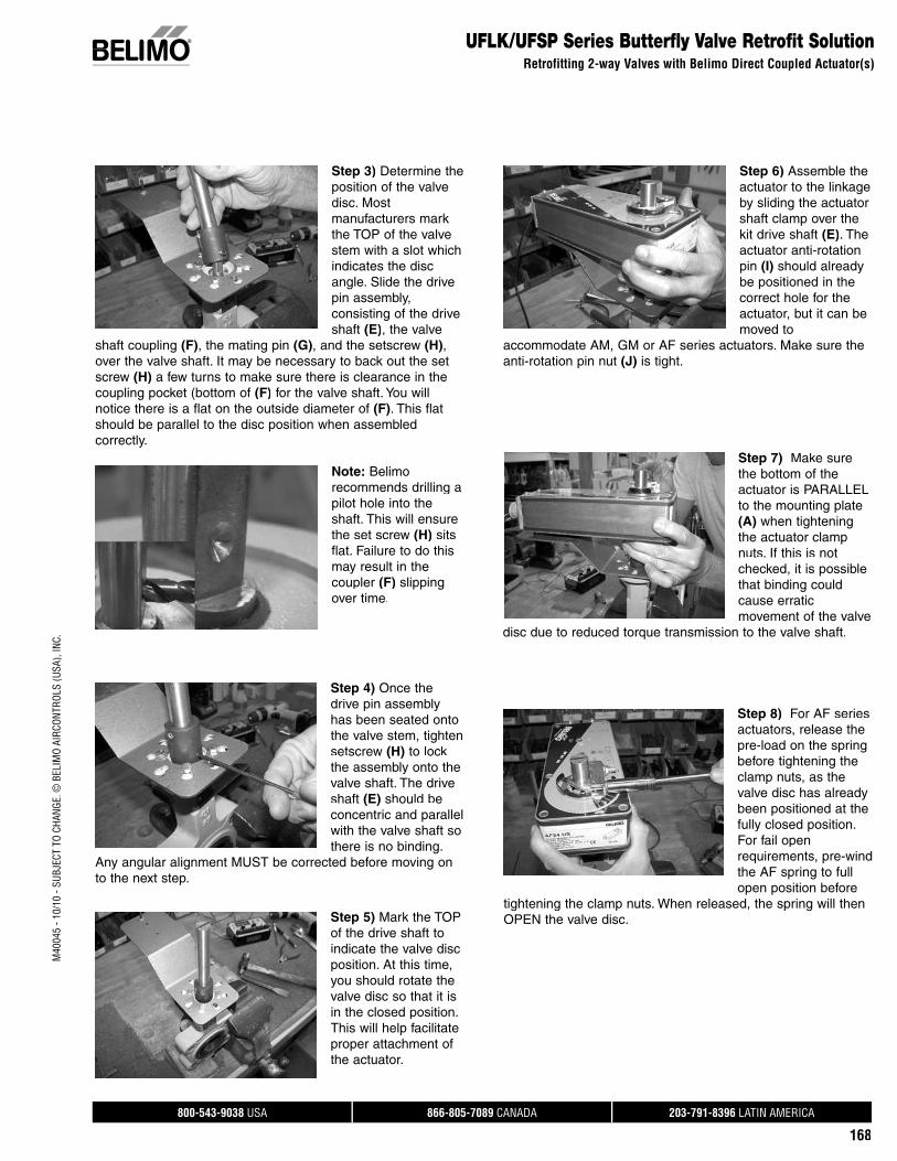
800-543-9038 USA 866-805-7089 CANADA 203-791-8396 LATIN AMERICA
168
M40
045
- 10/
10 -
SUBJ
ECT
TO C
HANG
E. ©
BEL
IMO
AIRC
ONTR
OLS
(USA
), IN
C.UFLK/UFSP Series Butterfly Valve Retrofit Solution
Retrofitting 2-way Valves with Belimo Direct Coupled Actuator(s)
Step 3) Determine the position of the valve disc. Mostmanufacturers mark the TOP of the valvestem with a slot whichindicates the disc angle. Slide the drivepin assembly, consisting of the driveshaft (E), the valve
shaft coupling (F), the mating pin (G), and the setscrew (H), over the valve shaft. It may be necessary to back out the setscrew (H) a few turns to make sure there is clearance in the coupling pocket (bottom of (F) for the valve shaft. You will notice there is a flat on the outside diameter of (F). This flatshould be parallel to the disc position when assembledcorrectly.
Step 4) Once the drive pin assemblyhas been seated onto the valve stem, tighten setscrew (H) to lock the assembly onto the valve shaft. The drive shaft (E) should be concentric and parallel with the valve shaft so there is no binding.
Any angular alignment MUST be corrected before moving onto the next step.
Step 5) Mark the TOP of the drive shaft toindicate the valve discposition. At this time,you should rotate the valve disc so that it is in the closed position. This will help facilitate proper attachment of the actuator.
Step 6) Assemble theactuator to the linkage by sliding the actuatorshaft clamp over the kit drive shaft (E). The actuator anti-rotation pin (I) should alreadybe positioned in the correct hole for the actuator, but it can be moved to
accommodate AM, GM or AF series actuators. Make sure the anti-rotation pin nut (J) is tight.
Step 7) Make surethe bottom of the actuator is PARALLELto the mounting plate (A) when tighteningthe actuator clamp nuts. If this is not checked, it is possiblethat binding couldcause erraticmovement of the valve
disc due to reduced torque transmission to the valve shaft.
Step 8) For AF series actuators, release the pre-load on the spring before tightening the clamp nuts, as the valve disc has already been positioned at the fully closed position. For fail openrequirements, pre-wind the AF spring to full open position before
tightening the clamp nuts. When released, the spring will thenOPEN the valve disc.
Note: Belimo recommends drilling a pilot hole into the shaft. This will ensure the set screw (H) sitsflat. Failure to do this may result in thecoupler (F) slipping over time.
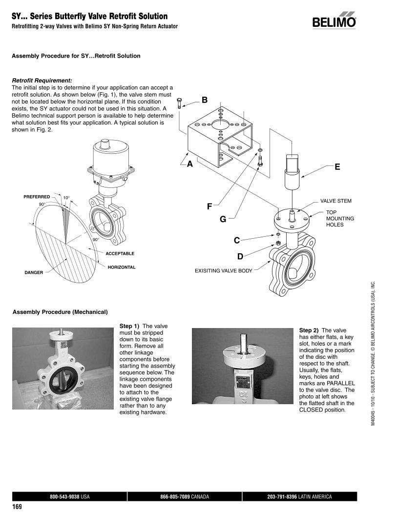
800-543-9038 USA 866-805-7089 CANADA 203-791-8396 LATIN AMERICA
169
M40
045
- 10/
10 -
SUBJ
ECT
TO C
HANG
E. ©
BEL
IMO
AIRC
ONTR
OLS
(USA
), IN
C.
SY… Series Butterfly Valve Retrofit SolutionRetrofitting 2-way Valves with Belimo SY Non-Spring Return Actuator
Assembly Procedure for SY…Retrofit Solution
PREFERRED
DANGER
ACCEPTABLE
HORIZONTAL
90°
90°
10°
Retrofit Requirement: The initial step is to determine if your application can accept a retrofit solution. As shown below (Fig. 1), the valve stem must not be located below the horizontal plane. If this condition exists, the SY actuator could not be used in this situation. ABelimo technical support person is available to help determinewhat solution best fits your application. A typical solution is shown in Fig. 2.
Step 1) The valve must be stripped down to its basicform. Remove all other linkage components before starting the assembly sequence below. Thelinkage components have been designed to attach to the existing valve flange rather than to any existing hardware.
Step 2) The valve has either flats, a key slot, holes or a mark indicating the position of the disc withrespect to the shaft.Usually, the flats, keys, holes andmarks are PARALLEL to the valve disc. The photo at left showsthe flatted shaft in the CLOSED position.
Assembly Procedure (Mechanical)
B
A
F
G
C
D
E
VALVE STEM
TOP MOUNTING HOLES
EXISITING VALVE BODY
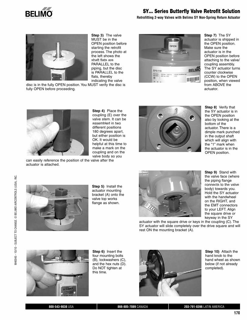
800-543-9038 USA 866-805-7089 CANADA 203-791-8396 LATIN AMERICA
170
M40
045
- 10/
10 -
SUBJ
ECT
TO C
HANG
E. ©
BEL
IMO
AIRC
ONTR
OLS
(USA
), IN
C.SY… Series Butterfly Valve Retrofit Solution
Retrofitting 2-way Valves with Belimo SY Non-Spring Return Actuator
Step 3) The valve MUST be in the OPEN position before starting the retrofit process. The photo atthe left shows the shaft flats are PARALLEL to thepiping, but the discis PARALLEL to theflats, therebyindicating the valve
disc is in the fully OPEN position. You MUST verify the disc is fully OPEN before proceeding.
Step 4) Place thecoupling (E) over thevalve stem. It can be assembled in twodifferent positions180 degrees apart,but either position isOK. It would behelpful at this time tomake a mark on thecoupling and on thevalve body so you
can easily reference the position of the valve after the actuator is attached.
Step 5) Install theactuator mounting bracket (A) onto the valve top worksflange as shown.
Step 6) Insert the four mounting bolts(B), lockwashers (C), and the hex nuts (D). Do NOT tighten at this time.
Step 7) The SY actuator is shipped in the OPEN position. Make sure the actuator is in the OPEN position before attaching to the valve/coupling assembly. The SY actuator turns counter clockwise (CCW) to the OPEN position, when viewed from ABOVE the actuator.
Step 8) Verify that the SY actuator is inthe OPEN position also by looking at the bottom of theactuator. There is a dimple mark punched in the output shaft which will align withthe "1" mark whenthe actuator is in the OPEN position.
Step 9) Stand withthe valve face (wherethe piping flange connects to the valve body) towards you.Hold the SY actuator with the handwheel on the RIGHT, andthe EMT connectors to your LEFT. Align the square drive orkeyway in the SY
actuator with the square drive or keys in the coupling (C). The SY actuator will slide completely over the drive square and willrest ON the mounting bracket (A).
Step 10) Attach thehand knob to thehand wheel as shownbelow (if not already completed).
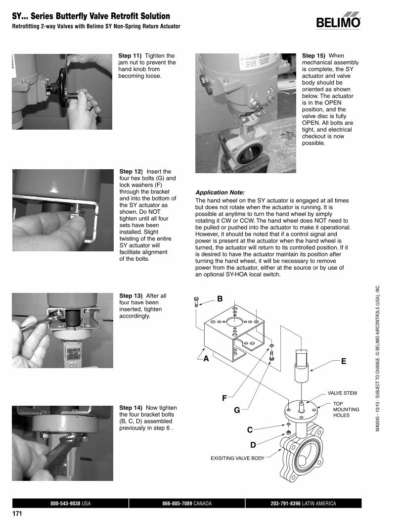
800-543-9038 USA 866-805-7089 CANADA 203-791-8396 LATIN AMERICA
171
M40
045
- 10/
10 -
SUBJ
ECT
TO C
HANG
E. ©
BEL
IMO
AIRC
ONTR
OLS
(USA
), IN
C.
Step 11) Tighten thejam nut to prevent the hand knob from becoming loose.
Step 12) Insert thefour hex bolts (G) and lock washers (F) through the bracket and into the bottom of the SY actuator as shown. Do NOTtighten until all four sets have been installed. Slight twisting of the entireSY actuator will facilitate alignment of the bolts.
Step 13) After allfour have been inserted, tighten accordingly.
Step 14) Now tightenthe four bracket bolts (B, C, D) assembledpreviously in step 6 .
Step 15) Whenmechanical assembly is complete, the SY actuator and valve body should be oriented as shownbelow. The actuator is in the OPEN position, and the valve disc is fullyOPEN. All bolts aretight, and electrical checkout is now possible.
SY… Series Butterfly Valve Retrofit SolutionRetrofitting 2-way Valves with Belimo SY Non-Spring Return Actuator
Application Note:The hand wheel on the SY actuator is engaged at all times but does not rotate when the actuator is running. It is possible at anytime to turn the hand wheel by simply rotating it CW or CCW. The hand wheel does NOT need tobe pulled or pushed into the actuator to make it operational. However, it should be noted that if a control signal and power is present at the actuator when the hand wheel is turned, the actuator will return to its controlled position. If it is desired to have the actuator maintain its position after turning the hand wheel, it will be necessary to remove power from the actuator, either at the source or by use of an optional SY-HOA local switch.
B
A
F
G
C
D
E
VALVE STEM
TOP MOUNTING HOLES
EXISITING VALVE BODY
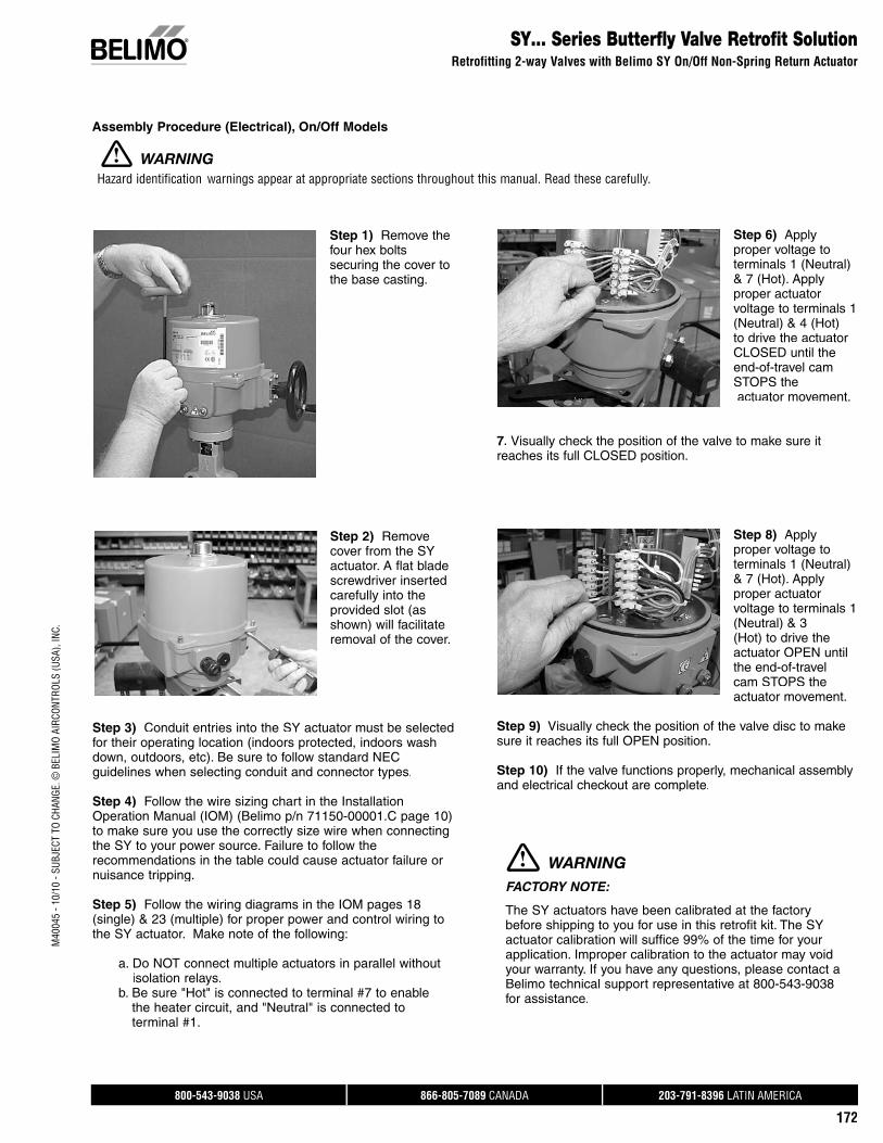
800-543-9038 USA 866-805-7089 CANADA 203-791-8396 LATIN AMERICA
172
M40
045
- 10/
10 -
SUBJ
ECT
TO C
HANG
E. ©
BEL
IMO
AIRC
ONTR
OLS
(USA
), IN
C.SY… Series Butterfly Valve Retrofit Solution
Retrofitting 2-way Valves with Belimo SY On/Off Non-Spring Return Actuator
Step 1) Remove the four hex boltssecuring the cover to the base casting.
Step 2) Removecover from the SYactuator. A flat bladescrewdriver inserted carefully into the provided slot (as shown) will facilitate removal of the cover.
Step 3) Conduit entries into the SY actuator must be selectedfor their operating location (indoors protected, indoors wash down, outdoors, etc). Be sure to follow standard NECguidelines when selecting conduit and connector types.
Step 4) Follow the wire sizing chart in the Installation Operation Manual (IOM) (Belimo p/n 71150-00001.C page 10) to make sure you use the correctly size wire when connecting the SY to your power source. Failure to follow therecommendations in the table could cause actuator failure or nuisance tripping.
Step 5) Follow the wiring diagrams in the IOM pages 18(single) & 23 (multiple) for proper power and control wiring to the SY actuator. Make note of the following:
a. Do NOT connect multiple actuators in parallel without isolation relays.
b. Be sure "Hot" is connected to terminal #7 to enable the heater circuit, and "Neutral" is connected to terminal #1.
Step 6) Applyproper voltage toterminals 1 (Neutral) & 7 (Hot). Applyproper actuator voltage to terminals 1(Neutral) & 4 (Hot) to drive the actuator CLOSED until the end-of-travel camSTOPS the actuator movement.
7. Visually check the position of the valve to make sure it reaches its full CLOSED position.
Step 8) Applyproper voltage toterminals 1 (Neutral) & 7 (Hot). Applyproper actuator voltage to terminals 1(Neutral) & 3(Hot) to drive theactuator OPEN until the end-of-travelcam STOPS theactuator movement.
Step 9) Visually check the position of the valve disc to make sure it reaches its full OPEN position.
Step 10) If the valve functions properly, mechanical assemblyand electrical checkout are complete.
Assembly Procedure (Electrical), On/Off Models
FACTORY NOTE:
The SY actuators have been calibrated at the factorybefore shipping to you for use in this retrofit kit. The SY actuator calibration will suffice 99% of the time for your application. Improper calibration to the actuator may voidyour warranty. If you have any questions, please contact a Belimo technical support representative at 800-543-9038for assistance.
WARNING
Hazard identification warnings appear at appropriate sections throughout this manual. Read these carefully.
WARNING

800-543-9038 USA 866-805-7089 CANADA 203-791-8396 LATIN AMERICA
173
M40
045
- 10/
10 -
SUBJ
ECT
TO C
HANG
E. ©
BEL
IMO
AIRC
ONTR
OLS
(USA
), IN
C.
SY… Series Butterfly Valve Retrofit SolutionRetrofitting 2-way Valves with Belimo SY Proportional Non-Spring Return Actuator
Assembly Procedure (Electrical), Proportional Models
Step 1) Remove thefour hex boltssecuring the cover tothe base casting.
Step 2) Remove cover from the SYactuator. A flat bladescrewdriver inserted carefully into the provided slot (as shown) will facilitate removal of the cover.
Step 3) Conduit entries into the SY actuator must be selectedfor their operating location (indoors protected, indoors wash down, outdoors, etc). Be sure to follow standard NECguidelines when selecting conduit and connector types.
Step 4) Follow the wire sizing chart in the Installation Operation manual (IOM) (Belimo p/n 70103-00001D page 17) to make sure you use the correct size wire when connecting the SY to your power source. Failure to follow therecommendations in the table could cause actuator failure or nuisance tripping.
Step 5) Follow the wiring diagrams in the IOM pages 14through 37 for proper power and control wiring to theSY actuator.
Note: All SY1-P and SY2..12-MFT actuators are factory pre-set with the proper customer requested control programming.
Step 6) Connect the proper electrical power and control wiringper the wiring diagrams located on pages 14-37.
Step 7) Check the operation of the actuator by commandingthe control system to generate control signals matching the needs of the job to run the valve from fully CLOSED to fullyOPEN, as well as a MID-POINT position. The indicator on thetop of the SY actuator will be an indicator as to the position ofthe actuator, and therefore, the valve position.
Step 8) If the valve functions properly, mechanical assembly and electrical checkout are complete.
FACTORY NOTE:
The SY actuators have been calibrated at the factory before shipping to you for use in this retrofit kit. The SYactuator calibration will suffice 99% of the time for your application. Improper calibration to the actuator may voidyour warranty. If you have any questions, please contact a Belimo technical support representative at 800-543-9038for assistance.
WARNING
Hazard IdentificationWarnings appear at appropriate sections throughout this manual. Read these carefully.

800-543-9038 USA 866-805-7089 CANADA 203-791-8396 LATIN AMERICA
174
M40
045
- 10/
10 -
SUBJ
ECT
TO C
HANG
E. ©
BEL
IMO
AIRC
ONTR
OLS
(USA
), IN
C.UFLK/UFSP Series Butterfly Valve Retrofit Solution
Retrofitting 3-way Valves with Belimo Direct Coupled Actuator(s)
Assembly Sequence for Existing Valves
A
B
C
D
E
F
G
H
I
J
K
L
MN
O P
TOP MOUNTING HOLESVALVE STEM
EXISTING VALVE BODIES
EXISTING TEE
Please refer to the above exploded view above when following the assembly procedure, to better identify which parts arebeing addressed in each step. Additionally, you need to determine the configuration of the valve you are trying to retrofit, using one of the three diagrams below:
The valves should be stripped down to their basic form, asshown. Remove all other linkage components before startingthe assembly sequence below. The linkage components have been designed to attach to the valve in this state, rather than to any existing hardware.
Depending on the orientation of the tee assembly, if the valves are mounted on the TOP and BRANCH positions (tee mounted vertically), or on the LEFT and BRANCH positions (tee mounted horizontally) you will refer to configuration codes X10-X15.
Open
DiscOpen
DiscClosed
S
Open
Check for rotation clearanceto brackets BEFORE attaching
Observe direction of rotationon actuator(s) BEFORE mountingonto bracketry.
actuator(s).
Disc Closed
X20 - X25:
Slave Valve is "S"Master Valve is "M"
Slave Valve is Normally Open
Set Valve "M" Closed as shownSet Valve "S": Open as shownAttach Crank Arms as shownValves turn in directions shown
Master Valve is Normally Closed
X20 - X25
M
Disc
Closedw/ "M" Disc
ArmCrank
w/ "S" DiscCrank Arm
Closed
X10 - X15:Master Valve is "M"Slave Valve is "S"Master Valve is Normally ClosedSlave Valve is Normally Open
Set Valve "M" Closed as shownSet Valve "S": Open as shownAttach Crank Arms as shownValves turn in directions shown
Check for rotation clearanceto brackets BEFORE attachingactuator(s).
Observe direction of rotationon actuator(s) BEFORE mountingonto bracketry.
Disc Closeds
DiscOpen
CrankArm
w/ "M" DiscClosed
Open
S
DiscClosed
DiscOpen
Crank Armw/ "S" Disc
Closed
X10 - X15
If the valves are mounted on the BOTTOM and BRANCHpositions (tee mounted vertically), or on the RIGHT andBRANCH positions (tee mounted horizontally) you will refer to configuration codes X20-X25.

800-543-9038 USA 866-805-7089 CANADA 203-791-8396 LATIN AMERICA
175
M40
045
- 10/
10 -
SUBJ
ECT
TO C
HANG
E. ©
BEL
IMO
AIRC
ONTR
OLS
(USA
), IN
C.
UFLK/UFSP Series Butterfly Valve Retrofit SolutionRetrofitting 3-way Valves with Belimo Direct Coupled Actuator(s)
Assembly Sequence for Existing Valves
Step 1) Assemblethe actuator mounting bracket(s) (A) to thetop of the valve actuator mounting pad(s) using the supplied bolts (B), lock washers (C) andnuts (D). Thebracket(s) need to be oriented so that they are parallel to the
RUN of the tee, unless you have configuration codes X30-35,in which case the bracket(s) must be mounted parallel to theBRANCH of the tee.
Step 2) Refer to the three configuration drawing types onpage 9 of the Butterfly Valve O & M (71150-00001) and position the valve discs asinstructed. Forexample, if you have a Configuration TypeA tee assembly, you will OPEN the master
valve (A), and CLOSE the slave valve (B). During theassembly procedure, CLOSED and OPEN means 0 degrees and 90 degrees respectively. Failure to position the discs intotheir quadrants will result in improper operation and performance of the retrofit kit. Most manufacturers mark the TOP of the valve stem with a slot which indicates the discangle.
Step 3) Slide thedrive pin assembly,consisting of the drive shaft(s) (E), the valveshaft couplings (F), the mating pins (G), and the setscrews (H), over the valveshafts. It may be necessary to back outthe set screws (H) a few turns to make
sure there is clearance in the coupling pockets (bottom of (F)for the valve shafts. Drive shafts (E) should be concentric and parallel with the valve shafts so there is no binding. Any angular alignment MUST be corrected before moving on to the next step.Note: Belimo recommends drilling a pilot hole into the shaft.This will ensure the set screw (H) sits flat. Failure to do this may result in the coupler (F) slipping over time.
Step 4) Mark the topof each drive shaft (E)to indicate the disc position. Typically, thisis done using a chisel to punch a line PARALLEL to thevalve disc to make iteasier to identify the disc position during the assembly process.
Open
Master Valve is Normally Closed
Valves turn in directions shownAttach Crank Arms as shownSet Valve "S": Open as shownSet Valve "M" Closed as shown
Slave Valve is Normally Open
Master Valve is "M"Slave Valve is "S"
X30 - X35:
Disc Closed
actuator(s).
onto bracketry.on actuator(s) BEFORE mountingObserve direction of rotation
to brackets BEFORE attachingCheck for rotation clearance
Open
Crank Armw/ "S" Disc
Closedw/ "M" Disc
Open
X30 - X35
M
ArmCrank
Disc
Open
Disc Closeds
Closed
S
Disc
If the valves are mounted on the TOP and BOTTOMpositions (tee mounted vertically), or on the LEFT andRIGHT positions (tee mounted horizontally) you willrefer to configuration codes X30-X35
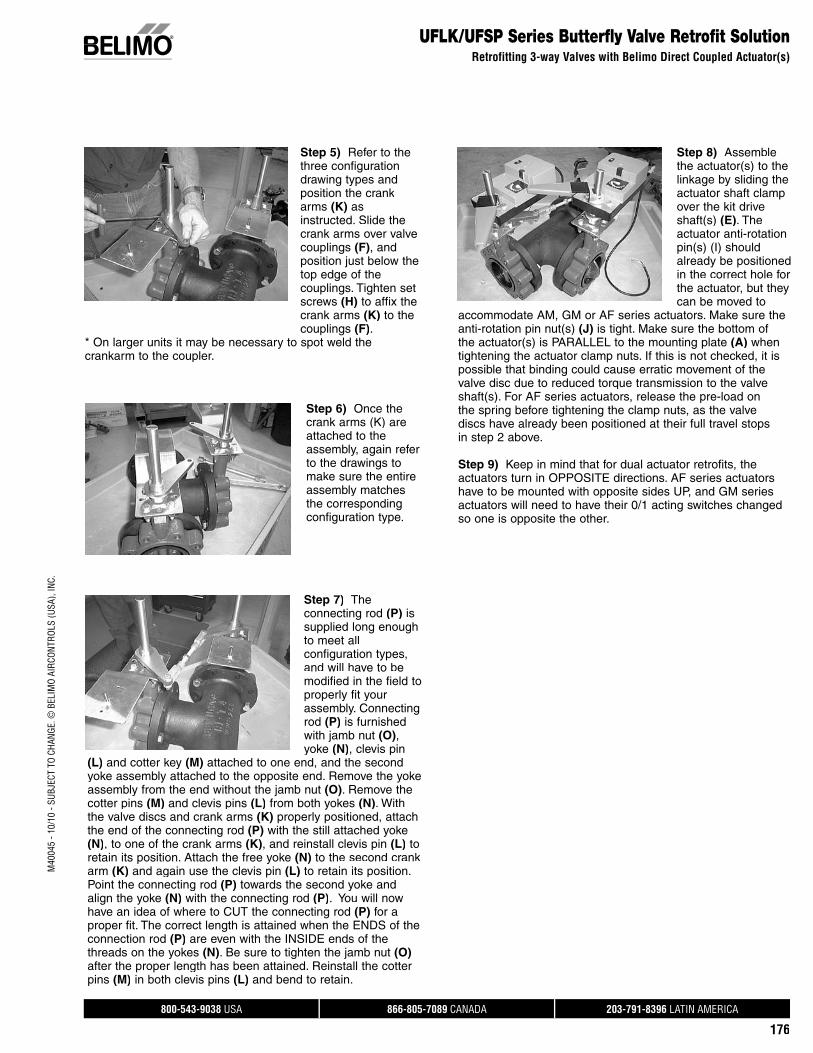
800-543-9038 USA 866-805-7089 CANADA 203-791-8396 LATIN AMERICA
176
M40
045
- 10/
10 -
SUBJ
ECT
TO C
HANG
E. ©
BEL
IMO
AIRC
ONTR
OLS
(USA
), IN
C.UFLK/UFSP Series Butterfly Valve Retrofit Solution
Retrofitting 3-way Valves with Belimo Direct Coupled Actuator(s)
Step 6) Once the crank arms (K) areattached to the assembly, again refer to the drawings tomake sure the entire assembly matches the corresponding configuration type.
Step 7) The connecting rod (P) issupplied long enough to meet all configuration types,and will have to be modified in the field to properly fit yourassembly. Connecting rod (P) is furnishedwith jamb nut (O), yoke (N), clevis pin
(L) and cotter key (M) attached to one end, and the secondyoke assembly attached to the opposite end. Remove the yoke assembly from the end without the jamb nut (O). Remove thecotter pins (M) and clevis pins (L) from both yokes (N). With the valve discs and crank arms (K) properly positioned, attachthe end of the connecting rod (P) with the still attached yoke(N), to one of the crank arms (K), and reinstall clevis pin (L) toretain its position. Attach the free yoke (N) to the second crank arm (K) and again use the clevis pin (L) to retain its position. Point the connecting rod (P) towards the second yoke andalign the yoke (N) with the connecting rod (P). You will nowhave an idea of where to CUT the connecting rod (P) for aproper fit. The correct length is attained when the ENDS of theconnection rod (P) are even with the INSIDE ends of thethreads on the yokes (N). Be sure to tighten the jamb nut (O)after the proper length has been attained. Reinstall the cotter pins (M) in both clevis pins (L) and bend to retain.
Step 8) Assemblethe actuator(s) to the linkage by sliding theactuator shaft clamp over the kit driveshaft(s) (E). Theactuator anti-rotation pin(s) (I) should already be positioned in the correct hole for the actuator, but they can be moved to
accommodate AM, GM or AF series actuators. Make sure theanti-rotation pin nut(s) (J) is tight. Make sure the bottom ofthe actuator(s) is PARALLEL to the mounting plate (A) when tightening the actuator clamp nuts. If this is not checked, it is possible that binding could cause erratic movement of thevalve disc due to reduced torque transmission to the valveshaft(s). For AF series actuators, release the pre-load on the spring before tightening the clamp nuts, as the valvediscs have already been positioned at their full travel stops in step 2 above.
Step 9) Keep in mind that for dual actuator retrofits, theactuators turn in OPPOSITE directions. AF series actuatorshave to be mounted with opposite sides UP, and GM seriesactuators will need to have their 0/1 acting switches changed so one is opposite the other.
Step 5) Refer to the three configuration drawing types andposition the crank arms (K) asinstructed. Slide thecrank arms over valve couplings (F), andposition just below thetop edge of the couplings. Tighten setscrews (H) to affix the crank arms (K) to the couplings (F).
* On larger units it may be necessary to spot weld thecrankarm to the coupler.

800-543-9038 USA 866-805-7089 CANADA 203-791-8396 LATIN AMERICA
177
M40
045
- 10/
10 -
SUBJ
ECT
TO C
HANG
E. ©
BEL
IMO
AIRC
ONTR
OLS
(USA
), IN
C.
SY… Series Butterfly Valve Retrofit SolutionRetrofitting 3-way Valves with Belimo SY Non-Spring Return Actuator
Assembly Procedure for SY…Retrofit Solution
PREFERRED
DANGER
ACCEPTABLE
HORIZONTAL
90°
90°
10°
O
M
F
LN
A
H
JK
B
CD
QR
P E
EXISITING TEE
EXISITING SLAVE VALVE
EXISITING MASTER VALVE
BRACKET OPENING
WELDED
The initial step is to determine if your application can accept a retrofit solution. As shown below (Fig. 1), the valve stem must not be located belowthe horizontal plane. If this condition exists, the SY actuator could not be used in this situation. A Belimo technicalsupport person is available to help determine what solutionbest fits your application. A typical solution is shown in Fig. 2.
Depending on the orientation of the tee assembly, if the valves are mounted on the TOP and BRANCH positions (teemounted vertically), or on the LEFT and BRANCH positions (tee mounted horizontally) you will refer to configuration codes X10-X15.
Master Valve is Normally Open
Valves turn in directions shownAttach Crank Arms as shown
Slave Valve is Normally Closed
Check for rotation clearanceto bracket BEFORE attaching
Observe direction of rotationon actuator BEFORE mounting
Bracket Opening Direction
w/ "S" DiscClosed
Crank Arm
w/ "M" Disc
CrankArm
Open
M
onto bracketry.
S
Master Valve is "M"Slave Valve is "S"
actuator.
X20-X25:
SY Orientation
S0
X20 - X25
Bracket Opening Direction
w/ "S" Disc
w/ "M" Disc
S
Closed
Crank Arm
Arm
Open
CrankM
on actuator BEFORE mounting
to bracket BEFORE attaching
Set Valve "M" Open as shown
Observe direction of rotation
Check for rotation clearance
Valves turn in directions shownAttach Crank Arms as shownSet Valve "S: Closed as shown
actuator.
onto bracketry.
X10-X15:
Slave Valve is "S"Master Valve is "M"
S
X10 - X15
If the valves are mounted on the BOTTOM and BRANCHpositions (tee mounted vertically), or on the RIGHT andBRANCH positions (tee mounted horizontally) you willrefer to configuration codes X20-X25.
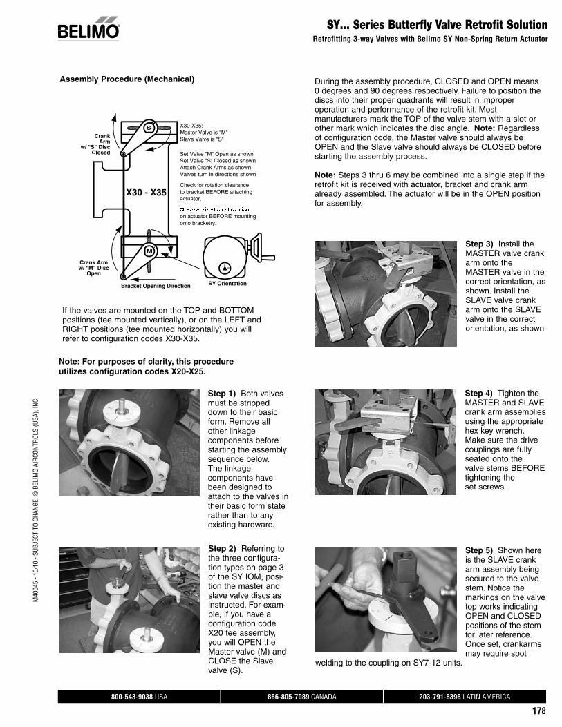
800-543-9038 USA 866-805-7089 CANADA 203-791-8396 LATIN AMERICA
178
M40
045
- 10/
10 -
SUBJ
ECT
TO C
HANG
E. ©
BEL
IMO
AIRC
ONTR
OLS
(USA
), IN
C.SY… Series Butterfly Valve Retrofit Solution
Retrofitting 3-way Valves with Belimo SY Non-Spring Return Actuator
Check for rotation clearance
Set Valve "S: Closed as shownSet Valve "M" Open as shown
Valves turn in directions shownAttach Crank Arms as shown
to bracket BEFORE attaching
on actuator BEFORE mounting
Bracket Opening Direction
Open
Crank Armw/ "M" Disc
w/ "S" DiscClosed
CrankArm
M
onto bracketry.
actuator.
S
Slave Valve is "S"Master Valve is "M"X30-X35:
X30 - X35
SY Orientation
S0
If the valves are mounted on the TOP and BOTTOMpositions (tee mounted vertically), or on the LEFT andRIGHT positions (tee mounted horizontally) you willrefer to configuration codes X30-X35.
Step 1) Both valvesmust be strippeddown to their basicform. Remove all other linkage components before starting the assembly sequence below. The linkage components havebeen designed to attach to the valves intheir basic form staterather than to anyexisting hardware.
Step 2) Referring tothe three configura-tion types on page 3of the SY IOM, posi-tion the master and slave valve discs asinstructed. For exam-ple, if you have a configuration code X20 tee assembly, you will OPEN the Master valve (M) andCLOSE the Slavevalve (S).
Note: For purposes of clarity, this procedureutilizes configuration codes X20-X25.
Step 3) Install the MASTER valve crank arm onto theMASTER valve in the correct orientation, as shown. Install the SLAVE valve crank arm onto the SLAVEvalve in the correctorientation, as shown.
Step 4) Tighten the MASTER and SLAVE crank arm assemblies using the appropriate hex key wrench. Make sure the drive couplings are fully seated onto the valve stems BEFORE tightening the set screws.
Step 5) Shown here is the SLAVE crank arm assembly being secured to the valve stem. Notice the markings on the valve top works indicating OPEN and CLOSED positions of the stem for later reference. Once set, crankarms may require spot
welding to the coupling on SY7-12 units.
During the assembly procedure, CLOSED and OPEN means0 degrees and 90 degrees respectively. Failure to position thediscs into their proper quadrants will result in improper operation and performance of the retrofit kit. Mostmanufacturers mark the TOP of the valve stem with a slot orother mark which indicates the disc angle. Note: Regardless of configuration code, the Master valve should always beOPEN and the Slave valve should always be CLOSED beforestarting the assembly process.
Note: Steps 3 thru 6 may be combined into a single step if the retrofit kit is received with actuator, bracket and crank armalready assembled. The actuator will be in the OPEN position for assembly.
Assembly Procedure (Mechanical)
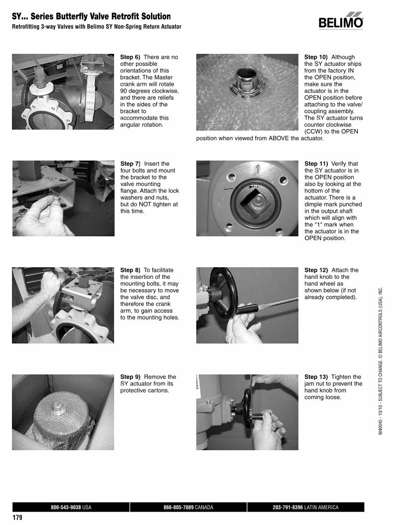
800-543-9038 USA 866-805-7089 CANADA 203-791-8396 LATIN AMERICA
179
M40
045
- 10/
10 -
SUBJ
ECT
TO C
HANG
E. ©
BEL
IMO
AIRC
ONTR
OLS
(USA
), IN
C.
SY… Series Butterfly Valve Retrofit SolutionRetrofitting 3-way Valves with Belimo SY Non-Spring Return Actuator
Step 6) There are no other possible orientations of this bracket. The Master crank arm will rotate 90 degrees clockwise, and there are reliefsin the sides of the bracket to accommodate this angular rotation.
Step 7) Insert thefour bolts and mountthe bracket to the valve mounting flange. Attach the lock washers and nuts,but do NOT tighten at this time.
Step 8) To facilitatethe insertion of the mounting bolts, it maybe necessary to move the valve disc, and therefore the crank arm, to gain access to the mounting holes.
Step 9) Remove the SY actuator from its protective cartons.
Step 10) Althoughthe SY actuator ships from the factory IN the OPEN position, make sure theactuator is in the OPEN position before attaching to the valve/coupling assembly. The SY actuator turns counter clockwise (CCW) to the OPEN
position when viewed from ABOVE the actuator.
Step 11) Verify thatthe SY actuator is in the OPEN position also by looking at thebottom of the actuator. There is adimple mark punchedin the output shaft which will align with the "1" mark whenthe actuator is in the OPEN position.
Step 12) Attach the hand knob to thehand wheel as shown below (if notalready completed).
Step 13) Tighten the jam nut to prevent the hand knob from coming loose.
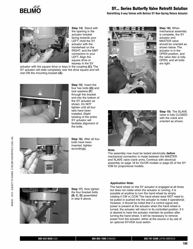
800-543-9038 USA 866-805-7089 CANADA 203-791-8396 LATIN AMERICA
180
M40
045
- 10/
10 -
SUBJ
ECT
TO C
HANG
E. ©
BEL
IMO
AIRC
ONTR
OLS
(USA
), IN
C.SY… Series Butterfly Valve Retrofit Solution
Retrofitting 3-way Valves with Belimo SY Non-Spring Return Actuator
Step 14) Stand withthe opening in the actuator bracketfacing towards yourLEFT. Hold the SYactuator with the handwheel on the RIGHT, and the EMTconnectors to your LEFT. Align thesquare drive or keyway in the SY
actuator with the square drive or keys in the coupling (C). TheSY actuator will slide completely over the drive square and willrest ON the mounting bracket (A).
Step 15) Insert the four hex bolts (G) andlock washers (F)through the bracketand into the bottom of the SY actuator as shown. Do NOT tighten until all four sets have beeninstalled. Slight twisting of the entireSY actuator willfacilitate alignment of the bolts.
Step 16) After all four bolts have beeninserted, tighten accordingly.
Step 17) Now tightenthe four bracket bolts(B, C, D) assembledin step 6 above.
Step 18) Whenmechanical assemblyis complete, the SYactuator and MASTER valve should be oriented asshown below. Theactuator is in the OPEN position, and the valve disc is fullyOPEN, and all bolts are tight.
Step 19) The SLAVE valve is fully CLOSED with the crank armoriented as shown.
Note:The assembly now must be tested electrically beforemechanical connection is made between the MASTER and SLAVE valve crank arms. Continue with electricalassembly on page 18 for On/Off models or page 20 of the SYIOM for proportional models.
Application Note:The hand wheel on the SY actuator is engaged at all times but does not rotate when the actuator is running. It is possible at anytime to turn the hand wheel by simply rotating it CW or CCW. The hand wheel does NOT need tobe pulled or pushed into the actuator to make it operational. However, it should be noted that if a control signal andpower is present at the actuator when the hand wheel isturned, the actuator will return to its controlled position. If it is desired to have the actuator maintain its position after turning the hand wheel, it will be necessary to remove power from the actuator, either at the source or by use of an optional SY-HOA local switch.

800-543-9038 USA 866-805-7089 CANADA 203-791-8396 LATIN AMERICA
181
M40
045
- 10/
10 -
SUBJ
ECT
TO C
HANG
E. ©
BEL
IMO
AIRC
ONTR
OLS
(USA
), IN
C.
SY… Series Butterfly Valve Retrofit SolutionRetrofitting 3-way Valves with Belimo SY On/Off Non-Spring Return Actuator
Step 21) Measure the distance betweenthe inboard end of the yokes to determine the proper length of the connecting rod. It is important to make sure the MASTER and SLAVE valves are in their proper positions (OPEN and CLOSED, respectively) before
taking this measurement. Otherwise, the connecting rod could be too short for proper calibration of the SLAVE valve.
Step 25) Using the correct control signal (On/Off or Proportional) drive the MASTER valve 25% CLOSED, then drive the MASTER valve fully OPEN. The SLAVE valve should now be fully CLOSED. The SLAVE valve should now be fully CLOSED. If the
SLAVE valve needs to be adjusted, it is accomplished byturning one of the yoke ends in (to shorten) or out (to lengthen)and rechecking the rotation angle using terminals #3 and #4 onthe SY actuator. Always be sure to let the electrical travel camsstop the SY actuator before making any adjustments in theyoke ends of the connecting rod.
Step 22) After the connecting rod is cut to the correct length, screw it into SLAVEvalve yoke end until the threads pass through the yoke andjust start to protrude into the inboard end of the yoke. The rod lock nut should be closest to the SLAVE valve yoke end.
Step 23) Remove the MASTER valve yokeend and thread it onto the connecting rod. Adjust the distance between the yokecenters to match the hole in the MASTER valve crank arm.
Step 24) Insert theclevis pin into the master crank arm.
Step 20) With the MASTER valve in itsfully OPEN position and the SLAVE valve in its fully CLOSED position, assemble the yoke and clevispins onto the crank arms, pointing towards each other as shown.
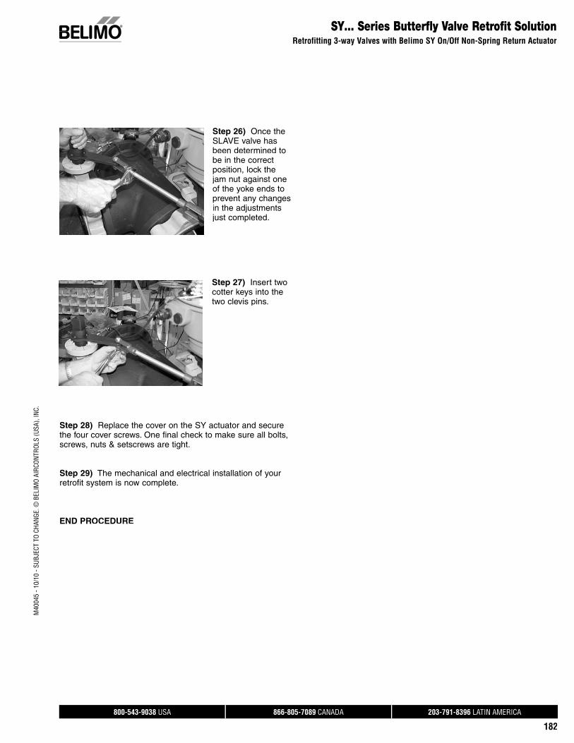
800-543-9038 USA 866-805-7089 CANADA 203-791-8396 LATIN AMERICA
182
M40
045
- 10/
10 -
SUBJ
ECT
TO C
HANG
E. ©
BEL
IMO
AIRC
ONTR
OLS
(USA
), IN
C.
Step 28) Replace the cover on the SY actuator and securethe four cover screws. One final check to make sure all bolts, screws, nuts & setscrews are tight.
Step 29) The mechanical and electrical installation of yourretrofit system is now complete.
END PROCEDURE
Step 26) Once the SLAVE valve hasbeen determined to be in the correct position, lock thejam nut against oneof the yoke ends to prevent any changesin the adjustments just completed.
Step 27) Insert two cotter keys into thetwo clevis pins.
SY… Series Butterfly Valve Retrofit SolutionRetrofitting 3-way Valves with Belimo SY On/Off Non-Spring Return Actuator
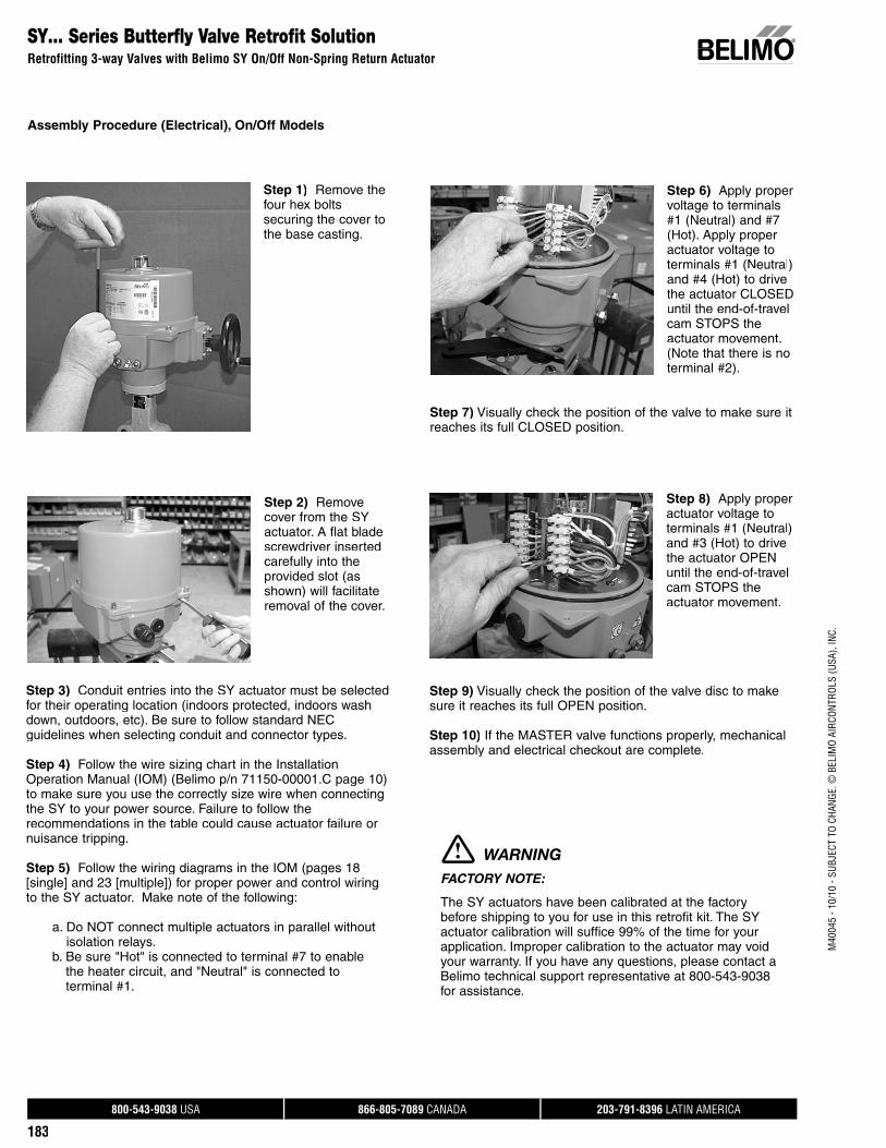
800-543-9038 USA 866-805-7089 CANADA 203-791-8396 LATIN AMERICA
183
M40
045
- 10/
10 -
SUBJ
ECT
TO C
HANG
E. ©
BEL
IMO
AIRC
ONTR
OLS
(USA
), IN
C.
SY… Series Butterfly Valve Retrofit SolutionRetrofitting 3-way Valves with Belimo SY On/Off Non-Spring Return Actuator
Step 1) Remove thefour hex boltssecuring the cover tothe base casting.
Step 6) Apply propervoltage to terminals #1 (Neutral) and #7(Hot). Apply properactuator voltage toterminals #1 (Neutral) and #4 (Hot) to drive the actuator CLOSED until the end-of-travelcam STOPS the actuator movement. (Note that there is no terminal #2).
Step 7) Visually check the position of the valve to make sure it reaches its full CLOSED position.
Step 2) Remove cover from the SY actuator. A flat bladescrewdriver inserted carefully into the provided slot (as shown) will facilitate removal of the cover.
Step 3) Conduit entries into the SY actuator must be selectedfor their operating location (indoors protected, indoors washdown, outdoors, etc). Be sure to follow standard NEC guidelines when selecting conduit and connector types.
Step 4) Follow the wire sizing chart in the InstallationOperation Manual (IOM) (Belimo p/n 71150-00001.C page 10) to make sure you use the correctly size wire when connectingthe SY to your power source. Failure to follow the recommendations in the table could cause actuator failure ornuisance tripping.
Step 5) Follow the wiring diagrams in the IOM (pages 18[single] and 23 [multiple]) for proper power and control wiringto the SY actuator. Make note of the following:
a. Do NOT connect multiple actuators in parallel withoutisolation relays.
b. Be sure "Hot" is connected to terminal #7 to enablethe heater circuit, and "Neutral" is connected to terminal #1.
Step 8) Apply proper actuator voltage toterminals #1 (Neutral) and #3 (Hot) to drive the actuator OPEN until the end-of-travel cam STOPS the actuator movement.
Step 9) Visually check the position of the valve disc to makesure it reaches its full OPEN position.
Step 10) If the MASTER valve functions properly, mechanicalassembly and electrical checkout are complete.
FACTORY NOTE:
The SY actuators have been calibrated at the factory before shipping to you for use in this retrofit kit. The SY actuator calibration will suffice 99% of the time for yourapplication. Improper calibration to the actuator may void your warranty. If you have any questions, please contact aBelimo technical support representative at 800-543-9038for assistance.
WARNING
Assembly Procedure (Electrical), On/Off Models
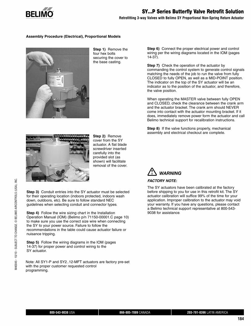
800-543-9038 USA 866-805-7089 CANADA 203-791-8396 LATIN AMERICA
184
M40
045
- 10/
10 -
SUBJ
ECT
TO C
HANG
E. ©
BEL
IMO
AIRC
ONTR
OLS
(USA
), IN
C.SY…P Series Butterfly Valve Retrofit Solution
Retrofitting 3-way Valves with Belimo SY Proportional Non-Spring Return Actuator
Step 1) Remove thefour hex boltssecuring the cover tothe base casting.
Assembly Procedure (Electrical), Proportional Models
Step 2) Remove cover from the SY actuator. A flat blade screwdriver inserted carefully into the provided slot (asshown) will facilitate removal of the cover.
Step 3) Conduit entries into the SY actuator must be selectedfor their operating location (indoors protected, indoors washdown, outdoors, etc). Be sure to follow standard NEC guidelines when selecting conduit and connector types.
Step 4) Follow the wire sizing chart in the InstallationOperation Manual (IOM) (Belimo p/n 71150-00001.C page 10) to make sure you use the correct size wire when connectingthe SY to your power source. Failure to follow therecommendations in the table could cause actuator failure or nuisance tripping.
Step 5) Follow the wiring diagrams in the IOM (pages 14-37) for proper power and control wiring to the SY actuator.
Step 6) Connect the proper electrical power and control wiring per the wiring diagrams located in the IOM (pages 14-37).
Step 7) Check the operation of the actuator by commanding the control system to generate control signals matching the needs of the job to run the valve from fully CLOSED to fully OPEN, as well as a MID-POINT position. The indicator on the top of the SY actuator will be an indicator as to the position of the actuator, and therefore,the valve position.
When operating the MASTER valve between fully OPEN and CLOSED, check the clearance between the crank armand the actuator bracket. The crank arm should NEVERcome into contact with the actuator mounting bracket. If it does, immediately remove power form the actuator and call Belimo technical support for recalibration instructions.
Step 8) If the valve functions properly, mechanical assembly and electrical checkout are complete.
FACTORY NOTE:
The SY actuators have been calibrated at the factorybefore shipping to you for use in this retrofit kit. The SY actuator calibration will suffice 99% of the time for yourapplication. Improper calibration to the actuator may voidyour warranty. If you have any questions, please contact a Belimo technical support representative at 800-543-9038 for assistance.
WARNING
Note: All SY1-P and SY2..12-MFT actuators are factory pre-setwith the proper customer requested control programming.

800-543-9038 USA 866-805-7089 CANADA 203-791-8396 LATIN AMERICA
185
M40
045
- 10/
10 -
SUBJ
ECT
TO C
HANG
E. ©
BEL
IMO
AIRC
ONTR
OLS
(USA
), IN
C.
VValve AccessoriesButterfly Valves
SY-HOA-110 Local Electric Disconnect SY2-SY12 110V 2 Position SY-HOA-110P Local Electric Disconnect SY2-SY12 110V ProportionalSY-HOA-24 Local Electric Disconnect SY2-SY12 24V 2 PositionSY-HOA-24P Local Electric Disconnect SY2-SY12 24V Proportional
SY-1000-FB01 1000 Ω Feedback Potentiometer SY2-12 2 PositionSY-1000-FB02 1000 Ω Feedback Potentiometer SY2-12 Proportional
NSV-SY-01 Battery Backup System for SY1-SY6 2 Position - 110 VACNSV-SY-02 Battery Backup System for SY1-SY6 Proportional - 110 VACNSV-SY-03 Battery Backup System for SY7 2 Position - 110 VACNSV-SY-04 Battery Backup System for SY7 Proportional - 110 VACNSV-SY-05 Battery Backup System for SY8-SY12 2 Position - 110 VACNSV-SY-06 Battery Backup System for SY8-SY12 Proportional - 110 VACNSV-SY-11 Battery Backup System for SY1-SY5 2 Position - 24 VACNSV-SY-12 Battery Backup System for SY1-SY5 Proportional - 24 VACNSV-SY-21 Battery Backup System for SY1-SY6 2 Position - 220 VACNSV-SY-22 Battery Backup System for SY1-SY6 Proportional - 220 VACNSV-SY-23 Battery Backup System for SY7-SY9 2 Position - 220 VACNSV-SY-24 Battery Backup System for SY7-SY9 Proportional - 220 VACNSV-SY-25 Battery Backup System for SY10-SY12 2 Position - 220 VACNSV-SY-26 Battery Backup System for SY10-SY12 Proportional - 220 VAC
ZG-SY23 SY2-3 Handwheel (replacement only)ZG-SY46 SY4-6 Handwheel (replacement only)ZG-SY78 SY7-8 Handwheel (replacement only)ZG-SY912 SY9-12 Handwheel (replacement only)
NSV-SY...Battery Backup System
SY-HOA...Local Electric Disconnect
SY...Handwheel

800-543-9038 USA 866-805-7089 CANADA 203-791-8396 LATIN AMERICA
186
Custom Ball Valve Retrofi t Solution FormUBSP Series
Ball valves with-out a mounting fl ange are typically not designed for installing actuation, therefore the valve design may not support modulation outside of manual usage. Belimo does not recommend retrofi tting these types of ball valves.
All dimensions should be taken with ALL original actuation and hardware components removed from the valve body.
An example using Mounting Style 3: Dimensions A & B (Dim A and Dim B) relate to the TOP mounting holes on the ball valve body. These holes are usually arranged on the body in a “X” pattern (MOUNT STYLE 3). This information is entered on the UBSP Series Ball Valve Retrofi t Form in the MOUNT STYLE section. The length of the valve stem sticking out of the top of the valve body is recorded under Dim D and E. The TOP mounting holes are usually drilled through the top fl ange, but sometimes are threaded. Enter this information on the form next to the mount style information previously recorded.
MOUNT STYLE 3: Dimensions A & B (Dim A and Dim B) relate to the TOP mounting holes on the ball valve body. These holes are usually arranged on the body in a “X” pattern (MOUNT STYLE 3). This information is entered on the UBSP Series Ball Valve Retrofi t Form in the MOUNT STYLE section. The length of the valve stem sticking out of the top of the valve body is recorded under Dim D and E. The TOP mounting holes are usually drilled through the top fl ange, but sometimes are threaded. Enter this information on the form next to the mount style information previously recorded.
STEM STYLE: Examine the valve being retrofi tted to establish which stem style matches the diagrams above. Use caution when recording these dimensions. Dim H refers to the valve stem diameter and should be measured at several points up and down as well as around the stem itself. Dim E refers to the length of the drive surface available, whether it is a key or fl atted surface. Dim F refers to the width of the drive surface or the distance across the fl ats. This is the most critical dimension for correct linkage operation. Please measure accordingly. Lastly please specify the desired actuator orientation in reference to the valve body using the ports as reference, i.e. over the “A” port etc. We have also includes an ISO-5211 standard dimension chart for reference. If the valve is labeled please specify its “F” number so that we may confi rm the dimensions per the ISO spec.
In addition, we require information about the environment and process in which this linkage system will be utilized. As well as the frequency of use the current actuator runs. This will help to ensure the longevity of the new linkage and actuator. Having the prior actuator spec and model will help.
The form must be completed in its entirety to guarantee the complete, perfect fi t of your retrofi t system. Keep in mind that retrofi t kits are designed with close-tolerance components which afford the most effi cient linkage systems. Measurements rounded to the nearest 1/8 or 1/16 inch will not perform as well (sometimes not at all) as a kit designed around careful measurements using proper equipment. Our designs are typically +.005” tolerance.
Required Tools - calipers and retrofi t form.
Disclaimer
While we will do our best to provide a linkage system designed around your specifi cations and measurements, we cannot be held responsible for linkages which do not fi t as a result of incorrect data supplied to Belimo. We will be happy to re-work components which do not fi t properly for a nominal fee.
Actuation, weather shields and linkages cannot be pre-assembled at the Belimo factory. The linkages are designed to be attached onto the valve body fi rst, then optional weather shields, and fi nally actuation products in the fi eld.
Close-off pressures are calculated using actuator torque, valve stroke, and valve area. Other factors may affect the rated Close-off pressures, including fl ow rates, system maintenance schedules, chemicals used in the shot feeder process, vicinity to pumps, condition of valve stem seals, and assembly of linkage material in the fi eld.
Valves that are being considered for retrofi t of actuation should be analyzed for their life expectancy before the retrofi t has taken place. Valves that leak through stem seals or casings will continue to leak with the new linkage system in place, maybe even more so. Rebuilding the packing on these valves may be more costly than replacing the valves themselves. In some cases, modifi cations may be necessary for proper operation of the linkage system. Belimo assumes NO responsibility for these modifi cations and are at the discretion of the user as to whether the modifi cations can be made.
NOTE: Although it is possible that the valve being retrofi tted has a Close-off pressure rating considerably higher than the actual system pressure, actuation products have been selected to meet the full rating of the valve body. This will assure operation of the valve when considering long term exposure to pumping systems. Belimo does not manufacture or document retrofi t packages utilizing actuation products designed around anything less than the full rating of the valve body.
M40
045
- 10/
10 -
SUBJ
ECT
TO C
HANG
E. ©
BEL
IMO
AIRC
ONTR
OLS
(USA
), IN
C.
Instructions for Completing this Form
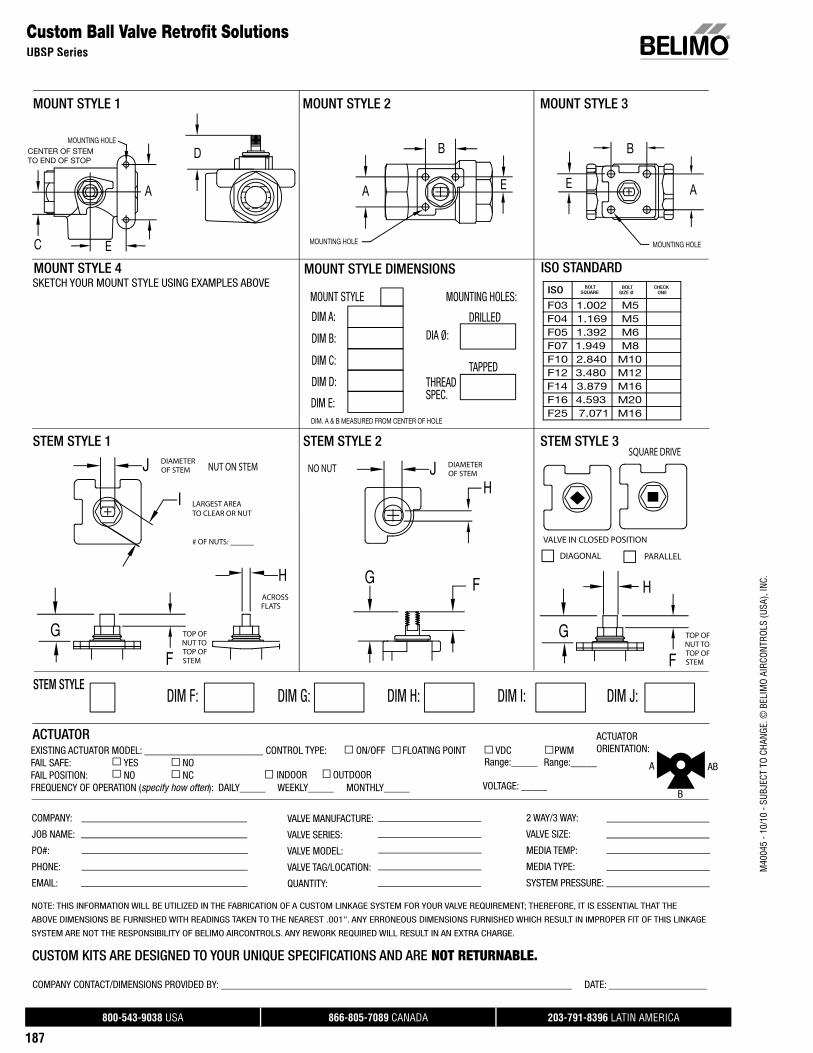
800-543-9038 USA 866-805-7089 CANADA 203-791-8396 LATIN AMERICA
187
EXISTING ACTUATOR MODEL: _______________________ CONTROL TYPE: ON/OFF FLOATING POINT VDC PWM FAIL SAFE: YES NOFAIL POSITION: NO NC FREQUENCY OF OPERATION (specify how often): DAILY_____ WEEKLY_____ MONTHLY_____
ACTUATORORIENTATION:
SKETCH YOUR MOUNT STYLE USING EXAMPLES ABOVE
DIA Ø:DRILLED
MOUNTING HOLES:MOUNT STYLE
DIM C:
DIM B:
DIM A:
A A
B
THREAD SPEC.
DIM. A & B MEASURED FROM CENTER OF HOLE
TAPPED
ACTUATOR
B
A
MOUNTING HOLE
HACROSS FLATS
I LARGEST AREATO CLEAR OR NUT
# OF NUTS: ______
G
F
TOP OF NUT TO TOP OF STEM
J DIAMETER OF STEM
C
J DIAMETER OF STEM
NUT ON STEM NO NUT
G F
STEM STYLE 1
DIM D:
D
STEM STYLE 2
MOUNT STYLE 1 MOUNT STYLE 2 MOUNT STYLE 3
MOUNT STYLE 4
STEM STYLE 3
VALVE IN CLOSED POSITION
DIM H:DIM G:DIM F:STEM STYLE
DIM I: DIM J:
CENTER OF STEMTO END OF STOP
MOUNTING HOLE MOUNTING HOLE
ISO STANDARD
H
H
G
F
TOP OF NUT TO TOP OF STEM
DIAGONAL PARALLEL
2 WAY/3 WAY:
VALVE SIZE:
MEDIA TEMP:
MEDIA TYPE:
SYSTEM PRESSURE:
VALVE MANUFACTURE:
VALVE SERIES:
VALVE MODEL:
VALVE TAG/LOCATION:
QUANTITY:
ISO BOLT SQUARE
BOLT SIZE Ø
CHECK ONE
F03 1.002 M5F04 1.169 M5F05 1.392 M6F07 1.949 M8F10 2.840 M10F12 3.480 M12F14 3.879 M16F16 4.593 M20F25 7.071 M16
Range:_____
COMPANY:
JOB NAME:
PO#:
PHONE:
EMAIL:
NOTE: THIS INFORMATION WILL BE UTILIZED IN THE FABRICATION OF A CUSTOM LINKAGE SYSTEM FOR YOUR VALVE REQUIREMENT; THEREFORE, IT IS ESSENTIAL THAT THE
ABOVE DIMENSIONS BE FURNISHED WITH READINGS TAKEN TO THE NEAREST .001". ANY ERRONEOUS DIMENSIONS FURNISHED WHICH RESULT IN IMPROPER FIT OF THIS LINKAGE
SYSTEM ARE NOT THE RESPONSIBILITY OF BELIMO AIRCONTROLS. ANY REWORK REQUIRED WILL RESULT IN AN EXTRA CHARGE.
CUSTOM KITS ARE DESIGNED TO YOUR UNIQUE SPECIFICATIONS AND ARE NOT RETURNABLE. COMPANY CONTACT/DIMENSIONS PROVIDED BY: ____________________________________________________________________ DATE: ___________________
A AB
B
INDOOR OUTDOOR
DIM E:
E E
E
MOUNT STYLE DIMENSIONS
Range:_____
SQUARE DRIVE
VOLTAGE: _____
Custom Ball Valve Retrofi t SolutionsUBSP Series
M40
045
- 10/
10 -
SUBJ
ECT
TO C
HANG
E. ©
BEL
IMO
AIRC
ONTR
OLS
(USA
), IN
C.
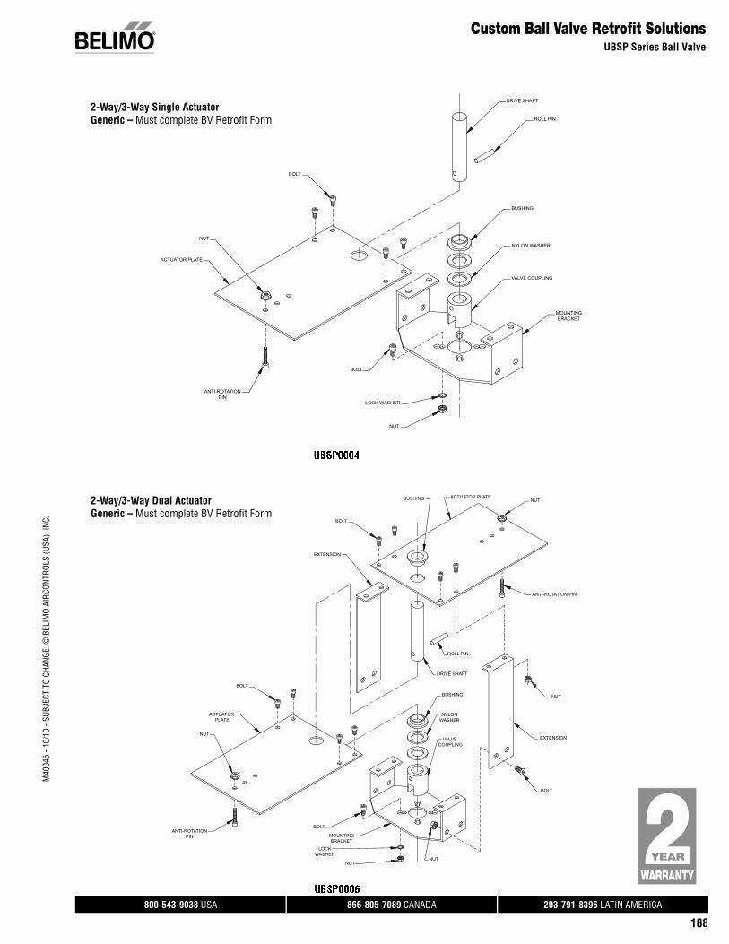
800-543-9038 USA 866-805-7089 CANADA 203-791-8396 LATIN AMERICA
188
Custom Ball Valve Retrofi t SolutionsUBSP Series Ball Valve
M40
045
- 10/
10 -
SUBJ
ECT
TO C
HANG
E. ©
BEL
IMO
AIRC
ONTR
OLS
(USA
), IN
C.
2-Way/3-Way Single ActuatorGeneric – Must complete BV Retrofit Form
DRIVE SHAFT
ROLL PIN
BUSHING
NYLON WASHER
VALVE COUPLING
MOUNTINGBRACKET
NUT
LOCK WASHER
BOLT
ANTI-ROTATIONPIN
ACTUATOR PLATE
NUT
BOLT
2-Way/3-Way Dual ActuatorGeneric – Must complete BV Retrofit Form
NUT
ANTI-ROTATION PIN
NUT
EXTENSION
EXTENSION
BOLT
BUSHING ACTUATOR PLATE
ROLL PIN
DRIVE SHAFT
BUSHING
NYLONWASHER
VALVE COUPLING
NUTNUT
LOCKWASHER
MOUNTINGBRACKET
BOLTANTI-ROTATION
PIN
NUT
ACTUATOR PLATE
BOLT
BOLT
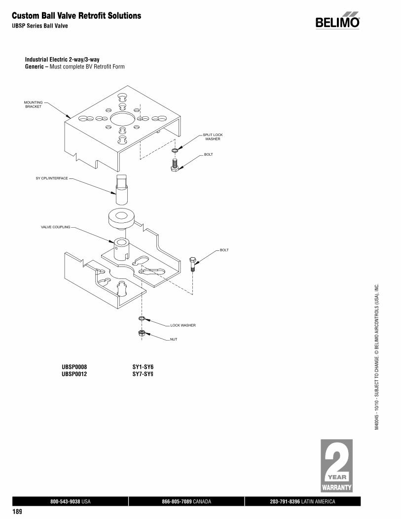
800-543-9038 USA 866-805-7089 CANADA 203-791-8396 LATIN AMERICA
189
Custom Ball Valve Retrofi t SolutionsUBSP Series Ball Valve
M40
045
- 10/
10 -
SUBJ
ECT
TO C
HANG
E. ©
BEL
IMO
AIRC
ONTR
OLS
(USA
), IN
C.
Industrial Electric 2-way/3-wayGeneric – Must complete BV Retrofit Form
MOUNTINGBRACKET
SY CPL/INTERFACE
VALVE COUPLING
NUT
LOCK WASHER
BOLT
BOLT
SPLIT LOCKWASHER
UBSP0008 SY1-SY6UBSP0012 SY7-SY9
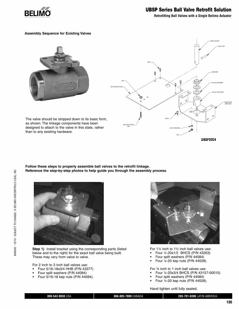
800-543-9038 USA 866-805-7089 CANADA 203-791-8396 LATIN AMERICA
190
M40
045
- 10/
10 -
SUBJ
ECT
TO C
HANG
E. ©
BEL
IMO
AIRC
ONTR
OLS
(USA
), IN
C.
DRIVE SHAFT
ROLL PIN
BUSHING
NYLON WASHER
VALVE COUPLING
MOUNTINGBRACKET
NUT
LOCK WASHER
BOLT
ANTI-ROTATIONPIN
ACTUATOR PLATE
NUT
BOLT
UBSP Series Ball Valve Retrofit SolutionRetrofitting Ball Valves with a Single Belimo Actuator
Step 1) Install bracket using the corresponding parts (listedbelow and to the right) for the exact ball valve being built. These may vary from valve to valve.
For 2 inch to 3 inch ball valves use: Four 5/16-18x3/4 HHB (P/N 43377) Four split washers (P/N 44084) Four 5/16-18 kep nuts (P/N 44094).
Follow these steps to properly assemble ball valves to the retrofit linkage. Reference the step-by-step photos to help guide you through the assembly process.
The valve should be stripped down to its basic form,as shown. The linkage components have been designed to attach to the valve in this state, rather than to any existing hardware.
For 1¼ inch to 1½ inch ball valves use:Four ¼-20x1/2 BHCS (P/N 43263)Four split washers (P/N 44084)Four ¼-20 kep nuts (P/N 44028).
For ¾ inch to 1 inch ball valves use:Four ¼-20x3/4 BHCS (P/N 43157-00010)Four split washers (P/N 44084)Four ¼-20 kep nuts (P/N 44028).
Hand tighten until fully seated.
Assembly Sequence for Existing Valves
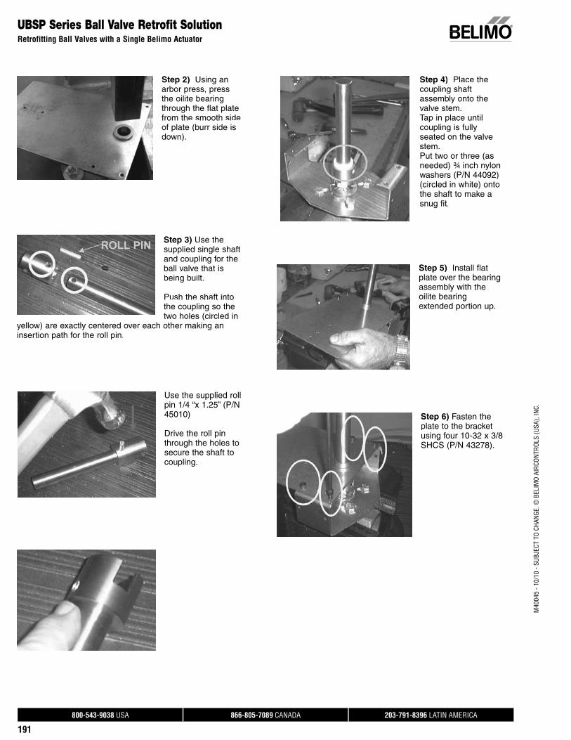
800-543-9038 USA 866-805-7089 CANADA 203-791-8396 LATIN AMERICA
191
M40
045
- 10/
10 -
SUBJ
ECT
TO C
HANG
E. ©
BEL
IMO
AIRC
ONTR
OLS
(USA
), IN
C.
UBSP Series Ball Valve Retrofit SolutionRetrofitting Ball Valves with a Single Belimo Actuator
Step 2) Using an arbor press, pressthe oilite bearing through the flat plate from the smooth side of plate (burr side isdown).
Step 3) Use thesupplied single shaftand coupling for theball valve that isbeing built.
Push the shaft into the coupling so the two holes (circled in
yellow) are exactly centered over each other making an insertion path for the roll pin.
Use the supplied rollpin 1/4 “x 1.25” (P/N 45010)
Drive the roll pin through the holes to secure the shaft to coupling.
Step 4) Place thecoupling shaft assembly onto the valve stem.Tap in place untilcoupling is fully seated on the valve stem.Put two or three (asneeded) ¾ inch nylonwashers (P/N 44092) (circled in white) onto the shaft to make asnug fit.
Step 5) Install flatplate over the bearingassembly with the oilite bearingextended portion up.
Step 6) Fasten theplate to the bracketusing four 10-32 x 3/8SHCS (P/N 43278).
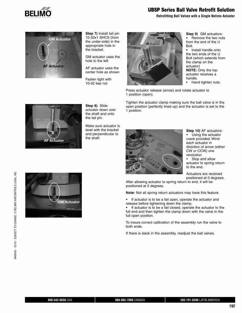
800-543-9038 USA 866-805-7089 CANADA 203-791-8396 LATIN AMERICA
192
M40
045
- 10/
10 -
SUBJ
ECT
TO C
HANG
E. ©
BEL
IMO
AIRC
ONTR
OLS
(USA
), IN
C.
UBSP Series Ball Valve Retrofit SolutionRetrofitting Ball Valves with a Single Belimo Actuator
Step 7) Install tail pin 10-32x1 SHCS (from the under-side) in the appropriate hole in the bracket.
GM actuator uses the hole to the left
AF actuator uses the center hole as shown
Fasten tight with10-32 kep nut
Step 8) Slideactuator down overthe shaft and onto the tail pin.
Make sure actuator islevel with the bracketand perpendicular to the shaft.
Step 9) GM actuators:Remove the two nuts from the end of the U Bolt. Install handle onto the two ends of the U Bolt (which extends fromthe clamp on the actuator)NOTE: Only the top actuator receives ahandle.Hand tighten nuts.
Press actuator release (arrow) and rotate actuator to 1 position (open).
Tighten the actuator clamp making sure the ball valve is in the open position (perfectly lined up) and the actuator is set to the 1 position.
Step 10) AF actuators: Using the actuator crank provided. Wind each actuator in direction of arrow (eitherCW or CCW) one revolution. Stop and allow actuator to spring return to the end.
Actuators are received positioned at 0 degrees.
After allowing actuator to spring return to end, it will bepositioned at 5 degrees.
Note: Not all spring return actuators may have this feature.
If actuator is to be a fail open, operate the actuator and release before tightening down the clamp. If actuator is to be a fail closed, operate the actuator to thefull end and then tighten the clamp down with the valve in thefull open position.
To insure correct calibration of the assembly run the valve toboth ends.
If there is slack in the assembly, readjust the ball valves.

800-543-9038 USA 866-805-7089 CANADA 203-791-8396 LATIN AMERICA
193
M40
045
- 10/
10 -
SUBJ
ECT
TO C
HANG
E. ©
BEL
IMO
AIRC
ONTR
OLS
(USA
), IN
C.
UBSP Series Ball Valve Retrofit SolutionRetrofitting Ball Valves with a Single Belimo Actuator
Step 11) For 3-wayball valves:The 3-way ball valveassembly is completed the same way with AF, GM,single, actuators.
Note: If using a spring return actuator pleaseverify what partshould be open and closed.
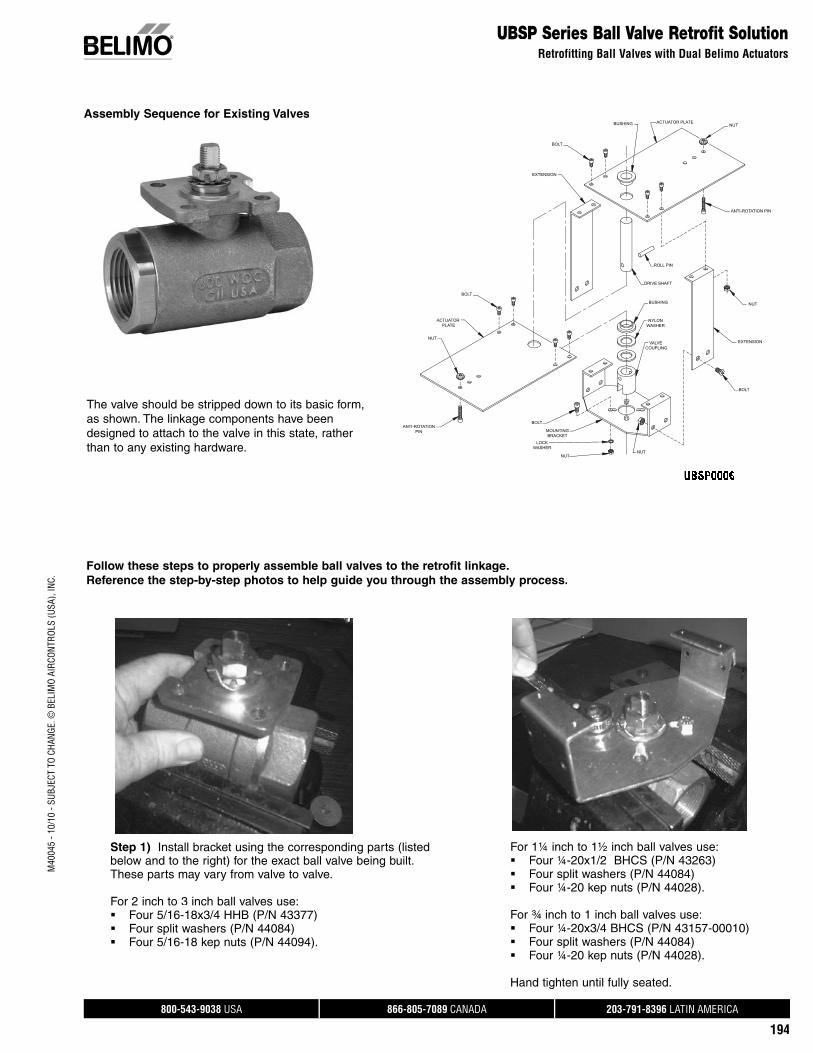
800-543-9038 USA 866-805-7089 CANADA 203-791-8396 LATIN AMERICA
194
M40
045
- 10/
10 -
SUBJ
ECT
TO C
HANG
E. ©
BEL
IMO
AIRC
ONTR
OLS
(USA
), IN
C.
UBSP Series Ball Valve Retrofit SolutionRetrofitting Ball Valves with Dual Belimo Actuators
NUT
ANTI-ROTATION PIN
NUT
EXTENSION
EXTENSION
BOLT
BUSHING ACTUATOR PLATE
ROLL PIN
DRIVE SHAFT
BUSHING
NYLONWASHER
VALVE COUPLING
NUTNUT
LOCKWASHER
MOUNTINGBRACKET
BOLTANTI-ROTATION
PIN
NUT
ACTUATOR PLATE
BOLT
BOLT
Step 1) Install bracket using the corresponding parts (listedbelow and to the right) for the exact ball valve being built. These parts may vary from valve to valve.
For 2 inch to 3 inch ball valves use: Four 5/16-18x3/4 HHB (P/N 43377) Four split washers (P/N 44084) Four 5/16-18 kep nuts (P/N 44094).
Follow these steps to properly assemble ball valves to the retrofit linkage. Reference the step-by-step photos to help guide you through the assembly process.
The valve should be stripped down to its basic form,as shown. The linkage components have been designed to attach to the valve in this state, rather than to any existing hardware.
For 1¼ inch to 1½ inch ball valves use:Four ¼-20x1/2 BHCS (P/N 43263)Four split washers (P/N 44084)Four ¼-20 kep nuts (P/N 44028).
For ¾ inch to 1 inch ball valves use:Four ¼-20x3/4 BHCS (P/N 43157-00010)Four split washers (P/N 44084)Four ¼-20 kep nuts (P/N 44028).
Hand tighten until fully seated.
Assembly Sequence for Existing Valves
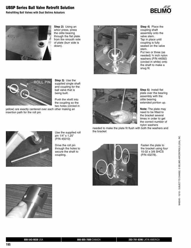
800-543-9038 USA 866-805-7089 CANADA 203-791-8396 LATIN AMERICA
195
M40
045
- 10/
10 -
SUBJ
ECT
TO C
HANG
E. ©
BEL
IMO
AIRC
ONTR
OLS
(USA
), IN
C.
UBSP Series Ball Valve Retrofit SolutionRetrofitting Ball Valves with Dual Belimo Actuators
Step 2) Using an arbor press, pressthe oilite bearing through the flat plate from the smooth side of plate (burr side isdown).
Step 3) Use thesupplied single shaftand coupling for theball valve that isbeing built.
Push the shaft into the coupling so the two holes (circled in
yellow) are exactly centered over each other making an insertion path for the roll pin.
Use the supplied rollpin 1/4” x 1.25” (P/N 45010)
Drive the roll pin through the holes to secure the shaft to coupling.
Step 4) Place thecoupling shaft assembly onto the valve stem.Tap in place untilcoupling is fully seated on the valve stem.Put two or three (asneeded) ¾ inch nylonwashers (P/N 44092) (circled in white) onto the shaft to make asnug fit.
Step 5) Install flatplate over the bearingassembly with the oilite bearingextended portion up.
Note: The plate may need to be fitted tothe bracket severaltimes in order to get the correct number ofnylon washers
needed to make the plate fit flush with both the washers andthe bracket.
Fasten the plate tothe bracket using four10-32 x 3/8 SHCS (P/N 43278).
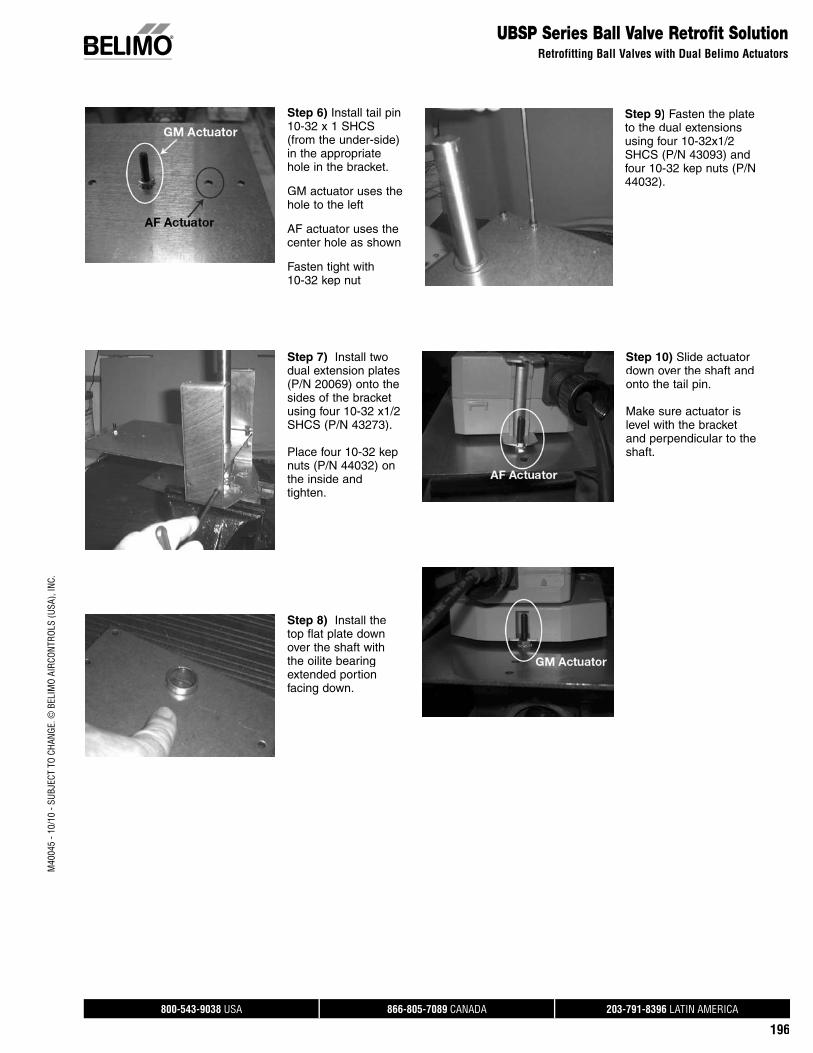
800-543-9038 USA 866-805-7089 CANADA 203-791-8396 LATIN AMERICA
196
M40
045
- 10/
10 -
SUBJ
ECT
TO C
HANG
E. ©
BEL
IMO
AIRC
ONTR
OLS
(USA
), IN
C.
Step 8) Install thetop flat plate downover the shaft with the oilite bearing extended portion facing down.
UBSP Series Ball Valve Retrofit SolutionRetrofitting Ball Valves with Dual Belimo Actuators
Step 6) Install tail pin 10-32 x 1 SHCS(from the under-side) in the appropriate hole in the bracket.
GM actuator uses the hole to the left
AF actuator uses the center hole as shown
Fasten tight with10-32 kep nut
Step 7) Install twodual extension plates (P/N 20069) onto the sides of the bracket using four 10-32 x1/2SHCS (P/N 43273).
Place four 10-32 kepnuts (P/N 44032) onthe inside and tighten.
Step 9) Fasten the plateto the dual extensions using four 10-32x1/2SHCS (P/N 43093) and four 10-32 kep nuts (P/N 44032).
Step 10) Slide actuator down over the shaft andonto the tail pin.
Make sure actuator islevel with the bracketand perpendicular to the shaft.
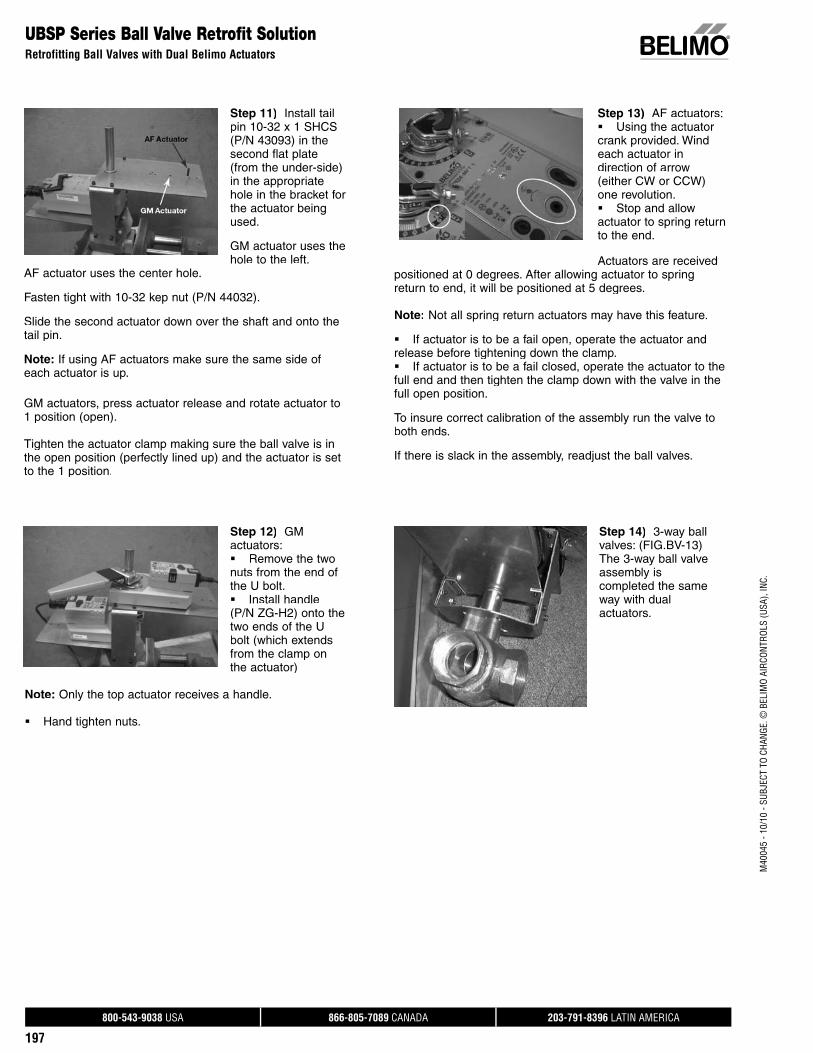
800-543-9038 USA 866-805-7089 CANADA 203-791-8396 LATIN AMERICA
197
M40
045
- 10/
10 -
SUBJ
ECT
TO C
HANG
E. ©
BEL
IMO
AIRC
ONTR
OLS
(USA
), IN
C.
Step 14) 3-way ball valves: (FIG.BV-13)The 3-way ball valve assembly iscompleted the same way with dualactuators.
Step 11) Install tailpin 10-32 x 1 SHCS (P/N 43093) in the second flat plate(from the under-side) in the appropriate hole in the bracket forthe actuator beingused.
GM actuator uses the hole to the left.
AF actuator uses the center hole.
Fasten tight with 10-32 kep nut (P/N 44032).
Slide the second actuator down over the shaft and onto the tail pin.
Note: If using AF actuators make sure the same side ofeach actuator is up.
GM actuators, press actuator release and rotate actuator to1 position (open).
Tighten the actuator clamp making sure the ball valve is inthe open position (perfectly lined up) and the actuator is set to the 1 position.
Step 13) AF actuators:Using the actuator crank provided. Windeach actuator in direction of arrow (either CW or CCW) one revolution.Stop and allow actuator to spring returnto the end.
Actuators are received positioned at 0 degrees. After allowing actuator to springreturn to end, it will be positioned at 5 degrees.
Note: Not all spring return actuators may have this feature.
If actuator is to be a fail open, operate the actuator and release before tightening down the clamp. If actuator is to be a fail closed, operate the actuator to thefull end and then tighten the clamp down with the valve in thefull open position.
To insure correct calibration of the assembly run the valve toboth ends.
If there is slack in the assembly, readjust the ball valves.
UBSP Series Ball Valve Retrofit SolutionRetrofitting Ball Valves with Dual Belimo Actuators
Step 12) GM actuators:Remove the twonuts from the end of the U bolt. Install handle (P/N ZG-H2) onto the two ends of the U bolt (which extendsfrom the clamp on the actuator)
Note: Only the top actuator receives a handle.
Hand tighten nuts.
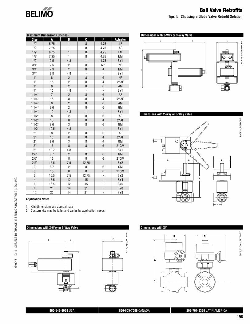
800-543-9038 USA 866-805-7089 CANADA 203-791-8396 LATIN AMERICA
198
Maximum Dimensions (Inches)Size A B C F Actuator1/2" 6.75 1 8 4.75 LF1/2" 7.25 1 8 4.75 AF1/2" 6.75 1 8 4.75 LM1/2" 7.25 1 8 4.75 NM1/2" 9.5 4.8 - 4.75 SY13/4" 7.5 2 8 6.5 NF3/4" 7.3 2 8 4 NM3/4" 9.8 4.8 - - SY11" 8 2 8 6 NF1" 15 2 8 4 2*AF1" 8 2 8 6 AM1" 10 4.8 - - SY1
1 1/4" 7 2 8 6 AF1 1/4" 15 8 8 4 2*AF1 1/4" 8 2 8 6 AM1 1/4" 8.6 2 8 6 GM1 1/4" 10 4.8 - - SY11 1/2" 8 2 8 6 AF1 1/2" 13 8 8 4 2*AF1 1/2" 8.6 2 8 6 GM1 1/2" 10.5 4.8 - - SY1
2" 8 2 8 6 AF2" 15 8 8 4 2*AF2" 8.6 2 8 6 GM2" 15 8 8 6 2*GM2" 10.7 4.8 - - SY1
2½” 8.7 2 8 6 GM2½” 15 8 8 6 2*GM2½” 15.5 7.5 12.75 - SY2
3 8.7 2 8 6 GM3 15 8 8 6 2*GM3 15.5 7.5 12.75 - SY24 16.5 12 15 - SY46 16.5 12 15 - SY58 20 14 21 - SY8
10 20 14 21 - SY8
Application Notes
1. Kits dimensions are approximate2. Custom kits may be taller and varies by application needs
Dimensions with 2-Way or 3-Way Valve
F
A
BC
B31
5_LF
ps_R
ET
RO
FIT
Dimensions with 2-Way or 3-Way Valve
B32
5VS
2AF.
psR
ET
RO
FITFBC
A
Dimensions with SY
A
B6V
S_S
YD
ims_
RE
TR
OF
IT
Dimensions with 2-Way or 3-Way Valve
A
BC F
E
PAG
E11
_RE
TR
OF
IT
M40
045
- 10/
10 -
SUBJ
ECT
TO C
HANG
E. ©
BEL
IMO
AIRC
ONTR
OLS
(USA
), IN
C.
Ball Valve RetrofitsTips for Choosing a Globe Valve Retrofit Solution
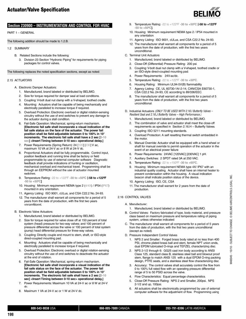
800-543-9038 USA 866-805-7089 CANADA 203-791-8396 LATIN AMERICA
199
M40
045
- 10/
10 -
SUBJ
ECT
TO C
HANG
E. ©
BEL
IMO
AIRC
ONTR
OLS
(USA
), IN
C.
Section 230900 – INSTRUMENTATION AND CONTROL FOR HVAC
PART 1 – GENERAL
The following addition should be made to 1.2.B.
1.2 SUMMARY
B. Related Sections include the following:3. Division 23 Section “Hydronic Piping” for requirements for piping
packages for control valves.
The following replaces the noted specification sections, except as noted.
2.15 ACTUATORS
A. Electronic Damper Actuators: 1. Manufactured, brand labeled or distributed by BELIMO.2. Size for torque required for damper seal at load conditions. 3. Coupling: V-bolt dual nut clamp with a V-shaped, toothed cradle. 4. Mounting: Actuators shall be capable of being mechanically and
electrically paralleled to increase torque if required. 5. Overload Protection: Electronic overload or digital rotation-sensing
circuitry without the use of end switches to prevent any damage tothe actuator during a stall condition.
6. Fail-Safe Operation: Mechanical, spring-return mechanism. [Electronic fail safe shall incorporate a visual indication of thefail safe status on the face of the actuator. The power failposition shall be field adjustable between 0 to 100% in 10°increments. The electronic fail safe shall have a 2 sec [0-10 sec] <Insert Timing between 0-10 sec> operational delay.]
7. Power Requirements (Spring Return): 24 [120] [230] V ac,maximum 10 VA at 24-V ac or 8 W at 24-V dc.
8. Proportional Actuators shall be fully programmable. Control input,position feedback and running time shall be factory or fieldprogrammable by use of external computer software Diagnostic feedback shall provide indications of hunting or oscillation,mechanical overload and mechanical travel. Programming shall be through an EEPROM without the use of actuator mountedswitches.
9. Temperature Rating: -22 to +122ºF -30 to +50ºC [-58 to +122ºF -50 to +50ºC]
10. Housing: Minimum requirement NEMA type 2 (4/4X) / IP54 (IP67)mounted in any orientation.
11. Agency Listing: ISO 9001, cULus, and CSA C22.2 No. 24-93.12. The manufacturer shall warrant all components for a period of 5
years from the date of production, with the first two years unconditional.
B. Electronic Valve Actuators:1. Manufactured, brand labeled or distributed by BELIMO.2. Size for torque required for valve close off at 150 percent of total
system (head) pressure for two-way valves; and 100 percent of pressure differential across the valve or 100 percent of total system(pump) head differential pressure for three-way valves.
3. Coupling: Directly couple end mount to stem, shaft, or ISO-style direct-coupled mounting pad.
4. Mounting: Actuators shall be capable of being mechanically andelectrically paralleled to increase torque if required.
5. Overload Protection: Electronic overload or digital rotation-sensing circuitry without the use of end switches to deactivate the actuatorat the end of rotation.
6. Fail-Safe Operation: Mechanical, spring-return mechanism. [Electronic fail safe shall incorporate a visual indication of thefail safe status on the face of the actuator. The power failposition shall be field adjustable between 0 to 100% in 10°increments. The electronic fail safe shall have a 2 sec [0-10 sec] <Insert Timing between 0-10 sec> operational delay.]
7. Power Requirements: Maximum 10 VA at 24-V ac or 8 W at 24-Vdc.
8. Maximum 1 VA at 24-V ac or 1 W at 24-V dc.
9. Temperature Rating: -22 to +122ºF -30 to +50ºC [-58 to +122ºF-50 to +50ºC].
10. Housing: Minimum requirement NEMA type 2 / IP54 mounted inany orientation.
11. Agency Listing: ISO 9001, cULus, and CSA C22.2 No. 24-93.12. The manufacturer shall warrant all components for a period of 5
years from the date of production, with the first two yearsunconditional.
C. Terminal Unit Actuators:1. Manufactured, brand labeled or distributed by BELIMO.2. Close-Off (Differential) Pressure Rating: 200 psi.3. Coupling: V-bolt dual nut clamp with a V-shaped, toothed cradle or
an ISO-style direct-coupled mounting pad.4. Power Requirements: 24V-ac/dc.5. Temperature Rating: -22 to +122ºF -30 to +50ºC.6. Housing Rating: Minimum UL94-5V(B) flammability.7. Agency Listing: CE, UL 60730-1A/-2-14, CAN/CSA E60730-1,
CSA C22.2 No. 24-93, CE according to 89/336/EEC.8. The manufacturer shall warrant all components for a period of 5
years from the date of production, with the first two yearsunconditional.
D. Industrial Actuators (ONLY TO BE USED WITH 2.16.I Butterfly Valves – Resilient Seat and 2.16.J Butterfly Valves – High Performance.)1. Manufactured, brand labeled or distributed by BELIMO.2. The combination of valve and actuator shall meet the close-off
requirements as specified in Section 2.16.H – Butterfly Valves.3. Coupling: ISO 5211 mounting standards.4. Overload Protection: A self resetting thermal switch embedded in
the motor. 5. Manual Override: Actuator shall be equipped with a hand wheel or
shaft for manual override to permit operation of the actuator in theevent of an electrical power failure
6. Power Requirements: 24VAC [120VAC] [230VAC] 1 pH.7. Auxiliary Switches: 2 SPDT rated 3A at 250 VAC.8. Temperature Rating: -22 to +150ºF -30 to +65ºC.9. Housing: Minimum requirement NEMA type 4X/ IP67 with an
industrial quality coating. Actuator shall have an internal heater toprevent condensation within the housing. A visual indicationbeacon shall indicate position status of the device.
10. Agency Listing: ISO, CE, CSA11. The manufacturer shall warrant for 2 years from the date of
production.
2.16 CONTROL VALVES
A. Manufacturer:1. Manufactured, brand labeled or distributed by BELIMO.
B. Control Valves: Factory fabricated of type, body material, and pressureclass based on maximum pressure and temperature rating of piping system, unless otherwise indicated.
C. The manufacturer shall warrant all components for a period of 5 yearsfrom the date of production, with the first two years unconditional(except as noted).
D. Pressure Independent Control Valves 1. NPS 2 and Smaller: Forged brass body rated at no less than 400
PSI, chrome plated brass ball and stem, female NPT union ends, dual EPDM lubricated O-rings and TEFZEL characterizing disc.
2. NPS 2-1/2 through 6: GG25 cast iron body according to ANSIClass 125, standard class B, stainless steel ball and blowout proof stem, flange to match ANSI 125 with a dual EPDM O-ring packingdesign, PTFE seats, and a stainless steel flow characterizing disc.
3. Accuracy: The control valves shall accurately control the flow from0 to 100% full rated flow with an operating pressure differential range of 5 to 50 PSID across the valve.
4. Flow Characteristics: Equal percentage characteristics.5. Close-Off Pressure Rating: NPS 2 and Smaller, 200psi. NPS
2-1/2 and up, 100psi.6. All actuators shall be electronically programmed by use of external
computer software for the adjustment of flow. Programming using
Actuator/Valve Specifi cation
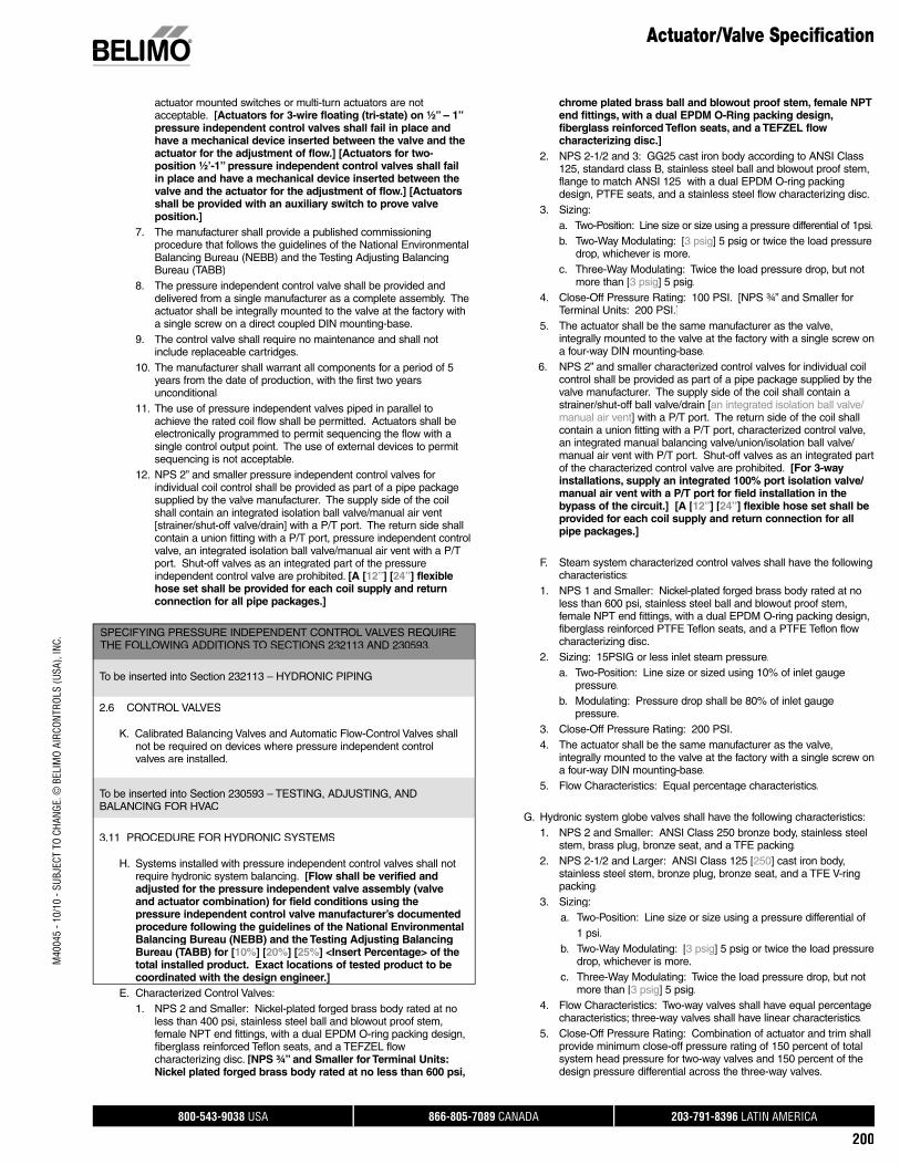
800-543-9038 USA 866-805-7089 CANADA 203-791-8396 LATIN AMERICA
200
M40
045
- 10/
10 -
SUBJ
ECT
TO C
HANG
E. ©
BEL
IMO
AIRC
ONTR
OLS
(USA
), IN
C.
actuator mounted switches or multi-turn actuators are notacceptable. [Actuators for 3-wire floating (tri-state) on ½” – 1” pressure independent control valves shall fail in place and have a mechanical device inserted between the valve and theactuator for the adjustment of flow.] [Actuators for two-position ½’-1” pressure independent control valves shall failin place and have a mechanical device inserted between thevalve and the actuator for the adjustment of flow.] [Actuatorsshall be provided with an auxiliary switch to prove valve position.]
7. The manufacturer shall provide a published commissioning procedure that follows the guidelines of the National EnvironmentalBalancing Bureau (NEBB) and the Testing Adjusting BalancingBureau (TABB)
8. The pressure independent control valve shall be provided anddelivered from a single manufacturer as a complete assembly. Theactuator shall be integrally mounted to the valve at the factory witha single screw on a direct coupled DIN mounting-base.
9. The control valve shall require no maintenance and shall not include replaceable cartridges.
10. The manufacturer shall warrant all components for a period of 5years from the date of production, with the first two yearsunconditional.
11. The use of pressure independent valves piped in parallel toachieve the rated coil flow shall be permitted. Actuators shall beelectronically programmed to permit sequencing the flow with a single control output point. The use of external devices to permit sequencing is not acceptable.
12. NPS 2” and smaller pressure independent control valves forindividual coil control shall be provided as part of a pipe packagesupplied by the valve manufacturer. The supply side of the coil shall contain an integrated isolation ball valve/manual air vent [strainer/shut-off valve/drain] with a P/T port. The return side shallcontain a union fitting with a P/T port, pressure independent controlvalve, an integrated isolation ball valve/manual air vent with a P/Tport. Shut-off valves as an integrated part of the pressure independent control valve are prohibited. [A [12”] [24”] flexiblehose set shall be provided for each coil supply and return connection for all pipe packages.]
SPECIFYING PRESSURE INDEPENDENT CONTROL VALVES REQUIRETHE FOLLOWING ADDITIONS TO SECTIONS 232113 AND 230593.
To be inserted into Section 232113 – HYDRONIC PIPING
2.6 CONTROL VALVES
K. Calibrated Balancing Valves and Automatic Flow-Control Valves shall not be required on devices where pressure independent control valves are installed.
To be inserted into Section 230593 – TESTING, ADJUSTING, ANDBALANCING FOR HVAC
3.11 PROCEDURE FOR HYDRONIC SYSTEMS
H. Systems installed with pressure independent control valves shall not require hydronic system balancing. [Flow shall be verified and adjusted for the pressure independent valve assembly (valve and actuator combination) for field conditions using the pressure independent control valve manufacturer’s documented procedure following the guidelines of the National Environmental Balancing Bureau (NEBB) and the Testing Adjusting BalancingBureau (TABB) for [10%] [20%] [25%] <Insert Percentage> of the total installed product. Exact locations of tested product to be coordinated with the design engineer.]
E. Characterized Control Valves: 1. NPS 2 and Smaller: Nickel-plated forged brass body rated at no
less than 400 psi, stainless steel ball and blowout proof stem,female NPT end fittings, with a dual EPDM O-ring packing design,fiberglass reinforced Teflon seats, and a TEFZEL flow characterizing disc. [NPS ¾” and Smaller for Terminal Units: Nickel plated forged brass body rated at no less than 600 psi,
chrome plated brass ball and blowout proof stem, female NPTend fittings, with a dual EPDM O-Ring packing design,fiberglass reinforced Teflon seats, and a TEFZEL flowcharacterizing disc.]
2. NPS 2-1/2 and 3: GG25 cast iron body according to ANSI Class125, standard class B, stainless steel ball and blowout proof stem,flange to match ANSI 125 with a dual EPDM O-ring packingdesign, PTFE seats, and a stainless steel flow characterizing disc.
3. Sizing: a. Two-Position: Line size or size using a pressure differential of 1psi. b. Two-Way Modulating: [3 psig] 5 psig or twice the load pressure
drop, whichever is more. c. Three-Way Modulating: Twice the load pressure drop, but not
more than [3 psig] 5 psig.4. Close-Off Pressure Rating: 100 PSI. [NPS ¾” and Smaller for
Terminal Units: 200 PSI.]5. The actuator shall be the same manufacturer as the valve,
integrally mounted to the valve at the factory with a single screw ona four-way DIN mounting-base.
6. NPS 2” and smaller characterized control valves for individual coilcontrol shall be provided as part of a pipe package supplied by thevalve manufacturer. The supply side of the coil shall contain astrainer/shut-off ball valve/drain [an integrated isolation ball valve/manual air vent] with a P/T port. The return side of the coil shallcontain a union fitting with a P/T port, characterized control valve,an integrated manual balancing valve/union/isolation ball valve/manual air vent with P/T port. Shut-off valves as an integrated partof the characterized control valve are prohibited. [For 3-way installations, supply an integrated 100% port isolation valve/manual air vent with a P/T port for field installation in thebypass of the circuit.] [A [12”] [24”] flexible hose set shall be provided for each coil supply and return connection for allpipe packages.]
F. Steam system characterized control valves shall have the followingcharacteristics:
1. NPS 1 and Smaller: Nickel-plated forged brass body rated at no less than 600 psi, stainless steel ball and blowout proof stem,female NPT end fittings, with a dual EPDM O-ring packing design,fiberglass reinforced PTFE Teflon seats, and a PTFE Teflon flowcharacterizing disc.
2. Sizing: 15PSIG or less inlet steam pressure.a. Two-Position: Line size or sized using 10% of inlet gauge
pressure.b. Modulating: Pressure drop shall be 80% of inlet gauge
pressure. 3. Close-Off Pressure Rating: 200 PSI. 4. The actuator shall be the same manufacturer as the valve,
integrally mounted to the valve at the factory with a single screw ona four-way DIN mounting-base.
5. Flow Characteristics: Equal percentage characteristics.
G. Hydronic system globe valves shall have the following characteristics:1. NPS 2 and Smaller: ANSI Class 250 bronze body, stainless steel
stem, brass plug, bronze seat, and a TFE packing.2. NPS 2-1/2 and Larger: ANSI Class 125 [250] cast iron body,
stainless steel stem, bronze plug, bronze seat, and a TFE V-ringpacking.
3. Sizing: a. Two-Position: Line size or size using a pressure differential of 1 psi.b. Two-Way Modulating: [3 psig] 5 psig or twice the load pressure
drop, whichever is more.c. Three-Way Modulating: Twice the load pressure drop, but not
more than [3 psig] 5 psig.4. Flow Characteristics: Two-way valves shall have equal percentage
characteristics; three-way valves shall have linear characteristics.5. Close-Off Pressure Rating: Combination of actuator and trim shall
provide minimum close-off pressure rating of 150 percent of totalsystem head pressure for two-way valves and 150 percent of thedesign pressure differential across the three-way valves.
Actuator/Valve Specifi cation
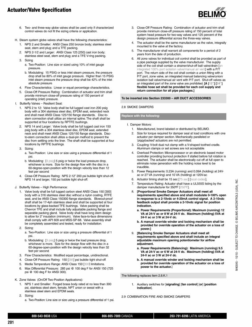
800-543-9038 USA 866-805-7089 CANADA 203-791-8396 LATIN AMERICA
201
6. Two- and three-way globe valves shall be used only if characterizedcontrol valves do not fit the sizing criteria or application.
H. Steam system globe valves shall have the following characteristics:1. NPS 2 and Smaller: ANSI Class 250 bronze body; stainless steel
seat, stem and plug; and a TFE packing.2. NPS 2-1/2 and Larger: ANSI Class 125 [250] cast iron body;
stainless steel seat, stem and plug; and a TFE V-ring packing.3. Sizing:
a. Two-Position: Line size or sized using 10% of inlet gaugepressure.
b. Modulating: 15 PSIG or less inlet steam pressure, the pressure drop shall be 80% of inlet gauge pressure. Higher than 15 PSIG inlet steam pressure the pressure drop shall be 42% of the inlet absolute pressure.
4. Flow Characteristics: Linear or equal percentage characteristics.5. Close-Off Pressure Rating: Combination of actuator and trim shall
provide minimum close-off pressure rating of 150 percent of operating (inlet) pressure.
I. Butterfly Valves – Resilient Seat: 1. NPS 2 to 12: Valve body shall be full lugged cast iron 200 psig
body with a 304 stainless steel disc, EPDM seat, extended neck and shall meet ANSI Class 125/150 flange standards. Disc-to-stem connection shall utilize an internal spline. The shaft shall besupported at four locations by RPTFE bushings.
2. NPS 14 and Larger: Valve body shall be full lugged cast iron 150psig body with a 304 stainless steel disc, EPDM seat, extended neck and shall meet ANSI Class 125/150 flange standards. Disc-to-stem connection shall utilize a dual-pin method to prevent the disc from settling onto the liner. The shaft shall be supported at fourlocations by RPTFE bushings.
3. Sizing: a. Two-Position: Line size or size using a pressure differential of 1
psi.b. Modulating: [3 psig] 5 psig or twice the load pressure drop,
whichever is more. Size for the design flow with the disc in a60-degree-open-position with the design velocity less than 12 feet per second.
4. Close-Off Pressure Rating: NPS 2-12” 200 psi bubble tight shut-off. NPS 14 and larger, 150 psi bubble tight shut-off.
J. Butterfly Valves – High Performance: 1. Valve body shall be full lugged carbon steel ANSI Class 150 [300]
body with a 316 stainless steel disc without a nylon coating, RTFEseat, and be ANSI Class 150300 flange standards. Blowout-proof shaft shall be 17-4ph stainless steel and shall be supported at four locations by glass-backed TFE bushings. Valve packing shall beChevron TFE and shall include fully adjustable packing flange andseparable packing gland. Valve body shall have long stem design to allow for 2” insulation (minimum). Valve face-to-face dimensionsshall comply with API 609 and MSS-SP-68. Valve assembly shallbe completely assembled and tested, ready for installation.
2. Sizing: a. Two-Position: Line size or size using a pressure differential of 1
psi.b. Modulating: [3 psig] 5 psig or twice the load pressure drop,
whichever is more. Size for the design flow with the disc in a60-degree-open-position with the design velocity less than 32 feet per second.
3. Flow Characteristics: Modified equal percentage, unidirectional.4. Close-Off Pressure Rating: 150 [285] psi bubble tight shut-off.5. Media Temperature Range: ANSI Class 150 [300] limitations.6. Max Differential Pressure: 285 psi @ 100 deg F for ANSI 150 (725
psi @ 100 deg F for ANSI 300).
K. Zone Valves (On/Off Two-Position Applications):1. NPS 1 and Smaller: Forged brass body rated at no less than 300
psi, stainless steel stem, female, NPT union or sweat with a stainless steel stem and EPDM seals.
2. Sizing: a. Two-Position: Line size or size using a pressure differential of 1 psi.
3. Close-Off Pressure Rating: Combination of actuator and trim shallprovide minimum close-off pressure rating of 150 percent of totalsystem head pressure for two-way valves and 125 percent of the design pressure differential across the three-way valves.
4. The actuator shall be the same manufacturer as the valve, integrally mounted to the valve at the factory.
5. The manufacturer shall warrant all components for a period of 2years from the date of production.
6. All zone valves for individual coil control shall be provided as part of a pipe package supplied by the valve manufacturer. The supply side of the coil shall contain a strainer/shut-off ball valve/drain [an integrated 100% port isolation valve/manual air vent] with a P/Tport. The return side of the coil shall contain a union fitting with a P/T port, zone valve, an integrated manual balancing valve/union/isolation ball valve/manual air vent with P/T port. Shut-off valves as an integrated part of the zone valve are prohibited. [A [12”] [24”]flexible hose set shall be provided for each coil supply and return connection for all pipe packages.]
To be inserted into Section 233300 – AIR DUCT ACCESSORIES
2.8 SMOKE DAMPERS
Replace with the following:
I. Damper Motors:1. Manufactured, brand labeled or distributed by BELIMO.2. Size for torque required for damper seal at load conditions with one
actuator per damper section. Mechanically paralleled or‘piggybacked’ actuators are not permitted.
3. Coupling: V-bolt dual nut clamp with a V-shaped toothed cradle. Aluminum clamps or set screws are not acceptable.
4. Overload Protection: Microprocessor or an electronic based motor controller providing burnout protection if stalled before full rotation isreached. The actuator shall be electronically cut off at full open to eliminate noise generation with the holding noise level to beinaudible.
5. Power Requirements: 0.23A (running) and 0.09A (holding) at 24V-ac or 27 VA (running) and 10 VA (holding) at 120V-ac.
6. Actuator timing shall be 15 sec [75 sec] [local codes]. 7. Temperature Rating: Actuator shall have a UL555S listing by the
damper manufacturer for 350ºF [250ºF].8. [Proportional Smoke Damper Actuators shall meet all
requirements specified above and shall modulate 0-100% openin response to a 2-10vdc or 4-20mA control signal. A 2-10vdcfeedback output shall provide a 2-10vdc signal for position indication.a. Power Requirements (Proportional): Maximum (running) 12
VA at 24-V ac or 8 W at 24-V dc. Maximum (holding) 5VA at24-V ac or 3 W at 24-V dc.
b. A manual override winder and locking mechanism shall beprovided for override operation of the actuator on a loss ofpower.]
9. [Balancing Smoke Damper Actuators shall meet allrequirements specified above and shall include an integral adjustable maximum opening potentiometer for airflowadjustment. a. Power Requirements (Balancing): Maximum (running) 9.5
VA at 24-V ac or 6 W at 24-V dc. Maximum (holding) 5VA at24-V ac or 3 W at 24-V dc.
b. A manual override winder and locking mechanism shall beprovided for override operation of the actuator on a loss ofpower to the actuator.]
The following replaces item 2.8.K.1
1. Auxiliary switches for [signaling] [fan control] [or] [positionindication].
2.9 COMBINATION FIRE AND SMOKE DAMPERS
Actuator/Valve Specifi cation
M40
045
- 10/
10 -
SUBJ
ECT
TO C
HANG
E. ©
BEL
IMO
AIRC
ONTR
OLS
(USA
), IN
C.
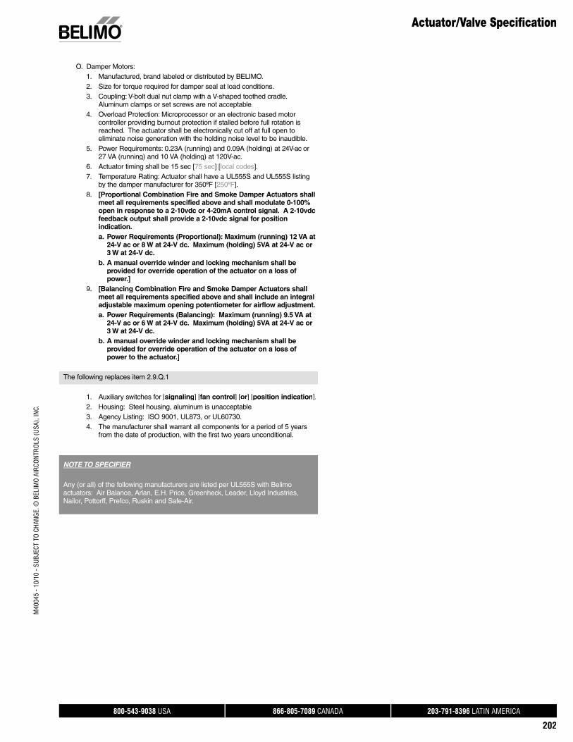
800-543-9038 USA 866-805-7089 CANADA 203-791-8396 LATIN AMERICA
202
O. Damper Motors:1. Manufactured, brand labeled or distributed by BELIMO.2. Size for torque required for damper seal at load conditions.3. Coupling: V-bolt dual nut clamp with a V-shaped toothed cradle.
Aluminum clamps or set screws are not acceptable.4. Overload Protection: Microprocessor or an electronic based motor
controller providing burnout protection if stalled before full rotation isreached. The actuator shall be electronically cut off at full open to eliminate noise generation with the holding noise level to be inaudible.
5. Power Requirements: 0.23A (running) and 0.09A (holding) at 24V-ac or27 VA (running) and 10 VA (holding) at 120V-ac.
6. Actuator timing shall be 15 sec [75 sec] [local codes]. 7. Temperature Rating: Actuator shall have a UL555S and UL555S listing
by the damper manufacturer for 350ºF [250ºF].8. [Proportional Combination Fire and Smoke Damper Actuators shall
meet all requirements specified above and shall modulate 0-100% open in response to a 2-10vdc or 4-20mA control signal. A 2-10vdc feedback output shall provide a 2-10vdc signal for position indication.a. Power Requirements (Proportional): Maximum (running) 12 VA at
24-V ac or 8 W at 24-V dc. Maximum (holding) 5VA at 24-V ac or 3 W at 24-V dc.
b. A manual override winder and locking mechanism shall beprovided for override operation of the actuator on a loss ofpower.]
9. [Balancing Combination Fire and Smoke Damper Actuators shallmeet all requirements specified above and shall include an integral adjustable maximum opening potentiometer for airflow adjustment. a. Power Requirements (Balancing): Maximum (running) 9.5 VA at
24-V ac or 6 W at 24-V dc. Maximum (holding) 5VA at 24-V ac or 3 W at 24-V dc.
b. A manual override winder and locking mechanism shall beprovided for override operation of the actuator on a loss ofpower to the actuator.]
The following replaces item 2.9.Q.1
1. Auxiliary switches for [signaling] [fan control] [or] [position indication].2. Housing: Steel housing, aluminum is unacceptable.3. Agency Listing: ISO 9001, UL873, or UL60730. 4. The manufacturer shall warrant all components for a period of 5 years
from the date of production, with the first two years unconditional.
NOTE TO SPECIFIER
Any (or all) of the following manufacturers are listed per UL555S with Belimo actuators: Air Balance, Arlan, E.H. Price, Greenheck, Leader, Lloyd Industries, Nailor, Pottorff, Prefco, Ruskin and Safe-Air.
Actuator/Valve Specifi cationM
4004
5 - 1
0/10
- SU
BJEC
T TO
CHA
NGE.
© B
ELIM
O AI
RCON
TROL
S (U
SA),
INC.
800-543-9038 USA 866-805-7089 CANADA 203-791-8396 LATIN AMERICA
203
Terms and Conditions
General1.1. The following Terms and Conditions of Sale (“Terms”) apply tothe sale of products described in this Product Guide (“Products”). As used herein, “Seller” or “Belimo” refers to Belimo Aircontrols(USA) Inc. or Belimo Aircontrols (CAN) Inc., as applicable, and“Client” refers to the individual or business entity that purchases theProducts from Seller. These Terms shall apply unless the parties mutually agree to different terms and memorialize such agreementin a writing signed by both Client and Seller.
II. Price2.1. The Seller’s price for Products (the “Price”) is net, F.O.B. Pointof Origin, and is calculated in US currency for sales made byBelimo Aircontrols (USA), Inc. and calculated in Canadian currency for sales made by Belimo Aircontrols (CAN) Inc.2.2. The Price, unless otherwise agreed upon, does not includefreight and packaging (wooden crates, pallets, etc), the costs ofwhich will be charged to Client at cost for each shipment and shallbe payable with payment of the Price.2.3. Orders for Products with a net value of less than US$300(CAN$450) will be subject to a US$20 (CAN$35) handling fee (the“Handling Fee”). The Handling Fee will not be charged for ordersof Products with a net value equal to or greater than US$300 (CAN$450) or for Products ordered through Seller’s internet order-ing system at: www.belimo.com.2.4. Seller reserves the right to make partial deliveries of orders ofProducts, each of which deliveries may be invoiced separately bySeller.2.5. The Price does not include charges for wiring diagrams, instal-lation, and commissioning, which will be charged to Client sepa-rately and will be payable on demand.
III. Payment3.1. Invoices are payable in US currency for sales made by BelimoAircontrols (USA), Inc. and in Canadian currency for sales made by Belimo Aircontrols (CAN) Inc. and are due no later than 30 daysfrom the date of invoice, without any deductions.3.2. If Client fails to pay the entire invoice balance within 60 daysfrom the date of the invoice, Client will be subject to an interest charge of 2% per month (or the maximum rate permitted by law, whichever is less) on the outstanding unpaid balance due to Seller.3.3. Clients who maintain outstanding balances for 45 days or moreafter the date of invoice may be subject to restricted shipments ofProducts or may be required to pay for all future deliveries ofProducts on a cash-on-delivery basis.
IV. Title and Risk4.1. Title to all Products shall remain with Seller and shall not passto Client until Seller has received full payment for the Products.
V. Damage or Loss in Transit5.1. Seller assumes no liability for damage or loss of shipment ofProducts, which risk shall at all times remain with the carrier. Allshipments must be unpacked and examined by Client immediately upon receipt. Any external evidence of loss or damage must benoted on the freight bill accompanying the shipment of Products or carrier’s receipt and signed by the carrier’s agent at the time ofdelivery. Failure to do so will result in the carrier’s refusal to honorany claim relating to damage of Products. Client must also notifySeller of such damage by providing Seller with a copy of the freightbill or damage report so that Seller can file a claim for loss or dam-age in transit with the carrier. If the damage does not become apparent until the shipment is unpacked, Client must make a request for inspection by the carrier’s agent and file with the carrierwithin 15 days after receipt of product and notify Seller of the same.Seller is not liable for consequential damage to Client’s property ora third-party’s property resulting from the installation of damaged
Products.
VI. Delivery 6.1. Seller undertakes to make every attempt to adhere to its stated
delivery parameters and to make a timely delivery of the Productsbut does not guarantee any delivery specifications. Each contractentered into for the purchase of Products is not cancelable nor is Seller liable for any direct or indirect losses that may arise, for anyreason whatsoever, due to Seller’s failure to meet any stated orassumed delivery schedules.
VII. Return of Goods 7.1. Products received by Client cannot be returned unless: (i)
Client alerts Seller that it intends to return such Products, (ii) Selleragrees to accept the return of such Products, (iii) Client obtains aReturn Material Authorization (“RMA”) number from Seller for thereturn of such Products, and (iv) Client follows all return instruc-tions provided by the Seller. The RMA number must be clearly written on the outside of all packaging for any returned Products.Only Products returned to the proper location as instructed bySeller and identified with an RMA number will be considered for credit.
7.2. Only Products that are returned in original packaging may beaccepted for return. All returned Products must be shipped toSeller at Client’s cost. Such returned Products must be received inas-new condition, adequate for resale as new Products to qualifyfor credit. Client will be responsible for payment of a restockingcharge for all returned Products in an amount no less than 20% ofthe invoice value of the Products (“Restocking Charges”). Productreceived damaged or showing evidence of having been installed will be refused or assessed a higher restocking charge. Customkits designed to a Client’s unique specifications are not returnable.If Client requests product to be returned to them, the Client will be responsible for return shipping charges. See specific product lit-erature for exclusions or exceptions.
7.3. Returns that result from Seller errors will be credited in full andwill not be subject to Restocking Charges.
VIII. WarrantyVIII.A 5-year Warranty 8.1. Products that are listed in this Product Guide as carrying a
5-year warranty to a location in the United States or Canada shallcarry a 5-year warranty. The 5-year warranty is unconditional forthe first two years from the date of production of the Products. After the first two years from the date of Production, the warranty shall be conditional and the warranty coverage shall not apply todamage to Products caused by ordinary wear and tear, negligenceor improper use by Client, or other causes beyond the control of theSeller. Product specific terms of warranty with regard to warrantyperiod or conditions of warranty may apply to certain specifiedProducts as stated in the documentation for those Products.
VIII.B 2-year Conditional warranty 8.2. Products that are listed in this Product Guide as carrying a
2-year to a location in the United States or Canada shall carry a 2-year warranty. The 2-year warranty is conditional and the war-ranty coverage shall not apply to damage to Products caused byordinary wear and tear, negligence or improper use by Client, orother causes beyond the control of the Seller. Product specific terms of warranty with regard to warranty period or conditions of warranty may apply to certain specified Products as stated in thedocumentation for those Products.
VIII.C General Warranty Terms 8.3. Seller’s warranty may be null and void in the event of any: (a)
modification or unauthorized repairs of Products by Client, (b)unauthorized incorporation or integration of Products into or withClient’s equipment, (c) use of Products in an unauthorized manner,or (d) damage to Products not caused by Seller.
Terms and Conditions of Sale and Warranty
M40
045
- 10/
10 -
SUBJ
ECT
TO C
HANG
E. ©
BEL
IMO
AIRC
ONTR
OLS
(USA
), IN
C.
800-543-9038 USA 866-805-7089 CANADA 203-791-8396 LATIN AMERICA
204
8.4. Client must promptly notify Seller of Products’ alleged defectand provide Seller with other evidence and documentation reason-ably requested by Seller. Before removing Products from service,Client should contact a Seller-authorized support technician bycalling Belimo customer service. The contact information forBelimo customer service is listed on the back page of Belimo’s Product Guide and Price List (“PGPL”) or may be found at www.belimo.com. Belimo customer service will work with field techni-cians to troubleshoot problems. Many problems can be resolvedover the phone.
8.5. If a problem cannot be resolved over the phone, an RMA num-ber will be issued by Seller for return of the Products. Prior toreturning any Products under a warranty, Client must obtain anRMA number from Seller, along with shipping instructions for the return. The RMA number must be clearly written on the outside ofthe box containing the returned Products. Only Products returnedto the proper location and identified with an RMA number will beaccepted by the Seller.
8.6. All returned Products should be packaged appropriately toprevent further damage. Seller reserves the right to refuse anyreturned material if improperly packaged or labeled (without an RMA number). Products returned without proper RMA documenta-tion will void Seller’s warranty.
8.7. Products found to be defective for which a warranty is appli-cable will either be replaced or repaired at the Seller’s discretion.Seller is not responsible for charges that Client may incur as aresult of the removal or replacement of Products.
8.8. Repaired or replacement Products are shipped from Seller viaground shipment. Other shipping methods are available at the soleexpense of the Client.
8.9. Repaired, replaced or exchanged Products will carry a war-ranty for a period of time equal to the greater of: (i) the remainderof the original 5-year warranty or 2-year warranty that was appli-cable to the repaired, replaced or exchanged Products, or (ii) six months, effective from the date the repaired, exchanged orreplaced Products are shipped by Seller (the “ReplacementWarranty Period”).
8.10. Advanced replacement Products for Products covered underwarranty may be obtained from Seller after the Belimo customerservice troubleshooting process has been completed. For indus-trial products (such as butterfly valves), a purchase order isrequired. The purchase order will be credited upon the receipt andverification by Seller of the returned defective Products. For non-industrial products, an invoice will be issued and shall be due andpayable if the returned Products are not received by Seller within60 days from the date of that the replacement Products areshipped. Additional charges may apply if the nature of the problemhas been misrepresented by Client.
8.11. Both the conditional and unconditional warranties cover theProducts only, and do NOT cover labor associated with the trouble-shooting, removal or replacement of such Products.
8.12. New Products ordered in an attempt to circumvent the war-ranty process may NOT be reimbursed if, upon receipt of returnedProducts, it is determined that the defect in the returned Productsis actually field related, or the Products have been returned for cosmetic reasons only.
8.13. Advanced replacement Products for butterfly valve actuatorsmay not be new, but have been verified by the Seller for electricaland mechanical operation. Such Products carry the full warranty for the entire Replacement Warranty Period.
IX. No Warranty for Non-HVAC Application 9.1. All Seller warranties shall extend only to HVAC use of the
Products. If Products are used in non-HVAC application (e.g., air-craft, industrial processes, etc.), Seller’s warranties shall not coversuch Products. Client will be solely responsible for any damage toor malfunction of Products or for any damage resulting from suchuse of Products.
X. Liability Disclaimer 10.1. These Terms constitute the entire understanding and agree-
ment between Seller and Client regarding the warranties that coverProducts and supersedes all previous understandings, agree-ments, communications and representations. Seller shall not beresponsible for and Client does not have any right to make any claim for, damage that occurs to any property other than Products. Seller shall in no way be responsible for any costs incurred byClient in the determination of the causes of damage to any of Client’s property, for expert opinions, or for any punitive or special,incidental or consequential damages of any kind whatsoever.
10.2. Seller shall not be liable for any damage resulting from orcontributed by Client or third parties acting within the scope ofresponsibility of Client or such third party when:
1. Products are used for non-HVAC applications, such as in air-crafts, industrial processes, etc.;
2. Client uses the Products without complying with applicable lawor institutional regulations or Belimo data and installation sheets or Client uses the Products without following good industry practice;
3. Products are used by personnel who have not received suitable instruction; or 4. Products are modified or repaired without the written approval
of Seller. When requested to do so, Client shall immediately release Seller
in full from any possible third party claims resulting in connection with the circumstances listed above. This also applies to claims inconnection with product liability.
10.3. If Client becomes aware that any third party has made orappears likely to make any claim regarding Products (including,without limitation, regarding Product defects or rights infringed by Products), then Client shall immediately inform Seller and afford to Seller all assistance that Seller may require to enforce its rights anddefend such claim.
XI. Proper Law and Jurisdiction 11.1. All sales of Products under these Terms and the warranties
described herein shall be governed by the laws of the State of Connecticut, and the parties agree to submit to the exclusive juris-diction of the Federal and state courts located in the State of Connecticut with respect to any dispute arising from the subjectmatter hereof. The parties hereby waive all rights to a jury trial inconnection with any claims relating to the subject matter hereof.
Terms and Conditions of Sale and WarrantyM
4004
5 - 1
0/10
- SU
BJEC
T TO
CHA
NGE.
© B
ELIM
O AI
RCON
TROL
S (U
SA),
INC.

ACR Supply Company Inc.2719 Hillsborough RoadDurham, NC 27705Phone: 919-286-2228With branches in NC
Aireco Supply9120 Washington BoulevardSavage, MD 20763-0414Phone: 301-953-8800With branches in MD, VA
Amcon Controls, Inc.11906 Warfield StreetSan Antonio,TX 78216Phone: 210-349-6161Houston, TX branch 713-464-7002
Applied Automation- Wilson Mohr3186 South Washington Street, #230Salt Lake City, UT 84115Phone: 801-486-6454
Boston Aircontrols, Inc.8 Blanchard RoadBurlington, MA 01803Phone: 888-423-2525
Charles D. Jones Co.445 Bryant Street, Unit #1Denver, CO 80204-4800Phone: 800-777-0910With branches in CO, MO, KS
Climatic Control Div/ICD5061 W. State StreetMilwaukee, WI 53208Phone: 800-242-1656With branches in WI
Cochrane Supply and Engineering, Inc.30303 Stephenson HighwayMadison Heights, MI 48071-1633Phone: 800-482-4894With branches in MI and Maumee, OH
Columbus Temperature Control1053 E. 5th AvenueColumbus, OH 43201Phone: 800-837-1837
Controlco5600 Imhoff Drive, Suite GConcord, CA 94520Phone: 925-602-7728With branches in CA, NV
Control Products9101 Jameel, Suite 130Houston, TX 77447Phone: 713-690-6300
Edward C. Smyers & Co.223 Fort Pitt BoulevardPittsburgh, PA 15222-1505Phone: 412-471-3222
Engineered Control Systems4805 N.W. 79th AvenueSuite 11Miami, FL 33166Phone: 305-418-8901With branches in FL
G & O Thermal Supply5435 N. Northwest HighwayChicago, IL 60630Phone: 773-763-1300With branches in IL
Industrial Controls Distributors LLC1776 Bloomsbury AvenueWanamassa, NJ 07712Phone: 800-631-2112With branches inGA, KY, IN, MA, ME, NC, NY, OH, PA, TN
Interstate HVAC Controls30 Vineland StreetBrighton, MA 02135Phone: 617-782-9000
Jackson Controls1708 E. 10th StreetIndianapolis, IN 46201Phone: 317-231-2200
M & M Controls9E West Aylesbury RoadTimonium, MD 21093Phone: 410-252-1221With a branch in Alexandria, VA
MICONTROLS, Inc.6516 5th Place SouthSeattle, WA 98124Phone: 800-877-8026With branches in WA, OR
Meier Supply123 Brown StreetJohnson City, NY 13790 Phone: 607-797-7700With branches in NY, PA
Minvalco, Inc.3340 Gorham AvenueMinneapolis, MN 55426-4267Phone: 952-920-0131With branches in MN
RSD/Refrigeration Supply Distribution26021 Atlantic Ocean DriveLake Forest, CA 92630Phone: 949-380-7878With branches inCA, NV, OR, AK, AZ, ID, UT, WA, MT
Saint Louis Boiler Supply, Co. 617 Hanley Industrial CourtSt. Louis, MO 63144Phone: 314-962-9242
South Side Control Supply, Co. 488 N. Milwaukee AvenueChicago, IL 60610-3923Phone: 312-226-4900With branches in IL, IN
Stromquist and Company4620 Atlanta RoadSmyrna, GA 30080Phone: 404-794-3440With a branch in Orlando, FL
Temperature Control Systems10315 Brockwood RoadDallas, TX 75238Phone: 214-343-1444With branches in OK, TX
Tower Equipment Co., Inc.1320 West Broad StreetStratford, CT 06615Phone: 800-346-4647
Twinco Supply Corporation55 Craven StreetHuntington Station, NY 11746-2143Phone: 800-794-3188With branches in NY
Wilson-Mohr, Inc.12610 West Airport Blvd, Suite 100Sugarland, TX 77478Phone: 281-295-8850
Belimo Platinum DistributorsU
SA
CA
NA
DA For a complete list of distributors
in Canada, please visit ourwebsite: www.belimo.caor call toll free: 866-805-7089

Belimo worldwide: www.belimo.com
BELIMO AmericasUSA Locations, 43 Old Ridgebury Road, Danbury, CT 06810Tel. 800-543-9038, Fax 800-228-8283, [email protected]
1049 Fortunato Loop, Sparks, NV 89436Tel. 800-987-9042, Fax 800-987-8875, [email protected]
Canada Locations, 14/16 – 5716 Coopers Avenue, Mississauga, Ontario L4Z 2E8Tel. 866-805-7089, Fax 905-712-3124, [email protected]
Latin America and The Caribbean Customer ServiceTel. 203-791-8396, Fax 203-791-9139, [email protected]


