Embed Size (px)
Citation preview
RECOGNITION OF EMERGENCY AND NON-EMERGENCY LIGHT USING MATROX AND VB6
MOHD NAZERI BIN MUHAMMAD
This thesis is submitted as partial fulfillment of the requirements for the award of the
Bachelor of Electrical Engineering (Power Systems)
Faculty of Electrical & Electronics Engineering
Universiti Malaysia Pahang
NOVEMBER, 2007
v
ABSTRACT
In a daily life there is always a problem to an emergency vehicle such as
ambulance, patrol car and fire-fighter to pass through traffic light because it was red
and it’s disturbing the drive. A camera system that consists of camera as sensor and
some other parts that detect an emergency vehicle could solve the problem from
blocked by another vehicle. When the camera that is placed at a certain distance from
the traffic light detects an emergency vehicle it would sent a data and it will start the
system, then it would activate the traffic light to change to green until the emergency
vehicle pass through. This project would focus on developing the software for image
processing of emergency light. The captured image will be analyzed using blob
analysis to identify connection regions of pixel within the image. The result will be
displayed on computer screen to indicate the processed image is emergency light or
non-emergency light. This project would use a Visual Basic 6 and Matrox where the
image will be process and analyze between emergency and non-emergency light.
1
CHAPTER 1
INTRODUCTION
1.1 Introduction
In the daily life we always see that there is always a problem to an emergency
vehicle such as ambulance, patrol car and fire-fighter to pass through traffic light
because it was red and it’s disturbing the drive. This situation is often happen
because lack of cooperation from civilian, sometimes driver do not had an experience
of this situation so they will waited the traffic light to turn green. There is also a
conflict with driver from another traffic light where when emergency light past
through traffic light on red condition the car from other traffic light did not notice the
emergency vehicle and it will cause accidence. The situation can cause a death if the
situation appeared. The top priority of this project is to make sure that emergency
vehicle past through a traffic light smoothly and safely.
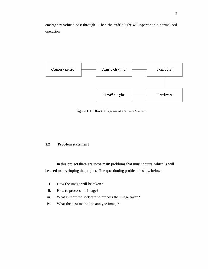
To achieve this target, camera system that consists of camera, frame grabber,
computer and hardware to activate the traffic light could solve the problem from
blocked by another vehicle. A camera at a certain distance is use as a sensor to take
an image in a real time where it needs to use a frame grabber to process the real time
image. From the frame grabber image will be loaded to computer where all
processing of image will be done, result of image processing will be display by using
Visual Basic 6 where GUI is implement in this project. After the result is display a
software will activated the hardware to change the traffic light to green until the
2
emergency vehicle past through. Then the traffic light will operate in a normalized
operation.
Figure 1.1: Block Diagram of Camera System
1.2 Problem statement
In this project there are some main problems that must inquire, which is will
be used to developing the project. The questioning problem is show below:-
i. How the image will be taken?
ii. How to process the image?
iii. What is required software to process the image taken?
iv. What the best method to analyze image?
3
1.3 Research Objective
Research of this project must take account concerning list below: -
i. To recognize suitable technique to captured image.
ii. To recognize method of process the image
iii. To recognize suitable software to process the captured image.
iv. To identify technique to analyze image.
1.4 Significance Of study (Main Objectives)
The main objective of this project is:
i. To study on image processing using Visual Basic 6 (VB6) and
Matrox. It is because to analyze and process the image will perform
by using Visual Basic 6 and Matrox (MIL). So it is needed to
familiarize with the software, where it will help in developing it.
ii. To develop software that can determine between emergency light and
non-emergency light, where it can be used as an application to solve
problem regarding traffic blocking the emergency vehicle when there
is an emergency. The emergency light of emergency vehicle will be
analyzed by the refraction color of the emergency light.
4
1.5 Scope of work
This project would focus on the image processing of police petrol car
emergency light for the software development. The result would be displayed on
computer screen to indicate the processed image is emergency light or non-
emergency light. This project would use a Visual Basic 6 and Matrox Imaging
Library 7 (MIL) to process and analyze the capture image between emergency and
non-emergency light.
5
CHAPTER 2
LITERATURE REVIEW
2.1 Introduction In this chapter will summarize the content of the paper, report and article that were
studied related to the project. The basic concept is illustrated in this chapter.
2.2 Visual Basic
Visual Basic is an application that uses to create a graphical user interface
(GUI), where ActiveX control is one of the applications in Visual Basic. The form is
created by using drag and drop techniques, the control can be place in the form by
drag the control into the toolbox. By inserting code in command button control the
program can automatically translate the case of the text being entered, or even
prevent certain characters from being inserted [1].
6
VB presents a 3-step approach for creating programs:
i. Design the appearance of your application.
ii. Assign property settings to the objects of your program.
iii. Write the code to direct specific tasks at runtime.
2.3 Matrox imaging library (MIL)
The Matrox imaging library (MIL) is a hardware-independent library divided
into different modules based on functionality. Where is has lot of function of image
processing such as blob analysis, OCR, pattern matching and lot more. Matrox
imaging library is an extended toolbox for Visual basic where the command
language for Matrox is Visual Basic and Visual C++ [2].
7
2.4 Image Processing
Image processing is form of information processing from the image, there a various
image processing operation [3]:
i. Combination of two or more images
ii. Image editing and digital retouching
iii. Image restoration to increase the quality of a digital image
iv. Segmentation of the image into regions
2.5 Noise
Image noise is an unwanted condition where it is because fluctuation of pixel
in an image, where mostly appeared in image regions with low signal level, such as
shadow regions or underexposed images. Removing noise cannot be done without
loss of some information in the image [4].
8
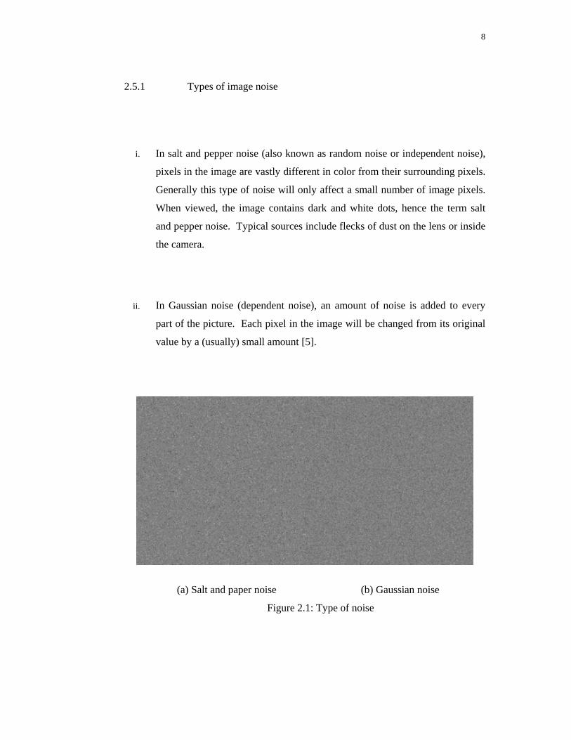
2.5.1 Types of image noise
i. In salt and pepper noise (also known as random noise or independent noise),
pixels in the image are vastly different in color from their surrounding pixels.
Generally this type of noise will only affect a small number of image pixels.
When viewed, the image contains dark and white dots, hence the term salt
and pepper noise. Typical sources include flecks of dust on the lens or inside
the camera.
ii. In Gaussian noise (dependent noise), an amount of noise is added to every
part of the picture. Each pixel in the image will be changed from its original
value by a (usually) small amount [5].
(a) Salt and paper noise (b) Gaussian noise
Figure 2.1: Type of noise
9
2.6 Type of emergency light
2.6.1 Optical type
In optical type there is 3 type of light, where rotating light contain a single
bulb around which a curved mirror is spun, creating a rotating beam of light, which
appears to flash when viewed from a stationary position. Rotating lights often use a
quartz-halogen or conventional incandescent bulb, though some rotating beacons are
now made with LEDs rather than bulbs. The second type is strobe light, based on
strobe lights similar to those used in flash photography. It produced a bright flash by
ionizing and then discharging a large current through the gas. Others optical type is
LED light, they can be programmed with a wider variety of flash patterns because of
their ability to be switched directly by electronics, as opposed to discharging a
capacitor through a gas-filled tub.
2.6.2 Mounting type
In mounting type is has verities of type, Roof-mounted single beacon is one
of the type that is widely used before Light bar were introduce, Light bars that may
contain fixed, rotating, strobe, or LED-based lights offering programmable flash
patterns where the flash pattern can be control. Other than that Body work mounted
is also one type the light where can be mounted on to the outside of the vehicle and
these can be used to provide directional lighting in key areas, such as in front for
clearing traffic, or to the rear for scene protection. Common places to mount such
beacons include on or in the grill of the vehicle and on the front of the rear view
mirrors, where they can gain maximum visibility, or as additional lighting such as on
the side of the bonnet which helps increase the warning for oncoming traffic when
pulling out of junctions. The last type is Interior type that be used in the interior of a
vehicle, generally on the dashboard, visor area, or rear deck [6].
10
2.7 Threshold
Threshold is used to segment an image by setting all pixels whose intensity
values are above a threshold to a foreground value and all the remaining pixels to a
background value. Threshold is use change image to a binary state where the pixel is
1 and 0. Thresholding is the simplest method of image segmentation. Several
different methods for choosing a threshold exist.
Fixed threshold
One alternative is to use a threshold that is chosen independently of the image
data. If it is known that one is dealing with very high-contrast images where the
objects are very dark and the background is homogeneous and very light, then a
constant threshold of 128 on a scale of 0 to 255 might be sufficiently accurate. By
accuracy we mean that the number of falsely-classified pixels should be kept to a
minimum.
Istogram-derived thresholds
In most cases the threshold is chosen from the brightness histogram of the
region or image that we wish to segment. A variety of techniques have been devised
to automatically choose a threshold starting from the gray-value histogram, {h[b] | b
= 0, 1, ... , 2B-1}. Many of these algorithms can benefit from a smoothing of the raw
histogram data to remove small fluctuations but the smoothing algorithm must not
shift the peak positions. This translates into a zero-phase smoothing algorithm given
below where typical values for W are 3 or 5:
11
Isodata algorithm
The histogram is initially segmented into two parts using a starting threshold
value such as 0 = 2B-1, half the maximum dynamic range. The sample mean (mf,0) of
the gray values associated with the foreground pixels and the sample mean (mb,0) of
the gray values associated with the background pixels are computed. A new
threshold value 1 is now computed as the average of these two sample means. The
process is repeated, based upon the new threshold, until the threshold value does not
change any more. In formula:
Triangle algorithm
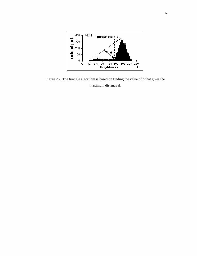
A line is constructed between the maximum of the histogram at brightness
bmax and the lowest value bmin = (p=0) % in the image. The distance d between the
line and the histogram h[b] is computed for all values of b from b = bmin to b = bmax.
The brightness value bo where the distance between h[bo] and the line is maximal is
the threshold value, that is, = bo. This technique is particularly effective when the
object pixels produce a weak peak in the histogram [7].
12
Figure 2.2: The triangle algorithm is based on finding the value of b that gives the
maximum distance d.
13
CHAPTER 3
METHODOLOGY 3.1 Interfacing MIL with Visual Basic
Firstly the Visual Basic 6 software must be installed by following the
instruction step. The important setting for this MIL installation show below:-
i. Development - Matrox imaging library, Active Mil and intelicam
ii. Hardware device - corono.II, VGA
Full version of MIL has no time limit where hardware like frame grabber or
digitizer can be use to interface with MIL. For evaluation software, user can only use
it for 30 day and after the duration MIL tools cannot be use anymore and the
software must be uninstall. The command of MIL tool is use a Visual Basic language
and the ActiveX will be automatically added to the Visual Basic. Installation of MIL
must be after the Visual Basic has been installed because if not the ActiveX from
MIL will not automatically add. MIL is also can be install at a Visual C++. After
the installation Active MIL user guide can be locate at ActiveMIL help where all
guided is provided.
14
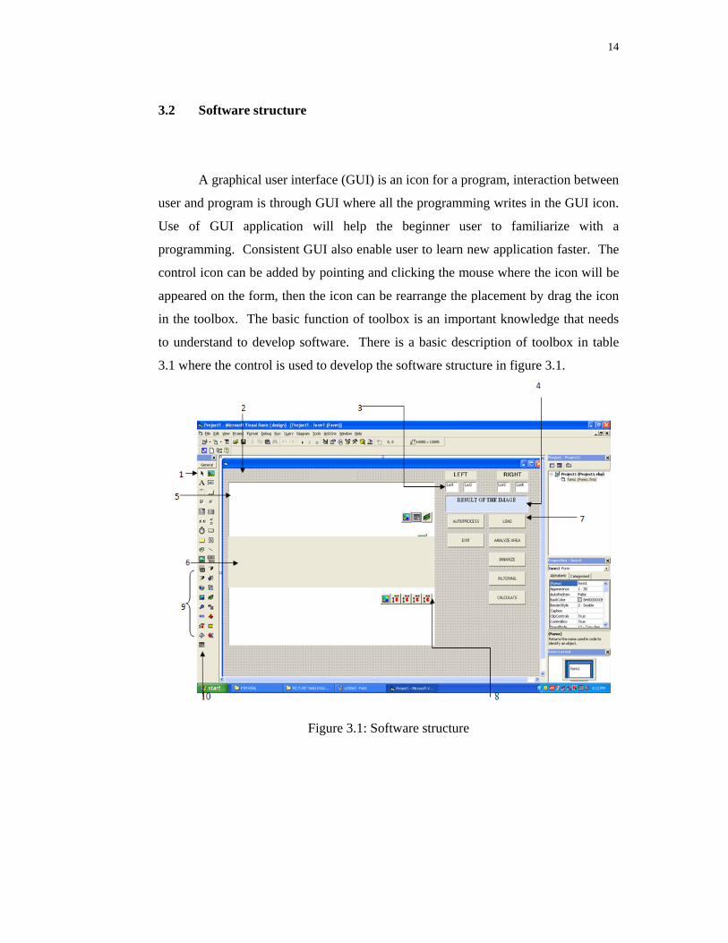
3.2 Software structure
A graphical user interface (GUI) is an icon for a program, interaction between
user and program is through GUI where all the programming writes in the GUI icon.
Use of GUI application will help the beginner user to familiarize with a
programming. Consistent GUI also enable user to learn new application faster. The
control icon can be added by pointing and clicking the mouse where the icon will be
appeared on the form, then the icon can be rearrange the placement by drag the icon
in the toolbox. The basic function of toolbox is an important knowledge that needs
to understand to develop software. There is a basic description of toolbox in table
3.1 where the control is used to develop the software structure in figure 3.1.
Figure 3.1: Software structure
15
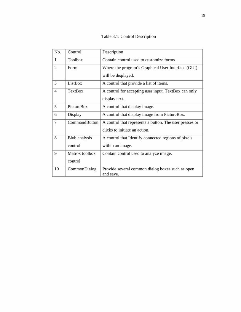
Table 3.1: Control Description
No. Control Description
1 Toolbox Contain control used to customize forms.
2 Form Where the program’s Graphical User Interface (GUI)
will be displayed.
3 ListBox A control that provide a list of items.
4 TextBox A control for accepting user input. TextBox can only
display text.
5 PictureBox A control that display image.
6 Display A control that display image from PictureBox.
7 CommandButton A control that represents a button. The user presses or
clicks to initiate an action.
8 Blob analysis
control
A control that Identify connected regions of pixels
within an image.
9 Matrox toolbox
control
Contain control used to analyze image.
10 CommonDialog Provide several common dialog boxes such as open and save.
16
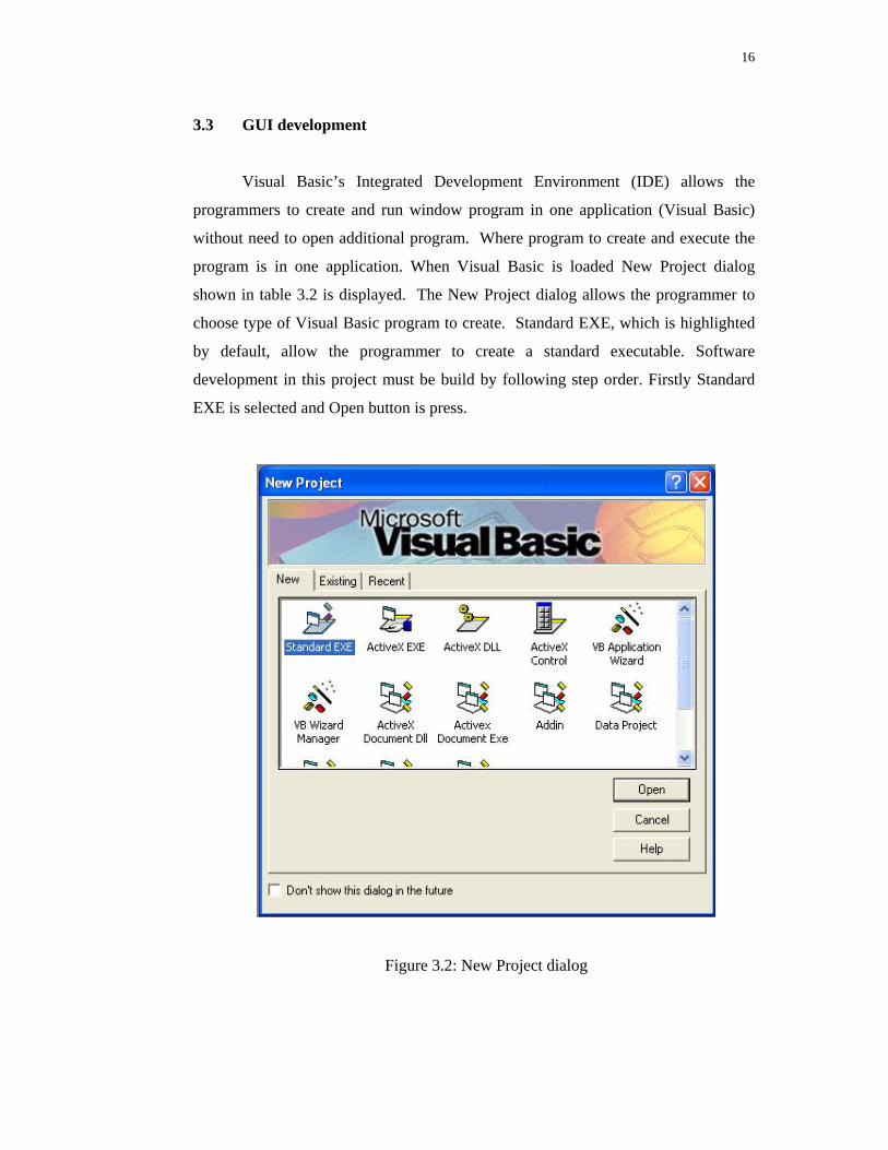
3.3 GUI development Visual Basic’s Integrated Development Environment (IDE) allows the
programmers to create and run window program in one application (Visual Basic)
without need to open additional program. Where program to create and execute the
program is in one application. When Visual Basic is loaded New Project dialog
shown in table 3.2 is displayed. The New Project dialog allows the programmer to
choose type of Visual Basic program to create. Standard EXE, which is highlighted
by default, allow the programmer to create a standard executable. Software
development in this project must be build by following step order. Firstly Standard
EXE is selected and Open button is press.
Figure 3.2: New Project dialog
17
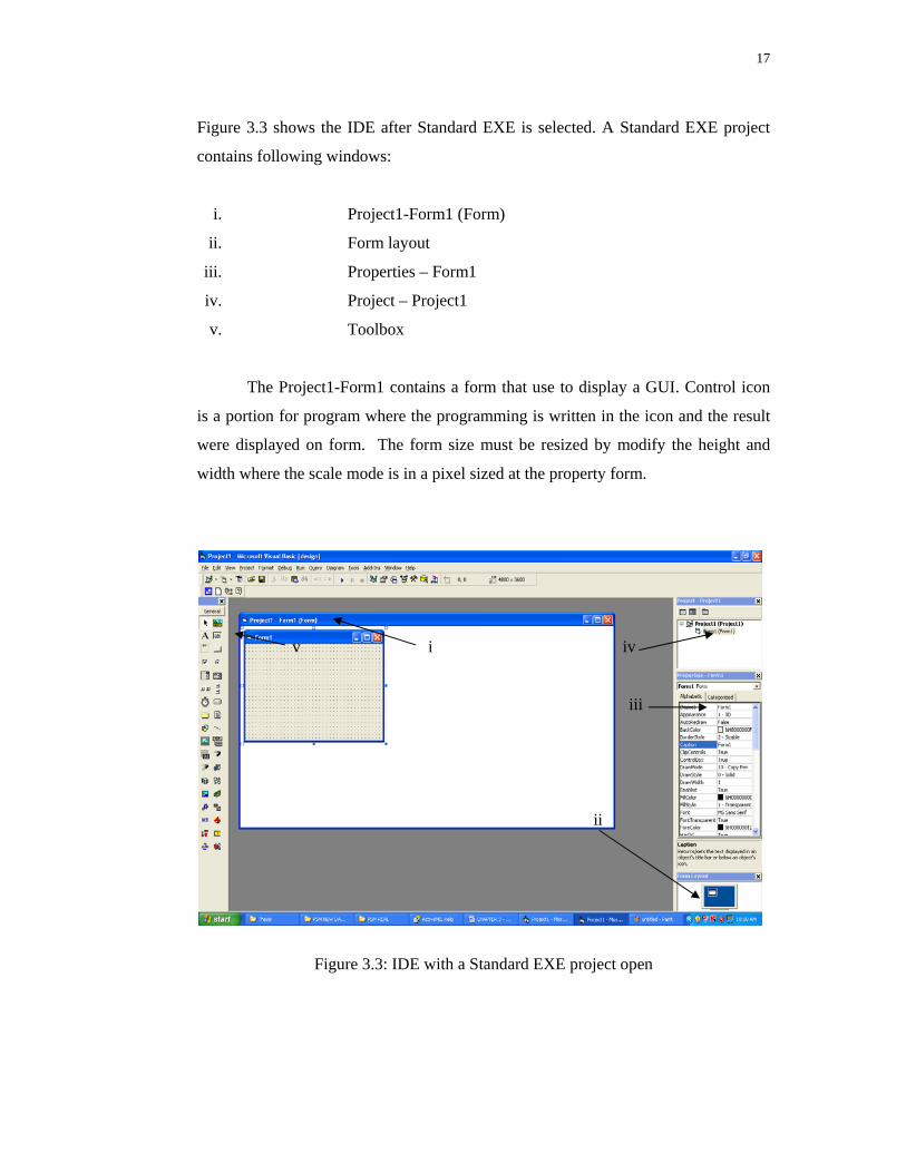
Figure 3.3 shows the IDE after Standard EXE is selected. A Standard EXE project
contains following windows:
i. Project1-Form1 (Form)
ii. Form layout
iii. Properties – Form1
iv. Project – Project1
v. Toolbox
The Project1-Form1 contains a form that use to display a GUI. Control icon
is a portion for program where the programming is written in the icon and the result
were displayed on form. The form size must be resized by modify the height and
width where the scale mode is in a pixel sized at the property form.
v i iv
iii
ii
Figure 3.3: IDE with a Standard EXE project open
18
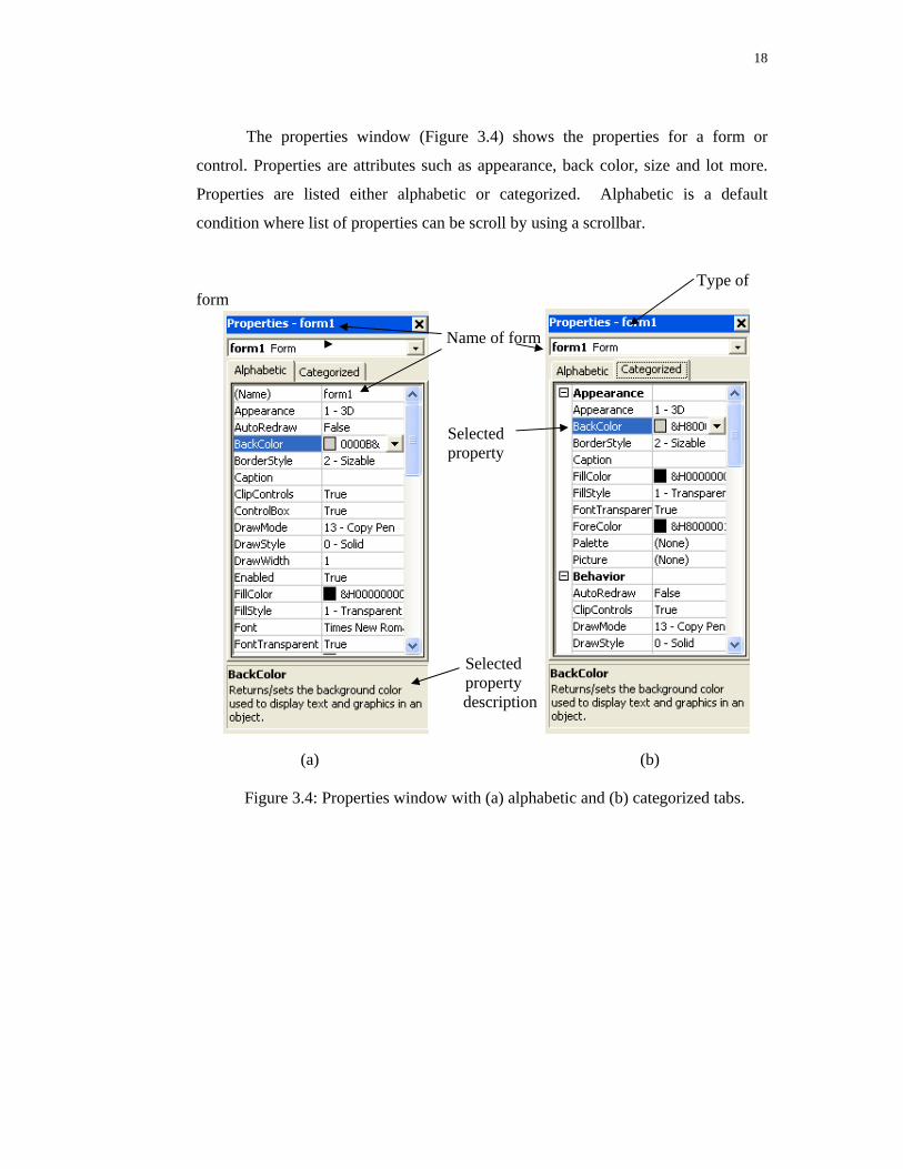
The properties window (Figure 3.4) shows the properties for a form or
control. Properties are attributes such as appearance, back color, size and lot more.
Properties are listed either alphabetic or categorized. Alphabetic is a default
condition where list of properties can be scroll by using a scrollbar.
Type of form
Name of form Selected property Selected property description (a) (b)
Figure 3.4: Properties window with (a) alphabetic and (b) categorized tabs.
19
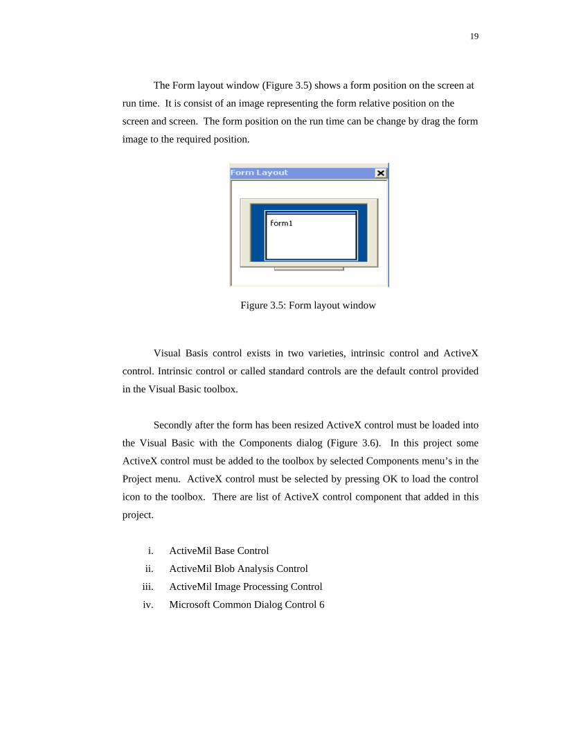
The Form layout window (Figure 3.5) shows a form position on the screen at
run time. It is consist of an image representing the form relative position on the
screen and screen. The form position on the run time can be change by drag the form
image to the required position.
Figure 3.5: Form layout window
Visual Basis control exists in two varieties, intrinsic control and ActiveX
control. Intrinsic control or called standard controls are the default control provided
in the Visual Basic toolbox.
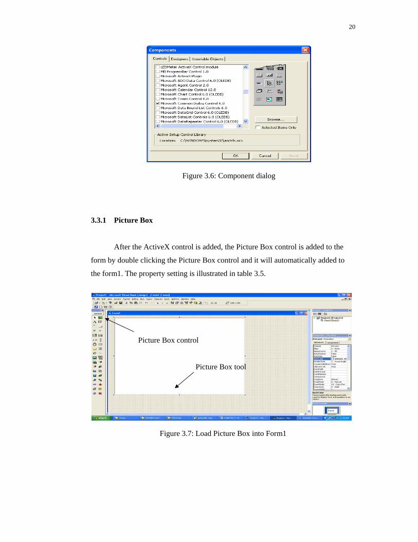
Secondly after the form has been resized ActiveX control must be loaded into
the Visual Basic with the Components dialog (Figure 3.6). In this project some
ActiveX control must be added to the toolbox by selected Components menu’s in the
Project menu. ActiveX control must be selected by pressing OK to load the control
icon to the toolbox. There are list of ActiveX control component that added in this
project.
i. ActiveMil Base Control
ii. ActiveMil Blob Analysis Control
iii. ActiveMil Image Processing Control
iv. Microsoft Common Dialog Control 6
20
Figure 3.6: Component dialog 3.3.1 Picture Box
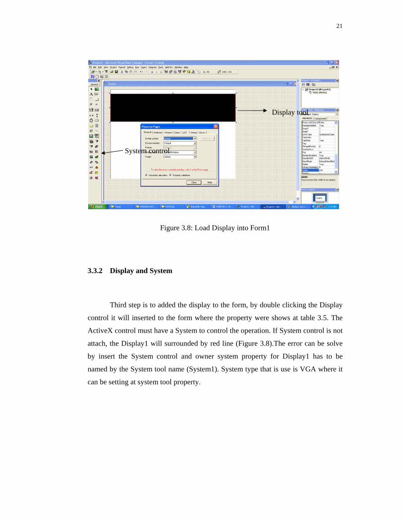
After the ActiveX control is added, the Picture Box control is added to the
form by double clicking the Picture Box control and it will automatically added to
the form1. The property setting is illustrated in table 3.5.
Picture Box control
Picture Box tool
Figure 3.7: Load Picture Box into Form1
21
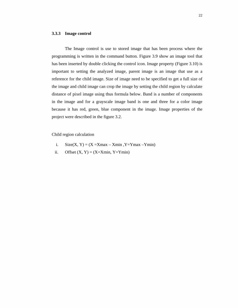
Display tool
System control
Figure 3.8: Load Display into Form1
3.3.2 Display and System
Third step is to added the display to the form, by double clicking the Display
control it will inserted to the form where the property were shows at table 3.5. The
ActiveX control must have a System to control the operation. If System control is not
attach, the Display1 will surrounded by red line (Figure 3.8).The error can be solve
by insert the System control and owner system property for Display1 has to be
named by the System tool name (System1). System type that is use is VGA where it
can be setting at system tool property.
22
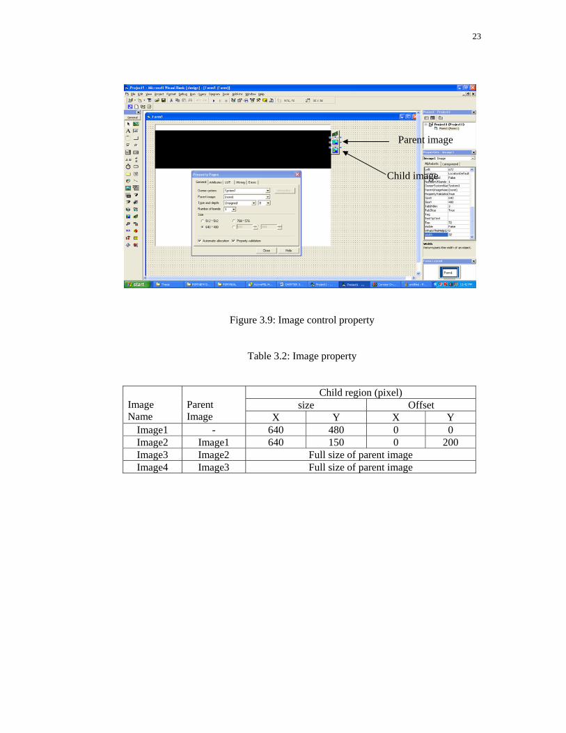
3.3.3 Image control
The Image control is use to stored image that has been process where the
programming is written in the command button. Figure 3.9 show an image tool that
has been inserted by double clicking the control icon. Image property (Figure 3.10) is
important to setting the analyzed image, parent image is an image that use as a
reference for the child image. Size of image need to be specified to get a full size of
the image and child image can crop the image by setting the child region by calculate
distance of pixel image using thus formula below. Band is a number of components
in the image and for a grayscale image band is one and three for a color image
because it has red, green, blue component in the image. Image properties of the
project were described in the figure 3.2.
Child region calculation
i. Size(X, Y) = (X =Xmax – Xmin ,Y=Ymax –Ymin)
ii. Offset (X, Y) = (X=Xmin, Y=Ymin)
23
Parent image
Child image
Figure 3.9: Image control property
Table 3.2: Image property
Image Name
Parent Image
Child region (pixel) size Offset
X Y X Y Image1 - 640 480 0 0 Image2 Image1 640 150 0 200 Image3 Image2 Full size of parent image Image4 Image3 Full size of parent image
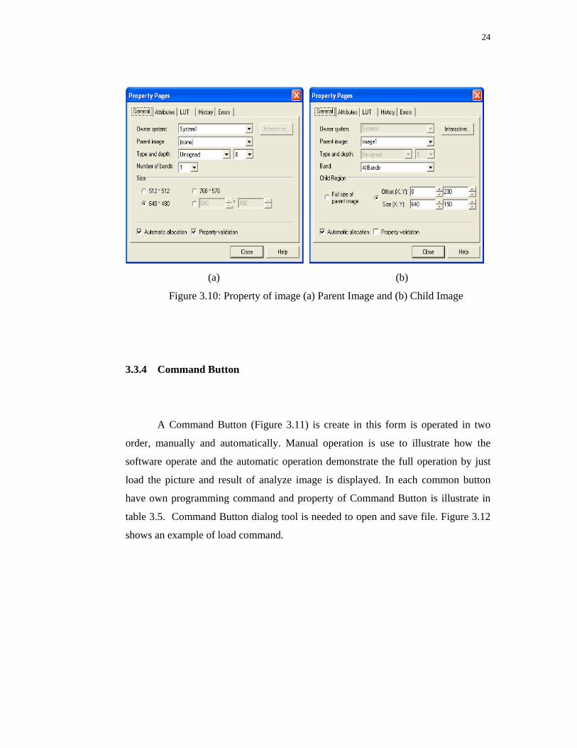
24
(a) (b)
Figure 3.10: Property of image (a) Parent Image and (b) Child Image
3.3.4 Command Button
A Command Button (Figure 3.11) is create in this form is operated in two
order, manually and automatically. Manual operation is use to illustrate how the
software operate and the automatic operation demonstrate the full operation by just
load the picture and result of analyze image is displayed. In each common button
have own programming command and property of Command Button is illustrate in
table 3.5. Command Button dialog tool is needed to open and save file. Figure 3.12
shows an example of load command.


