Embed Size (px)
Citation preview
Facolta di Ingegneria
Dottorato di Ricerca inInformatica ed Ingegneria dell’Automazione
Ciclo XXI
Profiling Mobile Identities
Fabio Dellutri
A.A. 2008/2009
Docente Guida/Tutor: Prof. Giuseppe F. ItalianoCoordinatore: Prof. Daniel P. Bovet


Abstract
The penetration of mobile phones reached 50% of the worldwide populationin early 2008 [1]. In the US alone, this percentage will surge past 100% by2013 [2]. Currently, most purchased mobile phones have enhanced applicationcapabilities and performances, regarding computational resources, connectiv-ity and battery: these mobile devices are referred to smartphones, actually cellphones with PDA functionalities which can host custom applications. Due tothose enriched capabilities, smartphones can collect large amounts of personalinformation, which, if analyzed, could reveal important aspects of the owner’sidentity, such as the kind of relationship with his contacts.
In this work we address the problem of reconstructing the identity profileof the owner, after a smartphone seizure, i.e., the social relationships which isshared by her and her contacts. This goal is achieved by analyzing personaldata stored into the device’s internal memory, and by correlating it with theWeb publicly available information about the owner and her contacts. The re-sulting social graph is further analyzed through spectral clustering algorithms,in order to find communities of people sharing the same interests.
Each phase of the process is described, and the results obtained are shown.In the interest of practical application, a workflow which disciplines severalstages of the profiling process is presented.
3

Acknowledgements
My thesis would not be complete without some words of thanks to the manyfriends, colleagues and family members who have supported me during thecourse of my PhD.
First I would like to thank Pino for the wisdom and guidance he has givenme. I have learned from him an enormous amount not only about research, butalso about the need for balance in all things. Thanks to Luigi for the hours spenthelping with my experiments, for bringing a sense of excitement about newideas and for understanding the importance of the obtained results. Thanksalso to Gianluigi for suggesting some interesting ideas behind this thesis.
I also thank all colleagues who I met through this experience of PhD. It hasbeen a great pleasure to work together. Sharing our ideas has been a greatchance of personal and professional growth. I would give special thanks toGianluca, Vittorio, Lele, Emiliano and Armando: no automatic tool will everbe able to measure our friendship!
Thanks to my family and friends for their love over the years. They haveshaped me with support, advice, opportunities and I am ever grateful for ev-erything they have done for me. Words cannot fully express how importantyou are to me.
Finally, I thank my love Ilaria, who believed in me every day. Without youall this would not have been possible.
5

Table of Contents
1 Motivation 131.1 Introduction . . . . . . . . . . . . . . . . . . . . . . . . . . . . . . 131.2 Contributions . . . . . . . . . . . . . . . . . . . . . . . . . . . . . 141.3 Thesis Outline . . . . . . . . . . . . . . . . . . . . . . . . . . . . . 17
2 Background and Related Work 192.1 Introduction . . . . . . . . . . . . . . . . . . . . . . . . . . . . . . 192.2 Mobile operating systems . . . . . . . . . . . . . . . . . . . . . . 192.3 Literature review . . . . . . . . . . . . . . . . . . . . . . . . . . . 222.4 Available products . . . . . . . . . . . . . . . . . . . . . . . . . . 25
3 Profiling system’s architecture 293.1 The Profiling Workflow . . . . . . . . . . . . . . . . . . . . . . . . 293.2 The Identity Profiler Framework . . . . . . . . . . . . . . . . . . 31
4 Smartphone’s internal memory acquisition 334.1 Introduction . . . . . . . . . . . . . . . . . . . . . . . . . . . . . . 334.2 Our methodology . . . . . . . . . . . . . . . . . . . . . . . . . . . 354.3 Implementation . . . . . . . . . . . . . . . . . . . . . . . . . . . . 374.4 Results and conclusions . . . . . . . . . . . . . . . . . . . . . . . 41
5 Smartphone’s data reverse engineering 455.1 Introduction . . . . . . . . . . . . . . . . . . . . . . . . . . . . . . 455.2 Our step-by-step Methodology . . . . . . . . . . . . . . . . . . . 465.3 Results . . . . . . . . . . . . . . . . . . . . . . . . . . . . . . . . . 57
6 The MIP process 616.1 Introduction . . . . . . . . . . . . . . . . . . . . . . . . . . . . . . 616.2 Smartphone Data Analysis . . . . . . . . . . . . . . . . . . . . . . 616.3 Web search analysis . . . . . . . . . . . . . . . . . . . . . . . . . . 646.4 Clustering . . . . . . . . . . . . . . . . . . . . . . . . . . . . . . . 706.5 Results . . . . . . . . . . . . . . . . . . . . . . . . . . . . . . . . . 776.6 Limitations of our method . . . . . . . . . . . . . . . . . . . . . . 78
7 Conclusions and Future Work 83
7

TABLE OF CONTENTS
A The Symbian S60 format 85A.1 Address book . . . . . . . . . . . . . . . . . . . . . . . . . . . . . 85A.2 Calendar . . . . . . . . . . . . . . . . . . . . . . . . . . . . . . . . 87A.3 Events log . . . . . . . . . . . . . . . . . . . . . . . . . . . . . . . 90A.4 SMS . . . . . . . . . . . . . . . . . . . . . . . . . . . . . . . . . . . 91
Bibliography 103
8

List of Figures
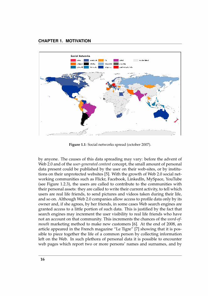
1.1 Social networks spread (october 2007). . . . . . . . . . . . . . . . 16
2.1 Technical data which can be extracted from the SIM card . . . . 26
3.1 The profiling workflow. . . . . . . . . . . . . . . . . . . . . . . . 303.2 The main interface of the analysis tool with example data. . . . 31
4.1 DFRWS Digital Investigation Framework. . . . . . . . . . . . . . 344.2 Data collection workflow . . . . . . . . . . . . . . . . . . . . . . . 354.3 How MIAT works. . . . . . . . . . . . . . . . . . . . . . . . . . . 364.4 These figures show screenshot version of MIAT we developed.
In (a) MIAT for Symbian. In (b) MIAT for Windows Mobile. . . 374.5 Windows Moble 5.0 memory architecture. . . . . . . . . . . . . . 40
5.1 The methodology flow . . . . . . . . . . . . . . . . . . . . . . . . 475.2 The format of the Ω operations sequence. In this figure is shown
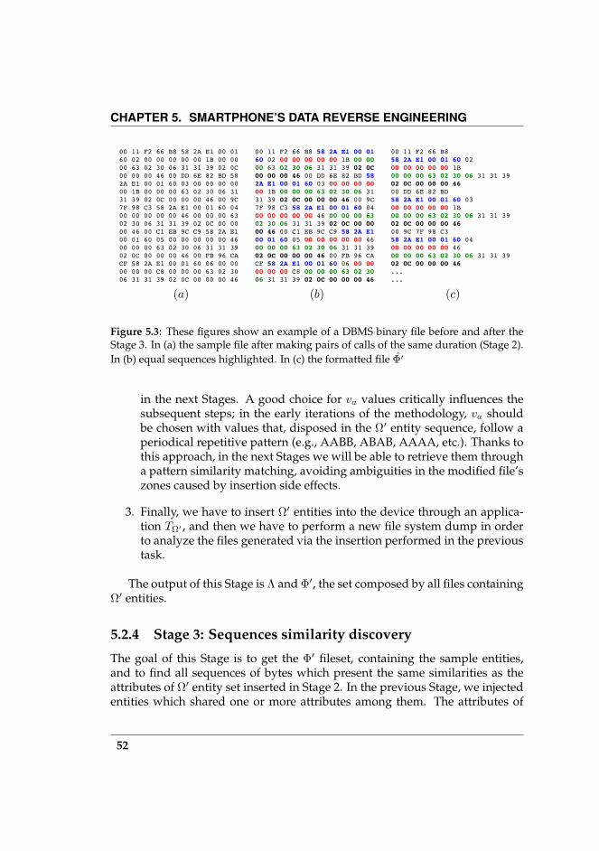
an example with contacts discovery as objective . . . . . . . . . 505.3 These figures show an example of a DBMS binary file before
and after the Stage 3. In (a) the sample file after making pairsof calls of the same duration (Stage 2). In (b) equal sequenceshighlighted. In (c) the formatted file Φ′ . . . . . . . . . . . . . . . 52
5.4 This three figures depict an example of the application of Stage5 on a file containing the phone’s address book. p 3350 604700613458442(a) A table with pseudo data type, got as output byStage 4. p 3350 6047006 13458442(b) The meta-format file beforeStage 5. p 3350 6047006 13458442(c) The meta-format file afterStage 5. . . . . . . . . . . . . . . . . . . . . . . . . . . . . . . . . . 60
6.1 The graph representation of contacts (a) and their relationshipswith the phone’s owner (b), which are revealed by the numberof calls and number of sms/mms. . . . . . . . . . . . . . . . . . . 62
6.2 After the smartphone analysis, the details about the calls andsms/mms are accessible simply by clicking on the edge betweenthe owner and the desired contact. . . . . . . . . . . . . . . . . . 64
9
LIST OF FIGURES
6.3 The graph representation of contacts before (a) and after (b) theSESORR execution. Black links represents relationships extractedfrom the mobile phone (mobile-edges). Blue links represents therelationships extracted from the Web (web-edges). . . . . . . . . 65
6.4 Frequency distribution of URLs (domains) providing relation-ships. Each graph refers to a distinct profile. . . . . . . . . . . . 67
6.5 When user clicks on an Web link (left-side), the framework showsinformation about indexes (right-side, top) and word frequen-cies found in the Web search result set. . . . . . . . . . . . . . . . 69
6.6 Sample undirected graph. . . . . . . . . . . . . . . . . . . . . . . 716.7 A small example network. (a) Before the clustering. (b) After
clustering through Spectral (k = 3). The black node is the smart-phone owner. . . . . . . . . . . . . . . . . . . . . . . . . . . . . . 73
6.8 Contact-to-cluster assignment. . . . . . . . . . . . . . . . . . . . 756.9 Clustering metrics trends. The profile graph used in this exam-
ple has 218 contacts and 1242 web-edges. k′ = 10 and its valueis shown by the black vertical line. . . . . . . . . . . . . . . . . . 78
6.10 Spectral and SVD number of empty clusters to the variation ofk parameter. The profile graph used in this example has 218contacts and 1242 web-edges. k′ = 10 and its value is shown bythe black vertical line. . . . . . . . . . . . . . . . . . . . . . . . . . 79
6.11 An example of clustering after applying the SVD method. At thetop, an overview of the entire graph. Each cluster has a colourassociated, then each node is coloured according with the clus-ter colour which it belongs to. At the bottom, some cluster sub-graphs extracted from the main graph. . . . . . . . . . . . . . . . 81
10

List of Tables
4.1 Files generated during the Seizure Process . . . . . . . . . . . . . 364.2 PDA forensic tools . . . . . . . . . . . . . . . . . . . . . . . . . . 394.3 Windows Mobile relevant files . . . . . . . . . . . . . . . . . . . 414.4 MIAT for Symbian and Paraben’s Device Seizure comparison,
and their hashes consistency. This table also shows the eventwhich trigger changes. . . . . . . . . . . . . . . . . . . . . . . . . 43
4.5 MIAT for Windows Mobile and Paraben’s PDA Seizure compar-ison, and their hashes consistency. . . . . . . . . . . . . . . . . . 43
5.1 Symbian files of interest . . . . . . . . . . . . . . . . . . . . . . . 58
A.1 Possible values for the rows of table “DATA TYPE TABLE”. Theydescribe the type of attributes present in the “DATA BLOCK”.(Symbian S60 v2) . . . . . . . . . . . . . . . . . . . . . . . . . . . 85
A.2 This table lists all contact’s data which can be found in the Con-tacts.cdb. Since data are located in three logical file areas, thetable is split in three parts. . . . . . . . . . . . . . . . . . . . . . . 93
A.3 This table lists all calendar entries such as Notes Meetings An-niversaries stored in the Calendar file. . . . . . . . . . . . . . . . 94
A.4 This table lists all event entries such as SMS, MMS, voice anddata calls, SIM change. . . . . . . . . . . . . . . . . . . . . . . . . 95
A.5 This table lists all fields characterizing an SMS. . . . . . . . . . . 96
11


1Motivation
1.1 Introduction
The mobile phone can be considered the ultimate disruptive technology: infact, like telephony, radio, television, and the Internet, mobile phones are dra-matically changing nearly every aspect of daily life, both inside businesses andin the daily lives of individuals, providing more applications and collectingmore private data. The new smartphones (118 million in 2007, Canalys) aremobile phones which have an outstanding computing capability, a sizeablememory, a multi-connectivity (HDSPA, Bluetooth, IR, WLAN) and a multime-dia recording system. Moreover, by running a complete operating system (OS)software with a standardized interface and platform for application develop-ers, such devices provide advanced features like e-mail and Internet capabili-ties and a full keyboard. Such features, as well as the high portability of mobiledevices, give the owner the chance to carry a lot of personal data such as con-tacts, call logs, messages, pictures, video, credit card and bank account codes.
Since these devices collect and store a large amount of personal data intotheir memories, they can be used as evidence in investigations. Moreover,personal data collected from their storage memories are the starting point toreconstruct the identity of the owner. In this work we will use the followingdefinition for the Identity Profile concept:
An identity profile associated with an individual is given bothby the set of people she knows (the contacts) and by the type andby the strength of the relationships that the individual has with hercontacts.
13
CHAPTER 1. MOTIVATION
Moreover, such a concept may be extended by the type and by the strengthof the relationships that the contacts share between them, introducing the pos-sibility of grouping among them contacts who share similar interests.
1.2 Contributions
This thesis addresses the problem of reconstructing the identity profile of theowner, after a smartphone seizure, by analyzing the personal data stored inthe device’s internal memory, and by correlating such information with the re-lationships of the owner and her contacts available on the World Wide Web.In order to achieve this objective, our work focuses on designing a workflowwhich disciplines several stages of the process, starting with the seizure ofthe device and ending with the identity profile. Such a workflow was imple-mented in a software framework which can be used by forensic operators. Inparticular our contributions cover the following areas:
1. Smartphone internal memory data seizure and acquisition: we studiedand developed an innovative approach to seize data from the device’sinternal memory.
2. Smartphone personal data decoding: we designed a data reverse engi-neering methodology, which aims at collecting knowledge about the mo-bile device’s internal database format, and facilitates the development offormat-specific parsers which are able to convert smartphone’s personaldata into a more suitable format.
3. Mobile identity profiling: we designed a process to analyze the smart-phone’s personal data and to show which relationships exist between theowner and its contacts, and, thanks to data collected by the Web searchengines, which interests are shared among the contacts.
In the following we will give a short motivation for each of the items above.
1.2.1 Smartphone internal memory data seizure and acquisi-tion
The growing prominence of forensic sciences, in the investigation chain, hasled to the broad use of forensic tools to acquire mobile phone internal mem-ory content, to provide evidence of a crime. However, as rule of thumb, the
14
1.2. CONTRIBUTIONS
crime-scene usually offers many different mobile phone/smartphone models,causing the forensic operators to be overwhelmed by using the one-on-oneconnectors for every single mobile device. Obviously interoperability is notassured for different manufacturer implementations and this leads to a greatunpredictability of the effectiveness of the tool on the crime scene. However,the main disadvantage is the partial access of the file system, which relies onthe communication protocol. Due to the continuous upgrading of smartphonehardware and software connection interfaces, a tool based on a protocol orconnected-via-cable approach could become obsolete in a very short time (lessthan one year) if not upgraded frequently.
For this reason, we have designed an acquisition methodology which ex-presses how to seize a device internal memory, and we developed a tool whichdumps the internal memory on a SD/MMC (Secure Digital / MultiMediaCard)memory inserted in the available external slot, called MIAT1 (Mobile InternalAcquisition Tool), making it unnecessary to connect the device to a PC.
1.2.2 Smartphone personal data decoding
After extracting a logical dump of the file system from the mobile device, weneed a method to decode and convert the personal data like contacts, messages,logs, calendars, in a more suitable format. Regardless of the device’s manufac-turer, model and OS version, we developed a methodology to support the datareverse engineering on smartphone file systems. In such way the smartphone’sDRE operators will be more flexible in the mobile file format knowledge andthey will be supported in developing software parsers for personal data of spe-cific mobile devices and OS.
1.2.3 Mobile identity profiling
The final challenge addressed in this work is to analyze the personal data de-coded from the mobile device, by building a model which connects the ownerwith her contacts and by showing how strong such relationships are. This in-formation is finally complemented with the personal information scattered onthe Internet. Nowadays, in fact, vast amount of personal data are left dailyon Web pages and are linkable to a person by the nearly-unique real-life iden-tifiers like name-surname, or phone numbers or email addresses. Such pagesare crawled every day by most search engines and are available for querying
1For Symbian OS [3] and Windows Mobile [4]
15
CHAPTER 1. MOTIVATION
Figure 1.1: Social networks spread (october 2007).
by anyone. The causes of this data spreading may vary: before the advent ofWeb 2.0 and of the user-generated content concept, the small amount of personaldata present could be published by the user on their web-sites, or by institu-tions on their unprotected websites [5]. With the growth of Web 2.0 social net-working communities such as Flickr, Facebook, LinkedIn, MySpace, YouTube(see Figure 1.2.3), the users are called to contribute to the communities withtheir personal assets: they are called to write their current activity, to tell whichusers are real life friends, to send pictures and videos taken during their life,and so on. Although Web 2.0 companies allow access to profile data only by itsowner and, if she agrees, by her friends, in some cases Web search engines aregranted access to a little portion of such data. This is justified by the fact thatsearch engines may increment the user visibility to real life friends who havenot an account on that community. This increments the chances of the word-of-mouth marketing method to make new customers [6]. At the end of 2008, anarticle appeared in the French magazine “Le Tigre” [7] showing that it is pos-sible to piece together the life of a common person by collecting informationleft on the Web. In such plethora of personal data it is possible to encounterweb pages which report two or more persons’ names and surnames, and by
16
1.3. THESIS OUTLINE
the topic of such web page it can be possible to outline the common groundshared by such people: they could be colleagues, attend the same university orcultivate the same hobbies.
By retrieving people’s public information on the World Wide Web, we com-plete the information about relationships between the phone owner and hiscontacts, and we are able to extend this investigation to the inter-contact rela-tionships, in order to build a more complete social network. As the resultingprofile model is a graph, it lends itself very well to more accurate analysis. Inthis work we propose two spectral clustering algorithms for finding commu-nities of people in the graph.
1.3 Thesis Outline
This thesis is broadly organised in order of application. A detailed descriptionof each chapter follows below.
Chapter 2 is a survey on mobile phone technology and on the existing mobileoperating systems. This chapter also reviews the literature about exist-ing approaches to the mobile forensics problem and resumes availableproducts.
Chapter 3 exposes the framework and the environment we developed in orderto implement the profiling workflow.
Chapter 4 describes technical aspects of the design of MIAT, the Mobile Inter-nal Acquisition Tool, and discusses the results obtained from the compar-ison with other products.
Chapter 5 proposes a wisdom-driven DRE methodological approach to de-code smartphone’s personal data. The chapter also shows the resultsobtained.
Chapter 6 presents the Mobile Identity Profiling (MIP) process, which is thecore concept of this work.
Chapter 7 summarises the findings of the thesis and considers directions forfuture work, including ideas for extending the MIP process to multipledevice at a time and for automating the entire process through the remoteForensic Farm.
17

2Background and Related Work
2.1 Introduction
This Chapter describes relevant background knowledge and related work forreaders to easily understand the analysis conducted in our work to be pre-sented and discussed in Chapters 4, 5 and 6. This chapter will deal with twodifferent areas: mobile device forensics and identity profiling over the Web.We will firstly review the literature about such areas, then we will give a reportof existing device examination products .
2.2 Mobile operating systems
2.2.1 Symbian
Symbian is a joint venture between Nokia, Motorola, Ericsson, Matsushita, andPsion that became independent in June 1998. Symbian was established by lead-ers in the computing and mobile industries to enable the mass market of com-municators and smart phones. Symbian is an open operating system, designedfor mobile devices, with associated libraries, user interface frameworks andreference implementations of common tools, produced by Symbian Ltd. Sym-bian evolved from Psion’s EPOC in 1998. Symbian OS is currently owned byBenQ, Ericsson, Panasonic, Nokia, Siemens AG and Sony Ericsson. There areseveral variations of the Symbian OS that are tailored for different devices. Thecapabilities of the Symbian OS depend on the device for which it was tailored.Each variation is called a Device Family Reference Design (DFRD). The benefitsof Symbian OS are the following:
19
CHAPTER 2. BACKGROUND AND RELATED WORK
• Faster time-to-market for platform vendors
• Open, standards-based platform for third-party application developers
• Excellent connectivity
• Advanced design
• Extensibility
• High-performance, 32-bit OS with pre-emptive multitasking
• Long battery life
• Wide industry support and commitment
• Applications that can be designed once and run on multiple devices
• Diversity of devices for consumers
2.2.2 Windows Mobile
Windows Mobile is an operating system that has both a look-and-feel and aprogrammer API that are similar to Microsoft Windows but which runs in adramatically reduced footprint. Windows Mobile is the successor operatingsystem to Windows CE. Windows Mobile runs on multiple hardware plat-forms including Pocket PCs, smartphones, Portable Media Center, and auto-mobiles. These hardware platforms did not always exist from the inceptionof Windows Mobile. Microsoft Pocket PC, sometimes referred to as P/PC orPPC, is based upon the Windows CE framework. Variants of this operatingsystem include versions such as Pocket PC 2000, Pocket PC 2002, WindowsMobile 2003/2003 SE, 5 and Windows Mobile 6.0. Variants also exist for Smart-phones, such as Windows Mobile 2003 Smartphone edition. One of the keybenefits of Microsoft’s Windows Mobile platform is file format compatibilitywith the desktop versions of the company’s productivity software. Mobile ver-sions of Microsoft software, such as Pocket Word, Pocket Excel, and PocketPowerPoint, allow individuals to view and edit these files outside of the homeand office. Another benefit is integration with Microsoft’s cross-platform so-lution, the .NET Framework. The .NET Framework and its associated classlibraries handle things such as memory management, file I/O, and many otherfunctions. The .NET Framework allows programmers to develop code in one
20
2.2. MOBILE OPERATING SYSTEMS
of several .NET languages, such as C and VB.NET. Pocket PCs run a simplifiedversion of the framework called the .NET Compact Framework. In order tomaintain synchronization and connectivity with desktop computers, Microsoftdeveloped the ActiveSync program. The user merely has to connect the PocketPC to the desktop computer in order to synchronize items such as appoint-ments, contact lists, and even multimedia files.
2.2.3 Palm
A Palm is a commonly referred to as a small-scale (hand-held) computer thatruns Palm’s PalmOS software. The Palm OS platform is an open architecturethat provides a basis for third-party developers and original equipment manu-facturers (OEMs) to create mobile computing solutions. Palm Computing wasfounded by Jeff Hawkins, Donna Dubinsky and Ed Colligan. The original pur-pose of the company was to create handwriting recognition software for otherdevices (Graffiti). The initial idea for the devices came from Hawkins’ habit ofcarrying a block of wood in her pocket. There are several tools available for theimage acquisition and analysis of Palm devices.
EnCase, published by Guidance Software, is a complete cyber forensicssoftware package that handles all steps of the investigative process, from theacquisition to the report creation. The software includes built-in capabilities forperforming MD5 hashing, data carving, deleted file recovery, and many otherfunctions. Although traditionally relegated to the realm of desktop computerforensics investigations, EnCase does support the acquisition and analysis of alimited number of Palm devices.
Paraben has a software application that is specifically designed for PDAforensics, PDA Seizure. This comprehensive tool allows PDA data to be ac-quired, viewed, and reported on, all within a Windows environment. The soft-ware comes equiped with quite a few key features. These features include theability to encrypt saved case files, BlackBerry OS support, built-in recovery ofPalm passwords, enhanced viewing on file data, complete physical and logicalacquisition for Palm PDA devices, and many more. It has a few drawbacks,in that some of the material acquired from the PDAs is hard to interpret by aperson that is not computer savi. Although, on the other hand it has featureslike a search portion that allows you to enter a search term and PDA Seizurewill bring up all files that have that term in them. This allows the investigatorto look for case specific information easily and quickly.
21

CHAPTER 2. BACKGROUND AND RELATED WORK
2.2.4 BlackBerry
The RIM BlackBerry is a personal wireless handheld device that supports e-mail, mobile phone capabilities, text messaging, web browsing, and other wire-less information services. It is most commonly utilized for business purposes.The BlackBerry was first introduced in 1999 by a company called Research InMotion (RIM). The BlackBerry OS provides easy access to applications such ase-mail, to do list, memos, address book, and many other features. Forensics onthe RIM platform is complicated by the fact that this is a ”push” device, i.e., theRIM server will push device to the PDA whenever the PDA’s radio is on andthere is data available. RIM devices also feature a remote self-destruct feature.This feature cannot be activated if the radio is turned off, of course. Both ofthese features mean that you need to be sure that the radio is off when doing aforensic investigation. Depending on the setting, entering a wrong password acertain number of times will wipe the device.
2.2.5 iPhone
The iPhone is an internet-connected multimedia smartphone designed andmarketed by Apple Inc. with a flush multi-touch screen and a minimal hard-ware interface. The iPhone was initially released with two options for internalstorage size: 4 GB or 8 GB. On September 5, 2007, Apple discontinued the 4 GBmodels. On February 5, 2008, Apple added a 16 GB model. All data is storedon an internal flash drive; the iPhone does not contain any memory card slotsfor expanded storage.
2.3 Literature review
2.3.1 Mobile device forensics
The term “Mobile Forensics” arose when the first PDA was able to store per-sonal data about its owner and, thus, it could be used as evidence during aninvestigation.
The Netherlands Forensic Institute (NFI) published a workflow for mobilephone forensic examination ([8]). A lot of relevant work about mobile foren-sics has been carried out by Jansen et al. [9, 10, 11, 12] on behalf of NIST.Topics of interest covered by the authors are forensic tools, impediments, pro-cedures and principles, preservation, acquisition, examination and analysis.
22
2.3. LITERATURE REVIEW
All phases are well described and they are currently used as guidelines. Theanalysis phase lacks a contacts correlation activity.
Zdziarski in [13] describes a method that allows the examiner to performa bit-by-bit copy of the iPhone’s user partition and can provide an MD5 sumto prove the copy was authentic. The method requires modifying a read-onlysystem partition to allow for this technique. Fortunately, this partition remainscompletely isolated from the partition containing user data and is intended toremain in a factory state throughout the life of the iPhone. This makes it anideal and forensically sound location to perform the necessary payload instal-lation, without violating user data.
Hoog in [14] reviews the forensic tools available for the iPhone, performsforensic analysis with each tool and reports on the installation, acquisition, re-porting and accuracy of each tool.
2.3.2 Mobile Data Reverse Engineering
At the time of writing, we are not aware of other works about how to decodethe personal information stored in the smartphone’s file system. Commercialforensic products such as Paraben [15], extract a logical dump and they are ableto decode it, but they provide neither their source code nor information aboutthe storing formats.
More generally speaking, research in data reverse engineering has beenunder-represented in the software reverse engineering area because the latterappears to be “more challenging and interesting than data reverse engineer-ing” [16]. Recently the attention to data reverse engineering techniques is in-creasing, because they represent the key to making several assessments likeincorporating legacy data in data warehouses, measuring the software quality,and, more generally, migrating from closed formats toward open standards.
Most of the works found in the literature about DRE deals with DBMS re-verse engineering. Since DBMSs provide the functionality to extract initial in-formation about the implemented physical data structure, database reverse en-gineering has a higher potential for automation than data reverse engineering.Consequently, most existing reverse engineering tools in this area consider in-formation systems that employ a database platform. A relevant work aboutthe auto-reverse engineering of input file is given by Tupni [17], a tool whichis able to decode various sets of data, such as record sequences, record types,and input constraints. The tool takes as input a set of different instances of afile format, and an application which is able to read them, then it learns infor-mation about the file format by tracing the application and by observing how
23
CHAPTER 2. BACKGROUND AND RELATED WORK
it reads the file. Tupni was tested on several common file formats and networkprotocols, and performs very well. Tupni tracks I/O operations performed byapplications running on the device. This is unuseful for our scope since we areinterested in tracking the Mobile device OS.
A generic methodological approach has been proposed by Aiken in [18].The author provides a DRE analysis template, which is a “system of ideas forguiding DRE analysis, an overall meta-data-gathering strategy, a collection ofmeasures, and an activity structure that can be used to assess progress towardspecific re-engineering goals”. Since the mobile environment is populated by alarge amount of device manufacturers, operating systems, DBMS and file for-mats, we think that a methodological approach is more convenient and flexiblethan a vertical one. Therefore we started from Aiken’s work and we followeda similar approach to deal with mobile environments. Thanks to this approachwe will be more tolerant if something changes in file formats and OS, whennew versions are released.
The most used tool to make DRE is the hex editor. Conti et al. in [19]proposed several interesting techniques to retrieve information from hex dumpthrough visual inspection.
2.3.3 Identity profiling over the Web
In this work we have widely adopted the concept of identity as “that part of theself by which we are known to others” ([20]). We fetch up the identity buildon the Internet through the analysis of Web pages where the subject appearsin conjunction with other contacts of her mobile contact list. Previous workachieved interesting results. Mika et al. in [21, 22], dealing with the problem of“bootstrapping” a Friend-Of-A-Friend (FOAF) based social network, proposed“the traditional Web as source of information about the social networks in acommunity”. So they introduced a system for collecting social network datawhich fetches data from the traditional Web by mining the index of Google.When the authors wrote (2005), they demonstrated their method through ex-amples of specific community with a significant on-line presence, i.e., a scien-tific community of computer science. Since social networks spread (see Figure1.2.3), many “common” users put themself on the Web and, in particular, theyentered information about who their friends are. Thus, nowadays, we can ex-tend Mika’s experiment to common users, thanks to the part of social networksdata that are available publicly on the Web and that is periodically crawled bysearch engines. A remarkable work about the identity construction on socialnetworks is given by Zhao et al. in [23], where the authors study identity con-
24

2.4. AVAILABLE PRODUCTS
struction on Facebook (http://www.facebook.com), an emergent social net-working site which became most popular among college students in the UnitedStates and then spread across other life contexts and countries. Facebook, likeother social networking environments, can be considered as a nonymous envi-ronment1, because the user is persuaded to publish her real name and typicallyshe knows her friends in the real world too, thus their digital identity is similarto the face-to-face identity. The authors accomplish their study by reportingthat Facebook users claim their identities implicitly, because they “show ratherthan tell”. The people they know are the most important data we need to re-construct the person profile.
2.4 Available products
A collection of surveys on mobile phones and PDA forensics is maintainedby NIST. An (un)updated list of available tools is reported in [10, 11, 12]. Inorder to achieve forensic seizure, closed and open source tools are available.The tools currently in use perform the acquisition of the mobile device internalmemory in a remote way: a forensic tool is connected with the target deviceand, using the OS services, it extracts the data like SMS, MMS, TODO list,pictures, ring tones, etc. This approach has the advantage of minimizing theinteraction towards the device and automating the process of seized data inter-pretation. The main disadvantage relies on the protocol closeness: we are notable to measure any memory alteration caused by data exchange. Moreover,to perform the acquisition process, a few of the available tools degrade the ev-idence putting an utility file in the device’s file system. Moreover, currentlyavailable products extract most data from the device, but they do not provideany functionality to further analyze data, as the solution we have studied inthis work.
2.4.1 SIM forensics
The data that a SIM card can provide the forensics examiner can be invaluableto an investigation. Acquiring a SIM card allows a large amount of informationthat the suspect has dealt with over the phone to be investigated. In general,some of this data can help an investigator to determine the phone numbers of
1The term “nonymous” is the opposite of “anonymous” and means an on-line relationshipwhich exists in the real world too. This type of on-line relationships is also called “anchored rela-tionships” ([23]).
25
CHAPTER 2. BACKGROUND AND RELATED WORK
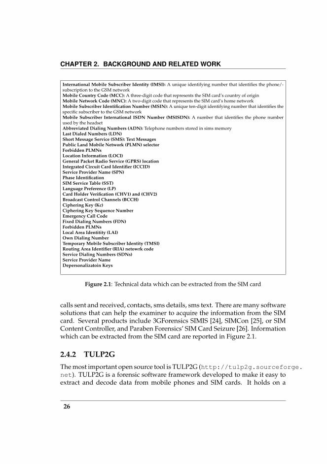
International Mobile Subscriber Identity (IMSI): A unique identifying number that identifies the phone/-subscription to the GSM networkMobile Country Code (MCC): A three-digit code that represents the SIM card’s country of originMobile Network Code (MNC): A two-digit code that represents the SIM card’s home networkMobile Subscriber Identification Number (MSIN): A unique ten-digit identifying number that identifies thespecific subscriber to the GSM networkMobile Subscriber International ISDN Number (MSISDN): A number that identifies the phone numberused by the headsetAbbreviated Dialing Numbers (ADN): Telephone numbers stored in sims memoryLast Dialed Numbers (LDN)Short Message Service (SMS): Text MessagesPublic Land Mobile Network (PLMN) selectorForbidden PLMNsLocation Information (LOCI)General Packet Radio Service (GPRS) locationIntegrated Circuit Card Identifier (ICCID)Service Provider Name (SPN)Phase IdentificationSIM Service Table (SST)Language Preference (LP)Card Holder Verification (CHV1) and (CHV2)Broadcast Control Channels (BCCH)Ciphering Key (Kc)Ciphering Key Sequence NumberEmergency Call CodeFixed Dialing Numbers (FDN)Forbidden PLMNsLocal Area Identitity (LAI)Own Dialing NumberTemporary Mobile Subscriber Identity (TMSI)Routing Area Identifier (RIA) netowrk codeService Dialing Numbers (SDNs)Service Provider NameDepersonalizatoin Keys
Figure 2.1: Technical data which can be extracted from the SIM card
calls sent and received, contacts, sms details, sms text. There are many softwaresolutions that can help the examiner to acquire the information from the SIMcard. Several products include 3GForensics SIMIS [24], SIMCon [25], or SIMContent Controller, and Paraben Forensics’ SIM Card Seizure [26]. Informationwhich can be extracted from the SIM card are reported in Figure 2.1.
2.4.2 TULP2GThe most important open source tool is TULP2G (http://tulp2g.sourceforge.net). TULP2G is a forensic software framework developed to make it easy toextract and decode data from mobile phones and SIM cards. It holds on a
26
2.4. AVAILABLE PRODUCTS
modular architecture ([27]) which defines a general examination workflow forinvestigators and offers an abstract design to developers of so called plug-ins.These plug-ins contain the actual investigation methods. From a user’s per-spective the advantage of using a framework concept is the “learn once applyeverywhere” principle. TULP2G implements the standard modem protocols(e.g., Hayes commands) and OBEX protocol to communicate with the device.Unfortunately, if a smartphone model does not implement these standards, thetool is unusable for the investigation. Currently, TULP2G components have be-come obsolete, as reported by its authors in the product’s Web page: “CurrentTULP2G plug-ins do not contain state of the art technology for the examinationof mobile phones. Most plug-ins were made years ago to demonstrate frame-work principles. Nowadays a lot of better (commercial and open source) toolsexist to assist you in the examination of mobile phones.”
2.4.3 Paraben Device Seizure
Among proprietary tools, the Paraben Device Seizure (http://www.paraben.com) is one of the most important; it implements specific, proprietary protocols(like D-Bus for Nokia smartphone) but, as for the TULP2G tool, unknown pro-tocols make the acquisition impossible. Recently Paraben Corporation releasedthe “CSI stick” (http://www.csistick.com) a portable data gathering andforensic tool, which allows the acquisition of data without using the forensicworkstation. This solution, however, still relies on proprietary plugs (currently,Motorola and Samsung).
2.4.4 .XRY
The .XRY tool by MicroSystemation (http://www.msab.com/en) adopts aquite similar approach to Paraben, with remote acquisition via hardware spe-cific plugs.
2.4.5 Neutrino
Recently, Guidance Software (http://www.guidancesoftware.com) intro-duced the Neutrino forensic acquisition device, which is capable of acquiringdata from a device connected through USB cables and able to analyze and cor-relate data coming both from mobile phone and computer. Moreover, Neutrinois the only device which integrates itself with EnCase package. Neutrino sharesthe approach with Paraben and MicroSystemation solutions, and it supports
27

CHAPTER 2. BACKGROUND AND RELATED WORK
roughly one hundred mobile phone models. It is bought with a subscriptionservice with monthly updates for acquiring newly-supported phones, includ-ing any required cables.
28

3Profiling system’s architecture
3.1 The Profiling Workflow
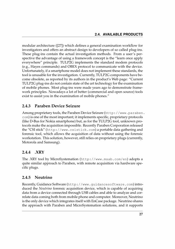
As mentioned before, the identity profiling activity takes place in a wider pro-cess, which can be modeled as a workflow. In Figure 3.1 the entire workflow isdepicted.
This process starts from the devices which have been seized. For each ofthem, depending on the device’s manufacturer and model, and on the mobileOS, the correct version of the tool (MIAT) which will acquire the content of theinternal memory must be chosen. After acquisition, the device file system’sdump is processed by the personal data decoder and the personal data (i.e.,contacts, calendar, messages and events log) are decoded and translated in amore suitable XML format. From this point personal data can be importedfrom the subsequent workflow’s components, that will be unaware of the de-vice they come from.
After being extracted and decoded, personal information needs to be an-alyzed in order to highlight the correlations among data and to help the in-vestigation in increasing the efficiency and effectiveness of the process. TheMobile Identity Profiler (MIP) process, that will be described in further detailin Chapter 6, was developed in order to capture the logical equivalent meta-information that data of a specific mobile device acquisition must contain (e.g.,contacts information, calls details, etc.). The tool reorganises collected data us-ing a specific proximity measure, and it also allows to consult the collected dataas they are recovered by the decoding tool. The innovative contribution of theMIP component is to reconstruct the interaction between the phone’s ownerand her contacts, and to reconstruct the relationships among them through the
29
CHAPTER 3. PROFILING SYSTEM’S ARCHITECTURE
Phone's Owner
MobileIdentityProfiler
Correlate mobile data to find social activities between the phone owner and his contacts
The resulting social graph is linked by edges between owner and contacts, and among them,
which are weighted with the influence factor.
Personal Data (XML)Contacts
SMS/MMS/EmailEvents log
PersonalData
Decoder
MIAT
PersonalData
Decoder
MIAT
PersonalData
Decoder
MIAT
Other Architectures
Combine with Web data (search engines, social networks, blogs, etc...)
to extend social correlations among contacts
Figure 3.1: The profiling workflow.
30
3.2. THE IDENTITY PROFILER FRAMEWORK
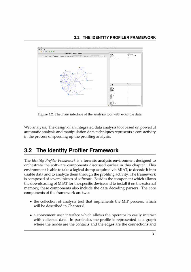
Figure 3.2: The main interface of the analysis tool with example data.
Web analysis. The design of an integrated data analysis tool based on powerfulautomatic analysis and manipulation data techniques represents a core activityin the process of speeding up the profiling analysis.
3.2 The Identity Profiler Framework
The Identity Profiler Framework is a forensic analysis environment designed toorchestrate the software components discussed earlier in this chapter. Thisenvironment is able to take a logical dump acquired via MIAT, to decode it intousable data and to analyze them through the profiling activity. The frameworkis composed of several pieces of software. Besides the component which allowsthe downloading of MIAT for the specific device and to install it on the externalmemory, these components also include the data decoding parsers. The corecomponents of the framework are two:
• the collection of analysis tool that implements the MIP process, whichwill be described in Chapter 6.
• a convenient user interface which allows the operator to easily interactwith collected data. In particular, the profile is represented as a graphwhere the nodes are the contacts and the edges are the connections and
31

CHAPTER 3. PROFILING SYSTEM’S ARCHITECTURE
the relationships existing between individuals. In Figure 3.2 is reporteda screenshot of the graphical interface.
The framework is written in Java 1.6 and SWING. We adopted an open-source library, JUNG, which provides a common framework for graph/net-work analysis and visualization. The clustering algorithms are written in C++,using the GNU compiler g++. We used the uBLAS package in the BOOST(http://www.boost.org/) library to manage graph and matrices, whilewe used the library SVDPACKC (http://www.netlib.org/svdpack/) tocompute the Singular Value Decomposition (SVD) of a matrix.
32
4Smartphone’s internal memory
acquisition
The main results of this chapter have been presented in [4, 28, 29]
4.1 Introduction
In this Chapter we will describe the methodology we developed to seize datacontained in the smartphone’s internal memory by a logical dump on an ex-ternal removable memory (if available), then we will present the tools we de-signed to implement such methodology.
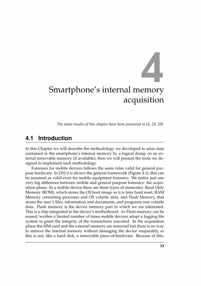
Forensics for mobile devices follows the same rules valid for general pur-pose hardware. In [30] it is shown the general framework (Figure 4.1); this canbe assumed as valid even for mobile equipment forensics. We notice just onevery big difference between mobile and general purpose forensics: the acqui-sition phase. In a mobile device there are three types of memories: Read OnlyMemory (ROM), which stores the OS boot image as it is later hard reset; RAMMemory containing processes and OS volatile data, and Flash Memory, thatstores the user’s files, information and documents, and programs non volatiledata. Flash memory is the device memory part in which we are interested.This is a chip integrated in the device’s motherboard. As Flash memory can beerased/written a limited number of times mobile devices adopt a logging filesystem to grant the integrity of the transactions executed. In the acquisitionphase the SIM-card and the external memory are removed but there is no wayto remove the internal memory without damaging the device irreparably, asthis is not, like a hard disk, a removable piece-of-hardware. Because of this,
33
CHAPTER 4. SMARTPHONE’S INTERNAL MEMORY ACQUISITION
Figure 4.1: DFRWS Digital Investigation Framework.
the most delicate operation to be done in a mobile environment is the seizureof the internal memory’s data.
The Mobile Internal Acquisition Tool (MIAT) acquires data directly fromthe internal memory to an external removable memory (like SD, mini SD, etc.),spawning an acquisition application stored in the same memory card held bythe forensic operator. This task is performed without the need of connectingthe device to PC. Thanks to this, forensic operators can avoid traveling withluggage full of one-on-one tools for every single mobile device. Even if theNIST guidelines say that “to acquire data from a phone, a connection must beestablished to the device from the forensic workstation” ([11]), we believe thatMIAT approach does not contrast those guidelines, but extends the forensicworkstation concept to the removable memory where the MIAT executable fileresides. The complete data seizure process is shown in Figure 4.2. In orderto acquire the memory content of a GSM, Bluetooth or Wi-Fi enabled mobiledevice, it is mandatory to shield the device with a Faraday cage [31]. Indeed,new incoming calls, SMS, e-mails, Bluetooth activity, connection status changesor GSM cell switch, could trigger events which may modify some of the filesystem’s objects.
34

4.2. OUR METHODOLOGY
Start
EndInternal memory collection
and removable support extraction
turn it on
Put the device in a
Faraday cage
Is there a memory card plugged-in?
Remove the memory
card
Make Memory card for seizure and insert it in
Is the device turned on?no
yes
yes
no
Figure 4.2: Data collection workflow
4.2 Our methodology
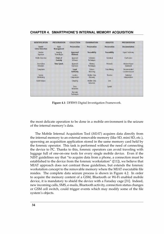
The MIAT is an alternative way to seize the internal memory data: it relies onlocal execution of an application which explores recursively the file system treeand copies each entry to a backup volume like an expansion memory card (Fig-ure 4.3). Before proceeding with the acquisition, the device should be switchedoff. Then, if the SIM and/or the memory card are inserted in the smartphone,we must remove them to collect the stored data. We note that the SIM card isusually located under the battery, for this reason we must turn off the device.Once the SIM and the memory card have been acquired, we use the host mem-ory card (different from the original memory card found in the device, part ofthe seizure) for the internal memory seizure: a tool for seizing data is storedin a memory card and the acquisition is performed locally. In order to grantdata integrity, during the acquisition process all files and directory are openedin read-only mode to preserve integrity. Moreover, in order to detect furthercorruptions, MIAT computes an MD5 hash before and after copying each file;MIAT also compiles a log file with all remarkable events (as shown in Table
35
CHAPTER 4. SMARTPHONE’S INTERNAL MEMORY ACQUISITION
Start more files? Stop
MD5
open opened? copying using specific OS apis
normal chunked copy
check integrity MD5
no
yes
no
yes
Figure 4.3: How MIAT works.
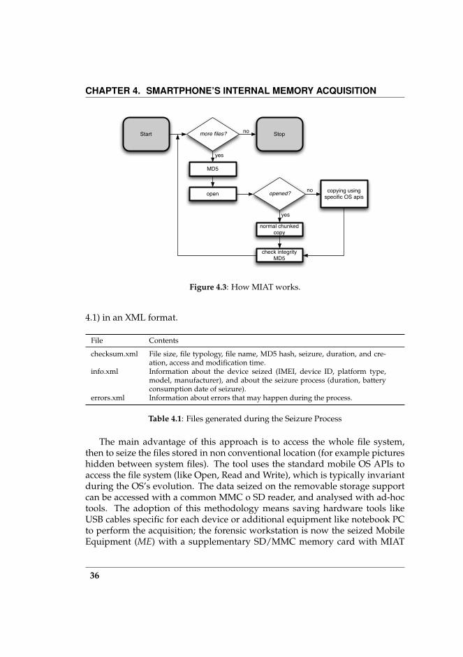
4.1) in an XML format.
File Contents
checksum.xml File size, file typology, file name, MD5 hash, seizure, duration, and cre-ation, access and modification time.
info.xml Information about the device seized (IMEI, device ID, platform type,model, manufacturer), and about the seizure process (duration, batteryconsumption date of seizure).
errors.xml Information about errors that may happen during the process.
Table 4.1: Files generated during the Seizure Process
The main advantage of this approach is to access the whole file system,then to seize the files stored in non conventional location (for example pictureshidden between system files). The tool uses the standard mobile OS APIs toaccess the file system (like Open, Read and Write), which is typically invariantduring the OS’s evolution. The data seized on the removable storage supportcan be accessed with a common MMC o SD reader, and analysed with ad-hoctools. The adoption of this methodology means saving hardware tools likeUSB cables specific for each device or additional equipment like notebook PCto perform the acquisition; the forensic workstation is now the seized MobileEquipment (ME) with a supplementary SD/MMC memory card with MIAT
36

4.3. IMPLEMENTATION
(a) (b)
Figure 4.4: These figures show screenshot version of MIAT we developed. In (a) MIATfor Symbian. In (b) MIAT for Windows Mobile.
onboard.The difference between MIAT and some other forensic tools (e.g., TULP2G)
is that the former interacts directly with the Operating System while the latterrequires an intermediary (located in the mobile phone) in charge of managingthe messages sent by remote forensic tool to the mobile phone. Since the inter-mediary code is almost always closed, the second case makes it impossible toverify how the intermediary code is written. Whenever the source code is notavailable, obviously, it is impossible to state by code reading if the tool respectsintegrity and the other required fundamental forensic properties.
We implemented MIAT for Symbian and Windows Mobile platforms. TheFigures 4.4(a-b) show the screenshots.
4.3 Implementation
4.3.1 Symbian
MIAT for Symbian, presented in [3], was developed to support and to test themethodology described above. Symbian is an operating system derived from
37
CHAPTER 4. SMARTPHONE’S INTERNAL MEMORY ACQUISITION
the Epoc operating system; Symbian OS supports a wide range of device cat-egories with several user interfaces, including Nokia S60, UIQ and the NTTDoCoMo common software platform for 3G FOMATM handsets. The com-monality of Symbian OS APIs enables development that targets all of thesephone platforms and categories. In order to produce executable code whichdoes not need of any other software layer (e.g., a JVM to interpret the byte-code) MIAT application was originally developed in C++, the native languageof the Symbian OS. Note that since there are many versions of each combina-tion OS/UI, there is a different SDK for each combination. You have to buildapplication for specific devices using the appropriate SDK of the correct ver-sion of the target phone. To improve the operational efficiency of the forensicsoperator, different versions of MIAT were compiled based on the various SDK.The specific required version of MIAT is recognized by the IMEI number asmentioned in the methodology above.
Most relevant files are locked by system processes, many files on the sys-tem are always open and locked by system processes. For example the fileContacts.cdb, which contains the database of contacts, is locked by PhoneBookthat is the address book process. In the past ([3]) we made use of the OS Backupservice to perform seizure of locked data. Such service is an utility allowing thebackup of the memory contents, even if these contents are locked. An applica-tion or a service can register itself and the files which locks. The Backup Servernotifies a backup request to registered applications, so they can release the locktemporarily. Once the file had been seized, the MIAT application could notifythis to Backup Server and then the system process could re-acquire the lock.In a recent work ([32]), we adopted a further alternative way to get access tolocked files. This way is accomplished by the Symbian RFs API method Read-FileSection that allows a file to be read without opening it. By this method it ispossible to seize the entire file system tree including files which have a persis-tent lock on; furthermore this strategy preserves integrity because the access isestablished in read-only mode, guaranteed by the OS.
4.3.2 Windows Mobile
Besides the Symbian version, we developed a version of MIAT for MicrosoftWindows Mobile Edition and we presented it in [4].
The term PocketPC refers to a Microsoft specification that sets various hard-ware and software requirements for a handheld-sized computer (PDA, Per-sonal Digital Assistant) that runs the Windows Mobile operating system. Asreported in Table 4.2, many tools perform forensic operations on a PDA. How-
38

4.3. IMPLEMENTATION
ever, as Ayers et al. assert in [11, 12, 33], the only NIST certified tool on aPocketPC is Paraben’s PDA Seizure. This tool performs data seizure of internalmemory in a remote way. Actually, the forensic tool is connected to a deviceby cradle or USB cable and, through the Microsoft’s ActiveSync protocol, itextracts data such as user’s files, call logs, SMS, MMS, TODO list, etc. Thisapproach has the advantage of minimizing the interaction towards the deviceand automating the process of seized data interpretation. The main disadvan-tage relies on the protocol closeness: we are not able to measure any memoryalteration caused by data exchange. Moreover, to perform the acquisition pro-cess, PDA seizure degrades the evidence putting a dll file in the device’s filesystem.
Palm OS PocketPC Linux PDA
pdd Acquisition NA NAPilot-Link Acquisition NA NAPDA Seizure Acquisition, Examina-
tion, ReportingAcquisition, Examina-tion, Reporting
NA
EnCase Acquisition, Examina-tion, Reporting
NA Examination, Reporting
POSE Examination, Reporting NA NAdd NA NA Acquisition
Table 4.2: PDA forensic tools
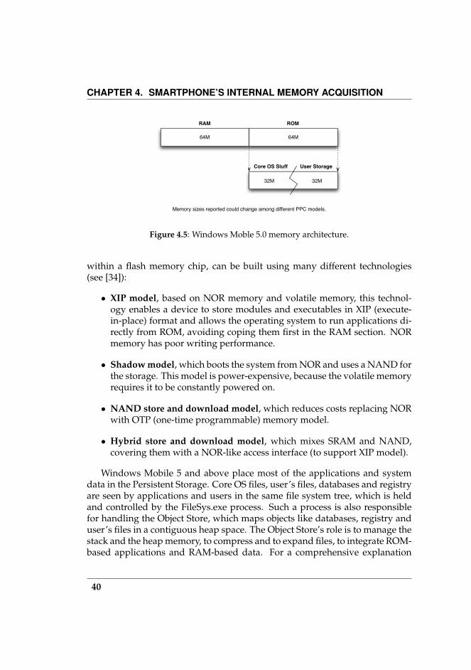
In Windows Mobile 2003 PocketPC and earlier, the device’s memory wassplit in two sections: a ROM section, containing all operating system core files,and a RAM section aimed at keeping the user storage (Storage Memory) andthe memory space for running applications and their data (Program Memory).The user can choose the amount of memory to be reserved to Storage Mem-ory and then to the Program Memory. The RAM chip was built on a volatilememory scheme, so a backup battery was required to keep the RAM circuitrypowered up, even if the device was just suspended. In case battery power sup-ply went down, all the user’s data were lost. Such a scenario forced the user torecharge the battery within a time limit of 72 hours (as mandatory by Microsoftto devices manufacturers).
Since Windows Mobile 5, memory architecture has been redesigned to im-plement a non-volatile user storage. Currently, the memory is split in twosections (see Figure 4.5): the RAM holds running processes data, whereas theROM keeps core OS code and libraries (called modules), the registry, databasesand user’s files. Such memory, also called Persistent Storage and contained
39
CHAPTER 4. SMARTPHONE’S INTERNAL MEMORY ACQUISITION
64M
RAM
64M
ROM
32M 32M
Core OS Stuff User Storage
Memory sizes reported could change among different PPC models.
Figure 4.5: Windows Moble 5.0 memory architecture.
within a flash memory chip, can be built using many different technologies(see [34]):
• XIP model, based on NOR memory and volatile memory, this technol-ogy enables a device to store modules and executables in XIP (execute-in-place) format and allows the operating system to run applications di-rectly from ROM, avoiding coping them first in the RAM section. NORmemory has poor writing performance.
• Shadow model, which boots the system from NOR and uses a NAND forthe storage. This model is power-expensive, because the volatile memoryrequires it to be constantly powered on.
• NAND store and download model, which reduces costs replacing NORwith OTP (one-time programmable) memory model.
• Hybrid store and download model, which mixes SRAM and NAND,covering them with a NOR-like access interface (to support XIP model).
Windows Mobile 5 and above place most of the applications and systemdata in the Persistent Storage. Core OS files, user’s files, databases and registryare seen by applications and users in the same file system tree, which is heldand controlled by the FileSys.exe process. Such a process is also responsiblefor handling the Object Store, which maps objects like databases, registry anduser’s files in a contiguous heap space. The Object Store’s role is to manage thestack and the heap memory, to compress and to expand files, to integrate ROM-based applications and RAM-based data. For a comprehensive explanation
40
4.4. RESULTS AND CONCLUSIONS
about how Windows Mobile uses the Object Store and manages linear flashmemory, see [35, 36].
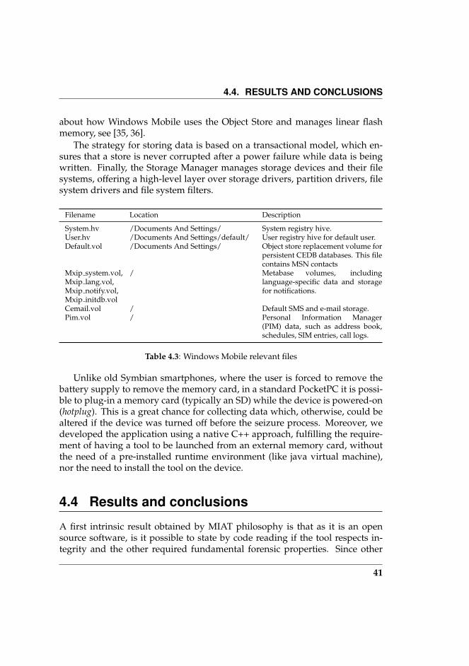
The strategy for storing data is based on a transactional model, which en-sures that a store is never corrupted after a power failure while data is beingwritten. Finally, the Storage Manager manages storage devices and their filesystems, offering a high-level layer over storage drivers, partition drivers, filesystem drivers and file system filters.
Filename Location Description
System.hv /Documents And Settings/ System registry hive.User.hv /Documents And Settings/default/ User registry hive for default user.Default.vol /Documents And Settings/ Object store replacement volume for
persistent CEDB databases. This filecontains MSN contacts
Mxip system.vol,Mxip lang.vol,Mxip notify.vol,Mxip initdb.vol
/ Metabase volumes, includinglanguage-specific data and storagefor notifications.
Cemail.vol / Default SMS and e-mail storage.Pim.vol / Personal Information Manager
(PIM) data, such as address book,schedules, SIM entries, call logs.
Table 4.3: Windows Mobile relevant files
Unlike old Symbian smartphones, where the user is forced to remove thebattery supply to remove the memory card, in a standard PocketPC it is possi-ble to plug-in a memory card (typically an SD) while the device is powered-on(hotplug). This is a great chance for collecting data which, otherwise, could bealtered if the device was turned off before the seizure process. Moreover, wedeveloped the application using a native C++ approach, fulfilling the require-ment of having a tool to be launched from an external memory card, withoutthe need of a pre-installed runtime environment (like java virtual machine),nor the need to install the tool on the device.
4.4 Results and conclusions
A first intrinsic result obtained by MIAT philosophy is that as it is an opensource software, is it possible to state by code reading if the tool respects in-tegrity and the other required fundamental forensic properties. Since other
41
CHAPTER 4. SMARTPHONE’S INTERNAL MEMORY ACQUISITION
application (Paraben, TULP2G) codes are almost always closed, this makes itimpossible to verify how their intermediary code is written.
In order to evaluate the performance, we compared MIAT for Symbian andWM with Paraben products. As a measure, we chose to detect which fileswere modified after the data seizure. We noticed that MIAT (both versions)performs as well as Paraben in coverage and in integrity. The results of thecomparison are reported in Tables 4.4 (Symbian) and 4.5 (Windows Mobile).Moreover, in both versions for Symbian and for Windows Mobile, MIAT isslower than Paraben in seizure times. Those are constrained by device typeand filesystem density. Moreover, MIAT copies the filesystem in a logical way,instead Parabens seems to get a copy of the device ROM at a lower level, byputting a library in the device’s filesystem.
Furthermore, MIAT can lower the effort for law enforcement agencies (LEAs),due to the non-technical skills required for the forensic operators; hence, we ex-pect the MIAT and the proposed methodology to speed up the forensic acquisi-tion process, especially when the amount of devices to analyse can overwhelmthe high tech crime units. Currently the MIAT tool is being experimented by aLEA, in order to establish if it could be proposed as a repeatable seizure tool inrespect of Italian laws.
Future developments of MIAT methodology will include (but are not lim-ited to) the OS DRM mechanism, in order to maintain the highest level of de-vice portability on Symbian phones and the development of an analysis farm,where to forward all the seized images (from the crime scene) in order to pro-vide a real time standard analysis of the mobile equipment.
42

4.4. RESULTS AND CONCLUSIONS
File Reboot Seiz. File Reboot Seiz.
100056c6.ini B 101f6df0.ini B BAlarmServer.ini B P Applications.dat B Mbackupdb.dat B P btregistry.dat Bcbtopicsmsgs.dat B CntModel.ini B PCommonData.D00 B P DRMHS.dat BECom.lang B HAL.DAT BLocaleData.D05 B P nssvasdatabase.db B BScShortcutEngine.ini B P smssmssegst.dat BSystem.ini B
B Means that a change happens for both toolsP Means that a change happens for PARABENM Means that a change happens for MIAT
Table 4.4: MIAT for Symbian and Paraben’s Device Seizure comparison, and theirhashes consistency. This table also shows the event which trigger changes.
File Paraben MIAT-WM
/Documents And Settings/default.vol − −/Documents And Settings/system.hv − −/Documents And Settings/default/user.hv − −/Windows/*.dll − −/mxip notify.vol
√?
/cemail.vol√
?/mxip system.vol
√ √
/mxip lang.vol√ √
/pim.vol ?√
− file not copied? file copied but its hash does not match√
file copied and hash matches
Table 4.5: MIAT for Windows Mobile and Paraben’s PDA Seizure comparison, and theirhashes consistency.
43


5Smartphone’s data reverse
engineering
The main results of this chapter have been presented in [37]
5.1 Introduction
After extracting the file system’s logical dump from a smartphone, we needa method to decode personal data stored within several mobile DBMS filesand to make them available to other applications. Such DBMS files containactual and obsolete data, i.e., old or deleted entities; this occurs because themobile OS, for performance reasons, defers the deletion as long as possible,e.g., when the free space available in the file system is not enough. Often mo-bile DBMS can be accessed via APIs provided by mobile OS manufacturers,but they are prevented from accessing those data, therefore they are not usefulin the forensic environment. Therefore we chose a Data Reverse Engineering(DRE) approach to retrieve and decode the storing format. In the traditionalarchitectures (PCs and mainframes) the DRE was studied as business solutioneither for the control of data handled via legacy applications or in order to re-construct deteriorated data. Developed models are too generic for mobile en-vironments [18], or they aims at discovering mainly the data model [38, 39, 40],or have been studied to address vertical problems like extracting data fromCOBOL, DB/2 [41] or Access. For our scope, we are not interested in discov-ering the data model because we know a priori which data we are looking for(e.g., all the user controllable data attributes like contact’s name and surnameor SMS text), and we do not care about the relational structure. Moreover,
45

CHAPTER 5. SMARTPHONE’S DATA REVERSE ENGINEERING
a great facility given by a methodological DRE application, is that, when fileformats change, after re-applying the methodology we are able to update ourknowledge about how data are stored.
In this chapter we will propose a methodology allowing smartphone’s DREoperators to be more flexible in the mobile file formats knowledge. As a matterof fact, the mobile phone environment is composed of a plethora of manu-facturers and operating systems, each of them is released in several versionswhich stores data in different formats. Handling such heterogeneity through amethodological approach is an important asset for mobile forensics and, moregenerally, for smartphones’ businesses.
As a case study we applied these methods to the Symbian OS, and we ob-tained several results, including the mapping between a given data and its lo-cation into the file system, the obsolete data recovering, and the Symbian per-sonal databases format reversed. The obtained results (see Section 5.3) showthat our methodology can be successfully applied to environments which aredifferent from our forensic starting point. The methodology helps to decodedatabases files and to develop ad-hoc parsers; data extracted by such parserscan be easily converted and used to perform tasks such as user profiling, devicesyncing or data recovery.
5.2 Our step-by-step Methodology
Smartphone’s operating systems save personal data in many DBMS tables whichare stored in binary files. Often the format of such files is not public and thetools available to read them rely on an operating system native API (if they runon the device) or on a porting of their code (if they run on a PC), and they cannot extract data in a forensic way, i.e., they do not retrieve information of highinvestigative value as deleted or modified data. Therefore, the solution is tointerpret the binary file directly in order to give a structure to the internal data.Initially the problem was addressed through the comparison of multiple filesof the same type, relying on the analyst’s ability in the intuitive interpretationof the data content. In such way the analysis of data was often confused andled to performing redundant operations without any result. Therefore, in or-der to preserve obsolete data, we chose to design a methodology for the binaryfile interpretation, which was able to decode the information required withoutperforming redundant operations. Furthermore, the methodology will help toretrieve the data alterations and deletions.
Our main contribution is to propose a wisdom-driven DRE methodologi-
46
5.2. OUR STEP-BY-STEP METHODOLOGY
cal approach to decode smartphone’s personal data, that are stored in severalDBMS-managed files; with this work we provide the tools to reach the follow-ing targets:
• understand where information is stored in the mobile device’s file sys-tem;
• retrieve and decode personal actual and obsolete data;
• develop a suitable parser.
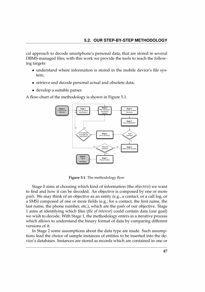
A flow-chart of the methodology is shown in Figure 5.1.
Stage 1:Files of interest
identification
Stage 2:Data hypothesis
and entities injection
Stage 3:Sequences similarity
discovery
Stage 4:Data interpretation
Stage 6:Error correction
Stage 5:Meta-format building
Stage 7:Parser building
Stage 8:Testing
& debugging
Goal reached?
Is it sufficient to modify the hypothesis?
Objective reached?
Yes
Yes
Yes
No
No
No
Stage 0:Choice of the
objective
Figure 5.1: The methodology flow
Stage 0 aims at choosing which kind of information (the objective) we wantto find and how it can be decoded. An objective is composed by one or moregoals. We may think of an objective as an entity (e.g., a contact, or a call log, ora SMS) composed of one or more fields (e.g., for a contact, the first name, thelast name, the phone number, etc.), which are the goals of our objective. Stage1 aims at identifying which files (file of interest) could contain data (our goal)we wish to decode. With Stage 1, the methodology enters in a iterative processwhich allows to understand the binary format of data by comparing differentversions of it.
In Stage 2 some assumptions about the data type are made. Such assump-tions lead the choice of sample instances of entities to be inserted into the de-vice’s databases. Instances are stored as records which are contained in one or
47
CHAPTER 5. SMARTPHONE’S DATA REVERSE ENGINEERING
more binary files. If required, the hypotheses made in Stage 2 will be refined inStage 6 and the instances may change. The number of instances inserted willdetermine the number of comparisons among binary records, that will affectthe precision of next Stage. Stage 3 deals with the binary files’ content format-ting, in order to make the data instances inserted in Stage 2 identifiable andcomparable. Usually, we try to group similar zones within the same samplebinary file, and among different sample binary files, and then proceed to theinterpretation.
Formatting must take into account the data interpreted successfully in pre-vious iterations, in order to cut them off (i.e., data already analyzed) from thestudy of a new format. The Stage 4 comprises two sub-tasks: the first dealswith identifying candidate bytes sequences, and the second aims at decodingthe candidate bytes sequences. The identification of candidate bytes sequencesis performed by removing all the sequences that do not match with the hy-pothesis of the Stage 2. The second task tries to find the connection betweenthe data inserted in Stage 2 (the instances) and its binary representation. Asdepicted in Figure 5.1, the methodology iterates through Stage 1, 2, 3, 4, and 6(error correction) until a goal is reached, i.e., the information about the formatof a entity’s field is exhaustive and a mapping between the field and its binarystoring format is found. The fifth Stage simply annotates in a meta-format allmapping information found. If the joining of all meta-format found allows thedecoding of the entire objective (the information needed) identified in Stage0, the methodology goes to Stage 7. At this Stage a piece of software able todecode automatically the now-exposed file format will be designed and imple-mented. All collected knowledge about the format turns into a set of softwarerequirements. This process must be repeated for each file marked as file of in-terest. Such a piece of software will be tested at Stage 8.
In the following sections we will describe each methodology Stage.
5.2.1 Stage 0: Choice of the objective
Before starting, we must to choose from which data we want to start the de-coding process. We define as objective the type of personal data (e.g., contacts,SMS, email, calendar, events log, etc.) we want to find into the device’s filesystem and to decode the binary format. An objective can be seen as the setof “atomic” goals that must be completed in order to reach the objective. Forinstance, in order to decode the contacts (the objective), after having detectedin which file (or files) they are stored, we have to find how the contact’s dataelements (goals) are encoded. Such goals are attributes such as name, surname,
48

5.2. OUR STEP-BY-STEP METHODOLOGY
mobile phone number, e-mail, street address, etc.Let an objective Γ be a set such that it contains the list of goals we want to
reach.Γ = γ1 . . . γn
In this Stage we can only define roughly an approximation of Γ: thanks toinformation about the objective’s data format that we will learn progressivelyin the next Stages, we will be able to refine Γ with more accurate goals.
5.2.2 Stage 1: Files of interest identificationGiven the objective chosen in the previous Stage, this step aims at identifyingfiles to be analyzed and decoded in next Stages. Mobile devices save personaldata in database files stored persistently in the file system. To identify the filescontaining the information we are looking for, we first need to cause a lot ofchanges inside these files in order to make them identifiable. These changesare objective-dependent: if we are looking for contacts, we will generate activ-ity like contact insertion; if we are looking for events log, we will make calls,sim-changes, and send and receive SMS. Each of these operations generates anentity (E) which will be stored as one or more records in the file system. Eachentity E is a set composed by m ∈ N attributes (ε).
For each goal γi ∈ Γ there is a set of attributes εj ∈ E such that, afterdiscovering the encoding of each εj in the set, the goal γi will be reached.
We define Ω as the sequence E1, . . . , En of entities we have to insert inthe device in order to modify all the files involved in the given objective.
The value of n depends on the objective’s type and on how its entities arestored. Then, n can only be supposed as the process starts, but it could berefined over the methodology’s iterations if needed.
For instance, let E be a contact’s card: each εi ∈ E will be an attribute suchas name, surname, date of birth, phone number, email address, and so on.
As a best practice, there is the need to fill every εi ∈ E attribute in order tomodify all possible files involved in Γ.
Let A be the fileset (in our case, the whole device’s file system) before per-forming the Ω operation set on the device. Let B br the fileset after performingΩ operation set. The application T of operations set Ω on the device is:
TΩ : A→ B
49
CHAPTER 5. SMARTPHONE’S DATA REVERSE ENGINEERING
John
Brown
+123423456
ε1
some_info
ε2
ε3
ε4
εm
E1 E2 En
Peter
White
+19280023
ε1
some_info
ε2
ε3
ε4
εm
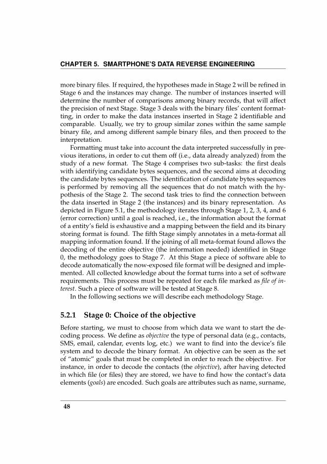
Ω ={ }Figure 5.2: The format of the Ω operations sequence. In this figure is shown an examplewith contacts discovery as objective
Let diff denote the function which computes the differences between twofilesets. The fileset C, which contains only files modified by the T application,is:
C = diff (B,A)
C may contain garbage data, since other operations may occur when theuser performs T . Then, we must “clean” C, searching and deleting all irrele-vant data. Let clean denote the function which cleans a fileset of garbage data.The fileset Φ is:
Φ = clean(C)
5.2.3 Stage 2: Data hypotheses and entities injection
After the insertion of the Ω entities, the Φ set tells us which files have beenmodified, but it still does not give us information about how the εi are encodedin the storage.
50
5.2. OUR STEP-BY-STEP METHODOLOGY
In Stage 2 we will perform three tasks:
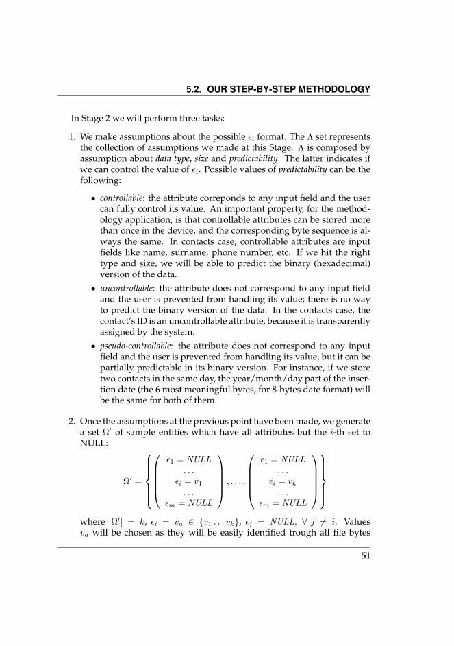
1. We make assumptions about the possible εi format. The Λ set representsthe collection of assumptions we made at this Stage. Λ is composed byassumption about data type, size and predictability. The latter indicates ifwe can control the value of εi. Possible values of predictability can be thefollowing:
• controllable: the attribute correponds to any input field and the usercan fully control its value. An important property, for the method-ology application, is that controllable attributes can be stored morethan once in the device, and the corresponding byte sequence is al-ways the same. In contacts case, controllable attributes are inputfields like name, surname, phone number, etc. If we hit the righttype and size, we will be able to predict the binary (hexadecimal)version of the data.
• uncontrollable: the attribute does not correspond to any input fieldand the user is prevented from handling its value; there is no wayto predict the binary version of the data. In the contacts case, thecontact’s ID is an uncontrollable attribute, because it is transparentlyassigned by the system.
• pseudo-controllable: the attribute does not correspond to any inputfield and the user is prevented from handling its value, but it can bepartially predictable in its binary version. For instance, if we storetwo contacts in the same day, the year/month/day part of the inser-tion date (the 6 most meaningful bytes, for 8-bytes date format) willbe the same for both of them.
2. Once the assumptions at the previous point have been made, we generatea set Ω′ of sample entities which have all attributes but the i-th set toNULL:
Ω′ =
ε1 = NULL
. . .εi = v1
. . .εm = NULL
, . . . ,
ε1 = NULL
. . .εi = vk
. . .εm = NULL
where |Ω′| = k, εi = va ∈ v1 . . . vk, εj = NULL, ∀ j 6= i. Valuesva will be chosen as they will be easily identified trough all file bytes
51
CHAPTER 5. SMARTPHONE’S DATA REVERSE ENGINEERING
00 11 F2 66 B8 58 2A E1 00 01 60 02 00 00 00 00 00 1B 00 00 00 63 02 30 06 31 31 39 02 0C 00 00 00 46 00 DD 6E 82 BD 58 2A E1 00 01 60 03 00 00 00 00 00 1B 00 00 00 63 02 30 06 31 31 39 02 0C 00 00 00 46 00 9C 7F 98 C3 58 2A E1 00 01 60 04 00 00 00 00 00 46 00 00 00 63 02 30 06 31 31 39 02 0C 00 00 00 46 00 C1 EB 9C C9 58 2A E1 00 01 60 05 00 00 00 00 00 46 00 00 00 63 02 30 06 31 31 39 02 0C 00 00 00 46 00 FB 96 CA CF 58 2A E1 00 01 60 06 00 00 00 00 00 C8 00 00 00 63 02 30 06 31 31 39 02 0C 00 00 00 46
00 11 F2 66 B8 58 2A E1 00 01 60 02 00 00 00 00 00 1B 00 00 00 63 02 30 06 31 31 39 02 0C 00 00 00 46 00 DD 6E 82 BD 58 2A E1 00 01 60 03 00 00 00 00 00 1B 00 00 00 63 02 30 06 31 31 39 02 0C 00 00 00 46 00 9C 7F 98 C3 58 2A E1 00 01 60 04 00 00 00 00 00 46 00 00 00 63 02 30 06 31 31 39 02 0C 00 00 00 46 00 C1 EB 9C C9 58 2A E1 00 01 60 05 00 00 00 00 00 46 00 00 00 63 02 30 06 31 31 39 02 0C 00 00 00 46 00 FB 96 CA CF 58 2A E1 00 01 60 06 00 00 00 00 00 C8 00 00 00 63 02 30 06 31 31 39 02 0C 00 00 00 46
00 11 F2 66 B8 58 2A E1 00 01 60 02 00 00 00 00 00 1B 00 00 00 63 02 30 06 31 31 39 02 0C 00 00 00 46 00 DD 6E 82 BD 58 2A E1 00 01 60 03 00 00 00 00 00 1B 00 00 00 63 02 30 06 31 31 3902 0C 00 00 00 46 00 9C 7F 98 C3 58 2A E1 00 01 60 04 00 00 00 00 00 46 00 00 00 63 02 30 06 31 31 39 02 0C 00 00 00 46 ......
(a) (b) (c)
Figure 5.3: These figures show an example of a DBMS binary file before and after theStage 3. In (a) the sample file after making pairs of calls of the same duration (Stage 2).In (b) equal sequences highlighted. In (c) the formatted file Φ′
in the next Stages. A good choice for va values critically influences thesubsequent steps; in the early iterations of the methodology, va shouldbe chosen with values that, disposed in the Ω′ entity sequence, follow aperiodical repetitive pattern (e.g., AABB, ABAB, AAAA, etc.). Thanks tothis approach, in the next Stages we will be able to retrieve them througha pattern similarity matching, avoiding ambiguities in the modified file’szones caused by insertion side effects.
3. Finally, we have to insert Ω′ entities into the device through an applica-tion TΩ′ , and then we have to perform a new file system dump in orderto analyze the files generated via the insertion performed in the previoustask.
The output of this Stage is Λ and Φ′, the set composed by all files containingΩ′ entities.
5.2.4 Stage 3: Sequences similarity discovery
The goal of this Stage is to get the Φ′ fileset, containing the sample entities,and to find all sequences of bytes which present the same similarities as theattributes of Ω′ entity set inserted in Stage 2. In the previous Stage, we injectedentities which shared one or more attributes among them. The attributes of
52

5.2. OUR STEP-BY-STEP METHODOLOGY
entities was injected following a pattern, like pairs of calls with the same du-ration or contacts with the same fields. In this Stage we have to highlight thefile’s byte sequences which are equal among them. In the call duration exam-ple, if we made c pairs of calls with the same duration, we will find c equalpairs of byte’s sequences in the events log file. Therefore, if the assumptions ofthe previous Stage were correct, the current step simplifies the interpretationtasks in the next Stages reducing the file’s complexity.
The Stage 3 process iterates through the following steps:
1. Discard file zones which are not directly affected by the operations inStage 2;
2. Identify attribute separation flags;
3. Identify, highlight and separate similar byte sequences.
In Figure 5.3 is shown an example in which we are going to format theevent log file to detect the storage format of the voice call duration. In theprevious Stage we made pairs of calls of the same duration (Figure 5.3a). Allthe useless information (metadata, index and tables) was discarded and similarzones were looked for in accordance with the methodology described.
Once similar zones are identified (Figure 5.3b), they have to be formattedin the same way to enable the next Stage to refine the identification and tounderstand which file parts were changed after the Ω′ entities insertion. Wemust separate the user added information from other file data (Figure 5.3c). Agood file formatting is given by isolating different file zones from similar ones,and then by isolating flags.
The output of this Stage is the Φ′ containing the formatted fileset.
5.2.5 Stage 4: Data interpretation
Stage 4 is composed of two steps; the candidate sequence identification and thecandidate sequence interpretation.
The candidate sequences are sequences of bytes, stored in the Φ′ fileset,in which we are likely to find the data we are looking for. ΣΓ,Λ is the set ofcandidate sequences for a given objective Γ, and under a given assumption Λ.
The candidate sequence identification relies on the hypothesis about at-tribute data properties made in Stage 2, and it deals with simplifying the se-quence, deleting all non-relevant data. In particular:
53

CHAPTER 5. SMARTPHONE’S DATA REVERSE ENGINEERING
• If the data is constant it is always stored in the same format, so the for-matted files containing the data can be simplified by removing all thedifferent bytes; if the data’s size is equal to the size in the assumptionsmade, such data is added to ΣΓ,Λ;
• If the data is variable probably the storing format will be always differ-ent, so all the equal formatted files parts can be removed to simplify. Ifthe data size is equal to the size in the assumptions, such data is addedto ΣΓ,Λ;
• If the data is pseudo-variable the storing format will be partially constantand partially variable; we have to look for the constant parts of the fileand, then, we can look at the proximity of the constant zone in an areawith its size equal to the hypothesis. Then the sequence is added to ΣΓ,Λ.
If ΣΓ,Λ = ∅ or |ΣΓ,Λ| is large (unmanageable quantity), in order to reduce thenumber of resulting candidate sequences, we have to analyse the results andunderstand how to change the Λ assumptions made in Stage 2 (through Stage6). Once the assumptions are modified and the new Ω′ entities are inserted inthe device (reiteration through Stages 2, 3 and 4), the precision of this Stagewill improve.
When we reach a manageable size of |ΣΓ,Λ|, the candidate sequence inter-pretation task can start. In this step we consider Λ to better understand whichpart of the candidate sequence represents the data we are interested in. We lookat the Ω′ sequence of operations and check if the sequence does match in thecandidate sequence set. If the sequence of attended values of attributes in Ω′ isthe same in the ΣΓ,Λ, the sequence is ready to be interpreted. As the databasefiles are usually in hexadecimal format and the target data are in a different for-mat (e.g., string, decimal format), it is necessary to transform data in a commonformat (e.g., decimal).
The last step to be performed is to compare data contained in the databasewith the data inserted in Ω′ entity sequence and, if those match, the storageformat is saved and the next Stage starts.
5.2.6 Stage 5: Meta-format building
After the data decoding in Stage 4, we need to store the information collectedin a intermediate format. This Stage should be seen as a “methodology inter-mediate status saving”, which helps the operator to choose the next γ goal toprocess, and to refine it if required. Before compiling the meta-format, this
54

5.2. OUR STEP-BY-STEP METHODOLOGY
Stage requires the compilation of a “formats table”. In such a table a list of datadiscovered at Stage 4 is reported, and for each data the following metadata areshown:
Field Name Is a text placeholder associated with the data. This label will besubstituted to the data value in the Φ′, in order to make its retrieval easier.
Size The size of data, expressed in bytes.
Description Other information, useful to the parser building Stage, like: whichinformation is held by the field, type of data, endianess, suggestions forthe automatic data localization, etc.
Example An example value of the field.
Each discovered data needs a row in the table. An example of formats table isshown in 5.4a.
After compiling the formats table, the meta-format file will be equivalent tothe sample binary file purged from non-relevant bytes. Data such as headers,indexes, etc, can be deleted if they are not relevant for the purposes of theobjective. The first step to be performed is to identify, for each entry in thetable, the values with which the data is manifested into the meta-format file(figure 5.4b) and to replace them with the related labels in the table (figure5.4c). In this way all relevant data in the meta-format file will be replaced byplaceholders that will be easily detected at the parser building Stage.
The example shown in Figure 5.4 takes into account a contacts file contain-ing two records with following fields: name, surname and company.
After this Stage, the given binary file could be automatically interpretable,if all the following conditions are satisfied:
1. The meta-format’s data and values not yet identified have a static size, sothey can be ignored. In this case the parser is able to skip them automat-ically;
2. All required meta-format’s data and values are identified;
3. If after having tried different hypotheses of Ω′, the identified zones inthe meta-format did not change at all, then the meta-format file and theformats table are stable.
55

CHAPTER 5. SMARTPHONE’S DATA REVERSE ENGINEERING
5.2.7 Stage 6: Error correction
This Stage will be performed if the current γi was not reached (e.g., Stage 4was unable to find a correct interpretation for the εi representation) and it ismandatory to re-iterate the methodology. The error leading to this Stage can becaused by two cases. In the following list we show the actions to be performedin the next iteration:
1. ΣΓ,Λ = ∅ or |ΣΓ,Λ| is high (unmanageable quantity): if there are no can-didate sequences or there are too many, some backtracking needs to beperformed to obtain a manageable number of candidate sequences. Someactions may be useful to do this:
(a) Changing the assumed data size. This implies reformatting the Φ′,building up a new Φ′. If ΣΓ,Λ = ∅ and we are looking for matchingsequences, we need to decrease the size. Two different big sequencesmight contain two matching smaller sequences. On the other hand,if we are looking for non-matching sequences, the size needs to beincreased. In the case where |ΣΓ,Λ| being high, if we are looking formatching sequences we need to increase the size, and decrease it fornon-matching sequences.
(b) Modifying Ω′, adding or deleting entities, or changing the εi values.A new Ω′ could give as output more accurate results. The changesshould be done according to the feeling of the operator, this is thehardest part of the whole process and the operator’s skills play thestarring role.
(c) Verifying Φ′ correctness. Verify that the file we are looking into isthe right one (the required information may reside in another file).
2. If the interpretation of candidate sequence did not decode any informa-tion about the storing format:
(a) Changing the assumed data size.
(b) Modifying Ω′. If an ambiguity among different candidate sequenceshappened, modify Ω′ in order to restrict the change to less bytes;
(c) Changing the data type. Changing the data type might help thedecoding from hex.
56

5.3. RESULTS
If none of the above cases apply, or the suggested changes did not lead toa correct data interpretation, we need to review the current γi goal in Stage 1.Each reached γ reduces the space of assumptions we are free to choose to buildΛ (and Ω′ as a consequence) for other γ.
5.2.8 Stage 7: Parser building
This Stage takes as input all collected knowledge about the given binary fileformat. The operator should be able to write a program that reads data fromthe logical dump of the smartphone and converts them in a XML format. Itis mandatory to implement a quality monitor that measures the number ofentries in which the parser encounters problems. The ratio r = F
T between thenumber of failures (F ) and the total number of entries (T ) will be an indicator ofthe need to perform additional methodology’s iterations. The threshold belowwhich r is acceptable depends on the required accuracy.
5.2.9 Stage 8:Testing and debugging
In this phase the parser produced in the last Stage will be applied on severallogical dumps, in order to test it and to debug it over real cases. In this Stagethe r values of the current parser it will be verified and will be established ifthe implementation precision is sufficient or not.
5.3 Results
In order to verify and to refine the methodology’s Stages, we took the SymbianS60 operating system as a case study. Applying the methodology produced theresults we are going to show in this section.
File of interest - Stage 1 helped us to find a list of files containing SMS, MMS,contacts, and all user’s personal data, which are shown in Table 5.1.
Symbian personal data files format - Thanks to the methodology we have beenable to reverse engineer the Symbian S60 DBMS file format. We appliedthe methodology to the contacts list, to the calendar, to the text/multime-dia messages and to the phone’s event log (which contains calls, sent and
57
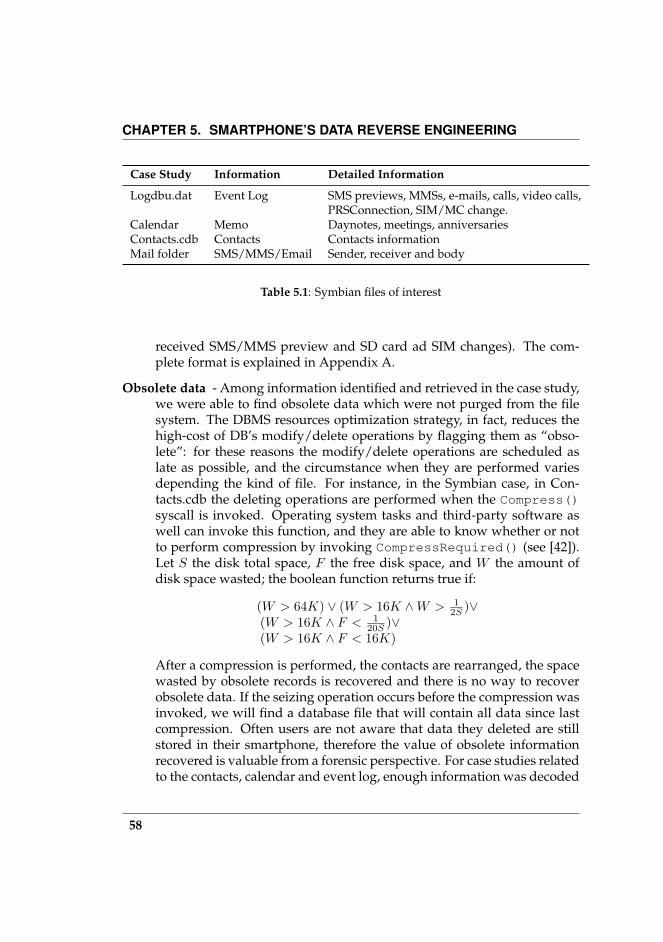
CHAPTER 5. SMARTPHONE’S DATA REVERSE ENGINEERING
Case Study Information Detailed Information
Logdbu.dat Event Log SMS previews, MMSs, e-mails, calls, video calls,PRSConnection, SIM/MC change.
Calendar Memo Daynotes, meetings, anniversariesContacts.cdb Contacts Contacts informationMail folder SMS/MMS/Email Sender, receiver and body
Table 5.1: Symbian files of interest
received SMS/MMS preview and SD card ad SIM changes). The com-plete format is explained in Appendix A.
Obsolete data - Among information identified and retrieved in the case study,we were able to find obsolete data which were not purged from the filesystem. The DBMS resources optimization strategy, in fact, reduces thehigh-cost of DB’s modify/delete operations by flagging them as “obso-lete”: for these reasons the modify/delete operations are scheduled aslate as possible, and the circumstance when they are performed variesdepending the kind of file. For instance, in the Symbian case, in Con-tacts.cdb the deleting operations are performed when the Compress()syscall is invoked. Operating system tasks and third-party software aswell can invoke this function, and they are able to know whether or notto perform compression by invoking CompressRequired() (see [42]).Let S the disk total space, F the free disk space, and W the amount ofdisk space wasted; the boolean function returns true if:
(W > 64K) ∨ (W > 16K ∧W > 12S )∨
(W > 16K ∧ F < 120S )∨
(W > 16K ∧ F < 16K)
After a compression is performed, the contacts are rearranged, the spacewasted by obsolete records is recovered and there is no way to recoverobsolete data. If the seizing operation occurs before the compression wasinvoked, we will find a database file that will contain all data since lastcompression. Often users are not aware that data they deleted are stillstored in their smartphone, therefore the value of obsolete informationrecovered is valuable from a forensic perspective. For case studies relatedto the contacts, calendar and event log, enough information was decoded
58
5.3. RESULTS
in order to reconstruct the owner communication history. In the casestudy of messages (SMS, MMS and emails, stored in the /System/Mailfolder) we were not able to find erased data, because OS purges immedi-ately deleted messages to optimize the available storage.
Unexpected information - A part of data attributes are not controllable by theuser, i.e., she can not insert them into the system explicitly, thus we werenot conscious of their presence. During Stage 4, the nature of our method-ology helped us to retrieve such “hidden” information, as the record’s IDand its creation date. Such an important result enforces the methodologyeffectiveness, since it is able to detect more goals than the identified onesin Stage 0; from the forensic point of view, such a result completes thescene by adding more information useful to trace the user’s activity. Inour case study, some unexpected information helped us to better under-stand the data model, thus the application’s behaviour.
We applied the methodology to more than 50 device dumps. At the be-ginning, the first dumps we studied came from Nokia N70 devices1, but werealized that the knowledge we had about the S60 format was still incompletesince the parser was unable to decode an older phone’s dump (Nokia 7610).After applying a few iterations of the methodology, we built a parser able tointerpret the new format.
1Equipped with Symbian OS v8.1a, S60 Platform Second Edition, Feature Pack 3
59

CHAPTER 5. SMARTPHONE’S DATA REVERSE ENGINEERING
Field Name Size Description Example
ID 4 Int, Bigend B6 03 00 00NAME LEN 1 Int, Littleend 0ENAME ( NAME LEN
2) String 43 6C 61 75 64
. . . . . . . . . . . .
(a)
B6 03 00 000E43 6C 61 75 64 69 610A44 72 61 67 6F1055 6E 69 72 6F 6D 61 3209 13 00 10
(b)
IDNAME LENGHTNAMESURNAME LENGHTSURNAMECOMPANY NAME LENGHTCOMPANY NAMECXF1
(c)
Figure 5.4: This three figures depict an example of the application of Stage 5 on a filecontaining the phone’s address book. (a) A table with pseudo data type, got as outputby Stage 4. (b) The meta-format file before Stage 5. (c) The meta-format file after Stage5.
60

6The MIP process
The main results of this chapter have been presented in [43]
6.1 Introduction
In this chapter we describe the Mobile Identity Profiling (MIP) process, whichaims at reconstructing a user’s profile by combining the smartphone’s dataanalysis with social relationships data found on the Web. Such a process is splitinto three stages: the Smartphone Data Analysis, the Web Data Analysis and theClustering Analysis. The goal of the process is to build a smartphone owner’ssocial network, namely the profile graph, and to find all sub-graphs (clusters)which represent the social groups within the graph.
6.2 Smartphone Data Analysis
The decoding phase aims at generating parsers which can export data in xml-format, or that can be integrated directly in the analysis application (in orderto simplify the workflow). Data decoded as contacts list, sms list, event logand calendar entries list can be hard to analyse manually by a human opera-tor, because she has to correlate their unique identifier, in order to reconstructsituations or conversations (or more precisely, the importance of relationships)between a device’s owner and their contacts.
The Smartphone Data Analysis performs such tasks automatically; it is com-posed of four sub-phases1: File Analysis, Contact Analysis, Event Analysis and
1In this work we do not deal with the calendar analysis.
61

CHAPTER 6. THE MIP PROCESS
(a) (b)
Figure 6.1: The graph representation of contacts (a) and their relationships with thephone’s owner (b), which are revealed by the number of calls and number of sms/mms.
Messages Analysis.The File Analysis phase will load in the framework each file contained in
the logical dump, and will organize them by their MIME-Type and run thedecoding tool over personal data files.
The Contact Analysis phase will merge together duplicate contacts infor-mation, highlighting those which provide incomplete data and which may rep-resent potential source of noise for the next Web analysis.
The Event Analysis will mine the phone’s log in order to reconstruct theuser’s activity. Although the event type may depends on the device type,events always belong to the following macro-classes: voice calls, data calls,sms/mms sent or received, SIM change, SD change. Voice calls and sms/mmslogs are useful for the reconstruction of the phone owner’s social activity, infact they are used to determine the strength of a bond between the owner andeach contact.
The Messages Analysis completes the event analysis by extending it to allsms/mms that have been deleted from event log but could still persist in thesaved sms/mms list.
After these analysis sub-phases have been completed, the profile graph G isbuilt and the information collected is organized and stored inside it. Such datastructure will give us the chance to represent the social network given by:
62

6.2. SMARTPHONE DATA ANALYSIS
Algorithm 1: Communication links building algorithmInput : A set of contacts C, the owner o, the graph G
foreach element c of C doif one or more calls exist between c and o then
x← number of calls (sent/received) between c and o
if one or more sms/mms exist between c and o theny ← is the number of sms/mms (sent/received) between c and o
w ← x + yif w > 0 ∧ E = c, o 6∈ G then create Ew(E)← w ; /* Assigns w as weight of E */
max←MaxW (G) ; /* Maximum weight among graph’s edges */foreach element E of G do
r(E)← 1− w(E)max
; /* The link’s lenght (or radius) */
• phone interaction between the owner and the contacts,
• web relationships between the owner and the contacts, and among them.
Let G = (V,E) an undirected2 graph, comprising a set V = 1, . . . , n of ver-texes or nodes together with a set E of edges or lines, which are 2-elementsubsets of V . Each edge has a value w ∈ [0 . . . 1] called “weight”. In our case,the vertex V represent the contacts found on the phone and stores all its data,while an edge E = u, v stores the phone interactions (mobile-edge) and/orweb relationships (web-edge) between the contacts u and v. The weight of Eindicates the importance of the link. We used a graph representation whichputs the phone’s owner in the center of a circle, where its contacts are drawnalong the circumference (Figure 6.1a). After the smartphone data analysis, thegraph is enriched with edges from the phone’s owner and the contacts we areable to trace a link between the owner and all contacts with whom she hascommunicated. The weight of these links is computed trivially as the sum be-tween the number of calls (sent or received) and sms/mms (send and received)between the owner and the contacts. Such weight is mainly used to computethe proximity between the vertex (the edge length or radius), that will be usedto represent graphically these relationships in the graph by bringing the mostfrequently contacted people near to the owner (Figure 6.1b). The algorithm
2A graph in which edges have no orientation, i.e., they are not ordered pairs, but sets u, v (or2-multisets) of vertexes.
63
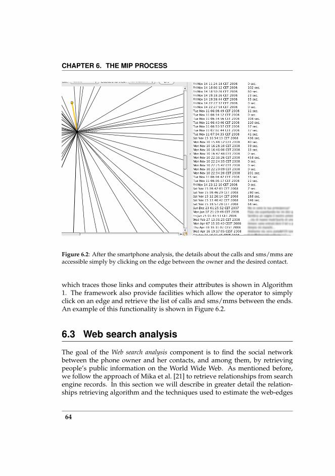
CHAPTER 6. THE MIP PROCESS
Figure 6.2: After the smartphone analysis, the details about the calls and sms/mms areaccessible simply by clicking on the edge between the owner and the desired contact.
which traces those links and computes their attributes is shown in Algorithm1. The framework also provide facilities which allow the operator to simplyclick on an edge and retrieve the list of calls and sms/mms between the ends.An example of this functionality is shown in Figure 6.2.
6.3 Web search analysis
The goal of the Web search analysis component is to find the social networkbetween the phone owner and her contacts, and among them, by retrievingpeople’s public information on the World Wide Web. As mentioned before,we follow the approach of Mika et al. [21] to retrieve relationships from searchengine records. In this section we will describe in greater detail the relation-ships retrieving algorithm and the techniques used to estimate the web-edges
64

6.3. WEB SEARCH ANALYSIS
(a) (b)
Figure 6.3: The graph representation of contacts before (a) and after (b) the SESORR ex-ecution. Black links represents relationships extracted from the mobile phone (mobile-edges). Blue links represents the relationships extracted from the Web (web-edges).
weight.
6.3.1 SESORR Algorithm
In order to reconstruct relationships among a phone’s contacts, we have usedthe huge amount of data collected by search engines over the years to obtainrelational network data. Our approach is to submit all possible pairs of namesand surnames to the search engine and to retrieve the results, i.e., the pageswhere the two pairs 〈name, surname〉i,j co-occur, by counting the number ofpages found (hits) and, for each of them, by saving the title and the short de-scription returned by the search engine. Moreover, it counts non-stop wordscontained in titles and description for further analysis. Serving this purpose,we designed the SESORR (Search Engine SOcial Relationships Retrieving) al-gorithm; the pseudocode is shown in Algorithm 2. As preliminary examina-tion, SESORR submits the query
〈name, surname〉 ∨ 〈surname, name〉
for each contact and stores the results in the G nodes data structures. In suchway it is able to discard from subsequent queries the contacts which are notpresent on the Web (i.e., the query returned a resultset R = ∅). Finally, for each
65
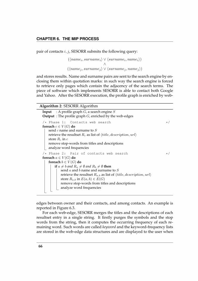
CHAPTER 6. THE MIP PROCESS
pair of contacts i, j, SESORR submits the following query:
(〈namei, surnamei〉 ∨ 〈surnamei, namei〉)∧
(〈namej , surnamej〉 ∨ 〈surnamej , namej〉)
and stores results. Name and surname pairs are sent to the search engine by en-closing them within quotation marks: in such way the search engine is forcedto retrieve only pages which contain the adjacency of the search terms. Thepiece of software which implements SESORR is able to contact both Googleand Yahoo. After the SESORR execution, the profile graph is enriched by web-
Algorithm 2: SESORR AlgorithmInput : A profile graph G, a search engine SOutput : The profile graph G, enriched by the web-edges
/* Phase 1: Contacts web search */foreach c ∈ V (G) do
send c name and surname to Sretrieve the resultset Rc as list of 〈title, description, url〉store Rc in cremove stop-words from titles and descriptionsanalyze word frequencies
/* Phase 2: Pair of contacts web search */foreach a ∈ V (G) do
foreach b ∈ V (G) doif a 6= b and Ra 6= ∅ and Rb 6= ∅ then
send a and b name and surname to Sretrieve the resultset Ra,b as list of 〈title, description, url〉store Ra,b in E(a, b) ∈ E(G)remove stop-words from titles and descriptionsanalyze word frequencies
edges between owner and their contacts, and among contacts. An example isreported in Figure 6.3.
For each web-edge, SESORR merges the titles and the descriptions of eachresultset entry in a single string. It firstly purges the symbols and the stopwords from the string, then it computes the occurring frequency of each re-maining word. Such words are called keyword and the keyword-frequency listsare stored in the web-edge data structures and are displayed to the user when
66
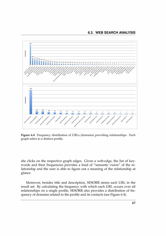
6.3. WEB SEARCH ANALYSIS
358
12397 97 85
72 7050 43 39 31 28 26 21 21 20 19 19 18 15 15 13 12 12 12 12 12 12 12 11 11 11 9 9 8 8 8 8 8 8 7 7 7 7 7 7 7 7
www.uniroma2.it
www.disp.uniroma2.it
www.facebook.com
www.informa>k.uni‐trier.de
web.uniroma2.it
www.universitor.it
www.ing.uniroma2.it
www.economia.unige.it
www.ording.roma.it
portal.acm.org
www.crlazio.it
www.ictsanita.it
www.assoteam.org
ieeexplore.ieee.org
www.ilcorrierelaziale.it
www.ingegneria‐online.it
www.assodipro.org
www.ricercaeinnovazione.regione.lazio.it
www.info.uniroma2.it
gauguin.info.uniroma2.it
www.ce.uniroma2.it
elezionicun.miur.it
toolserver.org
www.cs.unm.edu
www.dis.uniroma1.it
www.lrec‐conf.org
www.record‐public.com
www.roma09.it
www2.corpoforestale.it
concorsi.uniroma2.it
www.can>ne.org
www.systemdynamics.org
celes>al.eprints.org
clictvging.googlepages.com
art.uniroma2.it
erikdemaine.org
listsrv.nic.it
wotan.liu.edu
www.acquazzurra.it
www.cnipa.gov.it
catalog.lib.ncsu.edu
www.archive.org
www.fidalromasud.it
www.gius>zia.lazio.it
www.igi‐global.com
www.mfo.de
www.uniroma1.it
www2.uniroma2.it
occurren
ces
304
39 3929 24 21 15 14 13 12 11 9 9 9 8 7 7 7
www.uniroma2.it
www.tuscia2001.it
www.facebook.com
www.ilcorrierelaziale.it
www.disp.uniroma2.it
www.crlazio.it
www.viviviterbo.it
www.info.uniroma2.it
elezionicun.miur.it
[email protected]‐trier.de
etd.adm.unipi.it
www.linkedin.com
web.uniroma2.it
ieeexplore.ieee.org
www.ing.uniroma2.it
www.informaservizi.it
www.mulino.it
www.cnipa.gov.it
occurren
ces
Figure 6.4: Frequency distribution of URLs (domains) providing relationships. Eachgraph refers to a distinct profile.
she clicks on the respective graph edges. Given a web-edge, the list of key-words and their frequencies provides a kind of “semantic vision” of the re-lationship and the user is able to figure out a meaning of the relationship atglance.
Moreover, besides title and description, SESORR stores each URL in theresult set. By calculating the frequency with which each URL occurs over allrelationships on a single profile, SESORR also provides a distribution of fre-quency of domains related to the profile and its contacts (see Figure 6.4).
67

CHAPTER 6. THE MIP PROCESS
6.3.2 Web-edge weight estimationIn order to measure a Web-edge weight, i.e., how similar are two contacts be-tween which an Web-edge exists, we define a function σ(e) ∈ [0, 1] which mea-sures the similarity between u and v individuals. In the semantic Web area,the similarity between two classes is assessed by observing the number of in-stances that these classes share, their individual number of instances, and thetotal number of instances they contain. The most frequently used metrics arethe following:
Jaccard index between two sets X and Y is defined as the ratio between thesize of the intersection and the size of the union of the two sets beingcompared:
σ(X,Y ) =|X ∩ Y ||X ∪ Y |
where |.| denotes the size, i.e., the number of elements in the set. σ(X,Y ) =0 when the sets are disjoint; σ(X,Y ) = 1 when the sets are identical. Thisis very intuitive measure for the given setting as it measures the rela-tive overlap of the two sets. There is also a probabilistic interpretation,namely the probability that a random instance from the union is in theintersection of the two sets [44]. Independently the Dice coefficient hasbeen proposed, which is equal to the Jaccard index multiplied twice:
s = 2σ(X,Y ) =2|X ∩ Y ||X ∪ Y |
For further information see [45].
Normalized Google Distance (NGD) was introduced by Cilibrasi et al. [46]and it takes advantage of the number of hits returned by Google to com-pute the semantic distance between concepts. The concepts are repre-sented with their labels which are fed into the Google search engine assearch terms. Given two search terms x and y, the the normalised Googledistance between x and y, NGD(x, y), can be obtained as follows:
NDG(x, y) =maxlog f(x), log f(y) − log f(x, y)
logM −minlog f(x), log f(y)
where f(x) is the number of Google hits for the search term x, f(y) isthe number of Google hits for the search term y, f(x, y) is the number ofGoogle hits for the tuple of search terms xy, and M is the number of webpages indexed by Google, i.e., approximately ten billion pages.
68

6.3. WEB SEARCH ANALYSIS
Figure 6.5: When user clicks on an Web link (left-side), the framework shows informa-tion about indexes (right-side, top) and word frequencies found in the Web search resultset.
In our case, we want to compute the Jaccard similarity (σJ(e)) to an edgee = 〈u, v〉: let X = Wu the list of Web results of individual u, Y = Wv the list ofWeb results of individual v, X ∩ Y = We the list of Web results of edge e. TheJaccard similarity can be obtained as following:
σJ(e) =|We|
|Wu|+ |Wv|
If we compute σJ(e) only if |We| > 0, |Wu| > 0 and |Wv| > 0 because |We| =|Wu ∩Wv|, thus σJ(e) will have not singularities. Finally we observe that 0 ≤σJ(e) ≤ 1
2 . Thus, in order to be used as similarity weight, the Jaccard index hasto be normalized. The Dice’s similarity (σD) was introduced for such purpose:
σD(e) = 2σJ(e) =2|We|
|Wu|+ |Wv|
To compute the Google similarity (σG(e)), we compute the normalized googledistances for each edge e = 〈u, v〉, assigning f(x) = |Wu|, f(y) = |Wv| andf(x, y) = |We|:
σG(e) =maxlog |Wu|, log |Wv| − log |We|log(106)−minlog |Wu|, log |Wv|
69

CHAPTER 6. THE MIP PROCESS
In our experiments, Pearson’s correlation between the Jaccard index andthe NGD shows that their linear relationship is equal to 0.4. For this reason,and in order to have a more flexible tool which is able to adapt itself to the userexperience, our software give the faculty to choose which of the above threeindexes to use to measure the weight of the web-edge.
6.4 Clustering
As the final analysis stage, we want to identify subgroups of contacts sharingsimilarities. Generally speaking, the goal of clustering is to group togethersimilar elements and thereby to identify the skeleton structure of the inputdata.
In this work we have employed clustering techniques to split the phoneowner’s social graph into small subgraphs (clusters). We chose spectral algo-rithms because i) they are general and versatile, and ii) they proved to performeffectively in the identification of locally dense subgraphs that are sparselyinter-connected, also known as the paradigm of intra-cluster density versusinter-cluster sparsity (see [47]). For each cluster, we expect to find nodes whichshare strong similarities among them. Spectral methods have been frequentlyadapted, for examples see [48, 49, 50, 51, 52, 53]. While most of these spectralapproaches have been deeply analyzed from a theoretical point of view, to thebest of our knowledge only few methods that involve eigenvalue decomposi-tion (of the adjacency or related matrices) have been experimentally studiedand evaluated. An algorithm that embeds the graph using eigenvectors of thenormalized adjacency matrix has been tested as an example in [48]. We will seethat the tested algorithms performed effectively; however, the lack of a largeamount of available phone data prevented us from performing a broader ass-esment of clustering algorithms.
6.4.1 Notation
Graphs and matrices
Let A = (ai,j)1≤i≤n;1≤j≤n ∈ Rn×n be an n × n square matrix over the realnumbers; its i-th row (j-th column) is denoted by A(i) (A(j)). We can representan n-node graph by an n-by-n matrix. The weighted adjacency matrix Aw(G)
70

6.4. CLUSTERING
0
3 4
1
5
2
Figure 6.6: Sample undirected graph.
is a square matrix of order |V | and its entries are defined by:
[Aw(G)]u,v :=w if (u, v) ∈ E0 otherwise
A matrixA is called symmetric ifAT = A. If the graphG is undirected,Aw(G) issymmetric. For instance, the undirected graph shown in figure 6.6 is describedby the following symmetric matrix:
A =
0 0 0 1 1 00 0 0 0 1 10 0 0 1 0 11 0 1 0 0 01 1 0 0 0 00 1 1 0 0 0
Eigenvalues and eigenvectors
Eigenvalues are often introduced in the context of linear algebra or matrix the-ory. Given a linear transformation, an eigenvector of that linear transforma-tion is a nonzero vector which, when that transformation is applied to it, maychange in length, but not direction. For each eigenvector of a linear transforma-tion, there is a corresponding scalar value called an eigenvalue for that vector,which determines the amount the eigenvector is scaled under the linear trans-formation. In the real-world applications, eigenvalues and eigenvectors appear
71

CHAPTER 6. THE MIP PROCESS
as preferential axes of rotation of a rigid body, resonance frequencies, mainstress directions, and so on. The theory concerning eigenvalues and eigenvec-tors is also called spectral theory. Let A a square n× n matrix. A column vectorxr is an right-eigenvector if:
A · xr = λxr
while a left-eigenvector is a row-vector xl that is:
xl ·A = xlλ.
We call λ an eigenvalue of A. The eigenvalues of a graph are defined as theeigenvalues of its adjacency matrix. The set of eigenvalues of a graph is calleda graph spectrum [54].
Singular Value Decomposition
A singular value decomposition (SVD) of A is given by:
A = U · S · V
where:
U is an m×m orthogonal matrix, whose column vectors [u1 . . . um] are calledthe left singular vectors, they are eigenvectors of A · AT , and therefore areorthonormal3;
V is an n×n orthogonal matrix, whose column vectors [v1 . . . vn] are called theright singular vectors, they are the eigenvectors ofAT ·A, and therefore areorthonormal too;
S is anm×n diagonal matrix with nonnegative elements on the diagonal (andwith the same rank as A).
Such a decomposition exists for each matrix A. Conventionally, the singu-lar values which are the nonzero diagonal elements of S are ordered in non-increasing fashion. For further information see [55]. Please note that S isuniquely determined, and the same does not hold for the matrices U and V .
3A square matrix M is orthonormal if it is regular (det(M) = 0) and if MT = M−1; for anorthonormal matrix M it holds M−1 ·M = MT ·M = I . Also det(M) = ±1
72
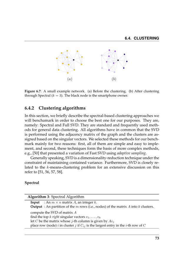
6.4. CLUSTERING
(a) (b)
Figure 6.7: A small example network. (a) Before the clustering. (b) After clusteringthrough Spectral (k = 3). The black node is the smartphone owner.
6.4.2 Clustering algorithms
In this section, we briefly describe the spectral-based clustering approaches wewill benchamark in order to choose the best one for our purposes. They are,namely: Spectral and Full SVD. They are standard and frequently used meth-ods for general data clustering. All algorithms have in common that the SVDis performed using the adjacency matrix of the graph and the clusters are as-signed based on the singular vectors. We selected these methods for our bench-mark mainly for two reasons: first, all of them are simple and easy to imple-ment, and second, these techniques form the basis of more complex methods,e.g., [50] that presented a variation of Fast SVD using adaptive sampling.
Generally speaking, SVD is a dimensionality-reduction technique under theconstraint of maintaining contained variance. Furthermore, SVD is closely re-lated to the k-means-clustering problem for an extensive discussion on thisrefer to [51, 56, 57, 58].
Spectral
Algorithm 3: Spectral AlgorithmInput : An m× n matrix A, an integer k.Output : An partition of the m rows (i.e., nodes) of the matrix A into k clusters.
compute the SVD of matrix Afind the top k right singular vectors v1, . . . , vk
let C be the matrix whose j-th column is given by Avj
place row (node) i in cluster j if Cij is the largest entry in the i-th row of C
73
CHAPTER 6. THE MIP PROCESS
The Spectral algorithm is essentially a projection onto the first k right sin-gular vectors. Its pseudocode is given in Algorithm 3. In [59, 52] it was calledSpectral Algorithm I and served Kannan et al. for their study of spectral graphclustering. The intuition of this technique is that the matrix A describes the lo-cation ofm points in an n-dimensional space. The projection onto the subspacedefined by the top k right singular vectors gives the best k-rank approximationof A. In the context of graph clustering the input matrix A is just the adjacencymatrix of the considered graph. The different dimensions in this space are theninterpreted as clusters and the assignment of nodes is done by choosing thatdimension/cluster that has the largest corresponding entry.
Full SVD
Drineas et al. studied in [51] k-means and its continuous version. While thediscrete version is known to be NP-hard, the latter can be solved efficientlyusing a projection onto the top k left singular values. Similar to the Spectralalgorithm, the cluster assignment is a discretization of the continuous solution.We refer to this method as Full SVD in order to avoid ambiguities with the SVDcomputation which is the core of all these algorithms. Its pseudocode is givenin Algorithm 4. The clustering algorithms (both the Spectral and the Full SVD)
Algorithm 4: Full SVDInput : An m× n matrix A, an integer k.Output : A partition of the m rows (i.e., nodes) of the matrix A into k clusters.
compute the SVD of matrix Afind the top k left singular vectors u1, . . . , uk
let C be the matrix whose jth column is given by uj , i.e., the first k columns of Uplace row i in cluster j if Cij is the largest entry in the i-th row of C
output a matrix C which has on the rows the nodes (contacts) indexes, and onthe columns the clusters indexes. The matrix cells represent intuitively theweight of how a contact belongs to a cluster. We choose to assign a node to thecluster with the maximum absolute value. In Figure 6.8 is shown a screenshotwith the C matrix details and, for each contact, the chosen cluster.
6.4.3 Clustering quality indicesIn order to give an evaluation of obtained clustering, we followed the approachof Brandes et al. [60, 48], who used a set of quality indices that measured the
74
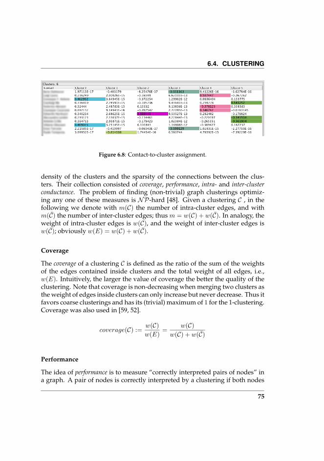
6.4. CLUSTERING
Figure 6.8: Contact-to-cluster assignment.
density of the clusters and the sparsity of the connections between the clus-ters. Their collection consisted of coverage, performance, intra- and inter-clusterconductance. The problem of finding (non-trivial) graph clusterings optimiz-ing any one of these measures is NP-hard [48]. Given a clustering C , in thefollowing we denote with m(C) the number of intra-cluster edges, and withm(C) the number of inter-cluster edges; thus m = w(C) + w(C). In analogy, theweight of intra-cluster edges is w(C), and the weight of inter-cluster edges isw(C); obviously w(E) = w(C) + w(C).
Coverage
The coverage of a clustering C is defined as the ratio of the sum of the weightsof the edges contained inside clusters and the total weight of all edges, i.e.,w(E). Intuitively, the larger the value of coverage the better the quality of theclustering. Note that coverage is non-decreasing when merging two clusters asthe weight of edges inside clusters can only increase but never decrease. Thus itfavors coarse clusterings and has its (trivial) maximum of 1 for the 1-clustering.Coverage was also used in [59, 52].
coverage(C) :=w(C)w(E)
=w(C)
w(C) + w(C)
Performance
The idea of performance is to measure “correctly interpreted pairs of nodes” ina graph. A pair of nodes is correctly interpreted by a clustering if both nodes
75

CHAPTER 6. THE MIP PROCESS
belong to the same cluster and are adjacent or if they are not adjacent and be-long to different clusters. Analogously to coverage, performance counts thenumber of correctly interpreted pairs and is then normalized by the total num-ber of node pairs. It was originally introduced in [61] and is closely related tothe editing distance of a clustering, i. e., the minimum number of edges thathave to be deleted or inserted in order to transform the graph into a set ofdisjoint complete subgraphs. Although it is similar to coverage, it addition-ally evaluates the sparsity between clusters and can thus favor fairly differentclusterings than coverage. Generally speaking, for sparse graphs performanceoften prefers fine clusterings.
performance(C) :=w(C) +
∑v,w6∈E,v∈Ci,w∈Cj
1n(n−1)
2
Intra- and Intercluster Conductance
The conductance measures the quality of a cut and the weight of edges in eitherof the two induced subgraphs [60, 48]. The conductance ϕ(G) of a graph G isthen the minimum conductance value over all cuts of G. For a clustering C =(C1, . . . , Ck) of a graph G, the intracluster conductance α(C) is the minimumconductance value over all induced subgraphs G[Ci], while the interclusterconductance δ(C) is the maximum conductance value over all induced cuts(Ci, V \Ci). For a formal definition of the different notions of conductance, letus first consider a cutC = (C, V \C) ofG and define conductance ϕ(C) and ϕ(G)as follows:
a(C) :=∑v∈C
∑cw∈V v,w∈E
ω(v, w) = 2∑
e∈E(C)
ω(e) +∑
f∈E(C,V \C)
ω(f)
ϕ(C) :=
1, C ∈ ∅, V 0, C 6∈ ∅, V and ω(C) = 0
ω(C)min(a(C),a(V \C)) , otherwise
ϕ(G) := minCV
ϕ(C)
Based on the notion of conductance, we can now define intra- α(C) and inter-cluster conductance δ(C).
76

6.5. RESULTS
α(C) := mini∈1,...,k
ϕ(G[Ci])
δ(C) :=
1, if C = V 1− max
i∈1,...,kϕ(Ci), otherwise
6.5 Results
All spectral clustering algorithms we proposed in this chapter take as inputthe k parameter, i.e., the number of clusters. Although an operator can feelfree to specify any 0 ≤ k ≤ n, where n is the number of nodes in G, the clus-tering indexes are heavily affected by the the number of clusters, as reportedin Figure 6.9. This Figure shows, for each clustering algorithm and for eachweb-edge weight metric, the performance of clustering quality indexes to thevariation of k parameter. The estimation of best-k is an open research topic. Arule of thumb is given by Mardia et al. in [62], in which the authors suggestthat an approximation of best-k is:
k′ =√n
2
with n the number of vertices.Moreover, as shown in Figure 6.10, both Spectral and SVD algorithms pro-
duce a certain percentage of empty clusters if k > k′. In Figure 6.11 is showna graph with 218 contacts and 1242 web-edges. This graph has been clusteredvia SVD clustering, with GND as web-edge weight metric and with k = k′.The figure also shows some clusters sampled from the the graph. By lookingat each cluster’s web-edge keywords, we have been able to gather the area ofinterest shared by individuals in the cluster.
In our specific case, we believe that there is no exact value of best-k thatcould be estimated a priori, and that this parameter changes case-by-case. Wegive the investigator all the instruments that can help her understand whichare reasonable values of k, and to develop a common sense to assess which arethe best values of clustering algorithms for each case.
77

CHAPTER 6. THE MIP PROCESS
0 10 20 30 40 50 60 70
0.0
0.2
0.4
0.6
0.8
1.0
k
spectral (unweighted)
0 10 20 30 40 50 60 70
0.0
0.2
0.4
0.6
0.8
1.0
k
spectral (Dice)
0 10 20 30 40 50 60 70
0.0
0.2
0.4
0.6
0.8
1.0
k
spectral (Google Similarity)
0 10 20 30 40 50 60 70
0.0
0.2
0.4
0.6
0.8
1.0
k
SVD (unweighted)
0 10 20 30 40 50 60 70
0.0
0.2
0.4
0.6
0.8
1.0
k
SVD (Dice)
0 10 20 30 40 50 60 70
0.0
0.2
0.4
0.6
0.8
1.0
k
SVD (Google Similarity)
coverageperformance
inter−cluster conductanceintra−cluster conductance
Figure 6.9: Clustering metrics trends. The profile graph used in this example has 218contacts and 1242 web-edges. k′ = 10 and its value is shown by the black vertical line.
6.6 Limitations of our method
Our profiling method relies on information stored in the smartphone and itsprecision depends by the quantity and quality of such data.
78
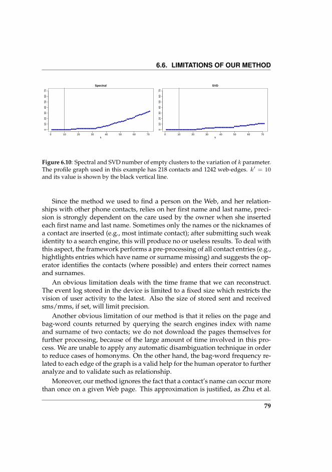
6.6. LIMITATIONS OF OUR METHOD
0 10 20 30 40 50 60 70
010
2030
4050
6070
k
Spectral
0 10 20 30 40 50 60 70
010
2030
4050
6070
k
SVD
Figure 6.10: Spectral and SVD number of empty clusters to the variation of k parameter.The profile graph used in this example has 218 contacts and 1242 web-edges. k′ = 10and its value is shown by the black vertical line.
Since the method we used to find a person on the Web, and her relation-ships with other phone contacts, relies on her first name and last name, preci-sion is strongly dependent on the care used by the owner when she insertedeach first name and last name. Sometimes only the names or the nicknames ofa contact are inserted (e.g., most intimate contact); after submitting such weakidentity to a search engine, this will produce no or useless results. To deal withthis aspect, the framework performs a pre-processing of all contact entries (e.g.,hightlights entries which have name or surname missing) and suggests the op-erator identifies the contacts (where possible) and enters their correct namesand surnames.
An obvious limitation deals with the time frame that we can reconstruct.The event log stored in the device is limited to a fixed size which restricts thevision of user activity to the latest. Also the size of stored sent and receivedsms/mms, if set, will limit precision.
Another obvious limitation of our method is that it relies on the page andbag-word counts returned by querying the search engines index with nameand surname of two contacts; we do not download the pages themselves forfurther processing, because of the large amount of time involved in this pro-cess. We are unable to apply any automatic disambiguation technique in orderto reduce cases of homonyms. On the other hand, the bag-word frequency re-lated to each edge of the graph is a valid help for the human operator to furtheranalyze and to validate such as relationship.
Moreover, our method ignores the fact that a contact’s name can occur morethan once on a given Web page. This approximation is justified, as Zhu et al.
79

CHAPTER 6. THE MIP PROCESS
demonstrated in [63]: page counts and name counts are highly correlated on alog-log scale.
Another source of noise is the fact that search engines4 will sometimes re-turn pages that do not include the search term at all. This can happen if thesearch term is contained in a link to the page (but not on the page itself).
4We noticed that this phenomenon happens on Google and Yahoo, but not Altavista[64]
80
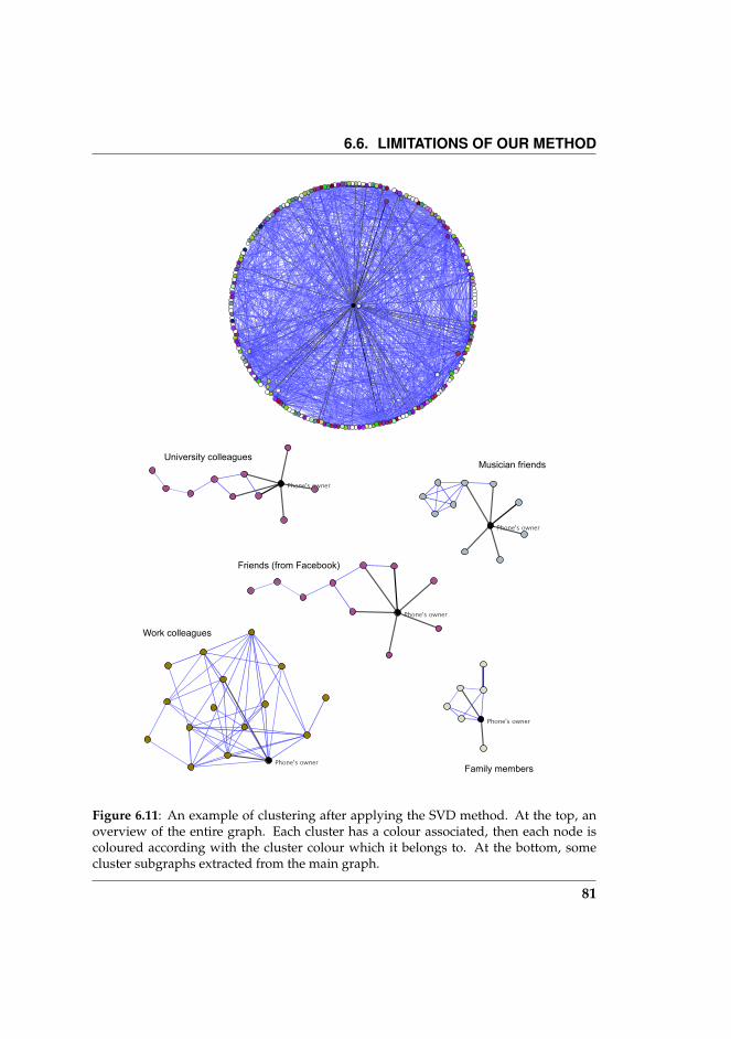
6.6. LIMITATIONS OF OUR METHOD
Work colleagues
Musician friends
Family members
Friends (from Facebook)
University colleagues
Figure 6.11: An example of clustering after applying the SVD method. At the top, anoverview of the entire graph. Each cluster has a colour associated, then each node iscoloured according with the cluster colour which it belongs to. At the bottom, somecluster subgraphs extracted from the main graph.
81

7Conclusions and Future Work
In this work we have presented a complete workflow which allows the in-vestigator to forensically extract the internal memory data contained in thesmartphones, to decode them, and to analyze such information in order toreconstruct the importance of relationships between the owner and its con-tacts, and, thanks to the data publicly available on the Web, to reconstruct theintra-contacts relationships. The resulting graph, namely the Identity Profile,is further analyzed with spectral clustering techniques coming from the graphtheory, and several groups of contacts sharing similar interest are found.
The MIP process illustrated in Chapter 6 analyzes a single device at a time.In order to have a more comprehensive profiling, we plan to extend this anal-ysis to more devices coming from different owners linked to the same case. Inthis way, correlations between different personal datasets may come to lightand this may open a more complete social network graph. Another benefit ofthis approach relies on the fact that if a contact belongs to two or more personaldatasets, its name and surname give a greater chance of disambiguation andthe limitations due to manual names refining can be mitigated.
The framework idea takes place in a wider concept, the remote ForensicFarm. In such a scenario, when the device acquisition is completed, the seizedimage is forwarded to the Forensic Farm, where all the data are collected andanalysed. The Forensic Farm is a laboratory specialised in Data Decoding andData Analysis of the mobile equipment’s internal memory copies. When anew internal memory copy is received from the forensic operator’s device, theForensic Farm’s software starts the framework and the data decoding oper-ation begins; the output of this operation consists of all the information re-siding on the smartphone’s internal memory copy but in an standard format,easy to be consulted, linked by the forensic investigator. As this phase fin-
83

CHAPTER 7. CONCLUSIONS AND FUTURE WORK
ishes, the analysis phase starts. In this step the software extracts standard cor-relations among all the information extracted in the data decoding stage (e.g.,contacts sending SMSes, with related content and details, incoming and out-coming calls, calendar events related), reconstructs the relationships amongcontacts through the Web analysis and identifies the clusters. After the smart-phone’s file system has been analysed the results are sent back to the operator,who receives via 3G/4G the results of the Forensic Farm’s work on her mobileequipment and she can decide what to do directly at the crime scene.
84

AThe Symbian S60 format
A.1 Address book
Type flag Meaning Type flag Meaning
04024008 fax 14020001 H fax2402C003 job 04140280 home24028004 mobile(work) 1C02C00C nickname0402000D video 1402400D video (home)0C02C00D wv user ID 0402C008 url04024009 po.box 04028009 extension0402400A city 0402800A state14024002 extension (home) 14028002 street (home)14024003 state (home) 14028003 country (home)24024006 street (work) 24028006 postal code (work)24024007 country (work) 3C02000B DTMFType flag Meaning Type flag Meaning
2402C004 W fax 04028007 general0402C007 mobile 1402C000 mobile(home)04028008 ? 04020008 pager2402800D video (work) 24020004 work14028001 url(home) 24024005 url(work)0402C009 street 0402000A postal code0402C00A country 14020002 po.box (home)1402C002 postal code (home) 14020003 city (home)2402C005 po.box (work) 24020006 extension (work)2402C006 city (work) 24020007 state (work)3402800B note
Table A.1: Possible values for the rows of table “DATA TYPE TABLE”. They describethe type of attributes present in the “DATA BLOCK”. (Symbian S60 v2)
Contacts and their data are stored in the Contacts.cdb file (located un-der C:\System\Data). During the methodology iterations, we found that
85

APPENDIX A. THE SYMBIAN S60 FORMAT
contacts data were fragmented and spread across the entire file. In fact, aftera contact update, Symbian preserves the old contact entry and appends newone at the end of the file with the same ID but fresh data. When the systemperforms a DB compression, obsolete entries are purged. After a first analysis,we found that data could grouped in three macro-areas (parts, see Table A.2).
For each contact, the three parts are connected because each of them sharesthe same contact ID. The first part stores metadata about each contact anda block containing attributes like phone/fax/mobile numbers, snail mail ad-dress and notes:
D2 6410 00 00 00FF 09 13 00 10 FF FF FF FF20 30 30 65 31 3230 30 66 66 61 3964 31 32 37 3676 12 9D FA 0F 20 E1 0076 12 9D FA 0F 20 E1 0004 00 00 00 00 0000 00 1F1D04 00 00 00 0414 02 00 00 00 00 00 00 00 00 00 0004 02 C0 07 00 00 00 00 00 00 00 0004 00 00 00 001A20 0033 33 38 38 37 36 35 34 32 33
VDIDCXF120 30 30 65 31 3230 30 66 66 61 3964 31 32 37 36EDIT DATECREATION DATE04 00 00 00 00 0000 00 1FTYPE TABLE LEN|
TYPE TABLE|
04 00 00 00 00DATA BLOCK LENFIELD FLAGDATA BLOCK
The second part stores contact’s name, surname and company:
10 00 00 001250 61 70 E0 20 43 65 6C 6C09 13 00 10
IDNAME LENGHTNAMECXF1
The third part stores email addresses:
1C3200 00 00 0310 00 00 00246F 64 6F 6D 65 6E 69 63 406C 69 62 65 72 6F 2E 69 74
EMAIL LENGHTEMAIL IDEMAIL FLAGIDEMAIL ADDRESS LENEMAIL ADDRESS
|
86

A.2. CALENDAR
A.2 Calendar
Calendar entries are stored in Calendar file (located under C:\System\Data).A calendar’s entry belongs to one of the following categories: anniversary, meet-ing or note. A sample of calendar’s entry, an anniversary without alarm, isshown below:
030F 00 00 000A5202 00 00 0001 00 00A4 28 52 0305AA 28 A2 AC01 00 00 01 0008 00 002041 6E 6E 69 76 65 72 7361 72 79 41 6F 66 660E 20 29AA 28AA 28
FTVSAFBLIDFlag1CD (GG MM)05AD A2 ACFlag3Flag2TLText|
ETSDED
An example of anniversary with the alarm setted to on is shown here below:
030F 00 00 001A5202 00 00 0001 00 00A4 28 5B 0305AA 28 A2 AC01 00 00 01 003C43 61 6C 65 6E 41 6C 6172 6D 53 6F 75 6E 64 3209 01 0008 00 001E41 6E 6E 69 76 65 72 7361 72 79 41 6F 6E0E 20 29AA 28AA 28
FTVSAFBLIDFlag1CD (GG MM)05AD ATVS2ANLATXT|
09 01 00Flag2TLText|
ETSDED
An example of meeting with the alarm set to off is shown below:
87
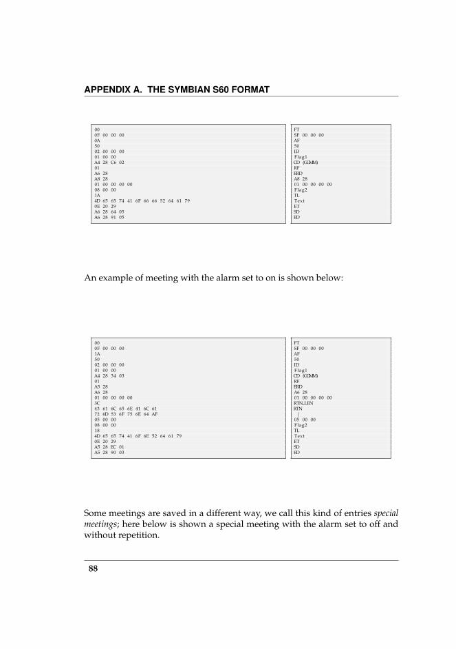
APPENDIX A. THE SYMBIAN S60 FORMAT
000F 00 00 000A5002 00 00 0001 00 00A4 28 C6 0201A6 28A8 2801 00 00 00 0008 00 001A4D 65 65 74 41 6F 66 66 52 64 61 790E 20 29A6 28 64 05A6 28 91 05
FTSF 00 00 00AF50IDFlag1CD (GGMM)RFERDA8 2801 00 00 00 00Flag2TLTextETSDED
An example of meeting with the alarm set to on is shown below:
000F 00 00 001A5002 00 00 0001 00 00A4 28 34 0301A5 28A6 2801 00 00 00 003C43 61 6C 65 6E 41 6C 6172 6D 53 6F 75 6E 64 AF05 00 0008 00 00184D 65 65 74 41 6F 6E 52 64 61 790E 20 29A5 28 EC 01A5 28 90 03
FTSF 00 00 00AF50IDFlag1CD (GGMM)RFERDA6 2801 00 00 00 00RTN LENRTN|
05 00 00Flag2TLTextETSDED
Some meetings are saved in a different way, we call this kind of entries specialmeetings; here below is shown a special meeting with the alarm set to off andwithout repetition.
88

A.2. CALENDAR
000F 00 00 00085002 00 00 0001 00 00A4 28 7A 0308 00 001C53 6D 65 65 74 41 6F66 66 52 6F 66 660E 20 29A6 28 64 05A6 28 91 05
FTSF 00 00 00AF50IDFlag1CD (GGMM)Flag2TLText|
ETSDED
An example of special meeting with the alarm set to on and repetition set to offis shown below:
000F 00 00 00185002 00 00 0001 00 00A4 28 9C 033C43 61 6C 65 6E 41 6C 6172 6D 53 6F 75 6E 64 AF05 00 0008 00 001A53 4D 65 65 74 41 6F6E 52 6F 66 660E 20 29A6 28 94 02A6 28 C1 02
FTSF 00 00 00AF50IDFlag1CD (GGMM)RTN LENRTN|
05 00 00Flag2TLText|
ETSDED
Notes are stored in a similar format as special meeting. An example of note isshown below:
020F 00 00 00085202 00 00 0001 00 00A4 28 6F 0308 00 001044 61 79 4E 6F 74 650E 20 29A5 28A5 28
FTVSAFBLIDFlag1CD ID2Flag2NLTextETSDED
89

APPENDIX A. THE SYMBIAN S60 FORMAT
A.3 Events log
Events and status changes are stored in Logdbu.dat file (located under C:\System\Data), and can belong to the following categories: sms , mms, voiceand data calls, SIM changes. In the last case, the event is stored as an sms, sowe will not examine it. Details about the fields are reported in Table A.4.
An example of SMS is shown in the following:
03BA A3 EB EB B6 2C E1 00FFB260 16 00 001C52 61 6D 6F 6E 61 20 4D6F 72 65 74 74 6904 00 05 00 338044 4F 4D 41 4E 49 20 53 45 52 41 2054 49 20 49 4E 56 49 54 4F 20 41 4420 55 53 43 49 52 45 20 49 4E 53 4945 4D 45 20 58 20 55 4E 41 20 43 454E 41 2C 6F 76 76 69 61 6D 65 6E 7465 20 6F 671A2B 33 39 XX XX XX XXXX XX XX XX XX XX180000 00 00 01 00 0000 00 00 00 00 0000 00 00 00 00 0000 01 00 00 00 A4
03DATEFFNAME FLAG|
60 16 00 00NAME LENGTHNAME04 00 05 00 33MESS LENGTH||
MESS|||
NUMBER LENGHTNUMBER|
18DIRECTION00 00 00 01 00 0000 00 00 00 00 0000 00 00 00 00 0000 01 00 00 00 A4
A voice call example is shown below:
001F 66 4A EF C8 2C E1 00017063 16 00 001C52 61 6D 6F 6E 61 20 4D6F 72 65 74 74 69010000 00 00 0067 02 361A2B 33 39 XX XX XX XXXX XX XX XX XX XX20 03 00 00 02 A617 00 00 A4
00DATE01NAME FLAG63 16 00 00NAME LENGHTNAME|
01DIRECTIONCALL TIME67 02 36NUMBER LENGHTNUMBER|
20 03 00 00 02 A617 00 00 A4
An MMS example is reported below:
90
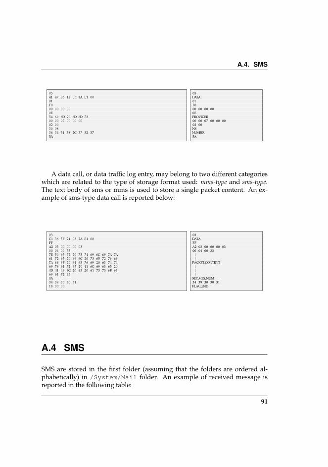
A.4. SMS
0541 47 86 12 05 2A E1 0001F000 00 00 000E54 69 6D 20 6D 6D 7300 00 07 00 00 0002 0030 0836 34 31 38 2C 37 32 375A
05DATA01F000 00 00 000EPROVIDER00 00 07 00 00 0002 00NSNUMBER5A
A data call, or data traffic log entry, may belong to two different categorieswhich are related to the type of storage format used: mms-type and sms-type.The text body of sms or mms is used to store a single packet content. An ex-ample of sms-type data call is reported below:
03C1 36 5F 21 08 2A E1 00FFA2 03 00 00 00 0300 04 00 337E 50 65 72 20 75 74 69 6C 69 7A 7A61 72 65 20 69 6C 20 73 65 72 76 697A 69 6F 20 64 65 76 69 20 61 74 7469 76 61 72 65 20 41 6C 69 63 65 204D 41 49 4C 20 65 20 61 73 73 6F 6369 61 72 650A34 39 30 30 3118 00 00
03DATAFFA2 03 00 00 00 0300 04 00 33||
PACKET CONTENT|||
SEP MES NUM34 39 30 30 31FLAG END
A.4 SMS
SMS are stored in the first folder (assuming that the folders are ordered al-phabetically) in /System/Mail folder. An example of received message isreported in the following table:
91

APPENDIX A. THE SYMBIAN S60 FORMAT
68 3C 00 10 68 3C. . .
00 10 00 00 00 0025 3A 00 100C 52 69 63 65 760E20 29 34 1800 10 45 04 01 0001 00 00 00 02 000100 00 00 00 00 0000 01 00 00 00FA 54 17 46 F2 29 E1 002833 34 39 34 36 37 37 31 34 36 344469 73 74 65 66 61 6E 6F 20 41 6C 6500 00 00 00 00 0200 00 00 02 03 0000 00 01 00 00 0000 00 00 00F1 5A 15 41 F2 29 E1 0002 91342B 33 39 33 32 30 3538 35 38 35 30 3015 00 812833 34 39 34 36 37 37 31 34 36
68 3C 00 10 68 3C. . .
00 10 00 00 00 00f l a g 1TextETReceived Flag Mar00 10 45 04 01 0001 00 00 00 02 00Received Flag00 00 00 00 00 0000 01 00 00 00DateSNLNumberNLName00 00 00 00 00 0200 00 00 02 03 0000 00 01 00 00 0000 00 00 00SCRDSCFSCNLSCN|
ESNFESNLESN
An example of sent message is reported in the following table:
68 3C 00 10 68 3C. . .
00 10 00 00 00 0025 3A 00 101049 6E 76 69 61 74 6F0E20 29 34 1800 10 F5 02 01 0000 00 00 00 00 000000 02 03 00 00 0001 00 00 00 01 0000 0000 0C 09 22 F2 1C 32 E1 0000 91342B 33 39 33 34 39 3230 30 30 38 39 3804 91342B 33 39 33 34 39 3436 37 37 31 34 3600 0000 93 2D 4B F2 29 E1 00
68 3C 00 10 68 3C. . .
00 10 00 00 00 00f l a g 1TLTextETReceived Flag Mar00 10 F5 02 01 0000 00 00 00 00 00Received Flag00 02 03 00 00 0001 00 00 00 01 0000 00Datef l a g 2UNLUN|
RNFRNLRN|
00 00SCRD
92

A.4. SMS
Field Name Size (Bytes) Description Example
VD 2 (Uncertain) Used by DB indexing D2 64ID 4 Contact identifier (stored as little-endian) 10 00 00 00CXF1 9 Flag. The first byte have to be equal to the last four. The second byte depends
on Symbian version; values can be 09, 0B, 10. ”13 00 10” is constant.FF 09 13 00 10 FFFF FF FF
EDIT DATE (ED) 8 17 bytes-offset from CXF1. Represents the number of microseconds from yearzero.
76 12 9D FA 0F 20E1 00
CREATION DATE (CD) 8 Represents the number of microseconds from year zero. 76 12 9D FA 0F 20E1 00
TYPE TABLE LEN(T T L)
1 41 bytes offset from CXF1. Stores the lenght (in bytes) of the TYPE TABLE 1D
TYPE TABLE (T T ) T T L Table of 12-bytes lenght rows, describing the types of the corrisponding datain the DATA BLOCK. The first 5 bytes are the table start flag. The last 5 bytesindicate the end table flag. The first 12-bytes row does not contain useful infor-mation. For further information about data types, see Table A.1.
04 00 00 00 0414 02 00 00 00 0000 00 00 00 00 0004 02 C0 07 00 0000 00 00 00 00 0004 00 00 00 00
DATA BLOCK LEN(DBL)
1 Stores the size in bytes of DATA BLOCK 1A
FIELD FLAG (F F ) 2 Flag which is repeated as many times as the number of fields in DATA BLOCK. 20 00
DATA BLOCK (DB) DBL−2F F−12 Stores contact’s information, according to fields type described in
TYPE TABLE. Each field is separated by 00.33 33 38 38 37 3635 34 32 33
ID 4 Contact identifier (stored as little-endian) - The same as above. 10 00 00 00NAME LENGHT (NL) 1 The size in nibbles of the name field. 0E
NAME NL2 The contact’s name 43 6C 61 75 64 69
6FSURNAME LENGHT(SL)
1 The size in nibbles of the surname field. 08
SURNAME SL2 The contact’s surname 43 65 71 61
COMPANY NAME LENGHT(CNL)
1 The size in nibbles of the company field. 0C
COMPANY NAME(CN )
1 The contact’s company 44 72 2E 77 68 79
CONTACT END 4 Flag. Denotes the end of a contact’s details. The first byte depends on symbianversion (09, 0B, 10, as in CXF1 field). The other bytes are constant.
09 13 00 10
EMAIL LENGHT (EL) 1 The size in nibbles of the email address block. 1C
EMAIL ID EL2 The ID of email address 32
EMAIL FLAG 4 Flag. 00 00 00 03ID 4 Contact identifier (stored as little-endian) - The same as above. 10 00 00 00EMAIL ADDRESS LENGHT(EF L)
1 The size in nibbles of the email address string. 24
EMAIL ADDRESS EF L2 The email address string. 6F 64 6F 6D 65 6E
69 63 40 6C 69 6265 72 6F 2E 69 74
Table A.2: This table lists all contact’s data which can be found in the Contacts.cdb.Since data are located in three logical file areas, the table is split in three parts.
93

APPENDIX A. THE SYMBIAN S60 FORMAT
Field Name Size (Bytes) Description Example
FT 1 Indicates the event type: if 00 is a Meeting if 02 is a daynote if 03 is an anniver-sary.
00
VARIABLE SEQUENCE(V S) 4 A four bytes variable secuence if the entry represents a Meeting and the firstbyte is 10 this indicates the meeting needs to be processed in a different way
0F OO OO OO
ALARM FLAG (AF ) 1 This byte indicates if the alarm is set to ON (1A for normal events 18 for SpecialMeetings) or OFF (0A for normal events 08 for Special Meetings).
0A
BODY LENGTH (BL) 1 Represents the length of the in nebbles of the following part of the entry. 52ID 4 Calendar entry identifier (stored as little-endian) 02 00 00 00Flag1 3 Indicates a calendar entry in this area 10 00 00CREATION DATE (CD) 4 Stores the creation date of the Calendar entry, is composer by GG and MM. A4 28 52 03DAY (GG) 2 Represents the day part of the CD field. A4 28MONTH (MM ) 2 Represents the month part of the CD field. 52 03REP FLAG (RF ) 1 Appears only for meeting type entryes; indicates if the repetition of the meeting
is daily (value 01), weekly (value 02), montly (value 03).01
REPEAT UNTIL 2 Appears only for meeting type entryes; indicates the date until the event hasto be repeated.
A5 28
ANNIVER DATE (AD) 2 Stores the date of the event, is an integer counting the number of days since1-1-1980. This field appears only if the entry type is Anniversary.
AA 28
ALARM TIME (AT ) 2 If the alarm is set to on stores the information about the alarm time, else isunused. For the day note this field does not appear.
A2 AC
VAR SEQ 5 is a variable secuence, in case of Anniversary the first 3 bytes are 01 00 00 if theanniversary’s alarm is set to off the lasttwo are 01 00 may vary but their valueis always lass than 32.,
01 00 00 01 00
AL NAME LEN (ANL) 1 Indicates the size in nibbles of the ALARM NAME field 3C
AL NAME (AN ) ANL4 Stores a text field indicating the ringtone name for the alarm 43 61 6C 65 6E 41
6C 61 72 6D 53 6F75 6E 64 32
Flag2 3 is a flag characterizing a calendar event 08 00 00TEXT LENGTH (T L) 1 Indicates the size in nibbles of the TEXT field 20
TEXT T L2 − 1 Stores the text field of the calendar entry 41 6E 6E 69 76 65
72 73 61 72 79 416F 66 66
END TEXT (ET ) 3 Is the end flag of the TEXT field the value is always 0E 20 29 0E 20 29START DATE (SD) 2 Stores the starting date of the entry if is a note or an anniversary else it does
not appearA5 28
START DATE M(SDM )
4 Stores the starting date of the entry if is a meeting else it does not appear A5 28 EC 01
END DATE (ED) 2 Stores the ending date of the entry if is a note or an anniversary else it does notappear
A5 28
END DATE M (EDM ) 4 Stores the ending date of the entry if is a meeting else it does not appear A5 28 90 03
Table A.3: This table lists all calendar entries such as Notes Meetings Anniversariesstored in the Calendar file.
94
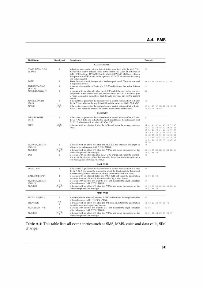
A.4. SMS
Field Name Size (Bytes) Description Example
COMMON PART
START DATA FLAG(SDF )
1 Indicates a date starting at next byte, this flag combined with the EDF in-dicates what kind of data are stored in the session. (03 DATA FF indicates anSMS, GPRS traffic or ‘DATAMESSAGE’ MMS, 05 DATA 01 MMS recived fromthe operator or GPRS traffic to the operator, 00 DATE 01 indicates incomingand outgoing calls)
03
DATE 8 Stores the date in wich the operation has been performed. The date in storedin big endian format.
BA A3 EB EB B6 2C E1 00
END DATA FLAG(EDF )
1 Is located with an offset of 8 after the SDF and indicates that a date finisheshere.
FF
NAME FLAG (NF ) 1 Is located with an offset of 1 after the EDF and if the entry refers to a con-tact present in the address book (for the SMS the value is B2 if the message isto/from a contact in the address book for calls the value can be 70 if presentelse 60).
B2
NAME LENGTH(NL)
1 If the contact is present in the address book is located with an offset of 4 afterthe NF and indicates the length in nibbles of the subsecuent field NAME.
1C
NAME NL2 If the contact is present in the address book is located with an offset of 1 after
the NL and stores the name of the contact stored in the address book.52 61 6D 6F 6E 61 20 4D 6F72 65 74 74 69
SMS PART
MESS LENGTH(ML)
1 If the contact is present in the address book is located with an offset of 5 afterthe NAME field and indicates the length in nibbles of the subsecuent fieldMESS, else is st with an offset of 5 after NF .
80
MESS ML2 Is located with an offset of 1 after the ML and stores the message sent/re-
cived.44 4F 4D 41 4E 49 20 53 4552 41 20 54 49 20 49 4E 5649 54 4F 20 41 44 20 55 5343 49 52 45 20 49 4E 53 4945 4D 45 20 58 20 55 4E 4120 43 45 4E 41 2C 6F 76 7669 61 6D 65 6E 74 65 20 6F67 1A
NUMBER LENGTH(NUL)
1 Is located with an offset of 1 after the MESS and indicates the length innibbles of the subsecuent field NUMBER.
1A
NUMBER NUL2 Is located with an offset of 1 after the NUL and stores the number of the
sender/recipient of the message.2B 33 39 XX XX XX XX XX XXXX XX XX XX
DIR 1 Is located with an offset of 2 after the NUMBER and stores the informa-tion about the direction of the data stored in the section (value 00 indicates asent message else the value will be 02).
02
CALL PART
DIRECTION 1 If the contact is present in the address book is located with an offset of 2 afterthe NAME and stores the information about the direction of the data storedin the section (value 00 indicates an exiting call else the value will be 02).
02
CALL TIME (CT ) 4 Is located with an offset of 2 after the DIR field and stores the informationabout the duration of the call, data is atored in big endian format.
00 00 00 00
NUMBER LENGHT(NUL)
1 Is located with an offset of 4 after the CT and indicates the length in nibblesof the subsecuent field NUMBER.
1A
NUMBER NUL2 Is located with an offset of 1 after the NUL and stores the number of the
sender/recipient of the message.2B 33 39 XX XX XX XX XX XXXX XX XX XX
MMS PART
PROV LEN (P L) 1 is located with an offset of 5 after the EDF and indicates the length in nibblesof the subsecuent field P ROV IDER.
0E
PROVIDER P L2 Is located with an offset of 1 after the P L field and stores the information
about the mms service provider’s name.54 69 6D 20 6D 6D 73
NUM START (NS) 2 Is located with an offset of 4 after the CT and indicates the length in nibblesof the subsecuent field NUMBER.
30 08
NUMBER NUL2 Is located with an offset of 1 after the NUL and stores the number of the
sender/recipient of the message.36 34 31 38 2C 37 32 37
Table A.4: This table lists all event entries such as SMS, MMS, voice and data calls, SIMchange.
95
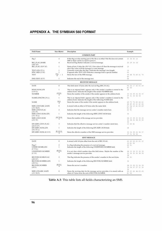
APPENDIX A. THE SYMBIAN S60 FORMAT
Field Name Size (Bytes) Description Example
COMMON PART
flag 1 4 If this flag is in the starting part of the file or at offset 5 the file does not containSMS so there will be no need to parse it.
25 3A 00 10
REC FLAG MARK(RF M )
4 Received Flag Marker indicates a recived message 20 29 34 18
REC FLAG (RF M ) 1 Starts at byte 13 after the (RF M ). If its value is 01 then the message is recivedelse if the value is 00 the message is a sent message.
10
TEXT LEN (T L) 1 Generally is just after the flag 1 indicates the message’s text length. 10SPEC MES (SM ) 1 If appears after TEXT LEN indicates a message from a special number. 02
TEXT T L2 − 1 Stores the text of the SMS message. 49 6E 76 69 61 74
6FEND TEXT (ET ) 1 Indicates the end of the message text. 0E
RECEIVED MESSAGE
DATE 8 This field starts 12 bytes after the recived flag (REC FLAG). FA 54 17 46 F2 29E1 00
SEND NUM LEN(SNL)
1 This is an otiponal field: appears only if the sender’s number is stored in theaddress book. Indicates the length of the sender NUMBER field.
28
NUMBER SNL4 Stores the number of the sender if the sender appears in the address book. 33 34 39 34 36 37
37 31 34 36 34NAME LENGTH (NL) 1 This is an otiponal field: appears only if the sender’s number is stored in the
address book. Indicates the length of the following NAME field.44
NAME NL4 Stores the name of the sender if the sender appears in the address book. 69 73 74 65 66 61
6E 6F 20 41 6C 65SERV CENT REC DATE(SCRD)
8 Is stored with an offset of 23 bytes after the name field. F1 5A 15 41 F2 29E1 00
SERV CENT FLAG(SCF )
2 Indicates that the message service center’s number starts here. 02 91
SERV CENT NUM LEN(SCNL)
1 Indicates the length of the following SERV CENT NUM field. 34
SERV CENT NUM(SCN )
SCNL4 Stores the number of the messge service provider. 2B 33 39 33 32 30
35 38 35 38 35 3030
EFF SERV CENT FLAG(ESCF )
3 Indicates that the effective message service center’s number starts here. 15 00 81
EFF SERV NUM LEN(ESNL)
1 Indicates the length of the following EFF SERV NUM field. 28
EFF SERV NUM (ESN ) ESNL4 Stores the effective number of the SMS message service provider. 33 34 39 34 36 37
37 31 34 36
SENT MESSAGE
DATE 8 Is stored with 14 bytes offset from the end of REC FLAG. 00 0C 09 22 F2 1C32 E1 00
Flag 2 2 Is a flag indicating the presence of a recived message. 00 91UNDEF NUMB LEN(UNL)
1 Indicates the length of the following UNDEFINED NUMBER field. 34
UNDEFINED NUMBER(UN )
RNL4 It is not clear which number does this field stores. Maybe the number of the
sender’s message service provider.2B 33 39 33 34 3932 30 30 30 38 3938
RECIVER NUMB FLAG(RNF )
2 This flag indicates the presence of the sender’s number in the next bytes. 04 91
RECIVER NUMBER LEN(RNL)
1 Indicates the length of the following RECIVER NUMBER field. 34
RECIVER NUMBER(RN )
RNL4 Stores the reciver’s number. 2B 33 39 33 34 39
34 36 37 37 31 3436
SERV CEN REC DATE(SCRD)
8 Stores the reciving date for the message service provider, it is stored with anoffset of 2 bytes from the end of RECIVER NUMBER.
00 93 2D 4B F2 29E1 00
Table A.5: This table lists all fields characterizing an SMS.
96
Bibliography
[1] RNCOS Industry Research Solutions. Global mobile phone penetrationto reach 50% in 2008.http://www.rncos.com/Blog/2008/05/Global-Mobile-Phone-Penetration-to-Reach-50-in-2008.html.
[2] SNL Financial. 10-year wireless projections.http://www.snl.com/press/20070823.asp.
[3] Gianluigi Me and Maurizio Rossi. Internal forensic acquisition for mobileequipments. In IEEE Computer Society Press, editor, 4th Int’l Workshop onSecurity in Systems and Networks (SSN2008), Proceedings of the InternationalParallel and Distributed Processing Symposium (IPDPS), 2008.
[4] Fabio Dellutri, Vittorio Ottaviani, and Gianluigi Me. Forensic acquisitionfor windows mobile pocketpc. In Proceedings of the Workshop on Securityand High Performance Computing Systems, HPCS 2008, Nicosia, Cyprus June3-6, 2008, pages 200–205.
[5] Michael Hampton. Personal data for 28,000 navy personnel found onpublic web site.http://www.homelandstupidity.us/2006/06/24/personal-data-for-28000-navy-personnel-found-on-public\-web-site/.
[6] Donna L. Hoffman and Thomas P. Novak. How to acquire customers onthe web. Hardvard Business Review, (78):179–188, 2002.
[7] Par Raphael Meltz. Marc l***, Le Tigre.http://www.le-tigre.net/Marc-L.html.November-december 2008.
[8] Netherlands Forensic Institute. Workflow for mobile phone forensicexaminations.http://www.holmes.nl/MPF/FlowChartForensicMobilePhone\Examination.htm.
[9] Wayne Jansen, Aurelien Delaitre, and Ludovic Moenner. Overcoming im-pediments to cell phone forensics. In HICSS ’08: Proceedings of the Proceed-ings of the 41st Annual Hawaii International Conference on System Sciences,page 483, Washington, DC, USA, 2008. IEEE Computer Society.
97
BIBLIOGRAPHY
[10] Rick Ayers and Wayne Jansen. Guidelines on cell phone forensics. Tech-nical report, NIST, 2007.
[11] Rick Ayers, Wayne Jansen, Ludovic Moenner, and Aurelien Delaitre. Cellphone forensic tools: An overview and analysis update. Technical report,NIST, 2007.
[12] Rick Ayers and Wayne Jansen. Pda forensic tools: An overview and anal-ysis. Technical report, NIST, 2004.
[13] Jonathan A. Zdziarski. iPhone Forensics - Recovering Evidence, Personal Data,and Corporate Assets. O’Reilly, 2008.
[14] Andrew Hoog. iphone forensics, annual report on iphone forensic in-dustry. Technical report, chicago-ediscovery.com chicago-ediscovery.comchicago-ediscovery.com chicago-ediscovery.com, 2009.
[15] Paraben Corporation. Paraben device seizure.http://www.paraben.com.
[16] Hausi A. Muller, Jens H. Jahnke, Dennis B. Smith, Margaret-Anne Storey,Scott R. Tilley, and Kenny Wong. Reverse engineering: a roadmap. InICSE ’00: Proceedings of the Conference on The Future of Software Engineering,pages 47–60, New York, NY, USA, 2000. ACM Press.
[17] Weidong Cui, Marcus Peinado, Karl Chen, Helen J. Wang, and Luis Irun-Briz. Tupni: automatic reverse engineering of input formats. In CCS ’08:Proceedings of the 15th ACM conference on Computer and communications se-curity, pages 391–402, New York, NY, USA, 2008. ACM.
[18] P. H. Aiken. Reverse engineering of data. IBM Systems Journal, 37(2):246–269, 1998.
[19] Gregory Conti, Erik Dean, Matthew Sinda, and Benjamin Sangster. Visualreverse engineering of binary and data files. In VizSec ’08: Proceedings ofthe 5th international workshop on Visualization for Computer Security, pages1–17, Berlin, Heidelberg, 2008. Springer-Verlag.
[20] David L. Altheide. Identity and the definition of the situation in a mass-mediated context. Symbolic Interaction, 23(1):1–27, 2000.
[21] Peter Mika. Bootstrapping the foaf-web: An experiment in social networkmining, 2004.
98
BIBLIOGRAPHY
[22] Peter Mika. Flink: Semantic web technology for the extraction and anal-ysis of social networks. Web Semantics: Science, Services and Agents on theWorld Wide Web, 3(2-3):211–223, October 2005.
[23] Shanyang Zhao, Sherri Grasmuck, and Jason Martin. Identity construc-tion on facebook: Digital empowerment in anchored relationships. Com-put. Hum. Behav., 24(5):1816–1836, 2008.
[24] 3gforensics. Simis 3g: Forensic sim card software.http://www.3gforensics.co.uk/products/simtools/simis3g.
[25] SIMCon forensics. Sim card recovery.http://www.simcon.no/.
[26] Paraben. Sim card seizure.http://www.paraben-forensics.com/catalog/product_info.php?products_id=289.
[27] Jeroen van den Bos and Ronald van der Knijff. Tulp2g – an open sourceforensic software framework for acquiring and decoding data stored inelectronic devices. International Journal of Digital Evidence, 2005.
[28] Rosamaria Berte, Fabio Dellutri, Antonio Grillo, Alessandro Lentini, Gi-anluigi Me, and Vittorio Ottaviani. Fast smartphones forensic analysisresults through miat and forensic farm. International Journal of ElectronicSecurity and Digital Forensics (IJESDF), Inderscience, 2008.
[29] Rosamaria Berte, Fabio Dellutri, Antonio Grillo, Alessandro Lentini, Gi-anluigi Me, and Vittorio Ottaviani. Handbook of Electronic Security and Dig-ital Forensics, chapter A Methodology for Smartphones Internal MemoryAcquisition, Decoding and Analysis. Worldscience, 2008.
[30] Peter Stephenson. Using a formalized approach to digital investigation.Computer Fraud & Security, 2003:17–20(4), July 2003.
[31] CA) Leyland, Walter E. (Riverside. Lightweight portable emi shieldingcontainer, August 1992.
[32] Alessandro Distefano and Gianluigi Me. An overall assessment of mobileinternal acquisition tool. Digital Investigation, 5(Supplement 1):S121–S127,2008.
99

BIBLIOGRAPHY
[33] Rick Ayers, Wayne Jansen, Ludovic Moenner, and Aurelien Delaitre. Anoverview and analysis of pda forensics tool. Digital Investigation, 2 (2):pp.120–132, 2005.
[34] Michael Santarini. Nand versus nor. EDN, October 2005.
[35] Microsoft. Linear flash memory devices on microsoft windows ce.http://www.microsoft.com/technet/archive/wce/plan/flashce.mspx.
[36] Microsoft. The windows ce 5.0 object store.http://msdn2.microsoft.com/en-us/library/ms885891.aspx.
[37] Fabio Dellutri, Vittorio Ottaviani, Daniele Bocci, Giuseppe F. Italiano, andGianluigi Me. Data reverse engineering on a smartphone. Submitted to the5th International Conference on Security and Privacy in Communication Net-works (SecureComm 2009), 2009.
[38] Chen and Associates. Reverse-DBMS (Access. 2.0) for Windows ReferenceManual Version 3.0, 1994.
[39] Roger H. L. Chiang. A knowledge-based system for performing reverseengineering of relational databases. Decis. Support Syst., 13(3-4):295–312,1995.
[40] Kathi Hogshead Davis. August-ii: a tool for step-by-step data model re-verse engineering. Reverse Engineering, 1995., Proceedings of 2nd WorkingConference on, pages 146–154, Jul 1995.
[41] Jean Henrard, Didier Roland, Anthony Cleve, and Jean-Luc Hainaut.Large-scale data reengineering: Return from experience. In WCRE ’08:Proceedings of the 2008 15th Working Conference on Reverse Engineering,pages 305–308, Washington, DC, USA, 2008. IEEE Computer Society.
[42] Contacts Database (CContactDatabase). Symbian developer library.http://www.symbian.com/Developer/techlib/v70docs/SDL_v7.0/doc_source/reference/cpp/ContactsModel/CContactDatabaseClass.html.
[43] Fabio Dellutri, Marco Gaertler, Robert Gorke, Giuseppe F. Italiano, andLuigi Laura. Experimental validation of svd-based graph clustering. 2009.Unpublished Manuscript.
100

BIBLIOGRAPHY
[44] Paul Jaccard. Etude comparative de la distribution florale dans une por-tion des alpes et des jura. Bull Soc Vaudoise Sci Nat, 37:547–579, 1901.
[45] Gerald Salton, editor. Automatic text processing. Addison-Wesley LongmanPublishing Co., Inc., Boston, MA, USA, 1988.
[46] Rudi L. Cilibrasi and Paul M. B. Vitanyi. The google similarity distance.IEEE Transactions on Knowledge and Data Engineering, 19(3):370–383, March2007.
[47] Marco Gaertler. Clustering. In Ulrik Brandes and Thomas Erlebach, edi-tors, Network Analysis: Methodological Foundations, volume 3418 of LectureNotes in Computer Science, pages 178–215. Springer, February 2005.
[48] Ulrik Brandes, Marco Gaertler, and Dorothea Wagner. Engineering GraphClustering: Models and Experimental Evaluation. ACM Journal of Experi-mental Algorithmics, 12(1.1):1–26, 2007.
[49] David Cheng, Ravi Kannan, Santosh Vempala, and Grant Wang. ADivide-and-Merge Methodology for Clustering. ACM Transactions onDatabase Systems, 31(4):1499–1525, 2006.
[50] Amit Deshpande, Luis Rademacher, Santosh Vempala, and Chen Wang.Matrix Approximation and Projective Clustering via Volume Sampling.In Proceedings of the 17th Annual ACM–SIAM Symposium on Discrete Algo-rithms (SODA’06), pages 1117–1126, 2006.
[51] Petros Drineas, Alan M. Frieze, Ravi Kannan, Santosh Vempala, andV. Vinay. Clustering Large Graphs via the Singular Value Decomposition.Machine Learning, 56(1-3):9–33, 2004.
[52] Ravi Kannan, Santosh Vempala, and Adrian Vetta. On Clusterings: Good,Bad, Spectral. Journal of the ACM, 51(3):497–515, May 2004.
[53] Daniel A. Spielman and Shang-Hau Teng. Spectral Partitioning Works:Planar Graphs and Finite Element Meshes. In Proceedings of the 37th An-nual IEEE Symposium on Foundations of Computer Science (FOCS’96), pages96–106, October 1996.
[54] Fan R. K. Chung. Spectral Graph Theory (CBMS Regional Conference Seriesin Mathematics, No. 92) (Cbms Regional Conference Series in Mathematics).American Mathematical Society, February 1997.
101

BIBLIOGRAPHY
[55] Gene H. Golub and Charles F. Van Loan. Matrix Computations. John Hop-kins University Press, 3rd edition, 1996.
[56] Chris H. Q. Ding and Xiaofeng He. K-Means Clustering via PrincipalComponent Analysis. In Proceedings of the twenty-first international confer-ence on Machine learning, volume 69, pages 29–39. ACM Press, 2004.
[57] Chris H. Q. Ding, Xiaofeng He, and Horst D. Simon. Nonnegative La-grangian Relaxation of K-Means and Spectral Clustering . In Proceedingsof the 16th European Conference on Machine Learning, volume 3720 of LectureNotes in Computer Science, pages 530–538. Springer, 2005.
[58] Chris H. Q. Ding, Xiaofeng He, and Horst D. Simon. On the Equivalenceof Nonnegative Matrix Factorization and Spectral Clustering. In Proceed-ings of the fifth SIAM International Conference on Data Mining, pages 606–610. SIAM, 2005.
[59] Ravi Kannan, Santosh Vempala, and Adrian Vetta. On Clusterings - Good,Bad and Spectral. In Proceedings of the 41st Annual IEEE Symposium onFoundations of Computer Science (FOCS’00), pages 367–378, 2000.
[60] Ulrik Brandes, Marco Gaertler, and Dorothea Wagner. Experiments onGraph Clustering Algorithms. In Proceedings of the 11th Annual EuropeanSymposium on Algorithms (ESA’03), volume 2832 of Lecture Notes in Com-puter Science, pages 568–579. Springer, 2003.
[61] Stijn M. van Dongen. Graph Clustering by Flow Simulation. PhD thesis,University of Utrecht, 2000.
[62] Kanti V. Mardia, J. T. Kent, and J. M. Bibby. Multivariate Analysis. Aca-demic Press, New York, 1979.
[63] Xiaojin Zhu and Ronald Rosenfeld. Improving trigram language model-ing with the world wide web, 2001.
[64] Frank Keller and Mirella Lapata. Using the web to obtain frequencies forunseen bigrams. Comput. Linguist., 29(3):459–484, 2003.
[65] Fabio Dellutri, Salvatore Di Blasi, and Giuseppe F. Italiano. Transparentfile protection in on-demand computing. In Hamid R. Arabnia, editor, InProceedings of the 2007 International Conference on Grid Computing & Applica-tions, GCA 2007, Las Vegas, Nevada, USA, June 25-28, 2007, pages 116–122.CSREA Press, 2007.
102
BIBLIOGRAPHY
[66] Fabio Dellutri, Giuseppe F. Italiano, and Gianluigi Me. Authentication inwireless mesh networks environment. Unpublished Manuscript.
[67] Fabio Dellutri, Gianluigi Me, and Maurizio A. Strangio. Local authentica-tion with bluetooth enabled mobile devices. In ICAS-ICNS ’05: Proceedingsof the Joint International Conference on Autonomic and Autonomous Systemsand International Conference on Networking and Services, page 72, Washing-ton, DC, USA, 2005. IEEE Computer Society.
103


