Embed Size (px)
Citation preview

Proceedings of the Institution of Civil Engineers
http://dx.doi.org/10.1680/grim.13.00045
Paper 1300045
Received 21/07/2013 Accepted 19/03/2014
Keywords: columns/geotechnical engineering/design methods & aids
ICE Publishing: All rights reserved
Ground Improvement
Prediction of stone column ultimate bearingcapacity using expansion cavity modelFrikha and Bouassida
Prediction of stone columnultimate bearing capacityusing expansion cavity modelj1 Wissem Frikha
Universite de Tunis El Manar/Ecole Nationale d’Ingenieurs de Tunis,Tunis, Tunisia
j2 Mounir BouassidaUniversite de Tunis El Manar/Ecole Nationale d’Ingenieurs de Tunis,Tunis, Tunisia
j1 j2
The ultimate bearing capacity of an isolated column was investigated by combining a state of stress with a failure
mechanism of lateral expansion in a cylindrical cavity which reproduces the stone column installation in a purely
cohesive soft soil. Some analytical and empirical methods were used to determine the limit pressure of a cylindrical
cavity with the assumption of varied behaviour laws of the medium around the cavity. These models permitted the
calculation of the limit pressure of an expanded cylindrical cavity from which the ultimate bearing capacity was
derived. Using recorded in situ data from load tests performed on 13 isolated column configurations, the model
parameters are identified. A comparison between experimental data and predictions generated from several models
is presented.
Notationci radius of plastic zone i
cU undrained shear strength
E Young’s modulus
Gl linear shear modulus
Gs secant shear modulus
KP coefficient of passive stress state
ki coefficient of compressibility of plastic zone i
L multiplier
p0 initial horizontal stress at rest
pl limit lateral pressure
p�l limit net lateral pressure
qu ultimate bearing capacity
R2 coefficient of determination
Æ ¼ c1=c2 ratio of the plastic radius variation
� ¼ p�l =cU coefficient
� non-elastic exponent
� Poisson’s ratio
� friction angle
ł dilation angle
1. IntroductionReinforcing soft clays by stone columns is becoming more
successful thanks to the use of advanced procedures of column
installation as well as higher interest by researchers on this topic.
The efficiency of this improvement technique consists in settle-
ment reduction and increase of bearing capacity of soft soils.
Furthermore, the rapid process of installation and inexpensive
cost make this technique quite competitive compared to other
types of foundations (Frikha et al., 2013).
The vibro-installation of stone columns was designed so that the
improvement of soft soil takes place by lateral expansion of the
added stone material. This expansion is induced by horizontal
vibrations powered by an eccentric motor within a vibro-probe.
Figure 1 illustrates that the diameter of installed stone columns
depends on the consistency of the soft soil layer. The lateral
expansion represents a loading subjected to the surrounding soft
soil from which results its primary consolidation.
Several investigations have been conducted to determine the
bearing capacity of an isolated column by considering several
methods, which are classified by Bouassida and Hadhri (1995)
into three categories. In the first approach, the state of stress was
considered (Aboshi et al., 1979). Second, a failure mechanism
was combined with a state of stress (Balaam and Booker, 1985;
Datye, 1982; Greenwood, 1970; Hughes et al., 1975; Van Impe
and De Beer, 1983). In the third type of approach a failure
mechanism only was used (Bouassida and Jellali, 2002). In the
present study, the second approach was considered to compute
the bearing capacity of an isolated column analytically. The
column installation was modelled in a similar manner to lateral
1

expansion of a cylindrical cavity by assuming an elastic–plastic
stone column behaviour. The stress distribution within the stone
column and surrounding soil was calculated using equilibrium
equations.
In the present study the bearing capacity of an isolated column
was determined from empirical predictions and analytical models
based on theoretical approaches of lateral expanded cylindrical
cavity. These models were calibrated from records of the ultimate
bearing capacity measured during in situ load testing of a column.
2. The problem of an expanded cylindricalcavity
The problem of cylindrical cavity expansion within a limitless
half space was initially investigated by Lame (1852). In this
contribution the soil surrounding the cavity exhibited linear
elastic behaviour and was assumed to be weightless, homo-
geneous, and isotropic.
It is difficult to examine all of the studies which have dealt with
the study of the expansion of a cylindrical cavity in an infinite
medium. However, it is possible to classify these studies accord-
ing to the type of contribution, namely analytical and numerical
methods. The analytical methods were developed by assuming
that the medium around the cavity followed various behaviour
laws such as linear elastic, elastic perfectly plastic, either by not
taking account of volume variation (Chadwick, 1959; Gibson and
Anderson, 1961; Hill, 1950; Menard, 1957) or by considering
volume variation (Carter et al., 1986; Hughes et al., 1975;
Ladanyi, 1963; Manassero, 1989; Mecsi, 1991; Salencon, 1966;
Vesic, 1972; Yu and Houlsby, 1991). In the analytical contribu-
tions, hypotheses were adopted for the soil behaviour either in
small strains (Bishop et al., 1945; Gibson and Anderson, 1961;
Hill, 1950; Hughes et al., 1975; Ladanyi, 1963; Menard, 1957;
Vesic, 1972; Windle and Wroth, 1977) or in large strains (Cao et
al., 2002; Carter et al., 1986; Chadwick, 1959; Yu and Houlsby,
1991, etc.). Note that Hughes et al. (1975) proposed neglecting
the elastic strain with respect to the plastic component, whereas
Carter et al. (1986) demonstrated that for a strain level beyond
10%, the elastic strain component should not be neglected. Based
on yield design theory approaches, Bouassida and Frikha (2007)
focused on the theoretical determination of the extreme net
pressure which results from lateral expansion exerted within an
infinite half-space in cylindrical as well as spherical cavities
(Frikha and Bouassida, 2013).
Frikha and Bouassida (2013) investigated the problem of ex-
panded cylindrical cavities in a homogeneous, isotropic and
weightless medium. Elastoplastic behaviour was assumed by
taking account of plastic volume variation. This latter was
described by a plastic potential of flow characterised with a
coefficient of compressibility, k. Therefore, an analytical limit
pressure was obtained as a function of mechanical characteristics
and the coefficient of compressibility of the expanded medium.
Stone column installation
A A A A A A
A–A A–A A–A
Probe insertion Lateral expansion of clayey soil Final stone column
Figure 1. Schematic of the vibro-replacement installation of
stone column (Frikha et al., 2013)
2
Ground Improvement Prediction of stone column ultimatebearing capacity using expansion cavitymodelFrikha and Bouassida
Offprint provided courtesy of www.icevirtuallibrary.comAuthor copy for personal use, not for distribution
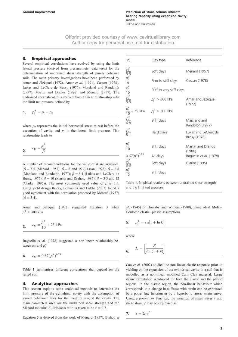
3. Empirical approachesSeveral empirical correlations have evolved by using the limit
lateral pressure (derived from pressuremeter data tests) for the
determination of undrained shear strength of purely cohesive
soils. The main primary investigations have been performed by
Amar and Jezequel (1972), Amar et al. (1991), Cassan (1978),
Lukas and LeClerc de Bussy (1976), Marsland and Randolph
(1977), Martin and Drahos (1986) and Menard (1957). The
undrained shear strength is derived from a linear relationship with
the limit net pressure defined by
p�l ¼ pl � p01:
where p0 represents the initial horizontal stress at rest before the
execution of cavity and pl is the lateral limit pressure. This
relationship leads to
cU ¼p�l�2:
A number of recommendations for the value of � are available.
(� ¼ 5.5 (Menard, 1957); � ¼ 8 and 15 (Cassan, 1978); � ¼ 6.8
(Marsland and Randolph, 1977); � ¼ 5.1 (Lukas and LeClerc de
Bussy, 1976); � ¼ 10 (Martin and Drahos, 1986); � ¼ 3.3 and 12
(Clarke, 1995)). The most commonly used value of � is 5.5.
Using yield design theory, Bouassida and Frikha (2007) found a
good agreement with the correlation proposed by Menard (1957)
(� ¼ 5.4).
Amar and Jezequel (1972) suggested Equation 3 when
p�l . 300 kPa
cU ¼p�l10þ 25 kPa3:
Baguelin et al. (1978) suggested a non-linear relationship be-
tween cU and p�l
cU ¼ 0.67( p�l )0.754:
Table 1 summarises different correlations that depend on the
tested soil.
4. Analytical approachesThis section exploits some analytical methods to determine the
limit pressure of the cylindrical cavity with the assumption of
varied behaviour laws for the medium around the cavity. The
main parameters used are the undrained shear strength and the
Menard modulus E. Poisson’s ratio is taken to be � ¼ 0.5.
Equation 5 is derived from the work of Menard (1957), Bishop et
al. (1945) or Houlsby and Withers (1988), using ideal Mohr–
Coulomb elastic–plastic assumptions
p�l ¼ cU 1þ ln I r½ �5:
where
I r ¼E
2cU(1þ �)
� �6:
Cao et al. (2002) studies the non-linear elastic response prior to
yielding on the expansion of the cylindrical cavity in a soil that is
modelled as a non-linear modified Cam Clay material. Large
strain formulation is adopted for both the elastic and the plastic
regions. In the elastic region, the non-linear behaviour which
corresponds to a change in stiffness with strain can be expressed
by a power law function or by a hyperbolic stress–strain curve.
Using a power law function, the variation of shear stress � and
shear strain ª may be expressed as
� ¼ Glª�7:
cU Clay type Reference
p�l5.5
Soft clays Menard (1957)
p�l8
Firm to stiff clays Cassan (1978)
p�l15
Stiff to very stiff clays
p�l5.5
p�l . 300 kPa Amar and Jezequel
(1972)p�l10þ 25 kPa p�l . 300 kPa
p�l6.8
Stiff clays Marsland and
Randolph (1977)p�l5.1
Hard clays Lukas and LeClerc de
Bussy (1976)
p�l10
Stiff clays Martin and Drahos
(1986)
0.67(p�l )0.75
All clays Baguelin et al. (1978)p�l3.3
Soft clays Clarke (1995)
p�l12
Stiff clays
Table 1. Empirical relations between undrained shear strength
and the limit net pressure
3
Ground Improvement Prediction of stone column ultimatebearing capacity using expansion cavitymodelFrikha and Bouassida
Offprint provided courtesy of www.icevirtuallibrary.comAuthor copy for personal use, not for distribution
where � is a non-linear elastic exponent (0 , � < 1) and Gs is
the secant shear modulus given by
Gs ¼ Glª��18:
Note that Gs equals the shear modulus of a linear material Gl if
� ¼ 1. Based on the power law function, the limit cavity pressure
is (Cao et al., 2002)
p�l ¼cU
�þ cU ln I r9:
Gupta (2000) analysed the expansion of a cylindrical cavity using
the above classical hypothesis. The sole difference was to assume
zero volume variation in the plastic zone; then the radial
displacement at the interface of the plastic and elastic zone is
R2c � R2
0 ¼ r2p � (rp � �rp)2
10:
where Rc, R0 and rp are the current and initial radii of the cavity,
respectively and the radius of the plastic zone
�rp ¼rp
2I r11:
After Gupta (2000), the limit net pressure is
p�l ¼ cU þ cU ln 4I2r =(4I r � 1)
� �12:
Frikha and Bouassida (2013) generalised the contribution of
Salencon (1966) related to an expanded cylindrical cavity within
a medium governed by a constitutive law with variable flow. This
problem was solved by dividing the medium around the cavity
into two zones. The first zone, close to the cavity border, was
assumed plastic with a variable flow law. The second zone was
assumed elastic. The plastic zone was divided into n flow zones,
each one being characterised by its own plastic radius ci and
coefficient of compressibility ki (i ¼ 1, n).
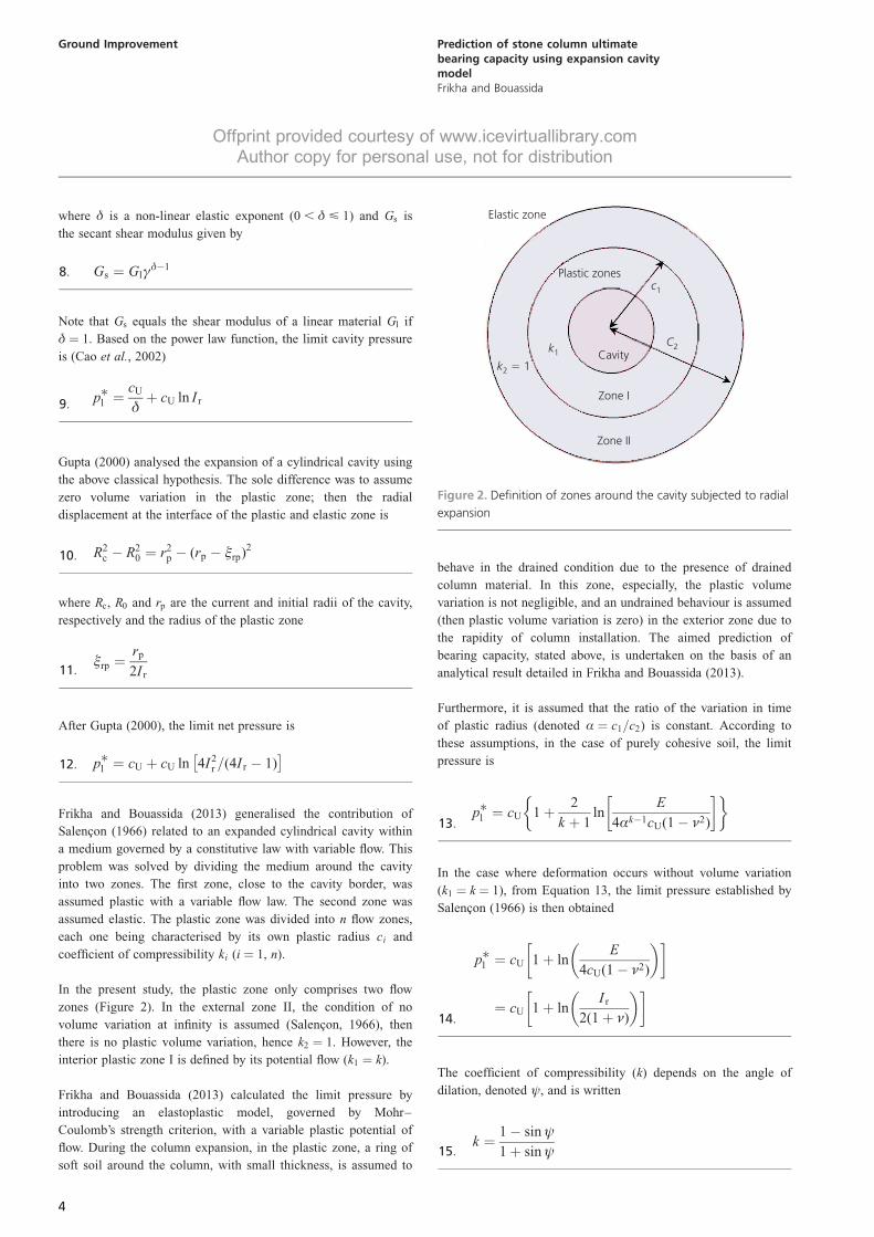
In the present study, the plastic zone only comprises two flow
zones (Figure 2). In the external zone II, the condition of no
volume variation at infinity is assumed (Salencon, 1966), then
there is no plastic volume variation, hence k2 ¼ 1. However, the
interior plastic zone I is defined by its potential flow (k1 ¼ k).
Frikha and Bouassida (2013) calculated the limit pressure by
introducing an elastoplastic model, governed by Mohr–
Coulomb’s strength criterion, with a variable plastic potential of
flow. During the column expansion, in the plastic zone, a ring of
soft soil around the column, with small thickness, is assumed to
behave in the drained condition due to the presence of drained
column material. In this zone, especially, the plastic volume
variation is not negligible, and an undrained behaviour is assumed
(then plastic volume variation is zero) in the exterior zone due to
the rapidity of column installation. The aimed prediction of
bearing capacity, stated above, is undertaken on the basis of an
analytical result detailed in Frikha and Bouassida (2013).
Furthermore, it is assumed that the ratio of the variation in time
of plastic radius (denoted Æ ¼ c1=c2) is constant. According to
these assumptions, in the case of purely cohesive soil, the limit
pressure is
p�l ¼ cU 1þ 2
k þ 1ln
E
4Æk�1cU(1� �2)
� �� �13:
In the case where deformation occurs without volume variation
(k1 ¼ k ¼ 1), from Equation 13, the limit pressure established by
Salencon (1966) is then obtained
p�l ¼ cU 1þ lnE
4cU(1� �2)
� � �
¼ cU 1þ lnI r
2(1þ �)
� � �14:
The coefficient of compressibility (k) depends on the angle of
dilation, denoted ł, and is written
k ¼ 1� sinł
1þ sinł15:
Elastic zone
Plastic zonesc1
C2Cavity
Zone I
Zone II
k1
k2 1�
Figure 2. Definition of zones around the cavity subjected to radial
expansion
4
Ground Improvement Prediction of stone column ultimatebearing capacity using expansion cavitymodelFrikha and Bouassida
Offprint provided courtesy of www.icevirtuallibrary.comAuthor copy for personal use, not for distribution
5. Ultimate bearing capacity of an isolatedcolumn
5.1 Background
The analytical model of the interaction of a stone column and the
soil surrounding the stone column has a very complex stress
history and is difficult to determine.
The radial stresses in the cavity could be of a high order
depending on the level of lateral deformation and the vibro-
compaction energy. After stone column installation, an annulus
of soil in the immediate vicinity of the stone column–soil
interface gains strength as consolidation takes place after installa-
tion. The extent of gain varies according to the distance from the
soil–stone column interface and is also dependent on the
consumption of the stone and the corresponding lateral displace-
ment.
There is a change in the stress conditions starting from the
initial Ko state in which the direction of the major principal
stress is vertical to a final axisymmetric state of stress in
which the maximum principal stress is in a horizontal radial
direction.
Depending on the type of column, based on the earlier work of
Datye (1982), three modes of failure can be foreseen, as detailed
in Soyez (1985): lateral expansion, generalised shearing in the
case of an end-bearing column, and punching failure in the case
of a floating column. The ultimate bearing capacity of an isolated
column is investigated here by combining a state of stress with a
failure mechanism of lateral expansion in the cylindrical cavity,
which reproduces the stone column installation in a purely
cohesive soft soil.
The proposed design approach is based on an initial categorisa-
tion of the soil zones into elastic and plastic zones (Datye, 1982).
The share of the load associated with the stone columns is
estimated by using equilibrium methods and a preliminary
evaluation is made of the hazard of the stone column yield in
different layers considering the in situ undrained strength and
overburden pressure in the different layers. The ultimate capacity
of the stone columns has generally been significantly higher than
the values estimated according to the parameters of the soil
(Datye and Madhav, 1988).
The isolated column is subjected to passive triaxial compression;
hence the ultimate bearing capacity as vertical stress is (Soyez,
1985)
qu ¼ Kppl16:
Kp ¼ tan2(�=4þ �=2) is the coefficient of passive pressure.
pl is the limit pressure in surrounding soil.
Otherwise by use of empirical and analytical equations (Equa-
tions 2, 5, 9, 12, 13 and 14), Equation 16 can be written
qu ¼ Kp( p0 þ LcU)17:
in which L is a multiplier.
The limit net pressure p�l can then be written as follows
p�l ¼ L:cU18:
5.2 Application with proposed model
Using different empirical approaches, the value of multiplier L
equals the coefficient � that can be varied from 3.3 to 15 (Table 1).
Using the described analytical approaches, the following values
of L may occur.
(a) The model of Menard (1957), Gibson and Anderson (1961)
and Bishop et al. (1945) give a limit net pressure equal to
p�l ¼ cU 1þ ln I r½ �19:
Combining Equation 17 with Equation 19, it becomes
L ¼ 1þ ln I r20:
In the case of compressible material � ¼ 0.5, the model of
Salencon (1966) is similar to that of Gibson and Anderson
(1961); the coefficient Ir will then be equal to
I r ¼E
2(1þ �)cU
¼ E
4(1� �2)cU
¼ E
3cU21:
(b) In the model of Gupta (2000), the multiplier L equals
L ¼ 1þ ln 4I2r =(4I r � 1)
� �22:
(c) In the model of Cao et al. (2002), the multiplier L equals
L ¼ 1
�þ ln I r23:
(d ) The model of Frikha and Bouassida (2013) can be considered
with the two laws of plastic flow described above. The
multiplier L is equal for a Poisson ratio ı ¼ 0.5 to
5
Ground Improvement Prediction of stone column ultimatebearing capacity using expansion cavitymodelFrikha and Bouassida
Offprint provided courtesy of www.icevirtuallibrary.comAuthor copy for personal use, not for distribution
L ¼ 1þ 2
k þ 1Ln
Ir
Æk�1
� 24:
In the following, the calibration of the model with two plastic
flow zones was undertaken, to determine the bearing capacity of
an isolated stone column.
6. Calibration of the suggested modelIt is very difficult to verify the assumed hypothesis through the
observed behaviour of the zone of interest because of the
disturbance caused during the installation of the stone columns
(Datye and Madhav, 1988). One must therefore rely on semi-
empirical methods and use results of load tests to evaluate the
adopted parameters.
Bergado and Lam (1987) tested 13 in situ stone column models
(G1 to G13); each model was characterised by specified grain-
size column material and process of installation. Table 2 presents
the recorded ultimate bearing capacity of all column models and
the angle of friction of column material.
The empirical and the analytical models can be calibrated using
the above results of Bergado and Lam (1987).
The calibration of the equations aims to determine the following
quantities
j the best value of multiplier L using empirical results
j the best fit of coefficient � in Equation 23 from the Cao et al.
(2002) model
j the values of Æ and k in Equation 24 from the Frikha and
Bouassida (2013) model.
The multiplier L using models of Gibson and Anderson (1961)
and Gupta (2000) can be derived directly from the soil parameters
E and cU:
For each column model, the recorded ultimate bearing capacity is
identified as that predicted by the analytical solution or the
empirical one whereas the value of p0 is calculated (at depths
equal to two column diameters) from full-scale data recorded on
isolated column models.
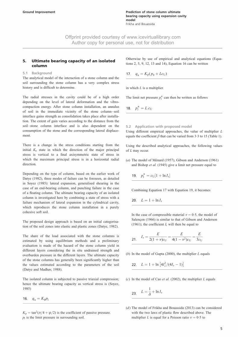
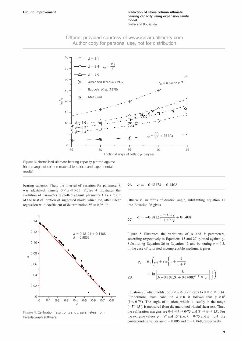
Figure 3 compares the empirical results and measured normalised
bearing capacity (qu/cU) as a function of the frictional angle of
stone material. It shows the empirical correlations over the
estimate (qu/cU) for reinforced clayey soil by a stone column.
The closed boundary of the measured bearing capacity of the
stone column is obtained in the range of values L ¼ 2.4 and
L ¼ 3.6. The best fit of the multiplier L (¼ �) as mentioned in
Figure 3 is equal to 3.1 with a coefficient of determination
R2 ¼ 0.49. The ultimate bearing capacity is then
qu
cU
¼ (3.1þ p0 ) Kp25:
The correlation in Equation 3 proposed by Amar and Jezequel
(1972) gives an underestimated bearing capacity because this
correlation is only valid for p�l . 300 kPa; that is not the case of
the considered experimental data (p�l , 300 kPa).
In turn, the non-linear empirical relation Equation 4, proposed by
Baguelin et al. (1978), overestimates the bearing capacity of the
isolated column. (Figure 3)
From Figure 3, the incompatibility between empirical results and
measurements from loading tests can be explained, the more
likely, by the uncertainty of the used correlation for the soft
Bangkok clay where Bergado and Lam (1987) performed their
trial tests.
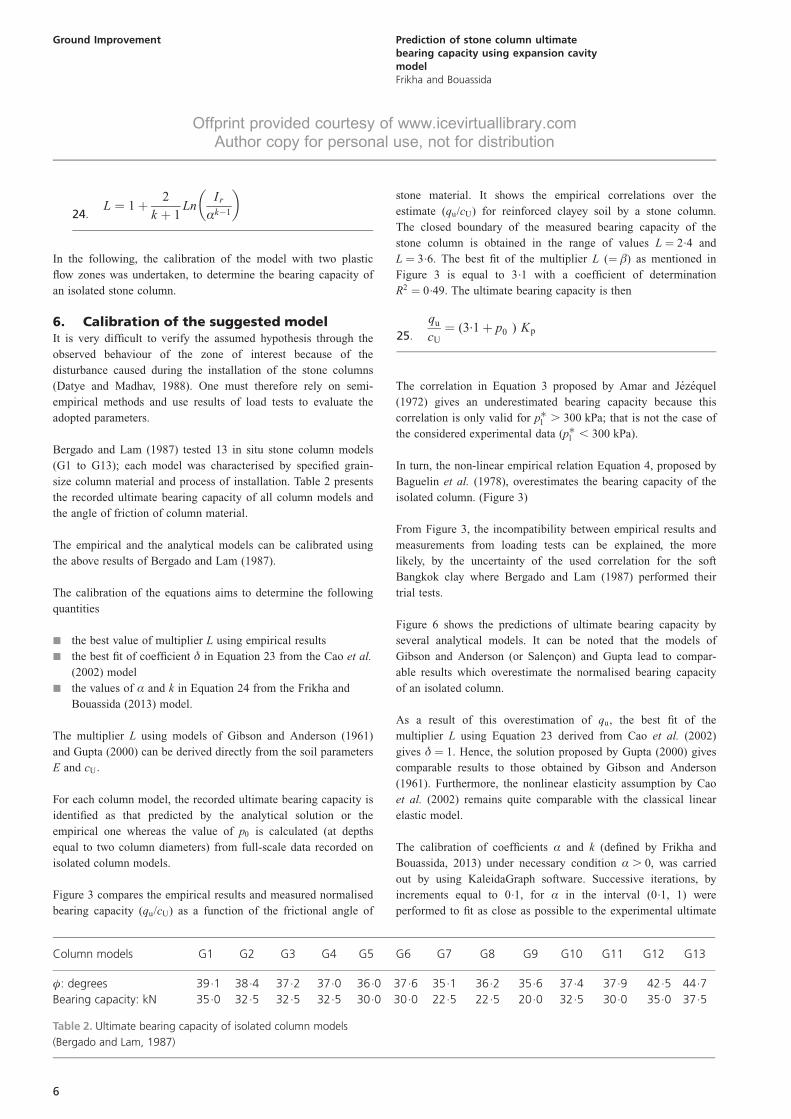
Figure 6 shows the predictions of ultimate bearing capacity by
several analytical models. It can be noted that the models of
Gibson and Anderson (or Salencon) and Gupta lead to compar-
able results which overestimate the normalised bearing capacity
of an isolated column.
As a result of this overestimation of qu, the best fit of the
multiplier L using Equation 23 derived from Cao et al. (2002)
gives � ¼ 1. Hence, the solution proposed by Gupta (2000) gives
comparable results to those obtained by Gibson and Anderson
(1961). Furthermore, the nonlinear elasticity assumption by Cao
et al. (2002) remains quite comparable with the classical linear
elastic model.
The calibration of coefficients Æ and k (defined by Frikha and
Bouassida, 2013) under necessary condition Æ . 0, was carried
out by using KaleidaGraph software. Successive iterations, by
increments equal to 0.1, for Æ in the interval (0.1, 1) were
performed to fit as close as possible to the experimental ultimate
Column models G1 G2 G3 G4 G5 G6 G7 G8 G9 G10 G11 G12 G13
�: degrees 39.1 38.4 37.2 37.0 36.0 37.6 35.1 36.2 35.6 37.4 37.9 42.5 44.7
Bearing capacity: kN 35.0 32.5 32.5 32.5 30.0 30.0 22.5 22.5 20.0 32.5 30.0 35.0 37.5
Table 2. Ultimate bearing capacity of isolated column models
(Bergado and Lam, 1987)
6
Ground Improvement Prediction of stone column ultimatebearing capacity using expansion cavitymodelFrikha and Bouassida
Offprint provided courtesy of www.icevirtuallibrary.comAuthor copy for personal use, not for distribution
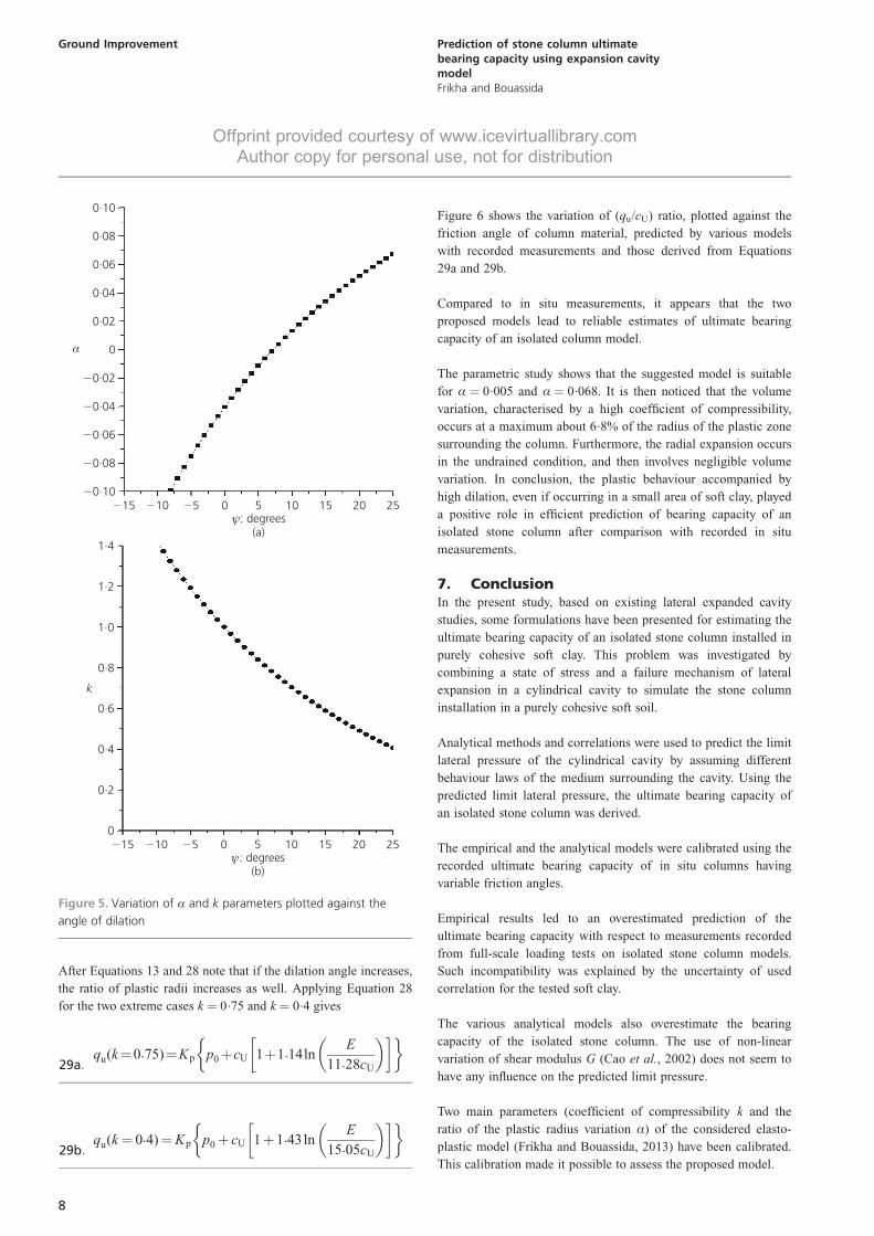
bearing capacity. Then, the interval of variation for parameter k
was identified, namely 0 , k < 0.75. Figure 4 illustrates the
evolution of parameter Æ plotted against parameter k as a result
of the best calibration of suggested model which led, after linear
regression with coefficient of determination R2 ¼ 0.98, to
Æ ¼ �0.1812k þ 0.140826:
Otherwise, in terms of dilation angle, substituting Equation 15
into Equation 26 gives
Æ ¼ �0.18121� sinł
1þ sinłþ 0.1408
27:
Figure 5 illustrates the variations of Æ and k parameters,
according respectively to Equations 15 and 27, plotted against ł.
Substituting Equation 26 in Equation 13 and by setting � ¼ 0.5,
in the case of saturated incompressible medium, it gives
qu ¼ Kp p0 þ cU 1þ 2
1þ k
��
3 lnE
3(�0.1812k þ 0.1408)k�1 3 cU
� ��28:
Equation 28 which holds for 0 , k < 0.75 leads to 0 < Æ < 0.14.
Furthermore, from condition Æ . 0 it follows that ł > 88
(k < 0.75). The angle of dilation, which is usually in the range
[�58; 158], is measured from the undrained triaxial shear test. Thus,
the calibration margins are 0.4 < k < 0.75 and 88 < ł < 158. For
the extreme values ł ¼ 88 and 158 (i.e. k ¼ 0.75 and k ¼ 0.4) the
corresponding values are Æ ¼ 0.005 and Æ ¼ 0.068, respectively.
0
5
10
15
20
25
30
35
40
25 30 35 40 45
qc
uu
/
Frictional angle of ballast : degreesφ
cU �p*
10l
� 25 kPa
c pU l0·750·67( *)�
� 3·1�
� 2·4�
� 3·6�
Amar and Jézéquel (1972)
Baguelin . (1978)et al
Measured
cU �p*l�
� 3·6�
� 3·1�
� 2·4�
Figure 3. Normalised ultimate bearing capacity plotted against
friction angle of column material (empirical and experimental
results)
0
0·02
0·04
0·06
0·08
0·10
0·12
0·14
0 0·1 0·2 0·3 0·4 0·5 0·6 0·7 0·8
α
k
α 0·1812 0·14080·9805
� ��
kR
Figure 4. Calibration result of Æ and k parameters from
KaleidaGraph software
7
Ground Improvement Prediction of stone column ultimatebearing capacity using expansion cavitymodelFrikha and Bouassida
Offprint provided courtesy of www.icevirtuallibrary.comAuthor copy for personal use, not for distribution
After Equations 13 and 28 note that if the dilation angle increases,
the ratio of plastic radii increases as well. Applying Equation 28
for the two extreme cases k ¼ 0.75 and k ¼ 0.4 gives
qu(k¼0.75)¼Kp p0þcU 1þ1.14lnE
11.28cU
� � �� �29a:
qu(k¼ 0.4)¼Kp p0þ cU 1þ1.43lnE
15.05cU
� � �� �29b:
Figure 6 shows the variation of (qu/cU) ratio, plotted against the
friction angle of column material, predicted by various models
with recorded measurements and those derived from Equations
29a and 29b.
Compared to in situ measurements, it appears that the two
proposed models lead to reliable estimates of ultimate bearing
capacity of an isolated column model.
The parametric study shows that the suggested model is suitable
for Æ ¼ 0.005 and Æ ¼ 0.068. It is then noticed that the volume
variation, characterised by a high coefficient of compressibility,
occurs at a maximum about 6.8% of the radius of the plastic zone
surrounding the column. Furthermore, the radial expansion occurs
in the undrained condition, and then involves negligible volume
variation. In conclusion, the plastic behaviour accompanied by
high dilation, even if occurring in a small area of soft clay, played
a positive role in efficient prediction of bearing capacity of an
isolated stone column after comparison with recorded in situ
measurements.
7. ConclusionIn the present study, based on existing lateral expanded cavity
studies, some formulations have been presented for estimating the
ultimate bearing capacity of an isolated stone column installed in
purely cohesive soft clay. This problem was investigated by
combining a state of stress and a failure mechanism of lateral
expansion in a cylindrical cavity to simulate the stone column
installation in a purely cohesive soft soil.
Analytical methods and correlations were used to predict the limit
lateral pressure of the cylindrical cavity by assuming different
behaviour laws of the medium surrounding the cavity. Using the
predicted limit lateral pressure, the ultimate bearing capacity of
an isolated stone column was derived.
The empirical and the analytical models were calibrated using the
recorded ultimate bearing capacity of in situ columns having
variable friction angles.
Empirical results led to an overestimated prediction of the
ultimate bearing capacity with respect to measurements recorded
from full-scale loading tests on isolated stone column models.
Such incompatibility was explained by the uncertainty of used
correlation for the tested soft clay.
The various analytical models also overestimate the bearing
capacity of the isolated stone column. The use of non-linear
variation of shear modulus G (Cao et al., 2002) does not seem to
have any influence on the predicted limit pressure.
Two main parameters (coefficient of compressibility k and the
ratio of the plastic radius variation Æ) of the considered elasto-
plastic model (Frikha and Bouassida, 2013) have been calibrated.
This calibration made it possible to assess the proposed model.
�0·10
�0·08
�0·06
�0·04
�0·02
0
0·02
0·04
0·06
0·08
0·10
�15 �10 �5 0 5 10 15 20 25
α
ψ: degrees(a)
0
0·2
0·4
0·6
0·8
1·0
1·2
1·4
�15 �10 �5 0 5 10 15 20 25
k
ψ: degrees(b)
Figure 5. Variation of Æ and k parameters plotted against the
angle of dilation
8
Ground Improvement Prediction of stone column ultimatebearing capacity using expansion cavitymodelFrikha and Bouassida
Offprint provided courtesy of www.icevirtuallibrary.comAuthor copy for personal use, not for distribution

REFERENCES
Aboshi H, Ichimoto E, Harada K and Enoki M (1979) The
compozer: a method to improve characteristics of soft clays
by inclusion of large diameter sand columns. Proceedings of
the International Symposium ‘Reinforcement of Soils’, ENPC-
LCPC, Paris, pp. 211–216.
Amar S and Jezequel FJ (1972) Essais en place et en laboratoire
sur sols coherents comparaison des resultats. Bulletin de
Laboratoire Central des Ponts et Chausees 58: 97–108, (in
French).
Amar S, Clark BGF, Gambin MP and Orr TLL (1991) Utilisation
des resultats des essais pressiometriques pour le
dimensionnement des fondations en Europe. In Rapport sur
l’Etat des Connaissances Etablies par le Comite Technique
Europeen de la SIMSTF, Comite Technique Regional
Europeen n84, 1ere Partie: Pressiometre Menard et
Pressiometre Autoforeur. A. A. Balkema, Rotterdam, the
Netherlands, pp. 25–48 (in French).
Baguelin F, Jezequel JF and Shields DH (1978) The Pressuremeter
and Foundation Engineering, 1st edn, Vol. 2, Series on Rock
and Soil Mechanics. Trans Tech Publications, Clausthal,
Germany.
Balaam NP and Booker JR (1985) Effect of stone column yield on
settlement of rigid foundations in stabilized clay.
International Journal of Numerical Analysis Methods in
Geomechanics 9(4): 331–351.
Bergado DT and Lam FL (1987) Full scale load test on granular
piles with different densities and different proportions of
gravel and sands on soft Bangkok clay. Soils and Foundations
27(1): 86–93.
Bishop RF, Hill R and Mott NF (1945) Theory of indentation and
hardness tests. Proceedings of the Physical Society 57(3):
147–159.
Bouassida M and Frikha W (2007) Extreme pressure due to the
expansion of a cylindrical or spherical cavity in limitless
medium: applications in soil mechanics. Acta Geotechnica
2(2): 87–96.
Bouassida M and Hadhri T (1995) Extreme load of soils
reinforced by columns: the case of an isolated column. Soils
and Foundations 35(1): 21–36.
Bouassida M and Jellali B (2002) Capacite portante d’un sol
renforce par une tranchee. Revue Francaise de Genie Civil
6(7–8): 1381–1395 (in French).
Cao LF, Teh CI and Chang M-F (2002) Analysis of undrained
cavity expansion in elasto-plastic soils with non-linear
elasticity. International Journal for Numerical and Analytical
Methods in Geomechanics 26(1): 25–52.
Carter JP, Booker JR and Yeung SK (1986) Cavity expansion in
cohesive frictional soils. Geotechnique 36(2): 349–358.
Cassan M (1978) Les Essais in Situ en Mecanique des Sols,
Editions Eyrolles, Paris, France, vol. 1 and 2.
Chadwick P (1959) The quasi-static expansion of a spherical
cavity in metal and ideal soils. Part I. Quarterly Journal of
Mechanics and Applied Mathematics 12(1): 52–71.
Clarke B (1995) Pressuremeters in Geotechnical Design. Blackie
Academic and Professional, Chapman & Hall, London, UK.
Ménard (1957); Gibson and Anderson (1961);Bishop (1945); Salençon (1966)et al.
Frikha and Bouassida (2013); 0·068, 0·4α � �k
Frikha and Bouassida (2013); 0·005, 0·75α � �k
Cao (2002); 0·5δ �et al.
Cao (2002); 0·9δ �et al.
Gupta (2000)
Measured
5
10
15
20
25
30
35
25 30 35 40 45
qc
uu
/
Frictional angle of ballast : degreesφ
Figure 6. Normalised ultimate bearing capacity plotted against
friction angle of column material (analytical and experimental
results)
9
Ground Improvement Prediction of stone column ultimatebearing capacity using expansion cavitymodelFrikha and Bouassida
Offprint provided courtesy of www.icevirtuallibrary.comAuthor copy for personal use, not for distribution
Datye KR (1982) Settlement and bearing capacity of foundation
system with stone columns. Proceedings of the Symposium on
Soil and Rock Improvement Techniques including Geotextiles,
Reinforced Earth and Modern Piling Methods, AIT–
Bangkok, pp. 1–27, A1.
Datye KR and Madhav MR (1988) Case histories of foundations
with stone columns. Proceedings of the 2nd International
Conference on Case Histories in Geotechnical Engineering,
St. Louis, MO, June 1–5, Paper No. 5. 37.
Frikha W and Bouassida M (2013) Cylindrical cavity expansion
in elastoplastic medium with a variable potential flow.
International Journal of Geomecanics, ASCE 13(1): 9–15.
Frikha W, Bouassida M and Canou J (2013) Observed behaviour
of laterally expanded stone column in soft soil. Geotechnical
and Geological Engineering 31(2): 739–752, http://
dx.doi.org/10.1007/s10706–013–9624–8.
Gibson RE and Anderson WF (1961) In situ measurement of soil
proprieties with the pressuremeter. Civil Engineering and
Public Review 56(658): 615–618.
Greenwood DA (1970) Mechanical improvement of soils below
ground surface. Proceedings of the Ground Engineering
Conference, Institution of Civil Engineering, London,
pp. 9–20.
Gupta RC (2000) An approach for estimating deformation moduli
from self-boring pressuremeter test data. Soils and
Foundations Japaneese Geotechnical Society 40(1): 23–33.
Hill R (1950) The expansion of a spherical shell. In The
Mathematical Theory of Plasticity. Oxford Classic Texts in
the Physical Sciences. Clarendon Press, Oxford, UK.
Houlsby GT and Withers NJ (1988) Analysis of cone pressuremeter
test in clay. Geotechnique 38(4): 575–587.
Hughes JMO, Withers NJ and Greenwood DA (1975) A field trial
of reinforcing effects of stone columns in soil. Geotechnique
25(1): 31–44.
Ladanyi B (1963) Expansion of a cavity in saturated clay
medium. Journal of Soil Mechanics and Foundation
Engineering Division, ASCE 89(SM 4): 127–161.
Lame G (1852) Lecons sur la Theorie Mathematique de
l’Elasticite des Corps Solides. Bachelier, Paris, France.
Lukas GL and LeClerc de Bussy B (1976) Pressuremeter and
laboratory test correlations for clays. Journal of Geotechnical
Engineering Division, ASCE 102(GT9): 954–963.
Manassero B (1989) Stress–strain relationships from drained self-
boring pressuremeter test in sands. Geotechnique 39(2): 293–
307.
Marsland A and Randolph MF (1977) Comparison on the results
from pressuremeter tests and large in situ plate test in London
clay. Geotechnique 27(2): 217–243.
Martin RE and Drahos EG (1986) Pressuremeter correlations for
preconsolidated clay. Proceedings of the In Situ’86 Use of In
Situ Tests in Geotechnical Engineering, Blacksburg, VA, pp.
206–220.
Mecsi J (1991) Stresses, displacements, volume changes around
the expansion cylinder in the soil. Proceedings of 10th
European Conference on Soil Mechanics and Foundation
Engineering, Florence, Italy, 26–30 May, pp. 243–246
Menard L (1957) Mesures in situ des proprietes physiques des
sols. Annales des Ponts et Chaussees 127(14): 357–376.
Salencon J (1966) Expansion quasi-statique d’une cavite a
symetrie spherique ou cylindrique dans un milieu
elastoplastique. Annales des Ponts et Chaussees 3(May–
June): 175–187.
Soyez B (1985) Methodes de dimensionnement des colonnes
ballastees. Bulletin de Laboratoire Central des Ponts et
Chausees 135(Jan–Feb): 35–51.
Van Impe W and De Beer E (1983) Improvement of settlement
behaviour of soft layers by means of stone columns.
Proceedings of the 8th European Conference on Soil
Mechanics and Foundation Engineering, Helsinki, vol. 1, pp.
309–312.
Vesic AS (1972) Expansion of cavities in infinite soil mass.
Journal of Soil Mechanics and Foundations Division, ASCE
2(3): 451–457.
Windle D and Wroth CP (1977) The use of a self-boring
pressuremeter to determine the undrained properties of clays.
Ground Engineering 10(6): 37–46.
Yu HS and Houlsby GT (1991) Finite cavity expansion in dilatant
soils: loading analysis. Geotechnique 41(2): 173–183.
WHAT DO YOU THINK?
To discuss this paper, please email up to 500 words to the
editor at [email protected]. Your contribution will be
forwarded to the author(s) for a reply and, if considered
appropriate by the editorial panel, will be published as a
discussion in a future issue of the journal.
Proceedings journals rely entirely on contributions sent in
by civil engineering professionals, academics and students.
Papers should be 2000–5000 words long (briefing papers
should be 1000–2000 words long), with adequate illustra-
tions and references. You can submit your paper online via
www.icevirtuallibrary.com/content/journals, where you
will also find detailed author guidelines.
10
Ground Improvement Prediction of stone column ultimatebearing capacity using expansion cavitymodelFrikha and Bouassida
Offprint provided courtesy of www.icevirtuallibrary.comAuthor copy for personal use, not for distribution