Embed Size (px)
Citation preview

PRACT CAL PHYS CS
H ENRY S . CA RH A RT , S C.D . , L L .D .
FO RMEREY PROFESSO R O F PH Y S ICS , UN I VERS IT Y O F MICH IGA N
A ND
H ORA T IO N . CH U T E, M .S .
INST RUCT OR IN P HY S ICS IN T H E A NN ARBOR H IGH SCHOOL
A LLY N A ND BAC O NBOSTON NEW YORK CH ICAGO
SAN FRANCISCO
COPYR IGH T . 1 920 , BY
H ENRY S . CARHART AND
H ORAT IO N. CH UT E
RDR
Norinoon 15minJ. S . Cushing Co.
—Berwick Smith Co .
Norwood , Mass . , U .S .A .
PREFACE
P ractical P hysics aims above all things to justify its title.
In introducing an exceptional ly large number of appl ications,the authors have not lost sight of the fact that the most prao
tical ~ book is the one from which the pupil can most easilylearn .
To secure this practical qual ity, the material is presented inthe simplest and clearest language short sentences and
paragraphs, terse statements,careful exp lanations, and an in
ductive development of each principle. The subject matteris logical ly arranged in the order fol lowed by most secondaryschools. Each pr inciple is il lustrated not only by diagrams
,
problems,and questions, but by its most str iking app l ications .
While the number of these practical appl ications is un
usual ly large, nothing has been included merely because it issensational ; every appl ication il lustrates some principletreated in the book. The utmost care has been taken to keepthewholework within easy range of the average pupi l
’s abil ity
,
and to prov ide material that can be easily mastered in a schoolyear .
TheWor ld War has emphasized once more the universal ityof physics. This universal ity is brought out in P ractical
Physics from thevery outset,always, however , with care that
the pupil understand the basic physical principles which underlie each appl ication.
July 4, 1 920.
459995

CONTENTS
C hapter I. IlltI'OdllCfiOIl P A GE
I . Matter and EnergyII . Properties of Matter
III . Physical Measurements
Chapter II. Molecular Physics
I. Molecular Motion
II. Surface PhenomenaIII . Molecular Forces in Solids
Chapter III . Mechanics of Fluids
I. Pressure of FluidsII . Bodies Immersed in L iquidsIII . Density and Specific GravityIV. Pressure of the A tmosphereV. Compression and Expansion of
VI . Pneumatic A ppliances
Chapter IV. Motion
I . Motion in Straight L inesII . Curvilinear Motion
III . S imple H armonic Motion
Mechanics of S olids
Measurement of ForceComposition of Forces and of VelocitiesNewton’
s Laws of MotionGravitationFalling BodiesCentripetal and Centrifugal ForceThe Pendulum
VI CON TEN TS
PA GE
I . Work and EnergyII . Machines
Chapter VII . Sound
I . Wave MotionII . Sound and its T ransmissionIII. Velocity of SoundIV. Reflection of SoundV. ResonanceVI . Characteristics of Musical SoundsVII. Interference and Beats
VIII . Musical S calesIX. Vibration of StringsX. Vibration of A ir in PipesXI. Graphic and Optical Methods
Chapter VIII . Light
I. Nature and T ransmission of L ightII . PhotometryIII . Reflection of L ightIV. Refraction of L ightV. Lenses
‘VI . Optical Instruments
VII . DispersionVIII. ColorIX. Interference and Diffraction
Chapter IX. H eat
I . H eat and TemperatureII . T he T hermometer
III . ExpansionIV. Measurement of H eatV. Change of State
VI. T ransmission of H eat
VII. H eat and Work
CON TEN TS
Chapter X. Magnetism
I. Magnets and Magnetic A ctionII. Nature of ~Magnetism
III. The Magnetic FieldIV. Terrestrial Magnetism
Chapter XI . Electrostatics
I . ElectrificationII . Electrostatic InductionIII. Electrical DistributionIV. Electric Potential and CapacityV. Electrical MachinesVI . A tmospheric Electricity
Chapter XII. Electric Currents
I . Voltaic CellsII . ElectrolysisIII . Ohm
’
s Law and its A pplicationsIV. H eating Effects of a CurrentV. Magnetic Properties of a CurrentVI . Electromagnets
VII . Measuring Instruments
Chapter XIII . Electromagnetic Induction
I . Faraday’s DiscoveriesII. Self-InductionIII . T he Induction CoilIV. Rad ioactivity and Electrons
Chapter XIV. Dynamo-ElectricMachinery
I . Direct Current MachinesII . A lternators and T ransformers
III . Electric L ightingIV. The Electric T elegraphV. The T elephoneVI . Wireless T elegraphy
CON TEN TS
Chapter XV. TheMotor Car
I. The EngineII . T he Storage BatteryIII . T he Chassis and Running GearIV. T he BrakeV. T he ClutchVI . T ransmission and Differential
T he Steering DeviceT he Starter
IX . On the RoadX. T he Pedestrian
Appendix
I. Geometrical ConstructionsII . Conver sion T ablesIII . Mensuration RulesIV. T ab le of DensitiesV. Geometrical Construction for Refraction of
Index
FULL PAGE ILLUSTRATIONS
Four Color Process Printing
Electric Welding .
Bureau of Standards, WashingtonCommon CrystalsGalileo GalileiBlaise PascalElephant Butte DamDry Dock Dewey ”
H ydro-airplanesMotion and ForceS ir Isaac NewtonY osemite FallCentrifugal ForcePisa CathedralUnited States 1 6-inch GunLord KelvinLord RayleighPhotographs of Sound WavesEcho BridgeH ermann von H elmholtzNiagara Falls Power P lantParabolic Mirror at Mount WilsonMoving Picture FilmVarious Spectr aBridge over the Firth of ForthJamesWatt
James Prescott JouleA Row of Cor liss EnginesFour-valve EngineSection and Rotor of Steam T ur bineFront and Rear Views of A irplaneBenjamin Franklin
X FULL P A GE ILL U S TRA TION 8
FA CING
H ans Christian OerstedA lessandro VoltaGeorg S imon Ohm
James Clerk-MaxwellJoseph H enryMichael FaradayS ir William CrookesWilhelm Konr ad RoentgenMadame Cur ieS ir Joseph John T homson
Field Magnet and Drum A rmature of D . C. Generator
Electr ic Engine Crossing the RockiesA rmature Core and Field Magnet of A . C. Generator
Dam and Power H ouse, Great Falls, Montana
T ransformers and SwitchesStator and Field of A . C. Generator
Stator of T hr ee-phaseMotor and Motor CompleteA lexander Graham Bel lSamuel F . B. Morse
Field Wireless of the United States A rmyWireless Room m a T ransatlantic L inerH einrich Rudolf H ertzT homas A lva EdisonGuglielmo Marconi
CH A PT ER I
INTRODUCT ION
I . MA TTER AND ENERGY
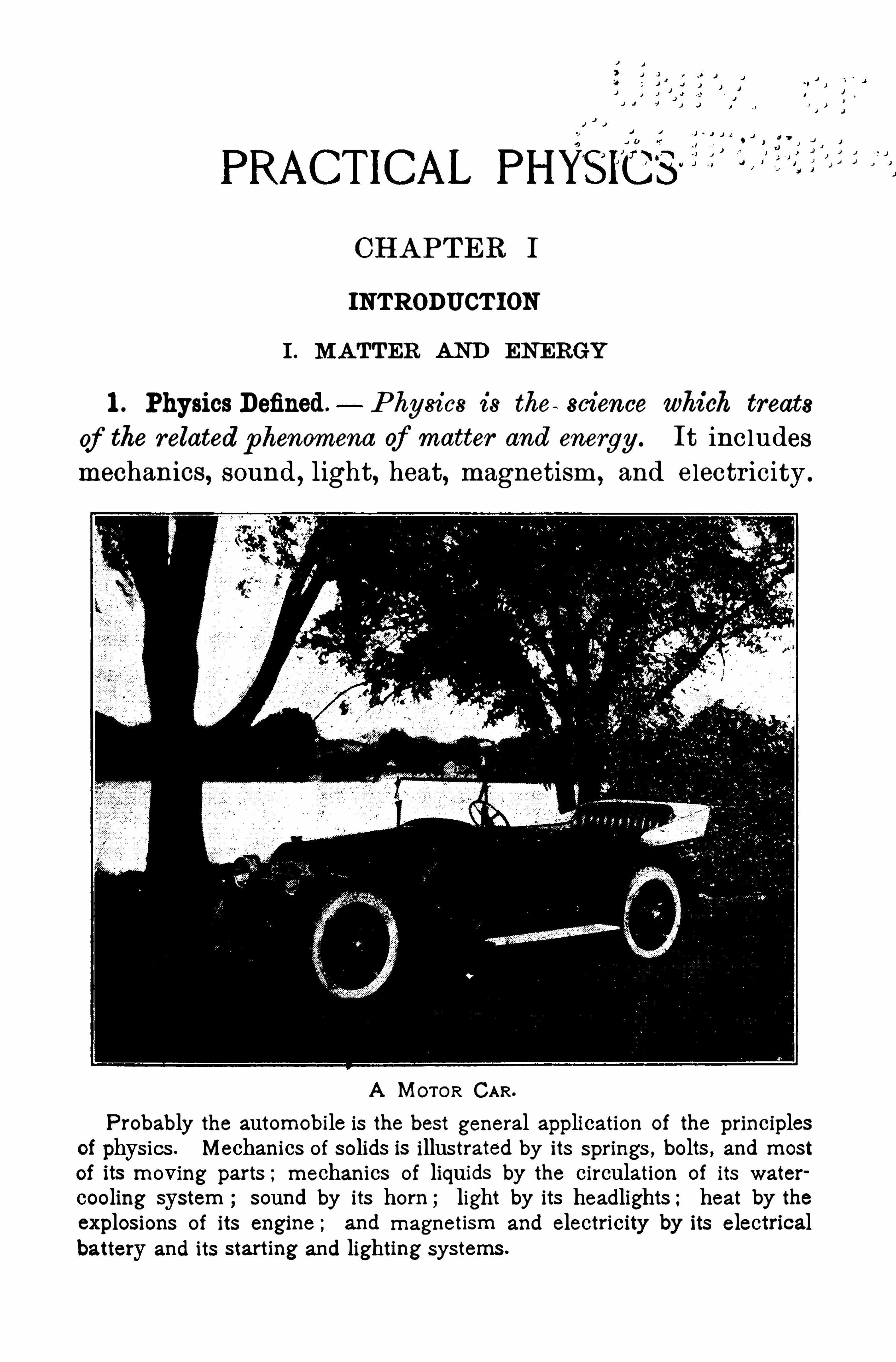
1 . Physics Defined. P hysics is the science which treats
of the related phenomena of matter and energy . It includesmechanics, sound , light, heat, magnetism, and electr icity .
A MOTOR CAR.
Probably the automobile is the best general application of the principlesof physics . Mechanics of solids is illustrated by its springs , bolts , and most
of its moving parts ;mechanics of liquids by the circulation of its water
cooling system ; sound by its horn ; light by its headlights ; heat by theexplosions of its engine ; and magnetism and electricity by its electricalbattery and its starting and lighting systems .
IN TROD U CTION
Matter? and bes ieryy scarcely admit of definition except
by means of their properties . Matter is everything we
can see, taste, or touch , such as earth,water , wood ,
iron,
gas—ih short, everything that occupies Space.
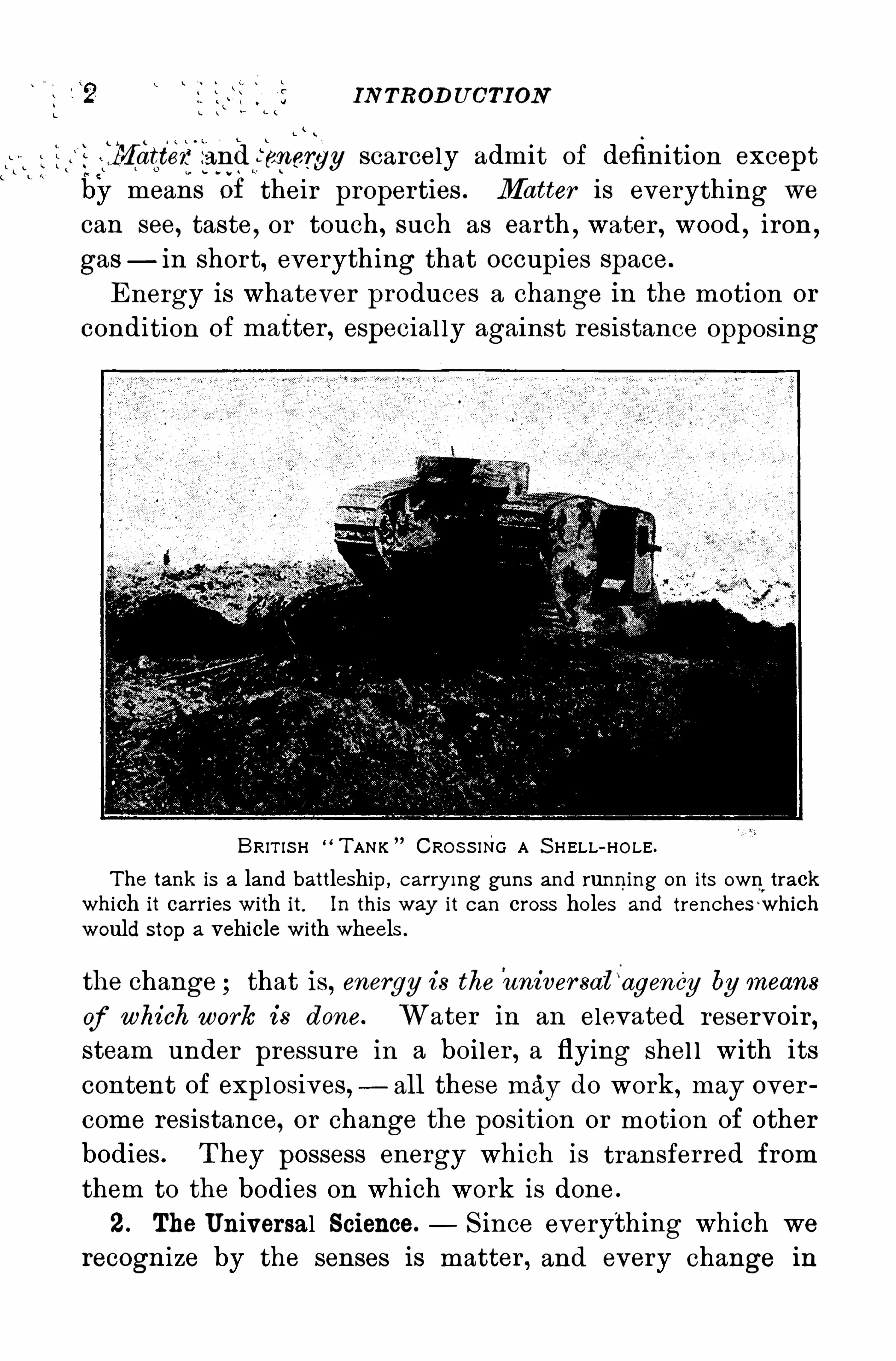
Energy is whatever produces a change in the motion or
condition of matter , especial ly against resistance opposing
BRIT IS H T ANK CRO S S ING A S HELL-HO LE.
The tank is a land battleship , carry ing guns and running on its own,
trackwhich it carries with it. In this way it can cross holes and trenches which
would stop a vehicle with wheels .
the change that is, energy is the aniver sa‘
l“agency by means
of which work is done. Water in an elevated reservoir ,steam under pressure in a boiler , a flying shel l with its
content of explosives, all these may do work ,may over
come resistance, or change the position or motion of other
bodies . T hey possess energy which is transferred from
them to the bodies on which work is done.
2. The Universal Science. S ince everything which we
recognize by the senses is matter , and every change in
TH E UN IVERS A L S CIEN CE 3
matter involves energy, it is plain that physics is a uni
versal science, touching our l ife at every point . Countless physical phenomena are taking p lace about us every
day ; a gir l cooking, a boy playing bal l , the fire-whistleblowing, the sun giv ing l ight and heat, a flag flapping in
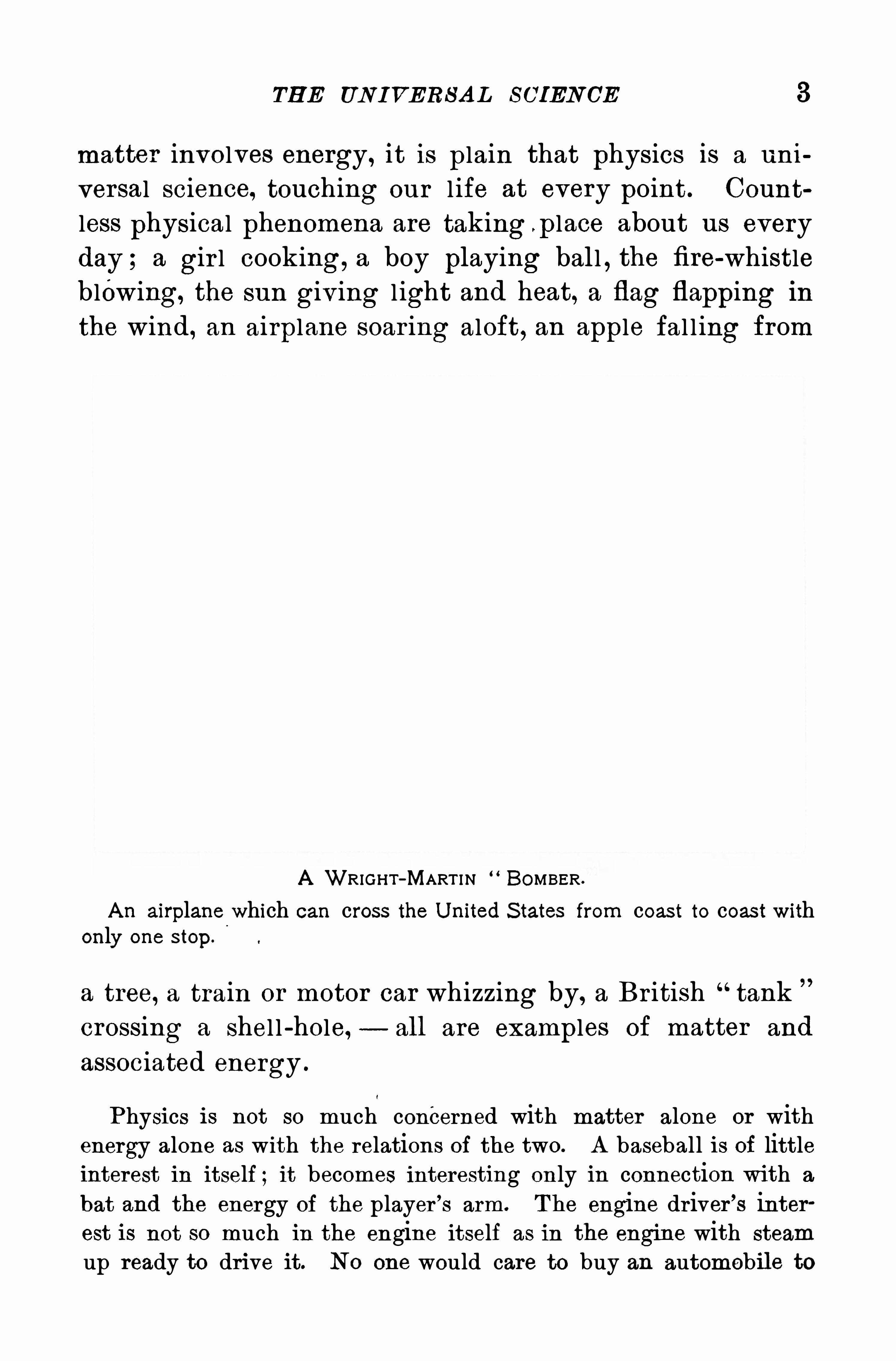
the wind , an airplane soar ing aloft, an apple fal l ing from
A WRIGHT-MART I N BOMBER .
A n airplane which can cross the U nited S tates from coast to coast withonly one step .
a tree, a train or motor car whizzing by, a Br itish tank
crossing a shel l -hole, — all are examples of matter and
associated energy .
Physics is not so much concerned with matter alone or withenergy alone as with the relations of the two. A baseball is of littleinterest in itself ; it becomes interesting on ly in connection with a
bat and the energy of the player ’
s arm. T he engine driver’
s interest is not so much in the engine itself as in the engin e with steam
up ready to drive it. N0 one would care to buy an automobile to
4 IN TROD UCTION
stand in a garage ;its attractiveness lies in the fact that it becomes
a thing of life when its motor is vitalized by the heat of combustionof gasoline vapor .
3 . Applications of the Pr inciples of Physics.— T he appli
cations of the pr inciples of physics in the household
and in the fami l iar arts are very numerous and affect us
constantly in dai ly l ife. Water under pressure is dcl ivered for domestic use, and fuel is used in the liquid or
in the gaseous form as wel l as in the solid . Electr icity
lights our houses, toasts our bread , and even cooks our
dai ly food . T he electr ic motor runs our vacuum cleanersand our sewing machines .
T he appl ications of physics in modern l ife are so nu
merous and they are changing so rapidly that we cannotexpect to learn about all of them in a year’s study ; but
physical p rinciples remain the same ; and if we acquire a
knowledge of these pr inciples and of their fami l iar appli
cations, we shal l be prepared to understand and to ex
plain other appl ications that have been made possible by
the science of physics .
So this book lays emphasis on the under lying pr inci
ples of physics, i l lustrating them by some of their inter
esting appl ications , leav ing it to the enthusiasm and
ingenuity of both teacher and pupils to supplement the
appl ications with others drawn from l ife and from scien
tific journals .
4 . States of Matter .— Matter exists in three distinct
states, exempl ified by water , which may assume either
the solid, the liquid, or the gaseous form , as ice, water , or
water vapor .
Br iefly descr ibed,
S olids have definite size and shape, and of er resistance
to any change of these.
FORCE 5
L iquids have definite size, but they take the shape of the
container and have afree surface.
Gases have neither definite size nor shape, both depending
on the container .
T hese are not all the differences between solids, liquids,and gases, but they serve to distinguish between them .
Some substances are neither wholly in the one state nor in the
other . Sealing wax softens by heat and passes gradually from the
solid to the liquid state. Shoemaker’swax breaks into fragments likea solid under the blow of a hammer , but under long-continued pressure it flows like a liquid, though slowly , and itmay be molded at will .
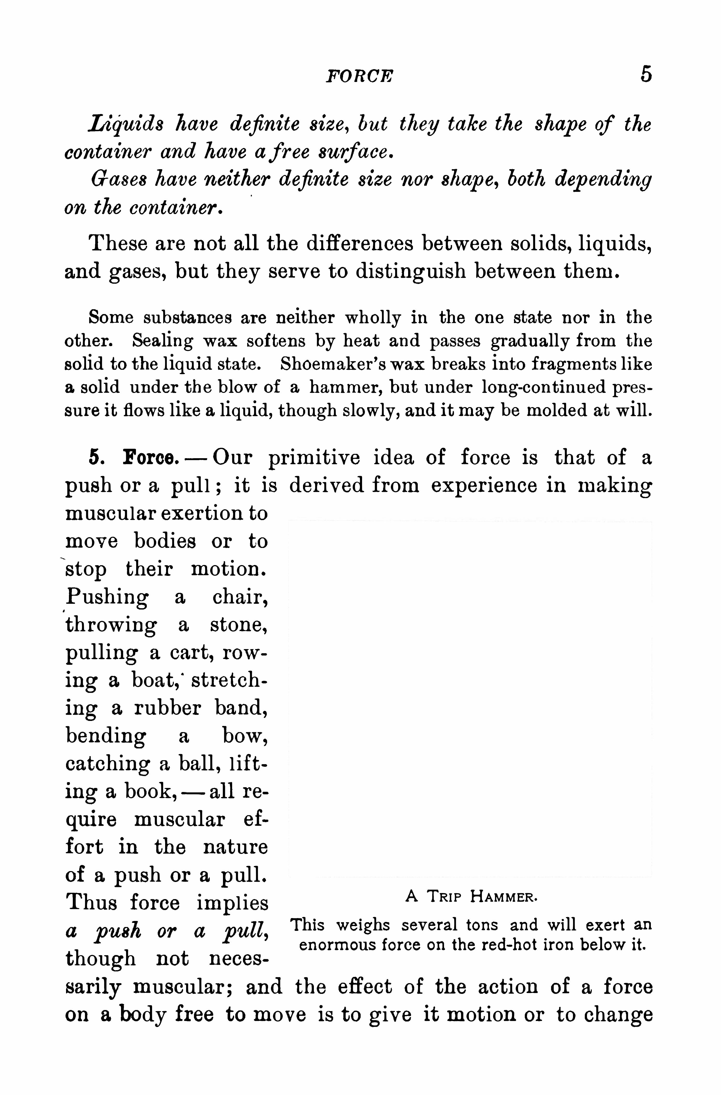
5. Force.—Our prim itive idea of force is that of a
push or a pul l ; it is derived from exper ience in makingmuscular exertion to
move bodies or to
stop their motion .
Pushing a chair ,throwing a stone,
pulling a cart, row
ing a boat,‘
stretching a rubber band ,
bending a bow,
catching a ball , l ifting a book,
—all re
qui re muscular ef
fort in the natureof a push or a pull .T hus force impl iesa push or a pull,
This weighs several tons and will exert anenormous force on the red-hot iron below it.
A T RIP H AMMER.
though not neces
sarily muscular; and the effect of the action of a force
on a body free to move is to give it motion or to change
6 IN TROD UCTION
its motion . For the present we shall make use of the
units of force familiar to us, such as the pound of forceand thegram of force, meaning thereby the forces equal
to that required to l ift the mass of a pound and that of a
gram respectively .
II . PROPERT IES OF MA TTER
6 . The Properties of Matter are those qual ities that serveto define it, as wel l as to distinguish one substance fromanother . A ll matter has extension or occupies space, and
so extension is a general proper ty of matter . On the otherhand common window glass lets l ight pass through it, or is
transparent, while a piece of sheet iron does not transmitlight, or is opaque. A watch Spr ing recovers its shape
after bending, or is elastic, whi le a str ip of lead possessesthis proper ty in so s light a degree that it is classed as in
elastic . . So we see that transparency and elasticity are
special proper ties of matter .
7 . Extension. A ll bodies have three dimensions, length ,
breadth , and thickness . A sheet of tissue paper or of gold
leaf, at first thought, appears to have but two'
dimensions,
length and breadth; but while its third' dimension is rel
atively smal l , if its thickness should actually become zero ,it would cease to be either a sheet of paper or a piece of
gold leaf. Extension is theproperty of occupying sp ace or
having dimensions.
8. Impenetrability.—While matter occupies space, no
two portions of matter can occupy the same space at the
same time. T he volume or bulk of an irregular sol id, such
as a lump of coal , may be measured by noting the volume of
liquid displaced when the solid is completely immersed in it .
The generalp rop er ty of matter that no two bodies can occupy
the same sp ace at the same time is known as impenetr ability .
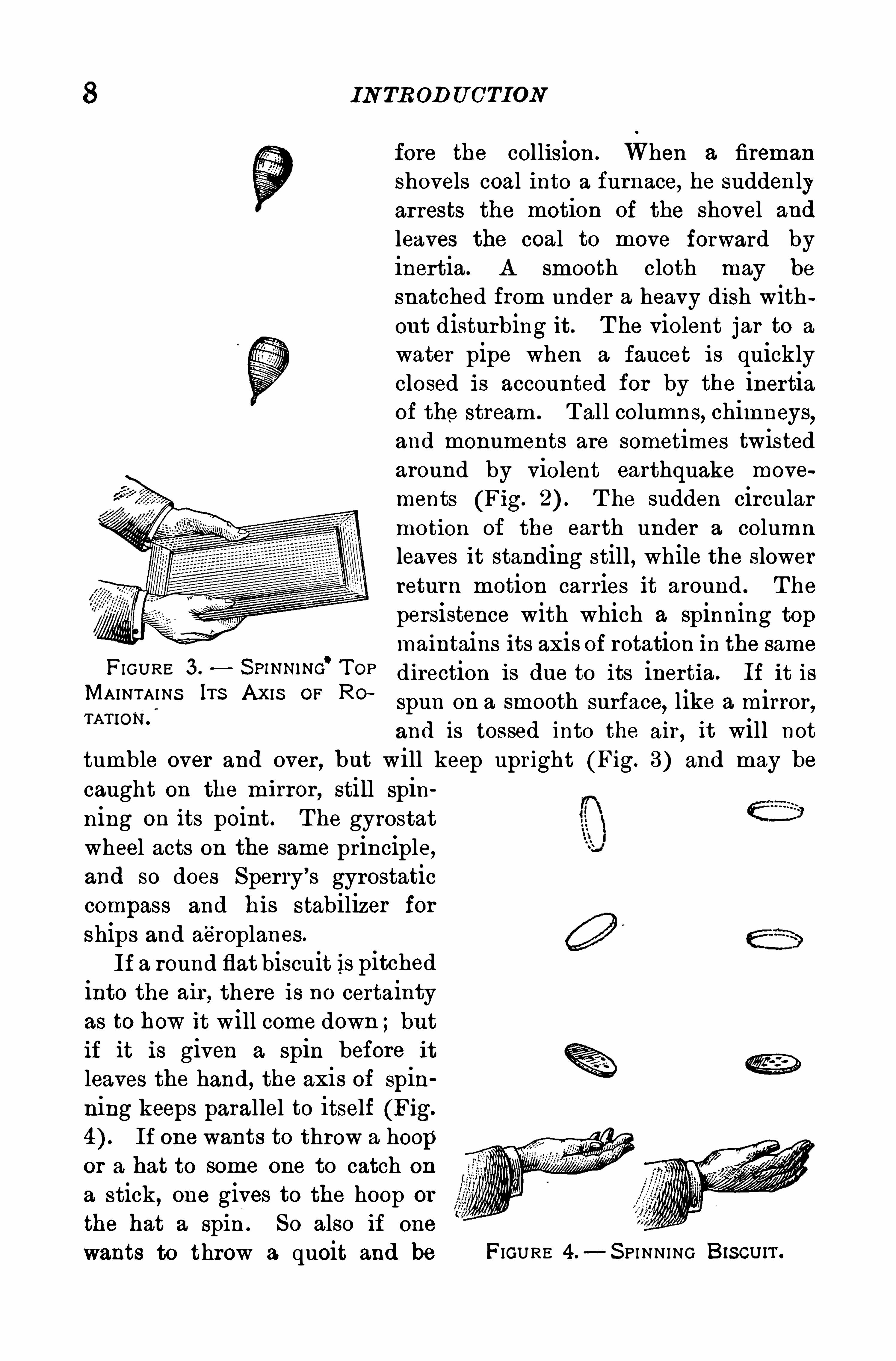
FIGURE 3 . S p inNiNG'T OP
MAINTAINS Irs AXIS OF RO
IN TROD U CTION
fore the collision . When a fireman
shovels coal into a furnace, he suddenlyarrests the motion of the shovel and
leaves the coal to move forward byinertia. A smooth cloth may be
snatched from under a heavy dish without disturbing it. T he violent jar to a
water pipe when a faucet is quicklyclosed is accounted for by the inertiaof the stream . T all columns, chimneys
,
and monuments are sometimes twistedaround by violent earthquake movements (Fig. T he sudden circularmotion of the earth under a columnleaves it standing still
,while the slower
return motion carries it around . T he
persistence with which a spinning topmaintains its axis of rotation in the same
direction is due to its inertia. If it is
spun on a smooth surface,like a mirror,
and is tossed into the air , it will not
tumble over and over , but will keep upright (Fig. 3) and may be
caught on the mirror , still spinning on its point. T he gyrostatwheel acts on the same principle,and so does Sperry’
s gyrostaticcompass and his stabilizer for
ships and aé roplanes.
If a round flat biscuit is pitchedinto the air , there is no certaintyas to how it will come down ;butif it is given a spin before it
leaves the hand, the axis of spinning keeps parallel to itself (Fig.
If one wants to throw a hoopor a hat to some one to catch on
a stick, one gives to the hoop or
the hat a spin . So also if one
wants to throw a quoit and be FIGURE 4 .- S PI NNING Biscurr.
MA S S 9
certain how it will alight, one gives it a spin. Its inertia keeps itspinning around the same axis in space .
T ie a piece of twine to a heavy weight, such as a flatiron . Bypull
ing slowly the flatiron may be lifted, but a sudden jerk on the twinewill break it because of the inertia of the weight .
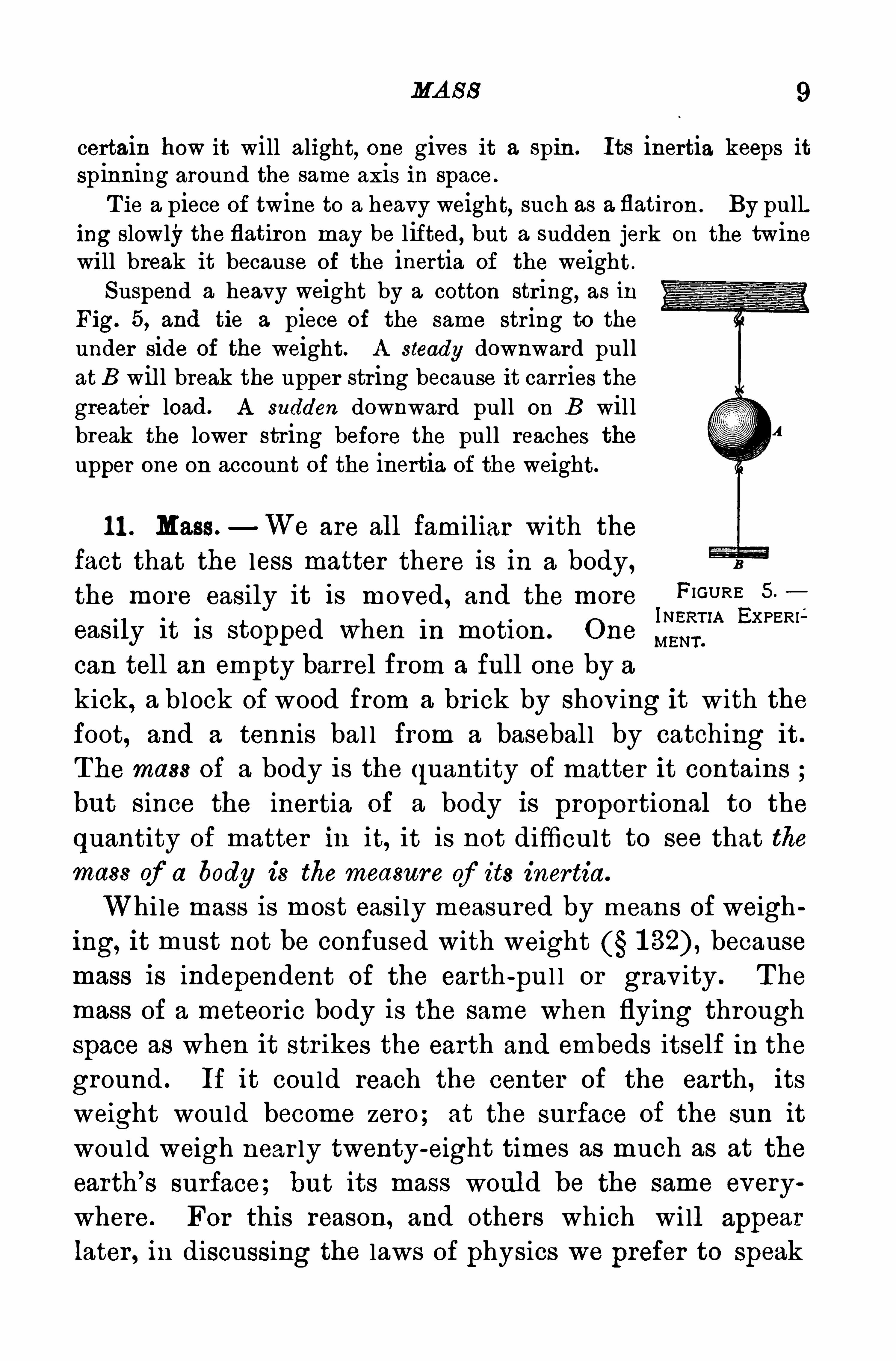
Suspend a heavy weight by a cotton string, as in
Fig. 5, and tie a piece of the same string to theunder side of the weight. A steady downward pullatB will break the upper string because it carr ies thegreater load . A sudden downward pull on B willbreak the lower string before the pull reaches theupper one on account of the inertia of the weight.
1 1 . Mass.—We are all familiar with the
fact that the less matter there is in a body,
the more easily it is moved , and the more FIGURE 5
InERr iA EKPERIeasfly i t 18 stopped when m moti on . One mam .
can tell an empty barrel from a full one by a
kick, a block of wood from a br ick by shov ing it with thefoot, and a tennis bal l from a baseball by catching it.
The mass of a body is the quantity of matter it containsbut since the inertia of a body is proportional to the
quantity of matter in it, it is not difficult to see that themass of a body is the measure of its inertia.
While mass is most easi ly measured by means of weighing, it must not be confused with weight because
mass is independent of the earth -
pul l or grav ity . T he
mass of a meteor ic body is the same when flying throughspace as when it str ikes the earth and embeds itself in the
ground . If it could reach the center of the earth, its
weight would become zero; at the surface of the sun it
would weigh near ly twenty-eight times as much as at the
earth’
s surface; but its mass woul d be the same everywhere. For this reason , and others which wi ll appear
later , in discussing the laws of physics we prefer to speak
1 0 IN TRODU CTION
of mass when a student thinks the term weight might beused as wel l .
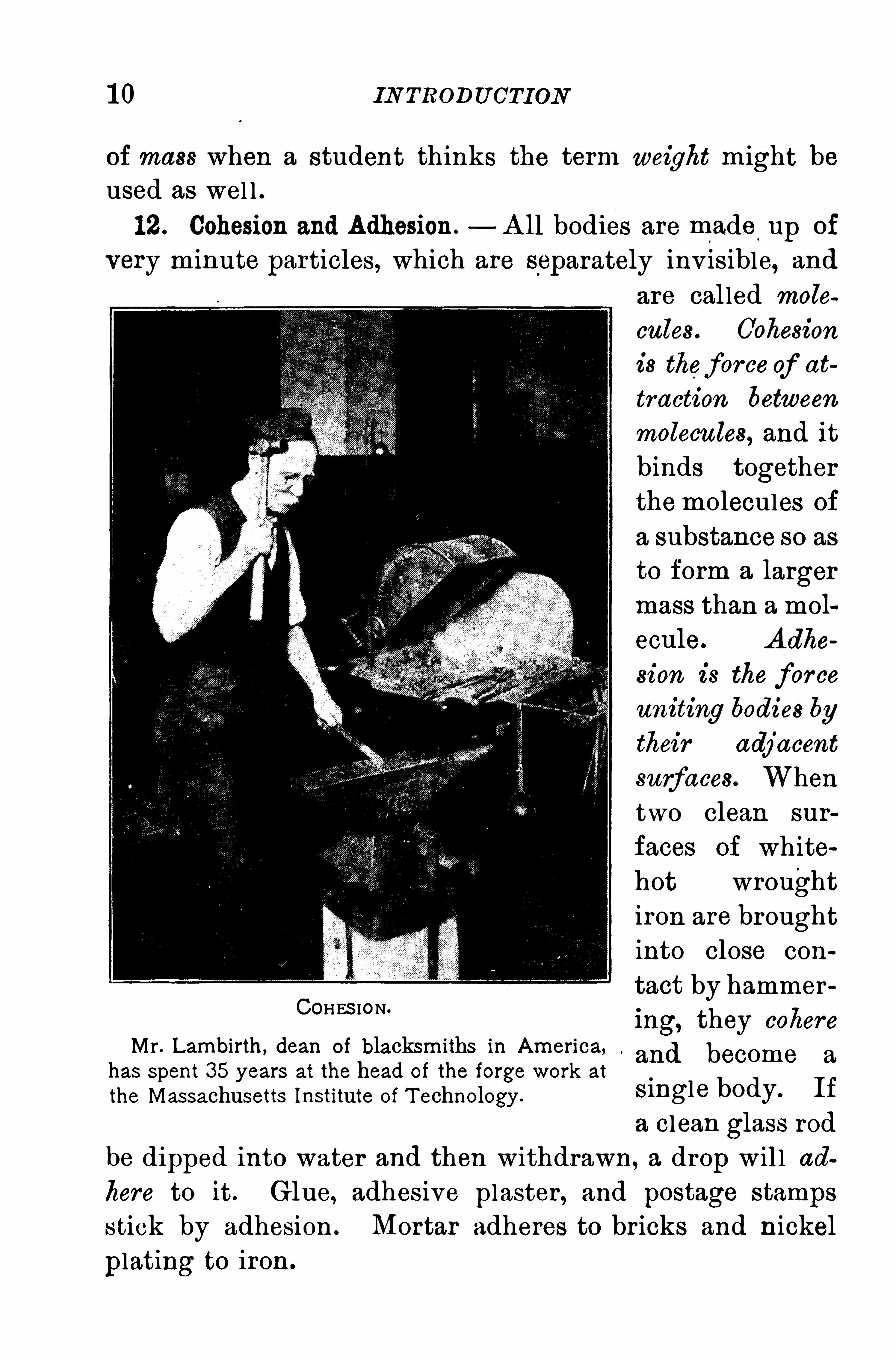
12. Cohesion and Adhesion. A ll bodies are made.
up of
very minute particles, which are separately inv isible, and
COHES ION.
Mr. Lambirth , dean of blacksmiths in America,has spent 35 years at the head of the forge work at
the Massachusetts Institute of T echnology .
are cal led molecules . Cohesion
is theforce of at
traction between
molecules, and it
binds togetherthemolecules of
a substance so as
to form a larger
mass than a mol
ecule. A dhe
sion is the forceuniting bodies by
their adjacent
surfaces. When
two clean sur
faces of whitehot wrought
iron are brought
into close con
tact by hammer
ing, they cohere'
and become a
single body. If
a clean glass rodbe dipped into water and then withdrawn, a drop will ad
here to it . Glue, adhesive plaster , and postage stamps
stick by adhesion . Mortar adheres to br icks and nickel
plating to iron.
P ORO S I T Y 1 1
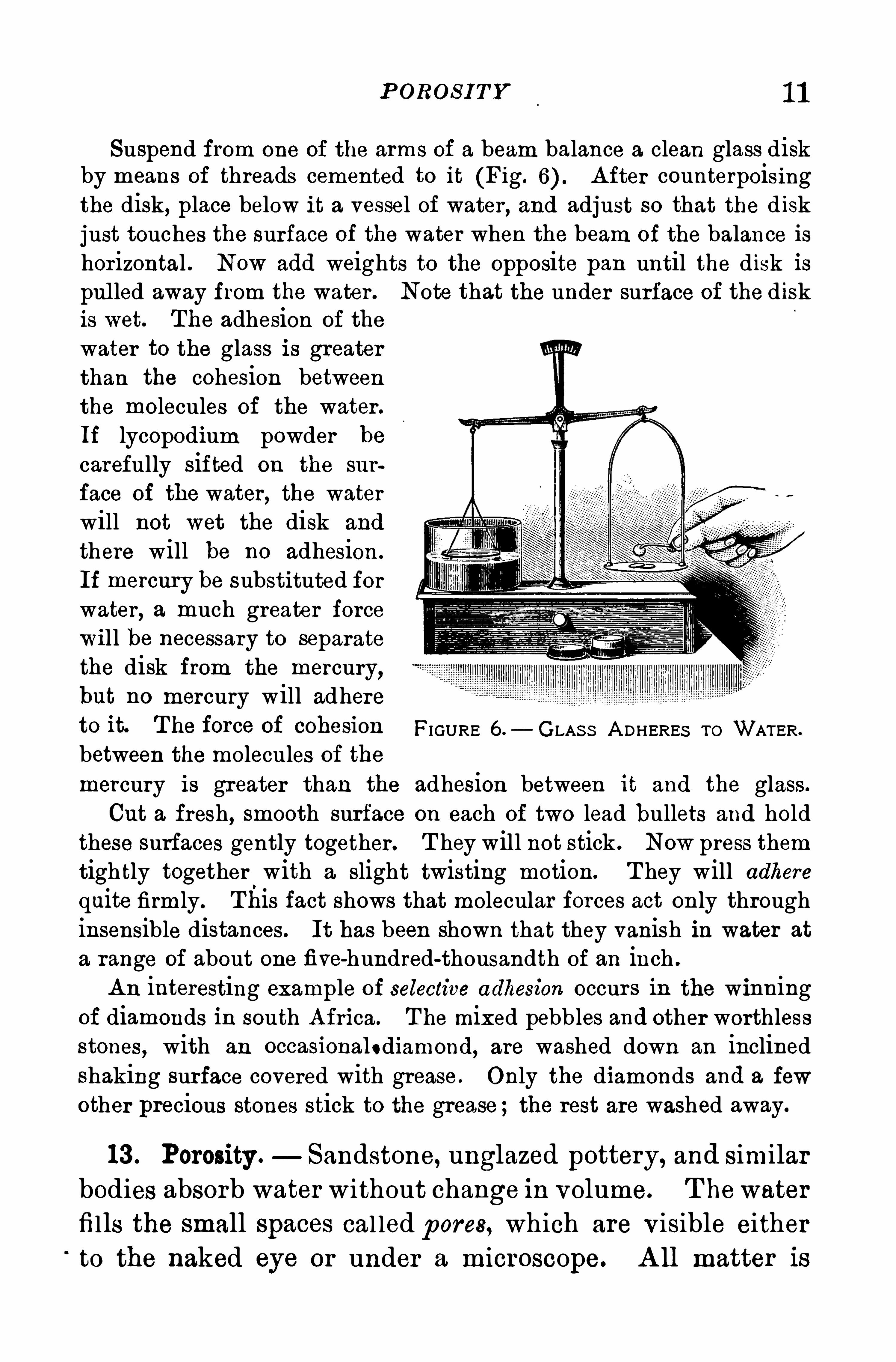
Suspend from one of the arms of a beam balance a clean glass diskby means of threads cemented to it (Fig. A fter counterpoisingthe disk, place below it a vessel of water , and adjust so that the diskjust touches the surface of the water when the beam of the balance ishorizontal . Now add weights to the opposite pan until the disk ispul led away from the water . Note that the under surface of the diskis wet. The adhesion of the
water to the glass is greaterthan the cohesion betweenthe molecules of the water .
If lycopodium powder be
carefully sifted on the sur
face of the water, the waterwill not wet the disk and
there will be no adhesion .
If mercury be substituted forwater , a much greater forcewill be necessary to separatethe disk from the mercury
,
but no mercury will adhereto it The force Of 00 11 8810 11 FIGURE — GLAS S A DHERES To WATER.
between the molecules of themercury is greater than the adhesion between it and the glass.
Cut a fresh, smooth surface on each of two lead bullets and holdthese surfaces gently together . T hey will not stick . Now press themtightly together with a slight twisting motion. T hey will adhere
quite firmly. This fact shows that molecular forces act only throughinsensible distances. It has been shown that they vanish in water at
a range of about one five-hundred-thousandth of an inch .
A n interesting example of selective adhesion occur s in the winningof diamonds in south A frica. The mixed pebbles and other worthlessstones, with an occasionalodiamond, are washed down an inclinedshaking surface covered with grease . Only the diamonds and a few
other precious stones stick to the grease ;the rest are washed away.
13 . Porosity . Sandstone, unglazed pottery, and similar
bodies absorb water without change in volume. T hewaterfills the small spaces cal led pores, which are visible eitherto the naked eye or under a microscope. A ll matter is
1 2 IN TRODU CTION
probably porous, though the pores are invisible, and the
corresponding property is cal led p orosity . In a famousxperiment in Florence many years ago, a hol low Sphereof heav i ly gi lded si lver was fil led with water and put
under pressure. T he water came through the pores of theS i lver and gold and stood in beads on the surface. FrancisBacon observed a S im i lar phenomenon with a lead sphere.
O il penetrates into marble and spreads through it. Even so densea substance as agate is porous, for it is ar tificially colored by the ah
sorption ,first of one liquid and then of another which acts chemically
on the first ;the result is a deposit of coloring matter in the pores of
the agate.
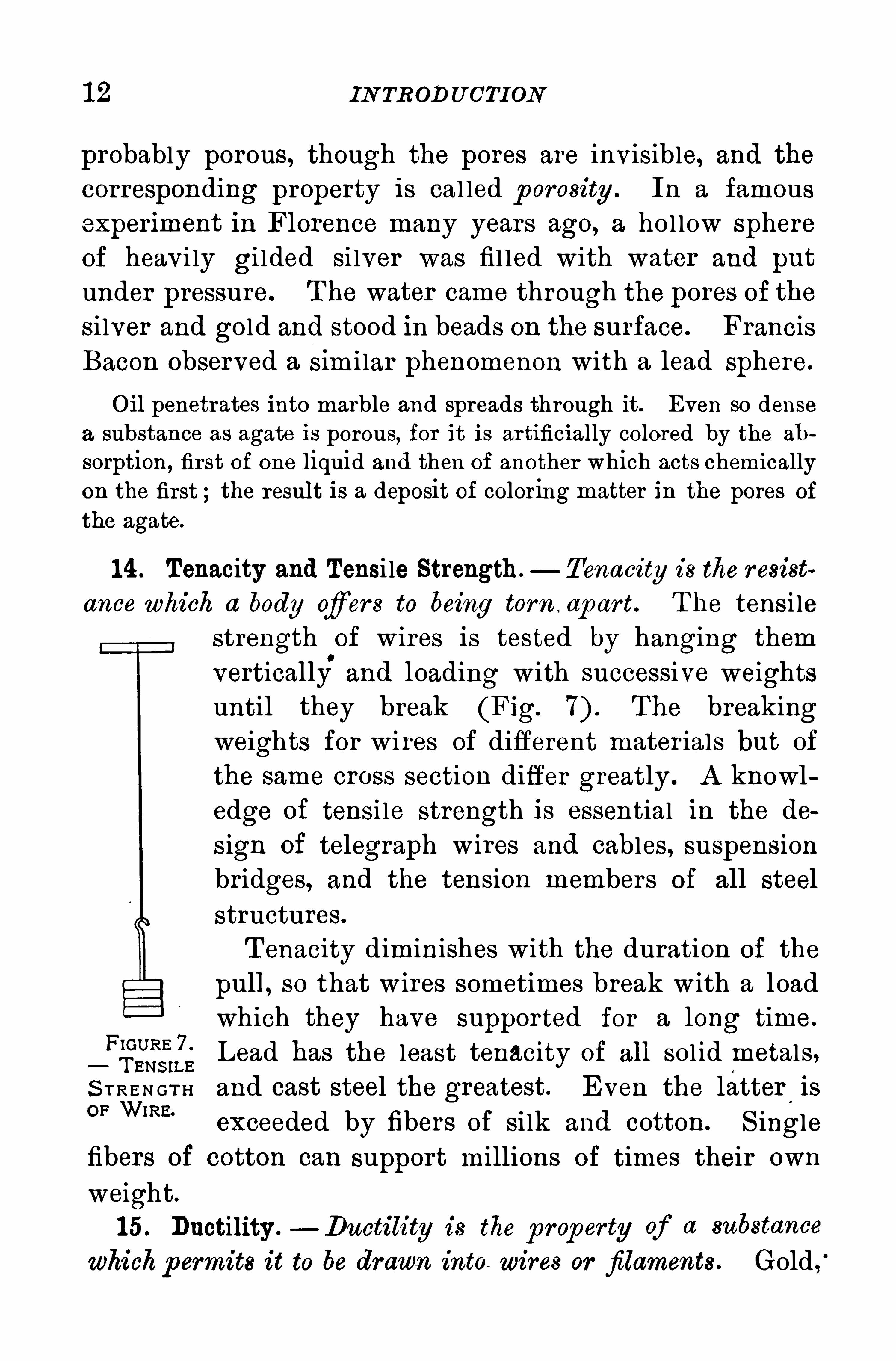
1 4 . Tenacity and Tensi le Strength . Tenacity is the resist
ance which a body of er s to being torn . ap ar t. T he tensi le
strength of wires is tested by hanging them
vertically.
and loading with successive weightsuntil they break (Fig. The breakingweights for wi res of different mater ials but of
the same cross section differ greatly . A knowl
edge of tensi le strength is essential in the de
sign of telegraph wires and cables, suspension
bridges, and the tension members of all steel
structures.
T enacity diminishes with the duration of the
pull, so that w ires sometimes break w ith a loadwhich they have suppor ted for a long time.
Lead has the least tenacity of all sol id metals.S T R E N GT H and cast steel the greatest. Even the latter
.
isOF W'RE'
exceeded by fibers of si lk and cotton. S ingle
fibers of cotton can support millions of times their own
weight.
15. Ductility .—Ductility is the p roperty of a substance
whichpermits it to be drawn into wires or filaments . Gold ,
‘
TENA CI T Y A ND TEN S IL E S TREN GTH 1 3
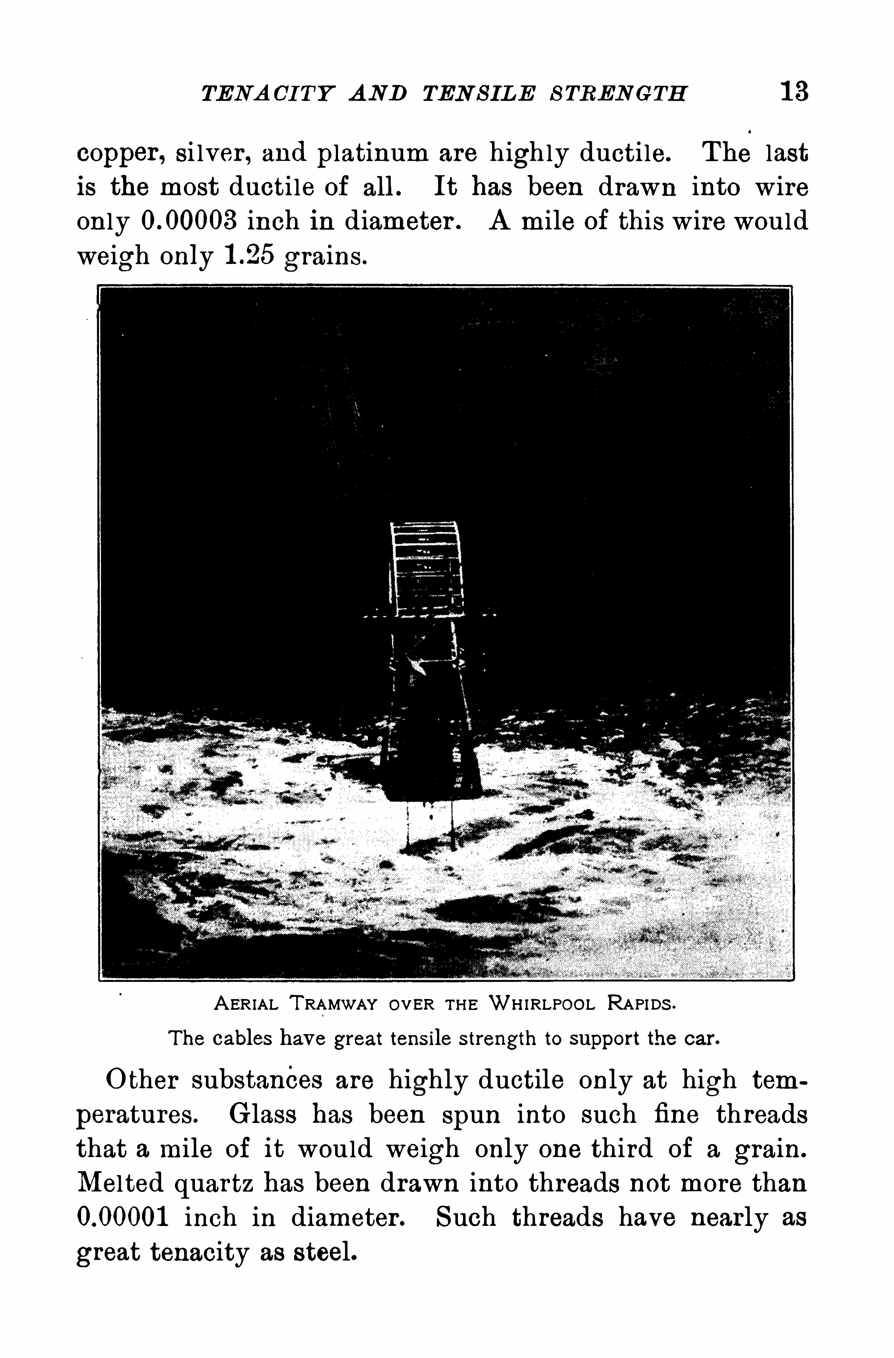
copper , si lver , and platinum are highly ducti le. The lastis the most ducti le of all . It has been drawn into wireonly inch in diameter . A mile of this wire would
weigh only grains .
A ERIAL T RAMWAY OVER T H E WH IRLPOOL RAPI DS .
The cables have great tens ile strength to support the car.
O ther substances are highly ductile only at high tem
peratures. Glass has been spun into such fine threadsthat a mile of it would weigh only one third of a grain.
Melted quartz has been drawn into threads not more thaninch in diameter . Such threads have nearly as
great tenacity as steel.
IN TROD U CTION
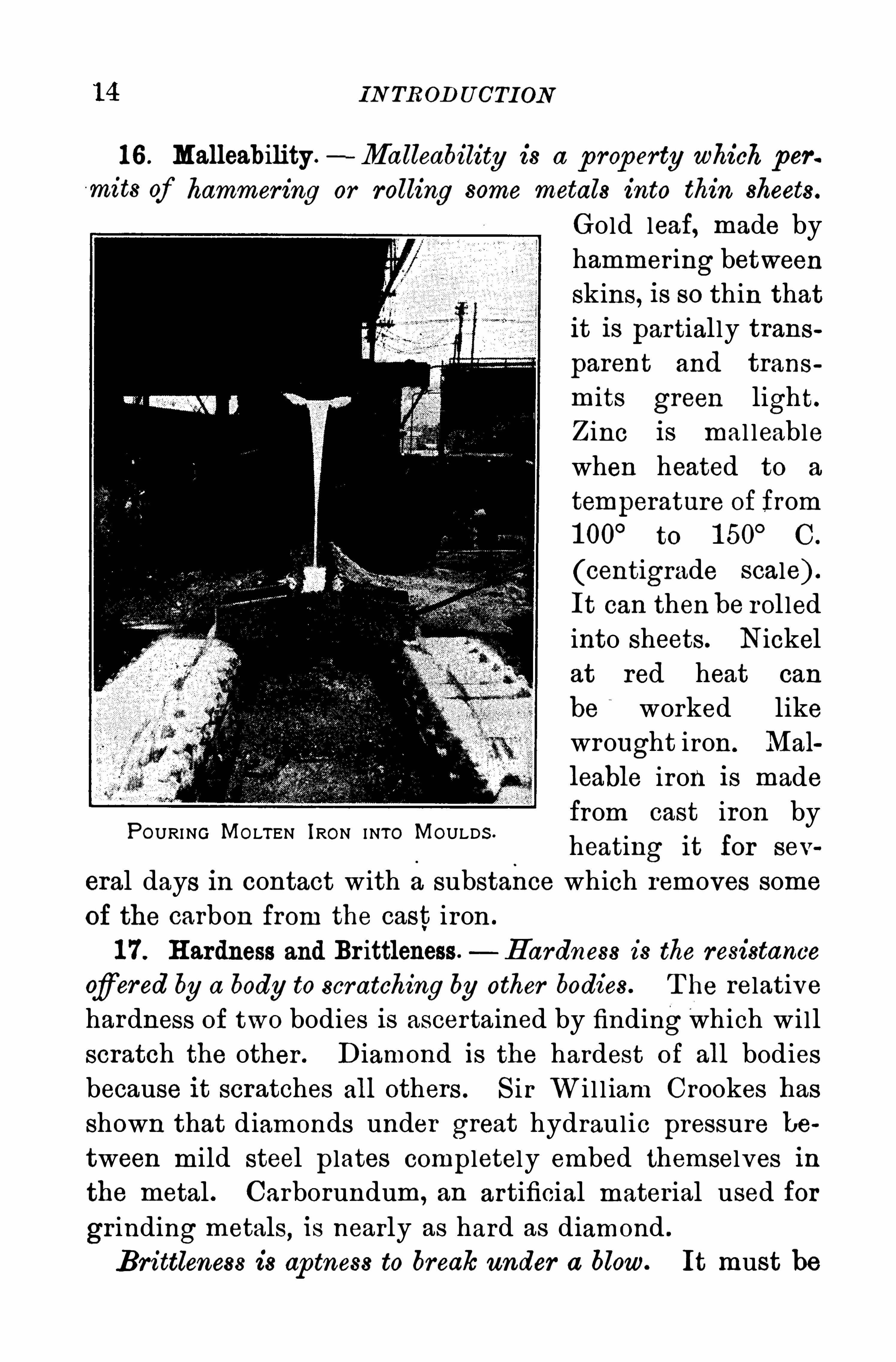
1 6 . Malleability .- Malleability is a p roperty which per
mits of hammering or rolling some metals into thin sheets.
Gold leaf, made byhammering betweenSkins, is so thin thatit is partially trans
parent and trans
mits green light.Zinc is mal leablewhen heated to a
temperature of from1 00
°to 1 50
°C.
(centigrade scale) .
It can then be rol led
into sheets. Nickel
at red heat can
be worked likewrought iron. Mal
leable iron is madefrom cast iron byheating it for sev
eral days in contact with a substance which removes some
of the carbon from the cast iron .
1 7 . H ardness and Br ittleness. H ardness is the resistance
afiered by a body to scratching by other bodies. T he relativehardness of two bodies is ascertained by finding which wi ll
scratch the other . Diamond is the hardest of all bodiesbecause it scratches all others . S ir W i l l iam Crookes has
shown that diamonds under great hydraulic pressure be
tween mild steel plates completely embed themselves in
the metal . Carborundum, an artificial material used for
grinding metals,is nearly as hard as diamond .
Brittleness is ap tness to break under a blow. It must be
POURING MOLTEN IRON INTO MOULDS .
1 6 IN TRODU CTION
Ex er c is esI
1 . Given a large crystal of rock candy. Can its volume be determined by the method outlined under impenetrability ? H ow ?
2 . T he volume of a bar of lead can be reduced by pounding it.
Explain .
3 . A smal l quantity of sugar can be dissolved in a cup of waterwithout increasing the volume. Explain
4 . A quick b low with a heavy knife W l ll Often remove smoothlythe neck of a glass bottle, while a less vigorous b low will shatter thebottle. Explain .
5 . Why can an athlete jump farther in a running jump than in
a standing jump ?6 . By str iking the end of the handle it can be dr iven into a heavy
ax much better than by pounding the ax. Why ?
7 . A man standing on a flat—bottomed car that is moving jumpsvertically upward. Will he come down on the spot from which hejumped ? Explain.
8. If a top be set spinning it stands up If not spinning it topplesover . Explain .
9 . A bullet fired from a rifle will pass through a pane of glass,cutting a fair ly smooth hole ;a stone thrown by the hand on strikinga pane of glass will shatter it. Explain.
1 0 . Name three properties Of matter that are characteristic of it.
1 1 . A rolling wheel does not fall over , but one not rolling topplesover . Why ?
1 2 . Why hold a heavy hammer against a spring board when dr iving a nail into it ?1 3 . In Ju les Verne
’
s T rip to the Moon the incident is told thatwhen a few days on the way the dog died and was thrown overboard .
T o their surpr ise the dead dog followed along after th em . Is Verne’
s
Physics correct Explain .
II . PH Y S ICA L MEA SUREMENT S
18. Units . T o measure any physical quantity a certaindefin ite amount of the same kind of quantity is used as the
unit. For example, to measure the length of a body, some


MEA S URES OF LENGTH 1 7
arbitrary length , as a foot, is chosen as the unit of length;the length of a body is the number of times this unit is con
tained in the longest dimension of the body . T he un it isalways expressed in giv ing the magnitude of any physical
quantity; the other part of the expression is the numer ical
value. For example, 60feet, 500 p ounds, 45 seconds .
In like manner, to measure a surface, the unit, or stand
ard surface, must be given, such as a square foot; and to
measure a volume, the unit must be a given volume, such ,
for example, as a cubic inch , a quart, or a gal lon .
19. Systems ofMeasurement. Commercial transactions inmost civ i l ized countr ies are carr ied on by a decimal systemof money, in which all the multiples are ten . It has the
advantage ofgreat convenience, for all numer ical operationsin it are the same as those for abstract numbers in the decimal system . T he system of weights and measures in use
in the Br itish Is les and in the U nited S tates is not a dec
imal system, and is neither rational nor convenient . On
the other hand most of the other civ i lized nations of the
wor ld within the last fifty years have adopted the metric
system, in which the relations are all expressed by some
power of ten . T he metr ic system is in wel l -nigh universal
use for scientific purposes . It furnishes a common numer
ical language and greatly reduces the labor of computation .
20. Measures of Length. In the metr ic system the uni t
of length is the meter . In the U nited S tates it is the dis
tance between two transverse lines on each of two bars of
platinum- iridium at the temperature of melting ice. T hesebars, which are cal led “
national prototypes, were made
by an international commission and were selected by lot
after two others had been chosen as the international pro
totypes”for preservation in the international laboratory
on neutral ground at Sevres near Par is . O ur national
1 8 IN TRODUCTION
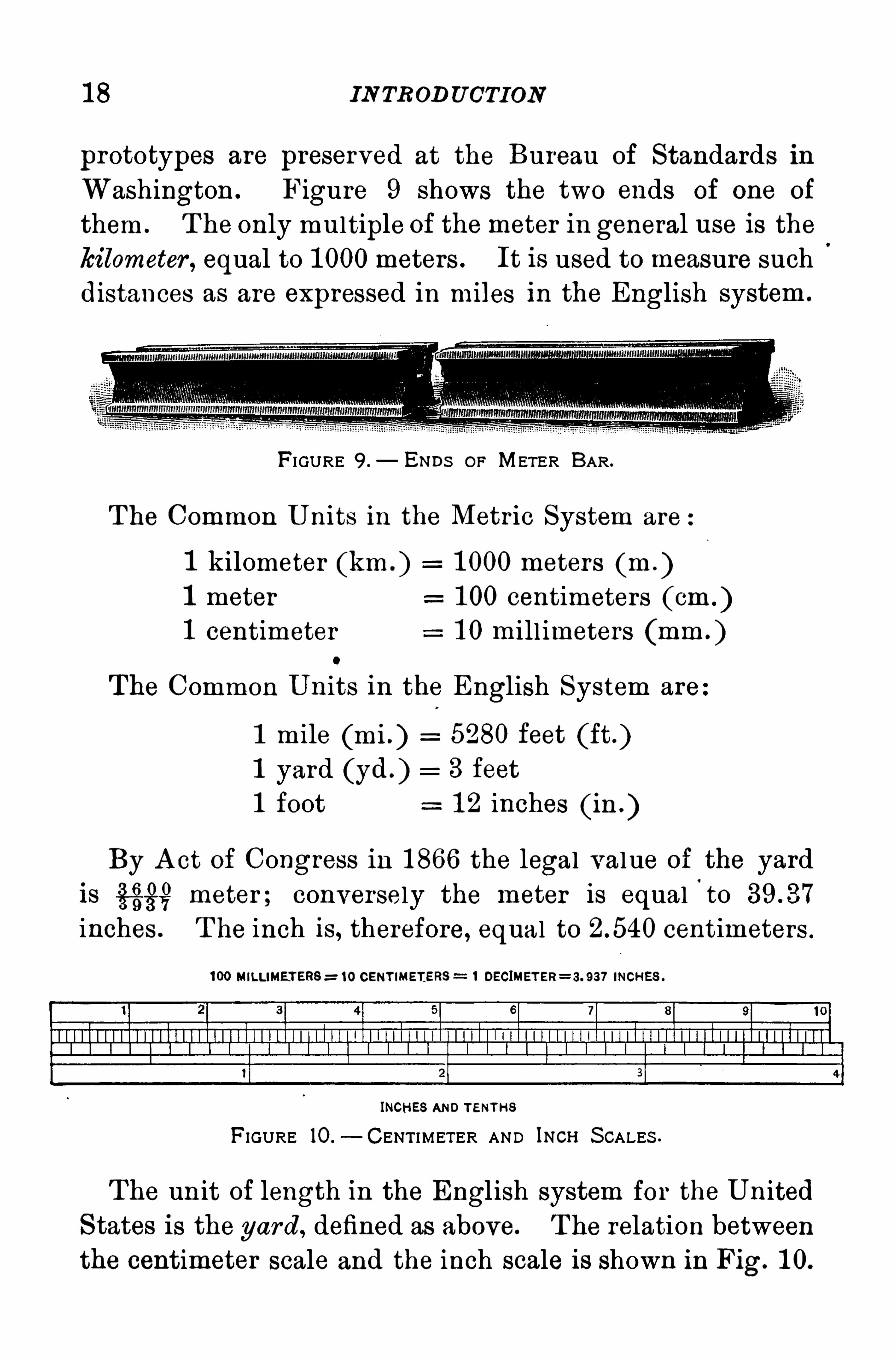
prototypes are preserved at the Bureau of Standards inWashington . Figure 9 shows the two ends of one of
them . T he only multiple of themeter in general use is thekilometer , equal to 1 000meters . It is used to measure suchdistances as are expressed in miles in the English system .
FI GURE 9 .— ENDs OF METER BAR .
T he Common U nits in the Metr ic System are
1 kilometer (km . ) 1 000 meters (m . )1 meter 1 00 centimeters (cm1 centimeter 1 0 mill imeters (mm . )
The Common U nits in the English System are
1 mile (mi . ) 5280 feet (ft .)1 yard (yd ) 3 feet
1 foot 1 2 inches (ih . )
By A ct of Congress in 1 866 the legal value of the yardis fig? meter ; conversely the meter is equal
'
to
inches . T he inch is, therefore, equal to centimeters .
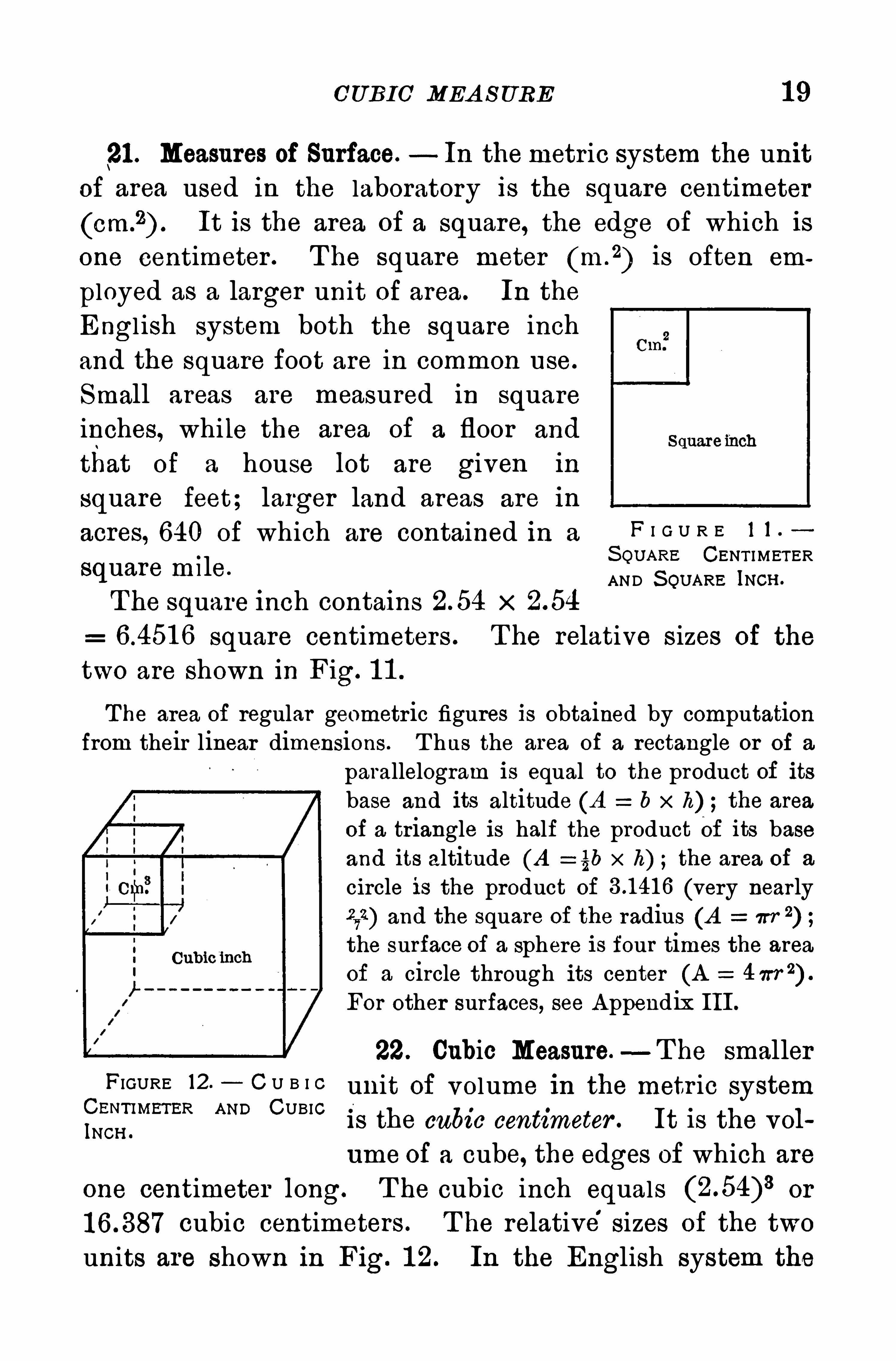
1 00 MILLIMETERS = 1 0 CENT IMETERS 1 DECIMET ER= 3. 937 INCHES .
INCHES AND TENTH SFIGURE 10.
—CENT I METER AND INCH S CALES .
The unit of length in the English system for the U nited
S tates is the yard, defined as above. T he relation between
the centimeter scale and the inch scale is shown in Fig. 1 0.
CUBIC MEA S URE 1 9
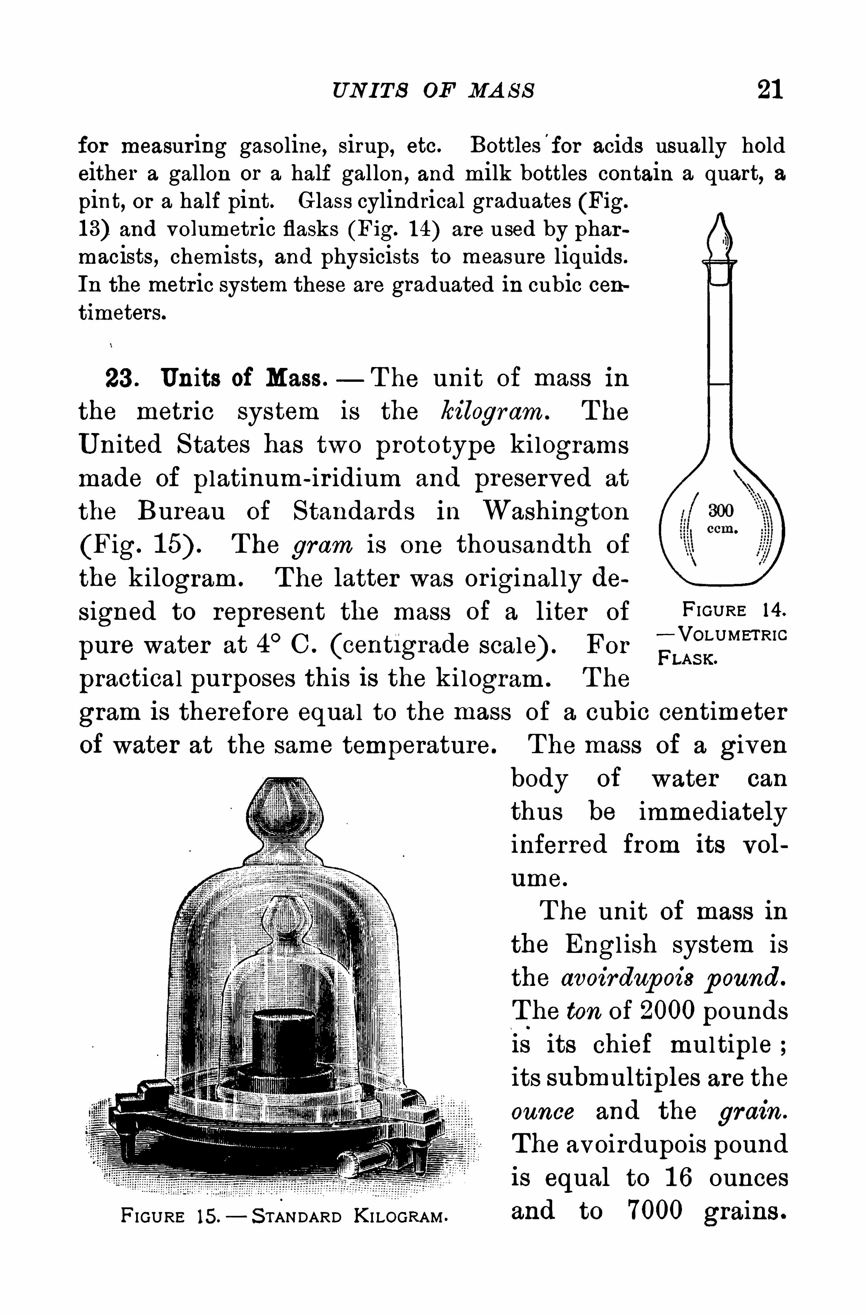
21 . Measures of Surface. In themetric system the unit
of area used in the laboratory is the square centimeter
It is the area of a square, the edge of which is
one centimeter . T he square meter (m .
2) is often em
ployed as a larger unit of area. In the
Engl ish system both the square inch
and the square foot are in common use.
Small areas are measured in squareinches, while the area of a floor and
that of a house lot are given in
square feet; larger land areas are in
acres, 640 of which are contained in a F I G U R E 1 1
S QU ARE CENT I METERSquare m l le. AND S QUARE INCH .
T he square inch contains x
square centimeters . T he relative S izes of the
two are Shown in Fig. 1 1 .
T he area of regular geometr ic figures is obtained by computationfrom their linear dimensions. T hus the area of a rectangle or of a
parallelogram is equal to the product of itsbase and its altitude (A b x h) ;the area
of a triangle is half the product Of its baseand its altitude (A = §b x h) ;the area of a
circle is the product of (very nearly272) and the square of the radius (A W 2
)the surface of a sphere is four times the area
of a circle through its center (A 4 7rr 2) .
For other surfaces, see A ppendix III .
22. Cubic Measure.—T he smaller
FIGURE 12 C U B I C unit of volume in the metr ic system
INE
c
l
iil R AND CUBIC
IS the cubic centimeter . It is the vol
ume of a cube, the edges of which are
one centimeter long. T he cubic inch equals or
cubic centimeters . T he relative’
sizes of the two
units are shown in Fig. 1 2. In the English system the

20 IN TROD U CTION
cubic foot and cubic yard are employed forlarger volumes . The cubical capacity of a
room or of a freight car would be expressedin cubic feet ; the volume of building sandand gravel or of earth embankments, cuts,or fil ls would be in cubic yards .
T he unit of capacity for l iquids in the
metric system is the liter . It is a decimeter
cube, that is, 1 000 cubic centimeters . T he
imperial gal l on of Great Br itain containsabout cubic inches , ‘ and holds 1 0
pounds of water at a temperature of 62°
Fahrenheit . T he United S tates gal lon has
FIGURE 13. the capacity of 231 cubic inches .
CY LINDR" Common U nits in the Metr ic SysC A L G L A S SGRADUATE.
tem
1 cubic meter (m.
3) 1 000 l iters (L)
1 liter 1 000 cubic centimeters (cm .
3)
Common U nits in the Engl ish System
1 cubic yard (cu . 27 cubic feet (cu . ft . )1 cubic foot 1 728 cubic inches (cu . in . )1 U . S . gal lon (gal. ) 4 quarts (qt .) 231 cubic inches
1 quart 2 pints (pt .)
The volume of a regular'
solid, or of a solid geometrical figure, may
be calculated from its linear dimensions. T hus, the number of cubicfeet in a room or in a rectangular block of marble is found by getting the continued product Of its length , its breadth , and its height
,
all measured in feet. T he volume of a cylinder is equal to the productof the area of its base and its height, both measured in the
same system of units.
L iquids are measured by means of gradua ted vessels of metal or of
glass . T hus, tin vessels holding a gallon, a quart, or a pint are used

UN ITS OF MA S S 21
for measur ing gasoline, sirup, etc. Bottles'
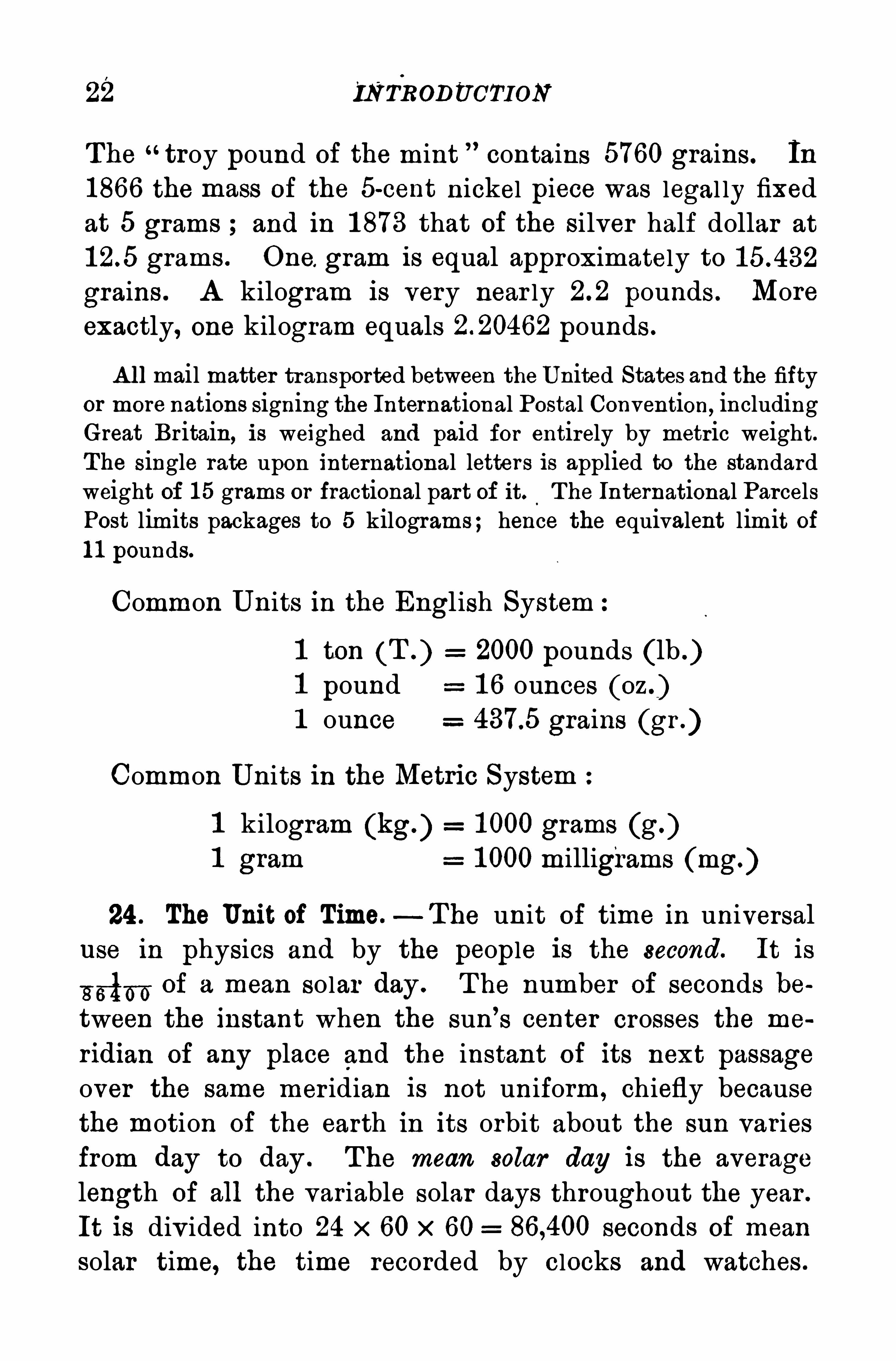
for acids usually holdeither a gallon or a half gallon, and milk bottles contain a quart, apint, or a half pint. Glass cylindrical graduates (Fig.
1 3) and volumetric flasks (Fig. 1 4) are used by pharmaoists, chemists , and physicists to measure liquids .
In the metr ic system these are graduated in cubic centimeters.
23 . Units of Mass.— T he unit of mass in
the metr ic system is the kilogram. T he
U nited S tates has two prototype kilogramsmade of platinum- ir idium and preserved at
the Bureau of Standards in Washington
(Fig. T he gram is one thousandth of
the kilogram . T he latter was or iginal ly de
signed to represent the mass of a l iter of
pure water at 4°C . (cent1grade scale) . For
practical purposes this is the kilogram . T he
FIGURE 14 .
VOLUMETRICFLAsx.
gram is therefore equal to the mass of a cubic centimeter
of water at the same temperature. T he mass of a given
FIGURE 15.— S TANDARD KI LOGRAM .
body of water can
thus be immediatelyinferred from its vol
ume.
T he unit of mass in
the Engl ish system is
the avoirdup ois p ound.
The ton of 2000 pounds
is its chief multiple ;its submultiples are the
ounce and the grain .
The avoirdupois pound
is equal to 1 6 ounces
and to 7000 grains .
22 INTRODUCTION
The troy pound of the mint contains 5760 grains. In
1866 the mass of the 5-cent nickel piece was legal ly fixed
at 5 grams and in 1 873 that of the silver half dollar at
grams . One. gram is equal approximately to
grains . A kilogram is very near ly pounds . More
exactly, one kilogram equals pounds .
A ll mail matter transported between the U nited States and the fiftyor more nations signing the International Postal Convention, includingGreat Britain, is weighed and paid for entirely by metric weight.The single rate upon international letters is applied to the standardweight of 1 5 grams or fractional part of it. The International ParcelsPost limits packages to 5 kilograms; hence the equivalent limit of1 1 pounds.
Common U nits in the English System
1 ton (T . ) 2000 pounds (lb1 pound 1 6 ounces1 ounce grains (gr .)
Common Units in the Metric System
1 kilogram (kg.) 1 000 grams (g.)1 gram 1 000 milligrams mg.)
24 . The Unit of Time.—T he unit of time in universal
use in physics and by the people is the second. It is
“rib—6 of a mean solar day . T he number of seconds between the instant when the sun’
s center crosses the me
ridian of any place and the instant of its next passage
over the same mer idian is not uniform , chiefly becausethe motion of the earth in its orbit about the sun variesfrom day to day . The mean solar day is the average
length of all the variable solar days throughout the year .
It is div ided into 24 x 60 x 60 seconds of mean
solar time, the time recorded by clocks and watches .
PROBLEMS 23
The sidereal day used in astronomy is near ly four minutesShorter than the mean solar day .
25. The Three Fundamental Units . Just as the meas
urement of areas and of volumes reduces Simply to the
measurement of length, so it has been found that themeasurement of most other physical quantities, such as
the speed of a ship, the pressure of water in the mains,the energy consumed by an electric lamp, and the horse
power of an engine, may be made in terms of the units of
length, mass, and time. For this reason these three are
considered fundamental units to distinguish them from all
others, which are cal led der ived units .
The system now in general use in the physical sciences
employs the centimeter as the unit of length , the gram as
the unit of mass, and the second as the unit of time . It
is accordingly known as the c. g. s . (centimeter -gram
second) system.
P rob lems
In solving these problems the student should use the relations andvalues given in 20, 22, and 23 .
1 . Reduce 76 cm. to its equivalent in inches.
2 . Express in feet the height Of Eiffel T ower , 355 m .
3 . T he metric ton is 1 000 kg. Find the difference between it andan American ton .
4 . If milk is 1 5 cents a quart, what would be the price per liter ?
5 . On the basis that one liter Of water weighs a kilogram ,what
wou ld a gallon Of water weigh in pounds ?
6 . What per cent larger than a pound avoirdupois is half a
kilogram ?
7 . If the speed limit on a state road is 25mi. per hour , what wouldthat be expressed in kilometers per hour ?
8. H ow many liters in a cubic foot of water ?
24 IN TRODU CTION
9 . What is the equivalent in the metric system Of a velocity of
1 090 ft. per second ?
1 0 . If a cylindrical jar is 4 in . in diameter and one foot deep, howmany liter s will it hold ?1 1 . Express the velocity of light miles per second in
kilometer s per second .
1 2 . What would be the error made if in measuring 1 2 ft. a bar
30 cm . long is used as a foot ?
1 3 . If a cubic foot of water weighs lb.,what would a pint of
water weigh ?1 4 . If coal sells at $ 1 2 per ton , what would kilograms cost ?
CH A PTER II
MOLECULAR PH Y S ICS
I . MOLECULAR MOTION
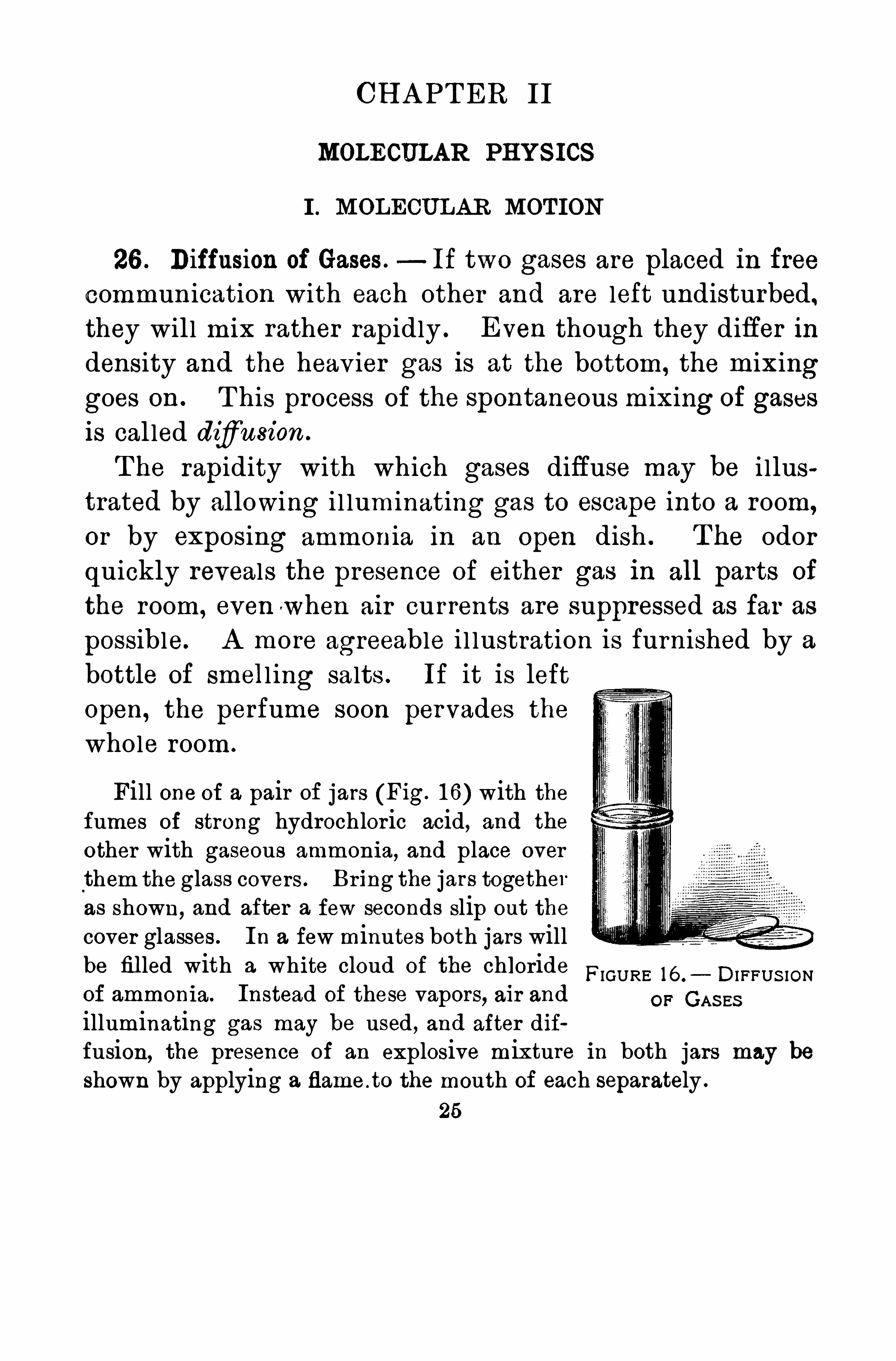
26 . Diffusion of Gases . If two gases are placed in freecommunication with each other and are left undisturbed,
they wil l mix rather rapidly . Even though they differ indensity and the heav ier gas is at the bottom, the mixinggoes on . T his process of the spontaneous mixing of gases
is cal led difiusion .
T he rapidity with which gases diffuse may be i llustrated by allowing i l luminating gas to escape into a room,
or by exposing ammonia in an open dish . T he odor
quickly reveals the presence of either gas in all parts of
the room, even when air currents are suppressed as far as
possible. A more agreeable i l lustration is furnished by a
bottle of smell ing salts . If it is left
Open, the perfume soon pervades thewhole room.
Fill one of a pair of jars (Fig. 1 6) with thefumes of strong hydrochloric acid, and the
other with gaseous ammonia, and place overthem the glass covers . Bring the jars togetheras shown, and after a few seconds slip out the
cover glasses . In a few minutes both jars willbe fil led with a white cloud of the chloride
FIGURE 16 . DI FFUS IONof ammonia. Instead of these vapors, air and OF GAS ESilluminating gas may be used , and after dif
fusion, the presence of an explosive mixture in both jars may beshown by applying a flame .to the mouth of each separately .
25
26 MOLECULAR PH Y S ICS
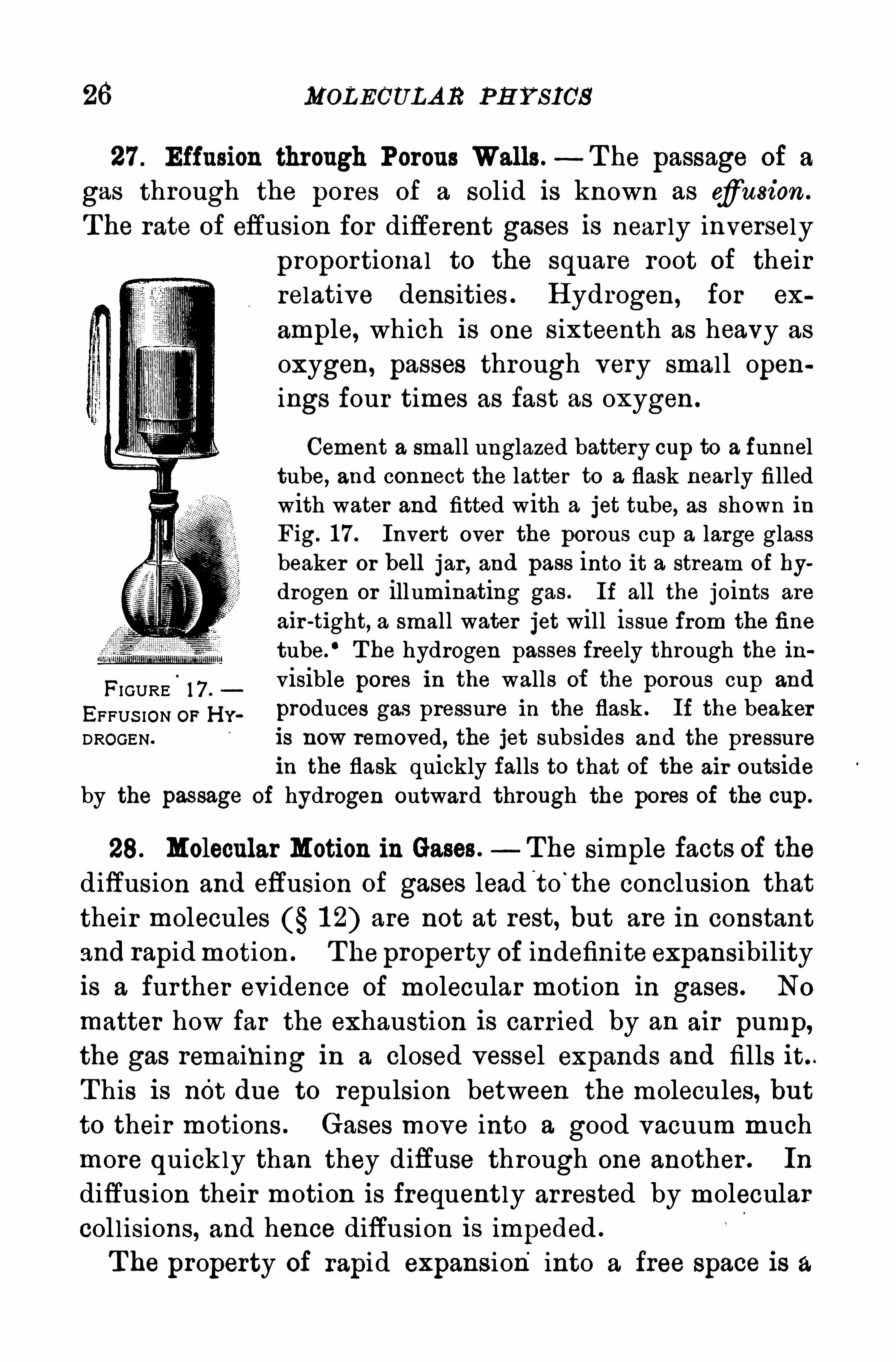
27 . Effusion through Porous Walls.—T he passage of a
gas through the pores of a solid is known as cfi'
usion .
T he rate of effusion for different gases is near ly inversely
proportional to the square root of theirrelative densities . H ydrogen, for ex
ample, which is one sixteenth as heavy as
oxygen, passes through very small openings four times as fast as oxygen .
Cement a small unglazed battery cup to a funneltube, and connect the latter to a flask nearly filledwith water and fitted with a jet tube, as shown inFig. 1 7 . Invert over the porous cup a large glassbeaker or hell jar , and pass into it a stream of hy
drogen or illuminating gas . If all the joints are
air -tight, a small water jet will issue from the fine
tube.
‘ T he hydrogen passes freely through the ih
FIGURE.
1 7 .
visible pores in the walls of the porous cup and
EFFUS ION OF H y . produces gas pressure in the flask . If the beakerDROGEN. is now removed, the jet subsides and the pressure
in the flask quickly falls to that of the air outsideby the passage of hydrogen outward through the pores of the cup.
28. Molecular Motion in Gases. The simple facts of thediffusion and effusion of gases lead t o
'
the conclusion that
their molecules 1 2) are not at rest, but are in constantand rapidmotion . T he property of indefinite expansibilityis a further evidence of molecular motion in gases . No
matter how far the exhaustion is carried by an air pump,the gas remaining in a closed vessel expands and fills it . .
T his is nOt due to repulsion between the molecules, but
to their motions . Gases move into a good vacuum muchmore quickly than they diffuse through one another . In
diffus ion their motion is frequent ly arrested by molecular
col l isions, and hence diffusion is impeded .
T he property of rapid expansion into a free space is a
28 MOL ECULA R P H Y S ICS
atmosphere, or 1 033 g. per square centimeter . It is about450m . per second . For the same pressure of hydrogen,
which is only one fourteenth as heavy as air , the velocity
has the enormous value of 1 850 m . per second . T he high
speed of the hydrogen molecules accounts for their relatively rapid progress through porous wal ls .
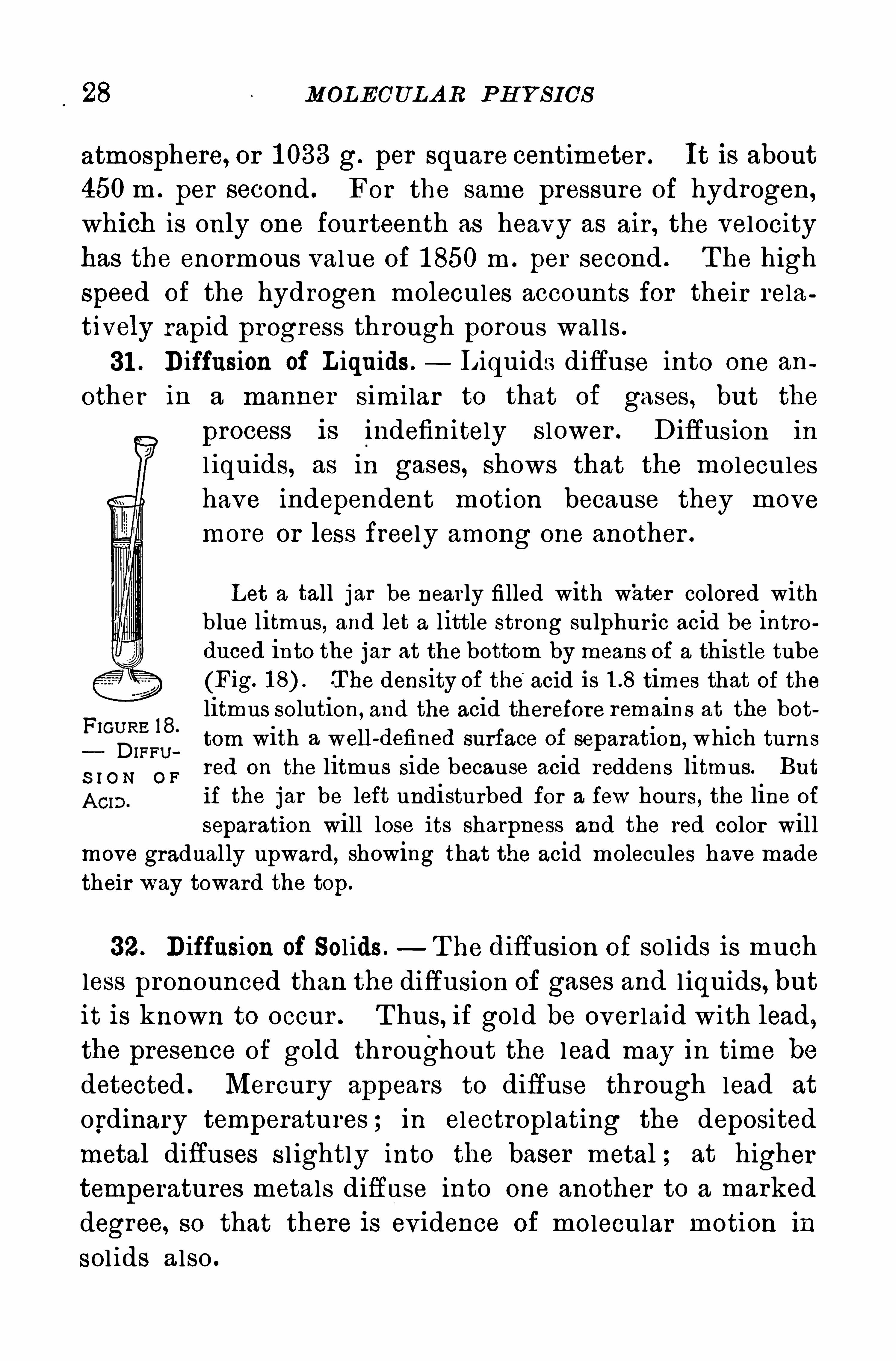
31 . Diffusion of L iquids. L iquids diffuse into one an
other in a manner simi lar to that of gases , but the
process is indefinitely slower . Diffusion in
l iquids, as in gases, Shows that the moleculeshave independent motion because they move
more or less freely among one another .
Let a tall jar be nearly filled with water colored withblue litmus, and let a little strong sulphur ic acid be introduced into the jar at the bottom by means of a thistle tube
(Fig. T he density of the’
acid is times that of thelitmus solution, and the acid therefore remains at the bottom with a well -defined surface of separation, which turnsred on the litmus side because acid reddens litmus. But
if the jar be left undisturbed for a few hours, the line of
separation will lose its sharpness and the red color willmove gradual ly upward, showing that the acid molecules have madetheir way toward the top.
32. Diffusion of Solids . T he diffusion of sol ids is much
less pronounced than the diffusion of gases and l iquids, butit is known to occur . T hus, if gold be over laid with lead,the presence of gold throughout the lead may in time bedetected . Mercury appears to diffuse through lead at
ordinary temperatures ; in electroplating the deposited
metal diffuses s l ightly into the baser metal ; at higher
temperatures metals diffuse into one another to a marked
degree, so that there is evidence of molecular motion in
sol ids a lso .
MOL ECUL A R FORCES IN L IQU IDS 29
II . SURFA CE PH ENOMENA
33 . Molecular Forces in Liquids . By an easy transitionof ideas we carry the pr imitive conception of force der ived
from the sense of muscular exertion over to forces otherthan those exerted by men and animals, such as those between the molecules of a body . Molecular forces act only
through insensible distances, such as the distances separating the molecules of sol ids and l iquids . A clean glass
rod does not attract water unti l there isactual contact between the two . If the
rod touches the water , the latter cl ingsto the glass, and when the rod is withdrawn , a drop adheres to it . If the dropis large enough , its weight tears it away,and it falls as a l ittle Sphere.
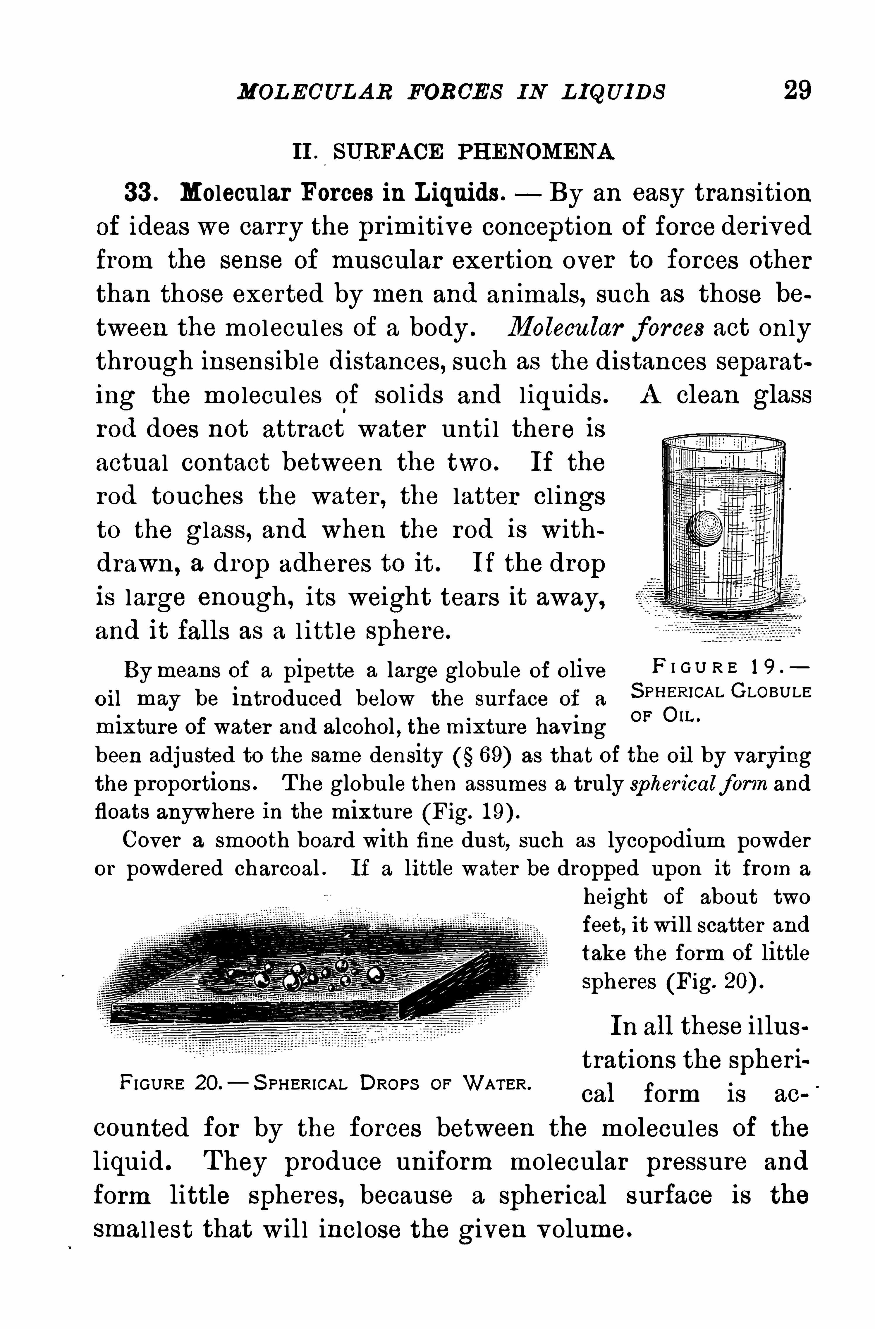
Bymeans of a pipette a large globule of olive F I G U R E 1 9 .
oil may be introduced below the surface of aS PH ER‘CA L GLOBULE
mixture of water and alcohol , the mixture havingOF on"
been adjusted to the same density 69) as that of the O il by varyingthe proportions . T he globule then assumes a truly spher icalform and
floats anywhere in the mixture (Fig.
Cover a smooth board with fine dust, such as lycopodium powderor powdered charcoal . If a little water be dropped upon it from a
height of about two
feet, it wi ll scatter and
take the form of littlespheres (Fig.
In all these i llustrations the spheri
cal form is ac
counted for by the forces between the molecules of the
liquid . T hey produce uniform molecular pressure and
form little spheres, because a Spher ical surface is the
smal lest that wil l inclose the given volume.
FI GURE 20.—S PHERICAL DROPS OF WATER.
30 MOLECUL AR P H Y S ICS
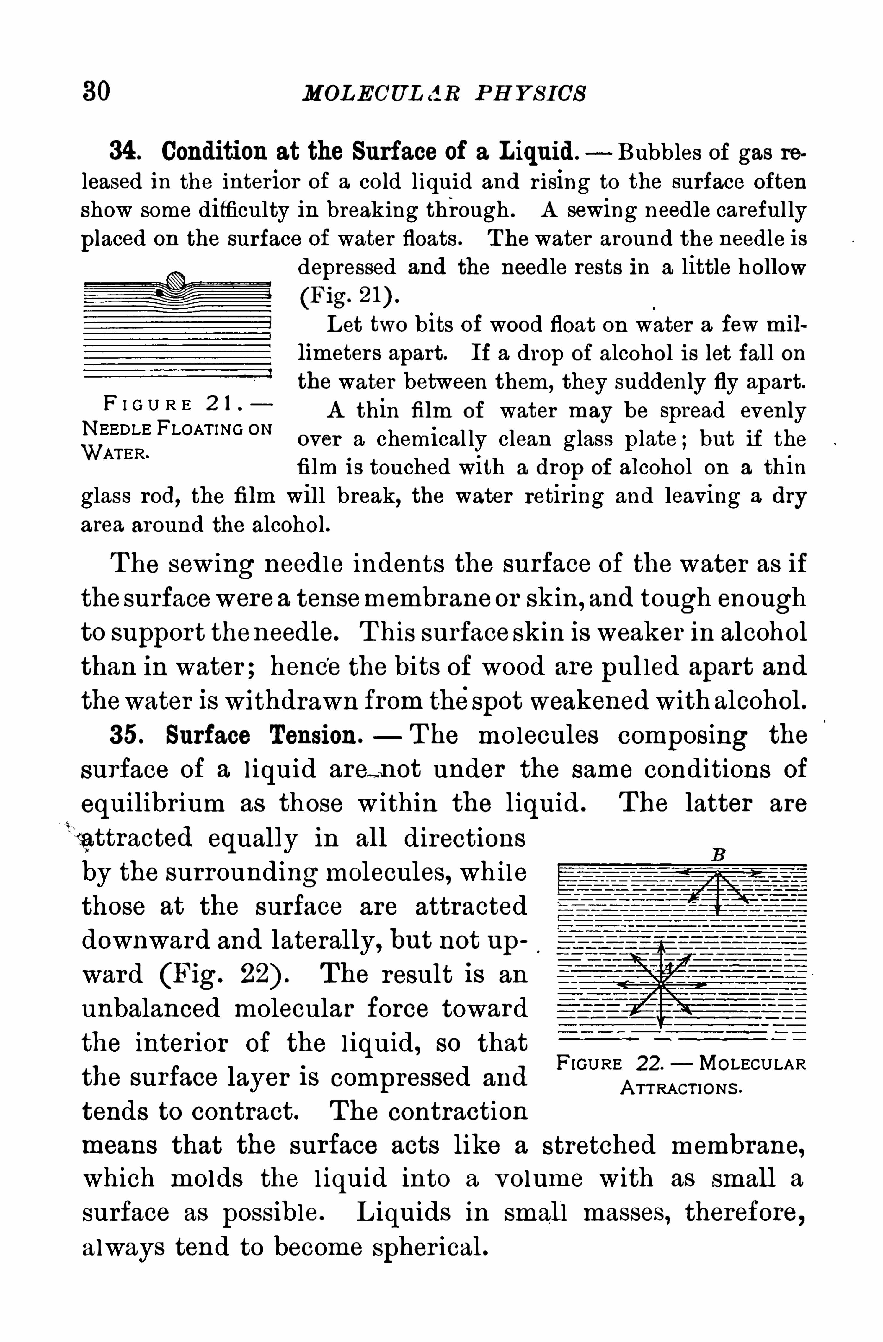
34 . Condition at the Surface of a Liquid. Bubbles of gas released in the interior of a cold liquid and r ising to the surface often
Show some difficulty in breaking through . A sewing needle careful ly
placed on the surface of water floats . T he water around the needle isdepressed and the needle rests in a little hollow
(Fig.
Let two bits of wood float on water a few millimeters apart. If a drop of alcohol is let fall onthe water between them , they suddenly fly apart.
A thin film Of water may be spread evenlyover a chemical ly clean glass plate ;but if thefilm is touched with a drop of alcohol on a thin
glass rod, the film will break, the water retiring and leaving a dry
area around the alcohol.
F I G U R E 2 1
NEEDLE FLOAT I NG ONWATER.
T he sewing needle indents the surface of the water as if
thesurfacewerea tensemembraneor skin, and tough enough
to support theneedle. T his surfaceSkin is weaker in alcohol
than in water ; hence the bits of wood are pul led apart and
thewater is withdrawn from thespot weakened with alcohol .
35. Surface Tension. T he molecules composing the
surface of a l iquid area not under the same conditions of
equilibr ium as those w ithin the liquid . T he latter are
lfattracted equally in all directions
by the surroundingmolecules, while
those at the surface are attracteddownward and laterally, but not upward (Fig. The result is an
unbalanced molecular force toward
the inter ior of the l iquid, so that
the surface layer is compressed and
tends to contract. T he contraction
means that the surface acts like a stretched membrane,which molds the l iquid into a volume with as small a
surface as possible. L iquids in small masses, therefore,always tend to become spher ical .
FIGURE 22. MOLECULARA TTRACT IONS .
IL L U S TRA TION S 31
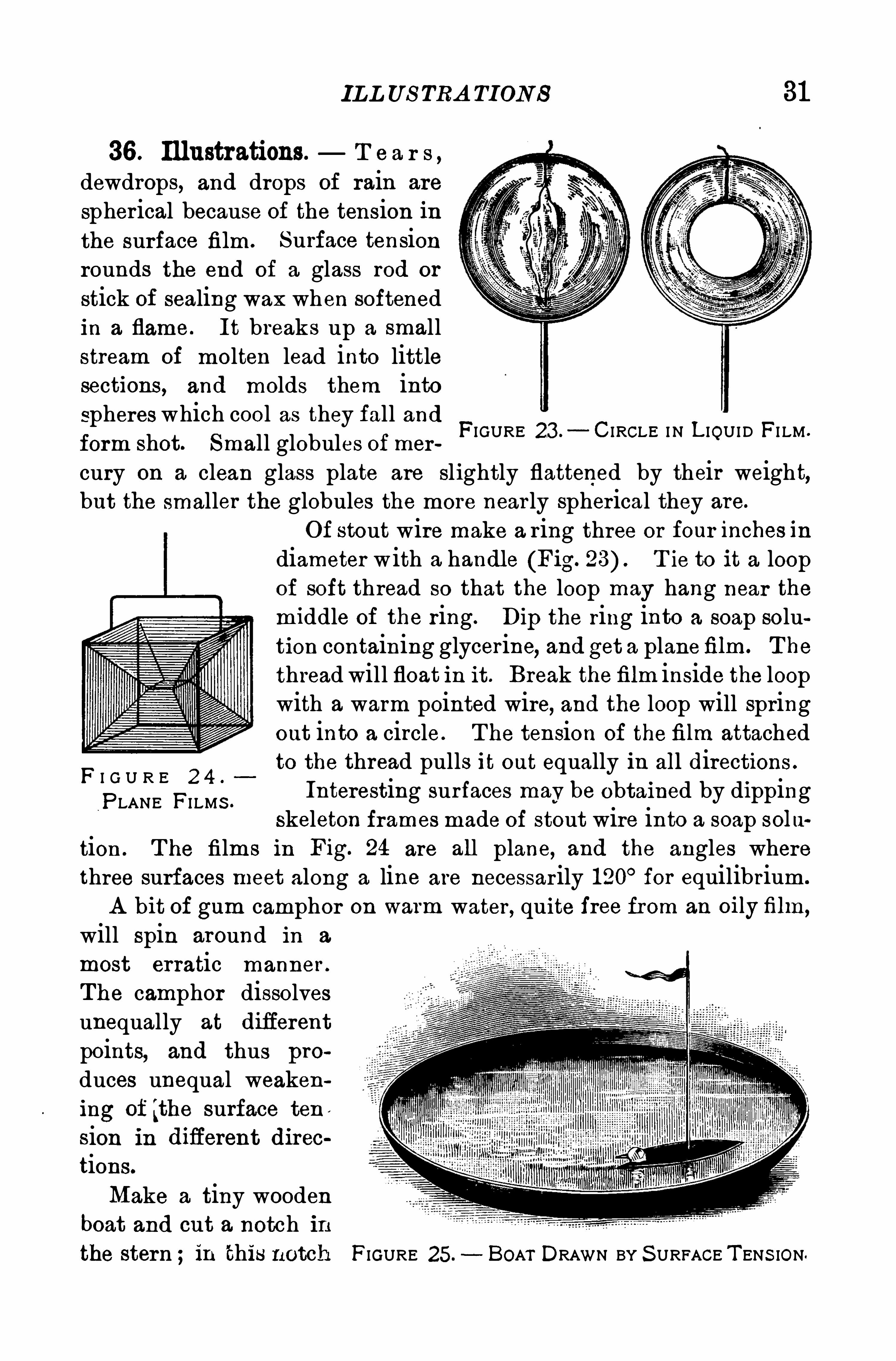
36 . Illustrations. T e a r s ,
dewdrops, and drops of rain are
Spherical because of the tension inthe surface film . Surface tensionrounds the end of a glass rod or
stick of sealing wax when softenedin a flame. It breaks up a smallstream of molten lead into littlesections , and molds them intosphereswhich cool as they fall andform shot. Small globules of mer
FIGURE 23 . C IRCLE I N L IQUID FI LM .
cury on a clean glass plate are slightly flattened by their weight,but the smaller the globules the more near ly spherical they are.
F I G U R E 2 4 .
PLANE FI LMS .
Of stout wire make a ring three or four inches in
diameter with a handle (Fig. 23) T ie to it a loopof soft thread so that the loop may hang near the
middle of the ring. Dip the ring into a soap solution containing glycerine
,and get a planefilm. T he
thread will float in it. Break thefilm inside the loopwith a warm pointed wire, and the loop will springout into a circle . T he tension of the film attachedto the thread pulls it out equally in all directions .
Interesting surfaces may be Obtained by dippingskeleton frames made of stout wire into a soap solu
tion . T he films in Fig. 24 are all plane, and the angles wherethree surfaces meet along a line are necessarily 1 20° for equilibrium.
A bit of gum camphor on warm water , quite free from an 0 i film,
will spin around in a
most erratic manner .
The camphor dissolvesunequally at difierent
points, and thus pro
duces unequal weakening of [the surface ten ,
sion in diflerent direc
tions.
Make a tiny woodenboat and cut a notch inthe stern ; in this notch FIGURE 25. BOAT DRAWN BY S URFACE T ENS ION.
32 MOLECUL A R P H Y S ICS
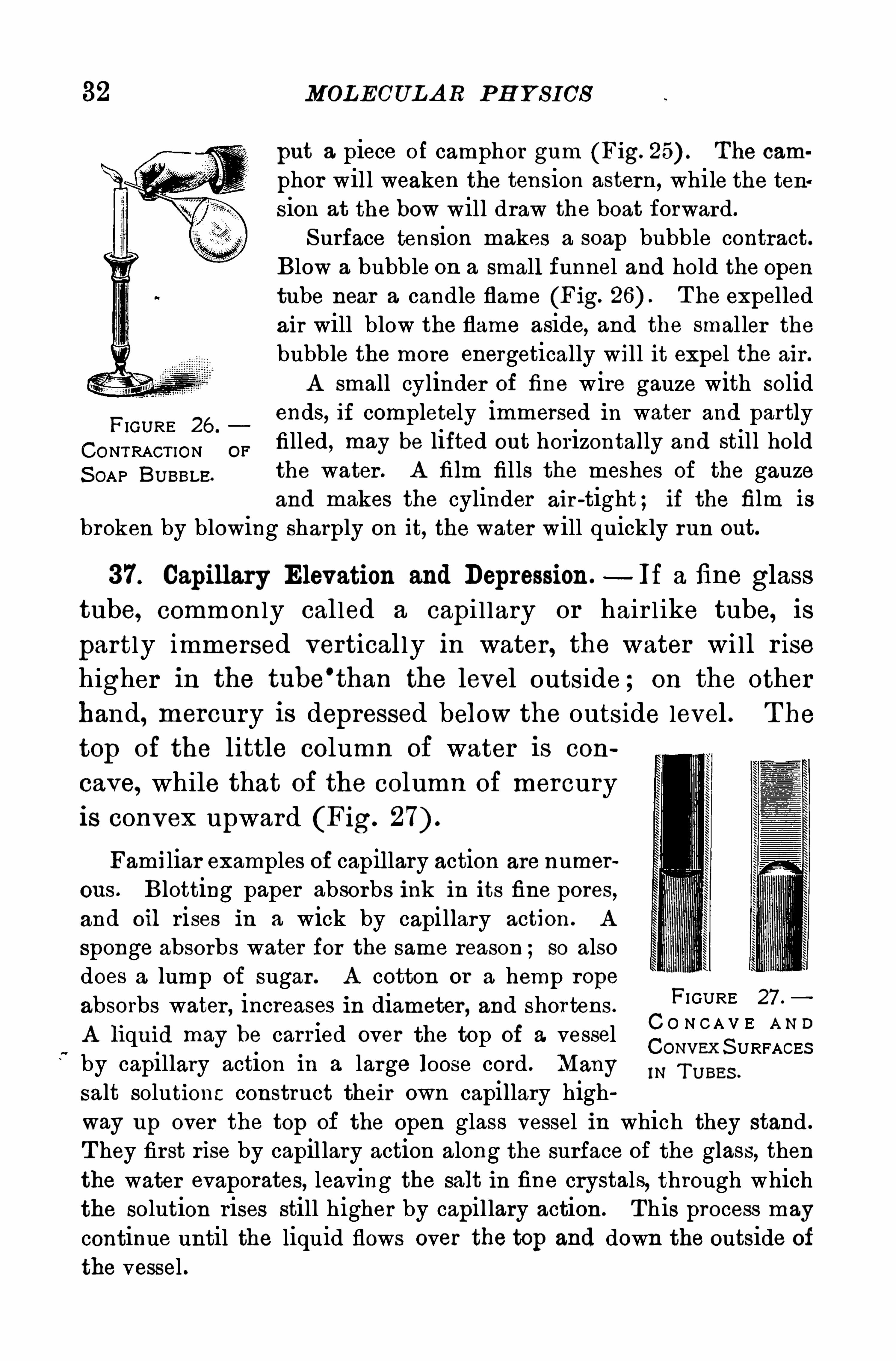
put a piece of camphor gum (Fig. The cam
phor will weaken the tension astern, while the tension at the bow will draw the boat forward.
Surface tension makes a soap bubble contract.Blow a bubb le on a small funnel and hold the opentube near a candle flame (Fig. T he expelledair will blow the flame aside, and the smaller thebubble the more energetically will it expel the air.
A small cylinder of fine wire gauze with solid
FIGURE 26 .
ends, if completely immersed in water and partly
CONTRACT ION OFfilled, may be lifted out horizontally and still hold
S OAP BU BBLE.the water . A film fills the meshes of the gauzeand makes the cylinder air -tight ; if the film is
broken by blowing sharply on it, the water will quickly run out.
37. Capillary Elevation and Depression.—If a fine glass
tube, common ly cal led a capi l lary or hair l ike tube, is
partly immersed vertical ly in water, the water wi ll r isehigher in the tube
’
than the level outside ; on the otherhand, mercury is depressed below the outside level . T he
top of the little column of water is con
cave, while that of the column of mercuryis convex upward (Fig.
Familiar examples of capillary action are numerous . Blotting paper absorbs ink in its fine pores,and Oil rises in a wick by capillary action . A
sponge absorbs water for the same reason ; so alsodoes a lump of sugar . A cotton or a hemp rcpe
absorbs water , increases in diameter , and shor tens .
FI GURE 27 ;
A li uid ma be carried over the to of a vessel C O N C A V E A N Dq y pCoNVEx S URFACES
by capillary action in a large loose cord . Many IN T U BES .
salt solutions construct their own capillary highway up over the top of the open glass vessel in which they stand .
T hey first rise by capillary action along the surface Of the glass, thenthe water evaporates, leaving the salt in fine crystals, through whichthe solution rises still higher by capillary action . This process may
continue until the liquid flows over the top and down the outside ofthe vessel .
CA P IL LA RY A CTION IN S OIL S 33
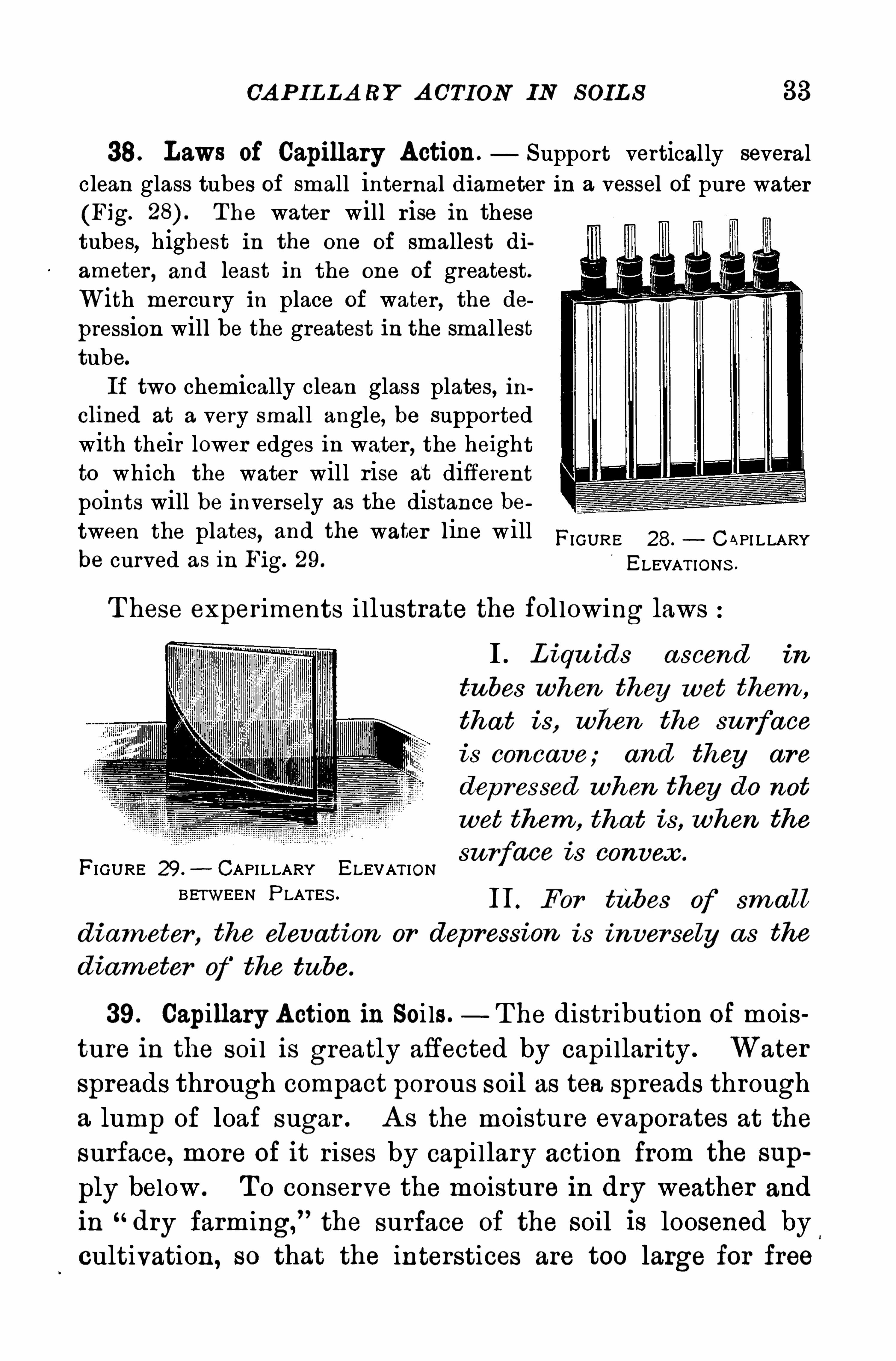
38. Laws of Capillary Action. Support vertically severalclean glass tubes of small internal diameter in a vessel of pure water(Fig. The water will r ise in thesetubes, highest in the one of smallest diameter , and least in the one of greatest.
With mercury in place of water , the depression will be the greatest in the smal lesttube.
If two chemically clean glass plates, ihclined at a very small angle, be supportedwith their lower edges in water , the heightto which the water will rise at differentpoints will be inversely as the distance between the plates, and the water line will FI GURE 28. C API LLARYbe curved as in Fig. 29. ELEVAT IONS .
T hese exper iments i llustrate the fol lowing laws
I . L iqu ids a scend in
tubes when they wet them ,
tha t is, when the su rface
is concave; and they are
dep ressed when they do not
wet them , tha t is, when the
su r ace is convex .
FI GURE 29 .- CAP I LLARY ELEVAT ION f
BETWEEN P LATES II . For tubes of sm all
diam eter , the elevation or depression is inversely as the
d iam eter of the tube.
39. Capillary A ction in Soi ls. T he distribution of mois
ture in the soi l is greatly affected by capi llar ity . Water
spreads through compact porous soil as tea spreads through
a lump of loaf sugar . A S the moisture evaporates at the
surface, more of it rises by capi llary action from the sup
ply below . T o conserve the moisture in dry weather and
in “dry farming,”the surface of the soil is loosened by
,
cultivation, so that the interstices are too large for free
34 MOL ECULA R P H Y S ICS
capil lary action . T he moisture then remains at a lowerlevel , where it is needed for the growth of plants .
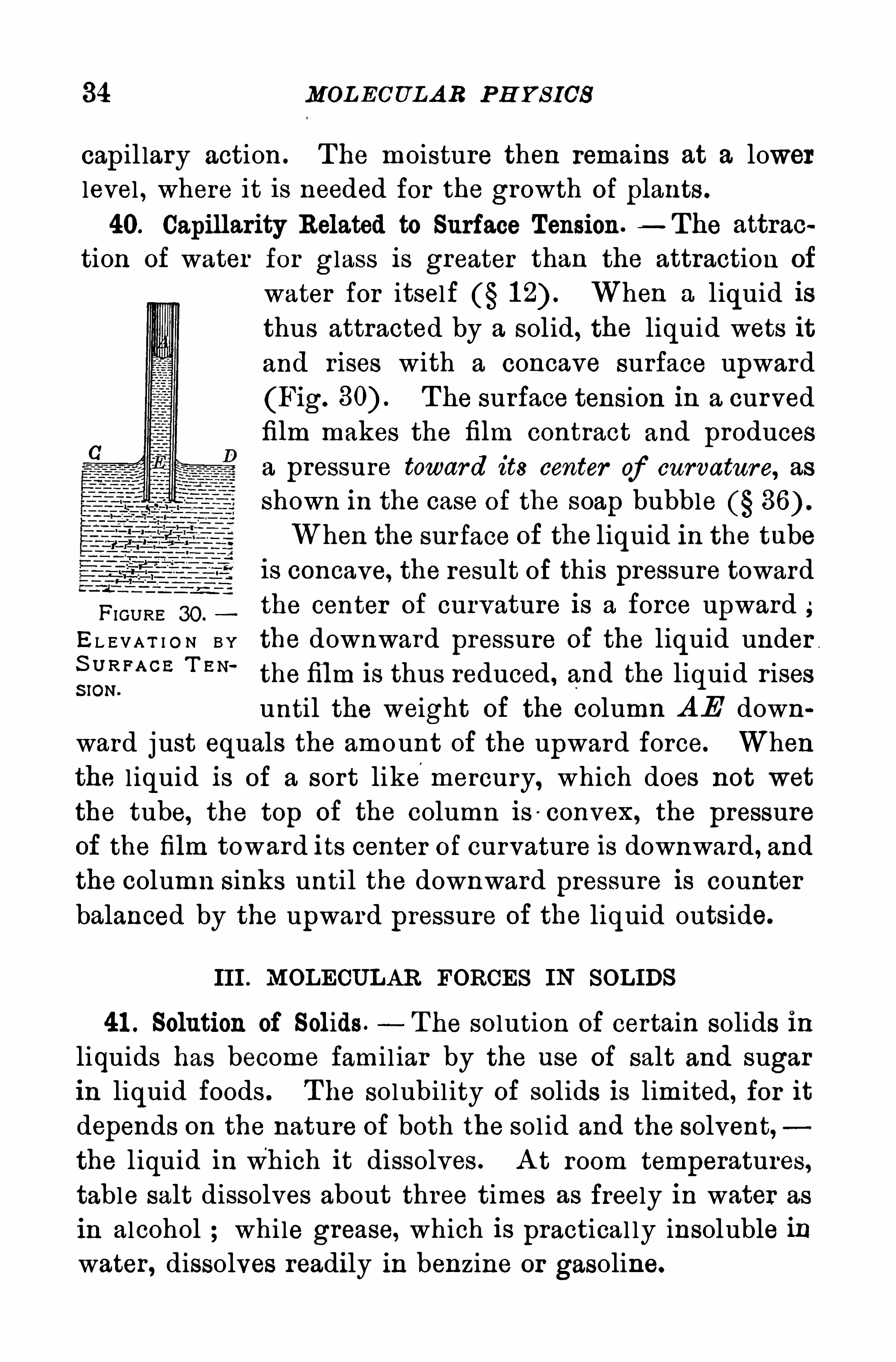
40. Capillarity Related to Surface Tension.—The attrac
tion of water for glass is greater than the attraction of
water for itself When a liquid isthus attracted by a solid, the liquid wets itand r ises with a concave surface upward
(Fig. The surface tension in a curvedfilm makes the film contract and producesa pressure toward its center of curvature, as
shown in the case of the soap bubbleWhen the surface of the liquid in the tube
is concave, the result of this pressure toward
FIGURE 30 .
the center of curvature is a force upward ;EL E VA T I O N B Y the downward pressure of the liquid under
igfiFA CE T EN‘
the film is thus reduced , and the liquid r isesuntil the weight of the column A E down
ward just equals the amount of the upward force. Whenthe l iquid is of a sort likemercury, which does not wet
the tube, the top of the column is -
convex, the pressureof the film toward its center of curvature is downward , and
the column sinks until the downward pressure is counter
balanced by the upward pressure of the liquid outside.
III . MOLECULAR FORCES IN SOLIDS
41 . Solution of Solids . T he solution of certain solids in
liquids has become fami l iar by the use of salt and sugar
in liquid foods . T he solubil ity of solids is limited, for it
depends on the nature of both the sol id and the solvent,the l iquid in wh ich it dissolves . A t room temperatures,table salt dissolves about three times as freely in water as
in alcohol while grease, which is practical ly insoluble inwater, dissolves readily in benzine or gasoline.
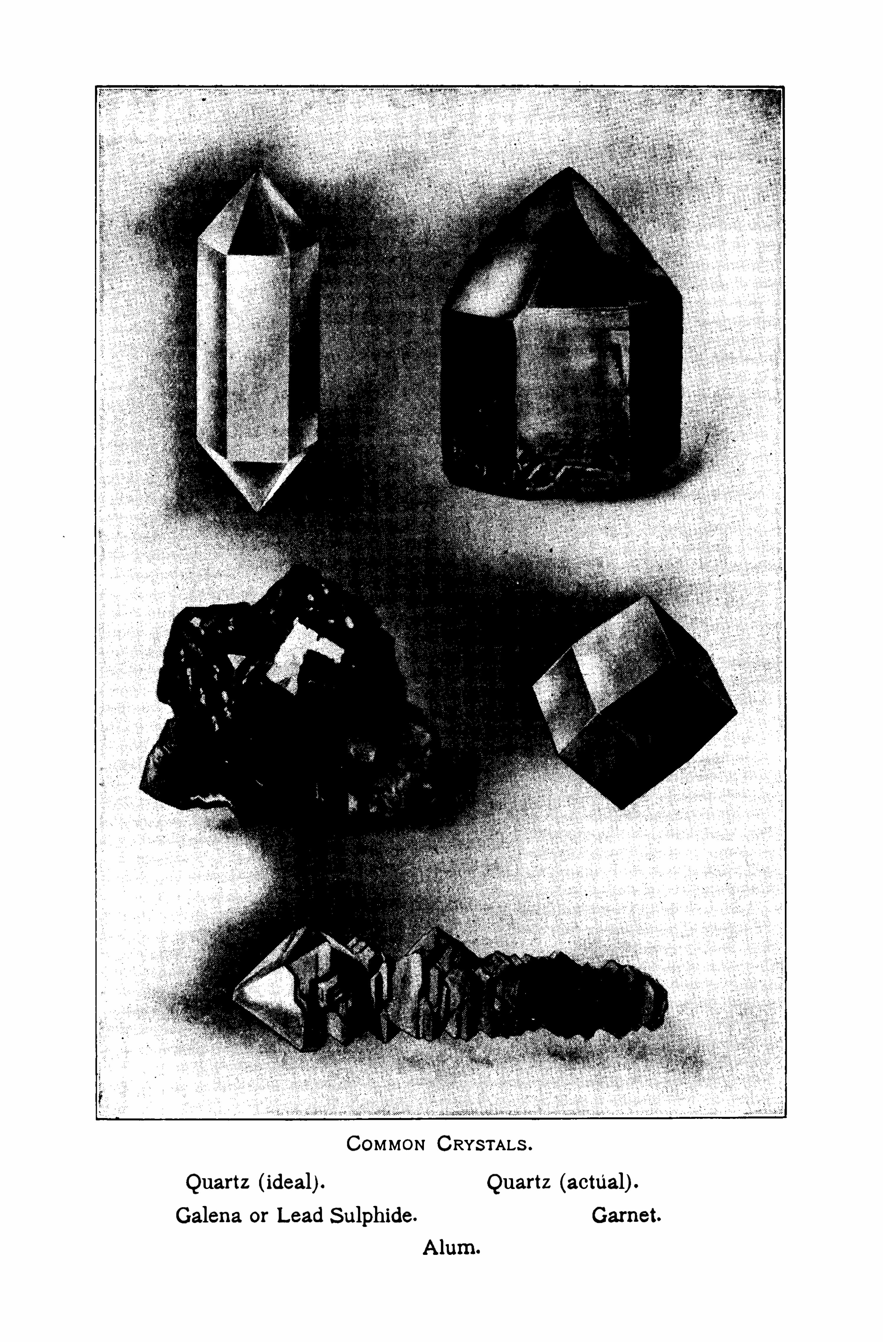
COMMON CRYS TALS .
Quartz (ideal) . Quartz (actual) .
Galena or Lead S ulphide Garnet.
CRY S TA L L IZA TION 35
Solution in a small degree takes place in many unsuspected cases .
T hus, certain kinds of glass dissolve to an appreciable extent in hot
water . Many rocks are slightly soluble in water , and the familiaradage that the “constant dropping of water wears away a stone is
accounted for , in part at least, by the solution of the stone. Flintglass, out ofwhich cut glass vessels are made, dissolves to some extent
in aqua ammonia ;this liquid should not be kept in cut glass bottles,nor should cut glass be washed in water containing ammonia.
T here is a definite limit to the quantity of a solid whichwi ll dissolve at any temperature in a given volume of a
liquid. For example, 360 g. of table salt wi ll dissolve in
a l iter of water at ordinary temperatures; this is equiva
lent to three quarters of a pound to the quart. When the
solution will dissolve no more of the sol id, it is said to be
saturated. A s a general rule, though it is not without
exceptions, the higher the temperature, the larger the
quantity of a solid dissolved by a l iquid . A l iquid which
is saturated at a higher temperature is supersaturated when
cooled to a lower one.
42. Crystallization. When a saturated solutionevapo
rates, the liquid only passes Off as a vapor ; the dissolved
substance remains behind as a sol id . When the'
sol idthus separates S low ly from the l iquid and the solution
remains undisturbed, the conditions are favorable for the
molecules to unite under the influence of their mu tual
attractions, and they assume regular geometr ic forms
called crystals .
‘
S imilar conditions exist when a saturated
solution cools and becomes supersaturated . The presence
of a minute crystal of the sol id then insures the formation
of more. T he process of the separation of a solid in the
form of crystals is known as crystallization .
Dissolve 1 00 gm . of common alum in a liter of hot water . H angsome strings in the solution and set aside in a quiet place for severalhours . T he strings will be covered with beautiful transparent octa
36 MOLECU LA R P H Y S ICS
hedral crystals . Copper sulphate may be used in place of the alum;large blue crystals will then collect on the strings .
Filter a saturated solution of common salt and set aside for twenty
-four hours. A n examination of the surface will reveal groups of
crystals floating about. Each one of these,when viewed through a
magnifying glass, will be found to be a little cube.
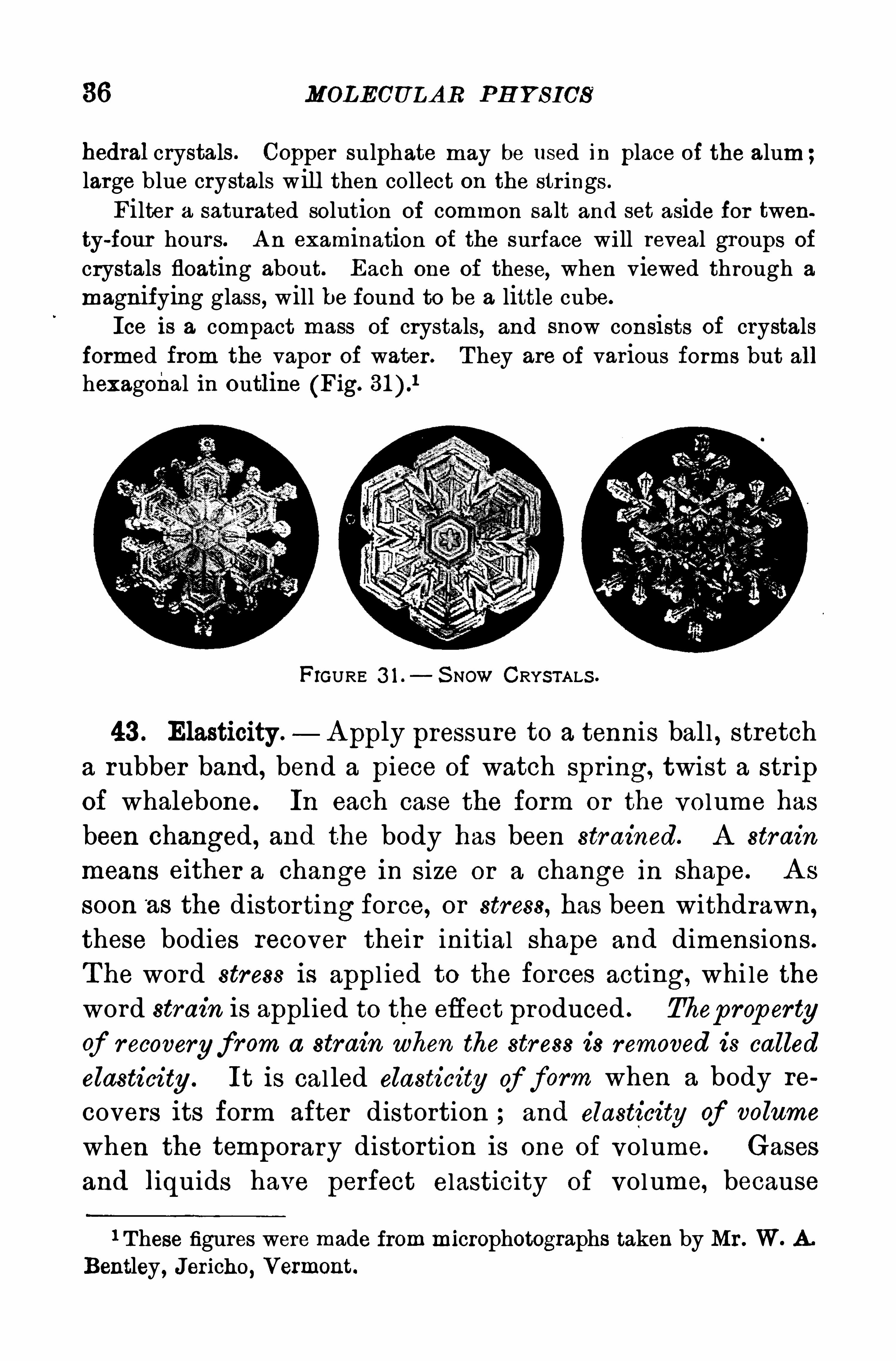
Ice is a compact mass of crystals, and snow consists of crystalsformed from the vapor of water . T hey are of various forms but allhexagonal in outline (Fig.
FIGURE 3 1 . S NOW CRYSTALS .
43 . Elasticity . A pply pressure to a tennis ball , stretcha rubber band , bend a piece of watch spr ing, twist a str ipof whalebone. In each case the form or the volume has
been changed , and the body has been str ained. A strain
means either a change in size or a change in shape. A s
soon ‘
as the distorting force, or stress, has been withdrawn,
these bodies recover their initial shape and dimensions.
T he word stress is appl ied to the forces acting, whi le the
word strain is applied to the effect produced . Thep rop erty
of recovery from a strain when the str ess is removed is called
elasticity . It is cal led elasticity of form when a body re
covers its form after distortion ; and elasticity of volume
when the temporary distortion is one of volume. Gases
and liquids have perfect elasticity of volume, because
1 These figures were made frommicrophotographs taken by Mr . W. A .
Bentley , Jericho, Vermont.
H OOKE’
S L A W 37
they recover their former volume when the original pressure is restored . T hey have no elasticity of form . S omesol ids, such as shoemaker ’s wax, lead, putty, and dough,when long-continued force is appl ied, yiel d s lowly and
never recover .
T he elasticity of a body may be called forth by pressure,by stretching, by bending, or by twisting. T he bounding bal l and the popgun are i l lustrations of the first ;rubber bands are fami l iar examples of the second bowsand spr ings of the third and the stretched spiral spr ingexempl ifies the fourth .
44 . H ooke’
s Law.—Sol ids have a l imit to their distor
tion, cal led the elastic limit, beyond which they yield and
are incapable of re
coveringtheir formor volume. T he
elastic limit of steelis very high steel
breaks before thereis much permanent
distortion . On the
other hand, lead does not recover completely from anydistortion .
When the strain in an elastic body does not exceed theelastic l imit, in general the d istor tion is p ropor tiona l to thedistorting for ce, or the str a in is propor tional to the stress ,
T his relation is known as H ooke’
s law.
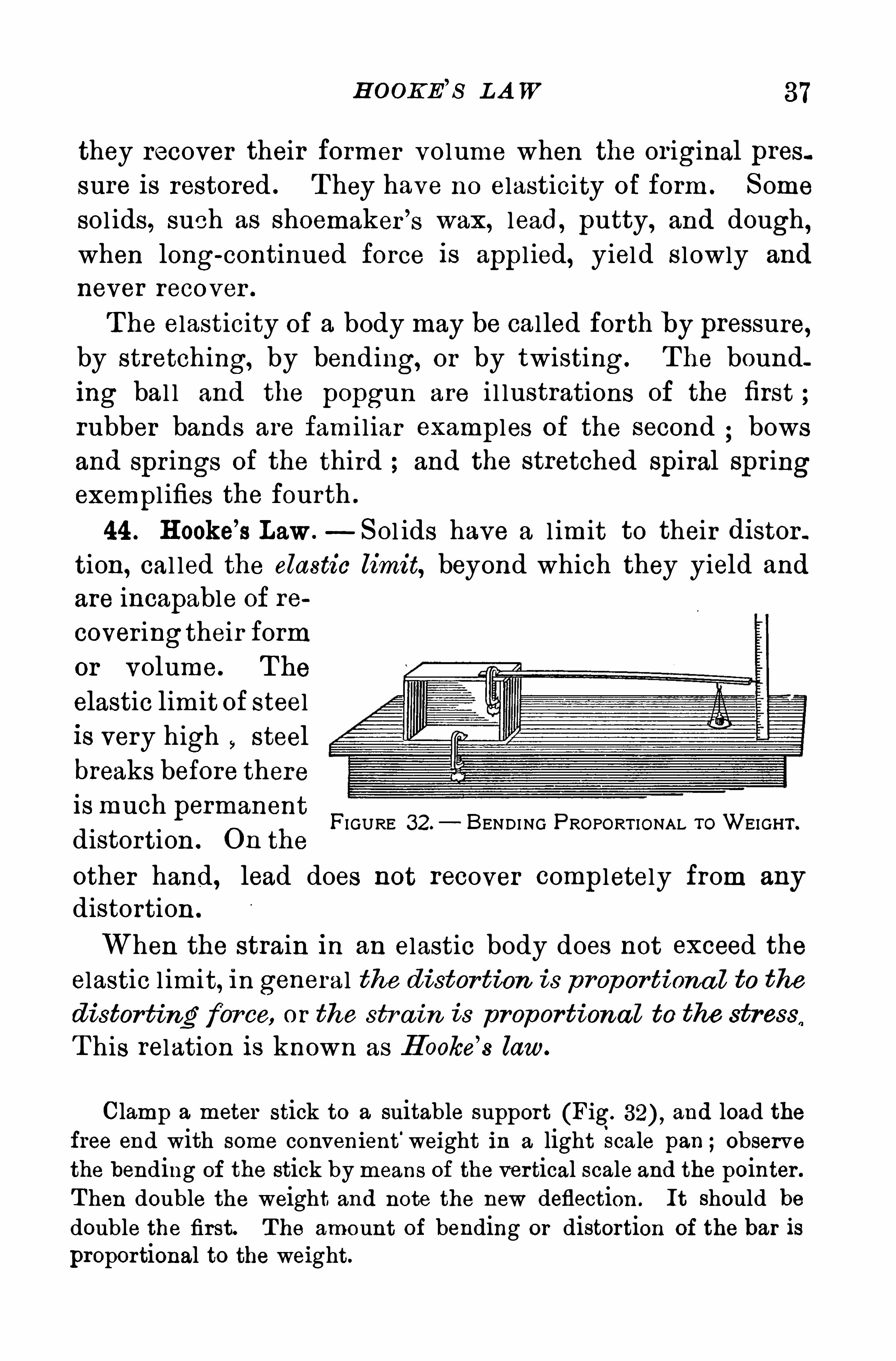
FIGURE 32. BENDING PROPORT IONAL ToWEIGHT.
Clamp a meter stick to a suitable support (Fig. and load thefree end with some convenient ' weight in a light Scale pan ;Observethe bending of the stick by means of the vertical scale and the pointer.
T hen double the weight and note the new deflection . It should bedouble the first. T he amount of bending or distortion Of the bar is
proportional to the weight.
38 MOL ECULA R P H Y S ICS
General ly, for a ll elastic d isp lacem ents within the
elastic lim it, the distortions Of'
any kind , du e to bending,
stretch ing, or twisting, a re pr opor tiona l to the forces pr odu cing them .
Q uestions and Exercises
1 . When a glass tube or rod is cut off its edges are sharp . Whydo they become rounded by softening in a blowpipe flame ?
2 . Why does a small vertical stream of water break into drops3 . Why does a dish with a sharp lip pour better than one with
out it ?
4 . A soap bubble is filled with air . Is the air inside denser or
rarer than the air outside5 . Explain the action of gasoline in removing grease spots . H ow
should it be applied so as to avoid the dark r ing which often remainsafter its use
6 . T he hairs of a camel’s-hair brush separate when placed in water ,but gather to a point when the brush is removed from the water .
Explain .
7 . A re the divisions on the scale of a spring balance equal ?VJhat law is illustrated ?
8 . In the stone quar r ies of ancient Egypt it is said that largeblocks of stone were loosened by drilling a ser ies of holes in the rock ,driving in wooden plugs, and then thoroughly wetting them. Ex
plain.
9 . Why is it difficult to write on clean glass with a pen ?
1 0 . A nalysis of the air in a closed room shows little or no diflerencein its composition in different parts of the room . Explain .
1 1 . If a capillary tube is supported vertically in a vessel of waterand the tube is shorter than the distance to which water would rise
in it, will the water flow out of the top ? Why ?
1 2 . If water r ises 1 5 mm . in a capillary tube of mm. diameter,
what must be the diameter of a tube in which water will rise 45 mm . ?
CH A PT ER III
MECHANICS OF FLU IDS
I. PRES SURE OF FLU IDS
45. Character istics of Fluids. A fluid has no shape of
its own , but takes the shape of the containing vessel . i t
cannot resist a stress unless it is suppor ted on all sides .
The molecules of a fluid at rest are disp laced by the sl ightest force; that is, a fluid yields to the continued appl ication of a force tending to change its shape. But fluidsexhibit wide differences in mobility , or readiness in y ielding to a stress . A lcohol , gasol ine, and sulphur ic ether
are examples of very mobi le liquids; glycer ine is verymuch less mobile, and tar sti l l less so .
In fact, liquids shade off gradual ly into solids . A stick
of seal ing wax supported at its ends yields continuous ly
to its own weight; in warm weather paraffin candles do
not maintain an U pr ight position in a candlestick, but
curve over or bend double; a cake of shoemaker ’s wax
on water , with bul lets on it and corks under it, yields to
both and is traversed by them in Opposite directions. A t
the same time, seal ing wax and shoemaker ’s wax when
cold break readily under the blow of a hammer .
46 . Viscosity . The resistance of a fluid toflowing under
stress is called viscosity . It is due to molecular fr iction .
T he s lowness with which a fine precipitate, thrown down
by chemical action, settles in water is owing to the vis
cosity of the l iquid; and the s low descent of a cloud is39
40 MECH A N ICS OF FL UIDS
accounted for by the viscosity . of the air . Viscosity varies
between wide l imits . It is less in gases than in liquids;hot water is less viscous than cold water ; hence the rela
tive ease with which a hot solution fi lters .
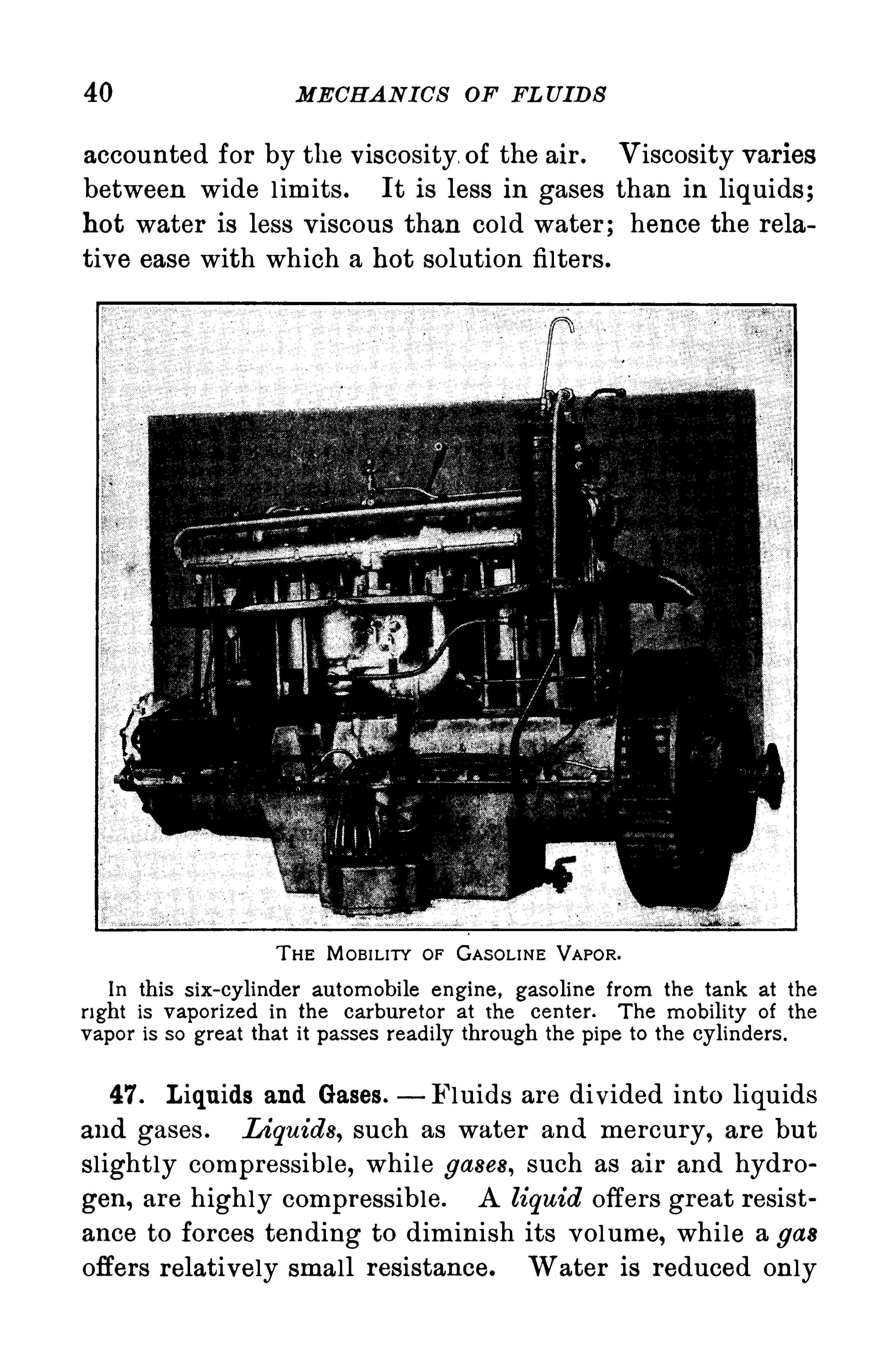
T H E MOBI LITY or GAS OLINE VAPOR.
In this S ix- cylinder automobile engine, gasoline from the tank at the
right is vaporized in the carburetor at the center. T he mobility of the
vapor is so great that it passes readily through the pipe to the cylinders .
47 . L iquids and Gases. Fluids are divided into liquids
and gases . L iquids, such as water and mercury, are but
sl ightly compressible, while gases , such as air and hydro
gen, are highly compressible. A liquid offers great resist
ance to forces tending to diminish its vol ume, while a gas
offers relatively small resistance. Water is reduced only
42 MECH A NICS OF FL U ID S
mits pressure in every direction . H ence the law first
announced by Pascal in 1 653
P ressu re app lied to an inclosed flu id is transm itted
equ a lly in a ll d irections and withou t d im inu tion to
every par t Of theflu id and Of the inter ior of the conta in
ing vessel .
T his is the fundamental law of the mechanics of fluids .
It is a direct consequence of their mobi lity, and it appl iesto both liquids and gases .
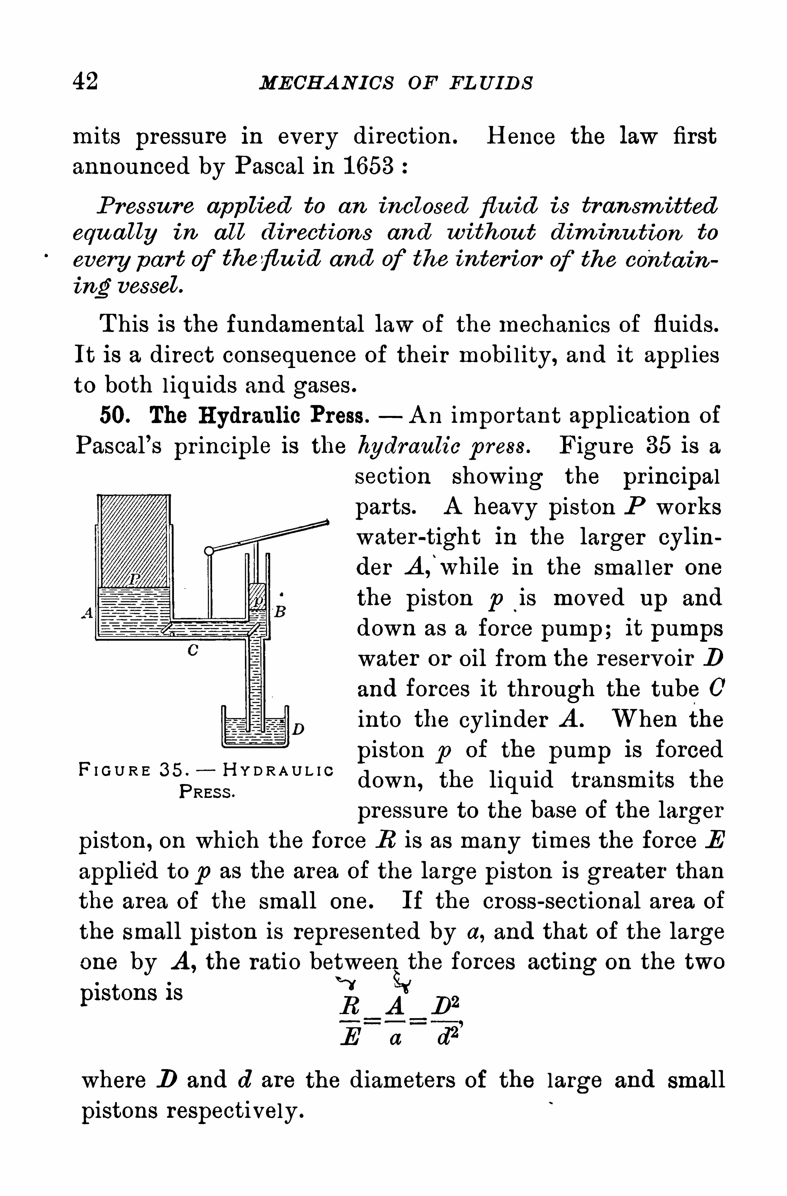
50. The H ydraulic Press. A n important application of
Pascal’s pr inciple is the hydraulic p ress . Figure 35 is a
section showing the pr incipal
parts. A heavy piston P workswater-tight in the larger cylin
der A f while in the smal ler one
the piston p ‘
is moved up and
down as a force pump; it pumpswater or Oil from the reservoir D
and forces it through the tube 0into the cylinder A . When the
piston p of the pump is forceddown, the liquid transmits the
pressure to the base of the larger
piston, on which the force R is as many times the force E
applied to p as the area of the large p iston is greater than
the area of the small one. If the cross-sectional area of
the small piston is represented by a, and that of the large
one by A , the rati o between the forces acting on the two0 wpistons i s R A D2
E a d2
where D and d are the diameters of the large and small
pistons respectively .
F I G U R E 3 5 . H Y D R A U L I CPRES S .


A PP L ICA TION OF TH E H YDRA ULIC P RES S 43
T hus, if the area A is 1 00 times the area a , a force of
1 0 pounds on the piston p becomes 1 000 pounds on P .
T he hydraul ic press is a device which permits Of the exer ~
tion of enormous forces .
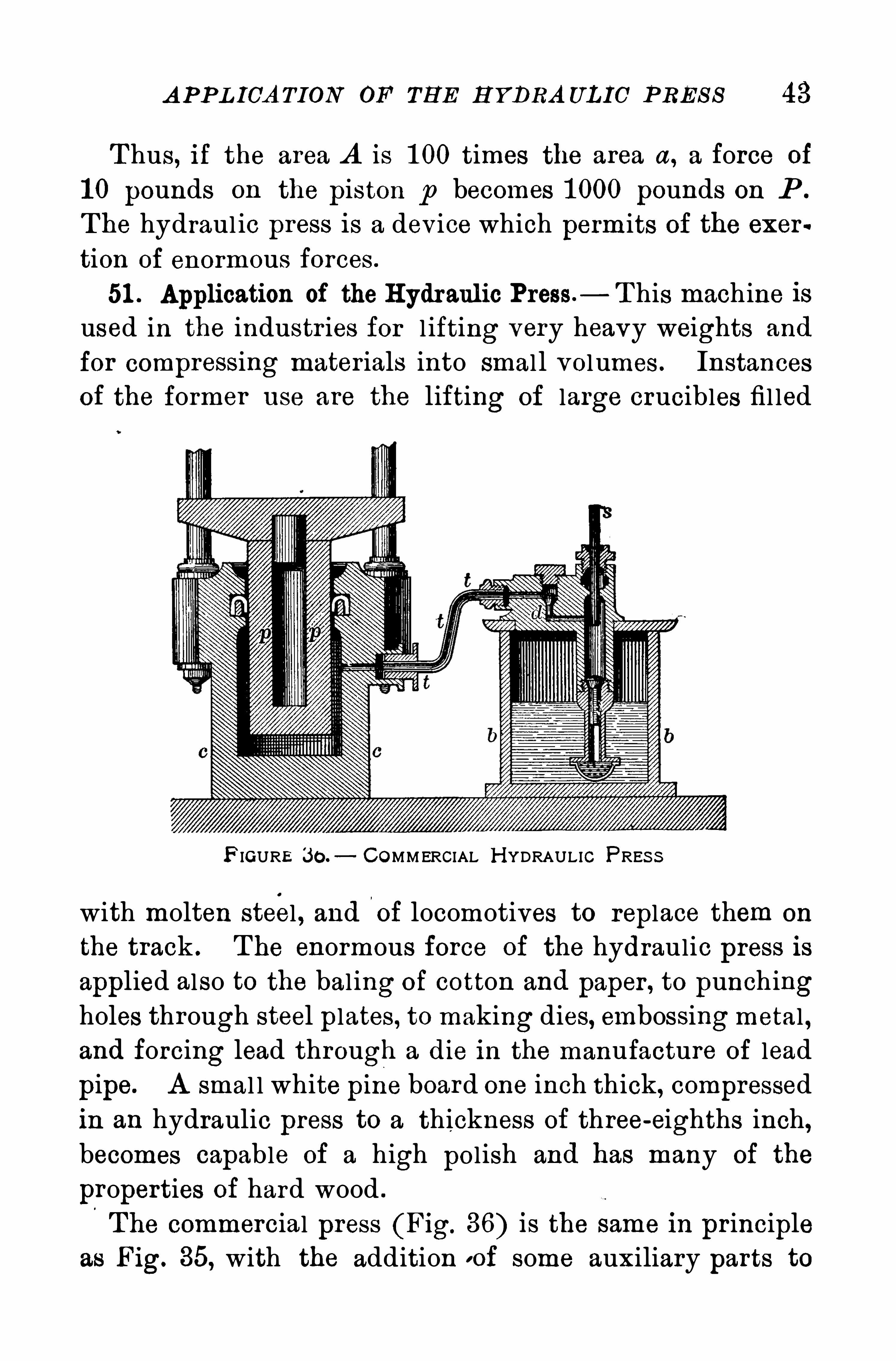
51 . Application of the H ydraulic Press. T his machine isused in the industr ies for l ifting very heavy weights and
for compressing mater ials into smal l volumes . Instances
of the former use are the lifting of large crucibles fil led
F IGURE 30 . COMMERCIAL H YDRAULIC PRES S
with molten steel , and'
oi locomotives to replace them on
the track . The enormous force Of the hydraulic press is
applied also to the bal ing of cotton and paper , to punchingholes through steel plates , to making dies, embossingmetal ,and forcing lead through a die in the manufacture of lead
pipe. A smal l white pine board one inch thick, compressedin an hydraulic press to a thickness of three-eighths inch,becomes capable of a high pol ish and has many of the
properties of hard wood .
The commercial press (Fig. 36) is the same in principleas Fig. 35, with the addition o f some auxiliary parts to
44 MECH A N ICS OF FL UIDS
make a working machine. The piston s of the force pumpmay be worked by any convenient power . It has a check
valve d which closes when 8 r ises and prevents the returnof the water from the large working cylinder . T he piston
P is surrounded by a pecul iar leather collar , without which
the press is a failure. T he larger the pressure in P , the
closer the leather col lar presses againstthe piston and prevents leakage. T he
upper portion of the machine, cut awayin the figure, differs according to the use
to which the press is put.
If the ratio between the cross-sectionsof the two pistons is 500, then when s is
pressed down with a force of 1 00 lb . the
piston P is forced up with a force of
lb .
In the hydraul ic press it is ev ident that
the small piston travels as many times
farther than the large one as the force
exerted by the large piston is greater
than the eflort applied to the small one.
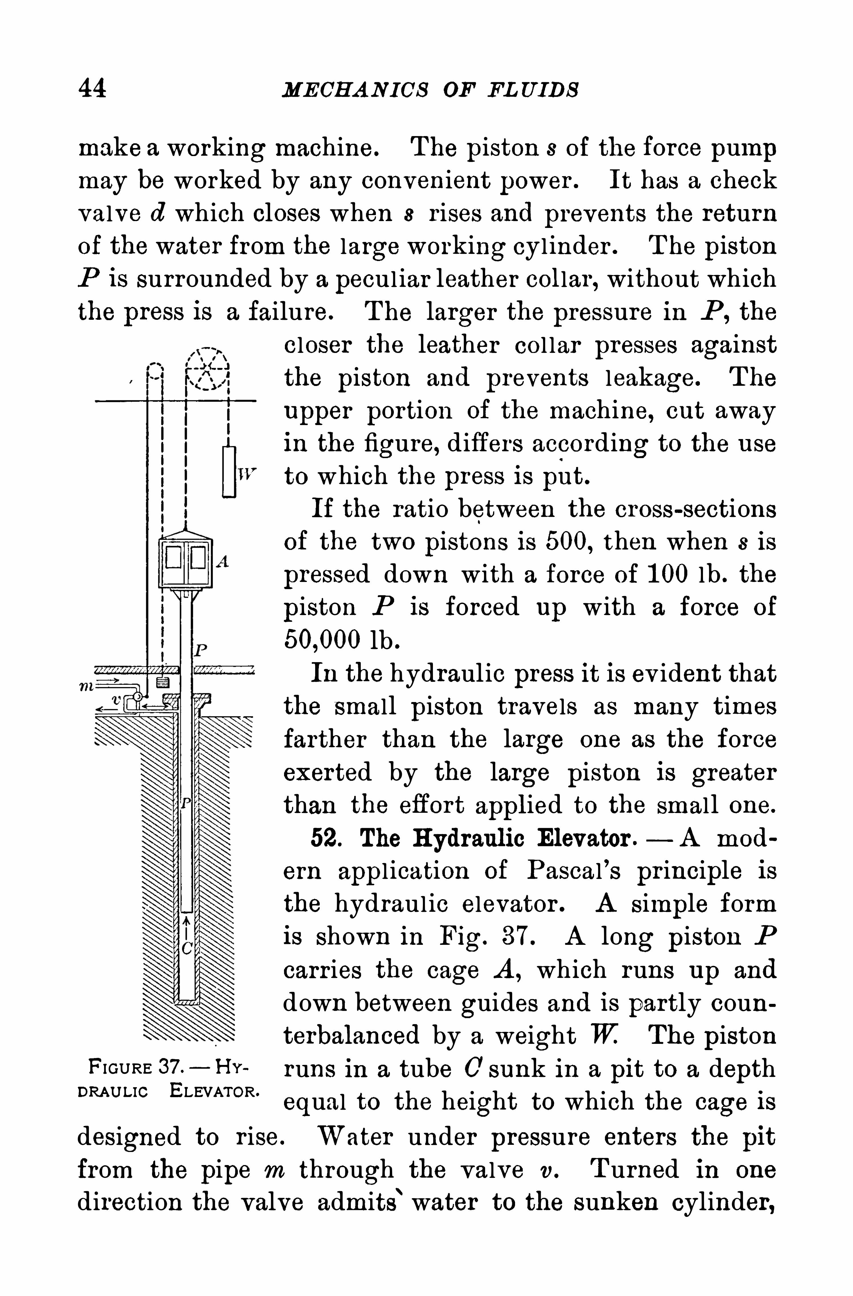
52. The H ydraulic Elevator .— A mod
ern appl ication of Pascal’s pr inciple is
the hydraulic elevator . A simple form
is shown in Fig. 37 . A long piston P
carries the cage A , which runs up and
down between guides and is partly counterbalanced by a weight W The piston
FIGURE 37 —H Y runs in a tube 0 sunk in a pit to a depthDRAU LIC ELEVATOR’
equal to the height to which the cage is
designed to r ise. Water under pressure enters the pit
from the pipe m through the valve v . T urned in one
direction the valve admits‘water to the sunken cylinder,
DOWNWA RD P RES S URE OF A L IQU ID 45
and the pressure forces the piston up when the operatorturns it in the other direction by pul l ing a cord, it al lowsthe water to escape into the sewer , and the elevator descends by its own weight.
When greater speed is required, the cage is connected
to the piston indirectly by a system of pulleys .
“T he cage
then usual ly runs four times as fast and four times as faras the piston .
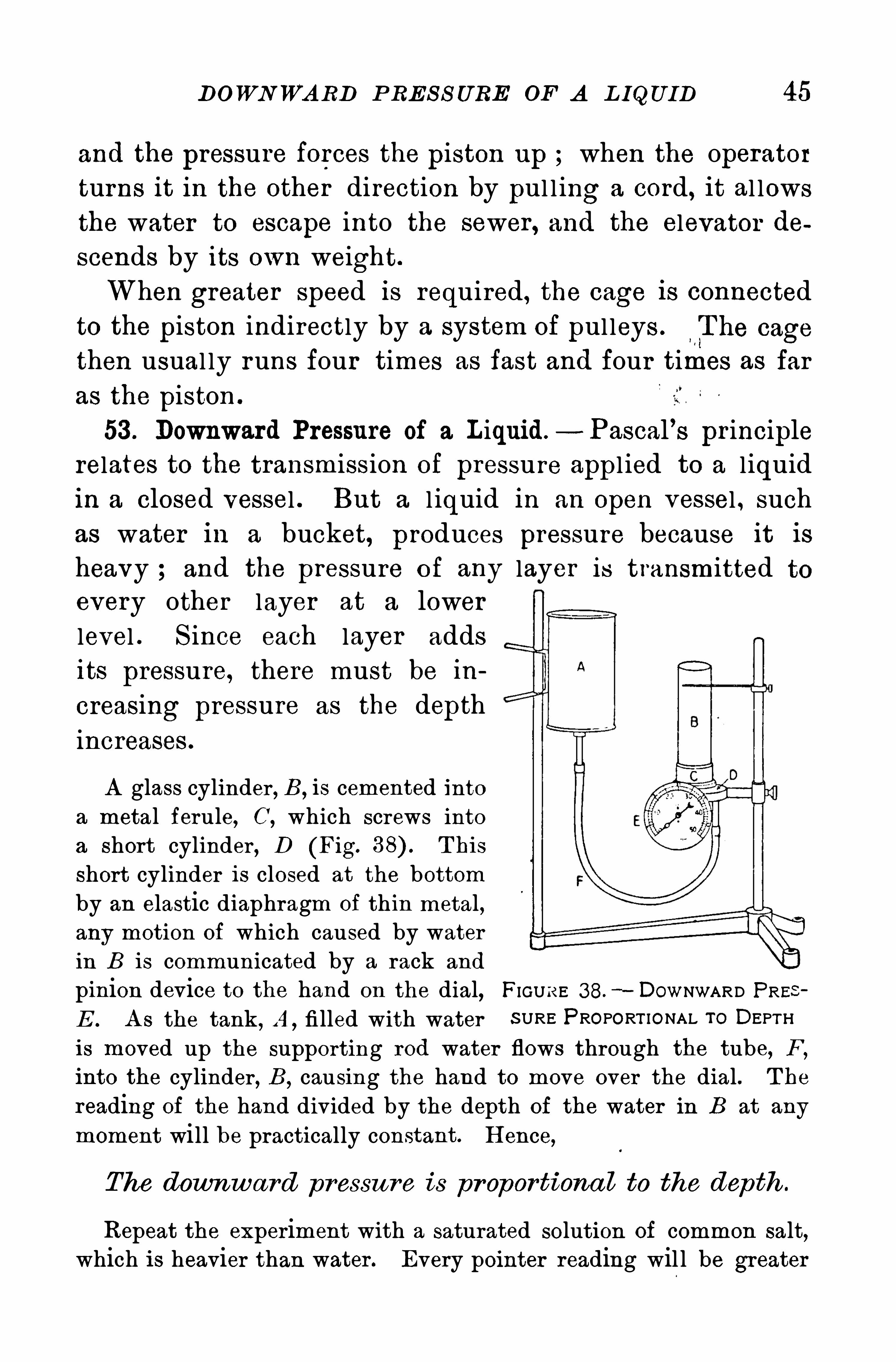
53 . Downward Pressure of a Liquid —Pascal’s principlerelates to the transmission of pressure appl ied to a l iquid
in a closed vessel . But a l iquid in an open vessel , such
as water in a bucket, produces pressure because it is
heavy ; and the pressure of any layer is transmittedevery other layer at a lower
level . S ince each layer adds
its pressure, there must be in
creasing pressure as the depth
increases .
A glass cylinder , B,is cemented into
a metal ferule, C, which screws intoa short cylinder , D (Fig. T his
short cylinder is closed at the bottomby an elastic diaphragm of thin metal,any motion of which caused by waterin B is communicated by a rack and
pinion device to the hand on the dial, FIGURE 38.- DOWNWARD PRE
E . A s the tank, A ,fi lled with water S URE PROPORT IONAL To DEPTH
is moved up the supporting rod water flows through the tube, F ,
into the cylinder , B ,causing the hand to move over the dial. T he
reading of the hand divided by the depth of the water in B at any
moment will be practically constant. H ence,
The downward pressu re is pr oportiona l to the depth .
Repeat the experiment with a saturated solution of common salt,which is heavier than water . Every pointer reading wil l be greater
46 MECH A N ICS OF FL UIDS
than the corresponding ones with water , but the same relation willexist between them. H ence,
The downward pressu re Of a liqu id
is p ropor tional to its den s ity
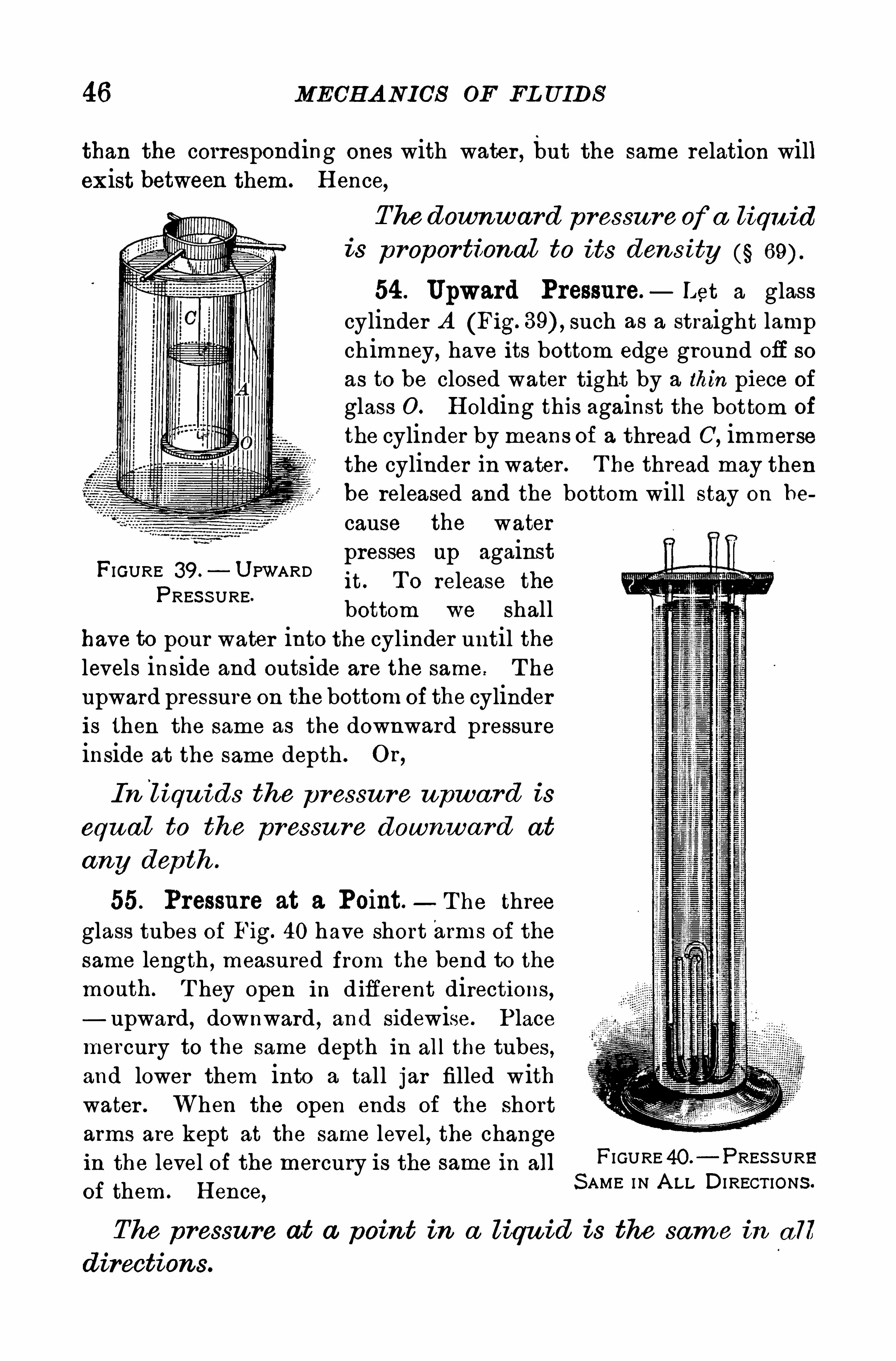
54 . Upward Pressure. Let a glasscylinder A (Fig. such as a straight lampchimney, have its bottom edge ground off so
as to be closed water tight by a thin piece of
glass 0 . H olding this against the bottom Of
the cylinder by means of a thread C,immerse
the cylinder in water . T he thread may thenbe released and the bottom will stay on be
cause the waterpresses up againstit . T o release the
bottom we shallhave to pour water into the cylinder until thelevels inside and outside are the same. T he
upward pressure on the bottom of the cylinderis then the same as the downward pressureinside at the same depth . O r ,
FIGURE 39 . U PWARDPRES S URE.
In l iqu ids the p ressu re upwa rd is
equ a l to the pressu re downwa rd at
any dep th .
55. Pressure at a Point.— T he three
glass tubes of Fig. 40 have short arms of the
same length , measured from the bend to themonth. T hey open in d ifferent directions ,— upward, downward , and sidewise. P lacemercury to the same depth in all the tubes ,and lower them into a tall jar filled withwater . When the open ends of the shortarms are kept at the same level , the changein the level of the mercury is the same in all
of them . H ence,
FIGURE 40. PRES S URES AME IN A LL DI RECT IONS .
The pressu re at a point in a liqu id is the sam e in a ll
directions.
48 MECH A N ICS OF FL UIDS
the weight in grams, the pressure p In water is equal tothe depth h, since a cubic centimeter of water weighs one
gram. T he pressure is then in grams per square centimeter . But if h is in feet and d in pounds per cubic foot,then p = h x pounds per square foot, since a cubicfoot of water weighs pounds. T o get the pressurein pounds per square inch , divide by 1 44, because thereare 1 44 square inches in a square foot.
T he force on any hor izontal area A is then
P A x h x d (Equation 1 )
If the given sur face is inclined, then the pressure in
creases from its value at the highest point submerged to
its value at the lowest point. In this case h means the
mean depth of the area, or the depth of its center of figure.
T he total force on any given plane area is always normal ,that is, perpendiculér to it. Equation 1 sti ll appl ies .
Examp les. T o calculate the force on the bottom and sides of a
cubical box 30 centimeter s on each edge, filled with water , and standing on a hor izontal plane:T he area of each face is 30 x 30 900 cm .
2 T hen the force on
the bottom at a depth of 30 cm . is 900 x 30 g. On the sidesthe pressure varies from zero to30 g. per square centimeter . T he
average pressure is halfway downat a point 1 5 cm. deep and is 15
g . per square centimeter . H encethe force tending to push out eachside is 900 x 1 5 g.
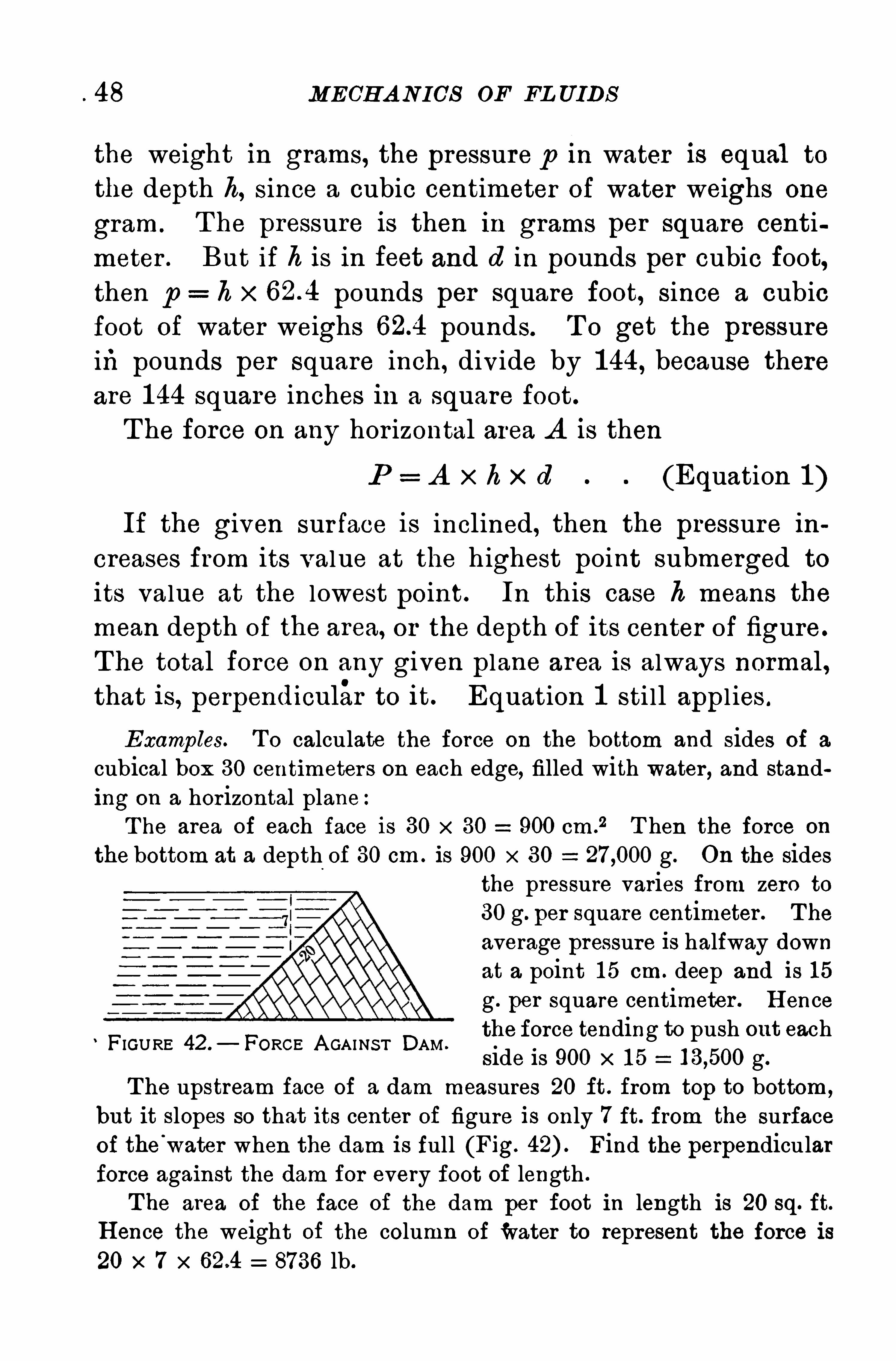
T he upstream face of a dam measures 20 ft. from top to bottom ,
but it slopes so that its center of figure is only 7 ft. from the surfaceof the
'
water when the dam is full (Fig. Find the perpendicularforce against the dam for every foot of length .
T he area of the face of the dam per foot in length is 20 sq. ft.
H ence the weight of the column of water to represent the force is20 x 7 x 8736 lb.
FIGURE 42 .
— FORCE A GAINS T DAM.
L EVEL OF L IQU ID IN CONNECTED VE S S EL S 49
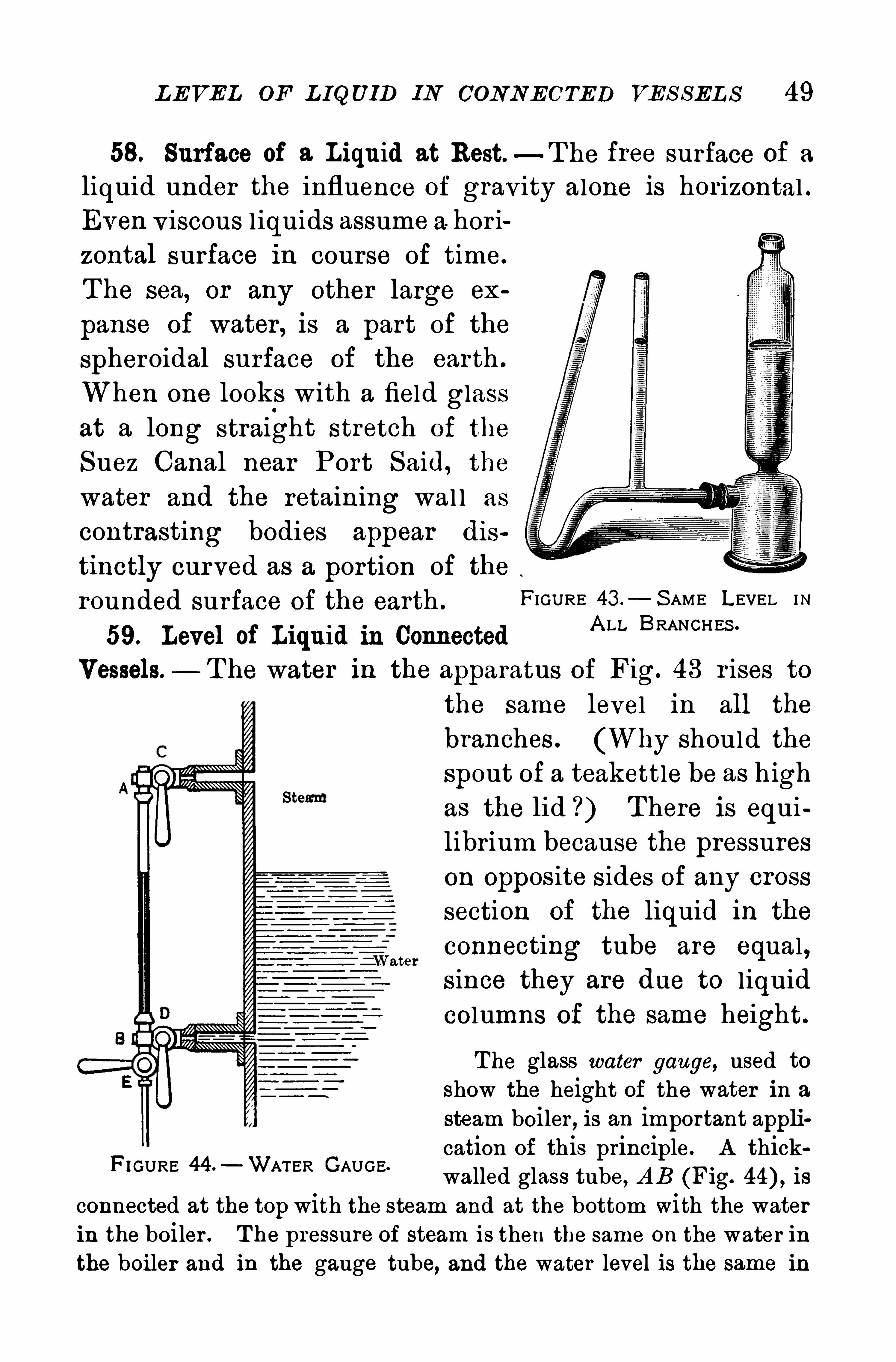
58. Surface of 3. Liquid at Rest—T he free surface of a
liquid under the influence of grav ity alone is horizontal .Even v iscous l iquids assume a hor i
zontal surface in course of time.
T he sea, or any other large ex
panse of water , is a part of the
spheroidal surface of the earth .
When one looks with a field glass
at a long straight stretch of the
Suez Canal near Port S aid, the
water and the retaining wal l as
contrasting bodies appear dis
tinctly curved as a portion of the
rounded surface of the earth .FIGURE 43 o
— S AME LEVEL m
59. Level of Liquid in ConnectedA LL BRANCHES ‘
Vessels — T he water in the apparatus of Fig. 43 r ises tothe same level in all the
branches . (Why should theSpout of a teakettle be as high
as the lid ? ) T here is equilibrium because the pressureson opposite sides of any cross
section of the liquid in the
connecting tube are equal ,since they are due to liquid
columns of the same height.
The glass water gauge, used toshow the height of the water in a
steam boiler , is an important appli
FIGURE 44 —WATER GAUGEcation of this principle. A thickwalled glass tube, A B (Fig. is
connected at the top with the steam and at the bottom with the waterin the boiler . T he pressure of steam is then the same on the water inthe boiler and in the gauge tube, and the water level is the same in
50 MECH A N ICS OF FL UIDS
the two . T he stopcocks C and D are kept open except when it becomes necessary to replace the glass tube. A nother stopcock E serves
to clean out the tube by running steam through it.
A nother application is the water level, consisting of two glass tubes,joined by a long rubber tube, and employed by builders for levelingfoundations.
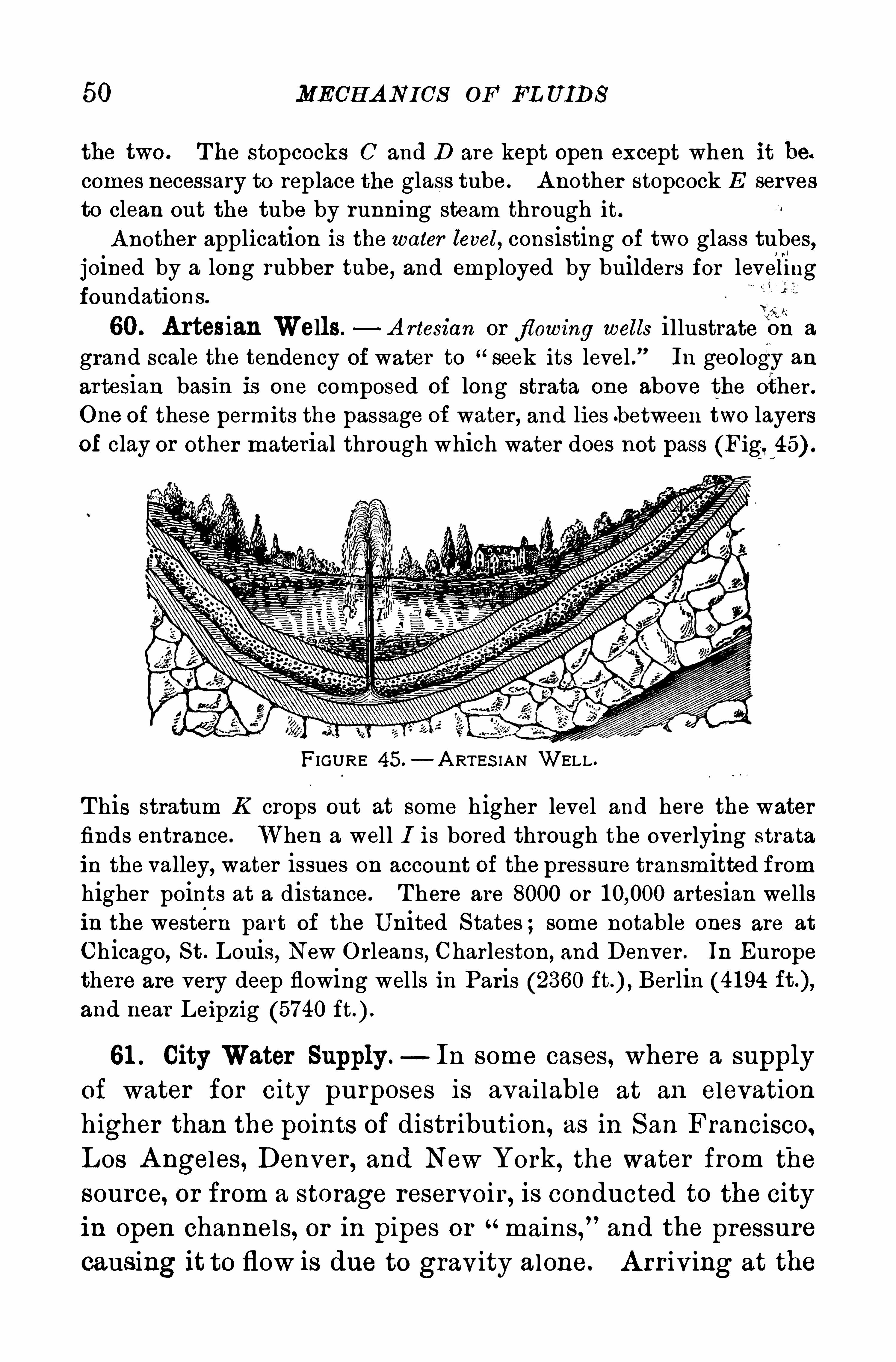
60. Artesian Wells.—A rtesian or fl owing wells illustrate On a
grand scale the tendency of water to seek its level . In geology anartesian basin is one composed of long strata one above the other .
One of these permits the passage of water , and lies b etween two layersof clay or other material through which water does not pass (Figl 45) .
FIGURE 45.— A RTES IAN WELL .
This stratum K crops out at some higher level and here the waterfinds entrance. When a well I is bored through the over lying strata
in the valley, water issues on account of the pressure transmitted fromhigher points at a distance. T here are 8000 or artesian wellsin the western part of the U nited S tates ; some notable ones are at
Chicago, St . Louis, New O rleans, Charleston, and Denver . In Europethere are very deep flowing wells in Paris (2360 Berlin (41 94and near Leipzig (5740
61 . City Water Supply. In some cases, where a supplyof water for city purposes is available at an elevation
higher than the points of distr ibution, as in San Francisco ,Los A ngeles, Denver , and New York, the water from the
source, or from a storage reservoir , is conducted to the cityin open channels, or in pipes or mains ,
”and the pressure
causing it to flow is due to gravity alone. A rr iving at the
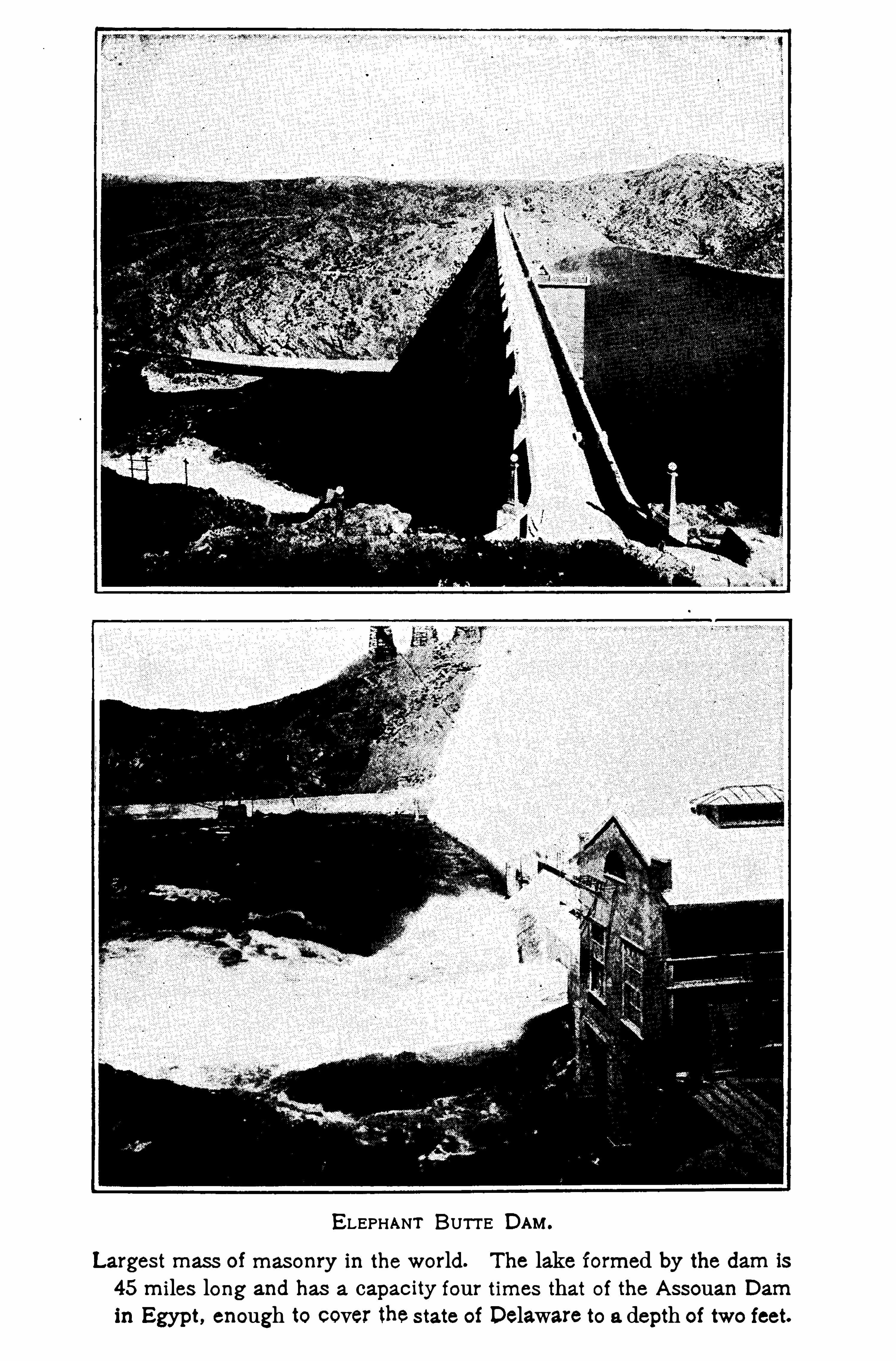
ELEPHANT BUTT E DAM.
Largest mass of masonry in the world. The lake formed by the dam is
45 miles long and has a capacity four times that of the A ssouan Damin Egypt, enough to cover thestate of Delaware to a depth of two feet.

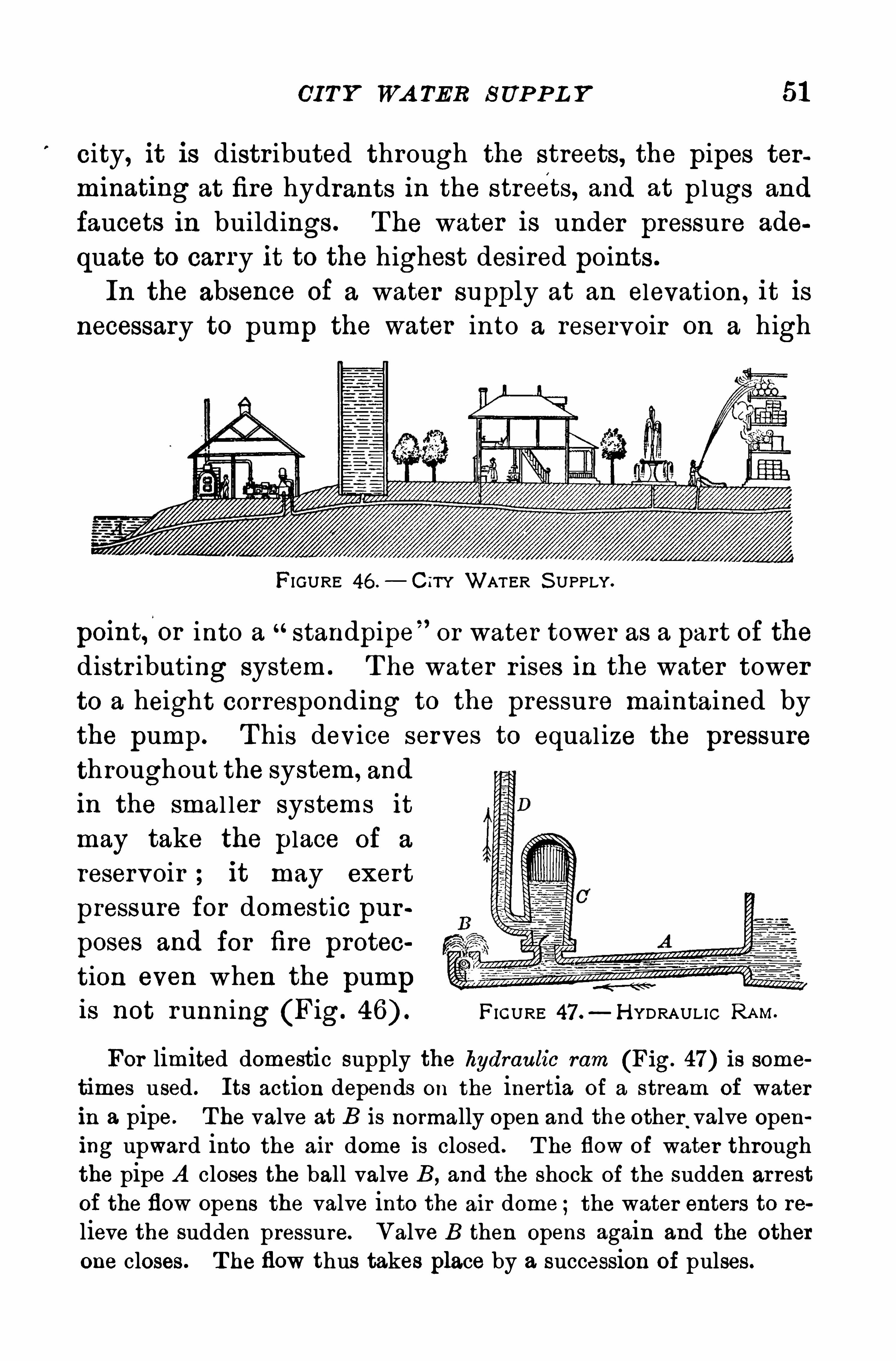
CI T Y WA TER S UP P L Y 51
city, it is distr ibuted through the streets, the pipes terminating at fire hydrants in the streets, and at plugs and
faucets in buildings . The water is under pressure ade
quate to carry it to the highest desired points .
In the absence of a water supply at an elevation , it is
necessary to pump the water into a reservoir on a high
FIGURE 46 .
— CITY WAT ER S UPPLY.
point,
‘
or into a standpipe or water tower as a part of the
distr ibuting system . T he water r ises in the water tower
to a height corresponding to the pressure maintained by
the pump. T his device serves to equal ize the pressurethroughout the system, and
in the smal ler systems it
may take the place of a
reservoir ; it may exert
pressure for domestic pur
poses and for fire protec
tion even when the pumpis not running (Fig. FIGURE 47 .
—H YDRAULIC RAM.
For limited domestic supply the hydraulic mm (Fig. 47) is some
times used . Its action depends on the inertia of a stream of waterin a pipe. T he valve at B is normally open and the other
.
valve Opening upward into the air dome is closed . T he flow of water throughthe pipe A closes the ball valve B, and the shock of the sudden arrest
of the flow opens the valve into the air dome ;the water enters to re
lieve the sudden pressure. Valve B then opens again and the otherone closes . T he flow thus takes place by a succession of pulses.
52 MECH A N ICS OF FL UIDS
Q ues tions and P rob lems
1 . If a pressure gauge be attached to the water pipe on the top
floor of a tall building and a second one be attached in the basement,
wi ll the readings be the same ? Why ?
2 . Why is there danger of bur sting a thermos bottle by forcingin the stopper when the bottle is full of liquid ?
3 . In a city supplied with water from a reservoir , to what heightwill the water rise in a vertical pipe connected with the system
4 . Why does a coiled garden hose tend to straighten out whenthe water is turned on ?
5 . Is the pressure against a dam that backs up the water for a
mile greater than on one that backs up the water for a half mile,the depth of water at the dam being the same in both cases ?
6 . T he cylinders of a hydraulic press are respectively 6 in . and
1 in . in diameter . If a force of 1 00 lb. is applied to the piston of the
smaller cylinder , what force will the larger piston exert ?
7 . A tank 1 0 ft. square and 1 0 ft. deep, ful l of water , wil l 'exert
how much force on the bottom H ow much on one side ?
8. A glass tube 76 cm . long is full of mercury. What is thepressur e in grams per cm.
2on the bottom ? (1 cm .
3of mercury weighs
g.)9 . A glass cylinder 6 in. in diameter and 1 2 in . deep
.is ful l of
water . What is the force of the water against its cylindrical surface
1 0 . If the pressure gauge of a water system regi sters 50 lh .
,how
high will water r ise in a vertical pipe attached thereto ?
1 1 . What weight can be supported on the platform of a hydrau licelevator , if the piston is 1 0 in . in diameter and the pressure gaugeregister 50 lb . to the square inch ?
1 2 . Sea water weighs 64 lb . to the cubic foot.
’
What force will beexerted on a board 1 0 ft. long and 1 ft. wide sunk horizontally in thesea to a depth of a mile ?
1 3 . T he pressure gauge of a water system regi sters 60 lb . to the
sq. in . on the ground floor and 30 lb . to the sq. in . on the top floor.
What is the difference of level ?
1 4 . A kerosene tank is 1 0 ft. in diameter and 1 0 ft. deep. When .
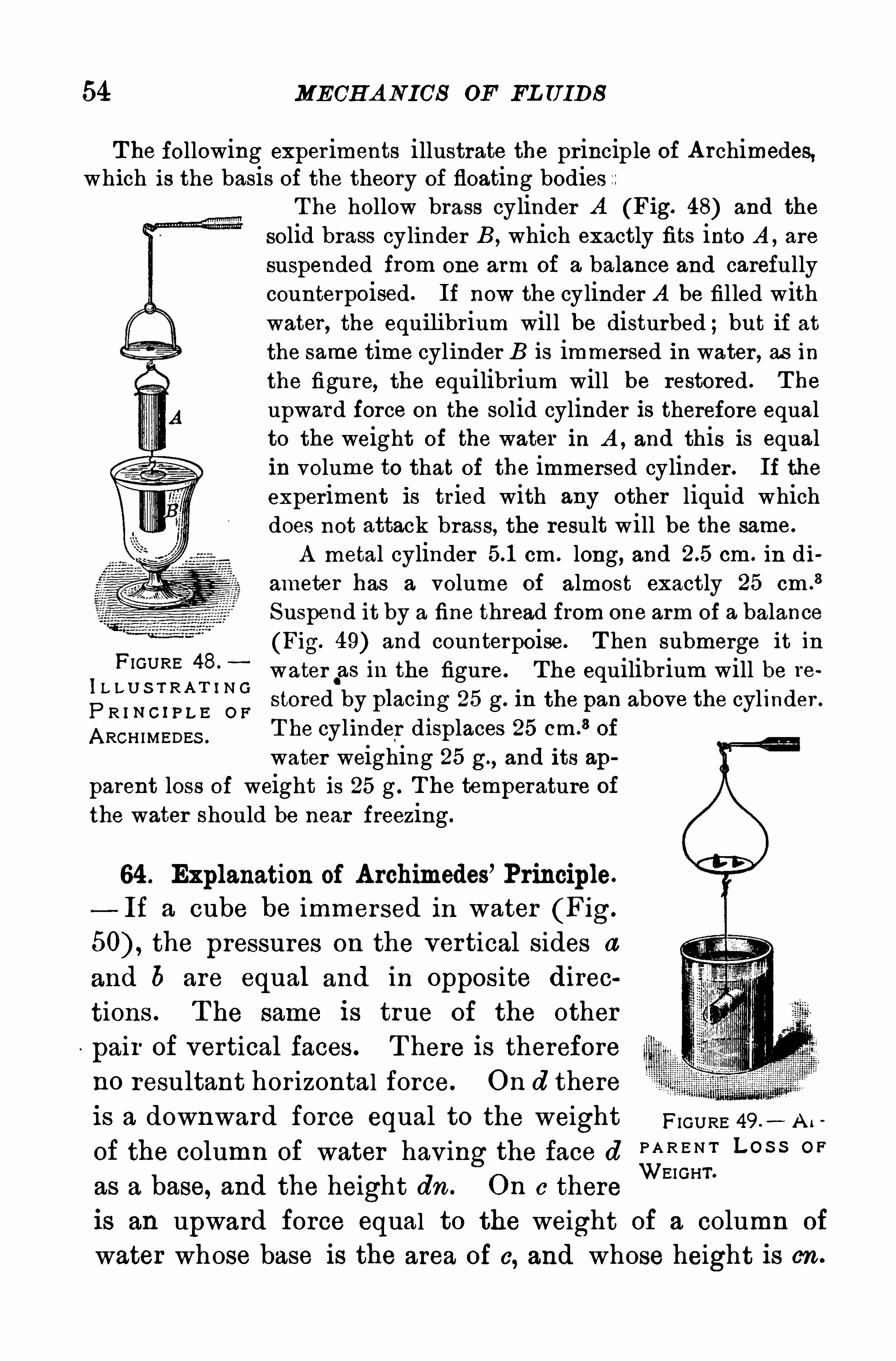
54 MECH A N ICS OF FL U IDS
T he following exper iments illustrate the principle of A rchimedes,which is the basis of the theory of floating bodies
T he hollow brass cylinder A (Fig. 48) and the
solid brass cylinder B, which exactly fits into A , are
suspended from one arm of a balance and carefullycounterpoised. If now the cylinder A be filled withwater, the equilibrium will be disturbed ;but if atthe same time cylinder B is immersed in water , as inthe figure, the equilibrium will be restored . T he
upward force on the solid cylinder is therefore equalto the weight of the water in A , and this is equalin volume to that of the immersed cylinder . If the
experiment is tried with any other liquid whichdoes not attack brass, the result will be the same.
A metal cylinder cm . long, and cm . in di
ameter has a volume of almost exactly 25 cm .
3
Suspend it by a fine thread from one arm of a balance
(Fig. 49) and counterpoise. T hen submerge it in
IL L U S T R A N N 0
water.as in the figure. The equilibrium will be re
P R I N C ! P L E 0 Fstored by placmg 25 g. In the pan above the cyl inder .
A RCH IMEDES .
T he cyl inder d i splaces 25 cm.3 of
water weighing 25 g., and its ap
parent loss Of weight is 25 g . T he temperature ofthe water should be near freezing.
FIGURE 48.
64 . Explanation of A rchimedes’ Principle.
If a cube be immersed in water (Fig.
the pressures on the vertical sides a
and b are equal and in opposite direc
tions . T he same is true of the other
pair of vertical faces . T here is therefore
no resultant hor izontal force. On d there
is a downward force equal to the weight FIGURE A .
Of the column of water having the face dP A R E N T L O S S O F
as a base, and the height dn . On c thereWEIGHT’
is an upward force equal to the weight of a column of
water whose base is the area of c, and whose height is on .
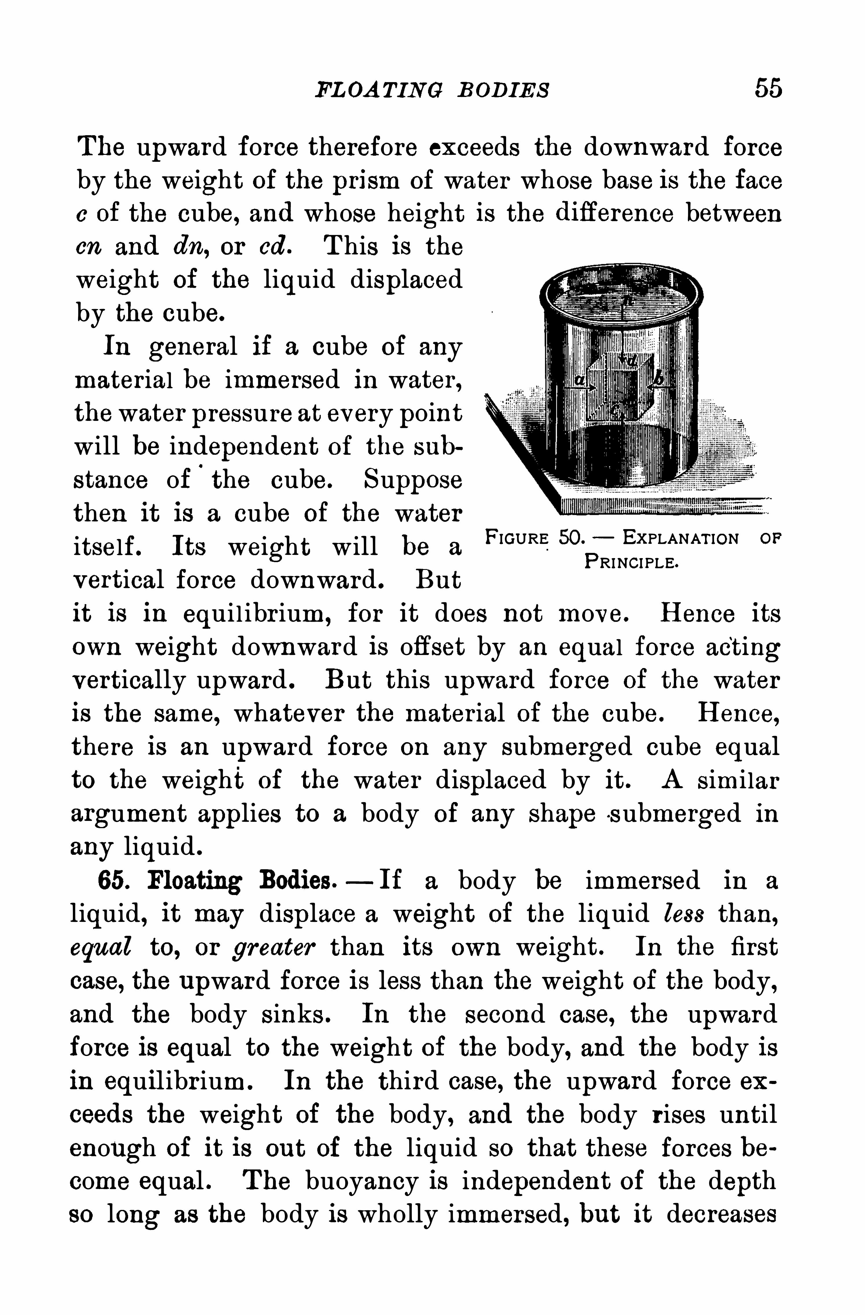
FL OA TING BODIES 55
The upward force therefore exceeds the downward forceby the weight of the prism of water whose base is the facec of the cube, and whose height is the diflerence betweencn and dn, or cd . T his is theweight of the liquid displaced
by the cube.
In general if a cube of any
material be immersed in water,thewater pressure at every point
will be independent Of the sub
stance of‘
the cube. Supposethen it is a cube of the water
itself. Its weight will be a
vertical force downward . But
it is in equil ibr ium , for it does not move. H ence its
own weight downward is offset by an equal force actingvertically upward . But this upward force of the water
is the same, whatever the mater ial of the cube. H ence,
there is an upward force on any submerged cube equalto the weight of the water displaced by it . A similarargument applies to a body of any Shape s ubmerged in
any liquid .
65. Floating Bodies.—If a body be immersed in a
liquid, it may displace a weight of the liquid less than,equal to, or greater than its own weight. In the first
case, the U pward force is less than the weight of the body,and the body sinks . In the second case, the upwardforce is equal to the weight of the body, and the body isin equilibr ium. In the third case, the upward force ex
ceeds the weight of the body, and the body rises untilenough of it is out of the liquid so that these forces be
come equal . T he buoyancy is independent of the depthso long as the body is wholly immersed, but it decreases
FIGURE 50. EXPLANAT ION OP
PRINCIPLE.
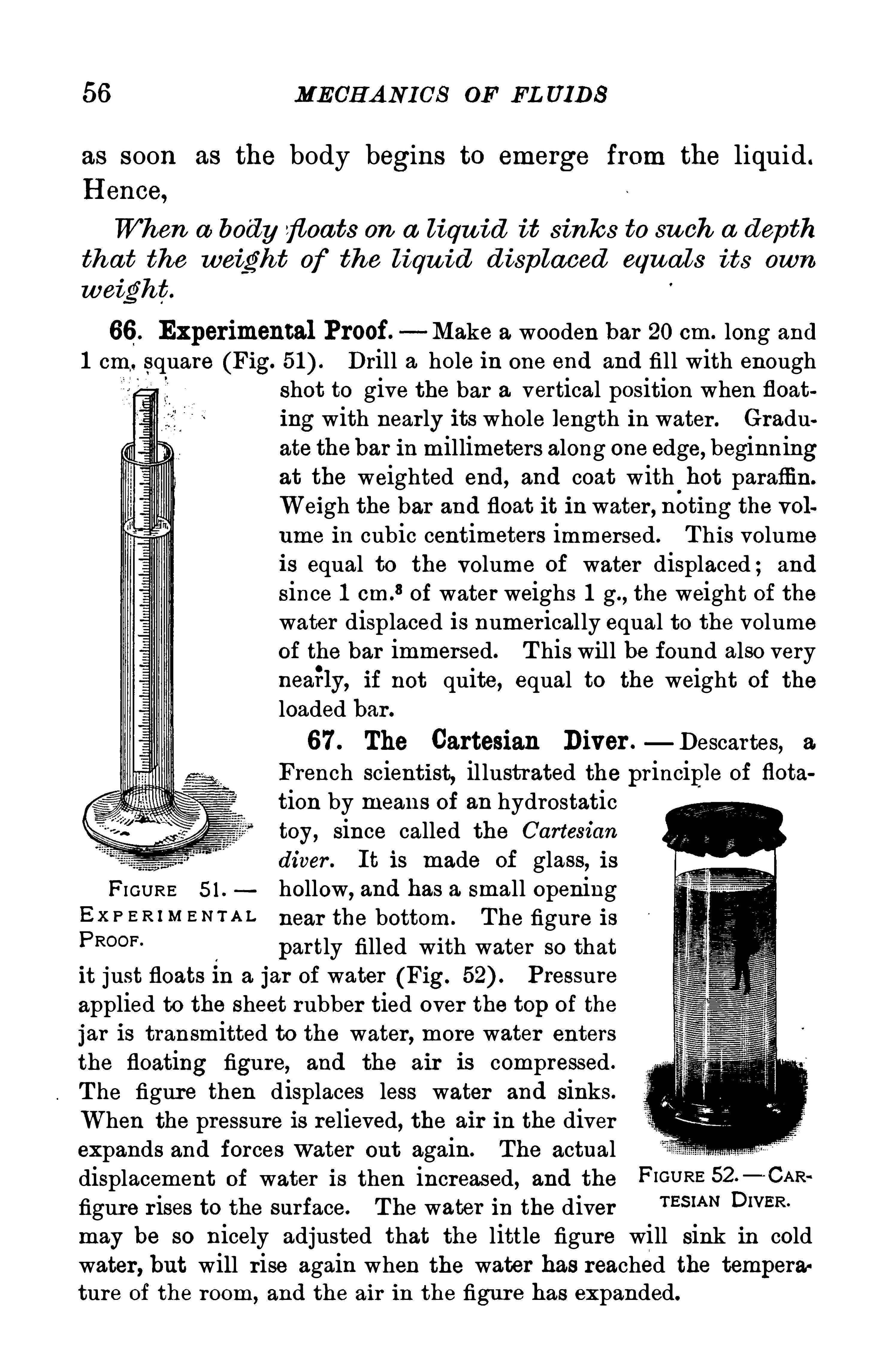
56 MECH A NICS OF EL UIDS
as soon as the body begins to emerge from the liquid .
H ence,
When a body floats on a liqu id it sinks to su ch a depth
that the weight Of the liqu id d isp laced equals its own
weight.
66 . Experimental Proof. Make a wooden bar 20 cm. long and
1 cm, square (Fig. Drill a hole in one end and fill with enoughshot to give the bar a vertical position when floating with nearly its whole length in water . Graduate thebar in millimeters along one edge
,beginning
at the weighted end, and coat with hot paraffin.
Weigh the bar and float it in water , nOting the volume in cubic centimeters immersed. T his volumeis equal to the volume Of water displaced ; and
since 1 cm.8 of water weighs 1 g., the weight of the
water displaced is numer ically equal to the volumeof the bar immersed. T his will be found also veryneaily, if not quite, equal to the weight of the
loaded bar .
67 . The Cartesian Diver .—Descartes, a
French scientist,il lustrated the principle of flota
tion by means of an hydrostatictoy, since called the Cartesian
diver . It is made of glass, isFI GURE 5 1 . hollow, and has a small opening
Ex P E R I M E N T A L near the bottom. The figure isPROOF“
partly filled with water so thatit just floats In a jar of water (Fig. Pressureapplied to the sheet rubber tied over the top of the
jar is transmitted to the water, more water enters
the floating figure, and the air is compressed .
T he figure then displaces less water and sinks.
When the pressure is relieved, the air in the diverexpands and forces water out again. The actualdisplacement of water is then increased, and the FIGURE 52 —CARfigure r ises to the surface. T he water in the diver 7 55m” DWER '
may be so nicely adjusted that the little figure will sink in coldwater, but will rise again when the water has reached the temperature of the room
, and the air in the figure has expanded.
TH E FL OA TING DRY DOCK 57
FI GURE 53 .— A U NITED S TATES S UBMARINE.
A good substitute for the diver is a small inverted homeopathic vialin a flat 1 6-Oz . prescription bottle, fi lled with water and closed with a
rubber stopper . When pressed, the sides yield, and the vial sinks.
A submarine boat is a modern Cartesian diver on a large scale. It
is provided with tight compartments, into which water may be ad
mitted to make it sink . It may be made to r ise to the surface by ex
pelling some of the water by powerful pumps.
68. The Floating Dry Dock .— T he floating dock re
sembles the submar ine in pr inciple. It is made buoyant
THE S AME S UBMARINE S UBMERGING.
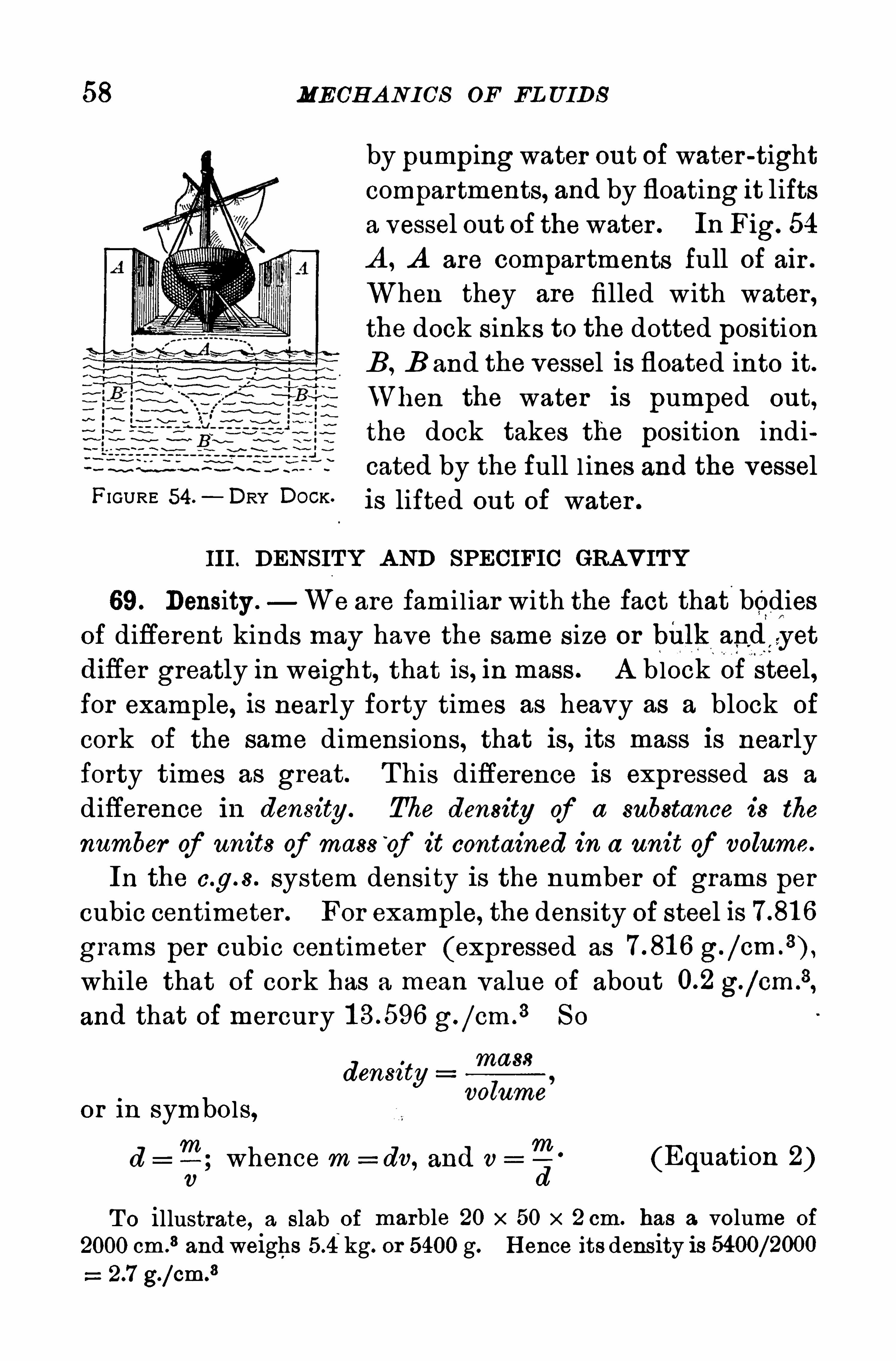
58 MECH A N I CS OF EL U IDS
FIGURE 54. DOCK.
III . DENS ITY A ND SPECIFIC GRAVITY
69. Density . We are fami l iar with the fact that bodiesof different kinds may have the same size or bii lk and
zgyet
difler greatly in weight, that is, in mass . A block of steel,for example, is nearly forty times as heavy as a block of
cork of the same dimensions, that is, its mass is nearlyforty times as great. T his difference is expressed as a
difference in density . The density of a substance is the
number of units of mass“
of it contained in a unit of volume.
In the c.g. s . system density is the number of grams per
cubic centimeter . For example, the density of steel is
grams per cubic centimeter (expressed as g.
while that of cork has a mean value of about g./cm .
3,
and that of mercury g./em .
3 S o
density
or in symbols,
T;whence m = dv, and v
7
3. (Equation 2)v
T o illustrate, a slab~
oi marble 20 x 50 x 2 cm. has a volume of
2000 cm .
3 and weighs kg. or 5400 g. H ence its density is
g./cm.3
by pumpingwater out of water -tightcompar tments, and by floating it liftsa vessel out of thewater . In Fig. 54
A , A are compartments full Of air .
When they are filled with water,the dock sinks to the dotted positionB , B and the vessel is floated into it.
t en the water is pumped out,
the dock takes the position indicated by the full l ines and the vessel
is lifted out of water .

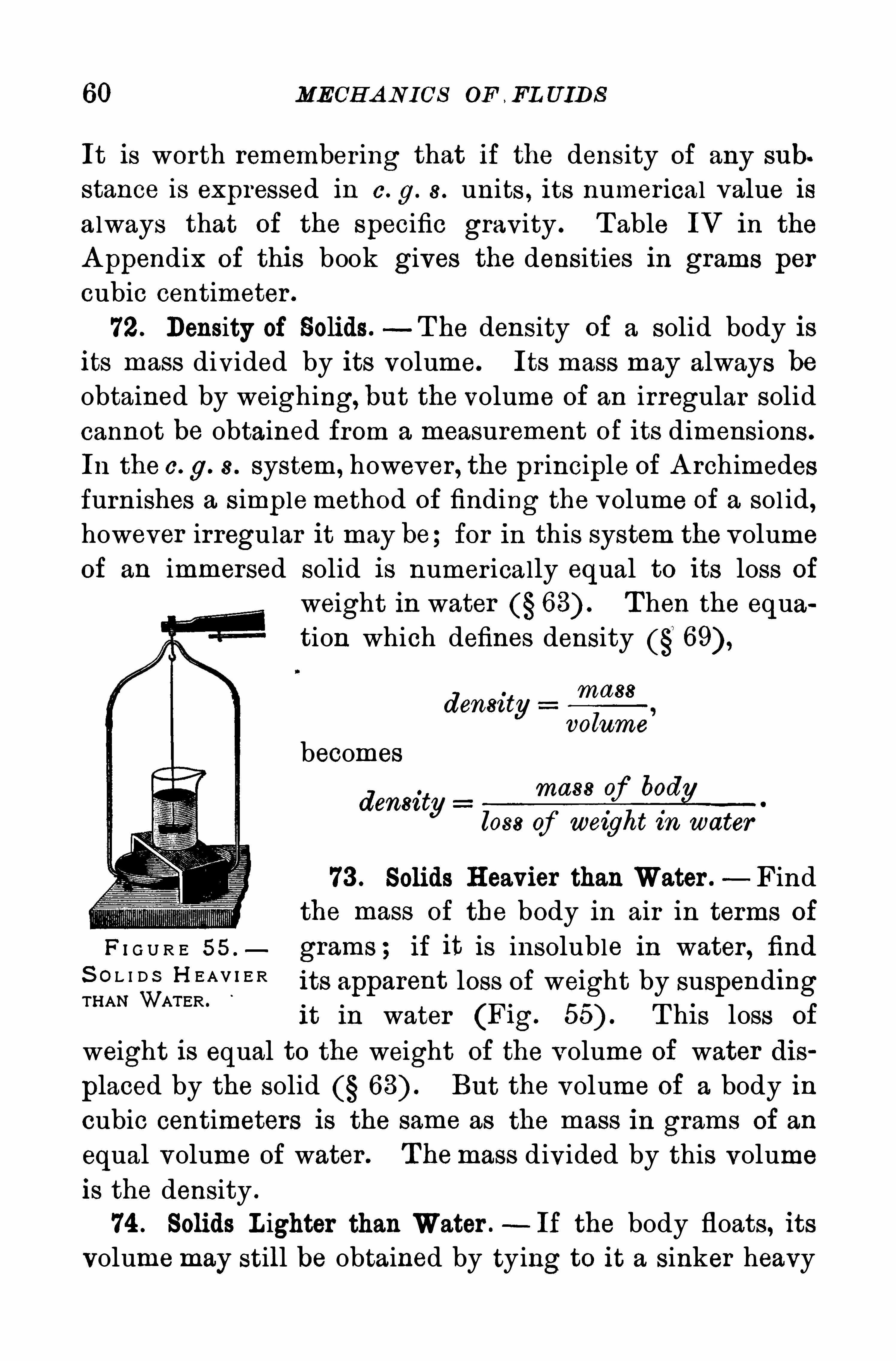
60 MECH A N ICS OF , FL U IDS
It is worth remember ing that if the density of any sub
stance is expressed in c. g. 8. units , its numerical value isalways that of the specific gravity . T able IV in the
A ppendix of this book gives the densities in grams per
cubic centimeter .
72. Density of Solids.—T he density of a solid body is
its mass divided by its volume. Its mass may always beobtained by weighing, but the volume of an irregular solid
cannot be obtained from a measurement of its dimensions .
In the c. g. 8. system, however , the principle of A rchimedesfurnishes a s implemethod of finding the volume of a sol id,however irregular it may be for in this system the volumeof an immersed solid is numer ically equal to its loss of
weight in water T hen the equation which defines density (g
massdensity
volume
becomes
densityM .
loss of weight in water
73 . Solids H eavier than Water . Find
the mass of the body in air in terms of
F I G U R E 55 . grams ; if it is insoluble in water , findS O L I D S H E AV I E RTHAN WATER .
Its apparent loss p f weight by suspending1 t In water (Flg. T hi s loss of
weight is equal to the weight of the volume of water dis
placed by the solid But the volume Of a body in
cubic centimeters is the same as the mass in grams Of an
equal volume of water . T hemass divided by this volume
is the density .
74 . Solids L ighter than Water .—Ii the body floats, its
volumemay still be obtained by tying to it a sinker heavy
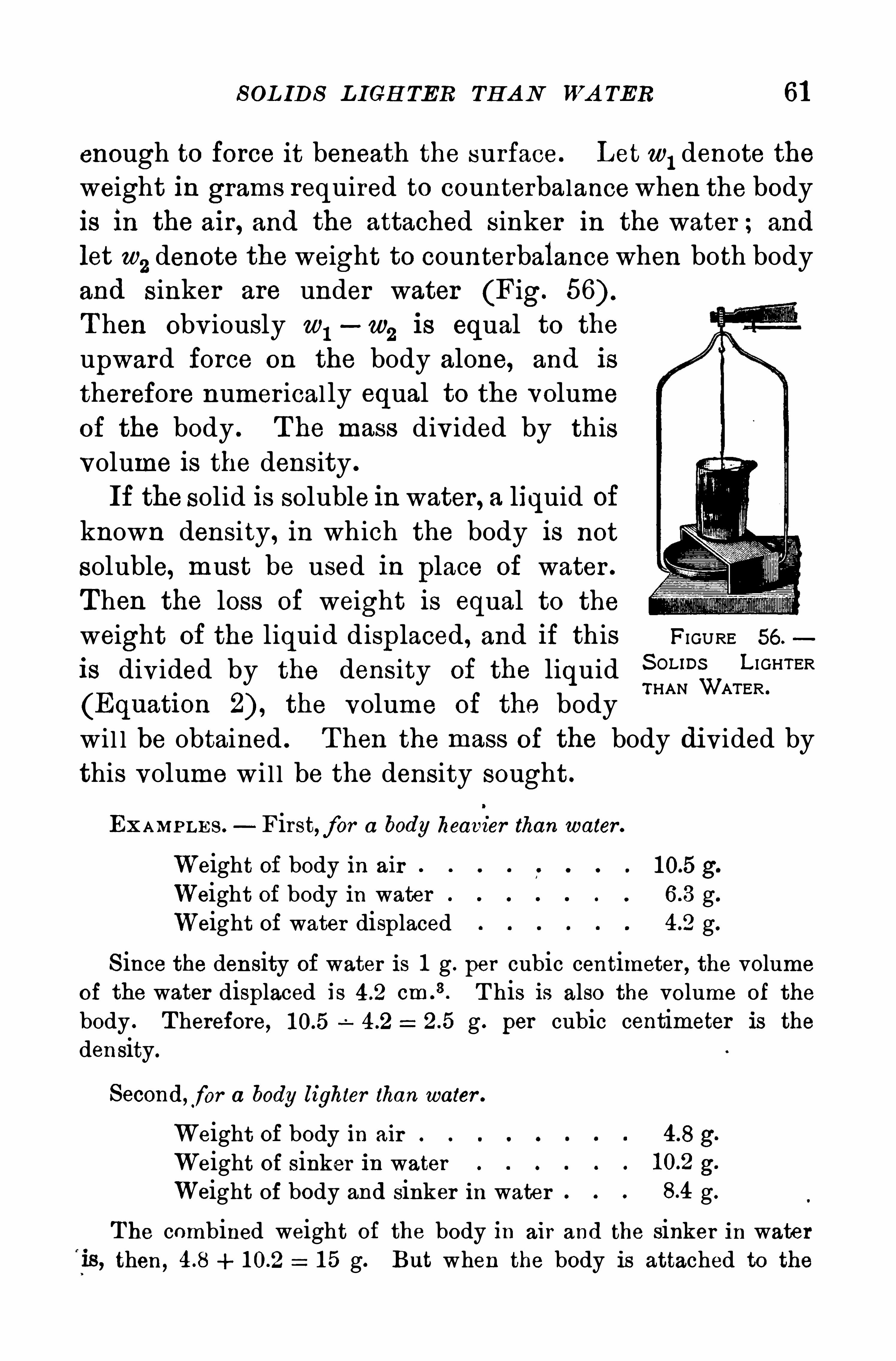
S OL IDS L IGH TER TH A N WA TER 61
enough to force it beneath the surface. Let w1denote the
weight in grams required to counterbalancewhen the body
is in the air , and the attached sinker in the water ; and
let w2denote the weight to counterbalancewhen both body
and s inker are under water (Fig.
T hen Obv iously w1—w
2is equal to the
upward force on the body alone, and is
therefore numer ical ly equal to the volumeof the body . T he mass div ided by thisvolume is the density .
If the solid is soluble in water , a liquid of
known density, in which the body is not
soluble, must be used in place Of water .
T hen the loss of weight is equal to the
weight of the liquid displaced , and if this FIGURE 56.
is divided by the density Of the liquidS OU DS L I GHTERTHAN WATER .
(Equatlon the volume of the body
wi l l be obtained . T hen the mass Of the body divided bythis volume wi l l be the density sought .
EXAMP LE S . First,for a body heavier than water .
Weight of body in air g.
Weight of body in water g.
Weight of water displaced g.
S ince the density of water is 1 g . per cubic centimeter , the volume
of the water displaced is cm .
3. T his is also the volume of the
body . T herefore, g . per cubic centimeter is the
density.
Second,for a body lighter than water .
Weight of body in air 4-8 g
Weight Of sinker in water g
Weight of body and sinker in water g.
T he combined weight of the body in air and the sinker in waterthen , 1 5 g. But when the body is attached to the
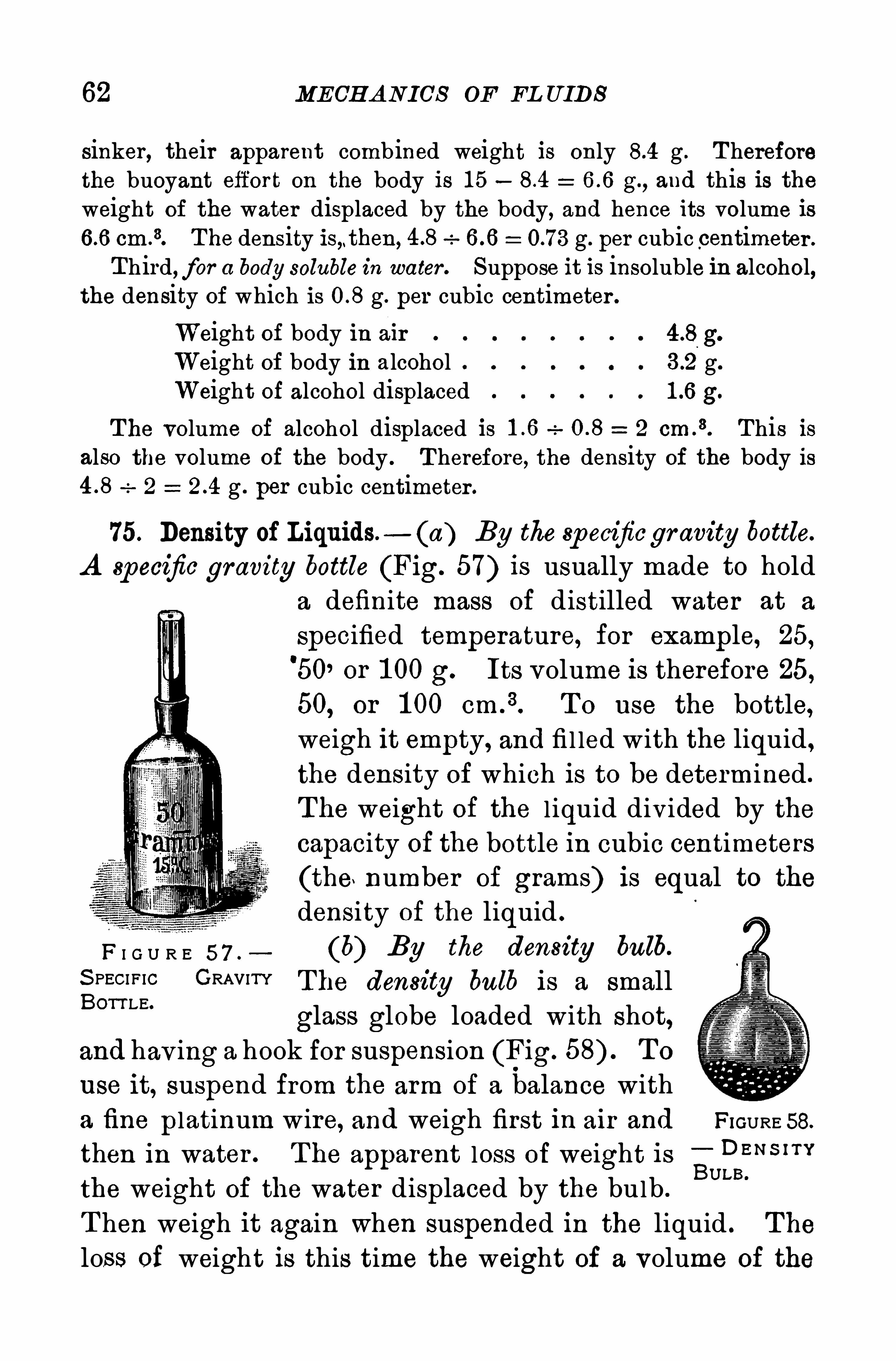
62 MECH A NICS OF EL UIDS
sinker, their apparent comb ined weight is only g . T hereforethe buoyant effort on the body is 1 5 g.
, and this is theweight of the water displaced by the body, and hence its volume is
cm.
3. T he density is,.then, g. per cubic centimeter .
T hird, for a body soluble in water . Suppose it is insoluble in alcohol,the density of which is g. per cubic centimeter .
Weight of body In ai r g.
Weight of body in alcohol g.
Weight of alcohol displaced g.
T he volume of alcohol displaced is 2 cm .
3. T his is
also the volume of the body . T herefore, the density of the body is2 g . per cubic centimeter .
75. Density of Liquids. (a) By the sp ecificgr avity bottle.
A Specific gravity bottle (Fig. 57) is usually made to hold
a definite mass of distilled water at a
specified temperature, for example, 25,'
50, or 1 00 g. Its volume is therefore 25,50, or 1 00 cm 3 T o use the bottle,weigh it empty, and fi l led with the liquid ,
the density of which is to be determined .
T he weight of the l iquid div ided by the
capacity of the bottle in cubic centimeters
(the number of grams) is equal to the
density of the liquid .
F I G U R E 5 7 , (b) By the density bulb.
S PECI F IC GRAVITY The density bulb is a smallBOTT LE“
glass globe loaded with shot,and hav ing a hook for suspension (Fig. T o
use it, suspend from the arm of a balance with
a fine platinum wire, and weigh first in air and FIGURE 58.
then in water . T he apparent loss of weight is EUPBBN S ’”
the weight of the water displaced by the bulb .
T hen weigh it again when suspended in the liquid . The
loss of weight is this time the weight of a volume of the
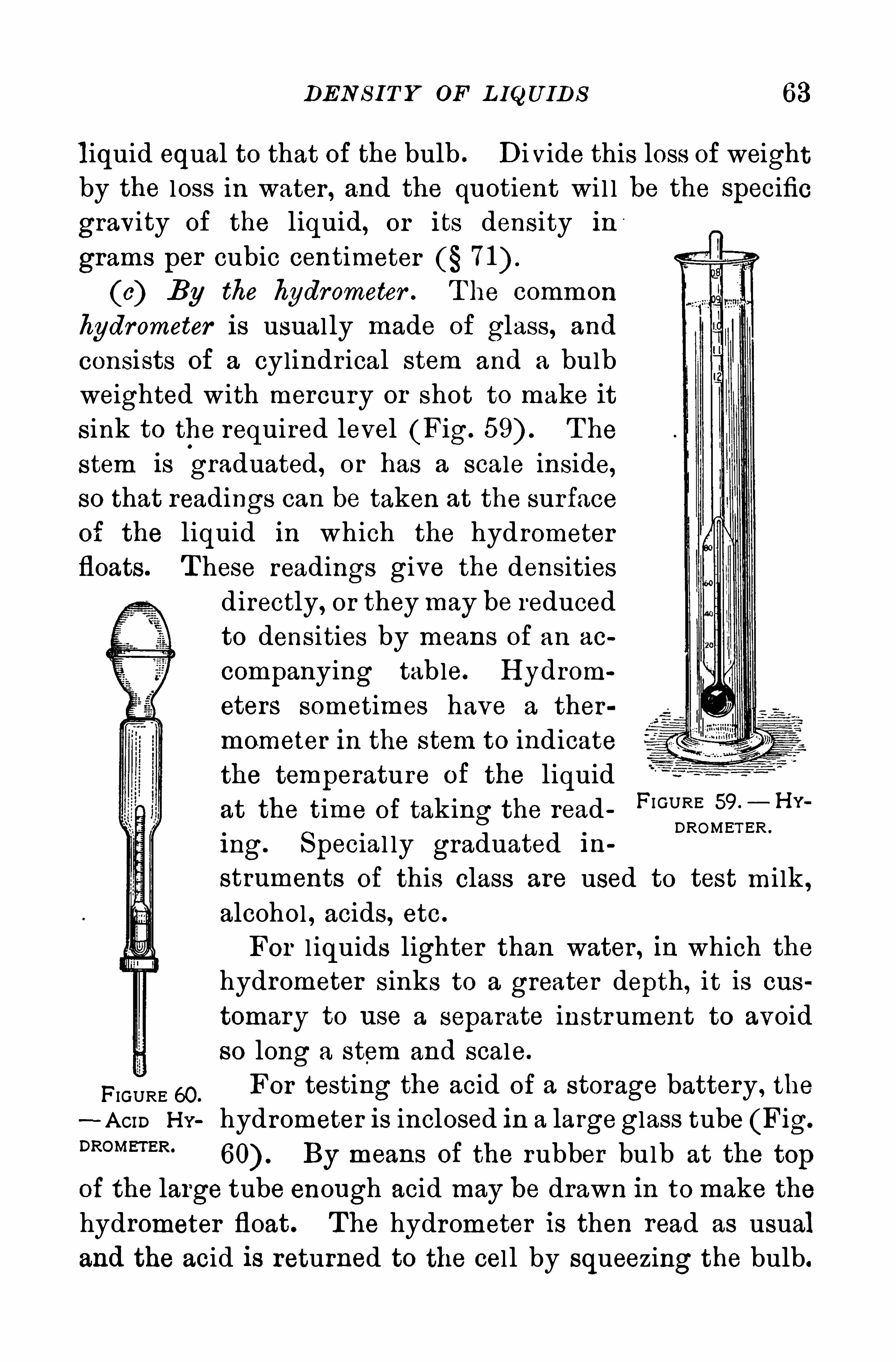
DEN S I T Y OF L IQU IDS 63
liquid equal to that of the bulb . Di vide this loss of weightby the l oss in water , and the quotient wi l l be the specific
gravity of the liquid, or its density in
grams per cubic centimeter
(c) By the hydrometer . T he commonhydrometer is usual ly made of glass, and
consists of a cylindr ical stem and a bulbweighted with mercury or shot to make itsink to the required level (Fig. T he
stem is graduated, or has a scale inside,so that readings can be taken at the surfaceof the liquid in which the hydrometerfloats. T hese readings give the densities
directly, or theymay be reduced
to densities by means of an ao
companying table. H ydrom
eters sometimes have a thermometer in the stem to indicatethe temperature of the liquid
at the time of taking the reading. Special ly graduated in
FI GURE 59. H Y
DROMET ER .
struments of this class are used to test mi lk ,
alcohol , acids, etc .
For l iquids lighter than water , in which the
hydrometer sinks to a greater depth, it is cus
tomary to use a separate instrument to avoid
so long a stem and scale.
FIGURE 60.
For testing the acid Of a storage battery , the
- A om H Y hydrometer is inclosed in a largeglass tube (Fig.
DROMm R‘
By means of the rubber bulb at the top
of the large tube enough acid may be drawn in to make the
hydrometer float. The hydrometer is then read as usual
and the acid is returned to the cel l by squeezing the bulb.
MECH A N ICS OF FL U IDS
Q uestions and P rob lems
1 . Why does an ocean steamer draw more water after enteringfresh water
2 . If the Cartesian diver should sink in the jar , why will theaddition of salt cause it to r ise
3 . What is the density of a body weighing 1 5 g. in air and 1 0 gin water ? What is its specific gravity ?
4 . A hollow brass ball weighs 1 kg. What must be its volume
so that it will just float in water ?5 . What is the density of a body weighing 20 g . in aii and 1 6 g.
in alcohol whose density is g. per cubic centimeter ?
6 . A bottle filled with water weighed 60 g. and when empty 20 g .
When filled with olive oil it weighed g. What is the density ofolive oil ?
7 . A density bulb weighed 75 g . in air,45 g . in water , and 21 g.
‘
in sulphuric acid . Calculate the density of the sulphur ic acid .
8 . A piece of wood weighs 96 g. in air,1 72 g . in water with
sinker attached . T he sinker alone in water weighs 220 g. Find thedensity of the wood .
9 . A piece of zinc weighs 70 g . in air, and 60 g . in water . Whatwill it weigh in alcohol of density g . per cubic centimeter
1 0 . The mark to which a certain hydrometer weighing 90 g. sinksin alcohol is noted . T o make it sink to the same mark in water itmust be weighted with g. What is the density of the alcohol ?
1 1 . A body floats half submerged in water . What is its specificgravity ? What part of it will be submerged in alcohol, specificgravity
1 2 . If an iron ball weighs lb . in air , what will it weigh inwater if its specific gravity is
1 3 . What is the specific gravity of a wooden ball that floats twothirds under water
1 4 . A ferry boat weigh s 700 tons. What will be the disp lacementof water if it takes on board a train weighing 600 tons ?
1 5 . A liter flask weighing 75 g . is half filled with water and halfwith glycerine. T he flask and liquids weigh 1205 g. What is thedensity of the glycerine ? What is its specific gravity ?
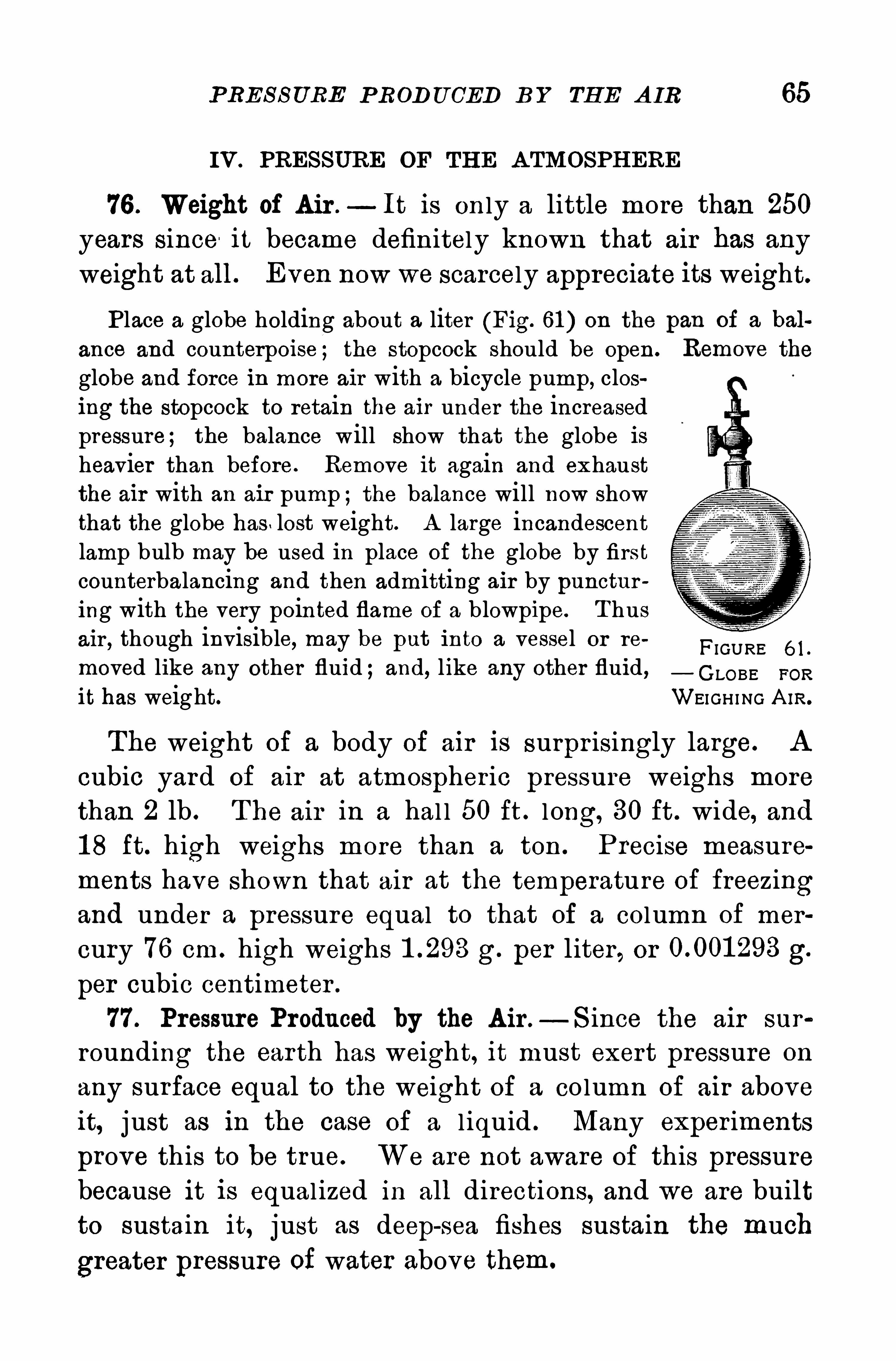
PRES S URE P ROD U CED B Y TH E A IR 65
IV. PRES SURE OF TH E A TMOSPH ERE
76 . Weight of A ir .—It is on ly a little more than 250
years since it became definitely known that air has any
weight at all. Even now we scarcely appreciate its weight.
Place a globe holding about a liter (Fig. 61 ) on the pan of a bal
ance and counterpoi se ; the stopcock should be open. Remove theglobe and force in more air with a bicycle pump, closing the stopcock to retain the air under the increasedpressure; the balance will show that the globe isheavier than before. Remove it again and exhaustthe air with an air pump ;the balance will now showthat the globe has . lost weight. A large incandescentlamp bulb may be used in place of the globe by firstcounterbalancing and then admitting air by puncturing with the very pointed flame of a blowpipe. T husair , though invisible, may be put into a vessel or re
0 0
FIGURE 6 1 .
moved like any other fluid ;and, l ike any other fluid, GLOBE FOR
it has weight. WEIGH I NG A IR.
The weight of a body of air is surpr isingly large. A
cubic yard of air at atmospher ic pressure weighs more
than 2 lb . T he air in a hal l 50 ft . l ong, 30 ft . wide, and1 8 ft. high weighs more than a ton . Precise measurements have shown that air at the temperature of freezingand under a pressure equal to that of a column of mer
cury 76 cm. high weighs g. per liter , or g.
per cubic centimeter .
77 . Pressure Produced by the A ir .— S ince the air sur
rounding the earth has weight, it must exert pressure on
any surface equal to the weight of a column of air above
it, j ust as in the case of a l iquid . Many experiments
prove this to be true. We are not aware Of this pressurebecause it is equal ized in all directions, and we are builtto sustain it, just as deep-sea fishes sustain the much
greater pressure of water above them.
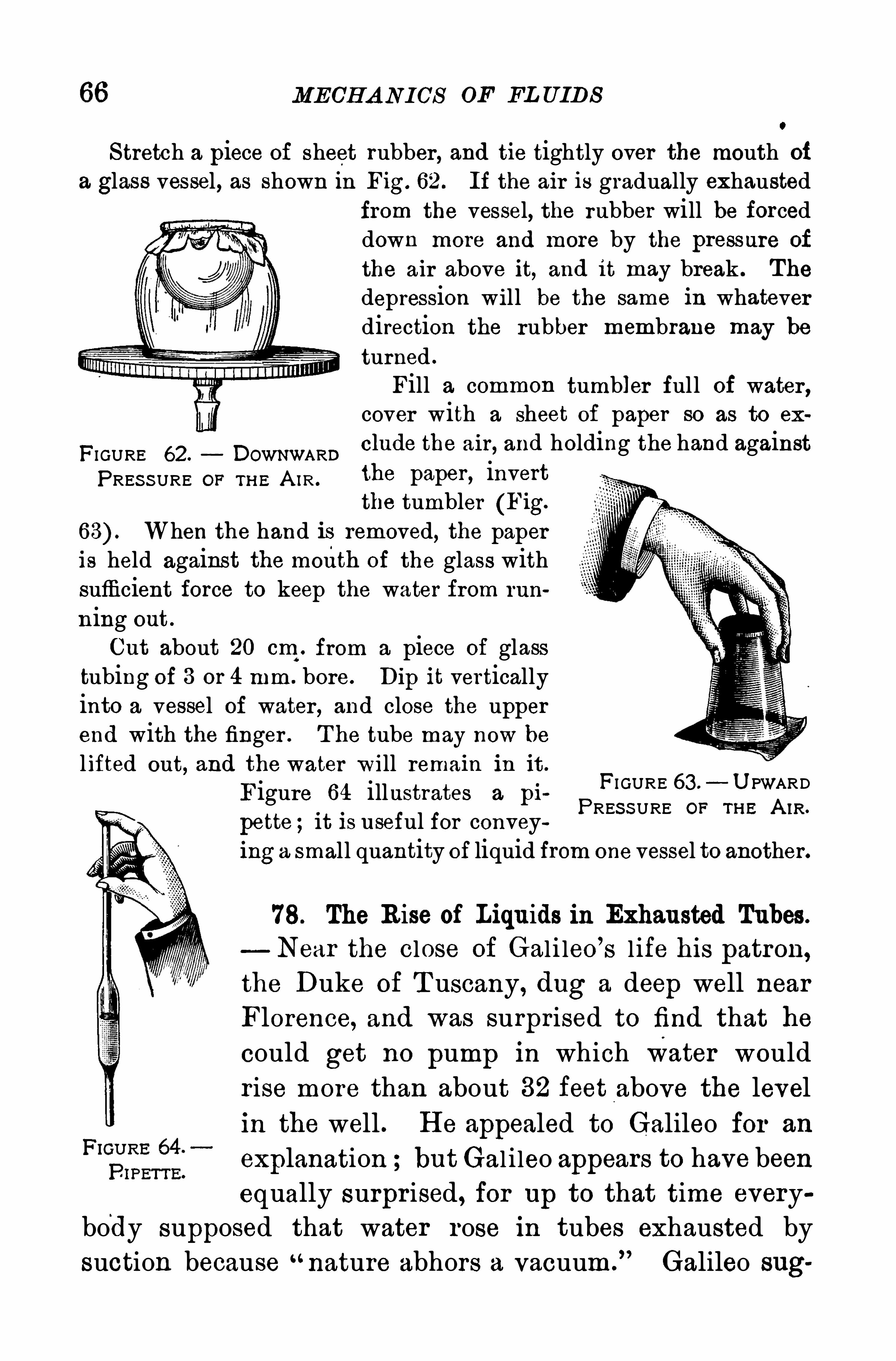
MECH A N ICS OF FL UIDS
0
Stretch a piece of sheet rubber, and tie tightly Over the mouth of
a glass vessel, as shown in Fig. 62. If the air is gradually exhaustedfrom the vessel, the rubber will be forceddown more and more by the pressure of
the air above it, and it may break . The
depression will be the same in whateverdirection the rubber membrane may be
turned .
Fill a common tumbler ful l of water ,cover with a sheet of paper so as to ex
FI GURE 62. DOW ARDclude the air, and holding the hand against
PRES S URE OP TH E A IR .the paper, invertthe tumbler (Fig.
When the hand is removed, the paperis held against the month of the glass withsufficient force to keep the water from run
ning out .
Cut about 20 cm . from a piece of glasstubing Of 3 or 4 mm . bore. Dip it verticallyinto a vessel of water , and close the upperend with the finger . T he tube may now be
l ifted out, and the water will remain in it .
Figure 64 illustrates a pi
pette ; it is useful for conveyinga small quantity of liquid from one vessel to another.
FI GURE 63 . U PWARDPRES S URE OF TH E A IR.
78. The Rise of Liquids in Exhausted Tubes.
Near the close of Gal i leo’
s l ife his patron,the Duke Of T uscany, dug a deep well near
Florence, and was surprised to find that he
could get no pump in which water wouldr ise more than about 32 feet above the level
in the well . H e appealed to Galileo for an
explanation ;but Gal i leo appears to have been
equally surpr ised, for up to that time everybody Supposed that water rose in tubes exhausted by
suction because “nature abhors a vacuum.
”Galileo sug

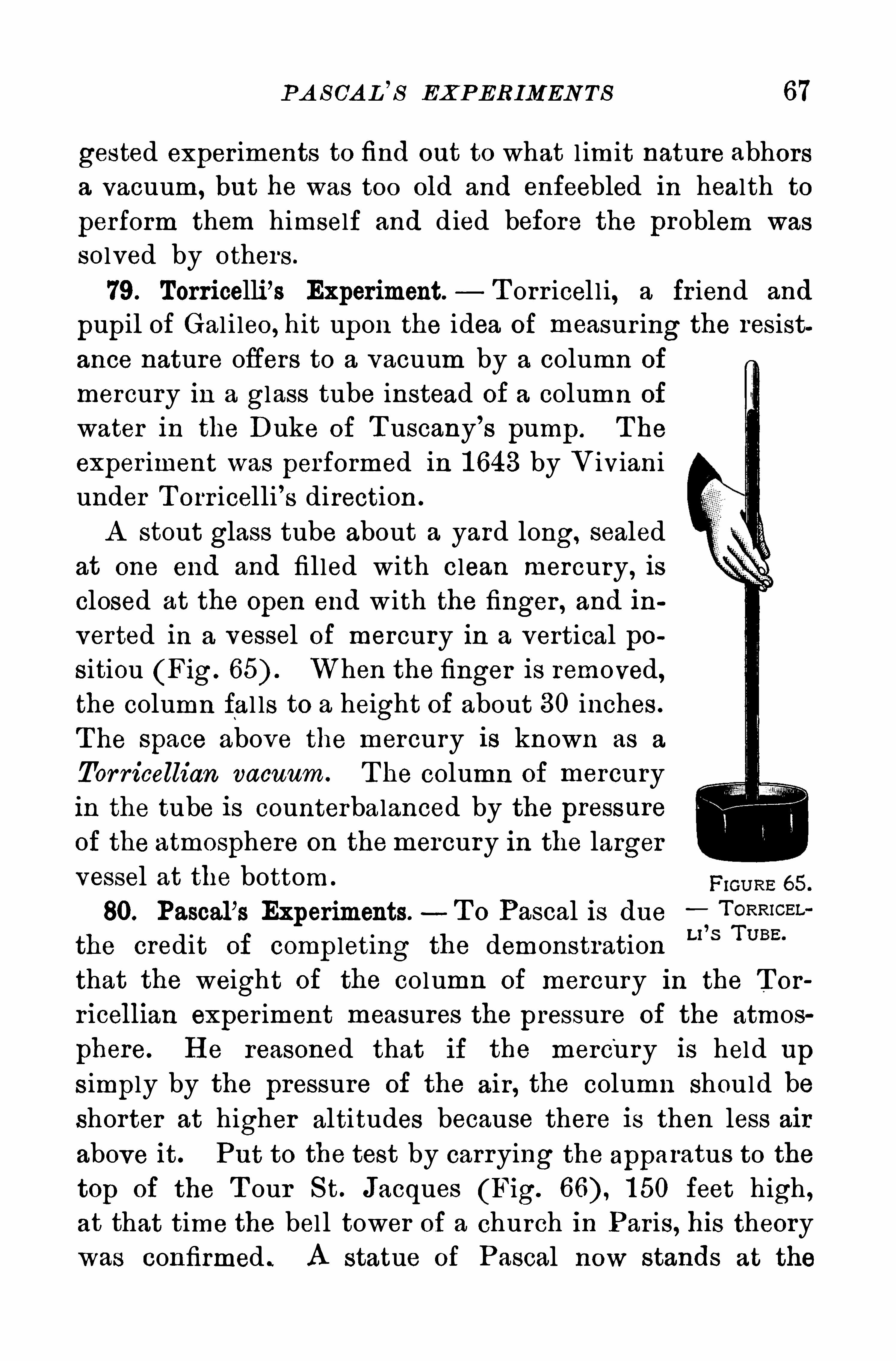
P A S CA D’
S EXP ERIMEN TS 67
gested experiments to find out to what l imit nature abhorsa vacuum, but he was too old and enfeebled in health to
perform them himself and died before the problem was
solved by others .
79. Torricelli’s Experiment. T orr icel l i, a fr iend and
pupil of Gal i leo, hit upon the idea of measur ing the resistance nature offers to a vacuum by a column of
mercury in a glass tube instead of a column of
water in the Duke of T uscany’
s pump . T he
experiment was performed in 1 643 by V ivianiunder T orr icelli’s direction .
A stout glass tube about a yard long, sealed
at one end and filled with clean mercury, isclosed at the Open end w ith the finger , and in
verted in a vessel of mercury in a vertical positiou (Fig. When the finger is removed,the column fal ls to a height of about 30 inches .
T he space above the mercury is known as a
Tor ricellian vacuum. T he column of mercuryin the tube is counterbalanced by the pressureof the atmosphere on themercury in the larger
vessel at the bottom .
80. Pascal’s Experiments.- T o Pascal is due
the credit of comp leting the demonstration
that the weight of the column of mercury in the T or
ricellian experiment measures the pressure of the atmos
phere. H e reasoned that if the mercury is held up
s imply by the pressure of the air, the column should be
shorter at higher altitudes because there is then less air
above it. Put to the test by carrying the apparatus to the
top of the T our S t. Jacques (Fig. 1 50 feet high ,at that time the bel l tower of a church in Par is, his theory
was confirmed . A statue of Pascal now stands at the
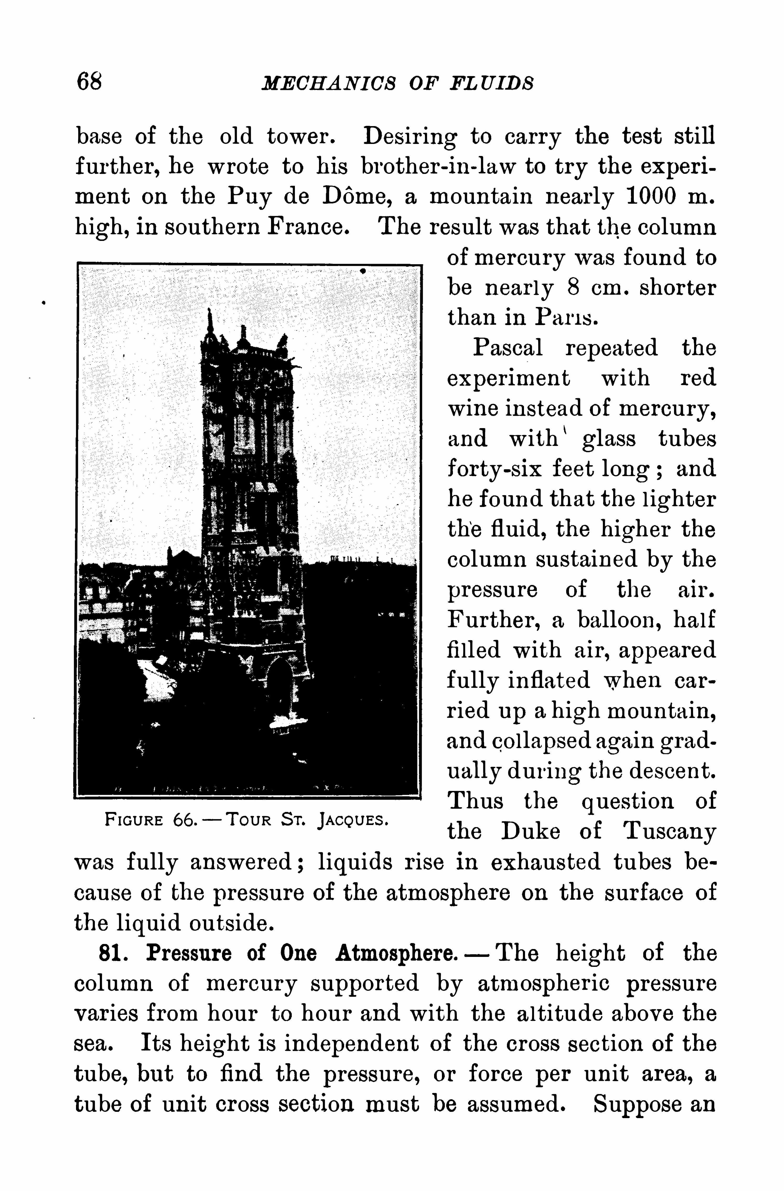
68 MECH A NICS OF FL UIDS
base of the old tower . Desir ing to carry the test stillfurther, he wrote to his brother -ln-law to try the experi
ment on the Puy de DOme, a mountain nearly 1 000 m .
high , in southern France. T he result was that the columnofmercury was found tobe near ly 8 cm . shorterthan in Pari s .
Pascal repeated the
experiment with red
wine instead of mercury,and with ‘glass tubesforty-six feet long ; and
he found that the l ighter
the fluid, the higher thecolumn sustained by the
pressure of the air .
Further , a balloon, half
filled with air , appeared
fully inflated when car
r ied up a high mountain,
and collapsed again grad
ually during the descent.
T hus the question of
the Duke of T uscany
was fully answered ; liquids r ise in exhausted tubes be
cause of the pressure of the atmosphere on the surface of
the liquid outside.
81 . Pressure of One Atmosphere.—T he height of the
column Of mercury supported by atmospher ic pressure
var ies from hour to hour and with the a ltitude above the
sea. Its height is independent of the cross section of the
tube, but to find the pressure, or force per unit area, a
tube of unit cross section must be assumed . Suppose an
FIGURE 66 .—T OUR S T. jACOU ES .
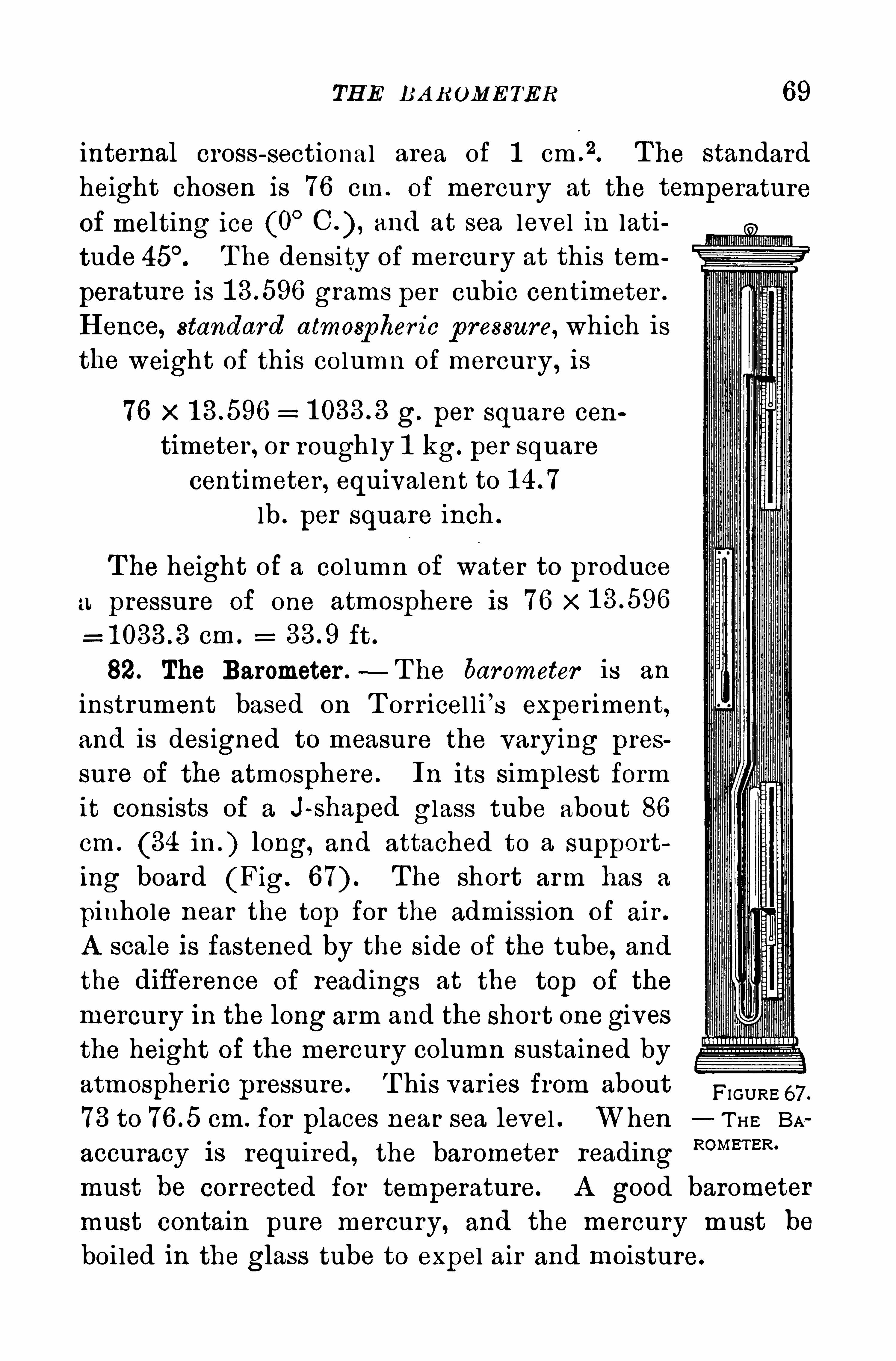
TH E BA R OMETER 69
internal cross-sectional area of 1 cm .
2. T he standard
height chosen is 76 cm. of mercury at the temperatureOf melting ice (0
°and at sea level in lati
tude T he density of mercury at this tem
perature is grams per cubic centimeter .
H ence, standard atmospher ic p ressure, which is
the weight Of this co lumn of mercury , is
76 x g. per square cen
timeter , or roughly 1 kg. per squarecentimeter , equivalent to
lb . per square inch .
T he height of a column Of water to produce
I. pressure of one atmosphere is 76 x 1 3 .596
em . ft .
82. The Barometer .—T he barometer is an
instrument based on T orr icel li ’s experiment,
and is des igned to measure the varying pres
sure Oi the atmosphere. In its simplest form
it consists of a J~ shaped glass tube about 86
cm . (34 in . ) long, and attached to a supporting board (Fig. The short arm has a
pinhole near the top for the adm ission of air .
A scale is fastened by the side of the tube, andthe diflerence of readings at the top of the
mercury in the long arm and the short one givesthe height of the mercury column sustained by
atmospheric pressure. T his var ies from about FIGURE 67 .
73 to cm. for places near sea level . When T H E BA
accuracy is required, the barometer readingROMETER‘
must be corrected for temperature. A good barometer
must contain pure mercury, and the mercury must beboi led in the glass tube to expel air and moisture.
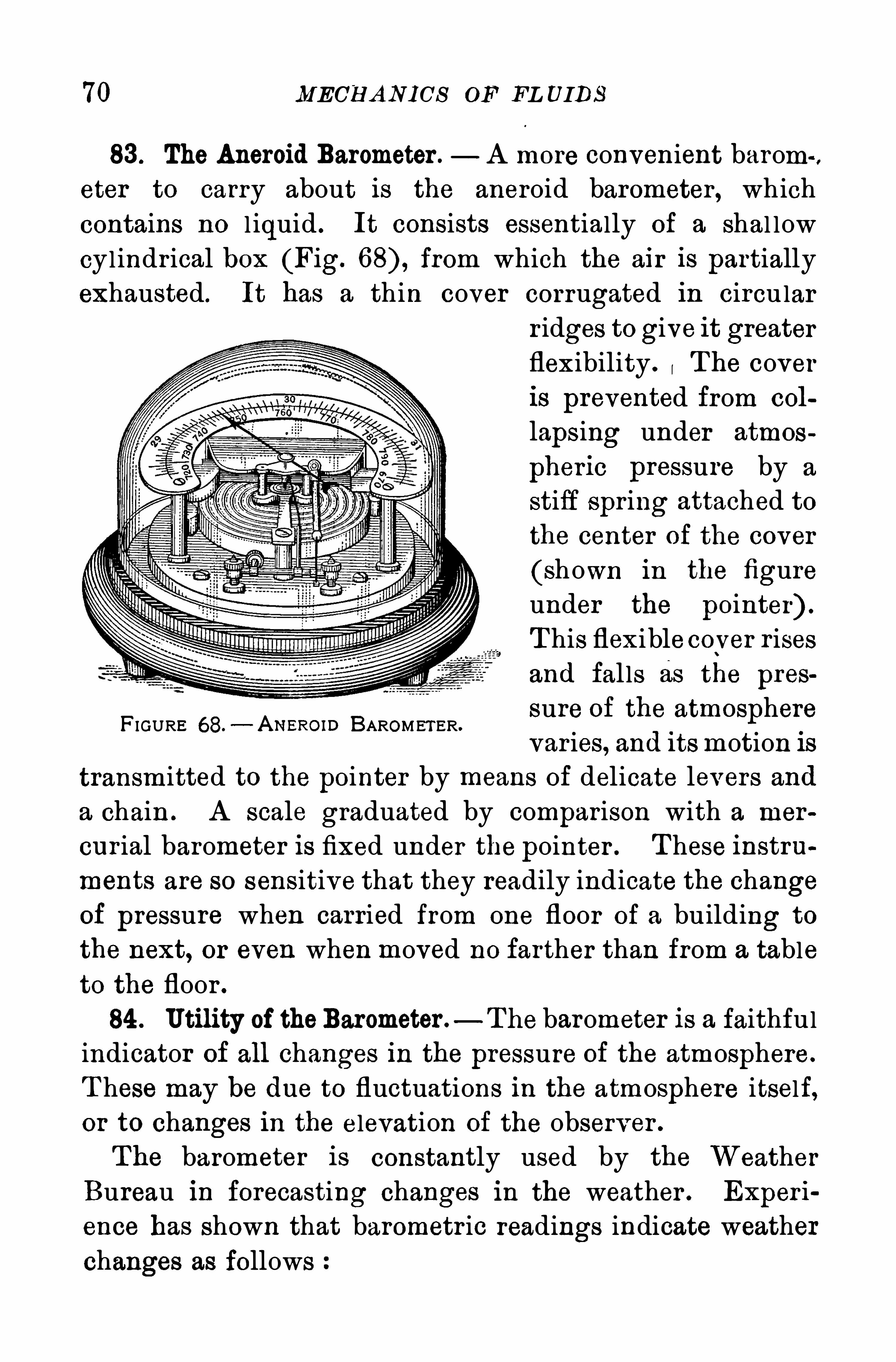
70 MECH A NICS op FL UIDS
83 . The Aneroid Barometer . A more convenient barom
eter to carry about is the aneroid barometer , which
contains no l iquid . It consists essentially of a shal low
cylindr ical box (Fig. from which the air is partially
exhausted. It has a thin cover corrugated in circularr idges to give it greaterflexibility . T he coveris prevented from col
lapsing under atmos
pheric pressure by a
stiff spr ing attached tothe center of the cover
(shown in the figureunder the pointer) .
T his flexiblecoy er r isesand fal ls as the pres
sure of the atmospherevar ies, and itsmotion is
transmitted to the pointer by means of delicate levers and
a chain . A scale graduated by comparison with a mer
cur ial barometer is fixed under the pointer . These instru
ments are so sensitive that they readily indicate the change
of pressure when carried from one floor of a building to
the next, or even when moved no farther than from a table
to the floor .
84 . Utility of theBarometer .—The barometer is a faithful
indicator of all changes in the pressure of the atmosphere.
T hese may be due to fluctuations in the atmosphere itself,or to changes in the elevation of the observer .
The barometer is constantly used by the Weather
Bureau in forecasting changes in the weather . Exper i
ence has shown that barometr ic readings indicate weather
changes as follows
F IGURE 68.— A NERom BAROMET ER.
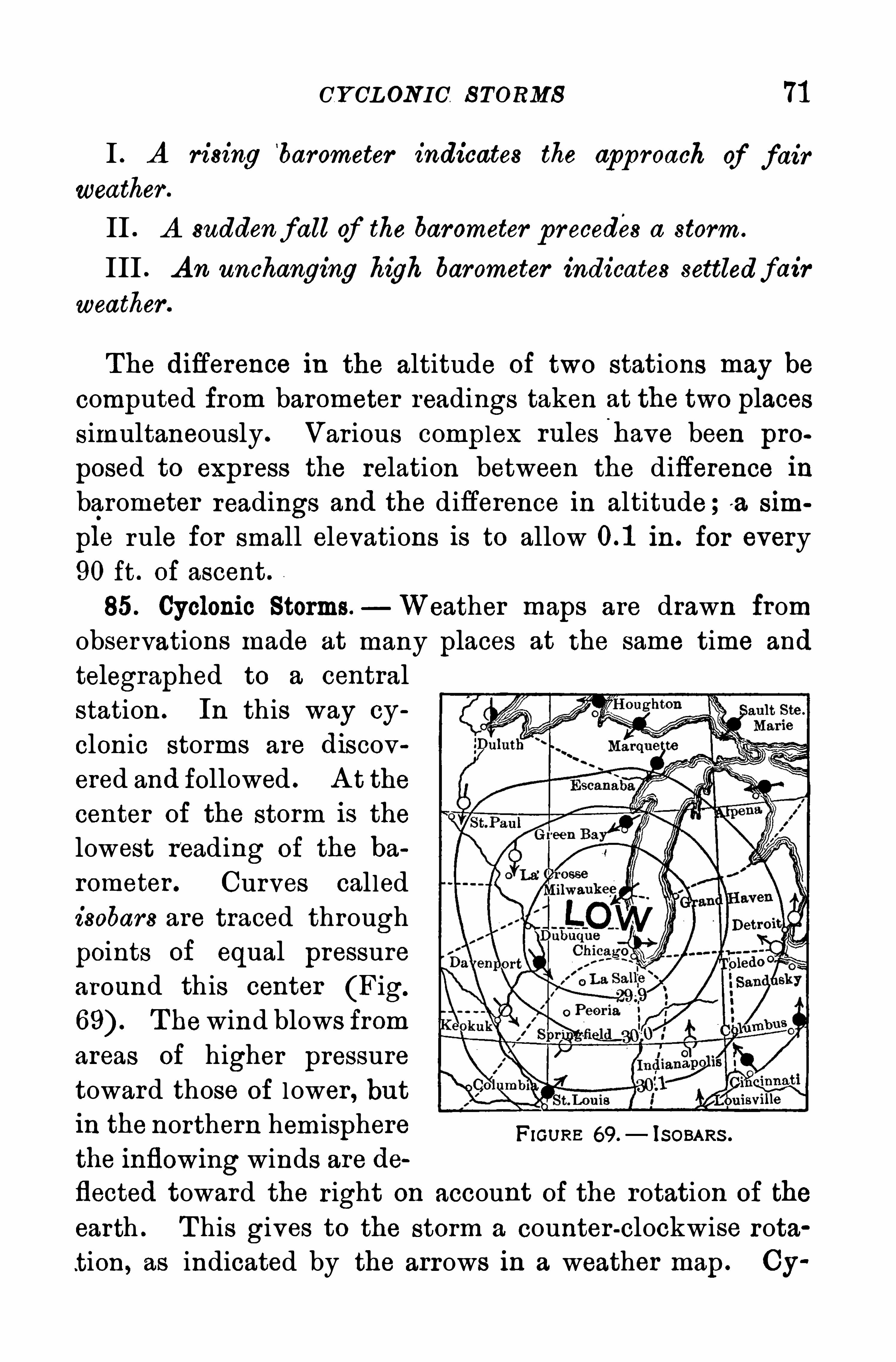
CY CLONIC S TORMS 71
I . A rising‘
barometer indicates the app roach of fair
weather .
II . A suddenfall of the barometer precedes a storm.
III . A n unchanging high barometer indicates settledfair
weather .
The diflerence in the altitude of two stations may becomputed from barometer readings taken at the two places
simultaneously . Var ious complex rulesi
have been pro
posed to express the relation between the difference inbarometer readings and the difference in altitude;a sim
ple rule for small elevations is to allow in . for every90 ft . of ascent
85. Cyclonic Storms. Weather maps are drawn fromobservations made at many places at the same time and
telegraphed to a central
station . In this way cy
clonic storms are discov
ered and followed . A t the
center of the storm is the
lowest reading of the ba
rometer . Curves called
isobars are traced through
points of equal pressurearound this center (Fig.
T hewind blows from
areas of higher pressure
toward those of l ower , but
in the northern hemisphere Frames 69.—150mm.
the inflowing winds are de
flected toward the r ight on account of the rotation of the
earth . T his gives to the storm a counter -clockwise rota
t ion, as indicated by the arrows in a weather map . Cy
72 MECH A N ICS OF FLU IDS
clonic storms usually cross the northwest boundary of the
U nited S tates from Br itish Columbia, travel in a south
easter ly direction until they cross the Rocky Mountainrange, and then turn northeaster ly toward the
‘
A tlanticcoast . S torms coming from the Gul f of Mexico usual lytravel along the A tlantic coast toward the northeast.
Q uestions and P rob lems
1 . What are theobjections to the use of water as the liquid forbarometers
2 . Why must the air be completely removed from the barometer
tube
3 . Why is mercury the best liquid to use in a barometer tube ?
4 . Point out some of the good points as well as some of the objectionable features of an aneroid barometer .
5 . Must a barometer be suspended out of doors in order to getthe air pressure ? Why ?
6 . Does the diameter of the bore of a barometer tube affect theheight to which the mercury rises ?
7 . H ow can you make water run in a regu lar stream from a
jug?
8. T he barometer reading is cm . Calculate the atmosphericpressure per square centimeter .
9 . T he barometer reading is 29 in . Calculate the atmosphericpressure per square inch .
1 0 . Calculate the buoyancy of the air for a ball 1 0 cm . in diameter
if a liter of air weighs g.
1 1 . T he density of glycerine is g. per cubic centimeter . If a
barometer were constructed for glycerine what wou ld be its readingwhen the mercurial barometer reads 73 cm . ?
1 2 . When the density of the air is g. per cubic centimeter , how much less will 200 cm .
8of cork weigh in air than in a
vacuum ?
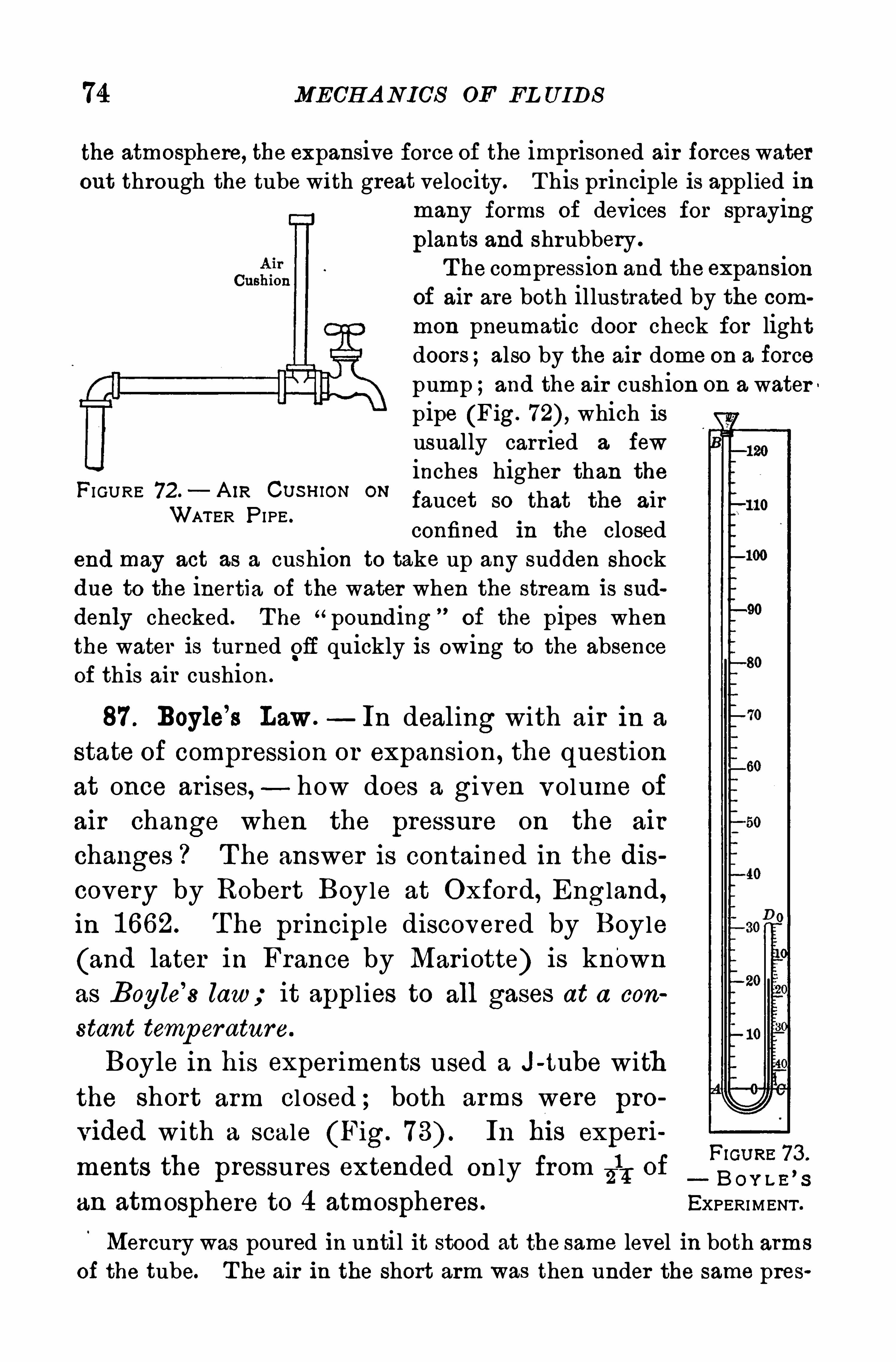
74 MECH A N ICS OF FL UIDS
the atmosphere, the expansive force of the imprisoned air forces waterout through the tube with great velocity. T his principle is applied in
many forms of devices for spraying
plants and shrubbery .
T he compression and the expansionof air are both illustrated by the com
mon pneumatic door check for lightdoors ;also by the air dome on a forcepump ;and the air cushion on a waterpipe (Fig. which isusually carried a few
inches higher than theFI GURE 72.
—A IR Cusmou ONfaucet so that the air
WATER P IPE .
confined in the closedend may act as a cushion to take up any sudden shockdue to the inertia of the water when the stream is sud
denly checked . T he “pounding ”of the pipes when
the water is turned gif quickly is owing to the absenceof this air cushion .
87 . Boyle’
s Law. In dealing with air in a
state of compression or expansion , the question
at once ar ises, - how does a given volume of
air change when the pressure on the air
changes ? T he answer is contained in the discovery by Robert Boyle at Oxford, England,in 1 662. T he pr inciple discovered by Boyle
(and later in France by Mar iotte) is known
as Bogle’
s law; it appl ies to all gases at a con
stant temperature.
Boyle in his exper iments used a J-tube withthe short arm cl osed ; both arms were pro
vided with a scale (Fig. In hi s experiFiGU RE 73 .
1ments the pressures extended on ly from7 1
ofEm ma’s
an atmosphere to 4 atmospheres . EXPERIMENT .
Mercury was poured in until it stood at the same level in both arms
of the tube. T he air in the short arm was then under the same pres
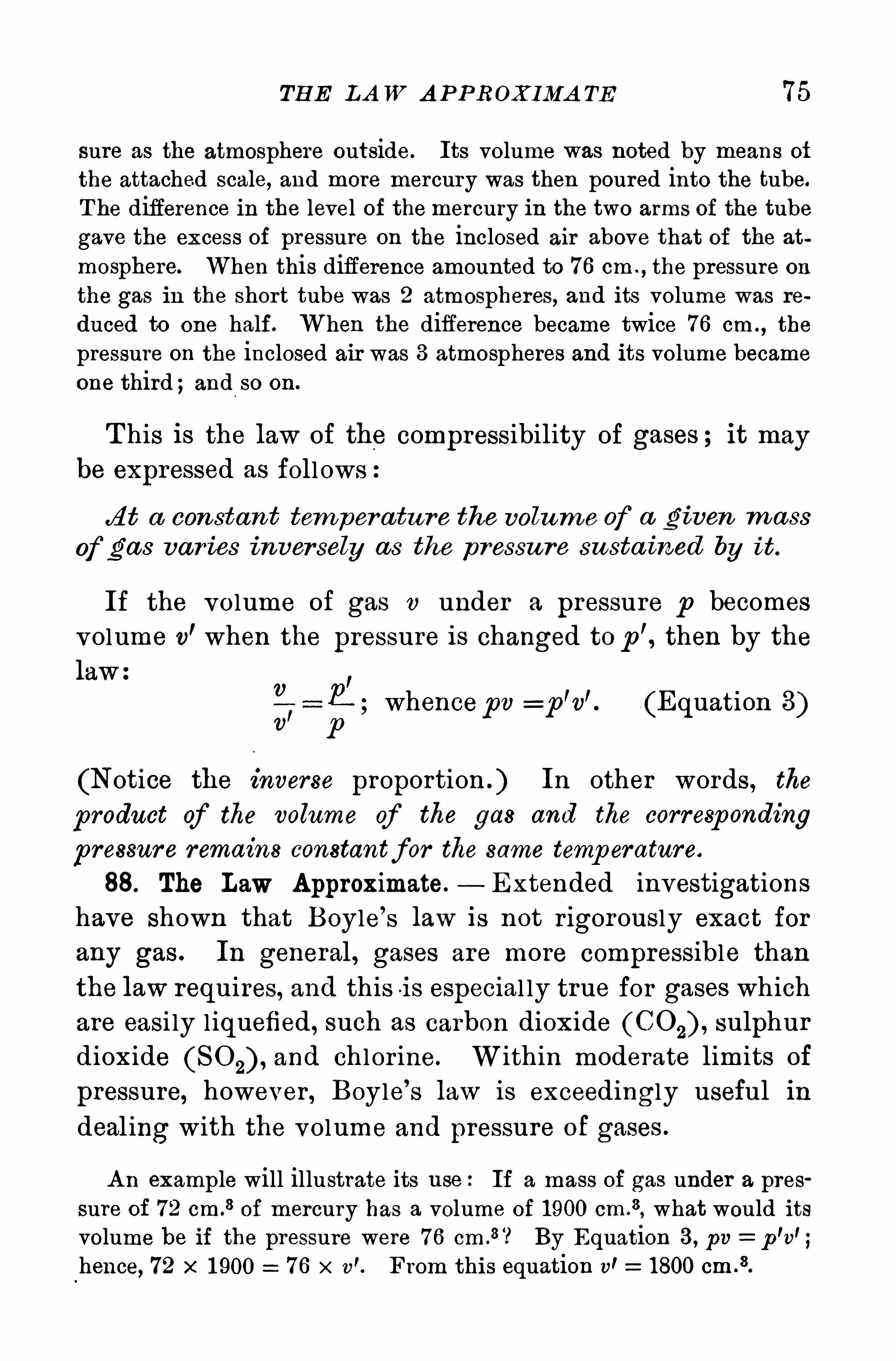
TH E LA W A P P ROXIMA TE 75
sure as the atmosphere outside. Its volume was noted by means of
the attached scale, and more mercury was then poured into the tube.
T he difference in the level of the mercury in the two arms of the tubegave the excess of pressure on the inclosed air above that of the at
mosphere. When this difference amounted to 76 cm .
,the pressure on
the gas in the short tube was 2 atmospheres, and its volume was re
duced to one half. When the difference became twice 76 cm . , the
pressure on the inclosed air was 3 atmospheres and its volume became
one third ;and so on.
T his is the law of the compressibility of gases ; it may
be expressed as follows
fit a con stan t tem per atu re the volum e of a given m ass
of gas var ies inversely as the p ressu re susta ined by it.
If the volume of gas 1) under a pressure p becomes
volume v’when the pressure is changed to p
’, then by the
lawv
7)
r
11; whencepv p v (Equation 3)
PI
(Notice the inverse proportion . ) In other words , the
product of the volume of the gas and the corresp onding
pressure remains constantfor the same temp erature.
88. The Law Approximate.— Extended investigations
have shown that Boyle’
s law is not r igorously exact for
any gas . In general, gases are more compressible than
the law requires, and this i s especial ly true for gases whichare easi ly liquefied , such as carbon dioxide (C0 2) , sulphur
dioxide and chlor ine. Within moderate limits of
pressure, however , Boyle’
s law is exceedingly useful in
deal ing with the volume and pressure of gases .
A n example will illustrate its use:If a mass of gas under a pressure of 72 cm.
3of mercury has a volume of 1900 cm .
3, what would its
volume be if the pressure were 76 cm .
3 ? By Equation 3 , pv p'v';
hence, 72 x 1 900 76 x v’. From this equation v' 1800 cm .
3.
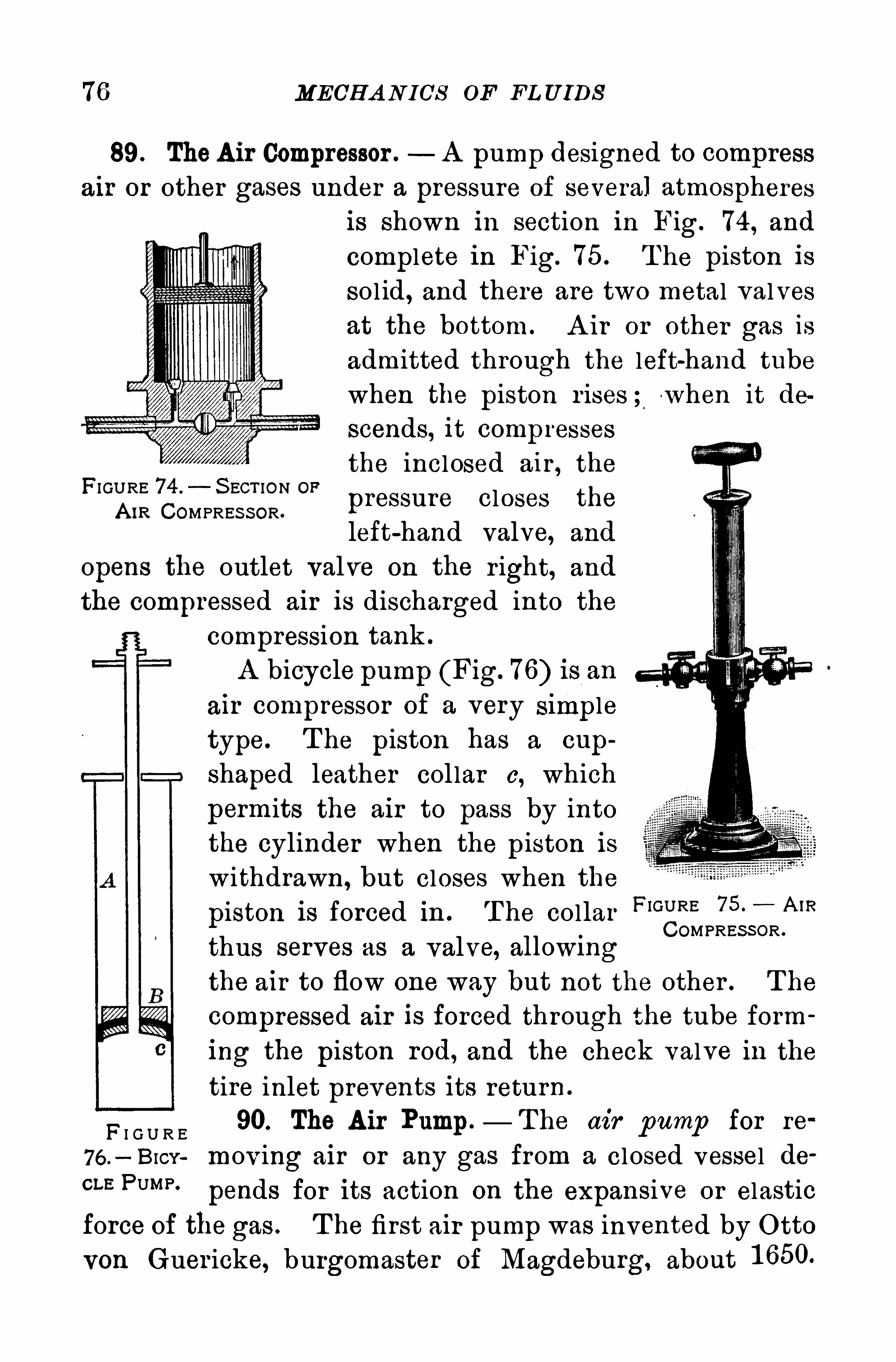
76 MECH A N ICS OF FL U IDS
89. TheA ir Compressor . A pump designed to compressair or other gases under a pressure of several atmospheres
is shown in section in Fig. 74 , and
complete in Fig. 75. T he piston issol id , and there are two metal valvesat the bottom. A ir or other gas isadmitted through the left-hand tubewhen the piston r ises ; w hen it de
scends, it compressesthe incl osed air , the
pressure closes the
left-hand valve, and
opens the outlet valve on the r ight, and
the compressed air is discharged into the
compression tank .
A bicycle pump (Fig. 76) is an
air compressor of a very S imple
type. T he piston has a cup
shaped leather col lar c, which
permits the air to pass by intothe cylinder when the piston is
withdrawn, but closes when the
piston is forced in . T he collar FIGURE A”?
COMPRES S OR .
thus serves as a valve, allowmgthe air to flow one way but not the other . T he
compressed air is forced through the tube form
ing the piston rod, and the check valve in the
tire inlet prevents its return .
F I G U R E 90. The A ir Pump — T he air pump for re
76 .—BICY mov ing air or any gas from a closed vessel de
CLE PUMP '
pends for its action on the expansive or elastic
force of the gas . T he first air pump was invented by O tto
von Guer icke, burgomaster of Magdeburg, about 1 650.
FIGURE 74 . S ECT ION OP
A IR COMPRES S OR .
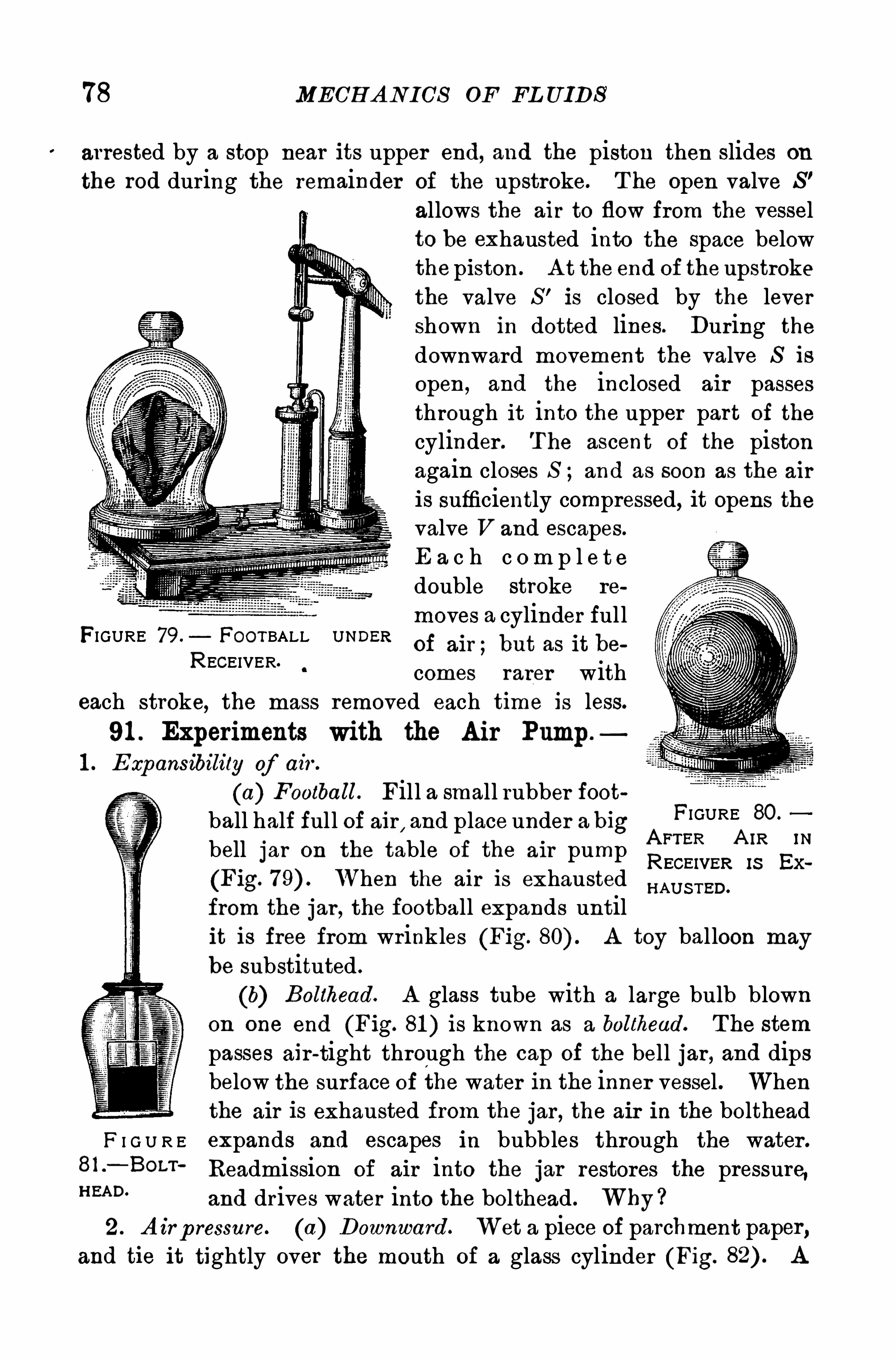
78 MECH A N ICS OF FL UIDS
arrested by a stop near its upper end, and the piston then slides on
the rod during the remainder of the upstroke. T he open valve S ’
allows the air to flow from the vesselto be exhausted into the Space belowthe piston. A t the end of the upstrokethe valve S ’ is closed by the levershown in dotted lines. During the
downward movement the valve S is
open , and the inclosed air passesthrough it into the upper part of the
cylinder . T he ascent of the pistonagain closes S and as soon as the air
is sufficiently compressed, it opens thevalve V and escapes.
E a c h c om p l e t edouble stroke re
moves a cylinder ful lof air ;but as it be
comes rarer witheach stroke, the mass removed each time 1 3 less.
91 . Experiments with the Air Pump.
1 . Expansibility of air .
(a) Football. Fill a small rubber football half ful l of air
,and place under a big
FIGURE 80 °
bell jar on the table of the air pump QFTER A IR IN
EGEIVER 18 Ex
(Fig. When the ai r Is exhaustedfrom the jar , the football expands untilit is free from wrinkles (Fig. A toy balloon may
be substituted .
(b) Bolthead. A glass tube with a large bulb blownon one end (Fig. 81 ) is known as a bolthead. T he stem
passes air -tight through the cap of the bell jar , and dipsbelow the surface of the water in the inner vessel . Whenthe air is exhausted from the jar , the air in the bolthead
F I G U R E expands and escapes in bubb les through the water .
81 —BOLT '
Readmission of air into the jar restores the pressure,H EAD‘
and drives water into the bolthead . Why ?2 . A irp ressure. (a) Downward. Wet a piece of parchment paper ,
and tie it tightly over the mouth of a glass cylinder (Fig. A
FIGURE 79. FOOTBALL U NDER
RECEIVER.
H AU S TED.
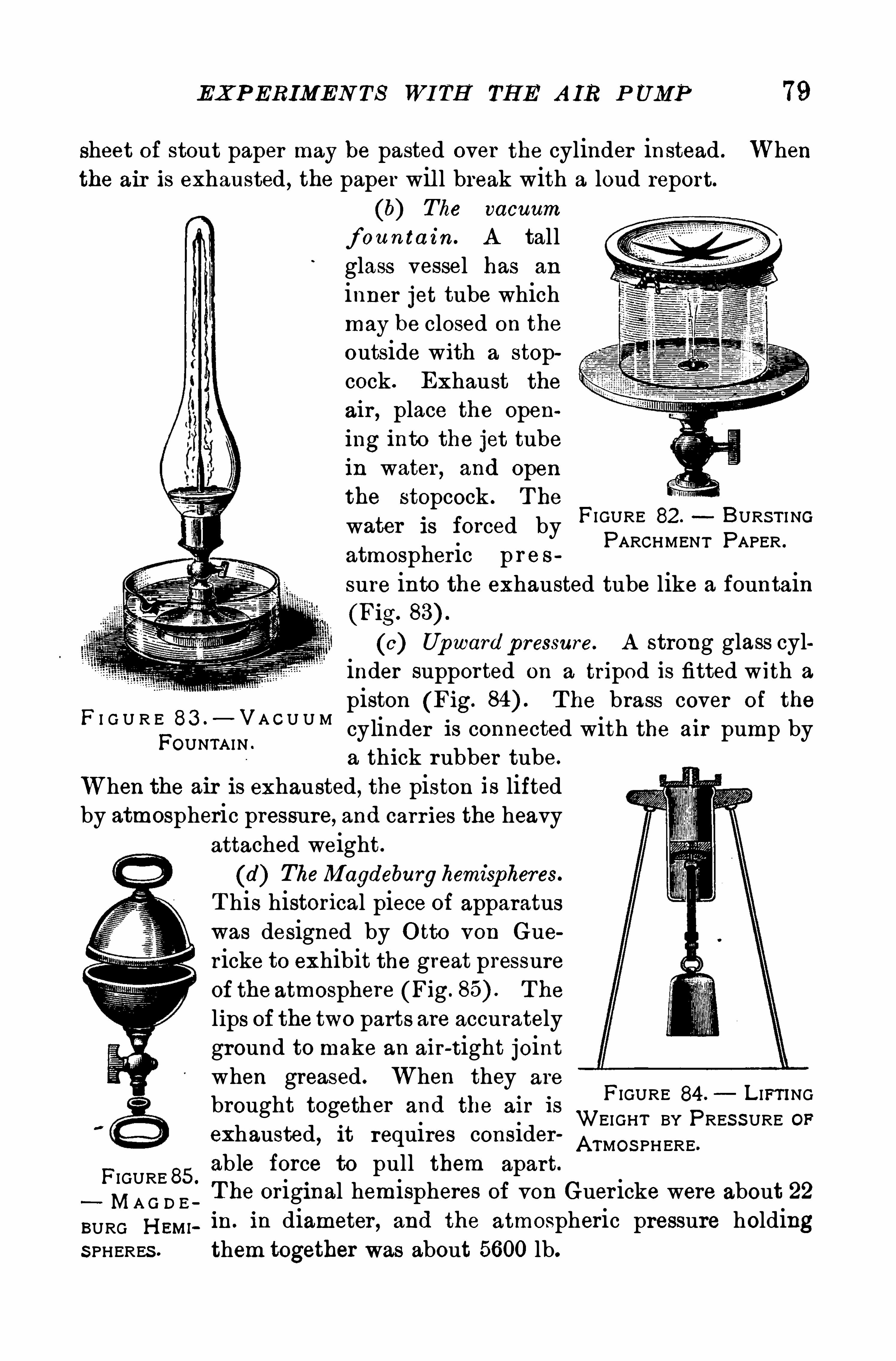
EXP ERIMEN TS WI TH TH E A IR P UMP 79
sheet of stout paper may be pasted over the cylinder instead . Whenthe air is exhausted , the paper wil l break with a loud report.
(b) The vacuum
f ou n ta in. A tallglass vessel has an
inner jet tube whichmay be closed on the
outside with a stopcock . Exhaust the
air , place the opening into the jet tubein water , and Openthe stopcock . T he
water is forced byatmospheric p r e ssure into the exhausted tube like a fountain(Fig.
(c) Upward p ressure. A strong glass cylinder supported on a tripod is fitted with a
piston (Fig. T he brass cover of the
cylinder is connected with the air pump bya thick rubber tube.
When the air is exhausted, the piston is liftedby atmospheric pressure, and carr ies the heavy
attached weight.
(d) TheMagdeburghemispheres.
T his historical piece of apparatuswas designed by O tto von Gue
r icke to exhibit the great pressureof the atmosphere (Fig. T he
lips of the two parts are accuratelyground to make an air-tight jointwhen greased. When they are
brought together and the air is
exhausted, it requires consider
FIGURE 85.
able force to pull them apart.
MA G D E_T he original hemispheres of von Guer icke were about 22
BURG H EW in. in diameter , and the atmospheric pressure holdingS PHERES . them together was about 5600 lb.
FI GURE 82 . BURS T I NGPARCHMENT PAPER .
F I G U R E 83 .—VA C U U M
FOUNTAIN .
FIGURE 84 . L IFT INGWEIGHT BY PRES S URE OPA TMO S PHERE.
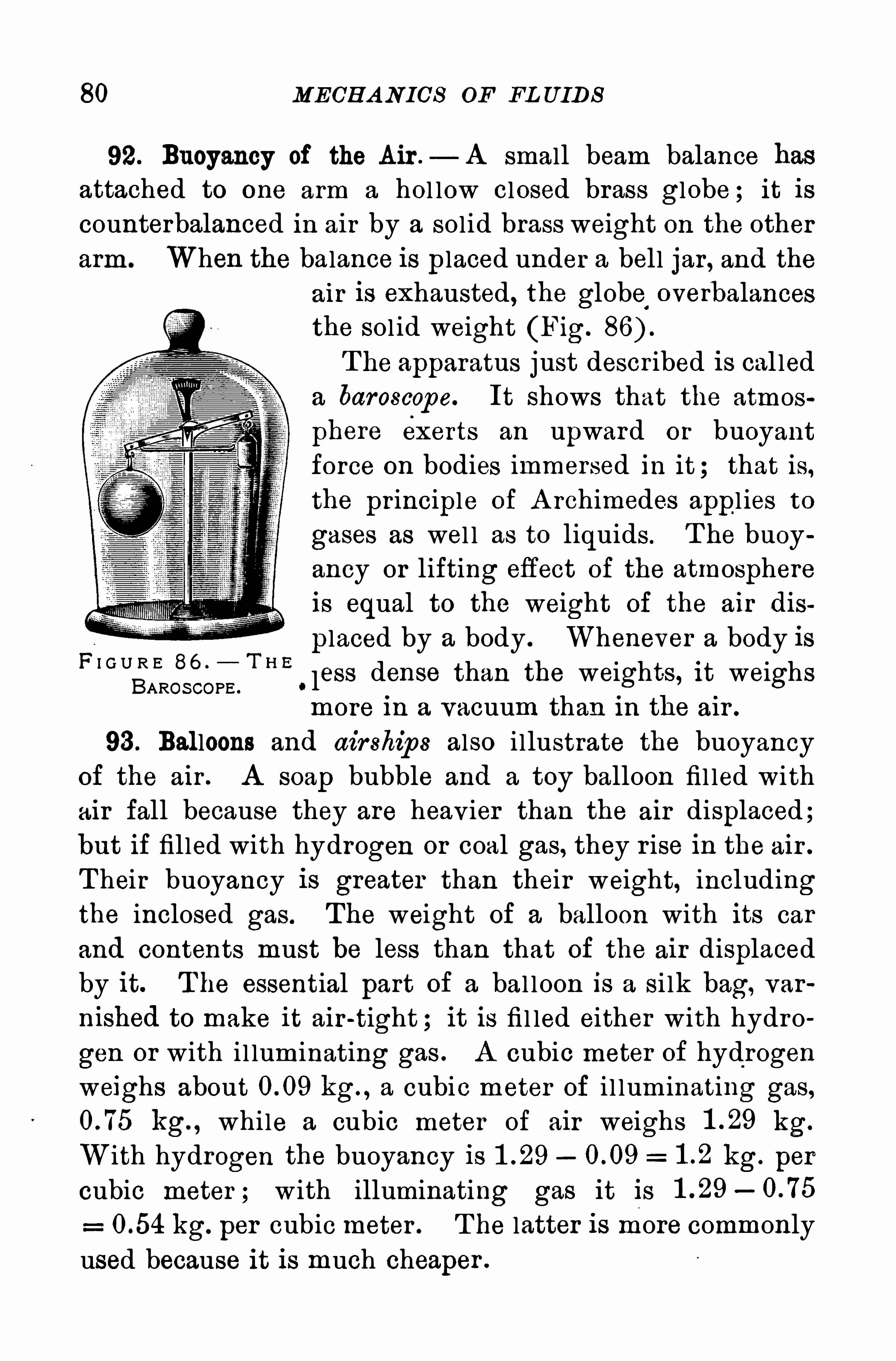
80 MECH A N ICS OE FL UIDS
92. Buoyancy of the Air .— A small beam balance has
attached to one arm a hol low closed brass globe ; it iscounterbalanced in air by a solid brass weight on the otherarm. When the balance is placed under a bell jar, and the
air is exhausted, the globe‘ overbalancesthe sol id weight (Fig.
T he apparatus just descr ibed is cal leda baroscop e. It shows that the atmos
phere exerts an upward or buoyantforce on bodies immersed in it ; that is,the principle of A rchimedes appl ies to
gases as wel l as to liquids . T he buoyancy or lifting effect of the atmosphereis equal to the weight of the air dis
p laced by a body . Whenever a body is
‘less dense than the weights, it weighsmore in a vacuum than in the air .
93 . Balloons and airship s also i llustrate the buoyancy
of the air . A soap bubble and a toy balloon fil led withair fall because they are heavier than the air displaced;but if filled with hydrogen or coal gas, they r ise in the air .
T heir buoyancy is greater than their weight, includingthe inclosed gas. The weight of a balloon with its car
and contents must be less than that of the air displacedby it. T he essential part of a bal l oon is a si lk bag, var
nished to make it air -tight ; it is fi l led either with hydro
gen or with il luminating gas . A cubic meter of hydrogen
weighs about kg. , a cubic meter of i l luminating gas,kg. , while a cubic meter of air weighs kg.
With hydrogen the buoyancy is kg. per
cubic meter ; w ith illuminating gas it is
kg. per cubic meter . T he latter is more commonly
used because it is much cheaper .
F I G U R E 86 .
BAROS COPE .
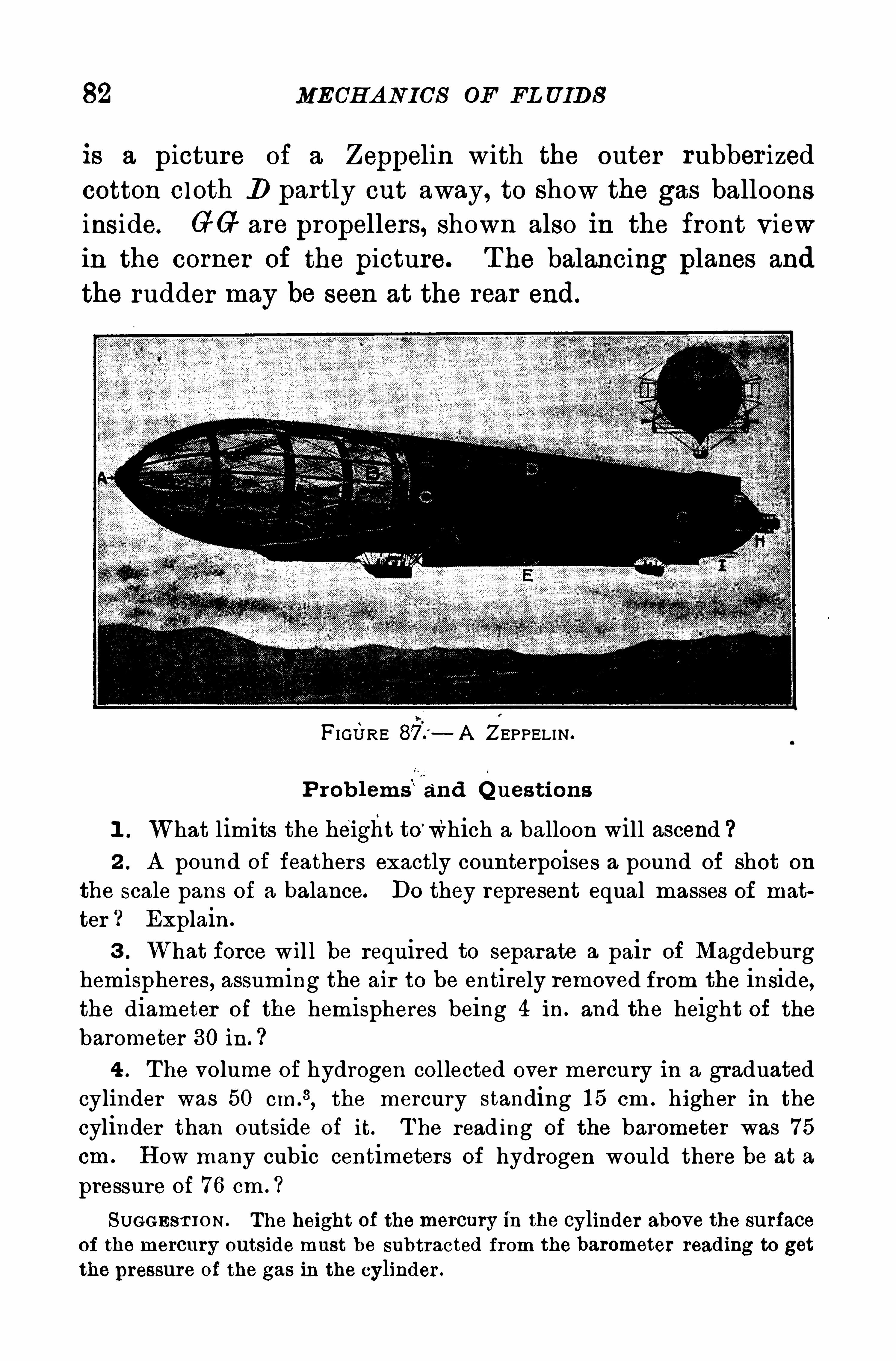
82 MECH A N ICS OF EL UIDS
is a picture of a Zeppelin with the outer rubber ized
cotton cl oth D partly cut away, to show the gas balloonsinside. GG are propellers, shown also in the front viewin the corner of the picture. T he balancing planes and
the rudder may be seen at the rear end.
FIGURE —A ZEPPELIN .
P rob lems"and Q ues tions
1 . What limits the helght to’which a balloon will ascend
2 . A pound of feathers exactly counterpoises a pound of shot on
the scale pans of a balance. Do they represent equal masses of mat
ter ? Explain .
3 . What force wil l be required to separate a pair of Magdeburghemispheres, assuming the air to be entirely removed from the inside,the diameter of the hemispheres being 4 in. and the height of thebarometer 30 in .
4 . The volume of hydrogen collected over mercury in a graduatedcylinder was 50 cIn .
3, the mercury standing 1 5 cm . higher in the
cylinder than outside of it. T he reading of the barometer was 75
cm . H ow many cubic centimeters of hydrogen would there be at a
pressure of 76 cm . ?
SUGGES T IO N . The height of the mercury in the cylinder above the surfaceof the mercury outside must be subtracted from the barometer reading to get
the pressure of the gas in the cylinder .
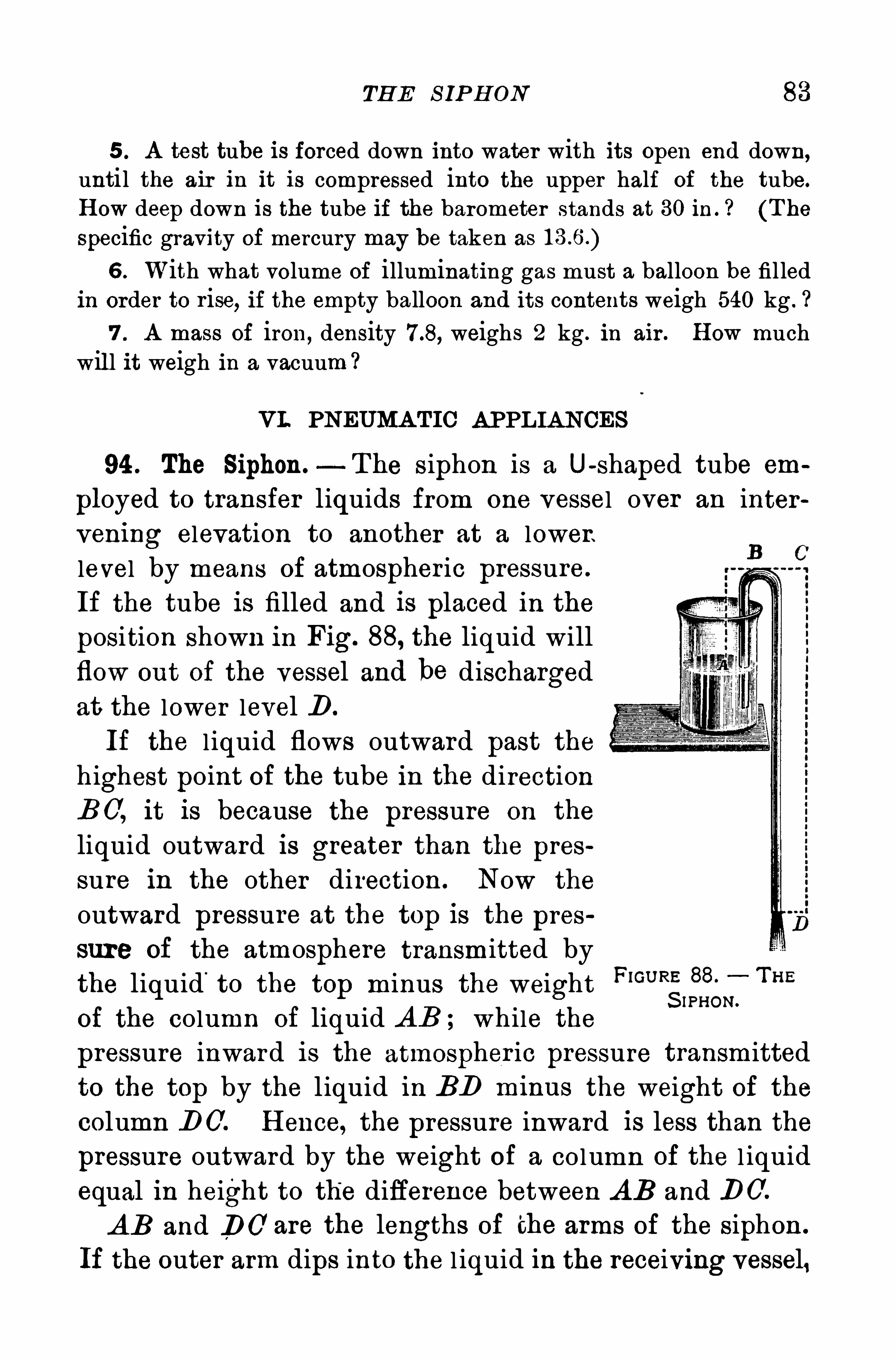
TH E S IP H ON 83
5 . A test tube is forced down into water with its open end down,until the air in it is compressed into the upper half of the tube.
H ow deep down is the tube if the barometer stands at 30 ih . ? (T he
specific gravity of mercury may be taken as
6 . With what volume of illuminating gas must a balloon be fil ledin order to r ise, if the empty balloon and its contents weigh 540 kg .
7 . A mass of iron, density weighs 2 kg . in air . H ow muchwill it weigh in a vacuum ?
VI. PNEUMA TIC A PPL IA NCES
94 . The Siphon.- The siphon is a U-shaped tube em
ployed to transfer liquids from one vessel over an inter
vening elevation to another at a lower.
level by means of atmospheric pressure.
If the tube is filled and is placed in the
position shown in Fig. 88, the liquid will
flow out of the vessel and be discharged
at the lower level D .
If the l iquid flows outward past the
highest point of the tube in the direction
B 0, it is because the pressure on the
liquid outward is greater than the pres
sure in the other direction . Now the
outward pressure at the top is the pres
sure of the atmosphere transmitted by
the liquid'
to the top minus the weightFIGU R
SISSC;T H E
of the column of liquid A B ; while the
pressure inward is the atmospher ic pressure transmitted
to the top by the l iquid in BD m1nus the weight of the
column DO. H ence, the pressure inward is less than the
pressure outward by the weight of a column of the l iquid
equal in height to the difference between A B and DO.
A B and DC are the lengths of the arms of the siphon .
If the outer arm dips into the l iquid in the receiving vessel,
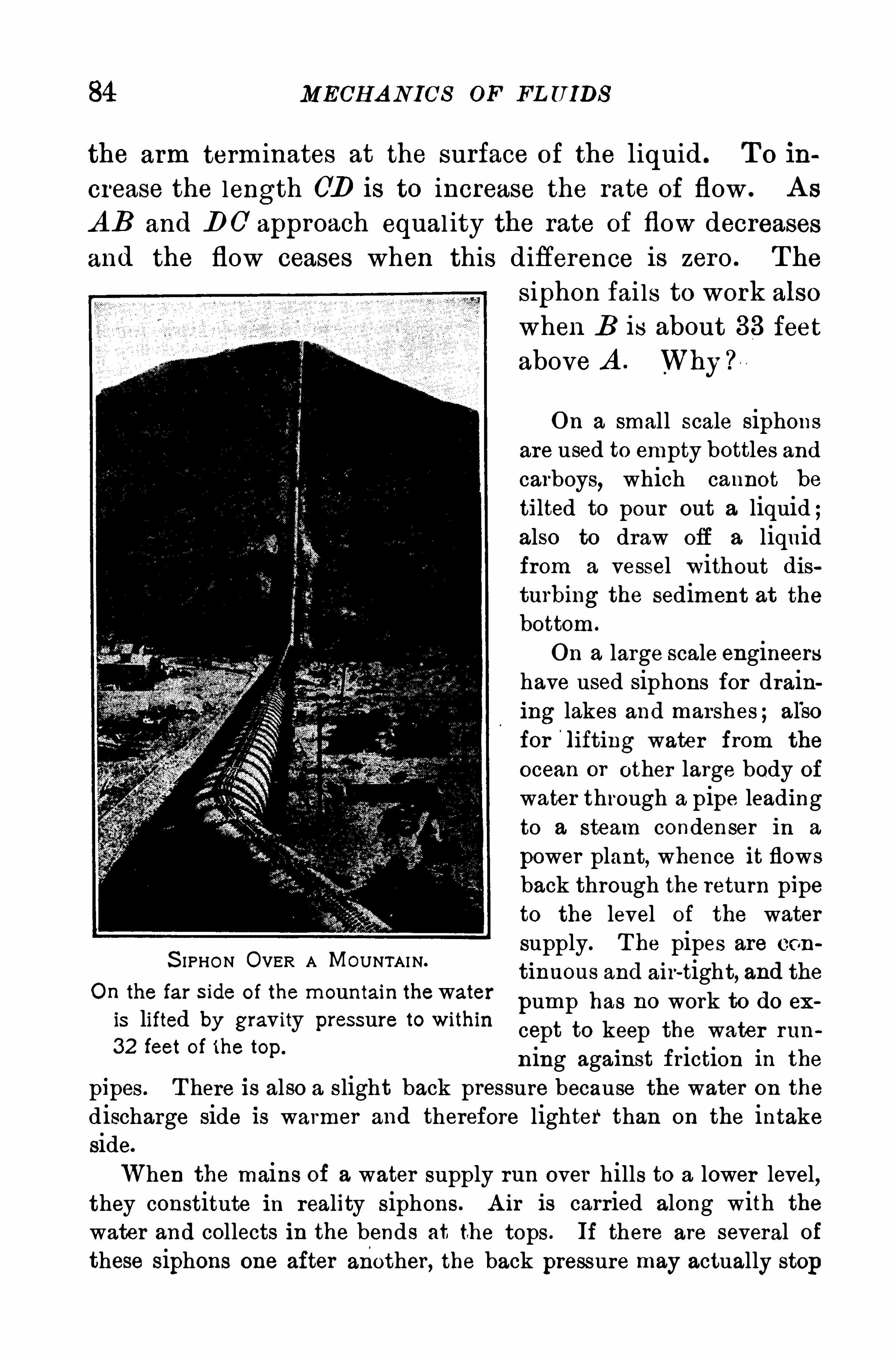
84 MECH A N ICS OF FL U IDS
the arm terminates at the surface of the liquid . T o in
crease the length CD is to increase the rate of flow . A s
A B and D 0 approach equal ity the rate of flow decreases
and the flow ceases when this difference is zero . T he
S IPHON OVER A MOUNTAIN.
On the far S ide of the mountain thewateris lifted by gravity pressure to within
32 feet of the top.
siphon fai ls to work also
when B is about 33 feetabove A . Why ?
On a small scale siphonsare used to empty bottles andcarboys, which cannot be
tilted to pour out a liquid ;also to draw off a liquidfrom a vessel without disturbing the sediment at the
bottom.
On a large scale engineershave used siphons for draining lakes and marshes ; al'sofor
'
lifting water from the
ocean or other large body ofwater through a pipe leadingto a steam condenser in a
power plant, whence it flowsback through the return pipeto the level of the watersupply. T he pipes are con
tinuous and air-tight, and the
pump has no work to do ex
cept to keep the water run
ning against friction in the
pipes. T here is also a slight back pressure because the water on thedischarge side is warmer and therefore lighter than on the intakeside.
When the mains of a water supply run over hills to a lower level,they constitute in reality siphons. A ir is carried along with the
water and collects in the bends at the tops . If there are several ofthese siphons one after another, the back pressure may actually stop
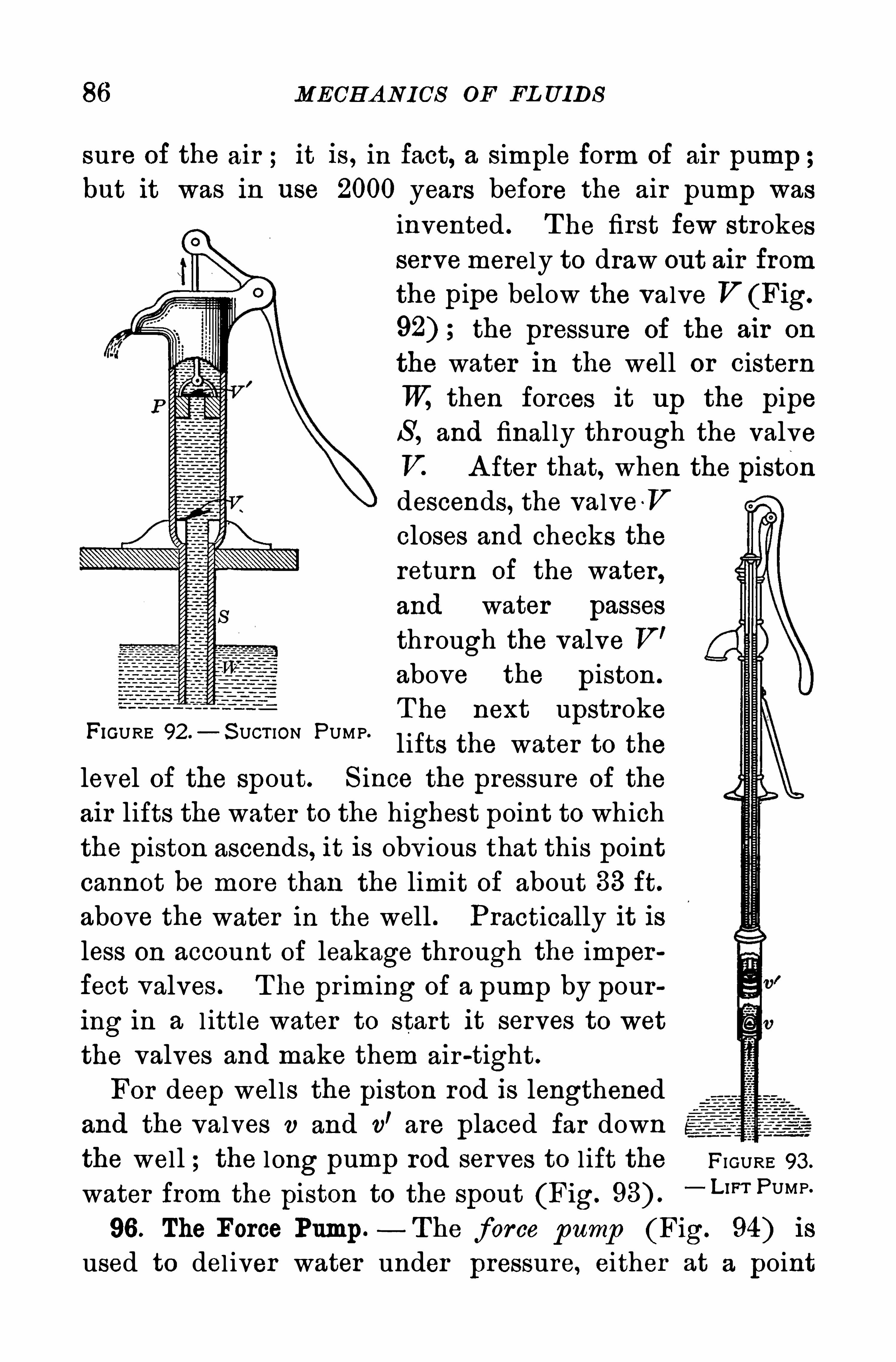
86 MECH A N I CS OF FL UIDS
sure of the air ; it is , in fact, a simple form of air pump ;but it was in use 2000 years before the air pump was
invented . T he first few strokesservemerely to draw out air fromthe pipe below the valve V (Fig.
the pressure of the air on
the water in the well or cisternTV, then forces it up the pipeS , and final ly through the valveV. A fter that, when the pistondescends, the valve -V
closes and checks thereturn of the water ,and water passes
through the valve V’
above the piston .
T he next upstrokelifts the water to the
level of the spout. S ince the pressure of the
air lifts the water to the highest point to which
the piston ascends, it is obv ious that this point
cannot be more than the limit of about 33 ft.above the water in the well . Practically it isless on account of leakage through the imperfect valves . T he pr iming of a pump by pouring in a l ittle water to start it serves to wet
the valves and make them air -tight.
For deep wel ls the piston rod is lengthenedand the valves v and v
’are placed far down
the well ; the long pump rod serves to l ift the
FIGURE 92 .—S UCT ION PUMP.
FI GURE 93 .
water from the piston to the spout (Fig.
“ U ” PUMP
96 . The Force Pump— The force pump (Fig. 94) is
used to del iver water under pressure, either at a point
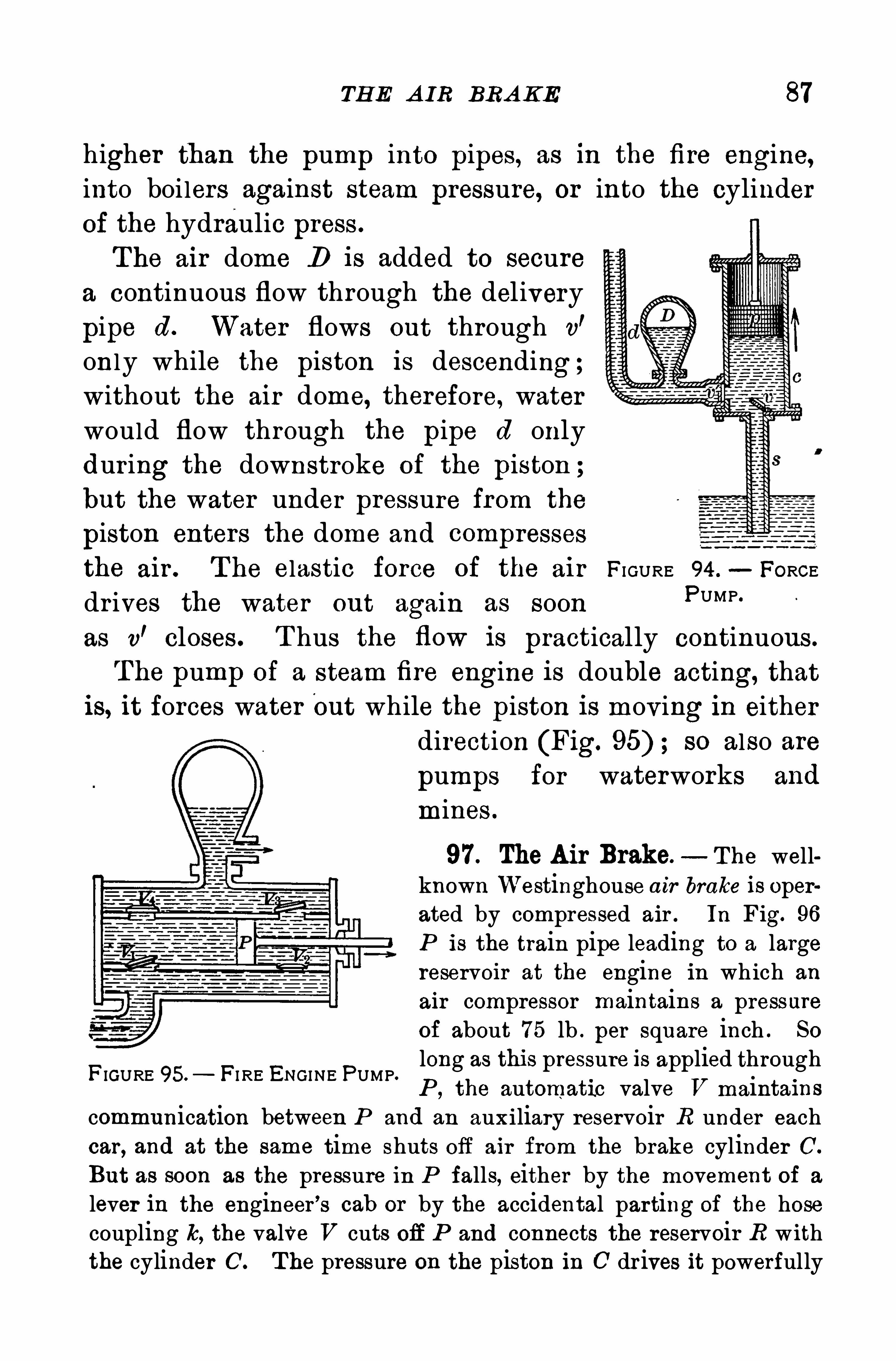
TH E A IR BRA KE 87
higher than the pump into pipes, as in the fire engine,into boilers against steam pressure, or into the cylinder
of the hydraulic press .
The air dome D is added to securea continuous flow through the delivery
pipe d . Water flows out through v’
only while the piston is descending;without the air dome, therefore, waterwould flow through the pipe d onlydur ing the downstroke of the piston ;but the water under pressure from the
piston enters the dome and compresses
the air . T he elastic force of the air FI GURE 94 .
—FORCE
dr ives the water out again as soon PUMP‘
as v’closes . T hus the flow is practically continuous.
The pump of a steam fire engine is double acting, thatis, it forces water out while the piston is moving in either
direction (Fig. so also are
pumps for waterworks and
mines .
97. The Air Brake. The wellknown Westinghouse air brake is operated by compressed air . In Fig. 96
P is the train pipe leading to a largereservoir at the engine in which an
air compressor maintains a pressureof about 75 lb . per square inch . So
long as this pressure is applied throughP , the automatic valve V maintains
communication between P and an auxiliary reservoir R under eachcar, and at the same time shuts off air from the brake cylinder 0 .
But as soon as the pressure in P falls, either by the movement of a
lever in the engineer ’s cab or by the accidental parting of the hosecoupling k, the valve V cuts off P and connects the reservoir R withthe cylinder C . T he pressure on the piston in 0 dr ives it powerfully
FIGURE 95. FI RE ENGINE PUMP.
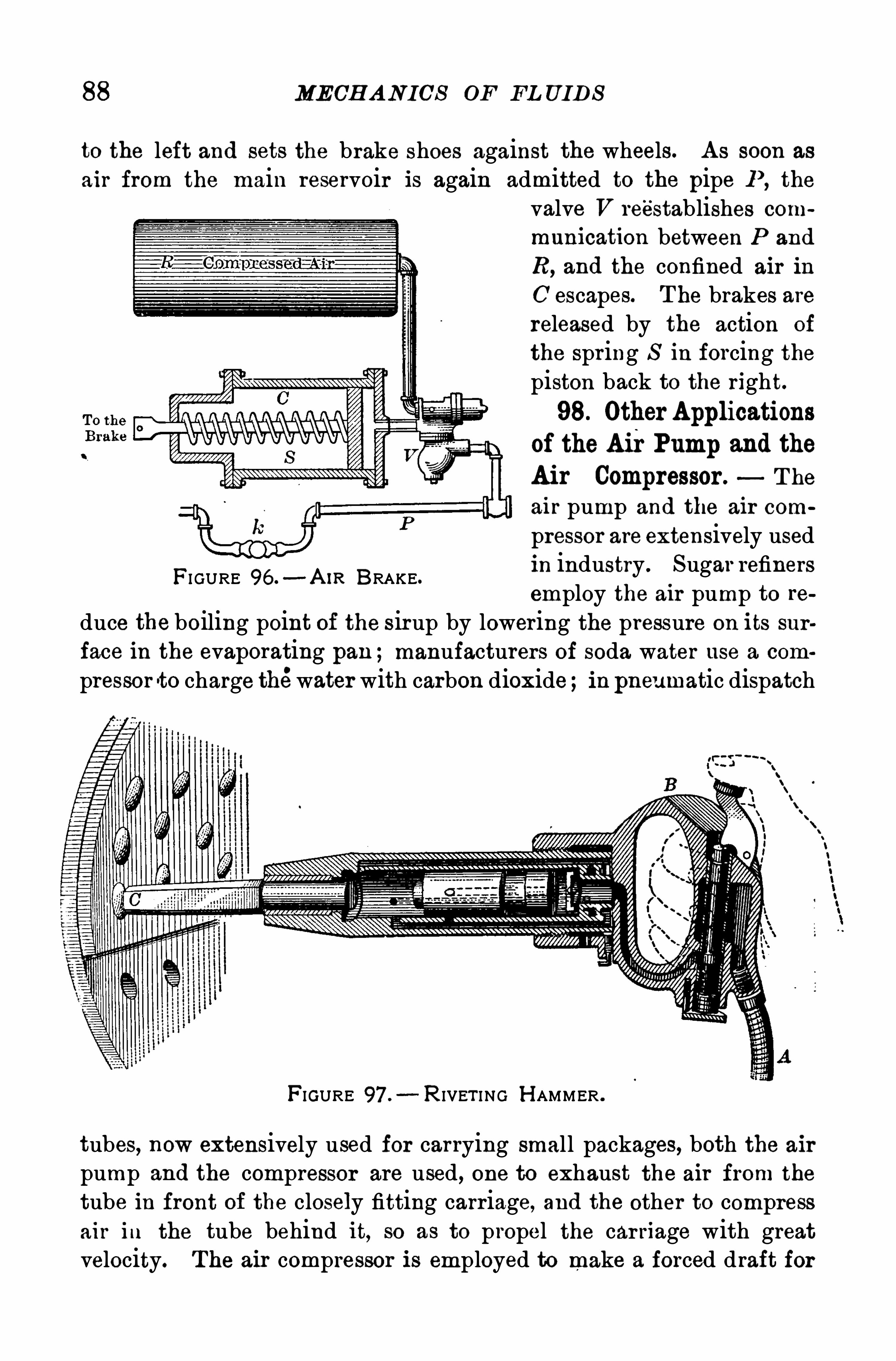
88 MECH A N ICS OF FL UID S
to the left and sets the brake shoes against the wheels. A s soon as
air from the main reservoir is again admitted to the pipe P , the
valve V re'
establishes com
munication between P and
R, and the confined air in
C escapes. T he brakes arereleased by the action of
the spring S in forcing thepiston back to the right.98. Other Applications
of the A ir Pump and the
Air Compressor . T he
air pump and the air com
pressor are extensively usedin industry . Sugar refinersemploy the air pump to re
duce the boiling point of the sirup by lowering the pressure on its sur
face in the evaporating pan ;manufacturers of soda water use a com
pressor -to charge thewater with carbon dioxide inpneumatic dispatch
FI GURE 96 .—A IR BRAKE.
FIGURE 97 .—R IVET I NG H AMMER .
tubes, now extensively used for carrying small packages, both the airpump and the compressor are used, one to exhaust the air from the
tube in front of the closely fitting carriage, and the other to compressair in the tube behind it, so as to propel the car riage with greatvelocity. The air compressor is employed to make a forced draft for
90 MECH A N I CS OE FL U IDS
8 . A diver works in 35 feet of sea water , specific gravityWhat pressure must the compression pump supply to counterbalancethe water pressure ?
9 . When the barometer reading is 73 cm. , what is the greatestpossible length of the short arm of a siphon when used for sulphuricacid, density g. per cubic centimeter ?
1 0 . If the pressure against the 8 in . piston of an air brakeis 80 lb.
per square inch, what is the force driving the piston forward ?
CH A PTER IV
MOTION
I . MOTION IN STRA IGH T LINES
99. All Motion Relative—Rest and motion are relativeterms only. A body is at rest when its relative positionwith respect to some point, l ine, or surface remains un
changed ; but when that relative position is changing, thebody is in motion .
The moving about of a person on a ship is relative to the vessel ;the movement of the ship across the ocean is relative to the earth’ssurface ;the daily motion of the earth’
s surface is relative to its axisof rotation ;the motion of the earth as a whole is relative to the sun ;
while the sun itself is drifting with other stars through space.
100. Types of Motion. Many familiar motions are irregular in every way, both as to direction and speed . T he
flight of a bird, the running of a boy at play, and even
the motion of a man r iding a horse, are i l lustrations . We
shall study only those motions that can be classified and
reduced to simple terms .
The line descr ibed by amoving body is its path. When
this path is straight, l ike that of a fal l ing body , the motion
is rectilinear ; when it is a curved line, l ike that of a
rocket, the motion is curvilinear .
T hen there is also simp le harmonic motion, exemplifiedby the to-and-fro swing of a pendulum ; and r otary motion
about an axis, such as the rotation of the earth on its axis,and that of the pulley and armature of a stationary elec
91
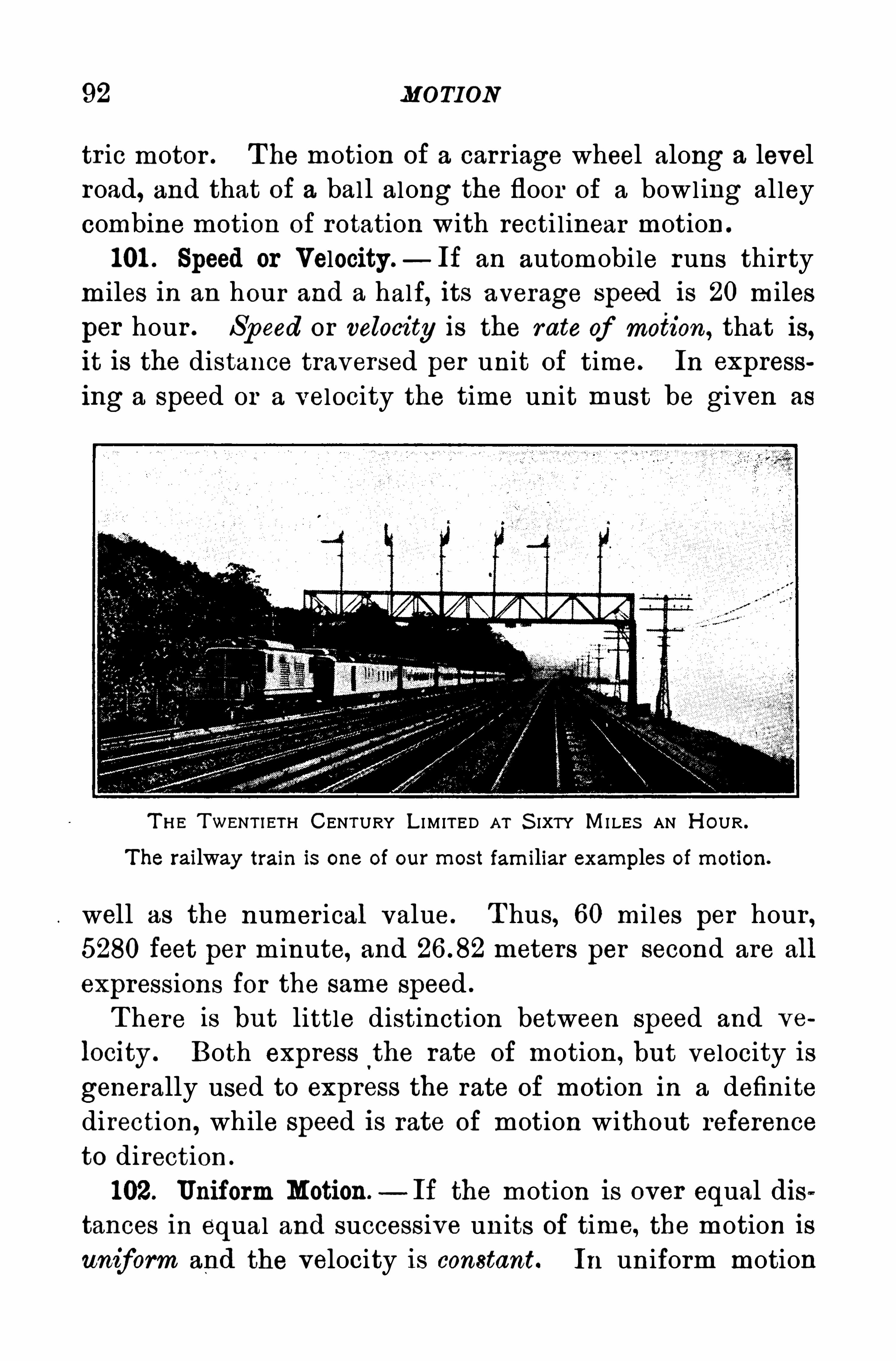
92 MOTION
tr ic motor . T he motion of a carr iage wheel along a level
road, and that of a bal l along the floor of a bow l ing al ley
combine motion of rotation with recti l inear motion .
101 . Speed or Velocity.— If an automobile runs thirty
miles in an hour and a half, its average speed is 20 miles
per hour . Speed or velocity is the rate of motion, that is,it is the distance traversed per unit of time. In express
ing a speed or a velocity the time un it must be given as
T H E TWENTIET I-I CENTURY L I M ITED A T S IXTY MI LES AN H OUR .
The railway train is one of our most fam iliar examples of motion.
well as the numer ical value . T hus, 60 mi les per hour ,5280 feet per m inute, and meters per second are all
expressions for the same speed .
T here is but little distinction between speed and ve
locity . Both express the rate of motion, but velocity is
generally used to express the rate of motion in a definite
direction,while speed is rate of motion without reference
to direction .
102. Uniform Motion — If the motion is over equal dis
tances in equal and successive units of time, the motion is
uniform and the velocity is constant. In uniform motion
94 MOTION
faster and faster ; it has a positive acceleration . A body
thrown upward goes more and more slowly ; it has a
negative acceleration. A l oaded sled starts from rest at
the top of a l ong hil l ; it gains in velocity as it descendsthe hil l ; it has a positive acceleration . When it reachesthe bottom, it loses velocity and is retarded , or has a
negative acceleration, until it stops . A cceleration is the
rate of change of Sp eed .
A cceleration change in sp eed p er unit time.
A cceleration is always expressed as so many units of
speed per unit of time. If, for example, a street car start
ing from rest gains uniformly in speed , so that at the end
of ten seconds it has a speed of 1 0 mi les per hour , its ac
celeration is its gain in speed-
per-hour acquired in one
second, or 1 m il’
e-per-hour per second .
105. Uniform A cceleration. If the change in velocity is
the same from second to second, the motion is uniformlyaccelerated . T he best example we have of uniformly ao
celerated motion is that of a fal l ing body, such as a stone
or an apple. Neglecting the resistance of the air , its gain
in vel ocity is m .-
per-second for every second it falls .
Its acceleration is therefore m .-
p er-second p er second;
in other words, it gains in velocity m .-
p er-second for
every second of time. T his is equivalent to an increase in
velocity of 588m .-
per-second acquired in a minute of time.
T he unit of time enters twice into every expression for
acceleration, the first to express the change in velocity,and the second to denote the inter val during which this
change takes place.
If an automobile starts from rest and increases its speed one foot a
second for a whole minute, its velocity at the end of the minute is60 ft. per second . S ince it gains in one second a velocity of one foot
DI S TA N CE TRA VERS ED 95
a s econd, and in one minute a velocity of 60 ft. a second, its acceleration may be expressed either as one foot-per
-second per second , or as60 ft.
-
per-second per minute. Its velocity is constantly changing ; its
acceleration is constant.
106 . Velocity in Uniformly Accelerated Motion . Supposea
’
body to move from rest in any given direction with a
constant acceleration of 5 ft.-
per-second per second . Its
velocity at the end of the first second wi l l be 5 ft. per
second ; at the end of two seconds, 2 x 5 ft . at the end
of three seconds, 3 x 5 ft. ; and at the end of t seconds,t x 5 ft. per second ; that is,
final velocity time acceleration,
or in symbols,v ta ; whence a (Equation 5)
H ence,
In uniform ly a ccelerated motion the speed acqu ired in
any given tim e is p ropor tional to the tim e.
107 . Distance traversed in Uniformly Accelerated Motion.
If we canfind the mean o r average velocity for any
period of t seconds, the distance 8 traversed in t secondsmay be found precisely as in the case of uniform motion
For a body starting from rest with an accelera
tion of 5 feet-per-second per second, for example, its ve
locity at the end of four seconds is 4 x 5 ft . per second, and
the average velocity for the four seconds is the mean be
tween 0 and 4 x 5, or 2 x 5 ft. per second, the velocity at
the middle of the period . SO at the end of t seconds the
average velocity is 7} ta ft . per second . T hen we have
distance average velocity x time,
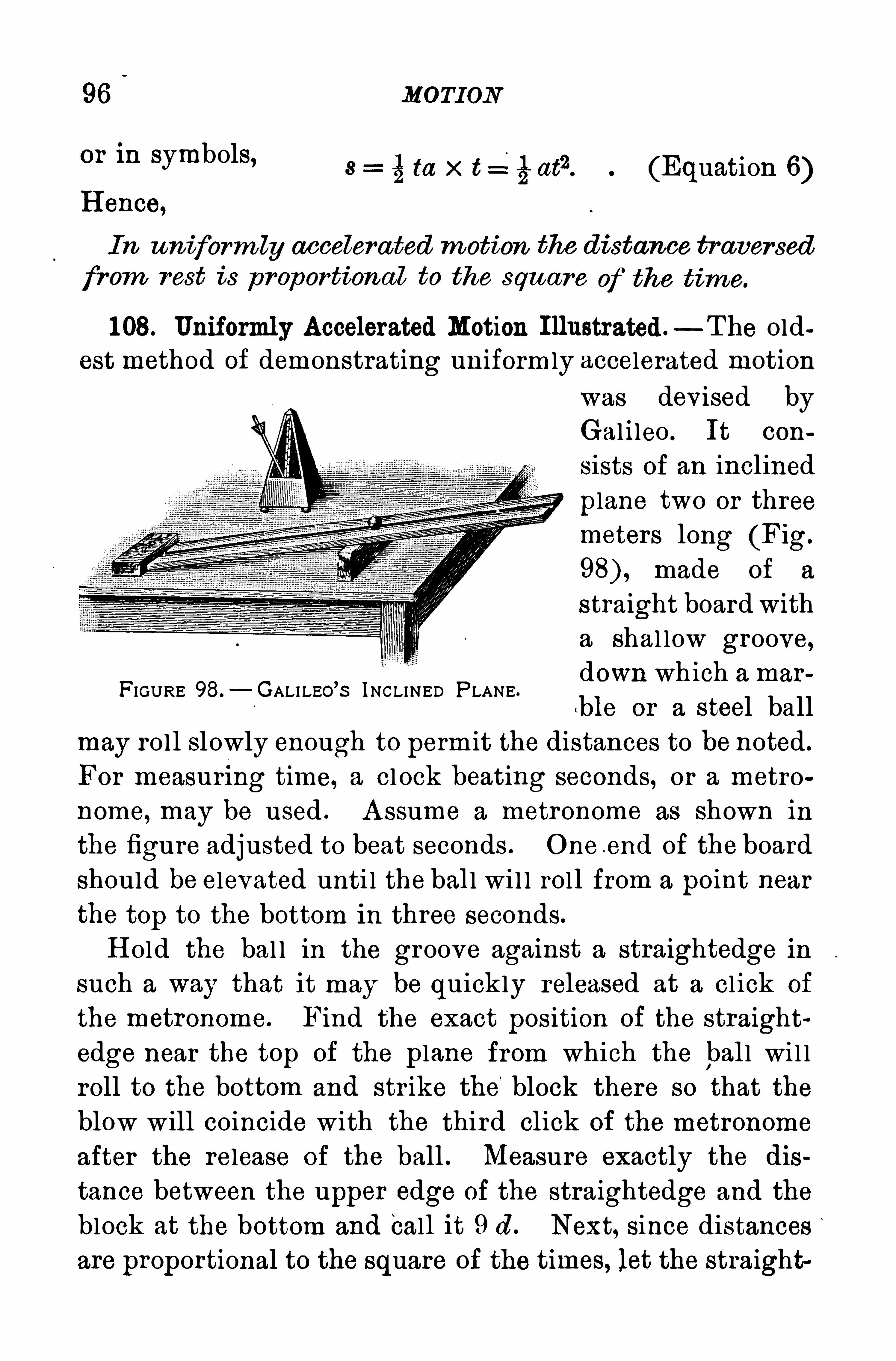
96 MOTION
or in symbols, mx t =figafl. (Equation 6)H ence,
I n uniform ly accelerated m otion the distance tr aversed
fr om rest is pr oportional to the square of the time.
1 08. Uniformly Accelerated Motion Illustrated —T he oldest method of demonstrating uniformly accelerated motion
was devised byGal i leo . It con
sists of an inclined
plane two or threemeters long (Fig.
made of a
straight board witha shal low groove,down which a mar
!ble or a steel ballmay rol l slowly enough to perm it the distances to be noted .
For measur ing time, a cl ock beating seconds, or a metro
nome, may be used . A ssume a metronome as shown in
the figure adjusted to beat seconds . One e nd of the board
should be elevated unti l the ball wi l l rol l from a point near
the top to the bottom in three seconds.
H old the bal l in the groove against a straightedge in
such a way that it may be quickly released at a cl ick of
the metronome. Find the exact position of the straight
edge near the top of the plane from which the bal l wi l lroll to the bottom and str ike the
'
block there so that theblow will coincide with the third click of the metronome
after the release of the ball . Measure exactly the dis
tance between the upper edge of the straightedge and the
block at the bottom and call it 9 d . Next, since distancesare proportional to the square of the times, let the straight
FIGURE 98.—GALI LEO’S INCLINED PLANE.
98 MOTION
column show that the distances traversed are proportionalto the squares of the time [compare Equation thoseof column three show that the distances in successiveseconds are as the odd numbers 1 , 3, 5, etc. T he resultsare shown graphical ly in Fig. 99.
P rob lems
NO T E . For the relation between the circumference of a circle and its
diameter , see the Mensuration Table in the A ppendix .
1 . A n aviator drives his aeroplane through the air a d istance of
500 km. in 8 hr . 20 min. What was his average speed per minute ?2 . T he englne drives a boat downstream at the rate of 1 5 m i. an
hour , while the current runs 3 ft . a second. H ow long will it take togo 50 mi. ?
3 . A man runs a quarter of a mile in seconds . A t thatspeed, what was his time for 1 00 yd .
4 . If a man can‘
run 1 00 yd . in 1 0 sec., whatwould be his time for
a mile,’
if it were possible to maintain the same speed ?
A procession 1 00 yd . long , moving at the rate of 3 mi. an hour ,passes over a bridge 120 yd . long. H ow long does it take the procession to pass entirely over the bridge ?
6 . A n express train is running 60 mi . an hour . If the train is500 ft. long, how many seconds will it be in passing completely over aviaduct 1 60 ft. in length
A locomotive driving wheel is 2 m . in diameter . If it makes200 revolutions per minute, what is the speed of the locomotive inkilometers per hour , assuming no slipping of the wheel on the track ?
8 . A n automobile running at a uniform speed of 25 mi. per houris 10mi . behind another one on the same highway running 20 mi. perhour . H ow long Wl ll it take the former to overtake the latter, andhow far will each machine have gone during this time ?
If the acceleration of a marble rolling down an inclined planeis 40
‘
cm.-
per-second per second, what will be its velocity after 3 sec.
from rest ?
1 0 . H ow far wi ll a marble travel down an inclined planein 3 see}if the acceleration Is 40 cm .
-
per-second per second ?
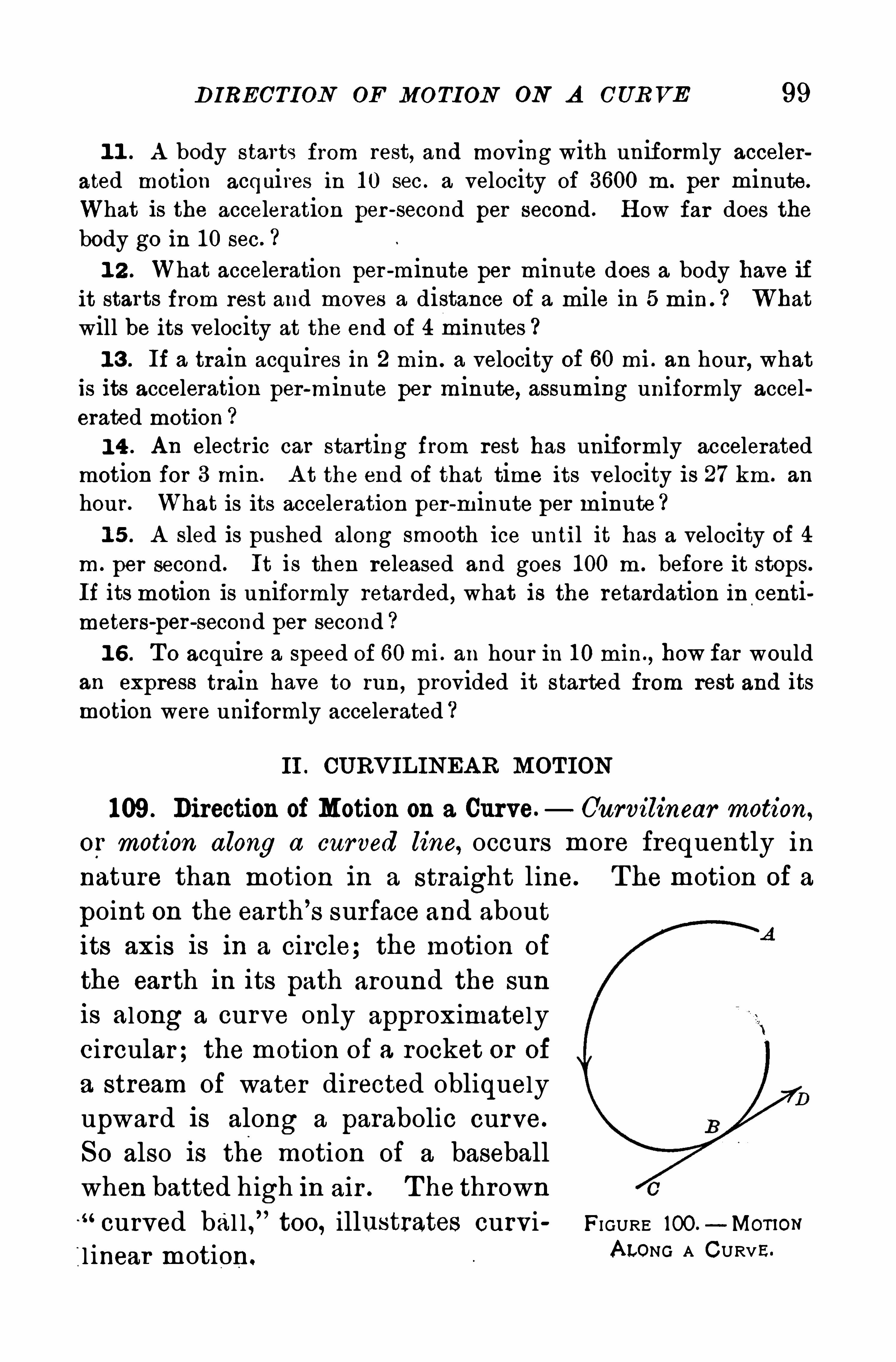
DIRECTION OF MOTION ON A CURVE 99
1 1 . A body starts from rest, and moving with uniformly acceler
ated motion acquires in 1 0 sec . a velocity of 3600 m . per minute.
What is the acceleration per -second per second . H ow far does thebody go in 1 0 sec.
1 2 . What acceleration per -minute per minute does a body have ifit starts from rest and moves a distance of a mile in 5 min . Whatwill be its velocity at the end of 4 m1nutes
1 3 . If a train acquires in 2 min . a velocity of 60 mi . an hour , whatis its acceleration per-minute per minute, assuming uniformly accelcrated motion
1 4 . An electric car starting from rest has uniformly acceleratedmotion for 3 min . A t the end of that time its velocity is 27 km . an
hour . What is its acceleration per -minute per minute ?1 5 . A sled is pushed along smooth ice until it has a velocity of 4
m . per second . It is then released and goes 1 00 m . before it stops.
If its motion is uniformly retarded , what is the retardation in centimeters—per -second per second ?1 6 . T o acquire a speed of 60 mi . an hour in 1 0 min.
, how far wouldan express train have to run
, provided it started from rest and its
motion were uniformly accelerated
II . CURVIL INEA R MOTION
109. Direction of Motion on a Curve. Curvilinear motion,
or motion along a curved line, occurs more frequently in
nature than motion in a straight line. The motion of a
point on the earth’
s surface and aboutits axis is in a circle; the motion of
the earth in its path around the sun
is along a curve only approximatelycircular; the motion of a rocket or of
a stream of water directed obliquelyupward is along a parabolic curve.
So also is the motion of a baseballwhen batted high in air . T he thrown“curved bal l ,
”too, illustrates curvi FI GURE too - Mom s
l inear motion.ALONG A CURVE.
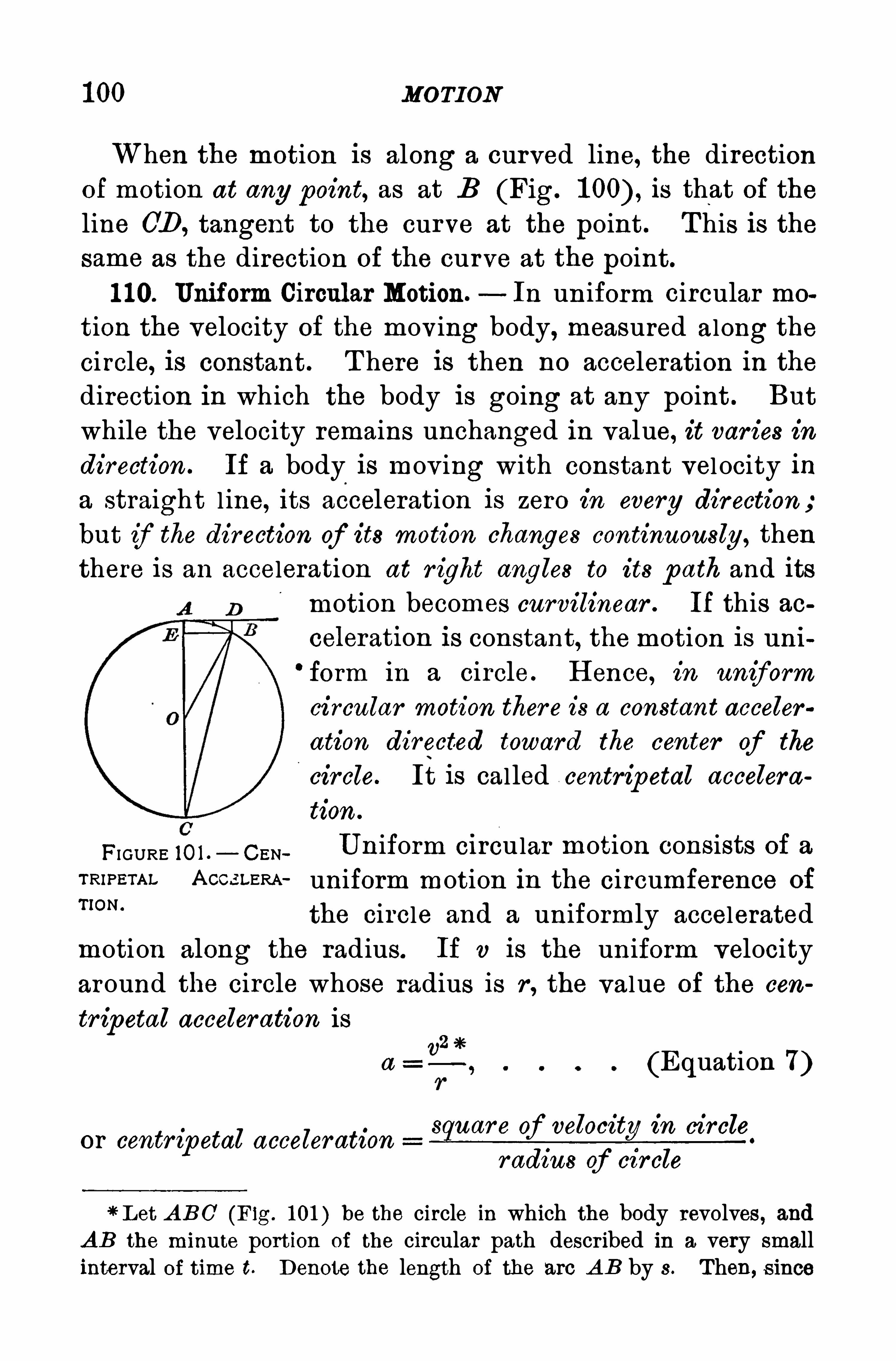
1 00 MOTION
When the motion is along a curved line, the directionof motion at any point, as at B (Fig. is that of theline CD , tangent to the curve at the point . T his is thesame as the direction of the curve at the point.
1 10. Uniform Circular Motion. In un iform circular mo
tion the velocity of the moving body, measured along thecircle, is constant. T here is then no acceleration in thedirection in which the body is going at any point . But
while the velocity remains unchanged in value, it var ies indirection . If a body is mov ing with constant vel ocity ina straight l ine, its acceleration is zero in every direction;
but if the direction of its motion changes continuously , thenthere is an acceleration at r ight angles to its p ath and its
motion becomes curvilinear . If this ao
celeration is constant, the motion is uni‘form in a circle . H ence, in uniform
circular motion ther e is a constant accoler
ation directed toward the center of the
ci r cle. It is called centripetal accelera
tion .
FI GURE 10 1 , _ CEN_ U niform ci rcular motion consists of a
TRIPETAL A CC-i l-ERA uniform motion in the circumference ofT’ON‘
the circle and a uniformly accelerated
motion along the radius. If v is the uniform velocity
around the circle whose radius is r , the value of the cen
tr ipetal acceler ation is
a (Equation 7)
s uar e of velocity in circleor centr ipetal acceleration
radius of ci rcle
! L et A BC (Fig. 1 01 ) be the circle in which the body revolves , andAB the minute portion of the circular path described in a very smallinterval of time t. Denote the length of the arc A B by s . Then, s ince

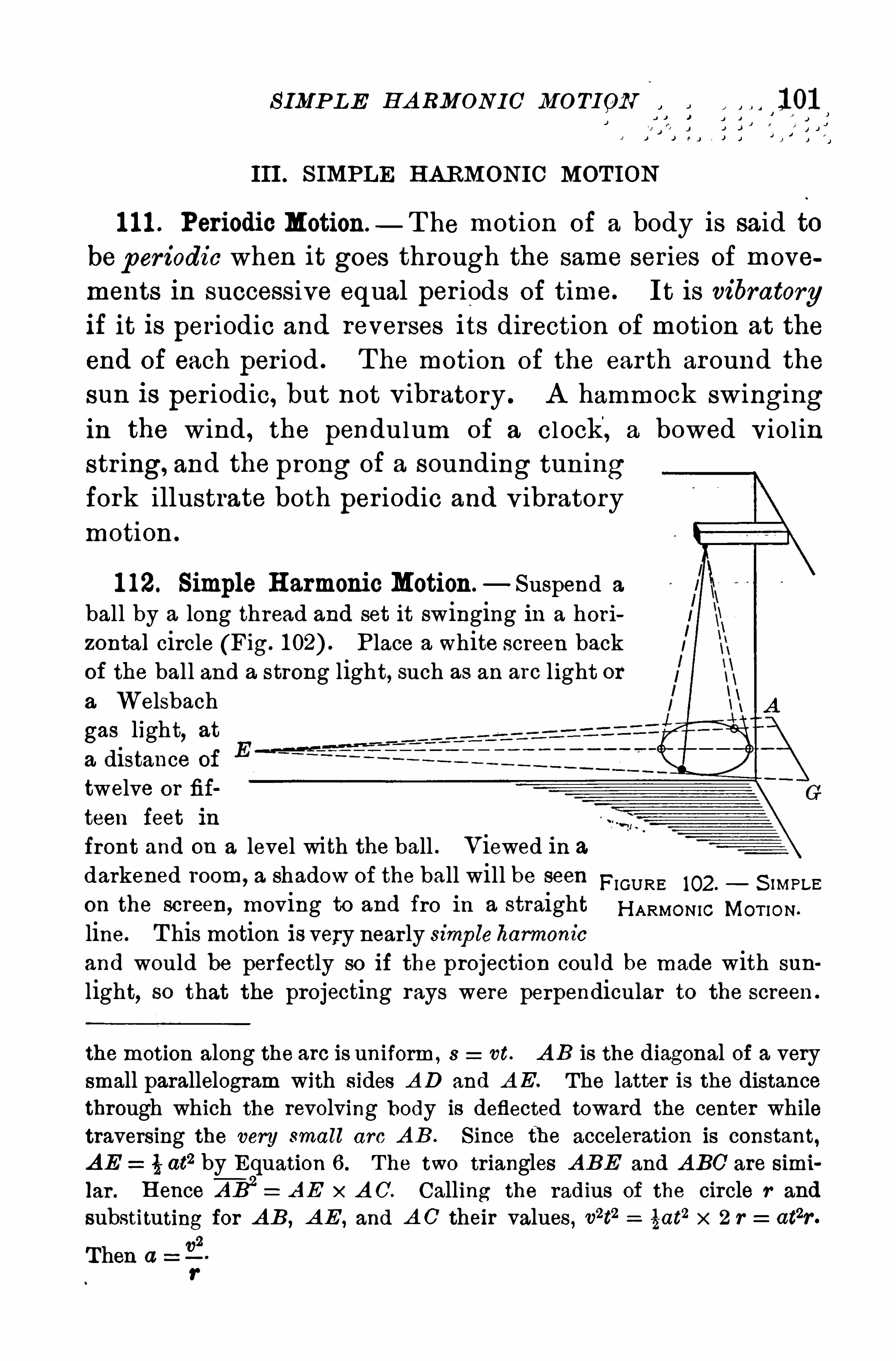
S IMP L E H A RMON IC MO TION
III . S IMPLE H A RMONIC MOT ION
1 1 1 . Periodic Motion — T he motion of a body is said tobeper iodic when it goes through the same ser ies of movements in successive equal per iods of time. It is vibratoryif it is periodic and reverses its direction of motion at the
end of each period . T he motion of the ear th around thesun is per iodic, but not v ibratory . A hammock swingingin the wind , the pendulum of a clock, a bowed v iolinstr ing, and the prong of a sounding tun ingfork illustrate both per iodic and v ibratorymotion .
1 12. Simple H armonic Motion —Suspend a
ball by a long thread and set it swinging in a horizontal circle (Fig. P lace a white Screen backof the ball and a strong light, such as an are light ora Welsbach
gas light, at
a distance of
twelve or fif
teen feet in
front and on a level with the ball . Viewed in adarkened room,
a shadow of the ball will be seen FIGURE 102. S N PLE
on the screen,moving to and fro in a straight H ARMONIC MOT ION .
line. T his motion is very near ly simp leharmonicand would be perfectly so if the projection could be made with sun
light, so that the projecting rays were perpendicular to the screen .
the motion along the arc is uniform , s vt. A B is the diagonal of a verysmall parallelogram with sides A D and A E. The latter is the distancethrough which the revolving body is deflected toward the center whiletraversing the very small arc A B . S ince th e acceleration is constant,A E : t at2 by Equation 6 . T he two triangles A BE and A BC are simi
lar . H ence A B2 = A E x A C. Calling the radius of the circle r and
substituting for A B , A E , and A C'their values , v2t2 _ tat
2 x 2 r _ atzr .
Then a 12
r
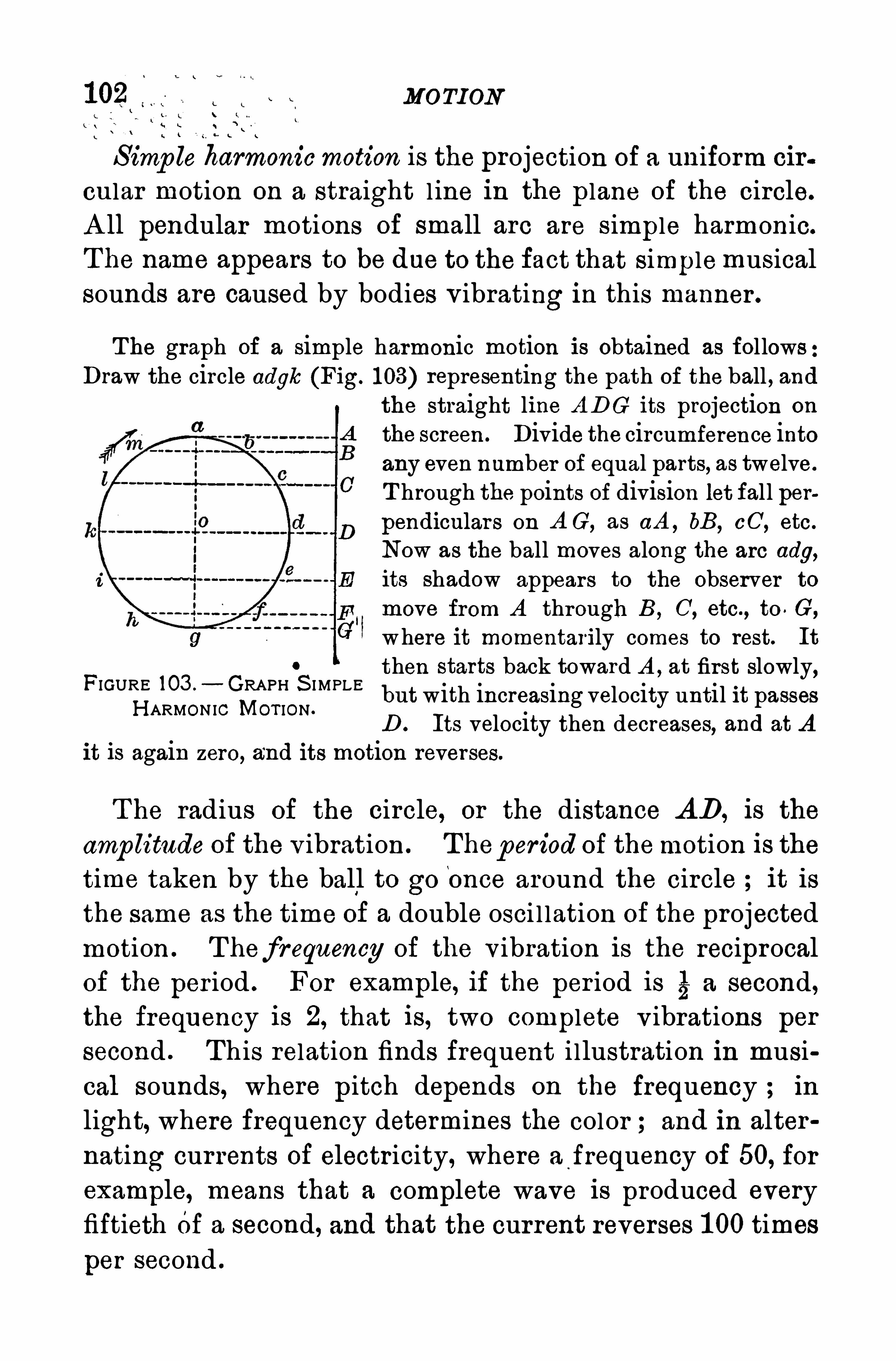
MOTI ON
S imp le harmonicmotion is the projection of a uniform cir
onlar motion on a straight l ine in the plane of the circle.
A ll pendular motions of small are are simple harmonic.
T he name appears to be due to the fact that simplemusicalsounds are caused by bodies v ibrating in this manner .
T he graph of a simple harmonic motion is obtained as followsDraw the circle adyk (Fig. 1 03) representing the path of the ball , and
the straight line A DG its projection on
the screen. Divide the circumference intoany even number of equal parts, as twelve.
T hrough the points of division let fall perpendiculars on A G, as aA , bB, CC, etc.
Now as the ball moves along the arc ady,
E its shadow appears to the observer to
move from A through B, C, etc., to . G,
where it momentarily comes to rest. It
then starts back toward A , at first slowly,but with increasing velocity until it passesD . Its velocity then decreases, and at A
it is again zero, and its motion reverses.
0
FIGURE 103 . GRAPH S I MPLEH ARMON IC MOT ION .
T he radius of the circle, or the distance A D, is the
amp litude of the v ibration . Thep eriod of themotion is thetime taken by the ball to go once around the circle it is
the same as the time of a double osci l lation of the projectedmotion . T hefr equency of the v ibration is the reciprocalof the per iod . For example, if the per iod is 5 a second,the frequency is 2, that is, two complete v ibrations per
second . T his relation finds frequent i llustration in musi
cal sounds, where pitch depends On the frequency ; in
light, where frequency determines the color and in alter
nating currents of electricity, where a frequency of 50, for
example, means that a complete wave is produced everyfiftieth Of a second, and that the current reverses 1 00 times
per second .
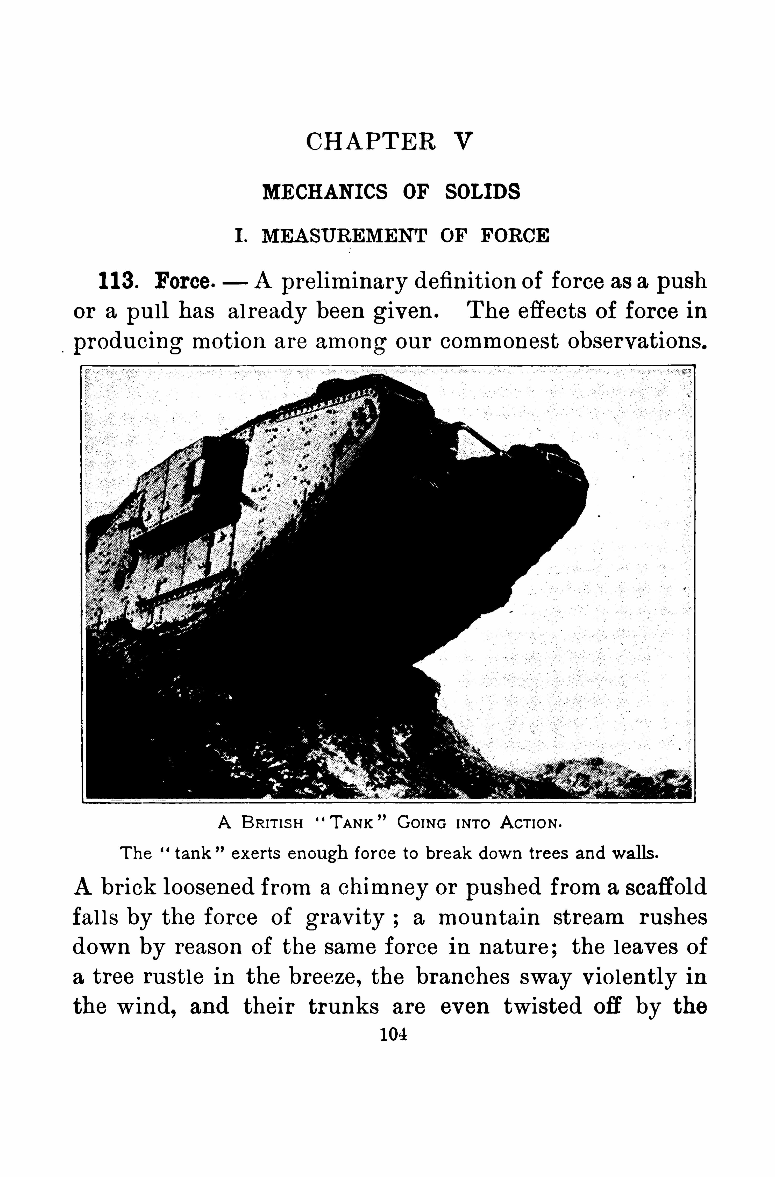
CH A PT ER V
MECH ANICS OF SOLIDS
I . MEA SUREMENT OF FORCE
1 1 3 . Force. A preliminary definition of force as a push
or a pull has already been given . T he effects of force in
producing motion are among our commonest observations.
A BRITIS I—I “TANK GOING I NTO A CT IO N .
T he “tank exerts enough force to break down trees and walls .
A br ick loosened from a chimney or pushed from a scaffold
fal ls by the force of gravity ; a mountain stream rushesdown by reason of the same force in nature; the leaves of
a tree rustle in the breeze, the branches sway violently in
the wind, and their trunks are even twisted ofi by the
104
UN ITS OF FORCE 1 05
force of the tornado; powder explodes in a rifle and the
bul let speeds toward its mark; l oud thunder makes the
earth tremble and v ivid l ightning rends a tree or shatters
a flagstaff. From many such fami l iar facts is derived the
conception thatforce is anything that p r oduces motion or
change ofmotion in mater ial bodies . It remains now to
explain how force is measured .
1 1 4. Units of Force.—Two systems of measur ing force
in common use are the gr avitational and the absolute. T he
gravitational unit of force is the weight of a standard mass,
such as the pound of for ce, the gram of for ce, or the kilo
gram of force. A pound of force means one equal to the
force required to l ift themass of a‘
pound against the down
ward pull of grav ity . T he same is true of the metr icunits with the difference in the mass lifted .
Grav itational units of force are not str ictly constantbecause the weight of the same mass var ies from point to
point on the earth’
s surface, and at different elevations .
T he actual force necessary to lift the mass of a pound at
the poles of the earth is greater than at the equator ; it isless on the top of a high mountain than in the neighbor ingval leys, and sti l l less than at the level of the sea. Gravi
tational units of force are convenient for the common pur
poses of life and for the work of the engineer , but they are
not suitable for precise measurements, especial ly in the
domain of electr icity .
T he so-called “absolute unit of force in the c.g.s. system
is the dyne (from the Greek word meaning force) . The
dyne is the force which imparts to a gram mass an accoler
ation equal to one centimeter -
per-second per second. T his
unit is invar iable in value, for it is independent of the var iable force of grav itation . It is indispensable in framingthe definitions of modern electrical and magnetic units .
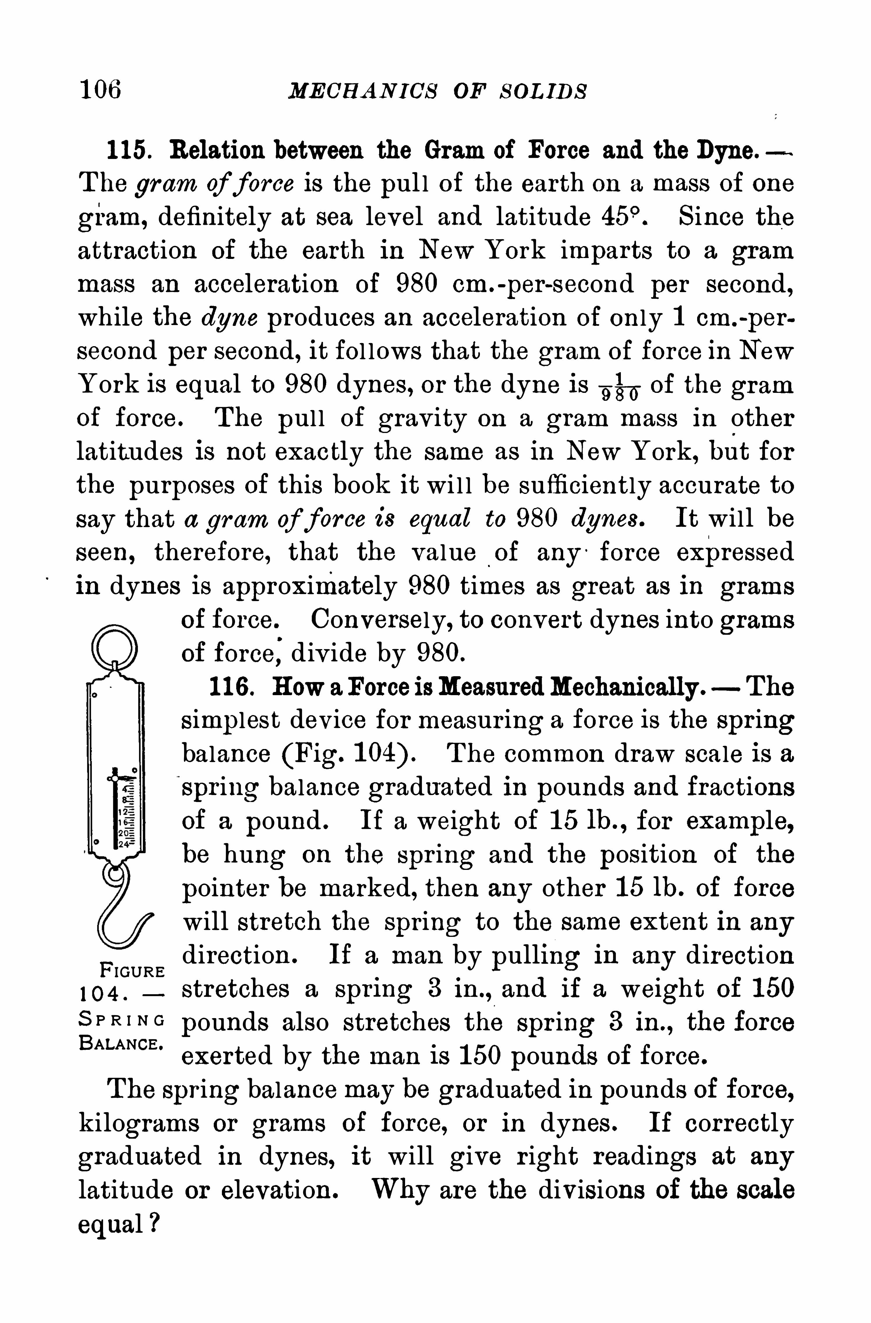
1 06 MECH A N ICS OF S OL IDS
1 15. Relation between the Gram of Force and theDyne.
T he gram of force is the pul l of the earth on a mass of one
gram, definitely at sea level and latitude S ince theattraction of the earth in New York imparts to a gram
mass an acceleration of 980 cm.-
per-second per second,
while the dyne produces an acceleration of only 1 cm.-
per
second per second, it fol lows that the gram of force in New
York is equal to 980 dynes , or the dyne is 3 57, oi the gramof force. The pull of grav ity on a gram mass in otherlatitudes is not exactly the same as in New York, b it forthe purposes of this book it wi l l be sufficiently accurate tosay that a gram of force is equal to 980 dynes . It will be
seen, therefore, that the value of any: force expressed
in dynes is approximately 980 times as great as in grams
of force Conversely, to convert dynes into grams
of force,div ide by 980.
1 1 6 . H ow aForceisMeasuredMechanically. The
S implest device for measur ing a force is the spr ingbalance (Fig. T he common draw scale is aSpr ing balance graduated in pounds and fractions
of a pound . If a weight of 1 5 lb. , for example,be hung on the spr ing and the position of the
pointer be marked, then any other 1 5 1h. of forcewill stretch the spring to the same extent in any
Fdirection . If a man by pulling 1 11 any directionIGURE
1 0 4 .stretches a spr lng 3 1n ., and If a weight of 1 50
S P R I N Gpounds also stretches the spr ing 3 in . , the force
BALANCE '
exerted by the man is 1 50 pounds of force.
The spring balancemay be graduated in pounds of force,kilograms or grams of force, or in dynes . If correctly
graduated in dynes, it will give r ight readings at any
latitude or elevation. Why are the divisions of the scale
equal
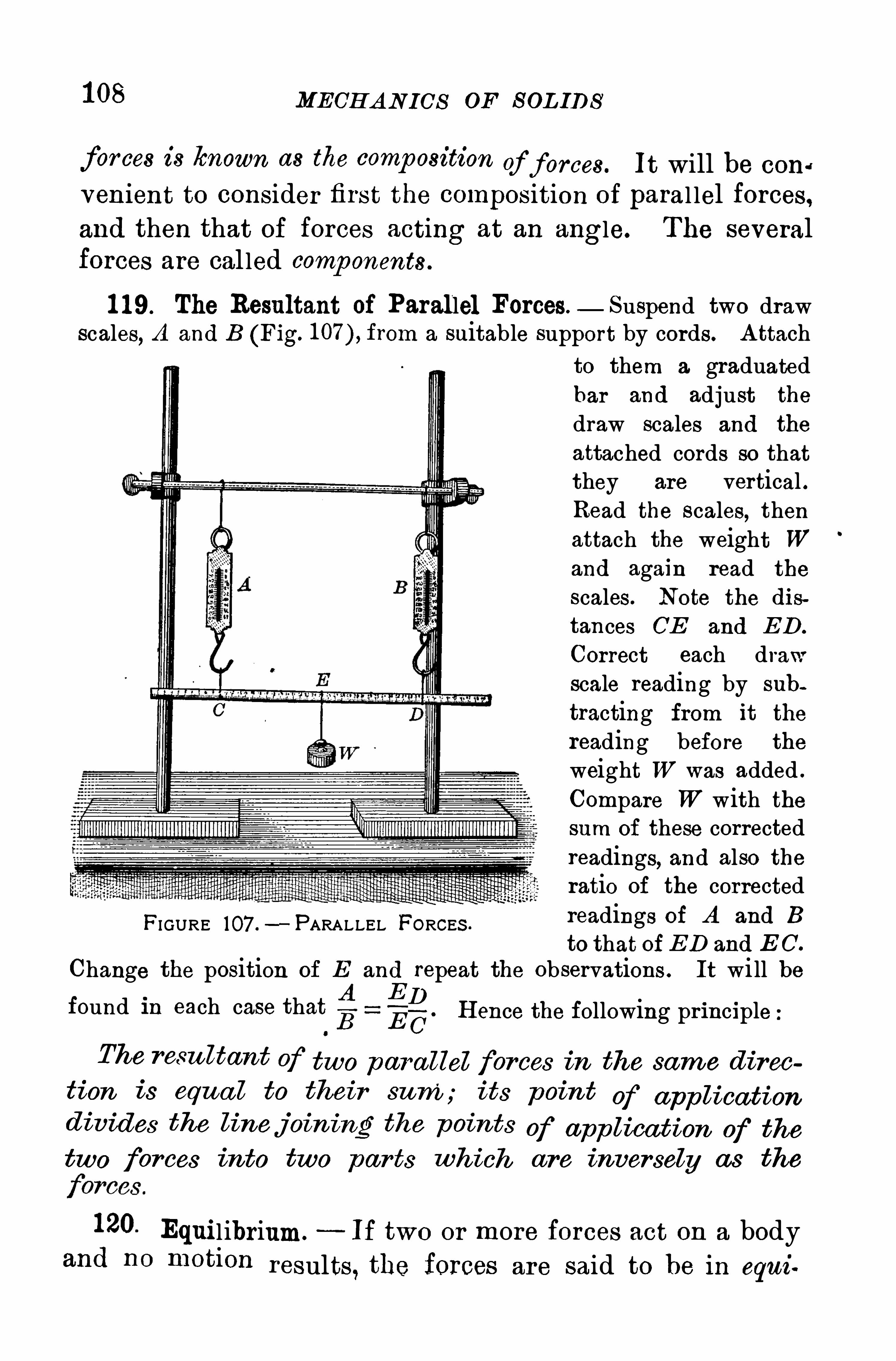
1 08 MECH A N ICS OF S OL IDS
for ces is known as the comp osition of forces. It will be coner
venient to consider first the composition of paral lel forces,and then that of forces acting at an angle. The severalforces are cal led comp onents .
1 1 9. The Resultant of Parallel Forces. Suspend two drawscales, A and B (Fig. from a suitable support by cords. A ttach
to them a graduatedbar and adjust the
draw scales and the
attached cords so thatthey are vertical .Read the scales, thenattach the weight Wand again read the
scales. Note the dis
tances CE and ED .
Correct each drawscale reading by sub
tracting from it the
reading before the
weight W was added .
Compare W with thesum of these correctedreadings, and also theratio of the correctedreadings of A and B
to that of ED and E C.
Change the position of E and repeat the observations . It will befound in each case thatg g—g. H ence the following principle
The resu ltant of two par a llel forces in the same d ircotion is equa l to their sum; its p oin t of app licationd ivides the linejoin ing the points of app lication of thetwo for ces into two par ts which are inversely as the
FI GURE 107 .—PARALLEL FORCES .
120. Equil ibrium. If two or more forces act on a bodyand no motion results, the forces are said to be in equi
RES UL TA N T OF TWO FORCE S A T A N A N GL E 1 09
librium. In Fig. 1 07 the weight W is equal and Opposite
to the resultant of the two forces measured by “the draw
scales A and B . T he three forces A , B , and W are in
equilibr ium. Further , each force is equal and opposite to
the resultant of the other two and is cal led their equi
librant. The equilibrium of a body does not mean that
its velocity is zero, but that its acceleration is zero . Best
means zero velocity ; equilibrium, zer o acceleration.
1 21 . Parallel Forces in Opposite Directions.—If two par
al lel forces act in Opposite directions,their resultant is
their difierence, and it acts in the direction of the larger
force. In Fig. 1 07 the resultant of A andW is equal andOpposite to B .
When the two paral lel forces acting in opposite directions are equal, they form a coup le. T he resultant of a
couple is zero ; that is, no single force can be substituted .
for it and produce the same effect. A couple producesmotion of rotation only, in which all the par ticles of the
body to which it is applied rotate in circles about a com
mon axis . For example, a magnetized sewing needlefloated on water is acted on by a couple when it is dis
placed from a north -and-south position . One end of the
needle is attracted toward the north , and the other toward
the south , with equal and parallel forces . T he effect is
to rotate the needle about a vertical axis until it returnsto a north-and-south position . T he common anger, as a
carpenter employs it to bore a hole, i l lustrates a couple inthe equal and opposite paral lel forces appl ied by the two
hands .
122. The Resultant of Two Forces Acting at an Angle.
T ie together three cords at D (Fig. 1 08) and fasten the three ends tothe hooks of the draw scales A , B , C . Pass their rings over pegs set
in a board at such distances apart that the draw scales will all be
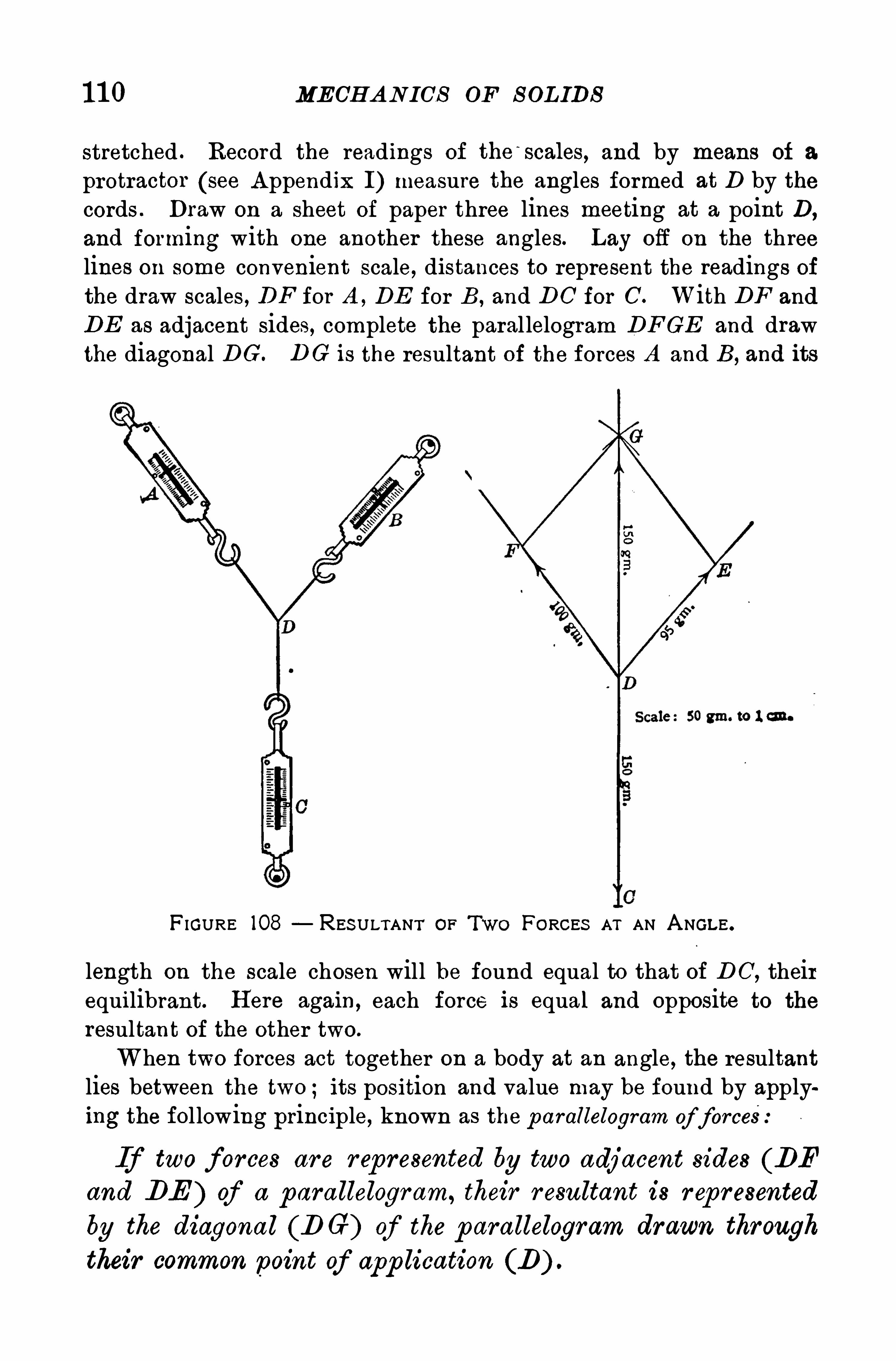
1 1 0 MECHANICS OF S OL IDS
stretched . Record the readings of the scales, and by means of a
protractor (see A ppendix I) measure the angles formed at D by thecords . Draw on a sheet of paper three lines meeting at a point D,
and forming with one another these angles. Lay off on the threelines on some convenient scale, distances to represent the readings ofthe draw scales, DF for A , DE for B , and DC for C. With DF and
DE as adjacent sides, complete the paral lelogram DFGE and drawthe diagonal DG. DG is the resultant of the forces A and B, and its
F IGURE 108 RES ULTANT or FORCES AT AN A NGLE .
length on the scale chosen will be found equal to that of DC, theirequilibrant. H ere again, each force is equal and opposite to the
resultant of the other two.
When two forces act together on a body at an angle, the resultantlies between the two ; its position and value may be found by applying the following principle, known as the p arallelogram of force
If two f orces ar e r ep resented by two adjacent sides (BFand BE ) of a parallelogram, their r esultant is r ep r esented
by the diagonal (DG) of the p arallelogram drawn through
their common point of app lication (D) .
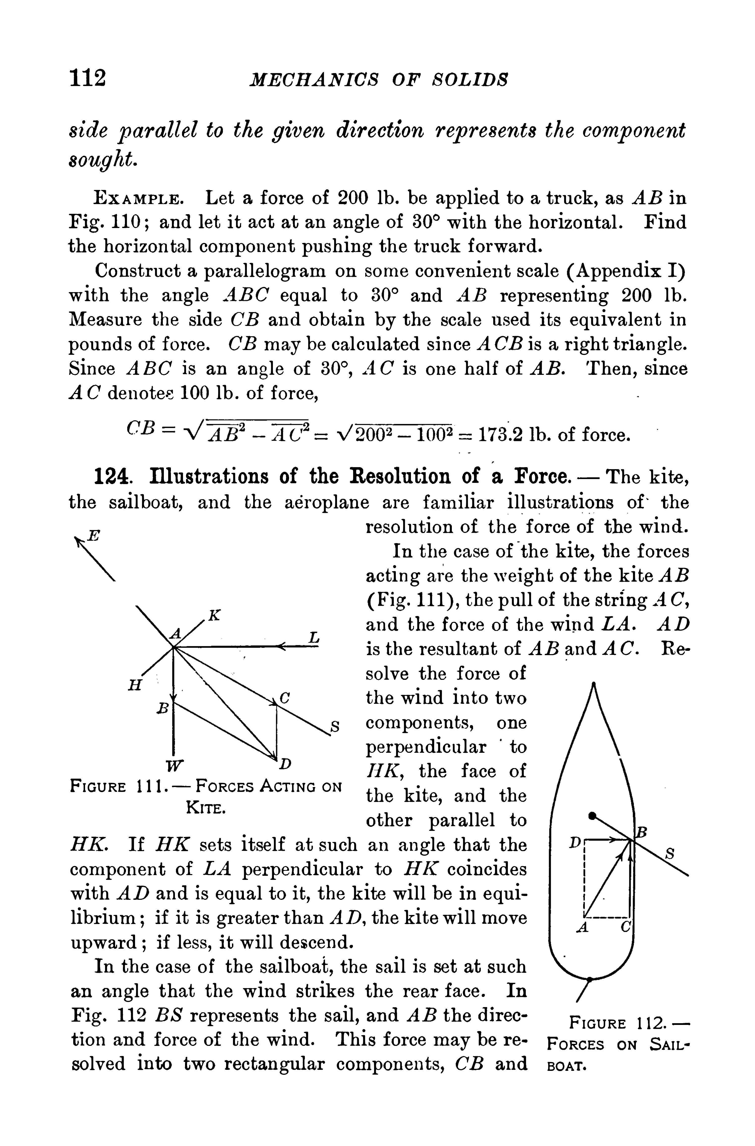
1 1 2 MECH A N ICS OF S OL IDS
side parallel to the given direction rep resents the comp onent
sought.
EXAMPLE . Let a force of 200 lb . be applied to a truck, as A B inFig. 1 10;and let it act at an angle of 30° with the horizontal . Findthe horizontal component pushing the truck forward .
Construct a parallelogram on some convenient scale (A ppendix I)with the angle A BC equal to 30
°and A B representing 200 lb .
Measure the side CB and obtain by the scale used its equivalent inpounds of force. CB may be calculated since A CB is a right triangle.
S ince A BC is an angle of A C is one half of A B . T hen, sinceA C denotes 1 00 lb . of force,
1 24 . Illustrations of the Resolution of aForce. T he kite ,the sailboat, and the aeroplane are familiar illustrations of
‘
the
resolution of the force of the wind .
In the case of the kite, the forcesacting are the weight of the kite A B
(Fig. the pull of the string A C,
and the force of the wind LA . A D
is the resultant of A B and A C . Re
solve the force of
the wind into twocomponents, one
perpendicular‘
to
H K, the face of
the kite, and the
other parallel toEX. If EX sets itself at such an angle that thecomponent of LA perpendicular to H K coincideswith A D and is equal to it, the kite will be in equilibr ium ; if it is greater than A D , the kitewill moveupward ; if less, it will descend .
In the case of the sailboat, the sail is set at suchan angle that the wind strikes the rear face. In
Fig. 1 12 BS represents the sail , and A B the direc
tion and force of the wind . T his force may be re
solved into two rectangular components, CB and
FIGURE 1 1 1 . FORCES A CT I NG ONKIrE.
FI GURE 1 12 .
FORCEs ON S AILBOAT .
COMP OS I TION A ND RES OL U TION OF VEL OCI TIE S 1 1 3
DB,of which CB represents the intensity of the force that drives the
boat forward.
In the case of the aeroplane (Fig. if a large flat surface,placed obliquely to the ground, be moved along rapidly, it will belifted upward by the vertical component of the reaction of the air
against it, equivalent to a wind, j ust as the kite is lifted . In both themonoplane and the biplane, large bent surfaces attached to a strong
light frame are forced through the air by a rapidly rotating propellerdriven by a powerful gasoline engine By means of suitable
FI GURE 1 13.—T H E FRENCHMAN VEDRINES AND H IS MONOPLANE.
levers under control of the driver , these planes, or certain auxiliary
planes, can be set at an angle to the stream of air against which theyare propel led . T hen, as with the kite, they rise through the air .
Vertical planes are attached to the frame to serve as rudders in steer
ing either to the right or the left.
125. Composition and Resolution of Velocities. A t the
Par is exposition in 1 900 a continuous moving sidewalkcarr ied v isitors around the grounds . A person walkingon this platform had a velocity with respect to the groundmade up of the velocity of the sidewalk relative to the
ground and the velocity of the person relative to the mov
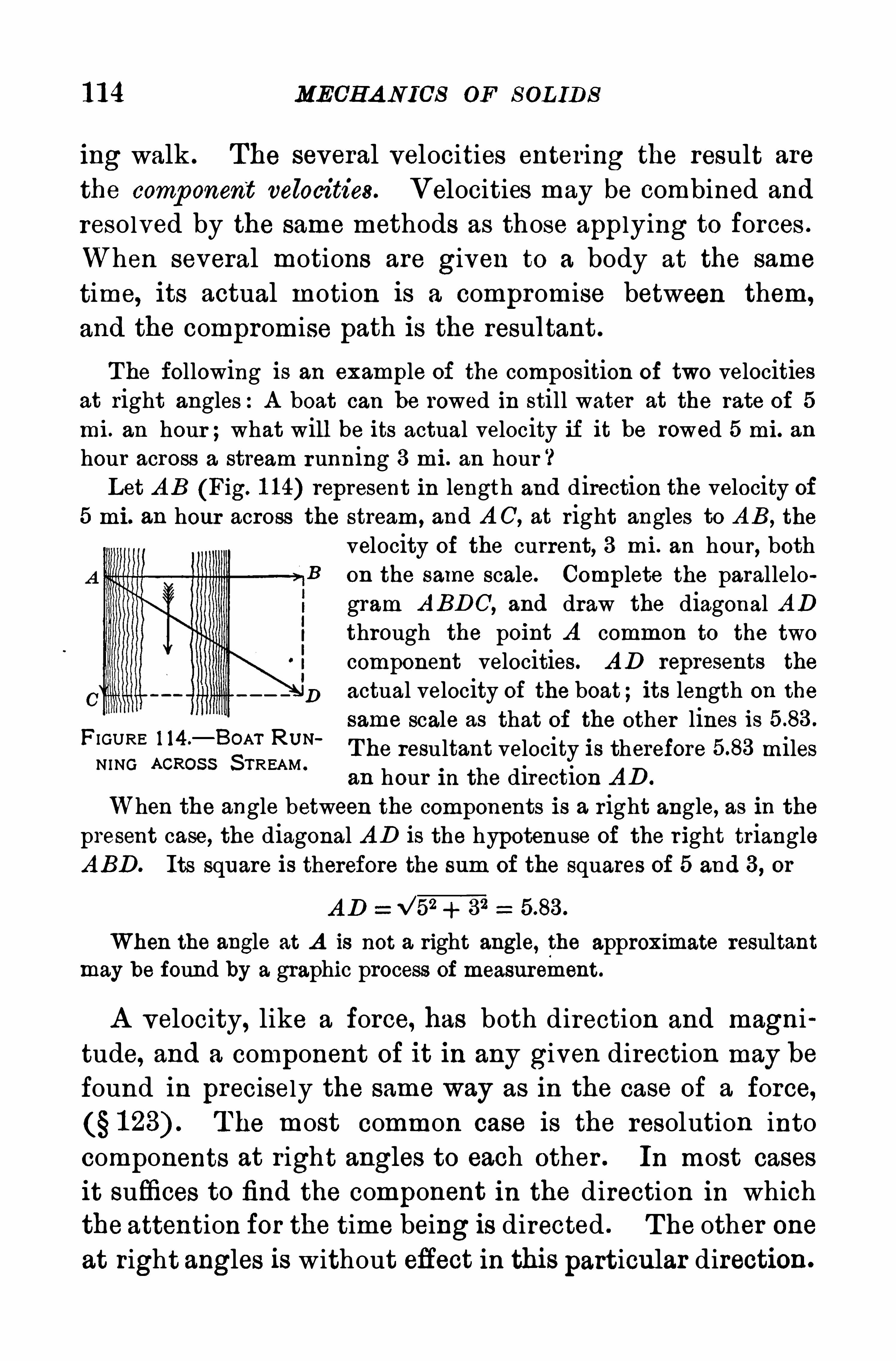
1 1 4 MECH A NICS OF S OL IDS
ing walk . The several velocities entering the result are
the comp onent velocities. Velocities may be combined and
resolved by the same methods as those applying to forces .
When several motions are given to a body at the same
time, its actual motion is a compromise between them,
and the compromise path is the resultant.
T he following is an example of the composition of two velocitiesat right angles:A boat can be rowed in still water at the rate of 5
mi. an hour ;what will be its actual velocity if it be rowed 5 mi. anhour across a stream running 3 mi. an hour ‘
3
Let A B (Fig. 1 1 4) represent in length and direction the velocity of5 mi. an hour across the stream , and A C, at right angles to A B,
the
velocity of the current, 3 mi . an hour, bothB on the same scale. Complete the parallelo
gram A BDC, and draw the diagonal ADthrough the point A common to the two
component velocities. A D represents the
D actual velocity of the boat; its length on the
same scale as that of the other lines isT he resultant velocity is therefore milesan hour in the direction A D .
When the angle between the components is a right angle, as in thepresent case, the diagonal A D is the hypotenuse of the r ight triangleA BD. Its square is therefore the sum of the squares of 5 and 3, or
A D 32
When the angle at A is not a right angle, the approximate resultantmay be found by a graphic process of measurement.
FIGURE 1 14 .—BOAT RUN
NING AcRoss S TREAM .
A velocity, like a force, has both direction and magni
tude, and a component of it in any given direction may be
found in precisely the same way as in the case of a force,T he most common case is the resolution into
components at right angles to each other . In most cases
it suffices to find the component in the direction in whichthe attention for the time being is directed . T he other one
at right angles is without effect in this particular direction.
1 1 6 MECH AN ICS OF S OL IDS
to give it a northward dir ection. In what direction does it go, andw hat single force will produce the same effect ?
1 1 . In towing a boat along a stream two ropes were used, the anglebetween them when taut being A force of 1 00 lb. was acting on
one rope and 1 50 lb . on the other. What resistance did the boat ofierto being moved1 2 . A sailboat is going eastward, the wind is from the northwest,
and the sail is set at an angle of 30° with the. direction of the wind .
If the wind’
s velocity is 1 2 miles an hour , what is the componentvelocity at right angles to the sail ?
III . NEWTON ’S LAWS OF MOTION
126 . Momentum. So far we have considered differentkinds of motion, or how bodies move, without reference tothe mass moved, and without consider ing the relationbetween force on the one hand and the moving mass and
its velocity on the other , or why bodies move. Beforetaking up the laws of motion , which outl ine the relationsbetween force and motion, it is necessary to define two
terms intimately associated with these laws . T he first of
these is momentum. Momentum is the p roduct of the mass
and the linear velocity of a mov ing body .
Momentum mass velocity, or M mv. (Equation 8)
In the c.g. s . system , the unit of momentum is the mo
mentum of a mass of 1 g. mov ing with a velocity of 1 cm .
per second . It has no recogn ized name. In the Engl ish
system, the unit of momentum is the momentum of a mass
of 1 lb . moving w ith a velocity of 1 ft . per second .
1 27 . Impulse. Suppose a bal l of 1 0 g. mass to be fired
from a r ifle with a velocity of cm . per second . Its
momentum would be units . If a truck weighing50 kg. moves at the rate of 1 0 cm . per second , its momen
tum is also units . But the bal l has acquired its
FIRS T L A W OF MOTION 1 1 7
momentum in a fraction of a second, while a minute or
more may have been spent in giving to the truck the
same momentum . In some sense the effort requi red to
set the bal l in motion is the same as that required to
give the equivalent amount of motion to the truck, be
cause the momenta of the two are equal .
T his equal ity is expressed by saying that the impulse is
the same in the two cases . S ince the effect is doubled
if the value of the force is doubled, or if the time dur ingwhich the force continues to act is doubled , it follows that
impulse is the p roduct of the force and the time it continues
to act. In estimating'
the effect of a force, the time ele
ment and the magnitude of the force are equally impor
tant . T he term impulse takes both into account .
1 28. Newton’s Laws of Motion —T he laws of motion,
formulated by S ir Isaac Newton (1 642 are to be
regarded as physical axioms, incapable of r igorous experimental proof. T hey must be considered as resting on
convictions drawn from observation and exper iment in
the domain of physics and astronomy . T he results der ived from their application have so far been found to beinvar iably true. T hey form the basis of many of the
important pr inciples of mechanics .
129. First Law of Motion. Every body continues in
its state of rest or of un iform m otion in a stra ight line,
unless compelled by app lied force to change that state.
T his is known as the law of iner tia because itasserts that a body persists in a condition of rest or of
uniform motion, unless it is compel led to change thatstate by the action of an external force. It is furthertrue that a body ofiers resistance to any such change in
1 1 8 MECH A NICS OF S OL IDS
proportion to its mass. H ence the term mass is now oftenused to denote the measure of a body’
s inertiaFrom this law is also derived the Newtonian definition
of force, for the law asserts that force is the sole cause ofchange of motion.
1 30. Second Law of Motion. Change of m om entum is
p ropor tiona l to the impressed force which produces it,
and takes p lace in the d irection in which the force acts .
T he second law points out two things
First. What the measure is of a force which produceschange of motion . Maxwel l restated the second law in
modern terms as fol lows The change of momentum of a
body is numer ically equal to the impulse which p roduces it,
and is in the same direction or in other words,
momentum (mass x velocity) impulse (force x time) .
Expressed in symbols, mv ft (Equation 9)
H ence,
T he initial velocity of the mass m before the force facted on it is here assumed to be zero, and v is the veloc
ity attained in t seconds . T hen the total momentum im
parted in the time t is mv, and ’therefore 371 71 is the rate oft
change of momentum. Force is therefore measured by the
rate of change of momentum. S ince 3) '
s the rate of changet
of velocity, or the acceleration a (see Equation wemaywrite
(Equation 1 0)
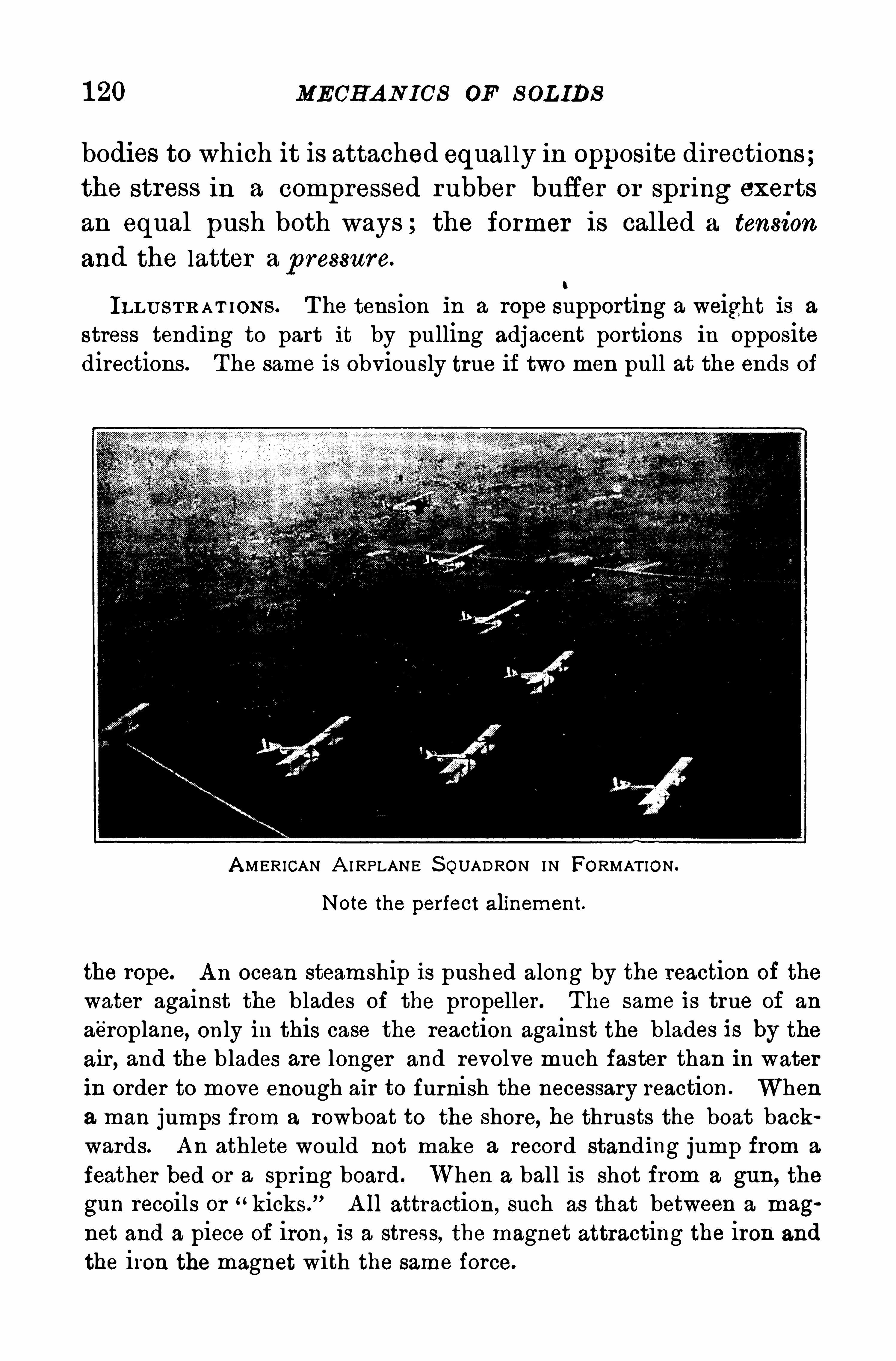
1 20 MECH A N ICS OF S OL IDS
bodies to which it is attached equal ly in opposite directions;the stress in a compressed rubber buffer or spr ing exerts
an equal push both ways ; the former is called a tension
and the latter a p ressure.
0
ILL U S T R A T ION S . The tension in a rope supporting a weight is a
stress tending to part it by pulling adjacent portions in oppositedirections . The same is obviously true if two men pull at the ends of
A MERICAN A I RPLANE S QUADRON IN FORMAT ION .
Note the perfect alinement.
the rope. A n ocean steamship is pushed along by the reaction of the
water against the blades of the propeller . The same is true of an
a'
e'
roplane, only in this case the reaction against the b lades is by theair , and the b lades are longer and revolve much faster than in waterin order to move enough air to furnish the necessary reaction . Whena man jumps from a rowboat to the shore, he thrusts the boat backwards. A n athlete would not make a record standing jump from a
feather bed or a spring board . When a ball is shot from a gun, the
gun recoils or kicks .
”A ll attraction , such as that between a mag
net and a piece of iron , is a stress, the magnet attracting the iron and
the iron the magnet with the same force.
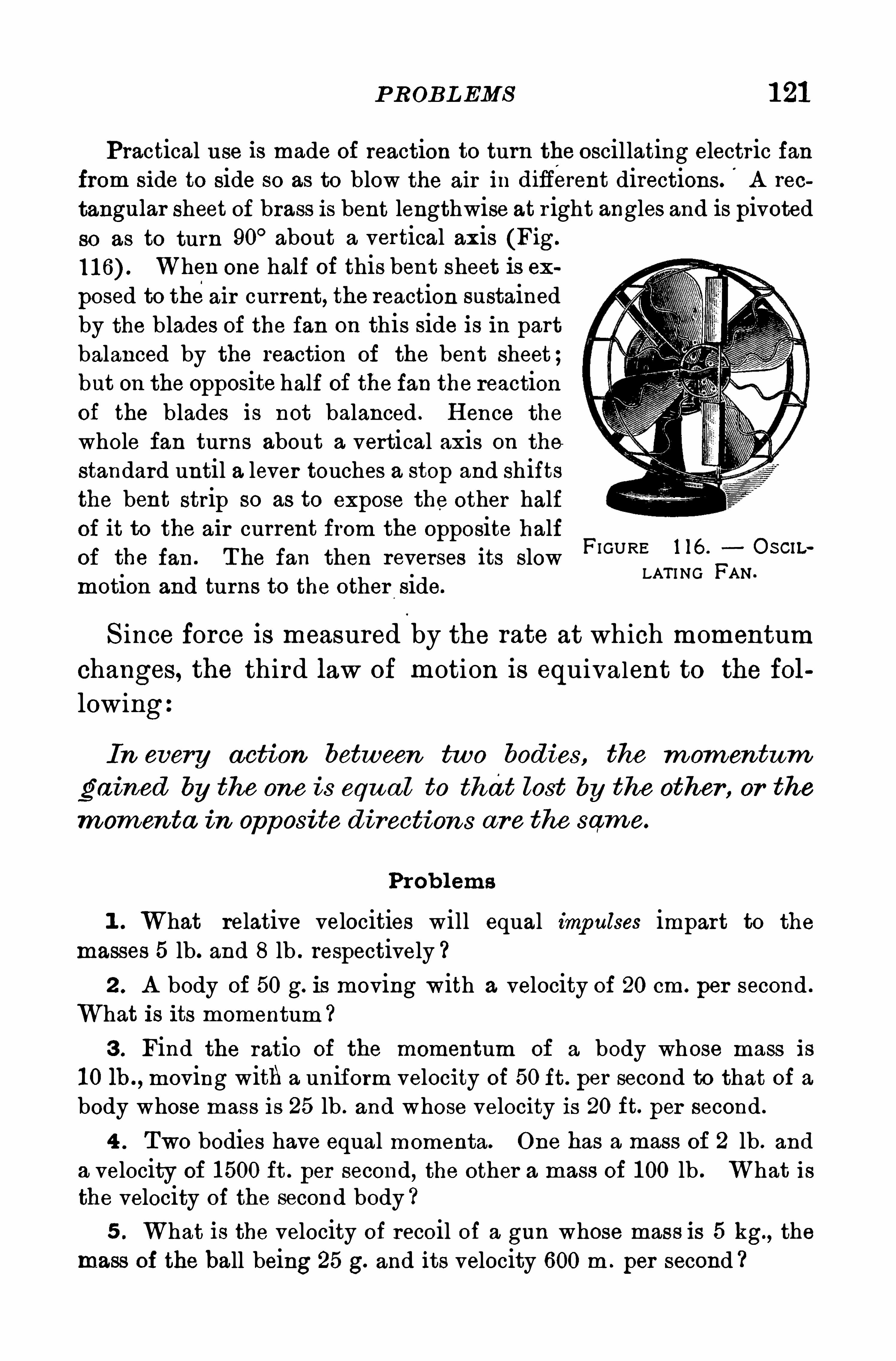
P ROBL EMS 1 21
Practical use is made of reaction to turn the oscillating electric fanfrom side to side so as to blow the air in difierent directions. A rec
tangular sheet of brass is bent lengthwise at r ight angles and is pivotedso as to turn 90
°about a vertical axis (Fig.
When one half of this bent sheet is ex
posed to theair current, the reaction sustainedby the blades of the fan on this side is in partbalanced by the reaction of the bent sheet ;but on the opposite half of the fan the reactionof the blades is not balanced . H ence the
whole fan turns about a vertical axis on the
standard until a lever touches a stop and shiftsthe bent strip so as to expose the other halfof it to the air current from the opposite halfOf the fan . T he fan then reverses its slowmotion and turns to the other side.
FI GURE 1 16 . O S CIL
LAT I NG FAN.
S ince force is measured by the rate at which momentumchanges, the third law of motion is equivalent to the fol
lowing
In every action between two bodies , the m om entum
gained by the one is equ a l to that lost by the other , or the
mom enta in opposite direction s a r e the same.
Prob lems
1 . What relative velocities will equal imp ulses impart to the
masses 5 lb. and 8 lb . respectively ?2 . A body of 50 g. is moving with a velocity of 20 cm. per second .
What is its momentum ?
3 . Find the ratio of the momentum of a body whose mass is
1 0 lh . , moving with a uniform velocity of 50 ft . per second to that of abody whose mass is 25 lb . and whose velocity is 20 ft. per second .
4 . Two bodies have equal momenta. One has a mass of 2 lb . and
a velocity of 1 500 ft . per second, the other a mass of 1 00 lb . What isthe velocity of the second body ?5 . What is the velocity of recoil of a gun whose mass is 5 kg., the
mass of the ball being 25 g. and its velocity 600 m . per second ?
1 22 MECH A N ICS OF S OL IDS
6 . A n unbalanced force of 500 dynes acts for 5 sec. on a mass of
50 g. What will be the velocity produced ?
7 . A force of 980 dynes acts on a mass of 1 g. What is the
acceleration ? H ow far will the body go in 1 0 sec.
8 . A force of 400 dynes acts on a body for 1 0 sec. What will bethe momentum at the end of this period ?
9 . A body is acted on by a force Of 1 00 dynes for 20 sec. and
acquires a velocity of 200 cm . per second .
’
What is its mass ?
1 0 . A force of 1 0 g. acts for 5 sec . on a body whose mass is 1 5 g .
What velocity is imparted
1 1 . What force in grams of force can impart to a mass of 50 g. an
acceleration of 980 cm .-
per-second per second ?
1 2 . A force of 50 g . acts for 5 sec. on a mass of 50 g. H ow far
will the body have gone in that time, starting from rest ?
IV . GRAVITA'
TION
1 32. Weight. The attraction of the earthfor all bodies is
called gravity . Theweight of a body is the measure of thisattraction . It is a pull on the bodyand therefore a force.
It makes a body fall with uniform acceleration cal led theacceleration of gravity and denoted by g. If we represent
the weight of a body by w and its mass by m, by Equation1 0, w mg. From this it appears that the weight of a body
is p ropor tional to its mass, and that the ratio of the weights
of two bodies at anyp lace is the same as that of their masses .
H ence, in the process of weighing with a beam balance,the mass of the body weighed is compared w ith that of astandard mass . When a beam balance shows equality of
weights, it shows also equality of masses .
1 33 . Direction of Gravity — T he direction in which theforce of gravity acts at any point is very near ly towardthe earth’
s center . It may be determined by suspendinga weight by a cord passing through the point. The cord
1 24 MECH A NICS‘
OF S OL IDS
remained for S ir Isaac Newton to discover the law of uni
versal grav itation . H e der ived this great general izationfrom a study of the planetary motions discovered by Kep~
ler . T he law may be expressed as follows
Every portion of m atter in the u n iverse a ttr acts every
other por tion , and the stress between them is d irectly p ro
por tional to the pr odu ct of their m a sses and inver sely
p ropor tiona l to the Square of the distance between their
centers of m ass .
For spherical bodies, l ike the sun, the earth , and the
planets, the attraction of gravitation is the same as if all
the“
matter in them were concentrated at their centers ;
hence, in applying to them the law of gravitation, the
distance between them is the distance between their cen
ters . Calculations made to find the centr ipetal acceleration of the moon in its orbit show that it is attracted to
the earth with a force which follows the law of universal
gravitation .
The law of universal gravitation does not refer in any way to
weight but to mass. It would be entirely meaningless to speak of the
weight of the earth, or of the moon,or of the sun , but their masses are
very definite quantities, the ratios of which are well known in as
tronomy. T hus the mass of the earth is about 80 times that of
the moon, and the mass Of the sun is about times that of theearth . T he weight of a pound mass at the distance of the moon is
on ly 75n the weight of a pound mass at the surface of the earth .
1 36 . Variation of Weight — S ince the earth is not a
Sphere but is flattened at the poles, it fol lows from the
law of grav itation that the acceleration of gravity, and
the weight of any body ,increase in going from the equa
tor toward either po le. If the earth were a uniform
sphere and stationary, the value of g would be the same


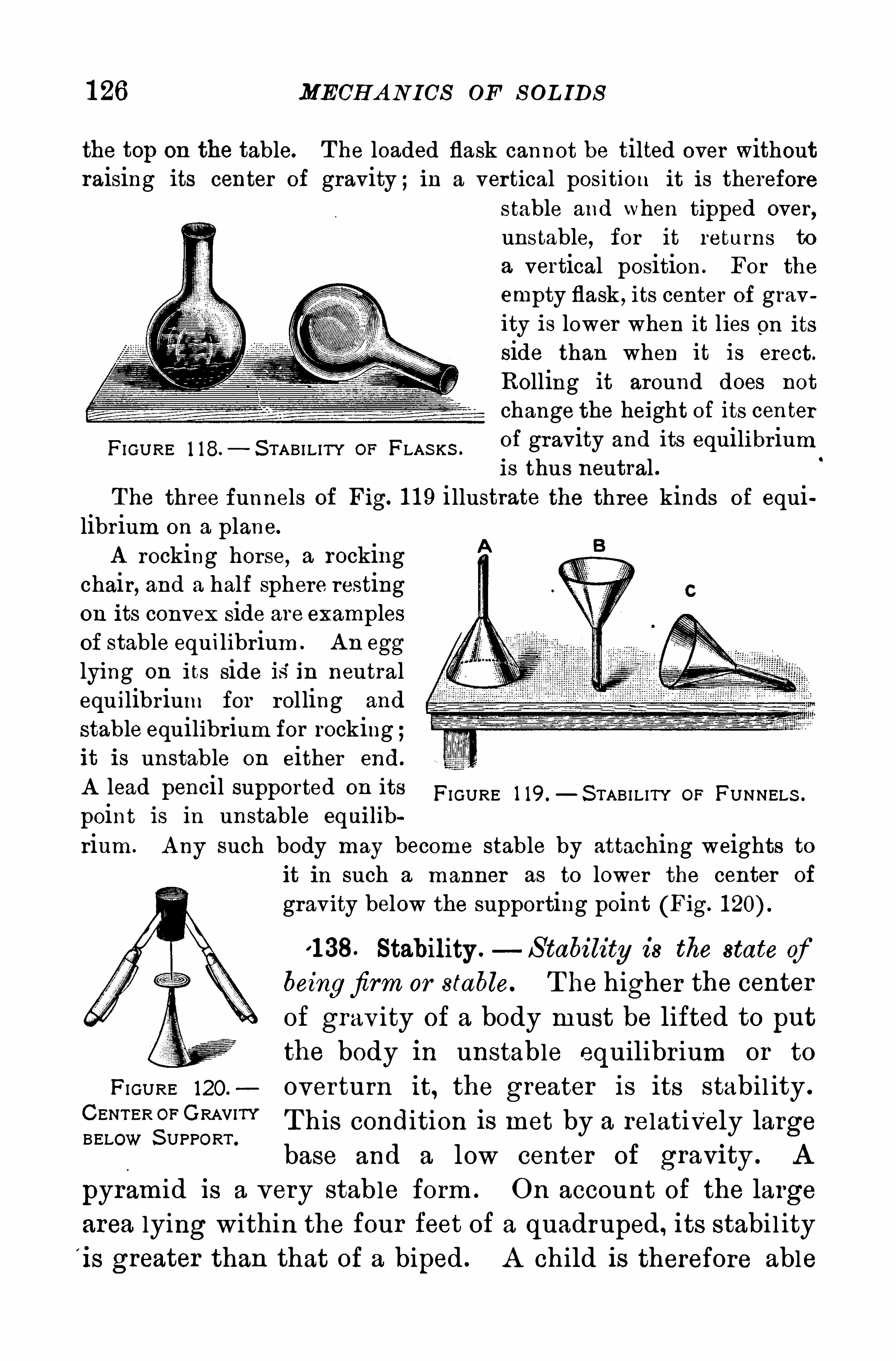
1 26 MECH A NICS OF S OL IDS
the top on the table. T he loaded flask cannot be tilted over withoutraising its center of gravity ; in a vertical position it is therefore
stable and when tipped over,unstable, for it returns to
a vertical position . For the
empty flask , its center of gravity is lower when it lies on itsside than when it is erect.
Rolling it around does not
change the height of its centerof gravity and its equilibriumis thus neutral .
The three funnels of Fig. 1 1 9 i llustrate the three kinds of equilibrium on a plane.
A rocking horse, a rockingchair, and a half Sphere restingon its convex side are examplesof stable equilibrium . A n egg
lying on its side is in neutralequilibrium for rol ling and
stable equilibrium for rocking ;it is unstable on either end.
A lead pencil supported on its FI GURE 1 19.—S TABILITY OP FUNNELS .
point is in unstable equilib
riam . A ny such body may become stable by attaching weights toit in such a manner as to lower the center of
gravity below the supporting point (Fig.
1 1 38. Stability .—S tability is the state of
beingfirm or stable. T he higher the centerof grav ity of a body must be lifted to putthe body in unstable equilibr ium or to
FI GURE 120. overturn it, the greater is its stabil ity .
CENTER OFGRAV’” T his condition is met by a relatively largeBELOW S UPPORTbase and a low center of graV1 ty . A
pyramid is a very stable form . On account of the largearea lying within the four feet of a quadruped , its stabil ityi s greater than that of a biped . A child is therefore able
FI GURE 1 18.— S TABI LITY OF FLAS KS .
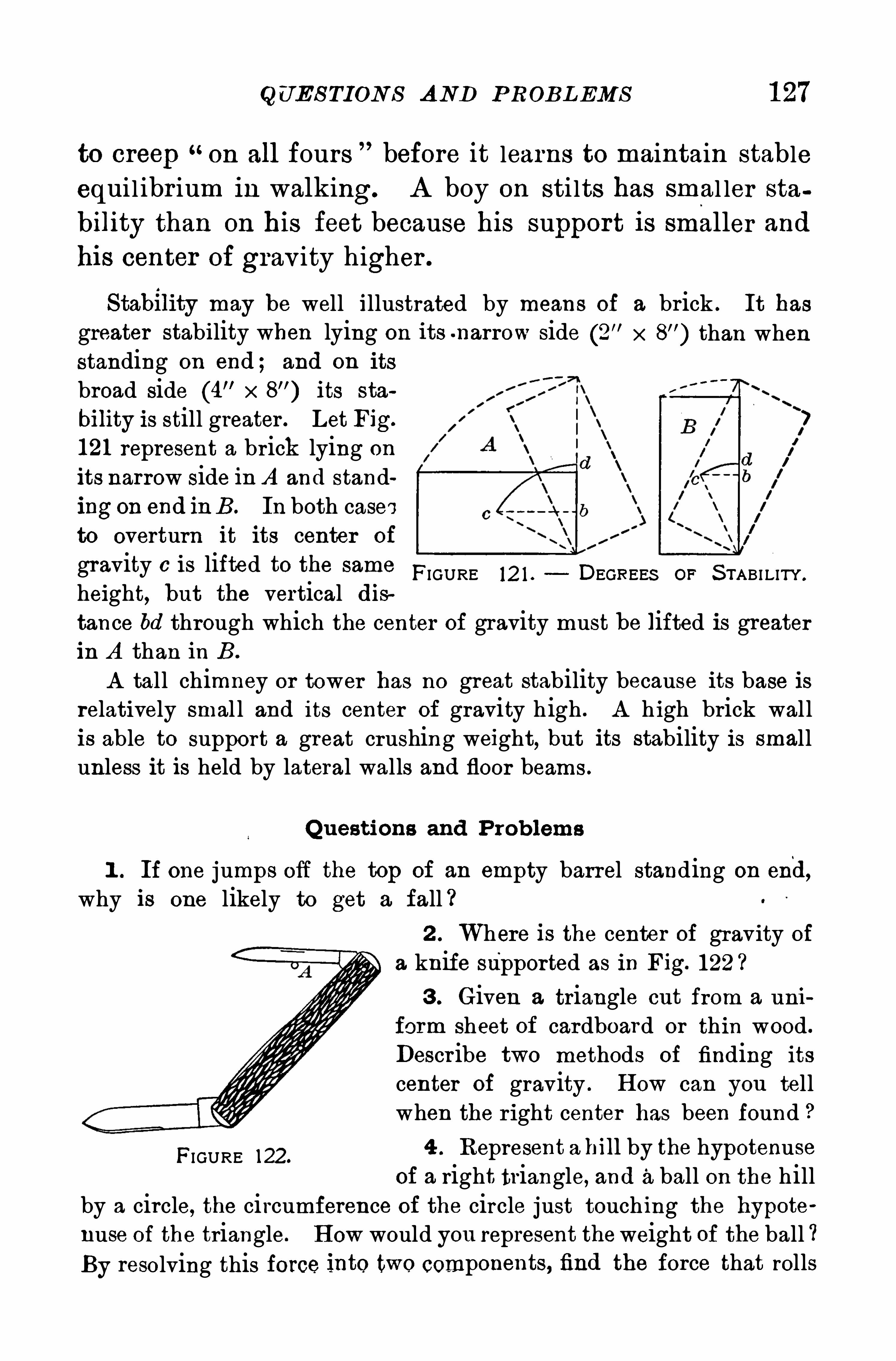
Q UE S TION S A ND P ROBL EMS 1 27
to creep on all fours before it learns to maintain stableequil ibr ium in walking. A boy on sti lts has smal ler sta
bility than on his feet because his support is smaller and
his center of grav ity higher .
Stabllity may be well illustrated by means of a brick . It has
greater stability when lying on its -narrow side (2” x than when
standing on end ; and on its
broad Side (4" x its sta
bility is still greater . Let Fig.
1 21 represent a brick lying on
its narrow side in A and standingon end inB . In both casesto overturn it its center of
gravity 6 is lifted to the same FIGURE 12 1 . DEGREES OF S TABI LITY .
height, but the vertical distance bd through which the center of gravity must be lifted is greaterin A than in B .
A tall chimney or tower has no great stability because its base isrelatively smal l and its center of gravity h igh . A h igh brick wal lis able to support a great crushing weight, but its stability is smallunless it is held by lateral walls and floor beams .
Q uestions and P roblems
1 . If one jumps Off the top of an empty barrel standing on end,why is one likely to get a fall ?
2 . Where is the center of gravity of
a knife supported as in Fig. 122 ?
3 . Given a triangle cut from a uni
form sheet of cardboard or thin wood .
Descr ibe two methods of finding its
center of gravity . H ow can you tellwhen the right center has been found
FIGURE 122.
4 . Represent a bill by the hypotenuseof a right triangle, and aball on the hill
by a circle, the circumference of the circle just touching the hypote
nuse of the triangle. H ow would you represent theweight of the ball ?By resolving this force into two components, find the force that rolls
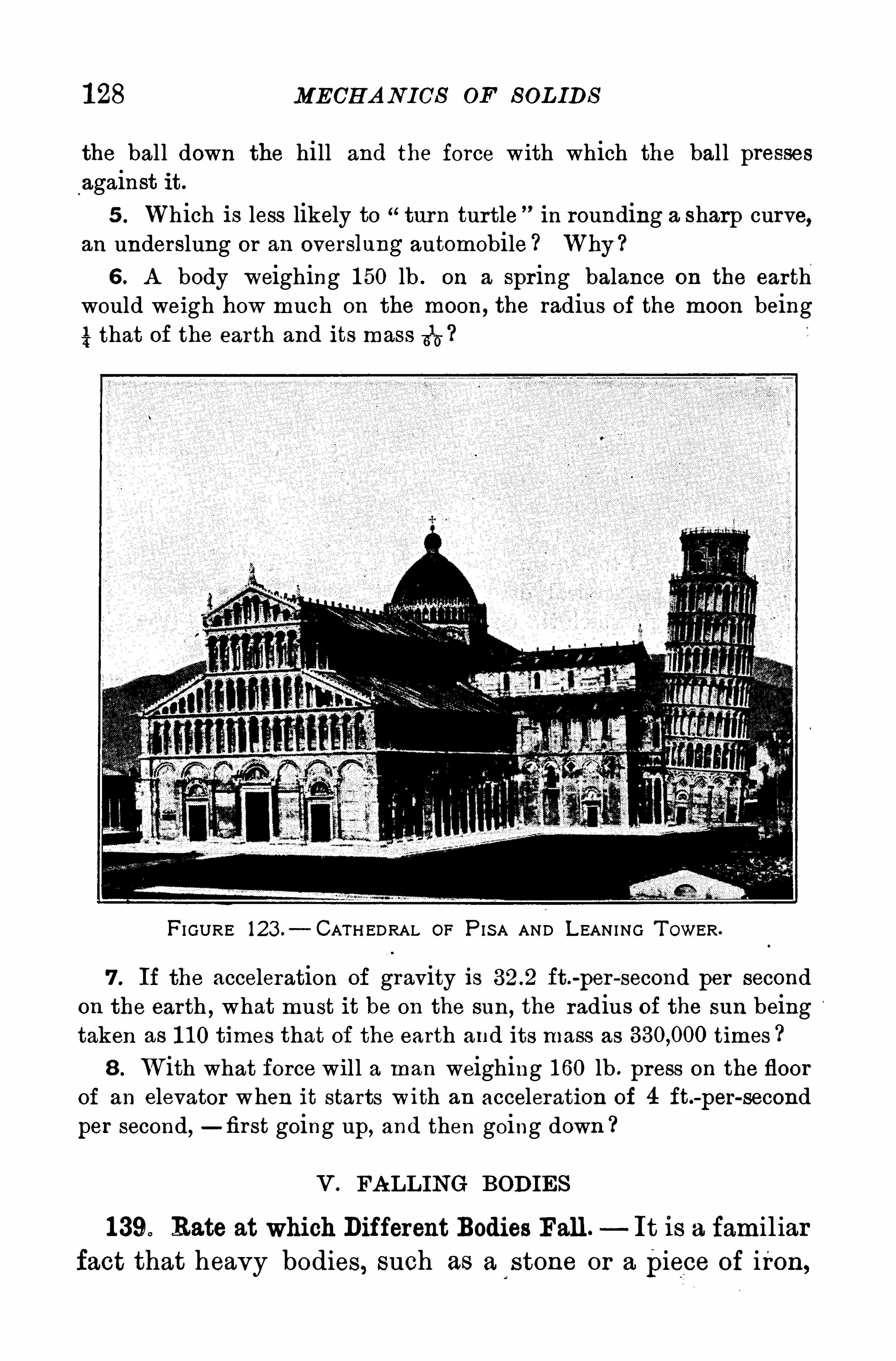
1 28 MECH A N ICS OF S OL IDS
the ball down the hill and the force with which the ball pressesagainst it.
5 . Which is less likely to turn turtle in rounding a sharp curve,an underslung or an overslung automobile Why ?
6 . A body weighing 1 50 lb . on a spring balance on the earthwould weigh how much on the moon , the radius of the moon being
4 that of the earth and its mass 315 ?
FI GURE 123 .— CATH EDRAL OF P ISA AND L EAN ING T OWER.
7 . If the acceleration of gravity is ft.-
per—second per second
on the earth , what must it be on the sun, the radius of the sun beingtaken as 1 1 0 times that of the earth and its mass as times
8 . With what force will a man weighing 1 60 lb . press on the floorof an elevator when it starts with an acceleration of 4 ft.-per
-secondper second,—first going up, and then going down ?
V . FA LL ING BODIES
1 39. Rate at which Different Bodies Fall. It is a famil iar
fact that heavy bodies , such as a stone or a piece of iron,
1 30 MECH A N ICS OF S OL IDS
first. T hen lay the paper on the cent and drop them in that position ;the paper will now fall as fast as the cent. Explain.
T he friction of the air against the surface of bodiesmoving throughit limits their velocity. A cloud floats, not because it is lighter thanthe atmosphere, for it is actually heavier , but because the surface friction is so large in compar ison with the weight of the minute drops ofwater , that the limiting velocity of fall is very small .When a stream of water flows over a high precipice, it is broken
into fine spray and falls S lowly . A t the Y osemite Fall (Fig. 1 25) a
large stream is broken by the resistance of the air until at the bottomof its 1 400 foot drop it becomes fine spray .
141 . Laws of Falling Bodies — Gal i leo ver ified the fol
lowing laws of fal l ing bodies
I . The velocity a tta ined by a falling body is propor
tional to the tim e of fa lling.
II The d istance fallen is p r opor tion a l to the squ a re ofthe time of descent.
III . The acceler ation i s twice the d istance a body fa llsin thefir st second .
T hese laws wi ll be recognized as identical wi th thoseder ived for uniformly accelerated motion, 1 06 and 1 07.
If the incl ined plane in Gal i leo’
s exper iment be tilted up
steeper , the effect wi ll be to increase the acceleration down
the plane and if the board be raised to a ver tical position,
the ball wi l l fal l freely under grav ity and the acceleration
wi l l become g
S ince the acceleration g is sensibly constant for smalldistances above the earth’
s sur face, the equations already
obtained for uniform ly accelerated motion may be appl ied
directly to falling bodies, by substituting g for a in Equa
tions 5 and 6 . T hus we have
v gt, (Equation 1 1 )
s gt2
(Equation 1 2)
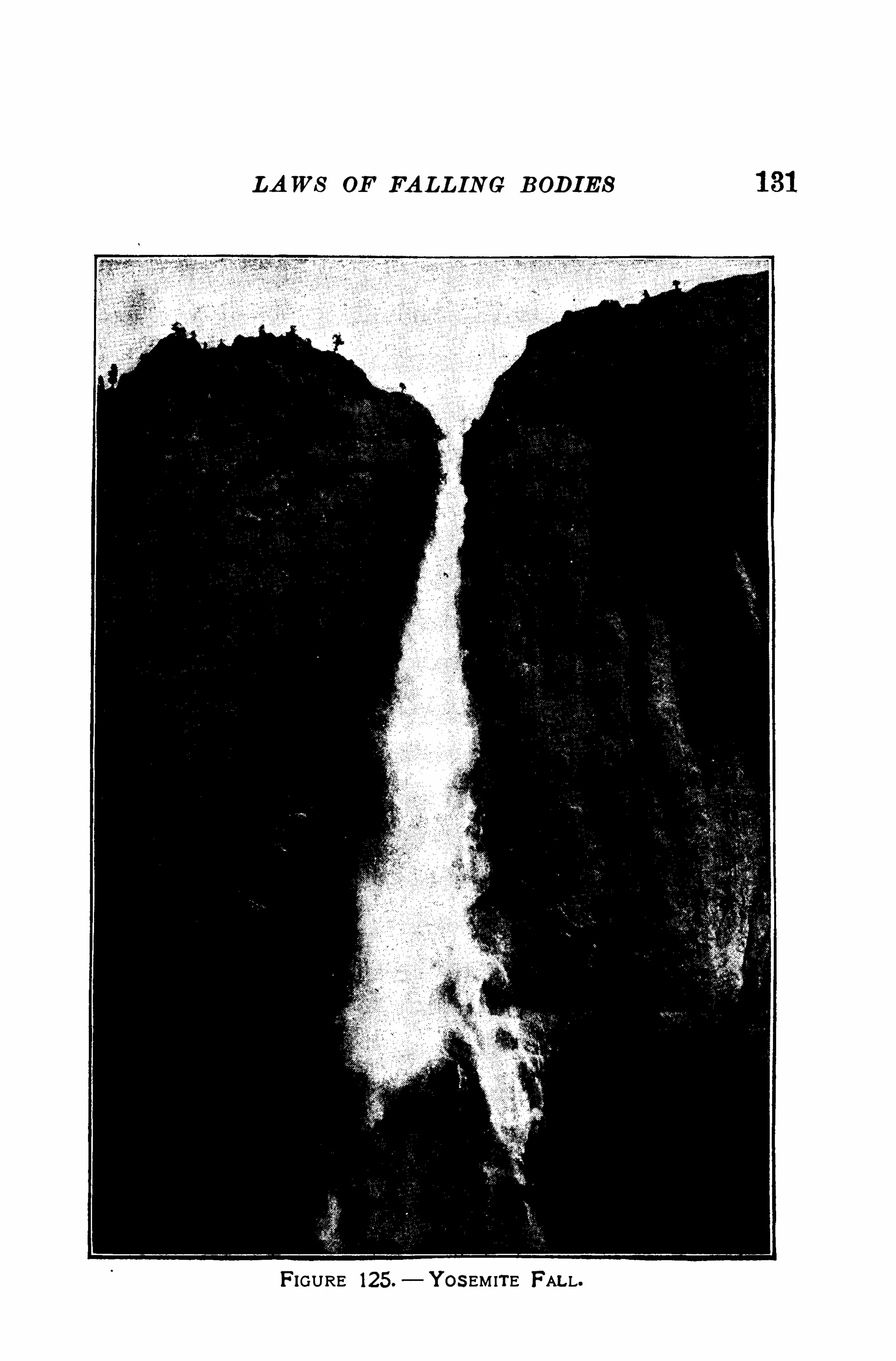
LA WS OF FA LL ING BODIES
FIGURE 125.— Y OS EM ITE FALL.
1 32 MECH A N ICS OF S OL ID S
If in Equation 1 2i
t is one Second , 8 é—g ; or the dis
tance a body fal ls from rest in the first second is half theacceleration of gravity . A body falls 490 cm . or ft.
the first second ; and the velocity attained is 980 cm . or
ft . per second .
1 42. Projection Upward.—When a body is thrown verti
cal ly upward , the acceleration is negative, and it loses
each second g units of velocity (980 cm . or
H ence, the time of ascent to the highest point is the timetaken to br ing the body to rest. If the vel ocity lost is gunits a second , the time
‘
required to lose v units of velocitywil l be the quotient of v by g, or
time of ascentveloci ty of pr oj ecti on upward
acceleration of gravity
In symbols (Equation 1 3)
For example, if the velocity of prOjectio yvard were
1 470 cm . per second, the time of ascent, ectin the
frictional resistance of the air , would be 1548
sec
ouds . T his is the same as the time of descent again to
the starting point ; hence, the body will return to the start
ing p oint with a velocity equal to the velocity of p rojection but
in the opposite dir ection . In this discussion of projection
upward, the resistance of the air is neglected .
P rob lems
U nless otherwise stated i n the problem, g is to be taken as 980 cm.
Or 32 ft.-per-second per second.
1 . T he tower of Pisa is 180 ft. high . In what time would a balldropped from the top reach the ground ? With what velocity wouldit strike ?
1 34 MECH A N ICS OF S OLIDS
The constantpullwhich deflects the body f rom a rectilinear
path and compels it to move in a curvilinear one is the cen
tr ip etalfor ce.
The resistancewhich a body ofiers on account of its inertia,to deflection f rom a straight line is the centrifugal force.
When the motion is uniform and circular , the force is atr ight angles to the path of the body around the circle and
constant.
T hese two forces are the two aspects of the stress in the
cord (third law of motion) , the action of the hand on the
bal l , and the reaction of the bal l on the band .
1 44 . Valueof Either Force The centr ipetal acceleration2
for uniform circular motion 1 1 0) is av_
, where v isr
the uniform velbcity in the circle, and r is the radius .
Further , in 1 30 the relation between force and accelera
tion was found to be as fol lows:force equals the product
of the mass and the acceleration imparted to it by the force.
H ence we have
centr ip etalfor ce mass centr ipetal acceleration,
f (Equation 1 4)
T his relation gives the value of either the centripetal
or the equal centr ifugal force in the absolute system of
measurement, because it is der ived from the laws of motion
and is independent of grav ity . In the metric system mmust be in grams, v in centimeters per second , and r in
centimeters ;f is then in dynes. T o obtainf in grams of
force, div ide by 980 In the English system, m
must be in pounds, v in feet per second, and r in feet ;
div iding by the result wi l l be in pounds of force.
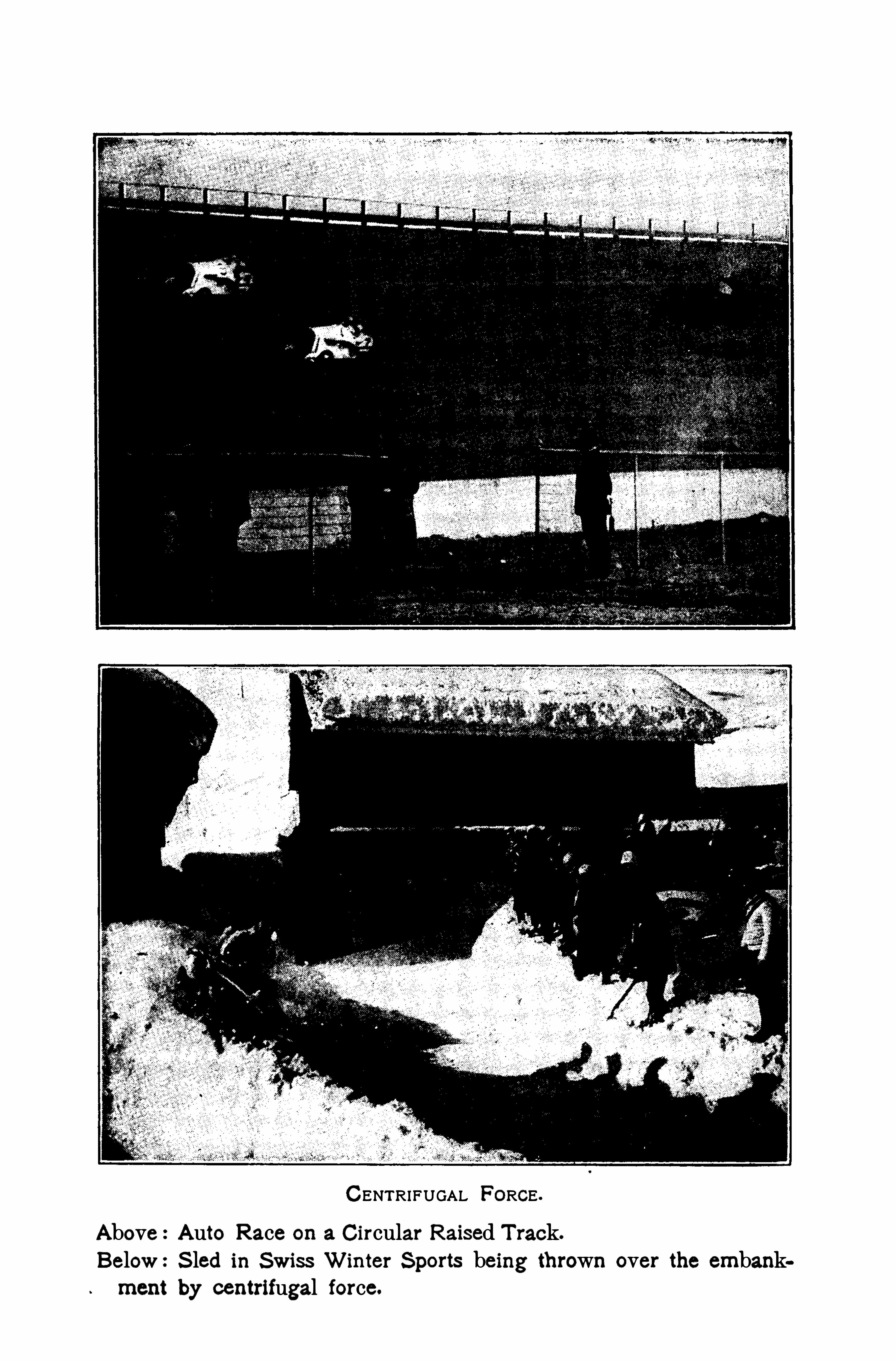
CENTRIFUGAL FORCE .
Above:Auto Race on a Circular Raised T rack.
Below:S led in Swiss Winter S ports being thrown over the embankment by centrifugal force.

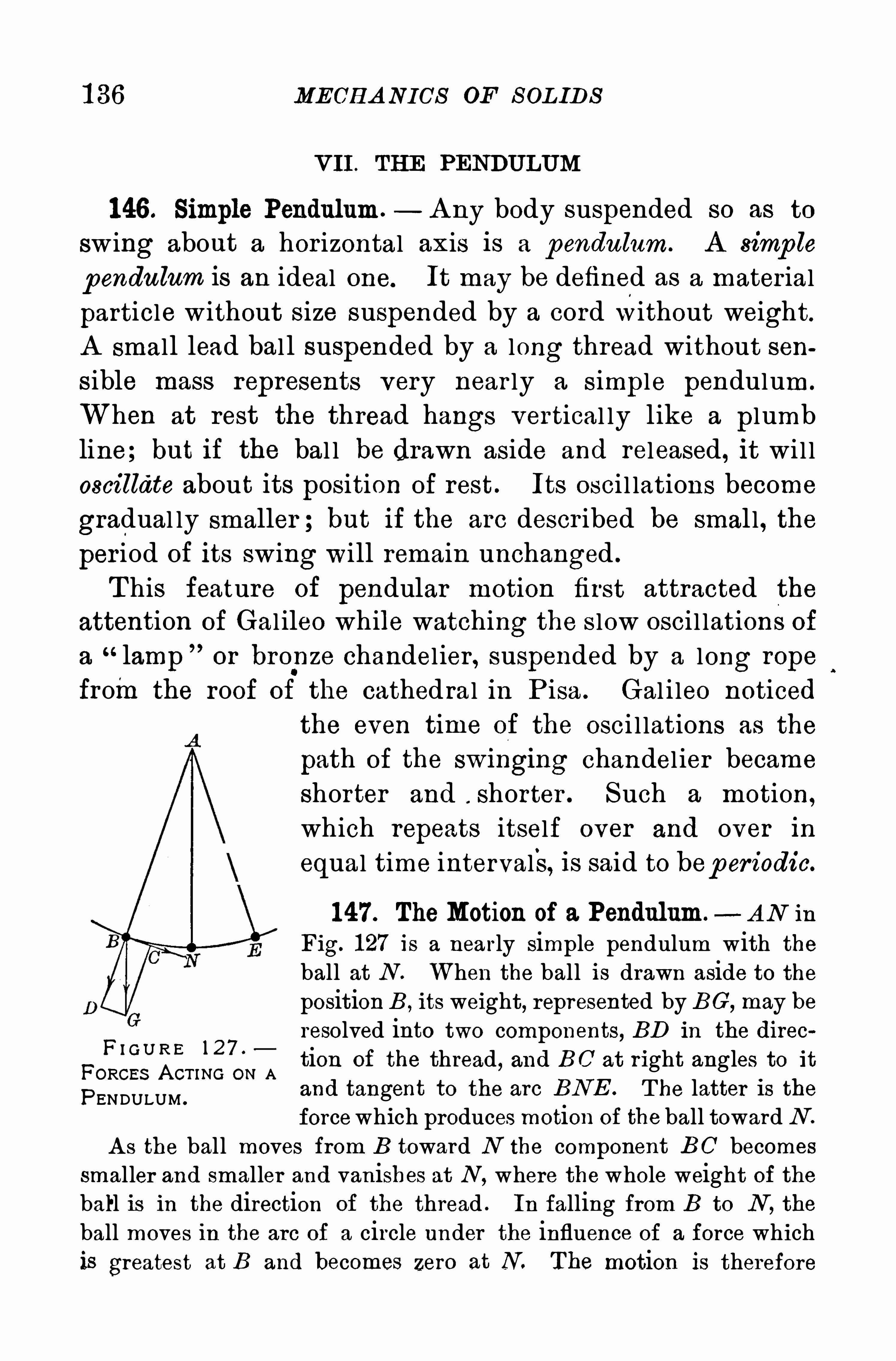
1 36 MECH A NICS OF S OL ID S
VII . TH E PENDU LUM
146 . Simple Pendulum.— A ny body suspended so as to
swing about a hor izontal axis is a pendulum. A simp le
pendulum is an ideal one. It may be defined as a mater ial
particle without S ize suspended by a cordwithout weight.
A small lead bal l suspended by a long thread without sensible mass represents very near ly a simple pendulum.
When at rest the thread hangs vertical ly l ike a plumbline; but if the bal l be drawn aside and released , it wi l l
oscillate about its position of rest . Its osci l lations become
gradual ly smaller ; but if the arc descr ibed be smal l , the
per iod of its swing will remain unchanged .
T his feature of pendular motion first attracted the
attention of Gal ileo while watching the s low osci l lations of
a“lamp or bropze chandel ier , suspended by a long rope
fromthe roof of the cathed ral in P isa . Gal i leo noticed
the even time of the osci l lations as the
path of the sw1nging chandel ier became
shorter and . shorter . Such a motion,
which repeats itself over and over in
equal time intervals, is said to bep er iodic.
1 47 . TheMotion of a Pendulum. A N in
Fig. 1 27 is a nearly simple pendulum with theball at N . When the ball is drawn aside to thepositionB , its weight, represented by BC ,
may be
resolved into two components, BD in the direc
F A tion of the thread , and BC at right angles to it
PENDULUM .
and tangent to the arc BNE . T he latter is theforcewhich produces motion of the ball toward N .
A s the ball moves from B toward N the component BC becomes
smaller and smaller and vanishes at N ,where the whole weight of the
ball is in the direction of the thread . In falling from B to N , the
ball moves in the arc of a circle under the influence of a force whichis greatest at B and becomes zero at N. The motion is therefore
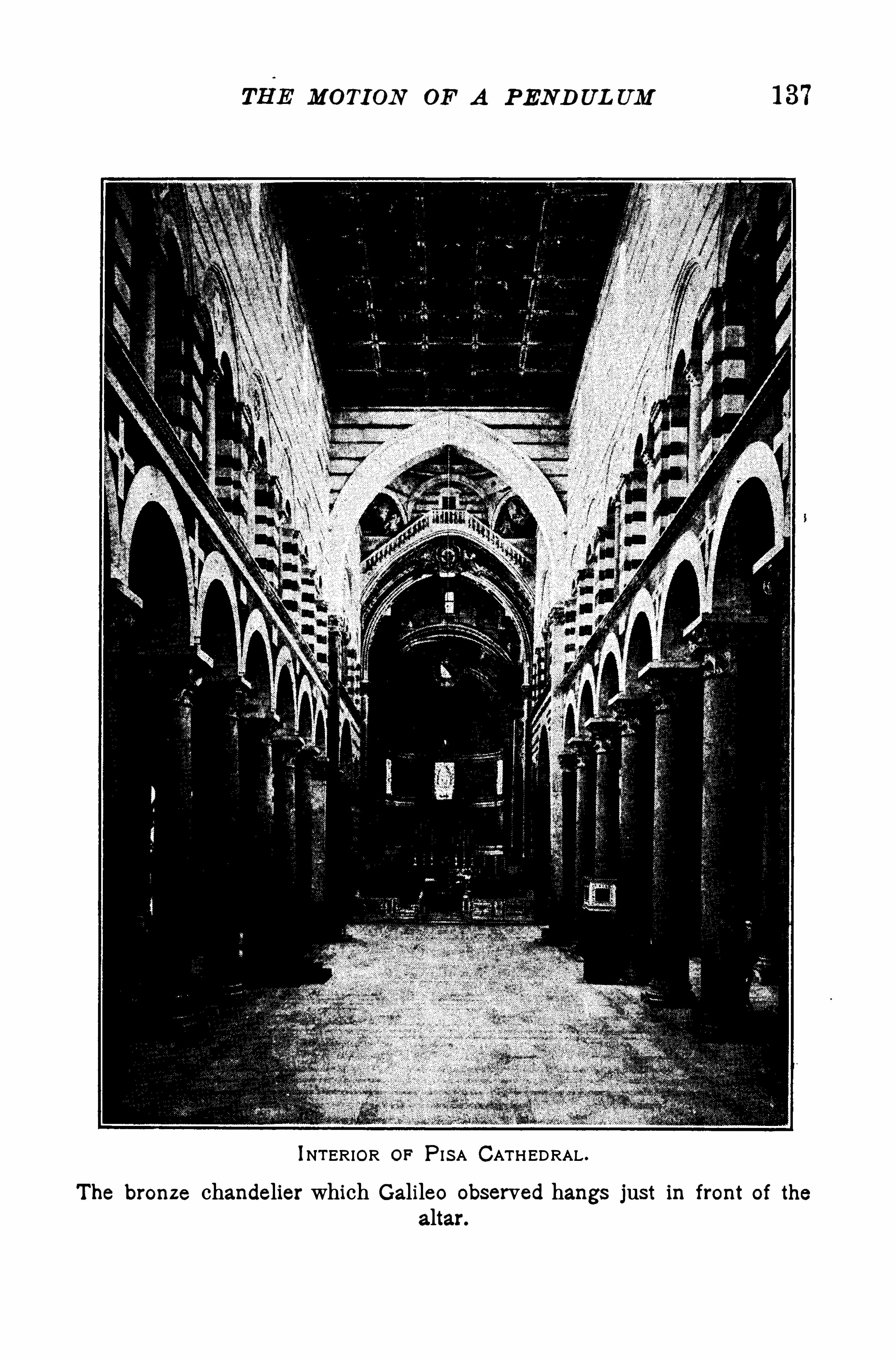
MOTION OF A PEND UL UM
INTERIOR OF P I SA CATHEDRAL .
The bronze chandelier which Galileo observed hangs just in front of the
altar.
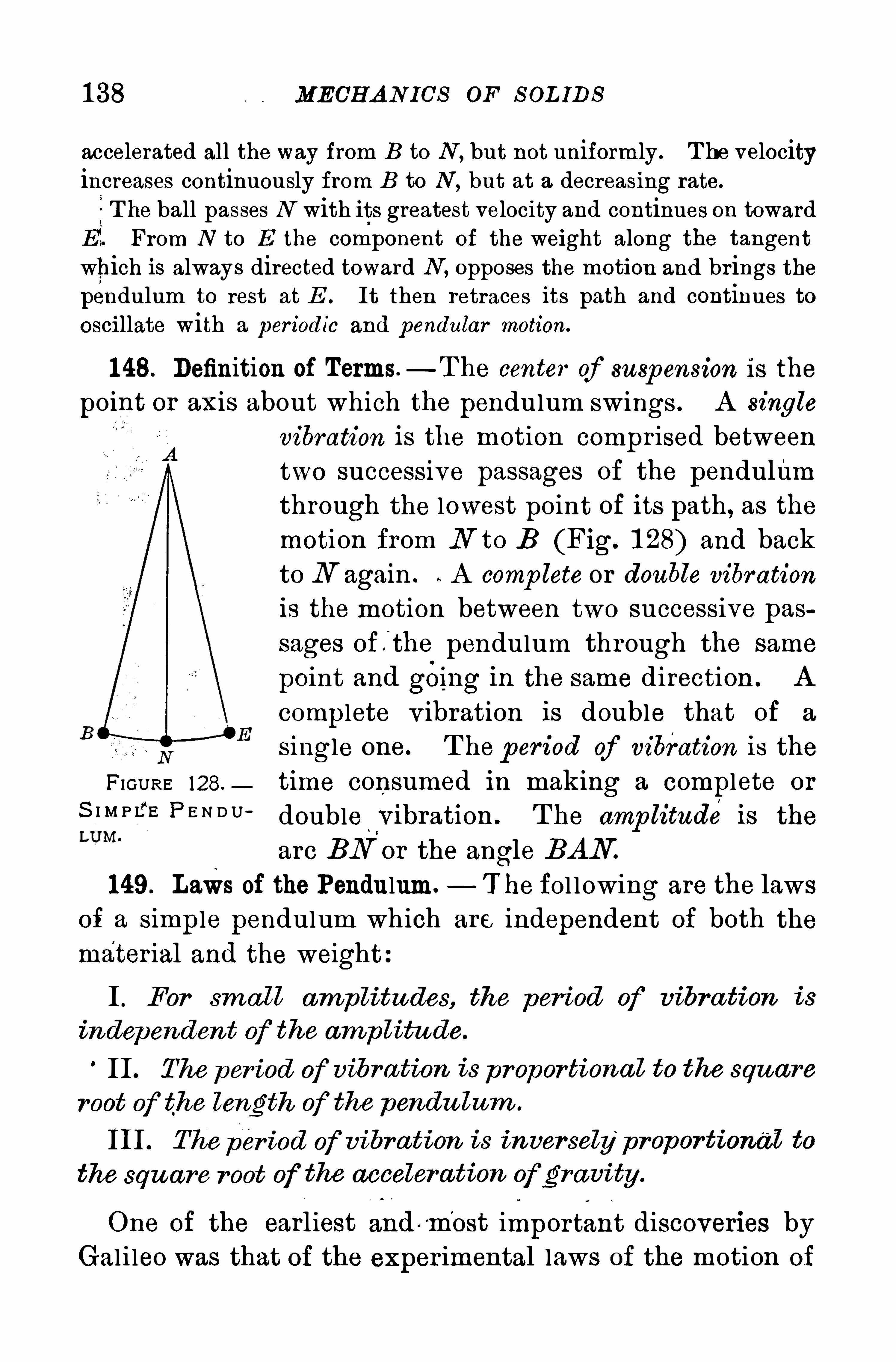
1 38 MECH A N ICS OF S OL IDS
accelerated all the way from B to N , but not uniformly . T he velocityincreases continuously from B to N , but at a decreasing rate.
5T he ball passes N with its greatest velocity and continues on towardE. From N to E the component of the weight along the tangentwhich is always directed toward N , opposes the motion and brings thependulum to rest at E . It then retraces its path and continues tooscillate with a per iodic and p endular motion.
1 48. Definition of Terms —T he center of suspension is the
point or axis about which the pendulum swings . A single
vibration is the motion compr ised betweentwo successive passages of the pendulumthrough the lowest point of its path, as themotion from N to B (Fig. 1 28) and backto N again . A comp lete or double vibration
is the motion between two successive passages of fthe pendulum through the same
point and gOing in the same direction . A
complete v ibration is double that of a
S ingle one. T he p er iod of vibration is the
FI GUR E 128.time consumed in making a complete or
S l M P f E P E N D U ‘ doublewvibration . T he amp litude is the
arc BN or the angle BAN
1 49. Laws of the Pendulum. T he fol lowing are the laws
of a simple pendulum which are independent of both the
mater ial and the weight:
I . For sma ll amplitudes, the period of vibra tion is
independent of the amp litu de.
II . The per iod of vibra tion is proportiona l to the squ are
root of the length of the pendu lum .
III . The per iod of vibr a tion is inver selyp ropor tional to
the squ are root of the acceler a tion Ofgravity .
One of the earliest and vm’
ost important discoveries by
Gal i leo was that of the exper imental laws of the motion of
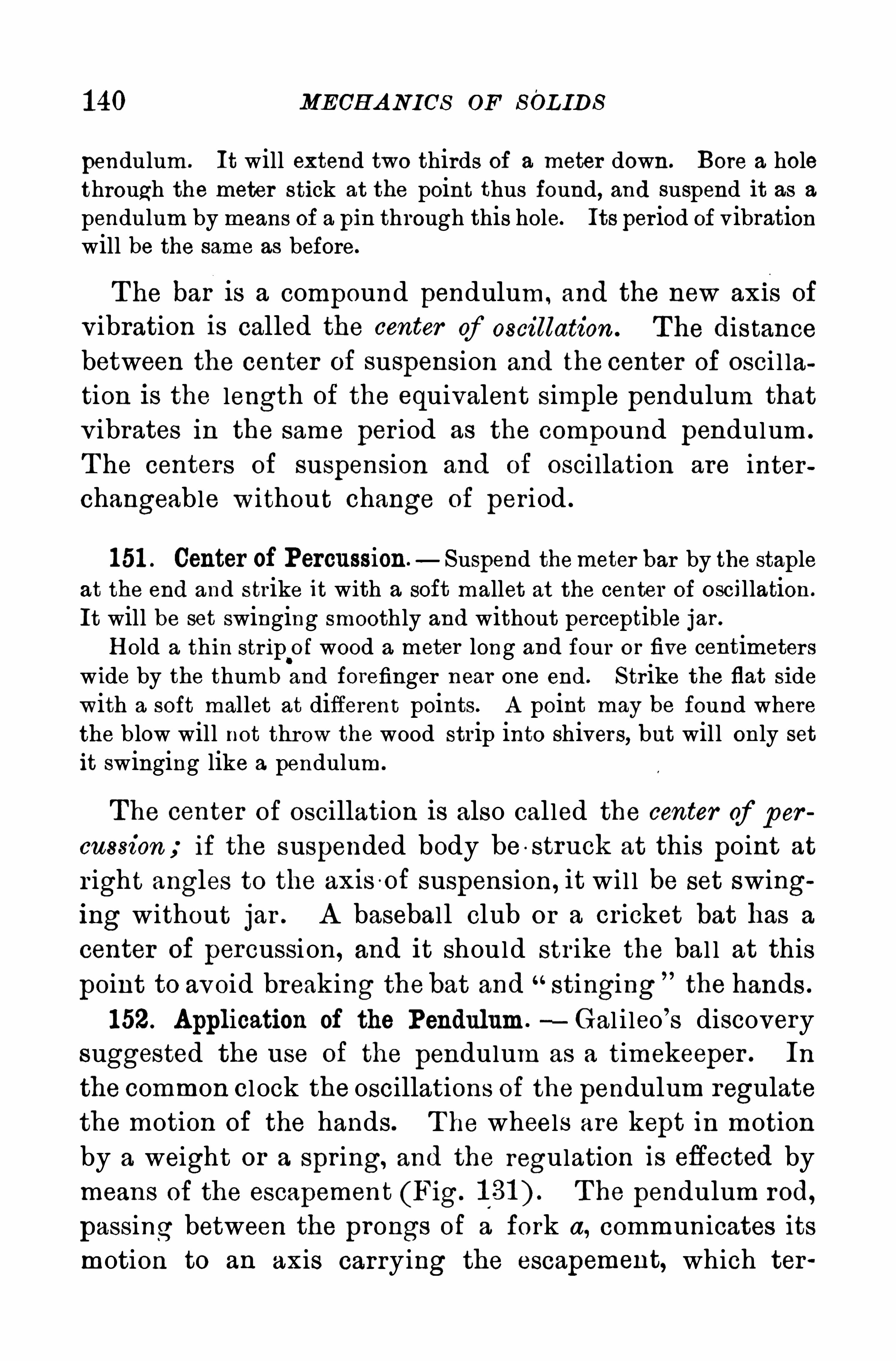
1 40 MECH A NICS OF SOL IDS
pendulum. It will extend two thirds of a meter down. Bore a holethrough the meter stick at the point thus found, and suspend it as a
pendulum by means of a pin through this hole. Its per iod of vibrationwill be the same as before.
T he bar i s a compound pendulum, and the new ax1 s of
v ibration is called the center of oscillation . The distancebetween the center of suspension and the center of osci l lation is the length of the equivalent simple pendulum thatv ibrates in the same per iod as the compound pendulum .
T he centers of suspension and of osci llation are interchangeable without change of per iod .
1 51 . Center of Percussion. Suspend themeter bar by the stapleat the end and strike it with a soft mallet at the center of oscillation.
It will be set swinging smoothly and without perceptible jar .
H old a thin str ip of wood a meter long and four or five centimeter swide by the thumb and forefinger near one end. Strike the flat sidewith a soft mallet at different points. A point may be found wherethe blow will not thr ow the wood strip into shivers, but will only setit swinging like a pendulum .
The center of oscillation is also cal led the center of p er
cussion if the suspended body be o struck at this point at
r ight angles to the axis of suspension, it wi l l be set swinging without jar . A baseball club or a cr icket bat has a
center of percussi on, and it should str ike the bal l at this
point to avoid breaking thebat and stinging the hands .
1 52. Application of the Pendulum.—Gal i leo’
s discoverysuggested the use of the pendulum as a timekeeper . In
the common cl ock the oscillations of the pendulum regulate
the motion of the hands. T he wheels are kept in motion
by a weight or a spring, and the regulation is eflected by
means of the escapement (Fig. T he pendulum rod,
passing between the prongs of a fork a, communicates its
motion to an axis carrying the escapement, which ter
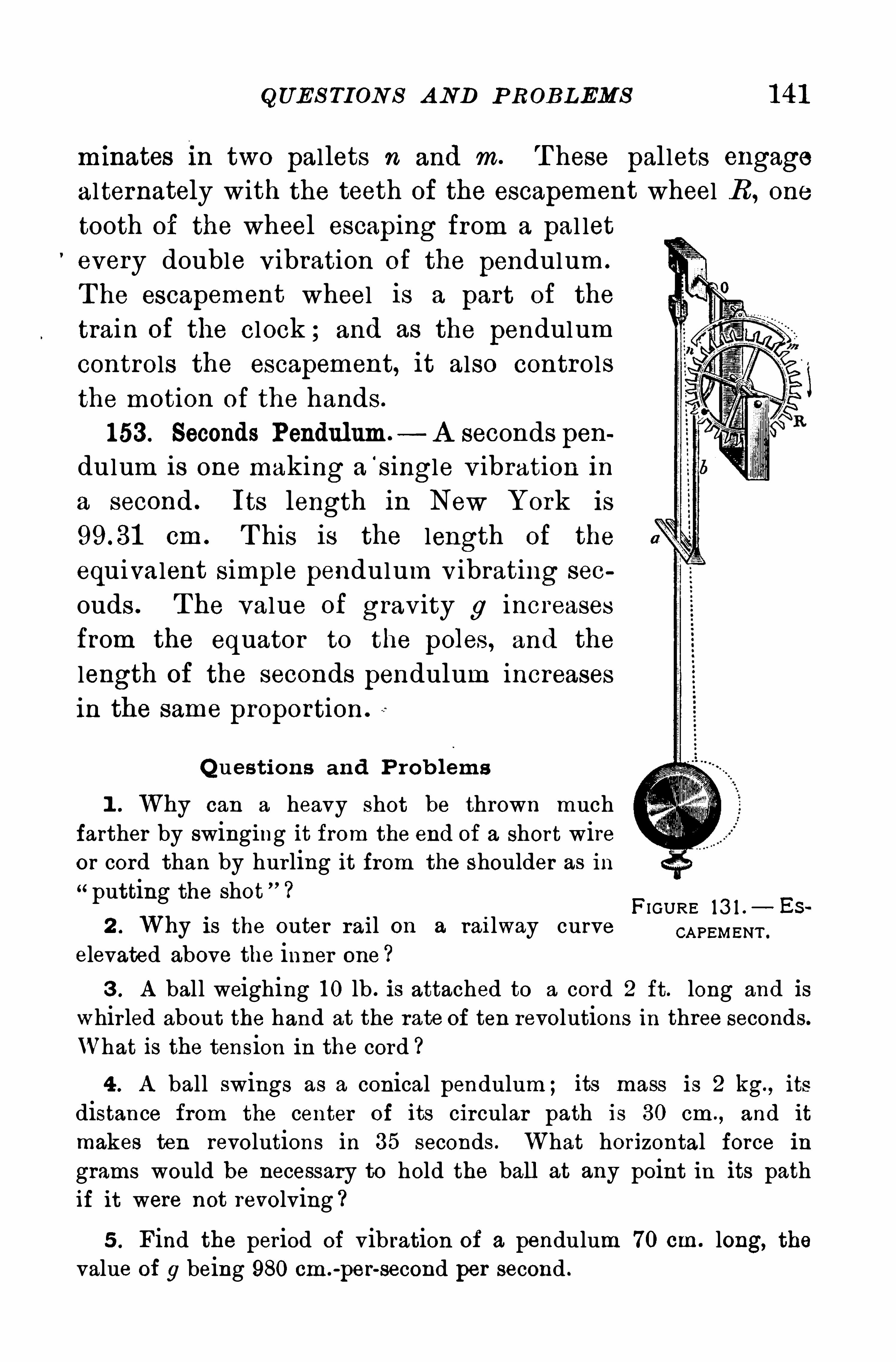
QUE S TI ON S A ND P ROBLEMS 1 41
minates in two pallets n and m. T hese pallets engage
alternately with the teeth of the escapement wheel B , one
tooth of the wheel escaping from a pal let
every double v ibration of the pendulum .
T he escapement wheel is a part of the
train of the clock ; and as the pendulum
controls the escapement, it also controls
the motion of the hands .
1 53 . Seconds Pendulum. A seconds pen
dulum is one making a‘
single v ibration in
a second . Its length in New York is
cm . T his is the length of the
equivalent simple pendulum v ibrating sec
ouds . T he value of grav ity g increases
from the equator to the poles , and the
length of the seconds pendulum increases
in the same proportion
Q ues tions and P rob lems
1 . Why can a heavy Shot be thrown muchfarther by swinging it from the end of a short wireor cord than by hur ling it from the shoulder as inputting the shot ” ?
2 . Why is the outer rail on a railway curveelevated above the inner one ?
FIGURE 13 1 . Es
CA PEMENT .
3 . A ball weighing 1 0 lb . is attached to a cord 2 ft. long and is
whir led about the hand at the rate of ten revolutions in three seconds.
What is the tension in the cord ?
4 . A ball swings as a conical pendulum ; its mass is 2 kg. , its
distance from the center of its circular path is 30 cm ., and it
makes ten revolutions in 35 seconds . What horizontal force in
grams would be necessary to hold the ball at any point in its pathif it were not revolving ?
5 . Find the period of vibration of a pendulum 70 cm. long, thevalue of 9 being 980 cm .
-
per-second per second .
1 42 MECH A N ICS OF S OL IDS
6 . Calculate the length of a seconds pendulum at a place wherethe value of g is 980 cm .
-
per-second per second .
7 . A t a place where g is 32 ft.-
per- second per second what is the
length of a pendulum that vibrates in sec. ?
8. What would be the acceleration of gravity if a pendulum one
meter long had a period of. vibration of one second ?
9 . If a simple pendulum 90 cm. long makes 64 S ingle vibrationsper minute, what is the value of g?
1 0 . Two balls of the same diameter but of different mater ials andmasses are suspended by threads of the same length and of negligiblemass. If made to vibrate as pendulums, will their periods of vibra~
tion difler and why ?
1 44 MECH A N ICA L WORK
weight ; the pi llars supporting a pediment over a porticodo no work ; a person holding a weight suffers fatigue,but does no work in the sense in which this word is used
in physics, where it is employed to descr ibe the result
accomp lished and not the efi‘brt made.
1 55. Measure of MechanicalWork .—Mechanical work is
measured by the product of the force and the displacement of its point of application in the direction in whichthe force acts , or
work force x displacement.
In symbolsw f x sf (Equation 1 6)
S ince force is equal to the product of mass and accelera
ti 1 30on 6w ma x 3 . (Equation 1 7)
1 56 . Units ofWork . Before use can be made of theseexpressions for work, it is necessary to define the unitsemployed in measur ing work .
" Three or four such unitsare in common use:
1 . T he foot p ound (ft. or the work done by a
pound of force working through a space of one foot. If
a pound weight is lifted a foot high, or if a body ismoved a distance of one foot by a force of one pound, afoot pound of work is done. T his unit is in common use
among Engl ish -speaking engineers . It is open to the
objection that it is var iable, since a pound of force var ieswith the latitude and with the elevation above sea level .
2. T he kilogram meter (kg. or the work done bya kilogram of fo rce working through a space of one
meter . It is the gravitational unit of work in the metr icsystem, and var ies in the same manner as the foot pound.
T he gram-centimeter is also used as a smal ler grav itational
P OWER 1 45
unit of work . The kilogrammeter is equal to
gram-centimeters .
3 . T he erg,l
or the work done by a dyne workingthrough a distance of one centimeter . T he erg is the
absolute unit in the c. g. 8. system and is invariable.
S ince a gram of force is equal to 980 dynes if
a gram mass be lifted vertical ly one centimeter , the workdone against grav ity is 980 ergs . H ence one kilogram
meter is equal to 980 x 1 000 x 1 00 ergs .
The mass of a“nickel is 5 g . T he work done in lifting it
through a vertical distance of 5 m. is the continued product of 5, 500,and 980, or ergs . T he erg is therefore a very small unitand not suitable for measur ing large quantities of work. For suchpurposes it is more convenient to use a multiple of the erg, called the
joule.
2 Its value is1 joule 1 07 ergs ergs.
Expressed in this larger unit, the work done 1n lifting the
nickel ” is joule.
3
1 57. Power .—While it takes time to do work, it is
plain that t ime is not an element in the amount of work
done. T o i l lustrate:Suppose a ton of marble is liftedby a steam engine out of a marble quar ry 300 ft . deep .
T he work is done by means of a wire rope, which the
engine winds on a‘ drum. If now the drum be replaced
by another of twice the diameter , and running at the
same rate of rotation, the ton of marble wi l l be l ifted in
half the time ; but the total work done against grav ityremains the same, namely, ft . lb.
In an important sense the engine as an agent for doingwork is twice as efl ective in the second instance as in the
1 The erg is from the Greek word meaning work .
2 From the noted English investigator Joule.
3 The joule is equal to about 4of a foot pound .
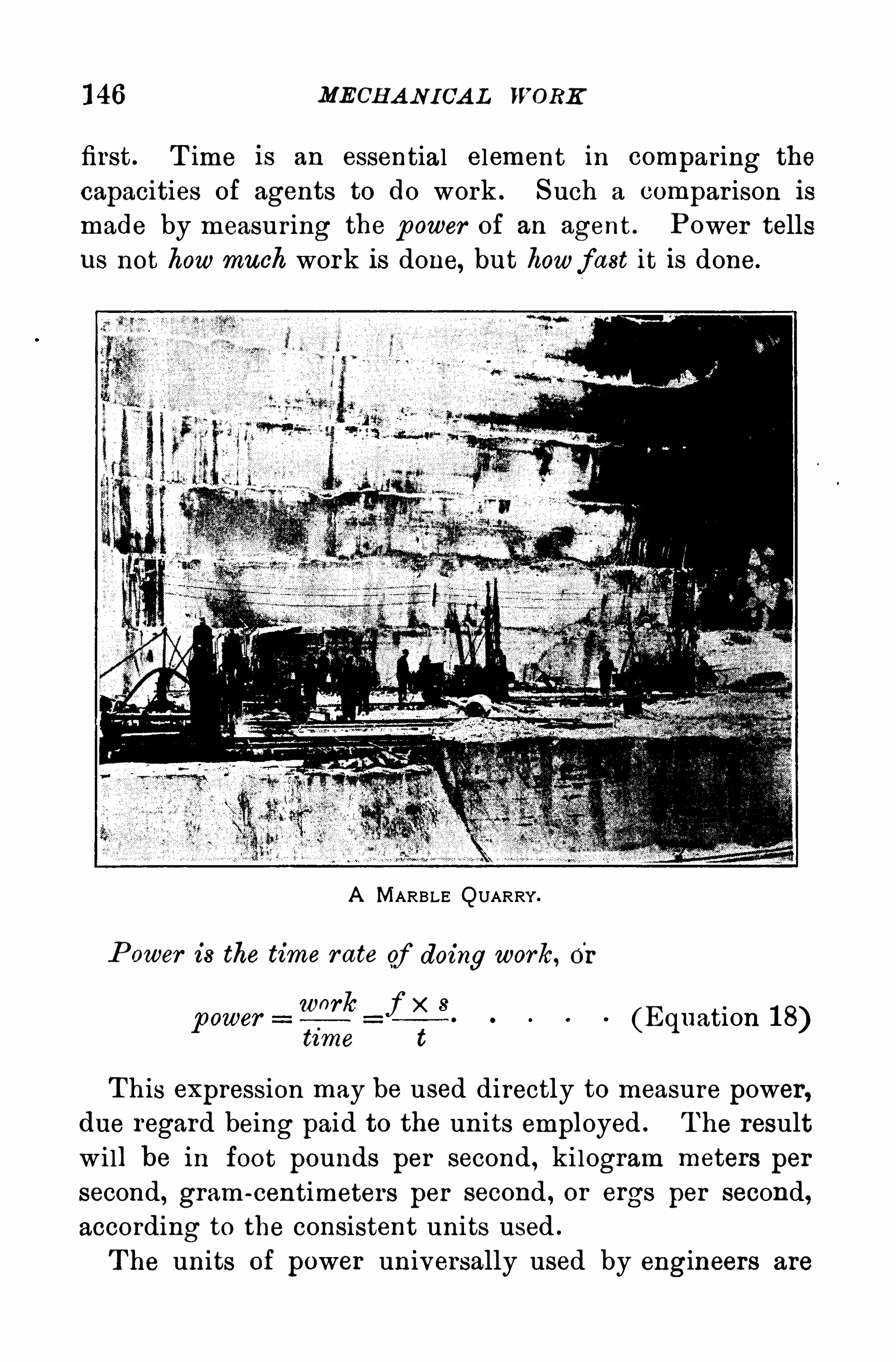
1 46 MECH A N ICA L WORK
first. T ime is an essential element in comparing the
capacities of agents to do work . S uch a compar ison is
made by measur ing the p ower of an agent . Power tellsus not howmuch work is done, but howfast it is done.
A MARBLE QUARRY.
P ower is the time r ate of doing work, or
work f x 8ower[9
time t(Equation 1 8)
T his expression may be used directly to measure power,due regard being paid to the units employed . T he resultw i ll be in foot pounds per second , kilogram meters per
second, gram-centimeters per second , or ergs per second,according to the consistent units used .
T he units of power universally used by engineers are
1 48 MECH A N I CA L WORK
H ence_ f x s=
5—
50 x t(Equati on 1 9)
in which f is in pounds of force, 8 in feet, and t in seconds.
In the c. g. 3 . system the watt 1 is the rate of workingequal to one joule per second . A kilowatt is
1 000 watts .
H a f X 3ence wa s K . =W
t x 1 010(Equat1 on 20)
In Equation 20 f is in dynes, s in centimeters, and tin seconds .
One horse power equals 746 watts, or kilowatt
(nearly it T o convert kilowatts into horse powersapproximately , add one third ; to convert horse powersinto kilowatts , subtract one four th . For example, 60 K .W.
are equal to 80 H .P . , and 1 00 H P . are equal to 75 K .W.
T he power capacity of direct current dynamo electric generators isnow universally expressed in kilowatts ;the steam engines and waterturbines used to drive these generators are commonly rated in the same
unit of power ; so. too, the capacity of electric motors is more often
given in kilowatts than in horse powers . A kilowatt hour means powerat the rate of a kilowatt expended for one hour . T hus, 20 kilowatthours mean 20 K .W. for one hour, or 5 K .W. for four hours, etc .
1 58. Energy— Exper ience teaches that under certain
conditions bodies possess the capacity for doing work .
T hus, a body of water at a high level , gas under pressure
in a tank , steam confined in a steam boiler , and the air
moving as a wind, are all able to do work by means of
appropriate motors . In general , a body or system onwhich
work has been done acquires increased capacity for doingwork . It is then said to possess more energy than before.
1 From the noted English engineer JamesWatt.
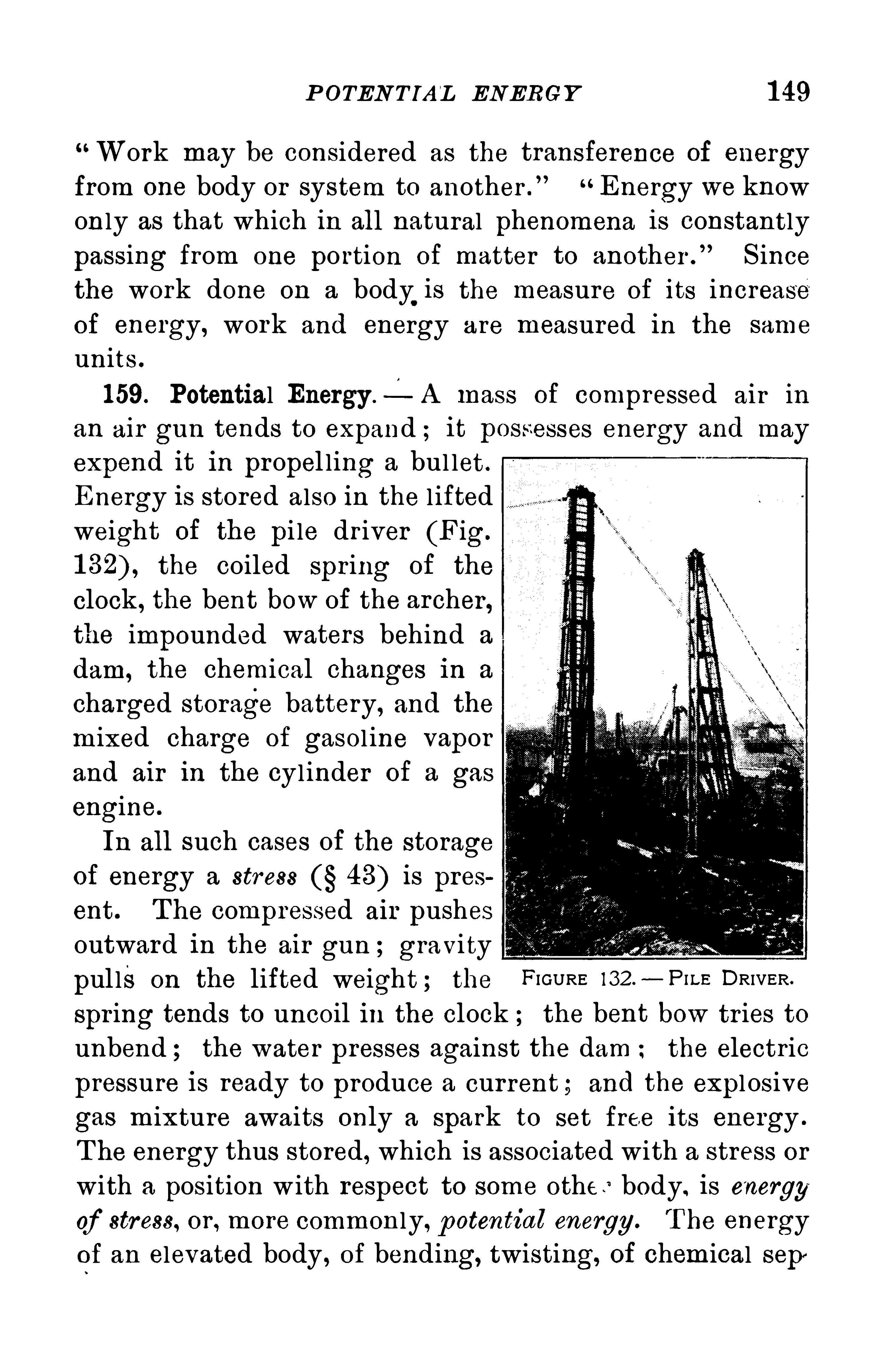
POTEN TIA L ENERGY 1 49
Work may be considered as the transference of energyfrom one body or system to another .
”Energy we know
only as that which in all natural phenomena is constantly
passing from one po rtion of matter to another .
”S ince
the work done on a body.
is the measure of its increaseof energy, work and energy are measured in the same
units .
1 59. Potential Energy — A mass of compressed air in
an air gun tends to expand ; it possesses energy and mayexpend it in propel ling a bul let .
Energy is stored also in the l iftedweight of the pi le dr iver (Fig.
the coiled spring of the
clock , the bent bow of the archer ,the impounded waters behind a
dam, the chemical changes in a
charged storage battery, and the
mixed charge of gasol ine vaporand air in the cylinder of a gas
engine.
In all such cases of the storageof energy a str ess 48) is present. T he compressed air pushesoutward in the air gun ; gravity
pul ls on the lifted weight ; the FIGURE 132 .—Pn. r DRIVER
spr ing tends to uncoil in the clock the bent bow tr ies to
unbend ; the water presses against the dam the electric
pressure is ready to produce a current ; and the expl osive
gas mixture awaits only a spark to set free its energy .
T he energy thus stored, which is associated with a stress or
with a position w ith respect to some other body. is energy
of stress, or , more commonly, p otential energy. T he energyof an elevated body , of bending, twisting, of chemical sep
150 MECHANICAL WORK
aration, and of air, steam, or water under pressure, are all
examples of potential energy .
1 60. Kinetic Energy .— A body also possesses energy in
consequence of its motion ; the energy of a moving bodyis known as kinetic energy . The
.descending hammer forces
the nail into the wood, the rushing torrent carries away
br idges and overturns buildings the swiftly moving can
non ball , by v irtue of its high speed , demol ishes fortifications or pierces the steel armor of. a battleship the energy
stored in the massive rotating flywheel keeps the enginerunning and may do work after the steam is shut off.
When the engine is speeding up, it pushes and pulls on
the shaft to increase the speed of the flywheel ; in otherwords, the engine does work on the flywheel . A fter
normal speed has been reached, all the work done by the
engine goes into the dr iven machinery; but if an extra
load comes on the engine, its speed does not drop sud
denly, because it is sustained by the flywheel giv ing out
some of its stored energy to help along the engine. The
engine tends to stop the flywheel , and this now does work
instead of absorbing energy .
When a meteor ic body, or“shooting star , enters the
earth’
s atmosphere, its energy of motion is converted into
heat by fr iction with'
the air ; the heat generated raises
the temperature of the meteor (at least on its surface)until it glows l ike a star . If it is smal l, it may even burn
up or become fine powder .
T he energy of the inv isible molecular motions of bodies
constituting heat is included under kinetic energy no less
than that of their v isible motion . H eat is a form of
kinetic energy .
Kinetic energy must not be confused wi th force. A
mass of mov ing matter carr ies with it kinetic energy, but

K INETIC ENERGY 1 51
it exerts no force until it encounters resistance. Energy
is then transferred to the Opposing body, and force is
exerted only dur ing the transfer .
1 6 1 . Measure of Energy .—Energy is measured in the
same terms as those used in measur ing work . In general ,
potential energy is the measure of the mechanical workdone in storing the energy, or
P .E . = f x 8. (Equation 21 )
If f is in pounds of force and s in feet, the resul t is in
foot pounds . S imi lar ly, if f is in grams of force and s
in centimeters, the potential energy is expressed in gram
centimeters .
S ince a gram of force is equal to 980 dynes , expressed
e sIn rg P .E . 980 x grams centimeters.
1 62. Kinetic Energy in Terms of Mass and Velocity.
The work fs done by the force f on the mass m to give itthe velocity while working through the distance 8,
measures the kinetic energy acquired, or ,
K E . = f x s .
But it is highly desirable to express kinetic energy in
terms of the mass m and the acquired velocity insteadof f and 8. By the second law of motion 1 30) f ma .
H ence K E . ma x 8. But s %at2. T hereforeK E
gmaz t z. A lso a at therefore
K E . (Equation 22)
Both m and v are magnitudes independent of gravitationit fol lows that the results calculated from Equation 22 cannot be in grav itational units . If m is expressed in gramsand o in centimeters per second, the kinetic energy is in
1 52 MECHANICAL WORK
ergs . S ince the gr'
am-centimeter is equal to 980 ergs , to
reduce the result to gram-centimeters , div ide by the valueof g in this system, or 980.
In precisely the.
same way, if m is in pounds and v in
feet per second, to obtain the energy in foot pounds,divide by the value of g in the English system,
T o illustrate:If an automobile, weighing 3000 lh .,is running at a
speed of 30 miles per hour, find its kinetic energy .
A mile a minute is 88 ft. per second , and 30 miles an hour or halfa mile a minute is 44 ft. per second . H ence the kinetic energy of themovmg car 1 s
3000 x 442
2 xft . lb .
T his energy represents very near ly thework.
required to lift the car30 ft . high against gravity, for this work is
o 3000 x 30 ft. lb.
A large ship, moving toward a wharf with a motion scarcely perceptible, will crush with great force smal l intervening craft . The
moving energy of the large vessel is great because of its enormous
mass, even though its velocity is small . Its weight is supported bythe water and has nothing to do with its crushing force.
1 63 . Transformations of Energy . When a bullet is shot
vertical ly upward, it gradual ly loses its motion and its
kinetic energy, but gains energy of position or potential
energy . When it reaches the highest point of its flight,its energy is all potential . It then descends, and gains
energy of motion at the expense of energy of position .
The one form of energy is, therefore, convertible into the
other .
T he pendulum illustrates the same pr inciple. While
the bob is mov ing from the lowest point of its path
toward either extremity , its kinetic energy is converted
into potential energy ; the reverse transformation sets in
154 MECHANICAL WORK
The remainder is dissipated as heat. This running down
of energy by p assing into an unavailable form is known as
the dissip ation of energy . It was first recognized and dis
tinctly stated by L ord Kelvin ' in 1 859.
The capacity which a body” possesses for doing workdoes not depend on the total quantity of energy which itmay possess, but only on that por tion which is available,
or is capable of being transferred to other bodies. In the
problems of phys 1cs our chief concern is with the var iations of energy in a body and not wi th its total value.
Q ues tions and P rob lem s
1 . A cord that will just support an iron ball will generally breakif the attached ball is lifted and al lowed to drop . Explain.
2 . In what form is the energy of a coiled spring ? Of a bomb ?Of a pile driver ?
3 . Lake T ahoe in the S ierra Nevadas is at an elevation of 6225 ft.
above the sea. A ccount for the energy of position stored there in thewater .
4 . Why has the ball in leaving the gun so much more energy of
motion than the gun has in the recoil ?5 . Why is perpetual motion impossib le ?6 . Is not the case of the earth gomg around the sun a case of
perpetual motion ? H ow does this differ from what is common lymeant by “perpetual motion
7 . A man weighing 200 lb . climbs to the top of a hill 900 ft.hi gh . H ow much work does he do ?
8. A man carries a ton of coal up a flight of stair s 1 4 ft. high.
H ow much work does he do ?9 . A force of 200 dynes moves a mass of 1 00 g. through a dis
tance of 50 cm . H ow much work is done ?1 0 . A load of two tons was drawn up a hill half a mile long by a
traction engine. T he hill was 1 00 ft. high . H ow much work wasdone ? What force did the engine exert ?
S UGGE S T ION .
—Notice that the work done by the engine in pulling the
load half a mile is the same as lifting it vertically 100 ft .
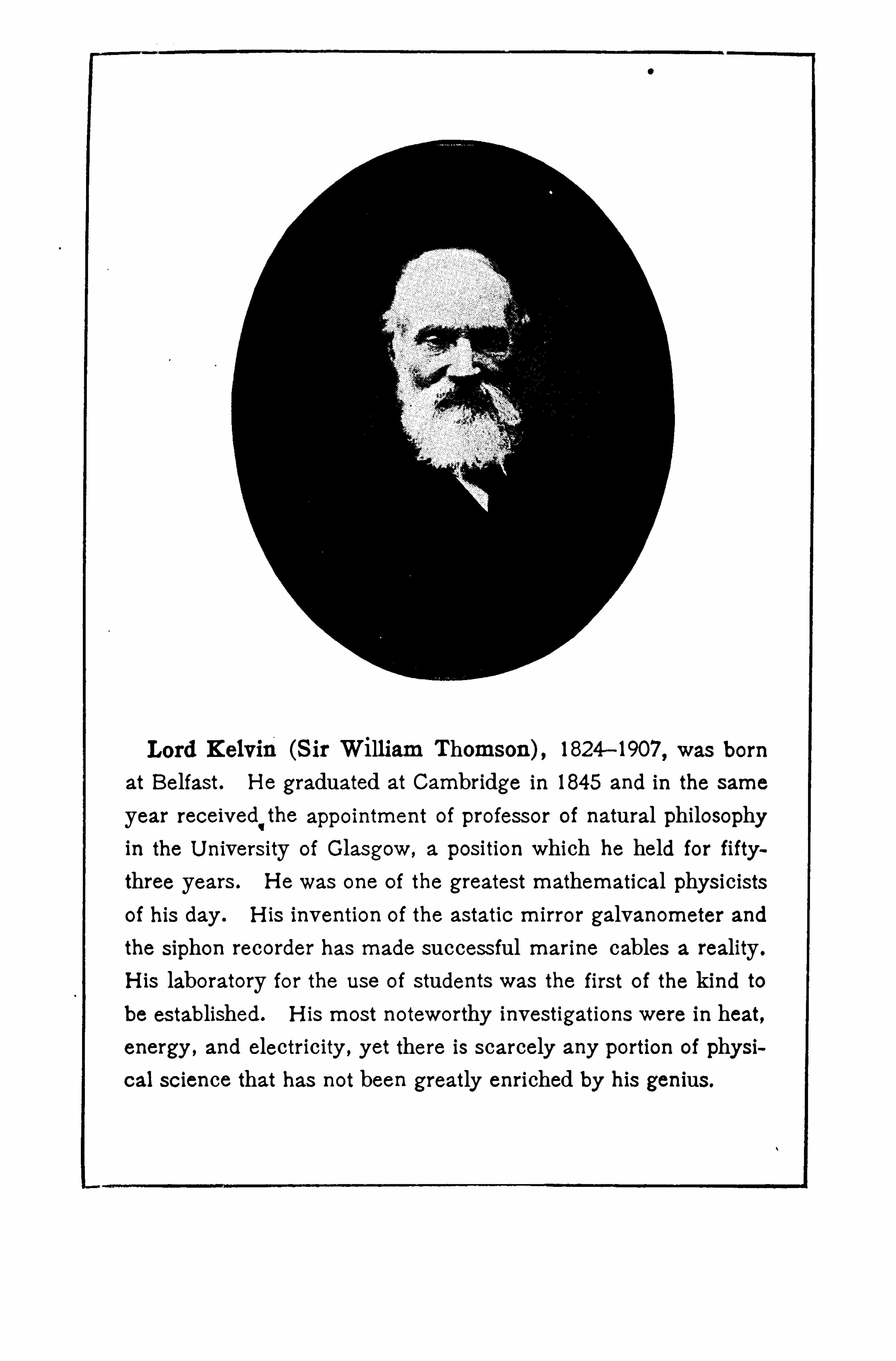
(S ir William Thomson) , 1824—1907 was born
at Belfast. H e graduated at Cambridge in 1845 and in the same
year received'the appointment of professor of natural philosophy
in the U niversity of Glasgow, a position which he held for fiftythree years . H e was one of the greatest mathematical physicistsof his day . H is invention of the astatic mirror galvanometer and
the siphon recorder has made successful marine cables a reality .
H is laboratory for the use of students was the first of the kind tobe established. H is most noteworthy investigations were in heat,energy , and electricity , yet there is scarcely any portion of physi
cal science that has not been greatly enriched by his genius .

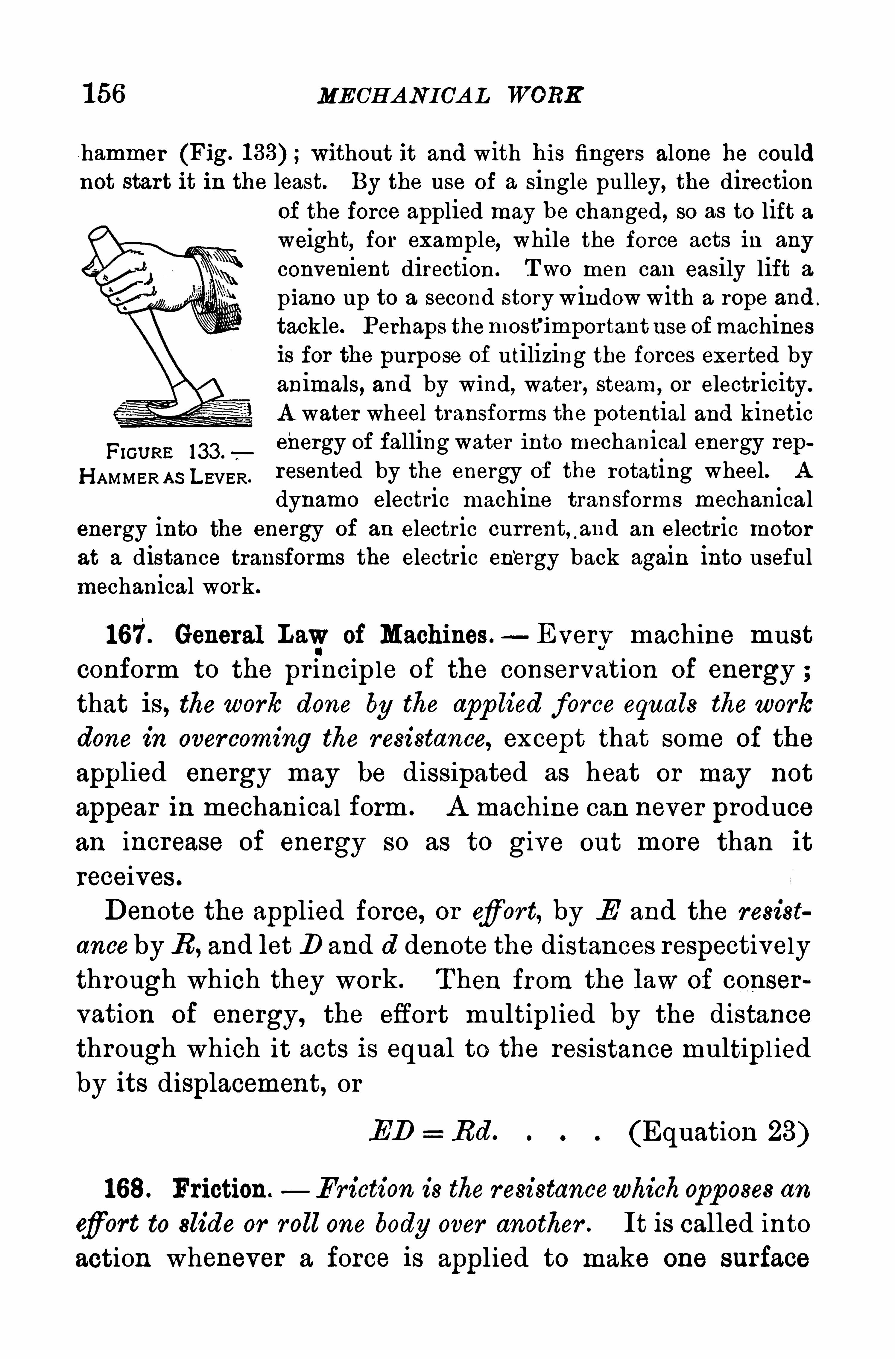
1 56 MECHAN ICAL WORK
hammer (Fig. without it and with his fingers alone he couldnot start it in the least. By the use of a single pulley, the direction
of the force applied may be changed , so as to lift aweight, for example, while the force acts in any
convenient direction . Two men can easily lift a
piano up to a second story window with a rope and .
tackle. Perhaps themost’
important use ofmachinesis for the purpose of utilizing the forces exerted byanimals, and by wind, water , steam, or electricity.
A water wheel transforms the potential and kinetic
FiGU RE 133 .
energy of falling water into mechanical energy repH AMMER A S LEVER.
resented by the energy of the rotating wheel. A
dynamo electric machine transforms mechanicalenergy into the energy of an electric current, .
and an electric motor
at a distance transforms the electric energy back again into usefulmechanical work.
167. General Lawof Machines.—Everv machine must
conform to the pr incip le of the conservation of energy ;that is, the work done by the app lied force equals thework
done in overcoming the resistance, except that some of the
applied energy may be dissipated as heat or may not
appear in mechanical form . A machine can never producean increase of energy so as to give out more than it
receives .
Denote the applied force, or efiort, by E and the resist
anceby R , and let D and d denote the distances respectivelythrough which they work . T hen from the law of conser
vation of energy, the effort multipl ied by the distance
through which it acts is equal to the resistance multipl ied
by its displacement, or
ED Rd. (Equation 23)
168. Friction. Friction is the resistancewhichopposes an
cf ort to slide or roll one body over another . It is called into
action whenever a force is applied to make one surface
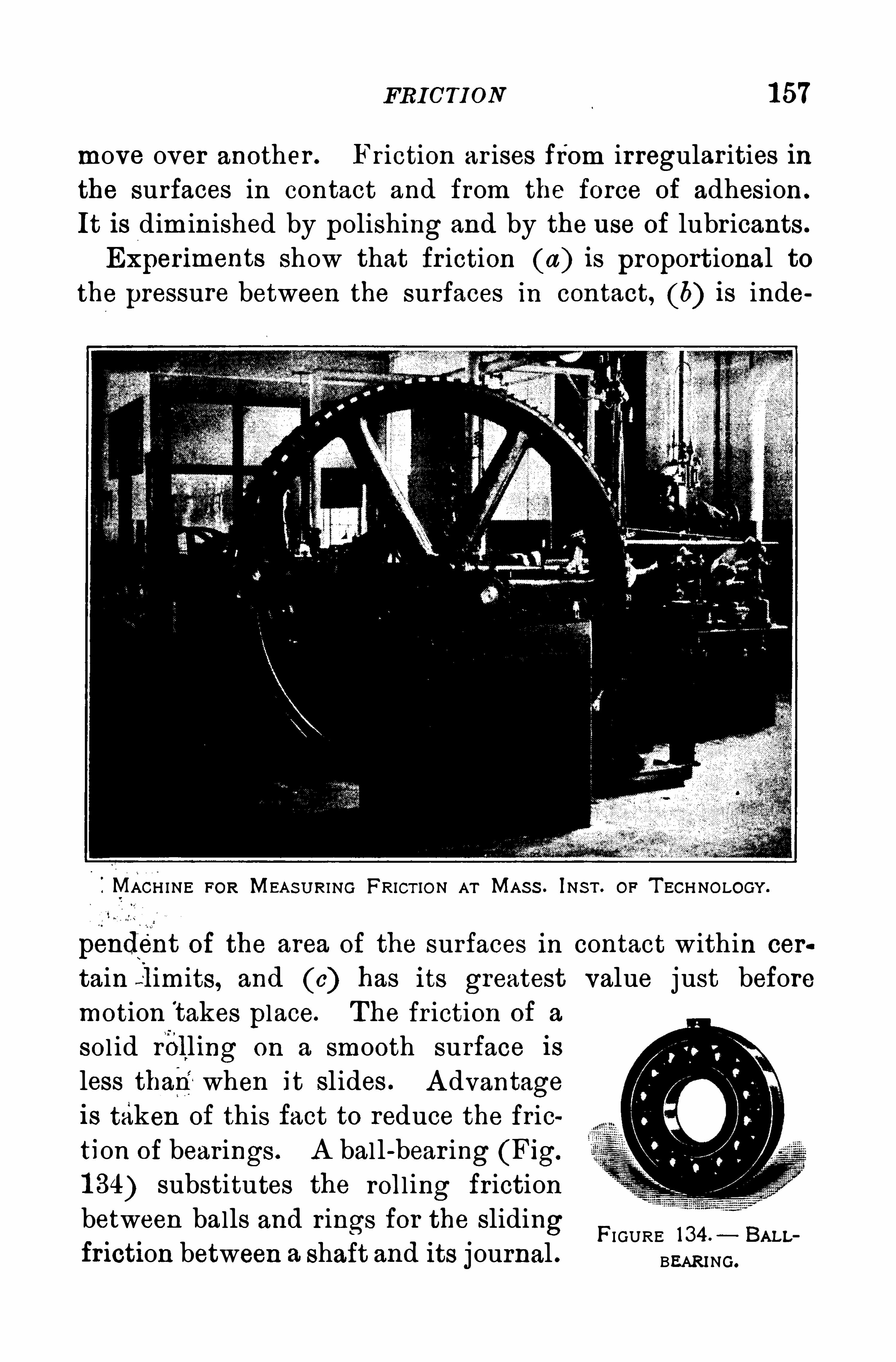
FRICTI ON 1 57
move over another . Friction ar ises from irregular ities in
the surfaces in contact and from the force of adhesion .
It is diminished by polishing and by the use of lubricants .
Experiments show that fr iction (a) is proport ional to
the pressure between the surfaces in contact, (b) is inde
IMACH INE FOR MEA S U RING FRICT ION AT MAS S . INS T . OF T ECHNOLOGY.
pendent of the area of the surfaces in contact within cer
tain l imits, and (c) has its greatest value j ust beforemotion takes place. The fr iction of a
sol id r
i
blling on a smooth surface is
less than"when it slides . A dvantageis taken of this fact to reduce the friction of bearings . A bal l-bear ing (Fig.
1 34) substitutes the roll ing frictionbetween balls and rings for the
.
sliding FI GURE Bu b
friction between a shaft and i ts journal . BEARING ,
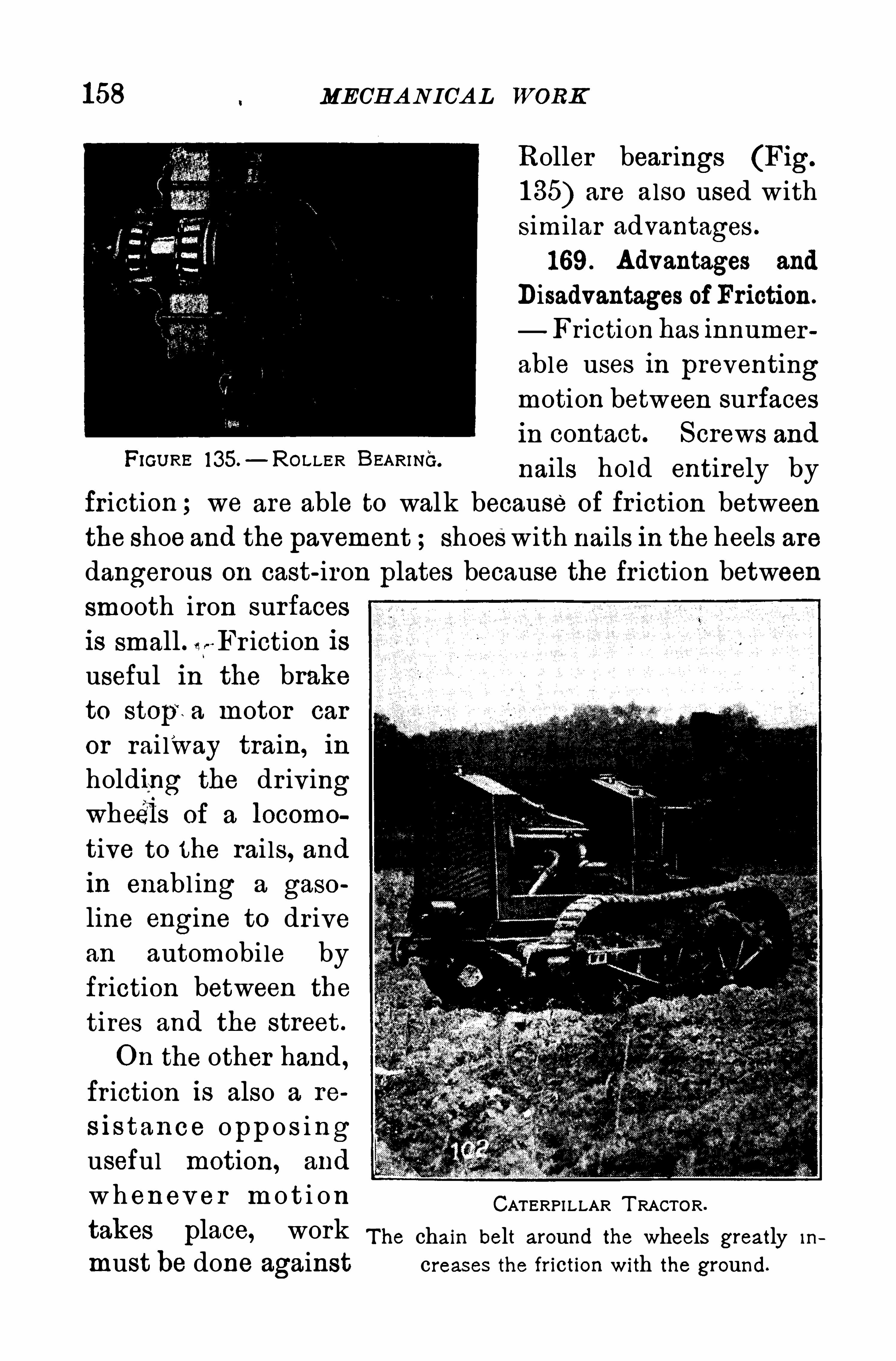
158 MECHANICAL WORK
Roller bear ings (Fig.
1 35) are also used withsimilar advantages .
169. Advantages and
Disadvantages of Friction.
Fr iction has innumer
able uses ih preventingmotion between surfacesin contact. Screws and
nails hold entirely by
friction ; we are able to walk because of fr iction between
the shoe and the pavement shoeswith nails in the heels aredangerous on cast-iron plates because the fr iction between
smooth iron surfacesis small . i
s" Fr iction is
useful in the braketo stop
‘
t a motor car
or rai lway train, in
holding the dr ivingwheéls of a locomo
tive to the rai ls, and
in enabl ing a gaso
line engine to dr ivean automobile byfriction between the
tires and the street .
On the other hand ,
friction is also a re
s is tan ce opp o s inguseful motion, and
wh enev e r m o t i on
FIGU RE 135.—ROLLER BEARINC.
CATERPI LLAR T RACTOR.
takes place, work The chain belt around the wheels greatly Ih
must be done against creases the friction with the ground.
MECH A NICA L WORK
fied lever , and the wedgeand the screw are modificationsof the incl ined plane, the mechanical powers may be re»
duced to three.
In solving problems relating to simple machines in ele
mentary physics it is customary to neglect fr iction and to
consider that the parts of machines are r igid and withoutweight. With these limitations, the law expressed by
Equation 23 holds good .
1 72. Mechanical Advantage.—A man working a pump
handle and pumping water is an agent app lying energy ;
the pump and thewater compose a system r eceiving energy .
In a simple machine the force exerted by the agent ap
plying energy, and the opposing force of the system re
ceiving energy, may be denoted by the two terms ,.
efior t,
E , and r esistance, R . T he problem in simple machines
consists in finding the ratio of the resistance to the
effort .
T he ratio of the resisting f or ce R to the applied force E
is called the mechanical advantage of the machine. T hisratio may a lways be expressed in terms of certain parts of
simple machines .
1 73 . Moment of 9. Force.—In the application of the
lever , the pul ley, or the wheel and axle there is motion
about an axis . T he appl ication of a single force to a bodywith a fixed axis produces rotation only . Examples are a
door swinging on its hinges and the flywheel Of an engine.
The effect of a force in producing rotation depends, notonly on the value of the force, but on the distance of its
line of appl ication from the axis Of rotation. A smal lerforce is required to close a door when it is applied at r ightangles to the door at the knob than when it is app l iednear the hinge. A lso, an increase in the speed of rota
tion of a flywheel may be secured either by increasing the
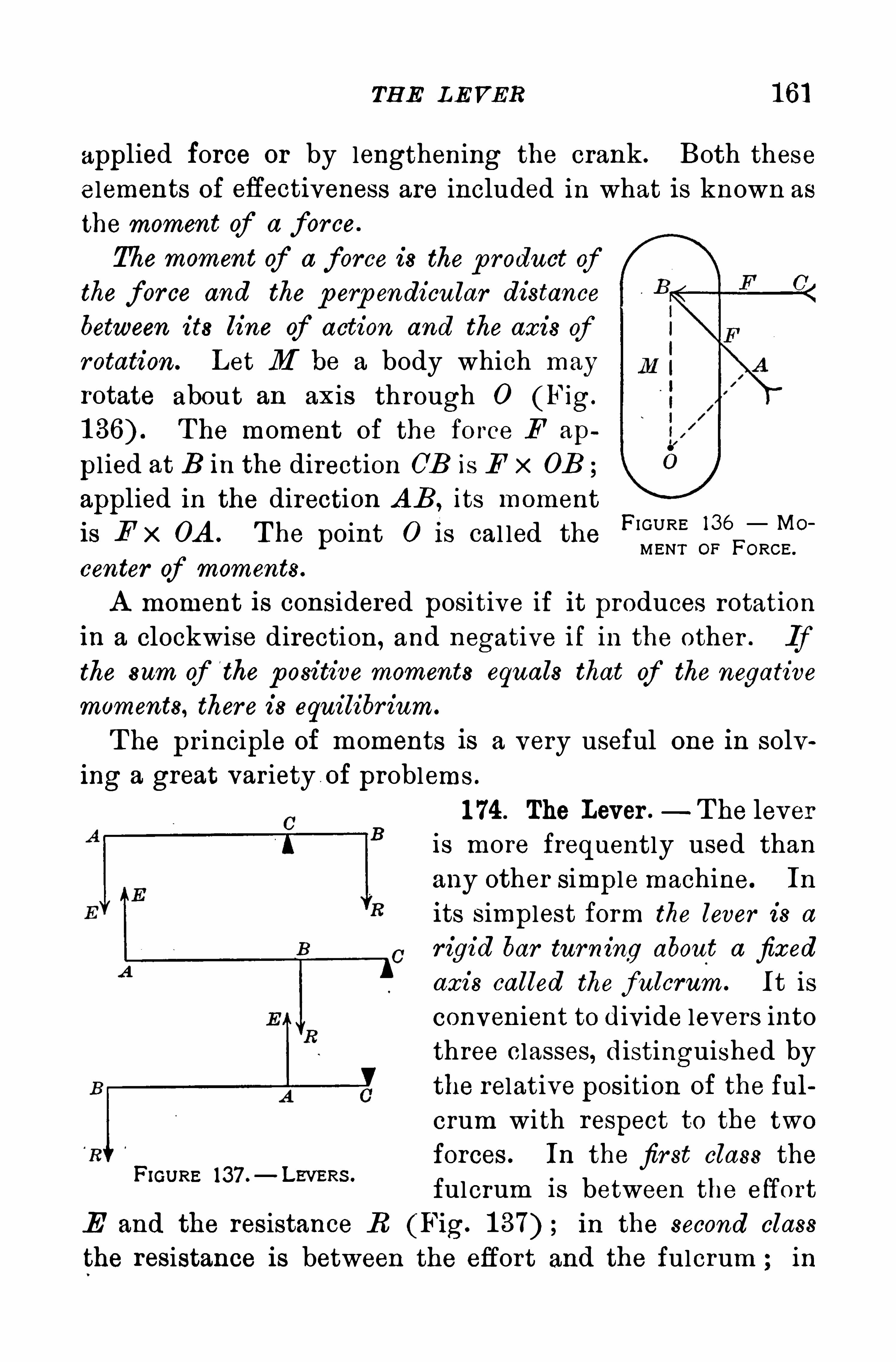
TH E LEVER 1 6]
applied force or by lengthening the crank . Both these
elements of efiectiveness are included in what is known as
the moment of a force.
The moment of a force is the p roduct ofthe force and the p erp endicular distance
between its line qf action and the axis ofrotation. Let M be a body which may
rotate about an axis through 0 (Fig.
T he moment of the force F ap
pl ied at B in the direction OB is E x 0B
applied in the direction A B , its moment
is E x 0A . T he point 0 i s cal led theFI GURE 136 MO“
MENT OF FORCE .
center of moments.
A moment is considered positive if it produces rotation
in a clockwise direction, and negative if in the other . Ifthe sum of the p ositive moments equals that of the negative
moments, there is equilibr ium.
T he principle of moments is a very useful one in solving a great variety of problems .
1 74. The Lever .—T he lever
is more frequently used than
any other simple machine. In
its simplest form the lever is a
r igid bar turning about a fixedaxis called the fulcrum. It is
convenient to divide levers into
three classes, distinguished by
the relative position of the ful
crum with respect to the two
forces . In the fir st class the
fulcrum is between the effort
E and the resistance R (Fig. in the second class
the resistance is between the effort and the fulcrum ; in
FIGURE 137 . LEVERs .
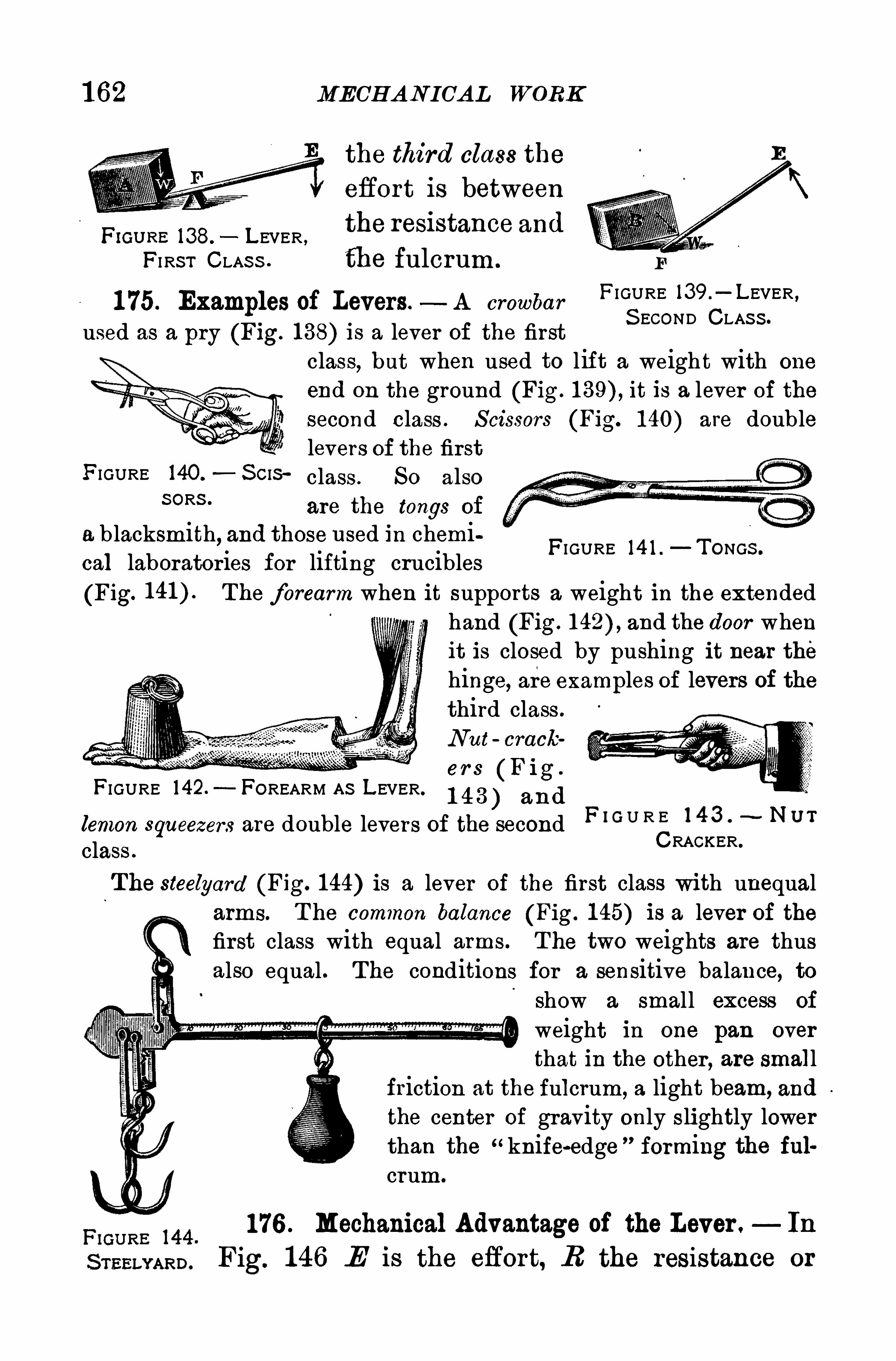
1 62 MECHAN ICAL WORK
the third class the
effort is between
FWU RE 138. LEVER ,
the resi stance and
FI RS T CLAS S . fll e fulcrum .
FI GURE l39 .
—LEVER ,1 75. Examples of Levers.- A crowbar
S ECOND CLAS S .
used as a pry (Fig. 1 38) is a lever of the firstclass, but when used to l ift a weight with one
end on the ground (Fig. it is a lever of the
second class . S cissors (Fig. 1 40) are doublelevers of the first
FIGURE 140. S CIS class , So alsoS ORS ‘
are the tongs of
a b lacksmith, and those used in chemical laboratories for lifting crucibles(Fig. The forearm when it supports a weight in the extended
hand (Fig. and the door whenit is closed by pushing it near thehinge, are examples of levers of thethird class .
N ut crack
er s (F ig .
FIGURE l42.—FOREARM A S LEVER. 1 4 3 ) and
FI GURE 14 1 . TONGS .
lemon squeezers are double levers of the second F I G U R E 1 4 3 N”7
class .
CRACKER.
T he steelyard (Fig. 144) is a lever of the first class with unequalarms. T he common balance (Fig. 1 45) is a lever of thefirst class with equal arms. T he two weights are thusalso equal . The conditions for a sensitive balance, to
show a small excess of
weight in one pan overthat in the other , are small
friction at the fulcrum, a light beam, and
the center of gravity only slightly lowerthan the “knife-edge ”
forming the fulcrum.
176 . Mechanical Advantage of the Lever . In
Fig. 1 46 E is the eflort, R the resistance or
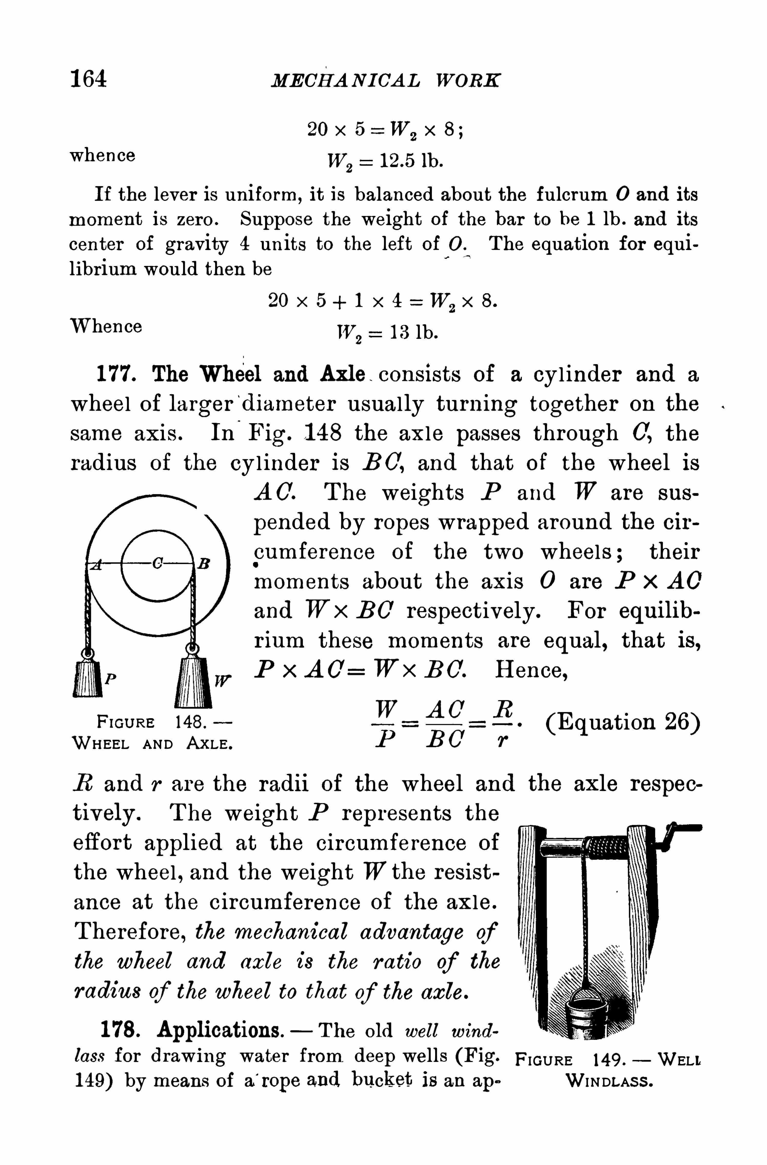
1 64 MECHANI CA L WORK
20 x 5 W,x s;
whence W,
12.5 1b .
If the lever is uniform, it is balanced about the fulcrum 0 and its
moment is zero . Suppose the weight of the bar to be 1 lb . and its
center of gravity 4 units to the left of 0 . The equation for equilibrium would then be
20 x 5 + 1
Whence W,
1 3 lb .
1 77. The Wheel and Axle consists of a cylinder and a
wheel of larger‘
diameter usually turning together on the
same axis . In'
Fig. 1 48 the axle passes through 0, the
radius of the cyl inder is B 0, and that of the wheel isA O. T he weights P and W are sus
pended by ropes wrapped around the cir
pumference of the two wheels ; theirmoments about the axis 0 are P x A O
and Wx E U respectively. For equilib
r ium these moments are equal, that is,P x A O= Wx E U. H ence,
H om e 148.
W A O 5 . (Equation 26)WHEEL AND A XLE .
P E U_
r
R and r are the radi i of the wheel and the axle respec
tively . T he weight P represents the
eflort applied at the circumference of
the wheel , and the weight Wthe resist
ance at the circumference of the axle.
T herefore, the mechanical advantage ofthe wheel and axle is the ratio of the
radius of the wheel to that of the axle.
1 78. Applications — T he old well wind
lass for drawing water from deep wells (Fig. FIGURE 149 , WELL1 49) by means of a
'
rope and bucket is an ape WI N DLAS S .
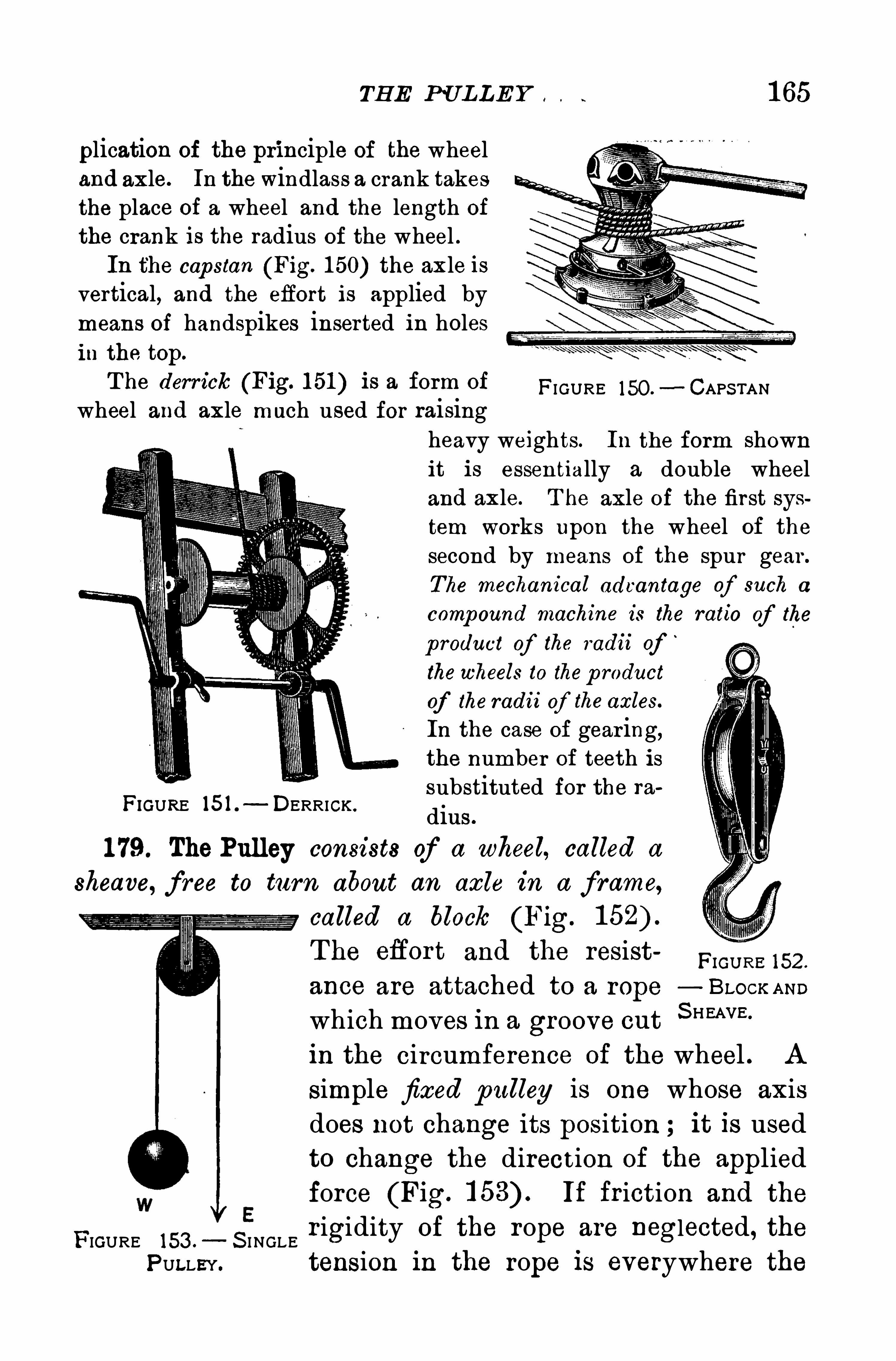
TH E PU L LE Y , t 1 65
plication of the principle of the wheeland axle. In the windlass a crank takesthe place of a wheel and the length ofthe crank is the radius of the wheel .In the cap stan (Fig. 1 50) the axle is
vertical, and the effort is applied bymeans of handspikes inserted in holesin the top.
T he derrick (Fig. 1 51 ) is a form of FI GURE 150.—CAPS TAN
wheel and axle much used for raisingheavy weights. In the form shownit is essentially a double wheeland axle. T he axle of the first system works upon the wheel of the
second by means of the spur gear .
The mechanical advantage of such a
comp ound machine is the ratio of the
p roduct of the radii of‘
thewheels to thep roduct
of the radii of the axles.
In the case of gear ing,the number of teeth issubstituted for the ra
dins .
1 79. The Pulley consists of a wheel, called a
sheave, f ree to turn about an axle in a frame,
called a block (Fig.
T he efior t and the resistFIGU RE ISZ.
ance are attached to a rope— BLOCK AND
which moves in a groove cutS HEA“
in the circumference of the wheel . A
simple fixed pulley is one whose axisdoes not change its position it is used
to change the direction of the appliedforce (Fig. If friction and the
FIGURE 153 .— S I NGLE r igidity of the rope are neglected, the
PULLEY. tension in the rope is everywhere the
FIGURE 15 1 . DERRICK .
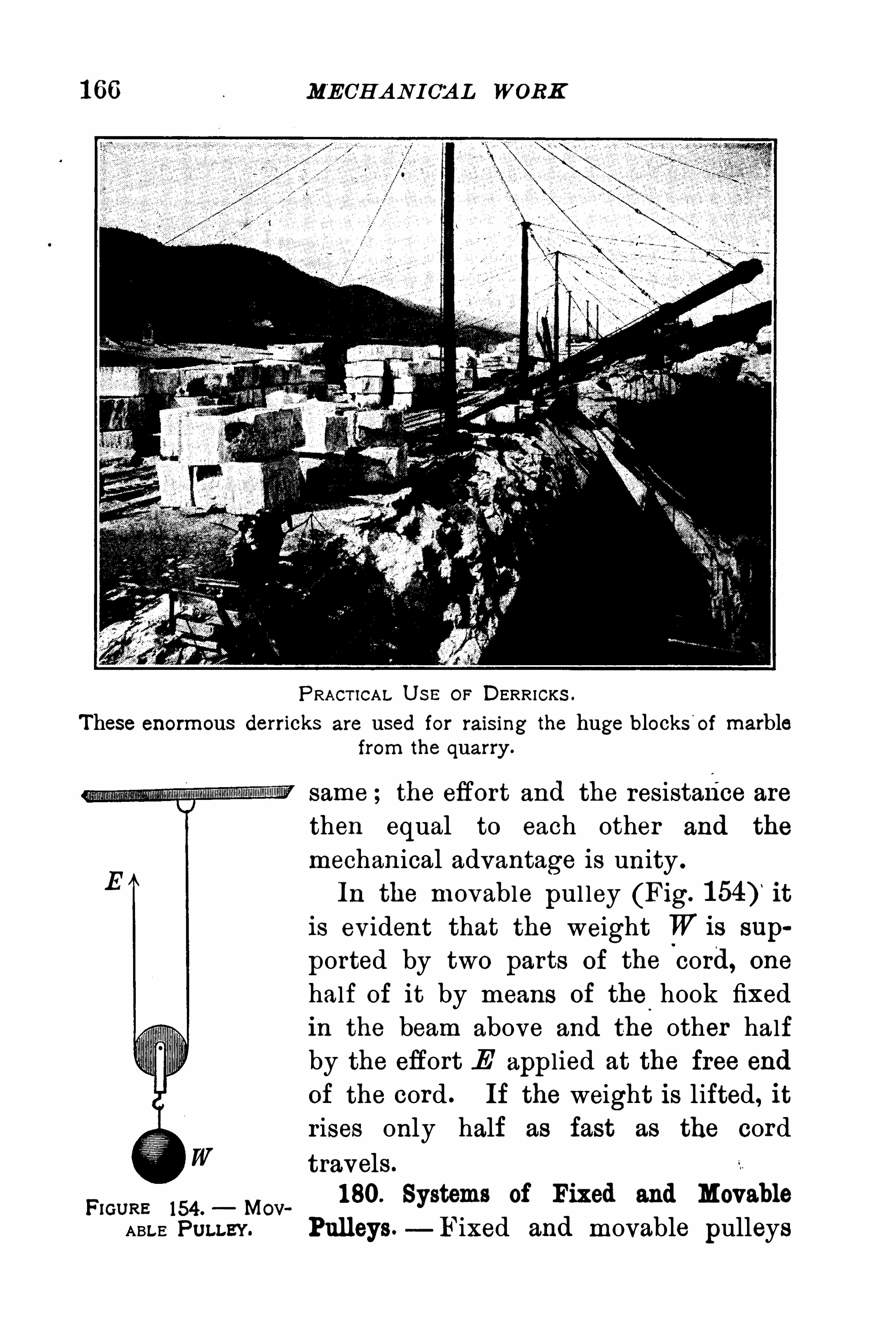
1 66 MECHANICAL WORK
PRACT ICA L U S E OF DERRICKS .
These enormous derricks are used for rais ing the huge blocks of marblefrom the quarry .
same ; the efiort and the resistance are
then equal to each other and the
mechanical advantage is unity .
In the movable pul ley (Fig. it
is evident that the weight W is sup
ported by two parts of the cord, one
half of it by means of the.
hook fixed
in the beam above and the other half
by the effort E applied at the free end
of the cord . If the weight is lifted, it
r ises only half as fast as the cord
travels .
pm “ 154 . Mov180. Systems of Fixed and Movable
ABLE PULLEY. Pulleys.—Fixed and movable pulleys
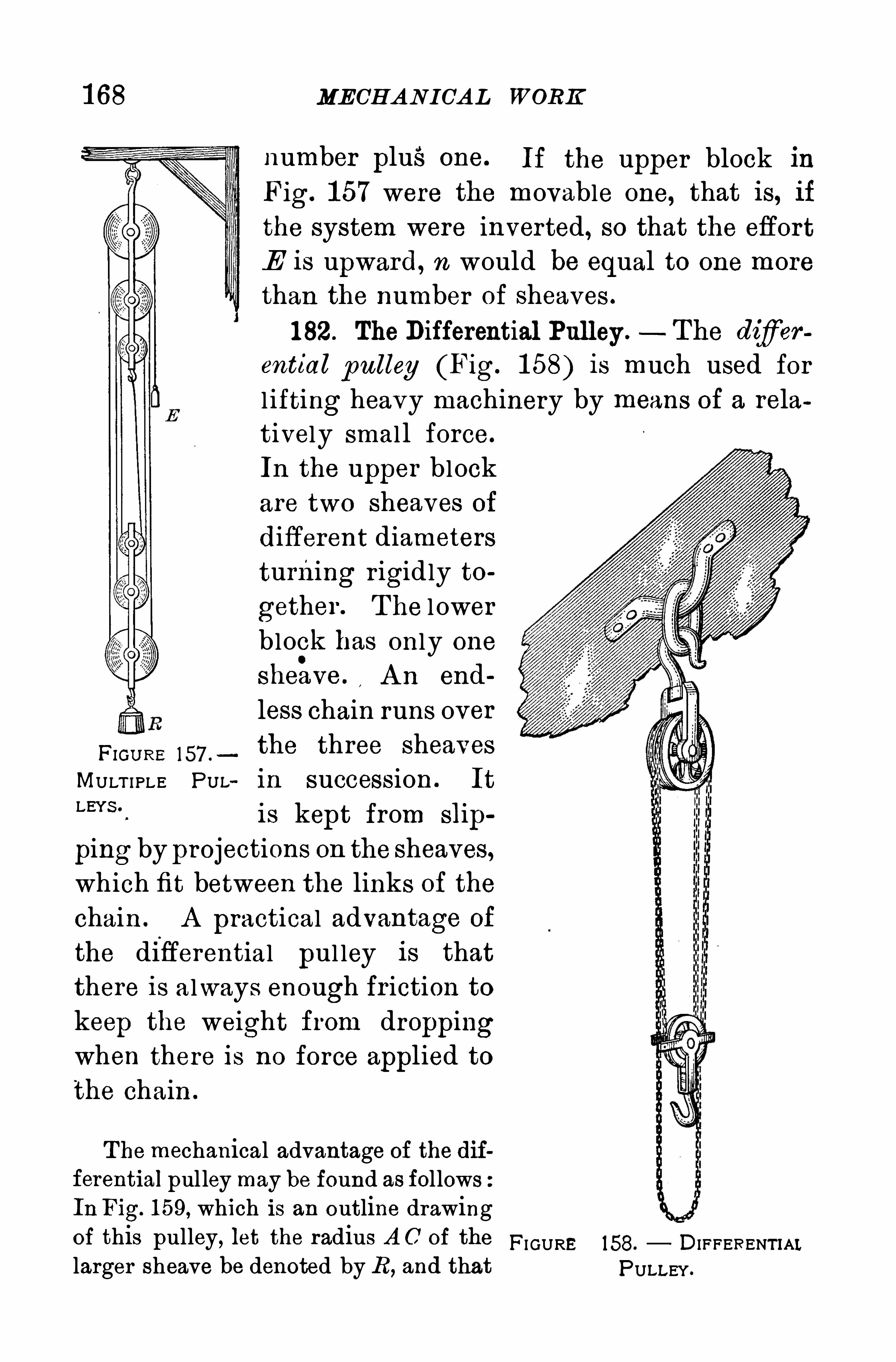
1 68 MECHANICAL WORK
number plus one. If the upper block in
Fig. 1 57 were the movable one, that is, ifthe system were inverted, so that the effort
E is upward, n would be equal to one morethan the number of sheaves .
1 82. The Differential Pulley . The difierential pulley (Fig. 1 58) is much used forl ifting heavy machinery by means of a relatively smal l force.
In the upper block
are two sheaves of
different diameters
turning r igidly to
gether . T he l ower
block has only one
shehve . A n end
less chain runs over
H om e 157 .
the three sheavesMULT I PLE P U L in succession . ItLEYS ‘
is kept from slip
ping by projections on the sheaves,which fit between the links of the
chain . A practical advantage of
the differential pul ley is thatthere is always enough fr iction to
keep the weight from droppingwhen there is no force applied tothe chain .
The mechanical advantage of the differential pul ley may be found as followsIn Fig. 1 59, which is an outline drawingof this pulley, let the radius A C of the FI GURElarger sheave be denoted by R , and that
158. DIFFERENT IALPULLEY .
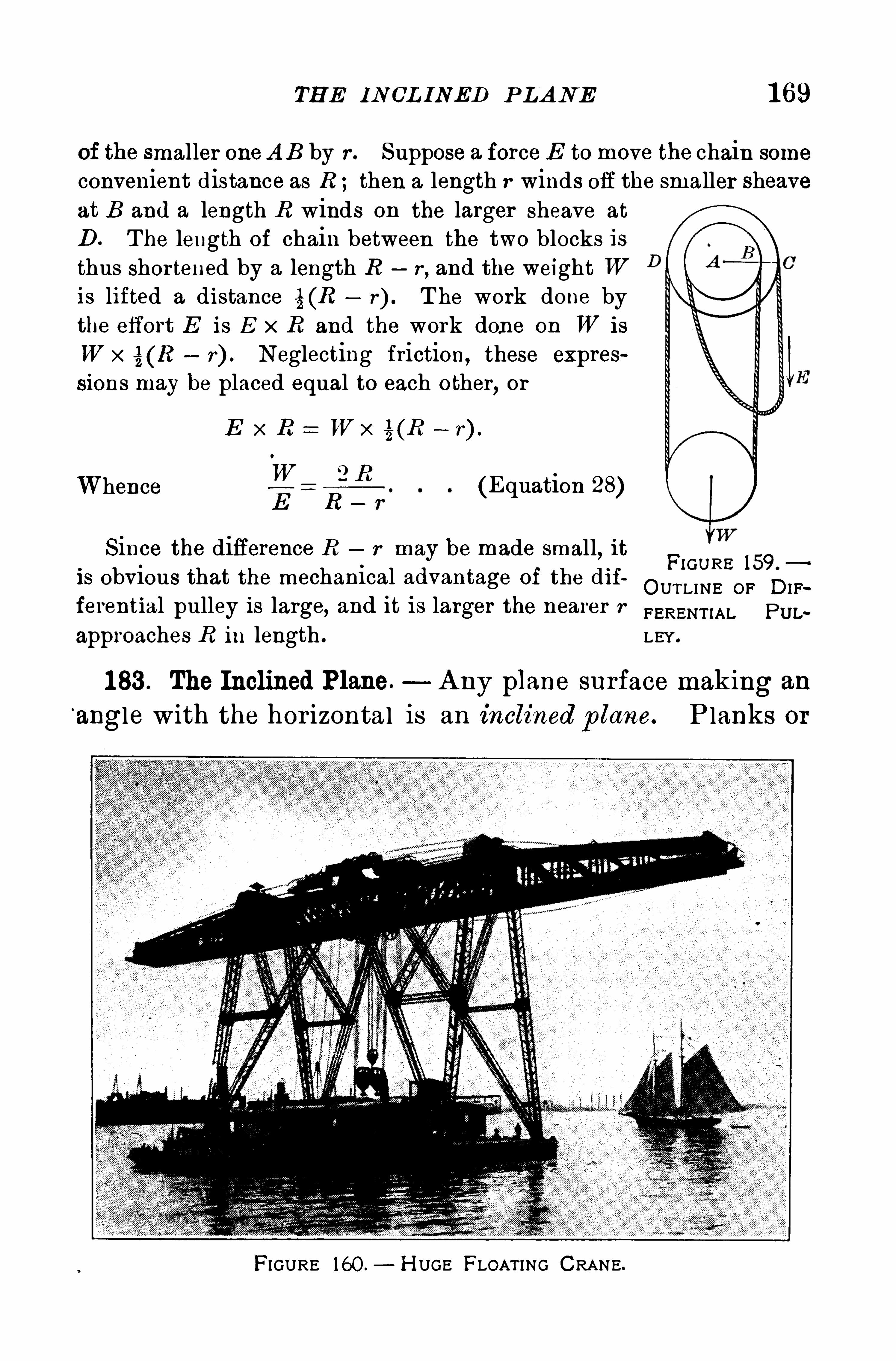
TH E IN CL INED P LANE 1 69
of the smaller oneA B by r . Suppose a force E to move the chain some
convenient distance as R ; then a length r winds Off the smaller sheaveat B and a length R winds on the larger sheave at
D . T he length of chain between the two blocks isthus shor tened by a length R r
, and the weight Wis lifted a distance % (R r) . T he work done bythe effort E is E x R and the work done on W is
W x r) . Neglecting friction, these expressions may be placed equal to each other
, or
E x R : W x % (R —r) .
W Q RhW ence
E R —r(Equation 28)
Since the difference R r may be made small, itis obvious that the mechanical advanta e of the dif
F’GU RE 159‘gOUTLINE OF DIF
ferential pulley is large, and i t i s larger the nearer r FERENTIA L pm ,
approaches R in length . LEY .
1 83 . The Inclined Plane. A ny plane surface making an
angle with the hor izontal is an inclined p lane. P lanks or
FIGURE 160 .— H UGE FLOAT ING CRA NE.
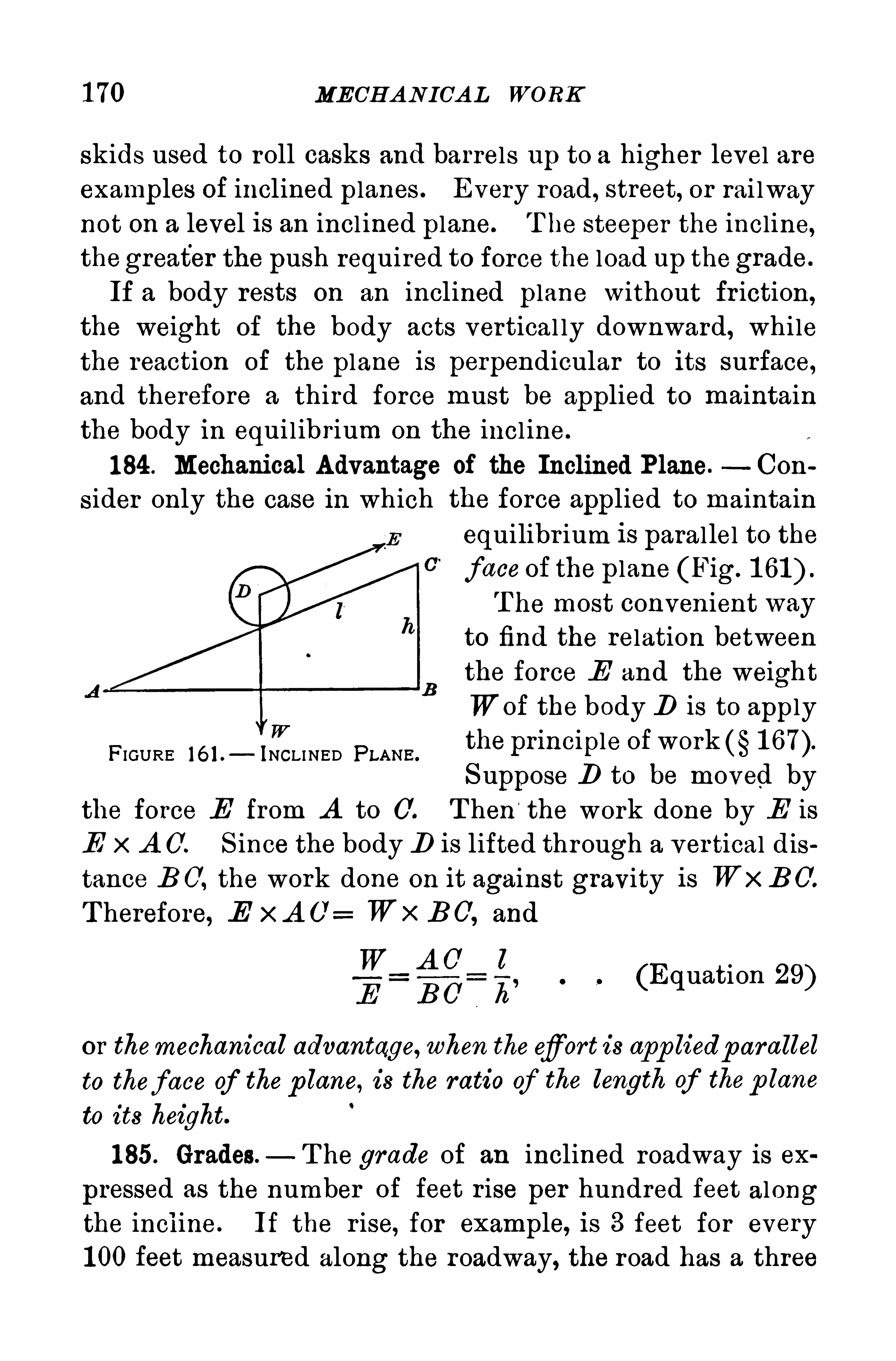
1 70 MECHANICAL WORK
skids used to roll casks and barrels up to a higher level areexamples of inclined planes . Every road , street, or rai lwaynot on a level is an incl ined plane. T he steeper the incline,thegreater the push required to force the load up thegrade.
If a body rests on an inclined plane without fr iction,
the weight of the body acts vertical ly downward, whilethe reaction of the plane is perpendicular to its surface,and therefore a third force must be applied to maintain
the body in equil ibrium on the incl ine.
1 84 . Mechanical Advantage of the Inclined Plane. Con
sider only the case in which the force applied to maintainequilibr ium is parallel to the
face of the plane (Fig.
T he most conven ient wayto find the relation betweenthe force E and the weight
Wof the body D is to applythe principle ofworkS uppose D to be moved by
the force E from A to 0 . T hen“
the work done by E is
E x A 0 . S ince the body D is lifted through a ver tical dis
tance B C, the work done on it against gravity is WxB 0.
T herefore, E xA O: Wx DO, and
W A C' l
E B O h’
FIGURE 16 1 . INCLI NED PLANE.
(Equation 29)
or themechanical advantage, when the efiort is app liedp arallel
to theface of the p lane, is the ratio of the length of thep lane
to its height.
1 85. Grades. T he grade of an inclined roadway is ex
pressed as the number of feet r ise per hundred feet alongthe incline. If the r ise, for example, is 3 feet for every
1 00 feet measured along the roadway, the road has a three
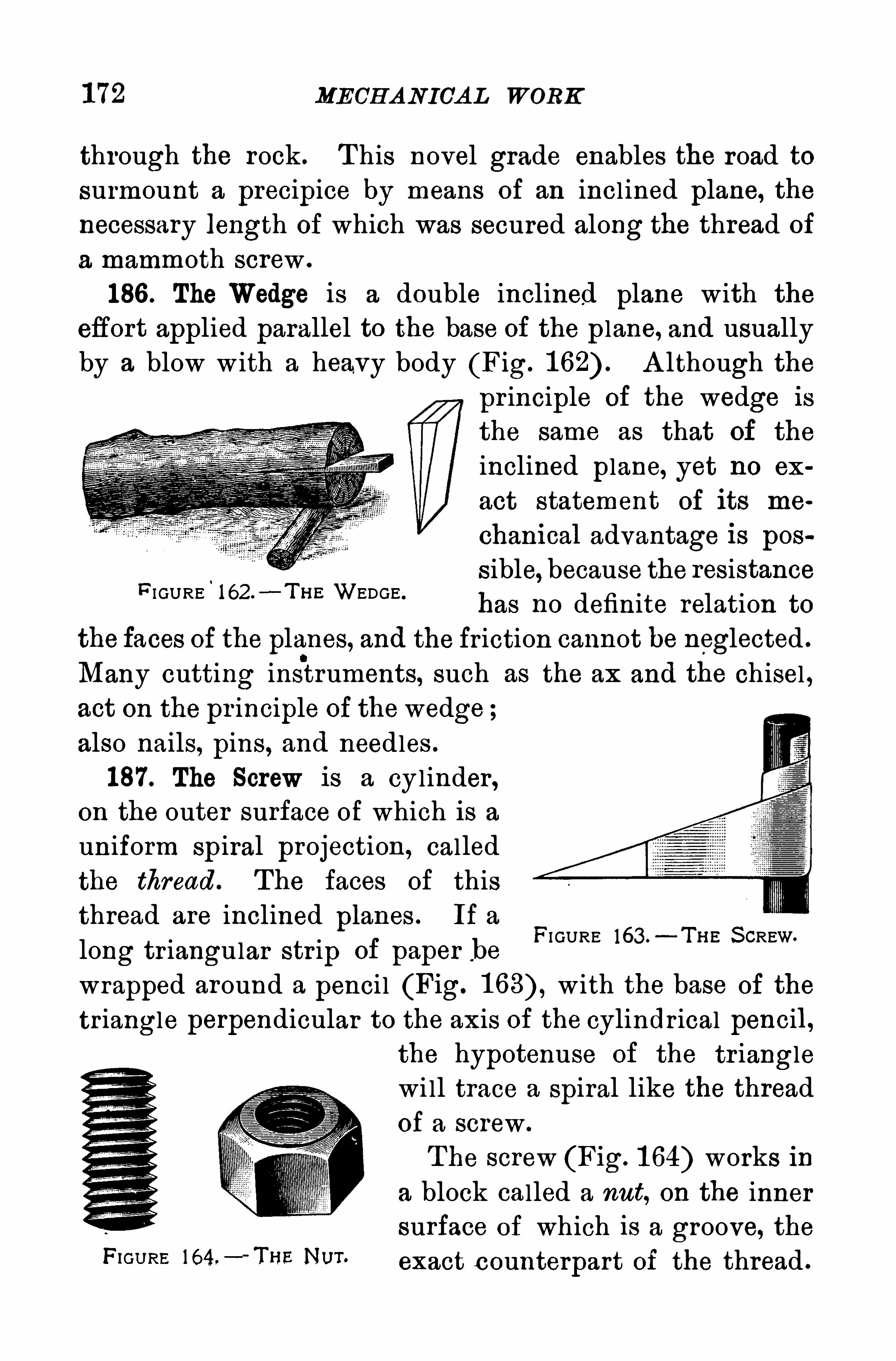
MECH A N ICA L WORK
through the rock . T his novel grade enables the road tosurmount a precipice by means of an incl ined plane, thenecessary length of which was secured along the thread of
a mammoth screw .
186 . The Wedge is a double inclined plane with the
effort applied parallel to the base Of the plane, and usually
by a blow w ith a heavy body (Fig. A lthough the
pr inciple of the wedge is
the same as that of the
inclined plane, yet no ex
act statement of its me
chanical advantage is pos
sible, because the resistancehas no definite relation to
the faces of the planes, and the friction cannot be neglected .
Many cutting instruments, such as the ax and the chisel ,act on the pr inciple of the wedge ;also nails, pins, and needles .
187. The Screw is a cylinder,on the outer surface of which is a
uniform spiral projection, called
the thread . The faces of this
thread are inclined planes . If a
long tr iangular str ip of paper _be
wrapped around a penci l (Fig. with the base of the
tr iangle perpendicular to the axis of the cylindrical pencil,the hypotenuse of the tr ianglewi ll trace a spiral like the thread
Of a screw .
T he screw (Fig. 1 64) works in
a block called a nut, on the inner
surface of which is a groove, theF‘GU RE 164'
- ‘ THE NU“ exact c ounterpart of the thread .
F I GURE 162.—T I-IE WEDGE .
FI GURE 163 .—T H E S CREW.
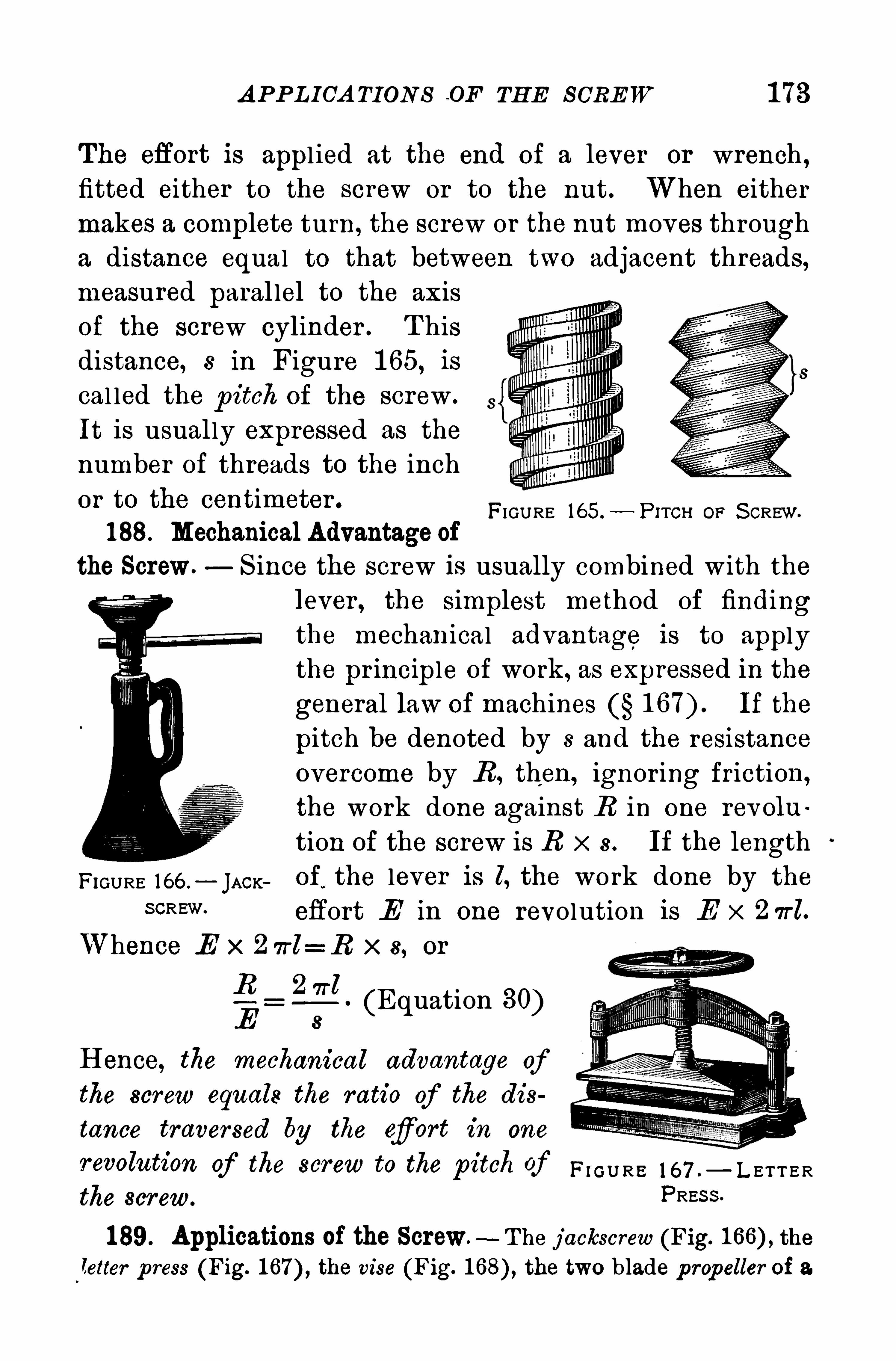
A P P L ICA TION S O F TH E S CREW 1 73
The efiort is appl ied at the end of a lever or wrench ,
fitted either to the screw or to the nut. When either
makes a complete turn, the screw or the nut moves through
a distance equal to that between two adjacent threads,measured paral lel to the axisof the screw cylinder . T hisdistance, 8 in Figure 1 65, is
cal led the p itch of the screw .
It is usual ly expressed as the
number of threads to the inch
or to the centimeter .
188. Mechanical Advantage of
the Screw. S ince the screw is usually combined with the
lever , the simplest method of findingthe mechanical advantage is to applythe pr inciple of work, as expressed in the
general law of machines If the
pitch be denoted by s and the resistance
overcome by R , then, ignor ing friction,
the work done against R in one revolu
tion of the screw is R x 8. If the length
FIGURE 166 .
—JACK of
,the lever is l, the work done by the
FI GURE 165.
—P ITCR OF S CREW.
SCREW effort E in one revolution is E x 2 7rl.
Whence E x 2 7rl= R x s, or
(Equation 30)
H ence, the mechanical advantage ofthe screw equals the ratio of the dis
tance traversed by the efiort in one
revolution of the screw to the pitch of m RE 1 67 ,_ L ET T E R
the screw.PRES S ”
189. Applications of the Screw.—T he jackscrew (Fig. the
letter p ress (Fig. 1 67 the vise (Fig. the two blade p ropeller of a.
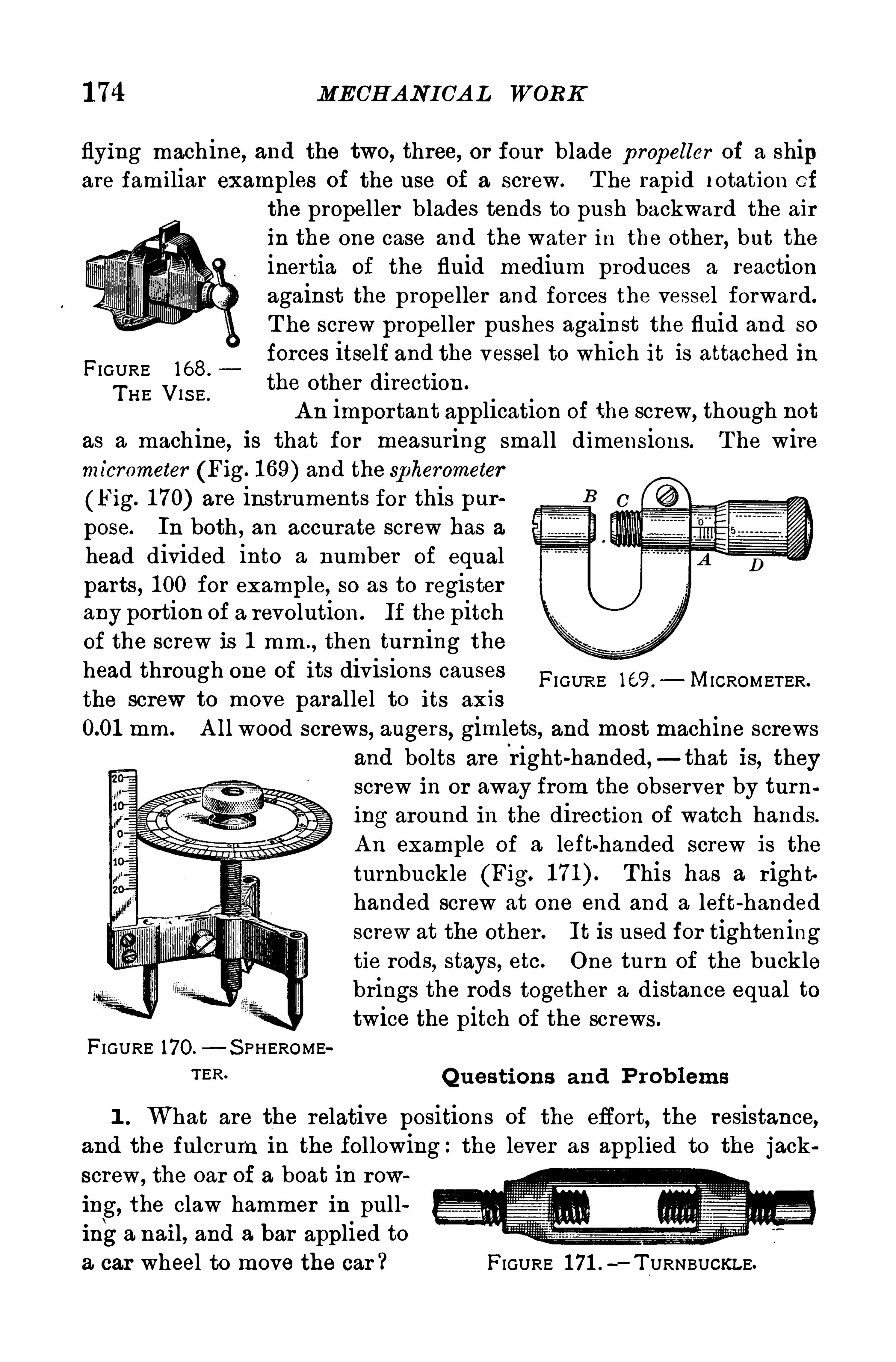
1 74 MECHANICAL WORK
flying machine, and the two, three, or four blade p ropeller of a shipare familiar examples of the use of a screw. T he rapid rotation Of
the propeller blades tends to push backward the air
in the one case and the water in the other , but theinertia of the fluid medium produces a reactionagainst the propeller and forces the vessel forward.
T he screw propeller pushes against the fluid and so
forces itself and the vessel to which it is attached inFIGURE 1 68.
T H E V1S E.
the other di rection .
A n important application of the screw, though notas a mach ine, is that for measuring small dimensions. T he wiremicrometer (Fig. 1 69) and the spherometer
(Fig. 1 70) are instruments for this purpose. In both , an accurate screw has ahead divided into a number of equalparts, 1 00 for example, so as to registerany portion of a revolution . If the pitchof the screw is 1 mm .
, then turning thehead through one of its divisions causesthe screw to move parallel to its axis
mm. A ll wood screws, angers, gimlets, and most machine screwsand bolts are
'
right-handed,—that is, theyscrew in or away from the observer by turning around in the direction of watch hands.
A n example of a left handed screw is the
turnbuckle (Fig. This has a r igh thanded screw at one end and a left-handedscrew at the other . It is used for tighteningtie rods, stays , etc. One turn of the bucklebrings the rods together a distance equal totwice the pitch of the screws .
FIGURE 170.
—S PHEROMETER Q uestions and P rob lems
FI GUR E 169 . MICROMETER.
1 . What are the relative positions of the effort, the resistance,and the fulcrum i n the following:the lever as applied to the jackscrew , the oar Of a boat in row
ing, the claw hammer in pullinga nail, and a bar applied toa car wheel to move the car ? FIGURE 1 71 .
—T URNBUCKLE.
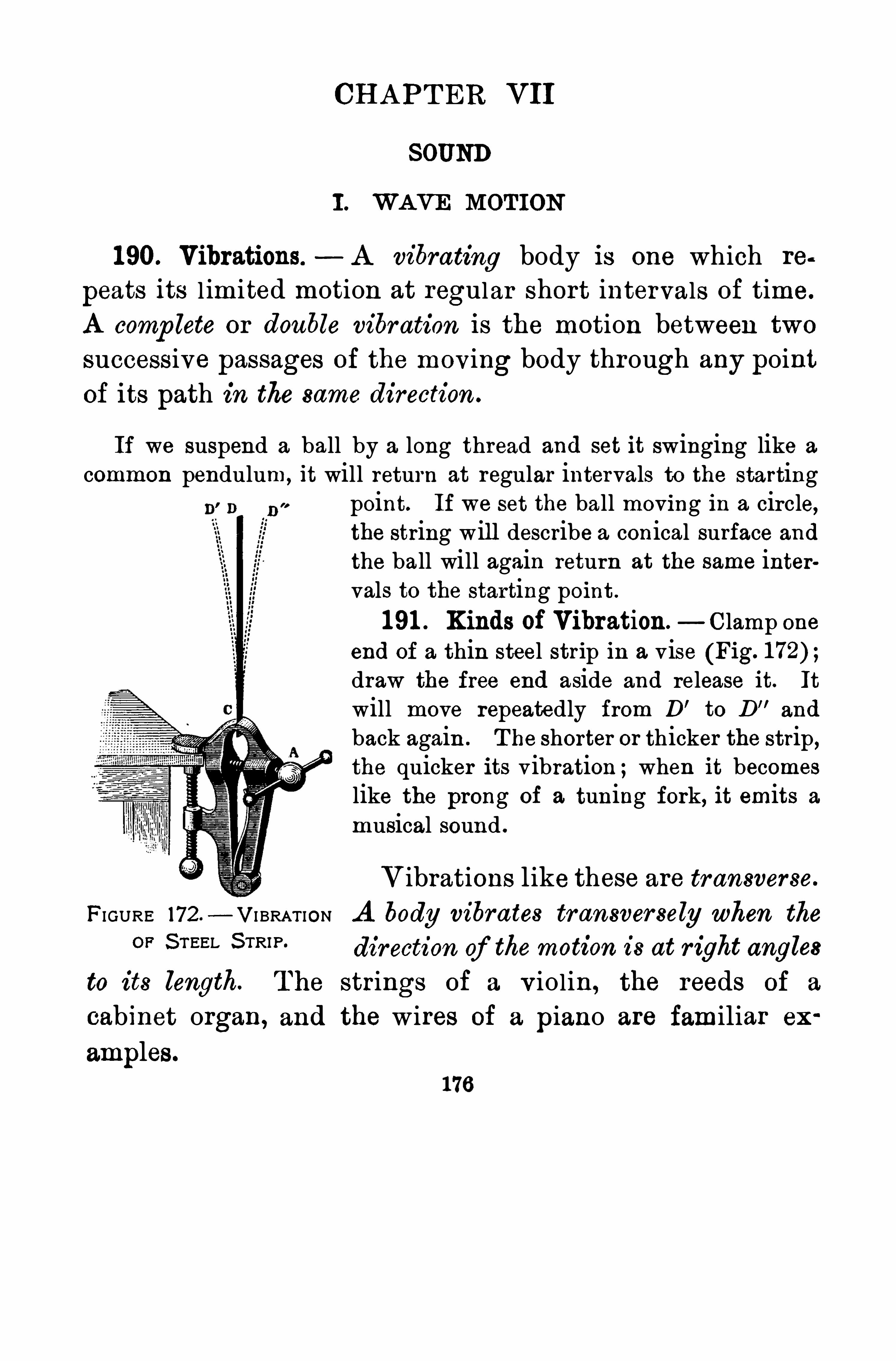
CH A PT ER VII
SOUND
I . WAVE MOTION
1 90. Vibrations. A vibrating body is one which re
peats its l imited motion at regular short intervals of time.
A comp lete or double vibration is the motion between two
successive passages of the moving body through any pointof its path in the same direction .
If we suspend a ball by a long thread and set it swinging like a
common pendulum,it will return at regular intervals to the starting
point. If we set the ball moving in a circle,the string will describe a conical surface and
the ball will again return at the same intervals to the starting point .
1 91 . Kinds of Vibration.—Clamp one
end of a thin steel strip in a vise (Fig.
draw the free end aside and release it. It
will move repeatedly from D’to D"
and
back again . T he shorter or thicker the strip ,the quicker its vibration ;when it becomes
like the prong of a tuning fork, it emits a
musical sound .
Vibrations like these are transverse.
FIGURE 172 — VI BRAT ION A body vibrates transversely when the
OF S TEEL 5mm direction of themotion is at r ight angles
to its length. The strings of a v iolin, the reeds of a
cabinet organ, and the wires of a piano are familiar ex
amples.
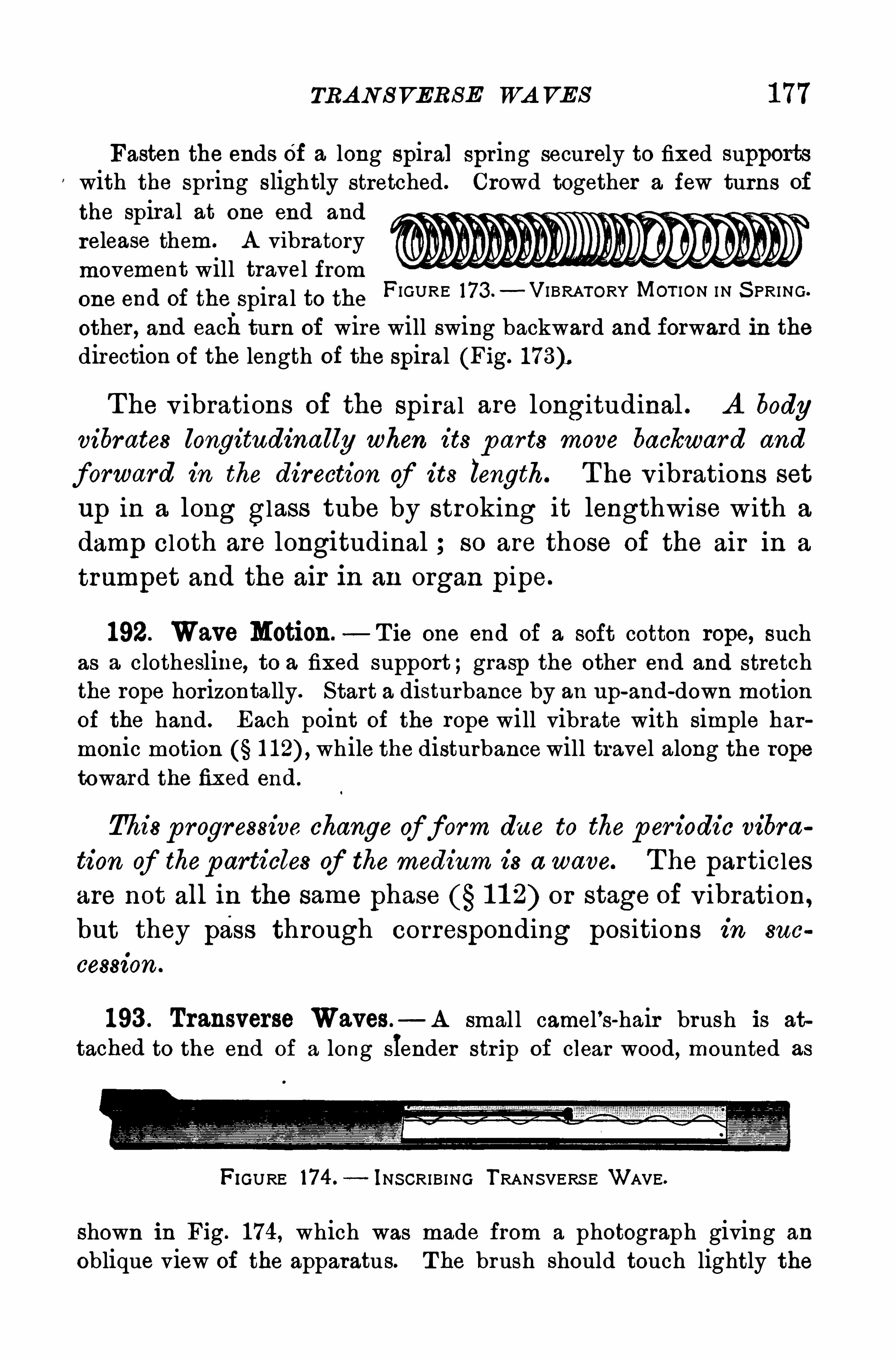
TRA N S VERS E WA VES 1 77
Fasten the ends Of a long spiral spring securely to fixed supportswith the spring slightly stretched. Crowd together a few turns of
the spiral at one end and
release them. A vibratorymovement will travel fromone end of the spiral to theother , and each turn of wire will swing backward and forward in thedirection of the length of the spiral (Fig.
FIGURE 173 .—VIBRATORY MOT ION IN S PRING.
The v ibrations Of the Spiral are longitudinal . A body
vibrates longitudinally when its p ar ts move backward and
forward in the direction of its length. T he v ibrations set
up in a long glass tube by stroking it lengthwise with a
damp cloth are longitudinal so are those of the air in a
trumpet and the air in an organ pipe.
192. Wave Motion.— T ie one end of a soft cotton rope, such
as a clothesline, to a fixed support ;grasp the other end and stretchthe rope horizontally. Start a disturbance by an up
-and-down motionOf the hand . Each point of the rope will vibrate with simple harmonic motion while the disturbance will travel along the rope
toward the fixed end.
This p rogressive change of form due to the p er iodic vibra
tion of thep articles of the medium is a wave. T he particlesare not all in the same phase 1 1 2) or stage of v ibration ,
but they pass through corresponding positions in suc
cession .
1 93 . Transverse Waves — A smal l camel’s-hair brush is at
tached to the end Of a long slender strip of clear wood, mounted as
FIGURE i74 .—INS CRIBING TRANSVERS E WAVE.
shown in Fig. 1 74, which was made from a photograph giving an
Oblique view Of the apparatus. T he brush should touch lightly the
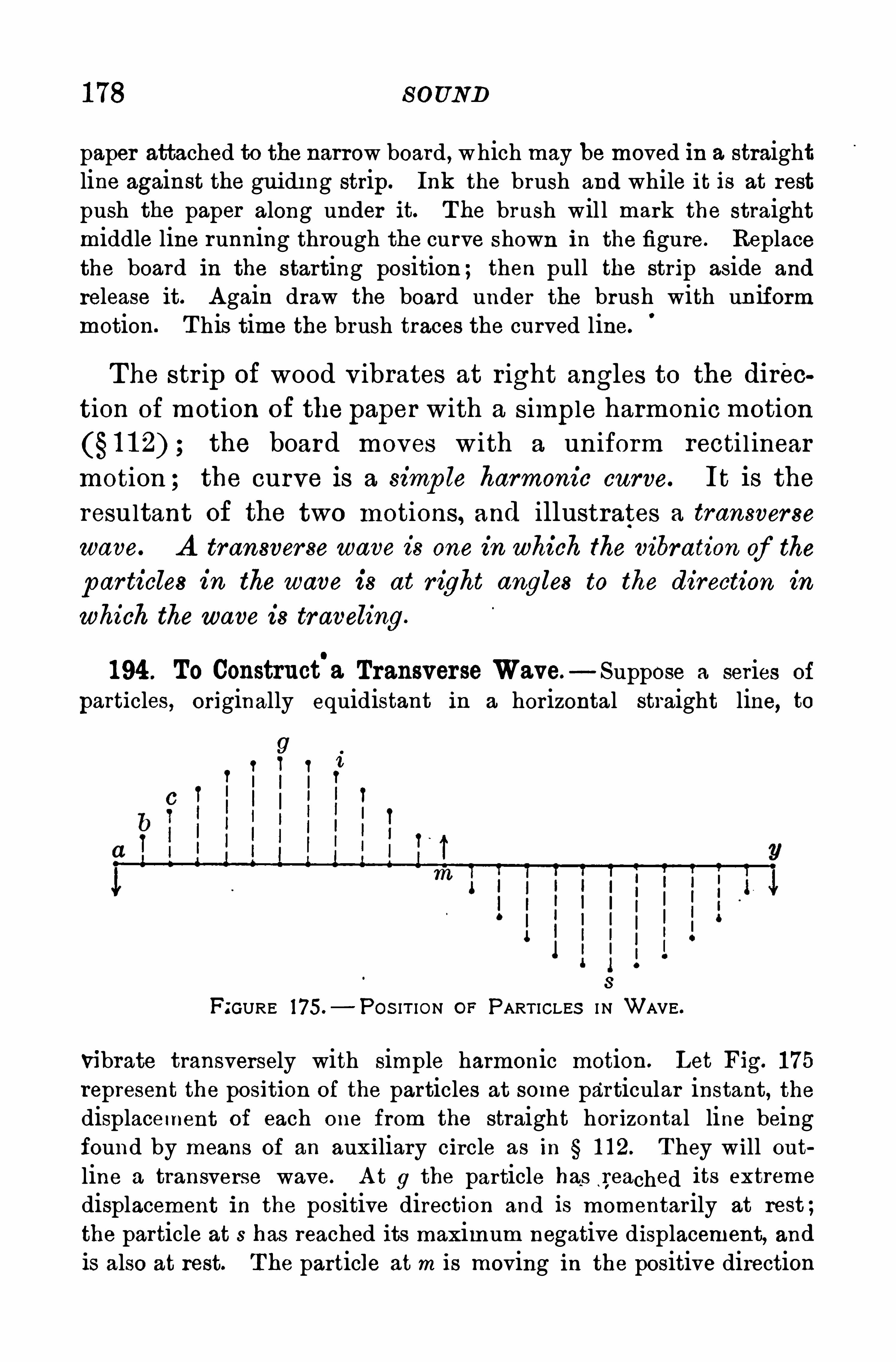
1 78 S OUND
paper attached to the narrow board , which may be moved in a straightline against the gui di ng strip. Ink the brush and while it is at rest
push the paper along under it. T he brush will mark the straightmiddle line running through the curve shown in the figure. Replacethe board in the starting position ; then pull the strip aside and
release it. A gain draw the board under the brush with uniformmotion. T his time the brush traces the curved line.
The str ip of wood v ibrates at right angles to the dircc
tion of motion of the paper with a simple harmonic motionthe board moves w ith a uniform recti l inear
motion ; the curve is a simp le harmonic curve. It is the
resultant of the two motions, and illustrates a transverse
wave. A transverse wave is one in which the vibration of the
particles in the wave is at r ight angles to the direction in
which the wave is traveling.
1 94 . To Construct'
a Transverse Wave.—Suppose a series of
particles, originally equidistant in a horizontal straight line, to
8
FIGURE 175.— POS IT ION or PART ICLES I N WAVE .
vibrate transversely with simple harmonic motion. Let Fig. 1 75
represent the position of the particles at some particular instant, thedisplacement of each one from the straight hor izontal line beingfound by means of an auxiliary circle as in 1 1 2. T hey will outline a transverse wave. A t 9 the particle has ,reached its extreme
displacement in the positive direction and is momentarily at rest;
the particle at s has reached its maximum negative displacement, and
is also at rest. T he particle at m is moving in the positive direction
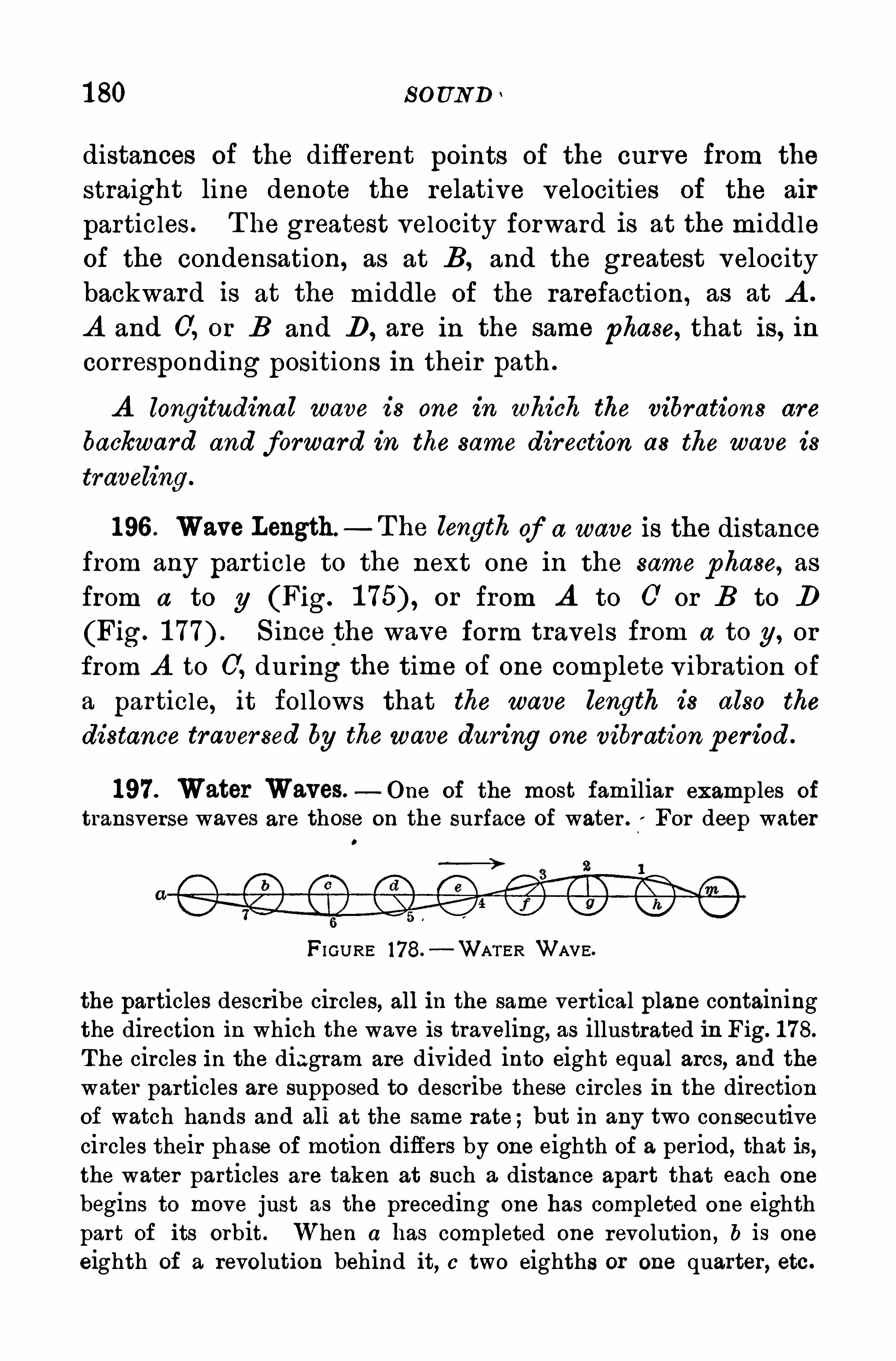
1 80 soUND
distances of the different points of the curve from the
straight line denote the relative velocities of the air
particles . T he greatest velocity forward is at the middle
of the condensation, as at B, and the greatest velocity
backward is at the m iddle of the rarefaction, as at A .
A and 0, or B and D , are in the same phase, that is, in
corresponding positions in their path .
A longitudinal wave is one in which the vibrations are
backward and forward in the same direction as the wave is
1 96 . Wave Length —T he length of a wave is the distancefrom any particle to the next one in the same phase, as
from a to g (Fig. or from A to 0 or B to D
(Fig. S ince the wave form travels from a to g, or
from A to 0, during the time of one complete v ibration of
a particle, it follows that the wave length is also the
distance traver sed by thewave during one vibration per iod .
1 97. Water Waves.—One of the most familiar examples of
transverse waves are those on the surface of water . For deep water0
FI GURE 178.—WA’I‘ER WAVE.
the particles describe circles, all in the same vertical plane containingthe direction in which the wave is traveling, as illustrated in Fig. 1 78.
The circles in the diagram are divided into eight equal arcs, and thewater particles are supposed to describe these circles in the directionof watch hands and all at the same rate;but in any two consecutivecircles their phase of motion diifers by one eighth of a period, that is,the water particles are taken at such a distance apart that each one
begins to move just as the preceding one has completed one eighthpar t of its orbit. When a has completed one revolution, b is one
eighth of a revolution behind it, c two eighths or one quarter, etc .
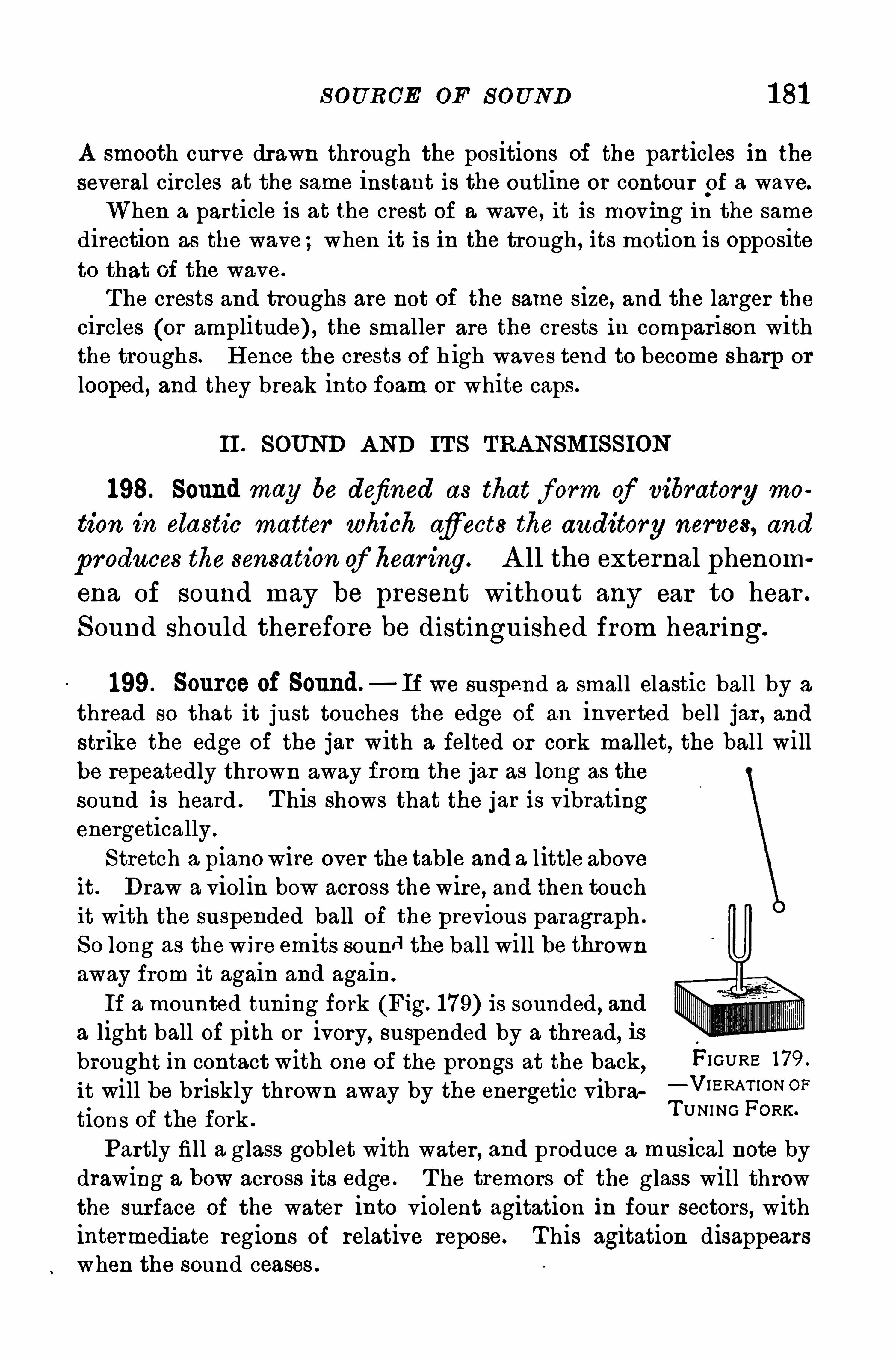
S OURCE OF S OUND 1 81
A smooth curve drawn through the positions of the particles in the
several circles at the same instant is the outline or contour p f a wave.
When a particle is at the crest of a wave, it is moving in the same
direction as the wave ;when it is in the trough , its motion is oppositeto that of the wave.
The crests and troughs are not of the same size, and the larger thecircles (or amplitude) , the smaller are the crests in comparison withthe troughs. H ence the crests of h igh waves tend to become sharp or
looped, and they break into foam or white caps.
II . SOUND AND IT S TRA NSMISS ION
198. Sound may be defined as that f orm of vibratory mo
tion in elastic matter which afiects the auditory nerves, and
p roduces the sensation of hear ing. A ll the external phenom
ena of sound may be present without any ear to hear .
S ound should therefore be distinguished from hear ing.
199. Source of Sound.—If we suspend a small elastic ball by a
thread so that it just touches the edge of an inverted bell jar , andstrike the edge of the jar with a felted or cork mallet, the bal l willbe repeatedly thrown away from the jar as long as the
sound is heard . T his shows that the jar is vibratingenergetically .
Stretch a piano wire over the table and a little aboveit. Draw a viol in bow across thewire, and then touchit with the suspended ball of the previous paragraph .
So long as thewire emits sound the ball will be thrownaway from it again and again .
If a mounted tuning fork (Fig. 1 79) is sounded, anda light ball of pith or ivory, suspended by a thread, isbrought in contact with one of the prongs at the back
,FI GURE 179 .
it will be briskly thrown away by the energetic vibra “ V‘ERAT ION OF
tions of the fork .
T UNING FORK
Partly fill a glass goblet with water, and produce a musical note by
drawing a bow across its edge . T he tremors of the glass will throwthe surface of the water into violent agitation in four sectors, withintermedi ate regions of relative repose. T his agitation disappearswhen the sound ceases .
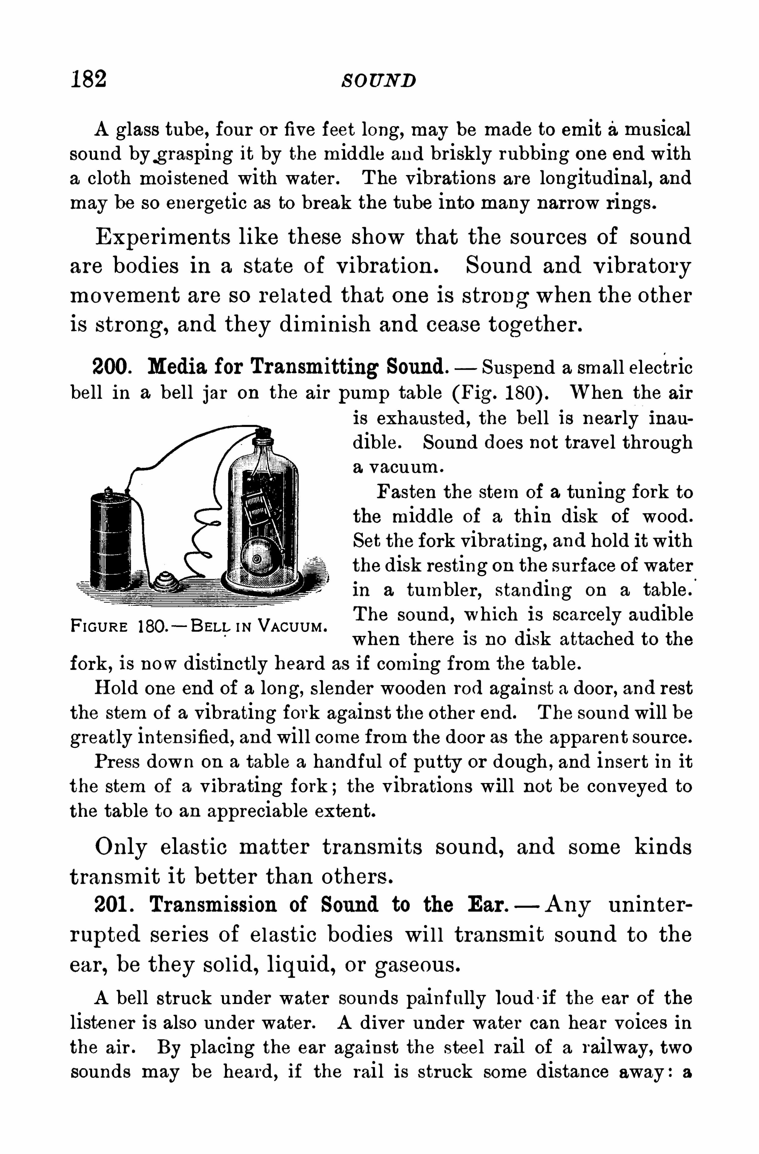
182 S OUND
A glass tube, four or five feet long, may be made to emit amusicalsound byg rasping it by the middle and briskly rubbing one end witha cloth moistened with water . T he vibrations are longitudinal, andmay be so energetic as to break the tube into many narrow rings .
Exper iments like these show that the sources of soundare bodies in a state of vibration . Sound and v ibratorymovement are so related that one is strong when the otheris strong, and they diminish and cease together .
200. Media for Transmitting Sound. Suspend a small electricbell in a bell jar on the air pump table (Fig. When the air
is exhausted , the hell is near ly inaudible. Sound does not travel througha vacuum .
Fasten the stem of a tuning fork tothe middle of a th in disk of wood .
Set the fork vibrating, and hold it withthe disk resting on the surface of waterin a tumbler , standing on a table.
T he sound , which is scarcely audiblewhen there is no disk attached to the
fork , is now distinctly heard as if coming from the table.
H old one end of a long, slender wooden rod against a door , and restthe stem of a vibrating fork against the other end. T he sound will begreatly intensified , and will come from the door as the apparent source.
Press down on a table a handful of putty or dough , and insert in itthe stern of a vibrating fork ;the vibrations will not be conveyed tothe table to an appreciable extent.
FI GURE 180.—BEI. I, I N VACUUM .
Only elastic matter transmits sound, and some kinds
transm it it better than others .
201 . Transmission of Sound to the Ear .—A ny uninter
rupted ser ies of elastic bodies wi l l transm it sound to the
ear , be they solid,liquid, or gaseous .
A bell struck under water sounds painfully loud -if the ear of the
listener is also under water . A diver under water can hear voices inthe air . By placing the ear against the steel rail of a railway, twosounds may be heard , if the rail is struck some distance away:a
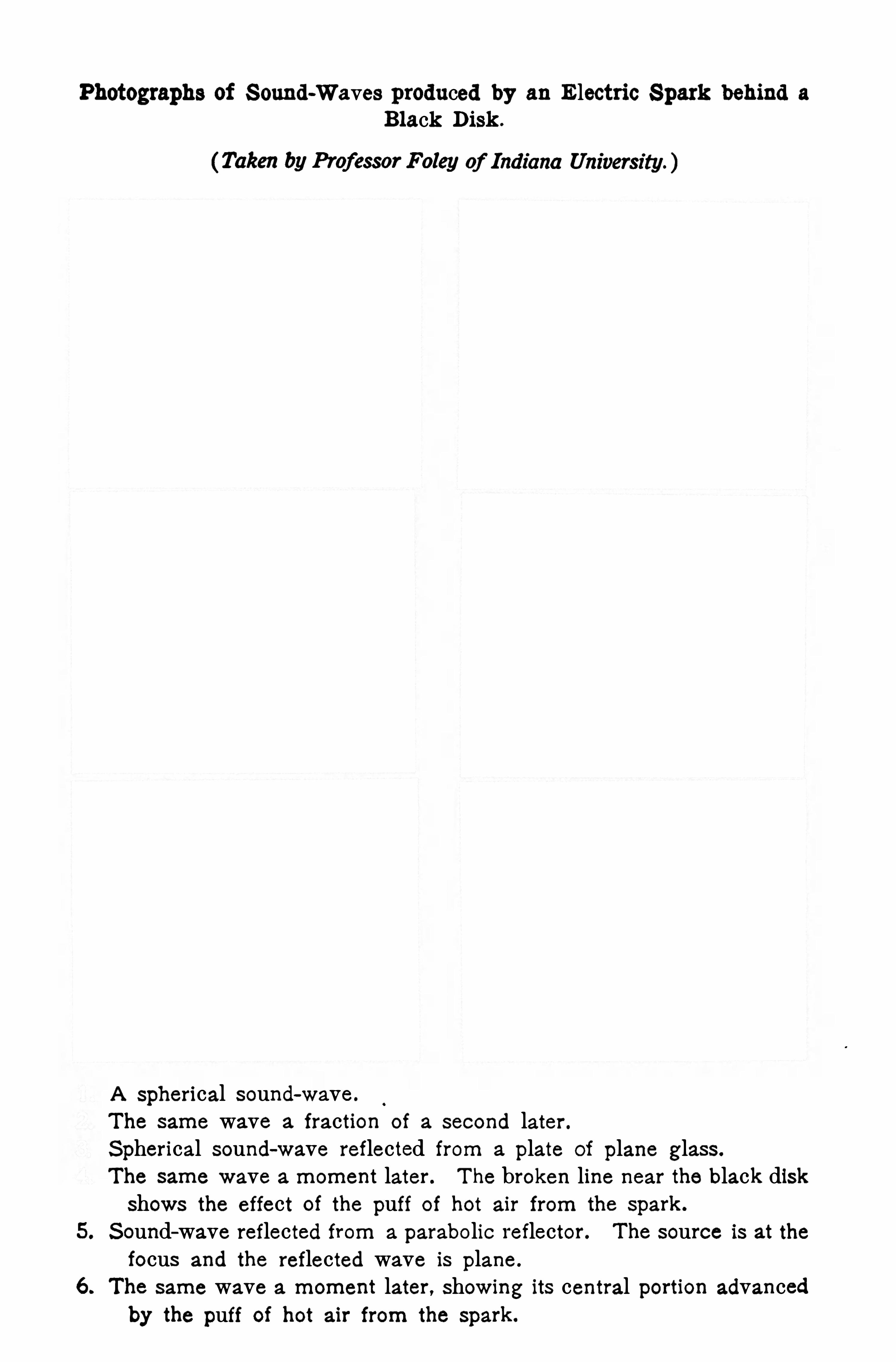
Photographs of S ound-Waves produced by an Electric S park behind a
Black Disk .
(Taken by Professor Foley of Indiana University . )
A Spherical sound-wave .
The same wave a fraction of a second later .
S pherical sound-wave reflected from a plate of plane glass .
The same wave a moment later . T he broken line near the black diskshows the effect Of the puff of hot air from the spark.
5. S ound-wave reflected from a parabolic reflector . The source is at thefocus and the reflected wave is plane .
6 . The same wave a moment later , Showing its central portion advancedby the puff of hot air from the spark.
MOTION OF TH E P A R TICLES OF A WA VE 1 83
louder one through the rails and then another through the air . The
faint scratching of a pin on the end of a long stick of timber, or theticking of a watch held against it, may be heard very distinctly if theear is applied to the other end .
The earth conducts sound so well that the stepping of a horse may
be heard by applying the ear to the ground. T his is understood bythe Indians . T he fir ing of a cannon at least 200 miles away may be
heard in the same way. T he report of a m ine blast reaches a listenersooner through the earth than through the air .
T he great eruption of Krakatoa in 1 883 gave rise to giganticsound waves, which produced at a distance of 2000 miles a report
like the firing of heavy guns.
202. Sound Waves When a tuning fork or similarbody is set v ibrating, the disturbances produced in the
air about it are known as sound waves . T hey consist of a
ser ies of condensations and rarefactions succeeding each
other at regular intervals . Each particle of air v ibratesin a short path in the direction of the sound transmission .
Its v ibrations are longitudinal as distinguished from the
transverse v ibrations in water waves.
203 . Motion of the Particles of a Wave—T he motion of
the particles of the medium conveying sound is distinctfrom the motion of the sound wave. A sound wave iscomposed of a condensation followed by a rarefaction .
In the former the particles have a forward motion in thedi rection in which the sound is traveling ; in the latter
they have a backward motion, while at the same time bothcondensation and rarefaction travel steadily forward .
T he independence of thetwo motions is aptly illustrated by a field ofgrain across which waves excited by thewind are cour sing. Each stalkof grain is secur ely anchored to the ground
,while the wave sweeps
onward. T he heads of grain in front of the crest are r ising,while all
those behind the crest and extending to the bottom of the trough arefalling. T hey all sweep forward and backward
, not simultaneously,but in succession, while the wave itself travels continuously forward .
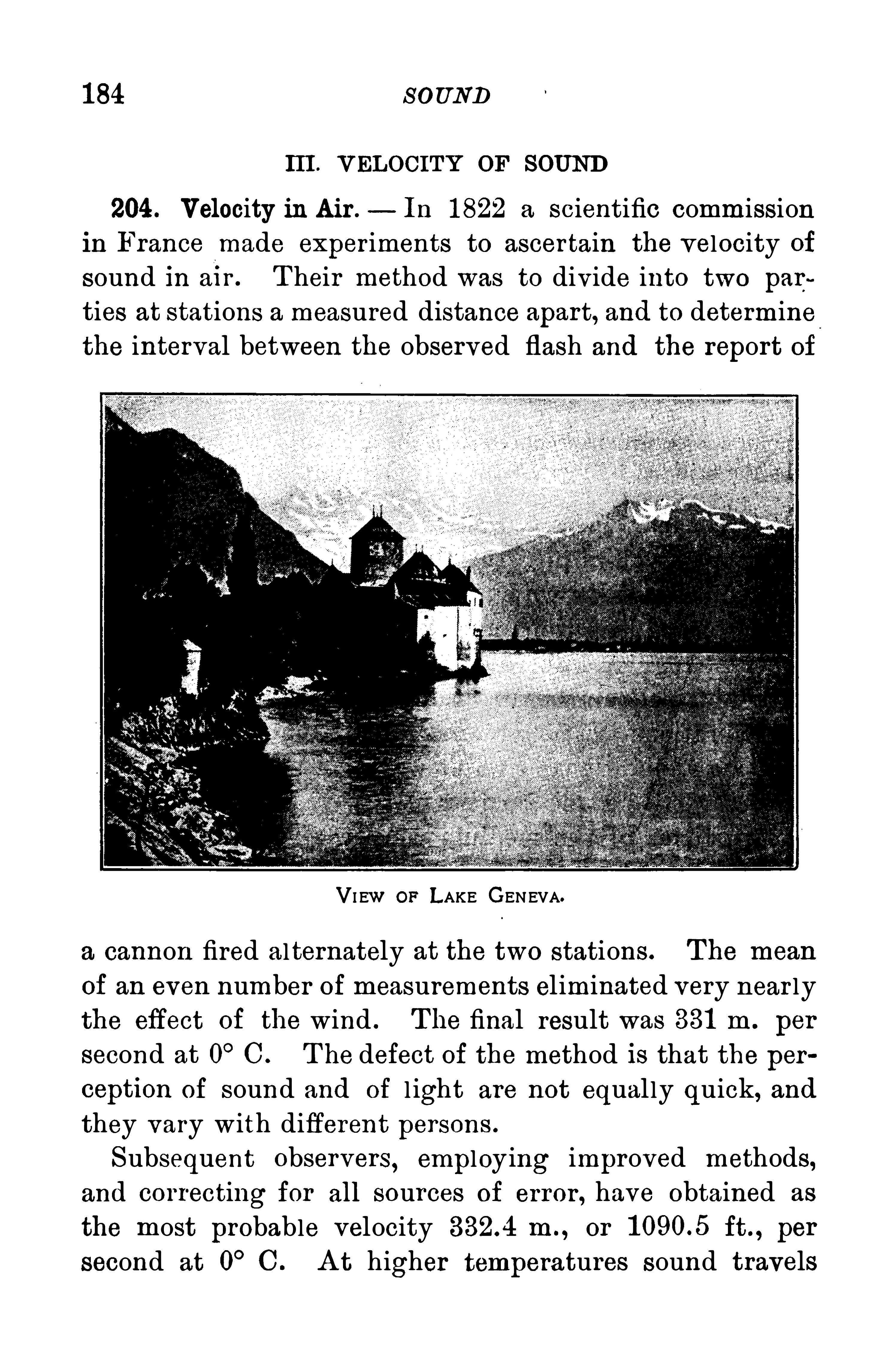
184 S OUND
III . VELOCITY OF SOUND
204 . Velocity in Air .
— In 1 822 a scientific commissionin France made exper iments to ascertain the velocity of
sound In an . T heir method was to divide into two par~
ties at stations a measured distance apart, and to determinethe interval between the observed flash and the report of
VI EW OF LAKE GENEVA.
a cannon fired alternately at the two stations. T he mean
of an even number of measurements eliminated very near lythe effect Of the wind . T he final result was 331 m . per
second at 0°C. T he defect of the method is that the per
ception of sound and of l ight are not equal ly quick, and
they vary with different persons .
Subsequent observers,employing improved methods,
and correcting for all sources of error , have obtained as
the most probable velocity in . , or ft . , per
second at 0°C . A t higher temperatures sound travels
1 86 S O UND
5 . A man sets his watch by a steam whistle wh ich blows at 12
o’clock .
.
T he whistle is mi . away and the temperature 1 5°C.
H ow.many seconds will the watch be in error ?
6 . A ball fired at a target was heard to strike after an interval of8 sec . T he distance of the target was ‘
1 mi. and the temperature of
the air 20° C. Whatwas the mean velocity of the ball ?
7 . T he distance between two points on a straight stretch of railway is 2565 m . A n observer listens at one Of these points and a
blow is struck on the rails at the other . If the temperature is 0° C. ,
what is the interval between the ar rival of the two sounds, one
through the rails and the other through the air ?
8 . A man watch ing for the report of a signal gun saw the flash2 sec. before he heard the report. If the temperature was 0
°C. and
the distance of the signal gun was 2225 ft .
, what was the velocity of
the wind ?9 . A shell fired at a target, distance half a mile, was heard to
strike it 5 sec. after leaving the gun . What was the average speedof the bul let
,the temperature of the air being 20° C. ?
IV . REFLECT ION OF SOUND
207 . Echoes.—A n echo is the r ep etition of a sound by re
flection from some distant surfaca A clear echo requires
a vertical reflecting surface, the dimensions of which are
large compared to the wave length of the sound . A cl iff,a wooded hil l , or the broad side of a large building may
serve'
as the reflecting surface. Its inequal ities must besmal l compared to the length of the incident sound wavesotherwise, the sound is diffused in all directions .
A loud sound in front of a tal l clifl an eighth of a mile
away wi l l be returned distinctly after about a second and
a sixth . If the reflecting surface is nearer than about fifty
feet, the reflected sound tends to strengthen the or iginal
one, as i llustrated by the greater distinctness of soundsindoors than in the open air . In large rooms where the
echoes produce a confusion of sounds the trouble may be


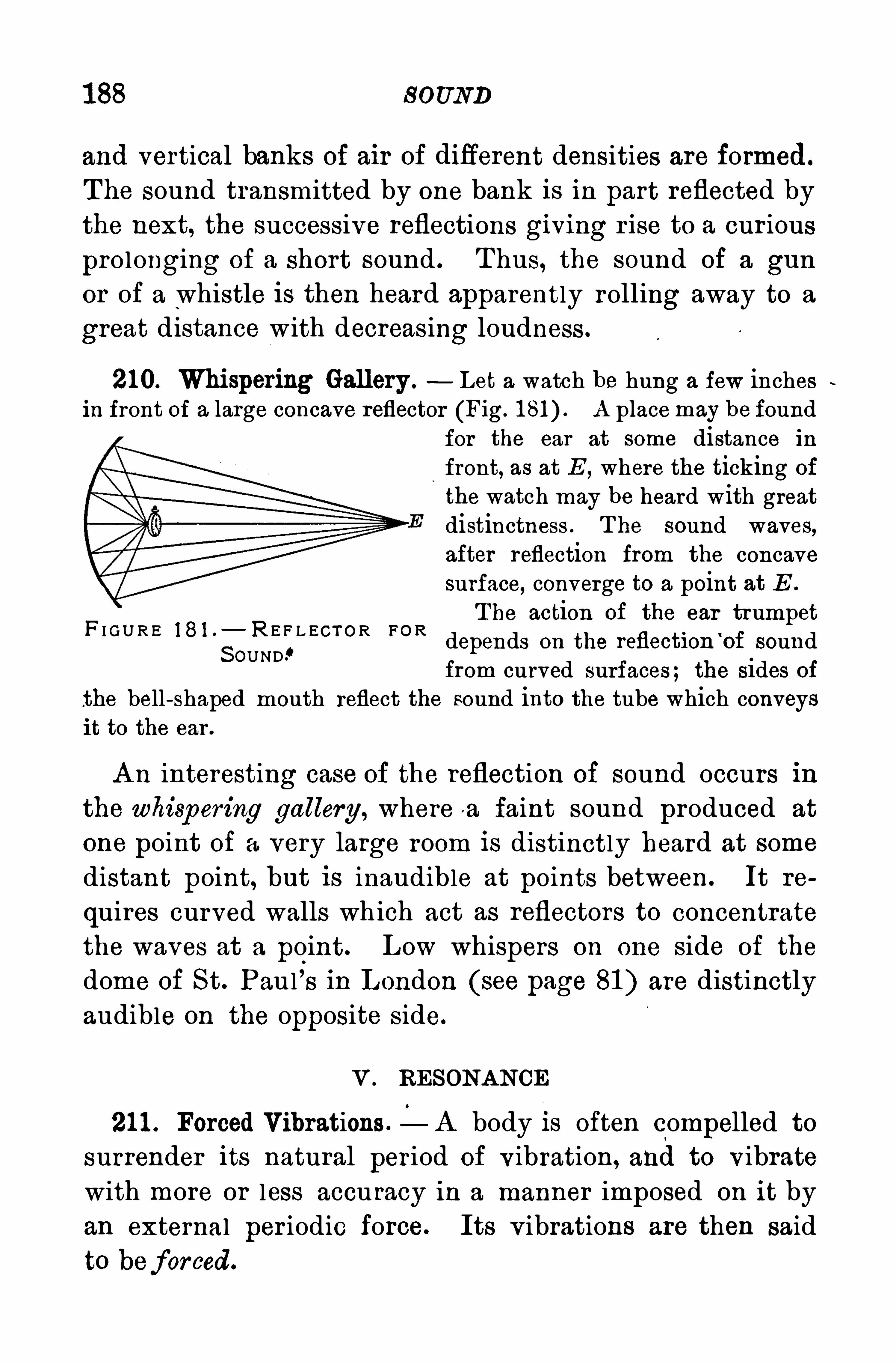
1 88 S OUND
and vertical banks of air of difierent densities are formed.
The sound transmitted by one bank is in part reflected bythe next, the successive reflections givmg r i se to a cur ious
prolonging of a short sound . T hus, the sound of a gun
or of a whistle i s then heard apparently rolling away to a
great distance with decreasing loudness.
210. Whispering Gallery . Let a watch be hung a few inchesin front of a large concave reflector (Fig. A placemay be found
for the ear at some distance in
front, as at E , where the ticking of
the watch may be heard with greatdistinctness . T he sound waves,after reflection from the concavesurface, converge to a point at E .
T he action of the ear trumpetdepends on the reflection
‘
of soundfrom curved surfaces; the sides of
the bell-shaped mouth reflect the sound into the tube which conveysit to the ear .
F I G U R E 1 8 1 . R E F L ECT O R FO R
S OUND!
A n interesting case of the reflection of sound occurs inthe whisp ering gallery, where a faint sound produced at
one point of a very large room is distinctly heard at some
distant point, but is inaudible at points between. It re
quires curved walls which act as reflectors to concentrate
the waves at a point . Low whispers on one side of the
dome of S t. Paul ’s in L ondon (see page 81 ) are distinctlyaudible on the opposite side.
V . RESONA NCE
21 1 . Forced Vibrations .- A body 18 often compelled to
surrender its natural per iod of v ibration, and to v ibrate
with more or less accu racy in a manner imposed on it by
an external per iodic force. Its v ibrations are then said
to beforced.
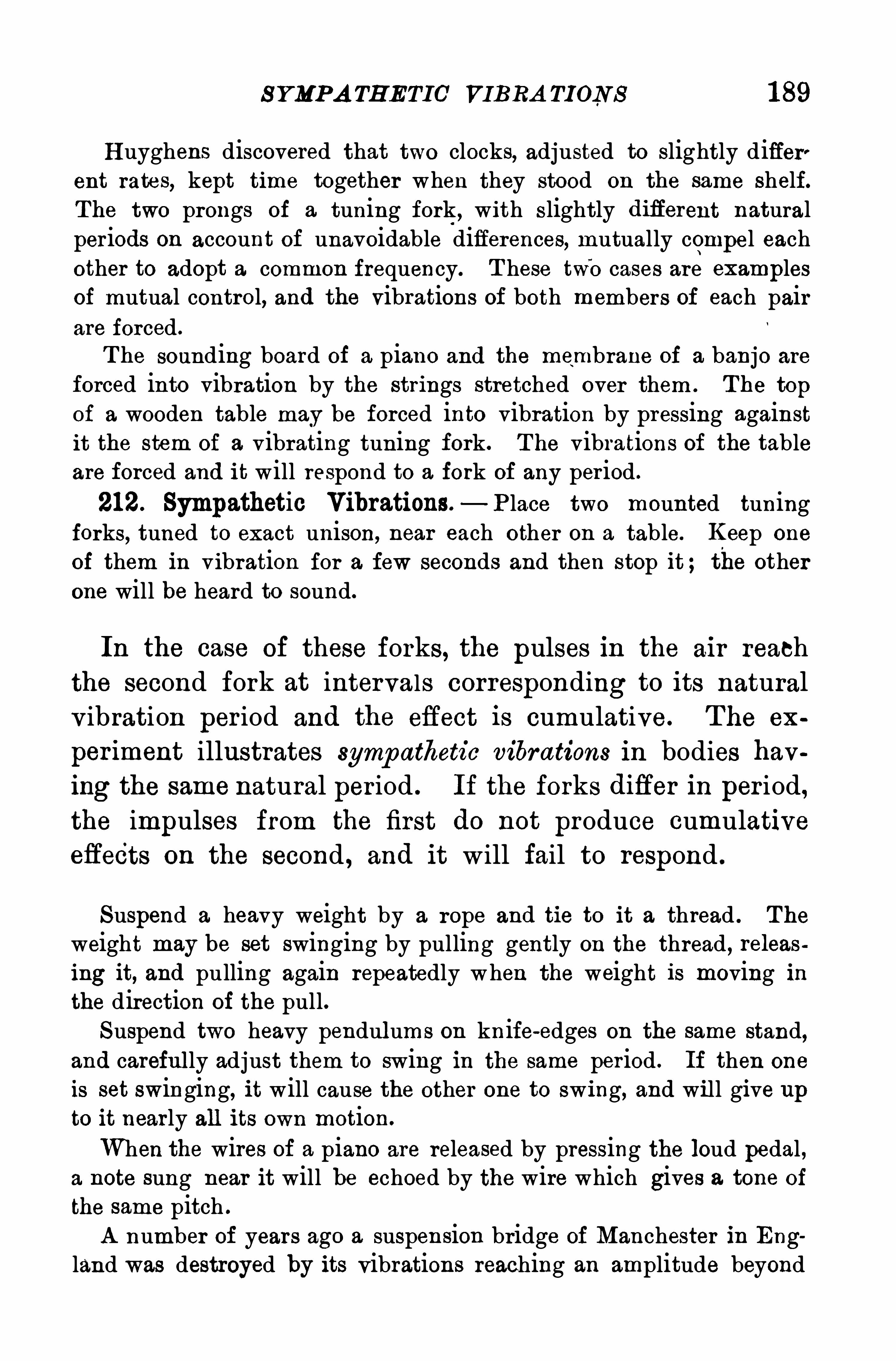
S YMPA TH ETIC' VIBRA TION S 1 89
H uyghens discovered that two clocks, adjusted to slightly differ'ent rates, kept time together when they stood on the same shelf.The two prongs of a tuning fork , with slightly diflerent naturalperiods on account of unavoidable differences, mutually compel eachother to adopt a common frequency. T hese twb cases are examplesof mutual control, and the vibrations of both members of each pairare forced.
T he sounding board of a piano and the membrane of a banjo are
forced into vibration by the strings stretched over them . T he top
of a wooden table may be forced into vibration by pressing againstit the stem of a vibrating tuning fork. T he vibrations of the tableare forced and it will respond to a fork of any per iod .
212. Sympathetic Vibrations.—P lace two mounted tuning
forks, tuned to exact unison, near each other on a table. Keep one
of them in vibration for a few seconds and then stop it ; the otherone will be heard to sound.
In the case of these forks, the pulses in the air reach
the second fork at intervals corresponding to its natural
v ibration per iod and the effect is cumulative. T he ex
per iment illustrates sympathetic vibrations in bodies having the same natural per iod . If the forks difler in per iod,the impulses from the first do not produce cumulativeeffects on the second , and it will fail to respond .
Suspend a heavy weight by a rope and tie to it a thread . T he
weight may be set swinging by pulling gently on the thread , releasing it, and pulling again repeatedly when the weight is moving inthe direction of the pull.Suspend two heavy pendulums on knife-edges on the same stand,
and careful ly adjust them to swing in the same period . If then one
is set swinging, it will cause the other one to swing, and will give upto it nearly all its own motion.
When the wires of a piano are released by pressing the loud pedal ,a note sung near it will be echoed by the wire which gives a tone of
the same pitch .
A number of years ago a suspension bridge of Manchester in England was destroyed by its vibrations reaching an amplitude beyond
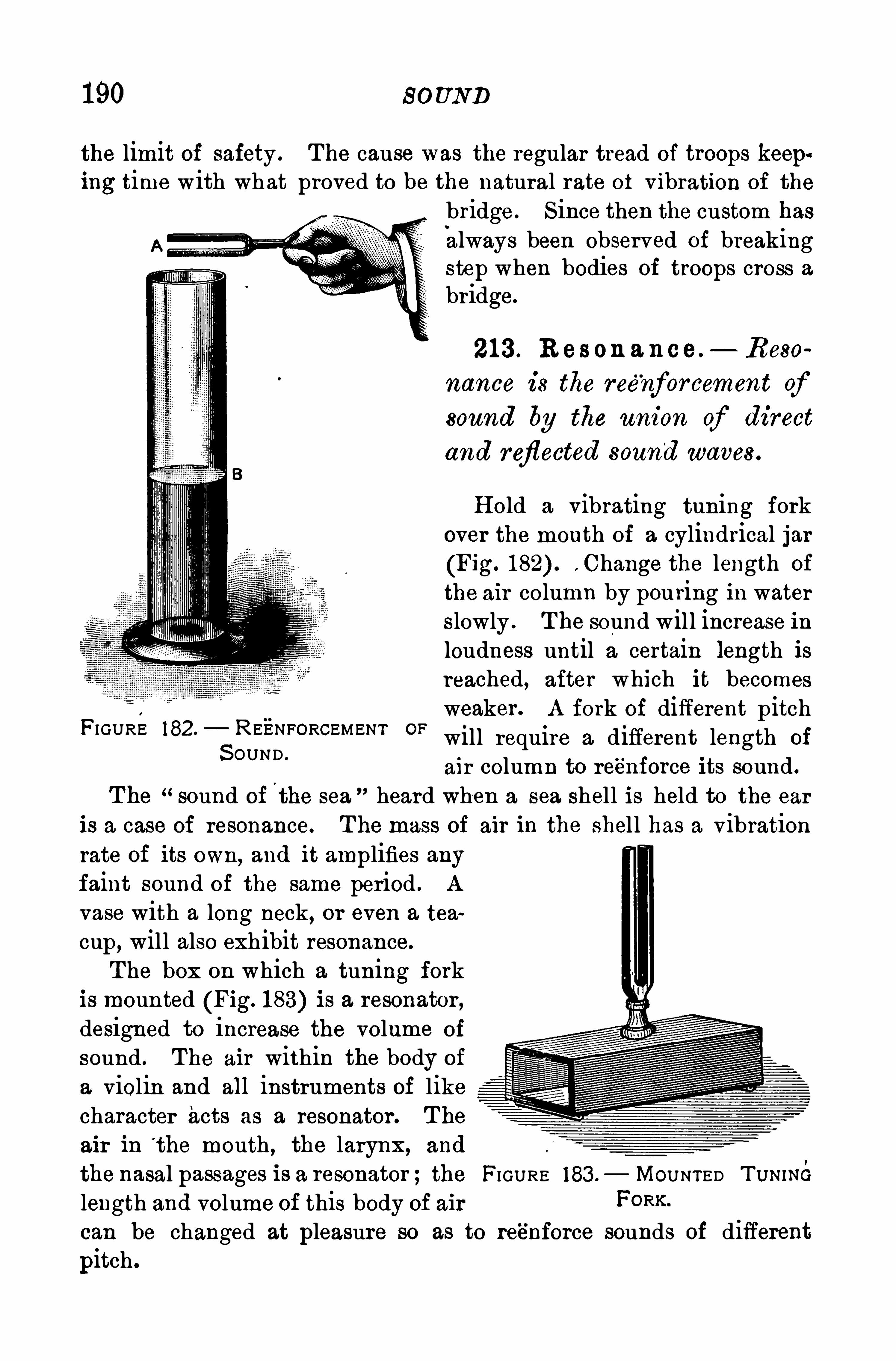
190 SOUND
the limit of safety . The cause was the regular tread of troops keep‘ing time with what proved to be the natural rate of vibration of the
bridge . S ince then the custom has
always been observed of breakingstep when bodies of troops cross abridge.
21 3 . R es on a nce. Reso
nance is the reenforcement ofsound by the union of direct
and reflected sound waves .
H old a vibrating tuning forkover the mouth of a cylindrical jar
(Fig. . Change the length of
the air column by pouring in waterslowly . T he sound will increase inloudness until a certain length isreached, after which it becomesweaker . A fork of different pitchwill require a different length of
air column to reenforce its sound .
T he “sound of the sea heard when a sea shell is held to the ear
is a case of resonance. T he mass of air in the shel l has a vibrationrate of its own, and it amplifies anyfaint sound of the same period . A
vase with a long neck, or even a tea
cup, will also exhibit resonance.
The box on which a tuning forkis mounted (Fig. 183) is a resonator ,
designed to increase the volume of
sound . The air within the body of
a violin and all instruments of likecharacter acts as a resonator. T he
air in t he mouth , the larynx, and
the nasal passages is a resonator ;the FI GURE 183 . MOUNTED T UNINO
length and volume of this body of air FORKcan be changed at pleasure so as to reenforce sounds of different
pitch .
FI GURE 182.— REENFORCEMENT OF
S OUND .
1 92 SOUND
T he air passes through the holes in a succession of puffs producingwaves in the air . T hese waves follow one another with definiterapidity, giving rise to the characteristic of sound called p itch. We
conclude that thep itch of a musical sound depends only upon the number
of p ulses which reach the ear per second. T o Galileo belongs the creditof first pointing out the relation of pitch to frequency of vibration .
H e illustrated it by drawing the edge of a card over the milled edgeof a coin .
21 7. Relation between Pitch, Wave Length, and Velocity.
If a tuning fork makes 256 v ibrations per second, and '
in that time a sound travels in air, at 20°C . , a distance of
344 m . , then the first wave wi l l be 344 m . from the fork
when it completes its 256th v ibration . H ence, in 344 m . ,
there will be 256 waves, and the length Of each will be
fig or m. In general, then,
wave length M,
f requency
v vor In symbols, l v nl, and n
n(Equation 31 )
218. Loudness —T he loudness of a sound depends on
the intensity of the v ibrations transmitted to the ear .
The energy of the v ibrations is proportional to the square
of their amplitude ; but since it is Obviously impracticable
to express a sensation in terms of a mathematical formula,it is sufficient to say that the loudness of
“
a sound increaseswith the amplitude of v ibration .
A s regards distance, geometrical considerations would
go to show that the energy of sound waves in the opendecreases as the square of the distance increases, but the
actual decrease in the intensity of sound is even greater
than this. T he energy of sound waves is gradually dis
sipated by conversion into heat through friction and
viscosity .

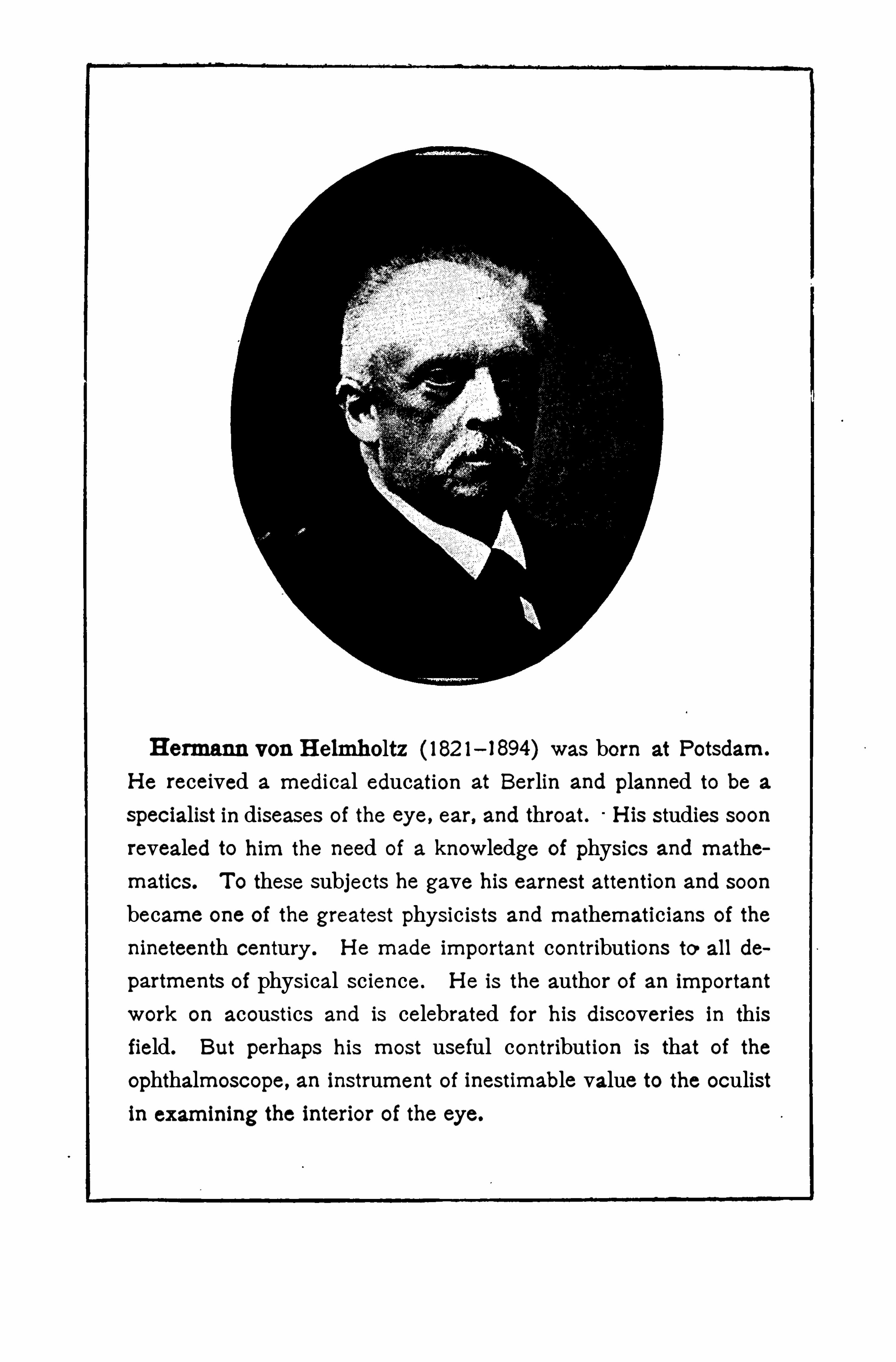
H ermann von H elmholtz (182 1—1894) was born Potsdam.
H e received a medical education at Berlin and planned to be a
specialist in diseases of the eye, ear , and throat. H is studies soon
revealed to him the need of a knowledge of physics and mathematies . T o these subjects he gave his earnest attention and soon
became one of the greatest physic ists and mathematicians of the
nineteenth century . H e made important contributions to all de
partments of physical science. H e is the author of an important
work on acoustics and is celebrated for his discoveries in this
field. But perhaps his most useful contribution is that of the
Ophthalmoscope, an instrument of inestimable value to the oculistin examining the interior of the eye.
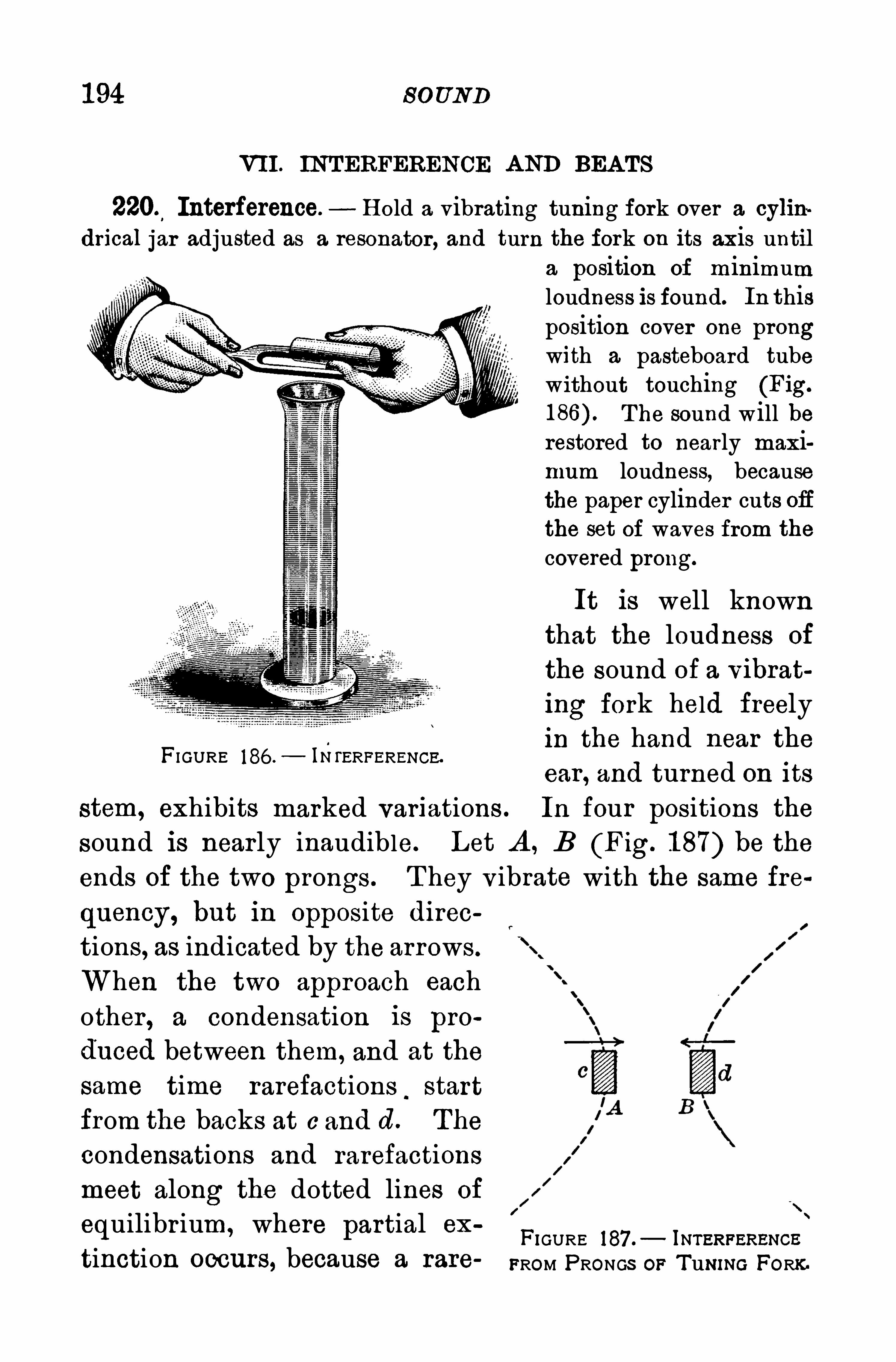
1 94 S OUND
VII . INTERFERENCE A ND BEA TS
2205Interference. H old a vibrating tuning fork over a cylin
drical jar adjusted as a resonator , and turn the fork on its axis untila position of minimumloudness is found. In thisposition cover one prongwith a pasteboard tubewithout touching (Fig.
T he sound will berestored to nearly maximum loudness, becausethe paper cylinder cuts Offthe set of waves from the
covered prong.
It is well knownthat the loudness of
the sound of a vibrat
ing fork held freelyin the hand near the
ear , and turned on its
stem, exhibits marked variations . In four positions the
sound is nearly inaudible. Let A , B (Fig. 1 87) be the
ends of the two prongs . T hey v ibrate with the same fre
quency, but in Opposite direc
tions, as indicated by the arrows.
When the two approach each
other , a condensation is pro
duced between them, and at the
same time rarefactions.start
from the backs at c and d. The
condensations and rarefactionsmeet along the dotted lines of
equilibr ium, where partial exFIGURE 187 .
— Iurenpzxsucs
i
tinction OOCll I'
S , because a rare FROM PRONGS op Tuwug FORK.
FI GURE 186 . IN l‘
ERFERENCE.
I
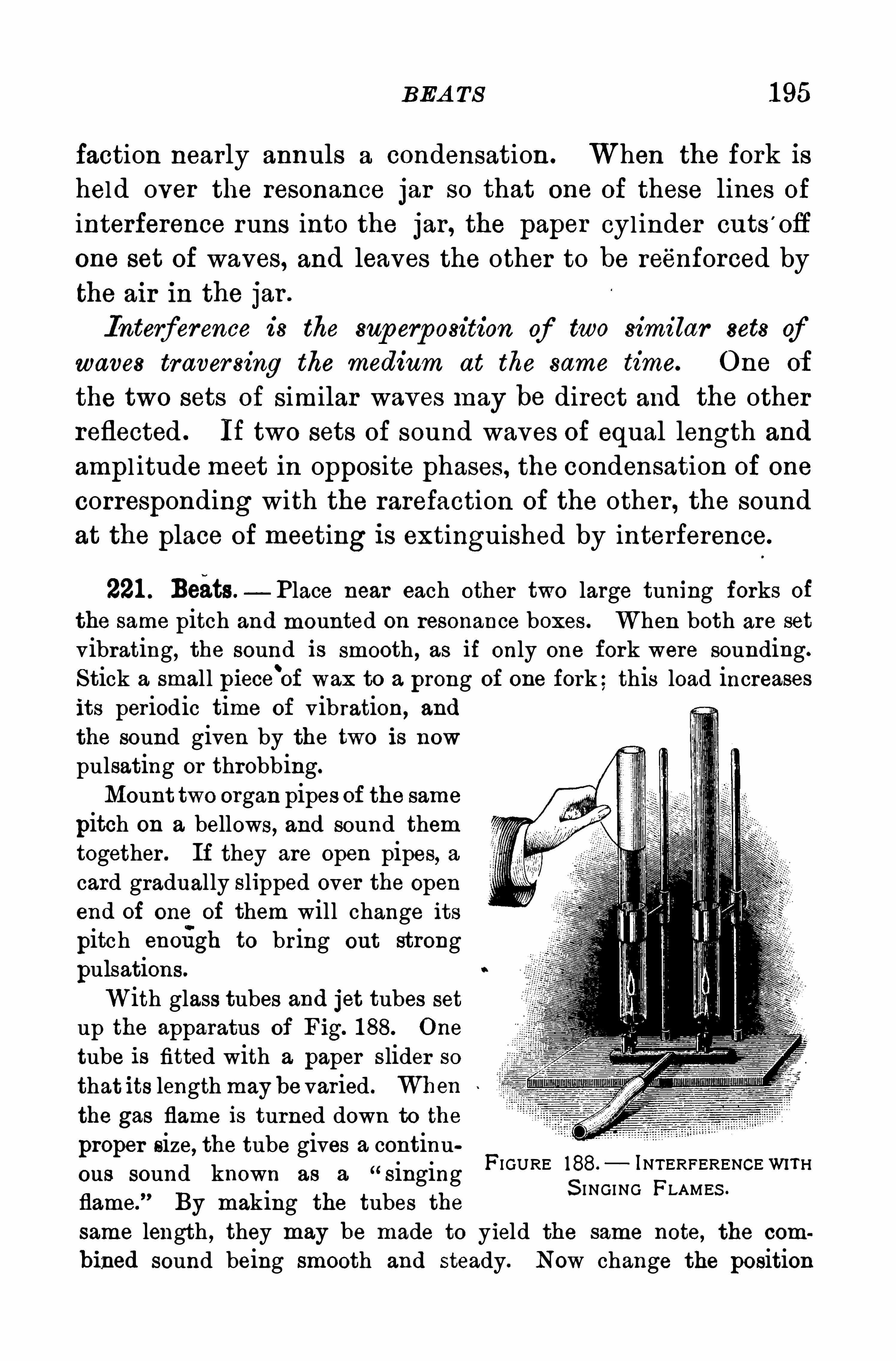
BEA TS 1 95
faction nearly annuls a condensation . When the fork ishel d over the resonance jar so that one of these lines of
interference runs into the jar , the paper cylinder cuts’
ofl
one set of waves, and leaves the other to be reenforced by
the air in the jar .
ence is the sup erposition of two similar sets ofwaves traver sing the medium at the same time. One of
the two sets of similar waves may be direct and the otherreflected . If two sets of sound waves of equal length and
ampl itudemeet in opposite phases, the condensation of one
corresponding with the rarefaction of the other , the sound
at the place of meeting is extinguished by interference.
221 . Beats — Place near each other two large tuning forks of
the same pitch and mounted on resonance boxes. When both are set
vibrating, the sound is smooth , as if only one fork were sounding.
Stick a small piece'
of wax to a prong of one fork;this load increasesits periodic time of vibration, and
the sound given by the two is now
pulsating or throbbing.
Mount two organ pipes of the same
pitch on a bellows, and sound themtogether . If they are open pipes, acard gradually slipped over the openend of one of them will change its
pitch enoflgh to bring out strong
pulsations.
With glass tubes and jet tubes setup the apparatus of Fig. 188. One
tube is fitted with a paper slider sothat its length may be varied . Whenthe gas flame is turned down to theproper size, the tube gives a continuous sound known as a
“singing
flame.
”By making the tubes the
same length , they may be made to yield the same note, the com
bined sound being smooth and steady. Now change the position
FI GURE 188. INTERFERENCE WITHS I NGING FLAMES .
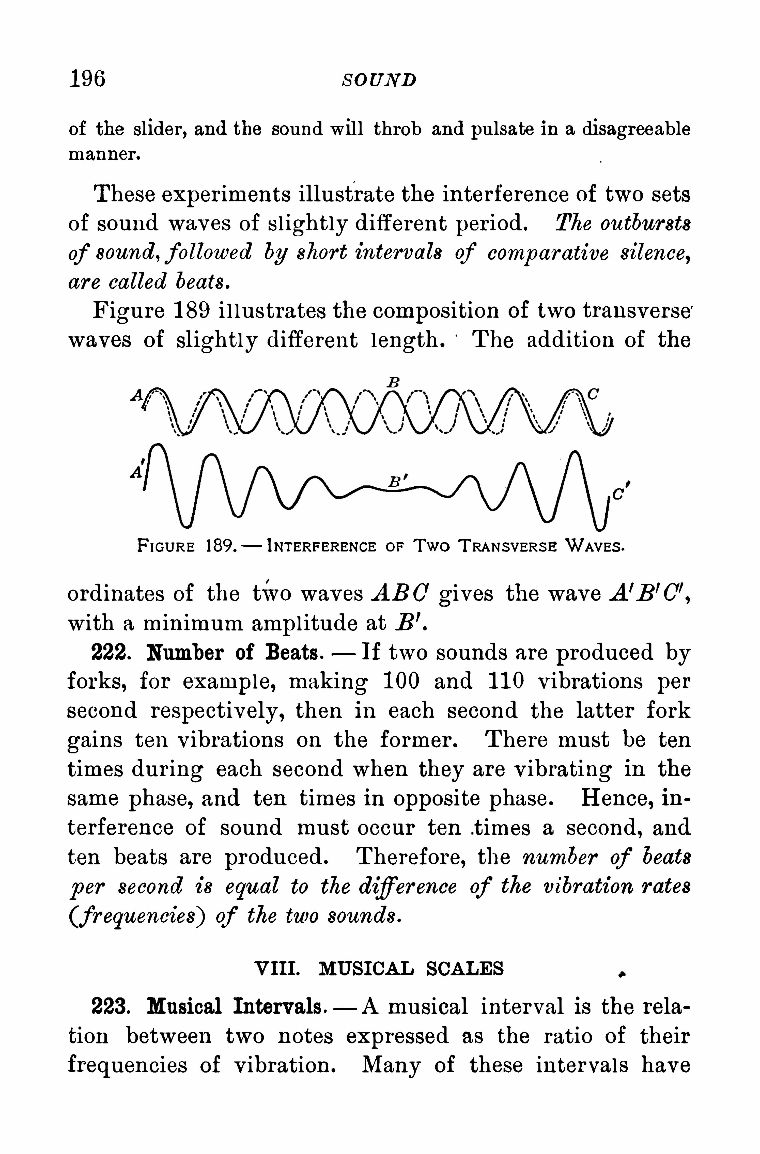
1 96 S O UND
of the slider, and the sound will throb and pulsate in a disagreeablemanner .
T hese exper iments illustrate the interference of two sets
of sound waves of s l ightly different per iod . The outbursts
of sound, followed by short intervals of comparative silence,
are called beats .
Figure 1 89 i l lustrates the composition of two transverse
waves of slightly different length . T he addition of the
FI GURE 189.
— iNTERFERENCE OF Two T RANSVERS E WAVES .
ordinates of the two waves A BO’ gives the wave A ’B’C"
with a minimum ampl itude at B’.
222. Number of Beats .—If two sounds are produced by
forks, for example, making 1 00 and 1 1 0 Vibrations per
second respectively, then in each second the latter fork
gains ten v ibrations on the former . T here must be ten
times dur ing each second when they are v ibrating in the
same phase, and ten times in opposite phase. H ence, in
terference of sound must occur ten .times a second, and
ten beats are produced . T herefore, the number of beats
p er second is equal to the difiference of the vibration r ates
(frequencies) of the two sounds .
VIII . MU SICA L SCA LES
223. Musical Intervals —A musical interval is the rela
tion between two notes expressed as the ratio of their
frequencies of v ibration . Many of these intervals have
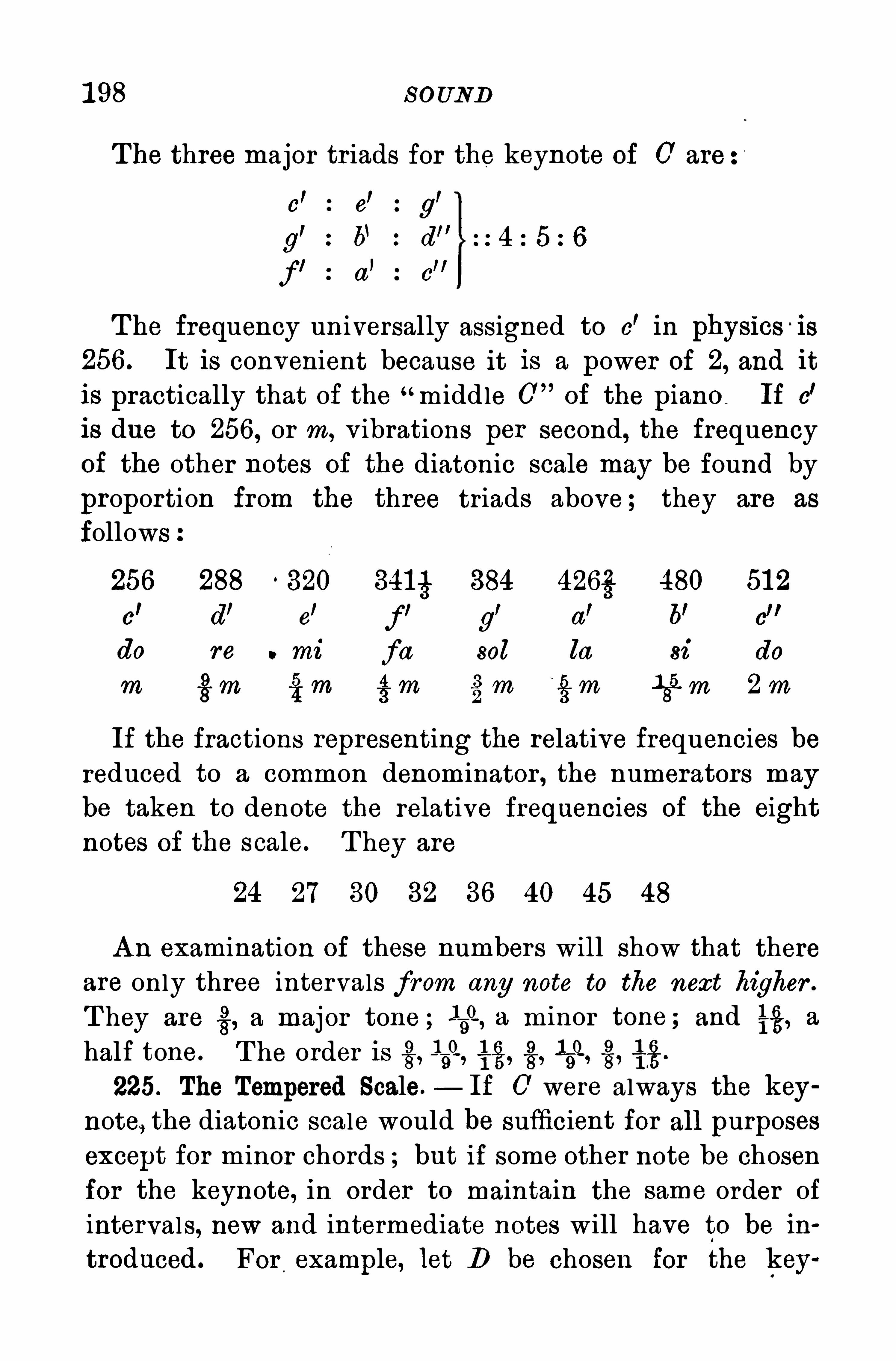
1 98 S O UND
T he three major tr iads for the keynote of C’ are
l I lc e g
g’ :b‘ d"
fl
a’
c”
T he frequency universally assigned to c’ in physics is
256. It is convenient because it is a power of 2, and it
is practically that of the“middle 0 of the piano If c
'
is due to 256, or m, v ibrations per second, the frequencyof the other notes of the diatonic scale may be found by
proportion from the three triads above ; they are as
follows
256 288 320 3415 384 426§ 480 51 2
c’ d’ e
rf’
g’ “I 6! e
”
do re mi fa sol la si do
m 43m 75;m gm gm gm 1
85 m 2m
If the fractions representing the relative frequencies bereduced to a common denominator , the numerators may
be taken to denote the relative frequencies of the eight
notes of the scale. T hey are
24 27 30 32 36 40 45 48
A n examination of these numbers will show that there
are only three intervals from any note to the next higher .
T hey are a major tone ; 359, a minor tone ; and it, a
half tone. T he order is 159, 4g, 1
59, 4g.
225. The Tempered Scale.— If C' were always the key
note, the diatonic scale would be sufficient for all purposes
except for minor chords ; but if some other note be chosen
for the keynote, in order to maintain the same order of
intervals, new and intermediate notes will have to be in
troduced. For example, let D be chosen for the key
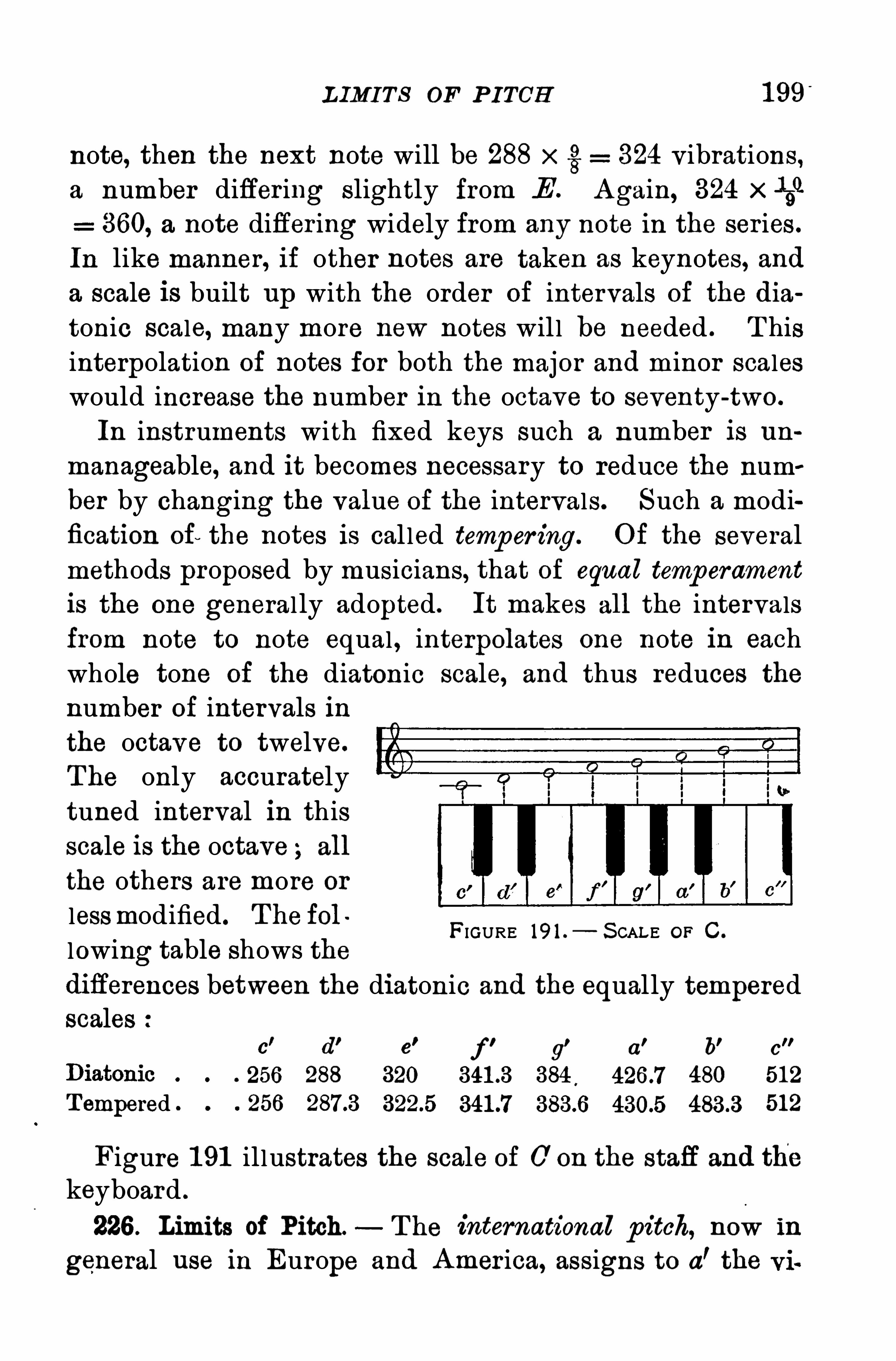
L IMI T S OF P ITCH 1 99”
note, then the next note will be 288 xg: 324 v ibrations,a number differ ing slightly from .E
’. A gain, 324 x -n
360, a note differ ing widely from any note in the ser ies .
In like manner, if other notes are taken as keynotes, and
a scale is built up with the order of intervals of the dia
tonic scale, many more new notes wil l be needed . T his
interpolation of notes for both the major and minor scales
would increase the number in the octave to seventy-two.
In instruments with fixed keys such a number is un
manageable, and it becomes necessary to reduce the num
ber by changing the value of the intervals. Such a modification of the notes is cal led temp er ing. O f the several
methods proposed by musicians, that of equal temperament
is the one general ly adopted. It makes all the intervalsfrom note to note equal , interpolates one note in each
whole tone of the diatonic scale, and thus reduces thenumber of intervals inthe octave to twelve.
The only accurately
tuned interval in thisscale is the octave all
the others are more or
lessmodified . T he fol
lowing table shows thediflerences between the diatonic and the equally temperedscales
FIGURE 19 1 .— S CAL E OF C .
c' d’ e
'
f g'
a' b' c
256 288 320 384,
480 51 2
T empered 256 512
Figure 1 91 illustrates the scale of C’on the staff and the
keyboard .
226 . Limits of Pitch. T he international p itch, now in
general use in Europe and A mer ica, assigns to a’the
200 S O UND
bration frequency of 435. But some orchestras haveadopted 440 v ibrations for a
’. In the modern piano of
seven octaves the bass A has a frequency of aboutthe highest A , 3480. T he lowest note of the organ is the
0 of 1 6 v ibrations per second ; the highest note is thesame as the highest note of the piano, the third octaveabove a
’, with a frequency of 3480.
T he limits of hear ing far exceed those of music. T he
range of audible sounds is about eleven octaves, or from
the 0 of 1 6 v ibrations to that of though many
persons of good hear ing perceive nothing above a fra
quenoy of an octave lower .
Q uestions and P roblems
1 . Why is the pitch of the sounds given by a phonograph rai sed byincreasing the speed of the cylinder or the disk containing the record ?
2 . A megaphone or a speaking tube makes a sound louder ‘at adistance. Explain why .
3 . The teeth of a ci rcular saw give a note of high pitch whenthey first strike a plank . Why does the pitch fall when the plank Is
pushed further against the saw ?
4 . Miners entombed by a fall of rock or by an explosion havesignaled by taps on a pipe or by pounding on the rock. H ow doesthe sound reach the surface ?
5 . Two Rookwood vases in the form of pitchers with slendernecks give musical sounds when one blows across their mouth . Whydoes the larger one give a note of lower pitch than the smaller ?
6 . What note is made by three times as many vibrations as 0
(middle C) ?7 . If c’ is due to 256 vibrations per second, what is the frequency
of g” in the next octave ?8 . What is the wave length of g
’ when sound travels 1 1 30 feet
per second ?9 . If c’ has 264 vibrations per second, how many has a’ ?
1 0 . When sound travels 1 120 ft. per second, the wave length of thenote given by a fork was ft. What was the pitch of the fork ?
I
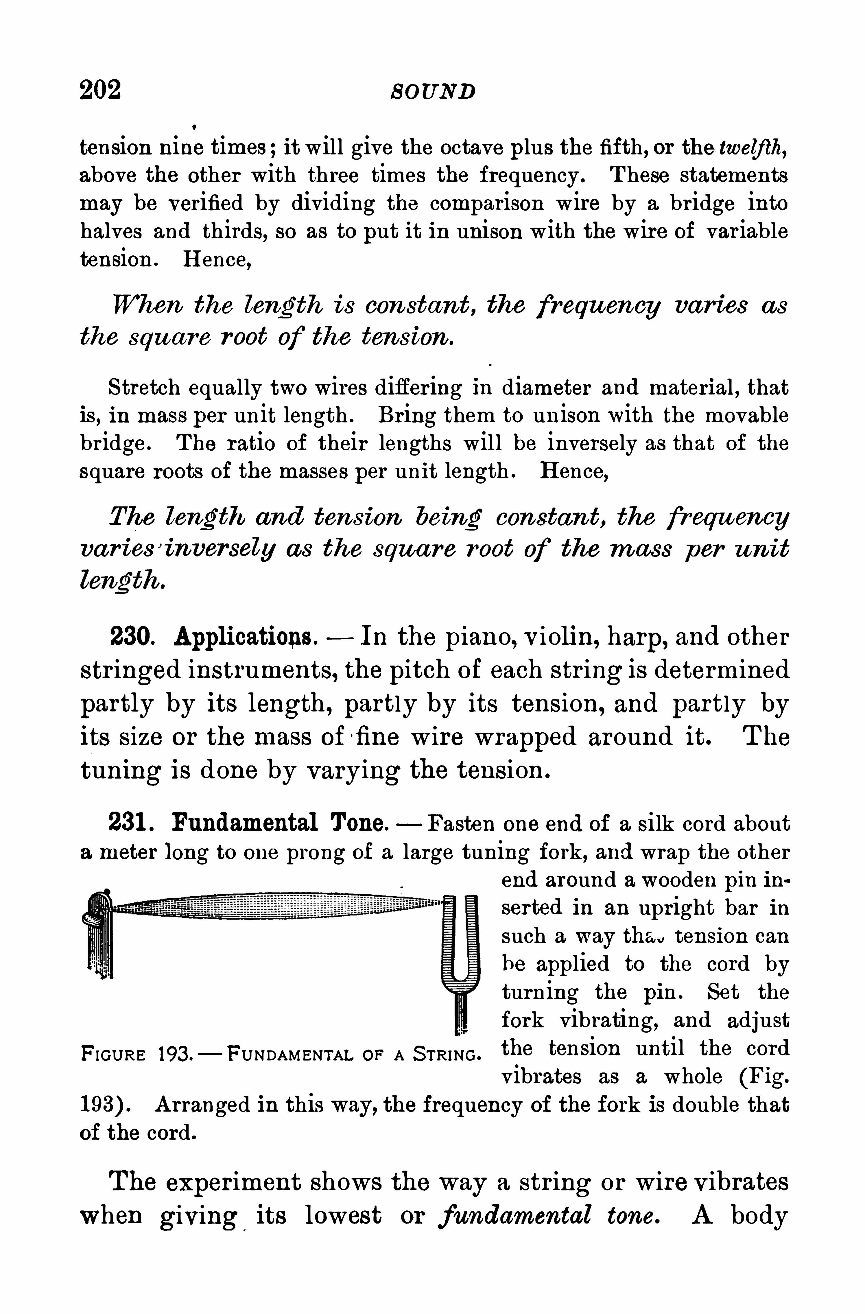
202 S OUND
tension nine times;it will give the octave plus the fifth, or the twelfth,above the other with three times the frequency . T hese statements
may be verified by dividing the comparison wire by a bridge intohalves and thirds, so as to put it in unison with the wire of var iabletension . H ence,
When the length is con stant, the frequency varies as
the square r oot of the tension .
S tretch equally two wires differ ing in diameter and material , thatis, in mass per unit length . Bring them to unison with the movablebridge . The ratio of their lengths will be inversely as that of the
square roots of the masses per unit length . H ence,
The length and tension being constan t, the frwu encyva r i eS
’
tnversely as the squa re r oot of the m ass per un it
230. Applications . In the piano, v iolin, harp, and other
str inged instruments, the pitch of each str ing is determined
partly by its length , partly by its tension, and partly by
its size or the mass offine wire wrapped around it. T he
tuning i s done by varying the tension .
231 . Fundamental Tone. Fasten one end of a silk cord abouta meter long to one prong of a large tuning fork, and wrap the other
end around a wooden pin ihserted in an upright bar insuch a way that tension can
be applied to the cord byturning the pin . Set the
fork vibrating, and adjust
FIGURE 193 .— FUNDAMENTAL OF A S TRING .
the tension until the cordvibrates as a whole (Fig.
A rranged in this way, the frequency of the fork is double thatof the cord .
T he experiment shows the way a str ing or wire vibrates
when giving its lowest or fundamental tone. A body
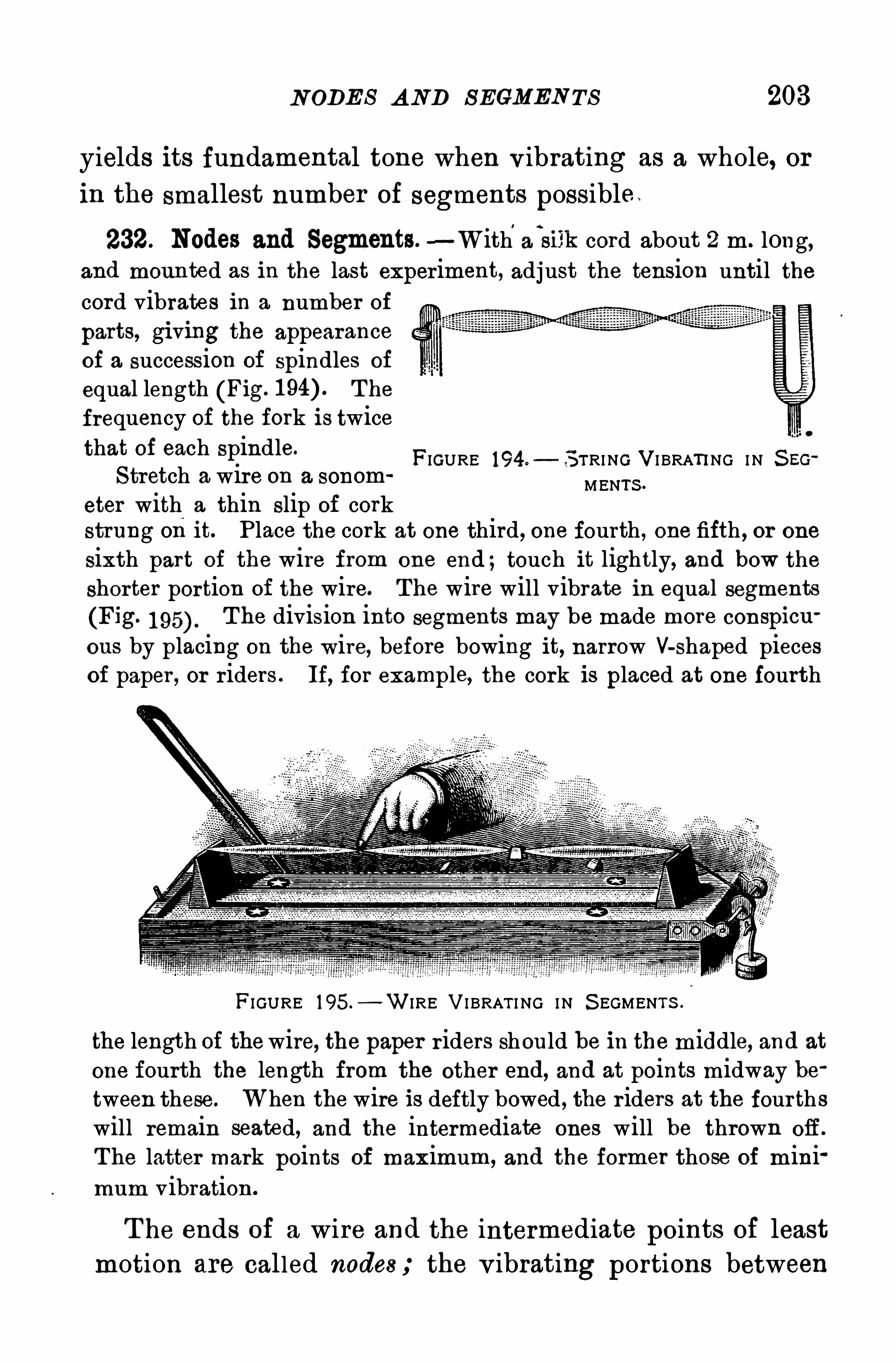
N ODE S A ND S EGMEN TS 208
yields its fundamental tone when v ibrating as a whole, or
in the smallest number of segments possible .
232. Nodes and Segments.—With
’
a
‘
silk cord about 2 m. long,and moun ted as in the last experiment, adjust the tension until the
cord vibrates in a number of
parts, giving the appearanceof a succession of spindles of
equal length (Fig. The
frequency of the fork is twicethat of each spindle.
S tretch a wire on a sonom
eter with a thin slip of corkstrung on it. P lace the cork at one third, one fourth , one fifth , or one
sixth part of the wire from one end ;touch it lightly, and bow the
shorter portion of the wire. The wire will vibrate in equal segments
(Fig. T he division into segments may be made more conspicu
ous by placing on the wire, before bowing it, narrow V-shaped pieces
of paper , or riders . If, for example, the cork is placed at one fourth
FIGURE 194.— S TRING VI BRATING I N S EG
MENTS .
FI GURE 195.
—W IRE VI BRAT I NG I N S EGMENT S .
the length of thewire, the paper r iders should be in the middle, and at
one fourth the length from the other end, and at points midway be
tween these. When the wire is deftly bowed , the r iders at the fourthswill remain seated, and the intermediate ones will be thrown off.
The latter mark points of maximum, and the former those of minimum vibration .
T he ends of a wire and the intermediate points of least
motion are called nodes ; the v ibrating portions between
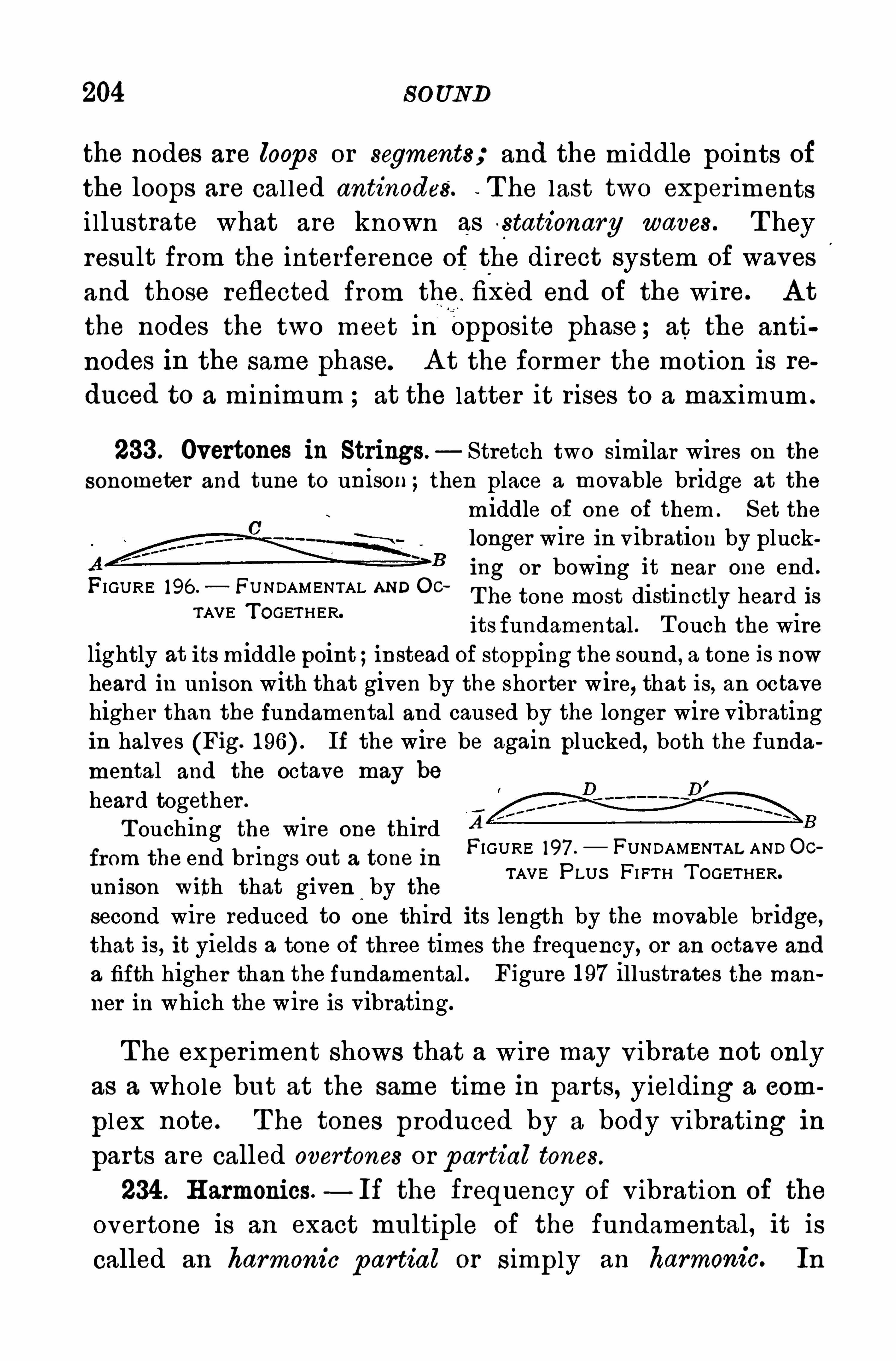
204 S O UND
the nodes are loop s or segments; and the middle points of
the loops are cal led antinodes‘
. - The last two exper iments
i llustrate what are known as s tationary waves . T hey
result from the interference of the direct system of waves
and those reflected from the . fixed end of the wire. A t
the nodes the two meet In opposite phase ; at the anti
nodes in the same phase. A t the former the motion is re
duced to a minimum at the latter it rises to a maximum .
233 . Overtones in Strings— Stretch two similar wires on the
sonometer and tune to unison ;then place a movable bridge at the
middle of one of them . Set the
longer wire in vibration by plucking or bowing it near one end .
T he tone most distinctly heard isits fundamental . T ouch the wire
lightly at itsmiddle point ;instead of stopping the sound , a tone is nowheard in unison with that given by the shorter wire, that is, an octavehigher than the fundamental and caused by the longer wire vibratingin halves (Fig. If the wire be again plucked, both the fundamental and the octave may be
heard together .
T ouching the wire one third A
from the end brings out a tone in FI GURE 197 . FUNDAMENTAL AND CcTAVE P LUS FIFTH T OGETHER.
un i son W ith that gi ven by thesecond wire reduced to one third its length by the movable br idge,that is, it yields a tone of three times the frequency, or an octave and
a fifth higher than the fundamental . Figure 1 97 illustrates the man
ner in which the wire is vibrating.
FI GURE 196 . FUNDAMENTAL AND OcTAVE T OGETHER.
T he exper iment shows that a wire may v ibrate not only
as a whole but at the same time in parts, yielding a com
plex note. T he tones produced by a body v ibrating in
parts are called over tones or p artial tones.
234 . H armonics — If the frequency of v ibration of the
overtone is an exact multiple of the fundamental, it is
called an harmonic partial or simply an harmonic. In
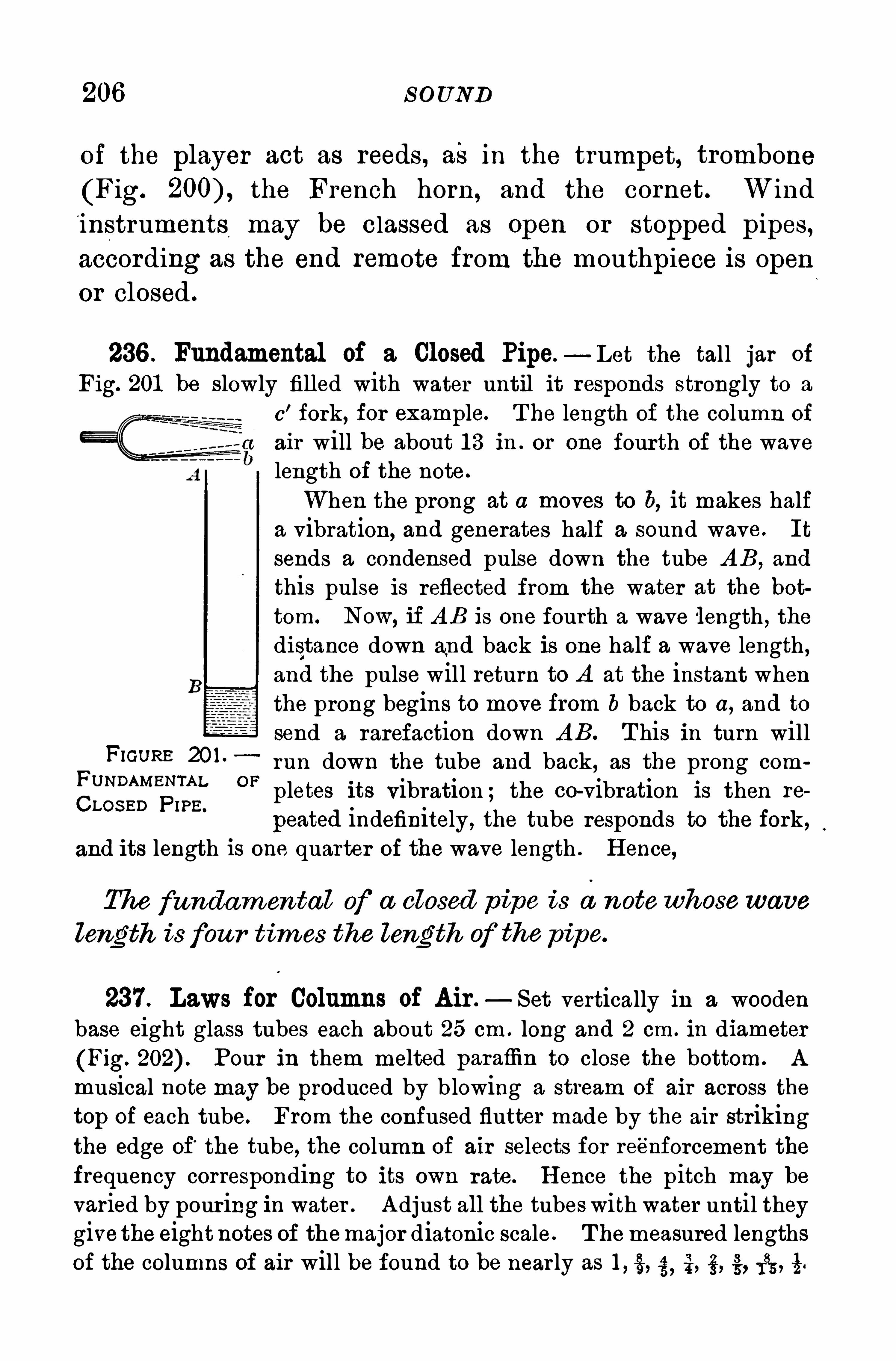
206 S O UND
of the player act as reeds, as in the trumpet, trombone
(Fig. the French horn, and the com et. Wind
instruments may be classed as Open or stopped pipes,according as the end remote from the mouthpiece is openor closed .
236 . Fundamental of a Closed Pipe—Let the tall jar of
Fig. 201 be slowly filled with water until it responds strongly to a
c’ fork, for example. T he length of the column of
a air will be about 1 3 in . or one four th of the wavelength of the note .
When the prong at a moves to b, it makes halfa vibration, and generates half a sound wave. It
sends a condensed pulse down the tube A B , and
this pulse is reflected from the water at the bot
tom. Now, if A B is one fourth a wave length , thedistance down and back is one half a wave length ,and the pulse will return to A at the instant whenthe prong begins to move from b back to a, and to
send a rarefaction down A B. T his in turn willF’GURE 20 1 °
run down the tube and back, as the prong comL O F pletes its vibration ; the co-vibration is then re
peated indefinitely, the tube responds to the fork ,and its length is one quarter of the wave length . H ence,
The fundam ental of a closed pipe is a notewhosewave
length is fou r tim es the length of the pipe.
237. Laws for Columns of Air . Set vertically in a woodenbase eight glass tubes each about 25 cm . long and 2 cm. in diameter
(Fig. Pour in them melted paraflin to close the bottom. A
musical note may be produced by b lowing a stream of air across thetop of each tube. From the confused flutter made by the air strikingthe edge of
’
the tube, the column of air selects for re'
enforcement the
frequency corresponding to its own rate. H ence the pitch may be
varied by pouring in water . A djust all the tubeswith water until theygive the eightnotes of themajor diatonic scale . Themeasured lengthsof the columns of air will be found to be near ly as l , g, 2, g, g,
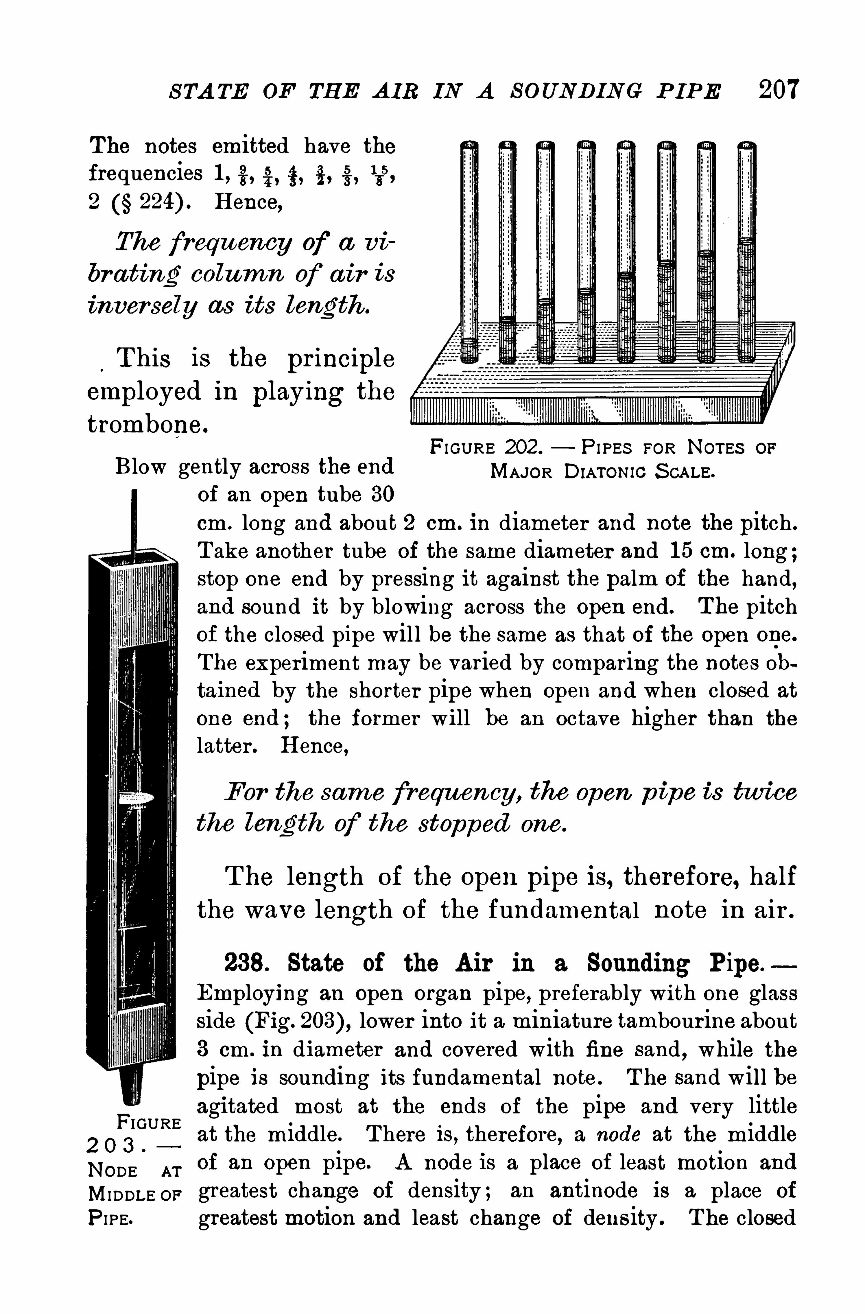
S TA TE OF TH E A IR IN A S OUNDIN C P IP E 207
The notes emitted have thefrequencies 1 , g, 4, i , g,
135,
2 H ence,
The frequency of a vi
bruting colum n of a ir is
inver sely as its length .
T his is the pr incipleemployed in playing the
trombone.
FI GURE 202 . P I PES FOR NOTES OF
Blow gently across the end MAJOR DIA-mmc S cALE.
of an open tube 30cm . long and about 2 cm. in diameter and note the pitch .
T ake another tube of the same diameter and 1 5 cm. long ;stop one end by pressing it against the palm of the hand,and sound it by blowing across the open end. The pitchof the closed pipe will be the same as that of the open one.
The experiment may be varied by comparing the notes ohtained by the shorter pipe when open and when closed at
one end ; the former will be an octave higher than the
latter . H ence,
For the same frequency, the Open p i pe i s twice
the length of the stopped one.
T he length of the open pipe is, therefore, halfthe wave length of the fundamental note in air .
238. State of the Air in a Sounding Pipe.
Employing an Open organ pipe, preferably with one glassside (Fig. lower into it a miniature tambourine about3 cm . in diameter and covered with fine sand , while thepipe is sounding its fundamental note . T he sand will beagitated most at the ends of the pipe and very little
2 O 3at the middle. T here is, therefore, a node at the middle
NODE.
M. of an open pipe. A node is a place of least motion and
MI DDLE op greatest change of density ; an antinode is a place of
P I PE. greatest motion and least change of density . T he closed
FI GURE
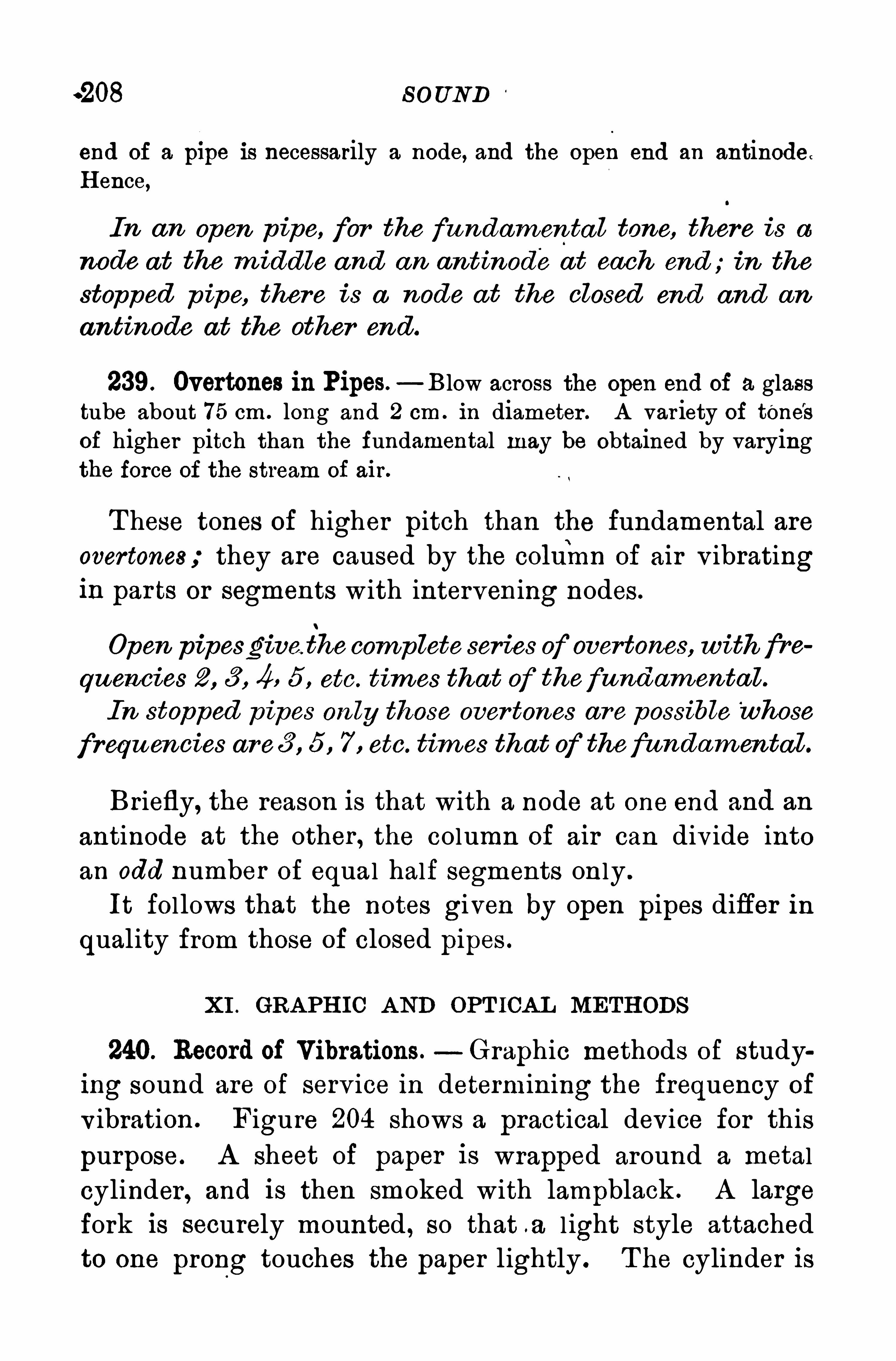
.208 S OUND
end of a plpe is necessarily a node, and the open end an antinode.
H ence,
In an Open p ipe, for the fu ndam en ta l tone, there is a
node at the m iddle and an antinodeat each end ; in the
stopped p ipe, there is a node at the closed end and an
antinode at the other end .
239. Overtones in Pipes.—Blow across the open end of a glass
tube about 75 cm . long and 2 cm . in diameter . A var iety of tene'
s
of higher pitch than the fundamental may be obtained by varyingthe force of the stream of air.
T hese tones of higher pitch than the fundamental are
overtones; they are caused by the coluinn of air v ibratingin parts or segments with intervening nodes .
Open pipesgive. the complete series of overtones, with fre
quencies 2 , 3 , 4, 5 , etc. tim es that of thefundamenta l .
In stopped p ipes on ly those over tones are possible‘
whose
frequ en cies are3 , 5 , 7 , etc. tim es that of thefundam ental .
Briefly, the reason is that with a node at one end and an
antinode at the other , the column of air can div ide into
an odd number of equal half segments only .
It follows that the notes given by open pipes differ in
quality from those of closed pipes .
XI . GRA PH IC A ND OPT ICA L METH ODS
240. Record of Vibrations.—Graphic methods of study
ing sound are of serv ice in determining the frequency of
v ibration . Figure 204 shows a practical device for this
purpose. A sheet of paper is wrapped around a metal
cylinder , and is then smoked with lampblack . A large
fork is securely mounted , so that .a l ight style attachedto one prong touches the paper lightly . T he cylinder is
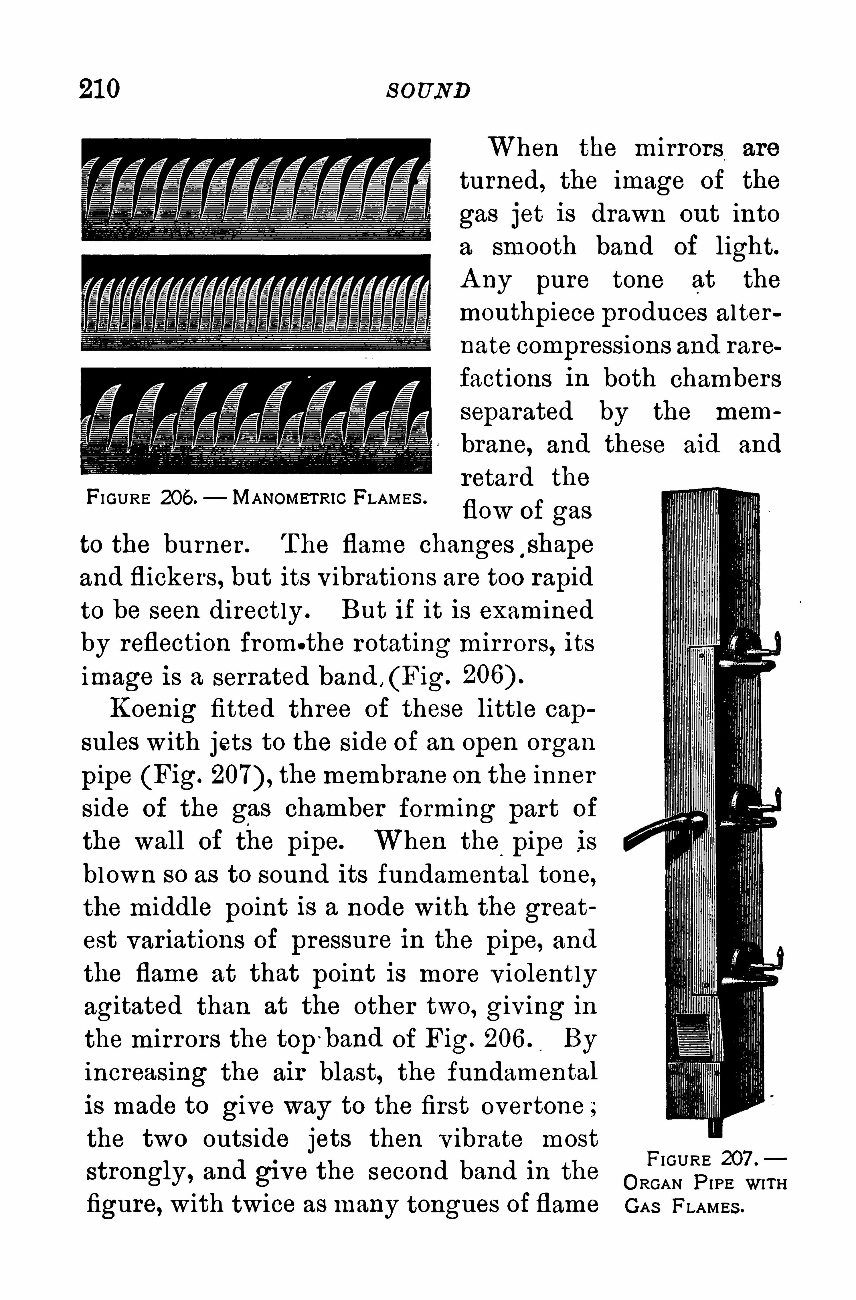
21 0 S OUND
When the m irrors are
turned, the image of the
gas jet is drawn out intoa smooth band of light.
A ny pure tone at the
mouthpiece produces alter
nate compressions and rare
factions in both chambers
separated by the mem
brane, and these aid and
retard the
flow of gas
to the burner . T he flame changes shape
and fl ickers, but its v ibrations are too rapid
to be seen directly . But if it is examinedby reflection from.the rotating mirrors, its
image is a serrated band , (Fig.
Koenig fitted three of these little cap
sules with jets to the side of an open organ
pipe (Fig. themembrane on the inner
side of the gas chamber forming part of
the wall of the pipe. When the pipe is
blown so as to sound its fundamental tone,
the middle point is a node with the great
est var iations of pressure In the pipe, and
the flame at that point is more v iolently
agitated than at the other two, giv ing in
the mirrors the top'band of Fig. 206 . By
increasing the air blast, the fundamental
is made to give way to the first overtone ;
the two outside jets then v ibrate most
strongly, and give the second band in the
figure, with twice as many tongues of flame
FIGURE 206 . MANGMETRIG FLAMES .
FI GURE 207 .
ORGAN P IPE WITHGA S FLAMES .
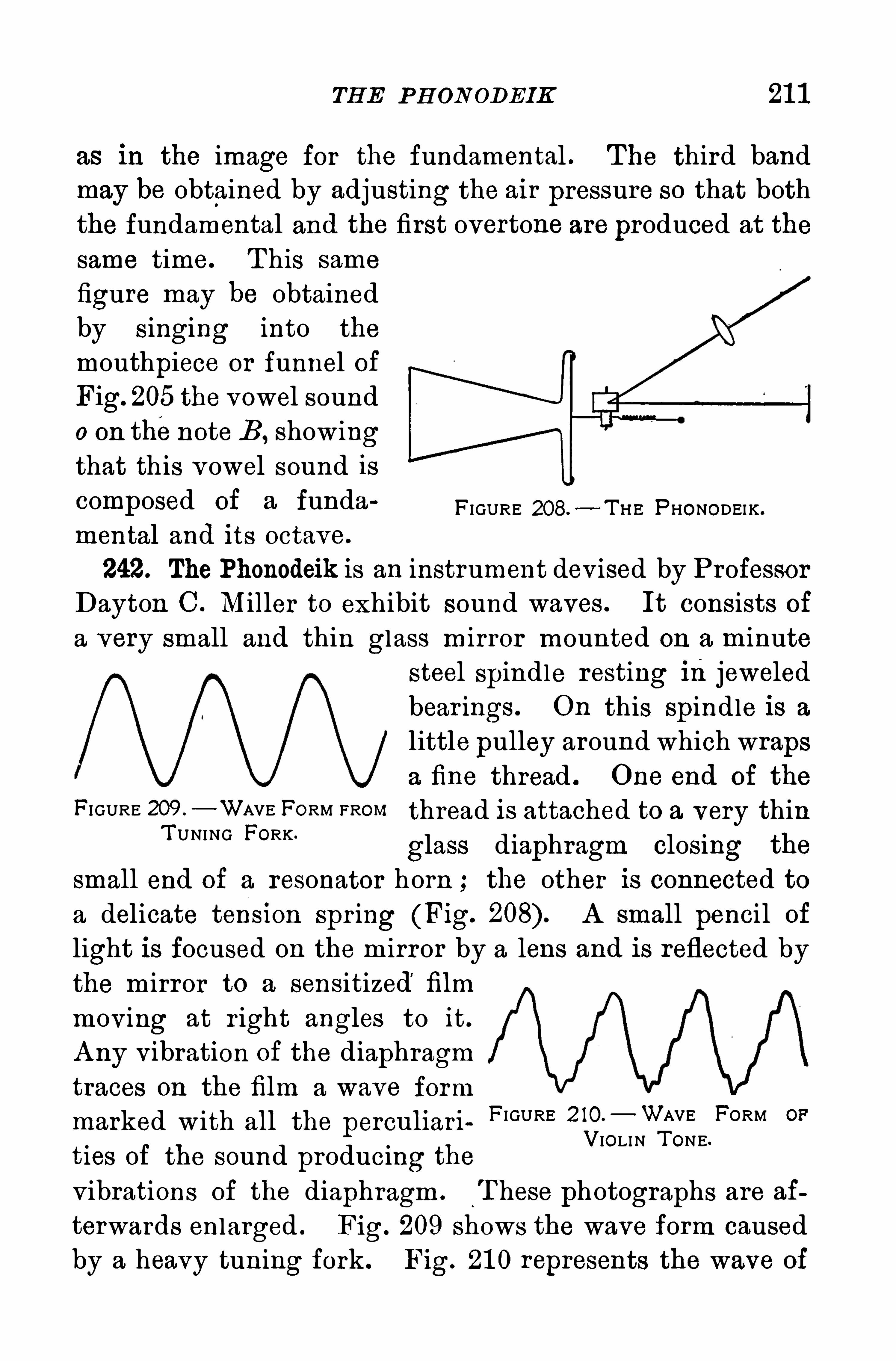
TH E P H ON ODEIK 21 1
as in the image for the fundamental . T he third band
may be obtained by adjusting the air pressure so that both
the fundamental and the first overtone are produced at the
same time. T his same
figure may be obtainedby singing into the
mouthpiece or funnel of
Fig. 205 the vowel sound
0 on thenote B , showingthat this vowel sound iscomposed Of a' funda FI GURE 208.
—T H E PHONODEI K .
mental and its octave.
242. The Phonodeik is an instrument dev ised by P rofessor
Dayton C . Miller to exhibit sound waves . It consists of
a very small and thin glass mirror mounted on a minute
steel spindle resting injeweled
bear ings . On this spindle is a
little pulley around which wrapsa fine thread . One end of the
FI GURE 209 —WAVE FORM FROM thread is attached to a very thinT UNING FORK '
glass diaphragm closing the
small end of a resonator horn ; the other is connected toa delicate tens1 0n spr ing (Fig. A small pencil of
light is focused on the m irror by a lens and is reflected bythe mirror to a sensitized film
moving at r ight angles to it.
A ny vibration of the diaphragmtraces on the film a wave form
marked with all the perculiari
ties of the sound producing thevibrations of the diaphragm . T hese photographs are af
terwards enlarged . Fig. 209 shows the wave form causedby a heavy tuning fork . Fig. 21 0 represents the wave of
FI GURE 2 10.—WAVE FORM OF
VIOLIN T ONE.
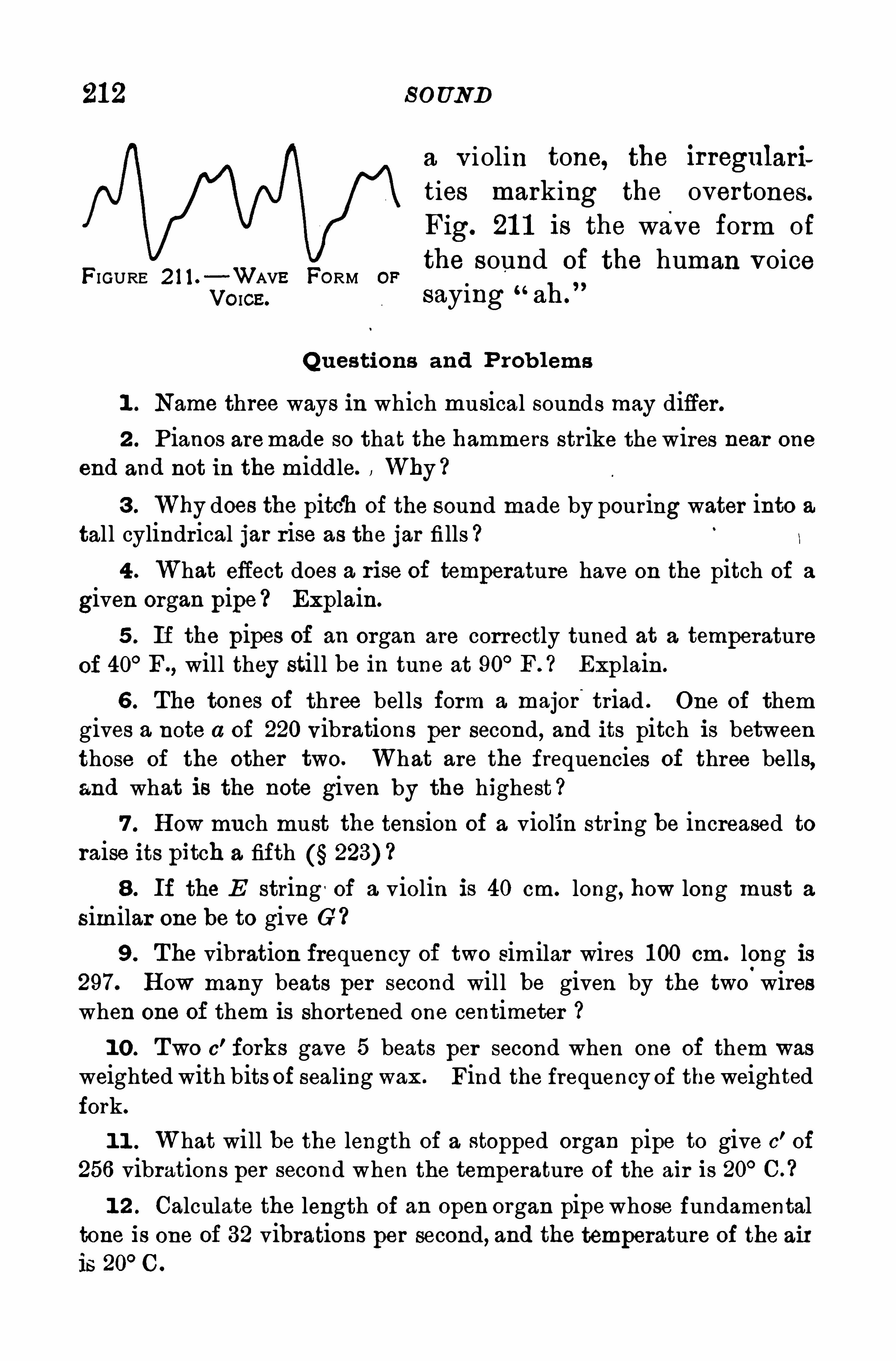
21 2 S O UND
FIGURE 2 1 1 . -WAVE FORM OF
VO ICE.
Q uestions and P rob lems
1 . Name three ways in which musical sounds may differ.
2 . P ianos aremade so that the hammers strike thewires near one
end and not in the middle. Why ?
3 . Why does the pitch of the sound made by pouring water into a
tall cylindrical jar rise as the jar fi lls ?
4 . What effect does a rise of temperature have on the pitch of a
given organ pipe Explain.
5 . If the pipes of an organ are correctly tuned at a temperatureof 40° F., will they still be in tune at 90
° F. ? Explain .
6 . The tones of three bel ls form a major triad . One of themgives a note a of 220 vibrations per second, and its pitch is betweenthose of the other two. What are the frequencies of three bells,and what is the note given by the highest ?
7 . H ow much must the tension of a violin string be increased toraise its pitch a fifth 223)
8. If the E string '
of a violin is 40 cm. long, how long must a
similar one be to give G?
9 . The vibration frequency of two similar wires 1 00 cm. long is297. H ow many beats per second will be given by the two wireswhen one of them is shortened one centimeter
1 0 . Two 0’ forks gave 5 beats per second when one of them was
weighted with bits of sealing wax . Find the frequency of the weightedfork.
1 1 . What will be the length of a stopped organ pipe to give c'of
256 vibrations per second when the temperature of the air is 20° C. ?
1 2 . Calculate the length of an open organ pipewhose fundamentaltone is one of 32 vibrations per second, and the temperature of the air
is 20° C.
a v iolin tone, the irregulari
ties marking the overtones.
Fig. 21 1 is the wave form of
the sound of the human voicesaying
“ah.
”
CH A PTER VIII
LIGHT
I . NA TURE AND TRA NSMISSION OF LIGHT
243 . The Ether . Exhaust the air as far as possible from a glassbell jar . Place a candle on the far side of the jar ; it will be seen as
clear ly before the air has been let into the bell jar as after .
It is obvious that the medium conveying light is not the
air and it must be something that exists even in a vacuum .
T his medium is vaguely known as the ether . It exists
everywhere, even penetrating between the molecules of
ordinary matter .
244 . Light.- T he prevai l ing v iew about the nature of
light is that it is a transverse wave motion in the ether .
H uyghens, a Dutch physicist, in 1-678 proposed the theory
that l ight is a wave motion ; later , Fresnel , a French
physicist, showed that the disturbancemust be transverse ;final ly Maxwell modified the theory to the effect that thesedisturbances are probably not transversephysicalmovements
of the ether , but transverse alterations in its electrical and
magnetic conditions.
245. Transparent and Opaque Bodies. When light fallson a body, in general , a part of it is reflected, a part passesthrough or is transm itted , and the rest is absorbed. A
body is transpar ent when it al lows light to pass through it
with so l ittle loss that objects can be easi ly distinguishedthrough it, as in the case of clear glass, air , pure water .
Translucent bodies transmit l ight, but so imperfectly that214
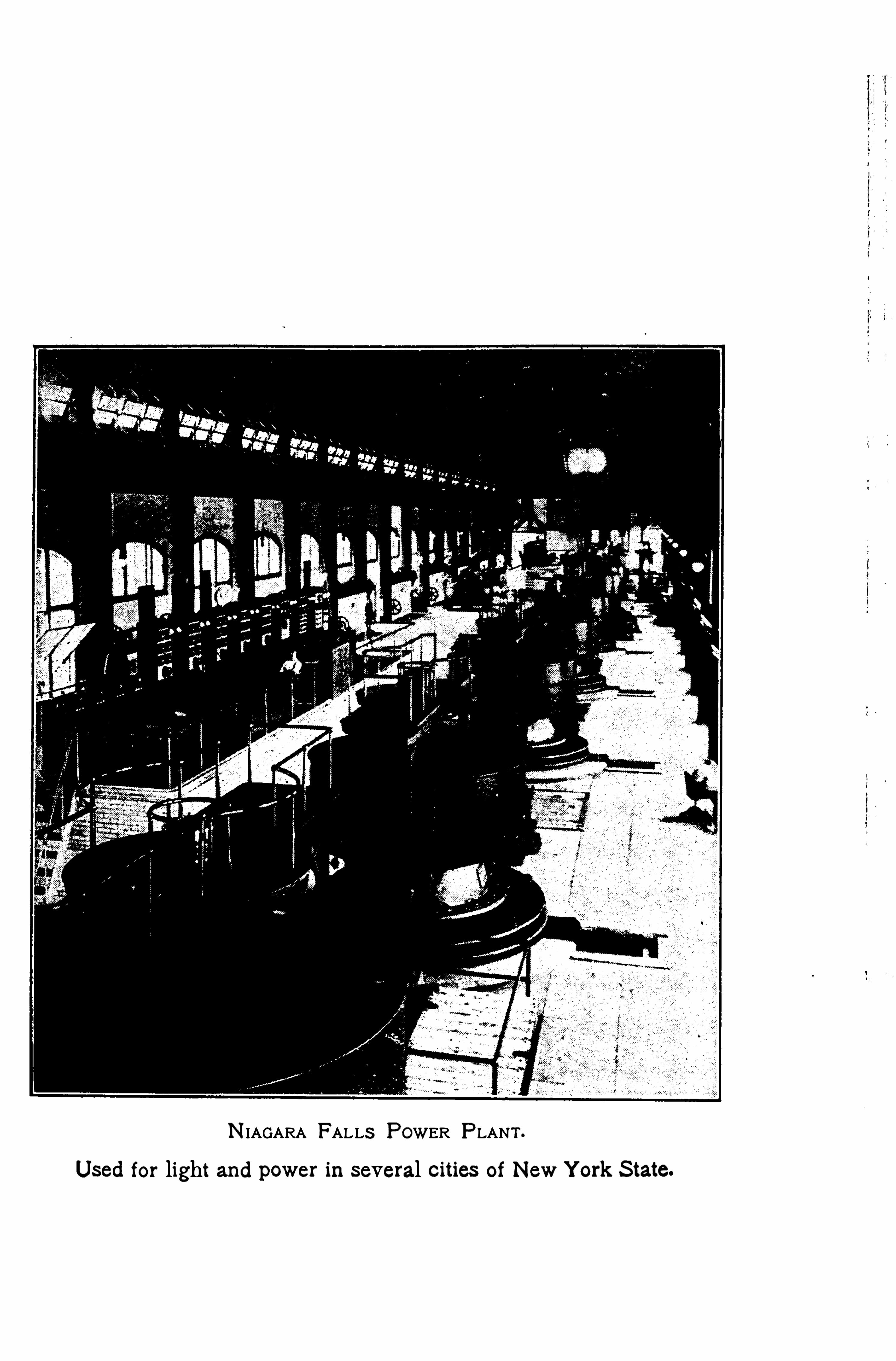
N IAGARA FALLS POWER P LANT .
Used for light and power in several cities of New Y ork S tate.

21 6 L IGH T
much earlier recorded ones, Roemer found that the mean inter val of time between two successive ecl ipses washours . From this it was easy to calculate in advance thetime at which succeeding eclipses would occur . But whenthe earth was goingdirectly away from Jupiter , as at E 1 , theecl ipse interval was found to be l onger than anywhere else;and at E
2,across the ear th’
s orbit from Jupiter , each eclipseoccurred about 1 000 sec. later than the predicted time.
To account for this difference Roemer advanced the theorythat this interval of 1 000 sec. is the time taken by lightto pass across the diameter of the earth’
s orbit. This gavefor the speed of light 309 mi l l ion meters, or mi les
per second .
Later determinations in our own country by Michelsonand Newcomb Show that the speed of light is km. ,
or mi. per second .
247 . Direction of Propagation. Place a sheet-iron cylinderover a strong light, such as aWelsbach gas lamp , in a darkened room.
T he cylinder should have a small hole opposite the light. S tretch a
heavy white thread in the light streaming through the aper ture.
When the thread is taut it is visible throughout its entire length, butif permitted to sag it becomes invisible.
T he exper iment shows that light travels in straight lines .
It will appear later that this is true on ly when the medium
through which light passes has the same physical proper
ties in all directions .
248. Ray, Beam, Pencil .—L ight is propagated outwardfrom the luminous source in concentric Spher ical waves ,as sound waves in air from a sonorous body . Rays are
the radii of these sp herical waves, and they are, therefore,normal (perpendicular) to them . T hey mark the direc
tion of propagation .
When the source of light is at a great distance, the rays
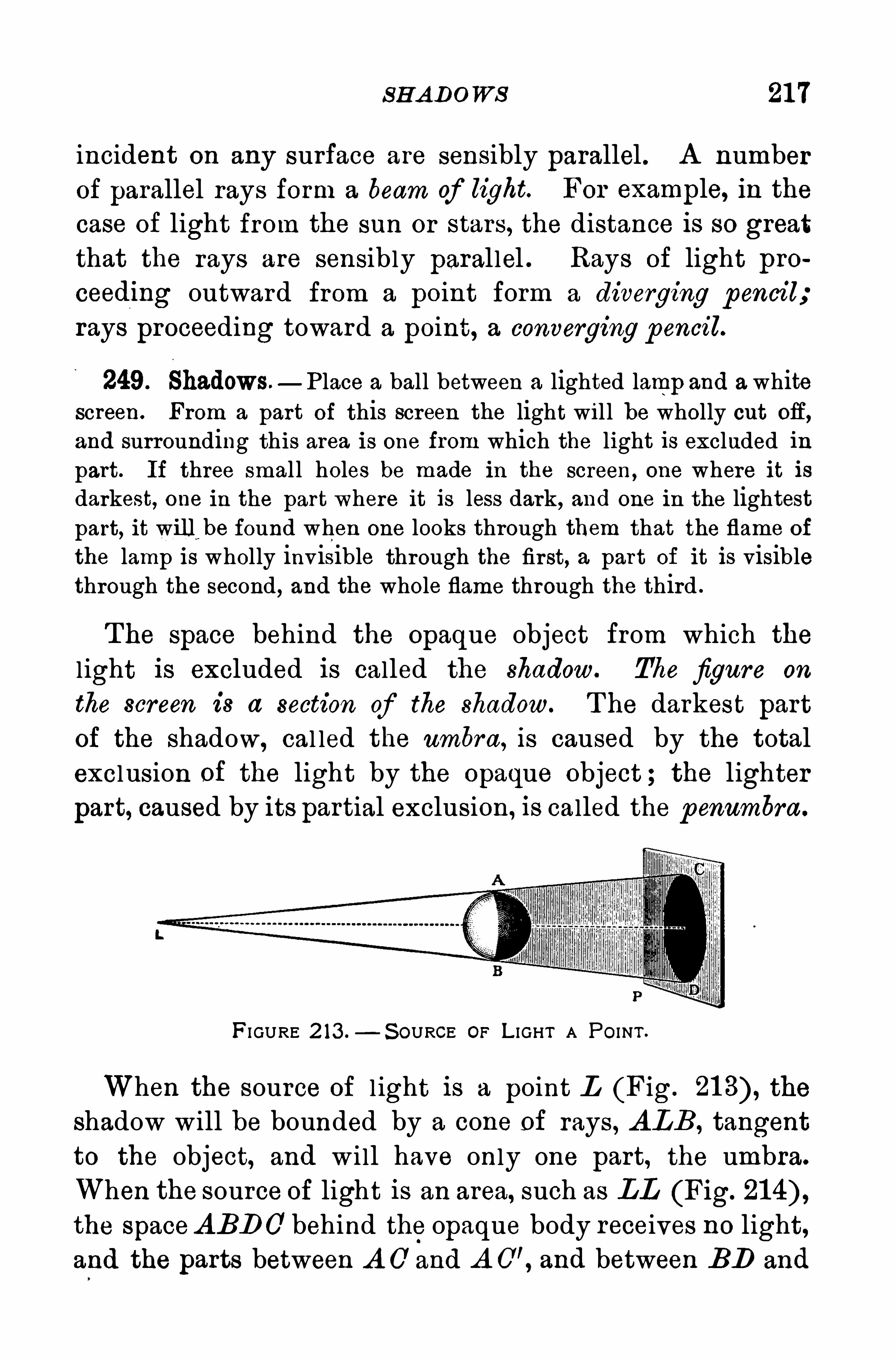
S H A DOWS 21 7
incident on any surface are sensibly parallel . A number
of parallel rays form a beam of light. For example, in the
case of light from the sun or stars, the distance is so great
that the rays are sensibly parallel . Rays of light pro
ceeding outward from a point form a diverging pencil;
rays proceeding toward a point, a converging pencil.
249. Shadows.—Place a ball between a lighted lamp and a white
screen. From a part of this screen the light wil l be wholly cut OE,
and surrounding this area is one from which the light is excluded inpart. If three smal l holes be made in the screen, one where it isdarkest, one in the part where it is less dark, and one in the lightestpart, it will be found when one looks through them that the flame of
the lamp is wholly invisible through the first, a part of it is visiblethrough the second, and the whole flame through the third .
T he space behind the Opaque object from which the
l ight is excluded is called the shadow. The figure on
the screen is a section of the shadow. T he darkest partof the shadow, cal led the ambra, is caused by the totalexclusion of the light by the Opaque object ; the lighter
part, caused by its partial exclusion, is called the penumbra .
FI GURE 2 13 .— S OURCE OF L IGHT A PO INT .
When the source of l ight is a point L (Fig. the
shadow will be bounded by a cone of rays , A LB , tangent
to the object, and wi ll have only one part, the umbra.
When the source of light is an area, such as LL (Fig.
the spaceABDO behind the opaque body receives no light,and the parts between A O and A O’
, and between BD and
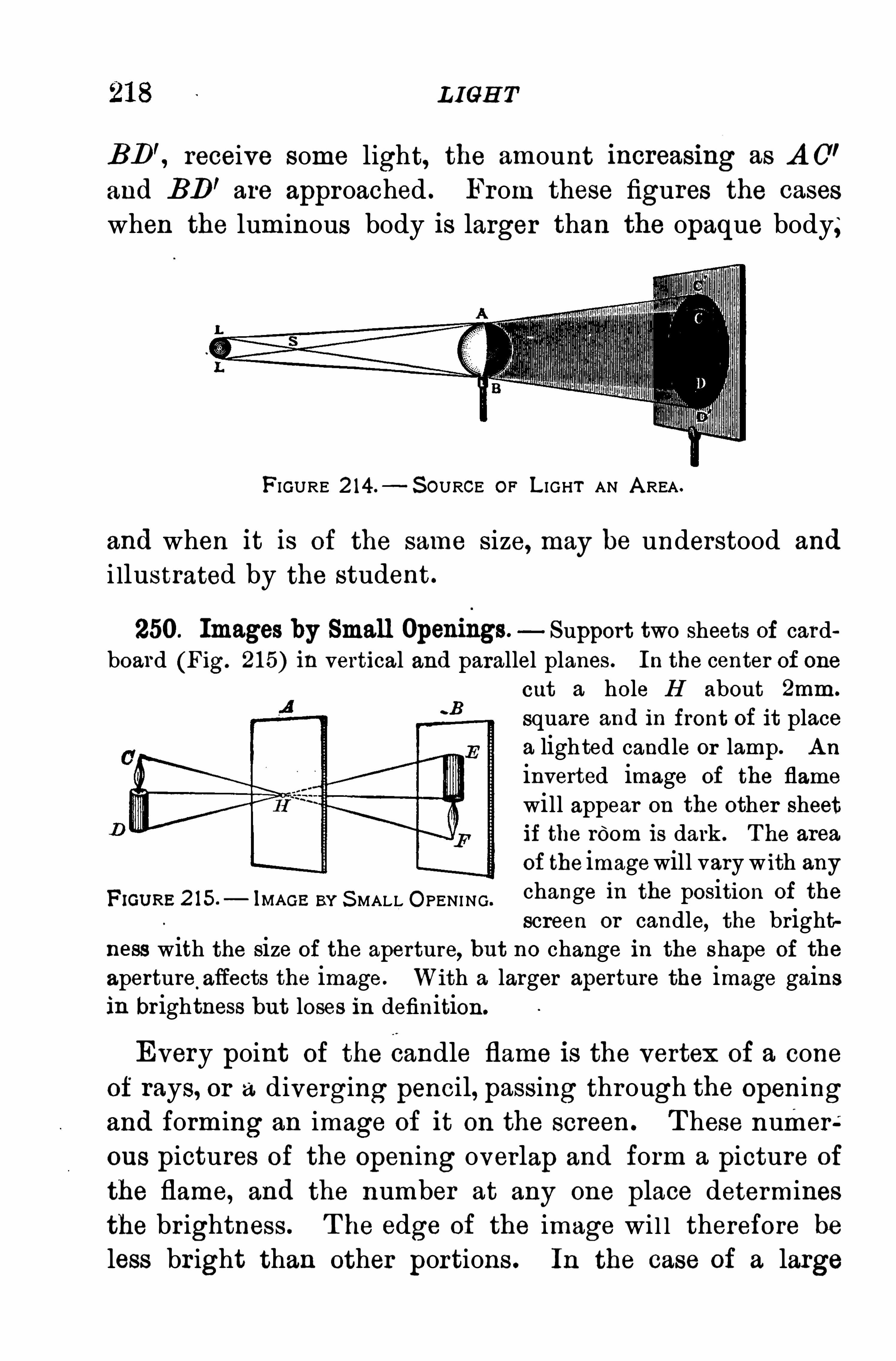
L IGH T
BD', receive some light, the amount increasmg as A O’
and BD'are approached . From these figures the cases
when the luminous body is larger than the opaque body;
FIGURE 2 14.—S OURCE OF L IGHT AN A REA .
and when it is of the same size, may be understood and
i llustrated by the student.
250. Images by Small Openings. Support two sheets of cardboard (Fig. 21 5) in vertical and parallel planes. In the center of one
cut a hole H about 2mm.
square and in front of it placea lighted candle or lamp. A n
inverted image of the flame
will appear on the other sheetif the room is dark . T he area
of the imagewill vary with anyFxGUR5 2 15 ,
_ 1MAGE BY S MALL O PENING.
change in the position of the
screen or candle, the brightness with the size of the aperture, but no change in the shape of the
aperture.affects the image. With a larger aperture the image gains
in brightness but loses in definition
Every point of the candle flame is the vertex of a coneof rays, or a diverging pencil, passing through the Openingand forming an image of it on the screen. T hese numer éous pictures of the Opening overlap and form a picture of
the flame, and the number at any one place determines
the brightness . T he edge of the image wi l l therefore be
less br ight than other portions . In the case of a large
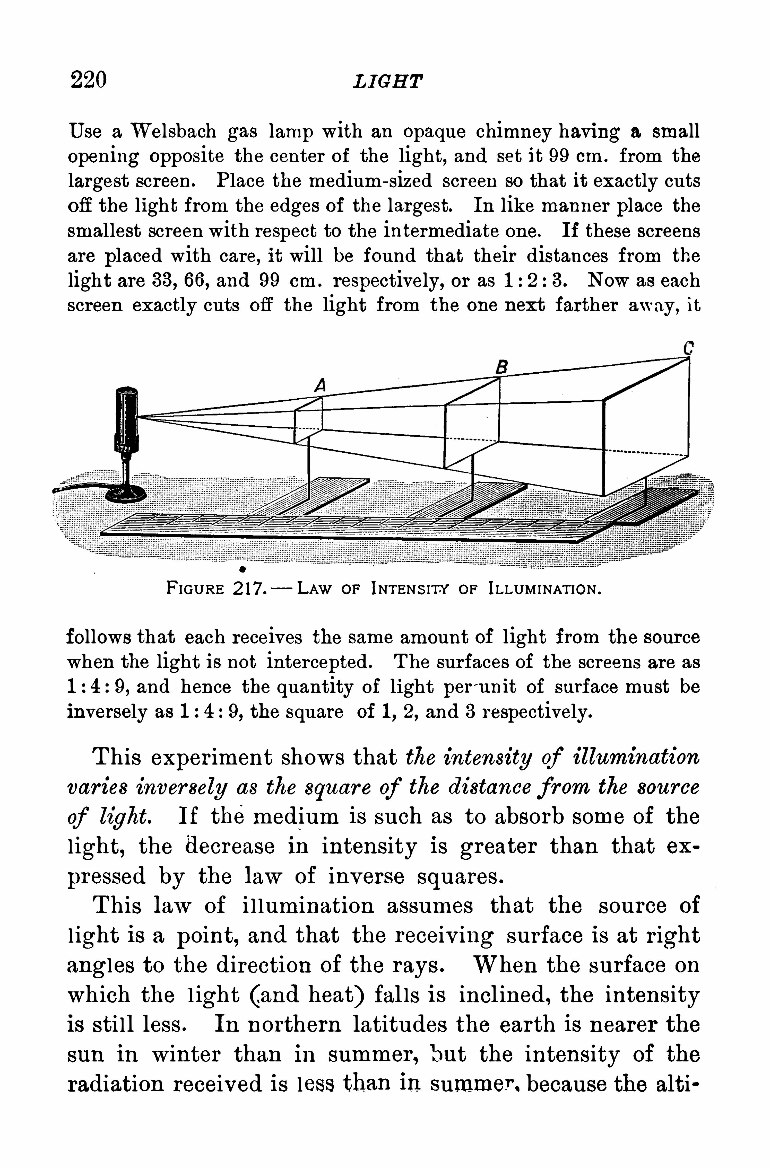
220 L IGH T
U se a Welsbach gas lamp with an opaque chimney having a smallopening opposite the center of the light, and set it 99 cm . from the
largest screen . P lace the medium- sized screen so that it exactly cutsoff the ligh t from the edges of the largest. In like manner place thesmallest screen with respect to the intermediate one. If these screensare placed with care, it will be found that their distances from the
light are 33, 66, and 99 cm . respectively, or as 3 . Now as eachscreen exactly cuts off the light from the one next farther away, it
FIGURE 2 17 .— LAW OF INTENS ITY OF ILLUMINAT ION .
follows that each receives the same amount of light from the sourcewhen the light is not intercepted . T he surfaces of the screens are as
9, and hence the quantity of light per'
unit of surface must beinversely as 1 4:9, the square of 1 , 2, and 3 respectively.
T his exper iment shows that the intensity of illumination
var ies inver sely as the squar e of the distancefrom the source
of light. If themedium is such as to absorb some of the
l ight, the decrease In intensity is greater than that ex
pressed by the law of inverse squares .
T his law of i l lumination assumes that the source of
l ight is a point, and that the receiv ing surface is at r ight
angles to the direction of the rays . When the surface on
which the l ight (and heat) fal ls is incl ined , the intensity
is sti ll less . In northern latitudes the earth is nearer the
sun in winter than in summer , but the intensity of the
radiation received is less than in summer . because the alti
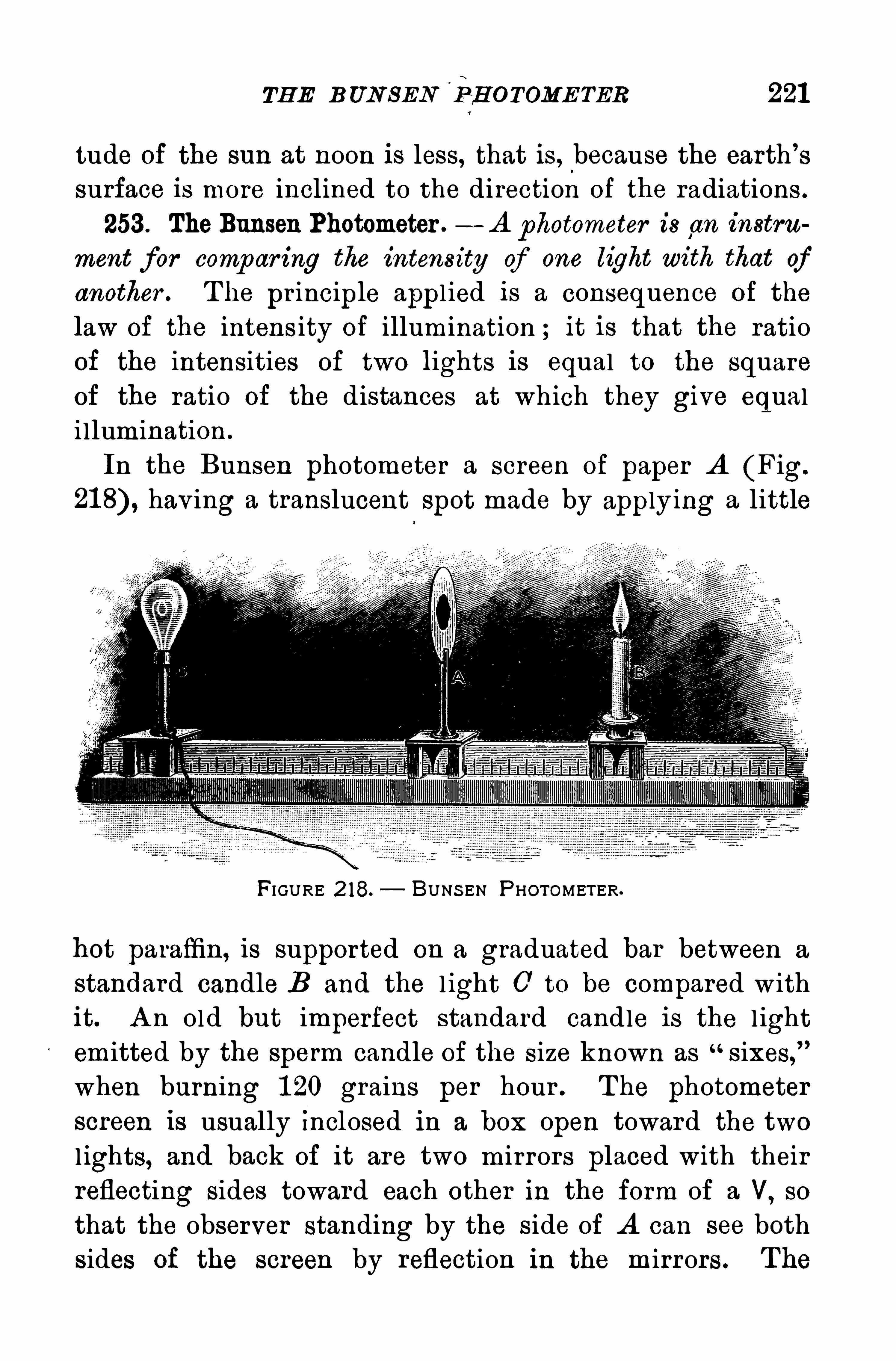
TH E B UN SEN‘
EH OTOME TER 221
tude of the sun at noon is less, that is , because the earth’
s
surface is more inclined to the direction of the radiations .
253 . TheBunsen Photometer .—A photometer is an instru
ment for comp ar ing the intensity of one light with that ofanother . T he pr inciple appl ied is a consequence of the
law of the intens ity of illumination ; it is that the ratio
of the intensities of two lights is equal to the square
of the ratio of the distances at which they give equali llumination .
In the Bunsen photometer a screen of paper A (Fig.
hav ing a translucent spot made by applying a little
FI GURE 2 18. BUNS EN P HOTOMETER.
hot paraffin, is supported on a graduated bar between a
standard candle B and the l ight 0 to be compared withit. A n old but imperfect standard candle is the l ightemitted by the sperm candle of the size known as
“sixes,
”
when burning 1 20 grains per hour . T he photometerscreen is usually Inclosed in a box Open toward the two
l ights, and back of it are two mirrors placed with theirreflecting sides toward each other in the form of a V, so
that the observer standing by the side of A can see bothsides of the screen by reflection in the mirrors . The
222 L IGH T
position of A or of B may then be adjusted until bothsides of the screen look al ike. T hen the intensity of 0
is to the intensity of B as 71 772is to AB?
In the Joly photometer two rectangular blocks of
paraffin, separated by a sheet of tinfoil , take the place of
the sheet of paper. When the l ights are balanced the
edges of the paraffin blocks are equally lighted .
Q uestions and P rob lems
1 . What Is thecauée'
of an eclipse. of the sun Explain by diagram,
2 . What is ~-the‘
causeo”
f“
ari eclipse of the moon ? Explain by diagram.
3 . Why does a small aperture in the camera give a more sharplydefined image than a large one ?
4 . Why is a larger aperture in the camera necessary for a snapshotthan for a time exposure ?
5 . In an attempt to determ ine the height of a tree the followingdata were obtained:L ength of the tree’
s shadow, 50 ft. length of theshadow of a vertical 1 0-ft. pole, 4 ft . What is the height of the tree ?
6 . Two lights, 25 and 1 00 c.p. respectively, are placed 60 ft. apart.
Where must a screen be placed between them and on the line joiningthem so as to be equally illuminated on its two sides ?
7 . Inmeasuring the candle power of a lamp the following data wereobtained:Distance of the standard lamp from the photometer di sk ,20 cm. ;distance of lamp, 1 20 cm . What is the candle power ?
8. If a book can be read at a distance of 1 ft. from a 20 c.p. electriclamp, at what distance from a 60 c .p . lamp can it be read with equalclearness ?
9 . T he picture of a tree taken with a pinhole camera was 1 0 cm.
long . The aperture was 20 cm. from the sensitive plate and 30 m .
from the tree. What is the height of the tree ?
1 0 . Two Mazda lamps are to be used to give equal illumination tothe two sides of a screen . One of themis 20 c.p. and distant 8 ft.
from the screen ;the other is 40 c.p. H ow far from the screen must’
the second lamp be placed to secure the desired illumination ?
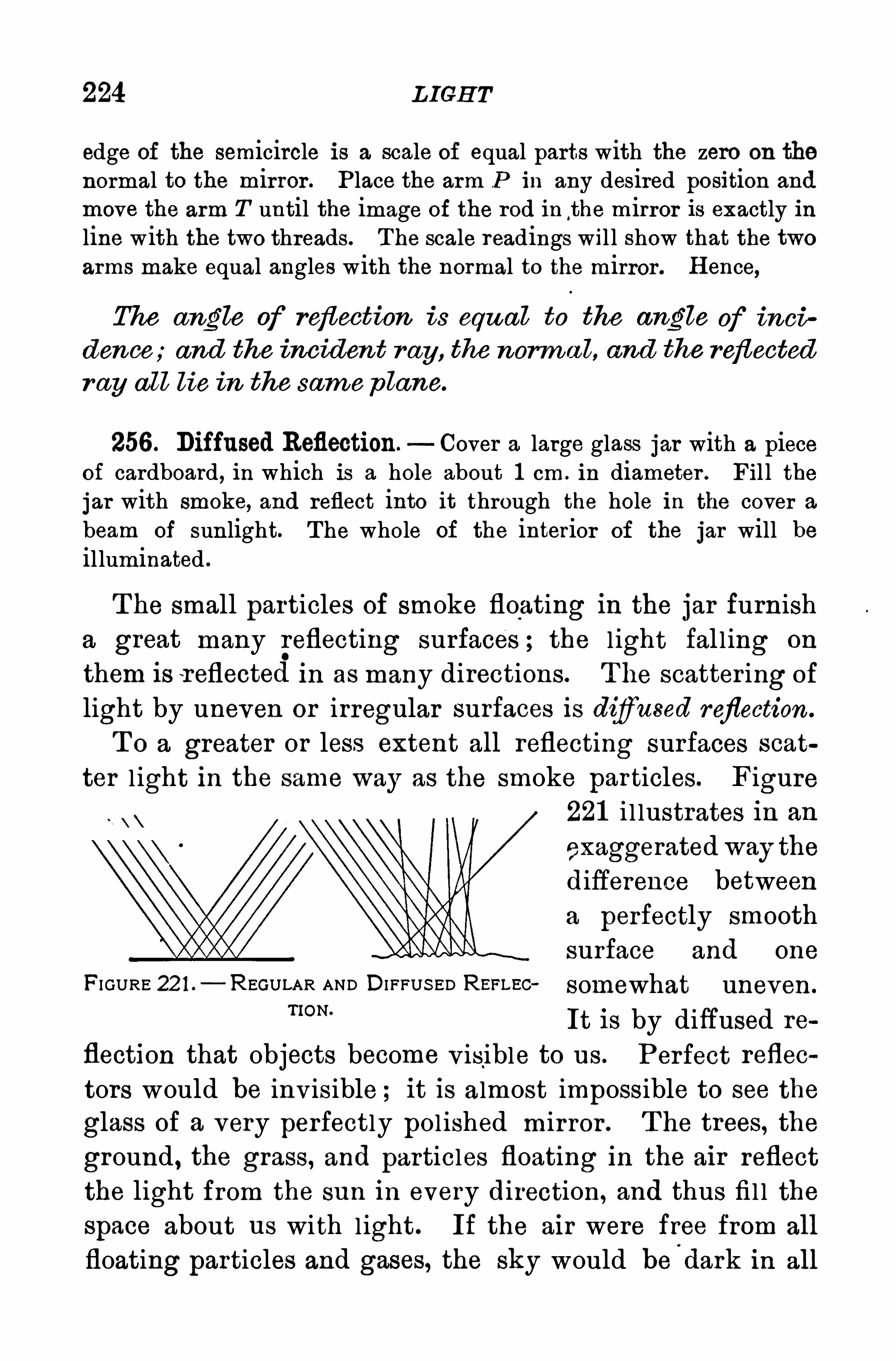
224 L IGH T
edge of the semicircle is a scale of equal parts with the zero on the
normal to the mirror . P lace the arm P in any desired position and
move the arm T until the image of the rod in the m irror is exactly inline with the two threads. The scale readings wil l show that the twoarms make equal angles with the normal to the mirror . H ence,
The angle of reflection is equ al to the angle of inci
dence;and the incident r ay , the norm a l, and the reflectedr ay all lie in the sam e p lane.
256 . Diffused Reflection. Cover a large glass jar with a pieceof cardboard, in which is a hole about 1 cm . in diameter . Fil l thejar with smoke, and reflect into it through the hole in the cover a
beam of sunlight. T he whole of the interior of the jar will beilluminated .
T he small particles of smoke floating in the jar furnisha great many reflecting surfaces ; the l ight fal l ing on
them is r eflected in as many directions. T he scatter ing of
light by uneven or irregular surfaces is difiused reflection .
T o a greater or less extent all reflecting surfaces scat
ter l ight in the same way as the smoke particles. Figure221 i l lustrates in an
exaggerated way thedifference betweena perfectly smooth
surface and one
FI GURE 22 1 .— REGULAR AND DI FFUS ED REFLEC somewhat uneven.
“ON‘
It is by diffused re
flection that objects become v isible to us . Perfect reflec
tors would be inv isible ; it is almost impossible to see the
glass of a very perfectly pol ished mirror . T he trees, the
ground , the grass, and particles floating in the air reflect
the light from the sun in every direction, and thus fi l l the
space about us with light . If the air were free from all
floating particles and gases, the sky would bed ark in all
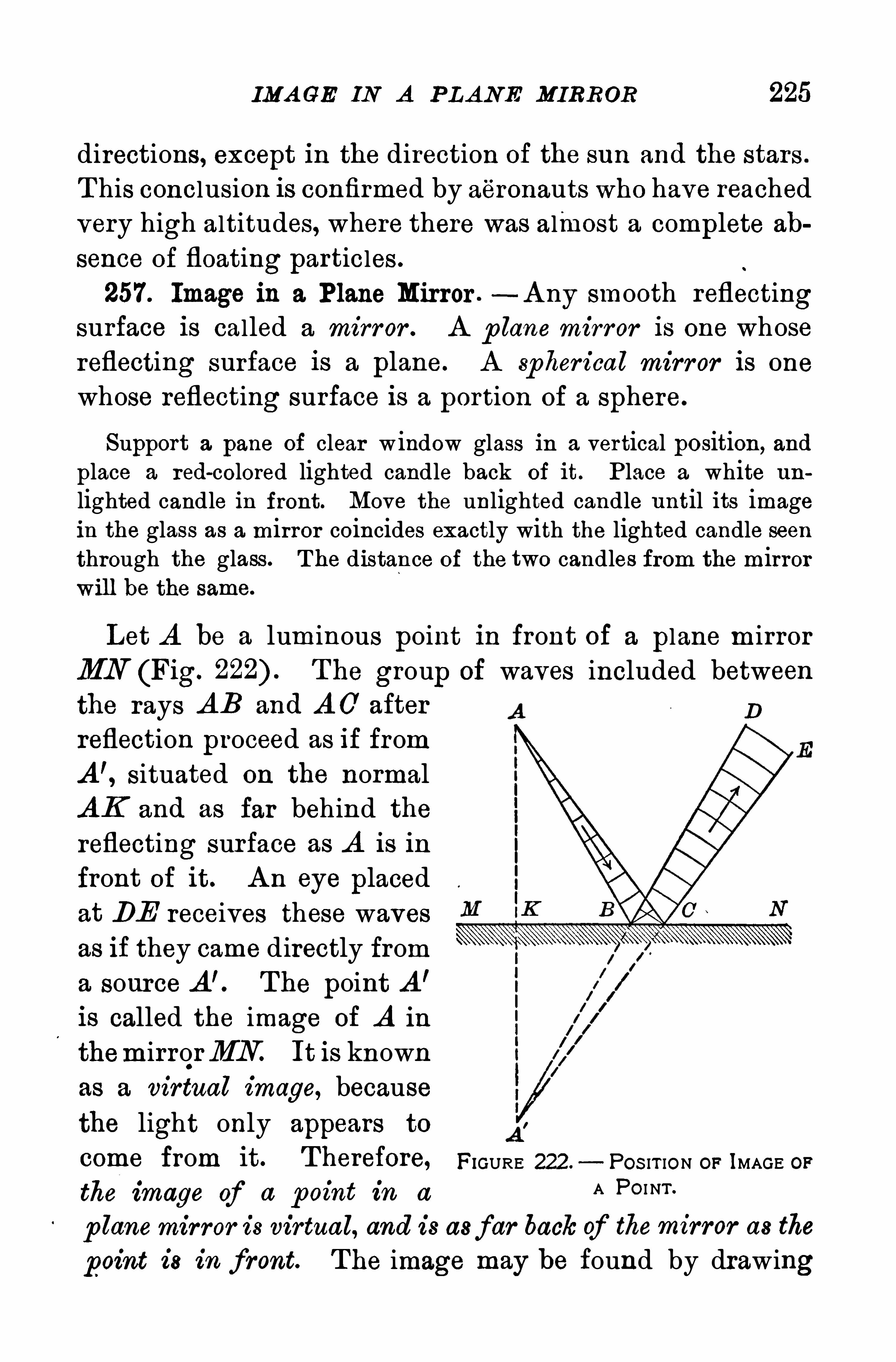
IMA GE IN A P LA NE MIRROR 225
directions, except in the direction of the sun and the stars .
T his conclusion is confirmed by aeronauts who have reached
very high altitudes, where there was almost a complete ab
sence of floating particles .
257. Image in a Plane Mirror .—A ny smooth reflecting
surface is called a mirror . A p lane mirr or is one whose
reflecting surface is a plane. A spher ical mirror is one
whose reflecting surface is a portion of a sphere.
Support a pane of clear window glass in a vertical position, and
place a red-colored lighted candle back of it. P lace a white un
lighted candle in front. Move the unlighted candle until its imagein the glass as a mirror coincides exactly with the lighted candle seenthrough the glass. T he distance of the two candles from the mirrorwill be the same.
Let A be a luminous point in front of a plane mirror
MN (Fig. T he group of waves included between
the rays A B and A O after
reflection proceed as if from
A ’, situated on the normal
A K and as far behind the
reflecting surface as A is in
front of it. A n eye placed
at DE receives these waves
as if they came directly from
a source A ’ The point A’
is called the image of A in
themirrorMN It is known
as a virtual image, because
the light only appears to
come from it" T herefOI'ea FIGURE 222 .— POS IT ION OF IMAGE OF
the image of a p oint in a A PO I NT
p lanemirror is virtual, and is asfar back of themirror as the
point is in front. T he image may be found by drawing
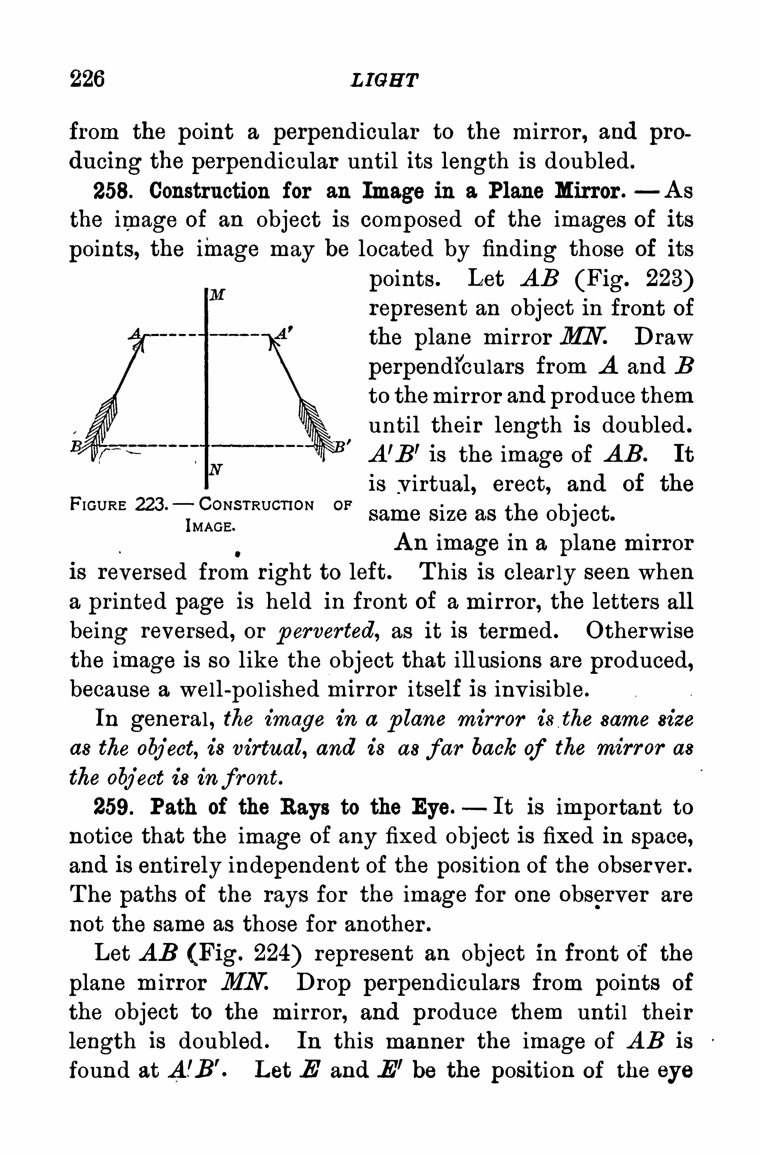
226 L IGH T
from the point a perpendicular to the mirror , and producing the perpendicular until its length is doubled.
258. Construction for an Image in a Plane Mirror .—A s
the image of an object is composed of the images of its
points, the image may be located by finding those of its
points. Let A B (Fig. 223)represent an object in front ofthe plane mirror MN Draw
perpendiculars from A and B
to themirror and produce them
until their length is doubled .
A ’B’ is the image of A B. It
is v irtual, erect, and of the
same size as the object.
A n image in a plane mirroris reversed from right to left. T his is clear ly seen when
a printed page is held in front of a mirror , the letters all
being reversed, or p erverted, as it is termed . O therwisethe image is so like the object that illusions are produced,because a well-pol ished mIrror itself is inv isible.
In general , the image in a p lane mirror is the same size
as the object, is virtual, and is as f ar back of the mirror as
the object is inf ront.
259. Path of the Rays to the Eye.—It is important to
notice that the image of any fixed object is fixed in space,
and is entirely independent of the position of the observer .
T he paths of the rays for the image for one observer are
not the same as those for another .
Let A B (Fig. 224) represent an object in front of the
plane mirror MN . Drop perpendiculars from points of
the object to the mirror , and produce them unti l their
length is doubled . In this manner the image of A B is
found at A .
’B’. Let E and E’ be the position of the eye
FIGURE 223 .— CONSTRUCT ION OF
IMAGE.
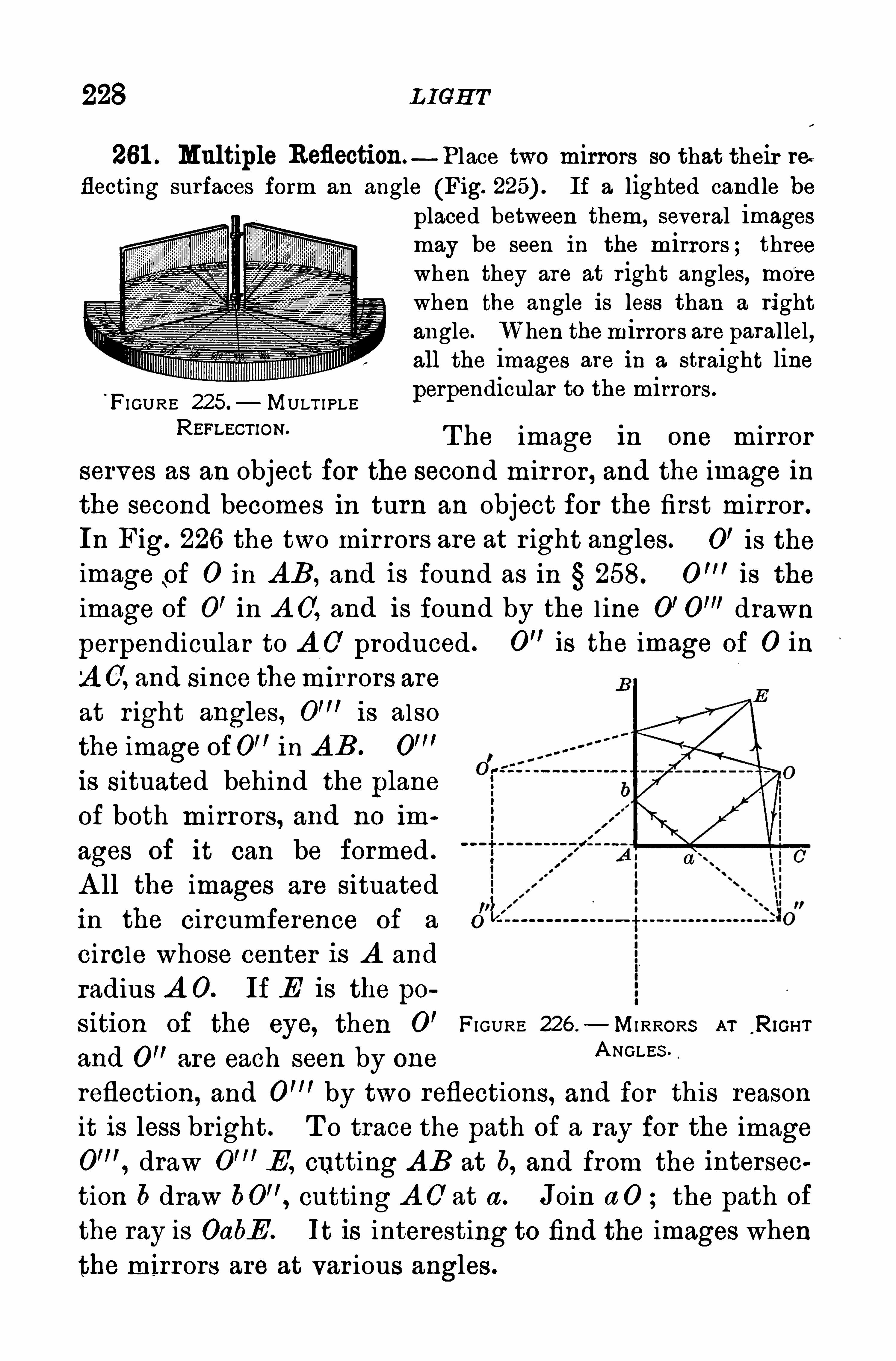
228 L IGH T
261 . Multiple Reflection—Place two mirrors so that their reflecting surfaces form an angle (Fig. If a lighted candle be
placed between them, several imagesmay be seen in the mirrors ; threewhen they are at r ight angles, more
when the angle is less than a rightangle. When themirrors are parallel,all the images are in a straight line
‘
FI GURE 2 5 MULT I PLE perpendicular to the mirrors .
REFLECT’ON' T he image in one mirrorserves as an object for the second mir ror , and the image in
the second becomes in turn an object for the first mirror .
In Fig. 226 the two mir rors are at r ight angles. 0’ is the
image of 0 in AB , and is found as in 258. is the
image of 0’ in A O, and is found by the l ine 0’ drawn
perpendicular to A O produced . 0” is the image of 0 in‘
A 0, and since them i rrors areat r ight angles, is alsothe image of0
” in A B .
is situated behind the plane
of both mirrors, and no im
ages of it can be formed . 3A ll the images are situated 5
in the circumference of a o'lf '
circle whose center is A and
radius A O. If E is the po
sition of the eye, then 0 ’FI GURE 226 .
— MI RRORS AT RIGHT
and 0” are each seen by oneA NGLES '
reflection, and by two reflections, and for this reasonit is less br ight. T o trace the path of a ray for the image
draw E , cutting AB at b, and from the intersec
tion 6 draw cutting A O at a . Join a 0 the path of
the ray is GabE . It is interesting to find the images when
the mirrors are at var ious angles.
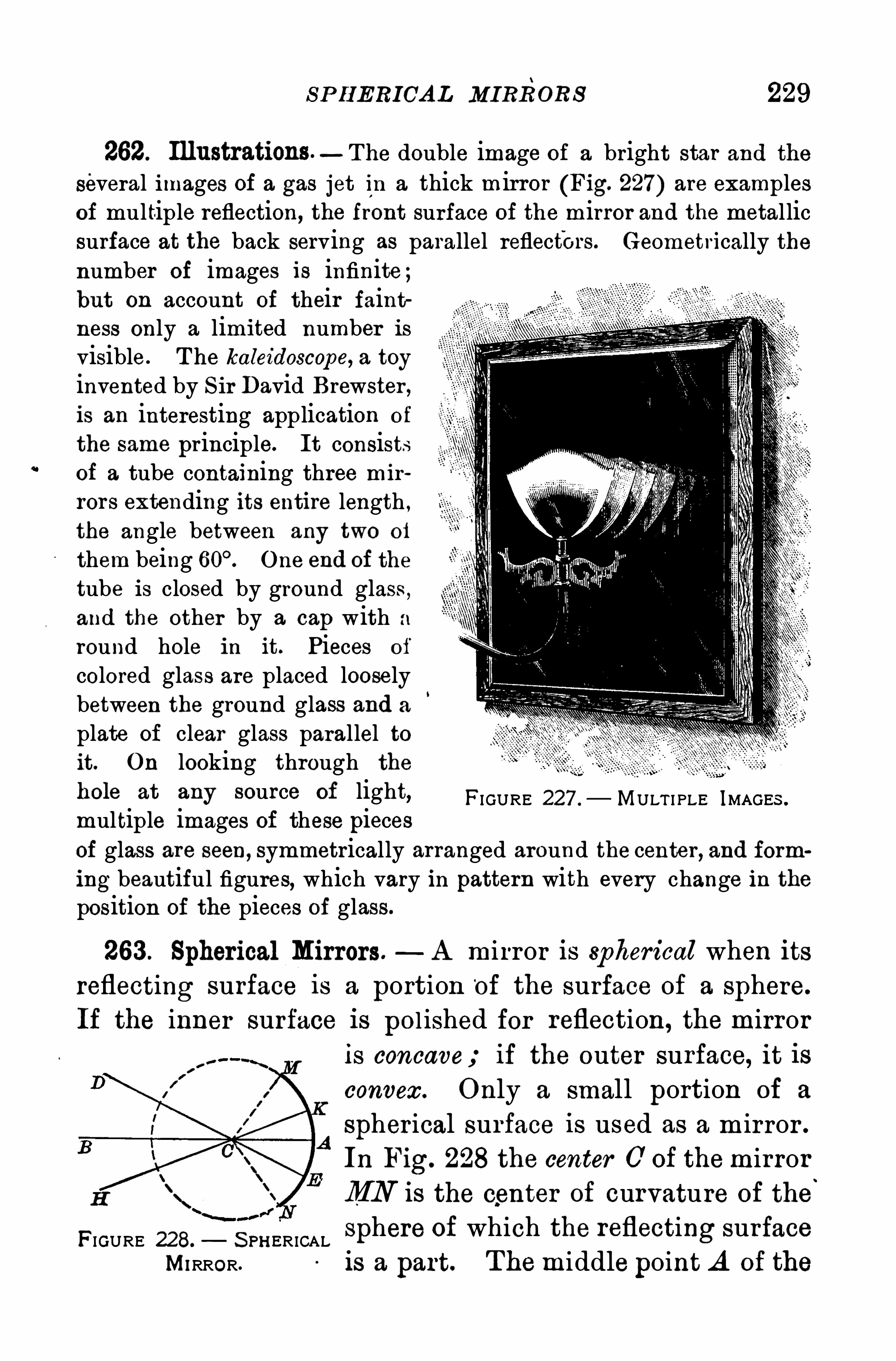
S P H ERIOA L MIRRORS 229
262. Illustrations—The double image of a bright star and the
several images of a gas jet in a thick mirror (Fig. 227) are examplesof multiple reflection, the front surface of the mirror and the metallicsurface at the back serving as parallel reflectors. Geometrically thenumber of images is infinite;but on account of their faintness only a limited number isvisible. T he kaleidoscope, a toy
invented by S ir David Brewster ,is an interesting application of
the same principle. It consistsof a tube containing three mirror s extending its entire length ,the angle between any two of
them being One end of the
tube is closed by ground glass ,and the other by a cap with a
round hole in it. Pieces of
colored glass are placed looselybetween the ground glass and a
plate of clear glass parallel toit. On looking through the
11 0 13 at any source Of light, FI GURE 227 . MULT I PLE IMAGES .
multiple images of these piecesof glass are seen, symmetrically arranged around the center , and forming beautiful figures, which vary in pattern with every change in theposition of the pieces of glass.
263. Spherical Mirrors. A mirror is spherical when itsreflecting surface 1 s a portion
‘
of the surface of a sphere.
If the inner surface is pol ished for reflection, the mirroris concave; if the outer surface, it isconvex. Only a small port ion of a
spher ical surface is used as a m irror .
In Fig. 228 the center 0 of themirrorMN is the center of curvature of the
'
FIGURE 2 8. S PH ER ICAL sphere of which the reflecting surface
MIRROR. is a part. Themiddle point A of the
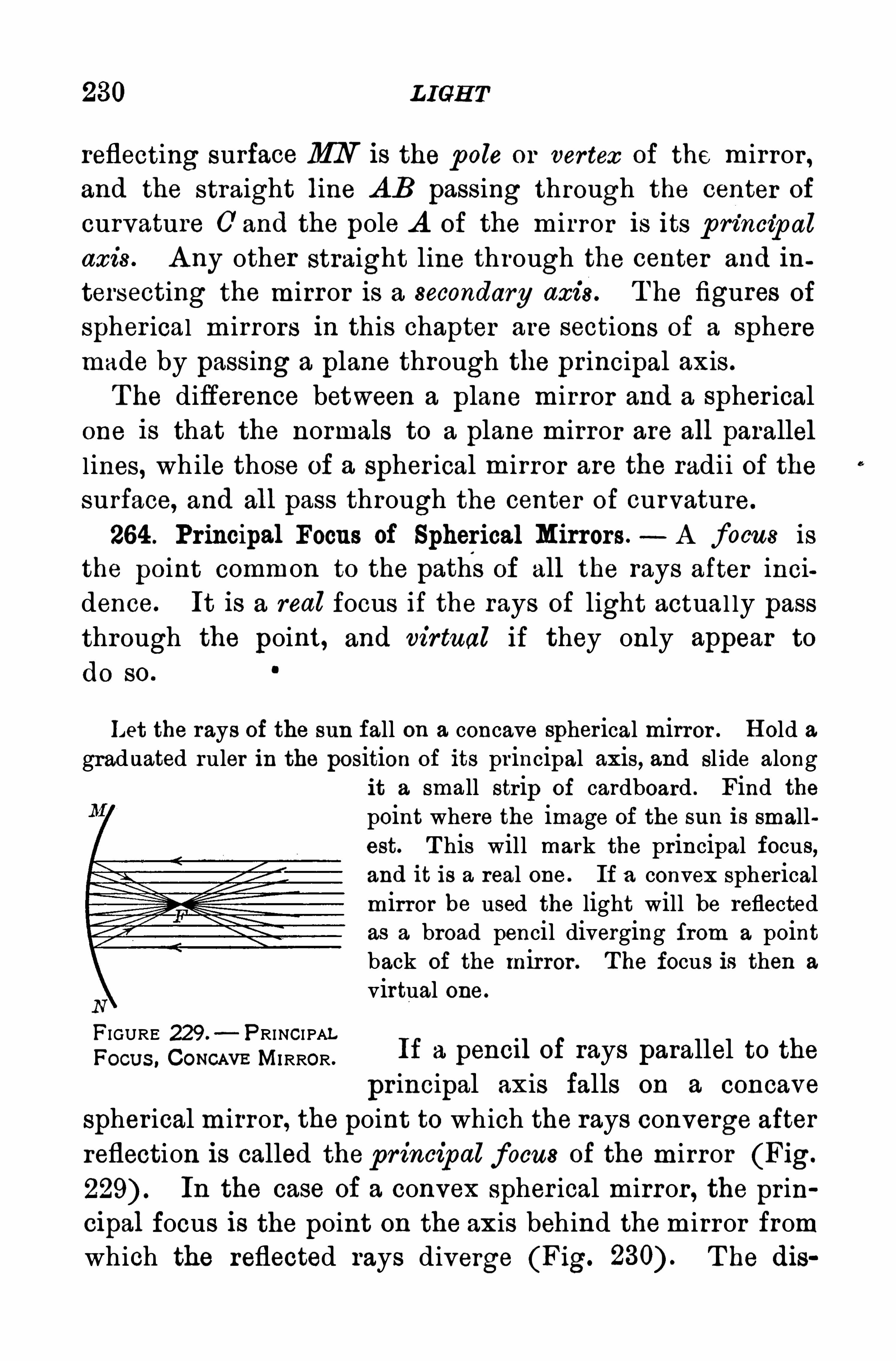
230 L IGH T
reflecting surface MN is the p ole or vertex of the mirror ,and the straight line AB passing through the center of
curvature 0 and the pole A of the mirror is its p rincip alaxis . A ny other straight line through the center and in
tersecting the mirror is a secondary axi s. T he figures of
spher ical m irrors in this chapter are sections of a spheremade by passing a plane through the principal axis .
T he difference between a plane mirror and a spher icalone is that the normals to a plane mirror are all parallel
l ines, while those of a spher ical mirror are the radii of thesurface, and all pass through the center of curvature.
264 . Principal Focus of Spherical Mirrors. A focus is
the point common to the paths of all the rays after inci
dence. It is a real focus if the rays of light actual ly passthrough the point, and virtual if they only appear to
do so.
Let the rays of the sun fall on a concave spherical mirror . H old agraduated ruler in the position of its principal axis, and slide along
it a small strip of cardboard . Find thepoint where the image of the sun is smallest. T his will mark the principal focus,and it is a real one. If a convex sphericalmirror be used the light will be reflectedas a broad pencil diverging from a pointback of the mirror . The focus is then a
virtual one.
FIGURE 229.—PRINCI PAL
Focus , Com m MIRROR .
If a pencII of rays parallel to the
pr incipal axis falls on a concave
spher ical mirror, the point to which the rays converge after
reflection is called the pr incipal focus of the mirror (Fig.
In the case of a convex spher ical mirror, the prin
cipal focus is the point on the axis behind themirror from
which the reflected rays diverge (Fig. T he dis
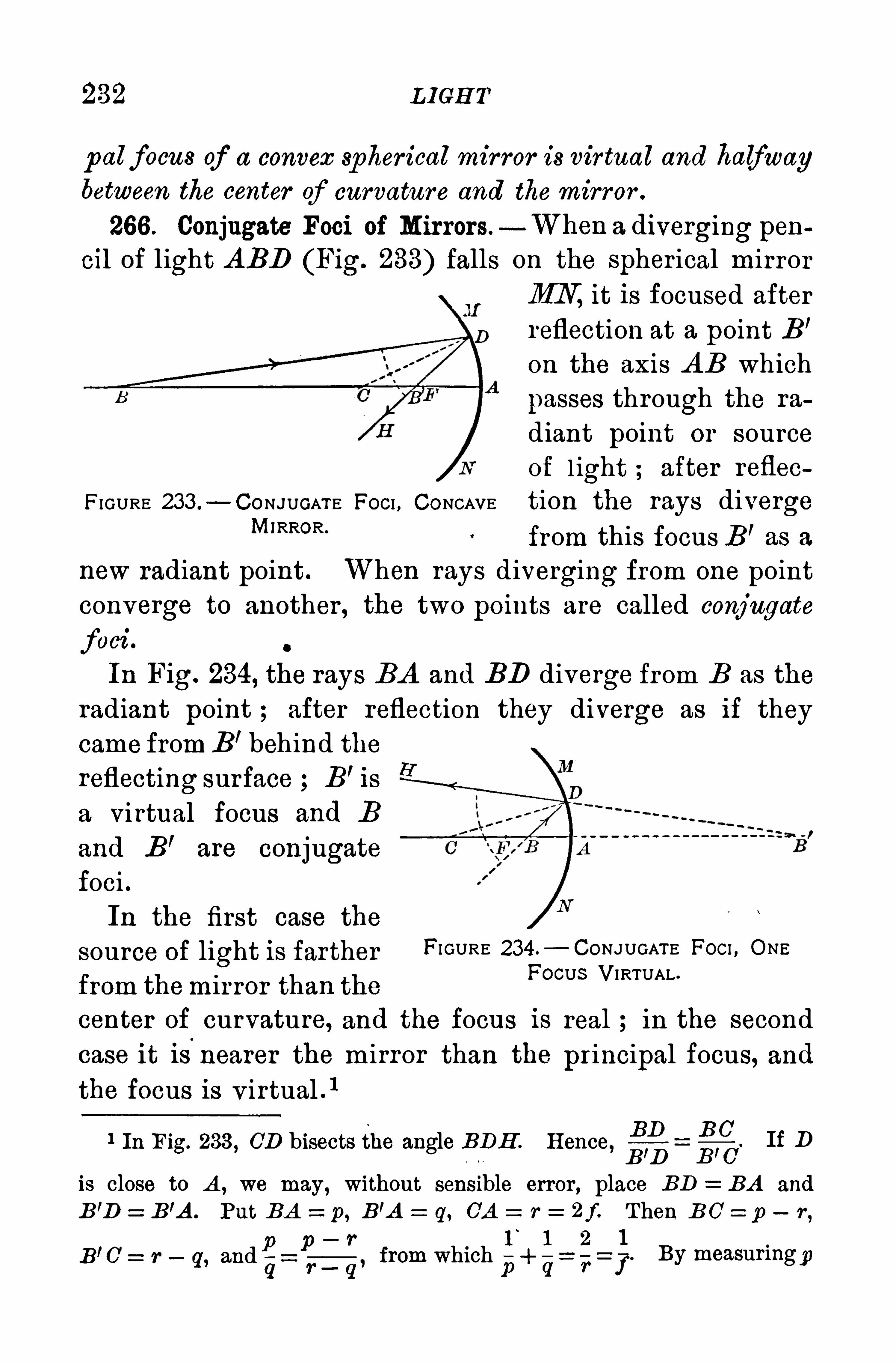
232 L IGH T
p alfocus of a convex spherical mirror is vir tual and halfwaybetween the center of curvature and the mirror .
266 . Conjugate Foci of Mirrors.—When a diverging pen
cil of light A BD (Fig. 233) falls on the spherical mirrorMN it is focused after
reflection at a point B’
on the axis A B which
passes through the ra
diant point or sourceof l ight ; after reflec
FIGURE 233 .
—CONJUGATE FOCI , CONCAVE tion the rays divergeM’RROR’
from this focus B’as a
new radiant point . When rays diverging from one pointconverge to another , the two points are called conjugate
foci . o
In Fig. 234, the rays BA and BD diverge from B as the
radiant point after reflection they diverge as if theycame from B’behind the
reflecting surface B’ is
a Vi rtual focus and B
and B’are conjugate
foci .In the first case the
source of light is farther FI GURE 234 .
— CONJUGATE FOCI , ONE
from themirror than theFOCUS VI RTUAL‘
center of curvature, and the focus is real in the second
case it is nearer the mirror than the pr incipal focus, and
the focus is v irtual . 1
H
BD BC. If D
R D B ’C
is close to A , we may, without sensible error , place BD BA and
B ’D z B’A . Put BA z p ,B’A z q, 0A = r = 2f. Then B O z p
—r,
p—r l
‘
1 2pB C _ r -
q, andg r q
’ from which +q r
1 In Fig. 233 , OD bisects the angle RDH . H ence,
1
7. By measuringp
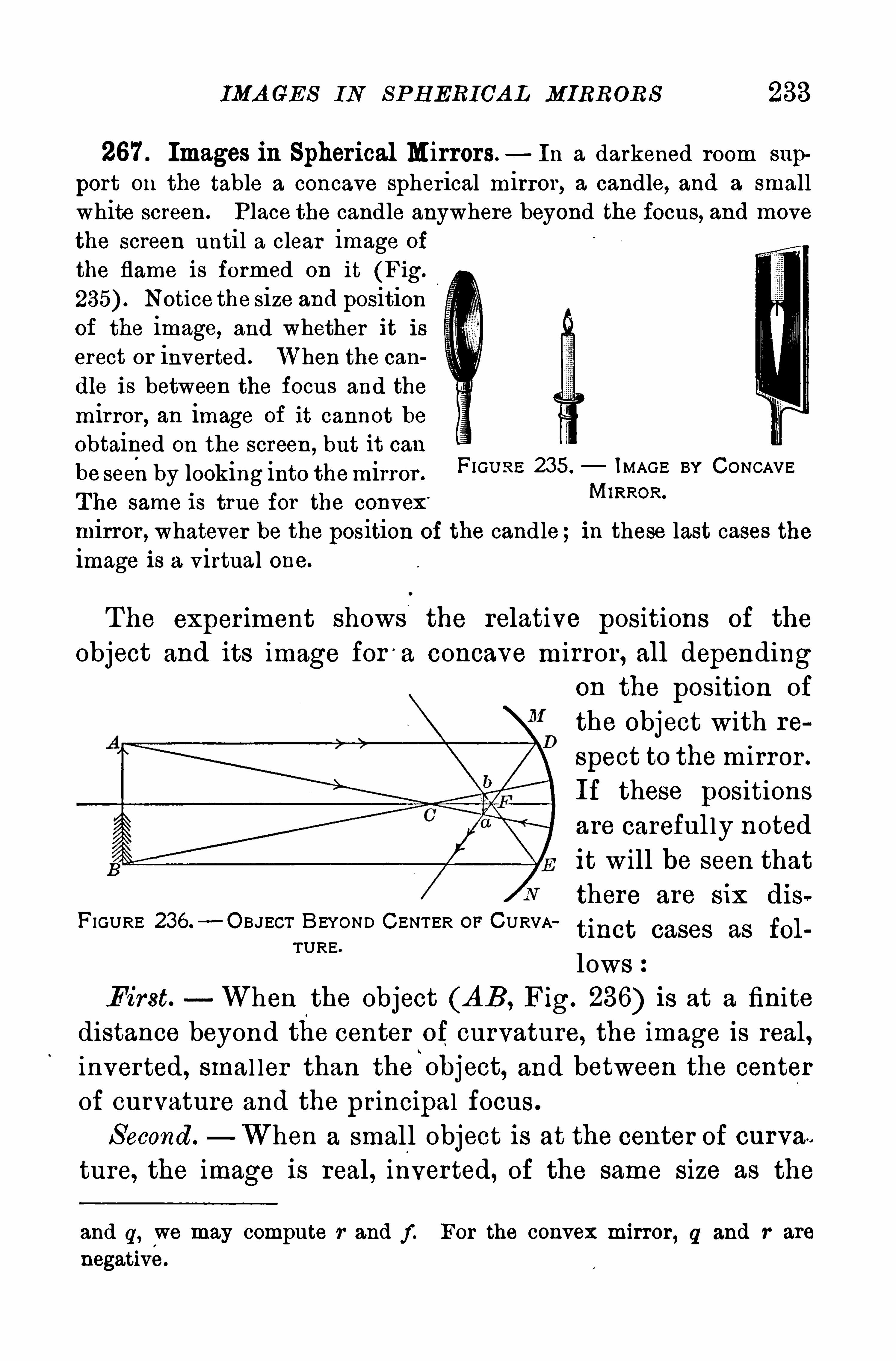
IMA GES IN S P H ERIOA L MIRRORS 233
267 . Images in Spherical Mirrors. In a darkened room sup
port on the table a concave spherical mirror, a candle, and a smallwhite screen . Place the candle anywhere beyond the focus, and movethe screen until a clear image of
the flame is formed on it (Fig.
Notice the size and positionof the image, and whether it iserect or inverted . When the candle is between the focus and the
mirror, an image of it cannot be
obtained on the screen ,but it can
be seen by looking into themirror .
F‘GU RE 235 IMAGE BY CONCAVE
The same is true for the convex’ MlRROR‘
mirror , whatever he the position of the candle; in these last cases theimage is a virtual one.
The exper iment shows the relative positions of the
object and its image for'
a concave mirror , all dependingon the position of
the Object with re
spect to themirror .
If these positions
are careful ly notedit will be seen that
there are six dis
tinct cases as fol
lowsFirst. When the object (AB, Fig. 236) is at a finite
distance beyond the center of curvature, the image is real,inverted, smal ler than the
i
object, and between the center
of curvature and the principal focus .
S econd. When a small object is at the center of curvae
ture, the image is real, inverted, of the same size as the
FIGURE 236.—O BJECT BEYOND CENTER OP CURVA
TURE.
and q, we may compute r and f . For the convex mirror, q and r are
negative.
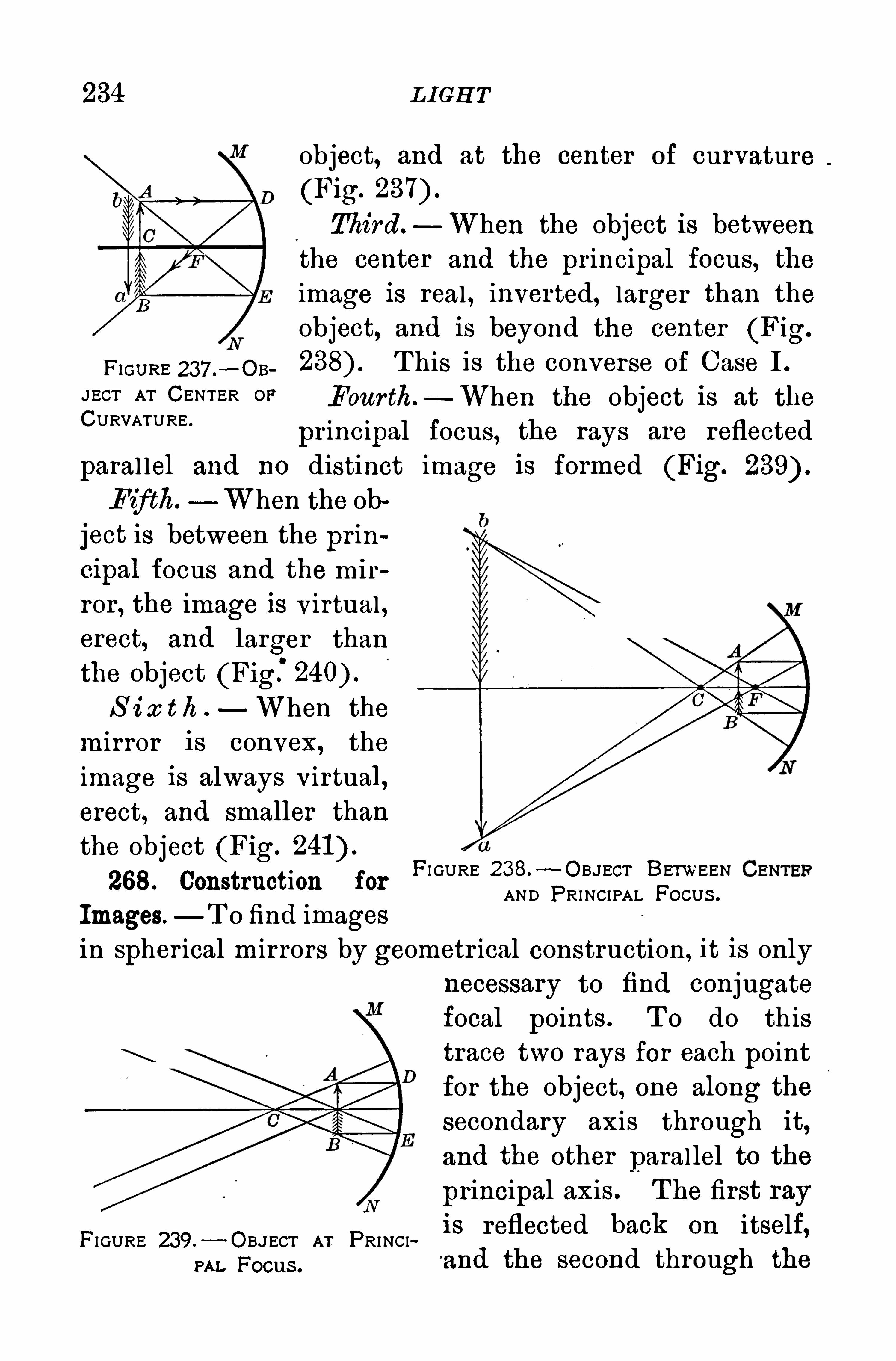
234 L IGH T
object, and at the center of curvature
(Fig.
Third —When the object is betweenthe center and the principal focus, theimage is real , inverted, larger than the
object, and is beyond the center (Fig.
pm ,“ 237 .—OB T his is the converse of Case I .
JECT AT CENTER OF Four th.—When the object is at the
CURVATURE‘pr incipal focus, the rays are reflected
paral lel and no distinct image is formed (Fig.
Fifth. When the ob
ject is between the prin
cipal focus and the mir
ror , the image is v irtual ,erect, and larger than
the object (Fig:S i x t h When the
mirror is convex, the
image is always virtual,erect, and smaller than
the object (Fig.
268. Construction for
Images. T o find images
in spher ical mirrors by geometr ical construction, it is onlynecessary to find conjugatefocal points . T o do this
trace two rays for each point
for the object, one along the
secondary axis through it,
and the other parallel to the
principal axis . The first ray
FI GURE 239.- OB.JECT AT PRINCI is reflected baCk on itself’
an, Focus .and the second through the
FI GURE 238.—OBJECT BETWEEN
AND PRINCI PAL FOCUS .
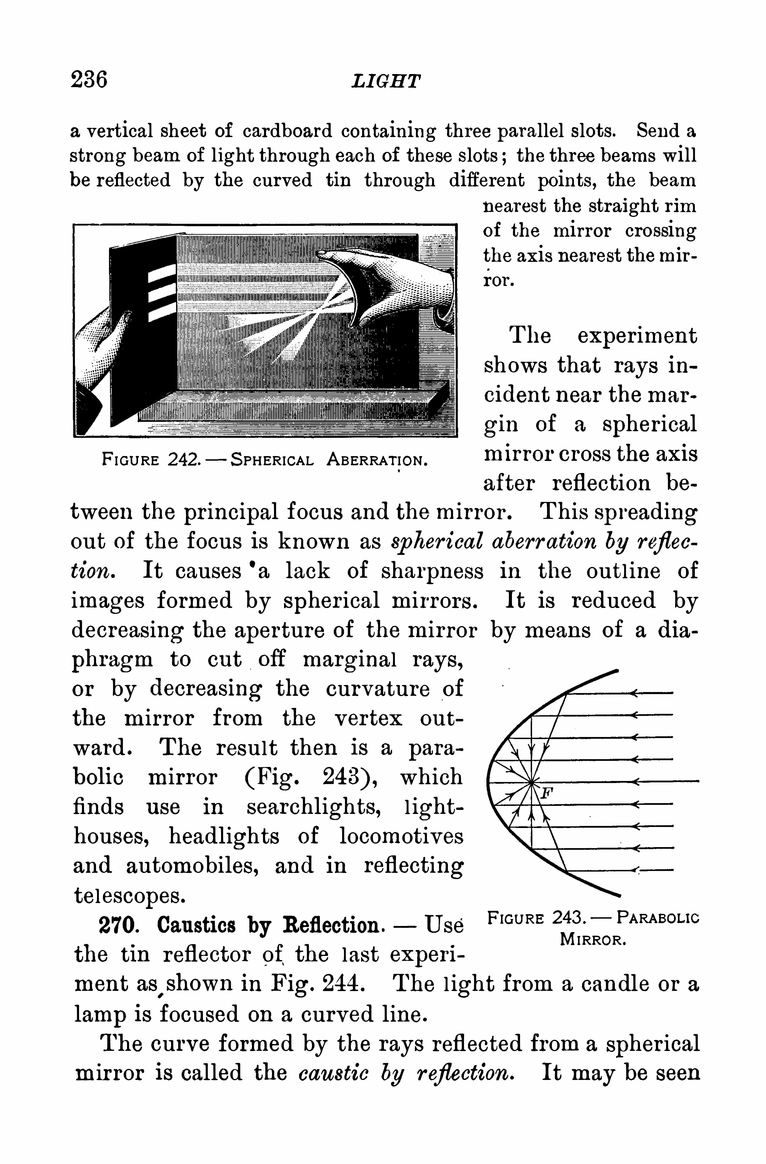
236 L IGH T
a vertical sheet of cardboard containing three parallel slots. Send astrong beam of light through each of these slots ;the three beams willbe reflected by the curved tin through different points, the beam
nearest the straight rimof the mirror crossingthe axis nearest themirror .
The experimentshows that rays ihcident near themar
gin of a spherical
FI GURE 242.- S PHERICAL A BERRAT ION .
m lrror cross the wa safter reflection be
tween the pr incipal focus and the mirror . T his spreadingout of the focus is known as spher ical aberr ation by reflection . It causes '
a lack of sharpness in the outl ine of
images formed by spher ical mirrors . It is reduced bydecreasing the aperture of the mirror by means of a dia
phragm to cut off marginal rays,or by decreasmg the curvature of
the mirror from the vertex out
ward . T he result then is a para
bolic mirror (Fig. which
finds use in searchlights, l ighthouses, headlights of locomotives
and automobiles, and in reflectingtelescopes.
270. Caustics by Reflection. U se’ F‘GURE
MI RROR .
the tin reflector of,the last exper i
ment astshown in Fig. 244 . T he l ight from a candle or a
lamp is focused on a curved line.
T he curve formed by the rays reflected from a spher ical
mir ror is called the caustic by r eflection . It may be seen


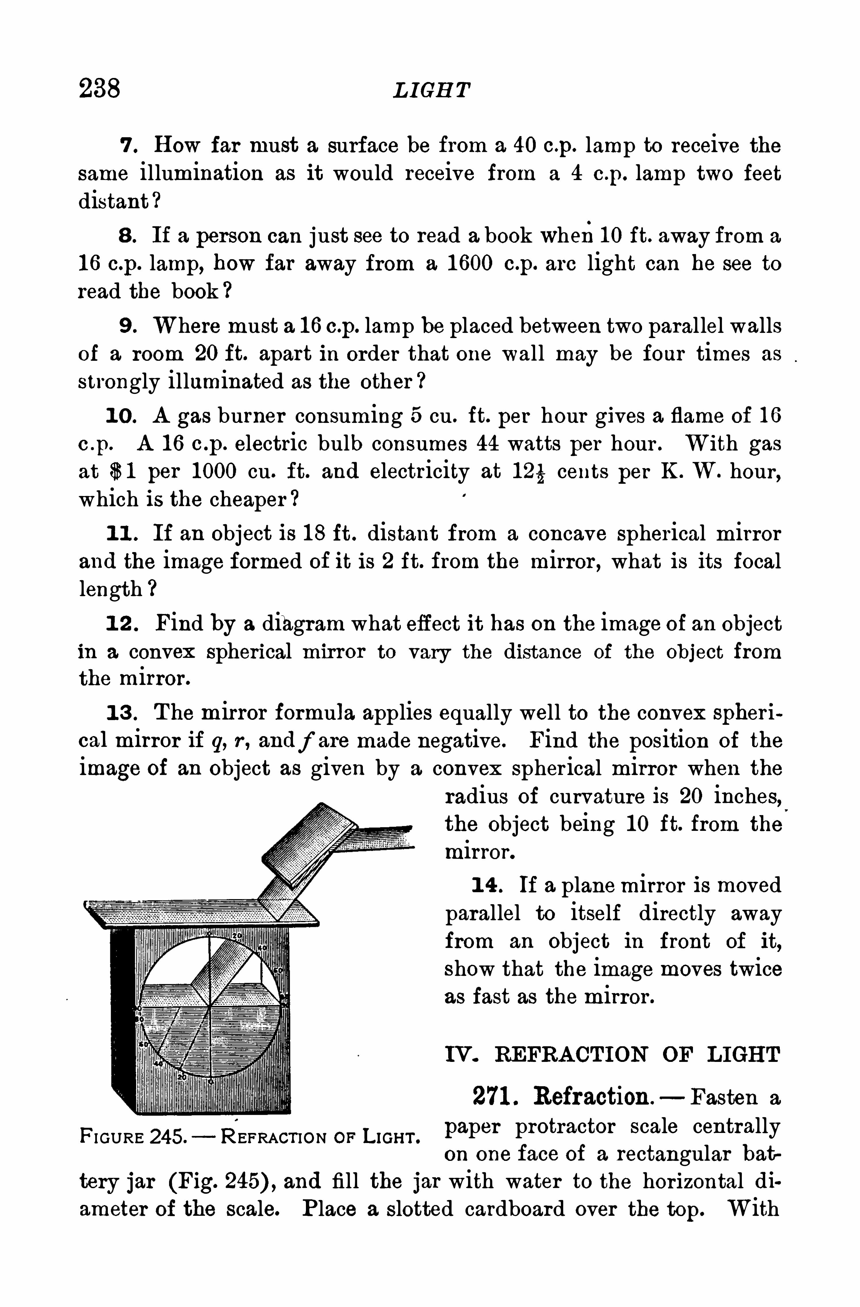
238 L IGH T
7 . H ow far must a surface be from a 40 c.p. lamp to receive thesame illumination as it would receive from a 4 c .p. lamp two feet
distant
8 . If a person can just see to read a book when1 0 ft. away from a
1 6 c.p. lamp, how far away from a 1 600 c.p. arc light can he see to
read the book ?
9 . Where must a 1 6 c.p. lamp be placed between two parallel wallsof a room 20 ft. apart in order that one wall may be four times as
strongly illuminated as the other
1 0 . A gas burner consuming 5 cu . ft. per hour gives a flame of 1 6
c .p. A 1 6 c .p . electric bulb consumes 44 watts per hour . With gasat $ 1 per 1 000 cu. ft. and electricity at 1 25 cents per K . W. hour ,which is the cheaper ?
1 1 . If an object is 1 8 ft . distant from a concave spherical mirrorand the image formed of it is 2 ft. from the mirror , what is its focallength
1 2 . Find by a diagram what effect it has on the image of an objectin a convex Spherical mirror to vary the distance of the object fromthe mirror.
1 3 . T he mirror formula applies equally well to the convex spheri
cal mirror if q, r , andf are made negative. Find the position of the
image of an object as given by a convex spher ical mirror when the
radius of curvature is 20 inches,the object being 1 0 ft. from the
mirror.
1 4 . If a planemirror is movedparallel to itself directly awayfrom an object in front of it,
Show that the image moves twiceas fast as the mirror .
IV. REFRA CT ION OF LIGH T
271 . Refraction —Fasten a
paper protractor scale centrallyon one face of a rectangular bat
tery jar (Fig. and fill the jar with water to the horizontal diameter of the scale. P lace a slotted cardboard over the top. With
FI GURE 245. REFRACT ION OP L IGHT .
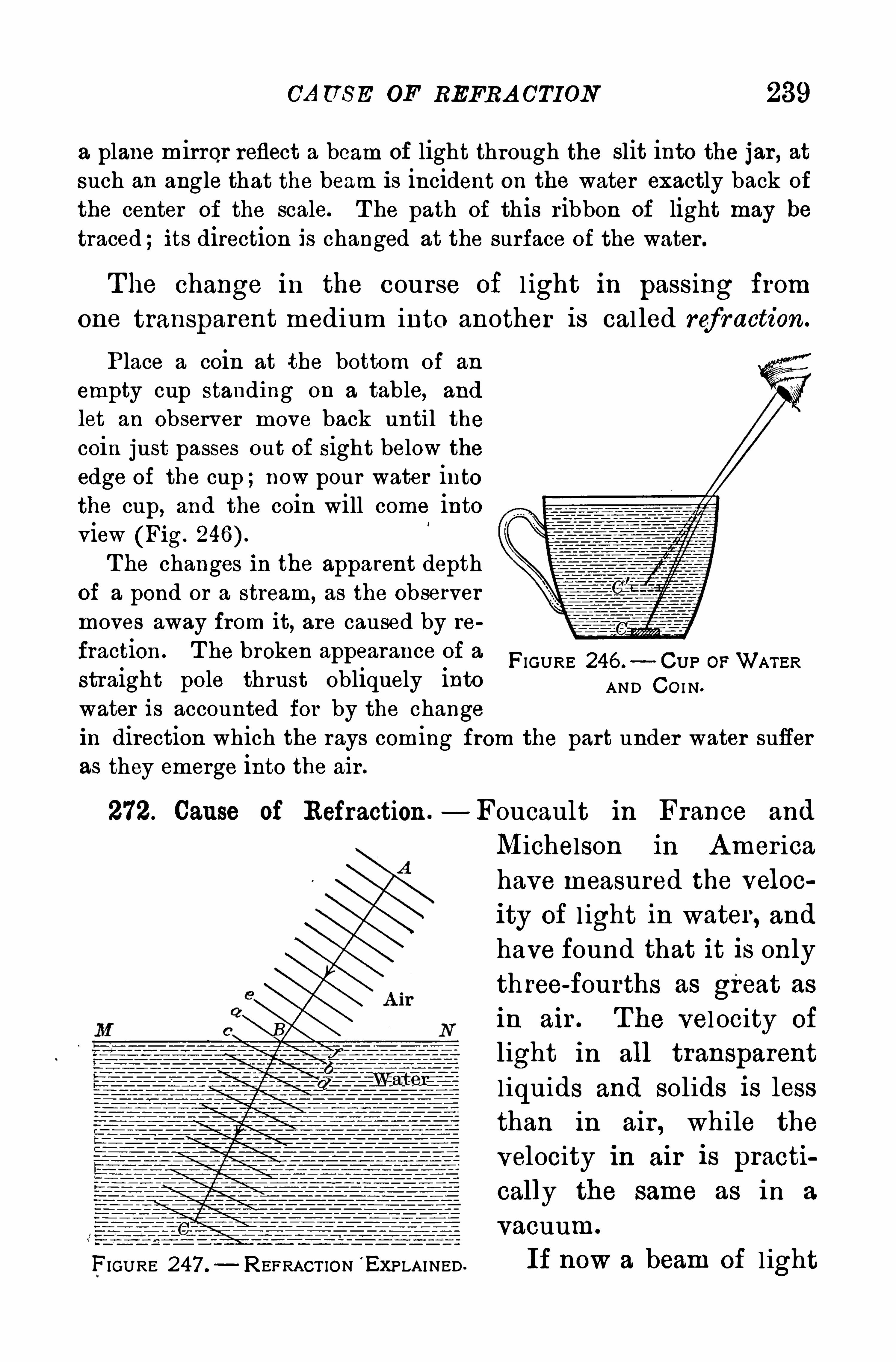
CA U S E OF REFRA OTION 239
a plane mirror reflect a beam of light through the slit into the jar , atsuch an angle that the beam is incident on the water exactly back of
the center of the scale. T he path of this ribbon of light may be
traced ;its direction is changed at the surface of the water .
The change in the course of l ight in passing from
one transparent medium into another is cal led refraction.
P lace a coin at the bottom of an
empty cup standing on a table, and
let an observer move back until thecoin just passes out of sight below the
edge of the cup ;now pour water intothe cup, and the coin will come intoview (Fig.
T he changes in the apparent depthof a pond or a stream, as the observermoves away from it, are caused by re
fraction . T he broken appearance of a
straight pole thrust obliquely intowater is accounted for by the change
FIGURE 246 . CU P OPWATERAND CO I N .
in direction which the rays coming from the part under water sufferas they emerge into the air .
272. Cause of Refraction .- Foucault in France and
FIGURE 247 . REFRACT ION E XPLAINED .
Michelson in A mer ica
have measured the veloc
ity of l ight in water , and
have found that it is only
th ree-fourths as great as
in air . T he vel ocity of
light in all transparent
l iquids and solids is lessthan in air , while the
velocity in air is practi
cally the same as in a
vacuum.
If now a beam of l ight
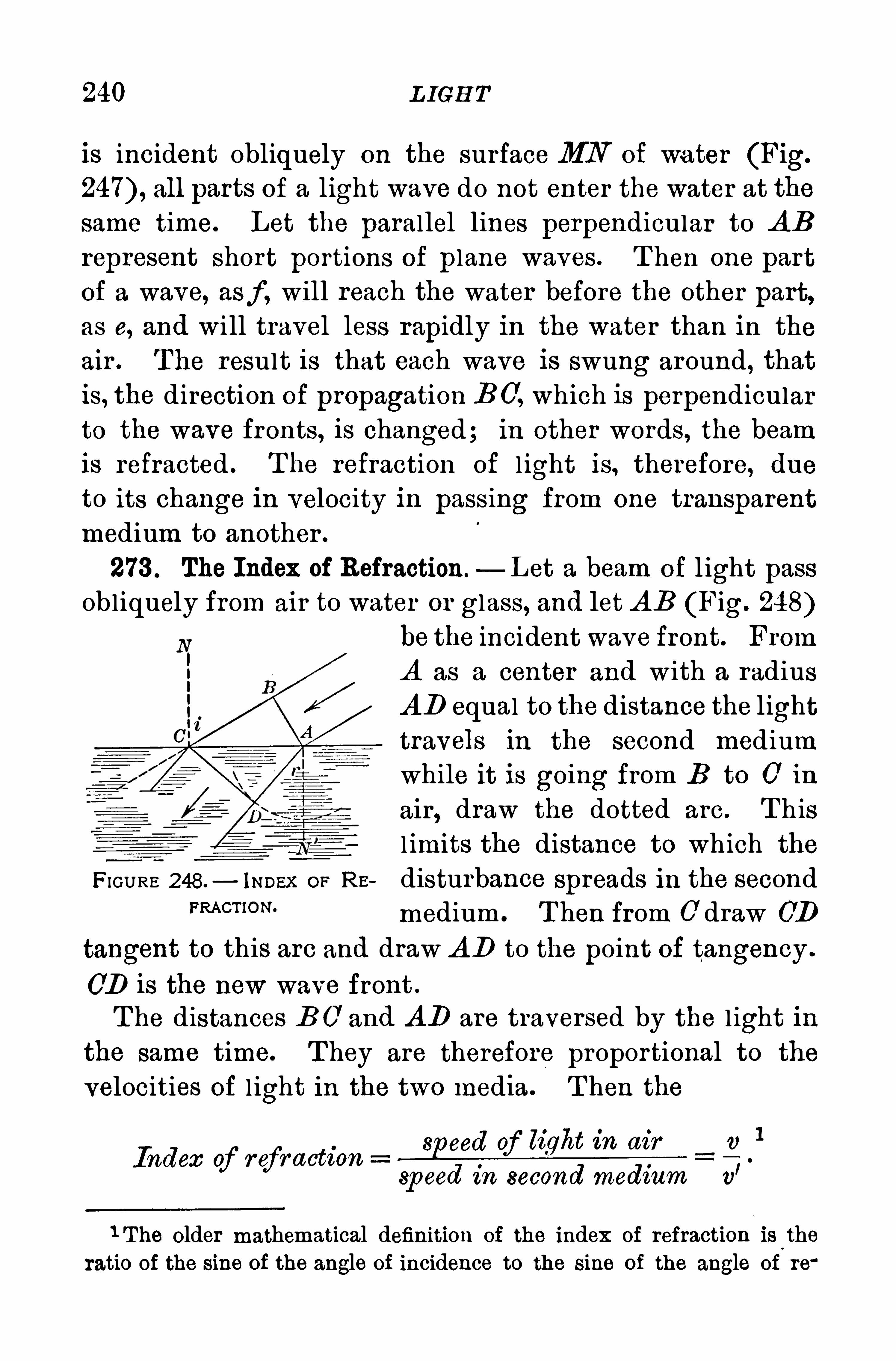
240 L IGH T
is incident obliquely on the surface MN of wa ter (Fig.
all parts of a light wave do not enter the water at thesame time. Let the parallel lines perpendicular to A Brepresent Short portions of plane waves . T hen one part
of a wave, asf , will reach the water before the other part,as e, and will travel less rapidly in the water than in the
air . T he result is that each wave is swung around, thatis, the direction of propagation BC
’, which is perpendicular
to the wave fronts, is changed; in other words, the beamis refracted . T he refraction of l ight is, therefore, dueto its change in velocity in passing from one transparent
medium to another .
273 . The Index of Refraction.— Let a beam of l ight pass
obliquely from air to water or glass, and let A B (Fig. 248)be the incident wave front. From
A as a center and with a radius
AD equal to the distance the light
travels in the second mediumwhile it is going from B to C in
air, draw the dotted arc . T his
l imits the distance to which the
FIGURE 248.— inner:or Rs disturbance spreads in the second
FRACT’ON ' medium . T hen from 0 draw (7D
tangent to this arc and draw A D to the point of tangency .
CD is the new wave front .
T he distances B 0 and A D are traversed by the l ight in
the same time. T hey are therefore proportional to the
velocities of l ight in the two media . T hen the
Index of refractions ccd of light in air v
1
sp eed in second medium v’
1 T he older mathematical definition of the index of refraction isl
the
ratio of the sine of the angle of incidence to the sine of the angle of re
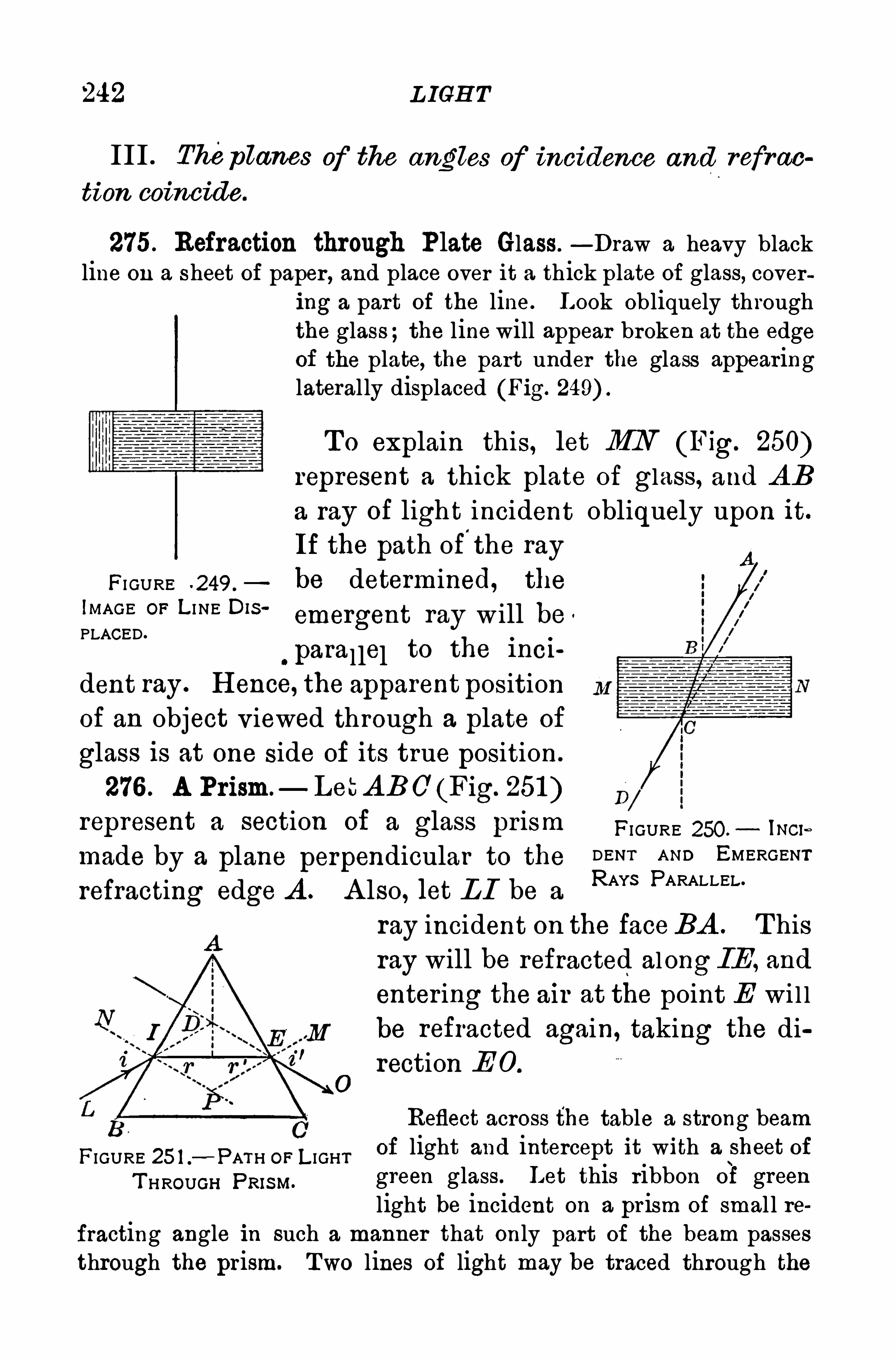
242 L IGH T
III . Thep lanes of the angles of incidence and refrac
tion coincide.
275. Refraction through Plate Glass.—Draw a heavy black
line on a sheet of paper , and place over it a thick plate of glass, covering a part of the line. L ook obliquely throughthe glass ;the line will appear broken at the edgeof the plate, the part under the glass appearinglateral ly displaced (Fig.
T o explain this, let MN (Fig. 250)represent a thick plate of glass, and A Ba ray of light incident obliquely upon it.
If the path of'
the ray
FI GURE -249 . be determined, theWAGE °F L I NE O‘S ‘
emergent ray w ill be '
PLACED.
, parallel to the 1nci
dent ray . H ence, the apparent position
of an object viewed through a plate of
glass is at one side of its true position.
276 . A Prism. LetA BC’(Fig. 251 )represent a section of a glass pr ism FI GURE 250. may ,
made by a plane perpendicular to the DENT A ND EMERGENT
refracting edge A . A lso , let L I be aRAYS PARALLEL
ray incident on the faceBA . T hisray will be refracted along IE , and
entering the air at the point E wi l l
i t! be refracted again, taking the direction E 0 .
Reflect across the table a strong beam
FIGURE 25 1 .
—PATH OF L IGHT of light and intercept it with a sheet of
T HROUGH pRISM.green glass. Let this ribbon of greenlight be incident on a pr ism of smal l re
fracting angle in such a manner that only part of the beam passesthrough the prism. Two lines of light may be traced through the
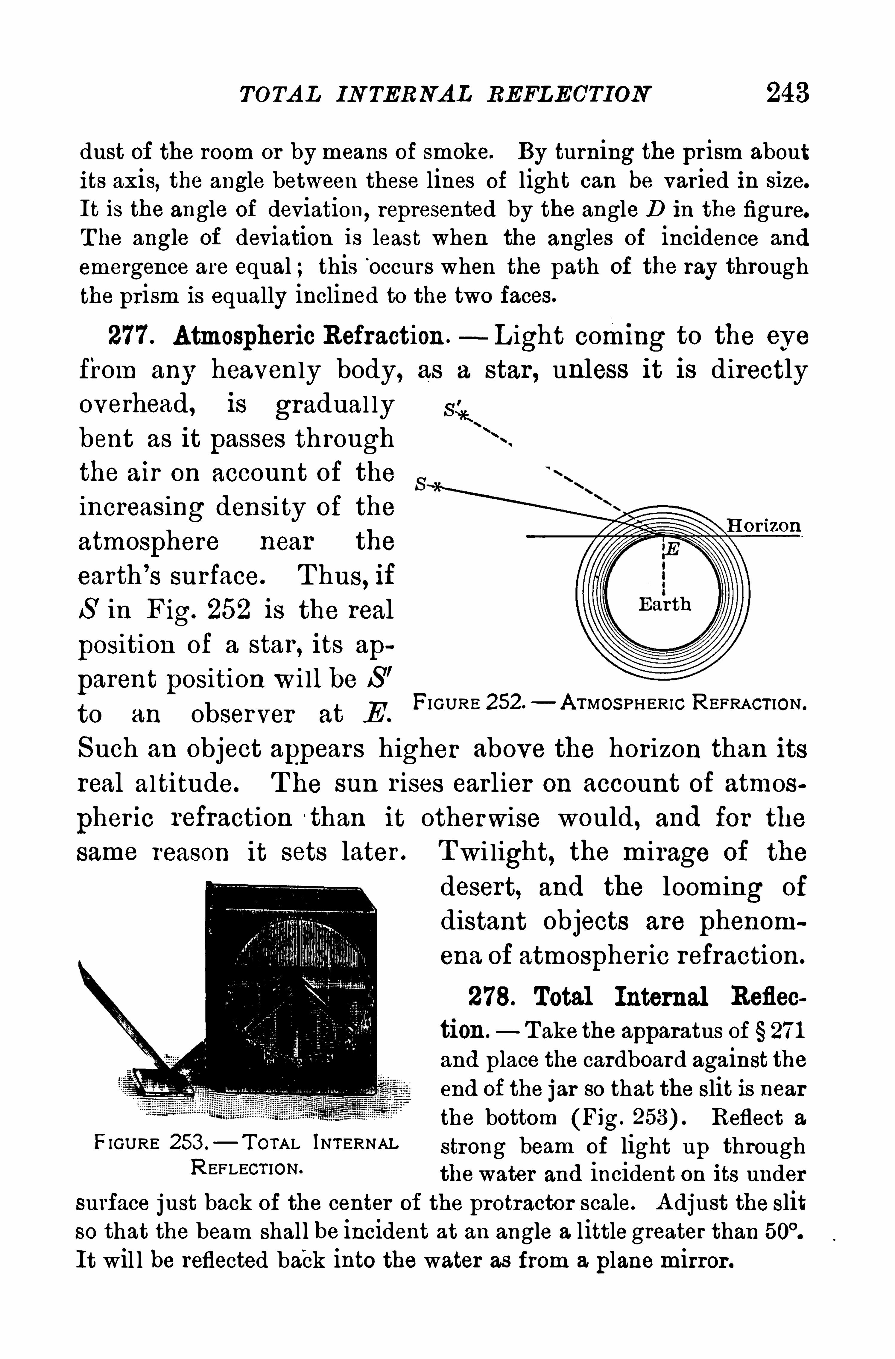
TOTA L IN TERNA L REFLECTION 243
dust of the room or by means of smoke. By turning the pr ism aboutits axis, the angle between these lines Of light can be varied in size.
It is the angle of deviation, represented by the angle D in the figure.T he angle of deviation is least when the angles of incidence and
emergence are equal ; this Occurs when the path of the ray throughthe prism is equally inclined to the two faces.
277 . Atmospheric Refraction.—L ight coming to the eye
from any heavenly body, as a star, unless it is directlyoverhead, is gradual ly S ir.bent as it passes throughthe air on account of theincreasing density of the
atmosphere near the
earth ’
s surface. T hus, ifS in Fig. 252 is the real
position of a star, its ap
parent position wi ll be S’
to an observer at EFI GURE 252 —A TMOS PHERIC REFRACT ION .
H or izon
Such an object appears higher above the horizon than itsreal altitude. T he sun r ises earlier on account of atmos
pheric refraction than it otherwise would, and for the
same reason it sets later . Twi light, the mirage of the
desert, and the looming of
distant objects are phenomena of atmospher ic refraction.
278. Total Internal Reflec
tion. T ake the apparatus of 271
and place the cardboard against theend of the jar so that the slit is nearthe bottom (Fig. Reflect a
FIGURE 253 .
— T OTAL INTERNAL strong beam of light up throughREFLECT ION thewater and incident on its under
surface just back of the center of the protractor scale. A djust the slitso that the beam shall be incident at an angle a little greater thanIt wil l be reflected back into the water as from a plane mirror .
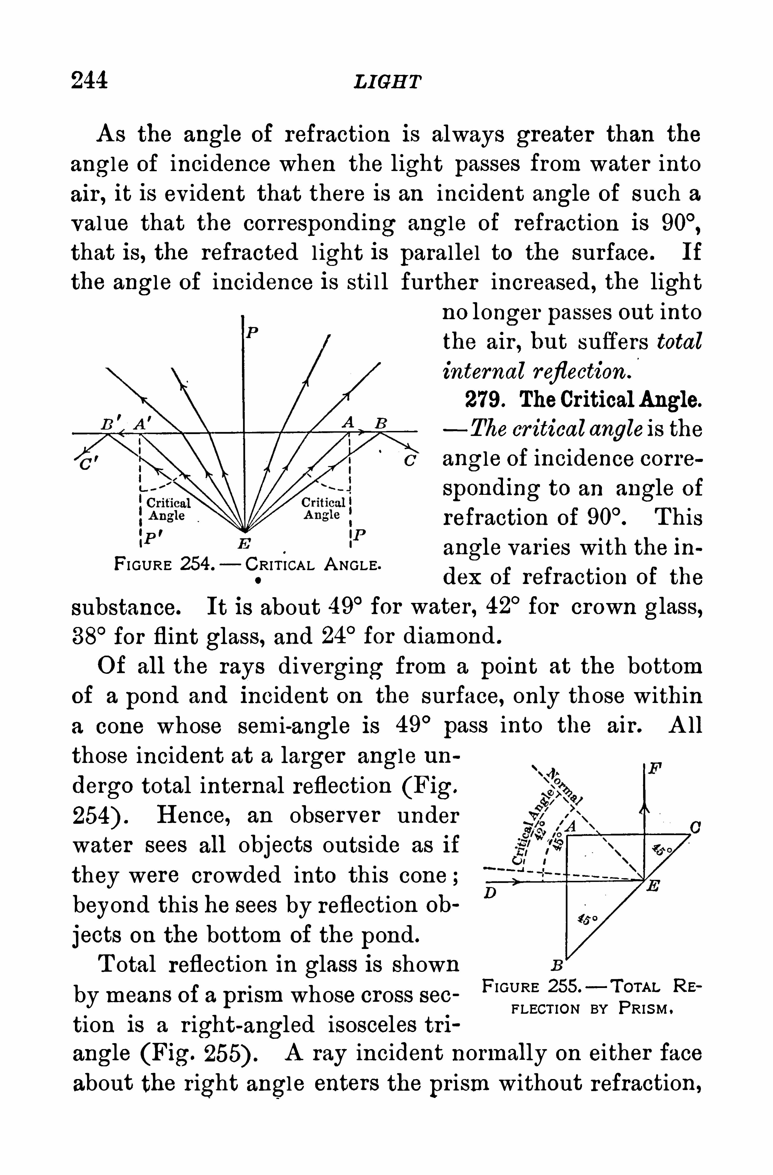
244 L IGH T
A s the angle of refraction is always greater than the
angle of incidence when the light passes from water into
air , it is evident that there is an incident angle of such a
value that the corresponding angle of refraction isthat is, the refracted light is parallel to the surface. If
the angle of incidence is sti l l further increased , the lightno longer passes out intothe air , but suffers totalinternal reflection .
279. TheCritical Angle.
- The critical angleis the
angle of incidence corresponding to an angle of
‘P'
refraction of T hisangle varies with the in
FI GURE 254 .
— C.
RIT ICAL A NGLE.
dex 0 f refraction of the
substance. It is about 49° for water , 42°for crown glass,
38°for flint glass, and 24
°for diamond .
O f all the rays diverging from a point at the bottom
of a pond and 1ncident on the surface, only those within
a cone whose semi-angle is 49°
pass into the air . A ll
those incident at a larger angle un
dergo total internal reflection (Fig.
H ence, an observer under
water sees all objects outside as if
they were crowded into this cone ;beyond this he sees by reflection ob
jects on the bottom of the pond.
T otal reflection in glass is shown
by means of a prism whose cross sec
tion is a r ight-angled isosceles tri
angle (Fig. A ray incident normally on either face
about the right angle enters the prism without refraction,
FIGURE 255.—TorAL RE
FLECT ION BY PRIS M .
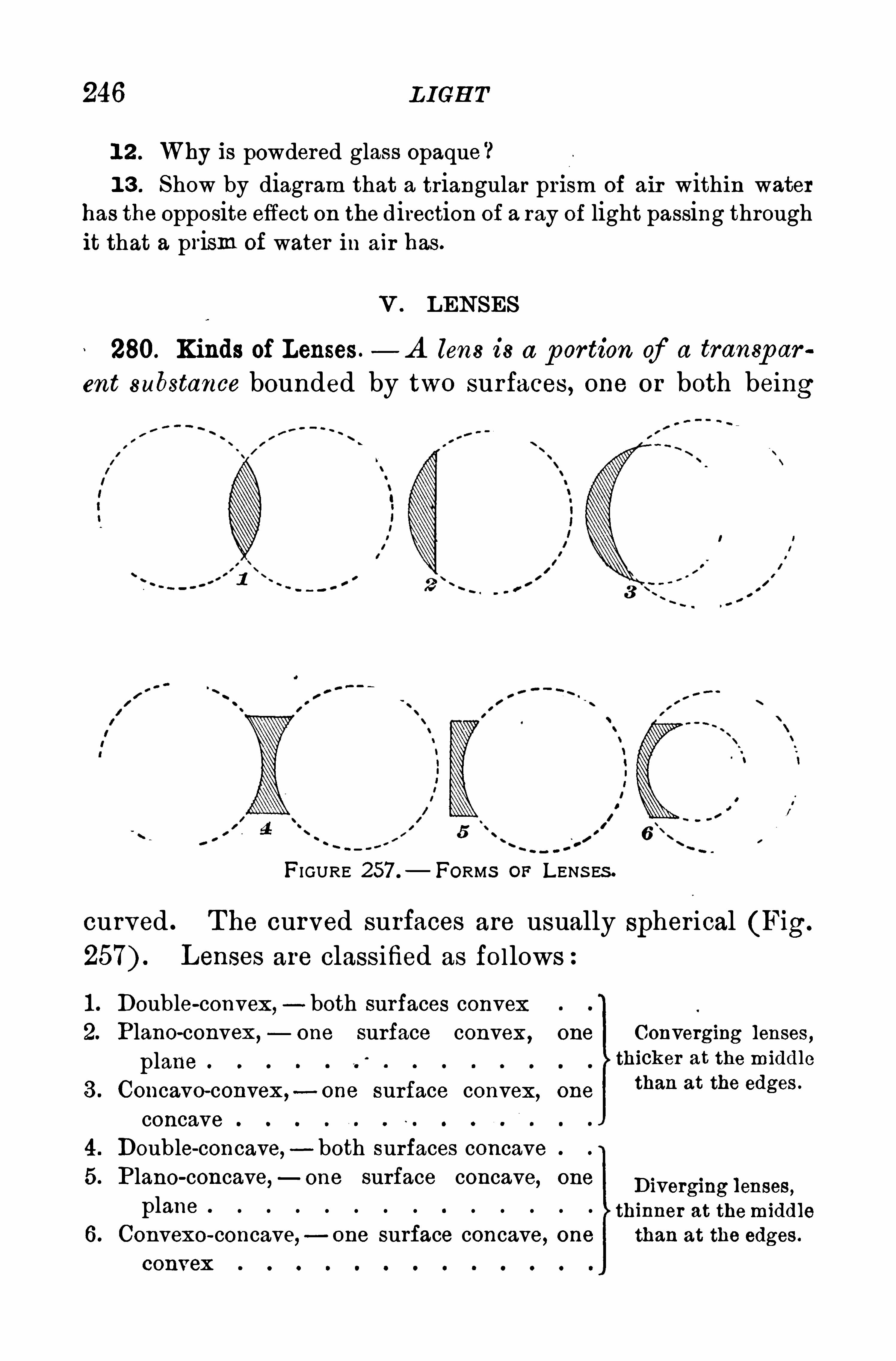
246 L IGH T
1 2 . Why is powdered glass opaque ?1 3 . Show by diagram that a triangular pri sm of air within water
has the opposite effect on the direction of a ray of light passing throughit that a prism of water in air has .
V . LENSES
280. Kinds of Lenses .— A lens is a p or tion of a transp ar
ent substance bounded by two surfaces, one or both being
FIGURE 257 .
— FORMS OF LENS ES .
curved . T he curved surfaces are usually spherical (Fig.
Lenses are classified as follows
1 . Double-convex, both surfaces convex2. Plano-convex ,
— one surface convex , one Converging lenses ,plane thicker at the middle
3 . Concavo-convex ,- one surface convex, one
than at the edges '
concave4. Double-concave, - both surfaces concave5. P lano-concave,—one surface concave, one Diverging lenses,
plane 0 o o o o o o o I o o o o o thinner at themiddle
6 . Convexo-concave,—one surface concave, one than at the edges .
CODVGX 0
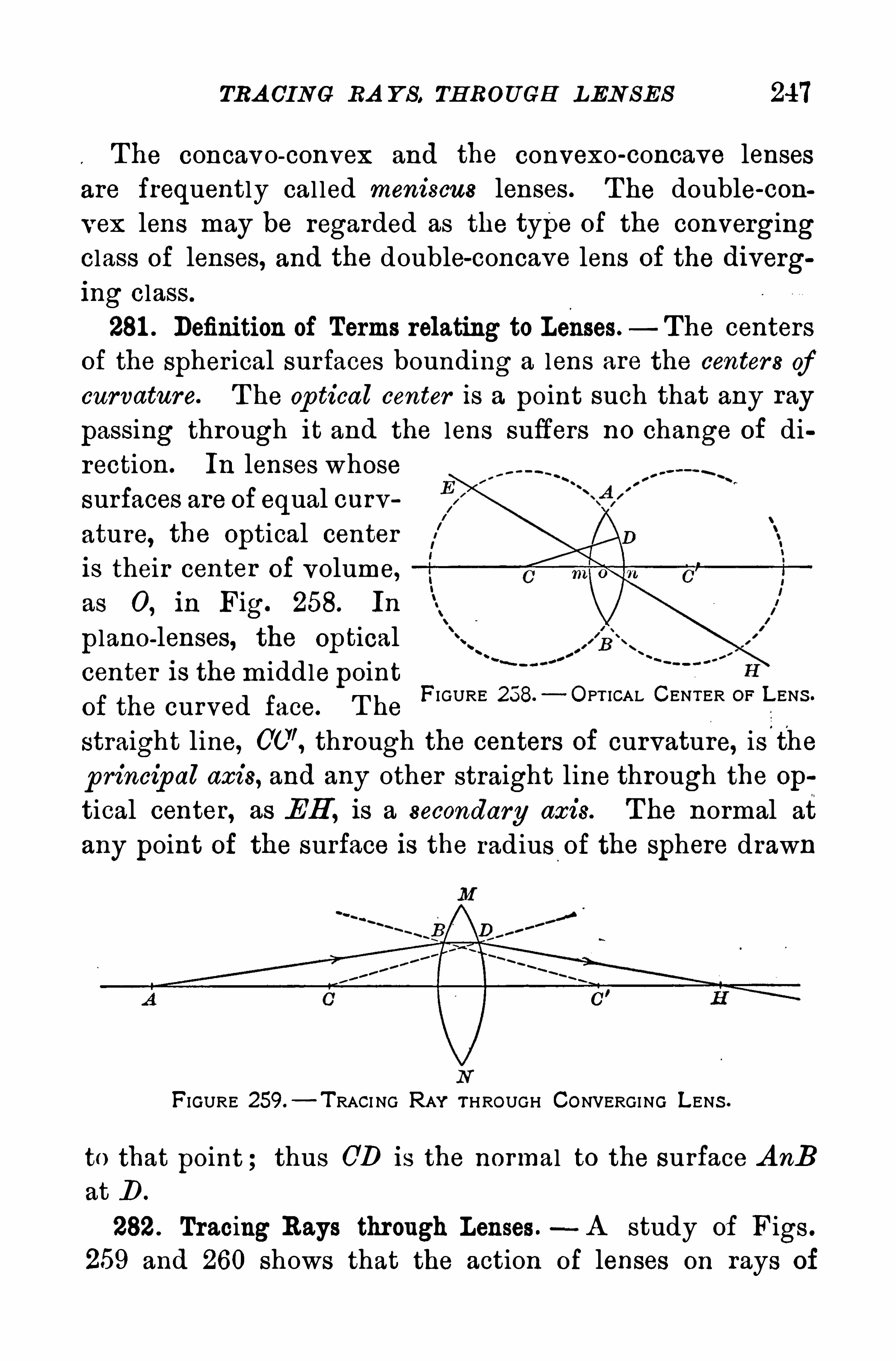
TRA CING RA Y S . TH ROUGH LEN SES 247
The concavo-convex and the convexo-concave lensesare frequently cal led meniscus lenses. T he double-con
vex lens may be regarded as the type of the convergingclass of lenses, and the double-concave lens of the diverg
ing class.
281 . Definition of Terms relating to Lenses. The centers
of the Spherical surfaces bounding a lens are the centers ofcurvature. T he op tical center is a point such that any ray
passing through it and the lens suffers no change of di
rection. In lenses whose
surfaces are of equal curv
ature, the Optical center
is their center of volume,
as 0 , in Fig. 258. In
plano-lenses, the Optical
center is themiddle point
of the curved face. T he
straight line, through the centers of curvature, is'
t'
he
p rincip al axis, and any other straight line through the op
tical center, as EH , is a secondary axis. T he normal at
any point of the surface is the radius of the sphere drawn
FIGURE 258. OPT ICAL CENTER OF L ENS .
FIGURE 259.
—T RACI NG RAY THROUGH CONVERGING LENS .
to that point ; thus CD is the normal to the surface A nBat D .
282. Tracing Rays through Lenses.—A study of Figs .
259 and 260 shows that the action of lenses on rays of
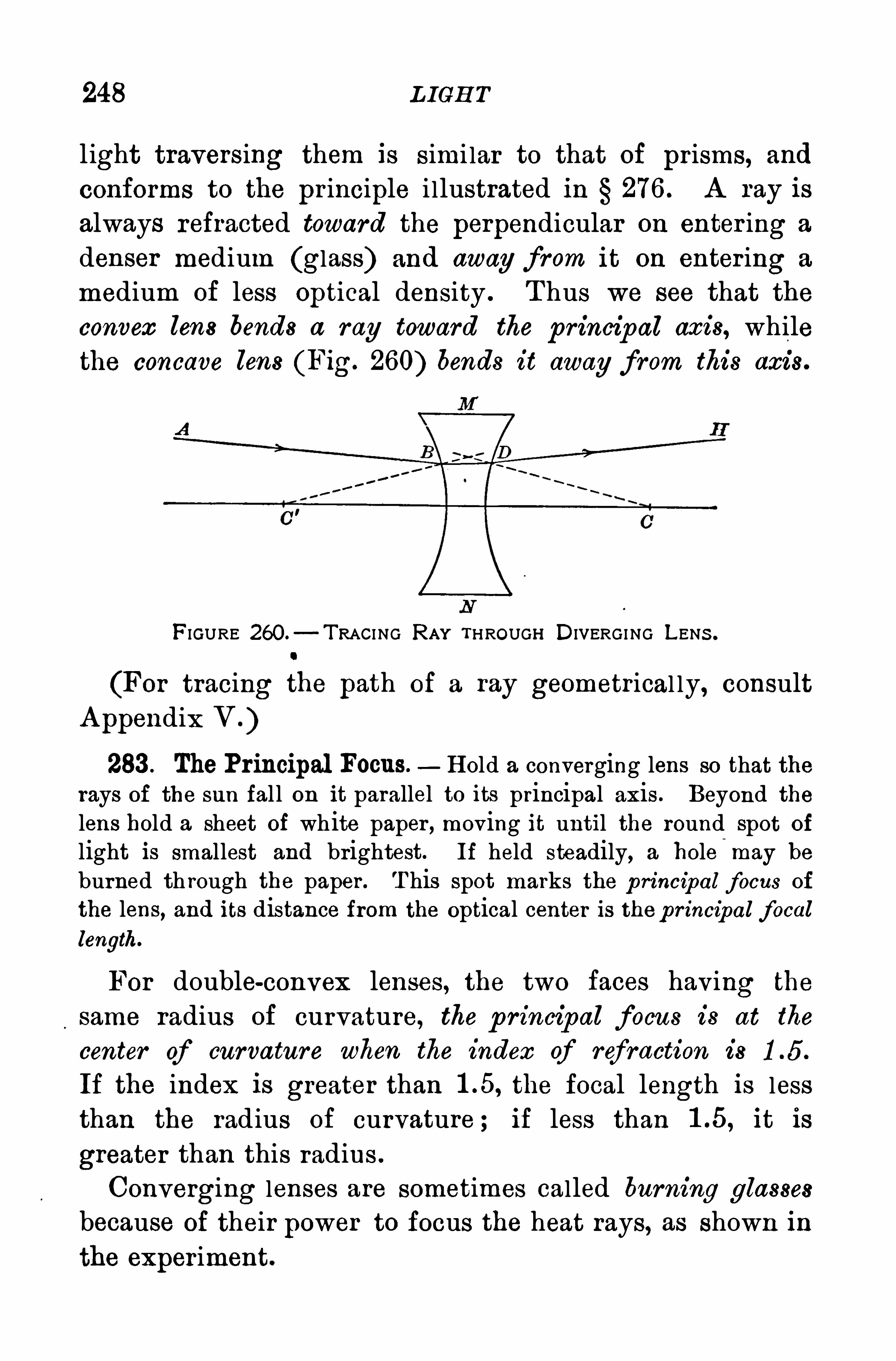
248 L IGH T
l ight traversing them is simi lar to that of prisms, and
conforms to the pr inciple i llustrated in 276 . A ray is
always refracted toward the perpendicular on enter ing a
denser medium (glass) and away from it on enter ing a
medium of less Optical density . T hus we see that theconvex lens bends a r ay toward the principal axis, whilethe concave lens (Fig. 260) bends it away from this axi s.
FIGURE 260.—TRACI NG RAY THROUGH DIVERGI NG LENS .
(For tracing the path of a ray geometrical ly, consultA ppendix V . )
283 . The Principal Focus. H old a converging lens so that therays of the sun fal l on it parallel to its principal axis . Beyond thelens hold a sheet of wh ite paper , moving it until the round spot of
light is smallest and brightest. If held steadily, a hole-
may be
burned th rough the paper . T his spot marks the p rincipal focus of
the lens, and its distance from the optical center is thep rincipal focallength.
For double-convex lenses, the two faces having the
same radius of curvature, the p rincipal focus is at the
center of curvature when the index of r ef raction is
If the index is greater than the focal length is lessthan the radius of curvature ; if less than it is
greater than this radius .
Converging lenses are sometimes called burning glasses
because of their power to focus the heat rays, as shown in
the experiment.
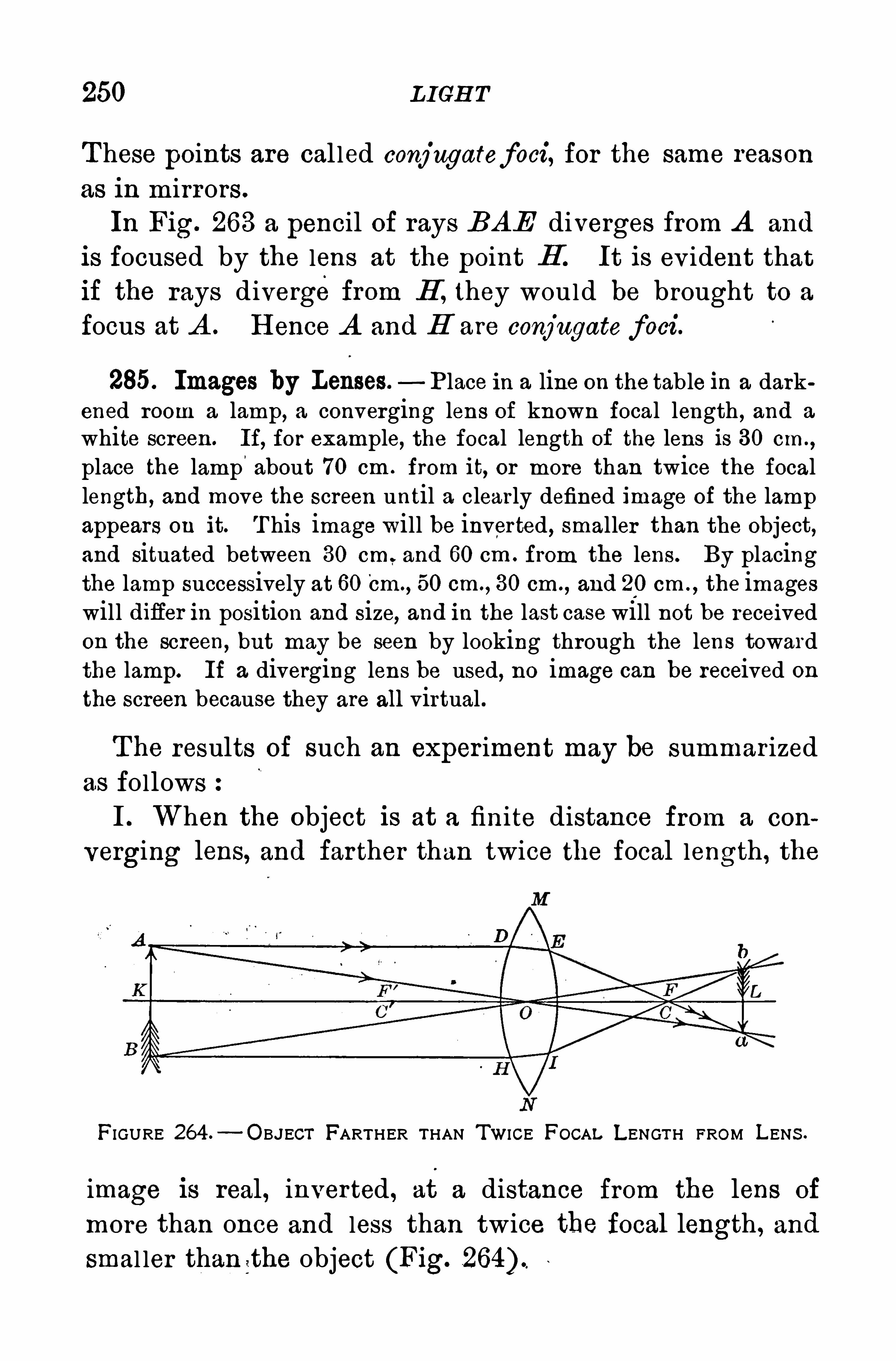
250 L IGH T
T hese points are cal led conjugatefoci, for the same reason
as in mirrors .
In Fig. 263 a pencil of rays BAE diverges from A and
is focused by the lens at the point B . It is ev ident that
if the rays divergefrom H , they would be brought to a
focus at A . H ence A and H are conjugate foci.
285. Images by Lenses. P lace in a line on the table in a darkened room a lamp, a converging lens of known focal length , and a
white screen. If, for example, the focal length of the lens is 30 cm.,
place the lamp'
about 70 cm . from it, or more than twice the focallength, and move the screen until a clearly defined image of the lampappears on it. T his image will be inverted , smaller than the object,and situated between 30 cm and 60 cm . from the lens . By placingthe lamp successively at 60 Cm .
, 50 cm. , 30 cm ., and 20 cm . , the images
will difier in position and size, and in the last case will not be receivedon the screen, but may be seen by looking through the lens towardthe lamp. If a diverging lens be used, no image can be received onthe screen because they are all virtual .
The results of such an exper iment may be summarized
as followsI . When the object is at a finite distance from a con
verging lens, and far ther than twice the focal length , the
FIGURE 264 —OBJECT FARTHER THAN TWICE FOCAL LENGTH FROM LENS .
image is real , inverted , at a distance from the lens of
more than once and less than twice the focal length, and
smal ler than t he object (Fig.
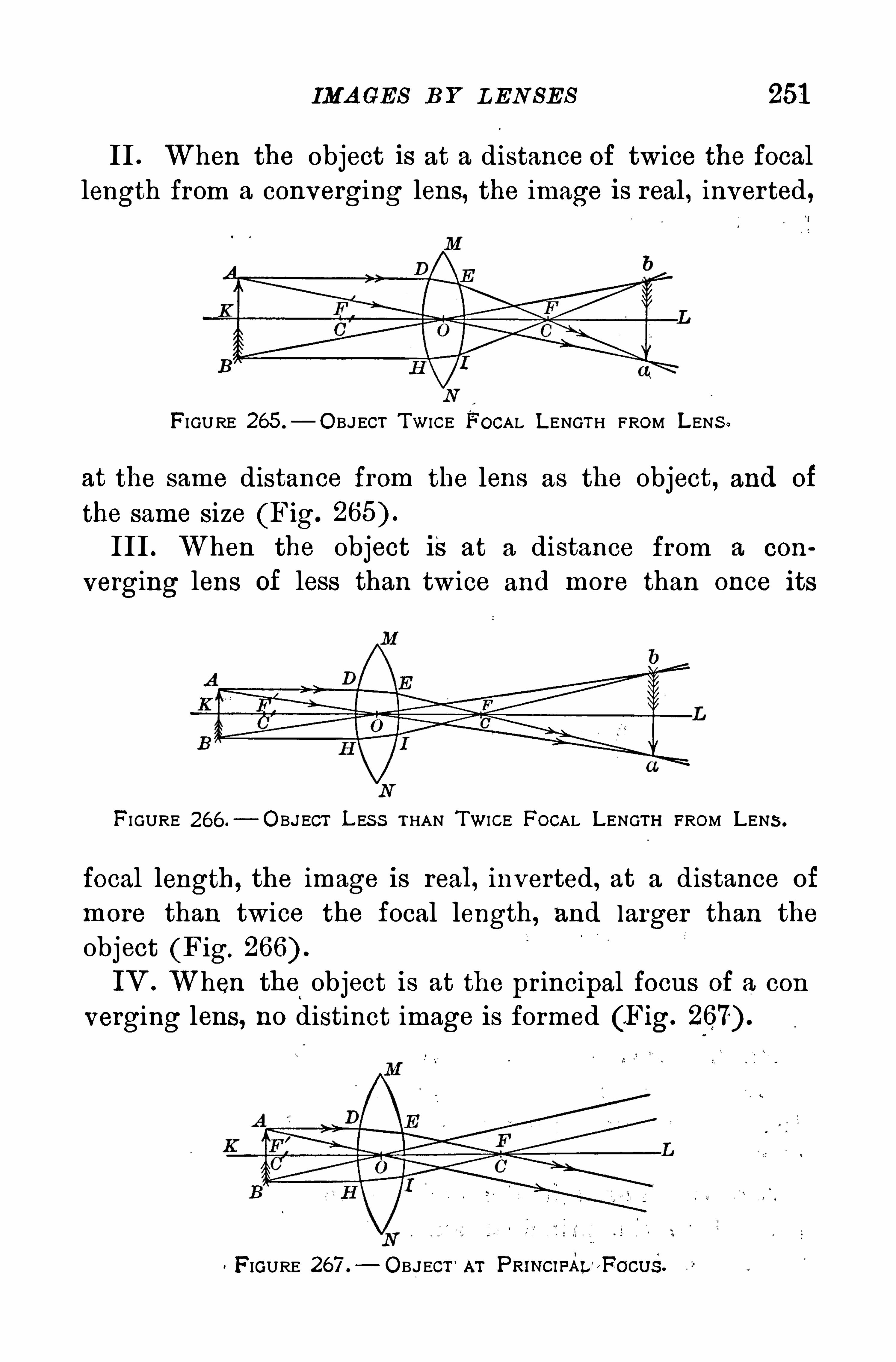
IMA GES B Y L EN SES 251
II . When the object is at a distance of twice the focallength from a converging lens, the image is real, inverted
FIGURE 265 .
— O BJECT TWICE FOCAL LENGTH FROM LENS .
at the same distance from the lens as the object , and of
the same size (Fig.
III . When the object Is at a distance from a con
verging lens of less than twice and more than once its
FI GURE 266 .—O B.JECT L ES S THAN TWICE FOCAL LENGTH FROM LENS .
focal length, the image is real, inverted, at a distance of
more than twice the focal length , and larger than the
object (Fig.
IV . When the object is at the principal focus of a con
verging lens, no distinct image is formed (F ig.
FIGURE 267 . OBJECT '
AT PRINCIFAL'F OCUS.
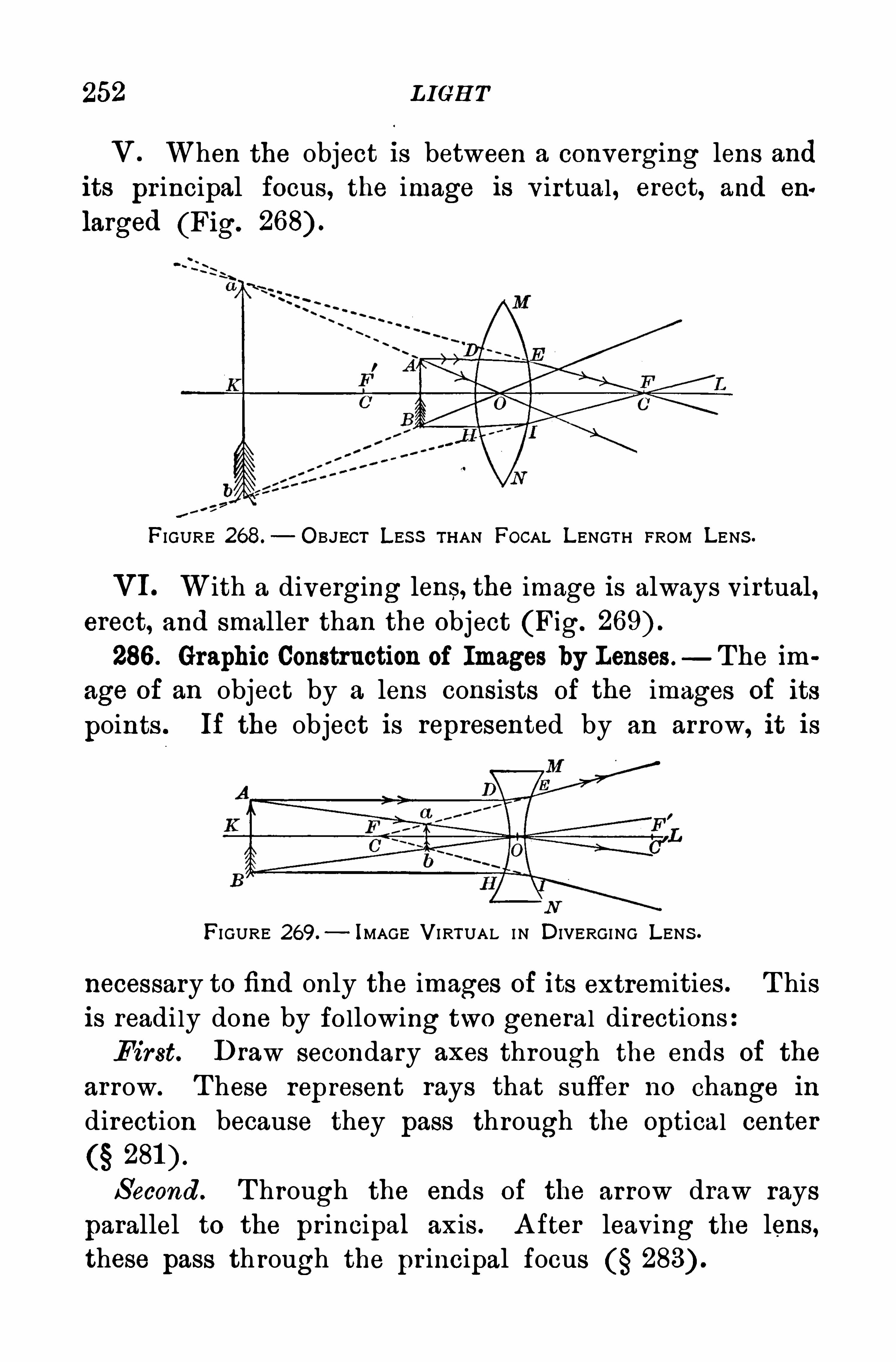
252 L IGH T
V . When the object is between a converging lens andits pr incipal focus, the image is v irtual , erect, and eu
larged (Fig.
FIGURE 268.
— OBJECT LES S THAN FOCAL LENGTH FROM LENS .
VI. With a diverging lens, the image is always virtual,erect, and smaller than the object (Fig.
286 . Graphic Construction of Images by Lenses —The im
age of an object by a lens consists of the images of its
points . If the object is represented by an arrow, it is
FI GURE 269.— IMAGE VI RTUAL IN DIVERGING LENS .
necessary to find only the images of its extremities . T hisis readily done by fo llowing two general directionsFirst. Draw secondary axes through the ends of the
arrow. T hese represent rays that suffer no change in
direction because they pass through the Optical center
S econd. T hrough the ends of the arrow draw rays
parallel to the principal axis . A fter leaving the lens,these pass through the pr incipal focus
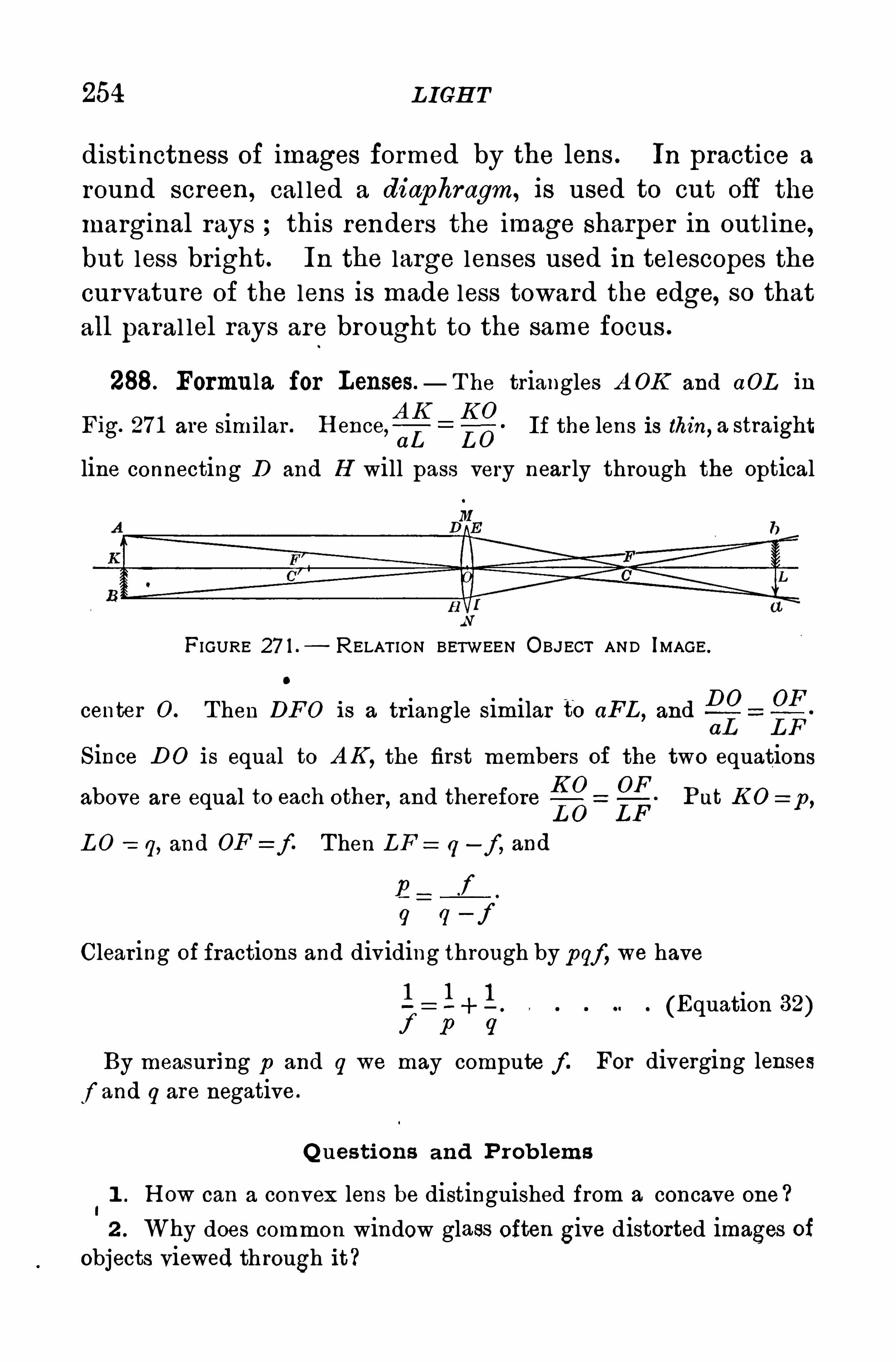
254 L IGH T
distinctness of images formed by the lens . In practice a
round screen, cal led a diaphragm, is used to cut off the
marginal rays this renders the image sharper in outl ine,but less bright. In the large lenses used in telescopes thecurvature of the lens is made less toward the edge, so thatall paral lel rays are brought to the same focus .
288. Formula for Lenses. T he triangles A OK and aOL in
Fig. 27 1 are similar . H ence,fi1£ g—O
QIf the lens is thin, a straight
line connecting D and H will pass very near ly through the optical
FIGURE 27 1 . RELAT ION BETWEEN OBJECT AND IMAGE .
center 0 . T hen DFO is a triangle similar to aFL , andDO OF
aL LF
S ince D O is equal to A K ,the first members of the two equations
K 0 OFb I t h th d tb f P t K O :a ove are equa o eac o er,an ere ore
L O LFu p
L O 2 1] , and OF Z f . Then Lq —f , and
f
9 (1—f
Clearing of fractions and dividing through by pgf, we have
1 1 + l . (Equation 32)f p 9
By measur ing p and q we may compute f . For diverging lenses
f and q are negative .
Q ues tions and P rob lems
1 . H ow can a convex lens be distinguished from a concave one ?
2 . Why does common window glass often give distorted images ofobjects viewed through it?
TH E MA GN IE Y IN G GLA S S 255
3 . H owcan the principal focal length of a concave spher ical mirrorbe found
4 . Given a collection of spectacle lenses ; select the concave fromthe convex.
5 . Why do so many cheap mirrors give distorted images
6 . If an oarsman sticks his oar into the water obliquely , why doesit appear broken at the point of entrance ?
7 . Concave spherical mirror s are often mounted in frames to be
used as hand glasses. Such mirrors are usually made by silvering one
face of a lens . Why can several images be seen in such a mirror ?
8. When is the distance between the object and its real image as
formed by a converging lens the least possible ?
9 . T he focal length of a camera lens is two inches. H ow far mustthe sensitized plate be from the lens, when the object is distant 1 00 ft.
1 0 . If a reading glass has a focal length of 1 6 in . and in its use is
held 1 0 in. from the book , what is the position of the virtual image ?
1 1 . A n object 1 00 cm . in front of a converging lens gives an image25 cm. back of the lens . What is the focal length of the lens ?
1 2 . Show by diagram what effect it has on the image of an objectby a diverging lens to move it farther away from the lens.
1 3 . Why is a convex mirror used on an automobile to view objectsback of the driver , instead of a plane mirror ?
1 4 . In a diverging lens, show that a pencil of light that convergesto a point beyond the focus of the lens issues as a diverging pencil .
1 5 . Where must a diverging lens be placed to render parallel aconverging pencil of light ?
VI . OPTICA L INSTRUMENTS
289 . The Magnifying Glass, or simp le microscop e, is a
double-convex lens, usually of short focal length . T he
object must be placed nearer the lens than its principalfocus . T he image is then v irtual , erect, and enlarged .
If AB is the object in Fig. 272, the v irtual image is ab ;
and if the eye be placed near the lens on the side opposite
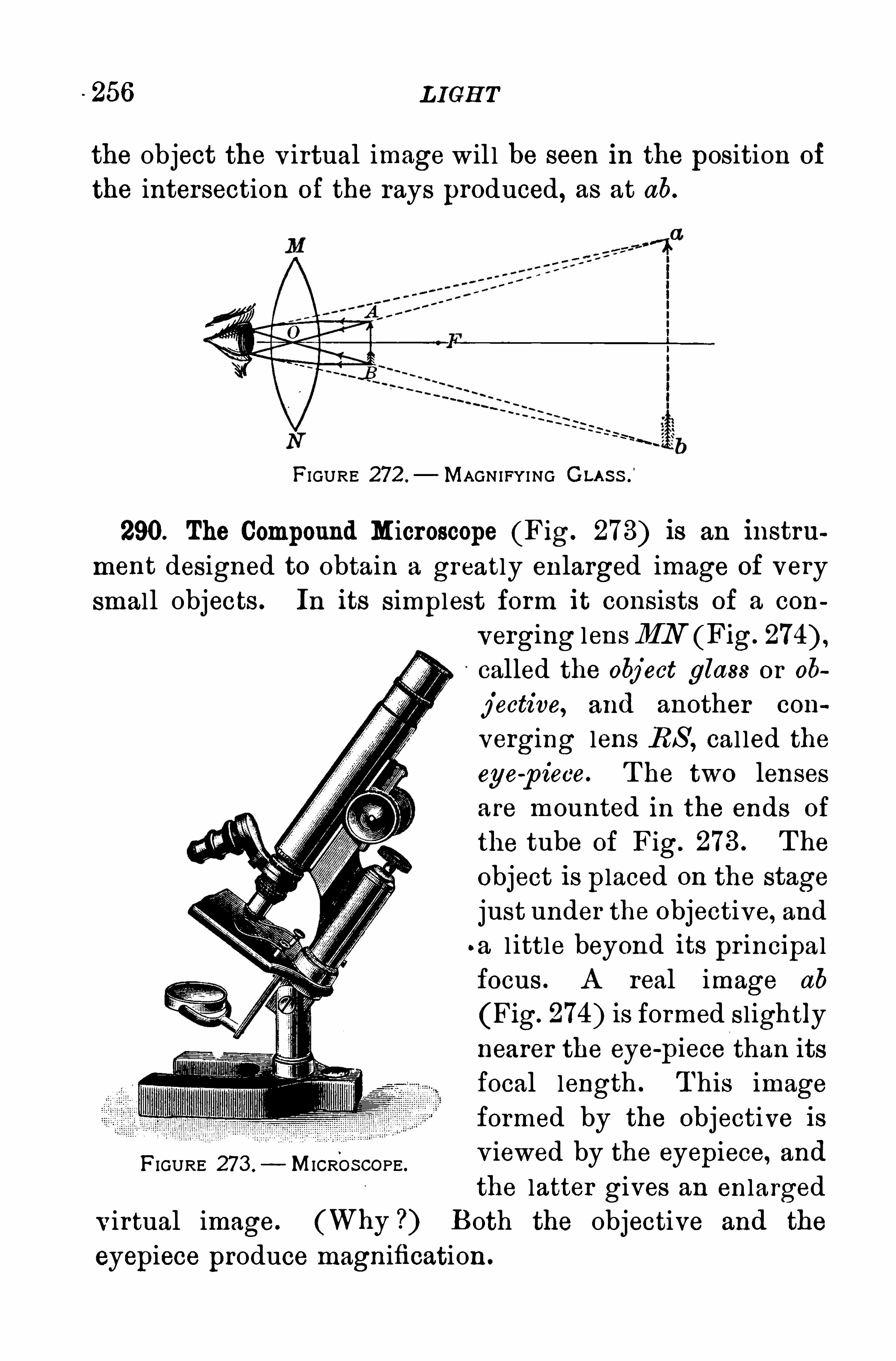
256 L IGH T
the object the v irtual image wil l be seen in the position of
the intersection of the rays produced, as at ab.
FIGURE 272 .
— MAGN IFYING CLA S S .
’
290. The Compound Microscope (Fig. 273) is an instru
ment designed to obtain a greatly enlarged image of very
small objects . In its simplest form it consists of a con
FIGURE 273 . MICROS COPE .
verging lensMN (Fig.
called the object glass or oh
jective, and another con
verging lens RS , cal led the
eye-
p iece. T he two lenses
are mounted in the ends of
the tube of Fig. 273 . T he
object is p laced on the stage
just under the objective, and
a l ittle beyond its pr incipalfocus . A real image ab
(Fig. 274) is formed slightlynearer the eye
-
piece than itsfocal length . T his image
formed by the objective isv iewed by the eyepiece, and
the latter gives an enlarged
v irtual image. (Why ?) Both the objective and the
eyepiece produce magnification.
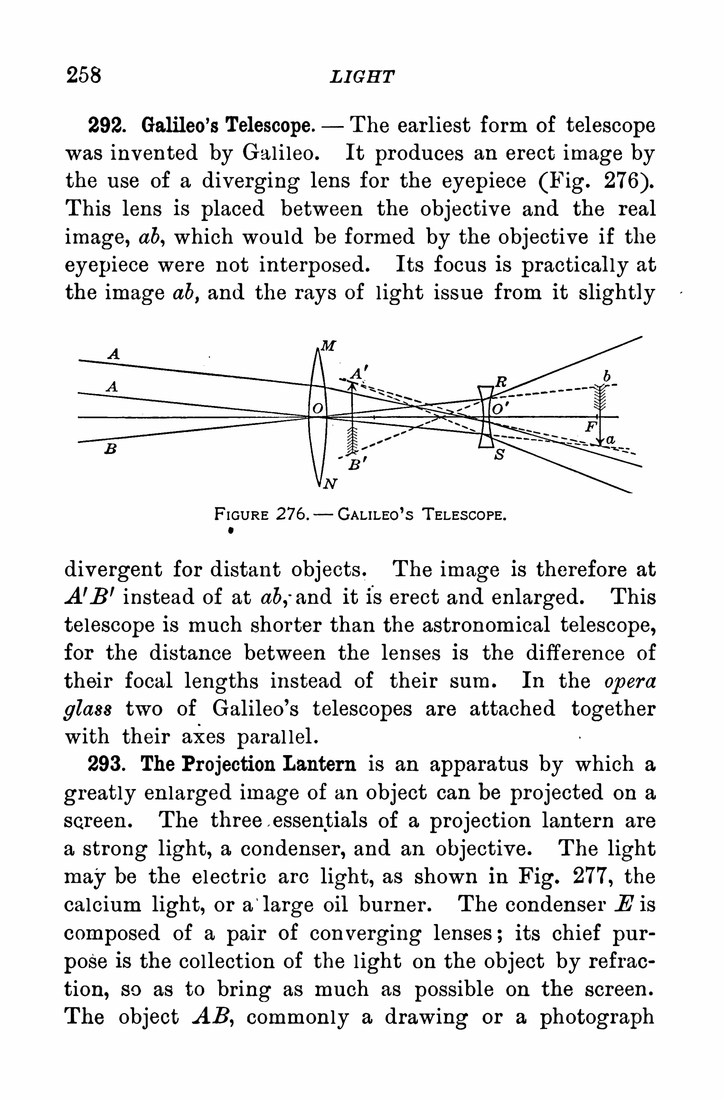
258 L IGH T
292. Galileo’s Telescope. T he earliest form of telescope
was invented by Gal i leo. It produces an erect image by
the use of a diverging lens for the eyepiece (Fig.
T his lens is placed between the objective and the real
image, ab, which would be formed by the objective if theeyepiece were not interposed . Its focus is practically at
the image ab,and the rays of l ight issue from it slightly
FI GURE 276 . GALILEo’S T ELES COPE .
0
divergent for distant objects . T he image is therefore at
A ’B ’ instead of at ab;and it Is erect and enlarged . T histelescope is much shorter than the astronom ical telescope,for the distance between the lenses is the difference of
their focal lengths instead of their sum . In the opera
glass two of Galileo’
s telescopes are attached together
with their axes paral lel .293 . The Projection Lantern is an apparatus by which a
greatly enlarged image of an object can be projected on a
screen . T he three e ssentials of a projection lantern are
a strong light, a condenser , and an objective. T he light
may be the electric arc light, as shown in Fig. 277, the
calcium light, or a‘
large oil burner . T he condenser E is
composed of a pair of converging lenses ; its chief pur
pose is the collection of the l ight on the object by refrac
tion, so as to bring as much as possible on the screen .
The object A B, commonly a drawing or a photograph
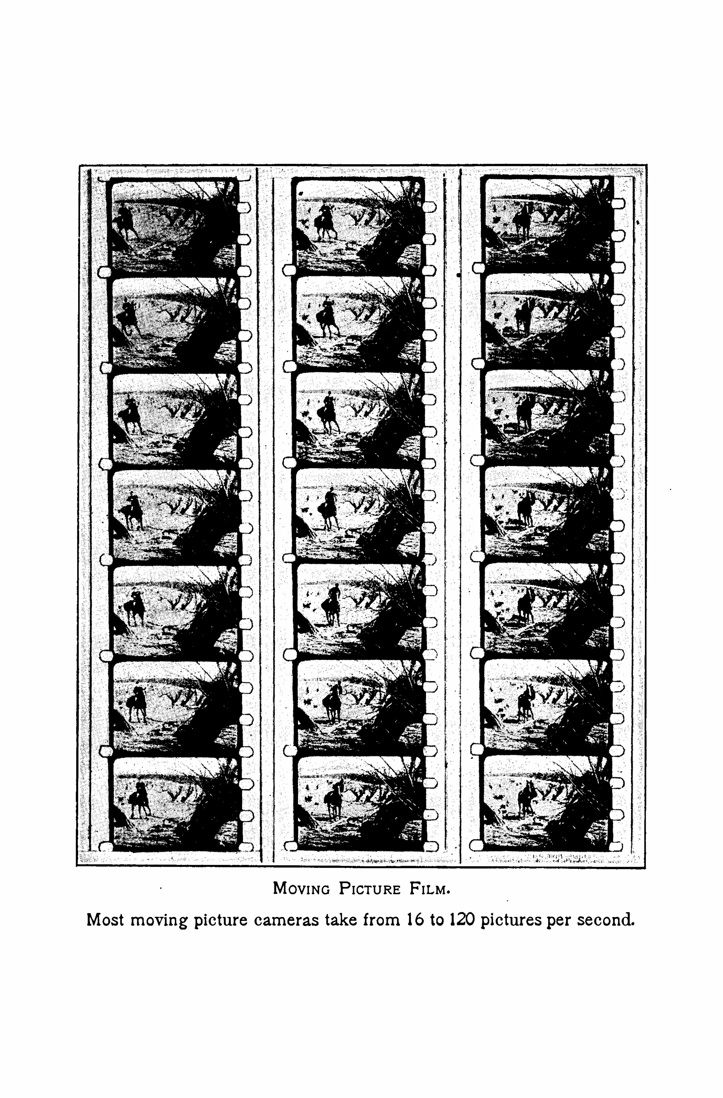
MOVING P ICTURE FILM .
Most moving picture cameras take from 16 to 120 pictures per second.

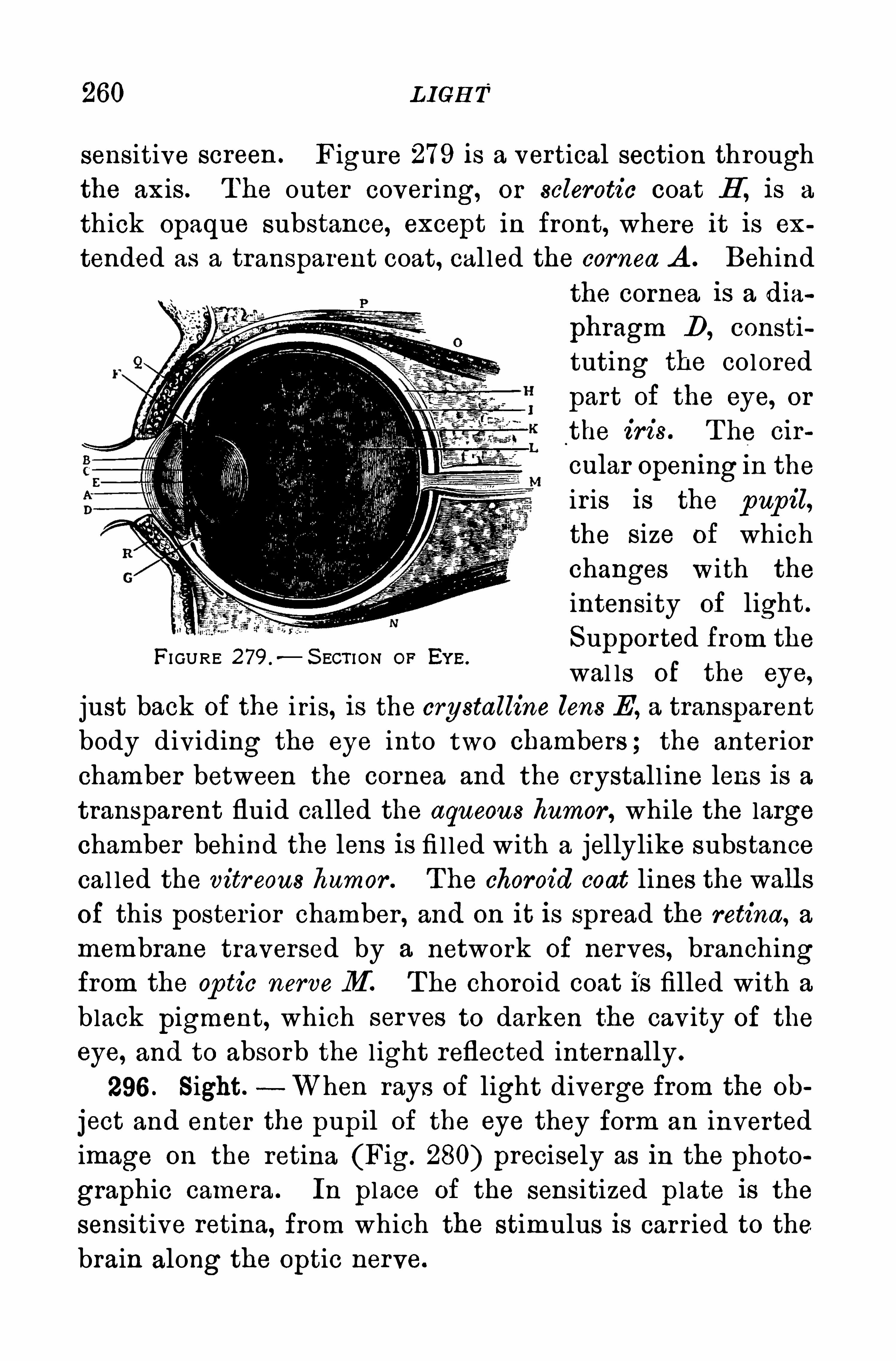
260 L IGH T
sensitive screen . Figure 279 is a vertical section through
the axis . T he outer cover ing, or sclerotic coat H’
, is a
thick Opaque substance, except in front, where it is ex
tended as a transparent coat, cal led the cornea A . Behindthe cornea is a dia
phragm D, constituting the colored
part of the eye, or
the iris . T he cir
cular Opening In the
ir is is the pupil,
the size of whichchanges with the
intensity of light .
Supported from the
wal ls of the eye,
just back of the i ris, is the crystalline lens E, a transparent
body dividing the eye into two chambers ; the anterior
chamber between the cornea and the crystall ine lens is atransparent fluid called the aqueous humor , while the largechamber behind the lens is fi l led with a jellylike substance
cal led the vitr eous humor . T he choroid coat lines the wall sof this poster ior chamber , and on it is spread the retina, a
membrane traversed by a network of nerves, branchingfrom the Op tic nerveM T he choroid coat is filled with a
black pigment, which serves to darken the cav ity of the
eye, and to absorb the l ight reflected internally .
296 . S ight. When rays of light diverge from the oh
ject and enter the pupil of the eye they form an invertedimage on the retina (Fig. 280) precisely as in the photo
graphic camera . In place of the sensitized p late is the
sensitive retina, from which the stimulus is carr ied to the
brain along the Optic nerve.
FI GURE 279 .
—S ECT ION OF EY E.
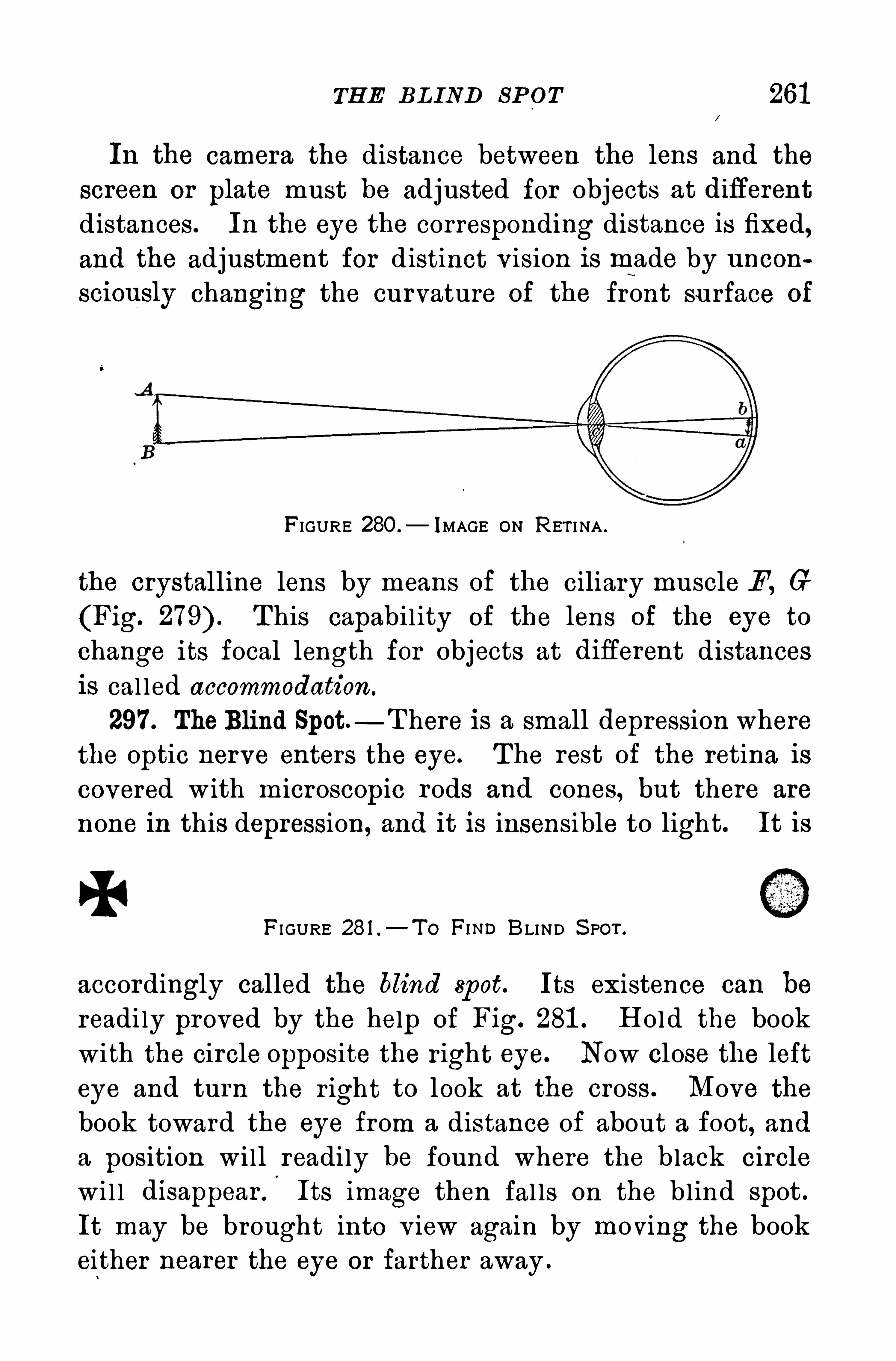
TH E BL IND SP OT 261
In the camera the distance between the lens and the
screen or plate must be adjusted for objects at diflerent
distances. In the eye the corresponding distance is fixed,and the adjustment for distinct v ision is made by uncon
sciously changing the curvature of the front surface of
FIGURE 28O.
— IMAGE ON RET I NA .
the crystalline lens by means of the ciliary muscle F, G
(Fig. T his capabil ity of the lens of the eye to
change its focal length for objects at difl'
erent distancesis cal led accommodation.
297 . TheBlind Spot—T here is a small depression where
the Optic nerve enters the eye. The rest of the retina iscovered w ith microscopic rods and cones, but there are
none in this depression, and it is insensible to light. It is
FI GURE 281 .
—T o FIND BLIND S POT .
accordingly called the blind spot. Its existence can be
readi ly proved by the help of Fig. 281 . H old the book
with the circle opposite the r ight eye. Now close the lefteye and turn the r ight to look at the cross . Move thebook toward the eye from a distance of about a foot, anda position wi ll readily be found where the black circlewi l l disappearf Its image then fal ls on the blind spot .
It may be brought into v iew again by moving the bookeither nearer the eye or farther away .
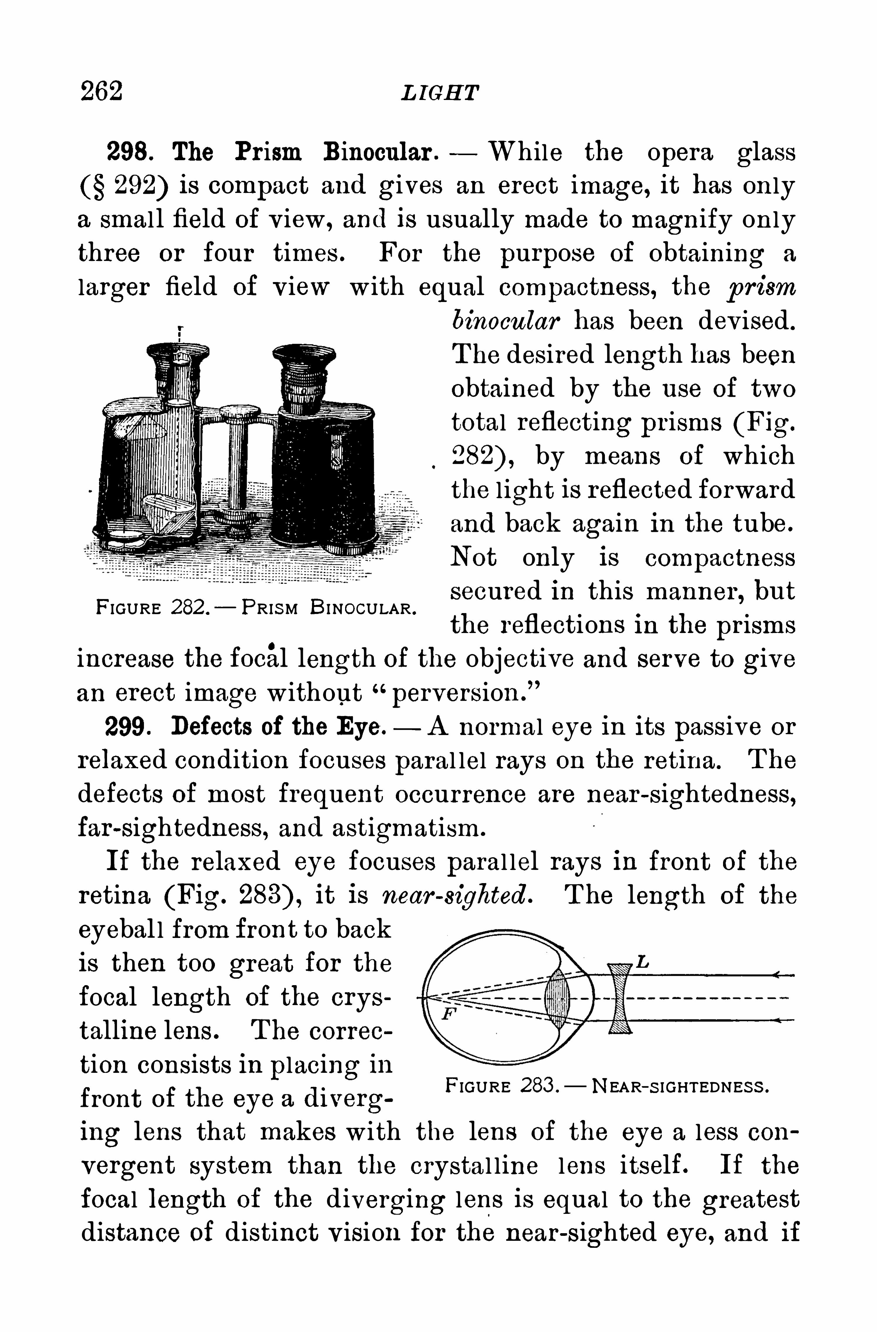
262 L IGH T
298. The Prism Binocular . While the opera glass292) is compact and gives an erect image, it has on ly
a smal l field of v iew , and is usually made to magnify onlythree or four times . For the purpose of obtaining a
larger field of v iew w ith equal compactness, the p rism
binocular has been devised .
T he desired length has been
obtained by the use of two
total reflecting pr isms (Fig.
by means of which
the l ight is reflected forwardand back again in the tube.
Not only is compactness
secured in this manner , but
the reflections in the pr isms
increase the focal length of the objective and serve to give
an erect image without perversion .
”
299. Defects of the Eye. A normal eye in its passive or
relaxed condition focuses paral lel rays on the retina. T he
defects of most frequent occurrence are near -sightedness,far-sightedness, and astigmatism.
If the relaxed eye focuses paral lel rays in front of the
retina (Fig. it is near -sighted. T he length of the
eyebal l from front to backis then too great for thefocal length of the crys
talline lens . T he correo
tion consists in placing in
front of the eye a diverg
ing lens that makes with the lens of the eye a less con
vergent system than the crystal line lens itself. If the
focal length of the diverging lens is equal to the greatest
distance of distinct vision for the near-sighted eye, and if
FIGURE 282 .
— PRIS M BI NOCULAR .
FIGURE 283 . NEAR—S I GHTEDNES S .
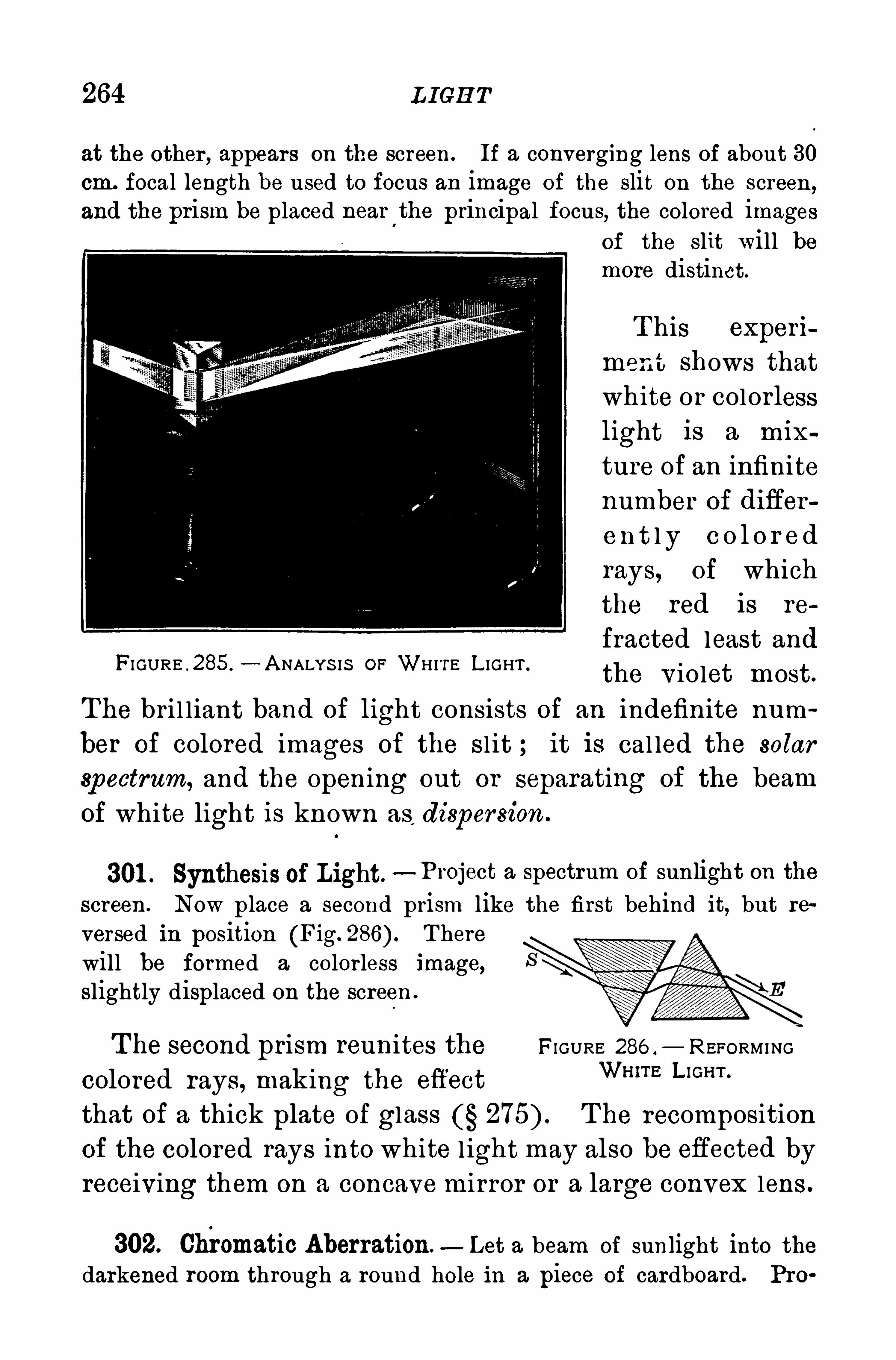
264 LIGH T
at the other , appears on the screen . If a converging lens of about 30cm. focal length be used to focus an image of the slit on the screen
,
and the prism be placed near'
the principal focus, the colored imagesof the slit will bemore distinct.
T his experi
ment shows thatwhite or colorlesslight is a mix
ture of an infinitenumber of difier
en t l y c o l o r edrays, of whichthe red is re
fracted least and
the v iolet most.
The bri l liant band of light consists of an indefinite num
ber of colored images of the sl it ; it is cal led the solar
spectrum, and the Opening out or separating of the beam
of white light is known as dispersion .
FI GURE . 285 .
—A NALYS IS OF WH ITE L IGHT .
301 . Synthesis of Light.
—Project a spectrum of sunlight on thescreen. Now place a second prism like the first behind it, but re
versed in position (Fig. T herewill be formed a colorless image,slightly displaced on the screen .
T he second prism reunites the FIGURE 286 .
— REFORMING
colored rays, making the effectWH‘TE L IGH T“
that of a thick plate of glass T he recomposition
of the colored rays into white l ight may also be eflected byreceiving them on a concave mirror or a large convex lens .
302. Chromatic Aberration. Let a beam of sunlight into thedarkened room through a round hole in a piece of cardboard. Pro
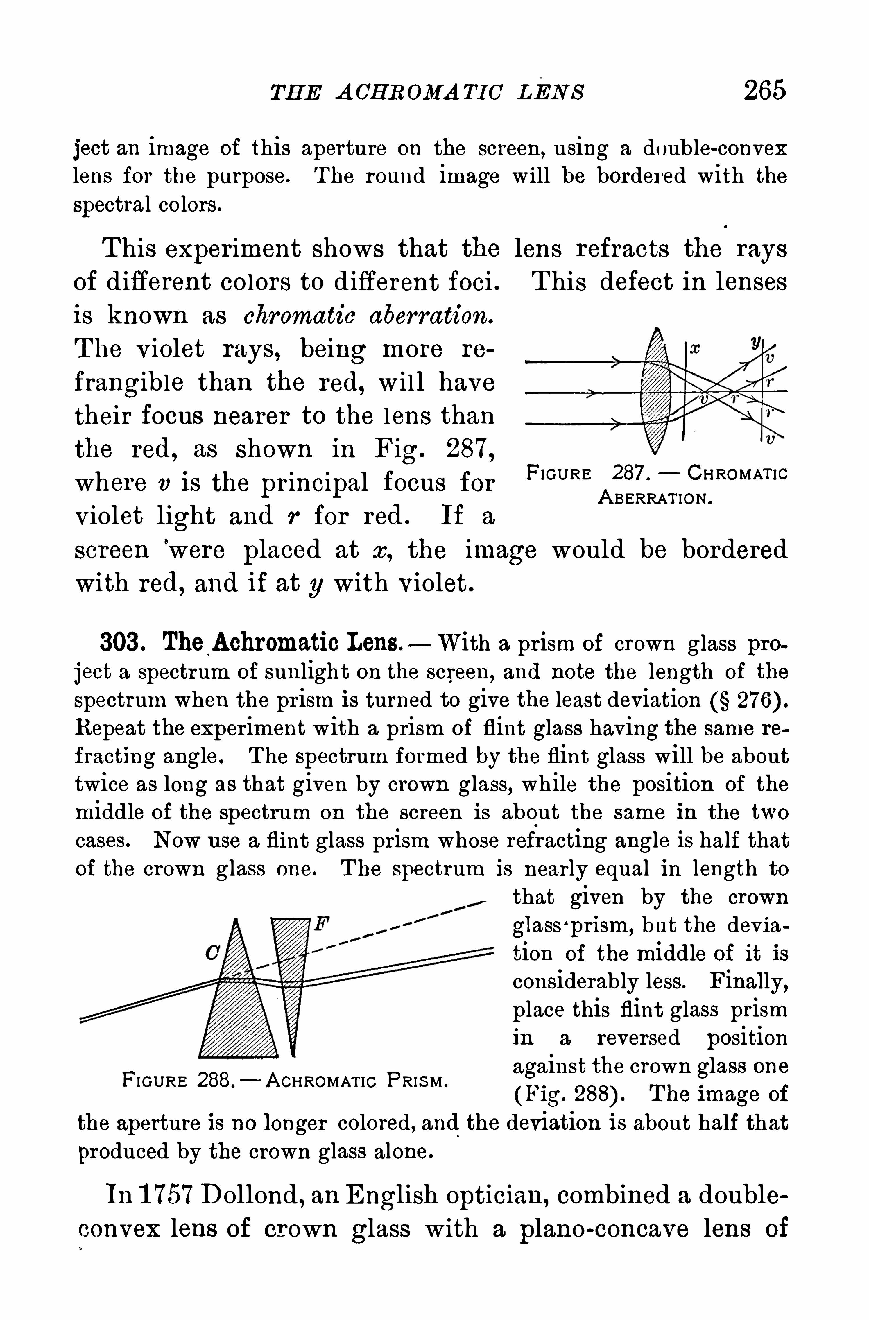
TH E A GH R OMA TIO LEN S 265
ject an image of this aperture on the screen , using a double-convexlens for the purpose. T he round image will be bordered with thespectral colors .
T his exper iment shows that the lens refracts the rays
of different colors to different foci . T his defect in lensesis known as chromatic aberration.
T he v iolet rays, being more re
frangible than the red, w il l have
their focus nearer to the lens than
the red, as shown in Fig. 287,
where v is the principal focus for
violet light and r for red . If a
screen’
were placed at x, the image would be borderedwith red, and if at y with v iolet.
FIGURE 287 . CHROMAT ICA BERRAT ION .
303 . The Achromatic Lens. With a prism of crown glass project a spectrum of sunlight on the screen, and note the length of the
spectrum when the pr ism is turned to give the least deviationRepeat the experiment with a prism of flint glass having the same re
fracting angle. T he spectrum formed by the flint glass will be abouttwice as long as that given by crown glass, while the position of the
middle of the spectrum on the screen is about the same in the two
cases. Now use a flint glass prism whose refracting angle is half thatof the crown glass one. T he spectrum is nearly equal in length to
that given by the crownglass
'
prism, but the deviation of the middle of it is
considerably less. Finally,place this flint glass prismin a reversed positionagainst the crown glass one(Fig. T he image of
the aperture is no longer colored, and the deviation is about half that
produced by the crown glass alone.
FI GURE 288.
—A CHROMAT IC PRIS M .
In 1 757 Dollond , an English optician, combined a double
convex lens of crown glass with a plano-concave lens of
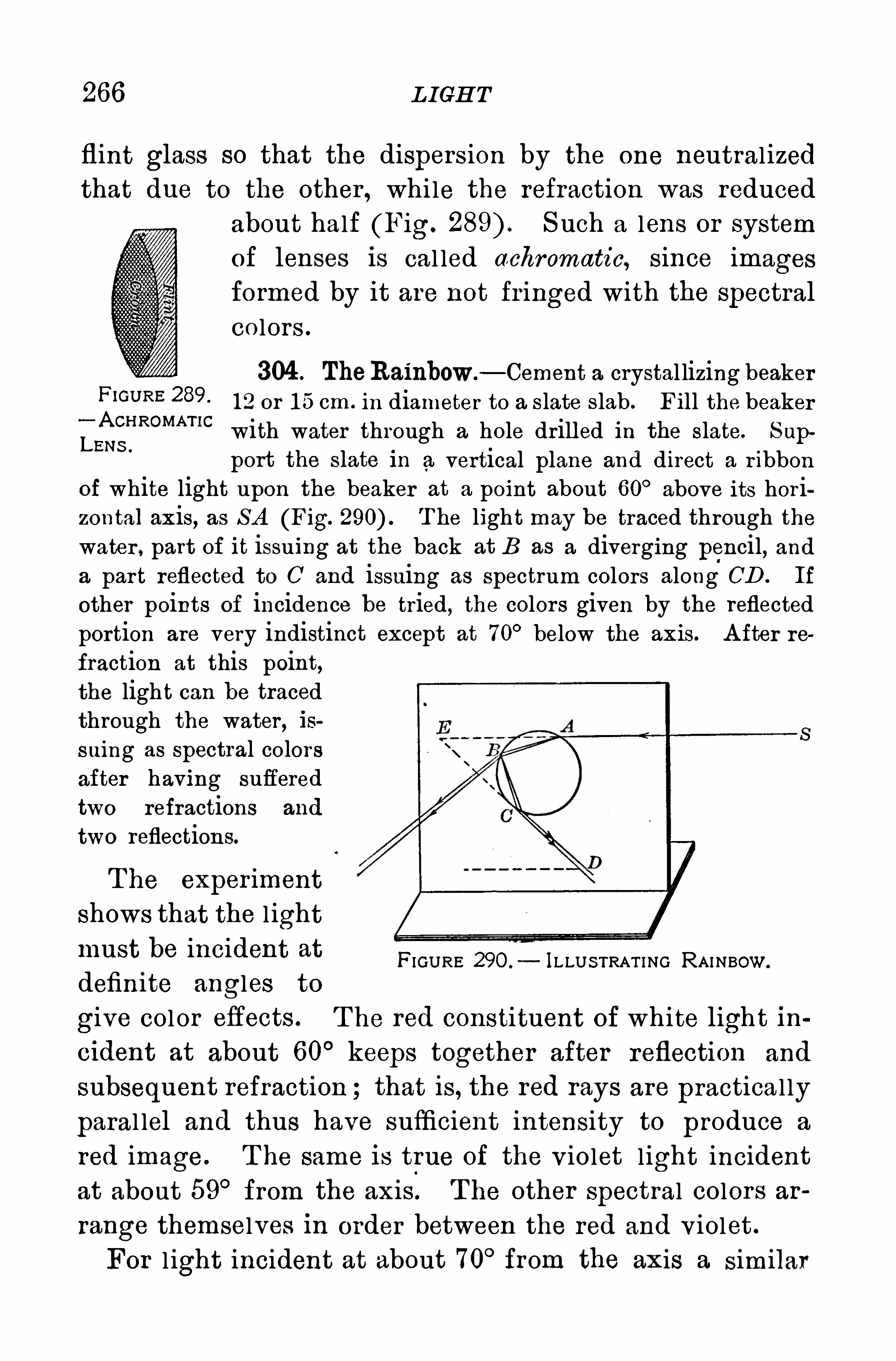
266 L IGH T
flint glass so that the dispers ion by the one neutral izedthat due to the other , while the refraction was reduced
about half (Fig. S uch a lens or systemof lenses is cal led achromatic, since images
formed by it are not fr inged with the spectral
Co lors .
304 . TheRainbow.—Cement a crystal lizing beaker
F‘GU RE 289 1 2 or 1 5 cm . in diameter to a slate s lab . Fill the beaker
LQZH ROMAT IC
with water through a hole drilled in the slate. S up
port the slate in a vertical plane and direct a r ibbonof white light upon the beaker at a point about 60° above its horizontal axis, as S A (Fig. T he light may be traced through thewater , part of it issuing at the back at B as a diverging pencil, anda part reflected to C and issuing as spectrum colors along CD . If
other points of incidence be tried, the colors given by the reflectedportion are very indistinct except at 70
° below the axis. A fter re
fraction at this point,the light can be tracedthrough the water, issuing as spectral colorsafter having sufferedtwo refractions and
two reflections.
T he exper iment
shows that the l ightmust be incident atdefinite angles to
give color eflects . T he red constituent of white light in
cident at about 60° keeps together after reflection and
subsequent refraction ; that is, the red rays are practical ly
paral lel and thus have sufficient intensity to produce a
red image . T he same is true of the v iolet l ight incident
at about 59° from the axis. T he other spectral colors ar
range themselves in order between the red and violet .
For l ight incident at about 70°from the axis a similar
FIGURE 290 . ILLU S TRAT I NG RAINBOW.
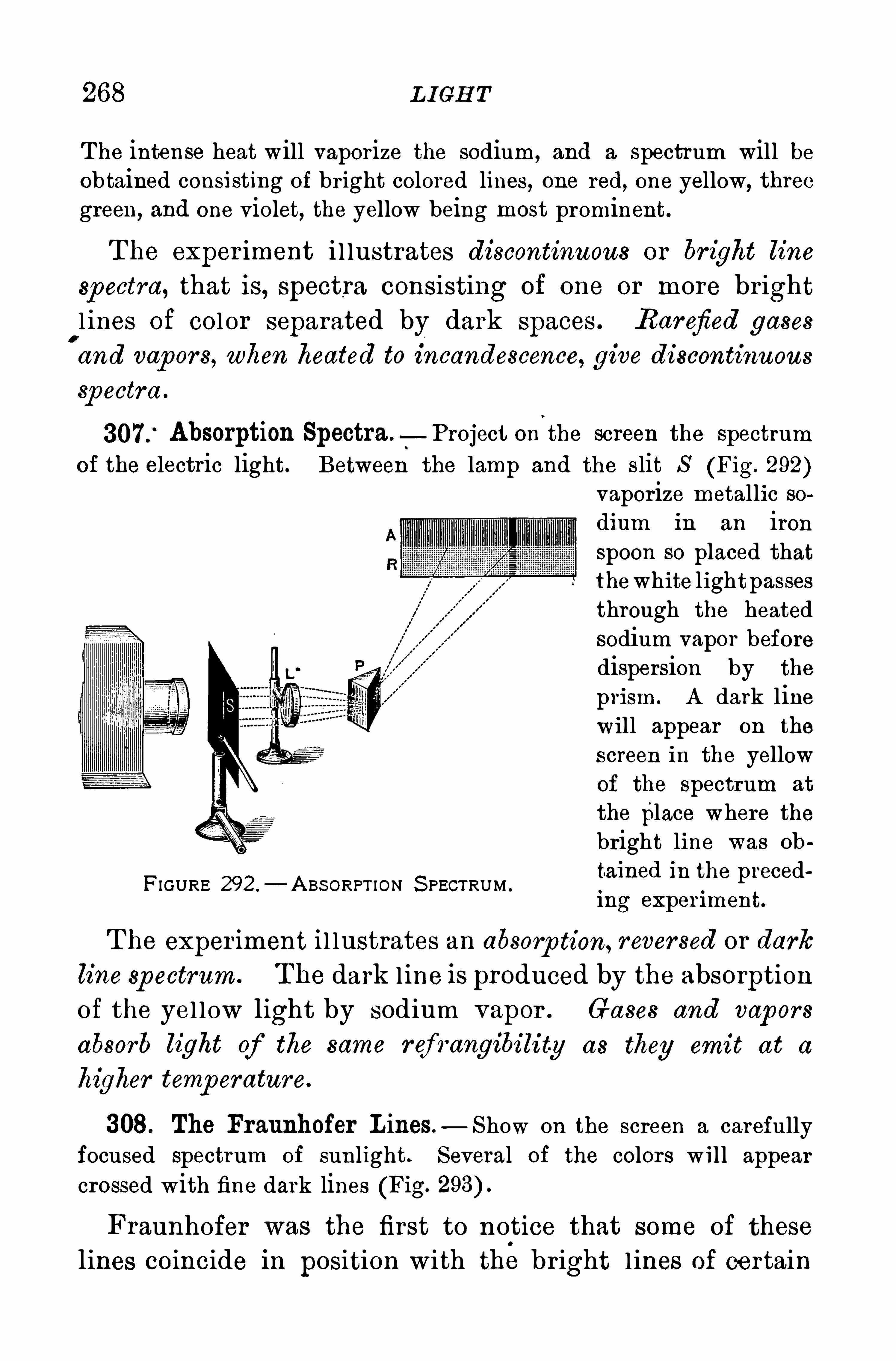
268 L I GH T
The intense heat will vaporize the sodium, and a spectrum will beobtained consisting of bright colored lines, one red, one yellow, threc
green, and one violet, the yellow being most prominent.
T he exper iment i l lustrates discontinuous or br ight line
spectra, that is, spectra consisting of one or more br ightl ines of color separated by dark spaces . Rarefied gases
'
and vap ors, when heated to incandescence, give discontinuous
Sp ectra .
Absorption Spectra.—Project on the screen the spectrum
of the electric light. Between the lamp and the slit S (Fig. 292)vaporize metallic sodium in an ironspoon so placed thatthewhite lightpassesthrough the heatedsodium vapor beforedispersion by the
prism. A dark linewill appear on the
screen in the yellowof the spectrum at
the place where thebright line was ob
tained in the precedFIGURE 292 .
— A BS ORPT ION S PECTRUM .
mg exper iment.
T he exper iment i l lustrates an absorp tion, rever sed or dark
line spectrum. The dark line is produced by the absorptionof the yel low light by sodium vapor . Gases and vapors
absorb light of the same ref rangibilit-y as they emit at a
higher temp erature.
308. The Fraunhofer Lines — Show on the screen a carefullyfocused spectrum of sunlight. Several of the colors w ill appearcrossed with fine dark lines (Fig.
Fraunhofer was the first to notice that some of these
lines coincide in position with the br ight l ines of certain
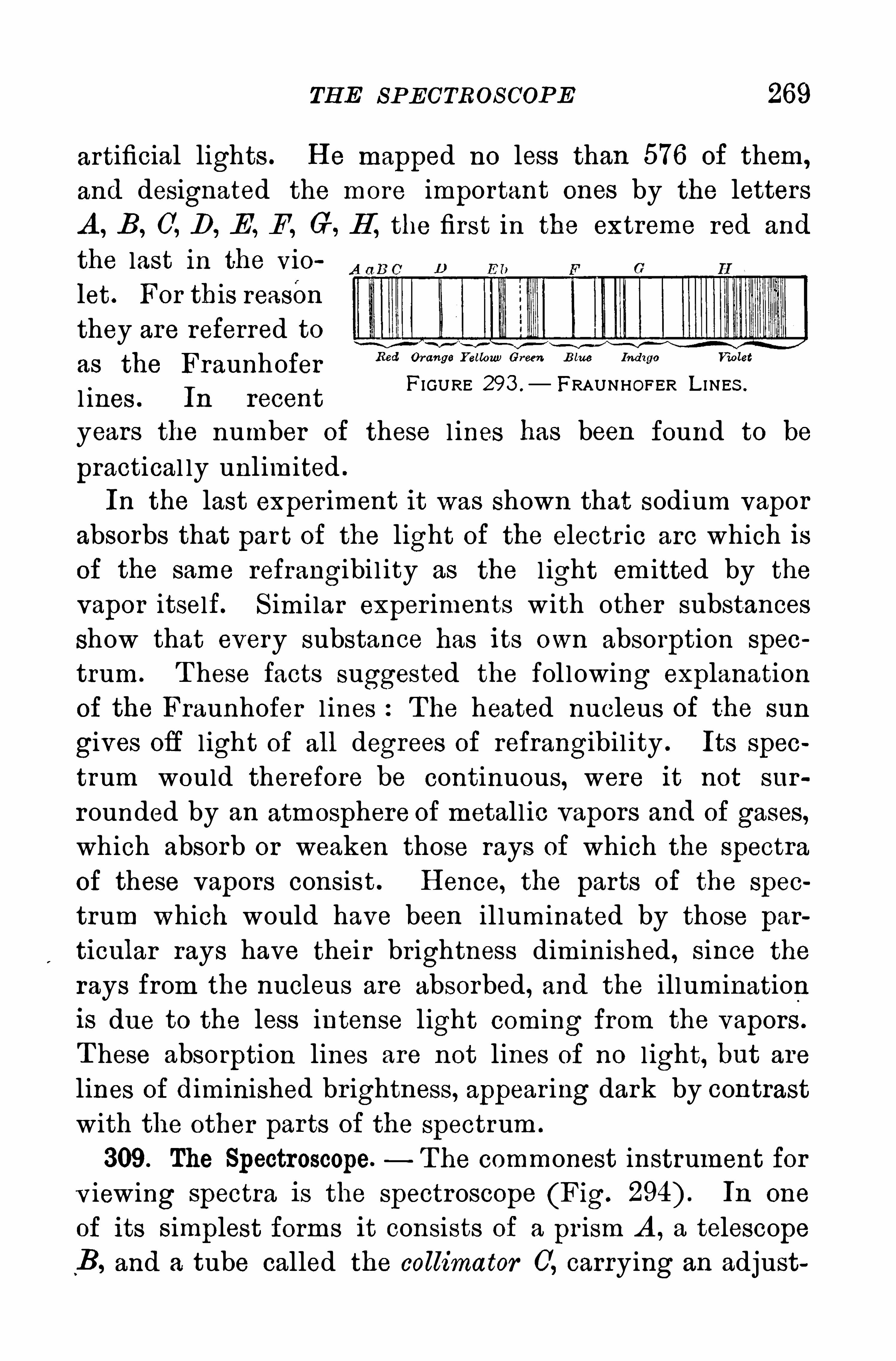
TH E SP ECTROS COP E 269
artificial lights . H e mapped no less than 576 of them,
and designated the more important ones by the letters
A , B, C, D, E , F , G, H , the first in the extreme red and
the last in the vio
let . For this reason
they are referred to
as the FraunhoferFIGURE 293 . FRAUNHOFER L I NES .
l ines . In recent
years the number of these l ines has been found to be
practical ly unlimited .
In the last exper iment it was shown that sodium vapor
absorbs that par t of the light of the electr ic arc which is
of the same refrangibi l ity as the l ight emitted by the
vapor itself. S imi lar exper iments w ith other substances
show that every substance has its own absorption spec
trum. T hese facts suggested the fol lowing explanation
of the Fraunhofer l ines :The heated nucleus of the sun
gives off l ight of all degrees of refrangibil ity . Its spec
trum would therefore be continuous, were it not sur
rounded by an atmosphere of metall ic vapors and of gases,
which absorb or weaken those rays of which the spectra
of these vapors consist . H ence, the parts of the spec
trum which would have been il luminated by those par
ticular rays have their brightness diminished , since the
rays from the nucleus are absorbed, and the illuminationis due to the less intense light coming from the vapors .
T hese absorption lines are not lines of no l ight, but are
lines of diminished br ightness, appear ing dark by contrastwith the other parts of the spectrum .
309. The Spectroscope. T he commonest instrument for
v iewing spectra is the spectroscope (Fig. In one
of its simplest forms it consists of a pr ism A , a telescope
“B, and a tube called the collimator 0, carrying an adjust
Red Orange Y ellow) Green B lue Ind igo Violet
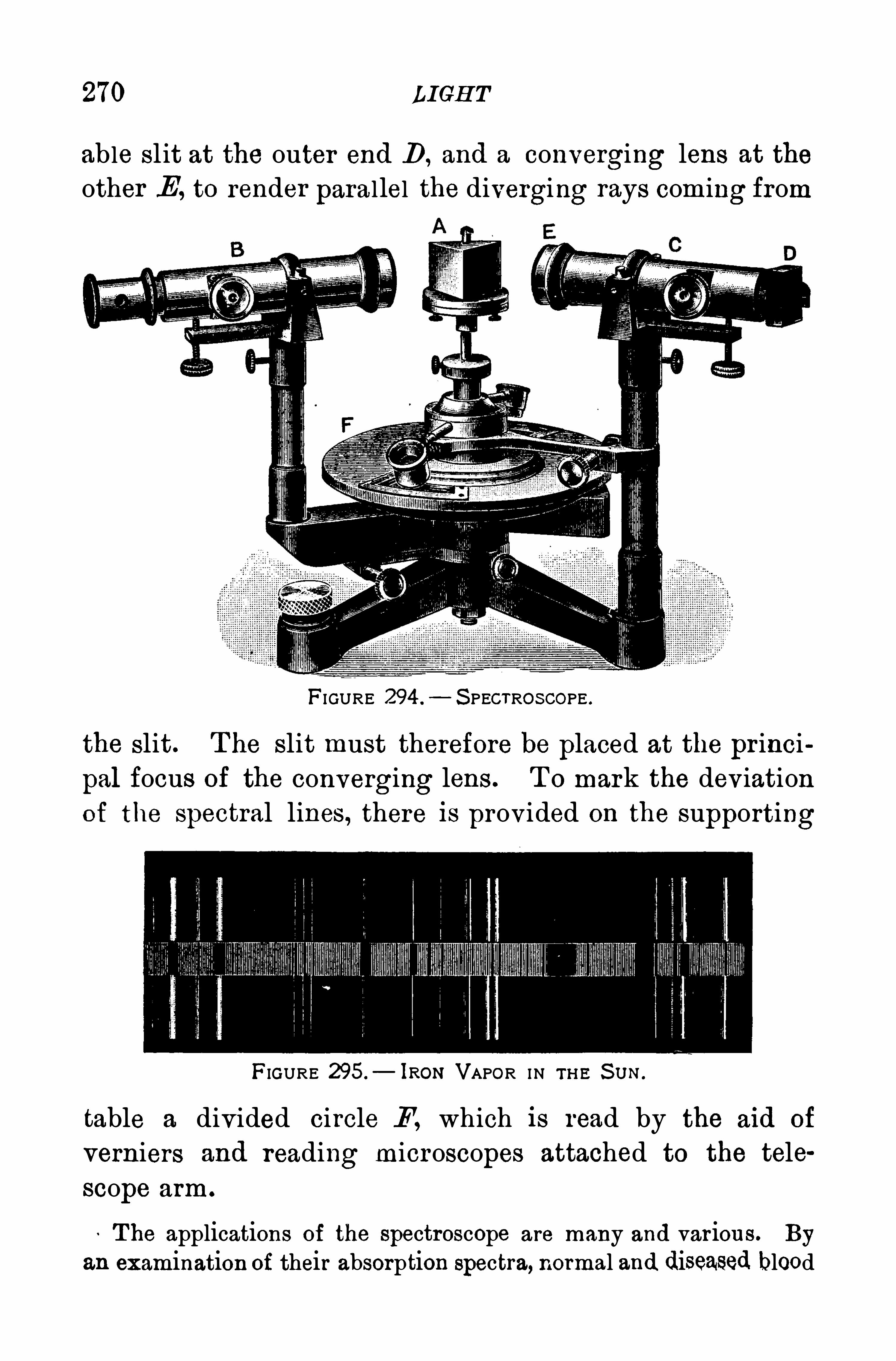
270 LI GH T
able sl it at the outer end D , and a converging lens at the
other E, to render parallel the diverging rays coming from
FIGURE 294 . S PECTRO SCOPE .
the slit. T he slit must therefore be placed at the pr inci
pal focus of the converging lens . T o mark the deviation
of the spectral lines, there is provided on the supporting
FIGURE 295.
— lR0N VAPOR IN TH E S U N .
table a divided circle F, which is read by the aid of
verniers and reading microscopes attached to the tele
scope arm.
T he applications of the spectroscope are many and various. By
an examination of their absorption spectra, normal and diseased blood

VA R IO U S S PECT RA
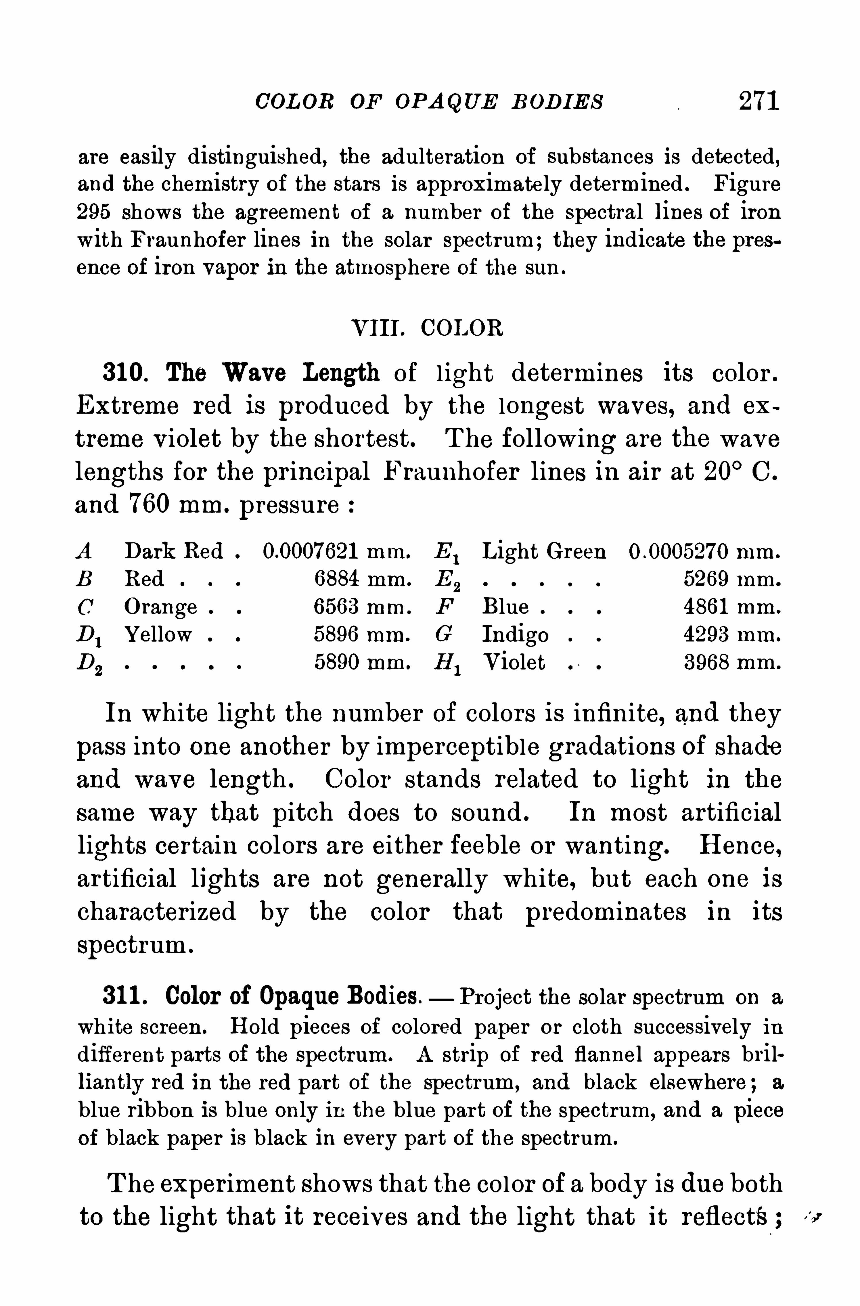
COL OR OF OPA QUE BODIES
are easily distinguished, the adulteration of substances is detected,and the chemistry of the stars is approximately determined . Figure295 shows the agreement of a number of the spectral lines of ironwith Fraunhofer lines in the solar spectrum;they indicate the presence of iron vapor in the atmosphere of the sun .
VIII . COLOR
310. The Wave Length of l ight determines its color .
Extreme red is produced by the longest waves, and ex
treme v iolet by the shortest. T he following are the wave
lengths for the pr incipal Fraunhofer lines in air at 20°C .
and 760 mm. pressure
A Dark Red 621 mm. E1L ight Green mm.
B Red 6884 mm . E2 5269 mm.
(7 O range 6563 mm . F Blue 486 1 mm .
D1Y ellow 5896 mm . G Indigo 4293 mm.
D2
5890 mm. H1Violet 3968mm .
In white light the number of colors is infinite, and they
pass into one another by imperceptible gradations of shadeand wave length . Color stands related to light in the
same way that pitch does to sound . In most artificiallights certain colors are either feeble or wanting. H ence,
artificial lights are not generally white, but each one is
characterized by the color that predominates in its
spectrum .
31 1 . Color of OpaqueBodies. Project the solar spectrum on a
white screen . H old pieces of colored paper or cloth successively indifferent parts of the spectrum . A strip of red flannel appears brilliantly red in the red part of the spectrum , and black elsewhere; a
blue ribbon is blue only in the blue par t of the spectrum, and a pieceof black paper is black in every part of the spectrum .
T he experiment shows that the col or of a body is due bothto the light that it receives and the light that it reflects
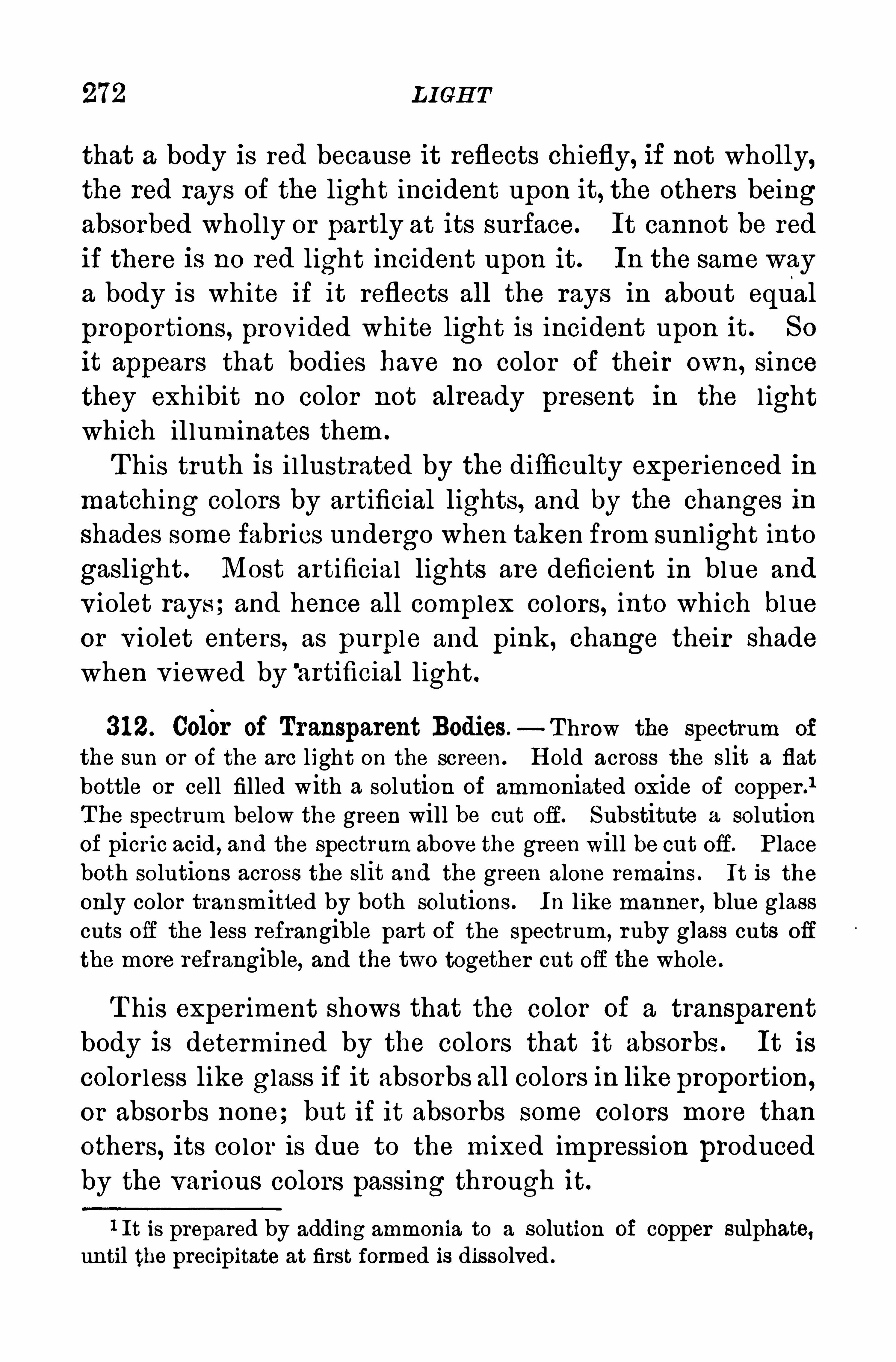
272 L IGH T
that a body is red because it reflects chiefly, if not wholly,the red rays of the light incident upon it, the others beingabsorbed wholly or partly at its surface. It cannot be red
if there is no red light incident upon it . In the same way
a body is white if it reflects all the rays in about equal
proportions, provided white light is incident upon it . So
it appears that bodies have no color of their own, sincethey exhibit no color not already present in the l ightwhich il luminates them .
T his truth is i l lustrated by the difficulty exper ienced inmatching colors by artificial lights, and by the changes in
shades some fabr ics undergo when taken from sunlight into
gaslight . Most artificial lights are deficient in blue and
violet rays ;and hence all complex colors , into which blueor v iolet enters, as purple and pink, change their shadewhen v iewed by '
artificial light.
31 2. Color of Transparent Bodies. Throw the spectrum of
the sun or of the arc light on the screen . H old across the slit a flat
bottle or cell filled with a solution of ammoniated oxide of copper .
1
The spectrum below the green will be cut off. Substitute a solutionof picric acid , and the spectrum above the green will be cut off. P laceboth solutions across the slit and the green alone remains . It is the
only color transmitted by both solutions. In like manner , blue glasscuts off the less refrangible part of the spectrum, ruby glass cuts off
the more refrangible, and the two together cut off the whole.
T his exper iment shows that the color of a transparent
body is determined by the colors that it absorbs . It is
color less like glass if it absorbs all colors in like proportion,or absorbs none; but if it absorbs some colors more than
others, its color is due to the mixed impression produced
by the various colors passing through it.
1 It is prepared by adding ammonia to a solution of copper sulphate,until the precipitate at first formed is dissolved .
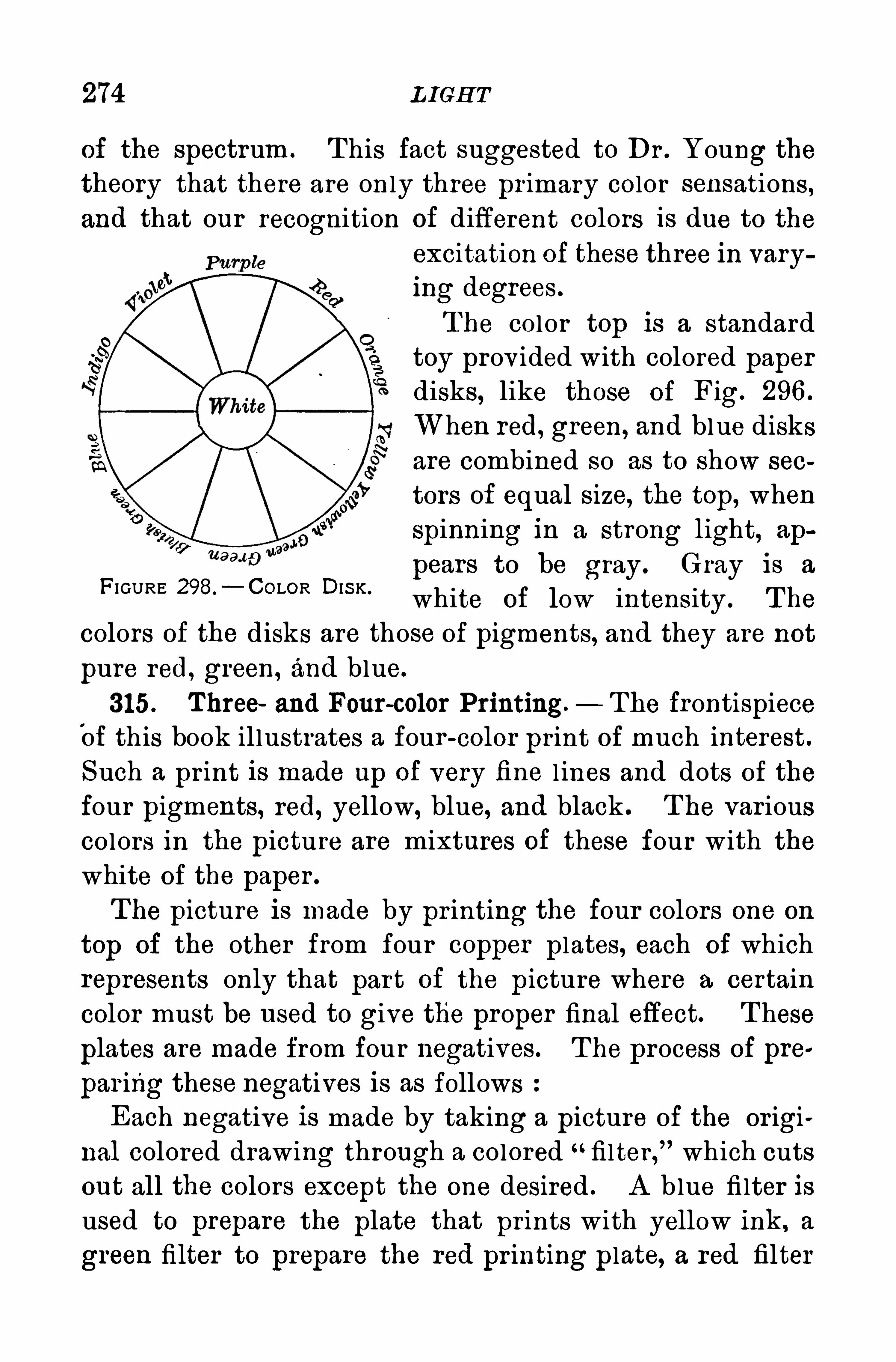
274 L IGH T
of the spectrum . T his fact suggested to Dr . Young thetheory that there are only three primary color sensations ,and that our recognition of different colors is due to the
excitation of these three in varying degrees .
T he color top is a standardtoy prov ided with colored paperdisks, like those of Fig. 296 .
When red, green, and blue disksare combined so as to show sec
tors of equal size, the top, whenspinning in a strong light, ap
pears to be gray . Gray is a
white of low intensity . T he
colors of the disks are those of pigments, and they are not
pure red, green, and blue.
315. Three and Four-color Printing. The frontispieceOf this book illustrates a four -color print of much interest .
S uch a print is made up of very fine l ines and dots of the
four pigments, red, yellow, blue, and black . T he var iouscolors in the picture are mixtures of these four with the
white of the paper .
The picture is made by pr inting the four colors one on
top of the other from four copper plates, each of whichrepresents only that par t of the picture where a certain
color must be used to give the proper final effect. T hese
plates are made from four negatives. T he process of pre
par ing these negatives is as followsEach negative is made by taking a picture of the or igi
nal colored drawing through a colored filter,” which cuts
out all the colors except the one desired . A blue fi lter isused to prepare the plate that prints with yellow ink, a
green filter to prepare the red pr inting plate, a red filter
FI GURE 298.
— COLOR DIS K .
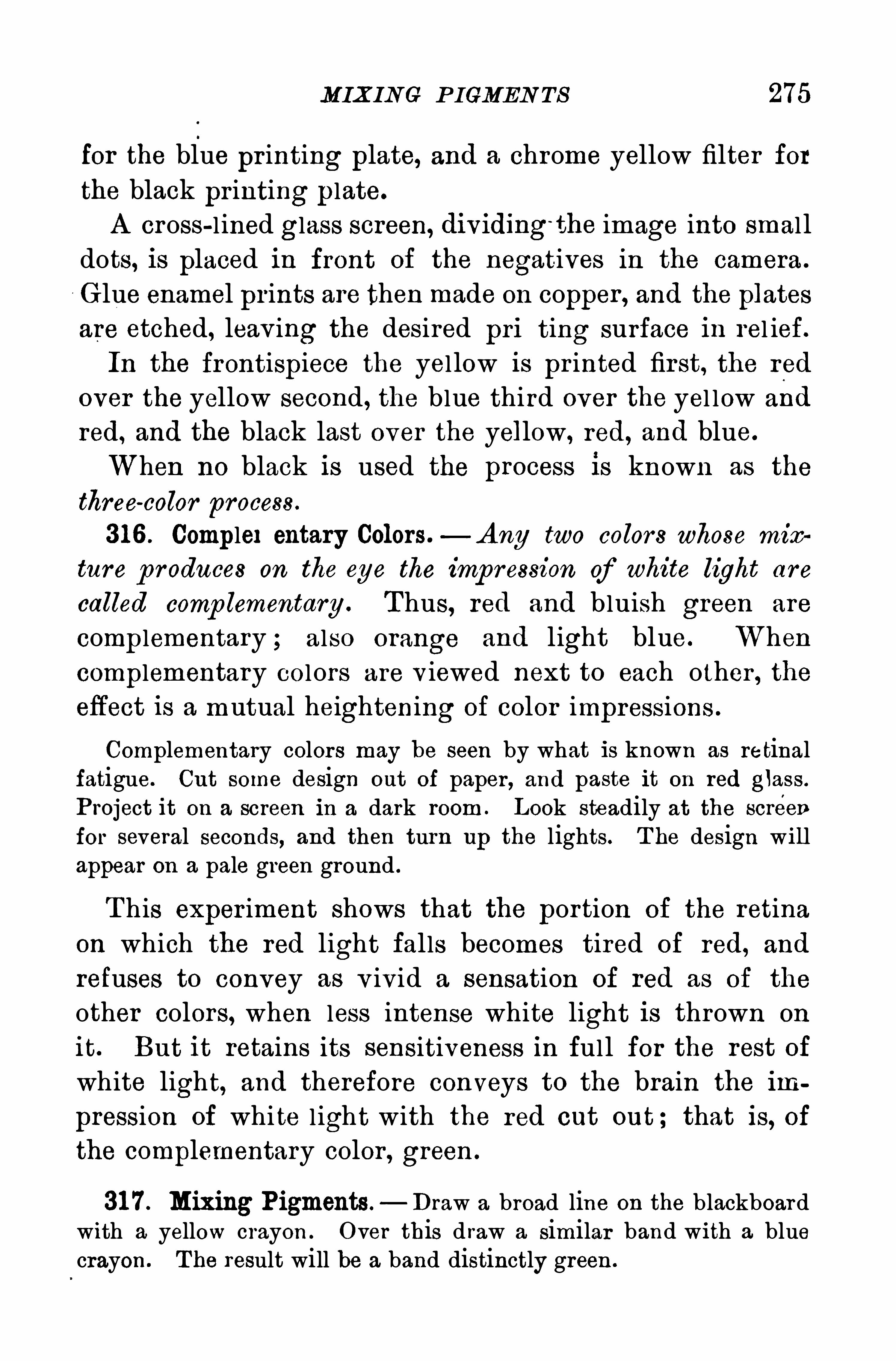
MIXIN G P IGMEN TS 275
for the blue pr inting plate, and a chrome yellow filter for
the black pr inting p late.
A cross-l ined glass screen, dividing‘
the image into smal l
dots, is placed in front of the negatives in the camera .
Glue enamel prints are then made 0 11 Copper , and the plates
are etched, leav ing the desired pri ting surface in rel ief.
In the frontispiece the yel low is pr inted fir st, the red
over the yellow second, the blue third over the yel low and
red, and the black last over the yellow, red, and blue.
When no black is used the process is known as the
three-color process .
31 6 . Complex entary Colors.—A ny two colors whose mix
tur e p roduces on the eye the imp ression of white light are
called comp lementary . Thus, red and bluish green are
complementary ; also orange and light blue. When
complementary colors are v iewed next to each other , theeffect is a mutual heightening of color impressions .
Complementary colors may be seen by what is known as retinalfatigue. Cut some design out of paper, and paste it on red glass .
Project it on a screen in a dark room . Look steadily at the screen
for several seconds, and then turn up the lights. T he design willappear on a pale green ground .
T his exper iment shows that the portion of the retinaon which the red light falls becomes tired Of red, and
refuses to convey as v ivid a sensation of red as of the
other colors, when less intense white light is thrown on
it. But it retains its sensitiveness in ful l for the rest of
white light, and therefore conveys to the brain the im
pression of white l ight with the red cut out ; that is, ofthe complementary color , green .
31 7 . Mixing Pigments. Draw a broad line on the blackboardwith a yellow crayon . O ver this d raw a similar band with a bluecrayon . T he result will be a band distinctly green .
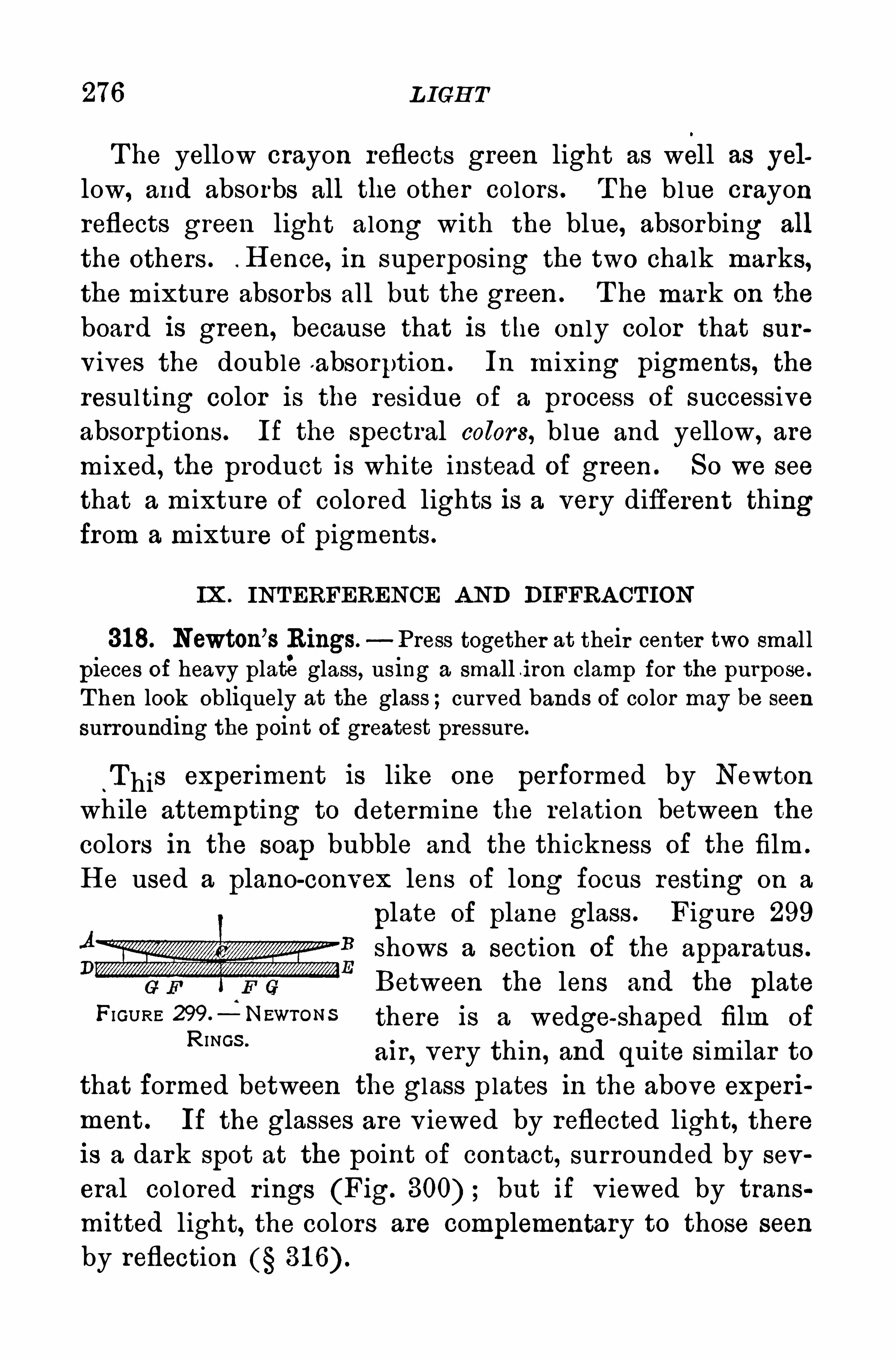
276 L IGH T
T he yellow crayon reflects green light as well as yel
low, and absorbs all the other colors . T he blue crayonreflects green light along with the blue, absorbing all
the others . . H ence, in superposing the two chalk marks,the mixture absorbs all but the green . T he mark on the
board is green, because that is the only color that sur
v ives the double a bsorption . In mixing pigments, theresulting color is the residue of a process of successiveabsorptions. If the spectral colors, blue and yellow, are
mixed, the product is white instead of green . So we see
that a mixture of colored lights is a very different thingfrom a mixture of pigments .
IX . INTERFERENCE A ND DIFFRA CT ION
318. Newton’s Rings. Press together at their center two smal l
pieces of heavy plateglass , using a small i ron clamp for the purpose .
T hen look obliquely at the glass ;curved bands of color may be seen
surrounding the point of greatest pressure.
“T his exper iment is like one performed by Newton
while attempting to determine the relation between the
colors in the soap bubble and the thickness of the film .
H e used a plano-convex lens of long focus resting on a
plate of plane glass . Figure 299B
shows a section of the apparatus .
Between the lens and the plateFIGURE 299-4 NEWT0 NS there is a wedge-shaped film of
R INGS '
air , very thin, and quite similar tothat formed between the glass p lates in the above experi
ment . If the glasses are v iewed by reflected light, thereis a dark spot at the point of contact, surrounded by sev
eral colored r ings (Fig. but if v iewed by trans
mitted light, the colors are complementary to those seen
by reflection
278 L IGH T
T he Colors of the soap bubble, of oil on water, of heatedmetals which easi ly oxidize, of a thin film of varnish, andof the surface of very old glass, are all caused by the interference of light reflected from the two surfaces of a
very thin film .
319. Diffraction.— P lace two superposed pieces of perforated
cardboard in front of the condenser of the projection lantern. The
projected images of the very small holes, as one piece is moved acrossthe other, are fringed with the spectral colors .
With a fine diamond point rule a number of equidistant paral lellines very close together on glass . T hey compose a transparent diffraction grating. S ubstitute this for the prism in projecting the spectrum of sun light or of the arc light on the screen T herewill be seen on the screen a central image of the slit, and on eitherside of it a ser ies of spectra. Cover half of the length of the slit withred glass and the other half with blue . T here will now be a seriesof red images and also a series of blue Ones, the red ones being farther apart than the blue . L ines ruled close together on smokedglass may be used instead of a
“grating.
”
T hese exper iments il lustrate a phenomenon known as
difiraction. T he colored bands are caused by the inter
ference of the waves of light which are propagated in all
directions from the fine openings . T he effects are v isible
because the transparent spaces are so small that the inten
sity of the direct light from the source is largely re
duced. Difl raction gratings are also made to operate byreflecting light. S tr iated surfaces, like mother-of—pear l ,changeable silk , and the plumage of many birds, owe
their beautiful changing colors to interference of light by
diffraction .
medium next to a rare one, and the latter in an optically rare mediumnext to a dense one. T his phase difference is additional to the one abovedescribed .
QUES TION S 279
Q uestions
1 . H ow many degrees is it from the sun to the highest point of theprimary rainbow
2 . Why is the red on the outside of the primary bow and on the
inside of the secondary bow3 . If there are but three primary sensations , red, green, and violet,
what effect would it have on a person ’
s vision if the nerves for red
sensations were inoperative ?
4 . Why is the secondary rainbow less bright than the primarybow ?
5 . A re the two images of an object as formed on the retina of the
two eyes identical Explain.
6 . A ccount for the crossed bands of light seen by looking throughthe wire screening of the window at the full moon.
7 . A ccount for the change in color of aniline purple when viewedby the light of a common kerosene lamp.
8 . Under what conditions could a rainbow be seen at midday
9 . A ccount for the colors on water when gasol ine is poured on it.
1 0 . Why does each person in using a microscope have to focus forhis own eyes ?
CH A PT ER IX
HEAT
1 . H EA T AND TEMPERA TURE
320. Nature of H eat.—For a long time it was believed
that heat was a subtle and weightless fluid that entered
bodies and possibly combined with them. T his fluid was
called calor ic. A bout the beginning of the last century
some experimentsof Count Rumford in boring brass can
non, and those of S ir H umphry Davy inmelting two piecesof ice at freez ing
.
temperature by the friction of one pieceon the other demonstrated that the caloric theory of heatwas no longer tenable ; and final ly about the middle of
the century, when Joule proved that a definite amount of
mechanical work is equivalent to a definite amount of
heat, it became evident that heat is a form of molecular
T he modern kinetic theory, briefly stated, is as followsT he molecules of a body have a cer tain amount of inde
pendent motion, general ly very irregular . A ny increasein the energy of this motion shows itself in additional
warmth , and any decrease by the cooling of the body .
T he heating or the cool ing of a body, by whatever
process, is but the transference or the transformation of
energy321 . Temperature.
- If we place a mass of hot I ron in
contact w ith a mass of cold iron, the latter becomes warmer
and the former cooler , the heat flowing from the hot body
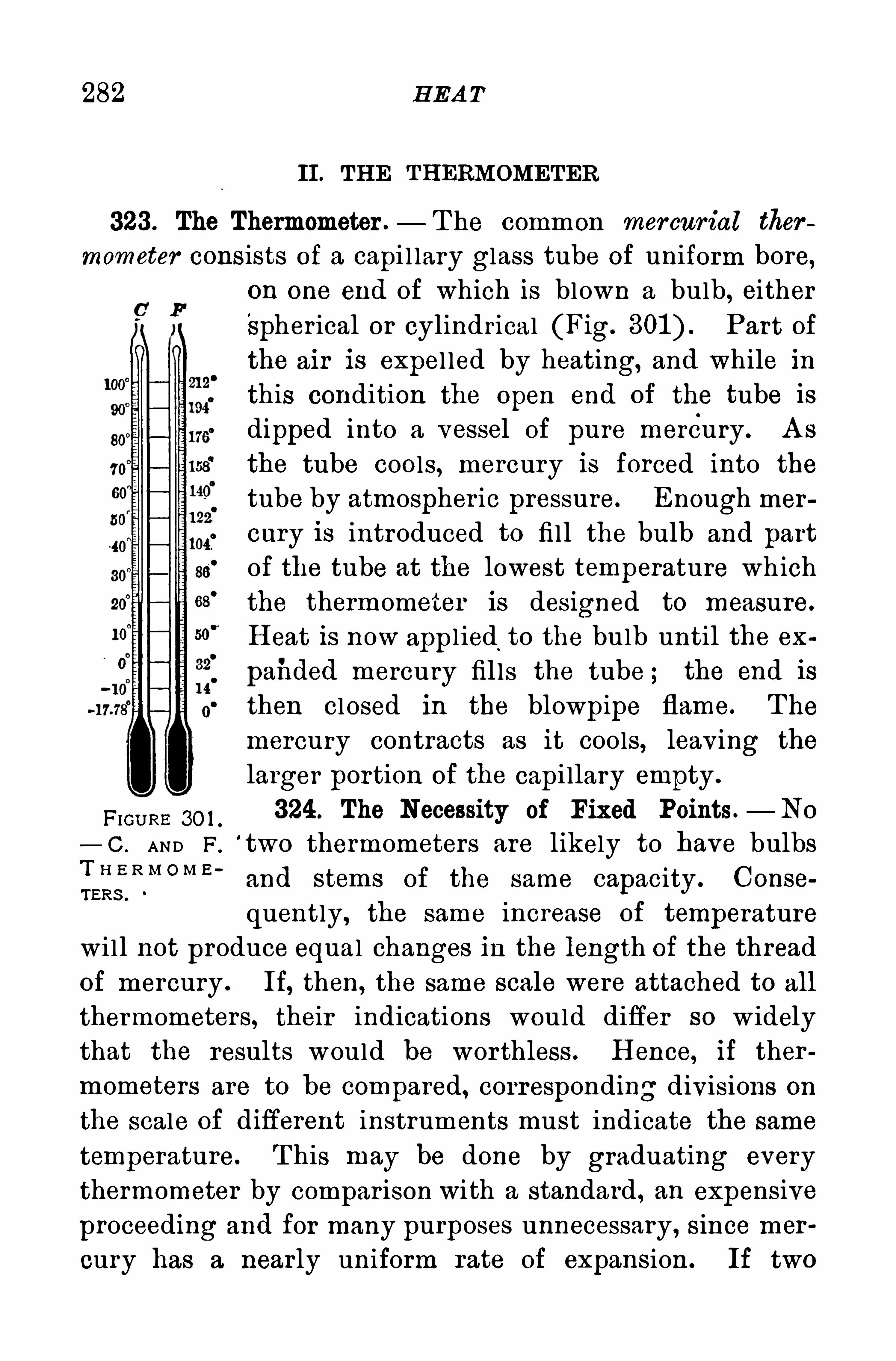
282 H EA T
II. TH E TH ERMOMETER
323. The Thermometer .— T he common mercurial ther
mometer consists of a capi l lary glass tube of uniform bore,on one end of which is blown a bulb
, eitherSpher ical or cylindrical (Fig. Part of
the air is expel led by heating, and while inthis condition the open end of the tube isdipped into a vessel of pure mercury . A s
the tube cools, mercury is forced into the
tube by atmospher ic pressure. Enough mercury is introduced to fi ll the bulb and part
of the tube at the lowest temperature whichthe thermometer is designed to measure.
H eat is now appl ied.
to the bulb until the ex
paiided mercury fil ls the tube ; the end is
then closed in the blowpipe flame. T he
mercury contracts as it cools, leaving the
larger portion of the capi llary empty .
FmU RE 30 1 .
324 . The Necessity of Fixed Points.—No
— C . AND F.
‘
two thermometers are likely to have bulbs
Lislw om z '
and stems of the same capacity . Conse
quently, the same increase of temperaturewi ll not produce equal changes in the length of the thread
of mercury . If, then, the same scale were attached to all
thermometers, their indications would differ so w idely
that the results would be wor thless . H ence, if ther
mometers are to be compared, corresponding divisions on
the scale of difierent instruments must indicate the same
temperature. T his may be done by graduating every
thermometer by compar ison with a standard , an expensive
proceeding and for many purposes unnecessary, since mer
cury has a nearly uniform rate of expansion. If two
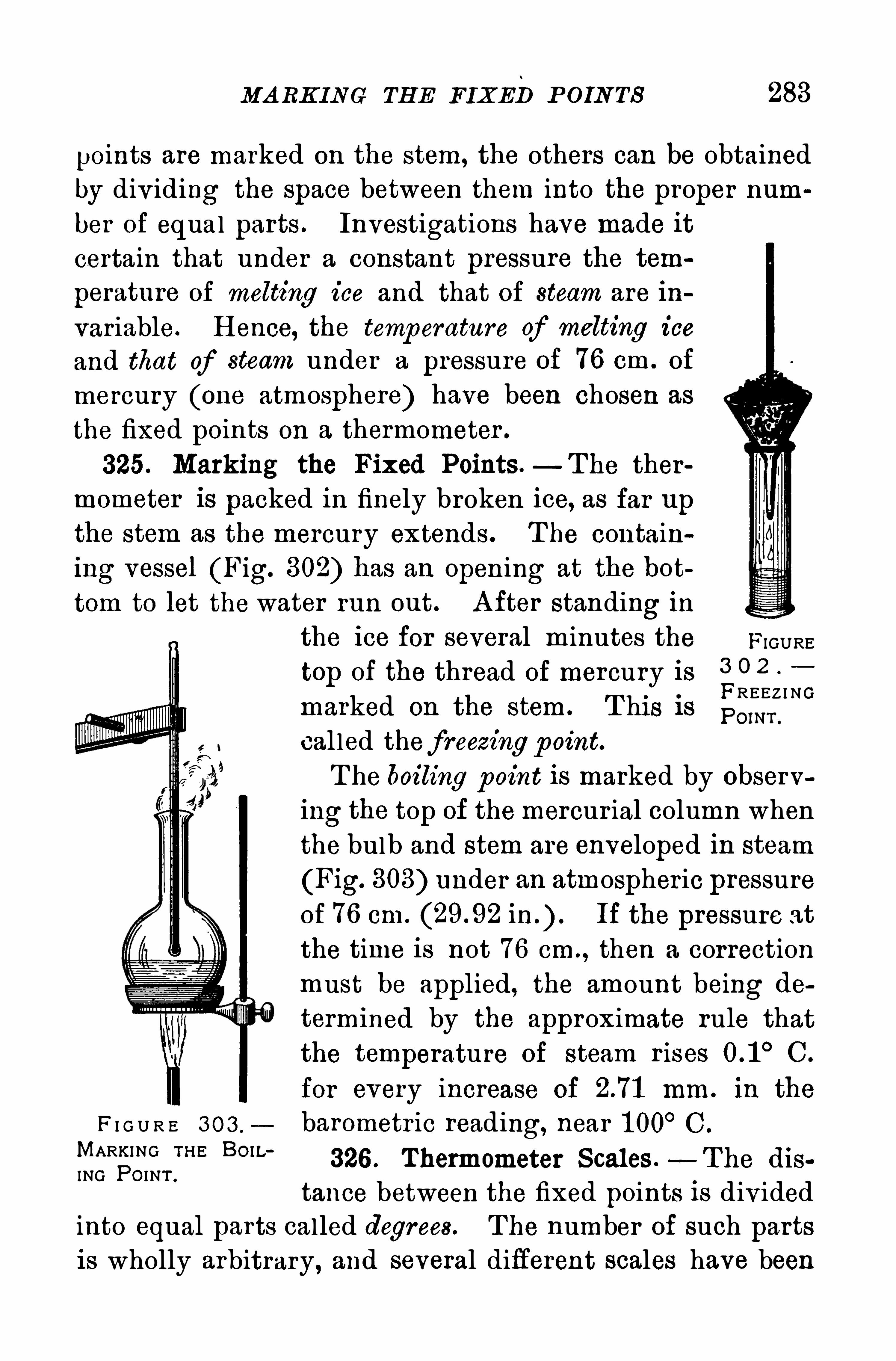
MA RK ING TH E FIXEDP OIN TS 283
points are marked on the stem, the others can be obtained
by div iding the space between them into the proper num
ber of equal parts . Investigations have made it
certain that under a constant pressure the tem
perature of melting ice and that of steam are in
variable. H ence, the temperature of melting iceand that of steam under a pressure of 76 cm. of
mercury (one atmosphere) have been chosen as
the fixed points on a thermometer .
325. Marking the Fixed Points .—T he ther
mometer is packed in finely broken ice, as far upthe stem as the mercury extends. T he contain
ing vessel (Fig. 302) has an opening at the bot
tom to let the water run out. A fter standing inthe ice for several minutes the FIGUREtop of the thread of mercury is 3 0 2
FREEZ I NGmarked on the stem . T his is pom .
cal led thefreezingp oint.T he boiling point is marked by observ
ing the top of themercurial column whenthe bulb and stem are enveloped in steam
(Fig. 303) under an atmospher ic pressureof 76 cm. If the pressure atthe time is not 76 cm. , then a correctionmust be applied, the amount being determined by the approximate rule thatthe temperature of steam r ises C.
for every increase of mm . in the
F I G U R E 3 0 3 , barometr ic reading, near 1 00°C .
MARKING TH E BOW 326 . Thermometer S cales .—T he disING PO INT .
tance between the fixed points is div idedinto equal parts called degrees. T he number of such partsis wholly arbitrary, and several different scales have been
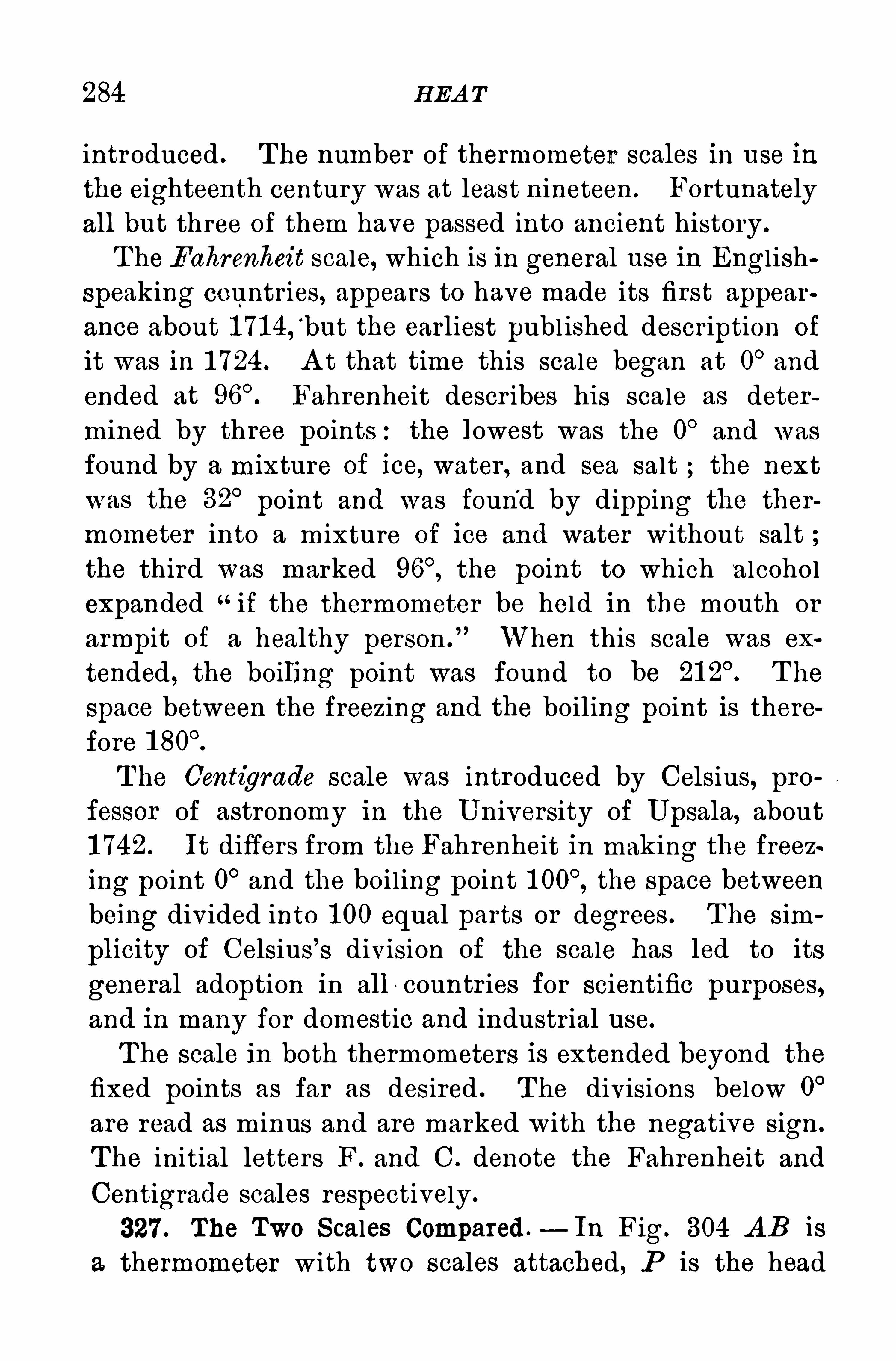
284 H EA T
introduced . T he number of thermometer scales in use in
the eighteenth century was at least nineteen . Fortunately
all but three of them have passed into ancient history .
T he Fahrenheit scale, which is in general use in Engl ish
speaking countries, appears to have made its first appear
ance about 1 71 4,‘
but the earliest publ ished descr iption of
it was in 1 724 . A t that time this scale began at 0°and
ended at Fahrenheit descr ibes his scale as deter
mined by three points:the lowest was the 0°and was
found by a mixture of ice, water , and sea salt the next
was the 32°
point and was found by dipping the ther
mometer into a mixture of ice and water without salt ;the third was marked the point to which alcohol
expanded“if the thermometer be held in the mouth or
armpit of a healthy person .
” When this scale was ex
tended , the boiling point was found to be T he
space between the freezing and the boiling point is there
fore
T he C'cntigrade scale was introduced by Celsius, pro
fessor of astronomy in the U niversity of U psala, about
1 742. It differs from the Fahrenheit in making the freez~
ing point 0°and the boi l ing point the space between
being div ided into 1 00 equal parts or degrees . The sim
plicity of Celsius’s division of the scale has led to its
general adoption in all -countr ies for scientific purposes,and in many for domestic and industr ial use.
T he scale in both thermometers is extended beyond the
fixed points as far as desired . The divisions below 0°
are read as m inus and are marked with the negative sign .
T he initial letters F. and C . denote the Fahrenheit and
Centigrade scales respectively .
327 . The Two Scales Compared .— In Fig. 304 A B is
a thermometer w ith two scales attached , P is the head
286 H EA T
top of the separated thread to mark the highest temperature registered . A sudden jerk or tapping of the thermometer forces the mercury down past the constr ictionand sets it for a new reading. The normal temperatureof the human body is 98 6° F. or 37
°C .
Questions and P rob lems
1 . Why do the degree spaces differ in length on diflerent thermometer s of the same scale ?
2 . What advantages does a thermometer with a cylindrical bulbhave over one with a spherical bulb ?
3 . Why is mercury preferable to other liquids for use in thermometers ?
4 . Why is it necessary to have fixed points in thermometers ?
5 . T he bulb of a thermometer generally contracts a little after
the thermometer is completed . What is the result on the readings ?
6 . Why is nitrogen used in preference to oxygen in thermometers
for high temperatures ?
7 . Why should the thermometer tube be of uniform bore?
8. Express in Fahrenheit degrees the fol lowing 4° C.
,30
° C.,
38° C.
9 . Express in Centigrade degrees the following 39°F.
, 40° F . ,
68° F.
1 0 . T he fixed points on a Centigrade thermometer were found tobe incor rect ;the freezing point read 2° and the boiling pointWhen this thermometer was immersed in a liquid the reading was
What was the correct temperature of the liquid
(NOTE .—Compare this incorrect thermometer with a correct one
just as a Fahrenheit thermometer is compared with a Centigrade in
1 1 . A thermometer read 40° C. in a water bath . When tested itwas found to read 0° at
!
the freezing point, but 95° instead of 100°at
the boiling point. What was the correct temperature of the bath ?
1 2 . If a Fahrenheit thermometer read 21 0° in steam and 3 1° in
melting ice, what would it read as the equivalent of 70° F.
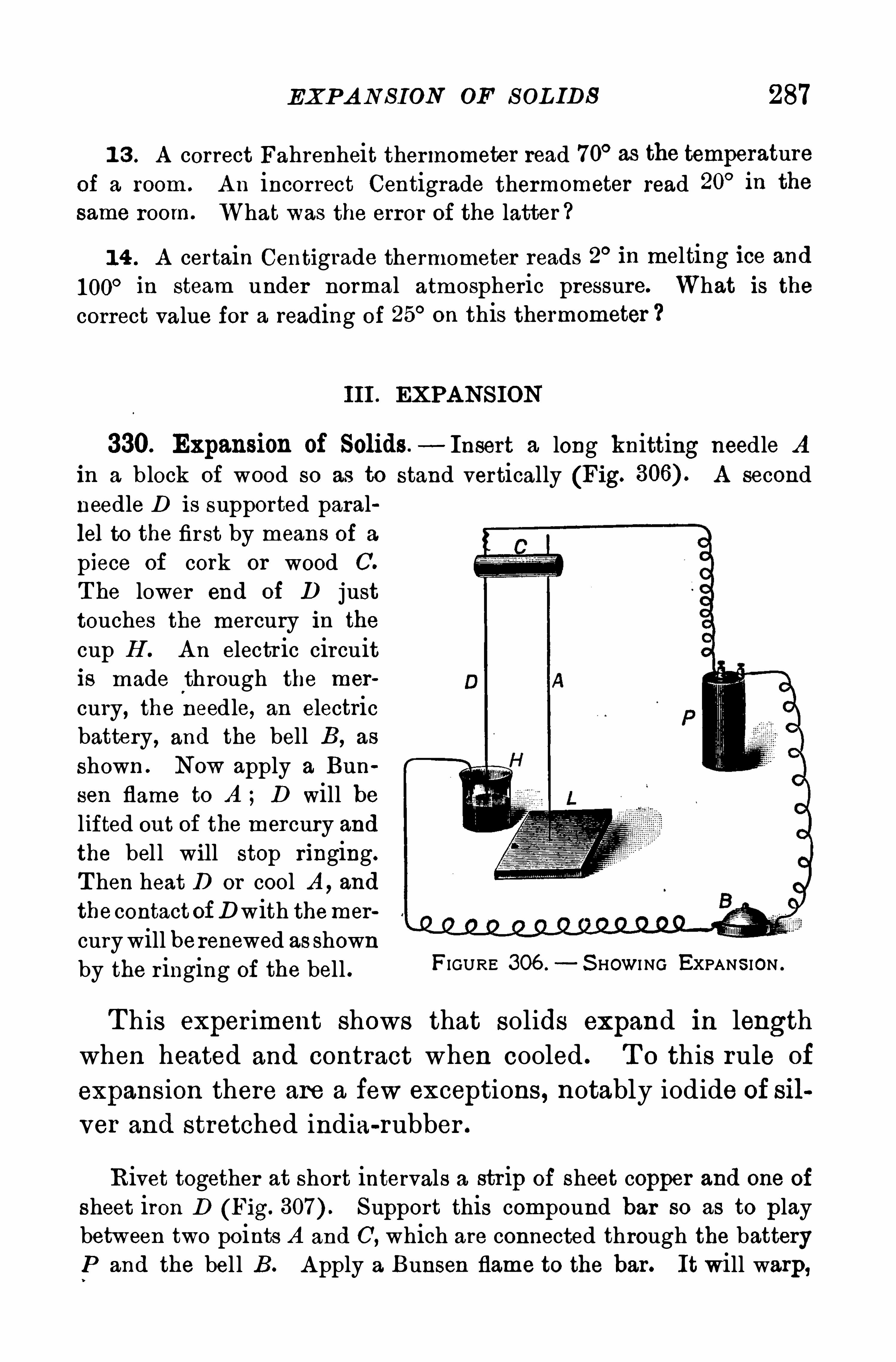
EXP A N S ION OF S OL IDS 287
1 3 . A correct Fahrenheit thermometer read 70° as the temperatureof a room . A n incorrect Centigrade thermometer read 20° in the
same room. What was the error of the latter ?
1 4 . A certain Centigrade thermometer reads 2° in melting ice and
1 00° in steam under normal atmospheric pressure. What is thecorrect value for a reading of 25° on this thermometer
III . EXPA NS ION
330. Expansion of Solids.—Insert a long knitting needle A
in a b lock of wood so as to stand vertically (Fig. A secondneedle D is supported parallel to the first by means of a
piece of cork or wood C.
T he lower end of D justtouches the mercury in the
cup H . A n electric circuitis made through the mer
cury, the needle, an electricbattery, and the bell B, as
shown . Now apply a Bun
sen flame to A ; D will belifted out of the mercury andthe bel l will stop ringing.
T hen heat D or cool A , and
the contact OfDwith themer
curywill berenewed as shownby the r inging of the bell . FIGURE 306 . S HOWI NG EXPANS ION .
T his experiment shows that solids expand in length
when heated and contract when cooled . T o this rule of
expansion there are a few exceptions, notably iodide of silver and stretched india-rubber .
Rivet together at short intervals a str ip of sheet copper and one of
sheet iron D (Fig. Support this compound bar so as to playbetween two points A and C, which are connected through the batteryP and the bel l B. A pply a Bunsen flame to the bar. It will warp,
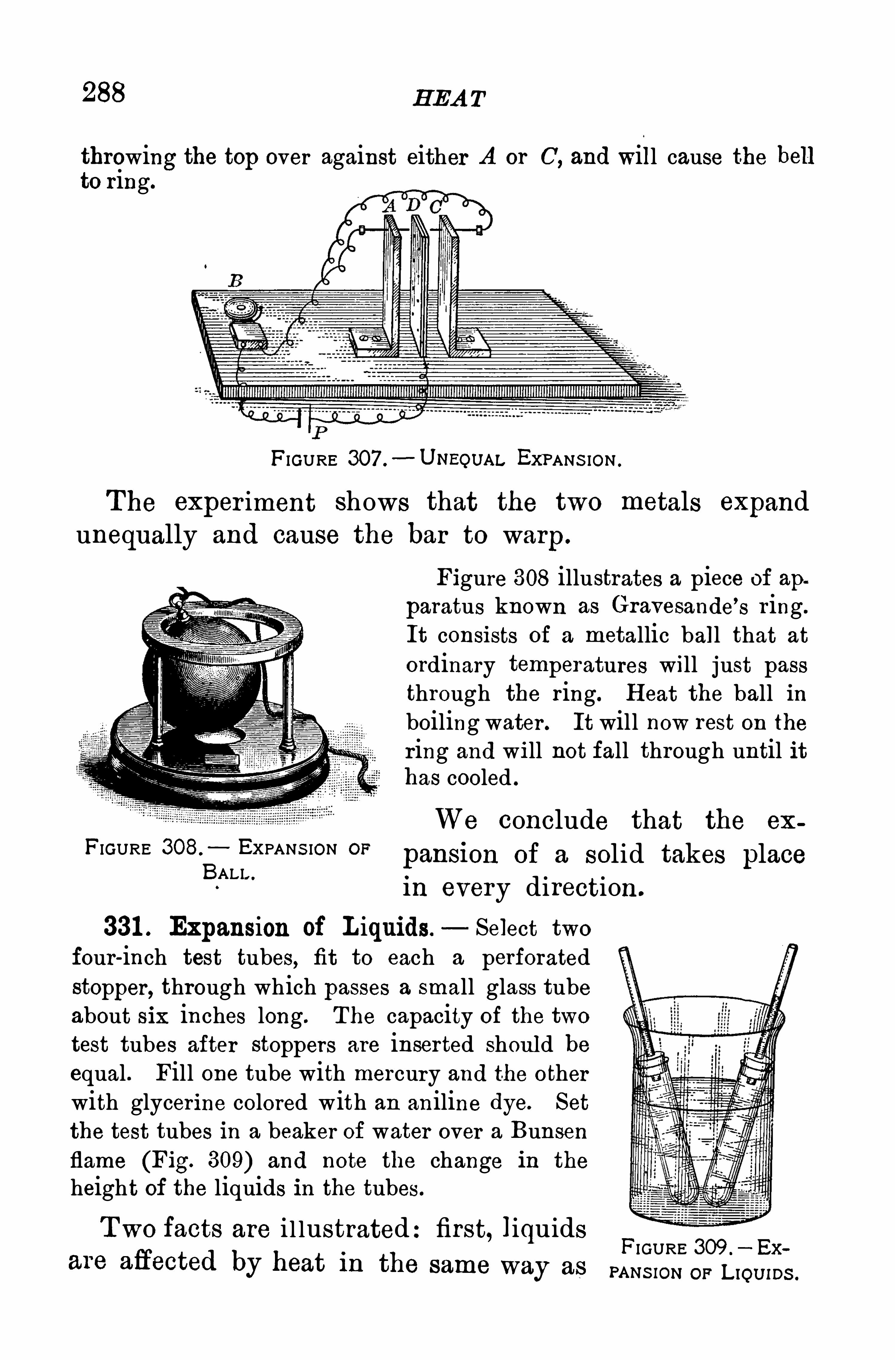
288 H EA T
throwing the top over against either A or C, and will cause the hellto ring.
FIGURE 307 .
—U NEOUAL EXPANS ION .
The exper iment shows that the two metals expand
unequally and cause the bar to warp.
Figure 308 illustrates a piece of apparatus known as Gravesande
’
s r ing.
It consists of a metallic ball that at
ordinary temperatures will just passthrough the ring. H eat the ball inboiling water . It will now rest on the
ring and will not fall through until ithas cooled .
We conclude that the ex
FIGURE 308. EXPANS ION OFpansion of a solid takes placeBALI“in every direction.
331 . Expansion of L iquids — Select twofour-inch test tubes, fit to each a perforatedstopper, through which passes a small glass tubeabout six inches long. The capacity of the twotest tubes after stoppers are inserted should beequal . Fill one tube with mercury and the otherwith glycerine colored with an aniline dye. Set
the test tubes in a beaker of water over a Bunsenflame (Fig. 309) and note the change in the
height of the liquids in the tubes.
Two facts are i l lustrated:first, liquids FIGURE 309 7 5»
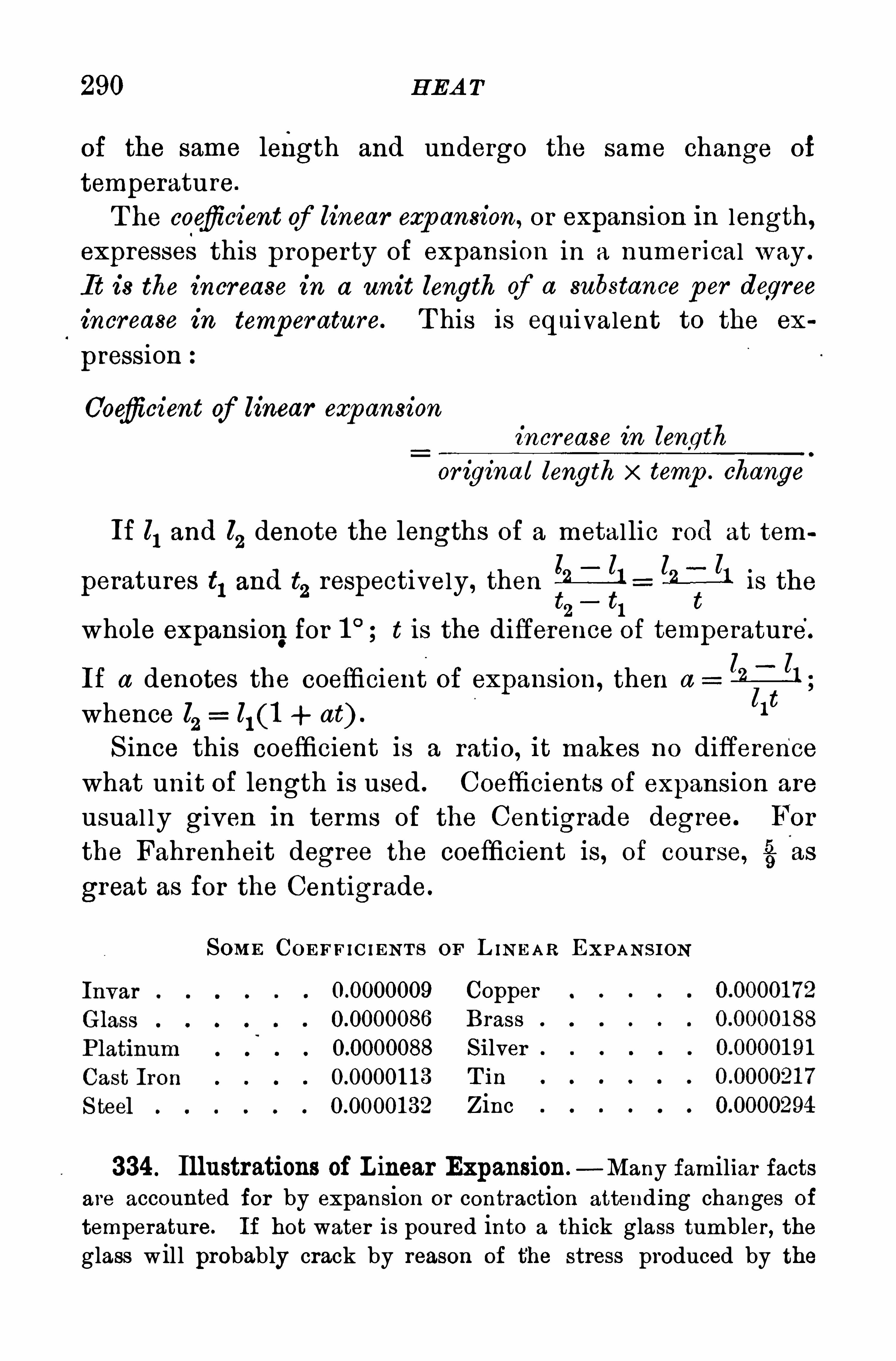
290 H EA T
of the same length and undergo the same change of
temperature.
T he coefiicient of linear exp ansion, or expansion in length,expresses this property of expansion in a numerical way .
It is the increase in a unit length of a substance per degree
increase in temper ature. T his is equivalent to the ex
pression
Coefiicient of linear expansion
increase in length
or igina l length x temp . change
If Z1and Z
2denote the lengths of a metallic rod at tem
peratures t1 and t2 respectively, then {fig—ll is the
2 1
whole expansionfor t is the difference of temperature.
If a denotes the coefficient of expansion, then a 21 5;
whence l l1 (1 at) .
llt
S ince this coefficient is a ratio, it makes no difference
what unit of length is used . Coefficients of expansion are
usual ly given in terms of the Centigrade degree. For
the Fahrenheit degree the coefficient is, of course, 55as
great as for the Centigrade.
SOME COEFF IC IENT S OF L INEAR EXP AN S ION
CopperBrass
S ilverT in
Zinc
334 . Illustrations of L inear Expansion —Many familiar factsare accounted for by expansion or contraction attending changes of
temperature. If hot water is poured into a thick glass tumbler, theglass will probably crack by reason of the stress produced by the

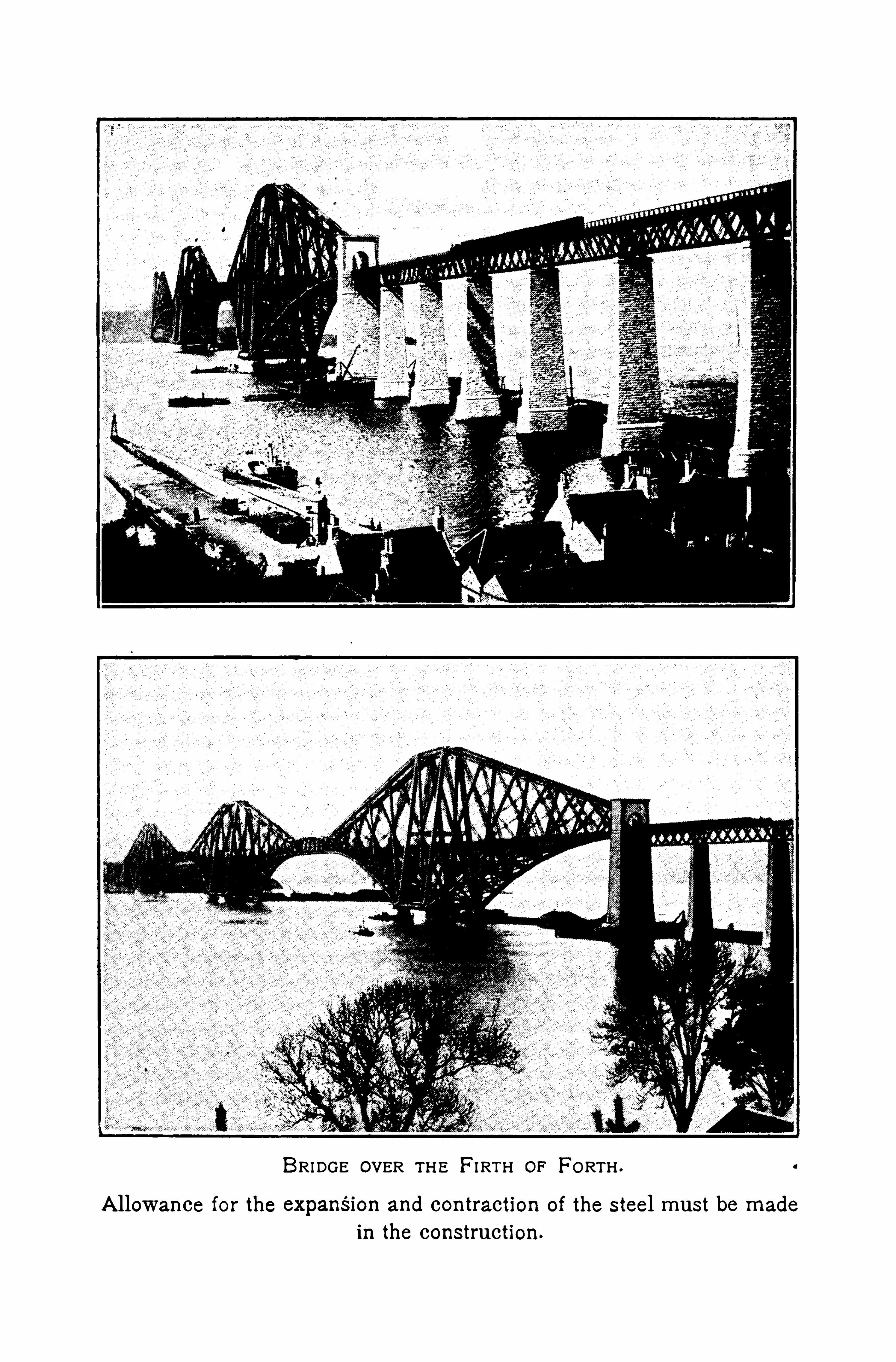
BRIDGE OVER TH E FI RTH OF FORTH .
A llowance for the expansIon and contraction of the steel must be made
in the construction.
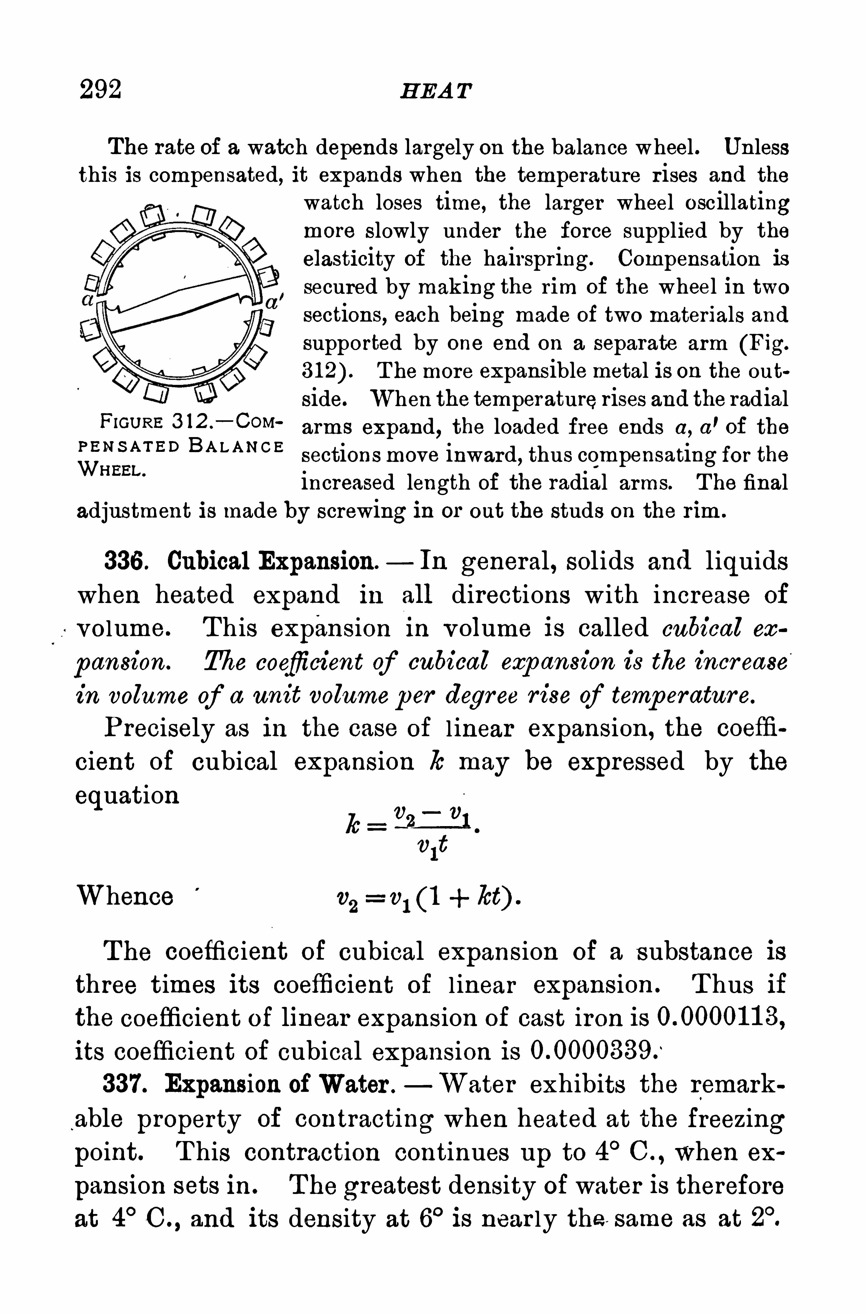
292 H EA T
The rate of a watch depends largely on the balance wheel . Unlessthis is compensated, it expands when the temperature r ises and the
watch loses time, the larger wheel oscillatingmore slowly under the force supplied by the
elasticity of the hairspring . Compensation is
secured by making the rim of the wheel in twosections, each being made of two materials andsupported by one end on a separate arm (Fig.
T he more expansible metal is on the out
side. When the temperaturerises and the radialFIGURE 3 12 —C°M‘
arms expand, the loaded free ends a , a’of the
BA L A N C Esections move inward, thus compensating for theincreased length of the radial arms. T he final
adjustment is made by screwing in or out the studs on the rim .
336 . Cubical Expansion— In general , solids and liquids
when heated expand in all directions with increase of
volume. T his expansion in volume is called cubical ecc
pansion. The coefficient of cubical exp ansion is the incr ease
in volume of a unit volumeper degree r ise of temp eratur e.
P recisely as in the case of l inear expansion, the coeffi
cient of cubical expansion lo may be expressed by the
equation
Whence v1 (1 lot) .
T he coefficient of cubical expansion of a substance isthree times its coefficient of l inear expansion . T hus if
the coefficient of linear expansion of cast iron isits coefficient of cubical expansion is337. Expansion ofWater .
—Water exhibits the remark
able property of contracting when heated at the freezingpoint. T his contraction continues up to 4
°C . , when ex
pansion sets in . T he greatest density of water is thereforeat 4
°C and its density at 6
°is near ly the same as at
TH E A B S OL U TE S CA LE 293
In a lake or pond water at 4°sinks to the bottom, while
water below 4° is l ighter.
and r ises to the top, where the
freezing begins . Ice forms at the surface of a body of
cold water , which freezes from the surface downwards.
Fishes are thus protected from freezing.
338. Law of Charles —It was shown by Charles, in> 1 787, that the volume of a given mass of any gas under
constant p r essure incr eases by a constant f raction of its
volume at zero for each r ise of temp eratur e of 10C . T he
investigations of Regnault and others show that the lawis not r igorously true, and that the accuracy of Char les’slaw is about the same as that of Boyle’s law. T he coeffi
cient of expansion 70 of dry air is or about237
-13
.
T his fraction may be considered as the coefficient of ex
pansion of any true gas
339 . The Absolute Scale — T he law of Charles leads toa scale of temperature cal led the absolute scale. By thislaw the volumes of any mass of gas, under constant pres
sure, at 0°C . , and at any other temperature t
°C . , are
connected by the fol lowing relations 336)
A t any other temperature, t’, the volume becomes
Divide (a) by (b) and
v 278+ t
v’
273 + t'
Suppose now a new scale is taken, whose zero is 273Centigrade div isions below the freezing point of water,
294 H EA T
and that temperatures on this scale are denoted by T.
T hen 273 + t wi ll be represented by T, and 273 + t’ byT’, and .
v 273 + t T
v' 273 + t
’ T”
or the volumes of the same mass of gas under constant p res
sure are pr op ortional to the temp eratures on this new scale.
The point 273° below 0° C. is cal led the absolute zero, and
the temperatures on this scale, absolute temp er atur es . U pto the present it has not been found possible to cool a
body to the absolute zero ; but by evaporating l iquidhydrogen under very low pressure, a temperature esti
mated to be within 9°of the absolute zero has been ob
tained by P rofessor Dewar ; and P rofessor Onnes, byliquefying hel ium, believes that he obtained a tempera
ture within 2° of 3° of the absolute zero .
A t these low temperatures steel and rubber become as
br ittle as glass .
340. The Gas Equation. T he laws of Boyle and Char lesmay be combined into one expression , which is known as
the gas equation . It has a wider appl ication even than itsmethod of der ivation would indicate.
Let v0, pO, TO be the volume, pressure, and absol ute tem
perature of a given mass of gas .
A lso let v, p , T be the corresponding quantities for the
same mass of gas at pressure p and temperature T .
T hen applying Boyle’
s law 87) to increase the pres
sure to the value p , the temperature remaining constant,
we havevi , 23.Iv To
where v' is the new volume corresponding to the pres
sure p .
296 H EA T
4 . If the bulb of a mercurial thermometer is plunged into hotwater , the top of the thread of mercury first falls and then rises.
Explain .
5 . A copper rod 1 25 cm . long at 0°C. expands to cm. at
1 00°C. Find the coefficient of linear expansion of copper .
6 . The coefficient of linear expansion of steel is 0 00001 32. Whatwill be the variation in length of a steel bridge 250 ft. long betweenthe temperatures 1 0° C. and 40
°C . ?
7 . The coefficient of linear expansion Of steel is and
that of zinc is 0 0000294. \Vhat relative lengths of rods of thesemetals will have equal expansions in length for the same changes oftemperature
8. The coefficient of the volume expansion Of glass isA density bottle at 1 5
°C. holds 25 cm .
3. What will be its capacity
at 25° C. ?
9 . Why shouldo
the reading of the mercurial barometer be cor
rected for temperature ? If the relative volume coefficient of expan
sion of mercury in glass is and the barometer reads 755 mm .
at 20° C.
,what would be the reduced reading at 0° C
1 0 . T he volume of a given mass of gas at 740 mm . pressure is1 200 cm.
3;find its volume at 760 mm .
1 1 . T he mass of a liter Of air at 0°C . and 76 cm. pressure is g.
Find the mass Of 1 0 liters of air at 20° C. and 74 cm . pressure.
1 2 . A liter of hydrogen at 1 5°C. is heated at constant pressure to
75° C. Find its volume.
1 3 . A quantity of gas is collected in a graduated tube over mer
cury. T he reading of the mercury level in the tube is 20 cm., the
volume Of the gas is 60 cm .
3, the temperature is 20° C.
,and the ba
rometer reading is 74 cm. H ow many cubic centimeters Of gas are
there at 0°C. and 76 cm. pressure ?
1 4 . T hree cubic centimeters of air are introduced into the vacuumof a mercur ial barometer . T he barometer read 76 cm . before introducing the air and 57 cm. after . What volumedoes the air occupy inthe barometer ?
SP ECIFIC H EA T
IV . MEA SUREMENT OF H EA T
341 . The Unit of H eat.—T he unit of heat in the c. g. 8.
system is the calor ie. It is defined as the quantity of heat
that will r aise the temperature of onegram cf water one de
gr ee Centigrade. T here is no agreement as to the position
of the one degree on the thermometr ic scale, although it isknown that the unit quantity of heat var ies s l ightly at
different points on the scale. If the degree'
interval
chosen is from 1 5°to 1 6
°C. , the calorie is then the one
hundredth part of the heat required to raise the tempera
ture of one gram of water from 0°to 1 00
°C .
In engineer ing practice in England and A mer ica the
Br itish thermal unit (B. T . U . ) is commonly employed . It
is the heat required to raise the temperatur e of one p ound
of water one degree Fahr enheit.
342. Thermal Capacity . T he thermal cap acity of a body
is the number of calor ies required to raise its temperature
one degree Centigrade. T he thermal capacity of equal
masses of different substances differs widely . For example,if 1 00 g. of water at 0
°C. be mixed with 1 00 g. at 1 00
°C . ,
the temperature of the whole will be very nearly C .
But if 1 00 g. of copper at 1 00°C. be cooled in 1 00 g. of
water at 0°C . , the final temperature wi ll be about C.
T he heat lost by the copper in cool ing through is
sufficient to heat the same mass of water only that is ,the thermal capacity of water is about ten times as great
as that of an equal mass of copper .
343 . Specific H eat. T he sp ecific heat of a substance isthe number of calories of heat required to raise the tem
perature of onegr am of it through one degree Centigrade.
It may be defined independently of any temperature scale
as the ratio between the number of units of heat required
298 H EA T
to raise the temperature of equal masses of the substanceand of water through one degree. T he specific heat of
mercury is that is, the heat that will raise 1 g. of
mercury through 1°C. wi l l raise 1 g. of water through
only C .
T he specific heat of water is twice as great as that of iceand more than twice as great as that of steam
under constant pressure
344 . Numerical Problem in Specific H eat. T he principle applied in the solution of such problems is that the gain or loss of heatby the water is equal to the loss or gain of heat by the body introducedinto the water. The gain or loss of heat by the body is equal to theproduct Of its mass, its specific heat, and its change of temperature.
T o illustrate:20 g. of iron at 98°C. are placed in 75 g . of water at
1 0°C. contained in a copper beaker weighing 1 5 g.
, specific heatT he resulting temperature of the water and the iron is C. Findthe specific heat of iron .
The thermal capacity of the beaker is 1 5 x calories.
T he heat lost by the iron is 20 x s x (98 calor ies, in which 3
represents the specific heat of iron, and (98 its change Of tem
perature. T he heat gained by the water and the copper vessel is (75x 1 0) calories ;the second fac tor is the gain in temper
ature of the water and the beaker . It follows by equating these twoquantities that 20 x s x (98 (75 x
Solving for s, we have 3 calorie per gram.
Questions and P rob lems
1 . What is the specific heat of water ?2 . A pound of water and a pound of lead are subjected to the
same source of heat for 10 min . Which will be at the higher tem
perature ?
3 . If equal quantities of heat are applied to equal masses of ironand lead, which will show the greater change of temperature
4 . Equal balls of iron and zinc are heated in boiling water and
are placed on a cake of beeswax . Which will melt the further intothe wax
300 H EA T
usually freezes at once, and its temperature r ises to the
freezing point.T he melting point of crystal l ine bodies is well marked .
A mixture of ice and water in any relative proportionwi l l remain without change if the temperature of the room
is 0°C . but if the temperature is above zero, some of the
ice wi l l mel t; if it is below zero, some of the water wil lfreeze. S ome substances, l ike wax , glass , and wroughtiron, have no sharp ly defined melting point. T hey first
soften and then pass more or less slow ly into the conditionof a v iscous l iquid . It is this property which perm its of
the bending and molding of glass, and the rolling, welding,and forging of iron .
346 . Change in Volume accompanying Fusion —Fit to a
small bottle a perforated stopper through which passes a fine glasstube. Fill with water recently boiled to expel the air
, the water ex
tending halfway up the tube. Pack the apparatus in a m ixture of
salt and finely broken ice. T he water column at first will fall slowly ,but in a few minutes it will begin to rise, and will continue to do so
until water flows out of the top of the tube. T he water in the bottlefreezes, expands, and causes the overflow.
Most substances occupy a larger volume in the liquid
state than in the sol id; that is , they expand in liquefying.
A few substances, like water and bismuth , expand in
solidifying. When water freezes, its volume increases
9 per cent . If this expansion 1 s resi sted , water in freezingis
\
capable of exerting a force of about 2000 kg. per
square centimeter . T his explains the bursting of water
pipes when the water in them freezes, and the rending of
rocks by the freezing of water in cracks and crev ices . T he
expansion of cast iron and type metal when they sol idify
accounts for the exact reproduetion of the mold in which
they are cast.
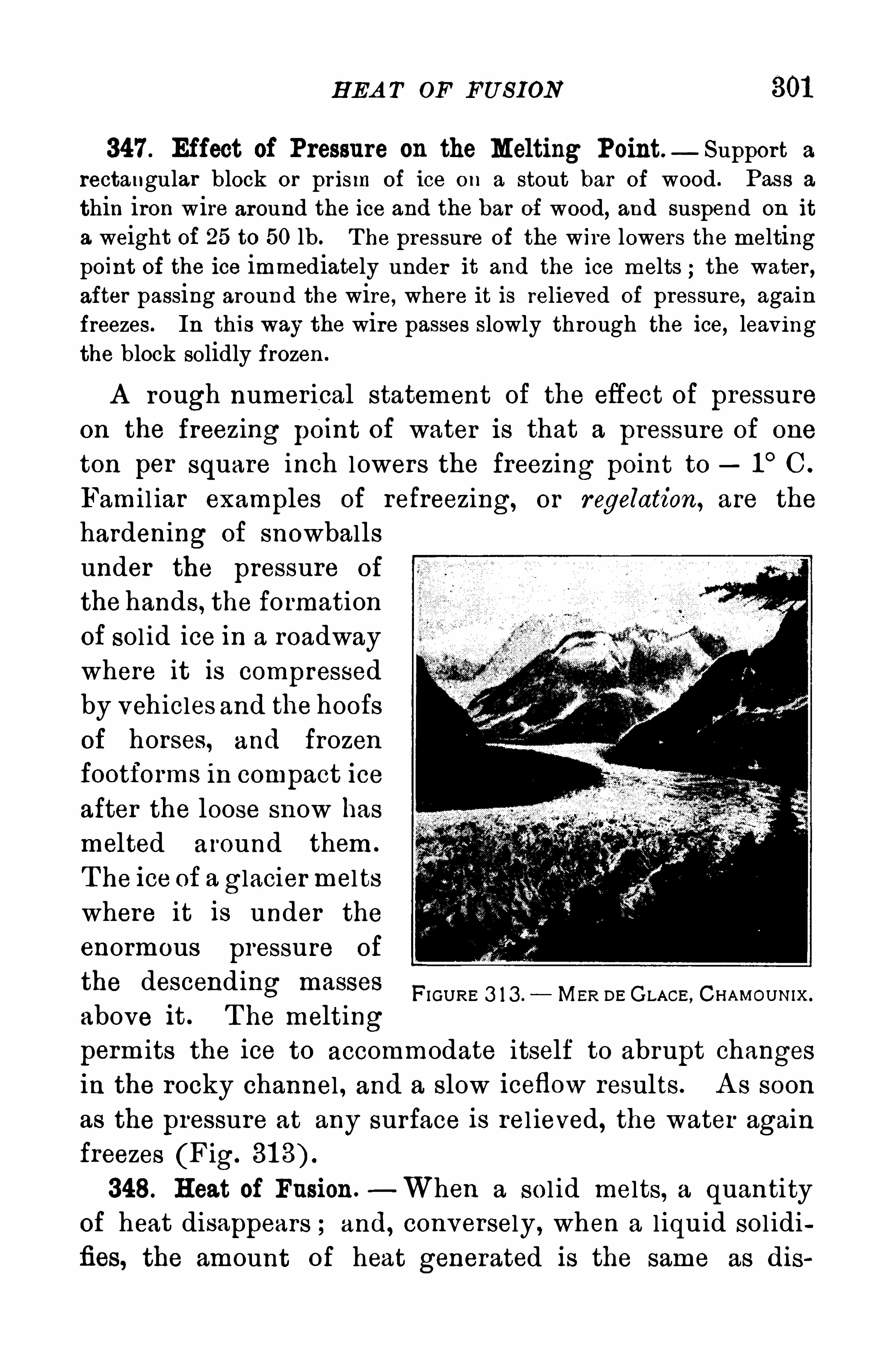
H EA T OF FU S ION
347 . Effect of Pressure on the Melting Point — Support a
rectangular block or pr ism of ice on a stout bar of wood . Pass a
thin iron wire around the ice and the bar of wood, and suspend on it
a weight of 25 to 50 lb. T he pressure of the wire lowers the meltingpoint of the ice immediately under it and the ice melts ; the water ,after passing around the wire, where it is relieved of pressure, againfreezes . In this way the wire passes slowly through the ice, leavingthe block solidly frozen .
A rough numerical statement of the effect of pressure
on the freezing point of water is that a pressure of one
ton per square inch lowers the freezing point to 1°C .
Famil iar examples of refreezing, or regelation, are the
hardening of snowballsunder the pressure of
the hands , the fo rmation
of sol id ice in a roadwaywhere it is compressedby vehicles and the hoofs
of horses, and frozen
footforms in compact ice
after the loose snow hasmelted around them .
T he ice of a glaciermelts
where it is under the
enormous pressure of
the descending masses
above it . T he meltingperm its the ice to accommodate itself to abrupt changesin the rocky channel , and a slow iceflow results. A s soonas the pressure at any surface is rel ieved, the water againfreezes (Fig.
348. H eat of Fusion.—When a sol id melts, a quantity
of heat disappears ; and, conversely , when a l iquid sol idifies, the amount of heat generated is the same as dis
FI GURE 3 1 3 . MER DE GLACE , CH AMOU NIX.
302 H EA T
appears during liquefaction . T he heat of fusion of a
substance is the number of calor ies required to melt a
gram of it without change of temperature. T he heat offusion of ice is 80 calor ies .
A s an illustration of the heat of fusion,place 200 g. of clean ice,
broken into small pieces, into 500 g . of water at 60° C. When the
ice has melted , the temperature will be about 20° C . T he heat lostby the 500 g . of water equals 500 x (60 20) calories . T hisheat goes to melt the ice and to raise the resulting water from 0° C. to
20° C. T o raise this water from 0°to 20° requi res 200 x
calories . T he remainder,
4000 calories, went tomelt the ice. Then the heat of fusion of ice is 200 80
calories per gram .
349. H eat lost in Solution. Fill a beaker partly full of waterat the temperature of the room, and add some ammonium nitratecrystals. The temperature of the water will fall as the crystals dissolve.
T his exper iment illustrates the fact that heat disap
pears when a body passes from the sol id to the l iquid
state by solution . The use of salt in soup or of sugar
in'
tea absorbs heat . T he heat energy is used to pull
down the sol id structure.
350. Freezing Mixtures.—Freezing mixtures are based
on the absorption of heat necessary to give fluidity . Salt
water freezes ;at a lower temperature than fresh water .
When salt and snow or pounded ice are mixed together ,both become fluid and absorb heat in the passage from
the one state to the other . By this mixture a tempera
ture of 22° C . may be obtained . S ti l l lower tempera
tures may be reached with other mixtures;notably with
sulpho-cyanide of sodium and water .
351 . Vaporization.—Pour a few drops of ether into a beaker
and cover closely with a plate of glass . A fter a few seconds bringa lighted taper to the mouth of the beaker . A sudden flash willshow that the vapor of ether was mixed with the air .
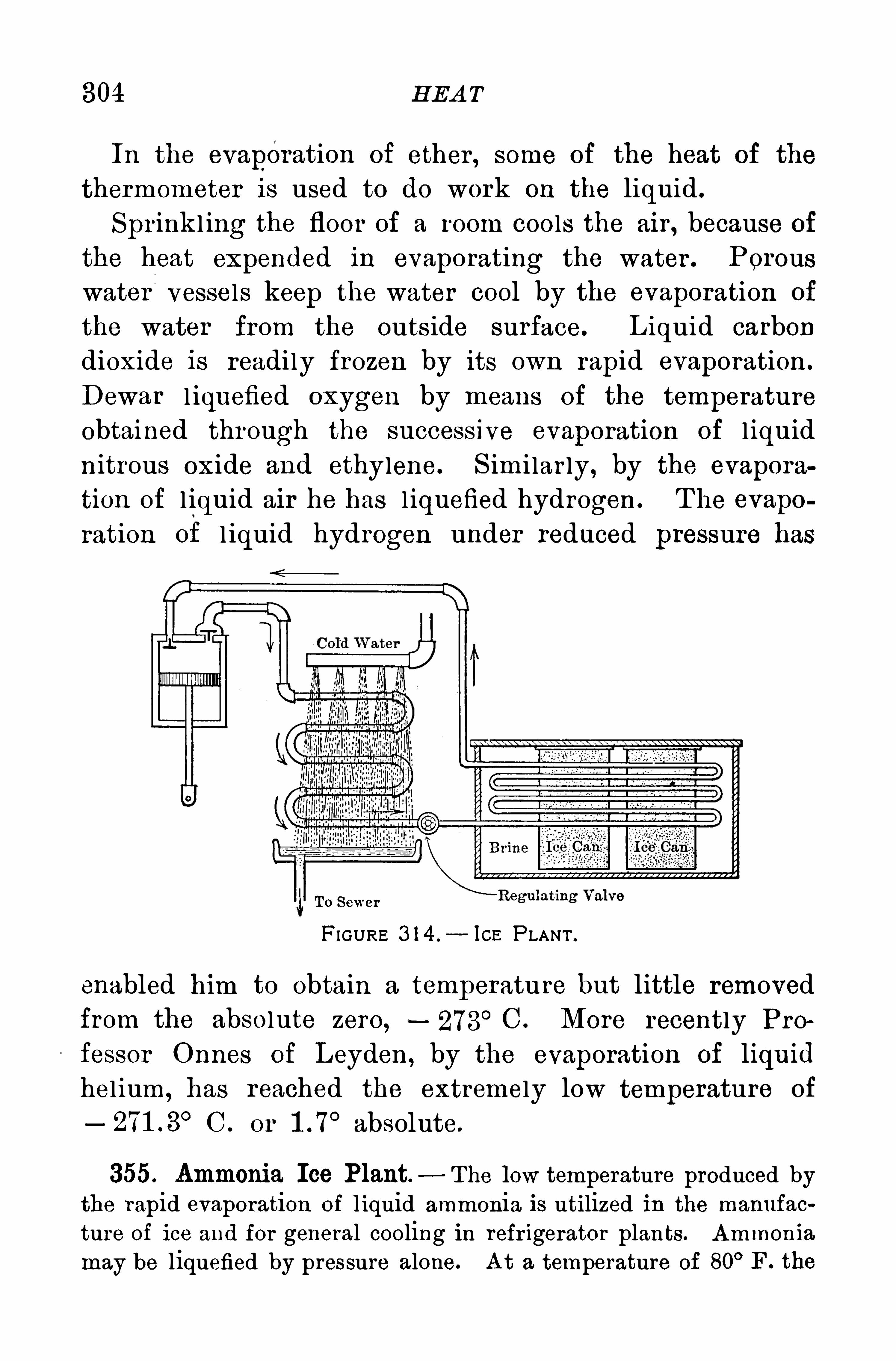
304 H EA T
In the evaporation of ether , some of the heat of the
thermometer is used to do work on the liquid .
Sprinkl ing the floor of a room coo ls the air , because of
the heat expended in evaporating the water . Porouswater vessels keep the water cool by the evaporation of
the water from the outs ide surface. L iquid carbondioxide is readily frozen by its own rapid evaporation .
Dewar l iquefied oxygen by means of the temperatureobtained through the successive evaporation of l iquid
n itrous oxide and ethylene. S imi lar ly, by the evapora
tion of l iquid air he has l iquefied hydrogen . T he evapo
ration of l iquid hydrogen under reduced pressure has
To Sewer
FIGURE 3 1 4 . 10 13 P LANT .
enabled him to obtain a temperatu re but little removedfrom the absolute zero, - 273
°C. More recently P ro
fessor Onnes of Leyden, by the evaporation of liquid
hel ium, has reached the extremely low temperature of
C . or absolute.
355. Ammonia Ice Plant — The low temperature produced bythe rapid evaporation of liquid ammonia is utilized in the manufac
ture of ice and for general cooling in refr igerator plants. Ammonia
may be liquefied by pressure alone. A t a temperature of 80° F . the
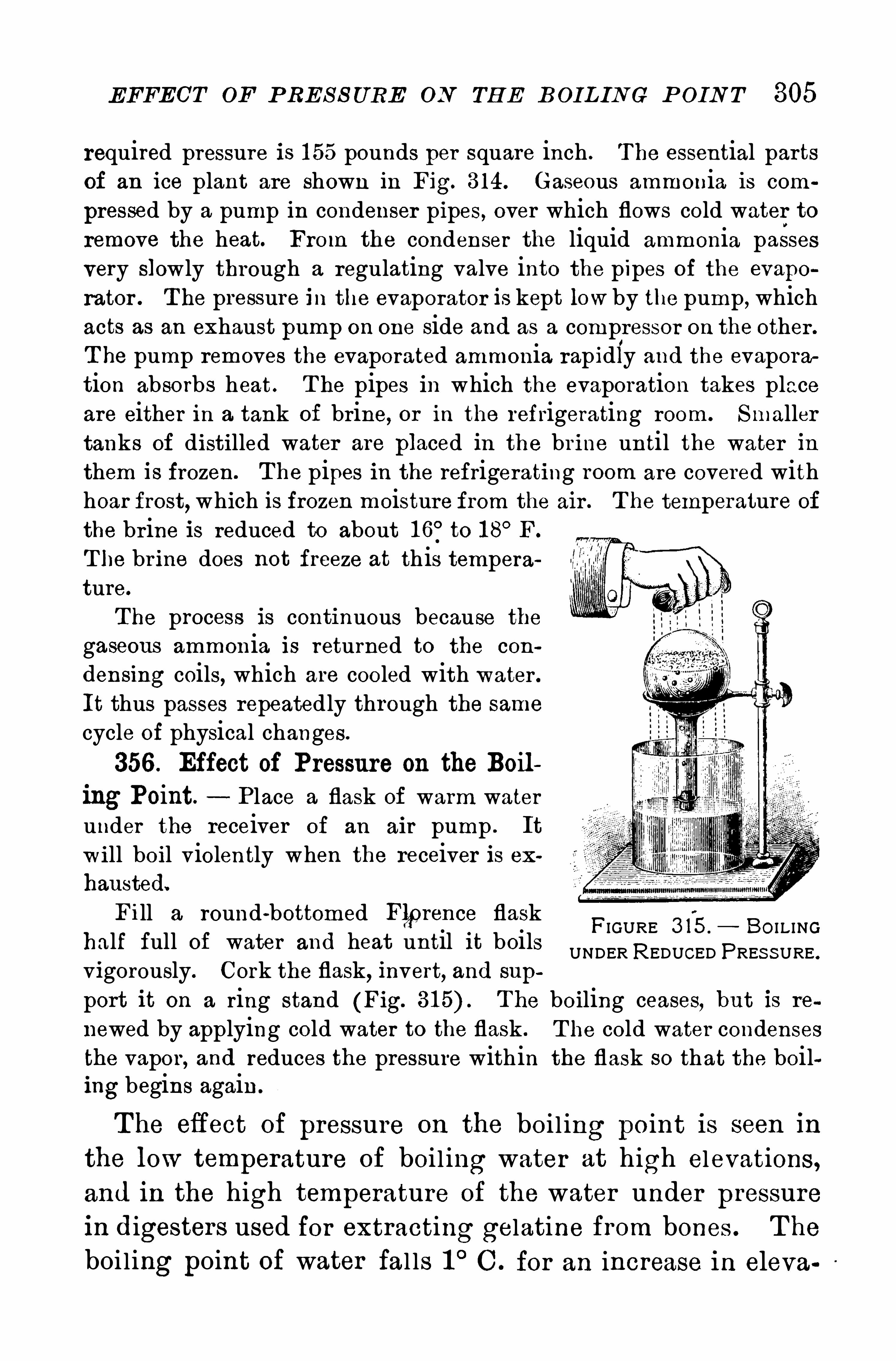
EFFECT OF P RES S URE ON TH E B OIL IN G P OIN T 305
required pressure is 1 55 pounds per square inch . The essential partsof an ice plant are shown in Fig. 3 14. Gaseous ammonia is com
pressed by a pump in condenser pipes, over which flows cold water toremove the heat. From the condenser the liquid ammonia passesvery slowly through a regulating valve into the pipes of the evapo
rator . T he pressure in the evaporator is kept lowby the pump , whichacts as an exhaust pump on one side and as a compressor on the other .
T he pump removes the evaporated ammonia rapidly and the evaporartion absorbs heat . T he pipes in which the evaporation takes placeare either in a tank Of brine, or in the refrigerating room. Smallertanks of distilled water are placed in the br ine until the water inthem is frozen. T he pipes in the refrigerating room are covered withhoar frost, which is frozen moisture from the air . T he temperature of
the br ine is reduced to about 1 6°to 1 8°F.
T he br ine does not freeze at th is temperature.
The process is continuous because the
gaseous ammonia is returned to the con
densing coils, which are cooled with water .
It thus passes repeatedly through the same
cycle of physical changes.
356 . Effect of Pressure on the Boiling Point. Place a flask of warm waterunder the receiver of an air pump . It
will boil violently when the receiver is exhausted.
Fill a round-bottomed Flprence flaskhalf full of water and heat until it boilsvigorously. Cork the flask, invert, and sup
port it on a ring stand (Fig. T he boiling ceases,but is re
newed by applying cold water to the flask . T he cold water condensesthe vapor, and reduces the pressure with in the flask so that the boiling begins again
FIGURE 3 15 . BO I L INGUNDER REDUCED PRES S URE .
T he efl ect of pressure on the boi l ing point is seen in
the low temperature of boi l ing water at high elevations,and in the high temperature of the water under pressurein digesters used for extracting gelatine from bones . T he
boiling point of water fal ls 1°C . for an increase in eleva
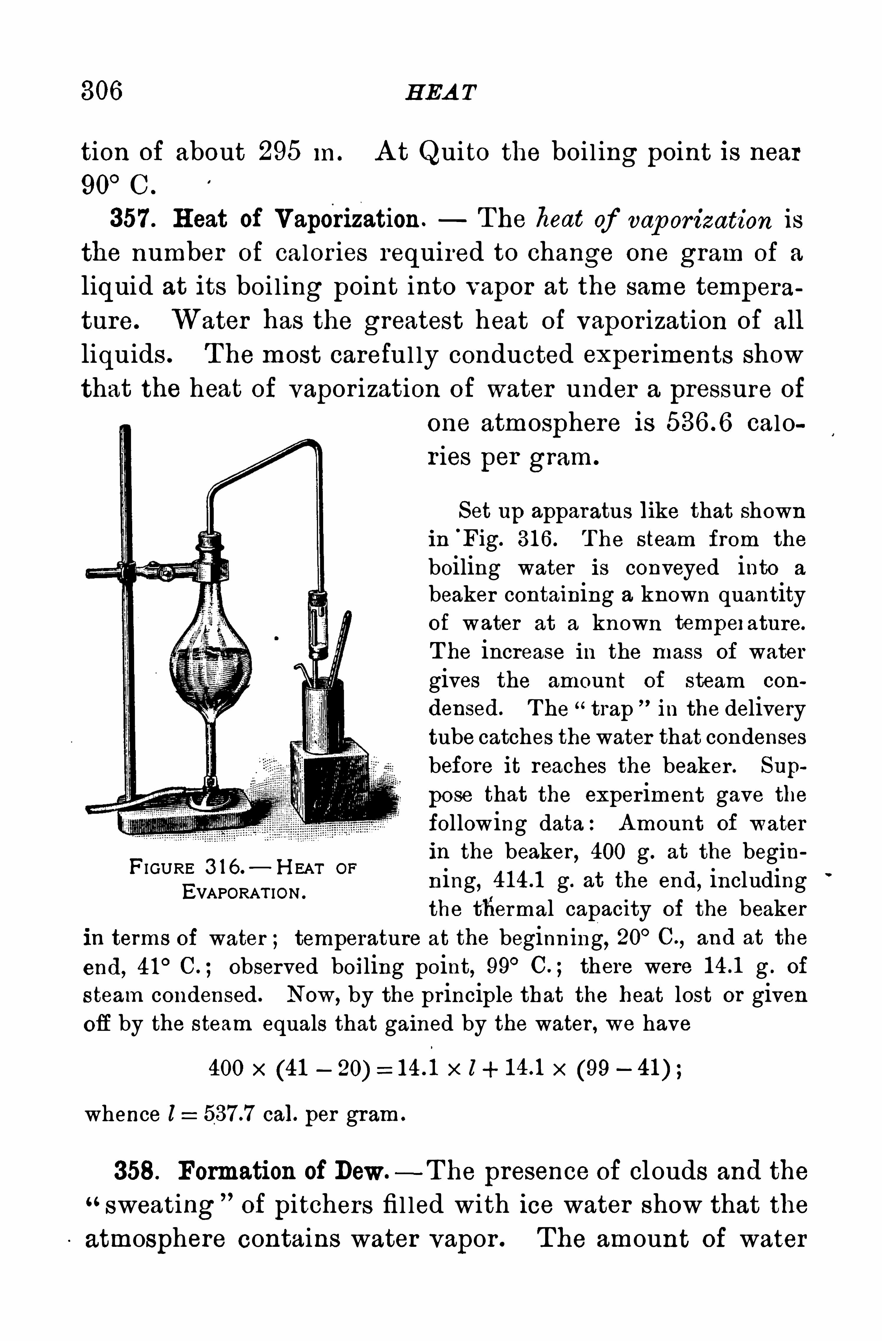
306 H EA T
tion of about 295 In . A t Quito the boi l ing point is near90
°C .
357 . H eat of Vaporization. T he heat of vap orization is
the number of calor ies required to change one gram of a
liquid at its boi l ing point into vapor at the same tempera
ture. Water has the greatest heat of vapor ization of all
liquids . T he most careful ly conducted exper iments show
that the heat of vapor ization of water under a pressure of
one atmosphere is calor ies per gram.
Set up apparatus like that shownin
'
Fig. 31 6 . T he steam from the
boiling water is conveyed into a
beaker containing a known quantityof water at a known tempeI ature.
T he increase in the mass of watergives the amount of steam con
densed. T he “trap in the deliverytube catches thewater that condensesbefore it reaches the beaker . Sup
pose that the exper iment gave the
following data: Amount of water
in the beaker , 400 g. at the beginning, g. at the end
,including
the thermal capacity of the beakerin terms of water ; temperature at the beginn ing, 20° C.
, and at the
end, 41° C. ; observed boiling point, 99° C. ; there were g . of
steam condensed . Now, by the principle that the heat lost or givenoff by the steam equals that gained by the water , we have
400 x (41 x l (99
FI GURE 3 1 6.
— H EAT OF
EVAPORAT ION .
whence l cal. per gram .
358. Formation of Dew.- T he presence of clouds and the
sweating of pitchers fi l led with ice water show that the
atmosphere contains water vapor . The amount of water
308 H EA T
liness and discomfort . On the other hand, excessivehumidity retards heal thful evaporation , gives a sensationof depression, and in hot weather checks Nature’
s methodof keeping cool by evaporation . T he humidity conduciveto health is about 50 per cent .
Q ues tions and P roblems
Why does a drop of alcohol on the hand feel cold ?
Why does a shower in summer cool the air ?
OO
N
H
Why is there less dew on gravel than on the grass ?
4 . Why can blocks of ice be made to adhere by pressure ?
5 . Why do your eye glasses fog over when you go from the coldair outside into a warm room ?
6 . Water in a porous vessel standing in a current of air is colderthan-water in a glass pitcher . Why ?
7 . Why doeswarming a room make it feel dryer ?
8. Why does water boil away faster on some days than on others ?
9 . Why does wind dry up the roads after a rain ?
1 0 . Why does moi sture collect on the carburetor of a gasolineengine when it is in operation unless it is heated ?
1 1 . H ow much heat does it take to convert 50 g. of water at 1 00°
C . into steam at 1 00°C.
1 2 . H ow much ice will 100 g . of water at 1 00° C. melt ?
1 3 . H ow much ice will 1 00 g . of steam at 1 00° C . melt ?
1 4 . 1 00 g . of ice and 20 g . of steam at 1 00° C. are put into a
calor imeter . If no heat is lost, what will be the temperature of the
water after all the ice is melted ?
1 5 . H ow much water at 80° C. will just melt a kilogram of ice ?
1 6 . H ow much steam will be required to raise the temperatureof a kilogram Of water from 20
°to 50
°C
1 7 . H ow much ice will it take to cool a kilogram of water from50
°to 20
° C. ?
1 8. Mt. Washington is 6288 ft. above sea level ;at what temperature does water boil on its top ?
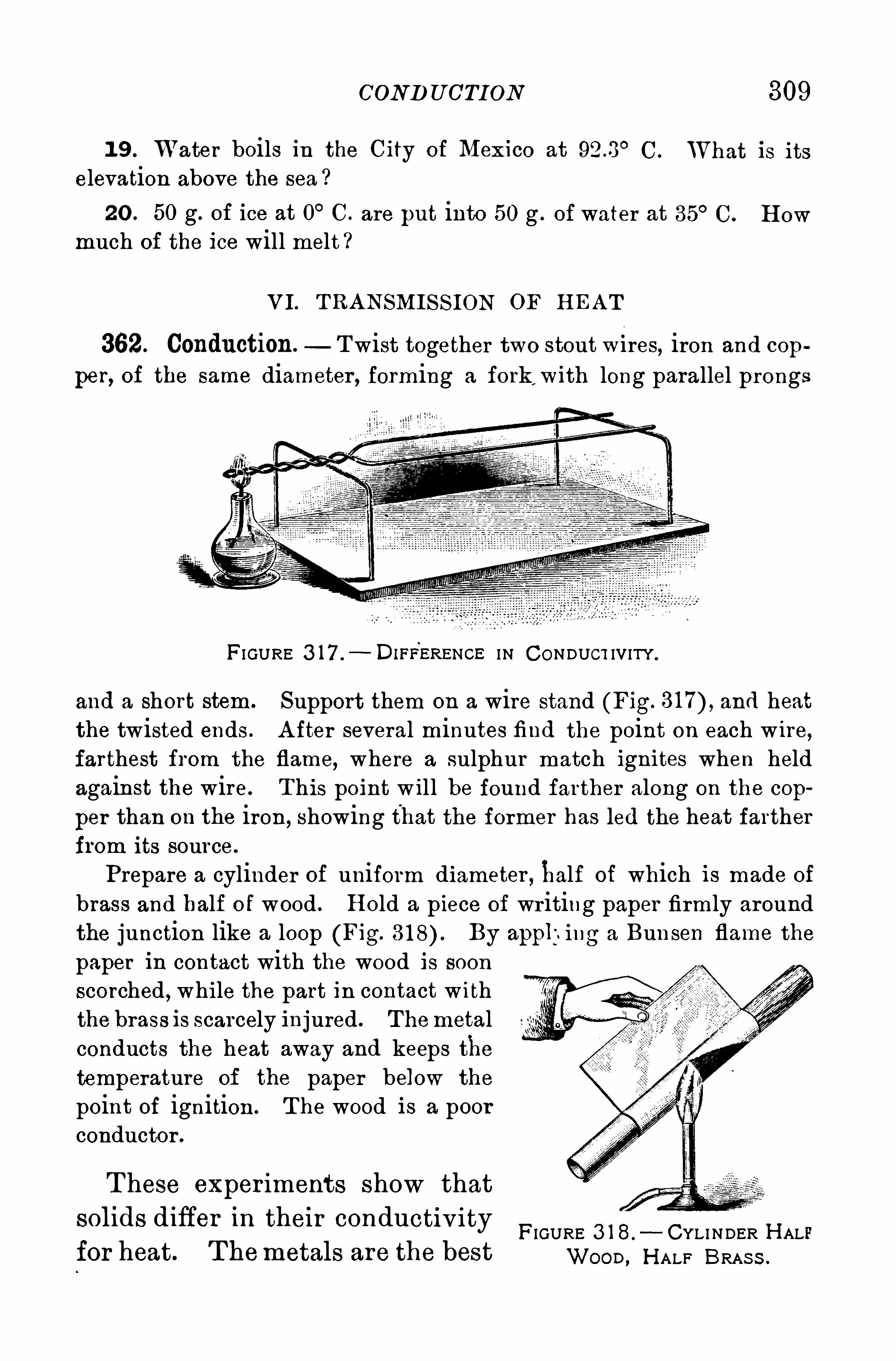
COND U CTI ON 309
1 9 . Water boils in the City of Mexico at 923 °C. IVhat is its
elevation above the sea
20 . 50 g. of ice at 0° C. are put into 50 g . of water at 35° C. H ow
much of the ice will melt ?
VI. T RANSMIS S ION OF H EA T
362. Conduction.Twist together two stout W i res, iron and cop
per, of the same diameter , forming a fork,with long parallel prongs
FI GURE 3 17 .
—DIFEERENGE I N CONDUCT IV ITY.
and a short stem. Support them on a wire stand (Fig. and heatthe twisted ends . A fter several minutes find the point on each wire,farthest from the flame, where a sulphur match ignites when heldagainst the wire. This point w ill be found farther along on the cop
per than on the iron, showing that the former has led the heat fartherfrom its source.
Prepare a cylinder of uniform diameter , half of which is made of
brass and half of wood . H old a piece of wr iting paper firmly aroundthe junction like a loop (Fig. By app];ing a Bunsen flame thepaper in contact with the wood is soonscorched , while the part in contact withthe brass is scarcely injured . Themetalconducts the heat away and keeps thetemperature of the paper below the
point of ignition. T he wood is a poorconductor .
T hese exper iments show thatSolldS d iffer In thei r conducti v i ty
FIGURE 3 1 8. CYLI NDER H ALFfor heat. T hemetals are the best woos , H ALF BRAS S .
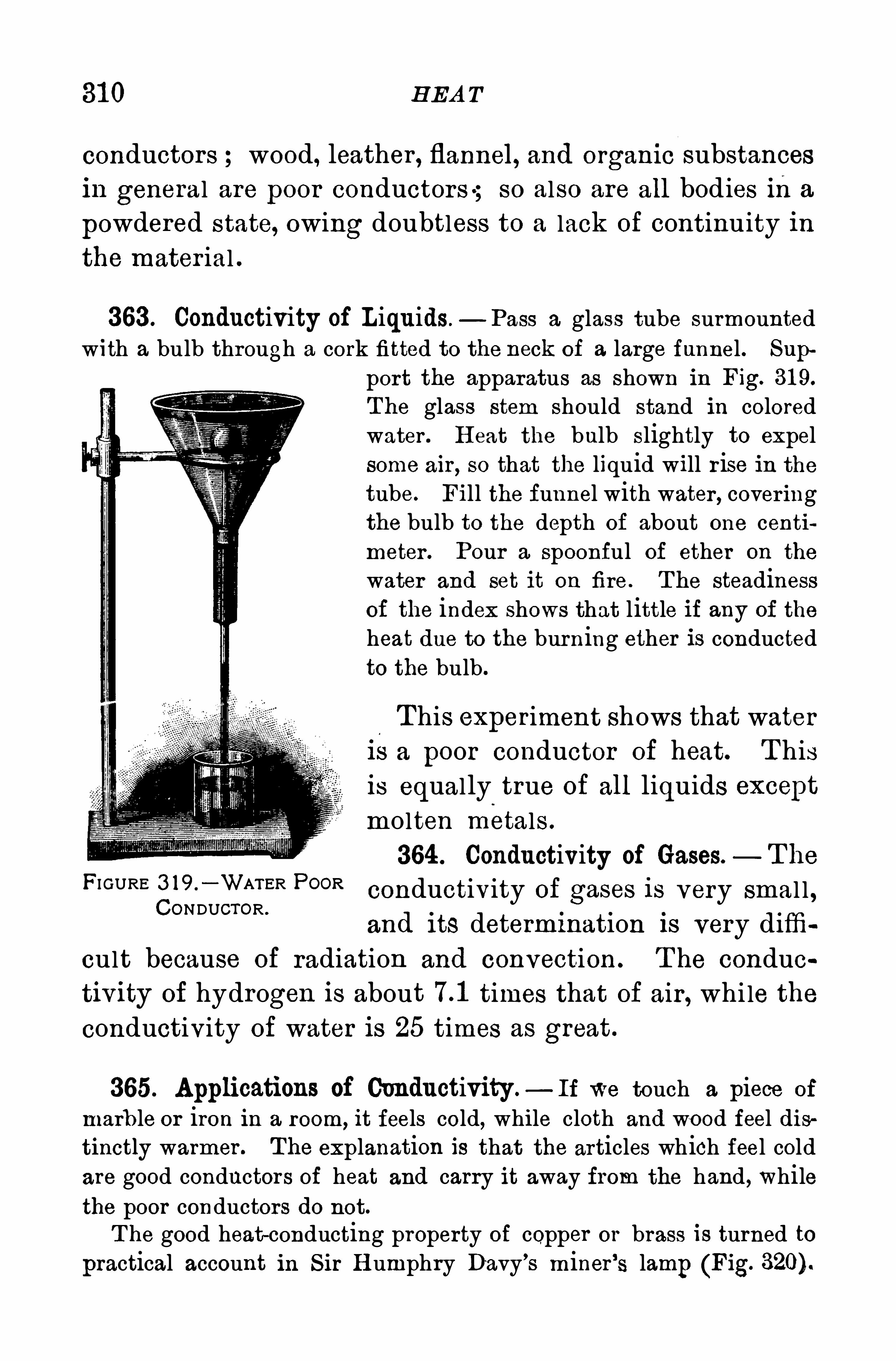
31 0 H EA T
conductors wood, leather , flannel, and organic substancesin general are poor conductors; so also are all bodies ina
powdered state, owing doubtless to a lack of continuity inthe mater ial .
363 . Conductivity of Liquids — Pass a glass tube surmountedwith a bulb through a cork fitted to the neck of a large funnel . Sup
port the apparatus as shown in Fig. 31 9.
T he glass stem should stand in coloredwater . H eat the bulb slightly to expelsome air , so that the liquid will r ise in thetube. Fill the funnel with water , cover ingthe bulb to the depth of about one centimeter . Pour a spoonful of ether on the
water and set it on fire . T he steadinessof the index shows that little if any of the
heat due to the burning ether is conductedto the bulb.
T his experiment shows that wateris a poor conductor of heat. T hisis equally true of all liquids except
molten metals .
364 . Conductivity of Gases.— T he
FI GURE 3 19 '
_ WATER P°°Rconductivity of gases is very smal l ,
CONDUCTOR .
and Its determination IS very difi‘i
cult because of radiation and convection . T he condue
tivity of hydrogen is about times that of air , whi le the
conductivity of water is 25 times as great .
365. Applications of Conductivity —Ir We touch a piece of
marb le or iron in a room,it feels cold, while cloth and wood feel dis
tinctly warmer . The explanation is that the articles which feel coldare good conductors of heat and carry it away from the hand , whilethe poor conductors do not.T he good heat-conducting property of copper or brass is turned to
practical account in S ir H umphry Davy’s miner ’s lamp (Fig.
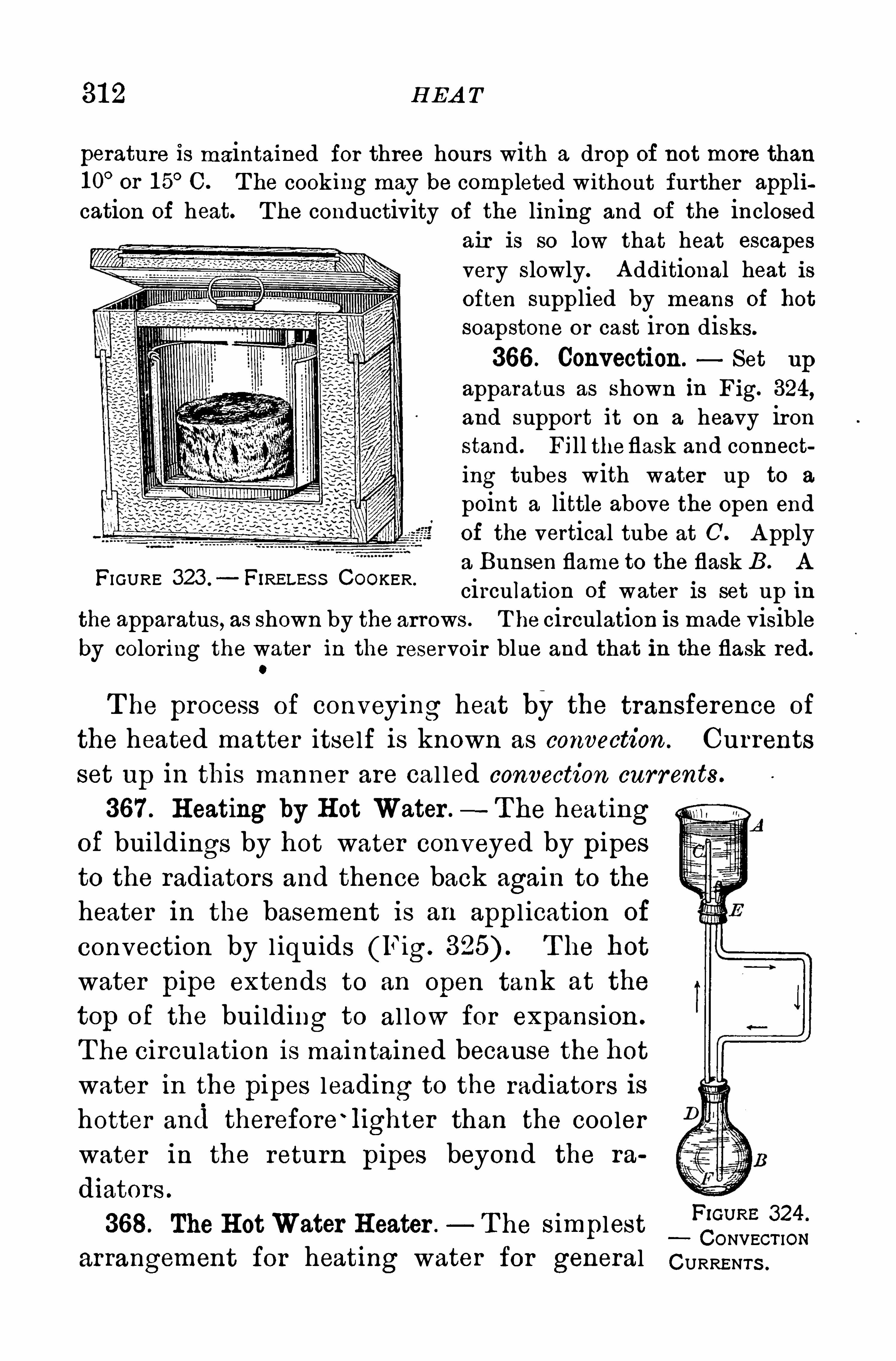
31 2 H EA T
perature is maintained for three hours with a drop of not more than1 0
°or 1 5° C. T he cooking may be completed without further appli
cation of heat. T he conductivity of the lining and of the inclosedair is so low that heat escapesvery slowly. A dditional heat isoften supplied by means of hot
soapstone or cast iron disks.
366 . Convection. Set up
apparatus as shown in Fig. 324,
and support it on a heavy ironstand . Fill the flask and connecting tubes with water up to a
point a little above the open end
Of the vertical tube at 0 . A pplya Bunsen flame to the flask B. A
circulation of water is set up inthe apparatus, as shown by the arrows . T he circulation is made visibleby coloring the water in the reservoir blue and that in the flask red.
0
FI GURE 323 .
—FiRELEss COOKER .
T he process of conveying heat by the transference of
the heated matter itself is known as convection . Currents
set up in this manner are cal led convection currents.
367 . H eating by H ot Water .—T he heating
of buildings by hot water conveyed by pipesto the radiators and thence back again to theheater in the basement is an appl ication of
convection by l iquids (Fig. T he hot
water pipe extends to an Open tank at the
top of the building to al low for expansion .
T he circulation is maintained because the hotwater in the pipes leading to the radiators is
hotter and therefore‘ lighter than the cooler
water in the return pipes beyond the ra
diators .
368. The H otWater H eater . T he s implestF'GURE 324
CONVECT IONarrangement for heating water for general CURRENTS .
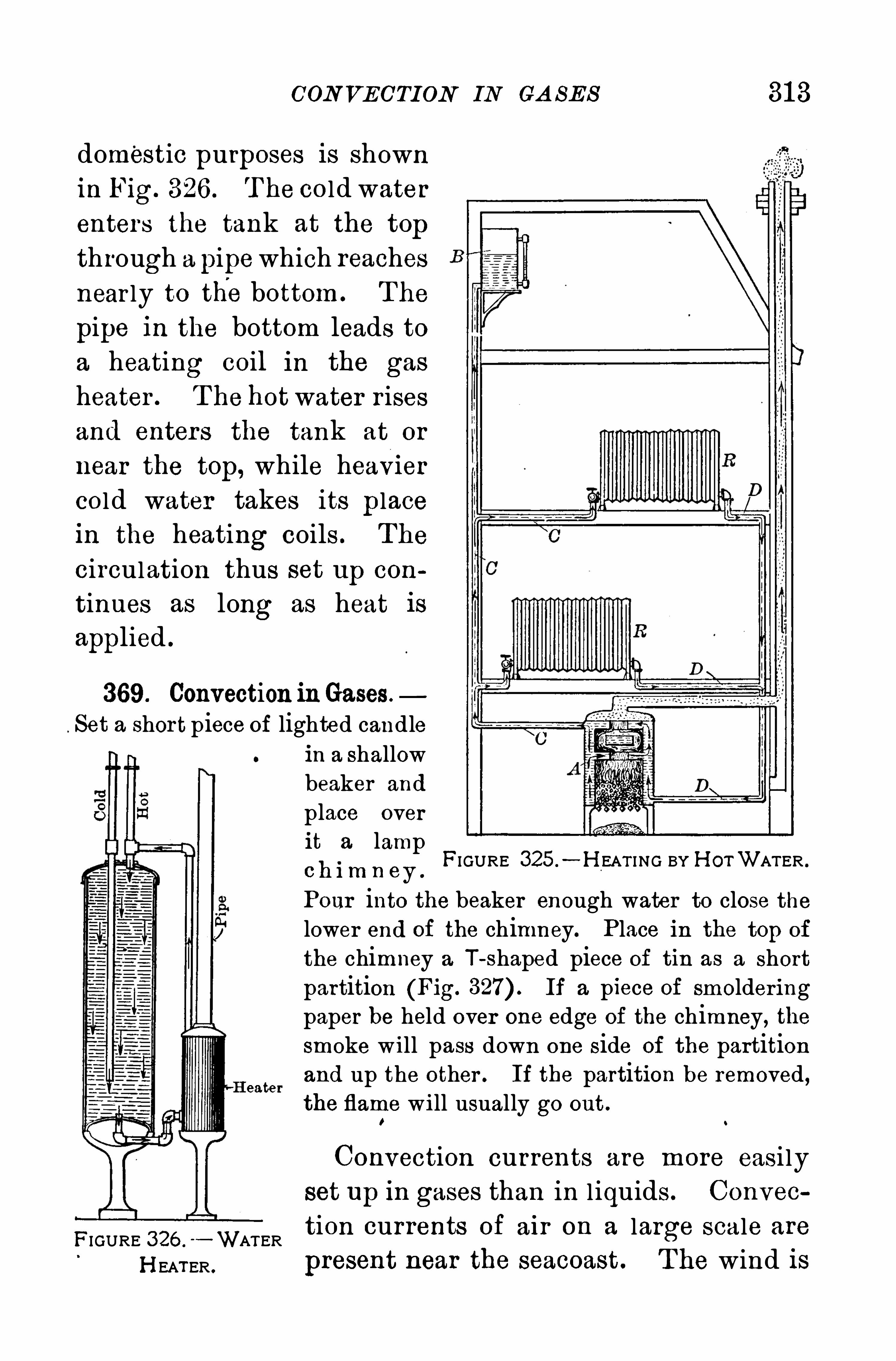
CON VECTION IN CA SES 31 3
domestic purposes is shownin Fig. 326 . T he cold water
enters the tank at the top
through a pipewhich reachesnear ly to thebottom . The
pipe in the bottom leads toa heating coil in the gas
heater . T he hotwater r isesand enter s the tank at or
near the top, while heavi ercold water takes its placein the heating coils . The
circulation thus set up con
tinnes as long as heat isapplied .
369. Convection inGases.
Set a short piece of lighted candlein a shallowbeaker and
place overit a lamp0 h im n ey
FIGURE 325 .
—H EAT I NG BY H OTWATER .
Pour into the beaker enough water to close thelower end Of the chimney. Place in the top of
the chimney a T-shaped piece of tin as a shortpartition (Fig. If a piece of smolderingpaper be held over one edge of the chimney, thesmoke will pass down one side of the partition
eaterand up the other . If the partition be removed,the flame will usually go out.
Convection currents are more easi ly
set up in gases than in l iquids . Convec
FIGURE 326 . WATER tion currents of air on a large scale are
H EATER . present near the seacoast . T he wind is
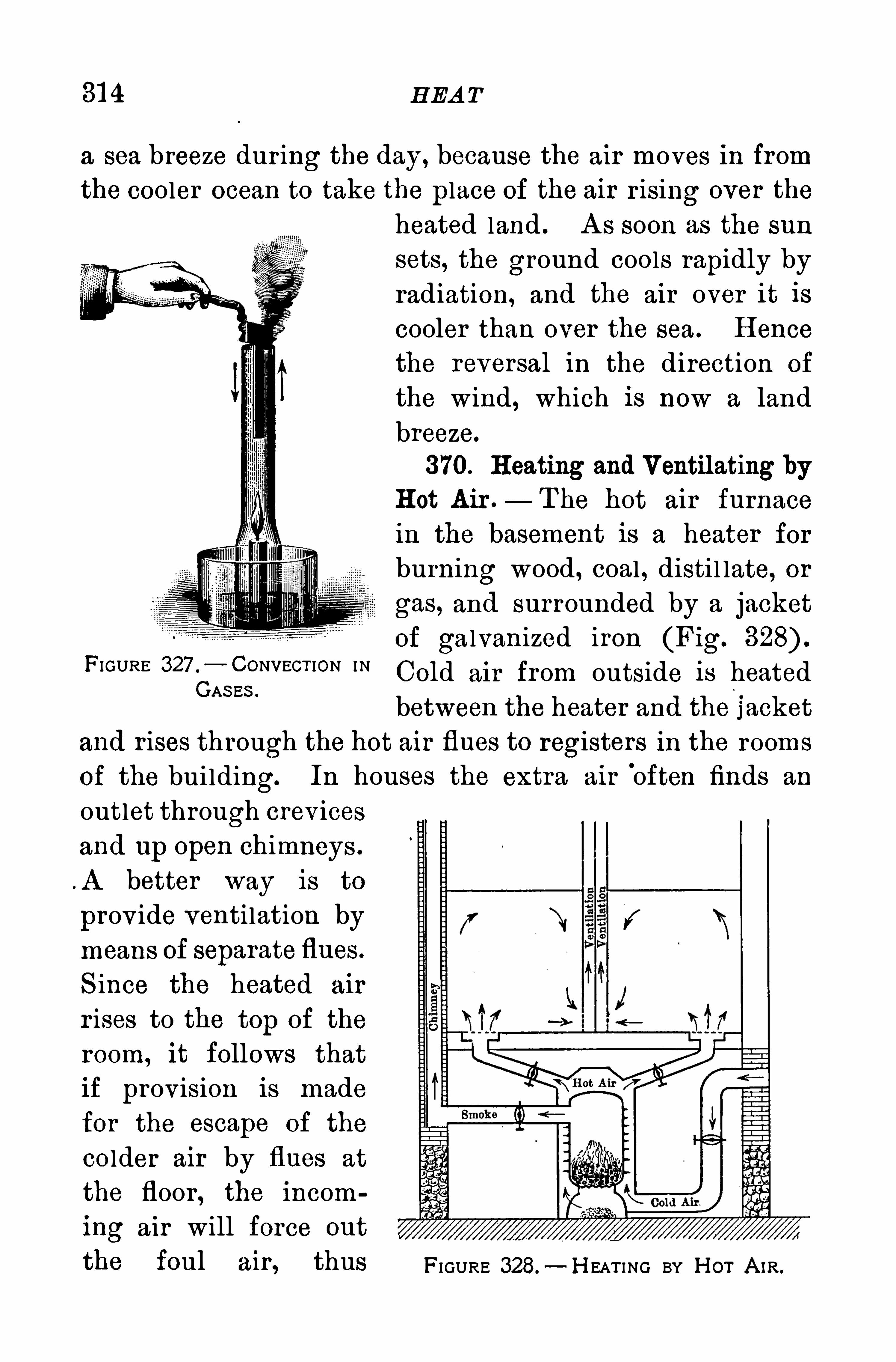
31 4 H EA T
a sea breeze during the day, because the air moves in fromthe cooler ocean to take the place of the air r ising over the
FIGURE 327 .
—CONVECT ION INGAS ES .
heated land . A s soon as the sun
sets, the ground cools rapidly byradiation, and the air over it iscooler than over the sea . H ence
the reversal in the direction of
the wind , which is now a land
breeze.
370. H eating and Ventilating byH ot Air .
—T he hot air furnacein the basement is a heater for
burning wood , coal , disti l late, or
gas, and surrounded by a jacket
of galvanized iron (Fig.
Cold air from outside is heated
between the heater and the j acket
and r ises through the hot air flues to registers in the rooms
of the building.
outlet through crevicesand up open chimneys .
A better way is to
prov ide ventilation bymeans of separateflues .
S ince the heated air
r ises to the top of the
room, it follows thatif prov ision is madefor the escape of the
colder air by flues at
the floor , the incom
ing air will force out
the foul air, thus
In houses the extra air'
often finds an
FIGURE 328.
—H EAT I NG BY H OT A IR .
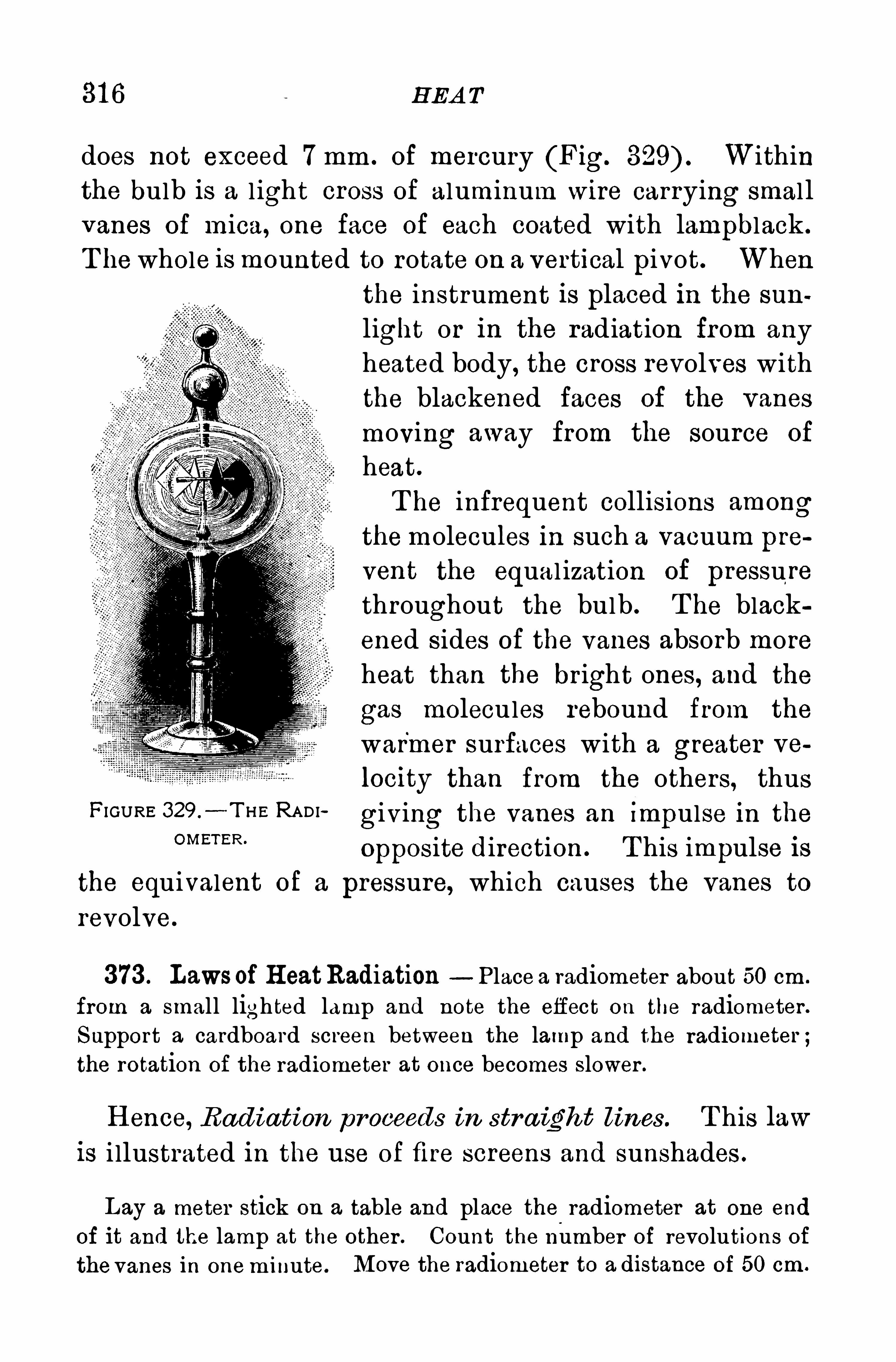
31 6 H EA T
does not exceed 7 mm . of mercury (Fig. Withinthe bulb is a l ight cross of aluminum wire carrying smal lvanes of mica, one face of each coated with lampblack .
T he whole is mounted to rotate on a vertical pivot. When
FIGURE 329 .
- T H E RADIOMETER .
the instrument is placed in the sun
light or in the radiation from any
heated body, the cross revolves withthe blackened faces of the vanes
moving away from the source of
heat.
T he infrequent collisions amongthemolecules in such a vacuum prevent the equal ization Of pressu rethroughout the bulb . T he black
ened sides of the vanes absorb moreheat than the bright ones, and the
gas molecules rebound from the
warmer surfaces with a greater ve
locity than from the others, thus
giving the vanes an Impulse in the
Opposite direction. T his impulse is
the equivalent of a pressure, which causes the vanes to
revolve.
373 . Lawsof H eatRadiation Place a radiometer about 50 cm .
from a small lighted lamp and note the effect on the radiometer.
Support a cardboard screen between the lamp and the radiometer ;the rotation of the radiometer at once becomes slower .
H ence, Rad iation proceeds in str a ight lines . T his law
is i llustrated in the use of fire screens and sunshades .
Lay a meter stick on a table and place the.
radiometer at one end
of it and the lamp at the other . Count the number of revolutions ofthe vanes in oneminute . Move the radiometer to a distance of 50 cm.
H EA T TRA N S P A REN CY 31 7
from the lamp and count the number of revolutions again for aminute.
It will be about four times as many as before.
H ence, The amount of rad iant energy received by a
body from any sm all rad ian t a rea va r ies inver sely as
the squa re of the distancefrom it a s a sou r ce.Note that
this law is the same as that relating to the intensity of
i l l umination in l ight
Support a plane mirror vertically on a table. A t right angles to it
and distant about 5 cm. support a vertical cardboard screen about50 cm. long and 20 cm. wide. On one side of this screen place a
lighted lamp and on theother the radiometer. T he vanes will revolverapidly whenever the lamp and the radiometer are in such a positionthat the screen bisects the angle made by lines drawn from them to
the same point on the mirror . T he angles between these lines andthe screen are the angles of incidence and reflection of the radiantenergy.
H ence, Rad iant energy is reflected from a polished su r
face so that the angles of incidence and reflection a re
equal .
Select two concavewall lamp reflectors of the same size and blackenone of them in the smoke from burning camphor gum. P lace a
lighted lamp about one meter from the radiometer and observe the
rate of rotation of the vanes . H old the clear reflector back of the
radiometer , so as to concentrate the radiation from the lamp upon it,and again note the rate of rotation. Now substitute the blackenedreflector for the clear one;the rate of rotation will be greatly reduced.
H ence, The capacity of a su rfa ce to reflect r adiant
energy depends both on the polish of the su rface and on
the nature of the m a teri a l. Pol ished brass is one of the
best reflectors and lampblack is the poorest.
374. H eat Transparency. Select two flat twelve ounce bottles;fill one with water and the other with a solution of iodine in carbondisulphide. Cut an opening in a sheet Of black cardboard of such a
31 8 H EA T
size that either bottle will cover it. P lace this cardboard between thelamp and the radiometer and note the effect on the radiometer as the
opening is closed successively by the bottles. T his experiment and
others similar to it show that
The transmission of radiant, energy through var ious sub
stances depends on the temperature of the source, and the
thickness and nature of the substance itself .
Substances that transmit a large part of the heat energy,such as the solution of iodine and rock salt, are said to bediathermanous those absorbing a large part, such as water ,are athermanous . Glass is diathermanous to radiations
from a source of high temperature, such as the sun, but
athermanous to radiations from sources of low tempera
ture, such as a stove. T he radiant energy from the sun
passes readily through the atmosphere to the earth , and
warms its surface ; but the radiations from the earth are
stopped to a large extent by the sur rounding atmosphere.
T his selective absorption is due in large measure to the
vapor of water in the air .
Q uestions
1 . Why will newspapers spread over plants protect them from
frost
2 . Why does a tall chimney have a stronger draft than a shortone ?
3 . Explain how it is possible to boil water in a paper pail Without burning the pail.
4 . Should the surface of a steam or hot water radiator be roughor polished ?5 . In what way does a stove heat a room ?
6 . Why does a woolen garment feel warmer than a cotton or a
linen one
7 . Why is glass an effective screen
320 H EA T
of the hands by a rope slipping rapidly through them, the
stream of sparks flying from an emery wheel , are instancesof the same kind of transformation ; the work done against
fr iction produces kinetic energy in the form of heat .
376 . TheMechanical Equivalent of H eat.—In 1 840 Joule
of Manchester in England began a ser ies of exper imentsto determinethe numer ical relation between the unit of
heat and the foot pound . H is exper iments extendedover a per iod of forty years . H is most successful method
consisted in measur ing the heat produced when a meas
ured amount of work was expended in heating water by
stirr ing it w ith paddles driven by weights fal l ing through
a known height . H is final result was that 772 ft .-lb.,
of work , when converted into heat, raise the temperatureof 1 lb . of water 1 ° F. , or 1 390 ft .
-lb. for 1° C . T he later
and more elabofate researches of Rowland in 1 879 and of
Gr iffiths in 1 893 show that the relation is 778 ft .-lb. for
1°F . , or kg.
-m . for 1°C. that is, if the work done
in l ifting kg. one meter high is all converted into
heat, it wi l l raise the temperature of 1 kg. of water 1 ° C .
T his relation is known as themechanical equivalent of heat.
Its value expressed in absolute units is x 1 07 ergs
per calorie.
377. The Steam Engine—T he most important devices
for the conversion of'
heat into mechanical work are the
steam engine and the gas engine. T he former in its
essential features was invented by James Watt . In the
reciprocating steam engine a plston is moved alternately
in Opposite directions by the pressure of steam appl iedfirst to one of its faces and then to the other . T his re
ciprocating or to-and-fro motion 18 converted into rotatorymotion by the device of a connecting rod, a crank, and a
flywheel .

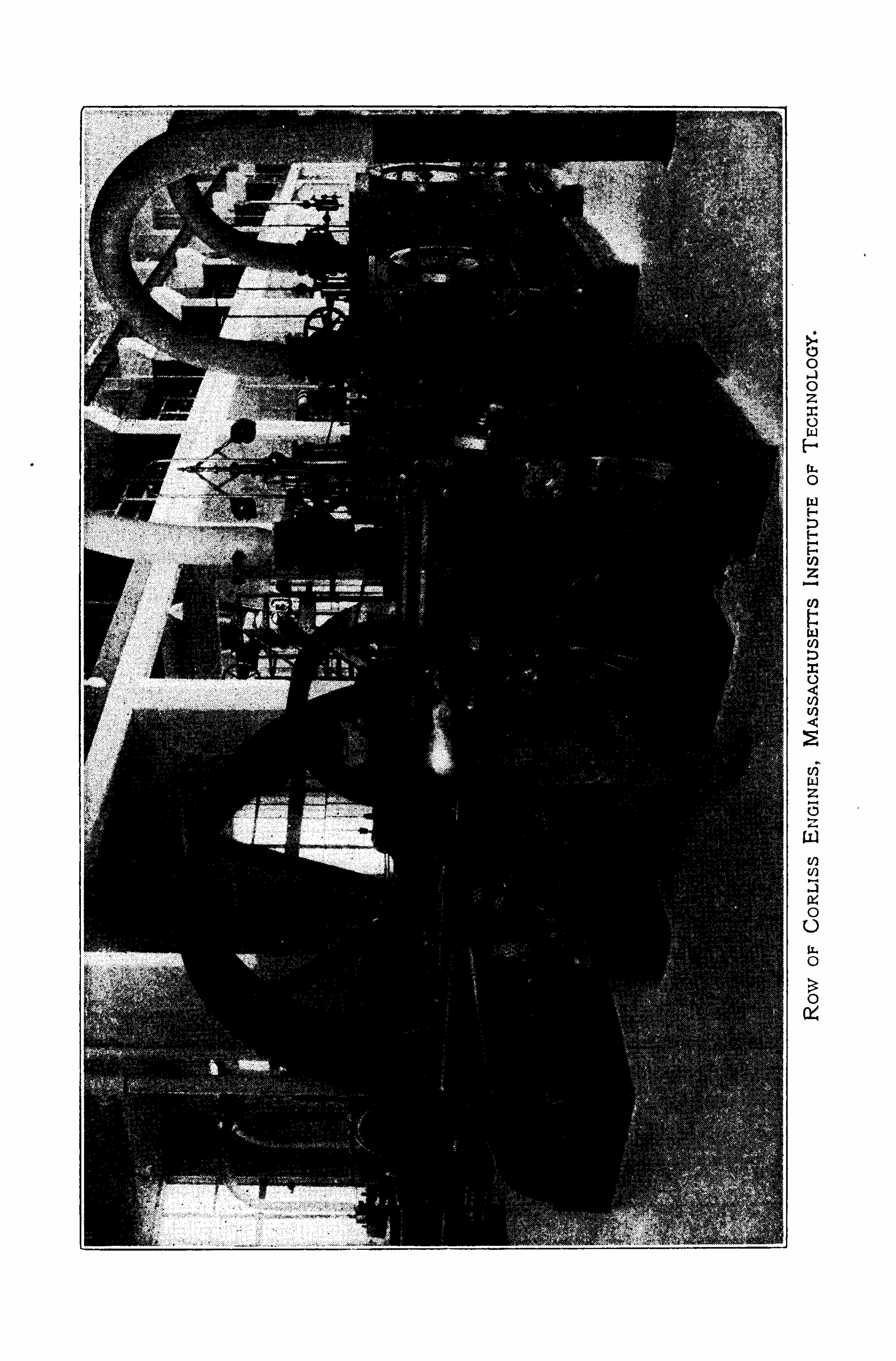
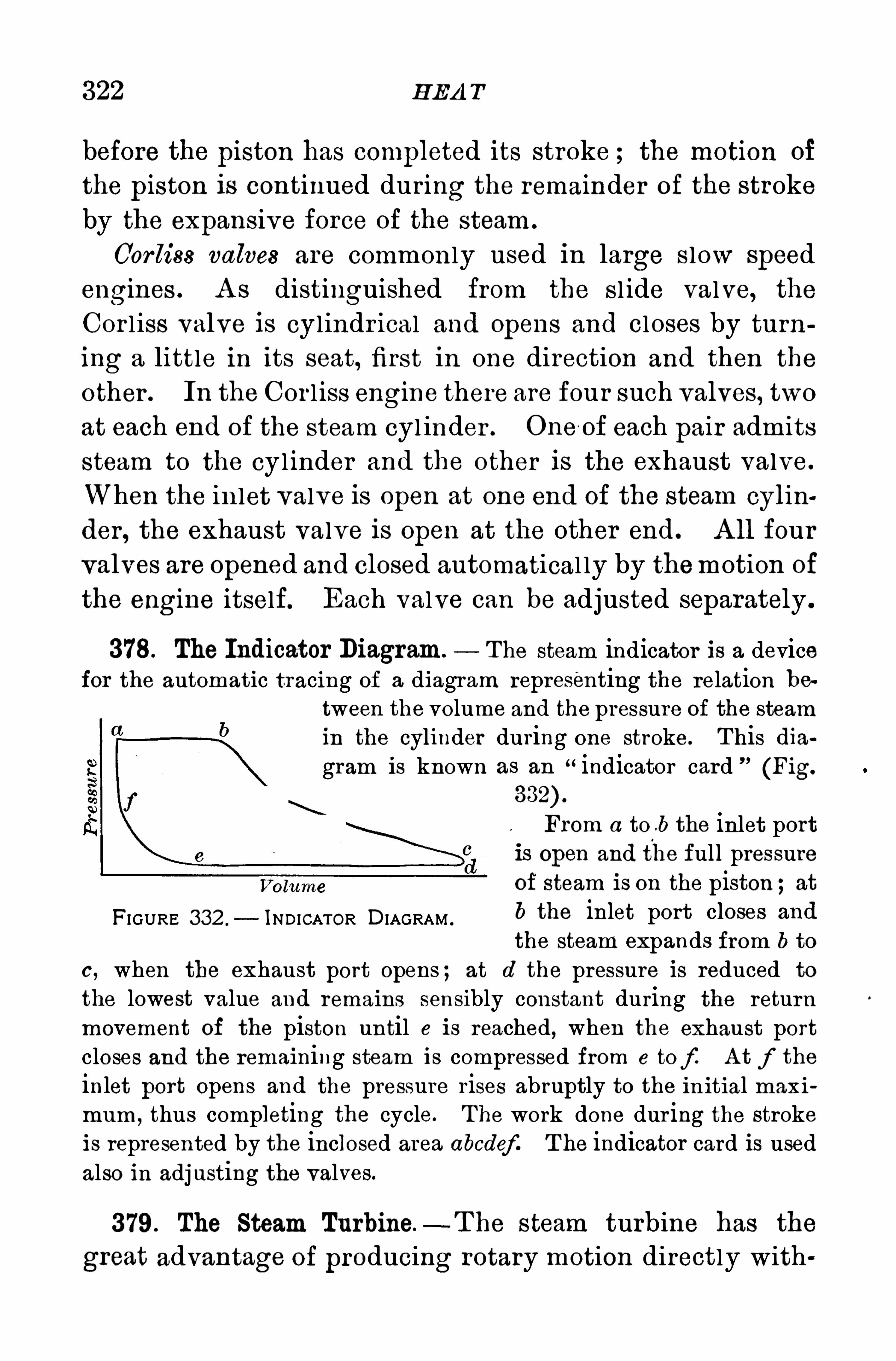
322 H EA T
before the piston has completed its stroke ; the motion of
the piston is continued during the remainder of the strokeby the expansive force of the steam .
Cor liss valves are commonly used in large s low speedengines . A s distinguished from the sl ide valve, the
Cor l iss valve is cylindr ical and Opens and closes by turning a little in its seat, first in one direction and then the
other . In the Cor l iss engine there are four such valves, twoat each end of the steam cyl inder . One /
of each pair admitssteam to the cyl inder and the other is the exhaust valve.
When the in let valve is open at one end Of the steam cylin
der , the exhaust valve is open at the other end. A ll four
valves are Opened and closed automatical ly by themotion of
the engine itself. Each valve can be adjusted separately .
378. The Indicator Diagram. T he steam indicator is a devicefor the automatic tracing of a diagram representing the relation be
tween the volume and the pressure of the steamin the cylinder during one stroke. T his diagram is known as an
“indicator card ”
(Fig.
From a to .b the inlet portis open and the full pressureof steam is on the piston ;at
FI GURE 332 .
- INDICATOR DIAGRAM .
b the inlet port closes and
the steam expands from b to
0 , when the exhaust port opens ; at d the pressure is reduced to
the lowest value and remains sensibly constant during the returnmovement of the piston until e is reached
,when the exhaust port
closes and the remaining steam l s compressed from c tof A t f the
inlet port opens and the pressure rises abruptly to the in itial maxi
mum ,thus completing the cycle. T he work done dur ing the stroke
is represented by the inclosed area abode]:T he indicator card is usedalso in adjusting the valves.
379. The Steam Turbine.- T he steam turbine has the
great advantage of producing rotary motion directly with
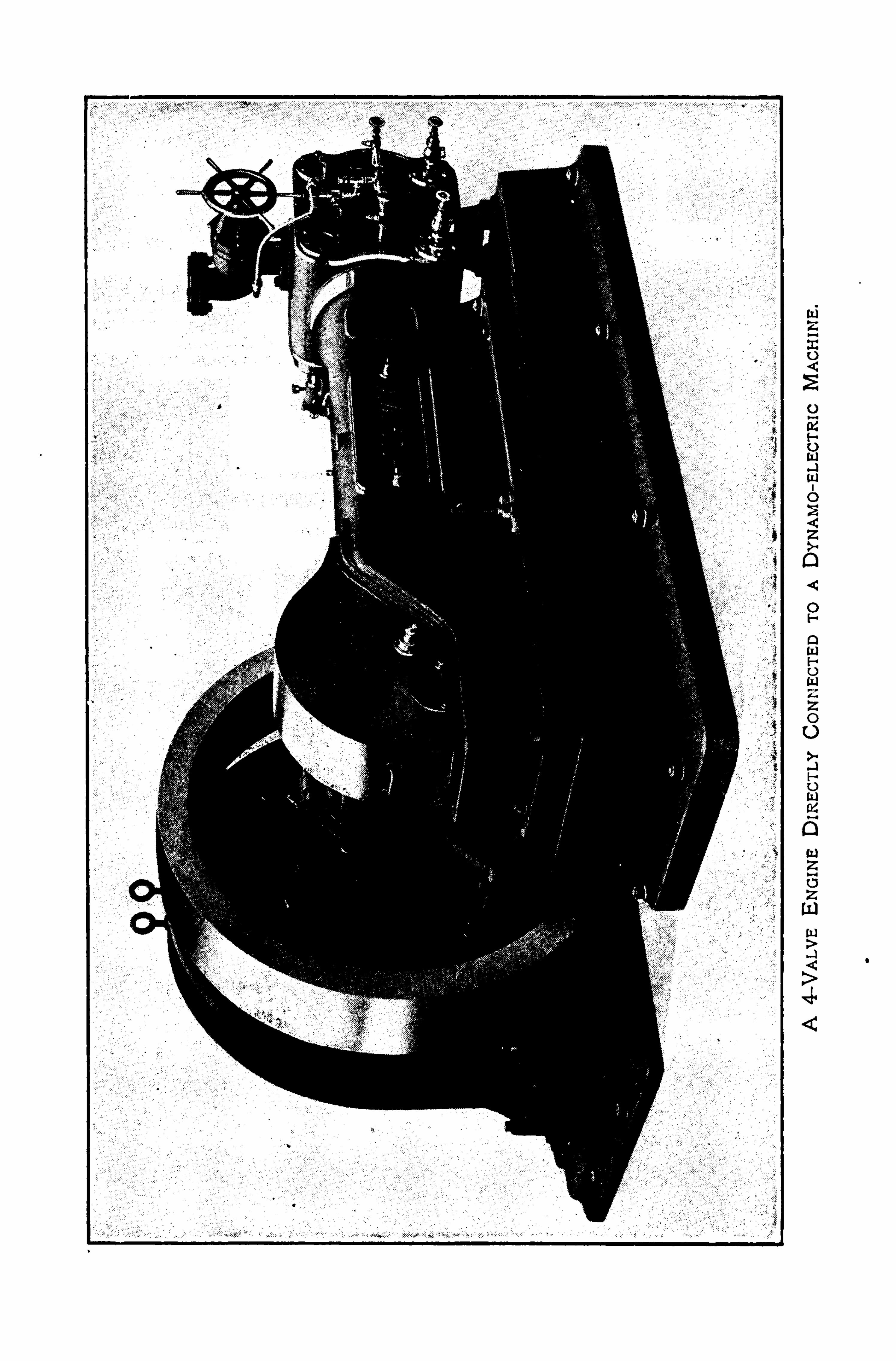
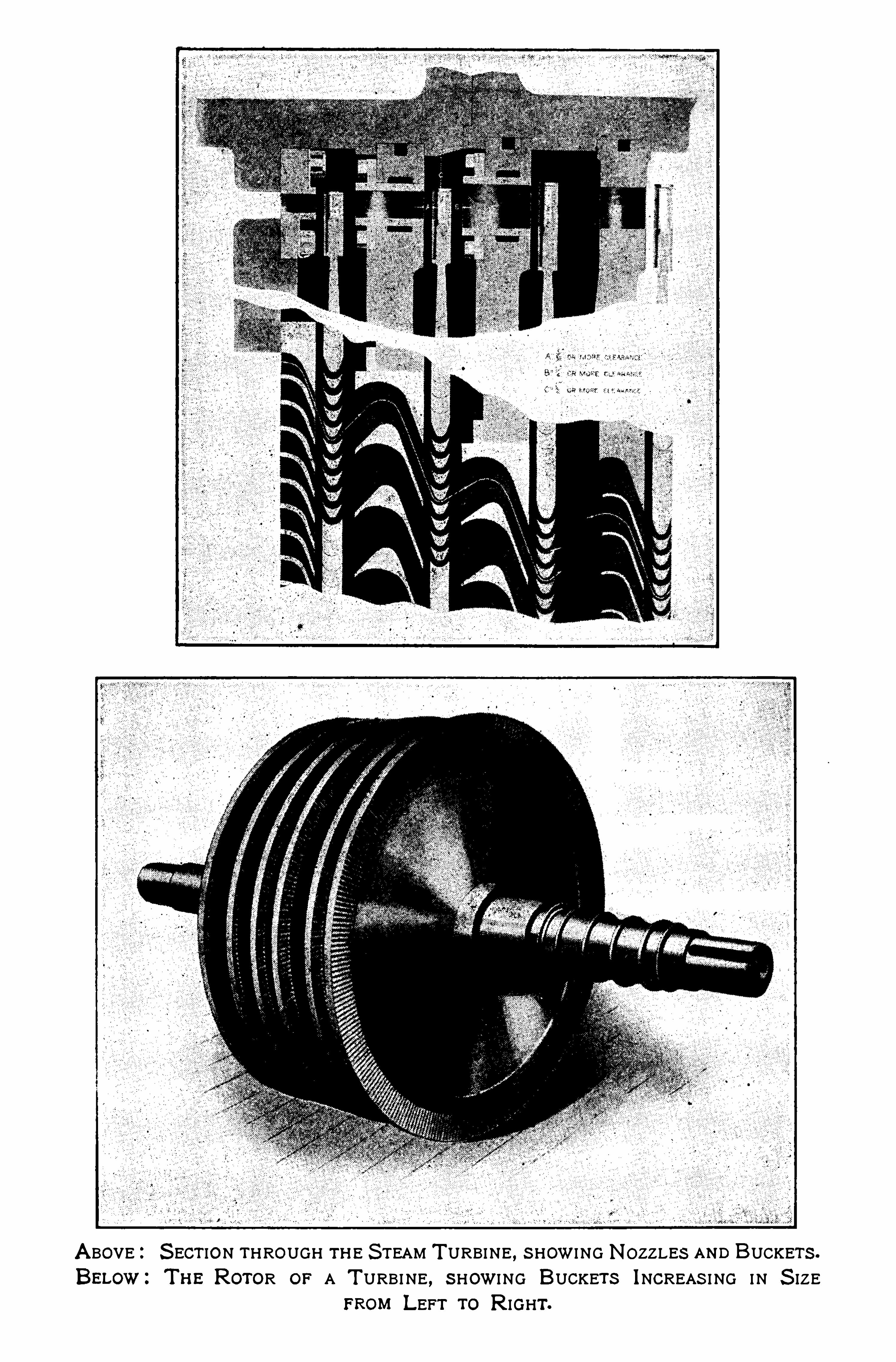
A BOVE:S ECT ION THROUGH TH E S TEAM T URBINE , S HOWI NG NOZZLES AND BUCKETS .
BELow:T H E ROTOR OF A T URBI NE , S HOWI NG BUCKETS INCREAS I NG I N S IZEFROM LEFT To R IGHT.
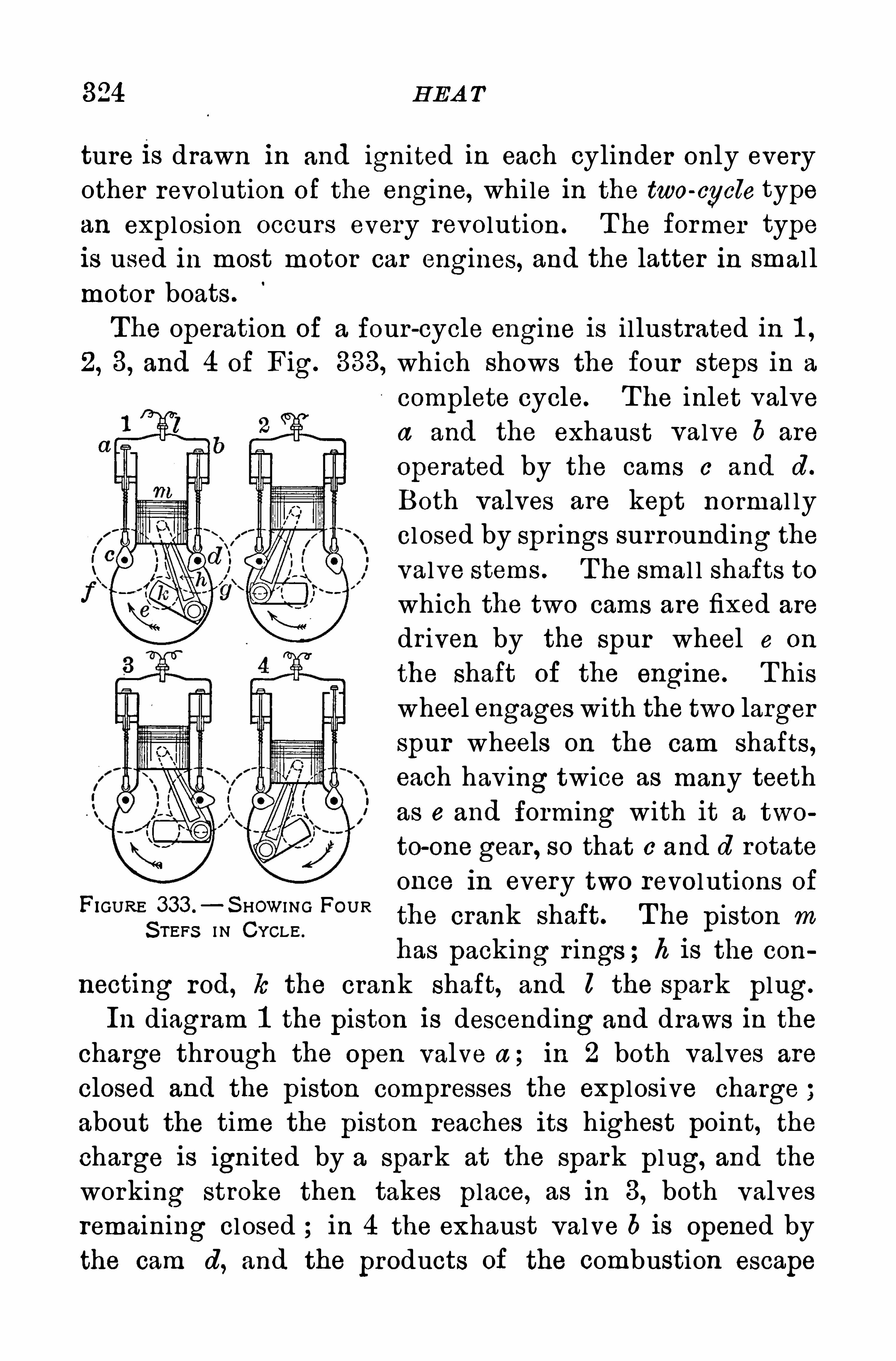
324 H EA T
ture 1 s drawn in and ignited in each cylinder only everyother revolution of the engine, while in the two-cycle typean explosion occurs every revolution . T he former typeis used in most motor car engines, and the latter in smal l
motor boats .
The operation of a four-cycle engine is illustrated in 1 ,2, 3, and 4 of Fig. 333, which shows the four steps in a
complete cycle. T he inlet valvea and the exhaust valve 6 are
operated by the cams c and d .
Both valves are kept normal lyclosed by spr ings surrounding thevalve stems . T he smal l shafts towhich the two cams are fixed are
dr iven by the spur wheel e on
the shaft of the engine. T hiswheel engages with the two largerspur wheels on the cam shafts,each hav ing twice as many teethas e and forming with it a two
to-one gear , so that e and d rotate
once in every two revol utions ofFIGURE
S
333 °
—S HOWI NG FOURthe crank shaft. The piston mTEFS I N CYCLE .
has packing r ings ; h is the con
necting rod, 10 the crank shaft, and l the spark plug.
In diagram 1 the piston is descending and draws in the
charge through the open valve a ; in 2 both valves are
closed and the piston compresses the explosive charge ;about the time the piston reaches its highest point, the
charge is ign ited by a spark at the spark plug, and the
working stroke then takes place, as in 3, both valves
remaining closed ; in 4 the exhaust valve 6 is opened by
the cam d, and the products of the combustion escape


FRONT AND REAR VIEws OF AN A ERIAL FL IW ER .
One of the smallest practical airplanes made.
326 H EA T
Questions and P rob lems
1 . Why does the temperature of the air under the bell jar of an
air pump fall when the pump is worked2 . Is there a difierence in the temperature of the steam as it enters
a steam engine and as it leaves at the exhaust Explain .
3 . Lead bullets are sometimes melted when they s trike a target.Explain .
4 . Does clothing keep the cold out or keep the heat in5 . Is there any less moisture in the air after it has passed through
a heated furnace into a room than there was before ?
6 . Why does the rapid driving of an automobile heat the air in
the tires ?7 . A mass of 200 g . moving with a speed of 50 m . per second is
suddenly stopped . If all its energy is converted into heat, how manycalories would be generated ‘
3
NOT E . A calorie equals x 1 07 ergs.
8 . If all the potential energy of a 300 kg. mass of rock is con
verted into heat by falling vertically 200 m .
,how many calories would
be generated ?
9 . H ow high could a 200 g. weight be lifted by the heat requiredto melt the same mass of ice
,if all the heat could be utilized for the
purpose?1 0 . If the average pressure of steam in the cylinder of an engme Is
1 00 lb . per square inch, the area of the piston is 80 sq . in ., and the
stroke 1 ft ., how many horse powers would be developed if the
engine makes two revolutions per second
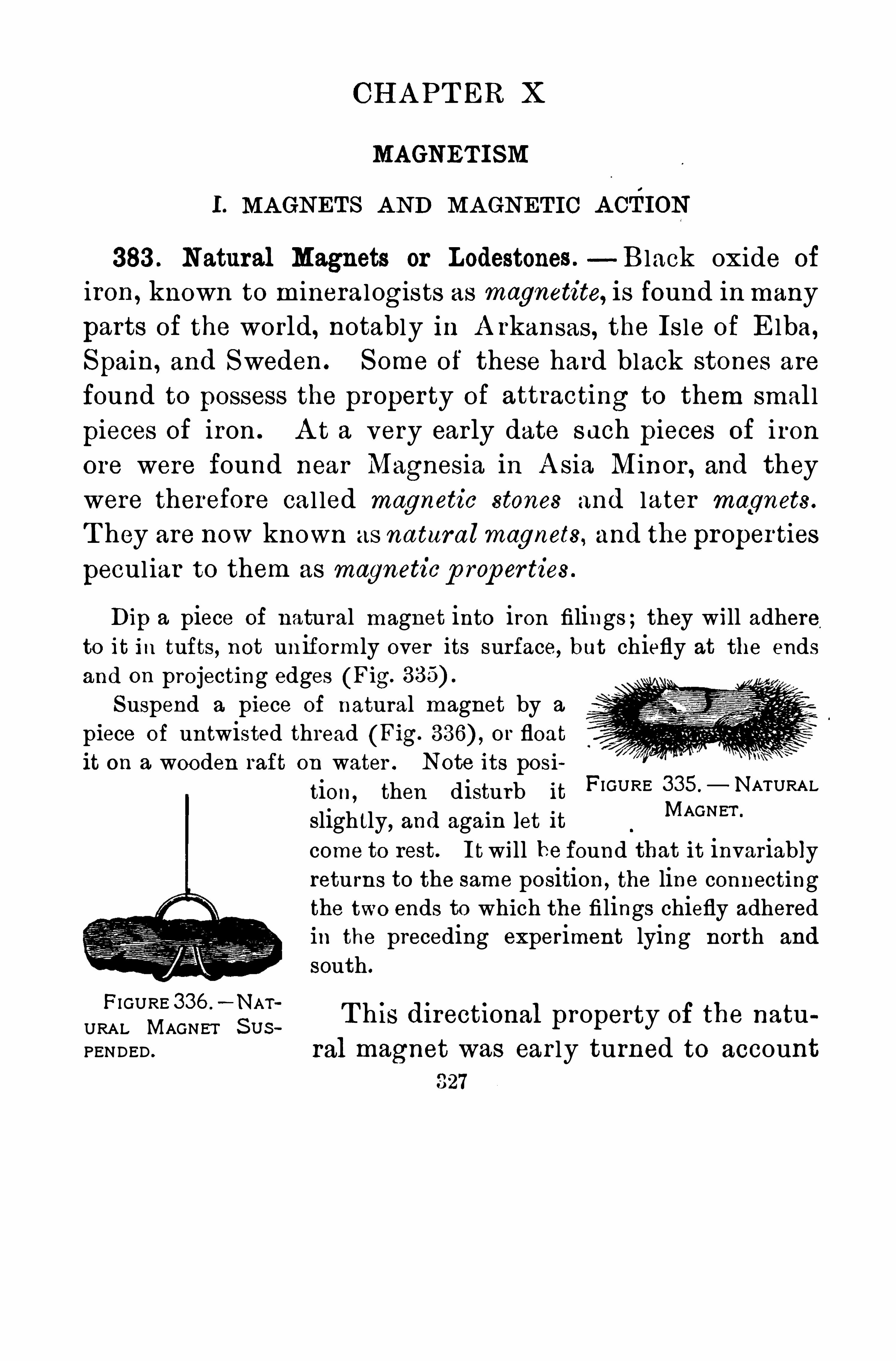
CH A PT ER X
MAGNET ISM
I. MA GNET S A ND MA GNET IC A CTION
383 . Natural Magnets or Lodestones . Black oxide of
iron,known to mineralogists as magnetite, is found in many
parts of the world, notably in A rkansas, the Isle of Elba,Spain, and Sweden . Some of these hard black stones are
found to possess the property of attractn to them smal l
pieces of iron . A t a very early date such pieces of iron
ore were found near Magnesia in A sia Minor , and they
were therefore cal led magnetic stones and later magnets .
T hey are now known as natural magnets, and the proper ties
peculiar to them as magnetic p rop er ties .
Dip a piece of natural magnet into iron filings ;they will adhereto it in tufts , not un iformly over its surface, but chiefly at the endsand on projecting edges (Fig.
Suspend a piece of natural magnet by a
piece of untwisted thread (Fig. or floatit on a wooden raft on water . Note its posi
tion, then disturb it FIGURE 335.
— NATURAL
slightly, and again let it MAGNET ‘
come to rest. I twill be found that it invariablyreturns to the same position , the line connectingthe two ends to which the filings chiefly adheredin the preceding experiment lying north and
south.
FI GURE 336 .
—NATURAL MAGNET S U s
T h is d1 rectIonal property of the natuPENDED .
ral magnet was ear ly turned to account
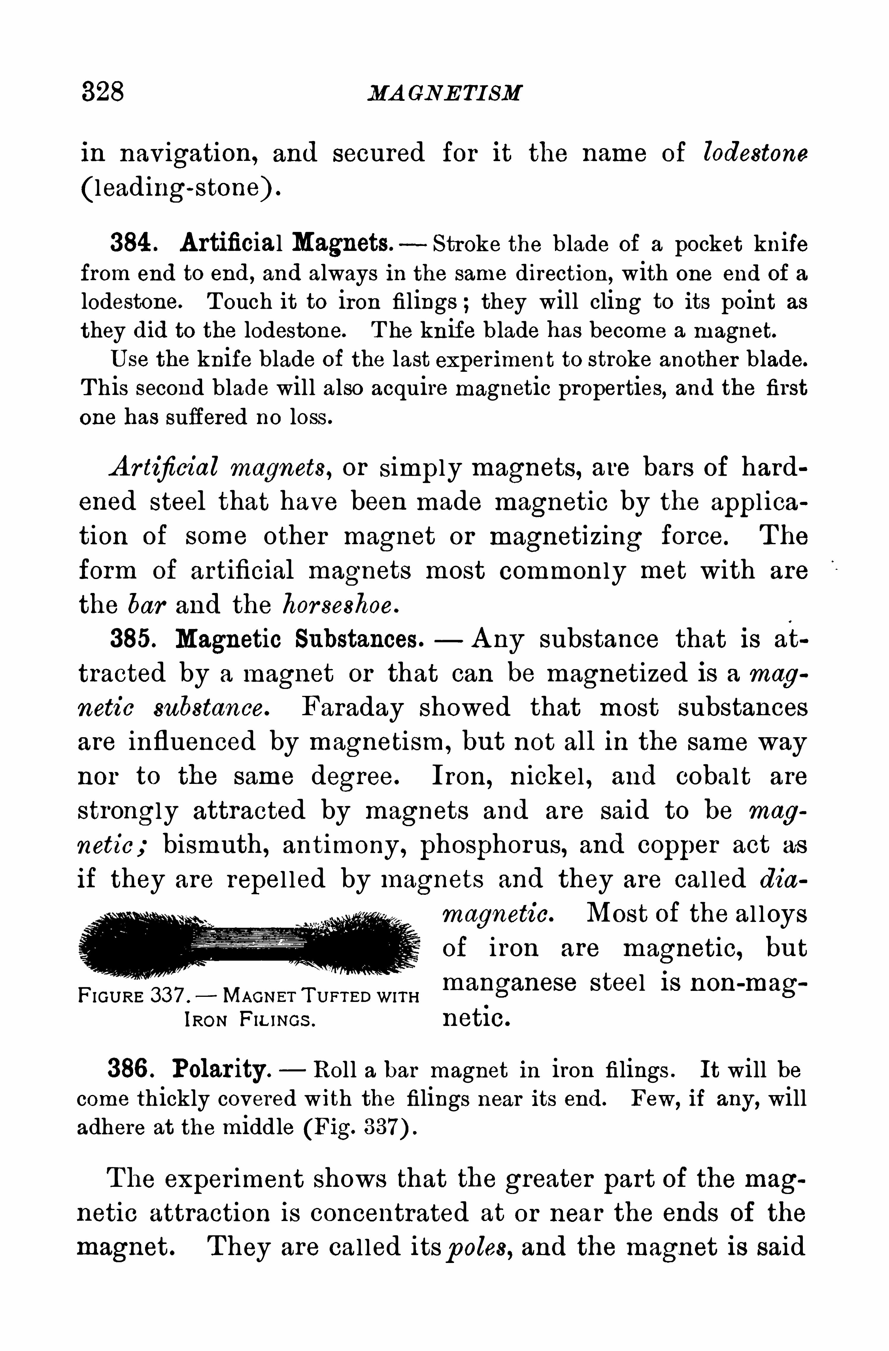
328 MA GNE TI SM
in navigation, and secured for it the name of lodestone
(leading-stone) .
384 . A rtificial Magnets.—Stroke the blade of a pocket knife
from end to end , and always in the same direction , with one end of a
lodestone. T ouch it to iron filings ;they will cling to its point as
they did to the lodestone. T he knife b lade has become a magnet.U se the knife blade of the last experiment to stroke another blade.
T his second blade will also acquire magnetic properties, and the firstone has suffered no loss .
A r tificial magnets, or simply magnets, are bars of hard
ened steel that have been made magnetic by the appl ica
tion of some other magnet or magnetizing force. T he
form of artificial magnets most common ly met with are
the bar and the hor seshoe.
385. Magnetic Substances.— A ny substance that is at
tracted by a magnet or that can be magnetized is a mag
netic substance. Faraday showed that most substances
are influenced by magnetism, but not all in the same way
nor to the same degree. Iron, nickel , and cobalt are
strongly attracted by magnets and are said to be mag
netic; bismuth, antimony, phosphorus, and Copper act as
if they are repel led by magnets and they are cal led diamagnetic. Most of the al loysof iron are magnetic, but
FIGURE 337 .
—MAGNET T U ETED WITH manganese S teel IS non-mag
IRON FIL INGs .netlc.
386 . Polar ity. Roll a bar magnet in iron filings . It will become thickly covered with the filings near its end. Few, if any, willadhere at the middle (Fig.
The exper iment shows that the greater part of the magnetic attraction is concentrated at or near the ends of the
magnet . T hey are cal led itsp oles, and the magnet is said
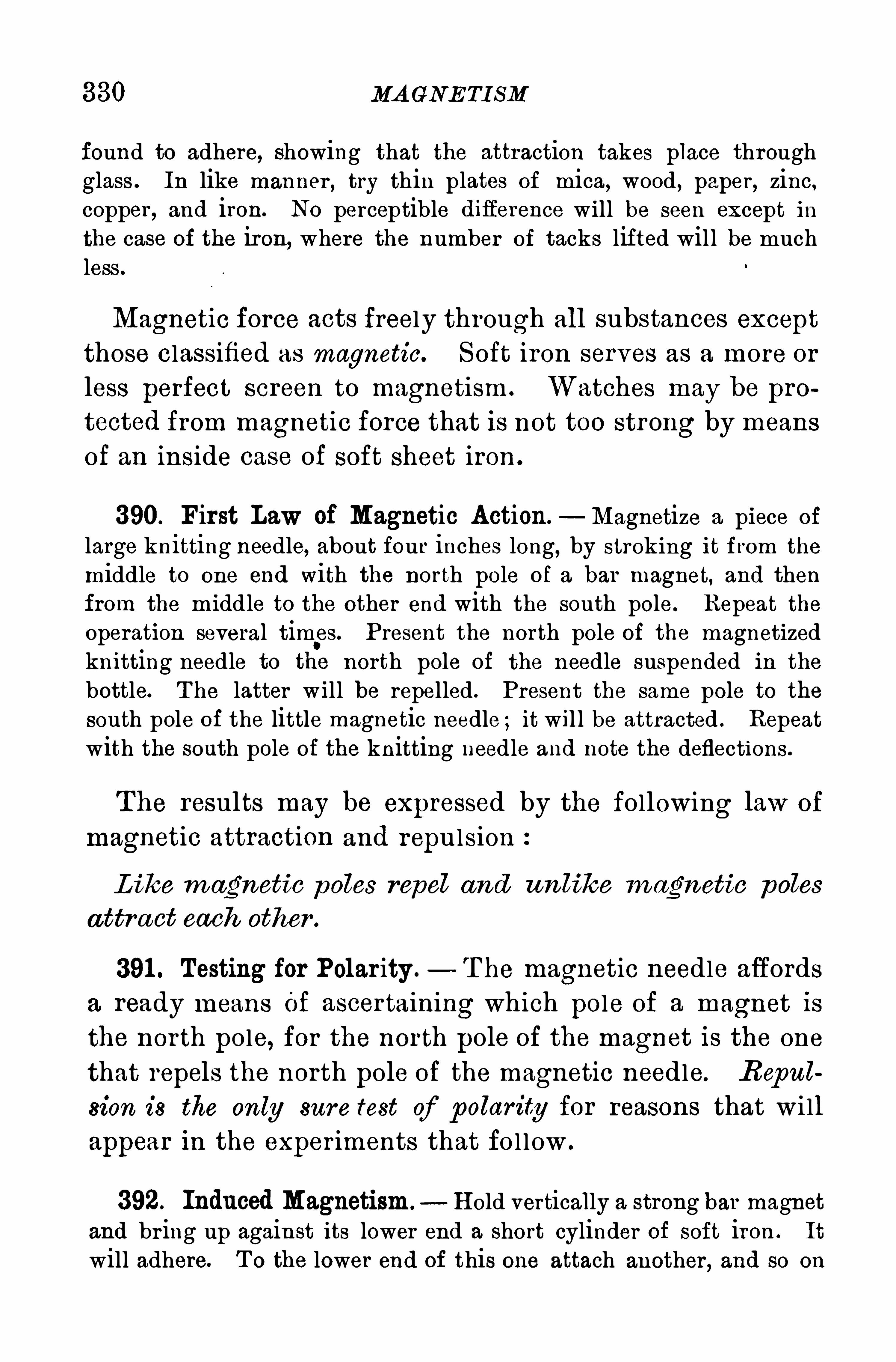
330 MA GNE TI SM
found to adhere, showing that the attraction takes place throughglass . In like manner , try thin plates of mica, wood , paper , zinc ,copper , and iron. No perceptible diflerence will be seen except inthe case of the iron, where the number of tacks lifted will be muchless .
Magnetic force acts freely through all substances except
those classified as magnetic. Soft iron serves as a more or
less perfect screen to magnetism . Watches may be pro
tected from magnetic force that is not too strong by means
of an inside case of soft sheet iron .
390. First Law of Magnetic Action.—Magnetize a piece of
large knitting needle, about four inches long, by stroking it from the
middle to one end with the north pole of a bar magnet, and thenfrom the midd le to the other end with the south pole. Repeat theoperation several tim
.es. Present the north pole of the magnetized
knitting needle to the north pole of the needle suspended in the
bottle. T he latter will be repelled . Present the same pole to thesouth pole of the little magnetic needle ; it wil l be attracted . Repeatwith the south pole of the knitting needle and note the deflections.
The results may be expressed by the following law of
magnetic attraction and repulsion
L ike m agnetic poles repel and unlike m agnetic poles
attra ct each other .
391 . Testing for Polar ity. T he magnetic needle affords
a ready means Of ascertaining which pole of a magnet is
the north pole, for the north pole of the magnet is the one
that repels the north pole of the magnetic needle. R eput
sion is the only sur e test of polarity for reasons that wi ll
appear in the exper iments that fo l low .
392. Induced Magnetism. H old vertically a strong bar magnetand br ing up against its lower end a short cylinder of soft iron . It
will adhere. T o the lower end of this one attach another , and so on
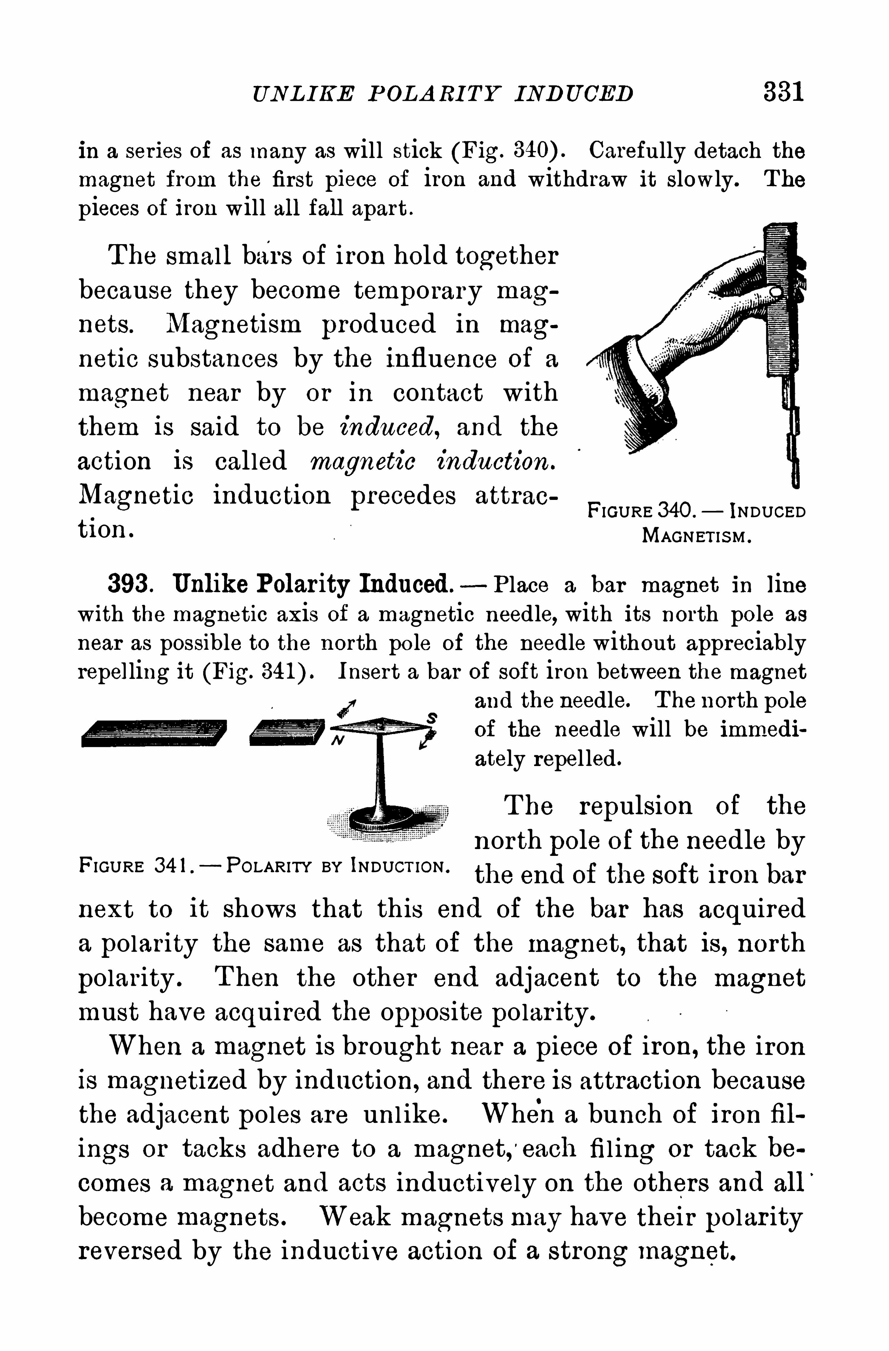
UNL I KE P OL A RI T Y INDU CED 331
in a series of as many as will stick (Fig. Carefully detach themagnet from the first piece of iron and withdraw it slowly. T he
pieces of iron will all fall apart .
T he small bars of iron hold together
because they become temporary mag
nets . Magnetism produced in magnetic substances by the influence of a
magnet near by or in contact with
them is said to be induced, and the
action is called magnetic induction .
Magnet1o 1nduct1 0n precedes attracFIGURE 340 .
— INDUCEDti on MAGNET IS M .
393 . Unlike Polarity Induced.- P lace a bar magnet in line
with the magnetic axis of a magnetic needle, with its north pole as
near as possible to the north po le of the needle without appreciablyrepelling it (Fig. Insert a bar of soft iron between the magnet
and the needle. T he north poleof the needle will be immediately repel led .
T he repulsion of the
north pole of the needle byFIGURE 34 1 .
—POLARITY BY INDUCT ION .
the end Of the soft iron barnext to it shows that this end of the bar has acquireda polarity the same as that of the magnet, that is, north
polar ity . T hen the other end adjacent to the magnet
must have acquired the opposite polar ity.
When a magnet is brought near a piece of iron, the ironis magnetized by induction, and there is attraction becausethe adjacent poles are unl ike. When a bunch of iron fil
ings or tacks adhere to a magnet,'
each fil ing or tack becomes a magnet and acts inductively on the others and all
’
become magnets . Weak magnets may have their polar ityreversed by the inductive action of a strong magnet.
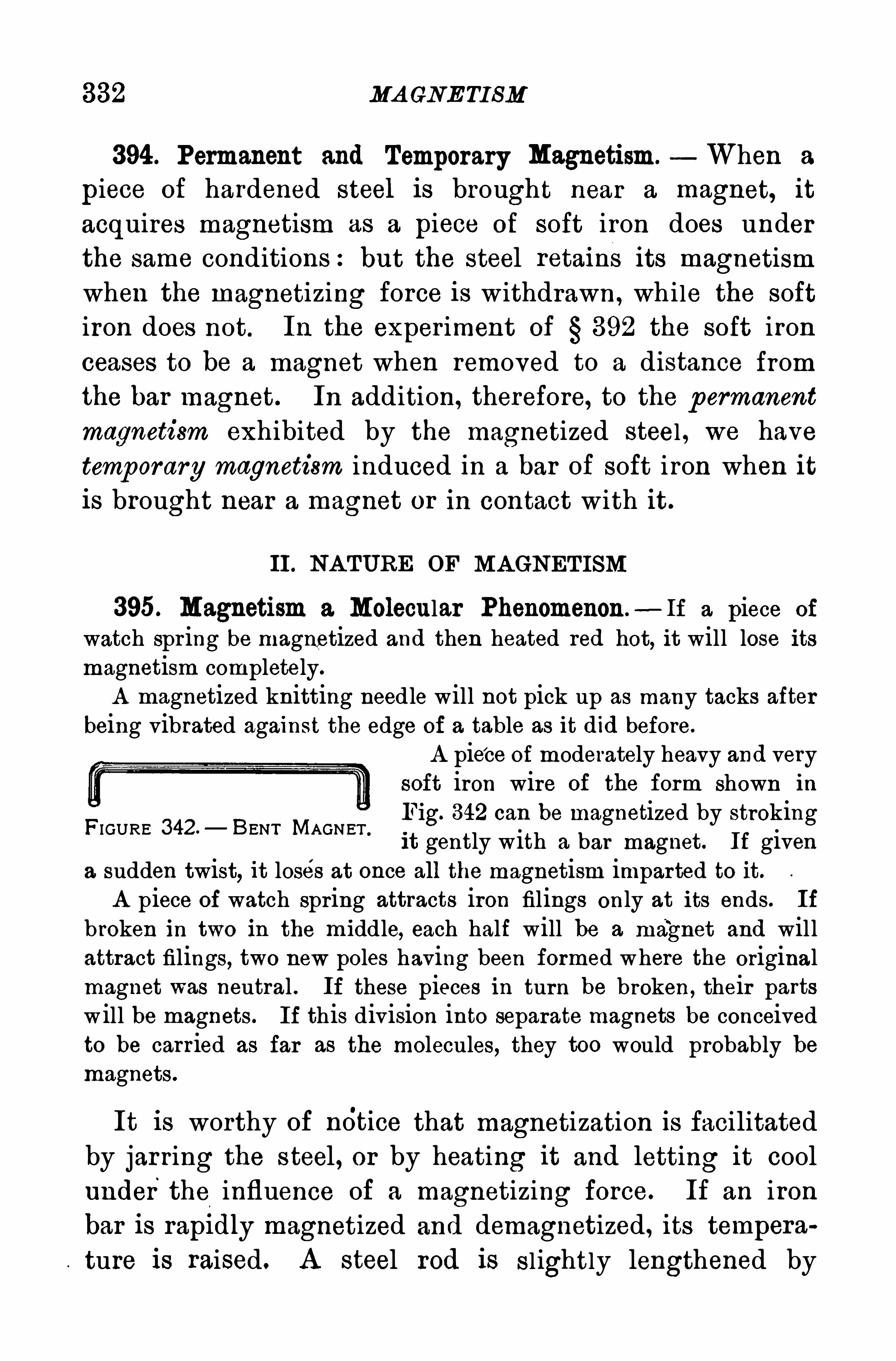
332 MA GNE TI SM
394 . Permanent and Temporary Magnetism. When a
piece of hardened steel is brought near a magnet, it
acquires magnetism as a piece of soft iron does underthe same conditions:but the steel retams its magnetismwhen the magnetizing force is withdrawn, while the softiron does not. In the experiment of 392 the soft ironceases to be a magnet when removed to a distance fromthe bar magnet. In addition, therefore, to the p ermanentmagnetism exhibited by the magnetized steel , we havetemporary magnetism induced in a bar of soft iron when itis brought near a magnet or in contact with it.
II . NA TURE OF MA GNETISM
395. Magnetism a Molecular Phenomenon.—If a piece of
watch spr ing be magnetized and then heated red hot, it will lose itsmagnetism completely.
A magnetized knitting needle will not pick up as many tacks afterbeing vibrated against the edge of a table as it did before.
A piece of moderately heavy and verysoft iron wire of the form shown in
Fig. 342 can be magnetized by strokingit gently with a bar magnet. If given
a sudden twist, it loses at once all the magnetism imparted to it.A piece of watch spring attracts iron filings only at its ends. If
broken in two in the middle, each half will be a magnet and willattract filings, two new poles having been formed where the originalmagnet was neutral . If these pieces in turn be broken, their partswill be magnets. If this division into separate magnets be conceivedto be carried as far as the molecules, they too would probably bemagnets.
FIGURE 342 —BENT MAGNET .
It is worthy of ndtice that magnetization is facilitatedby jar ring the steel, or by heating it and letting it coolunder the influence of a magnetizing force. If an iron
bar is rapldly magnetized and demagnetized, its tempera
ture is raised. A steel rod is sl ightly lengthened by
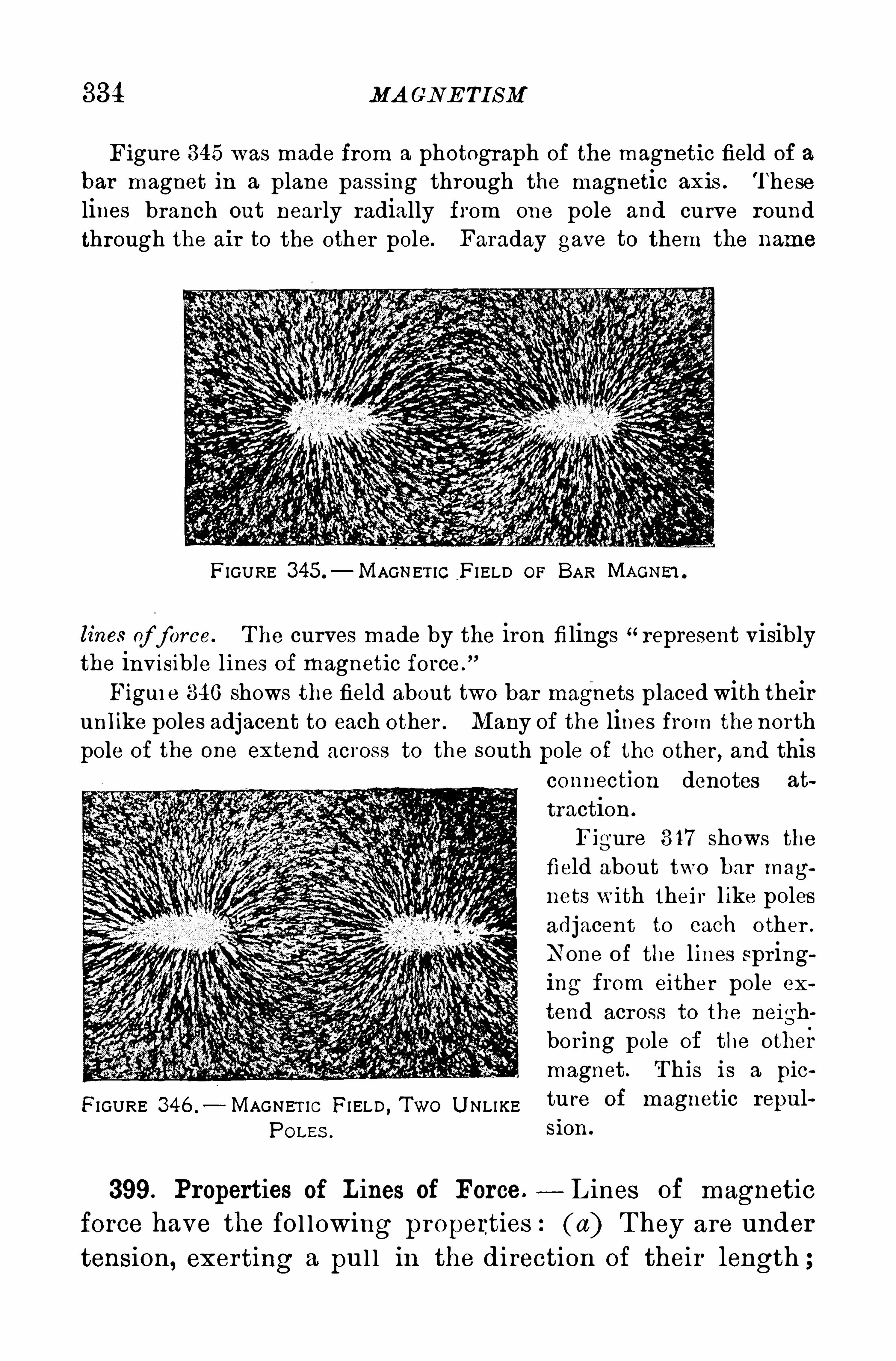
334 MA CNE TISM
Figure 345 was made from a photograph of the magnetic field of a
bar magnet in a plane passing through the magnetic axis . T heselines branch out nearly radially from one pole and curve roundthrough the air to the other pole. Faraday gave to them the name
FIGURE 345.
—MAGNET IC FI ELD OF BAR MAGNE‘I .
lines of force. T he curves made by the iron filings “represent visiblythe invisible lines of magnetic force .
Figui e 340 shows the field about two bar magnets placed with theirunlike poles adjacent to each other . Many of the lines from the northpole of the one extend across to the south pole of the other, and this
connection denotes at
traction .
Figure 3 17 shows thefield about two bar mag
nets with their l ike polesadjacent to each other .
None of the lines springing from either pole ex
tend across to the neighboring pole of the other
magnet . T his is a pic
FIGURE 346 .
— MAGNET IC FI ELD , TWO U NLIKE ture Of magnetic repul
POLEs .$ 1 0 1 1
399. Properties of Lines of Force.— L ines of magnetic
force have the fol lowing properties :(a) T hey are under
tension, exerting a pul l in the direction of their length ;
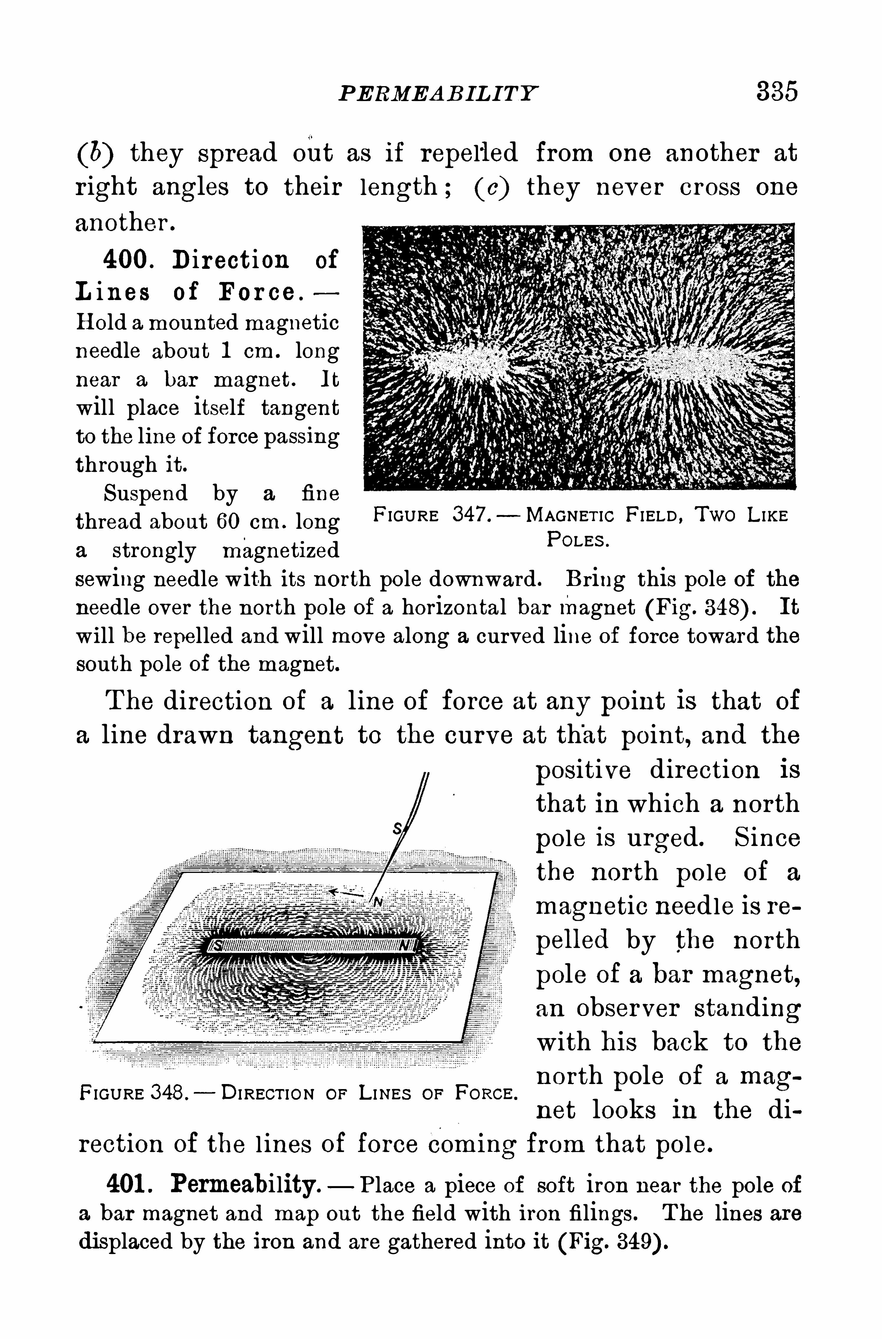
PERMEA BILITY 385
(6) they spread out as if repelled from one another at
r ight angles to their length ; (0) they never cross one
another .
400 . Direction of
L ines of For ce .
H old a mounted magneticneedle about 1 cm . longnear a bar magnet . It
will place itself tangentto the line of force passingthrough it.
Suspend by a fine
thread about 60 cm . longa strongly magnetized
FIGURE 347 .
— MAGNET IC FI ELD , Two L IKEPOLES .
sewing needle with its north pole downward . Bring this pole of the
needle over the north pole of a horizontal bar magnet (Fig. It
will be repelled and will move along a curved line of force toward thesouth pole of the magnet.
T he direction of a line of force at any point is that of
a line drawn tangent to the curve at that point, and the
FIGURE 348.
— DI RECT ION OF L INES OF FORGE.
positive direction is
that in which a north
pole is urged. S incethe north po le of a
magnetic needle is re
pelled by the north
pole of a bar magnet,
an observer standingwith his back to the
north pole of a mag
net looks in the direction of the l ines of force com i ng from that pole.
401 . Permeability. P lace a piece of soft iron near the pole of
a bar magnet and map out the field with iron filings . T he lines aredisplaced by the iron and are gathered into it (Fig.
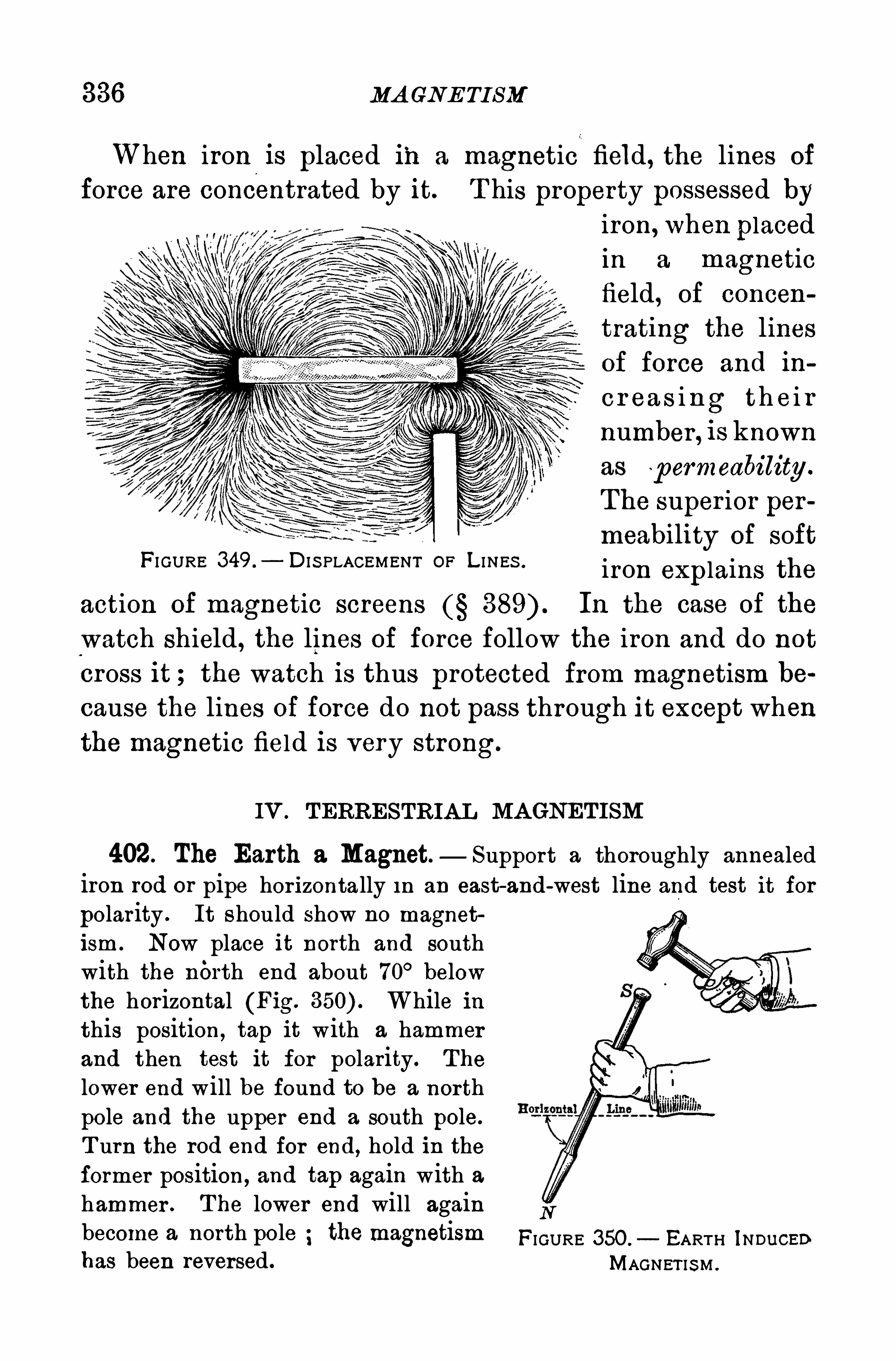
336 MA GNE TI SM
When iron is placed in a magnetic field , the lines of
force are concentrated by it. T his property possessed by
FI GURE 349 .
— DI S PLACEMENT OF L I NES .
iron, when placedin a magneticfield, of concen
trating the linesof force and in
c r ea s i ng th e i r
number , is known
as p ermeability .
The super ior per
meability of softiron explains the
action of magnetic screens In the case of the
watch shield , the lines of force follow the iron and do notcross it ; the watch is thus protected from magnetism be
cause the lines of force do not pass through it except whenthe magnetic field is very strong.
IV . TERRESTRIA L MA GNETISM
402. The Earth a Magnet— Support a thoroughly annealed
iron rod or pipe hor izontally in an east-and-west line and test it for
polarity . It should show no magnetism. Now place it north and southwith the north end about 70° belowthe horizontal (Fig. While inthis position, tap it with a hammerand then test it for polarity. The
lower end will be found to be a northpole and the upper end a south pole.
T urn the rod end for end, hold in theformer position , and tap again with ahammer . T he lower end will againbecome a north pole the magnetismhas been reversed.
N
FIGURE 350. EARTH INDuCEDMAGNET IS M .
338 MA GNE TI SM
rection, though resembling somewhat parallels of lati
tude.
404 . Magnetic Declination.- T he magnetic poles of the
earth do not coincide with the geographical poles, and
consequently the direction of the magnetic needle is not
in general that of the geographical mer idian. T he anglebetween the direction of the needle and the mer idian at
any place is the magnetic declination . T o Columbus belongs the undisputed discovery that the decl ination is dif
ferent at difierent points on the earth’
s surface. In 1 492
he discovered a place of no declination in the A tlanticO cean north of the A zores . T he decl ination at any place
is not constant, but changes as if the magnetic poles oscil
late, while the mean position about which they osci l lateis subject to a slow change of long per iod .
' T he annual
change on the Pacific coast is about and in New Eng
land about A t London in 1 657 the magnetic declination was zero, and it
.
attained its max imum wester ly
value of 24°in 1 81 6 ; in 1 915 it was 1 5
°1 9’ W.
405. Agonic Lines.— L ines drawn through places where
the needle points true north are cal led agonic lines . In
1 91 0 the agonic line in North Amer ica ran from the mag
netic pole southward across Lake S uperior, thence near
Lansing, Michigan, Col umbus, Ohio, through West Vir
ginia and South Carol ina, and it left the mainland near
Char leston on its way .to the magnetic pole in the south
ern hemisphereg East of this l ine the needle points west
of north ; west of it, it points east of north . L ines pass
ing through p laces of the same decl ination are called
isogonic lines .
QUE S TION S 339
Questions
1 . Given a bar magnet of unmarked’
polarity ; determine whichend is its north pole .
2 . Out of a group of materials, how would you select the mag
netic substances ?
3 . Given two bars exactly alike in appearance, one soft iron and
the other hardened steel . Select the steel one by means of magnetism.
4 . Magnetize a long darning needle, then break it in the m iddle.
Will there be two magnets, each with one pole5 . H ow would you magnetize a sewing needle so that the eye is
the north pole
6 . What efiect would it have on a compass to place it within an
iron kettle ?7 . Will an iron fence post standing in the ground have any in
fluence on the needle of a surveyor ’
s compass ?8 . Float a magnet on a cork . Will the earth’s magnetism cause
it to float toward the earth’
s magnetic pole
9 . Is the polarity of the earth’
s magnetism in the northern hernisphere the same as that of the north pole of a magnet ?
1 0 . Suppose you wish to make a magnetic needle. If it is bal
anced on a point so as to rest in a horizontal position before magnetization, will it rest horizontally after it is magnetized ?
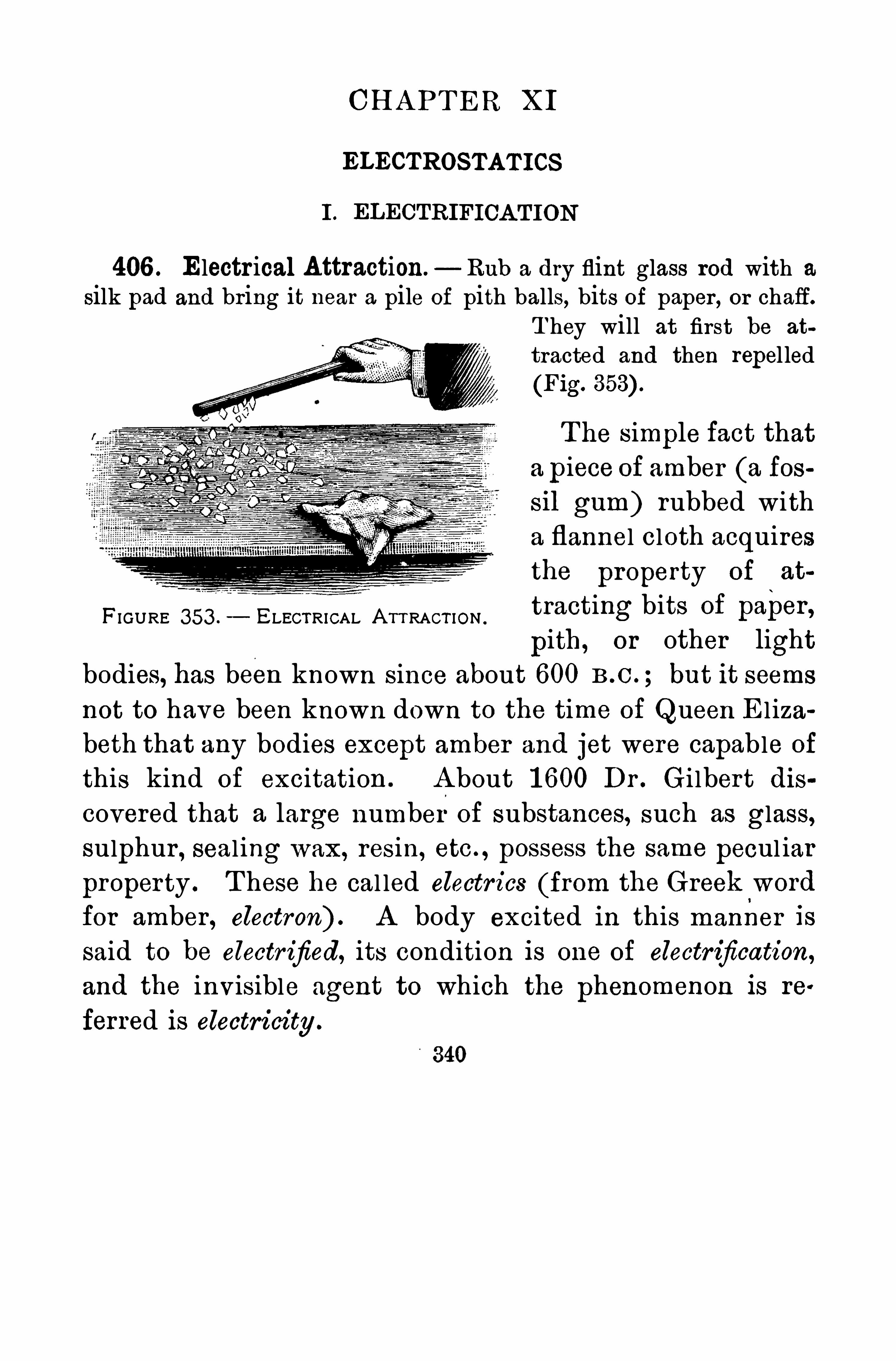
CH A PT ER XI
ELECTROSTATICS
I . ELECTRIFICA T ION
406 . Electr ical Attraction. Rub a dry flint glass rod with a
silk pad and bring it near a pile of pith balls, bits of paper , or chaff.T hey will at first be at
tracted and then repel led(Fig.
T he simple fact thata piece of amber (a fossil gum) rubbed witha flannel cloth acquiresthe property of at
tracting bits of paper ,pith , or other light
bodies, has been known since about 600 B .C . ; but it seems
not to have been known down to the time of Queen El iza
beth that any bodies except amber and jet were capable of
this kind of excitation . A bout 1 600 Dr . Gi lbert dis
covered that a large number of substances, such as glass,sulphur , seal ing wax, resin, etc. , possess the same pecul iar
property . T hese he cal led electr ics (from the Greek'
word
for amber , electron) . A body excited in this manner is
said to be electr ified, its condition is one of electrification,
and the invisible agent to which the phenomenon is re
ferred is electricity .
FIGURE 353 . ELECTRICAL A TT RACT ION .
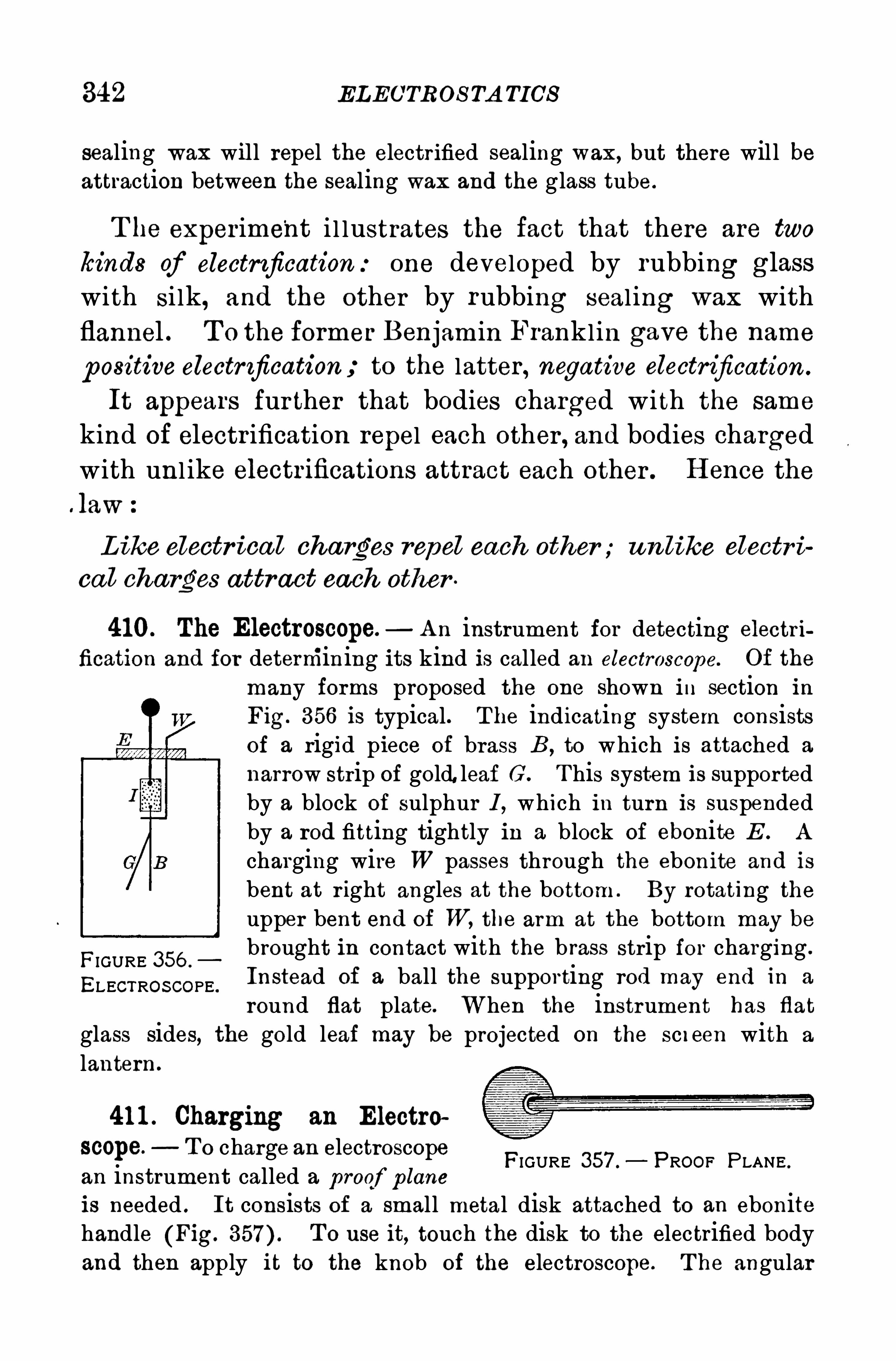
342 ELECTROS TA TICS
sealing wax will repel the electrified sealing wax, but there will beattraction between the sealing wax and the glass tube .
T he exper ime'
nt i l lustrates the fact that there are two
kinds of electrification:one developed by rubbing glasswith si lk, and the other by rubbing seal ing wax with
flannel . T o the former Benjamin Franklin gave the name
positive electr ification to the latter , negative electrification .
It appears fur ther that bodies charged with the same
kind of electr ification repel each other , and bodies charged
with unl ike electrifications attract each other . H ence the
law
L ike electr ica l charges repel each other ; un like electr i
ca l charges attract each other
410. The Electroscope.— A n instrument for detecting electr i
fication and for determining its kind is called an electroscope. Of the
many forms proposed the one shown in section in
Fig. 356 is typical. The indicating system consistsof a rigid piece of brass B , to which is attached a
narrow strip of gold.leaf G. T his system is supportedby a block of sulphur I , which in turn is suspendedby a rod fitting tightly in a block of ebonite E . A
charging wire W passes through the ebonite and is
bent at r ight angles at the bottom . By rotating the
upper bent end of W, the arm at the bottom may be
brought in contact with the b rass strip for charging .
Instead of a ball the supporting rod may end in a
round flat plate. When the instrument has flat
glass sides, the gold leaf may be projected on the screen with a
lantern .
FIGURE 356 .
ELECTROS COPE .
41 1 . Charging an Electro
scope. T o charge an electroscopean instrument called a p roof p laneis needed . It consists of a small metal disk attached to an ebonitehandle (Fig. T o use it, touch the disk to the electrified bodyand then apply it to the knob of the electroscope. T he angular
FIGURE 357 . PROOF PLANE .
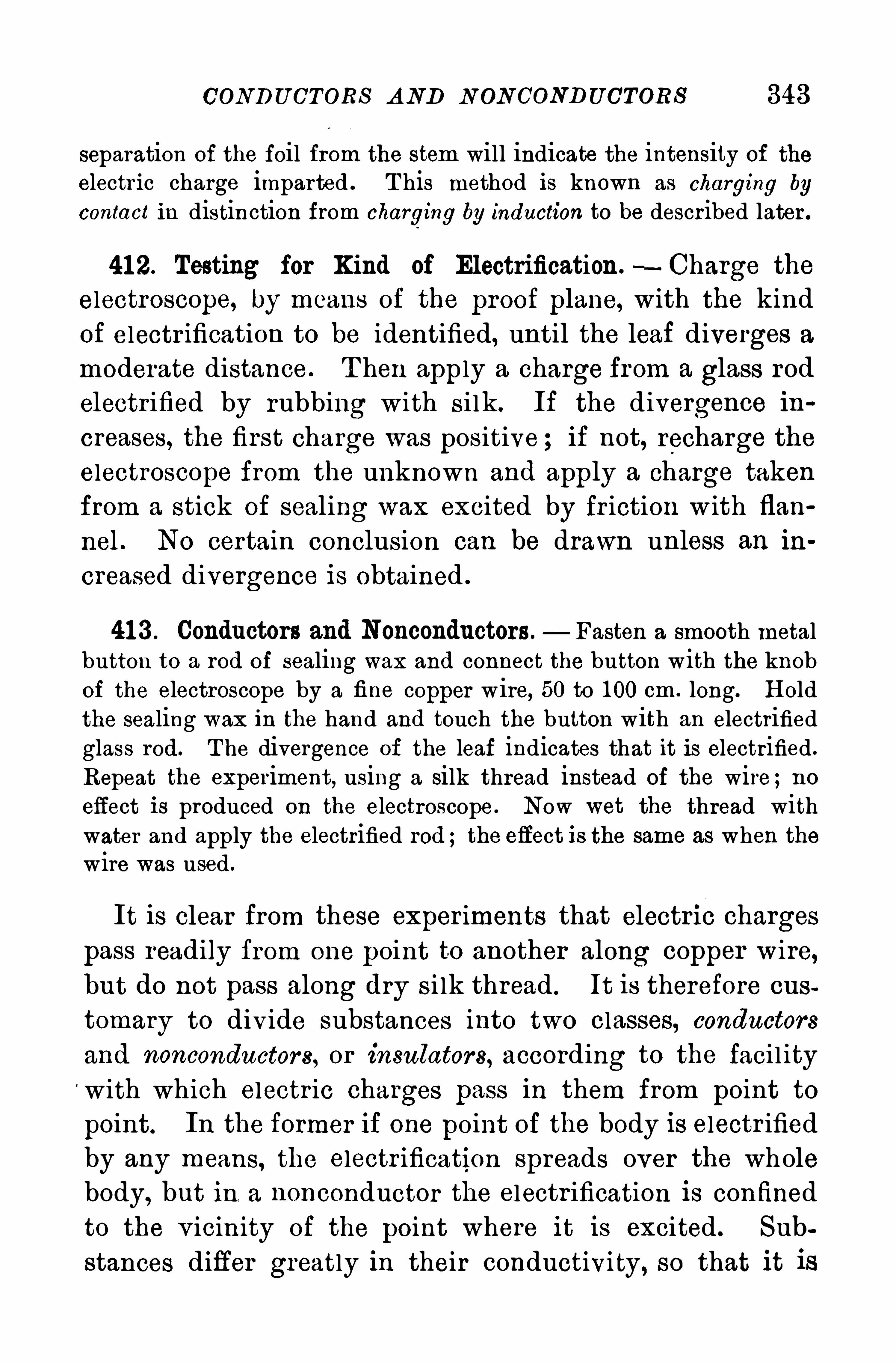
CONDU CTORS A ND N ON CONDUCTORS 343
separation of the foil from the stem will indicate the intensity of theelectr ic charge imparted . T his method is known as charging by
contact in distinction from charging by induction to be described later .
41 2. Testing for Kind of Electrification.—Charge the
electroscope, by means of the proof plane, with the kind
of electr ification to be identified, until the leaf diverges a
moderate distance . T hen apply a charge from a glass rod
electrified by rubbing with s i lk. If the divergence in
creases, the first charge was positive ; if not, recharge the
electroscope from the unknown and apply a charge taken
from a stick of sealing wax excited by fr iction w ith flan
nel. No certain conclusion can be drawn unless an in
creased divergence is obtained .
41 3 . Conductors and Nonconductors . Fasten a smooth metalbutton to a rod of sealing wax and connect the button with the knobof the electroscope by a fine copper wire, 50 to 1 00 cm . long. H oldthe sealing wax in the hand and touch the button with an electrifiedglass rod. T he divergence of the leaf indicates that it is electrified.
Repeat the experiment, using a silk thread instead of the wire ;noeffect is produced on the electroscope . Now wet the thread withwater and apply the electrified rod ; the effect is the same as when thewire was used .
It is clear from these exper iments that electr ic charges
pass readily from one point to another along copper wire,but do not pass along dry s i lk thread . It is therefore cus
tomary to div ide substances into two classes, conductors
and nonconductors, or insulators, according to the faci l ity
with which electr ic charges pass in them from point to
point. In the former if one point of the body is electr ifiedby any means, the electrification spreads over the wholebody, but in, a nonconductor the electr ification is confinedto the v icinity of the point where it is excited. Sub
stances differ greatly in their conductivi ty, so that it is
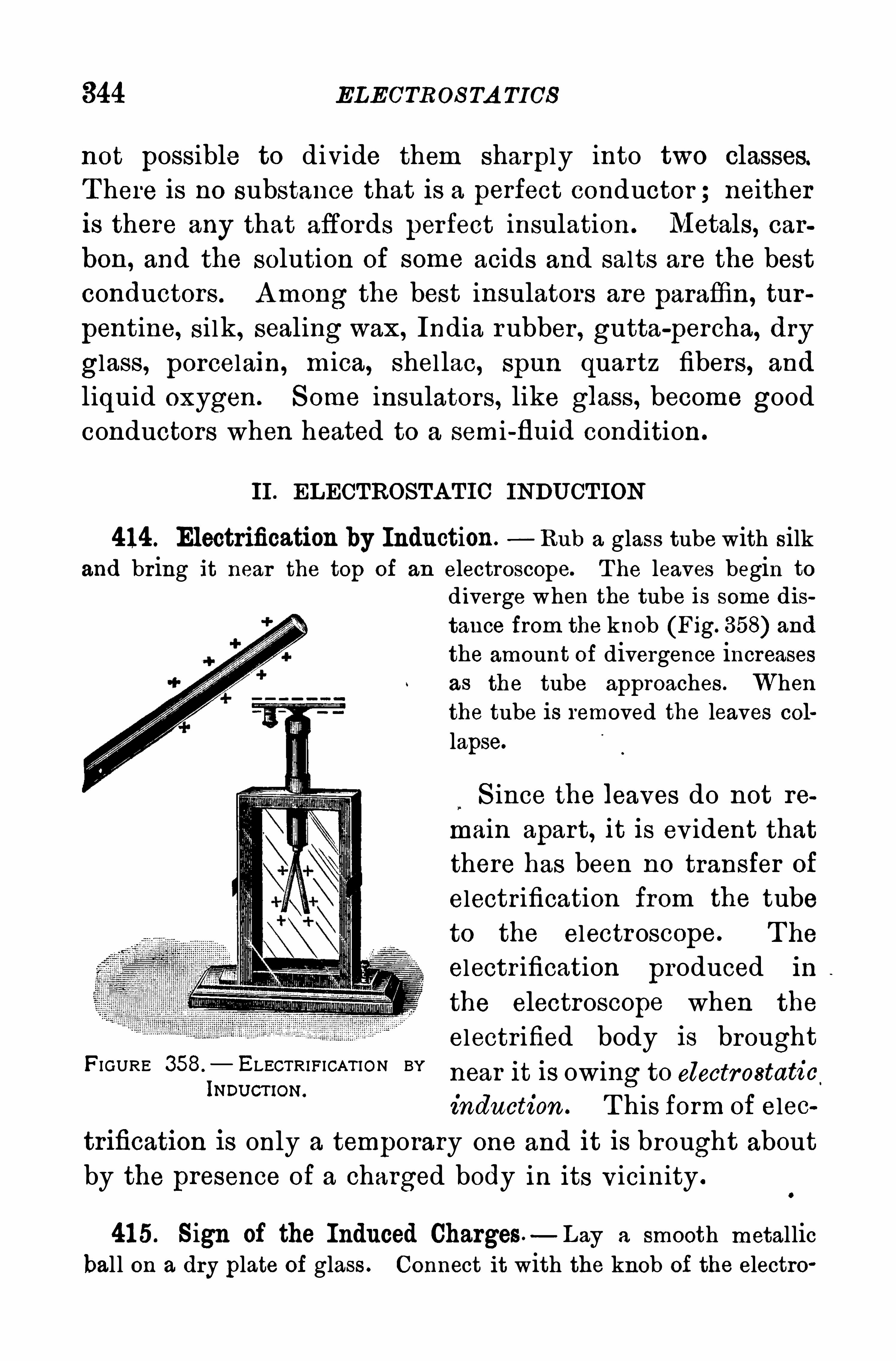
344 ELECTROS TA TICS
not possible to divide them sharply into two classes.T here is no substance that is a perfect conductor ; neitheris there any that affords perfect insulation . Metals, car
bon, and the solution of some acids and salts are the best
conductors . A mong the best insulators are paraffin, tur
pentine, silk, sealing wax , India rubber , gutta-percha, dry
glass, porcelain, mica, shellac, spun quartz fibers, and
liquid oxygen . S ome insulators, like glass, become good
conductors when heated to a semi-fluid condition.
II . ELECTROSTA TIC INDU CT ION
414. Electrification by Induction. Rub a glass tube with silkand bring it near the top of an electroscope. T he leaves begin to
diverge when the tube is some dis
tance from the knob (Fig. 358) andthe amount of divergence increasesas the tube approaches . Whenthe tube is removed the leaves col
lapse.
S ince the leaves do not re
main apart, it is ev ident that
there has been no transfer of
electrification from the tube
to the electroscope. T he
electr ification produced in
the electroscope when the
electrified body is brought
near it is owing to electrostatic
induction . T his form of elec
trification is only a temporary one and it is brought about
by the presence of a charged body in its v icinity .
FIGURE 358.
— ELECTRIFICAT ION BYINDU CT IoN.
41 5. Sign of the Induced Charges. Lay a smooth metallicball on a dry plate of glass . Connect it with the knob of the electro
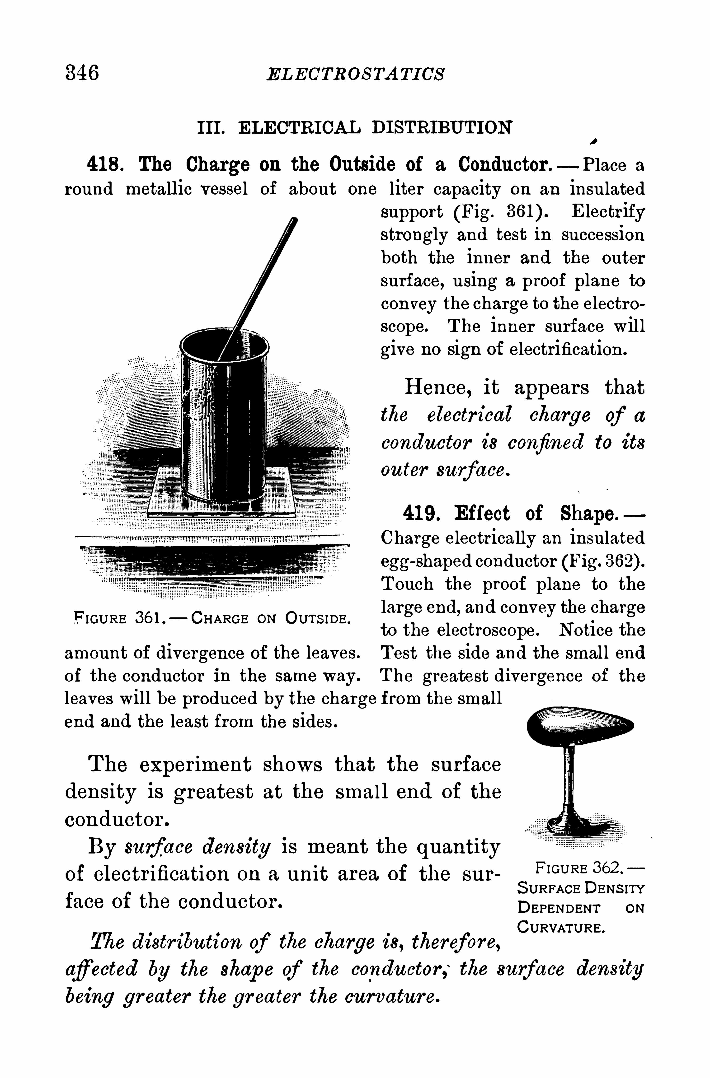
346 EL ECTROS TA TICS
III . ELECTRICAL DISTRIBUT IONI
418. The Charge on the Outside of a Conductor .—P lace a
round metallic vessel of about one liter capacity on an insulatedsupport (Fig. Electr ifystrongly and test in successionboth the inner and the outersurface, using a proof plane toconvey the charge to the electroscope. T he inner surface willgive no sign of electrification.
H ence, it appears thatthe electr ical charge of a
conductor is confined to its
outer surface.
419. Effect of Shape.
Charge electrically an insulatedegg
-shaped conductor (Fig.
T ouch the proof plane to the
large end, and convey the chargeto the electroscope. Notice the
amount of divergence of the leaves. T est the side and the small endof the conductor in the same way. T he greatest divergence of the
leaves will be produced by the charge from the smallend and the least from the sides .
F I GURE 36 1 .
—CHARGE ON OUTS I DE .
The exper iment shows that the surface
density is greatest at the smal l end of the
conductor .
By surface density is meant the quantity
of electr ification on a unit area of the surFIGURE 362
S URFACE DENS ITYface of the conductor . DEPENDENT ON
CURVATURE.
The distribution of the charge is, therefore,afiected by the shape of the conductor, the surface densitybeing greater the gr eater the curvature.
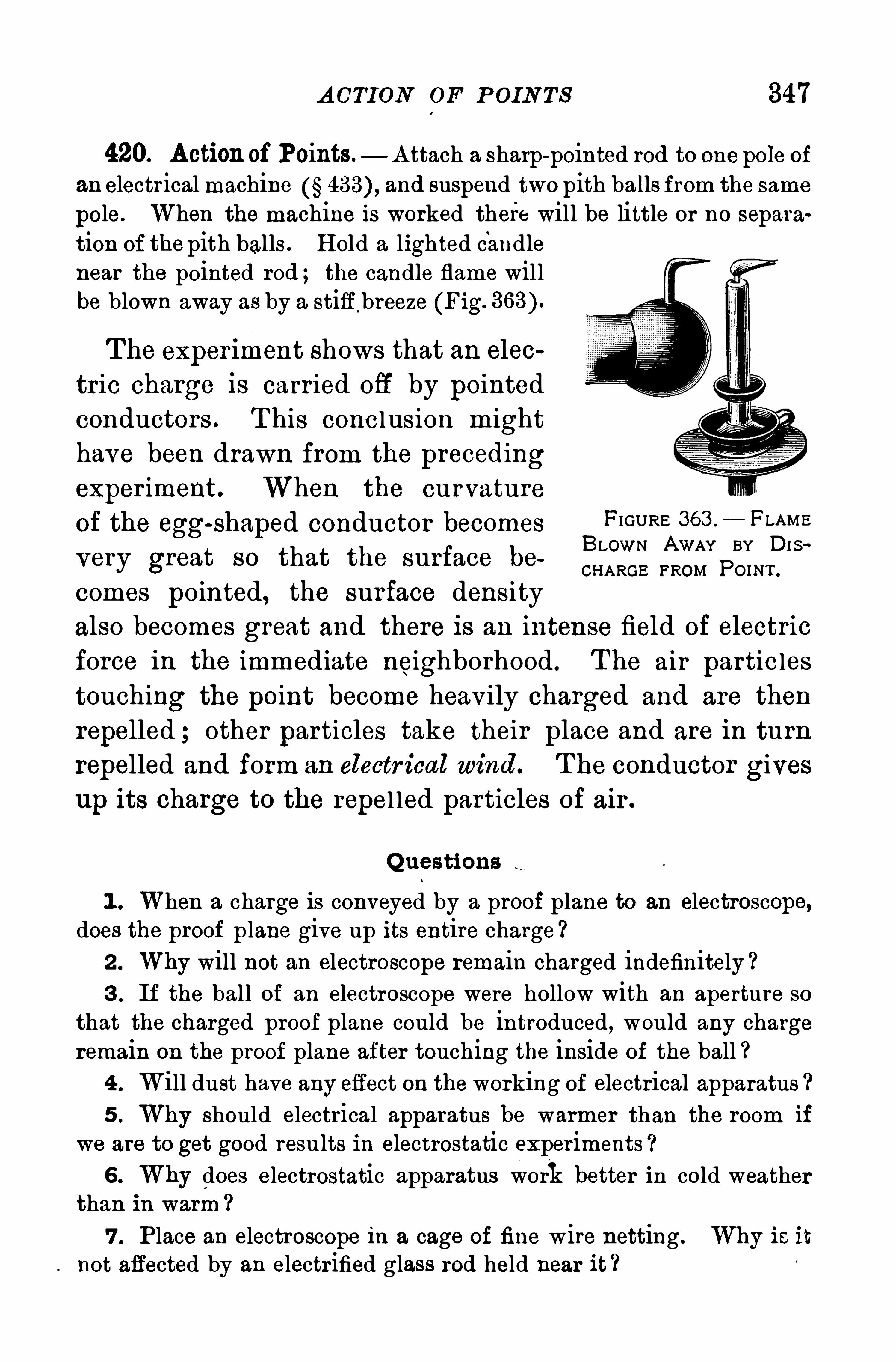
A CTION OF P OIN TS 347
420. Actionof Points. A ttach a sharp-pointed rod to one pole ofan electrical machine and suspend two pith balls from the same
pole. When the machine is worked there will be little or no separation of thepith balls . H old a lighted candlenear the pointed rod ; the candle flame willbe blown away as by a stiff breeze (Fig.
The experiment shows that an elec
tric charge is carr ied off by pointed
conductors . T his conc lusion might
have been drawn from the precedingexper iment. When the curvature
of the egg-shaped conductor becomes FIGURE 3611 — 1:LAME
BLOWN AWAY BY DISvery great so that the surface be CHARGE FROM pm ”.
comes pointed, the surface density
also becomes great and there is an intense field of electric
force in the immediate neighborhood . T he air particles
touching the point become heavily charged and are then
repelled ; other particles take their place and are in turn
repelled and form an electr ical wind. T he conductor gives
up its charge to the repel led particles of air .
Q uestions
1 . When a charge is conveyed by a proof plane to an electroscope,does the proof plane give up its entire charge ?2 . Why will not an electroscope remain charged indefinitely ?3 . If the ball of an electroscope were hollow with an aperture so
that the charged proof plane could be introduced , would any chargeremain on the proof plane after touching the inside of the ball ?4 . Will dust have any effect on the working of electrical apparatus5 . Why should electrical apparatus be warmer than the room if
we are to get good results in electrostatic experiments
6 . Why does electrostatic apparatus work better in cold weatherthan in warm7 . Place an electroscope in a cage of fine wire netting . Why is it
not affected by an electr ified glass rod held near it ?
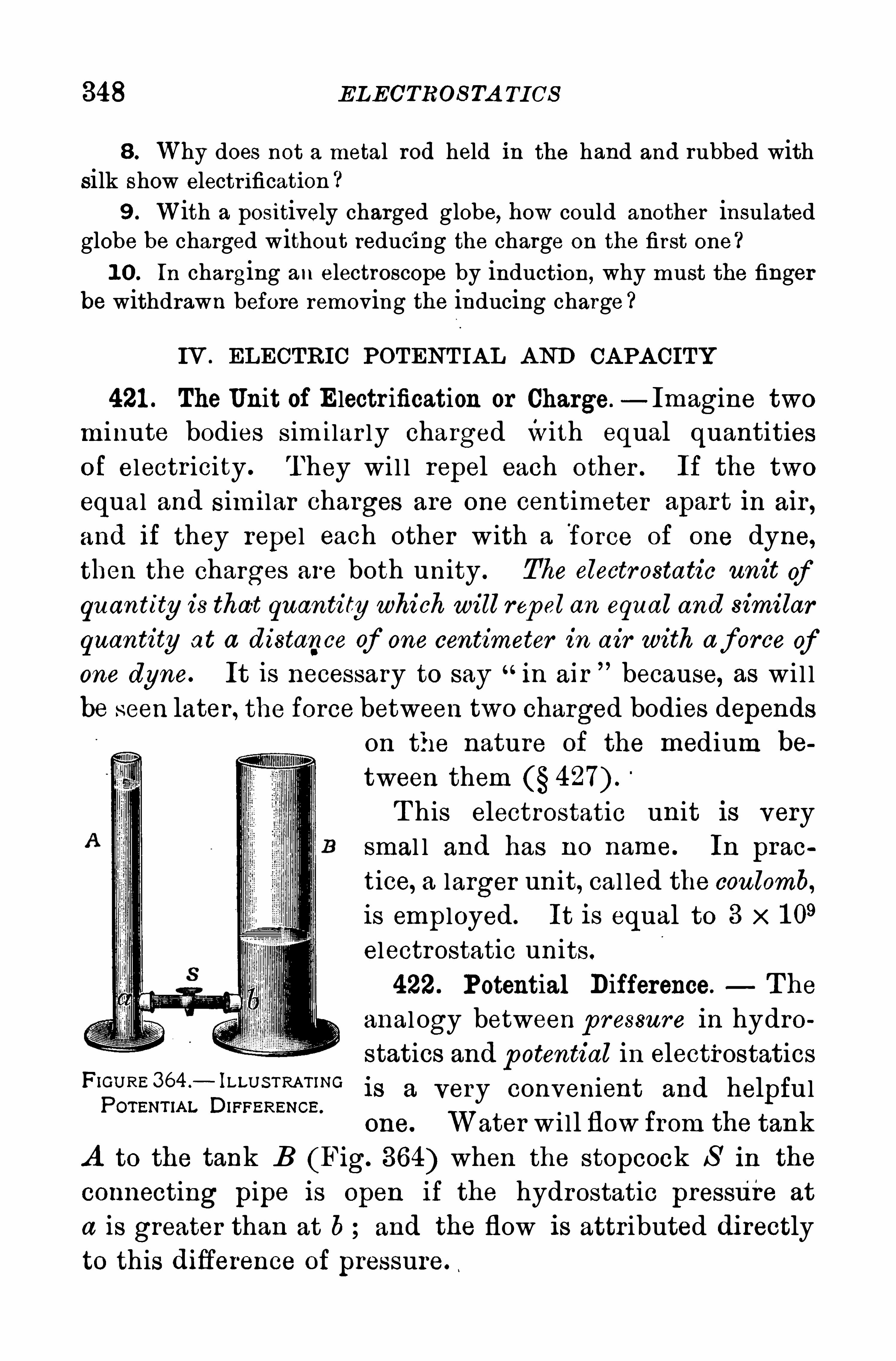
348 ELECTROS TA TI CS
8. Why does not a metal rod held in the hand and rubbed withsilk Show electrification ?
9 . With a positively charged globe, how could another insulatedglobe be charged without reducing the charge on the first one ?1 0 . In charging an electroscope by induction,
why must the fingerbe withdrawn before removing the inducing charge ?
IV . ELECTRIC POTENT IA L A ND CA PA CITY
421 . The Unit of Electr ification or Charge.—Imagine two
minute bodies s im ilar ly charged with equal quantitiesof electr icity . T hey wi l l repel each other . If the two
equal and s im ilar charges are one centimeter apar t in air ,
and if they repel each other with a force of one dyne,then the charges are both unity . The electr ostatic unit of
quantity is that quantity which will repel an equal and similar
quantity at a distance of one centimeter in air with af orce ofone dyne. It is necessary to say
“in air because, as wi l l
be seen later , the force between two charged bodies dependson the nature of the medium be
tween themT his electrostatic unit is very
smal l and has no name. In prao
tice, a larger unit, cal led the coulomb,is employed . It is equal to 3 x 1 0
9
electrostatic units.
422. Potential Difference. The
anal ogy between p ressure in hydro
statics and potential in electrostaticsFl
ghi irilL—
SIFTZS
RZiST
SNG is a very convenient and helpful
one. Water w i ll flow from the tank
A to the tank B (Fig. 364) when the stopcock S in the
connecting pipe is open if the hydrostatic pressure at
a is greater than at b and the flow is attributed di rectlyto this difierence of pressure.
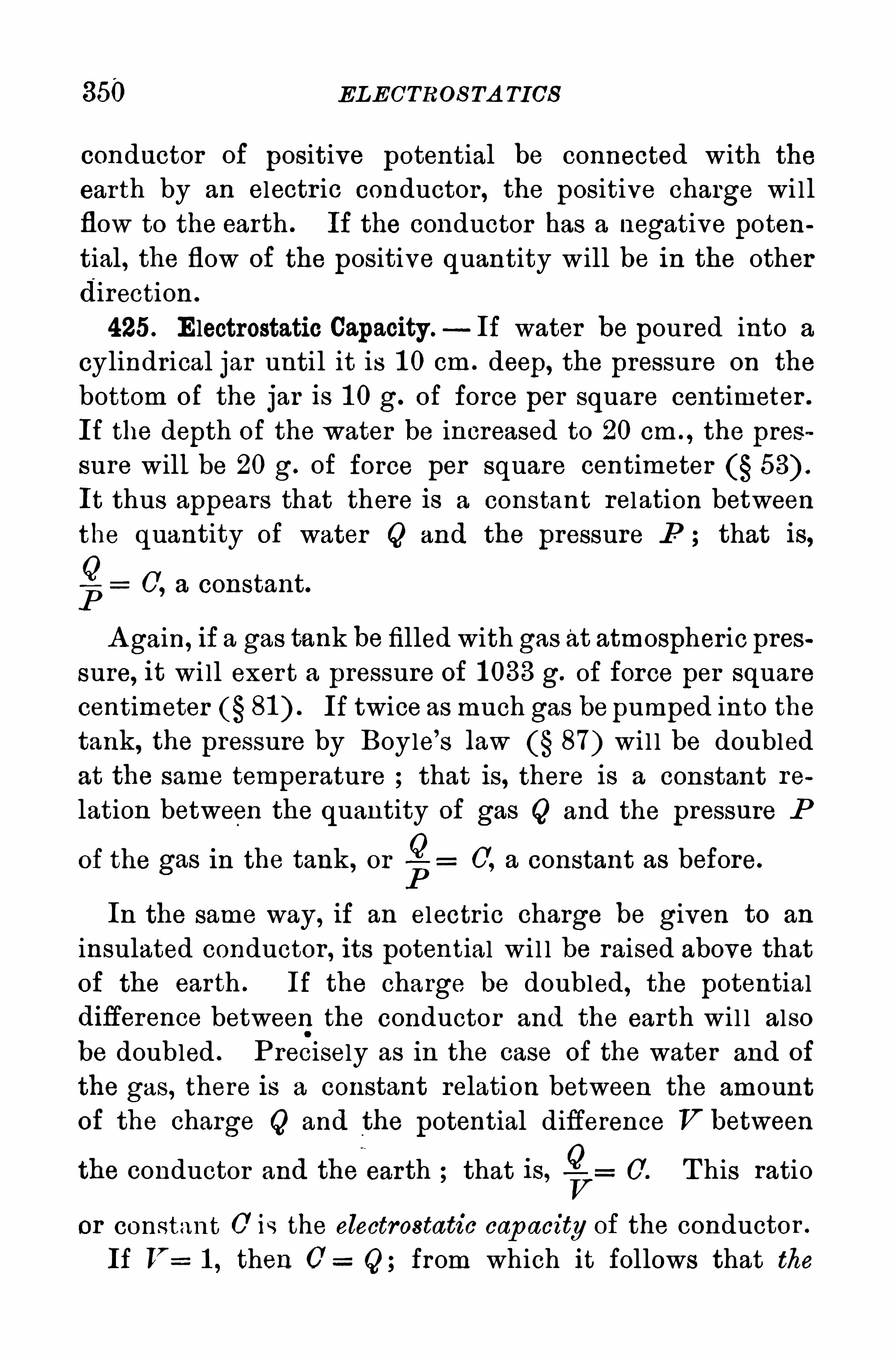
350 ELECTROS TA TICS
conductor of positive potential be connected with the
earth by an electr ic conductor , the positive charge wi l l
flow to the earth . If the conductor has a negative poten
tial, the flow of the positive quantity will be in the otherdirection .
425. Electrostatic Capacity —If water be poured into a
cylindrical jar until it is 1 0 cm . deep, the pressure on the
bottom of the jar is 1 0 g. of force per square centimeter .
If the depth of the water be increased to 20 cm . , the pres
sure will be 20 g. of force per square centimeter
It thus appears that there is a constant relation betweenthe quantity of water Q and the pressure P ; that is,
g 0, a constant.
A gain, if a gas tank be filled with gas at atmospheric pressure, it wi ll exer t a pressure of 1 033 g. of force per squarecentimeter If twice as much gas be pumped into thetank, the pressure by Boyle’
s law 87) wi l l be doubled
at the same temperature that is, there is a constant re
lation between the quantity of gas Q and the pressure P
Qof the gas in the tank , or C', a constant as before.
P
In the same way, if an electric charge be given to an
insulated conductor , its potential wi l l be raised above thatof the earth . If the charge be doubled , the potentialdifierence betweenthe conductor and the earth wi l l alsobe doubled . P recisely as in the case of the water and of
the gas, there is a constant relation between the amountof the charge Q and the potential difference V between
the conductor and the earth that is, 0 . T his ratio
or constant 0 is the electrostatic cap acity of the conductor .
If V 1 , then 0 Q; from which it follows that the
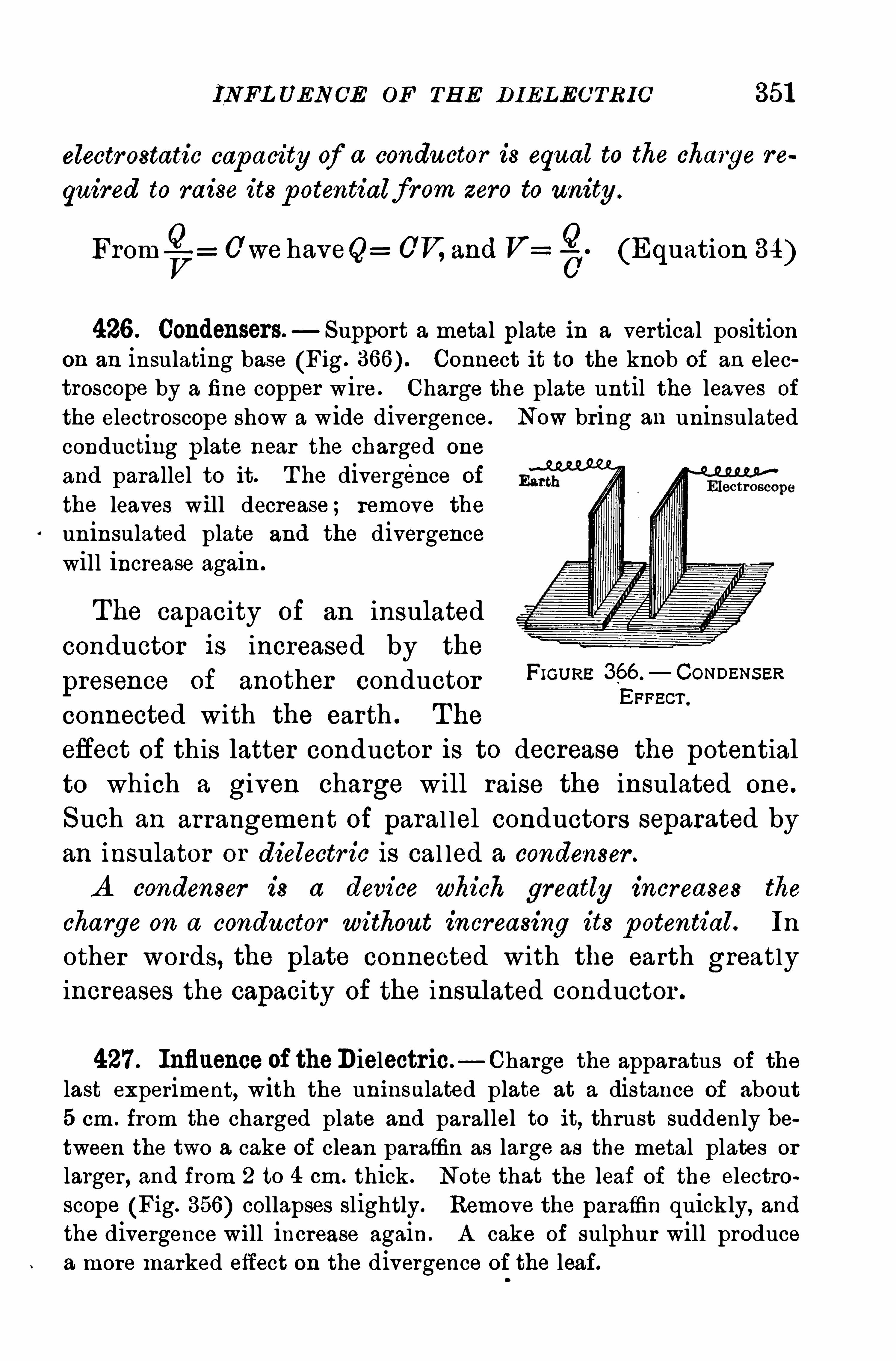
INFL UENOE OF TH E DIELECTRIC 351
electrostatic capacity of a conductor is equal to the charge re
quired to raise its p otentialf rom zero to unity .
From -Qf: 0 we haveQ: 0V, and V: (Equation 34)
426 . Condensers—Support a metal plate in a vertical positionon an insulating base (Fig. Connect it to the knob of an electroscope by a fine copper wire . Charge the plate until the leaves of
the electroscope Show a wide divergence. Now bring an uninsulatedconducting plate near the charged one
and parallel to it. T he divergence of
the leaves will decrease ; remove the
uninsulated plate and the divergencewill increase again .
The capacity of an insulated
conductor is increased by the
presence of another conductor F‘GURE“gagcf
omm sm
connected with the earth . The
efiect of this latter conductor is to decrease the potentialto which a given charge will raise the insulated one.
Such an arrangement of paral lel conductors separated byan insulator or dielectr ic is cal led a condenser .
A condenser is a device which greatly increases the
charge on a conductor without increasing its p otential. In
other words, the plate connected with the earth greatlyincreases the capacity of the insulated conductor .
427 . Influence of theDielectric— Charge the apparatus of the
last experiment, with the uninsulated plate at a distance of about5 cm . from the charged plate and parallel to it, thrust suddenly between the two a cake of clean paraffin as large as the metal plates or
larger , and from 2 to 4 cm. thick . Note that the leaf of the electroscope (Fig. 356) collapses slightly. Remove the paraffin quickly, andthe divergence will increase again . A cake of sulphur will producea more marked effect on the divergence of the leaf.
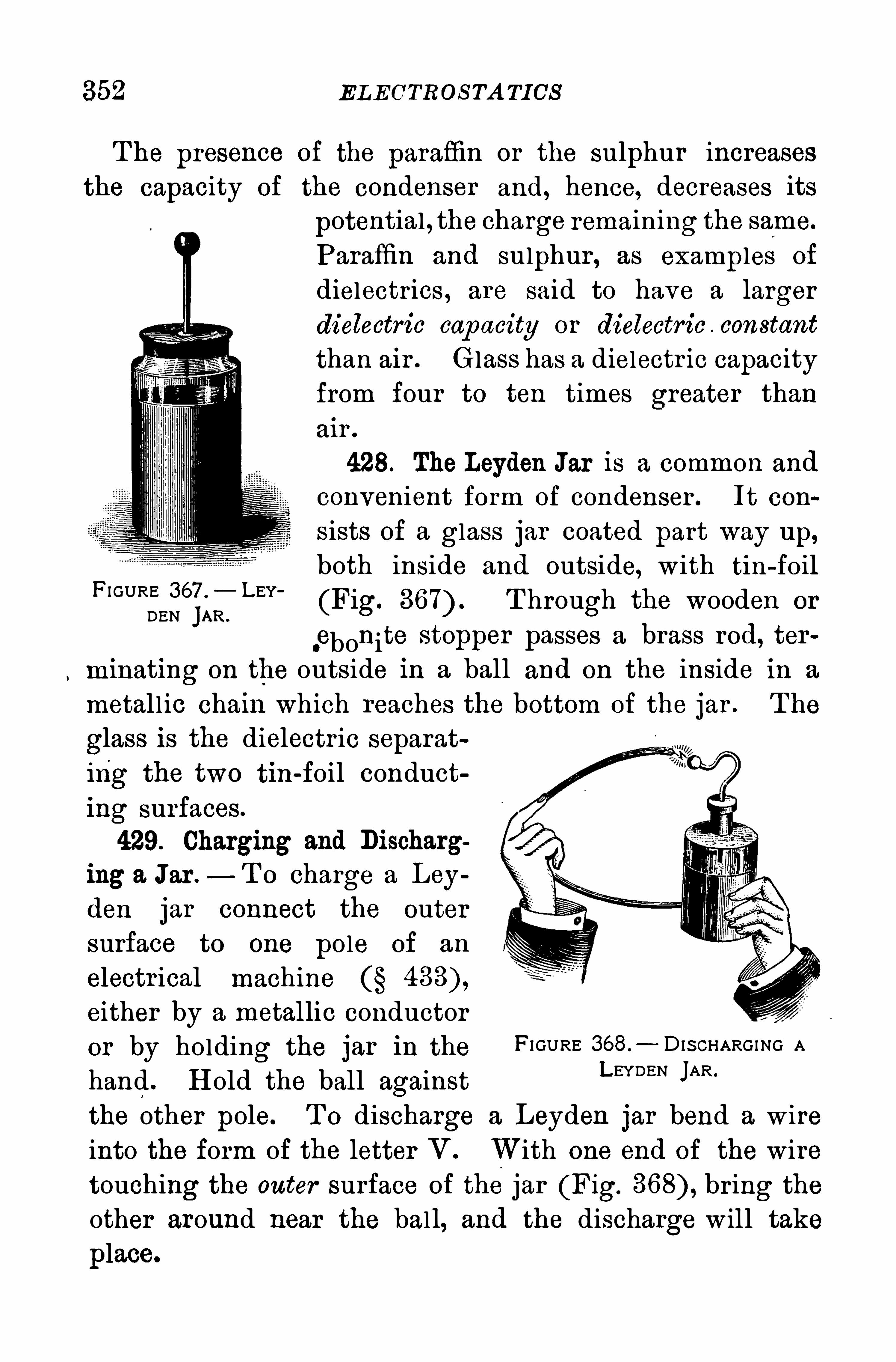
352 EL ECTROS TA TICS
T he presence of the paraflin or the sulphur increases
the capacity of the condenser and, hence, decreases its
potential , the charge remaining the same.
Paraffin and sulphur , as examples of
dielectrics , are said to have a larger
dielectric cap acity or dielectric constant
than air . Glass has a dielectr ic capacity
from four to ten times greater than
air .
428. The Leyden Jar is a common and
convenient form of condenser . It con
sists of a glass jar coated part way up,
both inside and outside, with tin-foilFI GURE 367 '
_ LEY '
(Fig. T hrough the wooden orDEN JAR .
.ebonite stopper passes a brass rod, ter
minating on the outside in a ball and on the inside in a
metall ic chain which reaches the bottom of the jar . T he
glass is the dielectr ic separat
ing the two tin-foil conduct
ing surfaces.
429. Charging and Discharg
ing a Jar .— T o charge a Ley
den jar connect the outer
surface to one pole of an
electr ical machineeither by a metallic conductor
or by holding the jar in the FI GURE 368.
— DIS CHARGING A
hand . H old the ball againstLEYDEN JAR
the other pole. T o discharge a Leyden jar bend a wire
into the form of the letter V . With one end of the wiretouching the outer surface of the jar (Fig. br ing theother around near the ball, and the discharge will take
place.
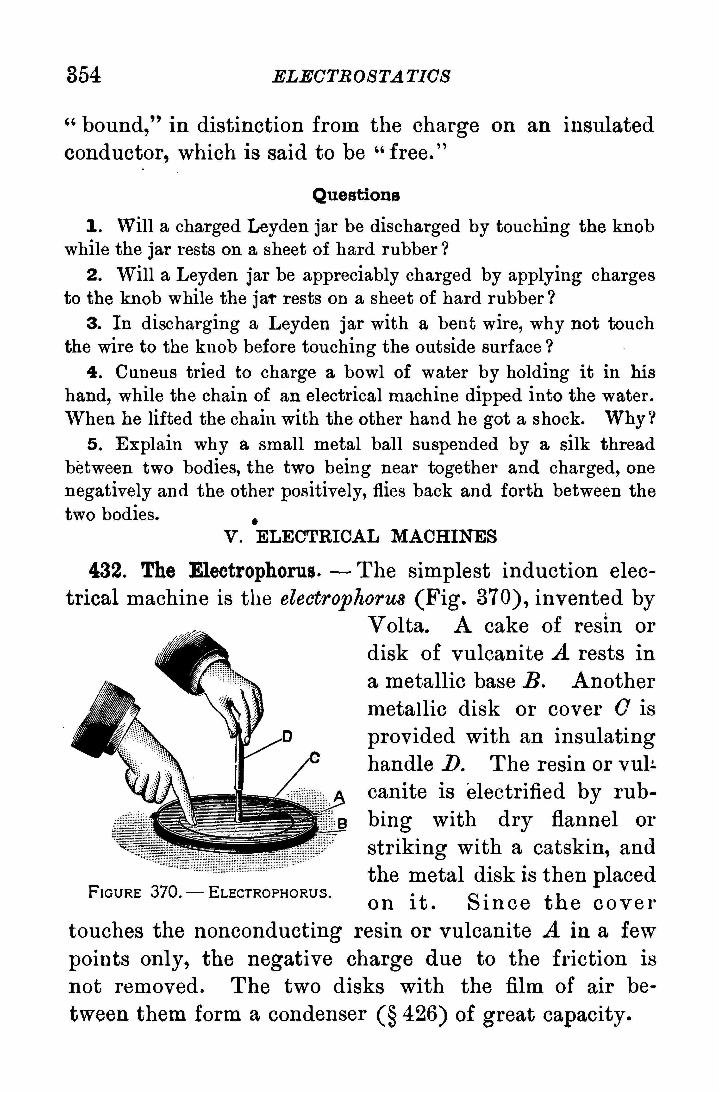
354 ELECTROS TA TICS
bound, in distinction from the charge on an insulated
conductor, which is said to be free.
”
Questions
1 . Will a charged Leyden jar be discharged by touching the knobwhile the jar rests on a sheet of hard rubber ?2 . Will a Leyden jar be appreciably charged by applying charges
to the knob while the jar rests on a sheet of hard rubber ?3 . In discharging a Leyden jar with a bent wire, why not touch
the wire to the knob before touching the outside surface4 . Cuneus tried to charge a bowl of water by holding it in hi s
hand,while the chain of an electrical machine dipped into the water .
When he lifted the chain with the other hand he got a shock. Why ?5 . Explain why a small metal ball suspended by a silk thread
between two bodies, the two being near together and charged, onenegatively and the other positively, flies back and forth between thetwo bodies.
V . ELECTRICA L MA CH INES
432. The Electrophorus.—T he simplest induction elec
trical machine is the electrophorus (Fig. invented by
Volta. A cake of resin or
disk of vulcanite A rests in
a metallic base B . A nothermetallic disk or cover 0 is
prov ided with an insulatinghandle D . T he resin or vul:
canite is electr ified by rub
bing with dry flannel or
str iking with a catskin, and
the metal disk is then placed
on it . S in ce th e c o v e r
touches the nonconducting resin or vulcanite A in a few
points only, the negative charge due to the friction is
not removed . The two disks with the film of air be
tween them form a condenser 426) of great capacity .
FIGURE 370 . ELECTROPHORUS .
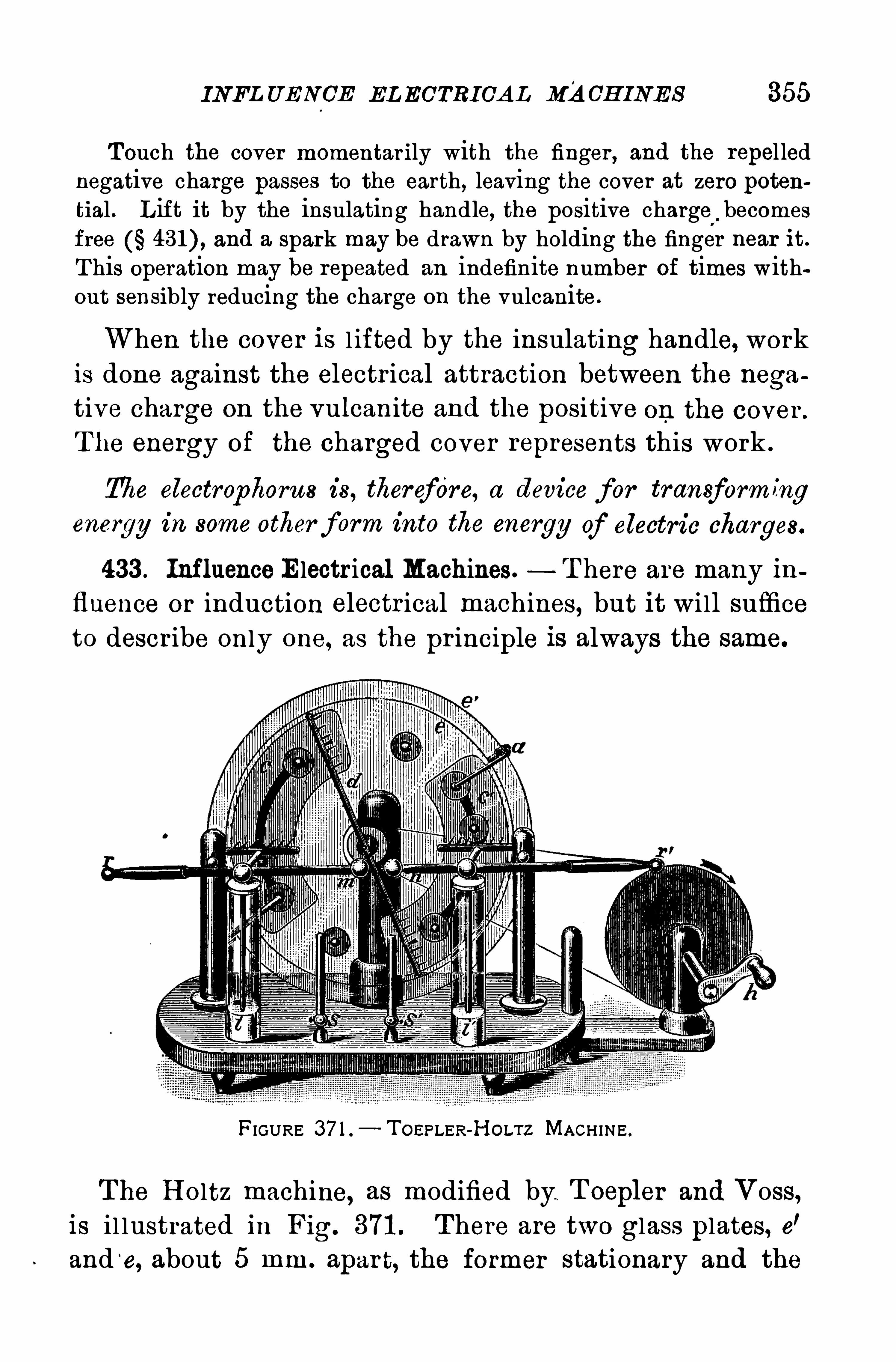
INFL UENCE EL ECTRICA L MACH INE S 355
Touch the cover momentar ily with the finger , and the repellednegative charge passes to the earth, leaving the cover at zero potential . L ift it by the insulating handle, the positive charge
”,becomes
free and a spark may be drawn by holding the finger near it .
T his operation may be repeated an indefinite number of times without sensibly reducing the charge on the vulcanite.
When the cover is l ifted by the insulating handle, workis done against the electr ical attraction between the nega
tive charge on the vulcanite and the positive on the cover .
T he energy of the charged cover represents this work .
The electrophorus is, therefore, a device for transform ingenergy in some other form into the energy of electric charges.
433 . Influence Electr ical Machines. T here are many influence or induction electr ical machines, but it wi ll sufficeto describe only one, as the pr inciple is always the same.
FIGURE 37 1 . T OEPLER- l‘lOLTZ MACHINE .
T he H oltz machine, as modified by. T oepler and Voss,
is il lustrated in Fig. 371 . There are two glass plates, e'
and ‘
e, about 5 mm. apar t, the former stationary and the
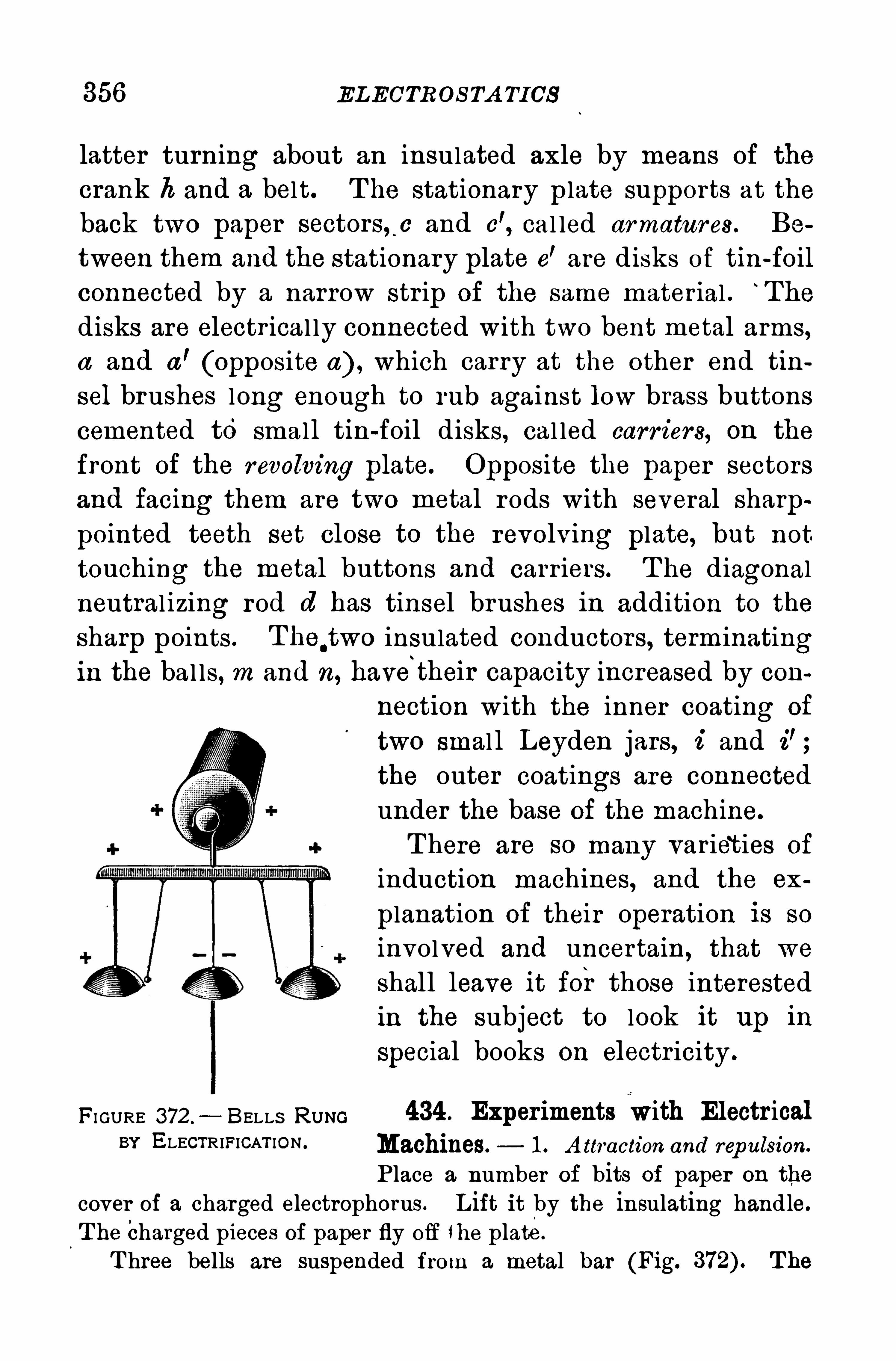
356 ELECTRO S TA TICS
latter turning about an insulated axle by means of the
crank h and a belt. T he stationary p late supports at the
back two paper sectors, .
c and c', cal led armatures . Be
tween them and the stationary plate e’are disks of tin -foil
connected by a narrow str ip of the same mater ial .“
The
disks are electr ical ly connected with two bent metal arms,a and a
’(opposite a) , which carry at the other end tin
sel brushes long enough to rub against low brass buttons
cemented to smal l tin-foil disks , cal led carr iers, on the
front of the revolving plate. Opposite the paper sectors
and facing them are two metal rods with several sharppointed teeth set close to the revolving plate, but not
touching the metal buttons and carr iers . T he diagonalneutral izing rod d has tinsel brushes in addition to the
sharp points . T he.two insulated conductors, term inating
in the bal ls, m and n, have‘
their capacity increased by con
nection with the inner coating of
two smal l Leyden jars, i and i’;
the outer coatings are connected
under the base of the machine.
T here are so many variet ies of
induction machines, and the ex
planation of their operation is so
involved and uncertain , that we
shall leave it for those interestedin the subject to look it up in
Special books on electr icity .
FI GURE 372 ,
—BELLS Rum 434 . Experiments with Electr icalBY ELECTRIFICAT ION Machines. 1 . A ttraction and rep ulsion.
P lace a number of bits of paper on the
cover of a charged electrophorus . L ift it by the insulating hand le.
T he Charged pieces of paper fly off the plate .
T hree bells are suspended from a metal bar (Fig. T he
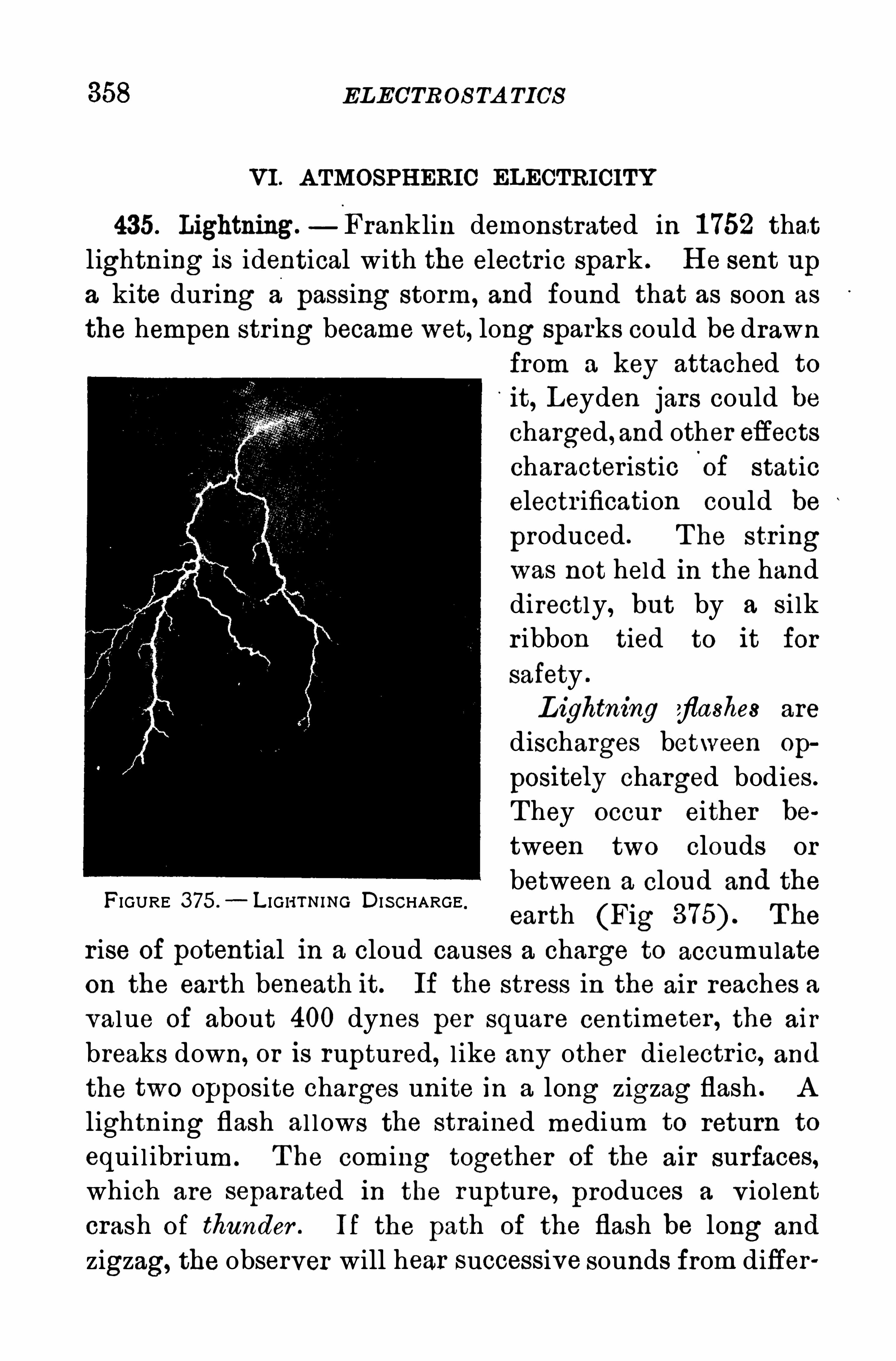
ELECTROS TA TICS
VI . A TMOSPH ERIC ELECTRICITY
435. Lightning.— Franklin demonstrated in 1 752 that
lightning is identical with the electric spark . H e sent up
a kite dur ing a passing storm, and found that as soon as
the hempen str ing became wet, long sparks could be drawn
from a key attached to
it, Leyden jars could be
charged, and other efiects
characteristic'
of static
electr ification could be
produced . T he str ingwas not held in the handdirectly, but by a si lk
r ibbon tied to it for
safety .
L ightning flashes are
discharges between Op
positely charged bodies .
T hey occur either be
tween two clouds or
FIGURE 375 —L IG I-ITNING DIS CHARGEbetween a Cloud and the
earth (Fig T he
r ise of potential in a cloud causes a charge to accumulateon the earth beneath it. If the stress in the air reaches avalue of about 400 dynes per square centimeter , the air
breaks down, or is ruptured, l ike any other dielectr ic, and
the two opposite charges unite in a long zigzag flash . A
lightning flash al lows the strained medium to return to
equi l ibr ium . T he coming together of the air surfaces,which are separated in the rupture, produces a v iolent
crash of thunder . If the path of the flash be long and
zigzag, the observer will hear successive sounds from differ
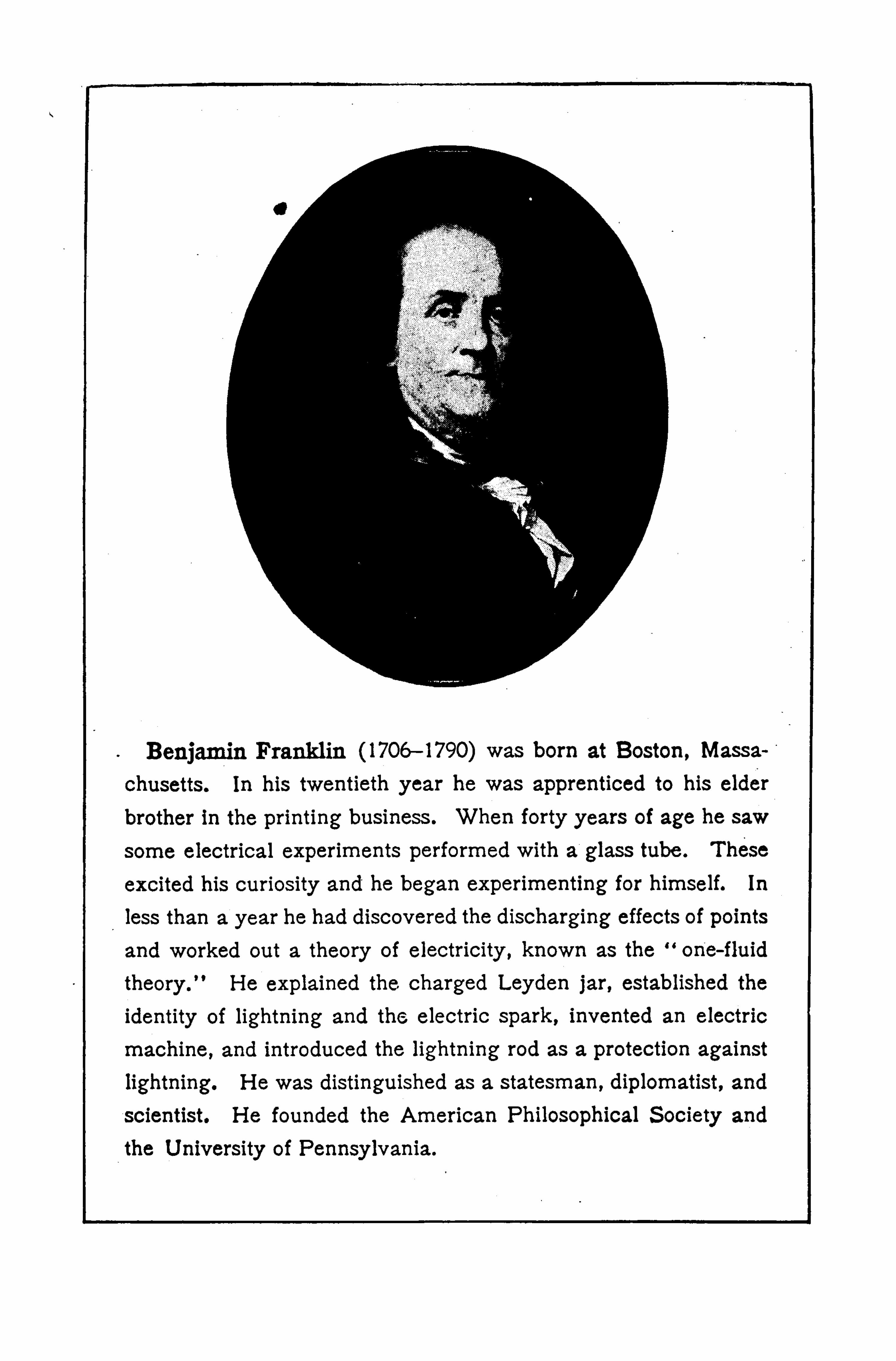

360 ELECTROS TA TICS
be connected with the main conductor . It is better"
to
have two or three descending rods than one, and all the
points and rods should be connected together as a network .
T he protection afforded by lightning rods, proper ly
erected, is abundantly proven by the statistics of mutual
fire insurance companies for buildings in the country .
437 . Oscillatory Discharge. When a Leyden jar is highlycharged, the potential difierence between its coatings increases untilthe dielectric between the discharge terminals suddenly breaks downand a spark passes. T his discharge usually consists of several oscillations or to-and-fro discharges, like the vibrations of an elastic systemor the surges of a mass of water after sudden release from pressure.
Imagine a tank with a partition across the middle and filled on one
side with water . If a small hole be made in the partition near ‘the
bottom, the water will slowly reach the same level on both sides without agitation ; but if the partition he suddenly removed, the firstviolent subsidencewill be succeeded by a return surge, and the to-and
fro motion of the water will continue with decreasing violence untilthe energy is all expended .
A series of similar surges occurs when a condenser is suddenly discharged by the breaking down o f the dielectric . T he oscillatory character of such electric discharges was discovered by Joseph H enry in1842. Its importance has been recognized only in recent times. S imilar electric oscillations probably take place in some lightning flashes .
438. The Aurora. T he aurora is due to silent dischargesin the upper regions of the atmosphere. Within the arctic
circle it occurs almost nightly, and sometimes with in
descr ibable splendor . The illumination of the aurora is
due to positive discharges passing from the higher regions
of the atmosphere to the earth . In our latitude these
silent streamers in the atmosphere are infrequent . When
they do occur they are accompanied by great disturbances
of the earth’s magnetism and by earth currents . Such
magnetic disturbances sometimes occur at the same time
in widely separated portions of the earth .
CH A PTER XII
ELECTRIC CURRENTS
I . VOLTA IC CELLS
439. An Electric Current.—T he discharge of a condenser
through a wire produces in and around the wire a state
called an electric current. If by any arrangement elec
tricity could be supplied to the condenser as .fast as it is
conveyed away through the wire, a continuous current
woul d be produced . A ny arrangement by which the ends
of a conducting wire are kept at different potentials wi ll
insure the flow of a continuous current through it.
It is analogous to the flow of heat through a metal rod
if one end is kept at.
a higher temperature than the other ,the heat flowing from the hotter to the colder end. So also
a stream of water flows through a section of pipe if the
pressure at one end is maintained higher than at the other .
It is customary to consider the electr ic current as flowingfrom positive to negative, that is, from higher potentialto lower .
One of the simplest means of maintaining a potentialdifference between the terminals of a conductor is the
pr imary or voltaic cell .
440. TheVoltaic Cell . Support a heavy strip of zinc and one
of sheet copper (Fig. 377) in dilute sulphuric acid (one part acid totwenty of water) . A fter the zinc has been in the acid a short time,it should be amalgamated by rubbing it with mercury. T here will beno apparent change when the plates are replaced in the acid, until
36 1
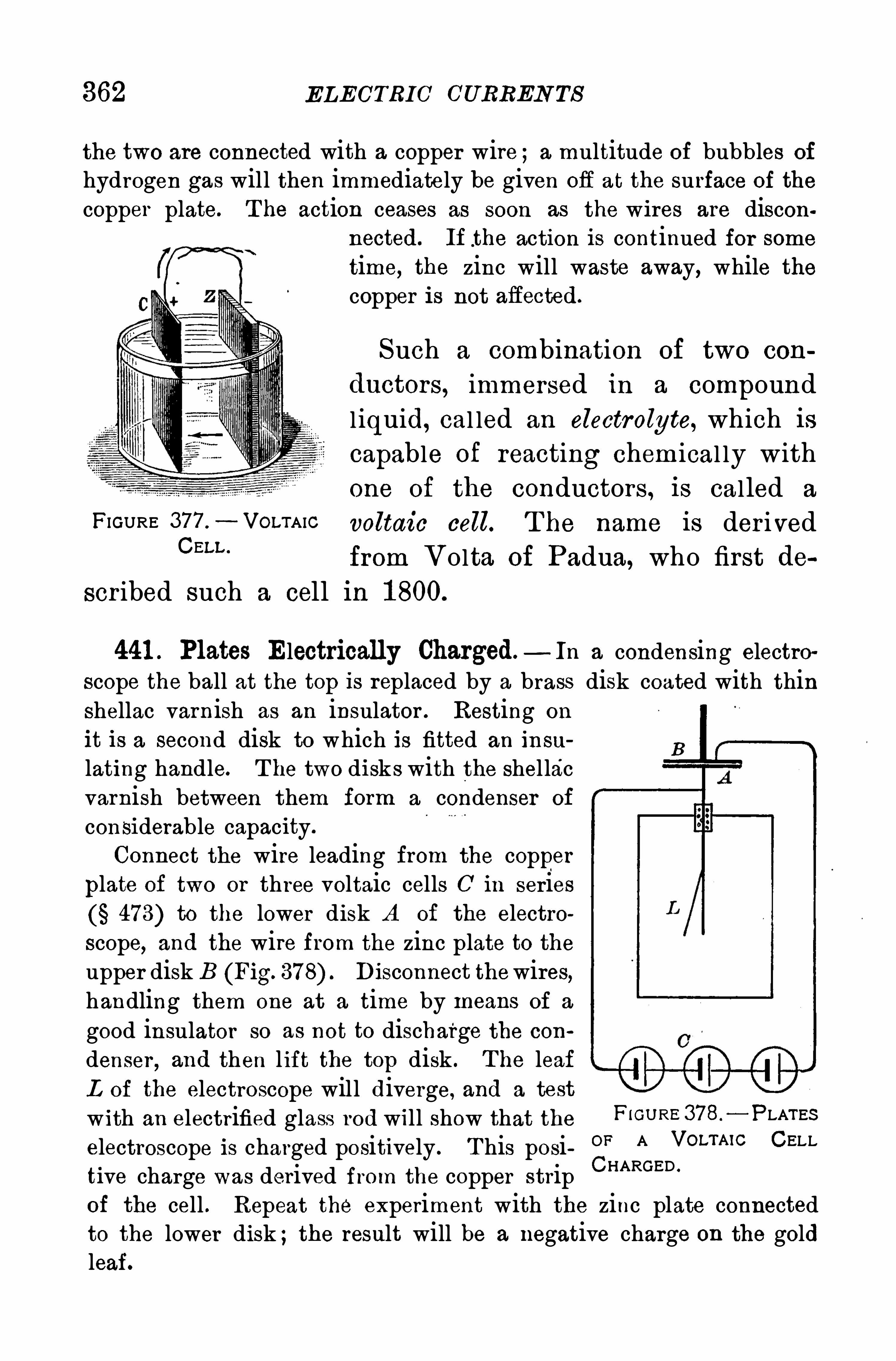
362 ELECTRI C CURREN TS
the two are connected with a copper wire ;a multitude of bubbles of
hydrogen gas will then immediately be given off at the surface of the
copper plate. T he action ceases as soon as the wires are disconnected. If .the action is continued for sometime, the zinc will waste away, while thecopper is not afiected.
Such a combination of two con
ductors, immersed in a compound
liquid, cal led an electrolyte, which iscapable of reacting chemical ly with
one of the conductors, is called a
FIGURE 377 .
— VOLTAIC voltaic cell. T he name is der ivedcm “
from Volta of Padua, who first de
scr ibed such a cell in 1 800.
441 . Plates Electrically Charged— In a condensing electro
scope the ball at the top is replaced by a brass disk coated with thinshellac varnish as an insulator . Resting on
it is a second disk to which is fitted an insu
lating handle. T he two disks with the shel lacvarnish between them form a condenser of
considerable capacity.
Connect the wire leading from the copper
plate of two or three voltaic cells 0 in series473) to the lower disk A of the electro
scope, and the wire from the zinc plate to theupper disk B (Fig. Disconnect thewires,handling them one at a time by means of a
good insulator so as not to discharge the con
denser , and then l ift the top disk . T he leafL of the electroscope will diverge, and a test
with an electrified glass rod will show that the P 10 0“3783—PLATESelectroscope is charged positively . T his posi OF A VOLTMC CELL
tive charge was derived from the copper strip CHARGED ’
of the cell . Repeat the experiment with the zinc plate connectedto the lower disk ;the result will be a negative charge on the goldleaf.
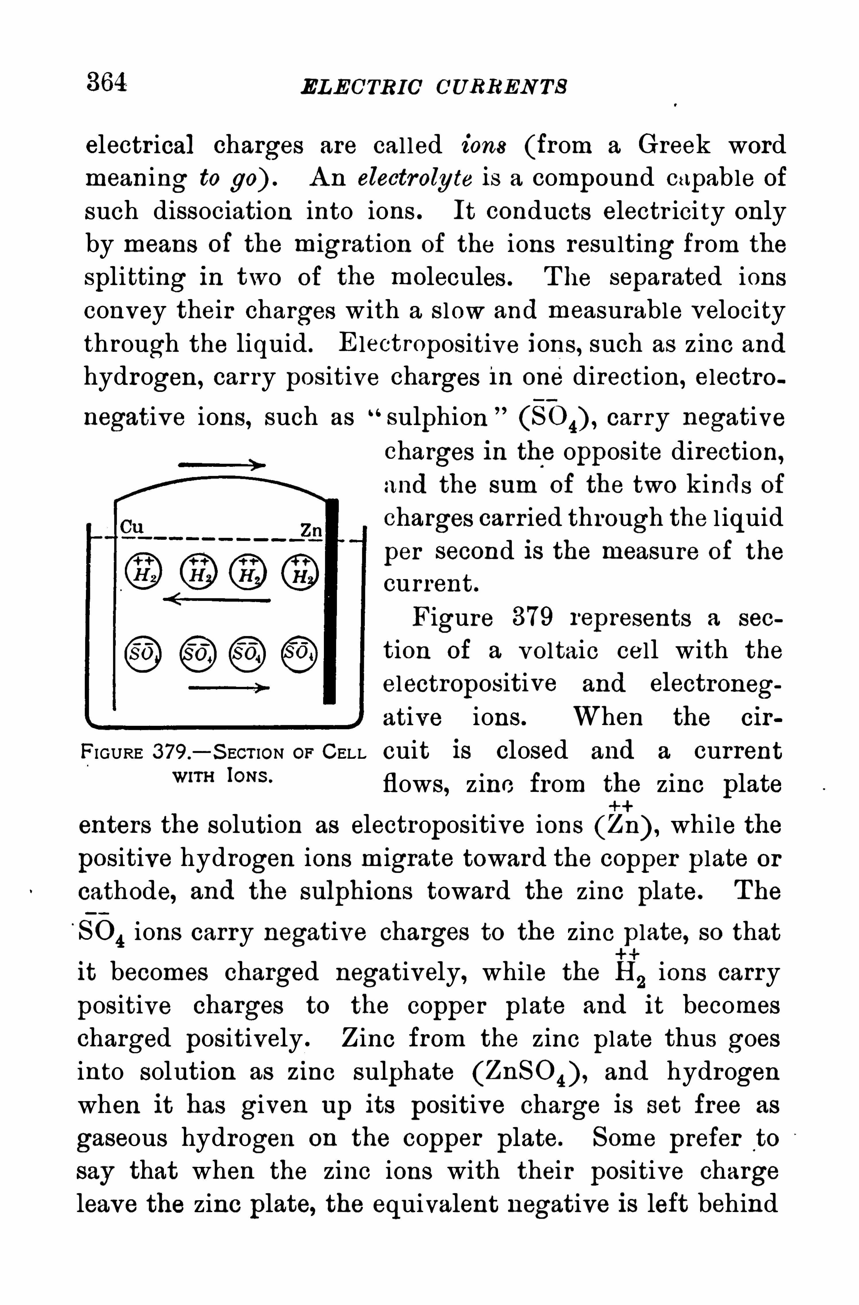
ELECTRIC C'URREN TS
electrical charges are cal led ions (from a Greek wordmeaning to go) . A n electrolyte is a compound capable of
such dissociation into ions . It conducts electr icity onlyby means of the migration of the ions resulting from the
splitting in two of the molecules . T he separated ionsconvey their charges w ith a s low and measurable velocitythrough the liquid . E lectropositive ions, such as z inc and
hydrogen, car ry positive charges 1 11 one direction, electro
negative ions, such as“sulphion
”
(S O 4) , car ry negativecharges in the opposite direction,and the sum of the two kinds of
charges carried through the l iquid
per second is the measure of the
current.
Figure 379 represents a sec
tion of a voltaic cell with the
electropositive and electroneg
ative ions. When the cir
FIGURE 3 79.
—S ECT ION OF CELL cuit is closed and a currentWIT“IONS “ flows, zinc from the zinc plate
enters the solution as electropositive ions (Zn) , while the
positive hydrogen ions migrate toward the copper plate or
cathode, and the sulphions toward the zinc plate. T he
SO4ions carry negative charges to the zinc plate, so that
it becomes charged negatively, while the If;ions carry
positive charges to the Copper plate and it becomescharged positively . Z inc from the zinc plate thus goesinto solution as zw o sulphate (ZnSO 4 ) , and hydrogen
when it has given up its positive charge is set free as
gaseous hydrogen on the Copper plate. Some prefer to
say that when the zinc ions with their positive chargeleave the zinc plate, the equivalent negative is left behind
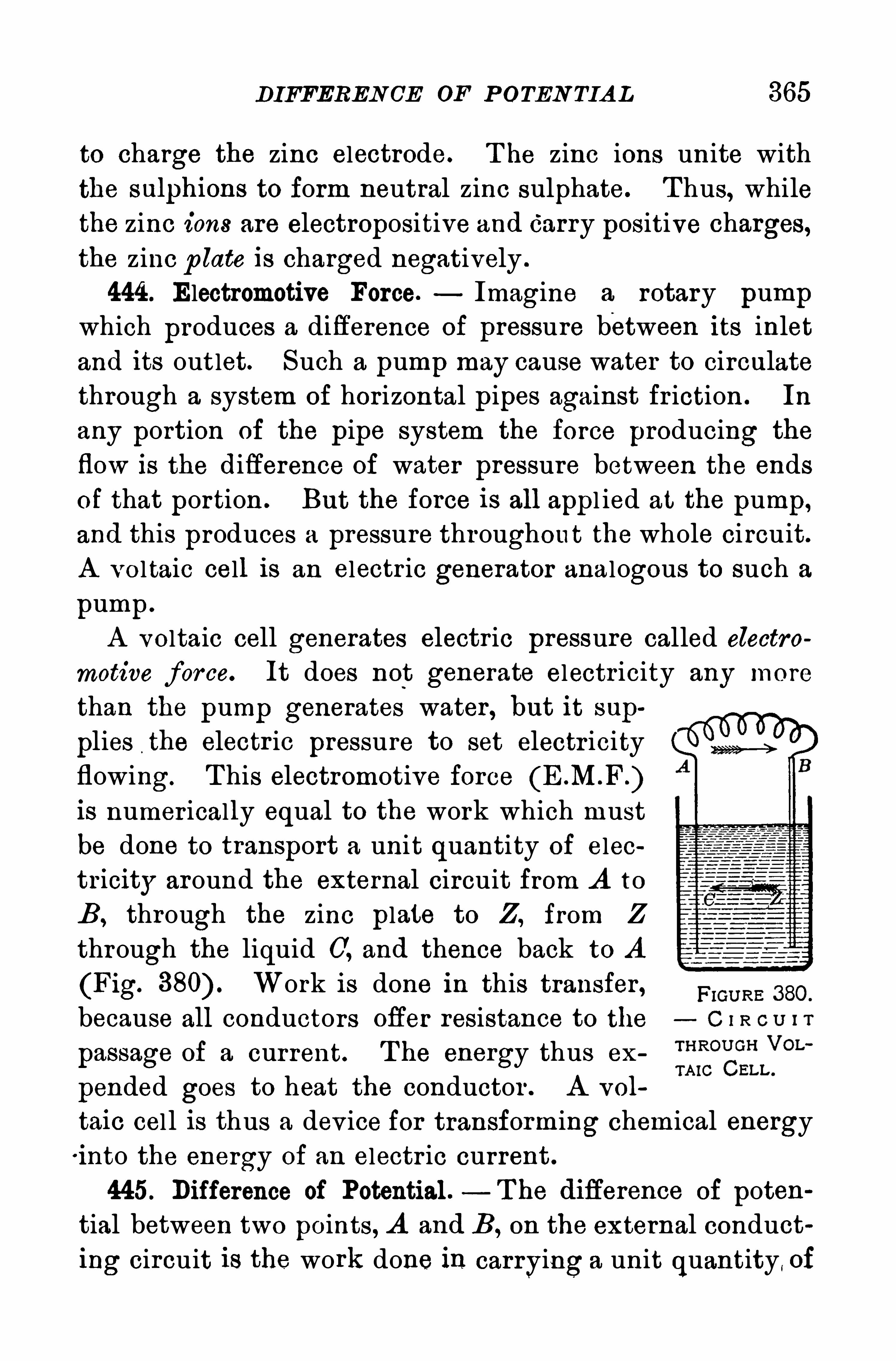
DIFFEREN CE OE P OTEN TIA L 365
to charge the zinc electrode. T he zinc ions unite with
the sulphions to form neutral zinc sulphate. T hus, while
the zinc ions are electropositive and Carry positive charges,the zinc p late is charged negatively .
444 . Electromotive Force. Imagine a rotary pumpwhich produces a difference of pressure between its inlet
and its outlet. Such a pump may cause water to circulate
through a system of horizontal pipes against fr iction . In
any portion of the pipe system the force producing the
flow is the difference of water pressure between the ends
of that portion . But the force is all appl ied at the pump,and this produces a pressure throughout the whole ci rcuit.
A vo ltaic cell is an electr ic generator analogous to such a
pump .
A voltaic cell generates electr ic pressure called electro
motive for ce. It does not generate electricity any more
than the pump generates water , but it sup
plies the electr ic pressure to set electr icityflowing. T his electromotive forceis numer ically equal to the work which must
be done to transport a unit quantity of electricity around the external circuit from A to
B , through the zinc plate to Z , from Z
through the liquid C, and thence back to A
(Fig. Work is done in this transfer ,because all conductors offer resistance to the
passage of a current. T he energy thus ex
pended goes to heat the conductor . A vol
taic cel l is thus a dev ice for transforming chemical energyi nto the energy of an electr ic current .
445. Difference of Potential . — T he difierence of potential between two points, A and B , on the external conducting circuit is the work done in carrying a unit quantity , of
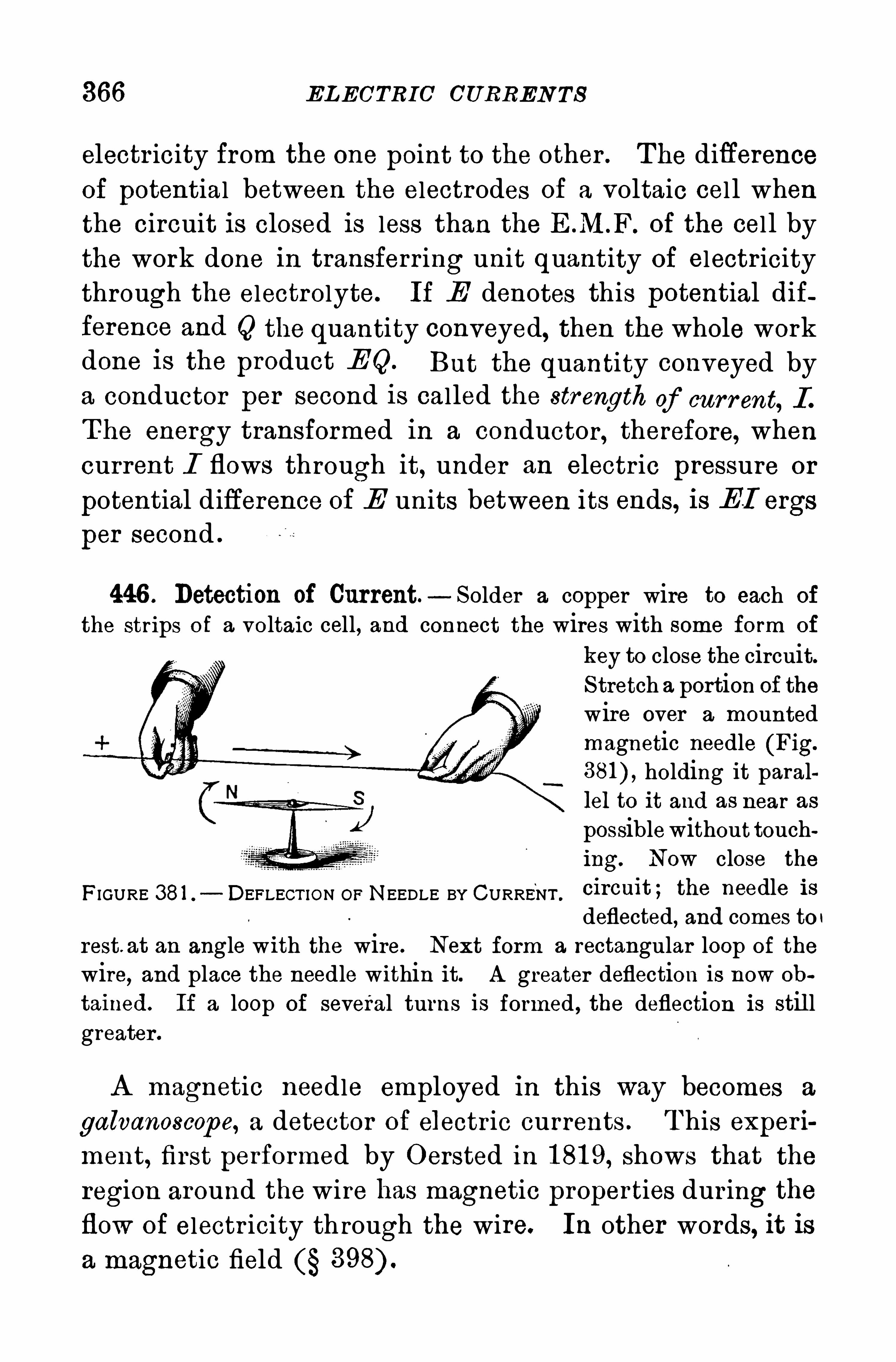
366 ELECTRIC CURREN TS
electr icity from the one point to the other . The differenceof potential between the electrodes of a voltaic cel l whenthe circuit is closed is less than the of the cel l bythe work done in transferring unit quantity of electricitythrough the electrolyte. If E denotes this potential difference and Q the quantity conveyed, then the whole workdone is the product E Q. But the quantity conveyed bya conductor per second is called the strength of cur r ent, I .
T he energy transformed in a conductor, therefore, when
current I flows through it, under an electr ic pressure or
potential difference of E units between its ends, is EI ergs
per second .
446 . Detection of Current — Solder a copper wire to each of
the strips of a voltaic cell, and connect the wires with some form of
key to close the circuit.S tretch a portion of thewire over a mountedmagnetic needle (Fig.
holding it parallel to it and as near as
possiblewithout touching. Now close the
FIGURE 381 . DEFLECT ION OF NEEDLE BY CURRENT .
Cl rcmt ; the needle 1 8
deflected, and comes to r
rest. at an angle with the wire. Next form a rectangular loop of the
wire,and place the needle within it. A greater deflection is now ob
tained. If a loop of several turns is formed , the deflection is stil lgreater .
A magnetic needle employed in this way becomes a
galvanoscope, a detector of electr ic currents . T his experi
ment, first performed by Oersted in 1 81 9, shows that the
region around the wire has magnetic properties dur ing the
flow of electr icity th rough the wire. In other words, it is
a magnetic field

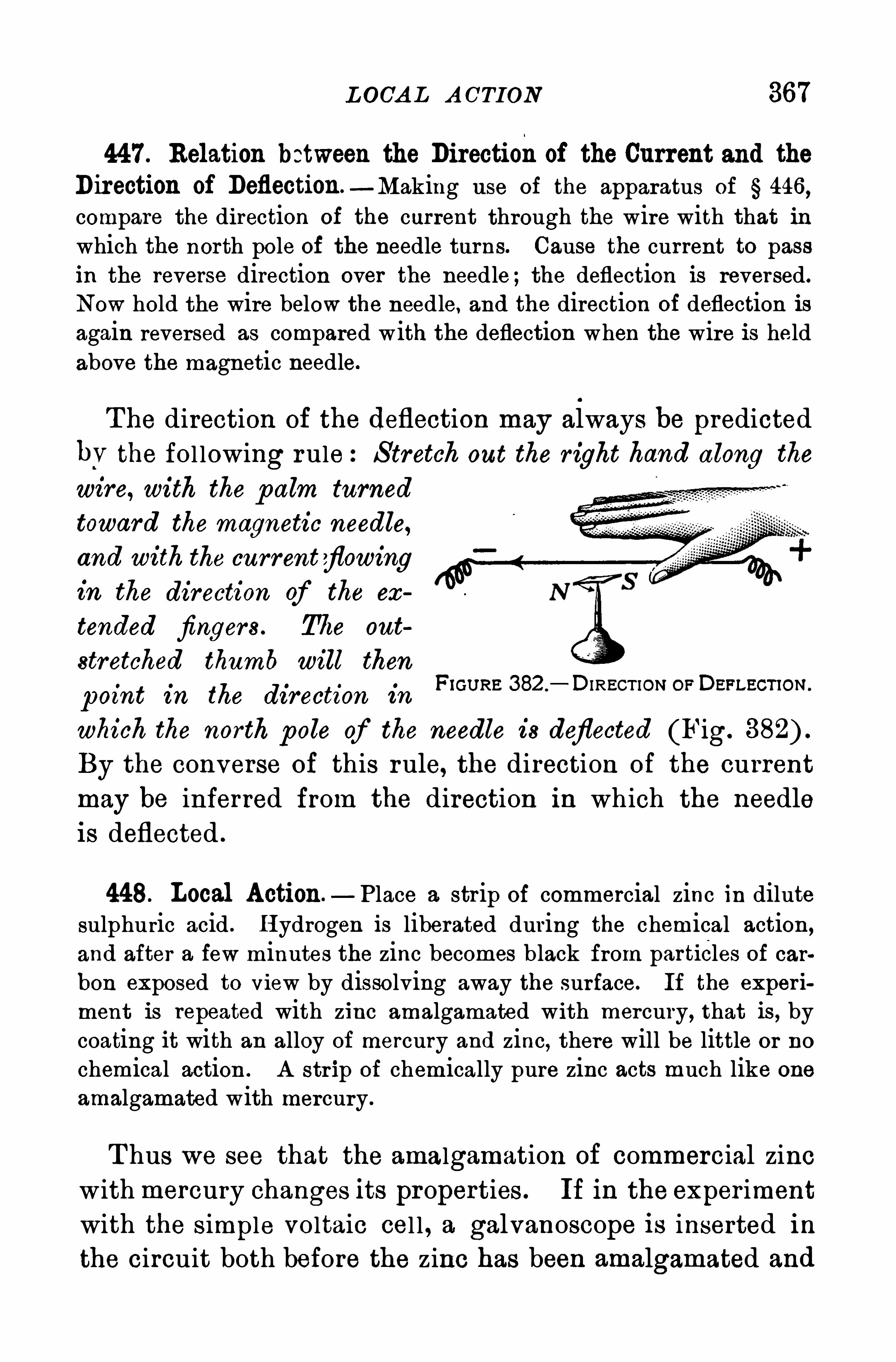
L OCA L A CTION 367
447 . Relation between the Directionof the Current and theDirection of Deflection—Making use of the apparatus of § 446 ,compare the direction of the current through the wire with that inwhich the north pole of the needle turns. Cause the current to passin the reverse direction over the needle;the deflection is reversed.
Now hold the wire below the needle, and the direction of deflection isagain reversed as compared with the deflection when the wire is heldabove the magnetic needle.
The direction of the deflection may always be predicted
bV the fol lowing rule:S tretch out the r ight hand along the
wire, with the p alm turned
toward the magnetic needle,
and with the currentflowingin the direction of the ex
tended fingers . T he oat
stretched thumb will then
p oint in the direction in
which the north pole of the needle is deflected (Fig.
By the converse of this rule, the direction of the currentmay be inferred from the direction in which the needleis deflected .
Frcuna 382 . DIRECTION or Derrecnon.
448. Local Action —Place a strip of commercial zinc in dilutesulphuric acid . H ydrogen is liberated during the chemical action,and after a few minutes the zinc becomes black from particles of carbon exposed to View by dissolving away the surface. If the experi
ment is repeated with zinc amalgamated with mercury, that is, bycoating it with an alloy of mercury and zinc, there will be little or no
chemical action . A str ip of chemically pure zinc acts much like one
amalgamated with mercury .
T hus we see that the amalgamation of commercial zincwith mercury changes its properties . If in the exper imentwith the simple voltaic cel l , a galvanoscope is inserted inthe circuit both before the zinc has been amalgamated and
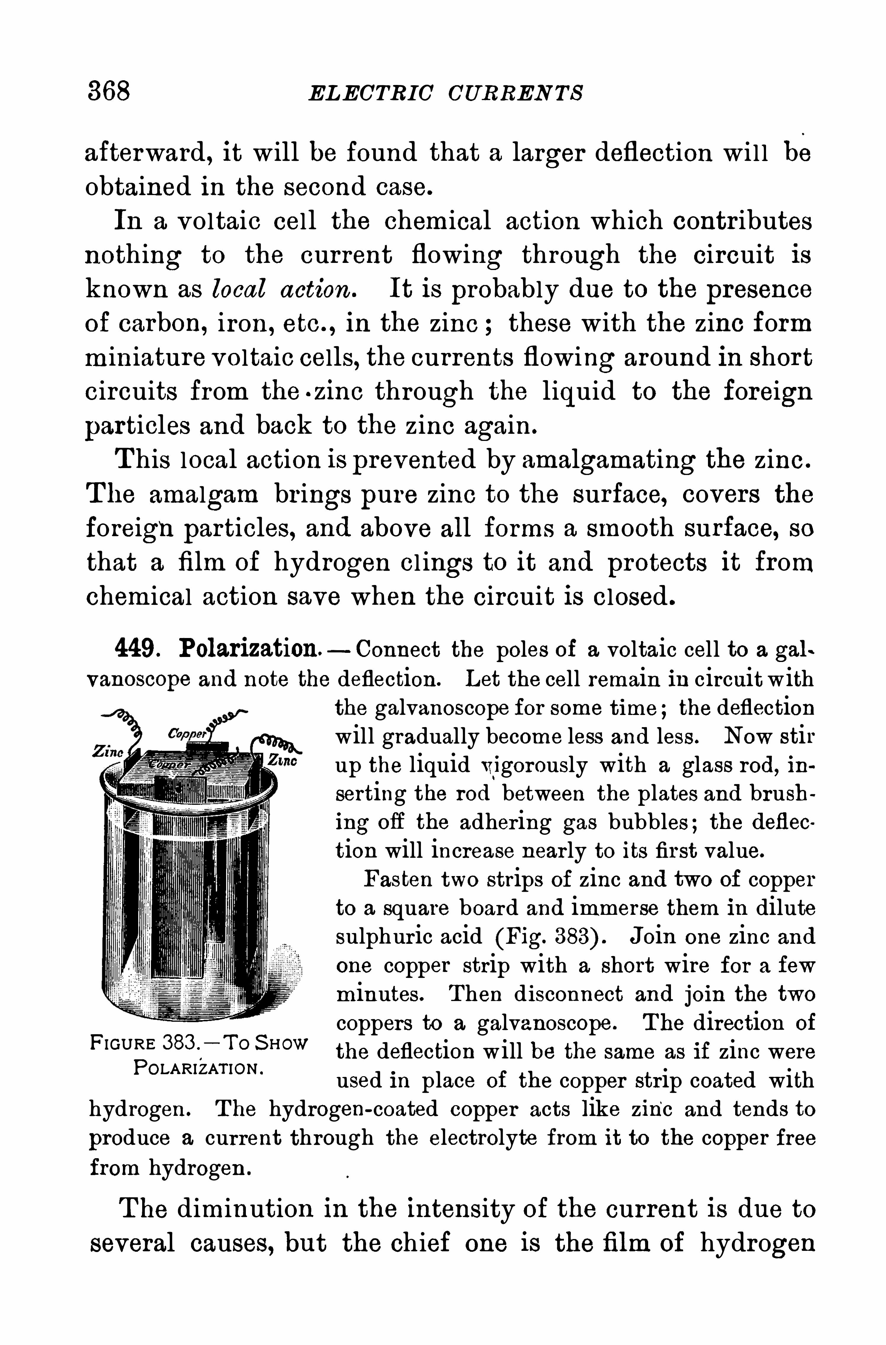
368 ELECTRIC CURREN TS
afterward , it will be found that a larger deflection wi l l beobtained in the second case.
In a voltaic cell the chemical action which contr ibutesnothing to the current flowing through the circuit isknown as local action . It is probably due to the presence
of carbon, iron, etc . , in the zinc these with the zinc form
miniature voltaic cells, the currents flowing around in shor tcircuits from the . zinc through the liquid to the foreign
particles and back to the zinc again.
T his local action is prevented by amalgamating the zinc.
T he amalgam br ings pure zinc to the surface, covers the
foreign particles, and above all forms a smooth surface, sothat a film of hydrogen cl ings to it and protects it fromchemical action save when the circuit is closed .
449. Polarization. Connect the poles of a voltaic cell to a gal
vanoscope and note the deflection. Let the cell remain in circuitwiththe galvanoscope for some time;the deflectionwill gradually become less and less . Now stirup the liquid vigorously with a glass rod, ihserting the rod between the plates and brushing ofl the adhering gas bubbles;the deflection will increase near ly to its first value.
Fasten two strips of zinc and two of copperto a square board and immerse them in dilutesulphuric acid (Fig. Join one zinc andone copper strip with a short wire for a few
minutes. Then disconnect and join the twocoppers to a galvanoscope. T he direction of
the deflection will be the same as if zinc wereused in place of the copper strip coated with
hydrogen. T he hydrogen-coated Copper acts like zinc and tends to
produce a current through the electrolyte from it to the copper freefrom hydrogen .
F IGURE 383 .
—T o S H OW
POLARI'
ZAT ION .
T he diminution in the intensity of the current is due to
several causes, but the chief one is the film of hydrogen
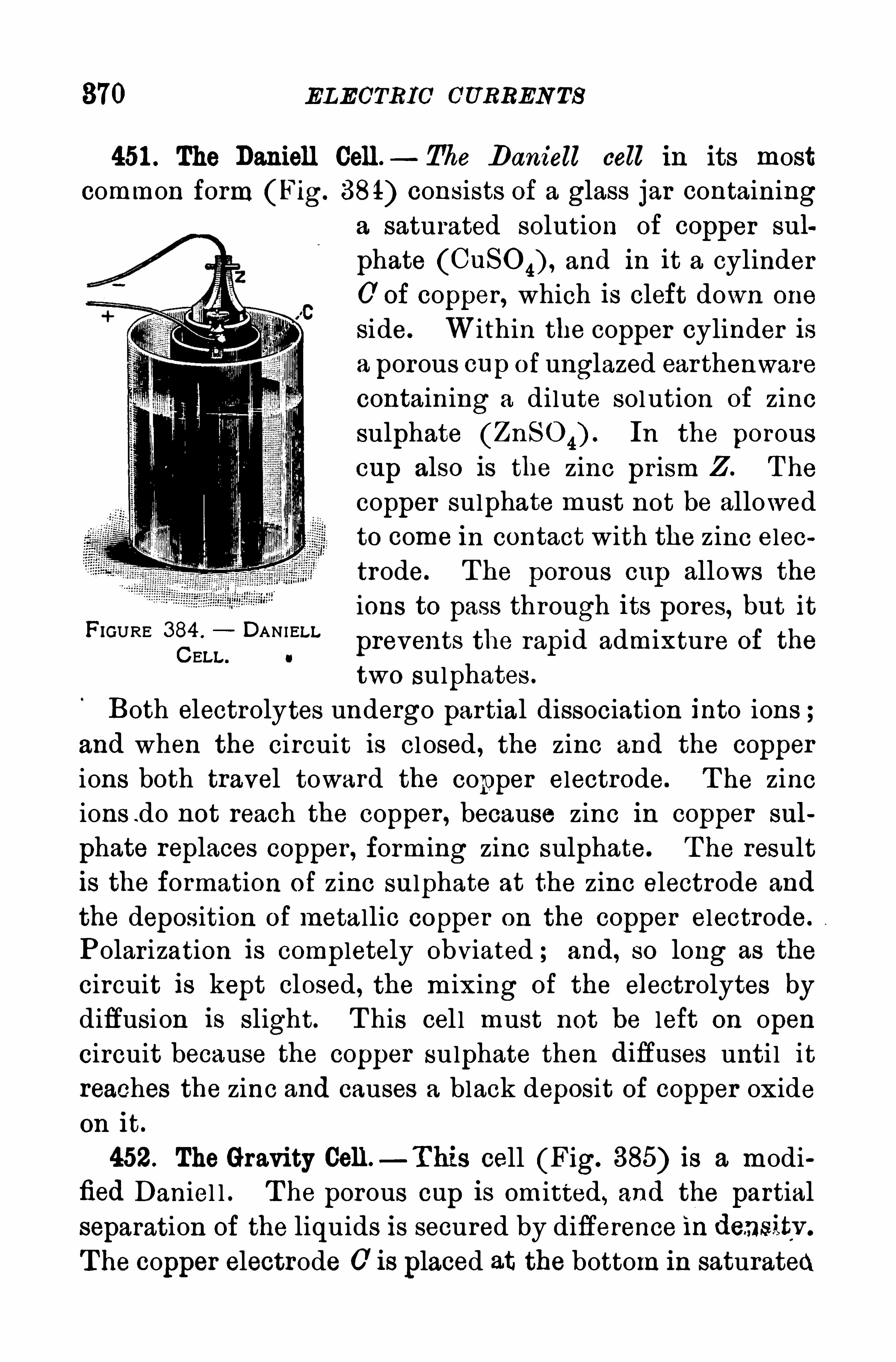
870 ELECTRIC CURRENTS
451 . The Daniell Cell. The Daniell cell in its mostcommon form (Fig. 384) consists of a glass jar containing
a saturated solution of copper sul
phate (CuSO 4) , and in it a cylinder0 of Copper, which is cleft down one
side. Within the copper cylinder isa porous cap of unglazed ear thenwarecontaining a dilute solution of zincsulphate (ZnSO 4) . In the porouscup also is the zinc pr ism Z . The
copper sulphate must not be allowed
to come in contact with the zinc electrode. The porous cup allows the
ions to pass through its pores, but it
prevents the rapid admixture of the
two sulphates .
Both electrolytes undergo partial dissociation into ions ;and when the circuit is cl osed , the zinc and the copper
ions both travel toward the copper electrode. T he zincions .do not reach the copper , because zinc in copper sul
phate replaces copper , forming zinc sulphate. T he result
is the formation of zinc sulphate at the zinc electrode and
the deposition of metallic copper on the copper electrode.
Polarization is completely obviated ; and, so long as the
circuit is kept closed, the mixing of the electrolytes bydiffusion is slight. T his cel l must not be left on open
circuit because the COppeI‘sulphate then difluses unti l it
reaches the zinc and causes a black deposit of copper oxide
on it.
452. The Gravity Celt—T his cell (Fig. 385) is a modified Daniel l . T he porous cup is omitted, and the partialseparation of the liquids is secured by difference in densitv .
T he copper electrode 0 is placed at the bottom in saturated
FIGURE 384 . DANIELLCELL . o
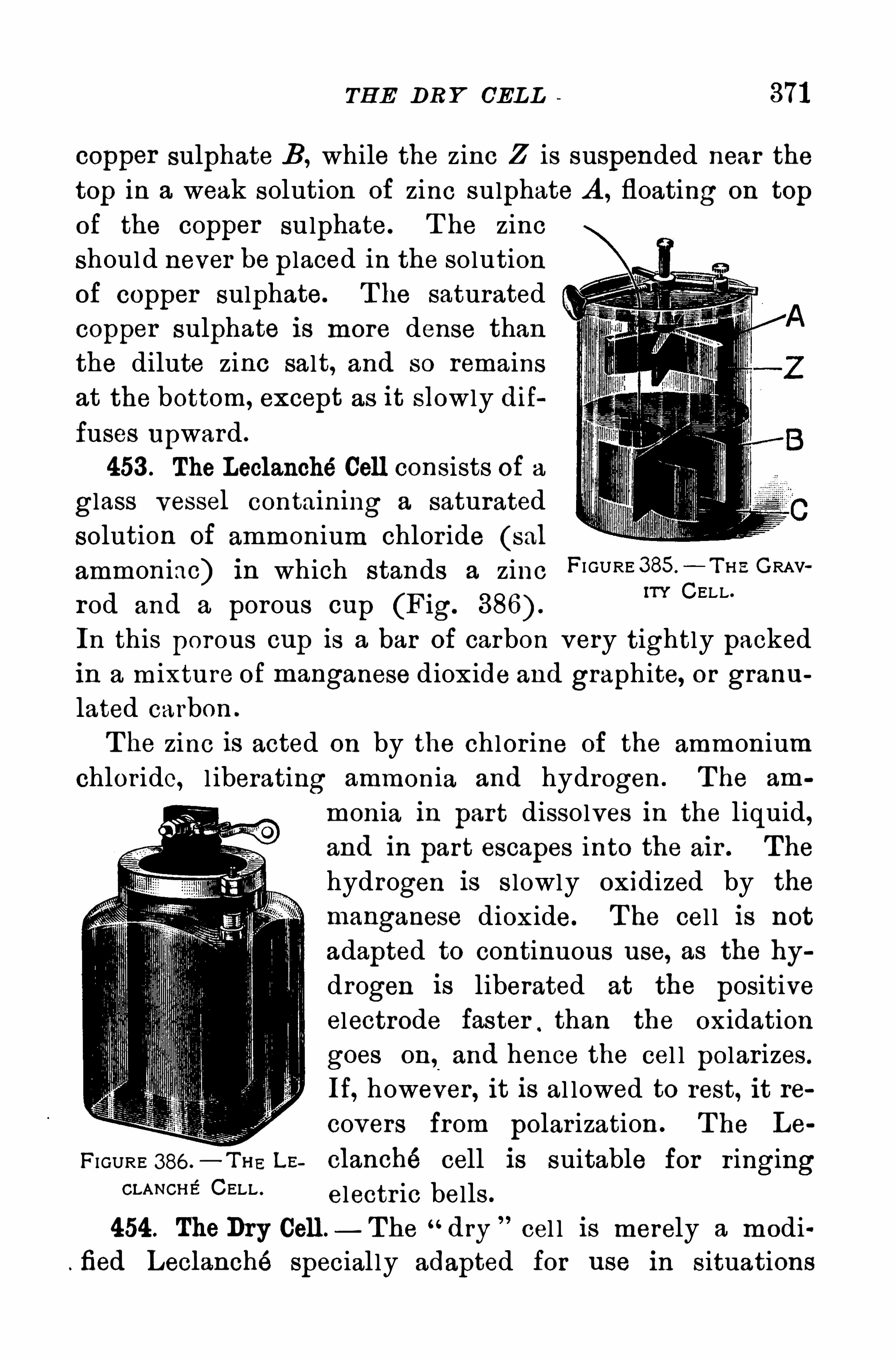
TH E DR Y CEL L 371
copper sulphate B, while the zinc Z is suspended near the
top in a weak solution of zinc sulphate A , floating on top
of the copper sulphate. T he zinc
should never be placed in the solution
of copper sulphate. T he saturated
copper sulphate is more dense than
the dilute zinc salt, and so remains
at the bottom, except as it slowly dif
fuses U pward .
453 . The Leclanché Cell consists of a
glass vessel containing a saturated
solution of ammonium chlor ide (sal
ammoniac) in which stands a zinc FI GURE 385 — T H E GRAV
rod and a porous cup (Fig.
IT? CELL .
In this porous cup is a bar of carbon very tightly packed
in a mixture of manganese dioxide and graphite, or granulated carbon .
T he zinc is acted on by the chlor ine of the ammonium
chloride, l iberating ammonia and hydrogen . T he am
monia in part dissolves in the l iquid,and in part escapes into the air . The
hydrogen is s lowly oxidized by the
manganese dioxide. T he cel l is not
adapted to continuous use, as the hy
drogen is liberated at the positive
electrode faster,than the oxidation
goes on, and hence the cel l polarizes .
If, however , it is al lowed to rest, it re
covers from polarization . T he Lo
FI GURE 386 .—Tm LE clanché cell is suitable for ringing
CLANCH Pf CELLelectr ic bells
454. TheDry Cell—The “dry cel l is merely a modi
fied Leclanché special ly adapted for use in s ituations
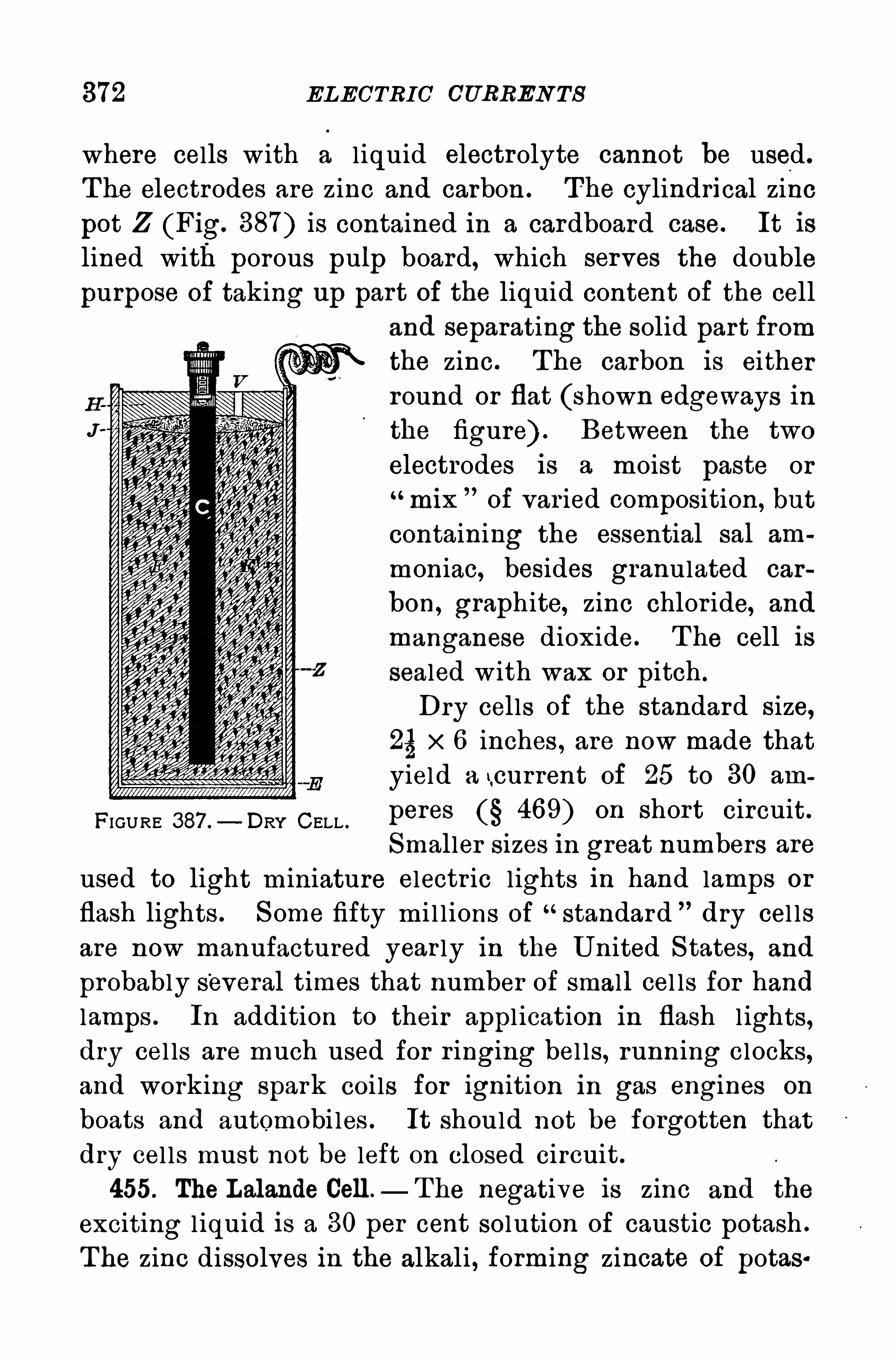
372 ELECTRIC CURREN TS
where cells with a l iquid electrolyte cannot be used.
T he electrodes are zinc and carbon . The cylindrical zinc
pot Z (Fig. 387) is contained in a cardboard case. It is
lined with porous pulp board, which serves the double
purpose of taking up part of the liquid content of the cell
and separating the solid part fromthe zinc. T he carbon is eitherround or flat (shown edgeways inthe figure) . Between the two
electrodes is a moist paste or
mix of var ied composition , but
containing the essential sal am
moniac, besides granulated car
bon, graphite, zinc chlor ide, and
manganese dioxide. T he cell is
sealed with wax or pitch .
Dry cells of the standard size,25x 6 inches , are now made thatyield a tcurrent of 25 to 30 am
peres 469) on short circuit.
Smaller sizes in great numbers areused to light m iniature electric l ights in hand lamps or
flash lights . S ome fifty mi l l ions of “standard dry cel ls
are now manufactured year ly in the U nited S tates, and
probably several times that number of small cel ls for hand
lamps . In addition to their appl ication in flash lights,dry cel ls are much used for r inging bel ls, running clocks,and working spark coi ls for ignition in gas engines on
boats and automobi les . It should not be forgotten that
dry cel ls must not be left on closed circuit.
455. The Lalande Cell — T he negative is zinc and the
exciting l iquid is a 30 per cent solution of caustic potash .
The zinc dissolves in the alkali , forming zincate of potes
FIGURE 387 . DRY CELL .
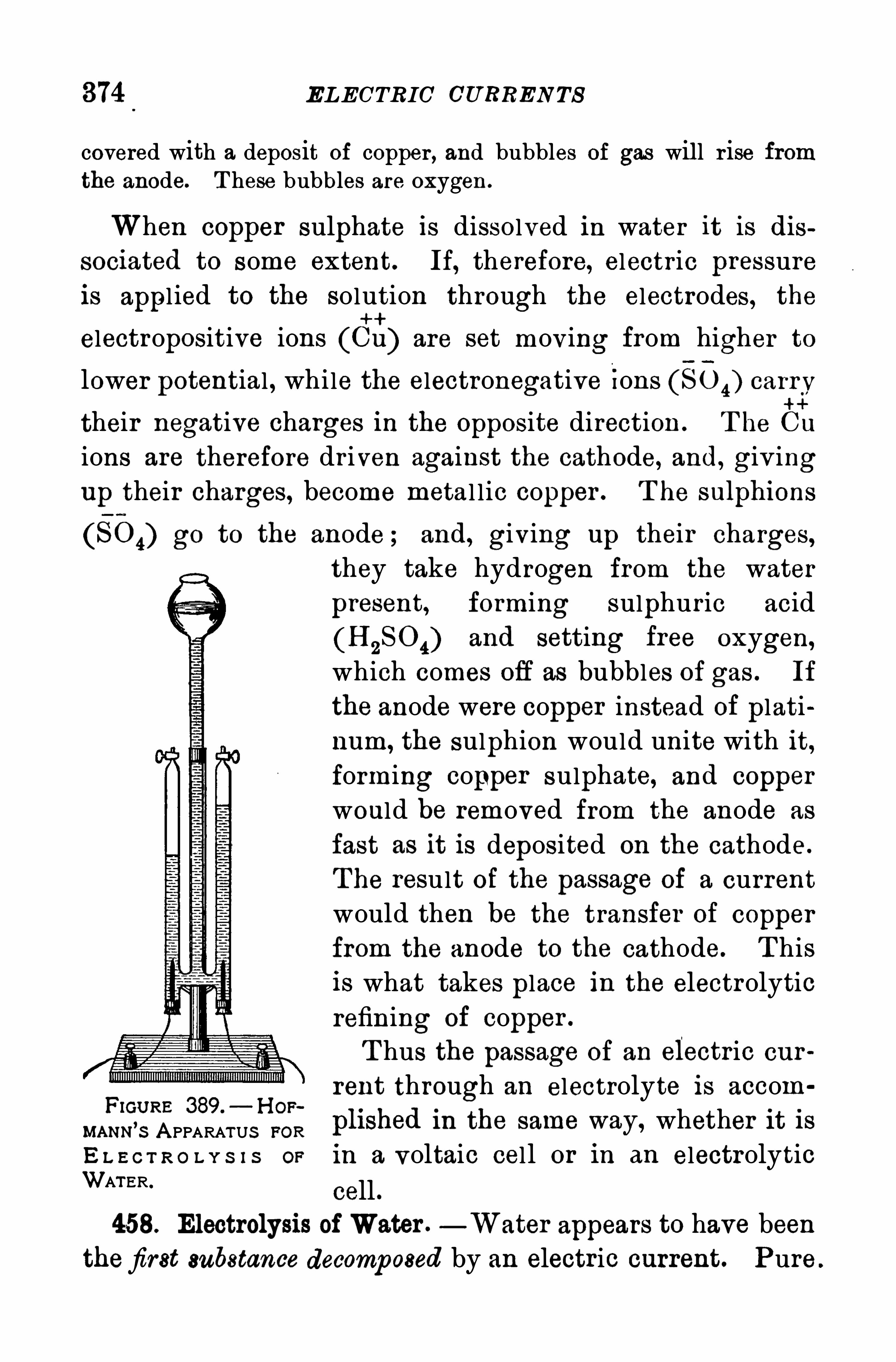
374 ELECTRIC CU RRENTS
covered with a deposit of copper , and bubbles of gas will r ise fromthe anode. T hese bubbles are oxygen .
When copper sulphate is dissolved in water it is dissociated to some extent. If, therefore, electric pressureis appl ied to the solution through the electrodes, the
electropositive ions (Cu) are set moving from higher to
lower potential , while the electronegative Ions (80 4) carry
their negative charges in the Opposite direction . T he Cu
ions are therefore dr iven against the cathode, and, giv ingup their charges, become metal l ic copper . T he sulphions
(80 4) go to the anode ; and, giving up their charges,they take hydrogen from the water
present, forming sulphur ic acid
and setting free oxygen,which comes ofl as bubbles of gas . If
the anode were copper instead of plati
num, the sulphion would unite with it,forming copper sulphate, and copper
would be removed from the anode as
fast as it is deposited on the cathode.
T he result of the passage of a current
would then be the transfer of copper
from the anode to the cathode. T his
is what takes place in the electrolytic
refining of copper .
T hus the passage of an electric cur
rent through an electrolyte is aecomFIcuRE 389.
—H or ~
mu m’s A PPARATUS FOR plished in the same way, whether it is
E L E C T R O L Y S I S or in a voltaic cell or in an electrolyticWATER.
cell
458. Electrolysis of Water .—Water appears to have been
thefirst substance decomposed by an electric current. Pure
LA ms or ELECTROL Y S IS 375
water does not conduct an appreciable current of elec
tricity, but if it is acidulated with a small quantity of
sulphur ic acid, electrolysis takes place.
In H ofmann’
s apparatus (Fig. 389) the acidulated water is pouredinto the bulb at the top, and the air escapes by the glass taps untilthe tubes are filled . T he electrodes at the bottom in the liquid are
platinum foil . If a current is sent through the liquid , bubbles of gas
will be liberated on the pieces of platinum foil . T he gases collectingin the tubes may be examined by letting them escape through the
taps . Oxygen will be found at the anode and hydrogen at the
cathode the volume of the hydrogen will be nearly twice that of theoxygen .
459. Laws of Electrolysis . T he fol lowing laws of elec
trolysis were established by Faraday.
I . Them a ss of an electr olyte decomposed by an electr ic
cu rr ent is p roportiona l to the quantity of electr icity con
veyed through it.
The mass of an ion l iberated in one second is, therefore,
proportional to the strength of current.
II . When the same quantity of electricity is conveyed
through d ifi'
erent electr olytes, the m asses of the difierent
ion s set free a t the electrodes a re pr opor tional to their
chem ica l equ iva lents .
By chemical equivalents are meant the relative
quantities of the ions which are chemical ly equivalent toone another , or take part in equivalent chemical reactions .
T hus, g. of zinc or g. of copper take the place of
one g. of hydrogen in sulphur ic acid (H 280 4) to form zincsulphate (ZnSO 4) or copper sulphate (CuSO 4) , respec
tively .
T he first law of electrolysis affords a valuable means of
compar ing the strength of two electr ic cur rents by deter

376 ELECTRIC CURREN Ts
mining the relative masses of any ion, such as silver or
copper , deposited by the two currents in succession in the
same time
460. Electroplating consists in cover ing bodies with a
coating of any metal by means of the electr ic cur rent.
The process may be summar ized as fol lows:T horoughly
clean the surface to remove all fatty matter . A ttach the
article to the negative electrode of a battery, and sus
pend it in a solution of some chemical salt of the metal
to be deposited . If silver, cyanide of silver dissolved
in cyanide of potassium is used; if copper , sulphate of
copper . T o maintain the strength of the sol ution a pieceof the metal of the kind to be deposited is attachedto the positive electrode of the battery and immersed in
the electrolyte.
.
T he action is similar to that heretofore
given. A rticles of iron, steel , zinc, tin,
'
aud lead cannot
be si lvered or gilded unless first covered with a thin coating of copper .
A ll silver plating, nickeling, gold plating, and so on, is
done by this process .
461 . Electrotyping consists in copyingmedals, wood-cuts,type, and the like in metal, usual ly copper , by means of the
electr ic current . A mold of the object is taken in wax or
plaster of Par is . T his is evenly covered with powdered
graphite to make the surface a conductor , and treated very
much as an object to be plated . When the deposit has be
come sufficiently thick it is removed from the mold and
backed or filled w ith type-metal .
Nearly all books nowadays are pr inted from electrotype
plates, and not as former ly from movable types .
462. The Storage Cell .— A ttach two lead plates, to wh ich are
soldered copper wires, to the opposite sides of a block of dry wood ,and immerse them in dilute sulphuric acid , one part acid to five of
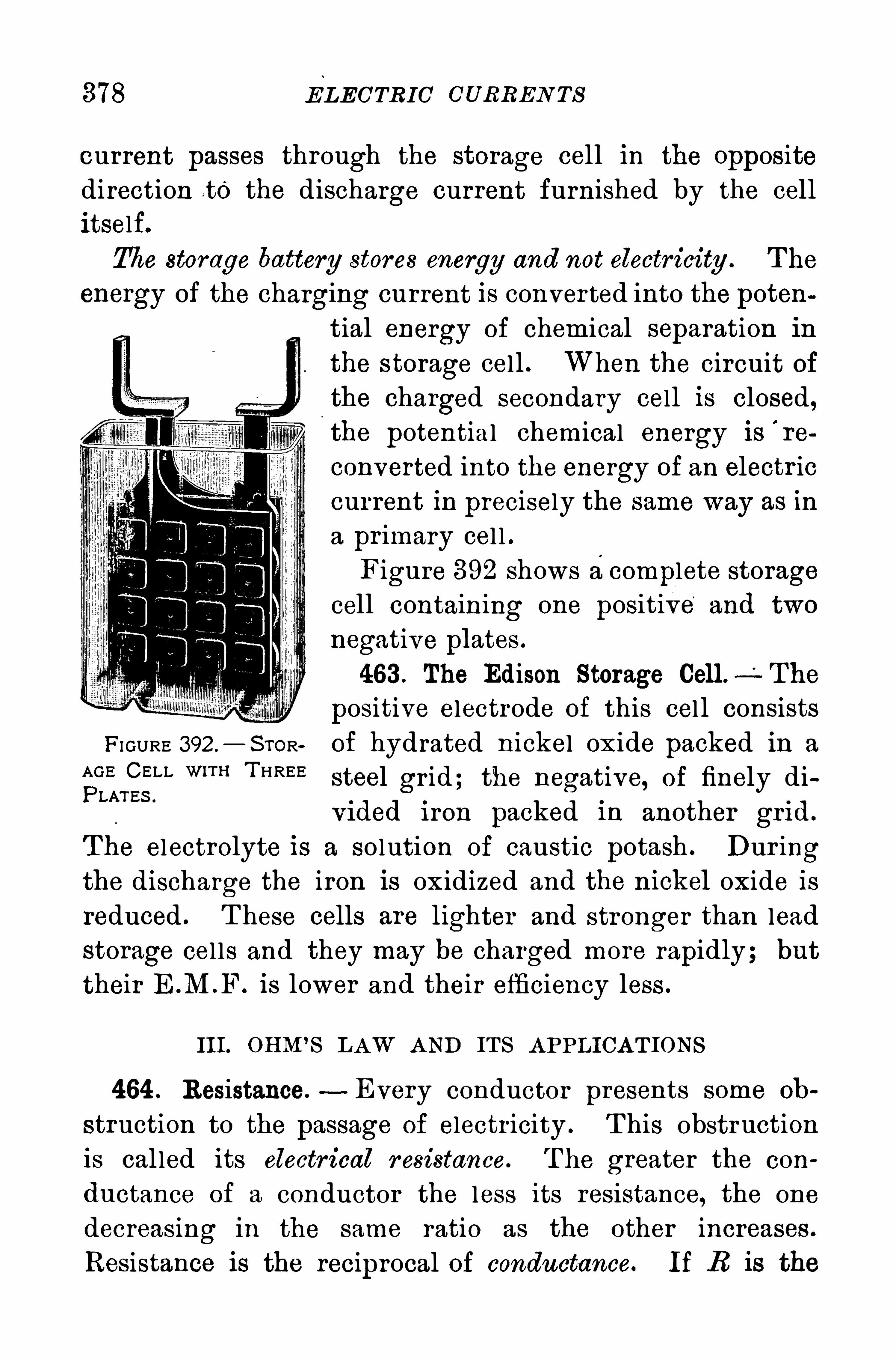
378 ELECTRIC CURREN Ts
current passes through the storage cell in the oppositedirection to the discharge current furnished by the cell
itself.The storage battery stores energy and not electricity . T he
energy of the charging current is conver ted into the potential energy of chemical separation in
the storage cell . When the circuit ofthe charged secondary cell is closed,the potential chemical energy is
'
re
converted into the energy of an electr iccurrent in precisely the same way as in
a pr imary cel l .Figure 392 shows acomplete storage
cell containing one positive and two
negative plates .
463 . The Edison Storage Cell. The
positive electrode of this cel l consists
FI GURE 392 .
— S TOR of hydrated nickel oxide packed in a
AGE CELL W‘T“T HREEsteel gr id; the negative, of finely di
PLAr Es .
Vlded 1 ron packed in another gr 1d .
T he electrolyte is a solution of caustic potash . Dur ingthe discharge the iron is oxidized and the mckel oxide is
reduced . T hese cells are lighter and stronger than lead
storage cel ls and they may be charged more rapidly; but
their E .M .F . is lower and their efficiency less .
III. OHM’S L AW A ND IT S A PPLICA T IONS
464 . Resistance.- Every conductor presents some oh
struction to the passage of electricity . T his obstruction
is cal led its electr ical r esistance. T he greater the con
ductance of a conductor the less its resistance, the one
decreasing in the same ratio as the other increases .
Resistance is the reciprocal of conductance. If R is the
EFFECT OF H EA T ON RESISTA N CE 379
resistance of a conductor and 0 its conductance, then
1
0
465. Unit of Resistance.—The pr imary standard unit of
resistance 1s the ohm. It is represented by the resistance
of a uniform thread of mercury cm. long and
g. in mass, at 0°C . T his standard is reproducible because
mercury can be obtained in great pur ity .
A commercial standard for practical purposes consists
of a resistance coil of suitable wire, adjusted to be exactly
equal to the pr imary legal mercury standard at some
definite temperature.
466 . Laws of Resistance. The r esistan ce of a con
du ctor is pr opor tional to its length . For examp le, if 39 ft.
of No . 24 copper wire (B. S . gauge) have a resistance
of 1 ohm, then 78 ft . of the same wire will have a resist
ance of 2 ohms .
2. The resistance of a conductor is inver sely pr opor
tiona l to its cr oss sectiona l area .In the case of round wire
the resistance is therefore 1nversely propor tional to the
square of the diameter . For example, No . 24 copper wirehas twice the diameter of No. 30. T hen 39 ft. of No . 24 has
a resistance of 1 ohm , and ft. of No . 30 (one-fourthof 39) also has a resistance of 1 ohm , both at 22
°C .
3 . The resistance Of a condu ctor of given length and
cr oss section depends upon the m ater ia l of wh ich it is
m ade, that is, upon the specific resistance, or resistivity of
the mater ial . For examp le, the resistance of ft. of No.
24 German silver wire is 1 ohm, while it takes 39 ft. of cop
per w ire of the same diameter to give the same resistance.
467. Effect of H eat on Resistance. Changes of tempera
ture aflect temporar i ly the resistance of metals, but all
metals are not affected to the same extent. Nearly all
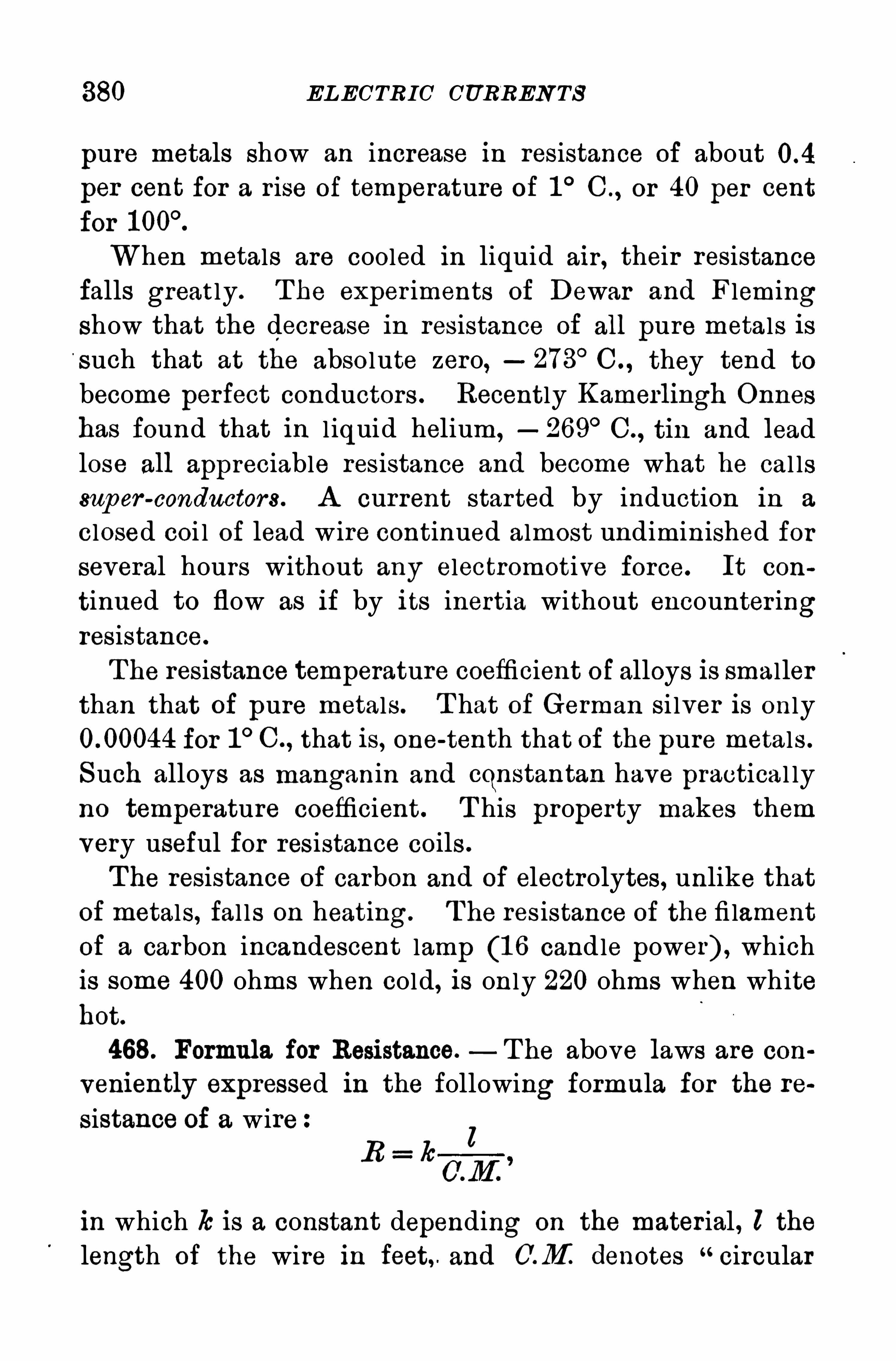
380 ELECTRIC CURREN TS
pure metals Show an increase in resistance of about
per cent for a r ise of temperature of 1 ° C . , or 40 per cent
for
When metals are cooled in liquid air , their resistancefalls great ly. T he exper iments of Dewar and Flemingshow that the decrease in resistance of all pure metals is
such that at the abso lute zero, 273°C . , they tend to
become perfect conductors . Recently Kamerlingh Onnes
has found that in l iquid helium,2 69
°C. , tin and lead
lose all appreciable resistance and become what he cal lssup er
-conductors . A current started by induction in a
closed coi l of lead wire continued almost undiminished for
several hours without any electromotive force. It con
tinned to flow as if by its inertia without encounter ingresistance.
The resistance temperature coefficient of alloys is smallerthan that of pure metals . T hat of German si lver is only
for 1°C. , that is, one-tenth that of the pure metals .
Such alloys as manganin and cqnstantan have practical ly
no temperature coefficient . T his property makes them
very useful for resistance coils .
T he resistance of carbon and of electrolytes, unlike that
of metals, fal ls on heating. T he res istance of the fi lament
of a carbon incandescent lamp (1 6 candle power) , which
is some 400 ohms when cold, is only 220 ohms when white
hot.
468. Formula for Resistance.—T he above laws are con
veniently expressed in the following formula for the re
sistence of a wirel
E = h
in which Is is a constant depending on the material , l the
length of the wire in feet, and GM denotes “circular

382 ELECTRIC CURREN TS
terials employed, and is entirely independent of the size
and shape of the plates , T he E M .F. of a Daniell cell
and of a gravity cell is about volts ; of a Leclanché
and of a dry cel l, volts ; of a lead storage cell, 2 volts .
T he practical international standard of electromotive
force is theWeston Normal Cell . The electrodes are cad
mium amalgam for
c the negative and
mercury for the
positive. T he elec
trolyte is a satu
m gmpm , rated solution of
cadmium sulphate,and the depolar izer
is mercurous sul
phate (Fig. T he E M.F. of the Weston cell in
volts is given by the following equation, the temperaturet being in centigrade degrees
F : (t (Equation 35)
FI GURE 393 .—WES TON NORMAL CELL.
471 . Ohm’s Law.
-T he definite relation existing be
tween strength of current, resistance, and is
known as Ohm’
s L aw:
The strength of a cu rrent equ als the electr om otive for ce
d ivided by the r esistance; then
ILM F . (or potentialdifierence2in voltscur rent in amp eres
resistance in ohms
or in symbols, E (Equation 36)R
9
where I is the current in amperes, F the E M .F. in volts,and .R the resistance in ohms . A pplied to a battery, if

GeorgS imonOhm (1789
1854) was born in Erlangen,
Bavaria. and was educatedat the U niversity of thattown. H e began his investigations by measuring the
electrical conductivity of
metals . In 1827 he ah
nounced the electrical lawnamed in his honor , and in1842 hewas elected to a pro
fessorship in the Universityof Munich.
Alessandro Volta (17451827) was born at Como , lt
aly . H e was profe'
ssor of
physics at the U niversity of
Pav ia , and was noted for his
researches and investigationsin electric ity . T he voltaiccell , the electroscope, the
electrical condenser , and theelectrophorus are due to his
genius .

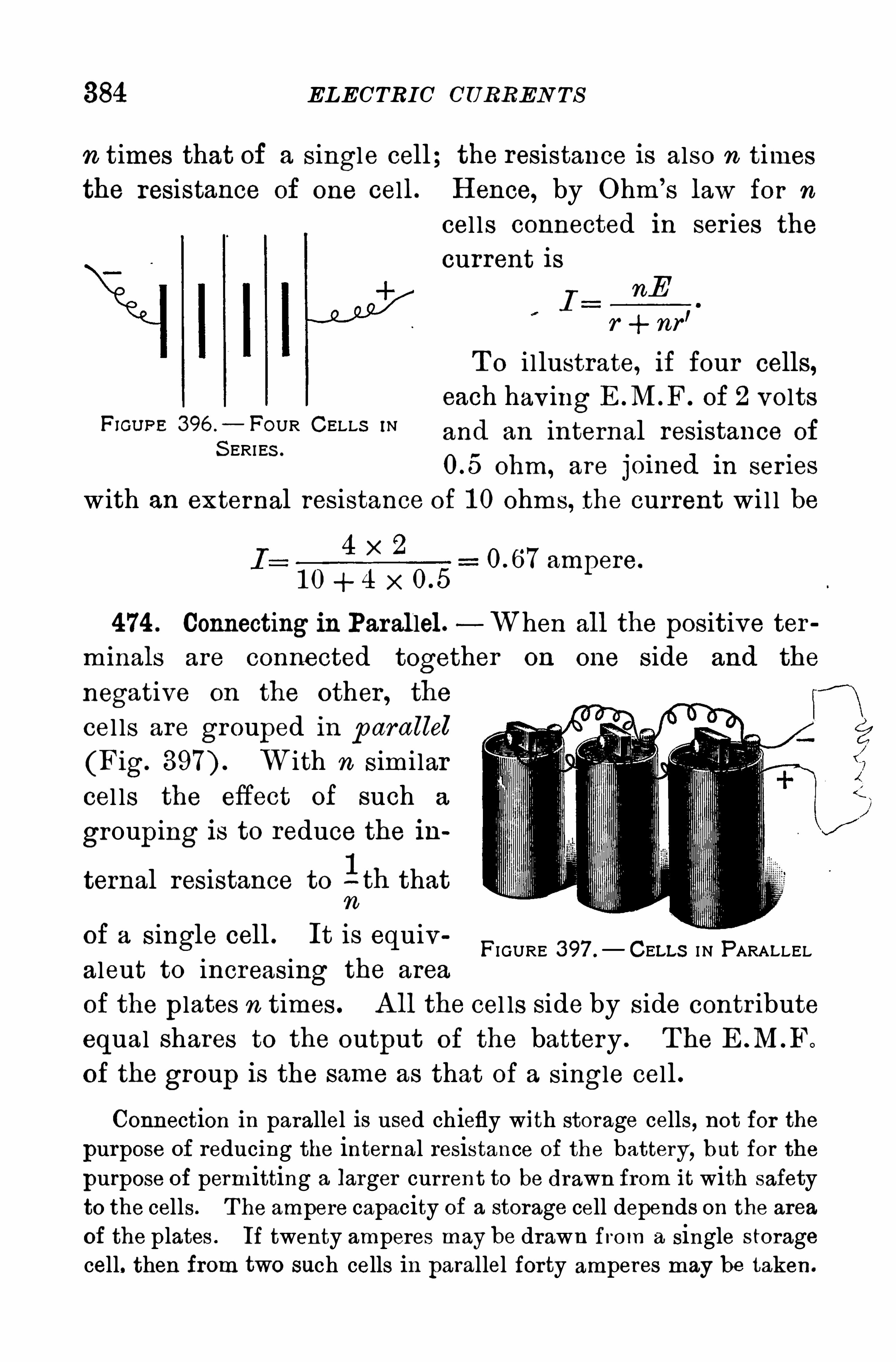
384 ELECTRIC CURREN TS
n times that of a single cell; the resistance is also n timesthe resistance of one cell. H ence, by Ohm’
s law for n
cel ls connected in ser ies thecurrent is
InF
r + nfl
T o i llustrate, if four cells,each hav ing E M .F . of 2 volts
F’GU PE 396 — FOUR CELLS ‘Nand an internal resistance of
S ERI ES .
ohm, are jomed ln semes
with an external resistance of 1 0 ohms, the current wi l l be
4 x 2
1 0 + 4 x 0.5
474 . Connecting in Parallel. When all the positive ter
m inals are connected together on one side and the
negative on the other , the
cel ls are grouped in p arallel
(Fig. W ith n sim i lar
cel ls the effect of such a
grouping is to reduce the in
1ternal resistance to - th that
n
of a single cell . It is equivaleut to increasing the area
of the plates n times . A ll the cel ls side by side contr ibuteequal shares to the output of the battery . T he E .M .F.
of the group is the same as that of a single cell .
ampere.
FI GURE 397 . CELLS I N PARALLEL
Connection in parallel is used chiefly with storage cells, not for the
purpose of reducing the internal resistance of the battery, but for the
purpose of permitting a larger current to be drawn from it with safetyto the cells . T he ampere capacity of a storage cell depends on the areaof the plates . If twenty amperes may be drawn from a single storagecell. then from two such cells in parallel forty amperes may be taken.

JO ULE’
S LA W 385
IV. H EA TING . EFFECT S OF A CURRENT
475. Electric Energy Converted into H eat. Send an electriccur rent through a piece of fine iron wire. T he wire is heated, and itmay be fused if the current is sufficiently strong .
The conversion of electr ical energy into other forms is
a fami l iar fact . In the storage battery the energy of the
charging cur rent is converted into the energy of chem ical
separation and stored as the potential energy of the
charged cells . In this exper iment the energy of the cur
rent is transformed into heat because of the resistancewhich the W Ire offers . If the resistance of an electr ic
circuit is not uniform , the most heat will be generated
where the resistance is the greatest .
Send the current from a few cells through a chain made of alternate pieces of iron and copper , soldered together (I 1g. T he
iron links may be made to
glow red hot, while the copper C
ones remain com arativelp yFI GURE 398. IRON AND COPPER L INKS .
cool. T he res1stance of the
iron wire is about seven times as great as that of copper of the same
length and gauge. Moreover, its thermal capacity is about threequarter s as great. H ence the rise of temperature of the n on links isroughly nine times as great as that of the copper ones.
476 . Joule’s Law. Joule demonstrated exper imental lythat the number of units of heat generated in a conductorby an electr ic cur rent is proportional:
a . TO the resistance of the condu ctor .
6 . To the squa re of the strength of cu r rent.
0 . TO the length of tim e the cu rr ent flows .
1
1 If H is the heat in calories,I the current strength in amperes
, R the
resistance in ohms , t the time in seconds,and the number of calories
equivalent to one joule, thén the heat equivalent of a current isH z x I 2R t calories .

386 ELECTRIC CURRENTS
477 . Applications of Electric H eating. Some of the more
important applications of electric heating are the following1 . E lectric Cautery. A thin plati
num wire heated to incandescence isemployed in surgery instead of a knife.
P latinum is very infusible and is not
corrosive.
2. S afetyFuses. A dvantage is takenof the low temperature of fusion of some alloys, in which lead is a
cons tituent, for making safety fuses to open a circuit automaticallywhenever the current becomes excessive (Fig.
3 . E lectric Welding. If the abutting ends
of two rods or bars are pressed together , whilea large current passes through them, enoughheat is generated at the j unction
,where the re
sistance is greatest, to soften and weld them to
gether . Figure 400 shows two welded joints asthey came from the welder .
4. The Electr ic Flatiron. Figure 401 showsa flatiron, par tly cut away, arranged to be
heated by an electric current. The current F’GU RE4OO —ELEC‘
enters by a flexible conductor and flows through F313:L L Y W E L D E D
the resistance coil E on the base of the iron .
A is a wooden handle to avoid the use of a holder . The resistanceis often arranged so as to con
centrate the heat at the pointof iron.
5. E lectric H eating. Electricstreet cars are often heated by acurrent through suitable resistances. S imilar devices for cocking are new articles of com
merce. Small furnaces for fusing, vulcanizing, and enamelingare common in dentistry .
FIGURE 40 1 . ELECTRIC FLAT IRON. Large furnaces are employedfor melting refractory substances, for the .reduction of certain ores,
and for chemical operations demanding a high temperature.
FI GURE 399 .
-CARTRI DGE FUS E .
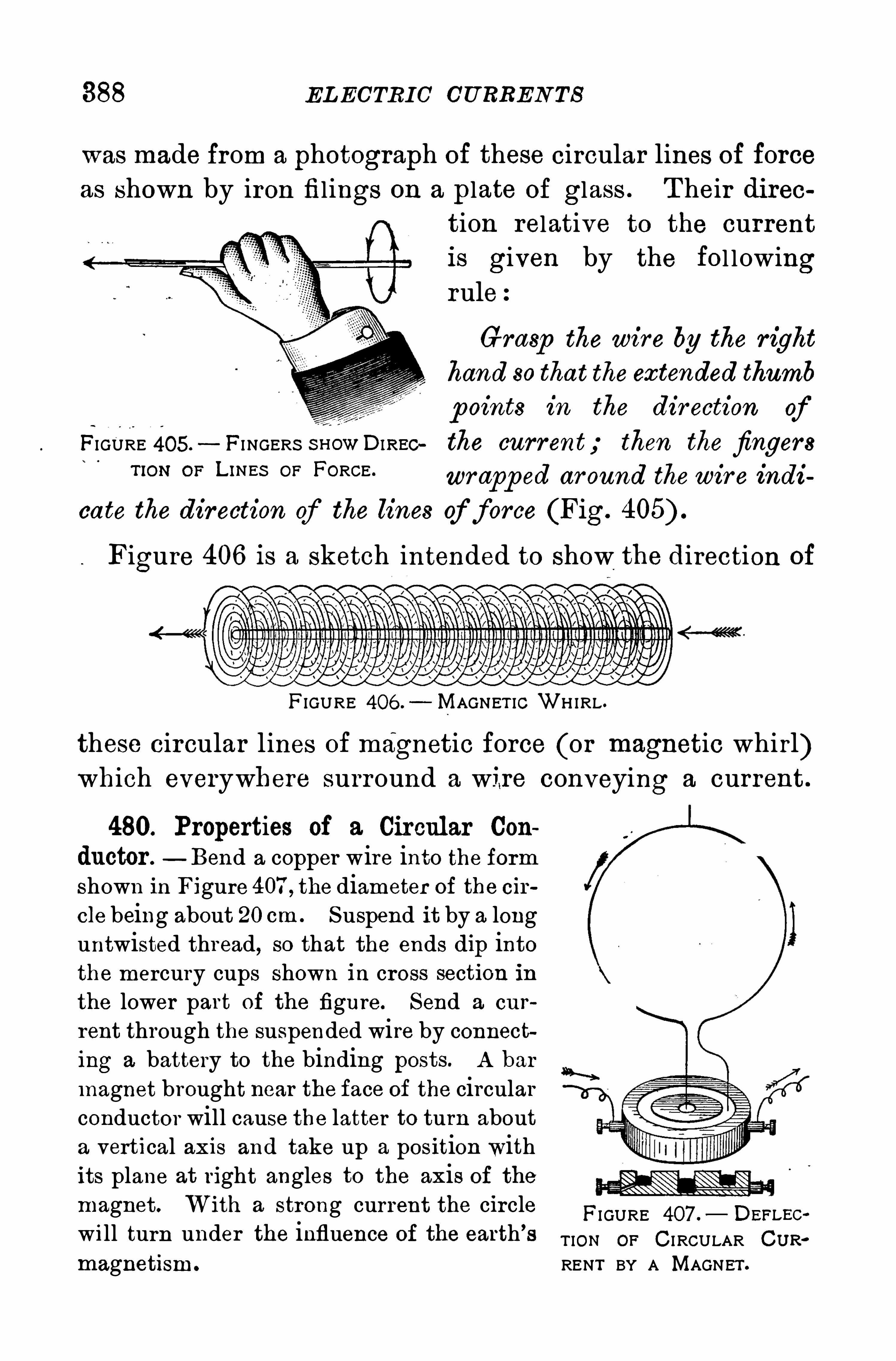
388 EL ECTRIC CU RREN TS
was made from a photograph of these circular lines Of forceas shown by iron filings on a plate of glass . T heir di rce
tion relative to the currentis given by the fol lowingrule:
Grasp the wire by the r ight
hand so that the extended thumb
p oints in the dir ection ofFIGURE 405.
—FI NGERS snowDIREC the current; then the fingers“ON OF L‘NES 0" FORCE ' wrapp ed ar ound thewire indi
cate the dir ection of the lines of force (Fig.
Figure 406 is a sketch intended to show the direction of
FIGURE 406 . MAGNET IC WH IRL .
these circular lines of magnetic force (or magnetic whirl)which everywhere surround a wire conveying a current .
480. Properties of a Circular Con
ductor . Bend a copper wire into the formshown in Figure 407 , the diameter of the cir
cle being about 20 cm . Suspend it by a longuntwisted thread, so that the ends dip intothe mercury cups shown in cross section inthe lower part of the figure. Send a cur
rent through the suspended wire by connecting a battery to the binding posts. A bar
magnet brought near the face of the circularconductor will cause the latter to turn abouta vertical axis and take up a position withits plane at right angles to the axis of themagnet. With a strong current the circle
FI GURE 407 .— DEELEc
will turn under the influence Of the earth’s TION OF C I RCULAR CUR.
magnetism . RENT BY A MAGNET .

P OL A RI T Y OF A H ELIX 389
T his exper iment shows that a circular current acts likea disk magnet, whose poles are its faces . T he linesof force surrounding the conductor in this form pass
through the circle and around from one face to the otherthrough the air outside the loop . The
north-seeking side is the one from
which the lines issue ; and to an ob
server looking toward the side, thecurrent flows around the loop counterclockwise (Fig.
If instead of a single turn we take along insulated wire and coil it into a
number of paral lel circles close to FIGU RE 408o
— L 1NES
gether, the magnetic effect wi l l be in OF FORCE THROUGH ALOOP.
creased . Such a coil is cal led a helix
or solenoid; and the passage of an electr ic current through
it gives to it all the proper ties of a cyl indr ical bar magnet.
T hread a loose coil of copper wire through holes in a sheet of m i ca,so that each turn lies half on one side and half on the other (Fig.
P lace horizontally and scatter fineiron filings evenly over the mica.
Send a strong curr ent through thecoil and gently tap them ica . T he
filings will gather in the generaldirection of the lines of forcethrough the helix .
481 . Polar ity of a H elix.
T he polar ity of a hel ix may
be determined by the followFIGURE 409 .
— FI ELD I N H ELIX. ing rule
Gr asp the coil with the right hand so that thefingers p ointin the direction of the curr ent ; the nor th polewill then be in
the direction of the extended thumb.

390 EL ECTRIC CURREN TS
482. Mutual Action of Two Currents — Make a rectangularcoil of insulated copper wire by winding four or five layers around
FIGURE 4 10. A CT ION BETWEENTwo C I RCUIT S .
the edge of, a board about 25 cm . square.
S lip the wire ofi the board and tie the
parts together in a number of placeswith thread . Bend the ends at rightangles to the frame, remove the insulation, and give them the shape shown inFigure 41 0. Suspend thewire frame bya long thread so that the ends dip intothe mercury cups.
Make a second similar but smallercoil and connect it in the same circuitwith the rectangular coil and a battery .
First. H old the coil EX with itsplane perpendicular to the plane of the
coil EF , with its edge H parallel to F ,
and with the currents in these two ad
jacent portions flowing in the same direction . The suspended coil willturn upon its axis, the edge F approaching H , as if it were attracted.S econd. Reverse EX so that the currents in
the adjacent portions K and F flow in oppositedirections . The edge F of the suspendbd coil willbe repelled by K .
Third. H old the coil EX within EF, so thattheir lower sides form an angle. EF will turnuntil the currents in its lower side are parallelwith those in H , and flowing in the same direction .
Mount a long flexible helix as in Figure 41 1 ,with the free end just dipping into the mercuryin the glass cup . Pass a sufficient current throughit ;it will shorten because of the attraction be
tween parallel turns, until the lower end leavesthe mercury and breaks the circuit. It will thenlengthen and close the circuit ready for anotheroscillation .
T hese facts may be summarized in the following laws ofaction between currents
FIGURE 4 1 I .
A TTRACT ION BETWEENT URNS .

ELECTRIC CURRENTS
VI. ELECTROMA GNET S
484. Effect of I ntroducing Iron into a Solenoid. Fill the
lower half Of the helix of 480 with soft straight iron wires, and
again pass the same current as before through the coil. The magnetic field will be greatly strengthened by the iron .
A helix of wire about an iron core is an electromagnet.
It was first made by S turgeon in 1 825. T he presence of
the iron core greatly increases the number of lines of force
threading through the hel ix from end to end, by reason of
FIGURE 4 14 .—IRON INCREAS ES MAGNET IC L I NES .
the greater permeability of iron as compared with air
-(Fig. If the iron is omitted, there are not on ly
fewer lines of force, but because Of their leakage at the
s ides of the helix, fewer traverse the entire length of
the coil .
The soft iron core of an electromagnet does not Showmuch magnetism except while the current is flowingthrough the magnetizing coil . T he loss of magnetism is
not quite complete when the current is inter rupted; thesmall amount remaining is called residual magnetism.
485. Relation between a Magnet and a Flexible Conductor .
—Iron fi lings arranged in circles about a conductor may be regardedas flexible magnetized iron winding itself into a helix around thecurrent ;conversely, a flexible conductor , carrying a current, winds
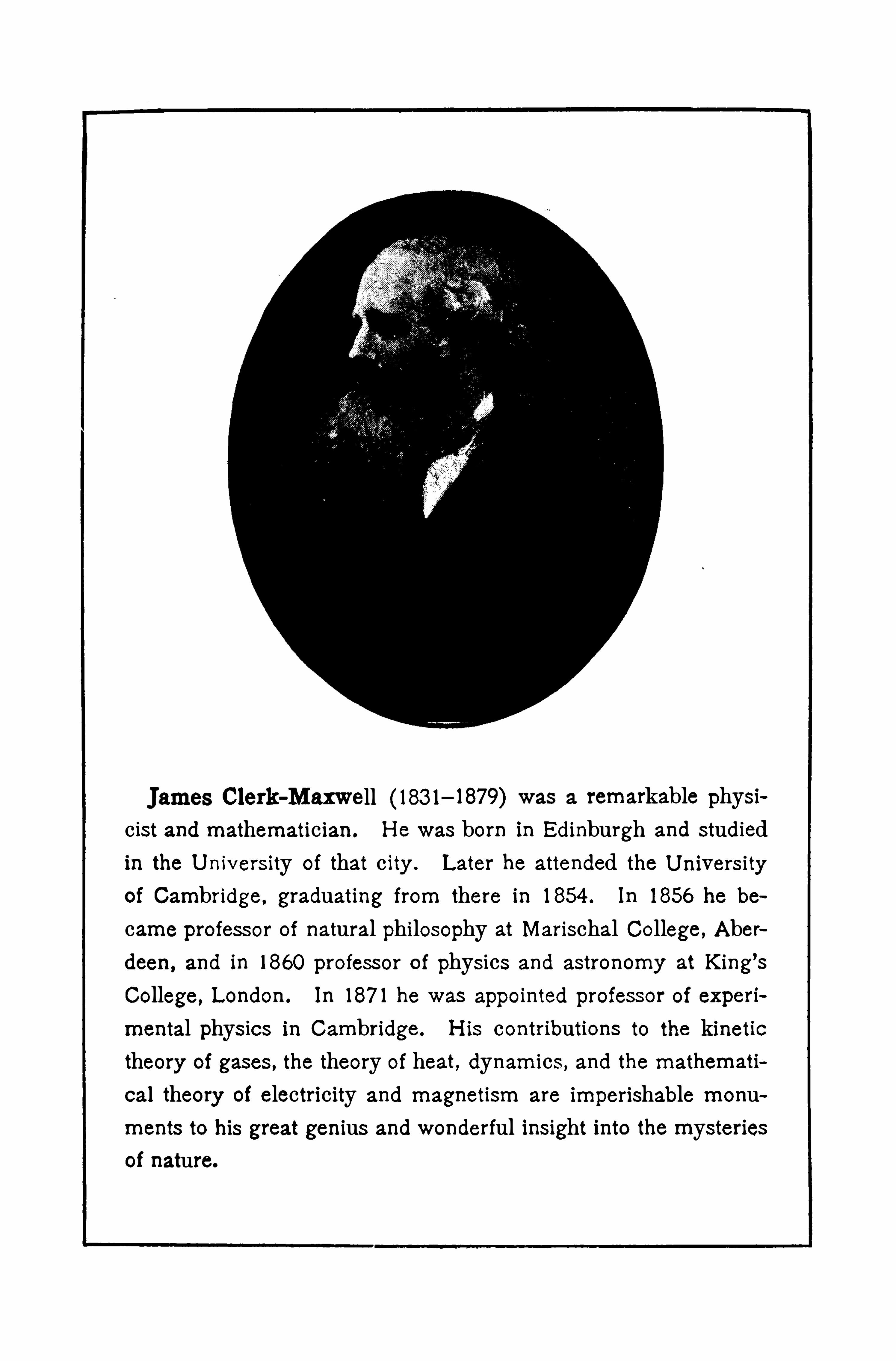
Clerk-Maxwell (183 1—1879) remarkable physicist and mathematician. H e was born in Edinburgh and studiedin the U nivers ity of that c ity . Later he attended the U nivers ityof Cambridge , graduating from there in 1854 . In 1856 he be
came professor Of natural philosophy at Marischal College, Aber
deen, and in 1860 professor O f physics and astronomy at King’s
College, London. In 187 1 he was appointed professor Of experi
mental physics in Cambridge. l-lis contributions to the kinetictheory Of gases , the theory Of heat, dynamics , and the mathemati
cal theory Of electricity and magnetism are imperishable monuments to his great genius and wonderful insight into the mysteriesof nature.


394 ELECTRIC CURREN T S
magnetic circuit . The residual magnetism is then much
greater than in the case of an open magnetic circuit withan air gap.
Br ing the armature in contact with the iron poles of the core, andclose the electric circuit after the circuit is opened, the armaturewillstill cling to the poles and can be removed only with some effort.
T hen place a piece of thin paper between the poles and the armature.
A fter the magnet has again been excited and the circuit Opened, thearmature will not now “
stick .
”T he paper
makes a thin air gap between the poles Of themagnet and the armature, and thus reducesthe residual magnetism .
487 . Applications of Electromagnets.
T he uses to which electromagnets areput inthe applications of electricity are so numerousthat a mere reference to them must suffice.
T he electromagnet enters into the construc
tion of electr ic bel ls, telegraph and telephoneinstruments, dynamos, motors, signaling devices, etc. It is also extensively used in lifting large masses Of iron
,such as castings,
rolled plates, pig iron, and steel girders (Fig.
T he lifting power depends chiefly onthe cross section Of the iron core and on the
ampere turns; that is, on the product of the
number Of amperes of current and the number of turns of wirewound on the magnet.
FI GURE 4 17 . L I FT I NGMAGNET .
VII . MEA SURING INSTRUMENTS
488. The Galvanometer .—T he instrument for the com
parison O f cur rents by means of their magnetic efiects is
cal led a galvanometer . A galvanoscope 446) becomes
a galvanometer by providing it with a scale so that the
deflections may be measured . If the galvanometer is
cal ibrated , so as to read directly in amperes, it is cal led an
ammeter . In very sensitive instruments a small mirror is

TH E D’
A RS ON VA L CA L VA N OMETER 395
attached to the movable part Of the instrument; it ~ is then
called a mirr or galvanometer . S ometimes a beam of light
from a lamp is reflected from this
smal l mirror back to a scale, and
sometimes the light from a scale
is reflected back to a small tele
scope, by means of which the deflections are read . In either casethe beam Of light then becomes a
long pointer without weight.
489. The d’Arsonval Galvanom
eter .—One of the most useful
forms of galvanometer is the
d’
A rsonval . T he plan of it'
is FIGURE 4 18.— PLAN OF D
’A R.
S ONVAL GALVANOMET ER.
shown in Figure 41 8 and a com
FI GURE 4 19.
S IMPLE D’A RS ON
VAL CALVANOM
ET ER .
plete working instrument in Figure 41 9.
Between the poles of a strong permanent
magnet Of the horseshoe form swings a
rectangular coil Of fine wire in such a way
that the current is led into the coil by thefine suspending W ire, and out by the wire
Spiral running to the base. A small mirror
is attached to the coil to reflect light from
a lamp or an i l luminated scale. Some
times the coil carries a l ight aluminum
pointer , which traverses a scale. Inside
the coi l is a soft iron tube supported from
the back of the case. It is designed to
concentrate the lines of force in the narrow
Openings between it and the poles of the
magnet .
In the d’
A rsonval galvanometer the coil is movable and
the magnet is fixed . Its chief advantages are simpl icity

396 EL ECTRIC CURREN TS
of construction, comparative independence Of the earth’
s
magnetic field, and the quickness with which the coilcomes to rest after deflection by a current through it.
490. The Voltmeter.
—The voltmeter is an
instrument designed tomeasure the differenceof potential in volts .
For direct currents the“most convenient portable voltmeter is madeon the pr incip le of the
d’
A rsonval galvanom
eter . One of the bestknown instruments Of
this class is shown in Figure 420. T he inter ior is rep
resented by Figure 421 , where a portion Of the in
strument is cut away to show the coil and the springs .
T he current is led in by one spiral spring and out by
the other . A ttached to the
coil is a very light aluminum
pointer, which moves over
the scale seen in Figure 420
where it stands at zero . S oft
iron pole pieces are screwed
fast to the poles of the per
manentmagnet, and they are
so shaped that the divisions
of thescale in volts areequal .
In circuit with the coil Of'
FIGURE 42 1 .
—1NS IDE OF VOLTMET ER.
the Instrument IS a 00 11 of
wire Of high resistance, so that when the voltmeter is placed
in circuit, only a smal l current wi l l flow through it.
FI GURE 420.—VOLTMETER.

398 ELECTRIC CU RREN Ts
by one path and part by the other . T he sum Of these twocurrents is always equal to the current In the undiv ided
part of the circuit, since thereis no accumulation of electr ic
l ity at any point. Either of
the branches between B and
A is called a shunt to the
other , and the currents through them are inversely p ropor
tional to their resistances .
h'
FI GURE 422 .—DIVI DED C IRCUIT
493. Resistance of a Divided Circuit—Let the total resistance between the points A and B (Fig. 422) be represented by R ,
that of the branch EmA by r , and of EnA by r’. The conductance Of
BA equals the sum of the conductances Of the two branches ; and,as
conductance is the reciprocal of resistance, the conductances of BA ,
EmA , and BnA are -
1 1, and
1respectively ; then -
1- l +
1
R 7'
7" R r 1
"
From this we derive R r:T o illustrate, let a galvanometerr r
whose resistance is 1 00 Ohms have its binding posts connected by ashunt of 50 Ohms resistance; then the total resistance of this divided
—1 00 X 50334 Ohms.
1 00 50
T he introduction of a shuntalways lessens the resistance between the points connected .
494 . Loss of Potentialalong a Conductor .
—Stretcha fine Wire of fair ly high resistance, such as a German silverNO . 30, along theedge of a meter
stick (Fig. Connect theends P and Q to a storage cel lwith a contact key in circuit.A t P connect a galvanometer in circuit with a high resistance R and
a S lide contact S . The galvanometer will indicate the difference of
potential between P and S , the point of contact on P Q . If S be
placed successively on P 0, at 1 0 cm., 20 cm.
, 30 cm., etc., from P , and
circuit is
FIGURE 423 . FALL OP POTENT IAL ALONGA CONDUCTOR .

WH EA TS TONE’
s BRIDGE 399
the galvanometer reading be recorded each time, the ratio of the
readings will be as 1 etc. S ince resistance is proportional tolength , these potential differences are as the resistances of the successive lengths Of the wire P Q, or the loss of potential is p roportional to theresistance passed over .
T his is equivalent to another statement Of Ohm’
s law ;
for since I E, and the cur rent through the conductor is
R
the same at all points, it fol lows that E must vary as R to
make I constant.
495. Wheatstone’
s Bridge,T heWheatstone’
s Bridge is a device for measuring resistances. T he four conductors, R 1 ,
R2,R3,R4
are the arms and BD the bridge (Fig.
When the circuit is Closed byclosing the key K2,
the current dividesat A , the two parts reuniting at C.
T he loss Of potential along A BC is thesame -as along A DC. If no currentflows through the galvanometer G
when the key K ,is also closed
, thenthere is no potential difference betweenB and D to produce a current. U nderthese conditions the loss of potentialfrom A to B is the same as from A
to D . We may then get an expression FIGURE 424 . WHEATSTONE’Sfor these potential differences and BRI DGE.place them equal to each other .
Let Ilbe the current through R
1 ; it will also be the currentthrough R
4, because none flows across through the galvanometer .
A lso let [2 be the current through the branch A DC . Then the potential difference between A and B by Ohm’
s law 47 1 ) is equal to R 1 1 1and the equal potential difference between A and D isR
212. Equating
these expressions,RI11
2 B212 (a)
In the same way the equal potential differences between B and C
d Dan and C g1veR41,2 R 1 (b)

400 EL ECTRIC CURREN TS
Dividing (a) by (6) gives
(Equation 38)
In practice three of the four resistances are adjustable and of
known value. T hey are adjusted until the galvanometer shows no
deflection when the keyX1 is closed after,
key K2. T he value of the
fourth resistance is then der ived from the relation in Equation 38.
P rob lems
1 . Calculate the resistance of 200 ft. of Copper wire (kNO . 24 (diameter
2 . A coil of iron wire(k is to have a resistanceof 25 ohms.
T he diameter of the wire used is in. H ow many feet will it require
3 . What diameter must a copper trolley (k have so thatthe resistance will be half an ohm to the mile ?
4 . A current of one ampere deposits by electrolysis g . of
copper in an hour . H ow long will it take a current of 5 amperes todeposit a kilogram of copper
5 . A current of two amperes passes through a solution of silvernitrate for one hour . H ow much silver will be deposited
6 . A current of 1 0 amperes is sent through a resistance of 4 ohms
for 1 0 minutes. H ow many calories of heat are generated ?7 . What current will 6 dry cells connected ln series, each having
an E .M . F. of volts and an internal resistance of ohm , givethrough an external resistance of 2 ohms ?
8 . A certain dry cell has a voltage of volts and when testedwith an ammeter gives 20 amperes. What is its internal resistance ?
9 . A certain lamp requires ampere current and an E.M. F. of
1 1 0 volts to light it. What is its resistance ?1 0 . A projection lantern requires a current of 15 amperes. T he
voltage of the supply is 1 1 0 volts and the loss in the lamp is 40 volts.
What resistance must be inserted in the line to the lantern ?
Michael Faraday , 179 1—1867 , was born near London, England.
H e was the son of a blacksmith arid received but little schooling,being apprenticed to a bookbinder when only thirteen years of
age. While employed in the bindery he became interested in
reading such scientific books as he found there. Later he appliedto S ir H umphry Davy for consideration and was made Davy'sassistant. From this time his risewas rapid ; in 1816 he publishedhis first S c ientific memoir ; in 1824 he became a member of the
Royal S ociety ; in 1825 he was elected director of the RoyalInstitution ; in 183 1 he announced the discovery of magneto
electric induction , the most important scientific discovery of any
age. In 1833 he was elected professor Of chemistry in the RoyalInstitution. H e was a remarkable experimenter and a most inter
esting lecturer , and amid all his wonderful achievements , he wasutterly wanting in vanity.
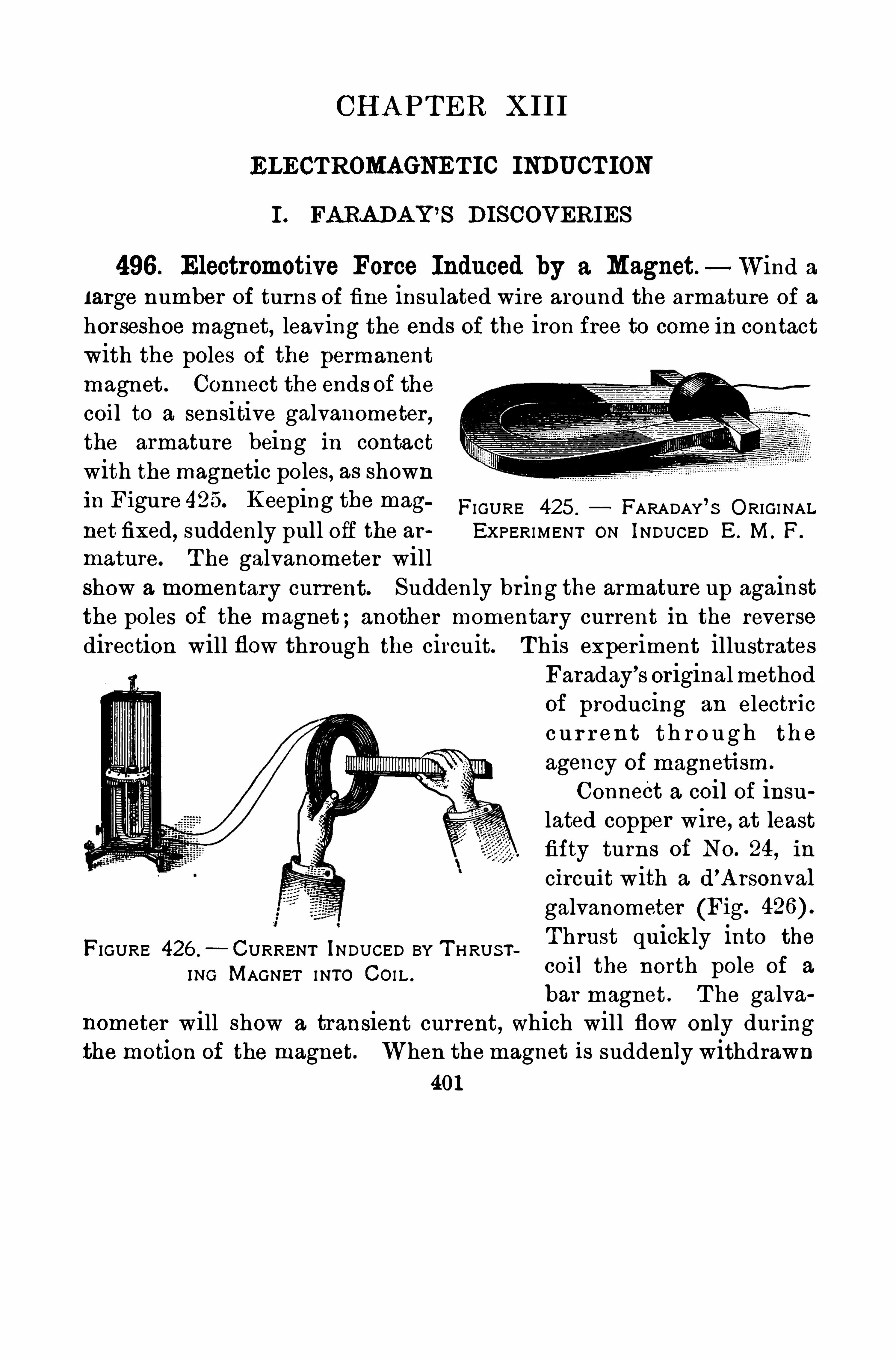
CH A PTER XIII
ELECTROMAGNET IC INDUCT ION
I . FA RA DA Y ’S DISCOVERIES
496. Electromotive Force Induced by a Magnet. Wind alarge number of turns of fine insulated wire around the armature of a
horseshoe magnet, leaving the ends of the iron free to come in contactwith the poles of the permanent
magnet . Connect the ends of thecoil to a sensitive galvanometer ,the armature being in contactwith the magnetic poles, as shownin Figure 425° Keeping the mag FIGURE 425 . FARADAY’S ORIGI NALnet fixed, suddenly pull off the ar EXPERIMENT ON INDUCED E. M. F.
mature. The galvanometer willshow a momentary current. Suddenly br ing the armature up againstthe poles of the magnet;another momentary cur rent in the reversedirection will flow through the circuit. T his experiment illustrates
FIGURE 426 .
—CURRENT INDUCED BY T HRUS TINC MAGNET I NTO CO I L .
Faraday’s originalmethodof producing an electricc u r r en t th r o u g h th e
agency of magnetism.
Connect a coil of insulated copper wire, at leastfifty turns of NO . 24, in
circuit with a d’
A rsonval
galvanometer (Fig.
T hrust quickly into the
coil the north pole of a
bar magnet . T he galvanometer will show a transient current, which will flow only duringthe motion of the magnet. When themagnet is suddenly withdrawn
401
402 ELECTROMA GNE TIC IND UCTION
a transient current is produced in the opposite direction to the firstone . If the south pole be thrust into the coil , and then withdrawn, .
the currents in both cases are the reverse of those with the north pole.
If we substitute a helix of a smaller number of turns, or a weaker barmagnet, the deflection will be less .
The momentary electromotive forces generated in the
coil are known as induced electromotiveforces, and the cur
rents as induced currents. T hey were discovered byFaraday in 1 831 .
497. Laws of Electromagnetic Induction. When the
armature in the first exper iment of the last article is incontact with the poles of the magnet, the number of l inesof force passing through the coi l , or l inked with it, is a
maximum . When the armature is pul led away, the num
ber of magnetic lines threading through the coi l rapidlydiminishes .
When the magnet in the second exper iment is thrustinto the coi l , it carr ies its l ines of force with it, so that
some of them at least encircle, or are l inked with, thewires of the coil . In both exper iments an electromotive
force is generated only while the number of l ines so linkedwith the coil is changing. T he E .M .F . is generated in
the coil in accordance with the foll owing laws
1 .An increase in the num ber of lines of force linked
with a conducting”
cir cu it produ ces an ind irect E .M . F .
a decr ease in the num ber of lines produces a directE . .M. F .
I I. The indu ced E .M F . at any instant is equa l to the
r ate of incr ease or decrea se in the n umber of lines of force
linked with the circu it.
A direct E .M .F. has a'
clockwise direction to an observer
looking al ong the lines of force of the magnet an indirect
E. M. F. is one in the Opposite direction . T hus, in Figure
404 EL ECTR OMA GNE TIC INDUCTI ON
If while P is inside S with the battery circuit closed, a bar of soft
iron is placed within P ,there is an increase of magnetic lines through
both coils and the inductive effect in S is the same as that producedby closing the circuit through P
The coil P is cal led the p rimary and S the secondary
coil . T he results may be summar ized as fol lows
I . .A m omentary cu r rent in the opposite d irection is
indu ced in the secondary condu ctor by the appr oach , the
star ting, or the strengthening of a cu r rent in the p r im ary .
II . .A m om entary cu rrent in the sam e d irection is in
duced in the secondary by the reced ing, the stepp ing, or
the weaken ing“of the cu r rent in the p r im a ry .
T he pr imary coil becomes a magnet when carrying an
electr ic current 480) and acts toward the secondary coil
as if it were ti. magnet. T he soft iron increases the
magnetic flux through the coil and so increases the induction .
499. Lenz’s Law. When this north pole of themagnet is
thrust into the coi l of Figure 427, the induced current flowing in the direction of the arrows produces lines of force
running in the Opposite direction to those from themagnet
T hese lines of force tend to Oppose the change
in the magnetic field within the coil, or the magnetic field
set up by the coil Opposes the motion of the magnet.
A gain , when the pr imary coi l of Figure 428 is insertedinto the secondary, the induced cur rent in the latter is
opposite in direction to the pr imary current, and paral lel
currents in opposite directions repel each other . In every
case of electromagnetic induction the change in the mag
netic field which produces the induced cur rent i s alwaysopposed by the magnetic field due to the induced currentitself.
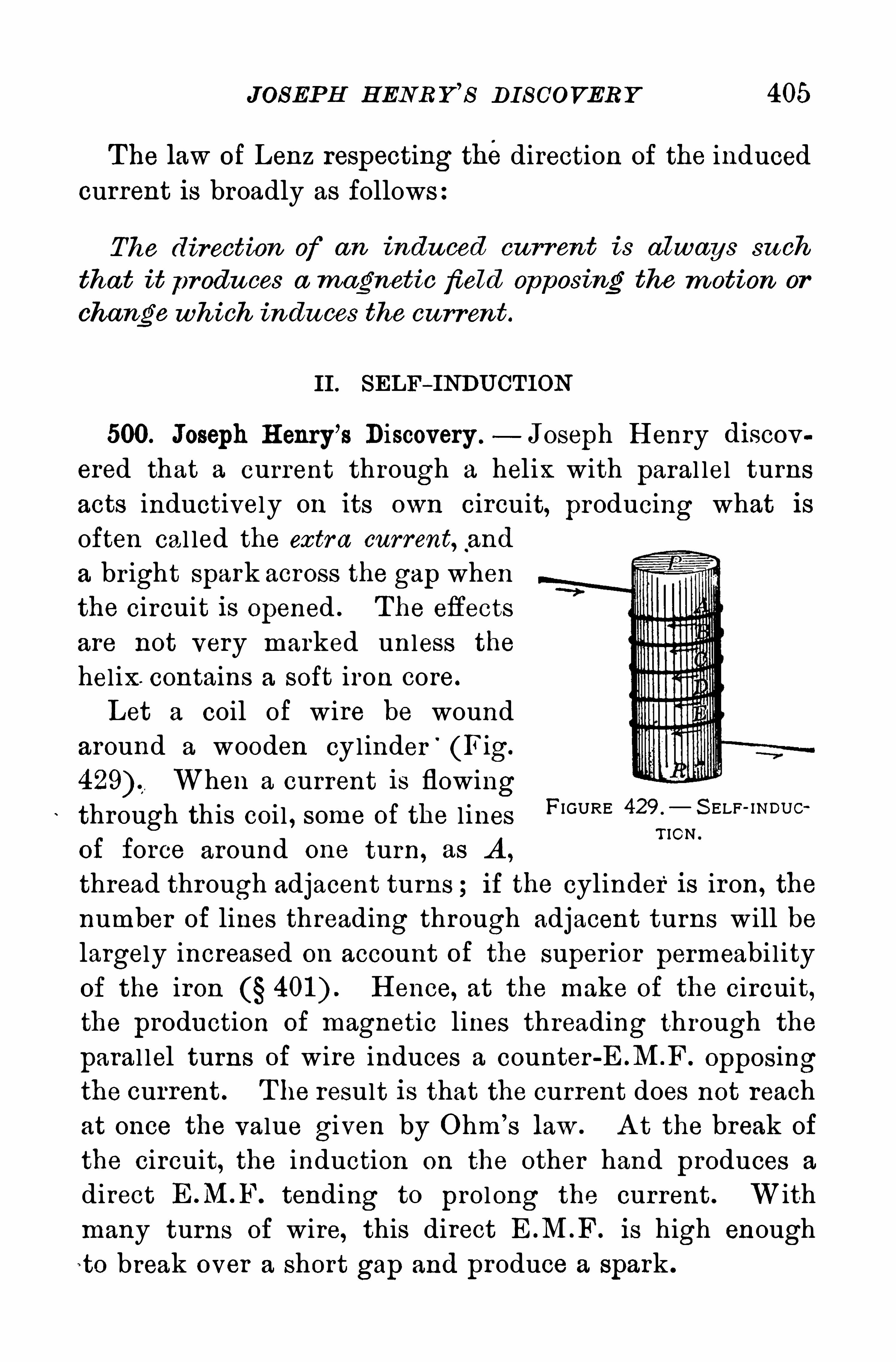
JOSEP H H ENR Y’
s DI S COVERY 405
The law of Lenz respecting thedirection of the induced
current is broadly as follows:
The direction of an indu ced cu rr ent is always su ch
tha t it produ ces a magnetic field Opposing the m otion or
change wh ich indu ces the cu rrent.
II . SELF—INDU CTION
500. Joseph H enry’s Discovery .
— Joseph H enry discov
ered that a current through a helix with paral lel turns
acts inductively on its own circuit, producing what isoften cal led the extra current, .
and
a br ight spark across the gap when
the circuit is opened . The effects
are not very marked unless the
hel ix. contains a soft iron core.
Let a coil of wire be wound
around a wooden cylinder'
(Fig.
429) When a current is flowingthrough this coi l , some of the l ines
of force around one turn, as A ,
thread through adjacent turns ; if the cylinder is iron, the
number of lines threading through adjacent turns will be
largely increased on account of the super ior permeabilityof the iron H ence, at the make of the circuit,the production of magnetic lines threading through the
paral lel turns of wire induces a counter opposingthe current . T he result is that the current does not reachat once the value given by Ohm’
s law . A t the break of
the circuit, the induction on the other hand produces a
direct E .M.F. tending to prolong the current . W ithmany turns of wire, this direct E .M .F. is high enough
to break over a short gap and produce a spark .
FIGURE 429 . S ELF- INDU cT ION .
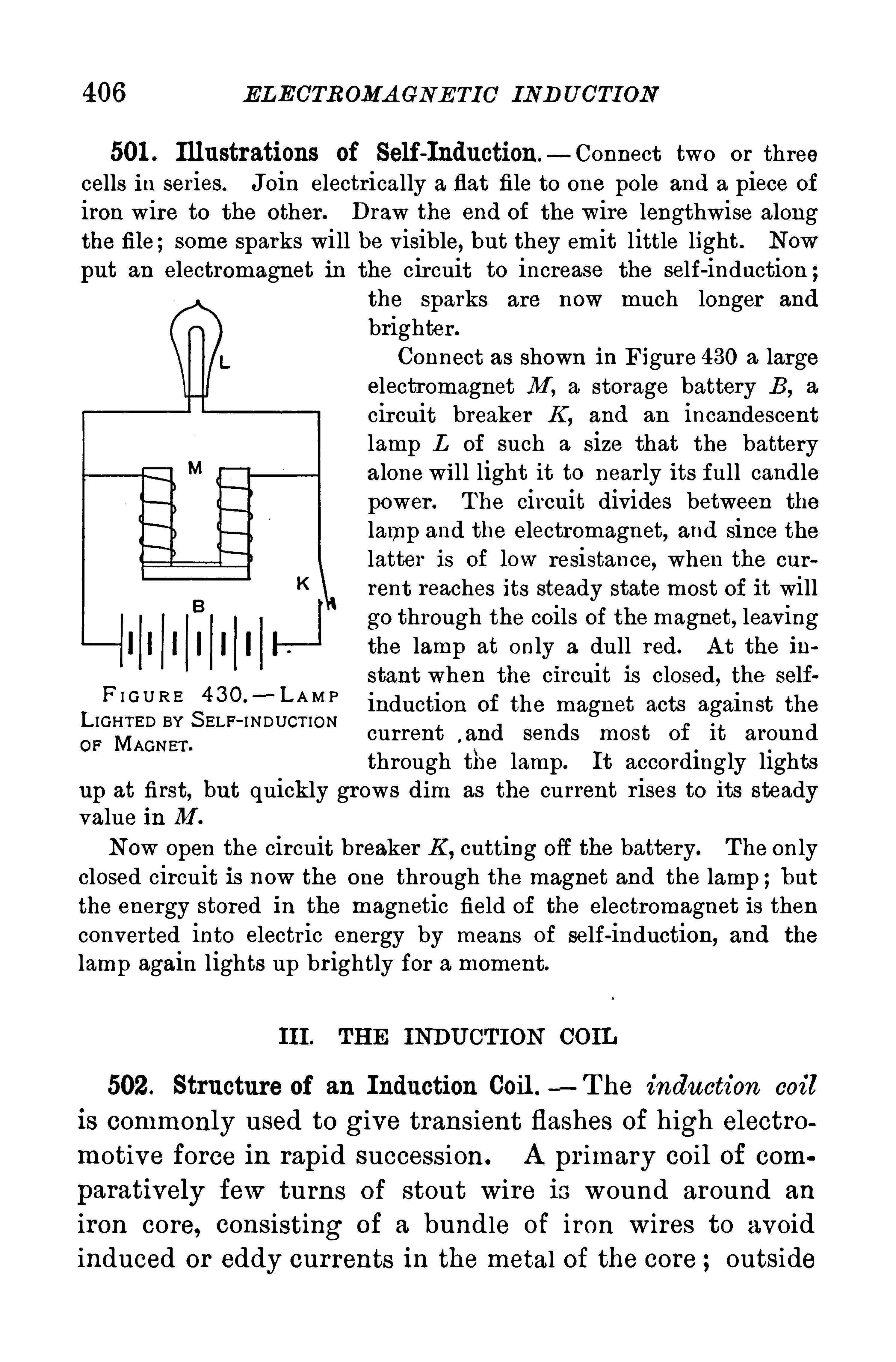
406 ELECTROMA GNE TIC IND UCTI ON
501 . Illustrations of Self-Induction—Connect two or threecells in series. Join electrically a flat file to one pole and a piece of
iron wire to the other . Draw the end of the wire lengthwise alongthe file;some sparks will be visible, but they emit little light. Now
put an electromagnet in the circuit to increase the self-induction ;the sparks are now much longer and
brighter .
Connect as shown in Figure 430 a largeelectromagnet M , a storage battery B , a
circuit breaker K , and an incandescentlamp L Of such a size that the batteryalone will light it to near ly its full candlepower . T he circuit divides between the
lamp and the electromagnet, and Since thelatter is of low resistance, when the cur
rent reaches its steady state most of it willgo through the coils of the magnet, leavingthe lamp at only a dull red. A t the in
stant when the circuit is closed, the selfinduction of the magnet acts against thecurrent
,and sends most of it around
through the lamp. It accordingly lightsup at first, but quickly grows dim as the current rises to its steadyvalue in M .
Now Open the circuit breaker K ,cutting off the battery. The only
closed circuit is now the one through the magnet and the lamp ;butthe energy stored in the magnetic field of the electromagnet is thenconverted into electric energy by means of self-induction, and the
lamp again lights up brightly for a moment.
F I G U R E 4 3O.
- L A M PL IGHTED BY S ELF- I NDUCT IONOP MAGNET .
III. TH E INDU CT ION COIL
502. Structure of an Induction Coil . —T he induction coil
is commonly used to give transient flashes of high electromotive force in rapid succession. A primary coil of com
paratively few turns of stout wire is wound around an
iron core, consisting of a bundle of iron wires to avoidinduced or eddy cur rents in the metal of the core ; outside
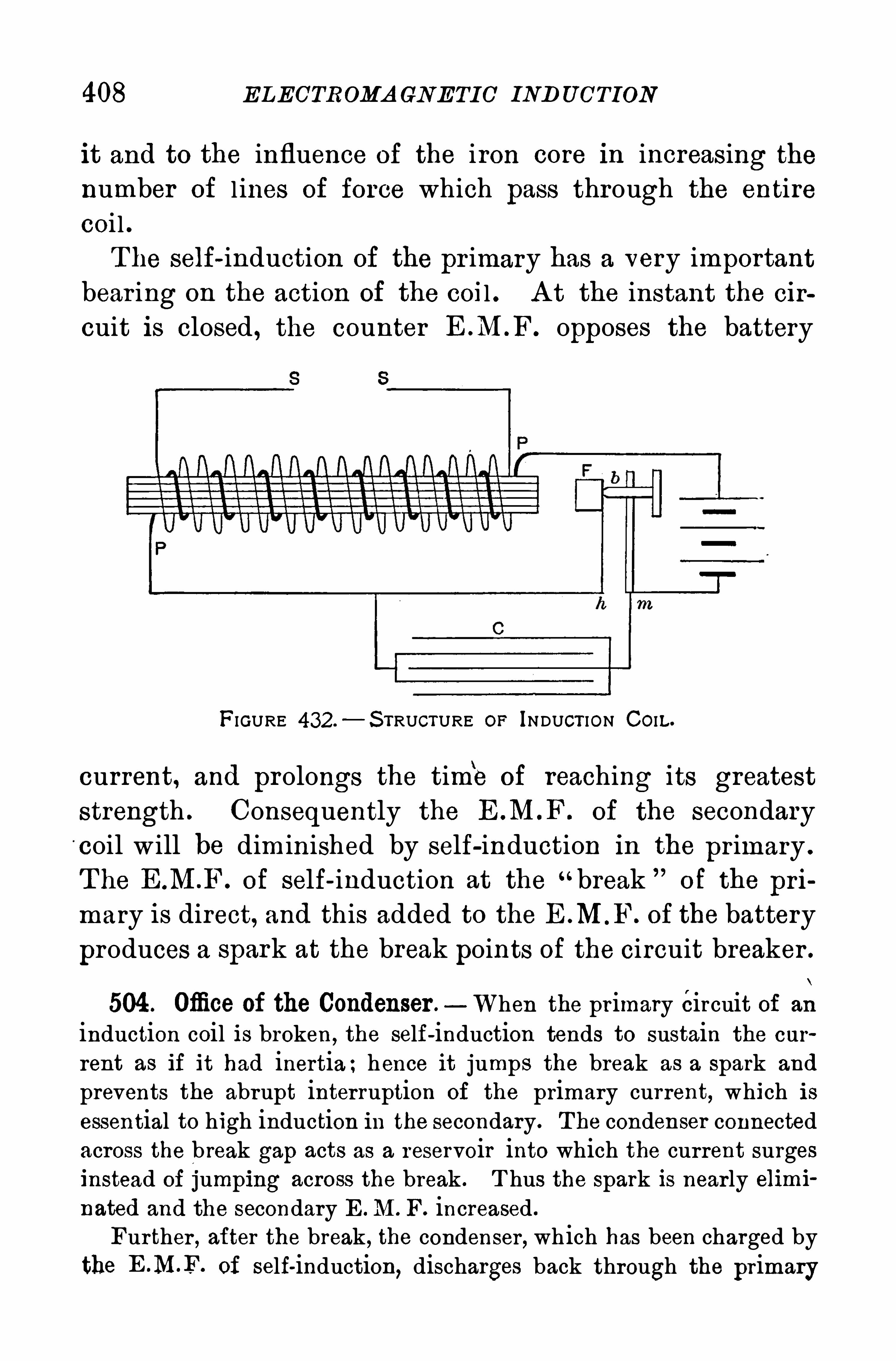
408 ELECTROMA GNETIC IND UCTION
it and to the influence of the iron core in increasing thenumber of l ines of force which pass through the entirecoi l .T he self- induction of the pr imary has a very important
bear ing on the action of the coil . A t the instant the cir
cuit is closed , the counter opposes the battery
FIGURE 432.—S TRUCTURE OF INDUCT ION CO IL.
current, and prolongs the time of reaching its greatest
strength . Consequently the of the secondarycoil w ill be diminished by self-induction in the primary .
T he E.M.F . Of self- induction at the “break ”of the pri
mary is direct, and this added to the E .M .F. of the battery
produces a spark at the break points of the circuit breaker .
504. Office of the Condenser . When the primary Circuit of an
induction coil is broken, the self-induction tends to sustain the cur
rent as if it had inertia ; hence it jumps the break as a spark and
prevents the abrupt interruption of the primary current, which isessential to high induction in the secondary. T he condenser connectedacross the break gap acts as a reservoir into which the current surgesinstead of jumping across the break . T hus the spark is nearly elimi
nated and the secondary E .M . F. increased .
Further , after the break, the condenser, wh ich has been charged bythe E .MHF of self-induction, discharges back through the primary
EXP ERIMEN TS WI TH TH E IND UCTI ON COIL 409
coil . The condenser thus causes an electr ic recoil in the current inthe reverse direction through the primary, demagnetizing the coreand increasing the rate of change of the magnetic flux , and so in
creasing the E.M. F . in the secondary. H ence, when the secondaryterminals are separated , the discharge is all in one direction and occurswhen the primary current is bi'oken .
505. Experiments with the Induction Coil . 1 . Physiological
Ef eets . H old in the hands the electrodes of a very small inductioncoil, of the style used by physicians. When the coil is working, a
peculiar muscular contraction is produced .
T he “shock from large coils is dangerous on account
of the high E .M .F. T he danger decreases with the ih
crease in the rapidity of the impulses or alternations .
Exper iments with induction coils, worked by alternatingcurrents of very high frequency , have demonstrated that
the discharge of the secondary up to .an ampere may be
taken through the body without injury .
2. Mechanical Efiects .—H old a piece of cardboard between the
electrodes of an induction coil giving a spark 3 cm . long. T he cardwill be perforated, leaving a burr on each side. T hin plates of anynonconductor can be perforated in the same manner .
3 . Chemical Ef ects.—Place on a plate of glass a strip of white
blotting-paper moistened with a solution of potassium iodide (a com
pound of potassium and iodine) and starch paste. A ttach one of the
electrodes of a small induction coil to the margin of the paper.
With an insulator , hand le a wire leading to the other electrode, andwhen the coil is in action, trace characters with the wire on the paper .
The discharge decomposes the potassium iodide, as shown by the bluemark . This b lue mark is due to the action of the iodine on the
starch .
If the current from the secondary of an induction coil be passedthrough air in a sealed tube, the nitrogen and oxygen will combine toform nitrous acid . T his is the basis of some of the commercialmethods of manuf acturing nitrogen compounds from the nitrogen of
the air .
4. H eating Efiects .—Figure 433 shows the plan of the “electric
bomb . It is usually made of wood. Fill the hole with gun powder
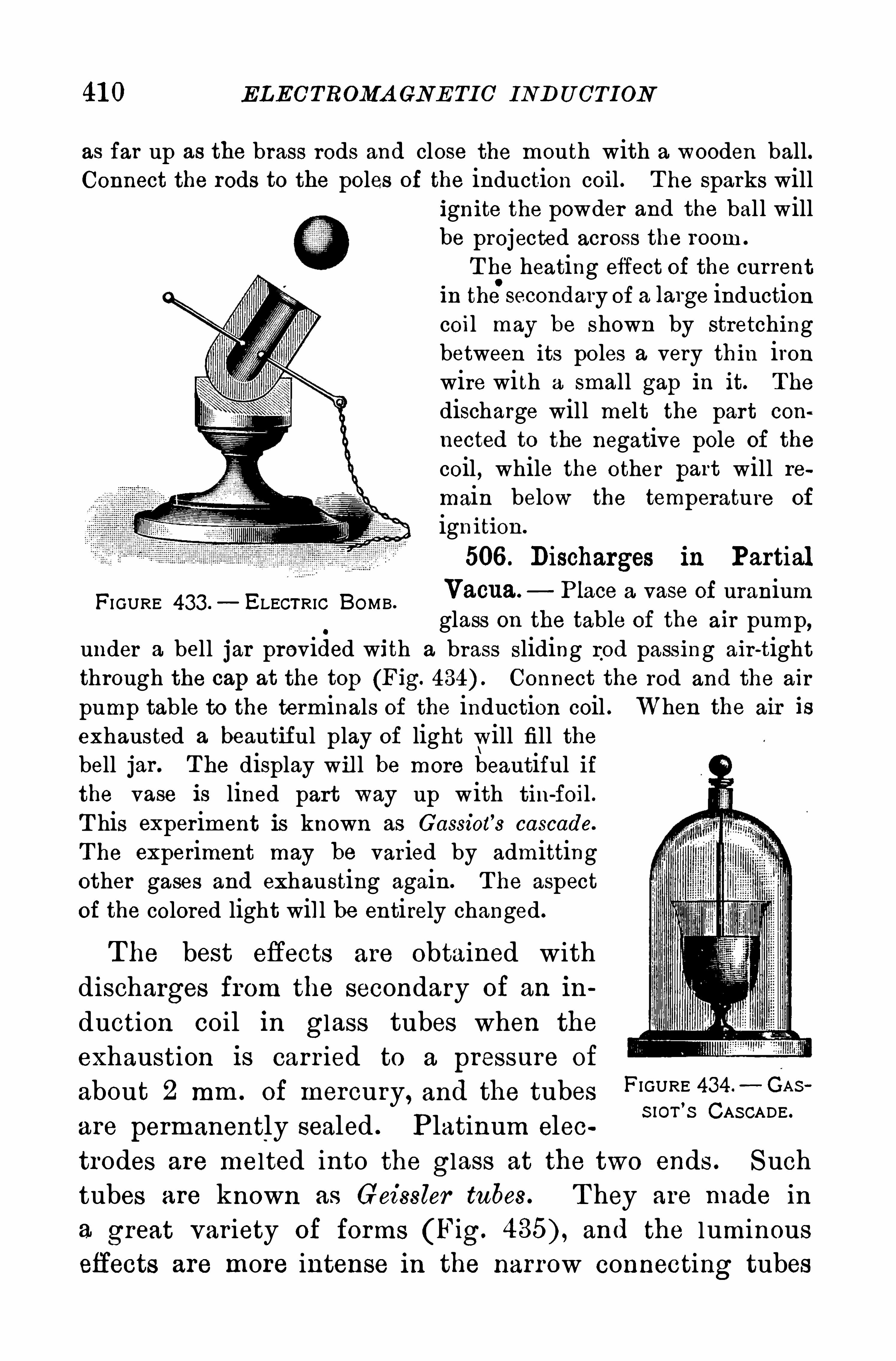
41 0 ELECTROMA GNE TIC IND U CTION
as far up as the brass rods and close the mouth with a wooden ball.Connect the rods to the poles of the induction coil . T he sparks will
FI GURE 433 .— ELECTRIC BOMB .
ignite the powder and the bal l willbe projected across the room .
T he heating effect of the currentin the secondaIy of a 1mge inductioncoil may be shown by stretchingbetween its poles a very thin ironwire with a small gap in it. T he
discharge will melt the part con
nected to the negative pole of the
coil , while the other part will re
main below the temperature of
ignition.
506 . Discharges in PartialVacua. Place a vase of uraniumglass on the table Of the air pump,
under a bell jar provided with a brass sliding rod passing air-tightthrough the cap at the top (Fig. Connect the rod and the air
pump table to the terminals of the induction coil .exhausted a beautiful play of light will fill thebell jar . T he display wil l be more beautiful ifthe vase is lined part way up with tin-foil .T his experiment is known as Cassiot
’
s cascade.
T he experiment may be varied by admittingother gases and exhausting again. T he aspectof the colored light will be entirely changed.
T he best effects are obtained with
discharges from the secondary of an in
duction coil in glass tubes when the
exhaustion is carr ied to a pressure of
about 2 mm . of mercury, and the tubes
are permanently sealed . Platinum elec
When the air is
FIGURE 434 . GA S
S IOT’
S CAS CADE .
trodes are melted into the glass at the two ends . Suchtubes are known as Geissler tubes. T hey are made in
a great var iety of forms (Fig. and the luminous
effects are more intense in the narrow connecting tubes
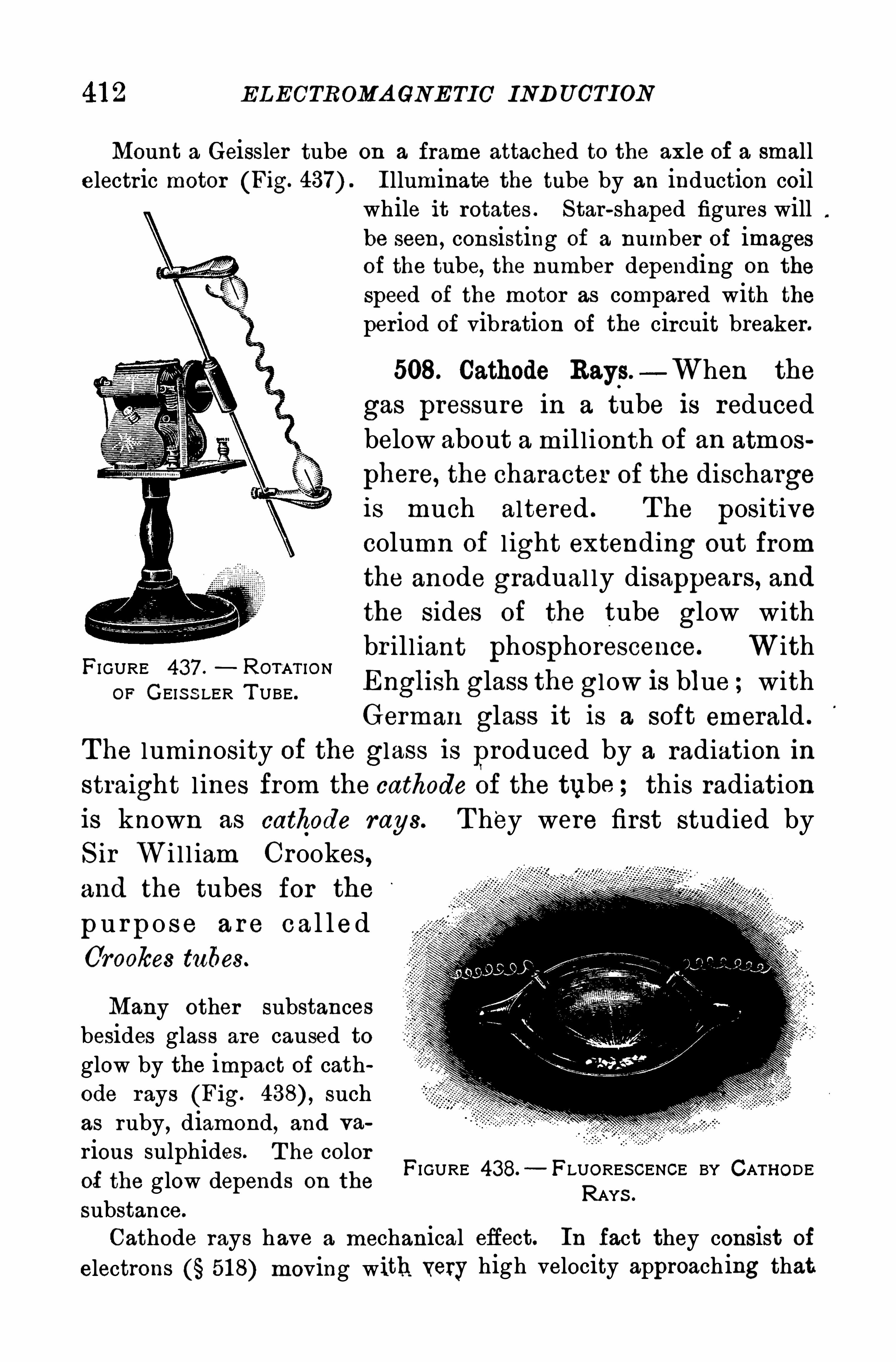
ELECTROMA GNE TIC INDUCTION
Mount a Geissler tube on a frame attached to the axle of a smallelectric motor (Fig. I lluminate the tube by an induction coil
while it rotates . S tar-shaped figures willbe seen , consisting of a number of imagesof the tube, the number depending on the
speed of the motor as compared with theperiod of vibration of the circuit breaker.
508. Cathode Rays—When the
gas pressure in a tube is reduced
below about a mil l ionth of an atmos
phere, the character of the dischargeis much altered . The positivecolumn of l ight extending out from
the anode gradual ly disappears, andthe sides of the tube glow withbr ill iant phosphorescence. With
English glass the glow is blue withGerman glass it is a soft emerald .
T he luminosity of the glass is produced by a radiation in
straight l ines from the cathode of the tube ; this radiation
is known as cathode rays. T hey were first studied byS ir Wi l l iam Crookes ,and the tubes for the
p u r p o se a r e c a l led
Crookes tubes.
FI GURE 437 . ROTAT IONOF GEIS S LER T UBE .
Many other substancesbesides glass are caused toglow by the impact of cathode rays (Fig. suchas ruby, diamond, and va
r ions sulphides. T he colorof the glow depends on the
substance.
Cathode rays have a mechanical efiect. In fact they consist of
electrons 518) moving with very high velocity approach ing that
FIGURE 438.—FLUORES CENCE BY CATHODE
RAYS .


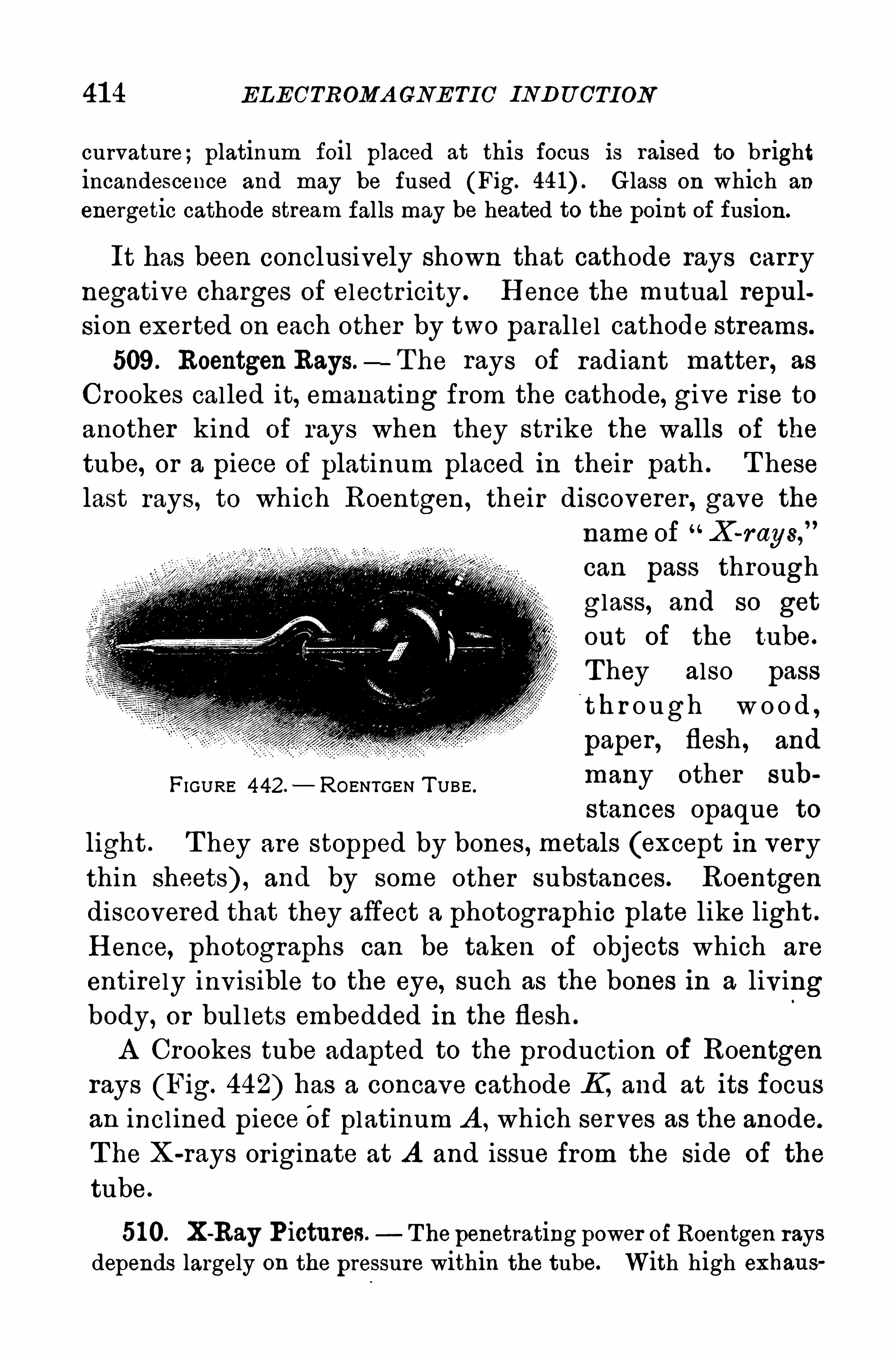
41 4 ELECTROMA GNE TIC INDU CTION
curvature; platinum foil placed at this focus is raised to brightincandescence and may be fused (Fig. Glass on which an
energetic cathode stream falls may be heated to the point of fusion.
It has been conclusively shown that cathode rays carry
negative charges of electricity . H ence the mutual repul
sion exerted on each other by two parallel cathode streams.
509. Roentgen Rays.—T he rays of radiant matter , as
Crookes called it, emanating from the cathode, give r ise toanother kind of rays when they str ike the walls of the
tube, or a piece of platinum placed in their path . T heselast rays, to which Roentgen, their discoverer, gave the
name of X-r ays,”
can pass through
glass, and so get
out of the tube.
T hey also pass
t h r o ugh w o o d ,
paper , flesh , and
many other sub
stances opaque to
light . T hey are stopped by bones, metals (except in very
thin sheets) , and by some other substances. Roentgendiscovered that they affect a photographic plate like light .
H ence, photographs can be taken Of objects which are
entirely inv isible to the eye, such as the bones in a livingbody, or bul lets embedded in the flesh .
A Crookes tube adapted to the production of Roentgenrays (Fig. 442) has a concave cathode If, and at its focus
an incl ined piece Of platinum A , which serves as the anode.
T he X-rays or iginate at A and issue from the side of the
tube.
51 0. X-Ray P ictures. T he penetrating power of Roentgen raysdepends largely on the pressure within the tube. With high exhaus
FIGURE 442. ROENTGEN T UBE .
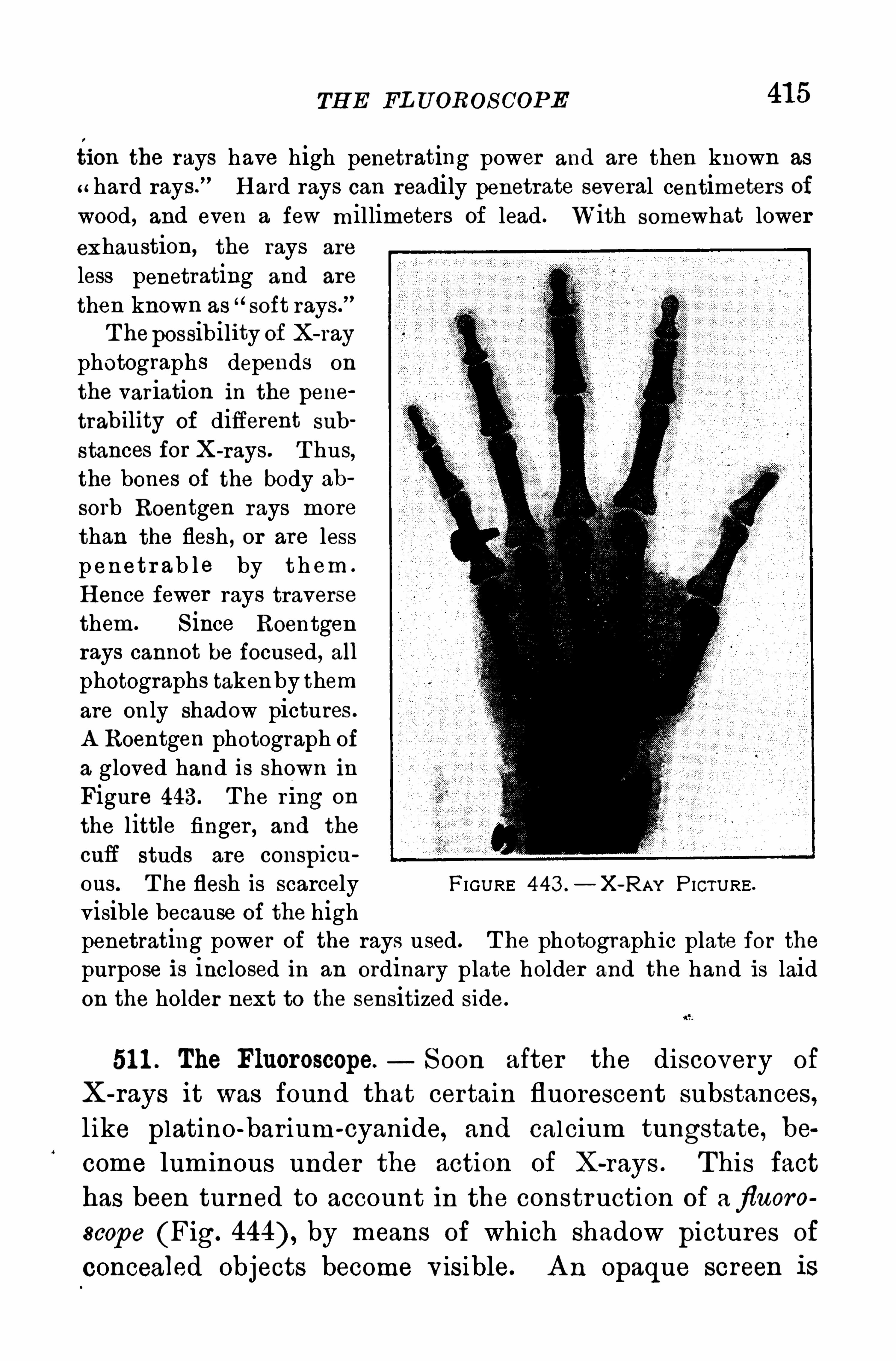
TH E FL U OROS COPE 41 5
tion the rays have high penetrating power and are then known as
hard rays.
”H ard rays can readily penetrate several centimeters of
wood, and even a few millimeters of lead . With somewhat lower
exhaustion,the rays are
less penetrating and are
then known as“soft rays.
”
T hepossibility of X-ray
photographs depends on
the variation in the penetrability of different sub
stances for X-rays. T hus,the bones of the body ab
sorb Roentgen rays more
than the flesh , or are lessp enetr ab le by t h em .
H ence fewer rays traversethem. S ince Roentgenrays cannot be focused, allphotographs takenby themare only shadow pictures.
A Roentgen photograph ofa gloved hand is shown inFigure 443 . T he r 1ng on
the little finger , and the
cufi studs are conspicu
0 11 3 T he flesh is scarcely FI GURE 443 .
— X-RAY P ICTURE .
visible because of the highpenetrating power of the rays used . T he photograph ic plate for thepurpose is inclosed in an ordinary plate holder and the hand is laidon the holder next to the sensitized side.
51 1 . The FluorosCOpe. S oon after the discovery of
X-rays it was found that certain fluorescent substances,like platino -bar ium-cyanide, and calcium tungstate, become luminous under the action of X-rays . T his facthas been turned to account in the construction of afluoroscope (Fig. by means of which shadow pictures of
concealed objects become v isible. A n opaque screen is
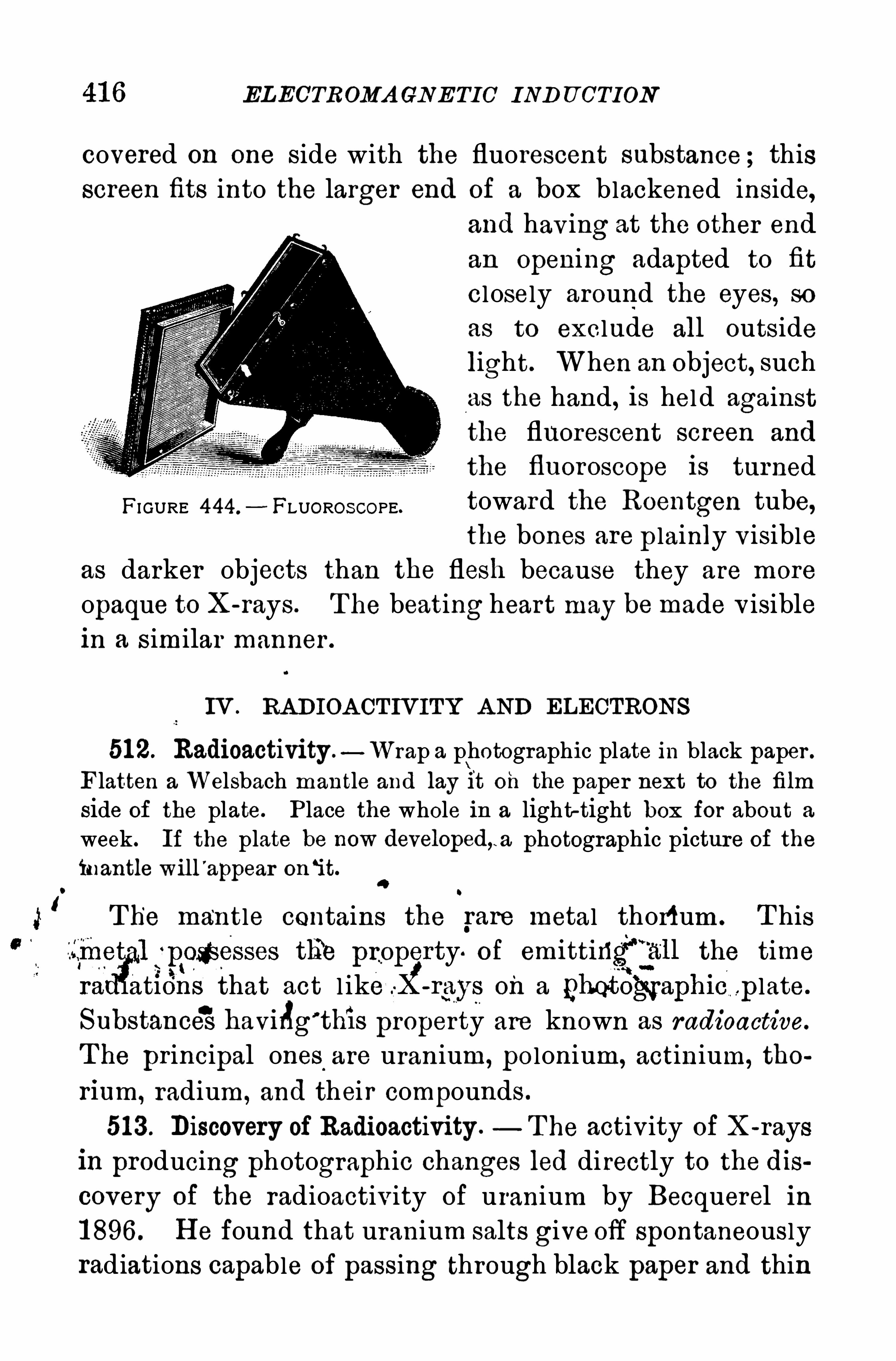
EL ECTROMA CN E TIC IND U CTION
covered on one side with the fluorescent substance ; thisscreen fits into the larger end of a box blackened inside,
and hav ing at the other end
an Opening adapted to fit
closely around the eyes, soas to exclude all outsidelight. When an Object, such
as the hand , is hel d againstthe fluorescent screen and
the fluoroscope is turned
FI GURE 444.
- FLUOROS COPE.toward the Roentgen tube,the bones are p lainly v isible
as darker objects than the flesh because they are more
opaque to X-rays . T he beating heart may be made v isiblein a similar manner .
IV . RADIOA CTIVITY A ND ELECTRONS
51 2. Radioactivity —Wrap a photographic plate in black paper .
Flatten a Welsbach mantle and lay it Oh the paper next to the film
side of the plate. P lace the whole in a light-tight box for about a
week. If the plate be now developed,. a photographic picture of the
inantle will'
appear on‘it.
4
IT he mantle contains the rare metal thori um . T his
tli‘e pro y» of emittiri the time
that act l ik on a p p late.
Substance'
S havilig’
this property are known as radioactive.
T he principal ones.
are uranium, polonium, actinium, tho
rium, radium, and their compounds .
51 3 . Discovery of Radioactivity .— T he activity of X-rays
in producing photographic changes led directly to the dis
covery of the radioactivity of uranium by Becquerel in
1 896 . H e found that uranium salts give off spontaneouslyradiations capable of passing through black paper and thin
41 8 ELECTROMA GNE TIC IND U CTION
and gamma rays . T he alpha rays are slightly deflected
to the left, the beta rays strongly to the r ight, while the
gamma rays are not affected in the least. T he fact thatthe alpha and beta rays suffer deviations in opposite directions shows not only that they are charged par ticles, butthat they are Oppositely charged , the former positively
and the latter negatively .
T he alpha rays are positively charged particles emitted
with an average velocity about one-fifteenth the speed of
l ight. T hey have little penetrating power and are ab
sorbed by a sheet of ordinary wr iting paper .
T he beta rays are negatively electr ified, highly penetra
tive, and identical in nature with cathode rays
T hey travel with an average speed from about one-half
down to about one-tenth that of light.
T he gamma rays are of very high penetratingpower , they
travel with the velocity of l ight, and appear to be identical
with X-ray'
s. T hey show no trace of electr ification .
51 6 . Radium a Product of Disintegration —U ranium has
the highest atomic weight of any known substance, and it
is always associated in nature with other radioactive sub
stances . T his association suggested that the other ra‘dio
active substances are der ived from uranium by its dis
integration, or loss of particles with reduction of atomic
weight. Such has been found to be the case. U ranium
Is the parent of ionium, and ionium is the parent of radium.
Radium is thus a product of disintegration.
Further , the radium atom disintegrates with the expul
sion of an alp ha particle and the alpha particle, after losingits positive charge, becomes an atom of helium. T hus a
known element is produced dur ing the transformation of
radioactive matter . A ll alpha par ticles from whatever
source consist of hel ium atoms carrying pos itive Charges.

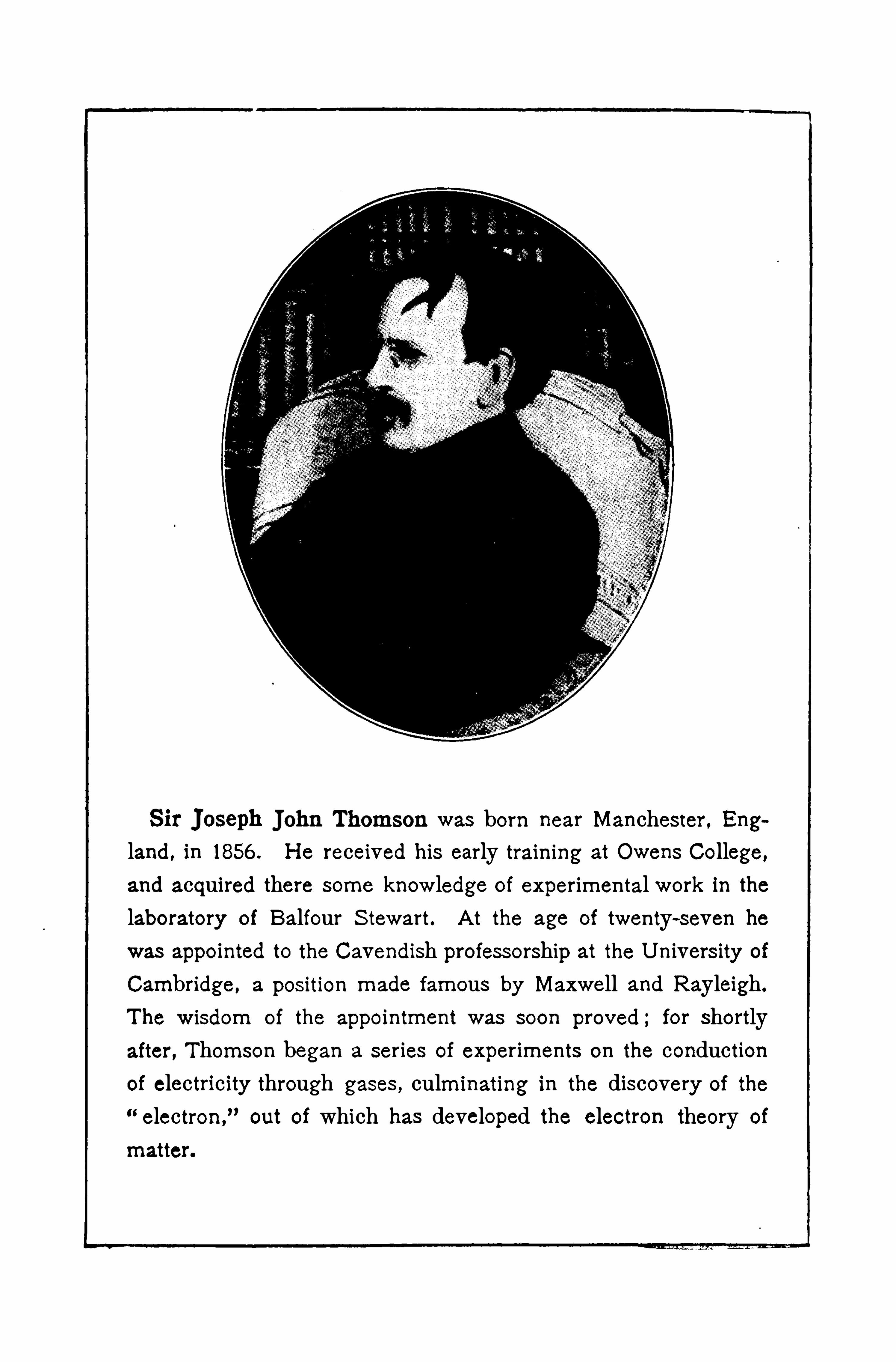
S ir Joseph Thomson was born near Manchester , England , in 1856 . H e received his early training at Owens College,
and acquired there some knowledge of experimental work in thelaboratory of Balfour S tewart. A t the age of twenty—seven hewas appointed to the Cavendish professorship at the U nivers ity of
Cambridge , a position made famous by Maxwell and Rayleigh.
The wisdom of the appointment was soon proved ; for shortlyafter , Thomson began a series of experiments on the conductionof electricity through gases , culminating in the discovery of the
“electron,
”out of which has developed the electron theory of
matter.

ELECTROMA GNE TIC INDU CTION
the electron is identical with the single atomic charge of
a negative ion in electrolysis . If positive electricity is
atomic, its atom is several thousands of times greater than
the atomic quantity of negative electr icity .
Electrons enter into the composition of all matter . A n
electric current is supposed to be a stream of electronsflowing under electr ic pressure through a conductor fromnegative to positive.
CH A PTER XIV
DY NAMO- ELECTRIC MACH INERY
I . DIRECT CURRENT MA CH INES
51 9. A Dynamo-Electric Generator is a machine to convert
mechanical energy into the energy of cur rents of electric
ity . It is a direct outgrowth of the br i l l iant discover ies
of Faraday about induced electromotive forces and currents
in 1 831 . It is an essential part of every system, steam or
hydro-electr ic, for electr ic lighting, the transmission of
electr ic power, electr ic railways, electr ic locomotives, elec
tric train l ighting, the charging of storage batter ies, electr ic
smelting, electrolytic refinement of metal s, and for every
other purpose to which large electr ic currents are appl ied .
520. Essential Parts of aDynamo-ElectricMachine. Everydynamo-electric machine has three essential parts:1 . T he
field magnet to produce a powerful magnetic field . 2. The
armature, a system of conductors wound on an iron core,
and revolv ing in the magnetic field in such a manner that
the magnetic flux through these conductors var ies con
tinuously . 3 . T he commutator , or the collecting r ings and
the brushes, by means of which the machine is connected
to the external circuit . If the magnetic field is producedby a permanent magnet, the machine is called a magneto,
such as is used in an automobile for ignition ; if by an
electromagnet, the machine is a dynamo, which is used in
electr ic l ighting stations, and for all other purposes requir
ing large currents generated by high power . Both are
often cal led generator s .
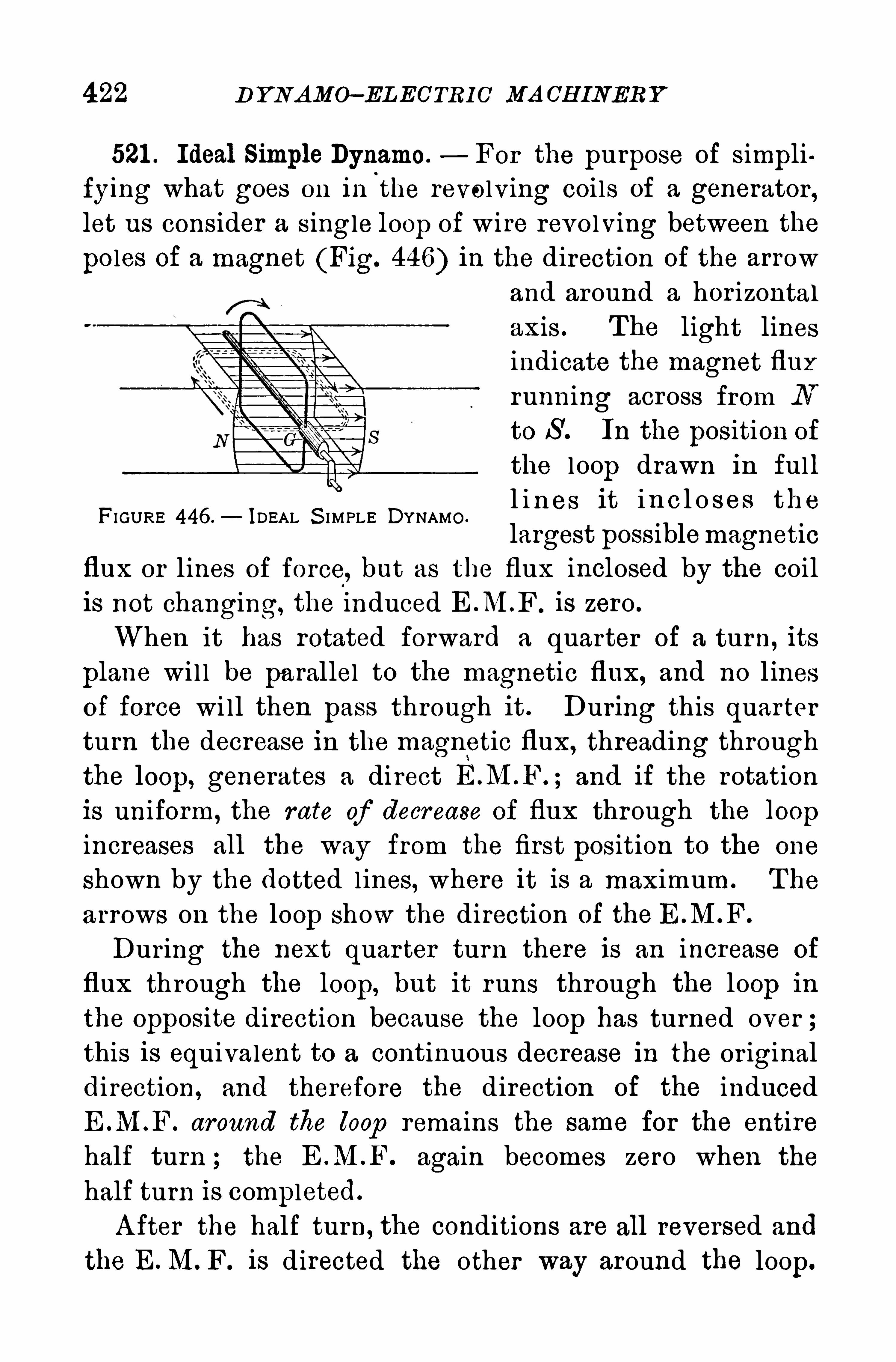
422 D Y NAMO—EL ECTRI O MA CH INERY
521 . Ideal Simlile Dynamo. For the purpose of simpli
fying what goes on in the revolving coils of a generator,let us consider a single loop of wi re revolving between the
poles of a magnet (Fig. 446) in the direction of the arrow
and around a hor izontalaxis . The light linesindicate the magnet fiux
running across from N
to S . In the position of
the loop drawn in fulll i n es it in c l o s es the
largest possiblemagneticflux or lines of force, but as the flux inclosed by the coilis not changing, the induced E .M.F . is zero .
When it has rotated forward a quarter of a turn, its
plane wi l l be pa rallel to the magnetic flux, and no l inesof force wi ll then pass through it . During this quarterturn the decrease in the magnetic flux, threading through
the loop, generates a direct and if the rotationis uniform, the rate of decrease of flux through the loop
increases all the way from the first position to the one
shown by the dotted lines, where it is a maximum. The
arrows on the loop show the direction of the E . .M.F
During the next quar ter turn there is an increase of
flux through the loop, but it runs through the loop in
the opposite direction because the loop has turned over ;this is equivalent to a continuous decrease in the or iginaldirection, and therefore the direction of the inducedE .M .F. around the loop remains the same for the entire
half turn ; the E .M .F. again becomes zero when the
half turn is completed.
A fter the half turn, the conditions are all reversed and
the E. M. F. is directed the other way around the loop.
FI GURE 446 .—IDEAL S I MPLE DYNAMO .
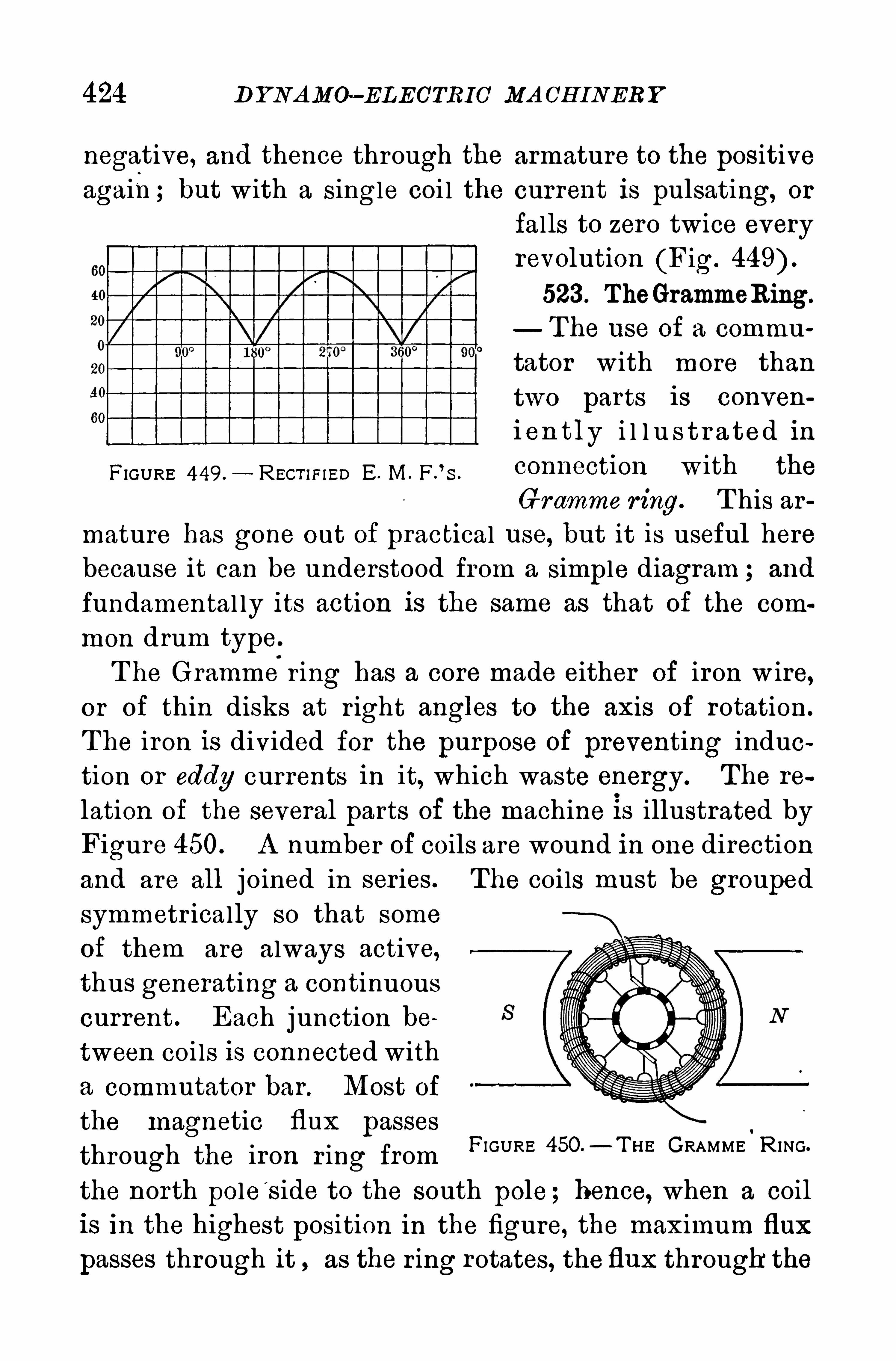
424 1 ) YNAMO—ELEC'TRIC MA CH INERY
negative, and thence through the armature to the positiveagain; but with a single coi l the current is pulsating, or
falls to zero twice everyrevolution (Fig.
523 . TheGrammeRing.
The use of a commu
tator with more than
two parts is conven
i en tly i l l u s t r a ted in
FIGURE 449 .- REGT II=IED E. M. F.
’s .
conll eCtion W ith the
Gramme ring. T his armature has gone out of practical use, but it is useful herebecause it can be understood from a simple diagram ; and
fundamental ly its action is the same as that of the com
mon drum typeT he Gramme r ing has a core made either of iron w ire,
or of thin disks at r ight angles to the axis of rotation.
T he iron is divided for the purpose of preventing induction or eddy currents in it, which waste energy. The re
lation of the several parts of the machine is illustrated byFigure 450. A number of coils are wound in one direction
and are all j oined in ser ies. The coi ls must be grouped
symmetr ically so that some
of them are always active,thus generating a continuous
current . Each junction be
tween coi ls is connected with
a commutator bar . Most of
the magnetic flux passes
through the iron r ing from
the north pole s ide to the south pole ; hence, when a coilis in the highest position in the figure, the maximum flux
passes through it as the r ing rotates, the flux through the
FIGURE 450 —T H E GRAMME.
R ING.
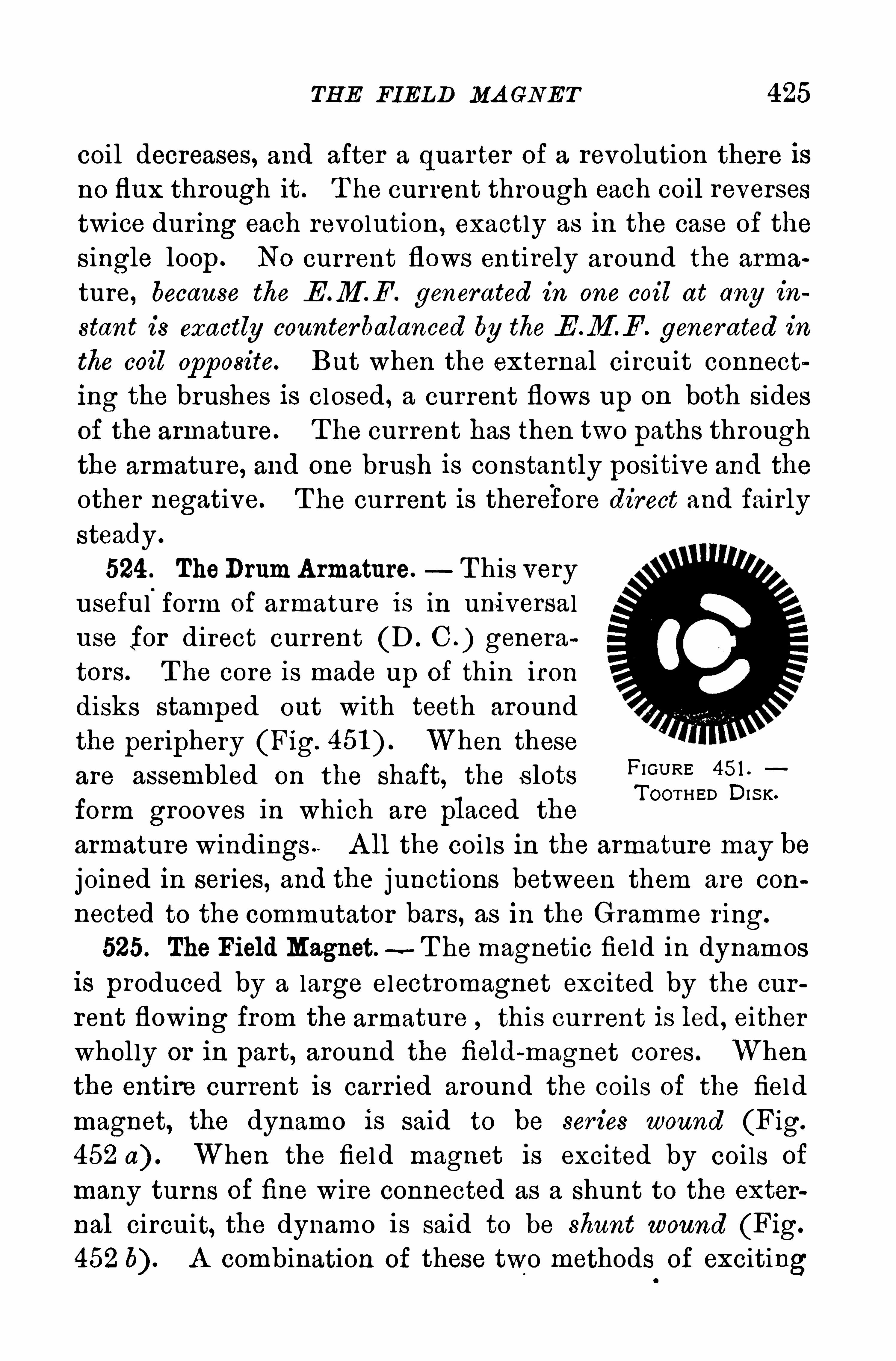
TH E FIELD MA GNET 425
coil decreases, and after a quar ter of a revolution there is
no flux through it . T he current through each coil reverses
twice dur ing each revolution, exactly as in the case of the
single loop . N0 current flows entirely around the arma
ture, because the E .M F . generated in one coil at any in
stant is exactly counterbalanced by the E .M F . generated in
the coil opposite. But when the external circuit connect
ing the brushes is closed , a current flows up on both sides
of the armature. T he current has then two paths through
the armature, and one brush is constantly positive and theother negative. T he current is therefore direct and fairly
steady .
524 . TheDrumA rmature. T his veryuseful
.
form of armature is in uni versaluse for direct current (D . C . ) genera
tors. T he core is made up of thin iron
disks stamped out with teeth aroundthe per iphery (Fig. When theseare assembled on the shaft, the s lotsform grooves in which are placed the
armature windings A ll the coils in the armature may be
joined in ser ies, and the junctions between them are con
nected to the commutator bars, as in the Gramme ring.
525. The Field Magnet. T hemagnetic field in dynamosis produced by a large electromagnet excited by the cur
rent flowing from the armature this current is led, eitherwholly or in part, around the field-magnet cores . Whenthe entire current is carr ied around the coi ls of the fiel dmagnet, the dynamo is said to be series wound (Fig.
452 a) . When the fiel d magnet is excited by coi ls of
many turns of fine wire connected as a shunt to the exter
nal circuit, the dynamo is said to be shunt wound (Fig.
452 b) . A combination of these two methods of exciting
FI GURE 451 .
T OOTHED DI S K.
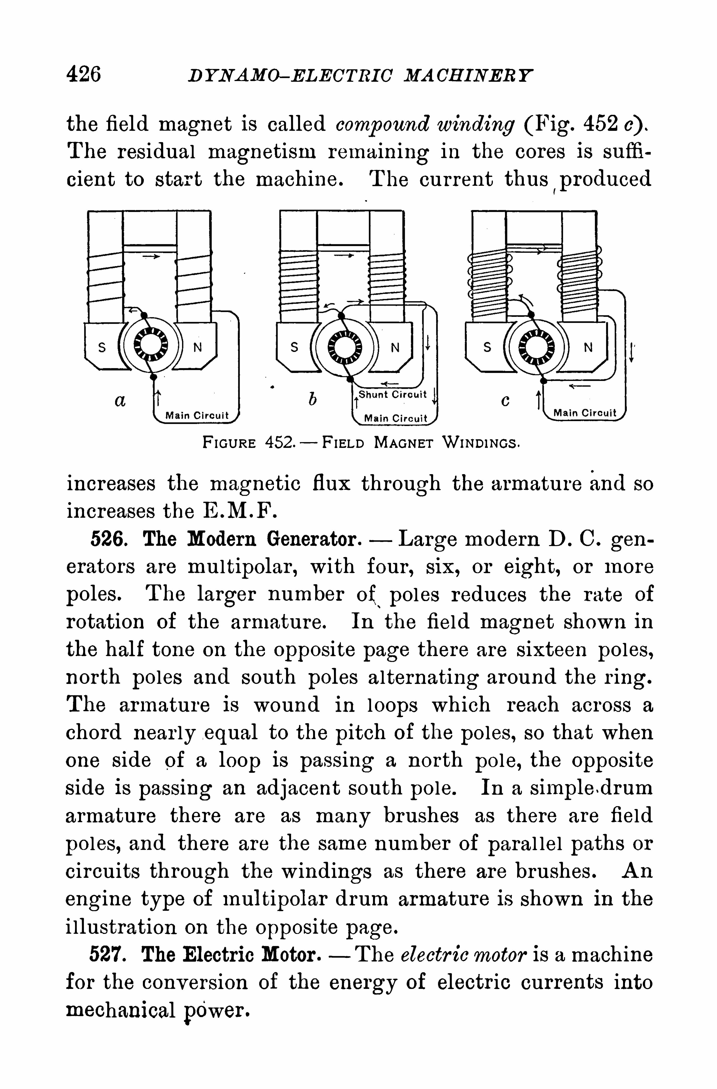
426 D YNAMO—ELECTRIC MA CH INER Y
the field magnet is called compound winding (Fig. 452 c) .
The residual magnetism remaining in the cores is suffi
cient to star t the machine. T he current thuslproduced
FI GURE 452 — FI ELD MAGNET WINDINGs .
increases the magnetic flux through the armature and so
increases the E M . .F
526 . The Modern Generator . Large modern D . C . gen
erators are multipolar , with four , six, or eight, or more
poles . T he larger number of poles reduces the rate of
rotation of the armature. In the field magnet shown inthe half tone on the opposite page there are sixteen poles,north poles and south poles alternating around the r ing.
The armature is wound in loops which reach across a
chord near ly .equal to the pitch of the poles, so that whenone side of a loop is passing a north pole, the Oppositeside is passing an adjacent south pole. In a simple drum
armature there are as many brushes as there are field
poles, and there are the same number of paral lel paths or
circuits through the windings as there are brushes . A n
engine type of multipolar drum armature is shown in the
i llustration on the Opposite page.
527. The Electric Motor .-T he electr icmotor is a machine
for the conversion of the energy of electr ic currents intomechanical power .

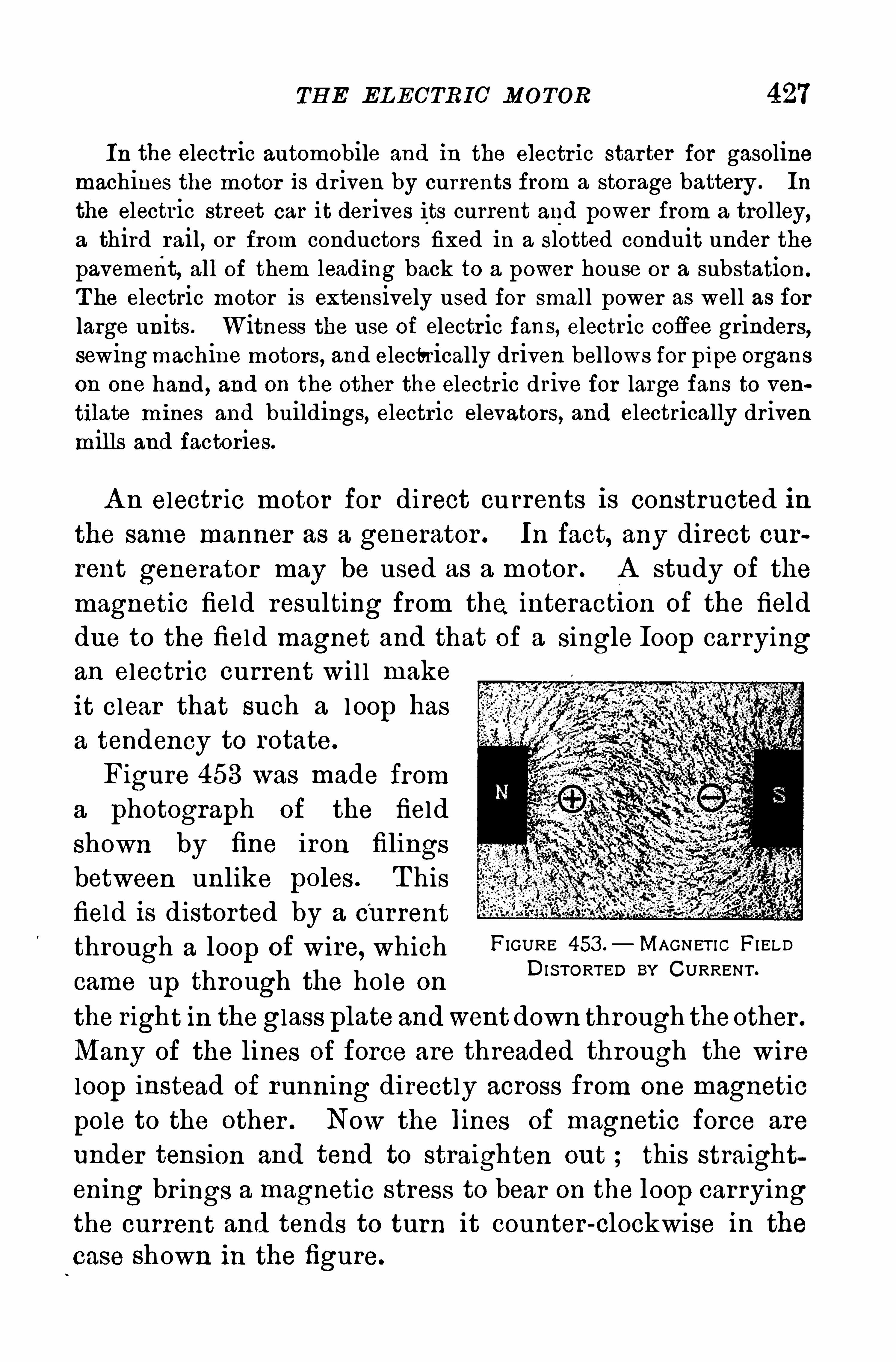
TH E EL ECTRIC MOTOR 427
In the electr ic automobile and in the electr ic starter for gasolinemachines the motor is dr iven by currents from a storage battery . In
the electric street car it der ives its current and power from a trolley,a third rail, or from conductors fixed in a slotted conduit under thepavement, all of them leading back to a power house or a substation.
T he electric motor is extensively used for small power as well as forlarge units. Witness the use of electric fans, electric coffee grinders,sewing machine motors , and electrically driven bel lows for pipe organson one hand , and on the other the electric dr ive for large fans to ven
tilate mines and buildings, electric elevators, and electrically drivenmills and factories.
A n electr ic motor for direct currents is constructed inthe same manner as a generator . In fact, any direct current generator may be used as a motor . A study of the
magnetic field resulting from the interacti on of the fielddue to the field magnet and that of a single Ioop carryingan electr ic current wi l l makeit clear that such a l oop hasa tendency to rotate.
Figure 453 was made froma photograph of the fieldshown by fine iron filingsbetween unlike poles . T hisfield is distorted by a currentthrough a loop of wire, which FIGURE 453 .
— MAGNET IC FI ELD
came up through the hole onDISTORTED BY CURRENT ’
the right in the glass plate andwent down through theother .
Many of the lines of force are threaded through the wireloop instead of running directly across from one magnetic
pole to the other . Now the lines of magnetic force are
under tension and tend to straighten out ; this straightening br ings a magnetic stress to bear on the Ioop car ryingthe current and tends to turn it counter-clockwise in the
case shown in the figure.
428 D Y NAMO—ELECTRIC MA CH INER Y
If the loop be al lowed to rotate in the direction of thismagnetic effort between the field and the loop, the loopw i l l become the armature of a motor and work wi ll bedone by the machine at the expense of the energy -of the
current flowing through it . If, however , the loop be
forcibly rotated clockwise by mechanical means, it wi llturn against the magnetic
'
efl'
brt acting on it, and workw i ll be done against the resistance of this magnetic
drag. T he loop will then be the armature wire of a
generator .
528. Forms of D. C. Motors.— S ince any D . C . generator
wi l l run as a motor , we find D . C. motors either ser ies or
shunt wound according to the .serv ice for which they are
designed . S er ies wound motors are used on street cars and
electric automobiles, where the servi ce requires var iable
speed . S hunt w'
ound motor s are used to run machinery in
shops and factor ies, where constant speed is desirable.
H igh speed motors are usual ly bipolar ; motors for slow
Speed serv ice have multipolar fiel ds .
T he torque, or turning moment, of an electric motor
depends both upon the strength of the magnetic field
and the cur rent through the armature. In a shuntwound motor the field strength is near ly constant ;
hence the torque var ies directly as the cur rent through
the armature. In a ser ies motor, on the other hand,the strength of field var ies nearly as the current, and
the current is the same through the field and the arma
ture. H ence the torque var ies as the square of the cur
rent . If the current is doubled ,it is doubled in both
the field and the armature, and the torque is therefore
quadrupled . T he ser ies motor is accordingly used wherea large starting torque is required, as in cranes and motor
Vehicles .
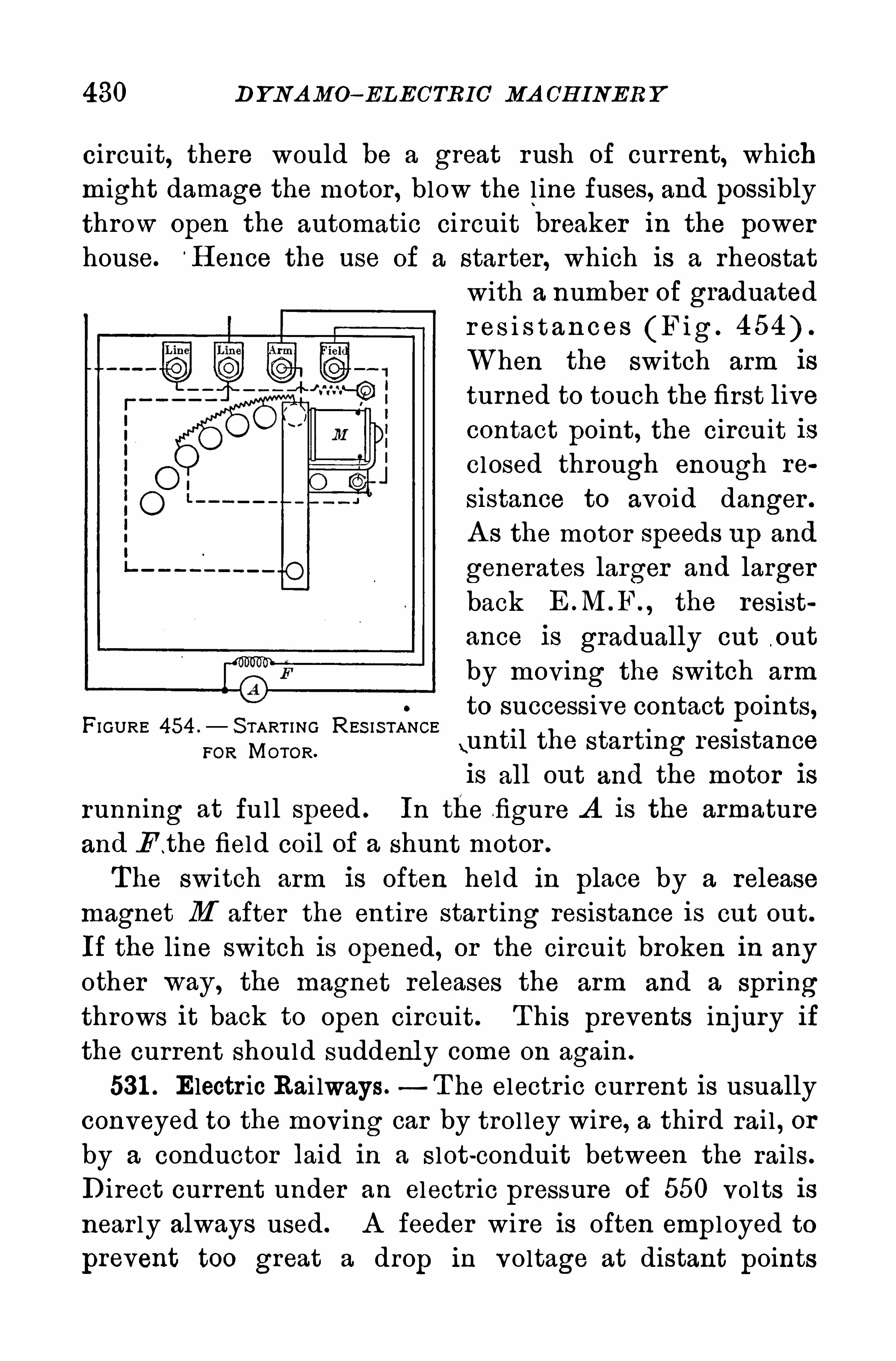
430 D YNAMO—EL ECTRIC’ MA CH INER Y
circuit, there would be a great rush of current, whichmight damage the motor , blow the l ine fuses, and possibly
throw Open the automatic circuit breaker in the powerhouse. H ence the use of a starter, which is a rheostat
with a number of graduatedr es i s t an ces (Fig .
When the switch arm is
turned to touch the first livecontact point, the circuit iscl osed through enough re
sistance to avoid danger .
A s the motor speeds up and
generates larger and larger
back the resistance is gradually cut o ut
by moving the switch arm
to successive contact points,FI GURE 454 .
— S TART I NG RES IS TANCE\unti l the starting res1 stance
FOR MOTOR.
is all out and the motor isrunning at full speed . In the figure A is the armatureand E t he field coil of a shunt motor .
The switch arm is often held in place by a release
magnet M after the entire starting resistance is cut out.
If the line switch is opened, or the circuit broken in any
other way, the magnet releases the arm and a spr ingthrows it back to open circuit . T his prevents injury if
the current should suddenly come on again .
531 . Electr ic Rai lways.—T he electr ic current is usually
conveyed to the mov ing car by trol ley wire, a third rai l , or
by a conductor laid in a slot-conduit between the rai ls .
Direct current under an electr ic pressure of 550 volts is
near ly always used . A feeder wire is often emp l oyed to
prevent too great a drop in voltage at distant points
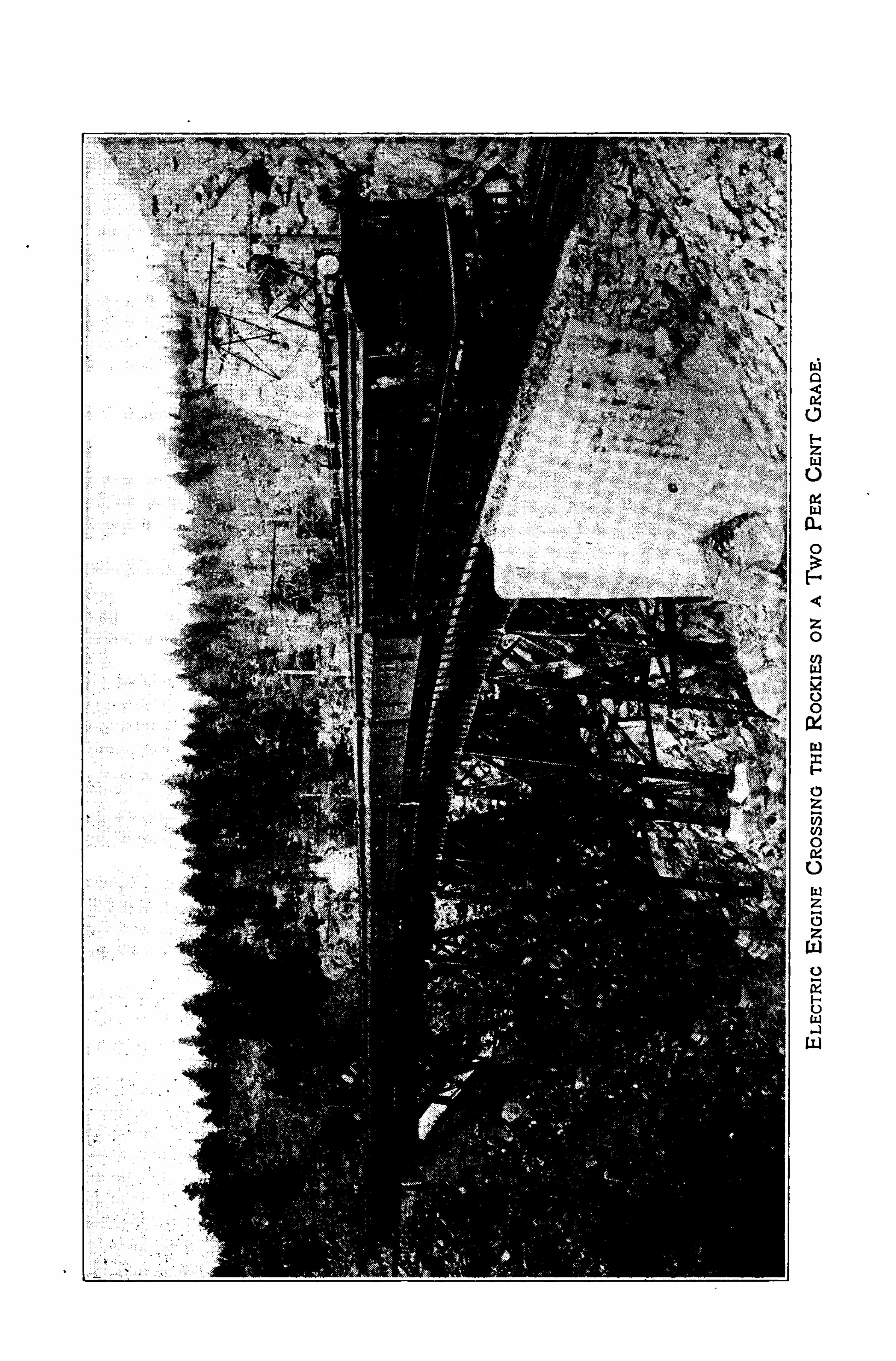
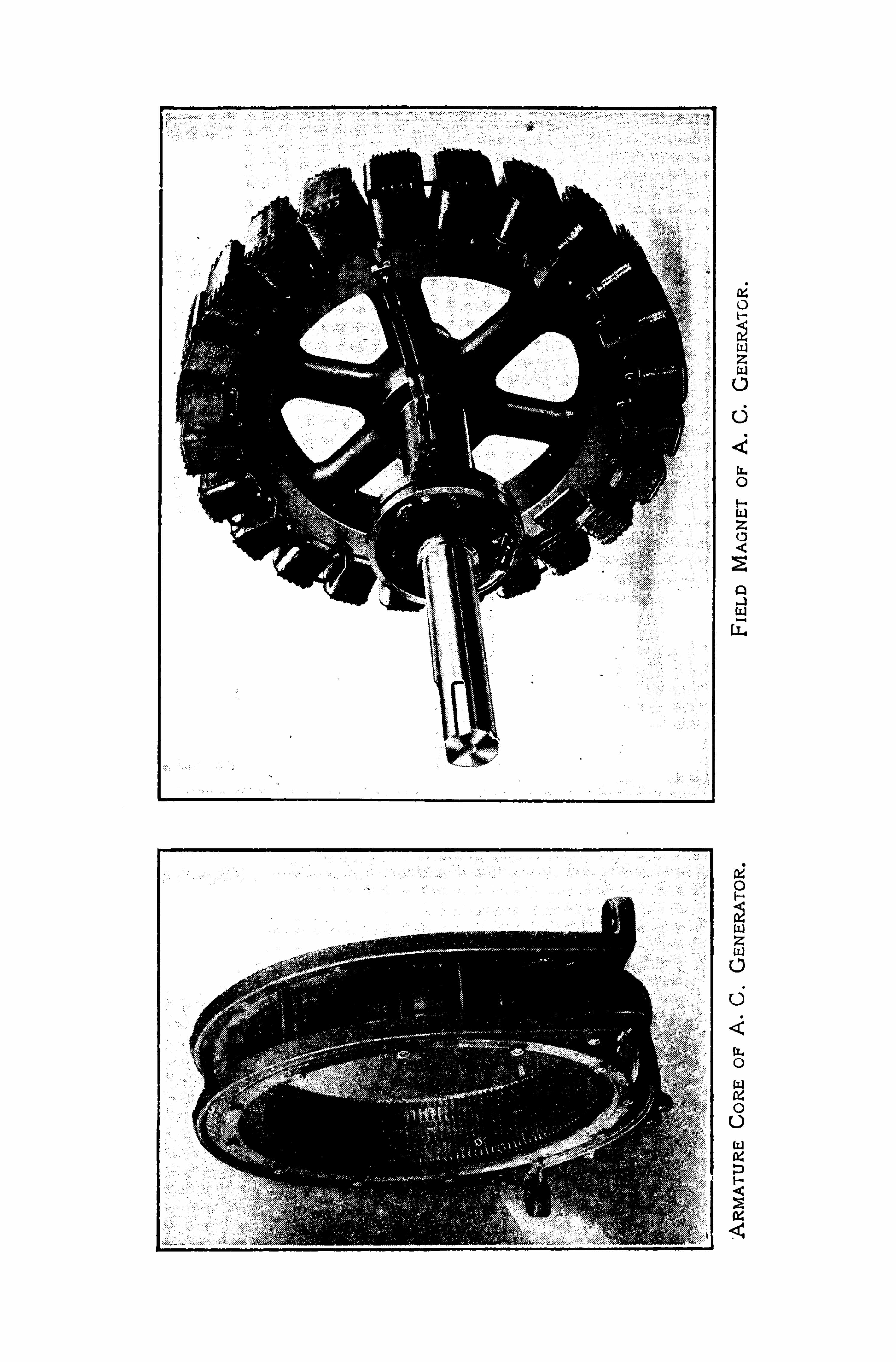
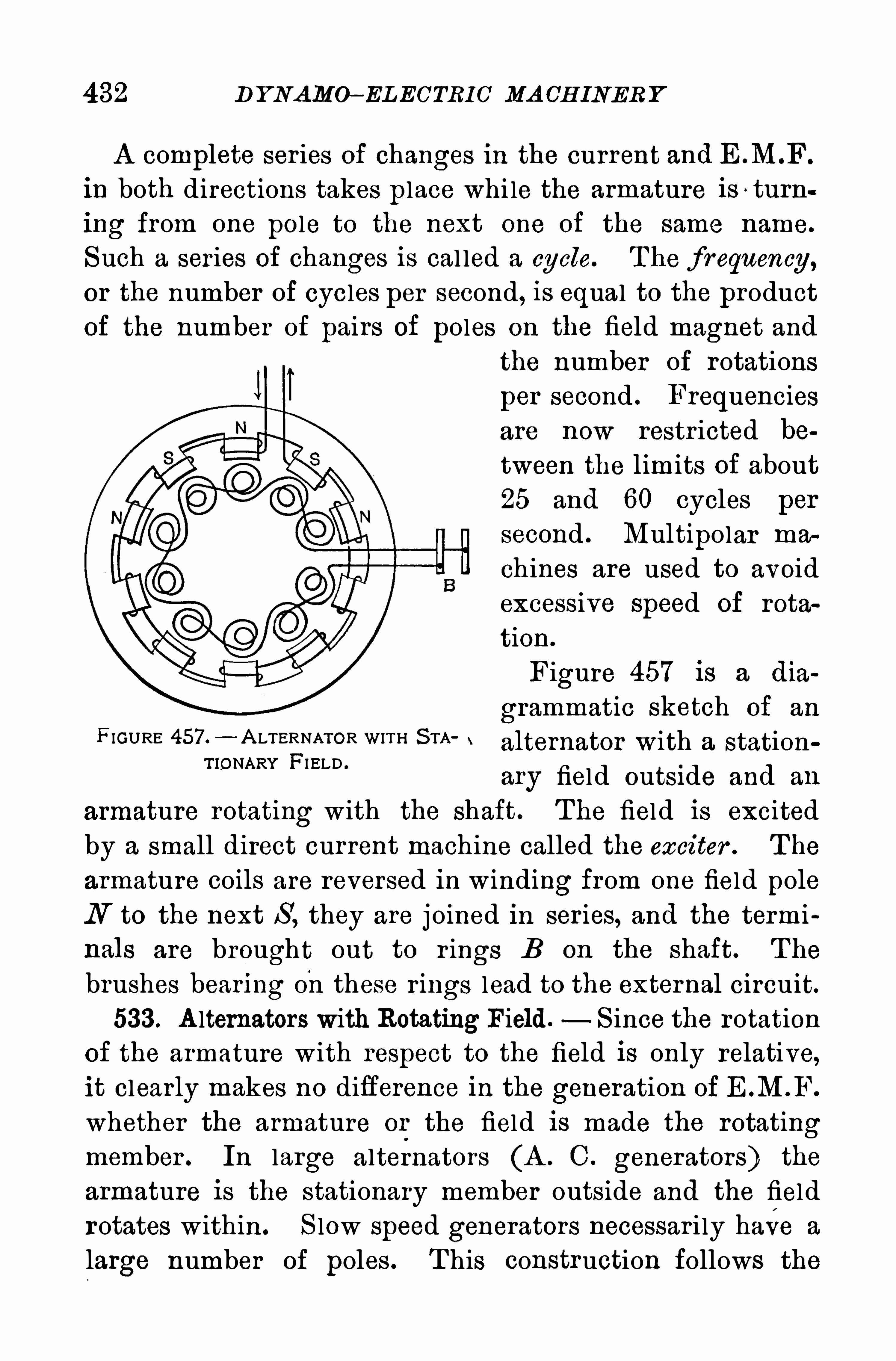
432 D Y NAMO—EL EC’TRIC MA CH INER Y
A complete ser ies of changes in the current and E .M“F
in both directions takes place whi le the armature is ~ turn
ing from one pole to the next one of the same name.
Such a series Of changes is cal led a cycle. T he f requency,or the number of cycles per second, is equal to the product
Of the number of pairs of poles on the field magnet and
the number of rotations
per second . Frequenciesare now restr icted be
tween the limits of about25 and 60 cycles per
second . Multipolar ma
chines are used to avoidexcessive Speed of rota
tion.
Figure 457 is a dia
grammatic sketch Of an
F IGURE 457.— A LTERNATOR WITH S TA alternator W ith a, S tationTIONARY FI ELD .
ary field outside and an
armature rotating with the shaft. T he field is excited
by a small direct cur rent machine called the exciter . T he
armature coils are reversed in winding from one field pole
N to the next S , they are j oined in ser ies, and the terminals are brought out to r ings B on the shaft. T he
brushes bearing onthese r ings lead to the external circuit.
533 . A lternators with Rotating Field. S ince the rotation
of the armature with respect to the field is only relative,it clearly makes no difference in the generation of E .M .F.
whether the armature or the field is made the rotatingmember . In large alternators (A . C . generators) the
armature is the stationary member outside and the fieldr otates within. S low speed generators necessar i ly have a
large number Of poles . T his construction follows the
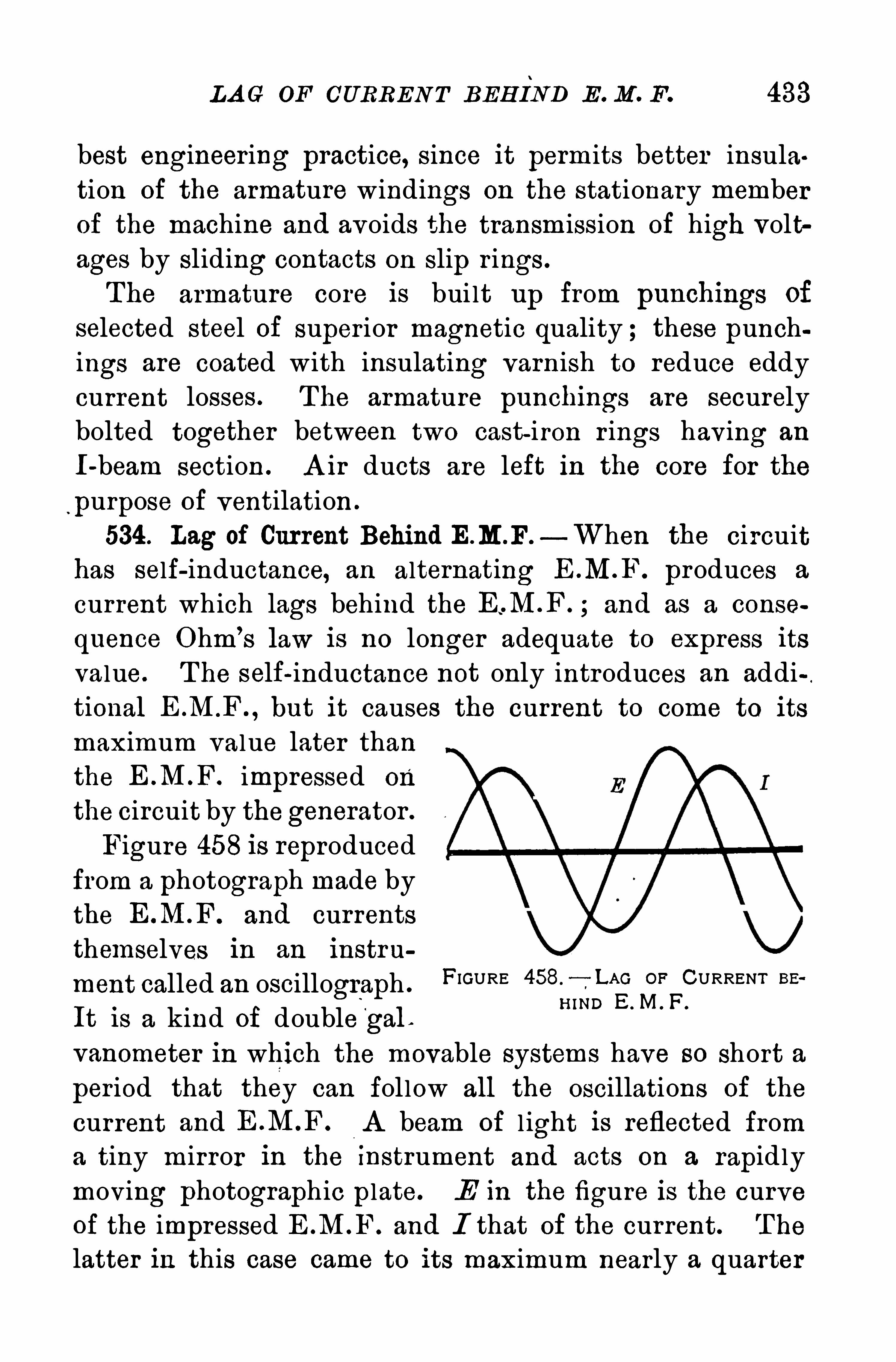
LA G OF CURREN T BEH IND E . M . F. 433
best engineering practice, since it permits better insula
tion of the armature windings on the stationary member
of the machine and avoids the transmission Of high volt
ages by S liding contacts on slip r ings .
The armature core is bui lt up from punchings of
selected steel Of super ior magnetic quality ; these punchings are coated with insulating varnish to reduce eddy
current losses . The armature punchings are securelybolted together between two cast-iron r ings having an
I-beam section . A ir ducts are left in the core for the
purpose of ventilation .
534 . Lag of Current Behind E.M.F.—When the circuit
has self-inductance, an alternating E .M.F . produces a
current which lags behind the and as a conse
quence Ohm’
s law is no longer adequate to express its
value. T he self-inductance not only introduces an additional but it causes the current to come to its
maximum value later thanthe impressed On
the circuit by thegenerator .
Figure 458 is reproducedfrom a photograph made bythe and currentsthemselves in an instru
ment called an oscillograph .
FIGURE 458. OF CURRENT BE
It is a kind of double‘
gal .
”IND E M ' F'
vanometer in which the movable systems have so Short a
per iod that they can fol low all the oscillations of the
current and A beam of l ight is reflected froma tiny mirror in the Instrument and acts on a rapidlymoving photographic plate. E in the figure is the curveof the impressed E .M .F. and I that Of the current. T he
latter in this case came to its maximum nearly a quarter
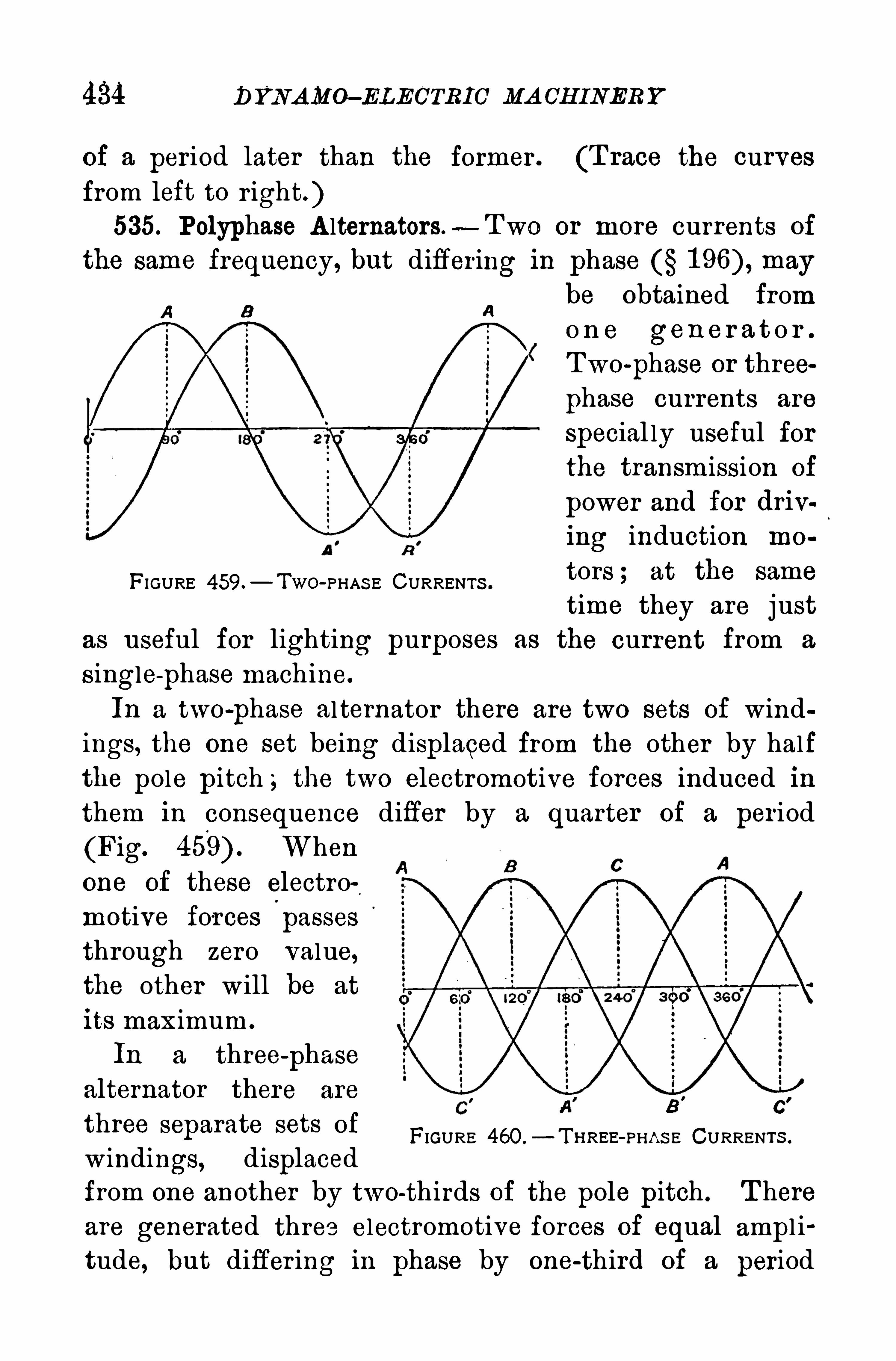
434 DYNAMO- ELECTRIC MA CH INERY
of a period later than the former . (T race the curves
from left to right. )535. Polyphase A lternators.
-Two or more currents of
the same frequency, but differ ing in phase may
be Obtained fromo n e gen e r a t o r .
Two-
phase or three
phase currents are
special ly useful forthe transmission of
power and for driv
ing induction mo
tors ; at the same
time they are justas useful for lighting purposes as the current from a
S ingle-
phase machine.
In a two-
phase alternator there are two sets of windings, the one set being displaced from the other by half
the pole pitch ; the two electromotive forces induced in
them in consequence differ by a quarter of a per iod
(Fig. When
one of these electro
motive forces passes
through zero value,the other will be at
its maximum.
In a three-
phase
alternator there are
three separate sets of
windings, displaced
from one another by two-thirds of the pole pitch . T here
are generated three electromotive forces of equal ampl i
tude, but differ ing in phase by one-third of a period
FIGURE 459.— TWO-PHAS E CURRENTS .
FIGURE 460 .
—T IIREE- PHA S E CURRENTS .
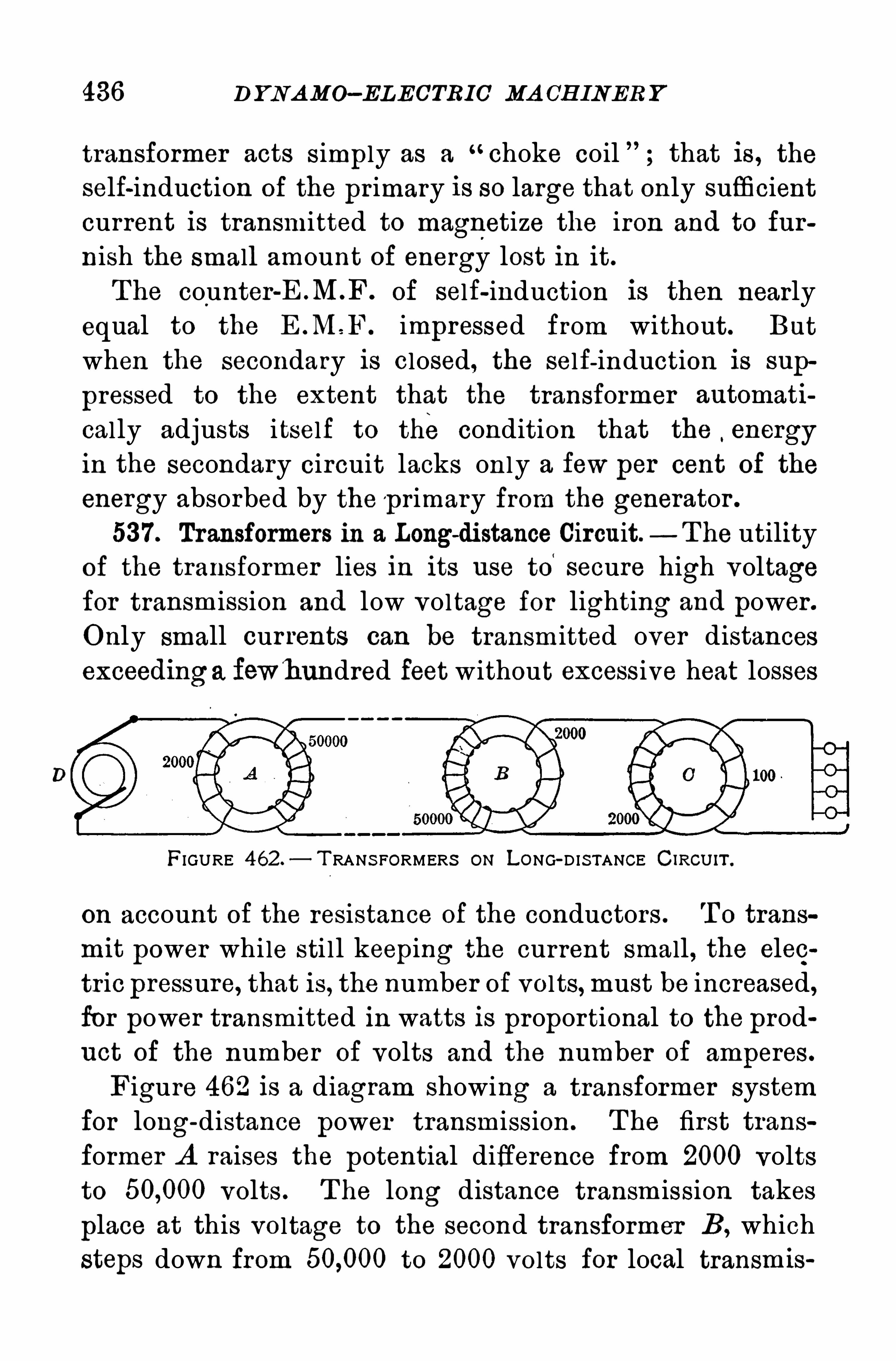
436 DYNA MO—ELECTRIC MA CH INER Y
transformer acts S imply as a“choke coil that is , the
self-induction of the pr imary is so large that only sufficientcurrent is transmitted to magnetize the iron and to fur
nish the small amount of energy lost in it.
T he counter of self-induction is then nearly
equal to the E M F. impressed from without. But
when the secondary is closed, the self-induction is sup
pressed to the extent that the transformer automati
cally adjusts itself to the condition that the,energy
in the secondary circuit lacks only a few per cent Of the
energy absorbed by the p rimary from the generator .
537. Transformers in a Longd istance Circuit.— The utility
of the transformer lies in its use to‘
secure high voltagefor transmission and low voltage for lighting and power .
Only small currents can be transmitted over distancesexceedinga fewhundred feet without excessive heat losses
FIGURE 462 —T RANS FORMERS ON LONG-D IS TANCE CIRcU IT .
on account of the resistance of the conductors . T O trans
mit power while sti ll keeping the current small , the elec
tric pressure, that is , the number of volts,must be increased,for power transmitted in watts is propor tional to the prod
uct of the number of volts and the number of amperes.
Figure 462 is a diagram Showing a transformer system
for long-distance power transmission . T he first trans
former A raises the potential difference from 2000 volts
to volts . T he long distance transm ission takes
place at this voltage to the second transformer B, which
steps down from to 2000 volts for local transmis
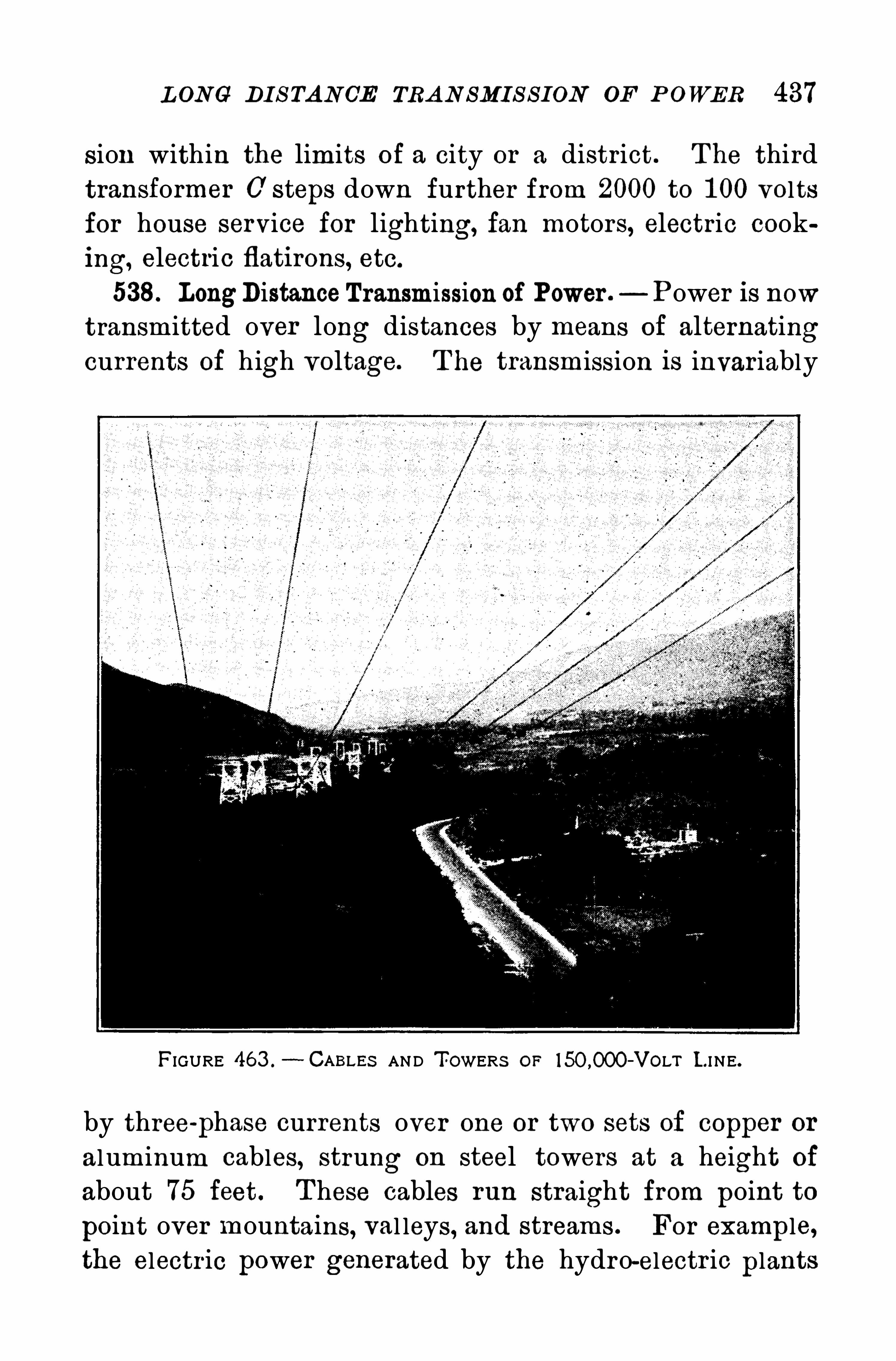
L ONG DI S TANCE TRA N SMI S S ION OF P OWER 437
sion within the limits of a city or a district. T he third
transformer 0 steps down further from 2000 to 1 00 volts
for house service for lighting, fan motors, electric cook
ing, electric flatirons, etc.
538. LongDistanceTransmission of Power . Power is nowtransmitted over long distances by means of alternatingcurrents of high voltage. T he transmission is invar iably
FIGURE 463 .
- CABLEs AND T OWERS OF —VOLT L I NE.
by three-
phase currents over one or two sets of copper or
aluminum cables, strung on steel towers at a height Of
about 75 feet . T hese cables run straight from point to
point over mountains, val leys, and streams . For example,the electr ic power generated by the hydro-electr ic plants
D YNA MO—ELECTRIC MA CH INER Y
at Niagara Fal ls is raised by Step-up transformers to
volts for transmission to distant cities,—Buffalo,Rochester , Syracuse, where it is used for street car serv ice,for power motors, and for lighting and other domestic
purposes .
A t Big Creek in the H igh S ierras in California, water
power to the extent Ofp
80,000 H . P . is now used for generating three-phase electr ic cur rents ; the vol tage is raisedby step
-up transformers to for transmission overaluminum cables 241 mi les to the Eagle Rock transformer
station . T hese cables are inch in diameter , and are
Strung feet apart, on steel towers averaging seven to
the mi le. A t present two sets of three-wire cables are in
use, each set strung on separate towers (Fig. U l ti
mately there will be three sets for the transmission of
H . P .
A t Eagle Rock step-down transformers reduce the elec
tr ic pressure to volts \ for transmission over the
Los A ngeles distr ict, and to volts for the Riversidedistrict and beyond . T he latter distr ict adds about 80
miles to the transmission, making 320 miles as a maximum .
539. The Rotating Magnetic Field,—It is Of first im
portance to understand how a magnetic field may rotatewhile the coils producing the field stand sti l l ; for ,
the
rotating field, invented by Ferraris and T es la, is the secret
of all A . C . induction motors for two or three-
phase
currents . A simple exper iment wi ll help to clear up the
problem.
Suspend a heavy ball by a string at least ten feet long and set it
swinging north and south with an amplitude O f a foot or more. A t
the instant when the ball stops at either extremity of its path, strikeit a b low with a mallet east and west. T his blow will cause an east
and west S imple harmonic motion, differing in phase from the north
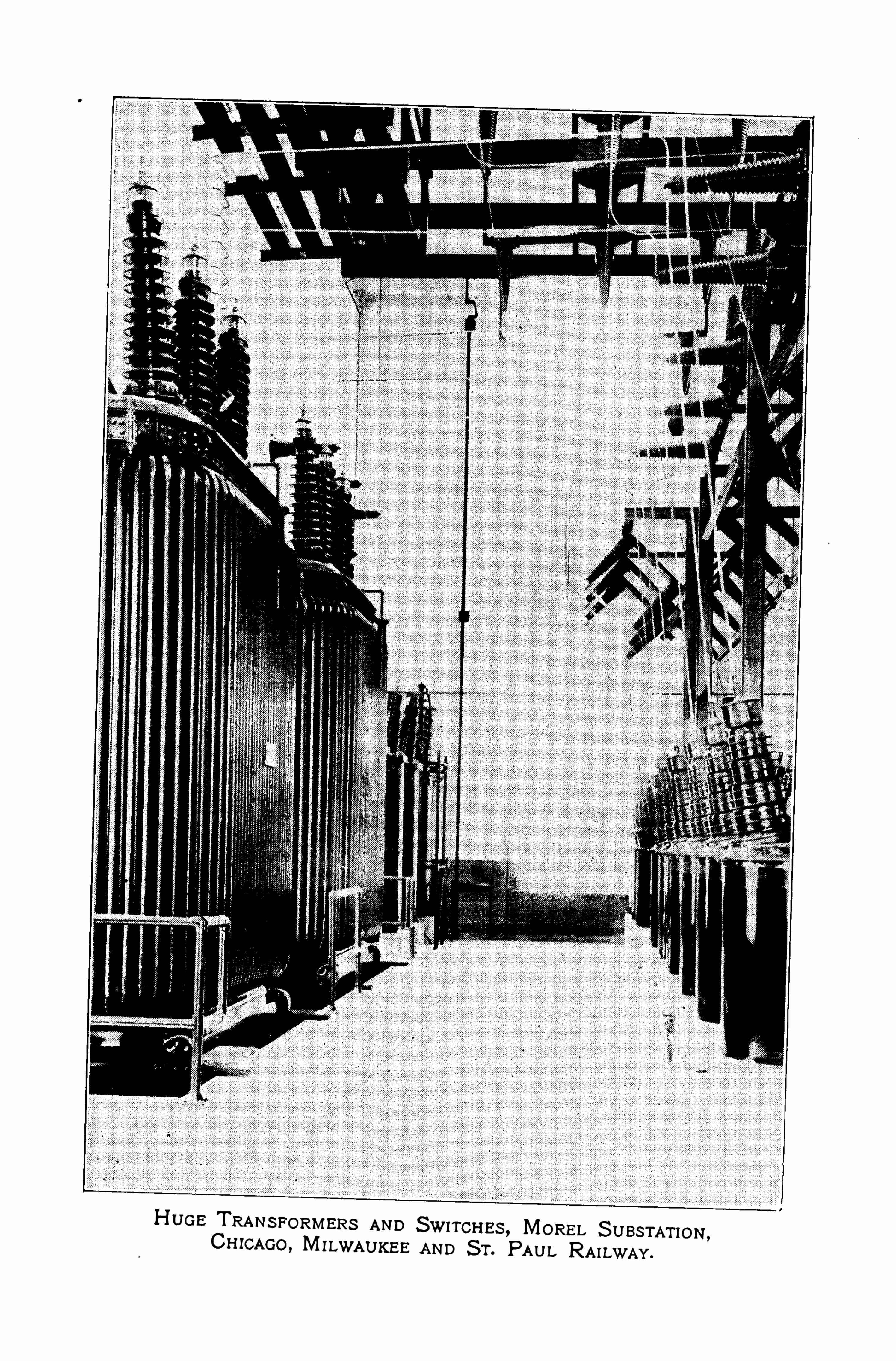
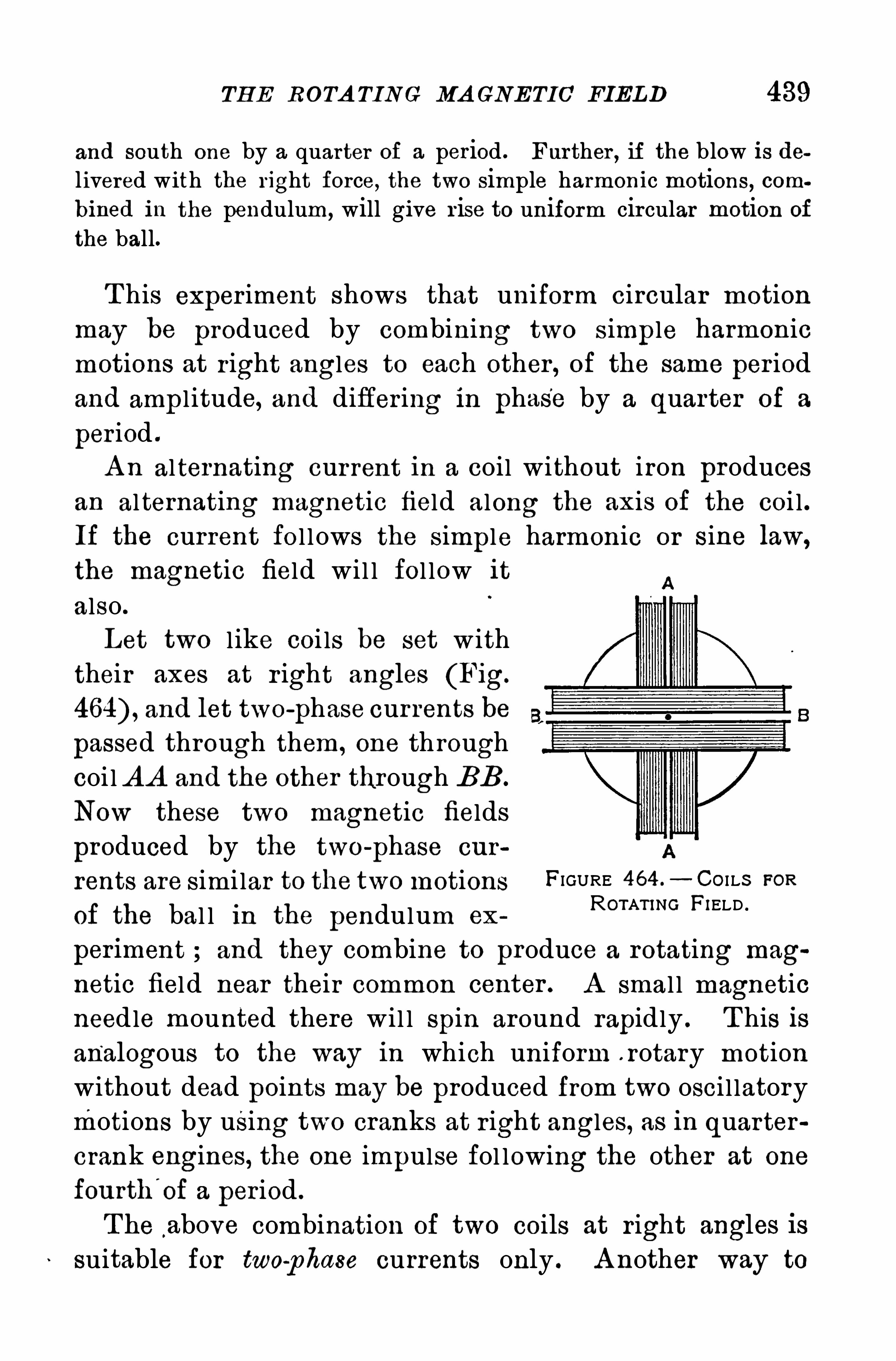
TH E ROTA TING MA GNE TIC FIELD 439
and south one by a quarter of a period . Further , if the blow is delivered with the right force, the two S imple harmonic motions , combined in the pendulum, will give r ise to uniform circular motion Of
the ball.
T his exper iment shows that uniform circular motion
may be produced by combining two S imple harmonic
motions at r ight angles to each other , of the same per iod
and amp l itude, and differ ing in phase by a quarter of a
per iod .
A n alternating cur rent in a coil without iron producesan alternating magnetic field along the axis Of the coi l .
If the current fo l l ows the simple harmonic or sine law,
the magnetic field wi l l fol low it
also .
Let two l ike coi ls be set w ith
their axes at r ight angles (Fig.
and let two-
phase cur rents be
passed through them , one th rough
coi l A A and the other through BB .
Now these two magnetic fields
produced by the two-
phase cur
rents are simi lar to the two motions FIGURE 464 - CO I LS FOR
of the bal l in the pendulum exROTAn NG F’ELD ‘
periment ; and they combine to produce a rotating mag
netic field near their common center . A smal l magnetic
needle mounted there wi l l Spin around rapidly . T his is
analogous to the way in which uniform . rotary motion
without dead points may be produced from two osci l latorymotions by using two cranks at r ight angles, as in quarter
crank engines, the one impulse fol lowing the other at one
fourth'
of a per iod .
T he above combination of two coils at r ight angles is
suitable for two-
phase currents only . A nother way to
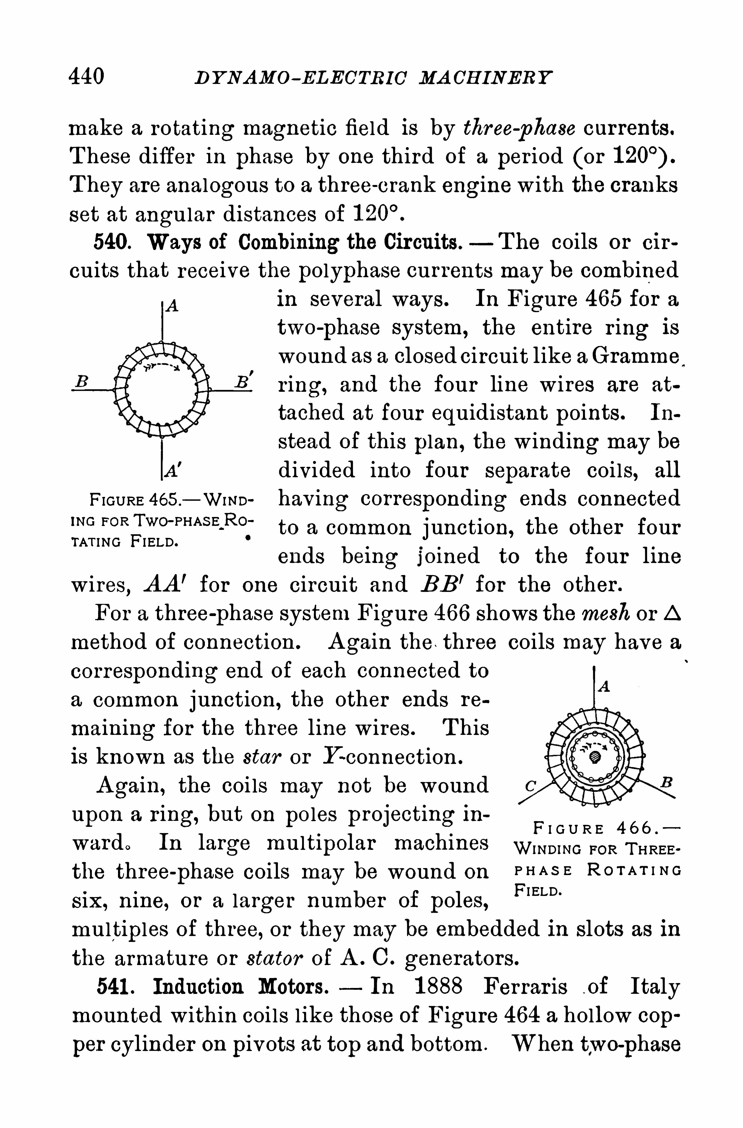
440 D Y NAMo- ELECTRIC MA CH INER Y
make a rotating magnetic field is by three-phase currents.
T hese differ in phase by one third of a per iod (or
T hey are analogous to a three-crank engine with the cranks
set at angular distances of
540. Ways of Combining the Circuits.—T he coils or cir
cuits that receive the polyphase currents may be combinedin several ways . In Figure 465 for a
two-
phase system, the entire r ing is
wound as a closed circuit like aGramme
B'
r ing, and the four line wires are at
tached at four equidistant points . In
stead Of this plan, the winding may be
divided into four separate coils, all
FIGURE 465 .
—Wa m hav ing corresponding ends connected‘NO FOR TWO' PHAS E R0:to a common j unction, the other fourTAT I NG FI ELD.
ends being j oined to the four l inewires
,A A ’ for one circuit and BB’ for the other .
For a three-
phase system Figure 466 Shows themesh or A
method of connection . A gain the , three coils may have a
corresponding end of each connected to
a common junction, the other ends re
maining for the three line wires . T hisis known as the star or Y -connection .
A gain, the coi ls may not be woundupon a r ing, but on poles projecting in
F I G U R E 4 6 6 .
ward o In large multipolar machines WmDING FOR T HREE.
the three-phase coils may be wound on P H A S E R O T A T I N G
six, nine, or a larger number of poles,FI ELD ’
multiples Of three, or they may be embedded in slots as in
the armature or stator of A . C . generators.
541 . Induction Motors. In 1 888 Ferrar is -of Italy
mounted within coils l ike those of Figure 464 a hollow cop
per cylinder on pivots at top and bottom . When two-phase
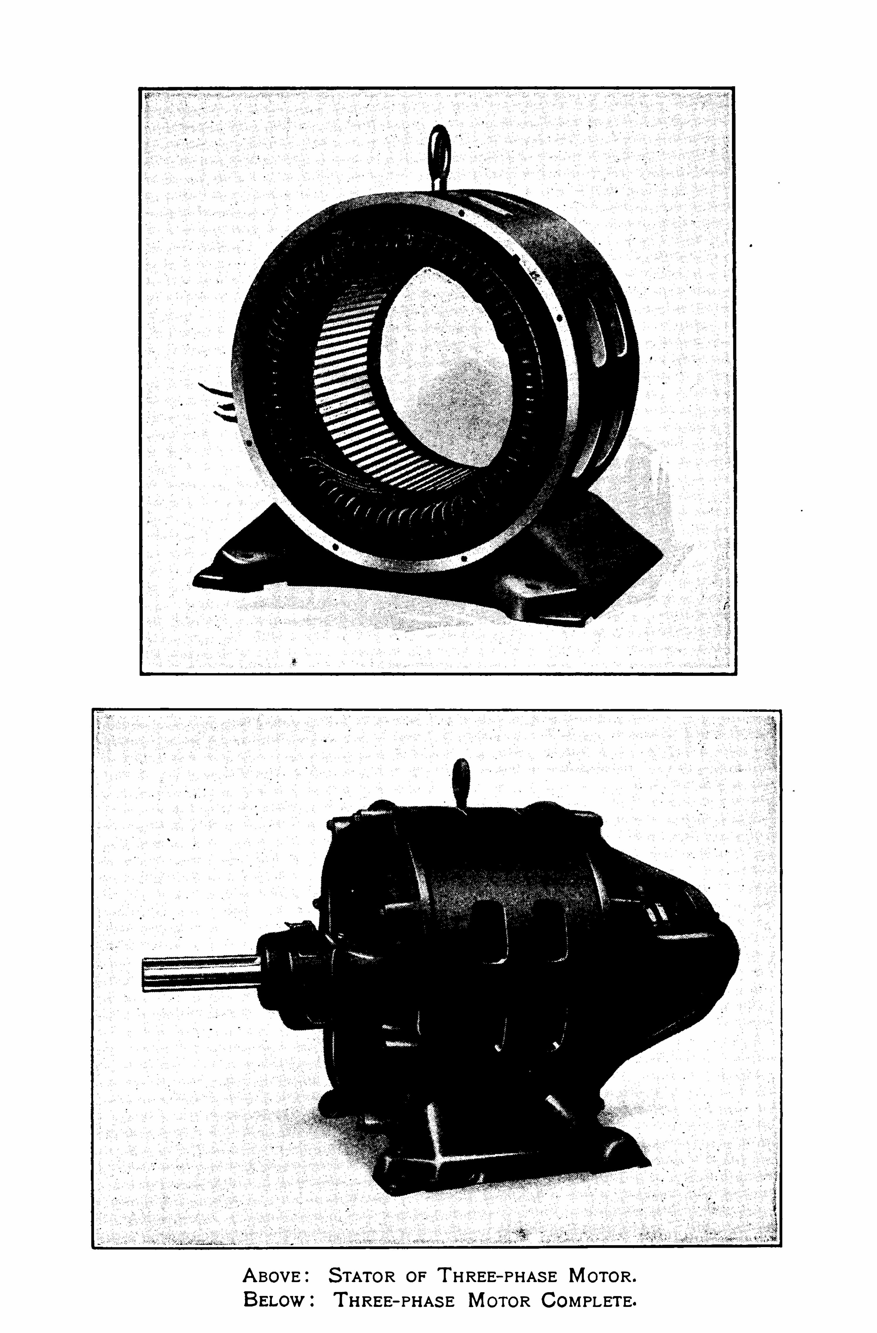
A BOVE:S TATOR OF T HREE—PHAS E MOTOR .
BELow z T RREE- PHAS E MOTOR COMPLETE.
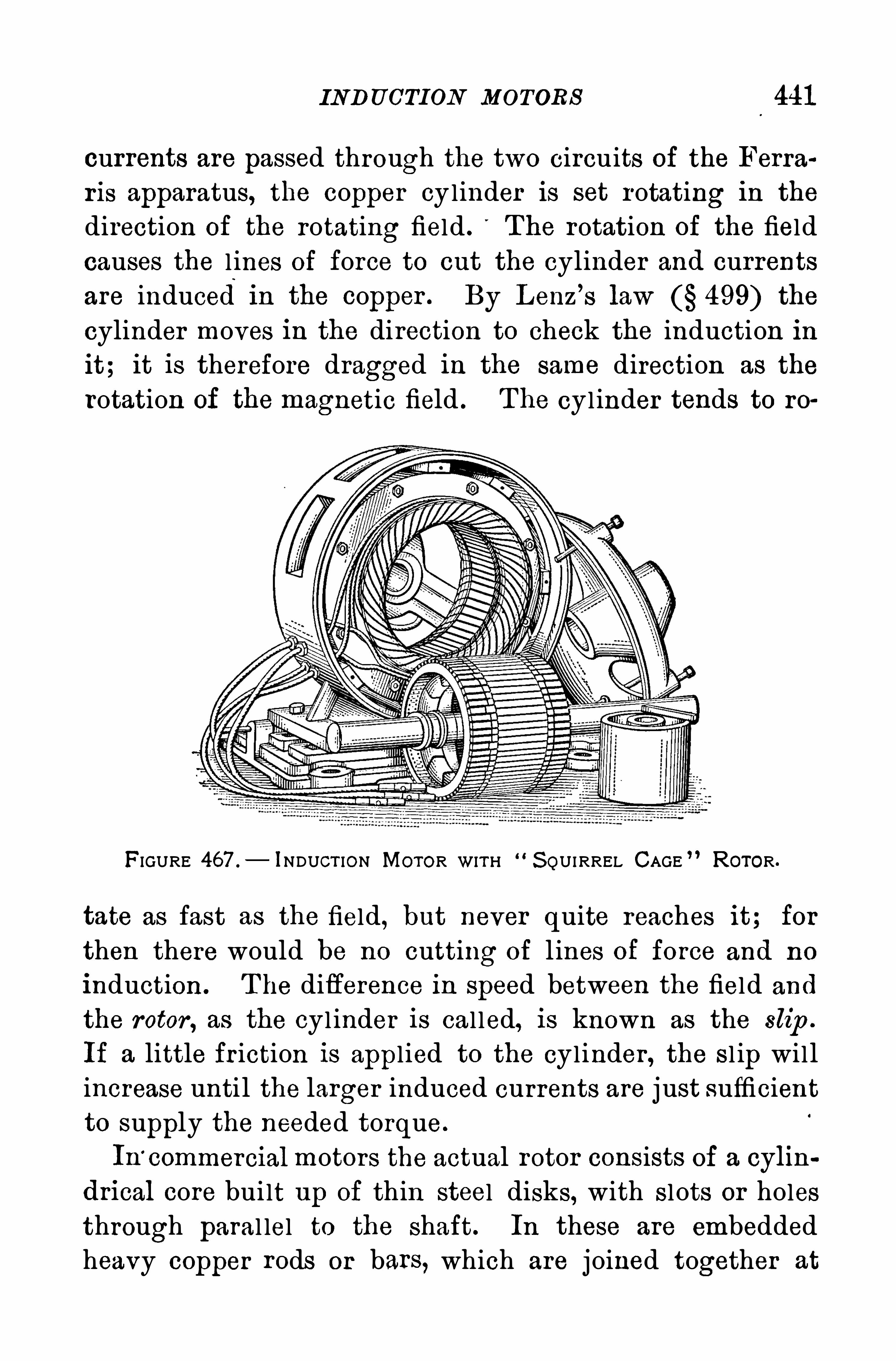
IND UCTION MOTORS 441
currents are passed through the two circuits of the Ferrar is apparatus, the copper cylinder is set rotating in the
direction of the rotating field . The rotation of the field
causes the l ines of force to cut the cylinder and currents
are induced in the copper . By L enz’
s law 499) the
cylinder moves in the direction to check the induction init; it is therefore dragged in the same direction as the
rotation of the magnetic field . The cylinder tends to ro
FIGURE 467 .
— INDUCT ION MOTOR WITH S QUIRREL CAGE ” ROTOR .
tate as fast as the field, but never quite reaches it; forthen there would be no cutting of l ines of force and no
induction . T he difference in speed between the field and
the rotor , as the cyl inder is cal led, is known as the slip .
If a little fr iction is appl ied to the cylinder , the sl ip wi l lincrease unti l the larger induced currents are j ust sufficientto supply the needed torque.
In’
commercialmotors the actual rotor consists of a cylin
drical core built up of thin steel disks, with S lots or holesthrough paral lel to the shaft. In these are embeddedheavy copper rods or bars, which are j oined together at
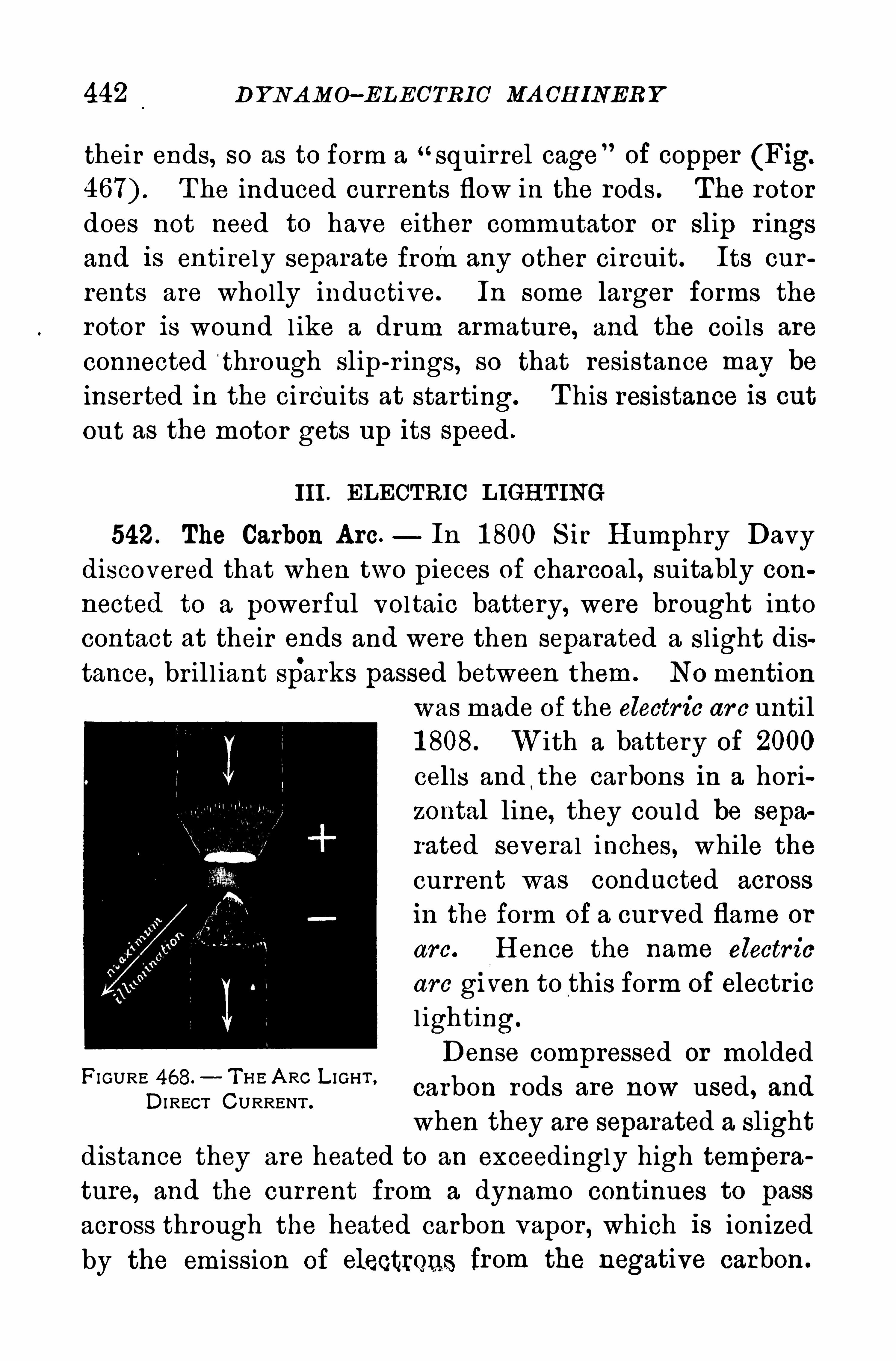
442 D YN A MO—ELEC’TRIC MA CH INERY
their ends, SO as to form a“squirrel cage of copper (Fig.
T he induced currents flow in the rods. The rotordoes not need to have either commutator or slip r ingsand is entirely separate fromany other circuit. Its cur
rents are wholly inductive. In some larger forms the
rotor is wound l ike a drum armature, and the coi ls are
connected t hrough slip-r ings, so that resistance may be
inserted in the circuits at starting. T his resistance is cutout as the motor gets up its speed .
III . ELECTRIC LIGH TING
542 . The Carbon Arc — In 1 800 S ir H umphry Davydiscovered that when two pieces of charcoal, suitably con
nected to a powerful voltaic battery, were brought intocontact at their ends and were then separated a S l ight distance, br il l iant sparks passed between them . NO mention
was made Of the electr ic ar c until1 808. W ith a battery of 2000
cells and!the carbons in a hor i
zontal line, they could be sepa
rated severa l inches, while the
current was conducted across
in the form of a curved flame or
arc. H ence the name electr ic
are gi ven to this form of electr icl ighting.
Dense compressed or molded
carbon rods are now used, and
when they are separated a slight
distance they are heated to an exceedingly high tempera
ture, and the current from a dynamo continues to pass
across through the heated carbon vapor , which is ionized
by the emission of electrQnS from the negative carbon .
FI GURE 468. T H E A RC L I GHT ,
DI RECT CURRENT .
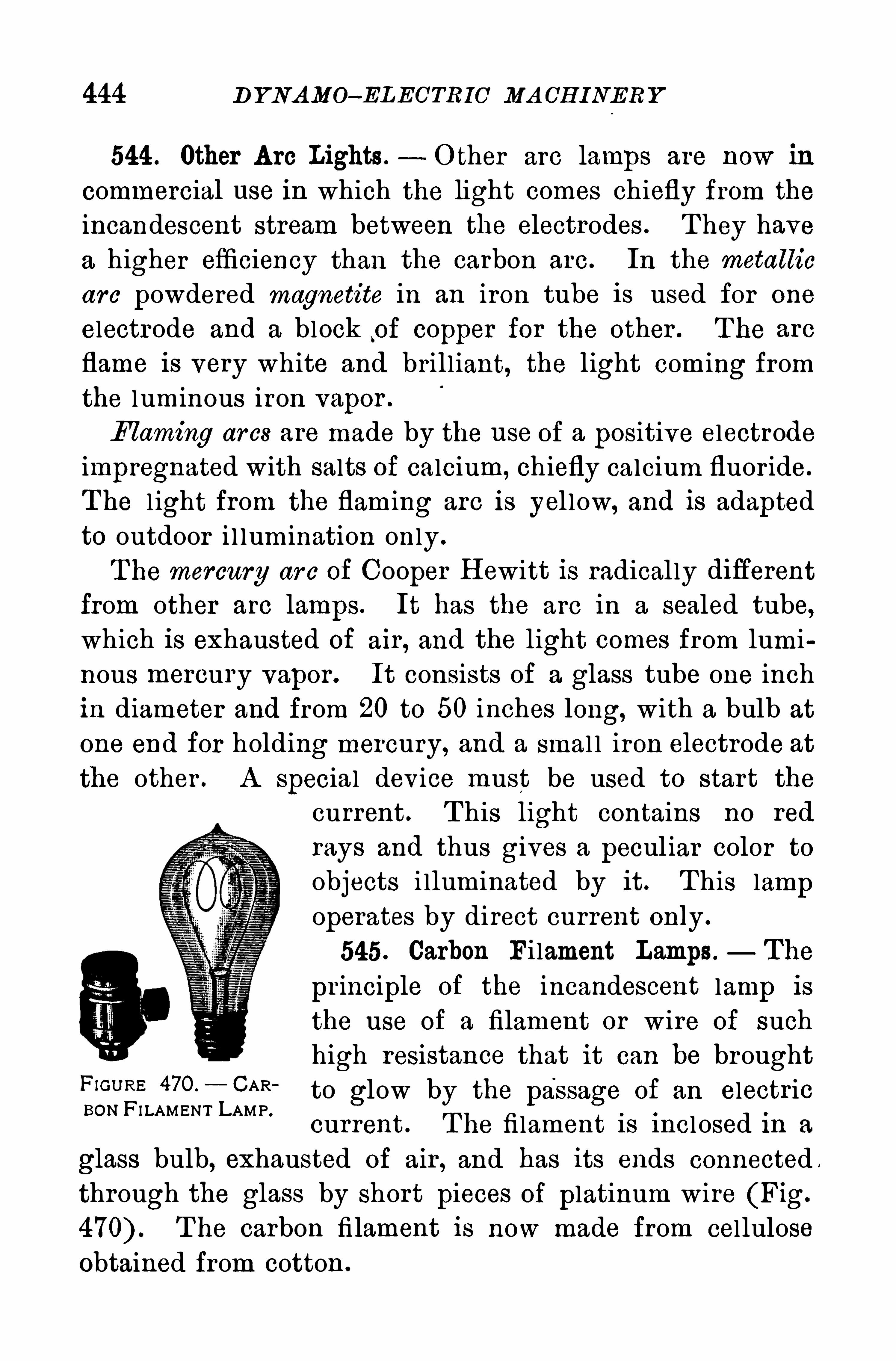
444 D YNAMO—ELEOTR 1 0 MA CH INERY
544 . Other A rc Lights .- O ther arc lamps are now in
commercial use in which the light comes chiefly from the
incandescent stream between the electrodes . T hey havea higher efficiency than the carbon arc. In the metallic
arc powdered magnetite in an iron tube is used for one
electrode and a block p f copper for the other . T he are
flame is very white and brill iant, the light coming from
the luminous iron vapor .
Flaming ar cs are made by the use of a positive electrodeimpregnated with salts Of calcium, chiefly calcium fluor ide.
T he l ight from the flaming arc is yel low, and is adaptedto outdoor i l lumination only .
T he mercury ar c of Cooper H ewitt is radical ly diflerentfrom other arc lamps. It has the arc in a sealed tube,which is exhausted Of air , and the light comes from lumi
nous mercury vapor . It consists of a glass tube one inch
in diameter and from 20 to 50 inches long, with a bulb at
one end for holding mercury, and a smal l iron electrode at
the other . A special device must be used to start the
current . T his light contains no red
rays and thus gives a pecul iar color toobjects i lluminated by it . T his lampoperates by direct current only .
545. Carbon Fi lament Lamps . The
pr inciple of the incandescent lamp is
the use of a filament or wire Of suchhigh resistance that it can be brought
F‘GU RE 47O°
_ CAR‘
to glow by the passage of an electricBON FILAMENT LAMP .
current . T he fi lament is incl osed in a
glass bulb, exhausted of air , and has its ends connected ,
through the glass by short pieces of platinum wire (Fig.
T he carbon filament is now made from cellulose
Obtained from cotton .
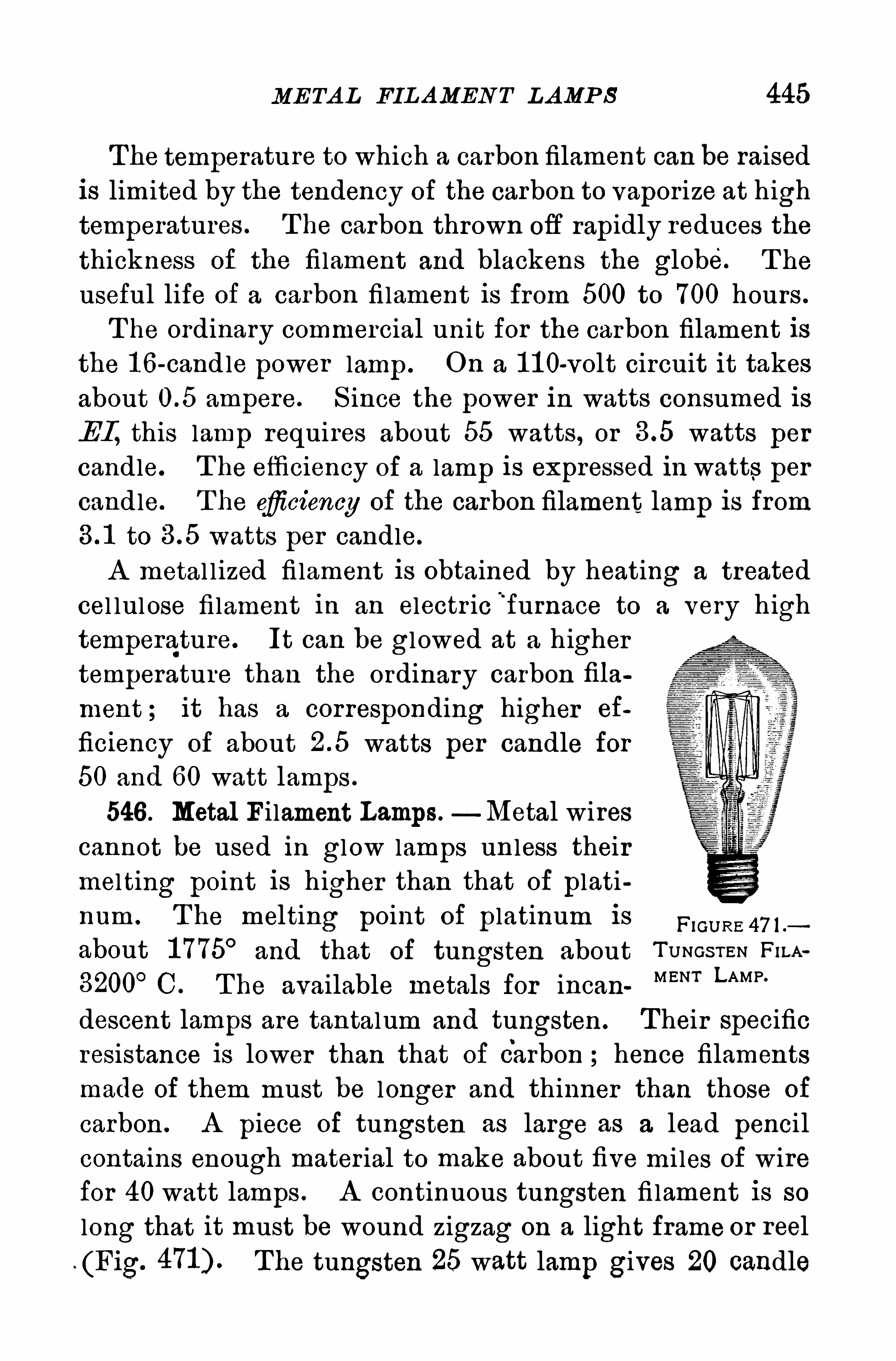
ME TA L FIL AMEN T L AMP S 445
The temperature to which a carbon filament can be raised
is limited by the tendency Of the carbon to vapor ize at high
temperatures . T he carbon thrown off rapidly reduces the
thickness Of the filament and blackens the globe. T he
useful life of a carbon fi lament is from 500 to 700 hours .
T he ordinary commercial uni t for the carbon filament is
the 1 6-candle power lamp . On a 1 1 0-volt circuit it takes
about ampere. S ince the power in watts consumed is
EI , this lamp requires about 55 watts , or watts per
candle. T he efficiency of a lamp is expressed in watts per
candle. T he eficiency of the carbon filament lamp is fromto watts per candle.
A metal l ized fi lament is Obtained by heating a treatedcel lulose filament in an electr ic
“
furnace to a very hightemperature. It can be gl owed at a highertemperature than the ordinary carbon filament ; it has a corresponding higher ef
ficiency of about watts per candle for50 and 60 watt lamps .
546 . Metal Filament Lamps. Metal wirescannot be used in glow lamps un less theirmel ting point is higher than that Of platinum . T he melting point Of platinum is H GU RE
about 1 775° and that of tungsten about T UNGS TEN Fir-A
3200°C. T he available metals for incan MENT LAMP’
descent lamps are tantalum and tungsten . T heir specificresistance is lower than that of Carbon ; hence filaments
made of them must be longer and thinner than those of
carbon . A piece of tungsten as large as a lead pencilcontains enough mater ial to make about five mi les of wirefor 40 watt lamps . A continuous tungsten fi lament is so
long that it must be wound zigzag on a light frame or reel
(Fig. The tungsten 25 watt lamp gives 20 candle
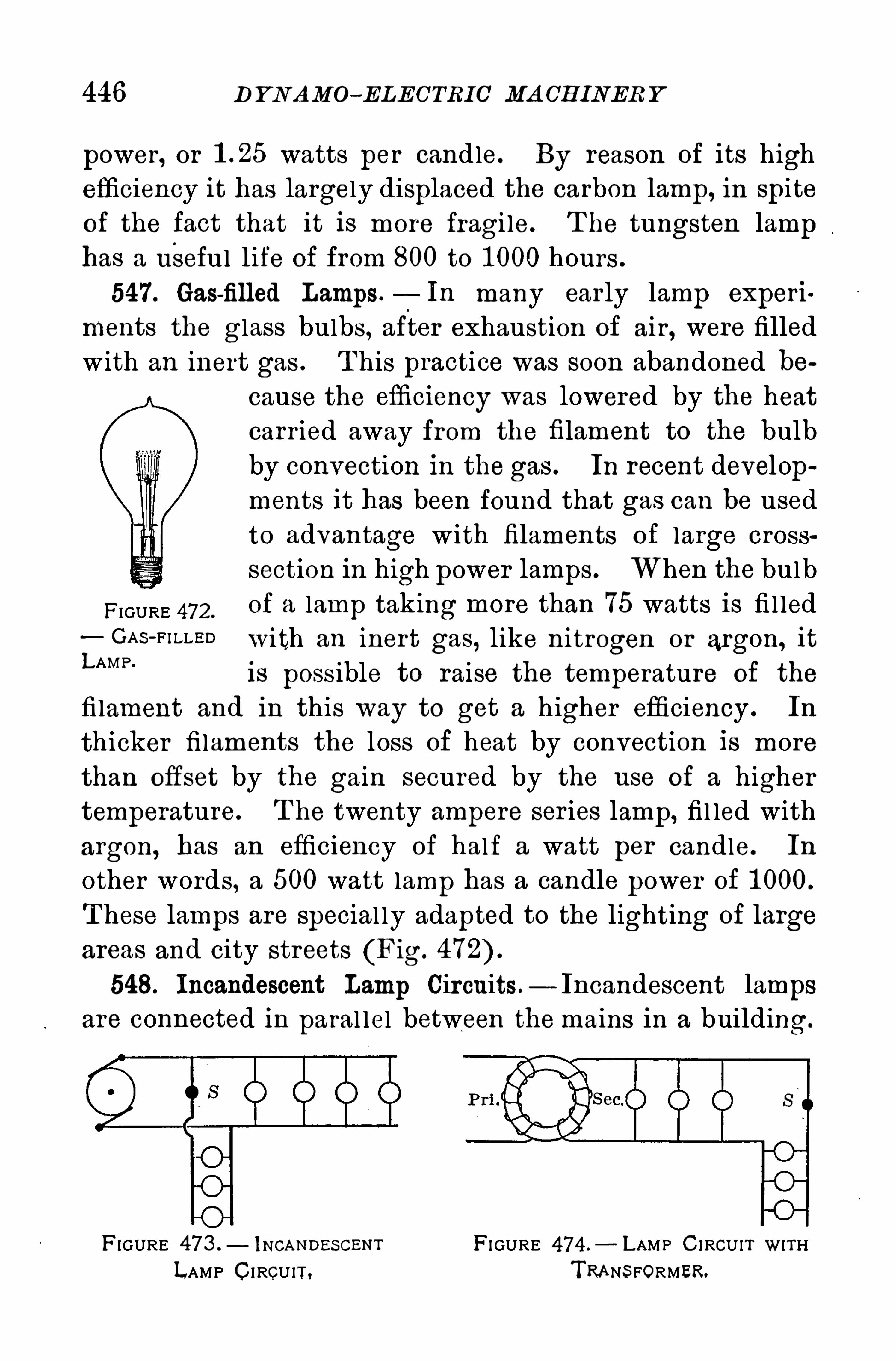
446 D YN AMO- ELECTRIC MA CH INER Y
power, or watts per candle. By reason of its high
efficiency it has largely displaced the carbon lamp, in spite
of the fact that it is more fragi le. T he tungsten lamphas a useful life of from 800 to 1 000 hours .
547. Gas-filled Lamps. In many early lamp experi
ments the glass bulbs, after exhaustion Of air , were filled
with an inert gas . T his practice was soon abandoned because the efficiency was lowered by the heat
carr ied away from the filament to the bulb
by convection in the gas . In recent developments it has been found that gas can be usedto advantage with filaments of large crosssection in high power lamps . When the bulb
FIGURE 472 .
of a lamp taking more than 75 watts is fi l ledGA S -FI LLED with an inert gas, like nitrogen or argon, it
LAMP '
is possible to raise the temperature Of the
fi lament and in this way to get a higher efficiency . In
thicker filaments the loss of heat by convection is more
than Offset by the gain secured by the use Of a higher
temperature. T he twenty ampere ser ies lamp, fil led with
argon, has an efficiency Of half a watt per candle. In
other words, a 500 watt lamp has a candle power of 1 000.
T hese lamps are special ly adapted to the lighting of large
areas and city streets (Fig.
548. Incandescent Lamp Circuits — Incandescent lampsare connected in paral lel between themains in a building.
FIGURE 473 .— lNCANDESCENT FI GURE 474 .
— LAMP C I RCUIT WITHLAMP CI RCUIT, TRANS FORMER.
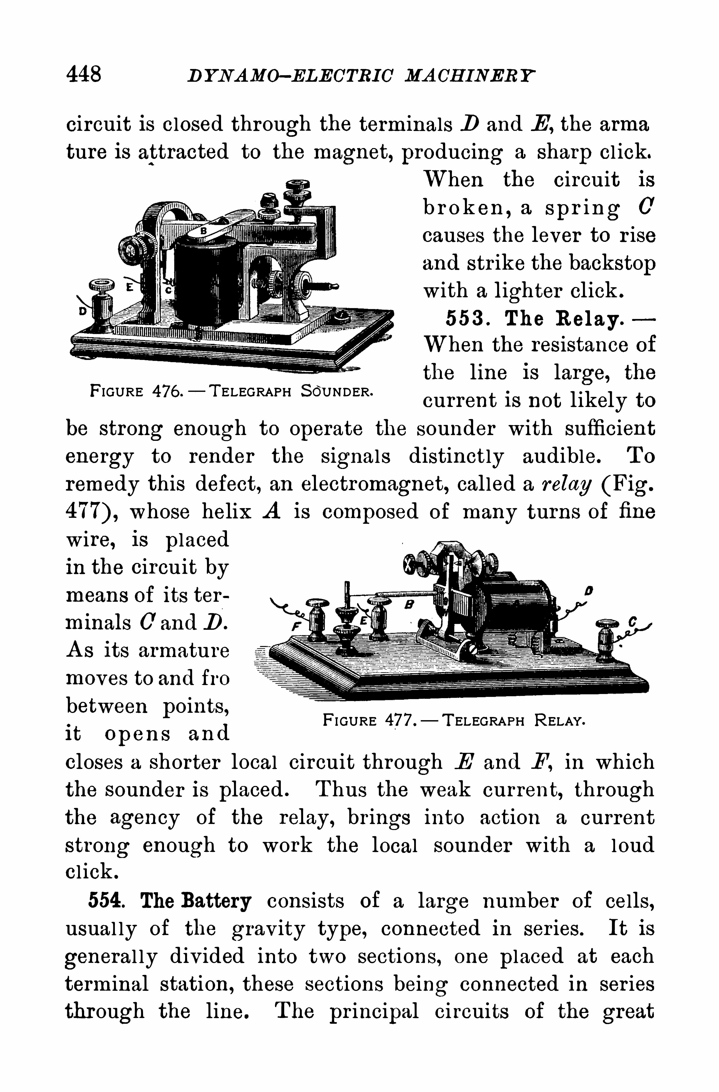
448 D Y NA MO—ELECTRIC MA CH INERY
circuit is closed through the terminals D and E , the arma
ture is attracted to the magnet, producing a sharp cl ick.
When the circuit is
b r ok en , a spr ing 0
causes the lever to r iseand str ike the backstopwith a lighter click .
553 . The Relay .
When the resistance of
the line is large, the
current is not likely to
be strong enough to operate the sounder with sufficient
energy to render the signals distinctly audible. T o
remedy this defect, an electromagnet, called a relay (Fig.
whose helix A is composed of many turns of fine
wire, is placedin the circuit bymeans Of its ter
minals C' and B .
A s its armaturemoves to and fro
between points,it O pen s and
closes a shorter local circuit through E and F , in whichthe sounder is placed . T hus the weak current, throughthe agency of the relay, brings into action a currentstrong enough to work the local sounder with a loudcl ick .
554. The Battery consists of a large number of cells,usual ly Of the gravity type, connected in ser ies. It is
general ly div ided into two sections, one placed at eachterminal station , these sections being connected in ser iesthrough the line. T he pr incipal ci rcuits of the great
FIGURE 476 .—T ELEGRAPH S OU NDER.
FI GURE 477 .
— T ELEGRAPH RELAY.

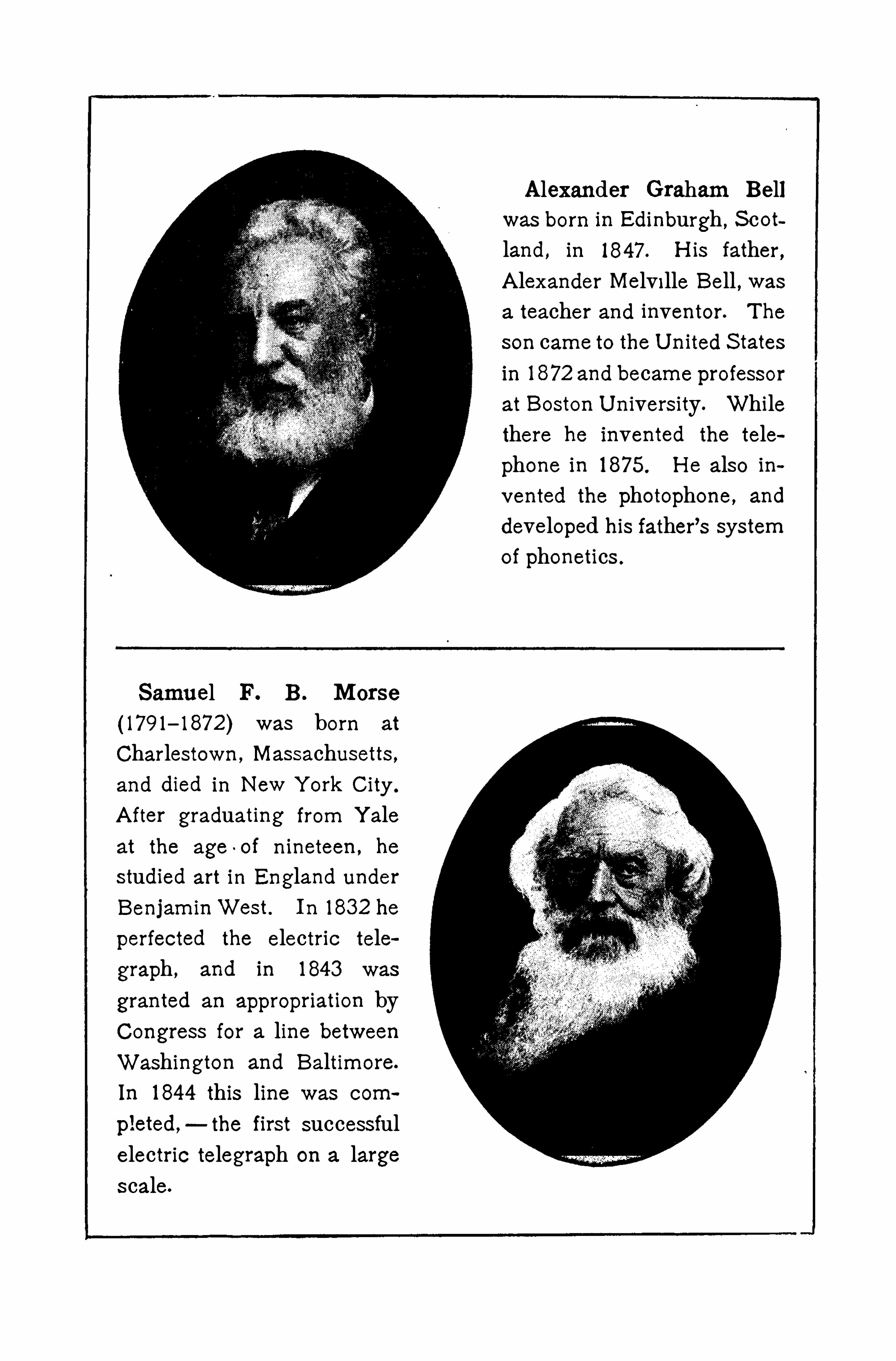
Samuel F. B. Morse
(179 1—1872) was born at
Charlestown , Massachusetts ,and died in New Y ork City .
A fter graduating from Y aleat the age
-oi nineteen , he
studied art in England underBenjam inWest. In 1832 he
perfected the electric tele
graph , and in 1843 was
granted an appropriation byCongress for a line betweenWashington and Baltimore.
In 1844 this line was com
pleted,—the first successful
electric telegraph on a largescale.
A lexander Graham Bellwas born in Edinburgh , S cotland, in 1847 . H is father ,A lexander Melville Bell , wasa teacher and inventor. T he
son came to the U nited S tates
in 1872 and became professor
at Boston U niversity. Whilethere he invented the tele
phone in 1875. H e also invented the photophone, and
developed his father’s system
of phonetics .
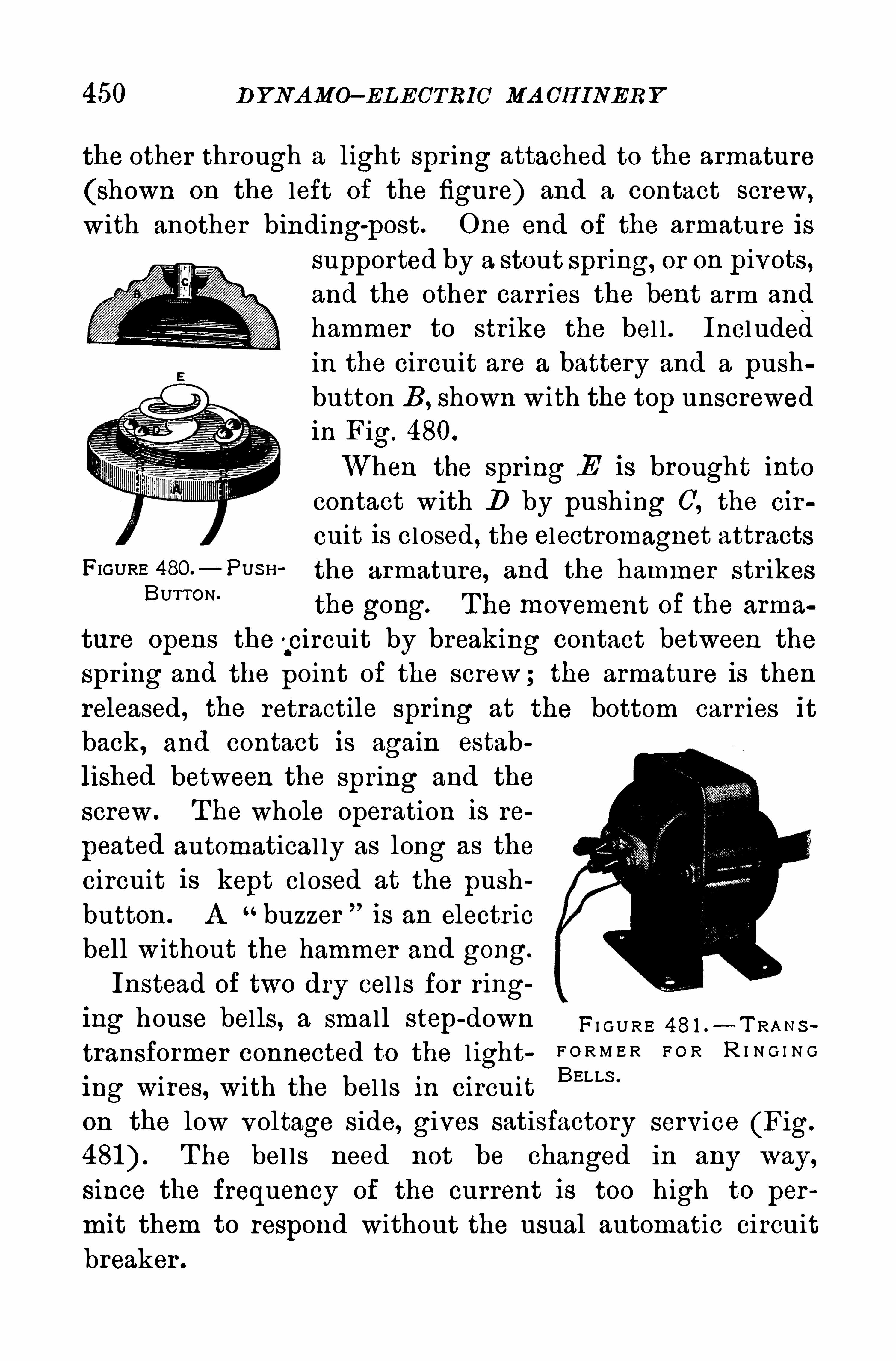
450 D YNA MO—EL ECTRIC MA CH INER Y
the other through a light spr ing attached to the armature
(shown on the left Of the figure) and a contact screw,
with another binding-
post. One end Of the armature issupported by a stout spr ing, or on pivots,and the other carr ies the bent arm and
hammer to strike the bel l . Incl udedin the circuit are a battery and a pushbutton B , shown with the top unscrewedin Fig. 480.
When the spring E is brought intocontact with D by pushing C
'
, the cir
cuit is closed, the electromagnet attractsFIGURE 480 - PUS H the armature, and the hammer str ikes
BUTTON‘
the gong. The movement of the arma
ture Opens the '
.circuit by breaking contact between the
Spr ing and the point Of the screw; the armature is thenreleased, the retractile spr ing at the bottom carr ies itback , and contact is again estab
lished between the spring and the
screw . T he whole Operation is re
peated automatical ly as long as the
circuit is kept closed at the push
button . A “buzzer is an electr icbell w ithout the hammer and gong.
Instead Of two dry cel ls for r inging house bells, a small step
-down F I G U RE 48 1 .- T RA N s
transformer connected to the l ight F O R M E R F O R R I N G I N G
ing wires, with the bel ls in circuit BELLS '
on the low voltage side, gives satisfactory service (Fig.
The bel ls need not be changed in any way,
since the frequency of the current is too high to per
mit them to respond without the usual automatic circuit
breaker .
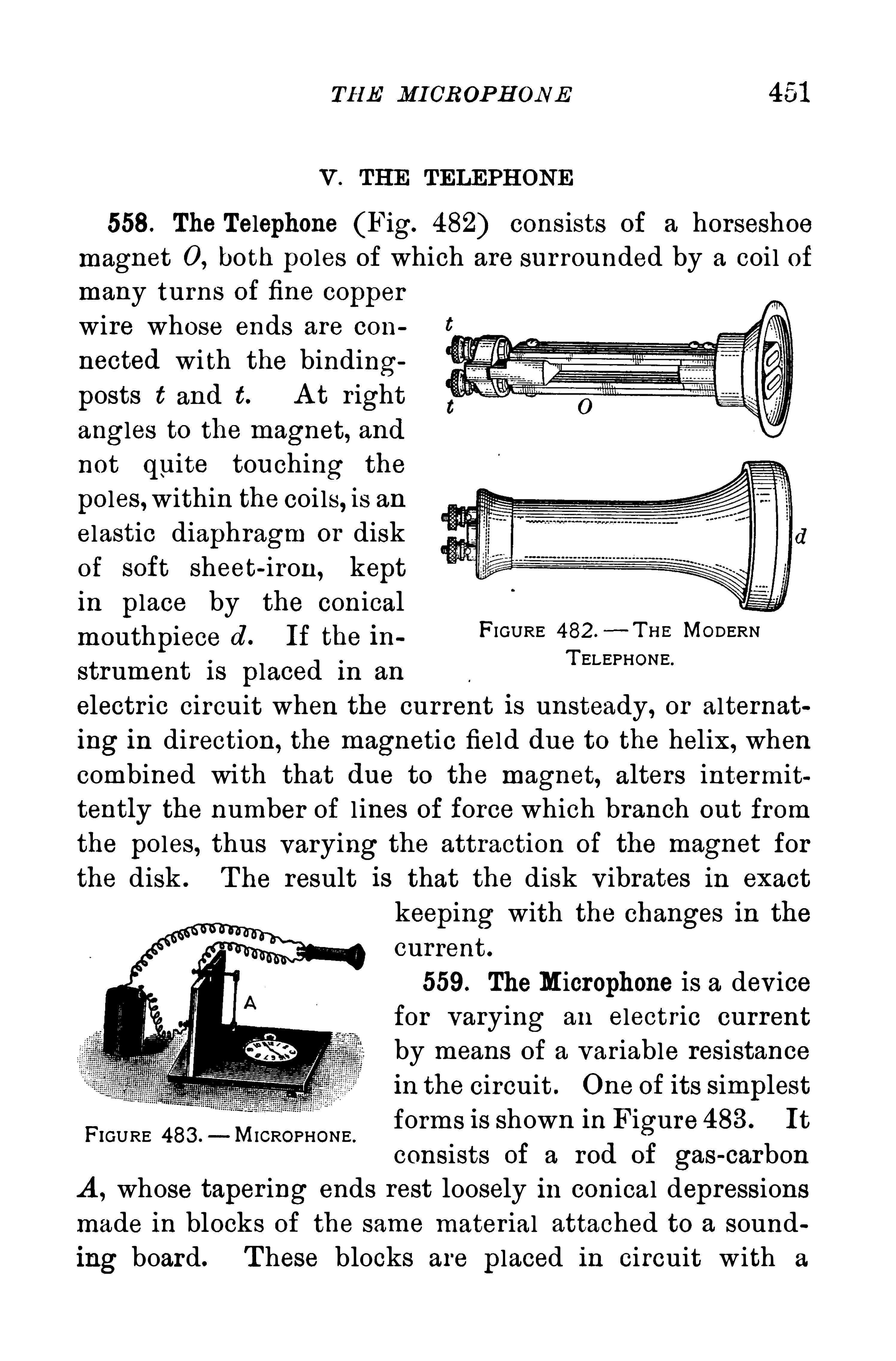
TH E MICROP H ONE 451
V . THE TELEPH ONE
558. The Telephone (Fig. 482) consists of a horseshoemagnet 0 , both poles of which are surrounded by a coil ofmany turns Of fine copper
wire whose ends are con
nected wi th the binding
posts t and t. A t right
angles to the magnet, and
not quite touching the
poles,within the coi ls, is anelastic diaphragm or diskof soft sheet-iron, keptin place by the conicalmouthpiece cl . If the in FIGURE 482 .
—T H E MODERN
strument is placed in anT ELEPHONE“
electr ic circuit when the current is unsteady, or alternating in direction, the magnetic field due to the helix, whencombined with that due to the magnet, alters intermittently the number of l ines of force which branch out from
the poles, thus varying the attraction Of the magnet for
the disk . The result is that the disk v ibrates in exact
keeping with the changes in the
current.
559. TheMicrophone is a devicefor varying an electric currentby means Of a variable resistancein the circuit . One Of its simplestforms is Shown in Figure 483 . It
consists of a rod of gas-carbon
A , whose taper ing ends rest loosely in conical depressionsmade in blocks Of the same mater ial attached to a sounding board. T hese blocks are placed in circuit w ith a
FIGURE 483 . MICROPHONE .
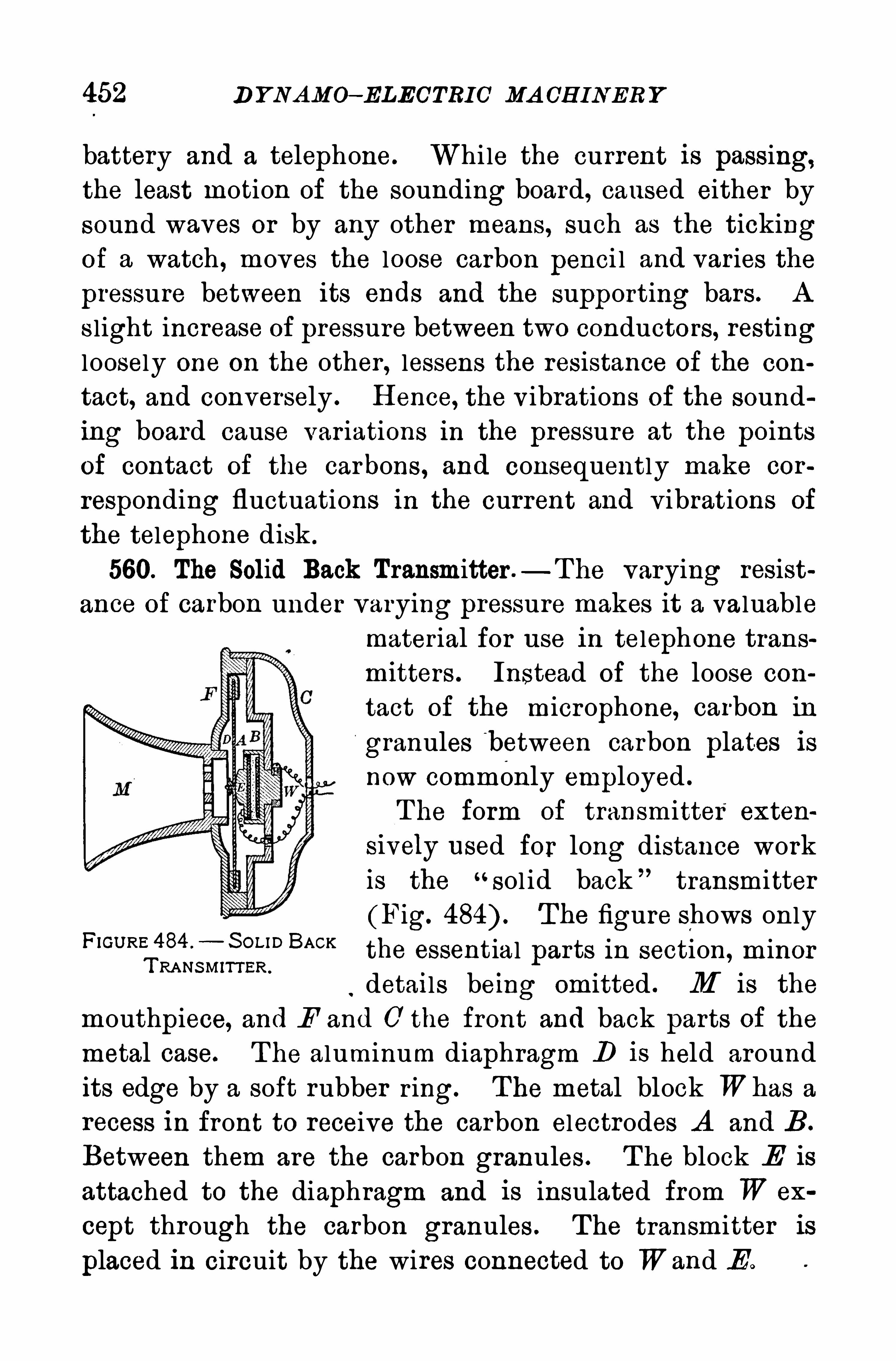
452 D Y NAMO—ELECTRIC MA CH INERY
battery and a telephone. While the current is passing,the least motion Of the sounding board, caused either by
sound waves or by any other means, such as the tickingof a watch , moves the loose carbon penci l and varies the
pressure between its ends and the supporting bars . A
s light increase of pressure between two conductors, restingloosely One on the other , lessens the resistance Of the con
tact, and conversely . H ence, the v ibrations of the sound
ing board cause variations in the pressure at the points
of contact of the carbons , and consequently make cor
responding fluctuations in the current and vibrations Of
the telephone disk .
560. The Solid Back Transmitter .—T he varying resist
ance of carbon under varying pressure makes it a valuablemater ial for use in telephone transmitters . Instead of the loose con
tact Of the microphone, carbon in
granules b etween carbon plates isnow commonly employed .
T he form of transmitter exten
S ively used for long distance workis the “
sol id back transmitter
(Fig. T he figure shows onlyBACK
the essential parts in section, minorRANSMITTER .
detai ls being omitted . M i s the
mouthpiece, and F and 0 the front and back parts of themetal case. T he aluminum diaphragm 1 ) is held aroundits edge by a soft rubber r ing. The metal block Whas a
recess in front to receive the carbon electrodes A and B .
Between them are the carbon granules . T he block E is
attached to the diaphragm and is insulated from W ex
cept through the carbon granules . The transmitter is
placed in circuit by the wires connected to Wand E .
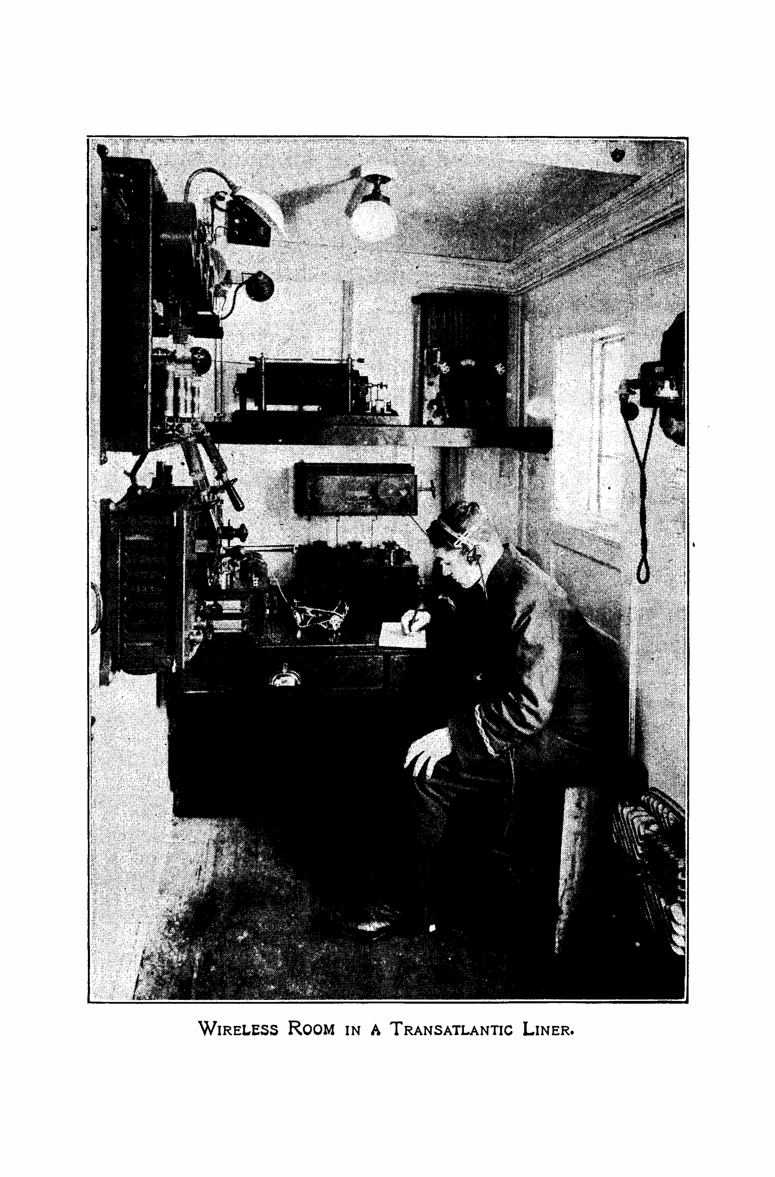
WIRELES S ROOM IN A T RANS ATLANTIC L INER.
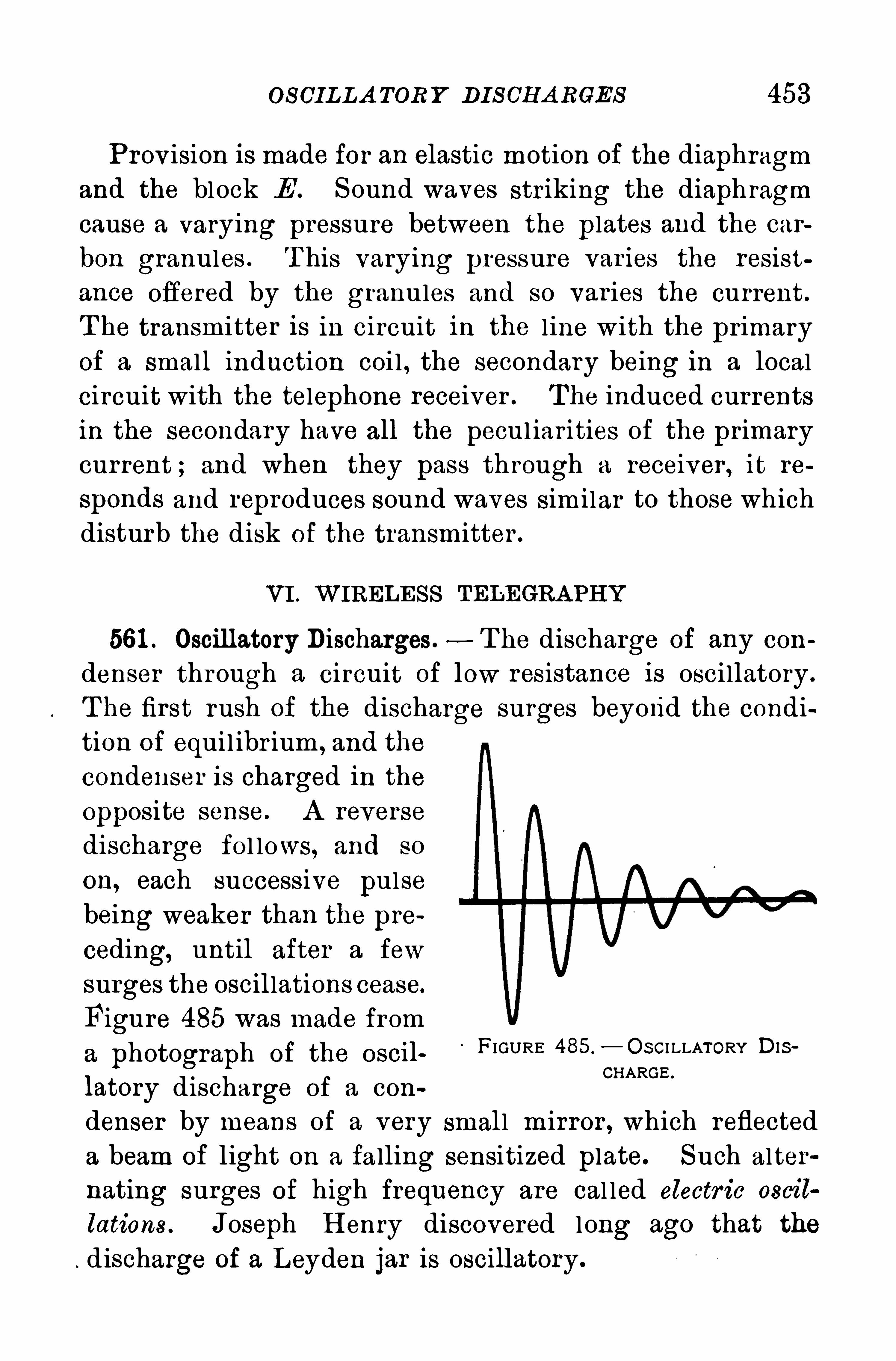
OS CIL LA TOR Y DIS CH A RGES 453
P rovision is made for an elastic motion Of the diaphragm
and the block E . Sound waves striking the diaph ragm
cause a varying pressure between the plates and the car
bon granules . T his varying pressure var ies the resist
ance Offered by the gra nules and so var ies the current .
T he transmitter is in circuit in the l ine with the pr imary
of a small induction coi l , the secondary being in a localcircuit with the telephone receiver . T he induced currentsin the secondary have all the pecul iar ities of the primarycur rent ; and when they pass th rough a receiver , it re
sponds and reproduces sound waves similar to those whichdisturb the disk of the transmitter .
VI . W IRELES S TELEGRA PH Y
561 . Oscillatory Discharges. T he discharge Of any con
denser through a circuit of low resistance is oscillatory .
T he first rush of the discharge surges beyond the condition of equil ibr ium , and the
condenser is charged in theopposite sense. A reverse
discharge fol lows, and so
on, each successive pulse
being weaker than the pre
ceding, until after a few
surges the oscillations cease.
Figure 485 was made from
a photograph of the oscil FIGURE 485.
—O S CI LLATORY DIS
latory discharge of a conCHARGE '
denser by means of a very smal l m irror , which reflecteda beam of light on a falling sensitized plate. Such alter
nating surges of high frequency are cal led electr ic oscil
lations . Joseph H enry discovered long ago that the
discharge of a Leyden jar is oscillatory.
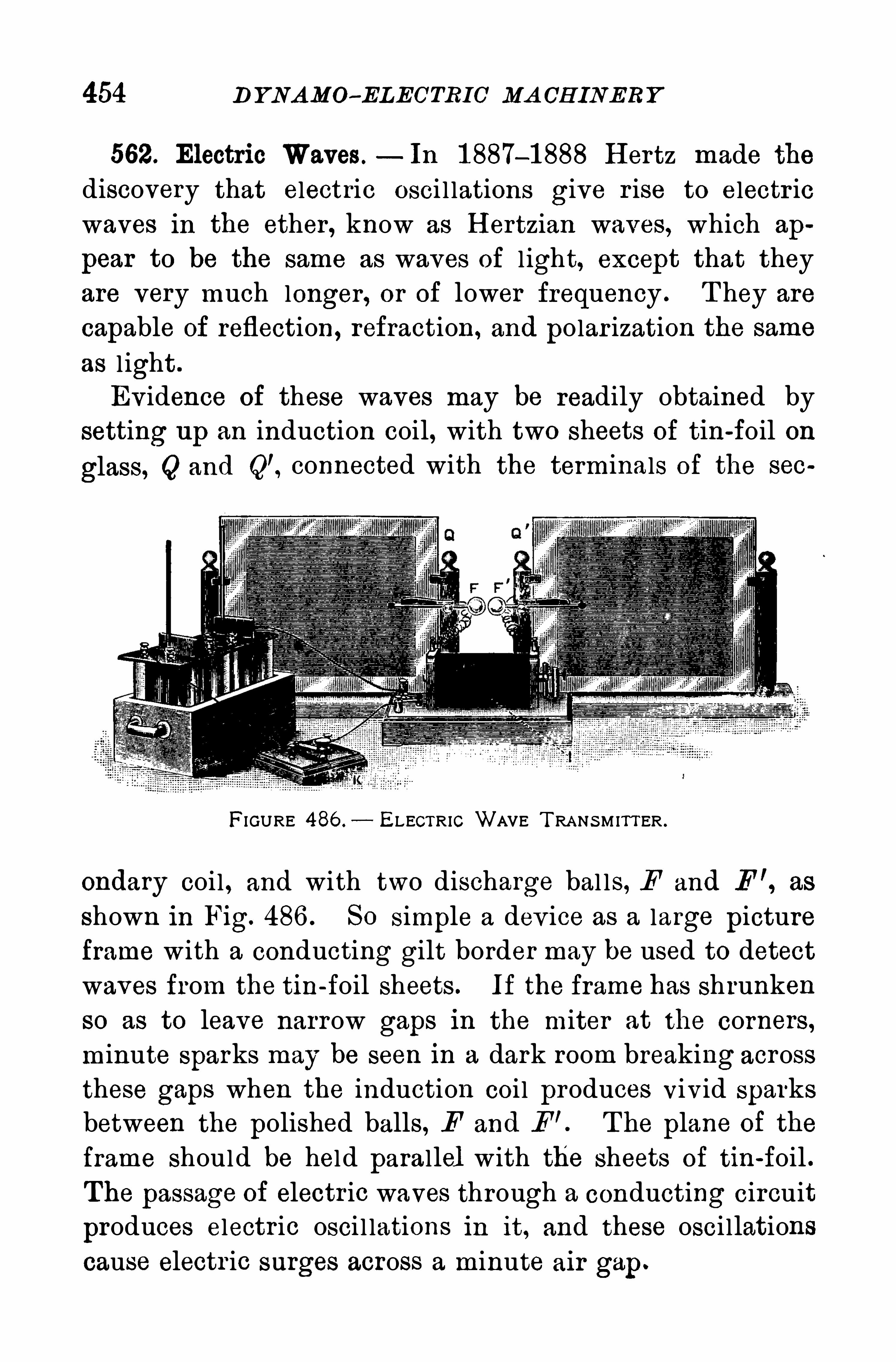
454 D YNAMO- ELECTRIC MA CH INERY
562. Electric Waves.—In 1 887—1888 H ertz made the
discovery that electric osci l lations give r ise to electr ic
waves in the ether , know as H ertzian waves, which ap
pear to be the same as waves of l ight, except that they
are very much longer , or of lower frequency . T hey are
capable of reflection, refraction, and polar ization the same
as l ight .
Ev idence of these waves may be readily obtained by
setting up an induction coil, with two sheets Of tin-foil on
glass, Q and Q’, connected with the terminals of the 86 0
FIGURE 486 . ELECTRIC WAVE T RA NS M ITTER .
ondary coil , and with two discharge bal ls, F and F ’, as
shown in Fig. 486 . SO simple a dev ice as a large picture
frame with a conducting gilt border may be used to detect
waves from the tin-foil sheets . If the frame has shrunken
so as to leave narrow gaps in the miter at the corners,
minute sparks may be seen in a dark room breaking across
these gaps when the induction coi l produces Viv id sparks
between the polished balls, F and F ’. T he plane of the
frame should be held parallel with the sheets of tin-foil .
The passage of electr ic waves through a conducting circuit
produces electric osci l lations in it, and these osci llations
cause electr ic surges across a minute air gap.
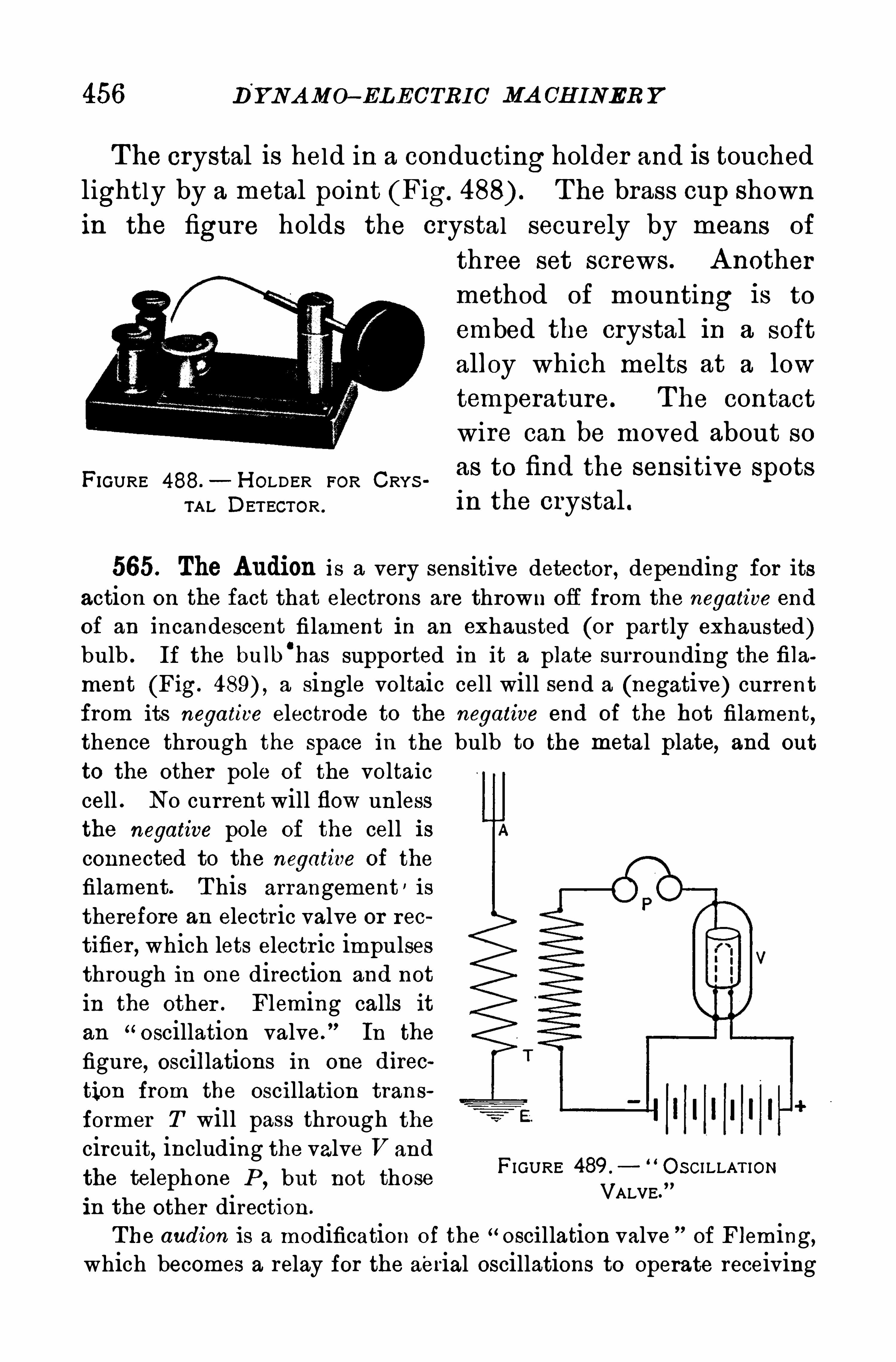
456 D'
YNA MO- ELECTRIC MA CH INER Y
The crystal is held in a conducting holder and is touchedlightly by a metal point (Fig. T he brass cup shownin the figure holds the crystal securely by means Of
FIGURE 488.— H OLDER FOR CRYS
TA L DETECTOR .
three set screws . A nothermethod of mounting is to
embed the crystal in a soft
alloy which melts at a low
temperature. T he contactwire can be moved about soas to find the sensitive spotsin the crystal .
565. The Audion is a very sensitive detector , depending for itsaction on the fact that electrons are thrown off from the negative end
of an incandescent filament in an exhausted (or partly exhausted)bulb . If the bulb
'
has supported in it a plate surrounding the filament (Fig. a single voltaic cell will send a (negative) currentfrom its negative electrode to the negative end of the hot filament,
thence through the space in the bulb to the metal plate, and out
to the other pole Of the voltaiccell . N0 current will flow unlessthe negative pole of the cell isconnected to the negative of the
filament. T his arrangement ' is
therefore an electric valve or rec
tifier , which lets electr ic impulsesthrough in one direction and not
in the other . Fleming calls itan
“oscillation valve. In the
figure, oscillations in one direc
tion from the oscillation trans
former T will pass through thecircuit
,including the valve V and
the telephone P,but not those
in the other direction .
FIGURE 489 . O SCI LLAT IONVALVE.
T he audion is a modification of the “oscillation valve of Fleming,which becomes a relay for the aerial oscillations to operate receiving
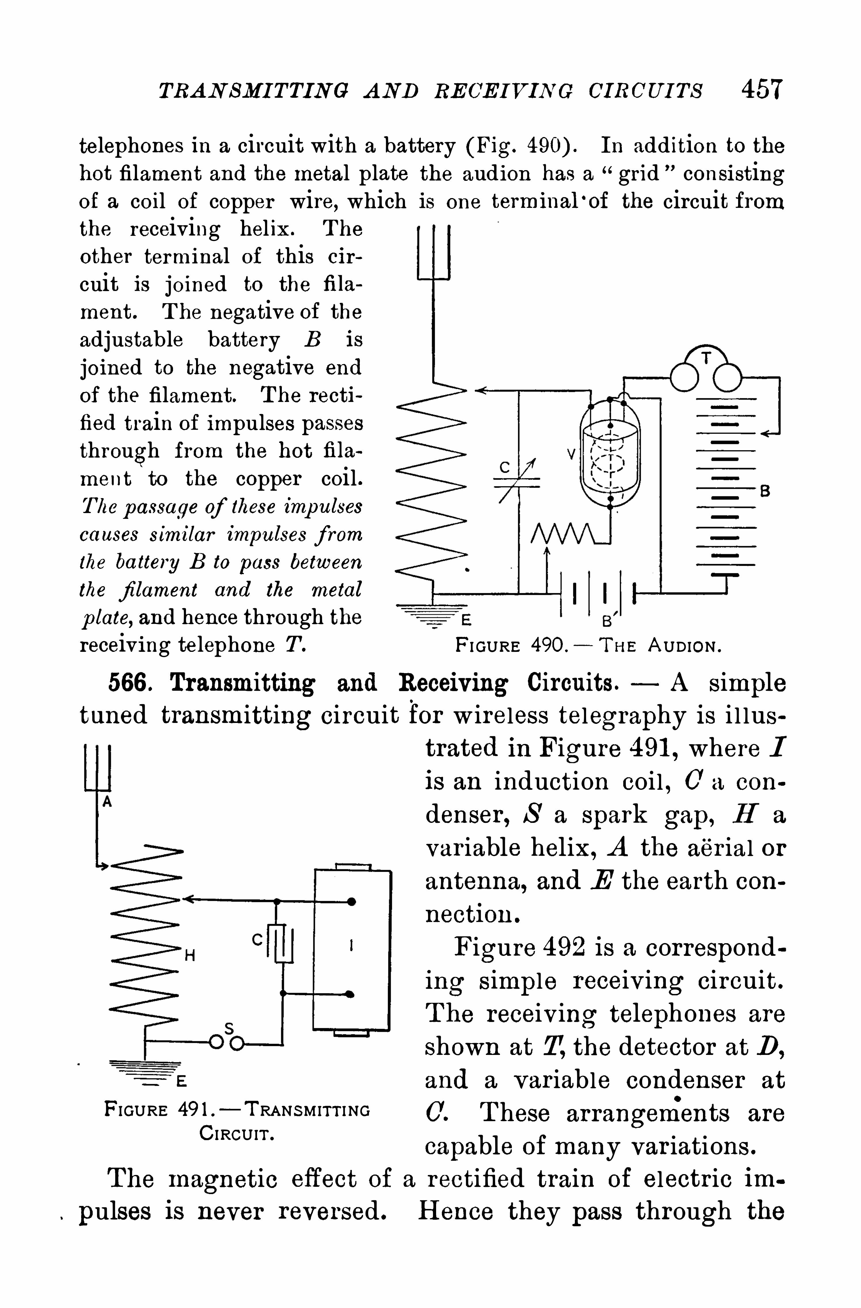
TRA N SMI TTING A ND RECE IVIN G CIRCU I TS 457
telephones in a circuit with a battery (Fig. In addition to thehot filament and the metal plate the audion has a grid consistingof a coil of copper wire, which is one terminal ‘of
the receiving helix . T he
other terminal of this cir
cuit is joined to the fila
ment. T he negative of theadjustable battery B is
joined to the negative end
of the filament. T he rectified train of impulses passesthrough from the hot fila
ment to the copper coil .The passage of these imp ulses
causes similar impulses f rom
the ba ttery B to pass between
the filament and the metal
plate, and hence through thereceiving telephone T .
circuit from
FI GURE 49O.
- T H E A UDION .
566 . Transmitting and Receiving Circuits. A simpletuned transmitting circuit for w ireless telegraphy is i l lus
FIGURE 49 1 T RANS MITT I NGC I RCUIT .
trated in Figure 491 , where Iis an induction coil , 0 a con
denser , S a spark gap, H a
var iable helix, A the aer ial or
antenna, and E the earth con
nection .
Figure 492 is a corresponding simple receiv ing circuit .
T he receiving telephones are
Shown at T, the detector at D,
and a var iable condenser at
T hese arrangements are
capable of many var iations .
The magnetic effect Of a rectified train of electric im
pulses is never reversed . H ence they pass through the
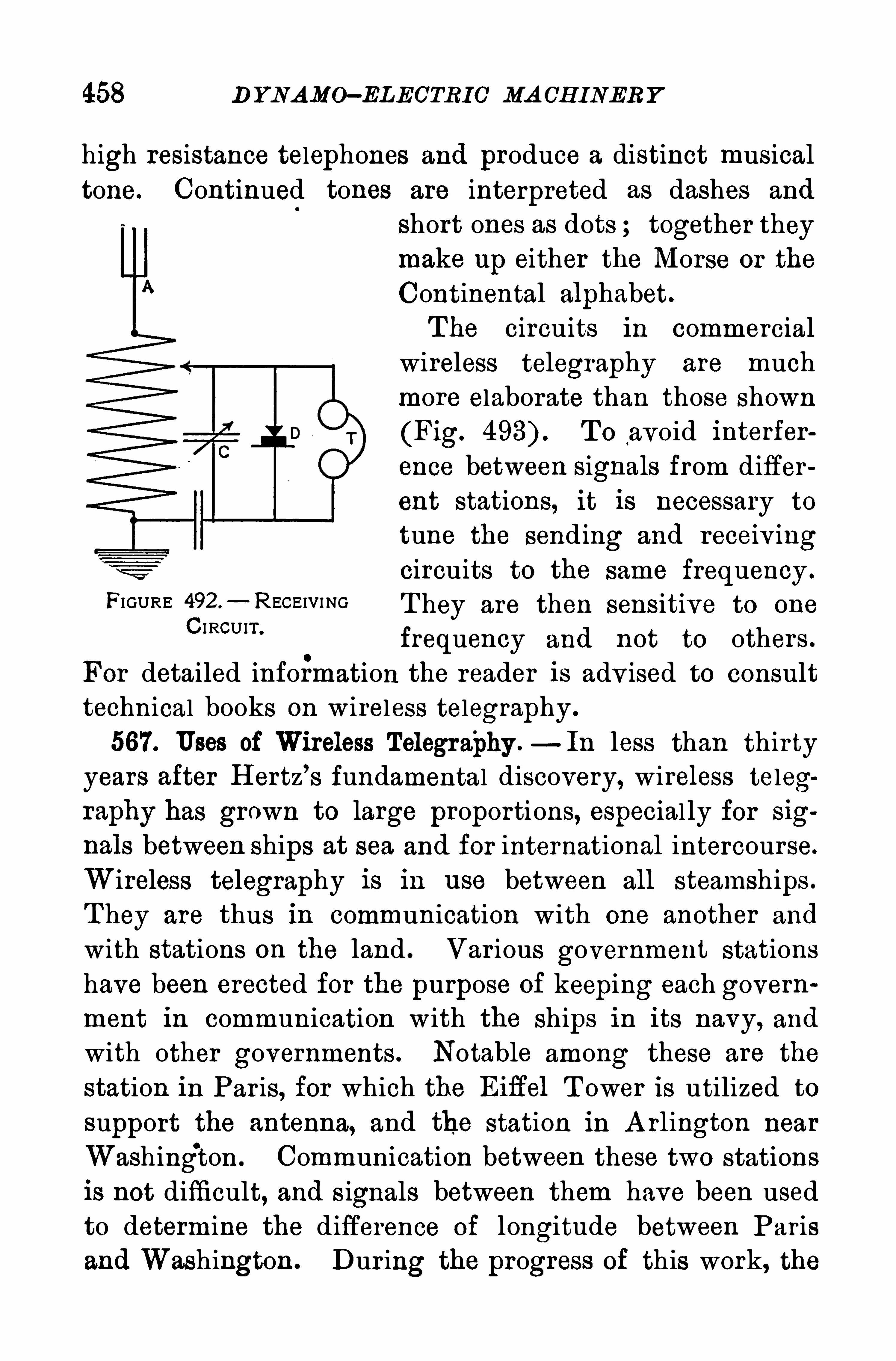
458 D YNAMO—ELEC’TRIC’ MA CH INER Y
high resistance telephones and produce a distinct musical
tone. Continued tones are interpreted as dashes and
short ones as dots ; together they
make up either the Morse or the
Continental alphabet.
T he circuits in commercial
wireless telegraphy are much
more elaborate than those shown
(Fig. T o avoid interfer
ence between signals from differ
ent stations, it is necessary to
tune the sending and receiv ingcircuits to the same frequency .
FIGURE 492-“ RECEIVI NG T hey are then sensitive to one
C I RCUIT ’
frequency and not to others .
For detailed information the reader is adv ised to consulttechnical books on wireless telegraphy .
567. Uses of Wireless Telegra'
phy .—In less than thirty
years after H ertz’s fundamental discovery, wireless telegraphy has grown to large proportions, especial ly for sig
nals between ships at sea and for international intercourse.
Wireless telegraphy is in use between all steamships .
T hey are thus in communication with one another and
with stations on the land . Var ious government stations
have been erected for the purpose of keeping each govern
ment in communication with the ships in its navy, and
with other governments . Notable among these are the
station in Par is, for which the Eih’el T ower is utilized to
support the antenna, and the station in A rlington near
Washing‘
ton. Communication between these two stations
is not difficult, and s ignals between them have been usedto determine the difference of longitude between Paris
and Washington . Dur ing the progress of this work, the

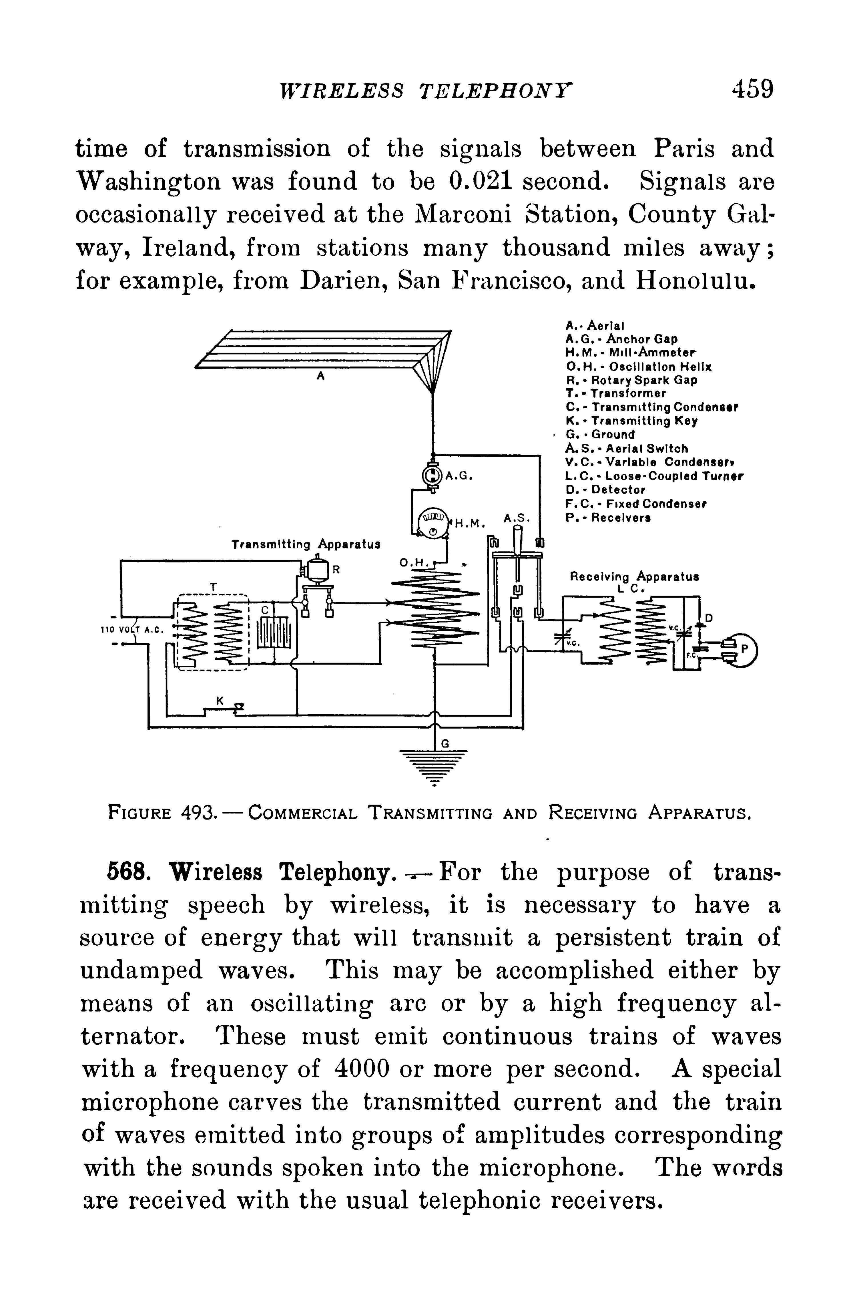
WI RELES S TELEP H ON Y 459
time of transmission of the signals between Par is and
Washington was found to be second . S ignals are
occasional ly received at the Marconi S tation , County Gal
way , Ireland, from stations many thousand mi les away ;for example, from Dar ien , San Francisco, and H ono lulu .
T ransmitting ApparatusReceiving Appa ra
L C .
FI GURE 493 .
— COMMERCIAL T RANS MITT I NG AND RECEIVI NG A PPARATUS .
568. Wireless Telephony .—For the purpose of trans
mitting speech by wi reless, it is necessary to have a
source of energy that wi l l transmit a persistent train of
undamped waves . T his may be accomplished either bymeans of an osci l lating are or by a high frequency al
ternator . T hese must emit continuous trains of waves
with a frequency of 4000 or more per second . A specialmicrophone carves the transmitted cur rent and the train
of waves emitted into groups of ampl itudes correspondingwith the sounds spoken into the microphone. T he wordsare received with the usual telephonic receivers .
Au Aeria lA .G. Anchor GapH .M. Mi l l -Ammeter0 . H . O sc i l l ation H e l ixR. Rotary S park GapT . T ransformerC . T ransmittingCondenser
K. T ransmitting KeyG. Ground
A. S . A eria l SwitchV. C . Va riab le Condensers
L . O . Loose-Coup led TurnerD. Detector
F. C . Fixed CondenserP . Receivers

CH A PTER XV
THE MOTOR CAR
569. The Modern Motor Car or Automobile has come into
such extensive use in the last few years that thepr inciples
of its construction and operation should be general ly
understood . Motor cars are usual ly classified accordingto the power which propels them, as electr ic, steam, and
gasol ine. S ince the gasol ine car is so much more widelyused than either of the other two
,it is the only one con
sidered in this chapter .
570. The Gasoline Automobile uses the internal combus
tion engine the four -cycle type, for its motor .
The number of cylinders var ies from four to twelve, and
the pistons, whatever their number,act on a common
crank shaf t. Figure 494 shows a four -cylinder'
engine and
Figure 495 a six . Whatever the number of cylinders,the energy from the expl osion is appl ied intermittently .
T he greater the number , the more nearly continuous isthe stream of energy .
In the four -cylinder engine there are two explosionsfor each revolution of the crank shaft, 1 80
0apart. For a
six, there are three, 1 200apart ; for an eight, there are
four,90
°apart ; and for a twelve, there are six
,60
°apart.
Figure 496 illustrates a twelve-cylinder engine or twinsix.
”
571 . The Engine.— The v ital part of the motor car is
the engine, and constant and intelligent attention on the
460
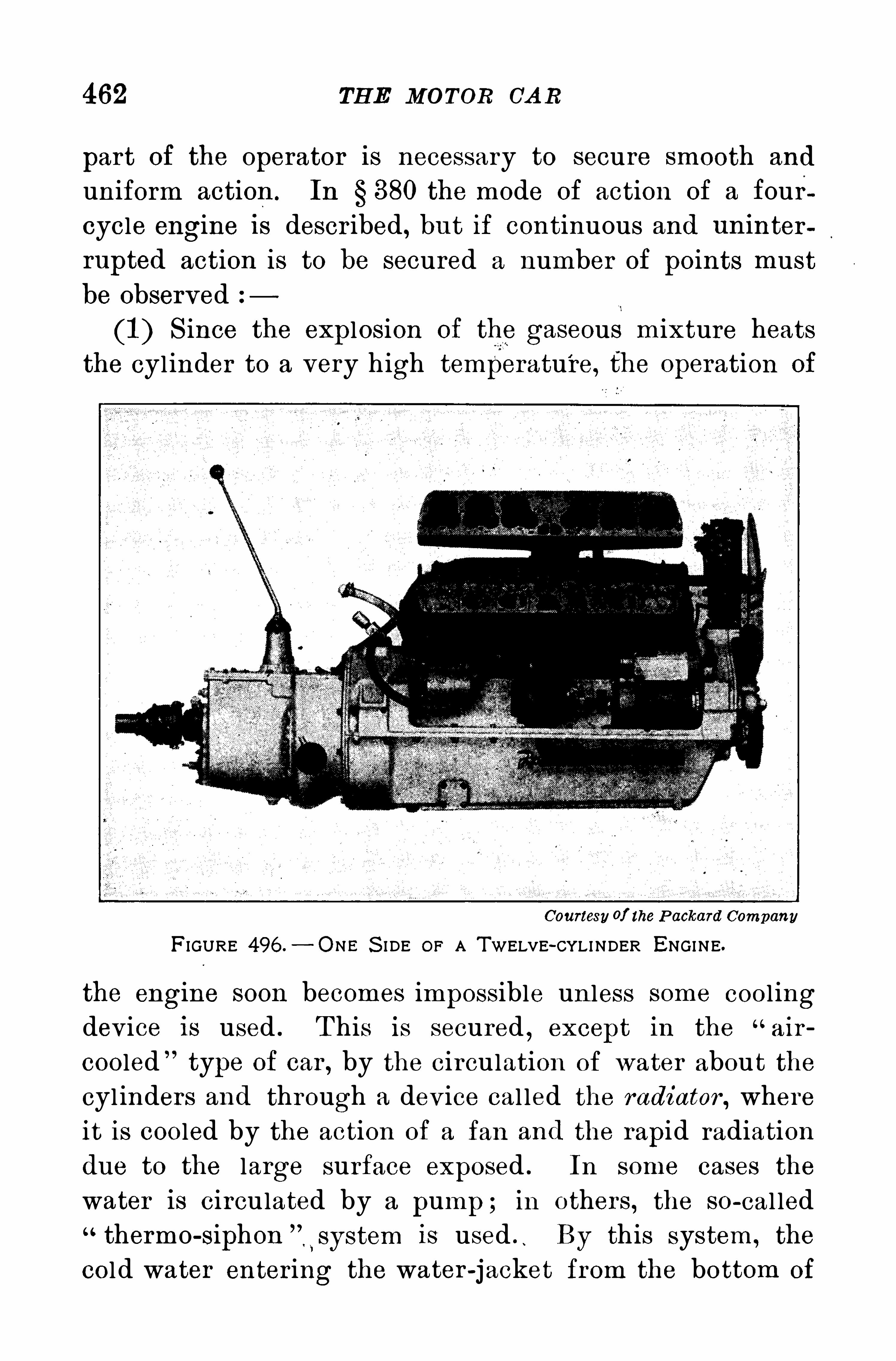
462 TH E MOTOR CA R
part of the operator is necessary to secure smooth and
uniform action . In § 880 the mode of action of a fourcycle engine i s descr ibed , but if continuous and uninter
rupted action is to be secured a number of points mustbe observed
(1 ) S ince the explosion of the gaseous mixture heatsthe cylinder to a very high temperature, the operation of
Courtesy of the P ackard CompanyFIGURE 496 .
— ONE S I DE OF A TWELVE-CYLINDER ENGINE.
the engine soon becomes impossible un less some cool ingdev ice is used . T his is secured
,except in the “
air
cooled type of car , by the circulation of water abou t the
cyl inders and through a dev ice cal led the radiator , where
it is cooled by the action of a fan and the rapid radiation
due to the large surface exposed . In some cases the
water is circulated by a pump ; in others , the so-cal led
thermo-siphon is used“ By this system , the
cold water enter ing the water -jacket from the bottom of
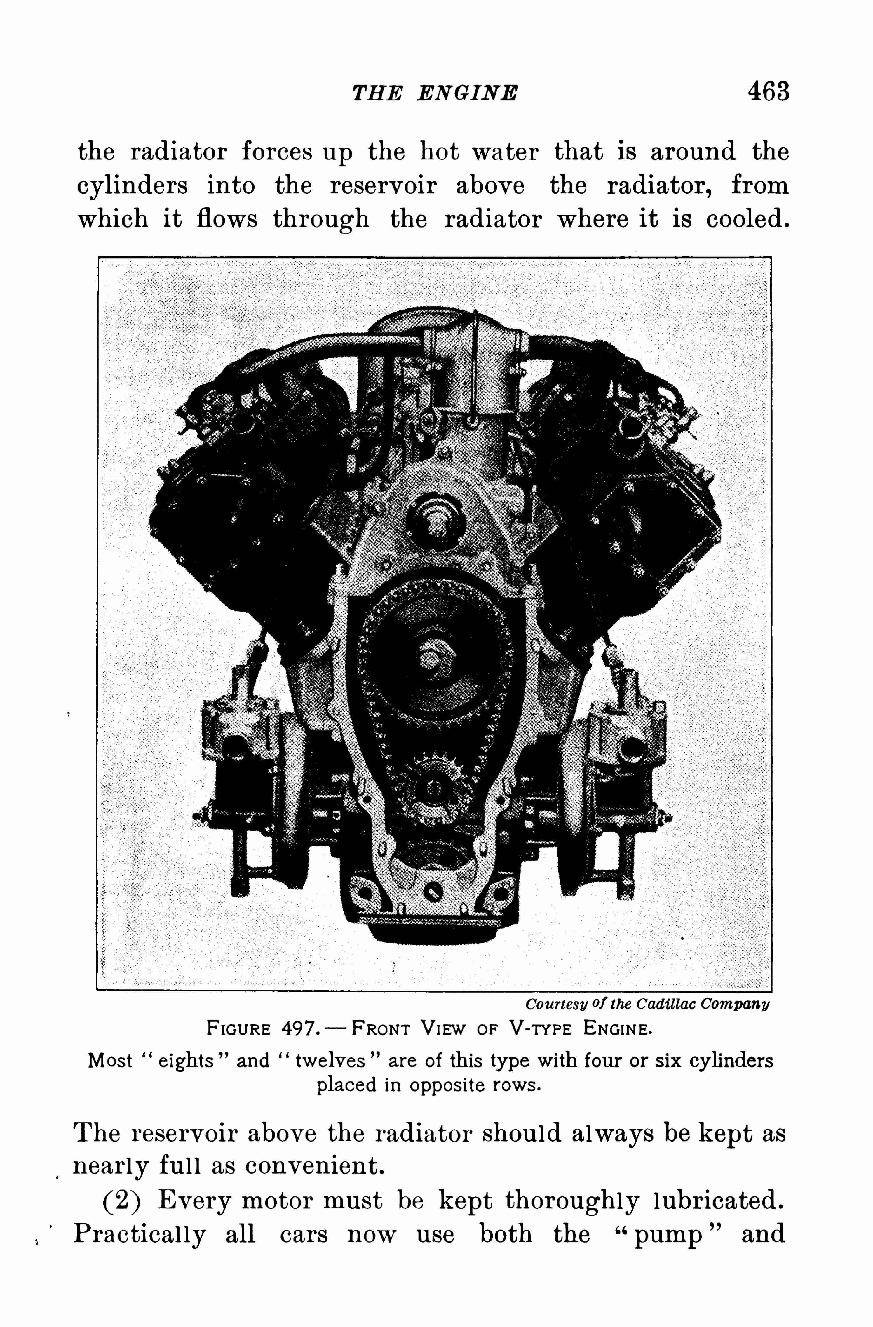
TH E ENGINE 463
the radiator forces up the hot water that is around the
cylinders into the reservoir above the radiator , from
which it flows through the radiator where it is cooled .
Courtesy of the Cadillac CompanyFIGURE 497 . FRONT VI EW OF V-TYPE ENGINE.
Most eights”and twelves are of this type with four or six cylinders
placed in oppos ite rows .
T he reservoir above the radiator should always be kept asnear ly ful l as convenient.
(2) Every motor must be kept thoroughly lubr icated .
P ractical ly all cars now use both the “pump
”and
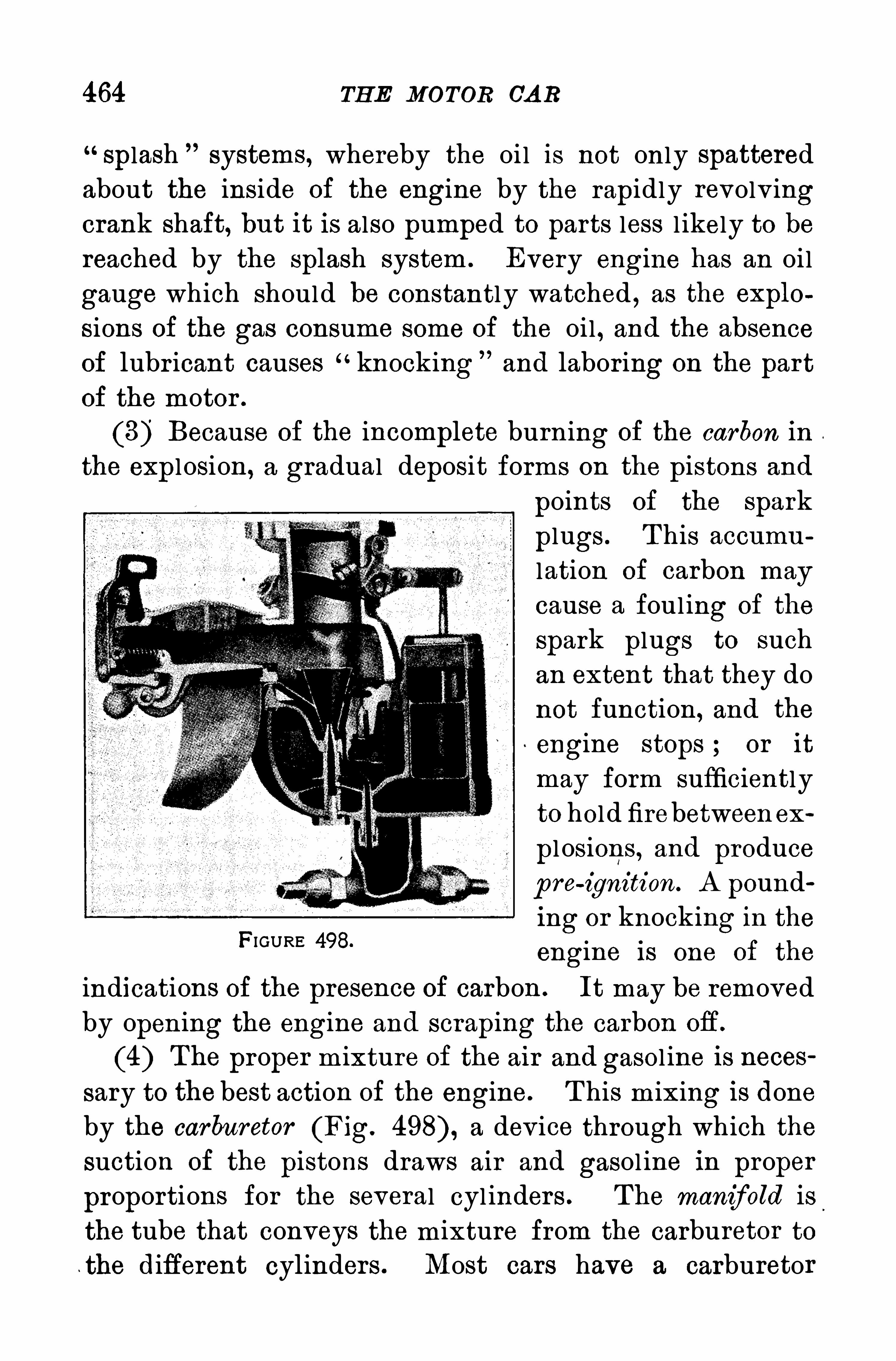
464 TH E MOTOR CA R
“Splash systems, whereby the oi l is not only spattered
about the inside of the engine by the rapidly revolv ingcrank shaft, but it is also pumped to parts less l ikely to bereached by the splash system . Every engine has an oil
gauge which should be constantly watched,as the explo
sions of the gas consume some of the oil , and the absenceof lubr icant causes “knocking and labor ing on the part
of the motor .
(8) Because of the incomplete burn ing of the carbon in
the explosion, a gradual deposit forms on the pistons and
points of the spark
plugs . T his accumu
lation of carbon may
cause a fouling of the
spark plugs to such
an extent that they do
not function , and the
engine stops or it
may form sufficiently
to hold firebetween ex
pl osions , and produce
p ro-ignition. A pound
ing or knocking in the
engine is one of the
indications of the presence of carbon . It may be removed
by open ing the engine and scraping the carbon ofi.
(4) The proper m ixture of the air and gasol ine is neces
sary to the best action of the engine. T his m ixing is done
by the carburetor (Fig. a dev ice through which the
suction of the pistons draws air and gasol ine in proper
proportions for the several cyl inders . The manifold is
the tube that conveys the mixture from the carburetor to
the different cylinders . Most cars have a carburetor
FIGURE 498.
466 TH E MOTOR CA R
which connects the spark plugs successively and explodesthe gas at the proper time.
Ignition troubles are usual ly caused by foul spark
plugs . When the action of the engine is jerky it showsthat some cylinder is “m issing.
”T he one at fault can
be ascertained by touching some metal par t of the enginewith the end of a screw-dr iver and holding another par tof the metal of the screw-dr iver close to the spark plugconnections . T he plug where mo spark jumps across is
probably the one causing the trouble .
572. The Storage Battery .—So little attention is re
quired by the storage" battery that it is often too much
neglected . It should be examined at least every two
weeks and the plates covered with distilled water . It
should be tested from time to.
time with the hydrometer
(Fig. 60) and recharged at once if the density has fal len
below .T he‘
electrolyte of a battery in good condition has a density from to A n idle battery
wi l l not remain charged but must have attention as often
as once every two weeks .
On long summer tr ips of continuous dr iv ing and
also by rapid dr iv ing for a few hours a battery some
times becomes overcharged . T his may be remedied by
switching on the l ights of the car for a while. In the
winter season , on account of the difficulty of star tingthe car when cold, the battery is l ikely to be run
down . T his condition wi ll be accentuated by the in
creased use of the lights . It will relieve the heavy
drain on the battery to start the car by the use of
the crank ; at least it is advisable to turn the engine
over a few times to get it well oiled before resorting to
the starter .
TH E R UNN ING GEA R 467
573 . The Chassis (pronounced“shassy is the name
appl ied to the skeleton body of the car (Fig. as
distinguished from the hood , which incl oses the engine,the tonneau, which is the rear seat div ision of a touringcar
,and the running gear , as the wheels are general ly
FIGURE 500 — A TYP ICAL CHAS S IS .
cal led . T he chief care required by the chassis is its
lubr ication . It is ful ly suppl ied with grease cups which
require constant “turning up”
and fil l ing. Grease
cups .which lubr icate revolv ing par ts require more fro
quent attention than those on joints and spr ing bol ts .
574 . The Running Gear consists of the wheels and tires .
T he rear wheels are usual ly lubr icated from the difierential 578) and require practical ly no atten tion . T he
bear ings of the front wheels are usual ly packed in grease,and at least once a year the wheels should be removedand the bear ings cleaned and repacked in grease .
T he tires consist of a flexible inner tube, containingair under pressure, and a thick outer casing, sometimes
cal led the shoe. T ire makers recommend a pressure of
about twenty pounds for each inch of cross sectional
diameter; that is , a four - inch tire should carry eighty
468 TH E MOTOR CA R
pounds’
pressure to the square inch ; a four and a halfninety pounds ; and a five-inch tire, one hundred pounds .
Less pressure may give more comfort in r iding, but thereis the danger that an excessive flattening of the tire mayseparate the layers of fabr ic and rubber .
T his appl ies to the heavy outer casing wherein lies themain expense in the maintenance of a car . O il and tar
are enemies of rubber and should be removed from the
tire as soon as possible by means of a cl oth dampenedwith gasol ine. Rough roads should either be avoided or
traversed at as low a speed as possible. Fast dr iv ing,especial ly in hot weather , is particularly hard on tires in
that the tires become heated and disintegration sets in .
A blow-out is caused by a weakening of the tire casingor shoe, through-which the inner tube is forced out by
the air pressure, exploding with a l oud report. A pune
ture is caused by a nai l , or some sharp instrument l ike a
piece of glass cutting through the casing and making a
smal l hole in the inner tube, through which the air es
capes gradual ly without “blowing out”
the casing.
Sometimes a leak occurs in the valve, which is delicately
constructed ,and the rubber washer of which may be
come defective through heat or age. The valve may
then be unscrewed by reversing the l ittle pointed cap
which protects it and a new valve may be screwed in at
sl ight expense.
575. The Brakes.—A ll automobiles are prov ided with
double brakes — the service brake, Operated by the foot,and the emergency brake, usual ly operated by a hand lever .
T hese brakes consist of steel bands l ined with asbestos
acting by fr iction on drums attached to the dr iv ing shaft
or to the rear wheels. They should always be kept in
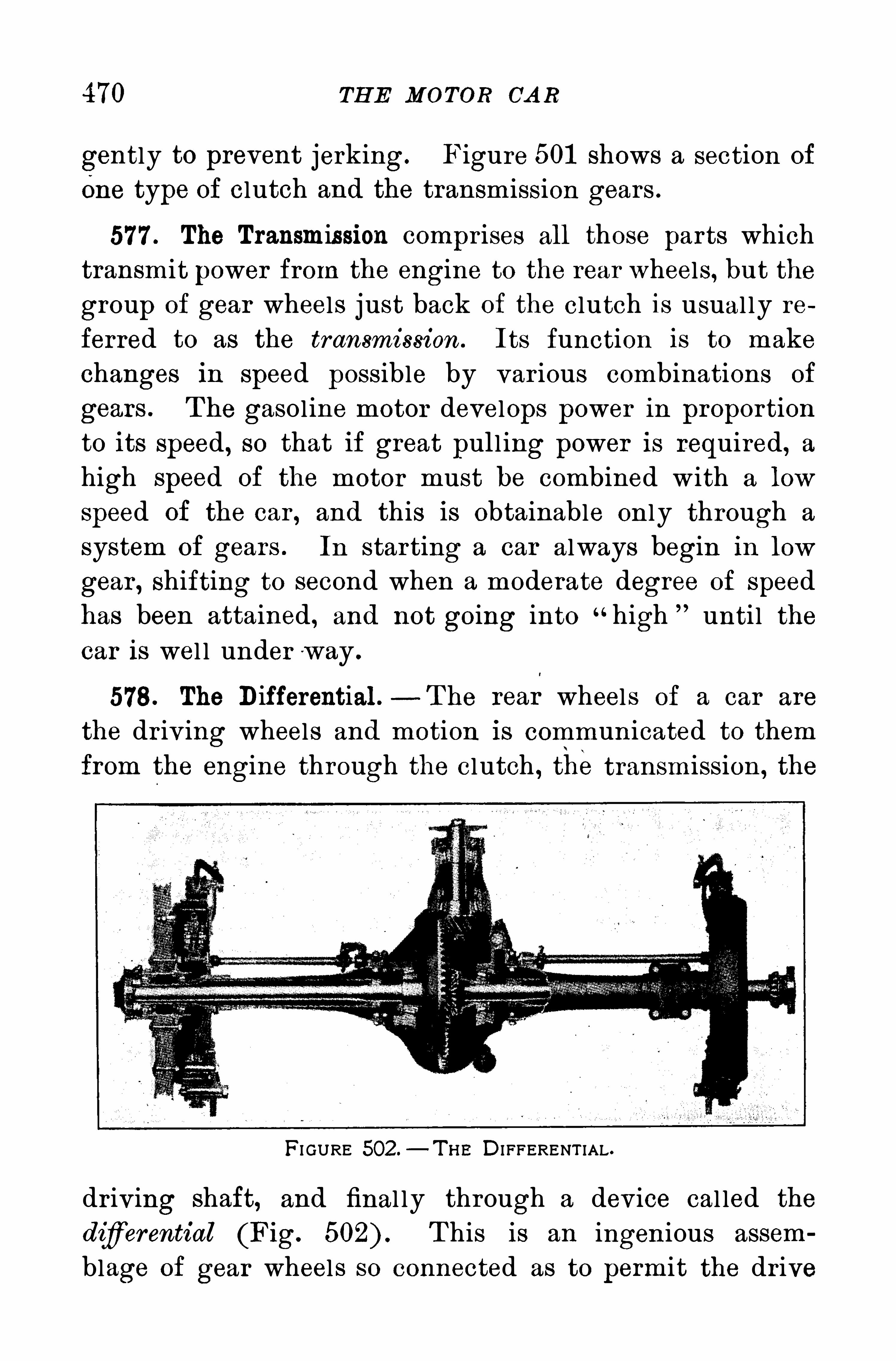
470 TH E MO TOR CA R
gently to prevent jerking. Figure 501 shows a section of
One type of clutch and the transm ission gears .
577 . The Transmission compr ises all those parts whichtransmit power from the engine to the rear wheels, but the
group of gear wheels just back of the clutch is usual ly re
ferred to as the transmission . Its function is to makechanges in speed possible by var ious combinations of
gears . T he gasoline motor develops power in proportion
to its speed, so that if great pul l ing power is required, ahigh speed of the motor must be combined with a low
speed of the car , and this is obtainable on ly through a
system of gears . In star ting a car always begin in low
gear , shifting to second when a moderate degree of speedhas been attained , and not going into “high
” unti l the
car is wel l under w ay .
578. The Differential . - T he rear wheels of a car are
the dr iv ing wheels and motion is communicated to them
from the engine through the clutch , the transmission , the
FI GURE 502 .—T H E DI FFERENT IAL.
dr iv ing shaft, and final ly through a dev ice cal led the
difierential (Fig. T his is an ingenious assem
blage of gear wheels so connected as to permit the dr ive
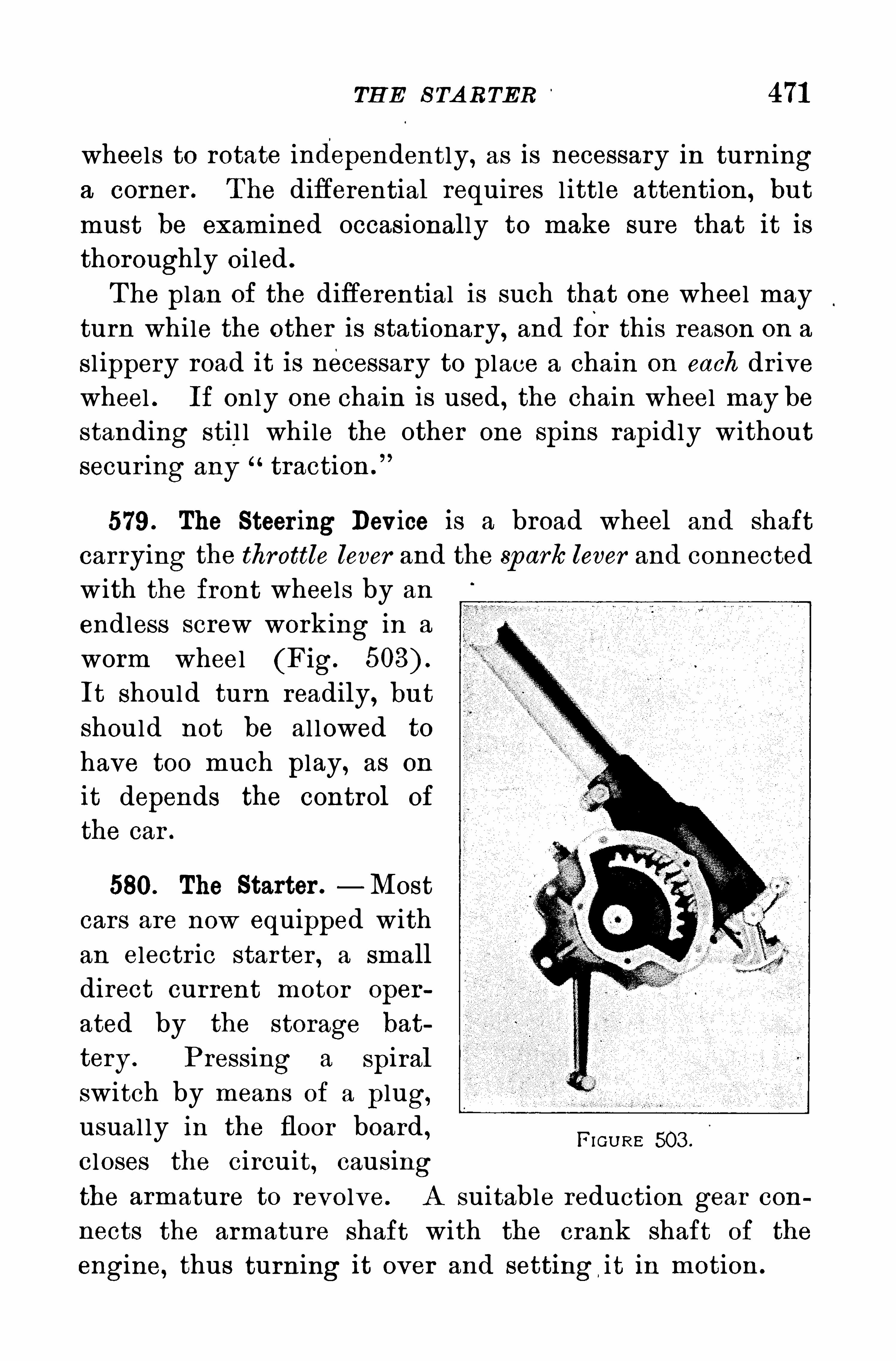
TH E S TA RTER 471
wheels to rotate independently, as is necessary in turninga corner . T he differential requires l ittle attention , but
must be examined occasionally to make sure that it isthoroughly oi led .
T he plan of the differential is such that one wheel may
turn while the other is stationary, and for this reason on a
sl ippery road it is necessary to place a chain on each dr ivewheel . If on ly one chain is used , the chain wheel may be
standing sti l l while the other one spins rapidly withoutsecur ing any traction .
”
579 . The Steer ing Device is a broad wheel and shaftcarrying the throttle lever and the spark lever and connectedw ith the front wheels by an
endless screw working in a
worm wheel (Fig.
It should turn readily, butshould not be al lowed to
have too much play, as on
it depends the control of
the car .
580. The Starter .—Most
cars are now equipped withan electr ic starter , a small
direct current motor oper
ated by the storage bat
tery . P ressing a spiralswitch by means of a plug,usual ly in the floor board , H om e 503 .
closes the circuit, causingthe armature to revolve . A suitable reduction gear con
nects the armature shaft with the crank shaft of the
engine, thus turning it over and setting it in motion .
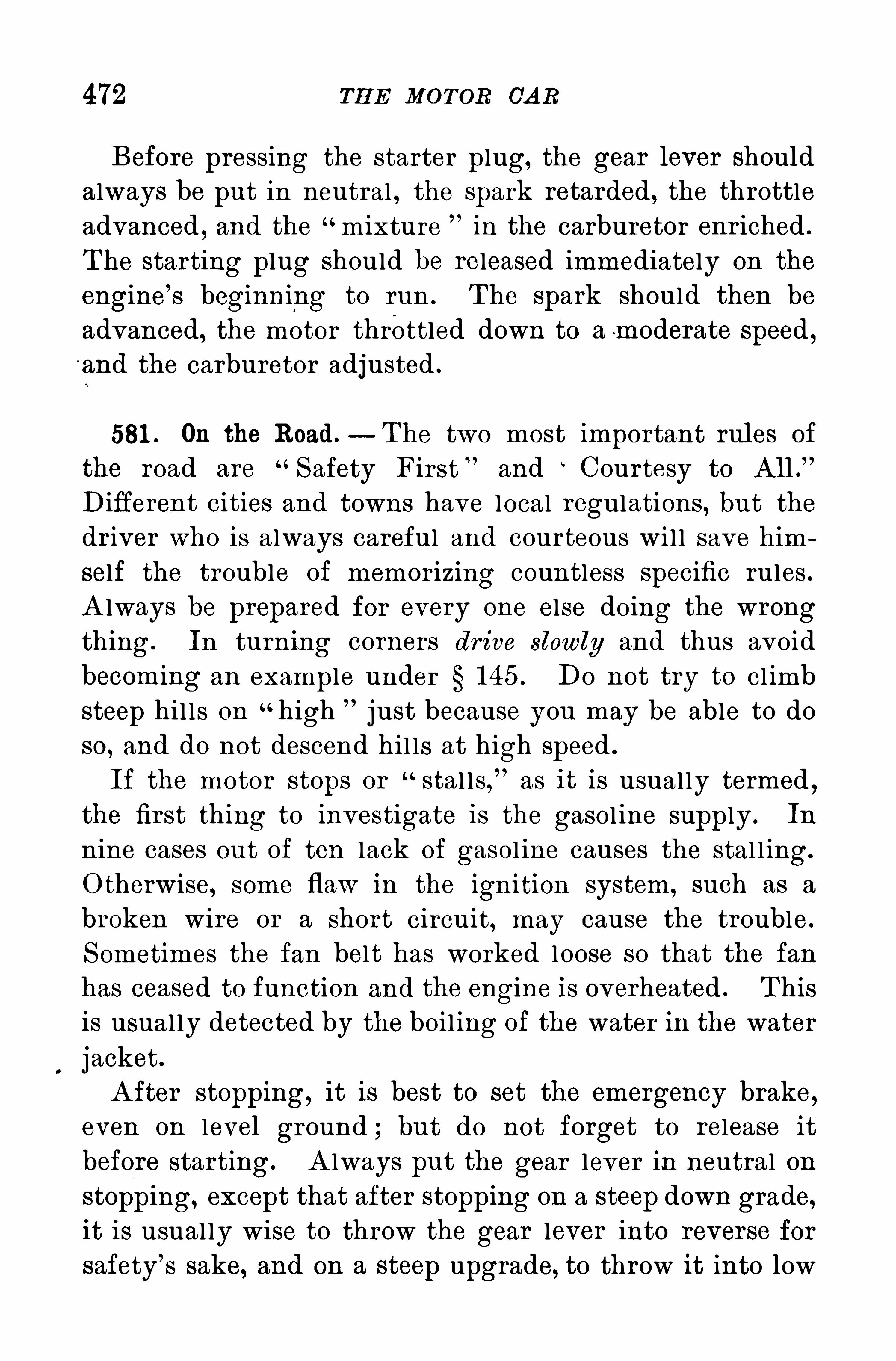
472 TH E MOTOR CA R
Before pressing the starter plug, the gear lever shouldalways be put in neutral , the spark retarded , the throttleadvanced ,
and the m ixture in the carburetor enr iched .
T he starting plug should be released immediately on the
engine’
s beginning to run . The spark should then be
advanced, the motor throttled down to am oderate Speed ,and the carburetor adjusted .
581 . On the Road.—T he two most important rules of
the road are Safety First ”and Cour tesy to A ll .
”
Different cities and towns have local regulations , but thedr iver who is always careful and courteous wi l l save him
self the trouble of memor izing countless specific rules .
A lways be prepared for every one else doing the wrongthing. In turning corners dr ive slowly and thus avoid
becoming an example under 1 45 . Do not try to cl imb
steep hil ls on“high just because you may be able to do
so, and do not descend hil ls at high speed .
If the motor stops or stal ls,”as it is usual ly termed
,
the first thing to investigate is the gasol ine supply . In
nine cases out of ten lack of gasol ine causes the stal l ing.
O therwise, some flaw in the ignition system , such as a
broken wire or a short circuit, may cause the trouble.
Sometimes the fan belt has worked loose so that the fan
has ceased to function and the engine is overheated . T his
is usual ly detected by the boi l ing of the water in the water
jacket.
A fter stopping, it is best to set the emergency brake,even on level ground ; but do not forget to release it
before starting. A lways put the gear lever in neutral on
stopping, except that after stopping on a steep down grade,it is usual ly wise to throw the gear lever into reverse for
safety’
s sake, and on a steep upgrade, to throw it into low
474 TH E MOTOR CA R
proceeding. If the dr iver is unfr iendly, we are completely
at his mercy and he can take us where he wi l l . If he is
fr iendly, we are subjecting him to r isk , because he is l iable
for any injury to us, whether in the car or in getting on
or off.
Courtesy, common sense, and obedience to traffic regu
lations are as important for pedestrians as for motorists .
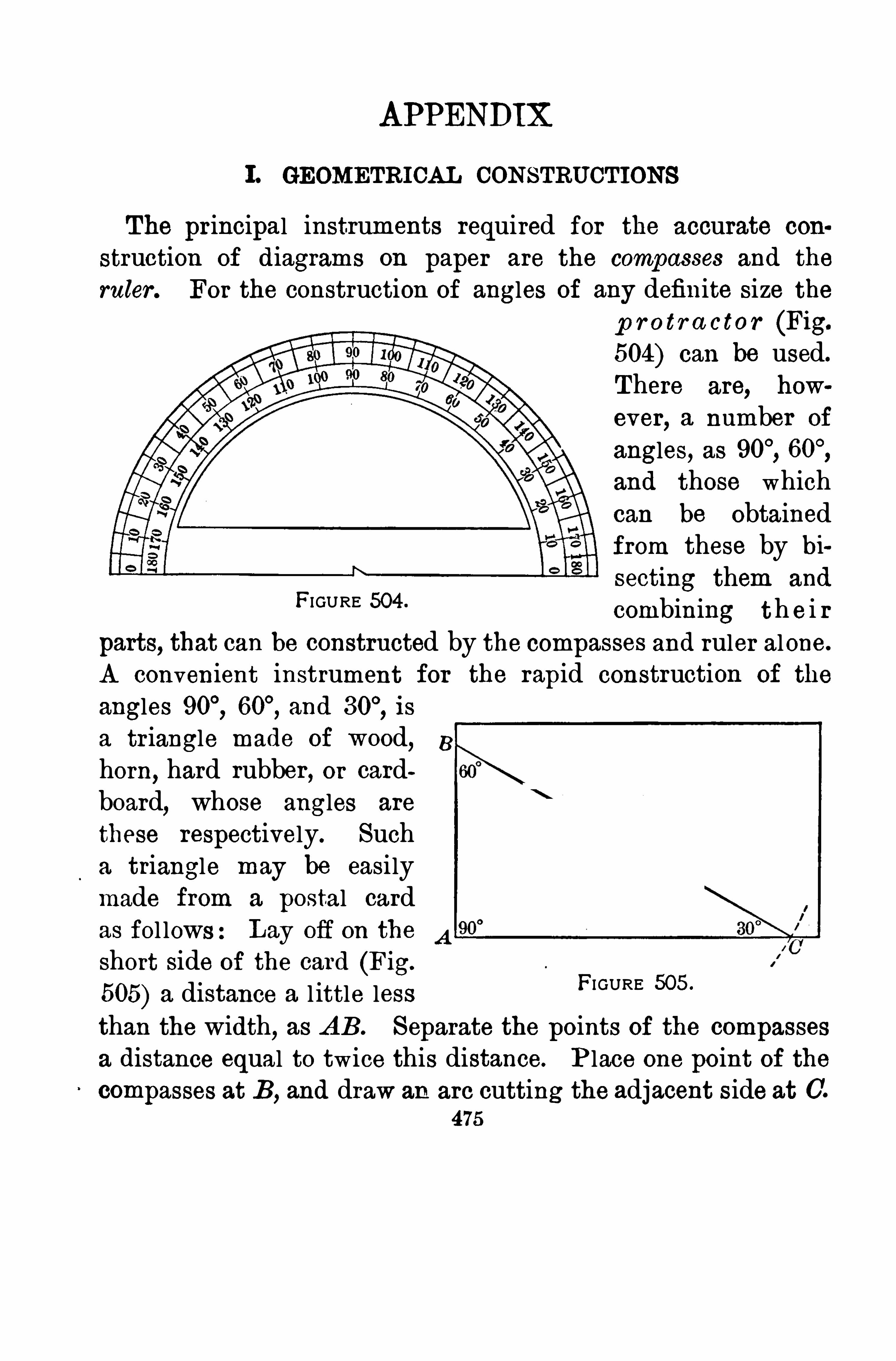
APPENDIX
1 . GEOMETRICAL CONSTRUCTIONS
The principal instruments required for the accurate con
struction of diagrams on paper are the compasses and the
ruler . For the construction of angles of any definite size the
p r o tr a ctor (Fig.
504) can be used.
There are, how
ever,a number of
angles, asand those whichcan be obtainedfrom these by bi
secting them and
combining th e i r
parts, that can be constructed by the compasses and ruler alone.
A convenient instrument for the rapid construction of the
angles and is
a triangle made of wood, 8
horn,hard rubber , or card
board, whose angles are
these respectively. Sucha triangle may be easilymade from a postal cardas fol lows:Lay ofi on the A
short side of the card (Fig.
505) a distance a l ittle lessthan the width, as A B. Separate the points of the compasses
a distance equal to twice this distance. P lace one point of thecompasses at B, and draw an arc cutting the adjacent side at C.
475
FIGURE 504 .
FI GURE 505 .
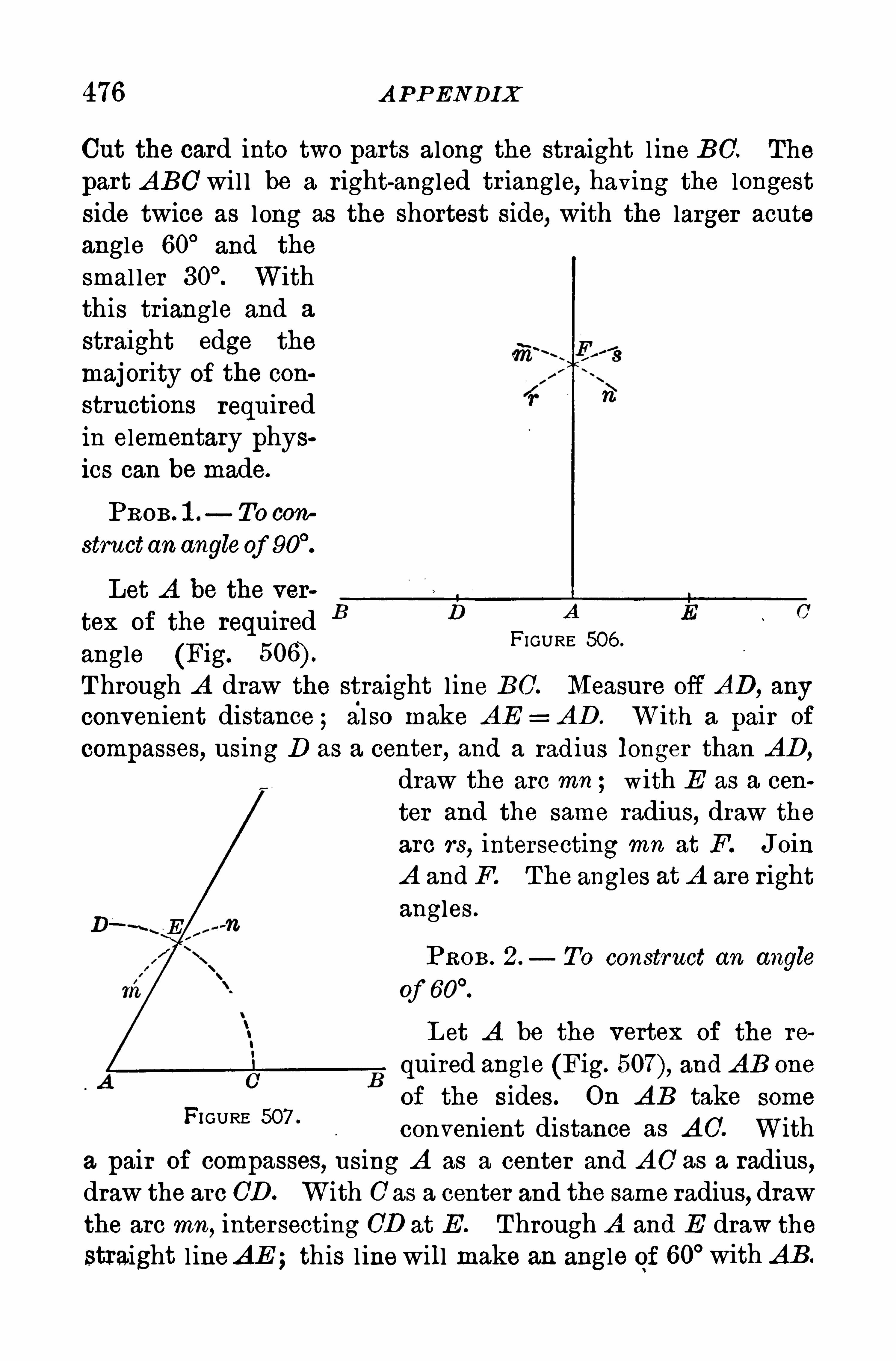
476 A P P ENDIX
Cut the card into two parts along the straight l ine B0 . The
part A BC’wil l be a right-angled tr iangle, having the longest
side twice as long as the shortest side,with the larger acute
angle 60°
and the
smal ler Withthis triangle and a
straight edge the
majority of the con
structions requiredin elementary physics can be made.
PROB. 1 . TO con
structan angle0f
Let A be the ver
tex of the requiredangle (Fig.
Through A draw the straight line B0 . Measure off AD, anyconvenient distance ; also make A E = A D . With a pair of
compasses, using D as a center, and a radius longer than A D,
draw the arc mn ; with E as a cen
ter and the same radius,draw the
arc rs,intersecting mn at F. Join
A and F. The angles at A are rightangles .
FIGURE 506 .
PROB . 2. To construct an angle
Of
L et A be the vertex of the re
quired angle (Fig. and A B one
of the sides. On A B take some
convenient distance as A O. Witha pair of compasses, using A as a center and A O as a radius,draw the arc CD. With 0 as a center and the same radius, drawthe arc mn, intersecting CD at E . Through A and E draw the
straight l ineAE ;this l inewill make an angle of 60° with A B.
FIGURE 507 .
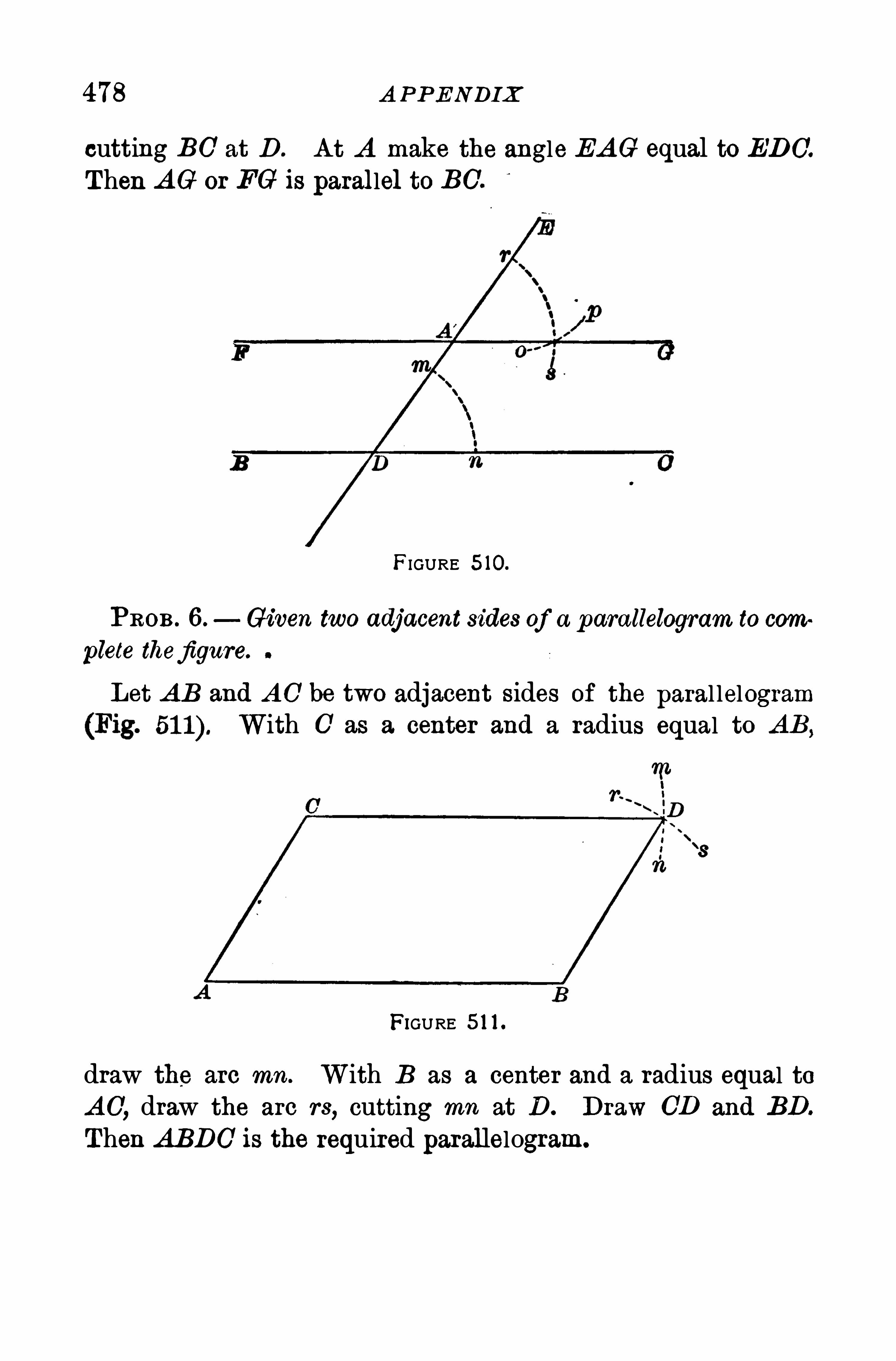
478 A P P ENDIX
cutting BO’at D . A t A make the angle EA G equal to EDO'.
Then A G or FG is parallel to BC.
FIGURE 5 10.
PROB . 6 . Given two adjacent sides of a p arallelogram to com
plete thefigure.
Let A B and A O be two adjacent sides of the paral lelogramWith 0 as a center and a radius equal to
FIGURE 5 1 1 .
draw the arc mn. With B as a center and a radius equal toA O, draw the arc rs, cutting mn at D . Draw CD and BD.
Then A BDC is the required parallelogram.
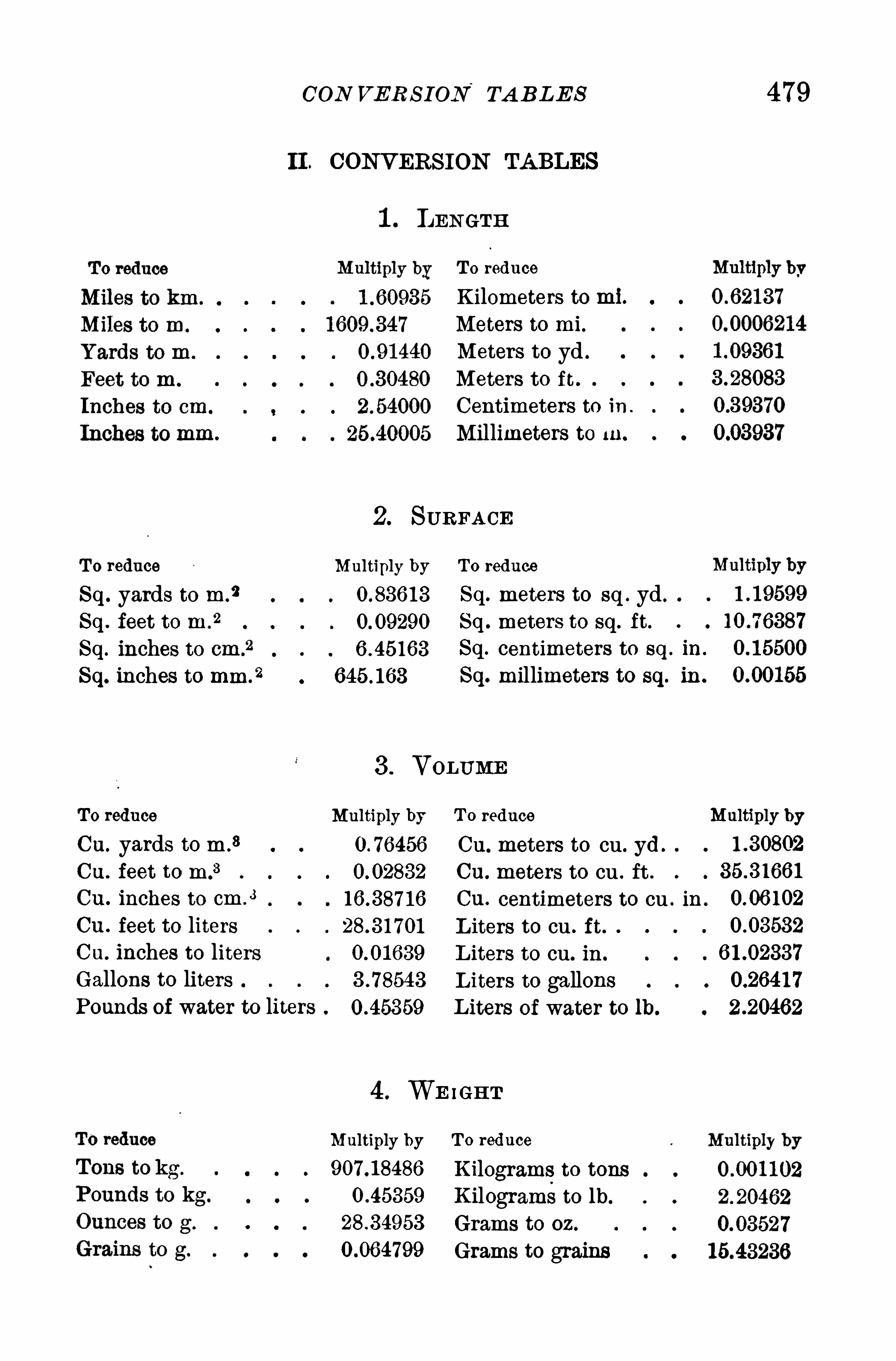
CON VER S ION‘
TA BLE S 479
II . CONVERS ION TA BLES
1 . LENGTH
T o reduce
Sq. yards to m.
2
Sq . feet to m 2
Sq. inches to cm .
2
Sq. inches to mm.
2
To reduce
Cu. yards to m .
3
Cu. feet to m 3
Cu . inches to cm .
3
Cu . feet to litersCu. inches to litersGallons to litersPounds of water to liters
T o reduce
Kilometers to ml.
Meters to mi.
Meters to yd .
Meters to i t
Centimeters to in .
Millimeters to In.
2. S U RFA CE
Multiply by To reduce
Sq. meters to sq . yd .
Sq . meters to sq. ft.
Sq. centimeters to sq . in.
Sq. millimeters to sq. in .
3 . VOLUME
Multiply by T o reduce Multiply byCu. meters to cu. yd
Cu. meters to cu . ft .
Cu. centimeters to cu . in .
L iters to cu . ft.
L iters to cu. in .
L iters to gallonsL iters of water to lb.
4 . WE IGH T
Multiply by T o reduce
Kilograms to tonsKilograms to lb.
Grams to oz .
Grams to grains
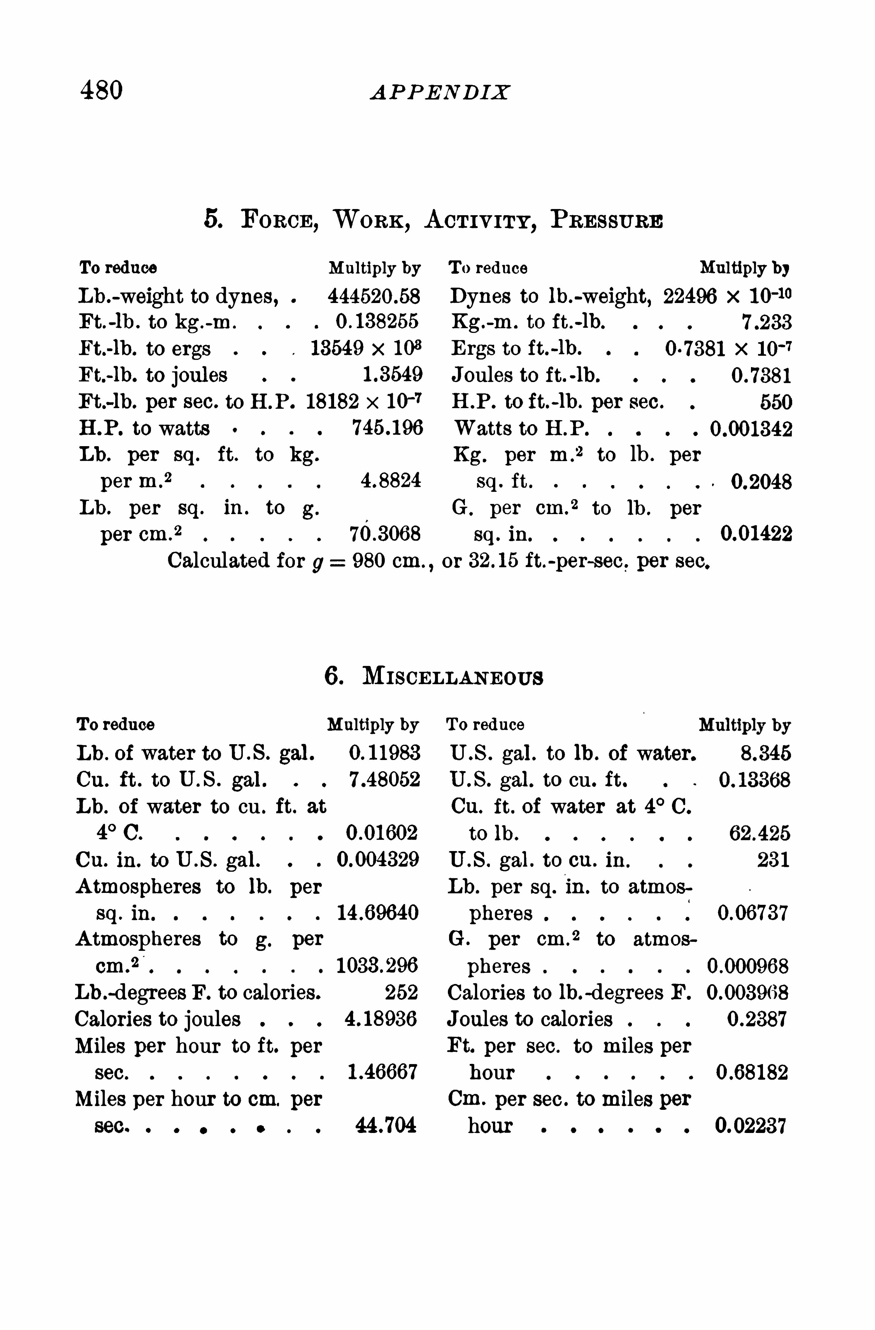
480 A P P ENDIX
5. FORCE, WORK , A CT IVITY , PRES SU RE
To reduce Multiply by T o reduce Multiply byLb .
-weight to dynes , 444520 58 Dynes to lb.-weight, 22496 x 1 0-10
Ft .-lb . to kg.
-m . Kg.-m . to ft .
-lb.
Ft.-1b. to ergs 13549 x 1 03 Ergs to ft.-lb. x
Ft.-lb. to joules Joules to ft. -ih.
Ft.-lb. per see. to H .P . 18182 x H .P . to ft.-lb . per sec.
H .P . to watts Watts to H .P .
Lb . per sq . ft. to kg. Kg. per m .
2 to lb . per
per m .
2 sq . ft .
Lb . per sq . in . to g. G per cm.
2 to lb. per
per cm .
2 sq . in.
Calculatedfor g: 980 cm. ,or ft.
-per-sec. per sec.
6 . MISCELLANEOU S
T o reduce Multiply by To reduce
Lb . of water to U .S . gal. U .S . gal. to 1h . of water.
Cu. ft . to U . S . gal . U .S . gal . to cu. ft .
Lb. of water to cu . ft. at Cu. ft. of water at 4° 0 .
4° C. to ih .
Cu. in. to U .S . gal. U .S . gal . to on. in
A tmospheres to lb. per Lb . per sq. in . to atmos
sq . in pheres
A tmospheres to g. per G . per cm .
2 to atmos
cm.
2pheres
Lb .-degrees F. to calories. 252 Calories to lb.
-degrees F.
Calories to joules Joules to caloriesMiles per hour to ft. per Ft. per sec. to miles persec. hour
Miles per hour to cm. per Cm. per sec. to miles per0 e 0 o e 44 .704 hour 0 e 0.02237
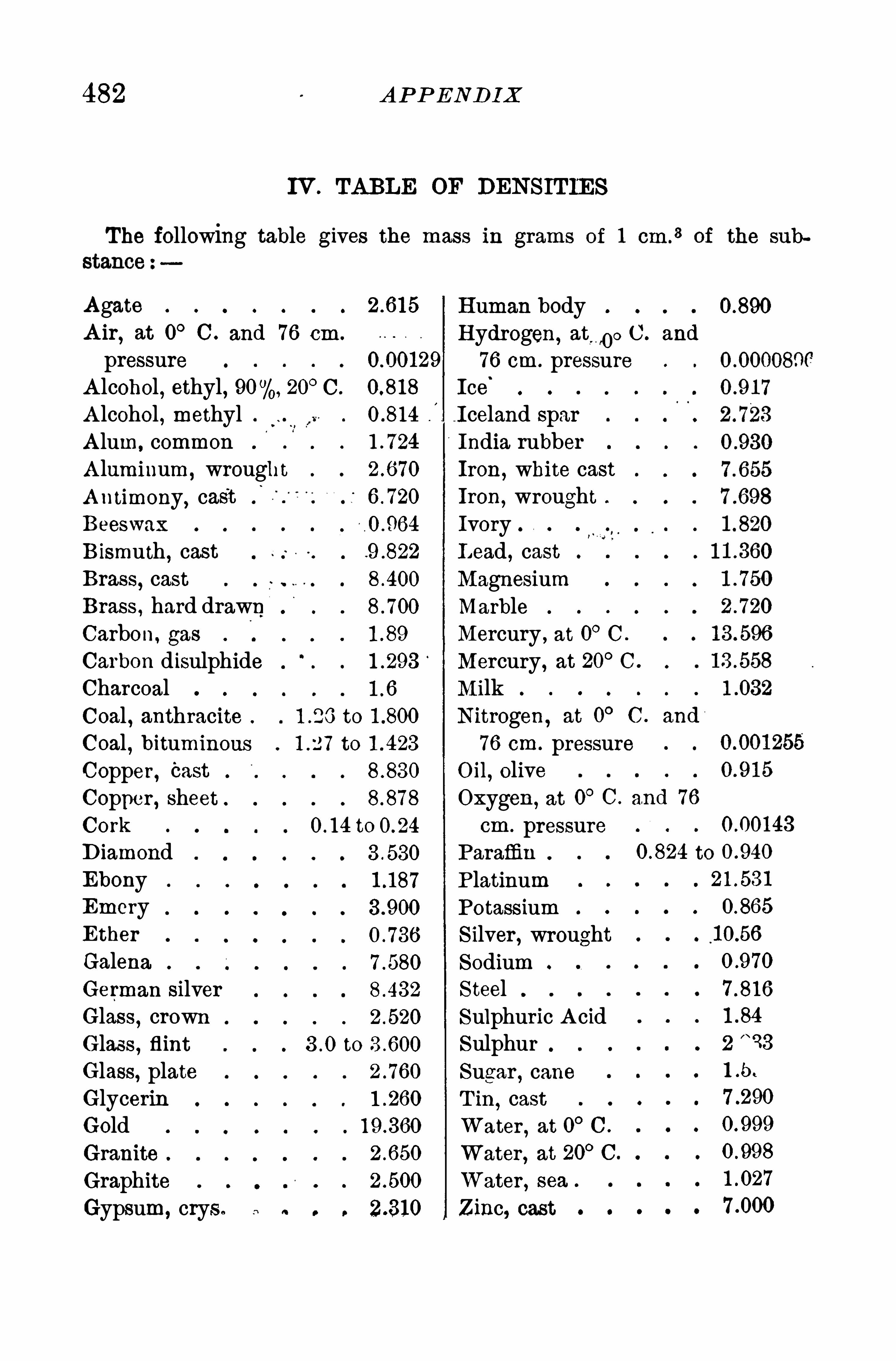
482 A P P END IX
IV . TA BLE OF DENS ITIES
The following table gives the mass in grams of 1 cm .
3 of the sub
A gateA ir
,at 0° C . and 76 cm .
pressureA lcohol
,ethyl
,90 20
°C.
A lcohol , methylA lum, commonA luminum,
wroughtA ntimony
,cast
Beeswax
Bismuth , castBrass
,cast
Brass , hard drawnCarbon, gas
Carbon disulphideCharcoalCoal , anthracite to
Coal,bituminous to
Copper , CastCopper , sheetCork to
DiamondEbonyEmeryEther
GalenaGerman silverGlass
,crown
Glass , flint to
Glass, plateGlycerinGoldGranite
GraphiteGypsum, crys .
H uman bodyH ydrogen,
at,0°C. and
76 cm. pressureIce
‘
Iceland sparIndia rubberIron
,white cast
Iron,wrought
IvoryL ead , castMagnesiumMarbleMercury , at 0° C .
Mercury, at 20° C .
MilkNitrogen
,at 0
° C . and
76 cm. pressureO il, oliveOxygen ,
at 0° C. and 76
cm . pressureParaffin to
P latinumPotassiumS ilver , wroughtSodiumS teel 7 .81 6
Sulphuric A cidSulphur 2
"
33
Sugar , caneT in
,cast
Water,at 0
°C .
Water,at 20
°C.
Water , sea
Zinc, cast
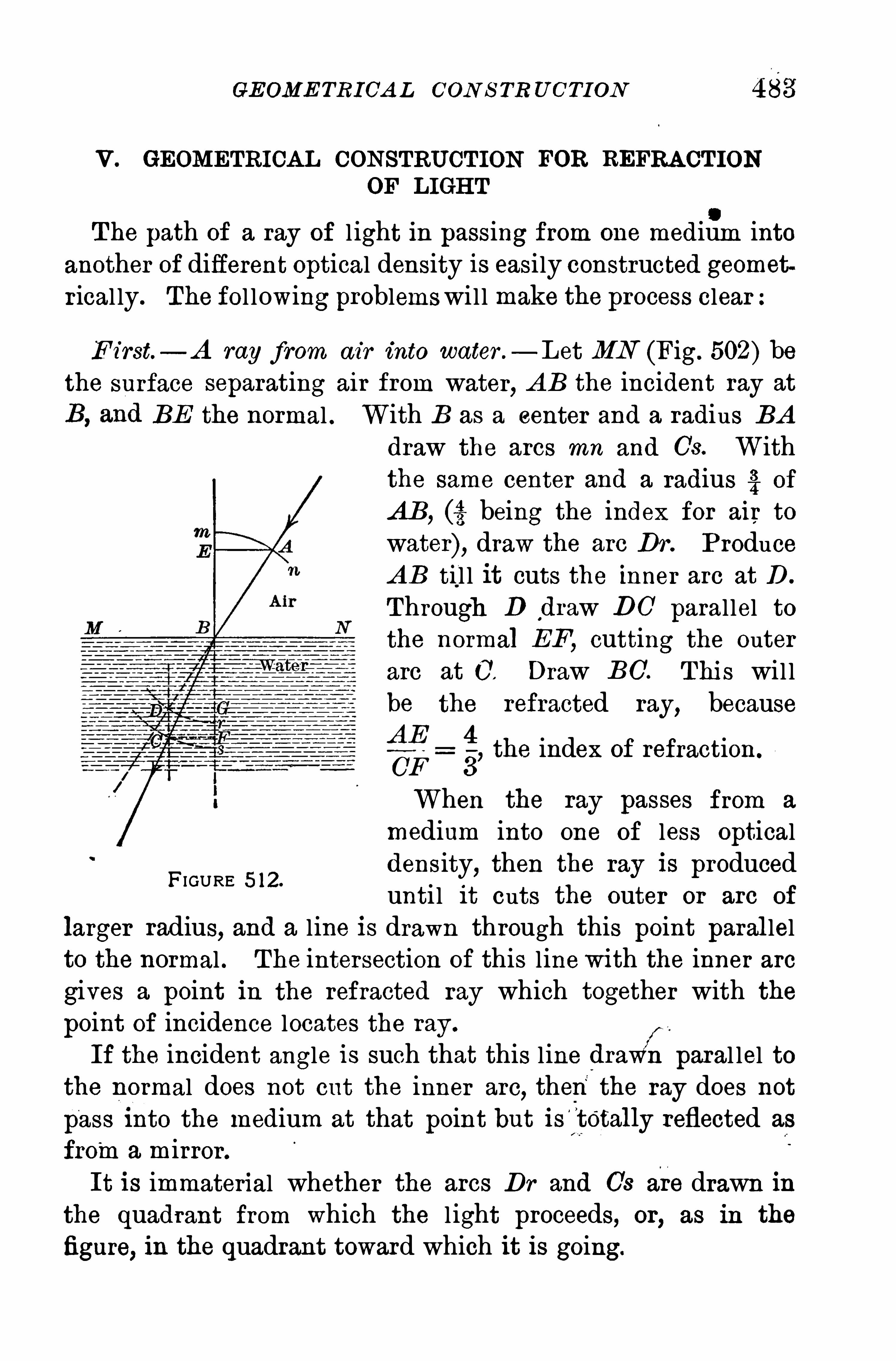
GEOME TRICA L CON S TR U CTI ON
V. GEOMETRICA L CONSTRUCTION FOR REFRA CT ION
OF LIGH T
e
The path of a ray of l ight in passing from one medium intoanother of different optical density is easily constructed geometrical ly. The fol lowing problemswi l l make the process clear:
F irst—A ray from air into water .—L et MN (Fig. 502) be
the surface separating air from water,A B the incident ray at
BE the normal . With B as a center and a radius BAdraw the arcs mn and Us. Withthe same center and a radius 3
3? of
AB, (3. being the index for air to
water), draw the are Dr . P roduceA B til l it cuts the inner arc at D .
Through D draw DO paral lel tothe normal EF
, cutting the outerarc at 0 . Draw BC. Thi s wil lbe the refracted ray, becauseA E 4
CF 3’
When the ray passes from a
medium into one of less opticaldensity, then the ray is producedunti l it cuts the outer or are of
larger radius, and a line is drawn through this point paral lelto the normal . The intersection of this linewi th the inner arc
gives a point in the refracted ray which together with the
point of incidence locates the ray .
If the incident angle is such that this line drawfiparal lel tothe normal does not cut the inner arc
,then the ray does not
pass into the medium at that point but is"
tOtally reflected as
froma mirror.
It is immaterial whether the arcs Dr and Us are drawn inthe quadrant from which the l ight proceeds, or
,as in the
figure, in the quadrant toward which it is going.
the index of refraction.
FIGURE 5 12.
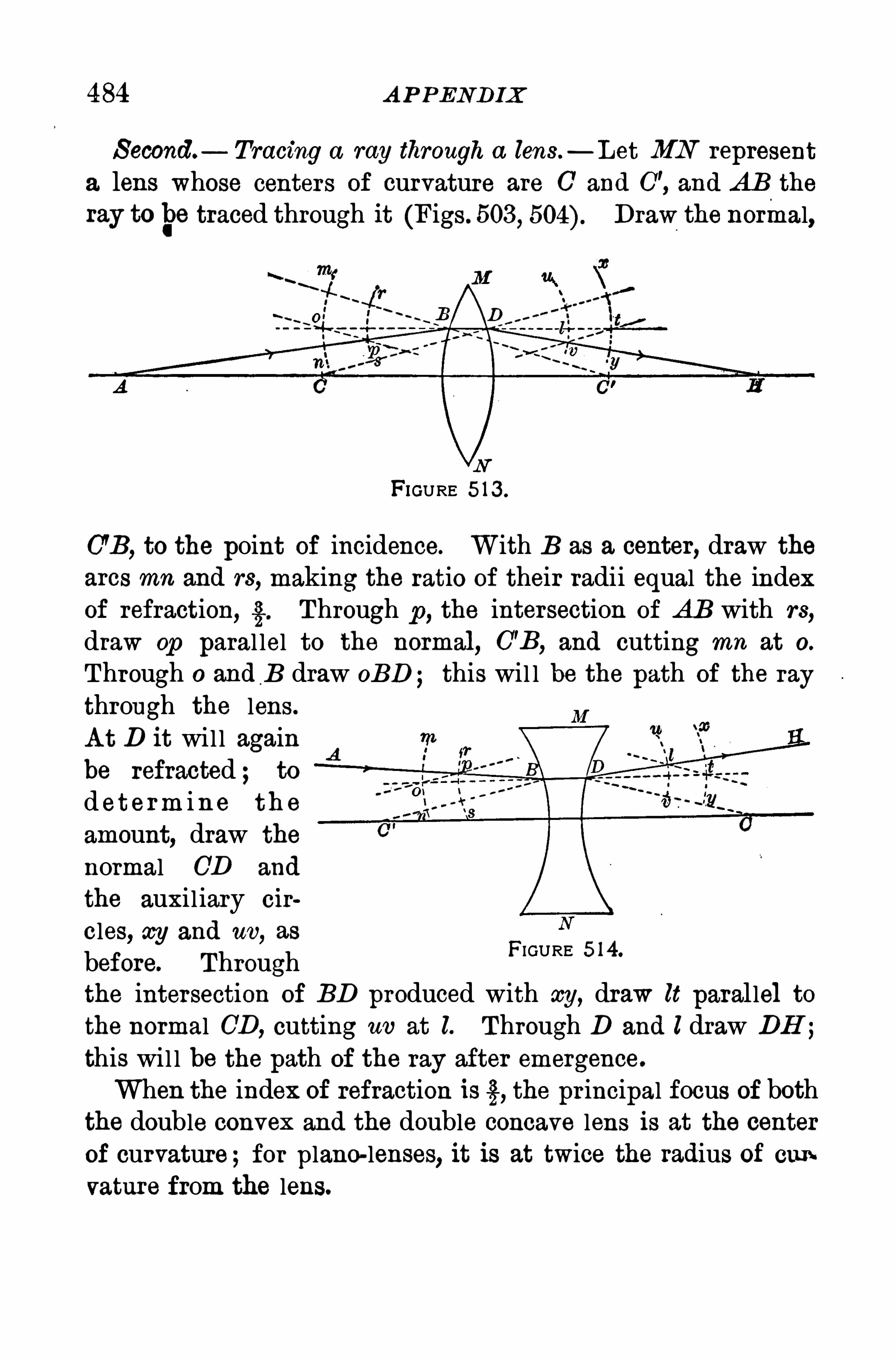
484 A P PENDIX
S econd. Tracing a ray through a lens —Let MN represent
a lens whose centers of curvature are C’ and C”, and AB the
ray tobe traced through it (Figs. 503,
Draw the normal,
FIGURE 5 13 .
(73 , to the point of incidence. With B as a center, draw the
arcs mn and rs, making the ratio of their radii equal the indexof refraction, g. Through p , the intersection of AB with rs,
draw op paral lel to the normal, C'B,and cutting ma at O.
Through O and B draw OBB this wil l be the path of the ray
through the lens.
A t D it wi l l againbe refracted ; to
d eterm ine th e
amount, draw the
normal CD and
the auxil iary cir
cles, my and uv,as
before. Throughthe intersection of BD produced with my, draw lt parallel to
the normal CD, cutting uv at l. Through D and I draw DH ;
this wil l be the path of the ray after emergence.
When the index of refraction is 3, the pr incipal focus of boththe double convex and the double concave lens is at the centerof curvature;for plano-lenses, it is at twice the radius of cumvature from the lens.
FIGURE 5 14.
2 INDEX
[References are to pages ]
Camera , photographer’s , 259 .
Capacity , dielectric , 352 ; electrostatic , 350 ; thermal , 297
Capillarity , 32 ; laws of, 33 ; re
lated to surface tension , 34 .
Capstan , 1 65 .
Carbon , in a motor car , 464 .
Carburetor , 464 .
Cartesian diver , 56 .
Cathode, ray s , 4 1 2 .
Caustic, 236 .
Cell , voltaic , 36 1 ; chemical actionin , 363 .
Center , of gravity , 1 23°
of oscillation , 1 39 ; of percussIOn , 1 40 ; of
suspension , 1 38.
Centrifugal force, 1 33 ; illustrations of, 1 35 ; its measure, 1 34 .
Centripetal force , 1 33 .
Charge, residual , 353 ;
353 .
Charles , law of, 293 .
Chassis , of a motor car , 467 .
Choke coil , 436 .
Chord, major , 1 97 ; minor , 1 97 .
Chromatic aberration , 264 .
Circuit, closing and Opening , 363 ;
divided , 397 ; electric , 363 ; trans
mitting and receiving, 457 .
Circular motion , 1 00.
Clarinet, 205 .
Clinical thermometer , 285 .
Clutch , of a motor car , 469 .
Coherer , 455 .
Cohesion, 1 0.
Coil , choke, 436 ; induction , 406 ;
primary , secondary , 407
Cold by evaporation , 303 .
Color , 27 1 ; complementary , 275 ;
mixing, 273 ; of opaque bodies ,27 1 ; of transparent bodies , 272 ;p rimary , 273 .
Commutator , 423 .
Composition of forces ,
velocities , 1 1 3 .
seat"
of,
1 07 ; of
Compressibility of air , 73
Concave, lens , 249 ; m i rror , 229 ;
focus of, 230 , 249 .
Condenser , 35 1 office of, 408.
Conductance, of electricity , 378
of heat , 309 .
Conductor , electrical , 343 ;on outside, 346 ;
about , 387 .
Cone clutch , 469 .
Conservation of energy , 1 53 .
Convection , 3 1 2 ; in gases , 3 1 3 .
Convex, lens , 246 ; mirror , 23 1
focus of, 230.
Cooling system, in a motor car , 462 ,
463 .
Coulomb , 348.
Couple, 1 09 .
Crank shaft, in a motor car , 460.
Critical angle , 244 .
Crookes tubes , 4 1 2 .
Crystal detectors , 455 .
Crystallization, 35 .
Current, electric , 36 1 ; convection ,
3 1 3 ; detection of, 366 ; heatingeffects of, 385 ; induced by cur
rents , 403 ; induced by magnets ,
402 ;magnetic p rop erties of, 387
mutual action of, 390 ; strengthof, 381 .
Curvilinear motion , 99 .
Cyclonic storms , 7 1 .
Cylinders , in a motor car , 460- 463 .
chargemagnetic field
Daniell cell , 370.
Day , sidereal , 23 ; solar , 22 .
Declination , magnetic , 338.
Density , 58; of a liquid; 62 ; of a
solid , 60 ; bulb , 62 .
Derrick , 1 65 .
Deviation, angle of, 24 1 .
Dew point, 307 .
Diamagnetic body , 328.
Diathermanous body , 3 18.
Diatonic scale, 1 97 .

[References are to pages .]
Dielectric, 351 ; capacity , 352 ; in
fluence of, 35 1 .
Difierential, in a motor car , 467 ,
470 , 47 1 .
Diffraction , 278.
Difiusion , 25 , 28.
Dipping needle , 337 .
Discharge, intermittent , 4 1 1 ; oscil
latory , 453 .
Dispersion , 263 .
Drum armature, 42 5 .
Dry cell , 37 1 .
Dry dock , 57 .
Dryness , 307 .
Ductility , 1 2 .
Dynamo, 42 1 ; compound , 426
series , 425 ; shunt , 425 .
Dyne , 1 05 .
Earth , a magnet , 336 .
Ebullition , 303 .
Echo , 186 .
Efficiency , 159 .
Efi'
usion,26 .
Elasticity , 36 ; lim it of, 36 ; of
form , 36 ; of volume, 36 .
Electric , bell , 449 ; circuit , 363 ;
current , 36 1 ; current detection ,
366 ; motor , 426 ; railway s , 430 ;telegraph , 447 ; waves , 454 .
Electrical , attraction , 340 ;
bution , 346 ; machines ,potential , 348; repulsion ,
resistance, 378 ; wind , 347 .
Electrification , 340 ; atmospheric,358; by induction , 344 ; kindsof, 34 1 ; simultaneous , 342 ; unit
of, 348.
Electrode, 363 , 377 .
Electrolysis , 373 ; laws of, 375 ; of
copper sulphate, 373 ;ofwater , 374 .
Electrolyte , 362, 373 .
Electromagnet , 392 ;
of, 394 .
Electromotive force, 365 , 381 ; in
distri
355
34 1
applications
duced by magnets , 401 ; inducedby currents , 403 .
Electrons , 4 1 9 .
Electrophorus , 354 .
Electroplating, 376 .
Electroscope, 342 .
Electrostatic, capacity ,
duction , 344 .
Electrostatics , 340.
Electrotyping, 376 .
Energy , 1 , 1 48; conservation of,
1 53 ; dissip ation of, 1 53 ; kinetic,
1 50 ; measure of, 1 51 ; potential ,149 ; transformation of, 1 52 .
350 in
Engine , gas , 323 ; steam , 320 ;
two-cy cle, 325 ; four-cy cle, 324 ,
460—4 66 .
English system of measurement ,22.
Equilibrant, 1 09.
Equilibrium, 1 08; kinds of, 1 25 ;
of floating bodies , 55 ; undergravity , 1 25 .
Erg, 1 45 .
Ether , 2 14 .
Evaporation , cold by , 303 .
Expansion , coefficient of, 289 ;
of gases , 289 ; of liquids , 288; of
solids , 287 .
Extension , 6 .
Eye, 259 ; defects of, 262.
Falling bodies , 1 28, 1 30.
Field , electrical , 387 , 391 ;
netic , 333 .
Fieldmagnet, 425 .
Floating bodies , 55 .
Fluids , 39°
characteristics of, 39 ;
p ressure In , 4 1 .
Fluoroscope, 4 1 5 .
Flute , 205 .
Focus , 230 ; conjugate, 232 ; of
lens , 249 ; of mirrors , 232 .
Foot, 18.
Foot pound , 144 .
mag
4 INDEX
[References are to pages ]
Force, 5, 1 04 ; composition of, 1 07
graphic rep resentation of, 1 07 ;
how measured , 1 06 ; molecular ,29 ; moment of, 1 60
°
parallelogram of, 1 1 0 ; resolution of, 1 1 1 ;
units of, 1 05 .
Force pump , 86 .
Forced vibrations , 1 88.
Fountain , siphon , 85 ; vacuum , 79.
Four-cylinder engine, 460 , 46 1 .
Fraunhofer lines , 268.
Freezing, mixtures , 302 ;point , 283 .
Friction , 1 56 ; uses of, 1 58, 469 .
Fundamental, tone, 202 ; units , 23 .
Fusion , 299 ; heat of, 301 .
Gallon , 20.
Galvanometer , d’
A rsonval, 395 .
Galvanoscope, 366 .
Gas engine, 322- 325 , 460
—466 .
Gas equation , 294 .
Gases , 40 ; comp ressibility of, 4 1 ;
expansion of, 289 ; media for
sound , 1 82 ; thermal conductivityof, 3 1 0.
Gassiot’
s cascade, 4 1 0.
Gauge, water , 49 .
Geissler tube, 4 1 0.
Grades , 1 70.
Grain , 2 1 .
Gram, 21 .
Gramme ring, 424 .
Gravitation , 1 22 ; law of, 1 23 .
Gravitational unit of force, 1 05 .
Gravity , 1 22 ; acceleration of, 1 22 ;
cell , 37 1 ; center of, 1 23 ; direc
tion of, 1 22 ; specific , 59 .
H ammer , riveting, 88.
H ardness , 1 4 .
H armonic, curv e,
1 01 .
H armonics , 204 .
H eat, 280 ; conduction of, 309 ; con
vection of, 3 1 2 ; due to electriccurrent , 385 ; from mechanical
1 78 motion ,
action , 3 19 ; kinetic theory of,280 ; lost in solution , 302 ; me
chanical equivalent of, 320 ;
measurement of, 297 ; nature of,
280 ; of fusion , 301 of vaporization , 306 ; radiant , 3 1 5 ; relatedto work, 3 1 9 ; Specific, 297
transmission of, 309 .
H eating by hot water , 3 1 2 .
H elix, 389 ; polarity of, 389 .
H oltz machine, 355 .
H ooke’
s law, 37
H orizontal line or plane, 1 23 .
H orse power , 1 47 .
H umidity , 307
H ydraulic, elevator , 44 ; p ress , 42
ram , 5 1 .
H ydro-airplanes , cuts facing page 66 .
H ydrometer , 63 , 466 .
H ydrostatic paradox, 47
Ice plant, ammonia , 304 .
Images , by lenses , 250 ; by mirrors ,225 , 233 ; by small openings , 218.
Impenetrability , 6 .
Impulse , 1 1 6 .
Incandescent lamp , 444 .
Inclination , 387 .
Inclined plane, 1 6 9 ;
advantage of, 1 70 .
Index of,
refraction , 240.
Indicator diagram , 322 .
Induced magnetism , 33 1 .
Induction , charging by , 345 ; coil ,406 ; electromagnetic, 401 ; electrostatic , 344 ; motors , 440 ; selfinduction , 405 .
Inertia , 7 .
Influence machine, 355 .
Insulator , 343 .
Intensity of illumination ,
mechanical
Interference, of light , 276 ; of
sound , 1 94 .
Intervals , 196 ; of diatonic scale,of tempered scale, 1 99 .
6 INDEX
[References are to p ages .]
Mass , 9 ; units of, 21 .
Matter , 1 ; p roperties of, 6 ; states
of, 4 .
M echanical advantage , 1 60 .
M echanical equivalent of
320.
M echanics , of fluids , 39 ; of solids ,1 04 .
M elting point,
pressure, 301 .
Meter , 1 7
M etric system , 1 7 .
M icrometer , 1 74 .
M icrophone, 45 1 .
Microscope, compound , 256 ; sim
ple, 255 .
M inor chord , 1 97 .
M irror , 225 ; focus of, 230 ; images
heat,
299 effect of
by , 226 , 233 ; p lane, 225 ;
spherical , 229 .
Mobility , 39 .
Molecular , forces , 29 ; motion ,
26 ; phy sics , 25 .
Moment, of a force, 1 60.
Momentum , 1 1 6 .
Motion , 9 1 ; accelerated , 95 ;
curvilinear , 99 ; harmonic, 1 01 ;
molecular , 26 ; periodic , 1 01
rectilinear , 9 1 ; rotary , 9 1 ;
uniform , 92°
vibratory 1 01 .
Motor , electri c , 426 ; induction ,
440.
Motor car , 1 , 460—474 .
Multiple-disk clutch , 469 .
Musical , scales , 1 96 ; sounds , 1 9 1 .
Needle, 337 ;dipp ing , magnetic ,
Newton’
s , laws of motion , 1 1 6 ;
rings , 276 .
Nodes , 203 .
Noise, 1 91 .
Octave, 197 .
Ohm’
s law, 378, 382.
Opaque bodies , 214 .
Opera glasses , 258.
Optical, center , 247255 .
O rgan pipe, 206 .
O scillation, center of, 1 39 ; electric ,360.
Ounce, 22 .
Overtones , 204 , 208.
instruments ,
Partial tones , 204 .
Pascal, experiments, 67 ; principle,
4 1 .
Pendulum , applications of, 1 40
laws of, 1 38; seconds , 14 1
simp le, 1 36 .
Percussion , center of, 1 40 .
Period of vibration , 1 38.
Periodic motion , 1 01 .
Permeability , 335 .
Phonodeik , 21 1 .
Photographer’
s camera , 259.
Photometer , 221 .
Photometry , 2 1 9
Physical measurements , 1 6 .
Physics , 1 .
Pigments , 275 .
Pistons , in a motor car , 4 60.
Pitch , 1 9 1 ; limits of, 1 99 ; relationto wave length , 1 92 ; of screw,
1 73 .
Plumb line , 1 23 .
Pneumatic appliances , 83 .
Points , action of, 347 .
Polarity of helix, 389.
Polarization , 368.
Polyphase alternators , 434 .
Porosity , 1 1 .
Potential, diflerence,
349 .
Pound, 2 1 .
Power , 1 45 .
Pre-ignition , 464 .
Pressure , 4 1 of fluids , 39 ; at a
point in fluids , 46 air , 65 down
348 zero ,
INDEX
[References are to
ward , 45 ; effect on boiling point ,305 ; effect on melting point , 301independent of shape of vessel , 47in tires , 467 .
Principle of Archimedes , 53 .
Prism , 242 ; angle of deviation , 243 .
Proof plane, 342 .
Properties of matter , 6 .
Pulley , 1 65 ; differential , 1 68 ;me
chanical advantage of, 1 67 ; sy s
tems of, 1 66 .
Pump , air , 76 ; comp ression , 76 ;
force, 86 ; lift , 85 .
Puncture, of a tire, 468.
1 93 ; due toQuality of sounds ,
overtones , 1 93 .
Radiation 3 1 5 ; laws of, 3 1 6 .
Radiator , in a motor car , 462 .
Radioactivity , 4 1 6 .
Radiometer , 3 1 5 .
Radium , 4 1 7
Rainbow, 266 .
Rays of light , 2 1 6 .
Reflection , diffused , 224 ; law of,
223 ; multip le ,228 ; of light ,
223 ; of sound , 186 ; regular ,223 ; total , 243 .
Refraction , cause of, 239 ; atmos
pheric , 243 ; laws of, 24 1 .
Regelation , 301 .
Relay , 448.
Resistance , of air , 1 29 ; electrical ,3 78; formula for , 380 ; laws of,
379 ; unit of, 379 .
Resolution , of a force, 1 1 1 ;
velocity , 1 1 3 .
Resonance, 188, 1 90.
Resonator , H elmholtz ’
s , 1 9 1 .
Resultant, 1 07 .
Riveting hammer , 88.
Roentgen rays , 4 1 4 .
Rotating field , 438.
Running gear , of a motor car , 467 ,
468.
of a
7
Scale, absolute, 293 ; diatonic ,1 97 ; tempered, 1 98.
S crew, 1 72 ; app lications of, 1 73
mechanical advantage of, 1 73 .
S econd , 22.
S econdary or storage cell, 376 .
S econds pendulum, 1 4 1 .
S elf-induction , 405
Shadows , 21 7 .
S hoe, in a motor car , 467
S idereal day , 23 .
S ight, 260.
S inging flame, 1 95 .
S iphon , 83 ; intermittent , 85 .
S ix-cylinder engine , 46 0 , 46 1 .
S olar day , 22 .
S olenoid , 389 ; polarity of, 389 .
a
S olids , 4 ; density of, 60 ; ex
thermal con
velocity'
of
pansion of, 287 ;
ductiv ity of, 309 ;
sound in , 185 .
S olution , 34 ; saturated, 35 ; heatlost in , 302 .
S onometer , 201 .
S ound , 1 76 , 181 ; air as a medium ,
1 82 ; liquids as media , 182 ;
loudness of, 1 92 ; musical , 1 91 ;quality of, 1 93 ; reflection of,
1 86 ; sources of, 181 ; trans
mission of, 1 82 ; velocity of,184 ;waves , 183 .
S ounder , telegraph , 447 .
S park lever , 47 1 .
S park plug, 465 .
S pecific gravity , 59 ; bottle, 62 .
S pecific heat, 297Spectroscope, 269 .
S pectrum , solar ,
268.
S peed , 92 ; of light , 21 5 .
S peeds , of a motor car , 470 .
S pherical aberration , in mirrors ,235 ; in lenses, 253 .
S pheroidal state , 303 .
Spherometer , 1 74 .
263 kinds of,
8 INDEX
[References are to pages ]
Splash system, of lubrication, 464 .
S tability , 1 26 .
S table equilibrium, 1 25 .
S talling, of a gas engine, 472 .
S tarter , in a motor car , 47 1 .
S tarting resistance, 429 .
S tates of matter , 4 .
S team, engine, 320 ; turbine, 322.
S teelyard , 1 62.
S torage cell , 376 , 466 ; Edison , 378.
S train, 36 .
S trength , of an electric current ,381 methods of vary ing, 383 .
S tress , 36 .
S trings , laws of, 201 .
Sublimation, 303 .
Submarine boat, 57
Surface tension, 30 ;
of, 3 1 .
S uspension , center of, 138.
Sympathetic vibrations , 189 .
Synthesis of light, 264 .
illustrations
T elegraph , electric, 447 key ,
447 ; signals , 449 ; system , 449 ;
wireless , 453 .
T elephone, 45 1 .
T elescope , astronomical ,Galileo’
s , 258.
T emperature, 280 ; measuring, 281 .
T empered scale, 1 98.
T empering, 15 , 1 99 .
T enacity , 1 2 .
Thermal capacity , 297
Thermometer , 282 ; clinical , 285 ;
limitations of, 285 ; scales , 283 .
Thermo-siphon , sy stem of cooling ,
462 .
Throttle lever , in a motor car , 47 1 .
Thunder , 358.
Time, 22 .
T imer , in a motor car , 465 .
T ires , 467 , 468.
Tone , fundamental , 202;p artial , 204 .
Torricellian experiment, 67 .
T ransformers , 435 ; out facing page
439 .
T ranslucent bodies , 21 4 .
Transmission , of heat , 267 ; of
power , 437 ; in a motor car , 469 ,
470.
Transmitter , 447 , 452 .
Transparent bodies , 2 1 4 .
Transverse vibrations , 1 76 .
Trombone, 205 .
Tuning fork , 1 90.
Turnbuckle , 1 74 .
Twelve-cylinder engine, 460 , 462.
Twin-six,
”460.
Units , 1 6 ; of heat , 297 °
of length ,1 7 ; of mass , 21 ; of time, 22.
V-type engine, 463 .
Vacuum , T orricellian , 67 .
Q
Vaporization , 302 ; heat of, 265 .
Velocity , 92 ; composition of, 1 1 3
of light , 2 1 5 ; of molecules , 27of sound , 1 84 ; resolution of, 1 1 3 .
Ventral segments , 204 .
Vertical line, 1 23 .
Vibration , amp litude of, 1 38;
complete , 1 38; forced , 188;
longitudinal , 1 77 of strings ,
201 ; period of, 1 38; single, 1 38 ;
sympathetic , 189 ; transverse,
1 76 .
Viscosity , 39 .
Volt, 381 .
Voltaic cell , 36 1 ; electrochemi calaction in , 363 .
Voltameter , 381 .
Voltmeter , 396 .
Water , gauge, 49 ; supply , 50
waves , 1 80.
Watt , 1 48.
Wave motion , 1 77 .
Waves , 1 77 ; longitudinal , 1 79 ;
electric , 454 ; length , 180 ; sound,183 ; transverse, 1 77 ;water , 180.