Embed Size (px)
Citation preview
Power+ INNOVATION · SOLUTIONS · SUPPORT · RELIABILITY
Power ProductsAC/DC Power Supplies
DC/DC Converters Noise Filters
2007/2008

Power alone is not enough which is why Lambda offers Power+
Power+ is our promise to deliver the lowest cost of ownership in the market through a combination of technical innovation driven by our customers needs, a wide range of power solutions, global application and logistics support, and also reliability in our products and everything we do.
Lambda Power+ turning the theory of lowest cost of ownership into reality.
INNOVATION • SOLUTIONS • SUPPORT • RELIABILITY
Power+. Theory equals reality.

INNOVATION • SOLUTIONS • SUPPORT • RELIABILITY 1
LLaammbbddaa EEuurrooppee is part of the Japan basedDensei Lambda group of companies and ownedby TDK Corporation TDK ADR (NYSE), TDK (LON)TDK (BRU) a leading global electronics companyheadquartered in Tokyo, www.tdk.com. We are aworld class leader in the design, manufactureand marketing of power supplies for a widerange of applications including test andmeasurement, factory automation, processcontrol, medical, communications, computingand COTS (commercial off-the-shelf). Foundedin 1948 we have developed a worldwidereputation and heritage for high quality, robustpower supplies and have rreeccooggnniisseeddlleeaaddeerrsshhiipp as the No1 supplier to the globalIndustrial power supply market.
OOnnee tthhiinngg has remained consistent over thelast half century though, the need for change.
� As our Customer's product requirementsbecome more diverse, we responded bybroadening our product range from low cost5W open frame AACC--DDCC power supplies to7,500W hot swap units and we continuallyadd new models every year.
� We developed a large DDCC--DDCC ccoonnvveerrtteerrportfolio to power many applications in therecent growth of communications, and wecontinue to launch leading edge products tosupport that market.
� The need for fast customisation has been metby our llooccaall EEuurrooppeeaann CCuussttoomm PPrroodduuccttSSoolluutt iioonnss Engineering Teams. A wide variety of products can be developed,ranging from simple modifications, valueadded solutions, or complete ‘ground up’custom products.
� Not all of our Customer needs are productbased though. FFiinnaanncciiaall ssttaabbii ll ii ttyy and theresources to continue to invest even ineconomic down cycles, play a key factor inpartner selection. Backed by the multi-billionresources of TDK Corporation, we haveincreased our R&D and capital expendituresto offer our customers the latest in leadingedge technologies.
� The end products that use Lambda powersupplies are often designed on one continentand built in another. We can truly provide that gglloobbaall ssuuppppoorrtt with nine manufacturingsites, eight R&D facilities, sales and serviceoffices across the world, and our authoriseddistribution network.
� The desire for iinnffoorrmmaatt iioonn - 24/7. Our website has a huge library of data, from legacyproducts that were designed decades ago tothe latest generation products.
� As we continually launch new products, weinvite you to cchheecckk for updates through ourwebsite wwwwww.. llaammbbddaa--eeuurrooppee..ccoomm inconjunction with using this catalogue.
You can also take advantage of ourIInntteerraacctt iivvee PPrroodduucctt SSeelleeccttoorrss on line
Thank you for requesting our catalogue, we welcome your feedback. You can contact usat [email protected].
About Lambda
AC-DC SELECTOR2
Industrial(Three YearWarranty)
Commercial(One-Two
Year Warranty)
HighReliabilityIndustrial(Five YearWarranty)
Single
Single&
Multiple
Single
Multiple
SingleSingle
Single
Programmable
DIN RailMount
Triple
Page No.
31
46
61
95
92
52
67
116
121
5
64
55
140
126
98
87
89
58
110
28
107
113
126
135
240
237
16
10
13
25
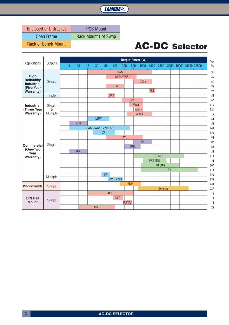
AC-DC Selector
Enclosed or L Bracket PCB Mount
Open Frame Rack Mount Hot Swap
Rack or Bench Mount
Applications OutputsOutput Power (W)
5 10 15 30 50 100 300 500 1000 1500 2500 3500 10000 15000 22500
JWS/JWSP
HWS
LZSa
RTW
RKE
JWT
MTW
KPS
ZP
SWS
PF
KW
PFE
TL (2U)
FPS (1U)
TH (1U)
TX
ZP
ZWD, ZWQ
ZUP
Genesys
DPP
DLP
DLP PU
Alpha
Vega Lite
Vega
NV
DSP
ZWS, ZWSAF, ZWSPAF
Single
12V
24V
48V
5VSingle
Single
Dual
Triple
Single
Dual
Triple
Dual
TripleMultiple
Single
Single
82-185VDC
200-400VDC
Dual
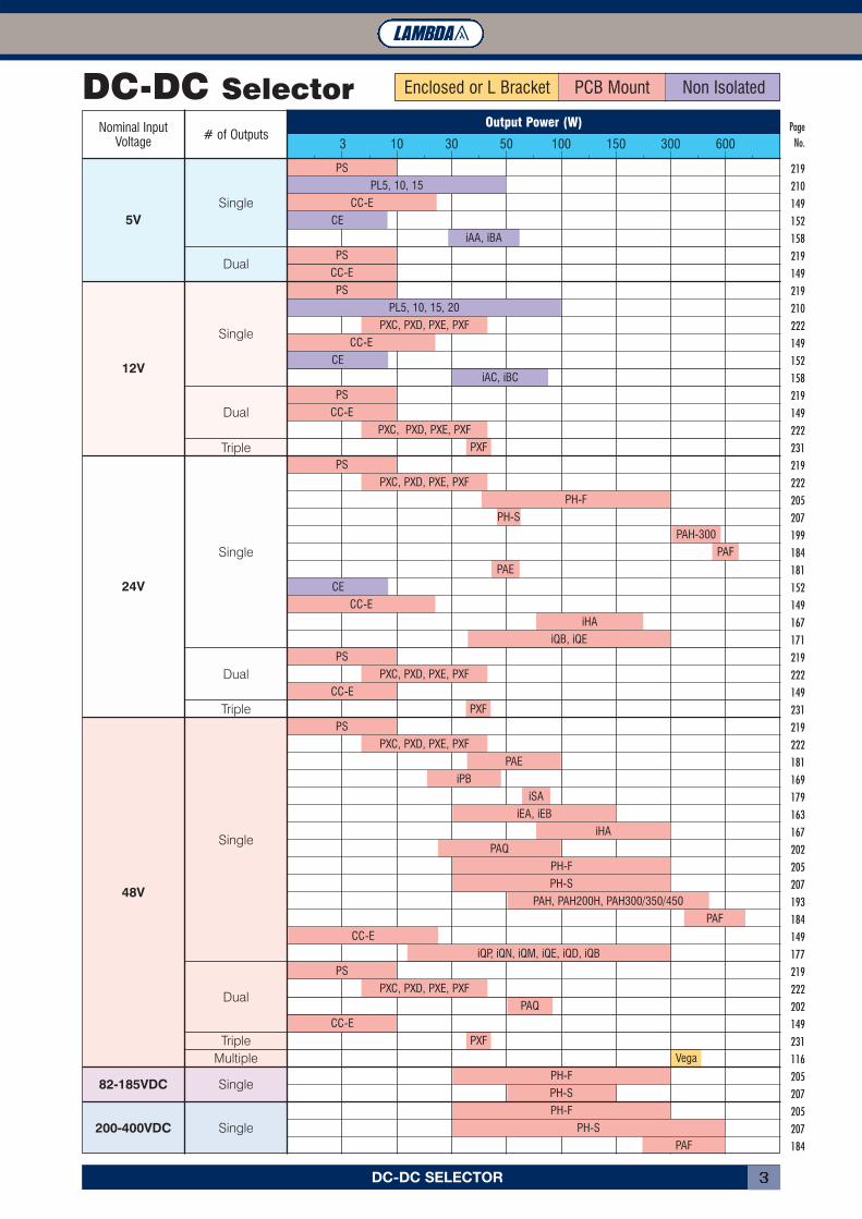
DC-DC SELECTOR 3
Page No.
219
210
149
152
158
219
149
219
210
222
149
152
158
219
149
222
231
219
222
205
207
199
184
181
152
149
167
171
219
222
149
231
219
222
181
169
179
163
167
202
205
207
193
184
149
177
219
222
202
149
231
116
205
207
205
207
184
DC-DC SelectorNominal Input
Voltage # of OutputsOutput Power (W)
3 10 30 50 100 150 300 600
PS
PL5, 10, 15
CC-E
CE
CE
iAA, iBA
PS
CC-E
PS
PS
CC-E
PS
PS
PS
PS
PXC, PXD, PXE, PXF
PAQ
CC-E
CC-E
PXF
Vega
PH-F
PH-S
PH-F
PH-S
PAF
PAE
PL5, 10, 15, 20
PXC, PXD, PXE, PXF
PXC, PXD, PXE, PXF
PXC, PXD, PXE, PXF
PXC, PXD, PXE, PXF
PXC, PXD, PXE, PXF
PAE
iPB
iSA
iHA
iEA, iEB
PAQ
PH-F
PH-S
PAH, PAH200H, PAH300/350/450
PAF
PXF
PH-F
PH-S
PAH-300
PAF
PXF
CC-E
CC-E
iQB, iQE
iHA
CE
iAC, iBC
CC-E
iQP, iQN, iQM, iQE, iQD, iQB
Enclosed or L Bracket PCB Mount Non Isolated
INDEX4
AC/DC POWER SUPPLIESAALLPPHHAA SSEERRIIEESS PPaaggee 55
DDLLPP SSEERRIIEESS PPaaggee 1100
DDLLPP--PPUU SSEERRIIEESS PPaaggee 1133
DDPPPP 1155--110000 SSEERRIIEESS PPaaggee 1166
DDPPPP 112200 && 224400 SSEERRIIEESS PPaaggee 1199
DDPPPP 448800 SSEERRIIEESS PPaaggee 2222
DDSSPP SSEERRIIEESS PPaaggee 2255
FFPPSS 11000000 SSEERRIIEESS PPaaggee 2288
HHWWSS SSEERRIIEESS PPaaggee 3311
HHWWSS 330000//660000WW SSEERRIIEESS PPaaggee 3344
HHWWSS 11550000 SSEERRIIEESS PPaaggee 3377
HHWWSS HHDD SSEERRIIEESS PPaaggee 4400
HHWWSS MMEE SSEERRIIEESS PPaaggee 4433
JJWWSS--PP SSEERRIIEESS PPaaggee 4466
JJWWSS SSEERRIIEESS PPaaggee 4499
JJWWTT SSEERRIIEESS PPaaggee 5522
KKPPSS SSEERRIIEESS PPaaggee 5555
KKWW SSEERRIIEESS PPaaggee 5588
LLZZSSaa SSEERRIIEESS PPaaggee 6611
MMTTWW SSEERRIIEESS PPaaggee 6644
NNVV--PPOOWWEERR SSEERRIIEESS ((NNVV--117755)) PPaaggee 6677
NNVV--PPOOWWEERR SSEERRIIEESS ((NNVV--330000)) PPaaggee 7722
NNVV--PPOOWWEERR SSEERRIIEESS ((NNVV--335500 FFEEPP)) PPaaggee 7777
NNVV--PPOOWWEERR SSEERRIIEESS ((NNVV--335500 //NNVV--770000)) PPaaggee 8822
PPFF SSEERRIIEESS PPaaggee 8877
PPFFEE 330000//550000//770000 SSEERRIIEESS PPaaggee 8899
RRKKEE SSEERRIIEESS PPaaggee 9922
RRTTWW SSEERRIIEESS PPaaggee 9955
SSWWSS 5500--115500WW SSEERRIIEESS PPaaggee 9988
SSWWSS 330000 && 660000 SSEERRIIEESS PPaaggee 110011
SSWWSS 660000 -- 11000000LL SSEERRIIEESS PPaaggee 110044
TTHH SSEERRIIEESS PPaaggee 110077
TTLL SSEERRIIEESS PPaaggee 111100
TTXX SSEERRIIEESS PPaaggee 111133
VVEEGGAA SSEERRIIEESS PPaaggee 111166
VVEEGGAA LLIITTEE SSEERRIIEESS PPaaggee 112211
ZZPP 2200 SSEERRIIEESS PPaaggee 112266
ZZPP 4400 && 6600 SSEERRIIEESS PPaaggee 112299
ZZPP 110000 SSEERRIIEESS PPaaggee 113322
ZZWWDD--PPAAFF SSEERRIIEESS PPaaggee 113355
ZZWWQQ SSEERRIIEESS PPaaggee 113388
ZZWWSS SSEERRIIEESS PPaaggee 114400
ZZWWSS--AAFF SSEERRIIEESS PPaaggee 114433
ZZWWSS--PPAAFF SSEERRIIEESS PPaaggee 114466
DC/DC CONVERTERSCCCC--EE SSEERRIIEESS PPaaggee 114499
CCEE 11000000 SSEERRIIEESS PPaaggee 115522
CCEE 11000055 SSEERRIIEESS PPaaggee 115555
iiAAAA//iiAACC SSEERRIIEESS PPaaggee 115588
iiBBAA//iiBBCC SSEERRIIEESS PPaaggee 116611
iiEEAA SSEERRIIEESS PPaaggee 116633
iiEEBB SSEERRIIEESS PPaaggee 116655
iiHHAA SSEERRIIEESS PPaaggee 116677
iiPPBB SSEERRIIEESS PPaaggee 116699
iiQQBB SSEERRIIEESS PPaaggee 117711
iiQQDD SSEERRIIEESS PPaaggee 117733
iiQQEE SSEERRIIEESS PPaaggee 117755
iiQQMM//iiQQNN//iiQQPP SSEERRIIEESS PPaaggee 117777
iiSSAA SSEERRIIEESS PPaaggee 117799
PPAAEE 5500//110000 SSEERRIIEESS PPaaggee 118811
PPAAFF 440000FF SSEERRIIEESS PPaaggee 118844
PPAAFF 445500FF//660000FF SSEERRIIEESS PPaaggee 118877
PPAAFF 770000FF SSEERRIIEESS PPaaggee 119900
PPAAHH SSEERRIIEESS PPaaggee 119933
PPAAHH 220000HH SSEERRIIEESS PPaaggee 119966
PPAAHH 330000//445500 SSEERRIIEESS PPaaggee 119999
PPAAQQ SSEERRIIEESS PPaaggee 220022
PPHH--FF SSEERRIIEESS PPaaggee 220055
PPHH--SS SSEERRIIEESS PPaaggee 220077
PPLL--55 SSEERRIIEESS PPaaggee 221100
PPLL 1100--2200SS SSEERRIIEESS PPaaggee 221133
PPLL 1100--2200 SSMMSS SSEERRIIEESS PPaaggee 221166
PPSSSS//PPSSDD SSEERRIIEESS PPaaggee 221199
PPXXCC0055 SSEERRIIEESS PPaaggee 222222
PPXXDD SSEERRIIEESS PPaaggee 222255
PPXXEE SSEERRIIEESS PPaaggee 222288
PPXXFF SSEERRIIEESS PPaaggee 223311
PPVV SSEERRIIEESS PPaaggee 223344
PROGRAMMABLEGGEENNEESSYYSS SSEERRIIEESS PPaaggee 223377
ZZUUPP SSEERRIIEESS PPaaggee 224400
SPECIAL ASSEMBLIESCCUUSSTTOOMMIISSEEDD PPRROODDUUCCTTSS PPaaggee 224433
FILTERSMMCC//MMZZ SSEERRIIEESS PPaaggee 224455
MMAA//MMXX SSEERRIIEESS PPaaggee 224488
LATEST NNEEWW NNVV MMEEDDIICCAALL RRAANNGGEENNVV--PPOOWWEERR SSEERRIIEESS ((NNVV--117755MM)) PPaaggee 225511
ALPHA SERIES 5
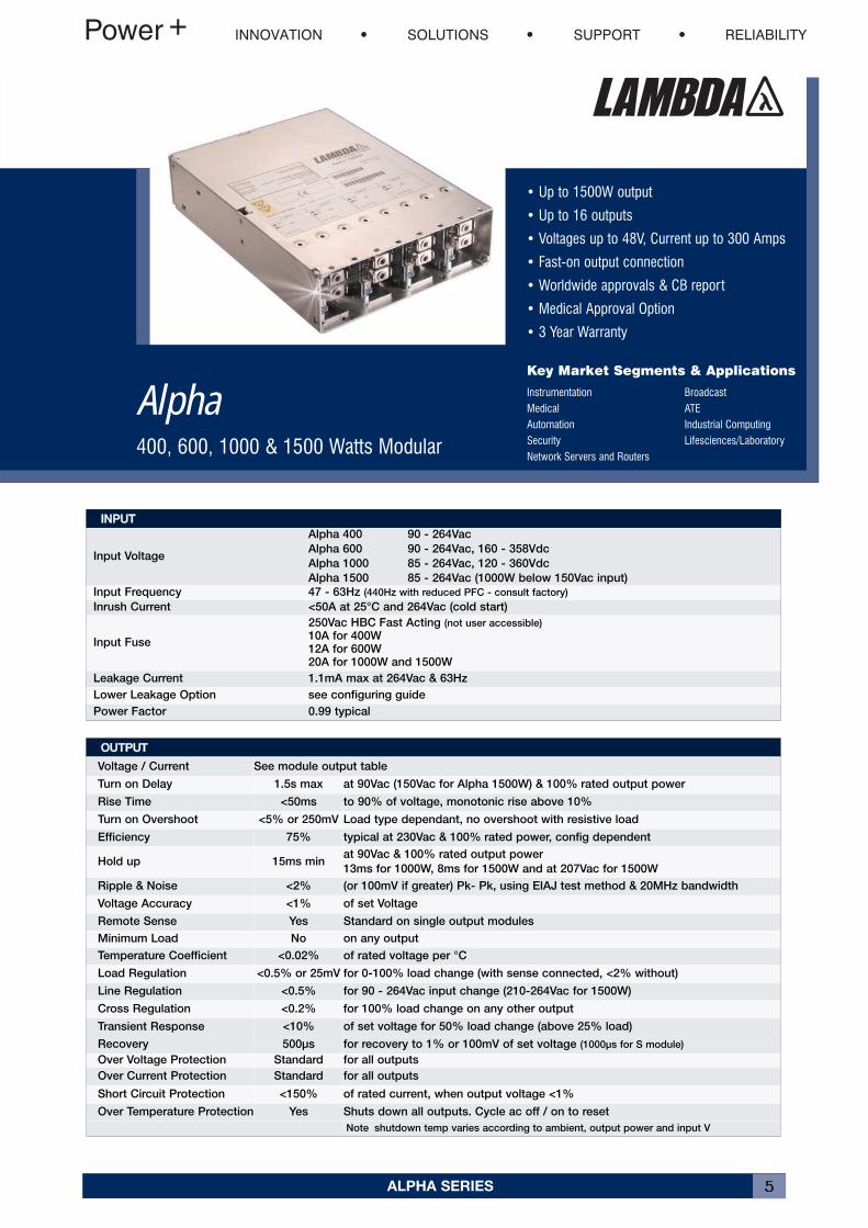
• Up to 1500W output
• Up to 16 outputs
• Voltages up to 48V, Current up to 300 Amps
• Fast-on output connection
• Worldwide approvals & CB report
• Medical Approval Option
• 3 Year Warranty
Key Market Segments & Applications
Instrumentation BroadcastMedical ATEAutomation Industrial ComputingSecurity Lifesciences/LaboratoryNetwork Servers and Routers
Alpha400, 600, 1000 & 1500 Watts Modular
IINNPPUUTTInput Voltage
Alpha 400 90 - 264Vac
Alpha 600 90 - 264Vac, 160 - 358Vdc
Alpha 1000 85 - 264Vac, 120 - 360Vdc
Alpha 1500 85 - 264Vac (1000W below 150Vac input)
Input Frequency 47 - 63Hz (440Hz with reduced PFC - consult factory)
Inrush Current <50A at 25°C and 264Vac (cold start)
Input Fuse
250Vac HBC Fast Acting (not user accessible)
10A for 400W12A for 600W20A for 1000W and 1500W
Leakage Current 1.1mA max at 264Vac & 63Hz
Lower Leakage Option see configuring guide
Power Factor 0.99 typical
OOUUTTPPUUTTVoltage / Current See module output table
Turn on Delay 1.5s max at 90Vac (150Vac for Alpha 1500W) & 100% rated output power
Rise Time <50ms to 90% of voltage, monotonic rise above 10%
Turn on Overshoot <5% or 250mV Load type dependant, no overshoot with resistive load
Efficiency 75% typical at 230Vac & 100% rated power, config dependent
Hold up 15ms minat 90Vac & 100% rated output power
13ms for 1000W, 8ms for 1500W and at 207Vac for 1500W
Ripple & Noise <2% (or 100mV if greater) Pk- Pk, using EIAJ test method & 20MHz bandwidth
Voltage Accuracy <1% of set Voltage
Remote Sense Yes Standard on single output modules
Minimum Load No on any output
Temperature Coefficient <0.02% of rated voltage per °C
Load Regulation <0.5% or 25mV for 0-100% load change (with sense connected, <2% without)
Line Regulation <0.5% for 90 - 264Vac input change (210-264Vac for 1500W)
Cross Regulation <0.2% for 100% load change on any other output
Transient Response
Recovery
<10% of set voltage for 50% load change (above 25% load)
500μs for recovery to 1% or 100mV of set voltage (1000μs for S module)
Over Voltage Protection Standard for all outputs
Over Current Protection Standard for all outputs
Short Circuit Protection <150% of rated current, when output voltage <1%
Over Temperature Protection Yes Shuts down all outputs. Cycle ac off / on to reset
Note shutdown temp varies according to ambient, output power and input V
INNOVATION SOLUTIONS SUPPORT RELIABILITY
ALPHA SERIES6
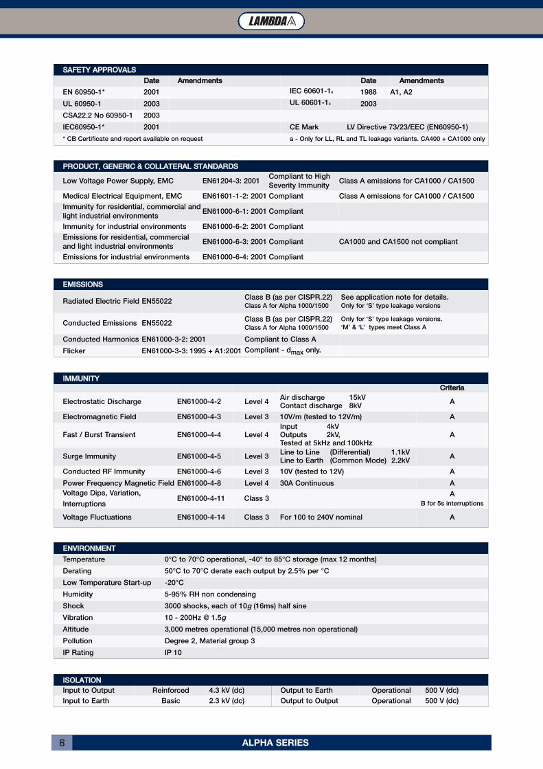
EENNVVIIRROONNMMEENNTTTemperature 0°C to 70°C operational, -40° to 85°C storage (max 12 months)
Derating 50°C to 70°C derate each output by 2.5% per °C
Low Temperature Start-up -20°C
Humidity 5-95% RH non condensing
Shock 3000 shocks, each of 10g (16ms) half sine
Vibration 10 - 200Hz @ 1.5g
Altitude 3,000 metres operational (15,000 metres non operational)
Pollution Degree 2, Material group 3
IP Rating IP 10
IIMMMMUUNNIITTYYCCrriitteerriiaa
Electrostatic Discharge EN61000-4-2 Level 4Air discharge 15kVContact discharge 8kV
A
Electromagnetic Field EN61000-4-3 Level 3 10V/m (tested to 12V/m) A
Fast / Burst Transient EN61000-4-4 Level 4Input 4kVOutputs 2kV,Tested at 5kHz and 100kHz
A
Surge Immunity EN61000-4-5 Level 3Line to Line (Differential) 1.1kVLine to Earth (Common Mode) 2.2kV
A
Conducted RF Immunity EN61000-4-6 Level 3 10V (tested to 12V) A
Power Frequency Magnetic Field EN61000-4-8 Level 4 30A Continuous A
Voltage Dips, Variation,
InterruptionsEN61000-4-11 Class 3
A
B for 5s interruptions
Voltage Fluctuations EN61000-4-14 Class 3 For 100 to 240V nominal A
SSAAFFEETTYY AAPPPPRROOVVAALLSSDDaattee AAmmeennddmmeennttss DDaattee AAmmeennddmmeennttss
EN 60950-1* 2001 IEC 60601-1a 1988 A1, A2
UL 60950-1 2003 UL 60601-1a 2003
CSA22.2 No 60950-1 2003
IEC60950-1* 2001 CE Mark LV Directive 73/23/EEC (EN60950-1)
* CB Certificate and report available on request a - Only for LL, RL and TL leakage variants. CA400 + CA1000 only
EEMMIISSSSIIOONNSSRadiated Electric Field EN55022
Class B (as per CISPR.22)Class A for Alpha 1000/1500
See application note for details.Only for ‘S’ type leakage versions
Conducted Emissions EN55022Class B (as per CISPR.22)Class A for Alpha 1000/1500
Only for ‘S’ type leakage versions.
‘M’ & ‘L’ types meet Class A
Conducted Harmonics EN61000-3-2: 2001 Compliant to Class A
Flicker EN61000-3-3: 1995 + A1:2001 Compliant - dmax only.
IISSOOLLAATTIIOONNInput to Output Reinforced 4.3 kV (dc) Output to Earth Operational 500 V (dc)
Input to Earth Basic 2.3 kV (dc) Output to Output Operational 500 V (dc)
PPRROODDUUCCTT,, GGEENNEERRIICC && CCOOLLLLAATTEERRAALL SSTTAANNDDAARRDDSSLow Voltage Power Supply, EMC EN61204-3: 2001
Compliant to High
Severity ImmunityClass A emissions for CA1000 / CA1500
Medical Electrical Equipment, EMC EN61601-1-2: 2001 Compliant Class A emissions for CA1000 / CA1500
Immunity for residential, commercial and
light industrial environmentsEN61000-6-1: 2001 Compliant
Immunity for industrial environments EN61000-6-2: 2001 Compliant
Emissions for residential, commercial
and light industrial environmentsEN61000-6-3: 2001 Compliant CA1000 and CA1500 not compliant
Emissions for industrial environments EN61000-6-4: 2001 Compliant
ALPHA SERIES 7
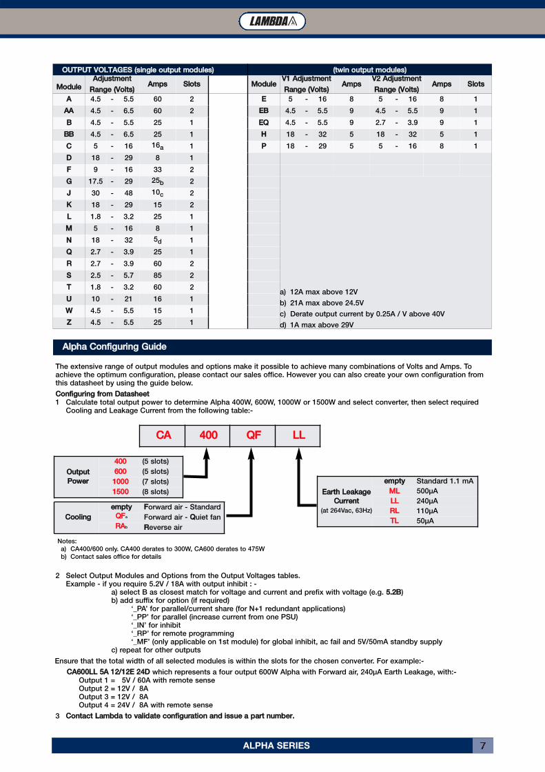
OOUUTTPPUUTT VVOOLLTTAAGGEESS ((ssiinnggllee oouuttppuutt mmoodduulleess)) ((ttwwiinn oouuttppuutt mmoodduulleess))MMoodduullee AAddjjuussttmmeenntt
RRaannggee ((VVoollttss)) AAmmppss SSlloottss MMoodduullee VV11 AAddjjuussttmmeennttRRaannggee ((VVoollttss)) AAmmppss VV22 AAddjjuussttmmeenntt
RRaannggee ((VVoollttss)) AAmmppss SSlloottssAA 4.5 - 5.5 60 2 EE 5 - 16 8 5 - 16 8 1
AAAA 4.5 - 6.5 60 2 EEBB 4.5 - 5.5 9 4.5 - 5.5 9 1
BB 4.5 - 5.5 25 1 EEQQ 4.5 - 5.5 9 2.7 - 3.9 9 1
BBBB 4.5 - 6.5 25 1 HH 18 - 32 5 18 - 32 5 1
CC 5 - 16 16a 1 PP 18 - 29 5 5 - 16 8 1
DD 18 - 29 8 1
FF 9 - 16 33 2
GG 17.5 - 29 25b 2
a) 12A max above 12V
b) 21A max above 24.5V
c) Derate output current by 0.25A / V above 40V
d) 1A max above 29V
JJ 30 - 48 10c 2
KK 18 - 29 15 2
LL 1.8 - 3.2 25 1
MM 5 - 16 8 1
NN 18 - 32 5d 1
QQ 2.7 - 3.9 25 1
RR 2.7 - 3.9 60 2
SS 2.5 - 5.7 85 2
TT 1.8 - 3.2 60 2
UU 10 - 21 16 1
WW 4.5 - 5.5 15 1
ZZ 4.5 - 5.5 25 1
The extensive range of output modules and options make it possible to achieve many combinations of Volts and Amps. Toachieve the optimum configuration, please contact our sales office. However you can also create your own configuration fromthis datasheet by using the guide below.
CCoonnffiigguurriinngg ffrroomm DDaattaasshheeeett1 Calculate total output power to determine Alpha 400W, 600W, 1000W or 1500W and select converter, then select required
Cooling and Leakage Current from the following table:-
2 Select Output Modules and Options from the Output Voltages tables.Example - if you require 5.2V / 18A with output inhibit : -
a) select B as closest match for voltage and current and prefix with voltage (e.g. 55..22BB)b) add suffix for option (if required)
‘_PA’ for parallel/current share (for N+1 redundant applications)‘_PP’ for parallel (increase current from one PSU)‘_IN’ for inhibit‘_RP’ for remote programming‘_MF’ (only applicable on 1st module) for global inhibit, ac fail and 5V/50mA standby supply
c) repeat for other outputs
Ensure that the total width of all selected modules is within the slots for the chosen converter. For example:-
CCAA660000LLLL 55AA 1122//1122EE 2244DD which represents a four output 600W Alpha with Forward air, 240μA Earth Leakage, with:-Output 1 = 5V / 60A with remote senseOutput 2 = 12V / 8AOutput 3 = 12V / 8AOutput 4 = 24V / 8A with remote sense
3 CCoonnttaacctt LLaammbbddaa ttoo vvaalliiddaattee ccoonnffiigguurraattiioonn aanndd iissssuuee aa ppaarrtt nnuummbbeerr..
AAllpphhaa CCoonnffiigguurriinngg GGuuiiddee
OOuuttppuuttPPoowweerr
440000 (5 slots)
660000 (5 slots)
11000000 (7 slots)
11550000 (8 slots)
CCoooolliinngg eemmppttyy FForward air - Standard
QQFFa Forward air - QQuiet fan
RRAAb RReverse air
EEaarrtthh LLeeaakkaaggeeCCuurrrreenntt
(at 264Vac, 63Hz)
eemmppttyy Standard 1.1 mA
MMLL 500μA
LLLL 240μA
RRLL 110μA
TTLL 50μA
CCAA 440000 QQFF LLLL
Notes:
a) CA400/600 only. CA400 derates to 300W, CA600 derates to 475W
b) Contact sales office for details
ALPHA SERIES8
4
5
6
1
2
3
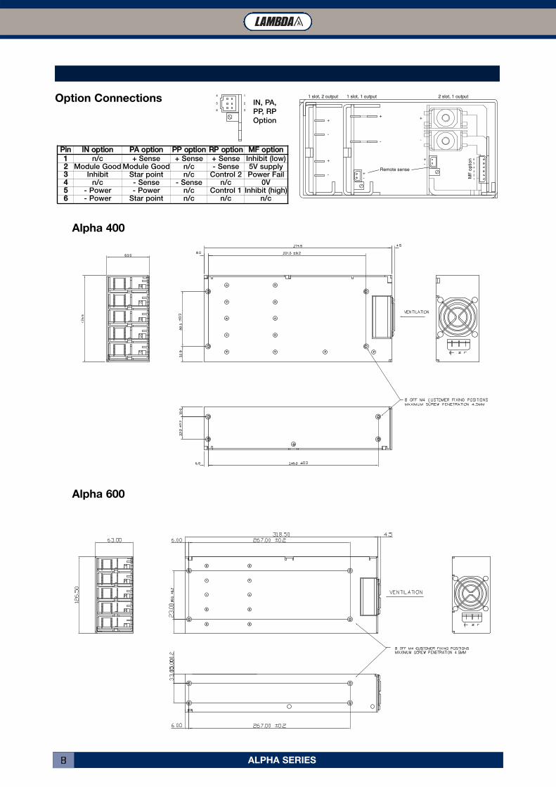
PPiinn IINN ooppttiioonn PPAA ooppttiioonn PPPP ooppttiioonn RRPP ooppttiioonn MMFF ooppttiioonn11 n/c + Sense + Sense + Sense Inhibit (low)22 Module Good Module Good n/c - Sense 5V supply33 Inhibit Star point n/c Control 2 Power Fail44 n/c - Sense - Sense n/c 0V55 - Power - Power n/c Control 1 Inhibit (high)66 - Power Star point n/c n/c n/c
Alpha 400
Alpha 600
+
-
+
-
+
-
+
-
+-
+-
6
5
4
3
2
1
Remote sense
1 slot, 2 output 1 slot, 1 output 2 slot, 1 output
MF
op
tio
n
IN, PA,
PP, RP
Option
Option Connections
ALPHA SERIES 9
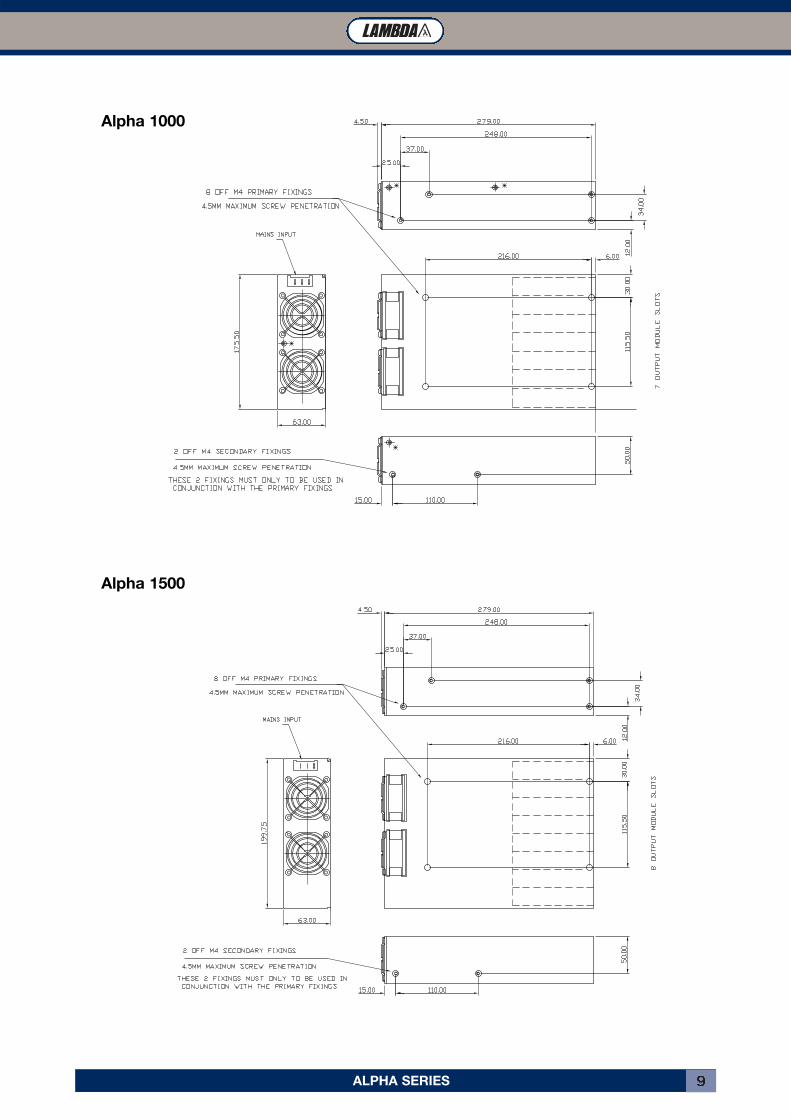
Alpha 1000
Alpha 1500
DLP SERIES10
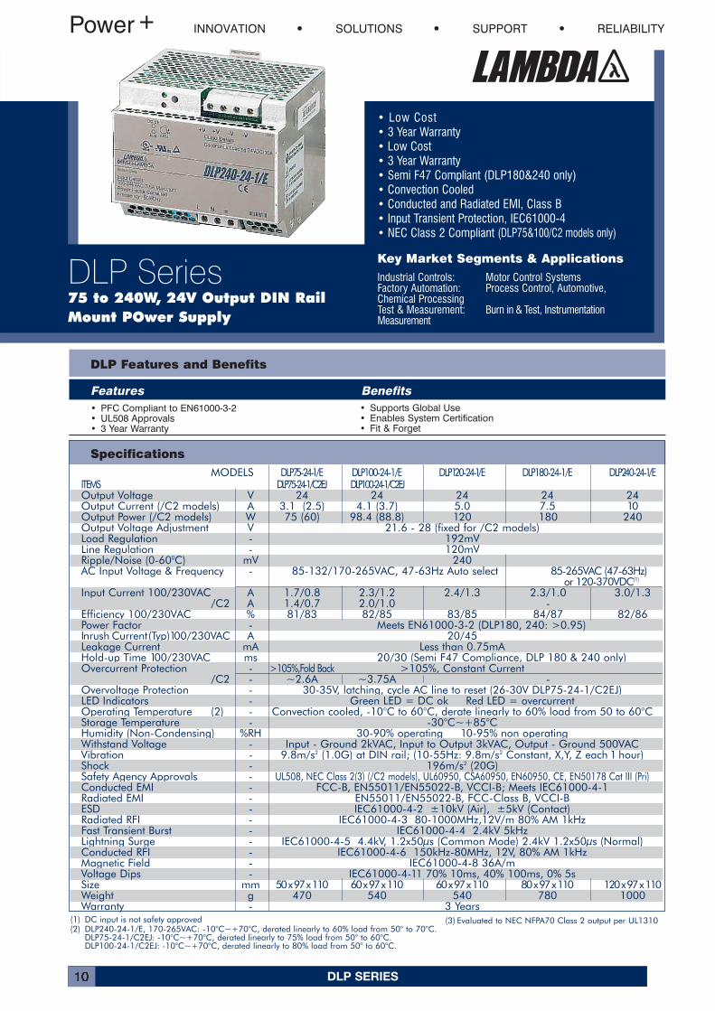
• Low Cost• 3 Year Warranty• Low Cost• 3 Year Warranty• Semi F47 Compliant (DLP180&240 only)• Convection Cooled• Conducted and Radiated EMI, Class B• Input Transient Protection, IEC61000-4• NEC Class 2 Compliant (DLP75&100/C2 models only)
Key Market Segments & Applications
Industrial Controls: Motor Control SystemsFactory Automation: Process Control, Automotive, Chemical ProcessingTest & Measurement: Burn in & Test, Instrumentation Measurement
INNOVATION SOLUTIONS SUPPORT RELIABILITY
DLP Series75 to 240W, 24V Output DIN RailMount POwer Supply
DLP Features and Benefits
Features Benefits• PFC Compliant to EN61000-3-2• UL508 Approvals• 3 Year Warranty
• Supports Global Use• Enables System Certification• Fit & Forget
Specifications
(1) DC input is not safety approved(2) DLP240-24-1/E, 170-265VAC: -10°C~+70°C, derated linearly to 60% load from 50° to 70°C.
DLP75-24-1/C2EJ: -10°C~+70°C, derated linearly to 75% load from 50° to 60°C.DLP100-24-1/C2EJ: -10°C~+70°C, derated linearly to 80% load from 50° to 60°C.
(3) Evaluated to NEC NFPA70 Class 2 output per UL1310
MODELS DLP75-24-1/E DLP100-24-1/E DLP120-24-1/E DLP180-24-1/E DLP240-24-1/EITEMS DLP75-24-1/C2EJ DLP100-24-1/C2EJOutput Voltage V 24 24 24 24 24Output Current (/C2 models) A 3.1 (2.5) 4.1 (3.7) 5.0 7.5 10Output Power (/C2 models) W 75 (60) 98.4 (88.8) 120 180 240Output Voltage Adjustment V 21.6 - 28 (fixed for /C2 models)Load Regulation - 192mVLine Regulation - 120mVRipple/Noise (0-600C) mV 240AC Input Voltage & Frequency - 85-132/170-265VAC, 47-63Hz Auto select 85-265VAC (47-63Hz)
or 120-370VDC(1)
Input Current 100/230VAC A 1.7/0.8 2.3/1.2 2.4/1.3 2.3/1.0 3.0/1.3/C2 A 1.4/0.7 2.0/1.0 -
Efficiency 100/230VAC % 81/83 82/85 83/85 84/87 82/86Power Factor - Meets EN61000-3-2 (DLP180, 240: >0.95)Inrush Current(Typ)100/230VAC A 20/45Leakage Current mA Less than 0.75mAHold-up Time 100/230VAC ms 20/30 (Semi F47 Compliance, DLP 180 & 240 only)Overcurrent Protection - >105%,Fold Back >105%, Constant Current
/C2 - ~2.6A ~3.75A -Overvoltage Protection - 30-35V, latching, cycle AC line to reset (26-30V DLP75-24-1/C2EJ)LED Indicators - Green LED = DC ok Red LED = overcurrentOperating Temperature (2) - Convection cooled, -10°C to 60°C, derate linearly to 60% load from 50 to 60°CStorage Temperature - -30°C~+85°CHumidity (Non-Condensing) %RH 30-90% operating 10-95% non operatingWithstand Voltage - Input - Ground 2kVAC, Input to Output 3kVAC, Output - Ground 500VACVibration - 9.8m/s2 (1.0G) at DIN rail; (10-55Hz: 9.8m/s2 Constant, X,Y, Z each 1 hour)Shock - 196m/s2 (20G)Safety Agency Approvals - UL508, NEC Class 2(3) (/C2 models), UL60950, CSA60950, EN60950, CE, EN50178 Cat III (Pri)Conducted EMI - FCC-B, EN55011/EN55022-B, VCCI-B; Meets IEC61000-4-1Radiated EMI - EN55011/EN55022-B, FCC-Class B, VCCI-BESD - IEC61000-4-2 ±10kV (Air), ±5kV (Contact)Radiated RFI - IEC61000-4-3 80-1000MHz,12V/m 80% AM 1kHzFast Transient Burst - IEC61000-4-4 2.4kV 5kHzLightning Surge - IEC61000-4-5 4.4kV, 1.2x50µs (Common Mode) 2.4kV 1.2x50µs (Normal)Conducted RFI - IEC61000-4-6 150kHz-80MHz, 12V, 80% AM 1kHzMagnetic Field - IEC61000-4-8 36A/mVoltage Dips - IEC61000-4-11 70% 10ms, 40% 100ms, 0% 5sSize mm 50 x 97 x 110 60 x 97 x 110 60 x 97 x 110 80 x 97 x 110 120 x 97 x 110Weight g 470 540 540 780 1000Warranty - 3 Years
DLP SERIES 11
1.2m/s Forced Air 50°C 55°C 60°C 65°C 70°C
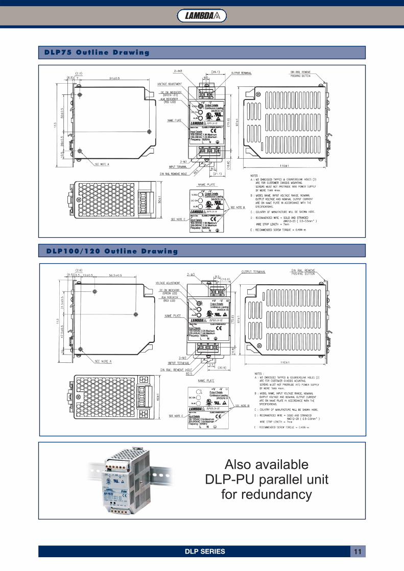
DLP75 Out l ine Drawing
DLP100/120 Out l ine Drawing
DLP75-24-1/E
DLP75-24-1/E
DLP100-24-1/E
DLP100-24-1/E
Also available DLP-PU parallel unit
for redundancy
DLP SERIES12
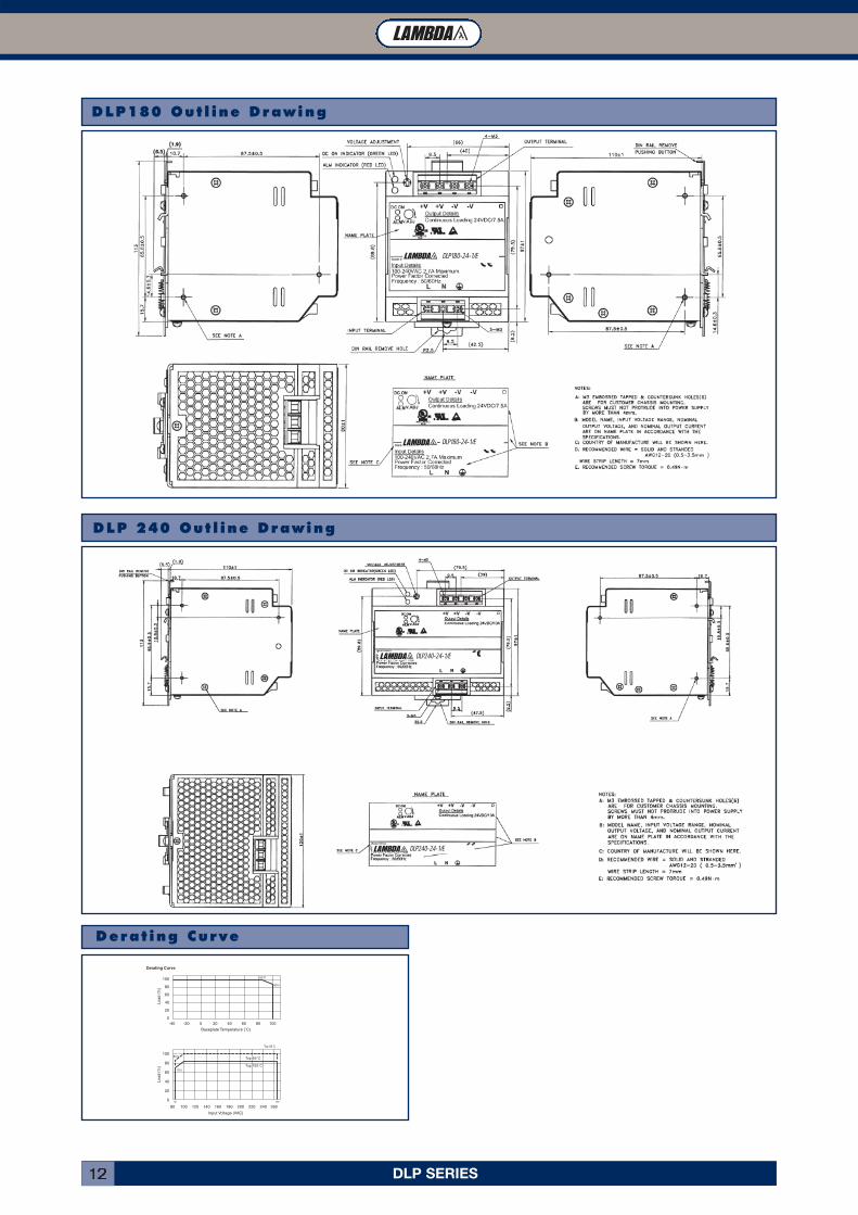
DLP180 Out l ine Drawing
DLP 240 Out l ine Drawing
100
80
60
40
20
0
100
80
60
40
20
0
Derating Curve
Baseplate Temperature (˚C)
Input Voltage (VAC)
Load
(%
)Lo
ad (
%)
-40
80 100 120 140 160 180 200 220 240 260
-20 20 40 60 80 1000
85˚C
Top 85 C
Top 85˚C
Top 100˚C
85%
70%
85%
85 265
Derat ing Curve
DLP240-24-1/E
DLP240-24-1/E
DLP180-24-1/E
DLP180-24-1/E

DLP-PU SERIES 13
• OR-ing Diodes Included
• Alarm Signals
• LED Indicators
• DIN Rail Mounting
Key Market Segments & Applications
Industrial Controls: Motor Control Systems
Factory Automation: Process Control, Automotive, Chemical Processing
Test & Measurement: Burn in & Test, Instrumentation Measurement
INNOVATION SOLUTIONS SUPPORT RELIABILITY
DLP-PU SeriesPower Supply Parallel orRedundancy Module
DLP-PU Features and Benefits
Features Benefits
• Internal ORing Diodes• Can Connect Two Units in Parallel• Output Voltage Monitoring (via relays)• DIN Rail Mounting
• Allows Redundant Operating• Enables System Scalability• Remote Alarm Notification• Easier System Integration
Specifications
MODELS DLP-PU/EITEMSInput Voltage Range VDC 21 - 28VDCNumber of inputs - TwoMaximum Input Current A 20A per inputMaximum Output Current A 20AOvercurrent protection - NoneVoltage Drop VDC 0.5VMaximum Reverse Voltage VDC 35VDCLED Indicators - Two green LEDs indicating each input is "good"Input Voltage Alarm - Relay off when input is <19.2V (±1%) or > 30V (±5%). NO and NC contactsRelay contact rating (max) - 28VDC, 1A or 120VAC, 0.5A (5mA minimum recommended)Cooling - ConvectionOperating Temperature -10 to +70°C, derate linearly to 60% from 60 to 70°CStorage Temperature - -30 to +90°CHumidity - Operating: 30 - 90%RH, Storage: 10 - 95%RH (non condensing)Withstand Voltage - Input or Output - Chassis, Input or Output - Relay Contacts,
Relay Contacts to Chassis; 500VAC for 1 min.Isolation Resistance - Input or Output - Chassis, Input or Output - Relay Contacts,
Relay Contacts to Chassis; >10M Ohms at 25°C, 70%RH and 500VDCVibration - Non operating, mounted on DIN Rail,10-55Hz (sweep for 1 min),
9.8m/s2 constant X, Y, Z each for 1 hourShock - 196m/s2
Safety Agency Approval - UL60950, CSA60950, EN60950, UL508, CSA22.2 No.14, EN60529 IP20, EN50178 Cat 1Size mm/in 50 x 97 x 110mm, 1.97x 3.81 x 4.33"Weight g 470gWarranty yrs Three Years
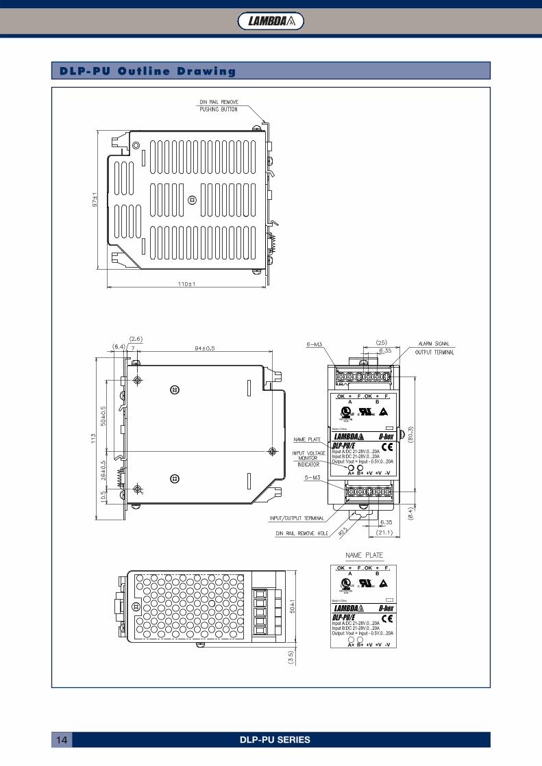
DLP-PU SERIES14
DLP-PU Out l ine Drawing
1.2m/s Forced Air 50°C 55°C 60°C 65°C 70°C
DLP-PU SERIES 15
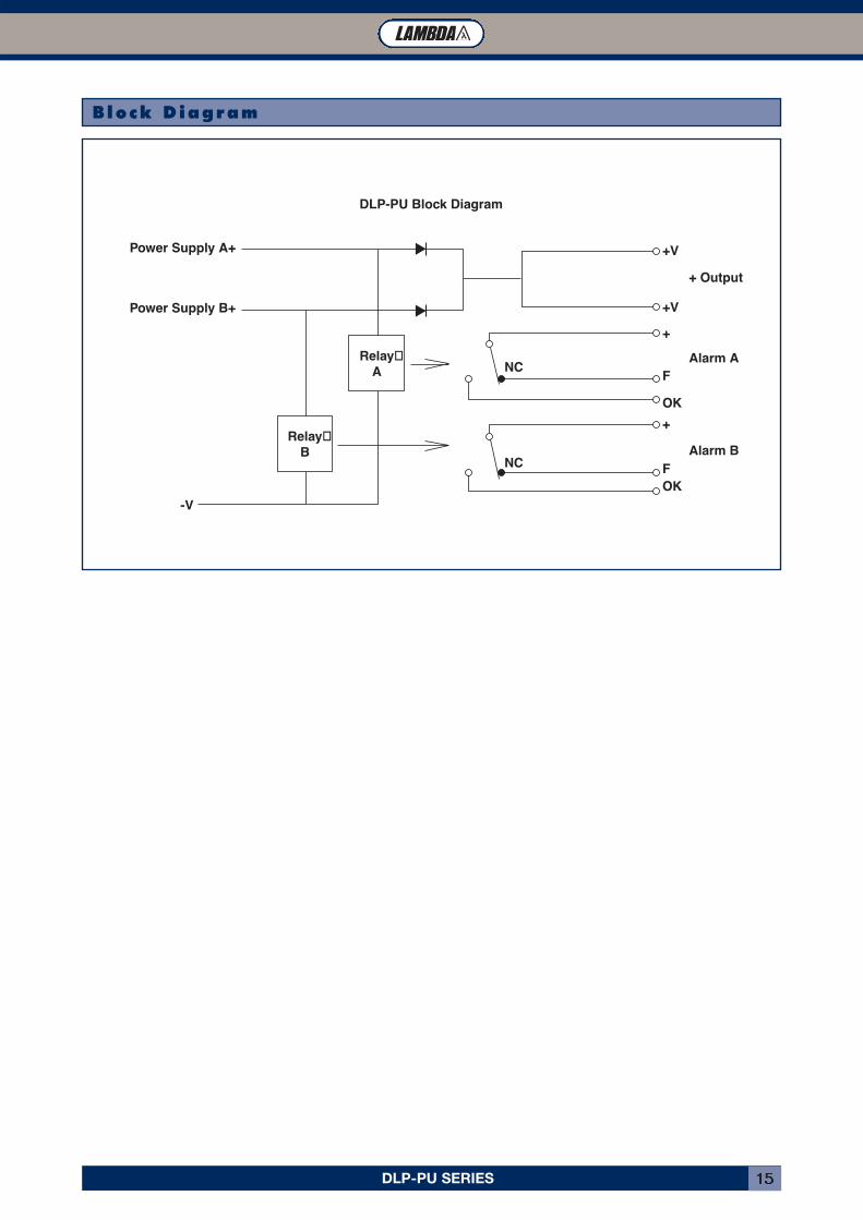
Relay�B
Relay�A
-V
Power Supply B+
+ Output
Alarm A
Alarm B
Power Supply A+
DLP-PU Block Diagram
+V
+V
NC
+
F
OK
NC
+
FOK
Block Diagram
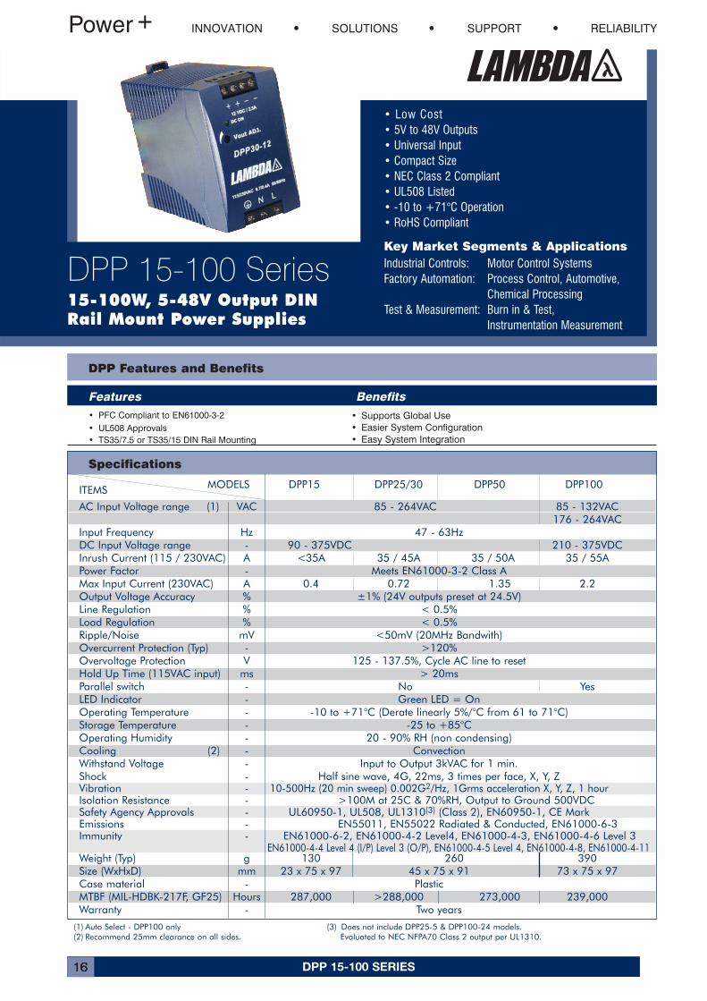
DPP 15-100 SERIES16
• Low Cost• 5V to 48V Outputs• Universal Input• Compact Size• NEC Class 2 Compliant• UL508 Listed• -10 to +71°C Operation• RoHS Compliant
Key Market Segments & ApplicationsIndustrial Controls: Motor Control SystemsFactory Automation: Process Control, Automotive,
Chemical ProcessingTest & Measurement: Burn in & Test,
Instrumentation Measurement
DPP Features and Benefits
Features Benefits• PFC Compliant to EN61000-3-2• UL508 Approvals• TS35/7.5 or TS35/15 DIN Rail Mounting
• Supports Global Use• Easier System Configuration• Easy System Integration
Specifications
(1) Auto Select - DPP100 only(2) Recommend 25mm clearance on all sides.
(3) Does not include DPP25-5 & DPP100-24 models. Evaluated to NEC NFPA70 Class 2 output per UL1310.
MODELS DPP15 DPP25/30 DPP50 DPP100ITEMS
AC Input Voltage range (1) VAC 85 - 264VAC 85 - 132VAC176 - 264VAC
Input Frequency Hz 47 - 63HzDC Input Voltage range - 90 - 375VDC 210 - 375VDCInrush Current (115 / 230VAC) A <35A 35 / 45A 35 / 50A 35 / 55APower Factor - Meets EN61000-3-2 Class AMax Input Current (230VAC) A 0.4 0.72 1.35 2.2Output Voltage Accuracy % ±1% (24V outputs preset at 24.5V)Line Regulation % < 0.5%Load Regulation % < 0.5%Ripple/Noise mV <50mV (20MHz Bandwith)Overcurrent Protection (Typ) - >120%Overvoltage Protection V 125 - 137.5%, Cycle AC line to resetHold Up Time (115VAC input) ms > 20msParallel switch - No YesLED Indicator - Green LED = OnOperating Temperature - -10 to +71°C (Derate linearly 5%/°C from 61 to 71°C)Storage Temperature - -25 to +85°COperating Humidity - 20 - 90% RH (non condensing)Cooling (2) - ConvectionWithstand Voltage - Input to Output 3kVAC for 1 min.Shock - Half sine wave, 4G, 22ms, 3 times per face, X, Y, ZVibration - 10-500Hz (20 min sweep) 0.002G2/Hz, 1Grms acceleration X, Y, Z, 1 hourIsolation Resistance - >100M at 25C & 70%RH, Output to Ground 500VDCSafety Agency Approvals - UL60950-1, UL508, UL1310(3) (Class 2), EN60950-1, CE MarkEmissions - EN55011, EN55022 Radiated & Conducted, EN61000-6-3Immunity - EN61000-6-2, EN61000-4-2 Level4, EN61000-4-3, EN61000-4-6 Level 3
EN61000-4-4 Level 4 (I/P) Level 3 (O/P), EN61000-4-5 Level 4, EN61000-4-8, EN61000-4-11Weight (Typ) g 130 260 390Size (WxHxD) mm 23 x 75 x 97 45 x 75 x 91 73 x 75 x 97Case material - PlasticMTBF (MIL-HDBK-217F, GF25) Hours 287,000 >288,000 273,000 239,000Warranty - Two years
INNOVATION SOLUTIONS SUPPORT RELIABILITY
DPP 15-100 Series15-100W, 5-48V Output DINRail Mount Power Supplies
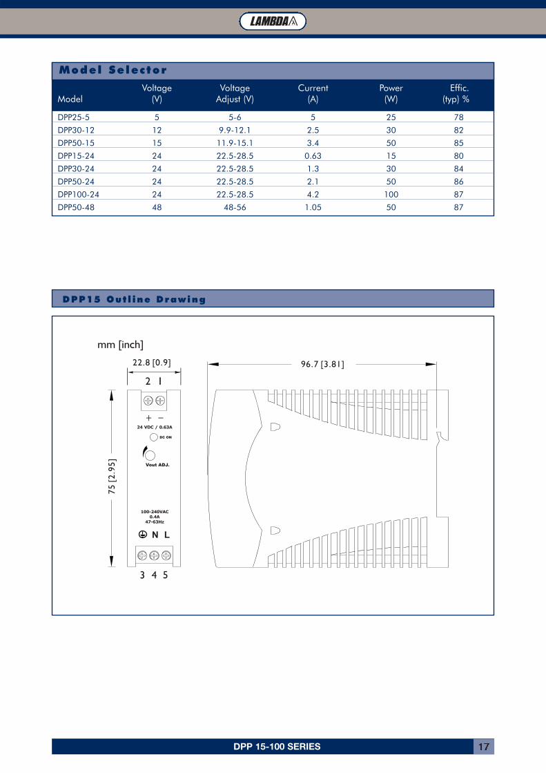
DPP 15-100 SERIES 17
DPP25-5 5 5-6 5 25 78
DPP30-12 12 9.9-12.1 2.5 30 82
DPP50-15 15 11.9-15.1 3.4 50 85
DPP15-24 24 22.5-28.5 0.63 15 80
DPP30-24 24 22.5-28.5 1.3 30 84
DPP50-24 24 22.5-28.5 2.1 50 86
DPP100-24 24 22.5-28.5 4.2 100 87
DPP50-48 48 48-56 1.05 50 87
Voltage Voltage Current Power Effic.Model (V) Adjust (V) (A) (W) (typ) %
Model Selector
DPP15 Out l ine Drawing
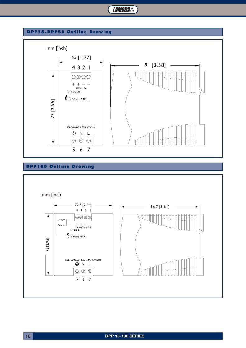
DPP 15-100 SERIES18
DPP100 Out l ine Drawing
DPP25-DPP50 Out l ine Drawing
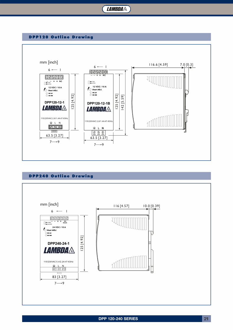
DPP 120-240 SERIES 19
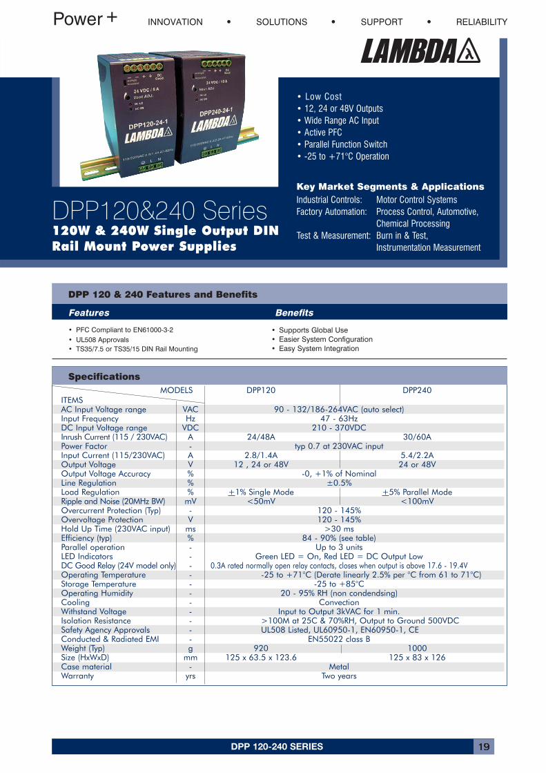
MODELS DPP120 DPP240ITEMSAC Input Voltage range VAC 90 - 132/186-264VAC (auto select)Input Frequency Hz 47 - 63HzDC Input Voltage range VDC 210 - 370VDCInrush Current (115 / 230VAC) A 24/48A 30/60APower Factor - typ 0.7 at 230VAC inputInput Current (115/230VAC) A 2.8/1.4A 5.4/2.2AOutput Voltage V 12 , 24 or 48V 24 or 48VOutput Voltage Accuracy % -0, +1% of NominalLine Regulation % ±0.5%Load Regulation % +1% Single Mode +5% Parallel ModeRipple and Noise (20MHz BW) mV <50mV <100mVOvercurrent Protection (Typ) - 120 - 145%Overvoltage Protection V 120 - 145%Hold Up Time (230VAC input) ms >30 msEfficiency (typ) % 84 - 90% (see table)Parallel operation - Up to 3 unitsLED Indicators - Green LED = On, Red LED = DC Output LowDC Good Relay (24V model only) - 0.3A rated normally open relay contacts, closes when output is above 17.6 - 19.4VOperating Temperature - -25 to +71°C (Derate linearly 2.5% per °C from 61 to 71°C)Storage Temperature - -25 to +85°COperating Humidity - 20 - 95% RH (non condendsing)Cooling - ConvectionWithstand Voltage - Input to Output 3kVAC for 1 min.Isolation Resistance - >100M at 25C & 70%RH, Output to Ground 500VDCSafety Agency Approvals - UL508 Listed, UL60950-1, EN60950-1, CEConducted & Radiated EMI - EN55022 class BWeight (Typ) g 920 1000Size (HxWxD) mm 125 x 63.5 x 123.6 125 x 83 x 126Case material - MetalWarranty yrs Two years
• Low Cost• 12, 24 or 48V Outputs• Wide Range AC Input• Active PFC• Parallel Function Switch• -25 to +71°C Operation
Key Market Segments & ApplicationsIndustrial Controls: Motor Control SystemsFactory Automation: Process Control, Automotive,
Chemical ProcessingTest & Measurement: Burn in & Test,
Instrumentation Measurement
DPP 120 & 240 Features and Benefits
Features Benefits
• PFC Compliant to EN61000-3-2• UL508 Approvals• TS35/7.5 or TS35/15 DIN Rail Mounting
• Supports Global Use• Easier System Configuration• Easy System Integration
Specifications
INNOVATION SOLUTIONS SUPPORT RELIABILITY
DPP120&240 Series120W & 240W Single Output DINRail Mount Power Supplies
DPP 120-240 SERIES20
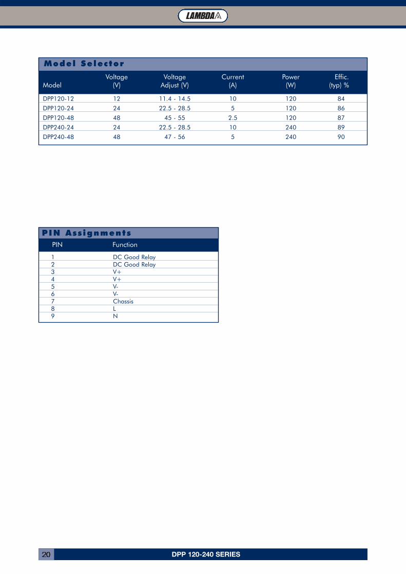
DPP120-12 12 11.4 - 14.5 10 120 84
DPP120-24 24 22.5 - 28.5 5 120 86
DPP120-48 48 45 - 55 2.5 120 87
DPP240-24 24 22.5 - 28.5 10 240 89
DPP240-48 48 47 - 56 5 240 90
Voltage Voltage Current Power Effic.Model (V) Adjust (V) (A) (W) (typ) %
Model Selector
1 DC Good Relay2 DC Good Relay3 V+4 V+5 V-6 V-7 Chassis8 L9 N
PIN Function
PIN Ass ignments
DPP 120-240 SERIES 21
DPP120
DPP240
DPP120
DPP240
DPP120 Out l ine Drawing
DPP240 Out l ine Drawing
DPP480 SERIES22
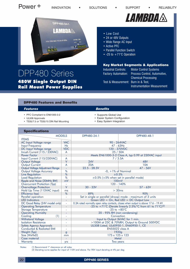
MODELS DPP480-24-1 DPP480-48-1ITEMSAC Input Voltage range VAC 90 - 264VACInput Frequency Hz 47 - 63HzDC Input Voltage range VDC 120 - 370VDCInrush Current (115 / 230VAC) A 25 / 50APower Factor - Meets EN61000-3-2 Class A, typ 0.99 at 230VAC inputInput Current (115/230VAC) A 7 / 3.5AOutput Voltage V 24V 48VOutput Current A 20A 10AOutput Voltage Adjustment Range - 22.5 - 28.5V 47 - 56VOutput Voltage Accuracy % -0, +1% of NominalLine Regulation % ±0.5%Load Regulation % ±0.5% (±5% when set in parallel mode)Ripple and Noise (20MHz BW) mV 100mVOvercurrent Protection (Typ) - 120 - 140%Overvoltage Protection V 30 - 33V 57 - 63VHold Up Time (115VAC input) ms > 30msEfficiency (typ) % 89% 90%Parallel operation - Set in single or parallel (droop) mode - maximum of 3 unitsLED Indicators - Green LED = On, Red LED = DC Output LowDC Good Relay (24V model only) - 0.3A rated normally open relay contacts, closes when output is above 17.6 - 19.4VOperating Temperature - -25 to +71°C (Derate linearly 2.5%/°C from 61 to 71°C)(2)
Storage Temperature - -25 to +85°COperating Humidity - 20 - 95% RH (non condensing)Cooling (1) - ConvectionWithstand Voltage - Input to Output 3kVAC for 1 min.Isolation Resistance - >100M at 25C & 70%RH, Output to Ground 500VDCSafety Agency Approvals - UL508 Listed, UL60950-1, EN60950-1, CEConducted & Radiated EMI - EN55022 class AWeight (Typ) g 1920gSize (WxHxD) mm 175 x 125 x 123Case material - MetalWarranty yrs Two years
• Low Cost• 24 or 48V Outputs• Wide Range AC Input• Active PFC• Parallel Function Switch• -25 to +71°C Operation
Key Market Segments & ApplicationsIndustrial Controls: Motor Control SystemsFactory Automation: Process Control, Automotive,
Chemical ProcessingTest & Measurement: Burn in & Test,
Instrumentation Measurement
DPP480 Features and Benefits
Features Benefits
• PFC Compliant to EN61000-3-2• UL508 Approvals• TS35/7.5 or TS35/15 DIN Rail Mounting
• Supports Global Use• Easier System Configuration• Easy System Integration
Specifications
INNOVATION SOLUTIONS SUPPORT RELIABILITY
DPP480 Series480W Single Output DINRail Mount Power Supplies
Notes: (1) Recommend 1" clearance on all sides(2) Derating curve applies for input of 110V and above. For 90V input derating at 4% per deg
DPP480 SERIES 23
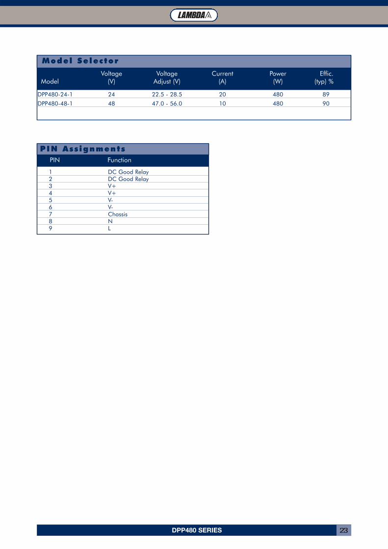
DPP480-24-1 24 22.5 - 28.5 20 480 89
DPP480-48-1 48 47.0 - 56.0 10 480 90
Voltage Voltage Current Power Effic.Model (V) Adjust (V) (A) (W) (typ) %
Model Selector
1 DC Good Relay2 DC Good Relay3 V+4 V+5 V-6 V-7 Chassis8 N9 L
PIN Function
PIN Ass ignments
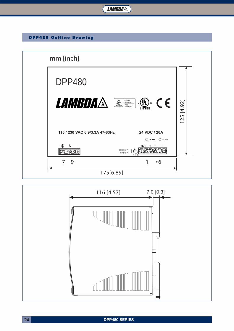
DPP480 SERIES24
116 [4.57] 10.0 [0.39]
DC LO
mm [inch]
24 VDC / 20A115 / 230 VAC 6.9/3.3A 47-63Hz
DPP480
12
5 [
4.9
2]
7 9
175[6.89]
1 6
DPP480 Out l ine Drawing
7.0 [0.3]
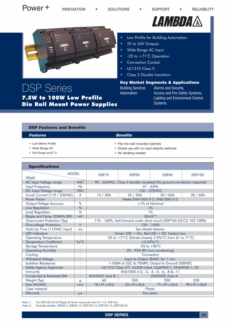
DSP SERIES 25
MODEL DSP10 DSP30 DSP60 DSP100ITEMSAC Input Voltage range VAC 90 - 264VAC, Class II double insulated (No ground connection required)Input Frequency Hz 47 - 63HzDC Input Voltage range VDC 120 - 370VDCInrush Current (115 / 230VAC) A 15 / 30A 25 / 50A 30 / 60A 30 / 60APower Factor Meets EN61000-3-2, EN61000-3-3Output Voltage Accuracy % ±1% of NominalLine Regulation % 1%Load Regulation % 1%Ripple and Noise (20MHz BW) mV 50mV(1)
Overcurrent Protection (Typ) - 110 - 160%, fold forward under short circuit (DSP100-24/C2 102-108%)Overvoltage Protection V 120 - 145%Hold Up Time (115VAC input) ms See Model SelectorLED Indicators - Green LED = On, Red LED = DC Output LowOperating Temperature - -25 to +71°C (Derate linearly 2.5%/°C from 61 to 71°C)Temperature Coefficient %/°C ±0.02%/°CStorage Temperature - -25 to +85°COperating Humidity - 20 - 95% RH (non condensing)Cooling - ConvectionWithstand Voltage - Input to Output 3kVAC for 1 min.Isolation Resistance - >100M at 25C & 70%RH, Output to Ground 500VDCSafety Agency Approvals - UL1310 Class 2(2), UL508 Listed, UL60950-1, EN60950-1, CEImmunity - EN61000-4-2, -3, -4, -5, -6, -8 & -11Conducted & Radiated EMI - EN55022 class B EN55022 class AWeight (Typ) g 60 200 250 320Size (WxHxD) mm 18 x 91 x 55.6 53 x 91x 55.6 71 x 91 x 55.6 90 x 91 x 56.8Case material - PlasticWarranty yrs Two years
DSP Features and Benefits
Features Benefits
INNOVATION SOLUTIONS SUPPORT RELIABILITY
DSP Series7.5W to 100W Low ProfileDin Rail Mount Power Supplies
• Low Profile for Building Automation
• 5V to 24V Outputs
• Wide Range AC Input
• -25 to +71°C Operation
• Convection Cooled
• UL1310 Class II
• Class 2 Double Insulation
Key Market Segments & ApplicationsBuilding Services Alarms and Security,Automation: Access and Fire Safety Systems,
Lighting and Environment ControlSystems.
Specifications
• Low 56mm Profile
• Wide Range AC
• Full Power at 61˚C
• Fits into wall mounted cabinets
• Global use with no input selector switches
• No derating needed
Note 1: For DSP100-24/C2 Ripple & Noise measured with Vin 115- 230 VacNote 2: Excludes Models: DSP60-5, DSP60-12, DSP100-12, DSP100-15, DSP100-24
DSP SERIES26
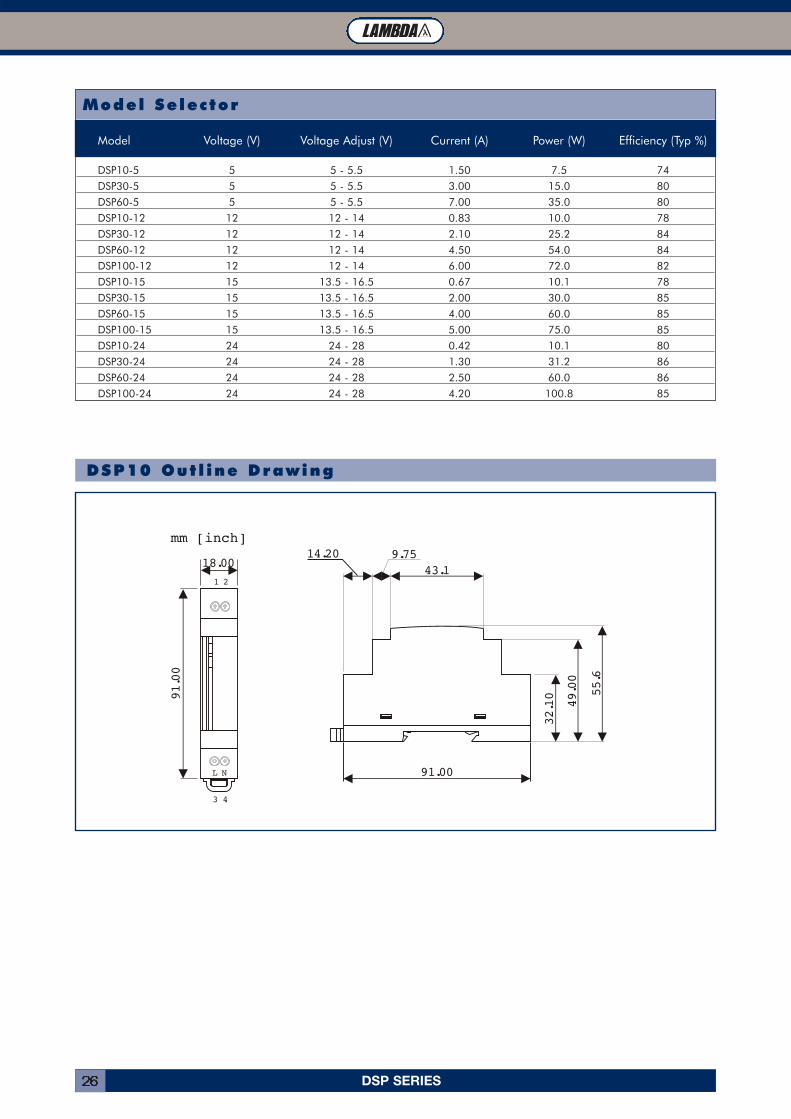
Model Selector
Model Voltage (V) Voltage Adjust (V) Current (A) Power (W) Efficiency (Typ %)
DSP10-5 5 5 - 5.5 1.50 7.5 74
DSP30-5 5 5 - 5.5 3.00 15.0 80
DSP60-5 5 5 - 5.5 7.00 35.0 80
DSP10-12 12 12 - 14 0.83 10.0 78
DSP30-12 12 12 - 14 2.10 25.2 84
DSP60-12 12 12 - 14 4.50 54.0 84
DSP100-12 12 12 - 14 6.00 72.0 82
DSP10-15 15 13.5 - 16.5 0.67 10.1 78
DSP30-15 15 13.5 - 16.5 2.00 30.0 85
DSP60-15 15 13.5 - 16.5 4.00 60.0 85
DSP100-15 15 13.5 - 16.5 5.00 75.0 85
DSP10-24 24 24 - 28 0.42 10.1 80
DSP30-24 24 24 - 28 1.30 31.2 86
DSP60-24 24 24 - 28 2.50 60.0 86
DSP100-24 24 24 - 28 4.20 100.8 85
mm [inch]14.20 9.75
43.1
91.00
32.10
49.00
55.6
18.00
91.00
1 2
L N
3 4
DSP10 Out l ine Drawing
DSP SERIES 27
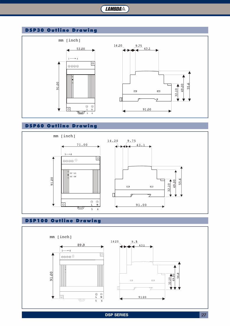
mm [inch]
91.00
32.10
49.00
56.8
14.20 9.7543.1
91.00
89.9
1 4
5 6
mm [inch]
71.00
91.00
14.20 9.7543.1
91.00
32.10
49.00
55.6
1 4
5 6
DC LO
DC ON
mm [inch]
53.00
91.00
14.20 9.7543.1
91.00
32.10
49.00
55.6
1 4
5 6
L N
DSP30 Out l ine Drawing
DSP60 Out l ine Drawing
DSP100 Out l ine Drawing
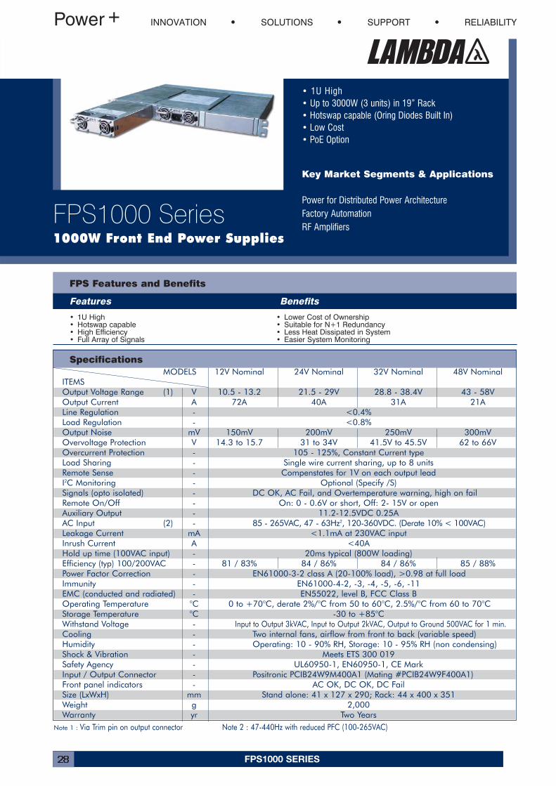
FPS1000 SERIES28
• 1U High• Up to 3000W (3 units) in 19” Rack• Hotswap capable (Oring Diodes Built In)• Low Cost• PoE Option
Key Market Segments & Applications
Power for Distributed Power ArchitectureFactory AutomationRF Amplifiers
INNOVATION SOLUTIONS SUPPORT RELIABILITY
FPS1000 Series1000W Front End Power Supplies
MODELS 12V Nominal 24V Nominal 32V Nominal 48V NominalITEMSOutput Voltage Range (1) V 10.5 - 13.2 21.5 - 29V 28.8 - 38.4V 43 - 58VOutput Current A 72A 40A 31A 21ALine Regulation - <0.4%Load Regulation - <0.8%Output Noise mV 150mV 200mV 250mV 300mVOvervoltage Protection V 14.3 to 15.7 31 to 34V 41.5V to 45.5V 62 to 66VOvercurrent Protection - 105 - 125%, Constant Current typeLoad Sharing - Single wire current sharing, up to 8 unitsRemote Sense - Compenstates for 1V on each output leadI2C Monitoring - Optional (Specify /S)Signals (opto isolated) - DC OK, AC Fail, and Overtemperature warning, high on failRemote On/Off - On: 0 - 0.6V or short, Off: 2- 15V or openAuxiliary Output - 11.2-12.5VDC 0.25AAC Input (2) - 85 - 265VAC, 47 - 63Hz2, 120-360VDC. (Derate 10% < 100VAC)Leakage Current mA <1.1mA at 230VAC inputInrush Current A <40AHold up time (100VAC input) - 20ms typical (800W loading)Efficiency (typ) 100/200VAC - 81 / 83% 84 / 86% 84 / 86% 85 / 88%Power Factor Correction - EN61000-3-2 class A (20-100% load), >0.98 at full loadImmunity - EN61000-4-2, -3, -4, -5, -6, -11EMC (conducted and radiated) - EN55022, level B, FCC Class BOperating Temperature °C 0 to +70°C, derate 2%/°C from 50 to 60°C, 2.5%/°C from 60 to 70°CStorage Temperature °C -30 to +85°CWithstand Voltage - Input to Output 3kVAC, Input to Output 2kVAC, Output to Ground 500VAC for 1 min.Cooling - Two internal fans, airflow from front to back (variable speed)Humidity - Operating: 10 - 90% RH, Storage: 10 - 95% RH (non condensing)Shock & Vibration - Meets ETS 300 019Safety Agency - UL60950-1, EN60950-1, CE MarkInput / Output Connector - Positronic PCIB24W9M400A1 (Mating #PCIB24W9F400A1)Front panel indicators - AC OK, DC OK, DC FailSize (LxWxH) mm Stand alone: 41 x 127 x 290; Rack: 44 x 400 x 351Weight g 2,000Warranty yr Two Years
Specifications
FPS Features and Benefits
Features Benefits
• 1U High• Hotswap capable• High Efficiency• Full Array of Signals
• Lower Cost of Ownership• Suitable for N+1 Redundancy• Less Heat Dissipated in System• Easier System Monitoring
Note 1 : Via Trim pin on output connector Note 2 : 47-440Hz with reduced PFC (100-265VAC)
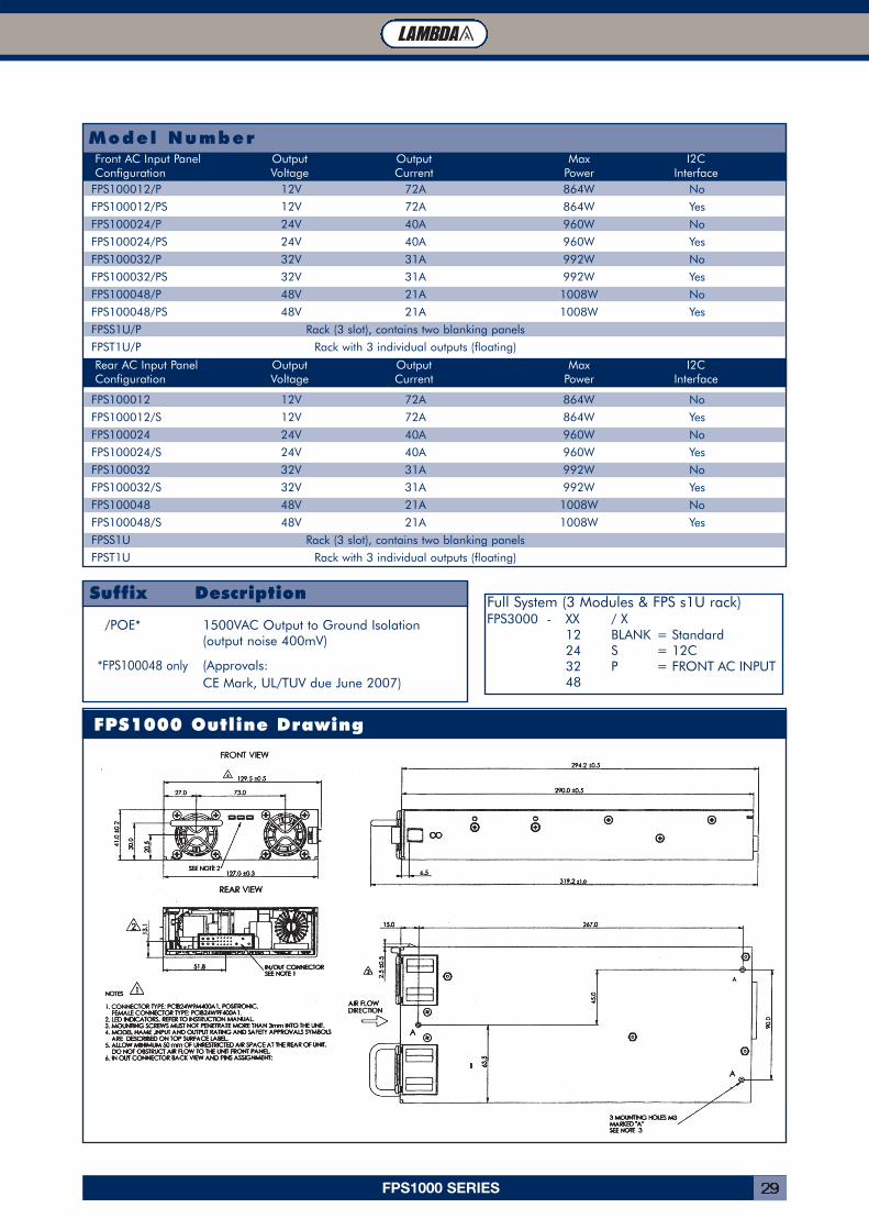
FPS1000 SERIES 29
FPS1000 Outline Drawing
/POE* 1500VAC Output to Ground Isolation(output noise 400mV)
*FPS100048 only (Approvals: CE Mark, UL/TUV due June 2007)
Suffix Description
Model Number
FPS100012/P 12V 72A 864W No
FPS100012/PS 12V 72A 864W Yes
FPS100024/P 24V 40A 960W No
FPS100024/PS 24V 40A 960W Yes
FPS100032/P 32V 31A 992W No
FPS100032/PS 32V 31A 992W Yes
FPS100048/P 48V 21A 1008W No
FPS100048/PS 48V 21A 1008W Yes
FPSS1U/P Rack (3 slot), contains two blanking panels
FPST1U/P Rack with 3 individual outputs (floating)
FPS100012 12V 72A 864W No
FPS100012/S 12V 72A 864W Yes
FPS100024 24V 40A 960W No
FPS100024/S 24V 40A 960W Yes
FPS100032 32V 31A 992W No
FPS100032/S 32V 31A 992W Yes
FPS100048 48V 21A 1008W No
FPS100048/S 48V 21A 1008W Yes
FPSS1U Rack (3 slot), contains two blanking panels
FPST1U Rack with 3 individual outputs (floating)
Front AC Input Panel Output Output Max I2CConfiguration Voltage Current Power Interface
Rear AC Input Panel Output Output Max I2CConfiguration Voltage Current Power Interface
Full System (3 Modules & FPS s1U rack)FPS3000 - XX / X
12 BLANK = Standard24 S = 12C32 P = FRONT AC INPUT48
FPS1000 SERIES30
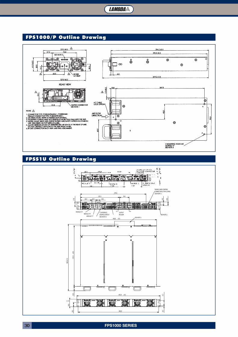
FPSS1U Outline Drawing
384.0
±1.0 35
1.0±0
.025
.0
440.0 ±0.5SEE NOTE 3.
65.4 24.0 24.0
225.5 56.5
379.0
14.0
20.0
27.8
MODULE "A"MODULE "B"
MODULE "C"
I C INTERFACEADDRESS SWITCH(SEE NOTE 4)
-V +VOUTPUTBUS BAR SEE NOTE 2.
SIGNALS AND CONTROLCONNECTOR D-TYPE 25 PINS(SEE NOTE 1.)
2
466.0
43.6
0.00.4
24.5
31.7
6.0
482.8 ±0.5
FPS1000/P Outline Drawing
HWS SERIES 31
Specifications
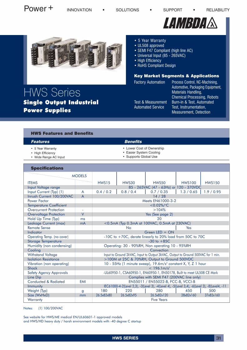
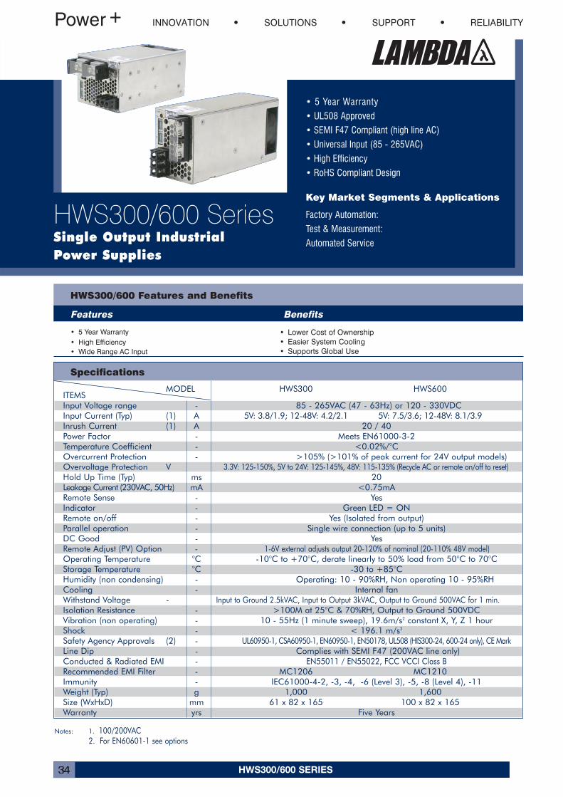
• 5 Year Warranty• UL508 approved• SEMI F47 Compliant (high line AC)• Universal Input (85 - 265VAC)• High Efficiency• RoHS Compliant Design
Key Market Segments & Applications
Factory Automation Process Control, NC-Machining,Automotive, Packaging Equipment, Materials Handling,Chemical Processing, Robots
Test & Measurement Burn-in & Test, Automated Automated Service Test, Instrumentation,
Measurement, Detection
HWS Features and Benefits
Features Benefits
• 5 Year Warranty• High Efficiency• Wide Range AC Input
• Lower Cost of Ownership• Easier System Cooling• Supports Global Use
INNOVATION SOLUTIONS SUPPORT RELIABILITY
HWS SeriesSingle Output IndustrialPower Supplies
MODELS
ITEMS HWS15 HWS30 HWS50 HWS100 HWS150Input Voltage range 85 - 265VAC (47 - 63Hz) or 120 - 370VDCInput Current (Typ) (1) A 0.4 / 0.2 0.8 / 0.4 0.7 / 0.35 1.3 / 0.65 1.9 / 0.95Inrush Current 100/200VAC A 14 / 28Power Factor Meets EN61000-3-2Temperature Coefficient <0.02%/oCOvercurrent Protection - >104%Overvoltage Protection V Yes (See page 2)Hold Up Time (Typ) ms 20Leakage Current (max) mA <0.5mA (Typ 0.3mA at 100VAC, 0.5mA at 230VAC)Remote Sense No YesIndicator Green LED = ONOperating Temp. (no cover) -10C to +70C, derate linearly to 20% load from 50C to 70CStorage Temperature -30 to +85CHumidity (non condensing) Operating: 30 - 90%RH, Non operating 10 - 95%RHCooling ConvectionWithstand Voltage Input to Ground 2kVAC, Input to Output 3kVAC, Output to Ground 500VAC for 1 min.Isolation Resistance >100M at 25C & 70%RH, Output to Ground 500VDCVibration (non operating) 10 - 55Hz (1 minute sweep), 19.6m/s2 constant X, Y, Z 1 hourShock < 196.1m/s2
Safety Agency Approvals -UL60950-1, CSA60950-1, EN60950-1, EN50178, Built to meet UL508 CE MarkLine Dip Complies with SEMI F47 (200VAC line only)Conducted & Radiated EMI EN55011 / EN55022-B, FCC-B, VCCI-BImmunity IEC61000-4-2(Level 2,3), -3(Level 3), -4(Level 4), -5(Level 3,4), -6(Level 3), -8(Level4, -11Weight (Typ) g 180 220 280 450 500Size (WxHxD) mm 26.5x82x80 26.5x82x95 26.5x82x120 28x82x160 37x82x160Warranty Five Years
Notes: (1) 100/200VAC
See website for HWS/ME medical EN/UL60601-1 approved models and HWS/HD heavy duty / harsh environment models with -40 degree C startup
HWS SERIES32
1.2m/s Forced Air 50°C 55°C 60°C 65°C 70°C
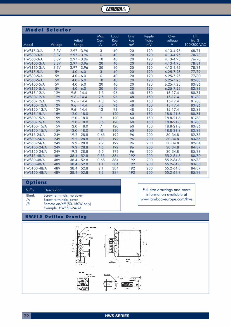
Model Selector
Options
Suffix Description
Max Load Line Ripple Over Eff.Adjust Curr. Reg Reg Noise voltage typ %
Model Voltage Range A mV mV mV V 100/200 VAC
Blank Screw terminals, no cover /A Screw terminals, cover /R Remote on/off (50-150W only)
Example: HWS50-24/RA
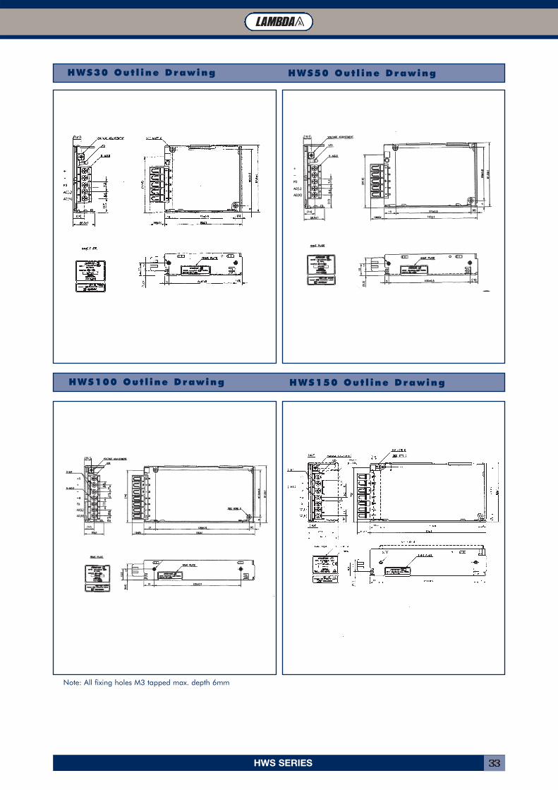
HWS15 Out l ine Drawing
Full size drawings and moreinformation available at
www.lambda-europe.com/hws
HWS15-3/A 3.3V 2.97 - 3.96 3 40 20 120 4.13-4.95 68/71HWS30-3/A 3.3V 2.97 - 3.96 6 40 20 120 4.13-4.95 70/73HWS50-3/A 3.3V 2.97 - 3.96 10 40 20 120 4.13-4.95 76/78HWS100-3/A 3.3V 2.97 - 3.96 20 40 20 120 4.13-4.95 78/81HWS150-3/A 3.3V 2.97 - 3.96 30 40 20 120 4.13-4.95 78/81HWS15-5/A 5V 4.0 - 6.0 3 40 20 120 6.25-7.25 77/79HWS30-5/A 5V 4.0 - 6.0 6 40 20 120 6.25-7.25 77/80HWS50-5/A 5V 4.0 - 6.0 10 40 20 120 6.25-7.25 82/83HWS100-5/A 5V 4.0 - 6.0 20 40 20 120 6.25-7.25 83/86HWS150-5/A 5V 4.0 - 6.0 30 40 20 120 6.25-7.25 83/86HWS15-12/A 12V 9.6 - 14.4 1.3 96 48 150 15-17.4 80/81HWS30-12/A 12V 9.6 - 14.4 2.5 96 48 150 15-17.4 81/83HWS50-12/A 12V 9.6 - 14.4 4.3 96 48 150 15-17.4 81/83HWS100-12/A 12V 9.6 - 14.4 8.5 96 48 150 15-17.4 83/86HWS150-12/A 12V 9.6 - 14.4 13 96 48 150 15-17.4 83/86HWS15-15/A 15V 12.0 - 18.0 1 120 60 150 18.8-21.8 80/81HWS30-15/A 15V 12.0 - 18.0 2 120 60 150 18.8-21.8 81/83HWS50-15/A 15V 12.0 - 18.0 3.5 120 60 150 18.8-21.8 81/83HWS100-15/A 15V 12.0 - 18.0 7 120 60 150 18.8-21.8 83/86HWS150-15/A 15V 12.0 - 18.0 10 120 60 150 18.8-21.8 83/86HWS15-24/A 24V 19.2 - 28.8 0.65 192 96 200 30-34.8 82/83HWS30-24/A 24V 19.2 - 28.8 1.3 192 96 200 30-34.8 83/86HWS50-24/A 24V 19.2 - 28.8 2.2 192 96 200 30-34.8 82/84HWS100-24/A 24V 19.2 - 28.8 4.5 192 96 200 30-34.8 84/87HWS150-24/A 24V 19.2 - 28.8 6.5 192 96 200 30-34.8 85/88HWS15-48/A 48V 38.4 - 52.8 0.33 384 192 200 55.2-64.8 80/80HWS30-48/A 48V 38.4 - 52.8 0.65 384 192 200 55.2-64.8 82/83HWS50-48/A 48V 38.4 - 52.8 1.1 384 192 200 55.2-64.8 83/85HWS100-48/A 48V 38.4 - 52.8 2.1 384 192 200 55.2-64.8 84/87HWS150-48/A 48V 38.4 - 52.8 3.3 384 192 200 55.2-64.8 85/88
HWS SERIES 33
HWS30 Out l ine Drawing HWS50 Out l ine Drawing
HWS100 Out l ine Drawing HWS150 Out l ine Drawing
Note: All fixing holes M3 tapped max. depth 6mm
HWS300/600 SERIES34
• 5 Year Warranty
• UL508 Approved
• SEMI F47 Compliant (high line AC)
• Universal Input (85 - 265VAC)
• High Efficiency
• RoHS Compliant Design
Key Market Segments & Applications
Factory Automation:
Test & Measurement:
Automated Service
INNOVATION SOLUTIONS SUPPORT RELIABILITY
HWS300/600 SeriesSingle Output IndustrialPower Supplies
Specifications
HWS300/600 Features and Benefits
Features Benefits
• 5 Year Warranty• High Efficiency• Wide Range AC Input
• Lower Cost of Ownership• Easier System Cooling• Supports Global Use
MODEL HWS300 HWS600ITEMSInput Voltage range - 85 - 265VAC (47 - 63Hz) or 120 - 330VDCInput Current (Typ) (1) A 5V: 3.8/1.9; 12-48V: 4.2/2.1 5V: 7.5/3.6; 12-48V: 8.1/3.9Inrush Current (1) A 20 / 40Power Factor - Meets EN61000-3-2Temperature Coefficient - <0.02%/°COvercurrent Protection - >105% (>101% of peak current for 24V output models)Overvoltage Protection V 3.3V: 125-150%, 5V to 24V: 125-145%, 48V: 115-135% (Recycle AC or remote on/off to reset)Hold Up Time (Typ) ms 20Leakage Current (230VAC, 50Hz) mA <0.75mARemote Sense - YesIndicator - Green LED = ONRemote on/off - Yes (Isolated from output)Parallel operation - Single wire connection (up to 5 units)DC Good - YesRemote Adjust (PV) Option - 1-6V external adjusts output 20-120% of nominal (20-110% 48V model)Operating Temperature °C -10°C to +70°C, derate linearly to 50% load from 50°C to 70°CStorage Temperature °C -30 to +85°CHumidity (non condensing) - Operating: 10 - 90%RH, Non operating 10 - 95%RHCooling - Internal fanWithstand Voltage - Input to Ground 2.5kVAC, Input to Output 3kVAC, Output to Ground 500VAC for 1 min.Isolation Resistance - >100M at 25°C & 70%RH, Output to Ground 500VDCVibration (non operating) - 10 - 55Hz (1 minute sweep), 19.6m/s2 constant X, Y, Z 1 hourShock - < 196.1 m/s2
Safety Agency Approvals (2) - UL60950-1, CSA60950-1, EN60950-1, EN50178, UL508 (HIS300-24, 600-24 only), CE MarkLine Dip - Complies with SEMI F47 (200VAC line only)Conducted & Radiated EMI - EN55011 / EN55022, FCC VCCI Class BRecommended EMI Filter - MC1206 MC1210Immunity - IEC61000-4-2, -3, -4, -6 (Level 3), -5, -8 (Level 4), -11Weight (Typ) g 1,000 1,600Size (WxHxD) mm 61 x 82 x 165 100 x 82 x 165Warranty yrs Five Years
Notes: 1. 100/200VAC2. For EN60601-1 see options
HWS300/600 SERIES 35
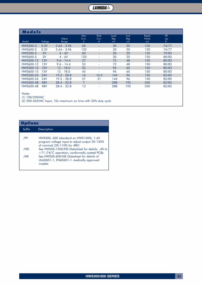
Models
HWS300-3 3.3V 2.64 - 3.96 60 - 30 20 120 74/77HWS600-3 3.3V 2.64 - 3.96 120 - 30 20 120 74/77HWS300-5 5V 4 - 6V 60 - 30 20 120 79/82HWS600-5 5V 4 - 6V 120 - 30 20 120 80/83HWS300-12 12V 9.6 - 14.4 27 - 72 48 150 80/83HWS600-12 12V 9.6 - 14.4 53 - 72 48 150 80/83HWS300-15 15V 12 - 18.0 22 - 96 60 150 80/83HWS600-15 15V 12 - 18.0 43 - 96 60 150 80/83HWS300-24 24V 19.2 - 28.8 14 16.5 144 96 150 82/85HWS600-24 24V 19.2 - 28.8 27 31 144 96 150 82/85HWS300-48 48V 38.4 - 52.8 7 - 288 192 350 82/85HWS600-48 48V 38.4 - 52.8 13 - 288 192 350 82/85
Notes(1) 100/200VAC(2) 200-265VAC Input, 10s maximum on time with 35% duty cycle
Max Peak Load Line Ripple Eff.Adjust Curr. Curr. Reg Reg Noise typ
Model Voltage Range A A2 mV mV mV % 1
Suffix Description
/PV HWS300, 600 (standard on HWS1500): 1-6V program voltage input to adjust output 20-120% of nominal (20-110% for 48V)
/HD See HWS50-1500/HD Datasheet for details. -40 to+71 (74)°C operation, conformally coated PCBs
/ME See HWS30-600/ME Datasheet for details of UL60601-1, EN60601-1 medically approved models
Options
HWS300/600 SERIES36
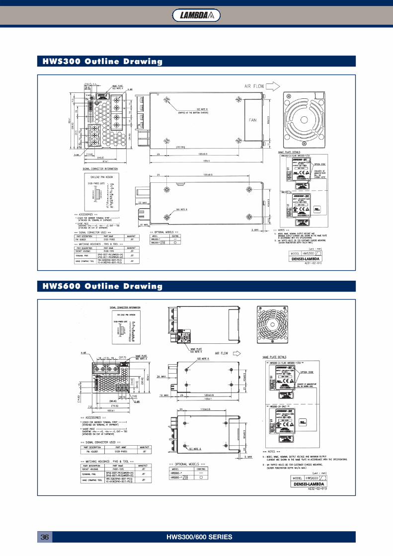
HWS300 Outline Drawing
HWS600 Outline Drawing
HWS1500 SERIES 37
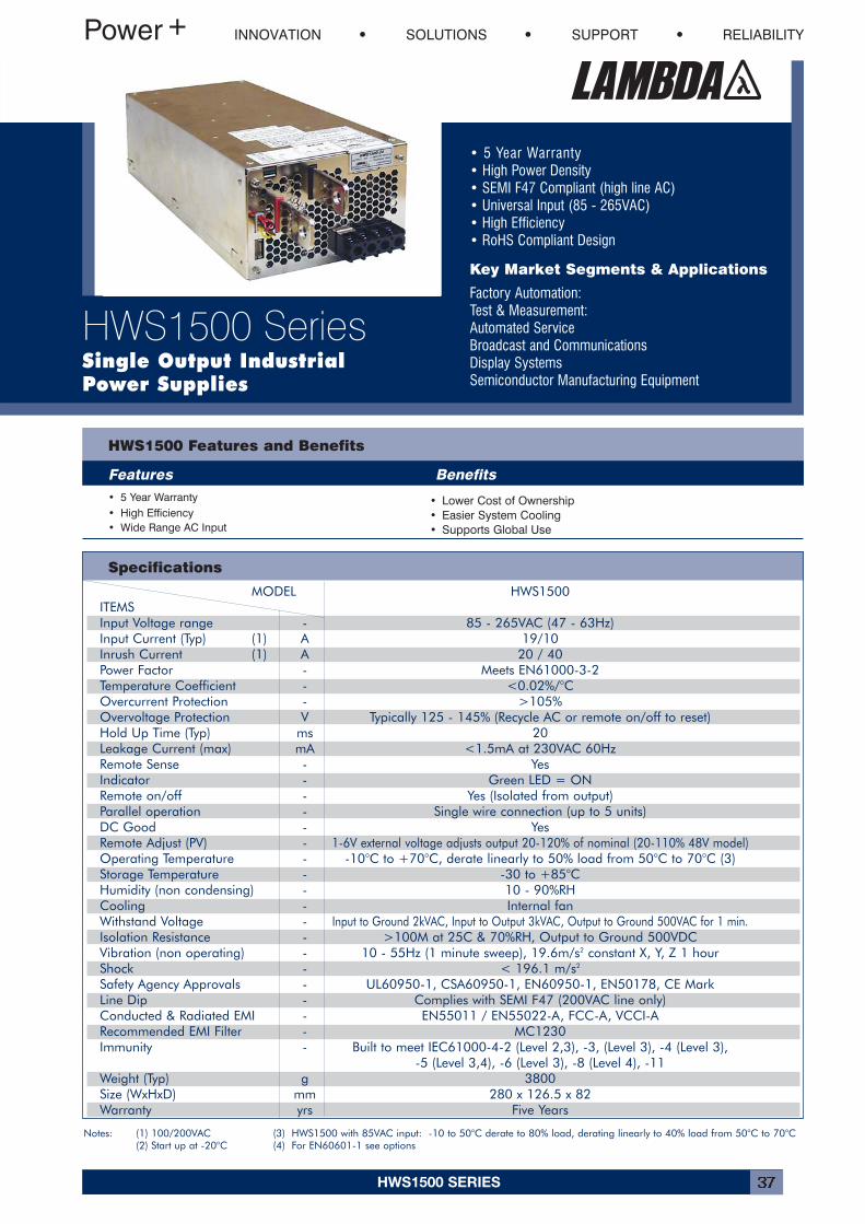
• 5 Year Warranty• High Power Density• SEMI F47 Compliant (high line AC)• Universal Input (85 - 265VAC)• High Efficiency• RoHS Compliant Design
Key Market Segments & Applications
Factory Automation:Test & Measurement:Automated ServiceBroadcast and CommunicationsDisplay SystemsSemiconductor Manufacturing Equipment
INNOVATION SOLUTIONS SUPPORT RELIABILITY
HWS1500 SeriesSingle Output IndustrialPower Supplies
Specifications
HWS1500 Features and Benefits
Features Benefits• 5 Year Warranty• High Efficiency• Wide Range AC Input
• Lower Cost of Ownership• Easier System Cooling• Supports Global Use
MODEL HWS1500ITEMSInput Voltage range - 85 - 265VAC (47 - 63Hz)Input Current (Typ) (1) A 19/10Inrush Current (1) A 20 / 40Power Factor - Meets EN61000-3-2Temperature Coefficient - <0.02%/°COvercurrent Protection - >105%Overvoltage Protection V Typically 125 - 145% (Recycle AC or remote on/off to reset)Hold Up Time (Typ) ms 20Leakage Current (max) mA <1.5mA at 230VAC 60HzRemote Sense - Yes Indicator - Green LED = ONRemote on/off - Yes (Isolated from output)Parallel operation - Single wire connection (up to 5 units)DC Good - YesRemote Adjust (PV) - 1-6V external voltage adjusts output 20-120% of nominal (20-110% 48V model)Operating Temperature - -10°C to +70°C, derate linearly to 50% load from 50°C to 70°C (3)Storage Temperature - -30 to +85°CHumidity (non condensing) - 10 - 90%RHCooling - Internal fanWithstand Voltage - Input to Ground 2kVAC, Input to Output 3kVAC, Output to Ground 500VAC for 1 min.Isolation Resistance - >100M at 25C & 70%RH, Output to Ground 500VDCVibration (non operating) - 10 - 55Hz (1 minute sweep), 19.6m/s2 constant X, Y, Z 1 hourShock - < 196.1 m/s2
Safety Agency Approvals - UL60950-1, CSA60950-1, EN60950-1, EN50178, CE MarkLine Dip - Complies with SEMI F47 (200VAC line only)Conducted & Radiated EMI - EN55011 / EN55022-A, FCC-A, VCCI-ARecommended EMI Filter - MC1230Immunity - Built to meet IEC61000-4-2 (Level 2,3), -3, (Level 3), -4 (Level 3),
-5 (Level 3,4), -6 (Level 3), -8 (Level 4), -11Weight (Typ) g 3800Size (WxHxD) mm 280 x 126.5 x 82Warranty yrs Five Years
Notes: (1) 100/200VAC(2) Start up at -20°C
(3) HWS1500 with 85VAC input: -10 to 50°C derate to 80% load, derating linearly to 40% load from 50°C to 70°C(4) For EN60601-1 see options
HWS1500 SERIES38
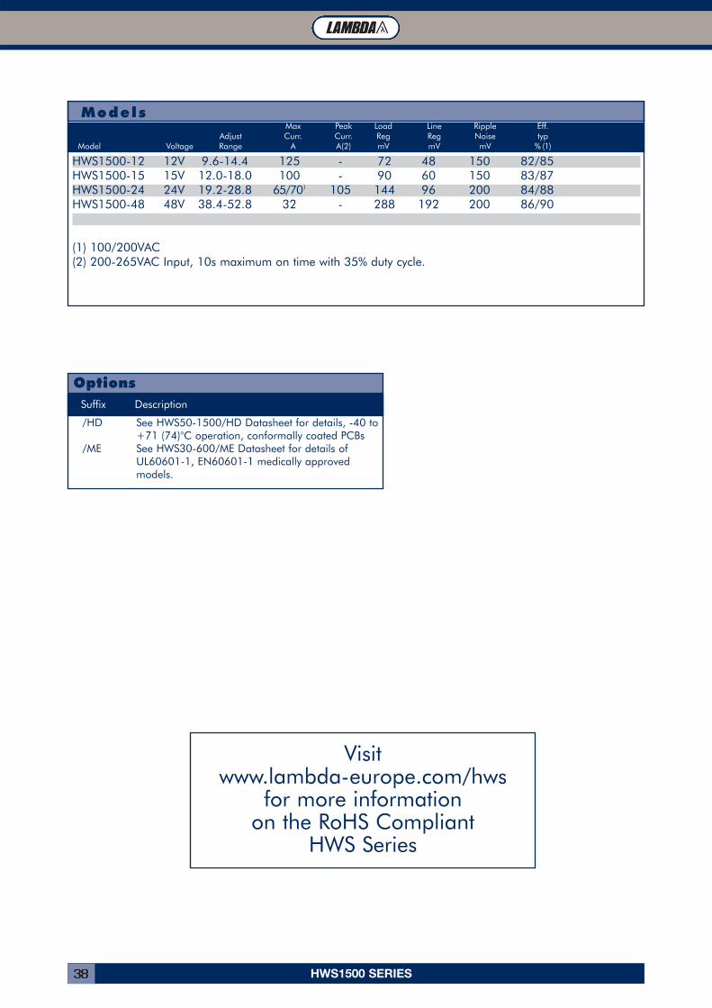
Models
HWS1500-12 12V 9.6-14.4 125 - 72 48 150 82/85HWS1500-15 15V 12.0-18.0 100 - 90 60 150 83/87HWS1500-24 24V 19.2-28.8 65/701 105 144 96 200 84/88HWS1500-48 48V 38.4-52.8 32 - 288 192 200 86/90
(1) 100/200VAC(2) 200-265VAC Input, 10s maximum on time with 35% duty cycle.
Max Peak Load Line Ripple Eff.Adjust Curr. Curr. Reg Reg Noise typ
Model Voltage Range A A(2) mV mV mV % (1)
Visit www.lambda-europe.com/hws
for more information on the RoHS Compliant
HWS Series
Suffix Description
/HD See HWS50-1500/HD Datasheet for details, -40 to+71 (74)°C operation, conformally coated PCBs
/ME See HWS30-600/ME Datasheet for details of UL60601-1, EN60601-1 medically approved models.
Options
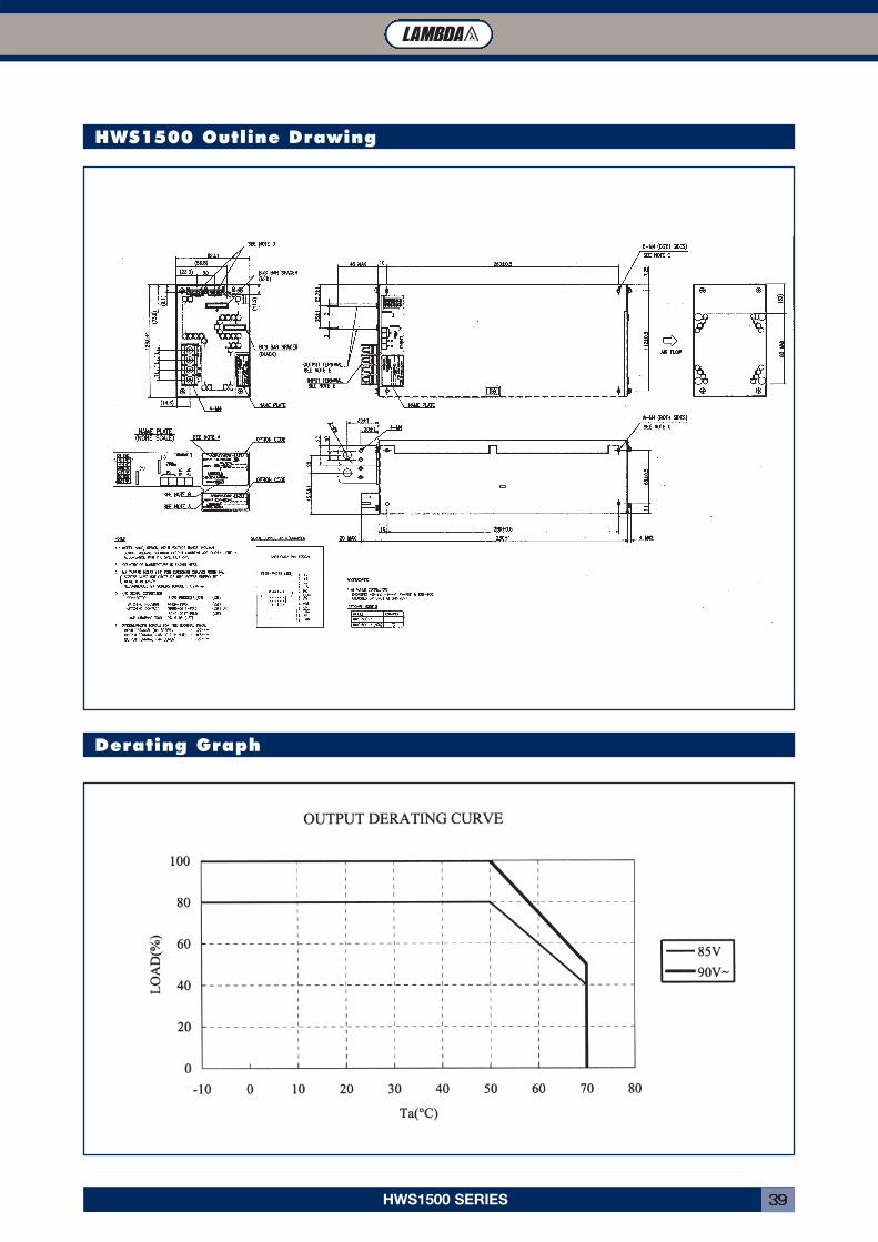
HWS1500 SERIES 39
HWS1500 Outline Drawing
Derating Graph
HWS-HD SERIES40
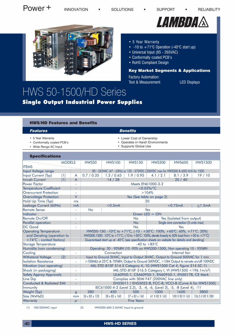
MODELS HWS50 HWS100 HWS150 HWS300 HWS600 HWS1500ITEMSInput Voltage range 85 - 265VAC (47 - 63Hz) or 120 - 370VDC (330VDC max for HWS300 & 600) N/A for 1500Input Current (Typ) (1) A 0.7 / 0.35 1.3 / 0.65 1.9 / 0.95 4.1 / 2.1 8.1 / 3.9 19 / 10Inrush Current (1) A 14 / 28 20 / 40Power Factor - Meets EN61000-3-2Temperature Coefficient - <0.02%/°COvercurrent Protection - >104%Overvoltage Protection V Yes (See table on page 2)Hold Up Time (Typ) ms 20Leakage Current (60Hz) mA <0.5mA <0.75mA <1.5mARemote Sense - No YesIndicator - Green LED = ONRemote On/Off - No Yes (Isolated from output)Parallel operation - No Single wire connection (5 units max)DC Good - No YesOperating Temperature HWS50-150: -10°C to +71°C, (-10 - +50°C: 100%, +60°C: 60%, +71°C: 20%)
and Derating (operation to HWS300-1500: -10°C to +71°C, (-10 to +50°C: 100%, derate linearly to 50% load from +50 to +71°C)+74°C - contact factory) Guaranteed start up at -40°C (see specification sheets on website for details and derating)
Storage Temperature -40 to +85°CHumidity (non condensing) Operating: 30 - 90%RH (10 -90% on HWS300-1500), Non operating 10 - 95%RHCooling - Convection Internal fanWithstand Voltage (2) - Input to Ground 2kVAC, Input to Output 3kVAC, Output to Ground 500VAC for 1 min.Isolation Resistance - >100MΩ at 25°C & 70%RH, Output to Ground 500VDC, >10M Output to remote on/off 100VDCVibration (non operating) - MIL-STD-810F 514.5 Category 4, 10 (HWS1500 Cat 4, figure 514.5C-1)Shock (in packaging) - MIL-STD-810F 516.5 Category I, VI (HWS1500 <196.1m/s2)Safety Agency Approvals - UL60950-1, CSA60950-1, EN60950-1, EN50178, CE MarkLine Dip - Complies with SEMI F47 (200VAC line only)Conducted & Radiated EMI - EN55011 / EN55022-B, FCC-B, VCCI-B (Curve A for HWS1500)Immunity IEC61000-4-2 (Level 2,3), -3, -4, -6, (Level 3), -5, -8 (Level 4), -11Weight (Typ) g 280 450 500 1000 1600 3800Size (WxHxD) mm 26 x 82 x 120 28 x 82 x 160 37 x 82 x 160 61 X 82 X 165 100 X 82 X 165 126.5 X 82 X 280Warranty yr Five Years
Specifications
• 5 Year Warranty• -10 to +71°C Operation (-40°C start up)• Universal Input (85 - 265VAC)• Conformally coated PCB’s• RoHS Compliant Design
Key Market Segments & Applications
Factory Automation:Test & Measurement: LED Displays
HWS/HD Features and Benefits
Features Benefits
• 5 Year Warranty• Conformally coated PCB’s• Wide Range AC Input
• Lower Cost of Ownership• Operates in Harsh Environments• Supports Global Use
INNOVATION SOLUTIONS SUPPORT RELIABILITY
HWS 50-1500/HD SeriesSingle Output Industrial Power Supplies
(1) 100/200VAC input (2) HWS300-600 2.5kVAC Input to ground
HWS-HD SERIES 41
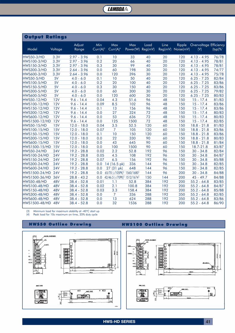
Output Ratings
Adjust Min Max Max Load Line Ripple Overvoltage EfficiencyModel Voltage Range Curr(A)3 Curr(A)4 Power(W) Reg(mV) Reg(mV) Noise(mV) (V) (typ)%1
HWS50-3/HD 3.3V 2.97 - 3.96 0.1 10 33 40 20 120 4.13 - 4.95 76/78HWS100-3/HD 3.3V 2.97 - 3.96 0.2 20 66 40 20 120 4.13 - 4.95 78/81HWS150-3/HD 3.3V 2.97 - 3.96 0.3 30 99 40 20 120 4.13 - 4.95 78/81HWS300-3/HD 3.3V 2.64 - 3.96 0.0 60 198 30 20 120 4.13 - 4.95 74/77HWS600-3/HD 3.3V 2.64 - 3.96 0.0 120 396 30 20 120 4.13 - 4.95 75/78HWS50-5/HD 5V 4.0 - 6.0 0.1 10 50 40 20 120 6.25 - 7.25 82/84HWS100-5/HD 5V 4.0 - 6.0 0.2 20 100 40 20 120 6.25 - 7.25 83/86HWS150-5/HD 5V 4.0 - 6.0 0.3 30 150 40 20 120 6.25 - 7.25 83/86HWS300-5/HD 5V 4.0 - 6.0 0.0 60 300 30 20 120 6.25 - 7.25 79/82HWS600-5/HD 5V 4.0 - 6.0 0.0 120 600 30 20 120 6.25 - 7.25 80/83HWS50-12/HD 12V 9.6 - 14.4 0.04 4.3 51.6 96 48 150 15 - 17.4 81/83HWS100-12/HD 12V 9.6 - 14.4 0.09 8.5 102 96 48 150 15 - 17.4 83/86HWS150-12/HD 12V 9.6 - 14.4 0.1 13 156 96 48 150 15 - 17.4 83/86HWS300-12/HD 12V 9.6 - 14.4 0.0 27 324 72 48 150 15 - 17.4 80/83HWS600-12/HD 12V 9.6 - 14.4 0.0 53 636 72 48 150 15 - 17.4 80/83HWS1500-12/HD 12V 9.6 - 14.4 0.0 125 1500 72 48 150 15 - 17.4 82/85HWS50-15/HD 15V 12.0 - 18.0 0.04 3.5 52.5 120 60 150 18.8 - 21.8 81/83HWS100-15/HD 15V 12.0 - 18.0 0.07 7 105 120 60 150 18.8 - 21.8 83/86HWS150-15/HD 15V 12.0 - 18.0 0.1 10 150 120 60 150 18.8 - 21.8 83/86HWS300-15/HD 15V 12.0 - 18.0 0.0 22 330 90 60 150 18.8 - 21.8 80/83HWS600-15/HD 15V 12.0 - 18.0 0.0 43 645 90 60 150 18.8 - 21.8 81/84HWS1500-15/HD 15V 12.0 - 18.0 0.0 100 1500 90 60 150 18.7-21.8 83/87HWS50-24/HD 24V 19.2 - 28.8 0.02 2.2 52.8 192 96 150 30 - 34.8 82/84HWS100-24/HD 24V 19.2 - 28.8 0.05 4.5 108 192 96 150 30 - 34.8 84/87HWS150-24/HD 24V 19.2 - 28.8 0.07 6.5 156 192 96 150 30 - 34.8 85/88HWS300-24/HD 24V 19.2 - 28.8 0.0 14 (16.5 pk) 336 144 96 150 30 - 34.8 82/85HWS600-24/HD 24V 19.2 - 28.8 0.0 27 (31 pk) 648 144 96 150 30 - 34.8 82/85HWS1500-24/HD 24V 19.2 - 28.8 0.0 65/70 (-/105PK)1 1560/16801 144 96 200 30 - 34.8 84/88HWS1500-36/HD 36V 28.8 - 43.2 0.0 42/46.5 (-/70PK)1 1512/16741 150 144 200 45 - 49.7 84/88HWS50-48/HD 48V 38.4 - 52.8 0.01 1.1 52.8 384 192 200 55.2 - 64.8 83/85HWS100-48/HD 48V 38.4 - 52.8 0.02 2.1 100.8 384 192 200 55.2 - 64.8 84/87HWS150-48/HD 48V 38.4 - 52.8 0.03 3.3 158.4 384 192 200 55.2 - 64.8 85/88HWS300-48/HD 48V 38.4 - 52.8 0.0 7 336 288 192 350 55.2 - 64.8 82/85HWS600-48/HD 48V 38.4 - 52.8 0.0 13 624 288 192 350 55.2 - 64.8 83/86HWS1500-48/HD 48V 38.4 - 52.8 0.0 32 1536 288 192 200 55.2 - 64.8 86/90
(3) Minimum load for maximum stability at -40°C start up(4) Peak load for 10s maximum on time, 35% duty cycle
HWS50 Out l ine Drawing HWS100 Out l ine Drawing
HWS-HD SERIES42
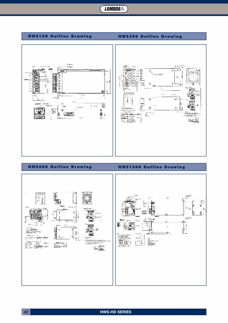
HWS150 Out l ine Drawing HWS300 Out l ine Drawing
HWS600 Out l ine Drawing HWS1500 Out l ine Drawing
HWS-ME SERIES 43
Specifications
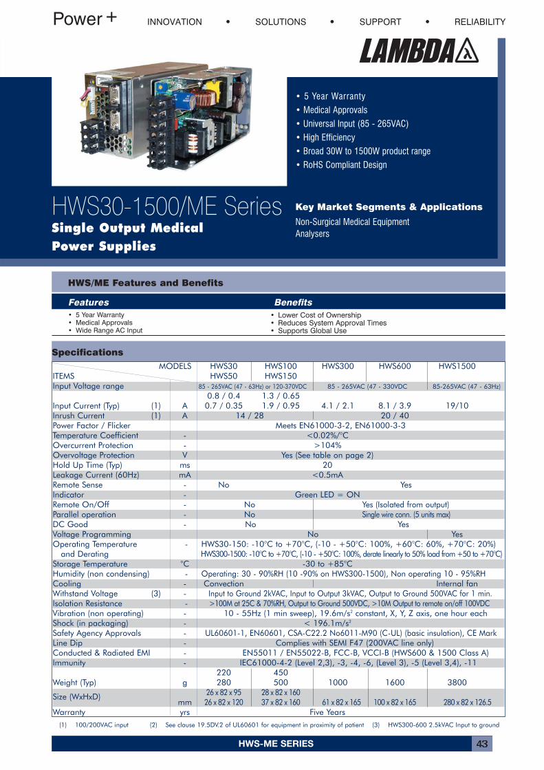
• 5 Year Warranty
• Medical Approvals
• Universal Input (85 - 265VAC)
• High Efficiency
• Broad 30W to 1500W product range
• RoHS Compliant Design
Key Market Segments & Applications
Non-Surgical Medical EquipmentAnalysers
HWS/ME Features and Benefits
Features Benefits• 5 Year Warranty• Medical Approvals• Wide Range AC Input
• Lower Cost of Ownership• Reduces System Approval Times• Supports Global Use
INNOVATION SOLUTIONS SUPPORT RELIABILITY
HWS30-1500/ME SeriesSingle Output MedicalPower Supplies
(1) 100/200VAC input (2) See clause 19.5DV.2 of UL60601 for equipment in proximity of patient (3) HWS300-600 2.5kVAC Input to ground
MODELS HWS30 HWS100 HWS300 HWS600 HWS1500ITEMS HWS50 HWS150Input Voltage range 85 - 265VAC (47 - 63Hz) or 120-370VDC 85 - 265VAC (47 - 330VDC 85-265VAC (47 - 63Hz)
0.8 / 0.4 1.3 / 0.65Input Current (Typ) (1) A 0.7 / 0.35 1.9 / 0.95 4.1 / 2.1 8.1 / 3.9 19/10Inrush Current (1) A 14 / 28 20 / 40Power Factor / Flicker Meets EN61000-3-2, EN61000-3-3Temperature Coefficient - <0.02%/°COvercurrent Protection - >104%Overvoltage Protection V Yes (See table on page 2)Hold Up Time (Typ) ms 20Leakage Current (60Hz) mA <0.5mARemote Sense - No YesIndicator - Green LED = ONRemote On/Off - No Yes (Isolated from output)Parallel operation - No Single wire conn. (5 units max)DC Good - No YesVoltage Programming No YesOperating Temperature - HWS30-150: -10°C to +70°C, (-10 - +50°C: 100%, +60°C: 60%, +70°C: 20%)
and Derating HWS300-1500: -10°C to +70°C, (-10 - +50°C: 100%, derate linearly to 50% load from +50 to +70°C)Storage Temperature °C -30 to +85°CHumidity (non condensing) - Operating: 30 - 90%RH (10 -90% on HWS300-1500), Non operating 10 - 95%RHCooling - Convection Internal fanWithstand Voltage (3) - Input to Ground 2kVAC, Input to Output 3kVAC, Output to Ground 500VAC for 1 min.Isolation Resistance - >100M at 25C & 70%RH, Output to Ground 500VDC, >10M Output to remote on/off 100VDCVibration (non operating) - 10 - 55Hz (1 min sweep), 19.6m/s2 constant, X, Y, Z axis, one hour eachShock (in packaging) - < 196.1m/s2
Safety Agency Approvals - UL60601-1, EN60601, CSA-C22.2 No6011-M90 (C-UL) (basic insulation), CE MarkLine Dip - Complies with SEMI F47 (200VAC line only)Conducted & Radiated EMI - EN55011 / EN55022-B, FCC-B, VCCI-B (HWS600 & 1500 Class A)Immunity - IEC61000-4-2 (Level 2,3), -3, -4, -6, (Level 3), -5 (Level 3,4), -11
220 450Weight (Typ) g 280 500 1000 1600 3800
26 x 82 x 95 28 x 82 x 160Size (WxHxD)mm 26 x 82 x 120 37 x 82 x 160 61 x 82 x 165 100 x 82 x 165 280 x 82 x 126.5
Warranty yrs Five Years
HWS-ME SERIES44
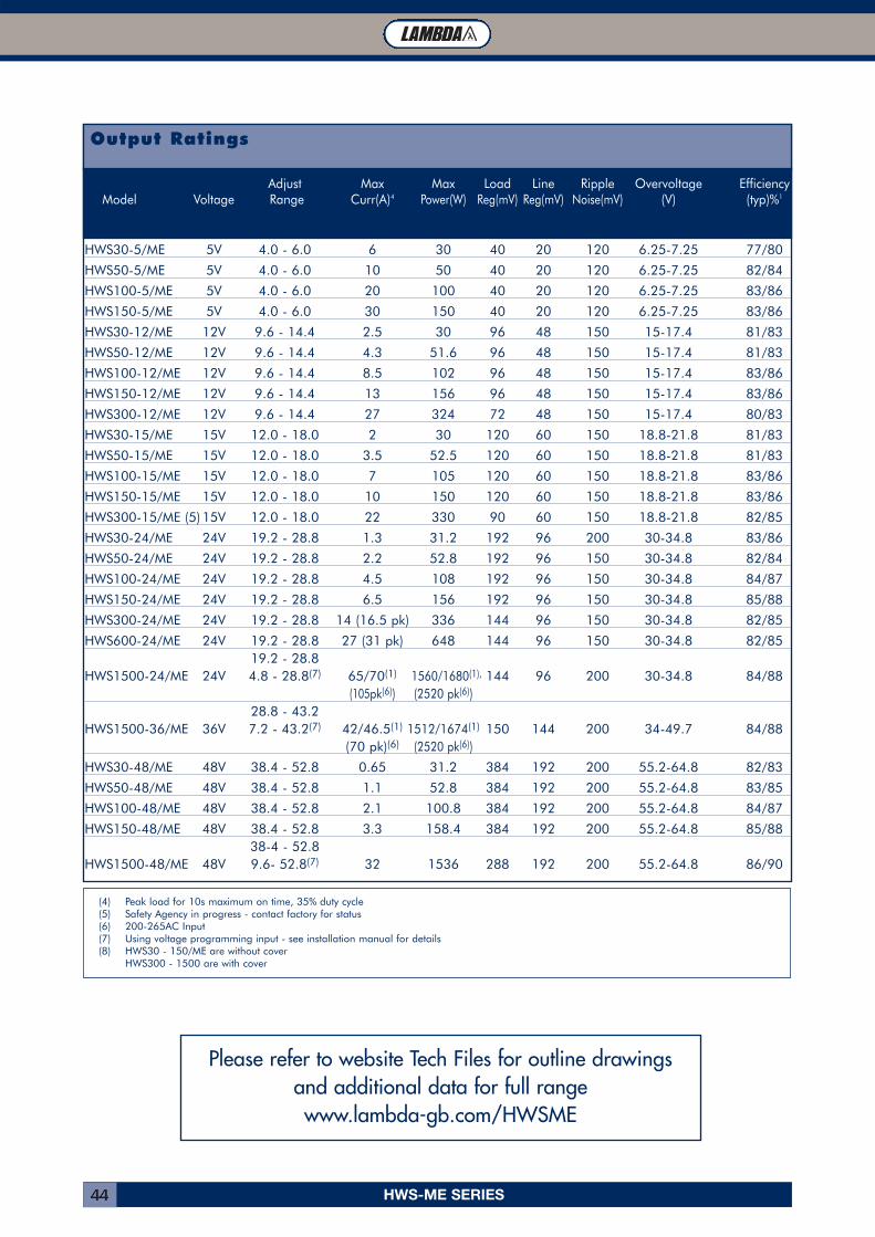
Output Ratings
Adjust Max Max Load Line Ripple Overvoltage EfficiencyModel Voltage Range Curr(A)4 Power(W) Reg(mV) Reg(mV) Noise(mV) (V) (typ)%1
HWS30-5/ME 5V 4.0 - 6.0 6 30 40 20 120 6.25-7.25 77/80
HWS50-5/ME 5V 4.0 - 6.0 10 50 40 20 120 6.25-7.25 82/84
HWS100-5/ME 5V 4.0 - 6.0 20 100 40 20 120 6.25-7.25 83/86
HWS150-5/ME 5V 4.0 - 6.0 30 150 40 20 120 6.25-7.25 83/86
HWS30-12/ME 12V 9.6 - 14.4 2.5 30 96 48 150 15-17.4 81/83
HWS50-12/ME 12V 9.6 - 14.4 4.3 51.6 96 48 150 15-17.4 81/83
HWS100-12/ME 12V 9.6 - 14.4 8.5 102 96 48 150 15-17.4 83/86
HWS150-12/ME 12V 9.6 - 14.4 13 156 96 48 150 15-17.4 83/86
HWS300-12/ME 12V 9.6 - 14.4 27 324 72 48 150 15-17.4 80/83
HWS30-15/ME 15V 12.0 - 18.0 2 30 120 60 150 18.8-21.8 81/83
HWS50-15/ME 15V 12.0 - 18.0 3.5 52.5 120 60 150 18.8-21.8 81/83
HWS100-15/ME 15V 12.0 - 18.0 7 105 120 60 150 18.8-21.8 83/86
HWS150-15/ME 15V 12.0 - 18.0 10 150 120 60 150 18.8-21.8 83/86
HWS300-15/ME (5) 15V 12.0 - 18.0 22 330 90 60 150 18.8-21.8 82/85
HWS30-24/ME 24V 19.2 - 28.8 1.3 31.2 192 96 200 30-34.8 83/86
HWS50-24/ME 24V 19.2 - 28.8 2.2 52.8 192 96 150 30-34.8 82/84
HWS100-24/ME 24V 19.2 - 28.8 4.5 108 192 96 150 30-34.8 84/87
HWS150-24/ME 24V 19.2 - 28.8 6.5 156 192 96 150 30-34.8 85/88
HWS300-24/ME 24V 19.2 - 28.8 14 (16.5 pk) 336 144 96 150 30-34.8 82/85
HWS600-24/ME 24V 19.2 - 28.8 27 (31 pk) 648 144 96 150 30-34.8 82/8519.2 - 28.8
HWS1500-24/ME 24V 4.8 - 28.8(7) 65/70(1) 1560/1680(1), 144 96 200 30-34.8 84/88(105pk(6)) (2520 pk(6))
28.8 - 43.2HWS1500-36/ME 36V 7.2 - 43.2(7) 42/46.5(1) 1512/1674(1) 150 144 200 34-49.7 84/88
(70 pk)(6) (2520 pk(6))
HWS30-48/ME 48V 38.4 - 52.8 0.65 31.2 384 192 200 55.2-64.8 82/83
HWS50-48/ME 48V 38.4 - 52.8 1.1 52.8 384 192 200 55.2-64.8 83/85
HWS100-48/ME 48V 38.4 - 52.8 2.1 100.8 384 192 200 55.2-64.8 84/87
HWS150-48/ME 48V 38.4 - 52.8 3.3 158.4 384 192 200 55.2-64.8 85/8838-4 - 52.8
HWS1500-48/ME 48V 9.6- 52.8(7) 32 1536 288 192 200 55.2-64.8 86/90
(4) Peak load for 10s maximum on time, 35% duty cycle(5) Safety Agency in progress - contact factory for status(6) 200-265AC Input(7) Using voltage programming input - see installation manual for details(8) HWS30 - 150/ME are without cover
HWS300 - 1500 are with cover
Please refer to website Tech Files for outline drawingsand additional data for full rangewww.lambda-gb.com/HWSME
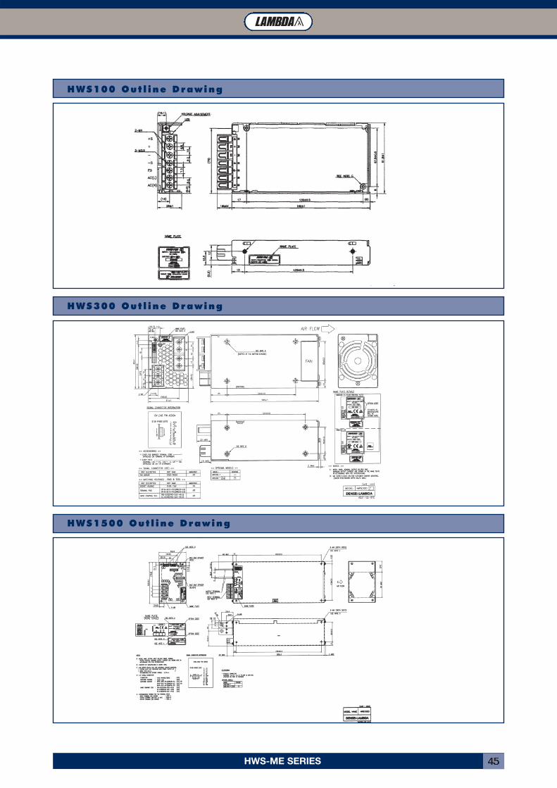
HWS-ME SERIES 45
HWS100 Out l ine Drawing
HWS300 Out l ine Drawing
HWS1500 Out l ine Drawing
JWS-P SERIES46
Specifications
JWS-P Features and Benefits
Features Benefits� VDE0160 Approved � No additional Approvals Needed� 5 Year Warranty � Lower Cost of Ownership� Power Factor Corrected � Supports Global Use� 200% Peak Power � Able to support motor start up currents
INNOVATION SOLUTIONS SUPPORT RELIABILITY
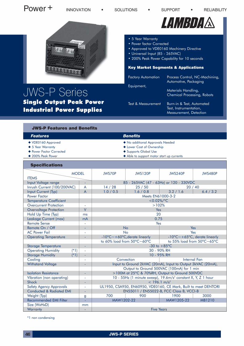
JWS-P SeriesSingle Output Peak Power Industrial Power Supplies
• 5 Year Warranty • Power factor Corrected• Approved to VDE0160 Machinery Directive• Universal Input (85 - 265VAC)• 200% Peak Power Capability for 10 seconds
Key Market Segments & Applications
Factory Automation Process Control, NC-Machining,Automotive, Packaging
Equipment, Materials Handling,Chemical Processing, Robots
Test & Measurement Burn-in & Test, Automated Test, Instrumentation, Measurement, Detection
*1 non condensing
MODEL JWS70P JWS120P JWS240P JWS480PITEMSInput Voltage range - 85 - 265VAC (47 - 63Hz) or 120 - 330VDCInrush Current (100/200VAC) A 14 / 28 25 / 50 20 / 40Input Current (Typ) A 1.0 / 0.5 1.6 / 0.8 3.2 / 1.6 6.4 / 3.2Power Factor Meets EN61000-3-2Temperature Coefficient <0.02%/ºCOvercurrent Protection - >102%Overvoltage Protection V YesHold Up Time (Typ) ms 20Leakage Current (max) mA 0.75Remote Sense - YesRemote On / Off - No YesAC Power Fail - No YesOperating Temperature - -10ºC~+60ºC,derate linearly -10ºC~+65ºC, derate linearly
to 60% load from 50ºC~60ºC to 55% load from 50ºC~65ºCStorage Temperature - -30 to +85ºCOperating Humidity (*1) - 30 - 90% RHStorage Humidity (*1) - 10 - 95% RHCooling - Convection Internal FanWithstand Voltage - Input to Ground 2kVAC (20mA), Input to Output 3kVAC (20mA),
Output to Ground 500VAC (100mA) for 1 minIsolation Resistance - >100M at 25ºC & 70%RH, Output to Ground 500VDCVibration (non operating) - 10 - 55Hz (1 minute sweep), 19.6m/s2 constant X, Y, Z 1 hourShock - < 196.1 m/s2
Safety Agency Approvals - UL1950, CSA950, EN60950, VDE0160, CE Mark, Built to meet DENTORIConducted & Radiated EMI - EN55011 / EN55022-B, FCC Class B, VCCI-BWeight (Typ) g 700 900 1900 3000Recommended EMI Filter - MAW1202-22 MAW1205-22 MB1210Size (WxHxD) mmWarranty - Five Years
JWS-P SERIES 47
Model Selector
Adjust Average Peak Ripple Model Voltage Range Current (A) Current (A) *1 Load Reg (mV) Line Reg (mV) Noise (mV) Efficiency (typ) %
JWS70P-24 24V 21.6 - 26.4 3 6 192 96 240 80JWS120P-24 24V 21.6 - 26.4 5 10 192 96 240 80JWS240P-24 24V 21.6 - 28.8 10 20 192 96 240 80JWS480P-24 24V 21.6 - 28.8 20 40 192 96 240 80JWS240P-36 36V 32.4 - 43.2 6.65 13.3 288 144 360 80JWS70P-48 48V 43.2 - 52.8 1.5 3 384 192 480 80JWS120P-48 48V 43.2 - 52.8 2.5 5 384 192 480 80JWS240P-48 48V 43.2 - 52.8 5 10 384 192 480 80JWS480P-48 48V 43.2 - 52.8 10 20 384 192 480 80
Note *1: Peak current for up to 10 seconds with a 50% duty cycle
Dimensions Table
JWS70P 50 92 188JWS120P 65 92 198JWS240P 92 120 190JWS480P 92 160 201
Height (H) Width (W) Depth (D)
All Dimensions in mm
JWS-P SERIES48
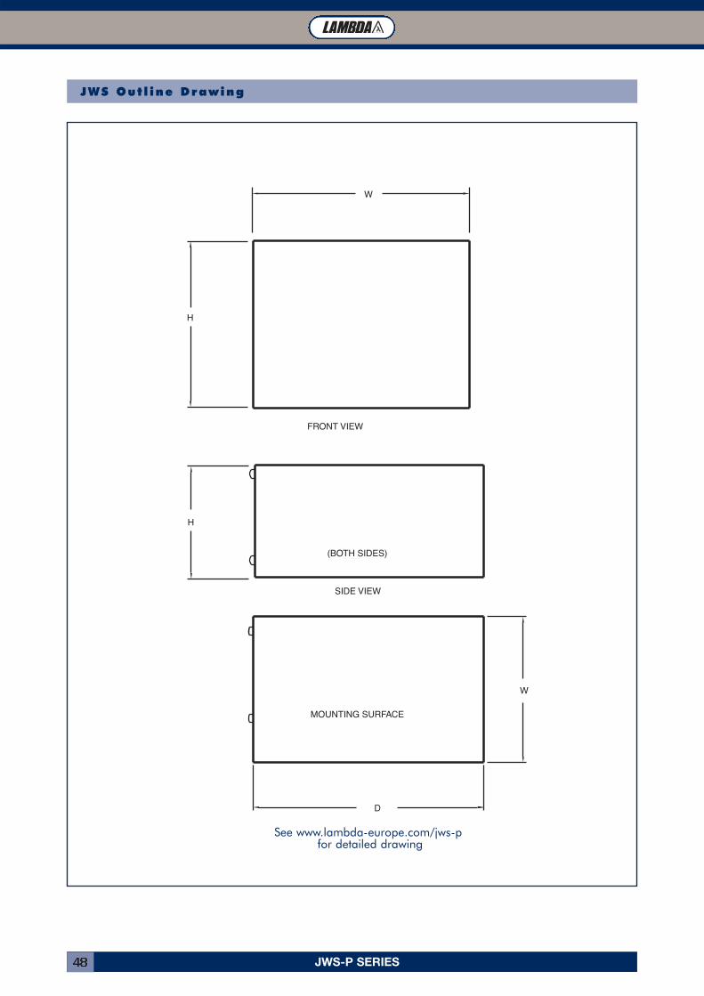
FRONT VIEW
SIDE VIEW
H
H
W
D
W
(BOTH SIDES)
MOUNTING SURFACE
JWS Out l ine Drawing
See www.lambda-europe.com/jws-pfor detailed drawing
JWS SERIES 49
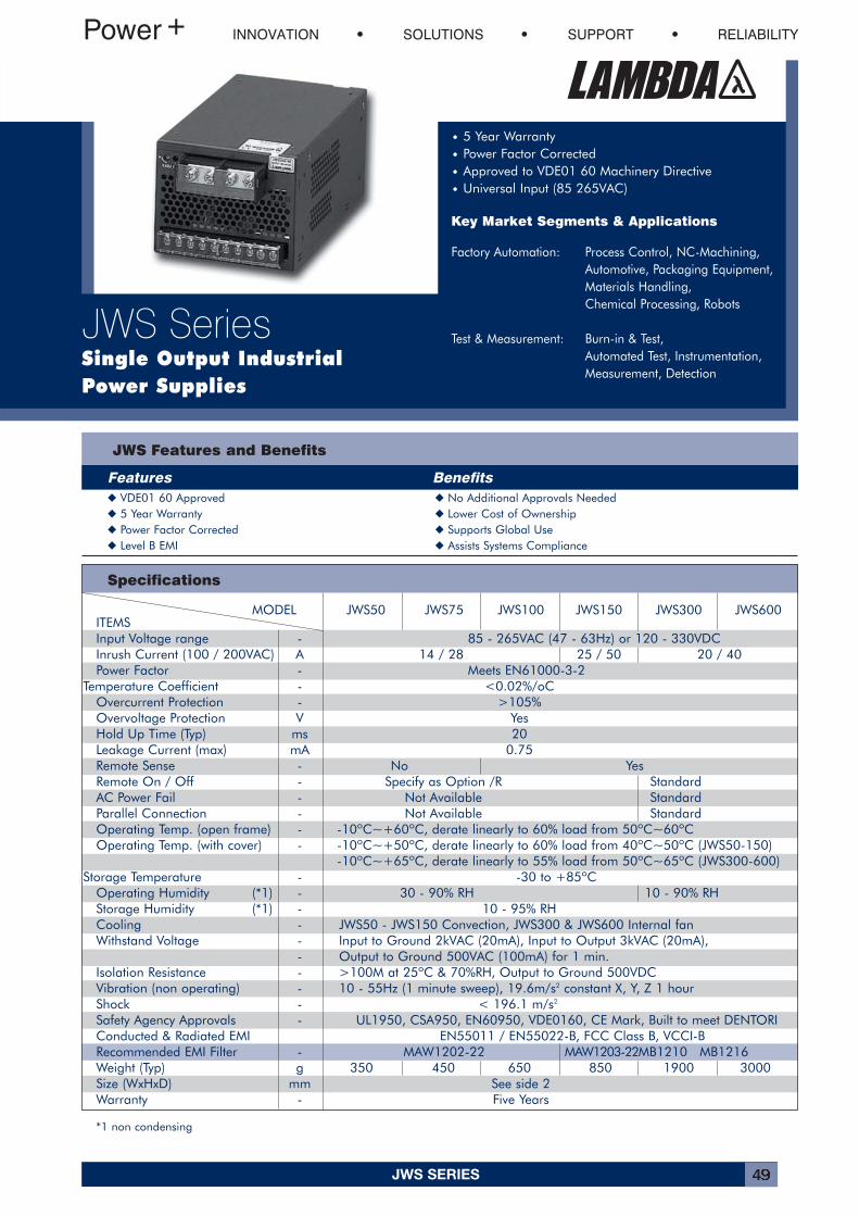
MODEL JWS50 JWS75 JWS100 JWS150 JWS300 JWS600ITEMSInput Voltage range - 85 - 265VAC (47 - 63Hz) or 120 - 330VDCInrush Current (100 / 200VAC) A 14 / 28 25 / 50 20 / 40Power Factor - Meets EN61000-3-2
Temperature Coefficient - <0.02%/oCOvercurrent Protection - >105%Overvoltage Protection V YesHold Up Time (Typ) ms 20Leakage Current (max) mA 0.75Remote Sense - No YesRemote On / Off - Specify as Option /R StandardAC Power Fail - Not Available StandardParallel Connection - Not Available StandardOperating Temp. (open frame) - -10ºC~+60ºC, derate linearly to 60% load from 50ºC~60ºCOperating Temp. (with cover) - -10ºC~+50ºC, derate linearly to 60% load from 40ºC~50ºC (JWS50-150)
-10ºC~+65ºC, derate linearly to 55% load from 50ºC~65ºC (JWS300-600)Storage Temperature - -30 to +85ºC
Operating Humidity (*1) - 30 - 90% RH 10 - 90% RHStorage Humidity (*1) - 10 - 95% RHCooling - JWS50 - JWS150 Convection, JWS300 & JWS600 Internal fanWithstand Voltage - Input to Ground 2kVAC (20mA), Input to Output 3kVAC (20mA),
- Output to Ground 500VAC (100mA) for 1 min.Isolation Resistance - >100M at 25ºC & 70%RH, Output to Ground 500VDCVibration (non operating) - 10 - 55Hz (1 minute sweep), 19.6m/s2 constant X, Y, Z 1 hourShock - < 196.1 m/s2
Safety Agency Approvals - UL1950, CSA950, EN60950, VDE0160, CE Mark, Built to meet DENTORIConducted & Radiated EMI EN55011 / EN55022-B, FCC Class B, VCCI-BRecommended EMI Filter - MAW1202-22 MAW1203-22MB1210 MB1216Weight (Typ) g 350 450 650 850 1900 3000Size (WxHxD) mm See side 2Warranty - Five Years
Specifications
JWS Features and Benefits
Features Benefits� VDE01 60 Approved � No Additional Approvals Needed� 5 Year Warranty � Lower Cost of Ownership� Power Factor Corrected � Supports Global Use� Level B EMI � Assists Systems Compliance
INNOVATION SOLUTIONS SUPPORT RELIABILITY
JWS SeriesSingle Output IndustrialPower Supplies
• 5 Year Warranty• Power Factor Corrected• Approved to VDE01 60 Machinery Directive• Universal Input (85 265VAC)
Key Market Segments & Applications
Factory Automation: Process Control, NC-Machining,Automotive, Packaging Equipment,Materials Handling,Chemical Processing, Robots
Test & Measurement: Burn-in & Test,Automated Test, Instrumentation,Measurement, Detection
*1 non condensing
JWS SERIES50
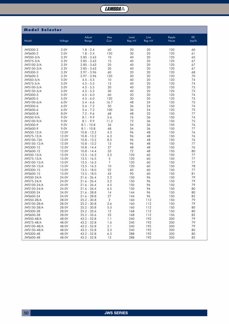
Model Selector
Adjust Max Load Line Ripple Eff.Model Voltage Range Curr. Reg mV Reg mV Noise (typ)%
JWS300-2 2.0V 1.8 - 2.4 60 20 20 120 60JWS600-2 2.0V 1.8 - 2.4 120 30 20 120 61JWS50-3/A 3.3V 2.85 - 3.63 10 40 20 120 65JWS75-3/A 3.3V 2.85 - 3.63 15 40 20 120 67JWS100-3/A 3.3V 2.85 - 3.63 20 40 20 120 67JWS150-3/A 3.3V 2.85 - 3.63 30 40 20 120 67JWS300-3 3.3V 2.97 - 3.96 60 20 20 120 68JWS600-3 3.3V 2.97 - 3.96 120 30 20 120 70JWS50-5/A 5.0V 4.5 - 5.5 10 40 20 120 74JWS75-5/A 5.0V 4.5 - 5.5 15 40 20 120 74JWS100-5/A 5.0V 4.5 - 5.5 20 40 20 120 75JWS150-5/A 5.0V 4.5 - 5.5 30 40 20 120 75JWS300-5 5.0V 4.5 - 6.0 60 20 20 120 74JWS600-5 5.0V 4.5 - 6.0 120 30 20 120 75JWS100-6/A 6.0V 5.4 - 6.6 16.7 48 24 120 75JWS300-6 6.0V 5.4 - 7.2 50 36 24 150 74JWS600-6 6.0V 5.4 - 7.2 100 36 24 120 75JWS600-8 8.0V 7.2 - 9.6 68 48 32 150 77JWS50-9/A 9.0V 8.1 - 9.9 5.6 76 36 150 74JWS100-9/A 9.0V 8.1 - 9.9 11.2 72 36 150 75JWS300-9 9.0V 8.1 - 10.8 34 54 36 150 76JWS600-9 9.0V 8.1 - 10.8 68 54 36 150 77JWS50-12/A 12.0V 10.8 - 13.2 4.3 96 48 150 76JWS75-12/A 12.0V 10.8 - 13.2 6.3 96 48 150 76JWS100-12A 12.0V 10.8 - 13.2 8.5 96 48 150 76JWS150-12/A 12.0V 10.8 - 13.2 13 96 48 150 77JWS300-12 12.0V 10.8 - 14.4 27 48 48 150 76JWS600-12 12.0V 10.8 - 14.4 53 72 48 150 80JWS50-15/A 15.0V 13.5 - 16.5 3.5 120 60 150 77JWS75-15/A 15.0V 13.5 - 16.5 5 120 60 150 77JWS100-15/A 15.0V 13.5 - 16.5 7 120 60 150 77JWS150-15/A 15.0V 13.5 - 16.5 10 120 60 150 78JWS300-15 15.0V 13.5 - 18.0 22 60 60 150 77JWS600-15 15.0V 13.5 - 18.0 43 90 60 150 81JWS50-24/A 24.0V 21.6 - 26.4 2.2 150 96 150 79JWS75-24/A 24.0V 21.6 - 26.4 3.2 150 96 150 79JWS100-24/A 24.0V 21.6 - 26.4 4.5 150 96 150 79JWS150-24/A 24.0V 21.6 - 26.4 6.5 150 96 150 80JWS300-24 24.0V 21.6 - 28.8 14 144 96 150 80JWS600-24 24.0V 21.6 - 28.8 27 144 96 150 82JWS50-28/A 28.0V 25.2 - 30.8 2 160 112 150 79JWS100-28/A 28.0V 25.2 - 30.8 3.6 160 112 150 79JWS150-28/A 28.0V 25.2 - 30.8 5.5 160 112 150 80JWS300-28 28.0V 25.2 - 33.6 12 168 112 150 80JWS600-28 28.0V 25.2 - 33.6 23 168 112 150 82JWS50-48/A 48.0V 43.2 - 52.8 1.1 240 192 200 79JWS75-48/A 48.0V 43.2 - 52.8 1.6 240 192 200 79JWS100-48/A 48.0V 43.2 - 52.8 2.1 240 192 200 79JWS150-48/A 48.0V 43.2 - 52.8 3.3 240 192 200 80JWS300-48 48.0V 43.2 - 52.8 6.5 288 192 350 80JWS600-48 48.0V 43.2 - 52.8 13 288 192 350 83
JWS SERIES 51
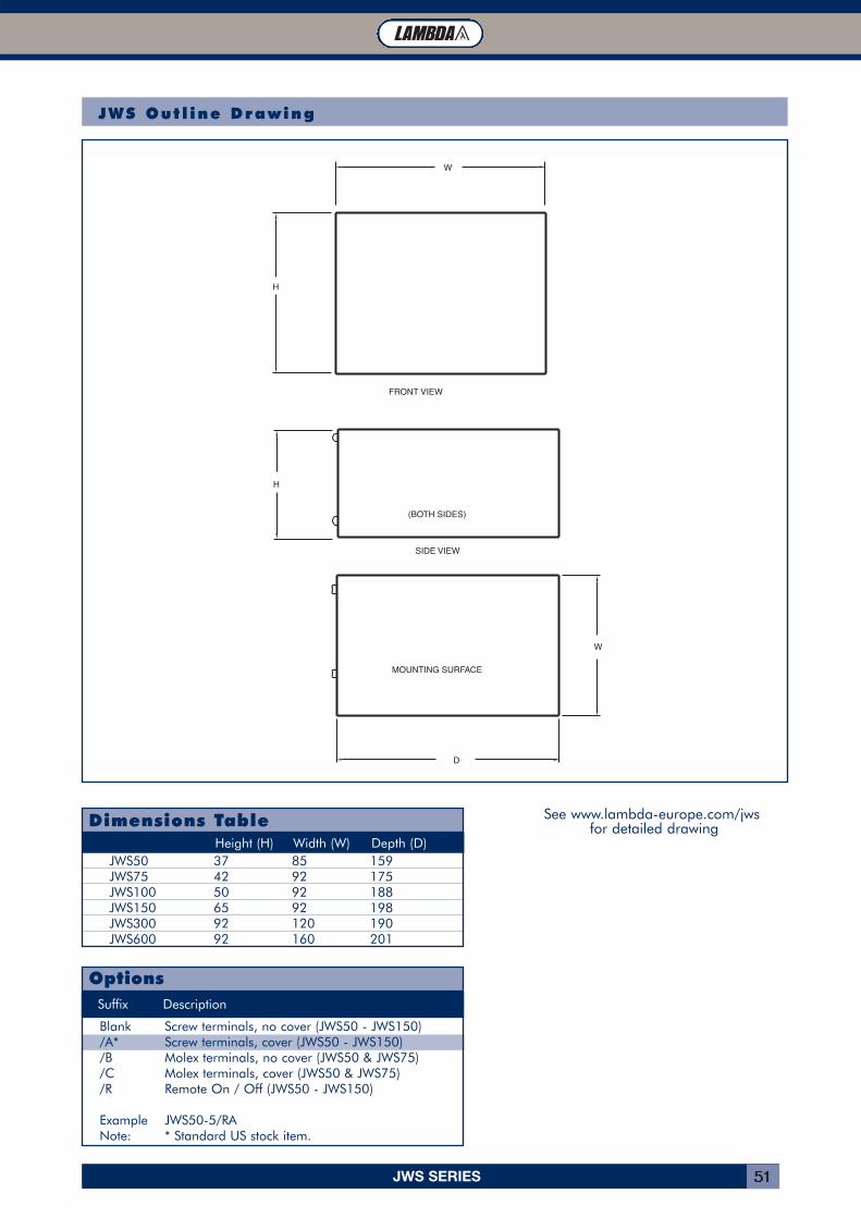
Dimensions Table
JWS50 37 85 159JWS75 42 92 175JWS100 50 92 188JWS150 65 92 198JWS300 92 120 190JWS600 92 160 201
Height (H) Width (W) Depth (D)
Suffix Description
Blank Screw terminals, no cover (JWS50 - JWS150)/A* Screw terminals, cover (JWS50 - JWS150)/B Molex terminals, no cover (JWS50 & JWS75)/C Molex terminals, cover (JWS50 & JWS75)/R Remote On / Off (JWS50 - JWS150)
Example JWS50-5/RANote: * Standard US stock item.
Options
FRONT VIEW
SIDE VIEW
H
H
W
D
W
(BOTH SIDES)
MOUNTING SURFACE
JWS Out l ine Drawing
See www.lambda-europe.com/jwsfor detailed drawing
JWT SERIES52
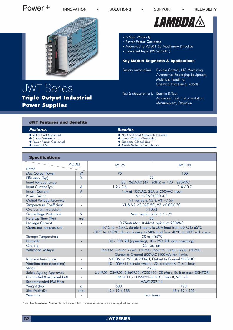
MODEL JWT75 JWT100ITEMSMax Output Power W 75 100Efficiency (Typ) % 72Input Voltage range - 85 - 265VAC (47 - 63Hz) or 120 - 330VDCInput Current Typ A 1.2 / 0.6 1.4 / 0.7Inrush Current A 14A at 100VAC, 28A at 200VAC inputPower Factor - Meets EN61000-3-2Output Voltage Accuracy - V1 variable, V2 & V3 +/-5%Temperature Coefficient - V1 & V2 <0.02%/ºC, V3 <0.03%/ºCOvercurrent Protection - >105%Overvoltage Protection V Main output only: 5.7 - 7VHold Up Time (Typ) ms 20Leakage Current - 0.75mA Max, 0.44mA typical at 230VACOperating Temperature - -10ºC to +65ºC, derate linearly to 50% load from 50ºC to 65ºC
-10ºC to +50ºC, derate linearly to 60% load from 40ºC to 50ºC with coverStorage Temperature - -30 to +85ºCHumidity - 30 - 90% RH (operating), 10 - 95% RH (non operating)Cooling - ConvectionWithstand Voltage - Input to Ground 2kVAC (20mA), Input to Output 3kVAC (20mA),
Output to Ground 500VAC (100mA) for 1 min.Isolation Resistance - >100M at 25ºC & 70%RH, Output to Ground 500VDCVibration (non operating) - 10 - 55Hz (1 minute sweep), 2G constant X, Y, Z 1 hourShock - <20GSafety Agency Approvals - UL1950, CSA950, EN60950, VDE0160, CE Mark, Built to meet DENTORIConducted & Radiated EMI - EN55011 / EN55022-B, FCC Class B, VCCI-BRecommended EMI Filter - MAW1202-22Weight (Typ) g 600 720Size (WxHxD) mm 42 x 92 x 188 48 x 92 x 203Warranty - Five Years
Specifications
JWT Features and Benefits
Features Benefits� VDE01 60 Approved � No Additional Approvals Needed� 5 Year Warranty � Lower Cost of Ownership� Power Factor Corrected � Supports Global Use� Level B EMI � Assists Systems Compliance
INNOVATION SOLUTIONS SUPPORT RELIABILITY
JWT SeriesTriple Output IndustrialPower Supplies
• 5 Year Warranty• Power Factor Corrected• Approved to VDE01 60 Machinery Directive• Universal Input (85 265VAC)
Key Market Segments & Applications
Factory Automation: Process Control, NC-Machining,Automotive, Packaging Equipment,Materials Handling,Chemical Processing, Robots
Test & Measurement: Burn-in & Test,Automated Test, Instrumentation,Measurement, Detection
Note: See Installation Manual for full details, test methods of parameters and application notes.
JWT SERIES 53
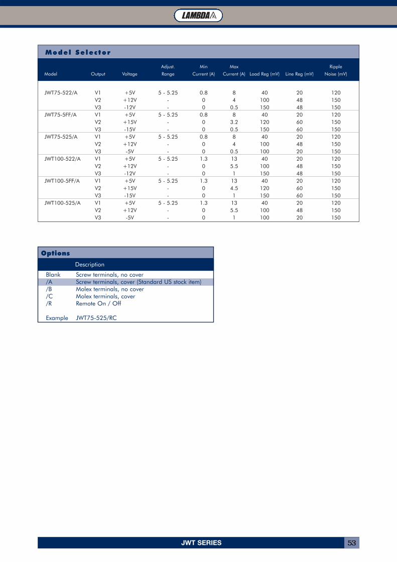
Model Selector
Adjust. Min Max Ripple
Model Output Voltage Range Current (A) Current (A) Load Reg (mV) Line Reg (mV) Noise (mV)
JWT75-522/A V1 +5V 5 - 5.25 0.8 8 40 20 120V2 +12V - 0 4 100 48 150V3 -12V - 0 0.5 150 48 150
JWT75-5FF/A V1 +5V 5 - 5.25 0.8 8 40 20 120V2 +15V - 0 3.2 120 60 150V3 -15V - 0 0.5 150 60 150
JWT75-525/A V1 +5V 5 - 5.25 0.8 8 40 20 120V2 +12V - 0 4 100 48 150V3 -5V - 0 0.5 100 20 150
JWT100-522/A V1 +5V 5 - 5.25 1.3 13 40 20 120V2 +12V - 0 5.5 100 48 150V3 -12V - 0 1 150 48 150
JWT100-5FF/A V1 +5V 5 - 5.25 1.3 13 40 20 120V2 +15V - 0 4.5 120 60 150V3 -15V - 0 1 150 60 150
JWT100-525/A V1 +5V 5 - 5.25 1.3 13 40 20 120V2 +12V - 0 5.5 100 48 150V3 -5V - 0 1 100 20 150
Suffix Description
Blank Screw terminals, no cover/A Screw terminals, cover (Standard US stock item)/B Molex terminals, no cover/C Molex terminals, cover/R Remote On / Off
Example JWT75-525/RC
Options
JWT SERIES54
FRONT VIEW
SIDE VIEW
H
H
W
D
W
(BOTH SIDES)
MOUNTING SURFACE
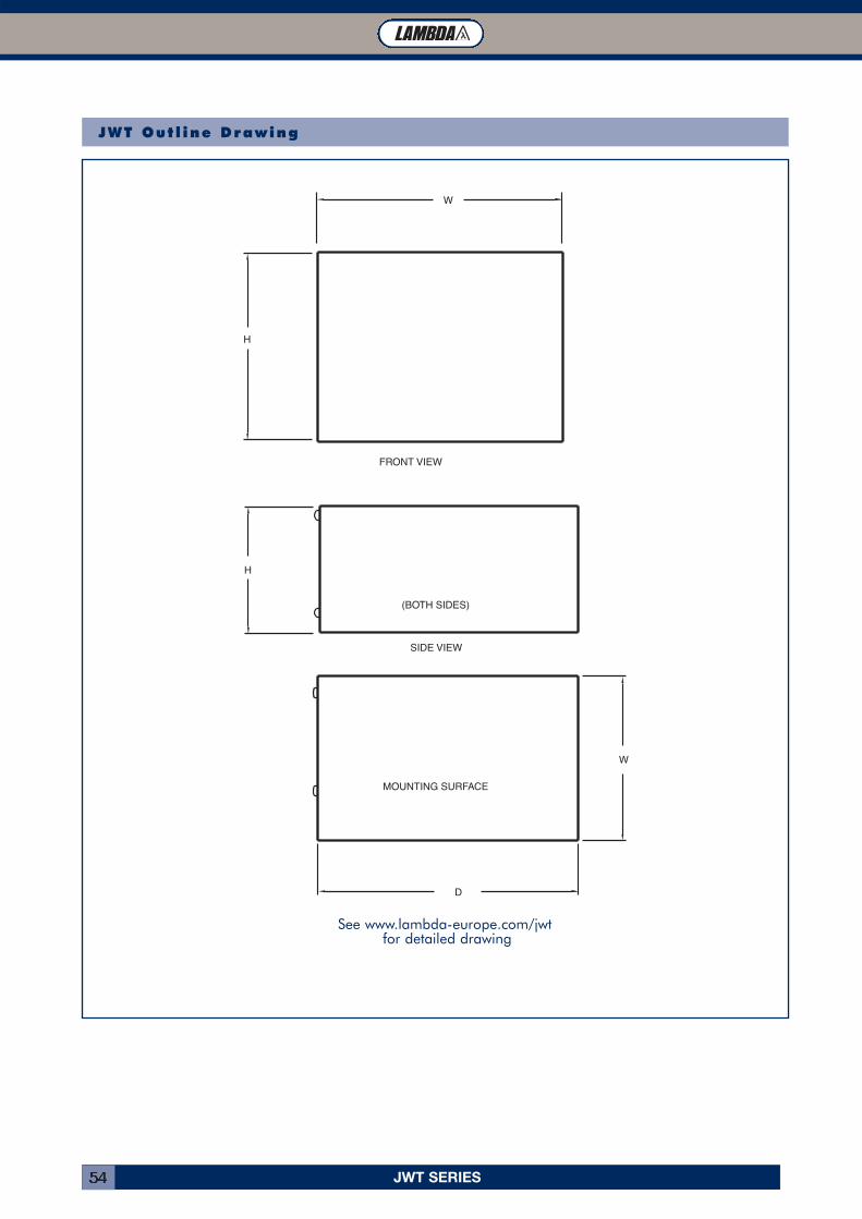
JWT Out l ine Drawing
See www.lambda-europe.com/jwtfor detailed drawing
KPS SERIES 55
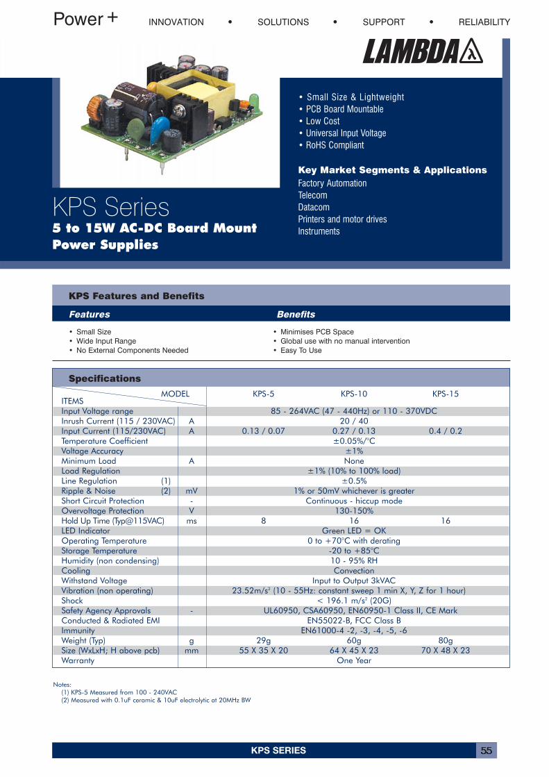
• Small Size & Lightweight• PCB Board Mountable• Low Cost• Universal Input Voltage• RoHS Compliant
Key Market Segments & ApplicationsFactory AutomationTelecomDatacomPrinters and motor drivesInstruments
INNOVATION SOLUTIONS SUPPORT RELIABILITY
KPS Series5 to 15W AC-DC Board MountPower Supplies
MODEL KPS-5 KPS-10 KPS-15ITEMSInput Voltage range 85 - 264VAC (47 - 440Hz) or 110 - 370VDCInrush Current (115 / 230VAC) A 20 / 40Input Current (115/230VAC) A 0.13 / 0.07 0.27 / 0.13 0.4 / 0.2Temperature Coefficient ±0.05%/°CVoltage Accuracy ±1%Minimum Load A NoneLoad Regulation ±1% (10% to 100% load)Line Regulation (1) ±0.5%Ripple & Noise (2) mV 1% or 50mV whichever is greaterShort Circuit Protection - Continuous - hiccup modeOvervoltage Protection V 130-150%Hold Up Time (Typ@115VAC) ms 8 16 16LED Indicator Green LED = OKOperating Temperature 0 to +70°C with deratingStorage Temperature -20 to +85°CHumidity (non condensing) 10 - 95% RHCooling ConvectionWithstand Voltage Input to Output 3kVACVibration (non operating) 23.52m/s2 (10 - 55Hz: constant sweep 1 min X, Y, Z for 1 hour)Shock < 196.1 m/s2 (20G)Safety Agency Approvals - UL60950, CSA60950, EN60950-1 Class II, CE MarkConducted & Radiated EMI EN55022-B, FCC Class BImmunity EN61000-4 -2, -3, -4, -5, -6Weight (Typ) g 29g 60g 80gSize (WxLxH; H above pcb) mm 55 X 35 X 20 64 X 45 X 23 70 X 48 X 23Warranty One Year
KPS Features and Benefits
Features Benefits
• Small Size• Wide Input Range• No External Components Needed
• Minimises PCB Space• Global use with no manual intervention• Easy To Use
Specifications
Notes:(1) KPS-5 Measured from 100 - 240VAC(2) Measured with 0.1uF ceramic & 10uF electrolytic at 20MHz BW
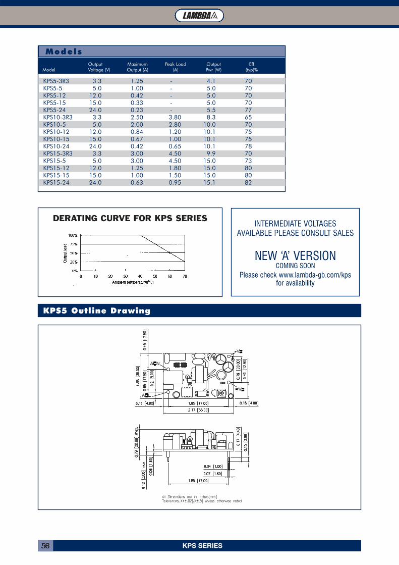
KPS SERIES56
KPS5 Outline Drawing
ModelsOutput Maximum Peak Load Output Eff
Model Voltage (V) Output (A) (A) Pwr (W) (typ)%
KPS5-3R3 3.3 1.25 - 4.1 70KPS5-5 5.0 1.00 - 5.0 70KPS5-12 12.0 0.42 - 5.0 70KPS5-15 15.0 0.33 - 5.0 70KPS5-24 24.0 0.23 - 5.5 77KPS10-3R3 3.3 2.50 3.80 8.3 65KPS10-5 5.0 2.00 2.80 10.0 70KPS10-12 12.0 0.84 1.20 10.1 75KPS10-15 15.0 0.67 1.00 10.1 75KPS10-24 24.0 0.42 0.65 10.1 78KPS15-3R3 3.3 3.00 4.50 9.9 70KPS15-5 5.0 3.00 4.50 15.0 73KPS15-12 12.0 1.25 1.80 15.0 80KPS15-15 15.0 1.00 1.50 15.0 80KPS15-24 24.0 0.63 0.95 15.1 82
DERATING CURVE FOR KPS SERIESINTERMEDIATE VOLTAGES
AVAILABLE PLEASE CONSULT SALES
NEW ‘A’ VERSIONCOMING SOON
Please check www.lambda-gb.com/kpsfor availability
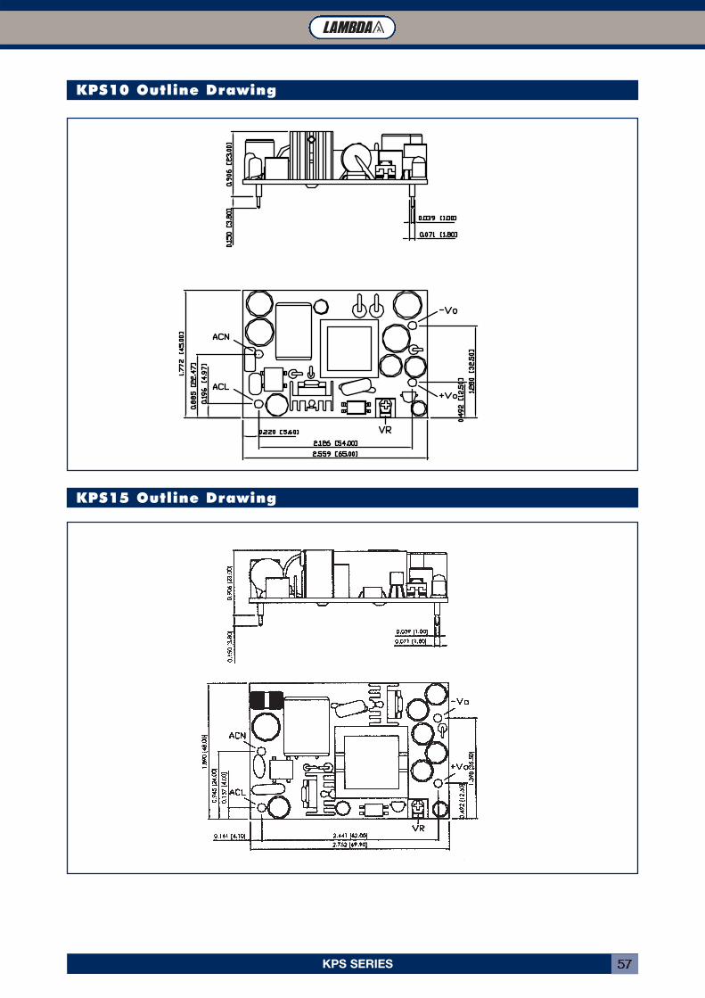
KPS SERIES 57
KPS10 Outline Drawing
KPS15 Outline Drawing
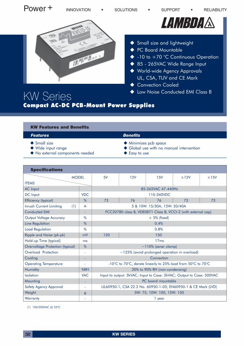
KW SERIES58
INNOVATION SOLUTIONS SUPPORT RELIABILITY
KW SeriesCompact AC-DC PCB-Mount Power Supplies
� Small size and lightweight� PC Board Mountable� -10 to +70 °C Continuous Operation� 85 - 265VAC Wide Range Input� World-wide Agency Approvals
UL, CSA, TUV and CE Mark� Convection Cooled� Low Noise Conducted EMI Class B
KW Features and Benefits
Features Benefits
� Small size � Minimizes pcb space� Wide input range � Global use with no manual intervention� No external components needed � Easy to use
Specifications
MODEL 5V 12V 15V ±12V ±15V
ITEMS
AC Input 85-265VAC 47-440Hz
DC Input VDC 110-340VDC
Efficiency (typical) % 73 76 76 73 73
Inrush Current Limiting (1) A 5 & 10W: 15/30A, 15W: 20/40A
Conducted EMI - FCC20780 class B, VDE0871 Class B, VCCI-2 (with external cap).
Output Voltage Accuracy % ± 5% (fixed)
Line Regulation % 0.4%
Load Regulation % 0.8%
Ripple and Noise (pk-pk) mV 120 150
Hold-up Time (typical) ms 17ms
Overvoltage Protection (typical) % ~110% (zener clamp)
Overload Protection - ~125% (avoid prolonged operation in overload)
Cooling - Convection
Operating Temperature - -10°C to 70°C, derate linearly to 25% load from 50°C to 70°C
Humidity %RH 20% to 90% RH (non-condensing)
Isolation VAC Input to output: 3kVAC; Input to Case: 2kVAC; Output to Case: 500VAC
Mounting - PC board mountable
Safety Agency Approval - UL60950-1; CSA 22.2 No. 60950-1-03; EN60950-1 & CE Mark (LVD)
Weight g 5W: 75, 10W: 100, 15W: 150
Warranty - 1 year
(1) 100/200VAC @ 25°C
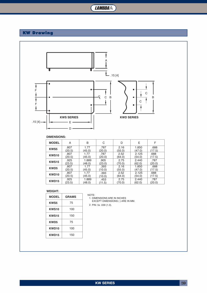
KW SERIES 59
KW Drawing
.6882.1251.77 .787.807KWS10 2.52
KWD15
KWD10
KWD5
150
100
75
KWD5
KWD10
KWD15
KWS15
WEIGHT:
KWS15
KWS10
KWS5
MODEL
75
150
100
GRAMS
(20.5)
(23.5).925
.807(20.5)
(23.5).807
(20.5).925
(45.0) (10.0)
1.889(48.0)
1.77(45.0)
.453(11.5)
(10.0).393
(48.0)1.77
(45.0)1.889
(23.0).393
(20.0).905
(54.0)2.440(62.0)
2.125(54.0)2.440(62.0)
1.850(47.0)(55.0)
2.52(64.0)
(70.0)2.75
(70.0)2.75
(64.0)
2.16(17.5).688(17.5).787
(20.0)
(17.5).787
(20.0).688
DIMENSIONS:
MODEL
KWS5
KWS SERIES KWD SERIES
.807(20.5)
A
.15 [4]
1.77(45.0)
B
.787(20.0)
C
E
D
F
F
1.850(47.0)(55.0)
2.16
D
.688(17.5)
E F
C C B B
.15 [4]
A
C
C
PIN: 5x .039 (1.0).
DIMENSIONS ARE IN INCHES EXCEPT DIMENSIONS ( ) ARE IN MM.
2.
NOTE:1.
L
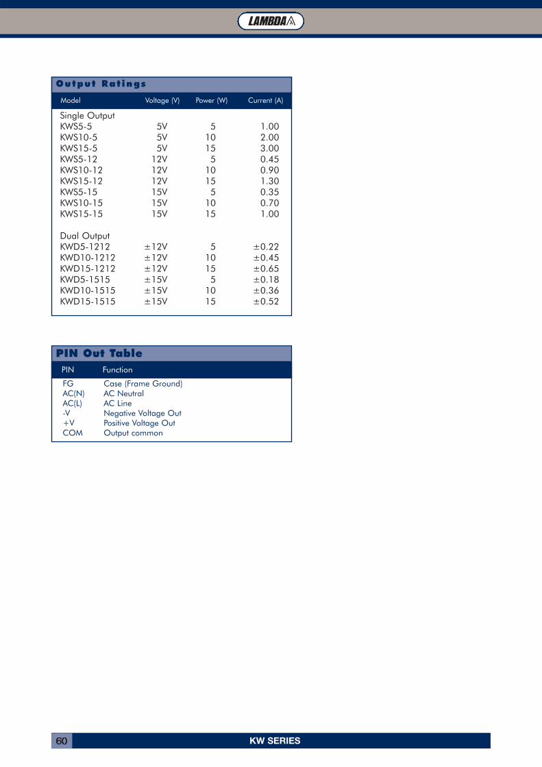
KW SERIES60
PIN Function
FG Case (Frame Ground)AC(N) AC NeutralAC(L) AC Line-V Negative Voltage Out+V Positive Voltage OutCOM Output common
PIN Out Table
Output Rat ings
Single OutputKWS5-5 5V 5 1.00KWS10-5 5V 10 2.00KWS15-5 5V 15 3.00KWS5-12 12V 5 0.45KWS10-12 12V 10 0.90KWS15-12 12V 15 1.30KWS5-15 15V 5 0.35KWS10-15 15V 10 0.70KWS15-15 15V 15 1.00
Dual OutputKWD5-1212 ±12V 5 ±0.22KWD10-1212 ±12V 10 ±0.45KWD15-1212 ±12V 15 ±0.65KWD5-1515 ±15V 5 ±0.18KWD10-1515 ±15V 10 ±0.36KWD15-1515 ±15V 15 ±0.52
Model Voltage (V) Power (W) Current (A)
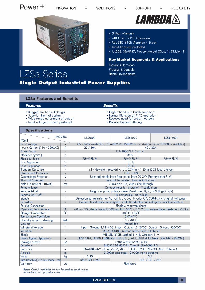
LZSa SERIES 61
MODELS LZSa500 LZSa1000 LZSa1500*ITEMSInput Voltage - 85 - 265V 47-440Hz, 100-400VDC (1500W model derates below 180VAC - see table)Inrush Current (110 / 220VAC) A 20 / 40A 40 / 80APower Factor - EN61000-3-2 Class AEfficiency (typical) % 84%Ripple & Noise - 75mV Pk-Pk 75mV Pk-Pk 75mV Pk-PkLine Regulation % 0.1%Load Regulation % 0.1%Transient Response - ±1% deviation, recovering to ±0.2% in <1.25ms (25% load change)Overcurrent Protection - 110 - 130%Overvoltage Protection V User adjustable from front panel from 20-36V (Factory set at 31V)Thermal Protection - Internal thermostat. Recycle AC to resetHold Up Time at 110VAC ms 20ms Hold Up, 20ms Ride ThroughRemote Sense - Compenstates for a total of 1V cable dropRemote Adjust - Using front panel potentiometer, Resistance (1k/V), or Voltage (1V/V)Remote On / Off - TTL compatible, active highSignals - Optocoupled transistor for AC Fail, DC Good, Inverter OK, 200kHz sync signal (ref-sense)Indicators - Green LED indicates output good, red LED indicates overvoltage or over temperatureParallel Connection - Single wire current shareOperating Temperature ºC -40º~+71ºC, derate linearly to 60% load from 60ºC~70ºC (20 min warm up period needed for <-30ºC)Storage Temperature ºC -40º to +85ºCTemperature Coefficient - 0.01%/ºCHumidity (non condensing) %RH 10 - 90%RHCooling - Internal fanWithstand Voltage - Input - Ground 2,121VDC, Input - Output 4,242VDC, Output - Ground 500VDCVibration - MIL-STD-810E, Method 516.4 Proc. I, II, IV, VIShock - MIL-STD-810E, Method 514.4, Category 1, 9Safety Agency Approvals - UL60950-1, UL508, EN60950-1, FM 3600, 3611, 3810, & CE Mark. SEMIF47(>100VAC)Leakage current uA <500uA at 265VAC, 60HzEmissions - EN55022/EN55011 Class B, EN61000-3-3Immunity - EN61000-4-2, -3, -4, -5, -6, -8, -11. IEEE C62.41 (6kV/30 Ohm, Criteria A)Altitude m 3,000m operating, 12,000m non operatingWeight kg 2.95 3.7Size (WxHxD)(w/o bus bars) mm 108 x 121 x 260 143 x 121 x 267Warranty yrs Five Years
LZSa Features and Benefits
Features Benefits
INNOVATION SOLUTIONS SUPPORT RELIABILITY
LZSa SeriesSingle Output Industrial Power Supplies
• 5 Year Warranty
• -40ºC to +71ºC Operation
• MIL-STD-810E Vibration / Shock
• Input transient protected
• UL508, SEMIF47, Factory Mutual (Class 1, Division 2)
Key Market Segments & Applications
Factory AutomationProcess & ControlsHarsh Environments
Specifications
• Rugged mechanical design • High reliability in harsh conditions• Superior thermal design • Longer life even at 71°C operation• Wide range adjustment of output • Reduces need for custom outputs• Input voltage transient protected • Reduced system filtering
Notes: (Consult Installation Manual for detailed specifications, test methods and application notes)
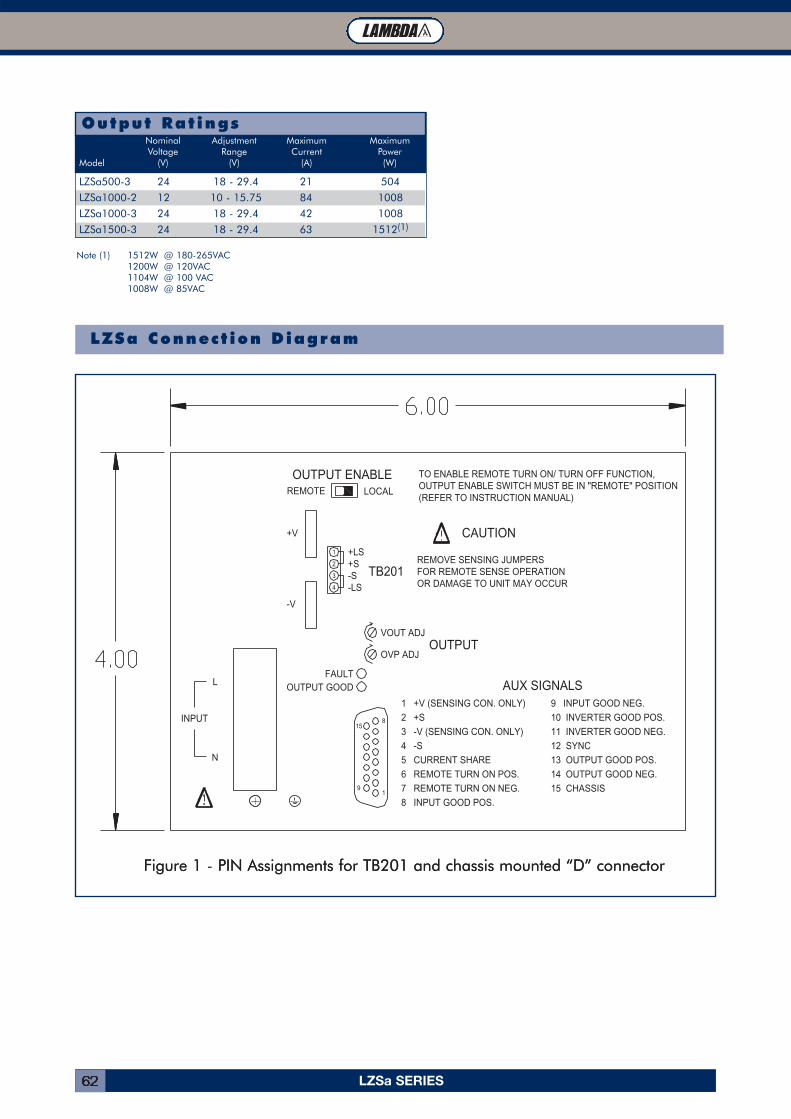
LZSa SERIES62
Output Rat ings
LZSa500-3 24 18 - 29.4 21 504
LZSa1000-2 12 10 - 15.75 84 1008
LZSa1000-3 24 18 - 29.4 42 1008
LZSa1500-3 24 18 - 29.4 63 1512(1)
Nominal Adjustment Maximum MaximumVoltage Range Current Power
Model (V) (V) (A) (W)
FFiigguurree 11 - PPIINN AAssssiiggnnmmeennttss ffoorr TTBB220011 aanndd cchhaassssiiss mmoouunntteedd ““DD”” ccoonnnneeccttoorr
LZSa Connect ion Diagram
Note (1) 1512W @ 180-265VAC1200W @ 120VAC1104W @ 100 VAC1008W @ 85VAC
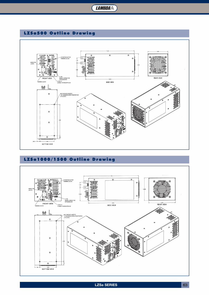
LZSa SERIES 63
LZSa500 Out l ine Drawing
LZSa1000/1500 Out l ine Drawing
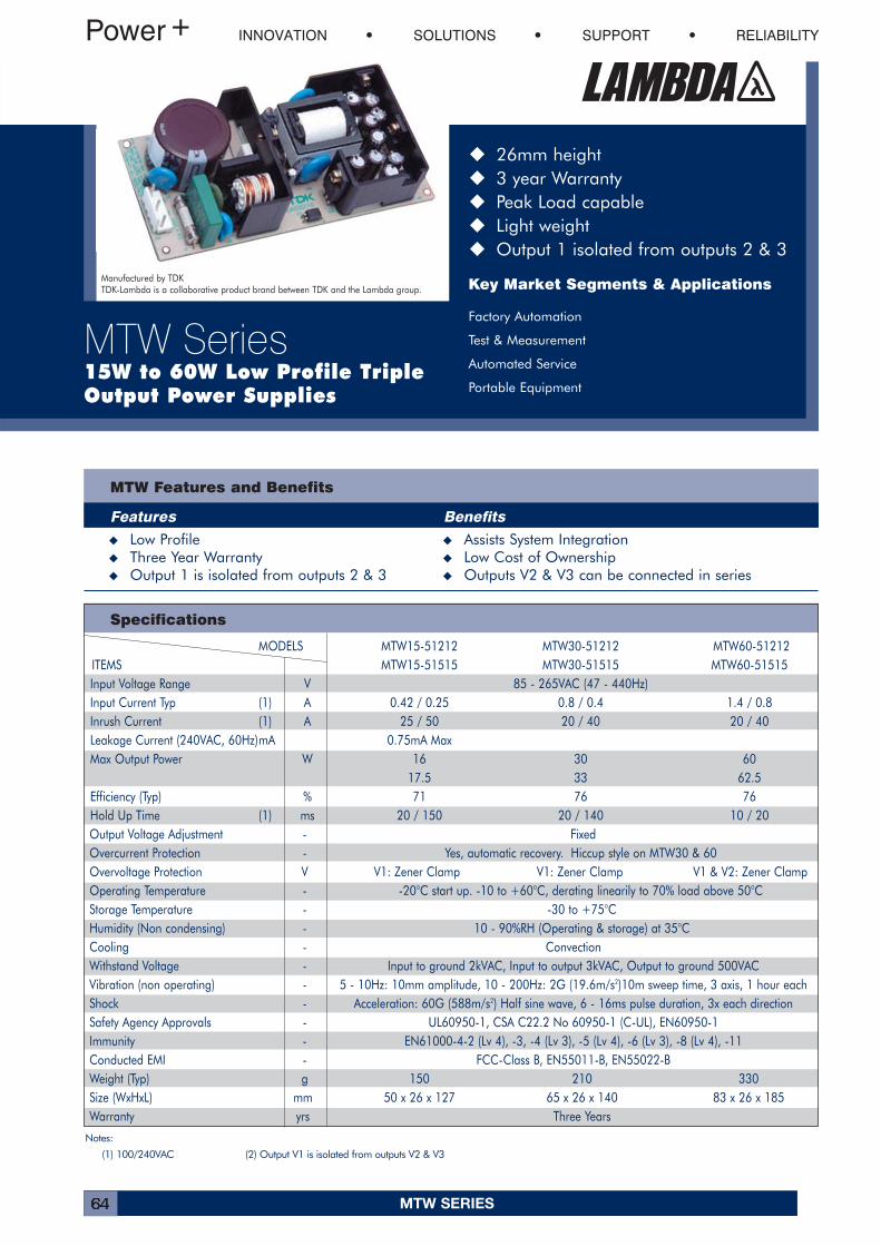
MTW SERIES64
INNOVATION SOLUTIONS SUPPORT RELIABILITY
MTW Series15W to 60W Low Profile Triple Output Power Supplies
� 26mm height� 3 year Warranty� Peak Load capable� Light weight� Output 1 isolated from outputs 2 & 3
Key Market Segments & Applications
Factory Automation
Test & Measurement
Automated Service
Portable Equipment
Manufactured by TDKTDK-Lambda is a collaborative product brand between TDK and the Lambda group.
MTW Features and Benefits
Features Benefits� Low Profile � Assists System Integration� Three Year Warranty � Low Cost of Ownership� Output 1 is isolated from outputs 2 & 3 � Outputs V2 & V3 can be connected in series
Specifications
MODELS MTW15-51212 MTW30-51212 MTW60-51212ITEMS MTW15-51515 MTW30-51515 MTW60-51515Input Voltage Range V 85 - 265VAC (47 - 440Hz)Input Current Typ (1) A 0.42 / 0.25 0.8 / 0.4 1.4 / 0.8Inrush Current (1) A 25 / 50 20 / 40 20 / 40Leakage Current (240VAC, 60Hz)mA 0.75mA MaxMax Output Power W 16 30 60
17.5 33 62.5Efficiency (Typ) % 71 76 76Hold Up Time (1) ms 20 / 150 20 / 140 10 / 20Output Voltage Adjustment - FixedOvercurrent Protection - Yes, automatic recovery. Hiccup style on MTW30 & 60Overvoltage Protection V V1: Zener Clamp V1: Zener Clamp V1 & V2: Zener ClampOperating Temperature - -20°C start up. -10 to +60°C, derating linearily to 70% load above 50°CStorage Temperature - -30 to +75°CHumidity (Non condensing) - 10 - 90%RH (Operating & storage) at 35°CCooling - ConvectionWithstand Voltage - Input to ground 2kVAC, Input to output 3kVAC, Output to ground 500VACVibration (non operating) - 5 - 10Hz: 10mm amplitude, 10 - 200Hz: 2G (19.6m/s2)10m sweep time, 3 axis, 1 hour eachShock - Acceleration: 60G (588m/s2) Half sine wave, 6 - 16ms pulse duration, 3x each directionSafety Agency Approvals - UL60950-1, CSA C22.2 No 60950-1 (C-UL), EN60950-1Immunity - EN61000-4-2 (Lv 4), -3, -4 (Lv 3), -5 (Lv 4), -6 (Lv 3), -8 (Lv 4), -11Conducted EMI - FCC-Class B, EN55011-B, EN55022-BWeight (Typ) g 150 210 330Size (WxHxL) mm 50 x 26 x 127 65 x 26 x 140 83 x 26 x 185Warranty yrs Three Years
Notes:
(1) 100/240VAC (2) Output V1 is isolated from outputs V2 & V3
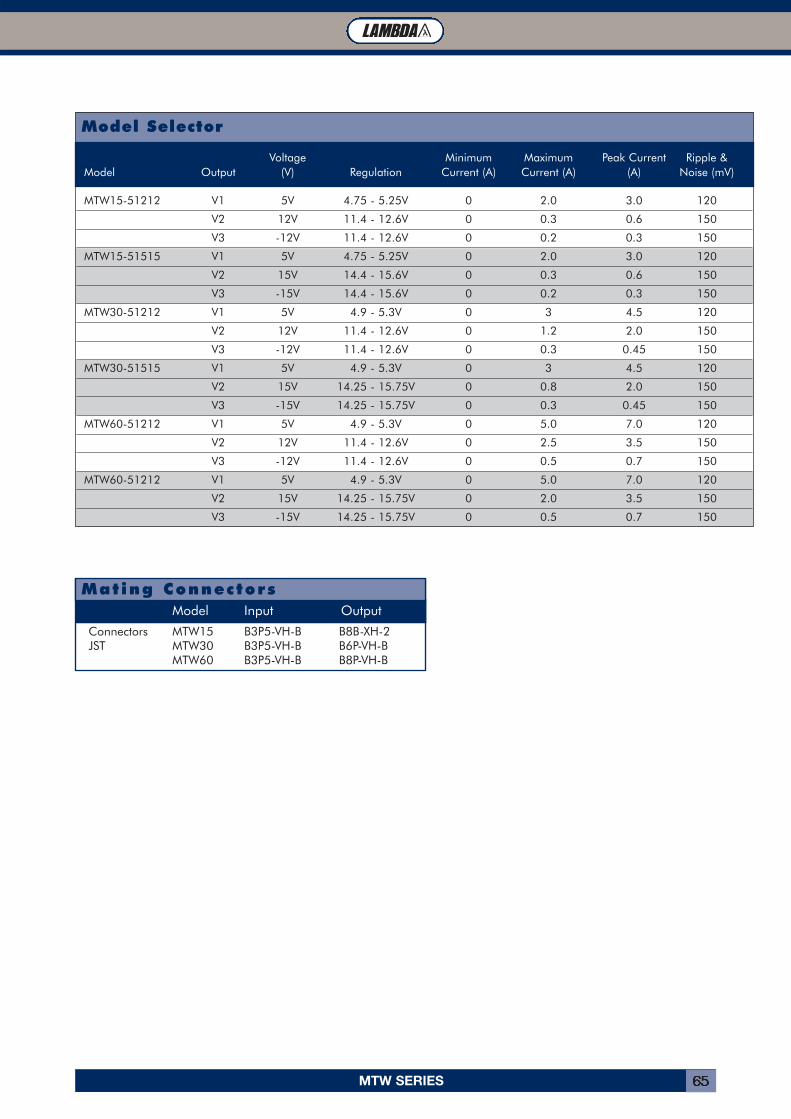
MTW SERIES 65
Connectors MTW15 B3P5-VH-B B8B-XH-2JST MTW30 B3P5-VH-B B6P-VH-B
MTW60 B3P5-VH-B B8P-VH-B
Model Input Output
Mating Connectors
Model Selector
Voltage Minimum Maximum Peak Current Ripple &Model Output (V) Regulation Current (A) Current (A) (A) Noise (mV)
MTW15-51212 V1 5V 4.75 - 5.25V 0 2.0 3.0 120
V2 12V 11.4 - 12.6V 0 0.3 0.6 150
V3 -12V 11.4 - 12.6V 0 0.2 0.3 150
MTW15-51515 V1 5V 4.75 - 5.25V 0 2.0 3.0 120
V2 15V 14.4 - 15.6V 0 0.3 0.6 150
V3 -15V 14.4 - 15.6V 0 0.2 0.3 150
MTW30-51212 V1 5V 4.9 - 5.3V 0 3 4.5 120
V2 12V 11.4 - 12.6V 0 1.2 2.0 150
V3 -12V 11.4 - 12.6V 0 0.3 0.45 150
MTW30-51515 V1 5V 4.9 - 5.3V 0 3 4.5 120
V2 15V 14.25 - 15.75V 0 0.8 2.0 150
V3 -15V 14.25 - 15.75V 0 0.3 0.45 150
MTW60-51212 V1 5V 4.9 - 5.3V 0 5.0 7.0 120
V2 12V 11.4 - 12.6V 0 2.5 3.5 150
V3 -12V 11.4 - 12.6V 0 0.5 0.7 150
MTW60-51212 V1 5V 4.9 - 5.3V 0 5.0 7.0 120
V2 15V 14.25 - 15.75V 0 2.0 3.5 150
V3 -15V 14.25 - 15.75V 0 0.5 0.7 150
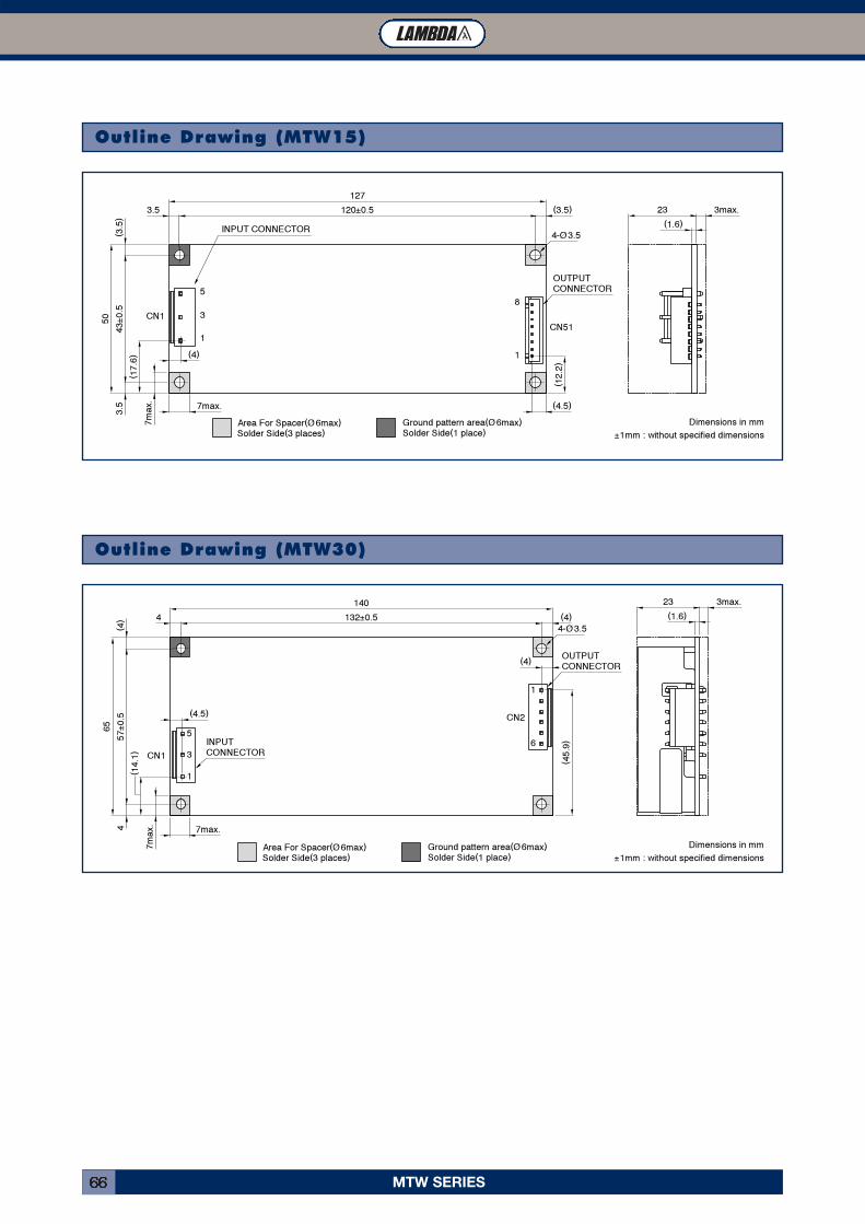
MTW SERIES66
Outline Drawing (MTW15)
127120±0.53.5 (3.5)
7max
.( 1
7.6)
43±0
.53.
5( 3
.5)
50
4-Ø 3.5
7max.
(4)
(4.5)
OUTPUTCONNECTOR
INPUT CONNECTOR
CN1CN51
5
3
1
8
1
( 12.
2)
3max.(1.6)
23
Area For Spacer(Ø 6max.)Solder Side(3 places)
Ground pattern area(Ø 6max.)Solder Side(1 place)
Dimensions in mm±1mm : without specified dimensions
Outline Drawing (MTW30)
3max.(1.6)
23
7max
.( 1
4.1)
7max.
(4.5)
(4)
( 45.
9)
140132±0.54 (4)
57±0
.54
( 4)
65
4-Ø 3.5
OUTPUTCONNECTOR
1
65
3
1
CN1
CN2
INPUTCONNECTOR
Area For Spacer(Ø 6max.)Solder Side(3 places)
Ground pattern area(Ø 6max.)Solder Side(1 place)
Dimensions in mm±1mm : without specified dimensions
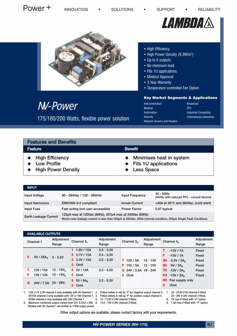
• High Efficiency• High Power Density (9.3W/in3)• Up to 5 outputs• No minimum load• Fits 1U applications• Medical Approval• 3 Year Warranty• Temperature controlled Fan Option
Key Market Segments & Applications
Instrumentation BroadcastMedical ATEAutomation Industrial ComputingSecurity Lifesciences/LaboratoryNetwork Servers and Routers
NV-Power175/180/200 Watts, flexible power solution
NV-POWER SERIES (NV-175) 67
FFeeaattuurreess aanndd BBeenneeffiittssFFeeaattuurree BBeenneeffiitt� High Efficiency � Minimises heat in system
� Low Profile � Fits 1U applications
� High Power Density � Less Space
IINNPPUUTTInput Voltage 90 - 264Vac / 120 - 350Vdc Input Frequency
45 - 63Hz(440Hz with reduced PFC - consult factory)
Input Harmonics EN61000-3-2 compliant Inrush Current <40A at 25°C and 264Vac, (cold start)
Input Fuse Fast acting (not user accessible) Power Factor 0.97 typical
Earth Leakage Current123μA max at 120Vac (60Hz), 257μA max at 240Vac (60Hz)
Worst case leakage current is less than 300μA at 264Vac, 63Hz (normal condition, 500μA Single Fault Condition)
AAVVAAIILLAABBLLEE OOUUTTPPUUTTSSChannel 1
Adjustment
RangeChannel 21
Adjustment
RangeChannel 33
Adjustment
RangeChannel 44
Adjustment
Range
55 5V / 25A2 5 - 5.5V
11 1.8V / 15A
22 2.7V / 15A
33 3.3V / 15A
00 Omit
0.9 - 3.3V
2.5 - 3.3V
2.5 - 3.3V TT 12V / 5A
FF 15V / 5A
GG 24V / 2.5A
00 Omit
12 - 15V
12 - 15V
18 - 24V
TT -12V / 1A
FF -15V / 1A
33HH -3.3V / 2A9
55HH -5V / 2A9
TTHH -12V / 2A9
FFHH -15V / 2A9
00HH Fan supply only
00 Omit
Fixed
Fixed
Fixed
Fixed
Fixed
Fixed
TT 12V / 15A
FF 15V / 12A
12 - 15V5
12 - 15V6
55 5V / 10A
00 Omit
3.3 - 5.5V
GG 24V / 7.5A 24 - 28V7
55 5V / 8A8
00 Omit
3.3 - 5.5V
7. 24 - 24.5V if 5V channel 2 fitted
24 - 26V if 24V channel 3 fitted.
8. 7A max if fitted with ‘-F’ option.
9. 1.5A max if fitted with ‘-F’ option.
3. Follow letters in red by ‘Y’ for negative output channel 3.
4. Follow letters in red by ‘P’ for positive output channel 4.
5. 12 - 12.5V if 24V channel 3 fitted.
6. 14.5 - 15V if 24V channel 3 fitted.
1. 1.8V, 2.7V, 3.3V channel 2 only available with 5V Channel 1
5V/10A channel 2 only available with 12V or 15V Channel 1
5V/8A channel 2 only available with 24V Channel 1.
2. Maximum combined output current from Ch1 & Ch2 = 25A
Models with 5V channel 1 are limited to 175W output power
Other output options are available, please contact factory with your requirements.
INNOVATION SOLUTIONS SUPPORT RELIABILITY
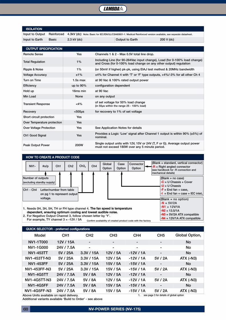
NV-POWER SERIES (NV-175)68
OOUUTTPPUUTT SSPPEECCIIFFIICCAATTIIOONNRemote Sense Yes Channels 1 & 2 - Max 0.5V total line drop.
Total Regulation 1%Including Line (for 90-264Vac input change), Load (for 0-100% load change)and Cross (for 0-100% load change on any other output) regulation
Ripple & Noise 1% (or 50mV if higher) pk-pk, using EIAJ test method & 20MHz bandwidth
Voltage Accuracy ±1% ±4% for Channel 4 with ‘T’ or ‘F’ type outputs, +4%/-3% for all other Ch 4
Turn on Time 1.5s max at 90 Vac & 100% rated output power
Efficiency up to 90% configuration dependent
Hold up 16ms min at 90 Vac
Min Load None on any output
Transient Response <4%of set voltage for 50% load change(in 50μs within the range 25 - 100% load)
Recovery <500μs for recovery to 1% of set voltage
Short circuit protection Yes
Over Temperature protection Yes
Over Voltage Protection Yes See Application Notes for details
Ch1 Good Signal YesProvides a Logic ‘Low’ signal after Channel 1 output is within 90% (±5%) ofnominal.
Peak Output Power 200WSingle output units with 12V, 15V or 24V (T, F or G). Average output powermust not exceed 180W over any 5 minute period.
HHOOWW TTOO CCRREEAATTEE AA PPRROODDUUCCTT CCOODDEENV1- #o/p Ch1 Ch2 Ch32 Ch4
Global
Option
Case
Option
Connector
Option
1. Needs 0H, 3H, 5H, TH or FH type channel 4. TThhee ffaann ssppeeeedd iiss tteemmppeerraattuurreeddeeppeennddeenntt,, eennssuurriinngg ooppttiimmuumm ccoooolliinngg aanndd lloowweesstt aauuddiibbllee nnooiissee..
2. For Negative Output Channel 3, follow chosen letter by ‘Y’.
For example, TY channel 3 = -12V / 5A
1. see page 3 for details of global optionAbove Units available on rapid delivery.
Additional variants available ‘Build to Order’ - see above
QQUUIICCKK SSEELLEECCTTOORR -- pprreeffeerrrreedd ccoonnffiigguurraattiioonnssModel CH1 CH2 CH3 CH4 CH5 Global Option1
NV1-1T000 12V / 15A - - - - No
NV1-1G000 24V / 7.5A - - - - No
NV1-453TT 5V / 25A 3.3V / 15A 12V / 5A -12V / 1A - No
NV1-453TT-N3 5V / 25A 3.3V / 15A 12V / 5A -12V / 1A 5V / 2A ATX (-N3)
NV1-453FF 5V / 25A 3.3V / 15A 15V / 5A -15V / 1A - No
NV1-453FF-N3 5V / 25A 3.3V / 15A 15V / 5A -15V / 1A 5V / 2A ATX (-N3)
NV1-4G5TT 24V / 7.5A 5V / 8A 12V / 5A -12V / 1A - No
NV1-4G5TT-N3 24V / 7.5A 5V / 8A 12V / 5A -12V / 1A 5V / 2A ATX (-N3)
NV1-4G5FF 24V / 7.5A 5V / 8A 15V / 5A -15V / 1A - No
NV1-4G5FF-N3 24V / 7.5A 5V / 8A 15V / 5A -15V / 1A 5V / 2A ATX (-N3)
Confirm availability of created product code with the factory
IISSOOLLAATTIIOONNInput to Output Reinforced 4.3kV (dc) Note: Basic for IEC/EN/UL/CSA60601-1. Medical Reinforced version available, see separate datasheet.
Input to Earth Basic 2.3 kV (dc) Output to Earth 200 V (dc)
Ch1 - Ch4 Letter/number from table
on pg 1 to represent output
voltage.
Number of outputs
(excluding standby supply)
(Blank = standard, vertical connector)
--RR = Right angled connector(see handbook for -R connection andmechanical details)
(Blank = no case)
--CC = U Chassis + Cover
--UU = U Chassis
--FF = End fan + case1
--II = End fan + case + IEC inlet1
(Blank = no option)
--NN = 5V/2A
--NN11 = 12V/1A
--NN22 = 13.5/1A
--NN33 = 5V/2A ATX compatible
--NN44 = 12V/1A ATX compatible
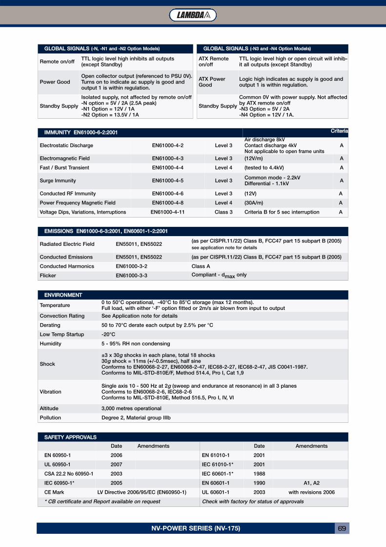
NV-POWER SERIES (NV-175) 69
EEMMIISSSSIIOONNSS EENN6611000000--66--33::22000011,, EENN6600660011--11--22::22000011Radiated Electric Field EN55011, EN55022
(as per CISPR.11/22) Class B, FCC47 part 15 subpart B (2005)
see application note for details
Conducted Emissions EN55011, EN55022 (as per CISPR.11/22) Class B, FCC47 part 15 subpart B (2005)
Conducted Harmonics EN61000-3-2 Class A
Flicker EN61000-3-3 Compliant - dmax only
GGLLOOBBAALL SSIIGGNNAALLSS ((--NN33 aanndd --NN44 OOppttiioonn MMooddeellss))ATX Remoteon/off
TTL logic level high or open circuit will inhib-it all outputs (except Standby)
ATX PowerGood
Logic high indicates ac supply is good andoutput 1 is within regulation.
Standby Supply
Common 0V with power supply. Not affectedby ATX remote on/off-N3 Option = 5V / 2A-N4 Option = 12V / 1A.
EENNVVIIRROONNMMEENNTTTemperature
0 to 50°C operational, -40°C to 85°C storage (max 12 months).Full load, with either ‘-F’ option fitted or 2m/s air blown from input to output
Convection Rating See Application note for details
Derating 50 to 70°C derate each output by 2.5% per °C
Low Temp Startup -20°C
Humidity 5 - 95% RH non condensing
Shock
±3 x 30g shocks in each plane, total 18 shocks30g shock = 11ms (+/-0.5msec), half sineConforms to EN60068-2-27, EN60068-2-47, IEC68-2-27, IEC68-2-47, JIS C0041-1987.Conforms to MIL-STD-810E/F, Method 514.4, Pro I, Cat 1,9
VibrationSingle axis 10 - 500 Hz at 2g (sweep and endurance at resonance) in all 3 planesConforms to EN60068-2-6, IEC68-2-6Conforms to MIL-STD-810E, Method 516.5, Pro I, IV, VI
Altitude 3,000 metres operational
Pollution Degree 2, Material group IIIb
GGLLOOBBAALL SSIIGGNNAALLSS ((--NN,, --NN11 aanndd --NN22 OOppttiioonn MMooddeellss))Remote on/off
TTL logic level high inhibits all outputs(except Standby)
Power GoodOpen collector output (referenced to PSU 0V).Turns on to indicate ac supply is good andoutput 1 is within regulation.
Standby Supply
Isolated supply, not affected by remote on/off-N option = 5V / 2A (2.5A peak)-N1 Option = 12V / 1A-N2 Option = 13.5V / 1A
IIMMMMUUNNIITTYY EENN6611000000--66--22::22000011 CCrriitteerriiaaElectrostatic Discharge EN61000-4-2 Level 3
Air discharge 8kVContact discharge 4kVNot applicable to open frame units
A
Electromagnetic Field EN61000-4-3 Level 3 (12V/m) A
Fast / Burst Transient EN61000-4-4 Level 4 (tested to 4.4kV) A
Surge Immunity EN61000-4-5 Level 3Common mode - 2.2kVDifferential - 1.1kV
A
Conducted RF Immunity EN61000-4-6 Level 3 (12V) A
Power Frequency Magnetic Field EN61000-4-8 Level 4 (30A/m) A
Voltage Dips, Variations, Interruptions EN61000-4-11 Class 3 Criteria B for 5 sec interruption A
SSAAFFEETTYY AAPPPPRROOVVAALLSSDate Amendments Date Amendments
EN 60950-1 2006 EN 61010-1 2001
UL 60950-1 2007 IEC 61010-1* 2001
CSA 22.2 No 60950-1 2003 IEC 60601-1* 1988
IEC 60950-1* 2005 EN 60601-1 1990 A1, A2
CE Mark LV Directive 2006/95/EC (EN60950-1) UL 60601-1 2003 with revisions 2006
* CB certificate and Report available on request Check with factory for status of approvals
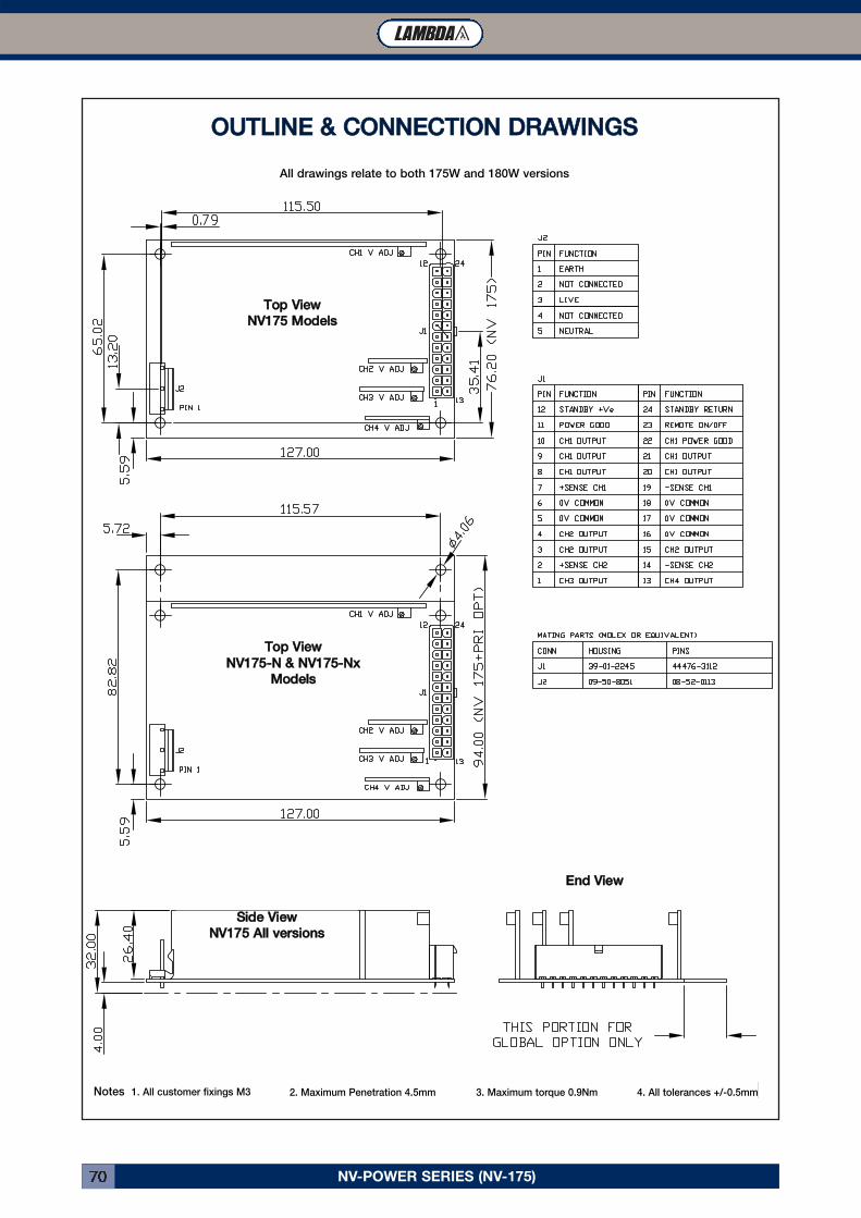
NV-POWER SERIES (NV-175)70
SSiiddee VViieewwNNVV117755 AAllll vveerrssiioonnss
TToopp VViieewwNNVV117755 MMooddeellss
EEnndd VViieeww
TToopp VViieewwNNVV117755--NN && NNVV117755--NNxx
MMooddeellss
OOUUTTLLIINNEE && CCOONNNNEECCTTIIOONN DDRRAAWWIINNGGSSAll drawings relate to both 175W and 180W versions
Notes 1. All customer fixings M3 2. Maximum Penetration 4.5mm 3. Maximum torque 0.9Nm 4. All tolerances +/-0.5mm
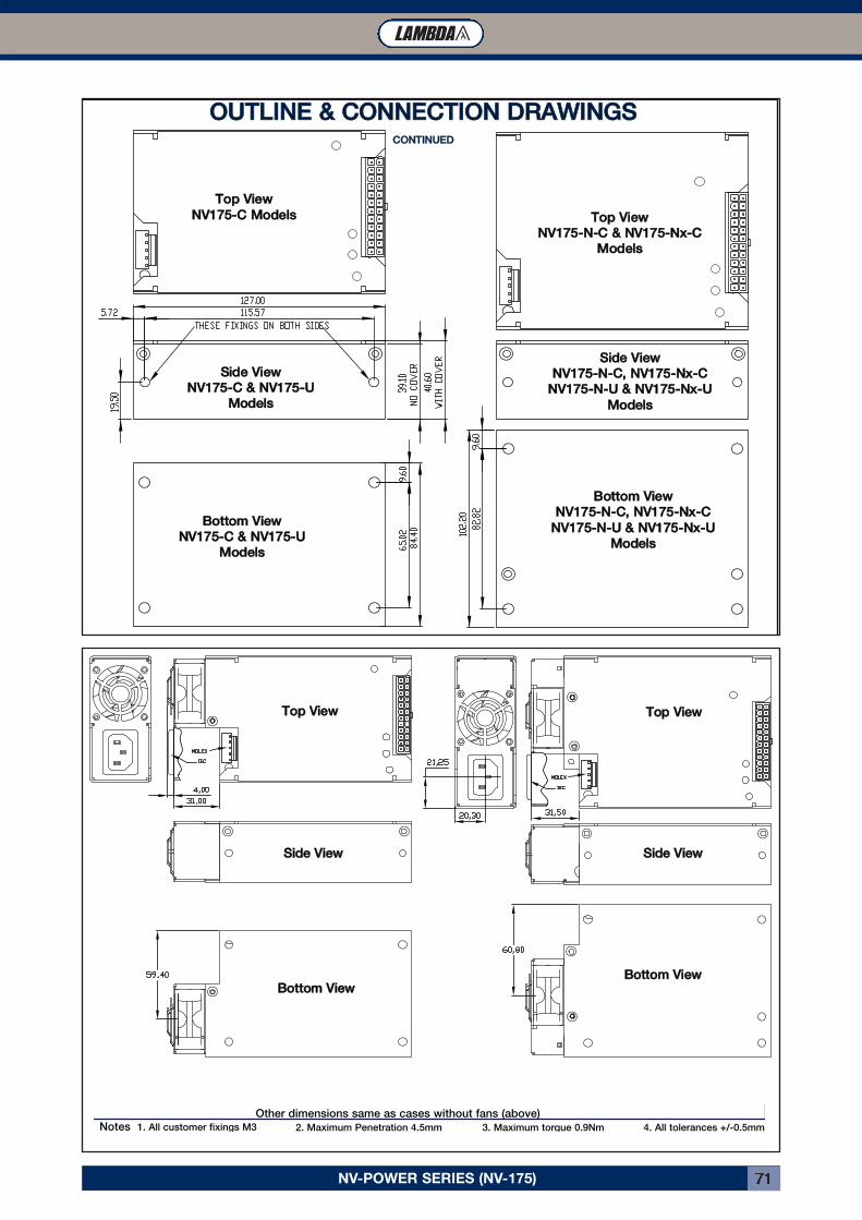
NV-POWER SERIES (NV-175) 71
TToopp VViieewwNNVV117755--CC MMooddeellss TToopp VViieeww
NNVV117755--NN--CC && NNVV117755--NNxx--CCMMooddeellss
SSiiddee VViieewwNNVV117755--CC && NNVV117755--UU
MMooddeellss
BBoottttoomm VViieewwNNVV117755--NN--CC,, NNVV117755--NNxx--CC
NNVV117755--NN--UU && NNVV117755--NNxx--UUMMooddeellss
SSiiddee VViieewwNNVV117755--NN--CC,, NNVV117755--NNxx--CC
NNVV117755--NN--UU && NNVV117755--NNxx--UUMMooddeellss
BBoottttoomm VViieewwNNVV117755--CC && NNVV117755--UU
MMooddeellss
OOUUTTLLIINNEE && CCOONNNNEECCTTIIOONN DDRRAAWWIINNGGSSCCOONNTTIINNUUEEDD
TToopp VViieeww TToopp VViieeww
SSiiddee VViieeww
BBoottttoomm VViieeww
SSiiddee VViieeww
BBoottttoomm VViieeww
Other dimensions same as cases without fans (above)Notes 1. All customer fixings M3 2. Maximum Penetration 4.5mm 3. Maximum torque 0.9Nm 4. All tolerances +/-0.5mm
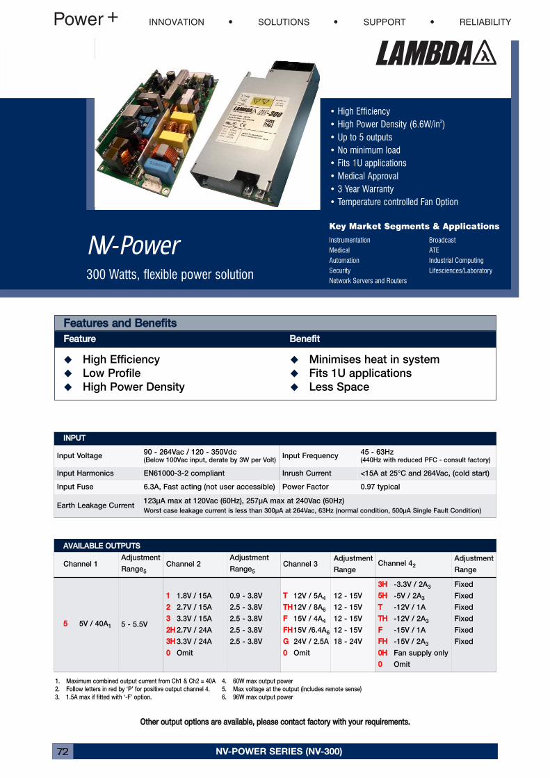
NV-POWER SERIES (NV-300)72
• High Efficiency• High Power Density (6.6W/in3)• Up to 5 outputs• No minimum load• Fits 1U applications• Medical Approval• 3 Year Warranty• Temperature controlled Fan Option
Key Market Segments & Applications
Instrumentation BroadcastMedical ATEAutomation Industrial ComputingSecurity Lifesciences/LaboratoryNetwork Servers and Routers
NV-Power300 Watts, flexible power solution
FFeeaattuurreess aanndd BBeenneeffiittssFFeeaattuurree BBeenneeffiitt� High Efficiency � Minimises heat in system
� Low Profile � Fits 1U applications
� High Power Density � Less Space
IINNPPUUTTInput Voltage
90 - 264Vac / 120 - 350Vdc(Below 100Vac input, derate by 3W per Volt)
Input Frequency45 - 63Hz(440Hz with reduced PFC - consult factory)
Input Harmonics EN61000-3-2 compliant Inrush Current <15A at 25°C and 264Vac, (cold start)
Input Fuse 6.3A, Fast acting (not user accessible) Power Factor 0.97 typical
Earth Leakage Current123μA max at 120Vac (60Hz), 257μA max at 240Vac (60Hz)
Worst case leakage current is less than 300μA at 264Vac, 63Hz (normal condition, 500μA Single Fault Condition)
AAVVAAIILLAABBLLEE OOUUTTPPUUTTSSChannel 1
Adjustment
Range5
Channel 2Adjustment
Range5
Channel 3Adjustment
RangeChannel 42
Adjustment
Range
55 5V / 40A1 5 - 5.5V
11 1.8V / 15A
22 2.7V / 15A
33 3.3V / 15A
22HH 2.7V / 24A
33HH 3.3V / 24A
00 Omit
0.9 - 3.8V
2.5 - 3.8V
2.5 - 3.8V
2.5 - 3.8V
2.5 - 3.8V
TT 12V / 5A4
TTHH12V / 8A6
FF 15V / 4A4
FFHH15V /6.4A6
GG 24V / 2.5A
00 Omit
12 - 15V
12 - 15V
12 - 15V
12 - 15V
18 - 24V
33HH -3.3V / 2A3
55HH -5V / 2A3
TT -12V / 1A
TTHH -12V / 2A3
FF -15V / 1A
FFHH -15V / 2A3
00HH Fan supply only
00 Omit
Fixed
Fixed
Fixed
Fixed
Fixed
Fixed
4. 60W max output power
5. Max voltage at the output (includes remote sense)
6. 96W max output power
1. Maximum combined output current from Ch1 & Ch2 = 40A
2. Follow letters in red by ‘P’ for positive output channel 4.
3. 1.5A max if fitted with ‘-F’ option.
OOtthheerr oouuttppuutt ooppttiioonnss aarree aavvaaiillaabbllee,, pplleeaassee ccoonnttaacctt ffaaccttoorryy wwiitthh yyoouurr rreeqquuiirreemmeennttss..
INNOVATION SOLUTIONS SUPPORT RELIABILITY
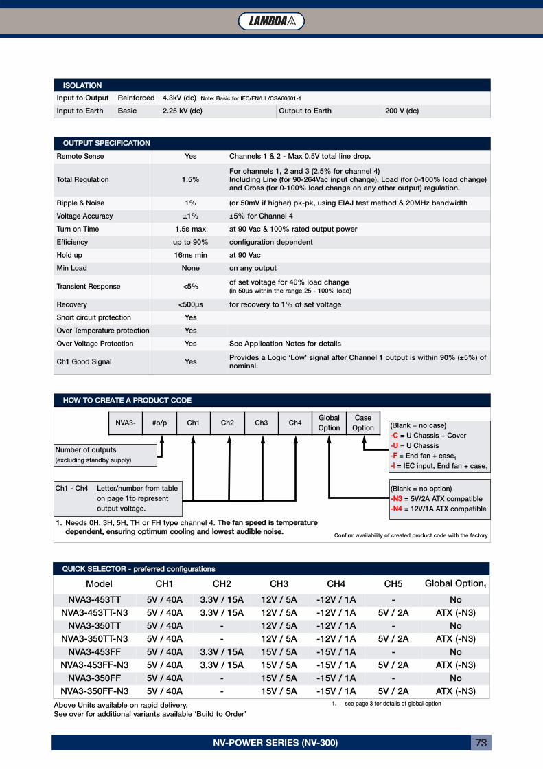
NV-POWER SERIES (NV-300) 73
OOUUTTPPUUTT SSPPEECCIIFFIICCAATTIIOONNRemote Sense Yes Channels 1 & 2 - Max 0.5V total line drop.
Total Regulation 1.5%For channels 1, 2 and 3 (2.5% for channel 4)Including Line (for 90-264Vac input change), Load (for 0-100% load change)and Cross (for 0-100% load change on any other output) regulation.
Ripple & Noise 1% (or 50mV if higher) pk-pk, using EIAJ test method & 20MHz bandwidth
Voltage Accuracy ±1% ±5% for Channel 4
Turn on Time 1.5s max at 90 Vac & 100% rated output power
Efficiency up to 90% configuration dependent
Hold up 16ms min at 90 Vac
Min Load None on any output
Transient Response <5%of set voltage for 40% load change(in 50μs within the range 25 - 100% load)
Recovery <500μs for recovery to 1% of set voltage
Short circuit protection Yes
Over Temperature protection Yes
Over Voltage Protection Yes See Application Notes for details
Ch1 Good Signal YesProvides a Logic ‘Low’ signal after Channel 1 output is within 90% (±5%) ofnominal.
HHOOWW TTOO CCRREEAATTEE AA PPRROODDUUCCTT CCOODDEENVA3- #o/p Ch1 Ch2 Ch3 Ch4
Global
Option
Case
Option
Number of outputs
(excluding standby supply)
(Blank = no case)
--CC = U Chassis + Cover
--UU = U Chassis
--FF = End fan + case1
--II = IEC input, End fan + case1
(Blank = no option)
--NN33 = 5V/2A ATX compatible
--NN44 = 12V/1A ATX compatible
1. Needs 0H, 3H, 5H, TH or FH type channel 4. TThhee ffaann ssppeeeedd iiss tteemmppeerraattuurreeddeeppeennddeenntt,, eennssuurriinngg ooppttiimmuumm ccoooolliinngg aanndd lloowweesstt aauuddiibbllee nnooiissee..
1. see page 3 for details of global optionAbove Units available on rapid delivery.
See over for additional variants available ‘Build to Order’
QQUUIICCKK SSEELLEECCTTOORR -- pprreeffeerrrreedd ccoonnffiigguurraattiioonnssModel CH1 CH2 CH3 CH4 CH5 Global Option1
NVA3-453TT 5V / 40A 3.3V / 15A 12V / 5A -12V / 1A - No
NVA3-453TT-N3 5V / 40A 3.3V / 15A 12V / 5A -12V / 1A 5V / 2A ATX (-N3)
NVA3-350TT 5V / 40A - 12V / 5A -12V / 1A - No
NVA3-350TT-N3 5V / 40A - 12V / 5A -12V / 1A 5V / 2A ATX (-N3)
NVA3-453FF 5V / 40A 3.3V / 15A 15V / 5A -15V / 1A - No
NVA3-453FF-N3 5V / 40A 3.3V / 15A 15V / 5A -15V / 1A 5V / 2A ATX (-N3)
NVA3-350FF 5V / 40A - 15V / 5A -15V / 1A - No
NVA3-350FF-N3 5V / 40A - 15V / 5A -15V / 1A 5V / 2A ATX (-N3)
Confirm availability of created product code with the factory
IISSOOLLAATTIIOONNInput to Output Reinforced 4.3kV (dc) Note: Basic for IEC/EN/UL/CSA60601-1
Input to Earth Basic 2.25 kV (dc) Output to Earth 200 V (dc)
Ch1 - Ch4 Letter/number from table
on page 1to represent
output voltage.
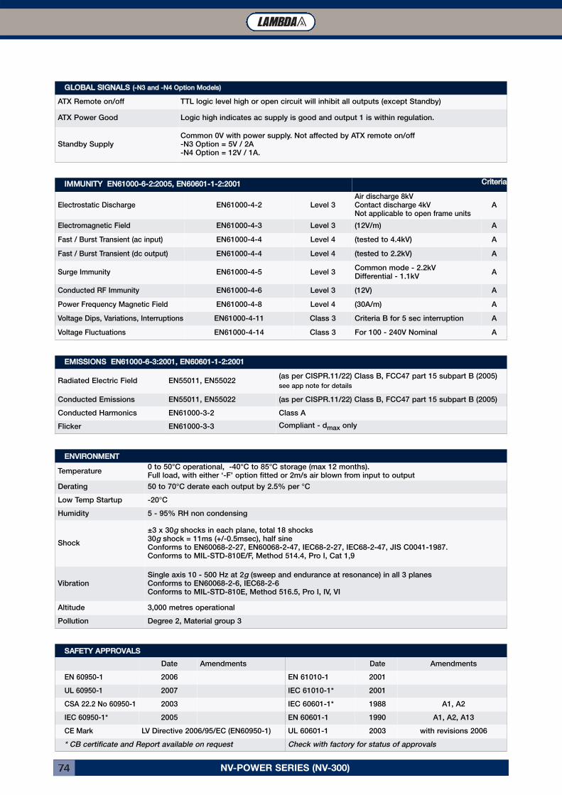
NV-POWER SERIES (NV-300)74
EEMMIISSSSIIOONNSS EENN6611000000--66--33::22000011,, EENN6600660011--11--22::22000011Radiated Electric Field EN55011, EN55022
(as per CISPR.11/22) Class B, FCC47 part 15 subpart B (2005)
see app note for details
Conducted Emissions EN55011, EN55022 (as per CISPR.11/22) Class B, FCC47 part 15 subpart B (2005)
Conducted Harmonics EN61000-3-2 Class A
Flicker EN61000-3-3 Compliant - dmax only
GGLLOOBBAALL SSIIGGNNAALLSS ((--NN33 aanndd --NN44 OOppttiioonn MMooddeellss))ATX Remote on/off TTL logic level high or open circuit will inhibit all outputs (except Standby)
ATX Power Good Logic high indicates ac supply is good and output 1 is within regulation.
Standby SupplyCommon 0V with power supply. Not affected by ATX remote on/off-N3 Option = 5V / 2A-N4 Option = 12V / 1A.
EENNVVIIRROONNMMEENNTTTemperature
0 to 50°C operational, -40°C to 85°C storage (max 12 months).Full load, with either ‘-F’ option fitted or 2m/s air blown from input to output
Derating 50 to 70°C derate each output by 2.5% per °C
Low Temp Startup -20°C
Humidity 5 - 95% RH non condensing
Shock
±3 x 30g shocks in each plane, total 18 shocks30g shock = 11ms (+/-0.5msec), half sineConforms to EN60068-2-27, EN60068-2-47, IEC68-2-27, IEC68-2-47, JIS C0041-1987.Conforms to MIL-STD-810E/F, Method 514.4, Pro I, Cat 1,9
VibrationSingle axis 10 - 500 Hz at 2g (sweep and endurance at resonance) in all 3 planesConforms to EN60068-2-6, IEC68-2-6Conforms to MIL-STD-810E, Method 516.5, Pro I, IV, VI
Altitude 3,000 metres operational
Pollution Degree 2, Material group 3
IIMMMMUUNNIITTYY EENN6611000000--66--22::22000055,, EENN6600660011--11--22::22000011 CCrriitteerriiaaElectrostatic Discharge EN61000-4-2 Level 3
Air discharge 8kVContact discharge 4kVNot applicable to open frame units
A
Electromagnetic Field EN61000-4-3 Level 3 (12V/m) A
Fast / Burst Transient (ac input) EN61000-4-4 Level 4 (tested to 4.4kV) A
Fast / Burst Transient (dc output) EN61000-4-4 Level 4 (tested to 2.2kV) A
Surge Immunity EN61000-4-5 Level 3Common mode - 2.2kVDifferential - 1.1kV
A
Conducted RF Immunity EN61000-4-6 Level 3 (12V) A
Power Frequency Magnetic Field EN61000-4-8 Level 4 (30A/m) A
Voltage Dips, Variations, Interruptions EN61000-4-11 Class 3 Criteria B for 5 sec interruption A
Voltage Fluctuations EN61000-4-14 Class 3 For 100 - 240V Nominal A
SSAAFFEETTYY AAPPPPRROOVVAALLSSDate Amendments Date Amendments
EN 60950-1 2006 EN 61010-1 2001
UL 60950-1 2007 IEC 61010-1* 2001
CSA 22.2 No 60950-1 2003 IEC 60601-1* 1988 A1, A2
IEC 60950-1* 2005 EN 60601-1 1990 A1, A2, A13
CE Mark LV Directive 2006/95/EC (EN60950-1) UL 60601-1 2003 with revisions 2006
* CB certificate and Report available on request Check with factory for status of approvals
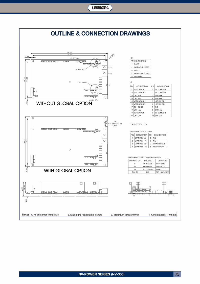
NV-POWER SERIES (NV-300) 75
J3
GLOBAL OPTION
ONLY
10 1
20 11
7 1
8 2
(or LO)
HI
CH4 V ADJ
HI
(or LO)
T2 (+)
T1 (-)
J1
PIN 1
34.0
0
4.0
0
28.0
0
1
2
3
4
5
6
7
8
9
1
2
3
4
5
CH4 O/P
0V COMMON
CH3 +Ve
N/C
-SENSE CH2
-SENSE CH1
CH2 +Ve
CH2 +Ve
0V COMMON
0V COMMON
CONNECTION
10
PIN
PIN
20
19
18
17
16
15
14
13
12
11
PIN
J2
J1
NEUTRAL
NOT CONNECTED
LIVE
NOT CONNECTED
EARTH
CONNECTION
CH4 O/P
0V COMMON
CH3 +Ve
CH1 GOOD
+SENSE CH2
+SENSE CH1
CH2 +Ve
CH2 +Ve
0V COMMON
0V COMMON
CONNECTION
120.0
0
4.0
0112.0
0
CH2 V ADJ
CH3 V ADJ
95.0
0
87.0
04.0
0
4.00
39-01-2205 44476-3112
TAG 19073-0165
50394
08-52-0113
CRIMP PIN
MATING PARTS (MOLEX OR EQUIVALENT)
CONNECTOR HOUSING
J1
J2
J3
T1 & T2 N/A
51110-0860
09-50-8051
J3 (GLOBAL OPTION ONLY)
4 STANDBY +Ve 8 REM ON/OFF
3 STANDBY -Ve 7 POWER GOOD
2 STANDBY +Ve 6 N/C
1 STANDBY -Ve 5 N/C
PIN CONNECTION PIN CONNECTION
T1 & T2 (SEE TOP LEFT)
WWWWIIIITTTTHHHHOOOOUUUUTTTT GGGGLLLLOOOOBBBBAAAALLLL OOOOPPPPTTTTIIIIOOOONNNN
WWWWIIIITTTTHHHH GGGGLLLLOOOOBBBBAAAALLLL OOOOPPPPTTTTIIIIOOOONNNN
NNNNVVVV333300000000 OOOOUUUUTTTTLLLLIIIINNNNEEEESSSS &&&& CCCCOOOONNNNNNNNEEEECCCCTTTTIIIIOOOONNNNSSSS((((OOOOPPPPEEEENNNN FFFFRRRRAAAAMMMMEEEE,,,, WWWWIIIITTTTHHHH &&&& WWWWIIIITTTTHHHHOOOOUUUUTTTT GGGGLLLLOOOOBBBBAAAALLLL OOOOPPPPTTTTIIIIOOOONNNN))))
IIIISSSSSSSSUUUUEEEE 1111 22225555....00009999....00006666 ((((PPPPRRRROOOOVVVVIIIISSSSIIIIOOOONNNNAAAALLLL))))
184.00
174.00
CH1 V ADJ
5.00
J2
OOUUTTLLIINNEE && CCOONNNNEECCTTIIOONN DDRRAAWWIINNGGSS
Notes 1. All customer fixings M3 2. Maximum Penetration 4.5mm 3. Maximum torque 0.9Nm 4. All tolerances +/-0.5mm
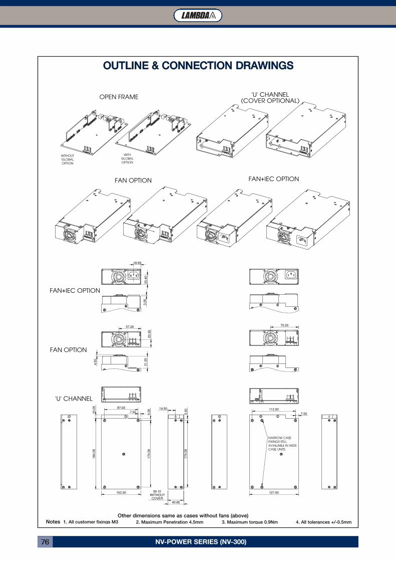
NV-POWER SERIES (NV-300)76
18.95
25.4
0
127.00
7.50
112.00
40.60
174.0
05.0
019.50
39.10
WITHOUT
COVER
184.0
0
5.0
0174.0
0
87.00
7.5010.0
0
102.00
FAN+IEC OPTION
NV300 OUTLINES & CONNECTIONSNV300 OUTLINES & CONNECTIONSNV300 OUTLINES & CONNECTIONSNV300 OUTLINES & CONNECTIONSCASING OPTIONS. ISSUE 1 25.09.06 (PROVISIONAL)CASING OPTIONS. ISSUE 1 25.09.06 (PROVISIONAL)CASING OPTIONS. ISSUE 1 25.09.06 (PROVISIONAL)CASING OPTIONS. ISSUE 1 25.09.06 (PROVISIONAL)
NARROW CASE
FIXINGS STILL
AVAILABLE IN WIDE
CASE UNITS.
'U' CHANNEL(COVER OPTIONAL)
72.20
31.2
0
4.0
0
OPEN FRAME
57.20
20.3
0
FAN OPTION
FAN+IEC OPTION
3.0
0
WITHOUT
GLOBAL
OPTION
WITH
GLOBAL
OPTION
'U' CHANNEL
FAN OPTION
OOUUTTLLIINNEE && CCOONNNNEECCTTIIOONN DDRRAAWWIINNGGSS
Other dimensions same as cases without fans (above)Notes 1. All customer fixings M3 2. Maximum Penetration 4.5mm 3. Maximum torque 0.9Nm 4. All tolerances +/-0.5mm
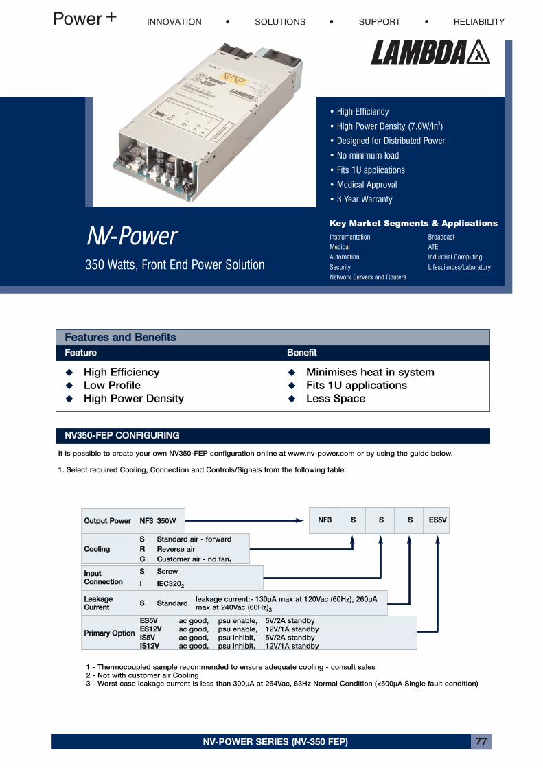
NV-POWER SERIES (NV-350 FEP) 77
• High Efficiency
• High Power Density (7.0W/in3)
• Designed for Distributed Power
• No minimum load
• Fits 1U applications
• Medical Approval
• 3 Year Warranty
Key Market Segments & Applications
Instrumentation BroadcastMedical ATEAutomation Industrial ComputingSecurity Lifesciences/LaboratoryNetwork Servers and Routers
NV-Power350 Watts, Front End Power Solution
NV-POWER SERIES (NV-350 FEP)
NNVV335500--FFEEPP CCOONNFFIIGGUURRIINNGGIt is possible to create your own NV350-FEP configuration online at www.nv-power.com or by using the guide below.
1. Select required Cooling, Connection and Controls/Signals from the following table:
1 - Thermocoupled sample recommended to ensure adequate cooling - consult sales2 - Not with customer air Cooling3 - Worst case leakage current is less than 300μA at 264Vac, 63Hz Normal Condition (<500μA Single fault condition)
FFeeaattuurreess aanndd BBeenneeffiittssFFeeaattuurree BBeenneeffiitt� High Efficiency � Minimises heat in system
� Low Profile � Fits 1U applications
� High Power Density � Less Space
PPrriimmaarryy OOppttiioonn EESS55VV ac good, psu enable, 5V/2A standbyEESS1122VV ac good, psu enable, 12V/1A standbyIISS55VV ac good, psu inhibit, 5V/2A standbyIISS1122VV ac good, psu inhibit, 12V/1A standby
LLeeaakkaaggeeCCuurrrreenntt SS SStandard
leakage current:- 130μA max at 120Vac (60Hz), 260μAmax at 240Vac (60Hz)3
IInnppuuttCCoonnnneeccttiioonn SS SScrew
II IIEC3202
CCoooolliinngg SS SStandard air - forward
RR RReverse air
CC CCustomer air - no fan1
OOuuttppuutt PPoowweerr NNFF33 3350W NNFF33 SS SS SS EESS55VV
INNOVATION SOLUTIONS SUPPORT RELIABILITY
NV-POWER SERIES (NV-350 FEP)78
OOUUTTPPUUTT MMOODDUULLEE ((TTyyppee FFEE))OOuuttppuutt 11 OOuuttppuutt 22 TToottaall
VVoollttaaggee RRaannggee MMaaxxiimmuummCCuurrrreenntt MMaaxxiimmuumm
PPoowweerr OOuuttppuuttVVoollttaaggee MMaaxxiimmuumm
CCuurrrreenntt MMaaxxiimmuummPPoowweerr MMaaxx OOuuttppuutt
PPoowweerr11.5 - 13.2 V 29.2A 350W 12 V 2A 24W 350W
NNVV335500--FFEEPP CCOONNFFIIGGUURRIINNGG2. Select output required from the Module Table below.
Example - if you require 12V 29A :-a) select FE module and prefix with voltage eg 1122FFEEThis will create a complete product description eg NNFF33SSSSSSEESS55VV 1122FFEE which represents a two output NV350-FEP withForward air, Screw i/p terminals, 300μA Leakage, ac good, PSU enable & 5V/2A aux supplyOutput 1 = 12V / 29.2A with screw terminalsOutput 2 = 12V / 2A with screw terminalsMax 350W continuous output power
3. Contact Lambda to issue a part number.
OOUUTTPPUUTTVoltage / Current See module tables
Turn on Time 1.5s max at 90Vac and 100% rated output power
Rise time <50ms to 90% of voltage, monotonic rise above 10%
Efficiency 90% Typical
Hold up 16ms min at 90Vac and 100% rated power
Ripple and Noise <1% Pk-Pk, using EIAJ test method & 20MHz bandwidth
Voltage Accuracy <1% of set voltage (±5% for channel 2)
Remote Sense Yes Standard on single o/p + ch1 of dual modules, max 0.5V total line drop
Minimum Load No on any output
Temperature Coefficient <0.02% of rated voltage per °C
Total Regulation 1%Including:- Load Regulation for 0-100% load change
and Line Regulation for 90-264Vac input change(2% for channel 2)
Transient Response <4% of set voltage for 50% load change
Recovery 500μs for recovery to 1% of set voltage
Over Voltage Protection (ch1) 15 - 16V
Over Current Protection (ch1) 110 - 150% of rated current, hiccup mode. Module primary side protected
Short Circuit Protection Yes
Over Temperature Protection Yes Cycle ac off/on to resetShutdown temperature varies according to ambient, o/p power & i/pV
IINNPPUUTTInput Voltage 90-264Vac
Input Frequency 47 - 63 Hz (up to 440Hz with reduced PFC)
Input Harmonics EN61000-3-2 compliant
Inrush Current <15A at 25°C and 264Vac (cold start)
Input Fuse 6.3A / 250Vac HBC Fast Acting (not user accessible)
Power Factor 0.97 (typical)
Leakage Current 130μA max at 120Vac (60Hz), 260μA max at 240Vac (60Hz)Worst case leakage current is less than 300μA at 264Vac, 63Hz Normal Condition (<500μA Single fault condition)
NV-POWER SERIES (NV-350 FEP) 79
SSIIGGNNAALLSS -- SSttaannddaarrddCh1 Good
Open collector output, (emitter connected to Ch1 0V)
‘On’ indicates output is within 90% (±5%) of nominal
Ch1 Remote Sense -
Ch1 Remote Sense +
Connections for remote sense. Up to 0.5V total line drop can be compensated. If remote sense
is not required, do not connect either ‘Sense -’ or ‘Sense +’
IISSOOLLAATTIIOONNInput to Output Reinforced 4.3kV (dc) Note: Basic for IEC/EN/UL/CSA60601-1
Input to Earth Basic 2.3kV (dc)
Output to Earth 200V (dc)
GGLLOOBBAALL IINNTTEERRFFAACCEE SSIIGGNNAALLSS -- wwiitthh PPrriimmaarryy OOppttiioonnAC good collectorAC good emitter
Uncommitted optocoupler. Turns on typically 5ms after ac is good and off typically 5ms beforeany channel falls below 95% of nominal
ES & IS Logic 0 TTL low enables (ES) or inhibits (IS) the entire psu including fan (except standby)
ES & IS Logic 1 TTL high enables (ES) or inhibits (IS) the entire psu including fan (except standby)
Standby Supply 5V / 2A (2.5A peak) or 12V / 1A (1.2A peak)
EENNVVIIRROONNMMEENNTTTemperature 0° to 50° operational, -40° to 85°C storage (max 12 months)
Derating 50°C to 70°C derate each output and total output power by 2.5% per °C
Low Temperature Start-up -20°C
Humidity 5-95% RH non condensing
Shock±3 x 30g shocks in each plane, total 18 shocks30g shock = 11ms (±0.5ms), half sineconforms to EN60068-2-27, EN60068-2-47, IEC68-2-27, IEC68-2-47, JIS C0041-1987.
Vibration Single axis 10 - 500Hz at 2g (sweep and endurance at resonance) in all 3 planes
Altitude 3,000 metres operational (15,000 metres non operational)
Pollution Degree 2, Material group IIIb
IIMMMMUUNNIITTYY EENN6611000000--66--22::22000055,, EENN6600660011--11--22::22000011 CCrriitteerriiaaElectrostatic Discharge EN61000-4-2 Level 4
Air discharge 15kVContact discharge 8kV
A
Electromagnetic Field EN61000-4-3 Level 3 tested to 12V/m A
Fast / Burst Transient (ac Input) EN61000-4-4 Level 4 tested to 4.4kV A
Fast / Burst Transient (dc Output) EN61000-4-4 Level 4 tested to 2.2kV A
Surge Immunity EN61000-4-5 Level 3Common mode to 2.2kVDifferential mode to 1.1kV
A
Conducted RF Immunity EN61000-4-6 Level 3 tested to 12V A
Power Frequency Magnetic Field EN61000-4-8 Level 4 Tested to 30A/m, 50/60Hz A
Voltage Dips, Variation, Interruptions EN61000-4-11 Class 3 Criteria B for 5 sec interruption A
Voltage Fluctuations EN61000-4-14 Class 3 For 100 - 240V Nominal A
SSAAFFEETTYY AAPPPPRROOVVAALLSSDDaattee AAmmeennddmmeennttss DDaattee AAmmeennddmmeennttss
EN 60950-1 2006 EN 61010-1 2001
UL 60950-1 2003 IEC 61010-1* 2001
CSA22.2 No 60950-1 2003 IEC 60601-1* 1988 A1, A2
IEC60950-1* 2001 EN 60601-1a 1990 A1, A2, A13
CE Mark LV Directive 2006/95/EC (EN60950-1) UL 60601-1 2003 with revisions 2006
* CB Certificate and report available on requesta - Not applicable to IEC320 input version
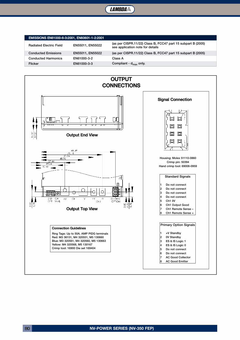
NV-POWER SERIES (NV-350 FEP)80
OOuuttppuutt TToopp VViieewwPrimary Option Signals
1 +V Standby
2 0V Standby
3 ES & IS Logic 1
4 ES & IS Logic 0
5 Do not connect
6 Do not connect
7 AC Good Collector
8 AC Good Emitter
Standard Signals
1 Do not connect
2 Do not connect
3 Do not connect
4 Do not connect
5 Ch1 0V
6 Ch1 Output Good
7 Ch1 Remote Sense –
8 Ch1 Remote Sense +
OOuuttppuutt EEnndd VViieeww
CCoonnnneeccttiioonn GGuuiiddeelliinneessRing Tags: Up to 50A. AMP PIDG terminals
Red: M3 36151, M4 320551, M5 130660
Blue: M3 320561, M4 320560, M5 130663
Yellow: M4 320568, M5 130167
Crimp tool: 16900 Die set 169404
OOUUTTPPUUTTCCOONNNNEECCTTIIOONNSS
Housing: Molex 51110-0860
Crimp pin: 50394
Hand crimp tool: 69008-0959
SSiiggnnaall CCoonnnneeccttiioonn
EEMMIISSSSIIOONNSS EENN6611000000--66--33::22000011,, EENN6600660011--11--22::22000011Radiated Electric Field EN55011, EN55022
(as per CISPR.11/22) Class B, FCC47 part 15 subpart B (2005)see application note for details
Conducted Emissions EN55011, EN55022 (as per CISPR.11/22) Class B, FCC47 part 15 subpart B (2005)
Conducted Harmonics EN61000-3-2 Class A
Flicker EN61000-3-3 Compliant - dmax only.
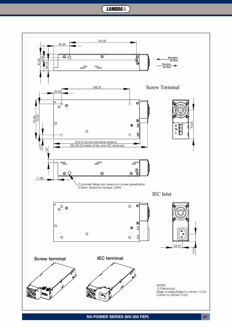
NV-POWER SERIES (NV-350 FEP) 81
Standard
air flow
Reverse
air flow
Screw terminal IEC terminal
ENL
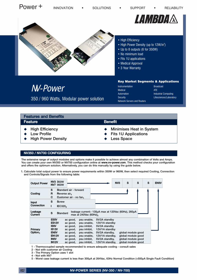
NV-POWER SERIES (NV-350 / NV-700)82
• High Efficiency• High Power Density (up to 12W/in3)• Up to 8 outputs (6 for 350W)• No minimum load• Fits 1U applications• Medical Approval• 3 Year Warranty
Key Market Segments & Applications
Instrumentation BroadcastMedical ATEAutomation Industrial ComputingSecurity Lifesciences/LaboratoryNetwork Servers and Routers
NV-Power350 / 960 Watts, Modular power solution
NNVV335500 // NNVV770000 CCOONNFFIIGGUURRIINNGGThe extensive range of output modules and options make it possible to achieve almost any combination of Volts and Amps.You can create your own NV350 or NV700 configuration online at wwwwww..nnvv--ppoowweerr..ccoomm. This method checks your configurationand offers the optimum solution. Alternatively, you can do this manually by using the guide below.
1. Calculate total output power to ensure power requirements within 350W or 960W, then select required Cooling, Connectionand Controls/Signals from the following table:
1 - Thermocoupled sample recommended to ensure adequate cooling - consult sales2 - Not with customer air Cooling3 - The Primary Option uses 1 slot4 - Not with NV75 - Worst case leakage current is less than 300μA at 264Vac, 63Hz Normal Condition (<500μA Single Fault Condition)
FFeeaattuurreess aanndd BBeenneeffiittssFFeeaattuurree BBeenneeffiitt� High Efficiency � Minimises Heat in System
� Low Profile � Fits 1U Applications
� High Power Density � Less Space
PPrriimmaarryyOOppttiioonn3
EESS55VV ac good, psu enable, 5V/2A standby
EESS1122VV ac good, psu enable, 12V/1A standby
IISS55VV ac good, psu inhibit, 5V/2A standby
IISS1122VV ac good, psu inhibit, 12V/1A standby
EENN55VV ac good, psu enable, 5V/2A standby, global module good
EENN1122VV ac good, psu enable, 12V/1A standby, global module good
IINN55VV ac good, psu inhibit, 5V/2A standby, global module good
IINN1122VV ac good, psu inhibit, 12V/1A standby, global module good
LLeeaakkaaggeeCCuurrrreenntt SS SStandard
leakage current:- 130μA max at 120Vac (60Hz), 260μAmax at 240Vac (60Hz)5
IInnppuuttCCoonnnneeccttiioonn SS SScrew
II IIEC3202
CCoooolliinngg SS SStandard air - forward
RR RReverse air4
CC CCustomer air - no fan1
OOuuttppuutt PPoowweerr NNVV33NNVV77 3350W
960WNNVV33 SS SS SS EENN55VV
INNOVATION SOLUTIONS SUPPORT RELIABILITY
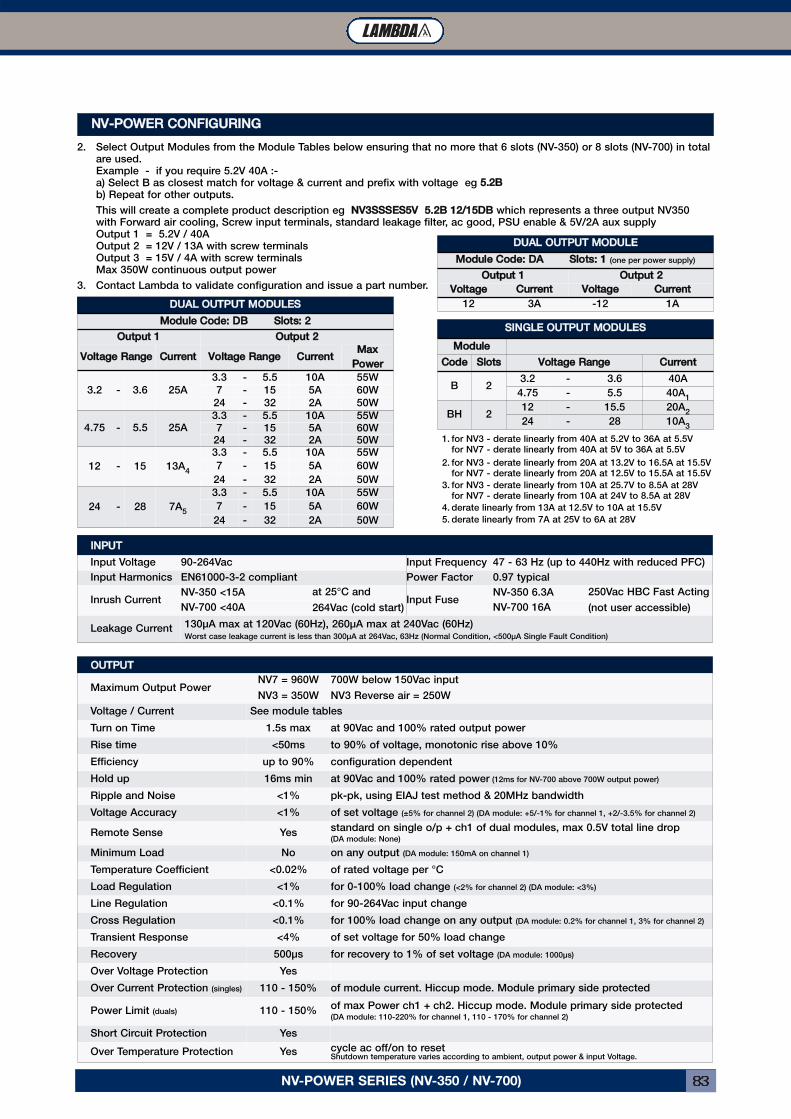
NV-POWER SERIES (NV-350 / NV-700) 83
NNVV--PPOOWWEERR CCOONNFFIIGGUURRIINNGG2. Select Output Modules from the Module Tables below ensuring that no more that 6 slots (NV-350) or 8 slots (NV-700) in total
are used.Example - if you require 5.2V 40A :-a) Select B as closest match for voltage & current and prefix with voltage eg 55..22BBb) Repeat for other outputs.
This will create a complete product description eg NNVV33SSSSSSEESS55VV 55..22BB 1122//1155DDBB which represents a three output NV350with Forward air cooling, Screw input terminals, standard leakage filter, ac good, PSU enable & 5V/2A aux supplyOutput 1 = 5.2V / 40AOutput 2 = 12V / 13A with screw terminalsOutput 3 = 15V / 4A with screw terminalsMax 350W continuous output power
3. Contact Lambda to validate configuration and issue a part number.
1. for NV3 - derate linearly from 40A at 5.2V to 36A at 5.5Vfor NV7 - derate linearly from 40A at 5V to 36A at 5.5V
2. for NV3 - derate linearly from 20A at 13.2V to 16.5A at 15.5Vfor NV7 - derate linearly from 20A at 12.5V to 15.5A at 15.5V
3. for NV3 - derate linearly from 10A at 25.7V to 8.5A at 28Vfor NV7 - derate linearly from 10A at 24V to 8.5A at 28V
4. derate linearly from 13A at 12.5V to 10A at 15.5V
5. derate linearly from 7A at 25V to 6A at 28V
SSIINNGGLLEE OOUUTTPPUUTT MMOODDUULLEESSMMoodduullee
CCooddee SSlloottss VVoollttaaggee RRaannggee CCuurrrreennttB 2
3.2 - 3.6 40A
4.75 - 5.5 40A1
BH 212 - 15.5 20A
2
24 - 28 10A3
DDUUAALL OOUUTTPPUUTT MMOODDUULLEESSMMoodduullee CCooddee:: DDBB SSlloottss:: 22
OOuuttppuutt 11 OOuuttppuutt 22VVoollttaaggee RRaannggee CCuurrrreenntt VVoollttaaggee RRaannggee CCuurrrreenntt MMaaxx
PPoowweerr3.2 - 3.6 25A
3.3 - 5.5 10A 55W
7 - 15 5A 60W
24 - 32 2A 50W
4.75 - 5.5 25A3.3 - 5.5 10A 55W7 - 15 5A 60W
24 - 32 2A 50W
12 - 15 13A4
3.3 - 5.5 10A 55W
7 - 15 5A 60W
24 - 32 2A 50W
24 - 28 7A5
3.3 - 5.5 10A 55W
7 - 15 5A 60W
24 - 32 2A 50W
OOUUTTPPUUTTMaximum Output Power
NV7 = 960W
NV3 = 350W
700W below 150Vac input
NV3 Reverse air = 250W
Voltage / Current See module tables
Turn on Time 1.5s max at 90Vac and 100% rated output power
Rise time <50ms to 90% of voltage, monotonic rise above 10%
Efficiency up to 90% configuration dependent
Hold up 16ms min at 90Vac and 100% rated power (12ms for NV-700 above 700W output power)
Ripple and Noise <1% pk-pk, using EIAJ test method & 20MHz bandwidth
Voltage Accuracy <1% of set voltage (±5% for channel 2) (DA module: +5/-1% for channel 1, +2/-3.5% for channel 2)
Remote Sense Yesstandard on single o/p + ch1 of dual modules, max 0.5V total line drop(DA module: None)
Minimum Load No on any output (DA module: 150mA on channel 1)
Temperature Coefficient <0.02% of rated voltage per °C
Load Regulation <1% for 0-100% load change (<2% for channel 2) (DA module: <3%)
Line Regulation <0.1% for 90-264Vac input change
Cross Regulation <0.1% for 100% load change on any output (DA module: 0.2% for channel 1, 3% for channel 2)
Transient Response <4% of set voltage for 50% load change
Recovery 500μs for recovery to 1% of set voltage (DA module: 1000μs)
Over Voltage Protection Yes
Over Current Protection (singles) 110 - 150% of module current. Hiccup mode. Module primary side protected
Power Limit (duals) 110 - 150%of max Power ch1 + ch2. Hiccup mode. Module primary side protected(DA module: 110-220% for channel 1, 110 - 170% for channel 2)
Short Circuit Protection Yes
Over Temperature Protection Yes cycle ac off/on to resetShutdown temperature varies according to ambient, output power & input Voltage.
IINNPPUUTTInput Voltage 90-264Vac Input Frequency 47 - 63 Hz (up to 440Hz with reduced PFC)
Input Harmonics EN61000-3-2 compliant Power Factor 0.97 typical
Inrush CurrentNV-350 <15A at 25°C and
264Vac (cold start)Input Fuse
NV-350 6.3A 250Vac HBC Fast Acting
(not user accessible)NV-700 <40A NV-700 16A
Leakage Current 130μA max at 120Vac (60Hz), 260μA max at 240Vac (60Hz)Worst case leakage current is less than 300μA at 264Vac, 63Hz (Normal Condition, <500μA Single Fault Condition)
DDUUAALL OOUUTTPPUUTT MMOODDUULLEEMMoodduullee CCooddee:: DDAA SSlloottss:: 11 (one per power supply)
OOuuttppuutt 11 OOuuttppuutt 22VVoollttaaggee CCuurrrreenntt VVoollttaaggee CCuurrrreenntt
12 3A -12 1A
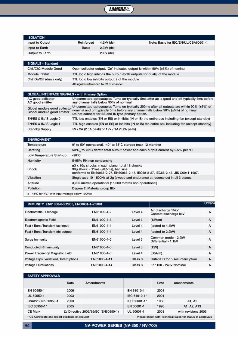
NV-POWER SERIES (NV-350 / NV-700)84
IISSOOLLAATTIIOONNInput to Output Reinforced 4.3kV (dc) Note: Basic for IEC/EN/UL/CSA60601-1
Input to Earth Basic 2.3kV (dc)
Output to Earth 200V (dc)
SSIIGGNNAALLSS -- SSttaannddaarrddCh1/Ch2 Module Good Open collector output. ‘On’ indicates output is within 90% (±5%) of nominal
Module Inhibit TTL logic high inhibits the output (both outputs for duals) of the module
Ch2 On/Off (duals only) TTL logic low inhibits output 2 of the module
All signals referenced to 0V of channel
EENNVVIIRROONNMMEENNTTTemperature 0° to 50° operational, -40° to 85°C storage (max 12 months)
Derating 50°Ca
to 70°C derate total output power and each output current by 2.5% per °C
Low Temperature Start-up -20°C
Humidity 5-95% RH non condensing
Shock±3 x 30g shocks in each plane, total 18 shocks30g shock = 11ms (±0.5ms), half sineconforms to EN60068-2-27, EN60068-2-47, IEC68-2-27, IEC68-2-47, JIS C0041-1987.
Vibration Single axis 10 - 500Hz at 2g (sweep and endurance at resonance) in all 3 planes
Altitude 3,000 metres operational (15,000 metres non operational)
Pollution Degree 2, Material group IIIb
a - 45°C for NV7 with input voltage below 100Vac
SSAAFFEETTYY AAPPPPRROOVVAALLSSDDaattee AAmmeennddmmeennttss DDaattee AAmmeennddmmeennttss
EN 60950-1 2006 EN 61010-1 2001
UL 60950-1 2003 IEC 61010-1* 2001
CSA22.2 No 60950-1 2003 IEC 60601-1* 1988 A1, A2
IEC 60950-1* 2005 EN 60601-1 1990 A1, A2, A13
CE Mark LV Directive 2006/95/EC (EN60950-1) UL 60601-1 2003 with revisions 2006
* CB Certificate and report available on request Please check with Technical Sales for status of approvals
GGLLOOBBAALL IINNTTEERRFFAACCEE SSIIGGNNAALLSS -- wwiitthh PPrriimmaarryy OOppttiioonnAC good collectorAC good emitter
Uncommitted optocoupler. Turns on typically 5ms after ac is good and off typically 5ms beforeany channel falls below 95% of nominal
Global module good collectorGlobal module good emitter
Uncommitted optocoupler. Turns on typically 200ms after all outputs are within 90% (±5%) ofnominal and off typically 5ms before any channel falls below 90% (±5%) of nominal.Do not connect for ES and IS type primary option.
EN/ES & IN/IS Logic 0 TTL low enables (EN or ES) or inhibits (IN or IS) the entire psu including fan (except standby)
EN/ES & IN/IS Logic 1 TTL high enables (EN or ES) or inhibits (IN or IS) the entire psu including fan (except standby)
Standby Supply 5V / 2A (2.5A peak) or 12V / 1A (1.2A peak)
IIMMMMUUNNIITTYY EENN6611000000--66--22::22000055,, EENN6600660011--11--22::22000011 CCrriitteerriiaaElectrostatic Discharge EN61000-4-2 Level 4
Air discharge 15kVContact discharge 8kV
A
Electromagnetic Field EN61000-4-3 Level 3 (12V/m) A
Fast / Burst Transient (ac input) EN61000-4-4 Level 4 (tested to 4.4kV) A
Fast / Burst Transient (dc output) EN61000-4-4 Level 4 (tested to 2.2kV) A
Surge Immunity EN61000-4-5 Level 3Common mode - 2.2kVDifferential - 1.1kV
A
Conducted RF Immunity EN61000-4-6 Level 3 (12V) A
Power Frequency Magnetic Field EN61000-4-8 Level 4 (30A/m) A
Voltage Dips, Variations, Interruptions EN61000-4-11 Class 3 Criteria B for 5 sec interruption A
Voltage Fluctuations EN61000-4-14 Class 3 For 100 - 240V Nominal A
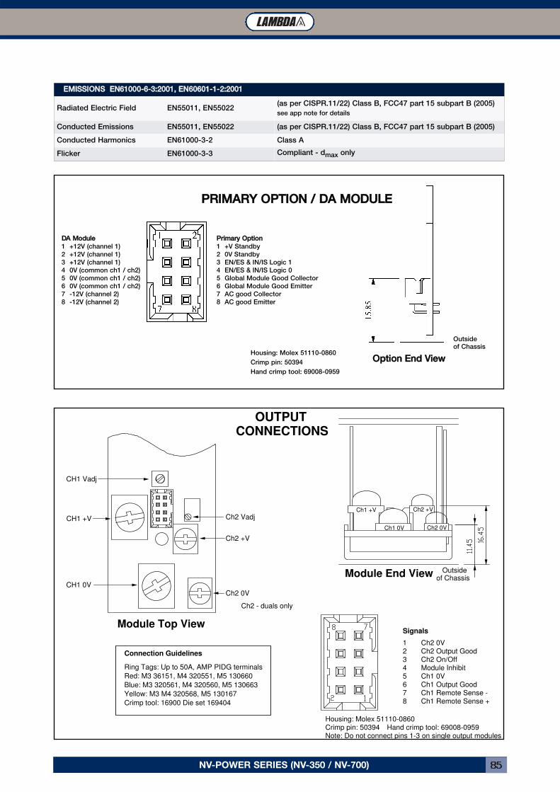
NV-POWER SERIES (NV-350 / NV-700) 85
OOppttiioonn EEnndd VViieeww
Ch1 +V
Ch1 0V
Ch2 +V
Ch2 0V
CH1 0V
CH1 +V
CH1 Vadj
Ch2 Vadj
Ch2 +V
Ch2 0V
Ch2 - duals only
Module Top View
Module End View
Signals
1 Ch2 0V2 Ch2 Output Good3 Ch2 On/Off4 Module Inhibit5 Ch1 0V6 Ch1 Output Good7 Ch1 Remote Sense -8 Ch1 Remote Sense +
Housing: Molex 51110-0860Crimp pin: 50394 Hand crimp tool: 69008-0959
Outsideof Chassis
Connection Guidelines
Ring Tags: Up to 50A, AMP PIDG terminals
Red: M3 36151, M4 320551, M5 130660
Blue: M3 320561, M4 320560, M5 130663
Yellow: M3 M4 320568, M5 130167
Crimp tool: 16900 Die set 169404
OUTPUTCONNECTIONS
Note: Do not connect pins 1-3 on single output modules
PPRRIIMMAARRYY OOPPTTIIOONN // DDAA MMOODDUULLEE
Outsideof Chassis
PPrriimmaarryy OOppttiioonn1 +V Standby
2 0V Standby
3 EN/ES & IN/IS Logic 1
4 EN/ES & IN/IS Logic 0
5 Global Module Good Collector
6 Global Module Good Emitter
7 AC good Collector
8 AC good Emitter
Housing: Molex 51110-0860
Crimp pin: 50394
Hand crimp tool: 69008-0959
DDAA MMoodduullee1 +12V (channel 1)
2 +12V (channel 1)
3 +12V (channel 1)
4 0V (common ch1 / ch2)
5 0V (common ch1 / ch2)
6 0V (common ch1 / ch2)
7 -12V (channel 2)
8 -12V (channel 2)
EEMMIISSSSIIOONNSS EENN6611000000--66--33::22000011,, EENN6600660011--11--22::22000011Radiated Electric Field EN55011, EN55022
(as per CISPR.11/22) Class B, FCC47 part 15 subpart B (2005)
see app note for details
Conducted Emissions EN55011, EN55022 (as per CISPR.11/22) Class B, FCC47 part 15 subpart B (2005)
Conducted Harmonics EN61000-3-2 Class A
Flicker EN61000-3-3 Compliant - dmax only
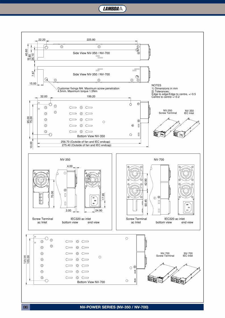
NV-POWER SERIES (NV-350 / NV-700)86
225.8022.20
26
.10
5.8
040
.60
32.00
75
.00
95
.00
199.20
275.40 (Outside of fan and IEC endcap)
10
.00 256.70 (Outside of fan and IEC endcap)
24.90
17
.95
70
.00
4.00
3.00
10
5.0
0
12
5.0
0
60
.45
42
.90
NV-350IEC InletScrew TerminalNV-350
NV-700Screw Terminal
NV-700IEC Inlet
Customer fixings M4. Maximum screw penetration4.5mm. Maximum torque 1.5Nm
15.00
7.8
7
Side View NV-350 / NV-700
Side View NV-350 / NV-700
Bottom View NV-350
Bottom View NV-700
NV-350
Screw Terminalac Inlet
IEC320 ac inletbottom view end view
Screw Terminalac Inlet
IEC320 ac inletbottom view end view
NV-700
Edge to edge/Edge to centre, +/-0.5Centre to centre +/-0.2
NOTES
2) Tolerances:1) Dimensions in mm
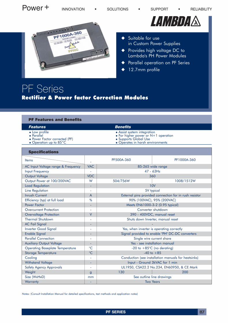
PF SERIES 87
Items - PF500A-360 PF1000A-360
AC Input Voltage range & Frequency VAC 85-265 wide rangeInput Frequency - 47 - 63HzOutput Voltage VDC 360Output Power at 100/200VAC W 504/756W 1008/1512WLoad Regulation - 10VLine Regulation - 5V typicalInrush Current A External pins provided connection for in rush resistorEfficiency (typ) at full load % 90% (100VAC), 95% (200VAC)Power Factor - Meets EN61000-3-2 (0.95 typical)Overcurrent Protection - Converter shutdownOvervoltage Protection V 390 - 400VDC, manual resetThermal Shutdown - Shuts down Inverter, manual resetAC Fail Signal - -Inverter Good Signal - Yes, when inverter is operating correctlyEnable Signal - Signal provided to enable "PH" DC-DC convertersParallel Connection - Single wire current shareAuxiliary Output Voltage - Yes - see installation manualOperating Baseplate Temperature °C -20 to +85°C (no derating)Storage Temperature °C -40 to +85Cooling - Conduction (see installation manuals for heatsinks)Withstand Voltage - Input - Ground 3kVAC for 1 minSafety Agency Approvals - UL1950, CSA22.2 No.234, EN60950, & CE MarkWeight g 130 200Size (WxHxD) mm See outline line drawingsWarranty - Two Years
Specifications
PF Features and Benefits
Features Benefits� Low profile � Assist system integration� Parallel � For higher power or N+1 operation� Power Factor corrected (PF) � Supports Global Use� Operation up to 85˚C � Operates in harsh environments
INNOVATION SOLUTIONS SUPPORT RELIABILITY
PF SeriesRectifier & Power factor Correction Modules
� Suitable for use in Custom Power Supplies
� Provides high voltage DC to Lambda's PH Power Modules
� Parallel operation on PF Series
� 12.7mm profile
Notes: (Consult Installation Manual for detailed specifications, test methods and application notes)
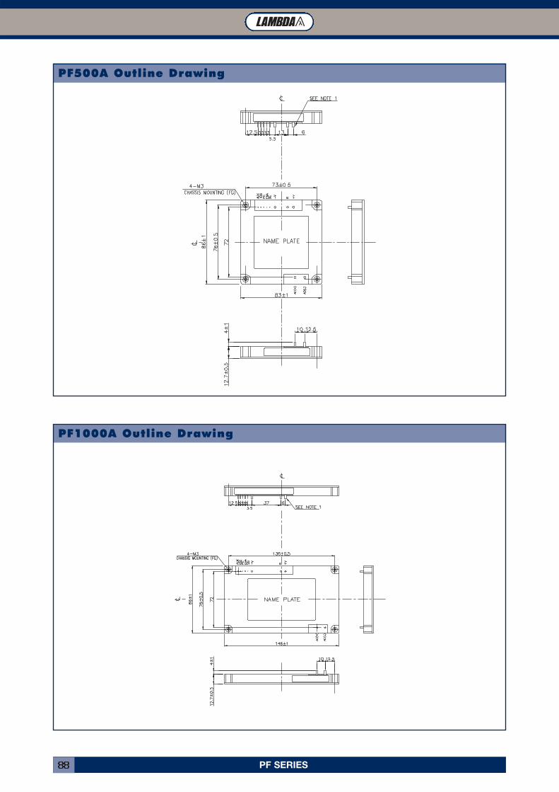
PF SERIES88
PF1000A Outline Drawing
PF500A Outline Drawing
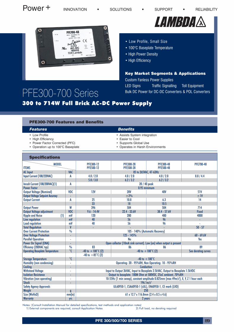
PFE 300/500/700 SERIES 89
• Low Profile, Small Size
• 100°C Baseplate Temperature
• High Power Density
• High Efficiency
Key Market Segments & Applications
Custom Fanless Power Supplies
LED Signs Traffic Signalling Toll Equipment
Bulk DC Power for DC-DC Converters & POL Converters
INNOVATION SOLUTIONS SUPPORT RELIABILITY
PFE300-700 Series300 to 714W Full Brick AC-DC Power Supply
PFE300-700 Features and Benefits
Features Benefits• Low Profile• High Efficiency• Power Factor Corrected (PFC)• Operation up to 100°C Baseplate
• Assists System integration• Easier to Cool• Supports Global Use• Operates in Harsh Environments
Specifications
Notes: (Consult Installation Manual for detailed specifications, test methods and application notes)1) External components are required, consult Application Notes 2) Full load, no derating required
MODEL PFE300-12 PFE300-28 PFE300-48 PFE700-48ITEMS PFE500-12 PFE500-28 PFE500-48AC Input VAC 85 to 265VAC, 47-63HzInput Current (100/220VAC) A 4.0 / 2.0 4.0 / 2.0 4.0 / 2.0 8.8 / 4.4
5.0 / 3.0 6.2 / 3.2 6.2 / 3.2Inrush Current (100/200VAC)(1) A 20 / 40 peakPower Factor 0.95 minimumOutput Voltage (Nominal) VDC 12V 28V 48V 51VOutput Voltage Setpoint Accuracy - ±2% ±1VOutput Current A 25 10.8 6.3 14
33 18 10.5Output Power W 396 504 504 714Output Voltage adjustment VDC 9.6 - 14.4V 22.4 - 33.6V 38.4 - 57.6V FixedRipple and Noise (1) mV 120 280 480 4000Line regulation mV 48 56 96 -Load regulation mV 48 56 96 -Total Regulation V - - - 50 - 57Over Current Protection % 105 - 140% (Automatic Recovery)Over Voltage Protection - 125 - 145% 60 - 69.6VParallel Operation - No YesPower On Signal (ENA) - Open collector (10mA sink current). Low (on) when output is presentEfficiency (200VAC typ) % 83 86 86 89Operating Baseplate Temperature °C -40 to +100°C (2) -40 to +100°C (2) See derating curves
-40 to +85°C (2)Storage Temperature °C -40 to +100°CHumidity (non condensing) - Operating: 20 - 95%RH, Non Operating: 10 - 95%RHCooling - ConductionWithstand Voltage - Input to Output 3kVAC, Input to Baseplate 2.5kVAC, Output to Baseplate 1.5kVDCIsolation Resistance - Output to baseplate: 100M Ohm at 500VDC, 25oC ambient, 70%RHVibration (non operating) - 10-55Hz (1 min sweep), constant amplitude 0.825mm (max 49m/s2), X, Y, Z 1 hour eachShock - 196.1m/s2
Safety Agency Approvals UL60950-1, CSA60950-1 (cUL), EN60950-1, CE mark (LVD)Weight g 250Size (WxHxD) mm(in) 61 x 12.7 x 116.8mm (2.4 x 0.5 x 4.6)Warranty yrs 2 years
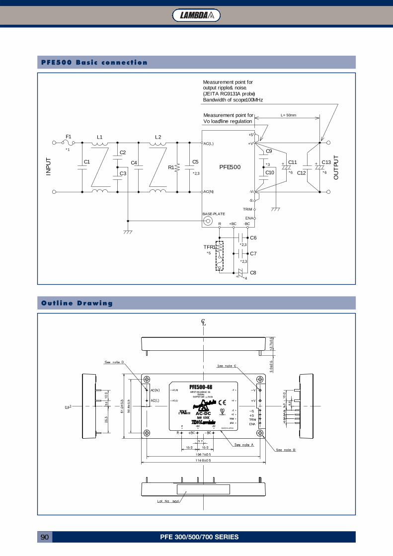
PFE 300/500/700 SERIES90
INP
UT
C7
C6
C4 C5
C3
C2
C10
C9
C8
F1
PFE500
AC(L)
AC(N)
+V
-V
+S
-S
TRIM
ENA
-BC+BCR
OU
TPU
T
C1
L1 L2
R1
BASE-PLATE
TFR1
C11
C12
*1
*2,3
*2,3
*2,3
*4
*5
*3
*6
Measurement point for Vo load/line regulation
L= 50mm
Measurement point foroutput ripple & noise.(JEITA RC-9131A probe)Bandwidth of scope: 100MHz
C13
*6
PFE500 Basic connect ion
Outl ine Drawing
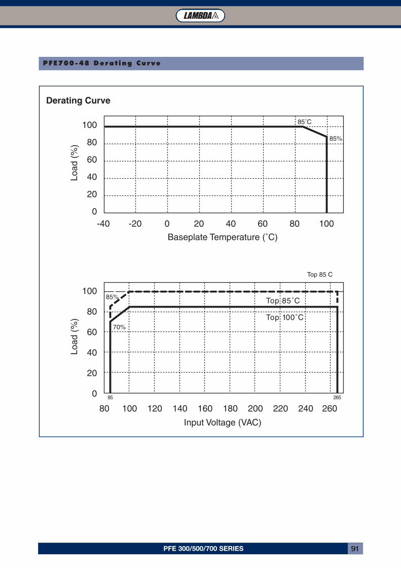
PFE 300/500/700 SERIES 91
PFE700-48 Derat ing Curve
100
80
60
40
20
0
100
80
60
40
20
0
Derating Curve
Baseplate Temperature (˚C)
Input Voltage (VAC)
Load
(%
)Lo
ad (
%)
-40
80 100 120 140 160 180 200 220 240 260
-20 20 40 60 80 1000
85˚C
Top 85 C
Top 85˚C
Top 100˚C
85%
70%
85%
85 265
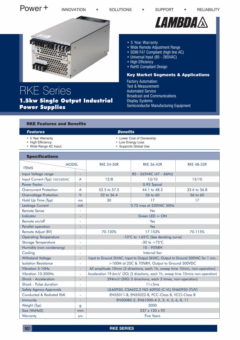
RKE SERIES92
• 5 Year Warranty• Wide Remote Adjustment Range• SEMI F47 Compliant (high line AC)• Universal Input (85 - 265VAC)• High Efficiency• RoHS Compliant Design
Key Market Segments & Applications
Factory Automation:Test & Measurement:Automated ServiceBroadcast and CommunicationsDisplay SystemsSemiconductor Manufacturing Equipment
INNOVATION SOLUTIONS SUPPORT RELIABILITY
RKE Series1.5kw Single Output IndustrialPower Supplies
Specifications
RKE Features and Benefits
Features Benefits• 5 Year Warranty• High Efficiency• Wide Range AC Input
• Lower Cost of Ownership• Low Energy Loss• Supports Global Use
MODEL RKE 24-50R RKE 36-42R RKE 48-32RITEMS
Input Voltage range - 85 - 265VAC (47 - 66Hz)Input Current (Typ) 100/240VAC A 12/8 13/10 13/10Power Factor - 0.95 TypicalOvercurrent Protection A 52.5 to 57.5 44.1 to 48.3 33.6 to 36.8Overvoltage Protection V 32 to 36.4 56 to 60 56 to 60Hold Up Time (Typ) ms 30 17 17Leakage Current mA 0.75 max at 230VAC 50HzRemote Sense - NoIndicator - Green LED = ONRemote on/off - YesParallel operation - YesRemote Adjust (RV) 70-130% 17-153% 70-115%Operating Temperature - -10°C to +65°C (See derating curve)Storage Temperature - -30 to +75°CHumidity (non condensing) - 10 - 95%RHCooling - Internal fanWithstand Voltage - Input to Ground 2kVAC, Input to Output 3kVAC, Output to Ground 500VAC for 1 min.Isolation Resistance - >100M at 25C & 70%RH, Output to Ground 500VDCVibration 5-10Hz - All amplitude 10mm (3 directions, each 1h, sweep time 10min, non-operation)Vibration 10-200Hz - Acceleration 19.6m/s2 (2G) (3 directions, each 1h, sweep time 10mins non-operation)Shock - Acceleration - 294m/s2 (30G) 3 directions, each 3 times, non-operation)Shock - Pulse duration - 11±5msSafety Agency Approvals - UL60950, CSA622,2 NO 60950 (C-VL) EN60950 (TUV)Conducted & Radiated EMI - EN55011-B, EN55022-B, FCC-Class B, VCCI-Class BImmunity - EN50082-2, EN61000-4-2, 3, 4, 5, 6, 8, 11 Weight (Typ) g 3000Size (WxHxD) mm 237 x 120 x 92Warranty yrs Five Years
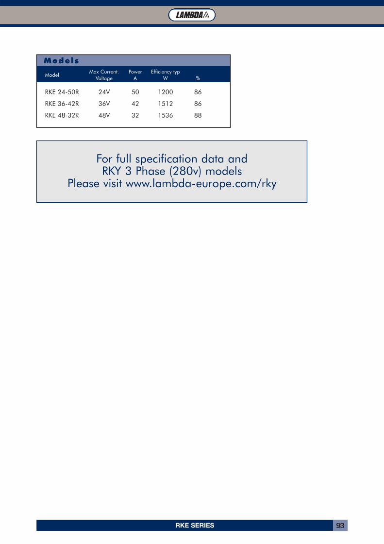
RKE SERIES 93
Models
For full specification data and RKY 3 Phase (280v) models
Please visit www.lambda-europe.com/rky
Max Current. Power Efficiency typModel
Voltage A W %
RKE 24-50R 24V 50 1200 86
RKE 36-42R 36V 42 1512 86
RKE 48-32R 48V 32 1536 88
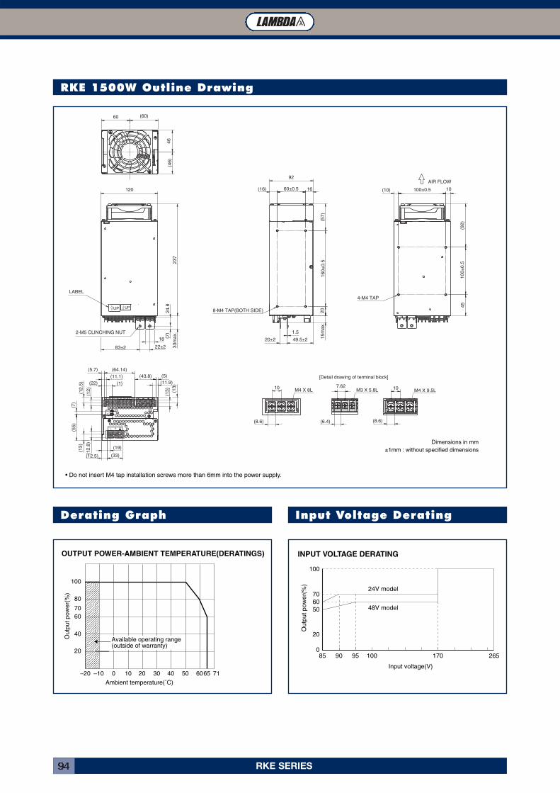
RKE SERIES94
RKE 1500W Outline Drawing
Derating Graph
• Do not insert M4 tap installation screws more than 6mm into the power supply.
AIR FLOW
(10) 100±0.5 10
(92
)1
00
±0
.54
5
4-M4 TAP
(16) 60±0.5 16
(57
)1
60
±0
.52
01
5m
ax.
1.5
49.5±220±2
92
8-M4 TAP(BOTH SIDE)
60 (60)
(46
)4
6
120
23
73
3m
ax.
UP UP
LABEL
(5.7) (64.14)
(43.8) (5)
(22)
(11.1)
(1) (11.9)
(13
)2
4.8
( 7)
(13
)
(12
.5)
(12
)
(7)
(55
)
(13
)
(12
.8)
(19)
(12.5) (33)
18
83±2 22±2
10
(8.6)
M4 X 8L
(6.4)
7.62M3 X 5.8L 10
M4 X 9.5L
(8.6)
[Detail drawing of terminal block]
2-M5 CLINCHING NUT
Dimensions in mm
±1mm : without specified dimensions
OUTPUT POWER-AMBIENT TEMPERATURE(DERATINGS)
20
40
60
80
70
100
–20 –10 0 10 20 30 40 50 6065 71
Ambient temperature(˚C)
Out
put p
ower
(%)
Available operating range(outside of warranty)
Input Voltage Derating
INPUT VOLTAGE DERATING
100
706050
20
085 90 95 100 170 265
48V model
24V model
Input voltage(V)
Out
put p
ower
(%)
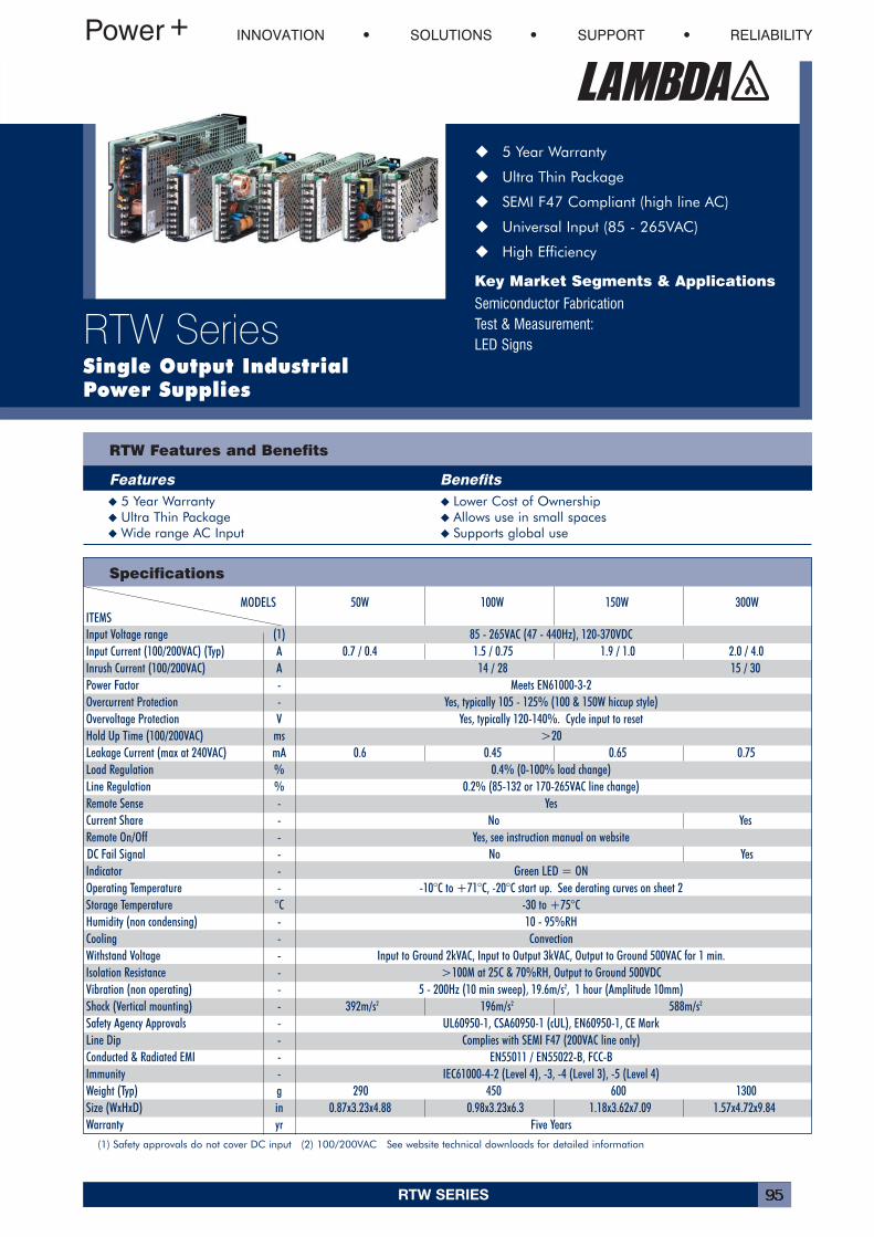
RTW SERIES 95
� 5 Year Warranty
� Ultra Thin Package
� SEMI F47 Compliant (high line AC)
� Universal Input (85 - 265VAC)
� High Efficiency
Key Market Segments & Applications
Semiconductor FabricationTest & Measurement:LED Signs
INNOVATION SOLUTIONS SUPPORT RELIABILITY
RTW SeriesSingle Output IndustrialPower Supplies
Specifications
RTW Features and Benefits
Features Benefits� 5 Year Warranty � Lower Cost of Ownership� Ultra Thin Package � Allows use in small spaces�Wide range AC Input � Supports global use
(1) Safety approvals do not cover DC input (2) 100/200VAC See website technical downloads for detailed information
MODELS 50W 100W 150W 300WITEMSInput Voltage range (1) 85 - 265VAC (47 - 440Hz), 120-370VDCInput Current (100/200VAC) (Typ) A 0.7 / 0.4 1.5 / 0.75 1.9 / 1.0 2.0 / 4.0Inrush Current (100/200VAC) A 14 / 28 15 / 30Power Factor - Meets EN61000-3-2Overcurrent Protection - Yes, typically 105 - 125% (100 & 150W hiccup style)Overvoltage Protection V Yes, typically 120-140%. Cycle input to resetHold Up Time (100/200VAC) ms >20Leakage Current (max at 240VAC) mA 0.6 0.45 0.65 0.75Load Regulation % 0.4% (0-100% load change)Line Regulation % 0.2% (85-132 or 170-265VAC line change)Remote Sense - YesCurrent Share - No YesRemote On/Off - Yes, see instruction manual on websiteDC Fail Signal - No YesIndicator - Green LED = ONOperating Temperature - -10°C to +71°C, -20°C start up. See derating curves on sheet 2Storage Temperature °C -30 to +75°CHumidity (non condensing) - 10 - 95%RHCooling - ConvectionWithstand Voltage - Input to Ground 2kVAC, Input to Output 3kVAC, Output to Ground 500VAC for 1 min.Isolation Resistance - >100M at 25C & 70%RH, Output to Ground 500VDCVibration (non operating) - 5 - 200Hz (10 min sweep), 19.6m/s2, 1 hour (Amplitude 10mm)Shock (Vertical mounting) - 392m/s2 196m/s2 588m/s2
Safety Agency Approvals - UL60950-1, CSA60950-1 (cUL), EN60950-1, CE MarkLine Dip - Complies with SEMI F47 (200VAC line only)Conducted & Radiated EMI - EN55011 / EN55022-B, FCC-BImmunity - IEC61000-4-2 (Level 4), -3, -4 (Level 3), -5 (Level 4)Weight (Typ) g 290 450 600 1300Size (WxHxD) in 0.87x3.23x4.88 0.98x3.23x6.3 1.18x3.62x7.09 1.57x4.72x9.84Warranty yr Five Years
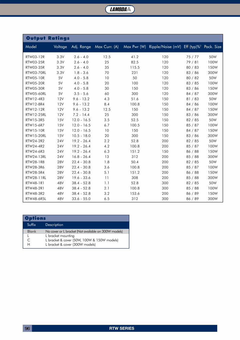
RTW SERIES96
Output Ratings
Model Voltage Adj. Range Max Curr. (A) Max Pwr (W) Ripple/Noise (mV) Eff (typ)%2 Pack. Size
RTW03-12R 3.3V 2.6 - 4.0 12.5 41.2 120 75 / 77 50WRTW03-25R 3.3V 2.6 - 4.0 25 82.5 120 79 / 81 100WRTW03-35R 3.3V 2.6 - 4.0 35 115.5 120 80 / 83 150WRTW03-70RL 3.3V 1.8 - 3.6 70 231 120 83 / 86 300WRTW05-10R 5V 4.0 - 5.8 10 50 120 80 / 82 50WRTW05-20R 5V 4.0 - 5.8 20 100 120 83 / 85 100WRTW05-30R 5V 4.0 - 5.8 30 150 120 83 / 86 150WRTW05-60RL 5V 3.5 - 5.6 60 300 120 84 / 87 300WRTW12-4R3 12V 9.6 - 13.2 4.3 51.6 150 81 / 83 50WRTW12-8R4 12V 9.6 - 13.2 8.4 100.8 150 84 / 86 100WRTW12-12R 12V 9.6 - 13.2 12.5 150 150 84 / 87 150WRTW12-25RL 12V 7.2 - 14.4 25 300 150 83 / 86 300WRTW15-3R5 15V 12.0 - 16.5 3.5 52.5 150 82 / 85 50WRTW15-6R7 15V 12.0 - 16.5 6.7 100.5 150 85 / 87 100WRTW15-10R 15V 12.0 - 16.5 10 150 150 84 / 87 150WRTW15-20RL 15V 10.5 - 18.0 20 300 150 83 / 86 300WRTW24-2R2 24V 19.2 - 26.4 2.2 52.8 200 82 / 85 50WRTW24-4R2 24V 19.2 - 26.4 4.2 100.8 200 85 / 87 100WRTW24-6R3 24V 19.2 - 26.4 6.3 151.2 150 86 / 88 150WRTW24-13RL 24V 16.8 - 26.4 13 312 200 85 / 88 300WRTW28-1R8 28V 22.4 - 30.8 1.8 50.4 200 82 / 85 50WRTW28-3R6 28V 22.4 - 30.8 3.6 100.8 200 85 / 87 100WRTW28-5R4 28V 22.4 - 30.8 5.1 151.2 200 86 / 88 150WRTW28-11RL 28V 19.6 - 33.6 11 308 200 85 / 88 300WRTW48-1R1 48V 38.4 - 52.8 1.1 52.8 300 82 / 85 50WRTW48-2R1 48V 38.4 - 52.8 2.1 100.8 300 85 / 88 100WRTW48-3R2 48V 38.4 - 52.8 3.2 153.6 200 86 / 89 150WRTW48-6R5L 48V 33.6 - 55.0 6.5 312 300 86 / 89 300W
Suffix Description
Blank No cover or L bracket (Not available on 300W models)L L bracket mountingC L bracket & cover (50W, 100W & 150W models)H L bracket & cover (300W models)
Options
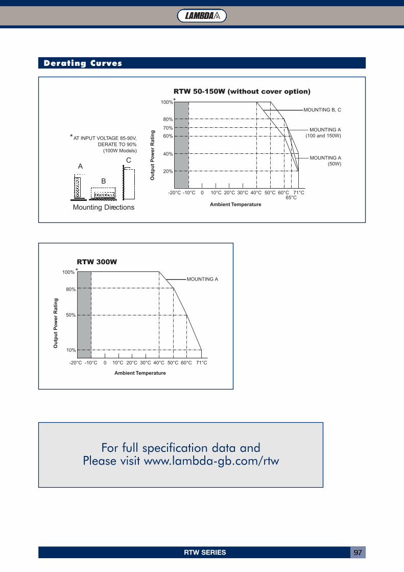
RTW SERIES 97
Derating Curves
For full specification data and Please visit www.lambda-gb.com/rtw
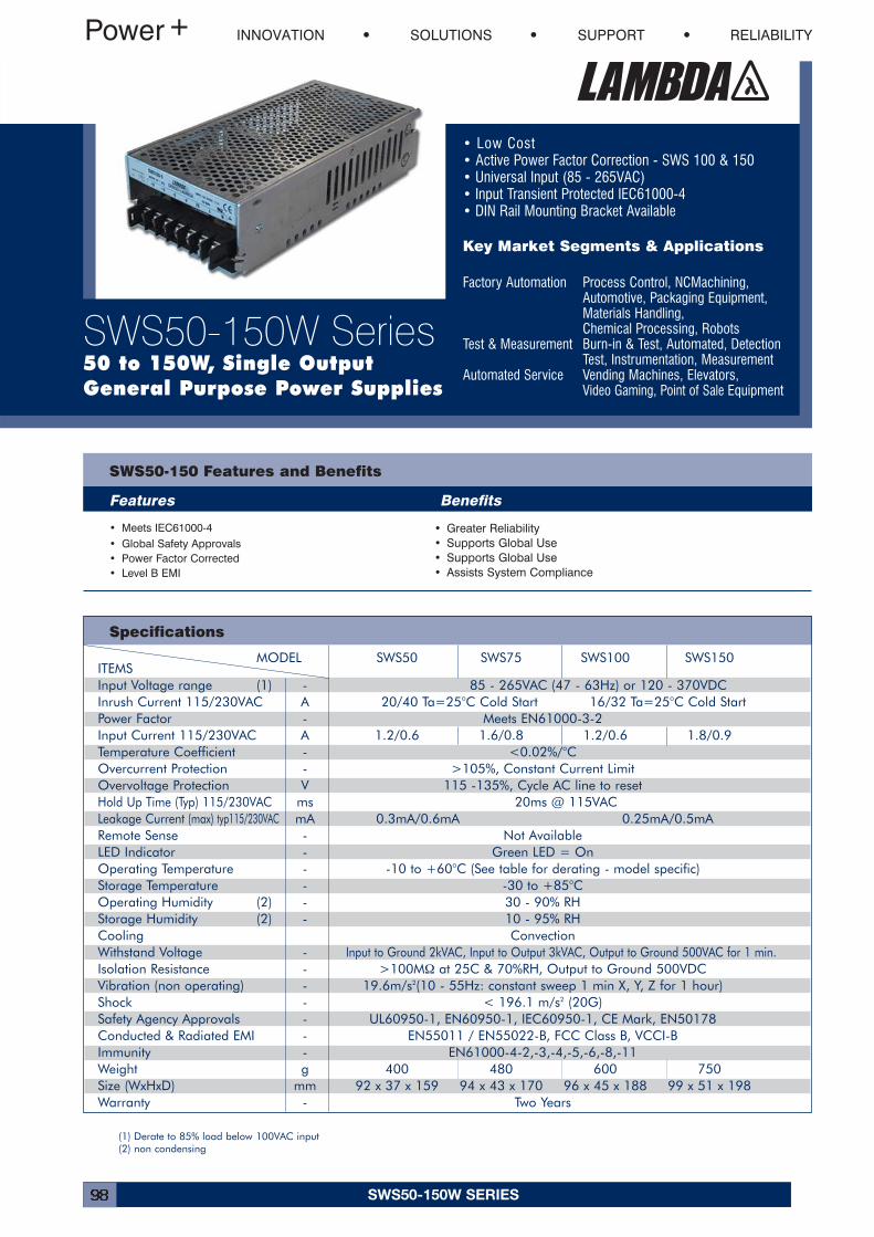
SWS50-150W SERIES98
• Low Cost• Active Power Factor Correction - SWS 100 & 150• Universal Input (85 - 265VAC)• Input Transient Protected IEC61000-4• DIN Rail Mounting Bracket Available
Key Market Segments & Applications
Factory Automation Process Control, NCMachining,Automotive, Packaging Equipment, Materials Handling,Chemical Processing, Robots
Test & Measurement Burn-in & Test, Automated, DetectionTest, Instrumentation, Measurement
Automated Service Vending Machines, Elevators, Video Gaming, Point of Sale Equipment
SWS50-150 Features and Benefits
Features Benefits
• Meets IEC61000-4• Global Safety Approvals• Power Factor Corrected• Level B EMI
• Greater Reliability• Supports Global Use• Supports Global Use• Assists System Compliance
INNOVATION SOLUTIONS SUPPORT RELIABILITY
SWS50-150W Series50 to 150W, Single OutputGeneral Purpose Power Supplies
Specifications
MODEL SWS50 SWS75 SWS100 SWS150ITEMSInput Voltage range (1) - 85 - 265VAC (47 - 63Hz) or 120 - 370VDCInrush Current 115/230VAC A 20/40 Ta=25°C Cold Start 16/32 Ta=25°C Cold StartPower Factor - Meets EN61000-3-2Input Current 115/230VAC A 1.2/0.6 1.6/0.8 1.2/0.6 1.8/0.9Temperature Coefficient - <0.02%/°COvercurrent Protection - >105%, Constant Current LimitOvervoltage Protection V 115 -135%, Cycle AC line to resetHold Up Time (Typ) 115/230VAC ms 20ms @ 115VACLeakage Current (max) typ115/230VAC mA 0.3mA/0.6mA 0.25mA/0.5mARemote Sense - Not Available LED Indicator - Green LED = OnOperating Temperature - -10 to +60°C (See table for derating - model specific)Storage Temperature - -30 to +85°COperating Humidity (2) - 30 - 90% RHStorage Humidity (2) - 10 - 95% RHCooling ConvectionWithstand Voltage - Input to Ground 2kVAC, Input to Output 3kVAC, Output to Ground 500VAC for 1 min.Isolation Resistance - >100MΩ at 25C & 70%RH, Output to Ground 500VDCVibration (non operating) - 19.6m/s2(10 - 55Hz: constant sweep 1 min X, Y, Z for 1 hour)Shock - < 196.1 m/s2 (20G)Safety Agency Approvals - UL60950-1, EN60950-1, IEC60950-1, CE Mark, EN50178Conducted & Radiated EMI - EN55011 / EN55022-B, FCC Class B, VCCI-BImmunity - EN61000-4-2,-3,-4,-5,-6,-8,-11Weight g 400 480 600 750Size (WxHxD) mm 92 x 37 x 159 94 x 43 x 170 96 x 45 x 188 99 x 51 x 198Warranty - Two Years
(1) Derate to 85% load below 100VAC input(2) non condensing
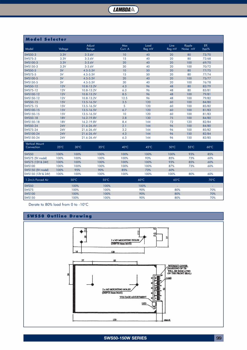
SWS50-150W SERIES 99
Model Selector
SWS50-3 3.3V 3-3.6V 10 40 20 80 73/70SWS75-3 3.3V 3-3.6V 15 40 20 80 72/68SWS100-3 3.3V 3-3.6V 20 40 20 100 69/70SWS150-3 3.3V 3-3.6V 30 40 20 100 70/72SWS50-5 5V 4.5-5.5V 10 50 20 80 77/75SWS75-5 5V 4.5-5.5V 15 50 20 80 77/74SWS100-5 5V 4.5-5.5V 20 40 20 100 75/77SWS150-5 5V 4.5-5.5V 30 40 20 100 76/78SWS50-12 12V 10.8-13.2V 4.3 96 48 80 82/79SWS75-12 12V 10.8-13.2V 6.3 96 48 80 83/81SWS100-12 12V 10.8-13.2V 8.5 96 48 100 79/81SWS150-12 12V 10.8-13.2V 12.5 96 48 100 79/82SWS50-15 15V 13.5-16.5V 3.5 120 60 100 84/80SWS75-15 15V 13.5-16.5V 5 120 60 100 85/82SWS100-15 15V 13.5-16.5V 6.7 120 60 100 81/83SWS150-15 15V 13.5-16.5V 10 120 60 100 81/83SWS50-18 18V 16.2-19.8V 2.8 130 75 100 84/80SWS150-18 18V 16.2-19.8V 8.4 144 72 120 82/84SWS50-24 24V 21.6-26.4V 2.1 144 96 100 84/80SWS75-24 24V 21.6-26.4V 3.2 144 96 100 85/82SWS100-24 24V 21.6-26.4V 4.3 144 96 150 82/84SWS150-24 24V 21.6-26.4V 6.3 144 96 150 82/85
Adjust Max Load Line Ripple Eff.Model Voltage Range Curr. A Reg mV Reg mV Noise mV (typ)%
Vertical MountConvection 25°C 30°C 35°C 40°C 45°C 50°C 55°C 60°C
1.2m/s Forced Air 50°C 55°C 60°C 65°C 70°C
SWS50 100% 100% 100% 100% 100% 100% 93% 85%SWS75 (5V model) 100% 100% 100% 100% 93% 85% 73% 60%SWS75 (12V & 24V) 100% 100% 100% 100% 100% 93% 85% 60%SWS100 100% 100% 100% 100% 100% 87% 73% 60%SWS150 (5V model) 100% 95% 90% 85% 73% 60% - -SWS150 (12V & 24V) 100% 100% 100% 100% 100% 100% 80% 60%
SWS50 100% 100% 100% - -SWS75 100% 100% 90% 80% 70%SWS100 100% 100% 90% 80% 70%SWS150 100% 100% 90% 80% 70%
Derate to 80% load from 0 to -10°C
SWS50 Out l ine Drawing
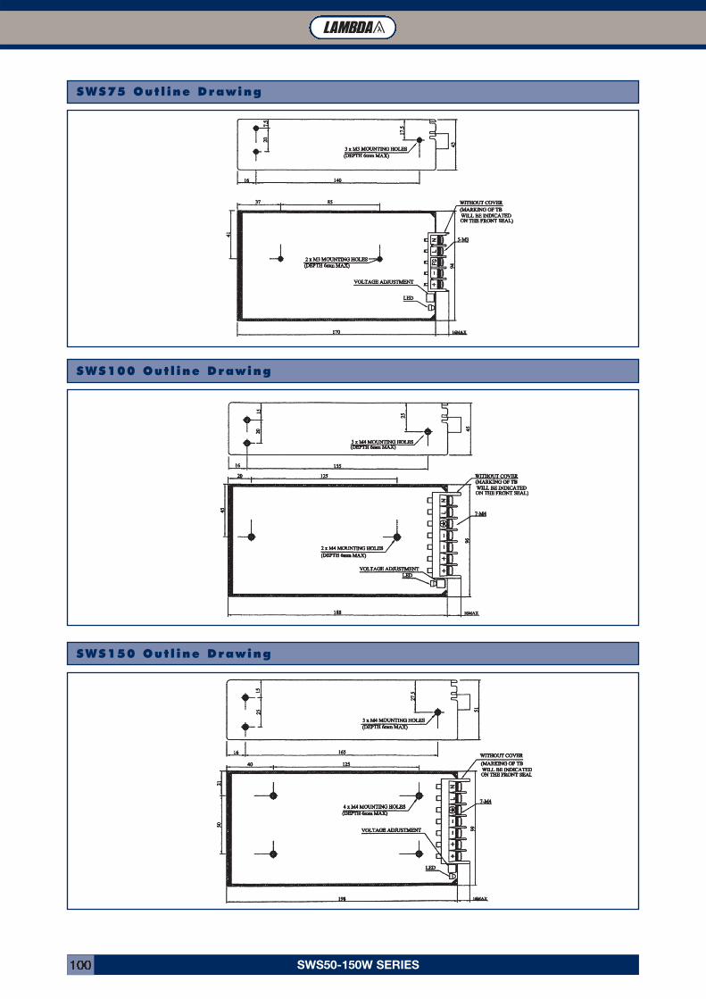
SWS50-150W SERIES100
SWS75 Out l ine Drawing
SWS100 Out l ine Drawing
SWS150 Out l ine Drawing
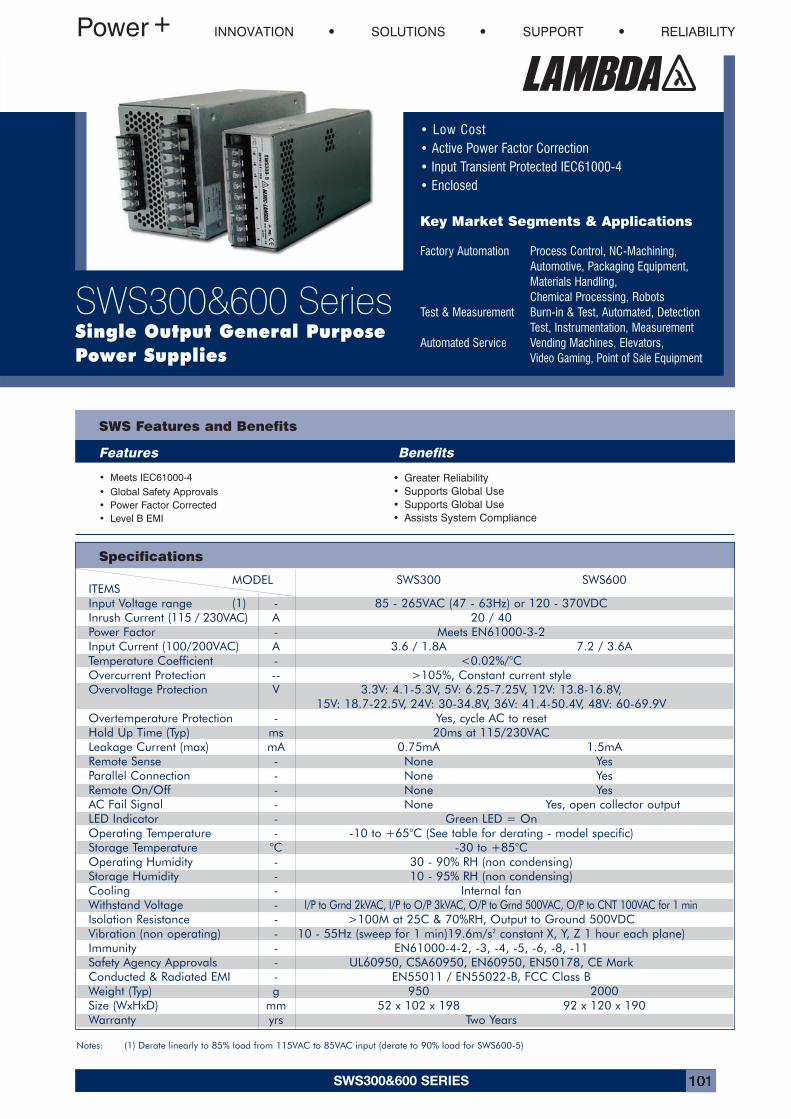
SWS300&600 SERIES 101
• Low Cost• Active Power Factor Correction• Input Transient Protected IEC61000-4• Enclosed
Key Market Segments & Applications
Factory Automation Process Control, NC-Machining,Automotive, Packaging Equipment, Materials Handling,Chemical Processing, Robots
Test & Measurement Burn-in & Test, Automated, DetectionTest, Instrumentation, Measurement
Automated Service Vending Machines, Elevators, Video Gaming, Point of Sale Equipment
SWS Features and Benefits
Features Benefits
• Meets IEC61000-4• Global Safety Approvals• Power Factor Corrected• Level B EMI
• Greater Reliability• Supports Global Use• Supports Global Use• Assists System Compliance
INNOVATION SOLUTIONS SUPPORT RELIABILITY
SWS300&600 SeriesSingle Output General PurposePower Supplies
Specifications
Notes: (1) Derate linearly to 85% load from 115VAC to 85VAC input (derate to 90% load for SWS600-5)
MODEL SWS300 SWS600ITEMSInput Voltage range (1) - 85 - 265VAC (47 - 63Hz) or 120 - 370VDCInrush Current (115 / 230VAC) A 20 / 40Power Factor - Meets EN61000-3-2Input Current (100/200VAC) A 3.6 / 1.8A 7.2 / 3.6ATemperature Coefficient - <0.02%/°COvercurrent Protection -- >105%, Constant current styleOvervoltage Protection V 3.3V: 4.1-5.3V, 5V: 6.25-7.25V, 12V: 13.8-16.8V,
15V: 18.7-22.5V, 24V: 30-34.8V, 36V: 41.4-50.4V, 48V: 60-69.9VOvertemperature Protection - Yes, cycle AC to resetHold Up Time (Typ) ms 20ms at 115/230VACLeakage Current (max) mA 0.75mA 1.5mARemote Sense - None YesParallel Connection - None YesRemote On/Off - None YesAC Fail Signal - None Yes, open collector outputLED Indicator - Green LED = OnOperating Temperature - -10 to +65°C (See table for derating - model specific)Storage Temperature °C -30 to +85°COperating Humidity - 30 - 90% RH (non condensing)Storage Humidity - 10 - 95% RH (non condensing)Cooling - Internal fanWithstand Voltage - I/P to Grnd 2kVAC, I/P to O/P 3kVAC, O/P to Grnd 500VAC, O/P to CNT 100VAC for 1 minIsolation Resistance - >100M at 25C & 70%RH, Output to Ground 500VDCVibration (non operating) - 10 - 55Hz (sweep for 1 min)19.6m/s2 constant X, Y, Z 1 hour each plane)Immunity - EN61000-4-2, -3, -4, -5, -6, -8, -11Safety Agency Approvals - UL60950, CSA60950, EN60950, EN50178, CE MarkConducted & Radiated EMI - EN55011 / EN55022-B, FCC Class BWeight (Typ) g 950 2000Size (WxHxD) mm 52 x 102 x 198 92 x 120 x 190Warranty yrs Two Years
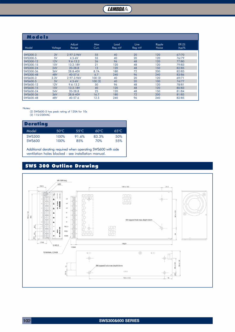
SWS300&600 SERIES102
SWS 300 Outline Drawing
SWS300 100% 91.6% 83.3% 50%SWS600 100% 85% 70% 55%
Additional derating required when operating SWS600 with sideventilation holes blocked - see installation manual.
Model 50°C 55°C 60°C 65°C
Derating
Notes:(2) SWS600-5 has peak rating of 120A for 10s(3) 115/230VAC
Models
SWS300-3 3V 2.97-3.96V 55 40 20 120 67/70SWS300-5 5V 4.5-6V 55 40 20 120 76/79SWS300-12 12V 9.6-13.2 26 96 48 120 77/80SWS300-15 15V 13.2-18V 21 120 48 120 79/83SWS300-24 24V 20-28.8 13 120 48 150 82/85SWS300-36 36V 28.8-40V 8.7A 180 72 200 82/85SWS300-48 48V 40-57.6 6.7 240 96 240 83/86SWS600-3 3.3V 2.97-3.96V 100 (2) 40 20 120 69/71SWS600-5 5V 4.5-6V 100 (2) 40 20 100 74/77SWS600-12 12V 9.6-13.2 50 96 48 120 78/81SWS600-15 15V 13.2-18V 40 120 48 120 80/83SWS600-24 24V 20-28.8 25 120 48 150 81/84SWS600-36 36V 28.8-40V 16.7 180 72 200 81/85SWS600-48 48V 40-57.6 12.5 240 96 240 82/85
Adjust Max Load Line Ripple Eff.(3)Model Voltage Range Curr. Reg mV Reg mV Noise (typ)%
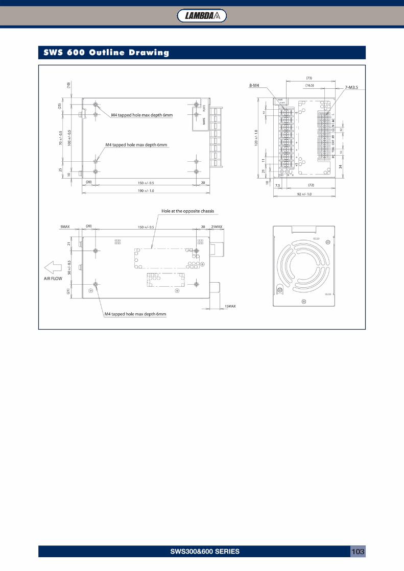
SWS300&600 SERIES 103
SWS 600 Outline Drawing
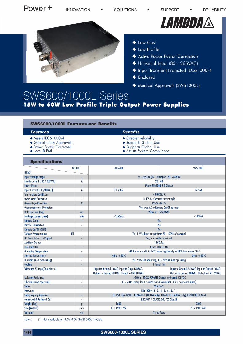
SWS600-1000L SERIES104
INNOVATION SOLUTIONS SUPPORT RELIABILITY
SWS600/1000L Series15W to 60W Low Profile Triple Output Power Supplies
� Low Cost
� Low Profile
� Active Power Factor Correction
� Universal Input (85 - 265VAC)
� Input Transient Protected IEC61000-4
� Enclosed
� Medical Approvals (SWS1000L)
SWS6000/1000L Features and Benefits
Features Benefits� Meets IEC61000-4 � Greater reliability� Global safety Approvals � Supports Global Use� Power Factor Corrected � Supports Global Use� Level B EMI � Assists System Compliance
Specifications
Notes: (1) Not available on 3.3V & 5V SWS1000L models
MODEL SWS600L SWS1000LITEMSInput Voltage range - 85 - 265VAC (47 - 63Hz) or 120 - 350VDCInrush Current (115 / 230VAC) A 20 / 40Power Factor - Meets EN61000-3-2 Class AInput Current (100/200VAC) A 7.1 / 3.6 12 / 6ATemperature Coefficient - <0.02%/°COvercurrent Protection - >105%, Constant current styleOvervoltage Protection V 125% -145%Overtemperature Protection - Yes, cycle AC or Remote On/Off to resetHold Up Time (Typ) ms 20ms at 115/230VACLeakage Current (max) mA <0.75mA <0.3mARemote Sense - YesParallel Connection - YesRemote On/Off (CNT) - YesVoltage Programming (1) - Yes, 1-6V adjusts output from 20 - 120% of nominalDC Good & Fan Fail Signal - Yes, open collector outputAuxiliary Output - 12V 0.1ALED Indicator - Green LED = OnOperating Temperature - -40°C start up. -20 to 74°C, derating linearly to 50% load above 50°CStorage Temperature - -40 to +85°C -30 to +85°CHumidity (non condensing) - 20 - 90% RH operating, 10 - 95%RH non operatingCooling - Internal fanWithstand Voltage(One minute) - Input to Ground 2kVAC, Input to Output 3kVAC, Input to Ground 2.6kVAC, Input to Output 4kVAC,
Output to Ground 500VAC, Output to CNT 100VAC Output to Ground 600VAC, Output to CNT 120VACIsolation Resistance - >50M at 25C & 70%RH, Output to Ground 500VDCVibration (non operating) - 10 - 55Hz (sweep for 1 min)23.52m/s2 constant X, Y, Z 1 hour each plane)Shock - 235.2m/s2
Immunity - EN61000-4-2, -3, -4, -5, -6, -8, -11Safety Agency Approvals - UL, CSA, EN60950-1, UL60601-1 (1000W only), IEC61010-1 (600W only), EN50178, CE MarkConducted & Radiated EMI - EN55011 / EN55022-B, FCC Class BWeight (Typ) g 1600 2200Size (WxHxD) mm 61 x 120 x 199 61 x 150 x 240Warranty yrs Three Years
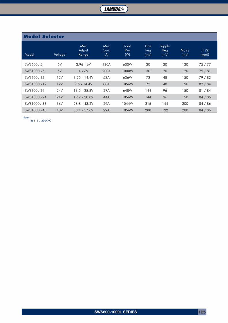
SWS600-1000L SERIES 105
Model Selector
Max Max Load Line RippleAdjust Curr. Pwr Reg Reg Noise Eff.(2)
Model Voltage Range (A) (W) (mV) (mV) (mV) (typ)%
SWS600L-5 5V 3.96 - 6V 120A 600W 30 20 120 75 / 77
SWS1000L-5 5V 4 - 6V 200A 1000W 30 20 120 79 / 81
SWS600L-12 12V 8.25 - 14.4V 53A 636W 72 48 150 79 / 82
SWS1000L-12 12V 9.6 - 14.4V 88A 1056W 72 48 150 82 / 84
SWS600L-24 24V 16.5 - 28.8V 27A 648W 144 96 150 81 / 84
SWS1000L-24 24V 19.2 - 28.8V 44A 1056W 144 96 150 84 / 86
SWS1000L-36 36V 28.8 - 43.2V 29A 1044W 216 144 200 84 / 86
SWS1000L-48 48V 38.4 - 57.6V 22A 1056W 288 192 200 84 / 86
Notes:(2) 115 / 230VAC
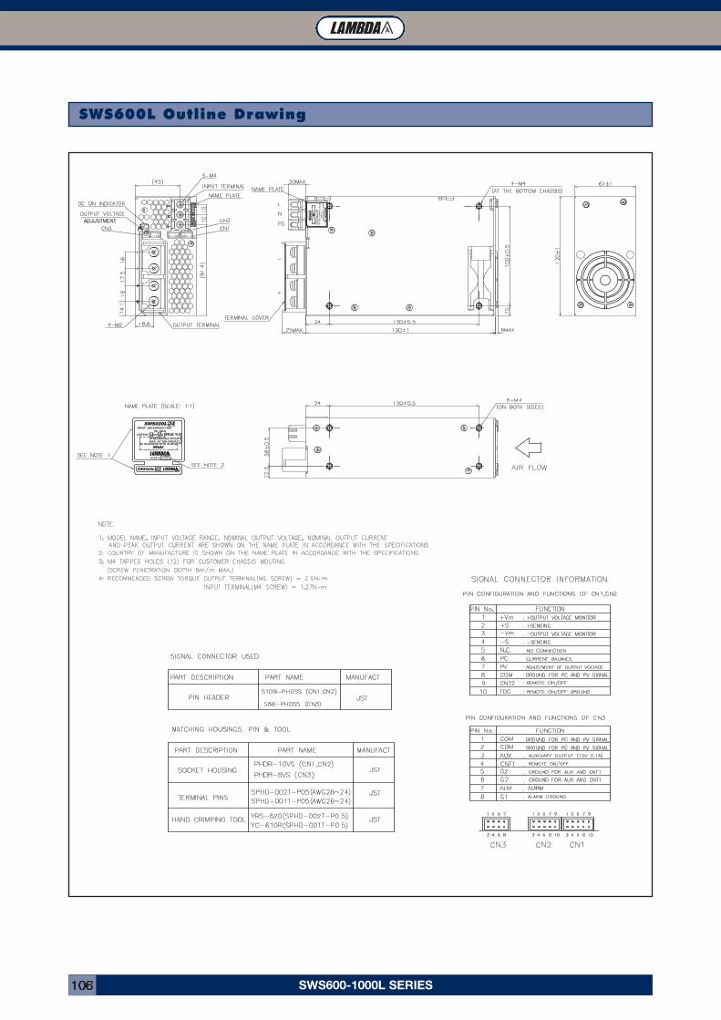
SWS600-1000L SERIES106
SWS600L Outline Drawing
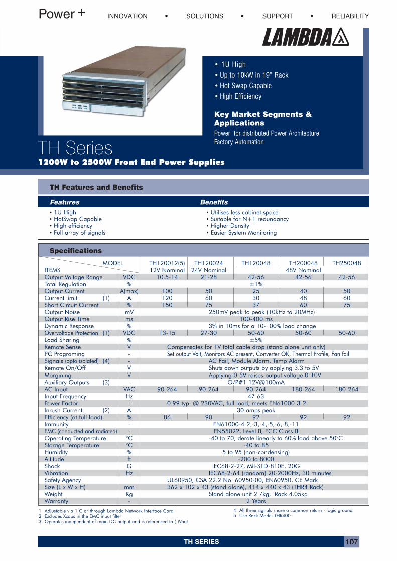
TH SERIES 107
• 1U High• Up to 10kW in 19” Rack• Hot Swap Capable• High Efficiency
Key Market Segments &ApplicationsPower for distributed Power Architecture Factory Automation
INNOVATION SOLUTIONS SUPPORT RELIABILITY
TH Series1200W to 2500W Front End Power Supplies
TH Features and Benefits
Features Benefits
Specifications
1 Adjustable via 1˚C or through Lambda Network Interface Card2 Excludes Xcaps in the EMC input filter3 Operates independent of main DC output and is referenced to (-)Vout
4 All three signals share a common return - logic ground5 Use Rack Model THR400
MODEL TH120012(5) TH120024 TH120048 TH200048 TH250048ITEMS 12V Nominal 24V Nominal 48V NominalOutput Voltage Range VDC 10.5-14 21-28 42-56 42-56 42-56Total Regulation % ±1%Output Current A(max) 100 50 25 40 50Current limit (1) A 120 60 30 48 60Short Circuit Current % 150 75 37 60 75Output Noise mV 250mV peak to peak (10kHz to 20MHz)Output Rise Time ms 100-400 msDynamic Response % 3% in 10ms for a 10-100% load changeOvervoltage Protection (1) VDC 13-15 27-30 50-60 50-60 50-60Load Sharing % ±5%Remote Sense V Compensates for 1V total cable drop (stand alone unit only)I2C Programing - Set output Volt, Monitors AC present, Converter OK, Thermal Profile, Fan failSignals (opto isolated) (4) - AC Fail, Module Alarm, Temp AlarmRemote On/Off V Shuts down outputs by applying 3.3 to 5VMargining V Applying 0-5V raises output voltage 0-10VAuxiliary Outputs (3) - O/P#1 12V@100mAAC Input VAC 90-264 90-264 90-264 180-264 180-264Input Frequency Hz 47-63Power Factor - 0.99 typ. @ 230VAC, full load, meets EN61000-3-2Inrush Current (2) A 30 amps peakEfficiency (at full load) % 86 90 92 92 92Immunity - EN61000-4-2,-3,-4,-5,-6,-8,-11EMC (conducted and radiated) - EN55022, Level B, FCC Class BOperating Temperature °C -40 to 70, derate linearly to 60% load above 50°CStorage Temperature °C -40 to 85Humidity % 5 to 95 (non-condensing)Altitude ft -200 to 8000Shock G IEC68-2-27, Mil-STD-810E, 20GVibration Hz IEC68-2-64 (random) 20-2000Hz, 30 minutesSafety Agency UL60950, CSA 22.2 No. 60950-00, EN60950, CE MarkSize (L x W x H) mm 362 x 102 x 43 (stand alone), 414 x 440 x 43 (THR4 Rack)Weight Kg Stand alone unit 2.7kg, Rack 4.05kgWarranty - 2 Years
• 1U High • Utilises less cabinet space• HotSwap Capable • Suitable for N+1 redundancy• High efficiency • Higher Density• Full array of signals • Easier System Monitoring
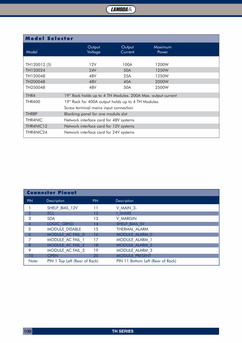
TH SERIES108
1.2m/s Forced Air 50°C 55°C 60°C 65°C 70°C
1.2m/s Forced Air 50°C 55°C 60°C 65°C 70°C
Model Selector
Output Output MaximumModel Voltage Current Power
TH120012 (5) 12V 100A 1200WTH120024 24V 50A 1250WTH120048 48V 25A 1250WTH200048 48V 40A 2000WTH250048 48V 50A 2500W
THR4 19” Rack holds up to 4 TH Modules. 200A Max. output current
THR400 19” Rack for 400A output holds up to 4 TH Modules.
Screw terminal mains input connection
THRBP Blanking panel for one module slot
THR4NIC Network interface card for 48V systems
THR4NIC12 Network interface card for 12V systems
THR4NIC24 Network interface card for 24V systems
Connector Pinout
1 SHELF_BIAS_12V 11 V_MAIN_3-2 SCL 12 I_SHARE3 SDA 13 V_MARGIN4 LOGIC_GRND 14 SHELF_BIAS_5V5 MODULE_DISABLE 15 THERMAL_ALARM6 MODULE_AC FAIL_0 16 MODULE_ALARM_07 MODULE_AC FAIL_1 17 MODULE_ALARM_18 MODULE_AC FAIL_2 18 MODULE_ALARM_29 MODULE_AC FAIL_3 19 MODULE_ALARM_310 OPEN 20 MODULE_PRESENTNote: PIN 1 Top Left (Rear of Rack) PIN 11 Bottom Left (Rear of Rack)
PIN Description PIN Description
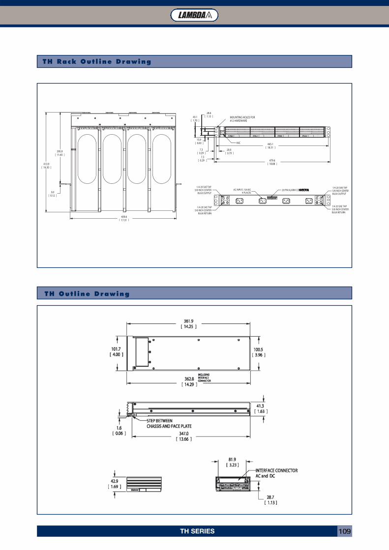
TH SERIES 109
TH Rack Out l ine Drawing
TH Out l ine Drawing
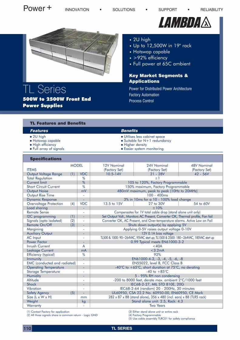
TL SERIES110
• 2U high• Up to 12,500W in 19" rack• Hotswap capable• >92% efficiency• Full power at 65C ambient
Key Market Segments &Applications
Power for Distributed Power Architecture
Factory Automation
Process Control
INNOVATION SOLUTIONS SUPPORT RELIABILITY
TL Series500W to 2500W Front End Power Supplies
TL Features and Benefits
Features Benefits
Specifications
(1) Contact Factory for application(2) All three signals share a common return - Logic GND
(3) Either stand alone unit or entire rack(4) Factory Programmable(5) Use cable assembly TLRC01 for safety compliance
MODEL 12V Nominal 24V Nominal 48V NominalITEMS (Factory Set) (Factory Set) (Factory Set)Output Voltage Range (1) VDC 10.5-14V 21 - 28V 42 - 56VTotal Regulation % ±1Current limit % 105 to 120%, Factory ProgrammableShort Circuit Current % 150% maximum, Factory ProgrammableOutput Noise mV 480mV maximum, peak to peak (10Hz to 20MHz)Output Rise Time - 100 - 400msDynamic Response - 3% in 10ms for a 10 - 100% load changeOvervoltage Protection (4) VDC 13.5 to 15V 27 to 30V 54 to 60VLoad sharing - ±10%Remote Sense - Compensates for 1V total cable drop (stand alone unit only)I2C programming (1) - Set Output Volt., Monitors AC Present, Converter OK, Thermal profile, Fan failSignals (opto isolated) (2) - Converter OK, AC Present, and Over-temperature alarms. Active Low on FailRemote On/Off (3) - Shuts down output(s) by applying 5VMargining - Applying 0-5V raises output voltage 0-10VAuxiliary Output - 12V 0.1A bias voltageAC Input - TL500 & 1000: 90~264VAC, 95VAC start up; TL1500 & 2500: 180~264VAC, 185VAC start upPower Factor - 0.99 Typical meets EN61000-3-2Inrush Current A <40ALeakage Current mA <3.2mAEfficiency (typical) % 92%Immunity - EN61000-4-2, -3, -4, -5, -6, -8EMC (conducted and radiated) - EN55022, level B, FCC Class BOperating Temperature - -40°C to +65°C, short duration at 75°C, no deratingStorage Temperature - -40 to +85°CHumidity - 5 - 95% RH non condensingAltitude - -200 to 8000 feet, derate max. ambient 2°C/1000 feetShock - IEC68-2-27, MIL STD 810E, 20GVibration - IEC68-2-64 (random) 20 - 200Hz, 30 minutesSafety Agency (5) - UL60950, CSA 22.2 No. 60950-00, EN60950, CE MarkSize (L x W x H) mm 282 x 87 x 88 (stand alone), 356 x 480 (incl. ears) x 88 (TLR5 rack)Weight kg Stand alone unit: 2.5, Rack: 4.3Warranty - Two Years
� 2U high � Utilises less cabinet space� Hotswap capable � Suitable for N+1 redundancy� High efficiency � Higher density� Full array of signals � Easier system monitoring
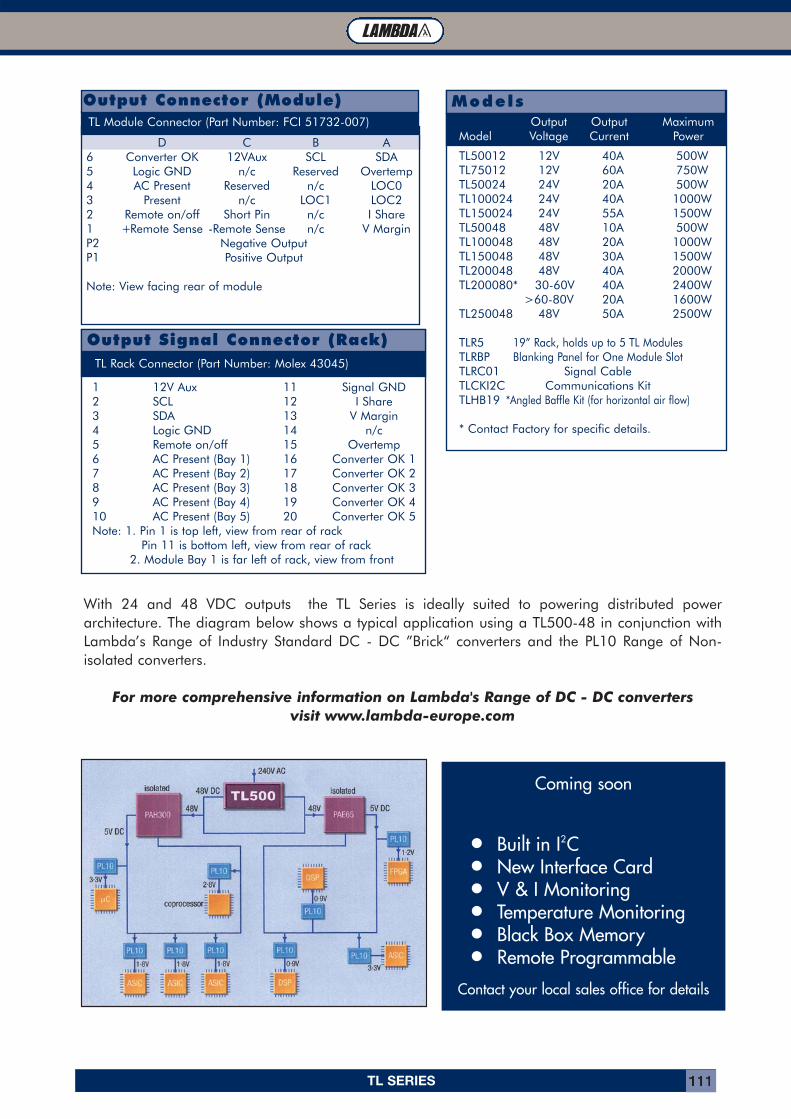
TL SERIES 111
Models
TL50012 12V 40A 500WTL75012 12V 60A 750WTL50024 24V 20A 500WTL100024 24V 40A 1000WTL150024 24V 55A 1500WTL50048 48V 10A 500WTL100048 48V 20A 1000WTL150048 48V 30A 1500WTL200048 48V 40A 2000WTL200080* 30-60V 40A 2400W
>60-80V 20A 1600WTL250048 48V 50A 2500W
TLR5 19” Rack, holds up to 5 TL ModulesTLRBP Blanking Panel for One Module SlotTLRC01 Signal CableTLCKI2C Communications KitTLHB19 *Angled Baffle Kit (for horizontal air flow)
* Contact Factory for specific details.
Output Output MaximumModel Voltage Current Power
TL Module Connector (Part Number: FCI 51732-007)
D C B A6 Converter OK 12VAux SCL SDA5 Logic GND n/c Reserved Overtemp4 AC Present Reserved n/c LOC03 Present n/c LOC1 LOC22 Remote on/off Short Pin n/c I Share1 +Remote Sense -Remote Sense n/c V MarginP2 Negative OutputP1 Positive Output
Note: View facing rear of module
Output Connector (Module)
Output Signal Connector (Rack)
1 12V Aux 11 Signal GND2 SCL 12 I Share3 SDA 13 V Margin4 Logic GND 14 n/c5 Remote on/off 15 Overtemp6 AC Present (Bay 1) 16 Converter OK 17 AC Present (Bay 2) 17 Converter OK 28 AC Present (Bay 3) 18 Converter OK 39 AC Present (Bay 4) 19 Converter OK 410 AC Present (Bay 5) 20 Converter OK 5Note: 1. Pin 1 is top left, view from rear of rack
Pin 11 is bottom left, view from rear of rack2. Module Bay 1 is far left of rack, view from front
TL Rack Connector (Part Number: Molex 43045)
Coming soonTL Range Intelligent Power
• Built in I2C• New Interface Card• V & I Monitoring• Temperature Monitoring• Black Box Memory• Remote Programmable
Contact your local sales office for details
With 24 and 48 VDC outputs the TL Series is ideally suited to powering distributed powerarchitecture. The diagram below shows a typical application using a TL500-48 in conjunction withLambda’s Range of Industry Standard DC - DC ”Brick“ converters and the PL10 Range of Non-isolated converters.
For more comprehensive information on Lambda's Range of DC - DC converters visit www.lambda-europe.com
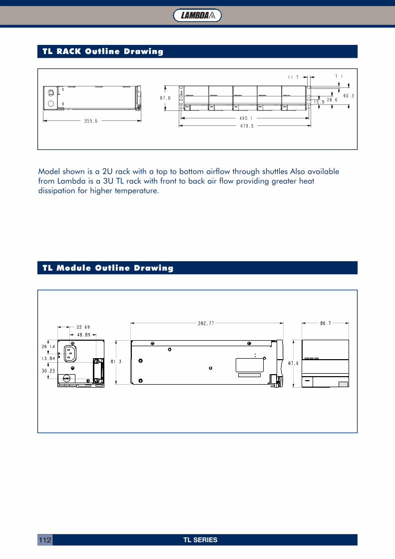
TL SERIES112
TL RACK Outline Drawing
TL Module Outline Drawing
Model shown is a 2U rack with a top to bottom airflow through shuttles Also availablefrom Lambda is a 3U TL rack with front to back air flow providing greater heat dissipation for higher temperature.
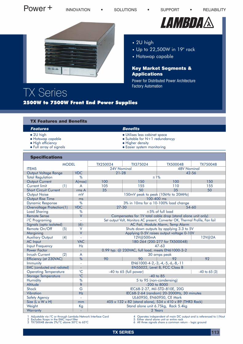
TX SERIES 113
• 2U high
• Up to 22,500W in 19" rack
• Hotswap capable
Key Market Segments &ApplicationsPower for Distributed Power ArchitectureFactory Automation
INNOVATION SOLUTIONS SUPPORT RELIABILITY
TX Series2500W to 7500W Front End Power Supplies
TX Features and Benefits
Features Benefits
Specifications
� 2U high � Utilises less cabinet space� Hotswap capable � Suitable for N+1 redundancyy� High efficiency � Higher density� Full array of signals � Easier system monitoring
MODEL TX250024 TX375024 TX500048 TX750048ITEMS 24V Nominal 48V NominalOutput Voltage Range VDC 21-28 42-56Total Regulation % ±1%Output Current A(max) 100 150 100 150Current limit (1) A 105 155 110 155Short Circuit Current rms A 35 50 35 50Output Noise mV 150mV peak to peak (10kHz to 20MHz)Output Rise Time ms 100-400 msDynamic Response % 3% in 10ms for a 10-100% load changeOvervoltage Protection(1) VDC 27-30 54-60Load Sharing % ±5% of full loadRemote Sense V Compensates for 1V total cable drop (stand alone unit only)i2C Programing - Set output Volt, Monitors AC present, Converter OK, Thermal Profile, Fan failSignals (opto isolated) (6)- AC Fail, Module Alarm, Temp AlarmRemote On/Off (5) V Shuts down outputs by applying 3.3 to 5VMargining V Applying 0-5V raises output voltage 0-10VAuxiliary Output (4) - 12V@500mA 12V@2AAC Input VAC 180-264 (200-277 for TX500048)Input Frequency Hz 47-63Power Factor - 0.99 typ. @ 230VAC, full load, meets EN61000-3-2Inrush Current (2) A 30 amps peakEfficiency (at 230VAC) % 90 90 92 92Immunity - EN61000-4-2,-3,-4,-5,-6,-8,-11EMC (conducted and radiated) - EN55022, Level B, FCC Class BOperating Temperature °C -40 to 65 (full power) -40 to 65 (3)Storage Temperature °C -40 to 85Humidity % 5 to 95 (non-condensing)Altitude ft -200 to 8000Shock G IEC68-2-27, Mil-STD-810E, 20GVibration Hz IEC68-2-64 (random) 20-2000Hz, 30 minutesSafety Agency - UL60950, EN60950, CE MarkSize (L x W x H) mm 405 x 132 x 82 (stand alone), 534 x 410 x 89 (THR3 Rack)Weight Kg Stand alone unit 6.75kg, Rack 5.4kgWarranty - 2 Years
1 Adjustable via i2C or through Lambda Network Interface Card2 Excludes Xcaps in the EMC input filter3 TX750048 derate 2%/°C above 50°C to 65°C
4 Operates independent of main DC output and is referenced to (-)Vout5 Either stand alone unit or entire rack6 All three signals share a common return - logic ground

TX SERIES114
TL Module Connector (Part Number: FCI 51732-007)
1.2m/s Forced Air 50°C 55°C 60°C 65°C 70°C
Output Output MaximumModel Voltage Current Power
Model Selector
Connector Pinout
PIN Description PIN Description
10 OPEN 20 MODULE_PRESENT9 OPEN 19 OPEN8 MODULE_AC FAIL_2 18 MODULE_ALARM_27 MODULE_AC FAIL_1 17 MODULE_ALARM_16 MODULE_AC FAIL_0 16 MODULE_ALARM_05 MODULE_DISABLE 15 THERMAL_FAIL4 LOGIC_GRND 14 OPEN3 SDA 13 V_MARGIN2 SCL 12 I_SHARE1 SHELF_BIAS 11 Vmain_2Note: PIN 10 Top Left PIN 20 Top Right
TX250024 24V 100A 2400WTX375024 24V 150A 3600WTX500048 48V 100A 4800WTX750048 48V 150A 7200WTXR3 19” Rack holds up to 3 TX ModulesTXRBP Blanking panel for one module slot
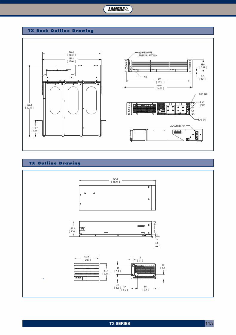
TX SERIES 115
TX Rack Out l ine Drawing
TX Out l ine Drawing
3300
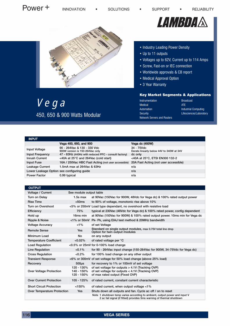
VEGA SERIES116
• Industry Leading Power Density
• Up to 11 outputs
• Voltages up to 62V, Current up to 114 Amps
• Screw, Fast-on or IEC connection
• Worldwide approvals & CB report
• Medical Approval Option
• 3 Year Warranty
Key Market Segments & Applications
Instrumentation BroadcastMedical ATEAutomation Industrial ComputingSecurity Lifesciences/LaboratoryNetwork Servers and Routers
V e g a450, 650 & 900 Watts Modular
IINNPPUUTTVVeeggaa 445500,, 665500,, aanndd 990000 VVeeggaa ddcc ((445500WW))
Input Voltage90 - 264Vac & 130 - 330 Vdc900W version is 150-264Vac only
34 - 75VdcDerate linearly below 44V to 340W at 34V
Input Frequency 47 - 63Hz (440Hz with reduced PFC - consult factory) dc only
Inrush Current <40A at 25°C and 264Vac (cold start) <40A at 25°C, ETSI EN300 132-2
Input Fuse 16A / 250Vac HBC Fast Acting (not user accessible) 20A Fast Acting (not user accessible)
Leakage Current 1.5mA max at 264Vac & 63Hz n/a
Lower Leakage Option see configuring guide n/a
Power Factor 0.99 typical n/a
OOUUTTPPUUTTVoltage / Current See module output table
Turn on Delay 1.5s max at 90Vac (150Vac for 900W, 48Vdc for Vega dc) & 100% rated output power
Rise Time <50ms to 90% of voltage, monotonic rise above 10%
Turn on Overshoot <5% or 250mV Load type dependant, no overshoot with resistive load
Efficiency 75% typical at 230Vac (48Vdc for Vega dc) & 100% rated power, config dependent
Hold up 16ms min at 90Vac (150Vac for 900W) & 100% rated output power. 10ms min for Vega dc
Ripple & Noise <1% or 50mV Pk- Pk, using EIAJ test method & 20MHz bandwidth
Voltage Accuracy <1% of set Voltage
Remote Sense YesStandard on single output modules, max 0.75V total line dropOption for twin output modules
Minimum Load No on any output
Temperature Coefficient <0.02% of rated voltage per °C
Load Regulation <0.5% or 25mV for 0-100% load change
Line Regulation <0.1% for 90 - 264Vac input change (150-264Vac for 900W, 34-75Vdc for Vega dc)
Cross Regulation <0.2% for 100% load change on any other output
Transient Response
Recovery
<6% or 300mV of set voltage for 50% load change (above 25% load)
500μs for recovery to 1% or 100mV of set voltage
Over Voltage Protection
120 - 130% of set voltage for outputs > 4.1V (Tracking OVP)
140 - 150% of set voltage for outputs < 4.1V (Tracking OVP)
120 - 150% of max rated output (Fixed OVP)
Over Current Protection 105 - 125% of rated current, constant current characteristic
Short Circuit Protection <150% of rated current, when output voltage <1%
Over Temperature Protection Yes Shuts down all outputs and fan. Cycle ac off / on to reset
Note 1 shutdown temp varies according to ambient, output power and input V2 ac fail signal (if fitted) provides 5ms warning of thermal shutdown
INNOVATION SOLUTIONS SUPPORT RELIABILITY
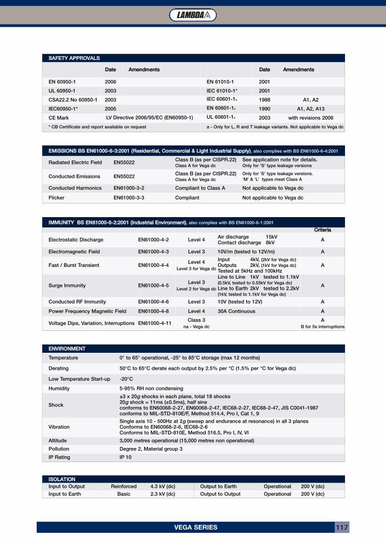
VEGA SERIES 117
EENNVVIIRROONNMMEENNTTTemperature 0° to 65° operational, -25° to 85°C storage (max 12 months)
Derating 50°C to 65°C derate each output by 2.5% per °C (1.5% per °C for Vega dc)
Low Temperature Start-up -20°C
Humidity 5-95% RH non condensing
Shock
±3 x 20g shocks in each plane, total 18 shocks20g shock = 11ms (±0.5ms), half sineconforms to EN60068-2-27, EN60068-2-47, IEC68-2-27, IEC68-2-47, JIS C0041-1987conforms to MIL-STD-810E/F, Method 514.4, Pro I, Cat 1, 9
VibrationSingle axis 10 - 500Hz at 2g (sweep and endurance at resonance) in all 3 planesConforms to EN60068-2-6, IEC68-2-6Conforms to MIL-STD-810E, Method 516.5, Pro I, IV, VI
Altitude 3,000 metres operational (15,000 metres non operational)
Pollution Degree 2, Material group 3
IP Rating IP 10
IIMMMMUUNNIITTYY BBSS EENN6611000000--66--22::22000011 ((IInndduussttrriiaall EEnnvviirroonnmmeenntt)), also complies with BS EN61000-6-1:2001
CCrriitteerriiaaElectrostatic Discharge EN61000-4-2 Level 4
Air discharge 15kVContact discharge 8kV
A
Electromagnetic Field EN61000-4-3 Level 3 10V/m (tested to 12V/m) A
Fast / Burst Transient EN61000-4-4Level 4
Level 3 for Vega dc
Input 4kV, (2kV for Vega dc)
Outputs 2kV, (1kV for Vega dc)
Tested at 5kHz and 100kHzA
Surge Immunity EN61000-4-5Level 3
Level 2 for Vega dc
Line to Line 1kV tested to 1.1kV(0.5kV, tested to 0.55kV for Vega dc)
Line to Earth 2kV tested to 2.2kV(1kV, tested to 1.1kV for Vega dc)
A
Conducted RF Immunity EN61000-4-6 Level 3 10V (tested to 12V) A
Power Frequency Magnetic Field EN61000-4-8 Level 4 30A Continuous A
Voltage Dips, Variation, Interruptions EN61000-4-11Class 3
na - Vega dc
A
B for 5s interruptions
SSAAFFEETTYY AAPPPPRROOVVAALLSSDDaattee AAmmeennddmmeennttss DDaattee AAmmeennddmmeennttss
EN 60950-1 2006 EN 61010-1 2001
UL 60950-1 2003 IEC 61010-1* 2001
CSA22.2 No 60950-1 2003 IEC 60601-1a 1988 A1, A2
IEC60950-1* 2005 EN 60601-1a 1990 A1, A2, A13
CE Mark LV Directive 2006/95/EC (EN60950-1) UL 60601-1a 2003 with revisions 2006
* CB Certificate and report available on request a - Only for L, R and T leakage variants. Not applicable to Vega dc
EEMMIISSSSIIOONNSS BBSS EENN6611000000--66--33::22000011 ((RReessiiddeennttiiaall,, CCoommmmeerrcciiaall && LLiigghhtt IInndduussttrriiaall SSuuppppllyy)), also complies with BS EN61000-6-4:2001
Radiated Electric Field EN55022Class B (as per CISPR.22)Class A for Vega dc
See application note for details.Only for ‘S’ type leakage versions
Conducted Emissions EN55022Class B (as per CISPR.22)Class A for Vega dc
Only for ‘S’ type leakage versions.
‘M’ & ‘L’ types meet Class A
Conducted Harmonics EN61000-3-2 Compliant to Class A Not applicable to Vega dc
Flicker EN61000-3-3 Compliant Not applicable to Vega dc
IISSOOLLAATTIIOONNInput to Output Reinforced 4.3 kV (dc) Output to Earth Operational 200 V (dc)
Input to Earth Basic 2.3 kV (dc) Output to Output Operational 200 V (dc)
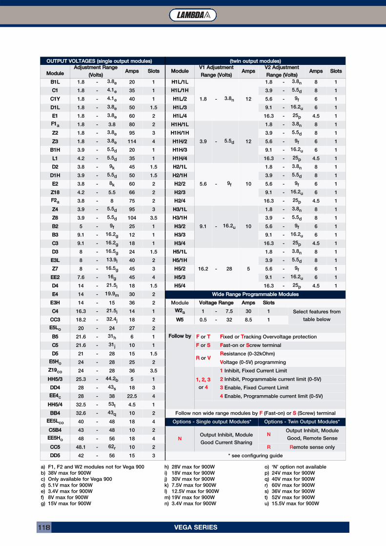
VEGA SERIES118
OOUUTTPPUUTT VVOOLLTTAAGGEESS ((ssiinnggllee oouuttppuutt mmoodduulleess)) ((ttwwiinn oouuttppuutt mmoodduulleess))MMoodduullee AAddjjuussttmmeenntt RRaannggee
((VVoollttss)) AAmmppss SSlloottss MMoodduullee VV11 AAddjjuussttmmeennttRRaannggee ((VVoollttss)) AAmmppss VV22 AAddjjuussttmmeenntt
RRaannggee ((VVoollttss)) AAmmppss SSlloottssBB11LL 1.8 - 3.8e 20 1 HH11LL//11LL
1.8 - 3.8n 12
1.8 - 3.8n 8 1
CC11 1.8 - 4.1e 35 1 HH11LL//11HH 3.9 - 5.5d 8 1
CC11YY 1.8 - 4.1e 40 1 HH11LL//22 5.6 - 9f 6 1
DD11LL 1.8 - 3.8e 50 1.5 HH11LL//33 9.1 - 16.2u 6 1
EE11 1.8 - 3.8e 60 2 HH11LL//44 16.3 - 25p 4.5 1
FF11a 1.8 - 3.8 80 2 HH11HH//11LL3.9 - 5.5d 12
1.8 - 3.8n 8 1
ZZ22 1.8 - 3.8e 95 3 HH11HH//11HH 3.9 - 5.5d 8 1
ZZ33 1.8 - 3.8e 114 4 HH11HH//22 5.6 - 9f 6 1
BB11HH 3.9 - 5.5d 20 1 HH11HH//33 9.1 - 16.2u 6 1
LL11 4.2 - 5.5d 35 1 HH11HH//44 16.3 - 25p 4.5 1
DD22 3.8 - 9k 45 1.5 HH22//11LL5.6 - 9f 10
1.8 - 3.8n 8 1
DD11HH 3.9 - 5.5d 50 1.5 HH22//11HH 3.9 - 5.5d 8 1
EE22 3.8 - 8k 60 2 HH22//22 5.6 - 9f 6 1
ZZ1188 4.2 - 5.5 66 2 HH22//33 9.1 - 16.2u 6 1
FF22a 3.8 - 8 75 2 HH22//44 16.3 - 25p 4.5 1
ZZ44 3.9 - 5.5d 95 3 HH33//11LL9.1 - 16.2u 10
1.8 - 3.8n 8 1
ZZ66 3.9 - 5.5d 104 3.5 HH33//11HH 3.9 - 5.5d 8 1
BB22 5 - 9f 25 1 HH33//22 5.6 - 9f 6 1
BB33 9.1 - 16.2g 12 1 HH33//33 9.1 - 16.2u 6 1
CC33 9.1 - 16.2g 18 1 HH33//44 16.3 - 25p 4.5 1
DD33 8 - 16.5g 24 1.5 HH55//11LL16.2 - 28 5
1.8 - 3.8n 8 1
EE33LL 8 - 13.9l 40 2 HH55//11HH 3.9 - 5.5d 8 1
ZZ77 8 - 16.5g 45 3 HH55//22 5.6 - 9f 6 1
EEEE22 7.6 - 16g 45 4 HH55//33 9.1 - 16.2u 6 1
DD44 14 - 21.5i 18 1.5 HH55//44 16.3 - 25p 4.5 1
EE44 14 - 19.9m 30 2 WWiiddee RRaannggee PPrrooggrraammmmaabbllee MMoodduulleessEE33HH 14 - 15 36 2 Module VVoollttaaggee RRaannggee AAmmppss SSlloottssCC44 16.3 - 21.5i 14 1 WW22a 1 - 7.5 30 1 Select features from
table belowCCCC33 18.2 - 32.4j 18 2 WW55 0.5 - 32 8.5 1
EE55LLo 20 - 24 27 2
BB55 21.6 - 31h 6 1 FFoollllooww bbyy FF or TT FFixed or TTracking Overvoltage protection
CC55 21.6 - 31j 10 1 FF or SS FFast-on or SScrew terminal
DD55 21 - 28 15 1.5RR or VV RResistance (0-32kOhm)
EE55HHo 24 - 28 25 2 VVoltage (0-5V) programming
ZZ1199co 24 - 28 36 3.5
11,, 22,, 33or 44
11 Inhibit, Fixed Current Limit
HHHH55//33 25.3 - 44.2b 5 1 22 Inhibit, Programmable current limit (0-5V)
DDDD44 28 - 43s 18 3 33 Enable, Fixed Current Limit
EEEE44c 28 - 38 22.5 4 44 Enable, Programmable current limit (0-5V)
HHHH55//44 32.5 - 53t 4.5 1
BBBB44 32.6 - 43q 10 2 Follow non wide range modules by FF (Fast-on) or SS (Screw) terminal
EEEE55LLco 40 - 48 18 4 Options - Single output Modules* Options - Twin Output Modules*
CC55BB44 43 - 48 10 2
NOutput Inhibit, Module
Good Current Sharing
NOutput Inhibit, Module
Good, Remote SenseEEEE55HHo 48 - 56 18 4
CCCC55 48.1 - 62r 10 2 R Remote sense only
DDDD55 42 - 56 15 3 * see configuring guide
a) F1, F2 and W2 modules not for Vega 900
b) 38V max for 900W
c) Only available for Vega 900
d) 5.1V max for 900W
e) 3.4V max for 900W
f) 8V max for 900W
g) 15V max for 900W
h) 28V max for 900W
i) 18V max for 900W
j) 30V max for 900W
k) 7.5V max for 900W
l) 12.5V max for 900W
m) 19V max for 900W
n) 3.4V max for 900W
o) ‘N’ option not available
p) 24V max for 900W
q) 40V max for 900W
r) 60V max for 900W
s) 36V max for 900W
t) 52V max for 900W
u) 15.5V max for 900W
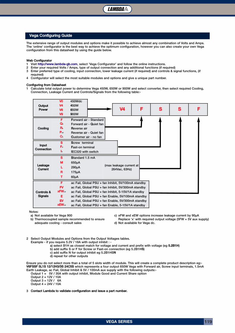
VEGA SERIES 119
VVeeggaa CCoonnffiigguurriinngg GGuuiiddeeThe extensive range of output modules and options make it possible to achieve almost any combination of Volts and Amps.The ‘online’ configurator is the best way to achieve the optimum configuration, however you can also create your own Vegaconfiguration from this datasheet by using the guide below.
WWeebb CCoonnffiigguurraattoorr1 Visit hhttttpp::////wwwwww..llaammbbddaa--ggbb..ccoomm, select ‘Vega Configurator’ and follow the online instructions.2 Enter your required Volts / Amps, type of output connection and any additional functions (if required)3 Enter preferred type of cooling, input connection, lower leakage current (if required) and controls & signal functions, (if
required)4 Configurator will select the most suitable modules and options and give a unique part number.
CCoonnffiigguurriinngg ffrroomm DDaattaasshheeeett1 Calculate total output power to determine Vega 450W, 650W or 900W and select converter, then select required Cooling,
Connection, Leakage Current and Controls/Signals from the following table:-
2 Select Output Modules and Options from the Output Voltages tables.Example - if you require 5.2V / 18A with output inhibit : -
a) select B1H as closest match for voltage and current and prefix with voltage (eg 55..22BB11HH)b) add suffix S or F for Screw or Fast-on connection (eg 5.2B1HSS)c) add suffix N for output inhibit eg 5.2B1HSNNd) repeat for other outputs
Ensure you do not select more than a total of 5 slots width of module. This will create a complete product description eg:-VV66FFSSSSFF 55LL11SS 1122//1122HH33//33SS 2244CC55SS which represents a four output 650W Vega with Forward air, Screw input terminals, 1.5mAEarth Leakage, ac Fail, Global Inhibit & 5V / 100mA aux supply with the following outputs:-
Output 1 = 5V / 35A with output inhibit, Module Good and Current Share optionOutput 2 = 12V / 10AOutput 3 = 12V / 6AOutput 4 = 24V / 10A
3 CCoonnttaacctt LLaammbbddaa ttoo vvaalliiddaattee ccoonnffiigguurraattiioonn aanndd iissssuuee aa ppaarrtt nnuummbbeerr..
OOuuttppuuttPPoowweerr
VV00 450Wdc
VV44 4450W
VV66 6650W
VV99 9900W
CCoooolliinnggFF FForward air - Standard
QQd Forward air - QQuiet fan
RRa RReverse air
PPad Reverse air - Quiet fan
CCb CCustomer air - no fan
LLeeaakkaaggeeCCuurrrreenntt
SS SStandard 1.5 mA
(max leakage current at
264Vac, 63Hz)
MM 650μA
LL 290μA
RR 175μA
TT 60μA
IInnppuuttCCoonnnneeccttiioonn
SS SScrew terminal
FFd FFast-on terminal
IId IIEC320 with switch
CCoonnttrroollss &&SSiiggnnaallss
FF ac Fail, Global PSU + fan Inhibit, 5V/100mA standby
FFVV ac Fail, Global PSU + fan Inhibit, 5V/300mA standby
xxFFWWcd ac Fail, Global PSU + fan Inhibit, 5-15V/1A standby
EE ac Fail, Global PSU + fan Enable, 5V/100mA standby
EEVV ac Fail, Global PSU + fan Enable, 5V/300mA standby
xxEEWWcd ac Fail, Global PSU + fan Enable, 5-15V/1A standby
VV44 FF SS SS FF
Notes:
a) Not available for Vega 900
b) Thermocoupled sample recommended to ensure
adequate cooling - consult sales
c) xFW and xEW options increase leakage current by 90μA
Replace ‘x’ with required output voltage (5FW = 5V aux supply)
d) Not available for Vega dc.
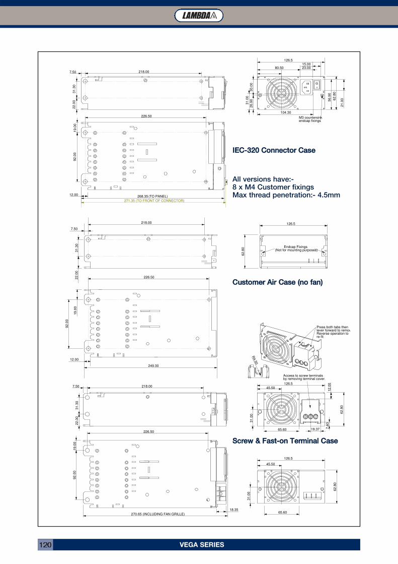
VEGA SERIES120
21.0
0
104.30
31.0
0
15.00
26.9
0 56.9
0
62.8
0
M3 countersinkendcap fixings
(TO PANEL)268.35
271.35 (TO FRONT OF CONNECTOR)
92.0
0
226.50
12.00
19.0
0
126.5
22.0
07.50 218.00
31.3
0
30.0
0
80.50 23.00
65.60
31.0
0
62.8
0
45.50
126.5
18.35
Press both tabs thenlever forward to removReverse operation tore-fit
19.37
12.0
07.6
0
Access to screw terminalsby removing terminal cover.
65.60
270.65 (INCLUDING FAN GRILLE)
45.50
31.0
0
62.8
0
92.0
0
226.50
19.0
0
126.5
22.0
0
7.50 218.00
31.3
0
92.0
0
226.50
12.00
19.0
0
249.30
62.8
0
126.5
Endcap Fixings(Not for mounting purposes)
22.0
0
7.50
218.00
31.3
0
R4.5
0
IIEECC--332200 CCoonnnneeccttoorr CCaasseeAll versions have:-8 x M4 Customer fixingsMax thread penetration:- 4.5mm
SSccrreeww && FFaasstt--oonn TTeerrmmiinnaall CCaassee
CCuussttoommeerr AAiirr CCaassee ((nnoo ffaann))
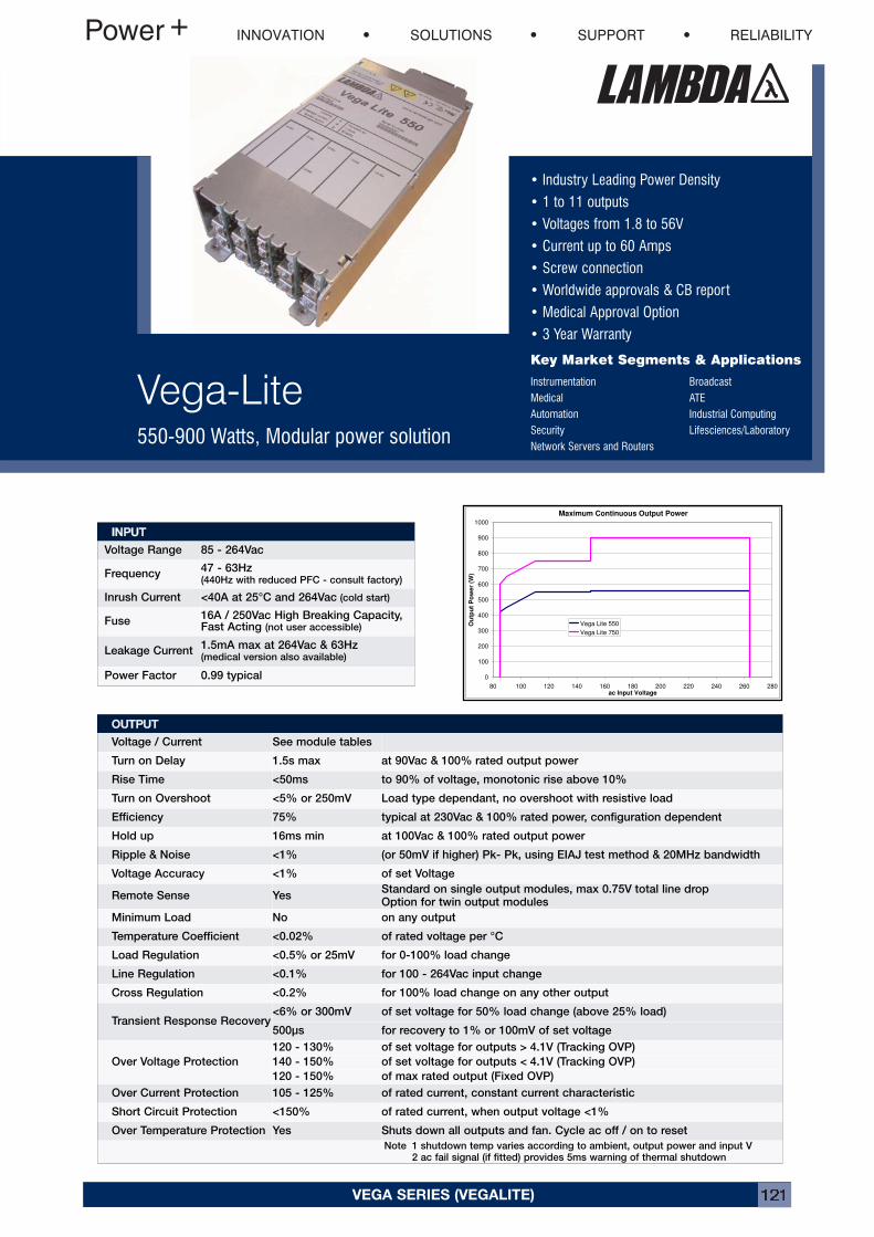
VEGA SERIES (VEGALITE) 121
• Industry Leading Power Density
• 1 to 11 outputs
• Voltages from 1.8 to 56V
• Current up to 60 Amps
• Screw connection
• Worldwide approvals & CB report
• Medical Approval Option
• 3 Year Warranty
Key Market Segments & Applications
Instrumentation BroadcastMedical ATEAutomation Industrial ComputingSecurity Lifesciences/LaboratoryNetwork Servers and Routers
Vega-Lite550-900 Watts, Modular power solution
VEGA SERIES (VEGA LITE)
Maximum Continuous Output Power
0
100
200
300
400
500
600
700
800
900
1000
80 100 120 140 160 180 200 220 240 260 280ac Input Voltage
Ou
tpu
tP
ow
er
(W)
Vega Lite 550
Vega Lite 750
OOUUTTPPUUTTVoltage / Current See module tables
Turn on Delay 1.5s max at 90Vac & 100% rated output power
Rise Time <50ms to 90% of voltage, monotonic rise above 10%
Turn on Overshoot <5% or 250mV Load type dependant, no overshoot with resistive load
Efficiency 75% typical at 230Vac & 100% rated power, configuration dependent
Hold up 16ms min at 100Vac & 100% rated output power
Ripple & Noise <1% (or 50mV if higher) Pk- Pk, using EIAJ test method & 20MHz bandwidth
Voltage Accuracy <1% of set Voltage
Remote Sense YesStandard on single output modules, max 0.75V total line dropOption for twin output modules
Minimum Load No on any output
Temperature Coefficient <0.02% of rated voltage per °C
Load Regulation <0.5% or 25mV for 0-100% load change
Line Regulation <0.1% for 100 - 264Vac input change
Cross Regulation <0.2% for 100% load change on any other output
Transient Response Recovery<6% or 300mV of set voltage for 50% load change (above 25% load)
500μs for recovery to 1% or 100mV of set voltage
Over Voltage Protection
120 - 130% of set voltage for outputs > 4.1V (Tracking OVP)
140 - 150% of set voltage for outputs < 4.1V (Tracking OVP)
120 - 150% of max rated output (Fixed OVP)
Over Current Protection 105 - 125% of rated current, constant current characteristic
Short Circuit Protection <150% of rated current, when output voltage <1%
Over Temperature Protection Yes Shuts down all outputs and fan. Cycle ac off / on to reset
Note 1 shutdown temp varies according to ambient, output power and input V2 ac fail signal (if fitted) provides 5ms warning of thermal shutdown
IINNPPUUTTVoltage Range 85 - 264Vac
Frequency47 - 63Hz(440Hz with reduced PFC - consult factory)
Inrush Current <40A at 25°C and 264Vac (cold start)
Fuse16A / 250Vac High Breaking Capacity,Fast Acting (not user accessible)
Leakage Current1.5mA max at 264Vac & 63Hz(medical version also available)
Power Factor 0.99 typical
INNOVATION SOLUTIONS SUPPORT RELIABILITY
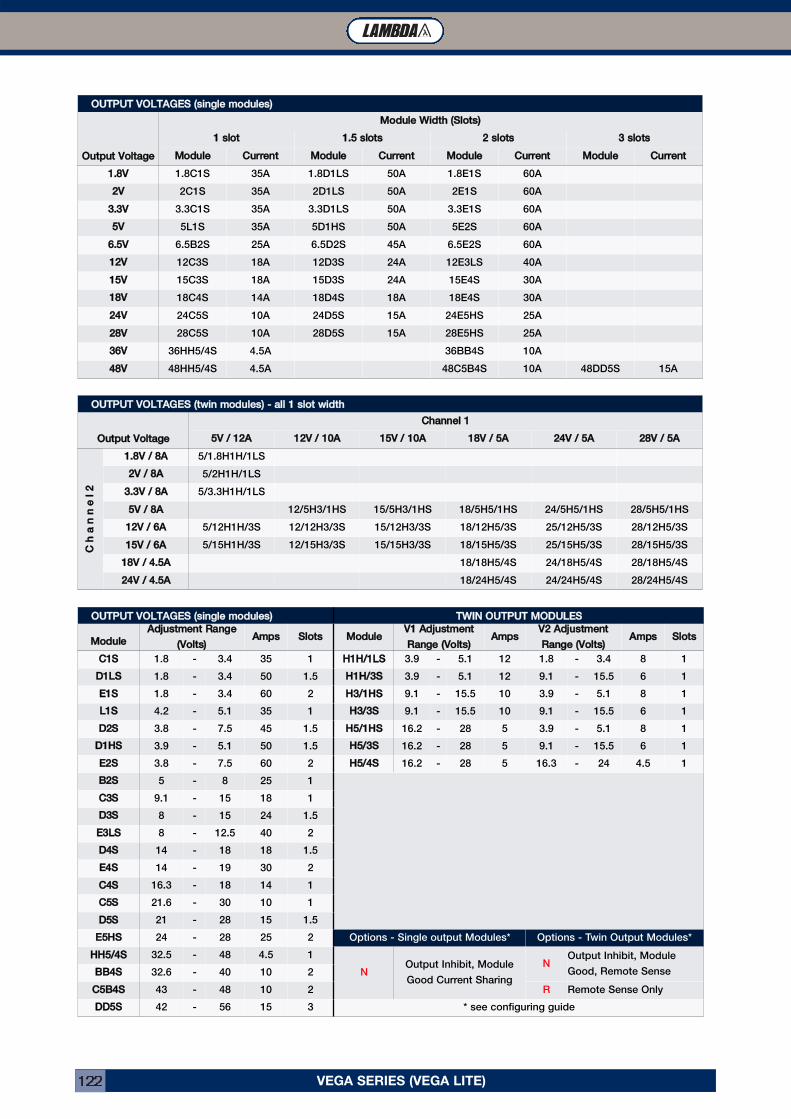
VEGA SERIES (VEGA LITE)122
OOUUTTPPUUTT VVOOLLTTAAGGEESS ((ssiinnggllee mmoodduulleess))OOuuttppuutt VVoollttaaggee
MMoodduullee WWiiddtthh ((SSlloottss))11 sslloott 11..55 sslloottss 22 sslloottss 33 sslloottss
MMoodduullee CCuurrrreenntt MMoodduullee CCuurrrreenntt MMoodduullee CCuurrrreenntt MMoodduullee CCuurrrreenntt11..88VV 1.8C1S 35A 1.8D1LS 50A 1.8E1S 60A
22VV 2C1S 35A 2D1LS 50A 2E1S 60A
33..33VV 3.3C1S 35A 3.3D1LS 50A 3.3E1S 60A
55VV 5L1S 35A 5D1HS 50A 5E2S 60A
66..55VV 6.5B2S 25A 6.5D2S 45A 6.5E2S 60A
1122VV 12C3S 18A 12D3S 24A 12E3LS 40A
1155VV 15C3S 18A 15D3S 24A 15E4S 30A
1188VV 18C4S 14A 18D4S 18A 18E4S 30A
2244VV 24C5S 10A 24D5S 15A 24E5HS 25A
2288VV 28C5S 10A 28D5S 15A 28E5HS 25A
3366VV 36HH5/4S 4.5A 36BB4S 10A
4488VV 48HH5/4S 4.5A 48C5B4S 10A 48DD5S 15A
OOUUTTPPUUTT VVOOLLTTAAGGEESS ((ttwwiinn mmoodduulleess)) -- aallll 11 sslloott wwiiddtthhOOuuttppuutt VVoollttaaggee CChhaannnneell 11
55VV // 1122AA 1122VV // 1100AA 1155VV // 1100AA 1188VV // 55AA 2244VV // 55AA 2288VV // 55AA
CChhaannnnee
ll22
11..88VV // 88AA 5/1.8H1H/1LS
22VV // 88AA 5/2H1H/1LS
33..33VV // 88AA 5/3.3H1H/1LS
55VV // 88AA 12/5H3/1HS 15/5H3/1HS 18/5H5/1HS 24/5H5/1HS 28/5H5/1HS
1122VV // 66AA 5/12H1H/3S 12/12H3/3S 15/12H3/3S 18/12H5/3S 25/12H5/3S 28/12H5/3S
1155VV // 66AA 5/15H1H/3S 12/15H3/3S 15/15H3/3S 18/15H5/3S 25/15H5/3S 28/15H5/3S
1188VV // 44..55AA 18/18H5/4S 24/18H5/4S 28/18H5/4S
2244VV // 44..55AA 18/24H5/4S 24/24H5/4S 28/24H5/4S
OOUUTTPPUUTT VVOOLLTTAAGGEESS ((ssiinnggllee mmoodduulleess)) TTWWIINN OOUUTTPPUUTT MMOODDUULLEESSMMoodduullee AAddjjuussttmmeenntt RRaannggee
((VVoollttss)) AAmmppss SSlloottss MMoodduullee VV11 AAddjjuussttmmeennttRRaannggee ((VVoollttss)) AAmmppss VV22 AAddjjuussttmmeenntt
RRaannggee ((VVoollttss)) AAmmppss SSlloottssCC11SS 1.8 - 3.4 35 1 HH11HH//11LLSS 3.9 - 5.1 12 1.8 - 3.4 8 1
DD11LLSS 1.8 - 3.4 50 1.5 HH11HH//33SS 3.9 - 5.1 12 9.1 - 15.5 6 1
EE11SS 1.8 - 3.4 60 2 HH33//11HHSS 9.1 - 15.5 10 3.9 - 5.1 8 1
LL11SS 4.2 - 5.1 35 1 HH33//33SS 9.1 - 15.5 10 9.1 - 15.5 6 1
DD22SS 3.8 - 7.5 45 1.5 HH55//11HHSS 16.2 - 28 5 3.9 - 5.1 8 1
DD11HHSS 3.9 - 5.1 50 1.5 HH55//33SS 16.2 - 28 5 9.1 - 15.5 6 1
EE22SS 3.8 - 7.5 60 2 HH55//44SS 16.2 - 28 5 16.3 - 24 4.5 1
BB22SS 5 - 8 25 1
CC33SS 9.1 - 15 18 1
DD33SS 8 - 15 24 1.5
EE33LLSS 8 - 12.5 40 2
DD44SS 14 - 18 18 1.5
EE44SS 14 - 19 30 2
CC44SS 16.3 - 18 14 1
CC55SS 21.6 - 30 10 1
DD55SS 21 - 28 15 1.5
EE55HHSS 24 - 28 25 2 Options - Single output Modules* Options - Twin Output Modules*
HHHH55//44SS 32.5 - 48 4.5 1
NOutput Inhibit, Module
Good Current Sharing
NOutput Inhibit, Module
Good, Remote SenseBBBB44SS 32.6 - 40 10 2
CC55BB44SS 43 - 48 10 2 R Remote Sense Only
DDDD55SS 42 - 56 15 3 * see configuring guide
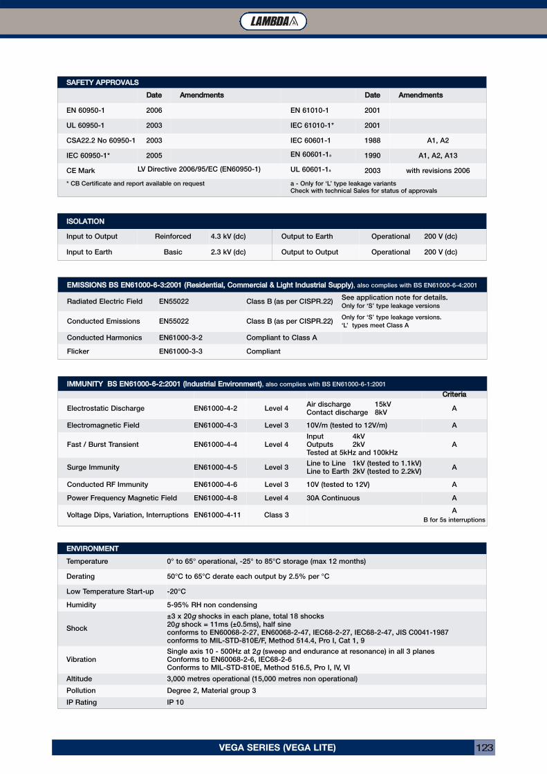
VEGA SERIES (VEGA LITE) 123
IISSOOLLAATTIIOONNInput to Output Reinforced 4.3 kV (dc) Output to Earth Operational 200 V (dc)
Input to Earth Basic 2.3 kV (dc) Output to Output Operational 200 V (dc)
EENNVVIIRROONNMMEENNTTTemperature 0° to 65° operational, -25° to 85°C storage (max 12 months)
Derating 50°C to 65°C derate each output by 2.5% per °C
Low Temperature Start-up -20°C
Humidity 5-95% RH non condensing
Shock
±3 x 20g shocks in each plane, total 18 shocks20g shock = 11ms (±0.5ms), half sineconforms to EN60068-2-27, EN60068-2-47, IEC68-2-27, IEC68-2-47, JIS C0041-1987conforms to MIL-STD-810E/F, Method 514.4, Pro I, Cat 1, 9
VibrationSingle axis 10 - 500Hz at 2g (sweep and endurance at resonance) in all 3 planesConforms to EN60068-2-6, IEC68-2-6Conforms to MIL-STD-810E, Method 516.5, Pro I, IV, VI
Altitude 3,000 metres operational (15,000 metres non operational)
Pollution Degree 2, Material group 3
IP Rating IP 10
SSAAFFEETTYY AAPPPPRROOVVAALLSSDDaattee AAmmeennddmmeennttss DDaattee AAmmeennddmmeennttss
EN 60950-1 2006 EN 61010-1 2001
UL 60950-1 2003 IEC 61010-1* 2001
CSA22.2 No 60950-1 2003 IEC 60601-1 1988 A1, A2
IEC 60950-1* 2005 EN 60601-1a 1990 A1, A2, A13
CE Mark LV Directive 2006/95/EC (EN60950-1) UL 60601-1a 2003 with revisions 2006
* CB Certificate and report available on request a - Only for ‘L’ type leakage variantsCheck with technical Sales for status of approvals
EEMMIISSSSIIOONNSS BBSS EENN6611000000--66--33::22000011 ((RReessiiddeennttiiaall,, CCoommmmeerrcciiaall && LLiigghhtt IInndduussttrriiaall SSuuppppllyy)), also complies with BS EN61000-6-4:2001
Radiated Electric Field EN55022 Class B (as per CISPR.22)See application note for details.Only for ‘S’ type leakage versions
Conducted Emissions EN55022 Class B (as per CISPR.22)Only for ‘S’ type leakage versions.
‘L’ types meet Class A
Conducted Harmonics EN61000-3-2 Compliant to Class A
Flicker EN61000-3-3 Compliant
IIMMMMUUNNIITTYY BBSS EENN6611000000--66--22::22000011 ((IInndduussttrriiaall EEnnvviirroonnmmeenntt)), also complies with BS EN61000-6-1:2001
CCrriitteerriiaaElectrostatic Discharge EN61000-4-2 Level 4
Air discharge 15kVContact discharge 8kV
A
Electromagnetic Field EN61000-4-3 Level 3 10V/m (tested to 12V/m) A
Fast / Burst Transient EN61000-4-4 Level 4Input 4kVOutputs 2kVTested at 5kHz and 100kHz
A
Surge Immunity EN61000-4-5 Level 3Line to Line 1kV (tested to 1.1kV)Line to Earth 2kV (tested to 2.2kV)
A
Conducted RF Immunity EN61000-4-6 Level 3 10V (tested to 12V) A
Power Frequency Magnetic Field EN61000-4-8 Level 4 30A Continuous A
Voltage Dips, Variation, Interruptions EN61000-4-11 Class 3A
B for 5s interruptions
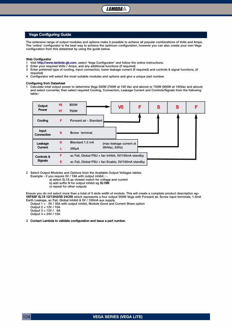
VEGA SERIES (VEGA LITE)124
VEGA SERIES (VEGA LITE)
VVeeggaa CCoonnffiigguurriinngg GGuuiiddeeThe extensive range of output modules and options make it possible to achieve all popular combinations of Volts and Amps.The ‘online’ configurator is the best way to achieve the optimum configuration, however you can also create your own Vegaconfiguration from this datasheet by using the guide below.
WWeebb CCoonnffiigguurraattoorr1 Visit hhttttpp::////wwwwww..llaammbbddaa--ggbb..ccoomm, select ‘Vega Configurator’ and follow the online instructions.2 Enter your required Volts / Amps, and any additional functions (if required)3 Enter preferred type of cooling, input connection, lower leakage current (if required) and controls & signal functions, (if
required)4 Configurator will select the most suitable modules and options and give a unique part number.
CCoonnffiigguurriinngg ffrroomm DDaattaasshheeeett1 Calculate total output power to determine Vega 550W (700W at 150 Vac and above) or 750W (900W at 150Vac and above)
and select converter, then select required Cooling, Connection, Leakage Current and Controls/Signals from the followingtable:-
2 Select Output Modules and Options from the Available Output Voltages tables.Example - if you require 5V / 18A with output inhibit : -
a) select 5L1S as closest match for voltage and currentb) add suffix N for output inhibit eg 55LL11SSNNc) repeat for other outputs
Ensure you do not select more than a total of 5 slots width of module. This will create a complete product description eg:-VV55FFSSSSFF 55LL11SS 1122//1122HH33//33SS 2244CC55SS which represents a four output 550W Vega with Forward air, Screw input terminals, 1.5mAEarth Leakage, ac Fail, Global Inhibit & 5V / 100mA aux supply.
Output 1 = 5V / 35A with output inhibit, Module Good and Current Share optionOutput 2 = 12V / 10AOutput 3 = 12V / 6AOutput 4 = 24V / 10A
3 CCoonnttaacctt LLaammbbddaa ttoo vvaalliiddaattee ccoonnffiigguurraattiioonn aanndd iissssuuee aa ppaarrtt nnuummbbeerr..
OOuuttppuuttPPoowweerr VV55 5550W
VV77 7750W
CCoooolliinngg FF FForward air - Standard
LLeeaakkaaggeeCCuurrrreenntt SS SStandard 1.5 mA (max leakage current at
264Vac, 63Hz)LL 290μA
IInnppuuttCCoonnnneeccttiioonn SS SScrew terminal
CCoonnttrroollss &&SSiiggnnaallss FF ac Fail, Global PSU + fan Inhibit, 5V/100mA standby
EE ac Fail, Global PSU + fan Enable, 5V/100mA standby
VV55 FF SS SS FF
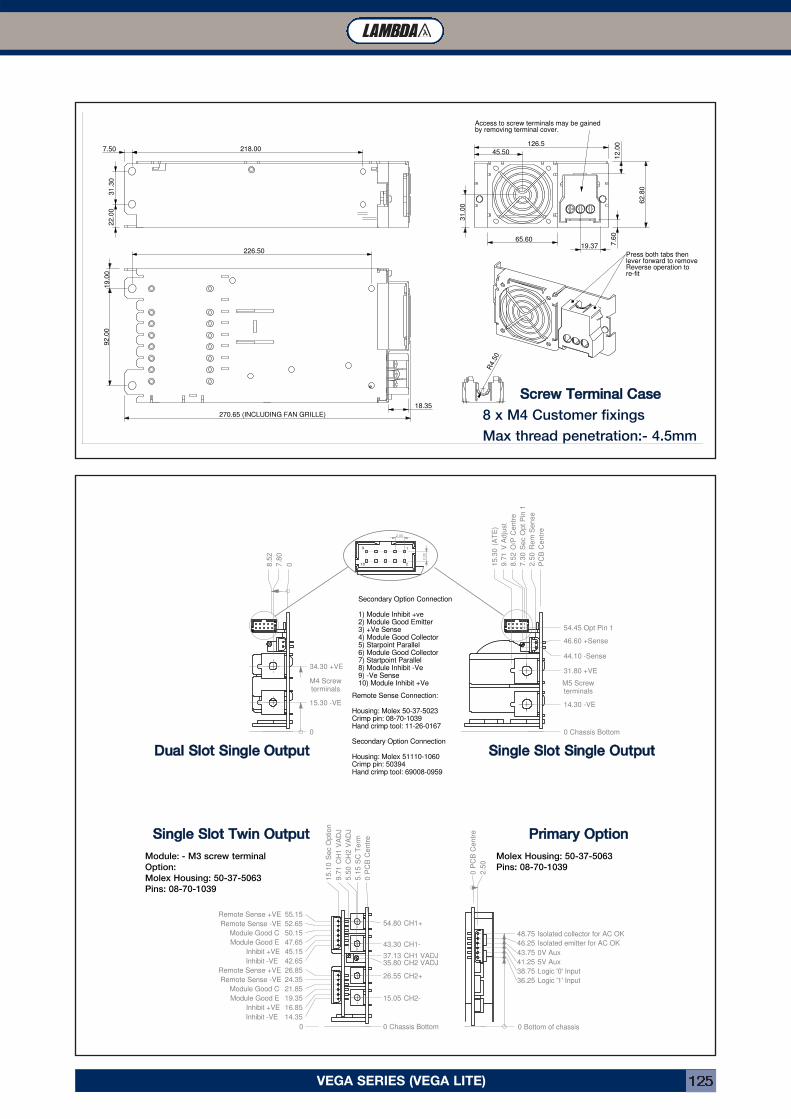
VEGA SERIES (VEGA LITE) 125
18.35
Press both tabs thenlever forward to removeReverse operation tore-fit
19.37
12.0
07.6
0
Access to screw terminals may be gained by removing terminal cover.
R4.5
0
65.60
270.65 (INCLUDING FAN GRILLE)
45.50
31.0
0
62.8
0
92.0
0
226.50
19.0
0
126.5
22.0
0
7.50 218.00
31.3
0
SSccrreeww TTeerrmmiinnaall CCaassee8 x M4 Customer fixings
Max thread penetration:- 4.5mm
PC
B C
entr
e
2.5
0 R
em
Sense
9.7
1 V
Adju
st
7.3
0 S
ec O
pt P
in 1
15.3
0 (
AT
E)
8.5
2 O
/P C
entr
e
Remote Sense Connection:
Housing: Molex 50-37-5023Crimp pin: 08-70-1039Hand crimp tool: 11-26-0167
Secondary Option Connection
Housing: Molex 51110-1060Crimp pin: 50394Hand crimp tool: 69008-0959
210
19
Secondary Option Connection
1) Module Inhibit +ve2) Module Good Emitter3) +Ve Sense4) Module Good Collector5) Starpoint Parallel6) Module Good Collector7) Startpoint Parallel8) Module Inhibit -Ve9) -Ve Sense10) Module Inhibit +Ve
2.0
0
2.00
0
08.5
2
7.8
0
15.30 -VE
34.30 +VE
0 Chassis Bottom
14.30 -VE
31.80 +VE
44.10 -Sense
46.60 +Sense
54.45 Opt Pin 1
M4 Screwterminals
M5 Screwterminals
0 Chassis Bottom
15.05 CH2-
26.55 CH2+
35.80 CH2 VADJ37.13 CH1 VADJ
43.30 CH1-
54.80 CH1+
0 P
CB
Centr
e
5.1
5 S
C T
erm
15.1
0 S
ec O
ption
5.5
0 C
H2 V
AD
J
9.7
1 C
H1 V
AD
J
0
Inhibit -VE 14.35
Inhibit +VE 16.85
Module Good E 19.35
Module Good C 21.85
Remote Sense -VE 24.35
Remote Sense +VE 26.85
Inhibit -VE 42.65
Inhibit +VE 45.15
Module Good E 47.65
Module Good C 50.15
Remote Sense -VE 52.65
Remote Sense +VE 55.15
0 P
CB
Centr
e
2.5
0
0 Bottom of chassis
36.25 Logic '1' Input
38.75 Logic '0' Input
41.25 5V Aux
43.75 0V Aux
46.25 Isolated emitter for AC OK
48.75 Isolated collector for AC OK
DDuuaall SSlloott SSiinnggllee OOuuttppuutt
SSiinnggllee SSlloott TTwwiinn OOuuttppuuttModule: - M3 screw terminal
Option:
Molex Housing: 50-37-5063
Pins: 08-70-1039
SSiinnggllee SSlloott SSiinnggllee OOuuttppuutt
PPrriimmaarryy OOppttiioonnMolex Housing: 50-37-5063
Pins: 08-70-1039
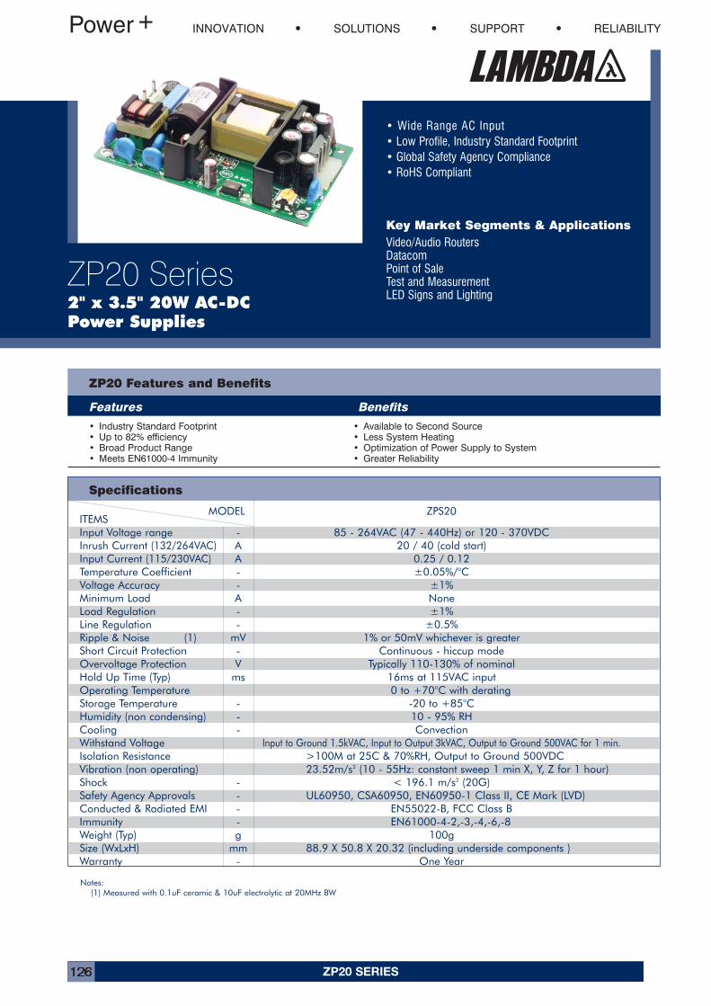
ZP20 SERIES126
• Wide Range AC Input• Low Profile, Industry Standard Footprint• Global Safety Agency Compliance• RoHS Compliant
Key Market Segments & ApplicationsVideo/Audio RoutersDatacomPoint of SaleTest and MeasurementLED Signs and Lighting
INNOVATION SOLUTIONS SUPPORT RELIABILITY
ZP20 Series2" x 3.5" 20W AC-DC Power Supplies
MODEL ZPS20ITEMSInput Voltage range - 85 - 264VAC (47 - 440Hz) or 120 - 370VDCInrush Current (132/264VAC) A 20 / 40 (cold start)Input Current (115/230VAC) A 0.25 / 0.12Temperature Coefficient - ±0.05%/°CVoltage Accuracy - ±1%Minimum Load A NoneLoad Regulation - ±1%Line Regulation - ±0.5%Ripple & Noise (1) mV 1% or 50mV whichever is greaterShort Circuit Protection - Continuous - hiccup modeOvervoltage Protection V Typically 110-130% of nominalHold Up Time (Typ) ms 16ms at 115VAC inputOperating Temperature 0 to +70°C with deratingStorage Temperature - -20 to +85°CHumidity (non condensing) - 10 - 95% RHCooling - ConvectionWithstand Voltage Input to Ground 1.5kVAC, Input to Output 3kVAC, Output to Ground 500VAC for 1 min.Isolation Resistance >100M at 25C & 70%RH, Output to Ground 500VDCVibration (non operating) 23.52m/s2 (10 - 55Hz: constant sweep 1 min X, Y, Z for 1 hour)Shock - < 196.1 m/s2 (20G)Safety Agency Approvals - UL60950, CSA60950, EN60950-1 Class II, CE Mark (LVD)Conducted & Radiated EMI - EN55022-B, FCC Class BImmunity - EN61000-4-2,-3,-4,-6,-8Weight (Typ) g 100gSize (WxLxH) mm 88.9 X 50.8 X 20.32 (including underside components )Warranty - One Year
ZP20 Features and Benefits
Features Benefits
• Industry Standard Footprint• Up to 82% efficiency• Broad Product Range• Meets EN61000-4 Immunity
• Available to Second Source• Less System Heating• Optimization of Power Supply to System• Greater Reliability
Specifications
Notes:(1) Measured with 0.1uF ceramic & 10uF electrolytic at 20MHz BW
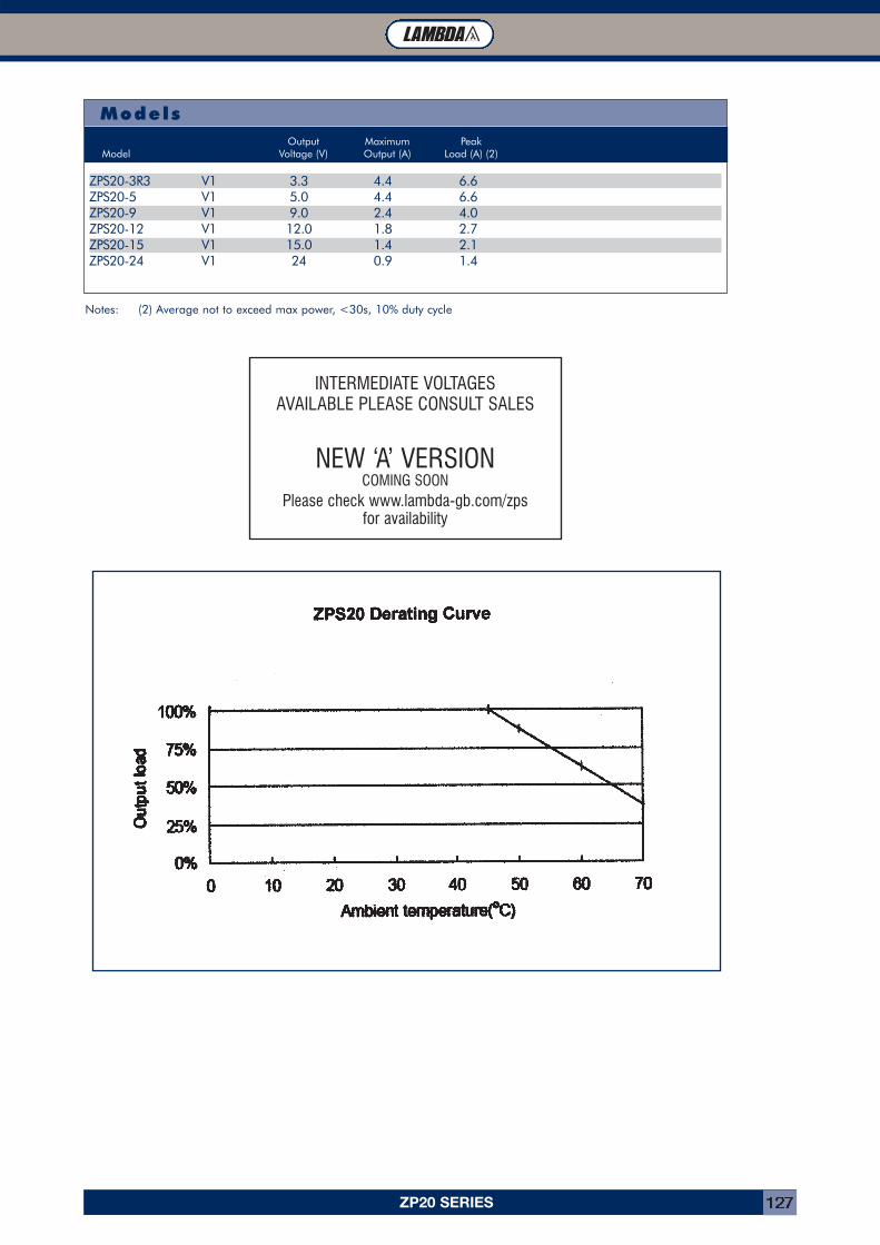
ZP20 SERIES 127
ModelsOutput Maximum Peak
Model Voltage (V) Output (A) Load (A) (2)
ZPS20-3R3 V1 3.3 4.4 6.6ZPS20-5 V1 5.0 4.4 6.6ZPS20-9 V1 9.0 2.4 4.0ZPS20-12 V1 12.0 1.8 2.7ZPS20-15 V1 15.0 1.4 2.1ZPS20-24 V1 24 0.9 1.4
Notes: (2) Average not to exceed max power, <30s, 10% duty cycle
INTERMEDIATE VOLTAGES AVAILABLE PLEASE CONSULT SALES
NEW ‘A’ VERSIONCOMING SOON
Please check www.lambda-gb.com/zpsfor availability
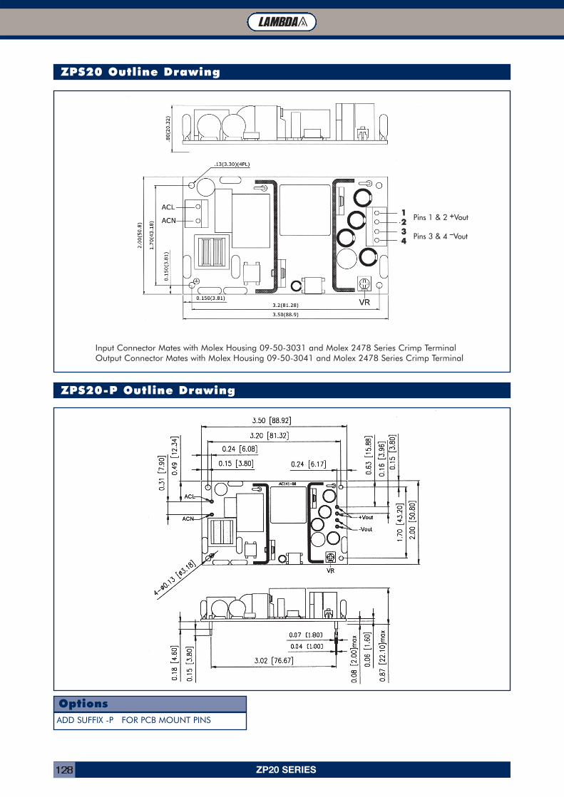
ZP20 SERIES128
ZPS20 Outline Drawing
ZPS20-P Outline Drawing
ADD SUFFIX -P FOR PCB MOUNT PINS
Options
Input Connector Mates with Molex Housing 09-50-3031 and Molex 2478 Series Crimp TerminalOutput Connector Mates with Molex Housing 09-50-3041 and Molex 2478 Series Crimp Terminal
11223344
Pins 1 & 2 +Vout
Pins 3 & 4 –Vout
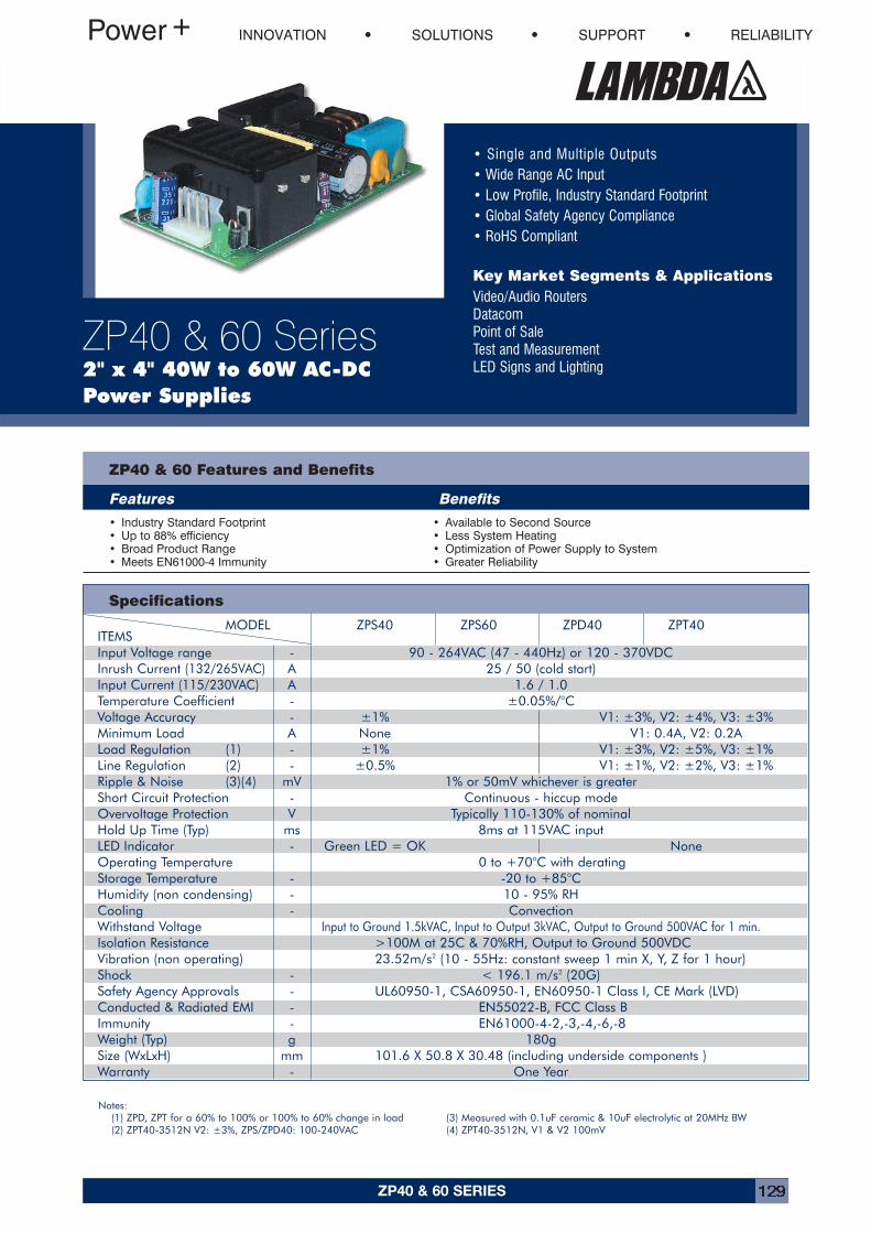
ZP40 & 60 SERIES 129
• Single and Multiple Outputs• Wide Range AC Input• Low Profile, Industry Standard Footprint• Global Safety Agency Compliance• RoHS Compliant
Key Market Segments & ApplicationsVideo/Audio RoutersDatacomPoint of SaleTest and MeasurementLED Signs and Lighting
INNOVATION SOLUTIONS SUPPORT RELIABILITY
ZP40 & 60 Series2" x 4" 40W to 60W AC-DCPower Supplies
MODEL ZPS40 ZPS60 ZPD40 ZPT40ITEMSInput Voltage range - 90 - 264VAC (47 - 440Hz) or 120 - 370VDCInrush Current (132/265VAC) A 25 / 50 (cold start)Input Current (115/230VAC) A 1.6 / 1.0Temperature Coefficient - ±0.05%/°CVoltage Accuracy - ±1% V1: ±3%, V2: ±4%, V3: ±3%Minimum Load A None V1: 0.4A, V2: 0.2ALoad Regulation (1) - ±1% V1: ±3%, V2: ±5%, V3: ±1%Line Regulation (2) - ±0.5% V1: ±1%, V2: ±2%, V3: ±1%Ripple & Noise (3)(4) mV 1% or 50mV whichever is greaterShort Circuit Protection - Continuous - hiccup modeOvervoltage Protection V Typically 110-130% of nominalHold Up Time (Typ) ms 8ms at 115VAC inputLED Indicator - Green LED = OK NoneOperating Temperature 0 to +70°C with deratingStorage Temperature - -20 to +85°CHumidity (non condensing) - 10 - 95% RHCooling - ConvectionWithstand Voltage Input to Ground 1.5kVAC, Input to Output 3kVAC, Output to Ground 500VAC for 1 min.Isolation Resistance >100M at 25C & 70%RH, Output to Ground 500VDCVibration (non operating) 23.52m/s2 (10 - 55Hz: constant sweep 1 min X, Y, Z for 1 hour)Shock - < 196.1 m/s2 (20G)Safety Agency Approvals - UL60950-1, CSA60950-1, EN60950-1 Class I, CE Mark (LVD)Conducted & Radiated EMI - EN55022-B, FCC Class BImmunity - EN61000-4-2,-3,-4,-6,-8Weight (Typ) g 180gSize (WxLxH) mm 101.6 X 50.8 X 30.48 (including underside components )Warranty - One Year
ZP40 & 60 Features and Benefits
Features Benefits
• Industry Standard Footprint• Up to 88% efficiency• Broad Product Range• Meets EN61000-4 Immunity
• Available to Second Source• Less System Heating• Optimization of Power Supply to System• Greater Reliability
Specifications
Notes:(1) ZPD, ZPT for a 60% to 100% or 100% to 60% change in load(2) ZPT40-3512N V2: ±3%, ZPS/ZPD40: 100-240VAC
(3) Measured with 0.1uF ceramic & 10uF electrolytic at 20MHz BW(4) ZPT40-3512N, V1 & V2 100mV
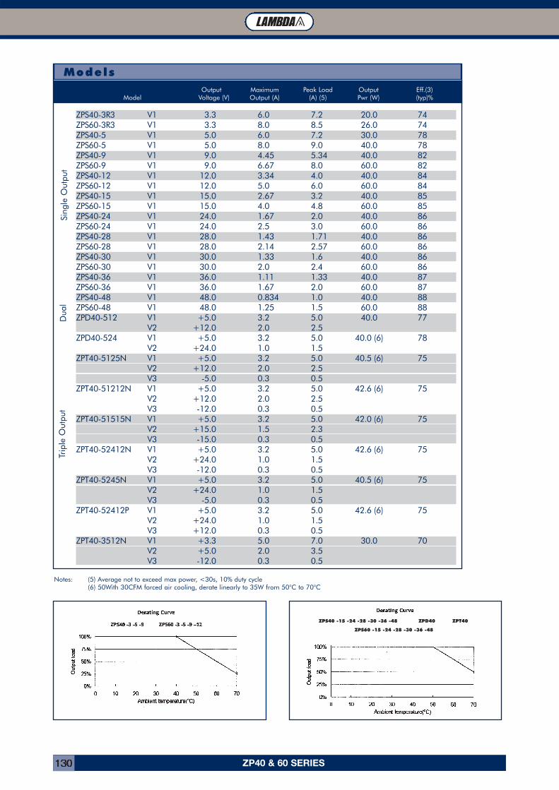
ZP40 & 60 SERIES130
ModelsOutput Maximum Peak Load Output Eff.(3)
Model Voltage (V) Output (A) (A) (5) Pwr (W) (typ)%
ZPS40-3R3 V1 3.3 6.0 7.2 20.0 74ZPS60-3R3 V1 3.3 8.0 8.5 26.0 74ZPS40-5 V1 5.0 6.0 7.2 30.0 78ZPS60-5 V1 5.0 8.0 9.0 40.0 78ZPS40-9 V1 9.0 4.45 5.34 40.0 82ZPS60-9 V1 9.0 6.67 8.0 60.0 82ZPS40-12 V1 12.0 3.34 4.0 40.0 84ZPS60-12 V1 12.0 5.0 6.0 60.0 84ZPS40-15 V1 15.0 2.67 3.2 40.0 85ZPS60-15 V1 15.0 4.0 4.8 60.0 85ZPS40-24 V1 24.0 1.67 2.0 40.0 86ZPS60-24 V1 24.0 2.5 3.0 60.0 86ZPS40-28 V1 28.0 1.43 1.71 40.0 86ZPS60-28 V1 28.0 2.14 2.57 60.0 86ZPS40-30 V1 30.0 1.33 1.6 40.0 86ZPS60-30 V1 30.0 2.0 2.4 60.0 86ZPS40-36 V1 36.0 1.11 1.33 40.0 87ZPS60-36 V1 36.0 1.67 2.0 60.0 87ZPS40-48 V1 48.0 0.834 1.0 40.0 88ZPS60-48 V1 48.0 1.25 1.5 60.0 88ZPD40-512 V1 +5.0 3.2 5.0 40.0 77
V2 +12.0 2.0 2.5ZPD40-524 V1 +5.0 3.2 5.0 40.0 (6) 78
V2 +24.0 1.0 1.5ZPT40-5125N V1 +5.0 3.2 5.0 40.5 (6) 75
V2 +12.0 2.0 2.5V3 -5.0 0.3 0.5
ZPT40-51212N V1 +5.0 3.2 5.0 42.6 (6) 75V2 +12.0 2.0 2.5V3 -12.0 0.3 0.5
ZPT40-51515N V1 +5.0 3.2 5.0 42.0 (6) 75V2 +15.0 1.5 2.3V3 -15.0 0.3 0.5
ZPT40-52412N V1 +5.0 3.2 5.0 42.6 (6) 75V2 +24.0 1.0 1.5V3 -12.0 0.3 0.5
ZPT40-5245N V1 +5.0 3.2 5.0 40.5 (6) 75V2 +24.0 1.0 1.5V3 -5.0 0.3 0.5
ZPT40-52412P V1 +5.0 3.2 5.0 42.6 (6) 75V2 +24.0 1.0 1.5V3 +12.0 0.3 0.5
ZPT40-3512N V1 +3.3 5.0 7.0 30.0 70V2 +5.0 2.0 3.5V3 -12.0 0.3 0.5
Sing
le O
utpu
tD
ual
Trip
le O
utpu
t
Notes: (5) Average not to exceed max power, <30s, 10% duty cycle(6) 50With 30CFM forced air cooling, derate linearly to 35W from 50°C to 70°C
ZPS40 -15 -24 -28 -30 -36 -48 ZPD40 ZPT40
ZPS60 -15 -24 -28 -30 -36 -48
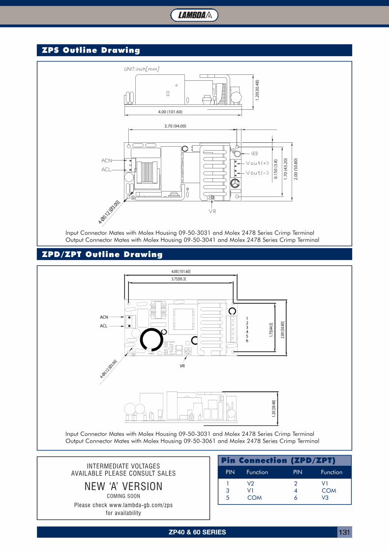
ZP40 & 60 SERIES 131
ZPS Outline Drawing
ZPD/ZPT Outline Drawing
PIN Function PIN Function
1 V2 2 V13 V1 4 COM5 COM 6 V3
Pin Connection (ZPD/ZPT)
Input Connector Mates with Molex Housing 09-50-3031 and Molex 2478 Series Crimp TerminalOutput Connector Mates with Molex Housing 09-50-3061 and Molex 2478 Series Crimp Terminal
Input Connector Mates with Molex Housing 09-50-3031 and Molex 2478 Series Crimp TerminalOutput Connector Mates with Molex Housing 09-50-3041 and Molex 2478 Series Crimp Terminal
INTERMEDIATE VOLTAGES AVAILABLE PLEASE CONSULT SALES
NEW ‘A’ VERSIONCOMING SOON
Please check www.lambda-gb.com/zpsfor availability
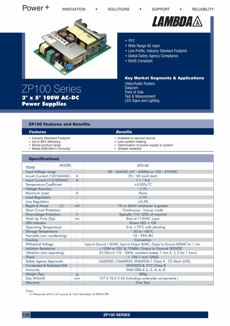
ZP100 SERIES132
• PFC• Wide Range AC Input• Low Profile, Industry Standard Footprint• Global Safety Agency Compliance• RoHS Compliant
Key Market Segments & ApplicationsVideo/Audio RoutersDatacomPoint of SaleTest & MeasurementLED Signs and Lighting
INNOVATION SOLUTIONS SUPPORT RELIABILITY
ZP100 Series3" x 5" 100W AC-DC Power Supplies
MODEL ZPS100ITEMSInput Voltage range - 90 - 264VAC (47 - 440Hz) or 120 - 370VDCInrush Current (132/264VAC) A 25 / 50 (cold start)Input Current (115/230VAC) A 1.1 / 0.6Temperature Coefficient - ±0.05%/°CVoltage Accuracy - ±1%Minimum Load A NoneLoad Regulation - ±1%Line Regulation - ±0.5%Ripple & Noise (1) mV 1% or 50mV whichever is greaterShort Circuit Protection - Continuous - hiccup modeOvervoltage Protection V Typically 110-130% of nominalHold Up Time (Typ) ms 8ms at 115VAC inputLED Indicator - Green LED = OKOperating Temperature 0 to +70°C with deratingStorage Temperature - -20 to +85°CHumidity (non condensing) - 10 - 95% RHCooling - ConvectionWithstand Voltage Input to Ground 1.5kVAC, Input to Output 3kVAC, Output to Ground 500VAC for 1 min.Isolation Resistance >100M at 25C & 70%RH, Output to Ground 500VDCVibration (non operating) 23.52m/s2 (10 - 55Hz: constant sweep 1 min X, Y, Z for 1 hour)Shock - < 196.1 m/s2 (20G)Safety Agency Approvals - UL60950, CSA60950, EN60950-1 Class II , CE Mark (LVD)Conducted & Radiated EMI - EN55022-B, FCC Class BImmunity - EN61000-4-2,-3,-4,-6,-8Weight (Typ) g 385gSize (WxLxH) mm 127 X 76.2 X 34 (including underside components )Warranty - One Year
ZP100 Features and Benefits
Features Benefits
• Industry Standard Footprint• Up to 85% efficiency• Broad product range• Meets EN61000-4 immunity
• Available to second source• Less system heating• Optimisation of power supply to system• Greater reliability
Specifications
Notes:(1) Measured with 0.1uF ceramic & 10uF electrolytic at 20MHz BW
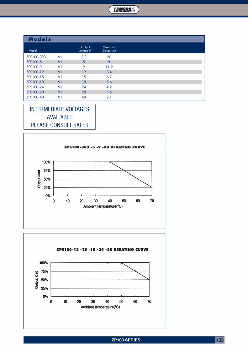
ZP100 SERIES 133
ModelsOutput Maximum
Model Voltage (V) Output (A)
ZPS100-3R3 V1 3.3 20ZPS100-5 V1 5 20ZPS100-9 V1 9 11.2ZPS100-12 V1 12 8.4ZPS100-15 V1 15 6.7ZPS100-18 V1 18 5.6ZPS100-24 V1 24 4.2ZPS100-28 V1 28 3.6ZPS100-48 V1 48 2.1
ZPS100-3R3 -5 -9 -48 DERATING CURVE
ZPS100-12 -15 -18 -24 -28 DERATING CURVE
INTERMEDIATE VOLTAGESAVAILABLE
PLEASE CONSULT SALES
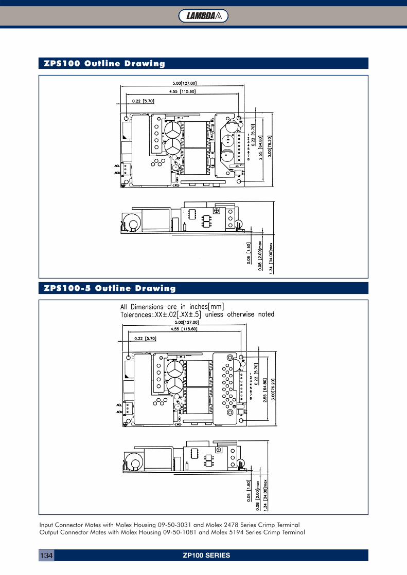
ZP100 SERIES134
ZPS100 Outline Drawing
ZPS100-5 Outline Drawing
Input Connector Mates with Molex Housing 09-50-3031 and Molex 2478 Series Crimp TerminalOutput Connector Mates with Molex Housing 09-50-1081 and Molex 5194 Series Crimp Terminal

ZWD-PAF SERIES 135
MODEL ZWD100PAF-0524 ZWD150PAF-0524 ZWD225PAF-0524ITEMSInput Voltage - 85-265VAC (47-63Hz), 120-370VDCInput Current (1) A 1.3 / 0.65 1.9 / 0.97 2.81 / 1.43Inrush Current (1)(2) A 15 / 30Power Factor - 0.99 at 100VAC, 0.95 at 200VAC, Meets EN61000-3-2Leakage Current mA 0.75mA maxTemperature Coefficient - <0.02%/°COvercurrent Protection (3) - 5V output: >105%, 24V output: >205%Overvoltage Protection (4) V 120- 145%Hold Up Time (Typ) (1) ms 5V output: 40ms, 24V output: 20msEfficiency (2) % 79 / 81 80 / 82 81 / 83Remote On/Off - On 24V output only, remove jumper to shutdownLine Regulation mV 5V output: 20mV, 24V output: 96mVLoad Regulation mV 5V output: 40mV, 24V output: 150mVRipple & Noise mV 5V output: 120mV, 24V output: 100W, 150mV; 150/225W, 240mVOperating Temperature - (Open frame or L bracket) -10°C to +70°C, derate linearly to 0% load from 50°C to 70°COperating Temperature - (With /A cover option) -10°C to +60°C, derate linearly to 0% load from 40°C to 60°CStorage Temperature - -30 to +85°CHumidity (non condensing) - Operating: 20 - 90%RH, Non-operating: 10 - 95% RHCooling - Convection cooledWithstand Voltage - I/P to Gnd 2kVAC (20mA), I/P to O/P 3kVAC (20mA), O/P to Gnd 500VAC (100mA) for 1 min.Isolation Resistance - >100M at 25°C & 70%RH, Output to Ground 500VDCVibration (non operating) - 10 - 55Hz (1 minute sweep), 19.6m/s2 constant X, Y, Z 1 hourShock - < 196.1 m/s2
Safety Agency Approvals - UL60950, CSA60950, EN60950, EN50178, CE MarkConducted & Radiated EMI - EN55022-B, FCC Class B, VCCI-BRecommended EMI Filter - MAW1203-22 MAW1205-22 MAW1205-22Immunity - EN61000-4-2, -3, -4, -5, -6, -8, -11Weight (Typ) g 460 (780 with cover) 530 (885 with cover) 670 (1065 with cover)Size (WxHxD) in 2.95 x 8.74 x 1.38 3.35 x 8.74 x 1.57 3.74 x 8.74 x 1.77Warranty yrs Two Years
• Universal Input (85 - 265VAC)• Power Factor Corrected • 200% Peak Power capability on 24V output• 2 Year Warranty• Individual output adjustment
Key Market Segments & Applications
Factory AutomationPrinter and Motor Drives
Kiosks
ZWD-PAF Features and Benefits
Features Benefits• Input Transient Protected• Power Factor Corrected• 200% Peak Power Capability
• Withstands Harsh Environments• Supports Global Use• Can Drive High current Start Up Devices or pulse loads
Specifications
INNOVATION SOLUTIONS SUPPORT RELIABILITY
ZWD-PAF Series100W to 440WDual Output Power Supplies
Notes: See installation manual for full specification.
(1) 100/200VAC (2) 25°C ambient (cold start) (3) Avoid prolonged operation in overload (4) OVP on 24V output will shutdown 24V output only
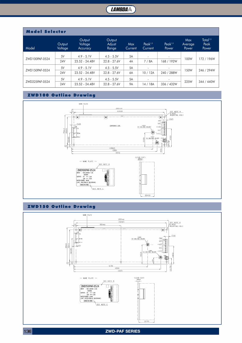
ZWD-PAF SERIES136
OUTPUT : 5V 5.0A
DE
NS
EI-L
AM
BD
A
(24V : 7/8A PEAK @ 100/200VAC)RATED POWER : 100W
4.0A24V
MADE IN CHINA
INPUT : 100-240VAC~1.4AZWD100PAF-0524
50/60Hz
50/60Hz
DE
NS
EI-L
AM
BD
A
6.0A
MADE IN CHINA
RATED POWER : 150W(24V : 10/12A PEAK @ 100/200VAC)
5.0AOUTPUT :24V5V
100-240VAC~2.0A
ZWD150PAF-0524INPUT :
Model Selector
Output Output Max Total1,5
Output Voltage Adjust Max Peak1,5 Peak1,5 Average PeakModel Voltage Accuracy Range Current Current Power Power Power
ZWD100PAF-05245V 4.9 - 5.1V 4.5 - 5.5V 5A - -
24V 23.52 - 24.48V 22.8 - 27.6V 4A 7 / 8A 168 / 192W100W 172 / 196W
ZWD150PAF-05245V 4.9 - 5.1V 4.5 - 5.5V 5A - -
24V 23.52 - 24.48V 22.8 - 27.6V 6A 10 / 12A 240 / 288W150W 246 / 294W
ZWD225PAF-05245V 4.9 - 5.1V 4.5 - 5.5V 5A - -
24V 23.52 - 24.48V 22.8 - 27.6V 9A 14 / 18A 336 / 432W225W 344 / 440W
ZWD100 Out l ine Drawing
ZWD150 Out l ine Drawing
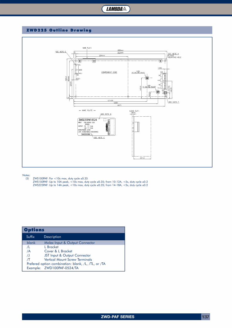
ZWD-PAF SERIES 137
Suffix Description
blank Molex Input & Output Connector/L L Bracket/A Cover & L Bracket/J JST Input & Output Connector/T Vertical Mount Screw TerminalsPrefered option combination: blank, /L, /TL, or /TAExample: ZWD100PAF-0524/TA
Options
Notes:(5) ZWS100PAF: For <10s max, duty cycle ≤0.35
ZWS150PAF: Up to 10A peak, <10s max, duty cycle ≤0.35; from 10-12A, <5s, duty cycle ≤0.2ZWS225PAF: Up to 14A peak, <10s max, duty cycle ≤0.35; from 14-18A, <5s, duty cycle ≤0.2
DE
NS
EI-L
AM
BD
A
5.0AOUTPUT : 5V
RATED POWER : 225W(24V : 14/18A PEAK @ 100/200VAC)
MADE IN CHINA
24V 9.0A
INPUT :
ZWD225PAF-0524100-240VAC~3.0A
50/60Hz
ZWD225 Out l ine Drawing
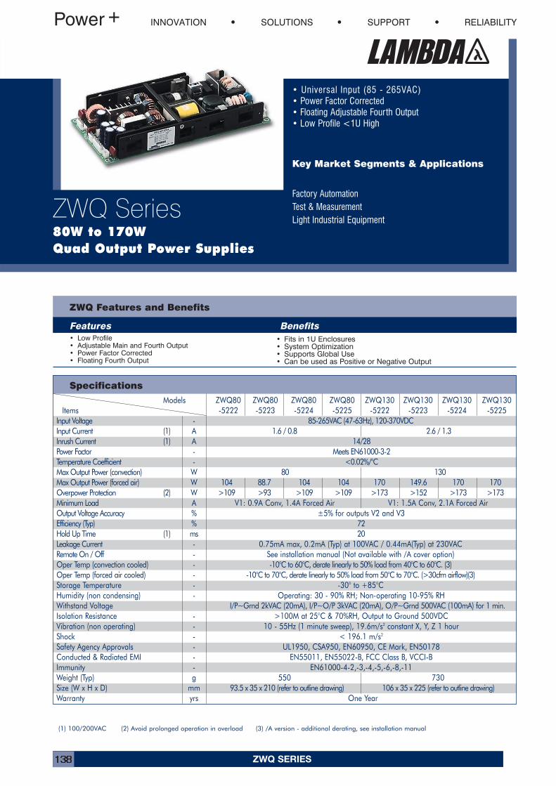
ZWQ SERIES138
Models ZWQ80 ZWQ80 ZWQ80 ZWQ80 ZWQ130 ZWQ130 ZWQ130 ZWQ130Items -5222 -5223 -5224 -5225 -5222 -5223 -5224 -5225
Input Voltage - 85-265VAC (47-63Hz), 120-370VDCInput Current (1) A 1.6 / 0.8 2.6 / 1.3Inrush Current (1) A 14/28Power Factor - Meets EN61000-3-2Temperature Coefficient - <0.02%/°CMax Output Power (convection) W 80 130Max Output Power (forced air) W 104 88.7 104 104 170 149.6 170 170Overpower Protection (2) W >109 >93 >109 >109 >173 >152 >173 >173Minimum Load A V1: 0.9A Conv, 1.4A Forced Air V1: 1.5A Conv, 2.1A Forced AirOutput Voltage Accuracy % ±5% for outputs V2 and V3Efficiency (Typ) % 72Hold Up Time (1) ms 20Leakage Current - 0.75mA max, 0.2mA (Typ) at 100VAC / 0.44mA(Typ) at 230VACRemote On / Off - See installation manual (Not available with /A cover option)Oper Temp (convection cooled) - -10°C to 60°C, derate linearly to 50% load from 40°C to 60°C. (3)Oper Temp (forced air cooled) - -10°C to 70°C, derate linearly to 50% load from 50°C to 70°C. (>30cfm airflow)(3)Storage Temperature - -30° to +85°CHumidity (non condensing) - Operating: 30 - 90% RH; Non-operating 10-95% RHWithstand Voltage I/P~Grnd 2kVAC (20mA), I/P~O/P 3kVAC (20mA), O/P~Grnd 500VAC (100mA) for 1 min.Isolation Resistance - >100M at 25°C & 70%RH, Output to Ground 500VDCVibration (non operating) - 10 - 55Hz (1 minute sweep), 19.6m/s2 constant X, Y, Z 1 hourShock - < 196.1 m/s2
Safety Agency Approvals - UL1950, CSA950, EN60950, CE Mark, EN50178Conducted & Radiated EMI - EN55011, EN55022-B, FCC Class B, VCCI-BImmunity - EN61000-4-2,-3,-4,-5,-6,-8,-11Weight (Typ) g 550 730Size (W x H x D) mm 93.5 x 35 x 210 (refer to outline drawing) 106 x 35 x 225 (refer to outline drawing)Warranty yrs One Year
• Universal Input (85 - 265VAC)• Power Factor Corrected • Floating Adjustable Fourth Output• Low Profile <1U High
Key Market Segments & Applications
Factory AutomationTest & MeasurementLight Industrial Equipment
ZWQ Features and Benefits
Features Benefits• Low Profile• Adjustable Main and Fourth Output• Power Factor Corrected• Floating Fourth Output
• Fits in 1U Enclosures• System Optimization• Supports Global Use• Can be used as Positive or Negative Output
Specifications
INNOVATION SOLUTIONS SUPPORT RELIABILITY
ZWQ Series80W to 170W Quad Output Power Supplies
(1) 100/200VAC (2) Avoid prolonged operation in overload (3) /A version - additional derating, see installation manual
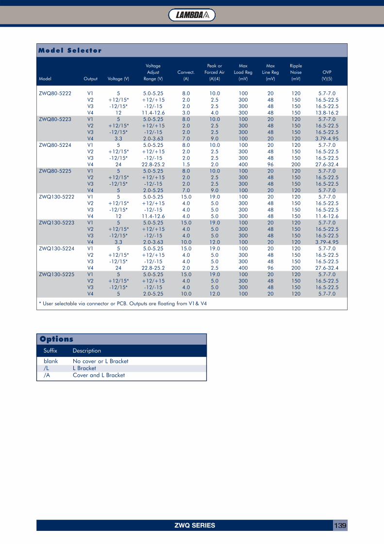
ZWQ SERIES 139
Model Selector
Voltage Peak or Max Max RippleAdjust Convect. Forced Air Load Reg Line Reg Noise OVP
Model Output Voltage (V) Range (V) (A) (A)(4) (mV) (mV) (mV) (V)(5)
ZWQ80-5222 V1 5 5.0-5.25 8.0 10.0 100 20 120 5.7-7.0V2 +12/15* +12/+15 2.0 2.5 300 48 150 16.5-22.5V3 -12/15* -12/-15 2.0 2.5 300 48 150 16.5-22.5V4 12 11.4-12.6 3.0 4.0 300 48 150 13.8-16.2
ZWQ80-5223 V1 5 5.0-5.25 8.0 10.0 100 20 120 5.7-7.0V2 +12/15* +12/+15 2.0 2.5 300 48 150 16.5-22.5V3 -12/15* -12/-15 2.0 2.5 300 48 150 16.5-22.5V4 3.3 2.0-3.63 7.0 9.0 100 20 120 3.79-4.95
ZWQ80-5224 V1 5 5.0-5.25 8.0 10.0 100 20 120 5.7-7.0V2 +12/15* +12/+15 2.0 2.5 300 48 150 16.5-22.5V3 -12/15* -12/-15 2.0 2.5 300 48 150 16.5-22.5V4 24 22.8-25.2 1.5 2.0 400 96 200 27.6-32.4
ZWQ80-5225 V1 5 5.0-5.25 8.0 10.0 100 20 120 5.7-7.0V2 +12/15* +12/+15 2.0 2.5 300 48 150 16.5-22.5V3 -12/15* -12/-15 2.0 2.5 300 48 150 16.5-22.5V4 5 2.0-5.25 7.0 9.0 100 20 120 5.7-7.0
ZWQ130-5222 V1 5 5.0-5.25 15.0 19.0 100 20 120 5.7-7.0V2 +12/15* +12/+15 4.0 5.0 300 48 150 16.5-22.5V3 -12/15* -12/-15 4.0 5.0 300 48 150 16.5-22.5V4 12 11.4-12.6 4.0 5.0 300 48 150 11.4-12.6
ZWQ130-5223 V1 5 5.0-5.25 15.0 19.0 100 20 120 5.7-7.0V2 +12/15* +12/+15 4.0 5.0 300 48 150 16.5-22.5V3 -12/15* -12/-15 4.0 5.0 300 48 150 16.5-22.5V4 3.3 2.0-3.63 10.0 12.0 100 20 120 3.79-4.95
ZWQ130-5224 V1 5 5.0-5.25 15.0 19.0 100 20 120 5.7-7.0V2 +12/15* +12/+15 4.0 5.0 300 48 150 16.5-22.5V3 -12/15* -12/-15 4.0 5.0 300 48 150 16.5-22.5V4 24 22.8-25.2 2.0 2.5 400 96 200 27.6-32.4
ZWQ130-5225 V1 5 5.0-5.25 15.0 19.0 100 20 120 5.7-7.0V2 +12/15* +12/+15 4.0 5.0 300 48 150 16.5-22.5V3 -12/15* -12/-15 4.0 5.0 300 48 150 16.5-22.5V4 5 2.0-5.25 10.0 12.0 100 20 120 5.7-7.0
* User selectable via connector or PCB. Outputs are floating from V1 & V4
Suffix Description
blank No cover or L Bracket/L L Bracket/A Cover and L Bracket
Options
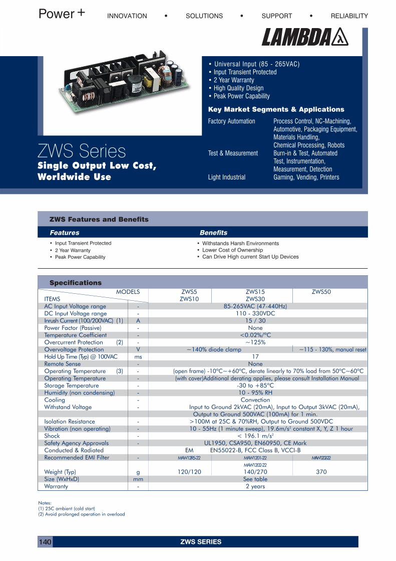
ZWS SERIES140
MODELS ZWS5 ZWS15 ZWS50 ITEMS ZWS10 ZWS30AC Input Voltage range - 85-265VAC (47-440Hz)DC Input Voltage range - 110 - 330VDCInrush Current (100/200VAC) (1) A 15 / 30Power Factor (Passive) - NoneTemperature Coefficient - <0.02%/ºCOvercurrent Protection (2) - ~125%Overvoltage Protection V ~140% diode clamp ~115 - 130%, manual resetHold Up Time (Typ) @ 100VAC ms 17Remote Sense - NoneOperating Temperature (3) - (open frame) -10ºC~+60ºC, derate linearly to 70% load from 50ºC~60ºCOperating Temperature - (with cover)Additional derating applies, please consult Installation ManualStorage Temperature - -30 to +85ºCHumidity (non condensing) - 10 - 95% RHCooling - ConvectionWithstand Voltage - Input to Ground 2kVAC (20mA), Input to Output 3kVAC (20mA),
Output to Ground 500VAC (100mA) for 1 min.Isolation Resistance - >100M at 25C & 70%RH, Output to Ground 500VDCVibration (non operating) - 10 - 55Hz (1 minute sweep), 19.6m/s2 constant X, Y, Z 1 hourShock - < 196.1 m/s2
Safety Agency Approvals - UL1950, CSA950, EN60950, CE MarkConducted & Radiated EM EN55022-B, FCC Class B, VCCI-BRecommended EMI Filter - MAW12R5-22 MAW1201-22 MAW1202-22
MAW1202-22
Weight (Typ) g 120/120 140/270 370Size (WxHxD) mm See tableWarranty - 2 years
• Universal Input (85 - 265VAC)• Input Transient Protected• 2 Year Warranty• High Quality Design• Peak Power Capability
Key Market Segments & Applications
Factory Automation Process Control, NC-Machining,Automotive, Packaging Equipment, Materials Handling,Chemical Processing, Robots
Test & Measurement Burn-in & Test, Automated Test, Instrumentation, Measurement, Detection
Light Industrial Gaming, Vending, Printers
ZWS Features and Benefits
Features Benefits• Input Transient Protected• 2 Year Warranty• Peak Power Capability
• Withstands Harsh Environments• Lower Cost of Ownership• Can Drive High current Start Up Devices
Specifications
INNOVATION SOLUTIONS SUPPORT RELIABILITY
ZWS SeriesSingle Output Low Cost,Worldwide Use
Notes:(1) 25C ambient (cold start)(2) Avoid prolonged operation in overload
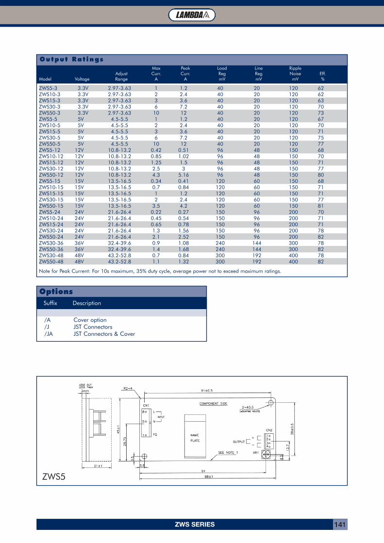
ZWS SERIES 141
1.2m/s Forced Air 50°C 55°C 60°C 65°C 70°C
Output Rat ings
ZWS5-3 3.3V 2.97-3.63 1 1.2 40 20 120 62ZWS10-3 3.3V 2.97-3.63 2 2.4 40 20 120 62ZWS15-3 3.3V 2.97-3.63 3 3.6 40 20 120 63ZWS30-3 3.3V 2.97-3.63 6 7.2 40 20 120 70ZWS50-3 3.3V 2.97-3.63 10 12 40 20 120 73ZWS5-5 5V 4.5-5.5 1 1.2 40 20 120 67ZWS10-5 5V 4.5-5.5 2 2.4 40 20 120 70ZWS15-5 5V 4.5-5.5 3 3.6 40 20 120 71ZWS30-5 5V 4.5-5.5 6 7.2 40 20 120 75ZWS50-5 5V 4.5-5.5 10 12 40 20 120 77ZWS5-12 12V 10.8-13.2 0.42 0.51 96 48 150 68ZWS10-12 12V 10.8-13.2 0.85 1.02 96 48 150 70ZWS15-12 12V 10.8-13.2 1.25 1.5 96 48 150 71ZWS30-12 12V 10.8-13.2 2.5 3 96 48 150 77ZWS50-12 12V 10.8-13.2 4.3 5.16 96 48 150 80ZWS5-15 15V 13.5-16.5 0.34 0.41 120 60 150 68ZWS10-15 15V 13.5-16.5 0.7 0.84 120 60 150 71ZWS15-15 15V 13.5-16.5 1 1.2 120 60 150 71ZWS30-15 15V 13.5-16.5 2 2.4 120 60 150 77ZWS50-15 15V 13.5-16.5 3.5 4.2 120 60 150 81ZWS5-24 24V 21.6-26.4 0.22 0.27 150 96 200 70ZWS10-24 24V 21.6-26.4 0.45 0.54 150 96 200 71ZWS15-24 24V 21.6-26.4 0.65 0.78 150 96 200 71ZWS30-24 24V 21.6-26.4 1.3 1.56 150 96 200 78ZWS50-24 24V 21.6-26.4 2.1 2.52 150 96 200 82ZWS30-36 36V 32.4-39.6 0.9 1.08 240 144 300 78ZWS50-36 36V 32.4-39.6 1.4 1.68 240 144 300 82ZWS30-48 48V 43.2-52.8 0.7 0.84 300 192 400 78ZWS50-48 48V 43.2-52.8 1.1 1.32 300 192 400 82
Note for Peak Current: For 10s maximum, 35% duty cycle, average power not to exceed maximum ratings.
Max Peak Load Line RippleAdjust Curr. Curr. Reg Reg Noise Eff.
Model Voltage Range A A mV mV mV %
Suffix Description
/A Cover option/J JST Connectors /JA JST Connectors & Cover
Options
ZWS5
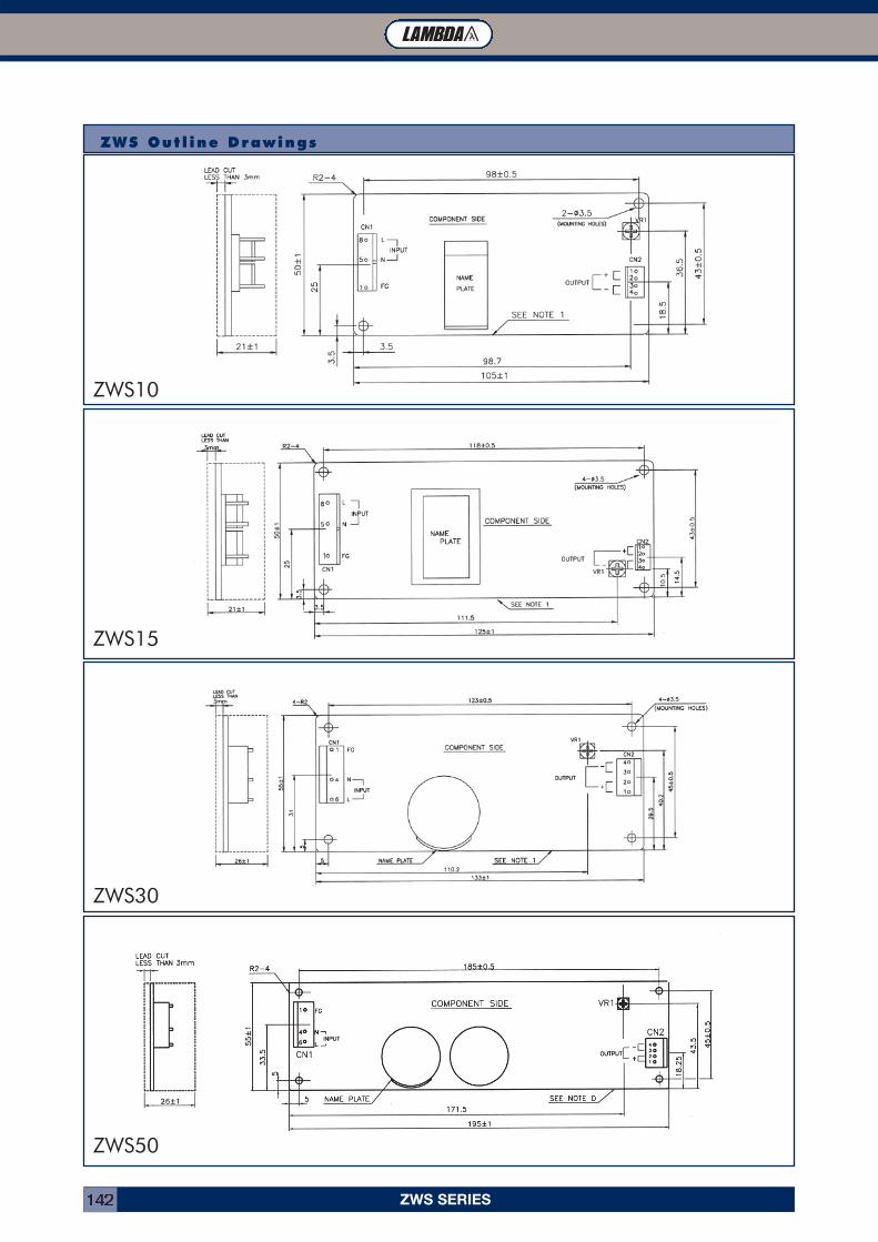
ZWS SERIES142
ZWS Out l ine Drawings
ZWS10
ZWS15
ZWS30
ZWS50
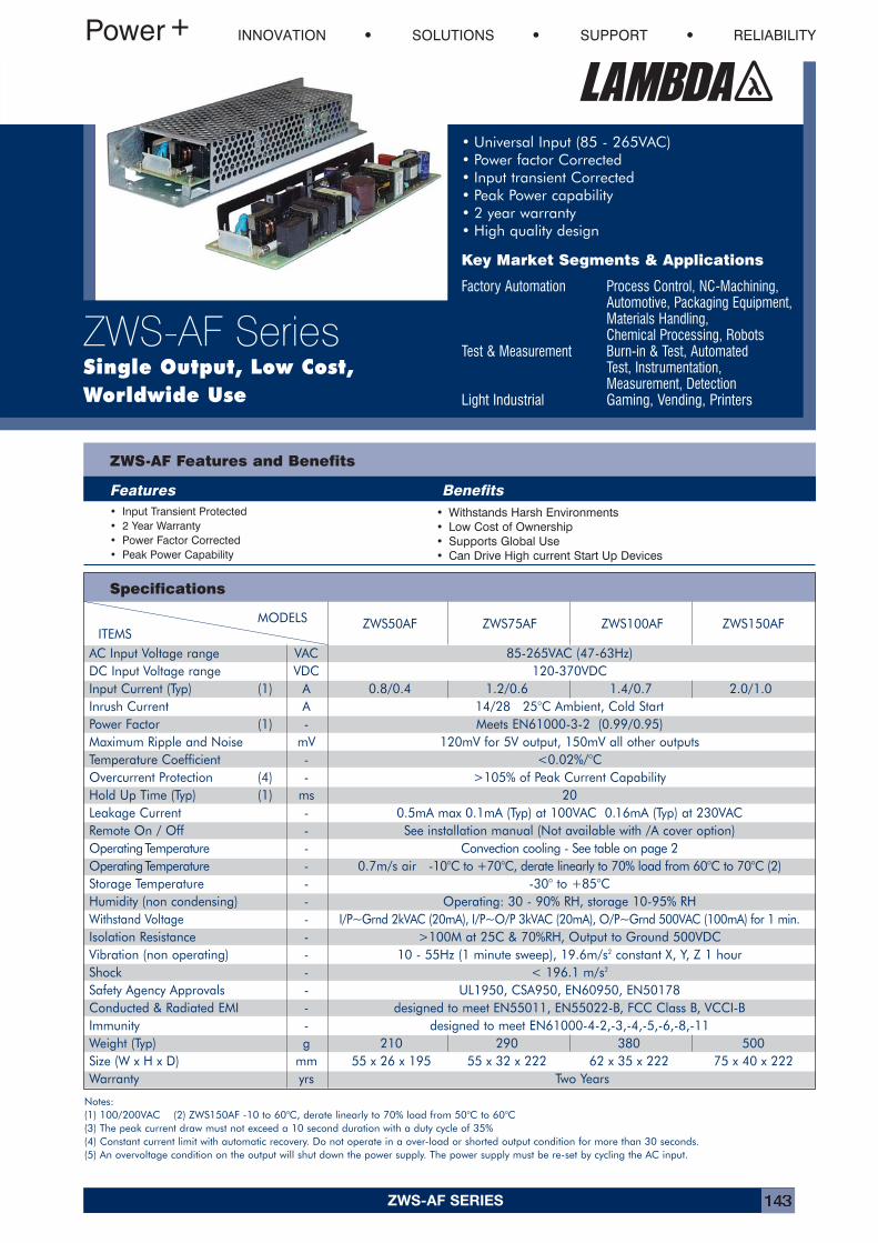
ZWS-AF SERIES 143
• Universal Input (85 - 265VAC)• Power factor Corrected• Input transient Corrected• Peak Power capability• 2 year warranty• High quality design
Key Market Segments & Applications
Factory Automation Process Control, NC-Machining,Automotive, Packaging Equipment, Materials Handling,Chemical Processing, Robots
Test & Measurement Burn-in & Test, Automated Test, Instrumentation, Measurement, Detection
Light Industrial Gaming, Vending, Printers
ZWS-AF Features and Benefits
Features Benefits• Input Transient Protected• 2 Year Warranty• Power Factor Corrected• Peak Power Capability
• Withstands Harsh Environments• Low Cost of Ownership• Supports Global Use• Can Drive High current Start Up Devices
Specifications
INNOVATION SOLUTIONS SUPPORT RELIABILITY
ZWS-AF SeriesSingle Output, Low Cost,Worldwide Use
MODELS ZWS50AF ZWS75AF ZWS100AF ZWS150AFITEMS
AC Input Voltage range VAC 85-265VAC (47-63Hz)DC Input Voltage range VDC 120-370VDCInput Current (Typ) (1) A 0.8/0.4 1.2/0.6 1.4/0.7 2.0/1.0Inrush Current A 14/28 25°C Ambient, Cold StartPower Factor (1) - Meets EN61000-3-2 (0.99/0.95)Maximum Ripple and Noise mV 120mV for 5V output, 150mV all other outputsTemperature Coefficient - <0.02%/°COvercurrent Protection (4) - >105% of Peak Current CapabilityHold Up Time (Typ) (1) ms 20Leakage Current - 0.5mA max 0.1mA (Typ) at 100VAC 0.16mA (Typ) at 230VACRemote On / Off - See installation manual (Not available with /A cover option)OperatingTemperature - Convection cooling - See table on page 2OperatingTemperature - 0.7m/s air -10°C to +70°C, derate linearly to 70% load from 60°C to 70°C (2) Storage Temperature - -30° to +85°CHumidity (non condensing) - Operating: 30 - 90% RH, storage 10-95% RHWithstand Voltage - I/P~Grnd 2kVAC (20mA), I/P~O/P 3kVAC (20mA), O/P~Grnd 500VAC (100mA) for 1 min.Isolation Resistance - >100M at 25C & 70%RH, Output to Ground 500VDCVibration (non operating) - 10 - 55Hz (1 minute sweep), 19.6m/s2 constant X, Y, Z 1 hourShock - < 196.1 m/s2
Safety Agency Approvals - UL1950, CSA950, EN60950, EN50178Conducted & Radiated EMI - designed to meet EN55011, EN55022-B, FCC Class B, VCCI-BImmunity - designed to meet EN61000-4-2,-3,-4,-5,-6,-8,-11Weight (Typ) g 210 290 380 500Size (W x H x D) mm 55 x 26 x 195 55 x 32 x 222 62 x 35 x 222 75 x 40 x 222Warranty yrs Two Years
Notes:(1) 100/200VAC (2) ZWS150AF -10 to 60°C, derate linearly to 70% load from 50°C to 60°C(3) The peak current draw must not exceed a 10 second duration with a duty cycle of 35%(4) Constant current limit with automatic recovery. Do not operate in a over-load or shorted output condition for more than 30 seconds.(5) An overvoltage condition on the output will shut down the power supply. The power supply must be re-set by cycling the AC input.
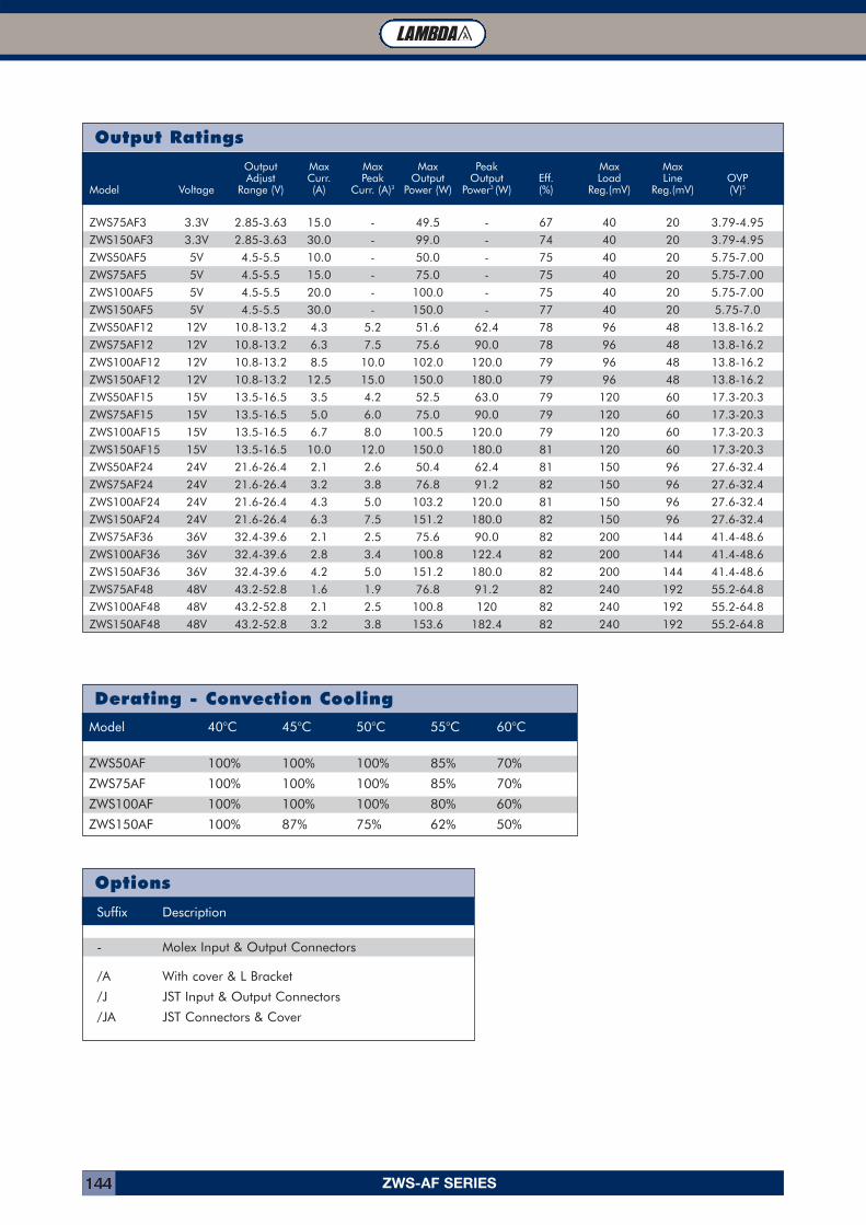
ZWS-AF SERIES144
Output Ratings
Derating - Convection Cooling
Options
Suffix Description
- Molex Input & Output Connectors
/A With cover & L Bracket
/J JST Input & Output Connectors
/JA JST Connectors & Cover
Model 40°C 45°C 50°C 55°C 60°C
ZWS50AF 100% 100% 100% 85% 70%
ZWS75AF 100% 100% 100% 85% 70%
ZWS100AF 100% 100% 100% 80% 60%
ZWS150AF 100% 87% 75% 62% 50%
Output Max Max Max Peak Max MaxAdjust Curr. Peak Output Output Eff. Load Line OVP
Model Voltage Range (V) (A) Curr. (A)3 Power (W) Power3 (W) (%) Reg.(mV) Reg.(mV) (V)5
ZWS75AF3 3.3V 2.85-3.63 15.0 - 49.5 - 67 40 20 3.79-4.95
ZWS150AF3 3.3V 2.85-3.63 30.0 - 99.0 - 74 40 20 3.79-4.95
ZWS50AF5 5V 4.5-5.5 10.0 - 50.0 - 75 40 20 5.75-7.00
ZWS75AF5 5V 4.5-5.5 15.0 - 75.0 - 75 40 20 5.75-7.00
ZWS100AF5 5V 4.5-5.5 20.0 - 100.0 - 75 40 20 5.75-7.00
ZWS150AF5 5V 4.5-5.5 30.0 - 150.0 - 77 40 20 5.75-7.0
ZWS50AF12 12V 10.8-13.2 4.3 5.2 51.6 62.4 78 96 48 13.8-16.2
ZWS75AF12 12V 10.8-13.2 6.3 7.5 75.6 90.0 78 96 48 13.8-16.2
ZWS100AF12 12V 10.8-13.2 8.5 10.0 102.0 120.0 79 96 48 13.8-16.2
ZWS150AF12 12V 10.8-13.2 12.5 15.0 150.0 180.0 79 96 48 13.8-16.2
ZWS50AF15 15V 13.5-16.5 3.5 4.2 52.5 63.0 79 120 60 17.3-20.3
ZWS75AF15 15V 13.5-16.5 5.0 6.0 75.0 90.0 79 120 60 17.3-20.3
ZWS100AF15 15V 13.5-16.5 6.7 8.0 100.5 120.0 79 120 60 17.3-20.3
ZWS150AF15 15V 13.5-16.5 10.0 12.0 150.0 180.0 81 120 60 17.3-20.3
ZWS50AF24 24V 21.6-26.4 2.1 2.6 50.4 62.4 81 150 96 27.6-32.4
ZWS75AF24 24V 21.6-26.4 3.2 3.8 76.8 91.2 82 150 96 27.6-32.4
ZWS100AF24 24V 21.6-26.4 4.3 5.0 103.2 120.0 81 150 96 27.6-32.4
ZWS150AF24 24V 21.6-26.4 6.3 7.5 151.2 180.0 82 150 96 27.6-32.4
ZWS75AF36 36V 32.4-39.6 2.1 2.5 75.6 90.0 82 200 144 41.4-48.6
ZWS100AF36 36V 32.4-39.6 2.8 3.4 100.8 122.4 82 200 144 41.4-48.6
ZWS150AF36 36V 32.4-39.6 4.2 5.0 151.2 180.0 82 200 144 41.4-48.6
ZWS75AF48 48V 43.2-52.8 1.6 1.9 76.8 91.2 82 240 192 55.2-64.8
ZWS100AF48 48V 43.2-52.8 2.1 2.5 100.8 120 82 240 192 55.2-64.8
ZWS150AF48 48V 43.2-52.8 3.2 3.8 153.6 182.4 82 240 192 55.2-64.8
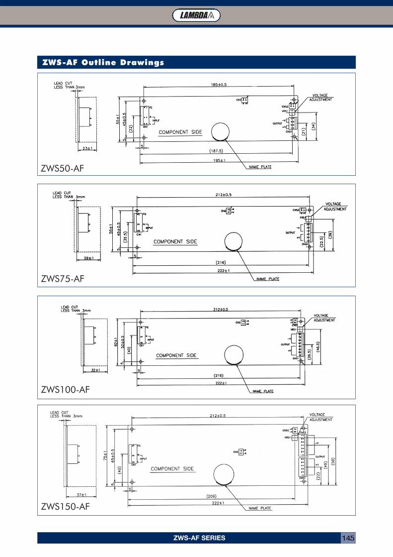
ZWS-AF SERIES 145
ZWS-AF Outline Drawings
ZWS50-AF
ZWS75-AF
ZWS100-AF
ZWS150-AF
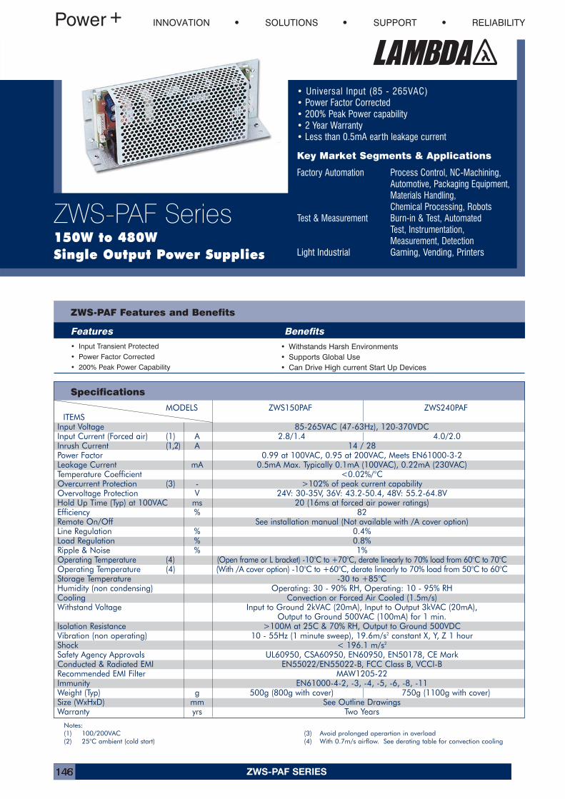
ZWS-PAF SERIES146
MODELS ZWS150PAF ZWS240PAFITEMS
Input Voltage 85-265VAC (47-63Hz), 120-370VDCInput Current (Forced air) (1) A 2.8/1.4 4.0/2.0Inrush Current (1,2) A 14 / 28Power Factor 0.99 at 100VAC, 0.95 at 200VAC, Meets EN61000-3-2Leakage Current mA 0.5mA Max. Typically 0.1mA (100VAC), 0.22mA (230VAC)Temperature Coefficient <0.02%/°COvercurrent Protection (3) - >102% of peak current capabilityOvervoltage Protection V 24V: 30-35V, 36V: 43.2-50.4, 48V: 55.2-64.8VHold Up Time (Typ) at 100VAC ms 20 (16ms at forced air power ratings)Efficiency % 82Remote On/Off See installation manual (Not available with /A cover option)Line Regulation % 0.4%Load Regulation % 0.8%Ripple & Noise % 1%Operating Temperature (4) (Open frame or L bracket) -10°C to +70°C, derate linearly to 70% load from 60°C to 70°COperating Temperature (4) (With /A cover option) -10°C to +60°C, derate linearly to 70% load from 50°C to 60°CStorage Temperature -30 to +85°CHumidity (non condensing) Operating: 30 - 90% RH, Operating: 10 - 95% RHCooling Convection or Forced Air Cooled (1.5m/s)Withstand Voltage Input to Ground 2kVAC (20mA), Input to Output 3kVAC (20mA),
Output to Ground 500VAC (100mA) for 1 min.Isolation Resistance >100M at 25C & 70% RH, Output to Ground 500VDCVibration (non operating) 10 - 55Hz (1 minute sweep), 19.6m/s2 constant X, Y, Z 1 hourShock < 196.1 m/s2
Safety Agency Approvals UL60950, CSA60950, EN60950, EN50178, CE MarkConducted & Radiated EMI EN55022/EN55022-B, FCC Class B, VCCI-BRecommended EMI Filter MAW1205-22Immunity EN61000-4-2, -3, -4, -5, -6, -8, -11Weight (Typ) g 500g (800g with cover) 750g (1100g with cover)Size (WxHxD) mm See Outline DrawingsWarranty yrs Two Years
• Universal Input (85 - 265VAC)• Power Factor Corrected • 200% Peak Power capability• 2 Year Warranty• Less than 0.5mA earth leakage current
Key Market Segments & Applications
Factory Automation Process Control, NC-Machining,Automotive, Packaging Equipment, Materials Handling,Chemical Processing, Robots
Test & Measurement Burn-in & Test, Automated Test, Instrumentation, Measurement, Detection
Light Industrial Gaming, Vending, Printers
ZWS-PAF Features and Benefits
Features Benefits• Input Transient Protected• Power Factor Corrected• 200% Peak Power Capability
• Withstands Harsh Environments• Supports Global Use• Can Drive High current Start Up Devices
Specifications
INNOVATION SOLUTIONS SUPPORT RELIABILITY
ZWS-PAF Series150W to 480WSingle Output Power Supplies
Notes:(1) 100/200VAC (3) Avoid prolonged operartion in overload(2) 25°C ambient (cold start) (4) With 0.7m/s airflow. See derating table for convection cooling
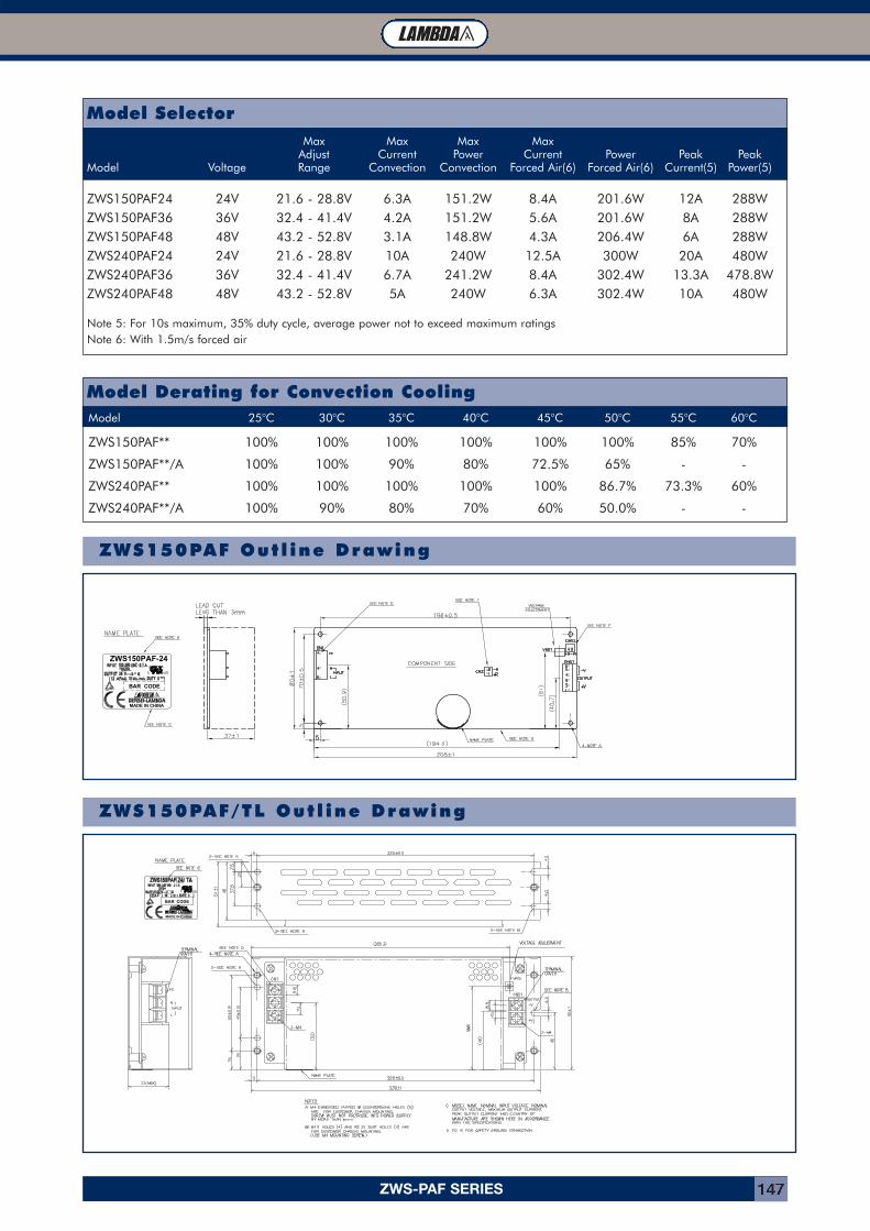
ZWS-PAF SERIES 147
Max Max Max MaxAdjust Current Power Current Power Peak Peak
Model Voltage Range Convection Convection Forced Air(6) Forced Air(6) Current(5) Power(5)
ZWS150PAF24 24V 21.6 - 28.8V 6.3A 151.2W 8.4A 201.6W 12A 288WZWS150PAF36 36V 32.4 - 41.4V 4.2A 151.2W 5.6A 201.6W 8A 288WZWS150PAF48 48V 43.2 - 52.8V 3.1A 148.8W 4.3A 206.4W 6A 288WZWS240PAF24 24V 21.6 - 28.8V 10A 240W 12.5A 300W 20A 480WZWS240PAF36 36V 32.4 - 41.4V 6.7A 241.2W 8.4A 302.4W 13.3A 478.8WZWS240PAF48 48V 43.2 - 52.8V 5A 240W 6.3A 302.4W 10A 480W
Note 5: For 10s maximum, 35% duty cycle, average power not to exceed maximum ratingsNote 6: With 1.5m/s forced air
Model Selector
Model 25°C 30°C 35°C 40°C 45°C 50°C 55°C 60°C
ZWS150PAF** 100% 100% 100% 100% 100% 100% 85% 70%
ZWS150PAF**/A 100% 100% 90% 80% 72.5% 65% - -
ZWS240PAF** 100% 100% 100% 100% 100% 86.7% 73.3% 60%
ZWS240PAF**/A 100% 90% 80% 70% 60% 50.0% - -
Model Derating for Convection Cooling
BAR CODE
ZWS150PAF-24
MADE IN CHINA
A
ZWS150PAF Out l ine Drawing
ZWS150PAF/TL Out l ine Drawing
MADE IN CHINA
BAR CODE
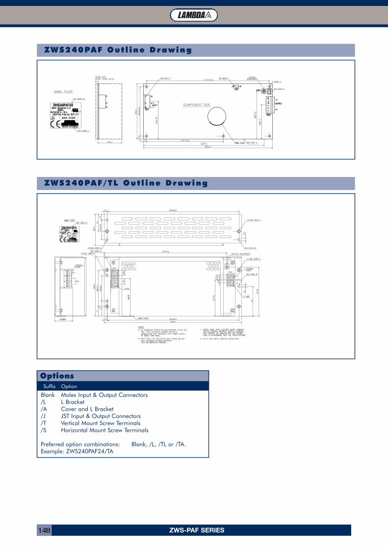
ZWS-PAF SERIES148
Suffix Option
Blank Molex Input & Output Connectors/L L Bracket/A Cover and L Bracket/J JST Input & Output Connectors/T Vertical Mount Screw Terminals/S Horizontal Mount Screw Terminals
Preferred option combinations: Blank, /L, /TL or /TA. Example: ZWS240PAF24/TA
Options
BAR CODE
MADE IN CHINA
ZWS240PAF Out l ine Drawing
BAR CODE
ZWS240PAF/TL Out l ine Drawing
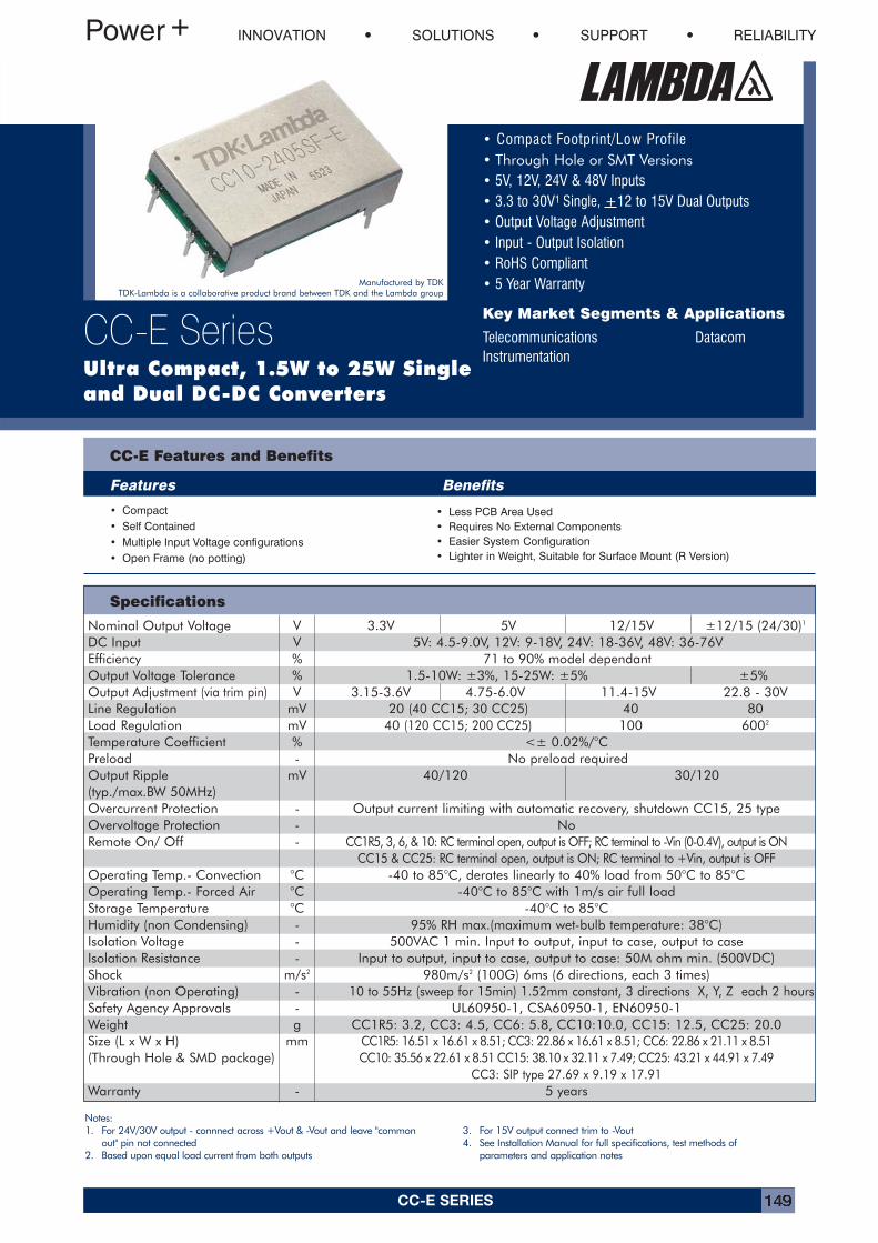
CC-E SERIES 149
Specifications
• Compact Footprint/Low Profile• Through Hole or SMT Versions• 5V, 12V, 24V & 48V Inputs• 3.3 to 30V1 Single, +12 to 15V Dual Outputs• Output Voltage Adjustment• Input - Output Isolation• RoHS Compliant• 5 Year Warranty
Key Market Segments & Applications
Telecommunications DatacomInstrumentation
CC-E Features and Benefits
Features Benefits
• Compact• Self Contained• Multiple Input Voltage configurations• Open Frame (no potting)
• Less PCB Area Used• Requires No External Components• Easier System Configuration• Lighter in Weight, Suitable for Surface Mount (R Version)
INNOVATION SOLUTIONS SUPPORT RELIABILITY
CC-E SeriesUltra Compact, 1.5W to 25W Single and Dual DC-DC Converters
Notes:1. For 24V/30V output - connnect across +Vout & -Vout and leave "common
out" pin not connected2. Based upon equal load current from both outputs
3. For 15V output connect trim to -Vout4. See Installation Manual for full specifications, test methods of
parameters and application notes
Manufactured by TDKTDK-Lambda is a collaborative product brand between TDK and the Lambda group
Nominal Output Voltage V 3.3V 5V 12/15V ±12/15 (24/30)1
DC Input V 5V: 4.5-9.0V, 12V: 9-18V, 24V: 18-36V, 48V: 36-76VEfficiency % 71 to 90% model dependantOutput Voltage Tolerance % 1.5-10W: ±3%, 15-25W: ±5% ±5%Output Adjustment (via trim pin) V 3.15-3.6V 4.75-6.0V 11.4-15V 22.8 - 30VLine Regulation mV 20 (40 CC15; 30 CC25) 40 80Load Regulation mV 40 (120 CC15; 200 CC25) 100 6002
Temperature Coefficient % <± 0.02%/°CPreload - No preload requiredOutput Ripple mV 40/120 30/120(typ./max.BW 50MHz)Overcurrent Protection - Output current limiting with automatic recovery, shutdown CC15, 25 typeOvervoltage Protection - NoRemote On/ Off - CC1R5, 3, 6, & 10: RC terminal open, output is OFF; RC terminal to -Vin (0-0.4V), output is ON
CC15 & CC25: RC terminal open, output is ON; RC terminal to +Vin, output is OFFOperating Temp.- Convection °C -40 to 85°C, derates linearly to 40% load from 50°C to 85°COperating Temp.- Forced Air °C -40°C to 85°C with 1m/s air full loadStorage Temperature °C -40°C to 85°CHumidity (non Condensing) - 95% RH max.(maximum wet-bulb temperature: 38°C)Isolation Voltage - 500VAC 1 min. Input to output, input to case, output to caseIsolation Resistance - Input to output, input to case, output to case: 50M ohm min. (500VDC)Shock m/s2 980m/s2 (100G) 6ms (6 directions, each 3 times)Vibration (non Operating) - 10 to 55Hz (sweep for 15min) 1.52mm constant, 3 directions X, Y, Z each 2 hoursSafety Agency Approvals - UL60950-1, CSA60950-1, EN60950-1Weight g CC1R5: 3.2, CC3: 4.5, CC6: 5.8, CC10:10.0, CC15: 12.5, CC25: 20.0Size (L x W x H) mm CC1R5: 16.51 x 16.61 x 8.51; CC3: 22.86 x 16.61 x 8.51; CC6: 22.86 x 21.11 x 8.51(Through Hole & SMD package) CC10: 35.56 x 22.61 x 8.51 CC15: 38.10 x 32.11 x 7.49; CC25: 43.21 x 44.91 x 7.49
CC3: SIP type 27.69 x 9.19 x 17.91Warranty - 5 years
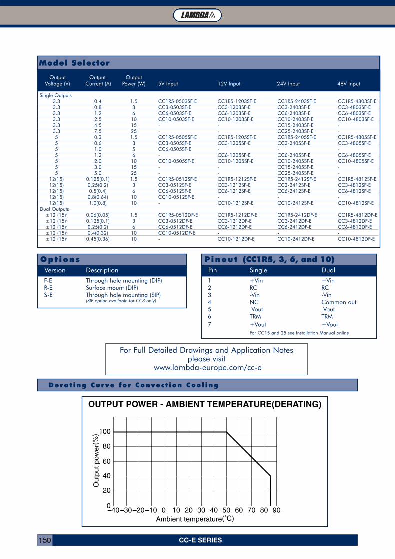
CC-E SERIES150
Derat ing Curve for Convect ion Cool ing
OUTPUT POWER - AMBIENT TEMPERATURE(DERATING)
–10–20–30–40 0 10 20 30 40 50 60 70 80 90
20
40
60
80
100
0
Ou
tpu
t p
ow
er(
%)
Ambient temperature(˚C)
Model Selector
Output Output OutputVoltage (V) Current (A) Power (W) 5V Input 12V Input 24V Input 48V Input
Single Outputs3.3 0.4 1.5 CC1R5-0503SF-E CC1R5-1203SF-E CC1R5-2403SF-E CC1R5-4803SF-E3.3 0.8 3 CC3-0503SF-E CC3-1203SF-E CC3-2403SF-E CC3-4803SF-E3.3 1.2 6 CC6-0503SF-E CC6-1203SF-E CC6-2403SF-E CC6-4803SF-E3.3 2.5 10 CC10-0503SF-E CC10-1203SF-E CC10-2403SF-E CC10-4803SF-E3.3 4.5 15 - - CC15-2403SF-E -3.3 7.5 25 - - CC25-2403SF-E -5 0.3 1.5 CC1R5-0505SF-E CC1R5-1205SF-E CC1R5-2405SF-E CC1R5-4805SF-E5 0.6 3 CC3-0505SF-E CC3-1205SF-E CC3-2405SF-E CC3-4805SF-E5 1.0 5 CC6-0505SF-E - - -5 1.2 6 - CC6-1205SF-E CC6-2405SF-E CC6-4805SF-E5 2.0 10 CC10-0505SF-E CC10-1205SF-E CC10-2405SF-E CC10-4805SF-E5 3.0 15 - - CC15-2405SF-E -5 5.0 25 - - CC25-2405SF-E -
12(15) 0.125(0.1) 1.5 CC1R5-0512SF-E CC1R5-1212SF-E CC1R5-2412SF-E CC1R5-4812SF-E12(15) 0.25(0.2) 3 CC3-0512SF-E CC3-1212SF-E CC3-2412SF-E CC3-4812SF-E12(15) 0.5(0.4) 6 CC6-0512SF-E CC6-1212SF-E CC6-2412SF-E CC6-4812SF-E12(15) 0.8(0.64) 10 CC10-0512SF-E - - -12(15) 1.0(0.8) 10 - CC10-1212SF-E CC10-2412SF-E CC10-4812SF-E
Dual Outputs±12 (15)3 0.06(0.05) 1.5 CC1R5-0512DF-E CC1R5-1212DF-E CC1R5-2412DF-E CC1R5-4812DF-E±12 (15)3 0.125(0.1) 3 CC3-0512DF-E CC3-1212DF-E CC3-2412DF-E CC3-4812DF-E±12 (15)3 0.25(0.2) 6 CC6-0512DF-E CC6-1212DF-E CC6-2412DF-E CC6-4812DF-E±12 (15)3 0.4(0.32) 10 CC10-0512DF-E - - -±12 (15)3 0.45(0.36) 10 - CC10-1212DF-E CC10-2412DF-E CC10-4812DF-E
F-E Through hole mounting (DIP)R-E Surface mount (DIP)S-E Through hole mounting (SIP)
(SIP option available for CC3 only)
Version Description
Options
1 +Vin +Vin2 RC RC3 -Vin -Vin4 NC Common out5 -Vout -Vout6 TRM TRM7 +Vout +Vout
For CC15 and 25 see Installation Manual online
Pin Single Dual
Pinout (CC1R5, 3, 6, and 10)
For Full Detailed Drawings and Application Notes please visit
www.lambda-europe.com/cc-e
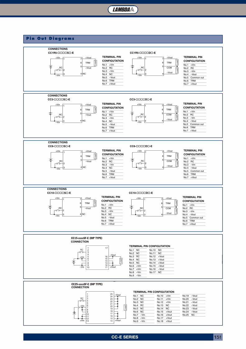
CC-E SERIES 151
Pin Out Diagrams
CONNECTIONSCC1R5-����S�-E CC1R5-����D�-E
1 7
2
3
5
6
4 NC
–Vout
+Vout
TRM
RC
+Vin
–Vin
Load
TERMINAL PINCONFIGUTATIONNo.1 +VinNo.2 RCNo.3 –VinNo.4 NCNo.5 –VoutNo.6 TRMNo.7 +Vout
1 7
2
3
5
6
4
COM
–Vout
+Vout
TRM
RC
+Vin
–Vin
Load
Load
TERMINAL PINCONFIGUTATIONNo.1 +VinNo.2 RCNo.3 –VinNo.4 –VoutNo.5 Common outNo.6 TRMNo.7 +Vout
CONNECTIONSCC3-����S�-E CC3-����D�-E
1 7
2
3
5
6
4 NC
–Vout
+Vout
TRM
RC
+Vin
–Vin
Load
TERMINAL PINCONFIGUTATIONNo.1 +VinNo.2 RCNo.3 –VinNo.4 NCNo.5 –VoutNo.6 TRMNo.7 +Vout
1 7
2
3
5
6
4
COM
–Vout
+Vout
TRM
RC
+Vin
–Vin
Load
Load
TERMINAL PINCONFIGUTATIONNo.1 +VinNo.2 RCNo.3 –VinNo.4 –VoutNo.5 Common outNo.6 TRMNo.7 +Vout
CONNECTIONSCC6-����S�-E CC6-����D�-E
1 7
2
3
5
6
4 NC
–Vout
+Vout
TRM
RC
+Vin
–Vin
Load
TERMINAL PINCONFIGUTATIONNo.1 +VinNo.2 RCNo.3 –VinNo.4 NCNo.5 –VoutNo.6 TRMNo.7 +Vout
1 7
2
3
5
6
4
COM
–Vout
+Vout
TRM
RC
+Vin
–Vin
Load
Load
TERMINAL PINCONFIGUTATIONNo.1 +VinNo.2 RCNo.3 –VinNo.4 –VoutNo.5 Common outNo.6 TRMNo.7 +Vout
CONNECTION
12345678910
17
161514131211 +Vout
–Vout+Vin
–Vin
RC
Load
TERMINAL PIN CONFIGUTATIONNo.1 NC No.10 NCNo.2 NC No.11 NCNo.3 RC No.12 +VoutNo.4 NC No.13 +VoutNo.5 NC No.14 +VoutNo.6 +Vin No.15 –VoutNo.7 +Vin No.16 –VoutNo.8 –Vin No.17 NCNo.9 –Vin
CONNECTION
(
+Vout
–Vout
–Vin
+Vin
456789
10111213
123
252423222120191817161514
RC
Load
TERMINAL PIN CONFIGUTATIONNo.1 NC No.10 +Vin No.19 –VoutNo.2 NC No.11 +Vin No.20 –VoutNo.3 NC No.12 +Vin No.21 –VoutNo.4 RC No.13 NC No.22 –VoutNo.5 NC No.14 NC No.23 –VoutNo.6 NC No.15 +Vout No.24 –VoutNo.7 –Vin No.16 +Vout No.25 NCNo.8 –Vin No.17 +VoutNo.9 –Vin No.18 +Vout
CONNECTIONSCC10-����S�-E CC10-����D�-E
1 7
2
3
5
6
4 NC
–Vout
+Vout
TRM
RC
+Vin
–Vin
Load
TERMINAL PINCONFIGUTATIONNo.1 +VinNo.2 RCNo.3 –VinNo.4 NCNo.5 –VoutNo.6 TRMNo.7 +Vout
1 7
2
3
5
6
4
COM
–Vout
+Vout
TRM
RC
+Vin
–Vin
Load
Load
TERMINAL PINCONFIGUTATIONNo.1 +VinNo.2 RCNo.3 –VinNo.4 –VoutNo.5 Common outNo.6 TRMNo.7 +Vout
CC15-xxxxSF-E (DIP TYPE)
CC25-xxxxSF-E (DIP TYPE)
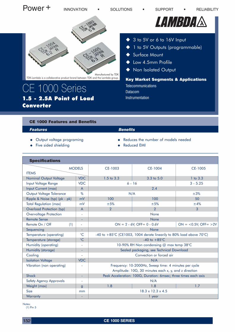
CE 1000 SERIES152
Specifications
� 3 to 5V or 6 to 16V Input
� 1 to 5V Outputs (programmable)
� Surface Mount
� Low 4.5mm Profile
� Non Isolated Output
Key Market Segments & Applications
Telecommunications
Datacom
Instrumentation
CE 1000 Features and Benefits
Features Benefits
� Output voltage programing � Reduces the number of models needed� Five sided shielding � Reduced EMI
INNOVATION SOLUTIONS SUPPORT RELIABILITY
CE 1000 Series1.5 - 2.5A Point of LoadConverter
Notes:(1) Pin 5
Manufactured by TDKTDK-Lambda is a collaborative product brand between TDK and the Lambda group.
MODELS CE-1003 CE-1004 CE-1005ITEMSNominal Output Voltage VDC 1.5 to 3.3 3.3 to 5.0 1 to 3.3Input Voltage Range VDC 6 - 16 3 - 5.25Input Current (max) A 2.4Output Voltage Tolerance % N/A ±3%Ripple & Noise (typ) (pk - pk) mV 100 100 50Total Regulation (max) mV ±5% ±5% ±4%Overload Protection (typ) A 2 2 3Overvoltage Protection - NoneRemote Sense - NoneRemote On / Off (1) - ON = 2 - 6V; OFF= 0 - 0.6V ON = <0.5V; OFF= >2VSequencing - NoneTemperature (operating) °C -40 to +85°C (CE1003, 1004 derate linearily to 80% load above 70°C)Temperature (storage) °C -40 to +85°CHumidity (operating) - 10-90% RH Non condensing @ max temp 38°CHumidity (storage) - Sealed packaging, see Technical DownloadCooling - Convection or forced airIsolation Voltage VDC N/AVibration (non operating) - Frequency: 10-2000Hz, Sweep time: 4 minutes per cycle
Amplitude: 10G, 30 minutes each x, y, and z directionShock - Peak Acceleration: 100G, Duration: 6msec; three times each axisSafety Agency Approvals - N/AWeight (max) g 1.8 1.8 1.7Size mm 18.3 x 12.3 x 4.5Warranty - 1 year
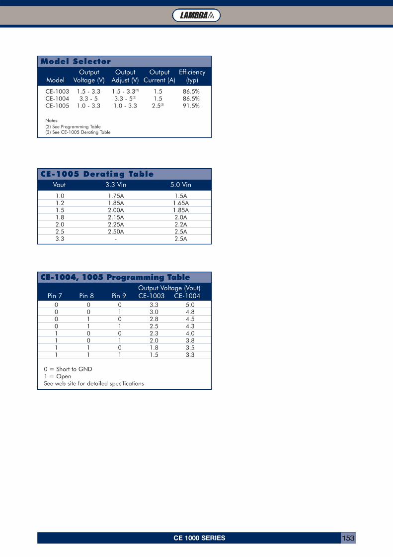
CE 1000 SERIES 153
0 0 0 3.3 5.00 0 1 3.0 4.80 1 0 2.8 4.50 1 1 2.5 4.31 0 0 2.3 4.01 0 1 2.0 3.81 1 0 1.8 3.51 1 1 1.5 3.3
0 = Short to GND1 = OpenSee web site for detailed specifications
Output Voltage (Vout)Pin 7 Pin 8 Pin 9 CE-1003 CE-1004
CE-1004, 1005 Programming Table
1.0 1.75A 1.5A1.2 1.85A 1.65A1.5 2.00A 1.85A1.8 2.15A 2.0A2.0 2.25A 2.2A2.5 2.50A 2.5A3.3 - 2.5A
Vout 3.3 Vin 5.0 Vin
CE-1005 Derating Table
CE-1003 1.5 - 3.3 1.5 - 3.3(2) 1.5 86.5%CE-1004 3.3 - 5 3.3 - 5(2) 1.5 86.5%CE-1005 1.0 - 3.3 1.0 - 3.3 2.5(3) 91.5%
Notes:(2) See Programming Table(3) See CE-1005 Derating Table
Output Output Output EfficiencyModel Voltage (V) Adjust (V) Current (A) (typ)
Model Selector
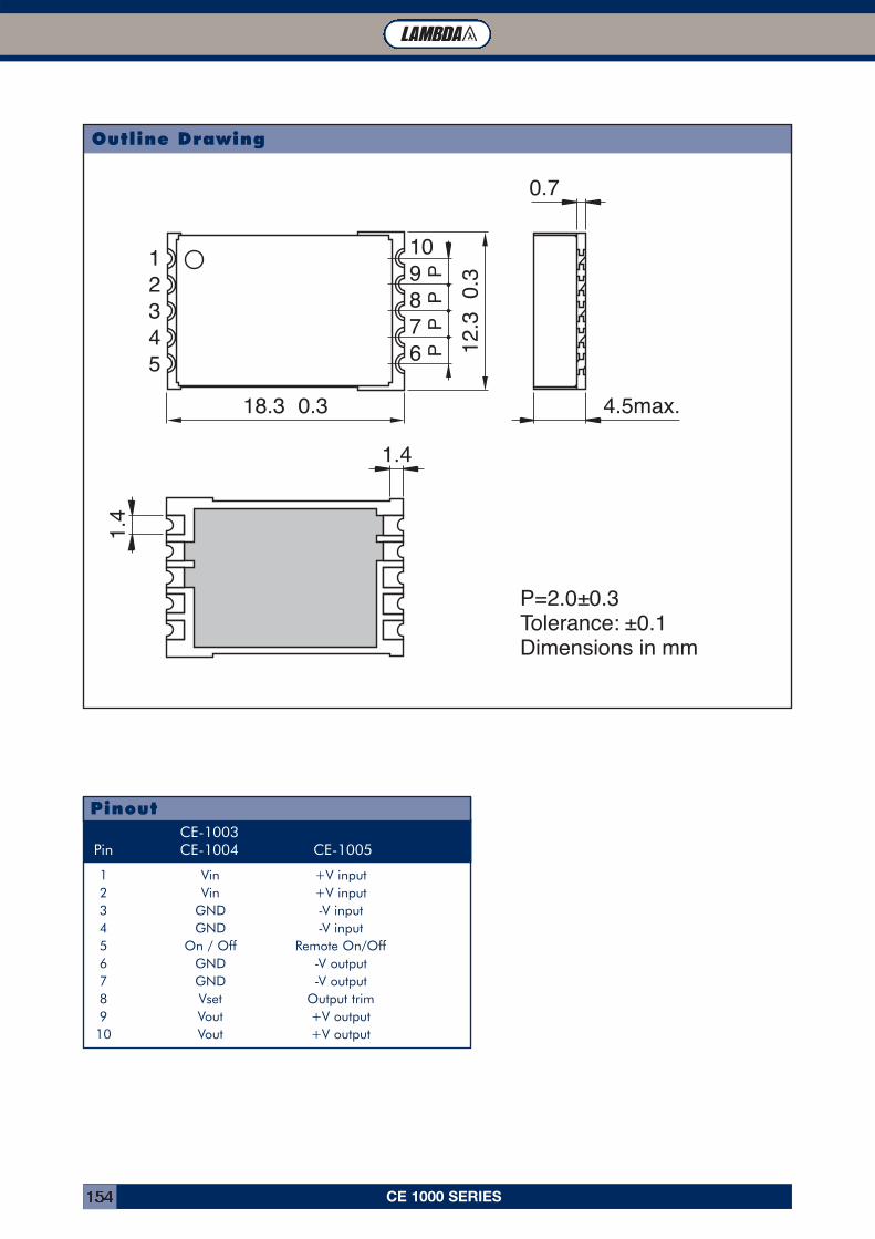
0.7
18.3 0.3 4.5max.
12.3
0.3
1098765
4321
1.4
1.4P
PP
P
P=2.0±0.3Tolerance: ±0.1Dimensions in mm
CE 1000 SERIES154
Outline Drawing
1 Vin +V input2 Vin +V input3 GND -V input4 GND -V input5 On / Off Remote On/Off6 GND -V output7 GND -V output8 Vset Output trim9 Vout +V output10 Vout +V output
CE-1003 Pin CE-1004 CE-1005
Pinout
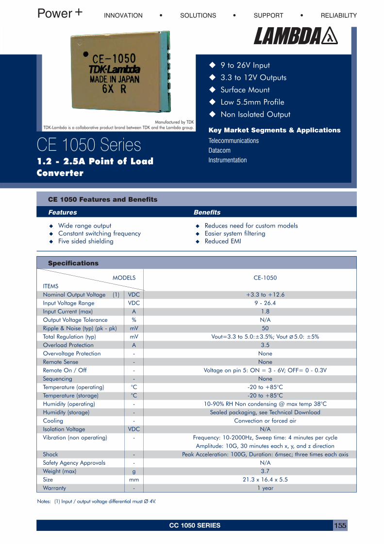
CC 1050 SERIES 155
Specifications
� 9 to 26V Input
� 3.3 to 12V Outputs
� Surface Mount
� Low 5.5mm Profile
� Non Isolated Output
Key Market Segments & Applications
Telecommunications
Datacom
Instrumentation
CE 1050 Features and Benefits
Features Benefits
� Wide range output � Reduces need for custom models� Constant switching frequency � Easier system filtering� Five sided shielding � Reduced EMI
INNOVATION SOLUTIONS SUPPORT RELIABILITY
CE 1050 Series1.2 - 2.5A Point of LoadConverter
Notes: (1) Input / output voltage differential must ∅∅ 4V.
Manufactured by TDKTDK-Lambda is a collaborative product brand between TDK and the Lambda group.
MODELS CE-1050ITEMSNominal Output Voltage (1) VDC +3.3 to +12.6Input Voltage Range VDC 9 - 26.4Input Current (max) A 1.8Output Voltage Tolerance % N/ARipple & Noise (typ) (pk - pk) mV 50Total Regulation (typ) mV Vout=3.3 to 5.0:±3.5%; Vout ∅∅ 5.0: ±5%Overload Protection A 3.5Overvoltage Protection - NoneRemote Sense - NoneRemote On / Off - Voltage on pin 5: ON = 3 - 6V; OFF= 0 - 0.3VSequencing - NoneTemperature (operating) °C -20 to +85°CTemperature (storage) °C -20 to +85°CHumidity (operating) - 10-90% RH Non condensing @ max temp 38°CHumidity (storage) - Sealed packaging, see Technical DownloadCooling - Convection or forced airIsolation Voltage VDC N/AVibration (non operating) - Frequency: 10-2000Hz, Sweep time: 4 minutes per cycle
Amplitude: 10G, 30 minutes each x, y, and z directionShock - Peak Acceleration: 100G, Duration: 6msec; three times each axis Safety Agency Approvals - N/AWeight (max) g 3.7Size mm 21.3 x 16.4 x 5.5Warranty - 1 year
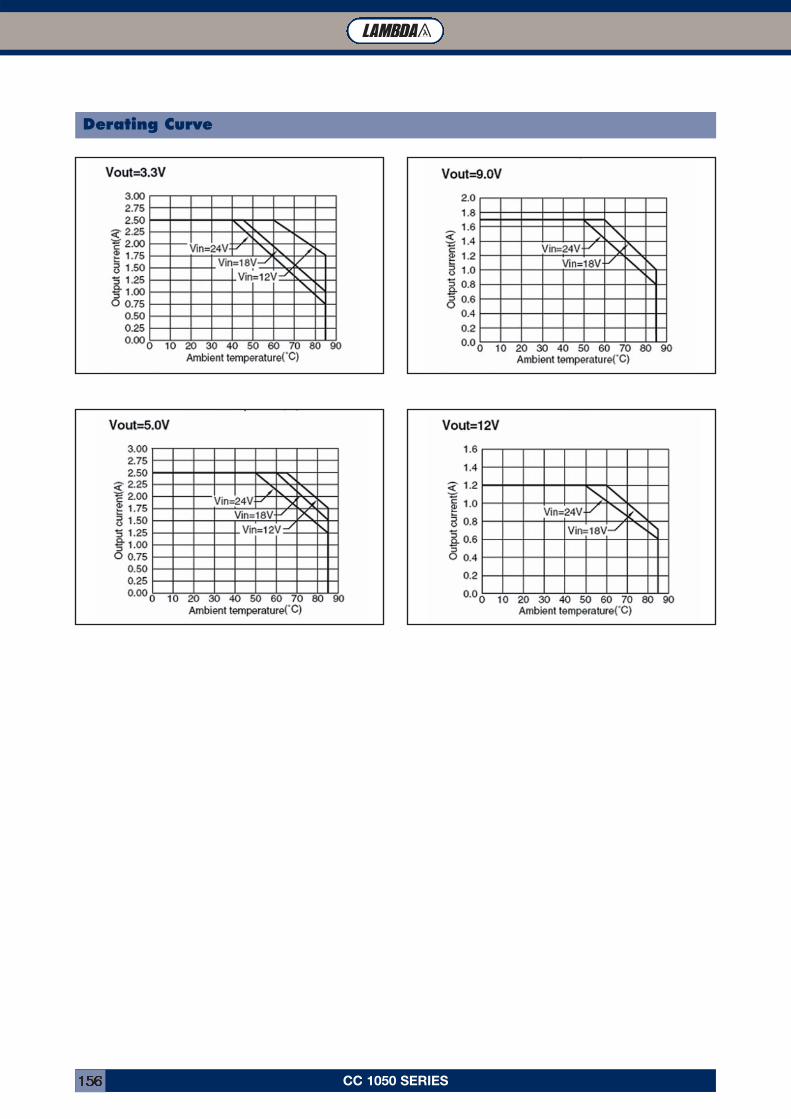
CC 1050 SERIES156
Derating Curve
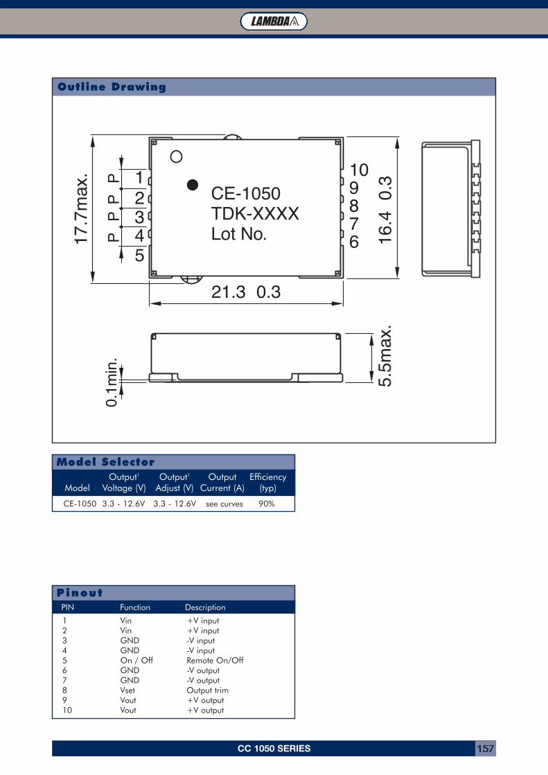
21.3 0.3
16.4
0.
35.
5max
.
109876
54321
17.7
max
.
P0.
1min
.P
PP
CE-1050TDK-XXXXLot No.
CC 1050 SERIES 157
1 Vin +V input2 Vin +V input3 GND -V input4 GND -V input5 On / Off Remote On/Off6 GND -V output7 GND -V output8 Vset Output trim9 Vout +V output10 Vout +V output
PIN Function Description
Pinout
CE-1050 3.3 - 12.6V 3.3 - 12.6V see curves 90%
Output1 Output1 Output EfficiencyModel Voltage (V) Adjust (V) Current (A) (typ)
Model Selector
Outline Drawing
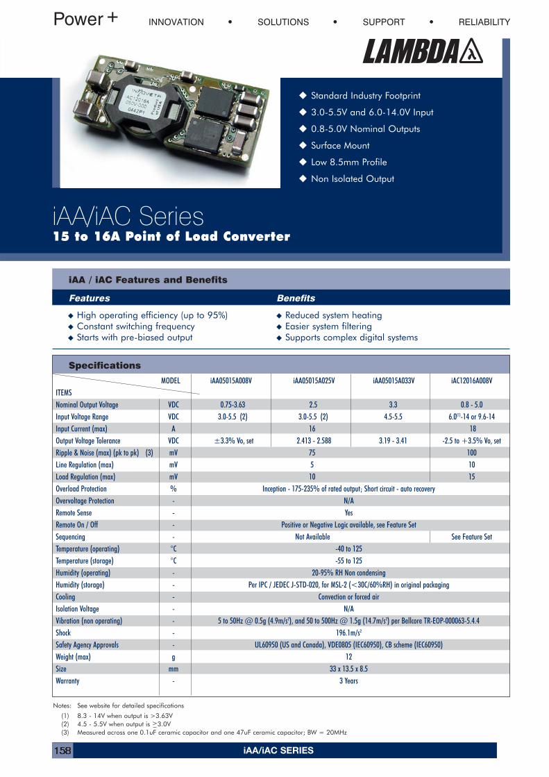
iAA/iAC SERIES158
INNOVATION SOLUTIONS SUPPORT RELIABILITY
iAA/iAC Series15 to 16A Point of Load Converter
� Standard Industry Footprint
� 3.0-5.5V and 6.0-14.0V Input
� 0.8-5.0V Nominal Outputs
� Surface Mount
� Low 8.5mm Profile
� Non Isolated Output
iAA / iAC Features and Benefits
Features Benefits
� High operating efficiency (up to 95%) � Reduced system heating� Constant switching frequency � Easier system filtering� Starts with pre-biased output � Supports complex digital systems
Specifications
Notes: See website for detailed specifications
(1) 8.3 - 14V when output is >3.63V(2) 4.5 - 5.5V when output is >3.0V(3) Measured across one 0.1uF ceramic capacitor and one 47uF ceramic capacitor; BW = 20MHz
MODEL iAA05015A008V iAA05015A025V iAA05015A033V iAC12016A008VITEMSNominal Output Voltage VDC 0.75-3.63 2.5 3.3 0.8 - 5.0Input Voltage Range VDC 3.0-5.5 (2) 3.0-5.5 (2) 4.5-5.5 6.0(1)-14 or 9.6-14Input Current (max) A 16 18Output Voltage Tolerance VDC ±3.3% Vo, set 2.413 - 2.588 3.19 - 3.41 -2.5 to +3.5% Vo, setRipple & Noise (max) (pk to pk) (3) mV 75 100Line Regulation (max) mV 5 10Load Regulation (max) mV 10 15Overload Protection % Inception - 175-235% of rated output; Short circuit - auto recoveryOvervoltage Protection - N/ARemote Sense - YesRemote On / Off - Positive or Negative Logic available, see Feature SetSequencing - Not Available See Feature SetTemperature (operating) °C -40 to 125Temperature (storage) °C -55 to 125Humidity (operating) - 20-95% RH Non condensingHumidity (storage) - Per IPC / JEDEC J-STD-020, for MSL-2 (<30C/60%RH) in original packagingCooling - Convection or forced airIsolation Voltage - N/AVibration (non operating) - 5 to 50Hz @ 0.5g (4.9m/s2), and 50 to 500Hz @ 1.5g (14.7m/s2) per Bellcore TR-EOP-000063-5.4.4Shock - 196.1m/s2
Safety Agency Approvals - UL60950 (US and Canada), VDE0805 (IEC60950), CB scheme (IEC60950)Weight (max) g 12Size mm 33 x 13.5 x 8.5Warranty - 3 Years
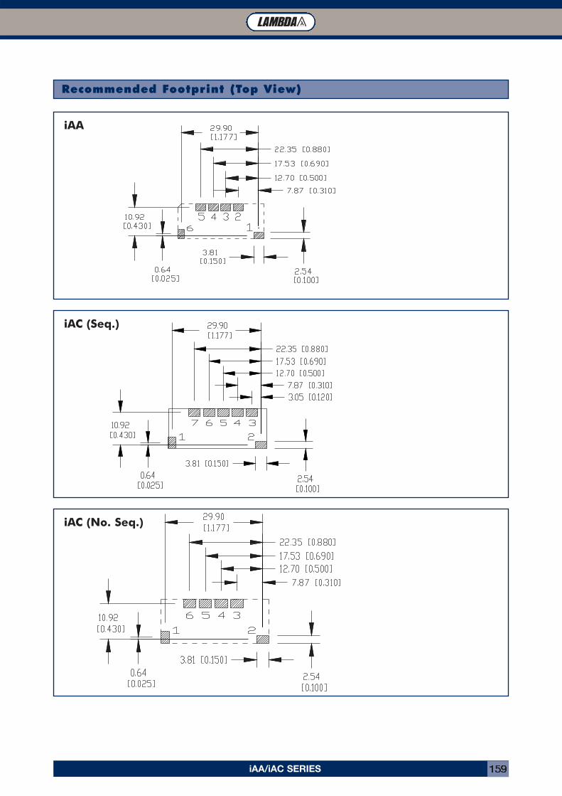
iAA/iAC SERIES 159
Recommended Footprint (Top View)
iAA
iAC (Seq.)
iAC (No. Seq.)
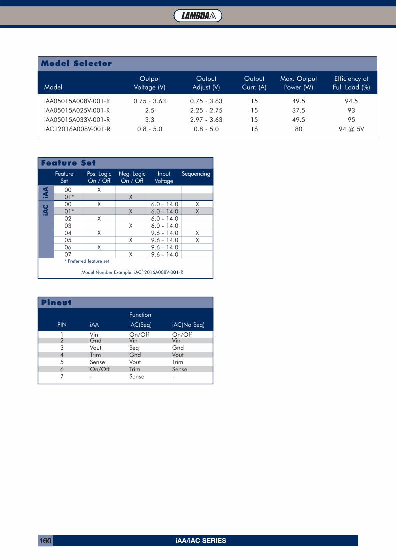
iAA/iAC SERIES160
Model Selector
Function
PIN iAA iAC(Seq) iAC(No Seq)
1 Vin On/Off On/Off2 Gnd Vin Vin3 Vout Seq Gnd4 Trim Gnd Vout5 Sense Vout Trim6 On/Off Trim Sense7 - Sense -
Pinout
Output Output Output Max. Output Efficiency atModel Voltage (V) Adjust (V) Curr. (A) Power (W) Full Load (%)
iAA05015A008V-001-R 0.75 - 3.63 0.75 - 3.63 15 49.5 94.5iAA05015A025V-001-R 2.5 2.25 - 2.75 15 37.5 93iAA05015A033V-001-R 3.3 2.97 - 3.63 15 49.5 95iAC12016A008V-001-R 0.8 - 5.0 0.8 - 5.0 16 80 94 @ 5V
Feature Pos. Logic Neg. Logic Input SequencingSet On / Off On / Off Voltage
00 X01* X00 X 6.0 - 14.0 X01* X 6.0 - 14.0 X02 X 6.0 - 14.003 X 6.0 - 14.004 X 9.6 - 14.0 X05 X 9.6 - 14.0 X06 X 9.6 - 14.007 X 9.6 - 14.0* Preferred feature set
Model Number Example: iAC12016A008V-001-R
Feature Set
iAA
iAC
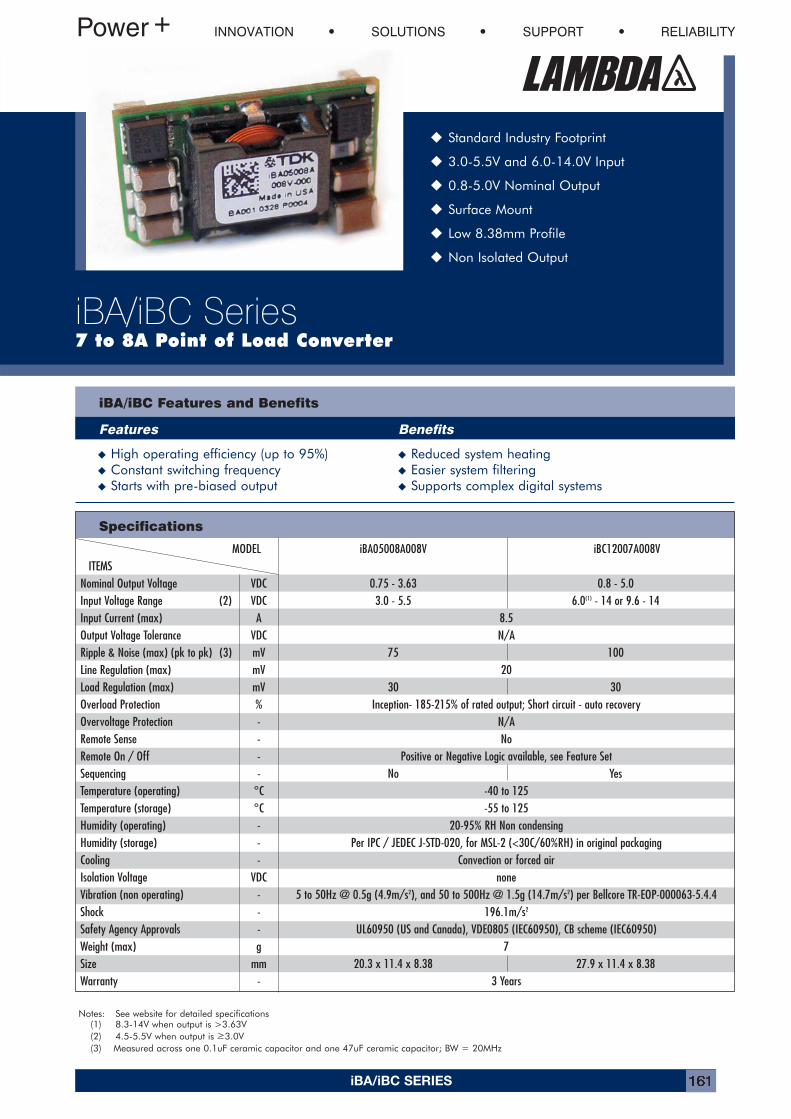
iBA/iBC SERIES 161
INNOVATION SOLUTIONS SUPPORT RELIABILITY
iBA/iBC Series7 to 8A Point of Load Converter
� Standard Industry Footprint
� 3.0-5.5V and 6.0-14.0V Input
� 0.8-5.0V Nominal Output
� Surface Mount
� Low 8.38mm Profile
� Non Isolated Output
iBA/iBC Features and Benefits
Features Benefits
� High operating efficiency (up to 95%) � Reduced system heating� Constant switching frequency � Easier system filtering� Starts with pre-biased output � Supports complex digital systems
Specifications
Notes: See website for detailed specifications(1) 8.3-14V when output is >3.63V(2) 4.5-5.5V when output is >3.0V(3) Measured across one 0.1uF ceramic capacitor and one 47uF ceramic capacitor; BW = 20MHz
MODEL iBA05008A008V iBC12007A008VITEMS
Nominal Output Voltage VDC 0.75 - 3.63 0.8 - 5.0Input Voltage Range (2) VDC 3.0 - 5.5 6.0(1) - 14 or 9.6 - 14Input Current (max) A 8.5Output Voltage Tolerance VDC N/ARipple & Noise (max) (pk to pk) (3) mV 75 100Line Regulation (max) mV 20Load Regulation (max) mV 30 30Overload Protection % Inception- 185-215% of rated output; Short circuit - auto recoveryOvervoltage Protection - N/ARemote Sense - NoRemote On / Off - Positive or Negative Logic available, see Feature SetSequencing - No YesTemperature (operating) °C -40 to 125Temperature (storage) °C -55 to 125Humidity (operating) - 20-95% RH Non condensingHumidity (storage) - Per IPC / JEDEC J-STD-020, for MSL-2 (<30C/60%RH) in original packagingCooling - Convection or forced airIsolation Voltage VDC noneVibration (non operating) - 5 to 50Hz @ 0.5g (4.9m/s2), and 50 to 500Hz @ 1.5g (14.7m/s2) per Bellcore TR-EOP-000063-5.4.4Shock - 196.1m/s2
Safety Agency Approvals - UL60950 (US and Canada), VDE0805 (IEC60950), CB scheme (IEC60950)Weight (max) g 7Size mm 20.3 x 11.4 x 8.38 27.9 x 11.4 x 8.38Warranty - 3 Years
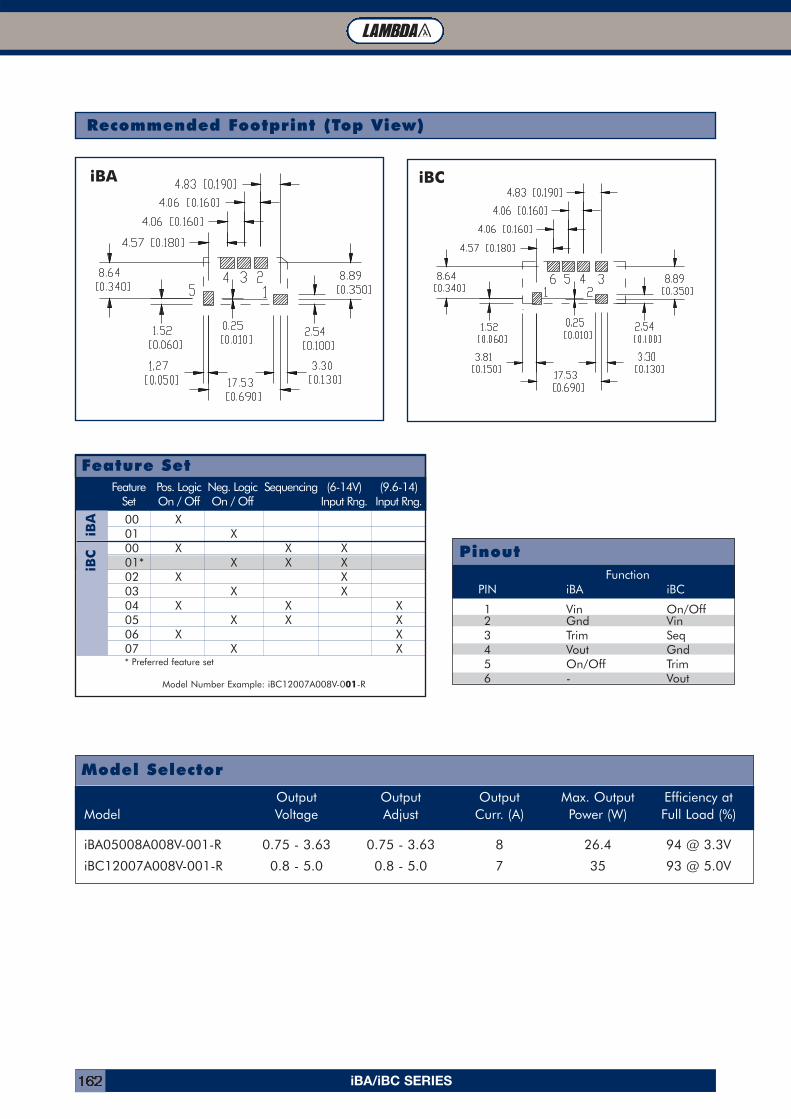
iBA/iBC SERIES162
Recommended Footprint (Top View)
iBA iBC
Feature Pos. Logic Neg. Logic Sequencing (6-14V) (9.6-14)Set On / Off On / Off Input Rng. Input Rng.
00 X01 X00 X X X01* X X X02 X X03 X X04 X X X05 X X X06 X X07 X X* Preferred feature set
Model Number Example: iBC12007A008V-001-R
Feature Set
iBA
iBC Pinout
FunctionPIN iBA iBC
1 Vin On/Off2 Gnd Vin3 Trim Seq4 Vout Gnd5 On/Off Trim6 - Vout
Model Selector
Output Output Output Max. Output Efficiency atModel Voltage Adjust Curr. (A) Power (W) Full Load (%)
iBA05008A008V-001-R 0.75 - 3.63 0.75 - 3.63 8 26.4 94 @ 3.3V
iBC12007A008V-001-R 0.8 - 5.0 0.8 - 5.0 7 35 93 @ 5.0V
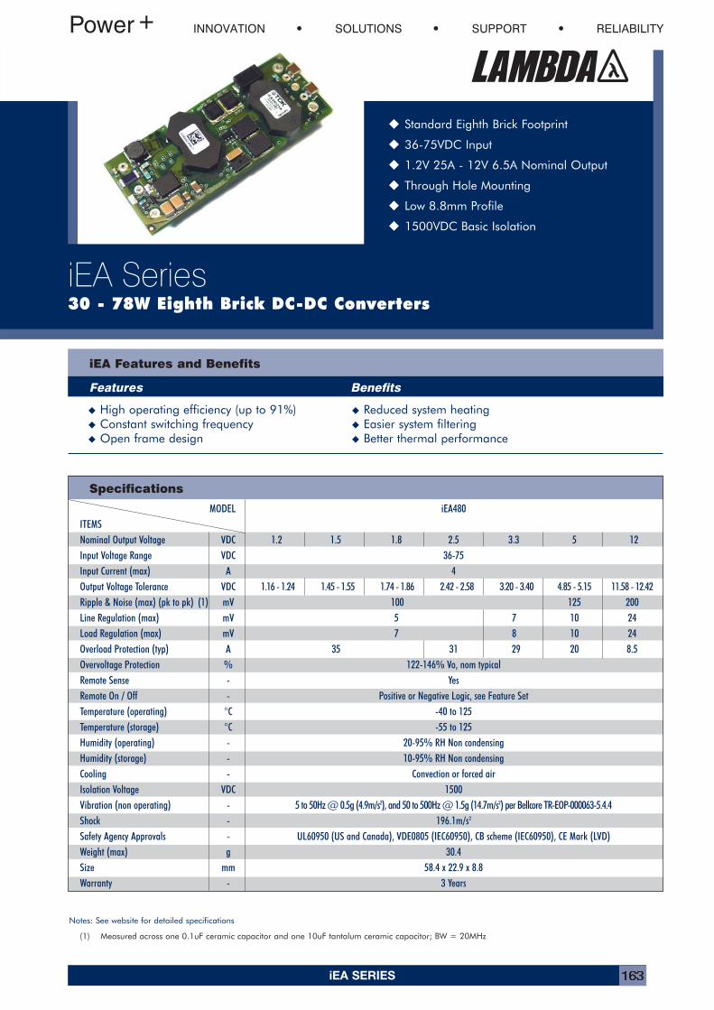
iEA SERIES 163
INNOVATION SOLUTIONS SUPPORT RELIABILITY
iEA Series30 - 78W Eighth Brick DC-DC Converters
� Standard Eighth Brick Footprint
� 36-75VDC Input
� 1.2V 25A - 12V 6.5A Nominal Output
� Through Hole Mounting
� Low 8.8mm Profile
� 1500VDC Basic Isolation
iEA Features and Benefits
Features Benefits
� High operating efficiency (up to 91%) � Reduced system heating� Constant switching frequency � Easier system filtering� Open frame design � Better thermal performance
Specifications
Notes: See website for detailed specifications
(1) Measured across one 0.1uF ceramic capacitor and one 10uF tantalum ceramic capacitor; BW = 20MHz
MODEL iEA480ITEMSNominal Output Voltage VDC 1.2 1.5 1.8 2.5 3.3 5 12Input Voltage Range VDC 36-75Input Current (max) A 4Output Voltage Tolerance VDC 1.16 - 1.24 1.45 - 1.55 1.74 - 1.86 2.42 - 2.58 3.20 - 3.40 4.85 - 5.15 11.58 - 12.42Ripple & Noise (max) (pk to pk) (1) mV 100 125 200Line Regulation (max) mV 5 7 10 24Load Regulation (max) mV 7 8 10 24Overload Protection (typ) A 35 31 29 20 8.5Overvoltage Protection % 122-146% Vo, nom typicalRemote Sense - YesRemote On / Off - Positive or Negative Logic, see Feature SetTemperature (operating) °C -40 to 125Temperature (storage) °C -55 to 125Humidity (operating) - 20-95% RH Non condensingHumidity (storage) - 10-95% RH Non condensingCooling - Convection or forced airIsolation Voltage VDC 1500Vibration (non operating) - 5 to 50Hz @ 0.5g (4.9m/s2), and 50 to 500Hz @ 1.5g (14.7m/s2) per Bellcore TR-EOP-000063-5.4.4Shock - 196.1m/s2
Safety Agency Approvals - UL60950 (US and Canada), VDE0805 (IEC60950), CB scheme (IEC60950), CE Mark (LVD)Weight (max) g 30.4Size mm 58.4 x 22.9 x 8.8Warranty - 3 Years
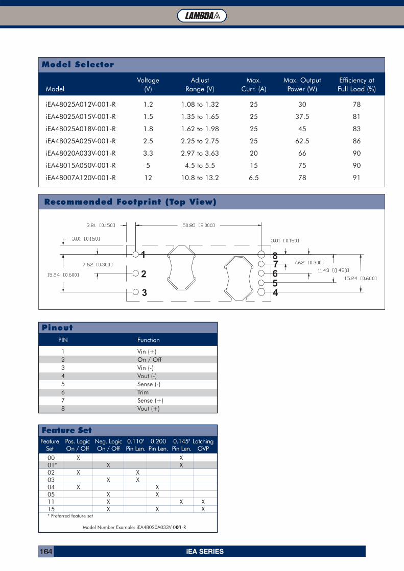
iEA SERIES164
Model Selector
Voltage Adjust Max. Max. Output Efficiency atModel (V) Range (V) Curr. (A) Power (W) Full Load (%)
iEA48025A012V-001-R 1.2 1.08 to 1.32 25 30 78
iEA48025A015V-001-R 1.5 1.35 to 1.65 25 37.5 81
iEA48025A018V-001-R 1.8 1.62 to 1.98 25 45 83
iEA48025A025V-001-R 2.5 2.25 to 2.75 25 62.5 86
iEA48020A033V-001-R 3.3 2.97 to 3.63 20 66 90
iEA48015A050V-001-R 5 4.5 to 5.5 15 75 90
iEA48007A120V-001-R 12 10.8 to 13.2 6.5 78 91
1 2 3
87654
Recommended Footprint (Top View)
PIN Function
1 Vin (+)2 On / Off3 Vin (-)4 Vout (-)5 Sense (-)6 Trim7 Sense (+)8 Vout (+)
Pinout
Feature Pos. Logic Neg. Logic 0.110" 0.200 0.145" LatchingSet On / Off On / Off Pin Len. Pin Len. Pin Len. OVP
00 X X01* X X02 X X03 X X04 X X05 X X11 X X X15 X X X* Preferred feature set
Model Number Example: iEA48020A033V-001-R
Feature Set
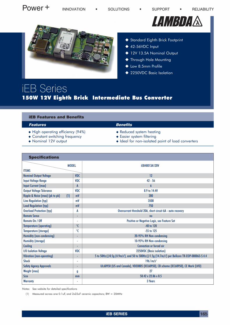
iEB SERIES 165
INNOVATION SOLUTIONS SUPPORT RELIABILITY
iEB Series150W 12V Eighth Brick Intermediate Bus Converter
� Standard Eighth Brick Footprint
� 42-56VDC Input
� 12V 13.5A Nominal Output
� Through Hole Mounting
� Low 8.5mm Profile
� 2250VDC Basic Isolation
iEB Features and Benefits
Features Benefits
� High operating efficiency (94%) � Reduced system heating� Constant switching frequency � Easier system filtering� Nominal 12V output � Ideal for non-isolated point of load converters
Specifications
MODEL iEB48013A120VITEMSNominal Output Voltage VDC 12Input Voltage Range VDC 42 - 56Input Current (max) A 6Output Voltage Tolerance VDC 8.9 to 14.4VRipple & Noise (max) (pk to pk) (1) mV 200Line Regulation (typ) mV 3500Load Regulation (typ) mV 750Overload Protection (typ) A Overcurrent threshold 20A, short circuit 6A - auto recoveryRemote Sense - noRemote On / Off - Positive or Negative Logic, see Feature SetTemperature (operating) °C -40 to 120Temperature (storage) °C -55 to 125Humidity (non-condensing) - 20-95% RH Non-condensingHumidity (storage) - 10-95% RH Non-condensingCooling - Convection or forced airI/O Isolation Voltage VDC 2250VDC (Basic isolation)Vibration (non-operating) - 5 to [email protected] (4.9m/s2), and 50 to [email protected] (14.7m/s2) per Bellcore TR-EOP-000063-5.4.4Shock - 196.1m/s2
Safety Agency Approvals - UL60950 (US and Canada), VDE0805 (IEC60950), CB scheme (IEC60950), CE Mark (LVD)Weight (max) g 27Size mm 58.42 x 22.86 x 8.5Warranty - 3 Years
Notes: See website for detailed specifications
(1) Measured across one 0.1uF, and 2x22uF ceramic capacitors; BW = 20MHz
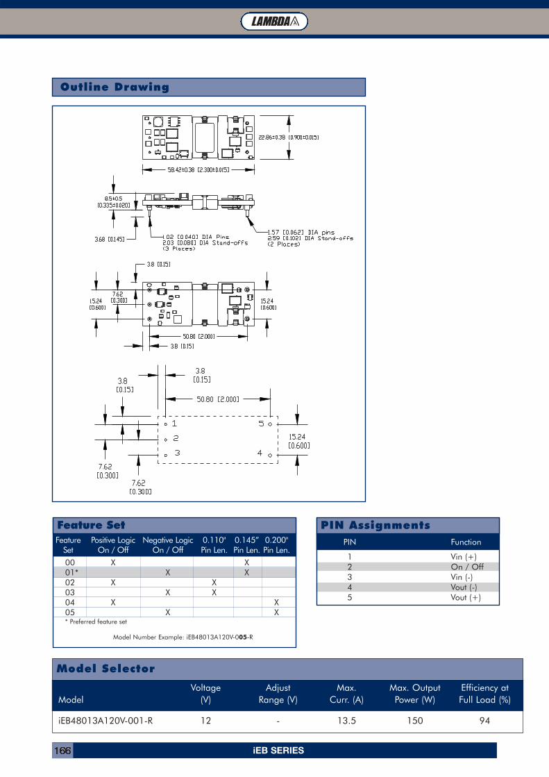
iEB SERIES166
Outline Drawing
Feature Positive Logic Negative Logic 0.110" 0.145” 0.200"Set On / Off On / Off Pin Len. Pin Len. Pin Len.
00 X X01* X X02 X X03 X X04 X X05 X X* Preferred feature set
Model Number Example: iEB48013A120V-005-R
Feature SetPIN Function
1 Vin (+)2 On / Off3 Vin (-)4 Vout (-)5 Vout (+)
PIN Assignments
Model Selector
Voltage Adjust Max. Max. Output Efficiency atModel (V) Range (V) Curr. (A) Power (W) Full Load (%)
iEB48013A120V-001-R 12 - 13.5 150 94
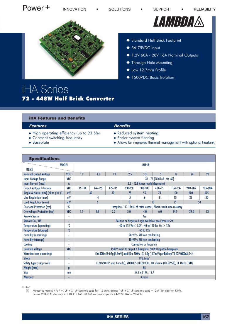
iHA SERIES 167
INNOVATION SOLUTIONS SUPPORT RELIABILITY
iHA Series72 - 448W Half Brick Converter
� Standard Half Brick Footprint
� 36-75VDC Input
� 1.2V 60A - 28V 16A Nominal Outputs
� Through Hole Mounting
� Low 12.7mm Profile
� 1500VDC Basic Isolation
iHA Features and Benefits
Features Benefits
� High operating efficiency (up to 93.5%) � Reduced system heating� Constant switching frequency � Easier system filtering� Baseplate � Allows for improved thermal management with optional heatsink
Specifications
MODEL iHA48ITEMS
Nominal Output Voltage VDC 1.2 1.5 1.8 2.5 3.3 5 12 24 28Input Voltage Range VDC 36 - 75 (28V/16A: 40 -60)Input Current (max) A 2.6 - 12.8 Amps model dependentOutput Voltage Tolerance VDC 1.16 -1.24 1.46 -1.55 1.75 -1.85 2.43-2.58 3.20 -3.40 4.84-5.15 11.64 -12.36 23.28 - 24.72 27.16 -28.84Ripple & Noise (max) (pk to pk) (1) mV 60 80 75 55 70 100 600 675Line Regulation (max) mV 4 5 6 8 15 25 30Load Regulation (max) mV 6 8 10 25 50Overload Protection (typ) % Inception- 113-156% of rated output; Short circuit auto recoveryOvervoltage Protection (typ) VDC 1.5 1.8 2.2 3.0 4.0 6.0 14.5 29.0 33Remote Sense - YesRemote On / Off - Positive or Negative Logic available, see Feature SetTemperature (operating) °C -40 to 115 Vo< 5.0V; -40 to 110 for Vo > 12VTemperature (storage) °C -55 to 125Humidity (operating) - 20-95% RH Non condensingHumidity (storage) - 10-95% RH Non condensingCooling - Convection or forced airIsolation Voltage VDC 1500V Input to output & baseplate, 500V Output to baseplateVibration (non operating) - 5 to 50Hz @ 0.5g (4.9m/s2), and 50 to 500Hz @ 1.5g (14.7m/s2) per Bellcore TR-EOP-000063-5.4.4Shock - 196.1m/s2
Safety Agency Approvals - UL60950 (US and Canada), VDE0805 (IEC60950), CB scheme (IEC60950), CE Mark (LVD)Weight (max) g 85Size mm 57.9 x 61.0 x 12.7Warranty - 3 years
Notes:(1) Measured across 47uF +1uF +0.1uF ceramic caps for 1.2-5Vo, across 1uF +0.1uF ceramic caps +10uF Tan cap for 12Vo,
across 200uF Al electrolytic +10uF +1uF +0.1uF ceramic caps for 24-28Vo BW = 20MHz.
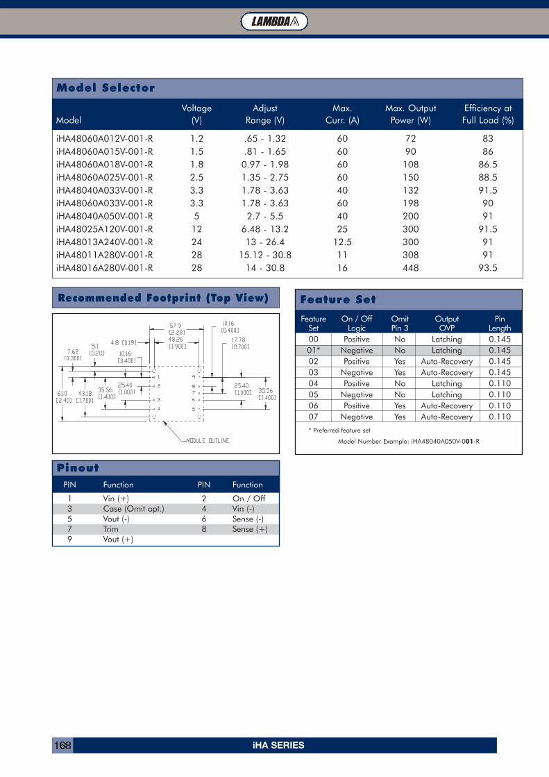
iHA SERIES168
Recommended Footprint (Top View)
Feature On / Off Omit Output Pin Set Logic Pin 3 OVP Length00 Positive No Latching 0.14501* Negative No Latching 0.14502 Positive Yes Auto-Recovery 0.14503 Negative Yes Auto-Recovery 0.14504 Positive No Latching 0.11005 Negative No Latching 0.11006 Positive Yes Auto-Recovery 0.11007 Negative Yes Auto-Recovery 0.110
* Preferred feature set
Model Number Example: iHA48040A050V-001-R
Feature Set
PIN Function PIN Function
1 Vin (+) 2 On / Off3 Case (Omit opt.) 4 Vin (-)5 Vout (-) 6 Sense (-)7 Trim 8 Sense (+)9 Vout (+)
Pinout
Model Selector
Voltage Adjust Max. Max. Output Efficiency atModel (V) Range (V) Curr. (A) Power (W) Full Load (%)
iHA48060A012V-001-R 1.2 .65 - 1.32 60 72 83iHA48060A015V-001-R 1.5 .81 - 1.65 60 90 86iHA48060A018V-001-R 1.8 0.97 - 1.98 60 108 86.5iHA48060A025V-001-R 2.5 1.35 - 2.75 60 150 88.5iHA48040A033V-001-R 3.3 1.78 - 3.63 40 132 91.5iHA48060A033V-001-R 3.3 1.78 - 3.63 60 198 90iHA48040A050V-001-R 5 2.7 - 5.5 40 200 91iHA48025A120V-001-R 12 6.48 - 13.2 25 300 91.5iHA48013A240V-001-R 24 13 - 26.4 12.5 300 91iHA48011A280V-001-R 28 15.12 - 30.8 11 308 91iHA48016A280V-001-R 28 14 - 30.8 16 448 93.5

iPB SERIES 169
INNOVATION SOLUTIONS SUPPORT RELIABILITY
iPB Series15 - 45W Pico Brick Converter
� Compact 30.5 x 29.3 x 8.1 mm
� 36-75VDC Input
� 1.5V 10A - 18V 2.5A Nominal Outputs
� Surface Mount
� Low 8.81mm Profile
� 1500VDC Basic Isolation
iPB Features and Benefits
Features Benefits
� High operating efficiency (up to 89%) � Reduced system heating� Constant switching frequency � Easier system filtering� 33% smaller than eighth brick � Optimization of board space
Specifications
MODEL iPB480ITEMSNominal Output Voltage VDC 1.5 1.8 2.5 3.3 5 12 15 18Input Voltage Range VDC 36 - 75Input Current (max) A 2.0 - 2.2 Amps model dependentOutput Voltage Tolerance VDC 1.45-1.55 1.74-1.86 2.41-2.58 3.19-3.41 4.8-5.2 11.52-12.48 14.4-15.6 17.1-18.9Ripple & Noise (max) (pk to pk) (1) mV 100 125 100Line Regulation (max) mV 5 6 8 24 30 36Load Regulation (max) mV 10 12 15 96 120 144Overload Protection (typ) % Inception - 120-150% of rated output; Short circuit - auto recoveryOvervoltage Protection VDC 1.8 2.2 3 12 10 19 19 27Remote Sense - NoRemote On / Off - Yes (Negative Logic)Temperature (operating) °C -40 to 115 -40 to 125Temperature (storage) °C -55 to 125Humidity (operating) - 20-95% RH Non condensingHumidity (storage) - Per IPC / JEDEC J-STD-020, for MSL-1 (<30C/85%RH) in original packagingCooling - Convection or forced airIsolation Voltage VDC 1500Vibration (non operating) - 5 to 50Hz @ 0.5g (4.9m/s2), and 50 to 500Hz @ 1.5g (14.7m/s2) per Bellcore TR-EOP-000063-5.4.4Shock - 196.1m/s2
Safety Agency Approvals - UL60950 (US and Canada), VDE0805 (IEC60950), CB scheme (IEC60950), CE Mark (LVD)Weight (max) g 18Size mm 30.5 x 29.3 x 8.81Warranty - 3 years
Notes: See website for detailed specifications
(1) Measured across one 3.3uF ceramic capacitor and one10uF Tan capacitor; BW = 20MHz
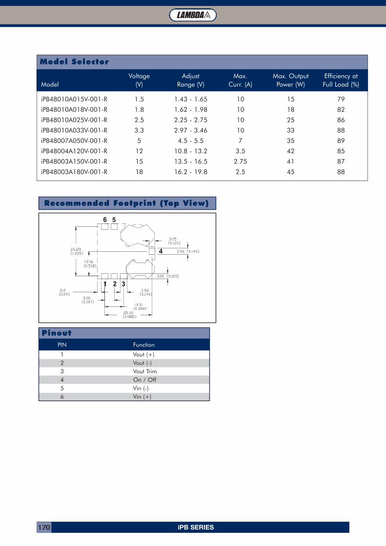
iPB SERIES170
Model Selector
Voltage Adjust Max. Max. Output Efficiency atModel (V) Range (V) Curr. (A) Power (W) Full Load (%)
iPB48010A015V-001-R 1.5 1.43 - 1.65 10 15 79
iPB48010A018V-001-R 1.8 1.62 - 1.98 10 18 82
iPB48010A025V-001-R 2.5 2.25 - 2.75 10 25 86
iPB48010A033V-001-R 3.3 2.97 - 3.46 10 33 88
iPB48007A050V-001-R 5 4.5 - 5.5 7 35 89
iPB48004A120V-001-R 12 10.8 - 13.2 3.5 42 85
iPB48003A150V-001-R 15 13.5 - 16.5 2.75 41 87
iPB48003A180V-001-R 18 16.2 - 19.8 2.5 45 88
Recommended Footprint (Top View)
1 2 3
4
56
PIN Function
1 Vout (+)2 Vout (-)3 Vout Trim4 On / Off5 Vin (-)6 Vin (+)
Pinout
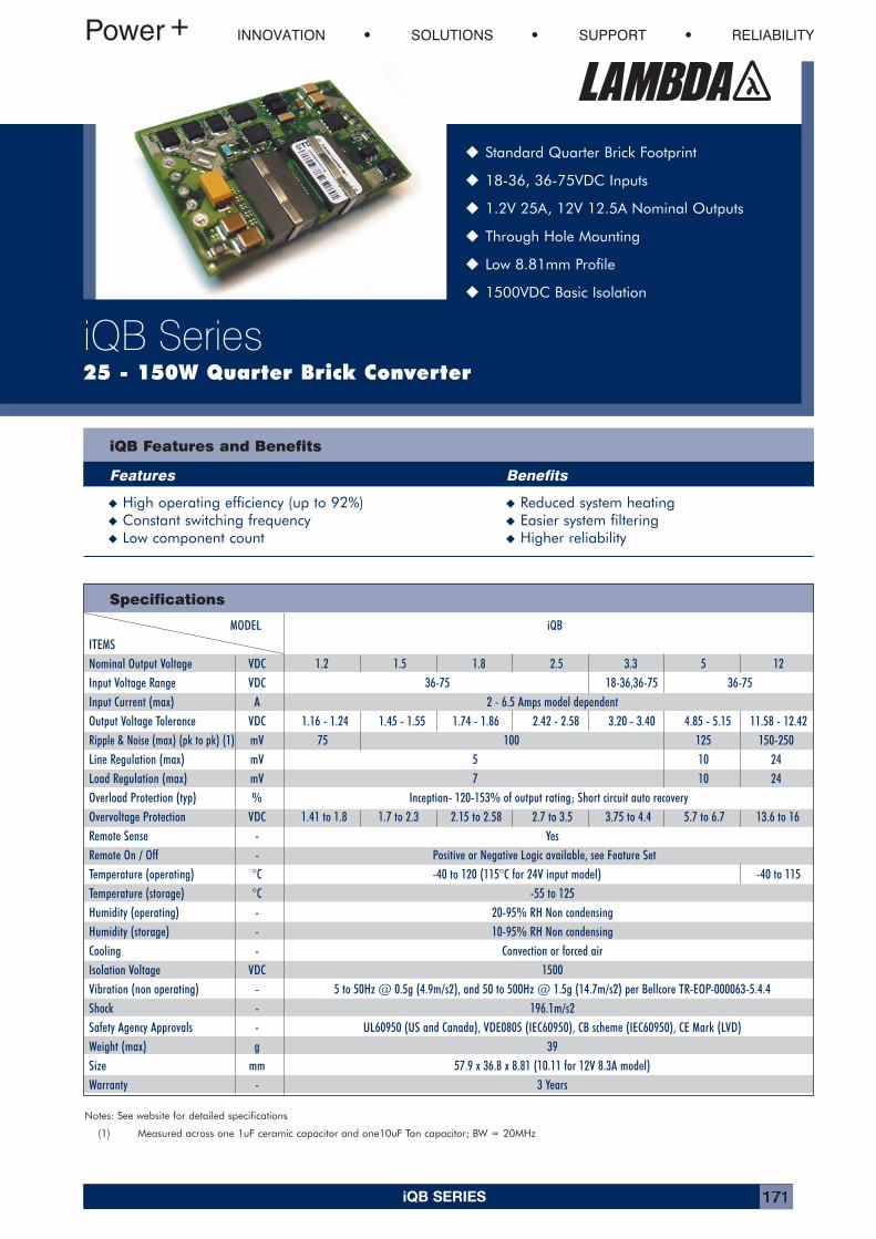
iQB SERIES 171
INNOVATION SOLUTIONS SUPPORT RELIABILITY
iQB Series25 - 150W Quarter Brick Converter
� Standard Quarter Brick Footprint
� 18-36, 36-75VDC Inputs
� 1.2V 25A, 12V 12.5A Nominal Outputs
� Through Hole Mounting
� Low 8.81mm Profile
� 1500VDC Basic Isolation
iQB Features and Benefits
Features Benefits
� High operating efficiency (up to 92%) � Reduced system heating� Constant switching frequency � Easier system filtering� Low component count � Higher reliability
Specifications
MODEL iQBITEMSNominal Output Voltage VDC 1.2 1.5 1.8 2.5 3.3 5 12Input Voltage Range VDC 36-75 18-36,36-75 36-75Input Current (max) A 2 - 6.5 Amps model dependentOutput Voltage Tolerance VDC 1.16 - 1.24 1.45 - 1.55 1.74 - 1.86 2.42 - 2.58 3.20 - 3.40 4.85 - 5.15 11.58 - 12.42Ripple & Noise (max) (pk to pk) (1) mV 75 100 125 150-250Line Regulation (max) mV 5 10 24Load Regulation (max) mV 7 10 24Overload Protection (typ) % Inception- 120-153% of output rating; Short circuit auto recoveryOvervoltage Protection VDC 1.41 to 1.8 1.7 to 2.3 2.15 to 2.58 2.7 to 3.5 3.75 to 4.4 5.7 to 6.7 13.6 to 16Remote Sense - YesRemote On / Off - Positive or Negative Logic available, see Feature SetTemperature (operating) °C -40 to 120 (115°C for 24V input model) -40 to 115Temperature (storage) °C -55 to 125Humidity (operating) - 20-95% RH Non condensingHumidity (storage) - 10-95% RH Non condensingCooling - Convection or forced airIsolation Voltage VDC 1500Vibration (non operating) - 5 to 50Hz @ 0.5g (4.9m/s2), and 50 to 500Hz @ 1.5g (14.7m/s2) per Bellcore TR-EOP-000063-5.4.4Shock - 196.1m/s2Safety Agency Approvals - UL60950 (US and Canada), VDE0805 (IEC60950), CB scheme (IEC60950), CE Mark (LVD)Weight (max) g 39Size mm 57.9 x 36.8 x 8.81 (10.11 for 12V 8.3A model)Warranty - 3 Years
Notes: See website for detailed specifications
(1) Measured across one 1uF ceramic capacitor and one10uF Tan capacitor; BW = 20MHz
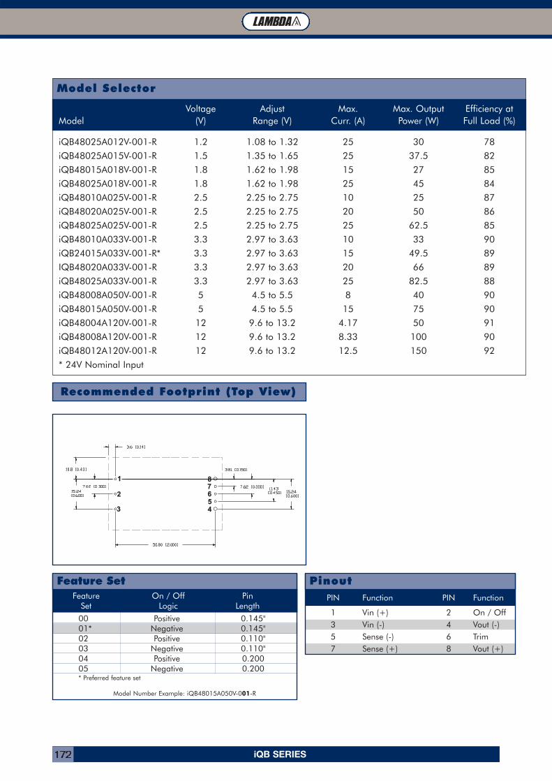
iQB SERIES172
Model Selector
Voltage Adjust Max. Max. Output Efficiency atModel (V) Range (V) Curr. (A) Power (W) Full Load (%)
iQB48025A012V-001-R 1.2 1.08 to 1.32 25 30 78
iQB48025A015V-001-R 1.5 1.35 to 1.65 25 37.5 82
iQB48015A018V-001-R 1.8 1.62 to 1.98 15 27 85
iQB48025A018V-001-R 1.8 1.62 to 1.98 25 45 84
iQB48010A025V-001-R 2.5 2.25 to 2.75 10 25 87
iQB48020A025V-001-R 2.5 2.25 to 2.75 20 50 86
iQB48025A025V-001-R 2.5 2.25 to 2.75 25 62.5 85
iQB48010A033V-001-R 3.3 2.97 to 3.63 10 33 90
iQB24015A033V-001-R* 3.3 2.97 to 3.63 15 49.5 89
IQB48020A033V-001-R 3.3 2.97 to 3.63 20 66 89
iQB48025A033V-001-R 3.3 2.97 to 3.63 25 82.5 88
iQB48008A050V-001-R 5 4.5 to 5.5 8 40 90
iQB48015A050V-001-R 5 4.5 to 5.5 15 75 90
iQB48004A120V-001-R 12 9.6 to 13.2 4.17 50 91
iQB48008A120V-001-R 12 9.6 to 13.2 8.33 100 90
iQB48012A120V-001-R 12 9.6 to 13.2 12.5 150 92
* 24V Nominal Input
Recommended Footprint (Top View)
1
2
3 45678
Feature On / Off PinSet Logic Length
00 Positive 0.145"01* Negative 0.145"02 Positive 0.110" 03 Negative 0.110" 04 Positive 0.20005 Negative 0.200* Preferred feature set
Model Number Example: iQB48015A050V-001-R
Feature SetPIN Function PIN Function
1 Vin (+) 2 On / Off3 Vin (-) 4 Vout (-)5 Sense (-) 6 Trim7 Sense (+) 8 Vout (+)
Pinout
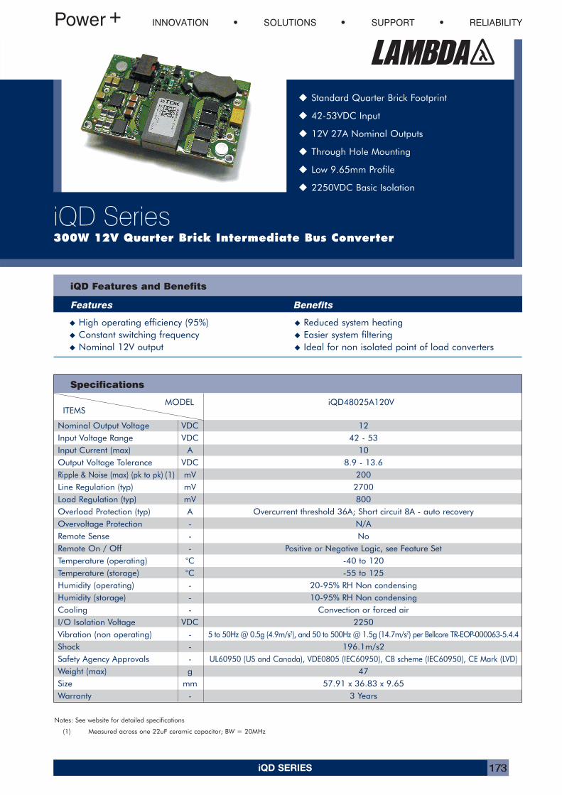
iQD SERIES 173
INNOVATION SOLUTIONS SUPPORT RELIABILITY
iQD Series300W 12V Quarter Brick Intermediate Bus Converter
� Standard Quarter Brick Footprint
� 42-53VDC Input
� 12V 27A Nominal Outputs
� Through Hole Mounting
� Low 9.65mm Profile
� 2250VDC Basic Isolation
iQD Features and Benefits
Features Benefits
� High operating efficiency (95%) � Reduced system heating� Constant switching frequency � Easier system filtering� Nominal 12V output � Ideal for non isolated point of load converters
Specifications
MODEL iQD48025A120VITEMS
Nominal Output Voltage VDC 12Input Voltage Range VDC 42 - 53Input Current (max) A 10Output Voltage Tolerance VDC 8.9 - 13.6Ripple & Noise (max) (pk to pk) (1) mV 200Line Regulation (typ) mV 2700Load Regulation (typ) mV 800Overload Protection (typ) A Overcurrent threshold 36A; Short circuit 8A - auto recoveryOvervoltage Protection - N/ARemote Sense - NoRemote On / Off - Positive or Negative Logic, see Feature SetTemperature (operating) °C -40 to 120Temperature (storage) °C -55 to 125Humidity (operating) - 20-95% RH Non condensingHumidity (storage) - 10-95% RH Non condensingCooling - Convection or forced airI/O Isolation Voltage VDC 2250Vibration (non operating) - 5 to 50Hz @ 0.5g (4.9m/s2), and 50 to 500Hz @ 1.5g (14.7m/s2) per Bellcore TR-EOP-000063-5.4.4Shock - 196.1m/s2Safety Agency Approvals - UL60950 (US and Canada), VDE0805 (IEC60950), CB scheme (IEC60950), CE Mark (LVD)Weight (max) g 47Size mm 57.91 x 36.83 x 9.65Warranty - 3 Years
Notes: See website for detailed specifications
(1) Measured across one 22uF ceramic capacitor; BW = 20MHz
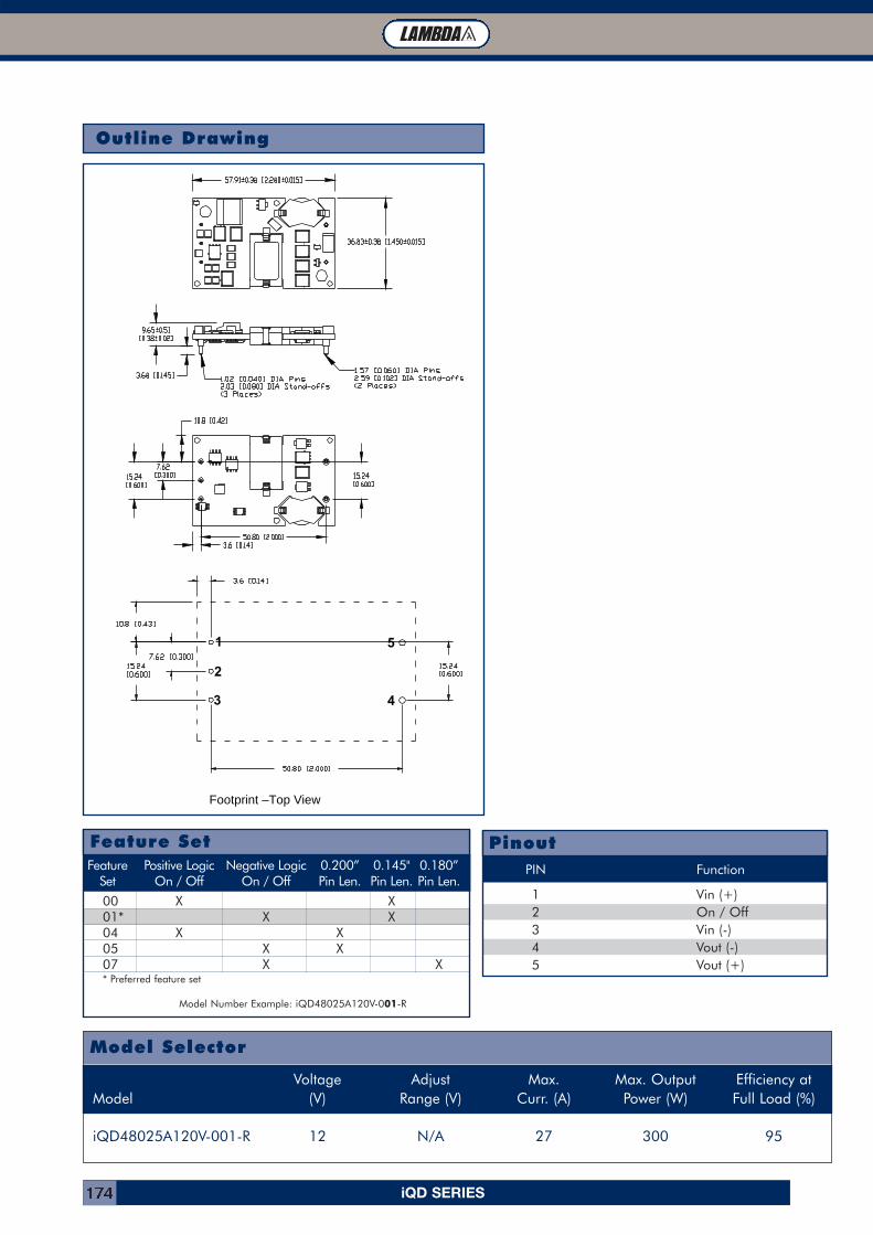
iQD SERIES174
Outline Drawing
Footprint –Top View
1
2
3 4
5
PIN Function
1 Vin (+)2 On / Off3 Vin (-)4 Vout (-)5 Vout (+)
Pinout
Model Selector
Voltage Adjust Max. Max. Output Efficiency atModel (V) Range (V) Curr. (A) Power (W) Full Load (%)
iQD48025A120V-001-R 12 N/A 27 300 95
Feature Positive Logic Negative Logic 0.200” 0.145" 0.180”Set On / Off On / Off Pin Len. Pin Len. Pin Len.
00 X X01* X X04 X X05 X X07 X X* Preferred feature set
Model Number Example: iQD48025A120V-001-R
Feature Set
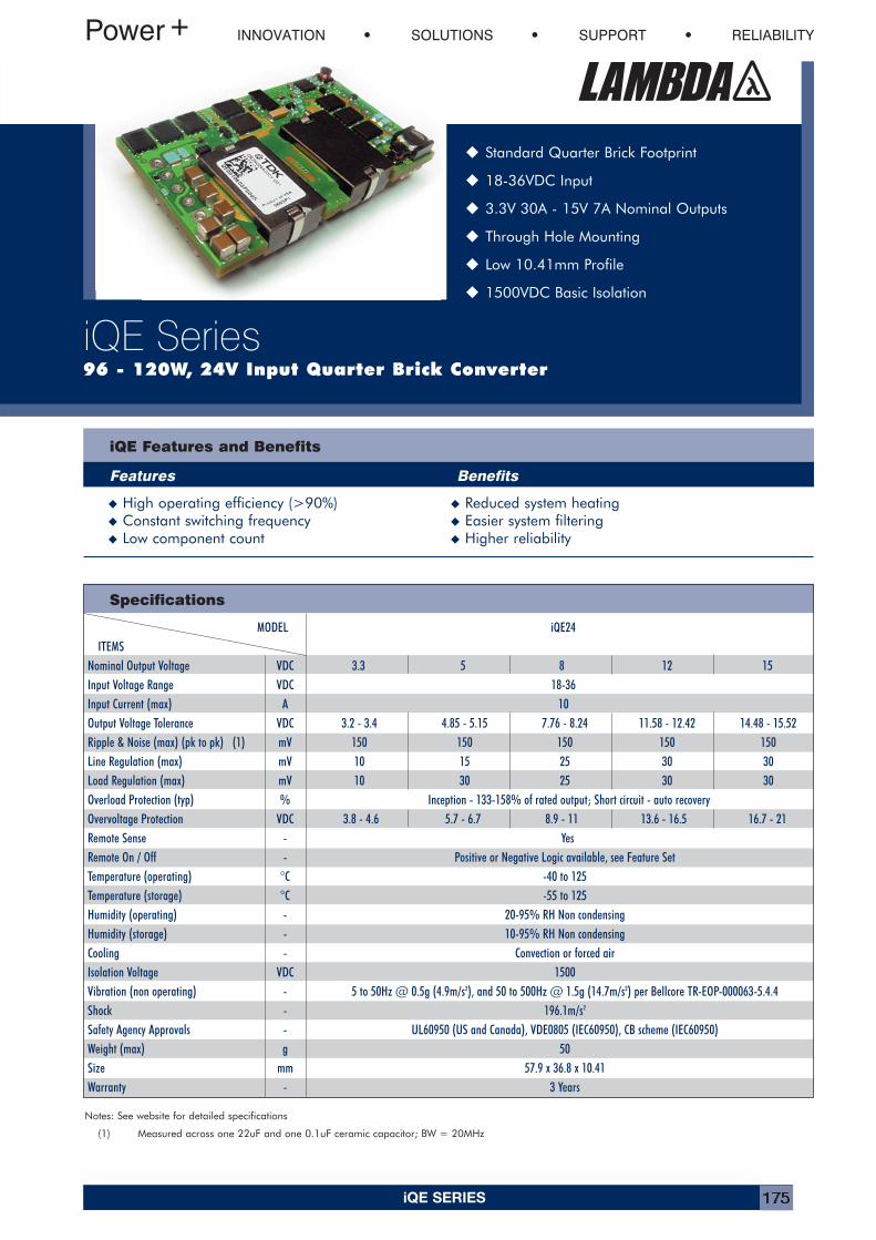
iQE SERIES 175
INNOVATION SOLUTIONS SUPPORT RELIABILITY
iQE Series96 - 120W, 24V Input Quarter Brick Converter
� Standard Quarter Brick Footprint
� 18-36VDC Input
� 3.3V 30A - 15V 7A Nominal Outputs
� Through Hole Mounting
� Low 10.41mm Profile
� 1500VDC Basic Isolation
iQE Features and Benefits
Features Benefits
� High operating efficiency (>90%) � Reduced system heating� Constant switching frequency � Easier system filtering� Low component count � Higher reliability
Specifications
MODEL iQE24ITEMS
Nominal Output Voltage VDC 3.3 5 8 12 15Input Voltage Range VDC 18-36Input Current (max) A 10Output Voltage Tolerance VDC 3.2 - 3.4 4.85 - 5.15 7.76 - 8.24 11.58 - 12.42 14.48 - 15.52Ripple & Noise (max) (pk to pk) (1) mV 150 150 150 150 150Line Regulation (max) mV 10 15 25 30 30Load Regulation (max) mV 10 30 25 30 30Overload Protection (typ) % Inception - 133-158% of rated output; Short circuit - auto recoveryOvervoltage Protection VDC 3.8 - 4.6 5.7 - 6.7 8.9 - 11 13.6 - 16.5 16.7 - 21Remote Sense - YesRemote On / Off - Positive or Negative Logic available, see Feature SetTemperature (operating) °C -40 to 125Temperature (storage) °C -55 to 125Humidity (operating) - 20-95% RH Non condensingHumidity (storage) - 10-95% RH Non condensingCooling - Convection or forced airIsolation Voltage VDC 1500Vibration (non operating) - 5 to 50Hz @ 0.5g (4.9m/s2), and 50 to 500Hz @ 1.5g (14.7m/s2) per Bellcore TR-EOP-000063-5.4.4Shock - 196.1m/s2
Safety Agency Approvals - UL60950 (US and Canada), VDE0805 (IEC60950), CB scheme (IEC60950)Weight (max) g 50Size mm 57.9 x 36.8 x 10.41Warranty - 3 Years
Notes: See website for detailed specifications
(1) Measured across one 22uF and one 0.1uF ceramic capacitor; BW = 20MHz
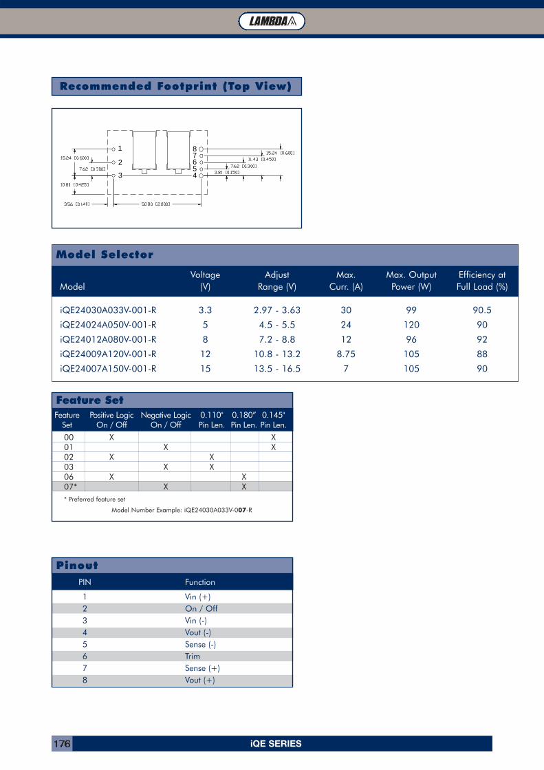
iQE SERIES176
Recommended Footprint (Top View)
3
2
1 87654
Model Selector
Voltage Adjust Max. Max. Output Efficiency atModel (V) Range (V) Curr. (A) Power (W) Full Load (%)
iQE24030A033V-001-R 3.3 2.97 - 3.63 30 99 90.5
iQE24024A050V-001-R 5 4.5 - 5.5 24 120 90
iQE24012A080V-001-R 8 7.2 - 8.8 12 96 92
iQE24009A120V-001-R 12 10.8 - 13.2 8.75 105 88
iQE24007A150V-001-R 15 13.5 - 16.5 7 105 90
Feature Positive Logic Negative Logic 0.110" 0.180” 0.145"Set On / Off On / Off Pin Len. Pin Len. Pin Len.
00 X X01 X X02 X X03 X X06 X X07* X X* Preferred feature set
Model Number Example: iQE24030A033V-007-R
Feature Set
PIN Function
1 Vin (+)2 On / Off3 Vin (-)4 Vout (-)5 Sense (-)6 Trim7 Sense (+)8 Vout (+)
Pinout
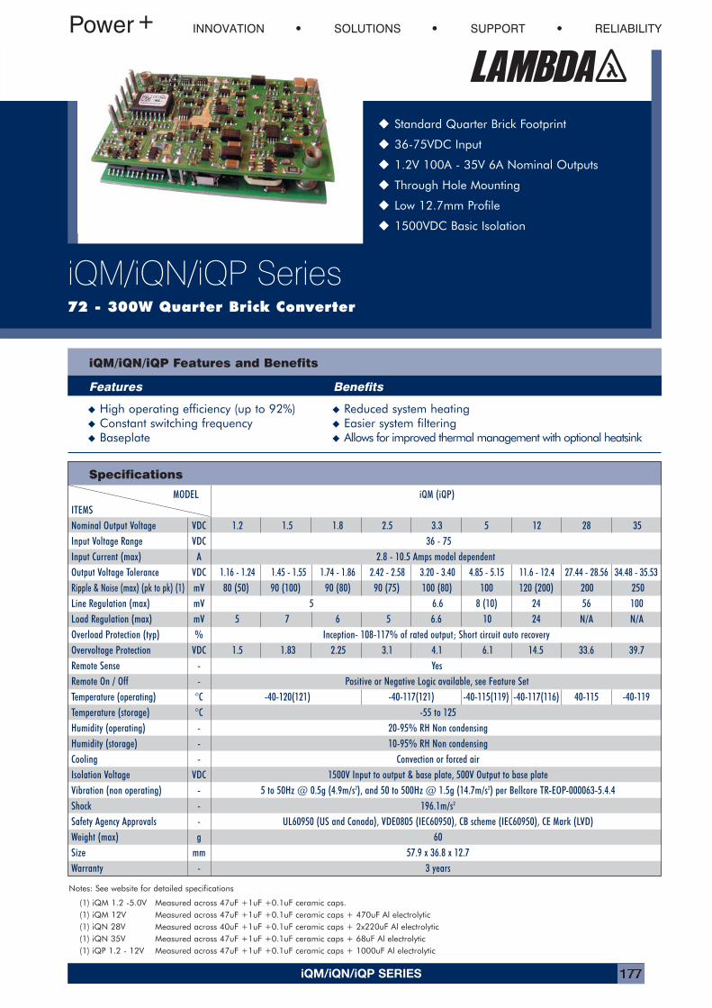
INNOVATION SOLUTIONS SUPPORT RELIABILITY
iQM/iQN/iQP Series72 - 300W Quarter Brick Converter
� Standard Quarter Brick Footprint
� 36-75VDC Input
� 1.2V 100A - 35V 6A Nominal Outputs
� Through Hole Mounting
� Low 12.7mm Profile
� 1500VDC Basic Isolation
iQM/iQN/iQP Features and Benefits
Features Benefits
� High operating efficiency (up to 92%) � Reduced system heating� Constant switching frequency � Easier system filtering� Baseplate � Allows for improved thermal management with optional heatsink
Specifications
MODEL iQM (iQP)ITEMSNominal Output Voltage VDC 1.2 1.5 1.8 2.5 3.3 5 12 28 35Input Voltage Range VDC 36 - 75Input Current (max) A 2.8 - 10.5 Amps model dependentOutput Voltage Tolerance VDC 1.16 - 1.24 1.45 - 1.55 1.74 - 1.86 2.42 - 2.58 3.20 - 3.40 4.85 - 5.15 11.6 - 12.4 27.44 - 28.56 34.48 - 35.53Ripple & Noise (max) (pk to pk) (1) mV 80 (50) 90 (100) 90 (80) 90 (75) 100 (80) 100 120 (200) 200 250Line Regulation (max) mV 5 6.6 8 (10) 24 56 100Load Regulation (max) mV 5 7 6 5 6.6 10 24 N/A N/AOverload Protection (typ) % Inception- 108-117% of rated output; Short circuit auto recoveryOvervoltage Protection VDC 1.5 1.83 2.25 3.1 4.1 6.1 14.5 33.6 39.7Remote Sense - YesRemote On / Off - Positive or Negative Logic available, see Feature SetTemperature (operating) °C -40-120(121) -40-117(121) -40-115(119) -40-117(116) 40-115 -40-119Temperature (storage) °C -55 to 125Humidity (operating) - 20-95% RH Non condensingHumidity (storage) - 10-95% RH Non condensingCooling - Convection or forced airIsolation Voltage VDC 1500V Input to output & base plate, 500V Output to base plateVibration (non operating) - 5 to 50Hz @ 0.5g (4.9m/s2), and 50 to 500Hz @ 1.5g (14.7m/s2) per Bellcore TR-EOP-000063-5.4.4Shock - 196.1m/s2
Safety Agency Approvals - UL60950 (US and Canada), VDE0805 (IEC60950), CB scheme (IEC60950), CE Mark (LVD)Weight (max) g 60Size mm 57.9 x 36.8 x 12.7Warranty - 3 years
iQM/iQN/iQP SERIES 177
Notes: See website for detailed specifications
(1) iQM 1.2 -5.0V Measured across 47uF +1uF +0.1uF ceramic caps.(1) iQM 12V Measured across 47uF +1uF +0.1uF ceramic caps + 470uF Al electrolytic(1) iQN 28V Measured across 40uF +1uF +0.1uF ceramic caps + 2x220uF Al electrolytic(1) iQN 35V Measured across 47uF +1uF +0.1uF ceramic caps + 68uF Al electrolytic(1) iQP 1.2 - 12V Measured across 47uF +1uF +0.1uF ceramic caps + 1000uF Al electrolytic
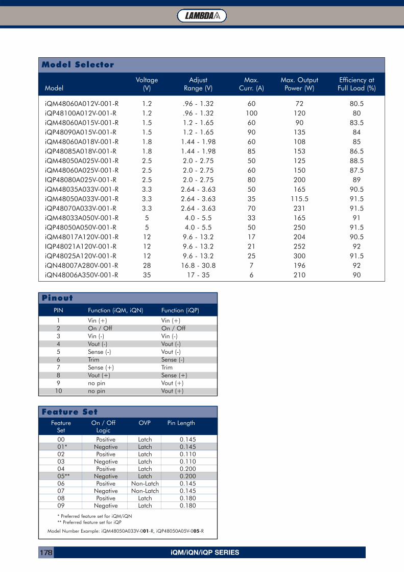
Model Selector
PIN Function (iQM, iQN) Function (iQP)
1 Vin (+) Vin (+)2 On / Off On / Off3 Vin (-) Vin (-)4 Vout (-) Vout (-)5 Sense (-) Vout (-)6 Trim Sense (-)7 Sense (+) Trim8 Vout (+) Sense (+)9 no pin Vout (+)10 no pin Vout (+)
Pinout
Feature On / Off OVP Pin LengthSet Logic
00 Positive Latch 0.14501* Negative Latch 0.14502 Positive Latch 0.11003 Negative Latch 0.11004 Positive Latch 0.20005** Negative Latch 0.20006 Positive Non-Latch 0.14507 Negative Non-Latch 0.14508 Positive Latch 0.18009 Negative Latch 0.180
* Preferred feature set for iQM/iQN** Preferred feature set for iQP
Model Number Example: iQM48050A033V-001-R, iQP48050A05V-005-R
Feature Set
Voltage Adjust Max. Max. Output Efficiency atModel (V) Range (V) Curr. (A) Power (W) Full Load (%)
iQM48060A012V-001-R 1.2 .96 - 1.32 60 72 80.5iQP48100A012V-001-R 1.2 .96 - 1.32 100 120 80iQM48060A015V-001-R 1.5 1.2 - 1.65 60 90 83.5iQP48090A015V-001-R 1.5 1.2 - 1.65 90 135 84iQM48060A018V-001-R 1.8 1.44 - 1.98 60 108 85iQP48085A018V-001-R 1.8 1.44 - 1.98 85 153 86.5iQM48050A025V-001-R 2.5 2.0 - 2.75 50 125 88.5iQM48060A025V-001-R 2.5 2.0 - 2.75 60 150 87.5IQP48080A025V-001-R 2.5 2.0 - 2.75 80 200 89iQM48035A033V-001-R 3.3 2.64 - 3.63 50 165 90.5iQM48050A033V-001-R 3.3 2.64 - 3.63 35 115.5 91.5iQP48070A033V-001-R 3.3 2.64 - 3.63 70 231 91.5iQM48033A050V-001-R 5 4.0 - 5.5 33 165 91iQP48050A050V-001-R 5 4.0 - 5.5 50 250 91.5iQM48017A120V-001-R 12 9.6 - 13.2 17 204 90.5IQP48021A120V-001-R 12 9.6 - 13.2 21 252 92iQP48025A120V-001-R 12 9.6 - 13.2 25 300 91.5iQN48007A280V-001-R 28 16.8 - 30.8 7 196 92iQN48006A350V-001-R 35 17 - 35 6 210 90
iQM/iQN/iQP SERIES178
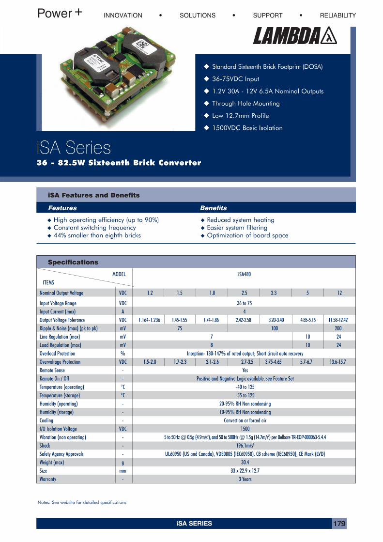
INNOVATION SOLUTIONS SUPPORT RELIABILITY
iSA Series36 - 82.5W Sixteenth Brick Converter
� Standard Sixteenth Brick Footprint (DOSA)
� 36-75VDC Input
� 1.2V 30A - 12V 6.5A Nominal Outputs
� Through Hole Mounting
� Low 12.7mm Profile
� 1500VDC Basic Isolation
iSA Features and Benefits
Features Benefits
� High operating efficiency (up to 90%) � Reduced system heating� Constant switching frequency � Easier system filtering� 44% smaller than eighth bricks � Optimization of board space
Specifications
Notes: See website for detailed specifications
MODEL iSA480ITEMS
Nominal Output Voltage VDC 1.2 1.5 1.8 2.5 3.3 5 12
Input Voltage Range VDC 36 to 75Input Current (max) A 4Output Voltage Tolerance VDC 1.164-1.236 1.45-1.55 1.74-1.86 2.42-2.58 3.20-3.40 4.85-5.15 11.58-12.42Ripple & Noise (max) (pk to pk) mV 75 100 200Line Regulation (max) mV 7 10 24Load Regulation (max) mV 8 10 24Overload Protection % Inception- 130-147% of rated output; Short circuit auto recoveryOvervoltage Protection VDC 1.5-2.0 1.7-2.3 2.1-2.6 2.7-3.5 3.75-4.65 5.7-6.7 13.6-15.7Remote Sense - YesRemote On / Off - Positive and Negative Logic available, see Feature SetTemperature (operating) °C -40 to 125Temperature (storage) °C -55 to 125Humidity (operating) - 20-95% RH Non condensingHumidity (storage) - 10-95% RH Non condensingCooling - Convection or forced airI/O Isolation Voltage VDC 1500Vibration (non operating) - 5 to 50Hz @ 0.5g (4.9m/s2), and 50 to 500Hz @ 1.5g (14.7m/s2) per Bellcore TR-EOP-000063-5.4.4Shock - 196.1m/s2
Safety Agency Approvals - UL60950 (US and Canada), VDE0805 (IEC60950), CB scheme (IEC60950), CE Mark (LVD)Weight (max) g 30.4Size mm 33 x 22.9 x 12.7Warranty - 3 Years
iSA SERIES 179
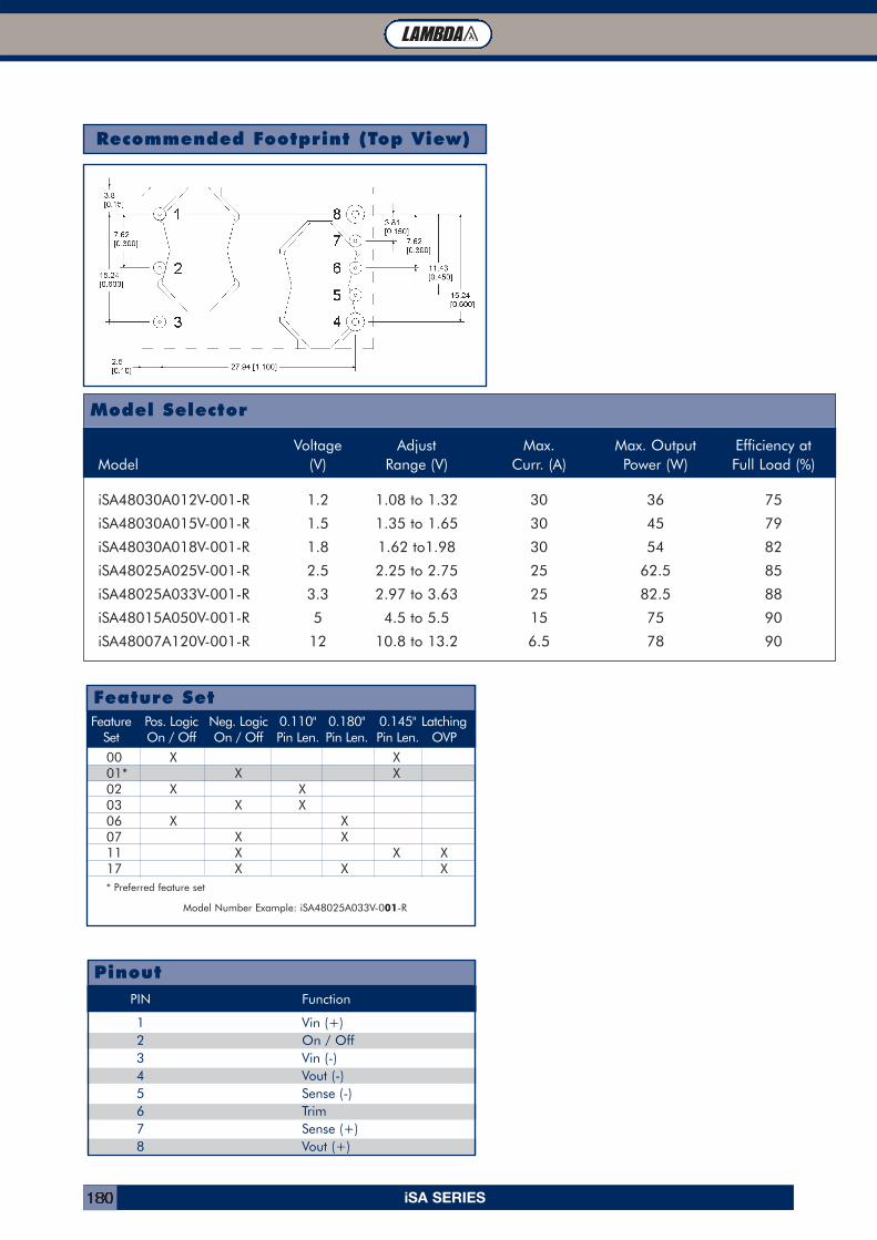
Recommended Footprint (Top View)
Model Selector
PIN Function
1 Vin (+)2 On / Off3 Vin (-)4 Vout (-)5 Sense (-)6 Trim7 Sense (+)8 Vout (+)
Pinout
Feature Pos. Logic Neg. Logic 0.110" 0.180" 0.145" LatchingSet On / Off On / Off Pin Len. Pin Len. Pin Len. OVP
00 X X01* X X02 X X03 X X06 X X07 X X11 X X X17 X X X* Preferred feature set
Model Number Example: iSA48025A033V-001-R
Feature Set
Voltage Adjust Max. Max. Output Efficiency atModel (V) Range (V) Curr. (A) Power (W) Full Load (%)
iSA48030A012V-001-R 1.2 1.08 to 1.32 30 36 75
iSA48030A015V-001-R 1.5 1.35 to 1.65 30 45 79
iSA48030A018V-001-R 1.8 1.62 to1.98 30 54 82
iSA48025A025V-001-R 2.5 2.25 to 2.75 25 62.5 85
iSA48025A033V-001-R 3.3 2.97 to 3.63 25 82.5 88
iSA48015A050V-001-R 5 4.5 to 5.5 15 75 90
iSA48007A120V-001-R 12 10.8 to 13.2 6.5 78 90
iSA SERIES180
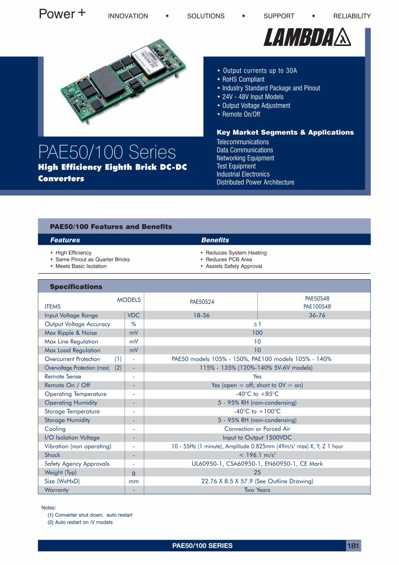
PAE50/100 SERIES 181
• Output currents up to 30A• RoHS Compliant• Industry Standard Package and Pinout• 24V - 48V Input Models• Output Voltage Adjustment• Remote On/Off
Key Market Segments & ApplicationsTelecommunicationsData CommunicationsNetworking EquipmentTest EquipmentIndustrial ElectronicsDistributed Power Architecture
INNOVATION SOLUTIONS SUPPORT RELIABILITY
PAE50/100 SeriesHigh Efficiency Eighth Brick DC-DCConverters
PAE50/100 Features and Benefits
Features Benefits
• High Efficiency• Same Pinout as Quarter Bricks• Meets Basic Isolation
• Reduces System Heating• Reduces PCB Area• Assists Safety Approval
Specifications
MODELS PAE50S24 PAE50S48ITEMS PAE100S48Input Voltage Range VDC 18-36 36-76Output Voltage Accuracy % ±1Max Ripple & Noise mV 100Max Line Regulation mV 10Max Load Regulation mV 10Overcurrent Protection (1) - PAE50 models 105% - 150%, PAE100 models 105% - 140%Overvoltage Protection (max) (2) - 115% - 135% (120%-140% 5V-6V models)Remote Sense - YesRemote On / Off - Yes (open = off; short to 0V = on)Operating Temperature - -40°C to +85°COperating Humidity - 5 - 95% RH (non-condensing)Storage Temperature - -40°C to +100°CStorage Humidity - 5 - 95% RH (non-condensing)Cooling - Convection or Forced AirI/O Isolation Voltage - Input to Output 1500VDCVibration (non operating) - 10 - 55Hz (1 minute), Amplitude 0.825mm (49m/s2 max) X, Y, Z 1 hourShock - < 196.1 m/s2
Safety Agency Approvals - UL60950-1, CSA60950-1, EN60950-1, CE MarkWeight (Typ) g 25Size (WxHxD) mm 22.76 X 8.5 X 57.9 (See Outline Drawing)Warranty - Two Years
Notes:(1) Converter shut down, auto restart(2) Auto restart on /V models
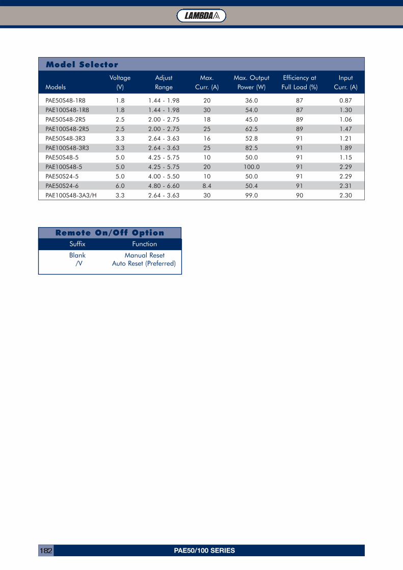
PAE50/100 SERIES182
Model Selector
Remote On/Off OptionSuffix Function
Blank Manual Reset/V Auto Reset (Preferred)
Voltage Adjust Max. Max. Output Efficiency at InputModels (V) Range Curr. (A) Power (W) Full Load (%) Curr. (A)
PAE50S48-1R8 1.8 1.44 - 1.98 20 36.0 87 0.87
PAE100S48-1R8 1.8 1.44 - 1.98 30 54.0 87 1.30
PAE50S48-2R5 2.5 2.00 - 2.75 18 45.0 89 1.06
PAE100S48-2R5 2.5 2.00 - 2.75 25 62.5 89 1.47
PAE50S48-3R3 3.3 2.64 - 3.63 16 52.8 91 1.21
PAE100S48-3R3 3.3 2.64 - 3.63 25 82.5 91 1.89
PAE50S48-5 5.0 4.25 - 5.75 10 50.0 91 1.15
PAE100S48-5 5.0 4.25 - 5.75 20 100.0 91 2.29
PAE50S24-5 5.0 4.00 - 5.50 10 50.0 91 2.29
PAE50S24-6 6.0 4.80 - 6.60 8.4 50.4 91 2.31
PAE100S48-3A3/H 3.3 2.64 - 3.63 30 99.0 90 2.30
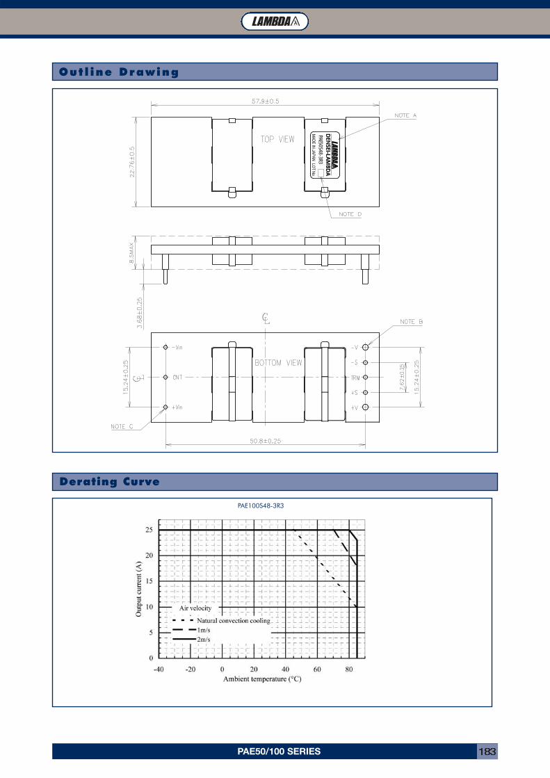
PAE50/100 SERIES 183
PAE50S48-3R3M
ADE IN
JAPANLO
T No.
Outl ine Drawing
Derating Curve
PAE100S48-3R3
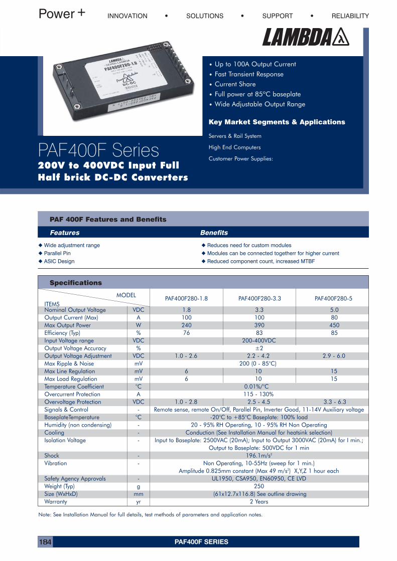
PAF400F SERIES184
MODEL PAF400F280-1.8 PAF400F280-3.3 PAF400F280-5ITEMSNominal Output Voltage VDC 1.8 3.3 5.0Output Current (Max) A 100 100 80Max Output Power W 240 390 450Efficiency (Typ) % 76 83 85Input Voltage range VDC 200-400VDCOutput Voltage Accuracy % ±2Output Voltage Adjustment VDC 1.0 - 2.6 2.2 - 4.2 2.9 - 6.0Max Ripple & Noise mV 200 (0 - 85°C)Max Line Regulation mV 6 10 15Max Load Regulation mV 6 10 15Temperature Coefficient °C 0.01%/°COvercurrent Protection A 115 - 130%Overvoltage Protection VDC 1.0 - 2.8 2.5 - 4.5 3.3 - 6.3Signals & Control - Remote sense, remote On/Off, Parallel Pin, Inverter Good, 11-14V Auxiliary voltageBaseplateTemperature °C -20°C to +85°C Baseplate: 100% loadHumidity (non condensing) - 20 - 95% RH Operating, 10 - 95% RH Non OperatingCooling - Conduction (See Installation Manual for heatsink selection)Isolation Voltage - Input to Baseplate: 2500VAC (20mA); Input to Output 3000VAC (20mA) for I min.;
Output to Baseplate: 500VDC for 1 minShock - 196.1m/s2
Vibration - Non Operating, 10-55Hz (sweep for 1 min.)Amplitude 0.825mm constant (Max 49 m/s2) X,Y,Z 1 hour each
Safety Agency Approvals - UL1950, CSA950, EN60950, CE LVDWeight (Typ) g 250Size (WxHxD) mm (61x12.7x116.8) See outline drawingWarranty yr 2 Years
PAF 400F Features and Benefits
Features Benefits
� Wide adjustment range � Reduces need for custom modules
� Parallel Pin � Modules can be connected togetherr for higher current
� ASIC Design � Reduced component count, increased MTBF
INNOVATION SOLUTIONS SUPPORT RELIABILITY
PAF400F Series200V to 400VDC Input FullHalf brick DC-DC Converters
• Up to 100A Output Current
• Fast Transient Response
• Current Share
• Full power at 85ºC baseplate
• Wide Adjustable Output Range
Key Market Segments & Applications
Servers & Rail System
High End Computers
Customer Power Supplies:
Specifications
Note: See Installation Manual for full details, test methods of parameters and application notes.
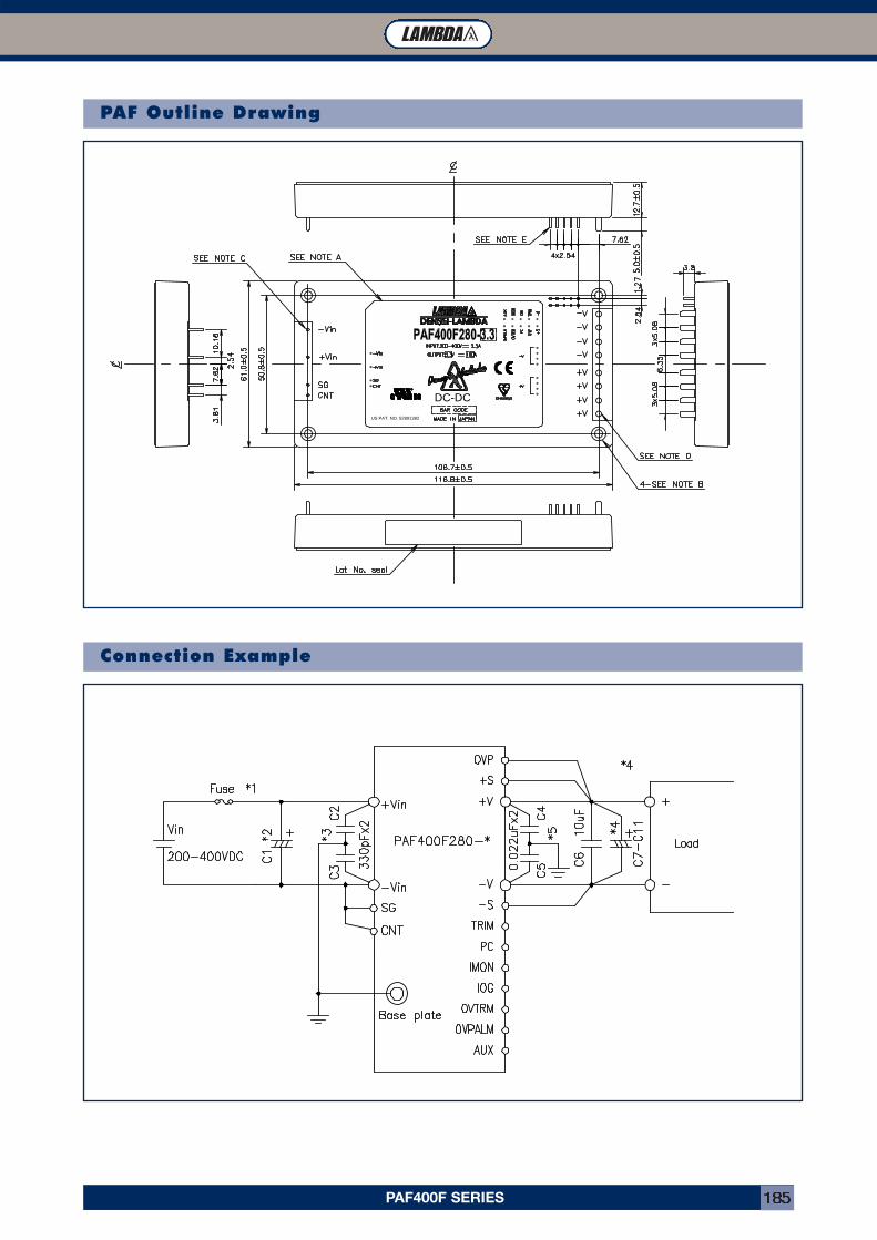
PAF400F SERIES 185
DC-DC
US PAT. NO. 52891382
PAF Outline Drawing
Connection Example
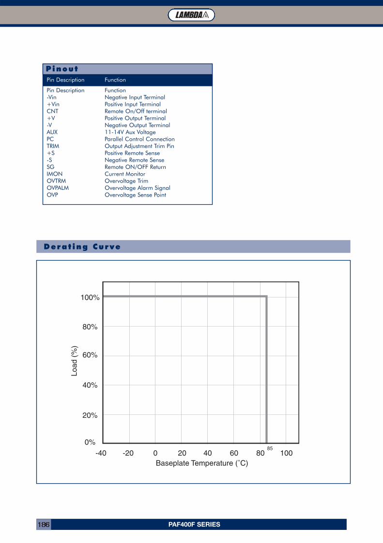
PAF400F SERIES186
Derat ing Curve
Pin Description Function-Vin Negative Input Terminal+Vin Positive Input TerminalCNT Remote On/Off terminal+V Positive Output Terminal-V Negative Output TerminalAUX 11-14V Aux VoltagePC Parallel Control ConnectionTRIM Output Adjustment Trim Pin+S Positive Remote Sense-S Negative Remote SenseSG Remote ON/OFF ReturnIMON Current MonitorOVTRM Overvoltage TrimOVPALM Overvoltage Alarm SignalOVP Overvoltage Sense Point
PinoutPin Description Function
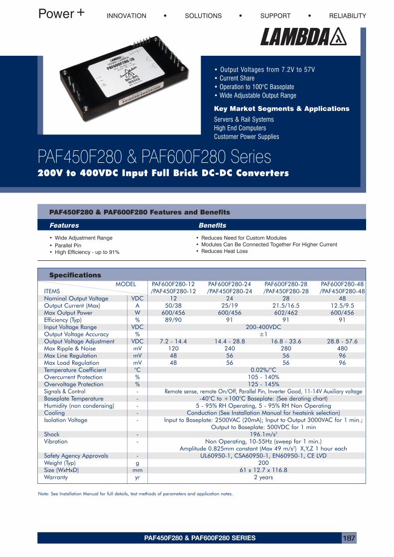
PAF450F280 & PAF600F280 SERIES 187
• Output Voltages from 7.2V to 57V• Current Share• Operation to 100°C Baseplate• Wide Adjustable Output Range
Key Market Segments & Applications
Servers & Rail SystemsHigh End ComputersCustomer Power Supplies
INNOVATION SOLUTIONS SUPPORT RELIABILITY
PAF450F280 & PAF600F280 Series200V to 400VDC Input Full Brick DC-DC Converters
PAF450F280 & PAF600F280 Features and Benefits
Features Benefits
• Wide Adjustment Range• Parallel Pin• High Efficiency - up to 91%
• Reduces Need for Custom Modules• Modules Can Be Connected Together For Higher Current• Reduces Heat Loss
SpecificationsMODEL PAF600F280-12 PAF600F280-24 PAF600F280-28 PAF600F280-48
ITEMS /PAF450F280-12 /PAF450F280-24 /PAF450F280-28 /PAF450F280-48Nominal Output Voltage VDC 12 24 28 48Output Current (Max) A 50/38 25/19 21.5/16.5 12.5/9.5Max Output Power W 600/456 600/456 602/462 600/456Efficiency (Typ) % 89/90 91 91 91Input Voltage Range VDC 200-400VDCOutput Voltage Accuracy % ±1Output Voltage Adjustment VDC 7.2 - 14.4 14.4 - 28.8 16.8 - 33.6 28.8 - 57.6Max Ripple & Noise mV 120 240 280 480Max Line Regulation mV 48 56 56 96Max Load Regulation mV 48 56 56 96Temperature Coefficient °C 0.02%/°COvercurrent Protection % 105 - 140%Overvoltage Protection % 125 - 145%Signals & Control - Remote sense, remote On/Off, Parallel Pin, Inverter Good, 11-14V Auxiliary voltageBaseplate Temperature - -40°C to +100°C Baseplate: (See derating chart)Humidity (non condensing) - 5 - 95% RH Operating, 5 - 95% RH Non OperatingCooling - Conduction (See Installation Manual for heatsink selection)Isolation Voltage - Input to Baseplate: 2500VAC (20mA); Input to Output 3000VAC for 1 min.;
Output to Baseplate: 500VDC for 1 minShock - 196.1m/s2
Vibration - Non Operating, 10-55Hz (sweep for 1 min.)Amplitude 0.825mm constant (Max 49 m/s2) X,Y,Z 1 hour each
Safety Agency Approvals - UL60950-1, CSA60950-1, EN60950-1, CE LVDWeight (Typ) g 200Size (WxHxD) mm 61 x 12.7 x 116.8 Warranty yr 2 years
Note: See Installation Manual for full details, test methods of parameters and application notes.
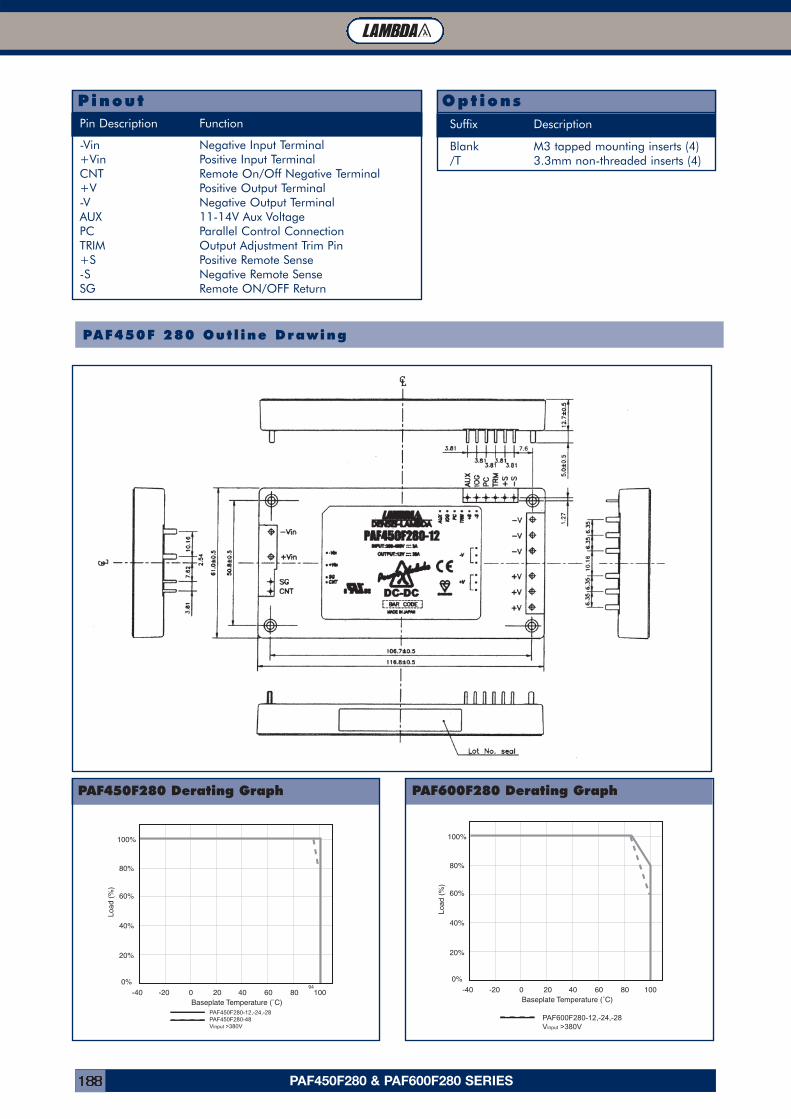
PAF450F280 & PAF600F280 SERIES188
1.2m/s Forced Air 50°C 55°C 60°C 65°C 70°C
PAF450F 280 Out l ine Drawing
-Vin Negative Input Terminal+Vin Positive Input TerminalCNT Remote On/Off Negative Terminal+V Positive Output Terminal-V Negative Output TerminalAUX 11-14V Aux VoltagePC Parallel Control ConnectionTRIM Output Adjustment Trim Pin+S Positive Remote Sense-S Negative Remote SenseSG Remote ON/OFF Return
PinoutPin Description Function
Blank M3 tapped mounting inserts (4)/T 3.3mm non-threaded inserts (4)
OptionsSuffix Description
PAF450F280 Derating Graph PAF600F280 Derating Graph
PAF450F280-12,-24,-28PAF450F280-48Vinput >380V
94
PAF600F280-12,-24,-28Vinput >380V
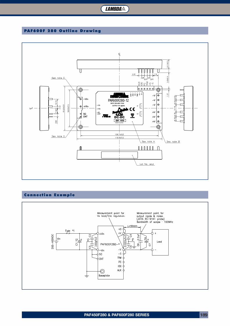
PAF450F280 & PAF600F280 SERIES 189
MADE IN JAPAN
INPUT:200-400V 4A
OUTPUT:12V 50A
PAF600F280-12
DC-DC+V
-V-Vin
+Vin
SGCNT
IOG +S -S
TRMPC
AU
X
PAF600F 280 Out l ine Drawing
Connect ion Example
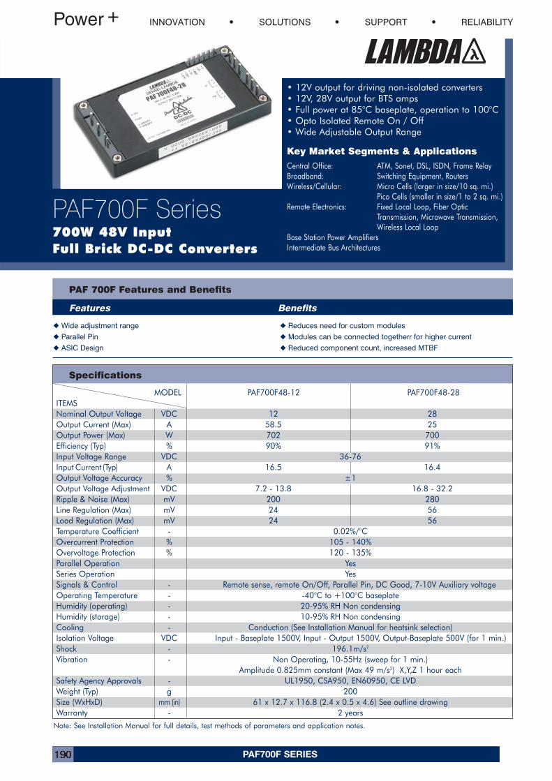
PAF700F SERIES190
MODEL PAF700F48-12 PAF700F48-28ITEMSNominal Output Voltage VDC 12 28Output Current (Max) A 58.5 25Output Power (Max) W 702 700Efficiency (Typ) % 90% 91%Input Voltage Range VDC 36-76Input Current (Typ) A 16.5 16.4Output Voltage Accuracy % ±1Output Voltage Adjustment VDC 7.2 - 13.8 16.8 - 32.2Ripple & Noise (Max) mV 200 280Line Regulation (Max) mV 24 56Load Regulation (Max) mV 24 56Temperature Coefficient - 0.02%/°COvercurrent Protection % 105 - 140%Overvoltage Protection % 120 - 135%Parallel Operation YesSeries Operation YesSignals & Control - Remote sense, remote On/Off, Parallel Pin, DC Good, 7-10V Auxiliary voltageOperating Temperature - -40°C to +100°C baseplateHumidity (operating) - 20-95% RH Non condensingHumidity (storage) - 10-95% RH Non condensingCooling - Conduction (See Installation Manual for heatsink selection)Isolation Voltage VDC Input - Baseplate 1500V, Input - Output 1500V, Output-Baseplate 500V (for 1 min.)Shock - 196.1m/s2
Vibration - Non Operating, 10-55Hz (sweep for 1 min.)Amplitude 0.825mm constant (Max 49 m/s2) X,Y,Z 1 hour each
Safety Agency Approvals - UL1950, CSA950, EN60950, CE LVDWeight (Typ) g 200Size (WxHxD) mm (in) 61 x 12.7 x 116.8 (2.4 x 0.5 x 4.6) See outline drawingWarranty - 2 years
PAF 700F Features and Benefits
Features Benefits
� Wide adjustment range � Reduces need for custom modules
� Parallel Pin � Modules can be connected togetherr for higher current
� ASIC Design � Reduced component count, increased MTBF
INNOVATION SOLUTIONS SUPPORT RELIABILITY
PAF700F Series700W 48V Input Full Brick DC-DC Converters
• 12V output for driving non-isolated converters• 12V, 28V output for BTS amps• Full power at 85°C baseplate, operation to 100°C• Opto Isolated Remote On / Off• Wide Adjustable Output Range
Key Market Segments & Applications
Central Office: ATM, Sonet, DSL, ISDN, Frame RelayBroadband: Switching Equipment, RoutersWireless/Cellular: Micro Cells (larger in size/10 sq. mi.)
Pico Cells (smaller in size/1 to 2 sq. mi.)Remote Electronics: Fixed Local Loop, Fiber Optic
Transmission, Microwave Transmission,Wireless Local Loop
Base Station Power AmplifiersIntermediate Bus Architectures
Specifications
Note: See Installation Manual for full details, test methods of parameters and application notes.
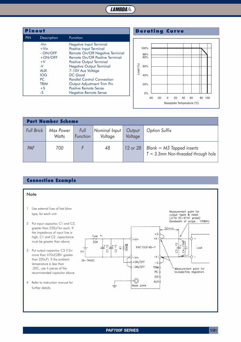
PAF700F SERIES 191
-Vin Negative Input Terminal+Vin Positive Input Terminal- ON/OFF Remote On/Off Negative Terminal+ON/OFF Remote On/Off Positive Terminal+V Positive Output Terminal-V Negative Output TerminalAUX 7-10V Aux VoltageIOG DC GoodPC Parallel Control ConnectionTRIM Output Adjustment Trim Pin+S Positive Remote Sense-S Negative Remote Sense
PinoutPIN Description Function
Derat ing Curve
Connection Example
Part Number Scheme
Note
1 Use external fuse of fast blow
type, for each unit
2 Put input capacitor, C1 and C2, greater than 220uf for each. If the impedance of input line is high, C1 and C2 capacitance must be greater than above.
3 Put output capacitor, C3 (12v: more than 470uF,28V: greater than 220uF). If the ambient temperature is less than -20C, use 4 pieces of the recommended capacitor above.
4 Refer to instruction manual for
further details.
Full Brick Max Power Full Nominal Input Output Option SuffixWatts Function Voltage Voltage
PAF 700 F 48 12 or 28 Blank = M3 Tapped insertsT = 3.3mm Non-threaded through hole
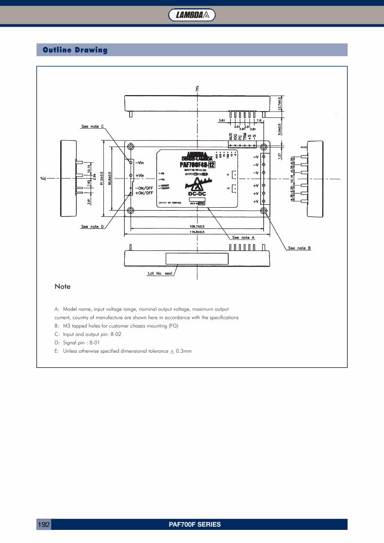
PAF700F SERIES192
Outline Drawing
Note
A: Model name, input voltage range, nominal output voltage, maximum output
current, country of manufacture are shown here in accordance with the specifications
B: M3 tapped holes for customer chassis mounting (FG)
C: Input and output pin: 8-02
D: Signal pin : 8-01
E: Unless otherwise specified dimensional tolerance + 0.3mm
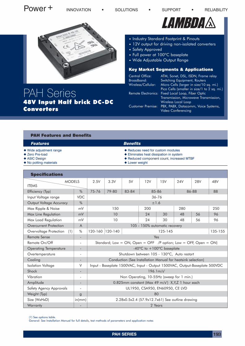
PAH SERIES 193
PAH Features and Benefits
Features Benefits
� Wide adjustment range � Reduces need for custom modules� Zero Pre-load � Eliminates heat dissipation in system� ASIC Design � Reduced component count, increased MTBF� No potting materials � Lower weight
INNOVATION SOLUTIONS SUPPORT RELIABILITY
PAH Series48V Input Half brick DC-DCConverters
• Industry Standard Footprint & Pinouts• 12V output for driving non-isolated converters• Safety Approved• Full power at 100ºC baseplate• Wide Adjustable Output Range
Key Market Segments & Applications
Central Office: ATM, Sonet, DSL, ISDN, Frame relayBroadband: Switching Equipment, RoutersWireless/Cellular: Micro Cells (larger in size/10 sq. mi.)
Pico Cells (smaller in size/1 to 2 sq. mi.)Remote Electronics: Fixed Local Loop, Fiber Optic
Transmission, Microwave Transmission,Wireless Local Loop
Customer Premise: PBX, PABX, Datacomm, Voice Systems,Video Conferencing
Specifications
(1) See options table.General: See Installation Manual for full details, test methods of parameters and application notes
MODELS 2.5V 3.3V 5V 12V 15V 24V 28V 48VITEMS
Efficiency (Typ) % 75-76 79-80 83-84 85-86 86-88 88
Input Voltage range VDC 36-76
Output Voltage Accuracy % ±1.6
Max Ripple & Noise mV 150 200 280 250
Max Line Regulation mV 10 24 30 48 56 96
Max Load Regulation mV 10 24 30 48 56 96
Overcurrent Protection A 105 - 150% automatic recovery
Overvoltage Protection (1) % 120-160 120-140 125-145 135-155
Remote Sense - Yes
Remote On/Off - Standard; Low = ON, Open = OFF /P option; Low = OFF, Open = ON)
Operating Temperature - -40ºC to +100ºC baseplate
Overtemperature - Shutdown between 105 - 130ºC, Auto restart
Cooling - Conduction (See Installation Manual for heatsink selection)
Isolation Voltage V Input - Baseplate 1500VAC, Input - Output 1500VAC, Output-Baseplate 500VDC
Shock - 196.1m/s2
Vibration - Non Operating, 10-55Hz (sweep for 1 min.)
Amplitude - 0.825mm constant (Max 49 m/s2) X,Y,Z 1 hour each
Safety Agency Approvals - UL1950, CSA950, EN60950, CE LVD
Weight (Typ) g 80
Size (WxHxD) in(mm) 2.28x0.5x2.4 (57.9x12.7x61) See outline drawing
Warranty - 2 Years
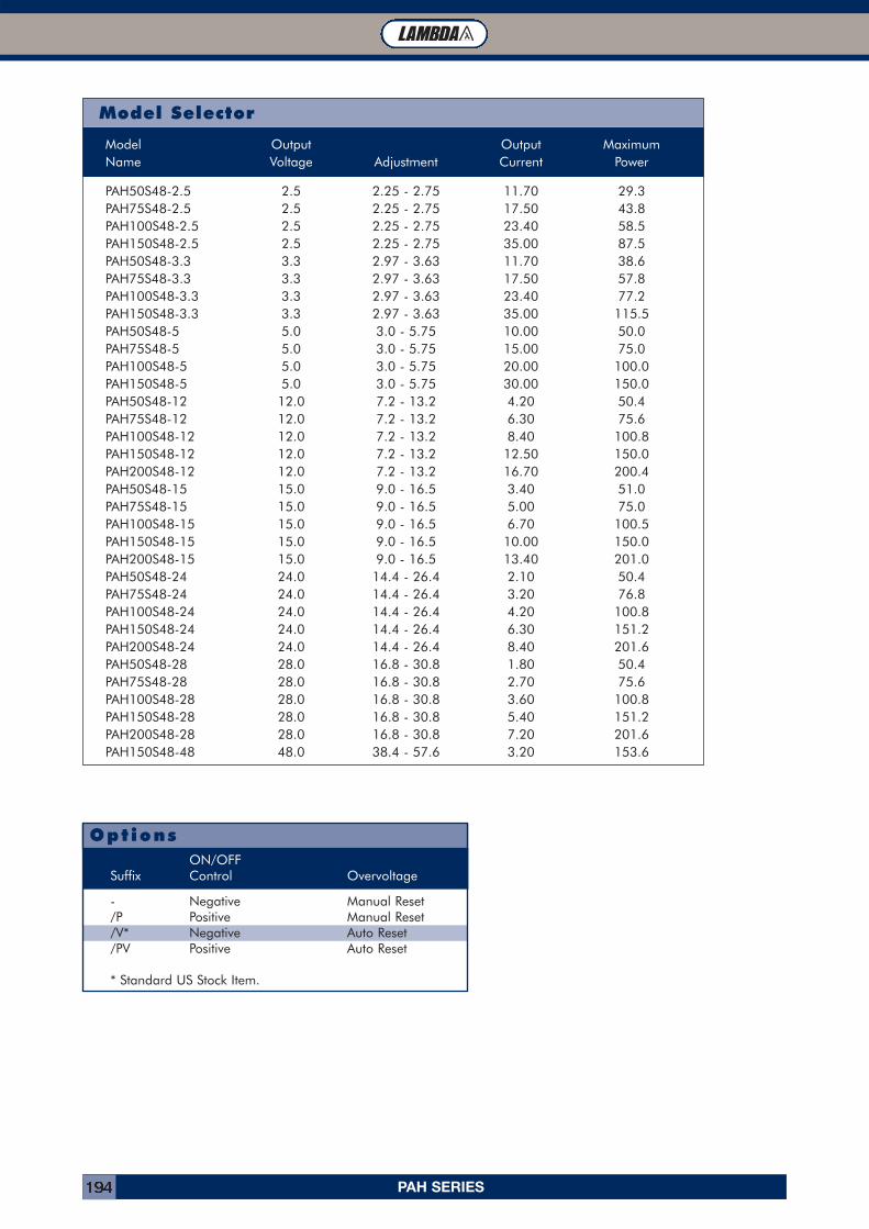
PAH SERIES194
- Negative Manual Reset/P Positive Manual Reset/V* Negative Auto Reset/PV Positive Auto Reset
* Standard US Stock Item.
OptionsON/OFF
Suffix Control Overvoltage
Model Output Output MaximumName Voltage Adjustment Current Power
PAH50S48-2.5 2.5 2.25 - 2.75 11.70 29.3PAH75S48-2.5 2.5 2.25 - 2.75 17.50 43.8PAH100S48-2.5 2.5 2.25 - 2.75 23.40 58.5PAH150S48-2.5 2.5 2.25 - 2.75 35.00 87.5PAH50S48-3.3 3.3 2.97 - 3.63 11.70 38.6PAH75S48-3.3 3.3 2.97 - 3.63 17.50 57.8PAH100S48-3.3 3.3 2.97 - 3.63 23.40 77.2PAH150S48-3.3 3.3 2.97 - 3.63 35.00 115.5PAH50S48-5 5.0 3.0 - 5.75 10.00 50.0PAH75S48-5 5.0 3.0 - 5.75 15.00 75.0PAH100S48-5 5.0 3.0 - 5.75 20.00 100.0PAH150S48-5 5.0 3.0 - 5.75 30.00 150.0PAH50S48-12 12.0 7.2 - 13.2 4.20 50.4PAH75S48-12 12.0 7.2 - 13.2 6.30 75.6PAH100S48-12 12.0 7.2 - 13.2 8.40 100.8PAH150S48-12 12.0 7.2 - 13.2 12.50 150.0PAH200S48-12 12.0 7.2 - 13.2 16.70 200.4PAH50S48-15 15.0 9.0 - 16.5 3.40 51.0PAH75S48-15 15.0 9.0 - 16.5 5.00 75.0PAH100S48-15 15.0 9.0 - 16.5 6.70 100.5PAH150S48-15 15.0 9.0 - 16.5 10.00 150.0PAH200S48-15 15.0 9.0 - 16.5 13.40 201.0PAH50S48-24 24.0 14.4 - 26.4 2.10 50.4PAH75S48-24 24.0 14.4 - 26.4 3.20 76.8PAH100S48-24 24.0 14.4 - 26.4 4.20 100.8PAH150S48-24 24.0 14.4 - 26.4 6.30 151.2PAH200S48-24 24.0 14.4 - 26.4 8.40 201.6PAH50S48-28 28.0 16.8 - 30.8 1.80 50.4PAH75S48-28 28.0 16.8 - 30.8 2.70 75.6PAH100S48-28 28.0 16.8 - 30.8 3.60 100.8PAH150S48-28 28.0 16.8 - 30.8 5.40 151.2PAH200S48-28 28.0 16.8 - 30.8 7.20 201.6PAH150S48-48 48.0 38.4 - 57.6 3.20 153.6
Model Selector
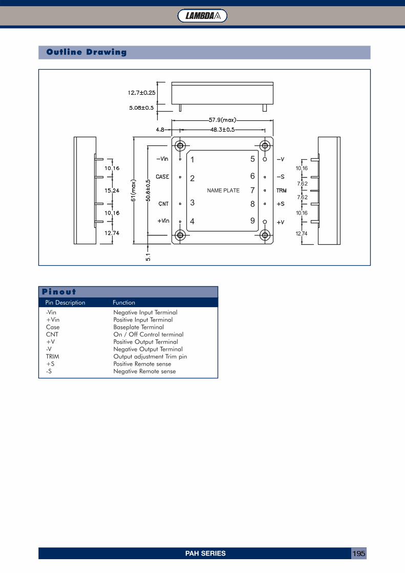
PAH SERIES 195
Outline Drawing
-Vin Negative Input Terminal+Vin Positive Input TerminalCase Baseplate TerminalCNT On / Off Control terminal+V Positive Output Terminal-V Negative Output TerminalTRIM Output adjustment Trim pin+S Positive Remote sense-S Negative Remote sense
Pin Description Function
Pinout
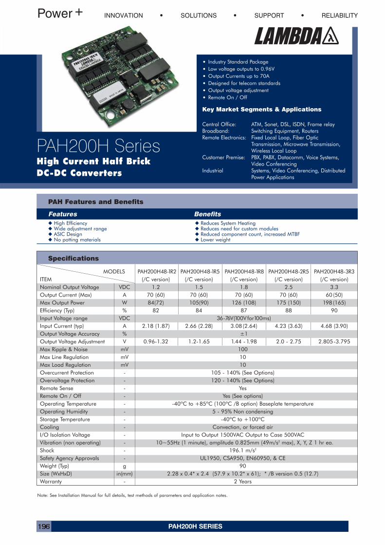
PAH200H SERIES196
Specifications
PAH Features and Benefits
Features Benefits� High Efficiency � Reduces System Heating� Wide adjustment range � Reduces need for custom modules� ASIC Design � Reduced component count, increased MTBF� No potting materials � Lower weight
INNOVATION SOLUTIONS SUPPORT RELIABILITY
PAH200H SeriesHigh Current Half BrickDC-DC Converters
• Industry Standard Package
• Low voltage outputs to 0.96V
• Output Currents up to 70A
• Designed for telecom standards
• Output voltage adjustment
• Remote On / Off
Key Market Segments & Applications
Central Office: ATM, Sonet, DSL, ISDN, Frame relayBroadband: Switching Equipment, RoutersRemote Electronics: Fixed Local Loop, Fiber Optic
Transmission, Microwave Transmission,Wireless Local Loop
Customer Premise: PBX, PABX, Datacomm, Voice Systems,Video Conferencing
Industrial Systems, Video Conferencing, DistributedPower Applications
MODELS PAH200H48-1R2 PAH200H48-1R5 PAH200H48-1R8 PAH200H48-2R5 PAH200H48-3R3ITEM (/C version) (/C version) (/C version) (/C version) (/C version)Nominal Output Voltage VDC 1.2 1.5 1.8 2.5 3.3Output Current (Max) A 70 (60) 70 (60) 70 (60) 70 (60) 60 (50)Max Output Power W 84(72) 105(90) 126 (108) 175 (150) 198 (165)Efficiency (Typ) % 82 84 87 88 90Input Voltage range VDC 36-76V(100V for100ms)Input Current (typ) A 2.18 (1.87) 2.66 (2.28) 3.08 (2.64) 4.23 (3.63) 4.68 (3.90)Output Voltage Accuracy % ±1Output Voltage Adjustment V 0.96-1.32 1.2-1.65 1.44 -1.98 2.0 - 2.75 2.805-3.795Max Ripple & Noise mV 100Max Line Regulation mV 10Max Load Regulation mV 10Overcurrent Protection - 105 - 140% (See Options)Overvoltage Protection - 120 - 140% (See Options)Remote Sense - YesRemote On / Off - Yes (See options)Operating Temperature - -40ºC to +85ºC (100ºC /B option) Baseplate temperatureOperating Humidity - 5 - 95% Non condensingStorage Temperature - -40ºC to +100ºCCooling - Convection, or forced airI/O Isolation Voltage - Input to Output 1500VAC Output to Case 500VACVibration (non operating) - 10~55Hz (1 minute), amplitude 0.825mm (49m/s2 max), X, Y, Z 1 hr ea.Shock - 196.1 m/s2
Safety Agency Approvals - UL1950, CSA950, EN60950, & CEWeight (Typ) g 90Size (WxHxD) in(mm) 2.28 x 0.4* x 2.4 (57.9 x 10.2* x 61); * /B version 0.5 (12.7)Warranty - 2 Years
Note: See Installation Manual for full details, test methods of parameters and application notes.
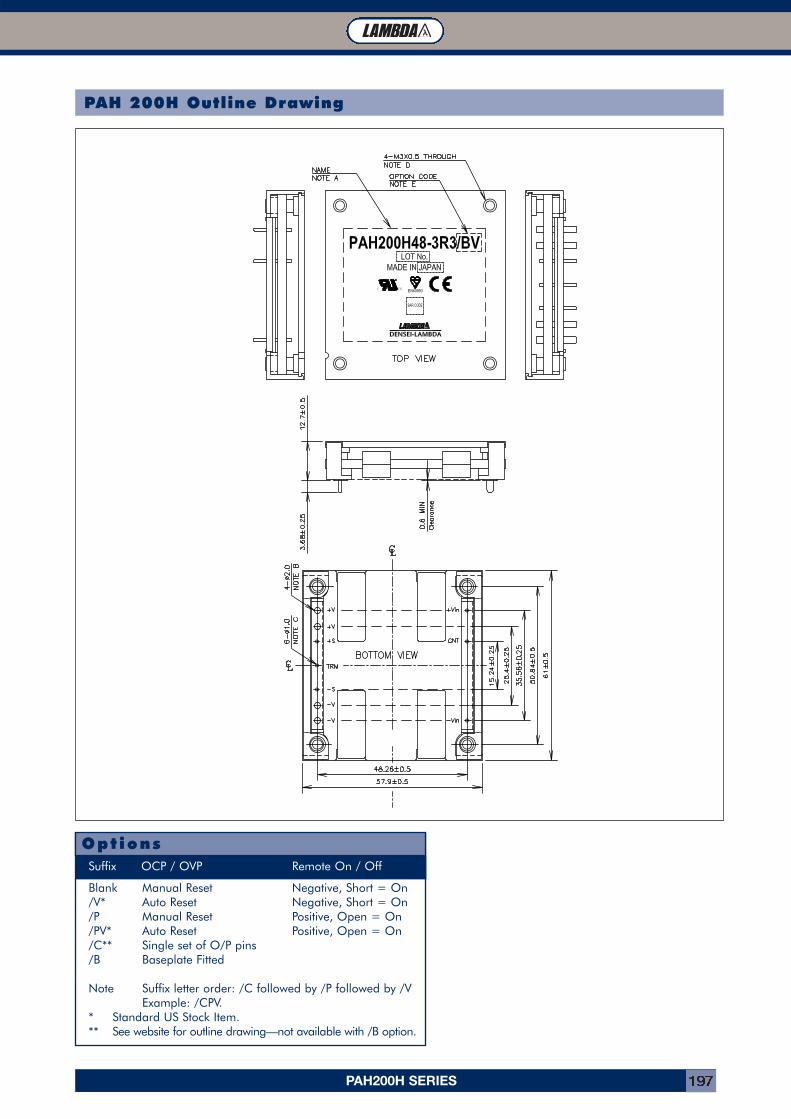
PAH200H SERIES 197
PAH 200H Outline Drawing
Blank Manual Reset Negative, Short = On/V* Auto Reset Negative, Short = On/P Manual Reset Positive, Open = On/PV* Auto Reset Positive, Open = On/C** Single set of O/P pins/B Baseplate Fitted
Note Suffix letter order: /C followed by /P followed by /VExample: /CPV.
* Standard US Stock Item.** See website for outline drawing—not available with /B option.
OptionsSuffix OCP / OVP Remote On / Off
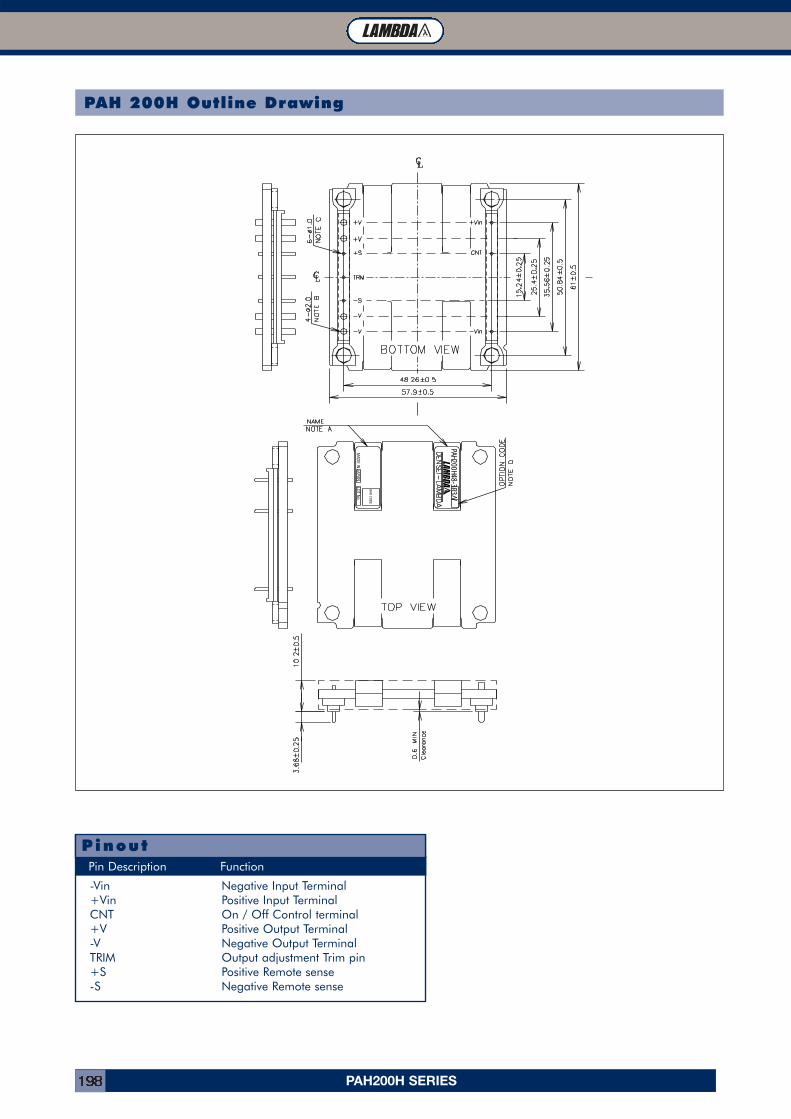
PAH200H SERIES198
PAH 200H Outline Drawing
-Vin Negative Input Terminal+Vin Positive Input TerminalCNT On / Off Control terminal+V Positive Output Terminal-V Negative Output TerminalTRIM Output adjustment Trim pin+S Positive Remote sense-S Negative Remote sense
Pin Description Function
Pinout
PAH200H48-3R3/V
MAD
E IN JAPAN
BAR C
OD
E
LOT N
o.
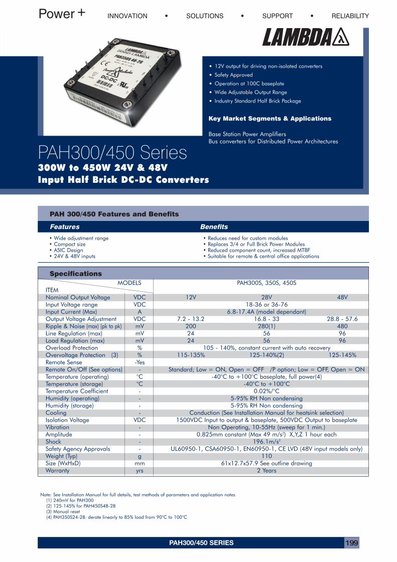
PAH300/450 SERIES 199
INNOVATION SOLUTIONS SUPPORT RELIABILITY
PAH300/450 Series300W to 450W 24V & 48VInput Half Brick DC-DC Converters
• 12V output for driving non-isolated converters
• Safety Approved
• Operation at 100C baseplate
• Wide Adjustable Output Range
• Industry Standard Half Brick Package
Key Market Segments & Applications
Base Station Power AmplifiersBus converters for Distributed Power Architectures
Specifications
PAH 300/450 Features and Benefits
Features Benefits
• Wide adjustment range • Reduces need for custom modules• Compact size • Replaces 3/4 or Full Brick Power Modules• ASIC Design • Reduced component count, increased MTBF• 24V & 48V inputs • Suitable for remote & central office applications
MODELS PAH300S, 350S, 450SITEMNominal Output Voltage VDC 12V 28V 48VInput Voltage range VDC 18-36 or 36-76Input Current (Max) A 6.8-17.4A (model dependant)Output Voltage Adjustment VDC 7.2 - 13.2 16.8 - 33 28.8 - 57.6Ripple & Noise (max) (pk to pk) mV 200 280(1) 480Line Regulation (max) mV 24 56 96Load Regulation (max) mV 24 56 96Overload Protection % 105 - 140%, constant current with auto recoveryOvervoltage Protection (3) % 115-135% 125-140%(2) 125-145%Remote Sense -YesRemote On/Off (See options) - Standard; Low = ON, Open = OFF /P option; Low = OFF, Open = ONTemperature (operating) °C -40°C to +100°C baseplate, full power(4)Temperature (storage) °C -40°C to +100°CTemperature Coefficient - 0.02%/°CHumidity (operating) - 5-95% RH Non condensingHumidity (storage) - 5-95% RH Non condensingCooling - Conduction (See Installation Manual for heatsink selection)Isolation Voltage VDC 1500VDC Input to output & baseplate, 500VDC Output to baseplateVibration - Non Operating, 10-55Hz (sweep for 1 min.)Amplitude - 0.825mm constant (Max 49 m/s2) X,Y,Z 1 hour eachShock - 196.1m/s2
Safety Agency Approvals - UL60950-1, CSA60950-1, EN60950-1, CE LVD (48V input models only)Weight (Typ) g 110Size (WxHxD) mm 61x12.7x57.9 See outline drawingWarranty yrs 2 Years
Note: See Installation Manual for full details, test methods of parameters and application notes(1) 240mV for PAH300(2) 125-145% for PAH450S48-28(3) Manual reset(4) PAH350S24-28: derate linearly to 85% load from 90°C to 100°C
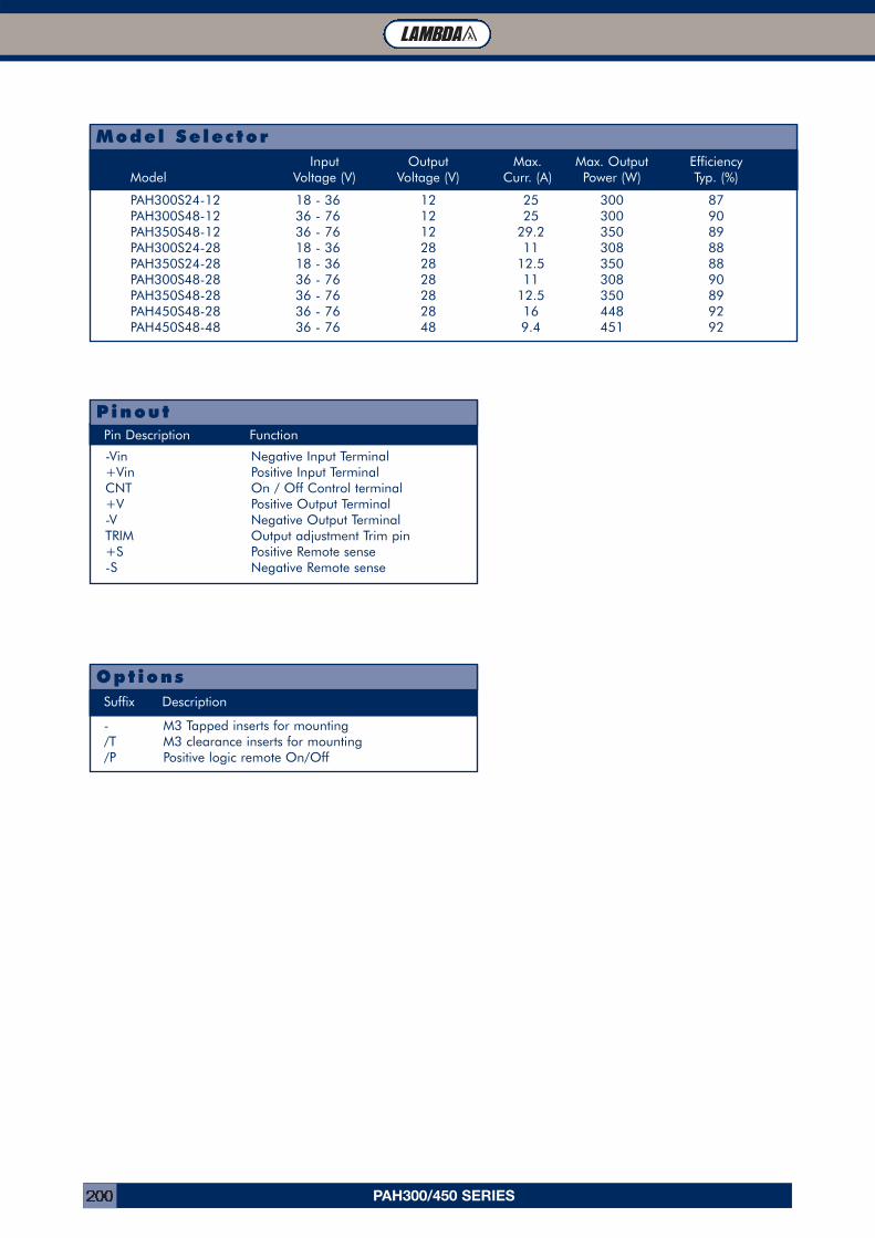
PAH300/450 SERIES200
TL Module Connector (Part Number: FCI 51732-007)
-Vin Negative Input Terminal+Vin Positive Input TerminalCNT On / Off Control terminal+V Positive Output Terminal-V Negative Output TerminalTRIM Output adjustment Trim pin+S Positive Remote sense-S Negative Remote sense
Pin Description Function
Pinout
- M3 Tapped inserts for mounting/T M3 clearance inserts for mounting/P Positive logic remote On/Off
OptionsSuffix Description
PAH300S24-12 18 - 36 12 25 300 87PAH300S48-12 36 - 76 12 25 300 90PAH350S48-12 36 - 76 12 29.2 350 89PAH300S24-28 18 - 36 28 11 308 88PAH350S24-28 18 - 36 28 12.5 350 88PAH300S48-28 36 - 76 28 11 308 90PAH350S48-28 36 - 76 28 12.5 350 89PAH450S48-28 36 - 76 28 16 448 92PAH450S48-48 36 - 76 48 9.4 451 92
Model SelectorInput Output Max. Max. Output Efficiency
Model Voltage (V) Voltage (V) Curr. (A) Power (W) Typ. (%)
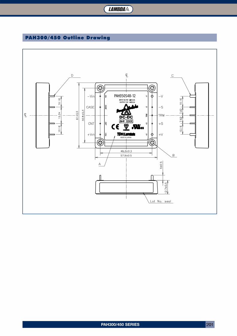
PAH300/450 SERIES 201
PAH300/450 Outline Drawing
CA
SE+Vin
CN
T
MADE IN JAPAN
+V
DC-DC TRM
+S-S
PAH350S48-12
-Vin
INPUT:36-76V 12.5AOUTPUT:12V 29.2A
-V
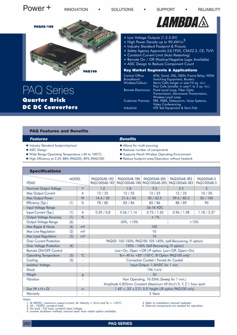
PAQ SERIES202
PAQ Features and Benefits
Features Benefits
INNOVATION SOLUTIONS SUPPORT RELIABILITY
PAQ SeriesQuarter BrickDC DC Converters
• Low Voltage Outputs (1.2-5.0V)• High Power Density up to 90.4W/in3
• Industry Standard Footprint & Pinouts• Safety Agency Approvals (UL1950, CSA22.2, CE, TUV)• Constant Current Limit (Auto Restarting)• Remote On / Off (Positive/Negative Logic Available)• ASIC Design to Reduce Component Count
Key Market Segments & ApplicationsCentral Office: ATM, Sonet, DSL, ISDN, Frame Relay, WDMBroadband: Switching Equipment, RoutersWireless/Celluar: Micro Cells (larger in size/10 sq. mi.)
Pico Cells (smaller in size/1 to 2 sq. mi.)Remote Electronics: Fixed Local Loop, Fiber Optic
Transmission, Microwave Transmission,Wireless Local Loop
Customer Premise: PBX, PABX, Datacomm, Voice Systems,Video Conferencing
Industrial ATE Test Equipment & Semi-Fab
Specifications
PAQ50/100
PAQ100
� Industry Standard footprint/pinout � Allows for multi-sourcing� ASIC Design � Reduces number of components� Wide Range Operating Temperature (-40 to 100°C) � Supports Harsh Wireless Operating Environment� High Efficiency at 3.3V, 88% (PAQ50), 89% (PAQ100) � Reduce footprint area/Operation without heatsink
Notes:1. At 48VDC, maximum output current, Air Velocity = 2m/s and Ta = +25°C. 5. Refer to installation manual (website).2. 36 - 76VDC, constant load. 6. External components are needed for operation.3. No load - Full load, constant input voltage.4. Inverter shutdown method, manual reset. Auto restart option available.
MODEL PAQ50S48-1R2 PAQ50S48-1R8 PAQ50S48-2R5 PAQ50S48-3R3 PAQ50S48-5ITEMS PAQ100S48-1R2 PAQ100S48-1R8 PAQ100S48-2R5 PAQ100S48-3R3 PAQ100S48-5
Nominal Output Voltage V 1.2 1.8 2.5 3.3 5Max Output Current A 12 / 25 12 / 25 12 / 25 12 / 25 10 / 20Max Output Power W 14.4 / 30 21.6 / 45 30 / 62.5 39.6 / 82.5 50 / 100Efficiency (Typ.) (1) % 78 / 80 83 / 84 85 / 86 88 / 89 90Input Voltage Range - 36-76 VDCInput Current (Typ.) (1) A 0.39 / 0.8 0.56 / 1.14 0.75 / 1.55 0.96 / 1.98 1.18 / 2.37Output Voltage Accuracy (1) % ± 1%Output Voltage Range (6) - -20%, +10% ±15%Max Ripple & Noise (6) mV 100Max Line Regulation (2) mV 10Max Load Regulation (3) mV 10Over Current Protection - PAQ50: 105-150%; PAQ100 105-140%; (self-Recovering /V option)Over Voltage Protection (4) - 120% - 140% (Self-Recovering /V option)Remote ON/OFF Control - Low=On, Open =Off (/P option: Low=Off, Open=On)Operating Temperature (5) °C Ta=-40 to +85° (100°C /B Option PAQ100 only)Cooling (5) - Convection Cooled / Forced Air CooledIsolation Voltage - Input-Output: 1.5kVDC for 1 min.Shock - 196.1m/s2
Weight g 50Vibration - Non Operating, 10-55Hz (Sweep for 1 min.)
Amplitude 0.825mm Constant (Maximum 49.0n/s2) X, Y, Z 1 hour eachSize (W x H x D) in 1.45" x .33" x 2.3"; 0.5" height (/B option PAQ100 only)Warranty - 2 Years
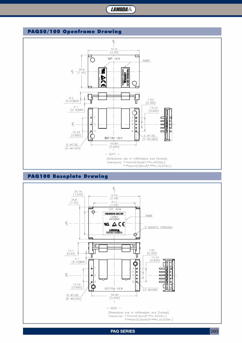
PAQ SERIES 203
PAQ50/100 Openframe Drawing
PAQ100 Baseplate Drawing
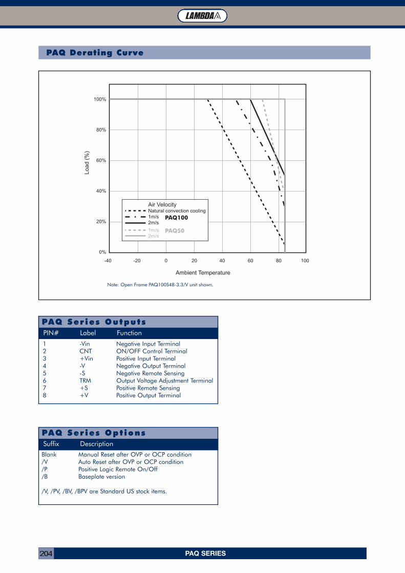
PAQ SERIES204
1 -Vin Negative Input Terminal2 CNT ON/OFF Control Terminal3 +Vin Positive Input Terminal4 -V Negative Output Terminal5 -S Negative Remote Sensing6 TRM Output Voltage Adjustment Terminal7 +S Positive Remote Sensing8 +V Positive Output Terminal
PIN# Label Function
PAQ Series Outputs
Blank Manual Reset after OVP or OCP condition/V Auto Reset after OVP or OCP condition/P Positive Logic Remote On/Off/B Baseplate version
/V, /PV, /BV, /BPV are Standard US stock items.
Suffix Description
PAQ Ser ies Opt ions
Note: Open Frame PAQ100S48-3.3/V unit shown.
PAQ Derating Curve
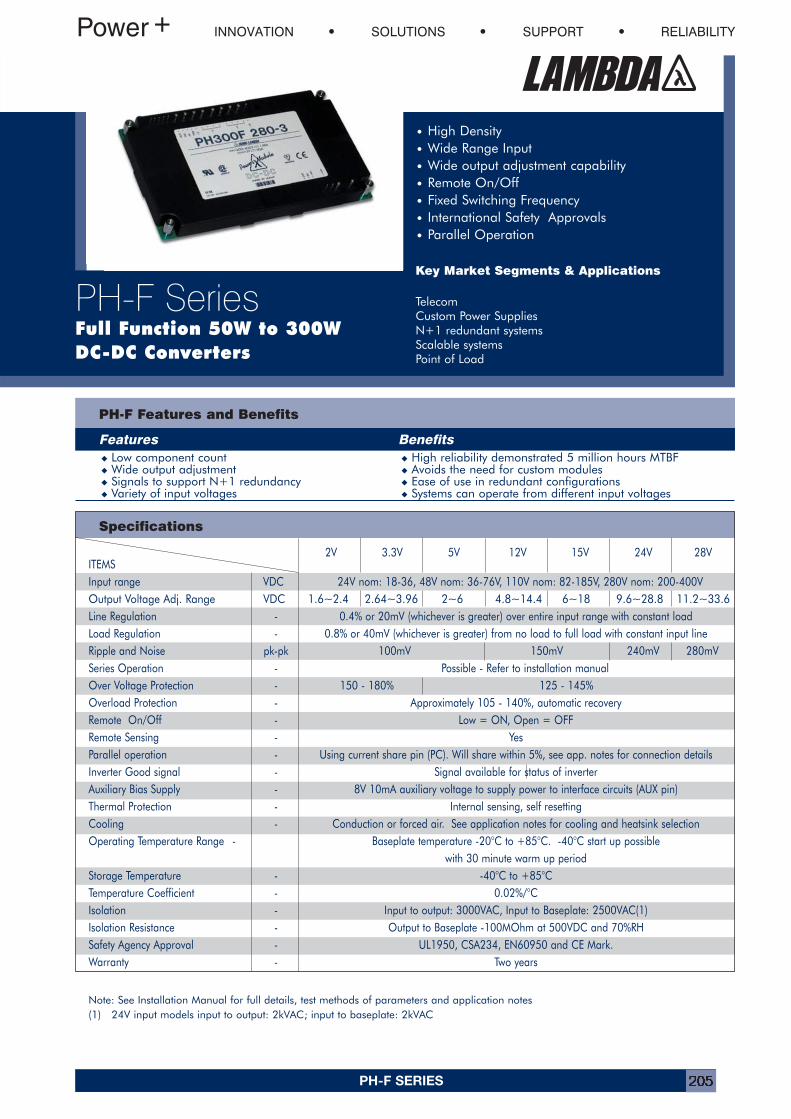
PH-F SERIES 205
Specifications
PH-F Features and Benefits
Features Benefits� Low component count � High reliability demonstrated 5 million hours MTBF� Wide output adjustment � Avoids the need for custom modules� Signals to support N+1 redundancy � Ease of use in redundant configurations� Variety of input voltages � Systems can operate from different input voltages
INNOVATION SOLUTIONS SUPPORT RELIABILITY
PH-F SeriesFull Function 50W to 300WDC-DC Converters
• High Density• Wide Range Input• Wide output adjustment capability• Remote On/Off• Fixed Switching Frequency• International Safety Approvals• Parallel Operation
Key Market Segments & Applications
TelecomCustom Power SuppliesN+1 redundant systemsScalable systemsPoint of Load
Note: See Installation Manual for full details, test methods of parameters and application notes(1) 24V input models input to output: 2kVAC; input to baseplate: 2kVAC
2V 3.3V 5V 12V 15V 24V 28VITEMSInput range VDC 24V nom: 18-36, 48V nom: 36-76V, 110V nom: 82-185V, 280V nom: 200-400VOutput Voltage Adj. Range VDC 1.6~2.4 2.64~3.96 2~6 4.8~14.4 6~18 9.6~28.8 11.2~33.6Line Regulation - 0.4% or 20mV (whichever is greater) over entire input range with constant loadLoad Regulation - 0.8% or 40mV (whichever is greater) from no load to full load with constant input lineRipple and Noise pk-pk 100mV 150mV 240mV 280mVSeries Operation - Possible - Refer to installation manualOver Voltage Protection - 150 - 180% 125 - 145%Overload Protection - Approximately 105 - 140%, automatic recoveryRemote On/Off - Low = ON, Open = OFFRemote Sensing - YesParallel operation - Using current share pin (PC). Will share within 5%, see app. notes for connection detailsInverter Good signal - Signal available for status of inverterAuxiliary Bias Supply - 8V 10mA auxiliary voltage to supply power to interface circuits (AUX pin)Thermal Protection - Internal sensing, self resettingCooling - Conduction or forced air. See application notes for cooling and heatsink selectionOperating Temperature Range - Baseplate temperature -20°C to +85°C. -40°C start up possible
with 30 minute warm up periodStorage Temperature - -40°C to +85°CTemperature Coefficient - 0.02%/°CIsolation - Input to output: 3000VAC, Input to Baseplate: 2500VAC(1)Isolation Resistance - Output to Baseplate -100MOhm at 500VDC and 70%RHSafety Agency Approval - UL1950, CSA234, EN60950 and CE Mark.Warranty - Two years
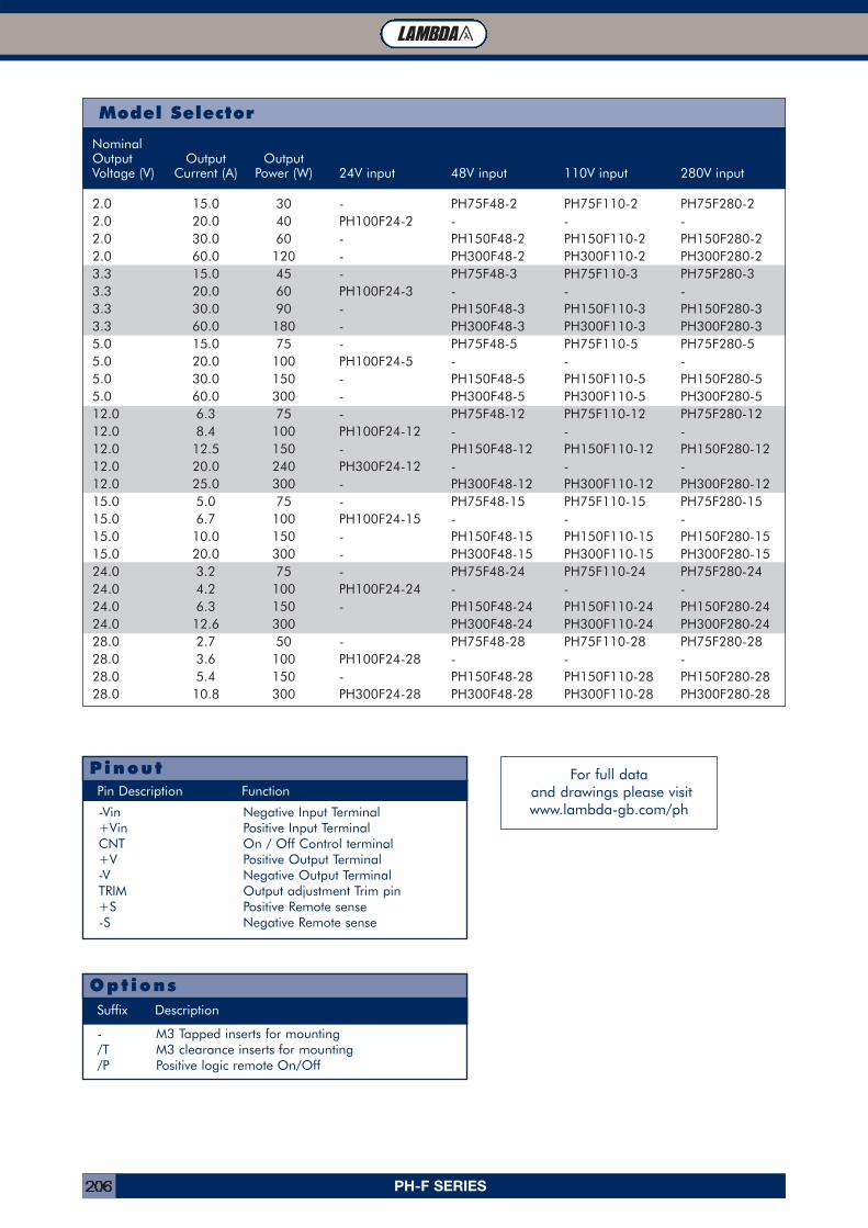
PH-F SERIES206
-Vin Negative Input Terminal+Vin Positive Input TerminalCNT On / Off Control terminal+V Positive Output Terminal-V Negative Output TerminalTRIM Output adjustment Trim pin+S Positive Remote sense-S Negative Remote sense
Pin Description Function
Pinout
- M3 Tapped inserts for mounting/T M3 clearance inserts for mounting/P Positive logic remote On/Off
OptionsSuffix Description
NominalOutput Output OutputVoltage (V) Current (A) Power (W) 24V input 48V input 110V input 280V input
2.0 15.0 30 - PH75F48-2 PH75F110-2 PH75F280-22.0 20.0 40 PH100F24-2 - - -2.0 30.0 60 - PH150F48-2 PH150F110-2 PH150F280-22.0 60.0 120 - PH300F48-2 PH300F110-2 PH300F280-23.3 15.0 45 - PH75F48-3 PH75F110-3 PH75F280-33.3 20.0 60 PH100F24-3 - - -3.3 30.0 90 - PH150F48-3 PH150F110-3 PH150F280-33.3 60.0 180 - PH300F48-3 PH300F110-3 PH300F280-35.0 15.0 75 - PH75F48-5 PH75F110-5 PH75F280-55.0 20.0 100 PH100F24-5 - - -5.0 30.0 150 - PH150F48-5 PH150F110-5 PH150F280-55.0 60.0 300 - PH300F48-5 PH300F110-5 PH300F280-512.0 6.3 75 - PH75F48-12 PH75F110-12 PH75F280-1212.0 8.4 100 PH100F24-12 - - -12.0 12.5 150 - PH150F48-12 PH150F110-12 PH150F280-1212.0 20.0 240 PH300F24-12 - - -12.0 25.0 300 - PH300F48-12 PH300F110-12 PH300F280-1215.0 5.0 75 - PH75F48-15 PH75F110-15 PH75F280-1515.0 6.7 100 PH100F24-15 - - -15.0 10.0 150 - PH150F48-15 PH150F110-15 PH150F280-1515.0 20.0 300 - PH300F48-15 PH300F110-15 PH300F280-1524.0 3.2 75 - PH75F48-24 PH75F110-24 PH75F280-2424.0 4.2 100 PH100F24-24 - - -24.0 6.3 150 - PH150F48-24 PH150F110-24 PH150F280-2424.0 12.6 300 PH300F48-24 PH300F110-24 PH300F280-2428.0 2.7 50 - PH75F48-28 PH75F110-28 PH75F280-2828.0 3.6 100 PH100F24-28 - - -28.0 5.4 150 - PH150F48-28 PH150F110-28 PH150F280-2828.0 10.8 300 PH300F24-28 PH300F48-28 PH300F110-28 PH300F280-28
Model Selector
For full dataand drawings please visitwww.lambda-gb.com/ph
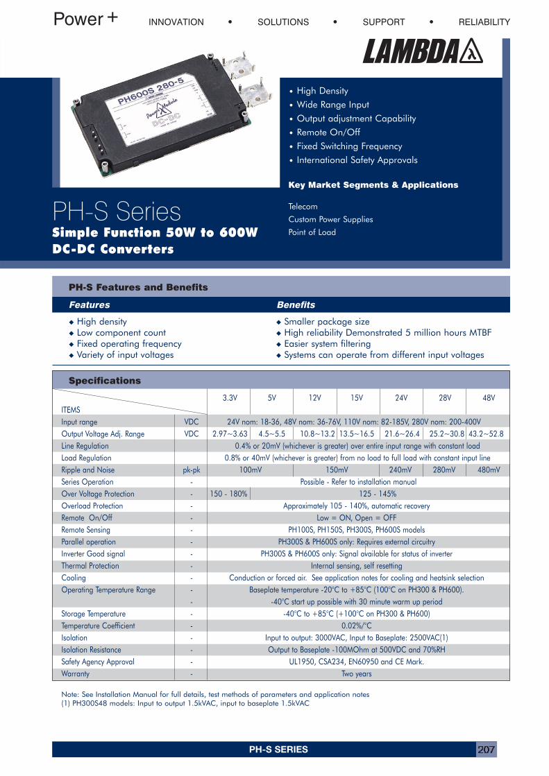
PH-S SERIES 207
Specifications
PH-S Features and Benefits
Features Benefits
INNOVATION SOLUTIONS SUPPORT RELIABILITY
PH-S SeriesSimple Function 50W to 600WDC-DC Converters
• High Density
• Wide Range Input
• Output adjustment Capability
• Remote On/Off
• Fixed Switching Frequency
• International Safety Approvals
Key Market Segments & Applications
Telecom
Custom Power Supplies
Point of Load
Note: See Installation Manual for full details, test methods of parameters and application notes(1) PH300S48 models: Input to output 1.5kVAC, input to baseplate 1.5kVAC
� High density � Smaller package size� Low component count � High reliability Demonstrated 5 million hours MTBF� Fixed operating frequency � Easier system filtering� Variety of input voltages � Systems can operate from different input voltages
3.3V 5V 12V 15V 24V 28V 48VITEMSInput range VDC 24V nom: 18-36, 48V nom: 36-76V, 110V nom: 82-185V, 280V nom: 200-400VOutput Voltage Adj. Range VDC 2.97~3.63 4.5~5.5 10.8~13.2 13.5~16.5 21.6~26.4 25.2~30.8 43.2~52.8Line Regulation 0.4% or 20mV (whichever is greater) over entire input range with constant loadLoad Regulation 0.8% or 40mV (whichever is greater) from no load to full load with constant input lineRipple and Noise pk-pk 100mV 150mV 240mV 280mV 480mVSeries Operation - Possible - Refer to installation manualOver Voltage Protection - 150 - 180% 125 - 145%Overload Protection - Approximately 105 - 140%, automatic recoveryRemote On/Off - Low = ON, Open = OFFRemote Sensing - PH100S, PH150S, PH300S, PH600S modelsParallel operation - PH300S & PH600S only: Requires external circuitryInverter Good signal - PH300S & PH600S only: Signal available for status of inverterThermal Protection - Internal sensing, self resettingCooling - Conduction or forced air. See application notes for cooling and heatsink selectionOperating Temperature Range - Baseplate temperature -20°C to +85°C (100°C on PH300 & PH600).
- -40°C start up possible with 30 minute warm up periodStorage Temperature - -40°C to +85°C (+100°C on PH300 & PH600)Temperature Coefficient - 0.02%/°CIsolation - Input to output: 3000VAC, Input to Baseplate: 2500VAC(1)Isolation Resistance - Output to Baseplate -100MOhm at 500VDC and 70%RHSafety Agency Approval - UL1950, CSA234, EN60950 and CE Mark.Warranty - Two years
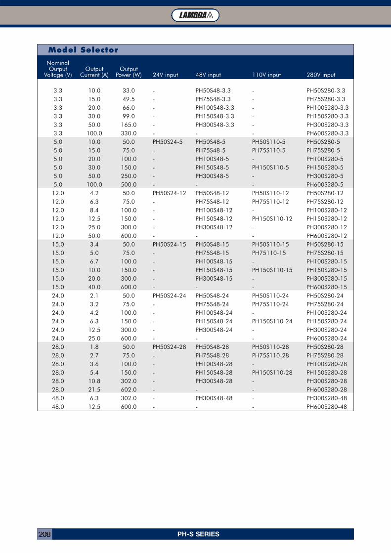
PH-S SERIES208
TL Module Connector (Part Number: FCI 51732-007)NominalOutput Output Output
Voltage (V) Current (A) Power (W) 24V input 48V input 110V input 280V input
3.3 10.0 33.0 - PH50S48-3.3 - PH50S280-3.33.3 15.0 49.5 - PH75S48-3.3 - PH75S280-3.33.3 20.0 66.0 - PH100S48-3.3 - PH100S280-3.33.3 30.0 99.0 - PH150S48-3.3 - PH150S280-3.33.3 50.0 165.0 - PH300S48-3.3 - PH300S280-3.33.3 100.0 330.0 - - - PH600S280-3.35.0 10.0 50.0 PH50S24-5 PH50S48-5 PH50S110-5 PH50S280-55.0 15.0 75.0 - PH75S48-5 PH75S110-5 PH75S280-55.0 20.0 100.0 - PH100S48-5 - PH100S280-55.0 30.0 150.0 - PH150S48-5 PH150S110-5 PH150S280-55.0 50.0 250.0 - PH300S48-5 - PH300S280-55.0 100.0 500.0 - - - PH600S280-512.0 4.2 50.0 PH50S24-12 PH50S48-12 PH50S110-12 PH50S280-1212.0 6.3 75.0 - PH75S48-12 PH75S110-12 PH75S280-1212.0 8.4 100.0 - PH100S48-12 - PH100S280-1212.0 12.5 150.0 - PH150S48-12 PH150S110-12 PH150S280-1212.0 25.0 300.0 - PH300S48-12 - PH300S280-1212.0 50.0 600.0 - - - PH600S280-1215.0 3.4 50.0 PH50S24-15 PH50S48-15 PH50S110-15 PH50S280-1515.0 5.0 75.0 - PH75S48-15 PH75110-15 PH75S280-1515.0 6.7 100.0 - PH100S48-15 - PH100S280-1515.0 10.0 150.0 - PH150S48-15 PH150S110-15 PH150S280-1515.0 20.0 300.0 - PH300S48-15 - PH300S280-1515.0 40.0 600.0 - - - PH600S280-1524.0 2.1 50.0 PH50S24-24 PH50S48-24 PH50S110-24 PH50S280-2424.0 3.2 75.0 - PH75S48-24 PH75S110-24 PH75S280-2424.0 4.2 100.0 - PH100S48-24 - PH100S280-2424.0 6.3 150.0 - PH150S48-24 PH150S110-24 PH150S280-2424.0 12.5 300.0 - PH300S48-24 - PH300S280-2424.0 25.0 600.0 - - - PH600S280-2428.0 1.8 50.0 PH50S24-28 PH50S48-28 PH50S110-28 PH50S280-2828.0 2.7 75.0 - PH75S48-28 PH75S110-28 PH75S280-2828.0 3.6 100.0 - PH100S48-28 - PH100S280-2828.0 5.4 150.0 - PH150S48-28 PH150S110-28 PH150S280-2828.0 10.8 302.0 - PH300S48-28 - PH300S280-2828.0 21.5 602.0 - - - PH600S280-2848.0 6.3 302.0 - PH300S48-48 - PH300S280-4848.0 12.5 600.0 - - - PH600S280-48
Model Selector
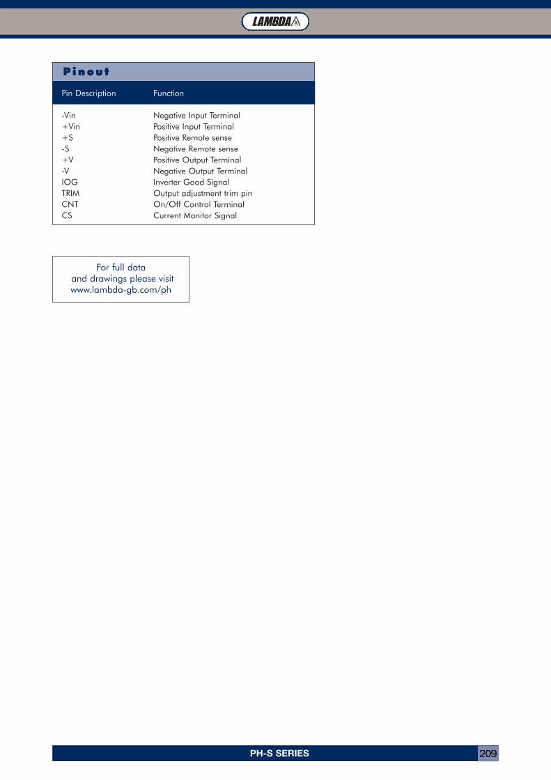
PH-S SERIES 209
Pin Description Function
-Vin Negative Input Terminal+Vin Positive Input Terminal+S Positive Remote sense-S Negative Remote sense+V Positive Output Terminal-V Negative Output TerminalIOG Inverter Good SignalTRIM Output adjustment trim pinCNT On/Off Control TerminalCS Current Monitor Signal
Pinout
For full dataand drawings please visitwww.lambda-gb.com/ph
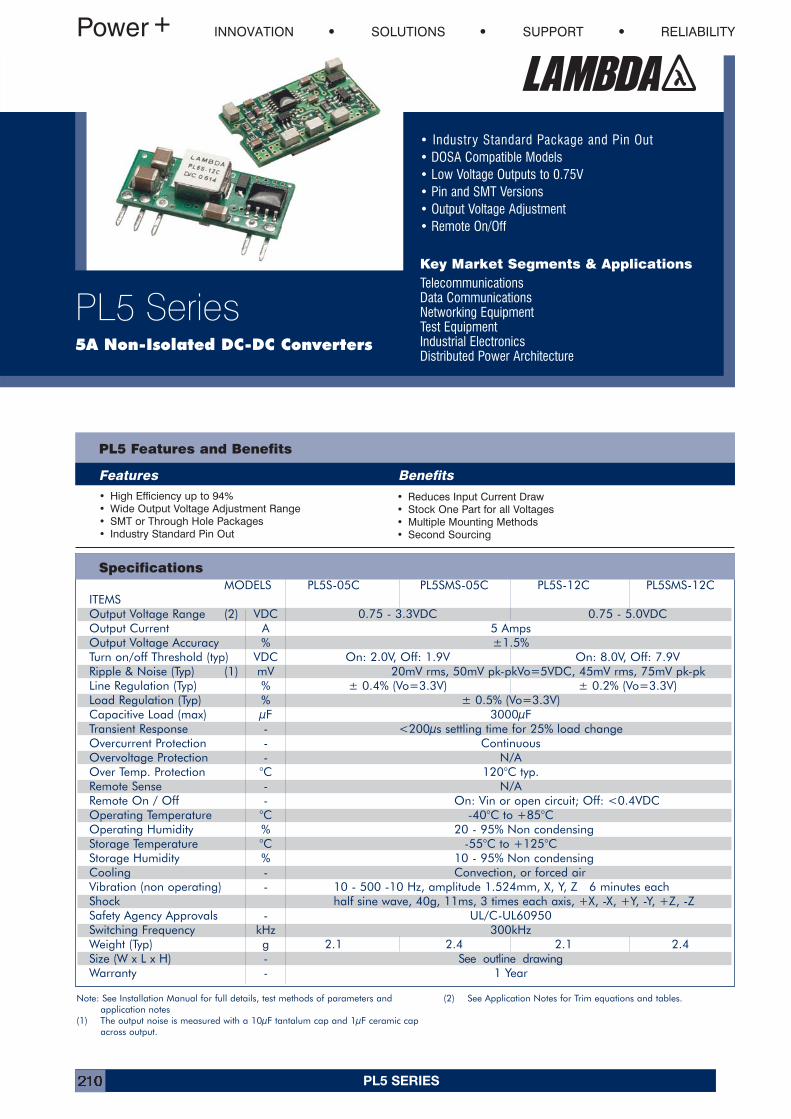
PL5 SERIES210
• Industry Standard Package and Pin Out• DOSA Compatible Models• Low Voltage Outputs to 0.75V• Pin and SMT Versions• Output Voltage Adjustment• Remote On/Off
Key Market Segments & ApplicationsTelecommunicationsData CommunicationsNetworking EquipmentTest EquipmentIndustrial ElectronicsDistributed Power Architecture
INNOVATION SOLUTIONS SUPPORT RELIABILITY
PL5 Series5A Non-Isolated DC-DC Converters
PL5 Features and Benefits
Features Benefits• High Efficiency up to 94%• Wide Output Voltage Adjustment Range• SMT or Through Hole Packages• Industry Standard Pin Out
• Reduces Input Current Draw• Stock One Part for all Voltages• Multiple Mounting Methods• Second Sourcing
SpecificationsMODELS PL5S-05C PL5SMS-05C PL5S-12C PL5SMS-12C
ITEMSOutput Voltage Range (2) VDC 0.75 - 3.3VDC 0.75 - 5.0VDCOutput Current A 5 AmpsOutput Voltage Accuracy % ±1.5%Turn on/off Threshold (typ) VDC On: 2.0V, Off: 1.9V On: 8.0V, Off: 7.9VRipple & Noise (Typ) (1) mV 20mV rms, 50mV pk-pkVo=5VDC, 45mV rms, 75mV pk-pkLine Regulation (Typ) % ± 0.4% (Vo=3.3V) ± 0.2% (Vo=3.3V)Load Regulation (Typ) % ± 0.5% (Vo=3.3V)Capacitive Load (max) µF 3000µFTransient Response - <200µs settling time for 25% load changeOvercurrent Protection - ContinuousOvervoltage Protection - N/AOver Temp. Protection °C 120°C typ.Remote Sense - N/ARemote On / Off - On: Vin or open circuit; Off: <0.4VDCOperating Temperature °C -40°C to +85°COperating Humidity % 20 - 95% Non condensingStorage Temperature °C -55°C to +125°CStorage Humidity % 10 - 95% Non condensingCooling - Convection, or forced airVibration (non operating) - 10 - 500 -10 Hz, amplitude 1.524mm, X, Y, Z 6 minutes eachShock half sine wave, 40g, 11ms, 3 times each axis, +X, -X, +Y, -Y, +Z, -ZSafety Agency Approvals - UL/C-UL60950Switching Frequency kHz 300kHzWeight (Typ) g 2.1 2.4 2.1 2.4Size (W x L x H) - See outline drawingWarranty - 1 Year
Note: See Installation Manual for full details, test methods of parameters and application notes
(1) The output noise is measured with a 10µF tantalum cap and 1µF ceramic capacross output.
(2) See Application Notes for Trim equations and tables.
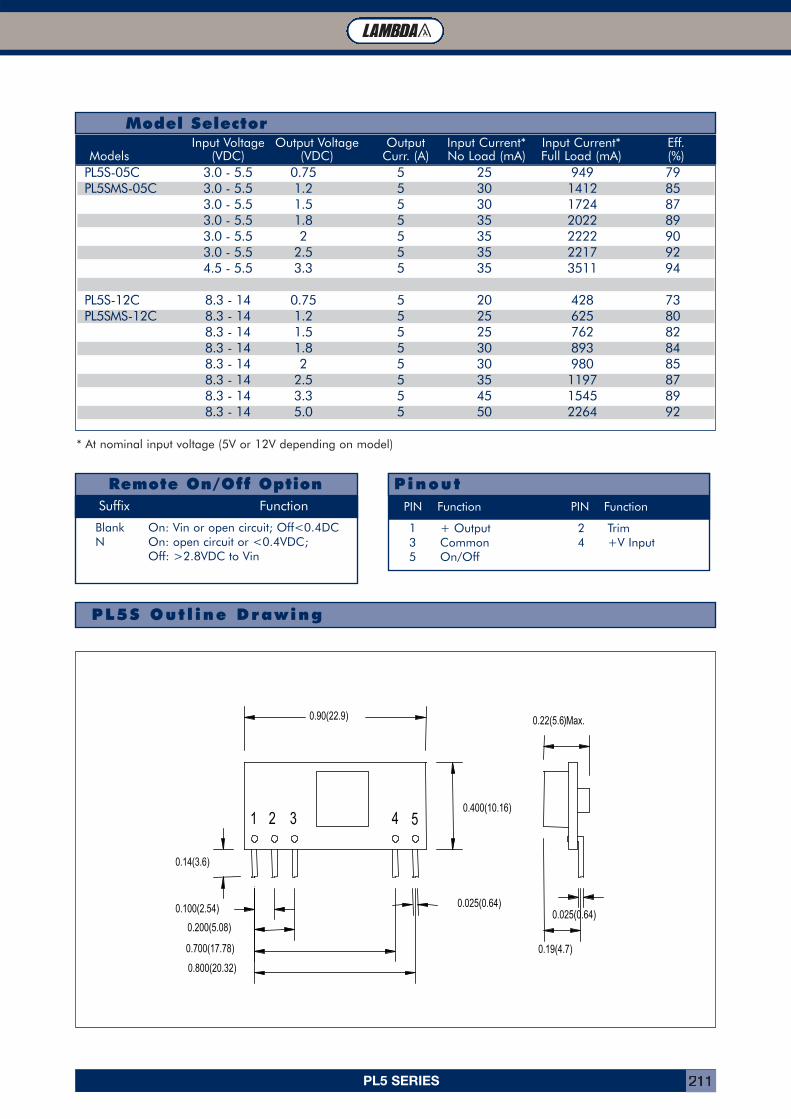
PL5 SERIES 211
Model SelectorInput Voltage Output Voltage Output Input Current* Input Current* Eff.
Models (VDC) (VDC) Curr. (A) No Load (mA) Full Load (mA) (%)
Remote On/Off OptionSuffix Function
Blank On: Vin or open circuit; Off<0.4DCN On: open circuit or <0.4VDC;
Off: >2.8VDC to Vin
PL5S-05C 3.0 - 5.5 0.75 5 25 949 79PL5SMS-05C 3.0 - 5.5 1.2 5 30 1412 85
3.0 - 5.5 1.5 5 30 1724 873.0 - 5.5 1.8 5 35 2022 893.0 - 5.5 2 5 35 2222 903.0 - 5.5 2.5 5 35 2217 924.5 - 5.5 3.3 5 35 3511 94
PL5S-12C 8.3 - 14 0.75 5 20 428 73PL5SMS-12C 8.3 - 14 1.2 5 25 625 80
8.3 - 14 1.5 5 25 762 828.3 - 14 1.8 5 30 893 848.3 - 14 2 5 30 980 858.3 - 14 2.5 5 35 1197 878.3 - 14 3.3 5 45 1545 898.3 - 14 5.0 5 50 2264 92
1 + Output 2 Trim3 Common 4 +V Input5 On/Off
PinoutPIN Function PIN Function
PL5S Out l ine Drawing
* At nominal input voltage (5V or 12V depending on model)
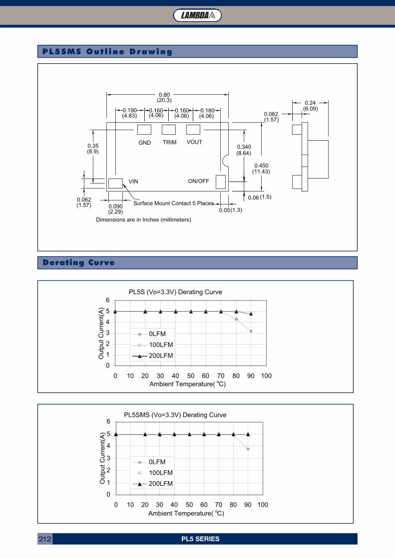
PL5 SERIES212
PL5SMS Out l ine Drawing
Derating Curve
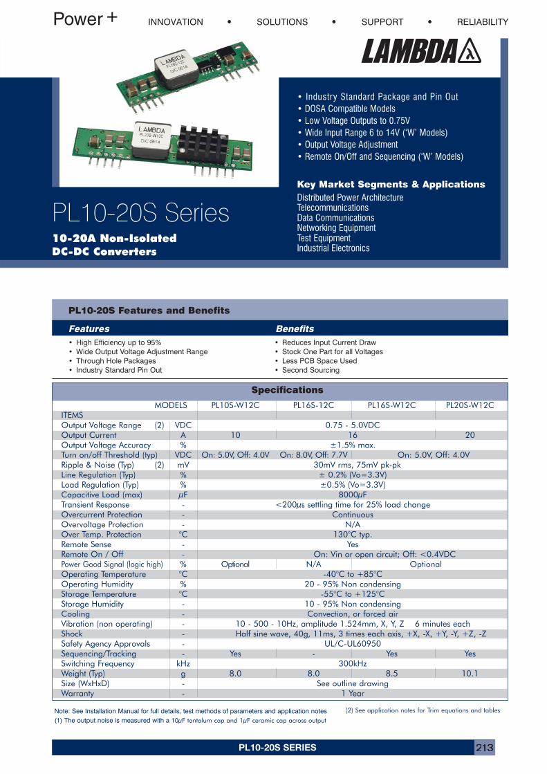
PL10-20S SERIES 213
Specifications
• Industry Standard Package and Pin Out• DOSA Compatible Models• Low Voltage Outputs to 0.75V• Wide Input Range 6 to 14V (‘W’ Models)• Output Voltage Adjustment• Remote On/Off and Sequencing (‘W’ Models)
Key Market Segments & ApplicationsDistributed Power ArchitectureTelecommunicationsData CommunicationsNetworking EquipmentTest EquipmentIndustrial Electronics
INNOVATION SOLUTIONS SUPPORT RELIABILITY
PL10-20S Series10-20A Non-Isolated DC-DC Converters
PL10-20S Features and Benefits
Features Benefits• High Efficiency up to 95%• Wide Output Voltage Adjustment Range• Through Hole Packages• Industry Standard Pin Out
• Reduces Input Current Draw• Stock One Part for all Voltages• Less PCB Space Used• Second Sourcing
MODELS PL10S-W12C PL16S-12C PL16S-W12C PL20S-W12CITEMSOutput Voltage Range (2) VDC 0.75 - 5.0VDCOutput Current A 10 16 20Output Voltage Accuracy % ±1.5% max.Turn on/off Threshold (typ) VDC On: 5.0V, Off: 4.0V On: 8.0V, Off: 7.7V On: 5.0V, Off: 4.0VRipple & Noise (Typ) (2) mV 30mV rms, 75mV pk-pkLine Regulation (Typ) % ± 0.2% (Vo=3.3V)Load Regulation (Typ) % ±0.5% (Vo=3.3V)Capacitive Load (max) µF 8000µFTransient Response - <200µs settling time for 25% load changeOvercurrent Protection - ContinuousOvervoltage Protection - N/AOver Temp. Protection °C 130°C typ.Remote Sense - YesRemote On / Off - On: Vin or open circuit; Off: <0.4VDCPower Good Signal (logic high) % Optional N/A OptionalOperating Temperature °C -40°C to +85°COperating Humidity % 20 - 95% Non condensingStorage Temperature °C -55°C to +125°CStorage Humidity - 10 - 95% Non condensingCooling - Convection, or forced airVibration (non operating) - 10 - 500 - 10Hz, amplitude 1.524mm, X, Y, Z 6 minutes eachShock - Half sine wave, 40g, 11ms, 3 times each axis, +X, -X, +Y, -Y, +Z, -ZSafety Agency Approvals - UL/C-UL60950Sequencing/Tracking - Yes - Yes YesSwitching Frequency kHz 300kHzWeight (Typ) g 8.0 8.0 8.5 10.1Size (WxHxD) - See outline drawingWarranty - 1 Year
Note: See Installation Manual for full details, test methods of parameters and application notes(1) The output noise is measured with a 10µF tantalum cap and 1µF ceramic cap across output
(2) See application notes for Trim equations and tables
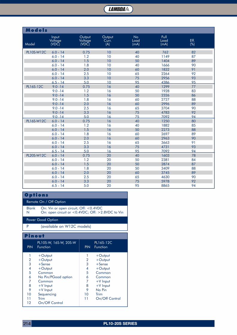
PL10-20S SERIES214
PL10S-W12C 6.0 - 14 0.75 10 40 762 826.0 - 14 1.2 10 40 1149 876.0 - 14 1.5 10 50 1404 896.0 - 14 1.8 10 40 1666 906.0 - 14 2.0 10 60 1832 916.0 - 14 2.5 10 65 2264 926.0 - 14 3.3 10 75 2956 936.5 - 14 5.0 10 95 4386 95
PL16S-12C 9.0 -14 0.75 16 40 1299 779.0 -14 1.2 16 50 1928 839.0 -14 1.5 16 50 2326 869.0 -14 1.8 16 60 2727 889.0 -14 2.0 16 60 2996 899.0 -14 2.5 16 65 3704 909.0 -14 3.3 16 75 4783 929.0 -14 5.0 16 75 7092 94
PL16S-W12C 6.0 - 14 0.75 16 40 1250 806.0 - 14 1.2 16 40 1882 856.0 - 14 1.5 16 50 2273 886.0 - 14 1.8 16 60 2697 896.0 - 14 2.0 16 60 2963 906.0 - 14 2.5 16 65 3663 916.0 - 14 3.3 16 75 4731 936.5 - 14 5.0 16 95 7092 94
PL20S-W12C 6.0 - 14 0.75 20 40 1603 786.0 - 14 1.2 20 50 2381 846.0 - 14 1.5 20 50 2874 876.0 - 14 1.8 20 50 3409 886.0 - 14 2.0 20 60 3745 896.0 - 14 2.5 20 65 4630 906.0 - 14 3.3 20 75 5978 926.5 - 14 5.0 20 95 8865 94
ModelsInput Output Output No Full
Voltage Voltage Curr. Load Load Eff.Model (VDC) (VDC) (A) (mA) (mA) (%)
1 +Output 1 +Output2 +Output 2 +Output3 +Sense 3 +Sense4 +Output 4 +Output5 Common 5 Common6 No Pin/PGood option 6 Common7 Common 7 +V Input8 +V Input 8 +V Input9 +V Input 9 No Pin
10 Sequencing 10 Trim11 Trim 11 On/Off Control12 On/Off Control
PinoutPL10S-W, 16S-W, 20S-W PL16S-12C
PIN Function PIN Function
Blank On: Vin or open circuit; Off: <0.4VDCN On: open circuit or <0.4VDC; Off: >2.8VDC to Vin
P (available on W12C models)
OptionsRemote On / Off Option
Power Good Option
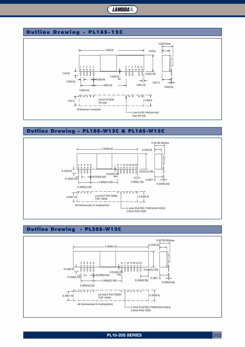
PL10-20S SERIES 215
All Dimmension In Inches(mm)
LAYOUT PATTERNTOP VIEW
0.33(8.4)0.29(7.4)
1.1mm PLATED THROUGH HOLE1.6mm PAD SIZE
0.025(0.64)
1.000(25.40)
2.00(50.8)
54321
0.14(3.6)
0.100(2.54)
0.400(10.20)
0.512(13.00)
11109876
0.050(1.30)
0.010(0.25)min.
0.28(7.1)
0.025(0.64)
0.23(5.8)
0.327(8.30)max.
Outl ine Drawing - PL16S -12C
All Dimmension In Inches(mm)
LAYOUT PATTERNTOP VIEW
0.33(8.4)0.29(7.4)
1.1mm PLATED THROUGH HOLE1.6mm PAD SIZE
0.025(0.64)
0.900(22.90)
2.40(61.0)
54321
0.14(3.6)
0.100(2.54)
0.400(10.20)
0.510(12.95)
121110987
0.250(6.35)
0.010(0.25)min.
0.28(7.1)
0.025(0.64)
0.23(5.8)
0.327(8.30)max.
6
Outline Drawing - PL10S-W12C & PL16S-W12C
Outline Drawing - PL20S-W12C
All Dimmension In Inches(mm)
LAYOUT PATTERNTOP VIEW
0.33(8.4)0.29(7.4)
1.1mm PLATED THROUGH HOLE1.6mm PAD SIZE
0.025(0.64)
0.900(22.90)
2.00(50.8)
54321
0.14(3.6)
0.100(2.54)
0.400(10.20)
0.510(12.95)
121110987
0.050(1.30)
0.010(0.25)min.
0.28(7.1)
0.025(0.64)
0.23(5.8)
0.327(8.30)max.
6
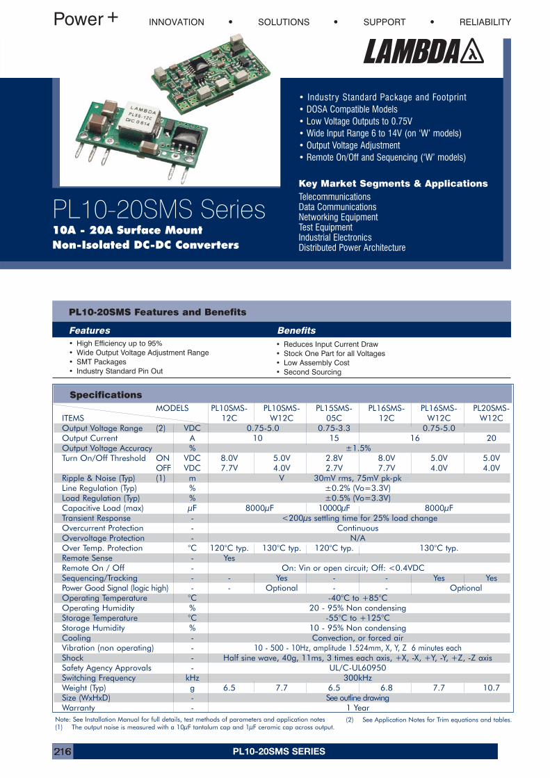
PL10-20SMS SERIES216
• Industry Standard Package and Footprint• DOSA Compatible Models• Low Voltage Outputs to 0.75V• Wide Input Range 6 to 14V (on ‘W’ models)• Output Voltage Adjustment• Remote On/Off and Sequencing (‘W’ models)
Key Market Segments & ApplicationsTelecommunicationsData CommunicationsNetworking EquipmentTest EquipmentIndustrial ElectronicsDistributed Power Architecture
INNOVATION SOLUTIONS SUPPORT RELIABILITY
PL10-20SMS Series10A - 20A Surface MountNon-Isolated DC-DC Converters
PL10-20SMS Features and Benefits
Features Benefits• High Efficiency up to 95%• Wide Output Voltage Adjustment Range• SMT Packages• Industry Standard Pin Out
• Reduces Input Current Draw• Stock One Part for all Voltages• Low Assembly Cost• Second Sourcing
Specifications
Note: See Installation Manual for full details, test methods of parameters and application notes(1) The output noise is measured with a 10µF tantalum cap and 1µF ceramic cap across output.
MODELS PL10SMS- PL10SMS- PL15SMS- PL16SMS- PL16SMS- PL20SMS-ITEMS 12C W12C 05C 12C W12C W12COutput Voltage Range (2) VDC 0.75-5.0 0.75-3.3 0.75-5.0Output Current A 10 15 16 20Output Voltage Accuracy % ±1.5%Turn On/Off Threshold ON VDC 8.0V 5.0V 2.8V 8.0V 5.0V 5.0V
OFF VDC 7.7V 4.0V 2.7V 7.7V 4.0V 4.0VRipple & Noise (Typ) (1) m V 30mV rms, 75mV pk-pkLine Regulation (Typ) % ±0.2% (Vo=3.3V)Load Regulation (Typ) % ±0.5% (Vo=3.3V)Capacitive Load (max) µF 8000µF 10000µF 8000µFTransient Response - <200µs settling time for 25% load changeOvercurrent Protection - ContinuousOvervoltage Protection - N/AOver Temp. Protection °C 120°C typ. 130°C typ. 120°C typ. 130°C typ.Remote Sense - YesRemote On / Off - On: Vin or open circuit; Off: <0.4VDCSequencing/Tracking - - Yes - - Yes YesPower Good Signal (logic high) - - Optional - - OptionalOperating Temperature °C -40°C to +85°COperating Humidity % 20 - 95% Non condensingStorage Temperature °C -55°C to +125°CStorage Humidity % 10 - 95% Non condensingCooling - Convection, or forced airVibration (non operating) - 10 - 500 - 10Hz, amplitude 1.524mm, X, Y, Z 6 minutes eachShock - Half sine wave, 40g, 11ms, 3 times each axis, +X, -X, +Y, -Y, +Z, -Z axisSafety Agency Approvals - UL/C-UL60950Switching Frequency kHz 300kHzWeight (Typ) g 6.5 7.7 6.5 6.8 7.7 10.7Size (WxHxD) - See outline drawingWarranty - 1 Year
(2) See Application Notes for Trim equations and tables.
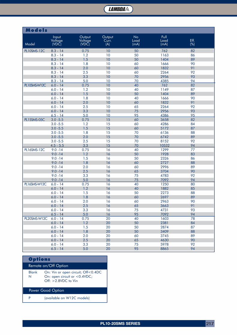
PL10-20SMS SERIES 217
OptionsRemote on/Off Option
Blank On: Vin or open circuit; Off<0.4DCN On: open circuit or <0.4VDC;
Off: >2.8VDC to Vin
N
P (available on W12C models)
Power Good Option
PL10SMS-12C 8.3 - 14 0.75 10 50 762 828.3 - 14 1.2 10 50 1163 868.3 - 14 1.5 10 50 1404 898.3 - 14 1.8 10 60 1666 908.3 - 14 2.0 10 60 1832 918.3 - 14 2.5 10 60 2264 928.3 - 14 3.3 10 70 2956 938.3 - 14 5.0 10 70 4385 94
PL10SMS-W12C 6.0 - 14 0.75 10 40 762 826.0 - 14 1.2 10 40 1149 876.0 - 14 1.5 10 50 1404 896.0 - 14 1.8 10 40 1666 906.0 - 14 2.0 10 60 1832 916.0 - 14 2.5 10 65 2264 926.0 - 14 3.3 10 75 2956 936.5 - 14 5.0 10 95 4386 95
PL15SMS-05C 3.0 -5.5 0.75 15 60 3658 823.0 -5.5 1.2 15 60 4286 843.0 -5.5 1.5 15 60 5172 873.0 -5.5 1.8 15 70 6136 883.0 -5.5 2.0 15 70 6742 893.0 -5.5 2.5 15 70 8152 924.5 - 5.5 3.3 15 70 10532 94
PL16SMS-12C 9.0 -14 0.75 16 40 1299 779.0 -14 1.2 16 50 1928 839.0 -14 1.5 16 50 2326 869.0 -14 1.8 16 60 2727 889.0 -14 2.0 16 60 2996 899.0 -14 2.5 16 65 3704 909.0 -14 3.3 16 75 4783 929.0 -14 5.0 16 75 7092 94
PL16SMS-W12C 6.0 - 14 0.75 16 40 1250 806.0 - 14 1.2 16 40 1882 856.0 - 14 1.5 16 50 2273 886.0 - 14 1.8 16 60 2697 896.0 - 14 2.0 16 60 2963 906.0 - 14 2.5 16 65 3663 916.0 - 14 3.3 16 75 4731 936.5 - 14 5.0 16 95 7092 94
PL20SMS-W12C 6.0 - 14 0.75 20 40 1603 786.0 - 14 1.2 20 50 2381 846.0 - 14 1.5 20 50 2874 876.0 - 14 1.8 20 50 3409 886.0 - 14 2.0 20 60 3745 896.0 - 14 2.5 20 65 4630 906.0 - 14 3.3 20 75 5978 926.5 - 14 5.0 20 95 8865 94
ModelsInput Output Output No Full
Voltage Voltage Curr. Load Load Eff.Model (VDC) (VDC) (A) (mA) (mA) (%)
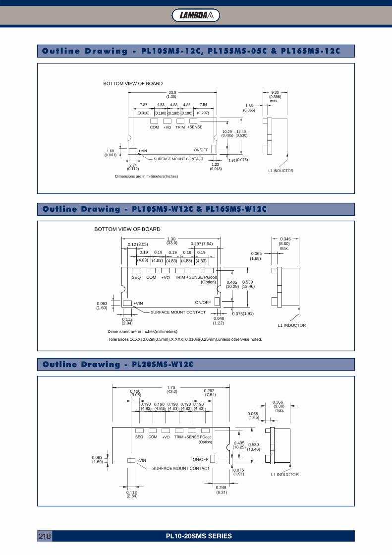
PL10-20SMS SERIES218
10.29 13.46
1.22
7.544.834.834.837.87
33.0
1.91
1.60
2.84
(1.30)
(0.310) (0.190) (0.190) (0.190) (0.297)
(0.405) (0.530)
(0.075)
(0.048)(0.112)
(0.063)
+SENSETRIM+VOCOM
ON/OFF+VIN
1.65
9.30(0.366)
(0.065)
max.
Dimensions are in millimeters(Inches)
BOTTOM VIEW OF BOARD
SURFACE MOUNT CONTACT
L1 INDUCTOR
Outl ine Drawing - PL10SMS-12C, PL15SMS-05C & PL16SMS-12C
+SENSETRIM+VOCOM
ON/OFF+VIN
0.366(9.30)
(1.65)
max.
SURFACE MOUNT CONTACT
L1 INDUCTOR
SEQ
0.063
0.1120.248
0.075
(6.31)
(1.91)
(2.84)
(1.60)
0.190(4.83)
0.190(4.83)
0.190(4.83)
0.190(4.83)
0.190(4.83)
(3.05)
0.065
0.405 0.530(10.29) (13.46)
PGood
0.120 0.297(7.54)
1.70(43.2)
(Option)
Outline Drawing - PL10SMS-W12C & PL16SMS-W12C
Outline Drawing - PL20SMS-W12C
0.405 0.530
0.048
0.297
0.190.190.19
0.121.30
0.075
0.063
0.112
(33.0)(3.05)
(4.83) (4.83) (4.83)
(7.54)
(10.29) (13.46)
(1.91)
(1.22)(2.84)
(1.60)
+SENSETRIM+VOCOM
ON/OFF+VIN
0.065
0.346(8.80)
(1.65)
max.
Dimensions are in Inches(millimeters)
Tolerances :X.XX¡ 0.02in(0.5mm),X.XXX¡ 0.010in(0.25mm),unless otherwise noted.
BOTTOM VIEW OF BOARD
SURFACE MOUNT CONTACT
L1 INDUCTOR
SEQ PGood
0.19
(4.83)
0.19
(4.83)
(Option)
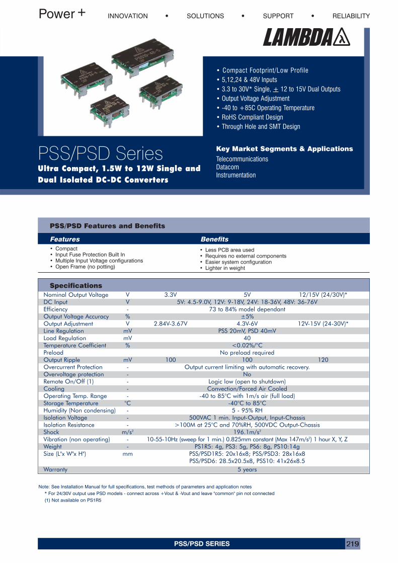
PSS/PSD SERIES 219
• Compact Footprint/Low Profile• 5,12,24 & 48V Inputs• 3.3 to 30V* Single, + 12 to 15V Dual Outputs• Output Voltage Adjustment• -40 to +85C Operating Temperature• RoHS Compliant Design• Through Hole and SMT Design
Key Market Segments & Applications
TelecommunicationsDatacomInstrumentation
INNOVATION SOLUTIONS SUPPORT RELIABILITY
PSS/PSD SeriesUltra Compact, 1.5W to 12W Single andDual Isolated DC-DC Converters
Features Benefits• Compact• Input Fuse Protection Built In• Multiple Input Voltage configurations• Open Frame (no potting)
• Less PCB area used• Requires no external components• Easier system configuration• Lighter in weight
SpecificationsNominal Output Voltage V 3.3V 5V 12/15V (24/30V)*DC Input V 5V: 4.5-9.0V, 12V: 9-18V, 24V: 18-36V, 48V: 36-76VEfficiency - 73 to 84% model dependantOutput Voltage Accuracy % ±5%Output Adjustment V 2.84V-3.67V 4.3V-6V 12V-15V (24-30V)*Line Regulation mV PSS 20mV, PSD 40mVLoad Regulation mV 40Temperature Coefficient % <0.02%/°CPreload No preload requiredOutput Ripple mV 100 100 120Overcurrent Protection - Output current limiting with automatic recovery. Overvoltage protection - NoRemote On/Off (1) - Logic low (open to shutdown)Cooling - Convection/Forced Air CooledOperating Temp. Range - -40 to 85°C with 1m/s air (full load)Storage Temperature °C -40°C to 85°CHumidity (Non condensing) - 5 - 95% RHIsolation Voltage - 500VAC 1 min. Input-Output, Input-ChassisIsolation Resistance - >100M at 25°C and 70%RH, 500VDC Output-ChassisShock m/s2 196.1m/s2
Vibration (non operating) - 10-55-10Hz (sweep for 1 min.) 0.825mm constant (Max 147m/s2) 1 hour X, Y, ZWeight - PS1R5: 4g, PS3: 5g, PS6: 8g, PS10:14gSize (L"x W"x H") mm PSS/PSD1R5: 20x16x8; PSS/PSD3: 28x16x8
PSS/PSD6: 28.5x20.5x8, PSS10: 41x26x8.5Warranty 5 years
Note: See Installation Manual for full specifications, test methods of parameters and application notes* For 24/30V output use PSD models - connect across +Vout & -Vout and leave "common" pin not connected(1) Not available on PS1R5
PSS/PSD Features and Benefits
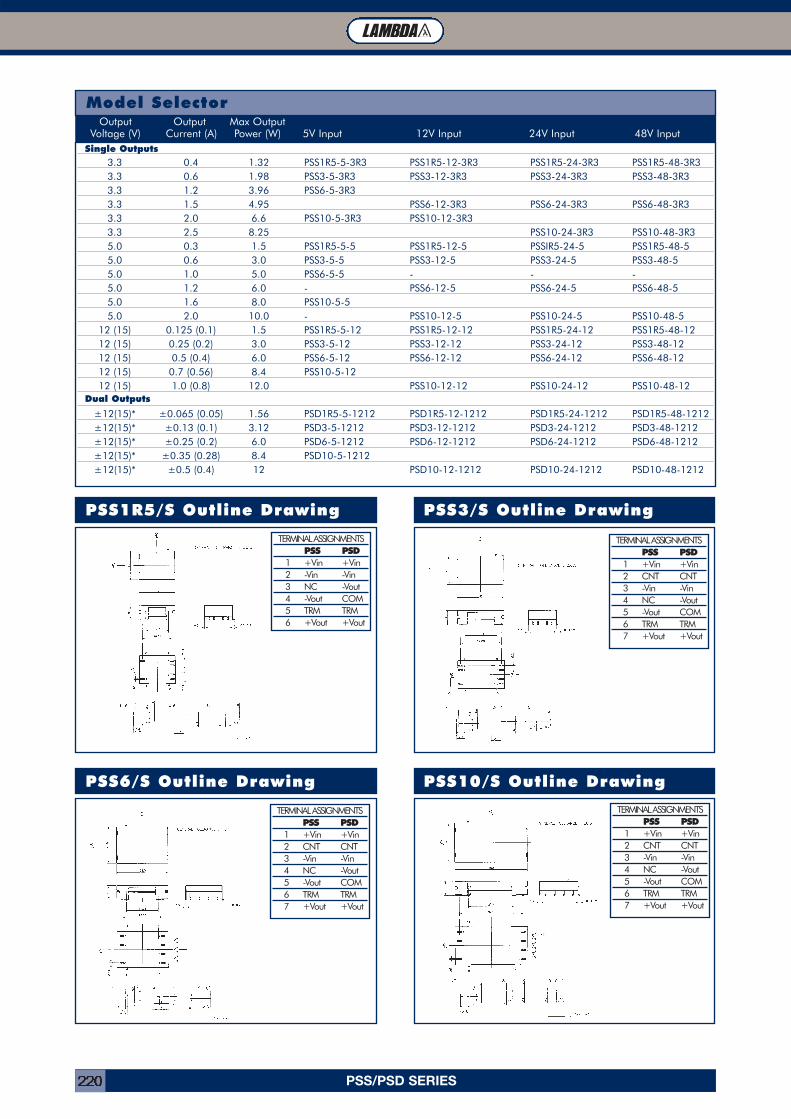
PSS/PSD SERIES220
PSS1R5/S Outline Drawing PSS3/S Outline Drawing
PSS6/S Outline Drawing PSS10/S Outline Drawing
Model SelectorOutput Output Max Output
Voltage (V) Current (A) Power (W) 5V Input 12V Input 24V Input 48V InputSingle Outputs
3.3 0.4 1.32 PSS1R5-5-3R3 PSS1R5-12-3R3 PSS1R5-24-3R3 PSS1R5-48-3R33.3 0.6 1.98 PSS3-5-3R3 PSS3-12-3R3 PSS3-24-3R3 PSS3-48-3R33.3 1.2 3.96 PSS6-5-3R33.3 1.5 4.95 PSS6-12-3R3 PSS6-24-3R3 PSS6-48-3R33.3 2.0 6.6 PSS10-5-3R3 PSS10-12-3R33.3 2.5 8.25 PSS10-24-3R3 PSS10-48-3R35.0 0.3 1.5 PSS1R5-5-5 PSS1R5-12-5 PSSIR5-24-5 PSS1R5-48-55.0 0.6 3.0 PSS3-5-5 PSS3-12-5 PSS3-24-5 PSS3-48-55.0 1.0 5.0 PSS6-5-5 - - -5.0 1.2 6.0 - PSS6-12-5 PSS6-24-5 PSS6-48-55.0 1.6 8.0 PSS10-5-55.0 2.0 10.0 - PSS10-12-5 PSS10-24-5 PSS10-48-5
12 (15) 0.125 (0.1) 1.5 PSS1R5-5-12 PSS1R5-12-12 PSS1R5-24-12 PSS1R5-48-1212 (15) 0.25 (0.2) 3.0 PSS3-5-12 PSS3-12-12 PSS3-24-12 PSS3-48-1212 (15) 0.5 (0.4) 6.0 PSS6-5-12 PSS6-12-12 PSS6-24-12 PSS6-48-1212 (15) 0.7 (0.56) 8.4 PSS10-5-1212 (15) 1.0 (0.8) 12.0 PSS10-12-12 PSS10-24-12 PSS10-48-12
Dual Outputs
±12(15)* ±0.065 (0.05) 1.56 PSD1R5-5-1212 PSD1R5-12-1212 PSD1R5-24-1212 PSD1R5-48-1212±12(15)* ±0.13 (0.1) 3.12 PSD3-5-1212 PSD3-12-1212 PSD3-24-1212 PSD3-48-1212±12(15)* ±0.25 (0.2) 6.0 PSD6-5-1212 PSD6-12-1212 PSD6-24-1212 PSD6-48-1212±12(15)* ±0.35 (0.28) 8.4 PSD10-5-1212±12(15)* ±0.5 (0.4) 12 PSD10-12-1212 PSD10-24-1212 PSD10-48-1212
TERMINAL ASSIGNMENTSPSS PSD
1 +Vin +Vin2 -Vin -Vin3 NC -Vout4 -Vout COM5 TRM TRM6 +Vout +Vout
TERMINAL ASSIGNMENTSPSS PSD
1 +Vin +Vin2 CNT CNT3 -Vin -Vin4 NC -Vout5 -Vout COM6 TRM TRM7 +Vout +Vout
TERMINAL ASSIGNMENTSPSS PSD
1 +Vin +Vin2 CNT CNT3 -Vin -Vin4 NC -Vout5 -Vout COM6 TRM TRM7 +Vout +Vout
TERMINAL ASSIGNMENTSPSS PSD
1 +Vin +Vin2 CNT CNT3 -Vin -Vin4 NC -Vout5 -Vout COM6 TRM TRM7 +Vout +Vout
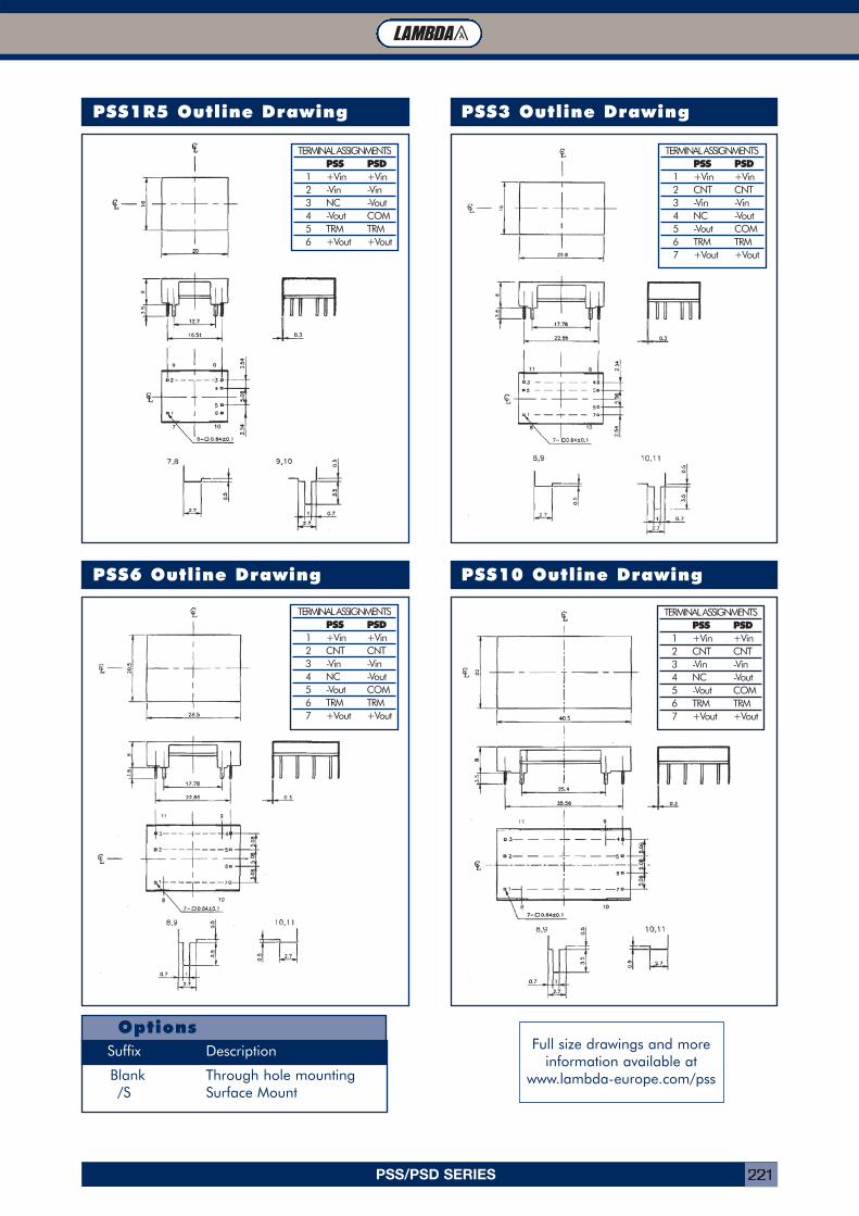
PSS/PSD SERIES 221
PSS1R5 Outline Drawing PSS3 Outline Drawing
PSS6 Outline Drawing PSS10 Outline Drawing
OptionsSuffix Description
Blank Through hole mounting/S Surface Mount
TERMINAL ASSIGNMENTSPSS PSD
1 +Vin +Vin2 -Vin -Vin3 NC -Vout4 -Vout COM5 TRM TRM6 +Vout +Vout
TERMINAL ASSIGNMENTSPSS PSD
1 +Vin +Vin2 CNT CNT3 -Vin -Vin4 NC -Vout5 -Vout COM6 TRM TRM7 +Vout +Vout
TERMINAL ASSIGNMENTSPSS PSD
1 +Vin +Vin2 CNT CNT3 -Vin -Vin4 NC -Vout5 -Vout COM6 TRM TRM7 +Vout +Vout
TERMINAL ASSIGNMENTSPSS PSD
1 +Vin +Vin2 CNT CNT3 -Vin -Vin4 NC -Vout5 -Vout COM6 TRM TRM7 +Vout +Vout
Full size drawings and moreinformation available at
www.lambda-europe.com/pss
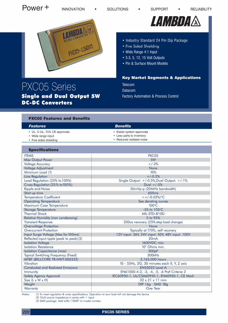
PXC05 SERIES222
Specifications
• Industry Standard 24 Pin Dip Package
• Five Sided Shielding
• Wide Range 4:1 Input
• 3.3, 5, 12, 15 Volt Outputs
• Pin & Surface Mount Models
Key Market Segments & Applications
Telecom
Datacom
Factory Automation & Process Control
PXC05 Features and Benefits
Features Benefits• UL, C-UL, TUV, CE approvals• Wide range input• Five sided shielding
• Easier system approvals• Less parts to inventory• Reduced radiated noise
INNOVATION SOLUTIONS SUPPORT RELIABILITY
PXC05 SeriesSingle and Dual Output 5W DC-DC Converters
Notes: (1) To meet regulation & noise specifications. Operation at zero load will not damage the device(2) 12uH source impedance in series with + input(3) SMD package: Add suffix “/SMD” to model number.
ITEMS PXC05Max Output Power 5WVoltage Accuracy +/-2%Voltage Adjustment NoneMinimum Load (1) 10%Line Regulation +/-0.2%Load Regulation (25% to100%) Single Output: +/-0.5%,Dual Output: +/-1%Cross Regulation (25% to100%) Dual +/-5%Ripple and Noise 50mVp-p (20MHz bandwidth)Start up time 600msTemperature Coefficient <+/-0.02%/oCOperating Temperature See derating curvesMaximum Case Temperature 100oCStorage Temperature -55 to 105oCThermal Shock MIL-STD-810DRelative Humidity (non condensing) 5 to 95%Transient Response 200us recovery (25% step load change)Overvoltage Protection NoneOvercurrent Protection Typically at 170%, self recoveryInput Surge Voltage (Max for100ms) 12V input: 36V, 24V input: 50V, 48V input: 100VReflected input ripple (peak to peak) (2) 20mAIsolation Voltage 1600VDC min.Isolation Resistance 109 Ohms min.Isolation Capacitance (max) 300pFTypical Switching Frequency (Fixed) 300kHzMTBF (BELLCORE TR-NWT-000332) 3,165,000 hoursVibration 10 - 55Hz, 2G, 30 minutes each X, Y, Z axisConducted and Radiated Emissions EN55022 Level AImmunity EN61000-4-2, -3, -4, -5, -6 Pref Criteria 2Safety Agency Approval IEC60950-1, UL/CSA60950-1, EN60950-1, CE MarkSize (L x W x H) 32 x 21 x 11 mmWeight DIP 16g SMD 18gWarranty One Year
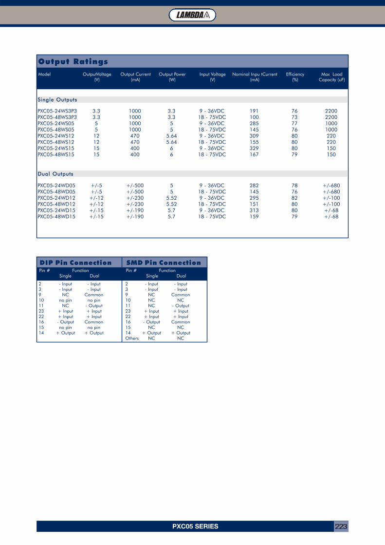
PXC05 SERIES 223
Output RatingsModel OutputVoltage Output Current Output Power Input Voltage Nominal Inpu tCurrent Efficiency Max Load
(V) (mA) (W) (V) (mA) (%) Capacity (uF)
SSiinnggllee OOuuttppuuttss
PXC05-24WS3P3 3.3 1000 3.3 9 - 36VDC 191 76 2200PXC05-48WS3P3 3.3 1000 3.3 18 - 75VDC 100 73 2200PXC05-24WS05 5 1000 5 9 - 36VDC 285 77 1000PXC05-48WS05 5 1000 5 18 - 75VDC 145 76 1000PXC05-24WS12 12 470 5.64 9 - 36VDC 309 80 220PXC05-48WS12 12 470 5.64 18 - 75VDC 155 80 220PXC05-24WS15 15 400 6 9 - 36VDC 329 80 150PXC05-48WS15 15 400 6 18 - 75VDC 167 79 150
DDuuaall OOuuttppuuttss
PXC05-24WD05 +/-5 +/-500 5 9 - 36VDC 282 78 +/-680PXC05-48WD05 +/-5 +/-500 5 18 - 75VDC 145 76 +/-680PXC05-24WD12 +/-12 +/-230 5.52 9 - 36VDC 295 82 +/-100PXC05-48WD12 +/-12 +/-230 5.52 18 - 75VDC 151 80 +/-100PXC05-24WD15 +/-15 +/-190 5.7 9 - 36VDC 313 80 +/-68PXC05-48WD15 +/-15 +/-190 5.7 18 - 75VDC 159 79 +/-68
DIP Pin ConnectionPin # Function
Single Dual
2 - Input - Input3 - Input - Input9 NC Common10 no pin no pin11 NC - Output23 + Input + Input22 + Input + Input16 - Output Common15 no pin no pin14 + Output + Output
SMD Pin ConnectionPin # Function
Single Dual
2 - Input - Input3 - Input - Input9 NC Common10 NC NC11 NC - Output23 + Input + Input22 + Input + Input16 - Output Common15 NC NC14 + Output + OutputOthers NC NC
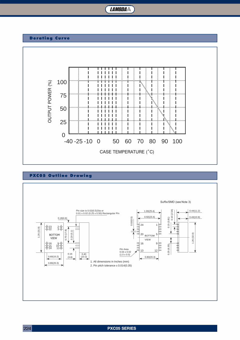
PXC05 SERIES224
Derat ing Curve
0
25
50
75
100
050 60 70 80 90 100-40 -25 -10
PXC05 Out l ine Drawing
1. All dimensions in Inches (mm)
2. Pin pitch tolerance ± 0.014(0.35)
Pin size is 0.02(0.5) Dia or0.01 x 0.02 (0.25 x 0.50) Rectangular Pin
14
2322
16
3
9
2
11
1.25
(31
.8)
0.60(15.2)
0.80(20.3)
0.40(10.2)
0.15(3.8)
0.70
(17
.8)
0.20
(5.
1)
0.18(4.6)
BOTTOMVIEW
15 10
Suffix /SMD (see Note 3
1.00(25.4)
0.92(23.4)
0.44(11.2)
0.43(10.9)
0.10
(2.
54)
0.15
(3.
81)
0.25
(6.
35) 1.
26 (
32.0
)
0.80(20.3)
0.02
(0.5
)
24
13
16
20
12
1
5
9
BOTTOM
VIEW
Pin Area0.04 x 0.02(1.0 x 0.5)
Suffix/SMD (see Note 3)
OU
TPU
T P
OW
ER
(%
)
CASE TEMPERATURE (˚C)
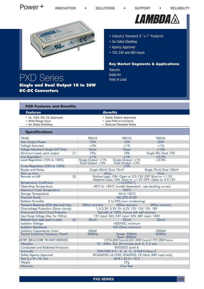
PXD SERIES 225
ITEMS PXD10 PXD15 PXD20Max Output Power 10W 15W 20WVoltage Accuracy ±2% ±1% ±1%Voltage Adjustment (Single O/P Only) None None ±10%Minimum Load, each output (1) 10% 10% Single 0%; Dual 10%Line Regulation ±1% ±1% ±0.2%Load Regulation (10% to 100%) Single Output: ±1% Single Output: ±1% ±0.5%
Dual Output: ±2% Dual Output: ±2%Cross Regulation (25% to 100%) ±5%Ripple and Noise Single 50mV, Dual 75mV Single 75mV, Dual 100mVStart up time 20ms 10msRemote on/off (3) Positive Logic: ON: Open or 3.5-12V, OFF Short or <1.2V
Negative Logic: ON: Short or <1.2V, OFF: Open or 3.5-12VTemperature Coefficient <±0.02%/°COperating Temperature -40°C to +85°C (model dependent - see derating curves)Maximum Case Temperature 100°CStorage Temperature -55 to 105°CThermal Shock MIL-STD-810DRelative Humidity 5 to 95% (non condensing)Transient Response (25% step load chg.) 500us recovery 500us recovery 300us recoveryOvervoltage Protection (Zener clamp) 1.5-3.3V: 3.9V, 5V: 6.2V, 12V: 15V, 15V: 18VOvercurrent & Short Circuit Protection Typically at 150%, hiccup with self recoveryInput Surge Voltage (Max. for 100ms) 12V input: 36V, 24V input: 50V, 48V input: 100VReflected input ripple (peak to peak) (2) 30mA 20mA 20mAIsolation Voltage 1600VDC minimumIsolation Resistance 109 Ohms minimumIsolation Capacitance (max) 300pF 1000pFTypical Switching Frequency (Fixed) 300kHz Single: 500kHz 500kHz
Dual: 300kHzMTBF (BELLCORE TR-NWT-000332) 1,976,000 hours2,041,000 hours1,791,000 hoursVibration 10 - 55Hz, 2G, 30 minutes each X, Y, Z axisConducted and Radiated Emissions EN55022 Level AImmunity EN61000-4-2, -3, -4, -5, -6 Pref Criteria 2Safety Agency Approval IEC606950, UL1950, EN60950, CE Mark (48V input only)Size (L x W x H) mm 50.8 x 25.4 x 10.2Weight 27gWarranty One Year
• Industry Standard 2” x 1” Footprint
• Six Sided Shielding
• Agency Approved
• 12V, 24V and 48V Inputs
Key Market Segments & Applications
TelecomDatacomPoint of Load
INNOVATION SOLUTIONS SUPPORT RELIABILITY
PXD SeriesSingle and Dual Output 10 to 20WDC-DC Converters
PXD Features and Benefits
Features Benefits• UL, CSA, EN, CE Approvals• Wide Range Input• Six Sided Shielding
• Easier System Approvals• Less Parts to Inventory• Reduced Radiated Noise
Specifications
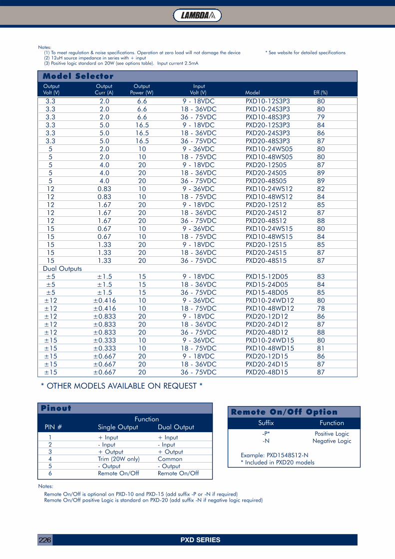
PXD SERIES226
Model SelectorOutput Output Output InputVolt (V) Curr (A) Power (W) Volt (V) Model Eff.(%)
3.3 2.0 6.6 9 - 18VDC PXD10-12S3P3 803.3 2.0 6.6 18 - 36VDC PXD10-24S3P3 803.3 2.0 6.6 36 - 75VDC PXD10-48S3P3 793.3 5.0 16.5 9 - 18VDC PXD20-12S3P3 843.3 5.0 16.5 18 - 36VDC PXD20-24S3P3 863.3 5.0 16.5 36 - 75VDC PXD20-48S3P3 875 2.0 10 9 - 36VDC PXD10-24WS05 805 2.0 10 18 - 75VDC PXD10-48WS05 805 4.0 20 9 - 18VDC PXD20-12S05 875 4.0 20 18 - 36VDC PXD20-24S05 895 4.0 20 36 - 75VDC PXD20-48S05 89
12 0.83 10 9 - 36VDC PXD10-24WS12 8212 0.83 10 18 - 75VDC PXD10-48WS12 8412 1.67 20 9 - 18VDC PXD20-12S12 8512 1.67 20 18 - 36VDC PXD20-24S12 8712 1.67 20 36 - 75VDC PXD20-48S12 8815 0.67 10 9 - 36VDC PXD10-24WS15 8015 0.67 10 18 - 75VDC PXD10-48WS15 8415 1.33 20 9 - 18VDC PXD20-12S15 8515 1.33 20 18 - 36VDC PXD20-24S15 8715 1.33 20 36 - 75VDC PXD20-48S15 87
Dual Outputs±5 ±1.5 15 9 - 18VDC PXD15-12D05 83±5 ±1.5 15 18 - 36VDC PXD15-24D05 84±5 ±1.5 15 36 - 75VDC PXD15-48D05 85
±12 ±0.416 10 9 - 36VDC PXD10-24WD12 80±12 ±0.416 10 18 - 75VDC PXD10-48WD12 78±12 ±0.833 20 9 - 18VDC PXD20-12D12 86±12 ±0.833 20 18 - 36VDC PXD20-24D12 87±12 ±0.833 20 36 - 75VDC PXD20-48D12 88±15 ±0.333 10 9 - 36VDC PXD10-24WD15 80±15 ±0.333 10 18 - 75VDC PXD10-48WD15 81±15 ±0.667 20 9 - 18VDC PXD20-12D15 86±15 ±0.667 20 18 - 36VDC PXD20-24D15 87±15 ±0.667 20 36 - 75VDC PXD20-48D15 87
PinoutFunction
PIN # Single Output Dual Output
1 + Input + Input2 - Input - Input3 + Output + Output4 Trim (20W only) Common5 - Output - Output6 Remote On/Off Remote On/Off
Remote On/Off OptionSuffix Function
-P* Positive Logic-N Negative Logic
Example: PXD1548S12-N* Included in PXD20 models
Notes:
Remote On/Off is optional on PXD-10 and PXD-15 (add suffix -P or -N if required)Remote On/Off positive Logic is standard on PXD-20 (add suffix -N if negative logic required)
Notes:(1) To meet regulation & noise specifications. Operation at zero load will not damage the device * See website for detailed specifications(2) 12uH source impedance in series with + input(3) Positive logic standard on 20W (see options table). Input current 2.5mA
* OTHER MODELS AVAILABLE ON REQUEST *
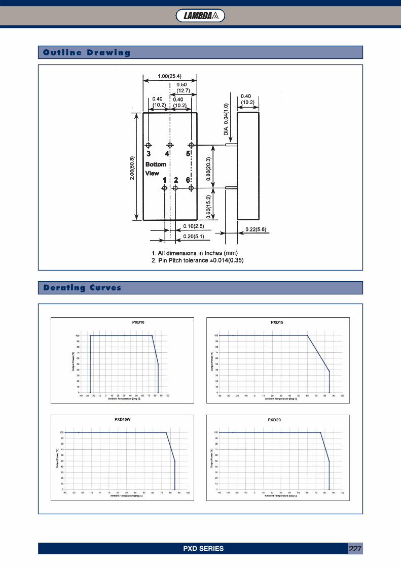
PXD SERIES 227
Outl ine Drawing
Derating Curves
PXD20

PXE SERIES228
• Industry Standard 2” x 1.6” Footprint
• Six Sided Shielding
• Agency Approved
• 12V, 24V and 48V Inputs
Key Market Segments & Applications
TelecomDatacomPoint of Load
INNOVATION SOLUTIONS SUPPORT RELIABILITY
PXE Features and Benefits
Features Benefits
• UL, CSA, EN, CE Approvals• Wide Range Input• Six Sided Shielding
• Easier System Approvals• Less Parts to Inventory• Reduced Radiated Noise
SpecificationsITEMS PXE20 PXE30Max Output Power 20W 30WVoltage Accuracy ±2% ±1%Voltage Adjustment (Single Output Only) ±10%Minimum Load, each output (1) 10% NoneLine Regulation ±0.2% for single, ±0.5% for dualLoad Regulation (25% to 100%) Single ±0.5%, Dual ±3% Single ±0.5%, Dual ±1%Cross Regulation (25% to 100%) Dual ±5%Ripple and Noise (P-P) Single: 75mV; Dual: 100mVStart up time 20ms typ. 25ms typ.Remote on/off (3) Positive Logic: ON: Open or 3.5-12V, OFF Short or <1.2VTemperature Coefficient <±0.02%/°COperating Temperature -40°C to +85°CMaximum Case Temperature 100°CStorage Temperature -55 to 105°CThermal Shock MIL-STD-810DRelative Humidity (non condensing) 5 to 95%Transient Response (25% step load change) 500us recovery 300us recoveryOvervoltage Protection (Zener clamp) 3.3V: 3.9V, 5V: 6.2V, 12V: 15V, 15V: 18VOvercurrent and Short Circuit Protection Typically at 150%, hiccup with self recoveryInput Surge Voltage (Maximum for 100ms) 12V input: 36V, 24V input: 50V, 48V input: 100VReflected input ripple (peak to peak) (2) 25mA 30mAIsolation Voltage 1600VDC minimum (Input-Output, Input-Case)Isolation Resistance 109 Ohms minimumIsolation Capacitance (max) 300pF 1000pFTypical Switching Frequency (Fixed) 300kHzMTBF (BELLCORE TR-NWT-000332) 1,976,000 hours 1,535,000 hoursVibration 10 - 55Hz, 2G, 30 minutes each X, Y, Z axisConducted and Radiated Emissions EN55022 Level AImmunity EN61000-4-2, -3, -4, -5, -6 Pref Criteria 2Safety Agency Approval IEC606950, UL1950, EN60950, CE Mark (48V input only)Size (L x W x H) mm 50.8 x 40.6 x 10.2Weight 48gWarranty One Year
Notes: (1) To meet regulation & noise specifications. Operation at zero load will not damage the device (2) 12uH source impedance in series with + input(3) Max sink current 20mA (PXE20), 2.5mA (PXE30); The on/off pin is referenced to the negative input
PXE SeriesSingle and Dual 20W to 30W DC-DC Converters
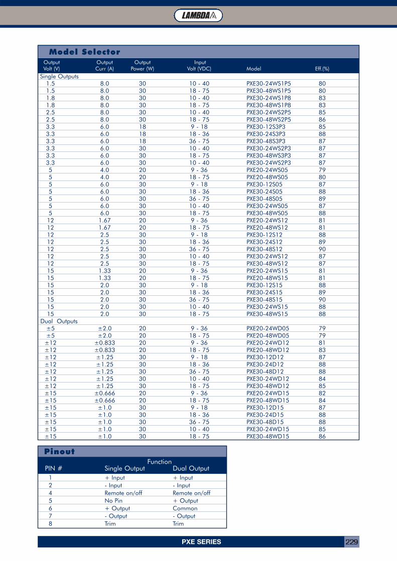
PXE SERIES 229
Model Selector
PinoutFunction
PIN # Single Output Dual Output
Single Outputs1.5 8.0 30 10 - 40 PXE30-24WS1P5 801.5 8.0 30 18 - 75 PXE30-48WS1P5 801.8 8.0 30 10 - 40 PXE30-24WS1P8 831.8 8.0 30 18 - 75 PXE30-48WS1P8 832.5 8.0 30 10 - 40 PXE30-24WS2P5 852.5 8.0 30 18 - 75 PXE30-48WS2P5 863.3 6.0 18 9 - 18 PXE30-12S3P3 853.3 6.0 18 18 - 36 PXE30-24S3P3 883.3 6.0 18 36 - 75 PXE30-48S3P3 873.3 6.0 30 10 - 40 PXE30-24WS2P3 873.3 6.0 30 18 - 75 PXE30-48WS3P3 873.3 6.0 30 10 - 40 PXE30-24WS2P3 875 4.0 20 9 - 36 PXE20-24WS05 795 4.0 20 18 - 75 PXE20-48WS05 805 6.0 30 9 - 18 PXE30-12S05 875 6.0 30 18 - 36 PXE30-24S05 885 6.0 30 36 - 75 PXE30-48S05 895 6.0 30 10 - 40 PXE30-24WS05 875 6.0 30 18 - 75 PXE30-48WS05 88
12 1.67 20 9 - 36 PXE20-24WS12 8112 1.67 20 18 - 75 PXE20-48WS12 8112 2.5 30 9 - 18 PXE30-12S12 8812 2.5 30 18 - 36 PXE30-24S12 8912 2.5 30 36 - 75 PXE30-48S12 9012 2.5 30 10 - 40 PXE30-24WS12 8712 2.5 30 18 - 75 PXE30-48WS12 8715 1.33 20 9 - 36 PXE20-24WS15 8115 1.33 20 18 - 75 PXE20-48WS15 8115 2.0 30 9 - 18 PXE30-12S15 8815 2.0 30 18 - 36 PXE30-24S15 8915 2.0 30 36 - 75 PXE30-48S15 9015 2.0 30 10 - 40 PXE30-24WS15 8815 2.0 30 18 - 75 PXE30-48WS15 88
Dual Outputs±5 ±2.0 20 9 - 36 PXE20-24WD05 79±5 ±2.0 20 18 - 75 PXE20-48WD05 79
±12 ±0.833 20 9 - 36 PXE20-24WD12 81±12 ±0.833 20 18 - 75 PXE20-48WD12 83±12 ±1.25 30 9 - 18 PXE30-12D12 87±12 ±1.25 30 18 - 36 PXE30-24D12 88±12 ±1.25 30 36 - 75 PXE30-48D12 88±12 ±1.25 30 10 - 40 PXE30-24WD12 84±12 ±1.25 30 18 - 75 PXE30-48WD12 85±15 ±0.666 20 9 - 36 PXE20-24WD15 82±15 ±0.666 20 18 - 75 PXE20-48WD15 84±15 ±1.0 30 9 - 18 PXE30-12D15 87±15 ±1.0 30 18 - 36 PXE30-24D15 88±15 ±1.0 30 36 - 75 PXE30-48D15 88±15 ±1.0 30 10 - 40 PXE30-24WD15 85±15 ±1.0 30 18 - 75 PXE30-48WD15 86
1 + Input + Input2 - Input - Input4 Remote on/off Remote on/off5 No Pin + Output6 + Output Common7 - Output - Output8 Trim Trim
Output Output Output InputVolt (V) Curr (A) Power (W) Volt (VDC) Model Eff.(%)
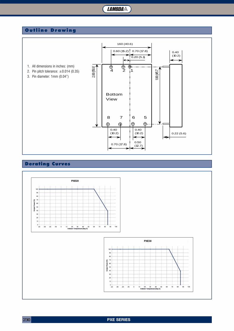
PXE SERIES230
1.60 (40.6)
0.20 (5.1)
0.70 (17.8)0.60 (15.2)
0.40(10.2)
0.40(10.2)
0.50(12.7)0.70 (17.8)
0.40(10.2)
0.22 (5.6)
124
58 7 6
BottomView
Outl ine Drawing
Derating Curves
1. All dimensions in inches: (mm)2. Pin pitch tolerance: ±0.014 (0.35)3. Pin diameter: 1mm (0.04”)
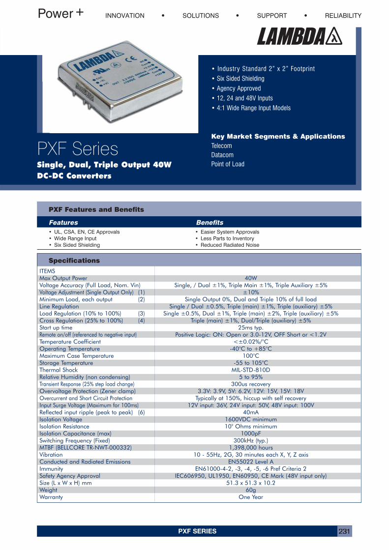
PXF SERIES 231
• Industry Standard 2” x 2” Footprint
• Six Sided Shielding
• Agency Approved
• 12, 24 and 48V Inputs
• 4:1 Wide Range Input Models
Key Market Segments & ApplicationsTelecomDatacomPoint of Load
INNOVATION SOLUTIONS SUPPORT RELIABILITY
PXF SeriesSingle, Dual, Triple Output 40W DC-DC Converters
PXF Features and Benefits
Features Benefits
Specifications
• UL, CSA, EN, CE Approvals• Wide Range Input• Six Sided Shielding
• Easier System Approvals• Less Parts to Inventory• Reduced Radiated Noise
ITEMSMax Output Power 40WVoltage Accuracy (Full Load, Nom. Vin) Single, / Dual ±1%, Triple Main ±1%, Triple Auxiliary ±5%Voltage Adjustment (Single Output Only) (1) ±10%Minimum Load, each output (2) Single Output 0%, Dual and Triple 10% of full loadLine Regulation Single / Dual ±0.5%, Triple (main) ±1%, Triple (auxiliary) ±5%Load Regulation (10% to 100%) (3) Single ±0.5%, Dual ±1%, Triple (main) ±2%, Triple (auxiliary) ±5%Cross Regulation (25% to 100%) (4) Triple (main) ±1%, Dual/Triple (auxiliary) ±5%Start up time 25ms typ.Remote on/off (referenced to negative input) Positive Logic: ON: Open or 3.0-12V, OFF Short or <1.2VTemperature Coefficient <±0.02%/°COperating Temperature -40°C to +85°CMaximum Case Temperature 100°CStorage Temperature -55 to 105°CThermal Shock MIL-STD-810DRelative Humidity (non condensing) 5 to 95%Transient Response (25% step load change) 300us recoveryOvervoltage Protection (Zener clamp) 3.3V: 3.9V, 5V: 6.2V, 12V: 15V, 15V: 18VOvercurrent and Short Circuit Protection Typically at 150%, hiccup with self recoveryInput Surge Voltage (Maximum for 100ms) 12V input: 36V, 24V input: 50V, 48V input: 100VReflected input ripple (peak to peak) (6) 40mAIsolation Voltage 1600VDC minimumIsolation Resistance 109 Ohms minimumIsolation Capacitance (max) 1000pFSwitching Frequency (Fixed) 300kHz (typ.)MTBF (BELLCORE TR-NWT-000332) 1,398,000 hoursVibration 10 - 55Hz, 2G, 30 minutes each X, Y, Z axisConducted and Radiated Emissions EN55022 Level AImmunity EN61000-4-2, -3, -4, -5, -6 Pref Criteria 2Safety Agency Approval IEC606950, UL1950, EN60950, CE Mark (48V input only)Size (L x W x H) mm 51.3 x 51.3 x 10.2Weight 60gWarranty One Year
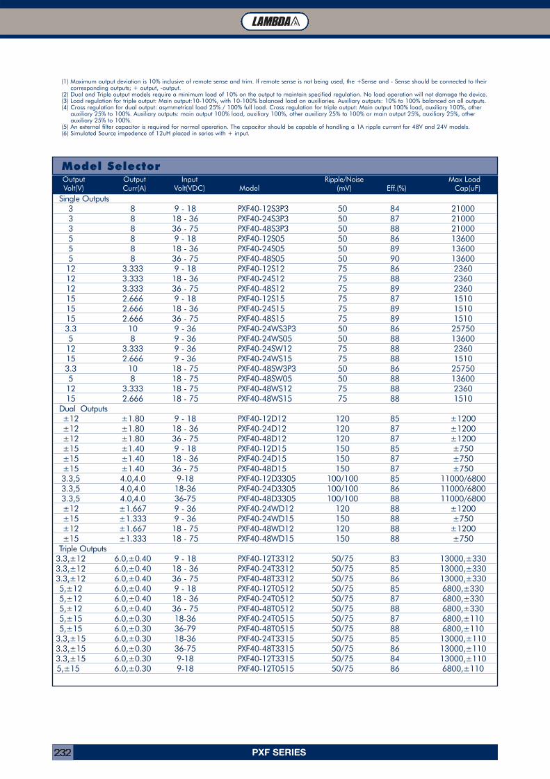
PXF SERIES232
Model SelectorOutput Output Input Ripple/Noise Max LoadVolt(V) Curr(A) Volt(VDC) Model (mV) Eff.(%) Cap(uF)
Single Outputs3 8 9 - 18 PXF40-12S3P3 50 84 210003 8 18 - 36 PXF40-24S3P3 50 87 210003 8 36 - 75 PXF40-48S3P3 50 88 210005 8 9 - 18 PXF40-12S05 50 86 136005 8 18 - 36 PXF40-24S05 50 89 136005 8 36 - 75 PXF40-48S05 50 90 1360012 3.333 9 - 18 PXF40-12S12 75 86 236012 3.333 18 - 36 PXF40-24S12 75 88 236012 3.333 36 - 75 PXF40-48S12 75 89 236015 2.666 9 - 18 PXF40-12S15 75 87 151015 2.666 18 - 36 PXF40-24S15 75 89 151015 2.666 36 - 75 PXF40-48S15 75 89 15103.3 10 9 - 36 PXF40-24WS3P3 50 86 257505 8 9 - 36 PXF40-24WS05 50 88 1360012 3.333 9 - 36 PXF40-24SW12 75 88 236015 2.666 9 - 36 PXF40-24WS15 75 88 15103.3 10 18 - 75 PXF40-48SW3P3 50 86 257505 8 18 - 75 PXF40-48SW05 50 88 1360012 3.333 18 - 75 PXF40-48WS12 75 88 236015 2.666 18 - 75 PXF40-48WS15 75 88 1510
Dual Outputs±12 ±1.80 9 - 18 PXF40-12D12 120 85 ±1200±12 ±1.80 18 - 36 PXF40-24D12 120 87 ±1200±12 ±1.80 36 - 75 PXF40-48D12 120 87 ±1200±15 ±1.40 9 - 18 PXF40-12D15 150 85 ±750±15 ±1.40 18 - 36 PXF40-24D15 150 87 ±750±15 ±1.40 36 - 75 PXF40-48D15 150 87 ±7503.3,5 4.0,4.0 9-18 PXF40-12D3305 100/100 85 11000/68003.3,5 4.0,4.0 18-36 PXF40-24D3305 100/100 86 11000/68003.3,5 4.0,4.0 36-75 PXF40-48D3305 100/100 88 11000/6800±12 ±1.667 9 - 36 PXF40-24WD12 120 88 ±1200±15 ±1.333 9 - 36 PXF40-24WD15 150 88 ±750±12 ±1.667 18 - 75 PXF40-48WD12 120 88 ±1200±15 ±1.333 18 - 75 PXF40-48WD15 150 88 ±750
Triple Outputs3.3,±12 6.0,±0.40 9 - 18 PXF40-12T3312 50/75 83 13000,±3303.3,±12 6.0,±0.40 18 - 36 PXF40-24T3312 50/75 85 13000,±3303.3,±12 6.0,±0.40 36 - 75 PXF40-48T3312 50/75 86 13000,±3305,±12 6.0,±0.40 9 - 18 PXF40-12T0512 50/75 85 6800,±3305,±12 6.0,±0.40 18 - 36 PXF40-24T0512 50/75 87 6800,±3305,±12 6.0,±0.40 36 - 75 PXF40-48T0512 50/75 88 6800,±3305,±15 6.0,±0.30 18-36 PXF40-24T0515 50/75 87 6800,±1105,±15 6.0,±0.30 36-79 PXF40-48T0515 50/75 88 6800,±110
3.3,±15 6.0,±0.30 18-36 PXF40-24T3315 50/75 85 13000,±1103.3,±15 6.0,±0.30 36-75 PXF40-48T3315 50/75 86 13000,±1103.3,±15 6.0,±0.30 9-18 PXF40-12T3315 50/75 84 13000,±1105,±15 6.0,±0.30 9-18 PXF40-12T0515 50/75 86 6800,±110
(1) Maximum output deviation is 10% inclusive of remote sense and trim. If remote sense is not being used, the +Sense and - Sense should be connected to theircorresponding outputs; + output, -output.
(2) Dual and Triple output models require a minimum load of 10% on the output to maintain specified regulation. No load operation will not damage the device.(3) Load regulation for triple output: Main output:10-100%, with 10-100% balanced load on auxiliaries. Auxiliary outputs: 10% to 100% balanced on all outputs.(4) Cross regulation for dual output: asymmetrical load 25% / 100% full load. Cross regulation for triple output: Main output 100% load, auxiliary 100%, other
auxiliary 25% to 100%. Auxiliary outputs: main output 100% load, auxiliary 100%, other auxiliary 25% to 100% or main output 25%, auxiliary 25%, otherauxiliary 25% to 100%.
(5) An external filter capacitor is required for normal operation. The capacitor should be capable of handling a 1A ripple current for 48V and 24V models.(6) Simulated Source impedence of 12uH placed in series with + input.
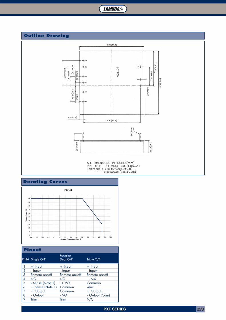
PXF SERIES 233
PinoutFunction
PIN# Single O/P Dual O/P Triple O/P
1 + Input + Input + Input2 - Input - Input - Input3 Remote on/off Remote on/off Remote on/off4 NC NC + Aux5 - Sense (Note 1) + VO Common6 + Sense (Note 1) Common -Aux7 + Output Common + Output8 - Output - VO - Output (Com)9 Trim Trim N/C
Derating Curves
Outline Drawing
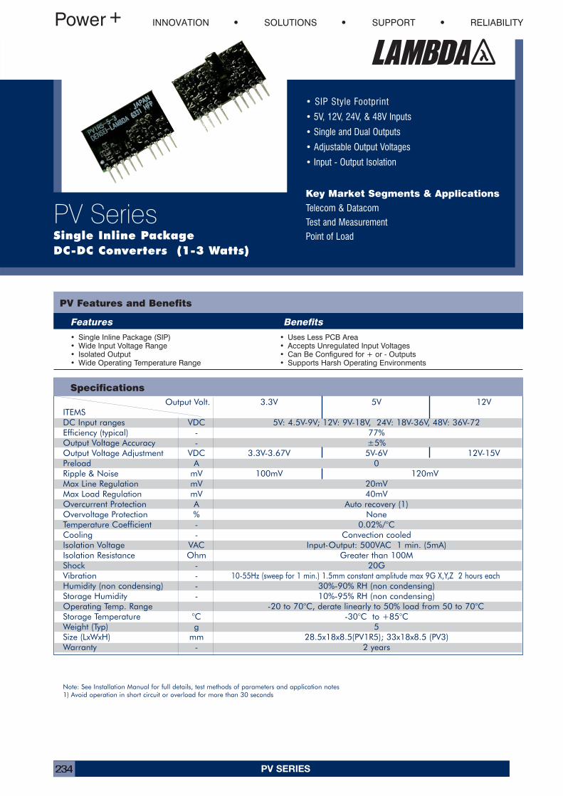
PV SERIES234
• SIP Style Footprint
• 5V, 12V, 24V, & 48V Inputs
• Single and Dual Outputs
• Adjustable Output Voltages
• Input - Output Isolation
Key Market Segments & Applications
Telecom & Datacom
Test and Measurement
Point of Load
PV Features and Benefits
Features Benefits
• Single Inline Package (SIP)• Wide Input Voltage Range• Isolated Output• Wide Operating Temperature Range
• Uses Less PCB Area• Accepts Unregulated Input Voltages• Can Be Configured for + or - Outputs• Supports Harsh Operating Environments
Specifications
INNOVATION SOLUTIONS SUPPORT RELIABILITY
PV SeriesSingle Inline Package DC-DC Converters (1-3 Watts)
Note: See Installation Manual for full details, test methods of parameters and application notes1) Avoid operation in short circuit or overload for more than 30 seconds
Output Volt. 3.3V 5V 12VITEMSDC Input ranges VDC 5V: 4.5V-9V; 12V: 9V-18V, 24V: 18V-36V, 48V: 36V-72Efficiency (typical) - 77%Output Voltage Accuracy - ±5%Output Voltage Adjustment VDC 3.3V-3.67V 5V-6V 12V-15VPreload A 0Ripple & Noise mV 100mV 120mVMax Line Regulation mV 20mVMax Load Regulation mV 40mVOvercurrent Protection A Auto recovery (1)Overvoltage Protection % NoneTemperature Coefficient - 0.02%/°CCooling - Convection cooledIsolation Voltage VAC Input-Output: 500VAC 1 min. (5mA)Isolation Resistance Ohm Greater than 100MShock - 20GVibration - 10-55Hz (sweep for 1 min.) 1.5mm constant amplitude max 9G X,Y,Z 2 hours eachHumidity (non condensing) - 30%-90% RH (non condensing)Storage Humidity - 10%-95% RH (non condensing)Operating Temp. Range -20 to 70°C, derate linearly to 50% load from 50 to 70°CStorage Temperature °C -30°C to +85°CWeight (Typ) g 5Size (LxWxH) mm 28.5x18x8.5(PV1R5); 33x18x8.5 (PV3)Warranty - 2 years
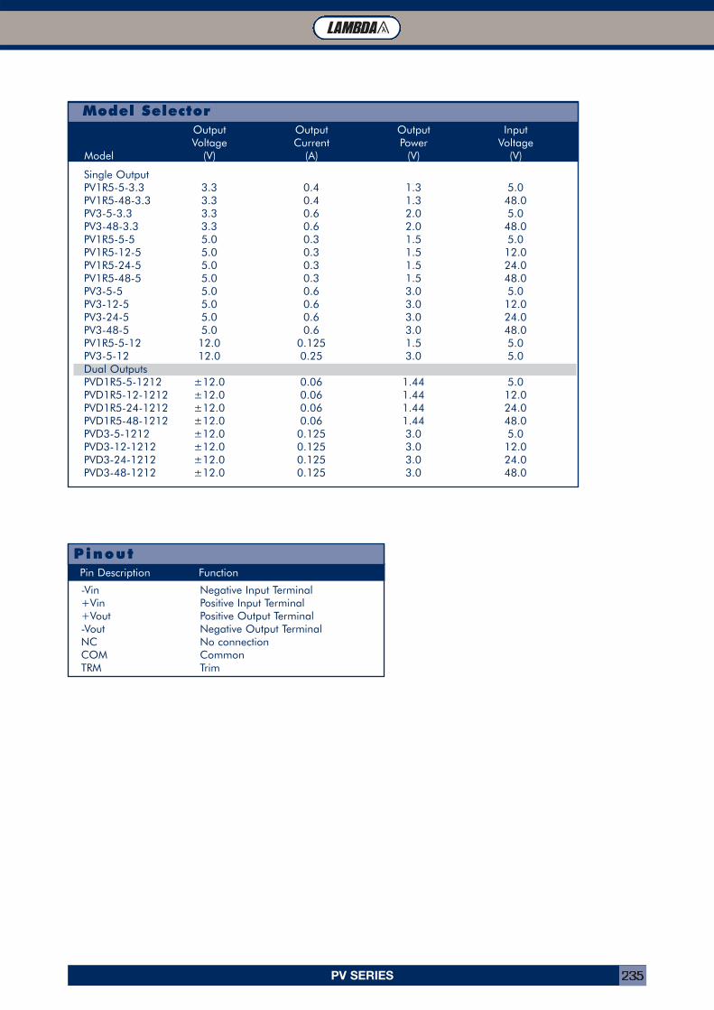
PV SERIES 235
Single OutputPV1R5-5-3.3 3.3 0.4 1.3 5.0PV1R5-48-3.3 3.3 0.4 1.3 48.0PV3-5-3.3 3.3 0.6 2.0 5.0PV3-48-3.3 3.3 0.6 2.0 48.0PV1R5-5-5 5.0 0.3 1.5 5.0PV1R5-12-5 5.0 0.3 1.5 12.0PV1R5-24-5 5.0 0.3 1.5 24.0PV1R5-48-5 5.0 0.3 1.5 48.0PV3-5-5 5.0 0.6 3.0 5.0PV3-12-5 5.0 0.6 3.0 12.0PV3-24-5 5.0 0.6 3.0 24.0PV3-48-5 5.0 0.6 3.0 48.0PV1R5-5-12 12.0 0.125 1.5 5.0PV3-5-12 12.0 0.25 3.0 5.0Dual OutputsPVD1R5-5-1212 ±12.0 0.06 1.44 5.0PVD1R5-12-1212 ±12.0 0.06 1.44 12.0PVD1R5-24-1212 ±12.0 0.06 1.44 24.0PVD1R5-48-1212 ±12.0 0.06 1.44 48.0PVD3-5-1212 ±12.0 0.125 3.0 5.0PVD3-12-1212 ±12.0 0.125 3.0 12.0PVD3-24-1212 ±12.0 0.125 3.0 24.0PVD3-48-1212 ±12.0 0.125 3.0 48.0
Output Output Output InputVoltage Current Power Voltage
Model (V) (A) (V) (V)
Model Selector
-Vin Negative Input Terminal+Vin Positive Input Terminal+Vout Positive Output Terminal-Vout Negative Output TerminalNC No connectionCOM CommonTRM Trim
Pin Description Function
Pinout
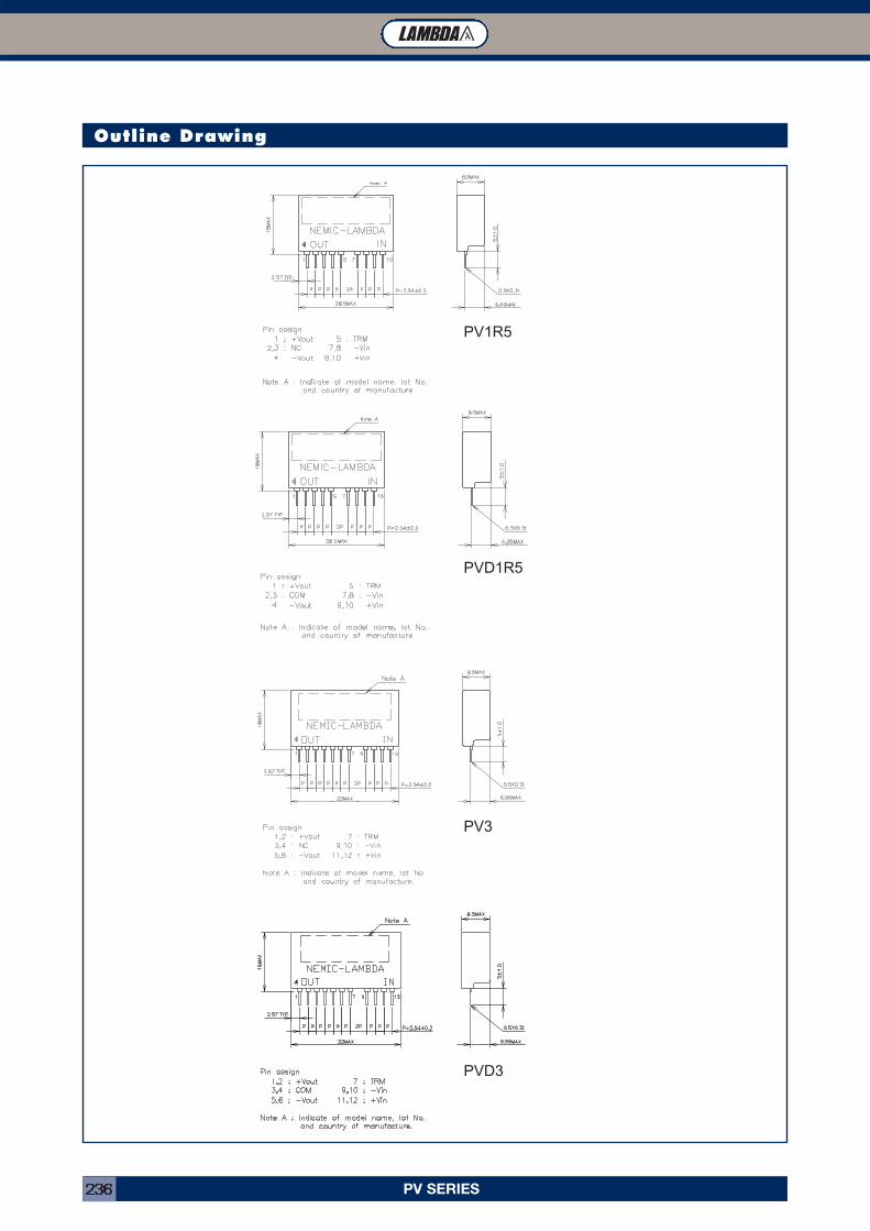
PV SERIES236
Outline Drawing
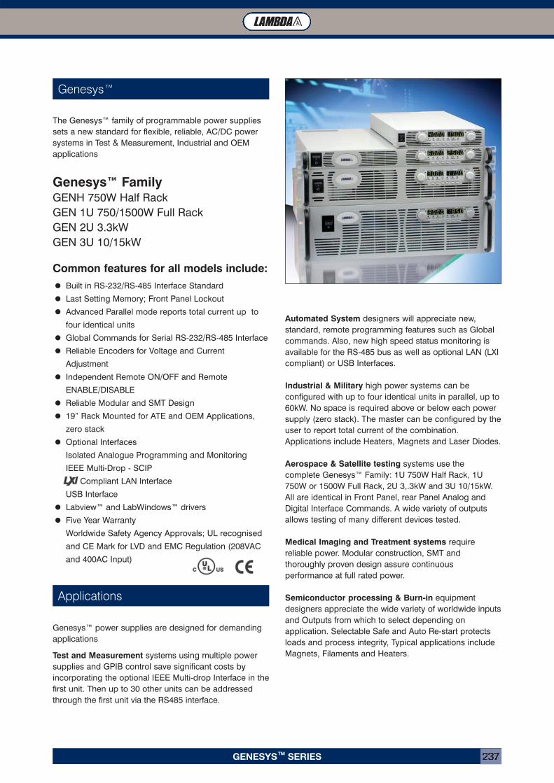
GENESYSTM SERIES 237
Genesys™
Applications
The Genesys™ family of programmable power suppliessets a new standard for flexible, reliable, AC/DC powersystems in Test & Measurement, Industrial and OEMapplications
Genesys™ FamilyGENH 750W Half RackGEN 1U 750/1500W Full RackGEN 2U 3.3kWGEN 3U 10/15kW
Common features for all models include:
• Built in RS-232/RS-485 Interface Standard
• Last Setting Memory; Front Panel Lockout
• Advanced Parallel mode reports total current up to
four identical units
• Global Commands for Serial RS-232/RS-485 Interface
• Reliable Encoders for Voltage and Current
Adjustment
• Independent Remote ON/OFF and Remote
ENABLE/DISABLE
• Reliable Modular and SMT Design
• 19” Rack Mounted for ATE and OEM Applications,
zero stack
• Optional Interfaces
Isolated Analogue Programming and Monitoring
IEEE Multi-Drop - SCIP
LXI Compliant LAN Interface
USB Interface
• Labview™ and LabWindows™ drivers
• Five Year Warranty
Worldwide Safety Agency Approvals; UL recognised
and CE Mark for LVD and EMC Regulation (208VAC
and 400AC Input)
Genesys™ power supplies are designed for demandingapplications
Test and Measurement systems using multiple powersupplies and GPIB control save significant costs byincorporating the optional IEEE Multi-drop Interface in thefirst unit. Then up to 30 other units can be addressedthrough the first unit via the RS485 interface.
Automated System designers will appreciate new,standard, remote programming features such as Globalcommands. Also, new high speed status monitoring isavailable for the RS-485 bus as well as optional LAN (LXIcompliant) or USB Interfaces.
Industrial & Military high power systems can beconfigured with up to four identical units in parallel, up to60kW. No space is required above or below each powersupply (zero stack). The master can be configured by theuser to report total current of the combination.Applications include Heaters, Magnets and Laser Diodes.
Aerospace & Satellite testing systems use thecomplete Genesys™ Family: 1U 750W Half Rack, 1U750W or 1500W Full Rack, 2U 3,.3kW and 3U 10/15kW.All are identical in Front Panel, rear Panel Analog andDigital Interface Commands. A wide variety of outputsallows testing of many different devices tested.
Medical Imaging and Treatment systems requirereliable power. Modular construction, SMT andthoroughly proven design assure continuousperformance at full rated power.
Semiconductor processing & Burn-in equipmentdesigners appreciate the wide variety of worldwide inputsand Outputs from which to select depending onapplication. Selectable Safe and Auto Re-start protectsloads and process integrity, Typical applications includeMagnets, Filaments and Heaters.
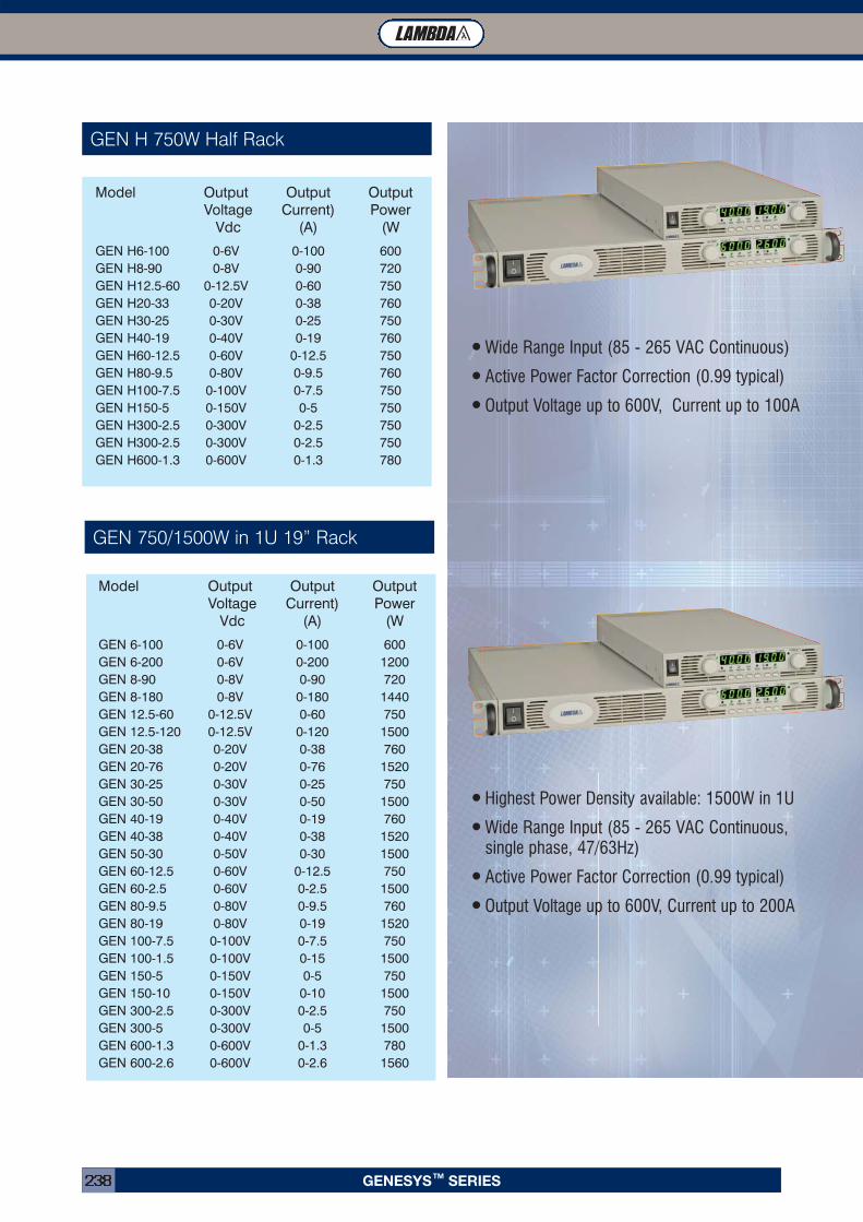
GENESYSTM SERIES238
GEN 750/1500W in 1U 19” Rack
•Wide Range Input (85 - 265 VAC Continuous)
•Active Power Factor Correction (0.99 typical)
•Output Voltage up to 600V, Current up to 100A
•Highest Power Density available: 1500W in 1U
•Wide Range Input (85 - 265 VAC Continuous, single phase, 47/63Hz)
•Active Power Factor Correction (0.99 typical)
•Output Voltage up to 600V, Current up to 200A
Model Output Output Output Voltage Current) Power
Vdc (A) (W
GEN 6-100 0-6V 0-100 600GEN 6-200 0-6V 0-200 1200GEN 8-90 0-8V 0-90 720GEN 8-180 0-8V 0-180 1440GEN 12.5-60 0-12.5V 0-60 750GEN 12.5-120 0-12.5V 0-120 1500GEN 20-38 0-20V 0-38 760GEN 20-76 0-20V 0-76 1520GEN 30-25 0-30V 0-25 750GEN 30-50 0-30V 0-50 1500GEN 40-19 0-40V 0-19 760GEN 40-38 0-40V 0-38 1520GEN 50-30 0-50V 0-30 1500GEN 60-12.5 0-60V 0-12.5 750GEN 60-2.5 0-60V 0-2.5 1500GEN 80-9.5 0-80V 0-9.5 760GEN 80-19 0-80V 0-19 1520GEN 100-7.5 0-100V 0-7.5 750GEN 100-1.5 0-100V 0-15 1500GEN 150-5 0-150V 0-5 750GEN 150-10 0-150V 0-10 1500GEN 300-2.5 0-300V 0-2.5 750GEN 300-5 0-300V 0-5 1500GEN 600-1.3 0-600V 0-1.3 780GEN 600-2.6 0-600V 0-2.6 1560
Model Output Output Output Voltage Current) Power
Vdc (A) (W
GEN H6-100 0-6V 0-100 600GEN H8-90 0-8V 0-90 720GEN H12.5-60 0-12.5V 0-60 750GEN H20-33 0-20V 0-38 760GEN H30-25 0-30V 0-25 750GEN H40-19 0-40V 0-19 760GEN H60-12.5 0-60V 0-12.5 750GEN H80-9.5 0-80V 0-9.5 760GEN H100-7.5 0-100V 0-7.5 750GEN H150-5 0-150V 0-5 750GEN H300-2.5 0-300V 0-2.5 750GEN H300-2.5 0-300V 0-2.5 750GEN H600-1.3 0-600V 0-1.3 780
GEN H 750W Half Rack
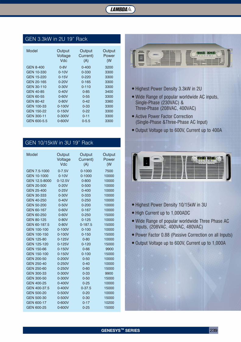
GENESYSTM SERIES 239
Model Output Output Output Voltage Current) Power
Vdc (A) (W
GEN 8-400 0-8V 0-400 3200GEN 10-330 0-10V 0-330 3300GEN 15-220 0-15V 0-220 3300GEN 20-165 0-20V 0-165 3300GEN 30-110 0-30V 0-110 3300GEN 40-85 0-40V 0-85 3400GEN 60-55 0-60V 0-55 3300GEN 80-42 0-80V 0-42 3360GEN 100-33 0-100V 0-33 3300GEN 150-22 0-150V 0-22 3300GEN 300-11 0-300V 0-11 3300GEN 600-5.5 0-600V 0-5.5 3300
Model Output Output Output Voltage Current) Power
Vdc (A) (W
GEN 7.5-1000 0-7.5V 0-1000 7500GEN 10-1000 0-10V 0-1000 10000GEN 12.5-8000 0-12.5V 0-800 10000GEN 20-500 0-20V 0-500 10000GEN 25-400 0-25V 0-400 10000GEN 30-333 0-30V 0-333 10000GEN 40-250 0-40V 0-250 10000GEN 50-200 0-50V 0-200 10000GEN 60-167 0-60V 0-167 10000GEN 60-250 0-60V 0-250 15000GEN 80-125 0-80V 0-125 10000GEN 60-187.5 0-80V 0-187.5 15000GEN 100-100 0-100V 0-100 10000GEN 100-150 0-100V 0-150 15000GEN 125-80 0-125V 0-80 10000GEN 125-120 0-125V 0-120 15000GEN 150-66 0-150V 0-66 9900GEN 150-100 0-150V 0-100 15000GEN 200-50 0-200V 0-50 10000GEN 250-40 0-250V 0-40 10000GEN 250-60 0-250V 0-60 15000GEN 300-33 0-300V 0-33 9900GEN 300-50 0-300V 0-50 15000GEN 400-25 0-400V 0-25 10000GEN 400-37.5 0-400V 0-37.5 15000GEN 500-20 0-500V 0-20 10000GEN 500-30 0-500V 0-30 15000GEN 600-17 0-600V 0-17 10200GEN 600-25 0-600V 0-25 15000
GEN 3.3kW in 2U 19” Rack
GEN 10/15kW in 3U 19” Rack
•Highest Power Density 3.3kW in 2U
•Wide Range of popular worldwide AC inputs,Single-Phase (230VAC) & Three-Phase (208VAC, 400VAC)
•Active Power Factor Correction (Single-Phase &Three-Phase AC Input)
•Output Voltage up to 600V, Current up to 400A
•Highest Power Density 10/15kW in 3U
•High Current up to 1,000ADC
•Wide Range of popular worldwide Three Phase AC Inputs, (208VAC, 400VAC, 480VAC)
•Power Factor 0.88 (Passive Correction on all Inputs)
•Output Voltage up to 600V, Current up to 1,000A
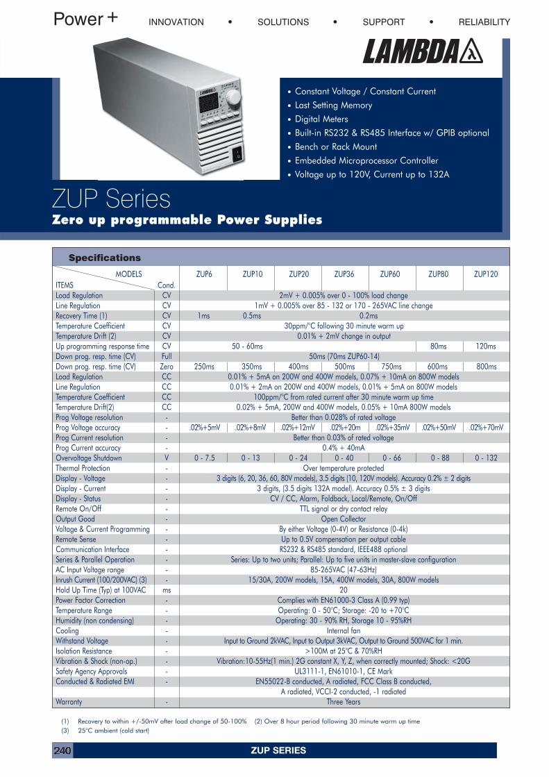
ZUP SERIES240
MODELS ZUP6 ZUP10 ZUP20 ZUP36 ZUP60 ZUP80 ZUP120ITEMS Cond.Load Regulation CV 2mV + 0.005% over 0 - 100% load changeLine Regulation CV 1mV + 0.005% over 85 - 132 or 170 - 265VAC line changeRecovery Time (1) CV 1ms 0.5ms 0.2msTemperature Coefficient CV 30ppm/°C following 30 minute warm upTemperature Drift (2) CV 0.01% + 2mV change in outputUp programming response time CV 50 - 60ms 80ms 120msDown prog. resp. time (CV) Full 50ms (70ms ZUP60-14)Down prog. resp. time (CV) Zero 250ms 350ms 400ms 500ms 750ms 600ms 800msLoad Regulation CC 0.01% + 5mA on 200W and 400W models, 0.07% + 10mA on 800W modelsLine Regulation CC 0.01% + 2mA on 200W and 400W models, 0.01% + 5mA on 800W modelsTemperature Coefficient CC 100ppm/°C from rated current after 30 minute warm up timeTemperature Drift(2) CC 0.02% + 5mA, 200W and 400W models, 0.05% + 10mA 800W modelsProg Voltage resolution - Better than 0.028% of rated voltageProg Voltage accuracy - .02%+5mV .02%+8mV .02%+12mV .02%+20m .02%+35mV .02%+50mV .02%+70mVProg Current resolution - Better than 0.03% of rated voltageProg Current accuracy - 0.4% + 40mAOvervoltage Shutdown V 0 - 7.5 0 - 13 0 - 24 0 - 40 0 - 66 0 - 88 0 - 132Thermal Protection - Over temperature protectedDisplay - Voltage - 3 digits (6, 20, 36, 60, 80V models), 3.5 digits (10, 120V models). Accuracy 0.2% ± 2 digitsDisplay - Current - 3 digits, (3.5 digits 132A model). Accuracy 0.5% ± 3 digitsDisplay - Status - CV / CC, Alarm, Foldback, Local/Remote, On/OffRemote On/Off - TTL signal or dry contact relayOutput Good - Open CollectorVoltage & Current Programming - By either Voltage (0-4V) or Resistance (0-4k)Remote Sense - Up to 0.5V compensation per output cableCommunication Interface - RS232 & RS485 standard, IEEE488 optionalSeries & Parallel Operation - Series: Up to two units; Parallel: Up to five units in master-slave configurationAC Input Voltage range - 85-265VAC (47-63Hz)Inrush Current (100/200VAC) (3) - 15/30A, 200W models, 15A, 400W models, 30A, 800W modelsHold Up Time (Typ) at 100VAC ms 20Power Factor Correction - Complies with EN61000-3 Class A (0.99 typ)Temperature Range - Operating: 0 - 50°C; Storage: -20 to +70°CHumidity (non condensing) - Operating: 30 - 90% RH, Storage 10 - 95%RHCooling - Internal fanWithstand Voltage - Input to Ground 2kVAC, Input to Output 3kVAC, Output to Ground 500VAC for 1 min.Isolation Resistance - >100M at 25°C & 70%RHVibration & Shock (non-op.) - Vibration:10-55Hz(1 min.) 2G constant X, Y, Z, when correctly mounted; Shock: <20GSafety Agency Approvals - UL3111-1, EN61010-1, CE MarkConducted & Radiated EMI - EN55022-B conducted, A radiated, FCC Class B conducted,
A radiated, VCCI-2 conducted, -1 radiatedWarranty - Three Years
Specifications
INNOVATION SOLUTIONS SUPPORT RELIABILITY
ZUP SeriesZero up programmable Power Supplies
• Constant Voltage / Constant Current
• Last Setting Memory
• Digital Meters
• Built-in RS232 & RS485 Interface w/ GPIB optional
• Bench or Rack Mount
• Embedded Microprocessor Controller
• Voltage up to 120V, Current up to 132A
(1) Recovery to within +/-50mV after load change of 50-100% (2) Over 8 hour period following 30 minute warm up time(3) 25°C ambient (cold start)
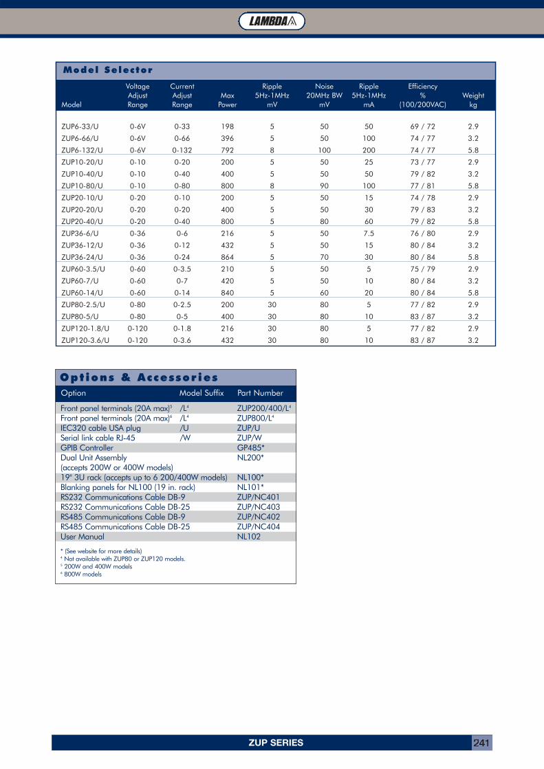
ZUP SERIES 241
TL Module Connector (Part Number: FCI 51732-007)Model Selector
Voltage Current Ripple Noise Ripple EfficiencyAdjust Adjust Max 5Hz-1MHz 20MHz BW 5Hz-1MHz % Weight
Model Range Range Power mV mV mA (100/200VAC) kg
ZUP6-33/U 0-6V 0-33 198 5 50 50 69 / 72 2.9
ZUP6-66/U 0-6V 0-66 396 5 50 100 74 / 77 3.2
ZUP6-132/U 0-6V 0-132 792 8 100 200 74 / 77 5.8
ZUP10-20/U 0-10 0-20 200 5 50 25 73 / 77 2.9
ZUP10-40/U 0-10 0-40 400 5 50 50 79 / 82 3.2
ZUP10-80/U 0-10 0-80 800 8 90 100 77 / 81 5.8
ZUP20-10/U 0-20 0-10 200 5 50 15 74 / 78 2.9
ZUP20-20/U 0-20 0-20 400 5 50 30 79 / 83 3.2
ZUP20-40/U 0-20 0-40 800 5 80 60 79 / 82 5.8
ZUP36-6/U 0-36 0-6 216 5 50 7.5 76 / 80 2.9
ZUP36-12/U 0-36 0-12 432 5 50 15 80 / 84 3.2
ZUP36-24/U 0-36 0-24 864 5 70 30 80 / 84 5.8
ZUP60-3.5/U 0-60 0-3.5 210 5 50 5 75 / 79 2.9
ZUP60-7/U 0-60 0-7 420 5 50 10 80 / 84 3.2
ZUP60-14/U 0-60 0-14 840 5 60 20 80 / 84 5.8
ZUP80-2.5/U 0-80 0-2.5 200 30 80 5 77 / 82 2.9
ZUP80-5/U 0-80 0-5 400 30 80 10 83 / 87 3.2
ZUP120-1.8/U 0-120 0-1.8 216 30 80 5 77 / 82 2.9
ZUP120-3.6/U 0-120 0-3.6 432 30 80 10 83 / 87 3.2
Options & Accessor iesOption Model Suffix Part Number
Front panel terminals (20A max)5 /L4 ZUP200/400/L4
Front panel terminals (20A max)6 /L4 ZUP800/L4
IEC320 cable USA plug /U ZUP/USerial link cable RJ-45 /W ZUP/WGPIB Controller GP485*Dual Unit Assembly NL200*(accepts 200W or 400W models)19" 3U rack (accepts up to 6 200/400W models) NL100*Blanking panels for NL100 (19 in. rack) NL101*RS232 Communications Cable DB-9 ZUP/NC401RS232 Communications Cable DB-25 ZUP/NC403RS485 Communications Cable DB-9 ZUP/NC402RS485 Communications Cable DB-25 ZUP/NC404User Manual NL102
* (See website for more details)4 Not available with ZUP80 or ZUP120 models.5 200W and 400W models6 800W models
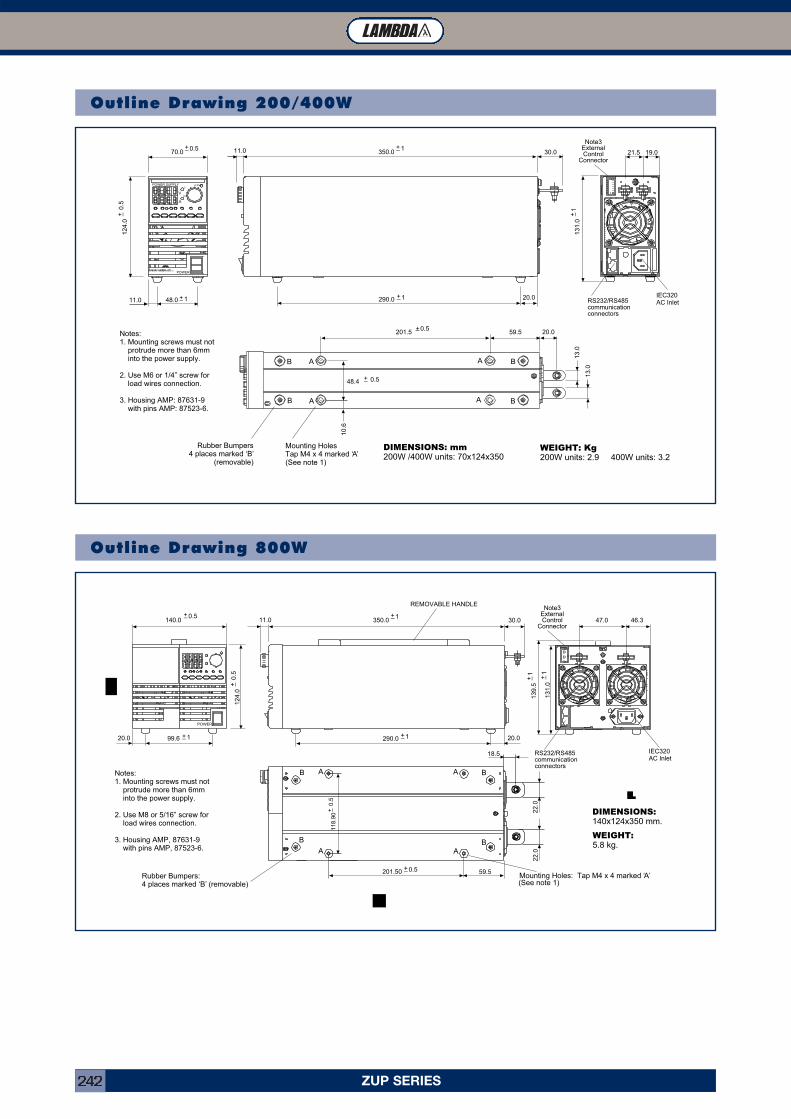
ZUP SERIES242
Outline Drawing 200/400W
Outline Drawing 800W
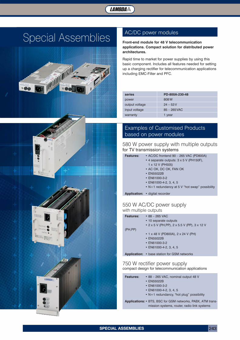
SPECIAL ASSEMBLIES 243
AC/DC power modulesAssembliesSpecial Assemblies
Features: • AC/DC frontend 90 – 265 VAC (PD800A)• 4 separate outputs: 3 x 5 V (PH150F),
1 x 12 V (PH505)• AC OK, DC OK, FAN OK• EN55022B• EN61000-3-2• EN61000-4-2, 3, 4, 5• N+1 redundancy at 5 V “hot swap” possibility
Application: • digital recorder
Examples of Customised Products based on power modules
Front-end module for 48 V telecommunication applications. Compact solution for distributed powerarchitectures.
Rapid time to market for power supplies by using thisbasic component. Includes all features needed for settingup a charging rectifier for telecommunication applicationsincluding EMC-Filter and PFC.
series PD-800A-230-48
power 808 W
output voltage 24 – 53 V
input voltage 85 – 265VAC
warranty 1 year
580 W power supply with multiple outputsfor TV transmission systems
Features: • 88 – 265 VAC• 10 separate outputs• 2 x 5 V (PH,PP), 2 x 5.5 V (PP), 3 x 12 V
(PH,PP)• 1 x 48 V (PD800A), 2 x 24 V (PH)• EN55022B• EN61000-3-2• EN61000-4-2, 3, 4, 5
Application: • base station for GSM networks
550 W AC/DC power supply with multiple outputs
Features: • 88 – 265 VAC, nominal output 48 V• EN55022B• EN61000-3-2• EN61000-4-2, 3, 4, 5• N+1 redundancy, "hot plug” possibility
Applications: • BTS, BSC for GSM networks, PABX, ATM trans-mission systems, router, radio link systems
750 W rectifier power supplycompact design for telecommunication applications
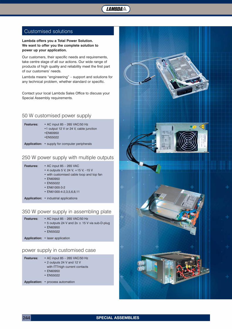
SPECIAL ASSEMBLIES244
Customised solutions
Lambda offers you a Total Power Solution. We want to offer you the complete solution to power up your application.
Our customers, their specific needs and requirements,take centre stage of all our actions. Our wide range ofproducts of high quality and reliability meet the first part of our customers’ needs.
Lambda means “engineering” – support and solutions forany technical problem, whether standard or specific.
Contact your local Lambda Sales Office to discuss yourSpecial Assembly requirements.
Features: • AC input 85 – 265 VAC/50 Hz•1 output 12 V or 24 V, cable junction•EN60950•EN55022
Application: • supply for computer peripherals
50 W customised power supply
Features: • AC input 85 – 265 VAC• 4 outputs 5 V, 24 V, +15 V, –15 V• with customised cable loop and top fan• EN60950• EN55022• EN61000-3-2• EN61000-4-2,3,5,6,8,11
Application: • industrial applications
250 W power supply with multiple outputs
Features: • AC input 85 – 265 VAC/50 Hz• 5 outputs 24 V and 2x ± 15 V via sub-D-plug• EN60950• EN55022
Application: • laser application
350 W power supply in assembling plate
Features: • AC input 85 – 265 VAC/50 Hz• 2 outputs 24 V and 12 V
with ITT-high current contacts• EN60950• EN55022
Application: • process automation
power supply in customised case
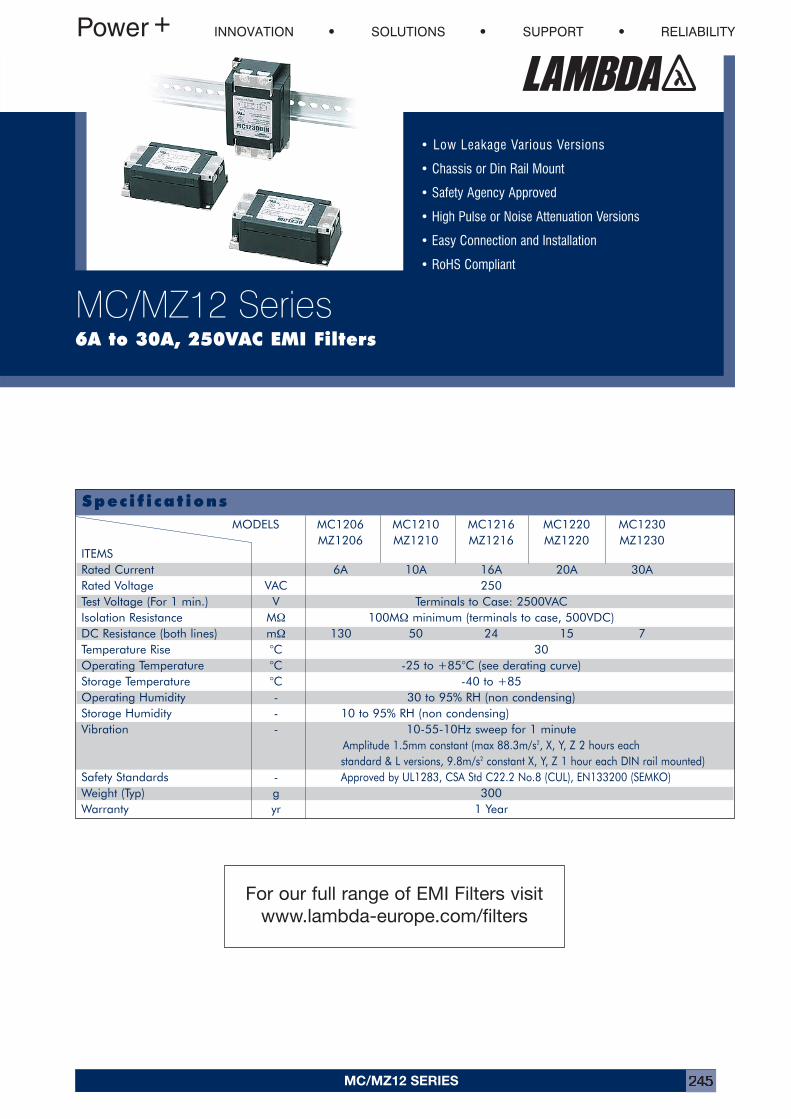
MC/MZ12 SERIES 245
Speci f i cat ions
• Low Leakage Various Versions
• Chassis or Din Rail Mount
• Safety Agency Approved
• High Pulse or Noise Attenuation Versions
• Easy Connection and Installation
• RoHS Compliant
INNOVATION SOLUTIONS SUPPORT RELIABILITY
MC/MZ12 Series6A to 30A, 250VAC EMI Filters
MODELS MC1206 MC1210 MC1216 MC1220 MC1230MZ1206 MZ1210 MZ1216 MZ1220 MZ1230
ITEMS Rated Current 6A 10A 16A 20A 30ARated Voltage VAC 250Test Voltage (For 1 min.) V Terminals to Case: 2500VACIsolation Resistance MΩ 100MΩ minimum (terminals to case, 500VDC)DC Resistance (both lines) mΩ 130 50 24 15 7Temperature Rise °C 30Operating Temperature °C -25 to +85°C (see derating curve)Storage Temperature °C -40 to +85Operating Humidity - 30 to 95% RH (non condensing)Storage Humidity - 10 to 95% RH (non condensing)Vibration - 10-55-10Hz sweep for 1 minute
Amplitude 1.5mm constant (max 88.3m/s2, X, Y, Z 2 hours each standard & L versions, 9.8m/s2 constant X, Y, Z 1 hour each DIN rail mounted)
Safety Standards - Approved by UL1283, CSA Std C22.2 No.8 (CUL), EN133200 (SEMKO)Weight (Typ) g 300Warranty yr 1 Year
For our full range of EMI Filters visitwww.lambda-europe.com/filters
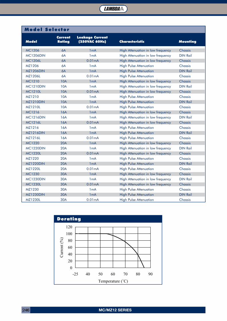
MC/MZ12 SERIES246
Model Selector
0
20
40
60
80
100
120
-25 40 50 60 70 80 90
Derating
Current Leakage CurrentModel Rating (250VAC 60Hz) Characteristic Mounting
MC1206 6A 1mA High Attenuation in low frequency Chassis
MC1206DIN 6A 1mA High Attenuation in low frequency DIN Rail
MC1206L 6A 0.01mA High Attenuation in low frequency Chassis
MZ1206 6A 1mA High Pulse Attenuation Chassis
MZ1206DIN 6A 1mA High Pulse Attenuation DIN Rail
MZ1206L 6A 0.01mA High Pulse Attenuation Chassis
MC1210 10A 1mA High Attenuation in low frequency Chassis
MC1210DIN 10A 1mA High Attenuation in low frequency DIN Rail
MC1210L 10A 0.01mA High Attenuation in low frequency Chassis
MZ1210 10A 1mA High Pulse Attenuation Chassis
MZ1210DIN 10A 1mA High Pulse Attenuation DIN Rail
MZ1210L 10A 0.01mA High Pulse Attenuation Chassis
MC1216 16A 1mA High Attenuation in low frequency Chassis
MC1216DIN 16A 1mA High Attenuation in low frequency DIN Rail
MC1216L 16A 0.01mA High Attenuation in low frequency Chassis
MZ1216 16A 1mA High Pulse Attenuation Chassis
MZ1216DIN 16A 1mA High Pulse Attenuation DIN Rail
MZ1216L 16A 0.01mA High Pulse Attenuation Chassis
MC1220 20A 1mA High Attenuation in low frequency Chassis
MC1220DIN 20A 1mA High Attenuation in low frequency DIN Rail
MC1220L 20A 0.01mA High Attenuation in low frequency Chassis
MZ1220 20A 1mA High Pulse Attenuation Chassis
MZ1220DIN 20A 1mA High Pulse Attenuation DIN Rail
MZ1220L 20A 0.01mA High Pulse Attenuation Chassis
MC1230 30A 1mA High Attenuation in low frequency Chassis
MC1230DIN 30A 1mA High Attenuation in low frequency DIN Rail
MC1230L 30A 0.01mA High Attenuation in low frequency Chassis
MZ1230 30A 1mA High Pulse Attenuation Chassis
MZ1230DIN 30A 1mA High Pulse Attenuation DIN Rail
MZ1230L 30A 0.01mA High Pulse Attenuation Chassis
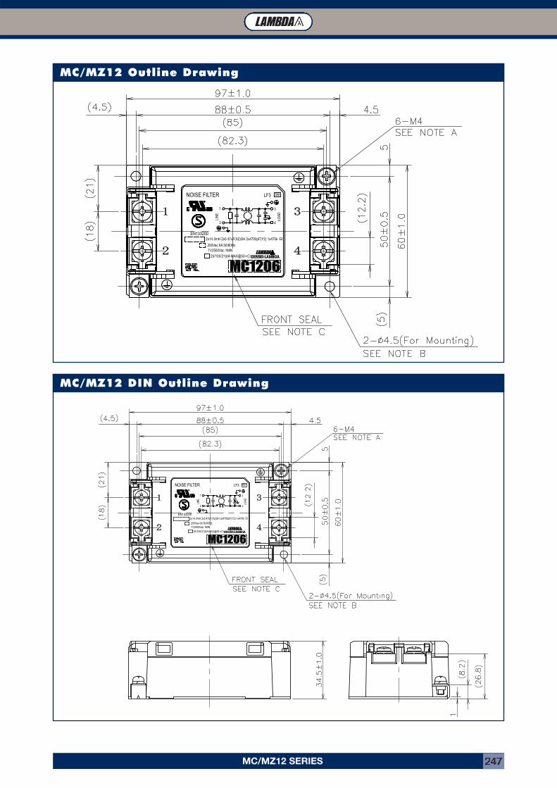
MC/MZ12 SERIES 247
MC/MZ12 Outline Drawing
MC/MZ12 DIN Outline Drawing
25/100/21(6A MAX@55 )
EN133200
250Vac 6A 50/60HzTV2500Vac 1MIN
NOISE FILTER
2x14.3mH 2x0.47uF(X2)SH 2x4700pF(Y2) 1x470k
LF3
2
∞C
LIN
E
1
4
Ω
3
LOAD
SM
25/100/21(6A MAX@55 )
EN133200
250Vac 6A 50/60HzTV2500Vac 1MIN
NOISE FILTER
2x14.3mH 2x0.47uF(X2)SH 2x4700pF(Y2) 1x470k
LF3
2
∞C
LIN
E
1
4
Ω
3
LOAD
SM
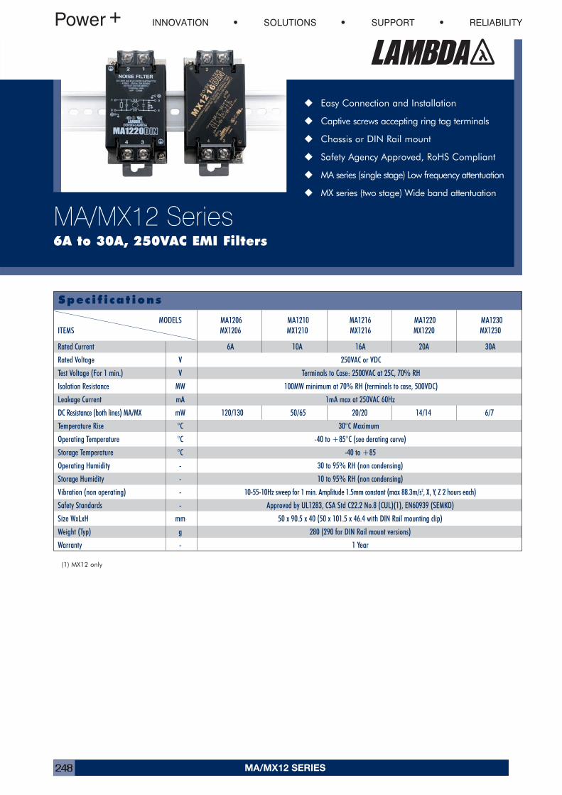
� Easy Connection and Installation
� Captive screws accepting ring tag terminals
� Chassis or DIN Rail mount
� Safety Agency Approved, RoHS Compliant
� MA series (single stage) Low frequency attentuation
� MX series (two stage) Wide band attentuation
INNOVATION SOLUTIONS SUPPORT RELIABILITY
MA/MX12 Series6A to 30A, 250VAC EMI Filters
Spec i f i cat ions
MODELS MA1206 MA1210 MA1216 MA1220 MA1230ITEMS MX1206 MX1210 MX1216 MX1220 MX1230
Rated Current 6A 10A 16A 20A 30A
Rated Voltage V 250VAC or VDC
Test Voltage (For 1 min.) V Terminals to Case: 2500VAC at 25C, 70% RH
Isolation Resistance MW 100MW minimum at 70% RH (terminals to case, 500VDC)
Leakage Current mA 1mA max at 250VAC 60Hz
DC Resistance (both lines) MA/MX mW 120/130 50/65 20/20 14/14 6/7
Temperature Rise °C 30°C Maximum
Operating Temperature °C -40 to +85°C (see derating curve)
Storage Temperature °C -40 to +85
Operating Humidity - 30 to 95% RH (non condensing)
Storage Humidity - 10 to 95% RH (non condensing)
Vibration (non operating) - 10-55-10Hz sweep for 1 min. Amplitude 1.5mm constant (max 88.3m/s2, X, Y, Z 2 hours each)
Safety Standards - Approved by UL1283, CSA Std C22.2 No.8 (CUL)(1), EN60939 (SEMKO)
Size WxLxH mm 50 x 90.5 x 40 (50 x 101.5 x 46.4 with DIN Rail mounting clip)
Weight (Typ) g 280 (290 for DIN Rail mount versions)
Warranty - 1 Year
(1) MX12 only
MA/MX12 SERIES248
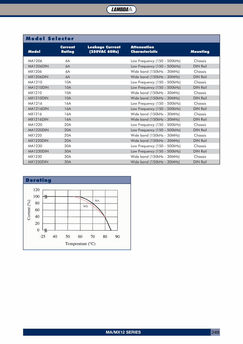
Model Selector
Current Leakage Current AttenuationModel Rating (250VAC 60Hz) Characteristic Mounting
MA1206 6A Low Frequency (150 - 500kHz) ChassisMA1206DIN 6A Low Frequency (150 - 500kHz) DIN RailMX1206 6A Wide band (150kHz - 30MHz) ChassisMX1206DIN 6A Wide band (150kHz - 30MHz) DIN RailMA1210 10A Low Frequency (150 - 500kHz) ChassisMA1210DIN 10A Low Frequency (150 - 500kHz) DIN RailMX1210 10A Wide band (150kHz - 30MHz) ChassisMX1210DIN 10A Wide band (150kHz - 30MHz) DIN RailMA1216 16A Low Frequency (150 - 500kHz) ChassisMA1216DIN 16A Low Frequency (150 - 500kHz) DIN RailMX1216 16A Wide band (150kHz - 30MHz) ChassisMX1216DIN 16A Wide band (150kHz - 30MHz) DIN RailMA1220 20A Low Frequency (150 - 500kHz) ChassisMA1220DIN 20A Low Frequency (150 - 500kHz) DIN RailMX1220 20A Wide band (150kHz - 30MHz) ChassisMX1220DIN 20A Wide band (150kHz - 30MHz) DIN RailMA1230 30A Low Frequency (150 - 500kHz) ChassisMA1230DIN 30A Low Frequency (150 - 500kHz) DIN RailMX1230 30A Wide band (150kHz - 30MHz) ChassisMX1230DIN 30A Wide band (150kHz - 30MHz) DIN Rail
Derating
MX
MA
MA/MX12 SERIES 249
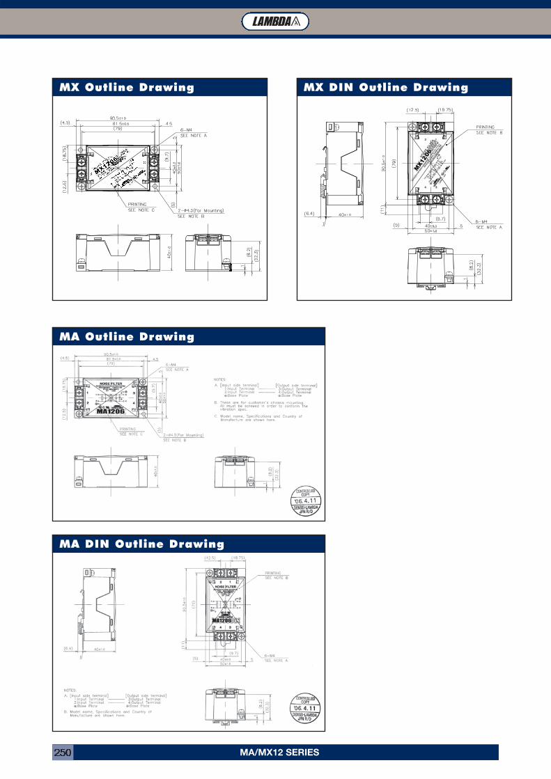
MA/MX12 SERIES250
MX Outline Drawing
MA Outline Drawing
MX DIN Outline Drawing
MA DIN Outline Drawing
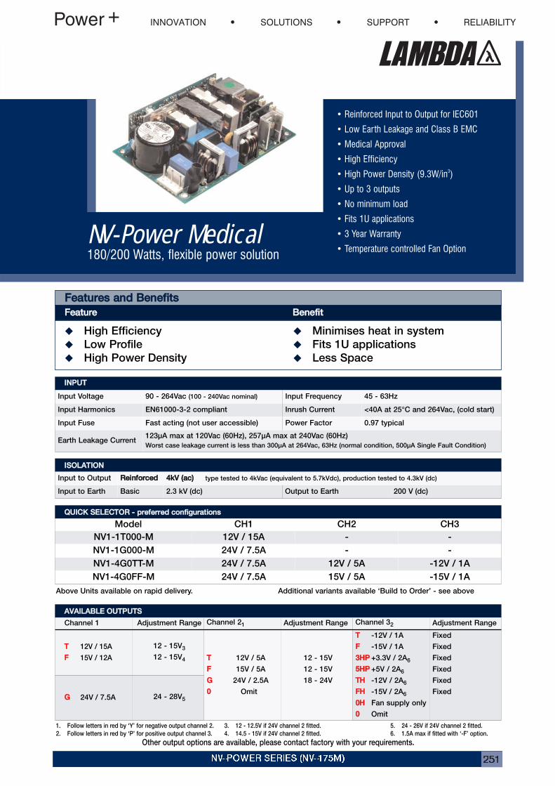
NV-POWER SERIES (NV-175M) 251
• Reinforced Input to Output for IEC601
• Low Earth Leakage and Class B EMC
• Medical Approval
• High Efficiency
• High Power Density (9.3W/in3)
• Up to 3 outputs
• No minimum load
• Fits 1U applications
• 3 Year Warranty
• Temperature controlled Fan OptionNV-Power Medical180/200 Watts, flexible power solution
FFeeaattuurreess aanndd BBeenneeffiittssFFeeaattuurree BBeenneeffiitt� High Efficiency � Minimises heat in system
� Low Profile � Fits 1U applications
� High Power Density � Less Space
IINNPPUUTTInput Voltage 90 - 264Vac (100 - 240Vac nominal) Input Frequency 45 - 63Hz
Input Harmonics EN61000-3-2 compliant Inrush Current <40A at 25°C and 264Vac, (cold start)
Input Fuse Fast acting (not user accessible) Power Factor 0.97 typical
Earth Leakage Current123μA max at 120Vac (60Hz), 257μA max at 240Vac (60Hz)
Worst case leakage current is less than 300μA at 264Vac, 63Hz (normal condition, 500μA Single Fault Condition)
AAVVAAIILLAABBLLEE OOUUTTPPUUTTSSChannel 1 Adjustment Range Channel 21 Adjustment Range Channel 32 Adjustment Range
TT 12V / 15A
FF 15V / 12A
12 - 15V3
12 - 15V4 TT 12V / 5A
FF 15V / 5A
GG 24V / 2.5A
00 Omit
12 - 15V
12 - 15V
18 - 24V
TT -12V / 1A
FF -15V / 1A
33HHPP +3.3V / 2A6
55HHPP +5V / 2A6
TTHH -12V / 2A6
FFHH -15V / 2A6
00HH Fan supply only
00 Omit
Fixed
Fixed
Fixed
Fixed
Fixed
FixedGG 24V / 7.5A 24 - 28V5
5. 24 - 26V if 24V channel 2 fitted.
6. 1.5A max if fitted with ‘-F’ option.
3. 12 - 12.5V if 24V channel 2 fitted.
4. 14.5 - 15V if 24V channel 2 fitted.
1. Follow letters in red by ‘Y’ for negative output channel 2.
2. Follow letters in red by ‘P’ for positive output channel 3.
Other output options are available, please contact factory with your requirements.
Above Units available on rapid delivery.
QQUUIICCKK SSEELLEECCTTOORR -- pprreeffeerrrreedd ccoonnffiigguurraattiioonnssModel CH1 CH2 CH3
NV1-1T000-M 12V / 15A - -
NV1-1G000-M 24V / 7.5A - -
NV1-4G0TT-M 24V / 7.5A 12V / 5A -12V / 1A
NV1-4G0FF-M 24V / 7.5A 15V / 5A -15V / 1A
Additional variants available ‘Build to Order’ - see above
IISSOOLLAATTIIOONNInput to Output RReeiinnffoorrcceedd 44kkVV ((aacc)) type tested to 4kVac (equivalent to 5.7kVdc), production tested to 4.3kV (dc)
Input to Earth Basic 2.3 kV (dc) Output to Earth 200 V (dc)
INNOVATION SOLUTIONS SUPPORT RELIABILITY
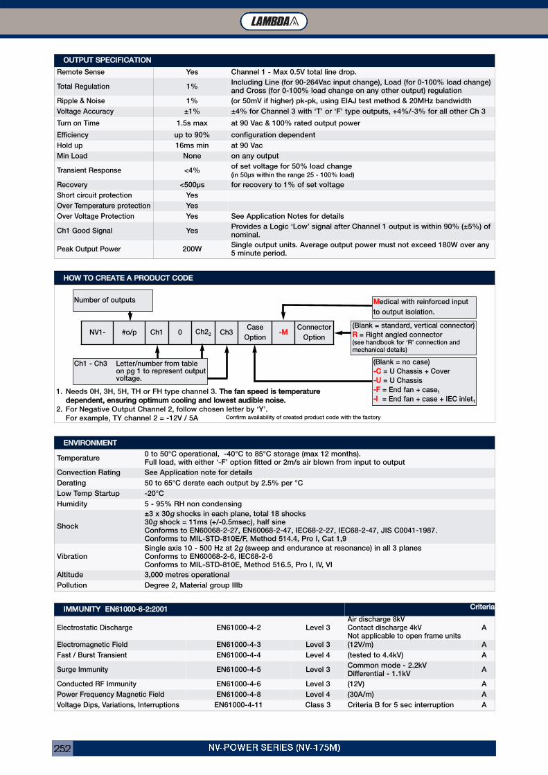
NV-POWER SERIES (NV-175M)252
OOUUTTPPUUTT SSPPEECCIIFFIICCAATTIIOONNRemote Sense Yes Channel 1 - Max 0.5V total line drop.
Total Regulation 1%Including Line (for 90-264Vac input change), Load (for 0-100% load change)and Cross (for 0-100% load change on any other output) regulation
Ripple & Noise 1% (or 50mV if higher) pk-pk, using EIAJ test method & 20MHz bandwidth
Voltage Accuracy ±1% ±4% for Channel 3 with ‘T’ or ‘F’ type outputs, +4%/-3% for all other Ch 3
Turn on Time 1.5s max at 90 Vac & 100% rated output power
Efficiency up to 90% configuration dependent
Hold up 16ms min at 90 Vac
Min Load None on any output
Transient Response <4%of set voltage for 50% load change(in 50μs within the range 25 - 100% load)
Recovery <500μs for recovery to 1% of set voltage
Short circuit protection Yes
Over Temperature protection Yes
Over Voltage Protection Yes See Application Notes for details
Ch1 Good Signal YesProvides a Logic ‘Low’ signal after Channel 1 output is within 90% (±5%) ofnominal.
Peak Output Power 200WSingle output units. Average output power must not exceed 180W over any5 minute period.
EENNVVIIRROONNMMEENNTTTemperature
0 to 50°C operational, -40°C to 85°C storage (max 12 months).Full load, with either ‘-F’ option fitted or 2m/s air blown from input to output
Convection Rating See Application note for details
Derating 50 to 65°C derate each output by 2.5% per °C
Low Temp Startup -20°C
Humidity 5 - 95% RH non condensing
Shock
±3 x 30g shocks in each plane, total 18 shocks30g shock = 11ms (+/-0.5msec), half sineConforms to EN60068-2-27, EN60068-2-47, IEC68-2-27, IEC68-2-47, JIS C0041-1987.Conforms to MIL-STD-810E/F, Method 514.4, Pro I, Cat 1,9
VibrationSingle axis 10 - 500 Hz at 2g (sweep and endurance at resonance) in all 3 planesConforms to EN60068-2-6, IEC68-2-6Conforms to MIL-STD-810E, Method 516.5, Pro I, IV, VI
Altitude 3,000 metres operational
Pollution Degree 2, Material group IIIb
IIMMMMUUNNIITTYY EENN6611000000--66--22::22000011 CCrriitteerriiaaElectrostatic Discharge EN61000-4-2 Level 3
Air discharge 8kVContact discharge 4kVNot applicable to open frame units
A
Electromagnetic Field EN61000-4-3 Level 3 (12V/m) A
Fast / Burst Transient EN61000-4-4 Level 4 (tested to 4.4kV) A
Surge Immunity EN61000-4-5 Level 3Common mode - 2.2kVDifferential - 1.1kV
A
Conducted RF Immunity EN61000-4-6 Level 3 (12V) A
Power Frequency Magnetic Field EN61000-4-8 Level 4 (30A/m) A
Voltage Dips, Variations, Interruptions EN61000-4-11 Class 3 Criteria B for 5 sec interruption A
HHOOWW TTOO CCRREEAATTEE AA PPRROODDUUCCTT CCOODDEE
NV1- #o/p Ch1 0 Ch22 Ch3Case
Option--MM Connector
Option
1. Needs 0H, 3H, 5H, TH or FH type channel 3. TThhee ffaann ssppeeeedd iiss tteemmppeerraattuurreeddeeppeennddeenntt,, eennssuurriinngg ooppttiimmuumm ccoooolliinngg aanndd lloowweesstt aauuddiibbllee nnooiissee..
2. For Negative Output Channel 2, follow chosen letter by ‘Y’.
For example, TY channel 2 = -12V / 5A Confirm availability of created product code with the factory
Ch1 - Ch3 Letter/number from tableon pg 1 to represent outputvoltage.
Number of outputs
(Blank = standard, vertical connector)
RR = Right angled connector(see handbook for ‘R’ connection andmechanical details)
(Blank = no case)
--CC = U Chassis + Cover
--UU = U Chassis
--FF = End fan + case1
--II = End fan + case + IEC inlet1
MMedical with reinforced input
to output isolation.
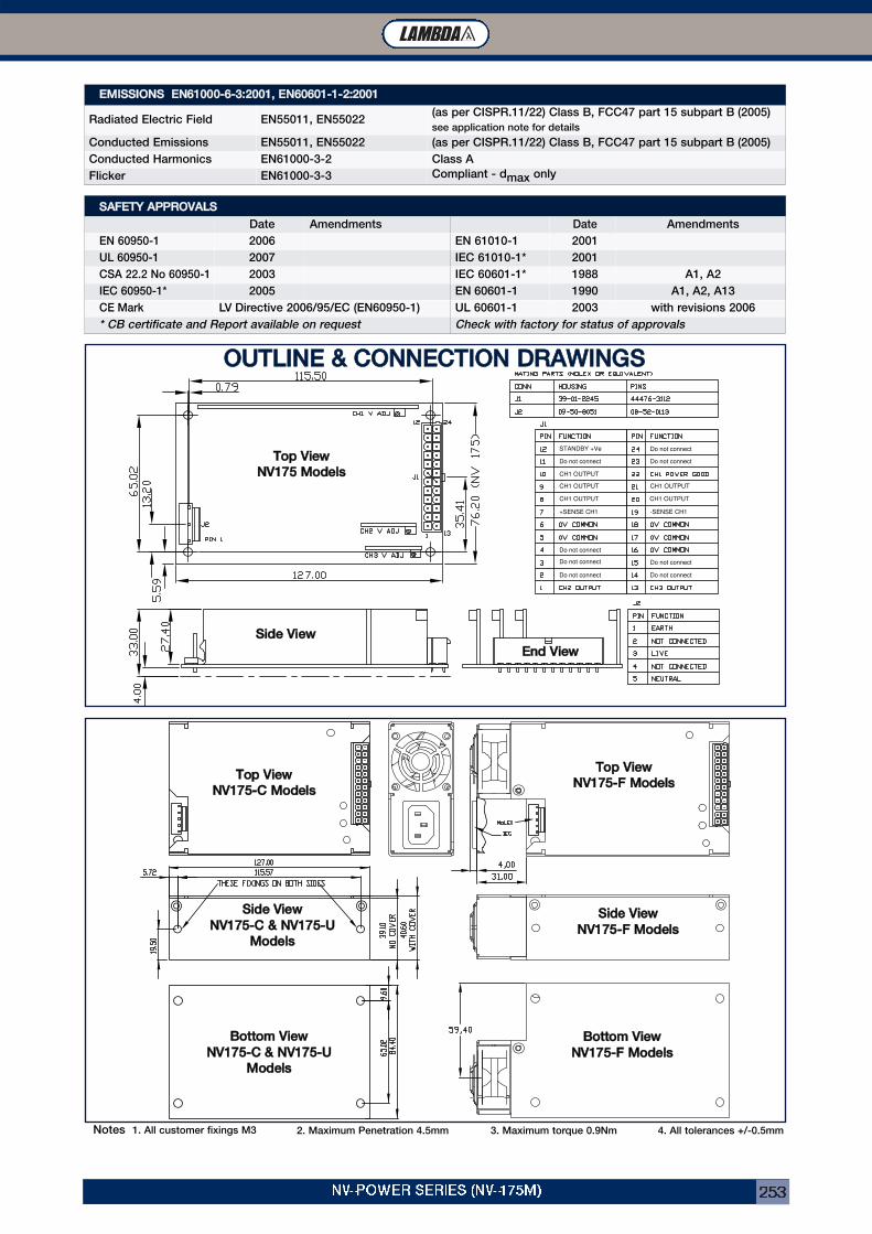
NV-POWER SERIES (NV-175M) 253
EEMMIISSSSIIOONNSS EENN6611000000--66--33::22000011,, EENN6600660011--11--22::22000011Radiated Electric Field EN55011, EN55022
(as per CISPR.11/22) Class B, FCC47 part 15 subpart B (2005)
see application note for details
Conducted Emissions EN55011, EN55022 (as per CISPR.11/22) Class B, FCC47 part 15 subpart B (2005)
Conducted Harmonics EN61000-3-2 Class A
Flicker EN61000-3-3 Compliant - dmax only
STANDBY +Ve
Do not connect
CH1 OUTPUT
CH1 OUTPUT
CH1 OUTPUT
CH1 OUTPUT
CH1 OUTPUT
Do not connect
Do not connect
Do not connect
Do not connect
Do not connect
Do not connect
Do not connect
+SENSE CH1 -SENSE CH1
SSiiddee VViieewwEEnndd VViieeww
OOUUTTLLIINNEE && CCOONNNNEECCTTIIOONN DDRRAAWWIINNGGSS
SSAAFFEETTYY AAPPPPRROOVVAALLSSDate Amendments Date Amendments
EN 60950-1 2006 EN 61010-1 2001
UL 60950-1 2007 IEC 61010-1* 2001
CSA 22.2 No 60950-1 2003 IEC 60601-1* 1988 A1, A2
IEC 60950-1* 2005 EN 60601-1 1990 A1, A2, A13
CE Mark LV Directive 2006/95/EC (EN60950-1) UL 60601-1 2003 with revisions 2006
* CB certificate and Report available on request Check with factory for status of approvals
Notes 1. All customer fixings M3 2. Maximum Penetration 4.5mm 3. Maximum torque 0.9Nm 4. All tolerances +/-0.5mm
TToopp VViieewwNNVV117755--CC MMooddeellss TToopp VViieeww
NNVV117755--FF MMooddeellss
SSiiddee VViieewwNNVV117755--CC && NNVV117755--UU
MMooddeellss
BBoottttoomm VViieewwNNVV117755--FF MMooddeellss
SSiiddee VViieewwNNVV117755--FF MMooddeellss
BBoottttoomm VViieewwNNVV117755--CC && NNVV117755--UU
MMooddeellss
TToopp VViieewwNNVV117755 MMooddeellss

NOTES254

NOTES 255

NOTES256

GLOBAL FACILITIES
Global Facilities
NNaaggaaookkaa ((JJaappaann))Manufacturing and R&D
AC-DC, DC-DC andcustom products
KKaarrmmiieell PPllaanntt ((IIssrraaeell))Manufacturing and R&D
Front end, Programmable power supplies andcustom products
CChhiinnaa PPllaannttManufacturing (Wuxi) and R&D (Shanghai)
AC-DC Converters, filters and custom products
II ll ffrraaccoommbbee PPllaanntt ((UU..KK..))Manufacturing and R&D
Configurable/modular (Alpha, NV, Vega) and custom products
SSeennaaii PPllaanntt ((MMaallaayyssiiaa))Manufacturing
AC-DC, DC-DC power modules andcustom products
KKuuaannttaann PPllaanntt ((MMaallaayyssiiaa))Manufacturing
AC-DC Converters and custom products
www.lambda-europe.com
Lambda GmbHKarl-Bold-Strasse 40D-77855 AchernTel. +49 / 7841 / 666 0Fax: +49 / 7841 / [email protected]
Lambda GmbHAredstrasse 22A-2544 LeobersdorfTel. +43 / 2256 / 655 84Fax: +43 / 2256 / 645 [email protected]
Lambda UKKingsley AvenueIlfracombeDevon EX34 8ESUnited KingdomTel. +44 / 12 71 85 66 66Fax: +44 / 12 71 86 48 94www.lambda-gb.com
Please contact your local sales office to find the best solution to your application.
Lambda ScandinaviaPO Box 546Rallarvägen 41SE-184 25 ÅkersbergaSwedenTel. +46 854 084 990Fax: +46 854 066 [email protected]
Lambda SASZAC des DelachesBP 1077-Gometz-le-ChatelF-91940 LES ULISTel. +33 / 1 60 12 71 65Fax: +33 / 1 60 12 71 [email protected]
Lambda S.r.l.Via dei Lavoratori 128/130IT 20092 Cinisello Balsamo (MI)Tel. +39 / 02 61 29 38 63Fax: +39 / 02 61 29 09 [email protected]
Power+ INNOVATION · SOLUTIONS · SUPPORT · RELIABILITY
Printed on paper sourced from fully sustainable forestsusing biodegradable vegetable and soya based inks
Printed by Toptown Printers Ltd +44 (0)1271 371271