Embed Size (px)
Citation preview
PILOT OPERATING HANDBOOK
ALPHA Trainer LSA Document No.: POH-162-00-40-001*REVISION A00Date of Issue: December 3rd, 2019
*applicable to all ALPHA Trainer aircraft, from serial number 996 AT 912 LSA onwards, that are registered as an S-LSA or E-LSA (experi-mental) airplane and have a MTOM of 550 kg.
Aircraft Serial Number: 1001 AT 912 LSA
Aircraft Registration Number: N221PF
PIPISTREL VERTICAL SOLUTIONS d.o.o.Vipavska cesta 2SI-5270 AjdovščinaSloveniaTel: + 386 5 36 63 873Fax: + 386 5 36 61 263Email: [email protected]
All rights reserved. Reproduction or disclosure to third parties of this document or any part thereof is not permitted, except with the prior and express written permission of Pipistrel Group’s R&D division, Pipistrel Vertical Solutions d.o.o., which is authorized to publish technical documentation for Pipistrel Group’s subsidiaries.
iiPAGE
ALPHA Trainer LSAPilot Operating Handbook
POH-162-00-40-001PAGE REV. 0
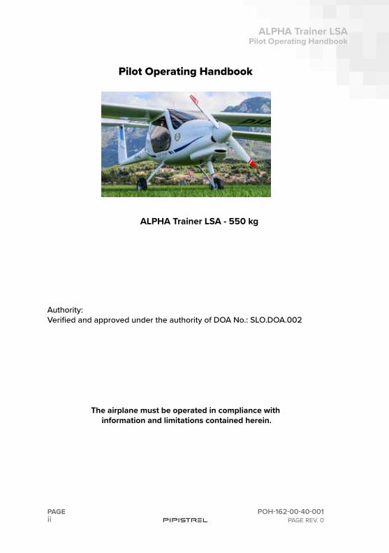
ALPHA Trainer LSA - 550 kg
Authority: Verified and approved under the authority of DOA No.: SLO.DOA.002
The airplane must be operated in compliance with information and limitations contained herein.
Pilot Operating Handbook
iii
ALPHA Trainer LSAPilot Operating Handbook
POH-162-00-40-001PAGE REV. 0
PAGE
SECTION CONTENTS
0 FOREWORD
1 GENERAL
2 LIMITATIONS
3 EMERGENCY PROCEDURES
4 NORMAL PROCEDURES
5 PERFORMANCE DATA
6 WEIGHT AND BALANCE
7 AIRPLANE DESCRIPTION
8 HANDLING, SERVICING AND MAINTENANCE
9 SUPPLEMENTS
Table of contents
Online updates, service notice tracking & airworthinress reporting
To access all publications that pertain to your aircraft, including instructions for continued airworthiness, please visit www.pipistrel-aircraft.com and login to our technical publication portal using the following:
Username: owner1Password: ab2008
ivPAGE
ALPHA Trainer LSAPilot Operating Handbook
POH-162-00-40-001PAGE REV. 0
Special statements in the Pilot Operating Handbook/Airplane Flight Manual concerning the safety or operation of the airplane are highlighted by being prefixed by one of the following terms:
WARNING: Means that the non-observance of the corresponding proce-dures lead to an immediate or significant degradation in flight safety.
CAUTION: Means that the non-observance of the corresponding proce-dures leads to a minor or to a long term degradation of the flight safety.
NOTE: Draws the attention to any special item not directly related to safety but which is important or unusual.
Revision tracking, filing and identifying
Pages to be removed or replaced in this pilot operating handbook (POH) are determined by the log of effective pages located in this section. This log con-tains the page number and revision number for each page within the POH. As revisions to the POH occur, the revision number on the affected pages is updated and the page number in the log is highlighted with bold font type. When two pages display the same page number, the page with the latest revision shall be used in the POH.
The revision number on the log of effective pages shall also coincide with the revision number of the page in question. As an alternative to removing and/or replacing individual pages, the owner can also print out a whole new manual in its current form.
Revised material is marked with a vertical bar that will extend the full length of deleted, new or revised text added to new or previously existing pages. This marker will be located adjacent to the applicable text in the marking on the outer side of the page. The same system applies when the header, figure or any other element inside this POH is revised. A list of revisions is located at the beginning of the log of effective pages. Pipistrel is not responsible for technical changes/updates to OEM manuals supplied with the aircraft (eg. radio, transponder, GPS, etc.).
USING THIS HANDBOOK

v
ALPHA Trainer LSAPilot Operating Handbook
POH-162-00-40-001PAGE REV. 0
PAGE
Doc.Rev.
Descrip-tion Reason for revision Affected pages Authority
A00 First / ALL SLO.DOA.002
Index of document revisions
viPAGE
ALPHA Trainer LSAPilot Operating Handbook
POH-162-00-40-001PAGE REV. 0
PAGE NUMBER
PAGE REV.
PAGE NUMBER
PAGE REV.
PAGE NUMBER
PAGE REV.
PAGE NUMBER
PAGE REV.
2
2 - 1 0
2 - 2 0
2 - 3 0
2 - 4 0
2 - 5 0
2 - 6 0
2 - 7 0
2 - 8 0
2 - 9 0
2 - 10 0
2 - 11 0
2 - 12 0
2 - 13 0
2 - 14 0
2 - 15 0
2 - 16 011 - 1 0
1 - 2 0
1 - 3 0
1 - 4 0
1 - 5 0
1 - 6 0
1 - 7 0
1 - 8 0
1 - 9 0
1 - 10 0
1 - 11 0
1 - 12 blank
0Cover 0
ii 0
iii 0
iv 0
v 0
vi 0
vii 0
viii blank
3
3 - 12 0
3 - 13 0
3 - 14 0
3 - 15 0
3 - 16 0
3 - 17 0
3 - 18 0
3 - 19 0
3 - 20 0
3 - 21 0
3 - 22 blank
3 - 23 0
3 - 24 blank
3 - 25 0
3 - 26 0
3 - 27 0
3 - 28 0
3 - 29 0
3 - 30 0
3 - 31 0
3 - 32 0
3 - 33 0
3 - 34 blank
4
4 - 1 0
4 - 2 0
4 - 3 0
4 - 4 blank
4 - 5 0
4 - 6 0
4 - 7 0
4 - 8 0
4 - 9 0
4 - 10 0
4 - 11 0
4 - 12 0
4 - 13 0
4 - 14 0
4 - 15 0
4 - 16 0
4 - 17 0
4 - 18 0
4 - 19 0
4 - 20 0
4 - 21 blank
4 - 22 blank
4 - 23 0
4 - 24 blank
4 - 25 0
4 - 26 0
4 - 27 0
4 - 28 0
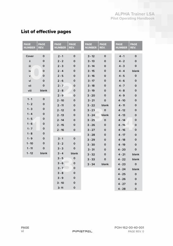
List of effective pages
33 - 1 0
3 - 2 0
3 - 3 0
3 - 4 blank
3 - 5 0
3 - 6 0
3 - 7 0
3 - 8 0
3 - 9 0
3 - 10 0
3- 11 0
vii
ALPHA Trainer LSAPilot Operating Handbook
POH-162-00-40-001PAGE REV. 0
PAGE
9 - 1 0
9 - 2 0
PAGE NUMBER
PAGE REV.
PAGE NUMBER
PAGE REV.
PAGE NUMBER
PAGE REV.
PAGE NUMBER
PAGE REV.
5
5 - 1 0
5 - 2 0
5 - 3 0
5 - 4 0
5 - 5 0
5 - 6 0
5 - 7 0
5 - 8 0
5 - 9 0
5 - 10 05 - 11 0
5 - 12 0
5 - 13 0
5 - 14 0
66 - 1 0
6 - 2 0
6 - 3 0
6 - 4 0
6 - 5 0
6 - 6 blank
7
7 - 1 0
7 - 2 0
7 - 3 0
7 - 4 blank
7 - 5 0
7 - 6 0
7 - 7 0
7 - 8 0
7 - 9 0
7 - 10 0
7 - 11 0
7 - 12 0
7 - 13 0
7 - 14 0
7 - 15 0
7 - 16 0
7 - 17 0
7 - 18 0
7 - 19 0
7 - 20 07 - 21 0
7 - 22 0
7 - 23 0
7 - 24 0
8
8 - 1 0
8 - 2 0
8 - 3 0
8 - 4 0
8 - 5 0
8 - 6 0
8 - 7 0
8 - 8 0
8 - 9 0
8 - 10 0
8 - 11 0
8 - 12 0
8 - 13 0
8 - 14 blank
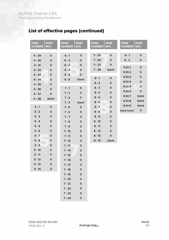
List of effective pages (continued)
44 - 29 0
4 - 30 0
4 - 31 0
4 - 32 0
4 - 33 0
4 - 34 0
4 - 35 0
4 - 36 0
4 - 37 0
4 - 38 blank
77 - 25 0
7 - 26 0
7 - 27 0
7 - 28 blank
9-S1
9-S1-1 0
9-S1-2 0
9-S1-3 0
9-S1-4 0
9-S1-5 0
9-S1-6 0
9-S1-7 blank
9-S1-8 blank
9-S1-9 blank
back-cover 0

This page is intentionally left blank.

SECTION
1
1-2PAGE
ALPHA Trainer LSAPilot Operating Handbook
POH-162-00-40-001PAGE REV. 0
PART SUBJECT PAGE NUMBER
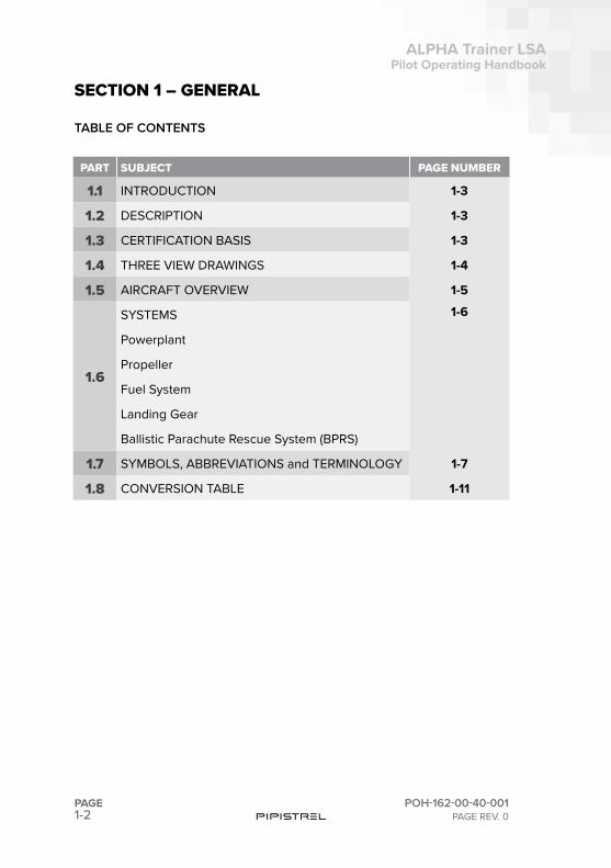
1.1 INTRODUCTION 1-3
1.2 DESCRIPTION 1-3
1.3 CERTIFICATION BASIS 1-3
1.4 THREE VIEW DRAWINGS 1-4
1.5 AIRCRAFT OVERVIEW 1-5
1.6
SYSTEMS 1-6
Powerplant
Propeller
Fuel System
Landing Gear
Ballistic Parachute Rescue System (BPRS)
1.7 SYMBOLS, ABBREVIATIONS and TERMINOLOGY 1-7
1.8 CONVERSION TABLE 1-11
SECTION 1 – GENERAL
TABLE OF CONTENTS
1-3
ALPHA Trainer LSAPilot Operating Handbook
POH-162-00-40-001PAGE REV. 0
PAGE
SECTION 1GENERAL
1.1. INTRODUCTION
This section contains information of general interest to pilots and owners. You will find the information useful in acquainting yourself with the airplane, as well as in loading, fueling, sheltering, and handling the airplane during ground operations. Additionally, this section contains definitions or explana-tions of symbols, abbreviations, and terminology used throughout this hand-book.
1.2. DESCRIPTION
The ALPHA Trainer is a two-seat aircraft of composite construction. The air-craft is arranged as a high wing mono-plane with cantilevered wings and a conventional empennage with a T-tail. The aircraft incorporates a tricycle landing gear and is equipped with a 59.6 kW Rotax 912 UL (or A2, avalable as option).
The seats are side-by side with full dual flight controls and joint levers for throttle, choke and flaps control. Access to cockpit is via two large gull-wing doors. Baggage area is behind the seats. The ALPHA Trainer is equipped with a ballistic parachute system.
The load-bearing structure of the airplane is made of carbon, glass and ara-mid fiber composite material, the components of which, epoxy resin as well as fiber materials, are in compliance with worldwide accepted aviation spec-ifications. The proven low-pressure wet lay-up method from the sailplane industry is used to build the airplane structure.
1.3. CERTIFICATION BASIS
ALPHA Trainer LSA complies with the following ASTM standard specifica-tions for Light Sport Aircraft:
F2245 / F2746 / F2295
1-4PAGE
ALPHA Trainer LSAPilot Operating Handbook
POH-162-00-40-001PAGE REV. 0
SECTION 1GENERAL
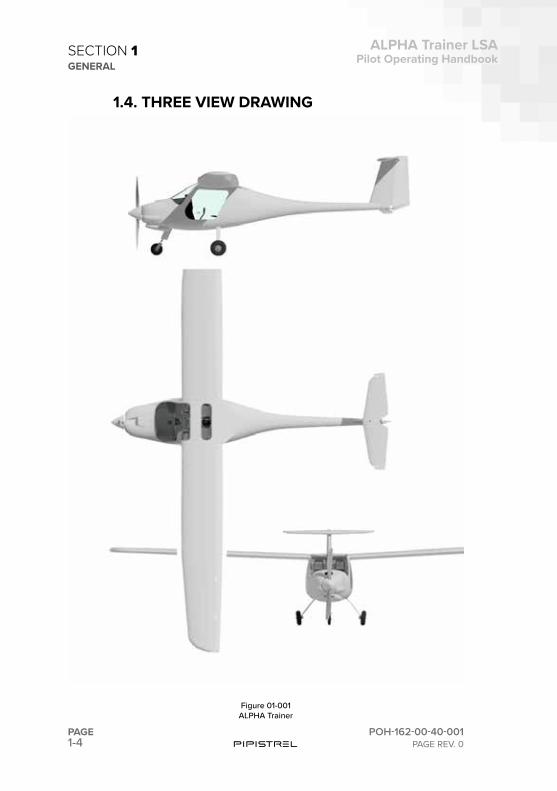
Figure 01-001ALPHA Trainer
1.4. THREE VIEW DRAWING
1-5
ALPHA Trainer LSAPilot Operating Handbook
POH-162-00-40-001PAGE REV. 0
PAGE
SECTION 1GENERAL
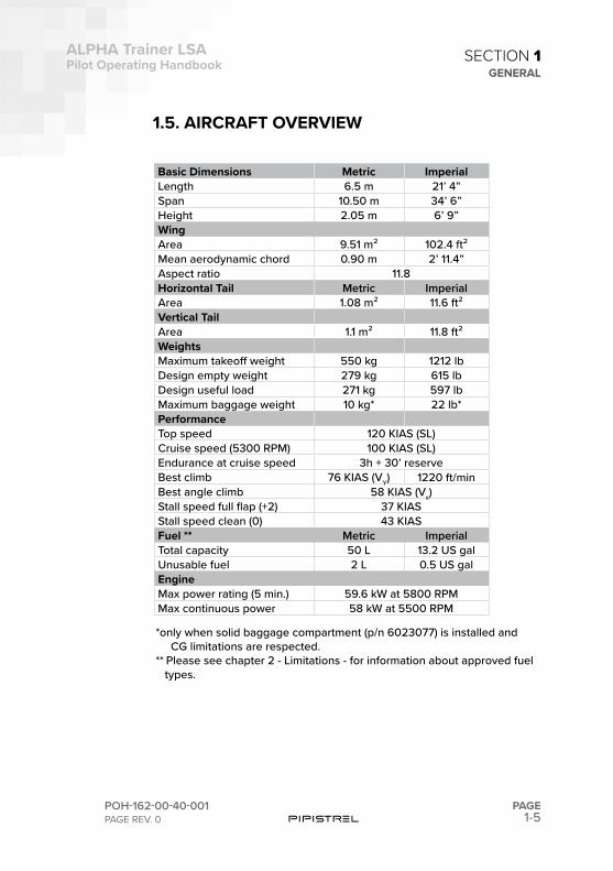
1.5. AIRCRAFT OVERVIEW
Basic Dimensions Metric ImperialLength 6.5 m 21’ 4”Span 10.50 m 34’ 6”Height 2.05 m 6’ 9”WingArea 9.51 m² 102.4 ft²Mean aerodynamic chord 0.90 m 2’ 11.4”Aspect ratio 11.8Horizontal Tail Metric ImperialArea 1.08 m² 11.6 ft²Vertical TailArea 1.1 m² 11.8 ft²WeightsMaximum takeoff weight 550 kg 1212 lbDesign empty weight 279 kg 615 lbDesign useful load 271 kg 597 lbMaximum baggage weight 10 kg* 22 lb*PerformanceTop speed 120 KIAS (SL)Cruise speed (5300 RPM) 100 KIAS (SL)Endurance at cruise speed 3h + 30’ reserve Best climb 76 KIAS (VY) 1220 ft/minBest angle climb 58 KIAS (Vx)Stall speed full flap (+2) 37 KIASStall speed clean (0) 43 KIASFuel ** Metric ImperialTotal capacity 50 L 13.2 US galUnusable fuel 2 L 0.5 US galEngineMax power rating (5 min.) 59.6 kW at 5800 RPMMax continuous power 58 kW at 5500 RPM
*only when solid baggage compartment (p/n 6023077) is installed and CG limitations are respected. ** Please see chapter 2 - Limitations - for information about approved fuel types.
1-6PAGE
ALPHA Trainer LSAPilot Operating Handbook
POH-162-00-40-001PAGE REV. 0
SECTION 1GENERAL
1.6. SYSTEMS
1.6.1. POWERPLANTThe engine installed is Rotax 912 UL providing 59.6 kW takeoff power. All limits as defined by the engine manufacturer apply. The engine can be oper-ated with AVGAS 100LL or MOGAS (min. RON 90 antiknock properties and max. 10% ethanol content) as by Rotax specification. The propeller is driven by a gearbox.
The engine is provided with a liquid cooling system for the cylinder heads and a ram-air cooling system for the cylinders. There is also an oil cooling system.
1.6.2. PROPELLERThe airplane is equipped with a Pipistrel FP02-80 propeller. It is a 2-blade, fixed pitch, wooden propeller with 1.65 m (65”) diameter.
1.6.3. FUEL SYSTEMThe airplane uses single tank located in the fuselage, behind the cabin. Max-imum usable fuel quantity is 34.5 kg / 48 L (36 kg / 50 L max tank capacity). The fuel system is provided with a mechanical pump mounted on the en-gine. A gascolator that removes water from the fuel system is mounted on the firewall and equipped with filter. A second fuel filter and an auxiliary elec-trical fuel pump (booster pump) are positioned downstream from the tank.
1.6.4. LANDING GEARThe airplane has as a tricycle type fixed landing gear. The nose wheel is steerable via rudder pedals. The main wheels are equipped with hydraulic brakes, which are operated with an handle located between the seats.
1.6.5. BALLISTIC PARACHUTE RESCUE SYSTEM (BPRS)The airplane is equipped with a ballistic deployed parachute rescue system GRS 6/473 SPEEDY. The system is not accounted for in the sense of “al-ternative level of safety”. It is purely considered as a true “second chance” beyond what is required by the certification standard. The period for repack-ing of the parachute is 6 years. The date of exchange is indicated on the parachute canister.
1-7
ALPHA Trainer LSAPilot Operating Handbook
POH-162-00-40-001PAGE REV. 0
PAGE
SECTION 1GENERAL
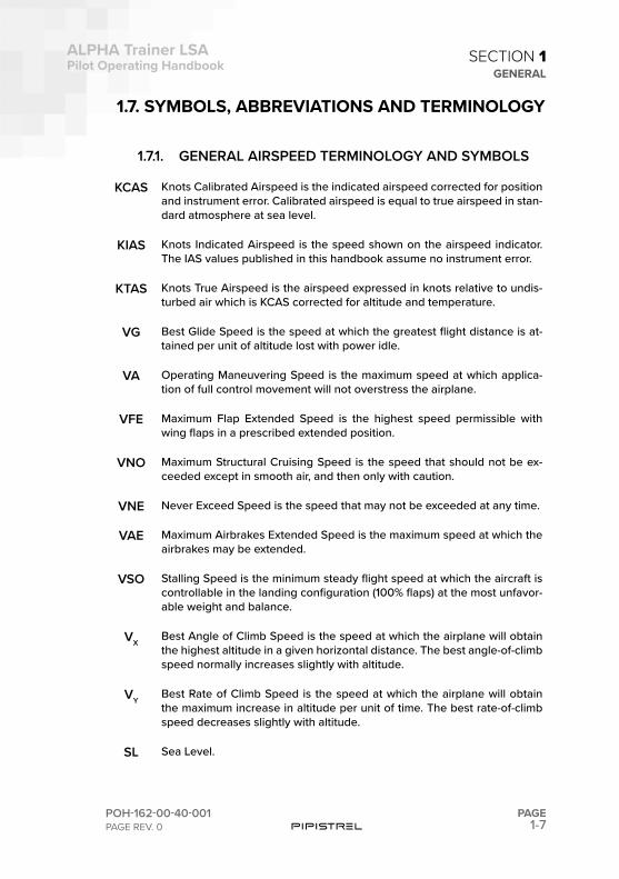
1.7. SYMBOLS, ABBREVIATIONS AND TERMINOLOGY
1.7.1. GENERAL AIRSPEED TERMINOLOGY AND SYMBOLS
KCAS Knots Calibrated Airspeed is the indicated airspeed corrected for position and instrument error. Calibrated airspeed is equal to true airspeed in stan-dard atmosphere at sea level.
KIAS Knots Indicated Airspeed is the speed shown on the airspeed indicator. The IAS values published in this handbook assume no instrument error.
KTAS Knots True Airspeed is the airspeed expressed in knots relative to undis-turbed air which is KCAS corrected for altitude and temperature.
VG Best Glide Speed is the speed at which the greatest flight distance is at-tained per unit of altitude lost with power idle.
VA Operating Maneuvering Speed is the maximum speed at which applica-tion of full control movement will not overstress the airplane.
VFE Maximum Flap Extended Speed is the highest speed permissible with wing flaps in a prescribed extended position.
VNO Maximum Structural Cruising Speed is the speed that should not be ex-ceeded except in smooth air, and then only with caution.
VNE Never Exceed Speed is the speed that may not be exceeded at any time.
VAE Maximum Airbrakes Extended Speed is the maximum speed at which the airbrakes may be extended.
VSO Stalling Speed is the minimum steady flight speed at which the aircraft is controllable in the landing configuration (100% flaps) at the most unfavor-able weight and balance.
VXBest Angle of Climb Speed is the speed at which the airplane will obtain the highest altitude in a given horizontal distance. The best angle-of-climb speed normally increases slightly with altitude.
VYBest Rate of Climb Speed is the speed at which the airplane will obtain the maximum increase in altitude per unit of time. The best rate-of-climb speed decreases slightly with altitude.
SL Sea Level.
1-8PAGE
ALPHA Trainer LSAPilot Operating Handbook
POH-162-00-40-001PAGE REV. 0
SECTION 1GENERAL
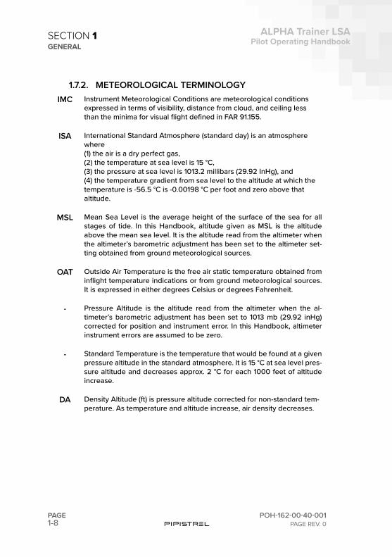
1.7.2. METEOROLOGICAL TERMINOLOGYIMC Instrument Meteorological Conditions are meteorological conditions
expressed in terms of visibility, distance from cloud, and ceiling less than the minima for visual flight defined in FAR 91.155.
ISA International Standard Atmosphere (standard day) is an atmosphere where (1) the air is a dry perfect gas, (2) the temperature at sea level is 15 °C, (3) the pressure at sea level is 1013.2 millibars (29.92 InHg), and (4) the temperature gradient from sea level to the altitude at which the temperature is -56.5 °C is -0.00198 °C per foot and zero above that altitude.
MSL Mean Sea Level is the average height of the surface of the sea for all stages of tide. In this Handbook, altitude given as MSL is the altitude above the mean sea level. It is the altitude read from the altimeter when the altimeter’s barometric adjustment has been set to the altimeter set-ting obtained from ground meteorological sources.
OAT Outside Air Temperature is the free air static temperature obtained from inflight temperature indications or from ground meteorological sources. It is expressed in either degrees Celsius or degrees Fahrenheit.
- Pressure Altitude is the altitude read from the altimeter when the al-timeter’s barometric adjustment has been set to 1013 mb (29.92 inHg) corrected for position and instrument error. In this Handbook, altimeter instrument errors are assumed to be zero.
- Standard Temperature is the temperature that would be found at a given pressure altitude in the standard atmosphere. It is 15 °C at sea level pres-sure altitude and decreases approx. 2 °C for each 1000 feet of altitude increase.
DA Density Altitude (ft) is pressure altitude corrected for non-standard tem-perature. As temperature and altitude increase, air density decreases.
1-9
ALPHA Trainer LSAPilot Operating Handbook
POH-162-00-40-001PAGE REV. 0
PAGE
SECTION 1GENERAL
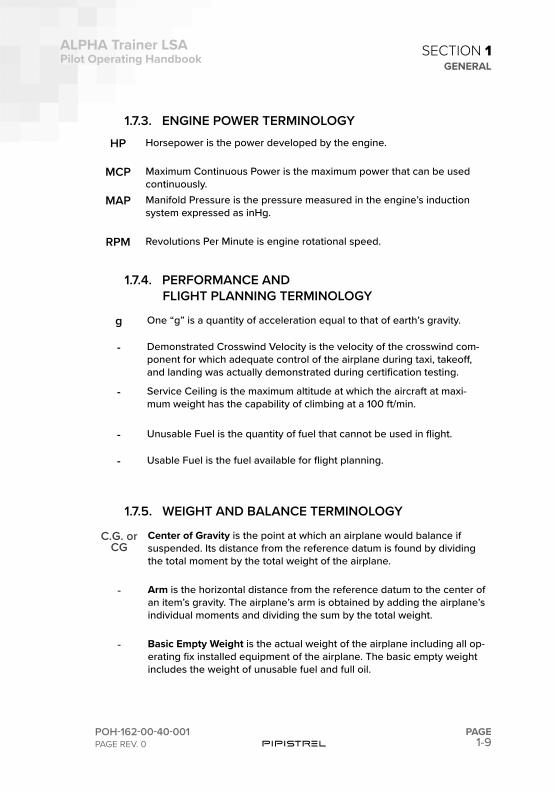
1.7.3. ENGINE POWER TERMINOLOGY
HP Horsepower is the power developed by the engine.
MCP Maximum Continuous Power is the maximum power that can be used continuously.
MAP Manifold Pressure is the pressure measured in the engine’s induction system expressed as inHg.
RPM Revolutions Per Minute is engine rotational speed.
1.7.4. PERFORMANCE AND FLIGHT PLANNING TERMINOLOGY
g One “g” is a quantity of acceleration equal to that of earth’s gravity.
- Demonstrated Crosswind Velocity is the velocity of the crosswind com-ponent for which adequate control of the airplane during taxi, takeoff, and landing was actually demonstrated during certification testing.
- Service Ceiling is the maximum altitude at which the aircraft at maxi-mum weight has the capability of climbing at a 100 ft/min.
- Unusable Fuel is the quantity of fuel that cannot be used in flight.
- Usable Fuel is the fuel available for flight planning.
1.7.5. WEIGHT AND BALANCE TERMINOLOGY
C.G. or CG
Center of Gravity is the point at which an airplane would balance if suspended. Its distance from the reference datum is found by dividing the total moment by the total weight of the airplane.
- Arm is the horizontal distance from the reference datum to the center of an item’s gravity. The airplane’s arm is obtained by adding the airplane’s individual moments and dividing the sum by the total weight.
- Basic Empty Weight is the actual weight of the airplane including all op-erating fix installed equipment of the airplane. The basic empty weight includes the weight of unusable fuel and full oil.
1-10PAGE
ALPHA Trainer LSAPilot Operating Handbook
POH-162-00-40-001PAGE REV. 0
SECTION 1GENERAL
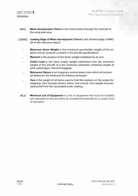
MAC Mean Aerodynamic Chord is the chord drawn through the centroid of the wing plan area.
LEMAC Leading Edge of Mean Aerodynamic Chord is the forward edge of MAC aft of the reference datum.
- Maximum Gross Weight is the maximum permissible weight of the air-plane and its contents as listed in the aircraft specifications.
- Moment is the product of the items weight multiplied by its arm.
- Useful Load is the basic empty weight subtracted from the maximum weight of the aircraft. It is the maximum allowable combined weight of pilot, passengers, fuel and baggage.
- Reference Datum is an imaginary vertical plane from which all horizon-tal distances are measured for balance purposes.
- Tare is the weight of all items used to hold the airplane on the scales for weighing. Tare includes blocks, shims, and chocks. Tare weight must be subtracted from the associated scale reading.
MLE Minimum List of Equipment is a list of equipment that must be installed and operable for the aircraft to be considered airworthy for a certain kind of operation.
1-11
ALPHA Trainer LSAPilot Operating Handbook
POH-162-00-40-001PAGE REV. 0
PAGE
SECTION 1GENERAL
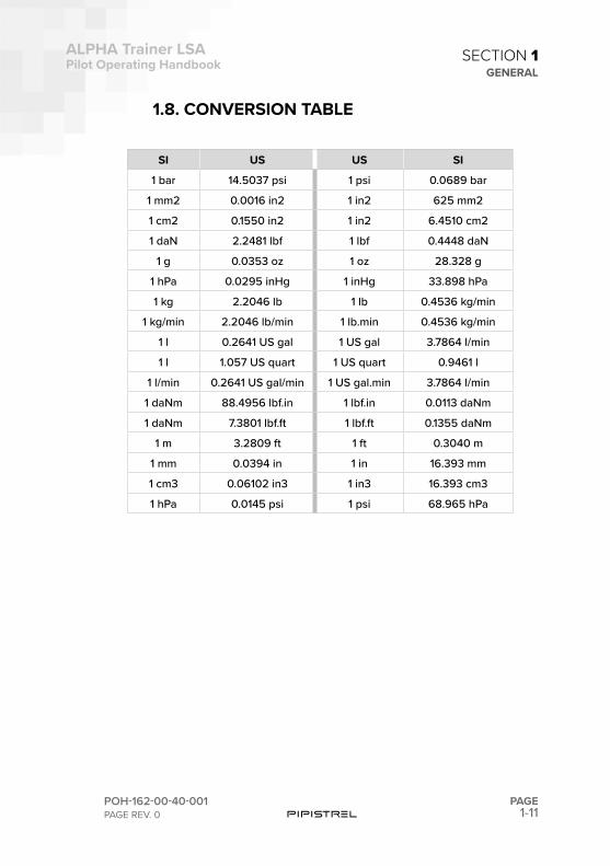
1.8. CONVERSION TABLE
SI US US SI
1 bar 14.5037 psi 1 psi 0.0689 bar
1 mm2 0.0016 in2 1 in2 625 mm2
1 cm2 0.1550 in2 1 in2 6.4510 cm2
1 daN 2.2481 lbf 1 lbf 0.4448 daN
1 g 0.0353 oz 1 oz 28.328 g
1 hPa 0.0295 inHg 1 inHg 33.898 hPa
1 kg 2.2046 lb 1 lb 0.4536 kg/min
1 kg/min 2.2046 lb/min 1 lb.min 0.4536 kg/min
1 l 0.2641 US gal 1 US gal 3.7864 l/min
1 l 1.057 US quart 1 US quart 0.9461 l
1 l/min 0.2641 US gal/min 1 US gal.min 3.7864 l/min
1 daNm 88.4956 lbf.in 1 lbf.in 0.0113 daNm
1 daNm 7.3801 lbf.ft 1 lbf.ft 0.1355 daNm
1 m 3.2809 ft 1 ft 0.3040 m
1 mm 0.0394 in 1 in 16.393 mm
1 cm3 0.06102 in3 1 in3 16.393 cm3
1 hPa 0.0145 psi 1 psi 68.965 hPa

This page is intentionally left blank.

SECTION
2
2-2PAGE
ALPHA Trainer LSAPilot Operating Handbook
POH-162-00-40-001PAGE REV. 0
SECTION 2LIMITATIONS
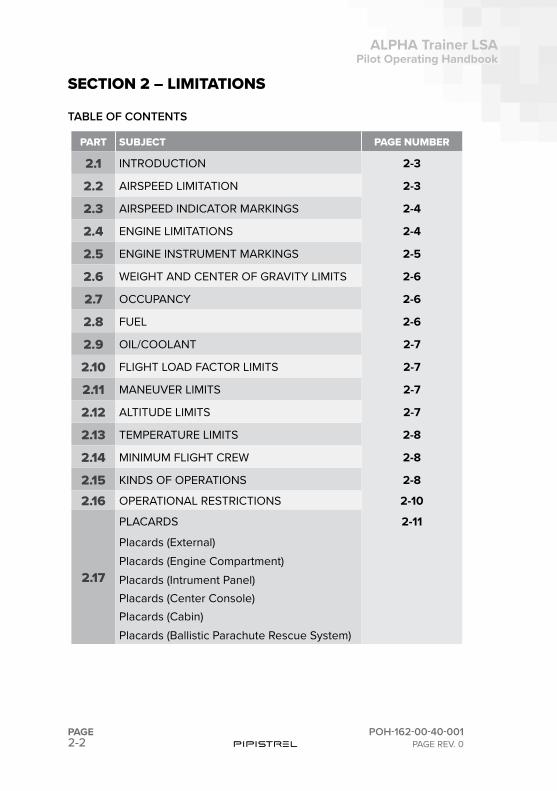
PART SUBJECT PAGE NUMBER
2.1 INTRODUCTION 2-3
2.2 AIRSPEED LIMITATION 2-3
2.3 AIRSPEED INDICATOR MARKINGS 2-4
2.4 ENGINE LIMITATIONS 2-4
2.5 ENGINE INSTRUMENT MARKINGS 2-5
2.6 WEIGHT AND CENTER OF GRAVITY LIMITS 2-6
2.7 OCCUPANCY 2-6
2.8 FUEL 2-6
2.9 OIL/COOLANT 2-7
2.10 FLIGHT LOAD FACTOR LIMITS 2-7
2.11 MANEUVER LIMITS 2-7
2.12 ALTITUDE LIMITS 2-7
2.13 TEMPERATURE LIMITS 2-8
2.14 MINIMUM FLIGHT CREW 2-8
2.15 KINDS OF OPERATIONS 2-8
2.16 OPERATIONAL RESTRICTIONS 2-10
2.17
PLACARDS 2-11
Placards (External)Placards (Engine Compartment)Placards (Intrument Panel)Placards (Center Console)Placards (Cabin)Placards (Ballistic Parachute Rescue System)
SECTION 2 – LIMITATIONS
TABLE OF CONTENTS
2-3
ALPHA Trainer LSAPilot Operating Handbook
POH-162-00-40-001PAGE REV. 0
PAGE
SECTION 2LIMITATIONS
2.1 INTRODUCTION
This section provides operating limitations, instrument markings and basic placards necessary for the safe operation of the airplane and its standard systems and equipment. Refer to section 9 for operating limitations for op-tional equipment.
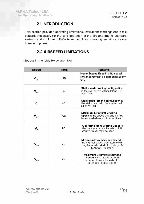
2.2 AIRSPEED LIMITATIONS
Speeds in the table below are KIAS.
Speed KIAS Remarks
VNE 135Never Exceed Speed is the speed limit that may not be exceeded at any time.
Vs0 37Stall speed - landing configuration is the stall speed with full flaps (+2) at MTOM.
Vs 43Stall speed - clean configuration is the stall speed with flaps retracted (0) at MTOM.
VNO 108Maximum Structural Cruising Speed is the speed that should not be exceeded except in smooth air.
VA 96Operating Maneuvering Speed is the maximum speed at which full control travel may be used.
VFE 70Maximum Flap Extended Speed is the highest speed permissible with
wing flaps extended at (+1) stage, 60 KIAS for (+2) stage.
VAE 70Maximum Airbrakes Extended
Speed is the highest speed permissible with the airbrakes
extended (if applicalble).
2-4PAGE
ALPHA Trainer LSAPilot Operating Handbook
POH-162-00-40-001PAGE REV. 0
SECTION 2LIMITATIONS
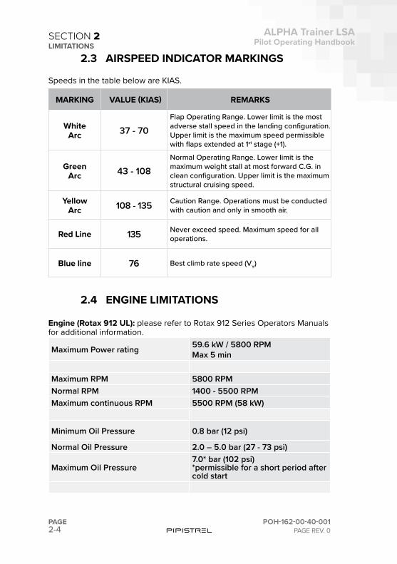
2.3 AIRSPEED INDICATOR MARKINGS
Speeds in the table below are KIAS.
2.4 ENGINE LIMITATIONS
Engine (Rotax 912 UL): please refer to Rotax 912 Series Operators Manuals for additional information.
Maximum Power rating 59.6 kW / 5800 RPMMax 5 min
Maximum RPM 5800 RPMNormal RPM 1400 - 5500 RPMMaximum continuous RPM 5500 RPM (58 kW)
Minimum Oil Pressure 0.8 bar (12 psi)
Normal Oil Pressure 2.0 – 5.0 bar (27 - 73 psi)
Maximum Oil Pressure7.0* bar (102 psi)*permissible for a short period after cold start
MARKING VALUE (KIAS) REMARKS
White Arc 37 - 70
Flap Operating Range. Lower limit is the most adverse stall speed in the landing configuration. Upper limit is the maximum speed permissible with flaps extended at 1st stage (+1).
Green Arc 43 - 108
Normal Operating Range. Lower limit is the maximum weight stall at most forward C.G. in clean configuration. Upper limit is the maximum structural cruising speed.
Yellow Arc 108 - 135 Caution Range. Operations must be conducted
with caution and only in smooth air.
Red Line 135 Never exceed speed. Maximum speed for all operations.
Blue line 76 Best climb rate speed (VY)
2-5
ALPHA Trainer LSAPilot Operating Handbook
POH-162-00-40-001PAGE REV. 0
PAGE
SECTION 2LIMITATIONS
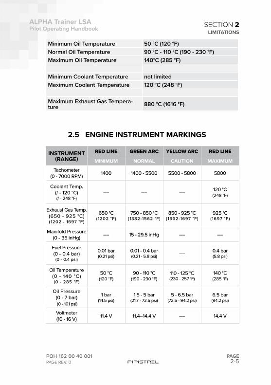
Minimum Oil Temperature 50 °C (120 °F)Normal Oil Temperature 90 °C - 110 °C (190 - 230 °F)Maximum Oil Temperature 140°C (285 °F)
Minimum Coolant Temperature not limitedMaximum Coolant Temperature 120 °C (248 °F)
Maximum Exhaust Gas Tempera-ture 880 °C (1616 °F)
2.5 ENGINE INSTRUMENT MARKINGS
INSTRUMENT (RANGE)
RED LINE GREEN ARC YELLOW ARC RED LINE
MINIMUM NORMAL CAUTION MAXIMUM
Tachometer(0 - 7000 RPM) 1400 1400 - 5500 5500 - 5800 5800
Coolant Temp.(/ - 120 °C)(/ - 248 °F)
–– –– –– 120 °C(248 °F)
Exhaust Gas Temp.(650 - 925 °C)(1202 - 1697 °F)
650 °C (1202 °F)
750 - 850 °C(1382-1562 °F)
850 - 925 °C(1562-1697 °F)
925 °C(1697 °F)
Manifold Pressure (0 - 35 inHg) –– 15 - 29.5 inHg –– ––
Fuel Pressure(0 - 0.4 bar)(0 - 0.4 psi)
0.01 bar (0.21 psi)
0.01 - 0.4 bar(0.21 - 5.8 psi) –– 0.4 bar
(5.8 psi)
Oil Temperature(0 - 140 °C)(0 - 285 °F)
50 °C (120 °F)
90 - 110 °C(190 - 230 °F)
110 - 125 °C(230 - 257 °F)
140 °C(285 °F)
Oil Pressure (0 - 7 bar) (0 - 101 psi)
1 bar (14.5 psi)
1.5 - 5 bar (21.7 - 72.5 psi)
5 - 6.5 bar(72.5 - 94.2 psi)
6.5 bar(94.2 psi)
Voltmeter(10 - 16 V) 11.4 V 11.4–14.4 V –– 14.4 V
2-6PAGE
ALPHA Trainer LSAPilot Operating Handbook
POH-162-00-40-001PAGE REV. 0
SECTION 2LIMITATIONS
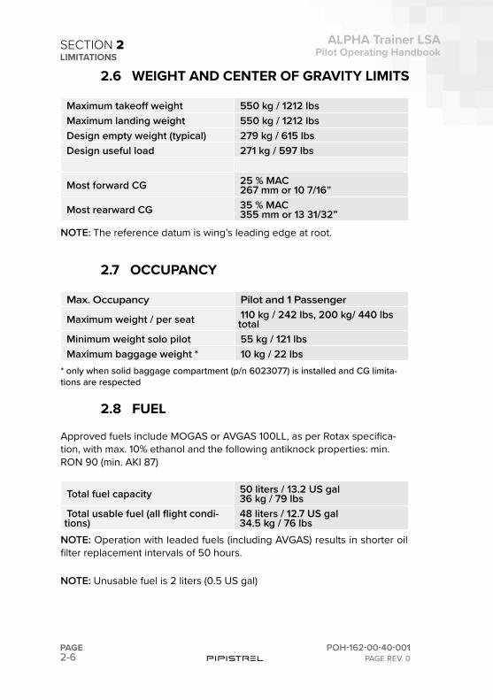
2.6 WEIGHT AND CENTER OF GRAVITY LIMITS
Maximum takeoff weight 550 kg / 1212 lbsMaximum landing weight 550 kg / 1212 lbsDesign empty weight (typical) 279 kg / 615 lbsDesign useful load 271 kg / 597 lbs
Most forward CG 25 % MAC267 mm or 10 7/16”
Most rearward CG 35 % MAC355 mm or 13 31/32”
NOTE: The reference datum is wing’s leading edge at root.
2.7 OCCUPANCY
Max. Occupancy Pilot and 1 Passenger
Maximum weight / per seat 110 kg / 242 lbs, 200 kg/ 440 lbs total
Minimum weight solo pilot 55 kg / 121 lbsMaximum baggage weight * 10 kg / 22 lbs
* only when solid baggage compartment (p/n 6023077) is installed and CG limita-tions are respected
2.8 FUEL
Approved fuels include MOGAS or AVGAS 100LL, as per Rotax specifica-tion, with max. 10% ethanol and the following antiknock properties: min. RON 90 (min. AKI 87)
Total fuel capacity 50 liters / 13.2 US gal36 kg / 79 lbs
Total usable fuel (all flight condi-tions)
48 liters / 12.7 US gal34.5 kg / 76 lbs
NOTE: Operation with leaded fuels (including AVGAS) results in shorter oil filter replacement intervals of 50 hours.
NOTE: Unusable fuel is 2 liters (0.5 US gal)
2-7
ALPHA Trainer LSAPilot Operating Handbook
POH-162-00-40-001PAGE REV. 0
PAGE
SECTION 2LIMITATIONS
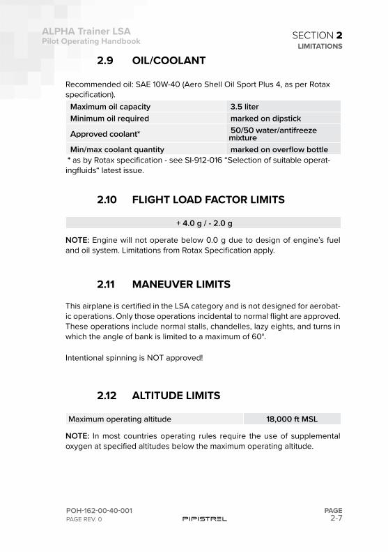
2.9 OIL/COOLANT
Recommended oil: SAE 10W-40 (Aero Shell Oil Sport Plus 4, as per Rotax specification).
Maximum oil capacity 3.5 literMinimum oil required marked on dipstick
Approved coolant* 50/50 water/antifreeze mixture
Min/max coolant quantity marked on overflow bottle * as by Rotax specification - see SI-912-016 “Selection of suitable operat-ingfluids“ latest issue.
2.10 FLIGHT LOAD FACTOR LIMITS
+ 4.0 g / - 2.0 g
NOTE: Engine will not operate below 0.0 g due to design of engine’s fuel and oil system. Limitations from Rotax Specification apply.
2.11 MANEUVER LIMITS
This airplane is certified in the LSA category and is not designed for aerobat-ic operations. Only those operations incidental to normal flight are approved. These operations include normal stalls, chandelles, lazy eights, and turns in which the angle of bank is limited to a maximum of 60°.
Intentional spinning is NOT approved!
2.12 ALTITUDE LIMITS
Maximum operating altitude 18,000 ft MSL
NOTE: In most countries operating rules require the use of supplemental oxygen at specified altitudes below the maximum operating altitude.
2-8PAGE
ALPHA Trainer LSAPilot Operating Handbook
POH-162-00-40-001PAGE REV. 0
SECTION 2LIMITATIONS
2.13 TEMPERATURE LIMITS
Flight when the temperature of the aircraft’s surface is at risk of exceeding 55° C is prohibited.
2.14 MINIMUM FLIGHT CREWThe minimum flight crew is one pilot.
2.15 KINDS OF OPERATION
The airplane is approved for the following operations:
- VFR-day
NOTE: The airplane must be equipped according to the MLE for the planned kind of operation, see 2.15.1.
- VFR-night
NOTE: The minimum equipment list for Night VFR is identical that for DAY-VFR, but shall include any additional equipment deemed necessary by local regulations in the given area of operation.
- IFR (VMC conditions only)
The minimum equipment list for IFR-VMC is identical that for DAY-VFR, but shall include any additional equipment deemed necessary by local regula-tions in the given area of operation.
NOTE: IFR flight only allowed in VMC conditions and with approved IFR in-struments and appropriate pilot rating/certification.
2-9
ALPHA Trainer LSAPilot Operating Handbook
POH-162-00-40-001PAGE REV. 0
PAGE
SECTION 2LIMITATIONS
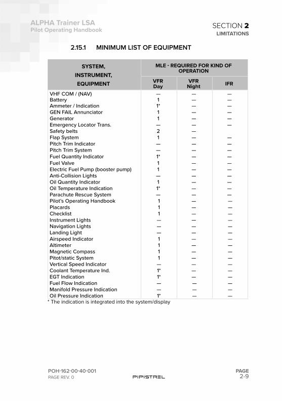
2.15.1 MINIMUM LIST OF EQUIPMENT
SYSTEM, INSTRUMENT,EQUIPMENT
MLE - REQUIRED FOR KIND OF OPERATION
VFR Day
VFR Night IFR
VHF COM / (NAV) — — —Battery 1 — —Ammeter / Indication 1* — —GEN FAIL Annunciator 1 — —Generator 1 — —Emergency Locator Trans. — — —Safety belts 2 —Flap System 1 — —Pitch Trim Indicator — — —Pitch Trim System — — —Fuel Quantity Indicator 1* — —Fuel Valve 1 — —Electric Fuel Pump (booster pump) 1 — —Anti-Collision Lights — — —Oil Quantity Indicator 1 — —Oil Temperature Indication 1* — —Parachute Rescue System — — —Pilot’s Operating Handbook 1 — —Placards 1 — —Checklist 1 — —Instrument Lights — — —Navigation Lights — — —Landing Light — — —Airspeed Indicator 1 — —Altimeter 1 — —Magnetic Compass 1 — —Pitot/static System 1 — —Vertical Speed Indicator — — —Coolant Temperature Ind. 1* — —EGT Indication 1* — —Fuel Flow Indication — — —Manifold Pressure Indication — — —Oil Pressure Indication 1* — —
* The indication is integrated into the system/display
2-10PAGE
ALPHA Trainer LSAPilot Operating Handbook
POH-162-00-40-001PAGE REV. 0
SECTION 2LIMITATIONS
2.16 OPERATIONAL RESTRICTIONS
Flight into known icing conditions is prohibited.
No flights in heavy rainfall or blizzard conditions.
Areas with risk of thunderstorms should be avoided.
Smoking is prohibited.
Engine: -25°C (oil temperature) to 50°C (ambient temperature) as per Rotax OM.
Do not take-off with airbrakes extended.
The 12 V power outlets are not approved to supply power to flight-critical communication or navigation devices.GPS is for information only and should not be used for primary navigation heading references.
Do not take-off or land when crosswind component exceeds 18 kts (9 m/s).
Do not take-off with flaps retracted (0).
2-11
ALPHA Trainer LSAPilot Operating Handbook
POH-162-00-40-001PAGE REV. 0
PAGE
SECTION 2LIMITATIONS
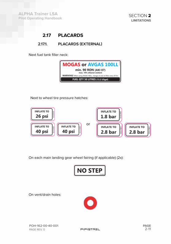
2.17 PLACARDS
2.17.1. PLACARDS (EXTERNAL)
Next fuel tank filler neck:
Next to wheel tire pressure hatches:
On each main landing gear wheel fairing (if applicable) (2x):
On vent/drain holes:
or
2-12PAGE
ALPHA Trainer LSAPilot Operating Handbook
POH-162-00-40-001PAGE REV. 0
SECTION 2LIMITATIONS
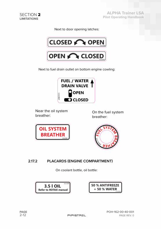
Next to door opening latches:
Next to fuel drain outlet on bottom engine cowling:
2.17.2 PLACARDS (ENGINE COMPARTMENT)
On coolant bottle, oil bottle:
OPENCLOSED
1111907
FUEL / WATERDRAIN VALVE
Near the oil systembreather:
On the fuel systembreather:
OIL SYSTEMBREATHER
1111941
FUEL
SYSTEM BREATHER
1111940
2-13
ALPHA Trainer LSAPilot Operating Handbook
POH-162-00-40-001PAGE REV. 0
PAGE
SECTION 2LIMITATIONS
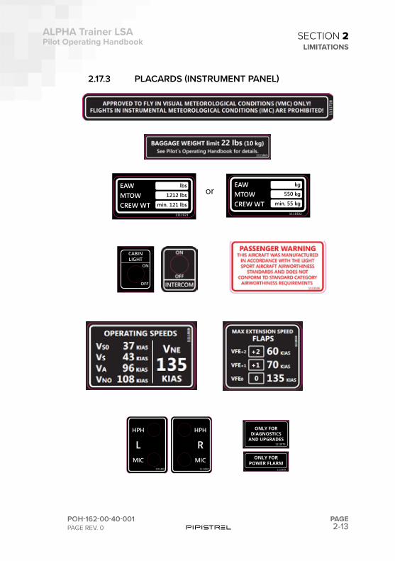
2.17.3 PLACARDS (INSTRUMENT PANEL)
EAWMTOWCREW WT
1111921
lbs
1212 lbs
min. 121 lbs
HPH
MIC
RHPH
MIC
L
1111830 1111830
orEAWMTOWCREW WT
kg
550 kg
min. 55 kg
1111922
CABINLIGHT
ON
OFF
1111879
ONLY FORDIAGNOSTICS
AND UPGRADES
ONLY FORPOWER FLARM
1111939
2-14PAGE
ALPHA Trainer LSAPilot Operating Handbook
POH-162-00-40-001PAGE REV. 0
SECTION 2LIMITATIONS
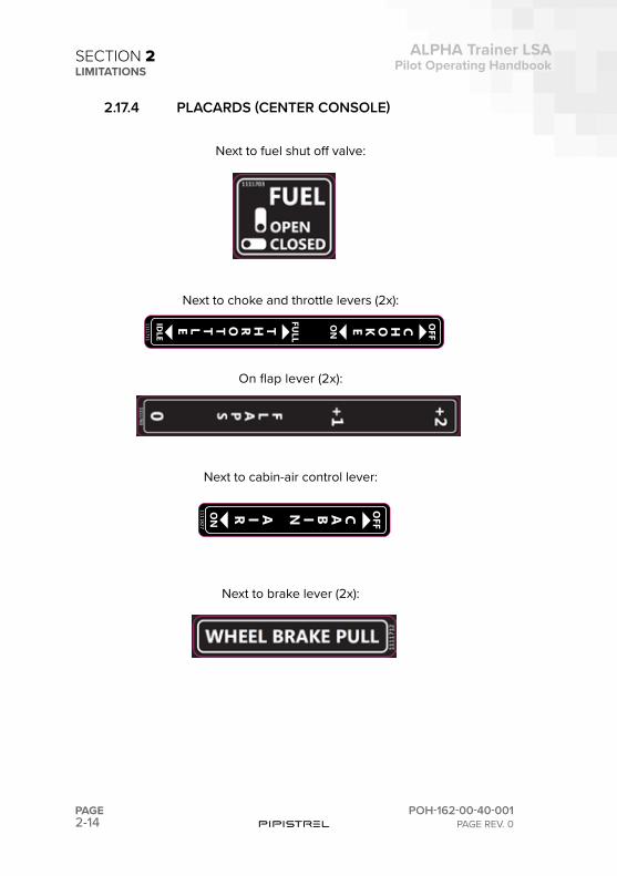
2.17.4 PLACARDS (CENTER CONSOLE)
Next to fuel shut off valve:
Next to choke and throttle levers (2x):
On flap lever (2x):
Next to cabin-air control lever:
Next to brake lever (2x):
ON CABIN OFF
AIR 1111827
THROTTLE FULL
IDLE
ON CHOKE OFF
1111711
2-15
ALPHA Trainer LSAPilot Operating Handbook
POH-162-00-40-001PAGE REV. 0
PAGE
SECTION 2LIMITATIONS
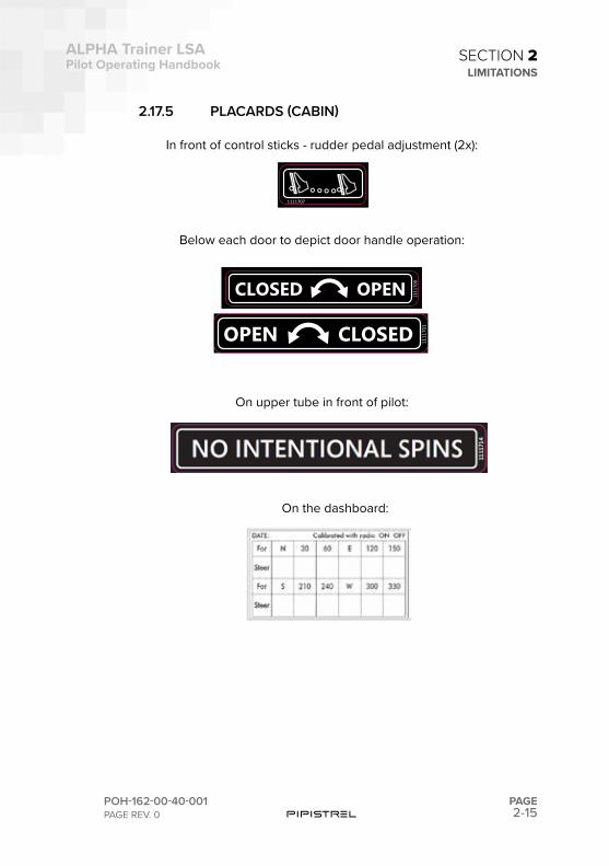
2.17.5 PLACARDS (CABIN)
In front of control sticks - rudder pedal adjustment (2x):
Below each door to depict door handle operation:
On upper tube in front of pilot:
1111707
OPEN CLOSED 1111
700
OPEN CLOSED 1111
701
On the dashboard:
2-16PAGE
ALPHA Trainer LSAPilot Operating Handbook
POH-162-00-40-001PAGE REV. 0
SECTION 2LIMITATIONS
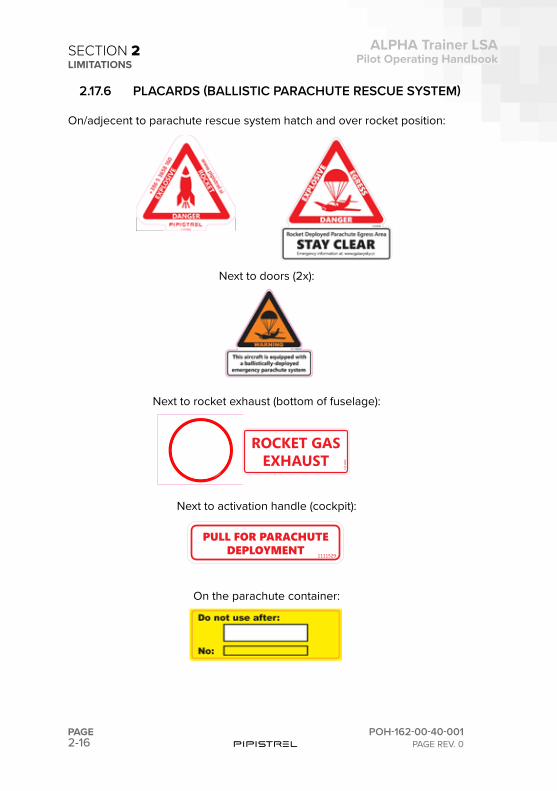
2.17.6 PLACARDS (BALLISTIC PARACHUTE RESCUE SYSTEM)
On/adjecent to parachute rescue system hatch and over rocket position:
Next to doors (2x):
Next to rocket exhaust (bottom of fuselage):
Next to activation handle (cockpit):
On the parachute container:
PULL FOR PARACHUTEDEPLOYMENT 1111529
1111607
1111
606

SECTION
3
3-2PAGE
ALPHA Trainer LSAPilot Operating Handbook
POH-162-00-40-001PAGE REV. 0
PART SUBJECT PAGE NUMBER
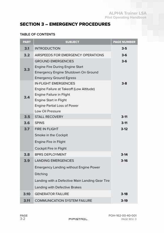
3.1 INTRODUCTION 3-5
3.2 AIRSPEEDS FOR EMERGENCY OPERATIONS 3-6
3.3
GROUND EMERGENCIES 3-6Engine Fire During Engine StartEmergency Engine Shutdown On GroundEmergency Ground Egress
3.4
IN-FLIGHT EMERGENCIES 3-8Engine Failure at Takeoff (Low Altitude)Engine Failure in FlightEngine Start in FlightEngine Partial Loss of PowerLow Oil Pressure
3.53 STALL RECOVERY 3-11
3.6 SPINS 3-11
3.7 FIRE IN FLIGHT 3-12
Smoke in the Cockpit
Engine Fire in Flight
Cockpit Fire in Flight
3.8 BPRS DEPLOYMENT 3-14
3.9 LANDING EMERGENCIES 3-16
Emergency Landing without Engine Power
Ditching
Landing with a Defective Main Landing Gear Tire
Landing with Defective Brakes
3.10 GENERATOR FAILURE 3-18
3.11 COMMUNICATION SYSTEM FAILURE 3-19
SECTION 3 – EMERGENCY PROCEDURES
TABLE OF CONTENTS
3-3
ALPHA Trainer LSAPilot Operating Handbook
POH-162-00-40-001PAGE REV. 0
PAGE
SECTION 3EMERGENCY PROCEDURES
PART SUBJECT PAGE NUMBER
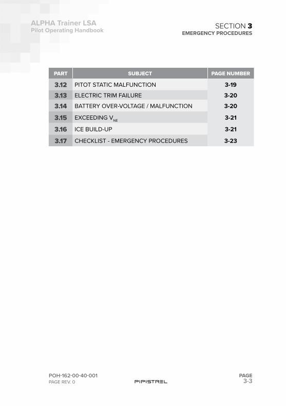
3.12 PITOT STATIC MALFUNCTION 3-19
3.13 ELECTRIC TRIM FAILURE 3-20
3.14 BATTERY OVER-VOLTAGE / MALFUNCTION 3-20
3.15 EXCEEDING VNE 3-21
3.16 ICE BUILD-UP 3-21
3.17 CHECKLIST - EMERGENCY PROCEDURES 3-23

This page is intentionally left blank.
3-5
ALPHA Trainer LSAPilot Operating Handbook
POH-162-00-40-001PAGE REV. 0
PAGE
SECTION 3EMERGENCY PROCEDURES
3.1 INTRODUCTION
This section provides procedures for handling emergencies and critical flight situations. Although emergencies caused by airplane, systems, or engine malfunctions are extremely rare, the guidelines described in this section should be considered and applied as necessary should an emer-gency arise.
En-route emergencies caused by weather can be minimized or eliminated by careful flight planning and good judgment when unexpected weather is encountered.
In-flight mechanical problems will be extremely rare if proper preflight in-spections and maintenance are practiced. Always perform a thorough walk-around preflight inspection before any flight to ensure that no damage oc-curred during the previous flight or while the airplane was on the ground. Pay special attention to any oil/fluid leaks or fuel stains that could indicate engine problems.
Aircraft emergencies are very dynamic events. Because of this, it is impossi-ble to address every action a pilot might take to handle a situation. However, four basic actions can be applied to any emergency:
Maintain Aircraft ControlMany minor aircraft emergencies turn into major ones when the pilot fails to maintain aircraft control. Remember, do not panic and do not fixate on a par-ticular problem. To avoid this, even in an emergency: aviate, navigate, and communicate, in this order. Never let anything interfere with your control of the airplane. Never stop flying.
Analyze the SituationOnce you are able to maintain control of the aircraft, assess the situation. Look at the engine parameters. Listen to the engine. Determine what the airplane is telling you.
Take Appropriate ActionIn most situations, the procedures listed in this section will either correct the aircraft problem or allow safe recovery of the aircraft. Follow them and use good pilot judgment.
3-6PAGE
ALPHA Trainer LSAPilot Operating Handbook
POH-162-00-40-001PAGE REV. 0
SECTION 3EMERGENCY PROCEDURES
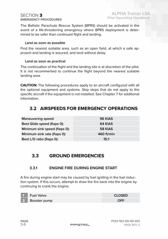
The Ballistic Parachute Rescue System (BPRS) should be activated in the event of a life-threatening emergency where BPRS deployment is deter-mined to be safer than continued flight and landing.
Land as soon as possibleFind the nearest suitable area, such as an open field, at which a safe ap-proach and landing is assured, and land without delay.
Land as soon as practicalThe continuation of the flight and the landing site is at discretion of the pilot.It is not recommented to continue the flight beyond the nearest suitable landing area.
CAUTION: The following procedures apply to an aircraft configured with all the optional equipment and systems. Skip steps that do not apply to the specific aircraft if the equipment is not installed. See Chapter 7 for additional information.
3.2 AIRSPEEDS FOR EMERGENCY OPERATIONS
Maneuvering speed: 96 KIASBest Glide speed (flaps 0): 64 KIASMinimum sink speed (flaps 0): 58 KIASMinimum sink rate (flaps 0): 460 ft/minBest L/D ratio (flaps 0): 15:1
3.3 GROUND EMERGENCIES
3.3.1 ENGINE FIRE DURING ENGINE START
A fire during engine start may be caused by fuel igniting in the fuel induc-tion system. If this occurs, attempt to draw the fire back into the engine by continuing to crank the engine.
1 Fuel Valve CLOSED2 Booster pump OFF
3-7
ALPHA Trainer LSAPilot Operating Handbook
POH-162-00-40-001PAGE REV. 0
PAGE
SECTION 3EMERGENCY PROCEDURES
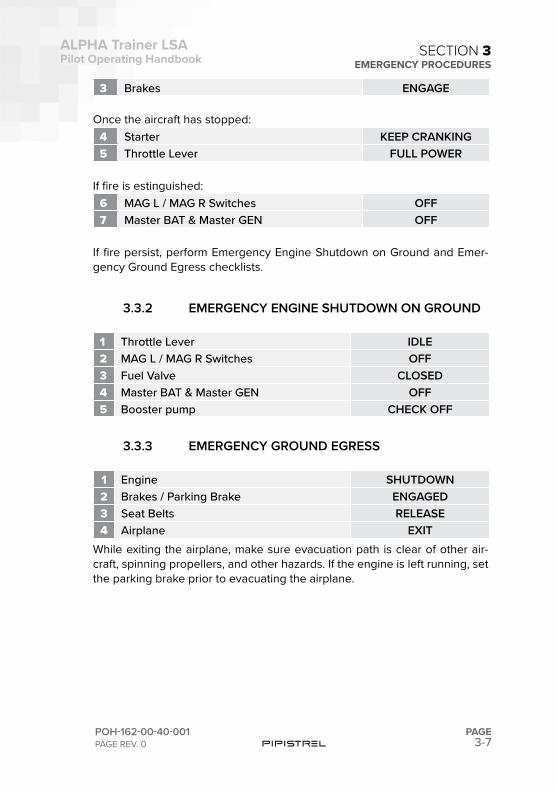
3 Brakes ENGAGE
Once the aircraft has stopped:4 Starter KEEP CRANKING5 Throttle Lever FULL POWER
If fire is estinguished:6 MAG L / MAG R Switches OFF7 Master BAT & Master GEN OFF
If fire persist, perform Emergency Engine Shutdown on Ground and Emer-gency Ground Egress checklists.
3.3.2 EMERGENCY ENGINE SHUTDOWN ON GROUND
1 Throttle Lever IDLE2 MAG L / MAG R Switches OFF3 Fuel Valve CLOSED4 Master BAT & Master GEN OFF5 Booster pump CHECK OFF
3.3.3 EMERGENCY GROUND EGRESS
1 Engine SHUTDOWN2 Brakes / Parking Brake ENGAGED3 Seat Belts RELEASE4 Airplane EXIT
While exiting the airplane, make sure evacuation path is clear of other air-craft, spinning propellers, and other hazards. If the engine is left running, set the parking brake prior to evacuating the airplane.
3-8PAGE
ALPHA Trainer LSAPilot Operating Handbook
POH-162-00-40-001PAGE REV. 0
SECTION 3EMERGENCY PROCEDURES
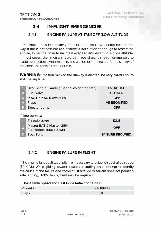
3.4 IN-FLIGHT EMERGENCIES
3.4.1 ENGINE FAILURE AT TAKEOFF (LOW ALTITUDE)
If the engine fails immediately after take-off, abort by landing on the run-way. If this is not possible and altitude is not sufficient enough to restart the engine, lower the nose to maintain airspeed and establish a glide attitude. In most cases, the landing should be made straight ahead, turning only to avoid obstructions. After establishing a glide for landing, perform as many of the checklist items as time permits.
WARNING:!!If a turn back to the runway is elected, be very careful not to stall the airplane.
1 Best Glide or Landing Speed (as appropriate) ESTABLISH2 Fuel Valve CLOSED3 MAG L / MAG R Switches OFF4 Flaps AS REQUIRED5 Booster pump OFF
If time permits:1 Throttle Lever IDLE
2 Master BAT & Master GEN(just before touch down) OFF
3 Seat Belts ENSURE SECURED
3.4.2 ENGINE FAILURE IN FLIGHT
If the engine fails at altitude, pitch as necessary to establish best glide speed (64 KIAS). While gliding toward a suitable landing area, attempt to identify the cause of the failure and correct it. If altitude or terrain does not permit a safe landing, BPRS deployment may be required.
Best Glide Speed and Best Glide Ratio conditions:Propeller STOPPEDFlaps 0
3-9
ALPHA Trainer LSAPilot Operating Handbook
POH-162-00-40-001PAGE REV. 0
PAGE
SECTION 3EMERGENCY PROCEDURES
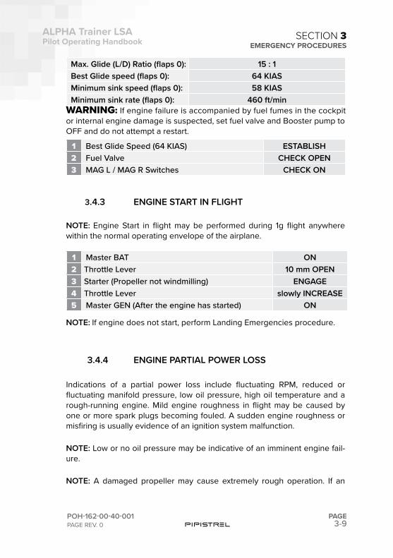
Max. Glide (L/D) Ratio (flaps 0): 15 : 1Best Glide speed (flaps 0): 64 KIASMinimum sink speed (flaps 0): 58 KIASMinimum sink rate (flaps 0): 460 ft/min
WARNING:!If engine failure is accompanied by fuel fumes in the cockpit or internal engine damage is suspected, set fuel valve and Booster pump to OFF and do not attempt a restart.
1 Best Glide Speed (64 KIAS) ESTABLISH2 Fuel Valve CHECK OPEN3 MAG L / MAG R Switches CHECK ON
3.4.3 ENGINE START IN FLIGHT
NOTE: Engine Start in flight may be performed during 1g flight anywhere within the normal operating envelope of the airplane.
1 Master BAT ON2 Throttle Lever 10 mm OPEN3 Starter (Propeller not windmilling) ENGAGE4 Throttle Lever slowly INCREASE5 Master GEN (After the engine has started) ON
NOTE: If engine does not start, perform Landing Emergencies procedure.
3.4.4 ENGINE PARTIAL POWER LOSS
Indications of a partial power loss include fluctuating RPM, reduced or fluctuating manifold pressure, low oil pressure, high oil temperature and a rough-running engine. Mild engine roughness in flight may be caused by one or more spark plugs becoming fouled. A sudden engine roughness or misfiring is usually evidence of an ignition system malfunction.
NOTE: Low or no oil pressure may be indicative of an imminent engine fail-ure.
NOTE: A damaged propeller may cause extremely rough operation. If an
3-10PAGE
ALPHA Trainer LSAPilot Operating Handbook
POH-162-00-40-001PAGE REV. 0
SECTION 3EMERGENCY PROCEDURES
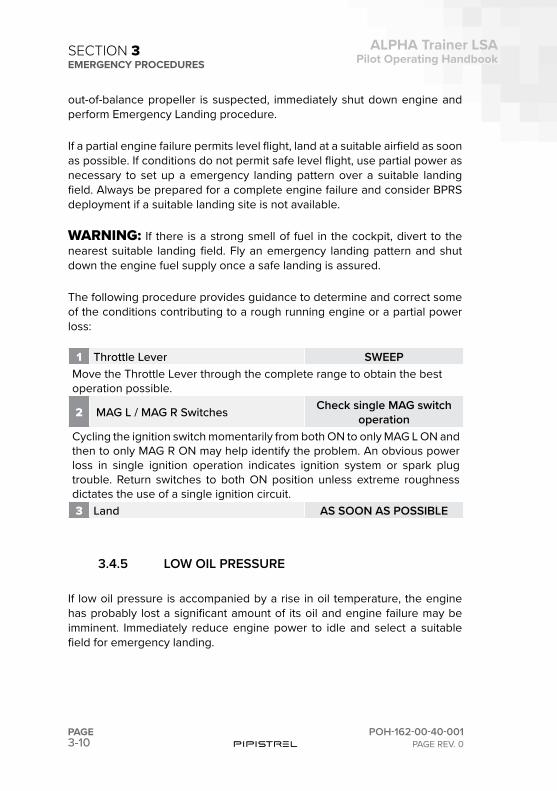
out-of-balance propeller is suspected, immediately shut down engine and perform Emergency Landing procedure.
If a partial engine failure permits level flight, land at a suitable airfield as soon as possible. If conditions do not permit safe level flight, use partial power as necessary to set up a emergency landing pattern over a suitable landing field. Always be prepared for a complete engine failure and consider BPRS deployment if a suitable landing site is not available.
WARNING: If there is a strong smell of fuel in the cockpit, divert to the nearest suitable landing field. Fly an emergency landing pattern and shut down the engine fuel supply once a safe landing is assured.
The following procedure provides guidance to determine and correct some of the conditions contributing to a rough running engine or a partial power loss:
1 Throttle Lever SWEEPMove the Throttle Lever through the complete range to obtain the best operation possible.
2 MAG L / MAG R Switches Check single MAG switch operation
Cycling the ignition switch momentarily from both ON to only MAG L ON and then to only MAG R ON may help identify the problem. An obvious power loss in single ignition operation indicates ignition system or spark plug trouble. Return switches to both ON position unless extreme roughness dictates the use of a single ignition circuit.3 Land AS SOON AS POSSIBLE
3.4.5 LOW OIL PRESSURE
If low oil pressure is accompanied by a rise in oil temperature, the engine has probably lost a significant amount of its oil and engine failure may be imminent. Immediately reduce engine power to idle and select a suitable field for emergency landing.
3-11
ALPHA Trainer LSAPilot Operating Handbook
POH-162-00-40-001PAGE REV. 0
PAGE
SECTION 3EMERGENCY PROCEDURES
WARNING: Prolonged use of high power settings after loss of oil pressure will lead to engine mechanical damage and total engine failure.
1 Throttle Lever MINIMUM REQUIRED2 Land AS SOON AS POSSIBLE
NOTE: Full power should only be used following a loss of oil pressure when operating close to the ground and only for the time necessary to climb to an altitude permitting a safe landing or analysis of the low oil pressure indication to confirm oil pressure has actually been lost.
If low oil pressure is accompanied by normal oil temperature, it is possible that the oil pressure sensor, gauge, or relief valve is malfunctioning. In any case, land as soon as practical and determine cause.
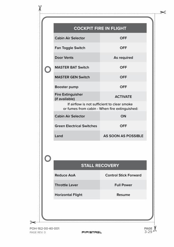
3.5 STALL RECOVERY
1 Reduce angle of attack Control Stick Forward 2 Throttle Lever Full Power3 Horizontal Flight Resume
3.6 SPINS
The airplane is NOT approved for intentional spins.
While the stall characteristics of the airplane make accidental entry into a spin extremely unlikely, spinning is possible. Spin entry can be avoided by using good airmanship: coordinated use of controls in turns, proper airspeed control and never abusing the flight controls with accelerated inputs when close to the stall.
If the controls are misapplied or abrupt inputs are made to the control sur-faces at or around stall, a sudden wing drop may be felt and a spiral or spin may be entered. In some cases it may be difficult to determine if the aircraft has entered a spiral or the started spinnig.
In any case, spin recovery technique is classic:
3-12PAGE
ALPHA Trainer LSAPilot Operating Handbook
POH-162-00-40-001PAGE REV. 0
SECTION 3EMERGENCY PROCEDURES
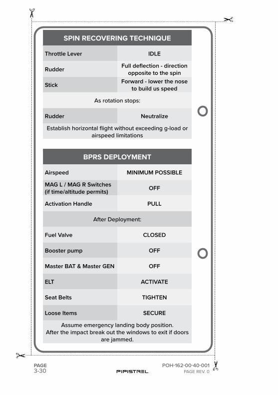
1 Throttle IDLE
2 Apply full rudder deflection in direction opposite the spin
3 Lower the nose towards the ground to build speed (Stick forward)
4 As rotation stops, neutralize rudder
5 Establish horizontal flight without exceeding g-load or airspeed lim-itations
3.7 FIRE IN FLIGHT
3.7.1 SMOKE IN THE COCKPIT
If smoke and/or fumes are detected in the cabin, check the engine parame-ters for any sign of malfunction. If a fuel leak has occurred, actuation of elec-trical components may cause a fire. If there is a strong smell of fuel in the cockpit, divert to the nearest suitable landing field. Perform an Emergency Landing and shut down the fuel supply to the engine once a safe landing is assured.
1 Cabin Air Selector ON2 Door Vents OPEN3 Fan Toggle Switch ON4 Airflow Direction Knob Feet position5 Temperature Control Knob Cold
If source of smoke and fume is firewall forward:1 Cabin Air Selector OFF2 Fan Toggle Switch OFF3 Door Vents AS REQUIRED4 Land AS SOON AS POSSIBLE
If airflow is not sufficient to clear smoke or fumes from cabin:1 Door Vents OPEN
3-13
ALPHA Trainer LSAPilot Operating Handbook
POH-162-00-40-001PAGE REV. 0
PAGE
SECTION 3EMERGENCY PROCEDURES
NOTE: Door structure/hinge is not designed for intentional open-door oper-ations. Be advised that the chances of door failure occuring is higher, as the airspeed at which the door’s opened at increases.
3.7.2 ENGINE FIRE IN FLIGHT
If an engine fire occurs during flight, do not attempt to restart the engine.
1 Fuel Valve CLOSED2 Booster pump OFF3 Cabin Air Selector OFF4 Fan Toggle Switch OFF5 Throttle Lever Full Forward6 MAG L / MAG R Switches OFF
7 Land (emergency landing) AS SOON AS POSSIBLE
8 Master BAT & Master GEN(just before touchdown)
OFF
NOTE: As an alternative, putting the airplane into a dive may put the fire out.
3.7.3 COCKPIT FIRE IN FLIGHT
If the cause of the fire is apparent and accessible, use a fire extinguisher (if available), or any other means, to extinguish flames and land as soon as possible. Opening the vents may feed the fire, but to avoid incapacitating the crew from smoke inhalation, it may be necessary to rid cabin of smoke or fumes.
1 Cabin Air Selector OFF
2 Fan Toggle Switch OFF
3 Door Vents AS REQUIRED
4 MASTER BAT Switch OFF
5 MASTER GEN Switch OFF
6 Booster pump OFF
7 Fire Extinguisher (if available) ACTIVATE
3-14PAGE
ALPHA Trainer LSAPilot Operating Handbook
POH-162-00-40-001PAGE REV. 0
SECTION 3EMERGENCY PROCEDURES
WARNING: If turning off the master switches eliminated the fire situation, leave the master switches OFF. Do not attempt to isolate the source of the fire by checking each individual electrical component.
CAUTION: When Master Switch is turned OFF, the engine will continue to run but the power to the Electronic Flight Displays will be cut. Refer to back-up instruments for the continuation of flight (if available).
WARNING:!!Should the fire extinguisher contain Halon gas, its operation can be toxic, especially in a closed area. After extinguishing fire, ventilate cabin by opening air vents and unlatching door (if required).
NOTE: Door structure/hinge is not designed for intentional open-door operations. Be advised that the chances of door failure occuring is higher, as the airspeed at which the door’s opened at increases.
If airflow is not sufficient to clear smoke or fumes from cabin after the fire has been extinguished:
1 Cabin Air Selector ON
2 Fan Toggle Switch ON
3 Temperature Control Knob Cold
4 Green Electrical Switches OFF
5 Land AS SOON AS POSSIBLE
3.8 BPRS DEPLOYMENT
The Ballistic Parachute Rescue System (BPRS) should be activated in the event of a life-threatening emergency where BPRS deployment is deter-mined to be safer than continued flight and landing.
WARNING:!BPRS deployment is expected to result in loss of the airframe and, depending upon adverse external factors such as high deployment speed, low altitude, or rough terrain may result in severe injury or death to the occupants. Because of this, BPRS should only be activated when any other means of handling the emergency would not protect the occupants from serious injury.
3-15
ALPHA Trainer LSAPilot Operating Handbook
POH-162-00-40-001PAGE REV. 0
PAGE
SECTION 3EMERGENCY PROCEDURES
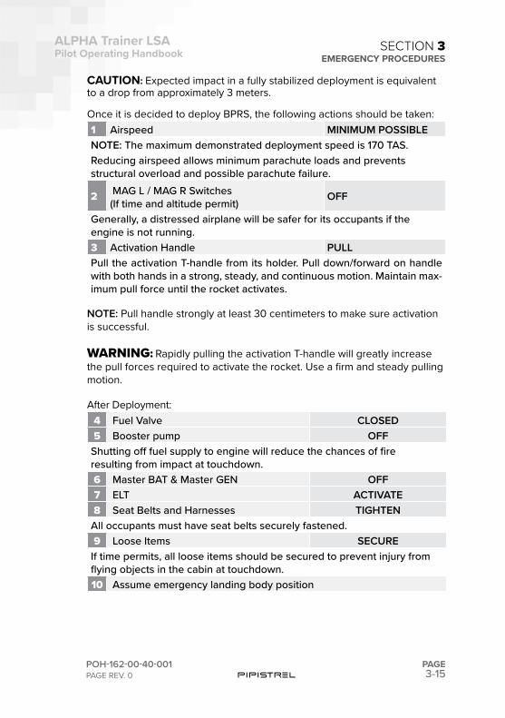
CAUTION: Expected impact in a fully stabilized deployment is equivalent to a drop from approximately 3 meters.
Once it is decided to deploy BPRS, the following actions should be taken:1 Airspeed MINIMUM POSSIBLE NOTE: The maximum demonstrated deployment speed is 170 TAS.Reducing airspeed allows minimum parachute loads and prevents structural overload and possible parachute failure.
2 MAG L / MAG R Switches(If time and altitude permit)
OFF
Generally, a distressed airplane will be safer for its occupants if the engine is not running.3 Activation Handle PULLPull the activation T-handle from its holder. Pull down/forward on handle with both hands in a strong, steady, and continuous motion. Maintain max-imum pull force until the rocket activates.
NOTE: Pull handle strongly at least 30 centimeters to make sure activation is successful.
WARNING:!Rapidly pulling the activation T-handle will greatly increase the pull forces required to activate the rocket. Use a firm and steady pulling motion.
After Deployment:4 Fuel Valve CLOSED5 Booster pump OFF
Shutting off fuel supply to engine will reduce the chances of fire resulting from impact at touchdown.6 Master BAT & Master GEN OFF7 ELT ACTIVATE8 Seat Belts and Harnesses TIGHTEN
All occupants must have seat belts securely fastened.9 Loose Items SECURE
If time permits, all loose items should be secured to prevent injury from flying objects in the cabin at touchdown.10 Assume emergency landing body position
3-16PAGE
ALPHA Trainer LSAPilot Operating Handbook
POH-162-00-40-001PAGE REV. 0
SECTION 3EMERGENCY PROCEDURES
The emergency landing body position is assumed by placing both hands on the lap, clasping one wrist with the opposite hand, and holding the up-per torso erect and against the seat backs.After the airplane comes to a complete stop, evacuate quickly and move upwind.As occupants exit the airplane, the reduced weight may allow winds to drag the airplane further. As a result of landing impact, the doors may jam. If the doors cannot be opened, break out the windows. Crawl through the opening.
3.9 LANDING EMERGENCIES
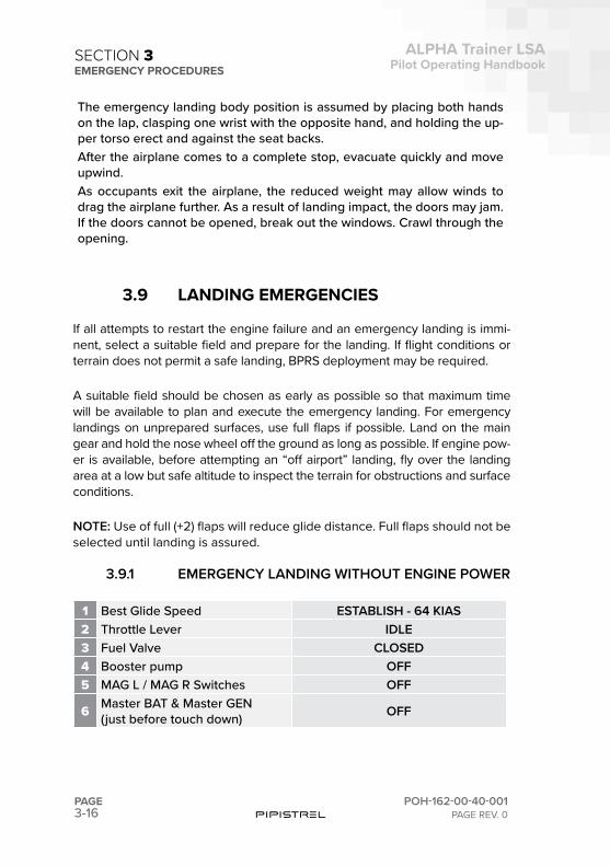
If all attempts to restart the engine failure and an emergency landing is immi-nent, select a suitable field and prepare for the landing. If flight conditions or terrain does not permit a safe landing, BPRS deployment may be required.
A suitable field should be chosen as early as possible so that maximum time will be available to plan and execute the emergency landing. For emergency landings on unprepared surfaces, use full flaps if possible. Land on the main gear and hold the nose wheel off the ground as long as possible. If engine pow-er is available, before attempting an “off airport” landing, fly over the landing area at a low but safe altitude to inspect the terrain for obstructions and surface conditions.
NOTE: Use of full (+2) flaps will reduce glide distance. Full flaps should not be selected until landing is assured.
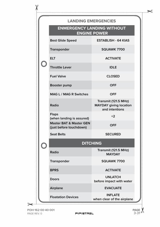
3.9.1 EMERGENCY LANDING WITHOUT ENGINE POWER
1 Best Glide Speed ESTABLISH - 64 KIAS2 Throttle Lever IDLE3 Fuel Valve CLOSED4 Booster pump OFF5 MAG L / MAG R Switches OFF
6 Master BAT & Master GEN(just before touch down) OFF
3-17
ALPHA Trainer LSAPilot Operating Handbook
POH-162-00-40-001PAGE REV. 0
PAGE
SECTION 3EMERGENCY PROCEDURES
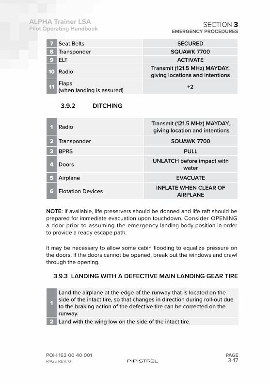
7 Seat Belts SECURED8 Transponder SQUAWK 77009 ELT ACTIVATE
10 Radio Transmit (121.5 MHz) MAYDAY,giving locations and intentions
11 Flaps(when landing is assured) +2
3.9.2 DITCHING
1 Radio Transmit (121.5 MHz) MAYDAY, giving location and intentions
2 Transponder SQUAWK 7700
3 BPRS PULL
4 Doors UNLATCH before impact with water
5 Airplane EVACUATE
6 Flotation Devices INFLATE WHEN CLEAR OF AIRPLANE
NOTE: If available, life preservers should be donned and life raft should be prepared for immediate evacuation upon touchdown. Consider OPENING a door prior to assuming the emergency landing body position in order to provide a ready escape path.
It may be necessary to allow some cabin flooding to equalize pressure on the doors. If the doors cannot be opened, break out the windows and crawl through the opening.
3.9.3 LANDING WITH A DEFECTIVE MAIN LANDING GEAR TIRE
1
Land the airplane at the edge of the runway that is located on the side of the intact tire, so that changes in direction during roll-out due to the braking action of the defective tire can be corrected on the runway.
2 Land with the wing low on the side of the intact tire.
3-18PAGE
ALPHA Trainer LSAPilot Operating Handbook
POH-162-00-40-001PAGE REV. 0
SECTION 3EMERGENCY PROCEDURES
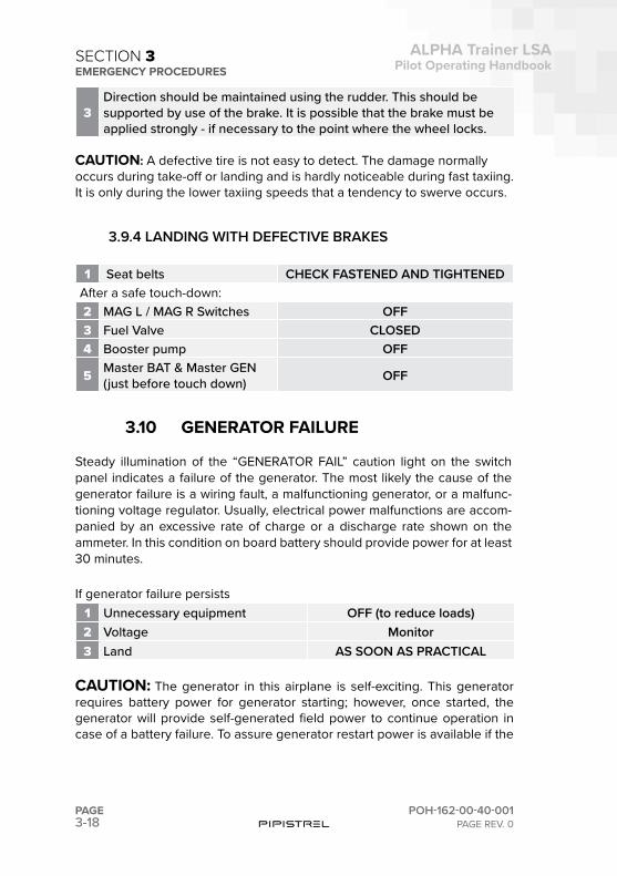
3Direction should be maintained using the rudder. This should be supported by use of the brake. It is possible that the brake must be applied strongly - if necessary to the point where the wheel locks.
CAUTION: A defective tire is not easy to detect. The damage normally occurs during take-off or landing and is hardly noticeable during fast taxiing. It is only during the lower taxiing speeds that a tendency to swerve occurs.
3.9.4 LANDING WITH DEFECTIVE BRAKES
1 Seat belts CHECK FASTENED AND TIGHTENEDAfter a safe touch-down:2 MAG L / MAG R Switches OFF3 Fuel Valve CLOSED4 Booster pump OFF
5 Master BAT & Master GEN (just before touch down) OFF
3.10 GENERATOR FAILURE
Steady illumination of the “GENERATOR FAIL” caution light on the switch panel indicates a failure of the generator. The most likely the cause of the generator failure is a wiring fault, a malfunctioning generator, or a malfunc-tioning voltage regulator. Usually, electrical power malfunctions are accom-panied by an excessive rate of charge or a discharge rate shown on the ammeter. In this condition on board battery should provide power for at least 30 minutes.
If generator failure persists1 Unnecessary equipment OFF (to reduce loads)2 Voltage Monitor3 Land AS SOON AS PRACTICAL
CAUTION: The generator in this airplane is self-exciting. This generator requires battery power for generator starting; however, once started, the generator will provide self-generated field power to continue operation in case of a battery failure. To assure generator restart power is available if the
3-19
ALPHA Trainer LSAPilot Operating Handbook
POH-162-00-40-001PAGE REV. 0
PAGE
SECTION 3EMERGENCY PROCEDURES
generator fails, the battery should not be disconnected during flight.
NOTE: If it is necessary to reduce electrical loads due to an generator mal-function, switch off electrical components and/or systems that are not essen-tial for the current flight conditions rather than pulling circuit breakers. Load shedding in this manner will prevent accidental circuit breaker disconnection and loss of power to flight-critical systems.
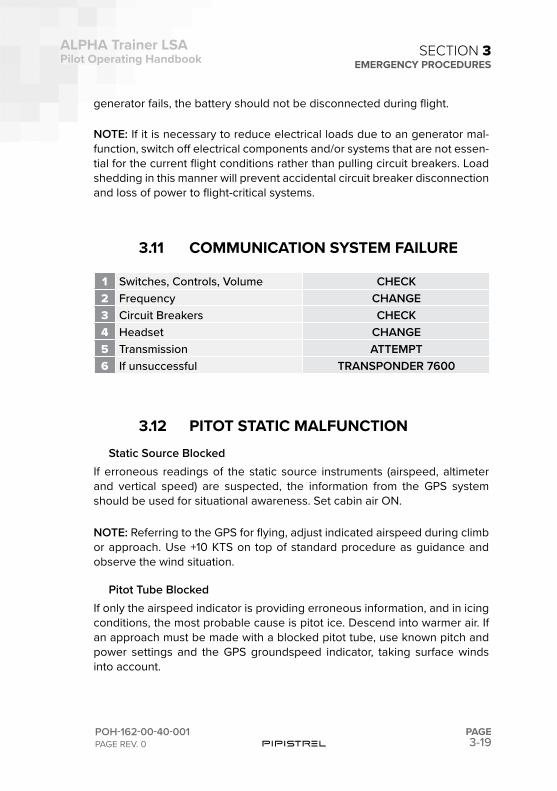
3.11 COMMUNICATION SYSTEM FAILURE
1 Switches, Controls, Volume CHECK2 Frequency CHANGE3 Circuit Breakers CHECK4 Headset CHANGE5 Transmission ATTEMPT6 If unsuccessful TRANSPONDER 7600
3.12 PITOT STATIC MALFUNCTIONStatic Source Blocked
If erroneous readings of the static source instruments (airspeed, altimeter and vertical speed) are suspected, the information from the GPS system should be used for situational awareness. Set cabin air ON.
NOTE: Referring to the GPS for flying, adjust indicated airspeed during climb or approach. Use +10 KTS on top of standard procedure as guidance and observe the wind situation.
Pitot Tube BlockedIf only the airspeed indicator is providing erroneous information, and in icing conditions, the most probable cause is pitot ice. Descend into warmer air. If an approach must be made with a blocked pitot tube, use known pitch and power settings and the GPS groundspeed indicator, taking surface winds into account.
3-20PAGE
ALPHA Trainer LSAPilot Operating Handbook
POH-162-00-40-001PAGE REV. 0
SECTION 3EMERGENCY PROCEDURES
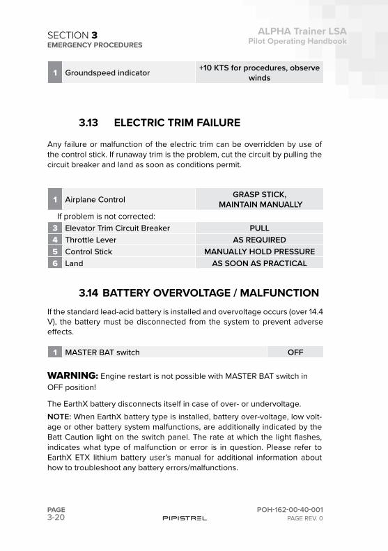
1 Groundspeed indicator +10 KTS for procedures, observe winds
3.13 ELECTRIC TRIM FAILURE
Any failure or malfunction of the electric trim can be overridden by use of the control stick. If runaway trim is the problem, cut the circuit by pulling the circuit breaker and land as soon as conditions permit.
1 Airplane Control GRASP STICK, MAINTAIN MANUALLY
If problem is not corrected:3 Elevator Trim Circuit Breaker PULL4 Throttle Lever AS REQUIRED5 Control Stick MANUALLY HOLD PRESSURE6 Land AS SOON AS PRACTICAL
3.14 BATTERY OVERVOLTAGE / MALFUNCTIONIf the standard lead-acid battery is installed and overvoltage occurs (over 14.4 V), the battery must be disconnected from the system to prevent adverse effects.
1 MASTER BAT switch OFF
WARNING:!Engine restart is not possible with MASTER BAT switch in OFF position!
The EarthX battery disconnects itself in case of over- or undervoltage. NOTE: When EarthX battery type is installed, battery over-voltage, low volt-age or other battery system malfunctions, are additionally indicated by the Batt Caution light on the switch panel. The rate at which the light flashes, indicates what type of malfunction or error is in question. Please refer to EarthX ETX lithium battery user’s manual for additional information about how to troubleshoot any battery errors/malfunctions.
3-21
ALPHA Trainer LSAPilot Operating Handbook
POH-162-00-40-001PAGE REV. 0
PAGE
SECTION 3EMERGENCY PROCEDURES
3.15 EXCEEDING VNE
Should the VNE be exceeded, pull the stick gently in order to reduce airspeed and continue flying using gentle control deflections. Land safely as soon as possible and have the aircraft verified for airworthiness by authorized service personnel.
3.16 ICE BUILD-UP
Turn back or change altitude to exit icing conditions. Consider lateral or ver-tical path reversal to return to last “known good” flight conditions. Maintain VFR flight! Set cabin air/heating ON. Watch for signs of icing on the pitot tube. In case of pneumatic instrument failures, use the GPS information to reference to approximate ground speed. Plan the landing at the nearest air-port, or a suitable off airport landing site in case of an extremely rapid ice build-up. Increase the speed to avoid stall.
CAUTION: Maneuver the airplane gently and leave the flaps retracted. When ice is built-up at the horizontal stabilizer, the change of pitching mo-ment due to flaps extension may result of loss of elevator control. Approach at elevated speeds (+15 KTS, also if using the GPS as a reference).
WARNING:!Failure to act quickly may result in an unrecoverable icing en-counter.
WARNING:!If control is lost, it may be necessary to deploy the Ballistic Parachute Rescue System (BPRS).

This page is intentionally left blank.
3-23
ALPHA Trainer LSAPilot Operating Handbook
POH-162-00-40-001PAGE REV. 0
PAGE
SECTION 3EMERGENCY PROCEDURES
3.17
CHECKLISTSCHECKLISTSEMERGENCY PROCEDURES

This page is intentionally left blank.
3-25POH-162-00-40-001PAGE REV. 0
PAGE
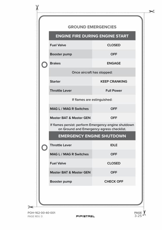
GROUND EMERGENCIES
ENGINE FIRE DURING ENGINE START
Fuel Valve CLOSED
Booster pump OFF
Brakes ENGAGE
Once aircraft has stopped:
Starter KEEP CRANKING
Throttle Lever Full Power
If flames are estinguished:
MAG L / MAG R Switches OFF
Master BAT & Master GEN OFF
If flames persist: perform Emergency engine shutdown on Ground and Emergency egress checklist.
EMERGENCY ENGINE SHUTDOWN
Throttle Lever IDLE
MAG L / MAG R Switches OFF
Fuel Valve CLOSED
Master BAT & Master GEN OFF
Booster pump CHECK OFF
3-26PAGE POH-162-00-40-001
PAGE REV. 0
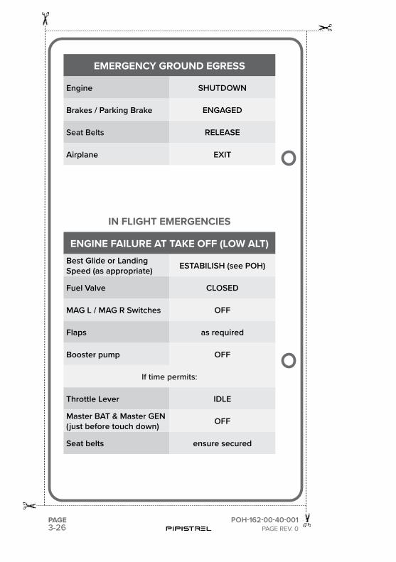
EMERGENCY GROUND EGRESS
Engine SHUTDOWN
Brakes / Parking Brake ENGAGED
Seat Belts RELEASE
Airplane EXIT
IN FLIGHT EMERGENCIES
ENGINE FAILURE AT TAKE OFF (LOW ALT)Best Glide or Landing Speed (as appropriate) ESTABILISH (see POH)
Fuel Valve CLOSED
MAG L / MAG R Switches OFF
Flaps as required
Booster pump OFF
If time permits:
Throttle Lever IDLE
Master BAT & Master GEN(just before touch down) OFF
Seat belts ensure secured
3-27POH-162-00-40-001PAGE REV. 0
PAGE
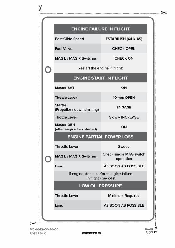
ENGINE FAILURE IN FLIGHT
Best Glide Speed ESTABILISH (64 KIAS)
Fuel Valve CHECK OPEN
MAG L / MAG R Switches CHECK ON
Restart the engine in flight:
ENGINE START IN FLIGHT
Master BAT ON
Thottle Lever 10 mm OPEN
Starter (Propeller not windmilling) ENGAGE
Thottle Lever Slowly INCREASE
Master GEN (after engine has started) ON
ENGINE PARTIAL POWER LOSS
Throttle Lever Sweep
MAG L / MAG R Switches Check single MAG switchoperation
Land AS SOON AS POSSIBLE
If engine stops: perform engine failure in flight check-list
LOW OIL PRESSURE
Throttle Lever Minimum Required
Land AS SOON AS POSSIBLE
3-28PAGE POH-162-00-40-001
PAGE REV. 0
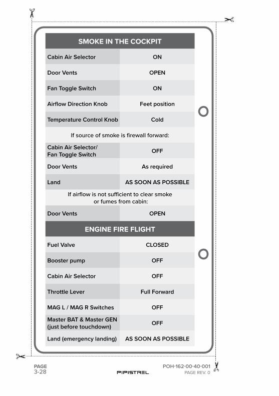
SMOKE IN THE COCKPIT
Cabin Air Selector ON
Door Vents OPEN
Fan Toggle Switch ON
Airflow Direction Knob Feet position
Temperature Control Knob Cold
If source of smoke is firewall forward:
Cabin Air Selector/Fan Toggle Switch OFF
Door Vents As required
Land AS SOON AS POSSIBLE
If airflow is not sufficient to clear smoke or fumes from cabin:
Door Vents OPEN
ENGINE FIRE FLIGHT
Fuel Valve CLOSED
Booster pump OFF
Cabin Air Selector OFF
Throttle Lever Full Forward
MAG L / MAG R Switches OFF
Master BAT & Master GEN(just before touchdown) OFF
Land (emergency landing) AS SOON AS POSSIBLE
3-29POH-162-00-40-001PAGE REV. 0
PAGE
COCKPIT FIRE IN FLIGHT
Cabin Air Selector OFF
Fan Toggle Switch OFF
Door Vents As required
MASTER BAT Switch OFF
MASTER GEN Switch OFF
Booster pump OFF
Fire Extinguisher (if available) ACTIVATE
If airflow is not sufficient to clear smoke or fumes from cabin - When fire extinguished:
Cabin Air Selector ON
Green Electrical Switches OFF
Land AS SOON AS POSSIBLE
STALL RECOVERY
Reduce AoA Control Stick Forward
Throttle Lever Full Power
Horizontal Flight Resume
3-30PAGE POH-162-00-40-001
PAGE REV. 0
SPIN RECOVERING TECHNIQUE
Throttle Lever IDLE
Rudder Full deflection - direction opposite to the spin
Stick Forward - lower the nose to build us speed
As rotation stops:
Rudder Neutralize
Establish horizontal flight without exceeding g-load or airspeed limitations
BPRS DEPLOYMENT
Airspeed MINIMUM POSSIBLE
MAG L / MAG R Switches (if time/altitude permits) OFF
Activation Handle PULL
After Deployment:
Fuel Valve CLOSED
Booster pump OFF
Master BAT & Master GEN OFF
ELT ACTIVATE
Seat Belts TIGHTEN
Loose Items SECURE
Assume emergency landing body position. After the impact break out the windows to exit if doors
are jammed.
3-31POH-162-00-40-001PAGE REV. 0
PAGE
LANDING EMERGENCIES
ENMERGENCY LANDING WITHOUT ENGINE POWER
Best Glide Speed ESTABLISH - 64 KIAS
Transponder SQUAWK 7700
ELT ACTIVATE
Throttle Lever IDLE
Fuel Valve CLOSED
Booster pump OFF
MAG L / MAG R Switches OFF
RadioTransmit (121.5 MHz)
MAYDAY giving location and intentions
Flaps (when landing is assured) +2
Master BAT & Master GEN(just before touchdown) OFF
Seat Belts SECURED
DITCHING
Radio Transmit (121.5 MHz) MAYDAY
Transponder SQUAWK 7700
BPRS ACTIVATE
Doors UNLATCH before impact with water
Airplane EVACUATE
Floatation Devices INFLATEwhen clear of the airplane
3-32PAGE POH-162-00-40-001
PAGE REV. 0
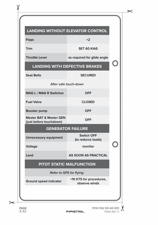
LANDING WITHOUT ELEVATOR CONTROL
Flaps +2
Trim SET 60 KIAS
Throttle Lever as required for glide angle
LANDING WITH DEFECTIVE BRAKES
Seat Belts SECURED
After safe touch-down
MAG L / MAG R Switches OFF
Fuel Valve CLOSED
Booster pump OFF
Master BAT & Master GEN(just before touchdown) OFF
GENERATOR FAILURE
Unnecessary equipment Switch OFF(to redurce loads)
Voltage monitor
Land AS SOON AS PRACTICAL
PITOT STATIC MALFUNCTION
Refer to GPS for flying:
Ground speed indicator +10 KTS for procedures,observe winds
3-33POH-162-00-40-001PAGE REV. 0
PAGE
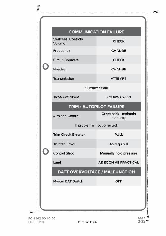
COMMUNICATION FAILURE Switches, Controls, Volume CHECK
Frequency CHANGE
Circuit Breakers CHECK
Headset CHANGE
Transmission ATTEMPT
If unsuccessful:
TRANSPONDER SQUAWK 7600
TRIM / AUTOPILOT FAILURE
Airplane Control Graps stick - maintain manually
If problem is not corrected:
Trim Circuit Breaker PULL
Throttle Lever As required
Control Stick Manually hold pressure
Land AS SOON AS PRACTICAL
BATT OVERVOLTAGE / MALFUNCTION
Master BAT Switch OFF

This page is intentionally left blank.

SECTION
4
4-2PAGE
ALPHA Trainer LSAPilot Operating Handbook
POH-162-00-40-001PAGE REV. 0
PART SUBJECT PAGE NUMBER
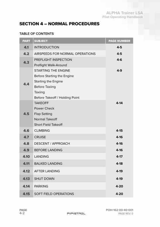
4.1 INTRODUCTION 4-5
4.2 AIRSPEEDS FOR NORMAL OPERATIONS 4-5
4.3PREFLIGHT INSPECTION 4-6Preflight Walk-Around
4.4
STARTING THE ENGINE 4-9Before Starting the EngineStarting the EngineBefore TaxiingTaxiingBefore Takeoff / Holding Point
4.5
TAKEOFF 4-14Power CheckFlap SettingNormal TakeoffShort Field Takeoff
4.6 CLIMBING 4-15
4.7 CRUISE 4-16
4.8 DESCENT / APPROACH 4-16
4.9 BEFORE LANDING 4-16
4.10 LANDING 4-17
4.11 BALKED LANDING 4-18
4.12 AFTER LANDING 4-19
4.13 SHUT DOWN 4-19
4.14 PARKING 4-20
4.15 SOFT FIELD OPERATIONS 4-20
SECTION 4 – NORMAL PROCEDURES
TABLE OF CONTENTS

4-3
ALPHA Trainer LSAPilot Operating Handbook
POH-162-00-40-001PAGE REV. 0
PAGE
SECTION 4NORMAL PROCEDURES
PART SUBJECT PAGE NUMBER
4.16 CHECKLIST - NORMAL PROCEDURES 4-23

This page is intentionally left blank.
4-5
ALPHA Trainer LSAPilot Operating Handbook
POH-162-00-40-001PAGE REV. 0
PAGE
SECTION 4NORMAL PROCEDURES
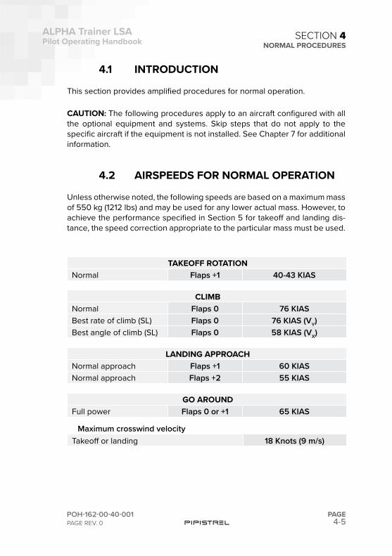
4.1 INTRODUCTION
This section provides amplified procedures for normal operation.
CAUTION: The following procedures apply to an aircraft configured with all the optional equipment and systems. Skip steps that do not apply to the specific aircraft if the equipment is not installed. See Chapter 7 for additional information.
4.2 AIRSPEEDS FOR NORMAL OPERATION
Unless otherwise noted, the following speeds are based on a maximum mass of 550 kg (1212 lbs) and may be used for any lower actual mass. However, to achieve the performance specified in Section 5 for takeoff and landing dis-tance, the speed correction appropriate to the particular mass must be used.
TAKEOFF ROTATIONNormal Flaps +1 40-43 KIAS
CLIMBNormal Flaps 0 76 KIASBest rate of climb (SL) Flaps 0 76 KIAS (VY)Best angle of climb (SL) Flaps 0 58 KIAS (VX)
LANDING APPROACHNormal approach Flaps +1 60 KIASNormal approach Flaps +2 55 KIAS
GO AROUNDFull power Flaps 0 or +1 65 KIAS
Maximum crosswind velocityTakeoff or landing 18 Knots (9 m/s)
4-6PAGE
ALPHA Trainer LSAPilot Operating Handbook
POH-162-00-40-001PAGE REV. 0
SECTION 4NORMAL PROCEDURES
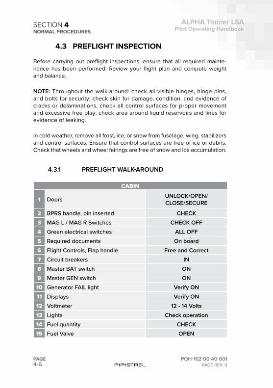
4.3 PREFLIGHT INSPECTION
Before carrying out preflight inspections, ensure that all required mainte-nance has been performed. Review your flight plan and compute weight and balance.
NOTE: Throughout the walk-around: check all visible hinges, hinge pins, and bolts for security; check skin for damage, condition, and evidence of cracks or delaminations, check all control surfaces for proper movement and excessive free play; check area around liquid reservoirs and lines for evidence of leaking.
In cold weather, remove all frost, ice, or snow from fuselage, wing, stabilizers and control surfaces. Ensure that control surfaces are free of ice or debris. Check that wheels and wheel fairings are free of snow and ice accumulation.
4.3.1 PREFLIGHT WALK-AROUND
CABIN
1 Doors UNLOCK/OPEN/ CLOSE/SECURE
2 BPRS handle, pin inserted CHECK3 MAG L / MAG R Switches CHECK OFF4 Green electrical switches ALL OFF5 Required documents On board6 Flight Controls, Flap handle Free and Correct7 Circuit breakers IN8 Master BAT switch ON9 Master GEN switch ON10 Generator FAIL light Verify ON11 Displays Verify ON12 Voltmeter 12 - 14 Volts13 Lights Check operation14 Fuel quantity CHECK15 Fuel Valve OPEN
4-7
ALPHA Trainer LSAPilot Operating Handbook
POH-162-00-40-001PAGE REV. 0
PAGE
SECTION 4NORMAL PROCEDURES
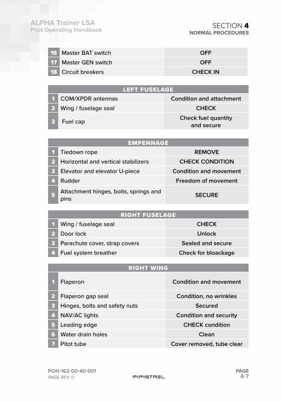
16 Master BAT switch OFF17 Master GEN switch OFF18 Circuit breakers CHECK IN
LEFT FUSELAGE1 COM/XPDR antennas Condition and attachment2 Wing / fuselage seal CHECK
3 Fuel cap Check fuel quantity and secure
EMPENNAGE1 Tiedown rope REMOVE2 Horizontal and vertical stabilizers CHECK CONDITION3 Elevator and elevator U-piece Condition and movement4 Rudder Freedom of movement
5 Attachment hinges, bolts, springs and pins SECURE
RIGHT FUSELAGE1 Wing / fuselage seal CHECK2 Door lock Unlock3 Parachute cover, strap covers Sealed and secure4 Fuel system breather Check for bloackage
RIGHT WING
1 Flaperon Condition and movement
2 Flaperon gap seal Condition, no wrinkles3 Hinges, bolts and safety nuts Secured4 NAV/AC lights Condition and security5 Leading edge CHECK condition6 Water drain holes Clean7 Pitot tube Cover removed, tube clear
4-8PAGE
ALPHA Trainer LSAPilot Operating Handbook
POH-162-00-40-001PAGE REV. 0
SECTION 4NORMAL PROCEDURES
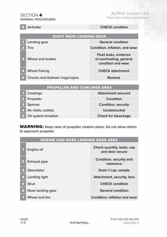
8 Airbrake CHECK condition
RIGHT MAIN LANDING GEAR1 Landing gear General condition2 Tire Condition, inflation, and wear
3 Wheel and brakesFluid leaks, evidence
of overheating, general condition and wear
4 Wheel Fairing CHECK attachment
5 Chocks and tiedown rings/ropes Remove
PROPELLER AND COWLINGS AREA1 Cowlings Attachment secured2 Propeller Condition3 Spinner Condition, security4 Air inlets, outlets Unobstructed5 Oil system breather Check for bloackage
WARNING: Keep clear of propeller rotation plane. Do not allow others to approach propeller.
ENGINE AND NOSE LANDING GEAR AREA
1 Engine oil Check quantity, leaks, cap and door secure
2 Exhaust pipe Condition, security and clearance
3 Gascolator Drain 1 cup, sample
4 Landing light Attachment, security, lens
5 Strut CHECK condition
6 Nose landing gear General condition
7 Wheel and tire Condition, inflation and wear
4-9
ALPHA Trainer LSAPilot Operating Handbook
POH-162-00-40-001PAGE REV. 0
PAGE
SECTION 4NORMAL PROCEDURES
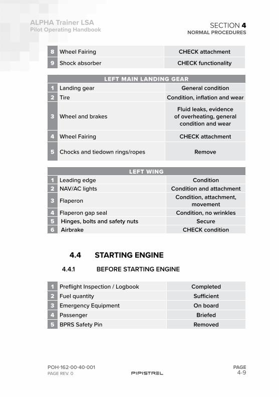
8 Wheel Fairing CHECK attachment
9 Shock absorber CHECK functionality
LEFT MAIN LANDING GEAR1 Landing gear General condition2 Tire Condition, inflation and wear
3 Wheel and brakesFluid leaks, evidence
of overheating, general condition and wear
4 Wheel Fairing CHECK attachment
5 Chocks and tiedown rings/ropes Remove
LEFT WING1 Leading edge Condition2 NAV/AC lights Condition and attachment
3 Flaperon Condition, attachment, movement
4 Flaperon gap seal Condition, no wrinkles5 Hinges, bolts and safety nuts Secure6 Airbrake CHECK condition
4.4 STARTING ENGINE
4.4.1 BEFORE STARTING ENGINE
1 Preflight Inspection / Logbook Completed2 Fuel quantity Sufficient3 Emergency Equipment On board4 Passenger Briefed5 BPRS Safety Pin Removed
4-10PAGE
ALPHA Trainer LSAPilot Operating Handbook
POH-162-00-40-001PAGE REV. 0
SECTION 4NORMAL PROCEDURES
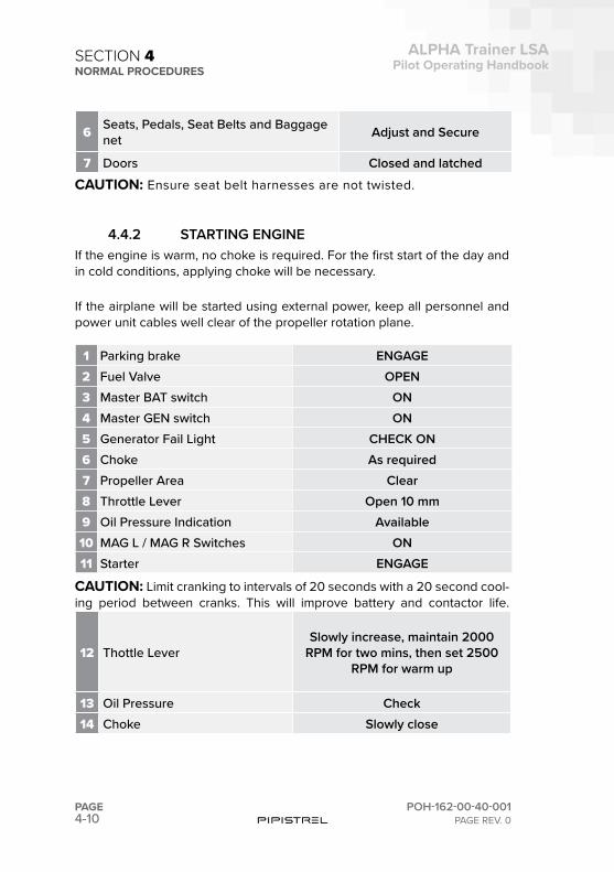
6 Seats, Pedals, Seat Belts and Baggage net Adjust and Secure
7 Doors Closed and latchedCAUTION: Ensure seat belt harnesses are not twisted.
4.4.2 STARTING ENGINEIf the engine is warm, no choke is required. For the first start of the day and in cold conditions, applying choke will be necessary.
If the airplane will be started using external power, keep all personnel and power unit cables well clear of the propeller rotation plane.
1 Parking brake ENGAGE2 Fuel Valve OPEN3 Master BAT switch ON4 Master GEN switch ON5 Generator Fail Light CHECK ON6 Choke As required7 Propeller Area Clear8 Throttle Lever Open 10 mm9 Oil Pressure Indication Available10 MAG L / MAG R Switches ON11 Starter ENGAGE
CAUTION: Limit cranking to intervals of 20 seconds with a 20 second cool-ing period between cranks. This will improve battery and contactor life.
12 Thottle LeverSlowly increase, maintain 2000
RPM for two mins, then set 2500 RPM for warm up
13 Oil Pressure Check14 Choke Slowly close
4-11
ALPHA Trainer LSAPilot Operating Handbook
POH-162-00-40-001PAGE REV. 0
PAGE
SECTION 4NORMAL PROCEDURES
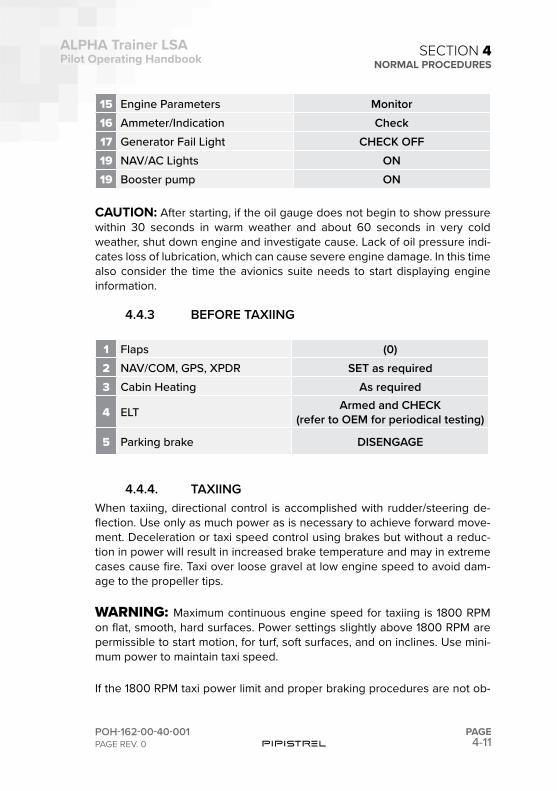
15 Engine Parameters Monitor16 Ammeter/Indication Check17 Generator Fail Light CHECK OFF19 NAV/AC Lights ON19 Booster pump ON
CAUTION: After starting, if the oil gauge does not begin to show pressure within 30 seconds in warm weather and about 60 seconds in very cold weather, shut down engine and investigate cause. Lack of oil pressure indi-cates loss of lubrication, which can cause severe engine damage. In this time also consider the time the avionics suite needs to start displaying engine information.
4.4.3 BEFORE TAXIING
1 Flaps (0)2 NAV/COM, GPS, XPDR SET as required3 Cabin Heating As required
4 ELT Armed and CHECK(refer to OEM for periodical testing)
5 Parking brake DISENGAGE
4.4.4. TAXIINGWhen taxiing, directional control is accomplished with rudder/steering de-flection. Use only as much power as is necessary to achieve forward move-ment. Deceleration or taxi speed control using brakes but without a reduc-tion in power will result in increased brake temperature and may in extreme cases cause fire. Taxi over loose gravel at low engine speed to avoid dam-age to the propeller tips.
WARNING: Maximum continuous engine speed for taxiing is 1800 RPM on flat, smooth, hard surfaces. Power settings slightly above 1800 RPM are permissible to start motion, for turf, soft surfaces, and on inclines. Use mini-mum power to maintain taxi speed.
If the 1800 RPM taxi power limit and proper braking procedures are not ob-
4-12PAGE
ALPHA Trainer LSAPilot Operating Handbook
POH-162-00-40-001PAGE REV. 0
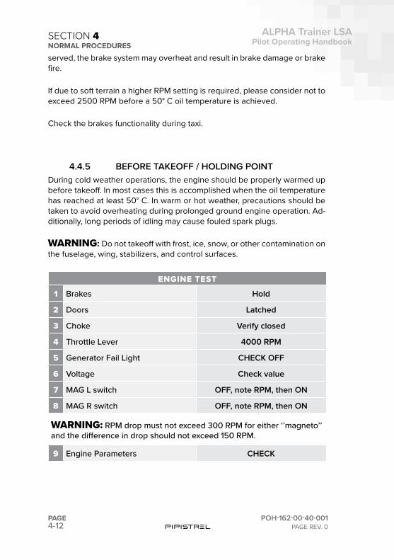
SECTION 4NORMAL PROCEDURESserved, the brake system may overheat and result in brake damage or brake fire.
If due to soft terrain a higher RPM setting is required, please consider not to exceed 2500 RPM before a 50° C oil temperature is achieved.
Check the brakes functionality during taxi.
4.4.5 BEFORE TAKEOFF / HOLDING POINTDuring cold weather operations, the engine should be properly warmed up before takeoff. In most cases this is accomplished when the oil temperature has reached at least 50° C. In warm or hot weather, precautions should be taken to avoid overheating during prolonged ground engine operation. Ad-ditionally, long periods of idling may cause fouled spark plugs.
WARNING: Do not takeoff with frost, ice, snow, or other contamination on the fuselage, wing, stabilizers, and control surfaces.
ENGINE TEST
1 Brakes Hold
2 Doors Latched
3 Choke Verify closed
4 Throttle Lever 4000 RPM
5 Generator Fail Light CHECK OFF
6 Voltage Check value
7 MAG L switch OFF, note RPM, then ON
8 MAG R switch OFF, note RPM, then ON
WARNING: RPM drop must not exceed 300 RPM for either ‘’magneto’’ and the difference in drop should not exceed 150 RPM.
9 Engine Parameters CHECK
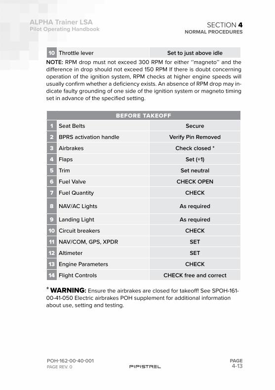
4-13
ALPHA Trainer LSAPilot Operating Handbook
POH-162-00-40-001PAGE REV. 0
PAGE
SECTION 4NORMAL PROCEDURES
10 Throttle lever Set to just above idleNOTE: RPM drop must not exceed 300 RPM for either ‘’magneto’’ and the difference in drop should not exceed 150 RPM If there is doubt concerning operation of the ignition system, RPM checks at higher engine speeds will usually confirm whether a deficiency exists. An absence of RPM drop may in-dicate faulty grounding of one side of the ignition system or magneto timing set in advance of the specified setting.
BEFORE TAKEOFF
1 Seat Belts Secure
2 BPRS activation handle Verify Pin Removed
3 Airbrakes Check closed *
4 Flaps Set (+1)
5 Trim Set neutral
6 Fuel Valve CHECK OPEN
7 Fuel Quantity CHECK
8 NAV/AC Lights As required
9 Landing Light As required
10 Circuit breakers CHECK
11 NAV/COM, GPS, XPDR SET
12 Altimeter SET
13 Engine Parameters CHECK
14 Flight Controls CHECK free and correct
* WARNING: Ensure the airbrakes are closed for takeoff! See SPOH-161-00-41-050 Electric airbrakes POH supplement for additional information about use, setting and testing.
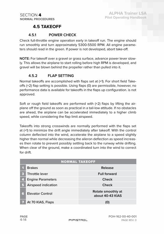
4-14PAGE
ALPHA Trainer LSAPilot Operating Handbook
POH-162-00-40-001PAGE REV. 0
SECTION 4NORMAL PROCEDURES
4.5 TAKEOFF
4.5.1 POWER CHECK Check full-throttle engine operation early in takeoff run. The engine should run smoothly and turn approximately 5300-5500 RPM. All engine parame-ters should read in the green. If power is not developed, abort take-off.
NOTE: For takeoff over a gravel or grass surface, advance power lever slow-ly. This allows the airplane to start rolling before high RPM is developed, and gravel will be blown behind the propeller rather than pulled into it.
4.5.2 FLAP SETTINGNormal takeoffs are accomplished with flaps set at (+1). For short field Take-offs (+2) flap setting is possible. Using flaps (0) are permissible, however, no performance data is available for takeoffs in the flaps up configuration. is not approved.
Soft or rough field takeoffs are performed with (+2) flaps by lifting the air-plane off the ground as soon as practical in a tail-low attitude. If no obstacles are ahead, the airplane can be accelerated immediately to a higher climb speed, while considering the flap limit airspeed.
Takeoffs into strong crosswinds are normally performed with the flaps set at (+1) to minimize the drift angle immediately after takeoff. With the control column deflected into the wind, accelerate the airplane to a speed slightly higher than normal while decreasing the aileron deflection as speed increas-es then rotate to prevent possibly settling back to the runway while drifting. When clear of the ground, make a coordinated turn into the wind to correct for drift.
NORMAL TAKEOFF
1 Brakes Release
3 Throttle lever Full forward4 Engine Parameters Check5 Airspeed indication Check
6 Elevator Control Rotate smoothly at about 40-43 KIAS
7 At 70 KIAS, Flaps (0)
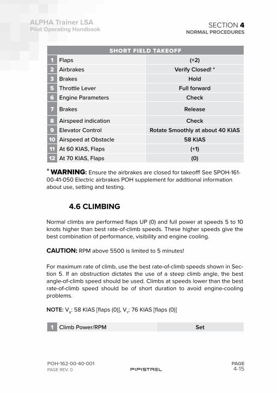
4-15
ALPHA Trainer LSAPilot Operating Handbook
POH-162-00-40-001PAGE REV. 0
PAGE
SECTION 4NORMAL PROCEDURES
SHORT FIELD TAKEOFF1 Flaps (+2)2 Airbrakes Verify Closed! *3 Brakes Hold5 Throttle Lever Full forward6 Engine Parameters Check
7 Brakes Release
8 Airspeed indication Check9 Elevator Control Rotate Smoothly at about 40 KIAS10 Airspeed at Obstacle 58 KIAS11 At 60 KIAS, Flaps (+1) 12 At 70 KIAS, Flaps (0)
* WARNING: Ensure the airbrakes are closed for takeoff! See SPOH-161-00-41-050 Electric airbrakes POH supplement for additional information about use, setting and testing.
4.6 CLIMBING
Normal climbs are performed flaps UP (0) and full power at speeds 5 to 10 knots higher than best rate-of-climb speeds. These higher speeds give the best combination of performance, visibility and engine cooling.
CAUTION: RPM above 5500 is limited to 5 minutes!
For maximum rate of climb, use the best rate-of-climb speeds shown in Sec-tion 5. If an obstruction dictates the use of a steep climb angle, the best angle-of-climb speed should be used. Climbs at speeds lower than the best rate-of-climb speed should be of short duration to avoid engine-cooling problems.
NOTE: VX: 58 KIAS [flaps (0)], VY: 76 KIAS [flaps (0)]
1 Climb Power/RPM Set
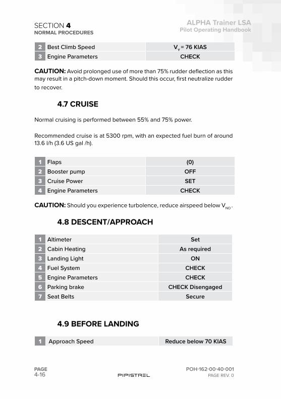
4-16PAGE
ALPHA Trainer LSAPilot Operating Handbook
POH-162-00-40-001PAGE REV. 0
SECTION 4NORMAL PROCEDURES
2 Best Climb Speed VY = 76 KIAS3 Engine Parameters CHECK
CAUTION: Avoid prolonged use of more than 75% rudder deflection as this may result in a pitch-down moment. Should this occur, first neutralize rudder to recover.
4.7 CRUISE
Normal cruising is performed between 55% and 75% power.
Recommended cruise is at 5300 rpm, with an expected fuel burn of around 13.6 l/h (3.6 US gal /h).
1 Flaps (0)2 Booster pump OFF3 Cruise Power SET4 Engine Parameters CHECK
CAUTION: Should you experience turbolence, reduce airspeed below VNO .
4.8 DESCENT/APPROACH
1 Altimeter Set2 Cabin Heating As required3 Landing Light ON4 Fuel System CHECK5 Engine Parameters CHECK6 Parking brake CHECK Disengaged7 Seat Belts Secure
4.9 BEFORE LANDING
1 Approach Speed Reduce below 70 KIAS
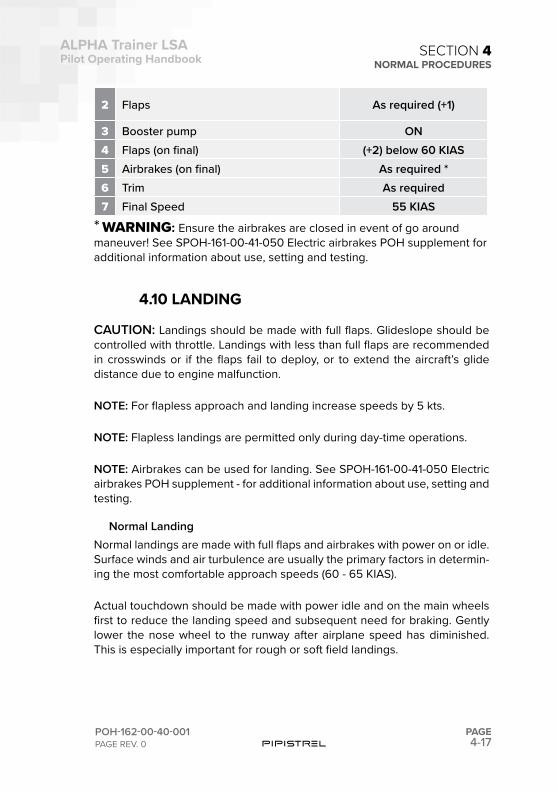
4-17
ALPHA Trainer LSAPilot Operating Handbook
POH-162-00-40-001PAGE REV. 0
PAGE
SECTION 4NORMAL PROCEDURES
2 Flaps As required (+1)
3 Booster pump ON4 Flaps (on final) (+2) below 60 KIAS5 Airbrakes (on final) As required *6 Trim As required7 Final Speed 55 KIAS
* WARNING: Ensure the airbrakes are closed in event of go around maneuver! See SPOH-161-00-41-050 Electric airbrakes POH supplement for additional information about use, setting and testing.
4.10 LANDING
CAUTION: Landings should be made with full flaps. Glideslope should be controlled with throttle. Landings with less than full flaps are recommended in crosswinds or if the flaps fail to deploy, or to extend the aircraft’s glide distance due to engine malfunction.
NOTE: For flapless approach and landing increase speeds by 5 kts.
NOTE: Flapless landings are permitted only during day-time operations.
NOTE: Airbrakes can be used for landing. See SPOH-161-00-41-050 Electric airbrakes POH supplement - for additional information about use, setting and testing.
Normal LandingNormal landings are made with full flaps and airbrakes with power on or idle. Surface winds and air turbulence are usually the primary factors in determin-ing the most comfortable approach speeds (60 - 65 KIAS).
Actual touchdown should be made with power idle and on the main wheels first to reduce the landing speed and subsequent need for braking. Gently lower the nose wheel to the runway after airplane speed has diminished. This is especially important for rough or soft field landings.
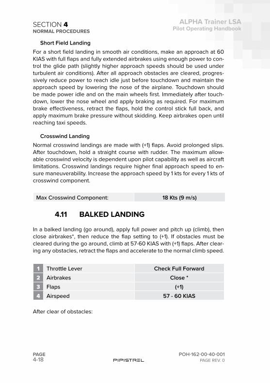
4-18PAGE
ALPHA Trainer LSAPilot Operating Handbook
POH-162-00-40-001PAGE REV. 0
SECTION 4NORMAL PROCEDURES
Short Field LandingFor a short field landing in smooth air conditions, make an approach at 60 KIAS with full flaps and fully extended airbrakes using enough power to con-trol the glide path (slightly higher approach speeds should be used under turbulent air conditions). After all approach obstacles are cleared, progres-sively reduce power to reach idle just before touchdown and maintain the approach speed by lowering the nose of the airplane. Touchdown should be made power idle and on the main wheels first. Immediately after touch-down, lower the nose wheel and apply braking as required. For maximum brake effectiveness, retract the flaps, hold the control stick full back, and apply maximum brake pressure without skidding. Keep airbrakes open until reaching taxi speeds.
Crosswind LandingNormal crosswind landings are made with (+1) flaps. Avoid prolonged slips. After touchdown, hold a straight course with rudder. The maximum allow-able crosswind velocity is dependent upon pilot capability as well as aircraft limitations. Crosswind landings require higher final approach speed to en-sure maneuverability. Increase the approach speed by 1 kts for every 1 kts of crosswind component.
Max Crosswind Component: 18 Kts (9 m/s)
4.11 BALKED LANDING
In a balked landing (go around), apply full power and pitch up (climb), then close airbrakes*, then reduce the flap setting to (+1). If obstacles must be cleared during the go around, climb at 57-60 KIAS with (+1) flaps. After clear-ing any obstacles, retract the flaps and accelerate to the normal climb speed.
1 Throttle Lever Check Full Forward2 Airbrakes Close *3 Flaps (+1)4 Airspeed 57 - 60 KIAS
After clear of obstacles:
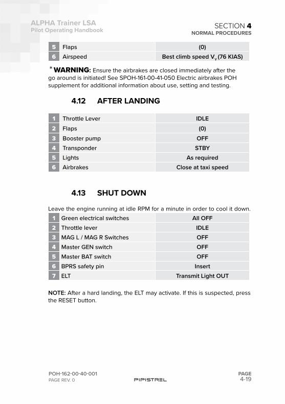
4-19
ALPHA Trainer LSAPilot Operating Handbook
POH-162-00-40-001PAGE REV. 0
PAGE
SECTION 4NORMAL PROCEDURES
5 Flaps (0)6 Airspeed Best climb speed VY (76 KIAS)
* WARNING: Ensure the airbrakes are closed immediately after the go around is initiated! See SPOH-161-00-41-050 Electric airbrakes POH supplement for additional information about use, setting and testing.
4.12 AFTER LANDING
1 Throttle Lever IDLE2 Flaps (0)3 Booster pump OFF4 Transponder STBY5 Lights As required6 Airbrakes Close at taxi speed
4.13 SHUT DOWN
Leave the engine running at idle RPM for a minute in order to cool it down.1 Green electrical switches All OFF2 Throttle lever IDLE3 MAG L / MAG R Switches OFF4 Master GEN switch OFF5 Master BAT switch OFF6 BPRS safety pin Insert7 ELT Transmit Light OUT
NOTE: After a hard landing, the ELT may activate. If this is suspected, press the RESET button.
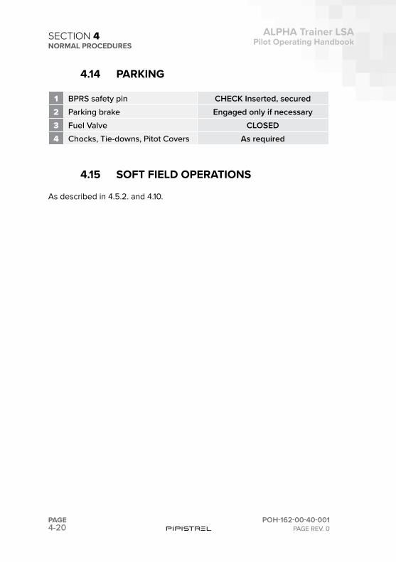
4-20PAGE
ALPHA Trainer LSAPilot Operating Handbook
POH-162-00-40-001PAGE REV. 0
SECTION 4NORMAL PROCEDURES
4.14 PARKING
1 BPRS safety pin CHECK Inserted, secured2 Parking brake Engaged only if necessary3 Fuel Valve CLOSED4 Chocks, Tie-downs, Pitot Covers As required
4.15 SOFT FIELD OPERATIONS
As described in 4.5.2. and 4.10.

This page is intentionally left blank.

This page is intentionally left blank.
4-23
ALPHA Trainer LSAPilot Operating Handbook
POH-162-00-40-001PAGE REV. 0
PAGE
SECTION 4NORMAL PROCEDURES
CHECKLISTSCHECKLISTSNORMAL PROCEDURES
4.16

This page is intentionally left blank.
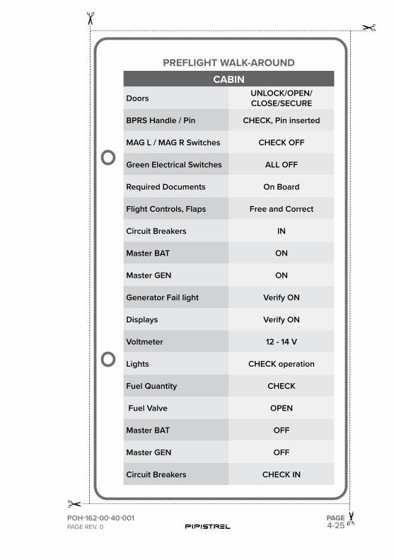
4-25POH-162-00-40-001PAGE REV. 0
PAGE
PREFLIGHT WALK-AROUNDCABIN
Doors UNLOCK/OPEN/CLOSE/SECURE
BPRS Handle / Pin CHECK, Pin inserted
MAG L / MAG R Switches CHECK OFF
Green Electrical Switches ALL OFF
Required Documents On Board
Flight Controls, Flaps Free and Correct
Circuit Breakers IN
Master BAT ON
Master GEN ON
Generator Fail light Verify ON
Displays Verify ON
Voltmeter 12 - 14 V
Lights CHECK operation
Fuel Quantity CHECK
Fuel Valve OPEN
Master BAT OFF
Master GEN OFF
Circuit Breakers CHECK IN
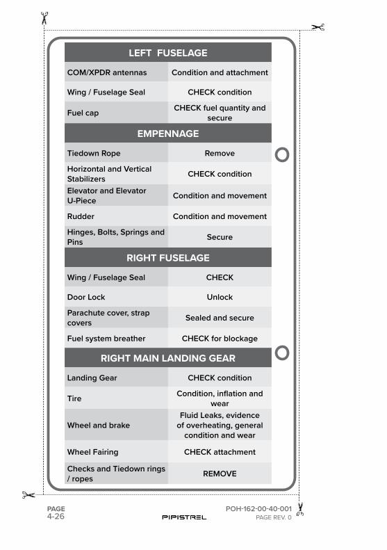
4-26PAGE POH-162-00-40-001
PAGE REV. 0
LEFT FUSELAGE
COM/XPDR antennas Condition and attachment
Wing / Fuselage Seal CHECK condition
Fuel cap CHECK fuel quantity and secure
EMPENNAGE
Tiedown Rope Remove
Horizontal and Vertical Stabilizers CHECK condition
Elevator and Elevator U-Piece Condition and movement
Rudder Condition and movement
Hinges, Bolts, Springs and Pins Secure
RIGHT FUSELAGE
Wing / Fuselage Seal CHECK
Door Lock Unlock
Parachute cover, strap covers Sealed and secure
Fuel system breather CHECK for blockage
RIGHT MAIN LANDING GEAR
Landing Gear CHECK condition
Tire Condition, inflation and wear
Wheel and brakeFluid Leaks, evidence
of overheating, general condition and wear
Wheel Fairing CHECK attachment
Checks and Tiedown rings / ropes REMOVE
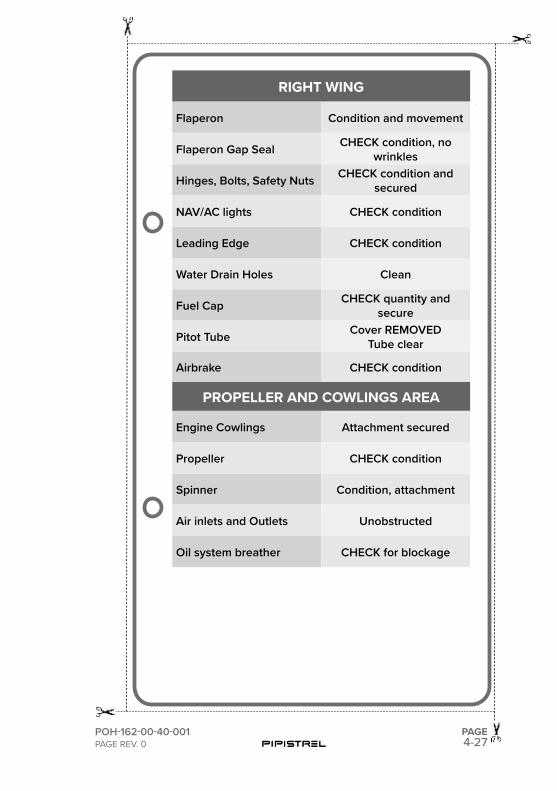
4-27POH-162-00-40-001PAGE REV. 0
PAGE
RIGHT WING
Flaperon Condition and movement
Flaperon Gap Seal CHECK condition, no wrinkles
Hinges, Bolts, Safety Nuts CHECK condition and secured
NAV/AC lights CHECK condition
Leading Edge CHECK condition
Water Drain Holes Clean
Fuel Cap CHECK quantity and secure
Pitot Tube Cover REMOVEDTube clear
Airbrake CHECK condition
PROPELLER AND COWLINGS AREA
Engine Cowlings Attachment secured
Propeller CHECK condition
Spinner Condition, attachment
Air inlets and Outlets Unobstructed
Oil system breather CHECK for blockage
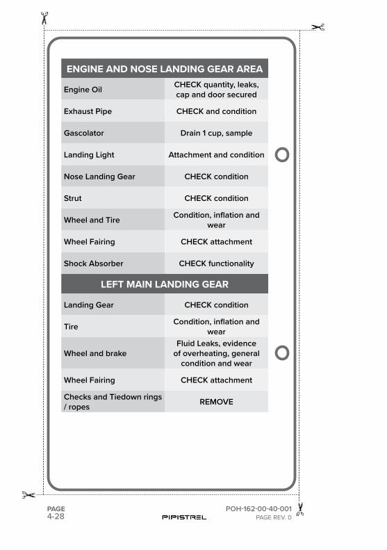
4-28PAGE POH-162-00-40-001
PAGE REV. 0
ENGINE AND NOSE LANDING GEAR AREA
Engine Oil CHECK quantity, leaks, cap and door secured
Exhaust Pipe CHECK and condition
Gascolator Drain 1 cup, sample
Landing Light Attachment and condition
Nose Landing Gear CHECK condition
Strut CHECK condition
Wheel and Tire Condition, inflation and wear
Wheel Fairing CHECK attachment
Shock Absorber CHECK functionality
LEFT MAIN LANDING GEAR
Landing Gear CHECK condition
Tire Condition, inflation and wear
Wheel and brakeFluid Leaks, evidence
of overheating, general condition and wear
Wheel Fairing CHECK attachment
Checks and Tiedown rings / ropes REMOVE
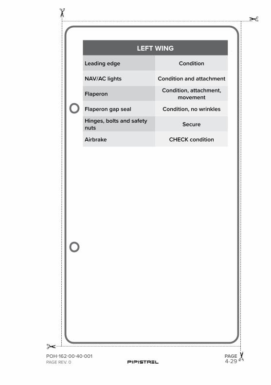
4-29POH-162-00-40-001PAGE REV. 0
PAGE
LEFT WING
Leading edge Condition
NAV/AC lights Condition and attachment
Flaperon Condition, attachment,movement
Flaperon gap seal Condition, no wrinkles
Hinges, bolts and safety nuts Secure
Airbrake CHECK condition
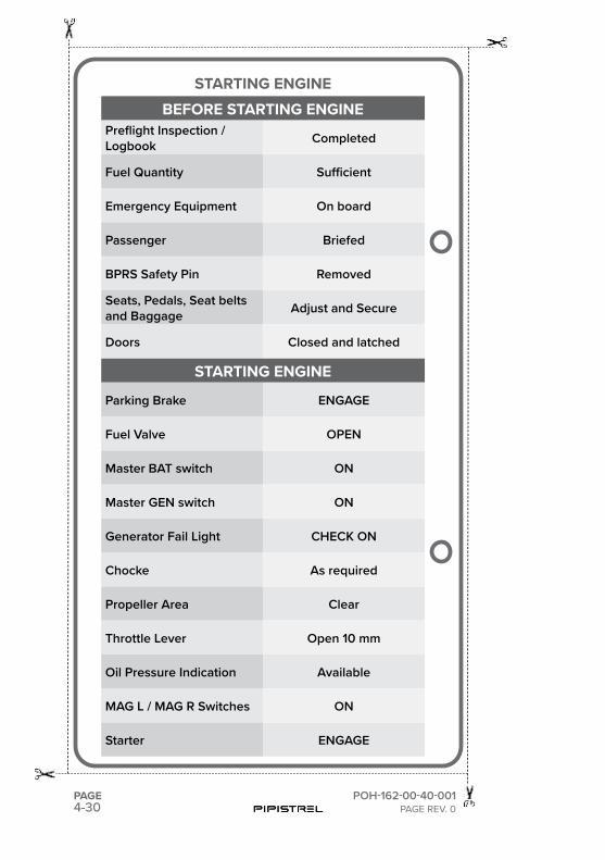
4-30PAGE POH-162-00-40-001
PAGE REV. 0
STARTING ENGINEBEFORE STARTING ENGINE
Preflight Inspection / Logbook Completed
Fuel Quantity Sufficient
Emergency Equipment On board
Passenger Briefed
BPRS Safety Pin Removed
Seats, Pedals, Seat belts and Baggage Adjust and Secure
Doors Closed and latched
STARTING ENGINE
Parking Brake ENGAGE
Fuel Valve OPEN
Master BAT switch ON
Master GEN switch ON
Generator Fail Light CHECK ON
Chocke As required
Propeller Area Clear
Throttle Lever Open 10 mm
Oil Pressure Indication Available
MAG L / MAG R Switches ON
Starter ENGAGE
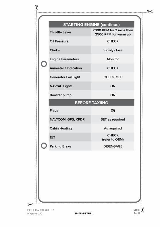
4-31POH-162-00-40-001PAGE REV. 0
PAGE
STARTING ENGINE (continue)
Throttle Lever 2000 RPM for 2 mins then 2500 RPM for warm up
Oil Pressure CHECK
Choke Slowly close
Engine Parameters Monitor
Ammeter / Indication CHECK
Generator Fail Light CHECK OFF
NAV/AC Lights ON
Booster pump ON
BEFORE TAXIING
Flaps (0)
NAV/COM, GPS, XPDR SET as required
Cabin Heating As required
ELT CHECK(refer to OEM)
Parking Brake DISENGAGE
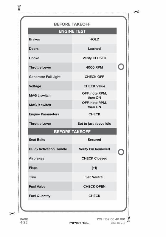
4-32PAGE POH-162-00-40-001
PAGE REV. 0
BEFORE TAKEOFFENGINE TEST
Brakes HOLD
Doors Latched
Choke Verify CLOSED
Throttle Lever 4000 RPM
Generator Fail Light CHECK OFF
Voltage CHECK Value
MAG L switch OFF, note RPM,then ON
MAG R switch OFF, note RPM,then ON
Engine Parameters CHECK
Throttle Lever Set to just above idle
BEFORE TAKEOFF
Seat Belts Secured
BPRS Activation Handle Verify Pin Removed
Airbrakes CHECK Cloesed
Flaps (+1)
Trim Set Neutral
Fuel Valve CHECK OPEN
Fuel Quantity CHECK
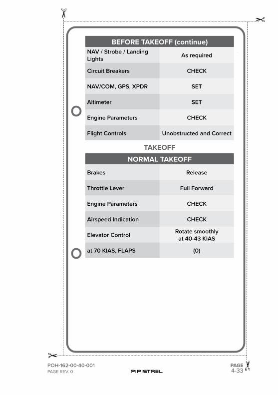
4-33POH-162-00-40-001PAGE REV. 0
PAGE
BEFORE TAKEOFF (continue)NAV / Strobe / Landing Lights As required
Circuit Breakers CHECK
NAV/COM, GPS, XPDR SET
Altimeter SET
Engine Parameters CHECK
Flight Controls Unobstructed and Correct
TAKEOFFNORMAL TAKEOFF
Brakes Release
Throttle Lever Full Forward
Engine Parameters CHECK
Airspeed Indication CHECK
Elevator Control Rotate smoothlyat 40-43 KIAS
at 70 KIAS, FLAPS (0)
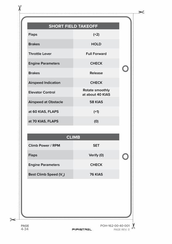
4-34PAGE POH-162-00-40-001
PAGE REV. 0
SHORT FIELD TAKEOFF
Flaps (+2)
Brakes HOLD
Throttle Lever Full Forward
Engine Parameters CHECK
Brakes Release
Airspeed Indication CHECK
Elevator Control Rotate smoothlyat about 40 KIAS
Airspeed at Obstacle 58 KIAS
at 60 KIAS, FLAPS (+1)
at 70 KIAS, FLAPS (0)
CLIMB
Climb Power / RPM SET
Flaps Verify (0)
Engine Parameters CHECK
Best Climb Speed (VY) 76 KIAS
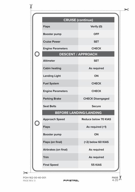
4-35POH-162-00-40-001PAGE REV. 0
PAGE
CRUISE (continue)
Flaps Verify (0)
Booster pump OFF
Cruise Power SET
Engine Parameters CHECK
DESCENT / APPROACH
Altimeter SET
Cabin heating As required
Landing Light ON
Fuel System CHECK
Engine Parameters CHECK
Parking Brake CHECK Disengaged
Seat Belts Secure
BEFORE LANDING/LANDING
Approach Speed Reduce below 70 KIAS
Flaps As required (+1)
Booster pump ON
Flaps (on final) (+2) below 60 KIAS
Airbrakes (on final) As required
Trim As required
Final Speed 55 KIAS
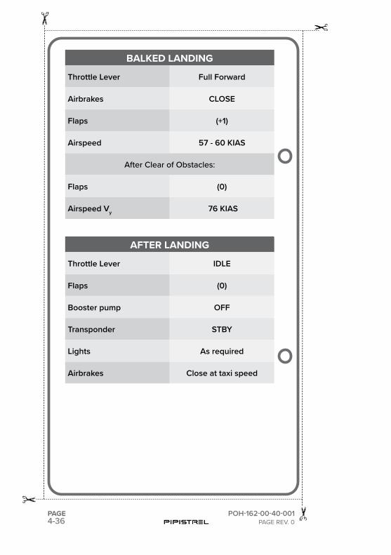
4-36PAGE POH-162-00-40-001
PAGE REV. 0
BALKED LANDING
Throttle Lever Full Forward
Airbrakes CLOSE
Flaps (+1)
Airspeed 57 - 60 KIAS
After Clear of Obstacles:
Flaps (0)
Airspeed Vy 76 KIAS
AFTER LANDING
Throttle Lever IDLE
Flaps (0)
Booster pump OFF
Transponder STBY
Lights As required
Airbrakes Close at taxi speed
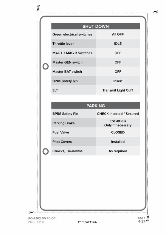
4-37POH-162-00-40-001PAGE REV. 0
PAGE
SHUT DOWN
Green electrical switches All OFF
Throttle lever IDLE
MAG L / MAG R Switches OFF
Master GEN switch OFF
Master BAT switch OFF
BPRS safety pin Insert
ELT Transmit Light OUT
PARKING
BPRS Safety Pin CHECK Inserted / Secured
Parking Brake ENGAGED Only if necessary
Fuel Valve CLOSED
Pitot Covers Installed
Chocks, Tie-downs As required

This page is intentionally left blank.

SECTION
5
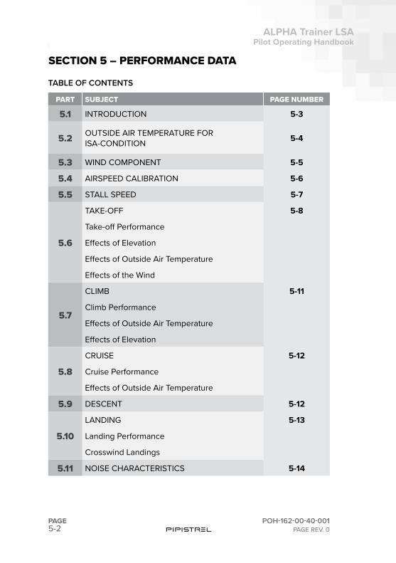
5-2PAGE
ALPHA Trainer LSAPilot Operating Handbook
POH-162-00-40-001PAGE REV. 0
SECTION 5PERFORMANCE DATA
PART SUBJECT PAGE NUMBER
5.1 INTRODUCTION 5-3
5.2 OUTSIDE AIR TEMPERATURE FOR ISA-CONDITION 5-4
5.3 WIND COMPONENT 5-5
5.4 AIRSPEED CALIBRATION 5-6
5.5 STALL SPEED 5-7
5.6
TAKE-OFF 5-8
Take-off Performance
Effects of Elevation
Effects of Outside Air Temperature
Effects of the Wind
5.7
CLIMB 5-11
Climb Performance
Effects of Outside Air Temperature
Effects of Elevation
5.8
CRUISE 5-12
Cruise Performance
Effects of Outside Air Temperature
5.9 DESCENT 5-12
5.10
LANDING 5-13
Landing Performance
Crosswind Landings
5.11 NOISE CHARACTERISTICS 5-14
SECTION 5 – PERFORMANCE DATA
TABLE OF CONTENTS
5-3
ALPHA Trainer LSAPilot Operating Handbook
POH-162-00-40-001PAGE REV. 0
PAGE
SECTION 5PERFORMANCE DATA
5.1. INTRODUCTION
The performance tables and diagrams on the following pages show the per-formance of the airplane. The data presented in these tables and diagrams has been derived from test–flights using an airplane and engine in good operating condition, and was corrected to standard atmospheric conditions 15˚ C and 1013.25 mbar at sea level.
The performance tables do not take into account the expertise of the pilot or the maintenance condition of the airplane. The performance illustrated in the tables can be achieved if the indicated procedures are followed and the airplane is in good maintenance condition.
Some undefined variables such as the operating condition of the engine, contamination of the aircrafts surface, or turbulence could have influences on flights distance and flights duration. For this reason, it is of utmost impor-tance that all available data is used when calculating the required amount of fuel for a flight.
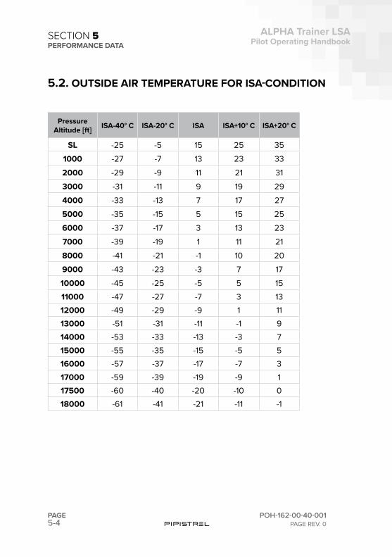
5-4PAGE
ALPHA Trainer LSAPilot Operating Handbook
POH-162-00-40-001PAGE REV. 0
SECTION 5PERFORMANCE DATA
5.2. OUTSIDE AIR TEMPERATURE FOR ISA-CONDITION
Pressure Altitude [ft] ISA-40° C ISA-20° C ISA ISA+10° C ISA+20° C
SL -25 -5 15 25 351000 -27 -7 13 23 332000 -29 -9 11 21 313000 -31 -11 9 19 294000 -33 -13 7 17 275000 -35 -15 5 15 256000 -37 -17 3 13 237000 -39 -19 1 11 218000 -41 -21 -1 10 209000 -43 -23 -3 7 1710000 -45 -25 -5 5 1511000 -47 -27 -7 3 1312000 -49 -29 -9 1 1113000 -51 -31 -11 -1 914000 -53 -33 -13 -3 715000 -55 -35 -15 -5 516000 -57 -37 -17 -7 317000 -59 -39 -19 -9 117500 -60 -40 -20 -10 018000 -61 -41 -21 -11 -1
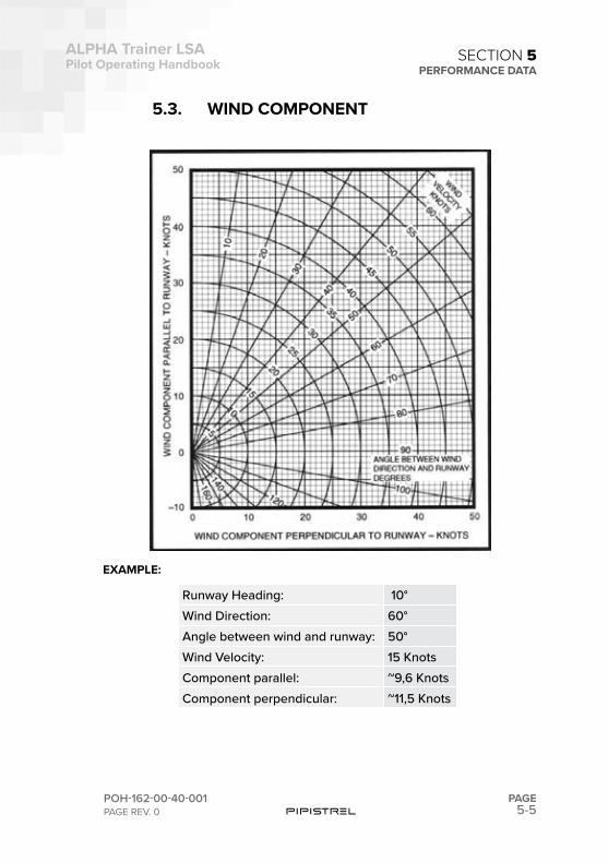
5-5
ALPHA Trainer LSAPilot Operating Handbook
POH-162-00-40-001PAGE REV. 0
PAGE
SECTION 5PERFORMANCE DATA
5.3. WIND COMPONENT
EXAMPLE:
Runway Heading: 10°Wind Direction: 60°Angle between wind and runway: 50°Wind Velocity: 15 KnotsComponent parallel: ~9,6 KnotsComponent perpendicular: ~11,5 Knots
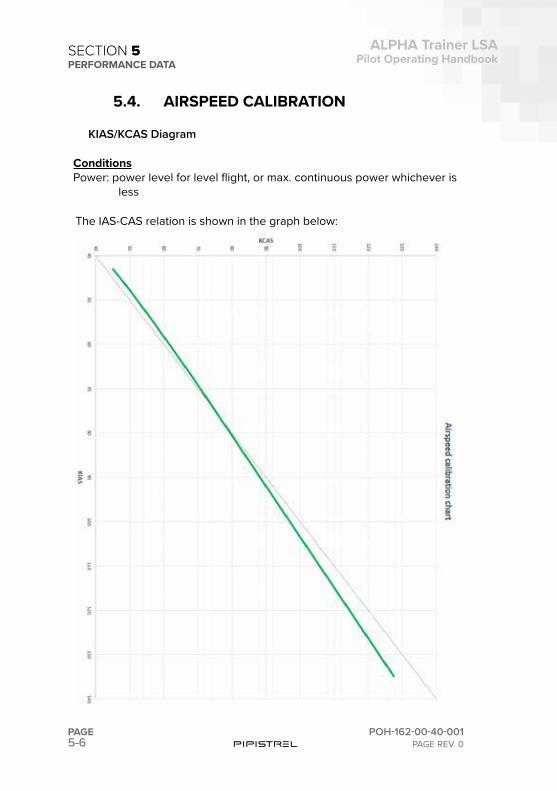
5-6PAGE
ALPHA Trainer LSAPilot Operating Handbook
POH-162-00-40-001PAGE REV. 0
SECTION 5PERFORMANCE DATA
5.4. AIRSPEED CALIBRATION
KIAS/KCAS Diagram
ConditionsPower: power level for level flight, or max. continuous power whichever is
less
The IAS-CAS relation is shown in the graph below:
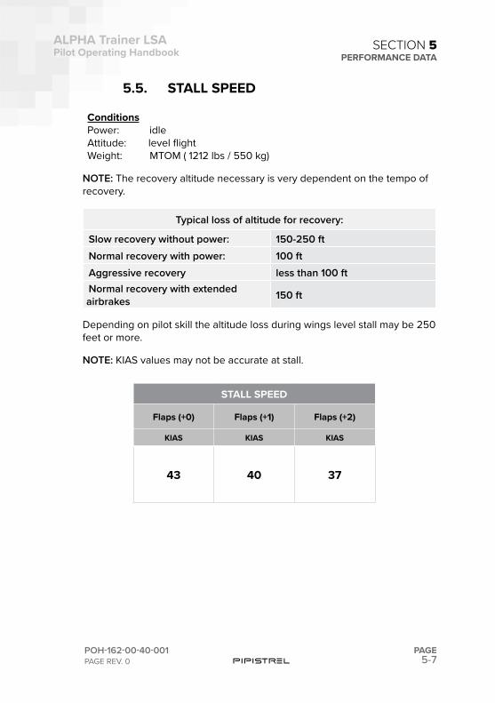
5-7
ALPHA Trainer LSAPilot Operating Handbook
POH-162-00-40-001PAGE REV. 0
PAGE
SECTION 5PERFORMANCE DATA
5.5. STALL SPEED
ConditionsPower: idleAttitude: level flightWeight: MTOM ( 1212 lbs / 550 kg)
NOTE: The recovery altitude necessary is very dependent on the tempo of recovery.
Typical loss of altitude for recovery:
Slow recovery without power: 150-250 ftNormal recovery with power: 100 ftAggressive recovery less than 100 ftNormal recovery with extended airbrakes 150 ft
Depending on pilot skill the altitude loss during wings level stall may be 250 feet or more.
NOTE: KIAS values may not be accurate at stall.
STALL SPEED
Flaps (+0) Flaps (+1) Flaps (+2)
KIAS KIAS KIAS
43 40 37
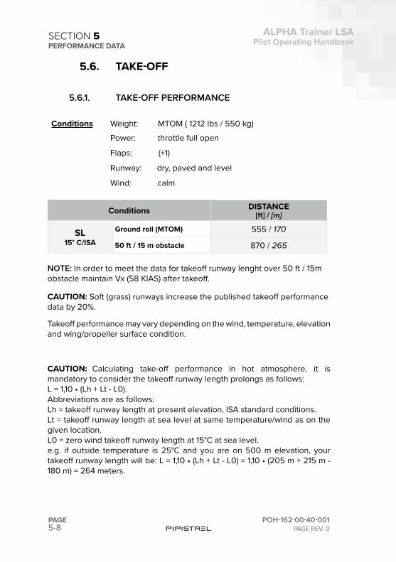
5-8PAGE
ALPHA Trainer LSAPilot Operating Handbook
POH-162-00-40-001PAGE REV. 0
SECTION 5PERFORMANCE DATA
5.6. TAKE-OFF
5.6.1. TAKE-OFF PERFORMANCE
Conditions Weight: MTOM ( 1212 lbs / 550 kg)
Power: throttle full open
Flaps: (+1)
Runway: dry, paved and level
Wind: calm
Conditions DISTANCE[ft] / [m]
SL15° C/ISA
Ground roll (MTOM) 555 / 170
50 ft / 15 m obstacle 870 / 265
NOTE: In order to meet the data for takeoff runway lenght over 50 ft / 15m obstacle maintain Vx (58 KIAS) after takeoff.
CAUTION: Soft (grass) runways increase the published takeoff performance data by 20%.
Takeoff performance may vary depending on the wind, temperature, elevation and wing/propeller surface condition.
CAUTION: Calculating take-off performance in hot atmosphere, it is mandatory to consider the takeoff runway length prolongs as follows: L = 1,10 • (Lh + Lt - L0).Abbreviations are as follows:Lh = takeoff runway length at present elevation, ISA standard conditions.Lt = takeoff runway length at sea level at same temperature/wind as on the given location.L0 = zero wind takeoff runway length at 15°C at sea level.e.g. if outside temperature is 25°C and you are on 500 m elevation, your takeoff runway length will be: L = 1,10 • (Lh + Lt - L0) = 1,10 • (205 m + 215 m - 180 m) = 264 meters.
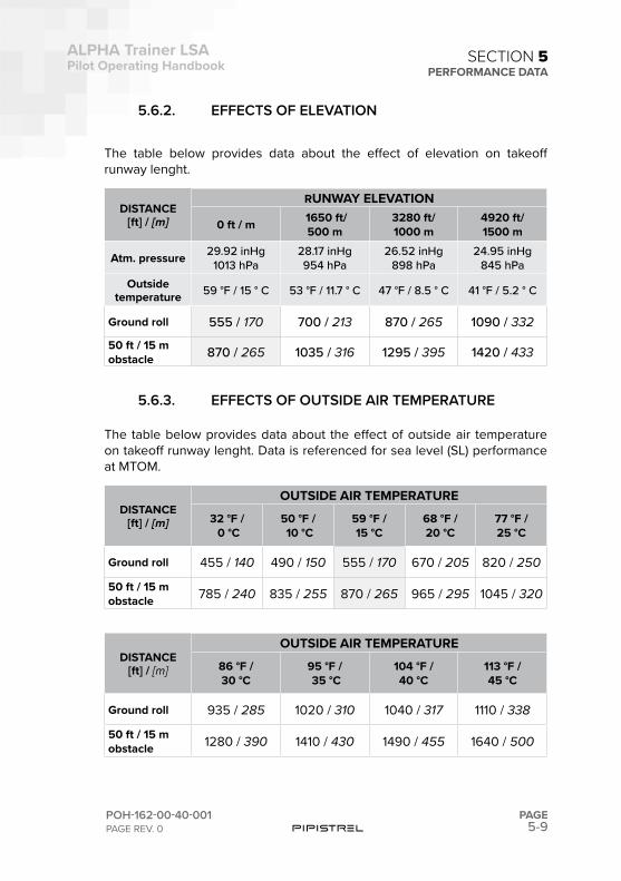
5-9
ALPHA Trainer LSAPilot Operating Handbook
POH-162-00-40-001PAGE REV. 0
PAGE
SECTION 5PERFORMANCE DATA
5.6.2. EFFECTS OF ELEVATION
The table below provides data about the effect of elevation on takeoff runway lenght.
DISTANCE[ft] / [m]
RUNWAY ELEVATION
0 ft / m 1650 ft/500 m
3280 ft/1000 m
4920 ft/1500 m
Atm. pressure 29.92 inHg1013 hPa
28.17 inHg954 hPa
26.52 inHg898 hPa
24.95 inHg845 hPa
Outside temperature 59 °F / 15 ° C 53 °F / 11.7 ° C 47 °F / 8.5 ° C 41 °F / 5.2 ° C
Ground roll 555 / 170 700 / 213 870 / 265 1090 / 332
50 ft / 15 mobstacle 870 / 265 1035 / 316 1295 / 395 1420 / 433
5.6.3. EFFECTS OF OUTSIDE AIR TEMPERATURE
The table below provides data about the effect of outside air temperature on takeoff runway lenght. Data is referenced for sea level (SL) performance at MTOM.
DISTANCE[ft] / [m]
OUTSIDE AIR TEMPERATURE
32 °F / 0 °C
50 °F / 10 °C
59 °F / 15 °C
68 °F / 20 °C
77 °F / 25 °C
Ground roll 455 / 140 490 / 150 555 / 170 670 / 205 820 / 250
50 ft / 15 mobstacle 785 / 240 835 / 255 870 / 265 965 / 295 1045 / 320
DISTANCE[ft] / [m]
OUTSIDE AIR TEMPERATURE
86 °F / 30 °C
95 °F / 35 °C
104 °F / 40 °C
113 °F / 45 °C
Ground roll 935 / 285 1020 / 310 1040 / 317 1110 / 338
50 ft / 15 mobstacle 1280 / 390 1410 / 430 1490 / 455 1640 / 500
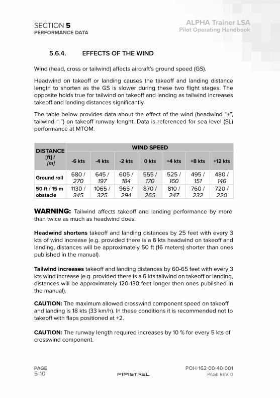
5-10PAGE
ALPHA Trainer LSAPilot Operating Handbook
POH-162-00-40-001PAGE REV. 0
SECTION 5PERFORMANCE DATA
5.6.4. EFFECTS OF THE WIND
Wind (head, cross or tailwind) affects aircraft’s ground speed (GS).
Headwind on takeoff or landing causes the takeoff and landing distance length to shorten as the GS is slower during these two flight stages. The opposite holds true for tailwind on takeoff and landing as tailwind increases takeoff and landing distances significantly.
The table below provides data about the effect of the wind (headwind “+”, tailwind “-”) on takeoff runway lenght. Data is referenced for sea level (SL) performance at MTOM.
DISTANCE[ft] / [m]
WIND SPEED
-6 kts -4 kts -2 kts 0 kts +4 kts +8 kts +12 kts
Ground roll 680 / 270
645 / 197
605 / 184
555 / 170
525 / 160
495 / 151
480 / 146
50 ft / 15 mobstacle
1130 / 345
1065 / 325
965 / 294
870 / 265
810 / 247
760 / 232
720 / 220
WARNING: Tailwind affects takeoff and landing performance by more than twice as much as headwind does.
Headwind shortens takeoff and landing distances by 25 feet with every 3 kts of wind increase (e.g. provided there is a 6 kts headwind on takeoff and landing, distances will be approximately 50 ft (16 meters) shorter than ones published in the manual).
Tailwind increases takeoff and landing distances by 60-65 feet with every 3 kts wind increase (e.g. provided there is a 6 kts tailwind on takeoff or landing, distances will be approximately 120-130 feet longer then ones published in the manual).
CAUTION: The maximum allowed crosswind component speed on takeoff and landing is 18 kts (33 km/h). In these conditions it is recommended not to takeoff with flaps positioned at +2.
CAUTION: The runway length required increases by 10 % for every 5 kts of crosswind component.
5-11
ALPHA Trainer LSAPilot Operating Handbook
POH-162-00-40-001PAGE REV. 0
PAGE
SECTION 5PERFORMANCE DATA
5.7. CLIMB
5.7.1. CLIMB PERFORMANCE
Climb performance may vary depending on, temperature, altitude, humidity and wing propeller surface condition.
Conditions Power: throttle full open
Weight: MTOM ( 1212 lbs / 550 kg)
Flaps: (0)
Best Climb Speed (VY) 76 KIASBest Climb rate 1220 ft/minClimb rate at 100 KIAS 800 ft/minBest Angle Climb Speed (Vx) 58 KIAS
5.7.2. EFFECTS OF OUTSIDE AIR TEMPERATURE
For every 5°C of OAT increase versus ISA, the climb rate decreases by 60 ft/min.
5.7.3. EFFECTS OF ELEVATION
The table below provides data about the effect of elevation on climb rate at best climb speed (VY) at MTOM.
ALTITUDE: CLIMB RATE:0 ft /m 1220 ft/min1600 ft / 500 m 1180 ft/min3300 ft / 1000 m 1100 ft/min5000 ft / 1500 m 1020 ft/min
NOTE: Climb rate is measured at max continuous power (5500 RPM), flaps (0) at VY and MTOM.
5-12PAGE
ALPHA Trainer LSAPilot Operating Handbook
POH-162-00-40-001PAGE REV. 0
SECTION 5PERFORMANCE DATA
5.8. CRUISE
5.8.1. CRUISE PERFORMANCE
Conditions Weight: MTOM ( 1212 lbs / 550 kg)Temperature: ISAWind: zeroAltitude: sea levelFlaps: (0)
Reference cruise parameters:
RPM KIAS FF [US gal] / [liter/h] ENDURANCE
5300 100 3.6 / 13.6 3 hrs + 30 min reserve
NOTE: Best economy cruising level for the ALPHA Trainer is 6000 ft. There, cruise performance is equivalent or better than above due to IAS-TAS relation, but fuel consumption is lower. At these parameters the fuel burn is around 13.6 litres per hour. For detailed fuel consumption determinationfor various cruising regimes consult the Rotax 912 Operators manual.
5.8.2. EFFECTS OF OUTSIDE AIR TEMPERATURE
For every 10°C of OAT increase versus ISA, the cruising speed at 5300 RPM decreases by 3 kts.
5.9. DESCENTReference values:
Sink rate - 58 KIAS - flaps (0) 460 ft/minBest L/D ratio speed - flaps (0) 64 KIAS Best L/D ratio - flaps (0) 15:1
5-13
ALPHA Trainer LSAPilot Operating Handbook
POH-162-00-40-001PAGE REV. 0
PAGE
SECTION 5PERFORMANCE DATA
5.10. LANDING
5.10.1. LANDING PERFORMANCE
Conditions Weight: MTOM ( 1212 lbs / 550 kg)Wind: zeroRunway: dry, level and pavedFlaps: (+2)Airspeed: 55 KIAS
CAUTION: Minimum recommended runway length for approaches is 1640 feet (500 m) with no obstacles inside the 3 deg glide slope area and runway heading in order ensure safe flying activity. Use of shorter strips should be considered a major exception and requires a lot of skill, heavy use of slipping until the last moment before touchdown and is performed at own risk.
PRESSUREAltitude [ft]
DISTANCE[ft] / [m]
SLGround roll 410 / 125
50 ft / 15 m obstacle 1510 / 460
CAUTION: Landing roll increases by 10 % for every 2000 ft increase in density altitude.CAUTION: Total landing distance increases by 2% for every 2000 ft increase in density altitude.
5.10.2. CROSSWIND LANDINGS
The maximum allowed crosswind component speed on landing is 18 kts (33 km/h). Normal crosswind landings are made with flaps extended to +1. Avoid prolonged slips. After touchdown, hold a straight course with rudder.Only in case of high crosswind component it is permitted to land with flaps retracted (0º).
CAUTION: The runway length required increases by 10 % for every 5 kts of crosswind component.

5-14PAGE
ALPHA Trainer LSAPilot Operating Handbook
POH-162-00-40-001PAGE REV. 0
SECTION 5PERFORMANCE DATA
5.11. NOISE CHARACTERISTICS
According to independent testing performed by German LBA-LTF noise reg-ulations the airplanes, the equivalent exhibited noise measures 55.8 dBa. Noise is measured on the ground when the airplane overflies at 500 ft at full power, at speed of best climb. Measures have been taken to make the cock-pit exceptionally quiet on the inside as well.

SECTION
6

6-2PAGE
ALPHA Trainer LSAPilot Operating Handbook
POH-162-00-40-001PAGE REV. 0
SECTION 6WEIGHT AND BALANCE
PART SUBJECT PAGE NUMBER
6.1 INTRODUCTION 6-3
6.2 C.G. SAMPLE CALCULATION 6-4
6.3 WEIGHT AND BALANCE CHART 6-5
SECTION 6 – WEIGHT AND BALANCE
TABLE OF CONTENTS
6-3
ALPHA Trainer LSAPilot Operating Handbook
POH-162-00-40-001PAGE REV. 0
PAGE
SECTION 6WEIGHT AND BALANCE
6.1 INTRODUCTION
This section provides information about how to calculate the takeoff weight and C.G. of the aircraft. Once calculated, these two values can be used to find a point on the weight and balance chart (see section 6.3) and thus de-termine whether aircraft is within the flight limits (see section 2.6). A sample calculation is provided for reference.
WARNING: It is the owner and/or operator’s responsibility to ensure the aircraft’s takeoff weight and C.G. are within the envelope presented in the weight and balance chart (see section 6.3).
NOTE: The aircraft’s empty weight and empty weight C.G. are the starting point for all takeoff calculations. Please refer to the aircraft’s weight and bal-ance report for the current empty weight data.
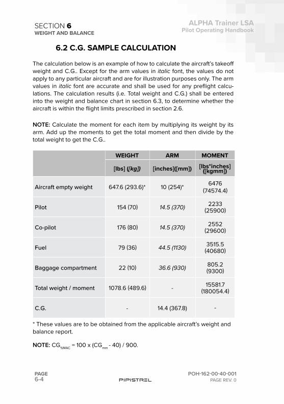
6-4PAGE
ALPHA Trainer LSAPilot Operating Handbook
POH-162-00-40-001PAGE REV. 0
SECTION 6WEIGHT AND BALANCE
6.2 C.G. SAMPLE CALCULATION
The calculation below is an example of how to calculate the aircraft’s takeoff weight and C.G.. Except for the arm values in italic font, the values do not apply to any particular aircraft and are for illustration purposes only. The arm values in italic font are accurate and shall be used for any preflight calcu-lations. The calculation results (i.e. Total weight and C.G.) shall be entered into the weight and balance chart in section 6.3, to determine whether the aircraft is within the flight limits prescribed in section 2.6.
NOTE: Calculate the moment for each item by multiplying its weight by its arm. Add up the moments to get the total moment and then divide by the total weight to get the C.G..
WEIGHT ARM MOMENT
[lbs] ([kg]) [inches]([mm]) [lbs*inches]([kgmm])
Aircraft empty weight 647.6 (293.6)* 10 (254)* 6476 (74574.4)
Pilot 154 (70) 14.5 (370) 2233(25900)
Co-pilot 176 (80) 14.5 (370) 2552(29600)
Fuel 79 (36) 44.5 (1130) 3515.5(40680)
Baggage compartment 22 (10) 36.6 (930) 805.2(9300)
Total weight / moment 1078.6 (489.6) - 15581.7(180054.4)
C.G. - 14.4 (367.8) -
* These values are to be obtained from the applicable aircraft’s weight and balance report.
NOTE: CG%MAC = 100 x (CGmm - 40) / 900.
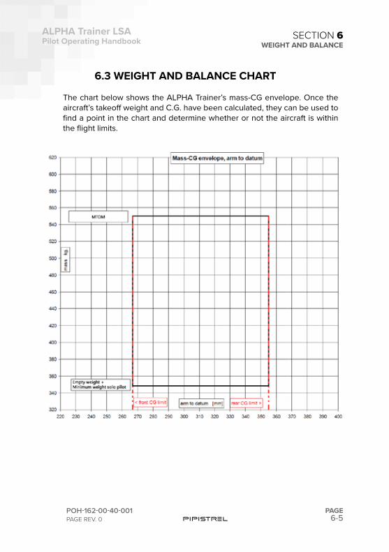
6-5
ALPHA Trainer LSAPilot Operating Handbook
POH-162-00-40-001PAGE REV. 0
PAGE
SECTION 6WEIGHT AND BALANCE
6.3 WEIGHT AND BALANCE CHART
The chart below shows the ALPHA Trainer’s mass-CG envelope. Once the aircraft’s takeoff weight and C.G. have been calculated, they can be used to find a point in the chart and determine whether or not the aircraft is within the flight limits.

This page is intentionally left blank.

SECTION
7
7-2PAGE
ALPHA Trainer LSAPilot Operating Handbook
POH-162-00-40-001PAGE REV. 0
SECTION 7AIRPLANE DESCRIPTION
PART SUBJECT PAGE NUMBER
7.1 INTRODUCTION 7-5
7.2
AIRCRAFT STRUCTURE 7-5FuselageWingsEmpennage
7.3
FLIGHT CONTROL SYSTEM 7-7Elevator Control SystemAileron Control SystemRudder Control SystemWing Flaps Control SystemAirbrakes Control SystemElevator Trim System
7.4
LANDING GEAR 7-8Main GearNose GearBrake System
7.5
AIRPLANE CABIN 7-10Cabin DoorsVentilationSeatsBaggage CompartmentsCabin Safety Equipment
7.6
POWERPLANT 7-11EngineEngine ComponentsEngine Operating Controls
SECTION 7 – AIRPLANE DESCRIPTION
TABLE OF CONTENTS
7-3
ALPHA Trainer LSAPilot Operating Handbook
POH-162-00-40-001PAGE REV. 0
PAGE
SECTION 7AIRPLANE DESCRIPTION
PART SUBJECT PAGE NUMBER
Engine Monitoring Instruments
Propeller7.7 FUEL SYSTEM 7-14
7.8
ELECTRICAL SYSTEM 7-15Electrical SystemPower GenerationPower Distribution Switches Warning LightsCircuit Breakers and FusesMiscellaneous Components
7.9LIGHTNING 7-18Exterior LightningInterior Lightning
7.10 ENVIRONMENTAL SYSTEM 7-197.11 PITOT SYSTEM 7-207.12 FLIGHT DECK ARRANGEMENT 7-217.13 FLIGHT INSTRUMENTS 7-23
7.14 EMERGENCY LOCATOR TRANSMITTER (ELT) 7-24
7.15
BALLISTIC PARACHUTE RESCUE SYSTEM BPRS) 7-24
System DescriptionActivationDeployment Characteristics

This page is intentionally left blank.
7-5
ALPHA Trainer LSAPilot Operating Handbook
POH-162-00-40-001PAGE REV. 0
PAGE
SECTION 7AIRPLANE DESCRIPTION
7.1 INTRODUCTION
This section provides a basic description and operation of the standard air-plane and its systems. Optional equipment described within this section is identified as optional.
7.2 AIRCRAFT STRUCTURE
7.2.1 FUSELAGEThe fuselage is designed as a carbon fiber honeycomb-sandwich construc-tion using aramide as inner laminate in the cockpit area. The main bulkhead is designed as a carbon / honeycomb sandwich. The undercarriage is at-tached directly to the engine mount, which is attached to the main bulkhead. The firewall is made out of CFRP prepreg honeycomb sandwich. It has a ceramic insulation with stainless steel sheet on top. In the baggage compart-ment there is a CFRP container for the ballistic rescue system. Primary and secondary control rods are covered by CFRP fairings to protect them from luggage. The baggage compartment floor is made out of CFRP. It is bolted to the bulkheads and to the CFRP tunnel, that covers the elevator control rod. The back rest is made out of GFRP and fixed to the bulkhead by velcro for easy access to the baggage compartment. The cabin floor is also the lower seat structure and made out of CFRP with aramide. The external structure is covered by a protective acrylic paint coating, which has already been ap-plied in the mold.
7.2.2 WINGSThe detachable wing is a single spar cantilever wing. The left and right wing are connected by two bolts through the spar ends. The wing structure is made mostly from carbon fibre. The main spar shear web and the root ribs are made from glass fibre. This is for visual inspection and easier damage detection reasons. The spar caps are produced using carbon roving. The wing spar is designed as double-T-type spar. Lateral loads and twisting moments are con-ventionally transferred to the fuselage through root ribs and lateral-force bolts. The wing shell is designed as a 2-cell CFRP sandwich shell which is closed by a rear shear web to which the flaperons are attached. The wings are connected as it is classic with gliders by two spar ends being connected with two main bolts. There is also the third mid-dle bolt to provide torsion stiffness mating the wings to the fuselage.
7-6PAGE
ALPHA Trainer LSAPilot Operating Handbook
POH-162-00-40-001PAGE REV. 0
SECTION 7AIRPLANE DESCRIPTION
The wings attach with shear pins to bushes at the fuselage root ribs. Each wing half can be optionally equipped with glider type electric airbrakes.
7.2.3 EMPENNAGEThe empennage consists of a horizontal stabilizer, a single piece elevator, a vertical fin and a rudder. All of the empennage components are convention-al spar (shear web) and skin construction.
The horizontal stabilizer is attached to an aluminum bracket that is pivoted to the vertical stabilizer and can be removed. The shell of the horizontal tail is designed as CFRP sandwich. The horizontal tail is attached to an alumi-num bracket at the back C-spar and a self locking bolt at the location of the front C-spar.
The elevator is designed as a bottom surface supported hinged flap. The elevator is actuated through a pushrod connected to the elevator control bracket. The elevator shell is designed as a 1-cell CFRP sandwich shell. The elevator is hinged in maintenance-free bushings mounted on stainless steel brackets at the stabilizer rear spar and bottom shell. Counterbalance weights are integrated into the elevator tips.
The vertical fin is designed to be one part with the tail fuselage, made of carbon honeycomb sandwich with carbon spars. The bending moment is carried by one C-type spar which is reinforced by CFRP tapes at the flanges.
The rudder is designed as a centrally supported hinged flap. The rudder shell is designed as single-cell GFRP sandwich shell. The rudder is hinged in two maintenance-free spherical plain bearings. Balancing weights are mounted at the front end of the rudder.
7-7
ALPHA Trainer LSAPilot Operating Handbook
POH-162-00-40-001PAGE REV. 0
PAGE
SECTION 7AIRPLANE DESCRIPTION
7.3 FLIGHT CONTROL SYSTEM
The aircraft uses conventional flight controls for ailerons, elevator and rud-der. The control surfaces are pilot controlled through either of two control sticks positioned centrally in front of each pilot. The location and design of the control sticks allow easy, natural use by the pilots. The control system uses a combination of push rods, cables and bell cranks for control of the surfaces.
Pitch trim is available through an electric button located on the instrument panel.
7.3.1 ELEVATOR CONTROL SYSTEMThe sticks are mounted on a common lateral rod which actuates the elevator longitudinal pushrod, running the length of the fuselage behind the cockpit control levers. A bell-crank is located on the bottom side of the vertical fin and can be inspected through a provision in the vertical stabilizer end-rib. The hook-up to the elevator is via a U-member which conforms to the shape of the elevator. In case the horizontal tail plane is removed the U-member remains attached to the fuselage whereas the elevator remains attached to the horizontal stabilizer. There are no cables in the pitch control system.
7.3.2 AILERON CONTROL SYSTEMRoll control is achieved by torsional activation of flaperon control surfaces via an all-pushrod mechanisms. A conventional center control stick is avail-able to each pilot. The sticks are mounted on a common lateral rod which actuates the elevator longitudinal pushrod. There is a bell-crank located on the bottom of the fuselage behind the seats which provides differential mo-tion. The flap handle is connected to this bell-crank, allowing for symmetric displacement of flaperons.
7.3.4 RUDDER CONTROL SYSTEMRudder pedals are available to each pilot and are adjustable in-flight in a fore-aft sense. Metal cables in teflon-coated bowdens run from the individual pedal to bellcranks located behind the seats and below the cargo compart-ment floor. Single cables run from the cable junction backwards and are at-tached directly to the rudder. The tension of the cables is adjusted with cable tensioners and rudder neutralisation is achieved by means of two retaining springs attached to the bellcranks junctions.
7-8PAGE
ALPHA Trainer LSAPilot Operating Handbook
POH-162-00-40-001PAGE REV. 0
SECTION 7AIRPLANE DESCRIPTION
The nose wheel is part of the yaw control system and is moved whenever the pedal is pressed. Cables for nosewheel steering run from the bellcranks be-hind the seats forward to the nosewheel hinge element, where a anti-shim-my damper is also connected to.
7.3.5 WING FLAPS CONTROL SYSTEMThere are no separate flap control surfaces in place. Function of flaps is achieved through symmetric deflections of the flaperons.
The flaps are hand activated through a lever common to both pilots, located between the seats. The handle is spring locked in 3 positions, corresponding to flap deflections of 0°, +9°, +19°. The positions are denominated (0), (+1), (+2) respectively. The thumb-lock button prevents inadverted handle movement. The backside of the flap handle connects to the main flaperon bell-crank.
7.3.6 AIRBRAKES CONTROL SYSTEM (optional)Schempp-Hirth Style electric (servo-operated) airbrakes are activated by a control switch on the instrument panel.
CAUTION: The system must be operated according the procedures and limitations explained in the following document SPOH-161-00-41-050_Elec-tric airbrakes POH supplement.
7.3.7 ELEVATOR TRIM SYSTEMSpring type elevator trim is activated by a linear servo motor assembly locat-ed behind the luggage compartment. The motion of the linear servo is con-trolled through a cockpit switch and an integral position sensor. Trim position is indicated with discrete steps on a dedicated LED display on the instrument panel.
7.4 LANDING GEAR
7.4.1 MAIN GEARThe landing gear is a conventional, fixed tricycle type. The main landing gear consists of a single composite landing gear strut made of glass fibre. The strut is composed by two parallel elements producing a semi-redundant structure and allowing for predictable locations of stress points. The tube-
7-9
ALPHA Trainer LSAPilot Operating Handbook
POH-162-00-40-001PAGE REV. 0
PAGE
SECTION 7AIRPLANE DESCRIPTION
less type wheel tire is 4.00 x 6. Wheel track is 1.60 m, wheel base 1.58 m. Inflate to 40 psi (2.8 bar).
7.4.2 NOSE GEAR The nose landing gear is supported from the main engine frame. The nose landing gear is steerable, connected to the rudder pedal control system and incorporates an oil-spring damper element. All wheels can be equipped with aerodynamic fairings made of CFRP. The tube-type nosewheel tire is 4.00 x 4. The nose gear is steerable. It is always connected to the rudder pedal control system. The suspension is a spring-type oleo-strut. The main tube of the strut and the fork are made out of aluminum. The inner tube is made out of crome plated steel. Inflate to 26 psi (1.8 bar).
7.4.3 BRAKE SYSTEMThe main wheels are equipped with hydraulic disc brakes. Brakes are acti-vated by a lever positioned in the central console between the seats. A metal pin on the brake handle is used to keep the handle pulled and thus mantain-ing pressure in the circuit and acting as parking brake function.
The brake system consists of a master cylinder activated by the brake han-dle, an hydraulic fluid reservoirs, a single drum (disc for Beringer wheels option) brake assembly on each main landing gear wheel, and associated hydraulic plumbing. Braking pressure is initiated by pulling the lever. The reservoir is serviced with DOT-4 hydraulic fluid.
Brake system malfunction or impending brake failure may be indicated by a gradual decrease in braking action after brake application, noisy or dragging brakes, soft or spongy handle, excessive travel, and/or weak braking action. Should any of these symptoms occur, immediate maintenance is required. If, during taxi or landing roll, braking action decreases, release the handle and then reapply the brakes with heavy pressure. If the brakes are spongy or handle travel increases, pumping the handle may build braking pressure.
CAUTION: Do not set the parking brake in flight. If a landing is made with the parking brake set, the brakes will maintain any pressure applied after touchdown.
The main wheel brakes are set for parking by using the parking brake pin on the brake activation handle. To apply the parking brake, set the brakes pulling the handle, and set the pin to keep the handle pulled.
7-10PAGE
ALPHA Trainer LSAPilot Operating Handbook
POH-162-00-40-001PAGE REV. 0
SECTION 7AIRPLANE DESCRIPTION
7.5 AIRPLANE CABIN
7.5.1 CABIN DOORSWindshield, upper window and doors’- windows are made from Lexan shat-ter-resistant polycarbonate. The fuselage has two cabin doors made out of CFRP frames.
Doors are locked in the closed position via 3 locking pins operated simulta-neously by rotating a common central handle.
7.5.2 VENTILATIONThe system’s primary source of fresh air is a set of adjustable vents that di-rect fresh ram air into the cabin.
7.5.3 SEATSThe seating arrangement consists of two seats, comprising a bottom cush-ion and hard padded back panel. The back panel rests on the cockpit aft bulkhead.
The seats are not adjustable in position or recline, however the back panel can be removed/reclined to access the baggage compartment.
7.5.4 BAGGAGE COMPARTMENTThe baggage compartment extends from behind the seats to the aft cabin bulkhead and is limited to 22 lbs (10 kg) of load only when equipped with the solid baggage compartment floor (optional). All items in the baggage com-partment must be secured in place.
7.5.5 CABIN SAFETY EQUIPMENT
Passenger RestraintsThe harness is a 4 point restraint system with turn-buckle quick release. The lap belt strands are attached to the composite seat shell that is locally rein-forced with M8 bolts. The shoulder harness strand is attached at the bottom of the rear baggage compartment bulkhead with M8 bolt. The attachment point is reinforced with a comoposite rib.
7-11
ALPHA Trainer LSAPilot Operating Handbook
POH-162-00-40-001PAGE REV. 0
PAGE
SECTION 7AIRPLANE DESCRIPTION
7.6 POWERPLANT
7.6.1 ENGINEThe engine installed is a Rotax 912 UL (A2 version offered as option) engine providing 59.6 kW takeoff power. All limits as defined by the engine manu-facturer apply. The engine can be operated with MOGAS or AVGAS 100LL, with max. 10% ethanol and the following antiknock properties: min. RON 90 (min. AKI 87) as by Rotax specification. The propeller is driven by a gearbox. The engine is provided with a liquid cooling system for the cylinder heads and a ram-air cooling system for the cylinders. There is also an oil cooling system for oil common to engine and gearbox.
7.6.2 ENGINE COMPONENTS
Oil SystemThe dry-sump lubrication system contains 3.5 liters of oil and consists of a tank, an oil cooler and a a mechanically-driven pump and optionally with a thermostat. Once the oil temperature reaches 80oC the thermostat opens, allowing the oil to flow through the coolers. A dipstick is present on the oil tank to check oil quantity.
CAUTION: The engine should not be operated with less than minimum in-dicated quantity of oil (dipstick). For extended flights, oil quantity of at least half-level between min and max deliminators is recommended.
Engine CoolingThe engine is air and water cooled. Cooling air enters the engine bay through an inlet on the starboard side of the spinner and is then distributed over the engine’s cylinders. The water cooling system consists of a cooler and me-chanically-driven pump to provide cooling to cylinder heads. The heated air exits the engine compartment through a common outlet on the bottom aft portion of the cowling. No movable cowl flaps are used.
CarburetorsDual needle-type Bing carburetors are used, each serving one cylinder bank. Lifetime fliters are installed directly on the carborettors. There is no addition-al air induction system or carburettor heat, as the engine receives pre-heat-ed air from the aft side of the cooling radiator.
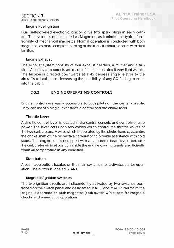
7-12PAGE
ALPHA Trainer LSAPilot Operating Handbook
POH-162-00-40-001PAGE REV. 0
SECTION 7AIRPLANE DESCRIPTION
Engine Fuel IgnitionDual self-powered electronic ignition drive two spark plugs in each cylin-der. The system is denominated as Magnetos, as it mimics the typical func-tionality of mechanical magnetos. Normal operation is conducted with both magnetos, as more complete burning of the fuel-air mixture occurs with dual ignition.
Engine ExhaustThe exhaust system consists of four exhaust headers, a muffler and a tail-pipe. All of it’s components are made of titanium, making it very light weight. The tailpipe is directed downwards at a 45 degrees angle relative to the aircraft’s roll axis, thus decreasing the possibility of any CO finding to enter into the cabin.
7.6.3 ENGINE OPERATING CONTROLS
Engine controls are easily accessible to both pilots on the center console. They consist of a single-lever throttle control and the choke lever.
Throttle LeverA throttle control lever is located in the central console and controls engine power. The lever acts upon two cables which control the throttle valves of the two carburetors. A wire, which is operated by the choke handle, actuates the choke shaft of the respective carburetor, to provide assistance with cold starts. The engine is not equipped with a carburetor heat device because the carburetor air inlet position inside the engine cowling grants a sufficiently warm air temperature in any condition.
Start buttonA push-type button, located on the main switch panel, activates starter oper-ation. The button is labeled START.
Magnetos/ignition switchesThe two ignition circuits are indipendently activated by two switches posi-tioned on the switch panel and designated MAG L and MAG R. Normally, the engine is operated on both magnetos (both switch OP) except for magneto checks and emergency operations.
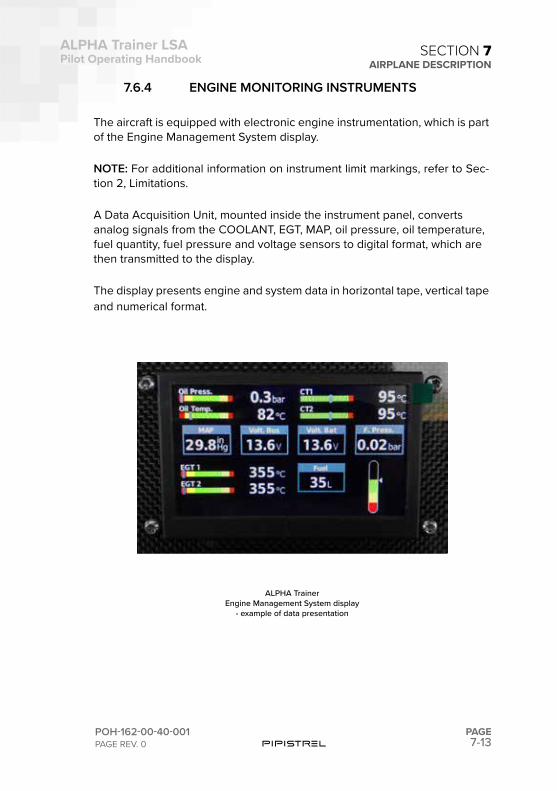
7-13
ALPHA Trainer LSAPilot Operating Handbook
POH-162-00-40-001PAGE REV. 0
PAGE
SECTION 7AIRPLANE DESCRIPTION
7.6.4 ENGINE MONITORING INSTRUMENTS
The aircraft is equipped with electronic engine instrumentation, which is part of the Engine Management System display.
NOTE: For additional information on instrument limit markings, refer to Sec-tion 2, Limitations.
A Data Acquisition Unit, mounted inside the instrument panel, converts analog signals from the COOLANT, EGT, MAP, oil pressure, oil temperature, fuel quantity, fuel pressure and voltage sensors to digital format, which are then transmitted to the display.
The display presents engine and system data in horizontal tape, vertical tape and numerical format.
ALPHA TrainerEngine Management System display
- example of data presentation
7-14PAGE
ALPHA Trainer LSAPilot Operating Handbook
POH-162-00-40-001PAGE REV. 0
SECTION 7AIRPLANE DESCRIPTION
7.6.5 PROPELLERThe airplane is equipped with a Pipistrel FP02-80 propeller. It is a 2-blade, fixed pitch, wooden propeller with 1.65 m (65”) diameter.
7.7 FUEL SYSTEM
The airplane has single 13.2 US gal (50 L) polyamide fuel tank in the fuse-lage, positioned behind the cabin. The maximum usable fuel quantity is 12.7 US gal or 76 lbs (34.5 kg or 48 L) (AVGAS or MOGAS, see chapter 2 - Lim-itations - for applicable fuel grades). Fuel quantity is measured by a level sensor in the tank and indicated on the Engine Management System display. Venting of the fuel tank is through a venting line connected to the bottom of the fuselage. After leaving the tank the fuel goes through a line fuel filter and throught the auxiliary electric pump (denominated BOOSTER PUMP on the switch), located on the bottom-side of the fuselage behind the cabin.
ALPHA TrainerFuel system schematic
7-15
ALPHA Trainer LSAPilot Operating Handbook
POH-162-00-40-001PAGE REV. 0
PAGE
SECTION 7AIRPLANE DESCRIPTION
Thereafter fuel enters the fuel shut-off valve, activated from the cabin, which has two positions: OPEN and CLOSED. When CLOSED position is selected the valve shuts off the fuel feed line. Once the fuel leaves the fuel valve it is fed through a gascolator, which has a drain valve. The gascolator removes water that may be in the fuel and filters out debris/foreign material. The fuel system features a fuel return line connected directly to the fuel tank.
NOTE: Indicated fuel flow on Engine Management System display, if avail-able, is for information only and it is calculated indirectly. It should not be used for navigation and flight planning purposes. Refer to fuel quantity indi-cator for actual fuel quantity on board and for tracking of fuel situation.
WARNING: Fuel system venting is essential to system operation. Block-age of the system will result in decreasing of fuel flow and eventual engine fuel starvation and stoppage. If takeoff weight limitations for the next flight permit, the fuel tank should be filled after each flight to prevent condensation.
DrainingThe sampling location is the gascolator in the engine compartment, acces-sible from the bottom engine cowl. The drain is used for draining water from the fuel system and is accesible from the outside. Industry standard fuel sam-pling cups or sticks should be used to perform draining.
7.8 ELECTRICAL SYSTEM
7.8.1 ELECTRICAL SYSTEMThe airplane is equipped with a single-generator, single-battery, 14-volt di-rect current (VDC) electrical system designed to reduce the risk of electrical system faults. The system provides uninterrupted power for avionics, flight instrumentation, lighting, and other electrically operated and controlled sys-tems during normal operation.
7.8.2 POWER GENERATIONThe electrical system is a 12-Volt DC system. Power is supplied by integrated generator with approximately 250 W AC output at 5800 RPM and rectified with electronic full-wave rectifier regulator (RU 912). The generator system
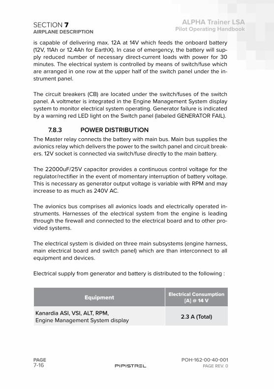
7-16PAGE
ALPHA Trainer LSAPilot Operating Handbook
POH-162-00-40-001PAGE REV. 0
SECTION 7AIRPLANE DESCRIPTION
is capable of delivering max. 12A at 14V which feeds the onboard battery (12V, 11Ah or 12.4Ah for EarthX). In case of emergency, the battery will sup-ply reduced number of necessary direct-current loads with power for 30 minutes. The electrical system is controlled by means of switch/fuse which are arranged in one row at the upper half of the switch panel under the in-strument panel.
The circuit breakers (CB) are located under the switch/fuses of the switch panel. A voltmeter is integrated in the Engine Management System display system to monitor electrical system operating. Generator failure is indicated by a warning red LED light on the Switch panel (labeled GENERATOR FAIL).
7.8.3 POWER DISTRIBUTIONThe Master relay connects the battery with main bus. Main bus supplies the avionics relay which delivers the power to the switch panel and circuit break-ers. 12V socket is connected via switch/fuse directly to the main battery.
The 22000uF/25V capacitor provides a continuous control voltage for the regulator/rectifier in the event of momentary interruption of battery voltage. This is necessary as generator output voltage is variable with RPM and may increase to as much as 240V AC.
The avionics bus comprises all avionics loads and electrically operated in-struments. Harnesses of the electrical system from the engine is leading through the firewall and connected to the electrical board and to other pro-vided systems.
The electrical system is divided on three main subsystems (engine harness, main electrical board and switch panel) which are than interconnect to all equipment and devices.
Electrical supply from generator and battery is distributed to the following :
Equipment Electrical Consumption [A] @ 14 V
Kanardia ASI, VSI, ALT, RPM,Engine Management System display 2.3 A (Total)

7-17
ALPHA Trainer LSAPilot Operating Handbook
POH-162-00-40-001PAGE REV. 0
PAGE
SECTION 7AIRPLANE DESCRIPTION
Kanardia Horis 0.23 A
Garmin GTR200 transceiver 0.51 A (Typical)2.6 A (Max)
Garmin GTX335 transponder 0.72 A (Typical)1.22 A (Max)
Landing light 5 A
NAV/AC lights 1 A (steady)2 A (Peak)
Electrical trim 0.3 A
7.8.4 SWITCHES
MASTER BAT switchThe MASTER BAT toggle Switch activates the relay to connect the battery with main bus. Main bus supplies the avionics relay which delivers the power to the switch panel and circuit breakers. 12V socket is connected via switch/fuse directly to the main battery. Starter button has no function when MAS-TER BAT switch is OFF.
During normal operation the battery is always connected. It only disconnects then the MASTER BAT switch is OFF.
MASTER GEN SwitchA toggle switch, labeled MASTER GEN, connects the generator to the bus.
7.8.5 WARNING LIGHTS
Generator Fail LightThe red GENERATOR FAIL Light on the upper-left side of the switch panel is
7-18PAGE
ALPHA Trainer LSAPilot Operating Handbook
POH-162-00-40-001PAGE REV. 0
SECTION 7AIRPLANE DESCRIPTION
connected to the voltage regulator. When ON, this means that the generator is not operating. Normal state (generator operating) is when this LED light is OFF.
NOTE: Engine RPM below 1600 will typically result in GENERATOR FAIL warning light to come ON, however this is not a failure but a case of insuffi-cient RPM to generate electrical power. Increase RPM.
Battery Caution LightThe orange Batt Caution light is installed on the switch panel only when EarthX battery is installed. Batt Caution light is ON when the battery man-agement system (BMS) integrated in the battery detects any malfunctions (See Chapter 3 - Emergency procedures for additional details).
7.8.6 CIRCUIT BREAKERS AND FUSESIndividual electrical circuits connected to the Buses in the airplane are pro-tected by re-settable circuit breakers mounted in the circuit breaker panel, part of the main switch panel below the instrument panel.
7.8.7 MISCELLANEOUS COMPONENTS
Convenience OutletsA 12-volt convenience outlet is installed on the switch panel. The receptacle accepts a standard cigarette-lighter plug. The outlet may be used to pow-er portable equipment non essential to flight. Amperage draw through the outlet must not exceed 2 A. Power for the convenience outlet is supplied through the 2-amp 12VDC OUTLET circuit breaker on the Battery Bus. USB sockets are optionally available.
7.9 LIGHTNING
7.9.1 EXTERIOR LIGHTNING
Navigation LightsThe airplane can be equipped with LED standard wing tip navigation lights. The lights are controlled through the NAV/AC light switch on the switch

7-19
ALPHA Trainer LSAPilot Operating Handbook
POH-162-00-40-001PAGE REV. 0
PAGE
SECTION 7AIRPLANE DESCRIPTION
panel. 12 VDC for navigation light operation is supplied through the NAV/STROBE light switch, which includes a resettable circuit breaker element.
Strobe LightAnti-collision strobe lights can be installed integral with the standard naviga-tion light and controlled by the same switch.
Landing LightA High Intensity LED landing light can be mounted in the lower engine cowl. The landing light is controlled through the LDG light switch on the switch panel. 12 VDC for navigation light operation is supplied through the LDG light switch, which includes a resettable circuit breaker element. The landing light has a built-in thermal protection and its operation is not time limited.
7.9.2 INTERIOR LIGHTNING
Instrument LightsDigital instrumentation (i.e. Horis) has backlit dimmable LCD displays and illuminated buttons.
7.10 ENVIRONMENTAL SYSTEM
There are two separate systems that account for cabin ventilation and heat-ing: the cabin passive inlets/outlets for fresh air routing (passive ventilation) and the cabin heat system.
Cabin passive ventilationThe system’s primary source of fresh air is a set of adjustable vents on the doors that direct fresh ram air into the cabin.
Basic heating system (standard equipment)This is the shut-off valve from the firewall forward compartment into the cab-in. This ON/OFF valve is controlled by a push-pull knob on the bottom of the switch panel, next to the battery disconnect ring. Pull to open, twist to lock, push to shut.
Advanced heating and ventilation system (optional equipment)This system replaces the basic heating system. It is composed of a stainless
7-20PAGE
ALPHA Trainer LSAPilot Operating Handbook
POH-162-00-40-001PAGE REV. 0
SECTION 7AIRPLANE DESCRIPTIONsteel heat muff fastened to the exhaust system muffler that serves as the system’s source of hot air. Air from the oil cooler enters the engine bay and is directed into the heat muff. Hot air leaving the heat muff is then directed through scat tubing to a mixer where it meets fresh air coming from a NACA inlet positioned on the upper engine cowling. The mixer regulates the fresh/hot air ratio passing through the cabin air selector, which is fastened to the aircraft’s firewall. The system is controlled from the cabin by a cabin heat panel and a stainless steel shut off valve. This ON/OFF valve is controlled by a push-pull knob on the bottom of the switch panel, next to the battery disconnect ring. Pull to open, twist to lock, push to shut.
The cabin heat panel is positioned on the instrument panel and allows the pilot to control, via rotary knobs and toggles switches, the temperature (fresh/hot air ratio), the flow (fan on/off) and where (cabin or windshield) the air entering the cabin should go.
The following are the offered control possibilities:
The bottom knob on the cabin heat system panel controls the direction of airflow, either towards the windshield (rotate left) or towards pilot’s feet (ro-tate right). Any setting inbetween these two results in air flowing in both directions.
The upper knob on the cabin heat system panel controls the temperature of the airflow. Rotate left for cooler and rotate right for warmer. Maximum cold position will result in external ambient being delivered to the cabin. In this case the system serves as an additional source of fresh air. Maximum hot position will only let the hot air from the exhaust muff into the cabin.
To activate windshield defrost turn the temperature knob on the cabin heat panel to HOT (upper knob, full right), select windshied as direction of airflow (bottom knob full left) and engage the fan (ON).
7.11 PITOT SYSTEM
The pitot-static system consists of a single pitot tube mounted on the star-board wing, approximately 3 meters from fuselage. The pitot tube drives the total and static pressure to the instruments.
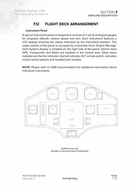
7-21
ALPHA Trainer LSAPilot Operating Handbook
POH-162-00-40-001PAGE REV. 0
PAGE
SECTION 7AIRPLANE DESCRIPTION
7.12 FLIGHT DECK ARRANGEMENTInstrument Panel
A typical instrument panel arrangement consists of a set of analogue gauges for airspeed, altitude, vertical speed and rpm. Each instrument features a LCD display showing the values indicated by the instrument pointers. The upper portion of the panel is occupied by a Kanardia Horis. Engine Manage-ment System display is installed on the right side of the panel. Garmin Aera GPS, Transponder and Radio are installed in the central area. Other items installed are the trim indicator, slip ball indicator, ELT remote switch, airbrakes control panel (option) and headset jack sockets.
NOTE: Please refer to OEM documentation for additional information about individual instruments.
ALPHA Trainer LSAExample of instrument panel configuration
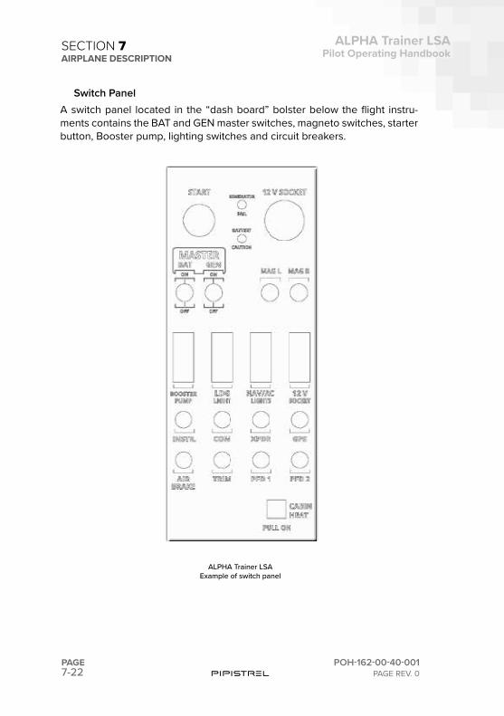
7-22PAGE
ALPHA Trainer LSAPilot Operating Handbook
POH-162-00-40-001PAGE REV. 0
SECTION 7AIRPLANE DESCRIPTION
Switch PanelA switch panel located in the “dash board” bolster below the flight instru-ments contains the BAT and GEN master switches, magneto switches, starter button, Booster pump, lighting switches and circuit breakers.
ALPHA Trainer LSAExample of switch panel
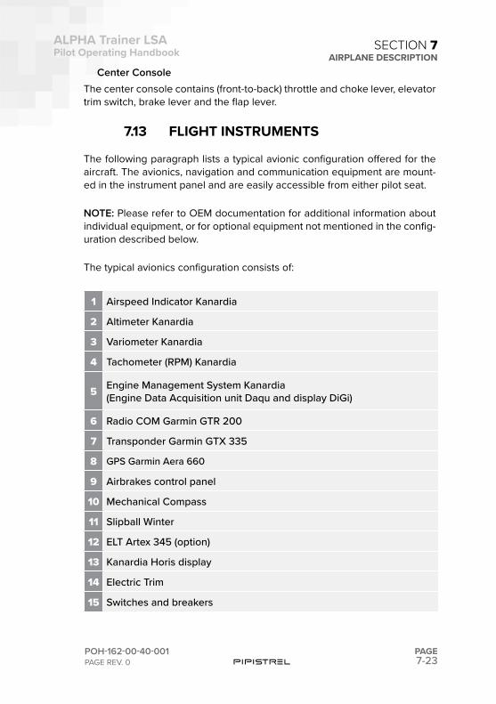
7-23
ALPHA Trainer LSAPilot Operating Handbook
POH-162-00-40-001PAGE REV. 0
PAGE
SECTION 7AIRPLANE DESCRIPTION
Center ConsoleThe center console contains (front-to-back) throttle and choke lever, elevator trim switch, brake lever and the flap lever.
7.13 FLIGHT INSTRUMENTS
The following paragraph lists a typical avionic configuration offered for the aircraft. The avionics, navigation and communication equipment are mount-ed in the instrument panel and are easily accessible from either pilot seat.
NOTE: Please refer to OEM documentation for additional information about individual equipment, or for optional equipment not mentioned in the config-uration described below.
The typical avionics configuration consists of:
1 Airspeed Indicator Kanardia
2 Altimeter Kanardia
3 Variometer Kanardia
4 Tachometer (RPM) Kanardia
5 Engine Management System Kanardia(Engine Data Acquisition unit Daqu and display DiGi)
6 Radio COM Garmin GTR 200
7 Transponder Garmin GTX 335
8 GPS Garmin Aera 660
9 Airbrakes control panel
10 Mechanical Compass
11 Slipball Winter
12 ELT Artex 345 (option)
13 Kanardia Horis display
14 Electric Trim
15 Switches and breakers
7-24PAGE
ALPHA Trainer LSAPilot Operating Handbook
POH-162-00-40-001PAGE REV. 0
SECTION 7AIRPLANE DESCRIPTION
7.14 EMERGENCY LOCATOR TRANSMITTER
The airplane is optionally equipped with a self-contained emergency locator transmitter (ELT). The transmitter and antenna are installed immediately be-hind the aft cabin wall to the right of the airplane centerline. The main trans-mitter control switch, labeled ON-OFF-ARMED, on the transmitter is in the armed position for normal operations. A remote switch and indicator panel is installed on the instrument panel. If rapid deceleration is detected, the transmitter will repeatedly transmit VHF band audio sweeps.
NOTE: Please refer to OEM documentation for additional information about ELT pre-flight testing procedures.
7.15 BALLISTIC PARACHUTE RESCUE SYSTEM (BPRS)
The aircraft is equipped with the Ballistic Parachute Rescue System (BPRS) designed to bring the aircraft and its occupants to the ground in the event of a life-threatening emergency. The system is intended to save the lives of the occupants but will most likely destroy the aircraft and may, in adverse circumstances, cause serious injury or death to the occupants. Because of this it is important carefully to consider when and how you would use the system.!
WARNING: The parachute system does not require electrical power for activation and can be activated at any time. The solid propellant rocket flight path is upward from the parachute cover. Stay clear of parachute canister area when aircraft is occupied. Do not allow children in the aircraft unat-tended.
7.15.1 SYSTEM DESCRIPTIONThe BPRS consists of a parachute, a solid-propellant rocket to deploy the parachute, a rocket activation handle, a composite container and a harness connecting the canopy to the wingbox structure.
A composite box containing the parachute and solid-propellant rocket is mounted to the airplane structure behind the right seat and is divided from
7-25
ALPHA Trainer LSAPilot Operating Handbook
POH-162-00-40-001PAGE REV. 0
PAGE
SECTION 7AIRPLANE DESCRIPTION
the baggage compartment. There is an exhaust tube leading the activation gasses from the rocket to the outside (bottom) of the fuselage, the exhaust is placarded.
The type of BPRS is Galaxy Rescue System GRS 6/473. The parachute sys-tem attaches with 2 belts to the aft fuselage/wings pins and belonging bulk-head. When deployed, the aircraft is suspended under the parachute with approx. 20° nose down attitude. The parachute system is activated by an activation handle, located between the occupant seats on the tubular struc-ture overhead. The handle is pulled forward and/or downward for activation. A rocket is ignited that leaves the fuselage through a special egress panel directly behind the main bulkhead. The rocket pulls the complete parachute package out of its container at once. Maximum demonstrated parachute activation speed is 170 KTAS.
7.15.2 ACTIVATIONThe BPRS is activated by an activation handle, located between the occu-pant seats on the tubular structure overhead. Pulling the activation T-handle will activate the rocket and initiate the BPRS deployment sequence.
To activate the rocket, two separate events must occur:
1
Pull the activation T-handle from its receptacle. Pulling the T-handle removes it from the o-ring seal that holds it in place and takes out the slack in the cable (approximately 5 cm of cable will be exposed). Once the slack is removed, the T-handle motion will stop and greater force will be required to activate the rocket.
2
Clasp both hands around activation T-handle and pull straight for-ward/downward with a strong, steady, and continuous force until the rocket activates. A chin-up type pull works best. Up to 200 N force, or greater, may be required to activate the rocket. The greater force required occurs as the cable arms and then releases the rocket ignit-er firing pin, which ignites the rocket fuel.
NOTE: Rapidly pulling on the activation T-handle greatly increases the pull forces required to activate the rocket.
A safety pin is provided to ensure that the activation handle is not pulled during inadvertantly; for example, the presence of unattended children in the airplane, the presence of people who are not familiar with the BPRS ac-tivation system in the airplane, or during display of the airplane. A “Remove
7-26PAGE
ALPHA Trainer LSAPilot Operating Handbook
POH-162-00-40-001PAGE REV. 0
SECTION 7AIRPLANE DESCRIPTION
Before Flight” streamer is attached to the pin.
WARNING: Always remove the safety pin of the BPRS before engine start-up and re-insert before leaving the aircraft.
WARNING: After maintenance has been performed or any other time the system has been safe tied, operators must verify that the pin has been removed before further flight.
7.15.3 DEPLOYMENT CHARACTERISTICSWhen the rocket launches, the parachute assembly is extracted outward due to rocket thrust and rearward due to relative airflow. In approximately two seconds the parachute will begin to inflate.
When air begins to fill the canopy, forward motion of the airplane will dramat-ically be slowed. This deceleration increases with airspeed but in all cases within the parachute envelope should be less than 4 g’s. During this de-celeration a slight nose-up may be experienced, particularly at high speed. Following any nose-up pitching, the nose will gradually drop until the aircraft is hanging nose-low beneath the canopy. Descent rate is expected to be less than 1500 feet per minute with a lateral speed equal to the velocity of the surface wind. In addition, surface winds may continue to drag the aircraft after ground impact.
CAUTION: Ground impact is expected to be equivalent to touchdown from a height of approximately 3 meters. Occupants must prepare for it in ac-cordance with the BPRS Deployment procedure in Section 3 - Emergency Procedures.
NOTE: The BPRS is designed to work in a variety of aircraft attitudes, includ-ing spins. However, deployment in an attitude other than level flight may yield deployment characteristics other than those described above.
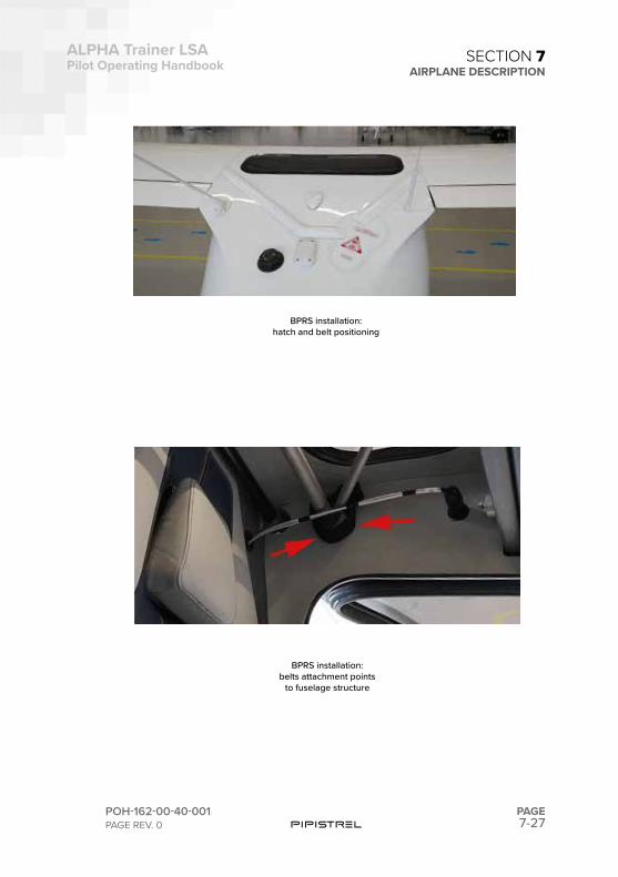
7-27
ALPHA Trainer LSAPilot Operating Handbook
POH-162-00-40-001PAGE REV. 0
PAGE
SECTION 7AIRPLANE DESCRIPTION
BPRS installation:hatch and belt positioning
BPRS installation:belts attachment points
to fuselage structure

This page is intentionally left blank.

SECTION
8
8-2PAGE
ALPHA Trainer LSAPilot Operating Handbook
POH-162-00-40-001PAGE REV. 0
PART SUBJECT PAGE NUMBER
8.1 INTRODUCTION 8-3
8.2 AIRPLANE INSPECTION PERIODS 8-3
8.3 PILOT CONDUCTED MAINTENANCE 8-3
8.4 CHANGES AND REPAIRS 8-4
8.5
SERVICING 8-4Tire ServicingBrake ServicingPropeller ServicingOil ServicingFuel System Servicing
8.6
GROUND HANDLING 8-8Application of External PowerTowing / Ground MovementsTaxing / Ground MovementsParkingTiedown
8.7CLEANING 8-10
Cleaning Exterior SurfacesCleaning Interior Surfaces
SECTION 8 – HANDLING AND SERVICING
TABLE OF CONTENTS
8-3
ALPHA Trainer LSAPilot Operating Handbook
POH-162-00-40-001PAGE REV. 0
PAGE
SECTION 8HANDLING AND SERVICING
8.1 INTRODUCTION
The airplane owner should establish contact with the dealer or certified ser-vice station for service and information. All correspondence regarding the airplane must include its serial number (see tail-mounted type dataplate). A maintenance manual with revision service may be procured by the man-ufacturer.
8.2 AIRPLANE INSPECTION PERIODS
All applicable periodical inspections can be found in the latest revision of the aircraft’s maintenance manual. The airworthiness authority may re-quire other inspections by issuing airworthiness directives applicable to the aircraft, engine, propeller and/or specific components. The owner is responsible for compliance with all applicable airworthiness directives and periodical inspections.
8.3 PILOT CONDUCTED MAINTENANCE
Please refer to applicable Aircraft Maintenance Manual (AMM) and the reg-ulations of the country of registration for information what maintenance may performed by the pilot.
8.4 CHANGES AND REPAIRS
Information regarding changes and repairs can be found in the applicable maintenance manual (AMM).
8-4PAGE
ALPHA Trainer LSAPilot Operating Handbook
POH-162-00-40-001PAGE REV. 0
SECTION 8HANDLING AND SERVICING
8.5 SERVICING
8.5.1 TIRE SERVICINGThe main landing gear wheel assemblies use 4.00 x 6 tires. The nose wheel assembly uses a 4.00 x 4 tire. For maximum service from the tires, keep them inflated to the proper pressure
Nose wheel tire (recommended): 26 psi (1.8 bar) Main wheel tires (recommended): 40 psi (2.8 bar)
When checking tire pressure, examine the tires for wear, cuts, nicks, bruises and excessive wear.
8.5.2 BRAKE SERVICING
Brake Hydraulic Fluid ReplenishingThe brake system is filled with DOT-4 hydraulic brake fluid. The fluid level should be checked at every oil change and at the annual / 100 h inspec-tions, replenishing the system when necessary. To replenish brake fluid:
1 Chock tires and release parking brake.
2 Clean area around the brake handle before opening reservoir cap itself.
3 Remove cap and add DOT-4 hydraulic fluid.4 Install cap, check brakes, inspect area for leaks.
8.5.3 PROPELLERThe spinner and backing plate should be cleaned and inspected for cracks frequently. Before each flight the propeller should be inspected for dents, scratches, as well as corrosion on visible metal parts. If found, they should be repaired as soon as possible by a rated mechanic, since a nick or scratch causes an area of increased stress which can lead to serious cracks or the loss of a propeller tip. The back face of the blades should be repainted when necessary with flat black paint to retard glare. Refer to Propeller Mainte-nance Manual for detailed information.
8-5
ALPHA Trainer LSAPilot Operating Handbook
POH-162-00-40-001PAGE REV. 0
PAGE
SECTION 8HANDLING AND SERVICING
8.5.4 OIL SERVICINGOil must be changed every 100 hours and sooner under unfavorable (AVGAS) operating conditions.
An oil filler cap and dipstick are located at the right side of the engine, accessible through an access door on the top right side of the engine cowl-ing. To check and add oil:
1 Open access door on upper cowl. Open cap of the oil bottle.2 Verify Master switches OFF, Ignition (Magneto switches) OFF.
3Rotate the propeller in normal direction until a blurbing noise is heard. This is an evidence the oil has pumped through the system properly.
4 Pull dipstick, clean dipstick, and verify oil level.
5 Add oil through filler as required to maintain level between indicat-ed min and max ticks. The capacity of oil system is 3.5 liters.
6 Reinstall dipstick and secure cap.7 Close and secure access door.
8.5.5 FUEL SYSTEM SERVICING
Fuel Filter ScreeningRefer to procedures in Maintenance manual
Filling Fuel TanksFuel filler is located on top of the fuselage, behind the cabin. The tank holds a maximum of 50 L.
WARNING: Have a fire extinguisher available.
Do not fill tank within 30 m of any electrical equipment capable of pro-ducing a spark.
Permit no smoking or open flame within 30 m of airplane or refuel vehi-cle.
Do not operate radios or electrical equipment during refuel operations.
Do not operate any electrical switches.
8-6PAGE
ALPHA Trainer LSAPilot Operating Handbook
POH-162-00-40-001PAGE REV. 0
SECTION 8HANDLING AND SERVICING
To refuel airplane:1 Place fire extinguisher near fuel tank being filled.
2Connect ground wire from refuel nozzle to airplane exhaust, from airplane exhaust to fuel truck or cart, and from fuel truck or cart to a suitable earth ground.
3 Place rubber protective cover over the fuselage around fuel filler.4 Remove fuel filler cap and fuel airplane to desired level.
NOTE: Keep fuel tank at least half full at all times to minimize condensation and moisture accumulation in the tank. In extremely humid areas, the fuel supply should be checked frequently and drained of condensation to pre-vent possible distribution problems.
5 Remove nozzle, install filler cap, and remove protective cover.6 Remove ground wires.7 Remove fire extinguisher.
Fuel Draining and SamplingTypically, fuel contamination results from foreign material such as water, dirt, rust, and fungal or bacterial growth. Additionally, chemicals and additives that are incompatible with fuel or fuel system components are also a source of fuel contamination. To assure that the proper grade of fuel is used and that contamination is not present, the fuel must be sampled prior to each flight.
Fuel drains is provided for the fuel gascolator. Fuel must be sampled by draining a cupful of fuel into a clear sample cup.
The gascolator drain is accessible through the lower engine cowling (left side) just forward of the firewall.
If sampling reveals contamination, the gascolator must be sampled again repeatedly until all contamination is removed. If after repeated samplings, evidence of significant contamination remains, do not fly the airplane until a mechanic is consulted, the fuel system is drained and purged, and the source of contamination is determined and corrected.
The gascolator sampling outlet is open by rotating the knob and closed by
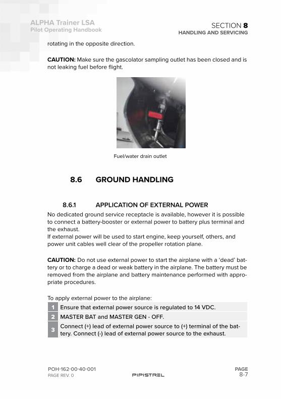
8-7
ALPHA Trainer LSAPilot Operating Handbook
POH-162-00-40-001PAGE REV. 0
PAGE
SECTION 8HANDLING AND SERVICING
rotating in the opposite direction.
CAUTION: Make sure the gascolator sampling outlet has been closed and is not leaking fuel before flight.
8.6 GROUND HANDLING
8.6.1 APPLICATION OF EXTERNAL POWERNo dedicated ground service receptacle is available, however it is possible to connect a battery-booster or external power to battery plus terminal and the exhaust.G! If external power will be used to start engine, keep yourself, others, and power unit cables well clear of the propeller rotation plane.
CAUTION: Do not use external power to start the airplane with a ‘dead’ bat-tery or to charge a dead or weak battery in the airplane. The battery must be removed from the airplane and battery maintenance performed with appro-priate procedures.
To apply external power to the airplane:1 Ensure that external power source is regulated to 14 VDC.2 MASTER BAT and MASTER GEN - OFF.
3 Connect (+) lead of external power source to (+) terminal of the bat-tery. Connect (-) lead of external power source to the exhaust.
Fuel/water drain outlet
8-8PAGE
ALPHA Trainer LSAPilot Operating Handbook
POH-162-00-40-001PAGE REV. 0
SECTION 8HANDLING AND SERVICING
4MASTER BAT switch to ON. 14 VDC from the external power unit will energize the main distribution and essential distribution buses. The airplane may now be started or electrical equipment operated.
CAUTION: If maintenance on avionics systems is to be performed, it is rec-ommended that external power be used.
To remove external power from airplane:1 Carefully remove cables from battery terminal and exhaust.
8.6.2 TAXIING / GROUND MOVEMENTSBefore attempting to taxi the airplane, ground personnel should be instruct-ed and authorized by the owner to taxi the airplane. Instruction should in-clude engine starting and shutdown procedures in addition to taxi and steer-ing techniques. All Normal procedures apply.
CAUTION: Verify that taxi and propeller blast areas are clear before begin-ning taxi.
Do not operate the engine at high RPM when running up or taxiing over ground containing loose stones or any loose material that may cause dam-age to the propeller blades. Taxi with minimum power needed for forward movement. Excessive braking may result in overheated or damaged brakes and/or fire. Observe wing clearance when taxiing near buildings or other stationary objects. If possible, station an observer outside the airplane. Avoid holes when taxiing over uneven ground.
1 Remove chocks.2 Start engine in accordance with Starting Engine procedure.3 Release parking brake.
4 Advance throttle to initiate taxi. Immediately after initiating taxi, apply the brakes to determine their effectiveness.
5 Taxi airplane to desired location.
8-9
ALPHA Trainer LSAPilot Operating Handbook
POH-162-00-40-001PAGE REV. 0
PAGE
SECTION 8HANDLING AND SERVICING
6 Shut down airplane and install chocks and tie-downs.
8.6.3 PARKINGFor parking:
1 Head airplane into the wind if possible.
2 Choose even terrain so that fuel does not spill because of sloped wings.
3 Retract flaps to 0, retract airbrakes.
4 Set parking brake by first applying brake pressure pulling the handle and then set the pin on the handle.
5 Chock both main gear wheels.6 Tie down airplane.7 Install a pitot head cover.
8 Fold the bottom part of the seat up (vertically) to prevent any mois-ture from accumulating below the seat.
9 Cabin a doors should be locked. Lock doors at own discretion.
CAUTION: Care should be taken when setting overheated brakes or during cold weather when accumulated moisture may freeze a brake.
8.6.4. TIE-DOWN
1 Head the airplane into the wind if possible2 Retract flaps to (0), retract airbrakes3 Chock the wheels4 Attach tie-down rings
5 Secure tie-down ropes to the wing tie-down rings and to the tail ring at approximately 45° angles to the ground
CAUTION: Anchor points for wing tie-downs should not be more than 5 m apart to prevent tie-down rings damage in heavy winds.
8-10PAGE
ALPHA Trainer LSAPilot Operating Handbook
POH-162-00-40-001PAGE REV. 0
SECTION 8HANDLING AND SERVICING
8.7 CLEANING
8.7.1. CLEANING EXTERIOR SURFACESThe airplane should be washed with a mild soap and water. Harsh abrasives or alkaline soaps or detergents could make scratches on painted or plastic surfaces. Cover static ports and other areas where cleaning solution could cause damage. Be sure to remove the static port covers before flight.
NOTE: Prior to cleaning, place the airplane in a shaded area to allow the surfaces to cool.
To wash the airplane, use the following procedure:1 Flush away loose dirt with water2 Apply cleaning solution with a soft cloth, a sponge or a soft bristle3 To remove exhaust stains, allow the solution to remain on the surface
4 To remove stubborn grease, use a cloth dampened with degreaser or naphtha.
5 Rinse all surfaces thoroughly.
Any good silicone free automotive wax may be used to preserve paint-ed surfaces. Soft cleaning cloths or a chamois should be used to prevent scratches when cleaning or polishing. A heavier coating of wax on the lead-ing surfaces will reduce the abrasion problems in these areas. Pledge spray is recommended to be applied once the surface is clean and can be used instead of waxing.
Windscreen and WindowsBefore cleaning lexan surfaces, rinse away all dirt particles before applying cloth or chamois. Never rub dry lexan. Do not attempt to polish lexan.
CAUTION: Clean windshield and windows only with a solvent free, none abrasive, antistatic cleaner. Do not use gasoline, alcohol, benzene, carbon tetrachloride, thinner, acetone, or glass window cleaning sprays. Use only a nonabrasive cotton cloth or genuine chamois to clean acrylic windows. Pledge spray is, however, recommended to be applied once the windshield is clean.
NOTE: Wiping with a circular motion can cause glare rings. Use an up and down wiping motion to prevent this. To prevent scratching from dirt that has
8-11
ALPHA Trainer LSAPilot Operating Handbook
POH-162-00-40-001PAGE REV. 0
PAGE
SECTION 8HANDLING AND SERVICING
accumulated on the cloth, fold cloth to expose a clean area after each pass.
1 Remove grease or oil using a soft cloth saturated mild detergent, then rinse with clean, fresh water.
2 Using a moist cloth or chamois, gently wipe the windows clean of all contaminates.
3 Dry the windows using a dry nonabrasive cotton cloth or chamois.
Engine CompartmentNOTE: Only to be cleaned by licensed service personnel.
1 Place a large pan under the engine to catch waste.2 Remove induction air filter and seal off induction system inlet.
3
With the engine cowling removed, spray or brush the engine with solvent or a mixture of solvent and degreaser. In order to remove especially heavy dirt and grease deposits, it may be necessary to brush areas that were sprayed.
CAUTION: Do not spray solvent into the generator, starter, or induction air intakes.
8.7.2. CLEANING INTERIOR SURFACES
Windshield and WindowsNever rub dry lexan. Do not attempt to polish lexan.
CAUTION: Clean lexan windows with a solvent free, none abrasive, anti-static acrylic cleaner. Do not use gasoline, alcohol, benzene, carbon tetra-chloride, thinner, acetone, or glass window cleaning sprays. Use only a non-abrasive cotton cloth or genuine chamois to clean acrylic windows. Paper towel or newspaper are highly abrasive and will cause hairline scratches.
NOTE: Wiping with a circular motion can cause glare rings. Use an up and down wiping motion to prevent this. To prevent scratching from dirt that has accumulated on the cloth, fold cloth to expose a clean area after each pass.
1 Wipe the windows clean with a moist cloth or chamois.
8-12PAGE
ALPHA Trainer LSAPilot Operating Handbook
POH-162-00-40-001PAGE REV. 0
SECTION 8HANDLING AND SERVICING
2 Dry the windows using a dry nonabrasive cotton cloth or chamois.
Instrument Panel and Electronic Display ScreensThe instrument panel, control knobs, and plastic trim need only to be wiped clean with a soft damp cloth. The multifunction display, primary flight display, and other electronic display screens should be cleaned with LCD Screen Cleaning Solution.
CAUTION: To avoid solution dripping onto display and possibly migrating into component, apply the cleaning solution to cloth first, not directly to the display screen. Use only a lens cloth or nonabrasive cotton cloth to clean display screens. Paper towels, tissue, or camera lens paper may scratch the display screen. Clean display screen with power idle.
1 Gently wipe the display with a clean, dry, cotton cloth.2 Moisten clean, cotton cloth with cleaning solution.
3 Wipe the soft cotton cloth across the display in one direction, moving from the top of the display to the bottom. Do not rub harshly.
4 Gently wipe the display with a clean, dry, cotton cloth.
The airplane interior can be cleaned with a mild detergent or soap and wa-ter. Harsh abrasives or alkaline soaps or detergents should be avoided. Sol-vents and alcohols may damage or discolor vinyl or urethane parts. Cover areas where cleaning solution could cause damage. Use the following pro-cedure:
CAUTION: Solvent cleaners and alcohol should not be used on interior parts. If cleaning solvents are used on cloth, cover areas where cleaning solvents could cause damage.
1 Clean headliner, and side panels, with a stiff bristle brush, and vacu-um where necessary.
2Soiled upholstery, may be cleaned with a good upholstery cleaner suitable for the material. Carefully follow the manufacturer’s instruc-tions. Avoid soaking or harsh rubbing.
Leather Upholstery and Seats

8-13
ALPHA Trainer LSAPilot Operating Handbook
POH-162-00-40-001PAGE REV. 0
PAGE
SECTION 8HANDLING AND SERVICING
Wipe leather upholstery with a soft, damp cloth. For deeper cleaning, use a mix of mild detergent and water. Do not use soaps as they contain alkaline which will cause the leather to age prematurely. Cover areas where cleaning solution could cause damage. Solvent cleaners and alcohol should not be used on leather upholstery.
1 Clean leather upholstery with a soft bristle brush and vacuum it.2 Wipe leather upholstery with a soft, damp cloth.
3 Soiled upholstery, may be cleaned with approved products. Avoid soaking or harsh rubbing.
CarpetsTo clean carpets, first remove loose dirt with a whiskbroom or vacuum. For soiled spots and stubborn stains use a non-flammable, dry cleaning fluid. Floor carpets may be cleaned like any household carpet.

This page is intentionally left blank.

SECTION
9
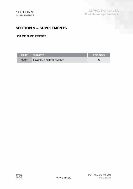
9-02PAGE
ALPHA Trainer LSAPilot Operating Handbook
POH-162-00-40-001PAGE REV. 0
SECTION 9SUPPLEMENTS
PART SUBJECT REVISION
9-S1 TRAINING SUPPLEMENT 0
SECTION 9 – SUPPLEMENTS
LIST OF SUPPLEMENTS

SUPPLEMENT
9-S1
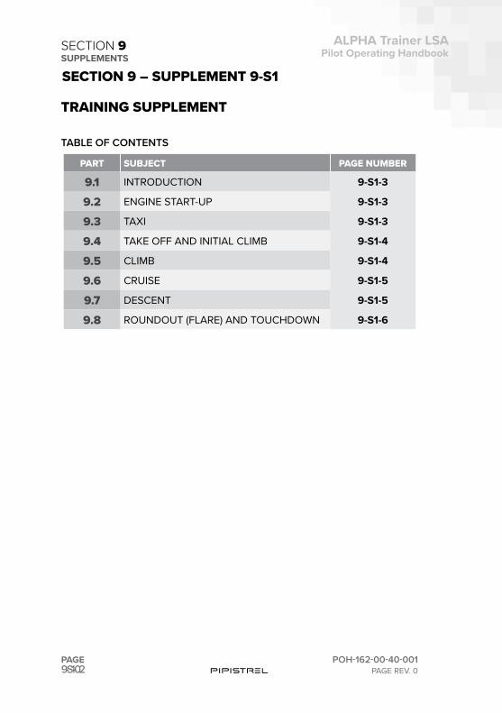
9-S1-02PAGE
ALPHA Trainer LSAPilot Operating Handbook
POH-162-00-40-001PAGE REV. 0
SECTION 9SUPPLEMENTS
PART SUBJECT PAGE NUMBER
9.1 INTRODUCTION 9-S1-3
9.2 ENGINE START-UP 9-S1-3
9.3 TAXI 9-S1-3
9.4 TAKE OFF AND INITIAL CLIMB 9-S1-4
9.5 CLIMB 9-S1-4
9.6 CRUISE 9-S1-5
9.7 DESCENT 9-S1-5
9.8 ROUNDOUT (FLARE) AND TOUCHDOWN 9-S1-6
SECTION 9 – SUPPLEMENT 9-S1
TABLE OF CONTENTS
TRAINING SUPPLEMENT
9-S1-03
ALPHA Trainer LSAPilot Operating Handbook
POH-162-00-40-001PAGE REV. 0
PAGE
SECTION 9SUPPLEMENTS
9.1 INTRODUCTION
This chapter has been written to assist owners/pilots/instructors of ALPHA Trainer on their quest to learn how to safely and efficiently fly this aircraft in addition to the information already assembled in the rest of this POH. This section will cover most operations the aircraft offers in an order established in section Normal procedures and recommended speeds. Please consider what follows as an add-on to that chapter.
9.2 ENGINE START-UP
First and foremost make sure you have sufficient fuel quantity on board for the desired length of flight. If you are not completely confident there is enough, step out of the aircraft and add more fuel into the tanks. There is an old aviators’ saying: “The only time you have too much fuel is when you are on fire.”
When engaging engine starter, wheel brakes MUST be engaged. To keep your propeller in perfect shape, avoid starting up on areas where there are small stones on the ground. Those little stones can easily be picked up by the propeller causing damage to the blades.
Warming up must be conducted below 2500 RPM. When reaching safe op-erational engine temperatures, verify maximum engine ground RPM. Hold the stick back completely and slowly(!) add throttle to full power, then verify RPM.
9.3 TAXI
Taxiing with the ALPHA Trainer is rather simple considering the steerable nose wheel. It is recommended you taxi slowly, up to 10 km/s (5 kts), while holding the stick back fully to ease the pressure of the nose wheel.
During taxiing monitor engine temperatures. Due to low airflow around the radiators the CHT and Oil temperature will rise during long taxi periods. If you are holding position, do not leave throttle at idle. It is better you have
9-S1-04PAGE
ALPHA Trainer LSAPilot Operating Handbook
POH-162-00-40-001PAGE REV. 0
SECTION 9SUPPLEMENTS
some 2500 RPM as this will provide some airflow from the propeller to the radiators and the temperatures will not rise so quickly. Should you see en-gine temperatures exceed safe operational values, shut off the engine, point the aircraft’s nose into the wind and wait for the temperatures to reduce.
9.4 TAKE OFF AND INITIAL CLIMB
Having checked and set all engine and aircraft parameters, you should be ready for take off by now. Reverify fuel valve is open. Trim lever should be in the middle.
Start the take-off roll gradually. Keep adding throttle smoothly and slowly to full power. There are two reasons for this. First, you change flight stage from zero movement to acceleration slowly; this provides you with time to react to conditions. Second, especially if taking-off from a gravel runway, this method of adding full throttle will prevent the little stones on the runway to damage the propeller. Extremely short runways are an exception. There you should line up the aircraft, set flaps to 2nd stage, step on the brakes, apply full power and release the brakes. As you start to move, pull the stick 1/3 of elevator’s deflection backwards to ease the pressure on the nose wheel and lift it off the runway slightly. Do not use full back deflection as this will cause the aircraft’s tail to touch the ground.
When the nose wheel has lifted off the ground, there is nothing else but to hold the same pitch attitude and the aircraft will become airborne. Cross-wind take-offs, depending on wind strength, require a little bit of aileron de-flection into the wind. Remember, wings must stay level throughout ground-roll, rotation and initial climb!
Having lifted off the ground, gently push the stick forward just a bit to accel-erate. At some 110 km/h (60 kts) set flaps to 1st stage, at 130 km/h (70 kts) set them to neutral.
9.5 CLIMB
A comfortable setting for climb is flaps in zero/neutral position, speed of 76 kts (140 km/h) at or slightly below 5500 RPM. In summer time or when outside temperature exceeds 85° F (30°C) you should consider climbing at some 85 kts (160 km/h) to provide more airflow to the engine radiators. Trim the aircraft for comfortable stick forces.
9-S1-05
ALPHA Trainer LSAPilot Operating Handbook
POH-162-00-40-001PAGE REV. 0
PAGE
SECTION 9SUPPLEMENTS
9.6 CRUISE
Make sure flaps are retracted. A comfortable cruise setting is 5300 engine RPM.
Cruising fast, do not kick-in rudder for turns! Above 85 kts (160 km/h) the rud-der becomes almost insignificant in comparison to aileron deflections when it comes to making a turn. Cruising fast, it is important to fly coordinated (ball in the middle) as this increases efficiency and decreases side-pressure onto vertical tail surfaces. Also, pay attention to turbulence. If you hit turbu-lence at speeds greater than VNO, reduce power immediately and pull up the nose to reduce speed.
If flying a traffic pattern, set engine power so that airspeed does not exceed 150 km/h (80 kts).
9.7 DESCENT
Descending with the Alpha Trainer is the stage of flight where the most care should be taken. The aircraft is aerodynamically clean and builds up speed very fast.
Start the descent by reducing throttle and keep your speed below VNO. During initial descent it is recommended you trim for a 10 kts lower speed than the one you decided to descent at. Do this for safety. In case you hit turbulence simply release forward pressure on the stick and the aircraft will slow down.
Also, keep in mind you need to begin your descent quite some time before destination. A comfortable
rate of descent is 500 fpm (2.5 m/s). So it takes you 2 minutes for a 1000 ft (300 m) drop. At 105 kts (200 km/h) this means 3.6 NM for each 1000 ft drop.
Entering the traffic pattern the aircraft must slow down. In order to do this, hold your altitude and reduce throttle to idle. Gradually slow down to below 80 kts (150 km/h), then set proper engine RPM to maintain speed of 70 kts (130 km/h). Trim the aircraft for comfortable stick forces.
9-S1-06PAGE
ALPHA Trainer LSAPilot Operating Handbook
POH-162-00-40-001PAGE REV. 0
SECTION 9SUPPLEMENTS
Before turning to base-leg, reduce power to idle and set flaps to 1st stage at 70 kts (130 km/h). Once out of the turn, reduce speed towards 60 kts (110 km/h). Power remains idle from the point of turning base all the way to touch-down. If you plan your approach this way, you will always be on the safe side - even if your engine fails, you will still be able to safely reach the runway!
Turn to final at 55 kts (100 km/h). When in runway heading, set flaps to 2nd stage. Use the throttle to obtain the desired descent path (if applicable).
9.8 ROUNDOUT (FLARE) AND TOUCHDOWN
Your speed should be a constant 55 kts (100 km/h) throughout the final with the descent path constant as well. At a height of 10 meters (25 feet) start a gentle flare and approach the aircraft must touch down with the main (back) wheels first, so that you will not bounce on the runway. After touchdown, op-erate the rudder pedals if necessary to maintain runway heading and try to have the nose wheel off the ground for as long as possible. When the nose wheel is to touch the ground, rudder pedals MUST be exactly in the middle not to cause damage to the steering mechanism. While braking, hold the stick back fully! Once you have come to a standstill, retract flaps all the way to normal 0° position (handle full down).
Should you bounce off the runway after touch-down, do not, under any cir-cumstances, push stick forward. Bouncing tends to reduce by itself anyhow.
Crosswind landings, depending on the wind speed, require some sort of drift correction. Most efficient is the low-wing method, where you are to lower the wing into the wind slightly and maintain course by applying appropriate rudder deflection. You can also try the crab method.

This page is intentionally left blank.

This page is intentionally left blank.

This page is intentionally left blank.
Pipistrel d.o.o.podjetje za alternativno letalstvo
Goriška cesta 50aSI-5270 Ajdovščina
Slovenija - EU
t +386 (0)5 3663 873f +386 (0)5 3661 263
Pipistrel ItaliaVia Fratelli Rusjan, 26
34070 Savogna d’Isonzo (GO)Italia - EU
t +39 3703207623 [email protected]
www.pipistrel-aircraft.com
Pipistrel Vertical Solutions d.o.o.Vipavska cesta 2
SI-5270 Ajdovščina Slovenija - EU
t +386 5 366 38 73f +386 5 366 12 63
[email protected] www.pipistrel-aircraft.com


![LSA [RUS] - Web-Shop KSB](https://img.dokumen.tips/doc/110x75/633476fe62e2e08d4902a322/lsa-rus-web-shop-ksb.jpg)