Embed Size (px)
Citation preview

arX
iv:c
ond-
mat
/990
4236
v2 [
cond
-mat
.sof
t] 1
6 Ju
l 199
9
Phase Separation of Rigid-Rod Suspensions in Shear Flow
Peter D. Olmsted1 and C.-Y. David Lu2
1Department of Physics, University of Leeds, Leeds LS2 9JT, UK ([email protected]) and 2Department of Physics
and Center of Complex Systems, National Central University, Chung-li, 320 Taiwan ([email protected])
(February 1, 2008)
We analyze the behavior of a suspension of rigid rod-like particles in shear flow using a mod-ified version of the Doi model, and construct diagrams for phase coexistence under conditions ofconstant imposed stress and constant imposed strain rate, among paranematic, flow-aligning ne-matic, and log-rolling nematic states. We calculate the effective constitutive relations that would bemeasured through the regime of phase separation into shear bands. We calculate phase coexistenceby examining the stability of interfacial steady states and find a wide range of possible “phase”behaviors.
I. INTRODUCTION
Shear flow has profound effects on complex fluids.It can perturb equilibrium phase transitions, such asthe isotropic-to-nematic (I-N) liquid crystalline tran-sition in wormlike micelles [1–3], thermotropic melts[4–7], or rigid-rod suspensions [8,9]; the nematic-smectictransition in thermotropic liquid crystals [10]; and theisotropic-to-lamellar transition [11] in surfactant sys-tems. Shear can also induce structures, such as the well-known multi-lamellar vesicles (onions) in surfactant sys-tems [12–14], that exist only as metastable equilibriumphases. Another well-known effect is the transition be-tween orientations of diblock copolymer lamellae in eitherthe steady shear flow [15,16], or the oscillatory shear flow[17–19], as a function of shear rate or frequency, and tem-perature.
Ι ΙΙ
Ι ΙΙ
Ι
γ.
σ xy
ΙΙ
strain rate
stre
ss
FIG. 1. Stress–strain-rate curves for the Doi model withdifferent excluded volume parameters u (taken from Fig. 3below). The dashed line segments are unstable (unphysical)steady states. The straight lines indicate possible coexistencebetween states I and II under conditions of common stress(horizontal lines) or strain rate (vertical line).
A related phenomenon is dynamic instability in non-Newtonian fluids whose theoretical homogeneous stress–
strain-rate constitutive relations exhibit multi-valued be-havior, as in theories of polymer melts [20,21] and worm-like micelles [22–24]. Such models may describe, for ex-ample, the spurt effect, whereby the flow rate of a fluidin a pipe changes discontinuously as a function of appliedpressure drop [25]. A non-monotonic constitutive curveas in Fig. 1 typically has a segment (shown as a brokenline) where bulk flow is unstable. If a mean strain rateis imposed which forces the system to lie on an unstablepart of the constitutive relation, a natural resolution forthis instability is to break the system into two regions,often called bands, one on the high strain rate branch andone on the low strain rate branch, to maintain the overallapplied strain rate. The most important unresolved ques-tion about these banded flows is, what determines thestress at which the system phase separates into bands?Experiments on many systems (reviewed in Sec. IIA),particularly the wormlike micelle surfactant systems, re-veal that there is a well-defined and reproducible selectedstress in a wide class of systems
There have been many suggestions for determining theselected stress. Some workers have assumed the existenceof a non-equilibrium potential and a variational principle[26,27]. This possibility is intriguing, although it remainsunproven. Early studies postulated a jump at the top ofthe stable viscous branch (“top jumping”) [21,22,28], butexperiments have shown that this is not the case [29]. Re-cent studies have solved the homogeneous flow equationsin various geometries using sophisticated hydrodynamicflow-solvers and found a selected stress [30,31]. How-ever, evidence is growing [32] that these calculations havehistory-dependent stress selection (which is in fact no se-lection) or introduce gradient terms due to the discretiza-tion of the system. A final method, which we follow here,has been to incorporate (physically present) non-localcontributions to the stress [5,6,33,34,9,32,35–37], and ex-amine the equations of motion under steady banded flowconditions.
Here we extend previous work [9] and calculate phasediagrams for rigid-rod suspensions in shear flow, solvingfor the interfacial profile between phases and using its
1

properties to determine the coexistence stress. As Fig. 1indicates, phase separation is possible at either a speci-fied stress (horizontal tie lines) or a specified strain rate(vertical tie lines). Only recently has the latter possibil-ity been speculated upon [28,9,27], and found experimen-tally [38]. We explore this possibility explicitly for ourmodel system, which possesses, in addition to the highand low strain rate (paranematic and nematic, respec-tively) branches shown in Fig. 1, a second high strain ratebranch in which the rods stand up in the flow, parallel tothe vorticity direction, instead of lying in the shear plane[39]. We study coexistence with this so-called ‘log-rolling’phase and find a rich non-equilibrium phase diagram.
The summary of this paper is as follows. In Section IIwe discuss the general issues of shear banding and phaseseparation in flow, and summarize the primary exper-imental evidence for this behavior. In Section III wepresent the modified Doi model [40,41] and in Section IVwe briefly discuss our algorithm for calculating the phasediagram. The general aspects of the interface construc-tion will be discussed elsewhere [35]. We present theresults for common stress and strain rate phase separa-tion in Section V and VI, respectively, and discuss someof the implications for metastability and experiments un-der controlled stress or controlled strain rate conditions.We finish in Section VII with a discussion and summary.While some of these results have been briefly summa-rized elsewhere [42], the current paper is a complete andself-contained discussion of the problem.
The reader interested in the phenomenology of phasediagrams for sheared complex fluids rather than liquidcrystals may safely skip Section III; the rest of the pa-per is general, and much of the discussion applies to anysystem undergoing phase separation in shear flow. Thereare, essentially, two steps to calculating phase behaviorin flow. One must derive the dynamical equations of mo-tion for fluid flow, composition, and the relevant struc-tural order parameter(s), which is quite difficult. Then,one must understand how to solve them and interpretthe results. While the modified Doi model does not ex-haust all possible phase diagrams (in particular, a shear-thickening model would be a nice complement), it hasmany universal features. One extremely important con-cept is that density and field variables are ill-defined innon-equilibrium systems: either stress or strain rate mayact as a control parameter analogous to an equilibriumfield variable (e.g. pressure, chemical potential), corre-sponding to the different orientations of the interface be-tween coexisting phases. Also, one can gain much intu-ition from the underlying stress–strain-rate–compositionsurface, a fact which we feel has been underappreciateduntil now.
II. SHEAR BANDING
A. Experimental Evidence
Shear banding has been confirmed in many systemsthrough direct optical and NMR visualization, and de-duced from rheological measurements. The best-studiedsystems are surfactant solutions of various kinds, includ-ing wormlike micelles and onion-lamellar phases. Rehageand Hoffmann [24] measured a plateau in the stress–strain-rate relation for wormlike micelles in shear flow.This behavior has since been seen in a number of worm-like micellar systems in various flow geometries, by theMontpellier [1–3], Strasbourg [43], Edinburgh [29], andMassey groups [44–47]. Berret et al. [3] visualized shearbands in the plateau region of the stress–strain-ratecurves using optical techniques, providing proof of band-ing; and Callaghan et al. [44–47] used NMR to measurethe velocity profile in various geometries (including Cou-ette, cone-and-plate, and pipe geometries).
The transition in these cases is to a strongly-aligned,possibly nematic, phase of wormlike micelles which has alower viscosity than the quiescent phase. It is not knownhow the length distribution changes in flow, althoughthis is certainly an important aspect of these ‘living’systems [48]. Wormlike micellar system can possess anequilibrium nematic phase, and in some cases the shear-induced phase is obviously influenced by the proximityof an underlying nematic phase transition [1,2,49,3,50].However, many wormlike micellar systems undergo band-ing at compositions much more dilute than that for I-Ncoexistence, and it is probable that in these cases flowinstability is due to the non-linear rheology of these sys-tems, which is in many respects similar to that of theDoi-Edwards model of polymer melts [23]. Since thereare at lease two possible effects (a nematic phase transi-tion and flow-instability of the micellar constitutive re-lation) apparently leading to flow-instability, these sys-tems are quite rich. It is tempting to analyze the extentto which these systems display behavior analogous to thekinetics of equilibrium phase separation, and groups haverecently begun to study the kinetics of non-equilibriumphase separation [2,29,51].
Pine and co-workers have recently studied a wormlikesurfactant system at extreme dilutions and found, sur-prisingly, that for low enough concentrations (but stillabove the overlap concentration) shear induces a vis-coelastic phase that they interpret as a gel [52–54]. Theorigins and structure of this gel are currently unknown.In controlled stress experiments they observe shear band-ing and a ‘plateau’ for stresses higher than a certainstress, in which the strain rate decreases as shear inducesthe gel. Above the stress at which the gel fills the samplecell the strain rate increases again to complete a dramaticS curve. For controlled strain rate experiments the sys-tem jumps, at a well defined strain rate, between the geland solution phases.
Another well-studied system is the onion lamellar sur-factant phase, originally studied by Roux, Diat, and Nal-
2

let [12–14]. These systems display a bewildering varietyof transitions between lamellar, aligned-lamellar, onion,and onion crystal phases of various symmetries, as func-tions of applied shear flow, temperature, and composi-tion. As an example, one particular system undergoestransitions, with increasing strain rate, from disorderedlamellae to onion, to onion-lamellae coexistence (in whichcoexistence is inferred from a plateau in the stress–strain-rate curves), to well-ordered lamellae [13]. Recently Bonnand co-workers [38] found shear-induced transitions be-tween different gel states of lamellar onion solutions withshear bands (visualized by inserting tracer particles) ori-ented with interface normals in the vorticity direction,indicating phase separation at common strain rate in-stead of common stress, as we clarify below. In this casethe averaged stress–strain-rate constitutive relation fol-lowed a sideways S curve under controlled strain rateconditions.
Mather et al. [7] have recently studied a thermotropicpolymer liquid crystal using visual and rheological mea-surements, and inferred a shear-induced nematic phasetransition and phase separation, the latter which theyattribute to polydispersity.
In summary, shear-banding has been seen in severalsystems, and in all cases is associated with some flow-induced change in the fluid microstructure. Most sys-tems are still poorly-understood [52,14,38] and, given therange of complexity, it is certain that many qualitativelynew phenomena remain to be discovered.
B. Theoretical Issues
The crux of the problem from a theoretical point ofview may be appreciated from Fig. 1. These stress–strain-rate curves are somewhat reminiscent of pressure-density (p− ρ) isotherms for a liquid-gas system. Curvesegments with negative slope, ∂σxy/∂γ < 0, are unstableand cannot describe a physical state of a bulk homo-geneous system. Analogously, isotherms with negativeslopes ∂p/∂ρ < 0 have negative bulk moduli and areunstable. The liquid-gas system resolves this instabil-ity by phase-separating into regions of different densi-ties (according to the lever rule to maintain the averagedensity). Similarly, the banded flows seen in the exper-iments described above appear to be a non-equilibriumphase separation into regions of high and low strain-rate,maintaining the applied mean strain rate.
In previous work [5,6,9] we constructed a ‘phase dia-gram’ by pursuing an analogy between homogeneous sta-ble steady states and equilibrium phases. As in equilib-rium, non-equilibrium ‘phases’ may be separated, in fieldvariable space, by hyper-surfaces representing continu-ous (e.g. critical points/lines) or discontinuous (‘first-order’) transitions. Coexistence implies an inhomoge-neous state spanning separate branches of the homo-geneous flow curves. Note, however, that there is an
ambiguity in connecting separate branches of the homo-geneous flow curves in Fig. 1. The top curve permitscoexistence of states with the same stress and differentstrain rates, while the lower curve also allows coexistenceof states with the same strain rate and different stresses[28,9]!
Fig. 2 shows that phase separation at a common stressoccurs such that the interface between bands is parallelto the vorticity-velocity plane (annular bands, in Couetteflow), while phase separation at a common strain rateoccurs with the interface between bands parallel to thevelocity–velocity-gradient plane (stacked discs, in Cou-ette flow).
ΙΙΙ
z
ΙΙ
Ιy
x
FIG. 2. Geometries for phase separation at common stress(left) or strain-rate (right) in a Couette rheometer. For phaseseparation at a common stress (left) phases I and II havedifferent strain rates, while at a common strain rate (right)they have different stresses. z is the vorticity axis, x is theflow direction, and y is the flow gradient axis.
This highlights a striking contrast between equilibriumand non-equilibrium systems. In equilibrium the fieldvariables (pressure, temperature, chemical potential) areuniquely defined and determine phase coexistence. Insheared fluids, one needs an extra field variable to deter-mine the extended phase diagram. However, for a system
with more than one choice of coexisting geometry, the ap-
propriate field variable may not necessarily be identified
a priori. The complete answer of how to determine (the-oretically) the dynamic field variable is not known. Ofcourse the nature of the constitutive relation may help,for example the top curve of the Fig. 1 does not allow thestrain rate as the field variable. We will come back to dis-cuss some possible answers to this interesting problem insubsection VII B (see also [28] for other suggestions).
Another important difference from equilibrium sys-tems is evident when, say assuming the system chooseto form shear bands at common stress, we try to deter-mine at which stress a system shear bands. The con-stitutive relations shown in Fig. 1 are calculated for ho-mogeneous states, and there is no apparent prescriptionfor determining the selected banding stress, despite theexperimental evidence for a selected stress. A similar ap-parent degeneracy occurs in first order phase transitionsin equilibrium statistical mechanics, but is easily resolvedby demanding that the system minimize its total free en-ergy, or, equivalently, by appealing to the convexity ofthe free energy of the equilibrium thermodynamic sys-tems [55]. This leads to equality of field variables betweentwo phases and the common tangent condition (e.g. the
3

Maxwell equal areas construction for liquid-gas coexis-tence [56], or the equal osmotic pressure condition, aidedby equal chemical potential, in rod suspensions [57]).
In the shear band problem, an unambiguous resolutionof this degeneracy is to consider the full inhomogeneous
(i.e. non-local in space) equations of motion, and deter-mine phase coexistence by that choice of field variables(appropriately chosen by hand) for which there exists astationary interfacial solution to the steady-state differ-ential equations of motion [5,34,9]. For zero stress thistechnique reduces, as it should, to minimization of thefree energy. The importance of inhomogeneous termsin fluid equations of motion has been noted by severalgroups, who pointed out that the standard fluid equa-tions can have ill-defined mathematical solutions [58] ifsuch terms are not included. Of course, if the phase di-agram depends sensitively on the form or magnitude ofthe inhomogeneous terms one need a detail understand-ing of the underlying physics. The use of a stable inter-face to select among possible coexisting states was firstpostulated for non-linear dynamical systems, as far aswe know, by Kramer [59], and later by Pomeau [60]; andfirst applied (independently) to complex fluids in Ref. [6].The inclusion of gradient terms in constitutive relationsis rapidly gaining acceptance, as recent preprints by Gov-eas (phase separation of model blends of long and shortpolymers) [36] and Dhont (introduction of model gradi-ent terms to resolve stress selection) [37] indicate.
In this work we study a model for rigid-rod suspensionsin shear flow. While there are certainly ongoing exper-iments on these systems [7], the primary motivation forthis extended work is to explore the manner in whichphase separation and coexistence occurs in complex flu-ids in flow. The approximations used in obtaining ourequations are severe (including a decoupling approxima-tion whose defects are well-known [61]), and we expectqualitative agreement at best. However, this is the firstcomplete study of which we are aware of non-equilibriumphase separation of a complex fluid in flow for a concretemodel, and we hope it illuminates the phenomenology offlow-induced phase transitions.
III. METHODOLOGY
We seek the equations of motion for a solution of rod-like particles. The most useful dynamic variables describ-ing the long-wavelength hydrodynamic degrees of free-dom are the volume fraction φ(r), the fluid velocity v(r),and the nematic order parameter tensor
Qαβ(r) = 〈νανβ − 1
3δαβ〉, (3.1)
where ν is the rod orientations, 〈·〉 denotes an averagearound the point r. Previous studies of liquid crystalsunder shear flow have been either for thermotropics [5,6],where the issues we present below associated with compo-sition coupling are not present; or homogeneous suspen-sions [8,39], where phase coexisting was not considered.
Our work below is based on the model extending thatof Doi [40,41]. See, et al. [8] studied the Doi model inshear flow, but did not attempt to consider phase coex-istence. Bhave, et al [39] analyzed this model in moredetail, but did not consider realistic phase separationbehavior. We augment this model with reasonable es-timates for translational entropy loss upon phase sepa-ration and for the free energy cost due to spatial inho-mogeneities. Zubarev studied shear-induced phase sepa-ration in a variation of the Doi model in flow based onthe equality of non-equilibrium free energies, calculatedfrom the flow-perturbed orientational distribution func-tion [26]. Zubarev only considered phase separation ata common strain rate, and did not treat the rheologicalresponse (stress) of the system or log-rolling states.
A. Equations of Motion
The free energy (e.g. as in Ref. [57]) is given by
F(φ,Q)= kBT
∫d3r
{φ
vr
logφ+(1−φ)
vs
log (1−φ)
+φ
vr
[1
2
(1− 1
3u)Tr Q2− 1
3uTrQ3+ 1
4u
(TrQ2
)2
+ 1
2K (∇αQβλ)
2]
+ 1
2
g
vs
(∇φ)2
}. (3.2)
Here, “Tr” denotes the trace, vr and vs are rod and sol-vent monomer volumes and
u ≡ ν2cdL2
0, (3.3)
is Doi’s excluded volume parameter [40,41], where c is theconcentration (number/volume) of rods of length L0 anddiameter d, and ν2 is a geometrical prefactor (Ref. [40]estimated ν2 = 5π/16 ≃ 0.98). The volume fraction φ is
φ = cvr, (3.4)
in terms of which
u = φLν2α, (3.5)
where L = L0/d is the rod aspect ratio and α is an O(1)prefactor defined by
vr = αd2L0. (3.6)
For spherocylinders, α = π[1 − 1/(3L)]/8 which reduces,in the limit L→ ∞, to α = π/8 ≃ 0.39. We use u and φinterchangeably below as a composition variable.
In much of what follows we make two further assump-tions to reduce the number of parameters in our model.We fix vs by assuming
vr = Lvs, (3.7)
4

which corresponds to a particular volume of the solventmolecules relative to that of the rod-like molecules. Fur-ther, we assume that the geometric factor ν2/α has thevalue unity, so that
u = φL, (3.8)
which corresponds to a particular shape of the rigid-rodmolecules. These two assumptions specify the detailedshape and volume ratio of the system we study below.For slightly different systems with vr 6= Lvs or ν2/α 6= 1,our work should still provide an accurate qualitative pic-ture.
The first two terms of Eq. (3.2) comprise the entropyof mixing, and the first three terms in square bracketsare from Doi’s expansion of the free energy (derived persolute molecule) in powers of the nematic order parame-ter Q. These terms were derived from the Smoluchowskiequation for the distribution function of rod orientations[40,41]. We keep the expansion to fourth order to de-scribe a first order transition and give the correct quali-tative trends.
Assuming Eqs. (3.7-3.8), we calculate the followingbiphasic coexistence regions,
{uI = 2.6925, uN = 2.7080} (L = 5.0) (3.9)
{uI = 2.6930, uN = 2.7074} (L = 4.7), (3.10)
where uI and uN are the excluded volume parameters(compositions) for the coexisting isotropic and nematicphases, respectively. Note the very weak dependence ofthe biphasic regime (in the scaled variable u = Lφ) on L.
The last two terms in Eq. (3.2) penalize spatial inho-mogeneities. By adding the single term proportional toK we have assumed a particular relation for the Frankconstants, (K1 =K2 =K,K3=0) [62,63]. Although Odijkhas calculated these constants for model liquid crystals(in the nematic regime) [64], we will see below that thischoice is probably unimportant for this model. More gen-erally, we expect the Frank constants to vary as functionsof Q(r) in physical systems, a situation which we havenot addressed here. The final term penalizes compositiongradients [65]. We are not aware of any calculations of gfor solutions of rod-like particles. In Eq. (3.2), we assumean athermal solution with no explicit interaction energy.
The nematic order parameter obeys the following equa-tion of motion [40,41]:
(∂t + v·∇)Q = F (κ,Q) + G(φ,Q) (3.11)
where καβ = ∇βvα. In Eq. (3.11) the (reactive) orderingterm F is given by
F (κ,Q)= 2
3κs+κ·Q+Q·κT −2(Q+ 1
3I)Tr(Q·κ),
(3.12)
where κs is the symmetric part of κ and I is the identitytensor. For simplicity, we have chosen the form appro-priate for an infinite aspect ratio (the prefactors differ
by O(1) constants for finite aspect ratios [41]). The cou-pling F to the flow both induces order, and dictates apreferred orientation. The dissipative portion G is
G(φ,Q) = 6Dr
kBT
vr
φH , (3.13)
where
Dr =ν1Dr0
(1 − 3
2TrQ2)2(cL3
0)2, (3.14)
is the collective rotational diffusion coefficient and
H = −
[δF
δQ− 1
3I Tr
δF
δQ
](3.15)
is the molecular field. Dr is the single-rod rotationaldiffusion coefficient and ν1 is an O(1) geometrical pref-actor, which will be fixed below Eq. 3.30. The rotationaldiffusion coefficient is
Dr0 =kBT lnL
3πηL30
, (3.16)
where η is the solvent viscosity. The Q-dependence inthe denominator of Eq. (3.14) enhances reorientation forwell-ordered systems [40]. Our choice for Dr is crude,since it applies to rods in concentrated solution andwe use it in the concentrated and semi-dilute regimes.As with many of our approximations, this gives us atractable model system with which to study the phe-nomenology of phase separation.
Doi and co-workers derived Eq. (3.11) for homogeneoussystems. We extend this to inhomogeneous systems byincluding the gradient terms implicit in the functionalderivative which defines H. Our choice of F is theso-called quadratic closure approximation to the Smolu-chowski equation [41]. This approximation ensures thatthe magnitude of the order parameter remain in the phys-ical range in the limit of strong ordering, but is knownto incorrectly predict phenomena such as director tum-bling and wagging. Many workers have investigated thesubtleties of various closure approximations and the de-gree to which they reproduce realistic flow behavior [61].Since our primary goal is to explore the method for cal-culating phase behavior and outline some of the possibil-ities for coexistence under flow, we confine ourselves tothis well-studied model.
The fluid velocity obeys [40,41,66]:
ρ (∂t + v · ∇)v = ∇·[2ηκs + σ(φ,κ,Q)] +δF
δφ∇φ− ∇p,
(3.17)
where η is the solvent viscosity, ρ the fluid mass density,and the pressure p enforces incompressibility, ∇ ·v = 0.For the low Reynold’s number situations considered here,
5
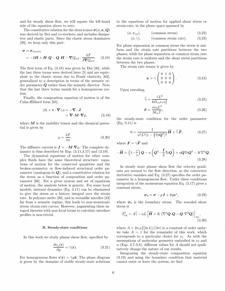
and for steady shear flow, we will equate the left-handside of the equation above to zero.
The constitutive relation for the stess tensor σ(φ,κ,Q)was derived by Doi and co-workers, and includes dissipa-tive and elastic parts. Since the elastic stress dominates[20], we keep only this part:
σ ≃ σelastic
= −3H + H ·Q − Q·H − ∇Qαβ ·δF
δ∇Qαβ
. (3.18)
The first term of Eq. (3.18) was given by Doi [40], whilethe last three terms were derived later [5] and are equiv-alent to the elastic stress due to Frank elasticity [63],generalized to a description in terms of the nematic or-der parameter Q rather than the nematic director. Notethat the last three terms vanish for a homogeneous sys-tem.
Finally, the composition equation of motion is of theCahn-Hilliard form [65];
(∂t + v · ∇)φ = −∇ · J
= ∇·M ·∇µ, (3.19)
where M is the mobility tensor and the chemical poten-tial is given by
µ =δF
δφ. (3.20)
The diffusive current is J = −M ·∇µ. The complete dy-namics is thus described by Eqs. (3.11,3.17) and (3.19).
The dynamical equations of motion for other com-plex fluids have the same theoretical structure: equa-tions of motion for the conserved quantities and thebroken-symmetry or flow-induced structural order pa-rameter (analogous to Q), and a constitutive relation forthe stress as a function of composition and order pa-rameter [66]. For a given system and set of equationsof motion, the analysis below is generic. For some localmodels, internal dynamics (Eq. 3.11) can be eliminatedto give the stress as a history integral over the strainrate. In polymer melts [20], and in wormlike micelles [23]far from a nematic regime, this leads to non-monotonicstress–strain-rate curves. However, augmenting these in-tegral theories with non-local terms to calculate interfaceprofiles is non-trivial.
B. Steady-state conditions
In this work we study planar shear flow, specified by
∂vx(r)
∂y= γ(r). (3.21)
For homogeneous flows v(r) = γyx. The phase diagramis given by the domains of stable steady-state solutions
to the equations of motion for applied shear stress orstrain-rate, in the phase space spanned by
(φ, σxy), (common stress) (3.22)
(φ, γ), (common strain rate). (3.23)
For phase separation at common stress the stress is uni-form and the strain rate partitions between the twophases; while for phase separation at common strain ratethe strain rate is uniform and the shear stress partitionsbetween the two phases.
The strain rate tensor is given by
κ = γ
0 1 00 0 00 0 0
. (3.24)
Upon rescaling,
γ =γL2
6Drν1ν2
2
(3.25)
σ =σν2L
3
3kBT, (3.26)
the steady-state condition for the order parameter(Eq. 3.11) is
0 =1
u2L2(1 − 3
2TrQ2)2
H + γ F , (3.27)
where F = γF and
−H =(1−
u
3
)Q − u
(Q2−
I
3TrQ
)+ uQTrQ2 −K∇2Q.
(3.28)
In steady state planar shear flow the velocity gradi-ents are normal to the flow direction, so the convectivederivative vanishes and Eq. (3.27) specifies the order pa-rameter in a homogeneous flow. Under these conditionsintegration of the momentum equation Eq. (3.17) gives aconstant stress,
σ0 = σ − p I + 2ηκs, (3.29)
where σ0 is the boundary stress. The rescaled shearstress is
σ0
xy = Aγ − uL[H +K
(∇2Q·Q − Q·∇2Q
)]
xy,
(3.30)
where A = 2ν1ν3
2(lnL)/(3π) is a constant of order unity:
we take A = 1 for the remainder of this work, whichcorresponds to a particular choice for ν1. As with theassumptions of molecular geometry embodied in ν2 andα (Eqs. 3.7-3.8), different values for A should not quali-tatively change the nature of our results.
Integrating the steady-state composition equation(3.19) and using the boundary condition that materialcannot enter or leave the system, we find
6

µ0 = µ(r) (3.31)
µ(r)
kBT= FDoi +
∂
∂φ[φ lnφ+ L (1 − φ) ln (1 − φ)]
+φL∂
∂uFDoi + 1
2K (∇Q)2 − gL∇2φ (3.32)
where Eqs. (3.7-3.8) have been used to specify the molec-ular geometry, µ0 is a constant of integration, and
FDoi = 1
2
(1− 1
3u)Tr Q2− 1
3uTrQ3+ 1
4u
(Tr Q2
)2
.
(3.33)
Note that the mobility tensor M plays no role in thesteady-state conditions, or in the resulting phase dia-gram.
Eqs. (3.27,3.30) and (3.31) completely specify the sys-tem in planar shear. Solving these equations will occupy
the remainder of this work. Note that variables γ, σ,µ/kBT are all dimensionless quantities.
IV. CALCULATION OF PHASE DIAGRAMS
A. Interface Calculation
The phase diagram is specified by solvingEqs. (3.27,3.30,3.31) for given µ0 and boundary stressσ0
xy. Non-equilibrium ‘phases’ are defined as the stablesteady-state space-uniform solutions to these equations.These inhomogeneous equations comprise a set of ordi-nary differential equations, through the gradients thatappear in the stress and in the functional derivatives thatdefine µ and H. The only parameters of the theory arethe rod aspect ratio L and the ratio of elastic constants,
λ =gL
K(4.1)
(K may be absorbed into the length scale of the system).
0.2 0.7 1.2
0.01
0.03
0.05
0.07
(a) u=2.55(b) u=2.58(c) u=2.60(d) u=2.65(e) u=2.70
a
b
c
d
e
nematic branch
paranematic branch
strain rate c_ � 104shearstressd � xy�102
FIG. 3. Homogeneous stress σxy vs. strain rate γ behaviorfor various excluded volumes, L = 5.0 and λ = 1.0. Dottedlines mark unstable branches. Similarly, curves along which∂µ/∂φ < 0 are linearly unstable.
We first fix φ (u) and solve the homogeneous algebraicversions of Eqs. (3.27) and (3.30) for Q and γ as a func-tion of σ0
xy∗. This is done for all φ. Because F(φ,Q) de-
scribes an I-N transition, at a given stress, multiple rootsexist, with distinct strain rates and Q. Fig. 3 shows thestress strain-rate relations for homogeneous solutions toEqs. (3.27) and (3.30) for L = 5.0 and λ = 1.0.
uu
uu
.γ
σ
ab
cd
xy
FIG. 4. Stress-strain-composition surface for the curves inFig 3. The plane is at σ0
xy = 0.05
The isotropic branch has a larger viscosity than thenematic branch, and has an increasing effective viscosityfor increasing concentration, reflecting the contribution
uH in Eq. (3.30). Conversely, the nematic branch has alower stress at higher concentrations due to the increasednematic order which permits less-hindered motion.
For a dilute isotropic system (curve a), shear flow con-tinuosly induces nematic order. A more aligned systemhas a lower effective viscosity, so the stress σ(γ) increases
∗In the few cases where the phase diagram in the σxy −µplane has a transition line parallel to the µ axis, one mustfirst fix µ0, and then determine σ0.
7

slower than linearly (shear-thins) as the magnitude of theorder parameter Q increases. Eventually the system at-tains, smoothly, a high strain rate state with a muchlower viscosity than in the limit of zero stress. For moreconcentrated systems (curves b, c and d) shear flow in-duces a transition to a nematic phase with lower viscosity,and σ(γ) is non-monotonic. There is a region of stressesfor which two stable strain rates exist, on either the ne-matic or isotropic branches of the constitutive curve. Forcompositions inside the biphasic regime (curve e) bothnematic and isotropic branches exist in the limit of zerostress, with the isotropic branch losing stability at highenough stress. Finally (not shown) for highly concen-trated systems only nematic branches exist.
As mentioned in Sec. IIB, we calculate the phase dia-gram by explicitly constructing the coexisting interfacialsolution [6]. In common stress coexistence, for example,the coexisting states have different strain rates and, gen-erally, different compositions. Hence, they connect thehigh and low strain rate branches of two different curvesin Fig. 3. It is easiest to visualize this by consideringthe intersection of a plane at a given stress σ0
xy with thesurface σxy(γ, u), as in Fig. 4.
2.59 2.60 2.61 2.62Excluded volume u
−0.20
−0.19
µ/k B
T
0.7
0.8
0.9
(a)
(b)
strainratec _ �104 (b�xy = 0:05)
FIG. 5. (a) Reduced strain rate γ(u) and (b) chemical po-tential µ(u) for the stress contour in Fig. 4 (σxy = 0.05). Thetie line is calculated using the interface construction.
At a given stress, the strain rate varies with composi-tion as shown in Fig. 5a. At coexistence, the chemicalpotential µ(r) must be constant through the interface, as
dictated by Eq. (3.31). The functional form of the non-equilibrium chemical potential is known from Eq. (3.32),and depends on the strain rate through the dependence ofthe nematic order parameter on the strain rate in steadystate. We plot µ(u) in Fig. 5b. There is a continuumrange of µ, which allow possible coexisting pairs of states.(Recall that u is proportional to the rod volume fractionφ).
We now impose the interface solvability condition asfollows. For a given stress σ0
xy, we determine a specificcoexistence chemical potential µ0, which allows a stableinterfacial solution to Eqs. (3.27,3.30,3.31). In practice,we eliminate γ(r) from Eq. (3.27) using Eq. (3.30), andsolve Eqs. (3.27) and (3.31) for the interfacial profile,with boundary conditions (fixed Q and u) chosen by twopoints on the low and high strain rate branches of Fig. 5bwith the same µ0. We adjust µ0 until a stationary interfa-cial profile is found. This solvability criterion give sharpselection on µ, and in this way determine a tie line on theγ−u plane, Fig. 5a. By varying the stress we computethe entire phase diagram in the σxy −u and γ−u planes.
For phase separation at a common strain rate theconstruction is analogous. One slices a vertical planethrough Fig. 4 at a given strain rate, constructs the curveµ(u) along the intersection with the surface, and searchesfor a stationary interfacial solution.
The interface calculations are carried out by discretiz-ing the system on a one-dimension mesh and, fromsmooth initial conditions, evolving Eqs. (3.27,3.30,3.31)forward using fictitious dynamics calculated with an im-plicit Crank-Nicholson scheme. Spatial variations areonly allowed in the direction in which phase separationoccurs, so we replace
∇ →
∂
∂ycommon stress
∂
∂zcommon strain rate,
(4.2)
where z is in the vorticity direction. We fix the valuesof u and Q at either side of the interface to lie on thehigh and low strain rate branches of Fig. 5, begin withsmooth initial conditions, and let the system “evolve”towards steady state. An interface develops between thetwo phases, and moves to one boundary or the other. Fora given stress, coexistence is determined by that chemi-cal potential µ for which a stationary interface lies in theinterior of the system (in the limit of large system size)[6]. An analogous construction may be made by main-taining a fixed mean strain rate on the unstable part ofa homogeneous curve, and then starting up the systemand allowing it to select a stress and chemical potential.In either case the selected stress is that stress for which astationary interfacial solution between the high and lowstrain rate branches exists. Such an interfacial solutionis known in dynamical systems theory as a heteroclinicorbit [59,60,9], and further work will investigate this inmore detail for simpler model systems [35,32,67].
8

We restrict the nematic order parameter to
Q =
q1 q3 0q3 q2 00 0 −(q1 + q2)
, (4.3)
since all steady state solutions with non-zero elementsQxz or Qyz are unstable due to the symmetry of shearflow [39]. In a similar calculation for thermotropic ne-matics in shear flow we have found that this restrictionon Q reproduces the same selected stress as that obtainedwhen keeping the full tensor [6].
For planar shear flow and a wide class of equations ofmotion we have shown that, if a coexisting solution ex-ists, it occurs at discrete points in the parameter set [35].For example, for a given stress σ0
xy, coexistence can oc-cur only at discrete values for µ0, that is, along lines inthe field variable space spanned by σxy−µ. This is anal-ogous to equilibrium systems where, for example, phasetransitions in a simple fluid occur along lines, rather thanwithin regions, in the pressure-temperature plane.
Note that a one-dimensional calculation does not de-termine the stability of the interfacial solution with re-spect to transverse undulations (capillary waves), whichcould be important in, particularly, the common stressgeometry [68].
B. Homogeneous Solutions
The modified Doi model in the quadratic closure ap-proximation has three stable solutions in homogeneousplanar shear flow. We refer the reader to Bhave, et al.
for further details [39].
I Paranematic: The paranematic state I inducedfrom a disordered equilibrium phase. The order pa-rameter Q is small and fairly biaxial, with majoraxis lying in the shear plane at an angle of almostπ/4 relative to the flow direction.
N Flow-Aligning Nematic: The flow-aligning nematicstate is much more strongly-aligned, has slight bi-axiality induced by the flow, and has the major axisof alignment in the flow plane at an angle of a fewdegrees relative to the flow direction. The I and N
states have the same symmetry.
L Log-Rolling Nematic: The log-rolling phase is alsoa well-aligned and almost uniaxial phase, but withmajor axis of alignment in the vorticity (z) direc-tion, so the rods spin about their major axes.
0.0 0.5 1.0 1.50.0
2.0
4.0
6.0
u=2.7u=2.9
I
N L
NL
strain rate c_ � 104stressc � xy�10
2
FIG. 6. Constitutive relations for I, N, and L states, forL = 5.0 and two values for the excluded volume parameter.
The I phase is stable at lower volume fractions andmerges with the N phase at high strain rates. The L
phase is stable only at higher volume fractions, and isdestabilized at high enough strain rates. For low strainrates the stress of the L state is lower than that of the N
state, which is lower than that of the I state (see Fig. 6).
Fig. 7 shows the regions of stability of the variousstates. The loop in Fig. 7a occurs for compositions suchthat the constitutive curve σ(γ) has the shape of curveb in Fig. 3. Similar phase-plane plots were calculated byBhave et al. [39] and See et al. [8]. They did not con-sider the mixing entropy needed to generate a realisticnematic transition, however, and always generated solu-tions for a given strain rate instead of a given stress. (thisexplains the absence of a loop in their phase-plane plotγ−φ). Their plots (compare Fig. 5 of Ref. [39]) corre-spond to truncating the loop in Fig. 7a. Fig. 7b has asimilar, barely discernable, loop near the critical point,within which there are no stable states. This instabil-ity is due to the instability of the composition equation,Eq. ( 3.19). In this region
∂µ
∂φ
∣∣∣∣σxy
< 0, (4.4)
which is equivalent to a negative diffusion coefficient, andis analogous to the conventional definition of the spinodalline for ordinary equilibrium demixing.
9

2.6 2.7 2.8 2.9Excluded volume parameter u
0.0
2.0
4.0
6.0
8.0
I
N
IN
INL
NL
(a)
(b)
2.6 2.7 2.8 2.90.0
0.5
1.0
I
N
IN
INL
NL
stressc � xy�102 ustrainratec _ �104
FIG. 7. Regions of stability of paranematic (I), nematic(N) and log-rolling (L) states in the strain-rate–composition(a) and stress-composition (b) planes for L = 5.0. Note thatthe loop in (a) contains no stable states. Stability limits arecalculated with respect to both order parameter and com-position fluctuations, for a given controlled stress. The thinloop in (b) encloses a region with no stable states, due to theinstability of the composition equation.
V. COMMON STRESS COEXISTENCE
For common stress coexistence the interface lies in thevelocity-vorticity plane, and inhomogeneities are in they direction (see Fig. 2). The stress balance condition atthe interface is σ · y uniform. σyy is taken care of bythe pressure and σzy vanishes by symmetry (no flow inthe z direction), leaving continuity of the shear stressσxy through the interface. The two coexisting phases Iand II have strain rates and compositions partitionedaccording to
φ = ζφI + (1 − ζ)φII (5.1)¯γ = ζγI + (1 − ζ)γII , (5.2)
where φ and ¯γ are the mean composition and strain rateand ζ is the fraction of material in phase I.
A. Paranematic–flow aligning coexistence (I-N)
Phase Diagram—Fig. 8 shows the tie lines computed
on the (σxy−u) and (γ−u) planes according to the pro-cedure outlined in Section III. Several features shouldbe noted. Flow induces nematic behavior in what, inequilibrium, would be an isotropic phase. The tie linesare horizontal in the (σxy−u) plane, since phases coex-ist at a prescribed stress; and have a positive slope in
the (γ−u) plane because the more concentrated nematicphase flows faster. There is a critical point at sufficientlystrong stress, whose existence is expected since the flow-aligning nematic and paranematic states have the samesymmetry (Q is biaxial) and their major axes in the shearplane.
More interesting is the changing slope of the tie lines.For weak stresses the equilibrium system is slightly per-turbed and the tie lines are almost horizontal. For highstresses the tie lines become more vertical and the com-position difference between the phases decreases. Theslope of the tie lines determines the shape of the meanstress–strain-rate relation σxy(¯γ) that would be measuredin steady state experiments.
2.550 2.600 2.650 2.7000.00
2.00
4.00
6.00
8.00
2.550 2.600 2.650 2.7000.00
0.50
1.00
1.50
I
N
I
N
I limit
N limit
N limit
I limit
Excluded volume parameter ushearstressc � xy�102
ustrainratec _ �104
FIG. 8. Phase diagram in the (σxy−u) (a) and (γ−u) (b)planes for L = 5.0, λ = 1.0, along with the limits of stabilityof I and N phases
10

1.0 1.1 1.26.9
7.1
7.3
0.7 0.9 1.15.0
5.5
6.0
6.5
0.0 0.1 0.2 0.30.0
0.5
1.0
1.5(a) (b) (c)
IN
I
N
u=2.555 u=2.58 u=2.685mean strain rate b_ � 104sheartress^� xy�102 b_ � 104 b_ � 104FIG. 9. Mean stress–strain-rate curves for coexistence at common stress, for L = 5.0 and λ = 1.0. The solid lines denotes I
and N branches; the dotted line in each figure denotes the stable N branch with which the I state coexists at the low strain rateboundary of the coexistence region, at a strain rate marked by an open circle ◦. The solid circles • and thick solid line denotethe stress that would be measured in the banded regime. Phase coexistence occurs between phases of different compositionsthan the mean compositions (u = 2.555, 2.58, 2.685). The unstable portion of the homogeneous flow curve is shown in (a) and(b), but not (c). Note that the plateaus in the two-phase regions in (a) and (b) rather obviously do not satisfy an equal areaconstruction with the underlying constitutive curve at the mean composition.
Mean Constitutive Relations—Consider a composi-tion in the range where phase-separation occurs. Forsmall applied stress σxy(¯γ) varies smoothly until the two-phase region is reached. At this stress, a tiny band ofhigh strain rate strongly-aligned nematic material ap-pears, with volume fraction determined by the lever rule,Eq. (5.1). The mean strain rate ¯γ is determined by thelever rule, Eq. (5.2), and the measured constitutive re-lation σxy(¯γ) is non-analytic at this point (see Fig. 9).As the stress is increased further, the system traversesthe two-phase region by jumping from tie line to tie line.Each successive tie line has a higher stress, a higher meanstrain rate, and a steadily increasing volume fractionof nematic phase. The compositions of both coexistingphases change steadily through the two-phase region.
The constitutive relation σxy(¯γ) through the two phaseregion is determined by the spacing and splay of the tielines. For mean compositions φ close to the equilib-rium isotropic-nematic transition (Fig. 9c) the tie lines
in the (γ−u) plane are fairly flat, so that the stress σxy
changes significantly through the two-phase region; andthe ‘plateau’ has definite curvature, reflecting the initialsplay of the tie lines. For slightly lower mean composi-tions (Fig. 9b) the ‘plateau’ is straighter and flatter, ascan be seen in (Fig. 10), because the lines are more verti-
cal in the (γ−u) plane. Finally, for compositions near thecritical point the plateau is flatter still but, more inter-estingly, phase coexistence occurs in a region where thestress-strain curve at the mean composition is no longernon-monotonic (Fig. 9a)! This is because stability ina two-phase system is also determined by the stabilitywith respect to composition variations. In fact, the localchemical potential µ(u) has negative slope and is unsta-ble on a segment of this curve. The tie line constructionis a graphical expression of the explanation proposed bySchmitt et al. [28], who attributed a sloped plateau to
composition-dependence of the stress-strain constitutiverelation. The general relation is given by
∂σ
∂ ¯γ=
[ζ
ηI
+1 − ζ
ηN
−m(σ)
{1 − ζ
γ′NηN
+ζ
γ′IηI
}]−1
,
(5.3)
where m(σ) is the slope of tie line with stress value σ, thelines {σI(φ), σN (φ), γI(φ), γN (φ)} bound the phase coex-istence domains in the σ−φ and γ−φ planes; ηk = ∂σk/∂γis the local viscosity of the kth branch, and γ′k = ∂γk/∂φ.
0.0 0.2 0.4 0.6 0.8 1.0 1.20
2
4
6
8
u=2.555u=2.685u=2.58
mean strain rate c_ � 104shearstressc � xy�102
FIG. 10. σxy vs. γ for common stress coexistence forL = 5.0 and λ = 1.0. The solid lines connecting the highand low strain rate branches at each composition denote thecomposite flow behavior at coexistence.
Measurements at controlled stress or controlledstrain rate—Although these calculations are for phaseseparation at a common stress, one may perform experi-ments at either controlled stress or strain rate. All three
11

composite curves in Fig. 9 have similar shapes, so we ex-pect the same qualitative behavior for all compositions.Controlled strain rate experiments should follow the ho-mogenous flow curves, except for strain rates in the co-existence regime. Here we expect the steady state toeventually be the banded state. This should presumablyoccur by a nucleation event after some time, for start-upstrain rates less than the I limit shown in Fig. 8a; andoccur immediately for imposed strain rates beyond thisstability limit. Conversely, upon decreasing the strainrate from the nematic phase we expect nucleated behav-ior for strain rates larger than the N limit, and insta-bility for smaller strain rates. In the metastable regimewe expect the flow curve to follow the underlying ho-mogeneous constitutive curve for the given composition,until the nucleation event occurs. Interestingly, there is asmall region (inside the loop in Fig. 8a) where the systemis unstable when brought, at controlled strain rate, intothis region from either the I or N states. This correspondsto constitutive curves with the multi-valued behavior ofcurve b in Fig. 3.
Controlled stress experiments should exhibit similarbehavior. Consider Fig. 9b. For initial applied stresseslarger than the minimum coexistence stress and less thanthe I limit of stability in Fig. 8b, we expect the systemto follow the homogenous flow curve until a nucleationevent occurs. After nucleation the strain rate should in-crease, until either the proper plateau strain rate or thehigh strain rate nematic state is reached, depending onthe magnitude of the stress. For stresses larger than thelimit of stability we expect the system to become immedi-ately unstable to either a banded flow or a homogeneousnematic phase, depending on the magnitude of the stress.Metastability: Experiments—Experiments on worm-like micelles [1,2,29] have found constitutive curves anal-ogous to those in, say, Fig. 9. In these experiments theplateau appears to be the stable states, while the por-tion of the constitutive curve (a ‘spine’) which extendsto stresses above the onset of the stress plateau appearsto be a metastable branch on which the system may re-main for a finite period of time under controlled stressor strain rate conditions. Refs. [2,29,51] conducted con-trolled strain-rate experiments and found that the sys-tem follows the composite curves (without ‘spines’ thatextend above the onset of the stress plateau) in Fig. 9,if care is taken to reach steady state. In these systemsthe plateaus were nearly flat, suggesting a very slightdependence of the flow behavior on composition. Forcontrolled strain rate quenches into what corresponds tothe two-phase region of Fig. 8a, the system took sometime to develop shear bands and phase separate. Thisrelaxation or ‘nucleation’ time decreased as the mean-strain rate was increased [29]. It is not clear that theyreached a limit of stability (which would be analogous tothe I limit in Fig. 8). The relaxation times were of order60−600 s, depending on temperature, mean composition,and mean strain rate. We emphasize that these experi-ments were on micellar solutions, which probably do not
show an isotropic-nematic transition, but still display thesame qualitative stress–strain-rate relationship as curveb in Fig. 3.
Ref. [44] revealed different stress plateaus upon con-trolling either the strain rate or the shear stress (seeFig. 7 of Ref. [44]) in cone-and-plate flow. In controlledstress experiments the stress plateau occurred at a stressof order 1.5 times the stress plateau observed under con-trolled strain rate conditions. Moreover, the flow curveunder controlled stress conditions exhibited a stress max-imum and then a decrease in stress to an approximate flatplateau. One explanation for the high stress plateau un-der controlled stress conditions could be that the ‘spine’never nucleated under controlled stress conditions, andthe system smoothly transformed to the high strain ratephase. However, we do not have an explanation for thedecrease and subsequent plateau in stress under appliedstrain rate conditions.
In other experiments, controlled stress experimentsrevealed two kinds of metastable behavior [29]. Forσp < σ < σjump, where σp is the minimum stress for theonset of banding in controlled strain rate experiments,the system maintained a strain rate on the ‘metastable’branch for indefinite times (measured times were up to104 s). For σ > σjump the system accelerated, after oforder 103 s, and left the rheometer. For these systemsit is not clear whether a stable high shear branch exists.An explanation for σjump is lacking. Evidently the nu-cleation processes governing metastability at controlledstress and controlled strain rate are different. Clearlywe need more experiments and theory about the natureof nucleation and metastability in controlled stress vs.controlled strain rate experiments.
Polydispersity—Fig. 11 shows the effect of rod aspectratio L on the phase diagram. A smaller rod aspect ra-tio couples more weakly to the flow, requiring a slightlylarger strain rate to induce a transition to the nematicphase (Fig. 11a). The resulting stress is slightly smallerbecause, when the system enters the two phase region thestress is largely determined by that of the paranematicbranch, which decreases with increasing L (Fig. 11b). Al-though the equilibrium phase boundaries are close (seeEqs. 3.9-3.10), the deviation is amplified considerably byapplying flow. This suggests that flow enhances the nat-ural tendency of length polydispersity to widen biphasicregimes.
12

2.55 2.60 2.65 2.70Excluded volume u
0
2
4
6
8
2.55 2.60 2.65 2.70u
0
0.5
1
1.5
I
N
L=5.0
L=4.7
I
N
L=4.7
L=5.0
stressc � xy�102strainratec _ �104
FIG. 11. Phase diagrams for L = 5.0 and L = 4.7 atcommon stress, for λ = 1.0.
B. Paranematic–Log rolling coexistence (I-L)
Fig. 12 shows the phase diagram calculated for coexis-tence between paranematic (I) and log rolling (L) states.As with I-N coexistence, the zero shear limit correspondsto the equilibrium biphasic region. However, for non-zero stress the biphasic region shifts in the direction ofhigher concentration. This is reasonable, since the sta-bility limit of the L phase shifts to higher concentrationswith increasing stress (Fig. 7). Note also that, since the I
and L phases have major axes of alignment in orthogonaldirections, there is no critical point. Instead, the win-dow of phase coexistence ends when the I phase becomesunstable to the N phase.
We have also computed phase coexistence between N
and L phases. This occurs at much higher compositions(u > u∗ & 3.0) and has a narrow width in compositiondue to the very slight difference in viscosities of the twophases. Unfortunately, we cannot resolve this coexistenceregime accurately within the numerical precision of ourcalculations and do not present these results here.
The existence of two possible phase diagrams for com-mon stress phase separation raises an interesting ques-tion. Can one observe I-L coexistence? Notice that I-L
coexistence can only occur for samples prepared at con-centrations at or above that necessary for equilibriumphase separation. One could prepare a phase separatedisotropic-nematic mixture and, by wall preparation, field
alignment, sedimentation, or other techniques, separatethe phases into two macroscopic domains with the ne-matic phase in the log-rolling geometry.
2.55 2.60 2.65 2.70Excluded volume parameter u
0
2
4
6
8
2.55 2.60 2.65 2.70u
0.0
0.5
1.0
L limit
IL
I
I limit
Lstressc � xy�10
2strainratec _ �104
FIG. 12. Phase diagram in the (σxy − u) and (γ − u)planes for paranematic–log-rolling coexistence, for L = 5.0and λ = 1.0. The dotted lines are the limits of stability of theI and L phases (see Fig. 7).
2.55 2.60 2.65 2.70
Excluded volume parameter u
0
2
4
6
8
I limit
L limit
I
N
IN limit Lsheartressc �
xy�102FIG. 13. Composite phase diagrams for I-L and I-N coex-
istence at common stress for L = 5.0 and λ = 1.0. We stressthat this represents two overlayed phase diagrams, and not asingle phase diagram. For example, there is no triple pointimplied by the intersection of the I-N and I-L phase diagrams.
Upon applying shear, the system could then maintaincoexistence and move through the I-L two-phase region.However, under controlled strain rate conditions, the I
13

material could decay into I-N coexistence (see Fig. 13).The resulting I-N coexistence occurs would quickly desta-bilize the entire I-L structure. Therefore the three-bandstructure N-I-L will not be present in this model, and itis probable that I-L coexistence could only exist underflow as a metastable state. Similar conclusions may bedrawn by examining the phase diagrams in field-variablespace, µ− σxy, as in Fig. 18a. In this case the chemicalpotential of the I phase, at I-L coexistence, is within theN region of the phase diagram for I-N coexistence, indi-cating a (possibly metastable) instability with respect toI-N phase separation. Moreover, the chemical potentialsof the three phases are never the same, except at restwhere the L and N states are identical apart from therod orientations.
VI. COMMON STRAIN RATE COEXISTENCE
For coexistence at common strain rate the interfacelies in the velocity–velocity-gradient plane, and inhomo-geneities are in the z direction (see Fig. 2). The stressbalance condition at the interface is σ · z uniform. Asbefore, σzz is taken care of by the pressure while σyz andσxz are zero by symmetry (and because there are no sta-ble q3 components in the order parameter tensor). Withbands in the z direction, the strain rate in each band isset by the relative velocity of the two plates (or cylinders,in a Couette device), and the shear stresses differ. Themean applied stress σxy is the area average of the stressapplied to each band. The coexisting phases have shearstresses and compositions partitioned according to
φ = ζφI + (1 − ζ)φII (6.1)
σxy = ζσI
xy + (1 − ζ)σII
xy, (6.2)
where σxy is the mean shear stress. The interfacial equa-tions to solve are Eqs. (3.27),(3.30), and (3.31).
Phase Diagram—Common strain rate I-N phase coex-istence is shown in Fig. 14. In this case the tie lines are
horizontal in the (γ−u) plane. They have a negative slopein the (σxy −u) plane because the paranematic I phasecoexists with a denser and less viscous flow-aligning N
phase. As with phase separation at common stress, thereis a (very small) loop in the limits of stability in the con-trol variable plane (γ−u) within which there are no stablehomogeneous states. The careful reader will note thatthe limits of stability at a given stress (Fig. 8) are dif-ferent from the limits of stability at a given strain rate.This is physically correct, and will be discussed below inSec. VII C.
2.57 2.61 2.65 2.69Excluded volume parameter u
0
2
4
6
2.57 2.61 2.65 2.69u
0
0.2
0.4
0.6
0.8
I phase boundaryN phase boundary
(a)
(b)
I
N
I limit
N limit
I limit
N limit
shearstress^� xy�102
c _ �104
FIG. 14. Common strain rate phase diagram in the (γ−u)(a) and (σxy−u) (b) planes, for L = 5.0 and λ = 1.0. Alsoshown are the limits of stability of the I and N phases (calcu-lated for a given imposed strain rate, in contrast to Figures7, 8, 12, and 13, in which the stability was calculated for animposed stress.)
There is an interesting crossover visible in the (σxy−u)plane. For higher mean compositions the fluid has ahigher stress in its high strain rate one-phase region thanin its low strain rate one-phase region; that is, respec-tively above and below the biphasic region in the Fig. 14a.Conversely, for low enough compositions u . 2.67, thestress in the high strain rate region immediately outsidethe biphasic regime is actually less than the stress justbefore the system enters the biphasic region, as can beseen by the crossing of the solid and dashed phase bound-aries in Fig. 14.
This crossover is straightforward to understand. Sincephase separation occurs at a given strain rate, and thestress of the N branch at a given composition and strainrate is always less than that of the corresponding I
branch, we expect a decrease in the stress upon leav-ing the biphasic regime in cases where the coupling tocomposition is less important. We saw in the analysis atcommon stress that composition effects are less impor-tant (for I-N coexistence) at lower compositions and highstrain rates, where the tie lines are more vertical. We ex-pect this near the critical point where the two phases be-come more and more similar. More generally, we expectthis behavior in situations where phase separation occursat a common strain rate into a shear-thinning state with
14

only slight changes in composition. In the more concen-trated regime, the coexistence plateau traverses a widerrange of concentrations and strain rates, and emergesinto the pure N phase with a higher stress (the width instrain rate of the phase coexistence regime is enough toovercome the shear thinning effect of the nematic phase).Mean Constitutive Relations— Figs. 15-16 show themean stress–strain-rate relations. As with common stressphase separation, the shape of the ‘plateau’ as the strainrate is swept through the two-phase region is not alwaysflat, and depends on the splay of the tie lines. At higherconcentrations the plateau has a positive slope while, inaccord with the crossover in the (σxy−u) phase diagram,for lower concentrations the plateau crosses over to neg-ative slope, which usually signifies a bulk instability. Asimple argument, analogous to that for the stability of abulk fluid, supports this. However, we note that a com-
posite negative slope curve was accessed, and apparentlyfound stable, by Hu et al. [69] under controlled stressconditions. The negative slope in Fig. 15a is likely to beinaccessible under controlled stress conditions, and theinstability argument may apply to controlled strain rateconditions. The general relation for the slope in the com-posite region is [28]
∂σ
∂γ= ηI ζ + ηN (1 − ζ) −m(γ)
{ηN (1 − ζ)
σ′N
+ηI ζ
σ′I
},
(6.3)
where m(γ) is the slope of the tie line with strain rate γand σ′
k = ∂σk/∂φ. In the limit of no concentration dif-ference (δφ = 0 or m(γ) = ∞), σ(γ) is vertical throughthe two phase region.
0.0 0.2 0.4 0.6 0.80.0
1.0
2.0
3.0
4.0
0.0 0.1 0.2 0.3 0.40.0
0.5
1.0
1.5
2.0
2.5
0.0 0.20.0
1.0
(a) (b) (c)
I
N I N IN
u=2.625u=2.669 u=2.681
strain rate b_ � 104meanstressb � xy�102 b_ � 104 b_ � 104FIG. 15. Mean stress–strain-rate curves for common strain rate coexistence for L = 5.0 and λ = 1.0. The solid lines denote
the stable I and N branches; the dotted line in each figure denotes the stable N branch with which the I state coexists at thelow strain rate boundary of the coexistence region, at a strain rate marked by an open circle ◦. The solid circles • and thicksolid line denote the stress that would be measured in the banded regime. The filled circles • and thick solid line denotes thestress measured under banded conditions.
Measurements at controlled stress or controlledstrain rate—For controlled strain rate measurementswe expect behavior similar to that for phase separationat common stress. For start-up experiments with meanstrain rates larger than the minimum strain rate for co-existence at a given composition, we expect the stressto follow the metastable branch until a nucleation eventcauses the stress to decrease to the plateau stress. Theexception is a composition such as that in Fig. 15a, forwhich the composite flow curve for I-N coexistence maybe mechanically unstable. Similar results should applyupon decreasing the strain rate from the shear-induced N
phase to below the N limit. As before, this expectation ofa nucleation event is based on a possibly misguided anal-ogy with equilibrium systems which, nonetheless, is en-couraging given the experiments which see “nucleation”type behavior in micelles under flow [2,29,51].
For controlled stress, the situation is slightly different.For compositions with mean stress–strain-rate curves of
the shape of Fig. 15c, we expect similar behavior to thatfound for common stress phase separation. However, forcompositions that yield curves such as Fig. 15a there isa window of stresses for which there are three possiblestates: homogeneous low strain rate and high strain ratebranches, and a banded intermediate branch. We empha-size that we have not determined the absolute stabilityof any of these branches. A possibility is that the systemhas hysteretic behavior. For example, in start-up exper-iments the system would remain on the I branch untila certain stress, at which point it would nucleate aftersome time and transform to either the high strain rateN branch or coexistence. We cannot tell which state itmight go to, from this analysis, but it seems likely that
15

it would jump straight to the N branch.† The same be-havior (in reverse) would be expected upon reducing thestress from the high strain rate N phase.
0.0 0.2 0.4 0.60.0
1.0
2.0
3.0
4.0u=2.625u=2.669u=2.681
strain rate c_ � 104meanshearstressc � xy�102
FIG. 16. σxy vs. γ for various compositions, for phase sep-aration at common strain rate and L = 5.
Although there have been anecdotal reports of shearbanding in the common strain rate geometry, there havebeen very few such results published. Bonn et al. [38]have recently reported results for sheared surfactantonion gels, along with visual confirmation of bands in thecommon strain rate geometry. In controlled strain rateexperiments they found constitutive curves analogous toFig. 15a or 15b. In controlled stress experiments theyfound hysteretic behavior, with the system flipping be-tween high and low strain rate branches after some delaytime, missing the coexistence ‘plateau’ regime. However,it is not clear that these were true steady state results.
Stable ‘negative-slope’ behavior was seen in a shear-thickening systems which phase separates at commonstress [52,53], under controlled stress conditions. In thiscase there was a single (mean) strain rate for a given ap-plied stress, and the measured constitutive relation hadan S shape rather than the sideways S shape of Fig. 15.
VII. DISCUSSION
A. Dependence on gradient terms
Gradient terms appear in all equations of motion forK 6= 0 and for any g, so to avoid unphysical equationswithout gradients (which cannot resolve interfaces) we
must have λ ∼ g/K < ∞. In the case of K = 0 and fi-nite g the Q equation of motion has no explicit gradientterms and hence can, in principle, support discontinu-ous solutions. The φ equation has gradients in this case,arising from the term g (∇φ)
2in the free energy density,
Eq. (3.2), so the system will eventually reach a state withsmooth solutions in both φ and Q. Conversely, for g = 0there are gradient terms in both the Q and φ dynamics,with the latter arising from the term φ (∇Q)
2in the free
energy density Eq. (3.2).
Phase boundaries for σxy = 0.01, 0.03 are shown inFig. 17. For λ ∈ (0.0 − 30.0) the phase boundaries arethe same, within the precision of our numerical calcula-tions, while there is a distinct difference for λ = ∞. Wehave discretized the system on a mesh of 125 points, andthe range of elastic constants is such that the width ofthe interface is at least 20 mesh points; large enough forsmooth behavior and much smaller than the system size.
0 10 20 30λ/L (L=5)
2.63
2.65
2.67
2.69
u � =1�xy = 0:01�xy = 0:03
FIG. 17. I-N phase boundaries for common stress phaseseparation as a function of λ/L, for L = 5.0. The diamonds� are for λ = ∞(K = 0, g = 1).
We cannot rule out the possibility that changes in λshift the phase boundaries by small amounts below ouraccuracy, which is of order 0.1% in u, but the apparentindependence of the phase boundaries on λ is curious.One might be tempted to generalize and suggest that, forfinite λ, there exists a selection criterion which involvesonly the homogeneous equations of motion, rather thanrequiring the inhomogenous terms as in the interface con-struction. An interface construction may also be used todetermine equilibrium phase boundaries, in which case astationary interface is equivalent to minimizing a free en-ergy and the (relaxational) dynamical equations derived
†If the system jumped from the I branch to the coextencebranch, increasing the stress further would decrease the strainrate and return the system to the I branch. Since it originallynucleated from the I branch, it seems unlikely that the originaljump could be to the coexisting plateau.
16

from a variational principle [6]. In the case of a van derWaals fluid this reproduces the Maxwell construction.
A steady state equation for a single variable ψ withhomogeneous and inhomogeneous terms of the form
σ0 = fhom(ψ) + finh(∂ψ/∂y) (7.1)
can be integrated to yield a solvability condition for σ0,which is equivalent to the stable interface method. Inequilibrium finh integrates exactly without an integrat-ing factor, since it typically arises from a variation of afree energy functional with respect to ψ, and the result σ0
(corresponding to the pressure in the van der Waals fluid)depends only on fhom. Out of equilibrium, integration isnot so simple, and the solvability condition depends, gen-erally, on the form of the gradient terms [60,35].
In the multivariable case considered here the steadystate conditions for the order parameter and composi-tion are coupled differential equations which are not in-tegrable in shear flow. This is because of the termsκ ·Q + Q ·κT in Eq. (3.12) and (∇2Q) ·Q − Q · (∇2Q)in Eq. (3.30). In extensional flow κ is symmetric, so thatκ ·Q + Q ·κT integrates to Tr(Q2κ)/2, while in shearflow this term can only be integrated by introducing anintegral representation [70]. Hence a first integral of thesteady state equations cannot be found in shear flow, andit seems unlikely that a general condition involving onlythe homogeneous portion of the steady state equationscan determine coexistence. While we appear to find, forthis set of gradient terms, solvability conditions that areindependent of λ for λ < ∞, the relationship of thisto a variational principle remains unknown. We havenot exhausted the possible gradient terms. For exam-ple, higher order gradients in the free energy ((∇2Q)2,etc.) would yield higher-order differential equations forthe interfacial profile, and other square gradient termssuch as Qαβ∇α∇βφ are possible [71]. Hence, we believethat, for finite λ, the apparent independence of our resultson gradient terms only applies to the particular (simple)family of gradient terms we have chosen. The structureof the differential equations describing the steady statesmay change abruptly for λ = ∞, for which a term is lostin the differential equations, leading to a distinctly dif-ferent selection criteria and the shifted phase boundaryin Fig. 17. Unfortunately, this particular set of equationsis too complex for this kind of analysis. For example, ina study of a simpler constitutive model, one can demon-strate that the selected stress depends on the detail formof the gradient terms [35].
Several workers have claimed to find an equal areasconstruction on the stress–strain-rate constitutive curve[30]. That is, the “plateau” as the system traverses thetwo-phase region is said to describe a path such thatthe areas above and below the plateau, enclosed by theplateau line and the underlying constitutive curve, arethe same. This is not true here, as can be seen in Fig. 15.
B. Which phase separation is preferred?
Having calculated both common strain rate and com-mon stress phase separation for the same system, andnoticing from Figs. 13 and 14 that there are compo-sitions and shear conditions which lie inside the two-phase regions of all three calculated phase separations,we must address the question of which phase separationoccurs. We have already argued that we expect I-L phase-separation at common stress to be metastable with re-spect to I-N phase separation at common stress. Whatabout the relative stability of I-N phase separation ateither common stress or common strain rate?
With limited one-dimensonal calculations for systemsof different symmetry (annular bands at common stressand stacked disk-like bands for common strain rate) itis impossible to calculate the stability of one interfaceprofile with respect to another. Renardy calculated thestability of common stress coexistence to capillary fluctu-ations [68], which is a start; and such a stability analysishas been performed, in part, on the layer orientation ofsmectic systems in flow [16]. However, some insight canbe obtained by examining the “phase diagrams” in thechemical potential–field variable (either stress or strainrate) planes. The solid lines in Fig. 18 are analogous tolines of phase coexistence in, for example, the pressure–temperature plane in a simple fluid.
Consider Fig. 18a. Here, σxy and µ are the proper fieldvariables for phase separation at a common stress, andthe solid lines denote the I-L and I-N phase boundaries.The dashed line denotes the range of stresses at coexis-tence for common strain rate phase separation (Fig. 18a),for which stress is a generalized density variable andstrain rate the field variable.
Fig. 18a indicates that, for a system undergoing I-N ata common strain rate, the chemical potential and stressfor the I phase falls within the single phase N region ofthe common stress phase diagram. Hence, we expect thisI phase to be unstable (or metastable) with respect tophase separation at common stress. Similarly, the con-trol parameters (chemical potential and stress) for theN phase coexisting at a common strain rate lie withinthe single phase I region for common stress phase separa-tion, which we also expect to be unstable (or metastable).Conversely, for a system coexisting at a common stressthe I phase lies within the single phase I region of the com-mon strain rate phase diagram (Fig. 18b), and similarlyfor the N phase. This suggests that phase separation at acommon strain rate is unstable (or metastable) with re-spect to phase separation at common stress, while phaseseparation at a common stress is stable.
17

0 0.2 0.4 0.6 0.8 1 1.2−0.23
−0.21
−0.19
−0.17
−0.15
µ/k B
T
IN (common strain rate)IN (common stress)
0 1 2 3 4 5 6 7−0.23
−0.21
−0.19
−0.17
−0.15
µ/k B
T
IL (common stress)IN (common stress)IN (common strain rate)
I
N
L
I
N
I
µI(fixed γ)
µN(fixed γ)
µN(fixed σ)
µI(fixed σ)
(b)
(a)
strain rate b_ � 104
stress c�xy � 102
FIG. 18. Phase diagrams in the chemical potential µ vs.stress plane (a) and the µ-strain rate plane (b). The solidlines denote the phase boundaries for common stress phasecoexistence in the µ−σ plane (a) and for common strain ratecoexistence in the µ− γ plane (b). The dashed lines denotethe coexisting stresses for common strain rate phase separa-tion within the common stress phase diagram (a); and viceversa in (b).
Note that, ultimately, this selection of phase coex-istence geometries follows from the transition being ashear-thinning transition; for a shear thickening transi-tion the situation could be reversed. In this case phasecoexistence at a common strain rate and a given µ wouldimply a shear-induced phase (analogous to the N phase)with a higher stress than the I phase. If the phase coex-istence line for common stress (strain rate) lay withina loop corresponding to the stresses (strain rates) forcommon strain rate (stress) coexistence, then commonstrain rate coexistence would be expected to be stable, byanalogy with the isotropic-nematic shear thinning model.Obviously this argument is delicate. In a fluid where onlyone phase coexistence (either common stress or commonstrain rate) is supported by the dynamical equations thisargument is moot.
0.4 0.5 0.6 0.7γ. *10
4
µ
D
AA
BB’ B
C
IσNσ
(a)
3 4 5σxy *10
2
A
B
D
B’B’
CC
Nγ Iγ
(b) (c)
0.3 0.5 0.7γ. *10
4
A
B
C
D
σxy
18

FIG. 19. Phase diagrams in the (a) µ−γ and (b) µ−σxy planes for I-N coexistence (the N state is stable for higher strainrate or stress, respectively). The thin vertical solid lines passing through B’-C and A-B-D denote phase coexistence at commonstrain rate and stress in (a) and (b), respectively. The broken lines marked Iγ and Nγ denote the coexisting states at commonstrain rate in the µ−σxy plane (b); while the broken lines Iσ and Nσ denote the coexisting states at common stress, in theµ−γ plane. (c) is the mean stress vs. strain rate curve. Shown is a path A-B-C-D taken under the proposition that the systemmaintains a global minimum in chemical potential. Point A is at coexistence in the µ−σxy plane (b), and hence corresponds totwo points, on lines Iσ and Nσ, in the µ−γ plane (a) for the two different strain rates of the coexisting phases. Similarly, pointC corresponds to coexistence at common strain rate in (a), with the coexisting phases at different stresses lying on lines Iγ andNγ in (b), at the two points C. Points B and B’ are coincident in (c), and correspond to a point switching from phase separationat common stress (B) to phase separation at common strain rate (B’). The path A-B-C in (c) may be traced in (b) by followingthe upper horizontal arrow until phase separation at common stress occurs at A, then along the segments A-B in (b) or A-B’
in (a) until phase separation at common strain rate occurs at B’. From this point until C the system phase separates along Iγ
and Nγ , with a mean stress given by the thick diagonal solid arrow B-C in (b) and the thick segment B’-C in (a). The systememerges from the two-phase region at C on Nγ , and continues through D on the high strain rate branch.
An alternative possibility is presented in Fig. 19 if oneargues that in steady state, among the possible phaseswhich are compatible with the interface solvability con-dition, the chemical potential reaches its absolute min-imum. Consider increasing the strain rate for a givenmean concentration. The thick horizontal arrows inFig. 19a-c denote the µ(σxy) and µ(γ) paths for the ho-mogeneous high and low shear rate states, in the twophase diagrams. In Fig. 19a the path is A-B’-C-D, inFig. 19b the path is A-B-C-D, and in Fig. 19c the path isA-B-C-D.
This path ensures that the system maintains the mini-mum chemical potential for an imposed strain rate. Uponincreasing the strain rate from zero the system remainsin the one phase region until A is reached, at which pointphase separation at common stress occurs. Note thatA spans two points of coexistence in the µ− γ plane(Fig. 19a) on the lines Iσ and Nσ. Upon further increas-ing the strain rate the system continues to phase separateat common stress, following the segment A-B in Fig. 19band the two (coexisting) segments A-B in Fig. 19a. Themean chemical potential and strain rate follow the di-agonal segment A-B’ in Fig. 19a. Upon increasing thestrain rate above B, the system can continue to maintainits lowest chemical potential by phase separating with acommon strain rate in the two phases, i.e. with shearbands in the vorticity direction. Hence, the system nextfollows the path B’-C in Fig. 19a (µ−γ plane) and the twocoexisting paths B’-C in Fig. 19b (µ−σxy plane), withthe mean chemical potential and stress following the di-agonal segment B-C in Fig. 19b. Finally, upon increasingthe strain rate above C the system continues along thehigh strain rate branch. The thin diagonal lines with ar-rows, B’-D in Fig. 19a and B-D in Fig. 19b show the paththat would be taken if the system passed through thetwo-phase region entirely with a common stress in thetwo phases. This scenario follows from minimizing thechemical potential, and its correctness, of course, shouldbe further examined by the full time evolution of theoriginal dynamic equations.
It is probable that boundary conditions also play a role.Consider a Couette device. Typically the walls provideuniform boundary conditions in the azimuthal direction,
while the slight inhomogeneity of Couette flow induces anasymmetry between the inner and outer cylinders. Theslightly higher stress near the inner wall provides a pref-erence for the high strain rate nematic phase, and hencemight enhance the stability of common stress phase sep-aration. Similarly, the intrinsic inhomogeneity (althoughweaker) in cone-and-plate rheometry induces a preferencefor the common stress interfacial configuration [46].
We are also unable to say anything about the num-ber or spacing of bands. Analogies with equilibrium sys-tems suggest that phase separation would coarsen untilthe system formed two bands at different strain rates(for phase separation at a common stress). This is thebehavior seen in visualizations of flow in Couette, cone-and-plate, and pipe geometries, where the intrinsic in-homogeneity provides a “seed” for macroscopic phaseseparation [2,44–47,52]. Recent visualization of bandingin lamellar surfactant systems [38] indicate that phaseseparation at a common strain rate can exhibit bands(disc-like bands in Couette flow) whose initial spacingdepends on the applied strain rate and coarsen in time.Unlike common stress bands, which are expected to (anddo) form macroscopic bands in Couette flow, there is noboundary effect in Couette (aside from perhaps sedimen-tation) which would encourage common strain rate bandsto coalesce readily. Normal stresses may play a role inthis process.
C. Stability at prescribed stress or prescribed strainrate
In calculating the phase diagrams we have calculatedthe stability of the fluid under conditions of either fixedstrain rate or fixed stress. These limits of stability, anal-ogous to spinodals in equilibrium systems, are displayedin Figures 8 and 14. Note that the stability limits andcritical points differ, depending on the control variable(stress σ or strain rate γ). To see why this is, note thatschematically the dynamical equations of motion have
19

the form
∂tx = f(x, γ) (7.2)
σ = g(x, γ) (7.3)
where x comprises the dynamical variables (order param-eter Q and composition φ). The second equation relatesthe stress to strain rate and dynamical variables at steadystate (or in the zero Reynolds number limit), which im-plies that the strain rate γ, for a given stress, is a functionγ = γ(σ,x). Consider fluctuations about a steady statex0: x = δx+x0. The dynamics for the fluctuation obeys
∂t δx =
{∂f
∂x+∂f
∂γ
∂γ
∂x
}· δx (7.4)
≡ {Mγ + δMσ} · δx (7.5)
The limit of stability for common strain rate is calcu-lated using the fluctuation matrix Mγ , while the limit ofstability for common stress was calculated using Mγ +δMσ. These correspond to different stability criteria.
The question of which spinodal could be observed inan experiment relies on the accuracy of prescribed stressand prescribed strain rate rheometers. For a rheometeroperating at a prescribed strain rate, then if δx goes un-stable through Mγ (in Eq. 7.2), the stress increases dueto Eq. (7.3) and no attempt is made to control it, lead-ing to instability. However, consider a rheometer whichmaintains a prescribed stress. If the system goes unstablein Eq. (7.2), the bulk stress will change due to Eq. (7.3).A sensitive and fast enough rheometer will respond byadjusting the strain rate accordingly, to maintain the im-posed stress. Hence, instability would be determined bythe sum Mγ + δMσ.
Similarly, in equilibrium systems a locus of stabilitymay be defined by, for example, the diverging of isother-mal or adiabatic, or isobaric or isochoric, response func-tions (or the vanishing of the appropriate modulus). Forexample, the isothermal and adiabatic compressibilitiesKT and KS differ by a term proportional to the quotientof the square of the thermal expansion coefficient αp andthe isobaric heat capacity cp:
KT −KS =vTα2
p
cp, (7.6)
where v is the specific volume. K−1
T vanishes along the
spinodal line vs(T ), while it is evident that K−1
S (propor-tional to the sound speed) does not. However, in equilib-rium, the critical point is uniquely defined in phase space,which is related to the fact that, for example, pressureis a unique function of the volume, and is in fact a statevariable. Conversely, we can see from the shape of thestress–strain rate curves for the Doi model (e.g. Fig. 3c-e), that the stress can be a multivalued function of strainrate; i.e. it is not a state function. Hence there is nocompelling reason to expect critical points at imposedstrain rate to be the same as critical points at imposed
stress. Similarly, the true spinodal, or locus of stabil-ity, is uniquely defined in an equilibrium system becauseof the convexity requirement on the entropy [72], andthere is no such universal convexity requirement (bar-ring entropy production, which is minimized only underrestricted conditions, and only locally rather than glob-ally) for non-equilibrium systems.
D. An analogy with equilibrium systems?
The liquid crystalline suspension under flow, indeedany system which undergoes a macroscopic bulk flow-induced phase transition, is analogous to an equilibriumternary system comprising species A, B, and solvent. Inour case, the roles of A and B are played by the rigidrod composition φ and either the stress σ or strain rateγ, depending on the nature of the phase separation. Forphase separation at common stress, the phase diagramin the stress-composition plane σ−φ is analogous to theµA−φB plane for the equilibrium system, while the γ−φplane is analogous to the φA− φB plane. In either case,the density variables, {γ, φ} in flow and {φA, φB} in theanalogous equilibrium system, are different in the two co-existing phases. The slope of the “plateau” in the σ− γplane, as the system traverses the two-phase region ofthe phase diagram, is analogous to a slope in the µA−φB
plane, the latter indicating that the chemical potential(or osmotic pressure) of the two phases varies across thecoexistence region.
Can this analogy be extended to the possibility ofphase separation at common stress or common strainrate? Certainly, one can consider a ternary system underconditions of either imposed φA or imposed µA, for whichone generally expects difference spinodal lines. That is,the spinodal is determined by the instability of a matrixin the two-dimensional space spanned by φA and φB ,and fixing φA or µA projects this instability onto differ-ent subspaces. Experimental conditions may dictate thatthe spinodal line under fixed φA is more likely to be seenby, since φA is conserved and cannot equilibrate quicklyto satisfy an imposed µA. However, we are not aware ofany ternary equilibrium system for which the equilibriumcoexistence conditions can differ; that is, equilibrium isalways specified by equality of µA and µB in the twophases, and never by equality of φA.
VIII. SUMMARY
In this work we have proposed a straightforward phe-nomenological extension to the Doi model for a solutionof rigid rod particles. We have added entropic terms, andincluded inhomogeneous terms in order to calculate, forthe first time, phase separation in shear flow. The mainresults of this study are as follows:
20

1. Phase separation may occur under conditions ofcommon stress or common strain rate, with differ-ent interface orientations with respect to flow ge-ometry for the two cases.
2. Although both phase separations are possible, thephase diagrams in the µ− σxy and µ− γ planes(Fig. 18) suggest that phase separation at a com-mon strain rate is metastable. This can be traced,for this model, to the shear-thinning character ofthe transition. For a shear thickening transitionan equivalent argument suggests that (if both arekinematic possibilities) common stress phase sep-aration is metastable with respect to strain ratephase separation.
3. The limits of stability (“spinodals”) and criticalpoints for systems at prescribed stress and pre-scribed strain rate differ; the difference of spinodalsis similar to equilibrium behavior, while the differ-ence of critical points is related to the fact thatneither stress or strain rate are always unique statefunctions.
4. An argument based on minimizing the chemical po-tential predicts a complex crossover from commonstress to common strain rate phase separation forcontrolled strain rate experiments. The veracity ofthis assumption is unknown.
5. We have calculated phase coexistence among threephases (paranematic I, flow-aligning nematic N, andlog-rolling nematic L), where only two phases ex-isted in equilibrium. We expect I-N phase coex-istence to be the stable configuration (Fig. 13),although I-L phase coexistence could exist as ametastable state with approprate preparation. Wedo not expect three phase coexistence for thismodel.
6. We have demonstrated how to calculate the meanstress–strain-rate relationship σ(¯γ) in the coexis-tence region. The shape of σ(¯γ) is determined bythe composition and strain rates of the coexistingphases [28].
7. A phase-separated system can exhibit an appar-ently unstable constitutive relation, with negativeslope ∂σxy/∂γ. Experiments have accessed suchnegative slope composite curves under controlledstress (rather than controlled strain rate) condi-tions [69].
8. Our method of solution is general and relies on theexistence of a set of dynamical equations of motionfor the structural order parameter of the particu-lar transition, including the dynamic response toinhomogeneities.
9. For λ = g/K finite the phase boundaries we havefound are, within our accuracy, independent of the
relative magnitude of the gradient terms in ourfree energy. Although this suggests that, for therestricted set of inhomogeneities we have incorpo-rated, a selection criterion exists involving only thehomogeneous equations of motion, this is not truein general for complex fluids in flow [35]. For λ = ∞the phase boundaries are slightly shifted.
10. Studies at different aspect ratios suggest that shearflow enhances polydispersity effects relative to theireffect on equilibrium phase boundaries.
We close by enumerating several open questions. First,systems such as wormlike micelles probably possess somecombination of a perturbed isotropic-nematic transitionand a dynamic instability of the molecular constitu-tive relation. It is conceivable that suitable composi-tions of these systems could yield a stress–strain-rate–composition surface (Fig. 4) with multiple folds. Second,it would be desirable to have a model shear-thickeningsystem in which to calculate properties of banded flows,to compare and contrast with the shear-thinning systemstudied here and to understand experiments on a widerange of systems, including clays and surfactant systems.Third, we have not addressed the number and possiblecoarsening of bands and band configurations; and thekinetics of phase separation has hardly been treated the-oretically [2], with experiments also at an early stage[2,29,51]. Finally, we do not yet know the conditionswhich may, if at all, distinguish between common stressor common strain rate phase coexistence.
ACKNOWLEDGMENTS
It is a pleasure to acknowledge helpful conversationsand correspondence with R. Ball, J.-F. Berret, G. Bishko,D. Bonn, M. Cates, F. Greco, J. Harden, S. Keller, G.Leal, T. McLeish, D. Pine, G. Porte, O. Radulescu, N.Spenley, L. Walker, and X.-F. Yuan. CYDL acknowl-edges funding from St. Catharine’s College, Cambridgeand the (Taiwan) National Science Council (NSC 88-2112-M-008-005).
[1] J. F. Berret, D. C. Roux, G. Porte, and P. Lindner,Shear-induced isotropic-to-nematic phase-transition inequilibrium polymers, Europhys. Lett. 25 (1994) 521.
[2] J. F. Berret, D. C. Roux, and G. Porte, Isotropic-to-nematic transition in wormlike micelles under shear,J. Phys. II (France) 4 (1994) 1261.
[3] J. F. Berret, G. Porte, and J. P. Decruppe, Inhomoge-neous shear flows of wormlike micelles: a master dynamicphase diagram, Phys. Rev. E 55 (1997) 1668.
21

[4] S. Hess, Pre- and post-transitional behavior of the flowalignment and flow-induced phase transition in liquidcrystals, Naturforsch. 31a (1976) 1507.
[5] P. D. Olmsted and P. M. Goldbart, Theory of the non-equilibrium phase transition for nematic liquid crystalsunder shear flow, Phys. Rev. A41 (1990) 4578.
[6] P. D. Olmsted and P. M. Goldbart, Isotropic-nematictransition in shear flow: State selection, coexistence,phase transitions, and critical behavior, Phys. Rev. A46(1992) 4966.
[7] P. T. Mather, A. Romo-Uribe, C. D. Han, and S. S. Kim,Rheo-Optical Evidence of a Flow-Induced Isotropic-Nematic Transition in a Thermotropic Liquid-CrystallinePolymer, Macromolecules 30 (1997) 7977.
[8] H. See, M. Doi, and R. Larson, The effect of steady flow-fields on the isotropic-nematic phase transition of rigidrod-like polymers, J. Chem. Phys. 92 (1990) 792.
[9] P. D. Olmsted and C.-Y. D. Lu, Coexistence and phaseseparation in sheared complex fluids, Phys. Rev. E56(1997) 55.
[10] C. R. Safinya, E. B. Sirota, and R. J. Plano, Nematic tosmectic-A phase transition under shear flow – a nonequi-librium synchrotron x-ray study, Phys. Rev. Lett. 66(1991) 1986.
[11] M. E. Cates and S. T. Milner, Role of shear in theisotropic-to-lamellar transition, Phys. Rev. Lett. 62(1989) 1856.
[12] D. Roux, F. Nallet, and O. Diat, Rheology of lyotropiclamellar phases, Europhys. Lett. 24 (1993) 53.
[13] O. Diat, D. Roux, and F. Nallet, Effect of shear on alyotropic lamellar phase, J. Phys. II (France) 3 (1993)1427.
[14] O. Diat, D. Roux, and F. Nallet, Layering effect in asheared lyotropic lamellar phase, Phys. Rev. E (1995)3296.
[15] G. H. Fredrickson, Steady shear alignment of blockcopolymers near the isotropic-lamellar transition, J.Rheol. 38 (1994) 1045.
[16] M. Goulian and S. T. Milner, Shear alignment and in-stability of smectic phases, Phys. Rev. Lett. 74 (1995)1775.
[17] K. A. Koppi et al., Lamellae orientation in dynamicallysheared diblock copolymer melts, J. Phys. II (France) 2(1992) 1941.
[18] K. I. Winey, S. S. Patel, R. G. Larson, and H. Watanabe,Interdependence of shear deformations and block copoly-mer morphology, Macromolecules 26 (1993) 2542.
[19] R. M. Kannan and J. A. Kornfield, Evolution of mi-crostructure and viscoelasticity during flow alignment ofa lamellar diblock copolymer, Macromolecules 27 (1994)1177.
[20] M. Doi and S. F. Edwards, The Theory of Polymer Dy-namics (Clarendon, Oxford, 1989).
[21] M. E. Cates, T. C. B. McLeish, and G. Marrucci, Therheology of entangled polymers at very high shear rates,Europhys. Lett. 21 (1993) 451.
[22] N. A. Spenley, M. E. Cates, and T. C. B. McLeish, Non-linear rheology of wormlike micelles, Phys. Rev. Lett. 71(1993) 939.
[23] M. E. Cates, Nonlinear Viscoelasticity of Wormlike
Micelles (and Other Reversibly Breakable Polymers),J. Phys. Chem. 94 (1990) 371.
[24] H. Rehage and H. Hoffmann, Viscoelastic surfactant solu-tions: model systems for rheological research, Mol. Phys.74 (1991) 933.
[25] T. C. B. McLeish and R. C. Ball, A molecular approachto the spurt effect in polymer melt flow, J. Poly. Sci.B-Poly. Phys. 24 (1986) 1735.
[26] A. Y. Zubarev, Isotropic medium-nematic transition inthe flowing suspension of elongated particles, Coll. J. 58(1996) 189.
[27] G. Porte, J. F. Berret, and J. L. Harden, Inhomogeneousflows of complex fluids: Mechanical instability versusnon-equilibrium phase transition, J. Phys. II (France) 7(1997) 459.
[28] V. Schmitt, C. M. Marques, and F. Lequeux, Shear-induced phase-separation of complex fluids – the roleof flow-concentration coupling, Phys. Rev. E52 (1995)4009.
[29] C. Grand, J. Arrault, and M. E. Cates, Slow tran-sients and metastability in wormlike micelle rheology,J. Phys. II (France) 7 (1997) 1071.
[30] F. Greco and R. C. Ball, Shear-band formation in a Non-Newtonian fluid model with a constitutive instability, J.Non-Newt. Fl. Mech 69 (1997) 195.
[31] P. Espanol, X. F. Yuan, and R. C. Ball, Shear band-ing flow in the Johnson-Segelman fluid, J. Non-Newt. Fl.Mech. 65 (1996) 93.
[32] P. D. Olmsted, O. Radulescu, and C.-Y. D. Lu, TheJohnson-Segalmann model with a diffusion term in Cou-ette flow, 1999, submitted.
[33] J. R. A. Pearson, Flow curves with a maximum, J. Rheol.38 (1994) 309.
[34] N. A. Spenley, X. F. Yuan, and M. E. Cates, Nonmono-tonic constitutive laws and the formation of shear-bandedflows, J. Phys. II (France) 6 (1996) 551.
[35] C.-Y. D. Lu, P. D. Olmsted, and R. C. Ball, The effectof non-local stress on the determination of shear bandingflow, 1999, submitted.
[36] J. L. Goveas and G. H. Fredrickson, Curvature-drivenshear-banding in polymer melts, preprint (1999) ,preprint.
[37] J. K. G. Dhont, A constitutive Relation describing theShear-Banding Transition, Physical Review E (1999) ,submitted.
[38] D. Bonn et al., Bistability in non-newtonian flow: rheol-ogy of lyotropic liquid crystals, Phys. Rev. E 58 (1998)2115.
[39] A. V. Bhave, R. K. Menon, R. C. Armstrong, and R. A.Brown, A constitutive equation for liquid-crystallinepolymer solutions, J. Rheol. 37 (1993) 413.
[40] M. Doi, Molecular dynamics and rheological propertiesof concentrated solutions of rodlike polymers in isotropicand liquid crystalline phases, J. Poly. Sci: Poly. Phys. 19(1981) 229.
[41] N. Kuzuu and M. Doi, Constitutive equation for nematicliquid crystals under weak velocity gradient derived froma molecular kinetic equation, J. Phys. Soc. Jap. 52 (1983)3486.
[42] P. D. Olmsted and C.-Y. D. Lu, Phase Coexistence of
22

Complex Fluids in Shear Flow, to be published, Far. Disc.(1999).
[43] V. Schmitt, F. Lequeux, A. Pousse, and D. Roux, Flowbehavior and shear-induced transition near an isotropic-nematic transition in equibrium polymers, Langmuir 10(1994) 955.
[44] P. T. Callaghan, M. E. Cates, C. J. Rofe, and J. B. A. F.Smeulders, A study of the spurt effect in wormlike mi-celles using nuclear- magnetic-resonance microscopy, J.Phys. II (France) 6 (1996) 375.
[45] R. W. Mair and P. T. Callaghan, Observation of shearbanding in worm-like micelles by nmr velocity imaging,Europhys. Lett. 36 (1996) 719.
[46] M. M. Britton and P. T. Callaghan, Two-phase shearband structures at uniform stress, Phys. Rev. Lett. 78(1997) 4930.
[47] R. W. Mair and P. T. Callaghan, Shear flow of worm-like micelles in pipe and cylindrical couette geometriesas studied by nuclear magnetic resonance microscopy, J.Rheol. 41 (1997) 901.
[48] P. van der Schoot, Nematic transition in solutions ofsemiflexible chains - influence of an annealed size dis-tribution, Macromolecules 27 (1994) 6473.
[49] D. C. Roux et al., Shear-induced orientations and tex-tures of nematic wormlike micelles, Macromolecules 28(1995) 1681.
[50] E. Cappelaere et al., Rheology, birefringence, and small-angle neutron scattering in a charged micellar system:evidence of a shear-induced phase transition, Phys. Rev.E 56 (1997) 1869.
[51] J. F. Berret, Transient rheology of wormlike micelles,Langmuir 13 (1997) 2227.
[52] P. Boltenhagen, Y. T. Hu, E. F. Matthys, and D. J.Pine, Inhomogeneous structure formation and shear-thickening in worm-like micellar solutions, Europhys.Lett. 38 (1997) 389.
[53] P. Boltenhagen, Y. T. Hu, E. F. Matthys, and D. J. Pine,Observation of bulk phase separation and coexistence ina sheared micellar solution, Phys. Rev. Lett. 79 (1997)2359.
[54] S. L. Keller, P. Boltenhagen, D. J. Pine, and J. A.Zasadzinski, Direct observation of shear-induced struc-tures in worm-like micelles: A freeze-fracture electronmicroscopy, Biophys. J. 72 (1997) TU428.
[55] R. B. Israel, Convexity in the Theory of Lattice Gases(Princeton University Press, Princeton, 1978).
[56] L. D. Landau and E. M. Lifschitz, Statistical Physics, 3rdEdition, Part 1 (Pergamon, Oxford, 1980).
[57] P. A. Buinen and H. N. W. Lekkerkerker, Isotropic-nematic phase separation of a dispersion of organophilicboehmite rods, J. Phys. Chem. 97 (1993) 11510.
[58] A. W. El-Kareh and L. G. Leal, Existence of solutions forall Deborah numbers for a non-newtonian model modifiedto include diffusion, J. Non-Newt. Fl. Mech. 33 (1989)257.
[59] L. Kramer, On the relative stability of states and first-order phase transitions in systems far from equilibrium,Z. Phys. B 41 (1981) 357.
[60] Y. Pomeau, Front motion metastability and subcriticalbifurcations in hydrodynamics, Physica 32D (1986) 3.
[61] C. V. Chaubal, L. G. Leal, and G. H. Fredrickson, Acomparison of closure approximations for the doi theoryof lcps, J. Rheol. 39 (1995) 73.
[62] T. C. Lubensky, Molecular Description of Nematic Liq-uid Crystals, Phys. Rev. A2 (1970) 2497.
[63] P. G. de Gennes and J. Prost, The Physics of LiquidCrystals, 2nd ed. (Clarendon, Oxford, 1993).
[64] T. Odijk, Elastic constants of nematic solutions of rod-like and semi-flexible polymers, Liq. Cryst. 1 (1986) 553.
[65] J. D. Gunton, M. S. Miguel, and P. S. Pahni, Phase Tran-sitions and Critical Phenomena (Academic Press, NewYork, 1983), Vol. 8, p. 267.
[66] P. M. Chaikin and T. C. Lubensky, Principles of Con-densed Matter Physics (Cambridge Unviersity Press,Cambridge, 1995).
[67] O. G. Radulescu and P. D. Olmsted, 1999, to be pub-lished.
[68] Y. Y. Renardy, Spurt and instability in a two-layerJohnson-Segalman liquid, The. Comp. Fl. Dyn. 7 (1995)463.
[69] Y. T. Hu, P. Boltenhagen, and D. J. Pine, Shear thicken-ing in low-concentration solutions of wormlike micelles.I. Direct visualization of transient behavior and phasetransitions, J. Rheol. 42 (1998) 1185.
[70] D. Zwillinger, Handbook of Differential Equations (Aca-demic Press, London, 1997).
[71] A. J. Liu and G. H. Fredrickson, Free Energy Functionalsfor Semi-Flexible Polymer Solutions and Blends, Macro-molecules 26 (1993) 2817.
[72] P. G. Debenedetti, Metastable Liquids: Concepts andPrinciples (Princeton University Press, Princeton, 1996).
23


