Embed Size (px)
Citation preview

Distribution:
1. M. Bernhardt 14. T. Miller TECHNICAL 2. J. Carroll 15. J. OtGrady INFORMATION 3. E. Clark 16. L. Peterson 4. C. Fenn 17. G. Robison A -002055 -MU 5. C. Gramm 18. J. Schlauch 18 May 1967 6. E. Granger 19. J. Sewell Sheets: 16 7. M. Harrison 20. J. Shafer 8. W. Haynie 21. T. Shrader 9. H. F. Hicks 22., A. B. Simmons
10. R. Keim 23. J. Stein 11. C. Lee 24. R. Stone 12. R. McCluney 25. E. Warnick 13. J. McLeod 26. Project File
To:
From:
Subject:
'References:
Distribution
R. McCluney
Optical Testing by Holographic Interferometry
(1) F-013747-KU, Applications of Holography to Inter-ferometric Testing, 14 March 1967
(2) F-013819-KU, 17 March 1967
(3) F-016546-KU, 25 April 1967
(4) A-002003-KU, Coherence Versus Fringe Visibility In Laser Interferometers, 19 April 1967
Summary
A new interferometric optical testing technique has
been found which shows promise in performing tests hetetofore not
possible with conventional interferometry. Some preliminary results
are presented of an attempt to establish the fundamental feasibility
of the new technique. With the new approach, a hologram is substi-
tuted for both the beam splitter and the reference mirror of a conven-
tional interferometer (Williams, Twyman-Green, Mach-Zehnder, etc.)

A-00205 5-MU Sheet 2
The interferograms which result are indistinguishable in quality from
those obtained by more conventional techniques.
Introduction •
There exist a number of optical tests which are either
very difficult and time consuming or are cuite impossible to perform
using conventional interferometric techniques.
One of these is the real-time, direct comparison of
a deformed optical surface with its undeformed self. Using conven-
tional interferometry, two interferograms must be made of the test
surface, one for each of its two states of deformation. Differences
must then be computed from the two interferograms in order to deter-
mine the actual deformation of the optical surface.
Using holographic interferometry, a single interfero-
gram can be made which will give the surface deformation directly, and
without need for a high quality reference surface. The technique is
applicable to both diffuse and specularly reflecting surfaces, and
can even be used for vibration analysis.
The purpose of this memo is to give a preliminary
indication of the technical feasibility of the new technique, as well
as to indicate some of the problems which will be encountered in its
application.
The results discussed were obtained during weeks 10 Aid
20 with a model 123 HeNe gas laser borrowed from Spectra-Physics.

A-002055-MB Sheet 3
For a general review of the holographic principles in-
volved see reference (1). For an indication of specific tests en-
visioned 'for the new technique see feferences (2) and (3).
Holographic Interferometry
Discussion
The configuration selected for preliminary tests (and
necessitated by available equipment) is shown schematically in figure
1. This is a hybrid arrangement in the sense that spherical wave-
fronts were used to test piano mirrors and division of wavefront rather
than division of amplitude was used in order to obtain the test and
reference beams. Actually the designation of test and reference beams
is quite arbitrary, as will be shown later.
For the purposes of this dismission, however, let us
designate mirror Mi in figure 1 the reference mirror and mirror M2 the
test mirror. During hologram readin, the interference between the
beams coming from Mi and M2 is recorded in the hologram. After pro-
cessing, the hologram is replaced in its holder.
The passage of beam lA from M, through the hologram plate
causes the creation within the hologram of a new beam 2B traveling
along the direction of beam 2A coming from 242 . If M2 has not been
removed from the apparatus, then the waves reflected by it will inter-
fere with those created within the hologram to produce interference fringes
in the region traversed by the beam from H2 . These fringes c=n be re-

A -002055 -MU Sheet 3a
Hologram
Beams A & 1
I
Interferogr ,,,./Laser Source
Figure 1. Configuration for preliminary evaluation of fringe quality in holographic interferometry.

A-002055—MU Sheet 4
a
b
Figure 2. Interferograms obtained from a hologram of a plane mirror at successive stages of hologram drying.

A-002055-MU Sheet 5
corded at I as an interferogram.
The beam from mirror M1 simply provides carrier or ref-
erence waves for recording and reconstructing light waves holographically.
The fringes recorded at I result from the interference between light
from M2 and light from the image of M2 recorded in the hologram (beams
2A and 2B).
Since there are only three optical elements along the
optical path from the laser source to the interferogram, the nature
of the fringes recorded will depend strictly upon these three elements.
They are mirrors M1 , M2, and hologram H. If each of these three ele-
ments has identically the same position, shape, and orientation during
readout that it had during readin, then the waves from M2 and the image
of M2 will interfere constructively and the interferogram will be uni-
formly bright. Displacement or distortion of any one of the three
elements between readin and readout will be evident as interference
fringes at I. These fringes will be a direct measure of the distor-
tion and/or displacement of the element under consideration.
Results
Figure 2 shows three interferograms made with the holo-
gram as the variable element. The hologram from which these were
made was exposed in an ordinary 4" x 5" plate holder. For readout
it was placed in another such holder with the center cut out to allow
for transmission. Two masks with different sized circular holes in

A-002055-MU Sheet 6
a b
d
Figure 3. Interferograms obtained from a hologram of a plane mirror at successive stages of emulsion shrinkage.

A -002055 -MU Sheet 7
them were placed over the mirrors to simulate the appearance of inter-
ferograms produced by circular piano mirrors of different diameters.
The similarity between the resulting interferograms and those produced
by a Williams interferometer is quite striking. The use of a differ-
ent holder for readout caused a change in the surface of the hologram
which introduced the interference fringes shown in figure 2a. This
interferogram was made with the emulsion still wet from the processing.
As the emulsion proceeded to dry, the ring radii increased as shown
in figures 2b and 2c, indicating a decrease in the distortion of the
hologram, or a return toward its original shape. A discussion of this
distortion problem will be presented later.
• The low noise which is evident in the interferograms
of figure 2 is the result of several "beam cleaning" techniques:
(1) _jise-e-f---Ec-pinhole spatial filter in the light coming from the laser source.
(2) Use of mirrors which were relatively free•of dirt, dust, and scratches.
(3) Moderate care to keep the photographic plate as clean as possible at all times.
Quality of Fringes
Since the interferograms in figures 2 and 3 could easily
represent the distortion of mirror M2 , rather than that of the holo-
gram, we can use them to evaluate the attainable quality of such inter-
ferograms. Though it may not be evident from the reproduction, the
original interferograms have high contrast and very little noise.
A -0O2055 -MU Sheet 8
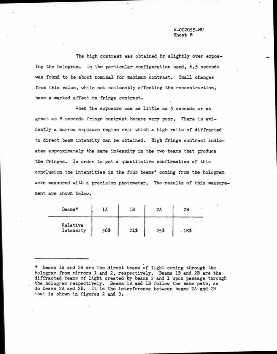
The high contrast was obtained by slightly over expos-
ing the hologram. In the particular configuration used, 6.5 seconds
was found to be about nominal for maximum contrast. Small changes
from this value, while not noticeably affecting the reconstruction,
have a marked affect on fringe contrast.
When the exposure was as little as 5 seconds or as
great as 8 seconds fringe contrast became very poor. There is evi-
dently a narrow exposure region ov.n.- which a high ratio of diffracted
to direct beam intensity can be obtained. High fringe contrast indic-
ates approximately the same intensity in the two beams that produce
the fringes. In order to get a quantitative confirmation of this
conclusion the intensities in the four beams* coming from the hologram
were measured with a precision photometer. The results of this measure-
ment are shown below.
Beams* lA 1B 2A 2B
Relative Intensity 36% 21% 25% •18%
* Beams lA and 2A are the direct beams of light coming through the hologram from mirrors 1 and 2, respectively. Beams 1B and 2B are the diffracted beams of light created by beams 2 and 1 upon passage through the hologram respectively. Beams lA and 1B follow the same path, as do beams 2A and 2B. It is the interference between beams 2A and 2B that is shown in figures 2 and 3.

A -002055 -MU Sheet 9
This explains the high contrast obtained in beam 2.
Numerically, the fringe visibility obtained was 0.76, according to
the above results. The attainment of this contrast was not done with-
out sacrifice,. however, since only 2% of the light incident on the
hologram goes into beams 2A and 2B which form the interferogram.
The distinction between reference and test beams is
quite arbitrary in this configuration, as mentioned earlier. This
fact is illustrated quite graphically by the appearance of an ap-
parently identical set of fringes in the beam from mirror M l.previously
designated the reference beam. This results from the fact that beam
2A is now acting as the reference beam for mirror Mi. It produces a
diffracted image of Ml (designated beam 1B) traveling along with beam
1A. The distortion from the hologram is introduced into beam 1B in ex-
actly the same way it was introduced into 2B. Hence the fringes in
both beams have the same appearance.
One is tempted to suggest that this phenomenon can be
used to extract the effect of a distorted hologram. One could simply
take the differences between the two interference patterns formed by
the two beams and the wavefront error produced by the hologram would
then cancel out. There are two objections to this approach. First,
having to take differences between two'interferograms eliminates some
of the directness and simplicity that were unique features of the
technique es originally proposed. Secondly, from the standpoint of
information transfer, any deformation introduced into one of the mirrors

A-002055-MU Sheet 10
will produce wavefront error in both beams. If M l is deformed between
readin and readout, this deformation will be carried along both beams
lA and 2B. Since the light in beam 2B has been diffracted by some
small angle 8, the information content in this beam will have been
altered slightly. Taking differences between the interference patterns
produced by the two beams will not only cancel the wavefront error intro-
duced by the hologram, but it will also cancel a major portion of that
introduced by the test mirror itself. This difference technique is
then undesirable.
Surface Quality of the Mirrors
As long as the mirrors remain accurately positioned
between readin and readout, there will be no stringent requirement on
their surface quality. For example, an independent measurement of the
flatness of the test mirror M2 has shown it to have saddle distor-
tion of approximately ten fringes in one direction and five in the
other. If figure 2c were a conventional interferogram this distor-
tion would be quite evident in the set of fringes produced. Mirrors
with surface errors in excess of 50A could have been used, and, if
there were no distortion of the hologram, would have produced fringes
which in conventional interferometry would have indicated mirror surface
errors less than X/20. The fundamental reason for this startling fact
is that with holographic interferometry you are comparing a surface
of arbitrary shape with itself, rather than with some other "reference"

A -002055 -MU Sheet 11
surface. Of course, by changing mirror 142 for another between readin
and readout, you could very easily perform a more conventional inter-
ferometrie test. But your interferometer now has one less Arm and
it has no beam splitter. The hologram takes the place of the beam
splitter.
L012€00 1Le2Sai... 0 11g...aleTAIU
It can here be noted that the hologram translational
and angular repositioning tolerances (0.5 cm, 0.4°) predicted analyti-
cally have been confirmed experimentally.
Problem Areas
The only major problem encountered was that of the
distortion of the hologram between readin and readout. As mentioned
before, figures 2a, b, and c show fringes at successive stages of holo-
gram drying. The nature of the changes indicates a decrease in the
distortion of the hologram as the hologram dried.
We conclude that this was caused by emulsion shrinkage
as the hologram dried, which compensated to some extent the distortion
introduced by changing plate holders. Of course the cause could have
been purely thermal in origin, but this is doubtful. In Figure 3 is
shown another sequence of interferograms, with the mirror masks re-
moved. The hologram plate was clamped in a specially designed rigid
stainless steel hglder before exposure and remained there throughout
processing and readout.

A -002055 -MU Sheet 12
In this sequence of interferograms, the hologram at
first had relatively little distortion. As the emulsion dried, the
distortion became significantly worse. In an attempt to make the holo-
gram return to its original shape, it was placed back in the wash bath
for fifteen minutes. Figure 3d is the interferogram made at the end
of this soaking. The distortion is still present. Perhaps the strong
clamping of the plate holder served to retain the distortion in spite
of any emulsion expansion which may have occurred.
For the testing of mirror MI the only element free to
change (either by replacement or deformation) between readin and read-
out should be the test mirror . MI. Hence the hologram deformation must
be eliminated. Several possibilities can be suggested in order to
eliminate wavefront errors produced by the hologram itself. These are:
(i) Use of a liquid gate to prevent the emulsion from .drying.
• (ii) Coat the emulsion with some kind of non-volatile
substance of uniform thickness which either seals the water into the emulsion or replaces the water lost from the emulsion with some other substance, the result being no net emul-sion shrinkage.
(iii) Use a thicker photographic plate, a thinner (less shrinking) emulsion, and/or a smaller hologram plate size.
(iv) Use a different, non-distorting, hologram re-cording medium.
The potential of each of the above items for solving
our particular distortion problem is being investigated. It is felt
that this distortion can be reduced at least to a level of introducing

A-002055-MO Sheet 13
no more than A/2 wavefront error into the system. One should then
be able to detect wavefront errors due to distortions of the test
piece with a 7 /10 accuracy even in the presence of a V2 residual
error.
Conclusions
If the exposed and processed hologram is completely
dry and if it is mounted firmly in a rigid holder, then it will re-
tain its shape indefinitely. If the distortion has been reduced to
some reasonable level (less than A/2 wavefront error) the remainder
of the diitortion can be removed by calibration, that is, by quanti-
tative measurement of the wavefront error introduced by the hologram.
This is done with conventional interferometers and the calibration pro-
cedure should here be the same, except that high quality mirrors are
pui needed. All that is required is stability of the mirrors Ml and
M2 between readin and readout on the order of the calibration accuracy
desired.
Assuming the hologram distortion problem can be ade-
quately solved, it appears that the fundamental feasibility of optical
testing by holographic interferometry has been established.
Applications
The most immediate application which comes to mind is
for direct interferometric evaluation of mirror deformation due to
thermal or mechanical causes. Ordinarily one would have to make two

A-002055-MU Sheet 14
interferograms of a mirror under test, each with respect to some inde-
pendent reference mirror, and then compute differences between the '
two interferograms. With holography, one can now produce interference
directly between a deformed test mirror and its undeformed self, with-
out need for an independent, high quality reference mirror.
Since there is no requirement for the surfaces of
mirrors MI and M2 to be specularly reflecting (indeed MI and M2 can
be any arbitrary objects), the technique can easily be used to test
unpolished, diffusely reflecting surfaces. That this is feasible will
be demonstrated in a later memo.
For such a test, one of the mirrors would be replaced
by the unpolished optic to be tested. Since the light received by
the hologram from this surface would now be substantially less, some
form of attenuation of the light from the other mirror might be
required during readout in order to achieve good fringe contrast.
In such diffuse reflection interferometry rather ac-
curate point-for-point superposition of the test surface $nd the image
of the test surface is required. This fact might make the effects of
hologram distortion more critical. It must then be concluded that a
major effort aimed at reducing this distortion is in order.
It is not intended that actual optical tests be per-
formed using the configuration of figure 1 without any modifications.
Functional configurations for testing both plane and curved surfaces

A-002055-MU Sheet 15
are given in reference 4.
Initially, applications of holographic testing will be
confined to those teats which cannot easily be performed using more
conventional interferometry. Ultimately, since a hologram can be
used to replace both the beam splitter and the reference mirror ef a
conventional interferometer, it is anticipated that the technique will
be able to compete favorably with conventicnal interferometry for the
same tests.
Additional possible applications can also here be cited:
(1) Use holographic interferometry to provide an ac-curate measure of grinding and polishing rates and effects using the unique difference measuring capability of holographic testing. The technique can be used ultimately for quantitative in-process testing.
(2) Provide a real-time readout during thermal cycling, or as a check for distortions introduced into a lens or mirror figure by the mounting. Another possibility would be for real-time readout during certain kinds of optical figuring.
(3) Provide a "tuning" capability for component mount assemblies, figure control devices, and even entire systems where element tilts and spacings are con-trol variables difficult to assess quantitative17.
(4) Vibration location and measurement applied to any arbitrary surface.
(5) Replacement of beam splitters and reference mir-rors by their holographic equivalents in practically any interferometer, thereby freeing these optics for other use.
In short, the technique appears to have enormous po-
tential in interferometrio testing.
217c Ci WRMcC:sb W. R. McCluney


