Embed Size (px)
Citation preview
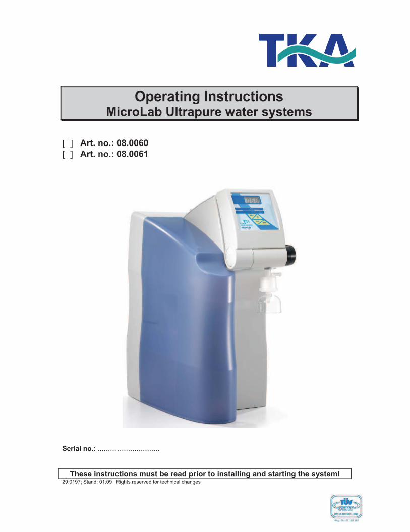
Operating Instructions MicroLab Ultrapure water systems
! " Art. no.: 08.0060
! " Art. no.: 08.0061
Serial no.: ................................
These instructions must be read prior to installing and starting the system! 29.0197; Stand: 01.09 Rights reserved for technical changes
MicroLab Ultrapure water system
2
Company TKA Wasseraufbereitungssysteme GmbH
Stockland 3 D-56412 Niederelbert
EEC Declaration of Conformity
acc. to EEC-Directive 98/37/EEC - Machine Directive -
We hereby declare that the products named below conform in their design and construction, as well as in the versions we have brought to market, to the fundamental safety and health re-quirements of
EEC-Directive 98/37/EEC. This declaration is invalidated should changes not agreed to by us are made to the machine.
Designation of the machine: Ultrapure water system Machine types: MicroLab MicroLab UV Applicable EEC Directives: EEC Machine Directive (98/37/EEC) EEC Low Voltage Directive (73/23/EEC) EEC Electromagnetic Compatibility Directive (89/336/EEC) Standards applied: DIN EN ISO 12100-1 DIN EN ISO 12100-2 DIN EN 1050 DIN EN 60204-1 DIN EN 55011 DIN EN 50082-2
Niederelbert, 15. May 2006 _____________________ Authorized representative of the manufacturer
MicroLab Ultrapure water system
3
Preface Dear Sir or Madam Thank you for the confidence you have placed in our Company in deciding to purchase an ultrapure water system from the MicroLab series. You have selected a high-quality product, and we ask you to please read through the informa-tion given on installation and operating in these Operating Instructions before you install and start to operate it. This is important as we, the manufacturer, cannot be held liable for any damage caused to the system by usage for other than the intended purpose or by improper operation, Niederelbert, 15.05.2006
MicroLab Ultrapure water system
4
1. Contents
Preface.........................................................................................................3
1. Contents..................................................................................................4
2. Notes on the Operating Instructions .......................................................6
3. Transport and packaging ........................................................................7
3.1 Examination on receipt.......................................................................................................73.2 Complaints .........................................................................................................................73.3 Packaging and return shipment..........................................................................................7
4. Parts standardly supplied........................................................................8
5. Safety precautions ..................................................................................9
6. Intended purpose ..................................................................................10
6.1 Application areas..............................................................................................................10
7. Technical data.......................................................................................11
8. How the system functions .....................................................................13
8.1 Flow chart for MicroLab....................................................................................................14
9. Installation.............................................................................................15
9.1 The installation area .........................................................................................................159.2 Installation ........................................................................................................................16
10. Start-up ...............................................................................................17
11. Operating elements.............................................................................18
12. System control ....................................................................................19
12.1 Menu ..............................................................................................................................1912.2 Setting the limiting conductivity value.............................................................................1912.3 Setting the limiting value für the temperature.................................................................2012.4 Communication ..............................................................................................................2012.5 Potential free contact......................................................................................................20
13. Maintenance .......................................................................................22
MicroLab Ultrapure water system
5
13.1 Replacing der pretreatment cartridge ............................................................................ 2313.2 Replacing the filter cartridge .......................................................................................... 2413.3 Disinfection .................................................................................................................... 25
14. Trouble shooting................................................................................. 26
15. Replacement parts und Consumables ............................................... 28
16. Accessories ........................................................................................ 29
17. Terminal assignment .......................................................................... 30
18. Maintenance record............................................................................ 32
MicroLab Ultrapure water system
6
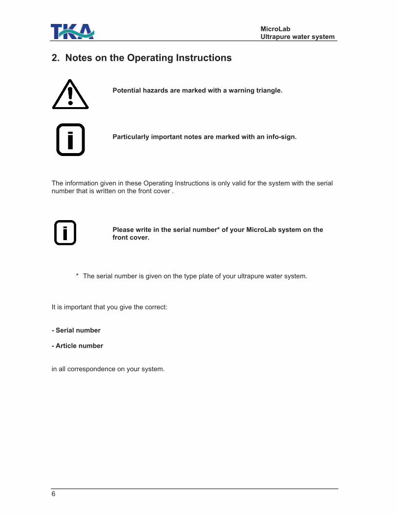
2. Notes on the Operating Instructions Potential hazards are marked with a warning triangle. Particularly important notes are marked with an info-sign. The information given in these Operating Instructions is only valid for the system with the serial number that is written on the front cover . Please write in the serial number* of your MicroLab system on the front cover. * The serial number is given on the type plate of your ultrapure water system. It is important that you give the correct: - Serial number - Article number in all correspondence on your system.
MicroLab Ultrapure water system
7
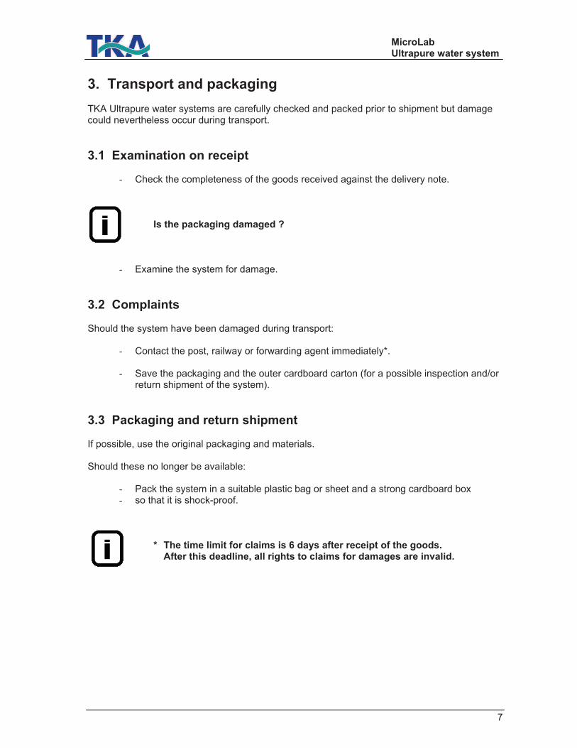
3. Transport and packaging TKA Ultrapure water systems are carefully checked and packed prior to shipment but damage could nevertheless occur during transport.
3.1 Examination on receipt
- Check the completeness of the goods received against the delivery note. Is the packaging damaged ?
- Examine the system for damage.
3.2 Complaints Should the system have been damaged during transport:
- Contact the post, railway or forwarding agent immediately*. - Save the packaging and the outer cardboard carton (for a possible inspection and/or
return shipment of the system).
3.3 Packaging and return shipment If possible, use the original packaging and materials. Should these no longer be available:
- Pack the system in a suitable plastic bag or sheet and a strong cardboard box - so that it is shock-proof.
* The time limit for claims is 6 days after receipt of the goods. After this deadline, all rights to claims for damages are invalid.
MicroLab Ultrapure water system
8
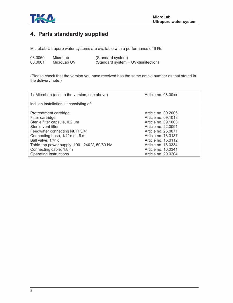
4. Parts standardly supplied MicroLab Ultrapure water systems are available with a performance of 6 l/h. 08.0060 MicroLab (Standard system) 08.0061 MicroLab UV (Standard system + UV-disinfection) (Please check that the version you have received has the same article number as that stated in the delivery note.)
1x MicroLab (acc. to the version, see above) Article no. 08.00xx incl. an installation kit consisting of: Pretreatment cartridge Article no. 09.2006 Filter cartridge Article no. 09.1018 Sterile filter capsule, 0.2 µm Article no. 09.1003 Sterile vent filter Article no. 22.0091 Feedwater connecting kit, R 3/4" Article no. 25.0071 Connecting hose, 1/4" o.d., 6 m Article no. 18.0137 Ball valve, 1/4" d Article no. 15.0112 Table-top power supply, 100 - 240 V, 50/60 Hz Article no. 16.0334 Connecting cable, 1.8 m Article no. 16.0341 Operating Instructions Article no. 29.0204
MicroLab Ultrapure water system
9
5. Safety precautions
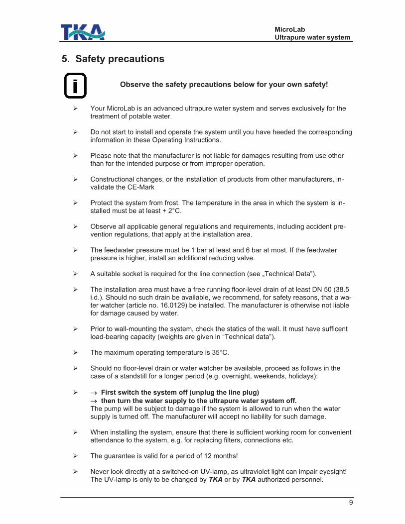
Observe the safety precautions below for your own safety!
! Your MicroLab is an advanced ultrapure water system and serves exclusively for the treatment of potable water.
! Do not start to install and operate the system until you have heeded the corresponding
information in these Operating Instructions.
! Please note that the manufacturer is not liable for damages resulting from use other than for the intended purpose or from improper operation.
! Constructional changes, or the installation of products from other manufacturers, in-
validate the CE-Mark
! Protect the system from frost. The temperature in the area in which the system is in-stalled must be at least + 2°C.
! Observe all applicable general regulations and requirements, including accident pre-
vention regulations, that apply at the installation area.
! The feedwater pressure must be 1 bar at least and 6 bar at most. If the feedwater pressure is higher, install an additional reducing valve.
! A suitable socket is required for the line connection (see „Technical Data”).
! The installation area must have a free running floor-level drain of at least DN 50 (38.5
i.d.). Should no such drain be available, we recommend, for safety reasons, that a wa-ter watcher (article no. 16.0129) be installed. The manufacturer is otherwise not liable for damage caused by water.
! Prior to wall-mounting the system, check the statics of the wall. It must have sufficent
load-bearing capacity (weights are given in “Technical data”).
! The maximum operating temperature is 35°C.
! Should no floor-level drain or water watcher be available, proceed as follows in the case of a standstill for a longer period (e.g. overnight, weekends, holidays):
! # First switch the system off (unplug the line plug)
# then turn the water supply to the ultrapure water system off. The pump will be subject to damage if the system is allowed to run when the water supply is turned off. The manufacturer will accept no liability for such damage.
! When installing the system, ensure that there is sufficient working room for convenient
attendance to the system, e.g. for replacing filters, connections etc. ! The guarantee is valid for a period of 12 months!
! Never look directly at a switched-on UV-lamp, as ultraviolet light can impair eyesight!
The UV-lamp is only to be changed by TKA or by TKA authorized personnel.
MicroLab Ultrapure water system
10
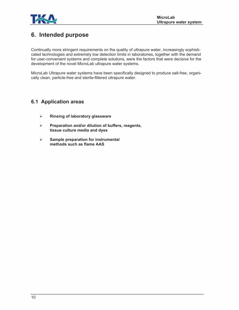
6. Intended purpose Continually more stringent requirements on the quality of ultrapure water, increasingly sophisti-cated technologies and extremely low detection limits in laboratories, together with the demand for user-convenient systems and complete solutions, were the factors that were decisive for the development of the novel MicroLab ultrapure water systems. MicroLab Ultrapure water systems have been specifically designed to produce salt-free, organi-cally clean, particle-free and sterile-filtered ultrapure water.
6.1 Application areas
! Rinsing of laboratory glassware ! Preparation and/or dilution of buffers, reagents,
tissue culture media and dyes ! Sample preparation for instrumental
methods such as flame AAS
MicroLab Ultrapure water system
11
7. Technical data
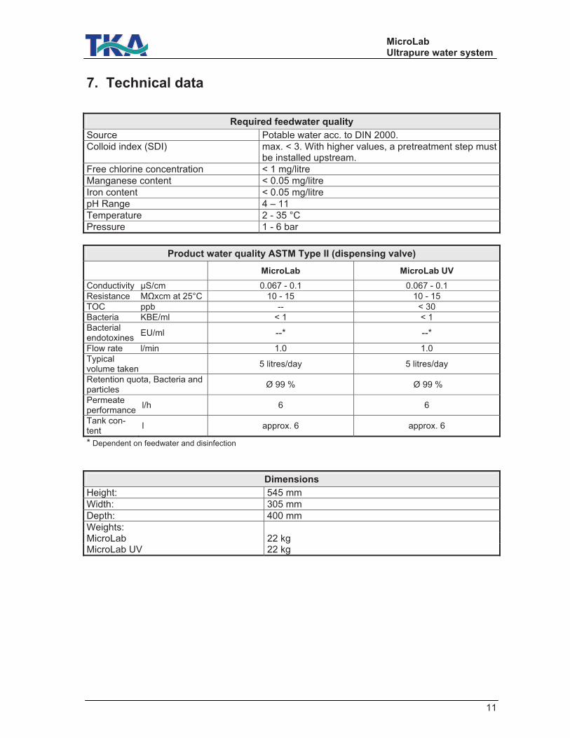
Required feedwater quality
Source Potable water acc. to DIN 2000.
Colloid index (SDI) max. < 3. With higher values, a pretreatment step must be installed upstream.
Free chlorine concentration < 1 mg/litre
Manganese content < 0.05 mg/litre
Iron content < 0.05 mg/litre
pH Range 4 – 11
Temperature 2 - 35 °C
Pressure 1 - 6 bar
Product water quality ASTM Type II (dispensing valve)
MicroLab MicroLab UV
Conductivity µS/cm 0.067 - 0.1 0.067 - 0.1
Resistance M!xcm at 25°C 10 - 15 10 - 15
TOC ppb -- < 30
Bacteria KBE/ml < 1 < 1
Bacterial endotoxines
EU/ml --* --*
Flow rate l/min 1.0 1.0 Typical volume taken
5 litres/day 5 litres/day
Retention quota, Bacteria and particles
Ø 99 % Ø 99 %
Permeate performance
l/h 6 6
Tank con-tent
l approx. 6 approx. 6
* Dependent on feedwater and disinfection
Dimensions
Height: 545 mm
Width: 305 mm
Depth: 400 mm
Weights: MicroLab 22 kg MicroLab UV 22 kg

MicroLab Ultrapure water system
12
Water connectors
Feedwater Hose, 1/4" o.d.
Concentrate Hose, 1/4" o.d.
Tank overflow Hose, 1/4" o.d.
High purity water Hose, 1/4" o.d.
Outlet/Dispensing valve Sterile filter capsule, 0.2 µm
Electrical connections
Voltage 100 - 240 V
Frequency 50/60 Hz
Power consumption approx. 60 W
Serial interface RS 232
Materials that contact water
Pump head Nylon with glass fibre
UV-lamp High purity quartz
UV-housing Edelstahl
Filter cartridge PP
Feedwater solenoid valve PA
Recirculation solenoid valve PA
Pressure hold valve Nickel-plated brass
Dispensing valve POM
Conductivity measuring cell PVC, stainless steel
Connections POM
Hoses PE
Gaskets EPDM
RO-Membrane PA
MicroLab Ultrapure water system
13
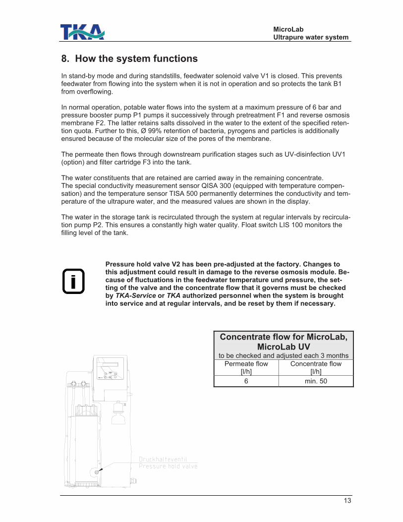
8. How the system functions In stand-by mode and during standstills, feedwater solenoid valve V1 is closed. This prevents feedwater from flowing into the system when it is not in operation and so protects the tank B1 from overflowing. In normal operation, potable water flows into the system at a maximum pressure of 6 bar and pressure booster pump P1 pumps it successively through pretreatment F1 and reverse osmosis membrane F2. The latter retains salts dissolved in the water to the extent of the specified reten-tion quota. Further to this, Ø 99% retention of bacteria, pyrogens and particles is additionally ensured because of the molecular size of the pores of the membrane. The permeate then flows through downstream purification stages such as UV-disinfection UV1 (option) and filter cartridge F3 into the tank. The water constituents that are retained are carried away in the remaining concentrate. The special conductivity measurement sensor QISA 300 (equipped with temperature compen-sation) and the temperature sensor TISA 500 permanently determines the conductivity and tem-perature of the ultrapure water, and the measured values are shown in the display. The water in the storage tank is recirculated through the system at regular intervals by recircula-tion pump P2. This ensures a constantly high water quality. Float switch LIS 100 monitors the filling level of the tank.
Pressure hold valve V2 has been pre-adjusted at the factory. Changes to this adjustment could result in damage to the reverse osmosis module. Be-cause of fluctuations in the feedwater temperature und pressure, the set-ting of the valve and the concentrate flow that it governs must be checked by TKA-Service or TKA authorized personnel when the system is brought into service and at regular intervals, and be reset by them if necessary.
Concentrate flow for MicroLab, MicroLab UV
to be checked and adjusted each 3 months
Permeate flow [l/h]
Concentrate flow [l/h]
6 min. 50
MicroLab Ultrapure water system
14
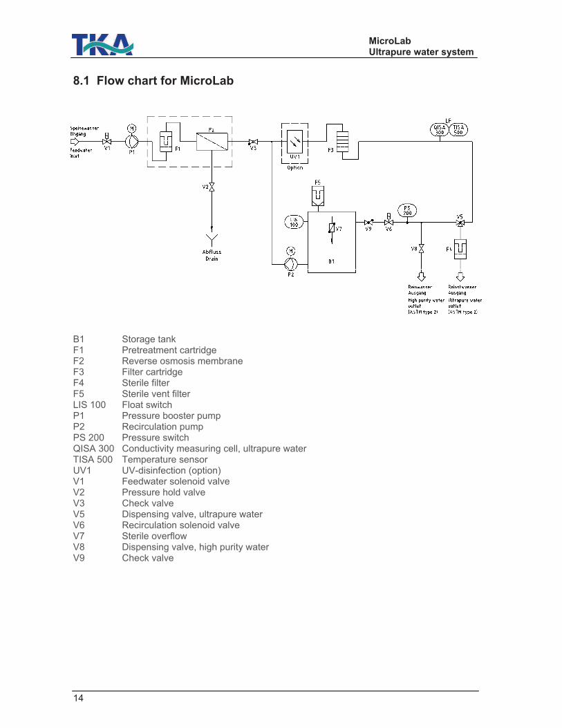
8.1 Flow chart for MicroLab
B1 Storage tank F1 Pretreatment cartridge F2 Reverse osmosis membrane F3 Filter cartridge F4 Sterile filter F5 Sterile vent filter LIS 100 Float switch P1 Pressure booster pump P2 Recirculation pump PS 200 Pressure switch QISA 300 Conductivity measuring cell, ultrapure water TISA 500 Temperature sensor UV1 UV-disinfection (option) V1 Feedwater solenoid valve V2 Pressure hold valve V3 Check valve V5 Dispensing valve, ultrapure water V6 Recirculation solenoid valve V7 Sterile overflow V8 Dispensing valve, high purity water V9 Check valve
MicroLab Ultrapure water system
15
9. Installation
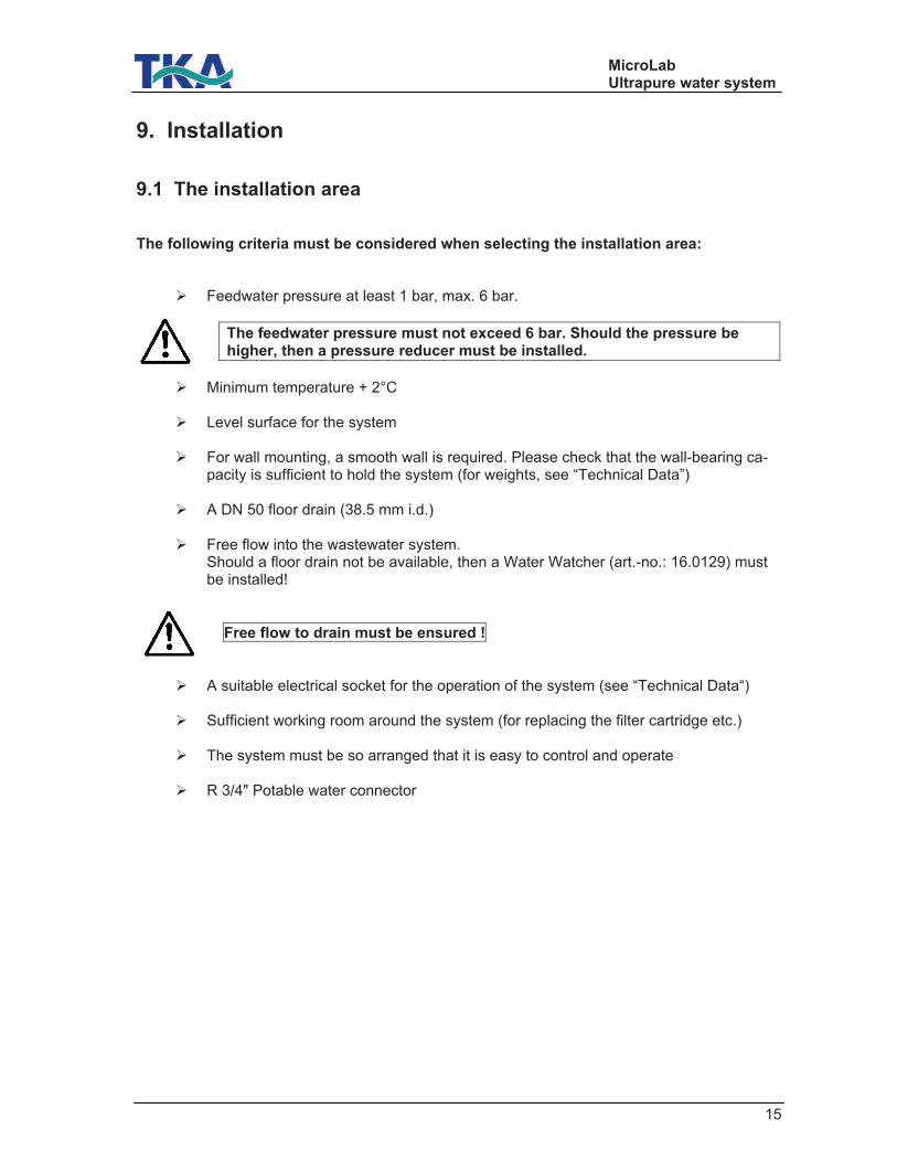
9.1 The installation area The following criteria must be considered when selecting the installation area:
! Feedwater pressure at least 1 bar, max. 6 bar.
The feedwater pressure must not exceed 6 bar. Should the pressure be higher, then a pressure reducer must be installed.
! Minimum temperature + 2°C
! Level surface for the system
! For wall mounting, a smooth wall is required. Please check that the wall-bearing ca-
pacity is sufficient to hold the system (for weights, see “Technical Data”)
! A DN 50 floor drain (38.5 mm i.d.)
! Free flow into the wastewater system. Should a floor drain not be available, then a Water Watcher (art.-no.: 16.0129) must be installed!
Free flow to drain must be ensured !
! A suitable electrical socket for the operation of the system (see “Technical Data“)
! Sufficient working room around the system (for replacing the filter cartridge etc.)
! The system must be so arranged that it is easy to control and operate
! R 3/4" Potable water connector
MicroLab Ultrapure water system
16
9.2 Installation
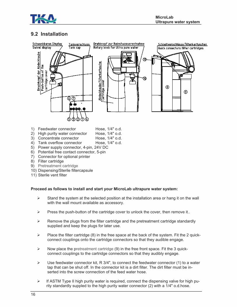
1) Feedwater connector Hose, 1/4" o.d. 2) High purity water connector Hose, 1/4" o.d. 3) Concentrate connector Hose, 1/4" o.d. 4) Tank overflow connector Hose, 1/4" o.d. 5) Power supply connector, 4-pin, 24V DC 6) Potential free contact connector, 5-pin 7) Connector for optional printer 8) Filter cartridge 9) Pretreatment cartridge 10) Dispensing/Sterile filtercapsule 11) Sterile vent filter Proceed as follows to install and start your MicroLab ultrapure water system:
! Stand the system at the selected position at the installation area or hang it on the wall with the wall mount available as accessory.
! Press the push-button of the cartridge cover to unlock the cover, then remove it..
! Remove the plugs from the filter cartridge and the pretreatment cartridge standardly
supplied and keep the plugs for later use.
! Place the filter cartridge (8) in the free space at the back of the system. Fit the 2 quick-connect couplings onto the cartridge connectors so that they audible engage.
! Now place the pretreatment cartridge (9) in the free front space. Fit the 3 quick-
connect couplings to the cartridge connectors so that they audibly engage.
! Use feedwater connector kit, R 3/4", to connect the feedwater connector (1) to a water tap that can be shut off. In the connector kit is a dirt filter. The dirt filter must be in-serted into the screw connection of the feed water hose.
! If ASTM Type II high purity water is required, connect the dispensing valve for high pu-
rity standardly suppled to the high purity water connector (2) with a 1/4" o.d.hose.
MicroLab Ultrapure water system
17
! Make a gravity-fall connection to the system (connections 3 and 4) to the wastewater drain with 1/4" o.d. hose.
! Screw the sterile vent filter (11) at the back of the system into the G 1/8" tank thread in-
tended for it. ! Connect the connecting cable of the table-top power unit standardly supplied to the 4-
pin socket (5) of the system.
! The system is now ready to operate.
! Open the feedwater tap and check that there are no leaks in the connections.
! Remove the cartridge cover and then fit it back on, checking that the latch on the right side of the cover engages when fitting it back on.
10. Start-up
The system must have cooled/warmed to room temperature prior to the first start-up.
Inspect all hose connections to check that they have been made as de-tailed in the “Installation" section.
Switch the system on by plugging the line cord into a suitable socket.. After a brief self-test of the system control, the system starts to produce ultrapure water. Wait until the tank has been filled for the first time and discard this water. The fill-ing of the tank can take approx. 1 hours. Afterwards the concentrate flow must be checked and adjusted, as described in the "How the system functions" section. Dispense at least 1 litre of water before screwing the sterile filter (10) that is stan-dardly supplied to the outlet of the dispensing valve Now set the wanted display mode, the limiting value for the conductivity and that for the temperature, as described in the “System control” section.

MicroLab Ultrapure water system
18
11. Operating elements
After switching on, all segments of the 7-segment display are shown for 3 seconds. During this time, the complete measurement cycle is run through and checked. In the basic setting, the display shows the conductivity in µS/cm. The display automatically scales in the range from 0.055 to 199 µS/cm. The upper LED-row shows the measurement mode that the measuring instrument is in. The LED for the corresponding measurement unit, µS/cm, M!xcm or °C lights up green. Should the end value of the measurement range be gone past (>199 µS/cm or >0.005 M!xcm),
then $200 appears in the display. Should the connection between the system and sensors be interrupted, then the red "Status Sens." LED lights up and "---" is shown in the display instead of a measured value. Should the connection to the temperature sensor be interrupted, then a buzzer is additionally activated. Quit-button: When a fault occurs, the Quit/UP-button allows the acoustic alarm (buzzer) to be switched off. This acoustic alarm is then only again active when the limiting value is exceeded. The fault message is also given out via the potential free contact.
MicroLab Ultrapure water system
19
12. System control
12.1 Menu The menu consists of three sub-menus: Switching to dual mode and selection of the unit for the conductivity measurement, the setting of the limiting value for the conductivity and the setting of the limiting value for the temperature. Mono/ dual measurement mode:
Mono measurement mode: In this mode, only the conductivity is displayed. The temperature can be read as long as the Enter-key is pressed.
Dual measurement mode: In this mode the temperature and conductivity are alternately displayed for 2 seconds each. The LEDs for the measurement unit are switched appropriately with the display. Press the menu-key once. The measurement mode that has just been set is displayed. The up and down keys can now be used to switch between the permanent display of the conductivity and the alternating display of conductivity/temperature. In the display, "c" is shown for conduc-tivity or "ct" for conductivity/temperature. In this mode, a simultaneous choice of measurement units, µS/cm or M!xcm, can also be made. The choice must be confirmed with Enter.The measurement units are shown by the ap-propriate LED. The following combinations are so possible: ct / M!xcm c / M!xcm Up/down ct / µS/cm c / µS/cm
12.2 Setting the limiting conductivity value Setting range: 0.055 - 30 µS/cm Basic setting: off Note: This limiting value can only be entered in µS/cm. To adjust the limiting value of the conductivity, press the menu-key twice (the red "Cond." LED lights up). Carry out the adjustment with the up and down keys. The particular place that is to be changed can be selected with the Enter-key and is then shown flashing in the display. When the wanted value is reached, confirm it with the Enter-key. Should a value of 30.1 µS/cm be set, then the word OFF appears in the display and the evalua-tion of the limiting value is switched off. When the limiting conductivity value is gone above (Limit value Conductivity), then the red "Cond." LED lights up and the fault is additionally signalled by a buzzing sound. The fault mes-sage can also be given out via an optional printer.
MicroLab Ultrapure water system
20
12.3 Setting the limiting value für the temperature Setting range: 10 - 40°C Basic setting: 35°C To adjust the limiting value of the temperature, press the menu-key three times (the red "Temp." LED lights up). Carry out the adjustment with the up and down keys. The particular place that is to be changed can be selected with the Enter-key and is then shown flashing in the display. When the wanted value is reached, confirm it with the Enter-key. Should a value of 30.1 µS/cm be set, then the word OFF appears in the display and the evalua-tion of the limiting value is switched off. When the limiting temperature value is exceeded (Limit value Temperature), then the red "Temp." LED lights up and the fault is additionally signalled by a buzzing sound. The fault mes-sage can also be given out via an optional printer.
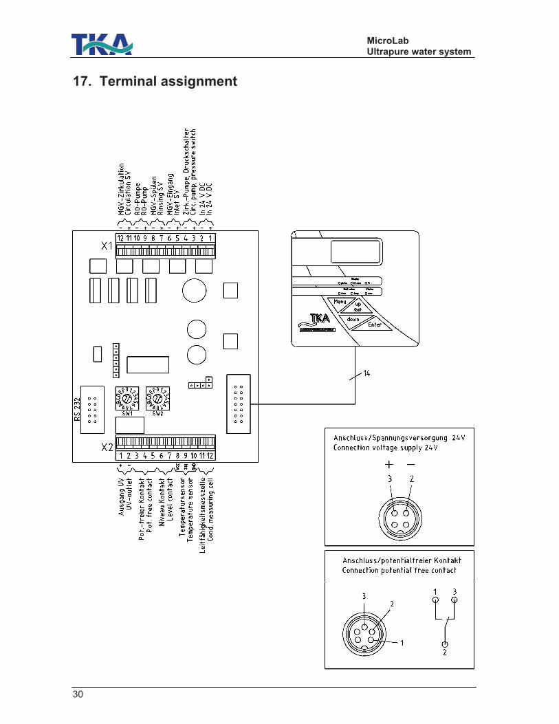
12.4 Communication The RS 232 interface allows a printer to be connected for the output of measured values. The interface runs at a transmission rate of 9600 bit/sec, 8 data bits,1 stop bit and no parity. The conductivity in µS/cm and the temperature in °C are given out on the serial interface sepa-rated by a comma. The conductivity is automatically scaled to three significant figures. Output takes place once per hour. When in operation, a press on the down key triggers a measured value print-out on the serial interface. Printout: for example: 0,068 µS/cm, 21,4 °C The SUB-D socket has the following assignment: PIN 2: RXD PIN 3: TXD PIN 5: GND
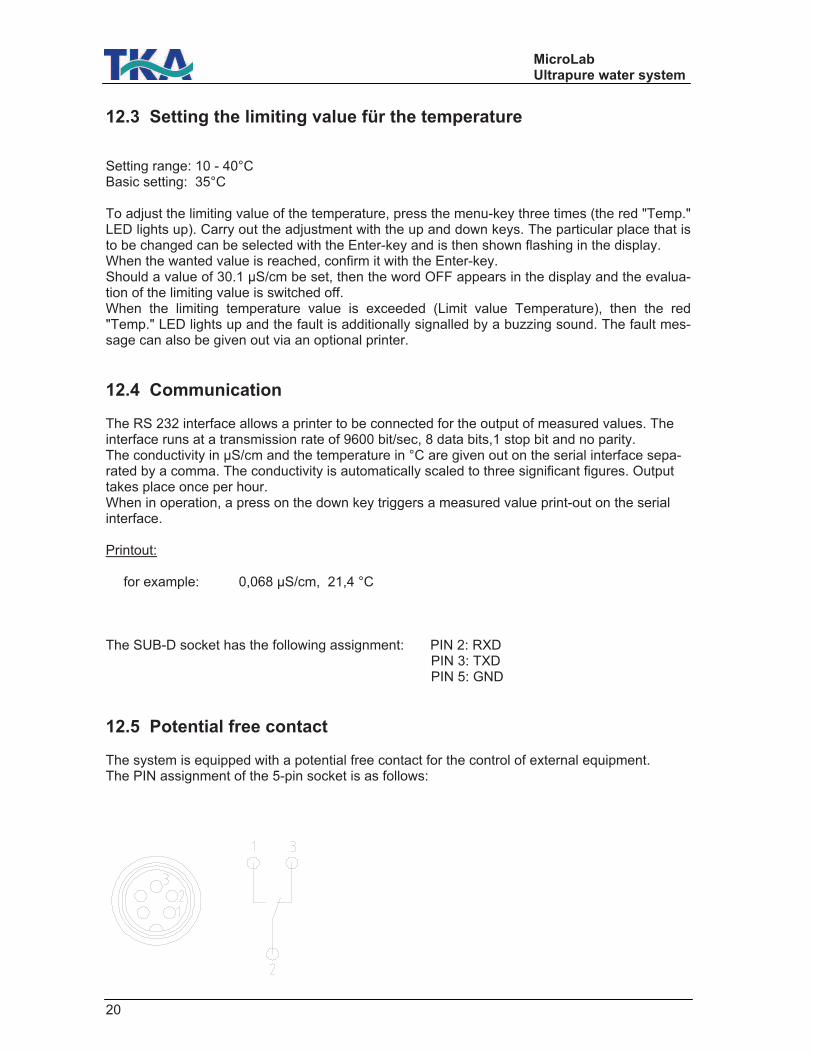
12.5 Potential free contact The system is equipped with a potential free contact for the control of external equipment. The PIN assignment of the 5-pin socket is as follows:
MicroLab Ultrapure water system
22
13. Maintenance Regular maintenance maintains the worth of your system. We recommend that you close a service contract with TKA or a service provider expressly au-thorized by TKA for the carrying out of the maintenance that is necessary. You then have the certainty of a high operational safety and reliability. NOTE! When your system is to work reliably for a long time, it must be checked, serviced and cared for at regular time intervals in accordance with these Operating Instructions! For this reason, the Operating Instructions must be readily available to operating and maintenance staff at all times, and be carefully followed! Please observe that, in accordance with the general terms and conditions of business of the TKA company, which are the basis for both parties, the guarantee loses its validity when the customer or a third party improperly installs, maintains, repairs, operates or alters the system, or operates it in an environment which does not fulfil the specified TKA installation conditions. Any maintenance work which should become necessary during the validity of the guarantee is only to be carried out by TKA or a TKA-authorized service provider. The operating staff assigned to work with the system is committed to carrying out the weekly checks. During the agreed term of validity of the guarantee, the maintenance record sheet supplied with these Operating Instructions is to be up-dated weekly. Should the maintenance record not be kept up-to-date, or be improperly, kept, i.e. without the necessary data recording, then the system is deemed to be improperly maintained and the guarantee becomes invalid. IMPORTANT! The cleaning and disinfection of your system is performed for reasons of hygiene and has no effect on the technical condition of the system. The must be cleaned and disinfected once per year.
When inspection or maintenance work is to be carried out on electrical equipment, then the system is to be separated from the mains by unplugging the line plug and securing it against inadvertent plugging in again. Such work is only to be carried out by trained, skilled electricians.
MicroLab Ultrapure water system
23
13.1 Replacing der pretreatment cartridge
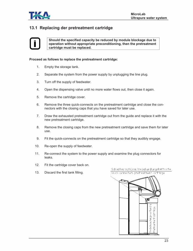
Should the specified capacity be reduced by module blockage due to operation without appropriate preconditioning, then the pretreatment cartridge must be replaced.
Proceed as follows to replace the pretreatment cartridge:
1. Empty the storage tank.
2. Separate the system from the power supply by unplugging the line plug.
3. Turn off the supply of feedwater.
4. Open the dispensing valve until no more water flows out, then close it again.
5. Remove the cartridge cover.
6. Remove the three quick-connects on the pretreatment cartridge and close the con-nectors with the closing caps that you have saved for later use.
7. Draw the exhausted pretreatment cartridge out from the guide and replace it with the
new pretreatment cartridge.
8. Remove the closing caps from the new pretreatment cartridge and save them for later use.
9. Fit the quick-connects on the pretreatment cartridge so that they audibly engage.
10. Re-open the supply of feedwater.
11. Re-connect the system to the power supply and examine the plug connectors for
leaks.
12. Fit the cartridge cover back on.
13. Discard the first tank filling.
MicroLab Ultrapure water system
24
13.2 Replacing the filter cartridge
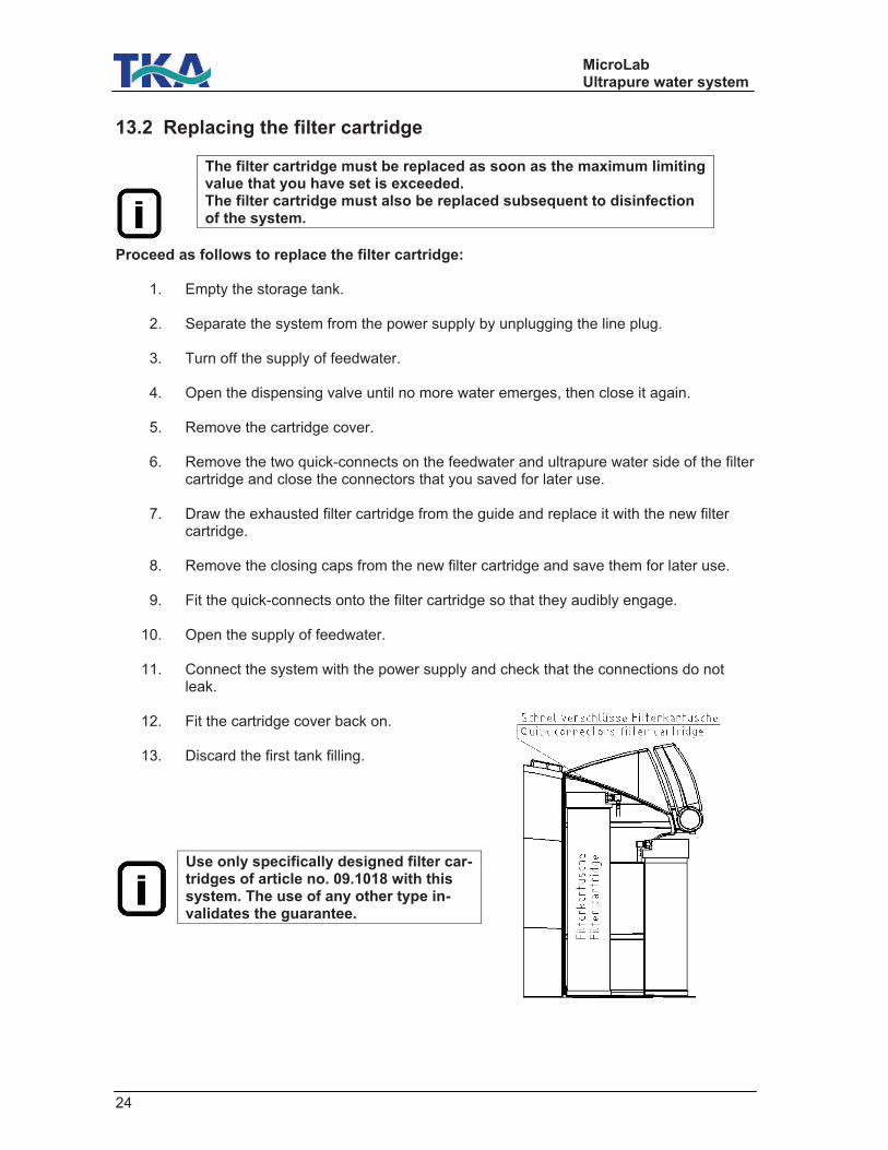
The filter cartridge must be replaced as soon as the maximum limiting value that you have set is exceeded. The filter cartridge must also be replaced subsequent to disinfection of the system.
Proceed as follows to replace the filter cartridge:
1. Empty the storage tank.
2. Separate the system from the power supply by unplugging the line plug.
3. Turn off the supply of feedwater.
4. Open the dispensing valve until no more water emerges, then close it again.
5. Remove the cartridge cover.
6. Remove the two quick-connects on the feedwater and ultrapure water side of the filter cartridge and close the connectors that you saved for later use.
7. Draw the exhausted filter cartridge from the guide and replace it with the new filter
cartridge.
8. Remove the closing caps from the new filter cartridge and save them for later use.
9. Fit the quick-connects onto the filter cartridge so that they audibly engage.
10. Open the supply of feedwater.
11. Connect the system with the power supply and check that the connections do not leak.
12. Fit the cartridge cover back on.
13. Discard the first tank filling.
Use only specifically designed filter car-tridges of article no. 09.1018 with this system. The use of any other type in-validates the guarantee.
MicroLab Ultrapure water system
25
13.3 Disinfection
Your system should be cleaned and disinfected at least once per year to kill any bacteria that are possibly in the tank. We recommend that you carry out cleaning and disinfection shortly pri-or to the time that the filter cartridge must be replaced.
Use MICRO-Chlor Granulate, article no. 09.2202 as disinfectant
Please observe the information given in the safety data sheet supplied with Micro-Chlor disinfectant to avoid possible health hazards!
Proceed as follows to disinfect your system:
1. Separate the system from the power supply by unplugging the line plug.
2. Open the lid of the storage tank and pour the contents of a can of MICRO-Chlor into the water-filled tank. Close the tank with the lid.
3. Re-connect the system to the power supply and let it run for 1 hour in normal opera-
tion for effective bactericidal effect.
4. Following this, discard two tank fillings.
5. Close the outlet valve and separate the system from the power supply.
6. Replace the filter cartridge and, if necessary, the pretreatment cartridge and sterile fil-ter, as described in the previous section..
7. Re-connect the system to the power supply.
8. Fill the tank completely once and discard this tank filling.
Prior to dispensing water for the first time, let water flow out for about 15 minutes. Following this, the system is ready to operate.
MicroLab Ultrapure water system
26
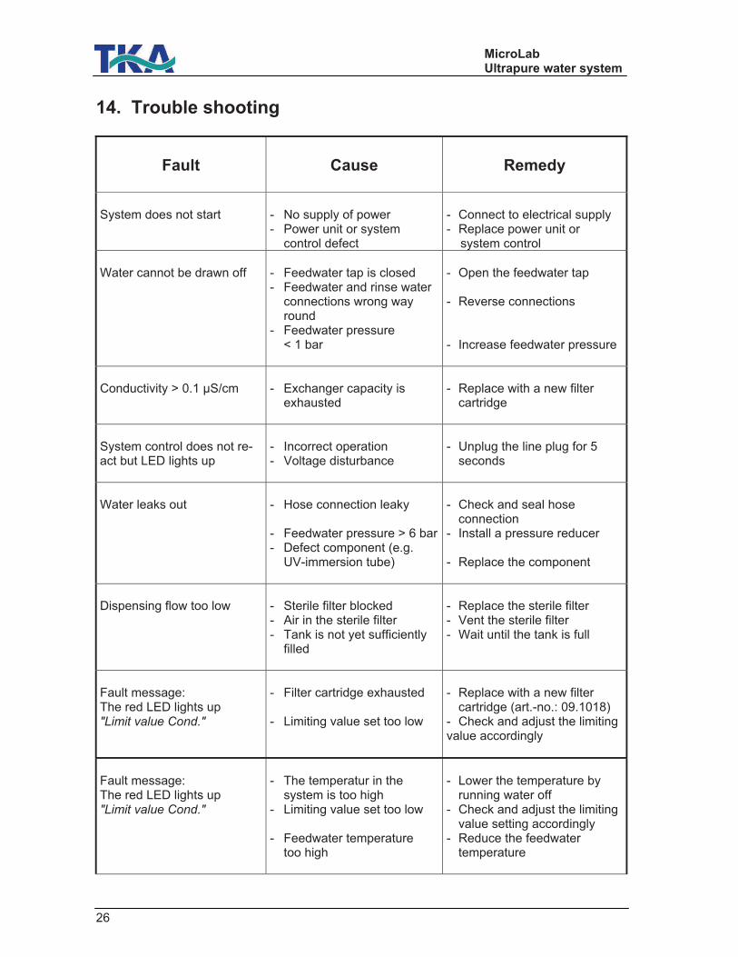
14. Trouble shooting
Fault
Cause
Remedy
System does not start
- No supply of power - Power unit or system control defect
- Connect to electrical supply - Replace power unit or system control
Water cannot be drawn off
- Feedwater tap is closed - Feedwater and rinse water connections wrong way round - Feedwater pressure < 1 bar
- Open the feedwater tap - Reverse connections - Increase feedwater pressure
Conductivity > 0.1 µS/cm
- Exchanger capacity is exhausted
- Replace with a new filter cartridge
System control does not re-act but LED lights up
- Incorrect operation - Voltage disturbance
- Unplug the line plug for 5 seconds
Water leaks out
- Hose connection leaky - Feedwater pressure > 6 bar- Defect component (e.g. UV-immersion tube)
- Check and seal hose connection - Install a pressure reducer - Replace the component
Dispensing flow too low
- Sterile filter blocked - Air in the sterile filter - Tank is not yet sufficiently filled
- Replace the sterile filter - Vent the sterile filter - Wait until the tank is full
Fault message: The red LED lights up "Limit value Cond."
- Filter cartridge exhausted - Limiting value set too low
- Replace with a new filter cartridge (art.-no.: 09.1018) - Check and adjust the limiting value accordingly
Fault message: The red LED lights up "Limit value Cond."
- The temperatur in the system is too high - Limiting value set too low - Feedwater temperature too high
- Lower the temperature by running water off - Check and adjust the limiting value setting accordingly - Reduce the feedwater temperature
MicroLab Ultrapure water system
27
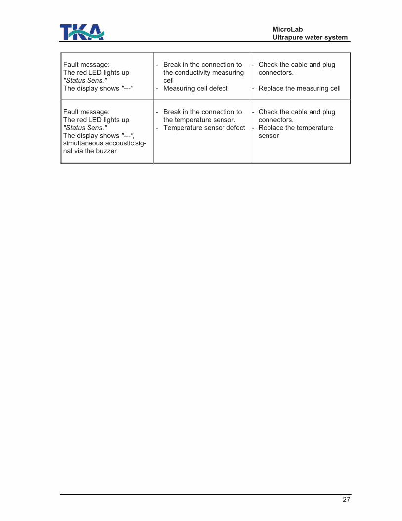
Fault message: The red LED lights up "Status Sens."
The display shows "---"
- Break in the connection to the conductivity measuring cell - Measuring cell defect
- Check the cable and plug connectors. - Replace the measuring cell
Fault message: The red LED lights up "Status Sens."
The display shows "---",simultaneous accoustic sig-nal via the buzzer
- Break in the connection to the temperature sensor. - Temperature sensor defect
- Check the cable and plug connectors. - Replace the temperature sensor
MicroLab Ultrapure water system
28
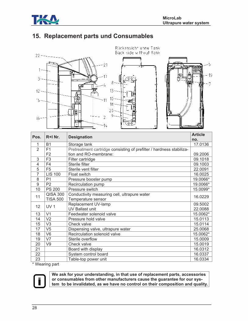
15. Replacement parts und Consumables
Pos. R+I Nr. Designation Article no.
1 B1 Storage tank 17.0136
2 F1 F2
Pretreatment cartridge consisting of prefilter / hardness stabiliza-tion and RO-membrane:
09.2006
3 F3 Filter cartridge 09.1018
4 F4 Sterile filter 09.1003
5 F5 Sterile vent filter 22.0091
7 LIS 100 Float switch 16.0025
8 P1 Pressure booster pump 19.0066*
9 P2 Recirculation pump 19.0066*
10 PS 200 Pressure switch 15.0099*
11 QISA 300 TISA 500
Conductivity measuring cell, ultrapure water Temperature sensor
16.0229
12 UV 1 Replacement UV-lamp UV Ballast unit
09.5002 22.0088
13 V1 Feedwater solenoid valve 15.0062*
14 V2 Pressure hold valve 15.0113
15 V3 Check valve 15.0114
17 V5 Dispensing valve, ultrapure water 25.0068
18 V6 Recirculation solenoid valve 15.0062*
19 V7 Sterile overflow 15.0009
20 V9 Check valve 15.0019
21 Board with display 16.0312
22 System control board 16.0337
23 Table-top power unit 16.0334
* Wearing part
We ask for your understanding, in that use of replacement parts, accessories or consumables from other manufacturers cause the guarantee for our sys-tem to be invalidated, as we have no control on their composition and quality.
MicroLab Ultrapure water system
29
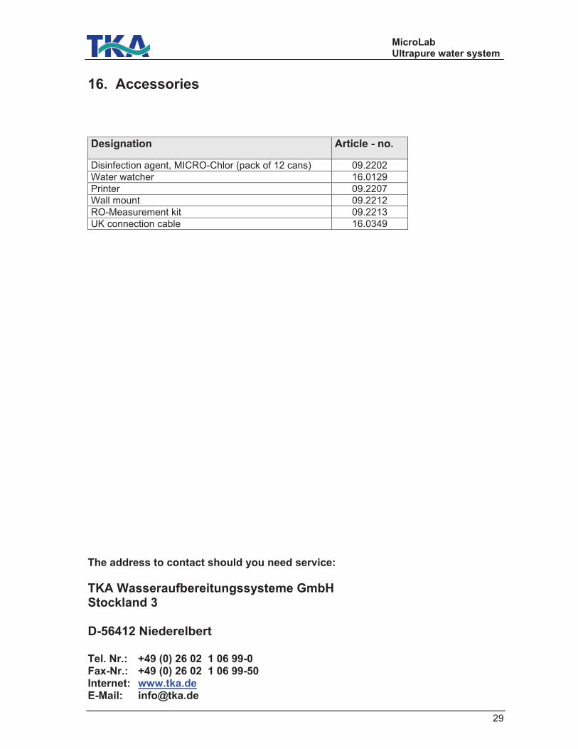
16. Accessories
Designation Article - no.
Disinfection agent, MICRO-Chlor (pack of 12 cans) 09.2202
Water watcher 16.0129
Printer 09.2207
Wall mount 09.2212
RO-Measurement kit 09.2213
UK connection cable 16.0349
The address to contact should you need service:
TKA Wasseraufbereitungssysteme GmbH Stockland 3 D-56412 Niederelbert Tel. Nr.: +49 (0) 26 02 1 06 99-0 Fax-Nr.: +49 (0) 26 02 1 06 99-50 Internet: www.tka.de E-Mail: [email protected]
MicroLab Ultrapure water system
30
17. Terminal assignment
MicroLab Ultrapure water system
31
MicroLab Ultrapure water system
32
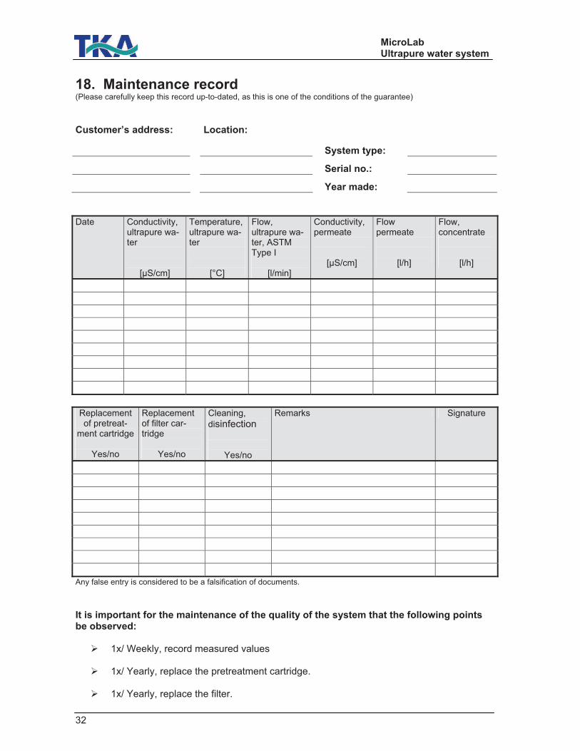
18. Maintenance record (Please carefully keep this record up-to-dated, as this is one of the conditions of the guarantee)
Customer’s address: Location:
System type:
Serial no.:
Year made:
Date Conductivity, ultrapure wa-ter
[µS/cm]
Temperature, ultrapure wa-ter
[°C]
Flow, ultrapure wa-ter, ASTM Type I
[l/min]
Conductivity, permeate
[µS/cm]
Flow permeate
[l/h]
Flow, concentrate
[l/h]
Replacement of pretreat-
ment cartridge
Yes/no
Replacement of filter car-tridge
Yes/no
Cleaning,
disinfection
Yes/no
Remarks Signature
Any false entry is considered to be a falsification of documents.
It is important for the maintenance of the quality of the system that the following points be observed: 1x/ Weekly, record measured values
1x/ Yearly, replace the pretreatment cartridge.
1x/ Yearly, replace the filter.