Embed Size (px)
Citation preview
ULTRAPURE WATER® May/June 2013 1
TechnologyREMOVAL OF NANOPARTICLES FROM SEMICONDUCTOR WATER
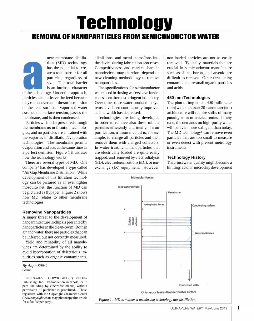
of the technology. Under this approach, particles cannot leave the feed because they cannot overcome the surface tension of the feed surface. Vaporized water escapes the surface tension, passes the membrane, and is then condensed.
Particles will not be pressured through the membrane as in filtration technolo-gies, and no particles are entrained with the vapor as in distillation/evaporation technologies. The membrane permits evaporation and acts at the same time as a perfect demister. Figure 1 illustrates how the technology works.
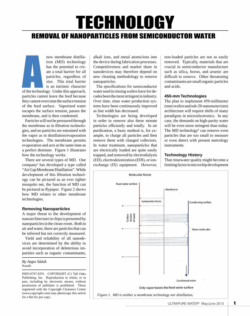
There are several types of MD. One companya has developed a type called “Air Gap Membrane Distillation”. While development of this filtration technol-ogy can be pictured as an ever tighter mosquito net, the function of MD can be pictured as flypaper. Figure 2 shows how MD relates to other membrane technologies.
Removing NanoparticlesA major threat to the development of nanoarchitecture in chips is presented by nanoparticles in the clean-room. Both in air and water, there are particles that can be inferred but not correctly measured.
Yield and reliability of all nanode-vices are determined by the ability to avoid incorporation of deleterious im-purities such as organic contaminants,
alkali ions, and metal atoms/ions into the device during fabrication processes. Competitiveness and market share in nanodevices may therefore depend on new cleaning methodology to remove nanoparticles.
The specifications for semiconductor water used in rinsing wafers have for de-cades been the most stringent in industry. Over time, rinse water production sys-tems have been continuously improved as line width has decreased.
Technologies are being developed in order to remove also these minute particles efficiently and totally. In air purification, a basic method is, for ex-ample, to charge all particles and then remove them with charged collectors. In water treatment, nanoparticles that are electrically loaded are quite easily trapped, and removed by electrodialysis (ED), electrodeionization (EDI), or ion-exchange (IX) equipment. However,
ISSN:0747-8291. COPYRIGHT (C) Tall Oaks Publishing, Inc. Reproduction in whole, or in part, including by electronic means, without permission of publisher is prohibited. Those registered with the Copyright Clearance Center (www.copyright.com) may photocopy this article for a flat fee per copy.
By Aapo SääskScarab
new membrane distilla-tion (MD) technology has the potential to cre-ate a total barrier for all particles, regardless of size. This total barrier is an intrinsic character a non-loaded particles are not as easily
removed. Typically, materials that are crucial in semiconductor manufacture such as silica, boron, and arsenic are difficult to remove. Other threatening contaminants are small organic particles and acids.
450-mm TechnologiesThe plan to implement 450-millimeter (mm) wafers and sub-20-nanometer (nm) architecture will require shifts of many paradigms in microelectronics. In any case, the demands on high-purity water will be even more stringent than today. The MD technologyb can remove even particles that are too small to measure or even detect with present metrology instruments.
Technology History That rinsewater quality might become a limiting factor in microchip development
Figure 1. MD is neither a membrane technology nor distillation.
ULTRAPURE WATER® May/June 2013 1
TECHNOLOGYREMOVAL OF NANOPARTICLES FROM SEMICONDUCTOR WATER
of the technology. Under this approach, particles cannot leave the feed because they cannot overcome the surface tension of the feed surface. Vaporized water escapes the surface tension, passes the membrane, and is then condensed.
Particles will not be pressured through the membrane as in filtration technolo-gies, and no particles are entrained with the vapor as in distillation/evaporation technologies. The membrane permits evaporation and acts at the same time as a perfect demister. Figure 1 illustrates how the technology works.
There are several types of MD. One companya has developed a type called “Air Gap Membrane Distillation”. While development of this filtration technol-ogy can be pictured as an ever tighter mosquito net, the function of MD can be pictured as flypaper. Figure 2 shows how MD relates to other membrane technologies.
Removing NanoparticlesA major threat to the development of nanoarchitecture in chips is presented by nanoparticles in the clean-room. Both in air and water, there are particles that can be inferred but not correctly measured.
Yield and reliability of all nanode-vices are determined by the ability to avoid incorporation of deleterious im-purities such as organic contaminants,
alkali ions, and metal atoms/ions into the device during fabrication processes. Competitiveness and market share in nanodevices may therefore depend on new cleaning methodology to remove nanoparticles.
The specifications for semiconductor water used in rinsing wafers have for de-cades been the most stringent in industry. Over time, rinse water production sys-tems have been continuously improved as line width has decreased.
Technologies are being developed in order to remove also these minute particles efficiently and totally. In air purification, a basic method is, for ex-ample, to charge all particles and then remove them with charged collectors. In water treatment, nanoparticles that are electrically loaded are quite easily trapped, and removed by electrodialysis (ED), electrodeionization (EDI), or ion-exchange (IX) equipment. However,
ISSN:0747-8291. COPYRIGHT (C) Tall Oaks Publishing, Inc. Reproduction in whole, or in part, including by electronic means, without permission of publisher is prohibited. Those registered with the Copyright Clearance Center (www.copyright.com) may photocopy this article for a flat fee per copy.
By Aapo SääskScarab
new membrane distilla-tion (MD) technology has the potential to cre-ate a total barrier for all particles, regardless of size. This total barrier is an intrinsic character A non-loaded particles are not as easily
removed. Typically, materials that are crucial in semiconductor manufacture such as silica, boron, and arsenic are difficult to remove. Other threatening contaminants are small organic particles and acids.
450-mm TechnologiesThe plan to implement 450-millimeter (mm) wafers and sub-20-nanometer (nm) architecture will require shifts of many paradigms in microelectronics. In any case, the demands on high-purity water will be even more stringent than today. The MD technologyb can remove even particles that are too small to measure or even detect with present metrology instruments.
Technology History That rinsewater quality might become a limiting factor in microchip development
Figure 1. MD is neither a membrane technology nor distillation.
2 ULTRAPURE WATER® May/June 2013
was predicted already in the 1980s. In 1989, a research project was therefore initiated by Scarab Development and ABB Corporate Research to develop MD technology for rinsewater treatment. A new company, Xzero AB, was founded in 1996 to develop the equipment under license from Scarab and a first presenta-tion of the technology was published in ULTRAPURE WATER in April 2006 (1). The article was based on a paper given at ULTRAPURE WATER Portland in October 2005.
Since 1996, Xzero has worked on improvements in module efficiency and in manufacturing technology and has tested industrial-scale MD equipment for other applications such as purification of flue gas concentrate, solar desalination, and concentration of reverse osmosis (RO) brine.
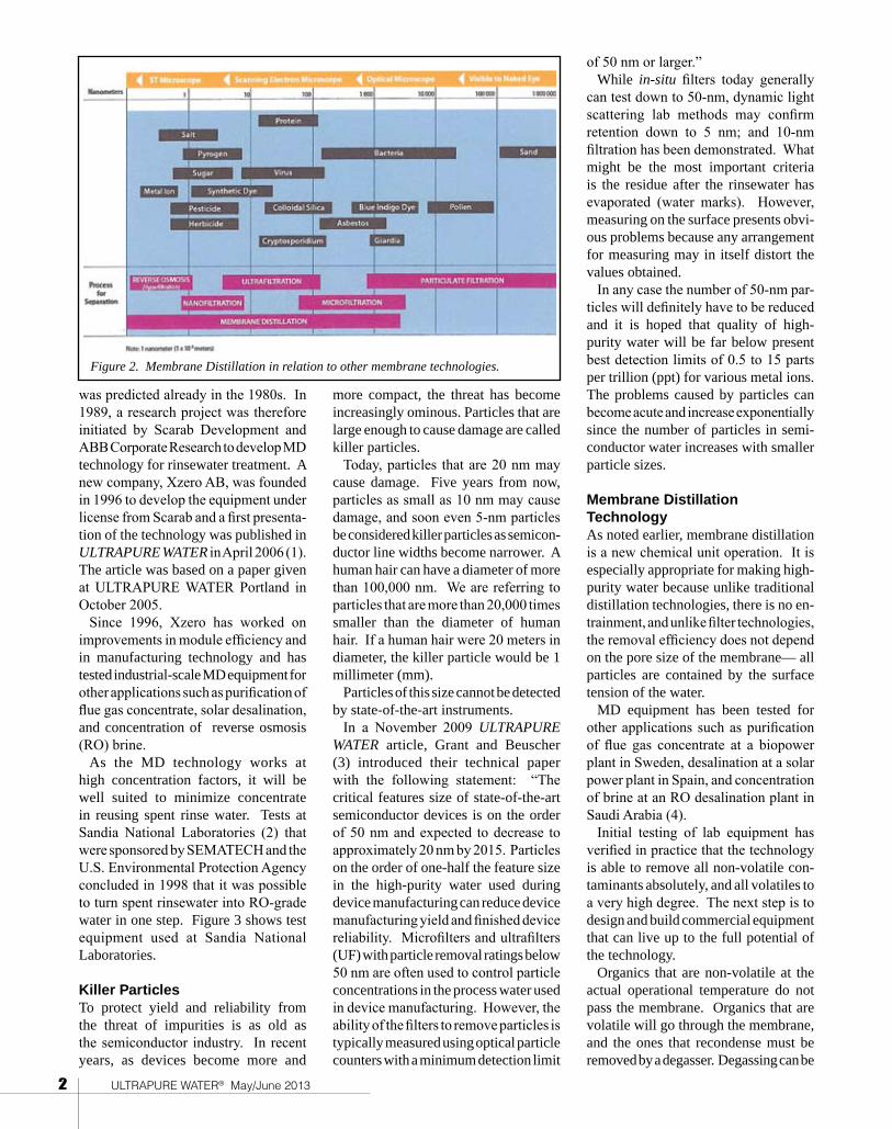
As the MD technology works at high concentration factors, it will be well suited to minimize concentrate in reusing spent rinse water. Tests at Sandia National Laboratories (2) that were sponsored by SEMATECH and the U.S. Environmental Protection Agency concluded in 1998 that it was possible to turn spent rinsewater into RO-grade water in one step. Figure 3 shows test equipment used at Sandia National Laboratories.
Killer ParticlesTo protect yield and reliability from the threat of impurities is as old as the semiconductor industry. In recent years, as devices become more and
more compact, the threat has become increasingly ominous. Particles that are large enough to cause damage are called killer particles.
Today, particles that are 20 nm may cause damage. Five years from now, particles as small as 10 nm may cause damage, and soon even 5-nm particles be considered killer particles as semicon-ductor line widths become narrower. A human hair can have a diameter of more than 100,000 nm. We are referring to particles that are more than 20,000 times smaller than the diameter of human hair. If a human hair were 20 meters in diameter, the killer particle would be 1 millimeter (mm).
Particles of this size cannot be detected by state-of-the-art instruments.
In a November 2009 ULTRAPURE WATER article, Grant and Beuscher (3) introduced their technical paper with the following statement: “The critical features size of state-of-the-art semiconductor devices is on the order of 50 nm and expected to decrease to approximately 20 nm by 2015. Particles on the order of one-half the feature size in the high-purity water used during device manufacturing can reduce device manufacturing yield and finished device reliability. Microfilters and ultrafilters (UF) with particle removal ratings below 50 nm are often used to control particle concentrations in the process water used in device manufacturing. However, the ability of the filters to remove particles is typically measured using optical particle counters with a minimum detection limit
of 50 nm or larger.” While in-situ filters today generally
can test down to 50-nm, dynamic light scattering lab methods may confirm retention down to 5 nm; and 10-nm filtration has been demonstrated. What might be the most important criteria is the residue after the rinsewater has evaporated (water marks). However, measuring on the surface presents obvi-ous problems because any arrangement for measuring may in itself distort the values obtained.
In any case the number of 50-nm par-ticles will definitely have to be reduced and it is hoped that quality of high-purity water will be far below present best detection limits of 0.5 to 15 parts per trillion (ppt) for various metal ions. The problems caused by particles can become acute and increase exponentially since the number of particles in semi-conductor water increases with smaller particle sizes.
Membrane Distillation Technology As noted earlier, membrane distillation is a new chemical unit operation. It is especially appropriate for making high-purity water because unlike traditional distillation technologies, there is no en-trainment, and unlike filter technologies, the removal efficiency does not depend on the pore size of the membrane— all particles are contained by the surface tension of the water.
MD equipment has been tested for other applications such as purification of flue gas concentrate at a biopower plant in Sweden, desalination at a solar power plant in Spain, and concentration of brine at an RO desalination plant in Saudi Arabia (4).
Initial testing of lab equipment has verified in practice that the technology is able to remove all non-volatile con-taminants absolutely, and all volatiles to a very high degree. The next step is to design and build commercial equipment that can live up to the full potential of the technology.
Organics that are non-volatile at the actual operational temperature do not pass the membrane. Organics that are volatile will go through the membrane, and the ones that recondense must be removed by a degasser. Degassing can be
Figure 2. Membrane Distillation in relation to other membrane technologies.
ULTRAPURE WATER® May/June 2013 3
accomplished by heating; preferentially before the MD, or between the MDs if a redundancy module is added.
Ions or particles will not pass the membranes. They cannot leave the surface of the feedwater because they are restrained by the surface tension of the water. Therefore there is no need from a purification aspect to include ED, EDI, IX, RO, or UF, and the like to the system. Pretreatment is needed to protect the equipment from scaling and fouling, and to prevent surfactants from entering the system. The latter would disrupt the surface tension of the water.
To render surfactants harmless, ozone or ultraviolet (UV) pretreatment can be used. For other purposes, conventional pretreatment will be sufficient. To scour the system, acids can be used. Since the membranes are of polytetrafluoroethyl-ene (PTFE) (also referred to as Teflon®), they can resist strong acids. This also means that acids can be concentrated to high concentrations.
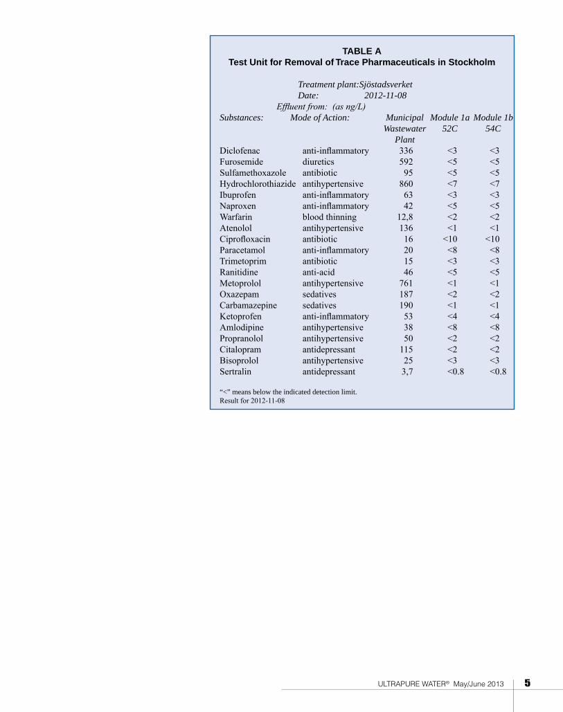
Industrial DevelopmentRecent test of removal efficiency. The MD technology has developed to the point where it is possible to supply indus-trially made demonstration equipment. Presently, a semi-commercial demo is being run in Stockholm in cooperation with the Royal Institute of Technology (KTH), and the Swedish Environmental
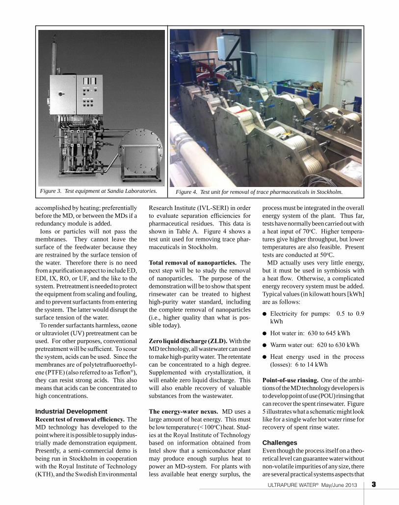
Research Institute (IVL-SERI) in order to evaluate separation efficiencies for pharmaceutical residues. This data is shown in Table A. Figure 4 shows a test unit used for removing trace phar-maceuticals in Stockholm.
Total removal of nanoparticles. The next step will be to study the removal of nanoparticles. The purpose of the demonstration will be to show that spent rinsewater can be treated to highest high-purity water standard, including the complete removal of nanoparticles (i.e., higher quality than what is pos-sible today).
Zero liquid discharge (ZLD). With the MD technology, all wastewater can used to make high-purity water. The retentate can be concentrated to a high degree. Supplemented with crystallization, it will enable zero liquid discharge. This will also enable recovery of valuable substances from the wastewater.
The energy-water nexus. MD uses a large amount of heat energy. This must be low temperature (< 100oC) heat. Stud-ies at the Royal Institute of Technology based on information obtained from Intel show that a semiconductor plant may produce enough surplus heat to power an MD-system. For plants with less available heat energy surplus, the
process must be integrated in the overall energy system of the plant. Thus far, tests have normally been carried out with a heat input of 70oC. Higher tempera-tures give higher throughput, but lower temperatures are also feasible. Present tests are conducted at 50oC.
MD actually uses very little energy, but it must be used in symbiosis with a heat flow. Otherwise, a complicated energy recovery system must be added. Typical values (in kilowatt hours [kWh] are as follows:
l Electricity for pumps: 0.5 to 0.9 kWh
l Hot water in: 630 to 645 kWh
l Warm water out: 620 to 630 kWh
l Heat energy used in the process (losses): 6 to 14 kWh
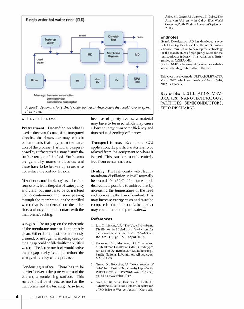
Point-of-use rinsing. One of the ambi-tions of the MD technology developers is to develop point of use (POU) rinsing that can recover the spent rinsewater. Figure 5 illustrates what a schematic might look like for a single wafer hot water rinse for recovery of spent rinse water.
Challenges Even though the process itself on a theo-retical level can guarantee water without non-volatile impurities of any size, there are several practical systems aspects that
Figure 3. Test equipment at Sandia Laboratories. Figure 4. Test unit for removal of trace pharmaceuticals in Stockholm.

4 ULTRAPURE WATER® May/June 2013
will have to be solved.
Pretreatment. Depending on what is used in the manufacture of the integrated circuits, the rinsewater may contain contaminants that may harm the func-tion of the process. Particular danger is posed by surfactants that may disturb the surface tension of the feed. Surfactants are generally macro molecules, and these have to be broken up in order to not reduce the surface tension.
Membrane and backing has to be cho-sen not only from the point of water purity and yield, but must also be guaranteed not to contaminate the vapor passing through the membrane, or the purified water that is condensed on the other side, and may come in contact with the membrane/backing.
Air-gap. The air gap on the other side of the membrane must be kept entirely clean. Either the air must be continuously cleaned, or nitrogen blanketing used or the air gap could be filled with the purified water. The latter method would solve the air-gap purity issue but reduce the energy efficiency of the process.
Condensing surface. There has to be barrier between the pure water and the coolant, a condensing surface. This surface must be at least as inert as the membrane and the backing. Also here,
because of purity issues, a material may have to be used which may cause a lower energy transport efficiency and thus reduced cooling efficiency.
Transport to use. Even for a POU application, the purified water has to be relayed from the equipment to where it is used. This transport must be entirely free from contamination.
Heating. The high-purity water from a membrane distillation unit will normally be around 40 to 50oC. If hotter water is desired, it is possible to achieve that by increasing the temperature of the feed and decreasing the flow of coolant. This may increase energy costs and must be compared to the addition of a heater that may contaminate the pure water.q
References
1. Liu, C.; Martin, A.R. “The Use of Membrane Distillation in High-Purity Production for the Semiconductor Industry”, ULTRAPURE WATER 23(3), pp. 32-38 (April 2006).
2. Donovan, R.P.; Morrison, D.J. “Evaluation of Membrane Distillation (MDU) Prototypes for Use in Semiconductor Manufacturing”, Sandia National Laboratories, Albuquerque, N.M, (1998).
3. Grant, D.; Beuscher, U. “Measurement of Sub-50-nm Particle Retention by High-Purity Water Filters”, ULTRAPURE WATER 26(11), pp. 34-40 (November 2009).
4. Syed, K.; Basha, A.; Bushnak, M.; Dolfe, H. “Membrane Distillation Test for Concentration of RO Brine at Wessco, Jeddah”, Xzero AB;
Åslin, M., Xzero AB, Lamyaa El-Gabry, The American University in Cairo, IDA World Congress, Perth, Western Australia (September 2011).
EndnotesaScarab Development AB has developed a type called Air Gap Membrane Distillation. Xzero has a license from Scarab to develop the technology for the manufacture of high-purity water for the semiconductor industry. This variation is distin-guished as XZERO-MD.bXZERO-MD is the name of the membrane distil-lation technology referred to in the text.
This paper was presented at ULTRAPURE WATER Micro 2012, which was conducted Nov. 13-14, 2012, in Phoenix.
Key words: DISTILLATION, MEM-BRANES, NANOTECHNOLOGY, PARTICLES, SEMICONDUCTORS, ZERO DISCHARGE
Figure 5. Schematic for a single wafer hot water rinse system that could recover spent rinse water.
ULTRAPURE WATER® May/June 2013 5
TABLE A Test Unit for Removal of Trace Pharmaceuticals in Stockholm
Treatment plant: Sjöstadsverket Date: 2012-11-08 Effluent from: (as ng/L) Substances: Mode of Action: Municipal Module 1a Module 1b Wastewater 52C 54C PlantDiclofenac anti-inflammatory 336 <3 <3Furosemide diuretics 592 <5 <5Sulfamethoxazole antibiotic 95 <5 <5Hydrochlorothiazide antihypertensive 860 <7 <7Ibuprofen anti-inflammatory 63 <3 <3Naproxen anti-inflammatory 42 <5 <5Warfarin blood thinning 12,8 <2 <2Atenolol antihypertensive 136 <1 <1Ciprofloxacin antibiotic 16 <10 <10Paracetamol anti-inflammatory 20 <8 <8Trimetoprim antibiotic 15 <3 <3Ranitidine anti-acid 46 <5 <5Metoprolol antihypertensive 761 <1 <1Oxazepam sedatives 187 <2 <2Carbamazepine sedatives 190 <1 <1Ketoprofen anti-inflammatory 53 <4 <4Amlodipine antihypertensive 38 <8 <8Propranolol antihypertensive 50 <2 <2Citalopram antidepressant 115 <2 <2Bisoprolol antihypertensive 25 <3 <3Sertralin antidepressant 3,7 <0.8 <0.8
“<” means below the indicated detection limit. Result for 2012-11-08

2 ULTRAPURE WATER® May/June 2013
was predicted already in the 1980s. In 1989, a research project was therefore initiated by Scarab Development and ABB Corporate Research to develop MD technology for rinsewater treatment. A new company, Xzero AB, was founded in 1996 to develop the equipment under license from Scarab and a first presenta-tion of the technology was published in ULTRAPURE WATER in April 2006 (1). The article was based on a paper given at ULTRAPURE WATER Portland in October 2005.
Since 1996, Xzero has worked on improvements in module efficiency and in manufacturing technology and has tested industrial-scale MD equipment for other applications such as purification of flue gas concentrate, solar desalination, and concentration of reverse osmosis (RO) brine.
As the MD technology works at high concentration factors, it will be well suited to minimize concentrate in reusing spent rinse water. Tests at Sandia National Laboratories (2) that were sponsored by SEMATECH and the U.S. Environmental Protection Agency concluded in 1998 that it was possible to turn spent rinsewater into RO-grade water in one step. Figure 3 shows test equipment used at Sandia National Laboratories.
Killer ParticlesTo protect yield and reliability from the threat of impurities is as old as the semiconductor industry. In recent years, as devices become more and
more compact, the threat has become increasingly ominous. Particles that are large enough to cause damage are called killer particles.
Today, particles that are 20 nm may cause damage. Five years from now, particles as small as 10 nm may cause damage, and soon even 5-nm particles be considered killer particles as semicon-ductor line widths become narrower. A human hair can have a diameter of more than 100,000 nm. We are referring to particles that are more than 20,000 times smaller than the diameter of human hair. If a human hair were 20 meters in diameter, the killer particle would be 1 millimeter (mm).
Particles of this size cannot be detected by state-of-the-art instruments.
In a November 2009 ULTRAPURE WATER article, Grant and Beuscher (3) introduced their technical paper with the following statement: “The critical features size of state-of-the-art semiconductor devices is on the order of 50 nm and expected to decrease to approximately 20 nm by 2015. Particles on the order of one-half the feature size in the high-purity water used during device manufacturing can reduce device manufacturing yield and finished device reliability. Microfilters and ultrafilters (UF) with particle removal ratings below 50 nm are often used to control particle concentrations in the process water used in device manufacturing. However, the ability of the filters to remove particles is typically measured using optical particle counters with a minimum detection limit
of 50 nm or larger.” While in-situ filters today generally
can test down to 50-nm, dynamic light scattering lab methods may confirm retention down to 5 nm; and 10-nm filtration has been demonstrated. What might be the most important criteria is the residue after the rinsewater has evaporated (water marks). However, measuring on the surface presents obvi-ous problems because any arrangement for measuring may in itself distort the values obtained.
In any case the number of 50-nm par-ticles will definitely have to be reduced and it is hoped that quality of high-purity water will be far below present best detection limits of 0.5 to 15 parts per trillion (ppt) for various metal ions. The problems caused by particles can become acute and increase exponentially since the number of particles in semi-conductor water increases with smaller particle sizes.
Membrane Distillation Technology As noted earlier, membrane distillation is a new chemical unit operation. It is especially appropriate for making high-purity water because unlike traditional distillation technologies, there is no en-trainment, and unlike filter technologies, the removal efficiency does not depend on the pore size of the membrane— all particles are contained by the surface tension of the water.
MD equipment has been tested for other applications such as purification of flue gas concentrate at a biopower plant in Sweden, desalination at a solar power plant in Spain, and concentration of brine at an RO desalination plant in Saudi Arabia (4).
Initial testing of lab equipment has verified in practice that the technology is able to remove all non-volatile con-taminants absolutely, and all volatiles to a very high degree. The next step is to design and build commercial equipment that can live up to the full potential of the technology.
Organics that are non-volatile at the actual operational temperature do not pass the membrane. Organics that are volatile will go through the membrane, and the ones that recondense must be removed by a degasser. Degassing can be
Figure 2. Membrane Distillation in relation to other membrane technologies.

ULTRAPURE WATER® May/June 2013 3
accomplished by heating; preferentially before the MD, or between the MDs if a redundancy module is added.
Ions or particles will not pass the membranes. They cannot leave the surface of the feedwater because they are restrained by the surface tension of the water. Therefore there is no need from a purification aspect to include ED, EDI, IX, RO, or UF, and the like to the system. Pretreatment is needed to protect the equipment from scaling and fouling, and to prevent surfactants from entering the system. The latter would disrupt the surface tension of the water.
To render surfactants harmless, ozone or ultraviolet (UV) pretreatment can be used. For other purposes, conventional pretreatment will be sufficient. To scour the system, acids can be used. Since the membranes are of polytetrafluoroethyl-ene (PTFE) (also referred to as Teflon®), they can resist strong acids. This also means that acids can be concentrated to high concentrations.
Industrial DevelopmentRecent test of removal efficiency. The MD technology has developed to the point where it is possible to supply indus-trially made demonstration equipment. Presently, a semi-commercial demo is being run in Stockholm in cooperation with the Royal Institute of Technology (KTH), and the Swedish Environmental
Research Institute (IVL-SERI) in order to evaluate separation efficiencies for pharmaceutical residues. This data is shown in Table A. Figure 4 shows a test unit used for removing trace phar-maceuticals in Stockholm.
Total removal of nanoparticles. The next step will be to study the removal of nanoparticles. The purpose of the demonstration will be to show that spent rinsewater can be treated to highest high-purity water standard, including the complete removal of nanoparticles (i.e., higher quality than what is pos-sible today).
Zero liquid discharge (ZLD). With the MD technology, all wastewater can used to make high-purity water. The retentate can be concentrated to a high degree. Supplemented with crystallization, it will enable zero liquid discharge. This will also enable recovery of valuable substances from the wastewater.
The energy-water nexus. MD uses a large amount of heat energy. This must be low temperature (< 100oC) heat. Stud-ies at the Royal Institute of Technology based on information obtained from Intel show that a semiconductor plant may produce enough surplus heat to power an MD-system. For plants with less available heat energy surplus, the
process must be integrated in the overall energy system of the plant. Thus far, tests have normally been carried out with a heat input of 70oC. Higher tempera-tures give higher throughput, but lower temperatures are also feasible. Present tests are conducted at 50oC.
MD actually uses very little energy, but it must be used in symbiosis with a heat flow. Otherwise, a complicated energy recovery system must be added. Typical values (in kilowatt hours [kWh] are as follows:
l Electricity for pumps: 0.5 to 0.9 kWh
l Hot water in: 630 to 645 kWh
l Warm water out: 620 to 630 kWh
l Heat energy used in the process (losses): 6 to 14 kWh
Point-of-use rinsing. One of the ambi-tions of the MD technology developers is to develop point of use (POU) rinsing that can recover the spent rinsewater. Figure 5 illustrates what a schematic might look like for a single wafer hot water rinse for recovery of spent rinse water.
Challenges Even though the process itself on a theo-retical level can guarantee water without non-volatile impurities of any size, there are several practical systems aspects that
Figure 3. Test equipment at Sandia Laboratories. Figure 4. Test unit for removal of trace pharmaceuticals in Stockholm.
4 ULTRAPURE WATER® May/June 2013
will have to be solved.
Pretreatment. Depending on what is used in the manufacture of the integrated circuits, the rinsewater may contain contaminants that may harm the func-tion of the process. Particular danger is posed by surfactants that may disturb the surface tension of the feed. Surfactants are generally macro molecules, and these have to be broken up in order to not reduce the surface tension.
Membrane and backing has to be cho-sen not only from the point of water purity and yield, but must also be guaranteed not to contaminate the vapor passing through the membrane, or the purified water that is condensed on the other side, and may come in contact with the membrane/backing.
Air-gap. The air gap on the other side of the membrane must be kept entirely clean. Either the air must be continuously cleaned, or nitrogen blanketing used or the air gap could be filled with the purified water. The latter method would solve the air-gap purity issue but reduce the energy efficiency of the process.
Condensing surface. There has to be barrier between the pure water and the coolant, a condensing surface. This surface must be at least as inert as the membrane and the backing. Also here,
because of purity issues, a material may have to be used which may cause a lower energy transport efficiency and thus reduced cooling efficiency.
Transport to use. Even for a POU application, the purified water has to be relayed from the equipment to where it is used. This transport must be entirely free from contamination.
Heating. The high-purity water from a membrane distillation unit will normally be around 40 to 50oC. If hotter water is desired, it is possible to achieve that by increasing the temperature of the feed and decreasing the flow of coolant. This may increase energy costs and must be compared to the addition of a heater that may contaminate the pure water.q
References
1. Liu, C.; Martin, A.R. “The Use of Membrane Distillation in High-Purity Production for the Semiconductor Industry”, ULTRAPURE WATER 23(3), pp. 32-38 (April 2006).
2. Donovan, R.P.; Morrison, D.J. “Evaluation of Membrane Distillation (MDU) Prototypes for Use in Semiconductor Manufacturing”, Sandia National Laboratories, Albuquerque, N.M, (1998).
3. Grant, D.; Beuscher, U. “Measurement of Sub-50-nm Particle Retention by High-Purity Water Filters”, ULTRAPURE WATER 26(11), pp. 34-40 (November 2009).
4. Syed, K.; Basha, A.; Bushnak, M.; Dolfe, H. “Membrane Distillation Test for Concentration of RO Brine at Wessco, Jeddah”, Xzero AB;
Åslin, M., Xzero AB, Lamyaa El-Gabry, The American University in Cairo, IDA World Congress, Perth, Western Australia (September 2011).
EndnotesaScarab Development AB has developed a type called Air Gap Membrane Distillation. Xzero has a license from Scarab to develop the technology for the manufacture of high-purity water for the semiconductor industry. This variation is distin-guished as XZERO-MD.bXZERO-MD is the name of the membrane distil-lation technology referred to in the text.
This paper was presented at ULTRAPURE WATER Micro 2012, which was conducted Nov. 13-14, 2012, in Phoenix.
Key words: DISTILLATION, MEM-BRANES, NANOTECHNOLOGY, PARTICLES, SEMICONDUCTORS, ZERO DISCHARGEFigure 5. Schematic for a single wafer hot water rinse system that could recover spent
rinse water.

ULTRAPURE WATER® May/June 2013 5
TABLE A Test Unit for Removal of Trace Pharmaceuticals in Stockholm
Treatment plant: Sjöstadsverket Date: 2012-11-08 Effluent from: (as ng/L) Substances: Mode of Action: Municipal Module 1a Module 1b Wastewater 52C 54C PlantDiclofenac anti-inflammatory 336 <3 <3Furosemide diuretics 592 <5 <5Sulfamethoxazole antibiotic 95 <5 <5Hydrochlorothiazide antihypertensive 860 <7 <7Ibuprofen anti-inflammatory 63 <3 <3Naproxen anti-inflammatory 42 <5 <5Warfarin blood thinning 12,8 <2 <2Atenolol antihypertensive 136 <1 <1Ciprofloxacin antibiotic 16 <10 <10Paracetamol anti-inflammatory 20 <8 <8Trimetoprim antibiotic 15 <3 <3Ranitidine anti-acid 46 <5 <5Metoprolol antihypertensive 761 <1 <1Oxazepam sedatives 187 <2 <2Carbamazepine sedatives 190 <1 <1Ketoprofen anti-inflammatory 53 <4 <4Amlodipine antihypertensive 38 <8 <8Propranolol antihypertensive 50 <2 <2Citalopram antidepressant 115 <2 <2Bisoprolol antihypertensive 25 <3 <3Sertralin antidepressant 3,7 <0.8 <0.8
“<” means below the indicated detection limit. Result for 2012-11-08


