Embed Size (px)
Citation preview

II002 Issue B © Alcon Components Ltd.
Specialist Applications Iron Brake Caliper & Disc
Limited Warranty &
Installation Instructions
CIR15 family calipers
Important – Read this document before proceeding
II002 Issue B © Alcon Components Ltd.
BRAKE PRODUCTS LIMITED WARRANTY Limited 12 Month/12,000 Mile Warranty Alcon Components Ltd. (“Alcon”) warrants that these brake products will be free from non-conformity in materials and workmanship for 12 months or 12,000 miles after installation, whichever comes first. In the event of a non-conformity, Alcon will repair or replace, at its sole discretion and option, the non-conforming product or part thereof free of charge. Simply contact Alcon using contact details to be found at www.alconusa.com and www.alcon.co.uk for instructions on obtaining repair or replacement. Any claims under this Limited Warranty must be made within 30 days of discovery of the non-conformity, or the claim will be null and void. Return of the non-conforming product or part thereof at the customer's expense, along with proof of purchase and/or mileage, may be required. This Limited Warranty does not apply to brake products that have been damaged, misused, altered, or installed or used in a manner contrary to Alcon’s instructions. Wear and tear on these brake products is normal, and is not an indication of a non-conformity. This Limited Warranty applies only to aftermarket brake products installed on passenger cars, vans and light trucks for on-road use. This Limited Warranty does not apply to any other use, including but not limited to racing, military (except for standard road vehicles armored for occupant protection), off-highway recreational, or off-highway competition. DISCLAIMER: THIS WARRANTY IS LIMITED TO REPAIR OR REPLACEMENT ONLY. This Limited Warranty does not cover labor for removing or reinstalling the non-conforming brake product or part thereof, or for the labor or costs of other materials removed or reinstalled in order to repair or replace the Product or part thereof. TO THE EXTENT PERMITTED BY LAW, ALCON, AND ITS AFFILIATES, DISTRIBUTORS, RETAILERS OR AGENTS, DISCLAIMS ALL OTHER IMPLIED OR EXPRESS WARRANTIES INCLUDING ALL WARRANTIES OF MERCHANTABILITY AND/OR FITNESS FOR A PARTICULAR PURPOSE, AND WARRANTY AGAINST INFRINGMENT. TO THE EXTENT THAT ANY IMPLIED WARRANTIES MAY NONETHELESS EXIST BY OPERATION OF LAW, SUCH WARRANTIES ARE LIMITED TO THE DURATION PROVIDED BY LAW. LIMITATION OF LIABILITY: This Limited Warranty is your sole and exclusive remedy and ALCON, and its affiliates, distributors, retailers or agents, shall not be liable for any damages, whether direct, indirect, incidental, special, consequential, exemplary, or otherwise, including property damage, lost revenues and lost profits, arising out of any theory of recovery, including statutory, contract or tort. Notwithstanding the term of any limited or implied warranty, or in the event that this Limited Warranty fails of its essential purpose, in no event will ALCON’s, or its affiliates’, distributors’, retailers’ or agent’s, entire liability exceed the purchase price of this product. Some states do not allow the exclusion or limitation of incidental or consequential damages so the above limitations or exclusions may not apply to you. Some states do not allow limitation on how long a limited warranty lasts, so the above limitation may not apply to you. This Limited Warranty gives you specific legal rights, and you may also have other rights which vary from state to state. Alcon Components Ltd., Apollo, Tamworth, Staffordshire, B79 7TN, United Kingdom Revised – July, 2016
2
II002 Issue B © Alcon Components Ltd.
Notes and disclaimers concerning application Important: Read these instructions carefully before fitment. Brake product specification Alcon Components have engineered a range of brake calipers and discs for special applications. Brake system calculations will need to be carried out to ensure that the specification meets the requirements of current legislation and are safe to use. Where there is doubt about the suitability of the product, Alcon can run individual brake system calculations and recommend the appropriate products. Caution:- This brake kit must be installed by a competent and suitably qualified person. It is the installer’s responsibility to ensure that any brake products fitted to a vehicle are suitable for application. Installation and clearance These parts have been designed using information available at the time of design. Alcon are unable to guarantee fitment to unknown wheels. 1:1 radial profile templates can be created for most applications to assess if sufficient clearance to the wheel is available. Templates come with full instructions on how to use them. It is very important that templates are printed accurately to scale. Due to differences in profile, it cannot be assumed that a larger diameter wheel will fit where a smaller one may not. Vehicle production tolerances may exceed those that the kit will accommodate, and the points in this document must be carefully observed during installation to ensure that the correct clearances are maintained. Wheel Spacers Some Alcon brake kits are supplied with appropriate wheel spacers. This will widen the track width of the vehicle. This is kept to a minimum. It is the responsibility of the customer to ensure that this falls within the requirements for air transportation where applicable. Alcon accepts no liability whatsoever for any issues of any sort arising through the fitting of alternative wheel spacers. Pad and disc life Alcon brake kits are designed to give increased pad area and disc thermal capacity. This will give improved disc and pad life when compared to the original brake system if used at the armoured weight. Depending upon the environment and use, brake pad and disc wear can vary considerably from one vehicle to another. Potential reasons for accelerated wear are as follows:- 1, Environment Some driving environments generate an aggressive paste between disc and pad that continually grinds the pad and disc when the brakes are not being applied. Typical environments where this may occur include quarries and desert conditions. 2, Driving style Brake pad life is not directly related to distance travelled. The number of brake applications and their severity vary significantly. If a driver is continually making heavy braking events then they are not only wearing the pads by the number of applications but accelerating the wear by running the brakes at a higher temperature. Brake pads wear more quickly at higher temperatures. 3, Brake drag If, for any reason, the pad is continually in contact with the disc the pad and disc will wear more quickly due to friction and temperature. This could be from some sort of locked pressure, seized piston, seized pad, etc. Alcon accepts no liability whatsoever for accelerated rate of pad or disc wear howsoever caused.
3
II002 Issue B © Alcon Components Ltd.
Notes and disclaimers concerning application (Cont’d) Important: Read these instructions carefully before fitment. Brake noise Alcon have made every effort to ensure a quiet brake. Brake noise is generated by vibrations in the whole vehicle corner. A brake kit may be quiet on one vehicle make and have noise present on another. To maintain good performance on higher performance vehicles, Alcon use higher than normal friction pad materials. These materials can be more prone to brake squeal. Alcon accepts no liability whatsoever for any brake noise howsoever caused. Vibration Alcon brake discs are manufactured by a methods that keep run-out and thickness variation to a minimum. They are also balanced to strict tolerances. Where a two-piece disc is supplied, the disc is finish-machined and balanced as a full assembly. Vibration can become present should pads and discs:- Not be installed correctly Not be correctly bedded-in Be subject to extreme abuse Alcon accepts no liability whatsoever for vibrations caused by incorrect installation, improper bedding –in or extreme use. Paint damage Brake fluid will damage most painted surfaces. Always try to contain or catch brake fluid during removal or fitting of brake components. Immediately clean any brake fluid spilled onto any painted surface with clean water. Alcon accepts no liability whatsoever for any damage to paintwork resulting from spilled brake fluid. Heat Soak After heavy use, do not rest your foot on the brake pedal while the vehicle is stationary. This practice will cause heat to ‘soak’ from the disc to the caliper and so to the brake fluid. In extreme cases the fluid may boil, leading to very poor braking performance. In addition, maintaining contact between pads and discs when stationary can cause pad material to adhere to the disc face and give rise to vibration. It is good practice to always use the handbrake rather than the footbrake when the vehicle is stationary. General modifications Do not make any modifications to the parts supplied in the brake kit. Alcon accepts no liability whatsoever for the consequences of using brake products that have been modified without its express written approval. Keep this document with your Owners Handbook for reference. Every effort has been made during the preparation of this literature to ensure that the information provided is correct. However, Alcon reserves the right to change information without notice.
4
II002 Issue B © Alcon Components Ltd.
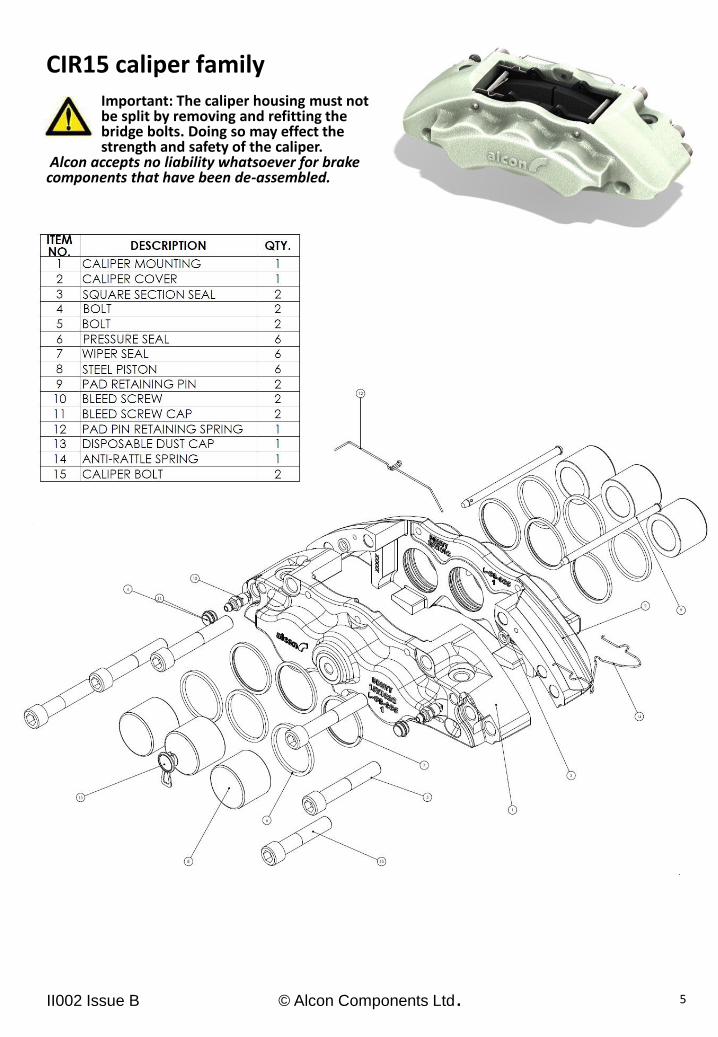
CIR15 caliper family Important: The caliper housing must not be split by removing and refitting the bridge bolts. Doing so may effect the strength and safety of the caliper. Alcon accepts no liability whatsoever for brake components that have been de-assembled.
5
II002 Issue B © Alcon Components Ltd.
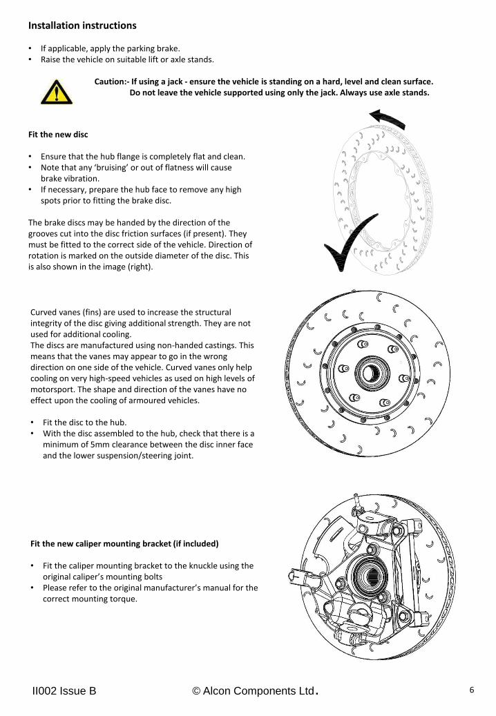
Fit the new disc
• Ensure that the hub flange is completely flat and clean. • Note that any ‘bruising’ or out of flatness will cause
brake vibration. • If necessary, prepare the hub face to remove any high
spots prior to fitting the brake disc. The brake discs may be handed by the direction of the grooves cut into the disc friction surfaces (if present). They must be fitted to the correct side of the vehicle. Direction of rotation is marked on the outside diameter of the disc. This is also shown in the image (right).
6
Curved vanes (fins) are used to increase the structural integrity of the disc giving additional strength. They are not used for additional cooling. The discs are manufactured using non-handed castings. This means that the vanes may appear to go in the wrong direction on one side of the vehicle. Curved vanes only help cooling on very high-speed vehicles as used on high levels of motorsport. The shape and direction of the vanes have no effect upon the cooling of armoured vehicles. • Fit the disc to the hub. • With the disc assembled to the hub, check that there is a
minimum of 5mm clearance between the disc inner face and the lower suspension/steering joint.
Fit the new caliper mounting bracket (if included) • Fit the caliper mounting bracket to the knuckle using the
original caliper’s mounting bolts • Please refer to the original manufacturer’s manual for the
correct mounting torque.
Installation instructions • If applicable, apply the parking brake. • Raise the vehicle on suitable lift or axle stands. Caution:- If using a jack - ensure the vehicle is standing on a hard, level and clean surface. Do not leave the vehicle supported using only the jack. Always use axle stands.
II002 Issue B © Alcon Components Ltd.
Front Brake kit Installation instructions (cont’d)
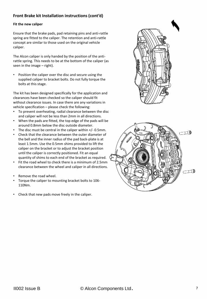
Fit the new caliper
Ensure that the brake pads, pad retaining pins and anti-rattle spring are fitted to the caliper. The retention and anti-rattle concept are similar to those used on the original vehicle caliper. The Alcon caliper is only handed by the position of the anti-rattle spring. This needs to be at the bottom of the caliper (as seen in the image – right). • Position the caliper over the disc and secure using the
supplied caliper to bracket bolts. Do not fully torque the bolts at this stage.
The kit has been designed specifically for the application and clearances have been checked so the caliper should fit without clearance issues. In case there are any variations in vehicle specification – please check the following: • To prevent overheating, radial clearance between the disc
and caliper will not be less than 2mm in all directions. • When the pads are fitted, the top edge of the pads will be
around 0.8mm below the disc outside diameter. • The disc must be central in the caliper within +/- 0.5mm. • Check that the clearance between the outer diameter of
the bell and the inner radius of the pad back-plate is at least 1.5mm. Use the 0.5mm shims provided to lift the caliper on the bracket or to adjust the bracket position until the caliper is correctly positioned. Fit an equal quantity of shims to each end of the bracket as required.
• Fit the road wheel to check there is a minimum of 2.5mm clearance between the wheel and caliper in all directions.
• Remove the road wheel. • Torque the caliper to mounting bracket bolts to 106-
110Nm.
• Check that new pads move freely in the caliper.
7
II002 Issue B © Alcon Components Ltd.
Brake kit Installation instructions Bleed the brakes • Bleed the brakes in accordance with the vehicle manufacturer’s instructions. • Only use DOT 4 brake fluid. • The caliper bleed screws must be tightened to 18Nm (cold). • To prevent damage to any painted surface, remove any spilled brake fluid immediately with clean cold water. • Remove any fluid in the area around the bleed screw thread and in the end of each bleed screw. • Check the complete hydraulic system for leaks before driving the vehicle. Re-fit the road wheels When the brake system has been sufficiently bled and a firm brake pedal has been achieved, replace the road wheels. Torque the wheel nuts to the original manufacturer’s specification. The brakes should now be checked for correct operation by driving the vehicle, making a few light brake applications from low speed in a safe location. Stopping performance of a newly fitted brake kit will be low initially, as all friction materials require a period of bedding in before optimum performance is achieved. Bedding new pads and discs Purpose: The two main reasons for bedding discs and pads in Alcon high performance brake kits are:- • To thermally condition the discs by raising the temperature gradually, thus reducing thermal shock and
preventing pad material from depositing unevenly on the disc surface. • To wear material from the pad surfaces until there is full-face contact with the disc. This may take longer to
achieve than the duration of the bedding procedure but pad area contact will increase during normal driving. Procedure: • Drive the vehicle to a road that allows the following procedure to be carried out safely and within the law. • From any speed between 60 and 100 km/h, apply light to moderate pedal effort to reduce speed by about
50km/h. Avoid coming to a complete stop if possible and accelerate back to speed. After approximately ten applications, allow the brakes to cool by driving without further brake applications. It will take approximately 200 km of urban driving to complete bed-in of the pads.
Servicing and maintenance instructions • Pads should be examined regularly for wear and condition. • Replace pads when less than 2mm of friction material remains anywhere over the surface. • When fitting new pads, thoroughly clean the pad location faces in the caliper, removing any debris and brake
dust with brake cleaner and a stiff brush. • The protruding pistons must be wiped clean before they are pushed back into the bores. • Discs must be replaced when the total thickness has worn below the minimum indicated on the disc or when
any of the face grooves across either inner or outer face have worn away. • If a disc shows any sign of cracking, which may occur after heavy usage, it must be replaced. • Remember to bed-in new pads and discs as described on the previous page.
8
II002 Issue B © Alcon Components Ltd.
Phone :- +44 (0)1827 723700
E-mail :- [email protected]
www.alcon.co.uk
Phone :- +1 (704) 799-2723
E-mail :- [email protected]
www.alconusa.com


