Embed Size (px)
Citation preview
MASSACHUSETTS INSTITUTE OF TECHNOLOGYARTIFICIAL INTELLIGENCE LABORATORYandCENTER FOR BIOLOGICAL COMPUTATIONAL LEARNINGWHITAKER COLLEGEA.I. Memo No. 1405 July, 1993C.B.C.L. Paper No. 78On Geometric and Algebraic Aspects of 3D A�ne and ProjectiveStructures from Perspective 2D ViewsAmnon ShashuaAbstractPart I of this paper investigates the di�erences | conceptually and algorithmically | between a�ne andprojective frameworks for the tasks of visual recognition and reconstruction from perspective views. Itis shown that an a�ne invariant exists between any view and a �xed view chosen as a reference view.This implies that for tasks for which a reference view can be chosen, such as in alignment schemes forvisual recognition, projective invariants are not really necessary. The projective extension is then derived,showing that it is necessary only for tasks for which a reference view is not available | such as happenswhen updating scene structure from a moving stereo rig. The geometric di�erence between the two proposedinvariants are that the a�ne invariant measures the relative deviation from a single reference plane, whereasthe projective invariant measures the relative deviation from two reference planes. The a�ne invariant canbe computed from three corresponding points and a fourth point for setting a scale; the projective invariantcan be computed from four corresponding points and a �fth point for setting a scale. Both the a�ne andprojective invariants are shown to be recovered by remarkably simple and linear methods.In part II we use the a�ne invariant to derive new algebraic connections between perspective views. Itis shown that three perspective views of an object are connected by certain algebraic functions of imagecoordinates alone (no structure or camera geometry needs to be involved). In the general case, three viewssatisfy a trilinear function of image coordinates. In case where two of the views are orthographic and thethird is perspective the function reduces to a bilinear form. In case all three views are orthographic thefunction reduces further to a linear form (the \linear combination of views" of [31]). These functions areshown to be useful for recognition, among other applications.Copyright c Massachusetts Institute of Technology, 1993This report describes research done within the Center for Biological and Computational Learning in the Department of Brainand Cognitive Sciences, and at the Arti�cial Intelligence Laboratory. Support for the A.I. Laboratory's arti�cial intelligenceresearch is provided in part by the Advanced Research Projects Agency of the Department of Defense under O�ce of NavalResearch contract N00014-91-J-4038. Support for the Center's research is provided in part by ONR contracts N00014-91-J-1270 and N00014-92-J-1879; by a grant from the National Science Foundation under contract ASC-9217041 (funds providedby this award include funds from ARPA provided under HPCC); and by a grant from the National Institutes of Health undercontract NIH 2-S07-RR07047-26. Additional support is provided by the North Atlantic Treaty Organization, ATR Audio andVisual Perception Research Laboratories, Mitsubishi Electric Corporation, Siemens AG., and Sumitomo Metal Industries. A.Shashua is supported by a McDonnell-Pew postdoctoral fellowship from the department of Brain and Cognitive Sciences.
1 IntroductionThe geometric relation between objects (or scenes) inthe world and their images, taken from di�erent viewingpositions by a pin-hole camera, has many subtleties andnuances and has been the subject of research in computervision since its early days. Two major areas in computervision have been shown to bene�t from an analytic treat-ment of the 3D to 2D geometry: visual recognition andreconstruction from multiple views (as a result of havingmotion sequences or from stereopsis).A recent approach with growing interest in the pastfew years is based on the idea that non-metric informa-tion, although weaker than the information provided bydepth maps and rigid camera geometries, is nonethelessuseful in the sense that the framework may provide sim-pler algorithms, camera calibration is not required, morefreedom in picture-taking is allowed | such as takingpictures of pictures of objects, and there is no need tomake a distinction between orthographic and perspectiveprojections. The list of contributions to this frameworkinclude (though not intended to be complete) [14, 26,33, 34, 9, 20, 3, 4, 28, 29, 19, 31, 23, 5, 6, 18, 27, 13, 12]| and relevant to this paper are the work described in[14, 4, 26, 28, 29].This paper has two parts. In Part I we investi-gate the intrinsic di�erences | conceptually and algo-rithmically | between an a�ne framework for recog-nition/reconstruction and a projective framework. Al-though the distinction between a�ne and projectivespaces, and between a�ne and projective properties, isperfectly clear from classic studies in projective and alge-braic geometries, as can be found in [8, 24, 25], it is lessclear how these concepts relate to reconstruction frommultiple views. In other words, given a set of views, un-der what conditions can we expect to recover a�ne in-variants? what is the bene�t from recovering projectiveinvariants over a�ne? are there tasks, or methodologies,for which an a�ne framework is completely su�cient?what are the relations between the set of views generatedby a pin-hole camera and the set of all possible projec-tions P3 7! P2 of a particular object? These are thekinds of questions for which the current literature doesnot provide satisfactory answers. For example, there is atendency in some of the work listed above, following thein uential work of [14], to associate the a�ne frameworkwith reconstruction/recognition from orthographic viewsonly. As will be shown later, the a�ne restriction neednot be coupled with the orthographic restriction on themodel of projection | provided we set one view �xed. Inother words, an uncalibrated pin-hole camera undergo-ing general motion can indeed be modeled as an \a�neengine" provided we introduce a \reference view", i.e.,all other views are matched against the reference viewfor recovering invariants or for achieving recognition.In the course of addressing these issues we derive twonew, extremely simple, schemes for recovering geometricinvariants | one a�ne and the other projective | whichcan be used for recognition and for reconstruction.Some of the ideas presented in this part of the pa-per follow the work of [14, 4, 26, 28, 29]. Section 3 ona�ne reconstruction from two perspective views, follows
and expands upon the work of [26, 14, 4]. Section 4 onprojective reconstruction, follows and re�nes the resultspresented in [28, 29].In Part II of this paper we use the results establishedin Part I (speci�cally those in Section 3) to address cer-tain algebraic aspects of the connections between mul-tiple views. Inspired by the work of [31], we addressthe problem of establishing a direct connection betweenviews, expressed as functions of image coordinates alone| which we call \algebraic functions of views". In addi-tion to linear functions of views, discovered by [31], ap-plicable to orthographic views only, we show that threeperspective views are related by trilinear functions oftheir coordinates, and by bilinear functions if two of thethree views are assumed orthographic | a case that willbe argued is relevant for purposes of recognition withoutconstraining the generality of the recognition process.Part II ends with a discussion of possible applicationsfor algebraic functions, other than visual recognition.2 Mathematical Notations andPreliminariesWe consider object space to be the three-dimensionalprojective space P3, and image space to be the two-dimensional projective space P2. Within P3 we will beconsidering the projective group of transformations andthe a�ne group. Below we describe basic de�nitions andformalism related to projective and a�ne geometries |more details can be found in [8, 24, 25].2.1 A�ne and Projective SpacesA�ne space over the �eld K is simply the vector spaceKn, and is usually denoted as An. Projective space Pnis the set of equivalence classes over the vector spaceKn+1. A point in Pn is usually written as a homoge-neous vector (x0; :::; xn), which is an ordered set of n+1real or complex numbers, not all zero, whose ratios onlyare to be regarded as signi�cant. Two points x and yare equivalent, denoted by x �= y, if x = �y for somescalar �. Likewise, two points are distinct if there is nosuch scalar.2.2 RepresentationsThe points in Pn admit a class of coordinate represen-tations R such that if R0 is any one allowable repre-sentation, the whole class R consists of all those rep-resentations that can be obtained from R0 by the ac-tion of the group GLn+1 of (n + 1) � (n + 1) non-singular matrices. It follows, that any one coordinaterepresentation is completely speci�ed by its standardsimplex and its unit point. The standard simplex isthe set of n + 1 points which have the standard coor-dinates (1; 0; :::; 0); (0;1; 0; :::; 0); :::; (0; 0; :::; 0;1) and theunit point is the point whose coordinates are (1; 1; :::; 1).It also follows that the coordinate transformation be-tween any two representations is completely determinedfrom n + 1 corresponding points in the two representa-tions, which give rise to a linear system of (n + 1)2 � 1or (n + 1)2 equations (depending on whether we set anarbitrary element of the matrix transform, or set one ofthe scale factors of the corresponding points).1
2.3 Subspaces and Cross RatiosA linear subspace � �= Pk � Pn is a hyperplane if k =n � 1, is a line when k = 1, and otherwise is a k-plane.There is a unique line in Pn through any two distinctpoints. Any point z on a line can be described as a linearcombination of two �xed points x;y on the line, i.e.,z �= x+ky. Let v �= x+k0y be another point on the linespanned by x;y, then the cross ratio of the four points issimply � = k=k0 which is invariant in all representationsR. By permuting the four points on the line the 24possible cross ratios fall into six sets of four with values�; 1=�; 1� �; (�� 1)=�; �=(�� 1) and 1=(1� �).2.4 ProjectionsLet Pn�1 � Pn be some hyperplane, and a point O 2Pn not lying on Pn�1. If we like, we can choose therepresentation such that Pn�1 is given by xn = 0 andthe point O = (0; 0; :::; 0; 1). We can de�ne a map�o : Pn � fOg ! Pn�1by �o : P 7! OP \ Pn�1;that is, sending a point P 2 Pn other thanO to the pointof intersection of the line OP with the hyperplane Pn�1.�o is the projection from the point O to the hyperplanePn�1, and the point O is called the center of projection(COP). In terms of coordinates x, this amounts to�o : (x0; :::; xn) 7! (x0; :::; xn�1):As an example, the projection of 3D objects onto animage plane is modeled by x 7! Tx, where T is a 3 �4 matrix, often called the camera transformation. Theset S of all views of an object (ignoring problems ofself occlusion, i.e., assuming that all points are visiblefrom all viewpoints) is obtained by the group GL4 of4 � 4 non-singular matrices applied to some arbitraryrepresentation of P3, and then dropping the coordinatex3.2.5 The A�ne SubgroupLet Ai � Pn be the subset of points (x0; :::; xn) withxi 6= 0. Then the ratios �xj = xj=xi are well de�ned andare called a�ne or Euclidean coordinates on the projec-tive space, and Ai is bijective to the a�ne space An,i.e. Ai �= An. The a�ne subgroup of GLn+1 leavesthe hyperplane xi = 0 invariant under all a�ne repre-sentations. Any subgroup of GLn+1 that leaves somehyperplane invariant is an a�ne subgroup, and the in-variant hyperplane is called the ideal hyperplane. As anexample, a subgroup of GL4 that leaves some plane in-variant is a�ne. It could be any plane, but if it is theplane at in�nity (x2 = 0) then the mapping P3 7! P2is created by parallel projection, i.e., the COP is at in-�nity. Since two lines are parallel if they meet on theideal hyperplane, then when the ideal hyperplane is atin�nity, a�ne geometry takes its \intuitive" form of pre-serving parallelism of lines and planes and preservingratios. The importance of the a�ne subgroups is thatthere exist a�ne invariants that are not projective in-variants. Parallelism, the concept of a midpoint, area oftriangles, classi�cation of conics are examples of a�neproperties that are not projective.
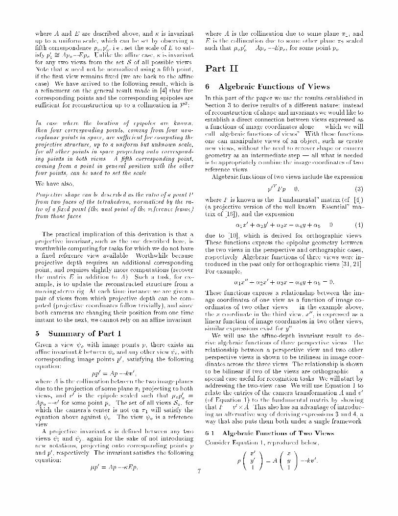
2.6 EpipolesGiven two cameras with positions of their COP atO;O0 2 P3, respectively, the epipoles are at the intersec-tion of the line OO0 with both image planes. Recoveringthe epipoles from point correspondences across two viewsis remarkably simple but is notoriously sensitive to noisein image measurements. For more details on recoveringepipoles see [4, 29, 28, 5], and for comparative and erroranalysis see [17, 22]. In Part I of this paper we assumethe epipoles are given; in Part II, where we make furtheruse of derivations made in Section 3, we show that forpurposes discussed there one can eliminate the epipolesaltogether.2.7 Image CoordinatesImage space is P2. Since the image plane is �nite, we canassign, without loss of generality, the value 1 as the thirdhomogeneous coordinate to every image point. That is,if (x; y) are the observed image coordinates of some point(with respect to some arbitrary origin| say the geomet-ric center of the image), then p = (x; y; 1) denotes thehomogeneous coordinates of the image plane. Note thatby this notation we are not assuming that an observedpoint in one image is always mapped onto an observed(i.e., not at in�nity) point in another view (that wouldconstitute an a�ne plane) | all what we are relyingupon is that points at in�nity are not observed anyway,so we are allowed to assign the value 1 to all observedpoints.2.8 General NotationsVectors are always column vectors, unless mentionedotherwise. The transpose notation will be added onlywhen otherwise there is a chance for confusion. Vectorswill be in bold-face only in conjunction with a scalar, i.e.,�x stands for the scalar � scaling the vector x. Scalarproduct will be noted by a center dot, i.e., x � y, againavoiding the transpose notation except when necessary.Cross product will be denoted as usual, i.e., x� y. Thecross product, viewed as an operator, can be used be-tween a vector x and a 3� 3 matrix A as follows:x�A = " x2a3 � x3a2x3a1 � x1a3x1a2 � x2a1 # ;where a1;a2;a3 are the row vectors of A, and x =(x1; x2; x3).Part I3 A�ne Structure and Invariant FromTwo Perspective ViewsThe key idea underlying the derivations in this section isto place the two camera centers as part of the referenceframe (simplex and unit point) of P3. Let P1; P2; P3 bethree object points projecting onto corresponding pointspj; p0j, j = 1; 2; 3, in the two views. We assign the coor-dinates (1; 0; 0; 0); (0;1; 0; 0); (0;0; 1; 0) to P1; P2; P3, re-spectively. For later reference, the plane passing through2
1
(0,0,0,1)(1,1,1,1)
(1,0,0,0)
(0,1,0,0)(0,0,1,0)
(α,β,γ,0)
(α,β,γ,0)’ ’’
P
PP
1
23
OO’
P
(1,1,1,0)
Π
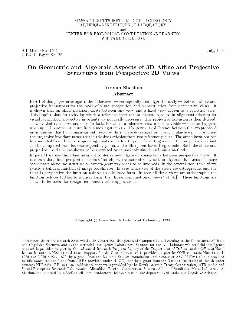
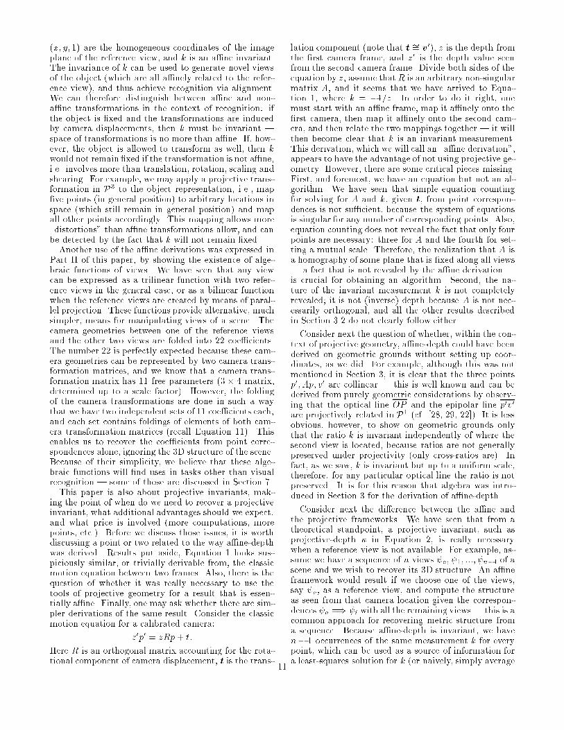
Figure 1:P1; P2; P3 will be denoted by �1. Let O be the COP ofthe �rst camera, and O0 the COP of the second camera.We assign the coordinates (0; 0; 0; 1); (1;1;1; 1) to O;O0,respectively (see Figure 1). This choice of representationis always possible because the two cameras are part ofP3. By construction, the point of intersection of the lineOO0 with �1 has the coordinates (1; 1; 1; 0) (note that �1is the plane x3 = 0, therefore the linear combination ofO and O0 with x3 = 0 must be a multiple of (1; 1; 1; 0)).Let P be some object point projecting onto p; p0. Theline OP intersects �1 at the point (�; �; ; 0). The coor-dinates �; �; can be recovered by projecting the imageplane onto �1, as follows. Let v; v0 be the location of bothepipoles in the �rst and second view, respectively (seeSection 2.6). Given the epipoles v and v0, we have by ourchoice of coordinates that p1; p2; p3 and v are projectively(in P2) mapped onto e1 = (1; 0; 0); e2 = (0; 1; 0); e3 =(0; 0; 1) and e4 = (1; 1; 1), respectively. Therefore, thereexists a unique element A1 2 PGL3 (3�3 matrix de�nedup to a scale) that satis�es A1pj �= ej , j = 1; 2; 3, andA1v = e4. Note that we have made a choice of scale bysetting A1v to e4, this is simply for convenience as willbe clear later on. It follows that A1p = (�; �; ).Similarly, the line O0P intersects �1 at (�0; �0; 0; 0).Let A2 2 PGL3 be de�ned by A2p0j �= ej , j = 1; 2; 3, andA2v0 = e4. It follows that A2p0 = (�0; �0; 0). Since Pcan be described as a linear combination of two pointsalong each of the lines OP , and O0P , we have the fol-lowing equation:P �= 0B@ �� 0 1CA+ k0B@ 0001 1CA = �0B@ �0�0 00 1CA + s0B@ 1111 1CA ;from which it immediately follows that k = s. We havetherefore, by the choice of putting both cameras on theframe of reference, that the transformation in P3 is a�ne(the plane �1 is preserved). If we leave the �rst camera�xed and move the second camera to a new position(must be a general position, i.e., O0 62 �1), then thetransformation in P3 belongs to the same a�ne group.
Note that since only ratios of coordinates are signi�cantin Pn, k is determined up to a uniform scale, and anypoint Po 62 �1 can be used to set a mutual scale forall views | by setting an appropriate scale for v0, forexample. The value of k can easily be determined asfollows: we have� �0�0 0 ! = �� !� k 111 ! :Multiply both sides by A�12 for which we get�p0 = Ap� kv0; (1)where A = A�12 A1. Note that A 2 PGL3 is acollineation between the two image planes, due to �1,determined by p0j �= Apj, j = 1; 2; 3, and Av = v0 (there-fore, can be recovered directly without going throughA1; A2). Since k is determined up to a uniform scale,we need a fourth correspondence po; p0o, and let A, or v0,be scaled such that p0o �= Apo � v0. Then k is an a�neinvariant, which we will refer to as \a�ne depth". Fur-thermore, (x; y; 1; k) are the homogeneous coordinatesrepresentation of P , and the 3 � 4 matrix [A;�v0] is acamera transformation matrix between the two views.Note that k is invariant when computed against a refer-ence view (the �rst view in this derivation), the cameratransformationmatrix does not only depend on the cam-era displacement but on the choice of three points, andthe camera is an \a�ne engine" if a reference view isavailable. More details on theoretical aspects of this re-sult are provided in Section 3.2, but �rst we discuss itsalgorithmic aspect.3.1 Two Algorithms: Re-projection and A�neReconstruction from Two PerspectiveViewsOn the practical side, we have arrived to a remarkablysimple algorithm for a�ne reconstruction from two per-spective/orthographic views (with an uncalibrated cam-era), and an algorithm for generating novel views of ascene (re-projection). For reconstruction we follow thesesteps:1. Compute epipoles v; v0 (see Section 2.6).2. Compute the matrix A that satis�es Apj �= p0j , j =1; 2; 3, and Av �= v0. This requires a solution of alinear system of eight equations (see Appendices in[19, 27, 28] for details).3. Set the scale of v0 by using a fourth correspondingpair po; p0o such that p0o �= Apo � v0.4. For every corresponding pair p; p0 recover the a�nedepth k that satis�es p0 �= Ap� kv0. As a technicalnote, k can be recovered in a least-squares fashionby using cross-products:k = (p0 � v0)T (p0 � Ap)k p0 � v0 k2 :Note that k is invariant as long as we use the �rst viewas a reference view, i.e., compute k between a referenceview p and any other view. The invariance of k can be3
used to \re-project" the object onto any third view p00,as follows. We observe:p00 �= Bp � kv00;for some (unique up to a scale) matrixB and epipole v00.One can solve for B and v00 by observing six correspond-ing points between the �rst and third view. Each pair ofcorresponding points pj; p00j contributes two equations:b31xjx00j + b32yjx00j�kjv003x00j + x00j =b11xj + b12yj + b13 � kjv001 ;b31xjy00j + b32yjy00j�kjv003y00j + y00j =b21xj + b22yj + b23 � kjv002 ;where b33 = 1 (this for setting an arbitrary scale becausethe system of equations is homogeneous | of coursethis prevents the case where b33 = 0, but in practicethis is not a problem; also one can use principal compo-nent analysis instead of setting the value of some cho-sen element of B or v00). The values of kj are foundfrom the correspondences pj ; p0j, j = 1; :::; 6 (note thatk1 = k2 = k3 = 0). Once B; v00 are recovered, we can�nd the location of p00i for any seventh point pi, by �rstsolving for ki from the equation p0i �= Api�kiv0, and thensubstituting the result in the equation p00i �= Bpi � kiv00.3.2 Results of Theoretical NatureLet o 2 S be some view from the set of all possibleviews, and let p1; p2; p3 2 o be non-collinear pointsprojected from some plane �. Also, let S� � S be thesubset of views for which the corresponding pairs of pj,j = 1; 2; 3, are non-collinear (A is full rank). Note thatS� contains all views for which the COP is not on �. Wehave the following result:There exists an a�ne invariant between a reference view o and the set of views S�.The result implies that, within the framework of un-calibrated cameras, there are certain tasks which are in-herently a�ne and, therefore, projective invariants arenot necessary and instead a�ne invariants are su�cient(it is yet to be shown when exactly do we need to recoverprojective invariants | this is the subject of Section 4).Consider for example the task of recognition within thecontext of alignment [30, 11]. In the alignment approach,two or more reference views (also called model views),or a 3D model, are stored in memory | and referred toas a \model" of the object. During the recognition pro-cess, a small number of corresponding points betweenthe reference views and the novel view are used for \re-projecting" the object onto the novel viewing position(as for example using the method described in the previ-ous section). Recognition is achieved if the re-projectedimage is successfully matched against the input image.This entails a sequential search over all possible modelsuntil a match is found between the novel view and there-projected view using a particular model. The impli-cation of the result above is that since alignment uses
1
O
P
Π
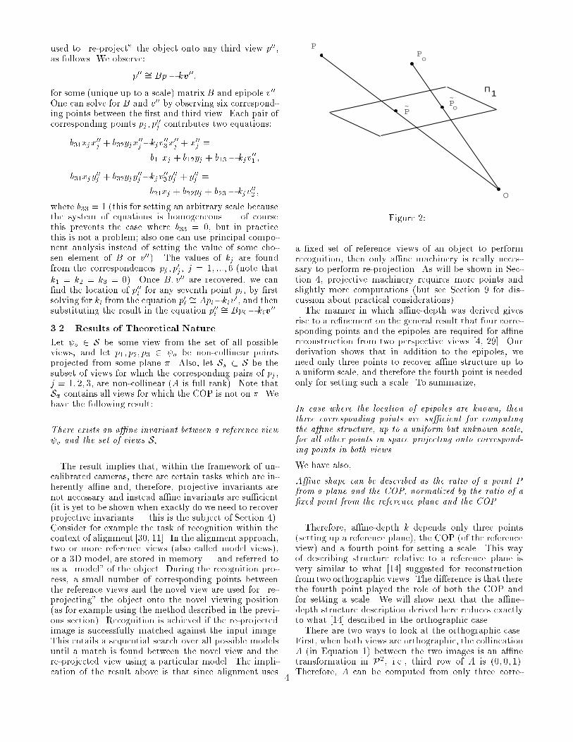
P
Po
~ Po
~
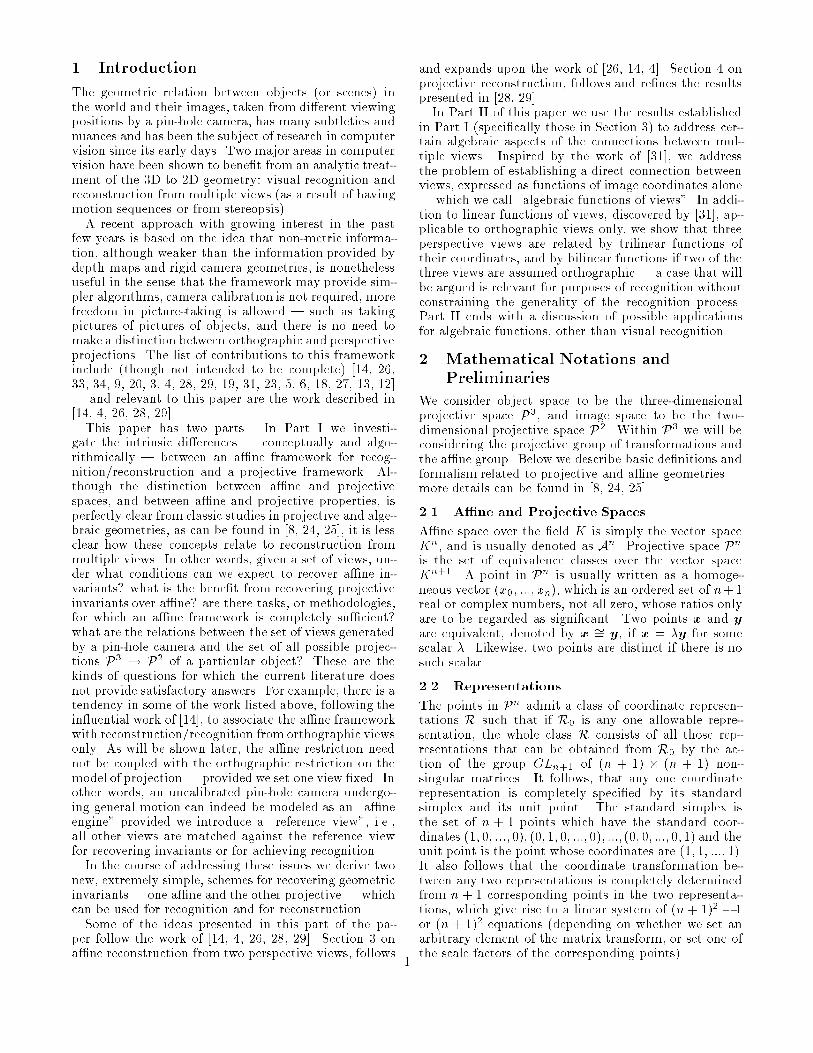
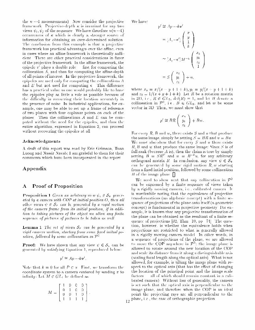
Figure 2:a �xed set of reference views of an object to performrecognition, then only a�ne machinery is really neces-sary to perform re-projection. As will be shown in Sec-tion 4, projective machinery requires more points andslightly more computations (but see Section 9 for dis-cussion about practical considerations).The manner in which a�ne-depth was derived givesrise to a re�nement on the general result that four corre-sponding points and the epipoles are required for a�nereconstruction from two perspective views [4, 29]. Ourderivation shows that in addition to the epipoles, weneed only three points to recover a�ne structure up toa uniform scale, and therefore the fourth point is neededonly for setting such a scale. To summarize,In case where the location of epipoles are known, thenthree corresponding points are su�cient for computingthe a�ne structure, up to a uniform but unknown scale,for all other points in space projecting onto correspond-ing points in both views.We have also,A�ne shape can be described as the ratio of a point Pfrom a plane and the COP, normalized by the ratio of a�xed point from the reference plane and the COP.Therefore, a�ne-depth k depends only three points(setting up a reference plane), the COP (of the referenceview) and a fourth point for setting a scale. This wayof describing structure relative to a reference plane isvery similar to what [14] suggested for reconstructionfrom two orthographic views. The di�erence is that therethe fourth point played the role of both the COP andfor setting a scale. We will show next that the a�ne-depth structure description derived here reduces exactlyto what [14] described in the orthographic case.There are two ways to look at the orthographic case.First, when both views are orthographic, the collineationA (in Equation 1) between the two images is an a�netransformation in P2, i.e., third row of A is (0; 0; 1).Therefore, A can be computed from only three corre-4

sponding points, Apj �= p0j , j = 1; 2; 3. Because both Oand O0 are at in�nity, then the epipole v0 is on the planex2 = 0, i.e., v03 = 0, and as a result all epipolar linesare parallel to each other. A fourth corresponding pointpo; p0o can be used to determine both the direction ofepipolar lines and to set the scale for the a�ne depth ofall other points | as described in [14]. We see, therefore,that the orthographic case is simply a particular case ofEquation 1. Alternatively, consider again the structuredescription entailed by our derivation of a�ne depth. Ifwe denote the point of intersection of the line OP with�1 by ~P , we have (see Figure 2)k = P� ~PP�OPo� ~PoPo�O :Let O (the COP of the �rst camera) go to in�nity, inwhich case a�ne-depth approachesk �! P � ~PPo � ~Po ;which is precisely the way shape was described in [14](see also [26, 27]). In the second view, if it is or-thographic, then the two trapezoids P; ~P; p0; Ap andPo; ~Po; p0o; Apo are similar, and from similarity of trape-zoids we obtain P � ~PPo � ~Po = p0 �App0o �Apo ;which, again, is the expression described in [14, 26]. Notethat a�ne-depth in the orthographic case does not de-pend any more on O, and therefore remains �xed regard-less of what pair of views we choose, namely, a referenceview is not necessary any more. This leads to the fol-lowing result:Let �S � S be the subset of views created by means ofparallel projection, i.e., the plane x2 = 0 is preserved.Given four �xed reference points, a�ne-depth on S isreference-view-dependent, whereas a�ne-depth on �S isreference-view-independent.Consider next the resulting camera transformationmatrix [A;�v0]. The matrix A depends on the choice ofthree points and therefore does not only depend on thecamera displacement. This additional degree of freedomis a direct result of our camera being uncalibrated, i.e.,we are free to choose the internal camera parameters (fo-cal length, principal point, and image coordinates scalefactors) as we like. The matrix A is unique, i.e., dependsonly on camera displacement, if we know in advance thatthe internal camera parameters remain �xed for all viewsS� . For example, assume the camera is calibrated in theusual manner, i.e., focal length is 1, principle point is at(0; 0; 1) in Euclidean coordinates, and image scale factorsare 1 (image plane is parallel to xy plane of Euclideancoordinate system). In that case A is an orthogonal ma-trix and can be recovered from two corresponding pointsand the epipoles | by imposing the constraint that vec-tor magnitudes remain unchanged (each point provides
three equations). A third corresponding point can beused to determine the re ection component (i.e., mak-ing sure the determinant of A is 1 rather than �1). Moredetails can be found in [27, 15]. Since in the uncalibratedcase A is not unique, let A� denote the fact that A isthe collineation induced by a plane �, and let k� denotethe fact that the a�ne-depth also depends on the choiceof �. We see, therefore, that there exists a family ofsolutions for the camera transformation matrix and thea�ne-depth as a function of �. This immediately impliesthat a naive solution for A; k, given v0, from point corre-spondences leads to a singular system of equations (evenif many points are used for a least-squares solution).Given the epipole v0, the linear system of equations forsolving for A and kj of the equation�p0j = Apj � kjv0;from point correspondences pj ; p0j is singular, unless fur-ther constraints are introduced.We see that equation counting alone is not su�cientfor obtaining a unique solution, and therefore the knowl-edge that A is a homography of a plane is critical for thistask. For example, one can solve for A and kj frommanycorrespondences in a least-squares approach by �rst set-ting kj = 0, j = 1; 2; 3 and k4 = 1, otherwise the solutionmay not be unique.Finally, consider the \price" we are paying for an un-calibrated, a�ne framework. We can view this in twoways, somewhat orthogonal. First, if the scene is un-dergoing transformations, and the camera is �xed, thenthose transformations are a�ne in 3D, rather than rigid.For purposes of achieving visual recognition the price weare paying is that we might confuse two di�erent ob-jects that are a�nely related. Second, because of thenon-uniqueness of the camera transformation matrix itappears that the set of views S� is a superset of the setof views that could be created by a calibrated camerataking pictures of the object. The natural question iswhether this superset can, nevertheless, be realized bya calibrated camera. In other words, if we have a cal-ibrated camera (or we know that the internal cameraparameters remain �xed for all views), then can we gen-erate S� , and if so how? This question was addressed�rst in [12] but assuming only orthographic views. Amore general result is expressed in the following propo-sition:Proposition 1 Given an arbitrary view o 2 S� gener-ated by a camera with COP at initial position O, then allother views 2 S� can be generated by a rigid motionof the camera frame from its initial position, if in addi-tion to taking pictures of the object we allow any �nitesequence of pictures of pictures to be taken as well.The proof has a trivial and a less trivial component.The trivial part is to show that an a�ne motion of thecamera frame can be decomposed into a rigid motionfollowed by some arbitrary collineation in P2. The lesstrivial component is to show that any collineation in P25
P
(0,0,0,1)
(1,0,0,0)
(0,1,0,0)
(0,0,1,0)
(1,1,1,1)
O
P
P
P
P
1
2
3
4
(1,1,1,0)
1
π
π2
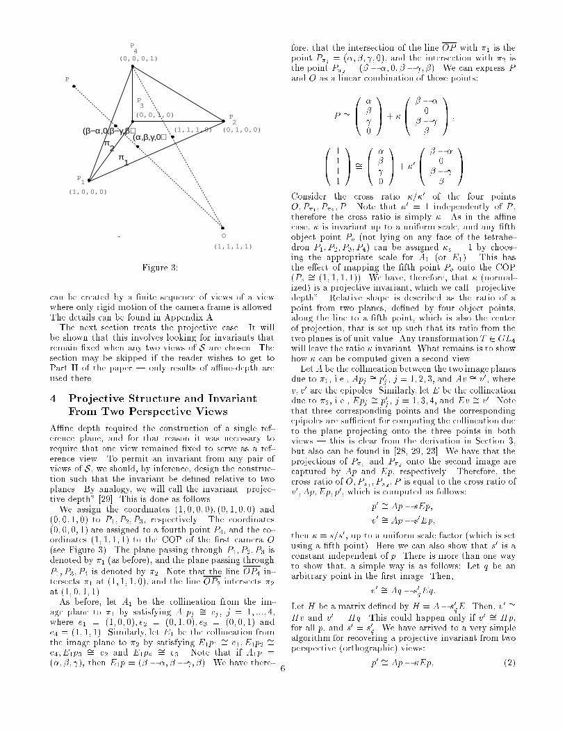
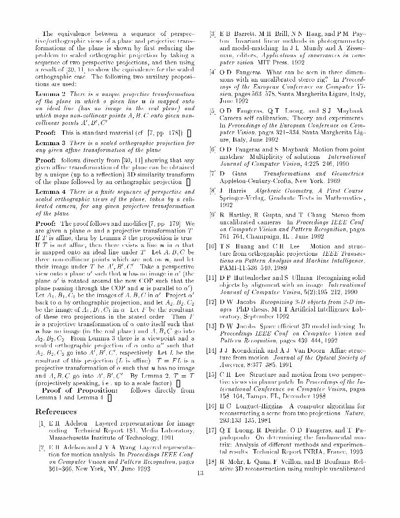
(α,β,γ,0)(β−α,0,β−γ,β)
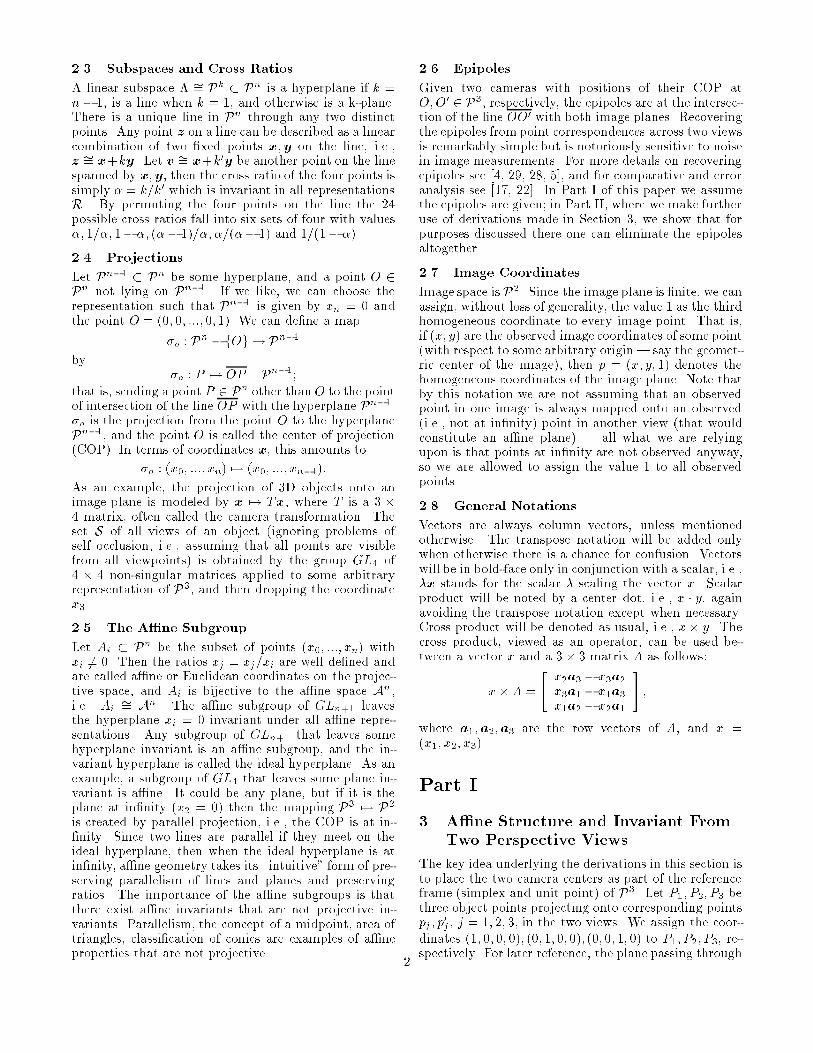
Figure 3:can be created by a �nite sequence of views of a viewwhere only rigid motion of the camera frame is allowed.The details can be found in Appendix A.The next section treats the projective case. It willbe shown that this involves looking for invariants thatremain �xed when any two views of S are chosen. Thesection may be skipped if the reader wishes to get toPart II of the paper | only results of a�ne-depth areused there.4 Projective Structure and InvariantFrom Two Perspective ViewsA�ne depth required the construction of a single ref-erence plane, and for that reason it was necessary torequire that one view remained �xed to serve as a ref-erence view. To permit an invariant from any pair ofviews of S, we should, by inference, design the construc-tion such that the invariant be de�ned relative to twoplanes. By analogy, we will call the invariant \projec-tive depth" [29]. This is done as follows.We assign the coordinates (1; 0; 0; 0); (0; 1; 0;0) and(0; 0; 1; 0) to P1; P2; P3, respectively. The coordinates(0; 0; 0; 1) are assigned to a fourth point P4, and the co-ordinates (1; 1; 1; 1) to the COP of the �rst camera O(see Figure 3). The plane passing through P1; P2; P3 isdenoted by �1 (as before), and the plane passing throughP1; P3; P4 is denoted by �2. Note that the line OP4 in-tersects �1 at (1; 1; 1; 0), and the line OP2 intersects �2at (1; 0; 1; 1).As before, let A1 be the collineation from the im-age plane to �1 by satisfying A1pj �= ej , j = 1; :::; 4,where e1 = (1; 0; 0); e2 = (0; 1; 0); e3 = (0; 0; 1) ande4 = (1; 1; 1). Similarly, let E1 be the collineation fromthe image plane to �2 by satisfying E1p1 �= e1; E1p2 �=e4; E1p3 �= e2 and E1p4 �= e3. Note that if A1p =(�; �; ), then E1p = (� � �; � � ; �). We have there-
fore, that the intersection of the line OP with �1 is thepoint P�1 = (�; �; ; 0), and the intersection with �2 isthe point P�2 = (� � �; 0; � � ; �). We can express Pand O as a linear combination of those points:P �= 0B@ �� 0 1CA+ �0B@ � � �0� � � 1CA ;0B@ 1111 1CA �= 0B@ �� 0 1CA + �00B@ � � �0� � � 1CAConsider the cross ratio �=�0 of the four pointsO;P�1; P�2 ; P . Note that �0 = 1 independently of P ,therefore the cross ratio is simply �. As in the a�necase, � is invariant up to a uniform scale, and any �fthobject point Po (not lying on any face of the tetrahe-dron P1; P2; P3; P4) can be assigned �o = 1 by choos-ing the appropriate scale for A1 (or E1). This hasthe e�ect of mapping the �fth point Po onto the COP(Po �= (1; 1; 1; 1)). We have, therefore, that � (normal-ized) is a projective invariant, which we call \projectivedepth". Relative shape is described as the ratio of apoint from two planes, de�ned by four object points,along the line to a �fth point, which is also the centerof projection, that is set up such that its ratio from thetwo planes is of unit value. Any transformation T 2 GL4will leave the ratio � invariant. What remains is to showhow � can be computed given a second view.Let A be the collineation between the two image planesdue to �1, i.e., Apj �= p0j , j = 1; 2; 3, and Av �= v0, wherev; v0 are the epipoles. Similarly, let E be the collineationdue to �2, i.e., Epj �= p0j, j = 1; 3; 4, and Ev �= v0. Notethat three corresponding points and the correspondingepipoles are su�cient for computing the collineation dueto the plane projecting onto the three points in bothviews | this is clear from the derivation in Section 3,but also can be found in [28, 29, 23]. We have that theprojections of P�1 and P�2 onto the second image arecaptured by Ap and Ep, respectively. Therefore, thecross ratio of O;P�1; P�2 ; P is equal to the cross ratio ofv0; Ap;Ep; p0, which is computed as follows:p0 �= Ap � sEp;v0 �= Ap � s0Ep;then � = s=s0, up to a uniform scale factor (which is setusing a �fth point). Here we can also show that s0 is aconstant independent of p. There is more than one wayto show that, a simple way is as follows: Let q be anarbitrary point in the �rst image. Then,v0 �= Aq � s0qEq:Let H be a matrix de�ned by H = A� s0qE. Then, v0 �=Hv and v0 = Hq. This could happen only if v0 �= Hp,for all p, and s0 = s0q. We have arrived to a very simplealgorithm for recovering a projective invariant from twoperspective (orthographic) views:p0 �= Ap� �Ep; (2)6
where A and E are described above, and � is invariantup to a uniform scale, which can be set by observing a�fth correspondence po; p0o, i.e., set the scale of E to sat-isfy p0o �= Apo�Epo. Unlike the a�ne case, � is invariantfor any two views from the set S of all possible views.Note that � need not be normalized using a �fth point,if the �rst view remains �xed (we are back to the a�necase). We have arrived to the following result, which isa re�nement on the general result made in [4] that �vecorresponding points and the corresponding epipoles aresu�cient for reconstruction up to a collineation in P3:In case where the location of epipoles are known,then four corresponding points, coming from four non-coplanar points in space, are su�cient for computing theprojective structure, up to a uniform but unknown scale,for all other points in space projecting onto correspond-ing points in both views. A �fth corresponding point,coming from a point in general position with the otherfour points, can be used to set the scale.We have also,Projective shape can be described as the ratio of a point Pfrom two faces of the tetrahedron, normalized by the ra-tio of a �xed point (the unit point of the reference frame)from those faces.The practical implication of this derivation is that aprojective invariant, such as the one described here, isworthwhile computing for tasks for which we do not havea �xed reference view available. Worthwhile becauseprojective depth requires an additional correspondingpoint, and requires slightly more computations (recoverthe matrix E in addition to A). Such a task, for ex-ample, is to update the reconstructed structure from amoving stereo rig. At each time instance we are given apair of views from which projective depth can be com-puted (projective coordinates follow trivially), and sinceboth cameras are changing their position from one timeinstant to the next, we cannot rely on an a�ne invariant.5 Summary of Part IGiven a view o with image points p, there exists ana�ne invariant k between o and any other view i, withcorresponding image points p0, satisfying the followingequation: �p0 = Ap� kv0;where A is the collineation between the two image planesdue to the projection of some plane �1 projecting to bothviews, and v0 is the epipole scaled such that �op0o =Apo � v0 for some point po. The set of all views S�1 forwhich the camera's center is not on �1 will satisfy theequation above against o. The view o is a referenceview.A projective invariant � is de�ned between any twoviews i and j , again for the sake of not introducingnew notations, projecting onto corresponding points pand p0, respectively. The invariant satis�es the followingequation: �p0 = Ap� �Ep;
where A is the collineation due to some plane �1, andE is the collineation due to some other plane �2 scaledsuch that �op0o = Apo �Epo, for some point po.Part II6 Algebraic Functions of ViewsIn this part of the paper we use the results established inSection 3 to derive results of a di�erent nature: insteadof reconstruction of shape and invariants we would like toestablish a direct connection between views expressed asa functions of image coordinates alone | which we willcall \algebraic functions of views". With these functionsone can manipulate views of an object, such as createnew views, without the need to recover shape or camerageometry as an intermediate step | all what is neededis to appropriately combine the image coordinates of tworeference views.Algebraic functions of two views include the expressionp0TFp = 0; (3)where F is known as the \Fundamental" matrix (cf. [4])(a projective version of the well known \Essential" ma-trix of [16]), and the expression�1x0 + �2y0 + �3x+ �4y + �5 = 0 (4)due to [10], which is derived for orthographic views.These functions express the epipolar geometry betweenthe two views in the perspective and orthographic cases,respectively. Algebraic functions of three views were in-troduced in the past only for orthographic views [31, 21].For example,�1x00 + �2x0 + �3x+ �4y + �5 = 0:These functions express a relationship between the im-age coordinates of one view as a function of image co-ordinates of two other views | in the example above,the x coordinate in the third view, x00, is expressed as alinear function of image coordinates in two other views,similar expressions exist for y00.We will use the a�ne-depth invariant result to de-rive algebraic functions of three perspective views. Therelationship between a perspective view and two otherperspective views is shown to be trilinear in image coor-dinates across the three views. The relationship is shownto be bilinear if two of the views are orthographic | aspecial case useful for recognition tasks. We will start byaddressing the two-view case. We will use Equation 1 torelate the entries of the camera transformation A and v0(of Equation 1) to the fundamental matrix by showingthat F = v0�A. This also has an advantage of introduc-ing an alternative way of deriving expressions 3 and 4, away that also puts them both under a single framework.6.1 Algebraic Functions of Two ViewsConsider Equation 1, reproduced below,� x0y01 ! = A xy1 !� kv0:7

By simple manipulation of this equation we obtain:k = v01 � x0v03x0a3 � p � a1 � p = v02 � y0v03y0a3 � p � a2 � p= y0v01 � x0v2x0a2 � p� y0a1 � p ; (5)where a1;a2;a3 are the row vectors of A and v0 =(v01; v02; v03). After equating the �rst two terms, we ob-tain: x0(v02a3 � p� v03a2 � p) + y0(v03a1 � p� v01a3 � p) +(v01a2 � p� v02a1 � p) = 0: (6)Note that the terms within parentheses are linear poly-nomials in x; y with �xed coe�cients (i.e., depend onlyon A and v0). Also note that we get the same expres-sion when equating the �rst and third, or the second andthird terms of Equation 5. This leads to the followingresult:The image coordinates (x; y) and (x0; y0) of two corre-sponding points across two perspective views satisfy aunique equation of the following form:x0(�1x+ �2y + �3) + y0(�4x+ �5y + �6) +�7x+ �8y + �9 = 0; (7)where the coe�cients �j , j = 1; :::; 9, have a �xed re-lation to the camera transformation A and v0 of Equa-tion 1: �1 = v02a31 � v03a21;�2 = v02a32 � v03a22;�3 = v02a33 � v03a23;�4 = v03a11 � v01a31;�5 = v03a12 � v01a32;�6 = v03a13 � v01a33;�7 = v01a21 � v02a11;�8 = v01a22 � v02a12;�9 = v01a23 � v02a13:Equation 7 can also be written as p0tFp = 0, wherethe entries of the matrix F are the coe�cients �j, andtherefore, F = v0�A. We have, thus, obtained a new andsimple relationship between the elements of the \funda-mental" matrix F and the elements of the camera trans-formation A and v0. It is worth noting that this resultcan be derived much easier, as follows. First, the rela-tionship p0tFp = 0 can be derived, as observed by [4],from the fact that F is a correlation mapping pointsp onto their corresponding epipolar lines l0 in the sec-ond image, and therefore p0 � l0 = 0. Second1, sincel0 �= v0 � Ap, we have F = v0 � A. It is known thatthe rank of the fundamental matrix is 2; we can use thisrelationship to show that as well:F = v0 �A = " v02a3 � v03a2v03a1 � v01a3v01a2 � v02a1 # ;1This was a comment made by Tuan Luong.
where a1;a2;a3 are the row vectors of A. Let f1;f2;f3be the row vectors of F , then it is easy to verify thatf3 �= �f1 + �f2;by setting �v02 = �v01:Next, we can use the result F = v0 � A to show howthe orthographic case, treated by [10], �ts this relation-ship. In the framework of Equation 1, we saw that withorthographic views we have A being a�ne in P2, i.e.,a3 � p = 1, and v03 = 0. After substitution in Equation 6,we obtain the equation:�1x0 + �2y0 + �3x+ �4y + �5 = 0; (8)where the coe�cients �j, j = 1; :::; 5 have the followingvalues: �1 = v02;�2 = �v01;�3 = v01a21 � v02a11;�4 = v01a22 � v02a12;�5 = v01a23 � v02a13:These coe�cients are also the entries of the fundamentalmatrix, which can also be derived from F = v0 � A bysetting v03 = 0 and a3 = (0; 0; 1).The algebraic function 7 can be used for re-projectiononto a third view, by simply noting that the function be-tween view 1 and 3, and the function between view 2 and3, provide two equations for solving for (x00; y00). Thiswas proposed in the past, in various forms, by [20, 3, 19].Since the algebraic function expresses the epipolar geom-etry between the two views, however, a solution can befound only if the COPs of the three cameras are non-collinear (cf. [28, 27]) | which can lead to numericalinstability unless the COPs are far from collinear. Thealternative, as shown next, is to derive directly alge-braic functions of three views. In that case, the coor-dinates (x00; y00) are solved for separately, each from asingle equation, without problems of singularities.6.2 Algebraic Functions of Three ViewsConsider Equation 1 applied between view 1 and 2, andbetween view 1 and 3:�p0 = Ap� kv0�p00 = Bp � kv00: (9)Here we make use of the result that a�ne-depth k isinvariant for any view in reference to the �rst view. Wecan isolate k again from Equation 9 and obtain:k = v001 � x00v003x00b3 � p� b1 � p = v002 � y00v003y00b3 � p� b2 � p= y00v001 � x00v002x00b2 � p� y00b1 � p ; (10)where b1; b2; b3 are the row vectors of B and v00 =(v001 ; v002 ; v003 ). Because of the invariance of k we can equateterms of Equation 5 with terms of Equation 10 and ob-tain trilinear functions of image coordinates across three8
views. For example, by equating the �rst two terms ineach of the equations, we obtain:x00(v01b3 � p� v003a1 � p) + x00x0(v003a3 � p� v03b3 � p) +x0(v03b1 � p � v001a3 � p) + v001a1 � p� v01b1 � p = 0: (11)This leads to the following result:The image coordinates (x; y), (x0; y0) and (x00; y00) ofthree corresponding points across three perspective viewssatisfy a trilinear equation of the following form:x00(�1x+ �2y + �3) + x00x0(�4x+ �5y + �6) +x0(�7x+ �8y + �9) + �10x+ �11y + �12 = 0; (12)where the coe�cients �j, j = 1; :::; 12, have a �xed rela-tion to the camera transformations between the �rst viewand the other two views.Note that the x coordinate in the third view, x00, is ob-tained as a solution of a single equation in coordinates ofthe other two views. The coe�cients �j can be recoveredas a solution of a linear system, directly if we observe 11corresponding points across the three views (more than11 points can be used for a least-squares solution), orwith fewer points by �rst recovering the elements of thecamera transforms as described in Section 3. Then, forany additional point (x; y) whose correspondence in thesecond image is known (x0; y0), we can recover the corre-sponding x coordinate, x00, in the third view by substi-tution in equation 12.In a similar fashion, after equating the �rst term ofEquation 5 with the second term of Equation 10, weobtain an equation for y00 as a function of the two otherviews:y00(�1x+ �2y + �3) + y00x0(�4x+ �5y + �6) +x0(�7x+ �8y + �9) + �10x+ �11y + �12 = 0: (13)Taken together, Equations 5 and 10 lead to 9 algebraicfunctions of three views, six of which are separate for x00and y00. The other four functions are listed below:x00(�) + x00y0(�) + y0(�) + (�) = 0; (14)y00(�) + y00y0(�) + y0(�) + (�) = 0; (15)x00x0(�) + x00y0(�) + x0(�) + y0(�) = 0; (16)y00x0(�) + y00y0(�) + x0(�) + y0(�) = 0; (17)where (�) represent linear polynomials in x; y. The so-lution for x00; y00 is unique without constraints on theallowed camera transformations. If we choose Equa-tions 12 and 13, then v01 and v03 should not vanish si-multaneously, i.e., v0 �= (0; 1; 0) is a singular case. Alsov00 �= (0; 1; 0) and v00 �= (1; 0; 0) give rise to singular cases.One can easily show that for each singular case thereare two other functions out of the nine available onesthat provide a unique solution for x00; y00. Note that thesingular cases are pointwise, i.e., only three epipolar di-rections are excluded, compared to the much strongersingular case when the algebraic function of two views isused separately, as described in the previous section.Taken together, the process of generating a novel viewcan be easily accomplished without the need to explicitly
recover structure (a�ne depth), camera transformation(matrices A;B and epipoles v0; v00) or epipolar geometry(just the epipoles or the Fundamental matrix) | for theprice of using more than the minimal number points thatare required otherwise (the minimal is six between thetwo model views and the novel third view).The connection between the general result of trilinearfunctions of views to the \linear combination of views"result [31] for orthographic views, can easily be seen bysetting A and B to be a�ne in P2, and v03 = v003 = 0.For example, Equation 11 reduces to:v01x00 � v001x0 + (v001a1 � p� v01b1 � p) = 0; (18)which is of the form:�1x00 + �2x0 + �3x+ �4y + �5 = 0:In the case where all three views are orthographic, thenx00 is expressed as a linear combination of image coordi-nates of the two other views | as discovered by [31].In the next section we address another case, interme-diate between the general trilinear and the orthographiclinear functions, which we �nd interesting for applica-tions of visual recognition.6.2.1 Recognition of Perspective views Froman Orthographic ModelConsider the case for which the two reference (model)views of an object are taken orthographically (using atele lens would provide a reasonable approximation), butduring recognition any perspective view of the object isallowed. It can easily be shown that the three views arethen connected via a bilinear function (instead of trilin-ear): A is a�ne in P2 and v03 = 0, therefore Equation 11reduces to: x00(v01b3 � p� v003a1 � p) + v003x00x0 �v001x0 + (v001a1 � p� v01b1 � p) = 0;which is of the following form:x00(�1x+ �2y + �3) + �4x00x0 +�5x0 + �6x+ �7y + �8 = 0: (19)Similarly, Equation 13 reduces toy00(�1x+ �2y + �3) + �4y00x0 +�5x0 + �6x+ �7y + �8 = 0: (20)A bilinear function of three views has two advantagesover the general trilinear function. First, only seven cor-responding points (instead of 11) across three views arerequired for solving for the coe�cients (compared to theminimal six if we �rst recover A;B; v0; v00). Second, thelower the degree of the algebraic function, the less sen-sitive the solution should be in the presence of errors inmeasuring correspondences. In other words, it is likely(though not necessary) that the higher order terms, suchas the term x00x0x in Equation 12, will have a higher con-tribution to the overall error sensitivity of the system.Compared to the case when all views are assumed or-thographic, this case is much less of an approximation.Since the model views are taken only once, it is not un-reasonable to require that they be taken in a special9

way, namely, with a tele lens (assuming we are dealingwith object recognition, rather than scene recognition).If that requirement is satis�ed, then the recognition taskis general since we allow any perspective view to be takenduring the recognition process.7 ApplicationsAlgebraic functions of views allow the manipulation ofimages of 3D objects without necessarily recovering 3Dstructure or any form of camera geometry (either full, orweak | the epipoles).The application that was emphasized throughout thepaper is visual recognition via alignment. In this con-text, the general result of a trilinear relationship betweenviews is not encouraging. If we want to avoid implicatingstructure and camera geometry, we must have 11 corre-sponding points across the three views | compared tosix points, otherwise. In practice, however, we wouldneed more than the minimal number of points in or-der to obtain a least squares solution. The question iswhether the simplicity of the method using trilinear func-tions translates also to increased robustness in practicewhen many points are used | this is an open question.Still in the context of recognition, the existence of bi-linear functions in the special case where the model isorthographic, but the novel view is perspective, is moreencouraging. Here we have the result that only seven cor-responding points are required to obtain recognition ofperspective views (provided we can satisfy the require-ment that the model is orthographic) compared to sixpoints when structure and camera geometry are recov-ered. The additional corresponding pair of points maybe indeed worth the greater simplicity that comes withworking with algebraic functions.There may exist other applications where simplicityis of major importance, whereas the number of pointsis less of a concern. Consider for example, the appli-cation of model-based compression. With the trilinearfunctions we need 22 parameters to represent a view asa function of two reference views in full correspondence.Assume both the sender and the receiver have the tworeference views and apply the same algorithm for obtain-ing correspondences between the two views. To senda third view (ignoring problems of self occlusions thatcould be dealt separately) the sender can solve for the22 parameters using many points, but eventually sendonly the 22 parameters. The receiver then simply com-bines the two reference views in a \trilinear way" giventhe received parameters. This is clearly a domain wherethe number of points are not a major concern, whereassimplicity, and probably robustness due to the short-cutin the computations, is of great importance.Related to image coding is a recent approach of imagedecomposition into \layers" as proposed in [1, 2]. In thisapproach, a sequence of views is divided up into regions,whose motion of each is described approximately by a2D a�ne transformation. The sender sends the �rst im-age followed only by the six a�ne parameters for eachregion for each subsequent frame. The use of algebraicfunctions of views can potentially make this approachmore powerful because instead of dividing up the scene
into planes (it would have planes if the projection wasparallel, in general its not even planes) one can attemptto divide the scene into objects, each carries the 22 pa-rameters describing its displacement onto the subsequentframe.Another area of application may be in computergraphics. Re-projection techniques provide a short-cutfor image rendering. Given two fully rendered viewsof some 3D object, other views (again ignoring self-occlusions) can be rendered by simply \combining" thereference views. Again, the number of correspondingpoints is less of a concern here.8 Summary of Part IIThe derivation of an a�ne invariant across perspectiveviews in Section 3 was used to derive algebraic func-tions of image coordinates across two and three views.These enable the generation of novel views, for purposesof visual recognition and for other applications, withoutgoing through the process of recovering object structure(metric or non-metric) and camera geometry.Between two views there exists a unique functionwhose coe�cients are the elements of the Fundamentalmatrix and were shown to be related explicitly to thecamera transformation A; v0:x0(�1x+ �2y + �3) + y0(�4x+ �5y + �6) +�7x+ �8y + �9 = 0:The derivation was also useful in making the connectionto a similar expression, due to [10], made in the contextof orthographic views.We have seen that trilinear functions of image coordi-nates exist across three views, one of them shown below:x00(�1x+ �2y + �3) + x00x0(�4x+ �5y + �6) +x0(�7x+ �8y + �9) + �10x+ �11y + �12 = 0:In case two of the views are orthographic, a bilinear re-lationship across three views holds. For example, thetrilinear function above reduces to:x00(�1x+ �2y + �3) + �4x00x0 +�5x0 + �6x+ �7y + �8 = 0:In case all three views are orthographic, a linear rela-tionship holds | as observed in [31]:�1x00 + �2x0 + �3x+ �4y + �5 = 0:9 General DiscussionFor purposes of visual recognition, by alignment, thetransformations induced by changing viewing positionsis at most a�ne. In other words, a pin-hole uncalibratedcamera is no more than an \a�ne engine" for tasks forwhich a reference view ( a model) is available. One ofthe goals of this paper was to make this claim and makeuse of it in providing methods for a�ne reconstructionand for recognition.An a�ne reconstruction follows immediately fromEquation 1 and the realization that A is a collineationof some plane which is �xed for all views. The recon-structed homogeneous coordinates are (x; y; 1; k) where10
(x; y; 1) are the homogeneous coordinates of the imageplane of the reference view, and k is an a�ne invariant.The invariance of k can be used to generate novel viewsof the object (which are all a�nely related to the refer-ence view), and thus achieve recognition via alignment.We can therefore distinguish between a�ne and non-a�ne transformations in the context of recognition: ifthe object is �xed and the transformations are inducedby camera displacements, then k must be invariant |space of transformations is no more than a�ne. If, how-ever, the object is allowed to transform as well, then kwould not remain �xed if the transformation is not a�ne,i.e. involves more than translation, rotation, scaling andshearing. For example, we may apply a projective trans-formation in P3 to the object representation, i.e., map�ve points (in general position) to arbitrary locations inspace (which still remain in general position) and mapall other points accordingly. This mapping allows more\distortions" than a�ne transformations allow, and canbe detected by the fact that k will not remain �xed.Another use of the a�ne derivations was expressed inPart II of this paper, by showing the existence of alge-braic functions of views. We have seen that any viewcan be expressed as a trilinear function with two refer-ence views in the general case, or as a bilinear functionwhen the reference views are created by means of paral-lel projection. These functions provide alternative, muchsimpler, means for manipulating views of a scene. Thecamera geometries between one of the reference viewsand the other two views are folded into 22 coe�cients.The number 22 is perfectly expected because these cam-era geometries can be represented by two camera trans-formation matrices, and we know that a camera trans-formation matrix has 11 free parameters (3 � 4 matrix,determined up to a scale factor). However, the foldingof the camera transformations are done in such a waythat we have two independent sets of 11 coe�cients each,and each set contains foldings of elements of both cam-era transformation matrices (recall Equation 11). Thisenables us to recover the coe�cients from point corre-spondences alone, ignoring the 3D structure of the scene.Because of their simplicity, we believe that these alge-braic functions will �nd uses in tasks other than visualrecognition | some of those are discussed in Section 7.This paper is also about projective invariants, mak-ing the point of when do we need to recover a projectiveinvariant, what additional advantages should we expect,and what price is involved (more computations, morepoints, etc.). Before we discuss those issues, it is worthdiscussing a point or two related to the way a�ne-depthwas derived. Results put aside, Equation 1 looks sus-piciously similar, or trivially derivable from, the classicmotion equation between two frames. Also, there is thequestion of whether it was really necessary to use thetools of projective geometry for a result that is essen-tially a�ne. Finally, one may ask whether there are sim-pler derivations of the same result. Consider the classicmotion equation for a calibrated camera:z0p0 = zRp+ t:Here R is an orthogonal matrix accounting for the rota-tional component of camera displacement, t is the trans-
lation component (note that t �= v0), z is the depth fromthe �rst camera frame, and z0 is the depth value seenfrom the second camera frame. Divide both sides of theequation by z, assume thatR is an arbitrary non-singularmatrix A, and it seems that we have arrived to Equa-tion 1, where k = �1=z. In order to do it right, onemust start with an a�ne frame, map it a�nely onto the�rst camera, then map it a�nely onto the second cam-era, and then relate the two mappings together | it willthen become clear that k is an invariant measurement.This derivation, which we will call an \a�ne derivation",appears to have the advantage of not using projective ge-ometry. However, there are some critical pieces missing.First, and foremost, we have an equation but not an al-gorithm. We have seen that simple equation countingfor solving for A and k, given t, from point correspon-dences is not su�cient, because the system of equationsis singular for any number of corresponding points. Also,equation counting does not reveal the fact that only fourpoints are necessary: three for A and the fourth for set-ting a mutual scale. Therefore, the realization that A isa homography of some plane that is �xed along all views| a fact that is not revealed by the a�ne derivation |is crucial for obtaining an algorithm. Second, the na-ture of the invariant measurement k is not completelyrevealed; it is not (inverse) depth because A is not nec-essarily orthogonal, and all the other results describedin Section 3.2 do not clearly follow either.Consider next the question of whether, within the con-text of projective geometry, a�ne-depth could have beenderived on geometric grounds without setting up coor-dinates, as we did. For example, although this was notmentioned in Section 3, it is clear that the three pointsp0; Ap; v0 are collinear | this is well known and can bederived from purely geometric considerations by observ-ing that the optical line OP and the epipolar line p0v0are projectively related in P1 (cf. [28, 29, 22]). It is lessobvious, however, to show on geometric grounds onlythat the ratio k is invariant independently of where thesecond view is located, because ratios are not generallypreserved under projectivity (only cross-ratios are). Infact, as we saw, k is invariant but up to a uniform scale,therefore, for any particular optical line the ratio is notpreserved. It is for this reason that algebra was intro-duced in Section 3 for the derivation of a�ne-depth.Consider next the di�erence between the a�ne andthe projective frameworks. We have seen that from atheoretical standpoint, a projective invariant, such asprojective-depth � in Equation 2, is really necessarywhen a reference view is not available. For example, as-sume we have a sequence of n views o; 1; :::; n�1 of ascene and we wish to recover its 3D structure. An a�neframework would result if we choose one of the views,say o, as a reference view, and compute the structureas seen from that camera location given the correspon-dences o =) i with all the remaining views | this is acommon approach for recovering metric structure froma sequence. Because a�ne-depth is invariant, we haven� 1 occurrences of the same measurement k for everypoint, which can be used as a source of information fora least-squares solution for k (or naively, simply average11
the n � 1 measurements). Now consider the projectiveframework. Projective-depth � is invariant for any twoviews i; j of the sequence. We have therefore n(n�1)occurrences of � which is clearly a stronger source ofinformation for obtaining an over-determined solution.The conclusion from this example is that a projectiveframework has practical advantages over the a�ne, evenin cases where an a�ne framework is theoretically su�-cient. There are other practical considerations in favorof the projective framework. In the a�ne framework, theepipole v0 plays a double role | �rst for computing thecollineation A, and then for computing the a�ne-depthof all points of interest. In the projective framework, theepipoles are used only for computing the collineations Aand E but not used for computing �. This di�erencehas a practical value as one would probably like to havethe epipoles play as little a role as possible because ofthe di�culty in recovering their location accurately inthe presence of noise. In industrial applications, for ex-ample, one may be able to set up a frame of referenceof two planes with four coplanar points on each of theplanes. Then the collineations A and E can be com-puted without the need for the epipoles, and thus theentire algorithm, expressed in Equation 2, can proceedwithout recovering the epipoles at all.AcknowledgmentsA draft of this report was read by Eric Grimson, TuanLuong and Nassir Navab; I am grateful to them for theircomments which have been incorporated in the report.AppendixA Proof of PropositionProposition 1 Given an arbitrary view o 2 S� gener-ated by a camera with COP at initial position O, then allother views 2 S� can be generated by a rigid motionof the camera frame from its initial position, if in addi-tion to taking pictures of the object we allow any �nitesequence of pictures of pictures to be taken as well.Lemma 1 The set of views S� can be generated by arigid camera motion, starting from some �xed initial po-sition, followed by some collineation in P2.Proof: We have shown that any view 2 S� can begenerated by satisfying Equation 1, reproduced below:p0 �= Ap� kv0:Note that k = 0 for all P 2 �. First, we transform thecoordinate system to a camera centered by sending � toin�nity: Let M 2 GL4 be de�ned asM = 264 1 0 0 00 1 0 00 0 1 01 1 1 1 375 :
We have: p0 �= Ap� kv0= [A;�v0]0B@ xy1k 1CA�= [A;�v0]M�10B@ xbybzb1 1CA= S xbybzb !+ u;where xb = x=(x + y + 1 + k); yb = y=(x + y + 1 + k)and zb = 1=(x+ y + 1 + k). Let R be a rotation matrixin 3D, i.e., R 2 GL3, det(R) = 1, and let B denote acollineation in P2, i.e., B 2 GL3, and let w be somevector in 3D. Then, we must show thatp0 �= BR xbybzb ! +Bw:For every R;B and w, there exists S and u that producethe same image, simply be setting S = BR and u = Bw.We must also show that for every S and u there existsR;B and w that produce the same image: Since S is offull rank (becasue A is), then the claim is true by simplysetting B = SRT and w = B�1u, for any arbitraryorthogonal matrix R. In conclusion, any view 2 S�can be generated by some rigid motion R;w startingfrom a �xed intial position, followed by some collineationB of the image plane.We need to show next that any collineation in P2can be expressed by a �nite sequence of views takenby a rigidly moving camera, i.e., calibrated camera. Itis worthwhile noting that the equivalence of projectivetransformations (an algebraic concept) with a �nite se-quence of projections of the plane onto itself (a geometricconcept) is fundamental in projective geometry. For ex-ample, it is known that any projective transformation ofthe plane can be obtained as the resultant of a �nite se-quence of projections [32, Thm. 10, pp. 74]. The ques-tion, however, is whether the equivalence holds whenprojections are restricted to what is generally allowedin a rigidly moving camera model. In other words, ina sequence of projections of the plane, we are allowedto move the COP anywhere in P3; the image plane isallowed to rotate around the new location of the COPand scale its distance from it along a distinguishable axis(scaling focal length along the optical axis). What is notallowed, for example, is tilting the image plane with re-spect to the optical axis (that has the e�ect of changingthe location of the principal point and the image scalefactors | all of which should remain constant in a cali-brated camera). Without loss of generality, the camerais set such that the optical axis is perpendicular to theimage plane, and therefore when the COP is an idealpoint the projecting rays are all perpendicular to theplane, i.e., the case of orthographic projection.12
The equivalence between a sequence of perspec-tive/orthographic views of a plane and projective trans-formations of the plane is shown by �rst reducing theproblem to scaled orthographic projection by taking asequence of two perspective projections, and then usinga result of [30, 11] to show the equivalence for the scaledorthographic case. The following two auxilary proposi-tions are used:Lemma 2 There is a unique projective transformationof the plane in which a given line u is mapped ontoan ideal line (has no image in the real plane) andwhich maps non-collinear points A;B;C onto given non-collinear points A0; B0; C 0.Proof: This is standard material (cf. [7, pp. 178]).Lemma 3 There is a scaled orthographic projection forany given a�ne transformation of the plane.Proof: follows directly from [30, 11] showing that anygiven a�ne transformation of the plane can be obtainedby a unique (up to a re ection) 3D similarity transformof the plane followed by an orthographic projection.Lemma 4 There is a �nite sequence of perspective andscaled orthographic views of the plane, taken by a cali-brated camera, for any given projective transformationof the plane.Proof: The proof follows and modi�es [7, pp. 179]. Weare given a plane � and a projective transformation T .If T is a�ne, then by Lemma 3 the proposition is true.If T is not a�ne, then there exists a line u in � thatis mapped onto an ideal line under T . Let A;B;C bethree non-collinear points which are not on u, and lettheir image under T be A0; B0; C 0. Take a perspectiveview onto a plane �0 such that u has no image in �0 (theplane �0 is rotated around the new COP such that theplane passing through the COP and u is parallel to �0).Let A1; B1; C1 be the images of A;B;C in �0. Project �0back to � by orthographic projection, and let A2; B2; C2be the image of A1; B1; C1 in �. Let F be the resultantof these two projections in the stated order. Then Fis a projective transformation of � onto itself such thatu has no image (in the real plane) and A;B;C go intoA2; B2; C2. From Lemma 3 there is a viewpoint and ascaled orthographic projection of � onto �00 such thatA2; B2; C2 go into A0; B0; C 0, respectively. Let L be theresultant of this projection (L is a�ne). T̂ = FL is aprojective transformation of � such that u has no imageand A;B;C go into A0; B0; C 0. By Lemma 2, T = T̂(projectively speaking, i.e., up to a scale factor).Proof of Proposition: follows directly fromLemma 1 and Lemma 4.References[1] E.H. Adelson. Layered representations for imagecoding. Technical Report 181, Media Laboratory,Massachusetts Institute of Technology, 1991.[2] E.H. Adelson and J.Y.A.Wang. Layered representa-tion for motion analysis. In Proceedings IEEE Conf.on Computer Vision and Pattern Recognition, pages361{366, New York, NY, June 1993.
[3] E.B. Barrett, M.H. Brill, N.N. Haag, and P.M. Pay-ton. Invariant linear methods in photogrammetryand model-matching. In J.L. Mundy and A. Zisser-man, editors, Applications of invariances in com-puter vision. MIT Press, 1992.[4] O.D. Faugeras. What can be seen in three dimen-sions with an uncalibrated stereo rig? In Proceed-ings of the European Conference on Computer Vi-sion, pages 563{578, Santa Margherita Ligure, Italy,June 1992.[5] O.D. Faugeras, Q.T. Luong, and S.J. Maybank.Camera self calibration: Theory and experiments.In Proceedings of the European Conference on Com-puter Vision, pages 321{334, Santa Margherita Lig-ure, Italy, June 1992.[6] O.D. Faugeras and S. Maybank. Motion from pointmatches: Multiplicity of solutions. InternationalJournal of Computer Vision, 4:225{246, 1990.[7] D. Gans. Transformations and Geometries.Appleton-Century-Crofts, New York, 1969.[8] J. Harris. Algebraic Geometry, A First Course.Springer-Verlag, Graduate Texts in Mathematics.,1992.[9] R. Hartley, R. Gupta, and T. Chang. Stereo fromuncalibrated cameras. In Proceedings IEEE Conf.on Computer Vision and Pattern Recognition, pages761{764, Champaign, IL., June 1992.[10] T.S. Huang and C.H. Lee. Motion and struc-ture from orthographic projections. IEEE Transac-tions on Pattern Analysis and Machine Intelligence,PAMI-11:536{540, 1989.[11] D.P. Huttenlocher and S. Ullman. Recognizing solidobjects by alignment with an image. InternationalJournal of Computer Vision, 5(2):195{212, 1990.[12] D.W. Jacobs. Recognizing 3-D objects from 2-D im-ages. PhD thesis, M.I.T Arti�cial Intelligence Lab-oratory, September 1992.[13] D.W. Jacobs. Space e�cient 3D model indexing. InProceedings IEEE Conf. on Computer Vision andPattern Recognition, pages 439{444, 1992.[14] J.J. Koenderink and A.J. Van Doorn. A�ne struc-ture from motion. Journal of the Optical Society ofAmerica, 8:377{385, 1991.[15] C.H. Lee. Structure and motion from two perspec-tive views via planar patch. In Proceedings of the In-ternational Conference on Computer Vision, pages158{164, Tampa, FL, December 1988.[16] H.C. Longuet-Higgins. A computer algorithm forreconstructing a scene from two projections. Nature,293:133{135, 1981.[17] Q.T. Luong, R. Deriche, O.D. Faugeras, and T. Pa-padopoulo. On determining the fundamental ma-trix: Analysis of di�erent methods and experimen-tal results. Technical Report INRIA, France, 1993.[18] R. Mohr, L. Quan, F. Veillon, and B. Boufama. Rel-ative 3D reconstruction using multiple uncalibrated13

images. Technical Report RT 84-IMAG, LIFIA |IRIMAG, France, June 1992.[19] J. Mundy and A. Zisserman. Appendix | pro-jective geometry for machine vision. In J. Mundyand A. Zisserman, editors, Geometric invariancesin computer vision. MIT Press, Cambridge, 1992.[20] J.L. Mundy, R.P. Welty, M.H. Brill, P.M. Payton,and E.B. Barrett. 3-D model alignment withoutcomputing pose. In Proceedings Image Understand-ing Workshop, pages 727{735. Morgan Kaufmann,San Mateo, CA, January 1992.[21] T. Poggio. 3D object recognition: on a result ofBasri and Ullman. Technical Report IRST 9005-03,May 1990.[22] Q.T.Luong and O.D. Faugeras. Determining thefundamental matrix with planes: Instability andnew algorithms. In Proceedings IEEE Conf. onComputer Vision and Pattern Recognition, pages489{494, New York, NY, June 1993.[23] L. Robert and O.D. Faugeras. Relative 3D position-ing and 3D convex hull computation from a weaklycalibrated stereo pair. In Proceedings of the Interna-tional Conference on Computer Vision, pages 540{544, Berlin, Germany, May 1993.[24] J.G. Semple and G.T. Kneebone. Algebraic Projec-tive Geometry. Clarendon Press, Oxford, 1952.[25] J.G. Semple and L. Roth. Introduction to AlgebraicGeometry. Clarendon Press, Oxford, 1949.[26] A. Shashua. Correspondence and a�ne shape fromtwo orthographic views: Motion and Recognition.A.I. Memo No. 1327, Arti�cial Intelligence Labo-ratory, Massachusetts Institute of Technology, De-cember 1991.[27] A. Shashua. Geometry and Photometry in 3D visualrecognition. PhD thesis, M.I.T Arti�cial IntelligenceLaboratory, AI-TR-1401, November 1992.[28] A. Shashua. Projective structure from two uncal-ibrated images: structure from motion and recog-nition. A.I. Memo No. 1363, Arti�cial IntelligenceLaboratory, Massachusetts Institute of Technology,September 1992.[29] A. Shashua. Projective depth: A geometric in-variant for 3D reconstruction from two perspec-tive/orthographic views and for visual recognition.In Proceedings of the International Conference onComputer Vision, pages 583{590, Berlin, Germany,May 1993.[30] S. Ullman. Aligning pictorial descriptions: an ap-proach to object recognition. Cognition, 32:193{254, 1989. Also: in MIT AI Memo 931, Dec. 1986.[31] S. Ullman and R. Basri. Recognition by linear com-bination of models. IEEE Transactions on PatternAnalysis and Machine Intelligence, PAMI-13:992|1006, 1991. Also in M.I.T AI Memo 1052, 1989.[32] O. Veblen and J.W. Young. Projective Geometry,Vol. 1. Ginn and Company, 1910.
[33] D. Weinshall. Model based invariants for3-D vi-sion. International Journal of Computer Vision,10(1):27{42, 1993.[34] D. Weinshall and C. Tomasi. Linear and incremen-tal acquisition of invariant shape models from imagesequences. In Proceedings of the International Con-ference on Computer Vision, pages 675{682, Berlin,Germany, May 1993.
14


