Embed Size (px)
Citation preview
HAL Id: hal-02131277https://hal.archives-ouvertes.fr/hal-02131277
Submitted on 16 May 2019
HAL is a multi-disciplinary open accessarchive for the deposit and dissemination of sci-entific research documents, whether they are pub-lished or not. The documents may come fromteaching and research institutions in France orabroad, or from public or private research centers.
L’archive ouverte pluridisciplinaire HAL, estdestinée au dépôt et à la diffusion de documentsscientifiques de niveau recherche, publiés ou non,émanant des établissements d’enseignement et derecherche français ou étrangers, des laboratoirespublics ou privés.
Numerical analysis of the V-Y shaped advancement flapDjamel Remache, Jérôme Chambert, Julien Pauchot, Emmanuelle Jacquet
To cite this version:Djamel Remache, Jérôme Chambert, Julien Pauchot, Emmanuelle Jacquet. Numerical analysis of theV-Y shaped advancement flap. Medical Engineering and Physics, Elsevier, 2015, 37 (10), pp.987-994.�10.1016/j.medengphy.2015.08.005�. �hal-02131277�
Numerical analysis of the V-Y shaped advancement flap
D. Remachea,b,c,1,2, J. Chamberta,b,c,∗, J. Pauchota,d,e, E. Jacqueta,b,c
aUniversity of Franche-Comte, 1 rue Claude Goudimel, 25030 Besancon Cedex, FrancebDepartment of Applied Mechanics, FEMTO-ST Institute – CNRS UMR 6174,
24 rue de l’Epitaphe, 25000 Besancon, FrancecUniversity Bourgogne Franche-Comte (UBFC)
dOrthopedic, Traumatology, Aesthetic, Plastic, Reconstructive and Hand Surgery Unit, University Hospital of Besancon, 3 bd Alexandre Fleming, 25030Besancon, France
eResearch Unit, EA 4268 I4S IFR 133 INSERM, 25030 Besancon, France
Abstract
The V-Y advancement flap is a usual technique for the closure of skin defects. A triangular flap is incised adjacent to a skin defect ofrectangular shape. As the flap is advanced to close the initial defect, two smaller defects in the shape of a parallelogram are formedwith respect to a reflection symmetry. The height of the defects depends on the apex angle of the flap and the closure efforts arerelated to the defects height. Andrades et al. [1] have performed a geometrical analysis of the V-Y flap technique in order to reacha compromise between the flap size and the defects width. However, the geometrical approach does not consider the mechanicalproperties of the skin. The present analysis based on the finite element method is proposed as a complement to the geometrical one.This analysis aims to highlight the major role of the skin elasticity for a full analysis of the V-Y advancement flap. Furthermore, thestudy of this technique shows that closing at the flap apex seems mechanically the most interesting step. Thus different strategiesof defect closure at the flap apex stemming from surgeon’s know-how have been tested by numerical simulations.
Keywords: Human skin, V-Y advancement flap, Finite Element Method, Hyperelasticity
1. Introduction
Complex flaps such as the Limberg skin flap [2] or Z-plastyflap [3, 4] have been largely discussed in the literature on thecontrast of the V-Y advancement flap for which only few the-oretical studies have been proposed [1, 5]. However this tech-nique is generally used when a wound with a lack of substanceneeds to be covered.
A previous study [5] has been recently proposed to highlightthe relation between the geometric parameters of the V-Y flap.In this previous paper, the skin has been considered as a rigidmembrane and the technique has consisted in lessening the dis-tance to suture through the three edges of the flap instead ofconcentrating on the initial lack of substance. Nevertheless theeffective closure of skin defects is mainly obtained thanks to theelasticity of the tissue.
In the present paper, a more realistic approach is proposedby taking skin extensibility into account in order to quantify thesensitivity of several parameters for the V-Y advancement flap:
∗Corresponding author. Tel.: +33 3 81 66 60 25; fax: +33 3 81 66 67 00Email addresses: [email protected] (D. Remache),
[email protected] (J. Chambert),[email protected] (J. Pauchot),[email protected] (E. Jacquet)
1Unite INSERM UMR 930 – Imagerie et Cerveau, Universite Francois Ra-belais, Equipe 5 – Imagerie et Ultrasons, 2 Bd Tonnelle, 37044 Tours Cedex 9,France.
2Laboratoire de Mecanique et Rheologie, INSA Centre Val de Loire, Uni-versite Francois Rabelais Tours, 3 rue de la Chocolaterie CS 23410, 41034Blois cedex, France.
• The dimensions of the flap ;
• The elastic properties of the skin ;
• The natural tension within the tissue ;
• The way to close and suture the wound.
The numerical analysis concerns the simulation of the sutureand the prediction of the forces induced to close the wound.For each simulation, the skin flap is qualified by evaluating theclosure effort at the most critical stitch point, also named thecorner stitch. The critical stitch point is the one which requiresthe highest closure force and coincides with the flap apex whenreaching the opposite edges of the wound. It is shown that acompromise between the size of the flap and the level of theclosure effort value has to be found. The sensitivity to the me-chanical parameters shows that the closure effort at the cornerstitch is not only dependent on the size to be covered. At theend, the surgeon’s technique is analysed: first by modifying theway of suturing the corner stitch and then by stretching the flapbefore suturing the wound.
2. Clinical practice of the V-Y advancement flap
2.1. Description of the V-Y advancement flap
In some clinical cases, it is necessary that the surgeon per-forms a chirurgical excision of cutaneous lesions such as tu-mours or nodules by cutting a large strip of skin. The V-Y
Article accepted for publication in Medical Engineering and Physics http://dx.doi.org/10.1016/j.medengphy.2015.08.005
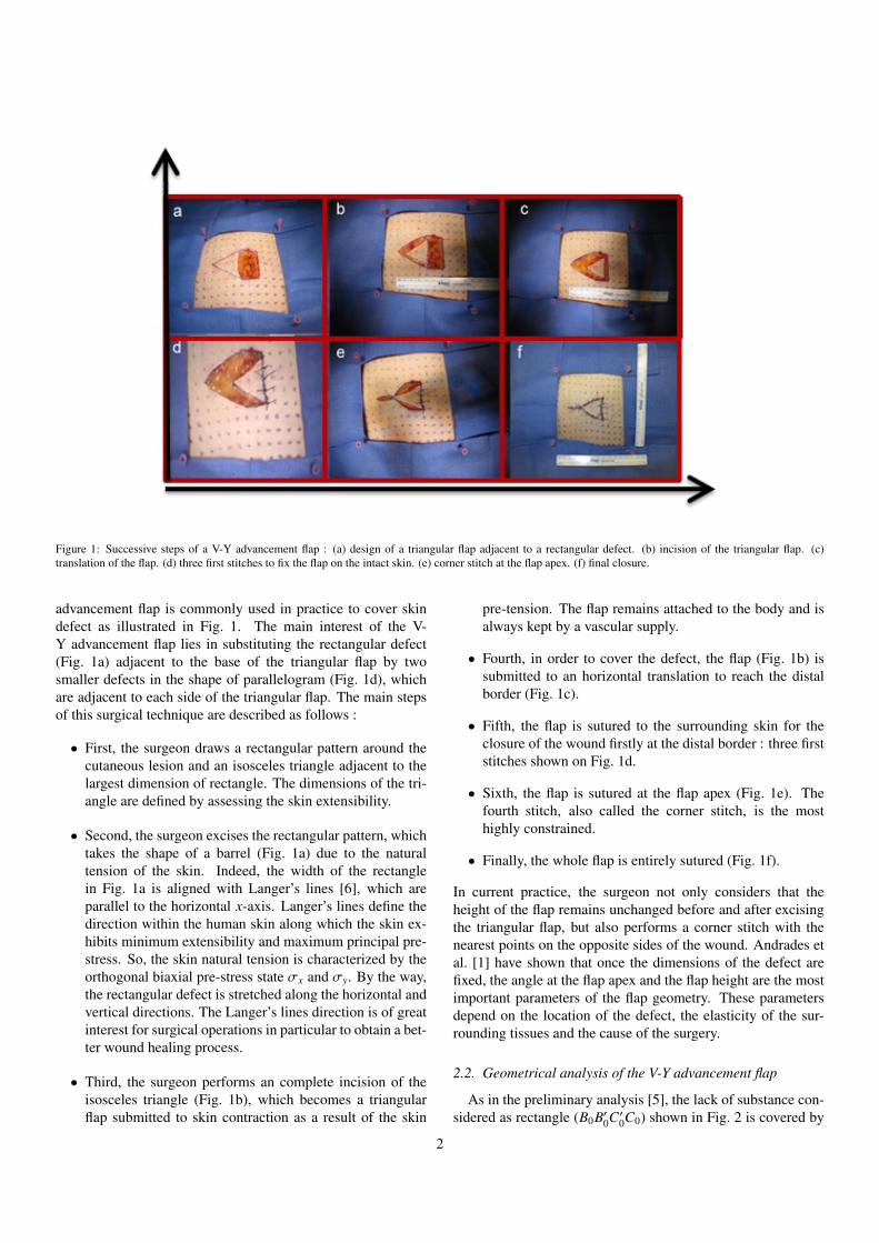
Figure 1: Successive steps of a V-Y advancement flap : (a) design of a triangular flap adjacent to a rectangular defect. (b) incision of the triangular flap. (c)translation of the flap. (d) three first stitches to fix the flap on the intact skin. (e) corner stitch at the flap apex. (f) final closure.
advancement flap is commonly used in practice to cover skindefect as illustrated in Fig. 1. The main interest of the V-Y advancement flap lies in substituting the rectangular defect(Fig. 1a) adjacent to the base of the triangular flap by twosmaller defects in the shape of parallelogram (Fig. 1d), whichare adjacent to each side of the triangular flap. The main stepsof this surgical technique are described as follows :
• First, the surgeon draws a rectangular pattern around thecutaneous lesion and an isosceles triangle adjacent to thelargest dimension of rectangle. The dimensions of the tri-angle are defined by assessing the skin extensibility.
• Second, the surgeon excises the rectangular pattern, whichtakes the shape of a barrel (Fig. 1a) due to the naturaltension of the skin. Indeed, the width of the rectanglein Fig. 1a is aligned with Langer’s lines [6], which areparallel to the horizontal x-axis. Langer’s lines define thedirection within the human skin along which the skin ex-hibits minimum extensibility and maximum principal pre-stress. So, the skin natural tension is characterized by theorthogonal biaxial pre-stress state σx and σy. By the way,the rectangular defect is stretched along the horizontal andvertical directions. The Langer’s lines direction is of greatinterest for surgical operations in particular to obtain a bet-ter wound healing process.
• Third, the surgeon performs an complete incision of theisosceles triangle (Fig. 1b), which becomes a triangularflap submitted to skin contraction as a result of the skin
pre-tension. The flap remains attached to the body and isalways kept by a vascular supply.
• Fourth, in order to cover the defect, the flap (Fig. 1b) issubmitted to an horizontal translation to reach the distalborder (Fig. 1c).
• Fifth, the flap is sutured to the surrounding skin for theclosure of the wound firstly at the distal border : three firststitches shown on Fig. 1d.
• Sixth, the flap is sutured at the flap apex (Fig. 1e). Thefourth stitch, also called the corner stitch, is the mosthighly constrained.
• Finally, the whole flap is entirely sutured (Fig. 1f).
In current practice, the surgeon not only considers that theheight of the flap remains unchanged before and after excisingthe triangular flap, but also performs a corner stitch with thenearest points on the opposite sides of the wound. Andrades etal. [1] have shown that once the dimensions of the defect arefixed, the angle at the flap apex and the flap height are the mostimportant parameters of the flap geometry. These parametersdepend on the location of the defect, the elasticity of the sur-rounding tissues and the cause of the surgery.
2.2. Geometrical analysis of the V-Y advancement flap
As in the preliminary analysis [5], the lack of substance con-sidered as rectangle (B0B′0C′0C0) shown in Fig. 2 is covered by
2
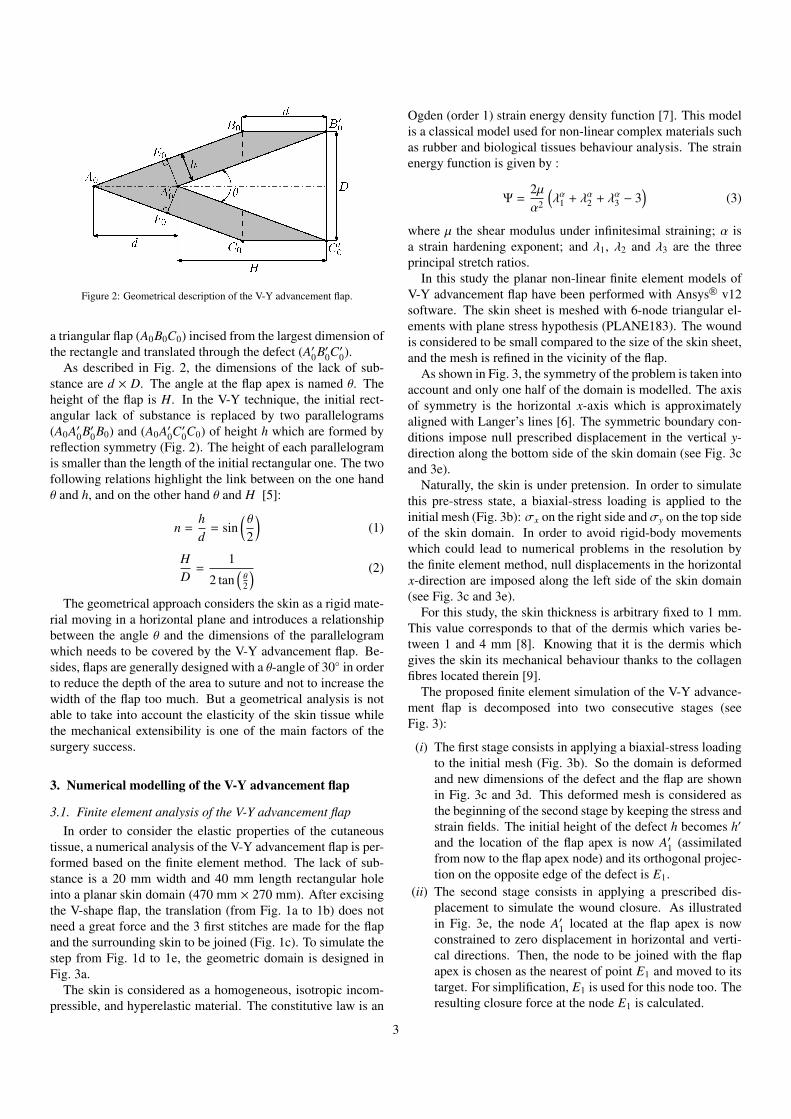
Figure 2: Geometrical description of the V-Y advancement flap.
a triangular flap (A0B0C0) incised from the largest dimension ofthe rectangle and translated through the defect (A′0B′0C′0).
As described in Fig. 2, the dimensions of the lack of sub-stance are d × D. The angle at the flap apex is named θ. Theheight of the flap is H. In the V-Y technique, the initial rect-angular lack of substance is replaced by two parallelograms(A0A′0B′0B0) and (A0A′0C′0C0) of height h which are formed byreflection symmetry (Fig. 2). The height of each parallelogramis smaller than the length of the initial rectangular one. The twofollowing relations highlight the link between on the one handθ and h, and on the other hand θ and H [5]:
n =hd
= sin(θ
2
)(1)
HD
=1
2 tan(θ2
) (2)
The geometrical approach considers the skin as a rigid mate-rial moving in a horizontal plane and introduces a relationshipbetween the angle θ and the dimensions of the parallelogramwhich needs to be covered by the V-Y advancement flap. Be-sides, flaps are generally designed with a θ-angle of 30◦ in orderto reduce the depth of the area to suture and not to increase thewidth of the flap too much. But a geometrical analysis is notable to take into account the elasticity of the skin tissue whilethe mechanical extensibility is one of the main factors of thesurgery success.
3. Numerical modelling of the V-Y advancement flap
3.1. Finite element analysis of the V-Y advancement flapIn order to consider the elastic properties of the cutaneous
tissue, a numerical analysis of the V-Y advancement flap is per-formed based on the finite element method. The lack of sub-stance is a 20 mm width and 40 mm length rectangular holeinto a planar skin domain (470 mm × 270 mm). After excisingthe V-shape flap, the translation (from Fig. 1a to 1b) does notneed a great force and the 3 first stitches are made for the flapand the surrounding skin to be joined (Fig. 1c). To simulate thestep from Fig. 1d to 1e, the geometric domain is designed inFig. 3a.
The skin is considered as a homogeneous, isotropic incom-pressible, and hyperelastic material. The constitutive law is an
Ogden (order 1) strain energy density function [7]. This modelis a classical model used for non-linear complex materials suchas rubber and biological tissues behaviour analysis. The strainenergy function is given by :
Ψ =2µα2
(λα1 + λα2 + λα3 − 3
)(3)
where µ the shear modulus under infinitesimal straining; α isa strain hardening exponent; and λ1, λ2 and λ3 are the threeprincipal stretch ratios.
In this study the planar non-linear finite element models ofV-Y advancement flap have been performed with Ansys R© v12software. The skin sheet is meshed with 6-node triangular el-ements with plane stress hypothesis (PLANE183). The woundis considered to be small compared to the size of the skin sheet,and the mesh is refined in the vicinity of the flap.
As shown in Fig. 3, the symmetry of the problem is taken intoaccount and only one half of the domain is modelled. The axisof symmetry is the horizontal x-axis which is approximatelyaligned with Langer’s lines [6]. The symmetric boundary con-ditions impose null prescribed displacement in the vertical y-direction along the bottom side of the skin domain (see Fig. 3cand 3e).
Naturally, the skin is under pretension. In order to simulatethis pre-stress state, a biaxial-stress loading is applied to theinitial mesh (Fig. 3b): σx on the right side andσy on the top sideof the skin domain. In order to avoid rigid-body movementswhich could lead to numerical problems in the resolution bythe finite element method, null displacements in the horizontalx-direction are imposed along the left side of the skin domain(see Fig. 3c and 3e).
For this study, the skin thickness is arbitrary fixed to 1 mm.This value corresponds to that of the dermis which varies be-tween 1 and 4 mm [8]. Knowing that it is the dermis whichgives the skin its mechanical behaviour thanks to the collagenfibres located therein [9].
The proposed finite element simulation of the V-Y advance-ment flap is decomposed into two consecutive stages (seeFig. 3):
(i) The first stage consists in applying a biaxial-stress loadingto the initial mesh (Fig. 3b). So the domain is deformedand new dimensions of the defect and the flap are shownin Fig. 3c and 3d. This deformed mesh is considered asthe beginning of the second stage by keeping the stress andstrain fields. The initial height of the defect h becomes h′
and the location of the flap apex is now A′1 (assimilatedfrom now to the flap apex node) and its orthogonal projec-tion on the opposite edge of the defect is E1.
(ii) The second stage consists in applying a prescribed dis-placement to simulate the wound closure. As illustratedin Fig. 3e, the node A′1 located at the flap apex is nowconstrained to zero displacement in horizontal and verti-cal directions. Then, the node to be joined with the flapapex is chosen as the nearest of point E1 and moved to itstarget. For simplification, E1 is used for this node too. Theresulting closure force at the node E1 is calculated.
3
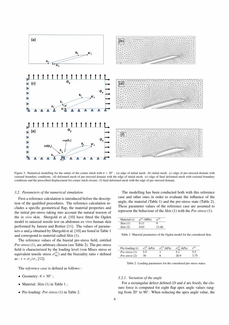
Figure 3: Numerical modelling for the suture of the corner stitch with θ = 30◦ : (a) edge of initial mesh. (b) initial mesh. (c) edge of pre-stressed domain withexternal boundary conditions. (d) deformed mesh of pre-stressed domain with the edge of initial mesh. (e) edge of final deformed mesh with external boundaryconditions and the prescribed displacement for corner stitch closure. (f) final deformed mesh with the edge of pre-stressed domain.
3.2. Parameters of the numerical simulation
First a reference calculation is introduced before the descrip-tion of the qualified procedures. The reference calculation in-cludes a specific geometrical flap, the material properties andthe initial pre-stress taking into account the natural tension ofthe in vivo skin. Shergold et al. [10] have fitted the Ogdenmodel to uniaxial tensile test on abdomen ex vivo human skinperformed by Jansen and Rottier [11]. The values of parame-ters α and µ obtained by Shergold et al. [10] are listed in Table 1and correspond to material called Skin (1).
The reference values of the biaxial pre-stress field, entitledPre-stress (1), are arbitrary chosen (see Table 2). The pre-stressfield is characterized by the loading level (von Mises stress orequivalent tensile stress σ(1)
eq ) and the biaxiality ratio r definedas : r = σy/σx [12].
The reference case is defined as follows :
• Geometry: θ = 30◦ ;
• Material: Skin (1) in Table 1 ;
• Pre-loading: Pre-stress (1) in Table 2.
The modelling has been conducted both with this referencecase and other ones in order to evaluate the influence of theangle, the material (Table 1) and the pre-stress state (Table 2).These parameter values of the reference case are assumed torepresent the behaviour of the Skin (1) with the Pre-stress (1).
Material (i) µ(i) (MPa) α(i)
Skin (1) 0.11 9Skin (2) 0.03 13.46
Table 1: Material parameters of the Ogden model for the considered skin.
Pre-loading (i) σ(i)x (kPa) σ(i)
y (kPa) σ(i)eq (kPa) r(i)
Pre-stress (1) 5.5 1 5.1 5.5Pre-stress (2) 30 8 26.9 3.75
Table 2: Loading parameters for the considered pre-stress states.
3.2.1. Variation of the angleFor a rectangular defect defined (D and d are fixed), the clo-
sure force is computed for eight flap apex angle values rang-ing from 20◦ to 90◦. When reducing the apex angle value, the
4
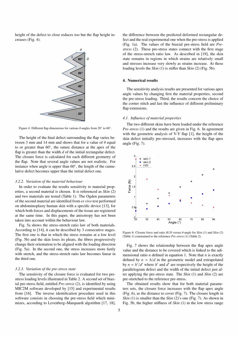
height of the defect to close reduces too but the flap height in-creases (Fig. 4).
Figure 4: Different flap dimensions for various θ-angles from 20◦ to 60◦.
The height of the final defect surrounding the flap varies be-tween 3 mm and 14 mm and shows that for a value of θ equalto or greater than 60◦, the suture distance at the apex of theflap is greater than the width d of the initial rectangular defect.The closure force is calculated for each different geometry ofthe flap. Note that several angle values are not realistic. Forinstance when angle is upper than 60◦, the length of the cumu-lative defect becomes upper than the initial defect one.
3.2.2. Variation of the material behaviourIn order to evaluate the results sensitivity to material prop-
erties, a second material is chosen. It is referenced as Skin (2)and two materials are tested (Table 1). The Ogden parametersof the second material are identified from ex vivo test performedon abdominoplasty human skin with a specific device [13], forwhich both forces and displacements of the tissue are registeredat the same time. In this paper, the anisotropy has not beentaken into account within the behaviour law.
Fig. 5a shows the stress-stretch ratio law of both materials.According to [14], it can be described by 3 consecutive stages.The first one is that in which the stress remains at a low level(Fig. 5b) and the skin loses its pleats, the fibres progressivelychange their orientation to be aligned with the loading direction(Fig. 5a). In the second one, the stress increases more fastlywith stretch, and the stress-stretch ratio law becomes linear inthe third one.
3.2.3. Variation of the pre-stress stateThe sensitivity of the closure force is evaluated for two pre-
stress loading levels illustrated in Table 2. A second set of biax-ial pre-stress field, entitled Pre-stress (2), is identified by usingMIC2M software developed by [15] and experimental resultsfrom [16]. The inverse identification procedure used in thissoftware consists in choosing the pre-stress field which mini-mizes, according to Levenberg–Marquardt algorithm [17, 18],
the difference between the predicted deformed rectangular de-fect and the real experimental one when the pre-stress is applied(Fig. 1a). The values of the biaxial pre-stress field are Pre-stress (2). These pre-stress states connect with the first stageof the stress-stretch ratio law. As described in [19], the skinstate remains in regions in which strains are relatively smalland stresses increase very slowly as strains increase. At theseloading levels the Skin (1) is stiffer than Skin (2) (Fig. 5b).
4. Numerical results
The sensitivity analysis results are presented for various apexangle values by changing first the material properties, secondthe pre-stress loading. Third, the results concern the choice ofthe corner stitch and last the influence of different preliminaryflap extensions.
4.1. Influence of material properties
The two different skins have been loaded under the referencePre-stress (1) and the results are given in Fig. 6. In agreementwith the geometric analysis of V-Y flap [1], the height of theskin defect initially pre-stressed, increases with the flap apexangle (Fig. 7).
Figure 6: Closure force and ratio H/D versus θ-angle for Skin (1) and Skin (2)(Table 1) constrained to the reference Pre-stress (1) (Table 2).
Fig. 7 shows the relationship between the flap apex anglevalue and the distance to be covered which is linked to the adi-mensional ratio n defined in equation 1. Note that n is exactlydefined by n = h/d in the geometric model and extrapolatedby n = h′/d′ where h′ and d′ are respectively the height of theparallelogram defect and the width of the initial defect just af-ter applying the pre-stress state. The Skin (1) and Skin (2) arepre-stretched to the reference pre-stress.
The obtained results show that for both material parame-ters sets, the closure force increases with the flap apex angle(Fig. 6), as the distance to cover (Fig. 7). The closure length inSkin (1) is smaller than the Skin (2)’s one (Fig. 7). As shown inFig. 5b, the higher stiffness of Skin (1) in the low stress range
5
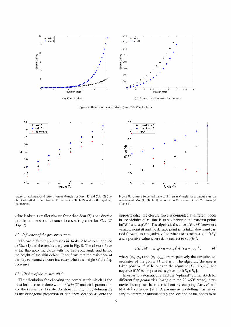
(a) Global view. (b) Zoom in on low stretch ratio zone.
Figure 5: Behaviour laws of Skin (1) and Skin (2) (Table 1).
Figure 7: Adimentional ratio n versus θ-angle for Skin (1) and Skin (2) (Ta-ble 1) submitted to the reference Pre-stress (1) (Table 2), and for the rigid flap(geometric).
value leads to a smaller closure force than Skin (2)’s one despitethat the adimensional distance to cover is greater for Skin (2)(Fig. 7).
4.2. Influence of the pre-stress state
The two different pre-stresses in Table 2 have been appliedto Skin (1) and the results are given in Fig. 8. The closure forceat the flap apex increases with the flap apex angle and hencethe height of the skin defect. It confirms that the resistance ofthe flap to wound closure increases when the height of the flapdecreases.
4.3. Choice of the corner stitch
The calculation for choosing the corner stitch which is themost loaded one, is done with the Skin (2) materials parametersand the Pre-stress (1) state. As shown in Fig. 3, by defining E1as the orthogonal projection of flap apex location A′1 onto the
Figure 8: Closure force and ratio H/D versus θ-angle for a unique skin pa-rameters set Skin (1) (Table 1) submitted to Pre-stress (1) and Pre-stress (2)(Table 2).
opposite edge, the closure force is computed at different nodesin the vicinity of E1 that is to say between the extrema pointsinf(E1) and sup(E1). The algebraic distance d(E1,M) between avariable point M and the defined point E1 is taken down and car-ried forward as a negative value where M is nearest to inf(E1)and a positive value where M is nearest to sup(E1).
d(E1,M) = ±
√(xM − xE1 )2 + (yM − yE1 )2 , (4)
where (xM , yM) and (xE1 , yE1 ) are respectively the cartesian co-ordinates of the points M and E1. The algebraic distance istaken positive if M belongs to the segment [E1; sup(E1)] andnegative if M belongs to the segment [inf(E1); E1].
In order to automatically find the “optimal” corner stitch fordifferent flap geometries (θ-angle in the 20◦–60◦ range), a nu-merical study has been carried out by coupling Ansys R© andMatlab R© softwares [20]. A parametric modelling was neces-sary to determine automatically the location of the nodes to be
6
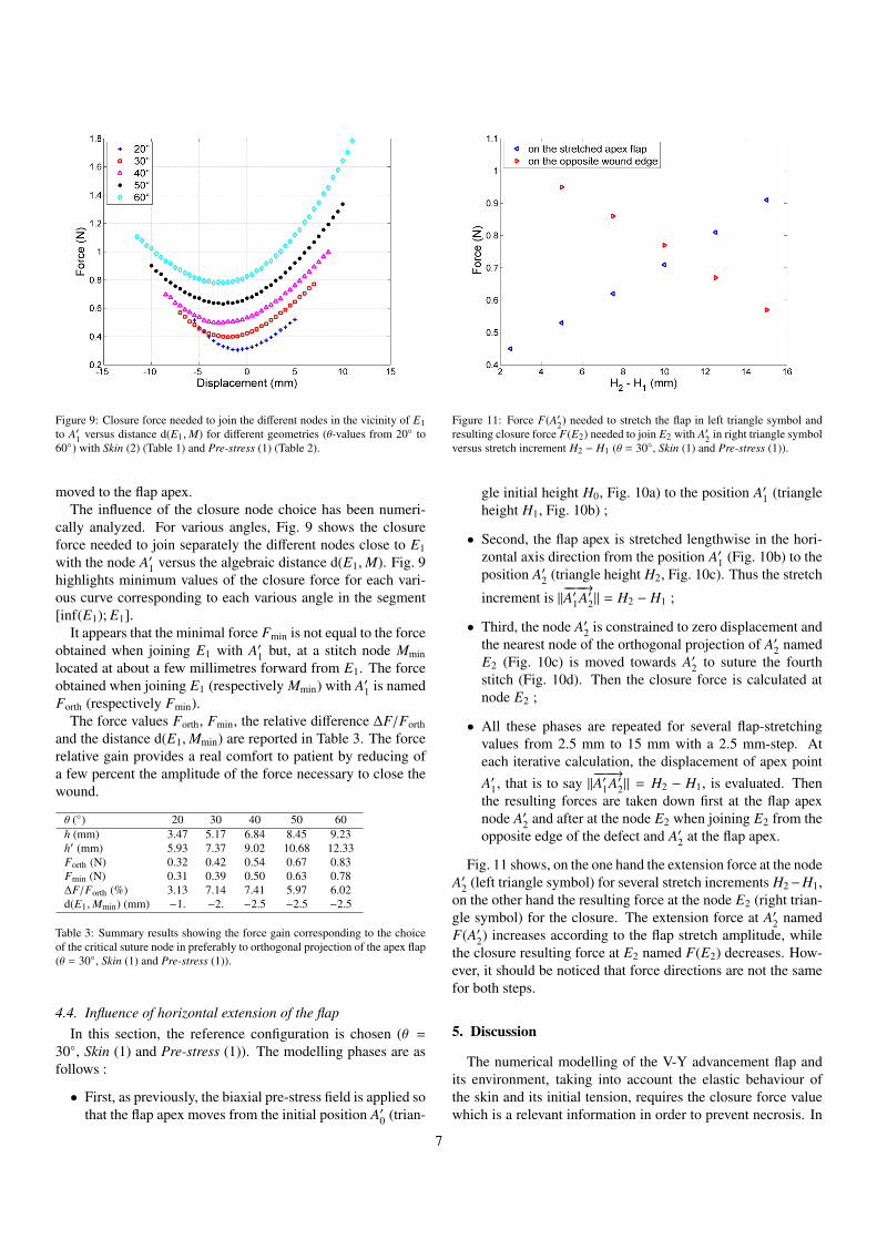
Figure 9: Closure force needed to join the different nodes in the vicinity of E1to A′1 versus distance d(E1,M) for different geometries (θ-values from 20◦ to60◦) with Skin (2) (Table 1) and Pre-stress (1) (Table 2).
moved to the flap apex.The influence of the closure node choice has been numeri-
cally analyzed. For various angles, Fig. 9 shows the closureforce needed to join separately the different nodes close to E1with the node A′1 versus the algebraic distance d(E1,M). Fig. 9highlights minimum values of the closure force for each vari-ous curve corresponding to each various angle in the segment[inf(E1); E1].
It appears that the minimal force Fmin is not equal to the forceobtained when joining E1 with A′1 but, at a stitch node Mminlocated at about a few millimetres forward from E1. The forceobtained when joining E1 (respectively Mmin) with A′1 is namedForth (respectively Fmin).
The force values Forth, Fmin, the relative difference ∆F/Forthand the distance d(E1,Mmin) are reported in Table 3. The forcerelative gain provides a real comfort to patient by reducing ofa few percent the amplitude of the force necessary to close thewound.
θ (◦) 20 30 40 50 60h (mm) 3.47 5.17 6.84 8.45 9.23h′ (mm) 5.93 7.37 9.02 10.68 12.33Forth (N) 0.32 0.42 0.54 0.67 0.83Fmin (N) 0.31 0.39 0.50 0.63 0.78∆F/Forth (%) 3.13 7.14 7.41 5.97 6.02d(E1,Mmin) (mm) −1. −2. −2.5 −2.5 −2.5
Table 3: Summary results showing the force gain corresponding to the choiceof the critical suture node in preferably to orthogonal projection of the apex flap(θ = 30◦, Skin (1) and Pre-stress (1)).
4.4. Influence of horizontal extension of the flapIn this section, the reference configuration is chosen (θ =
30◦, Skin (1) and Pre-stress (1)). The modelling phases are asfollows :
• First, as previously, the biaxial pre-stress field is applied sothat the flap apex moves from the initial position A′0 (trian-
Figure 11: Force F(A′2) needed to stretch the flap in left triangle symbol andresulting closure force F(E2) needed to join E2 with A′2 in right triangle symbolversus stretch increment H2 − H1 (θ = 30◦, Skin (1) and Pre-stress (1)).
gle initial height H0, Fig. 10a) to the position A′1 (triangleheight H1, Fig. 10b) ;
• Second, the flap apex is stretched lengthwise in the hori-zontal axis direction from the position A′1 (Fig. 10b) to theposition A′2 (triangle height H2, Fig. 10c). Thus the stretch
increment is ‖−−−−→A′1A′2‖ = H2 − H1 ;
• Third, the node A′2 is constrained to zero displacement andthe nearest node of the orthogonal projection of A′2 namedE2 (Fig. 10c) is moved towards A′2 to suture the fourthstitch (Fig. 10d). Then the closure force is calculated atnode E2 ;
• All these phases are repeated for several flap-stretchingvalues from 2.5 mm to 15 mm with a 2.5 mm-step. Ateach iterative calculation, the displacement of apex pointA′1, that is to say ‖
−−−−→A′1A′2‖ = H2 − H1, is evaluated. Then
the resulting forces are taken down first at the flap apexnode A′2 and after at the node E2 when joining E2 from theopposite edge of the defect and A′2 at the flap apex.
Fig. 11 shows, on the one hand the extension force at the nodeA′2 (left triangle symbol) for several stretch increments H2−H1,on the other hand the resulting force at the node E2 (right trian-gle symbol) for the closure. The extension force at A′2 namedF(A′2) increases according to the flap stretch amplitude, whilethe closure resulting force at E2 named F(E2) decreases. How-ever, it should be noticed that force directions are not the samefor both steps.
5. Discussion
The numerical modelling of the V-Y advancement flap andits environment, taking into account the elastic behaviour ofthe skin and its initial tension, requires the closure force valuewhich is a relevant information in order to prevent necrosis. In
7
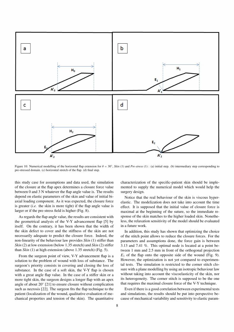
Figure 10: Numerical modelling of the horizontal flap extension for θ = 30◦, Skin (1) and Pre-stress (1) : (a) initial step. (b) intermediary step corresponding topre-stressed domain. (c) horizontal stretch of the flap. (d) final step.
this study case for assumptions and data used, the simulationof the closure at the flap apex determines a closure force valuebetween 0 and 3 N whatever the flap angle value is. The resultsdepend on elastic parameters of the skin and value of initial bi-axial loading component. As it was expected, the closure forceis greater (i.e. the skin is more tight) if the flap angle value islarger or if the pre-stress field is higher (Fig. 8).
As regards the flap angle value, the results are consistent withthe geometrical analysis of the V-Y advancement flap [5] byitself. On the contrary, it has been shown that the width ofthe skin defect to cover and the stiffness of the skin are notnecessarily adequate to predict the closure force. Indeed, thenon-linearity of the behaviour law provides Skin (1) stiffer thanSkin (2) at low extension (below 1.35 stretch) and Skin (2) stifferthan Skin (1) at high extension (above 1.35 stretch) (Fig. 5).
From the surgeon point of view, V-Y advancement flap is asolution to the problem of wound with loss of substance. Thesurgeon’s priority consists in covering and closing the loss ofsubstance. In the case of a soft skin, the V-Y flap is chosenwith a great angle flap value. In the case of a stiffer skin or amore tight skin, the surgeon designs a longer flap with an apexangle of about 20◦ [21] to ensure closure without complicationsuch as necrosis [22]. The surgeon fits the flap technique to thepatient (localization of the wound, qualitative evaluation of me-chanical properties and tension of the skin). The quantitative
characterization of the specific-patient skin should be imple-mented to supply the numerical model which would help thesurgery design.
Notice that the real behaviour of the skin is viscous hyper-elastic. The modelization does not take into account the timeeffect. It is supposed that the initial value of closure force ismaximal at the beginning of the suture, so the immediate re-sponse of the skin matches to the higher loaded skin. Nonethe-less, the relaxation sensitivity of the model should be evaluatedin a future work.
In addition, this study has shown that optimizing the choiceof the stitch point allows to reduce the closure forces. For theparameters and assumptions done, the force gain is between3.13 and 7.41 %. This optimal node is located at a point be-tween 1 mm and 2.5 mm in front of the orthogonal projectionE1 of the flap onto the opposite side of the wound (Fig. 9).However, the optimization is not yet compared to experimen-tal tests. The simulation is restricted to the corner stitch clo-sure with a plane modelling by using an isotropic behaviour lawwithout taking into account the viscoelasticity of the skin, norits heterogeneity. The corner stitch is supposed to be the onethat requires the maximal closure force of the V-Y technique.
Even if there is a good correlation between experimental testsand simulations, the results should be put into perspective be-cause of mechanical variability and sensitivity to elastic param-
8
eters. After qualitatively evaluating the specific-patient caseand choosing the geometry and localization of the V-Y flap,the surgeon’s practical experience consists in first stretching theflap and second performing a corner stitch point with the near-est point on the opposite side. The calculated “optimized” stitchis consistent with the surgeon’s practise. The first stretching ofthe flap compensates for the retraction of the skin because of thein vivo natural stress. This stretching replaces the flap apex atits original position. Then the surgeon sutures the flap directlywith the nearest point on the opposite edge of the wound. Quan-titatively, the relative difference in closure force is able to be upto about 7 % (see Table 3). This can be considered low but canbring comfort to the patient and possibly avoid a complication.
In Fig. 11, the stretch force is proportional to the stretch itselfand the resulting closure force is inversely proportional to thestretch. The compromise between force of the stretch and thecorresponding closure force is not easy to find but exists. Thestretching of the flap reduces the width of the defect and thusreduces the closure force even if the stretch needs some efforttoo.
This is of crucial interest for the surgeon who tries to reducethe tension within the skin in order to avoid any risk of necrosis.Indeed, if a cutaneous necrosis occurs in the neighbourhoodof the scar, the wound healing process is definitively stoppedin the affected area. Finally, the numerical analysis of the V-Y advancement flap by finite element method may give usefulindication for the surgeon.
In conclusion, this finite element analysis of the V-Y ad-vancement flap has highlighted the key role of skin elasticityfor the choice of the flap apex angle. In addition two differentversions of suture technique at the flap apex (with and withoutstretching the flap) are numerically evaluated. Both methodsare aimed at minimizing the tension at the corner stitch, and arecompared from a mechanical point of view. These two meth-ods simulate the surgical gesture. Nevertheless, the mechanicalaspect is only one among many other medical factors, and thefinal choice of the closure technique remains the surgeon’s de-cision.
Conflict of interest statement
No conflict of interest.
Funding and ethical approval
Funding : none declared.Ethical approval : not required.
References
[1] Andrades PR, Calderon W, Leniz P, Bartel G, Danilla S, Benitez S. Geo-metric analysis of the V-Y advancement flap and its clinical applications.Plast Reconstr Surg 2005;115(6):1582 – 1590.
[2] Lister GD, Gibson T. Closure of rhomboid skin defects: The flaps ofLimberg and Dufourmentel. Br J Plast Surg 1972;25:300 – 314.
[3] Retel V, Vescovo P, Jacquet E, Trivaudey F, Varchon D, Burtheret A.Nonlinear model of skin mechanical behaviour analysis with finite ele-ment method. Skin Res Technol 2001;7(3):152 – 158.
[4] Chu DY. Mathematical principle of planar Z-plasty. Plast Reconstr Surg2000;105(1):105 – 108.
[5] Pauchot J, Chambert J, Remache D, Elkhyat A, Jacquet E. Geometricalanalysis of the V–Y advancement flap applied to a keystone flap. J PlastReconstr Aesthet Surg 2012;65(8):1087 – 1095.
[6] Langer K. On the anatomy and physiology of the skin: I. The cleav-ability of the cutis. Br J Plast Surg 1978;31(1):3 – 8. (Translated by T.Gibson from Langer K. (1861). Zur Anatomie und Physiologie der Haut.I. Uber die Spaltbarkeit der Cutis. Sitzungsbericht der Mathematisch-naturwissenschaftlichen Classe der Kaiserlichen Academie der Wis-senschaften, Wien, 44, pp. 19 – 46).
[7] Ogden RW. Large deformation isotropic elasticity - on the correlation oftheory and experiment for incompressible rubberlike solids. Proc R SocLond A 1972;326(1567):565 – 584.
[8] Xu F, Lu T. Introduction to Skin Biothermomechanics and Thermal Pain.Springer; 2011.
[9] Brown IA. A scanning electron microscope study of the effects of uniaxialtension on human skin. Br J Dermatol 1973;89(4):383 – 393.
[10] Shergold OA, Fleck NA, Radford D. The uniaxial stress versus strainresponse of pig skin and silicone rubber at low and high strain rates. Int JImpact Eng 2006;32(9):1384 – 1402.
[11] Jansen LH, Rottier PB. Some mechanical properties of human abdom-inal skin measured on excised strips: A study of their dependence onage and how they are influenced by the presence of striae. Dermatol1958;117(2):65 – 83.
[12] Reihsner R, Balogh B, Menzel EJ. Two-dimensional elastic properties ofhuman skin in terms of an incremental model at the in vivo configuration.Med Eng Phys 1995;17(4):304 – 313.
[13] Capek L, Lochman Z, Dzan L, Jacquet E. Biaxial extensometer for mea-suring of the human skin anisotropy in vivo. In: 5th Cairo InternationalBiomedical Engineering Conference. IEEE, Cairo, Egypt; 2010, p. 83 –85.
[14] Delalleau A, Josse G, Lagarde JM, Zahouani H, Bergheau JM. A nonlin-ear elastic behavior to identify the mechanical parameters of human skinin vivo. Skin Res Technol 2008;14(2):152 – 164.
[15] Richard F. Identification du comportement et evaluation de la fiabilitedes composites stratifies. Ph.D. thesis; University of Franche-Comte,Besancon, France; 1999.
[16] Remache D, Pauchot J, Chambert J, Capek L, Jacquet E. Experimentaland numerical analysis of a V-Y advancement flap on human skin ex vivo.Comput Methods Biomech Biomed Eng 2011;14(sup1):137 – 138.
[17] Levenberg K. A method for the solution of certain non-linear problemsin least squares. Quart Appl Math 1944;2(2):164 – 168.
[18] Marquardt DW. An algorithm for least-squares estimation of nonlinearparameters. J Soc Ind Appl Math 1963;11(2):431 – 441.
[19] Chaudhry HR, Bukiet B, Findley T, Ritter AB. Evaluation of residualstress in rabbit skin and the relevant material constants. J Theor Biol1998;192(2):191 – 195.
[20] Billon K, Gallecier F. Numerical optimization of the V-Y advancementflap geometry. Technical report; University of Franche-Comte, Besancon,France; 2012.
[21] Pauchot J, Servagi S, Laveaux C, Lasserre G, Tropet Y. Bilateral latis-simus dorsi V-Y musculocutaneous rotation flap for closure of a large dor-sal radionecrosis. Geometric analysis and interest. About one case. AnnChir Plast Esthet 2010;55(1):66 – 70.
[22] Pauchot J, Remache D, Chambert J, Elkhyat A, Jacquet E. Finite elementanalysis to determine stress fields at the apex of V-Y flaps. Eur J PlastSurg 2013;36(3):185 – 190.
9


