Embed Size (px)
Citation preview

Novel cylindrical, air-coupled acoustic levitation/concentration devicesGregory Kaduchak, Dipen N. Sinha, and David C. Lizon Citation: Review of Scientific Instruments 73, 1332 (2002); doi: 10.1063/1.1448900 View online: http://dx.doi.org/10.1063/1.1448900 View Table of Contents: http://scitation.aip.org/content/aip/journal/rsi/73/3?ver=pdfcov Published by the AIP Publishing
This article is copyrighted as indicated in the article. Reuse of AIP content is subject to the terms at: http://scitationnew.aip.org/termsconditions. Downloaded to IP:
192.12.184.6 On: Sat, 08 Mar 2014 20:05:04

REVIEW OF SCIENTIFIC INSTRUMENTS VOLUME 73, NUMBER 3 MARCH 2002
This art
Novel cylindrical, air-coupled acoustic levitation Õconcentration devicesGregory Kaduchak,a) Dipen N. Sinha, and David C. LizonLos Alamos National Laboratory, Electronic and Electrochemical Materials and Devices Group,Mail Stop D-429, Los Alamos, New Mexico 87545
~Received 1 August 2001; accepted for publication 12 December 2001!
A new class of devices for levitation and/or concentration of aerosols and small liquid/solid samples~up to several millimeters in diameter! in air has been developed. The novelty of these devices istheir simplicity in design. These are inexpensive, low-power, and, in their simplest embodiment, donot require accurate alignment of a resonant cavity. Best of all, these can be off-the-shelf items. Thedevices are constructed from a hollow, cylindrical piezoelectric tube. The main design criteriarequires a resonant mode of the tube to match a resonant mode of the interior air-filled cavity. Oncematched, it is shown that drops of water in excess of 1 mm in diameter may be levitated inside thecylinder cavity against the force of gravity for less than 1 Watt of input electrical power. Efficientconcentration/agglomeration of aerosol particles in air is also demonstrated. ©2002 AmericanInstitute of Physics.@DOI: 10.1063/1.1448900#
ars
piss
ngn
esea
he
itatheleid
it
nlyica
aei
ngicll
lion
llowledtheeofice
l-
eibe
odey of
oftectiontheth-
i-histubeair-in
eof
go-theum-ed
hisol-
I. INTRODUCTION
Acoustic levitation provides a means to isolate smsamples~diameters typically less than several millimete!without the influence of a containment vessel.1–8 Mostacoustic levitation devices operate by localizing a samnear the nodal planes of an acoustic standing wave. Thisviable placement technique to measure material propertiesmall sample quantities~e.g., droplets, aerosols, etc.! withoutobscuring the results with the effects of a mountiapparatus.3,4 Other applications use the acoustic force to cocentrate aerosols and/or particulates near the nodal planthe acoustic field for harvesting or sedimentation purposAdvances in the design of acoustic levitators over the pseveral decades have proven useful for applications wsamples reside in either gaseous or liquid host media.
The standing wave field produced by an acoustic levtion device is very dependent upon spatial alignment ofsystem components and often requires moderate to hightrical power input. This is especially true for levitating soland liquid samples in air. The large acoustic impedance mmatch between the displacement generating device andair medium is a difficult problem to overcome. Resonatransduction devices2,9 (Q.1000) have been built especialfor this problem and have proven quite useful when electrpower efficiency is not a limiting factor.
In this article, we describe several embodiments ofextremely simple acoustic levitation device for use as anficient levitator/concentrator of samples in air. This deviceconstructed from a hollow, cylindrical piezoelectric~PZT!crystal in contrast with the more traditional method of usiparallel plate transducer assemblies. This novel cylindrarrangement allows several important advantages as widiscussed in this article.
For the devices presented here, the crystal and/or cydrical cavity have been slightly modified. Such modificati
a!Electronic mail: [email protected]
1330034-6748/2002/73(3)/1332/5/$19.00
icle is copyrighted as indicated in the article. Reuse of AIP content is subje
192.12.184.6 On: Sat, 0
ll
lea
of
-of
s.stre
-ec-
s-het
l
nf-s
albe
n-
is necessary to tune a resonance frequency of the hocrystal to a corresponding resonant mode of the air-filcavity. We show that when the resonance frequency ofinterior cylindrical cavity is matched to a structural modresonance of the cylindrical piezoelectric, the efficiencythe device becomes extremely high. Additionally, the devrequires no alignment~in its simplest form!, power consump-tion is low, and the hollow PZT cylinders are commerciaoff-the-shelf items.
The article will begin with a short description of thoperating mode of the devices in Sec. II. It will also descrtheir construction. In this section thePZT tubeis modified toadjust the frequency of the lowest order resonance msuch that its frequency matches the resonance frequencthe internal, air-filled cylindrical cavity. This is followed inSec. III by experimental results demonstrating the abilitythe cylindrical levitation device to both acoustically levitasamples and also acoustically concentrate aerosols. SeIV describes a different embodiment of the device wherecavity instead of the cylinder is modified to match the breaing mode resonance of the cylinder.
II. DEVICE DESCRIPTION
The levitator consists simply of a hollow, cylindrical pezoelectric tube. The fundamental design criterion of tnovel design requires that a structural resonance of thecoincide with a corresponding resonance mode of thefilled cavity. Moreover, to achieve the necessary efficiencydriving the air-filled cylindrical cavity, it is required that thstructural resonance mode of the cylinder be comprisedpredominantly radial displacements. Due to mode orthonality, it is also required that the resonance modes ofcylinder and the cavity share the same azimuthal mode nber. For simplicity, axisymmetric modes will be assumthroughout the article.
We present the design of two types of devices in tarticle. The first type, a levitation device, consists of a h
2 © 2002 American Institute of Physics
ct to the terms at: http://scitationnew.aip.org/termsconditions. Downloaded to IP:
8 Mar 2014 20:05:04

mr
resd
tehk
reo
telino
ida
giontio
carllo
le
.
a-vi
bebe
fe
-
aenton.
f themthees is
so-er
-kehisuchity.ityitsnd
by
letnts.note
onsionthe
1333Rev. Sci. Instrum., Vol. 73, No. 3, March 2002 Notes
This art
low, piezoelectric tube with an inner diameter 16.9 mouter diameter 19.0 mm, and length 17.0 mm. The cylindemanufactured by Valpey–Fisher Corporation~HopkintonMA !. The type of piezoelectric material is the manufactunumber VP-A55. It is radially poled with nickel electrodeon the outer and inner surfaces. Measurements of the ravelocity using a commercial Doppler laser vibrome~Ometron VH300! show that the lowest order mode witappreciable radial surface displacements occurs near 61for the thin tube. This resonance occurs at the manufactupredicted value for the frequency of the breathing modethe piezoelectric cylinder.
It is now necessary to consider the frequency characistics of the cavity such that the acoustic modes of the cydrical cavity may be matched with the structural modesthe tube. For the coupled system of an air-filled cavity insa high impedance container, it is appropriate to treat the city and container as two uncoupled resonators.10 Due to thelarge impedance mismatch, the cavity is considered a riwalled enclosure. Similarly, the minimal loading of the airthe tube allows use of pressure release boundary condito determine the resonance modes of the tube wall.
Consider a spatial pressure distribution in the cylindriair-filled cavity. Barmatzet al.11 derived an expression fothe radiation potentialU of the acoustic force on a smaspherical particle in a cylindrical standing wave field. Faxisymmetric normal modes, the potential may be written11
U~r !5
S B1
3Jo
2~kr !2B2
2J1
2~kr ! D~pR3rn0
2!, ~1!
where
B1512rc2
rpcp2 , B25
2~rp2r!
~2rp1r!.
Herec is the compressional velocity in air,r is the air den-sity, cp is the compressional velocity of the bulk particmaterial,rp is the particle density,n0 is the maximum par-ticle velocity, andJn is a Bessel function of the first kindThe compressional wave number in air isk52p f /c andr isthe radial coordinate. For a rigid-walled cavity of inner rdiusR, the normal mode resonance frequencies of the caare f m5cXm /(2pR) where Xm is the mth zero of J1(X)50. ~It is assumed that the acoustic radial wave numXm /R is much greater than the acoustic axial wave numthroughout this article; the cylinder is long.!
Using the results in Eq.~1!, the calculated frequency othe cavity resonance closest to the frequency of the loworder axisymmetric cylinder resonance~61 kHz! is 65.7 kHz.This corresponds to them53 mode. ~The resonance frequency is calculated using a valuecair5343 m/s at 20 C.! Aplot of the calculated time-averaged radial forceF52dU/dr on a particle in the cavity is shown in Fig. 1~a!.The parameters used in the calculation correspond to a wdroplet in air. Note that them53 resonance depicts threstable equilibrium positions~denoted by the gray circles ithe figure! where the force goes to zero and adjacent resing forces act in the direction of the equilibrium positio
icle is copyrighted as indicated in the article. Reuse of AIP content is subje
192.12.184.6 On: Sat, 0
,is
r
ialr
Hzr’sf
r--fev-
d-
ns
l
r
ty
rr
st
ter
r-
These forces weaken as the distance from the center ocavity increases. In the cylindrical cavity these equilibriupositions define three concentric cylindrical surfaces inabsence of other forces. A cross section of these surfacshown in Fig. 1~b!.
Because of the frequency difference between the renance frequency for the radial vibrations of the PZT cylind~61 kHz! and the resonance frequency of them53 mode ofits interior cavity~65.7 kHz!, it is necessary to tune the resonance frequency of either the cylinder or the cavity to mathe two frequencies match. For the first embodiment of tdevice, the resonance frequency of the cylinder is tuned sthat it coincides with the resonance frequency of the cavIt would be preferable if the frequency of the resonant cavmatched the breathing mode frequency of the cylinder instock form, however to this point the authors have not foua stock PZT cylinder that has this property.
We tuned the resonance frequency of the cylinderslicing the cylinder axially as shown in Fig. 2.12 The slice has
FIG. 1. ~a! Normalized time-averaged force felt by a spherical water dropin a cylindrical cavity of the same dimension as used in the experimeThe arrows correspond to the direction of the force. The gray circles dethe stable equilibrium positions.~b! Diagram of the interior cavity of thecylindrical levitator. The dotted lines denote the stable equilibrium positiin the absence of gravity. When gravity is acting in the downward directin the plane of the image, the stable equilibrium positions are denoted byblack circles.
ct to the terms at: http://scitationnew.aip.org/termsconditions. Downloaded to IP:
8 Mar 2014 20:05:04

rltineso
prinofeinne
ore
e-in
he
nr are-
theity
htly
errcexi-
hevity.the
rces ins
fn
ins-
oid,ous-ento
reor
ingiteeporularin-
ind
Figi-
lin-ium
the
. Ad
1334 Rev. Sci. Instrum., Vol. 73, No. 3, March 2002 Kaduchak, Sinha, and Lizon
This art
a width of approximately 0.50 mm and is made with a rotadiamond saw. The result of axially slicing the cylinder resuin the creation of a predominantly radial mode shiftedfrequency by;5–7 kHz from the breathing mode of thunsliced cylinder. This new mode coincides with the renance frequency of the air-filled resonant cavity form53.Measurements made with a laser vibrometer show no apciable change in the radial vibration amplitude of the cylder relative to the unsliced cylinder except in the vicinitythe slice. In this local region, there is a marked decreasthe radial vibration amplitude. It should be noted thatother experiments involving cylinders identical to the odescribed above, a simple crack coincident with the axisthe cylinder is sufficient to obtain the same scale of fquency tuning.
III. EXPERIMENT AND RESULTS
The modified PZT cylinder is mounted with a threpoint clamp as shown in Fig. 3. In this figure gravity acts
FIG. 3. Two drops levitated in a hollow PZT cylinder. Gravity is actingthe downward direction in the plane of the image. The drops are levitatethe two innermost stable equilibrium positions in the cavity as shown in1~b! at positionsB andC. The major diameter of the larger drop is approxmately 0.92 mm.
FIG. 2. Diagram of the hollow PZT cylinder used in the experimentsslice is made axially in the wall of the device to tune its breathing mofrequency.
icle is copyrighted as indicated in the article. Reuse of AIP content is subje
192.12.184.6 On: Sat, 0
ys
-
e--
in
f-
the direction pointing towards the bottom of the page. Texcitation signal is a sinusoid at frequencyf 566.7 kHz. Dueto the high efficiency of this levitation device, it is drivedirectly from a function generator eliminating the need fopower amplifier. The ambient temperature for the measuments isT;27 C. Since both the resonance frequency ofcrystal and the resonance frequency of the air-filled cavare temperature dependent~as will be discussed later!, reso-nance frequencies used in the measurements vary sligdepending on the local temperature.
Notice the samples levitated in the cavity of the cylindin Fig. 3. Here two water drops are levitated against the foof gravity. The location of the samples corresponds appromately to the gravitational potential energy minimum of tnodal rings that represent the pressure nodes of the caThe equilibrium positions of the drops are depicted bylarge, black dots in Fig. 1~b! at positionsB andC. In theseexperiments, it was observed that a finite restoring foalong the cylinder axis does exist and acts along the axithe direction pointing toward the midpoint of the cylinder. Aa result of this force~most likely due to the finite length othe cylinder! the cavity exhibits a stable equilibrium positiowith weak restoring forces acting along the cylinder axis.
The major diameter of the drop in the innermost ringFig. 3 is 0.92 mm and the minor diameter is 0.55 mm. Asuming the drop occupies the volume of an oblate spherits mass is calculated to be 0.243 mg. This requires an actic force of 2.3931026 N acting on the drop to oppose thgravitational force. The measured input electrical power ithe device is approximately 115 mW.
A visual inspection of the nodal pattern of the pressufield is obtained by pumping a small amount of water vapinto the cavity. Figure 4 is a Schlieren photograph displaythe results of this type of experiment. Here a diffuse whlight is used to illuminate the interior cylindrical cavity. Thimage is dominated by light scattered from the water vadroplets. In the image, the plane of the paper is perpendicto the axis of the cylinder. It is easy to discern the two
at.
FIG. 4. Schlieren photograph of water vapor being pumped into the cydrical cavity. Effective concentration is observed near the stable equilibrpositions of the cavity in the absence of gravity as shown in Fig. 1~b!. Thetwo innermost rings are easy to discern while the outermost ring nearwall of the cylinder is somewhat blurred.
e
ct to the terms at: http://scitationnew.aip.org/termsconditions. Downloaded to IP:
8 Mar 2014 20:05:04
at-
hetle
n
mn,ry.
dllemwhe6a
illesnocte
i
es
on-3.2
nceer.andheion
thisd
erral
ureon,re
em
ularthe
ss
toThethe
two
1335Rev. Sci. Instrum., Vol. 73, No. 3, March 2002 Notes
This art
nermost rings where the water vapor has been concentrinto concentric rings. More difficult to determine is the ouermost ring which is visible in various locations near tinterior wall of the device. The drive voltage necessaryconcentrate the aerosol into the observed nodal rings isthan 1.0 Vpp .
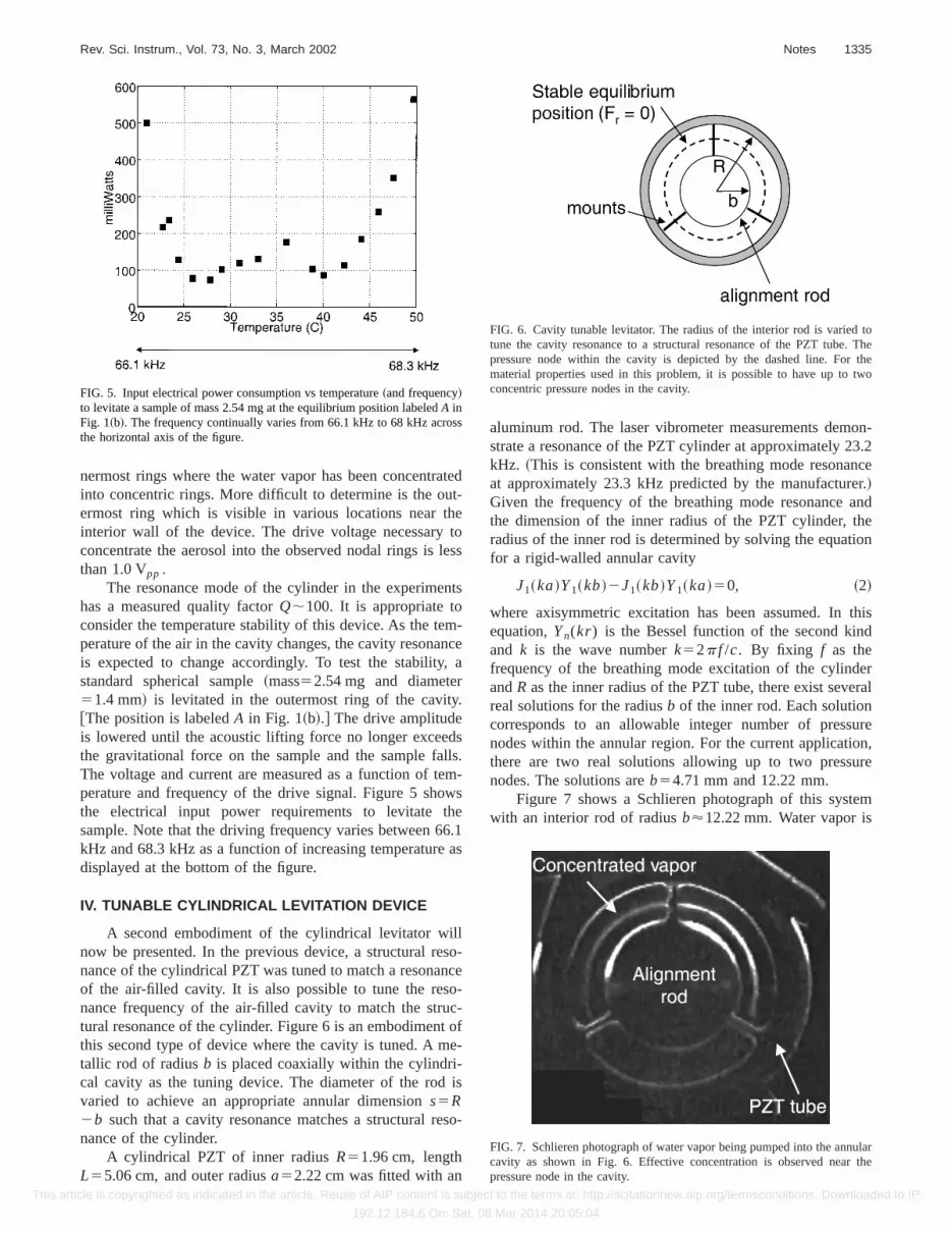
The resonance mode of the cylinder in the experimehas a measured quality factorQ;100. It is appropriate toconsider the temperature stability of this device. As the teperature of the air in the cavity changes, the cavity resonais expected to change accordingly. To test the stabilitystandard spherical sample~mass52.54 mg and diamete51.4 mm! is levitated in the outermost ring of the cavit@The position is labeledA in Fig. 1~b!.# The drive amplitudeis lowered until the acoustic lifting force no longer exceethe gravitational force on the sample and the sample faThe voltage and current are measured as a function of tperature and frequency of the drive signal. Figure 5 shothe electrical input power requirements to levitate tsample. Note that the driving frequency varies between 6kHz and 68.3 kHz as a function of increasing temperaturedisplayed at the bottom of the figure.
IV. TUNABLE CYLINDRICAL LEVITATION DEVICE
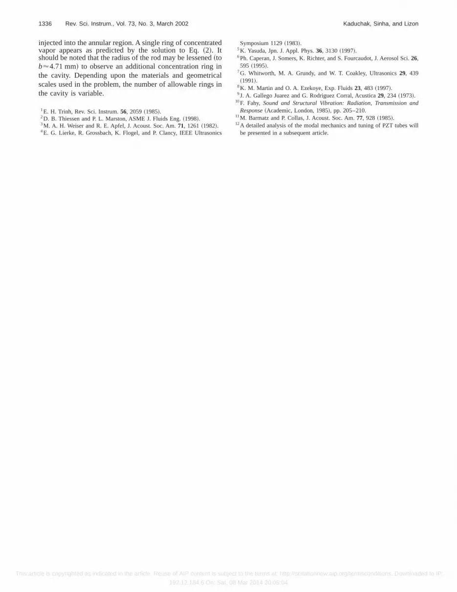
A second embodiment of the cylindrical levitator wnow be presented. In the previous device, a structural rnance of the cylindrical PZT was tuned to match a resonaof the air-filled cavity. It is also possible to tune the resnance frequency of the air-filled cavity to match the strutural resonance of the cylinder. Figure 6 is an embodimenthis second type of device where the cavity is tuned. A mtallic rod of radiusb is placed coaxially within the cylindri-cal cavity as the tuning device. The diameter of the rodvaried to achieve an appropriate annular dimensions5R2b such that a cavity resonance matches a structural rnance of the cylinder.
A cylindrical PZT of inner radiusR51.96 cm, lengthL55.06 cm, and outer radiusa52.22 cm was fitted with an
FIG. 5. Input electrical power consumption vs temperature~and frequency!to levitate a sample of mass 2.54 mg at the equilibrium position labeledA inFig. 1~b!. The frequency continually varies from 66.1 kHz to 68 kHz acrothe horizontal axis of the figure.
icle is copyrighted as indicated in the article. Reuse of AIP content is subje
192.12.184.6 On: Sat, 0
ted
oss
ts
-cea
ss.
-s
.1s
o-ce--of-
s
o-
aluminum rod. The laser vibrometer measurements demstrate a resonance of the PZT cylinder at approximately 2kHz. ~This is consistent with the breathing mode resonaat approximately 23.3 kHz predicted by the manufactur!Given the frequency of the breathing mode resonancethe dimension of the inner radius of the PZT cylinder, tradius of the inner rod is determined by solving the equatfor a rigid-walled annular cavity
J1~ka!Y1~kb!2J1~kb!Y1~ka!50, ~2!
where axisymmetric excitation has been assumed. Inequation,Yn(kr) is the Bessel function of the second kinand k is the wave numberk52p f /c. By fixing f as thefrequency of the breathing mode excitation of the cylindandR as the inner radius of the PZT tube, there exist severeal solutions for the radiusb of the inner rod. Each solutioncorresponds to an allowable integer number of pressnodes within the annular region. For the current applicatithere are two real solutions allowing up to two pressunodes. The solutions areb54.71 mm and 12.22 mm.
Figure 7 shows a Schlieren photograph of this systwith an interior rod of radiusb'12.22 mm. Water vapor is
FIG. 7. Schlieren photograph of water vapor being pumped into the anncavity as shown in Fig. 6. Effective concentration is observed nearpressure node in the cavity.
FIG. 6. Cavity tunable levitator. The radius of the interior rod is variedtune the cavity resonance to a structural resonance of the PZT tube.pressure node within the cavity is depicted by the dashed line. Formaterial properties used in this problem, it is possible to have up toconcentric pressure nodes in the cavity.
ct to the terms at: http://scitationnew.aip.org/termsconditions. Downloaded to IP:
8 Mar 2014 20:05:04
te
dinics
ic
i.
nd
will
1336 Rev. Sci. Instrum., Vol. 73, No. 3, March 2002 Kaduchak, Sinha, and Lizon
This art
injected into the annular region. A single ring of concentravapor appears as predicted by the solution to Eq.~2!. Itshould be noted that the radius of the rod may be lessene~tob'4.71 mm! to observe an additional concentration ringthe cavity. Depending upon the materials and geometrscales used in the problem, the number of allowable ringthe cavity is variable.
1E. H. Trinh, Rev. Sci. Instrum.56, 2059~1985!.2D. B. Thiessen and P. L. Marston, ASME J. Fluids Eng.~1998!.3M. A. H. Weiser and R. E. Apfel, J. Acoust. Soc. Am.71, 1261~1982!.4E. G. Lierke, R. Grossbach, K. Flogel, and P. Clancy, IEEE Ultrason
icle is copyrighted as indicated in the article. Reuse of AIP content is subje
192.12.184.6 On: Sat, 0
d
alin
s
Symposium 1129~1983!.5K. Yasuda, Jpn. J. Appl. Phys.36, 3130~1997!.6Ph. Caperan, J. Somers, K. Richter, and S. Fourcaudot, J. Aerosol Sc26,595 ~1995!.
7G. Whitworth, M. A. Grundy, and W. T. Coakley, Ultrasonics29, 439~1991!.
8K. M. Martin and O. A. Ezekoye, Exp. Fluids23, 483 ~1997!.9J. A. Gallego Juarez and G. Rodriguez Corral, Acustica29, 234 ~1973!.
10F. Fahy, Sound and Structural Vibration: Radiation, Transmission aResponse~Academic, London, 1985!, pp. 205–210.
11M. Barmatz and P. Collas, J. Acoust. Soc. Am.77, 928 ~1985!.12A detailed analysis of the modal mechanics and tuning of PZT tubes
be presented in a subsequent article.
ct to the terms at: http://scitationnew.aip.org/termsconditions. Downloaded to IP:
8 Mar 2014 20:05:04


