Embed Size (px)
Citation preview
Journal of Rehabilitation in Civil Engineering 3-2 (2015) 80-88
journal homepage: http://civiljournal.semnan.ac.ir/
Behavior Comparison of Uniaxial Cylindrical Columns
Strengthened with CFRP
Ali Delnavaz1*
and Mohammad Hamidnia2
1. Assistant Professor, Department of Civil and Surveying Engineering, Qazvin Branch, Islamic Azad University,
Qazvin, Iran
2. M.Sc. Structural Eng., Department of Civil and Surveying Engineering, Qazvin Branch, Islamic Azad University,
Qazvin, Iran
Corresponding author: [email protected]
ARTICLE INFO
ABSTRACT
Article history:
Received: 12 February 2015
Accepted: 20 June 2016
In recent years application of CFRP sheets in the
strengthening of the concrete circular column has increased
numerously. Knowing the exact behavior of concrete
cylindrical columns confined with CFRP is of the first order
of importance. ISIS Code of Canada has given relations for
strength increase of circular columns confined with CFRP
sheets, these relations are defined for a specified range of
confinement pressure, and for higher confinement pressures
there are no relations describing the behavior of the confined
specimen. In this paper, cylindrical specimens with different
concrete strengths and a variable number of CFRP layers
were used. They were modeled in finite element software.
After verification of models with laboratory works; results of
finite element modeling were compared with ISIS Canada.
The analytical results show that with a change in concrete
strength the results have a different error from ISIS results.
Therefore, for confinement pressure of more than the
permissible value of ISIS code, change in the amount of
strength increases was studied.
Keywords:
Cylindrical specimen,
CFRP,
Confinement pressure,
Uniaxial strength.
1. Introduction
Concrete confinement imposes multi axial
compressive stress on the concrete, and
causes increase of its ultimate strength and
ductility, consequently prevents it from early
collapse of the concrete usually. Concrete
confinement is done by perimeter turnings of
CFRP sheets. FRP confining effect in
structural members has been the subject of
different studies [1-3]. Although in old
buildings the retrofitting of concrete
members were done by FRP confinement to
restore or even to increase the strength
capacity [4-6]. Some researchs about
effectiveness of FRP on axial stress–strain
A. Delnavaz and M. Hamidnia/ Journal of Rehabilitation in Civil Engineering 3-2 (2015) 80-88 81
curve of confined concrete and cylindrical
specimens load capacity of concrete also
have been done [7-12].
In 2002, Li et al studied different rebar
arrangements for strengthening of cyclic
specimens strengthened with CFRP. They
found out that compressive strength of
cylindrical concrete specimen confined with
CFRP is not related to rebar arrangements
[13,14].
According to ISIS Canada Educational
module 4 the compressive pressure of
confinement, for a cylindrical column, is
calculated using relations (1) to (3) [15]. In
equation (1) 𝑁𝑏 the number of layers, 𝜙𝑓𝑟𝑝
perimeter reduction confinement, 𝑓𝑓𝑟𝑝 CFRP
maximum strength, 𝑡𝑓𝑟𝑝 CFRP sheets
thickness, and 𝐷𝑔 is the specimen
diameter. 𝜙𝑐 in relation (2) is the concrete
resistance factor and 𝑤𝑤 is the volumetric
confinement ratio. 𝑓𝑐𝑐 in equation (3) is the
ultimate strength of confined concrete, 𝛼𝑝𝑐 is
a performance confinement (that depends on
a number of factors such as FRP type,
concrete strength, and member size). ISIS
Design manual No. 4 currently recommends
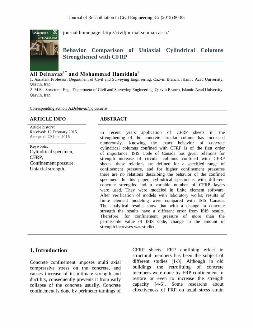
that 𝛼𝑝𝑐 be taken as 1.0. Fig (1) shows
confinement mechanism for axial
strengthening of circular reinforced concrete
specimen using externally bounded FRP
wraps.
(1) 𝑓𝑙𝑓𝑟𝑝 =
2 𝑁𝑏𝜙𝑓𝑟𝑝𝑓𝑓𝑟𝑝𝑡𝑓𝑟𝑝
𝐷𝑔
(2) 𝑤𝑤 =
2 𝑓𝑙𝑓𝑟𝑝
𝜙𝑐𝑓𝑐
(3) 𝑓𝑐𝑐 = 𝑓𝑐(1 + 𝛼𝑝𝑐𝑤𝑤)
(4) 𝑓𝑙𝑓𝑟𝑝 ≤
𝑓𝑐,
2𝛼𝑝𝑐(
1
𝑘𝑒− 𝜙𝑐)
The maximum confinement pressure that
ISIS code considers for the specimens
confined with CFRP is calculated from
relation (4). In this relation, considering 𝑘𝑒
and 𝜙𝑐, they are equal to 0.8 and 0.6,
respectively, thus the allowable confinement
pressure is calculated as 0.325𝑓𝑐,.
Fig (1) Mechanism for axial strengthening of circular
reinforced concrete specimen using externally bounded
FRP wraps [15].
In this article, a cylindrical concrete
specimen was modeled and analyzed 3
dimensionally in Abaqus software. It was
verified with experimental work of complete
confinement and ISIS code’s result. Also
using CFRP with different number of layers
and change in concrete strength was studied.
At the end with increase in specimen’s
confinement pressure more than allowed ISIS
value, we investigated this parameter in
confining method.
2. Modeling
2.1. Concrete modeling
Concrete modeling was done with an
eight-node cubic element (3D) in Abaqus
software. By comparing relations for
82 A. Delnavaz and M. Hamidnia/ Journal of Rehabilitation in Civil Engineering 3-2 (2015) 80-88
concrete behavior from Majewski [16], Euro
code EN 1992-1-1[17] , Wang and Hsu [18],
the EN 1992-1-1 model confirmed with the
laboratory work very well. Therefore, to
define the concrete behavior the relations of
EN 1992-1-1 [17,19] were used. Then
plasticity damage model for the concrete was
defined with relations (5) through (11).
(5) 𝜎𝑐 = 𝑓𝑐𝑚
𝑘𝜂 − 𝜂2
1 + (𝑘 − 2)𝜂
(6) 𝑘 = 1.05𝐸𝑐𝑚
𝜀𝑐1
𝑓𝑐𝑚
, 𝜂 =εc
εc1
(7) 𝜀𝑐1
= 0.7(𝑓𝑐𝑚)0.31
(8) 𝐸𝑐𝑚 = 22(0.1𝑓𝑐𝑚)0.3
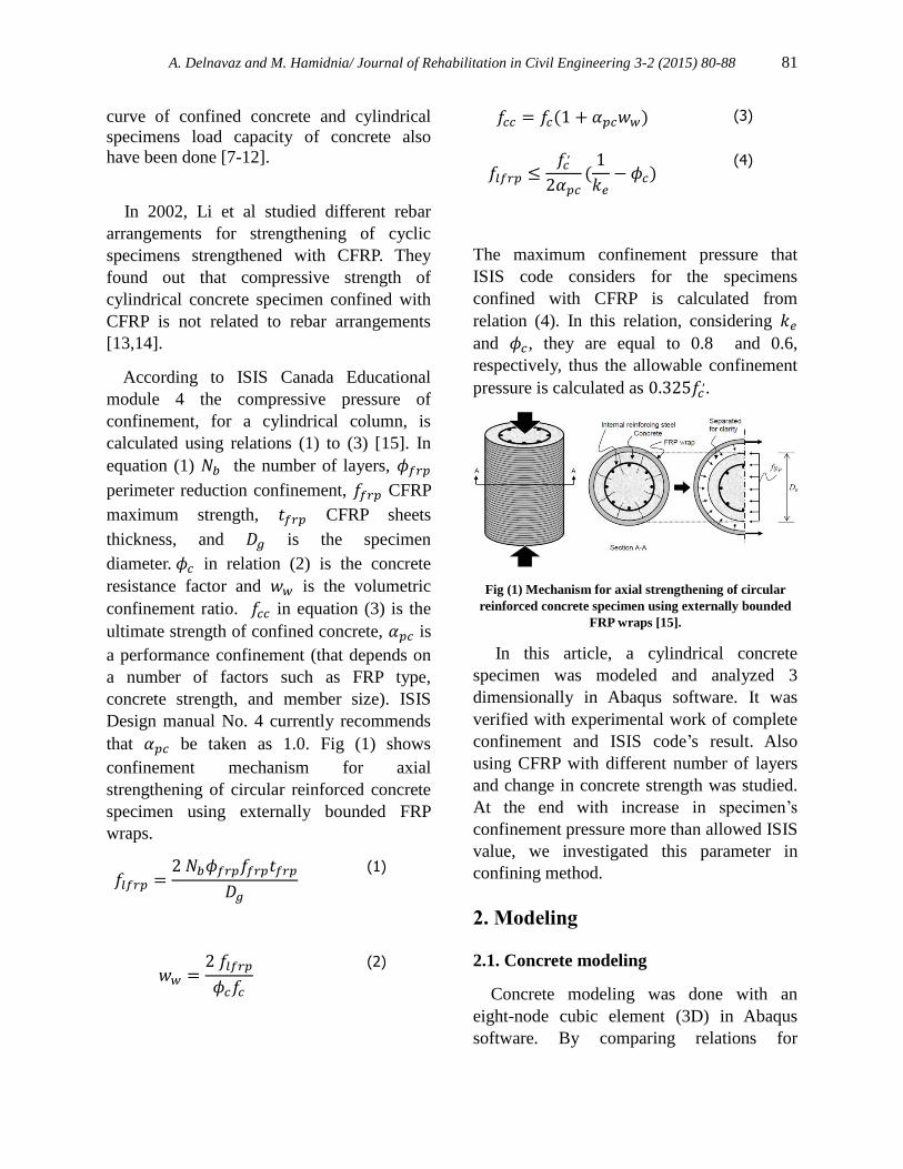
Compressive stress of concrete, up to 0.4𝑓𝑐𝑚,
is elastic and greater than that from relation
(5) the stress is defined as non-linear. The
maximum compressive stress of concrete is
𝑓𝑐𝑚. The compressive stress (𝜎𝑐) is a function
of variables 𝜂, 𝑘. These variables are
calculated from relation (6). εc is the
compressive strain for concrete, related to 𝜎𝑐.
Concrete strain at maximum compressive
stress is εc1, 𝑓𝑐𝑚, which is calculated from
relation (7). Concrete elastic module is
calculated from relation (8) a function of the
maximum compressive stress of concrete.
Fig. (2) shows the compressive behavior.
Fig.(2) Concrete compressive behavior.
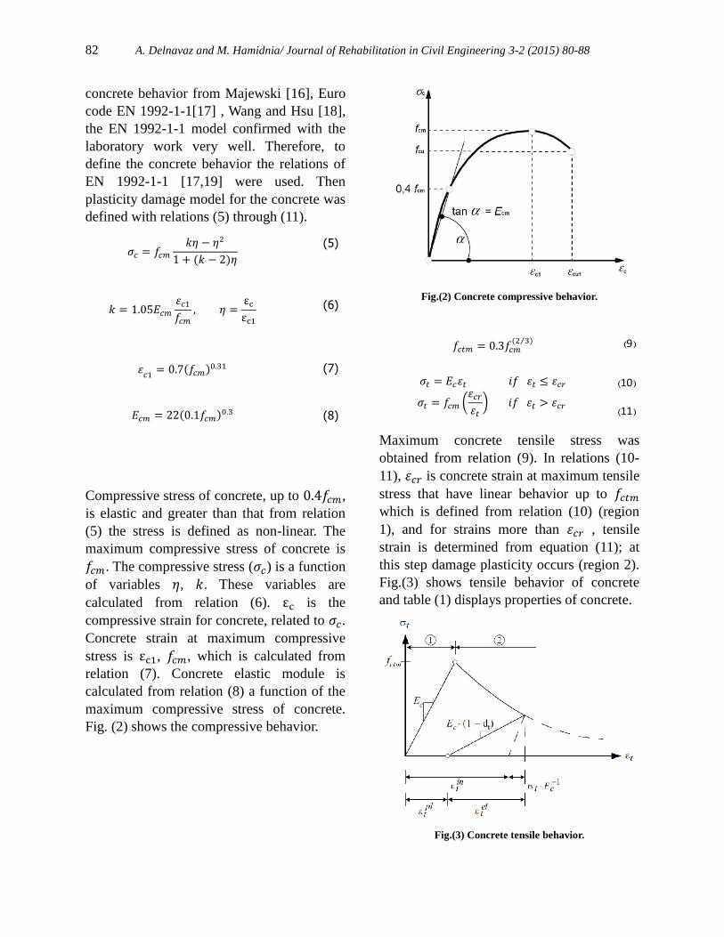
Maximum concrete tensile stress was
obtained from relation (9). In relations (10-
11), 𝜀𝑐𝑟 is concrete strain at maximum tensile
stress that have linear behavior up to 𝑓𝑐𝑡𝑚
which is defined from relation (10) (region
1), and for strains more than 𝜀𝑐𝑟 , tensile
strain is determined from equation (11); at
this step damage plasticity occurs (region 2).
Fig.(3) shows tensile behavior of concrete
and table (1) displays properties of concrete.
Fig.(3) Concrete tensile behavior.
(9) 𝑓𝑐𝑡𝑚 = 0.3𝑓𝑐𝑚(2 3)⁄
(10)
(11)
𝜎𝑡 = 𝐸𝑐𝜀𝑡 𝑖𝑓 𝜀𝑡 ≤ 𝜀𝑐𝑟
𝜎𝑡 = 𝑓𝑐𝑚 (𝜀𝑐𝑟
𝜀𝑡
) 𝑖𝑓 𝜀𝑡 > 𝜀𝑐𝑟
A. Delnavaz and M. Hamidnia/ Journal of Rehabilitation in Civil Engineering 3-2 (2015) 80-88 83
Table (1) Concrete properties.
Poison
ratio Elasticity
module (MPa)
Density (kg/m3
) Compressive
stress (MPa)
0.2 26154 2400 17.8
0.2 28960 2400 25
0.2 34545 2400 45
2.2. Modeling CFRP
All of CFRP sheets have lamina type and
modeled with shell element [20] and have 10
cm width. Also in applying CFRP, resin
applied has more strength than CFRP’s,
therefore in this modeling we neglect CFRP
slips on concrete surface and its traction was
defined as tie. Table (2) shows CFRP
properties.
Table (2) CFRP properties.
4100 Longitudinal tensile strength (MPa)
3206 Longitudinal compressive strength
(MPa) 80.136 Transvers tensile strength (MPa)
240.4 Transvers compressive strength (MPa)
80.136 Longitudinal shear strength (MPa)
120.246 Transvers shear strength (MPa)
1536 Density (kg/m3)
240 Elastic module (GPa)
0.25 Poison ratio
0.12 Thickness (mm)
3. Strengthening specimens
All of specimens have 30 cm diameter and
60 cm height, numbering specimens from left
to right represents, specimen’s concrete
strength that starts with S, and then total
number of CFRP layers. Confinement details
were explained in table (3). Uniaxial load
may act perpendicular to CFRP jackets and
causes the jacket to buckle rapidly, this
situation occurs when CFRP jackets confines
all external specimens’ area, to stop
occurring this we use a finite spacing of
layers (5 mm) between jackets at the upper
side or down side of specimens’ surface, with
this method confinement pressure is reached
and jackets do not buckle rapidly.
Table (3) Strengthening details.
Confinement
pressure (MPa)
No.
of
layers
Confinement
type Concrete
strength (MPa)
Specimen
- -
Without
cover
17.8 25
45
S17-0W
S25-0W
S45-0W
3.28
1
Fully
covered
17.8 25
45
S17-1W
S25-1W
S45-1W
9.84
3
Fully
covered
17.8 25
45
S17-3W
S25-3W
S45-3W
19.68
6
Fully
covered
17.8 25
45
S17-6W
S25-6W
S45-6W
29.52
9
Fully
covered
17.8 25
45
S17-9W
S25-9W
S45-9W
4. Model verification and finite
element results
Types of jackets have negligible effect on
linear behavior of specimens. Specimens
with different jackets in linear behavior are
similar to each other, and since low stress
concrete has low lateral expansion, jackets do
not act. But in plastic region, increase in
stress causes a lot of lateral expansion, and
that causes confinement pressure creation
[21, 22].
84 A. Delnavaz and M. Hamidnia/ Journal of Rehabilitation in Civil Engineering 3-2 (2015) 80-88
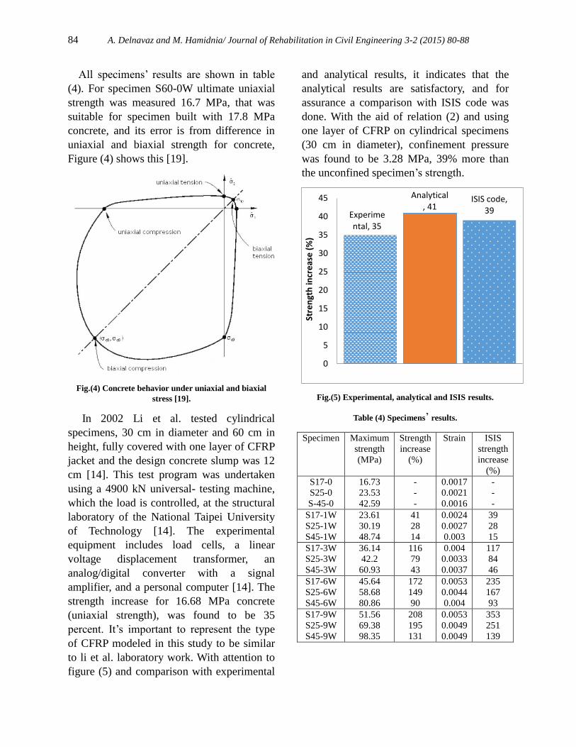
All specimens’ results are shown in table
(4). For specimen S60-0W ultimate uniaxial
strength was measured 16.7 MPa, that was
suitable for specimen built with 17.8 MPa
concrete, and its error is from difference in
uniaxial and biaxial strength for concrete,
Figure (4) shows this [19].
Fig.(4) Concrete behavior under uniaxial and biaxial
stress [19].
In 2002 Li et al. tested cylindrical
specimens, 30 cm in diameter and 60 cm in
height, fully covered with one layer of CFRP
jacket and the design concrete slump was 12
cm [14]. This test program was undertaken
using a 4900 kN universal- testing machine,
which the load is controlled, at the structural
laboratory of the National Taipei University
of Technology [14]. The experimental
equipment includes load cells, a linear
voltage displacement transformer, an
analog/digital converter with a signal
amplifier, and a personal computer [14]. The
strength increase for 16.68 MPa concrete
(uniaxial strength), was found to be 35
percent. It’s important to represent the type
of CFRP modeled in this study to be similar
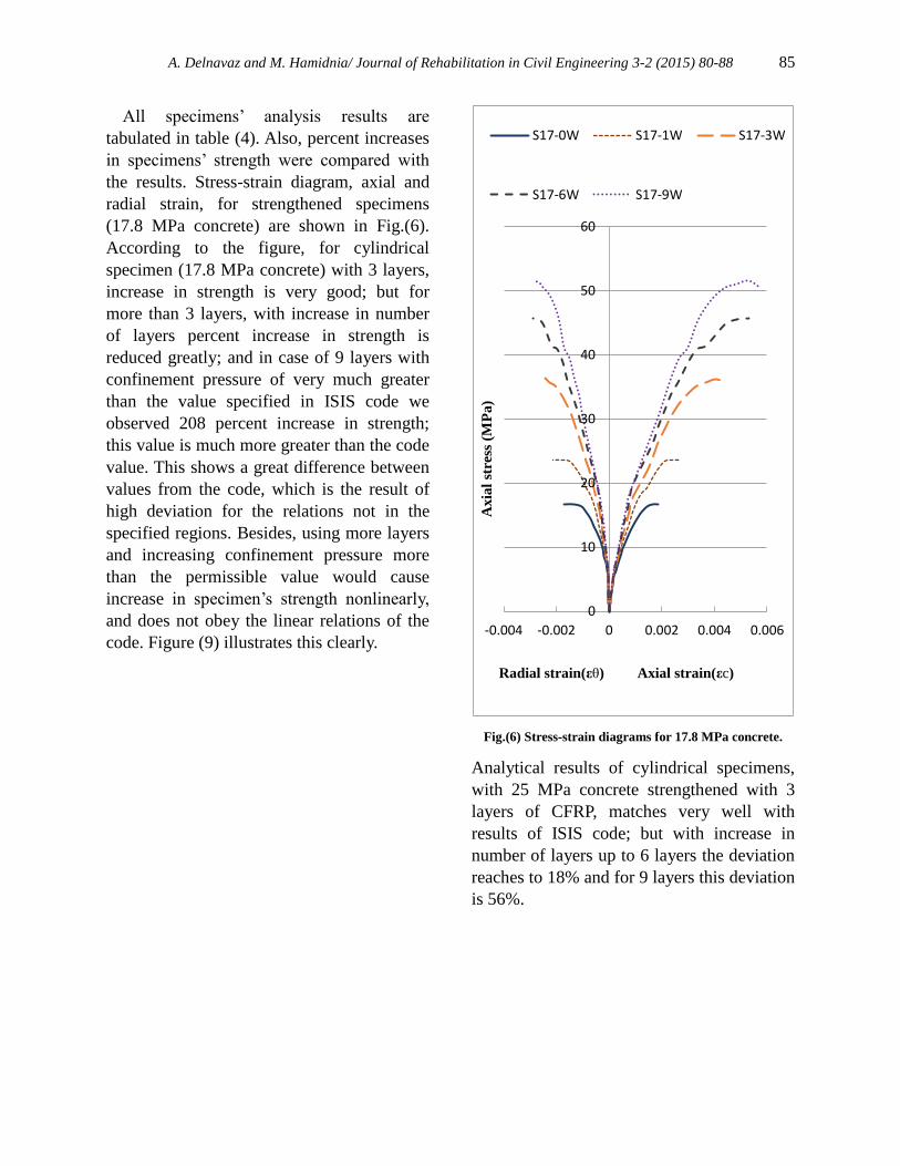
to li et al. laboratory work. With attention to
figure (5) and comparison with experimental
and analytical results, it indicates that the
analytical results are satisfactory, and for
assurance a comparison with ISIS code was
done. With the aid of relation (2) and using
one layer of CFRP on cylindrical specimens
(30 cm in diameter), confinement pressure
was found to be 3.28 MPa, 39% more than
the unconfined specimen’s strength.
Fig.(5) Experimental, analytical and ISIS results.
Table (4) Specimens’ results.
ISIS
strength
increase
(%)
Strain Strength
increase
(%)
Maximum
strength (MPa)
Specimen
-
-
-
0.0017
0.0021
0.0016
-
-
-
16.73
23.53
42.59
S17-0
S25-0
S-45-0
39
28
15
0.0024
0.0027
0.003
41
28
14
23.61 30.19
48.74
S17-1W
S25-1W
S45-1W 117
84
46
0.004
0.0033
0.0037
116
79
43
36.14 42.2
60.93
S17-3W
S25-3W
S45-3W 235
167
93
0.0053
0.0044
0.004
172
149
90
45.64
58.68
80.86
S17-6W
S25-6W
S45-6W
353
251
139
0.0053
0.0049
0.0049
208
195
131
51.56
69.38
98.35
S17-9W
S25-9W
S45-9W
Experimental, 35
Analytical, 41
ISIS code, 39
0
5
10
15
20
25
30
35
40
45
Stre
ngt
h in
cre
ase
(%
)
A. Delnavaz and M. Hamidnia/ Journal of Rehabilitation in Civil Engineering 3-2 (2015) 80-88 85
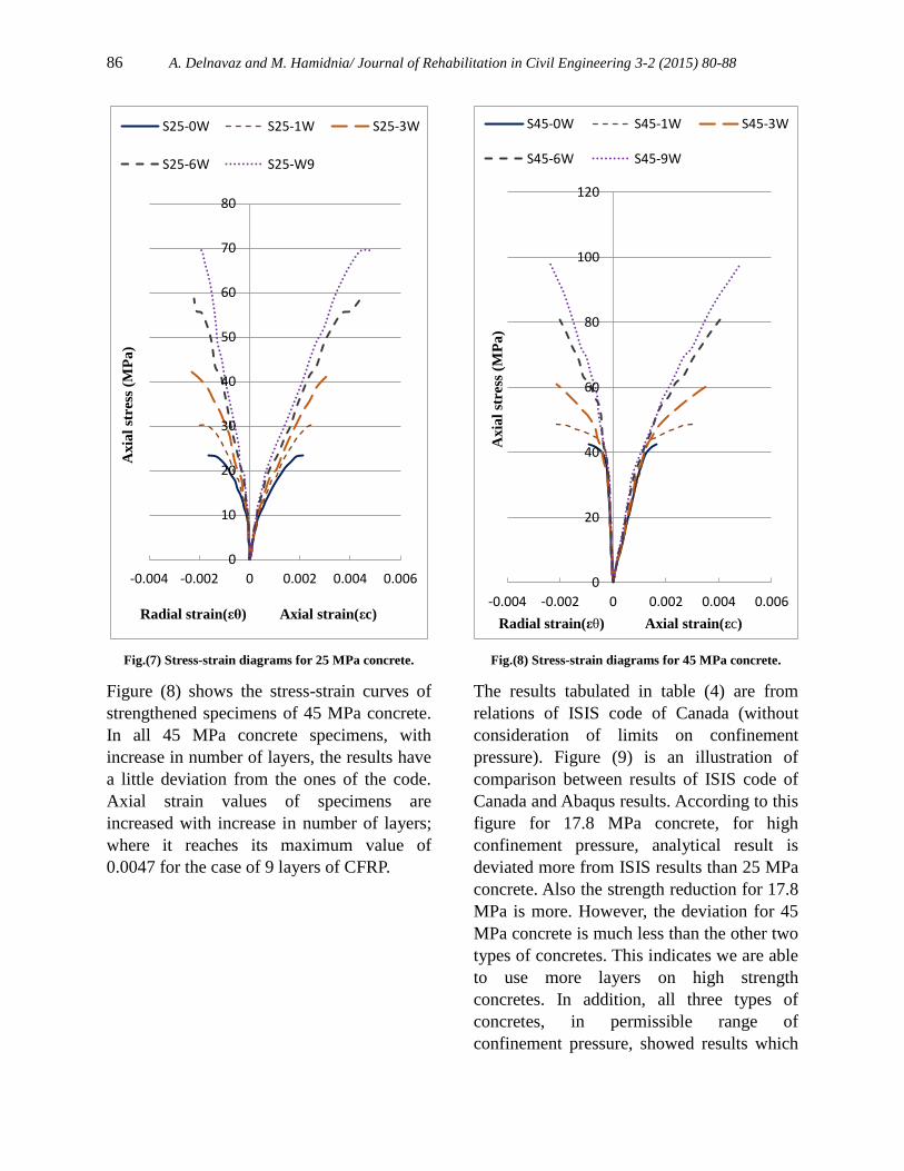
All specimens’ analysis results are
tabulated in table (4). Also, percent increases
in specimens’ strength were compared with
the results. Stress-strain diagram, axial and
radial strain, for strengthened specimens
(17.8 MPa concrete) are shown in Fig.(6).
According to the figure, for cylindrical
specimen (17.8 MPa concrete) with 3 layers,
increase in strength is very good; but for
more than 3 layers, with increase in number
of layers percent increase in strength is
reduced greatly; and in case of 9 layers with
confinement pressure of very much greater
than the value specified in ISIS code we
observed 208 percent increase in strength;
this value is much more greater than the code
value. This shows a great difference between
values from the code, which is the result of
high deviation for the relations not in the
specified regions. Besides, using more layers
and increasing confinement pressure more
than the permissible value would cause
increase in specimen’s strength nonlinearly,
and does not obey the linear relations of the
code. Figure (9) illustrates this clearly.
Fig.(6) Stress-strain diagrams for 17.8 MPa concrete.
Analytical results of cylindrical specimens,
with 25 MPa concrete strengthened with 3
layers of CFRP, matches very well with
results of ISIS code; but with increase in
number of layers up to 6 layers the deviation
reaches to 18% and for 9 layers this deviation
is 56%.
0
10
20
30
40
50
60
-0.004 -0.002 0 0.002 0.004 0.006
Axia
l st
ress
(M
Pa
)
Radial strain(εθ) Axial strain(εc)
S17-0W S17-1W S17-3W
S17-6W S17-9W
86 A. Delnavaz and M. Hamidnia/ Journal of Rehabilitation in Civil Engineering 3-2 (2015) 80-88
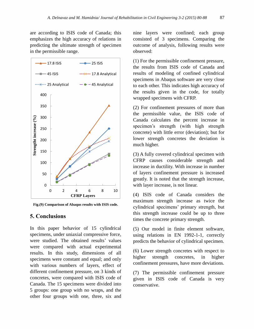
Fig.(7) Stress-strain diagrams for 25 MPa concrete.
Figure (8) shows the stress-strain curves of
strengthened specimens of 45 MPa concrete.
In all 45 MPa concrete specimens, with
increase in number of layers, the results have
a little deviation from the ones of the code.
Axial strain values of specimens are
increased with increase in number of layers;
where it reaches its maximum value of
0.0047 for the case of 9 layers of CFRP.
Fig.(8) Stress-strain diagrams for 45 MPa concrete.
The results tabulated in table (4) are from
relations of ISIS code of Canada (without
consideration of limits on confinement
pressure). Figure (9) is an illustration of
comparison between results of ISIS code of
Canada and Abaqus results. According to this
figure for 17.8 MPa concrete, for high
confinement pressure, analytical result is
deviated more from ISIS results than 25 MPa
concrete. Also the strength reduction for 17.8
MPa is more. However, the deviation for 45
MPa concrete is much less than the other two
types of concretes. This indicates we are able
to use more layers on high strength
concretes. In addition, all three types of
concretes, in permissible range of
confinement pressure, showed results which
0
10
20
30
40
50
60
70
80
-0.004 -0.002 0 0.002 0.004 0.006
Axia
l st
ress
(M
Pa
)
Radial strain(εθ) Axial strain(εc)
S25-0W S25-1W S25-3W
S25-6W S25-W9
0
20
40
60
80
100
120
-0.004 -0.002 0 0.002 0.004 0.006
Axia
l st
ress
(M
Pa
)
Radial strain(εθ) Axial strain(εc)
S45-0W S45-1W S45-3W
S45-6W S45-9W
A. Delnavaz and M. Hamidnia/ Journal of Rehabilitation in Civil Engineering 3-2 (2015) 80-88 87
are according to ISIS code of Canada; this
emphasizes the high accuracy of relations in
predicting the ultimate strength of specimen
in the permissible range.
Fig.(9) Comparison of Abaqus results with ISIS code.
5. Conclusions
In this paper behavior of 15 cylindrical
specimens, under uniaxial compressive force,
were studied. The obtained results’ values
were compared with actual experimental
results. In this study, dimensions of all
specimens were constant and equal; and only
with various numbers of layers, effect of
different confinement pressure, on 3 kinds of
concretes, were compared with ISIS code of
Canada. The 15 specimens were divided into
5 groups: one group with no wraps, and the
other four groups with one, three, six and
nine layers were confined; each group
consisted of 3 specimens. Comparing the
outcome of analysis, following results were
observed:
(1) For the permissible confinement pressure,
the results from ISIS code of Canada and
results of modeling of confined cylindrical
specimens in Abaqus software are very close
to each other. This indicates high accuracy of
the results given in the code, for totally
wrapped specimens with CFRP.
(2) For confinement pressures of more than
the permissible value, the ISIS code of
Canada calculates the percent increase in
specimen’s strength (with high strength
concrete) with little error (deviation); but for
lower strength concretes the deviation is
much higher.
(3) A fully covered cylindrical specimen with
CFRP causes considerable strength and
increase in ductility. With increase in number
of layers confinement pressure is increased
greatly. It is noted that the strength increase,
with layer increase, is not linear.
(4) ISIS code of Canada considers the
maximum strength increase as twice the
cylindrical specimens’ primary strength, but
this strength increase could be up to three
times the concrete primary strength.
(5) Our model in finite element software,
using relations in EN 1992-1-1, correctly
predicts the behavior of cylindrical specimen.
(6) Lower strength concretes with respect to
higher strength concretes, in higher
confinement pressures, have more deviations.
(7) The permissible confinement pressure
given in ISIS code of Canada is very
conservative.
0
50
100
150
200
250
300
350
400
0 2 4 6 8 10
Str
en
gth
t in
crea
se (
%)
CFRP Layers
17.8 ISIS 25 ISIS
45 ISIS 17.8 Analytical
25 Analytical 45 Analytical
88 A. Delnavaz and M. Hamidnia/ Journal of Rehabilitation in Civil Engineering 3-2 (2015) 80-88
6. Refrences
[1] Kwan, AKH., Chau, SL., Au, FTK. (2006).
“Improving flexural ductility of high-
strength concrete beams”. Proc ICE –
Struct. Build, 159(6), pp. 339–347.
[2] Paultre, P., Legeron, F., Mongeau, D. (2001).
“Influence of concrete strength and
transverse reinforcement yield strength on
behavior of high-strength concrete
columns”. ACI Struct. J., 98(4): pp. 490–
501.
[3] Cusson, D., Paultre, P. (1994). “High-strength
concrete columns confined by rectangular
ties”. J StructEng,120(3): pp. 783–804.
[4] Xiao, Y. (2004). “Applications of FRP
composites in concrete columns”. Adv.
Struct. Eng., Vol.7(4): pp. 335–343.
[5] Xiao, Y., Ma, R. (1997). “Seismic retrofit of
RC circular columns using prefabricated
composite jacketing”. J Struct. Eng.,
123(10): pp. 1357–1364.
[6] Ilki, A., Peker, O., Karamuk, E., Demir, C.,
Kumbasar, N. (2008). “FRP retrofit of low
and medium strength circular and
rectangular reinforced concrete columns”.
J Mater Civ. Eng., 20(2): pp. 169–88.
[7] Ozbakkaloglu, T. (2013). “Compressive
behavior of concrete-filled FRP tube
columns: assessment of critical column
parameters”. Eng. Struct., 51: pp. 188–199.
[8] Xiao, Y., Wu, H. (2003). “Compressive
behavior of concrete confined by various
types of FRP composite jackets”. J Reinf
Plast Compos, 22(13): pp. 1187–1201.
[9] Rousakis, TC., Karabinis, AI., Kiousis, PD.
(2007). “FRP-confined concrete members:
axial compression experiments and
plasticity modelling”. Eng. Struct., 29(7):
pp. 1343–1353.
[10] Ozbakkaloglu, T., Lim, JC., Vicent, T.
(2013). “FRP-confined concrete in circular
sections: review and assessment of stress–
strain models”. Eng. Struct., 49: pp. 1068–
1088.
[11] Idris, Y., Ozbakkaloglu, T. (2013). “Seismic
behavior of high-strength concrete-filled
FRP tube columns”. J. Compos. Constr.,
Vol. 17 (6) pp. 1943.
[12] Ozbakkaloglu, T. (2013). “Compressive
behavior of concrete-filled FRP tube
columns: assessment of critical column
parameters”. Eng. Struct., Vol. 51 pp. 188–
199.
[13] Li, Y., Fang, T., Chern, C. (2003). “A
Constitutive Model for Concrete Cylinder
Confined by Steel Reinforcement and
Carbon Fiber Sheet”. pacific conference on
earthquake engineering,.
[14] Li, Y., Lin, C., Sung, Y. (2003). “A
constitutive model for concrete confined
with carbon fiber reinforced plastics”.
Mechanics of Materials, Vol. 35, pp 603–
619.
[15] ISIS educational module 4. (2004). “An
introduction to FRP strengthening of
concrete structures”. prepared by ISIS
Canada, February 2004.
[16] Majewski, S. (2003). “The mechanics of
structural concrete in terms of elasto-
plasticity”. Silesian Polytechnic Publishing
House, Gliwice,. [17] EN 1992-1-1. (2004). “ Eurocode 2 Design
of concrete structures - Part 1-1: General
rules and rules for buildings”.
[18] Wang, T., Hsu, T.T.C. (2001). “Nonlinear
finite element analysis of concrete
structures using new constitutive models”.
Computers and Structures, Vol. 79, Iss. 32,
, pp. 2781–2791. [19] Kmiecik, P., Kaminski, M. (2011).
“Modelling of reinforced concrete
structures and composite structures with
concrete strength degradation taken into
consideration”. Archives of civil and
mechanical engineering, No. 3. [20] Abaqus theory manual and users' manual,
version 6.10. (2010).
[21] Bouchelaghem, H., Bezazi, A., Scarpa, F.
(2011). “Compressive behavior of concrete
cylindrical FRP-confined columns
subjected to a new sequential loading
technique”. Composites: Part B, Vol. 42,
pp 1987–1993. [22] Uya, B., Taoa, Z., Hanc, L. (2011).
“Behaviour of short and slender concrete-
filled stainless steel tubular columns”.
Journal of Constructional Steel Research,
Vol. 67, pp 360–378.


