Embed Size (px)
Citation preview
Note: Within nine months of the publication of the mention of the grant of the European patent in the European PatentBulletin, any person may give notice to the European Patent Office of opposition to that patent, in accordance with theImplementing Regulations. Notice of opposition shall not be deemed to have been filed until the opposition fee has beenpaid. (Art. 99(1) European Patent Convention).
Printed by Jouve, 75001 PARIS (FR)
(19)E
P1
204
410
B1
��&��� ��������(11) EP 1 204 410 B1
(12) EUROPEAN PATENT SPECIFICATION
(45) Date of publication and mention of the grant of the patent: 12.09.2012 Bulletin 2012/37
(21) Application number: 00953110.4
(22) Date of filing: 27.07.2000
(51) Int Cl.:A61K 9/48 (2006.01)
(86) International application number: PCT/EP2000/007295
(87) International publication number: WO 2001/008666 (08.02.2001 Gazette 2001/06)
(54) MULTI-COMPONENT PHARMACEUTICAL DOSAGE FORM
MULTIKOMPONENT PHARMAZEUTISCHE DOSIERFORM
FORME DE DOSAGE PHARMACEUTIQUE A PLUSIEURS COMPOSANTS
(84) Designated Contracting States: AT BE CH CY DE DK ES FI FR GB GR IE IT LI LU MC NL PT SEDesignated Extension States: SI
(30) Priority: 30.07.1999 GB 991777230.07.1999 GB 991777430.07.1999 GB 991777530.07.1999 GB 9917777
(43) Date of publication of application: 15.05.2002 Bulletin 2002/20
(73) Proprietor: Capsugel Belgium NV2880 Bornem (BE)
(72) Inventors: • CLARKE, Allan, J.,
SmithKline Beecham Pharma.King of Prussia, PA 19406 (US)
• FONIO, Teodoro,SmithKline Beecham S.p.A.I-20021 Baranzate di Bollate (IT)
• HARRIS, Geoffrey, A. ,SmithKline Beecham Pharma.Worthing,west Sussex BN14 8QH (GB)
• KIFT, Ronald,SmithKline Beecham Pharma.Harlow,Essex CM19 5AW (GB)
• LIGHTFOOT, Donald,SmithKline Beecham Pharma.Collegeville, PA 19426-0989 (US)
• MCGINLEY, Shane,Smithkline Beecham Pharma.Collegeville, PA 19426-0989 (US)
• OFSHARICK, Thomas,Smithkline Beecham Pharma.Collegeville, PA 19426-0989 (US)
• SZYMCZAK, Margaret, M.,SmithKline Beecham Pharma.Philadelphia, PA 19103 (US)
(74) Representative: Hyden, Martin Douglas et alFinnegan Avenue Louise, 326 Box 371050 Brussels (BE)
(56) References cited: WO-A-95/16438 US-A- 4 738 817US-A- 5 074 426 US-A- 5 674 530
EP 1 204 410 B1
2
5
10
15
20
25
30
35
40
45
50
55
Description
[0001] This invention relates to pharmaceutical formu-lations, being a dosage form comprising a capsule com-partment - linker unit - capsule compartment assemblyfor oral dosing.[0002] Various types of pharmaceutical dosage formare known for oral dosing. Pharmaceutical capsules arewell known, generally being intended for oral dosing.Such capsules generally comprise an envelope wall of apharmaceutically acceptable, e. g. orally ingestible, pol-ymer material such as gelatin, although other materialsfor capsule walls, e. g. starch and cellulose based poly-mers are also known. Such capsules generally have softwalls made by making a film on a capsule former, whichis then allowed to dry. Rigid walled capsules made byinjection moulding are also known, see for example US4576284, US 4591475, US 4655840, US 4738724, andUS 4790881 (all to Warner Lambert). These disclosespecific constructions of capsules made of gelatin, starchand other polymers, and methods of making them byinjection moulding of hydrophilic polymer-water mixtures.US 4576284 specifically discloses such capsules provid-ed with a cap which closes the capsule, and which isformed in situ on the filled capsule by moulding. US4738724 discloses a wide range of rigid capsule shapesand parts.[0003] US 5074426 discloses divisible capsules com-prising two closed capsule compartments divisibly con-nected together. US 4738817 discloses two-compart-ment capsules comprising two- open- mouthed compart-ments connected by a linker. US 5674530 discloses amethod of making a drug delivery system including thesteps of filling a first water permeable capsule half witha drug and an osmotic agent and plugging an open-endof the capsule. Multi-compartment capsules, includingthose of the type where each compartment has differentdrug release characteristics or for example contains adifferent drug substance or formulation are also known,for example in US 4738724 (Warner-Lambert), US5672359 (University of Kentucky), US 5443461 (AlzaCorp.), WO 9516438 (Cortecs Ltd.), WO 9012567(Helminthology Inst.), DE-A 3727894, BE 900950 (Warn-er Lambert), FR 2524311, NL 7610038 (Tapanhony NV),FR 28646 (Pluripharm), US 3228789 (Glassman), US3186910 (Glassman) among others. US 4738817 dis-closes a multicompartment capsule with a similar con-struction to those of US 3228789 and US 3186910, madeof a water-plasticised gelatin.[0004] Pharmaceutical dosage forms are also knownwhich comprise a matrix of a solid polymer, in which adrug substance is dispersed, embedded or dissolved asa solid solution. Such matrixes may be formed by an in-jection moulding process. This technology is discussedin Cuff G, and Raouf F, Pharmaceutical Technology June1998 p 96-106. Some specific formulations for such dos-age forms are for example disclosed in US 4,678,516;US 4,806,337; US 4,764,378; US 5,004,601; US
5,135,752; US 5,244,668; US 5,139,790; US 5,082,655among others; in which a polyethylene glycol ("PEG")matrix is used and solid dosage forms are made by in-jection moulding.[0005] It is an object of this invention to provide analternative and improved pharmaceutical dosage formwhich provides inter alia greater flexibility in producing adosage form adapted to a patient’s specific administra-tion requirement, and to ease of manufacture. Other ob-jects and advantages of the invention will be apparentfrom the following description.[0006] The present invention relates to a multi-compo-nent pharmaceutical dosage form comprising a capsulecompartment - linker unit - capsule compartment assem-bly wherein each capsule compartment has a baseclosed by a base wall, side walls extending from the basewall and an open mouth, and being a drug substancecontaining capsule compartment which can release itsdrug substance in the gastrointestinal environment, thetwo capsule compartments are linked together by a linkerunit positioned between adjacent pairs of said capsulecompartments, characterised by the linker unit being inthe form of a solid wall part with oppositely facing plugconnectable parts which connect in a plug and socketmanner with the open mouth of the two capsule compart-ments to thereby form said assembly, each plug connect-able part having an abutment surface to define and limitthe extent to which each plug part can extend into theopen mouth of a capsule compartment by abuttingagainst the rim of the open mouth of the capsule com-partment when the plug part extends to a suitable extentinto the open mouth of the capsule compartment, a cap-sule compartment and linker unit being connected to-gether by an weld in the assembled dosage form andbeing retained together by the weld at least prior to ad-ministration to a patient.[0007] The connectable nature of these sub-units ad-vantageously enables various subunits having differentdrug release characteristics and/or contents to be as-sembled and connected together to produce a dosageform. This can facilitate the rapid prototyping of a dosageform comprising a combination of different drug sub-stances in respective subunits, and/or combinations ofthe same or different drug substances with different re-lease characteristics, whilst simplifying the formulationprocedure.[0008] In a first embodiment of this invention the phar-maceutical dosage form comprises a plurality of capsulecompartments each bounded and physically separatedfrom at least one adjacent compartment by a wall madeof a pharmaceutically acceptable polymer material, ad-jacent compartments being connected together in the as-sembled dosage form and being retained together by thelinker at least prior to administration to a patient, one ormore of the compartments containing a drug substance,and wherein the linker is provided by a weld betweenparts of the assembled dosage form, suitably betweenimmediately adjacent parts.
1 2
EP 1 204 410 B1
3
5
10
15
20
25
30
35
40
45
50
55
[0009] Suitably in the assembled dosage form of thisfirst embodiment there are two such capsule compart-ments.[0010] In a second embodiment of this invention thepharmaceutical dosage form comprising a capsule com-partment - linker unit - capsule compartment assemblybeing connected together in the assembled dosage formand being retained together by the connection at leastprior to administration to a patient, at least one of thesub-units being a solid sub-unit comprising a solid matrixof a polymer which contains a drug substance, the poly-mer being soluble, dispersible or disintegrable in the pa-tient’s gastro-intestinal environment to thereby releasethe drug substance, and wherein the connection is pro-vided by a weld between parts of the assembled dosageform.[0011] In one form of this second embodiment all ofthe sub-units in the dosage form of this invention may besolid sub-units, e. g. two or more such solid subunits, e.g. three such solid sub-units.[0012] In another form of this second embodiment, oneor more of the sub-units comprise a solid sub-unit, andone or more of the other sub-units may comprises a cap-sule compartment bounded by a wall made of a pharma-ceutically acceptable polymer material, one or more ofthe said capsule compartments containing a drug sub-stance.[0013] Suitably in the assembled dosage form thereare at least two, for example three or more, e. g. four subunits. Such an assembled dosage form may comprisethree or four sub-units comprising one, two or three solidsub-units, combined with independently one, two or threecapsule sub-units. Three or more such sub-units may forexample be linearly disposed in the assembled dosageform, e. g. in an arrangement comprising two end subu-nits at opposite ends of the line, and one or more inter-mediate sub-units. For example such an assembled dos-age form may comprise a solid sub-unit connected to acapsule compartment; a solid sub-unit between two endcapsule compartments;; an end capsule compartment,an intermediate solid sub-unit and an end solid sub-unit;In one embodiment one or more, e. g. all, of the sub-unitsmay for example be substantially cylindrical, which termincludes shapes which have a circular, oval or oblatecircular cross section across the longitudinal axis, andshapes which have parallel or tapering e. g. with-sidewalls which taper conically over at least part of their ex-tent. Solid sub-units may also be substantially cylindricalin shape. Such substantially cylindrical sub-units may beprovided with connectable parts at one or both of theirlongitudinally disposed ends so that the assembled dos-age form may also be overall of a substantially cylindricalshape.[0014] The multi-component dosage form of this inven-tion comprises two capsule compartments.[0015] In the assembled dosage form the adjacentsub-units being capsule compartmentsare connected to-gether by means of a weld at the area where two adjacent
parts of the dosage form, e. g. subunits, are in contact,e. g. a thermal weld, an ultrasonic or inductive weld, oran adhesive weld (e. g. curable adhesives such as UVcurable adhesive). A thermal weld may for example beachieved by bringing sub-units into adjacent contact andapplying localised heating for example produced by di-recting a laser beam or a fine jet of hot gas e. g. nitrogenat the area where two adjacent sub-units are in contact.[0016] In thermal, inductive and ultrasonic welding nor-mally localised fusion together of the materials of adja-cent parts of the dosage form which are in contact occurs,and on subsequent solidification of the materials a bondis formed between the adjacent parts. An adhesive weldmay be achieved by applying an adhesive (e. g. curableadhesives such as UV curable adhesive) to parts of thedosage form which when the dosage form is assembledare in contact, and then causing or allowing the adhesiveto set.[0017] The multi-component dosage form of thepresent invention is particularly suited to fabrication usingultrasonic welding.[0018] Ultrasonic welding is a known technique involv-ing the use of high frequency sound energy to soften ormelt a thermoplastic material at the site where a joint withthe material is required. A general description of ultra-sonic welding is for example to be found in the publica-tion"Ultrasonic Welding of Thermoplastics" (TWI Ltd.,Abington, Cambridgeshire GB, (1997)). Parts to be joinedare held together under pressure and then subjected toultrasonic vibrations usually at a frequency of 20 - 40kHz. The actual mechanism responsible for the genera-tion of heat at the joint site is not well understood. Anultrasonic welding machine comprises five main compo-nents, being a power supply, a control system, a weldinghead, fixturing to hold the parts to be welded, and a sys-tem to apply the required pressure. The power supplyconverts electricity into high frequency electric powerwhich drives a transducer, e. g. a piezoelectric transduc-er, which converts electrical energy, e. g. from the mainssupply, into mechanical, i. e. ultrasonic, energy. Betweenthe transducer and the parts to be welded is located abooster and horn system, being a usually metallic com-ponent which serves to amplify the ultrasonic waves (thebooster horn), transmit the clamping pressure, and de-liver the sound energy to the part to be welded (the sono-trode or welding horn). For successful ultrasonic weldingcareful design of the parts to be welded and set up of thewelding equipment is important.[0019] Adjacent parts of the dosage form of the inven-tion, e. g. of adjacent sub-units may have features tofacilitate the connection of the parts together, particularlyto assist or supplement the weld.[0020] For example adjacent parts, e. g. sub-units, ofthe dosage form of this invention may have substantiallyplanar regions of their surface which may be brought intocontact and then the weld may be formed, or may haveregions of their surface of complementary, preferably in-terconnecting shapes, thereby facilitating connecting
3 4
EP 1 204 410 B1
4
5
10
15
20
25
30
35
40
45
50
55
subunits together by engagement of these complemen-tary shaped parts.[0021] Preferably, additionally or alternatively adja-cent sub-units may be provided with respectively inter-connectable first and second connectable parts such thatthe first connectable part on one sub-unit may connectwith the second connectable part on an adjacent part ofthe dosage form, e. g. an adjacent sub-unit in a suitableconfiguration, e. g. in the above-mentioned linear config-uration. This interconnection may contribute to thestrength of bond achieved by the weld, or additionallymay help to hold adjacent parts of the dosage form to-gether prior to and in readiness for the weld to be formedand contributes to the retention of the adjacent sub-unitstogether, e. g. via a retaining friction, snap, screw or otherkind of fit between the connectable parts. The connect-able parts may be such as to facilitate the assembly to-gether of the sub-units in preferred configurations, e. g.the connectable part (s) on one or more one sub-unit maybe such as to only connect with a corresponding con-nectable part on other selected subunits but not with non-corresponding connectable parts on other sub-units.[0022] For example in one embodiment the respectivefirst and second connectable parts may be respectivelyinterlocking parts. For example the first or second partmay be a socket part, and the corresponding second orfirst connectable part may be a corresponding plug partwhich fits into the socket with a retaining friction, snap,screw or other kind of interlocking fit. If for example theseplug and socket parts are common then any plug part onany solid sub-unit or capsule compartment may intercon-nect with any socket part on another solid sub-unit orcapsule compartment.[0023] In a friction fit for example the plug part may beslightly larger than the socket such that force needs tobe applied against the natural resilience and contact fric-tion of the plug and socket parts to cause the plug partto enter the socket, and similar force needs to be appliedto separate them. In a snap fit for example the plug andsocket parts may be respectively provided with a con-cavity and a corresponding convexity, such as a ridgeand groove, which lock together as the parts are forcedtogether against the natural resilience of the parts. Sucha ridge and groove may for example comprise a co-op-erating circumferential or part circumferential bead andgroove, for example located about the circumference ofa connectable plug and socket part.[0024] Above-mentioned US 4576284 and US4738724 disclose a range of interlocking parts of thisgeneral type by means of which capsule compartmentsmay be made to interlock together. See for example Figs.1, 2 and 3 of US 4576284 which discloses interlockingparts by means of which a cap may be retained on themouth of a capsule, and Figs. 4-43 of US 4738724 whichdisclose numerous interlocking parts by means of whichpart capsule shells may interlock and be retained togeth-er as an assembled complete capsule.[0025] The above-described first and second connect-
able parts facilitate assembly of subunits together usinga linker unit.[0026] In a dosage form of the invention comprising alinear disposition of three or more e. g. four, sub-units,an intermediate sub-unit may be provided with one ormore connectable parts for example one at each end,which may connect with one or more connectable parton an adjacent intermediate sub unit. An end sub-unitmay be provided with one or more connectable part whichmay connect with a connectable part on an adjacent in-termediate sub-unit and/or with one or more connectablepart on another end sub-unit. By means of this two endsub-units may connect together in a dosage form com-prising two sub-units, or two end sub-units may be con-nected to one or more intermediate sub-units. By usingcommon first and second connectable parts on the sub-units the various end and intermediate sub-units may bemade such that they may be connected together in var-ious combinations of assembled dosage forms.[0027] One or more sub-units which are capsule com-partments may for example be substantially tub-shaped,i. e. having a base closed by a base wall, and side wallsextending from the base wall (herein referred to as an"up-ward"direction), and an upper open mouth.[0028] The dosage form include one or more linker unitpositioned between adjacent pairs of sub-units. At leastone weld in the dosage form may be between a sub-unitand such a linker unit. Such a linker unit may for examplehave connectable parts which are connectable to theabove-mentioned first and/or second connectable partson the adjacent sub-units. Suitably to facilitate a linearassembly of sub-units in the dosage form a linker unitmay have its connectable parts in opposite linear facingdirections. Such a linker unit comprises a closure for themouth opening of a capsule compartment, e. g. connect-ing with the capsule compartment in the manner of a plugor a cap for its mouth opening, and having a connectablepart enabling connection to an adjacent sub-unit, e. g.another capsule compartment.[0029] In a specific form the linker has one or two con-nectable parts which connect with the mouth opening ofa capsule compartment. For example such a linker mayhave two connectable parts which are opposite facingplug parts and which can connect in a plug and socketmanner with the mouth opening of two oppositely-facingcapsule compartments to thereby form a capsule-linker-capsule assembly. Suitably welds, e. g. ultrasonic welds,may be formed between both of the capsule compart-ments and the linker between them in such a dosageform.[0030] For example in one form such a closure maybe provide with two oppositely-facing plug connectableparts which can connect with two socket connectableparts on adjacent sub-units, e. g. the mouth openings ofopposite-facing capsule compartments. Such a closureacts as a linker between two capsule compartments withtheir mouth openings oppositely facing, in a capsule com-partment-linker-capsule compartment linear arrange-
5 6
EP 1 204 410 B1
5
5
10
15
20
25
30
35
40
45
50
55
ment. For example this arrangement is an end compart-ment-linker-end compartment arrangement.[0031] Other ways in which such a linker may be usedin a dosage form of the invention will be apparent. Forexample an intermediate capsule compartment may bein the form of a generally cylindrical shape with two op-positely facing open ends, and two linkers may connectvia respectively one each of their connectable parts withan open end of the cylinder, leaving the other connectablepart available for connection to respectively another sub-unit.[0032] For forming an ultrasonic weld between adja-cent parts of the dosage form of this invention, it is pre-ferred that adjacent parts of the dosage form betweenwhich the ultrasonic weld is formed, for example of ad-jacent contacting, capsule compartments of adjacentcontacting parts of a linker and a capsule compartment,in particular of end capsule compartments with a linkerin between, are profiled and dimensioned to facilitate anultrasonic shear joint. A shear joint is one type of weldstructure which can be used in ultrasonic welding of pol-ymer materials. Adjacent parts to be brought into contactand welded are dimensioned and profiled to provide asmall initial contact area, then a controlled interferenceoccurs along the joint as the parts collapse together underthe application of ultrasonic energy.[0033] For example a suitable profile is provided byplug and socket connectable parts comprising engagingtenon parts (e. g. opposite facing complementary steps),where the length of one tenon is less than the length ofthe other tenon part, and under the ultrasonic weldingoperation the material of the parts can collapse until thetenon parts longitudinally engage.[0034] The multicomponent dosage form of this inven-tion comprising a capsule compartment-linker-capsulecompartment in a linear arrangement and connected to-gether by means of at least one ultrasonic weld formedbetween a capsule compartment and the linker is a par-ticular form of this invention, and some preferred featuresof this form are discussed below.[0035] Advantageous features of the capsule compart-ments have been devised to facilitate assembly and/orultrasonic welding of the dosage form of this invention.[0036] The wall of the capsule compartment is prefer-ably ca. 0.1 - 0.8mm, especially 0.3 - 0.5mm thick, atleast in the cylindrical side walls of the compartment, thisthickness being generally found suitable as a minimumto reduce the risk of damage to the compartment by theultrasonic energy during the welding operation. A thick-ness of 0.45 � 0.05 mm is particularly preferred as abalance between strength for welding and drug contentrelease. The end compartments in such a two compart-ment capsule are suitably each in the shape of a cylinderhaving one open end and one closed end. The closedend is suitably closed by a generally rounded, e. g. hem-ispherical end wall, e. g. an open ended"buck-et"or"tub"shape. Suitably the side walls taper gently in ashallow conical fashion, the cross section being greatest
at the open end (e. g. inter alia to facilitate removal froman injection mould). Suitably the central part of the round-ed end of such a bucket or tub shape may be flattenedto facilitate the application of ultrasonic energy during thewelding operation.[0037] The connectable parts of the linker is a plug partwhich fits in a plug-and-socket manner into the open endof a capsule compartment. Therefore such a plug part istypically a cylindrical shape, corresponding closely to theinternal shape of the open end of a capsule compartmentadjacent to the open end.[0038] The linker is in the form of a solid wall part withoppositely facing plug connectable parts, oppositely fac-ing end surfaces of the plug parts extending generallytransverse to the longitudinal direction of the linker. Eachplug part is a snug friction fit into the open end of a capsulecompartment. Preferably each plug part is provided withan abutment surface to define and limit the extent towhich each plug part can extend into the open end of acapsule compartment by abutting against the rim of theopen end of a capsule compartment when the plug partextends to a suitable extent into the capsule mouth.[0039] In one construction, the linker comprises a gen-erally cylindrical solid body, its opposite facing ends be-ing plug parts, with two oppositely facing abutment sur-faces each being a surface of a ledge formed around thecircumference of the cylindrical body and generally pla-nar in a plane perpendicular to the length direction. Sucha ledge may typically be ring shaped with its plane per-pendicular to the longitudinal direction of the capsule.With such a linker the assembled dosage form comprisestwo capsule compartments each in the shape of a cylin-der having one open end and one closed end (e. g. theabove-described tub or bucket shapes), with their openends in an opposite facing relationship, with a linker be-tween them with each of the opposite facing plug partsof the linker fitting in a plug-and-socket manner into theopen end of a capsule compartment, with an ultrasonicweld formed between a plug part and/or an abutmentsurface of the linker and the compartment wall in the vi-cinity of the open end, e. g. the rim of the open end.[0040] The assembled dosage form may comprisethree capsule compartments, two being end compart-ments each in the shape of a cylinder having one openend and one closed end., with their open ends in an op-posite facing relationship, with an intermediate compart-ment longitudinally between the two end compartments,with a linker between each end compartment and theintermediate compartment and with each of the oppositefacing plug parts of the linker fitting in a plug-and -socketmanner into the open end of a capsule compartment,with an ultrasonic weld formed between a plug part and/oran abutment surface of the linker and the compartmentwall in the vicinity of the open end, e.g. the rim of theopen end.[0041] Advantageous features of the linker have alsobeen devised to facilitate assembly and/or ultrasonicwelding of the dosage form of this invention.
7 8
EP 1 204 410 B1
6
5
10
15
20
25
30
35
40
45
50
55
[0042] Preferably the linker is overall in the form of acylindrical body flattened in its length direction, for exam-ple having diameter : length ratios in the range 4 : 1 to1.5 : 1. The body may have an end surface which is sub-stantially planar over at least 50% of its extent to facilitateultrasonic energy from a welding horn to the area wherethe ultrasonic weld is to be formed when the plug part ofthe linker is fitted into the open end. For example suchplanar surface may be a ring-shaped surface surroundinga central concavity. In a multi-capsule compartment ofthis invention which is of the order of size of conventionalcapsules it appears to be advantageous for such a planarsurface to extend continuously over a dimension of atleast 2 mm, e. g. over at least 4mm2-area to allow ultra-sonic energy to be applied to such a surface by meansof an ultrasonic welding horn whilst minimising the riskof damaging, e. g. cracking, the linker. Also it appears tobe advantageous for the linker to have a length of at least2 mm to allow ultrasonic energy to be applied to the linkerby means of an ultrasonic welding horn whilst minimisingthe risk of damaging the linker. Similarly with a capsulecompartment wall the shape of a cylinder having oneopen end and one closed end, it is again preferred thatat least 5 % of the outer surface of the closed end issubstantially planar, to facilitate the application of ultra-sonic energy. Again it appears to be advantageous forsuch a planar surface to extend continuously over a di-mension of at least 2 mm e. g. over at least 4mm2 area.[0043] A plug part of such a linker may typically havea length of up to ca. 45 % of the length of the linker, e.g. up to ca. 25%.[0044] Generally for the ultrasonic welding operationto form an ultrasonic weld in a multicomponent dosageform of the above-described type comprising a capsulecompartment-linker-capsule compartment in a linear ar-rangement, of a size typical of a pharmaceutical capsule,a conventional (e. g. Branson, Rainbow) ultrasonic weld-ing machine operating at 20 - 40 KHz can produce asuitable weld in ca. 500ms.[0045] The assembly and ultrasonic welding of themulticomponent dosage form of the above-describedtype comprising a capsule compartment-linker-capsulecompartment in a linear arrangement may comprise thesteps of first filling a first capsule compartment with asuitable quantity of drug substance; insertion of a firstplug part of a linker into the open end of the first capsulecompartment and welding this in place; filling a secondcapsule compartment containing a suitable quantity ofdrug substance; insertion of the opposite, second, plugpart of the linker into the open end of the second capsulecompartment and welding the linker and second capsulecompartment together. The weld is preferably an ultra-sonic weld.[0046] The parts of the dosage form of this invention,e. g. a capsule compartment wall, a solid sub-unit, or aclosure or linker as described above may comprise anypharmaceutically acceptable polymer (and adhesive ma-terial if adhesive welds are formed) which is generally
regarded as safe, e. g. for oral injestion and is capableof being formed into the required shape of a capsule com-partment wall, a solid subunit, or a closure or linker asdescribed above. A preferred method of forming the pol-ymer material into the desired shape is injection mould-ing, which may be a hot or cold runner injection mouldingprocess. Suitable injection moulding machines for sucha process are known.[0047] In the process of injection moulding a fluid pol-ymer is injected under pressure into a precisely madedie cavity in a mould block. Injection moulding processescan enable the sub-units to be made with the precisionnecessary to achieve connection by tight friction-fit orsnap-fit interlocking and to maintain suitable contact be-tween adjacent parts to facilitate a weld. Suitable tech-niques of injection moulding are known from for examplethe art of manufacture of small plastic components e. g.small parts of LEGO™ toys. Processes such as thosedescribed in Cuff. G and Raouf. F (op. cit.) may be usedto manufacture such solid sub-units and capsule com-partments via injection moulding.[0048] Consequently the invention also provides amoulding process, for example an injection moulding orpowder compression process, wherein sub-units, includ-ing the solid sub-units and capsule compartments of thedosage form are made in respective mould cavities.[0049] The invention also provides a mould or die, forexample an injection mould or powder compressionmould or die suitable for use in this moulding process.Such a mould or die may have a mould cavity correspond-ing to the shape of the sub-unit. Moulds may be madeby known metal engraving processes such as spark-ero-sion, and it is generally preferred to use moulds madefrom pharmaceutically acceptable metals e. g. steels ofthe type known for use in tablet compression dyes.[0050] Suitable polymers for the parts of the dosageform of this invention include: polyvinyl alcohol (PVA),natural polymers (such as polysaccharides like pullulan,carrageenan, xanthan, chitosan or agar gums), polyeth-ylene glycols (PEG), polyethylene oxides (PEO), mix-tures of PEGs and PEOs, hydroxypropylmethylcellulose(HPMC), methylcellulose, hydroxyethylcellulose, hy-droxyethyl methylcellulose, hydroxypropylcellulose,methacrylic acid copolymer (such as Eudragit ETM,Eudragit LU and/or Eudragit S), ammonium methacrylatecopolymers (such as Eudragit RLTM and/or EudragitRUS), carboxymethylcellulose, povidone (polyvinyl pyr-rolidone), polyglycolysed glycerides (such as Gelucire44/14TM, Gelucire 50/02TM, Gelucire 50/13 and Gelu-cire 53/10w), carboxyvinyl polymers (such as Carbopol-sTI"), polyoxyethylene-polyoxypropylene copolymers(such as Poloxamer 188w).[0051] Acrylic and/or methacrylic acid-based polymerswhich are soluble in intestinal fluids and which can beformed into capsules are for example disclosed in US5705189 (Roehm GmbH). The Eudragit TM polymersdiscussed above for example are extrudable and mayfor example be plasticised with e. g. triethyl citrate, or
9 10
EP 1 204 410 B1
7
5
10
15
20
25
30
35
40
45
50
55
glyceryl monostearate.[0052] Preferred polymers are orally ingestible poly-mers and include polyvinyl alcohol, hydroxypropyl methylcellulose, and other cellulose-based polymers.[0053] Preferred polymers also include polymer mate-rials which preferentially dissolve or disintegrate at dif-ferent points in the digestive tract. Such polymers includethe known acrylic and/or methacrylic acid-based poly-mers which are soluble in intestinal fluids, e. g. theEudragit series of commercially available polymers. Ex-amples of these include Eudragit E™, such as EudragitE 100™, which preferentially dissolves in the more acidpH of the stomach, or enteric polymers such as EudragitL™ and/or Eudragit S™ which preferentially dissolve inthe more alkaline pH of the intestine, and Preferred pol-ymers also include polymers which dissolve slowly, e. g.a predetermined rate in the digestive tract, such asEudragit RL™ e. g. Eudragit RL 100™, and/or EudragitRS™ e. g. Eudragit R100™, and/or blends of suchEudragit™ polymers.[0054] The polymer material (s) may include other sub-stances to modify their properties and to adapt them tovarious applications, including for example the followinggeneral classes of substances. Surfactants, such asPolysorbate 80™, sodium lauryl sulphate, and Polyoxyl40™ hydrogenated castor oil. Absorption enhancers,such as Labrasol™, Transcutol™; glidants, such as stear-yl alcohol, talc, magnesium stearate, silicon dioxide,amorphous silicic acid, fumed silica, Simeticone™; plas-ticizers, such as triethyl citrate, acetyl triethyl citrate, trib-utyl citrate, acetyl tributyl citrate, glyceryl monostearate,diethyl phthalate, dibutyl phthalate, propylene glycol,triacetin and castor oil; substances for release modifica-tion, such as ethyl cellulose and cellulose acetate phtha-late; disintegrants, such as sodium starch glycollate, cro-scarmellose sodium, crospovidone (crosslinked polyvi-nyl pyrrolodone), colouring agents, flavouring agents andsweetening agents.[0055] The sub-units may additionally include materi-als in the polymer materials of which they are made toenhance the ease with which they can be welded togeth-er.The sub-units may additionally be provided with con-structional features and/or include materials in the poly-mer materials of which they are made to enhance theease with which they can be welded together, e. g. opac-ifier materials such as carbon (e. g. 0.2-0.5 %), iron ox-ides or titanium dioxide (e. g. 0.5-1.0%) to help the pol-ymer to absorb laser energy. Such opacifier materialsare generally regarded as safe.[0056] For example each of a plurality of sub units, e.g. of capsule compartments, solid sub-units, or combi-nations thereof may comprise the same or different pol-ymer.[0057] For example each of a plurality of sub units, e.g. of capsule compartments, solid sub-units, or combi-nations thereof may comprise the same or different drugsubstance.
[0058] For example each sub-unit may contain thesame drug substance but releasable in the gastro-intes-tinal tract of the patient at a different rate, at differenttimes after administration to the patient or at differentplaces in the patient’s gastrointestinal system. Alterna-tively each sub-unit may contain a different drug sub-stance, each of which may be released at the same or adifferent rate or time after administration or place in thepatient’s gastro-intestinal system.[0059] For example. two capsule compartments mayeach contain different drug substances, and/or differentdrug substance formulations, and/or the same drug indifferent formulations, so that a combination of two ormore drug substances or formulations may be adminis-tered to a patient.[0060] The dosage form of this invention enables theassembly together of sub-units which differ in their drugcontent and/or drug content release characteristics toprovide a dosage form tailored to specific administrationrequirements.[0061] The dimensions and shape of each of the sub-units and hence of the overall assembled dosage formmay be determined by the nature and quantity of the ma-terial to be contained therein and the intended mode ofadministration and intended recipients. For example adosage form intended for oral administration may be ofa shape and size similar to that of known capsules in-tended for oral administration.[0062] The dosage form is particularly suitable forpresentation as an oral dosage form containing one ormore drug substances suitable for oral administration,and appears to be suitable for all types of such drug sub-stance.[0063] As explained in Cuff G. and Raouf F. (op. cit.),in the matrix of solid subunits the drug substance maybe present in various states. For example it may comprisediscrete particles dispersed in the matrix, for example inthe case of particles that do not readily dissolve in thefluid polymer. Alternatively the drug substance may bepresent as a solid solution in the solid polymer of thematrix.[0064] Alternatively some of the drug substance maycomprise discrete particles and some may be present asa solid solution in the polymer. When two or more solidsubunits are present the drug substance present in eachsolid sub-unit may be in the same or in different states,e. g. having different drug substance release character-istics.[0065] The drug substance (s) contained in any cap-sule compartment may be present in any suitable, e. g.conventional, form, e. g. as a powder, granules, compact,microcapsules, gel, syrup or liquid provided that the cap-sule compartment wall material is sufficiently inert to theliquid content of the latter three forms. The contents ofthe compartments, e. g. drug substances, may be intro-duced into the compartments by standard methods suchas those used conventionally for filling capsules, such asdosating pins or die filling.
11 12
EP 1 204 410 B1
8
5
10
15
20
25
30
35
40
45
50
55
The sub-units may differ from each other in their drugcontent release characteristics, and this may be achievedin various ways.[0066] For example one or more solid sub-units andcapsule compartments may be substantially immediaterelease, i. e. releasing their drug content substantiallyimmediately upon injestion or on reaching the stomach.This may for example be achieved by means of the matrixpolymer or the capsule compartment wall dissolving, dis-integrating or otherwise being breached to release thedrug content substantially immediately. Generally, imme-diate-release sub-units are preferably provided by beingcapsule compartments.[0067] For example one or more solid sub-units andcapsule compartments may be sustained-release sub-units. Preferably these are solid sub-units, as a bulk ma-trix of polymer is likely to dissolve or disperse more slowlyto release its drug content that a thin walled capsule.[0068] For example one or more solid sub-units andcapsule compartments may be pulsed-release sub-unitsfor example releasing their drug content at a specific pre-determined point in a patient’s gastro-intestinal system.This may be achieved by the use of polymer materialswhich dissolve or disperse only at defined pH environ-ments, such as the above mentioned Eudragit™ poly-mers.[0069] In the case of the above-described linear ar-rangement of sub-units, suitably one of the end sub-units,particularly a capsule compartment may be a substan-tially immediate-release compartment, so that the dis-ruption of this end sub-unit has little or no influence onthe other sub-units, e. g. the other end sub-unit or theintermediate sub-unit (s), in the assembly. In such a casethe other end and the intermediate sub-unit (s) may bedelayed or pulse release sub-units, i. e. releasing theirdrug content at a delayed time after administration. Forexample in the case of oral administration these delayedrelease subunits may release their drug content in thestomach, small or large intestine.[0070] For example in the above-described capsulecompartment-linker-capsule compartment dosage formone capsule compartment may be effectively immediaterelease and the other may be sustained, delayed orpulsed release. To achieve this for example one capsulecompartment may be made of polymer materials whichcause the capsule compartment to release its drug con-tent in the stomach or upper part of the digestive tract,and the linker (acting as a closure for the second com-partment) and the second compartment itself may bemade of materials e. g. the above described enteric pol-ymers, which release their drug content only in the intes-tinal environment.[0071] Determination of the time or location within thegastro-intestinal tract at which a sub-unit releases its drugsubstance content may be achieved by for example thenature of the sub-unit material, e. g. a solid sub-unit matrixpolymer or a capsule compartment wall material, or inthe case of an end compartment which is closed by a
closure, by the nature of the closure material. For exam-ple the wall of different, e. g. adjacent, compartmentsmay be made of polymers which are different or whichotherwise differ in their dissolution or disintegration char-acteristics so as to endow different compartments withdifferent drug release characteristics.Similarly for example the polymer matrix material of dif-ferent, e. g. adjacent, solid subunits may be made of pol-ymers which are different or which otherwise differ in theirdissolution or disintegration characteristics so as to en-dow different solid subunits with different drug releasecharacteristics.[0072] For example the matrix, wall or closure materialmay be a polymer which dissolves or disperses at stom-ach pH to release the drug substance in the stomach.Alternatively the wall material of different compartmentsmay differ so that different compartments have differentrelease characteristics.[0073] For example a capsule compartment may haverespectively a matrix or a wall or a closure comprising anenteric polymer which dissolves or disperses at the pHof the small or large intestine to release the drug sub-stance in the intestine. Suitable such polymers have beendescribed above, for example with reference to US5705189.[0074] Additionally or alternatively the wall materialmay differ in thickness between compartments so thatthicker walled compartments disrupt more slowly thanthinner walled compartments.Additionally or alternatively the compartment walls or theclosure may have areas or points of weakness whichpreferentially dissolve and may therebydetermine the time of onset and/or rate of release of thedrug substance content. For example such points ofweakness may comprise holes, e. g. small holes, e. g.laser-drilled holes in the compartment wall or the closure,these holes being closed and/or covered with a film of apolymer material that dissolves at a pre-determined pointin the digestive tract, for example an enteric polymer ma-terial. For example such points of weakness may com-prise thinned parts in a capsule compartment wall formedduring the moulding operation in which the capsule com-partment is formed.[0075] The sub-units may additionally or alternativelyhave surface or other constructional features which mod-ify their drug release characteristics. For example solidsub-units may be provided with internal cavities or chan-nels to create a large surface area. For example solidsub-units may be in the form of hollow cylinders, donuts,or toroids, which shapes are known to tend towards first-order dissolution or erosion in liquid media and corre-spondingly to tend toward first-order release of drug con-tent dispersed therein.The invention will now be described by way of exampleonly with reference to:
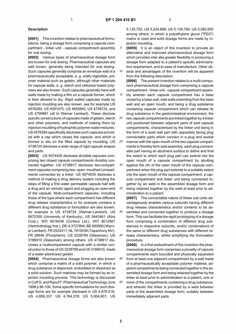
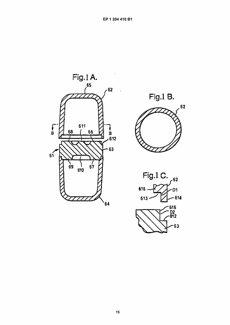
Fig. 1 shows longitudinal and cross sections, and anenlarged part view of another dosage form of the
13 14
EP 1 204 410 B1
9
5
10
15
20
25
30
35
40
45
50
55
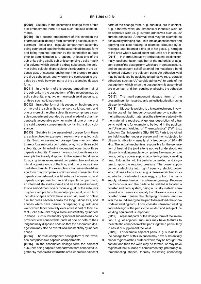
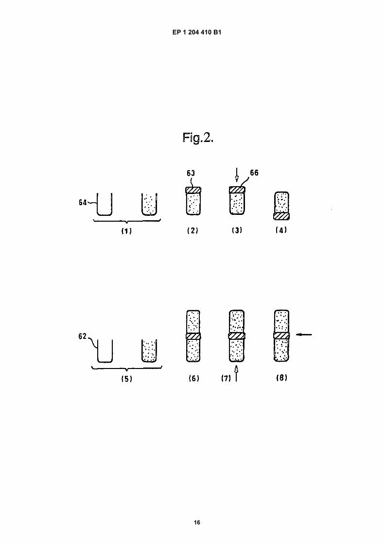
invention.Fig. 2 shows an assembly sequence of a dosageform of Fig. 1.
[0076] Fig. 1 shows dosage form assembly 61. Asshown in the longitudinal section Fig. 1A and the crosssection Fig. 1B this comprises an assembly of an endcapsule compartment 62-linker 63-end capsule compart-ment 64 in a linear arrangement. Each end compartment62, 64 is suitably in the shape of a cylinder having oneopen end and one closed end. The closed end is in theform of a generally hemispherical end wall, forming anopen ended "bucket"or "tub" shape. The side walls ofeach capsule compartment taper gently in a shallow con-ical fashion, the cross section being greatest at the openend. The central part 65 of the rounded end of each com-partment 62, 64 is flattened over at least 5 % of the endsurface area to facilitate the application of ultrasonic en-ergy during the welding operation. The wall of each cap-sule compartment 62, 64 is ca. mm thick in the cylindricalside walls of the compartment.[0077] The"linker"63 is provided in the form of a solidwall with oppositely facing surfaces 66, 67 extending gen-erally transverse to the longitudinal direction of the linker,being the end surfaces of oppositely facing plug connect-able parts 68, 69 formed at each of its longitudinal ends.The linker 63 is a generally cylindrical body flattened inits length direction with a diameter: length ratio ca. 3: 1.In a specific embodiment the diameter of the linker 63 isca 7.5 mm, and its length ca. 3.0 mm The end surfaces66, 67 are substantially planar over at least 50% of theirextent to facilitate application of ultrasonic energy theretoin the welding operation. The planar surface 66, 67 is aring-shaped surface surrounding a central concavity 610on each face, in which is the residue 611 of the injectionmoulding runner. The planar surface 66, 67 extends con-tinuously over a dimension of at least 2 mm, i. e. havinga surface area of at least 4mm. Each plug part 68, 69 isa snug friction fit into the open end of a capsule compart-ment 62, 64. Each plug part 68, 69 is provided with anabutment surface 612 each being a surface of a ledgeformed around the circumference of the cylindrical body63. The ledge 612 is ring shaped with its plane perpen-dicular to the longitudinal direction of the capsule. Theledge 612 defines and limit the extent to which each plugpart 68, 69 can extend into the open end of a capsulecompartment 62, 64 by abutting against the rim of theopen end of a capsule compartment 62, 64. In the specificembodiment the ledge 612 is ca 0.3 mm wide in the di-rection across the length direction.[0078] An ultrasonic weld is formed between each plugpart 68, 69 and/or an abutment surface 612 of the linker63 and the compartment wall 62, 64 in the vicinity of theopen end, e. g. the rim of the open end. The lower com-partment 64 is shown formed in this way, the upper com-partment 62 being shown disassembled.[0079] For forming an ultrasonic weld between adja-cent contacting parts of the capsule compartments 62,
64 and the linker 63 these parts are profiled and dimen-sioned to facilitate an ultrasonic shear joint, as shownenlarged in Fig. 1C.[0080] The plug 68 and socket 613 connectable partscomprise interlocking tenon parts 614, 615, where thelength of one tenon 614 (D1 ca. 0.2-0.3 mm) is less thanthe length (D2 ca. 0.5-0.6 mm) of the other tenon part615, and under the ultrasonic welding operation the ma-terial of the capsule compartment 62 in the region 616can collapse until the tenon parts longitudinally engageto form the ultrasonic weld between the capsule com-partment 62 and the linker 63. The weld between thelinker 63 and the compartment 64 has been formed in asimilar manner.[0081] The length D2 of the plug part, being ca. 0.55mm, is ca. 20% of the overall length of the linker 63 be-tween the end surfaces 66 and 67.[0082] Fig. 2 shows a typical assembly procedure fora dosage form of Fig. 1. This comprises the followingsteps:
(1) a first capsule compartment 64 is positioned andsupported in a suitable holding means with its mouthopening pointing upwards, and the capsule compart-ment 64 is filled with a suitable quantity of a drugsubstance.(2) a first plug part 69 of a linker 63 is inserted intothe open end of the first capsule compartment 64.In this manner the linker 63 forms a closure for themouth opening of the capsule compartment 64.(3) a downwardly pointing ultrasonic horn (notshown) is applied to the surface 66 of the linker 63,i. e. to the opposite surface to that of the first plugpart 69, and an ultrasonic weld between the linker63 and the first capsule compartment 64 is formed.(4) the formed assembly of first capsule compart-ment 64 and linker 63 is inverted so that the plugpart 68 is pointing downwards.(5) a second capsule compartment 62 is positionedand supported in a suitable holding means (notshown) with its mouth opening pointing upwards, ina manner analogous to step 1, and the second com-partment 62 is filled with a suitable quantity of drugsubstance.(6) The opposite, second, plug part 68 of the linker63 is inserted into the open end of the second cap-sule compartment 62.(7) an ultrasonic horn (not shown) is applied to theouter surface of the second compartment 62 fromunderneath. An ultrasonic weld is formed betweenthe linker 63 and the second capsule compartment62.
[0083] In an alternative welding mode shown (8) anultrasonic horn (not shown) is applied laterally as shownby the arrow to the side of the region of contact betweenthe capsule compartment 64 and the linker 63.[0084] In other alternative modes (not shown) thermal,
15 16
EP 1 204 410 B1
10
5
10
15
20
25
30
35
40
45
50
55
laser or adhesive welds may be formed between the cap-sule compartments 62 and 64 and the linker 63.[0085] Each of the compartments and sub-units in Fig.1 may be made of the same or different polymer and mayhave the same or different drug release characteristics.
Claims
1. A multi-component pharmaceutical dosage form(61) comprising a capsule compartment (62) - linkerunit (63) - capsule compartment (64) assemblywherein each capsule compartment (62) has a baseclosed by a base wall, side walls extending from thebase wall and an open mouth, and being a drug sub-stance containing capsule compartment (62,64)which can release its drug substance in the gastroin-testinal environment, the two capsule compartments(62,64) are linked together by a linker unit (63) po-sitioned between adjacent pairs of said capsule com-partments (62,64), characterised by:
the linker unit (63) being in the form of a solidwall part with oppositely facing plug connectableparts (68,69) which connect in a plug and socketmanner with the open mouth of the two capsulecompartments (62,64) to thereby form said as-sembly(61),each plug connectable part (68,69) having anabutment surface (612) to define and limit theextent to which each plug part (68,69) can ex-tend into the open mouth of a capsule compart-ment (62,64) by abutting against the rim of theopen mouth of the capsule compartment (62,64)when the plug part (68,69) extends to a suitableextent into the open mouth of the capsule com-partment,a capsule compartment (62,64) and linker unit(63) being connected together by an weld in theassembled dosage form (61) and being retainedtogether by the weld at least prior to administra-tion to a patient.
2. A dosage form (61) according to claim 1 character-ised by an ultrasonic weld formed between both cap-sule compartments (62,64) and the linker unit (63).
3. A dosage form (61) according to claim 2 character-ised in that adjacent parts (614, 615) of the dosageform (61) between which the ultrasonic weld isformed are profiled and dimensioned to facilitate anultrasonic shear joint.
4. A dosage form (61) according to claim 3 character-ised by a plug part (68,69) on a linker unit (63) andan open end of a capsule compartment (62,64) com-prising engaging tenon parts (614,615) where thelength of one tenon is less than the length of the
other tenon part, and under the ultrasonic weldingoperation the material of the parts can collapse untilthe tenon parts longitudinally engage.
5. A dosage form (61) according to any one of claims1 to 4 characterised in that the wall of the capsulecompartment (62,64) is 0.3 - 0.5 mm thick.
6. A dosage form (61) according to any one of claims1 to 5 characterised in that the capsule compart-ments (62, 64) are each in the shape of a cylinderhaving one open end and one opposite end closedby a generally hemispherical end wall, the side wallstaper gently in a shallow conical fashion, the crosssection being greatest at the open end, and the cen-tral part of the rounded closed end is flattened (65)to facilitate the application of ultrasonic energy dur-ing the welding operation.
7. A dosage form (61) according to any one of the pre-ceding claims characterised in that the linker unit(63) comprises a generally cylindrical solid body, itsopposite facing ends being plug parts (68,69) withtwo oppositely facing abutment surfaces (612) eachbeing a surface of a ledge formed around the cir-cumference of the cylindrical body.
8. A dosage form (61) according to any one of the pre-ceding claims characterised in that the linker unit(63) is overall in the form of a cylindrical body flat-tened in its length direction and having diameter :length ratios in the range 4 : 1 to 1.5 : 1.
9. A dosage form (61) according to any one of the pre-ceding claims characterised by a capsule compart-ment (62,64) wall in the shape of a cylinder havingone open end and one opposite closed end, and atleast 5% of the outer surface of the closed end issubstantially planar (65).
10. A dosage form (61) according to any one of the pre-ceding claims characterised in that the two capsulecompartments (62,64) differ in their wall thicknessso that a thicker walled compartment (62,64) disruptsmore slowly than a thinner walled compartment(62,64).
11. A dosage form (61) according to any one of the pre-ceding claims characterised in that the two capsulecompartments (62,64) have areas or points of weak-ness which preferentially dissolve.
12. A dosage form (61) according to any one of the pre-ceding claims characterised by a capsule compart-ment (62,64) or linker unit (63) made of a pharma-ceutically acceptable polymer which is generally re-garded as safe for oral injestion and is capable ofbeing formed into the required shape.
17 18
EP 1 204 410 B1
11
5
10
15
20
25
30
35
40
45
50
55
13. A dosage form (61) according to any one of the pre-ceding claims characterised in that one or bothcapsule compartment (62,64) or the linker unit (63)is substantially immediate release.
14. A dosage form (61) according to any one of the pre-ceding claims characterised in that one or bothcapsule compartment (62,64) or the linker unit (63)is sustained release or pulsed release.
15. A process for manufacturing a dosage form (61) ac-cording to any one of claims 1 to 14 which comprisesa capsule compartment (62) - linker (63) - capsulecompartment (64) in a linear arrangement, charac-terised by the steps of:
first filling a first capsule compartment (64) witha suitable quantity of drug substance;insertion of a first plug part (69) of a linker unit(63) into the open end of the first capsule com-partment (64) and welding the linker unit inplace;filling a second capsule compartment (62) witha suitable quantity of drug substance;insertion of the opposite, second, plug part (68)of the linker unit (63) into the open end of thesecond capsule compartment (62) and weldingthe linker unit (63) and second capsule compart-ment (62) together.
16. A process according to claim 15 characterised inthatwhen filling the first capsule compartment (64) witha suitable quantity of drug substance the capsulecompartment (64) is positioned and supported withits open end pointing upward;ultrasonically welding the linker unit in place is per-formed by applying a downwardly pointing ultrasonichorn to the surface (66) of the linker unit (63) oppositeto the first plug part (69);the formed assembly of first capsule compartment(64) and linker unit (63) is inverted so that the plugpart (69) is pointing downward,positioning the second capsule compartment (62)with its open end pointing upwards and filling thesecond capsule compartment (62) with a suitablequantity of drug substance;the opposite, second, plug part (68) of the linker (63)is inserted into the open end of the second capsulecompartment (62);and ultrasonically welding the linker unit (63) andsecond capsule compartment (62) together is per-formed by applying an ultrasonic horn to the outersurface of the second capsule compartment (62)from underneath.
17. A process according to claim 16 characterised inthat an ultrasonic horn is applied laterally to the side
of the region of contact between the capsule com-partment (64) and the linker (63).
Patentansprüche
1. Mehrkomponenten-Dosisform (61), umfassend ei-nen Bausatz aus Kapselabteil (62) - Verbindungs-einheit (63) - Kapselabteil (64), wobei jedes Kapsel-abteil (62) eine Basis aufweist, die durch eine Ba-siswand, Seitenwände, die sich von der Basiswandund einer offenen Mündung erstrecken, geschlos-sen ist und ein eine Arzneimittelsubstanz enthalten-des Kapselabteil (62, 64) ist, das seine Arzneimittel-substanz in die Magen-Darm-Umgebung freisetzenkann, wobei die beiden Kapselabteile (62, 64) durcheine Verbindungseinheit (63) miteinander verbun-den sind, die zwischen benachbarten Paaren der ge-nannten Kapselabteile (62, 64) positioniert ist, da-durch gekennzeichnet, dass:
die Verbindungseinheit (63) in Form eines soli-den Wandteils mit sich gegenüberliegenden, aneinen Stopfen anschließbaren Teilen (68, 69)besteht, die sich mit der offenen Mündung derbeiden Kapselabteile (62, 64) an einen Stopfenund eine Buchse anschließen lassen, um somitden genannten Bausatz (61) zu bilden,jedes an einem Stopfen anschließbare Teil (68,69) eine Anlagefläche (612) aufweist, um dasAusmaß zu definieren und zu limitieren, zu wel-chem sich jedes Stopfenteil (68, 69) in die offeneMündung eines Kapselabteils (62, 64) durch dieAnlage gegen den Rand der offenen Mündungdes Kapselabteils (62, 64) erstrecken kann,wenn sich das Stopfenteil (68, 69) bis zu einemgeeigneten Ausmaß in die offene Mündung desKapselabteils erstreckt,ein Kapselabteil (62, 64) und eine Verbindungs-einheit (63), die durch eine Schweißnaht in dermontierten Dosisform (61) miteinander verbun-den sind und durch die Schweißnaht wenigstensvor der Verabreichung an einen Patienten zu-sammengehalten werden.
2. Dosisform (61) nach Anspruch 1, gekennzeichnetdurch eine Ultraschall-Schweißnaht zwischen denKapselabteilen (62, 64) und der Verbindungseinheit(63) gebildet ist.
3. Dosisform (61) nach Anspruch 2, dadurch gekenn-zeichnet, dass benachbarte Teile (614, 615) derDosisform (61), zwischen denen die Ultraschall-Schweißnaht gebildet ist, derart geformt und bemes-sen sind, um eine Ultraschall-Scherkluft zu ermög-lichen.
4. Dosisform (61) nach Anspruch 3, gekennzeichnet
19 20
EP 1 204 410 B1
12
5
10
15
20
25
30
35
40
45
50
55
durch ein Stopfenteil (68, 69) an einer Verbindungs-einheit (63) und einem offenen Ende eines Kapsel-abteils (62, 64), umfassend eingreifende Zapfenteile(614, 615), wobei die Länge eines Zapfens kürzerist, als die Länge des anderen Zapfenteils und wobeimit dem Ultraschall-Schweißbetrieb das Material derTeile zerfallen kann, bis die Zapfenteile längs ein-greifen.
5. Dosisform (61) nach einem der Ansprüche 1 bis 4,dadurch gekennzeichnet, dass die Wand desKapselabteils (62, 64) 0,3 - 0,5 mm dick ist.
6. Dosisform (61) nach einem der Ansprüche 1 bis 5,dadurch gekennzeichnet, dass die Kapselabteile(62, 64) jeweils die Form eines Zylinders mit einemoffenen Ende und einem gegenüberliegenden Endeaufweisen, das durch eine im Allgemeinen halbku-gelförmige Endwand verschlossen ist, wobei sich dieSeitenwände leicht in einer flachen, konischen Artund Weise verjüngen, wobei der Querschnitt am of-fenen Ende am größten ist und der mittige Teil desabgerundeten, geschlossenen Endes flach (65) ist,um die Anwendung von Ultraschallenergie währenddem Schweißbetrieb zu ermöglichen.
7. Dosisform (61) nach einem der vorstehenden An-sprüche, dadurch gekennzeichnet, dass die Ver-bindungseinheit (63) einen im Allgemeinen zylindri-schen, soliden Körper umfasst, dessen gegenüber-liegenden Enden Stopfenteile (68, 69) mit zwei ge-genüberliegenden Anlageflächen (612) sind, wobeijede eine Fläche eines Vorsprungs ist, der um denUmfang des zylindrischen Körpers herum gebildetist.
8. Dosisform (61) nach einem der vorstehenden An-sprüche, dadurch gekennzeichnet, dass die Ver-bindungseinheit (63) insgesamt die Form eines zy-lindrischen Körpers aufweist, der in der Längenrich-tung flach ist und den nachfolgenden Durchmesser:Längenverhältnisse aufweist im Bereich von 4:1 bis1,5:1.
9. Dosisform (61) nach einem der vorstehenden An-sprüche, gekennzeichnet durch eine Kapselabteil-wand (62, 64) in der Form eines Zylinders, mit einemoffenen Ende und einem gegenüberliegenden ge-schlossenen Ende, wobei wenigstens 5 % der Au-ßenfläche des geschlossenen Endes im Wesentli-chen eben (65) ist.
10. Dosisform (61) nach einem der vorstehenden An-sprüche, dadurch gekennzeichnet, dass sich diebeiden Kapselabteile (62, 64) in deren Wanddickederart unterscheiden, dass sich ein Abteil (62, 64)mit dickerer Wand langsamer abtrennt, als ein Abteil(62, 64) mit dünnerer Wand.
11. Dosisform (61) nach einem der vorstehenden An-sprüche, dadurch gekennzeichnet, dass die bei-den Kapselabteile (62, 64) Schwachstellen oderSchwachpunkte aufweisen, die sich bevorzugt auf-lösen.
12. Dosisform (61) nach einem der vorstehenden An-sprüche, gekennzeichnet durch ein Kapselabteil(62, 64) oder eine Verbindungseinheit (63), herge-stellt aus einem pharmazeutisch verträglichen Poly-mer, das im Allgemeinen für die orale Einnahme alsrisikolos gilt und in der Lage ist, in die erforderlicheForm geformt zu werden.
13. Dosisform (61) nach einem der vorstehenden An-sprüche, dadurch gekennzeichnet, dass ein oderbeide Kapselabteile (62, 64) oder die Verbindungs-einheit (63) im Wesentlichen sofort freisetzend ist.
14. Dosisform (61) nach einem der vorstehenden An-sprüche, dadurch gekennzeichnet, dass ein oderbeide Kapselabteile (62, 64) oder die Verbindungs-einheit (63) Langzeitfreisetzend oder Puls-freiset-zend sind.
15. Verfahren zur Herstellung einer Dosisform (61) nacheinem der Ansprüche 1 bis 14, umfassend ein Kap-selabteil (62), eine Verbindung (63), ein Kapselabteil(64) in einer linearen Anordnung, gekennzeichnetdurch die nachfolgenden Schritte:
zunächst das Befüllen eines ersten Kapselab-teils (64) mit einer geeigneten Menge an Arz-neimittelsubstanz;Einsetzen eines ersten Stopfenteils (69) einerVerbindungseinheit (63) in das offene Ende desersten Kapselabteils (64) und Verschweißen derVerbindungseinheit an Ort und Stelle;Befüllen eines zweiten Kapselabteils (62) mit ei-ner geeigneten Menge an Arzneimittelsubstanz;Einsetzen des entgegengesetzten, zweitenStopfenteils (68) der Verbindungseinheit (63) indas offene Ende des zweiten Kapselabteils (62)und Zusammenschweißen der Verbindungsein-heit (63) und des zweiten Kapselabteils (62).
16. Verfahren nach Anspruch 15, dadurch gekenn-zeichnet, dassbeim Befüllen des ersten Kapselabteils (64) mit einergeeigneten Menge an Arzneimittelsubstanz dasKapselabteil (64) mit seinem offenen Ende nachoben gerichtet positioniert und getragen wird;das Ultraschallschweißen der Verbindungseinheitan Ort und Stelle durch Anwenden einer Sonotrodean der Fläche (66) der Verbindungseinheit (63) ge-genüber des ersten Stopfenteils (69) durchgeführtwird;der gebildete Bausatz des ersten Kapselabteils (64)
21 22
EP 1 204 410 B1
13
5
10
15
20
25
30
35
40
45
50
55
und der Verbindungseinheit (63) derart invertiertwird, dass das Stopfenteil (69) nach unten gerichtetist;das zweite Kapselabteil (62) mit seinem offenen En-de nach unten gerichtet ist und das zweite Kapsel-abteil (62) mit einer geeigneten Menge an Arznei-mittelsubstanz befüllt wird;das entgegengesetzte, zweite Stopfenteil (68) derVerbindung (63) in das offene Ende des zweitenKapselabteils (62) eingesetzt wird;und dass das Ultraschall-Zusammenschweißen derVerbindungseinheit (63) und des zweiten Kapselab-teils (62) durch Anwenden einer Sonotrode an derAußenfläche des zweiten Kapselabteils (62) von un-ten her durchgeführt wird.
17. Verfahren nach Anspruch 16, dadurch gekenn-zeichnet, dass eine Sonotrode lateral an der Seitedes Kontaktbereichs zwischen dem Kapselabteil(64) und der Verbindung (63) angewendet wird.
Revendications
1. Forme galénique pharmaceutique à plusieurs com-posants (61) comprenant un ensemble de compar-timent de capsule (62) - unité de liaison (63) - com-partiment de capsule (64), chaque compartiment decapsule (62) ayant une base fermée par une paroide base, des parois latérales s’étendant de la paroide base et un orifice ouvert et étant une substancemédicamenteuse contenant un compartiment decapsule (62, 64) qui peut libérer sa substance mé-dicamenteuse dans l’environnement gastro-intesti-nal, les deux compartiments de capsule (62, 64)étant liés conjointement par une unité de liaison (63)placée entre des paires adjacentes desdits compar-timents de capsule (62, 64), caractérisée par :
l’unité de liaison (63) qui est sous la forme d’unepartie de paroi solide comportant des parties deconnecteur pouvant être raccordées, se faisantface en opposé (68, 69) qui se raccordent à lamanière d’éléments enfichables avec l’orificeouvert des deux compartiments de capsule (62,64) pour former ainsi ledit ensemble (61),chaque partie de connecteur raccordable (68,69) ayant une surface d’appui (612) pour définiret limiter l’étendue sur laquelle chaque partie deconnecteur (68, 69) peut s’étendre dans l’orificeouvert du compartiment de capsule (62, 64) enappuyant contre un bord de l’orifice ouvert ducompartiment de capsule (62, 64) lorsque la par-tie de connecteur (68, 69) s’étend dans une am-pleur appropriée dans l’orifice ouvert du com-partiment de capsule,un compartiment de capsule (62, 64) et une uni-té de liaison (63) étant raccordés conjointement
par une soudure dans la forme galénique as-semblée (61) et étant retenus conjointement parle soudage au moins avant administration à unpatient.
2. Forme galénique (61) selon la revendication 1, ca-ractérisée par un soudage à ultrasons formé entreles deux compartiments de capsule (62, 64) et l’unitéde liaison (63).
3. Forme galénique (61) selon la revendication 2, ca-ractérisée en ce que des parties adjacentes (614,615) de la forme galénique (61) entre lesquelles lasoudure à ultrasons est formée sont profilées et di-mensionnées de façon à faciliter une jointure par ci-saillement à ultrasons.
4. Forme galénique (61) selon la revendication 3, ca-ractérisée par une partie de connecteur (68, 69) surune unité de liaison (63) et une extrémité ouverted’un compartiment de capsule (62, 64) comprenantdes parties de tenon de mise en prise (614, 615), lalongueur d’un tenon étant inférieure à la longueur del’autre partie de tenon, et dans une opération de sou-dage à ultrasons, le matériau des parties pouvants’affaisser jusqu’à ce que les parties de tenon soienten prise longitudinalement.
5. Forme galénique (61) selon l’une quelconque desrevendications 1 à 4, caractérisée en ce que la pa-roi du compartiment de capsule (62, 64) est de 0,3à 0,5 mm d’épaisseur.
6. Forme galénique (61) selon l’une quelconque desrevendications 1 à 5, caractérisée en ce que lescompartiments de capsule (62, 64) sont chacun sousla forme d’un cylindre ayant une extrémité ouverteet une extrémité opposée fermée par une paroi ter-minale généralement hémisphérique, les parois la-térales s’affinant légèrement de manière légèrementconique, la section transversale étant plus grande àl’extrémité d’ouverture et la partie centrale de l’ex-trémité fermée arrondie étant aplatie (65) pour faci-liter l’application d’une énergie ultrasonore pendantl’opération de soudage.
7. Forme galénique (61) selon l’une quelconque desrevendications précédentes, caractérisée en ceque l’unité de liaison (63) comprend un corps solidegénéralement cylindrique, ses extrémités se faisantface en opposé étant des parties de connecteur (68,69) comportant deux surfaces d’appui (612) se fai-sant face en opposé, chacune étant une surface d’unrebord formé sur le pourtour du corps cylindrique.
8. Forme galénique (61) selon l’une quelconque desrevendications précédentes, caractérisée en ceque l’unité de liaison (63) est globalement sous la
23 24
EP 1 204 410 B1
14
5
10
15
20
25
30
35
40
45
50
55
forme d’un corps cylindrique aplati dans sa directionlongitudinale et ayant des rapports diamètre : lon-gueur de l’ordre de 4:1 à 1,5:1.
9. Forme galénique (61) selon l’une quelconque desrevendications précédentes, caractérisée par uneparoi de compartiment de capsule (62, 64) sous laforme d’un cylindre ayant une extrémité ouverte etune extrémité fermée opposée et au moins 5% dela surface extérieure de l’extrémité fermée étantsubstantiellement planaires (65).
10. Forme galénique (61) selon l’une quelconque desrevendications précédentes, caractérisée en ceque les deux compartiments de capsule (62, 64) dif-fèrent dans leur épaisseur de paroi de sorte qu’uncompartiment à paroi plus épaisse (62, 64) se rompeplus lentement qu’un compartiment à paroi plus fine(62, 64).
11. Forme galénique (61) selon l’une quelconque desrevendications précédentes, caractérisée en ceque les deux compartiments de capsule (62, 64) ontdes zones ou points de faiblesse qui se dissolventde préférence.
12. Forme galénique (61) selon l’une quelconque desrevendications précédentes, caractérisée par uncompartiment de capsule (62, 64) ou une unité deliaison (63) constitué(e) d’un polymère pharmaceu-tiquement acceptable qui est généralement consi-déré comme inoffensif pour l’ingestion orale et peutêtre moulé à la forme requise.
13. Forme galénique (61) selon l’une quelconque desrevendications précédentes, caractérisée en ceque l’un ou les deux compartiment(s) de capsule(62, 64) ou l’unité de liaison (63) sont substantielle-ment à libération immédiate.
14. Forme galénique (61) selon l’une quelconque desrevendications précédentes, caractérisée en ceque l’un ou les deux compartiment(s) de capsule(62, 64) ou l’unité de liaison (63) sont à libérationprolongée ou à libération pulsée.
15. Procédé de production d’une forme galénique (61)selon l’une quelconque des revendications 1 à 14,qui comprend un compartiment de capsule (62) -segment de liaison (63) - compartiment de capsule(64) dans une disposition linéaire, caractérisé parles étapes comprenant :
tout d’abord, le remplissage d’un premier com-partiment de capsule (64) avec une quantité ap-propriée de substance médicamenteuse ;l’insertion d’une première partie de connecteur(69) d’une unité de liaison (63) dans l’extrémité
ouverte du premier compartiment de capsule(64) et le soudage de l’unité de liaison en place ;le remplissage d’un deuxième compartiment decapsule (62) avec une quantité appropriée desubstance médicamenteuse ;l’insertion de la deuxième partie de connecteuropposée (68) de l’unité de liaison (63) dans l’ex-trémité ouverte du deuxième compartiment decapsule (62) et le soudage conjointement del’unité de liaison (63) et du deuxième comparti-ment de capsule (62).
16. Procédé selon la revendication 15, caractérisé ence quelors du remplissage du premier compartiment decapsule (64) avec une quantité appropriée de subs-tance médicamenteuse, le compartiment de capsule(64) est placé et soutenu avec son extrémité ouvertedirigée vers le haut ;le soudage à ultrasons de l’unité de liaison en placeest réalisé en appliquant un cornet à ultrasons dirigévers le bas sur la surface (66) de l’unité de liaison(63) opposée à la première partie de connecteur(69) ;l’ensemble formé du premier compartiment de cap-sule (64) et de l’unité de liaison (63) est inversé desorte que la partie de connecteur (69) soit dirigéevers le bas,le placement du deuxième compartiment de capsule(62) avec son extrémité ouverte dirigée vers le hautet le remplissage du deuxième compartiment de cap-sule (62) avec une quantité appropriée de substancemédicamenteuse ;la deuxième partie de connecteur opposée (68) dusegment de liaison (63) étant insérée dans l’extré-mité ouverte du deuxième compartiment de capsule(62) ;et le soudage par ultrasons de l’unité de liaison (63)et du deuxième compartiment de capsule (62) con-jointement est réalisé en appliquant un cornet à ul-trasons sur la surface extérieure du deuxième com-partiment de capsule (62) par le dessous.
17. Procédé selon la revendication 16, caractérisé ence qu’un cornet à ultrasons est appliqué latérale-ment sur le côté de la région de contact entre le com-partiment de capsule (64) et le segment de liaison(63).
25 26
EP 1 204 410 B1
15
EP 1 204 410 B1
16

EP 1 204 410 B1
17
REFERENCES CITED IN THE DESCRIPTION
This list of references cited by the applicant is for the reader’s convenience only. It does not form part of the Europeanpatent document. Even though great care has been taken in compiling the references, errors or omissions cannot beexcluded and the EPO disclaims all liability in this regard.
Patent documents cited in the description
• US 4576284 A [0002] [0024]• US 4591475 A [0002]• US 4655840 A [0002]• US 4738724 A [0002] [0003] [0024]• US 4790881 A [0002]• US 5074426 A [0003]• US 4738817 A [0003]• US 5674530 A [0003]• US 5672359 A [0003]• US 5443461 A [0003]• WO 9516438 A [0003]• WO 9012567 A [0003]• DE 3727894 A [0003]• BE 900950 [0003]
• FR 2524311 [0003]• NL 7610038 [0003]• FR 28646 [0003]• US 3228789 A, Glassman [0003]• US 3186910 A [0003]• US 4678516 A [0004]• US 4806337 A [0004]• US 4764378 A [0004]• US 5004601 A [0004]• US 5135752 A [0004]• US 5244668 A [0004]• US 5139790 A [0004]• US 5082655 A [0004]• US 5705189 A [0051] [0073]
Non-patent literature cited in the description
• CUFF G ; RAOUF F. Pharmaceutical Technology,June 1998, 96-106 [0004]
• Ultrasonic Welding of Thermoplastics. TWI Ltd, 1997[0018]