Embed Size (px)
Citation preview

FACTORY AUTOMATION
MODULAR PLC FAMILYMELSEC iQ-R series/System Q/L series
PLC Control
Motion
PC
Process
Multi CPU solutions
Redundancy
IEC 61131-3
Networking
Scalable
Machine control
Plant management
Safety

2
Global player
Global impact of Mitsubishi Electric
Through Mitsubishi Electric’s vision, “Changes for the Better“ are possible for a brighter future.
We bring together the best minds to cre-ate the best technologies. At Mitsubishi Electric, we understand that technology is the driving force of change in our lives. By bringing greater comfort to daily life, maximising the efficiency of businesses and keeping things running accross so-ciety, we integrate technology and in-novation to bring changes for the better.
Mitsubishi Electric is involved in many areas including the following
Energy and electric systemsA wide range of power and electrical products from generators to large-scale displays.
Electronic devicesA wide portfolio of cutting-edge semiconductor devices for systems and products.
Home applianceDependable consumer products like air conditioners and home entertainment systems.
Information and communication systemsCommercial and consumer-centric equipment, products and systems.
Industrial automation systemsMaximising productivity and efficiency with cutting-edge automation technology.
3
Contents
Contents
Global standards 4
World leading PLCs 5
Multi platform 6–7
MELSEC iQ-R series, System Q, L series 8–10
Safety for all systems 11
Motion control 12–13
PC control 14–15
Process control 16–18
Programming 19
Plant solutions 20
Machine solutions 21
Your solution partner 23
Section 2: Technical Information

4
Flexible automationThe MELSEC iQ-R series, MELSEC System Q and MELSEC L series provide global so-lutions for a vast range of applications. Pioneered by Mitsubishi Electric, these automation systems are modular auto-mation platforms that bring together all features from a variety of different engi-neering disciplines, including traditional and advanced programmable logic controllers (PLCs), information technol-ogy, motion control and process-based control philosophies. Their focus is on boosting productivity, helping users re-duce their total cost of ownership while increasing their return on investment.
Manufactured to the highest standardsMitsubishi Electric automation products enjoy a global reputation for outstand-ing quali ty and reliability. The process starts at the design stage, where qual-ity is designed into even the smallest components. Our systematic pursuit of “best practice” means that Mitsubishi Electric products readily comply with shipping approvals, product directives and standards.
One of the world’s top PLC makersThe Worldwide PLC Survey conducted by the respected American automa-tion research company ARC continues to confirm that Mitsubishi Electric is the world’s largest volume producer of PLCs.
ARC is protected by ARC Advisory Group copyright 2004
Global standards
Global standards
Through Mitsubishi Electric’s vision, “Changes for the better” are possible for a brighter future
5
World leading PLCs
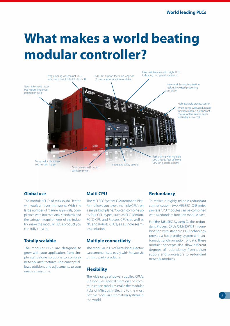
Global useThe modular PLCs of Mitsubishi Electric will work all over the world. With the large number of marine approvals, com-pliance with international standards and the stringent requirements of the indus-try, make the modular PLC a product you can fully trust in.
Totally scalableThe modular PLCs are designed to grow with your application, from sim-ple stand alone solutions to complex network architectures. The concept al-lows additions and adjustments to your needs at any time.
Multi CPUThe MELSEC System Q Automation Plat-form allows you to use multiple CPU’s on a single backplane. You can combine up to four CPU types, such as PLC, Motion, PC, C-CPU and Process CPU’s, as well as NC and Robots CPU’s, as a single seam-less solution.
Multiple connectivityThe modular PLCs of Mitsubishi Electric can communicate easily with Mitsubishi or third party products.
FlexibilityThe wide range of power supplies, CPU’s, I/O modules, special function and com-munication modules make the modular PLCs of Mitsubishi Electric to the most flexible modular automation systems in the world.
RedundancyTo realize a highly reliable redundant control system, two MELSEC iQ-R series process CPU modules can be combined with a redundant function module each.
For the MELSEC System Q, the redun-dant Process CPUs Q12/25PRH in com-bination with standard PLC technology provide a hot standby system with au-tomatic synchronization of data. These modular concepts also allow different degrees of redundancy from power supply and processors to redundant network modules.
What makes a world beating modular controller?
Many built in functions such as data logger
Easy maintenance with bright LEDs indicating the operational statusAll CPU’s support the same range of
I/O and special function modules
Task sharing with multiple CPU’s, (up to four different CPU’s in a single system)
Programming via Ethernet, USB, serial, networks (CC-Link IE, CC-Link)
New high-speed system bus realizes improved production cycle
Integrated safety controlDirect access to IT system database servers
High-available process control
When paired with a redundant function module, a redundant control system can be easily realized at a low cost.
Inter-modular synchronization realizes increased processing accuracy

6
Multi platform
Sophisticated yet simple
The modular conceptThis sophisticated concept of the modu-lar PLCs from Mitsubishi Electric allows users to mix and select the best com-bination of CPUs, communication de-vices, special function modules and I/O modules. This allows users to configure systems into what they need, when they need it, where they need it.
Multiple capabilitiesThe MELSEC System Q allows to com-bine basic and advanced PLC CPUs, spe-cialist motion and process controllers and even PC CPUs (industrial PCs) into a single System Q solution with up to four different CPU modules.
The concept of the MELSEC L series re-quires no rack and is ideal for medium-sized control applications. Using a sim-ple motion module, up to 16 servo axes can be controlled here too.
This range of options gives the user a wide range of control philosophies, programming concepts and languages.
The MELSEC iQ-R series enables total integration of control and communi-cations from a single, highly scalable hardware platform, capable of handling anything from a handful of I/O up to sev-eral thousand. Integrated safety control, a vast range of integrated functions as well as high-available process control make it the core for next-generation automation environment.
Mitsubishi Electric’s modular control solutions span a wide range of capabilities.
PER
FOR
MA
NC
E SY
STEM
MO
DU
LAR
PLC
I/O
MELSEC iQ-R series
MELSEC System Q
MELSEC L series
7
Multi platform
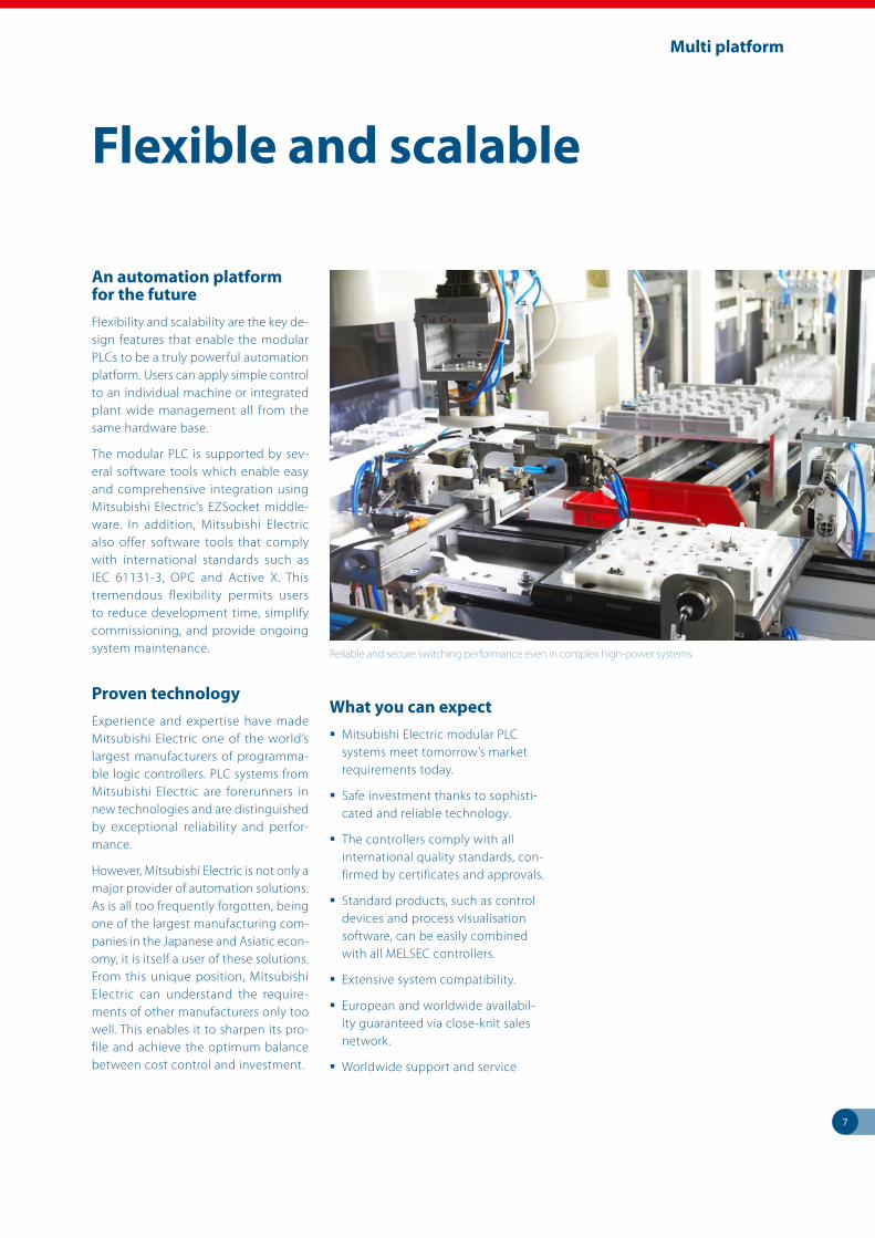
An automation platform for the futureFlexibility and scalability are the key de-sign features that enable the modular PLCs to be a truly powerful automation platform. Users can apply simple control to an individual machine or integrated plant wide management all from the same hardware base.
The modular PLC is supported by sev-eral software tools which enable easy and comprehensive integration using Mitsubishi Electric’s EZSocket middle-ware. In addition, Mitsubishi Electric also offer software tools that comply with international standards such as IEC 61131-3, OPC and Active X. This tremendous flexibility permits users to reduce development time, simplify commissioning, and provide ongoing system maintenance.
Proven technologyExperience and expertise have made Mitsubishi Electric one of the world’s largest manufacturers of programma-ble logic controllers. PLC systems from Mitsubishi Electric are forerunners in new technologies and are distinguished by exceptional reliability and perfor-mance.
However, Mitsubishi Electric is not only a major provider of automation solutions. As is all too frequently forgotten, being one of the largest manufacturing com-panies in the Japanese and Asiatic econ-omy, it is itself a user of these solutions. From this unique position, Mitsubishi Electric can understand the require-ments of other manufacturers only too well. This enables it to sharpen its pro-file and achieve the optimum balance between cost control and investment.
What you can expect Mitsubishi Electric modular PLC
systems meet tomorrow’s market requirements today.
Safe investment thanks to sophisti-cated and reliable technology.
The controllers comply with all international quality standards, con-firmed by certificates and approvals.
Standard products, such as control devices and process visualisation software, can be easily combined with all MELSEC controllers.
Extensive system compatibility.
European and worldwide availabil-ity guaranteed via close-knit sales network.
Worldwide support and service
Reliable and secure switching performance even in complex high-power systems
Flexible and scalable
8
MELSEC iQ-R series
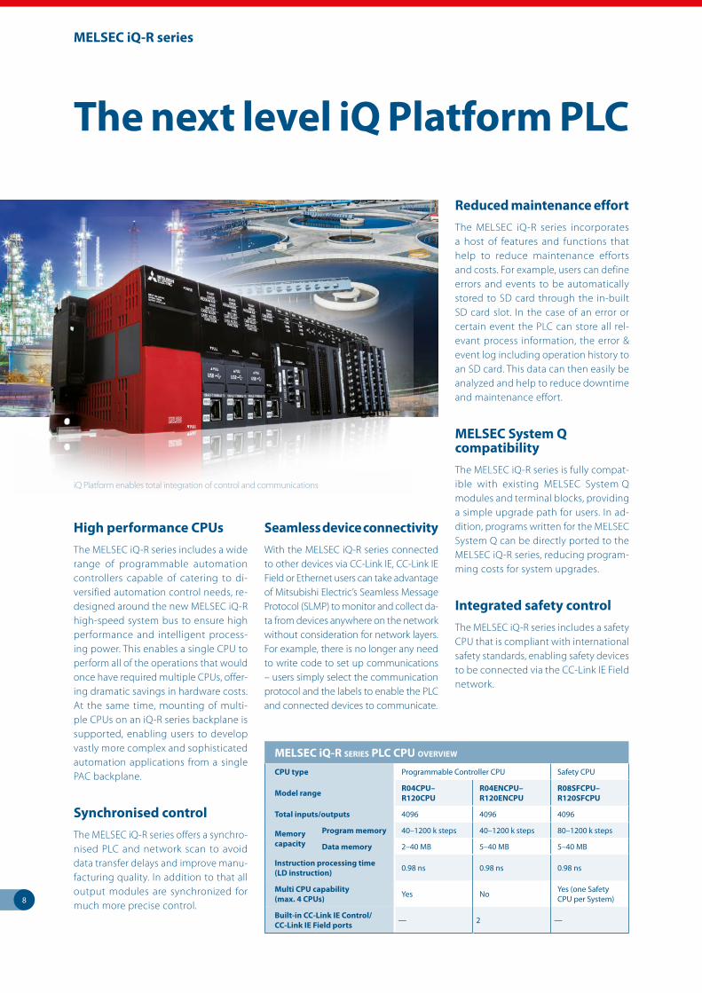
The next level iQ Platform PLC
High performance CPUsThe MELSEC iQ-R series includes a wide range of programmable automation controllers capable of catering to di-versified automation control needs, re-designed around the new MELSEC iQ-R high-speed system bus to ensure high performance and intelligent process-ing power. This enables a single CPU to perform all of the operations that would once have required multiple CPUs, offer-ing dramatic savings in hardware costs. At the same time, mounting of multi-ple CPUs on an iQ-R series backplane is supported, enabling users to develop vastly more complex and sophisticated automation applications from a single PAC backplane.
Synchronised controlThe MELSEC iQ-R series offers a synchro-nised PLC and network scan to avoid data transfer delays and improve manu-facturing quality. In addition to that all output modules are synchronized for much more precise control.
Seamless device connectivityWith the MELSEC iQ-R series connected to other devices via CC-Link IE, CC-Link IE Field or Ethernet users can take advantage of Mitsubishi Electric’s Seamless Message Protocol (SLMP) to monitor and collect da-ta from devices anywhere on the network without consideration for network layers. For example, there is no longer any need to write code to set up communications – users simply select the communication protocol and the labels to enable the PLC and connected devices to communicate.
Reduced maintenance effortThe MELSEC iQ-R series incorporates a host of features and functions that help to reduce maintenance efforts and costs. For example, users can define errors and events to be automatically stored to SD card through the in-built SD card slot. In the case of an error or certain event the PLC can store all rel-evant process information, the error & event log including operation history to an SD card. This data can then easily be analyzed and help to reduce downtime and maintenance effort.
MELSEC System Q compatibilityThe MELSEC iQ-R series is fully compat-ible with existing MELSEC System Q modules and terminal blocks, providing a simple upgrade path for users. In ad-dition, programs written for the MELSEC System Q can be directly ported to the MELSEC iQ-R series, reducing program-ming costs for system upgrades.
Integrated safety controlThe MELSEC iQ-R series includes a safety CPU that is compliant with international safety standards, enabling safety devices to be connected via the CC-Link IE Field network.
iQ Platform enables total integration of control and communications
MELSEC iQ-R SERiES PLC CPU ovERviEw
CPU type Programmable Controller CPU Safety CPU
Model range R04CPU– R120CPU
R04ENCPU–R120ENCPU
R08SFCPU–R120SFCPU
Total inputs/outputs 4096 4096 4096
Memory capacity
Program memory 40–1200 k steps 40–1200 k steps 80–1200 k steps
Data memory 2–40 MB 5–40 MB 5–40 MB
Instruction processing time (LD instruction) 0.98 ns 0.98 ns 0.98 ns
Multi CPU capability (max. 4 CPUs) Yes No Yes (one Safety
CPU per System)
Built-in CC-Link IE Control/ CC-Link IE Field ports — 2 —
9
MELSEC System Q
The CPUs of the MELSEC System QFor advanced machine designs and con-trolling manufacturing cells, including infrastructure and site-wide manage-ment, MELSEC System Q’s CPUs offer incredible performance and versatility.
Processors are available with a wide range of memory capacities, all of which can be expanded as required. This means that MELSEC System Q PLCs can support complex programs as well as store large volumes of operation data.
Universal PLC CPUsUniversal PLC CPUs are the latest gen-eration of modular CPUs for the MELSEC System Q controller platform and they are the foundation of the iQ Platform system. They can be combined with the motion, robot and NC CPUs to configure scalable and highly flexible modular au-tomation systems.
ScalableAll MELSEC System Q PLC processors are interchangeable, which means processing power can be increased as applications grow, protecting your investment in in-frastructure and hardware.
Multi Processor supportUp to four separate MELSEC System Q PLC CPUs can be placed in a single sys-tem. These can be used to control their own set of dedicated tasks or for sharing the processing and control load, making the total system highly responsive. This provides users with faster, more dynam-ic control, leading to better production quality and improved production rates.
Robots and NC CPUsRobots and CNC controllers combine faster processing speed and enhanced motion control, providing superior flex-ibility and performance when designing Motion and Robot automation systems.
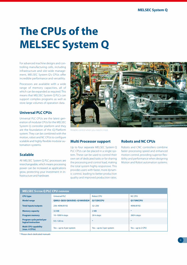
Reliable control when you need it most.
MELSEC SyStEM Q PLC CPU ovERviEw
CPU type Universal PLC Robot CPU NC CPU
Model range Q00UJ–Q02U Q03UD(E)–Q100UD(E)H Q172DCCPU Q173NCCPU
Total inputs/outputs 256–4096/8192 32–256 4096/8192
Memory capacity 32 MB 2 MB *
Program memory 10–1000 k steps 26 k steps 260 k steps
Program cycle period per logical instruction 9.5–120 ns * *
Multi CPU capability (max. 4 CPUs) Yes – up to 4 per system Yes – up to 3 per system Yes – up to 2 CPU
* Please ckeck dedicated manuals
10
MELSEC L series
Reliable, ease to use and flexibleThe modular MELSEC L series has been designed with high reliability, user friend-liness and flexibility in mind and has built-in functions that are usually found only in compact PLCs. Engineers and program-mers can use their time more efficiently, saving valuable development time. Thanks to its sophisticated approach, the L series can be used at low costs and with minimum space requirements in a variety of applications. A system that easily fits perfectly in every respect.
High system flexibilityThe rack-free design promotes high system flexibility with minimum form factor. The single-CPU architecture in-cludes built-in Ethernet and Mini-USB interfaces, a SD/SDHC memory card slot for program storage and data logging, and 24 digital I/O for simple high-speed counting and positioning functions.
Besides the functions already built-in, the CPU can be supplemented with up to 40 extension and special func-
tion modules for additional digital and analog I/Os, high-speed counters, com-munications interfaces, Simple Motion, positioning etc.
Built-in I/O functionsThe L series CPU has all the most impor-tant features normally needed already built-in. This minimizes hardware and en-
gineering costs significantly. Up to 2 servo axes or stepper motors can be controlled via the integrated pulse outputs without the need for additional modules.
Every MELSEC L series CPU comes with 24 points of built-in I/Os as standard. These I/O points are capable of many functions usually reserved for separate modules. Save on system costs by using the built-in functions for a variety of applications.
USB and Ethernet as standardThe built-in USB 2.0 port or Ethernet in-terface can be used to connect directly at the installation site. The Ethernet in-terface supports direct connection and does not require any configuration of the PLC or PC to operate.
Data loggingThe built-in data logging function pro-vides an easy way to collect informa-tion for troubleshooting, performance evaluation, and other uses. The included configuration tool makes setting up the data logging function a breeze with a step-by-step wizard like interface. Us-ing the software GX LogViewer, the captured data is easy to interpret and understand.
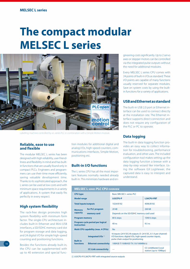
Labelling machine controlled by a L series PLC in combination with a Simple Motion module.
The compact modular MELSEC L series
MELSEC L SERiES PLC CPU ovERviEw
CPU type Basic MELSEC L series PLC
Model range L02CPU-P L26CPU-PBT
Total inputs/outputs 1024/8192 4096/8192
Memory capacity
for PLC program 20 kB 260 kB
memory card Depends on the SD/SDHC memory card used
Program memory 80 k steps 1040 k steps
Program cycle period per logical instruction 40 ns 9.5 ns
Multi CPU capability (max. 4 CPUs) No
Built-in functions
Integrated I/Os 116 inputs (24 V DC)/8 outputs (5–24 V DC, 0.1 A per channel) I/O functions: digital I/Os, high-speed counter inputs, pulse chain output for positioning
Ethernet connectivity 10BASE-T/100BASE-TX (10/100MBit/s)
CC-Link connectivity — CC-LinkMaster/Local station (up to 10Mbps)
1 L02CPU-P/L26CPU-PBT with integrated source outputs

11
Safety for all systems
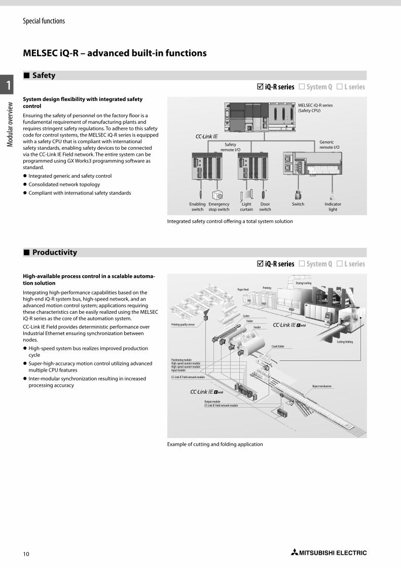
Mitsubishi Electric provides for the MELSEC System Q and the iQ-R series a complete safety solution that can be fully integrated into the automation concept of your system. This allows visualization information, realizing op-timal safety control and boosting pro-ductivity.
Flexible implementationIt’s obvious that the safety solution has to protect workers from dangerous ma-chinery and environments. However, from a cost perspective, it should also be simple to implement and flexible enough to meet the needs of any system design. MELSEC System Q meets these requirements with a unique, multi-facet-ed safety solution. The safety functions can either be directly mounted on the rack, be decentralized I/O, or sit on the open CC-Link Safety network.
The MELSEC iQ-R series is equipped with a safety CPU enabling safety devices to be connected via the CC-Link IE Field network.
Specify with confidenceThe safety solutions of the MELSEC System Q and the MELSEC iQ-R series have been fully certified by all applica-ble safety organizations to EN 954-1 Cat-egory 4, ISO 13849-1 PL e, and IEC 61508 (JIS C 0508) SIL 3 and are certified by TÜV Rheinland.
Integrated generic and safety controlThe MELSEC iQ-R series safety CPU can execute both safety and non-safety programs, enabling easy integration into existing or new control systems. The safety CPU enables safety devices such as safety light curtains, emergency switches, and door switches to be con-nected via the CC-Link IE Field network without requiring a separate dedicated
network line. Wiring and space can be reduced as having multiple network ca-bles are no longer required resulting in lower integration costs.
Easy cost savingThe simplest MELSEC System Q safety option is to fit a safety relay module on the rack alongside all other system components. In this way, a system which is mostly used for conventional control can also meet safety requirements with-out the need for the cost of a dedicated safety controller. The safety relay mod-ules provide the right number of safety I/O without any special programming.
If safety I/O is required in other loca-tions around the system, safety exten-sion I/O modules offer additional “plug and play” safety by connecting directly to the safety I/O module on the rack.
MELSEC System Q provides also the flex-ibility to add safety I/O modules to a conventional CC-Link network alongside other CC-Link devices such as inverters, I/O or HMI units.
Small, simple, and safeThe MELSEC WS Safety Controller pro-vides a cost effective way to add a safety controller capability to individual ma-chines, or smaller scale systems. Its com-pact size insures easy placement in most control cabinets, without adding extra cost. Configuration saves engineering time by using a graphical icon based method, and program development and certification is simplified by the use of safety function blocks.
Safeguarding large systemsThe MELSEC QS Safety PLC offers a mod-ern approach to safety by combining a CC-Link Safety distributed I/O network with the flexibility of a modular control-ler. This offers the capacity to cover an entire production line, while bringing the benefits of reduced wiring, rapid diagnostics and easy program modi-fication and maintenance. Of course, since this is a safety controller however, there is a full complement of safeguards against system failure and unauthorized access.
Safety for all systems
Keep plant personnel safe from harm
12
Motion control
The challenge of Motion Control
Extended application rangeThe current trend for production sys-tems for small quantities with a wide variety of types means that motion con-trollers are expected to offer a broad us-age spectrum. Mitsubishi Electric offers various solutions for motion control, from Simple Motion modules to Motion Controller CPU modules.
Simple motion modules are easy to setup and offer high-precision motion control-ler performance. This is an easy-to-use module specifically designed for highly precise motion control applications.
User-friendly develop ment environmentPowerful functions which have been optimised for efficiency are provided via a user-friendly development envi-ronment. These simplify system design, commissioning and fault finding, in-crease data security and lead to shorter downtimes.
Motion control with the MELSEC System QA QDS motion system with Q17nDSCPU controller and QD77MS simple motion module enables various types of con-trol to be implemented such as posi-tion, speed and torque control, press and power screwdriver monitoring, syn-chronous regulation and cam control. Possible applications for these many control types include a wide range of industrial systems such as X-Y tables, winders, packing machines and bot-tling machines.
The Q17nDSCPU motion controller and the QD77MS Simple Motion module ensure compatibility with conventional servo amplifiers and motion controllers, enabling them to continue to be used.
Reliable safety monitoringSafety in production is an absolute must as all machines and equipment must comply with the international safety standards. The Q17nDSCPU is equipped as standard with safety functions which are certified to EN ISO 13849-1 Category 3, PL d.
Visualising servo dataInformation on power consumption is necessary in order to save energy. The Q17nDSCPU and the QD77MS simple motion module have an optional moni-toring function which can be used, for example, to read out the motor current or the total power consumption of the servo system via SSCNETIII/H. This con-sumption data can then be analysed on a monitor.
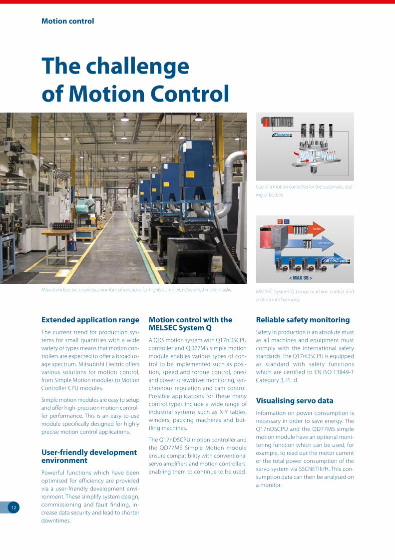
Mitsubishi Electric provides a number of solutions for highly complex, networked motion tasks.
Use of a motion controller for the automatic seal-
ing of bottles
MELSEC System Q brings machine control and
motion into harmony.
13
Motion control
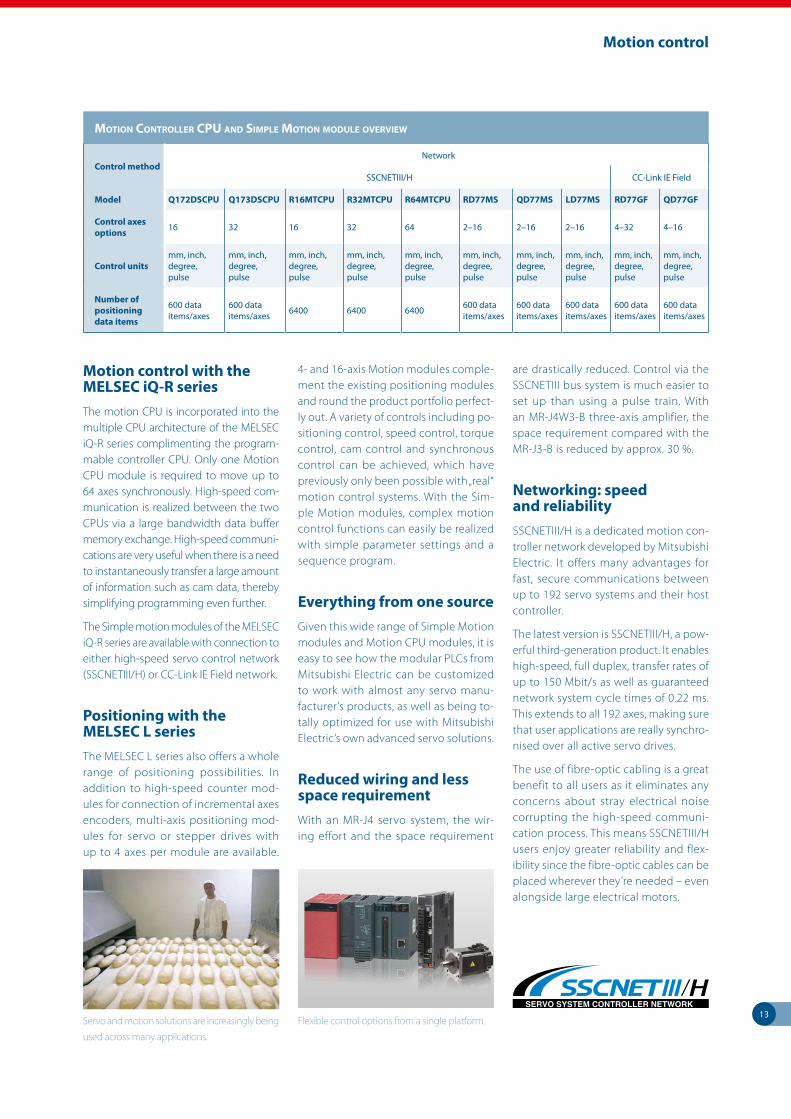
Servo and motion solutions are increasingly being
used across many applications.
Motion control with the MELSEC iQ-R seriesThe motion CPU is incorporated into the multiple CPU architecture of the MELSEC iQ-R series complimenting the program-mable controller CPU. Only one Motion CPU module is required to move up to 64 axes synchronously. High-speed com-munication is realized between the two CPUs via a large bandwidth data buffer memory exchange. High-speed communi-cations are very useful when there is a need to instantaneously transfer a large amount of information such as cam data, thereby simplifying programming even further.
The Simple motion modules of the MELSEC iQ-R series are available with connection to either high-speed servo control network (SSCNETIII/H) or CC-Link IE Field network.
Positioning with the MELSEC L seriesThe MELSEC L series also offers a whole range of positioning possibilities. In addition to high-speed counter mod-ules for connection of incremental axes encoders, multi-axis positioning mod-ules for servo or stepper drives with up to 4 axes per module are available.
4- and 16-axis Motion modules comple-ment the existing positioning modules and round the product portfolio perfect-ly out. A variety of controls including po-sitioning control, speed control, torque control, cam control and synchronous control can be achieved, which have previously only been possible with „real“ motion control systems. With the Sim-ple Motion modules, complex motion control functions can easily be realized with simple parameter settings and a sequence program.
Everything from one sourceGiven this wide range of Simple Motion modules and Motion CPU modules, it is easy to see how the modular PLCs from Mitsubishi Electric can be customized to work with almost any servo manu-facturer’s products, as well as being to-tally optimized for use with Mitsubishi Electric’s own advanced servo solutions.
Reduced wiring and less space requirementWith an MR-J4 servo system, the wir-ing effort and the space requirement
are drastically reduced. Control via the SSCNETIII bus system is much easier to set up than using a pulse train. With an MR-J4W3-B three-axis amplifier, the space requirement compared with the MR-J3-B is reduced by approx. 30 %.
Networking: speed and reliabilitySSCNETIII/H is a dedicated motion con-troller network developed by Mitsubishi Electric. It offers many advantages for fast, secure communications between up to 192 servo systems and their host controller.
The latest version is SSCNETIII/H, a pow-erful third-generation product. It enables high-speed, full duplex, transfer rates of up to 150 Mbit/s as well as guaranteed network system cycle times of 0.22 ms. This extends to all 192 axes, making sure that user applications are really synchro-nised over all active servo drives.
The use of fibre-optic cabling is a great benefit to all users as it eliminates any concerns about stray electrical noise corrupting the high-speed communi-cation process. This means SSCNETIII/H users enjoy greater reliability and flex-ibility since the fibre-optic cables can be placed wherever they’re needed – even alongside large electrical motors.
Motion Controller CPU and SiMPle Motion ModUle overview
Control methodNetwork
SSCNETIII/H CC-Link IE Field
Model Q172DSCPU Q173DSCPU R16MTCPU R32MTCPU R64MTCPU RD77MS QD77MS LD77MS RD77GF QD77GF
Control axes options 16 32 16 32 64 2–16 2–16 2–16 4–32 4–16
Control unitsmm, inch, degree, pulse
mm, inch, degree, pulse
mm, inch, degree, pulse
mm, inch, degree, pulse
mm, inch, degree, pulse
mm, inch, degree, pulse
mm, inch, degree, pulse
mm, inch, degree, pulse
mm, inch, degree, pulse
mm, inch, degree, pulse
Number of positioning data items
600 data items/axes
600 data items/axes 6400 6400 6400 600 data
items/axes600 data items/axes
600 data items/axes
600 data items/axes
600 data items/axes
Flexible control options from a single platform.
14
PC control
IT for support, monitoring and control
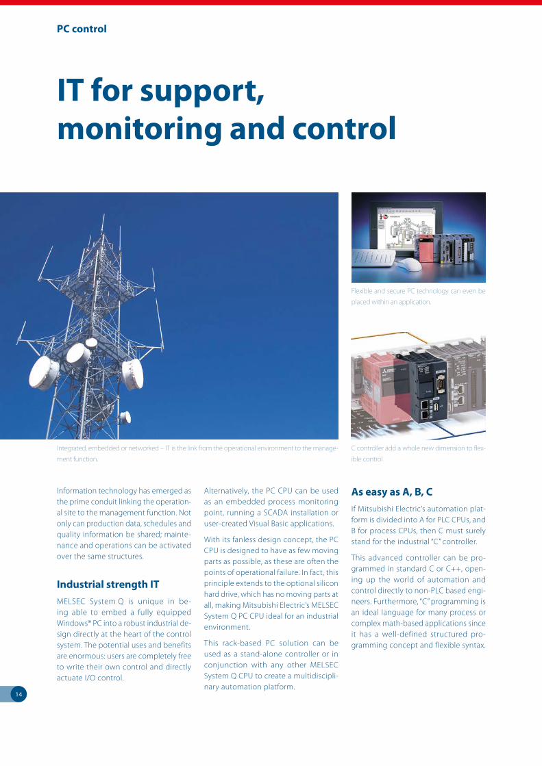
Information technology has emerged as the prime conduit linking the operation-al site to the management function. Not only can production data, schedules and quality information be shared; mainte-nance and operations can be activated over the same structures.
Industrial strength ITMELSEC System Q is unique in be-ing able to embed a fully equipped Windows® PC into a robust industrial de-sign directly at the heart of the control system. The potential uses and benefits are enormous: users are completely free to write their own control and directly actuate I/O control.
Alternatively, the PC CPU can be used as an embedded process monitoring point, running a SCADA installation or user-created Visual Basic applications.
With its fanless design concept, the PC CPU is designed to have as few moving parts as possible, as these are often the points of operational failure. In fact, this principle extends to the optional silicon hard drive, which has no moving parts at all, making Mitsubishi Electric’s MELSEC System Q PC CPU ideal for an industrial environment.
This rack-based PC solution can be used as a stand-alone controller or in conjunction with any other MELSEC System Q CPU to create a multidiscipli-nary automation platform.
As easy as A, B, CIf Mitsubishi Electric’s automation plat-form is divided into A for PLC CPUs, and B for process CPUs, then C must surely stand for the industrial “C” controller.
This advanced controller can be pro-grammed in standard C or C++, open-ing up the world of automation and control directly to non-PLC based engi-neers. Furthermore, “C” programming is an ideal language for many process or complex math-based applications since it has a well-defined structured pro-gramming concept and flexible syntax.
Integrated, embedded or networked – IT is the link from the operational environment to the manage-
ment function.
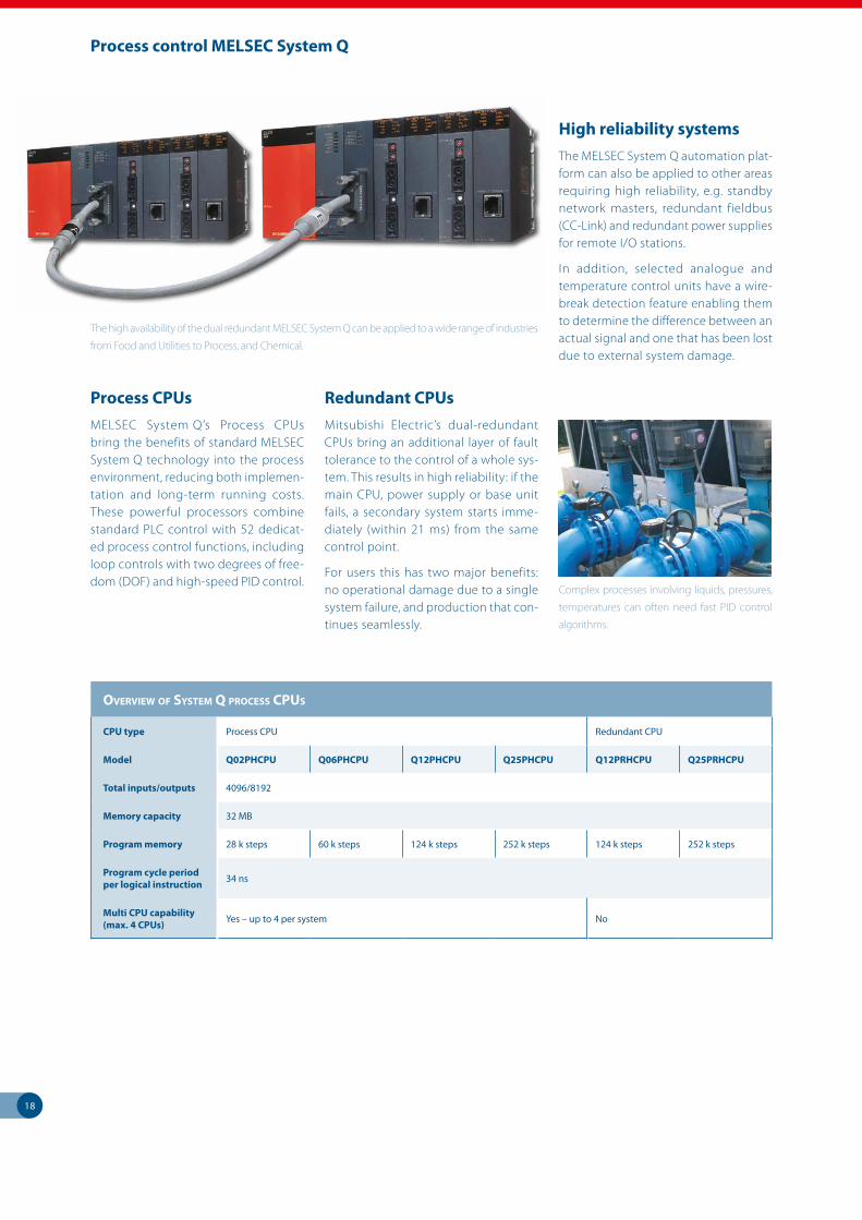
Flexible and secure PC technology can even be
placed within an application.
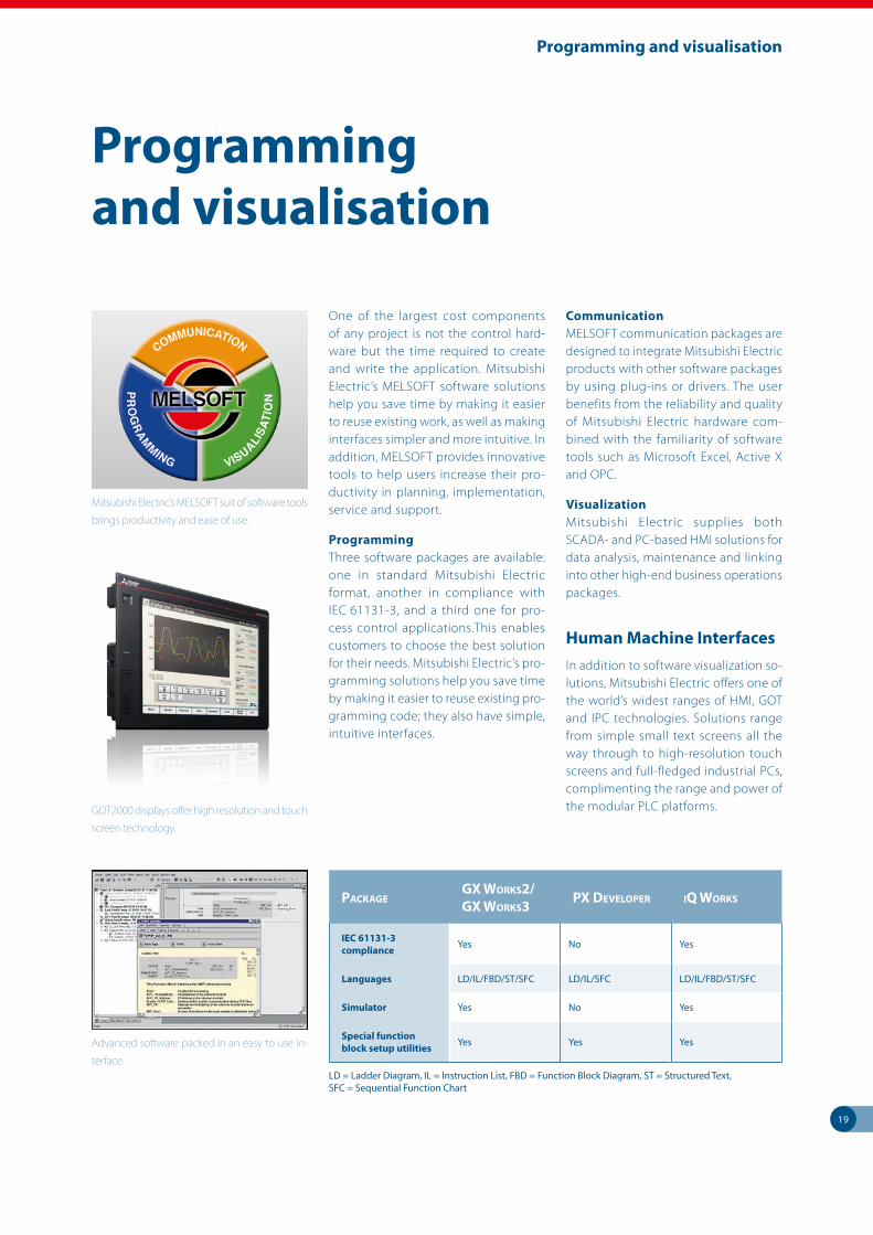
C controller add a whole new dimension to flex-
ible control

15
PC control
Overview Of PC and C COntrOller CPUs
CPU type Windows® PC C controller C controller C controller
Model Q10WCPU-W1-E/CFE R12CCPU-V Q06CCPU Q12DCCPU
Total inputs/outputs1 input (shutdown), 2 outputs (shutdown, watchdog timer)
4096 4096/8192 4096/8192
Memory capacity 4 GB, built-in SSD (Solid State Disk)
Use of storage cards means data and programs can be stored for later retrieval
Program memory1 GB (main)/ 32+24 kB (L1 cache) / 512 kB (L2 cache)
256 MB/ 4 MB backup RAM
64 MB (main)/ 128 kB battery backed
128 MB (main)/ 128 kB battery backed
Processor speed/ cycle time
Intel® Atom™ Processor N450 1.66 GHz
ARM Cortex-A9 Dual Core
SH RISC Processor *
SH RISC Processor *
Multi CPU capability (max. 4 CPUs) Yes Yes Yes Yes
* VxWorks real time system
Flexible and reliable communication is a key issue
in many application regardless of scale and size.
Web server technology brings intuitive access
directly to the heart of the control solution.
The MELSEC iQ-R series module R12CCPU-V and the MELSEC System Q module Q12DCCPU-V have been metic-ulously designed to eliminate as many failure-prone elements as possible, in-cluding fans and hard drives. Combined with the widely used VxWorks operat-ing system from Wind River, this makes Mitsubishi Electric C controller a power-ful CPU fit for industrial environments. In addition, programming support for the CODESYS controller development system is available from 3S-Smart Soft-ware Solutions, which provides users with convenient object-oriented envi-ronments.
Based on the Q12DCCPU-V a connec-tion also to Profinet and in combination with a partner solution to Ethernet/IP was realized.
Remote managementThe MELSEC iQ-R series and the MELSEC System Q offer various solutions to the problem of remote management. These can be used independently or com-bined into multifunction systems.
NetworkingThe automation platform supports a variety of networking and communi-cations modules, including Ethernet, CC-Link, CC-Link IE, CC-Link IE Field, CC-Link Safety, MELSECNET/H, FL-NET, Profibus DP, DeviceNetTM, AS-interface, Modbus® TCP and Modbus® RTU. Many CPU modules offer build-in network-ing capabilities, such as Ethernet or CC-Link IE.
Communication is as easy as selecting the module you need.
WebserverThe QJ71WS96 is a dedicated web-server module that fits directly onto the MELSEC System Q backplane. It offers on-board webpages as well as Java scripting and 100 MB Ethernet that make it easier than ever to share information.
MES InterfaceBoth the QJ71MES96 of the MELSEC System Q and the RD81MES96 of the MELSEC iQ-R series offer the possibility to connect directly with commercial da-tabase applications like Oracle, MS SQL Server and MS Access. The MES mod-ule supports bi-directional data transfer with several databases and the event-driven communications reduce the net-work load. The use of the MES module reduces system complexity and cost, making gateways a thing of the past.
IPC panelsInformation technology also comes to the MELSEC automation platform in the form of industrial personal Computers (IPCs). These units provide an ideal so-lution for placing a PC access point di-rectly in the production environment.
Models can be connected directly to the PLC or via a network, ensuring that all areas of the operation are kept supplied with up-to-date information directly from the Automation Controller.

16
ovERviEw of iQ-R PRoCESS CPUS
CPU type Process CPU
Model range R08PCPU–R120PCPU
Total inputs/ outputs 4096
Memory capacity
Program memory 80–1200 k steps
Data memory 5–40 MB
Instruction processing time (LD instruction)
0.98 ns
Multi CPU capability (max. 4 CPUs)
Yes (in process mode, not possible in redundant mode)
Build-in CC-Link IE Control/CC-Link IE Field ports
—
Process control MELSEC iQ-R
Scalable automation solutionThe MELSEC iQ-R series enables a pro-cess control system through its range of CPU modules (up to 1200 k steps) integrating advanced PID and general control into one module providing ex-cellent system scalability (from small to large) for a best-fit solution. When paired with a redundant function mod-ule, it realizes a redundant control sys-tem ideal for applications that require highly reliable control. Various network modules with redundant functionality embedded are also available, further improving reliability.
Embedded PID algorithmsThe process CPU includes dedicated algorithms such as two-degree-of-freedom PID, sample PI, and auto tun-ing support advanced process control.
Extensive visualization and data acquisitionThrough its interconnectivity with su-pervisory control and data acquisition (SCADA) software, extensive plant-wide monitoring and control can be real-ized. Mitsubishi SCADA MC Works64 is a next generation supervisory control and data acquisition (SCADA) software providing extensive visualization with its enhanced interconnectivity with the MELSEC iQ-R series. Advanced features such as energy management, scheduling, alarm and event manage-ment, trending, reporting, historian, and Geo-SCADA monitoring realize intuitive factory-wide control.
MELSEC iQ-R: High-available process control
Mitsubishi Electric offers highly scalable process solutions
High availability across multiple levelsThe MELSEC iQ-R series redundant sys-tem enables high availability at multiple levels in the control system hierarchy, from visualization (SCADA) to network control.
Integrated software simplifies engineeringThe integrated engineering software GX Works3 enables programming in mutliple program languages such as function block diagram (FBD) for pro-cess control. Intuitive features for simpli-fying process control system engineer-ing include process tag label (variable) sharing, simple program structures, and easy project upload/download to the process CPU.

17
Process control MELSEC System Q
MELSEC System Q: Process control you can count on
A platform to build onThe strength of MELSEC System Q’s au-tomation platform really comes into its own in traditional specialist industries. The unique flexibility of proven off-the-shelf control components such as I/O and communication devices, teamed with dedicated special devices like process CPUs, assures high functional-ity, ease of use and targeted control – all within budget.
Two worlds meetOur dedicated MELSEC System Q pro-cess CPUs build on the already high functionality of Mitsubishi’s advanced PLC CPUs. This powerful combination of sequential control overlaid with dedi-cated process instructions gives users a hybrid control solution with the best of both worlds.
This is complemented in turn by a range of dedicated channel-isolated and high-resolution analogue modules. Here, too, a combination of specialized and stand-ard modules as well as HART protocol supporting analog I/O’s provide the basis for practical and flexible solutions.
High system availability can be main-tained through various means, including redundant process CPUs, stand-by net-work masters, and redundant network configurations, as well as by wire-break detection and a “hot-swap” capability that allows modules to be replaced dur-ing live operation.
Programming can be implemented using a wide range of tools such as IEC 61131-3 compliant software and the process-dedicated PX Developer.
Reliable system operation is essential in the process industry.
18
Process control MELSEC System Q
Overview Of SyStem Q prOceSS cpUS
CPU type Process CPU Redundant CPU
Model Q02PHCPU Q06PHCPU Q12PHCPU Q25PHCPU Q12PRHCPU Q25PRHCPU
Total inputs/outputs 4096/8192
Memory capacity 32 MB
Program memory 28 k steps 60 k steps 124 k steps 252 k steps 124 k steps 252 k steps
Program cycle period per logical instruction 34 ns
Multi CPU capability (max. 4 CPUs) Yes – up to 4 per system No
Process CPUsMELSEC System Q’s Process CPUs bring the benefits of standard MELSEC System Q technology into the process environment, reducing both implemen-tation and long-term running costs. These powerful processors combine standard PLC control with 52 dedicat-ed process control functions, including loop controls with two degrees of free-dom (DOF) and high-speed PID control.
Redundant CPUsMitsubishi Electric’s dual-redundant CPUs bring an additional layer of fault tolerance to the control of a whole sys-tem. This results in high reliability: if the main CPU, power supply or base unit fails, a secondary system starts imme-diately (within 21 ms) from the same control point.
For users this has two major benefits: no operational damage due to a single system failure, and production that con-tinues seamlessly.
High reliability systemsThe MELSEC System Q automation plat-form can also be applied to other areas requiring high reliability, e.g. standby network masters, redundant fieldbus (CC-Link) and redundant power supplies for remote I/O stations.
In addition, selected analogue and temperature control units have a wire-break detection feature enabling them to determine the difference between an actual signal and one that has been lost due to external system damage.
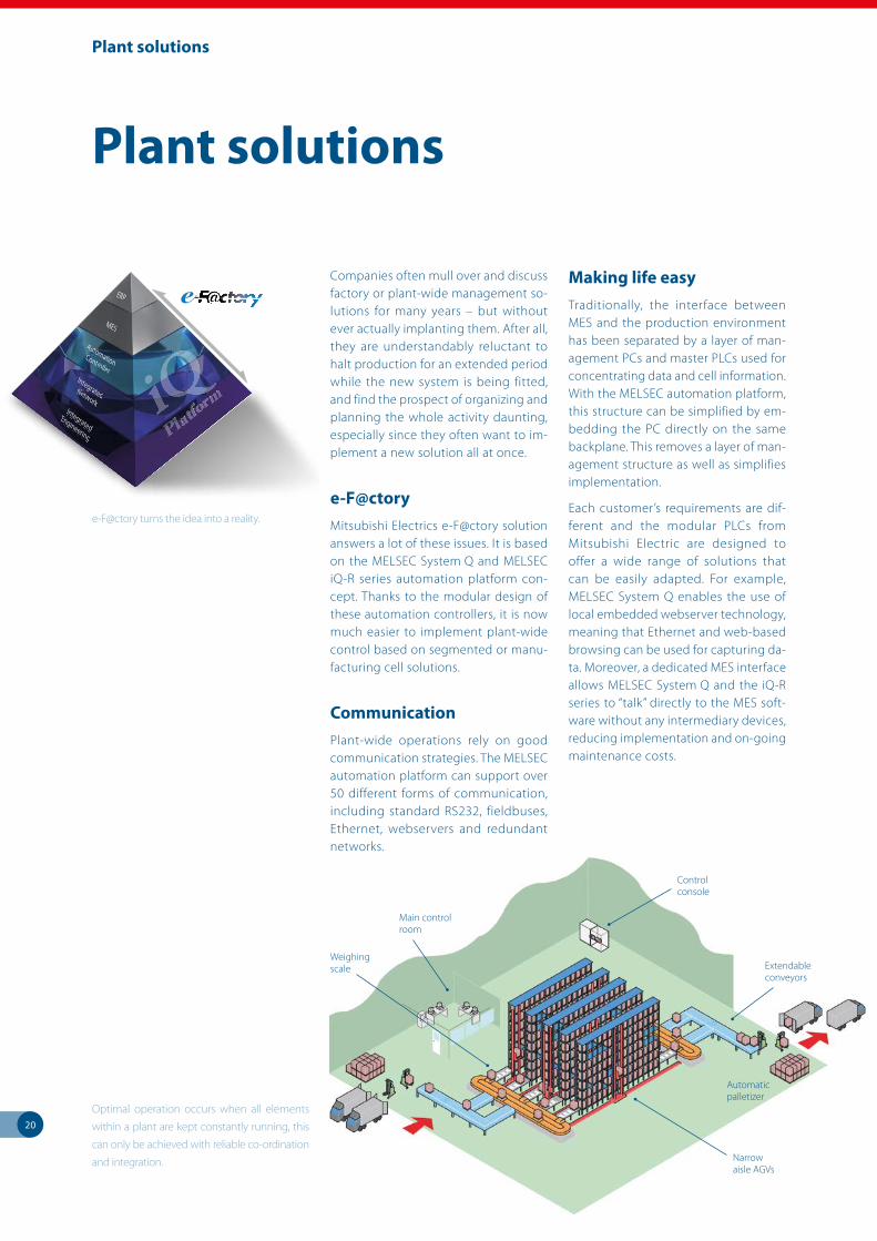
Complex processes involving liquids, pressures,
temperatures can often need fast PID control
algorithms.
The high availability of the dual redundant MELSEC System Q can be applied to a wide range of industries
from Food and Utilities to Process, and Chemical.
19
Programming and visualisation
PackagegX Works2/ gX Works3 PX DeveloPer iQ Works
IEC 61131-3 compliance Yes No Yes
Languages LD/IL/FBD/ST/SFC LD/IL/SFC LD/IL/FBD/ST/SFC
Simulator Yes No Yes
Special function block setup utilities Yes Yes Yes
LD = Ladder Diagram, IL = Instruction List, FBD = Function Block Diagram, ST = Structured Text, SFC = Sequential Function Chart
Mitsubishi Electric’s MELSOFT suit of software tools
brings productivity and ease of use.
GOT2000 displays offer high resolution and touch
screen technology.
One of the largest cost components of any project is not the control hard-ware but the time required to create and write the application. Mitsubishi Electric’s MELSOFT software solutions help you save time by making it easier to reuse existing work, as well as making interfaces simpler and more intuitive. In addition, MELSOFT provides innovative tools to help users increase their pro-ductivity in planning, implementation, service and support.
ProgrammingThree software packages are available: one in standard Mitsubishi Electric format, another in compliance with IEC 61131-3, and a third one for pro-cess control applications.This enables customers to choose the best solution for their needs. Mitsubishi Electric’s pro-gramming solutions help you save time by making it easier to reuse existing pro-gramming code; they also have simple, intuitive interfaces.
CommunicationMELSOFT communication packages are designed to integrate Mitsubishi Electric products with other software packages by using plug-ins or drivers. The user benefits from the reliability and quality of Mitsubishi Electric hardware com-bined with the familiarity of software tools such as Microsoft Excel, Active X and OPC.
VisualizationMitsubishi Electric supplies both SCADA- and PC-based HMI solutions for data analysis, maintenance and linking into other high-end business operations packages.
Human Machine InterfacesIn addition to software visualization so-lutions, Mitsubishi Electric offers one of the world’s widest ranges of HMI, GOT and IPC technologies. Solutions range from simple small text screens all the way through to high-resolution touch screens and full-fledged industrial PCs, complimenting the range and power of the modular PLC platforms.
Programming and visualisation
Advanced software packed in an easy to use in-
terface.
20
Companies often mull over and discuss factory or plant-wide management so-lutions for many years – but without ever actually implanting them. After all, they are understandably reluctant to halt production for an extended period while the new system is being fitted, and find the prospect of organizing and planning the whole activity daunting, especially since they often want to im-plement a new solution all at once.
e-F@ctoryMitsubishi Electrics e-F@ctory solution answers a lot of these issues. It is based on the MELSEC System Q and MELSEC iQ-R series automation platform con-cept. Thanks to the modular design of these automation controllers, it is now much easier to implement plant-wide control based on segmented or manu-facturing cell solutions.
CommunicationPlant-wide operations rely on good communication strategies. The MELSEC automation platform can support over 50 different forms of communication, including standard RS232, fieldbuses, Ethernet, webservers and redundant networks.
Making life easyTraditionally, the interface between MES and the production environment has been separated by a layer of man-agement PCs and master PLCs used for concentrating data and cell information. With the MELSEC automation platform, this structure can be simplified by em-bedding the PC directly on the same backplane. This removes a layer of man-agement structure as well as simplifies implementation.
Each customer’s requirements are dif-ferent and the modular PLCs from Mitsubishi Electric are designed to offer a wide range of solutions that can be easily adapted. For example, MELSEC System Q enables the use of local embedded webserver technology, meaning that Ethernet and web-based browsing can be used for capturing da-ta. Moreover, a dedicated MES interface allows MELSEC System Q and the iQ-R series to “talk” directly to the MES soft-ware without any intermediary devices, reducing implementation and on-going maintenance costs.
Plant solutions
Plant solutions
Control console
Extendable conveyors
Automatic palletizer
Narrow aisle AGVs
Weighing scale
Main control room
IntegratedEnE gineering
InInInInI tetteggrattedededNeNeNeNeNeNetttwwork
AAututu omommataationCoCoCoCCContrroller
MESS
ERP
e-F@ctory turns the idea into a reality.
Optimal operation occurs when all elements
within a plant are kept constantly running, this
can only be achieved with reliable co-ordination
and integration.

21
Each machine presents different chal-lenges to the control system. Sometimes high quantities of I/O are required lo-cally or are networked. Small controller size is often important, while at other times the key factors will be tempera-ture, positioning, or analogue control.
For the machine designer, an ideal solution is to have a standard control philosophy that can be adapted to each machine’s individual needs. This is exact-ly what the modular PLCs of Mitsubishi Electric bring to machine control.
CompactDue to its modular design, the modular PLCs from Mitsubishi Electric use less panel space than many other control-lers. In addition, Mitsubishi Electric of-fers a wide range of high-density I/O cards and analogue modules that are ideal for minimizing installation space. For very compact installations, the rack-free PLC of the MELSEC L series is the ideal choice, which can additionally be enhanced by network modules or re-mote I/Os.
FlexibleWhen designing a control system for a given machine, flexibility is often a key requirement. Many machine manufac-turers develop ranges of products which require a basic control concept to which additional features can be added as ma-chine performance increases. Consider-ing that, the modular PLCs of Mitsubishi Electric are ideal.
The modular PLCs from Mitsubishi Electric encompass a wide range of modules, including various types of temperature and analogue modules, different positioning modules and a wide range of communication devices. These modules can be combined with all CPUs.
Easy programmingOne of the largest costs in any con-trol solution is the programming and engineering time. The modular PLCs from Mitsubishi Electric overcome this problem with user-friendly, intuitive programming tools. With all that, reus-able program components and the use of function blocks and the sequential function chart were placed in the fore-ground. Embedded set-up tools support this process, making the configuration of special function modules simple, quick, and easy.
Machine solutions
A horizontal packaging machine can present many challenges to the automation engineer.
Bag folding
Product feed conveyor
Product in
Film
End sealing/ cutting point
Product out
Exit conveyor
Film grip and heat sealing rollers
Example of temperature control.
Machine solutions
22
Mitsubishi Electric products are found in an almost infinite variety of industrial, infrastructure and service sector con-texts, ranging from critical applications in the pharmaceuticals industry to state-of-the-art leisure and entertainment fa-cilities. Here are just a few examples of recent applications:
Agriculture – Irrigation systems– Plant handling systems– Sawmills
Building management– Smoke detection monitoring– Ventilation and temperature
control – Lift (elevator) control– Automated revolving doors– Telephone management– Energy management– Swimming pool management
Construction – Steel bridge manufacturing– Tunnel boring systems
Food and drink– Bread manufacture (mixing/baking)– Food processing (washing/sorting/
slicing/packaging)
Leisure – Multiplex cinema projection– Animated mechatronics
(museums/theme parks)
Medical– Respiration machine testing– Sterilization
Pharmaceutical/chemical– Dosing control– Pollution measurement systems – Cryogenic freezing– Gas chromatography– Packaging
Plastics– Plastic welding systems – Energy management systems for
injection moulding machines – Loading/unloading machines– Blow moulding test machines– Injection moulding machines
Automotive
Printing
Textiles
Transportation– Sanitation on passenger ships– Sanitation on rail rolling stock– Fire tender, pump management– Waste disposal truck management
Utilities– Waste water treatment– Fresh water pumping– Sewage plants
Application solutions
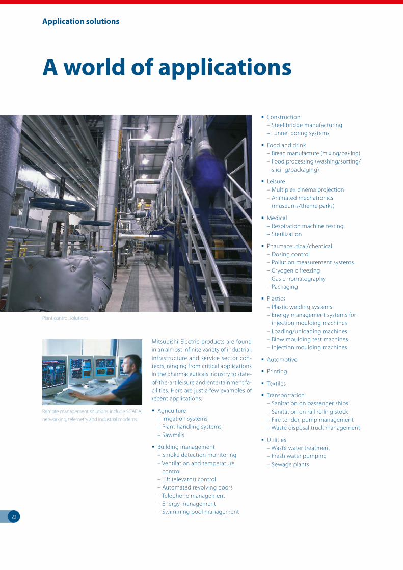
A world of applications
Plant control solutions
Remote management solutions include SCADA,
networking, telemetry and industrial modems.
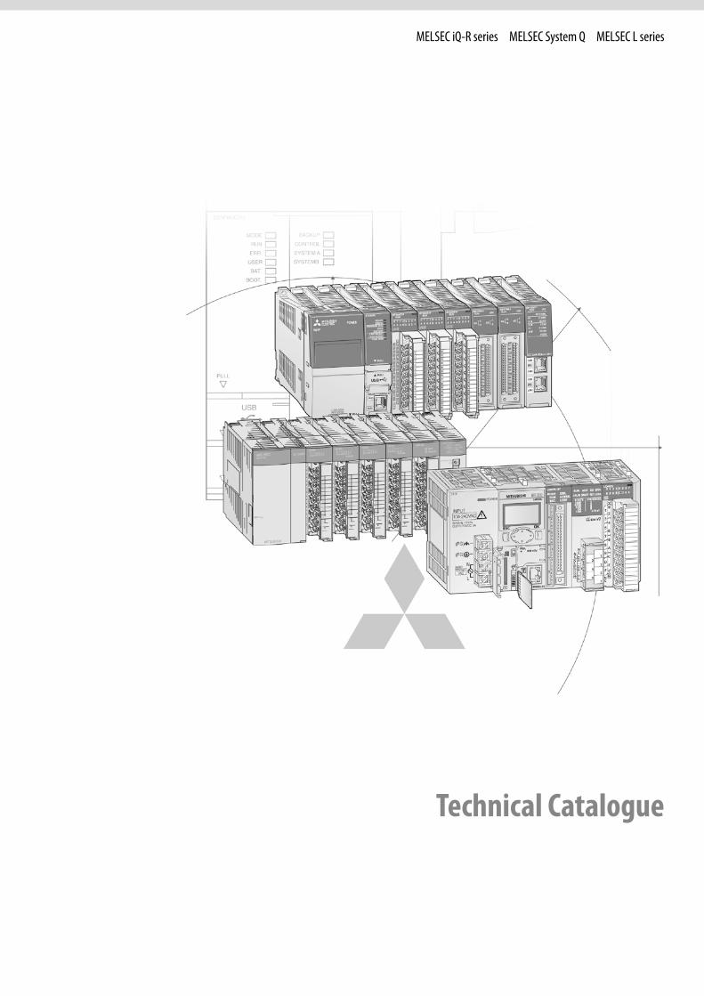
MELSEC iQ-R series MELSEC System Q MELSEC L series
Technical Catalogue
2
Further publications within the industrial automation range
FX FamilyProduct catalogue for programmable logic controllers and accessories for the MELSEC FX family
HMI FamilyProduct catalogue for operator terminals, supervision software and accessories
FR FamilyProduct catalogue for frequency inverters and accessories
MR FamilyProduct catalogue for servo amplifiers and servo motors as well as motion controller and accessories
MELFA FamilyProduct catalogue for industrial robots and accessories
LVS FamilyProduct catalogue for low voltage switchgears,magnetic contactors and circuit breakers
Automation BookOverview on all Mitsubishi Electric automation products, like frequency inverters, servo/motion, robots etc.
More information?
The catalogue at hand is designed to give an overview of the extensive range of iQ-R, System Q and L series of MELSEC PLCs. If you cannot find the infor-mation you require in this catalogue, there are a number of ways you can get further details on configuration and technical issues, pricing and availability.
For technical issues visit the https://eu3a.mitsubishielectric.com website. Our website provides a simple and fast way of accessing further technical data and up to the minute details on our products and services. Manuals and catalogues are available in several different languages and can be downloaded for free.
For technical, configuration, pricing and availability issues contact our distributors and partners. Mitsubishi Electric partners and distributors are only too happy to help answer your technical questions or help with configuration building. For a list of Mitsubishi Electric partners please see the back of this catalogue or alternatively take a look at the “contact us” section of our website.
About this technical catalogue
This catalogue is a guide to the range of products available. For detailed configuration rules, system building, installation and configuration the associated product manuals must be read. You must satisfy yourself that any system you design with the products in this catalogue is fit for purpose, meets your requires and conforms to the product configuration rules as defined in the product manuals.
Specifications are subject to change without notice. All trademarks acknowledged.
© Mitsubishi Electric Europe B.V., Factory Automation - European Business Group
The products of Mitsubishi Electric Europe B.V., that are listed and described in this document, are neither subject to approval for export nor subject to the Dual-Use List.
Brochures
1
2
3
4
5
6
3
Contents
MELSEC modular PLCs – iQ-R series, System Q and L series
1 Modular overviewMELSEC iQ-R SERIES, SYSTEM Q AND L SERIES
Specifications . . . . . . . . . . . . . . . . . . . . . . . . . . . . . . . . . . . . . . . . . . . . . . . . . . . . . . . . . . . . . . . . . . . . . . . . . . . . . . . . . . . . . . . . . . . . 6 Overview of the modular series . . . . . . . . . . . . . . . . . . . . . . . . . . . . . . . . . . . . . . . . . . . . . . . . . . . . . . . . . . . . . . . . . . . . . . . . . . . 7 Special functions MELSEC iQ-R . . . . . . . . . . . . . . . . . . . . . . . . . . . . . . . . . . . . . . . . . . . . . . . . . . . . . . . . . . . . . . . . . . . . . . . . . . . 10 Special functions MELSEC System Q . . . . . . . . . . . . . . . . . . . . . . . . . . . . . . . . . . . . . . . . . . . . . . . . . . . . . . . . . . . . . . . . . . . . . . 12 Special functions MELSEC L . . . . . . . . . . . . . . . . . . . . . . . . . . . . . . . . . . . . . . . . . . . . . . . . . . . . . . . . . . . . . . . . . . . . . . . . . . . . . . 14
2 MELSEC iQ-R seriesSYSTEM DESCRIPTION AND BASIC COMPONENTS
Configuration and handling . . . . . . . . . . . . . . . . . . . . . . . . . . . . . . . . . . . . . . . . . . . . . . . . . . . . . . . . . . . . . . . . . . . . . . . . . . . . . 16 Base units . . . . . . . . . . . . . . . . . . . . . . . . . . . . . . . . . . . . . . . . . . . . . . . . . . . . . . . . . . . . . . . . . . . . . . . . . . . . . . . . . . . . . . . . . . . . . . . 17 Power supply modules . . . . . . . . . . . . . . . . . . . . . . . . . . . . . . . . . . . . . . . . . . . . . . . . . . . . . . . . . . . . . . . . . . . . . . . . . . . . . . . . . . 18 CPU modules . . . . . . . . . . . . . . . . . . . . . . . . . . . . . . . . . . . . . . . . . . . . . . . . . . . . . . . . . . . . . . . . . . . . . . . . . . . . . . . . . . . . . . . . . . . 19
DIGITAL MODULES Input modules . . . . . . . . . . . . . . . . . . . . . . . . . . . . . . . . . . . . . . . . . . . . . . . . . . . . . . . . . . . . . . . . . . . . . . . . . . . . . . . . . . . . . . . . . . 24 Output modules . . . . . . . . . . . . . . . . . . . . . . . . . . . . . . . . . . . . . . . . . . . . . . . . . . . . . . . . . . . . . . . . . . . . . . . . . . . . . . . . . . . . . . . . 26 Combined I/O module . . . . . . . . . . . . . . . . . . . . . . . . . . . . . . . . . . . . . . . . . . . . . . . . . . . . . . . . . . . . . . . . . . . . . . . . . . . . . . . . . . . 28
SPECIAL FUNCTION MODULES Analog modules . . . . . . . . . . . . . . . . . . . . . . . . . . . . . . . . . . . . . . . . . . . . . . . . . . . . . . . . . . . . . . . . . . . . . . . . . . . . . . . . . . . . . . . . 29 Temperature control modules . . . . . . . . . . . . . . . . . . . . . . . . . . . . . . . . . . . . . . . . . . . . . . . . . . . . . . . . . . . . . . . . . . . . . . . . . . . 32 High-speed counter modules . . . . . . . . . . . . . . . . . . . . . . . . . . . . . . . . . . . . . . . . . . . . . . . . . . . . . . . . . . . . . . . . . . . . . . . . . . . . 33 Positioning modules . . . . . . . . . . . . . . . . . . . . . . . . . . . . . . . . . . . . . . . . . . . . . . . . . . . . . . . . . . . . . . . . . . . . . . . . . . . . . . . . . . . . 34 Simple Motion modules . . . . . . . . . . . . . . . . . . . . . . . . . . . . . . . . . . . . . . . . . . . . . . . . . . . . . . . . . . . . . . . . . . . . . . . . . . . . . . . . . 35 Interface modules . . . . . . . . . . . . . . . . . . . . . . . . . . . . . . . . . . . . . . . . . . . . . . . . . . . . . . . . . . . . . . . . . . . . . . . . . . . . . . . . . . . . . . . 36 Network modules . . . . . . . . . . . . . . . . . . . . . . . . . . . . . . . . . . . . . . . . . . . . . . . . . . . . . . . . . . . . . . . . . . . . . . . . . . . . . . . . . . . . . . . 37 MES Interface module . . . . . . . . . . . . . . . . . . . . . . . . . . . . . . . . . . . . . . . . . . . . . . . . . . . . . . . . . . . . . . . . . . . . . . . . . . . . . . . . . . . 38 iQ-R C-Application Server . . . . . . . . . . . . . . . . . . . . . . . . . . . . . . . . . . . . . . . . . . . . . . . . . . . . . . . . . . . . . . . . . . . . . . . . . . . . . . . . 39 High-speed data logger module . . . . . . . . . . . . . . . . . . . . . . . . . . . . . . . . . . . . . . . . . . . . . . . . . . . . . . . . . . . . . . . . . . . . . . . . . 40 C intelligent function module . . . . . . . . . . . . . . . . . . . . . . . . . . . . . . . . . . . . . . . . . . . . . . . . . . . . . . . . . . . . . . . . . . . . . . . . . . . . 41
DIMENSIONS Dimensions . . . . . . . . . . . . . . . . . . . . . . . . . . . . . . . . . . . . . . . . . . . . . . . . . . . . . . . . . . . . . . . . . . . . . . . . . . . . . . . . . . . . . . . . . . . . . 42
ACCESSORIESRefer to chapter 5
1
2
3
4
5
6
4
Contents
3 MELSEC System QSYSTEM DESCRIPTION AND BASIC COMPONENTS
Configuration and handling . . . . . . . . . . . . . . . . . . . . . . . . . . . . . . . . . . . . . . . . . . . . . . . . . . . . . . . . . . . . . . . . . . . . . . . . . . . . . 45 Base units . . . . . . . . . . . . . . . . . . . . . . . . . . . . . . . . . . . . . . . . . . . . . . . . . . . . . . . . . . . . . . . . . . . . . . . . . . . . . . . . . . . . . . . . . . . . . . . 50 Power supply modules . . . . . . . . . . . . . . . . . . . . . . . . . . . . . . . . . . . . . . . . . . . . . . . . . . . . . . . . . . . . . . . . . . . . . . . . . . . . . . . . . . 52 CPU modules . . . . . . . . . . . . . . . . . . . . . . . . . . . . . . . . . . . . . . . . . . . . . . . . . . . . . . . . . . . . . . . . . . . . . . . . . . . . . . . . . . . . . . . . . . . 53
DIGITAL MODULES Input modules . . . . . . . . . . . . . . . . . . . . . . . . . . . . . . . . . . . . . . . . . . . . . . . . . . . . . . . . . . . . . . . . . . . . . . . . . . . . . . . . . . . . . . . . . . 60 Output modules . . . . . . . . . . . . . . . . . . . . . . . . . . . . . . . . . . . . . . . . . . . . . . . . . . . . . . . . . . . . . . . . . . . . . . . . . . . . . . . . . . . . . . . . 62
SPECIAL FUNCTION MODULES Analog modules . . . . . . . . . . . . . . . . . . . . . . . . . . . . . . . . . . . . . . . . . . . . . . . . . . . . . . . . . . . . . . . . . . . . . . . . . . . . . . . . . . . . . . . . 64 Temperature control modules . . . . . . . . . . . . . . . . . . . . . . . . . . . . . . . . . . . . . . . . . . . . . . . . . . . . . . . . . . . . . . . . . . . . . . . . . . . 69 Load cell module . . . . . . . . . . . . . . . . . . . . . . . . . . . . . . . . . . . . . . . . . . . . . . . . . . . . . . . . . . . . . . . . . . . . . . . . . . . . . . . . . . . . . . . . 70 Analog CT input module . . . . . . . . . . . . . . . . . . . . . . . . . . . . . . . . . . . . . . . . . . . . . . . . . . . . . . . . . . . . . . . . . . . . . . . . . . . . . . . . 71 Loop control module . . . . . . . . . . . . . . . . . . . . . . . . . . . . . . . . . . . . . . . . . . . . . . . . . . . . . . . . . . . . . . . . . . . . . . . . . . . . . . . . . . . . 72 Counter modules . . . . . . . . . . . . . . . . . . . . . . . . . . . . . . . . . . . . . . . . . . . . . . . . . . . . . . . . . . . . . . . . . . . . . . . . . . . . . . . . . . . . . . . . 73 Positioning modules . . . . . . . . . . . . . . . . . . . . . . . . . . . . . . . . . . . . . . . . . . . . . . . . . . . . . . . . . . . . . . . . . . . . . . . . . . . . . . . . . . . . 75 Simple Motion modules . . . . . . . . . . . . . . . . . . . . . . . . . . . . . . . . . . . . . . . . . . . . . . . . . . . . . . . . . . . . . . . . . . . . . . . . . . . . . . . . . 79 Interface modules . . . . . . . . . . . . . . . . . . . . . . . . . . . . . . . . . . . . . . . . . . . . . . . . . . . . . . . . . . . . . . . . . . . . . . . . . . . . . . . . . . . . . . . 80 Network modules . . . . . . . . . . . . . . . . . . . . . . . . . . . . . . . . . . . . . . . . . . . . . . . . . . . . . . . . . . . . . . . . . . . . . . . . . . . . . . . . . . . . . . . 82 Web server module . . . . . . . . . . . . . . . . . . . . . . . . . . . . . . . . . . . . . . . . . . . . . . . . . . . . . . . . . . . . . . . . . . . . . . . . . . . . . . . . . . . . . 83 MES Interface module . . . . . . . . . . . . . . . . . . . . . . . . . . . . . . . . . . . . . . . . . . . . . . . . . . . . . . . . . . . . . . . . . . . . . . . . . . . . . . . . . . . 84 Q Series C-Application Server . . . . . . . . . . . . . . . . . . . . . . . . . . . . . . . . . . . . . . . . . . . . . . . . . . . . . . . . . . . . . . . . . . . . . . . . . . . . 85 High-speed data logger module . . . . . . . . . . . . . . . . . . . . . . . . . . . . . . . . . . . . . . . . . . . . . . . . . . . . . . . . . . . . . . . . . . . . . . . . . 86 Interrupt module and high-speed inputs . . . . . . . . . . . . . . . . . . . . . . . . . . . . . . . . . . . . . . . . . . . . . . . . . . . . . . . . . . . . . . . . . 87
DIMENSIONS Dimensions . . . . . . . . . . . . . . . . . . . . . . . . . . . . . . . . . . . . . . . . . . . . . . . . . . . . . . . . . . . . . . . . . . . . . . . . . . . . . . . . . . . . . . . . . . . . . 88
ACCESSORIESRefer to chapter 5
4 MELSEC L seriesSYSTEM DESCRIPTION AND BASIC COMPONENTS
Configuration and handling . . . . . . . . . . . . . . . . . . . . . . . . . . . . . . . . . . . . . . . . . . . . . . . . . . . . . . . . . . . . . . . . . . . . . . . . . . . . . 92 Power supply modules . . . . . . . . . . . . . . . . . . . . . . . . . . . . . . . . . . . . . . . . . . . . . . . . . . . . . . . . . . . . . . . . . . . . . . . . . . . . . . . . . . 94 CPU modules . . . . . . . . . . . . . . . . . . . . . . . . . . . . . . . . . . . . . . . . . . . . . . . . . . . . . . . . . . . . . . . . . . . . . . . . . . . . . . . . . . . . . . . . . . . 95
DIGITAL MODULES Input modules . . . . . . . . . . . . . . . . . . . . . . . . . . . . . . . . . . . . . . . . . . . . . . . . . . . . . . . . . . . . . . . . . . . . . . . . . . . . . . . . . . . . . . . . . . 96 Output modules . . . . . . . . . . . . . . . . . . . . . . . . . . . . . . . . . . . . . . . . . . . . . . . . . . . . . . . . . . . . . . . . . . . . . . . . . . . . . . . . . . . . . . . . 97
SPECIAL FUNCTION MODULES IO-Link module . . . . . . . . . . . . . . . . . . . . . . . . . . . . . . . . . . . . . . . . . . . . . . . . . . . . . . . . . . . . . . . . . . . . . . . . . . . . . . . . . . . . . . . . . 98 Analog modules . . . . . . . . . . . . . . . . . . . . . . . . . . . . . . . . . . . . . . . . . . . . . . . . . . . . . . . . . . . . . . . . . . . . . . . . . . . . . . . . . . . . . . . . 99 Temperature control modules . . . . . . . . . . . . . . . . . . . . . . . . . . . . . . . . . . . . . . . . . . . . . . . . . . . . . . . . . . . . . . . . . . . . . . . . . .104 Flexible high-speed I/O control module . . . . . . . . . . . . . . . . . . . . . . . . . . . . . . . . . . . . . . . . . . . . . . . . . . . . . . . . . . . . . . . . .105 Counter modules . . . . . . . . . . . . . . . . . . . . . . . . . . . . . . . . . . . . . . . . . . . . . . . . . . . . . . . . . . . . . . . . . . . . . . . . . . . . . . . . . . . . . . .106 Interface modules . . . . . . . . . . . . . . . . . . . . . . . . . . . . . . . . . . . . . . . . . . . . . . . . . . . . . . . . . . . . . . . . . . . . . . . . . . . . . . . . . . . . . .107 Positioning modules . . . . . . . . . . . . . . . . . . . . . . . . . . . . . . . . . . . . . . . . . . . . . . . . . . . . . . . . . . . . . . . . . . . . . . . . . . . . . . . . . . .108 Simple motion modules . . . . . . . . . . . . . . . . . . . . . . . . . . . . . . . . . . . . . . . . . . . . . . . . . . . . . . . . . . . . . . . . . . . . . . . . . . . . . . . .109 Network modules . . . . . . . . . . . . . . . . . . . . . . . . . . . . . . . . . . . . . . . . . . . . . . . . . . . . . . . . . . . . . . . . . . . . . . . . . . . . . . . . . . . . . .110 Serial communication adapter and end cover . . . . . . . . . . . . . . . . . . . . . . . . . . . . . . . . . . . . . . . . . . . . . . . . . . . . . . . . . . .111
DIMENSIONS Dimensions . . . . . . . . . . . . . . . . . . . . . . . . . . . . . . . . . . . . . . . . . . . . . . . . . . . . . . . . . . . . . . . . . . . . . . . . . . . . . . . . . . . . . . . . . . . .112
ACCESSORIESRefer to chapter 5

1
2
3
4
5
6
5
Contents
5 Accessories
ACCESSORIES FOR THE MELSEC MODULAR SERIES Batteries, DIN rail mounting adapters, connection cables with connectors . . . . . . . . . . . . . . . . . . . . . . . . . . . . . . . .114 37 and 40-pin connectors, wireless LAN adapter . . . . . . . . . . . . . . . . . . . . . . . . . . . . . . . . . . . . . . . . . . . . . . . . . . . . . . . . .115 Industrial switching HUB, Ethernet adapter module . . . . . . . . . . . . . . . . . . . . . . . . . . . . . . . . . . . . . . . . . . . . . . . . . . . . .116
MELSEC iQ-R series SD memory cards, extended SRAM cassettes, connection cables, blank cover modules . . . . . . . . . . . . . . . . . . .117
MELSEC System Q Dummy module, ERNT – conversion adapters, PCMCIA adapter unit . . . . . . . . . . . . . . . . . . . . . . . . . . . . . . . . . . . . .118 Connection cables, tracking cables, programming cables . . . . . . . . . . . . . . . . . . . . . . . . . . . . . . . . . . . . . . . . . . . . . . . .119 Connector disconnection prevention holder, adapter cables, memory cards . . . . . . . . . . . . . . . . . . . . . . . . . . . . .120 Extended SRAM cassettes, SRAM card batteries, interchangeable terminal blocks for I/O modules . . . . . . . . .121
MELSEC L series Display module, SD memory cards, branch/extension module . . . . . . . . . . . . . . . . . . . . . . . . . . . . . . . . . . . . . . . . . . .122 Space module, extension cables, spring clamp terminal block (push-in type) . . . . . . . . . . . . . . . . . . . . . . . . . . . . .123
6 Programming systems
PROGRAMMING Software, iQ Works . . . . . . . . . . . . . . . . . . . . . . . . . . . . . . . . . . . . . . . . . . . . . . . . . . . . . . . . . . . . . . . . . . . . . . . . . . . . . . . . . . . . .124 GX Works, visualisation software . . . . . . . . . . . . . . . . . . . . . . . . . . . . . . . . . . . . . . . . . . . . . . . . . . . . . . . . . . . . . . . . . . . . . . . .125 Profibus software . . . . . . . . . . . . . . . . . . . . . . . . . . . . . . . . . . . . . . . . . . . . . . . . . . . . . . . . . . . . . . . . . . . . . . . . . . . . . . . . . . . . . .126
Appendix
Index . . . . . . . . . . . . . . . . . . . . . . . . . . . . . . . . . . . . . . . . . . . . . . . . . . . . . . . . . . . . . . . . . . . . . . . . . . . . . . . . . . . . . . . . . . . . . . . . . .128
6
Modular overview
1
Mod
ular o
verv
iew
MELSEC iQ-R MELSEC System Q MELSEC L
P1L ER
LINK
P1L ER
LINK
0
1
2
3
4
5
6
7
8
9
A
B
C
D
E
F
0
1
2
3
4
5
6
7
8
9
A
B
C
D
E
F
0
1
2
3
4
5
6
7
8
9
A
B
C
D
E
F
POWER
R61P
POWER
INPUT
100-240VAC
L61P
50/60Hz 130VA
(FG)
OUTPUT
INPUT100-240
VAC
5VDC 5A
(FG)
N
L
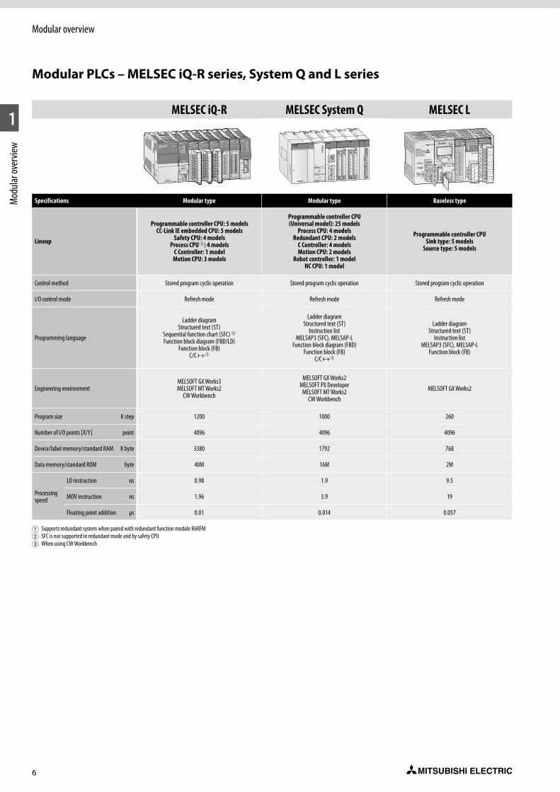
Specifications Modular type Modular type Baseless type
Lineup
Programmable controller CPU: 5 modelsCC-Link IE embedded CPU: 5 models
Safety CPU: 4 modelsProcess CPU 1: 4 models
C Controller: 1 modelMotion CPU: 3 models
Programmable controller CPU(Universal model): 25 models
Process CPU: 4 modelsRedundant CPU: 2 models
C Controller: 4 modelsMotion CPU: 2 models
Robot controller: 1 modelNC CPU: 1 model
Programmable controller CPUSink type: 5 models
Source type: 5 models
Control method Stored program cyclic operation Stored program cyclic operation Stored program cyclic operation
I/O control mode Refresh mode Refresh mode Refresh mode
Programming language
Ladder diagramStructured text (ST)
Sequential function chart (SFC) 2Function block diagram (FBD/LD)
Function block (FB)C/C++3
Ladder diagramStructured text (ST)
Instruction listMELSAP3 (SFC), MELSAP-L
Function block diagram (FBD)Function block (FB)
C/C++3
Ladder diagramStructured text (ST)
Instruction listMELSAP3 (SFC), MELSAP-L
Function block (FB)
Engineering environmentMELSOFT GX Works3MELSOFT MT Works2
CW Workbench
MELSOFT GX Works2MELSOFT PX Developer
MELSOFT MT Works2CW Workbench
MELSOFT GX Works2
Program size K step 1200 1000 260
Number of I/O points [X/Y] point 4096 4096 4096
Device/label memory/standard RAM K byte 3380 1792 768
Data memory/standard ROM byte 40M 16M 2M
Processing speed
LD instruction ns 0.98 1.9 9.5
MOV instruction ns 1.96 3.9 19
Floating point addition μs 0.01 0.014 0.057
1 Supports redundant system when paired with redundant function module R6RFM2 SFC is not supported in redundant mode and by safety CPU3 When using CW Workbench
Modular PLCs – MELSEC iQ-R series, System Q and L series
7
Modular overview
1
Mod
ular o
verv
iew
MELSEC iQ-R series
The iQ Platform builds on the power of Mitsubishi Electric’s high performance program-mable automation controllers (PAC), comple-menting this with a broad range of control modules and network interfaces.
The iQ-R series CPU offers dramatic improve-ments in performance, setting new bench-mark standards for processing speed. At the same time, the iQ-R series offers reductions in development cost, maintenance cost and risk of system failure, while providing an innovative upgrade path that will enable users to take advantage of ongoing developments through software upgrades rather than hardware upgrades.
Mounting of multiple CPUs on an iQ-R series backplane is supported, enabling users to develop vastly more complex and sophisticated automation applications from a single PAC backplane.
z Productivity – Improve productivity through advanced performance/functionality
z Scalability – offers Multi CPU solutions on a single backplane
z Connectivity – Seamless connectivity within all levels of manufacturing
z Flexibility – solutions can combine 4 CPU types as a seamless solution; PLC, Motion, Robots, NC, PC and Process CPUs
z Engineering – Reducing development costs through intuitive engineering
z Compatibility – Compatible with most exist-ing MELSEC System Q I/O
z Security – Unauthorized access protection across distributed control network
z Maintenance – Reduce maintenance costs and downtime utilizing easier maintenance features
MELSEC System Q
MELSEC System Q has been designed to be at the heart of your manufacturing process, as it is at the heart of Mitsubishi Electric‘s compo-nent automation concept. It offers you total integration of your control and communication needs from a single platform – connecting your automation with your business needs.
z Communication – is a communication hub connecting to fieldbus or data networks including 100 Mbps Ethernet
z Scalability – offers Multi CPU solutions on a single backplane
z Flexibility – solutions can combine 4 CPU types as a seamless solution; PLC, Motion, Robots, NC, PC and Process CPUs
z MES and web server module for quick and simple connectivity to the IT world
z Redundancy options ranging from full redun-dant PLC hardware to redundant network options improve uptime and productivity
MELSEC L series
The MELSEC L series is a powerful but compact modular controller with many features built-in to the CPU itself. The rack-free design promotes high system flexibility with minimum form factor. Built-in Mini-B USB and Ethernet allow for easy communication, along with a built-in SD/SDHC memory slot for data logging and mem-ory storage, and built-in digital I/O for simple high-speed counting and positioning functions.
The high-performance version CPU also includes a built-in CC-Link interface for Master/Local Sta-tion networking. This highly flexible architecture makes the MELSEC L series ideal for both stand-alone and networked machines.
z Rack-free design
z CPUs packed with comprehensive built-in features/functions
z Integrated data logging
z Built-in I/O features
z Communication and networking capabilities
z High-end 16-axis motion expansion possible using SSCNETIII/H

8
Modular overview
1
Mod
ular o
verv
iew
Modular controllers like Mitsubishi Electric’s MELSEC iQ-R series, System Q and the L series are high-performance PLC systems with broad functionality. The range, power and function of these high-end PLCs is impressive, with opera-tion times measured in nanoseconds.
The modular design allows flexible usage in a broad range of applications. Additional back-planes can be added as the system expands.
Modular PLCs comprise a power supply, one or more CPU modules and I/O and/or special func-tion modules.
Use of digital and special function modules
The use of digital and analog modules and most special function modules is dependent only on the maximum available number of addresses and thus on the CPU used in each case.
The following modules are available for assem-bling the system:
Pulse catch and interrupt modules
Digital input modules for pulse storage and for processing subroutines.
Digital input/output modules
For various signal levels with transistor, relay or triac switches.
Analog input/output modules
For processing current/voltage signals and for temperature value acquisition as well as temperature control with direct connection of Pt100 resistance thermometers or thermocouples. A HART enabled module for current input is also available for the MELSEC System Q.
Positioning modules
High-speed counter modules with possi-bility for connection of incremental shaft encoder or multiaxial positioning modules for servo and step drives with up to 8 axes per module.
Communications modules
Interface modules with RS232/RS422/ RS485 interface for connection of peripherals or for PLC-PLC communi cation.
Network modules
For interfacing with Ethernet, CC-Link, CC-Link IE, Profibus DP/Profinet, Modbus®/ TCP/RTU, DeviceNet™, AS-Interface and MELSEC networks.
QJ71BR11
QJ71BR11
RUN
STATION NO.X10
X1
MODE
MNG
T.PASS D.LINK
SD RD
ERR. L ERR.
0123456789
Q64ADRUN
ERROR
A/D0~±10V0~20mA
CH1
CH2
CH3
CH4
I+
V+
I+
V+
I+
V+
I+
V-
SLD
V-
SLD
V-
SLD
V-
SLD
A.G.
(FG)
V+
1
3
5
7
9
B
D
F
2
4
6
8
A
C
E
12VDC24VDC0.5A
L
L
L
L
L
L
L
L
L
L
L
L
L
L
L
L
COM
QY80
FUSE
0123456789
0 1 2 3 4 5 6 7
8 9 A B C D E F
0123456789
1
3
5
7
9
B
D
F
2
4
6
8
A
C
E
NC
24VDC4mA
COM
QX800 1 2 3 4 5 6 78 9 A B C D E F
0123456789
1
3
5
7
9
B
D
F
2
4
6
8
A
C
E
NC
24VDC4mA
COM
QX800 1 2 3 4 5 6 78 9 A B C D E F
Q06HCPU
RS-232
USB
PULL
MODERUNERR.
USERBAT.
BOOT
Q61P-A2
PULL
MITSUBISHI
POWER
BASE UNITMODEL Q38B
SERIAL 0205020E
BASE UNITMODEL Q38BSERIAL 0205020E0100017-A
POWER CPU I / 00 Q38B(N)I / 07I / 06 I / 05I / 04I / 03
E.S.DI / 02I / 01
P1L ER
LINK
P1L ER
LINK
0
1
2
3
4
5
6
7
8
9
A
B
C
D
E
F
0
1
2
3
4
5
6
7
8
9
A
B
C
D
E
F
0
1
2
3
4
5
6
7
8
9
A
B
C
D
E
F
POWER
R61P
INPUTV1+ I1+ V2+ I2+ VI-
ANALOG
OUTPUT
V+ I+ VI-
X17X16
X21X20
X23X22
X25X24
X27X26
ANALOG
100M
SD/RD
ERR
OPEN
10BASE-T/100BASE-TX
0 1 2 3 4 5 6 7
10 11 12 13 14 15 16 17
0 1 2 3 4 5 6 7
10 11 12 13 14 15 16 17
20 21 22 23 24 25 26 27
X11 X13 Y15 Y17 LOTY12 Y145
Y16
The MELSEC PLC family
MELSEC System Q
MELSEC FX3 series
MELSEC L series
Equipment features
MELSEC iQ-F FX5 series
MELSEC iQ-R series
Modular PLCs
Compact PLCs
MELSEC System Qredundancy/process

9
Modular overview
1
Mod
ular o
verv
iew
Mitsubishi Electric provides all aspects of control on a consolidated automation platform.
With the iQ Platform, which includes the MELSEC iQ-R series and System Q, we provide an extensive array of controller types. This platform not only has sequence controllers, but also
other various controllers specific to an industry or application area. These are, process control-ler, C language, embedded industrial PC, CNC controller, robot controller and HMI.
Together with the abundant I/O that is available for this series, the iQ Platform solution can be
applied to almost any kind of application scope, with productivity kept optimum and reduced TCO being key.
This is a true solution for automation, this is iQ Platform.
iQ Platform
BASE UNITMODEL Q38BSERIAL 0205020E0100017-A
POWER CPU I / 00 Q38B(N)I / 07I / 06 I / 05I / 04I / 03
E.S.DI / 02I / 01
P1L ER
LINK
P1L ER
LINK
0
1
2
3
4
5
6
7
8
9
A
B
C
D
E
F
0
1
2
3
4
5
6
7
8
9
A
B
C
D
E
F
0
1
2
3
4
5
6
7
8
9
A
B
C
D
E
F
POWER
R61P
R120SFCPU
PLC control
Motion control
Process control
C Controller
High-speed motion
Monitor and control
Common engineering platform
Automotive
Material handling
Semiconductor
Plant
CC-Link
Safety control
10
1
Mod
ular o
verv
iewSpecial functions
Safety þ iQ-R series ¨ System Q ¨ L seriesSystem design flexibility with integrated safety control
Ensuring the safety of personnel on the factory floor is a fundamental requirement of manufacturing plants and requires stringent safety regulations. To adhere to this safety code for control systems, the MELSEC iQ-R series is equipped with a safety CPU that is compliant with international safety standards, enabling safety devices to be connected via the CC-Link IE Field network. The entire system can be programmed using GX Works3 programming software as standard.
z Integrated generic and safety control
z Consolidated network topology
z Compliant with international safety standards
Integrated safety control offering a total system solution
MELSEC iQ-R – advanced built-in functions
Example of cutting and folding application
Enabling switch
Emergency stop switch
Light curtain
Door switch
Switch Indicator light
Safety remote I/O
Generic remote I/O
MELSEC iQ-R series (Safety CPU)
Productivity þ iQ-R series ¨ System Q ¨ L seriesHigh-available process control in a scalable automa-tion solution
Integrating high-performance capabilities based on the high-end iQ-R system bus, high-speed network, and an advanced motion control system; applications requiring these characteristics can be easily realized using the MELSEC iQ-R series as the core of the automation system.
CC-Link IE Field provides deterministic performance over Industrial Ethernet ensuring synchronization between nodes.
z High-speed system bus realizes improved production cycle
z Super-high-accuracy motion control utilizing advanced multiple CPU features
z Inter-modular synchronization resulting in increased processing accuracy
Printing quality sensor
Positioning moduleHigh-speed counter moduleHigh-speed counter moduleInput module
CC-Link IE Field network module
Output moduleCC-Link IE Field network module
Reject mechanism
Cutting/foldingCrank folder
Feeder
Folder
Cutter
Paper feed PrintingDrying/cooling
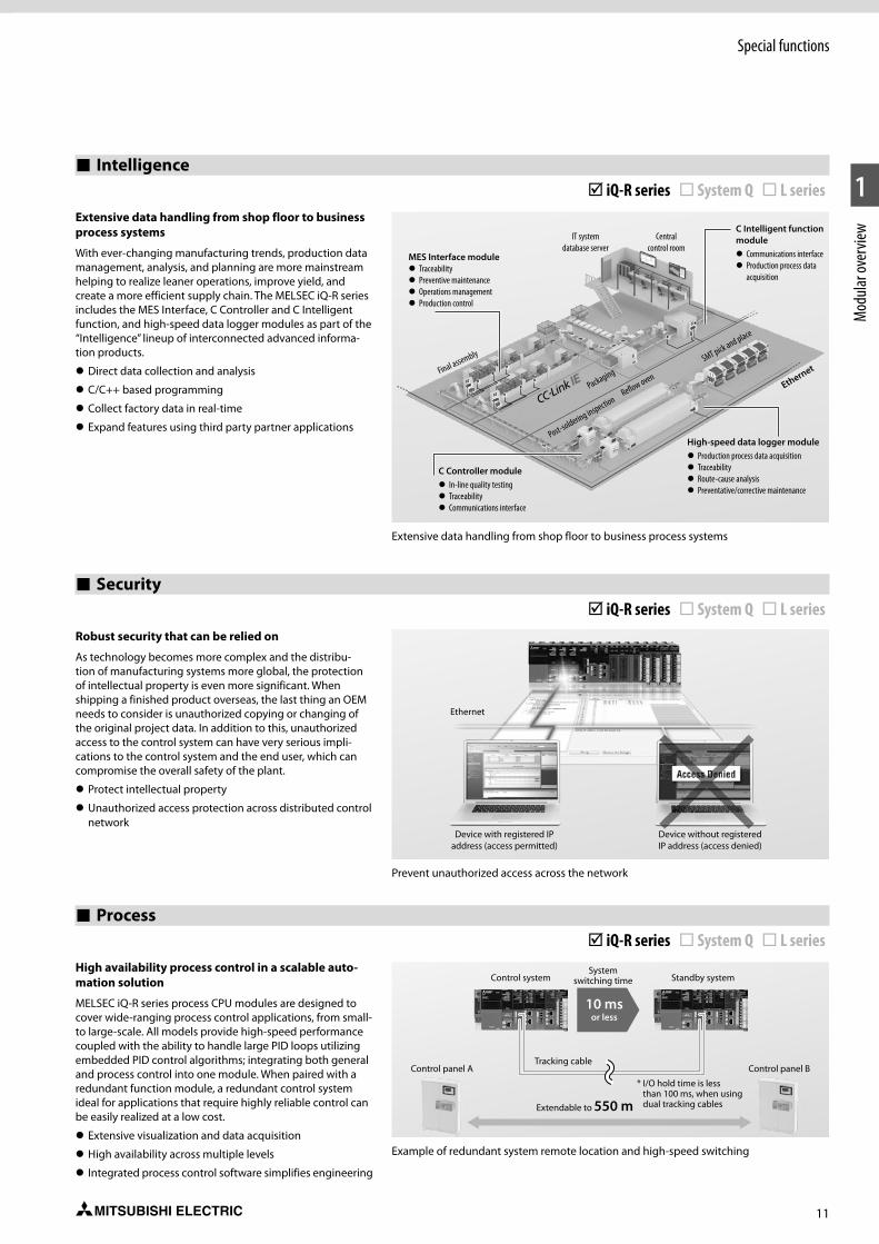
11
Special functions
1
Mod
ular o
verv
iew
Intelligence þ iQ-R series ¨ System Q ¨ L seriesExtensive data handling from shop floor to business process systems
With ever-changing manufacturing trends, production data management, analysis, and planning are more mainstream helping to realize leaner operations, improve yield, and create a more efficient supply chain. The MELSEC iQ-R series includes the MES Interface, C Controller and C Intelligent function, and high-speed data logger modules as part of the “Intelligence” lineup of interconnected advanced informa-tion products.
z Direct data collection and analysis
z C/C++ based programming
z Collect factory data in real-time
z Expand features using third party partner applications
Extensive data handling from shop floor to business process systems
MES Interface module z Traceability z Preventive maintenance z Operations management z Production control
Final assembly
C Controller module z In-line quality testing z Traceability z Communications interface
Post-soldering inspectionReflow oven
Packaging
IT system database server
Central control room
SMT pick and place
Ethernet
High-speed data logger module z Production process data acquisition z Traceability z Route-cause analysis z Preventative/corrective maintenance
C Intelligent function module
z Communications interface z Production process data
acquisition
Security þ iQ-R series ¨ System Q ¨ L seriesRobust security that can be relied on
As technology becomes more complex and the distribu-tion of manufacturing systems more global, the protection of intellectual property is even more significant. When shipping a finished product overseas, the last thing an OEM needs to consider is unauthorized copying or changing of the original project data. In addition to this, unauthorized access to the control system can have very serious impli-cations to the control system and the end user, which can compromise the overall safety of the plant.
z Protect intellectual property
z Unauthorized access protection across distributed control network
Prevent unauthorized access across the network
Ethernet
Device with registered IP address (access permitted)
Device without registered IP address (access denied)
Process þ iQ-R series ¨ System Q ¨ L seriesHigh availability process control in a scalable auto-mation solution
MELSEC iQ-R series process CPU modules are designed to cover wide-ranging process control applications, from small- to large-scale. All models provide high-speed performance coupled with the ability to handle large PID loops utilizing embedded PID control algorithms; integrating both general and process control into one module. When paired with a redundant function module, a redundant control system ideal for applications that require highly reliable control can be easily realized at a low cost.
z Extensive visualization and data acquisition
z High availability across multiple levels
z Integrated process control software simplifies engineering
Example of redundant system remote location and high-speed switching
Control panel A Control panel B
Control system Standby systemSystem
switching time
* I/O hold time is less than 100 ms, when using dual tracking cables
Tracking cable
10 msor less
Extendable to 550 m
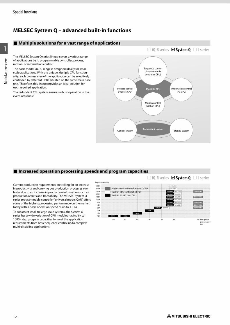
12
Special functions
1
Mod
ular o
verv
iew
Multiple soIutions for a vast range of applications ¨ iQ-R series þ System Q ¨ L seriesThe MELSEC System Q series lineup covers a various range of applications be it, programmable controller, process, motion, or information control.
The basic model QCPU range is designed ideally for small scale applications. With the unique Multiple CPU function-ality, each process area of the application can be selectively controlled by different CPUs situated on the same main base unit. Therefore, this lineup provides an ideal solution for each required application.
The redundant CPU system ensures robust operation in the event of trouble.
Increased operation processing speeds and program capacities ¨ iQ-R series þ System Q ¨ L seriesCurrent production requirements are calling for an increase in productivity and carrying out production processes even faster due to an increase in production information such as production results and traceability. The MELSEC System Q series programmable controller “universal model QnU” offers some of the highest processing performance on the market today with a basic operation speed of up to 1.9 ns.
To construct small to large scale systems, the System Q series has a wide variation of CPU modules having 8k to 1000k step program capacities to meet the application requirements from basic sequence control up to complex multi-discipline applications.
10K
15K
30K
40K
60K
100K
130K
20K
200K
260K
500K
1000K
40 20 9.580 60120 1.9
Q00UJ Q00U
Q01U
Q02U
Q03UD Q03UDE
Q04UDVCPU
Q06UDVCPU
Q03UDVCPU
Q13UDVCPU
Q26UDVCPU
Q04UDH
Q06UDH
Q10UDH
Q13UDH
Q04UDEH
Q06UDEH
Q10UDEH
Q13UDEH
Q20UDH Q20UDEH
Q26UDH Q26UDEH
Q100UDEH
Q50UDEH
MELSEC System Q – advanced built-in functions
Sequence control(Programmablecontroller CPU)
Process control(Process CPU)
Information control(PC CPU)
Motion control(Motion CPU)
Control system Standy systemRedundant system
Multiple CPU
High-speed universal model QCPUBuilt-in Ethernet port QCPUBuilt-in RS232 port CPU
Basic operation processing speed (ns)
Program capacity (step)

13
Special functions
1
Mod
ular o
verv
iew
Multiple CPU system configuration ¨ iQ-R series þ System Q ¨ L seriesThe System Q series can combine multiple CPUs together on the same system to build the required application configuration. Control of I/O modules can be segmented between different CPUs. CPUs communicate with each other via shared memory, and can increase system performance by distributing tasks between different CPUs. A variety of methods exist for controlling the methods by which CPUs communicate, but in each case the development effort is simplified by available software tools.
* The redundant CPU does not support the multiple CPU.
Integration of Process CPU, Motion CPU and PC CPU ¨ iQ-R series þ System Q ¨ L seriesThe System Q series multiple CPU system function allows programmable controller CPU, process, motion, and per-sonal computer CPUs to be mounted together, enabling utilization of their respective strong points and design of an optimal system.
Note: Only the following combinations can be used with the basic model. Basic model CPU + Motion CPU Basic model CPU + PC CPU Basic model CPU + Motion CPU + PC CPU
* SSCNET is a high-speed serial communication network that links motion CPUs and servo amplifiers with less wiring. SSCNET & SSCNETII are metal cable types, and SSCNETIII is a fiber optic cable type
Q25HCPU QX41
MODE
RUN
ERR
USER
BAT
BOOT
QY42 QY42Q12HCPU
MODE
RUN
ERR
USER
BAT
BOOT
Q12HCPU
MODE
RUN
ERR
USER
BAT
BOOT
QY42QY42 QX41
Q25HCPU QX41
MODE
RUN
ERR
USER
BAT
BOOT
QY42 QJ71LP21
Q12HCPU QX41
MODE
RUN
ERR
USER
BAT
BOOT
QJ71LP21
Q12HCPU
USBUSB
QY42
MODE
RUN
ERR
USER
BAT
BOOT
RS-232PULL
QY42
1
2 31 4 5 6
3
2
4
65QJ71LP21
USB
PULL
RS-232
USB
PULL
RS-232
USB
PULL
RS-232
USB
PULL
RS-232
USB
PULL
RS-232
PULL
QY42
PULL
Q61P-A1 POWER
PULL
POWERQ61P-A1
PULL
POWERQ61P-A1
PULL
POWERQ61P-A1
QX41Q25PHCPU
MODERUNERR
USERBAT
BOOT
USBUSB
PULL
RS-232
PPC-CPU686CONTEC
0123456789ABCDEF
Q62AD-GH
0123456789ABCDEF
Q62AD-FG
SERVO SYSTEM CONTROLLER NETWORK
MODERUNERR
USERBAT
BOOT
USBUSB
PULL
CN2
CN1BAT
PC
FRONTSSCNET
Q25PHCPU
MITSUBISHI MITSUBISHI
PULL
POWERQ61P-A1
Up to 4 CPUs can be installed. Modules are managed CPU-by-CPU. Use standard System Q series I/O and intelligent function modules (there are restrictions on the number and versions).
ManagementManagement
Management
Servo amplifier
Servo motor
Host device
Ethernet
I/O control
Loop control/analog processing
Sequence controlProcess control
Motion controlInformation control
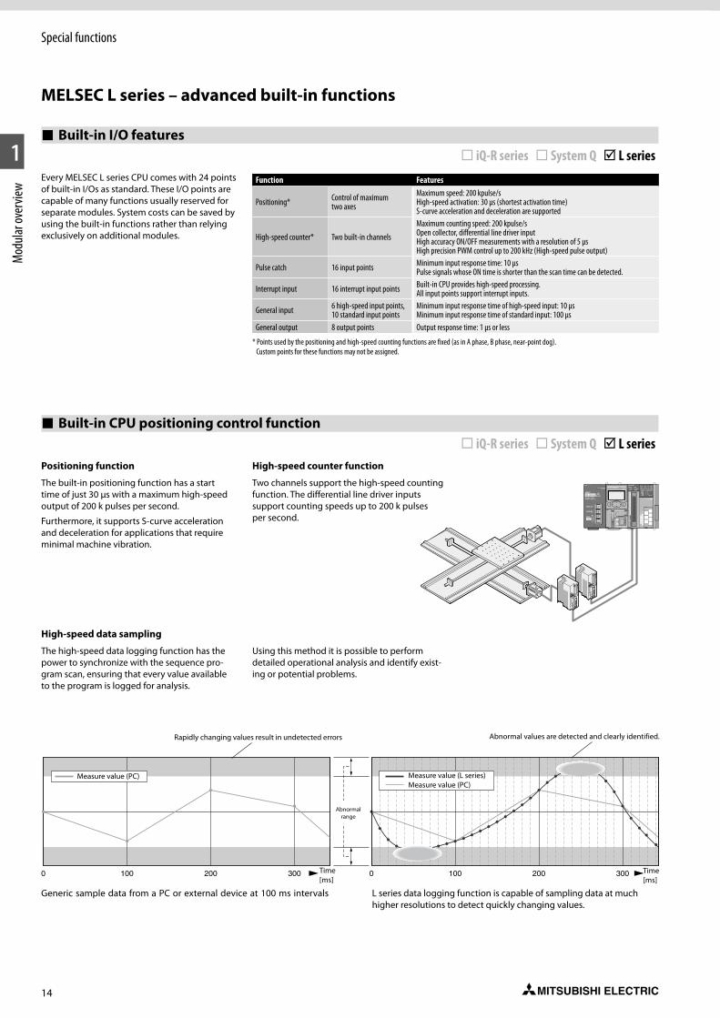
14
Special functions
1
Mod
ular o
verv
iew
0 100 200 3000 100 200 300
Every MELSEC L series CPU comes with 24 points of built-in I/Os as standard. These I/O points are capable of many functions usually reserved for separate modules. System costs can be saved by using the built-in functions rather than relying exclusively on additional modules.
Function Features
Positioning* Control of maximum two axes
Maximum speed: 200 kpulse/s High-speed activation: 30 µs (shortest activation time) S-curve acceleration and deceleration are supported
High-speed counter* Two built-in channels
Maximum counting speed: 200 kpulse/s Open collector, differential line driver input High accuracy ON/OFF measurements with a resolution of 5 µs High precision PWM control up to 200 kHz (High-speed pulse output)
Pulse catch 16 input points Minimum input response time: 10 µs Pulse signals whose ON time is shorter than the scan time can be detected.
Interrupt input 16 interrupt input points Built-in CPU provides high-speed processing. All input points support interrupt inputs.
General input 6 high-speed input points, 10 standard input points
Minimum input response time of high-speed input: 10 µs Minimum input response time of standard input: 100 µs
General output 8 output points Output response time: 1 µs or less
* Points used by the positioning and high-speed counting functions are fixed (as in A phase, B phase, near-point dog). Custom points for these functions may not be assigned.
High-speed data sampling
The high-speed data logging function has the power to synchronize with the sequence pro-gram scan, ensuring that every value available to the program is logged for analysis.
Using this method it is possible to perform detailed operational analysis and identify exist-ing or potential problems.
Positioning function
The built-in positioning function has a start time of just 30 μs with a maximum high-speed output of 200 k pulses per second.
Furthermore, it supports S-curve acceleration and deceleration for applications that require minimal machine vibration.
High-speed counter function
Two channels support the high-speed counting function. The differential line driver inputs support counting speeds up to 200 k pulses per second.
L series data logging function is capable of sampling data at much higher resolutions to detect quickly changing values.
Generic sample data from a PC or external device at 100 ms intervals
Measure value (PC) Measure value (L series) Measure value (PC)
Abnormal range
Rapidly changing values result in undetected errors Abnormal values are detected and clearly identified.
Time [ms]
Time [ms]
MELSEC L series – advanced built-in functions
Built-in I/O features ¨ iQ-R series ¨ System Q þ L series
Built-in CPU positioning control function ¨ iQ-R series ¨ System Q þ L series
15
Special functions
1
Mod
ular o
verv
iew
Make highly accurate measurements with a resolution of 5 μs
Using pulse measurement mode, where the input signal ON/OFF time is 200 μs or greater, highly accurate measurements in units of 5μs or greater are possible. For example it is possible to calculate length by knowing the “work object passing speed” and measur-ing the ON time of the sensor.
OFFat work passing end
ONat work passing start
Work objectSensor (Pulse generator)
Sensor on time (the time it takes
for the work object to pass)
High-speed counter
A: Work passing start B: Work passing end
The ON time of the input signal (minimum of 200 μs) can be measured precisely to a resolution of 5 μs.
B (OFF)A (ON)
High precision PWM control up to 200 kHz
Using the pulse width modulation control function of the high-speed outputs, cycle times as fast as 5 μs can be created. Simply input the ON time and cycle time to drive a wide range of devices from lighting dimmer control, motors, and heaters to precision inspection equipment requiring high resolution performance.
Setting Range DescriptionPWM output ON time* 0 or 10 to 10000000 * [0.1 µs] Set the ON time of output pulsePWM output cycle time* 50 to 1000000 * [0.1 µs] Set the cycle time of output pulse
* The PWM output ON time must be ≤ the PWM output cycle time.
Lighting dimmer control using PWM output
** In cases where the first six digits of the serial number are “120722” or later. Previous serial numbers of the CPU module are applied to 100 mA.
Overhead lighting dimmer control, maximum load 250 mA **
PWM output ON time
PWM output cycle time
Duty CycleON timeCycle time
Guaranteed input pulse detection
Typical PLC input devices are unable to detect pulse signals whose ON time is shorter than the scan time or do not occur during I/O refresh peri-ods. The pulse catch function allows these signals to be reliably detected and passed to the sequence program. This function is different from the interrupt input function in that it does not require any special program-ming. Pulse catch inputs may be used in programs exactly the same as traditional input (X) signals.
Program Scan
Sequence program
I/O Refresh Time
Rising edge detection
Input signal
Pulse catch input
ON for 1 scan
Input detection is assured
Data logging function
The built-in data logging function provides an easy way to collect infor-mation for troubleshooting, performance evaluation, and other uses. The included configuration tool makes setting up the data logging function a breeze with a step-by-step wizard like interface. Using GX LogViewer, the captured data is easy to interpret and understand.
Configuration tool
Select the logging type.Make the desired settings on each screen and click the Next button until all settings are complete.
16
1
2
MEL
SEC i
Q-R s
eries
System description
To succeed in highly competitive markets, it’s important to build automation systems that ensure high productivity and consistent product quality. The MELSEC iQ-R series has been devel-oped from the ground up based on common problems faced by customers and rationaliz-ing them into seven key areas: productivity, engineering, maintenance, quality, connectivity, security and compatibility. Mitsubishi Electric is taking a three-point approach to solving these problems: Reducing TCO 1 , increasing reliability and reuse of existing assets.
As a bridge to the next generation in automa-tion, the MELSEC iQ-R series is a driving force behind revolutionary progress in the future of manufacturing.
1 Total Cost of Ownership
z System design flexibility with integrated safety control
z Improve productivity through advanced performance/ functionality
z Reducing development costs through intui-tive engineering
z Reduce maintenance costs and downtime utilizing easier maintenance features
z Reliable and trusted MELSEC product quality
z Extensive data handling from shop floor to business process systems
z Seamless network reduces system costs
z Robust security that can be relied on
z Extensive compatibility with existing products
Revolutionary, next-generation controllers building a new era in automation
POWER
R61P
0
1
2
3
4
5
6
7
8
9
A
B
C
D
E
F
P1L ER
LINK
P1L ER
LINK
System structure
The CPU and modules are connected to a base unit which has an internal bus connection for high-speed communication between the indi-vidual modules and the CPUs. A power supply module which supplies the voltage for the entire modules is also installed on this base unit.
The base units are available in different versions with 5 to 12 module slots.
Each base unit can be supplemented by means of an extension unit providing additional slots. Up to seven extension base units can be connected and a maximum of 64 modules installed at any one time. An RQ extension base unit is also available, ensuring compatibility with existing MELSEC System Q modules.
For cabling larger systems and machines – e. g. in a modular design – the use of remote I/O modules offers additional communications facilities
What a system looks like
Power supply module
CPU module Digital I/O moduleSpecial function
module Network module
Base unit
Terminal block also available with spring clamps
Interface for extension base unit (under the transparent cover)
SD memory card
Backup battery (slot on the lower side)
Ethernet interface
USB interface
MELSEC iQ-R series
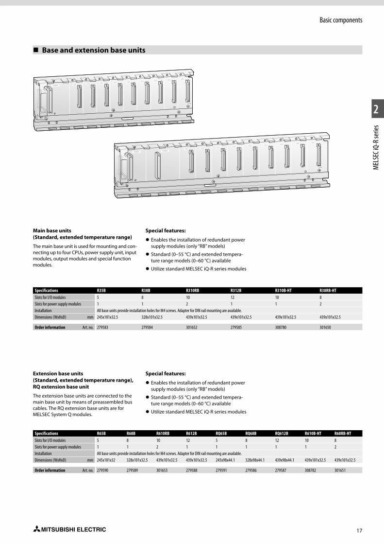
17
1
2
MEL
SEC i
Q-R s
eries
Basic components
Base and extension base units
Specifications R65B R68B R610RB R612B RQ65B RQ68B RQ612B R610B-HT R68RB-HTSlots for I/O modules 5 8 10 12 5 8 12 10 8Slots for power supply modules 1 1 2 1 1 1 1 1 2Installation All base units provide installation holes for M4 screws. Adapter for DIN rail mounting are available.Dimensions (WxHxD) mm 245x101x32 328x101x32.5 439x101x32.5 439x101x32.5 245x98x44.1 328x98x44.1 439x98x44.1 439x101x32.5 439x101x32.5
Order information Art. no. 279590 279589 301653 279588 279591 279586 279587 308782 301651
Main base units (Standard, extended temperature range)
The main base unit is used for mounting and con-necting up to four CPUs, power supply unit, input modules, output modules and special function modules.
Special features:
z Enables the installation of redundant power supply modules (only “RB” models)
z Standard (0–55 °C) and extended tempera-ture range models (0–60 °C) available
z Utilize standard MELSEC iQ-R series modules
Specifications R35B R38B R310RB R312B R310B-HT R38RB-HTSlots for I/O modules 5 8 10 12 10 8Slots for power supply modules 1 1 2 1 1 2Installation All base units provide installation holes for M4 screws. Adapter for DIN rail mounting are available.Dimensions (WxHxD) mm 245x101x32.5 328x101x32.5 439x101x32.5 439x101x32.5 439x101x32.5 439x101x32.5
Order information Art. no. 279583 279584 301652 279585 308780 301650
Extension base units (Standard, extended temperature range), RQ extension base unit
The extension base units are connected to the main base unit by means of preassembled bus cables. The RQ extension base units are for MELSEC System Q modules.
Special features:
z Enables the installation of redundant power supply modules (only “RB” models)
z Standard (0–55 °C) and extended tempera-ture range models (0–60 °C) available
z Utilize standard MELSEC iQ-R series modules
POWERI/O 0 I/O 1 I/O 2 I/O 3 I/O 4 I/O 5 I/O 6 I/O 7
R3BB
CPU
POWER POWERI/O 0 I/O 1 I/O 2 I/O 3 I/O 4 I/O 5 I/O 6 I/O 7
R3BB
CPU
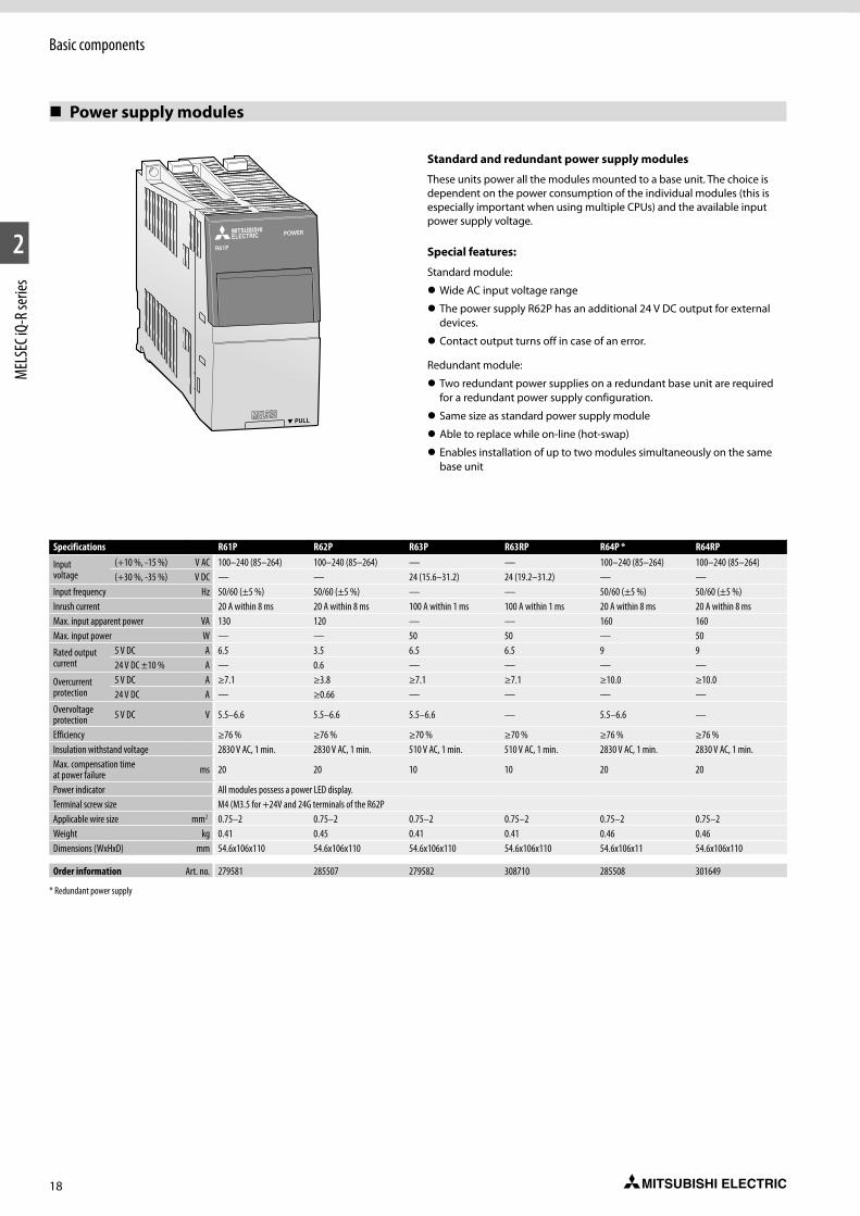
18
1
2
MEL
SEC i
Q-R s
eries
Basic components
Standard and redundant power supply modules
These units power all the modules mounted to a base unit. The choice is dependent on the power consumption of the individual modules (this is especially important when using multiple CPUs) and the available input power supply voltage.
Special features:
Standard module:
z Wide AC input voltage range
z The power supply R62P has an additional 24 V DC output for external devices.
z Contact output turns off in case of an error.
Redundant module:
z Two redundant power supplies on a redundant base unit are required for a redundant power supply configuration.
z Same size as standard power supply module
z Able to replace while on-line (hot-swap)
z Enables installation of up to two modules simultaneously on the same base unit
Power supply modules
POWER
R61P
Specifications R61P R62P R63P R63RP R64P * R64RP
Input voltage
(+10 %, -15 %) V AC 100–240 (85–264) 100–240 (85–264) — — 100–240 (85–264) 100–240 (85–264)(+30 %, -35 %) V DC — — 24 (15.6–31.2) 24 (19.2–31.2) — —
Input frequency Hz 50/60 (±5 %) 50/60 (±5 %) — — 50/60 (±5 %) 50/60 (±5 %)Inrush current 20 A within 8 ms 20 A within 8 ms 100 A within 1 ms 100 A within 1 ms 20 A within 8 ms 20 A within 8 msMax. input apparent power VA 130 120 — — 160 160Max. input power W — — 50 50 — 50
Rated output current
5 V DC A 6.5 3.5 6.5 6.5 9 924 V DC ±10 % A — 0.6 — — — —
Overcurrent protection
5 V DC A ≥7.1 ≥3.8 ≥7.1 ≥7.1 ≥10.0 ≥10.024 V DC A — ≥0.66 — — — —
Overvoltage protection 5 V DC V 5.5–6.6 5.5–6.6 5.5–6.6 — 5.5–6.6 —
Efficiency ≥76 % ≥76 % ≥70 % ≥70 % ≥76 % ≥76 %Insulation withstand voltage 2830 V AC, 1 min. 2830 V AC, 1 min. 510 V AC, 1 min. 510 V AC, 1 min. 2830 V AC, 1 min. 2830 V AC, 1 min.Max. compensation time at power failure ms 20 20 10 10 20 20
Power indicator All modules possess a power LED display.Terminal screw size M4 (M3.5 for +24V and 24G terminals of the R62PApplicable wire size mm2 0.75–2 0.75–2 0.75–2 0.75–2 0.75–2 0.75–2Weight kg 0.41 0.45 0.41 0.41 0.46 0.46Dimensions (WxHxD) mm 54.6x106x110 54.6x106x110 54.6x106x110 54.6x106x110 54.6x106x11 54.6x106x110
Order information Art. no. 279581 285507 279582 308710 285508 301649
* Redundant power supply
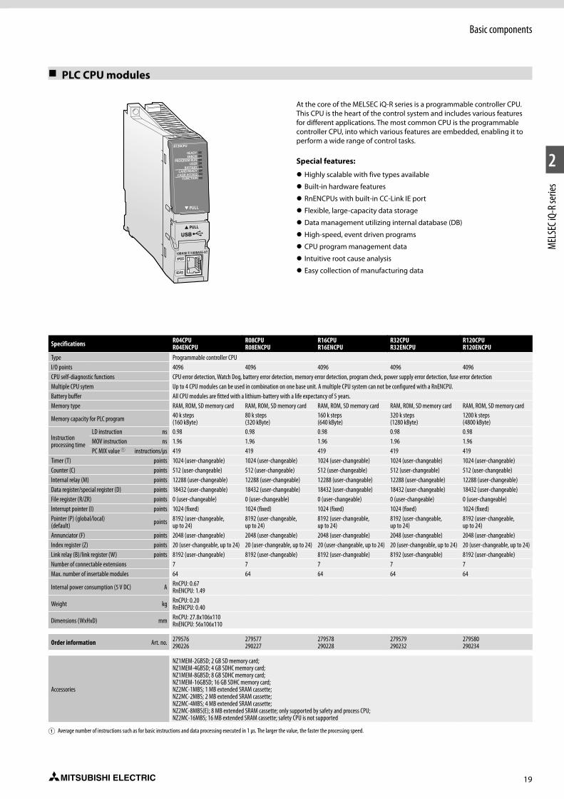
19
1
2
MEL
SEC i
Q-R s
eries
Basic components
PLC CPU modules
At the core of the MELSEC iQ-R series is a programmable controller CPU. This CPU is the heart of the control system and includes various features for different applications. The most common CPU is the programmable controller CPU, into which various features are embedded, enabling it to perform a wide range of control tasks.
Special features:
z Highly scalable with five types available
z Built-in hardware features
z RnENCPUs with built-in CC-Link IE port
z Flexible, large-capacity data storage
z Data management utilizing internal database (DB)
z High-speed, event driven programs
z CPU program management data
z Intuitive root cause analysis
z Easy collection of manufacturing data
Specifications R04CPUR04ENCPU
R08CPUR08ENCPU
R16CPUR16ENCPU
R32CPUR32ENCPU
R120CPUR120ENCPU
Type Programmable controller CPUI/O points 4096 4096 4096 4096 4096CPU self-diagnostic functions CPU error detection, Watch Dog, battery error detection, memory error detection, program check, power supply error detection, fuse error detectionMultiple CPU sytem Up to 4 CPU modules can be used in combination on one base unit. A multiple CPU system can not be configured with a RnENCPU.Battery buffer All CPU modules are fitted with a lithium-battery with a life expectancy of 5 years.Memory type RAM, ROM, SD memory card RAM, ROM, SD memory card RAM, ROM, SD memory card RAM, ROM, SD memory card RAM, ROM, SD memory card
Memory capacity for PLC program 40 k steps (160 kByte)
80 k steps (320 kByte)
160 k steps (640 kByte)
320 k steps (1280 kByte)
1200 k steps (4800 kByte)
Instruction processing time
LD instruction ns 0.98 0.98 0.98 0.98 0.98MOV instruction ns 1.96 1.96 1.96 1.96 1.96PC MIX value 1 instructions/μs 419 419 419 419 419
Timer (T) points 1024 (user-changeable) 1024 (user-changeable) 1024 (user-changeable) 1024 (user-changeable) 1024 (user-changeable)Counter (C) points 512 (user-changeable) 512 (user-changeable) 512 (user-changeable) 512 (user-changeable) 512 (user-changeable)Internal relay (M) points 12288 (user-changeable) 12288 (user-changeable) 12288 (user-changeable) 12288 (user-changeable) 12288 (user-changeable)Data register/special register (D) points 18432 (user-changeable) 18432 (user-changeable) 18432 (user-changeable) 18432 (user-changeable) 18432 (user-changeable)File register (R/ZR) points 0 (user-changeable) 0 (user-changeable) 0 (user-changeable) 0 (user-changeable) 0 (user-changeable)Interrupt pointer (I) points 1024 (fixed) 1024 (fixed) 1024 (fixed) 1024 (fixed) 1024 (fixed)Pointer (P) (global/local) (default) points 8192 (user-changeable,
up to 24)8192 (user-changeable, up to 24)
8192 (user-changeable, up to 24)
8192 (user-changeable, up to 24)
8192 (user-changeable, up to 24)
Annunciator (F) points 2048 (user-changeable) 2048 (user-changeable) 2048 (user-changeable) 2048 (user-changeable) 2048 (user-changeable)Index register (Z) points 20 (user-changeable, up to 24) 20 (user-changeable, up to 24) 20 (user-changeable, up to 24) 20 (user-changeable, up to 24) 20 (user-changeable, up to 24)Link relay (B)/link register (W) points 8192 (user-changeable) 8192 (user-changeable) 8192 (user-changeable) 8192 (user-changeable) 8192 (user-changeable)Number of connectable extensions 7 7 7 7 7Max. number of insertable modules 64 64 64 64 64
Internal power consumption (5 V DC) A RnCPU: 0.67RnENCPU: 1.49
Weight kg RnCPU: 0.20RnENCPU: 0.40
Dimensions (WxHxD) mm RnCPU: 27.8x106x110RnENCPU: 56x106x110
Order information Art. no. 279576290226
279577290227
279578290228
279579290232
279580290234
Accessories
NZ1MEM-2GBSD; 2 GB SD memory card; NZ1MEM-4GBSD; 4 GB SDHC memory card; NZ1MEM-8GBSD; 8 GB SDHC memory card; NZ1MEM-16GBSD; 16 GB SDHC memory card; NZ2MC-1MBS; 1 MB extended SRAM cassette; NZ2MC-2MBS; 2 MB extended SRAM cassette; NZ2MC-4MBS; 4 MB extended SRAM cassette; NZ2MC-8MBS(E); 8 MB extended SRAM cassette; only supported by safety and process CPU;NZ2MC-16MBS; 16 MB extended SRAM cassette; safety CPU is not supported
1 Average number of instructions such as for basic instructions and data processing executed in 1 μs. The larger the value, the faster the processing speed.
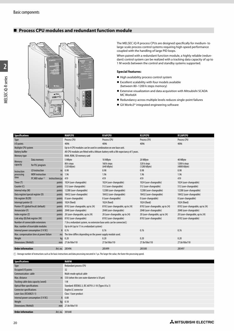
20
1
2
MEL
SEC i
Q-R s
eries
Basic components
The MELSEC iQ-R process CPUs are designed specifically for medium- to large-scale process control systems requiring high-speed performance coupled with the handling of large PID loops.
When paired with a redundant function module, a highly reliable (redun-dant) control system can be realized with a tracking data capacity of up to 1 M words between the control and standby systems supported.
Special features:
z High availability process control system
z Excellent scalability with four models available (between 80–1200 k steps memory)
z Extensive visualization and data acquisition with Mitsubishi SCADA MC Works64
z Redundancy across multiple levels reduces single-point failures
z GX Works3* integrated engineering software
Specifications R08PCPU R16PCPU R32PCPU R120PCPUType Process CPU Process CPU Process CPU Process CPUI/O points 4096 4096 4096 4096Multiple CPU system Up to 4 CPU modules can be used in combination on one base unit.Battery buffer All CPU modules are fitted with a lithium-battery with a life expectancy of 5 years.Memory type RAM, ROM, SD memory card
Memory capacity
Data memory 5 MByte 10 MByte 20 MByte 40 MByte
for PLC program 80 k steps (320 kByte)
160 k steps (640 kByte)
320 k steps (1280 kByte)
1200 k steps (4800 kByte)
Instruction processing time
LD instruction ns 0.98 0.98 0.98 0.98MOV instruction ns 1.96 1.96 1.96 1.96PC MIX value 1 instructions/μs 419 419 419 419
Timer (T) points 1024 (user-changeable) 1024 (user-changeable) 1024 (user-changeable) 1024 (user-changeable)Counter (C) points 512 (user-changeable) 512 (user-changeable) 512 (user-changeable) 512 (user-changeable)Internal relay (M) points 12288 (user-changeable) 12288 (user-changeable) 12288 (user-changeable) 12288 (user-changeable)Data register/special register (D) points 18432 (user-changeable) 18432 (user-changeable) 18432 (user-changeable) 18432 (user-changeable)File register (R/ZR) points 0 (user-changeable) 0 (user-changeable) 0 (user-changeable) 0 (user-changeable)Interrupt pointer (I) points 1024 (fixed) 1024 (fixed) 1024 (fixed) 1024 (fixed)Pointer (P) (global/local) (default) points 8192 (user-changeable, up to 24) 8192 (user-changeable, up to 24) 8192 (user-changeable, up to 24) 8192 (user-changeable, up to 24)Annunciator (F) points 2048 (user-changeable) 2048 (user-changeable) 2048 (user-changeable) 2048 (user-changeable)Index register (Z) points 20 (user-changeable, up to 24) 20 (user-changeable, up to 24) 20 (user-changeable, up to 24) 20 (user-changeable, up to 24)Link relay (B)/link register (W) points 8192 (user-changeable) 8192 (user-changeable) 8192 (user-changeable) 8192 (user-changeable)Number of connectable extensions 7 (In a redundant system, no extension base units can be connected.)Max. number of insertable modules Up to 64 (up to 11 in a redundant system)Internal power consumption (5 V DC) A 0.76 0.76 0.76 0.76Max. compensation time at power failure ms The time differs depending on the power supply module used.Weight kg 0.20 0.20 0.20 0.20Dimensions (WxHxD) mm 27.8x106x110 27.8x106x110 27.8x106x110 27.8x106x110
Order information Art. no. 285496 285499 285500 285497
1 Average number of instructions such as for basic instructions and data processing executed in 1 μs. The larger the value, the faster the processing speed.
Process CPU modules and redundant function module
Specifications R6RFMType Redundant process CPUOccupied I/O points 32Communication cable Multi-mode optical cableMax. distance m 550 (when the core outer diameter is 50 μm)Tracking cable data capacity (word) 1 MOptical fiber specifications Standard: IEEE802.3, IEC 60793-2-10 (Types A1a.1)Connector specifications Duplex LC connectorLaser class (IEC60825-1) Class 1 laser productInternal power consumption (5 V DC) A 0.88Weight kg 0.18Dimensions (WxHxD) mm 27.8x106x110
Order information Art. no. 301648
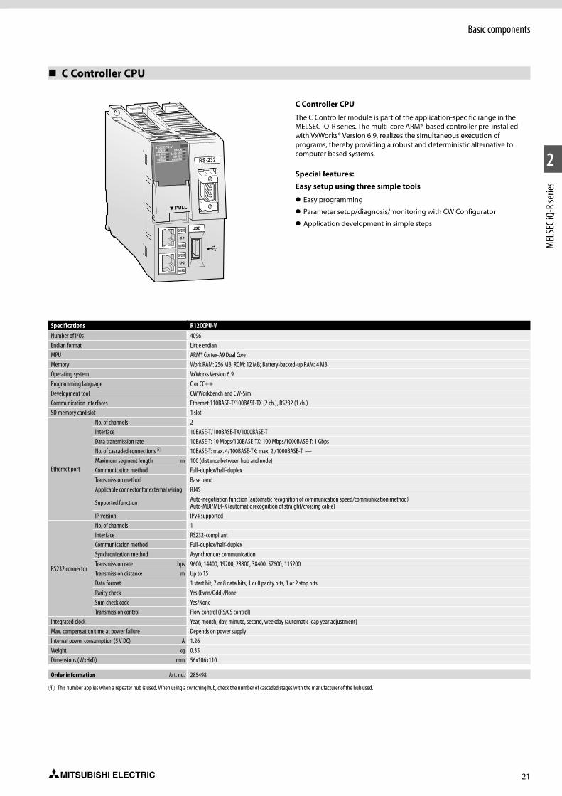
21
1
2
MEL
SEC i
Q-R s
eries
Basic components
C Controller CPU
Specifications R12CCPU-VNumber of I/Os 4096Endian format Little endianMPU ARM® Cortex-A9 Dual CoreMemory Work RAM: 256 MB; ROM: 12 MB; Battery-backed-up RAM: 4 MBOperating system VxWorks Version 6.9Programming language C or CC++Development tool CW Workbench and CW-SimCommunication interfaces Ethernet 110BASE-T/100BASE-TX (2 ch.), RS232 (1 ch.)SD memory card slot 1 slot
Ethernet port
No. of channels 2Interface 10BASE-T/100BASE-TX/1000BASE-TData transmission rate 10BASE-T: 10 Mbps/100BASE-TX: 100 Mbps/1000BASE-T: 1 GbpsNo. of cascaded connections 1 10BASE-T: max. 4/100BASE-TX: max. 2 /1000BASE-T: —Maximum segment length m 100 (distance between hub and node)Communication method Full-duplex/half-duplexTransmission method Base bandApplicable connector for external wiring RJ45
Supported function Auto-negotiation function (automatic recognition of communication speed/communication method)Auto-MDI/MDI-X (automatic recognition of straight/crossing cable)
IP version IPv4 supported
RS232 connector
No. of channels 1Interface RS232-compliantCommunication method Full-duplex/half-duplexSynchronization method Asynchronous communicationTransmission rate bps 9600, 14400, 19200, 28800, 38400, 57600, 115200Transmission distance m Up to 15Data format 1 start bit, 7 or 8 data bits, 1 or 0 parity bits, 1 or 2 stop bitsParity check Yes (Even/Odd)/NoneSum check code Yes/NoneTransmission control Flow control (RS/CS control)
Integrated clock Year, month, day, minute, second, weekday (automatic leap year adjustment)Max. compensation time at power failure Depends on power supplyInternal power consumption (5 V DC) A 1.26Weight kg 0.35Dimensions (WxHxD) mm 56x106x110
Order information Art. no. 285498
1 This number applies when a repeater hub is used. When using a switching hub, check the number of cascaded stages with the manufacturer of the hub used.
C Controller CPU
The C Controller module is part of the application-specific range in the MELSEC iQ-R series. The multi-core ARM®-based controller pre-installed with VxWorks® Version 6.9, realizes the simultaneous execution of programs, thereby providing a robust and deterministic alternative to computer based systems.
Special features:Easy setup using three simple tools
z Easy programming
z Parameter setup/diagnosis/monitoring with CW Configurator
z Application development in simple stepsSPEED
CH1
SD/RD
SPEED
CH2
SD/RD
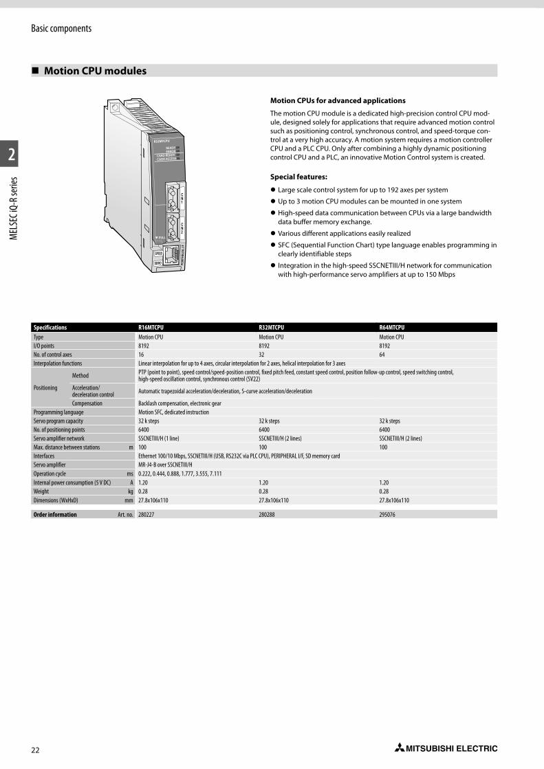
22
1
2
MEL
SEC i
Q-R s
eries
Basic components
Motion CPU modules
SPEED
CN1
CN2
SD/RD
Specifications R16MTCPU R32MTCPU R64MTCPUType Motion CPU Motion CPU Motion CPUI/O points 8192 8192 8192No. of control axes 16 32 64Interpolation functions Linear interpolation for up to 4 axes, circular interpolation for 2 axes, helical interpolation for 3 axes
Positioning
Method PTP (point to point), speed control/speed-position control, fixed pitch feed, constant speed control, position follow-up control, speed switching control, high-speed oscillation control, synchronous control (SV22)
Acceleration/ deceleration control Automatic trapezoidal acceleration/deceleration, S-curve acceleration/deceleration
Compensation Backlash compensation, electronic gearProgramming language Motion SFC, dedicated instructionServo program capacity 32 k steps 32 k steps 32 k stepsNo. of positioning points 6400 6400 6400Servo amplifier network SSCNETIII/H (1 line) SSCNETIII/H (2 lines) SSCNETIII/H (2 lines)Max. distance between stations m 100 100 100Interfaces Ethernet 100/10 Mbps, SSCNETIII/H (USB, RS232C via PLC CPU), PERIPHERAL I/F, SD memory cardServo amplifier MR-J4-B over SSCNETIII/HOperation cycle ms 0.222, 0.444, 0.888, 1.777, 3.555, 7.111Internal power consumption (5 V DC) A 1.20 1.20 1.20Weight kg 0.28 0.28 0.28Dimensions (WxHxD) mm 27.8x106x110 27.8x106x110 27.8x106x110
Order information Art. no. 280227 280288 295076
Motion CPUs for advanced applications
The motion CPU module is a dedicated high-precision control CPU mod-ule, designed solely for applications that require advanced motion control such as positioning control, synchronous control, and speed-torque con-trol at a very high accuracy. A motion system requires a motion controller CPU and a PLC CPU. Only after combining a highly dynamic positioning control CPU and a PLC, an innovative Motion Control system is created.
Special features:
z Large scale control system for up to 192 axes per system
z Up to 3 motion CPU modules can be mounted in one system
z High-speed data communication between CPUs via a large bandwidth data buffer memory exchange.
z Various different applications easily realized
z SFC (Sequential Function Chart) type language enables programming in clearly identifiable steps
z Integration in the high-speed SSCNETIII/H network for communication with high-performance servo amplifiers at up to 150 Mbps
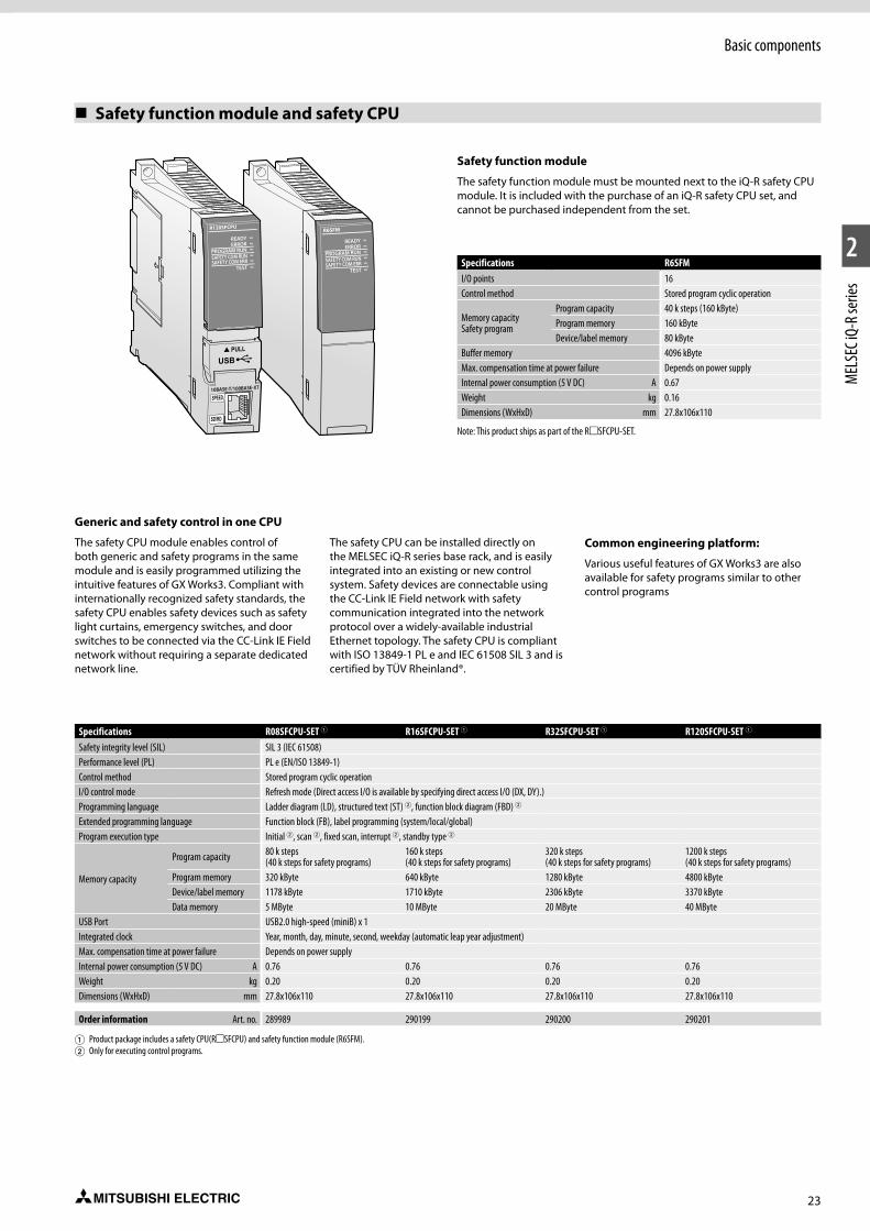
23
1
2
MEL
SEC i
Q-R s
eries
Basic components
Safety function module and safety CPU
Specifications R08SFCPU-SET 1 R16SFCPU-SET 1 R32SFCPU-SET 1 R120SFCPU-SET 1
Safety integrity level (SIL) SIL 3 (IEC 61508)Performance level (PL) PL e (EN/ISO 13849-1)Control method Stored program cyclic operationI/O control mode Refresh mode (Direct access I/O is available by specifying direct access I/O (DX, DY).)Programming language Ladder diagram (LD), structured text (ST) 2, function block diagram (FBD) 2
Extended programming language Function block (FB), label programming (system/local/global)Program execution type Initial 2, scan 2, fixed scan, interrupt 2, standby type 2
Memory capacity
Program capacity 80 k steps (40 k steps for safety programs)
160 k steps (40 k steps for safety programs)
320 k steps (40 k steps for safety programs)
1200 k steps (40 k steps for safety programs)
Program memory 320 kByte 640 kByte 1280 kByte 4800 kByteDevice/label memory 1178 kByte 1710 kByte 2306 kByte 3370 kByteData memory 5 MByte 10 MByte 20 MByte 40 MByte
USB Port USB2.0 high-speed (miniB) x 1Integrated clock Year, month, day, minute, second, weekday (automatic leap year adjustment)Max. compensation time at power failure Depends on power supplyInternal power consumption (5 V DC) A 0.76 0.76 0.76 0.76Weight kg 0.20 0.20 0.20 0.20Dimensions (WxHxD) mm 27.8x106x110 27.8x106x110 27.8x106x110 27.8x106x110
Order information Art. no. 289989 290199 290200 290201
1 Product package includes a safety CPU(RmSFCPU) and safety function module (R6SFM). 2 Only for executing control programs.
Generic and safety control in one CPU
The safety CPU module enables control of both generic and safety programs in the same module and is easily programmed utilizing the intuitive features of GX Works3. Compliant with internationally recognized safety standards, the safety CPU enables safety devices such as safety light curtains, emergency switches, and door switches to be connected via the CC-Link IE Field network without requiring a separate dedicated network line.
The safety CPU can be installed directly on the MELSEC iQ-R series base rack, and is easily integrated into an existing or new control system. Safety devices are connectable using the CC-Link IE Field network with safety communication integrated into the network protocol over a widely-available industrial Ethernet topology. The safety CPU is compliant with ISO 13849-1 PL e and IEC 61508 SIL 3 and is certified by TÜV Rheinland®.
Common engineering platform:
Various useful features of GX Works3 are also available for safety programs similar to other control programs
Safety function module
The safety function module must be mounted next to the iQ-R safety CPU module. It is included with the purchase of an iQ-R safety CPU set, and cannot be purchased independent from the set.
Specifications R6SFM I/O points 16Control method Stored program cyclic operation
Memory capacity Safety program
Program capacity 40 k steps (160 kByte)Program memory 160 kByteDevice/label memory 80 kByte
Buffer memory 4096 kByteMax. compensation time at power failure Depends on power supplyInternal power consumption (5 V DC) A 0.67Weight kg 0.16Dimensions (WxHxD) mm 27.8x106x110
Note: This product ships as part of the RmSFCPU-SET.
R120SFCPU
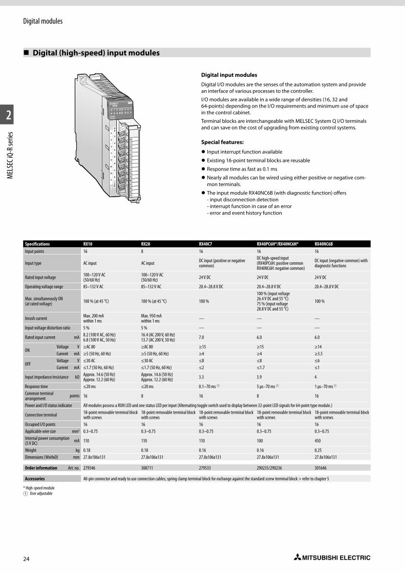
24
1
2
MEL
SEC i
Q-R s
eries
Digital modules
Specifications RX10 RX28 RX40C7 RX40PC6H*/RX40NC6H* RX40NC6BInput points 16 8 16 16 16
Input type AC input AC input DC input (positive or negative common)
DC high-speed input (RX40PC6H: positive commonRX40NC6H: negative common)
DC input (negative common) with diagnostic functions
Rated input voltage 100–120 V AC (50/60 Hz)
100–120 V AC (50/60 Hz) 24 V DC 24 V DC 24 V DC
Operating voltage range 85–132 V AC 85–132 V AC 20.4–28.8 V DC 20.4–28.8 V DC 20.4–28.8 V DC
Max. simultaneously ON (at rated voltage) 100 % (at 45 °C) 100 % (at 45 °C) 100 %
100 % (input voltage 26.4 V DC and 55 °C)75 % (input voltage 28.8 V DC and 55 °C)
100 %
Inrush current Max. 200 mA within 1 ms
Max. 950 mA within 1 ms — — —
Input voltage distortion ratio 5 % 5 % — — —
Rated input current mA 8.2 (100 V AC, 60 Hz)6.8 (100 V AC, 50 Hz)
16.4 (AC 200 V, 60 Hz) 13.7 (AC 200 V, 50 Hz) 7.0 6.0 6.0
ONVoltage V ≥AC 80 ≥AC 80 ≥15 ≥15 ≥14Current mA ≥5 (50 Hz, 60 Hz) ≥5 (50 Hz, 60 Hz) ≥4 ≥4 ≥3.5
OFFVoltage V ≤30 AC ≤30 AC ≤8 ≤8 ≤6Current mA ≤1.7 (50 Hz, 60 Hz) ≤1.7 (50 Hz, 60 Hz) ≤2 ≤1.7 ≤1
Input impedance/resistance kΩ Approx. 14.6 (50 Hz)Approx. 12.2 (60 Hz)
Approx. 14.6 (50 Hz)Approx. 12.2 (60 Hz) 3.3 3.9 4
Response time ≤20 ms ≤20 ms 0.1–70 ms 1 5 μs–70 ms 1 1 μs–70 ms 1
Common terminal arrangement points 16 8 16 8 16
Power and I/O status indicator All modules possess a RUN LED and one status LED per input (Alternating toggle switch used to display between 32-point LED signals for 64-point type module.)
Connection terminal 18-point removable terminal block with screws
18-point removable terminal block with screws
18-point removable terminal block with screws
18-point removable terminal block with screws
18-point removable terminal block with screws
Occupied I/O points 16 16 16 16 16Applicable wire size mm2 0.3–0.75 0.3–0.75 0.3–0.75 0.3–0.75 0.3–0.75Internal power consumption (5 V DC) mA 110 110 110 100 450
Weight kg 0.18 0.18 0.16 0.16 0.25Dimensions (WxHxD) mm 27.8x106x131 27.8x106x131 27.8x106x131 27.8x106x131 27.8x106x131
Order information Art. no. 279546 308711 279533 290235/290236 301646
Accessories 40-pin connector and ready to use connection cables; spring clamp terminal block for exchange against the standard screw terminal block > refer to chapter 5
* High-speed module1 User adjustable
0
1
2
3
4
5
6
7
8
9
A
B
C
D
E
F
Digital input modules
Digital I/O modules are the senses of the automation system and provide an interface of various processes to the controller.
I/O modules are available in a wide range of densities (16, 32 and 64-points) depending on the I/O requirements and minimum use of space in the control cabinet.
Terminal blocks are interchangeable with MELSEC System Q I/O terminals and can save on the cost of upgrading from existing control systems.
Special features:
z Input interrupt function available
z Existing 16-point terminal blocks are reusable
z Response time as fast as 0.1 ms
z Nearly all modules can be wired using either positive or negative com-mon terminals.
z The input module RX40NC6B (with diagnostic function) offers - input disconnection detection - interrupt function in case of an error - error and event history function
Digital (high-speed) input modules
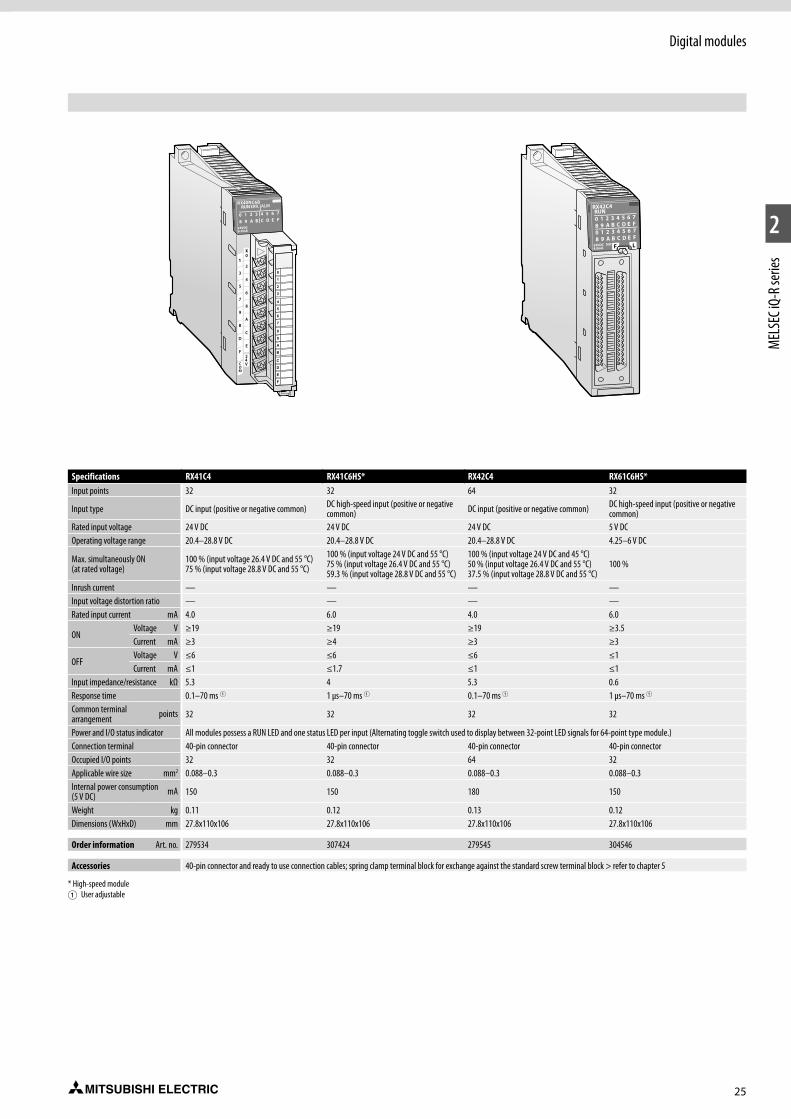
25
1
2
MEL
SEC i
Q-R s
eries
Digital modules
Digital (high-speed) input modules
Specifications RX41C4 RX41C6HS* RX42C4 RX61C6HS*Input points 32 32 64 32
Input type DC input (positive or negative common) DC high-speed input (positive or negative common) DC input (positive or negative common) DC high-speed input (positive or negative
common)Rated input voltage 24 V DC 24 V DC 24 V DC 5 V DCOperating voltage range 20.4–28.8 V DC 20.4–28.8 V DC 20.4–28.8 V DC 4.25–6 V DC
Max. simultaneously ON (at rated voltage)
100 % (input voltage 26.4 V DC and 55 °C)75 % (input voltage 28.8 V DC and 55 °C)
100 % (input voltage 24 V DC and 55 °C)75 % (input voltage 26.4 V DC and 55 °C)59.3 % (input voltage 28.8 V DC and 55 °C)
100 % (input voltage 24 V DC and 45 °C)50 % (input voltage 26.4 V DC and 55 °C)37.5 % (input voltage 28.8 V DC and 55 °C)
100 %
Inrush current — — — —Input voltage distortion ratio — — — —Rated input current mA 4.0 6.0 4.0 6.0
ONVoltage V ≥19 ≥19 ≥19 ≥3.5Current mA ≥3 ≥4 ≥3 ≥3
OFFVoltage V ≤6 ≤6 ≤6 ≤1Current mA ≤1 ≤1.7 ≤1 ≤1
Input impedance/resistance kΩ 5.3 4 5.3 0.6Response time 0.1–70 ms 1 1 μs–70 ms 1 0.1–70 ms 1 1 μs–70 ms 1
Common terminal arrangement points 32 32 32 32
Power and I/O status indicator All modules possess a RUN LED and one status LED per input (Alternating toggle switch used to display between 32-point LED signals for 64-point type module.)Connection terminal 40-pin connector 40-pin connector 40-pin connector 40-pin connectorOccupied I/O points 32 32 64 32Applicable wire size mm2 0.088–0.3 0.088–0.3 0.088–0.3 0.088–0.3Internal power consumption (5 V DC) mA 150 150 180 150
Weight kg 0.11 0.12 0.13 0.12Dimensions (WxHxD) mm 27.8x110x106 27.8x110x106 27.8x110x106 27.8x110x106
Order information Art. no. 279534 307424 279545 304546
Accessories 40-pin connector and ready to use connection cables; spring clamp terminal block for exchange against the standard screw terminal block > refer to chapter 5
* High-speed module1 User adjustable
0
1
2
3
4
5
6
7
8
9
A
B
C
D
E
F

26
1
2
MEL
SEC i
Q-R s
eries
Digital modules
Specifications RY10R2 RY18R2 RY20S6 RY40NT5P RY40PT5P RY40PT5BOutput points 16 8 16 16 16 16
Output type Relay Relay Triac Transistor (sink) Transistor (source) Transistor with diagnostic functions (source)
Common terminal arrangement points 16 8 16 16 16 16
Insulation method Relay Relay Photocoupler Photocoupler Photocoupler PhotocouplerRated output voltage 24 V DC/240 V AC 24 V DC/240 V AC 100–240 V AC 12–24 V DC 12–24 V DC 24 V DCOperating voltage range — — — 10.2–28.8 V DC 10.2–28.8 V DC 20.4–28.8 V DC
Min. switching load 5 V DC (1 mA) 5 V DC (1 mA)24 V AC (100 mA) 100 V AC (25 mA) 240 V AC (25 mA)
— — —
Max. switching voltage 125 V DC/ 264 V AC 125 V DC/264 V AC 288 V AC — — —
Max. output current A 2 2 0.6 0.5 0.5 0.5Output current per group TYP A 8 8 4.8 5 5 5
Inrush current — — — Current is limited by the overload protection
Current is limited by the overload protection
Current is limited by the overload protection
Leakage current at OFF mA — — ≤1.5 (120 V AC), ≤3 (240 V AC) ≤0.1 ≤0.1 ≤0.3
Response timeOFF R ON ≤10 ms ≤10 1 ≤0.5 ms ≤0.5 ms ≤0.5 msON R OFF ≤12 ms ≤12 1 ≤1 ms ≤1 ms ≤1.5 ms
LifeMechanical Switching 20 million times Switching 20 million times — — — —
Electrical Switching 300000 times or more
Switching 100000 times or more — — — —
Max. switching frequency 3600 times/h 3600 times/h — — — —Surge suppression — — CR absorber Zener diode Zener diode Zener diodeFuse — — — — — —Power indicator All modules possess a RUN LED and one status LED per output (Alternating toggle switch used to display between 32-point LED signals for 64-point type module.)
Connection terminal 18-point removable terminal block with screws
18-point removable terminal block with screws
18-point removable termi-nal block with screws
18-point removable terminal block with screws
18-point removable terminal block with screws
18-point removable terminal block with screws
Occupied I/O points 16 16 16 16 16 16Applicable wire size mm2 0.3–0.75 0.3–0.75 0.3–0.75 0.3–0.75 0.3–0.75 0.3–0.75
Ext. power supplyVoltage — — — 12–24 V DC 12–24 V DC 24 V DCCurrent mA — — — 4 (at 24 V DC) 16 (at 24 V DC) 87 (at 24 V DC)
Internal power consumption (5 V DC) mA 450 430 (all output points ON) 250 (all output points ON) 140 130 190
Weight kg 0.22 0.22 0.40 0.16 0.16 0.24Dimensions (WxHxD) mm 27.8x106x131 27.4x98x90 27.4x98x112 27.8x106x131 27.8x106x131 27.8x106x131
Order information Art. no. 279550 308712 308676 279547 279551 301647
Accessories 40-pin connector and ready to use connection cables; spring clamp terminal block for exchange against the standard screw terminal block > refer to chapter 5
0
1
2
3
4
5
6
7
8
9
A
B
C
D
E
F
Digital output modules
A variety of digital output modules are available including relay, transistor sink (wired as positive common) and transistor source (wired as negative common). Load voltages include 240 V AC and 5 V to 24 V DC, with various current ratings.
Special features:
z Output modules with relays or transistor outputs
z Overload protection
z Connection of output signals via removable terminal blocks or connectors
z Relay health diagnostics for preventive maintenance
z The output module RY40PT5B (with diagnostic function) offers - output short-circuit and disconnection detection - interrupt function in case of an error - error and event history function.
Digital (high-speed) output modules
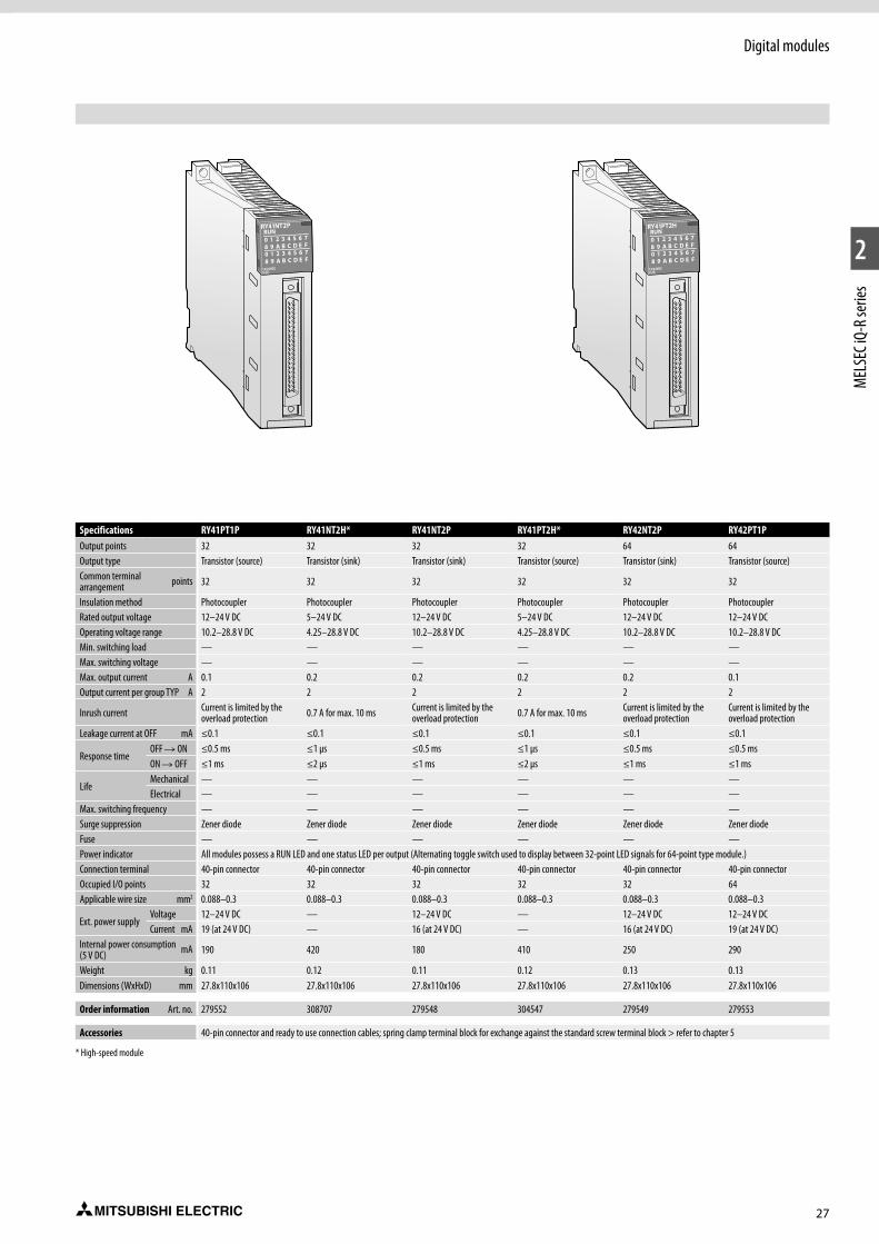
27
1
2
MEL
SEC i
Q-R s
eries
Digital modules
Digital (high-speed) output modules
Specifications RY41PT1P RY41NT2H* RY41NT2P RY41PT2H* RY42NT2P RY42PT1POutput points 32 32 32 32 64 64Output type Transistor (source) Transistor (sink) Transistor (sink) Transistor (source) Transistor (sink) Transistor (source)Common terminal arrangement points 32 32 32 32 32 32
Insulation method Photocoupler Photocoupler Photocoupler Photocoupler Photocoupler PhotocouplerRated output voltage 12–24 V DC 5–24 V DC 12–24 V DC 5–24 V DC 12–24 V DC 12–24 V DC Operating voltage range 10.2–28.8 V DC 4.25–28.8 V DC 10.2–28.8 V DC 4.25–28.8 V DC 10.2–28.8 V DC 10.2–28.8 V DCMin. switching load — — — — — —Max. switching voltage — — — — — —Max. output current A 0.1 0.2 0.2 0.2 0.2 0.1Output current per group TYP A 2 2 2 2 2 2
Inrush current Current is limited by the overload protection 0.7 A for max. 10 ms Current is limited by the
overload protection 0.7 A for max. 10 ms Current is limited by the overload protection
Current is limited by the overload protection
Leakage current at OFF mA ≤0.1 ≤0.1 ≤0.1 ≤0.1 ≤0.1 ≤0.1
Response timeOFF R ON ≤0.5 ms ≤1 μs ≤0.5 ms ≤1 μs ≤0.5 ms ≤0.5 msON R OFF ≤1 ms ≤2 μs ≤1 ms ≤2 μs ≤1 ms ≤1 ms
LifeMechanical — — — — — —Electrical — — — — — —
Max. switching frequency — — — — — —Surge suppression Zener diode Zener diode Zener diode Zener diode Zener diode Zener diodeFuse — — — — — —Power indicator All modules possess a RUN LED and one status LED per output (Alternating toggle switch used to display between 32-point LED signals for 64-point type module.)Connection terminal 40-pin connector 40-pin connector 40-pin connector 40-pin connector 40-pin connector 40-pin connectorOccupied I/O points 32 32 32 32 32 64Applicable wire size mm2 0.088–0.3 0.088–0.3 0.088–0.3 0.088–0.3 0.088–0.3 0.088–0.3
Ext. power supplyVoltage 12–24 V DC — 12–24 V DC — 12–24 V DC 12–24 V DCCurrent mA 19 (at 24 V DC) — 16 (at 24 V DC) — 16 (at 24 V DC) 19 (at 24 V DC)
Internal power consumption (5 V DC) mA 190 420 180 410 250 290
Weight kg 0.11 0.12 0.11 0.12 0.13 0.13Dimensions (WxHxD) mm 27.8x110x106 27.8x110x106 27.8x110x106 27.8x110x106 27.8x110x106 27.8x110x106
Order information Art. no. 279552 308707 279548 304547 279549 279553
Accessories 40-pin connector and ready to use connection cables; spring clamp terminal block for exchange against the standard screw terminal block > refer to chapter 5
* High-speed module

28
1
2
MEL
SEC i
Q-R s
eries
Digital modules
Combined I/O module
Combined I/O module
In addition to dedicated digital input and output modules, if only a few I/O points are required, a combined I/O module is available. This is an excellent alternative for cost-sensitive applications.
Special features:
z Input response time adjustable
z Connection of input and output signals via two 40-pin connectors
z Switch for alternating between indication of input or output status
z Output overload protection
z Overheat protection
z Input interrupt function
Specifications RH42C4NT2PDC inputInput points 32Rated input voltage V DC 24Rated input current mA 4 (at 24 V DC)
ONVoltage V ≥19Current mA ≥3
OFFVoltage V ≤6Current mA ≤1
Input resistance ? kΩ 5.3
Response timeOFF R ON ms 0.1–70 ms (user adjustable)ON R OFF ms 0.2–70 ms (user adjustable)
Transistor (sink) outputOutput points 32Rated output voltage V DC 12–24 V DCMax. output current A 0.2/point, Pilot Duty, 2/commonMaximum inrush current Current is limited by the overload protection
Response timeOFF R ON ms ≤5ON R OFF ms ≤1
Fuse —
External power supplyVoltage 12–24 V DCCurrent mA 16 (at 24 V DC)
Protection functions Overload protection, overheat protectionCommonCommon terminal arrangement points 32Noise suppression MΩ 10Connection terminal 40-pin connectorInternal power consumption (5 V DC) mA 220Weight kg 0.13Dimensions (WxHxD) mm 27.8x106x110
Order information Art. no. 279554
Accessories 40-pin connector and ready to use connection cables; spring clamp terminal block for exchange against the standard screw terminal block > refer to chapter 5
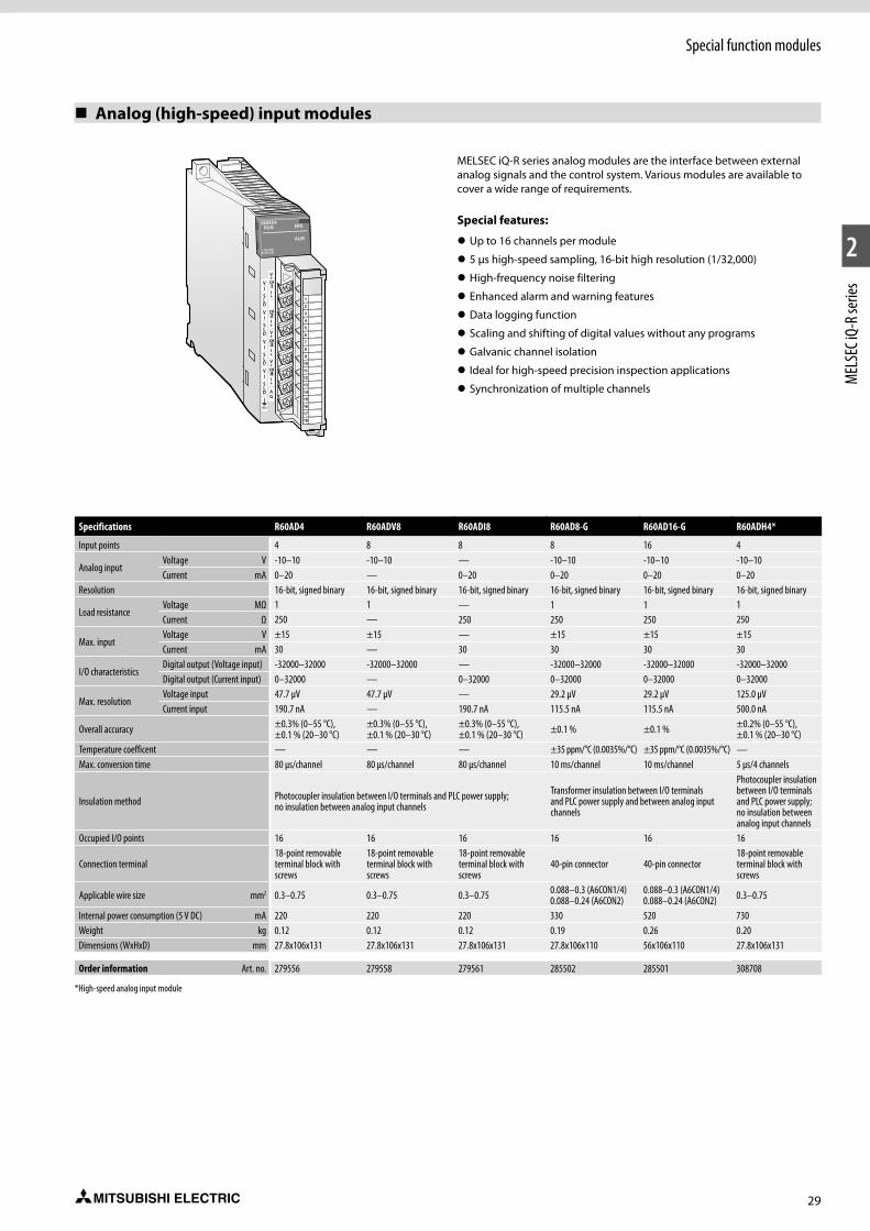
29
1
2
MEL
SEC i
Q-R s
eries
Special function modules
Analog (high-speed) input modules
12345678910
1112
13
14
15
16
1718
IV
SLD
IV
SLD
IV
SLD
(FG)
IV
SLD V
+
CH3
CH4
CH1
V+
I+
CH2I+V+
I+V+
I+
AG
MELSEC iQ-R series analog modules are the interface between external analog signals and the control system. Various modules are available to cover a wide range of requirements.
Special features:
z Up to 16 channels per module
z 5 μs high-speed sampling, 16-bit high resolution (1/32,000)
z High-frequency noise filtering
z Enhanced alarm and warning features
z Data logging function
z Scaling and shifting of digital values without any programs
z Galvanic channel isolation
z Ideal for high-speed precision inspection applications
z Synchronization of multiple channels
Specifications R60AD4 R60ADV8 R60ADI8 R60AD8-G R60AD16-G R60ADH4*
Input points 4 8 8 8 16 4
Analog inputVoltage V -10–10 -10–10 — -10–10 -10–10 -10–10Current mA 0–20 — 0–20 0–20 0–20 0–20
Resolution 16-bit, signed binary 16-bit, signed binary 16-bit, signed binary 16-bit, signed binary 16-bit, signed binary 16-bit, signed binary
Load resistanceVoltage MΩ 1 1 — 1 1 1Current Ω 250 — 250 250 250 250
Max. inputVoltage V ±15 ±15 — ±15 ±15 ±15Current mA 30 — 30 30 30 30
I/O characteristicsDigital output (Voltage input) -32000–32000 -32000–32000 — -32000–32000 -32000–32000 -32000–32000Digital output (Current input) 0–32000 — 0–32000 0–32000 0–32000 0–32000
Max. resolutionVoltage input 47.7 µV 47.7 µV — 29.2 µV 29.2 µV 125.0 µVCurrent input 190.7 nA — 190.7 nA 115.5 nA 115.5 nA 500.0 nA
Overall accuracy ±0.3% (0–55 °C), ±0.1 % (20–30 °C)
±0.3% (0–55 °C), ±0.1 % (20–30 °C)
±0.3% (0–55 °C), ±0.1 % (20–30 °C) ±0.1 % ±0.1 % ±0.2% (0–55 °C),
±0.1 % (20–30 °C)Temperature coefficent — — — ±35 ppm/°C (0.0035%/°C) ±35 ppm/°C (0.0035%/°C) —Max. conversion time 80 µs/channel 80 µs/channel 80 µs/channel 10 ms/channel 10 ms/channel 5 µs/4 channels
Insulation method Photocoupler insulation between I/O terminals and PLC power supply; no insulation between analog input channels
Transformer insulation between I/O terminals and PLC power supply and between analog input channels
Photocoupler insulation between I/O terminals and PLC power supply; no insulation between analog input channels
Occupied I/O points 16 16 16 16 16 16
Connection terminal18-point removable terminal block with screws
18-point removable terminal block with screws
18-point removable terminal block with screws
40-pin connector 40-pin connector18-point removable terminal block with screws
Applicable wire size mm2 0.3–0.75 0.3–0.75 0.3–0.75 0.088–0.3 (A6CON1/4) 0.088–0.24 (A6CON2)
0.088–0.3 (A6CON1/4) 0.088–0.24 (A6CON2) 0.3–0.75
Internal power consumption (5 V DC) mA 220 220 220 330 520 730Weight kg 0.12 0.12 0.12 0.19 0.26 0.20Dimensions (WxHxD) mm 27.8x106x131 27.8x106x131 27.8x106x131 27.8x106x110 56x106x110 27.8x106x131
Order information Art. no. 279556 279558 279561 285502 285501 308708
*High-speed analog input module

30
1
2
MEL
SEC i
Q-R s
eries
Special function modules
Analog output modules
12345678910
1112
13
14
15
16
1718
(FG)
COMNC
CH1
V+
I+
COMNC
CH2
V+
I+
COMNC
CH3
V+
I+
COM
NC
CH4
V+
I+
24V
24G
+
MELSEC iQ-R series analog output modules reliably deliver accurate analog values. A variety of modules (voltage, current, or mixed) are available to cover a wide range of application requirements, such as frequency inverters, valves or slide valves.
Faster, smoother predefined wave signal output
The analog output module enables pre-registration of waveforms easily using MELSOFT GX Works3, realizing a smoother continuous output that closely matches the precision required for the application, such as torque control for a press or injection molding machine. Registering the waveform in the module is simple and easy, and does not require a dedicated analog output program, such as for continuous line control, further reducing programming time.
Special features:
z Up to 16 channels per module
z Shift operation and scaling can be used without creating programs; they can be simply set on parameters. This simple setting minimizes program development cost as well as the program size.
Specifications R60DA4 R60DAH4 R60DAV8 R60DAI8 R60DA8-G R60DA16-GOutput points 4 4 8 8 8 16Digital input 16-bit, signed binary 16-bit, signed binary 16-bit, signed binary 16-bit, signed binary 16-bit, signed binary 16-bit, signed binary
Analog outputVoltage V DC -10–10 -10–10 -10–10 — -12–12 -12–12Current mA DC 0–20 0–20 — 0–20 0–20 0–20
Load resistanceVoltage 1 kΩ–500 Ω min. 1 kΩ 1 kΩ–500 Ω — min. 1 kΩ min. 1 kΩCurrent 0–600 Ω 0–600 Ω — 0–600 Ω 0–600 Ω 0–600 Ω
Digital input valueVoltage output -32000–32000 -32000–32000 -32000–32000 — -32000–32000 -32000–32000Current output 0–32000 0–32000 — 0–32000 0–32000 0–32000
Max. resolutionVoltage output µV 125 µV — 125 µV — 125 µV 125 µVCurrent output nA 350.9 nA — — — 360.1 nA 360.1 nA
Overall accuracy ± 0.3 % (0–55 °C), ± 0.1 % (20–30 °C)
± 0.3 % (0–55 °C), ± 0.1 % (20–30 °C)
± 0.3 % (0–55 °C), ± 0.1 % (20–30 °C)
± 0.3 % (0–55 °C), ± 0.1 % (20–30 °C) ±0.1 % ±0.1 %
Conversion speed 80 µs/channel 80 µs/channel 80 µs/channel 80 µs/channel 1 ms/channel 1 ms/channel
Insulation method Photocoupler insulation between I/O terminals and PLC power supply; no insulation between analog output channels; transformer between external power supply and output channels.
Transformer insulation between I/O terminals and PLC power supply, between analog output channels and between external power supply and output channels.
Occupied I/O points 16 16 16 16 16 48
Connection terminal18-point removable terminal block with screws
18-point removable terminal block with screws
18-point removable terminal block with screws
18-point removable terminal block with screws
40-pin connector 40-pin connector
Applicable wire size mm2 0.3–0.75 0.3–0.75 0.3–0.75 0.3–0.75 0.088–0.3 (A6CON1/4) 0.088–0.24 (A6CON2)
0.088–0.3 (A6CON1/4) 0.088–0.24 (A6CON2)
External power consumption 24 V DC, +20 %, -15 %, 0.14 A
24 V DC, +20 %, -15 %, 0.14 A
24 V DC, +20 %, -15 %, 0.16 A
24 V DC, +20 %, -15 %, 0.26 A
24 V DC, +20 %, -15 %, 0.36 A
24 V DC, +20 %, -15 %, 0.70 A
Internal power consumption 5 V DC mA 160 160 160 160 180 250Weight kg 0.14 0.14 0.14 0.14 0.21 0.32Dimensions (WxHxD) mm 27.8x106x131 27.8x106x131 27.8x106x131 27.8x106x131 27.8x106x110 56x106x110
Order information Art. no. 279557 307260 279560 279559 285504 285503
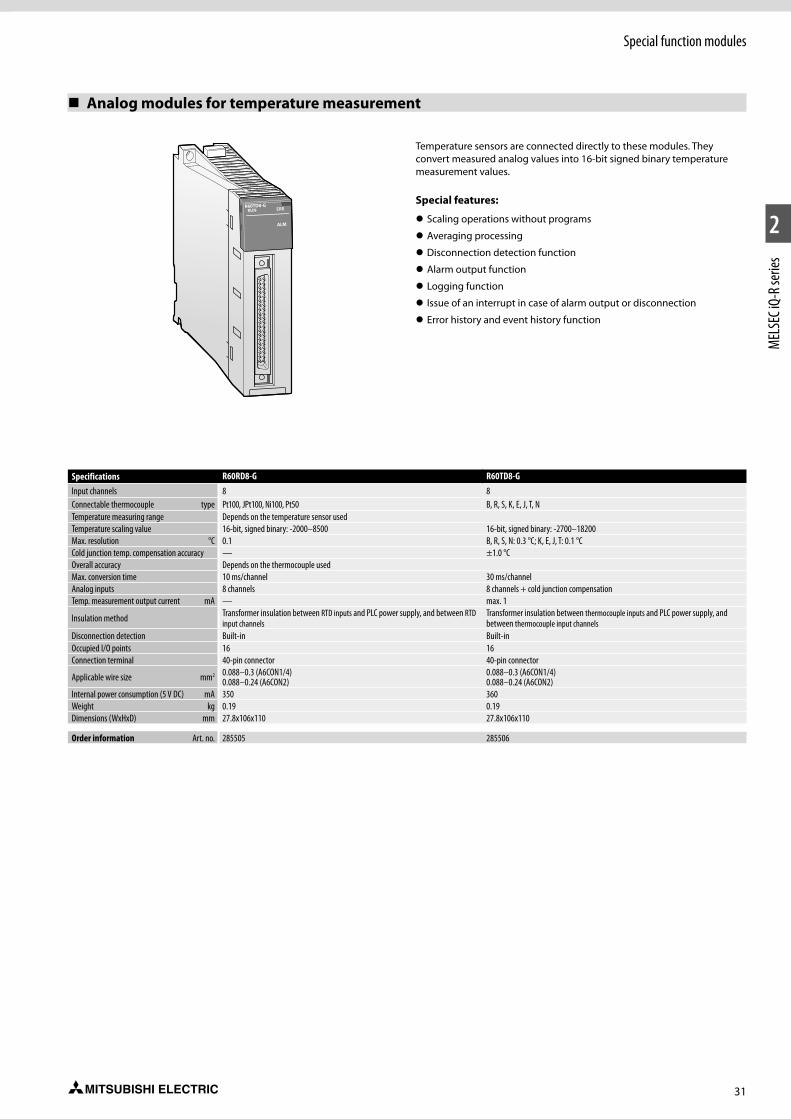
31
1
2
MEL
SEC i
Q-R s
eries
Special function modules
Analog modules for temperature measurement
Specifications R60RD8-G R60TD8-GInput channels 8 8Connectable thermocouple type Pt100, JPt100, Ni100, Pt50 B, R, S, K, E, J, T, NTemperature measuring range Depends on the temperature sensor usedTemperature scaling value 16-bit, signed binary: -2000–8500 16-bit, signed binary: -2700–18200Max. resolution °C 0.1 B, R, S, N: 0.3 °C; K, E, J, T: 0.1 °CCold junction temp. compensation accuracy — ±1.0 °COverall accuracy Depends on the thermocouple usedMax. conversion time 10 ms/channel 30 ms/channelAnalog inputs 8 channels 8 channels + cold junction compensationTemp. measurement output current mA — max. 1
Insulation method Transformer insulation between RTD inputs and PLC power supply, and between RTD input channels
Transformer insulation between thermocouple inputs and PLC power supply, and between thermocouple input channels
Disconnection detection Built-in Built-inOccupied I/O points 16 16Connection terminal 40-pin connector 40-pin connector
Applicable wire size mm2 0.088–0.3 (A6CON1/4) 0.088–0.24 (A6CON2)
0.088–0.3 (A6CON1/4) 0.088–0.24 (A6CON2)
Internal power consumption (5 V DC) mA 350 360Weight kg 0.19 0.19Dimensions (WxHxD) mm 27.8x106x110 27.8x106x110
Order information Art. no. 285505 285506
Temperature sensors are connected directly to these modules. They convert measured analog values into 16-bit signed binary temperature measurement values.
Special features:
z Scaling operations without programs
z Averaging processing
z Disconnection detection function
z Alarm output function
z Logging function
z Issue of an interrupt in case of alarm output or disconnection
z Error history and event history function

32
1
2
MEL
SEC i
Q-R s
eries
Special function modules
Temperature control modules
12345678910
1112
13
14
15
16
1718
MELSEC iQ-R Series temperature control modules are ideal for applications requiring highly stable and responsive temperature control. The series comes with thermocouple and RTD input module types and are available with or without heater disconnection detection.
Special features:
z Selection of various control modes possible
z Easy parameter setting with GX Works3
z Auto-tuning function for setting of suitable PID constants.
z Sensor correction function
z Scaling function
z Heater disconnection detection function
z Unused channels can be used for temperature measurement
z Inter-module link function
z Q compatible mode allows to use existing programs for a MELSEC series Q module
z Error history and event history function
Specifications R60TCTRT2TT2 R60TCRT4 R60TCTRT2TT2BW R60TCRT4BWControl output type Transistor Transistor Transistor TransistorInputs 4 channels 4 channels 4 channels 4 channels
Supported temperature sensors R, K, J, T, S, B, E, N, U, L, PLII, W5Re/W26Re Pt100, JPt100 R, K, J, T, S, B, E, N, U, L, PLII,
W5Re/W26Re Pt100, JPt100
Sampling cycle Switchable between 250 ms and 500 ms/4 channelsControl output cycle s 0.5–100 0.5–100 0.5–100 0.5–100Input filter 1–100 s (0 s: input filter OFF) 1–100 s (0 s: input filter OFF) 1–100 s (0 s: input filter OFF) 1–100 s (0 s: input filter OFF)Temperature control method PID ON/OFF impulse or 2-position control
PID constant range
PID constant setting Setting with automatic tuning possibleProportional band P 0.0–1000 % (0 %: 2-position control) 0.0–1000 % (0 %: 2-position control) 0.0–1000 % (0 %: 2-position control) 0.0–1000 % (0 %: 2-position control)Integral time I 0–3600 s (0 setting for P/PD control) 0–3600 s (0 setting for P/PD control) 0–3600 s (0 setting for P/PD control) 0–3600 s (0 setting for P/PD control)Differential time D 0–3600 s (0 setting for P/PI control) 0–3600 s (0 setting for P/PI control) 0–3600 s (0 setting for P/PI control) 0–3600 s (0 setting for P/PI control)
Target value setting range Within the temperature range of the thermocouple/platinum resistance thermomete usedDead band setting range 0.1–10.0 % 0.1–10.0 % 0.1–10.0 % 0.1–10.0 %
Transistor output
Output signal (sink) ON/OFF pulse ON/OFF pulse ON/OFF pulse ON/OFF pulseRated load voltage 10–30 V DC 10–30 V DC 10–30 V DC 10–30 V DCMax. load current 0.1 A/1 point, 0.4 A/common 0.1 A/1 point, 0.4 A/common 0.1 A/1 point, 0.4 A/common 0.1 A/1 point, 0.4 A/commonMax. rush current 400 mA, 10 ms 400 mA, 10 ms 400 mA, 10 ms 400 mA, 10 ms
Max. voltage drop when ON 0.1 V DC (TYP) 0.1 A 2.5 V DC (MAX) 0.1 A
0.1 V DC (TYP) 0.1 A 2.5 V DC (MAX) 0.1 A
0.1 V DC (TYP) 0.1 A 2.5 V DC (MAX) 0.1 A
0.1 V DC (TYP) 0.1 A 2.5 V DC (MAX) 0.1 A
Response time OFF R ON: <2 ms ON R OFF: <2 ms
OFF R ON: <2 ms ON R OFF: <2 ms
OFF R ON: <2 ms ON R OFF: <2 ms
OFF R ON: <2 ms ON R OFF: <2 ms
Insulation method Transformer insulation between input terminals and PLC power supply, and between input channelsOccupied I/O points 16 16 32 32
Connection terminal 18-point removable terminal block with screws
18-point removable terminal block with screws
Two 18-point removable terminal blocks with screws
Two 18-point removable terminal blocks with screws
Applicable wire size mm2 0.3–0.75 0.3–0.75 0.3–0.75 0.3–0.75Internal power consumption (5 V DC) mA 280 280 310 310Weight kg 0.22 0.22 0.34 0.34Dimensions (WxHxD) mm 27.8x106x110 27.8x106x110 56x106x110 56x106x110
Order information Art. no. 290202 290203 290204 290225
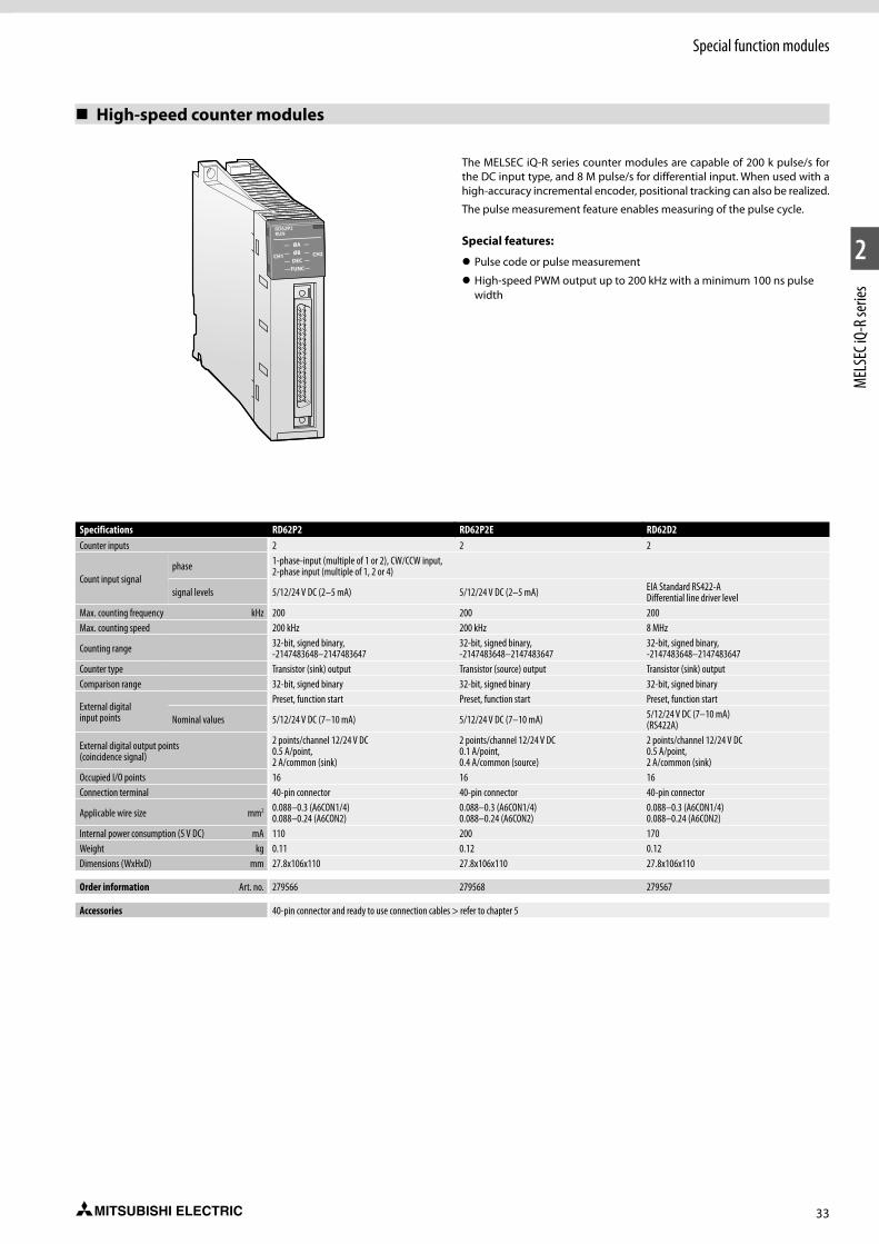
33
1
2
MEL
SEC i
Q-R s
eries
Special function modules
High-speed counter modules
The MELSEC iQ-R series counter modules are capable of 200 k pulse/s for the DC input type, and 8 M pulse/s for differential input. When used with a high-accuracy incremental encoder, positional tracking can also be realized.
The pulse measurement feature enables measuring of the pulse cycle.
Special features:
z Pulse code or pulse measurement
z High-speed PWM output up to 200 kHz with a minimum 100 ns pulse width
Specifications RD62P2 RD62P2E RD62D2Counter inputs 2 2 2
Count input signalphase 1-phase-input (multiple of 1 or 2), CW/CCW input,
2-phase input (multiple of 1, 2 or 4)
signal levels 5/12/24 V DC (2–5 mA) 5/12/24 V DC (2–5 mA) EIA Standard RS422-ADifferential line driver level
Max. counting frequency kHz 200 200 200Max. counting speed 200 kHz 200 kHz 8 MHz
Counting range 32-bit, signed binary, -2147483648–2147483647
32-bit, signed binary, -2147483648–2147483647
32-bit, signed binary, -2147483648–2147483647
Counter type Transistor (sink) output Transistor (source) output Transistor (sink) outputComparison range 32-bit, signed binary 32-bit, signed binary 32-bit, signed binary
External digital input points
Preset, function start Preset, function start Preset, function start
Nominal values 5/12/24 V DC (7–10 mA) 5/12/24 V DC (7–10 mA) 5/12/24 V DC (7–10 mA) (RS422A)
External digital output points (coincidence signal)
2 points/channel 12/24 V DC 0.5 A/point, 2 A/common (sink)
2 points/channel 12/24 V DC 0.1 A/point, 0.4 A/common (source)
2 points/channel 12/24 V DC 0.5 A/point, 2 A/common (sink)
Occupied I/O points 16 16 16Connection terminal 40-pin connector 40-pin connector 40-pin connector
Applicable wire size mm2 0.088–0.3 (A6CON1/4) 0.088–0.24 (A6CON2)
0.088–0.3 (A6CON1/4) 0.088–0.24 (A6CON2)
0.088–0.3 (A6CON1/4) 0.088–0.24 (A6CON2)
Internal power consumption (5 V DC) mA 110 200 170Weight kg 0.11 0.12 0.12Dimensions (WxHxD) mm 27.8x106x110 27.8x106x110 27.8x106x110
Order information Art. no. 279566 279568 279567
Accessories 40-pin connector and ready to use connection cables > refer to chapter 5
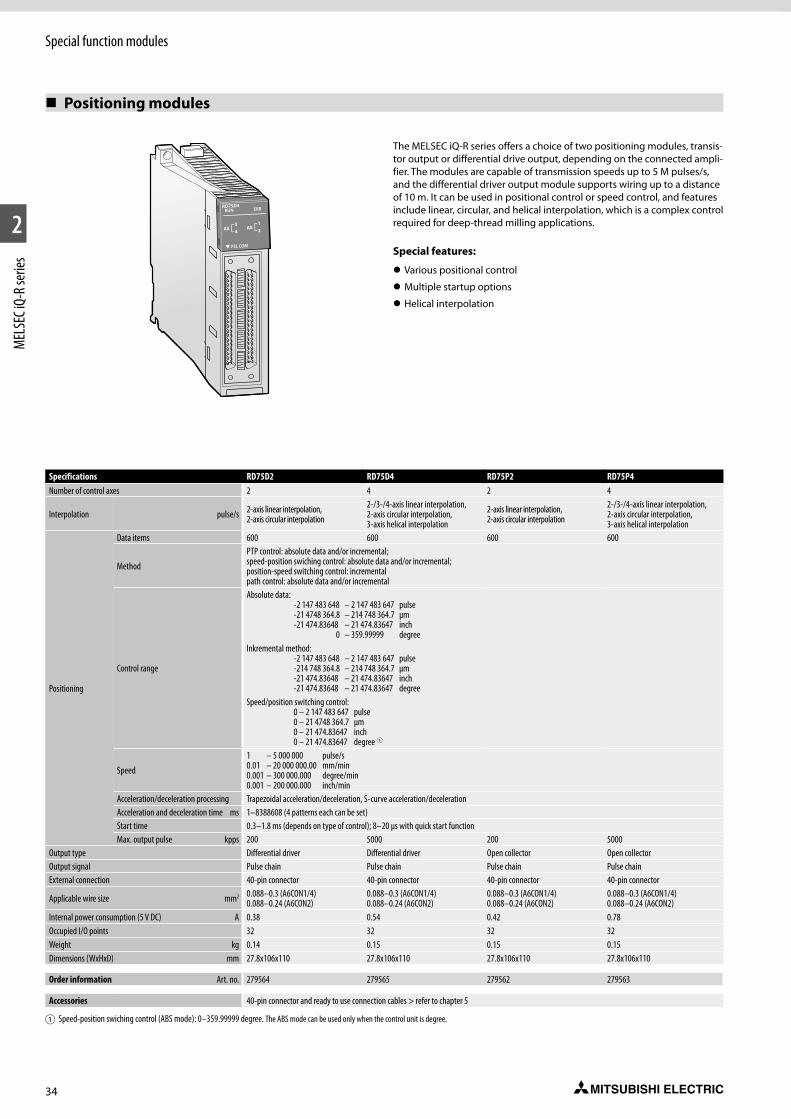
34
1
2
MEL
SEC i
Q-R s
eries
Special function modules
Positioning modules
The MELSEC iQ-R series offers a choice of two positioning modules, transis-tor output or differential drive output, depending on the connected ampli-fier. The modules are capable of transmission speeds up to 5 M pulses/s, and the differential driver output module supports wiring up to a distance of 10 m. It can be used in positional control or speed control, and features include linear, circular, and helical interpolation, which is a complex control required for deep-thread milling applications.
Special features:
z Various positional control
z Multiple startup options
z Helical interpolation
Specifications RD75D2 RD75D4 RD75P2 RD75P4Number of control axes 2 4 2 4
Interpolation pulse/s 2-axis linear interpolation,2-axis circular interpolation
2-/3-/4-axis linear interpolation, 2-axis circular interpolation, 3-axis helical interpolation
2-axis linear interpolation,2-axis circular interpolation
2-/3-/4-axis linear interpolation, 2-axis circular interpolation, 3-axis helical interpolation
Positioning
Data items 600 600 600 600
Method
PTP control: absolute data and/or incremental; speed-position swiching control: absolute data and/or incremental; position-speed switching control: incremental path control: absolute data and/or incremental
Control range
Absolute data: -2 147 483 648 – 2 147 483 647 pulse -21 4748 364.8 – 214 748 364.7 µm -21 474.83648 – 21 474.83647 inch 0 – 359.99999 degreeInkremental method: -2 147 483 648 – 2 147 483 647 pulse -214 748 364.8 – 214 748 364.7 µm -21 474.83648 – 21 474.83647 inch -21 474.83648 – 21 474.83647 degreeSpeed/position switching control: 0 – 2 147 483 647 pulse 0 – 21 4748 364.7 µm 0 – 21 474.83647 inch 0 – 21 474.83647 degree 1
Speed
1 – 5 000 000 pulse/s 0.01 – 20 000 000.00 mm/min 0.001 – 300 000.000 degree/min 0.001 – 200 000.000 inch/min
Acceleration/deceleration processing Trapezoidal acceleration/deceleration, S-curve acceleration/decelerationAcceleration and deceleration time ms 1–8388608 (4 patterns each can be set)Start time 0.3–1.8 ms (depends on type of control); 8–20 µs with quick start functionMax. output pulse kpps 200 5000 200 5000
Output type Differential driver Differential driver Open collector Open collectorOutput signal Pulse chain Pulse chain Pulse chain Pulse chainExternal connection 40-pin connector 40-pin connector 40-pin connector 40-pin connector
Applicable wire size mm2 0.088–0.3 (A6CON1/4) 0.088–0.24 (A6CON2)
0.088–0.3 (A6CON1/4) 0.088–0.24 (A6CON2)
0.088–0.3 (A6CON1/4) 0.088–0.24 (A6CON2)
0.088–0.3 (A6CON1/4) 0.088–0.24 (A6CON2)
Internal power consumption (5 V DC) A 0.38 0.54 0.42 0.78Occupied I/O points 32 32 32 32Weight kg 0.14 0.15 0.15 0.15Dimensions (WxHxD) mm 27.8x106x110 27.8x106x110 27.8x106x110 27.8x106x110
Order information Art. no. 279564 279565 279562 279563
Accessories 40-pin connector and ready to use connection cables > refer to chapter 5
1Speed-position swiching control (ABS mode): 0–359.99999 degree. The ABS mode can be used only when the control unit is degree.
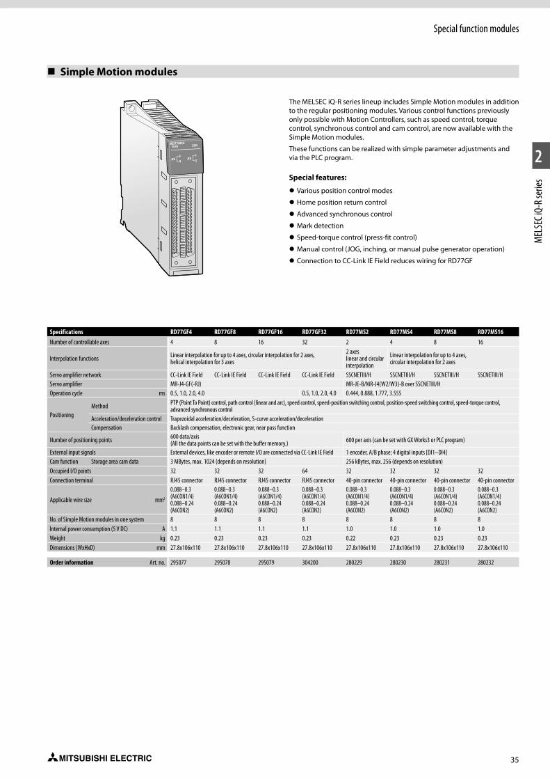
35
1
2
MEL
SEC i
Q-R s
eries
Special function modules
Simple Motion modules
Specifications RD77GF4 RD77GF8 RD77GF16 RD77GF32 RD77MS2 RD77MS4 RD77MS8 RD77MS16Number of controllable axes 4 8 16 32 2 4 8 16
Interpolation functions Linear interpolation for up to 4 axes, circular interpolation for 2 axes, helical interpolation for 3 axes
2 axes linear and circular interpolation
Linear interpolation for up to 4 axes, circular interpolation for 2 axes
Servo amplifier network CC-Link IE Field CC-Link IE Field CC-Link IE Field CC-Link IE Field SSCNETIII/H SSCNETIII/H SSCNETIII/H SSCNETIII/HServo amplifier MR-J4-GF(-RJ) MR-JE-B/MR-J4(W2/W3)-B over SSCNETIII/HOperation cycle ms 0.5, 1.0, 2.0, 4.0 0.5, 1.0, 2.0, 4.0 0.444, 0.888, 1.777, 3.555
PositioningMethod PTP (Point To Point) control, path control (linear and arc), speed control, speed-position switching control, position-speed switching control, speed-torque control,
advanced synchronous controlAcceleration/deceleration control Trapezoidal acceleration/deceleration, S-curve acceleration/decelerationCompensation Backlash compensation, electronic gear, near pass function
Number of positioning points 600 data/axis (All the data points can be set with the buffer memory.) 600 per axis (can be set with GX Works3 or PLC program)
External input signals External devices, like encoder or remote I/O are connected via CC-Link IE Field 1 encoder, A/B phase; 4 digital inputs [DI1–DI4]Cam function Storage area cam data 3 MBytes, max. 1024 (depends on resolution) 256 kBytes, max. 256 (depends on resolution)Occupied I/O points 32 32 32 64 32 32 32 32Connection terminal RJ45 connector RJ45 connector RJ45 connector RJ45 connector 40-pin connector 40-pin connector 40-pin connector 40-pin connector
Applicable wire size mm2
0.088–0.3 (A6CON1/4) 0.088–0.24 (A6CON2)
0.088–0.3 (A6CON1/4) 0.088–0.24 (A6CON2)
0.088–0.3 (A6CON1/4) 0.088–0.24 (A6CON2)
0.088–0.3 (A6CON1/4) 0.088–0.24 (A6CON2)
0.088–0.3 (A6CON1/4) 0.088–0.24 (A6CON2)
0.088–0.3 (A6CON1/4) 0.088–0.24 (A6CON2)
0.088–0.3 (A6CON1/4) 0.088–0.24 (A6CON2)
0.088–0.3 (A6CON1/4) 0.088–0.24 (A6CON2)
No. of Simple Motion modules in one system 8 8 8 8 8 8 8 8Internal power consumption (5 V DC) A 1.1 1.1 1.1 1.1 1.0 1.0 1.0 1.0Weight kg 0.23 0.23 0.23 0.23 0.22 0.23 0.23 0.23Dimensions (WxHxD) mm 27.8x106x110 27.8x106x110 27.8x106x110 27.8x106x110 27.8x106x110 27.8x106x110 27.8x106x110 27.8x106x110
Order information Art. no. 295077 295078 295079 304200 280229 280230 280231 280232
The MELSEC iQ-R series lineup includes Simple Motion modules in addition to the regular positioning modules. Various control functions previously only possible with Motion Controllers, such as speed control, torque control, synchronous control and cam control, are now available with the Simple Motion modules.
These functions can be realized with simple parameter adjustments and via the PLC program.
Special features:
z Various position control modes
z Home position return control
z Advanced synchronous control
z Mark detection
z Speed-torque control (press-fit control)
z Manual control (JOG, inching, or manual pulse generator operation)
z Connection to CC-Link IE Field reduces wiring for RD77GF
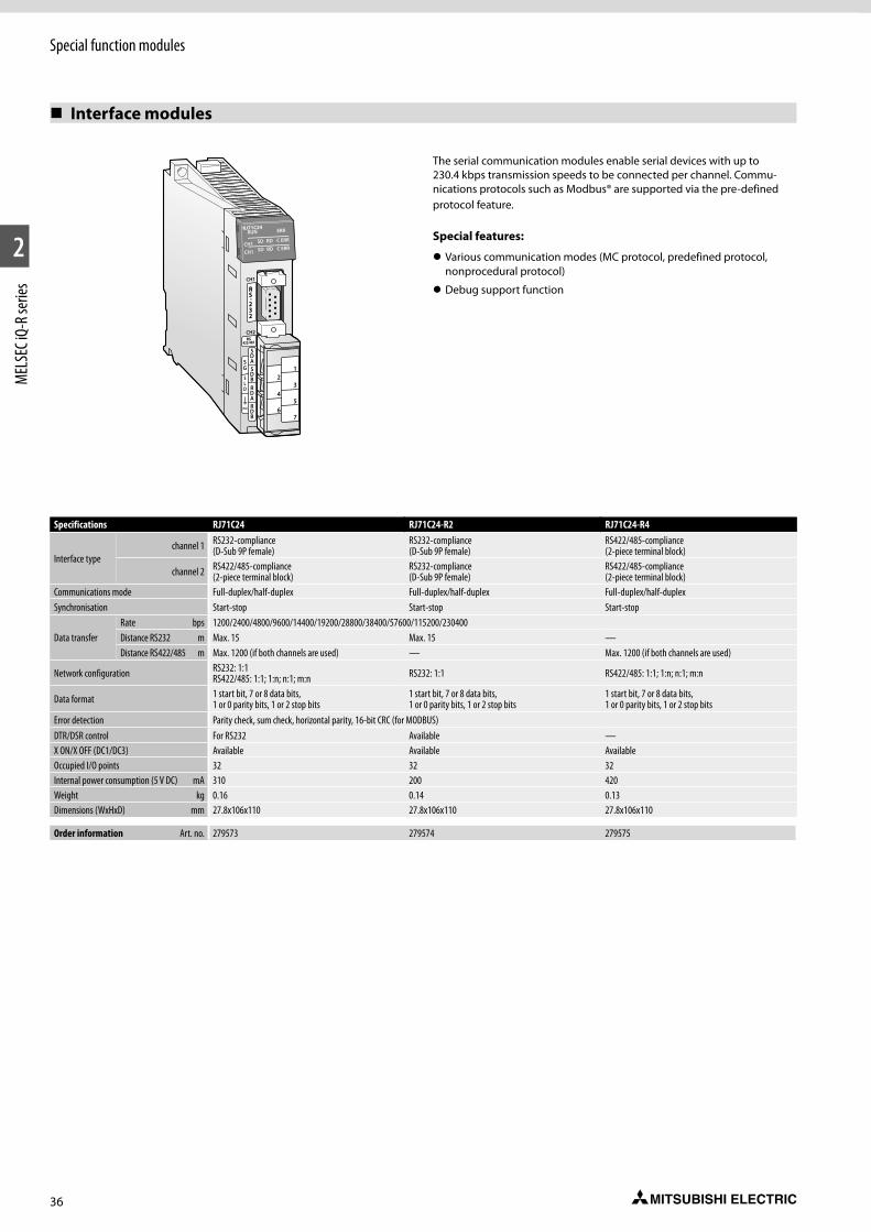
36
1
2
MEL
SEC i
Q-R s
eries
Special function modules
Interface modules
Specifications RJ71C24 RJ71C24-R2 RJ71C24-R4
Interface type channel 1 RS232-compliance
(D-Sub 9P female)RS232-compliance (D-Sub 9P female)
RS422/485-compliance (2-piece terminal block)
channel 2 RS422/485-compliance (2-piece terminal block)
RS232-compliance (D-Sub 9P female)
RS422/485-compliance (2-piece terminal block)
Communications mode Full-duplex/half-duplex Full-duplex/half-duplex Full-duplex/half-duplexSynchronisation Start-stop Start-stop Start-stop
Data transfer Rate bps 1200/2400/4800/9600/14400/19200/28800/38400/57600/115200/230400Distance RS232 m Max. 15 Max. 15 —Distance RS422/485 m Max. 1200 (if both channels are used) — Max. 1200 (if both channels are used)
Network configuration RS232: 1:1 RS422/485: 1:1; 1:n; n:1; m:n RS232: 1:1 RS422/485: 1:1; 1:n; n:1; m:n
Data format 1 start bit, 7 or 8 data bits, 1 or 0 parity bits, 1 or 2 stop bits
1 start bit, 7 or 8 data bits, 1 or 0 parity bits, 1 or 2 stop bits
1 start bit, 7 or 8 data bits, 1 or 0 parity bits, 1 or 2 stop bits
Error detection Parity check, sum check, horizontal parity, 16-bit CRC (for MODBUS)DTR/DSR control For RS232 Available —X ON/X OFF (DC1/DC3) Available Available AvailableOccupied I/O points 32 32 32Internal power consumption (5 V DC) mA 310 200 420Weight kg 0.16 0.14 0.13Dimensions (WxHxD) mm 27.8x106x110 27.8x106x110 27.8x106x110
Order information Art. no. 279573 279574 279575
CH1
CH2
The serial communication modules enable serial devices with up to 230.4 kbps transmission speeds to be connected per channel. Commu-nications protocols such as Modbus® are supported via the pre-defined protocol feature.
Special features:
z Various communication modes (MC protocol, predefined protocol, nonprocedural protocol)
z Debug support function
37
1
2
MEL
SEC i
Q-R s
eries
Special function modules
Network modules
The network and interface modules of the MELSEC iQ-R series ensure a vast selection of interconnectivity possibilities with various protocols and network topologies providing the best-fit solution for various applications. At the core of the Series is the CC-Link IE network family which is a high-speed 1 Gbps control level and field level Ethernet topology industrial open network.
Seamless message protocol (SLMP*) network communications
With SLMP, it is possible to seamlessly access production management systems, program-mable controllers and other devices using the same method, eliminating concerns about network hierarchies and boundaries. Tasks such as machine monitoring, data collection and maintenance can be performed from virtually anywhere on the network. Used together with the Ethernet module, SLMP-ready Ethernet devices such as a machine vision sensor or RFID controller can be interfaced to the CC-Link IE Field Network without further adding another network.* SLMP (Seamless Message Protocol): Is a client/server protocol that
enables communications between Ethernet-ready and CC-Link IE compatible devices.
Special features: z 1 Gbps high-speed, large bandwidth of 128 k word for CC-Link IE
z Connect to two separate networks using a single module
z Seamless networking (SLMP)
z Loop-back function
z Auto-return when faulty station is replaced
z Supports standard interfaces such as RS232 and RS422/485
Ethernet module
Module Specifications Art. no.
RJ71EN71 1 Gbps, 100/10 Mbps, multiple network, Ethernet cable (Category 5e or higher, double shielded/STP) 279570
CC-Link IE control module
Module Specifications Art. no.
RJ71GP21-SX1 Gbps, control/normal station, fiber optic cable, dual loop, which satisfies 1000 BASE-SX standard: multi-mode optical fiber (GI)
279571
CC-Link IE Field module
Module Specifications Art. no.
RJ71GF11-T2 1 Gbps, master/slave module, Ethernet cable (Category 5e or higher, double shielded/STP) 279569
CC-Link IE Field remote head module
Module Specifications Art. no.
RJ72GF15-T2 1 Gbps, remote station, Ethernet cable (Category 5e or higher, double shielded/STP) 297947
AnyWireASLINK master module
Module Specifications Art. no.RJ51AW12AL Sensor-level network 301856
CC-Link module
Module Specifications Art. no.RJ61BT11 Max. 10 Mbps, master/local station (CC-Link Ver.2) 279572
Profinet module
Module Specifications Art. no.RJ71PN92* Profinet master module 308713
Profibus DP module
Module Specifications Art. no.RJ71PB91V* Profibus master/slave module 308714
CANopen module
Module Specifications Art. no.RJ71CN91* CANopen communication module 308735
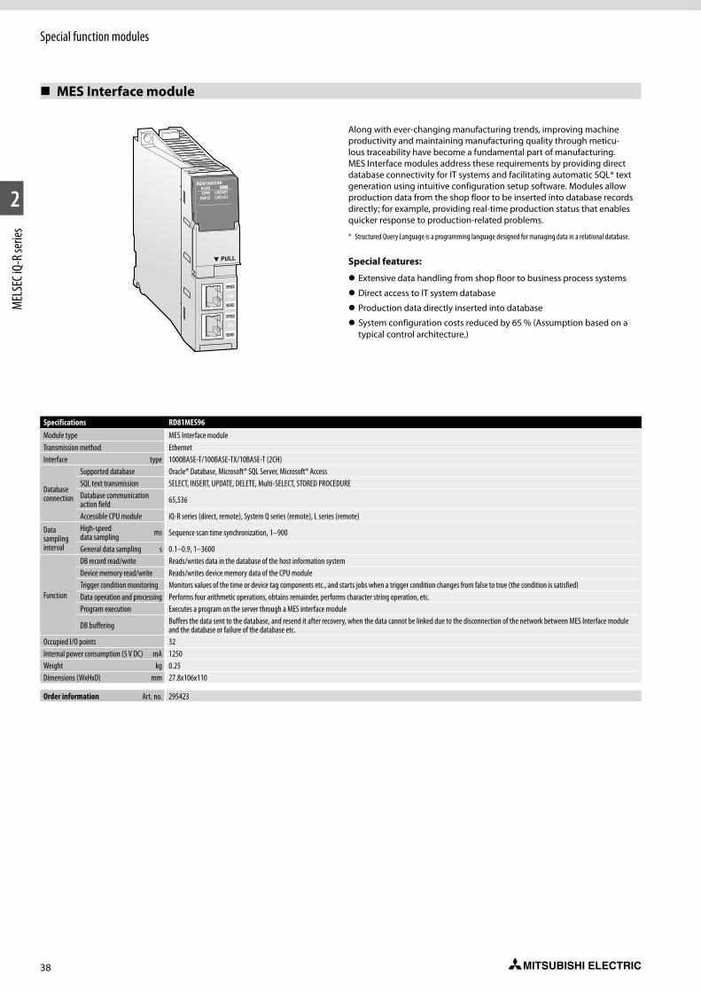
38
1
2
MEL
SEC i
Q-R s
eries
Special function modules
MES Interface module
Specifications RD81MES96Module type MES Interface moduleTransmission method Ethernet Interface type 1000BASE-T/100BASE-TX/10BASE-T (2CH)
Database connection
Supported database Oracle® Database, Microsoft® SQL Server, Microsoft® AccessSQL text transmission SELECT, INSERT, UPDATE, DELETE, Multi-SELECT, STORED PROCEDUREDatabase communication action field 65,536
Accessible CPU module iQ-R series (direct, remote), System Q series (remote), L series (remote)
Data sampling interval
High-speed data sampling ms Sequence scan time synchronization, 1–900
General data sampling s 0.1–0.9, 1–3600
Function
DB record read/write Reads/writes data in the database of the host information systemDevice memory read/write Reads/writes device memory data of the CPU moduleTrigger condition monitoring Monitors values of the time or device tag components etc., and starts jobs when a trigger condition changes from false to true (the condition is satisfied)Data operation and processing Performs four arithmetic operations, obtains remainder, performs character string operation, etc.Program execution Executes a program on the server through a MES interface module
DB buffering Buffers the data sent to the database, and resend it after recovery, when the data cannot be linked due to the disconnection of the network between MES Interface module and the database or failure of the database etc.
Occupied I/O points 32Internal power consumption (5 V DC) mA 1250Weight kg 0.25Dimensions (WxHxD) mm 27.8x106x110
Order information Art. no. 295423
Along with ever-changing manufacturing trends, improving machine productivity and maintaining manufacturing quality through meticu-lous traceability have become a fundamental part of manufacturing. MES Interface modules address these requirements by providing direct database connectivity for IT systems and facilitating automatic SQL* text generation using intuitive configuration setup software. Modules allow production data from the shop floor to be inserted into database records directly; for example, providing real-time production status that enables quicker response to production-related problems.
* Structured Query Language is a programming language designed for managing data in a relational database.
Special features:
z Extensive data handling from shop floor to business process systems
z Direct access to IT system database
z Production data directly inserted into database
z System configuration costs reduced by 65 % (Assumption based on a typical control architecture.)
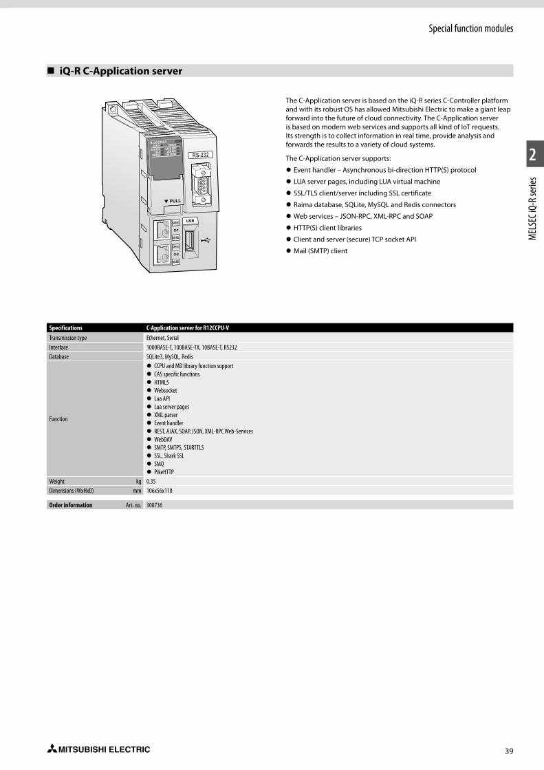
39
1
2
MEL
SEC i
Q-R s
eries
Special function modules
iQ-R C-Application server
SPEED
CH1
SD/RD
SPEED
CH2
SD/RD
The C-Application server is based on the iQ-R series C-Controller platform and with its robust OS has allowed Mitsubishi Electric to make a giant leap forward into the future of cloud connectivity. The C-Application server is based on modern web services and supports all kind of IoT requests. Its strength is to collect information in real time, provide analysis and forwards the results to a variety of cloud systems.
The C-Application server supports:
z Event handler – Asynchronous bi-direction HTTP(S) protocol
z LUA server pages, including LUA virtual machine
z SSL/TLS client/server including SSL certificate
z Raima database, SQLite, MySQL and Redis connectors
z Web services – JSON-RPC, XML-RPC and SOAP
z HTTP(S) client libraries
z Client and server (secure) TCP socket API
z Mail (SMTP) client
Specifications C-Application server for R12CCPU-VTransmission type Ethernet, SerialInterface 1000BASE-T, 100BASE-TX, 10BASE-T, RS232Database SQLite3, MySQL, Redis
Function
z CCPU and MD library function support z CAS specific functions z HTML5 z Websocket z Lua API z Lua server pages z XML parser z Event handler z REST, AJAX, SOAP, JSON, XML-RPC Web-Services z WebDAV z SMTP, SMTPS, STARTTLS z SSL, Shark SSL z SMQ z PikeHTTP
Weight kg 0.35Dimensions (WxHxD) mm 106x56x110
Order information Art. no. 308736
40
1
2
MEL
SEC i
Q-R s
eries
Special function modules
High-speed data logger module
The production process data acquisition feature of this high-speed data logger module contributes to improving production quality and efficiency, thereby realizing optimal production processes. The module enables log-ging of various data such as Unicode, CSV, and BIN text formats, which can be utilized for spreadsheet reporting owing to the automatic report gen-eration feature: BIN text format data can be ported directly to Microsoft® Windows® Excel®. Logging files can also be automatically sent to a FTP server or directly into a Microsoft® Windows® share folder.
Special features:
z Data logging synchronized with control system scan time
z Easier root cause analysis
z Utilize data for various analysis and maintenance processes
z Built-in SD memory slot
Specifications RD81DL96Accessible CPU modules iQ-R series (direct, remote), System Q series (remote), L series (remote)
Data sampling interval
High-speed data sampling ms z Sequence scan time synchronization z 0.5–0.9, 1–32767 (for trigger logging) z 2–32767 (for continuous logging)
General data sampling s z 0.1–0.9, 1–32767 z Time interval specification (specify hour/minute/second)
Amount of sampled data
High-speed data sampling Overall amount of data: 32768 (per setting: 1024) z Overall number of device points: 32768 (per setting: 4096)
General data sampling z Overall amount of data: 65536 (per setting: 1024) z Overall amount of data: 262144 (per setting: 4096)
Function
Data logging Logs CPU module device values at specified data sampling intervals.Event logging Monitors sampled device values from the CPU module, and logs events that occur.Report Outputs the data sampled by the high-speed data logger module as an Excel® file.
RecipeExecutes the following operations using recipe files stored in the SD memory card:
z Transfer device values written on the recipe files to devices in the CPU module. z Transfer device values in the CPU module to the recipe files.
Internal power consumption (5 V DC) A 1.1Weight kg 0.24Dimensions (WxHxD) mm 27.8x106x110
Order information Art. no. 308709
41
1
2
MEL
SEC i
Q-R s
eries
Special function modules
C intelligent function module
C/C++ program execution
The C Intelligent function module is available with a multi-core ARM®-based controller pre-installed with VxWorks® Version 6.9, which realizes simultaneous execution of programs, thereby providing a robust and deterministic alternative to computer-based systems. Utilizing a fan-less hardware design, the C Intelligent function module is ideal for clean fab-based environments, where dust circulation can be detrimental to the production environment, and can be used for applications such as in-line production quality testing or as a gateway for various industry-specific communications protocols.
Special features:
z Realize complex arithmetic equations in C/C++
z Application development in simple steps
z Emulates the same features as a standalone C Controller
z SD memory card slot
Specifications RD55UP06-V
Hardware
Endian format Little endianMPU ARM® Cortex-A9 Dual CoreWorking RAM 128 MB ROM 12 MB
Software
Operating system VxWorks Version 6.9Programming language C language (C/C++)Programming development environment CW Workbench/Wind River Workbench3.3Setting/monitoring tool GX Works3 (SW1DND-GXW3-E) a
Communication interface Ethernet (1000BASE-T/100BASE-TX/10BASE-T) (1 CH)Occupied I/O points 32Clock Obtained from a programmable controller CPU (in multiple CPU system, CPU No. 1). Internal power consumption (5 V DC) A 1.09Weight kg 0.24Dimensions (WxHxD) mm 27.8x106x110
Order information Art. no. 303298
1 Setting and monitoring of the module is integrated within the GX Works3 engineering software.
Accessories for the iQ-R series from page 114 onward!
42
1
2
MEL
SEC i
Q-R s
eries
Dimensions
Base units
Type X (in mm)
R35B 245R38B 328R38RB-HT 439R310RB, R310B-HT 439R312B 439
Type X (in mm)R65B, RQ65B 245R68B, RQ68B 328R68RB-HT 439R610RB, R610B-HT 439R612B, RQ612B 439
Extension base units
101
X
101
X
Unit: mm54.6
106
984
110
Power supply
Unit: mm
Unit: mm

43
1
2
MEL
SEC i
Q-R s
eries
Dimensions
CPU modules
98 106
4
110 27.8 56
Type W H DR04CPU R08CPU R16CPU R32CPU R120CPU
27.8 106 110
R04ENCPU R08ENCPU R16ENCPU R32ENCPU R120ENCPU
56 106 110
Unit: mm
C Controller CPU
98 106
4
110 56
Process CPU modules and redundant function module
98 106
4
110 27.8 Unit: mm
Unit: mm
(W)(D) (W)
(H)
44
1
2
MEL
SEC i
Q-R s
eries
Dimensions
Safety function module and safety CPU
98 106
4
110 27.8 Unit: mm
I/O modules, blank cover module special function modules
Unit: mm
27.8131
110
98 106
4
18-point screw terminal block
27.8110
98 106
4
Blank cover module
27.8110
98 106
4
40-pin connector, 32 points module
27.8110
98 106
4
40-pin connector, 64 points module
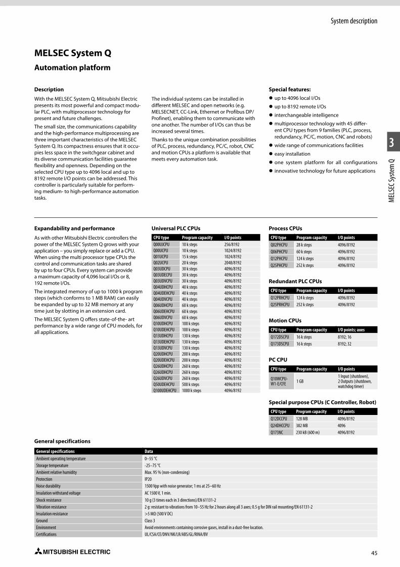
45
1
2
3
MEL
SEC S
yste
m Q
System description
Description
With the MELSEC System Q, Mitsubishi Electric presents its most powerful and compact modu-lar PLC, with multiprocessor technology for present and future challenges.
The small size, the communications capability and the high-performance multiprocessing are three important characteristics of the MELSEC System Q. Its compactness ensures that it occu-pies less space in the switchgear cabinet and its diverse communication facilities guarantee flexibility and openness. Depending on the selected CPU type up to 4096 local and up to 8192 remote I/O points can be addressed. This controller is particularly suitable for perform-ing medium- to high-performance automation tasks.
The individual systems can be installed in different MELSEC and open networks (e.g. MELSECNET, CC-Link, Ethernet or Profibus DP/Profinet), enabling them to communicate with one another. The number of I/Os can thus be increased several times.
Thanks to the unique combination possibilities of PLC, process, redundancy, PC/C, robot, CNC and motion CPUs a platform is available that meets every automation task.
Special features: z up to 4096 local I/Os
z up to 8192 remote I/Os
z interchangeable intelligence
z multiprocessor technology with 45 differ-ent CPU types from 9 families (PLC, process, redundancy, PC/C, motion, CNC and robots)
z wide range of communications facilities
z easy installation
z one system platform for all configurations
z innovative technology for future applications
Automation platform
Expandability and performance
As with other Mitsubishi Electric controllers the power of the MELSEC System Q grows with your application – you simply replace or add a CPU. When using the multi processor type CPUs the control and communication tasks are shared by up to four CPUs. Every system can provide a maximum capacity of 4,096 local I/Os or 8, 192 remote I/Os.
The integrated memory of up to 1000 k program steps (which conforms to 1 MB RAM) can easily be expanded by up to 32 MB memory at any time just by slotting in an extension card.
The MELSEC System Q offers state-of-the- art performance by a wide range of CPU models, for all applications.
Universal PLC CPUs
CPU type Program capacity I/O pointsQ00UJCPU 10 k steps 256/8192Q00UCPU 10 k steps 1024/8192Q01UCPU 15 k steps 1024/8192Q02UCPU 20 k steps 2048/8192Q03UDCPU 30 k steps 4096/8192Q03UDECPU 30 k steps 4096/8192Q03UDVCPU 30 k steps 4096/8192Q04UDHCPU 40 k steps 4096/8192Q04UDEHCPU 40 k steps 4096/8192Q04UDVCPU 40 k steps 4096/8192Q06UDHCPU 60 k steps 4096/8192Q06UDEHCPU 60 k steps 4096/8192Q06UDVCPU 60 k steps 4096/8192Q10UDHCPU 100 k steps 4096/8192Q10UDEHCPU 100 k steps 4096/8192Q13UDHCPU 130 k steps 4096/8192Q13UDEHCPU 130 k steps 4096/8192Q13UDVCPU 130 k steps 4096/8192Q20UDHCPU 200 k steps 4096/8192Q20UDEHCPU 200 k steps 4096/8192Q26UDHCPU 260 k steps 4096/8192Q26UDHCPU 260 k steps 4096/8192Q26UDVCPU 260 k steps 4096/8192Q50UDEHCPU 500 k steps 4096/8192Q100UDEHCPU 1000 k steps 4096/8192
Process CPUs
CPU type Program capacity I/O pointsQ02PHCPU 28 k steps 4096/8192Q06PHCPU 60 k steps 4096/8192Q12PHCPU 124 k steps 4096/8192Q25PHCPU 252 k steps 4096/8192
Redundant PLC CPUs
CPU type Program capacity I/O pointsQ12PRHCPU 124 k steps 4096/8192Q25PRHCPU 252 k steps 4096/8192
Motion CPUs
CPU type Program capacity I/O points; axesQ172DSCPU 16 k steps 8192; 16Q173DSCPU 16 k steps 8192; 32
PC CPU
CPU type Program capacity I/O points
Q10WCPU-W1-E/CFE 1 GB
1 Input (shutdown), 2 Outputs (shutdown, watchdog timer)
Special purpose CPUs (C Controller, Robot)
CPU type Program capacity I/O pointsQ12DCCPU 128 MB 4096/8192Q24DHCCPU 382 MB 4096Q173NC 230 kB (600 m) 4096/8192
MELSEC System Q
General specifications
General specifications DataAmbient operating temperature 0–55 °CStorage temperature -25–75 °CAmbient relative humidity Max. 95 % (non-condensing)Protection IP20Noise durability 1500 Vpp with noise generator; 1 ms at 25–60 HzInsulation withstand voltage AC 1500 V, 1 min.Shock resistance 10 g (3 times each in 3 directions)/EN 61131-2Vibration resistance 2 g: resistant to vibrations from 10–55 Hz for 2 hours along all 3 axes; 0.5 g for DIN rail mounting/EN 61131-2Insulation resistance >5 MΩ (500 V DC)Ground Class 3Environment Avoid environments containing corrosive gases, install in a dust-free location.Certifications UL/CSA/CE/DNV/NK/LR/ABS/GL/RINA/BV
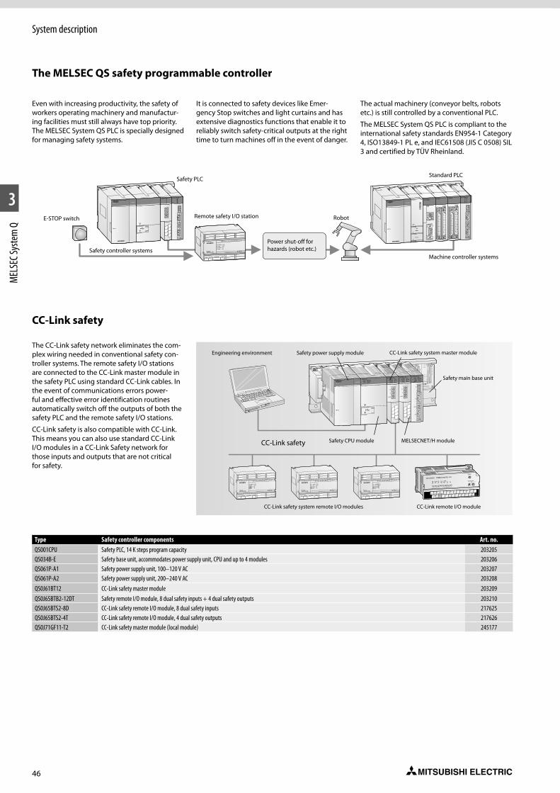
46
System description
1
2
3
MEL
SEC S
yste
m Q
Safety PLC
E-STOP switch
Safety controller systems
Remote safety I/O station
Power shut-off for hazards (robot etc.)
Robot
Machine controller systems
Standard PLC
The MELSEC QS safety programmable controller
Even with increasing productivity, the safety of workers operating machinery and manufactur-ing facilities must still always have top priority. The MELSEC System QS PLC is specially designed for managing safety systems.
It is connected to safety devices like Emer-gency Stop switches and light curtains and has extensive diagnostics functions that enable it to reliably switch safety-critical outputs at the right time to turn machines off in the event of danger.
The actual machinery (conveyor belts, robots etc.) is still controlled by a conventional PLC.
The MELSEC System QS PLC is compliant to the international safety standards EN954-1 Category 4, ISO13849-1 PL e, and IEC61508 (JIS C 0508) SIL 3 and certified by TÜV Rheinland.
The CC-Link safety network eliminates the com-plex wiring needed in conventional safety con-troller systems. The remote safety I/O stations are connected to the CC-Link master module in the safety PLC using standard CC-Link cables. In the event of communications errors power-ful and effective error identification routines automatically switch off the outputs of both the safety PLC and the remote safety I/O stations.
CC-Link safety is also compatible with CC-Link. This means you can also use standard CC-Link I/O modules in a CC-Link Safety network for those inputs and outputs that are not critical for safety.
Type Safety controller components Art. no.QS001CPU Safety PLC, 14 K steps program capacity 203205QS034B-E Safety base unit, accommodates power supply unit, CPU and up to 4 modules 203206QS061P-A1 Safety power supply unit, 100–120 V AC 203207QS061P-A2 Safety power supply unit, 200–240 V AC 203208QS0J61BT12 CC-Link safety master module 203209QS0J65BTB2-12DT Safety remote I/O module, 8 dual safety inputs + 4 dual safety outputs 203210QS0J65BTS2-8D CC-Link safety remote I/O module, 8 dual safety inputs 217625QS0J65BTS2-4T CC-Link safety remote I/O module, 4 dual safety outputs 217626QS0J71GF11-T2 CC-Link safety master module (local module) 245177
Engineering environment Safety power supply module CC-Link safety system master module
Safety main base unit
Safety CPU module MELSECNET/H module
CC-Link safety system remote I/O modules CC-Link remote I/O module
CC-Link safety
CC-Link safety
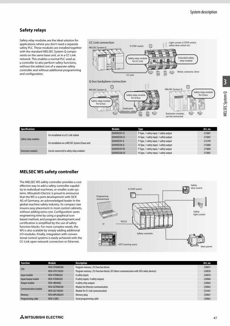
47
System description
1
2
3
MEL
SEC S
yste
m Q
Safety relays
Safety relay modules are the ideal solution for applications where you don’t need a separate safety PLC. These modules are installed together with the standard MELSEC System Q compo-nents on the same base unit, or in a CC-Link network. This enables a normal PLC used as a controller to also perform safety functions, without the added cost of a separate safety controller and without additional programming and configuration.
MELSEC WS safety controller
The MELSEC WS safety controller provides a cost effective way to add a safety controller capabil-ity to individual machines, or smaller scale sys-tems. Mitsubishi Electric is proud to announce that the WS is a joint development with SICK AG of Germany, an acknowledged leader in the global machine safety industry. Its compact size insures easy placement in most control cabinets, without adding extra cost. Configuration saves engineering time by using a graphical icon based method, and program development and certification is simplified by the use of safety function blocks. For more complex needs, the WS is also scalable by simply adding additional I/O modules. Finally, integration with conven-tional control systems is easily achieved with the CC-Link open network connection or Ethernet.
Specifications Module Type Art. no.
Safety relay modulesFor installation in a CC-Link station
QS90SR2SP-CC P-Type, 1 safety input, 1 safety output 215801QS90SR2SN-CC N-Type, 1 safety input, 1 safety output 215803
For installation on a MELSEC System Q base unitQS90SR2SP-Q P-Type, 1 safety input, 1 safety output 215799QS90SR2SN-Q N-Type, 1 safety input, 1 safety output 215800
Extension modules Can be connected to safety relay modulesQS90SR2SP-EX P-Type, 1 safety input, 1 safety output 215804QS90SR2SN-EX N-Type, 1 safety input, 1 safety output 215805
Function Module Description Art. no.
CPUWS0-CPU000200 Program memory: 255 function blocks 230057WS0-CPU130202 Program memory: 255 function blocks; EFI (direct communication with SICK safety devices) 230058
Input module WS0-XTDI80202 8 safety inputs 230059Input/output modul WS0-XTIO84202 8 safety inputs; 4 safety outputs 230060Output module WS0-4RO4002 4 safety relay outputs 230064
Communication moduleWS0-GETH00200 Module for Ethernet communication 230063WS0-GCC100202 Module for CC-Link communication 235441
Memory WS0-MPL000201 Memory plug 230061Programming cable WS0-C20R2 Serial programming cable 230062
Erweiterungskabel
CC-Link connection
Q-bus backplane connection
MELSEC System Q
MELSEC System Q
E-STOP switch
CC-Link
Light curtain, E-STOP switch, safety door switch etc.
Motor, contactor, drive
Extended safety relay module
Safety relay module for CC-Link
Safety relay module for Q-bus
Safety relay module for Q-bus
Safety relay module for Q-bus
MELSEC System Q
Extension modules can be connected
Dedicated extension cable
E-STOP switch
Engineering environment
Safety door switch
Safety light curtain
Safety controller
GOT (coming soon)
orRS232
Main power
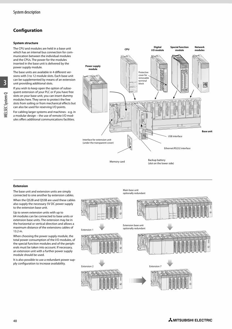
48
System description
1
2
3
MEL
SEC S
yste
m Q
Configuration
System structure
The CPU and modules are held in a base unit which has an internal bus connection for com-munication between the individual modules and the CPUs. The power for the modules inserted in the base unit is delivered by the power supply module.
The base units are available in 4 different ver-sions with 3 to 12 module slots. Each base unit can be supplemented by means of an extension unit providing additional slots.
If you wish to keep open the option of subse-quent extension of your PLC or if you have free slots on your base unit, you can insert dummy modules here. They serve to protect the free slots from soiling or from mechanical effects but can also be used for reserving I/O points.
For cabling larger systems and machines - e.g. in a modular design – the use of remote I/O mod-ules offers additional communications facilities.
Extension
The base unit and extension units are simply connected to one another by extension cables.
When the Q52B and Q55B are used these cables also supply the necessary 5V DC power supply to the extension base unit.
Up to seven extension units with up to 64 modules can be connected to base units or extension base units. The extension may be in the horizontal or vertical direction and allows a maximum distance of the extensions cables of 13.2 m.
When choosing the power supply module, the total power consumption of the I/O modules, of the special function modules and of the periph-erals must be taken into account. If necessary, an extension unit with a further power supply module should be used.
It is also possible to use a redundant power sup-ply configuration to increase availability.
QJ71BR11
QJ71BR11
RUN
STATION NO.X10
X1
MODE
MNG
T.PASS D.LINK
SD RDERR. L ERR.
0123456789
Q64ADRUN
ERROR
A/D0~±10V0~20mA
CH1
CH2
CH3
CH4
I+
V+
I+
V+
I+
V+
I+
V-
SLD
V-
SLD
V-
SLD
V-
SLD
A.G.
(FG)
V+
1
3
5
7
9
B
D
F
2
4
6
8
A
C
E
12VDC24VDC0.5A
L
L
L
L
L
L
L
L
L
L
L
L
L
L
L
L
COM
QY80
FUSE
0123456789
0 1 2 3 4 5 6 7
8 9 A B C D E F
0123456789
1
3
5
7
9
B
D
F
2
4
6
8
A
C
E
NC
24VDC4mA
COM
QX800 1 2 3 4 5 6 78 9 A B C D E F
Q06HCPU
RS-232
USB
PULL
MODERUNERR.
USERBAT.
BOOT
Q06HCPU
RS-232
USB
PULL
MODERUNERR.
USERBAT.
BOOT
Q61P-A2
PULL
MITSUBISHI
POWER
BAMODSERIAL
SE UNITEL Q38B
0205020E
QJ71BR11
QJ71BR11
RUN
STATION NO.X10
X1
MODE
MNG
T.PASS D.LINK
SD RDERR. L ERR.
0123456789
Q64ADRUN
ERROR
A/D0~±10V0~20mA
CH1
CH2
CH3
CH4
I+
V+
I+
V+
I+
V+
I+
V-
SLD
V-
SLD
V-
SLD
V-
SLD
A.G.
(FG)
V+
1
3
5
7
9
B
D
F
2
4
6
8
A
C
E
12VDC24VDC0.5A
L
L
L
L
L
L
L
L
L
L
L
L
L
L
L
L
COM
QY80
FUSE
0123456789
0 1 2 3 4 5 6 7
8 9 A B C D E F
0123456789
1
3
5
7
9
B
D
F
2
4
6
8
A
C
E
NC
24VDC4mA
COM
QX800 1 2 3 4 5 6 78 9 A B C D E F
0123456789
1
3
5
7
9
B
D
F
2
4
6
8
A
C
E
NC
24VDC4mA
COM
QY800 1 2 3 4 5 6 78 9 A B C D E F
0123456789
1
3
5
7
9
B
D
F
2
4
6
8
A
C
E
NC
24VDC4mA
COM
QX800 1 2 3 4 5 6 78 9 A B C D E F
Q61P-A2
PULL
MITSUBISHI
POWER
BAMODSERIAL
SE UNITEL Q38B
0205020E
FUSE
QJ71BR11
QJ71BR11
RUN
STATIO N NO.
X10
X1
MODE
MN G
T.PASS D.LINK
SD RD
ER R. L ER R.
0123456789
1
3
5
7
9
B
D
F
2
4
6
8
A
C
E
NC
24VDC
4mA
COM
QX800 1 2 3 4 5 6 7
8 9 A B C D E F
0123456789
1
3
5
7
9
B
D
F
2
4
6
8
A
C
E
NC
24VDC
4mA
COM
QX800 1 2 3 4 5 6 7
8 9 A B C D E F
0123456789
1
3
5
7
9
B
D
F
2
4
6
8
A
C
E
NC
24VDC
4mA
COM
QX800 1 2 3 4 5 6 7
8 9 A B C D E F
0123456789
1
3
5
7
9
B
D
F
2
4
6
8
A
C
E
NC
24VDC
4mA
COM
QX800 1 2 3 4 5 6 7
8 9 A B C D E F
0123456789
1
3
5
7
9
B
D
F
2
4
6
8
A
C
E
NC
24VDC
4mA
COM
QX800 1 2 3 4 5 6 7
8 9 A B C D E F
0123456789
1
3
5
7
9
B
D
F
2
4
6
8
A
C
E
NC
24VDC
4mA
COM
QX800 1 2 3 4 5 6 7
8 9 A B C D E F
0123456789
1
3
5
7
9
B
D
F
2
4
6
8
A
C
E
NC
24VDC
4mA
COM
QX800 1 2 3 4 5 6 7
8 9 A B C D E F
0123456789
1
3
5
7
9
B
D
F
2
4
6
8
A
C
E
NC
24VDC
4mA
COM
QX800 1 2 3 4 5 6 7
8 9 A B C D E F
Q06HCPU
RS-232
USB
PULL
MODERUNERR.
USERBAT.
BOOT
Q06HCPU
RS-232
USB
PULL
MODERUNERR.
USERBAT.
BOOT
MELSECQ64RP
POWER
PULL
MITSUBISHI
MELSECQ64RP
POWER
PULL
MITSUBISHI
QJ71BR11
QJ71BR11
RUN
STATION NO.
X10
X1
MODE
MNG
T.PASS D.LINK
SD RD
ER R. L ER R.
0123456789
1
3
5
7
9
B
D
F
2
4
6
8
A
C
E
NC
24VDC
4mA
COM
QX800 1 2 3 4 5 6 7
8 9 A B C D E F
0123456789
1
3
5
7
9
B
D
F
2
4
6
8
A
C
E
NC
24VDC
4mA
COM
QX800 1 2 3 4 5 6 7
8 9 A B C D E F
0123456789
1
3
5
7
9
B
D
F
2
4
6
8
A
C
E
NC
24VDC
4mA
COM
QX800 1 2 3 4 5 6 7
8 9 A B C D E F
0123456789
1
3
5
7
9
B
D
F
2
4
6
8
A
C
E
NC
24VDC
4mA
COM
QX800 1 2 3 4 5 6 7
8 9 A B C D E F
0123456789
1
3
5
7
9
B
D
F
2
4
6
8
A
C
E
NC
24VDC
4mA
COM
QX800 1 2 3 4 5 6 7
8 9 A B C D E F
0123456789
1
3
5
7
9
B
D
F
2
4
6
8
A
C
E
NC
24VDC
4mA
COM
QX800 1 2 3 4 5 6 7
8 9 A B C D E F
0123456789
1
3
5
7
9
B
D
F
2
4
6
8
A
C
E
NC
24VDC
4mA
COM
QX800 1 2 3 4 5 6 7
8 9 A B C D E F
0123456789
1
3
5
7
9
B
D
F
2
4
6
8
A
C
E
NC
24VDC
4mA
COM
QX800 1 2 3 4 5 6 7
8 9 A B C D E FMELSECQ64RP
POWER
PULL
MITSUBISHI
MELSECQ64RP
POWER
PULL
MITSUBISHI
BA
MOD
SERIAL
SE UNIT
EL Q38B
Main base unit optionally redundant
Extension base unit optionally redundantExtension 1
Extension 2 Extension 7
MITSUBISHI
2M
INSERT
FL
A
SH
C
A
R
D
BAMODSERIAL 0100017-A
SE UNITEL Q38B
0205020E
POWERCPU I / 00
Q38B(N)
I / 07I / 06
I / 05I / 04
I / 03
E.S.DI / 02
I / 01
0123456789
1
3
5
7
9
B
D
F
2
4
6
8
A
C
E
NC
24VDC4mA
COM
QX800 1 2 3 4 5 6 78 9 A B C D E F
Q06HCPU
RS-232
USB
PULL
MODERUNERR.
USERBAT.
BOOT
Q61P-A2
PULL
MITSUBISHI
POWER
10BASE-T/100BASE-TX
QJ71E71-100
QJ71E71-100RUN ERR.
INT. COM ERR.
OPENSD RD
100M
AX2AX1
AX4AX3
QD75P4RUN AX1
AX2AX3AX4ERR.
EJECT
C
A
R
D
MODE
RUN
ERR.
USER
BAT.
BOOT.
ON
STOP RUN
RESET L.CLR
SW
1
2
3
4
5
10 BASE-T/100 BASE-TX
100
M
SD/
PO
Power supply module
Interface for extension unit (under the transparent cover)
CPU
Memory card
Digital I/O module
Ethernet/RS232 interface
USB interface
Base unit
Special function module
Protective cover for removable terminal block
Network modules
Backup battery (slot on the lower side)

49
System description
1
2
3
MEL
SEC S
yste
m Q
Multiple CPU high-speed main base unit (Q3mDB)
CPU 2 to 4 High-speed universal model QCPU Universal model QCPU Process CPU Motion CPU/
Robot CPU 1/CNC CPU C Controller CPU
CPU 1
Q03UDVQ04UDVQ06UDVQ13UDVQ26UDV
Q03UD(E) Q04UD(E)HQ06UD(E)H Q10UD(E)HQ13UD(E)H Q20UD(E)HQ26UD(E)HQ50UDEHQ100UDEH
Q02PHQ06PHQ12PHQ25PH
Q172DSQ173DSCR750-QCR751-QQ173NC
Q24DHCCPU-VQ24DHCCPU-VGQ24DHCCPU-LSQ12DCCPU-V
Q06CCPU-V
High-speed universal model QCPU
Q03UDV U U u U U —Q04UDV U U u U U —Q06UDV U U u U U —Q13UDV U U u U U —Q26UDV U U u U U —
Universal model QCPU
Q00U — — — — u u
Q01U — — — — u u
Q02U — — — — u u
Q03UD(E) U U u U U u
Q04UD(E)H U U u U U u
Q06UD(E)H U U u U U u
Q10UD(E)H U U u U U u
Q13UD(E)H U U u U U u
Q20UD(E)H U U u U U u
Q26UD(E)H U U u U U u
Q50UDEH U U u U U u
Q100UDEH U U u U U u
Main base unit other than (Q3mDB)
CPU 2 to 4 High-speed universal model QCPU Universal model QCPU Process CPU Motion CPU/
Robot CPU 1/CNC CPU C Controller CPU
CPU 1
Q03UDVQ04UDVQ06UDVQ13UDVQ26UDV
Q03UD(E) Q04UD(E)HQ06UD(E)H Q10UD(E)HQ13UD(E)H Q20UD(E)HQ26UD(E)HQ50UDEHQ100UDEH
Q02PHQ06PHQ12PHQ25PH
Q172DSQ173DSCR750-QCR751-QQ173NC
Q24DHCCPU-VQ24DHCCPU-VGQ24DHCCPU-LSQ12DCCPU-V
Q06CCPU-V
High-speed universal model QCPU
Q03UDV u u u 2 — u 4 —Q04UDV u u u 2 — u 4 —Q06UDV u u u 2 — u 4 —Q13UDV u u u 2 — u 4 —Q26UDV u u u 2 — u 4 —
Universal model QCPU
Q00U — — — — u 4 u 4
Q01U — — — — u 4 u 4
Q02U — — — — u 4 u 4
Q03UD (E) u u u 2 — u 4 u 4
Q04UD (E) H u u u 2 — u 4 u 4
Q06UD (E) H u u u 2 — u 4 u 4
Q10UD (E) H u u u 2 — u 4 u 4
Q13UD (E) H u u u 2 — u 4 u 4
Q20UD (E) H u u u 2 — u 4 u 4
Q26UD (E) H u u u 2 — u 4 u 4
Q50UDEH u u u 2 — u 4 u 4
Q100UDEH u u u 2 — u 4 u 4
U = available u = optional — = not availableNotes:1 The robot CPU includes CR750-Q, CR751-Q.2 The slim type main base unit (Q3mSB) cannot be used.3 Can only use 1x Motion CPU.4 In case of using Q06CCPU-V or Q12DCCPU-V, the redundant power main base unit (Q3mRB) cannot be used.5 Cannot be used together with Q03UD(E), Q04UD(E)H, Q06UD(E)H, Q10UD(E)H, Q13UD(E)H, Q20UD(E)H, Q26UD(E)H, Q50UDEH, Q100UDEH, Q03UDV, Q04UDV, Q06UDV, Q13UDV, Q26UDVCPU or Q12DCCPU-V..
Module combinations for multiple CPU system

50
1
2
3
MEL
SEC S
yste
m Q
Basic components
Main base units
Safety main base unit
The safety main base unit holds and connects the safety CPU and up to two CC-Link safety master modules and Ethernet modules.
Special features:
z Automatic module addressing
z The base unit is mounted by means of screws or on a profiled rail with an integrated adapter.
Specifications QS034BSlots for I/O modules 4Slots for power supply modules 1Internal power consumption (5 V DC) 0.095 AInstallation Provides installation holes for M4 screws.Dimensions (WxHxD) mm 245x98x44.1
Order information Art. no. 203206
Accessories Connection cables; adapter for DIN rail mounting > refer to chapter 5
Specifications Q32SB Q33B Q33SB Q35B Q35SB Q35DB Q38B Q38DB* Q38RB* Q312B* Q312DB*Slots for I/O modules 2 3 3 5 5 5 8 8 8 12 12Slots for power supply modules 1 1 1 1 1 1 1 1 2 1 1Installation All base units provide installation holes for M4 screws.Dimensions (WxHxD) mm 114x98x18.5 189x98x44.1 142x98x18.5 245x98x44.1 197.5x98x18.5 245x98x44.1 328x98x44.1 328x98x44.1 439x98x44.1 439x98x44.1 439x98x44.1
Order information Art. no. 147273 136369 147284 127586 147285 249091 127624 207608 157573 129566 207609
Accessories Connection cables; adapter for DIN rail mounting > refer to chapter 5
* These base units are required for the new iQ Platform motion, NC and robot CPUs.
Main base unit
The main base unit is used for holding and cou-pling CPUs, power supply unit, input modules, output modules, special function modules and field bus connections.
Special features:
z Module addressing is automatic and it is assumed that the base units have 8 slots. Sixteen addresses are assigned to empty slots and non-existent slots (in base units with less than 8 slots). The automatic addressing can be changed with the I/O Assignment function.
z Base units with slots for two redundant power supplies increase the availability of the system.
z The units are mounted by means of screws or on a profiled rail with an integrated adapter.
BA
MOD
SERIAL 0100017-A
SE UNIT
EL Q38B
0205020E
Q38B(N)
POWER
I / 06I / 05
I / 04I / 03
E.S.DI / 02
I / 01I / 00
CPUPOWER
BAMODSERIAL 0100017-A
SE UNITEL Q38B
0205020E
Q38B(N)
POWER
I / 07I / 06I / 05I / 04I / 03
E.S.DI / 02I / 01I / 00CPU
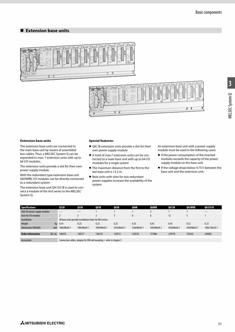
51
Basic components
1
2
3
MEL
SEC S
yste
m Q
Extension base units
Specifications Q52B Q55B Q63B Q65B Q68B Q68RB Q612B Q65WRB QA1S51BSlots for power supply modules — — 1 1 1 2 1 1 —Slots for I/O modules 2 5 3 5 8 8 12 5 1Installation All base units provide installation holes for M4 screws.Weight kg 0.14 0.23 0.23 0.25 0.35 0.45 0.45 0.52 0.23Dimensions (WxHxD) mm 106x98x44.1 189x98x44.1 189x98x44.1 245x98x44.1 328x98x44.1 439x98x44.1 439x98x44.1 439x98x44.1 100x130x50.7
Order information Art. no. 140376 140377 136370 129572 129578 157066 129579 210163 249092
Accessories Connection cables; adapter for DIN rail mounting > refer to chapter 5
Extension base units
The extension base units are connected to the main base unit by means of assembled bus cables. Thus, a MELSEC System Q can be expanded to max. 7 extension units with up to 64 I/O modules.
The extension units provide a slot for their own power supply module.
With the redundant type extension base unit Q65WRB, I/O modules can be directly connected to a redundant system.
The extension base unit QA1S51B is used to con-nect a module of the AnS series to the MELSEC System Q.
Special features:
z Q6mB extension units provide a slot for their own power supply module
z A total of max.7 extension units can be con-nected to a main base unit with up to 64 I/O modules for a single system
z The maximum distance from the first to the last base unit is 13.2 m.
z Base units with slots for two redundant power supplies increase the availability of the system.
An extension base unit with a power supply module must be used in the following cases:
z If the power consumption of the inserted modules exceeds the capacity of the power supply module on the base unit.
z If the voltage drops below 4.75 V between the base unit and the extension unit.
BAMODSERIAL
SE UNITEL Q38B
Q68B(N)
POWER
I / 07 I / 08I / 06I / 05I / 04I / 03
E.S.DI / 02I / 01I / 00
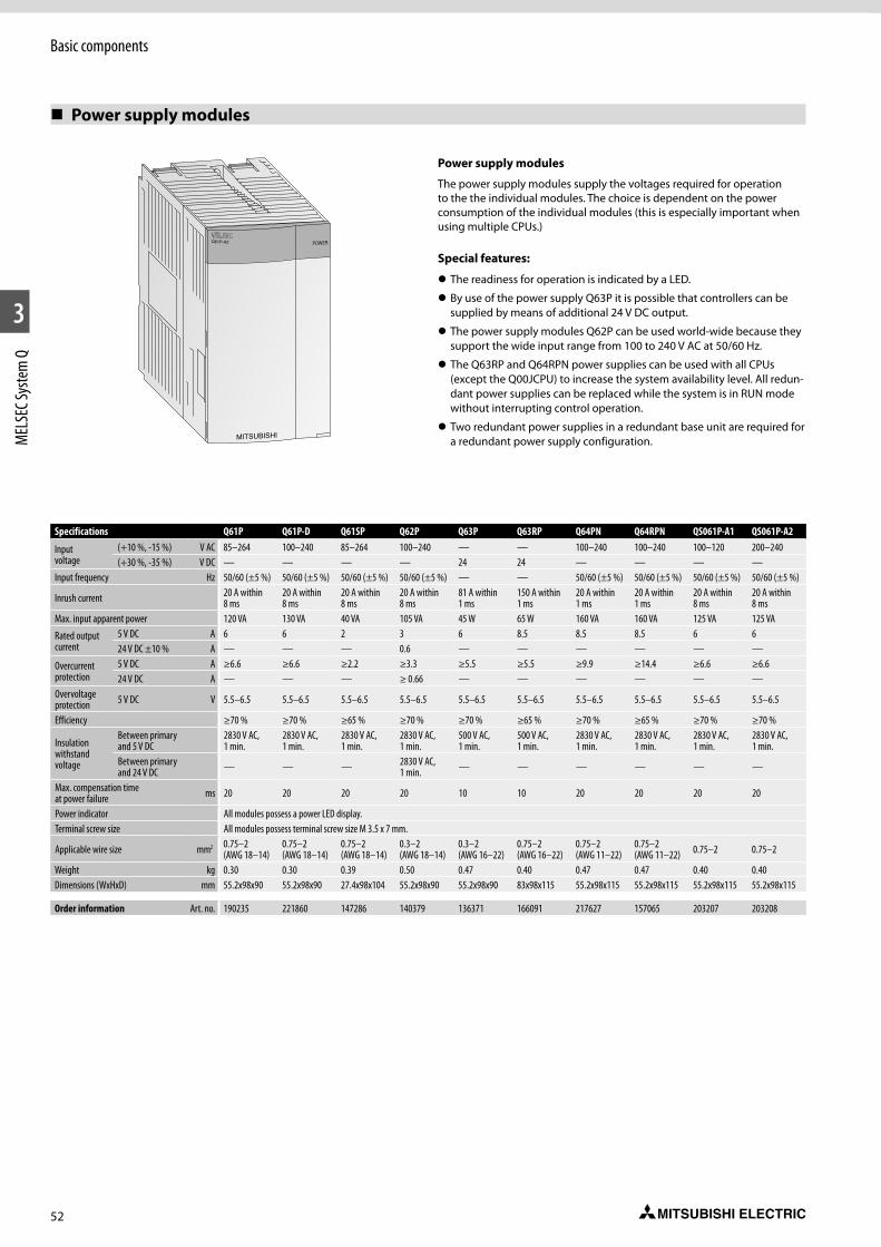
52
Basic components
1
2
3
MEL
SEC S
yste
m Q
Power supply modules
Power supply modules
The power supply modules supply the voltages required for operation to the the individual modules. The choice is dependent on the power consumption of the individual modules (this is especially important when using multiple CPUs.)
Special features:
z The readiness for operation is indicated by a LED.
z By use of the power supply Q63P it is possible that controllers can be supplied by means of additional 24 V DC output.
z The power supply modules Q62P can be used world-wide because they support the wide input range from 100 to 240 V AC at 50/60 Hz.
z The Q63RP and Q64RPN power supplies can be used with all CPUs (except the Q00JCPU) to increase the system availability level. All redun-dant power supplies can be replaced while the system is in RUN mode without interrupting control operation.
z Two redundant power supplies in a redundant base unit are required for a redundant power supply configuration.
Specifications Q61P Q61P-D Q61SP Q62P Q63P Q63RP Q64PN Q64RPN QS061P-A1 QS061P-A2
Input voltage
(+10 %, -15 %) V AC 85–264 100–240 85–264 100–240 — — 100–240 100–240 100–120 200–240(+30 %, -35 %) V DC — — — — 24 24 — — — —
Input frequency Hz 50/60 (±5 %) 50/60 (±5 %) 50/60 (±5 %) 50/60 (±5 %) — — 50/60 (±5 %) 50/60 (±5 %) 50/60 (±5 %) 50/60 (±5 %)
Inrush current 20 A within 8 ms
20 A within 8 ms
20 A within 8 ms
20 A within 8 ms
81 A within 1 ms
150 A within 1 ms
20 A within 1 ms
20 A within 1 ms
20 A within 8 ms
20 A within 8 ms
Max. input apparent power 120 VA 130 VA 40 VA 105 VA 45 W 65 W 160 VA 160 VA 125 VA 125 VA
Rated output current
5 V DC A 6 6 2 3 6 8.5 8.5 8.5 6 624 V DC ±10 % A — — — 0.6 — — — — — —
Overcurrent protection
5 V DC A ≥6.6 ≥6.6 ≥2.2 ≥3.3 ≥5.5 ≥5.5 ≥9.9 ≥14.4 ≥6.6 ≥6.624 V DC A — — — ≥ 0.66 — — — — — —
Overvoltage protection 5 V DC V 5.5–6.5 5.5–6.5 5.5–6.5 5.5–6.5 5.5–6.5 5.5–6.5 5.5–6.5 5.5–6.5 5.5–6.5 5.5–6.5
Efficiency ≥70 % ≥70 % ≥65 % ≥70 % ≥70 % ≥65 % ≥70 % ≥65 % ≥70 % ≥70 %
Insulation withstand voltage
Between primary and 5 V DC
2830 V AC, 1 min.
2830 V AC, 1 min.
2830 V AC, 1 min.
2830 V AC, 1 min.
500 V AC, 1 min.
500 V AC, 1 min.
2830 V AC, 1 min.
2830 V AC, 1 min.
2830 V AC, 1 min.
2830 V AC, 1 min.
Between primary and 24 V DC — — — 2830 V AC,
1 min. — — — — — —
Max. compensation time at power failure ms 20 20 20 20 10 10 20 20 20 20
Power indicator All modules possess a power LED display.Terminal screw size All modules possess terminal screw size M 3.5 x 7 mm.
Applicable wire size mm2 0.75–2 (AWG 18–14)
0.75–2 (AWG 18–14)
0.75–2 (AWG 18–14)
0.3–2 (AWG 18–14)
0.3–2 (AWG 16–22)
0.75–2 (AWG 16–22)
0.75–2 (AWG 11–22)
0.75–2 (AWG 11–22) 0.75–2 0.75–2
Weight kg 0.30 0.30 0.39 0.50 0.47 0.40 0.47 0.47 0.40 0.40Dimensions (WxHxD) mm 55.2x98x90 55.2x98x90 27.4x98x104 55.2x98x90 55.2x98x90 83x98x115 55.2x98x115 55.2x98x115 55.2x98x115 55.2x98x115
Order information Art. no. 190235 221860 147286 140379 136371 166091 217627 157065 203207 203208
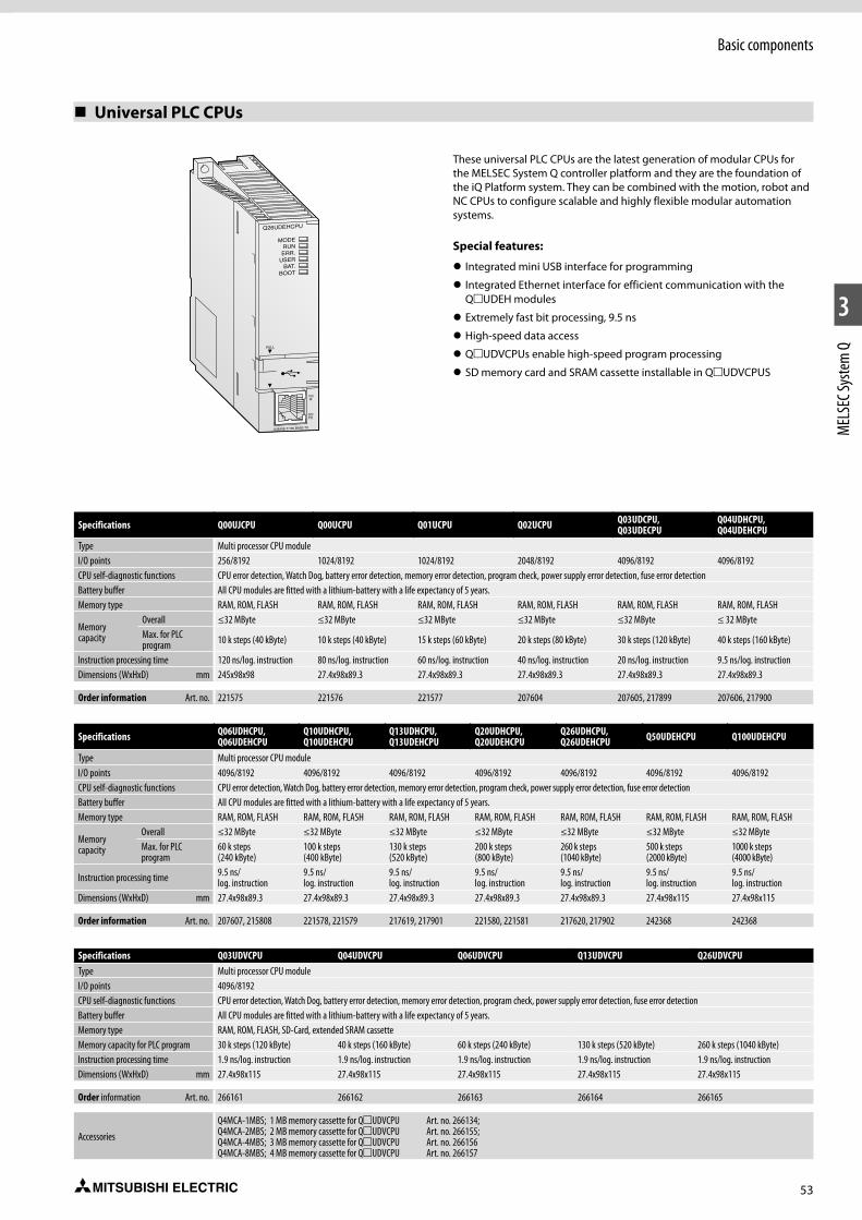
53
Basic components
1
2
3
MEL
SEC S
yste
m Q
Universal PLC CPUs
Specifications Q00UJCPU Q00UCPU Q01UCPU Q02UCPU Q03UDCPU, Q03UDECPU
Q04UDHCPU, Q04UDEHCPU
Type Multi processor CPU moduleI/O points 256/8192 1024/8192 1024/8192 2048/8192 4096/8192 4096/8192CPU self-diagnostic functions CPU error detection, Watch Dog, battery error detection, memory error detection, program check, power supply error detection, fuse error detectionBattery buffer All CPU modules are fitted with a lithium-battery with a life expectancy of 5 years.Memory type RAM, ROM, FLASH RAM, ROM, FLASH RAM, ROM, FLASH RAM, ROM, FLASH RAM, ROM, FLASH RAM, ROM, FLASH
Memory capacity
Overall ≤32 MByte ≤32 MByte ≤32 MByte ≤32 MByte ≤32 MByte ≤ 32 MByteMax. for PLC program 10 k steps (40 kByte) 10 k steps (40 kByte) 15 k steps (60 kByte) 20 k steps (80 kByte) 30 k steps (120 kByte) 40 k steps (160 kByte)
Instruction processing time 120 ns/log. instruction 80 ns/log. instruction 60 ns/log. instruction 40 ns/log. instruction 20 ns/log. instruction 9.5 ns/log. instructionDimensions (WxHxD) mm 245x98x98 27.4x98x89.3 27.4x98x89.3 27.4x98x89.3 27.4x98x89.3 27.4x98x89.3
Order information Art. no. 221575 221576 221577 207604 207605, 217899 207606, 217900
These universal PLC CPUs are the latest generation of modular CPUs for the MELSEC System Q controller platform and they are the foundation of the iQ Platform system. They can be combined with the motion, robot and NC CPUs to configure scalable and highly flexible modular automation systems.
Special features:
z Integrated mini USB interface for programming
z Integrated Ethernet interface for efficient communication with the QmUDEH modules
z Extremely fast bit processing, 9.5 ns
z High-speed data access
z QmUDVCPUs enable high-speed program processing
z SD memory card and SRAM cassette installable in QmUDVCPUS
Specifications Q06UDHCPU, Q06UDEHCPU
Q10UDHCPU, Q10UDEHCPU
Q13UDHCPU, Q13UDEHCPU
Q20UDHCPU, Q20UDEHCPU
Q26UDHCPU, Q26UDEHCPU Q50UDEHCPU Q100UDEHCPU
Type Multi processor CPU moduleI/O points 4096/8192 4096/8192 4096/8192 4096/8192 4096/8192 4096/8192 4096/8192CPU self-diagnostic functions CPU error detection, Watch Dog, battery error detection, memory error detection, program check, power supply error detection, fuse error detectionBattery buffer All CPU modules are fitted with a lithium-battery with a life expectancy of 5 years.Memory type RAM, ROM, FLASH RAM, ROM, FLASH RAM, ROM, FLASH RAM, ROM, FLASH RAM, ROM, FLASH RAM, ROM, FLASH RAM, ROM, FLASH
Memory capacity
Overall ≤32 MByte ≤32 MByte ≤32 MByte ≤32 MByte ≤32 MByte ≤32 MByte ≤32 MByteMax. for PLC program
60 k steps (240 kByte)
100 k steps (400 kByte)
130 k steps (520 kByte)
200 k steps (800 kByte)
260 k steps (1040 kByte)
500 k steps (2000 kByte)
1000 k steps (4000 kByte)
Instruction processing time 9.5 ns/ log. instruction
9.5 ns/ log. instruction
9.5 ns/ log. instruction
9.5 ns/ log. instruction
9.5 ns/ log. instruction
9.5 ns/ log. instruction
9.5 ns/ log. instruction
Dimensions (WxHxD) mm 27.4x98x89.3 27.4x98x89.3 27.4x98x89.3 27.4x98x89.3 27.4x98x89.3 27.4x98x115 27.4x98x115
Order information Art. no. 207607, 215808 221578, 221579 217619, 217901 221580, 221581 217620, 217902 242368 242368
Specifications Q03UDVCPU Q04UDVCPU Q06UDVCPU Q13UDVCPU Q26UDVCPUType Multi processor CPU moduleI/O points 4096/8192CPU self-diagnostic functions CPU error detection, Watch Dog, battery error detection, memory error detection, program check, power supply error detection, fuse error detectionBattery buffer All CPU modules are fitted with a lithium-battery with a life expectancy of 5 years.Memory type RAM, ROM, FLASH, SD-Card, extended SRAM cassetteMemory capacity for PLC program 30 k steps (120 kByte) 40 k steps (160 kByte) 60 k steps (240 kByte) 130 k steps (520 kByte) 260 k steps (1040 kByte)Instruction processing time 1.9 ns/log. instruction 1.9 ns/log. instruction 1.9 ns/log. instruction 1.9 ns/log. instruction 1.9 ns/log. instructionDimensions (WxHxD) mm 27.4x98x115 27.4x98x115 27.4x98x115 27.4x98x115 27.4x98x115
Order information Art. no. 266161 266162 266163 266164 266165
Accessories
Q4MCA-1MBS; 1 MB memory cassette for QmUDVCPU Art. no. 266134; Q4MCA-2MBS; 2 MB memory cassette for QmUDVCPU Art. no. 266155; Q4MCA-4MBS; 3 MB memory cassette for QmUDVCPU Art. no. 266156 Q4MCA-8MBS; 4 MB memory cassette for QmUDVCPU Art. no. 266157
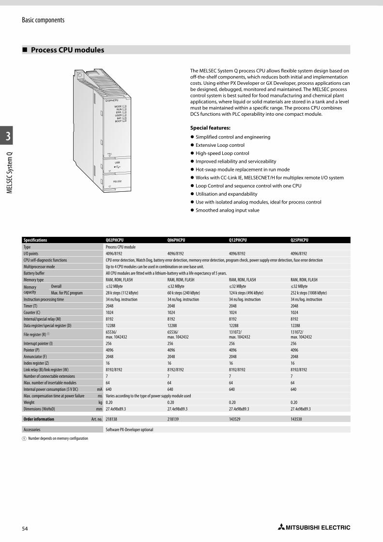
54
Basic components
1
2
3
MEL
SEC S
yste
m Q
Process CPU modules
Q12PHCPU
RS-232
USB
PULL
MODERUNERR.
USERBAT.
BOOT
The MELSEC System Q process CPU allows flexible system design based on off-the-shelf components, which reduces both initial and implementation costs. Using either PX Developer or GX Developer, process applications can be designed, debugged, monitored and maintained. The MELSEC process control system is best suited for food manufacturing and chemical plant applications, where liquid or solid materials are stored in a tank and a level must be maintained within a specific range. The process CPU combines DCS functions with PLC operability into one compact module.
Special features:
z Simplified control and engineering
z Extensive Loop control
z High-speed Loop control
z Improved reliability and serviceability
z Hot-swap module replacement in run mode
z Works with CC-Link IE, MELSECNET/H for multiplex remote I/O system
z Loop Control and sequence control with one CPU
z Utilisation and expandability
z Use with isolated analog modules, ideal for process control
z Smoothed analog input value
Specifications Q02PHCPU Q06PHCPU Q12PHCPU Q25PHCPUType Process CPU moduleI/O points 4096/8192 4096/8192 4096/8192 4096/8192CPU self-diagnostic functions CPU error detection, Watch Dog, battery error detection, memory error detection, program check, power supply error detection, fuse error detectionMultiprocessor mode Up to 4 CPU modules can be used in combination on one base unit.Battery buffer All CPU modules are fitted with a lithium-battery with a life expectancy of 5 years.Memory type RAM, ROM, FLASH RAM, ROM, FLASH RAM, ROM, FLASH RAM, ROM, FLASH
Memory capacity
Overall ≤32 MByte ≤32 MByte ≤32 MByte ≤32 MByteMax. for PLC program 28 k steps (112 kByte) 60 k steps (240 kByte) 124 k steps (496 kByte) 252 k steps (1008 kByte)
Instruction processing time 34 ns/log. instruction 34 ns/log. instruction 34 ns/log. instruction 34 ns/log. instructionTimer (T) 2048 2048 2048 2048Counter (C) 1024 1024 1024 1024Internal/special relay (M) 8192 8192 8192 8192Data register/special register (D) 12288 12288 12288 12288
File register (R) 1 65536/ max. 1042432
65536/ max. 1042432
131072/ max. 1042432
131072/ max. 1042432
Interrupt pointer (I) 256 256 256 256Pointer (P) 4096 4096 4096 4096Annunciator (F) 2048 2048 2048 2048Index register (Z) 16 16 16 16Link relay (B)/link register (W) 8192/8192 8192/8192 8192/8192 8192/8192 Number of connectable extensions 7 7 7 7Max. number of insertable modules 64 64 64 64Internal power consumption (5 V DC) mA 640 640 640 640Max. compensation time at power failure ms Varies according to the type of power supply module usedWeight kg 0.20 0.20 0.20 0.20Dimensions (WxHxD) mm 27.4x98x89.3 27.4x98x89.3 27.4x98x89.3 27.4x98x89.3
Order information Art. no. 218138 218139 143529 143530
Accessories Software PX-Developer optional
1 Number depends on memory configuration
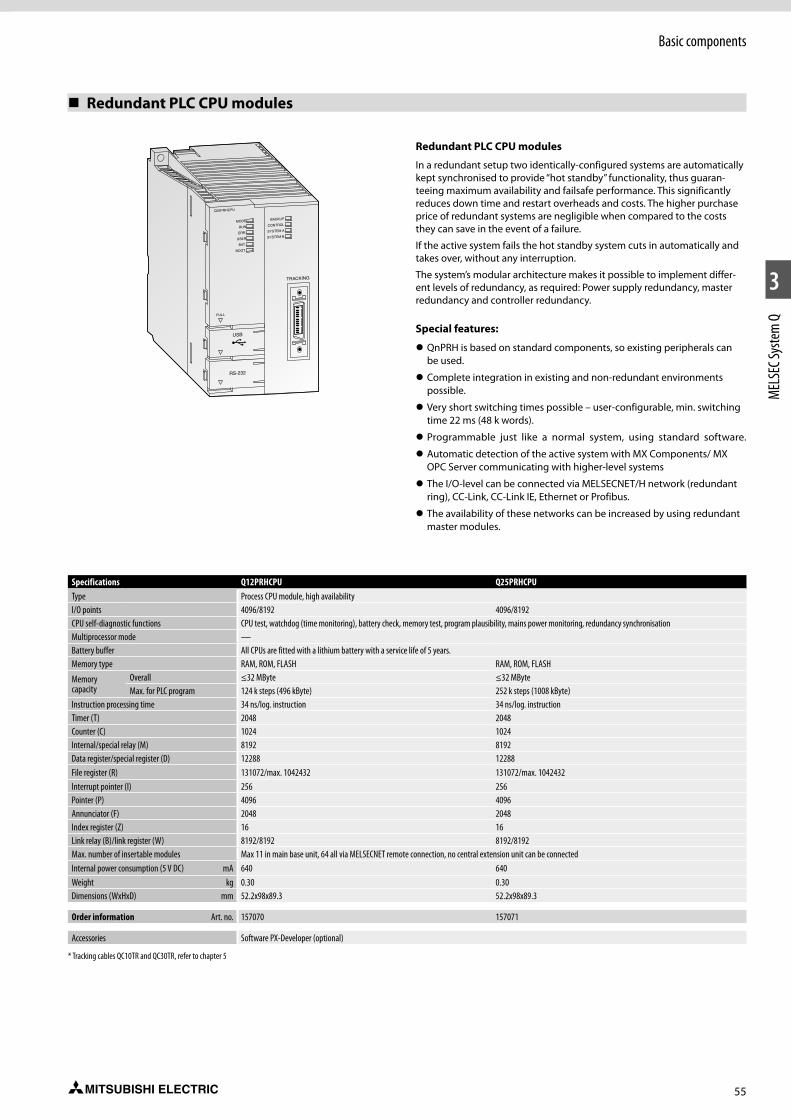
55
Basic components
1
2
3
MEL
SEC S
yste
m Q
Redundant PLC CPU modules
Specifications Q12PRHCPU Q25PRHCPUType Process CPU module, high availabilityI/O points 4096/8192 4096/8192CPU self-diagnostic functions CPU test, watchdog (time monitoring), battery check, memory test, program plausibility, mains power monitoring, redundancy synchronisationMultiprocessor mode —Battery buffer All CPUs are fitted with a lithium battery with a service life of 5 years.Memory type RAM, ROM, FLASH RAM, ROM, FLASH
Memory capacity
Overall ≤32 MByte ≤32 MByteMax. for PLC program 124 k steps (496 kByte) 252 k steps (1008 kByte)
Instruction processing time 34 ns/log. instruction 34 ns/log. instructionTimer (T) 2048 2048Counter (C) 1024 1024Internal/special relay (M) 8192 8192Data register/special register (D) 12288 12288File register (R) 131072/max. 1042432 131072/max. 1042432Interrupt pointer (I) 256 256Pointer (P) 4096 4096Annunciator (F) 2048 2048Index register (Z) 16 16Link relay (B)/link register (W) 8192/8192 8192/8192 Max. number of insertable modules Max 11 in main base unit, 64 all via MELSECNET remote connection, no central extension unit can be connectedInternal power consumption (5 V DC) mA 640 640Weight kg 0.30 0.30Dimensions (WxHxD) mm 52.2x98x89.3 52.2x98x89.3
Order information Art. no. 157070 157071
Accessories Software PX-Developer (optional)
* Tracking cables QC10TR and QC30TR, refer to chapter 5
Redundant PLC CPU modules
In a redundant setup two identically-configured systems are automatically kept synchronised to provide “hot standby” functionality, thus guaran-teeing maximum availability and failsafe performance. This significantly reduces down time and restart overheads and costs. The higher purchase price of redundant systems are negligible when compared to the costs they can save in the event of a failure.
If the active system fails the hot standby system cuts in automatically and takes over, without any interruption.
The system’s modular architecture makes it possible to implement differ-ent levels of redundancy, as required: Power supply redundancy, master redundancy and controller redundancy.
Special features:
z QnPRH is based on standard components, so existing peripherals can be used.
z Complete integration in existing and non-redundant environments possible.
z Very short switching times possible – user-configurable, min. switching time 22 ms (48 k words).
z Programmable just like a normal system, using standard software.
z Automatic detection of the active system with MX Components/ MX OPC Server communicating with higher-level systems
z The I/O-level can be connected via MELSECNET/H network (redundant ring), CC-Link, CC-Link IE, Ethernet or Profibus.
z The availability of these networks can be increased by using redundant master modules.
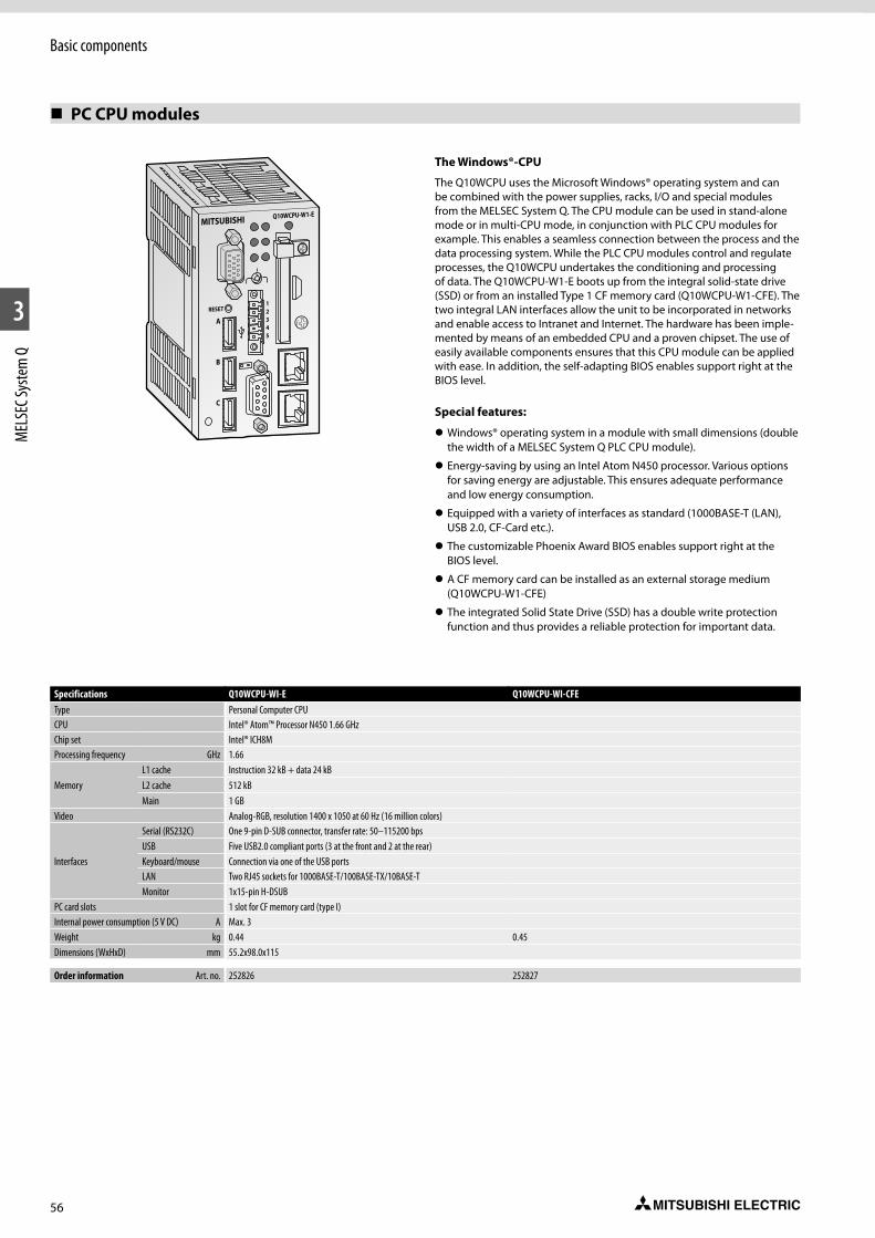
56
Basic components
1
2
3
MEL
SEC S
yste
m Q
PC CPU modules
Specifications Q10WCPU-WI-E Q10WCPU-WI-CFEType Personal Computer CPUCPU Intel® Atom™ Processor N450 1.66 GHzChip set Intel® ICH8MProcessing frequency GHz 1.66
MemoryL1 cache Instruction 32 kB + data 24 kBL2 cache 512 kBMain 1 GB
Video Analog-RGB, resolution 1400 x 1050 at 60 Hz (16 million colors)
Interfaces
Serial (RS232C) One 9-pin D-SUB connector, transfer rate: 50–115200 bpsUSB Five USB2.0 compliant ports (3 at the front and 2 at the rear)Keyboard/mouse Connection via one of the USB portsLAN Two RJ45 sockets for 1000BASE-T/100BASE-TX/10BASE-TMonitor 1x15-pin H-DSUB
PC card slots 1 slot for CF memory card (type I) Internal power consumption (5 V DC) A Max. 3Weight kg 0.44 0.45Dimensions (WxHxD) mm 55.2x98.0x115
Order information Art. no. 252826 252827
The Windows®-CPU
The Q10WCPU uses the Microsoft Windows® operating system and can be combined with the power supplies, racks, I/O and special modules from the MELSEC System Q. The CPU module can be used in stand-alone mode or in multi-CPU mode, in conjunction with PLC CPU modules for example. This enables a seamless connection between the process and the data processing system. While the PLC CPU modules control and regulate processes, the Q10WCPU undertakes the conditioning and processing of data. The Q10WCPU-W1-E boots up from the integral solid-state drive (SSD) or from an installed Type 1 CF memory card (Q10WCPU-W1-CFE). The two integral LAN interfaces allow the unit to be incorporated in networks and enable access to Intranet and Internet. The hardware has been imple-mented by means of an embedded CPU and a proven chipset. The use of easily available components ensures that this CPU module can be applied with ease. In addition, the self-adapting BIOS enables support right at the BIOS level.
Special features:
z Windows® operating system in a module with small dimensions (double the width of a MELSEC System Q PLC CPU module).
z Energy-saving by using an Intel Atom N450 processor. Various options for saving energy are adjustable. This ensures adequate performance and low energy consumption.
z Equipped with a variety of interfaces as standard (1000BASE-T (LAN), USB 2.0, CF-Card etc.).
z The customizable Phoenix Award BIOS enables support right at the BIOS level.
z A CF memory card can be installed as an external storage medium (Q10WCPU-W1-CFE)
z The integrated Solid State Drive (SSD) has a double write protection function and thus provides a reliable protection for important data.
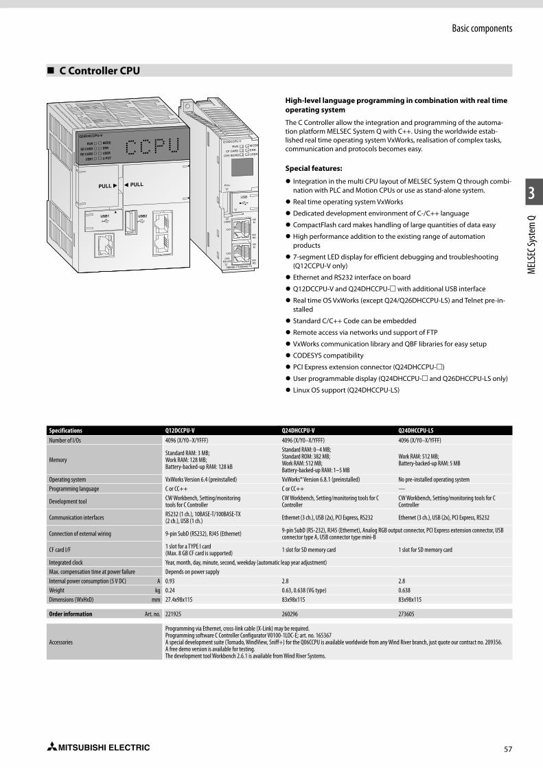
57
Basic components
1
2
3
MEL
SEC S
yste
m Q
C Controller CPU
Specifications Q12DCCPU-V Q24DHCCPU-V Q24DHCCPU-LSNumber of I/Os 4096 (X/Y0–X/YFFF) 4096 (X/Y0–X/YFFF) 4096 (X/Y0–X/YFFF)
MemoryStandard RAM: 3 MB; Work RAM: 128 MB; Battery-backed-up RAM: 128 kB
Standard RAM: 0–4 MB; Standard ROM: 382 MB; Work RAM: 512 MB;Battery-backed-up RAM: 1–5 MB
Work RAM: 512 MB; Battery-backed-up RAM: 5 MB
Operating system VxWorks Version 6.4 (preinstalled) VxWorks® Version 6.8.1 (preinstalled) No pre-installed operating systemProgramming language C or CC++ C or CC++ —
Development tool CW Workbench, Setting/monitoringtools for C Controller
CW Workbench, Setting/monitoring tools for C Controller
CW Workbench, Setting/monitoring tools for C Controller
Communication interfaces RS232 (1 ch.), 10BASE-T/100BASE-TX (2 ch.), USB (1 ch.) Ethernet (3 ch.), USB (2x), PCI Express, RS232 Ethernet (3 ch.), USB (2x), PCI Express, RS232
Connection of external wiring 9-pin SubD (RS232), RJ45 (Ethernet) 9-pin SubD (RS-232), RJ45 (Ethernet), Analog RGB output connector, PCI Express extension connector, USB connector type A, USB connector type mini-B
CF card I/F 1 slot for a TYPE I card (Max. 8 GB CF card is supported) 1 slot for SD memory card 1 slot for SD memory card
Integrated clock Year, month, day, minute, second, weekday (automatic leap year adjustment)Max. compensation time at power failure Depends on power supplyInternal power consumption (5 V DC) A 0.93 2.8 2.8Weight kg 0.24 0.63, 0.638 (VG type) 0.638Dimensions (WxHxD) mm 27.4x98x115 83x98x115 83x98x115
Order information Art. no. 221925 260296 273605
Accessories
Programming via Ethernet, cross-link cable (X-Link) may be required. Programming software C Controller Configurator V0100-1LOC-E; art. no. 165367A special development suite (Tornado, WindView, Sniff+) for the Q06CCPU is available worldwide from any Wind River branch, just quote our contract no. 209356. A free demo version is available for testing.The development tool Workbench 2.6.1 is available from Wind River Systems.
High-level language programming in combination with real time operating system
The C Controller allow the integration and programming of the automa-tion platform MELSEC System Q with C++. Using the worldwide estab-lished real time operating system VxWorks, realisation of complex tasks, communication and protocols becomes easy.
Special features:
z Integration in the multi CPU layout of MELSEC System Q through combi-nation with PLC and Motion CPUs or use as stand-alone system.
z Real time operating system VxWorks
z Dedicated development environment of C-/C++ language
z CompactFlash card makes handling of large quantities of data easy
z High performance addition to the existing range of automation products
z 7-segment LED display for efficient debugging and troubleshooting (Q12CCPU-V only)
z Ethernet and RS232 interface on board
z Q12DCCPU-V and Q24DHCCPU-m with additional USB interface
z Real time OS VxWorks (except Q24/Q26DHCCPU-LS) and Telnet pre-in-stalled
z Standard C/C++ Code can be embedded
z Remote access via networks und support of FTP
z VxWorks communication library and QBF libraries for easy setup
z CODESYS compatibility
z PCI Express extension connector (Q24DHCCPU-m)
z User programmable display (Q24DHCCPU-m and Q26DHCCPU-LS only)
z Linux OS support (Q24DHCCPU-LS)

58
Basic components
1
2
3
MEL
SEC S
yste
m Q
Motion CPU modules
Specifications Q172DSCPU Q173DSCPUType Motion CPU Motion CPUI/O points 8192 8192No. of control axes 16 32Interpolation functions Linear interpolation for up to 4 axes, circular interpolation for 2 axes, helical interpolation for 3 axes
Positioning
Method PTP (point to point), speed control/speed-position control, fixed pitch feed, constant speed control, position follow-up control, speed switching control, high-speed oscillation control, synchronous control (SV22)
Acceleration/ deceleration control Automatic trapezoidal acceleration/deceleration, S-curve acceleration/deceleration
Compensation Backlash compensation, electronic gearProgramming language Motion SFC, dedicated instructions, software for conveyor assembly (SV13), virtual mechanical support language (SV22)
Processing speed
SV130.22 ms (1.–4. axis), 0.44 ms (5.–10.axis), 0.88 ms (11.–16.axis)
0.22 ms (1.–4. axis),0.44 ms (5.–10. axis),0.88 ms (11.–24. axis)1.77 ms (25.–32. axis)
SV22 0.44 ms (1.–6. axis), 0.88 ms (7.–16. axis)
0.44 ms (1.–6. axis),0.88 ms (7.–16. axis)1.77 ms (17.–32. axis)
Program capacity 16 k steps 16 k stepsNo. of positioning points 3200
Program execution
Number of multi executed programs Max. 256
Number of multi active steps Max. 256 steps in all programs
Executed tasks
normal Executed in motion main cycle
interrupt Executed in fixed cycles (0.88 ms, 1.7 ms, 3.5 ms, 7.1 ms, 14.2 ms), 16 external interrupt points (QI60 interrupt module inputs), executed with interrupt from PLC CPU (when executing the S(P).GINT instruction)
NMI 16 points; executed when input ON is set among an interrupt module (e.g. QI60)Interfaces SSCNETIII/H (USB, RS232C via PLC CPU)Real I/O points (PX/PY) 256 (these I/Os can be allocated directly to the motion CPU)Certifications CE, UL & cUL CE, UL & cULInternal power consumption (5 V DC) A 1.44 1.75Weight kg 0.38 0.38Dimensions (WxHxD) mm 27.4x120.5x120.3 27.4x120.5x120.3
Order information Art. no. 248700 248701
Accessories Interface modules for manual pulse generator, encoder and external signals (for detailed information please refer to the catalogue “Motion Controller MELSEC System Q”.)
The high-speed dynamic motion CPU
The motion controller CPU controls and synchronizes the connected servo amplifiers and servo motors. A motion system besides the controller CPU as well includes a PLC CPU. Only after combining a highly dynamic positioning control and a PLC an innovative and autarkical motion control system is created.
While the Motion CPU controls large-scale servo movements the PLC CPU is responsible for the machine control and the communication at the same time.
Special features:
z Using multiple CPUs to distribute the load improves the overall perfor-mance of the whole system
z Use of up to 3 motion CPUs within one system
z Large scale control system for up to 96 axes per system
z Interpolation of 4 axes simultaneously
z Software cam control
z Virtual and real master axes
z Integration in the high-speed SSCNETIII/H network for communication with high-performance servo amplifiers at up to 150 Mbps

59
Basic components
1
2
3
MEL
SEC S
yste
m Q
Safety CPU module
Specifications QS001CPUI/O points 4096/8192Control method Cyclic program executionProgramming language (Sequence Control) Relay symbol language, function blockProcessing speed 0.10–0.35 µsConstant scan 1–2,000 ms (setting unit: 1 ms)Program capacity 14 k steps (56 kB)Memory capacity 128 kBMax. number of stored files 3Internal relay (M) 6144Link relay (B) 2048Timer (T) 512Counter (C) 512Data register (D) 6144Link register (W) 2048Annunciator (F) 1024RUN/PAUSE contact RUN contact: 1 point can be set in the range of X0 to 17FF, PAUSE contact: noneClock function Year, month, date, hour, minute, second, day (automatic leap-year detectionInternal power consumption(5 V DC) A 0.43Weight kg 0.29Dimensions (WxHxD) mm 55.2x98x113.8
Order information Art. no. 203205
Safety control with QS safety PLC
The CC-Link safety network eliminates the complex wiring needed in conventional safety controller systems. The remote safety I/O stations are connected to the CC-Link safety master module in the safety PLC using standard CC-Link cables. In the event of communications errors powerful and effective error identification routines automatically switch off the outputs of both the safety PLC and the remote safety I/O stations.
CC-Link safety is also compatible with CC-Link. This means you can also use standard CC-Link I/O modules in a CC-Link safety network for those inputs and outputs that are not critical for safety.
Special features:
z Conforms to the safety requirements of EN 954-1 Category 4, ISO 13849-1 PL e, and IEC 61508 (JIS C 0508) SIL 3 and certified by TÜV Rheinland
z Automatic checking of safety inputs and outputs and external devices (cable breaks, short circuits, fused contactor contacts etc.)
z Program and configure with the familiar GX Developer programming software packages. No new skills or software are required.
z Reduced wiring requirements cuts costs
z Comprehensive diagnostics functions
z Versatile: A single safety CPU can control up to 84 remote safety stations
z The CC-Link standard enables connection of third-party products com-patible with the safety concept
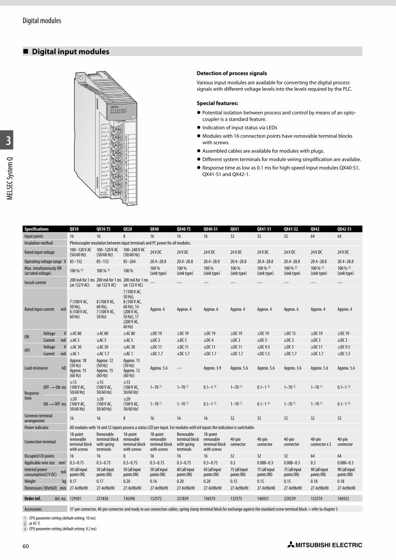
60
1
2
3
MEL
SEC S
yste
m Q
Digital modules
1
0
3
5
7
9
B
D
F
2
4
6
8
A
C
E
NC100VDC8mA60Hz7mA50Hz
COM
0123456789ABCDEF
QX100 1 2 3 4 5 6 78 9 A B C D E F
Detection of process signals
Various input modules are available for converting the digital process signals with different voltage levels into the levels required by the PLC.
Special features:
z Potential isolation between process and control by means of an opto-coupler is a standard feature.
z Indication of input status via LEDs
z Modules with 16 connection points have removable terminal blocks with screws.
z Assembled cables are available for modules with plugs.
z Different system terminals for module wiring simplification are availabe.
z Response time as low as 0.1 ms for high-speed input modules QX40-S1, QX41-S1 and QX42-1.
Digital input modules
Specifications QX10 QX10-TS QX28 QX40 QX40-TS QX40-S1 QX41 QX41-S1 QX41-S2 QX42 QX42-S1 QX50 QX70 QX71 QX72 QX80 QX80-TS QX81 QX81-S2 QX82 QX82-S1Input points 16 16 8 16 16 16 32 32 32 64 64 16 16 32 64 16 16 32 32 64 64Insulation method Photocoupler insulation between input terminals and PC power for all modules.
Rated input voltage 100–120 V AC (50/60 Hz)
100–120 V AC (50/60 Hz)
100–240 V AC (50/60 Hz) 24 V DC 24 V DC 24 V DC 24 V DC 24 V DC 24 V DC 24 V DC 24 V DC 48 V DC 5 V DC/12 V DC 5 V DC/12 V DC 5 V DC/12 V DC 24 V DC 24 V DC 24 V DC 24 V DC 24 V DC 24 V DC
Operating voltage range V 85–132 85–132 85–264 20.4–28.8 20.4–28.8 20.4–28.8 20.4–28.8 20.4–28.8 20.4–28.8 20.4–28.8 20.4–28.8 40.8–52.8 4.5–6/10.2–14.4 4.5–6/10.2–14.4 4.5–6/10.2–14.4 20.4–28.8 20.4–28.8 20.4–28.8 20.4–28.8 20.4–28.8 20.4–28.8Max. simultaneously ON (at rated voltage) 100 % 2 100 % 2 100 % 100 %
(sink type)100 % (sink type)
100 % (sink type)
100 % (sink type)
100 % 2(sink type)
100 % 2(sink type)
100 % 2 (sink type)
100 % 2(sink type) 100 % 100 % 100 % 100 % 100 % 100 % 100 % 100 % (at 40 °C) 100 % 2 100 % 2
Inrush current 200 mA for 1 ms (at 132 V AC)
200 mA for 1 ms (at 132 V AC)
200 mA for 1 ms (at 132 V AC) — — — — — — — — — — — — — — — — — —
Rated input current mA
7 (100 V AC, 50 Hz), 8 (100 V AC, 60 Hz)
8 (100 V AC, 60 Hz), 7 (100 V AC, 50 Hz)
7 (100 V AC, 50 Hz), 8 (100 V AC, 60 Hz), 14 (200 V AC, 50 Hz), 17 (200 V AC, 60 Hz)
Approx. 4 Approx. 4 Approx. 6 Approx. 4 Approx. 4 Approx. 6 Approx. 4 Approx. 4 Approx. 4 5 V DC: approx. 1.212 V DC: approx. 3.3
5 V DC: approx. 1.212 V DC: approx. 3.3
5 V DC: approx. 1.212 V DC: approx. 3.3 Approx. 4 Approx. 4 Approx. 4 Approx. 6 Approx. 4 Approx. 4
ONVoltage V ≥AC 80 ≥AC 80 ≥AC 80 ≥DC 19 ≥DC 19 ≥DC 19 ≥DC 19 ≥DC 19 ≥DC 15 ≥DC 19 ≥DC 19 ≥DC 28 ≥DC 3.5 ≥DC 3.5 ≥DC 3.5 ≥DC 19 ≥DC 19 ≥DC 19 ≥DC 15 ≥DC 19 ≥DC 19Current mA ≥AC 5 ≥AC 5 ≥AC 5 ≥DC 3 ≥DC 3 ≥DC 4 ≥DC 3 ≥DC 3 ≥DC 3 ≥DC 3 ≥DC 3 ≥DC 2.5 ≥DC 1 ≥DC 1 ≥DC 3 ≥DC 3 ≥DC 3 ≥DC 3 ≥DC 3 ≥DC 3 ≥DC 3
OFFVoltage V ≤AC 30 ≤AC 30 ≤AC 30 ≤DC 11 ≤DC 11 ≤DC 11 ≤DC 11 ≤DC 9.5 ≤DC 5 ≥DC 11 ≤DC 9.5 ≥DC 10 ≤DC 1 ≤DC 1 ≤DC 1 ≤DC 11 ≤DC 11 ≤DC 11 ≤DC 5 ≤DC 11 ≤DC 9.5Current mA ≤AC 1 ≤AC 1.7 ≤AC 1 ≤DC 1.7 ≤DC 1.7 ≤DC 1.7 ≤DC 1.7 ≤DC 1.5 ≤DC 1.7 ≥DC 1.7 ≤DC 1.5 ≥DC 1.7 ≤DC 0.1 ≤DC 0.1 ≤DC 0.1 ≤DC 1.7 ≤DC 1.7 ≤DC 1.7 ≤DC 1.7 ≤DC 1.7 ≤DC 1.5
Load resistance kΩ
Approx. 18 (50 Hz) Approx. 15 (60 Hz)
Approx. 12 (50 Hz) Approx. 15 (60 Hz)
Approx. 15 (50 Hz) Approx. 12 (60 Hz)
Approx. 5.6 — Approx. 3.9 Approx. 5.6 Approx. 5.6 Approx. 3.6 Approx. 5.6 Approx. 5.6 Approx. 11.2 Approx. 3.3 Approx. 3.3 Approx. 3.3 Approx. 5.6 Approx. 5.6 Approx. 5.6 Approx. 3.6 Approx. 5.6 Approx. 5.6
Response time
OFF R ON ms≤15 (100 V AC, 50/60 Hz)
≤15 (100 V AC, 50/60 Hz)
≤15 (100 V AC, 50/60 Hz)
1–70 1 1–70 1 0.1–1 3 1–70 1 0.1–1 3 1–70 1 1–70 1 0.1–1 3 1–70 1 1–70 1 1–70 1 1–70 1 1–70 1 1–70 1 1–70 1 1–70 1 1–70 1 0.1–1 1
ON R OFF ms≤20 (100 V AC, 50/60 Hz)
≤20 (100 V AC, 50/60 Hz)
≤20 (100 V AC, 50/60 Hz)
1–70 1 1–70 1 0.1–1 3 1–70 1 0.1–1 3 1–70 1 1–70 1 0.1–1 3 1–70 1 1–70 1 1–70 1 1–70 1 1–70 1 1–70 1 1–70 1 1–70 1 1–70 1 0.1–1 1
Common terminal arrangement 16 16 8 16 16 16 32 32 32 32 32 16 16 32 32 16 16 32 32 32 32 x 2
Power indicator All modules with 16 and 32 inputs possess a status LED per input. For modules with 64 inputs the indication is switchable.
Connection terminal
18-point removable terminal block with screws
Removable terminal block with spring terminals
18-point removable terminal block with screws
18-point removable terminal block with screws
Removable terminal block with spring terminals
18-point removable terminal block with screws
40-pin connector
40-pin connector
40-pin connector
40-pin connector x 2
40-pin connector
18-point removable terminal block with screws
18-point removable terminal block with screws
40-pin connector 40-pin connector18-point removable terminal block with screws
Removable terminal block with spring terminals
Compact connector 37-pin D-Sub
37-pin D-sub connector 40-pin connector 40-pin connector x 2
Occupied I/O points 16 16 8 16 16 16 32 32 32 64 64 16 16 32 64 16 16 32 32 64 64Applicable wire size mm2 0.3–0.75 0.3–0.75 0.3–0.75 0.3–0.75 0.3–0.75 0.3–0.75 0.3 0.088–0.3 0.088–0.3 0.3 0.088–0.3 0.3–0.75 0.3–0.75 0.088–0.3 0.088–0.3 0.3–0.75 0.3–0.75 0.3 0.088–0.3 0.088–0.3 0.3Internal power consumption(5 V DC) mA 50 (all input
points ON)50 (all input points ON)
50 (all input points ON)
50 (all input points ON)
60 (all input points ON)
60 (all input points ON)
75 (all input points ON)
75 (all input points ON)
75 (all input points ON)
90 (all input points ON)
90 (all input points ON)
50 (all input points ON)
55 (all input points ON)
70 (all input points ON)
85 (all input points ON)
50 (all input points ON)
50 (all input points ON)
75 (all input points ON)
75 (all input points ON)
90 (all input points ON)
90 (all input points ON)
Weight kg 0.17 0.17 0.20 0.16 0.20 0.20 0.15 0.15 0.15 0.18 0.18 0.13 0.14 0.12 0.13 0.16 0.16 0.16 0.16 0.18 0.18Dimensions (WxHxD) mm 27.4x98x90 27.4x98x90 27.4x98x90 27.4x98x90 27.4x98x90 27.4x98x90 27.4x98x90 27.4x98x90 27.4x98x90 27.4x98x90 27.4x98x90 27.4x98x90 27.4x98x90 27.4x98x90 27.4x98x90 27.4x98x90 27.4x98x90 27.4x98x90 27.4x98x90 27.4x98x90 27.4x98x90
Order inf. Art. no. 129581 221838 136396 132572 221839 136574 132573 146921 229239 132574 146922 204678 136397 136398 136399 127587 221840 129594 229240 150836 150837
Accessories 37-pin connector, 40-pin connector and ready to use connection cables; spring clamp terminal block for exchange against the standard screw terminal block > refer to chapter 5
1 CPU parameter setting (default setting: 10 ms) 2 at 45 °C 3 CPU parameter setting (default setting: 0.2 ms)

61
Digital modules
1
2
3
MEL
SEC S
yste
m Q
Digital input modules
Specifications QX10 QX10-TS QX28 QX40 QX40-TS QX40-S1 QX41 QX41-S1 QX41-S2 QX42 QX42-S1 QX50 QX70 QX71 QX72 QX80 QX80-TS QX81 QX81-S2 QX82 QX82-S1Input points 16 16 8 16 16 16 32 32 32 64 64 16 16 32 64 16 16 32 32 64 64Insulation method Photocoupler insulation between input terminals and PC power for all modules.
Rated input voltage 100–120 V AC (50/60 Hz)
100–120 V AC (50/60 Hz)
100–240 V AC (50/60 Hz) 24 V DC 24 V DC 24 V DC 24 V DC 24 V DC 24 V DC 24 V DC 24 V DC 48 V DC 5 V DC/12 V DC 5 V DC/12 V DC 5 V DC/12 V DC 24 V DC 24 V DC 24 V DC 24 V DC 24 V DC 24 V DC
Operating voltage range V 85–132 85–132 85–264 20.4–28.8 20.4–28.8 20.4–28.8 20.4–28.8 20.4–28.8 20.4–28.8 20.4–28.8 20.4–28.8 40.8–52.8 4.5–6/10.2–14.4 4.5–6/10.2–14.4 4.5–6/10.2–14.4 20.4–28.8 20.4–28.8 20.4–28.8 20.4–28.8 20.4–28.8 20.4–28.8Max. simultaneously ON (at rated voltage) 100 % 2 100 % 2 100 % 100 %
(sink type)100 % (sink type)
100 % (sink type)
100 % (sink type)
100 % 2(sink type)
100 % 2(sink type)
100 % 2 (sink type)
100 % 2(sink type) 100 % 100 % 100 % 100 % 100 % 100 % 100 % 100 % (at 40 °C) 100 % 2 100 % 2
Inrush current 200 mA for 1 ms (at 132 V AC)
200 mA for 1 ms (at 132 V AC)
200 mA for 1 ms (at 132 V AC) — — — — — — — — — — — — — — — — — —
Rated input current mA
7 (100 V AC, 50 Hz), 8 (100 V AC, 60 Hz)
8 (100 V AC, 60 Hz), 7 (100 V AC, 50 Hz)
7 (100 V AC, 50 Hz), 8 (100 V AC, 60 Hz), 14 (200 V AC, 50 Hz), 17 (200 V AC, 60 Hz)
Approx. 4 Approx. 4 Approx. 6 Approx. 4 Approx. 4 Approx. 6 Approx. 4 Approx. 4 Approx. 4 5 V DC: approx. 1.212 V DC: approx. 3.3
5 V DC: approx. 1.212 V DC: approx. 3.3
5 V DC: approx. 1.212 V DC: approx. 3.3 Approx. 4 Approx. 4 Approx. 4 Approx. 6 Approx. 4 Approx. 4
ONVoltage V ≥AC 80 ≥AC 80 ≥AC 80 ≥DC 19 ≥DC 19 ≥DC 19 ≥DC 19 ≥DC 19 ≥DC 15 ≥DC 19 ≥DC 19 ≥DC 28 ≥DC 3.5 ≥DC 3.5 ≥DC 3.5 ≥DC 19 ≥DC 19 ≥DC 19 ≥DC 15 ≥DC 19 ≥DC 19Current mA ≥AC 5 ≥AC 5 ≥AC 5 ≥DC 3 ≥DC 3 ≥DC 4 ≥DC 3 ≥DC 3 ≥DC 3 ≥DC 3 ≥DC 3 ≥DC 2.5 ≥DC 1 ≥DC 1 ≥DC 3 ≥DC 3 ≥DC 3 ≥DC 3 ≥DC 3 ≥DC 3 ≥DC 3
OFFVoltage V ≤AC 30 ≤AC 30 ≤AC 30 ≤DC 11 ≤DC 11 ≤DC 11 ≤DC 11 ≤DC 9.5 ≤DC 5 ≥DC 11 ≤DC 9.5 ≥DC 10 ≤DC 1 ≤DC 1 ≤DC 1 ≤DC 11 ≤DC 11 ≤DC 11 ≤DC 5 ≤DC 11 ≤DC 9.5Current mA ≤AC 1 ≤AC 1.7 ≤AC 1 ≤DC 1.7 ≤DC 1.7 ≤DC 1.7 ≤DC 1.7 ≤DC 1.5 ≤DC 1.7 ≥DC 1.7 ≤DC 1.5 ≥DC 1.7 ≤DC 0.1 ≤DC 0.1 ≤DC 0.1 ≤DC 1.7 ≤DC 1.7 ≤DC 1.7 ≤DC 1.7 ≤DC 1.7 ≤DC 1.5
Load resistance kΩ
Approx. 18 (50 Hz) Approx. 15 (60 Hz)
Approx. 12 (50 Hz) Approx. 15 (60 Hz)
Approx. 15 (50 Hz) Approx. 12 (60 Hz)
Approx. 5.6 — Approx. 3.9 Approx. 5.6 Approx. 5.6 Approx. 3.6 Approx. 5.6 Approx. 5.6 Approx. 11.2 Approx. 3.3 Approx. 3.3 Approx. 3.3 Approx. 5.6 Approx. 5.6 Approx. 5.6 Approx. 3.6 Approx. 5.6 Approx. 5.6
Response time
OFF R ON ms≤15 (100 V AC, 50/60 Hz)
≤15 (100 V AC, 50/60 Hz)
≤15 (100 V AC, 50/60 Hz)
1–70 1 1–70 1 0.1–1 3 1–70 1 0.1–1 3 1–70 1 1–70 1 0.1–1 3 1–70 1 1–70 1 1–70 1 1–70 1 1–70 1 1–70 1 1–70 1 1–70 1 1–70 1 0.1–1 1
ON R OFF ms≤20 (100 V AC, 50/60 Hz)
≤20 (100 V AC, 50/60 Hz)
≤20 (100 V AC, 50/60 Hz)
1–70 1 1–70 1 0.1–1 3 1–70 1 0.1–1 3 1–70 1 1–70 1 0.1–1 3 1–70 1 1–70 1 1–70 1 1–70 1 1–70 1 1–70 1 1–70 1 1–70 1 1–70 1 0.1–1 1
Common terminal arrangement 16 16 8 16 16 16 32 32 32 32 32 16 16 32 32 16 16 32 32 32 32 x 2
Power indicator All modules with 16 and 32 inputs possess a status LED per input. For modules with 64 inputs the indication is switchable.
Connection terminal
18-point removable terminal block with screws
Removable terminal block with spring terminals
18-point removable terminal block with screws
18-point removable terminal block with screws
Removable terminal block with spring terminals
18-point removable terminal block with screws
40-pin connector
40-pin connector
40-pin connector
40-pin connector x 2
40-pin connector
18-point removable terminal block with screws
18-point removable terminal block with screws
40-pin connector 40-pin connector18-point removable terminal block with screws
Removable terminal block with spring terminals
Compact connector 37-pin D-Sub
37-pin D-sub connector 40-pin connector 40-pin connector x 2
Occupied I/O points 16 16 8 16 16 16 32 32 32 64 64 16 16 32 64 16 16 32 32 64 64Applicable wire size mm2 0.3–0.75 0.3–0.75 0.3–0.75 0.3–0.75 0.3–0.75 0.3–0.75 0.3 0.088–0.3 0.088–0.3 0.3 0.088–0.3 0.3–0.75 0.3–0.75 0.088–0.3 0.088–0.3 0.3–0.75 0.3–0.75 0.3 0.088–0.3 0.088–0.3 0.3Internal power consumption(5 V DC) mA 50 (all input
points ON)50 (all input points ON)
50 (all input points ON)
50 (all input points ON)
60 (all input points ON)
60 (all input points ON)
75 (all input points ON)
75 (all input points ON)
75 (all input points ON)
90 (all input points ON)
90 (all input points ON)
50 (all input points ON)
55 (all input points ON)
70 (all input points ON)
85 (all input points ON)
50 (all input points ON)
50 (all input points ON)
75 (all input points ON)
75 (all input points ON)
90 (all input points ON)
90 (all input points ON)
Weight kg 0.17 0.17 0.20 0.16 0.20 0.20 0.15 0.15 0.15 0.18 0.18 0.13 0.14 0.12 0.13 0.16 0.16 0.16 0.16 0.18 0.18Dimensions (WxHxD) mm 27.4x98x90 27.4x98x90 27.4x98x90 27.4x98x90 27.4x98x90 27.4x98x90 27.4x98x90 27.4x98x90 27.4x98x90 27.4x98x90 27.4x98x90 27.4x98x90 27.4x98x90 27.4x98x90 27.4x98x90 27.4x98x90 27.4x98x90 27.4x98x90 27.4x98x90 27.4x98x90 27.4x98x90
Order inf. Art. no. 129581 221838 136396 132572 221839 136574 132573 146921 229239 132574 146922 204678 136397 136398 136399 127587 221840 129594 229240 150836 150837
Accessories 37-pin connector, 40-pin connector and ready to use connection cables; spring clamp terminal block for exchange against the standard screw terminal block > refer to chapter 5
1 CPU parameter setting (default setting: 10 ms) 2 at 45 °C 3 CPU parameter setting (default setting: 0.2 ms)
62
Digital modules
1
2
3
MEL
SEC S
yste
m Q
Adapted output technology
The MELSEC System Q output modules have different switching elements for adaptation to many control tasks.
Special features:
z Output modules with relay, transistor or triac switches
z Potential isolation between process and control by means of an opto-coupler is a standard feature
z Modules with potential isolation between the channels
z Modules with 16 protection points have removable terminal blocks with screws
z Assembled cables are available for modules with D-sub plugs (Q32CBL: 3 m or 5 m; Q40CBL: 3 m or 5 m).
z Different system terminals for simplified cabling and to supplement the performance of the modules are availabe.
z Response time of 2 µs for high-speed output module QY41H
z The QY68A has 8 independent transistor outputs.
0
1
3
5
7
9
B
D
F
2
4
6
8
A
C
E
24VDC240VAC2A
123456789ABCDEF
L
L
L
L
L
L
L
L
L
L
L
L
L
L
L
L
QY100 1 2 3 4 5 6 78 9 A B C D E F
NC
COM
Specifications QY10 QY10-TS QY18A QY22 QY40P QY40P-TS QY41H QY41P QY42P QY50 QY68A QY70 QY71 QY80 QY80-TS QY81P QY82POutputs 16 16 8 16 16 16 32 32 64 16 8 16 32 16 16 32 64
Output type Relay Relay Relay Triac Transistor (sink type)
Transistor (sink type)
Transistor high-speed (sink type)
Transistor (sink type)
Transistor (sink type)
Transistor (sink type)
Transistor (sink/source type)
Transistor (sink type)
Transistor (sink type)
Transistor (source type)
Transistor (source type)
Transistor (source type)
Transistor (source type)
Common terminal arrangement points 16 16 8 16 16 16 32 32 32 16 8 16 32 16 16 32 32Insulation method Relay Relay Relay Photocoupler insulation between output terminals and PC power
Rated output voltage 24 V DC/240 V AC 24 V DC/240 V AC 24 V DC/240 V AC 100–240 V AC 12/24 V DC 12/24 V DC 5–24 V DC 12/24 V DC 12/24 V DC 12/24 V DC 5–24 V DC 5/12 V DC 5/12 V DC 12/24 V DC 12/24 V DC 12/24 V DC 12/24 V DC
Operating voltage range — — — — 10.2–28.8 V DC 10.2–28.8 V DC 4.25–28.8 V DC 10.2–28.8 V DC 10.2–28.8 V DC 10.2–28.8 V DC 4.5–28.8 V DC 4.5–15 V DC 4.5–15 V DC 10.2–28.8 V DC 10.2–28.8 V DC 10.2–28.8 V DC 10.2–28.8 V DC
Min. switching load 5 V DC (1 mA) 5 V DC (1 mA) 5 V DC (1 mA)24 V AC (100 mA) 100 V AC (25 mA) 240 V AC (25 mA)
— — — — — — — — — — — — —
Max. switching voltage 125 V DC/264 V AC 125 V DC/264 V AC 125 V DC/264 V AC 288 V AC — — — — — — — — — — — — —Max. output current A 2 2 2 0.6 0.1 0.1 0.2 0.1 0.1 0.5 2 0.016 0.016 0.5 0.5 0.1 0.1Output current per group TYP A 8 8 8 4.8 1.6 1.6 2 2 2 4 — 0.256 0.512 4 4 2 2Inrush current — — — — 0.7 A for ≤10 ms 0.7 A for ≤10 ms 0.7 A for ≤10 ms 0.7 A for ≤10 ms 0.7 A for ≤10 ms 4 A for ≤10 ms 8 A for ≤10 ms 40 mA for ≤10 ms 40 mA for ≤10 ms 4 A for ≤10 ms 4 A for ≤10 ms 0.7 A for ≤10 ms 0.7 A for ≤10 ms
Leakage current at OFF mA — — — ≤1.5 (120 V AC), ≤3 (240 V AC) ≤0.1 ≤0.1 ≤0.1 ≤0.1 ≤0.1 ≤0.1 ≤0.1 — — ≤0.1 ≤0.1 ≤0.1 ≤0.1
Response timeOFF R ON ms ≤10 ≤10 ≤10 1 ≤1 ≤1 ≤2 µs ≤1 ≤1 ≤1 ≤3 ≤0.5 ≤0.5 1 1 1 ≤1ON R OFF ms ≤12 ≤12 ≤12 1 ≤1 ≤1 ≤2 µs ≤1 ≤1 ≤1 ≤10 ≤0.5 ≤0.5 1 1 1 ≤1
LifeMechanical Switching 20 million times — — — — — — — — — — — — — —Electrical Switching 100000 times or more — — — — — — — — — — — — — —
Max. switching frequency Switching 3600 times/h — — — — — — — — — — — — — —Noise suppression — — — CR absorber Zener diode Zener diode Zener diode — — Zener diode Zener diode — — Zener diode Zener diode Zener diode Zener diodeFuse — — — — — — — Short-circuit proof Short-circuit proof 6.7 A — 1.6 A 1.6 A 6.7 A 6.7 A Short-circuit proof —Power indicator All modules possess a status LED per output.Fuse blown indicator — — — — — — — — — LED — LED LED LED LED LED —
Connection terminal18-point removable terminal block with screws
Removable terminal block with spring terminals
18-point removable terminal block with screws
18-point removable terminal block with screws
18-point removable terminal block with screws
Removable terminal block with spring terminals
40-pin connector
40-pin connector
40-pin connector x 2
18-point remov-able terminal block with screws
18-point remov-able terminal block with screws
18-point remov-able terminal block with screws
40-pin connector
18-point remov-able terminal block with screws
Removable terminal block with spring terminals
Compact connector 37-pin D-Sub
40-pin connector x 2
Occupied I/O points 16 16 16 16 16 16 32 32 64 16 16 16 32 16 16 32 64Applicable wire size mm2 0.3–0.75 0.3–0.75 0.3–0.75 0.3–0.75 0.3–0.75 0.3–0.75 0.088–0.3 0.3 0.3 0.3–0.75 0.3–0.75 0.3–0.75 0.088–0.3 0.3–0.75 0.3–0.75 0.3 0.3
Ext. power supply req.
Voltage — — — — 12–24 V DC 12–24 V DC — 12–24 V DC 12–24 V DC 12–24 V DC — 5–12 V DC 5–12 V DC 12–24 V DC 12–24 V DC 12–24 V DC 12–24 V DCCurrent mA — — — — 10 (24 V DC) 10 (24 V DC) — 20 (24 V DC) 20 (24 V DC) 20 mA (24 V DC) — 90 mA (12 V DC) 170 mA (12 V DC) 20 mA (24 V DC) 20 mA (24 V DC) 40 mA (24 V DC) 40 mA (24 V DC)
Internal power consumption (5 V DC) mA 430 (all output
points ON)430 (all output points ON)
430 (all output points ON)
250 (all output points ON)
65 (all output points ON)
65 (all output points ON)
370 (all output points ON)
105 (all output points ON)
150 (all output points ON)
80 (all output points ON)
110 (all output points ON)
95 (all output points ON)
150 (all output points ON)
80 (all output points ON)
80 (all output points ON)
95 (all output points ON)
160 (all output points ON)
Weight kg 0.22 0.22 0.22 0.40 0.16 0.16 0.10 0.15 0.17 0.17 0.14 0.14 0.14 0.17 0.17 0.15 0.17Dimensions (WxHxD) mm 27.4x98x90 27.4x98x90 27.4x98x90 27.4x98x112 27.4x98x90 27.4x98x90 27.4x98x90 27.4x98x90 27.4x98x90 27.4x98x90 27.4x98x90 27.4x98x90 27.4x98x90 27.4x98x90 27.4x98x90 27.4x98x90 27.4x98x90
Order information Art. no. 129605 221841 136401 136402 132575 221842 308738 132576 132577 132578 136403 136404 136405 127588 221843 129607 242366
Accessories 37-pin connector, 40-pin connector and ready to use connection cables; spring clamp terminal block for exchange against the standard screw terminal block > refer to chapter 5
Digital output modules
63
Digital modules
1
2
3
MEL
SEC S
yste
m Q
Specifications QY10 QY10-TS QY18A QY22 QY40P QY40P-TS QY41H QY41P QY42P QY50 QY68A QY70 QY71 QY80 QY80-TS QY81P QY82POutputs 16 16 8 16 16 16 32 32 64 16 8 16 32 16 16 32 64
Output type Relay Relay Relay Triac Transistor (sink type)
Transistor (sink type)
Transistor high-speed (sink type)
Transistor (sink type)
Transistor (sink type)
Transistor (sink type)
Transistor (sink/source type)
Transistor (sink type)
Transistor (sink type)
Transistor (source type)
Transistor (source type)
Transistor (source type)
Transistor (source type)
Common terminal arrangement points 16 16 8 16 16 16 32 32 32 16 8 16 32 16 16 32 32Insulation method Relay Relay Relay Photocoupler insulation between output terminals and PC power
Rated output voltage 24 V DC/240 V AC 24 V DC/240 V AC 24 V DC/240 V AC 100–240 V AC 12/24 V DC 12/24 V DC 5–24 V DC 12/24 V DC 12/24 V DC 12/24 V DC 5–24 V DC 5/12 V DC 5/12 V DC 12/24 V DC 12/24 V DC 12/24 V DC 12/24 V DC
Operating voltage range — — — — 10.2–28.8 V DC 10.2–28.8 V DC 4.25–28.8 V DC 10.2–28.8 V DC 10.2–28.8 V DC 10.2–28.8 V DC 4.5–28.8 V DC 4.5–15 V DC 4.5–15 V DC 10.2–28.8 V DC 10.2–28.8 V DC 10.2–28.8 V DC 10.2–28.8 V DC
Min. switching load 5 V DC (1 mA) 5 V DC (1 mA) 5 V DC (1 mA)24 V AC (100 mA) 100 V AC (25 mA) 240 V AC (25 mA)
— — — — — — — — — — — — —
Max. switching voltage 125 V DC/264 V AC 125 V DC/264 V AC 125 V DC/264 V AC 288 V AC — — — — — — — — — — — — —Max. output current A 2 2 2 0.6 0.1 0.1 0.2 0.1 0.1 0.5 2 0.016 0.016 0.5 0.5 0.1 0.1Output current per group TYP A 8 8 8 4.8 1.6 1.6 2 2 2 4 — 0.256 0.512 4 4 2 2Inrush current — — — — 0.7 A for ≤10 ms 0.7 A for ≤10 ms 0.7 A for ≤10 ms 0.7 A for ≤10 ms 0.7 A for ≤10 ms 4 A for ≤10 ms 8 A for ≤10 ms 40 mA for ≤10 ms 40 mA for ≤10 ms 4 A for ≤10 ms 4 A for ≤10 ms 0.7 A for ≤10 ms 0.7 A for ≤10 ms
Leakage current at OFF mA — — — ≤1.5 (120 V AC), ≤3 (240 V AC) ≤0.1 ≤0.1 ≤0.1 ≤0.1 ≤0.1 ≤0.1 ≤0.1 — — ≤0.1 ≤0.1 ≤0.1 ≤0.1
Response timeOFF R ON ms ≤10 ≤10 ≤10 1 ≤1 ≤1 ≤2 µs ≤1 ≤1 ≤1 ≤3 ≤0.5 ≤0.5 1 1 1 ≤1ON R OFF ms ≤12 ≤12 ≤12 1 ≤1 ≤1 ≤2 µs ≤1 ≤1 ≤1 ≤10 ≤0.5 ≤0.5 1 1 1 ≤1
LifeMechanical Switching 20 million times — — — — — — — — — — — — — —Electrical Switching 100000 times or more — — — — — — — — — — — — — —
Max. switching frequency Switching 3600 times/h — — — — — — — — — — — — — —Noise suppression — — — CR absorber Zener diode Zener diode Zener diode — — Zener diode Zener diode — — Zener diode Zener diode Zener diode Zener diodeFuse — — — — — — — Short-circuit proof Short-circuit proof 6.7 A — 1.6 A 1.6 A 6.7 A 6.7 A Short-circuit proof —Power indicator All modules possess a status LED per output.Fuse blown indicator — — — — — — — — — LED — LED LED LED LED LED —
Connection terminal18-point removable terminal block with screws
Removable terminal block with spring terminals
18-point removable terminal block with screws
18-point removable terminal block with screws
18-point removable terminal block with screws
Removable terminal block with spring terminals
40-pin connector
40-pin connector
40-pin connector x 2
18-point remov-able terminal block with screws
18-point remov-able terminal block with screws
18-point remov-able terminal block with screws
40-pin connector
18-point remov-able terminal block with screws
Removable terminal block with spring terminals
Compact connector 37-pin D-Sub
40-pin connector x 2
Occupied I/O points 16 16 16 16 16 16 32 32 64 16 16 16 32 16 16 32 64Applicable wire size mm2 0.3–0.75 0.3–0.75 0.3–0.75 0.3–0.75 0.3–0.75 0.3–0.75 0.088–0.3 0.3 0.3 0.3–0.75 0.3–0.75 0.3–0.75 0.088–0.3 0.3–0.75 0.3–0.75 0.3 0.3
Ext. power supply req.
Voltage — — — — 12–24 V DC 12–24 V DC — 12–24 V DC 12–24 V DC 12–24 V DC — 5–12 V DC 5–12 V DC 12–24 V DC 12–24 V DC 12–24 V DC 12–24 V DCCurrent mA — — — — 10 (24 V DC) 10 (24 V DC) — 20 (24 V DC) 20 (24 V DC) 20 mA (24 V DC) — 90 mA (12 V DC) 170 mA (12 V DC) 20 mA (24 V DC) 20 mA (24 V DC) 40 mA (24 V DC) 40 mA (24 V DC)
Internal power consumption (5 V DC) mA 430 (all output
points ON)430 (all output points ON)
430 (all output points ON)
250 (all output points ON)
65 (all output points ON)
65 (all output points ON)
370 (all output points ON)
105 (all output points ON)
150 (all output points ON)
80 (all output points ON)
110 (all output points ON)
95 (all output points ON)
150 (all output points ON)
80 (all output points ON)
80 (all output points ON)
95 (all output points ON)
160 (all output points ON)
Weight kg 0.22 0.22 0.22 0.40 0.16 0.16 0.10 0.15 0.17 0.17 0.14 0.14 0.14 0.17 0.17 0.15 0.17Dimensions (WxHxD) mm 27.4x98x90 27.4x98x90 27.4x98x90 27.4x98x112 27.4x98x90 27.4x98x90 27.4x98x90 27.4x98x90 27.4x98x90 27.4x98x90 27.4x98x90 27.4x98x90 27.4x98x90 27.4x98x90 27.4x98x90 27.4x98x90 27.4x98x90
Order information Art. no. 129605 221841 136401 136402 132575 221842 308738 132576 132577 132578 136403 136404 136405 127588 221843 129607 242366
Accessories 37-pin connector, 40-pin connector and ready to use connection cables; spring clamp terminal block for exchange against the standard screw terminal block > refer to chapter 5
Digital output modules
0123456789ABCDEF
QY800 1 2 3 4 5 6 78 9 A B C D E F
FUSE
1
3
5
7
9
B
D
F
2
4
6
8
A
C
E
L
L
L
L
L
L
L
L
L
L
L
L
L
L
L
L
COM
12VDC24VDC0.5A
64
Special function modules
1
2
3
MEL
SEC S
yste
m Q
Analog input modules
Specifications Q64AD Q64ADH Q68ADV Q68ADIInput points 4 4 8 8
Analog input -10 V/10 V (0 mA/20 mA)
-10 V/10 V (0 mA/20 mA) -10 V/10 V 0 mA/20 mA
Resolution 16 bits binary (incl. sign) 16 bits binary (incl. sign) 16 bits binary (incl. sign) 16 bits binary (incl. sign)
Load resistanceVoltage MΩ 1 1 1 1Current Ω 250 250 250 250
Max. inputVoltage V ±15 ±15 ±15 ±15Current mA ±30 ±30 ±30 ±30
I/O characteristics 1Analog input -10–10 V 0–20 mA -10–10 V -10–10 V 0–20 mADigital output 1/4000, 1/12000, 1/16000 1/4000, 1/8000, 1/12000 1/20000, 1/22500 1/4000, 1/12000, 1/16000 1/4000, 1/8000, 1/12000
Max. resolution
Voltage input2.5 mV1.25 mV0.83 mV
—
500 µV250 µV219 µV200 µV
2.5 mV5 mV1.25 mV1 mV
—
Current input —10 µA 5 µA 3.33 µA
1000 nA878 nA800 nA
— 0–20 mA4–20 mA
Overall accuracy ±0.4 % (0–55 °C), ±0.1 % (20–30 °C) ±0.2 % (0–55 °C), ±0.1 % (20–30 °C) ±0.4 % (0–55 °C), ±0.1 % (20–30 °C)
Max. conversion time 80 µs/channel (+160 µs with temperature drift compensation)Insulation method Photocoupler insulation between output terminals and PC power for all modules.Occupied I/O points 16 16 16 16Connection terminal All modules are fitted with a terminal block with 18 screw terminals.External power consumption Not neccessary for any moduleApplicable wire size mm2 0.3–0.75 0.3–0.75 0.3–0.75 0.3–0.75Internal power consumption (5 V DC) mA 630 520 640 640Weight kg 0.14 0.18 0.19 0.19Dimensions (WxHxD) mm 27.4x98x90 27.4x98x90 27.4x98x90 27.4x98x90
Order information Art. no. 129615 251331 129616 129617
1 ±0.4 % (0–55 °C); ±0.1 % (20–30 °C)
321
456789101112131415161718
RUN
ERROR
Q68ADV
A/D0~10V
CH1
CH3
CH2
CH4
CH5
CH7
CH8
CH6
V+
V+
V+
V+
V+
V+
V+
V-
V-
V-
V-
V-
V-
V-
V-
A.G.
(FG)
V+
Detection of analog process signals
The analog input modules convert analog process signals, for example pressure, flow or fill level, linearly into digital values, which are further processed by the Q CPU.
Special features:
z Up to 8 channels per module (Q68ADm) and up to 256 channels per system (Q CPU)
z Resolution of 0.83 mV and 3.33 µA (Q64AD)
z Conversion time of 80 µs/channel (Q68ADm)
z Calculation of average value over the time or measurement cycles can be configured
z Integrated logging function (Q64ADH)
z Flow amount measurement function (Q64ADH)
z Potential isolation between process and control by means of an opto-coupler is a standard feature.
z All modules are provided with a removable terminal block fastened with screws.
65
Special function modules
1
2
3
MEL
SEC S
yste
m Q
Analog input modules
Channel isolated and high resolution
The analog input modules convert analog process signals into digital values with high accuracy. With the exception of the ME1AD8HAI-Q, all channels are isolated between each other and against the external power supply with high dielectric withstand voltage for both.
The ME1AD8HAI-Q provides a HART master function and can communi-cate with up to eight HART-enabled devices. The connection of standard analog input devices is also supported.
Special features:
z Potential isolation between each channel and between process and control is a standard feature.
z High resolution: 16/32 bit signed binary
z High accuracy with a reference accuracy of ±0.05 % and a temperature coefficient of ±71.4 ppm/°C
z Integrated short circuit protection by limiting the input current
z Signal conditioning function for the Q62AD-DGH
z Q66AD-DG signal converter
z Power supply for 2-wire transmitter (Q66AD-GD, ME1AD8HAI-Q)
z A primary delay filter smoothes out the line of digital output values by a user-defined time constant
z Terminal block is fastened with screws and removable.
321
A/D-10~10V0~20mA
456789101112131415161718
CH1
CH2
CH3
CH4
I+
V+
I+
V+
I+
V+
I+
V-
SLD
V-
SLD
V-
SLD
V-
SLD
RUN ALM
ERR
V+
Q64AD-GH Q68AD-GRUN
ERR.
ALM
Specifications Q62AD-DGH Q64AD-GH Q66AD-DG Q68AD-G ME1AD8HAI-QInput points 2 4 6 8 8Analog input 4 mA/20 mA -10 V/10 V (0 mA/20 mA) 0 mA/4 mA/20 mA -10 V/10 V (0 mA/20 mA) 0 mA/4 mA/20 mAResolution 16/32 bits binary (incl. sign) 16/32 bits binary (incl. sign) 16 bits binary (incl. sign) 16 bits binary (incl. sign) 16 bits signed binary
Load resistance
Voltage MΩ — 1 — 1 —Current Ω 250 250 250 250 250
Max. inputVoltage V ±15 ±15 — ±15 —Current mA ±30 ±30 ±30 ±30 ±30
I/O characteristics
Analog input 4–20 mA -10–10 V 0–20 mA -10–10 V; 0–20 mA 0–20 mA; 4–20 mA
Digital output 0–32000 (16 bits) 0–64000 (32 bits)
-32000–32000 (16 bits), -64000–64000 (32 bits), 0–32000 (16 bits), 0–64000 (32 bits)
-96–4095 (16 bits), -288–12287 (16 bits)
-12288–12287 (16 bits), -16384–16383 (16 bits), -32768–32767 (16 bits)
0–32000 (16 bits, 32 bits)
Max. resolution
Voltage input —
0–10 V: 156.3 µV (32 bits), 312.6 µV (16 bits), 0–5 V: 78.2 µV (32 bits), 156.4 µV (16 bits), 1–5 V: 62.5 µV (32 bits), 125.0 µV (16 bits), -10–10 V: 156.3 µV (32 bits), 312.6 µV (16 bits)
—
0–10 V: 0.625 mV (16 bits), 0–5 V: 0.416 mV (16 bits), 1–5 V: 0.333 mV (16 bits), -10–10 V: 0.625 mV (16 bits), user defined: 0.333 mV (16 bits)
—
Current input
4–20 mA: 0.25 µA (32 bits), 0.50 µA (16 bits) user defined: 0.151 µA (32 bits), 0.303 µA (16 bits)
0–20 mA: 0.312 µA (32 bits), 0.625 µA (16 bits) 4–20 mA: 0.25 µA (32 bits), 0.50 µA (16 bits) user defined: 0.151 µA (32 bits), 0.303 µA (16 bits)
0–20 mA: 1.66 µA (16 bits) 4–20 mA: 1.33 µA (16 bits) user defined: 1.33 µA (16 bits)
0–20 mA: 1.66 µA (16 bits) 4–20 mA: 1.33 µA (16 bits) user defined: 1.33 µA (16 bits)
0–20 mA: 0.625 µA 4–20 mA: 0.50 µA
Overall accuracy ±0.05 % ±0.05 % ±0.1 % ±0.1 % ±0.15 %Temperature coefficent ±71.4 ppm/°C (0.00714 %/°C) ±71.4 ppm/°C (0.00714 %/°C) ±71.4 ppm/°C (0.00714 %/°C) ±71.4 ppm/°C (0.00714 %/°C) —Max. conversion time 10 ms/2 channels 10 ms/4 channels 10 ms/channel 10 ms/channel 80 ms (channel independent)
Insulation method Photocoupler insulation between each channel
Photocoupler insulation between each channel
Transformer insulation between the input channels and between the channels and PLC power
Transformer insulation between the input channels and between the channels and PLC power
Photocoupler insulation between the channels and OLC power; No insulation between analog input channels
Occupied I/O points 16 16 16 16 32
Connection terminal 18-point removable terminal block with screws
18-point removable terminal block with screws 40-pin connector at the front 40-pin connector at the front 18-point removable terminal
block with screwsExternal power consumption 24 V DC, 360 mA Not neccessary 24 V DC, 360 mA Not necessary 24 V DC, 300 mAApplicable wire size mm2 0.3–0.75 0.3–0.75 0.3 0.3 0.51Internal power consumption (5 V DC) mA 220 890 420 460 320Weight kg 0.19 0.20 0.22 0.16 0.19Dimensions (WxHxD) mm 27.4x98x90 27.4x98x90 27.4x102x130 27.4x102x90 27.4x98x90
Order information Art. no. 145036 143542 204676 204675 229238
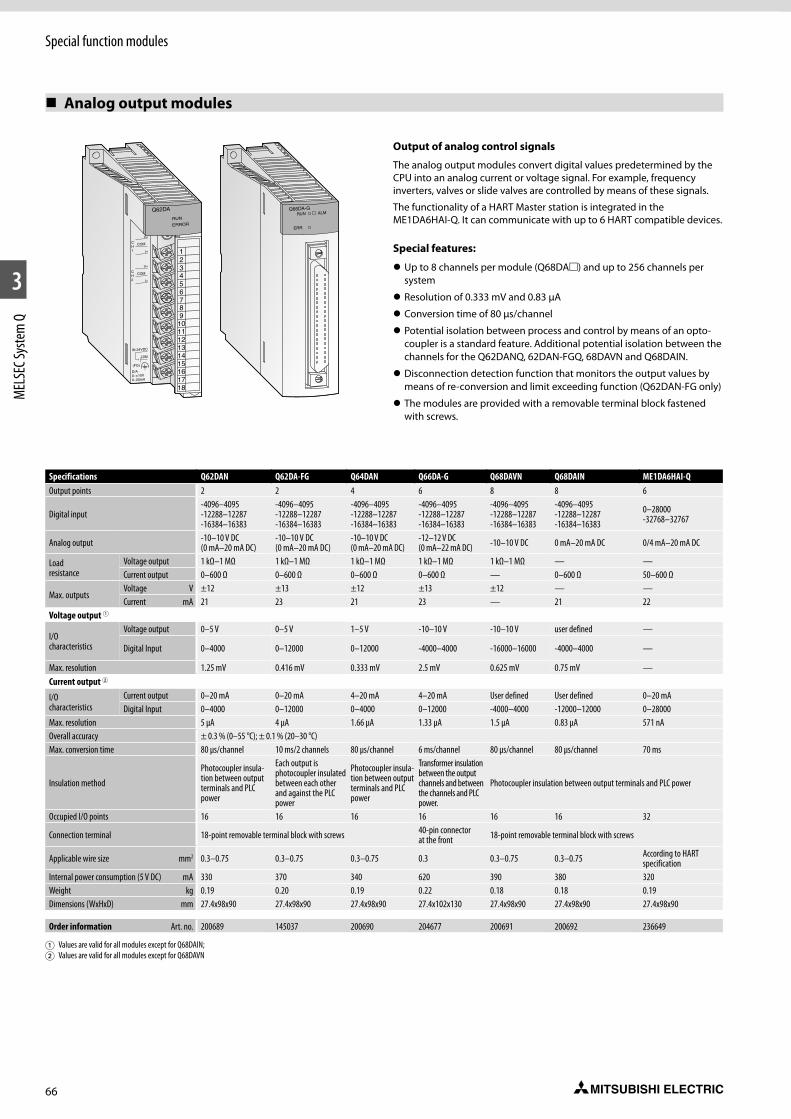
66
Special function modules
1
2
3
MEL
SEC S
yste
m Q
Analog output modules
Output of analog control signals
The analog output modules convert digital values predetermined by the CPU into an analog current or voltage signal. For example, frequency inverters, valves or slide valves are controlled by means of these signals.
The functionality of a HART Master station is integrated in the ME1DA6HAI-Q. It can communicate with up to 6 HART compatible devices.
Special features:
z Up to 8 channels per module (Q68DAm) and up to 256 channels per system
z Resolution of 0.333 mV and 0.83 µA
z Conversion time of 80 µs/channel
z Potential isolation between process and control by means of an opto-coupler is a standard feature. Additional potential isolation between the channels for the Q62DANQ, 62DAN-FGQ, 68DAVN and Q68DAIN.
z Disconnection detection function that monitors the output values by means of re-conversion and limit exceeding function (Q62DAN-FG only)
z The modules are provided with a removable terminal block fastened with screws.
321
D/A0~±10V0~20mA
456789101112131415161718
CH1
CH2
I+
V+
I+
COM
COM
IN 24VDC
(FG)
RUN
V+
COM
ERROR
Q62DA Q66DA-GRUN
ERR.
ALM
Specifications Q62DAN Q62DA-FG Q64DAN Q66DA-G Q68DAVN Q68DAIN ME1DA6HAI-QOutput points 2 2 4 6 8 8 6
Digital input-4096–4095-12288–12287-16384–16383
-4096–4095-12288–12287-16384–16383
-4096–4095-12288–12287-16384–16383
-4096–4095-12288–12287-16384–16383
-4096–4095-12288–12287-16384–16383
-4096–4095-12288–12287-16384–16383
0–28000 -32768–32767
Analog output -10–10 V DC (0 mA–20 mA DC)
-10–10 V DC (0 mA–20 mA DC)
-10–10 V DC (0 mA–20 mA DC)
-12–12 V DC (0 mA–22 mA DC) -10–10 V DC 0 mA–20 mA DC 0/4 mA–20 mA DC
Load resistance
Voltage output 1 kΩ–1 MΩ 1 kΩ–1 MΩ 1 kΩ–1 MΩ 1 kΩ–1 MΩ 1 kΩ–1 MΩ — —Current output 0–600 Ω 0–600 Ω 0–600 Ω 0–600 Ω — 0–600 Ω 50–600 Ω
Max. outputsVoltage V ±12 ±13 ±12 ±13 ±12 — —Current mA 21 23 21 23 — 21 22
Voltage output 1
I/O characteristics
Voltage output 0–5 V 0–5 V 1–5 V -10–10 V -10–10 V user defined —
Digital Input 0–4000 0–12000 0–12000 -4000–4000 -16000–16000 -4000–4000 —
Max. resolution 1.25 mV 0.416 mV 0.333 mV 2.5 mV 0.625 mV 0.75 mV —Current output 2
I/O characteristics
Current output 0–20 mA 0–20 mA 4–20 mA 4–20 mA User defined User defined 0–20 mADigital Input 0–4000 0–12000 0–4000 0–12000 -4000–4000 -12000–12000 0–28000
Max. resolution 5 µA 4 µA 1.66 µA 1.33 µA 1.5 µA 0.83 µA 571 nAOverall accuracy ± 0.3 % (0–55 °C); ± 0.1 % (20–30 °C)Max. conversion time 80 µs/channel 10 ms/2 channels 80 µs/channel 6 ms/channel 80 µs/channel 80 µs/channel 70 ms
Insulation method
Photocoupler insula-tion between output terminals and PLC power
Each output is photocoupler insulated between each other and against the PLC power
Photocoupler insula-tion between output terminals and PLC power
Transformer insulation between the output channels and between the channels and PLC power.
Photocoupler insulation between output terminals and PLC power
Occupied I/O points 16 16 16 16 16 16 32
Connection terminal 18-point removable terminal block with screws 40-pin connector at the front 18-point removable terminal block with screws
Applicable wire size mm2 0.3–0.75 0.3–0.75 0.3–0.75 0.3 0.3–0.75 0.3–0.75 According to HART specification
Internal power consumption (5 V DC) mA 330 370 340 620 390 380 320Weight kg 0.19 0.20 0.19 0.22 0.18 0.18 0.19Dimensions (WxHxD) mm 27.4x98x90 27.4x98x90 27.4x98x90 27.4x102x130 27.4x98x90 27.4x98x90 27.4x98x90
Order information Art. no. 200689 145037 200690 204677 200691 200692 236649
1 Values are valid for all modules except for Q68DAIN; 2 Values are valid for all modules except for Q68DAVN

67
Special function modules
1
2
3
MEL
SEC S
yste
m Q
Combined analog input/output module
321
A/D0~±10V0~20mA
456789101112131415161718
CH1
CH2
CH3
CH4
I+
V+
I+
V+
I+
V+
I+
V-
SLD
V-
SLD
V-
SLD
V-
SLD
A.G.
(FG)
RUN
ERROR
V+
Q64AD2DA
ALM
Q64AD2DA
With the analog input/output module Q64AD2DA the user has a module that has both, four analog inputs and two analog outputs.
Selection of current or voltage input signal is possible for the analog inputs.
Special features:
z Detection and output of voltage and current with only one module.
z Detection of analog signals with either standard or high resolution
Specifications Q64AD2DAInput points 4
Analog inputVoltage V -10–10Current mA 0–20
Load resistanceVoltage MΩ 1Current Ω 250
Max. inputVoltage V ±15Current mA ±30
I/O characteristicsAnalog input -10–10 V; 0–20 mADigital output ±1/4000, ±1/16000; ±1/4000, ±1/12000
Max. resolutionVoltage input 0.333 mVCurrent input 0.83 µA
Accuracy ±0.4 % (0–55 °C), ±0.1 % (20–30 °C)Max. conversion time 500 µs/channelOutput points 2Digital input -16384–16383
Analog outputVoltage V -10–10Current mA 0–20
Load resistanceVoltage output 1 kΩ–1 MΩCurrent output 0–600 Ω
Max. outputVoltage V ±12Current mA 21
I/O characteristicsAnalog output -10–10 V; 0–20 mADigital input ±1/4000, ±1/16000; ±1/4000, ±1/12000;
Max. resolutionVoltage output 0.333 mV
Current output 1.33 µAAccuracy ±0.3 % (0–55 °C), ±0.1 % (20–30 °C)Max. conversion time 500 µs/channelConnection terminal 18-point removable terminal block with screwsOccupied I/O points 16Dimensions (WxHxD) mm 27.4x98x90
Order information Art. no. 229238
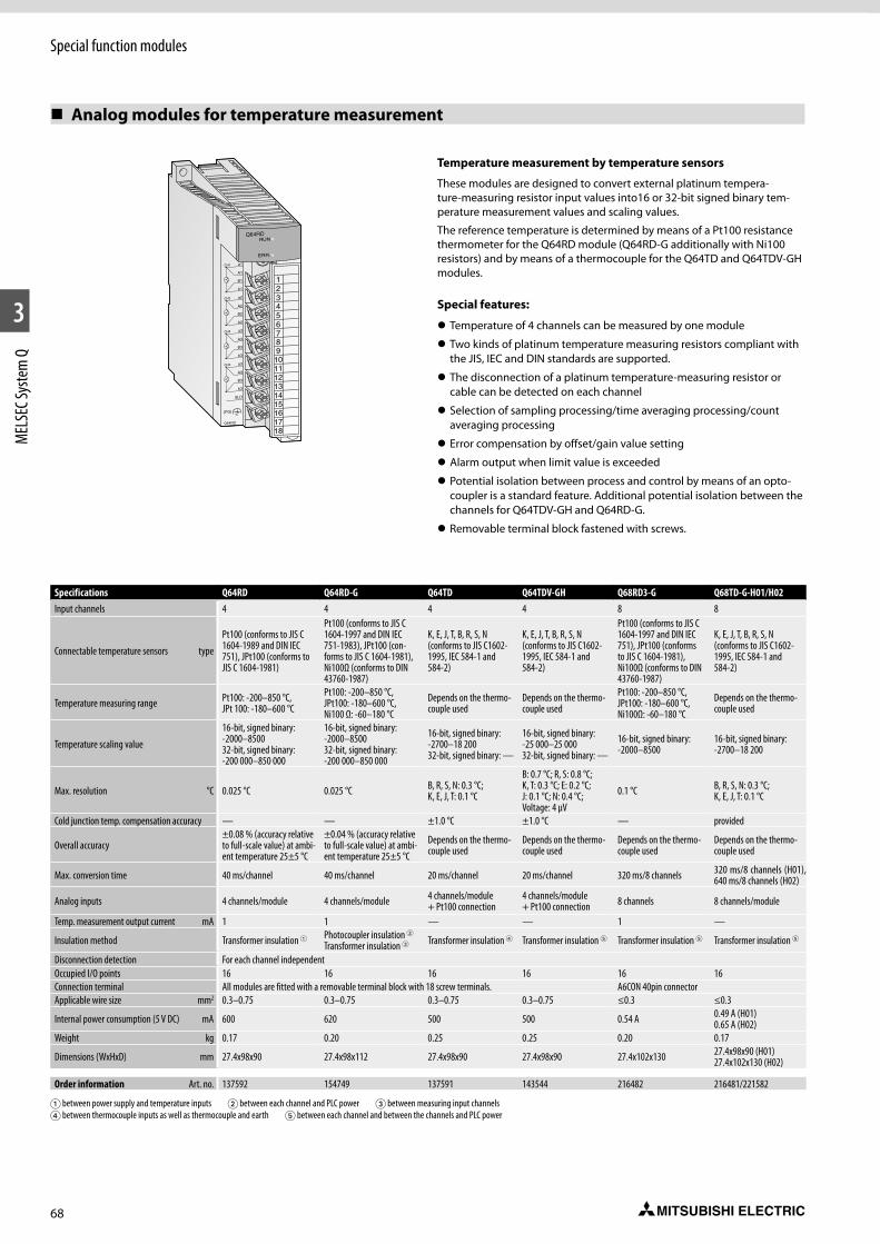
68
Special function modules
1
2
3
MEL
SEC S
yste
m Q
Analog modules for temperature measurement
321
456789101112131415161718
Q64RD
CH1
CH2
CH3
CH4
a1
a2
a3
a3
B1
B2
B3
B3
A1
A2
A3
A3
b1
b2
b3
b3
SLD
(FG)
Q64RDRUN
ERR.
Specifications Q64RD Q64RD-G Q64TD Q64TDV-GH Q68RD3-G Q68TD-G-H01/H02Input channels 4 4 4 4 8 8
Connectable temperature sensors type
Pt100 (conforms to JIS C 1604-1989 and DIN IEC 751), JPt100 (conforms to JIS C 1604-1981)
Pt100 (conforms to JIS C 1604-1997 and DIN IEC 751-1983), JPt100 (con-forms to JIS C 1604-1981), Ni100Ω (conforms to DIN 43760-1987)
K, E, J, T, B, R, S, N (conforms to JIS C1602-1995, IEC 584-1 and 584-2)
K, E, J, T, B, R, S, N (conforms to JIS C1602-1995, IEC 584-1 and 584-2)
Pt100 (conforms to JIS C 1604-1997 and DIN IEC 751), JPt100 (conforms to JIS C 1604-1981), Ni100Ω (conforms to DIN 43760-1987)
K, E, J, T, B, R, S, N (conforms to JIS C1602-1995, IEC 584-1 and 584-2)
Temperature measuring range Pt100: -200–850 °C, JPt 100: -180–600 °C
Pt100: -200–850 °C, JPt100: -180–600 °C, Ni100 Ω: -60–180 °C
Depends on the thermo-couple used
Depends on the thermo-couple used
Pt100: -200–850 °C, JPt100: -180–600 °C, Ni100Ω: -60–180 °C
Depends on the thermo-couple used
Temperature scaling value
16-bit, signed binary: -2000–8500 32-bit, signed binary: -200 000–850 000
16-bit, signed binary: -2000–8500 32-bit, signed binary: -200 000–850 000
16-bit, signed binary: -2700–18 200 32-bit, signed binary: —
16-bit, signed binary: -25 000–25 000 32-bit, signed binary: —
16-bit, signed binary: -2000–8500
16-bit, signed binary: -2700–18 200
Max. resolution °C 0.025 °C 0.025 °C B, R, S, N: 0.3 °C;K, E, J, T: 0.1 °C
B: 0.7 °C; R, S: 0.8 °C; K, T: 0.3 °C; E: 0.2 °C; J: 0.1 °C; N: 0.4 °C; Voltage: 4 µV
0.1 °C B, R, S, N: 0.3 °C;K, E, J, T: 0.1 °C
Cold junction temp. compensation accuracy — — ±1.0 °C ±1.0 °C — provided
Overall accuracy±0.08 % (accuracy relative to full-scale value) at ambi-ent temperature 25±5 °C
±0.04 % (accuracy relative to full-scale value) at ambi-ent temperature 25±5 °C
Depends on the thermo-couple used
Depends on the thermo-couple used
Depends on the thermo-couple used
Depends on the thermo-couple used
Max. conversion time 40 ms/channel 40 ms/channel 20 ms/channel 20 ms/channel 320 ms/8 channels 320 ms/8 channels (H01),640 ms/8 channels (H02)
Analog inputs 4 channels/module 4 channels/module 4 channels/module + Pt100 connection
4 channels/module + Pt100 connection 8 channels 8 channels/module
Temp. measurement output current mA 1 1 — — 1 —
Insulation method Transformer insulation 1 Photocoupler insulation 2 Transformer insulation 3 Transformer insulation 4 Transformer insulation 5 Transformer insulation 5 Transformer insulation 5
Disconnection detection For each channel independentOccupied I/O points 16 16 16 16 16 16Connection terminal All modules are fitted with a removable terminal block with 18 screw terminals. A6CON 40pin connectorApplicable wire size mm2 0.3–0.75 0.3–0.75 0.3–0.75 0.3–0.75 ≤0.3 ≤0.3
Internal power consumption (5 V DC) mA 600 620 500 500 0.54 A 0.49 A (H01) 0.65 A (H02)
Weight kg 0.17 0.20 0.25 0.25 0.20 0.17
Dimensions (WxHxD) mm 27.4x98x90 27.4x98x112 27.4x98x90 27.4x98x90 27.4x102x130 27.4x98x90 (H01) 27.4x102x130 (H02)
Order information Art. no. 137592 154749 137591 143544 216482 216481/221582
1 between power supply and temperature inputs 2 between each channel and PLC power 3 between measuring input channels 4 between thermocouple inputs as well as thermocouple and earth 5 between each channel and between the channels and PLC power
Temperature measurement by temperature sensors
These modules are designed to convert external platinum tempera-ture-measuring resistor input values into16 or 32-bit signed binary tem-perature measurement values and scaling values.
The reference temperature is determined by means of a Pt100 resistance thermometer for the Q64RD module (Q64RD-G additionally with Ni100 resistors) and by means of a thermocouple for the Q64TD and Q64TDV-GH modules.
Special features:
z Temperature of 4 channels can be measured by one module
z Two kinds of platinum temperature measuring resistors compliant with the JIS, IEC and DIN standards are supported.
z The disconnection of a platinum temperature-measuring resistor or cable can be detected on each channel
z Selection of sampling processing/time averaging processing/count averaging processing
z Error compensation by offset/gain value setting
z Alarm output when limit value is exceeded
z Potential isolation between process and control by means of an opto-coupler is a standard feature. Additional potential isolation between the channels for Q64TDV-GH and Q64RD-G.
z Removable terminal block fastened with screws.
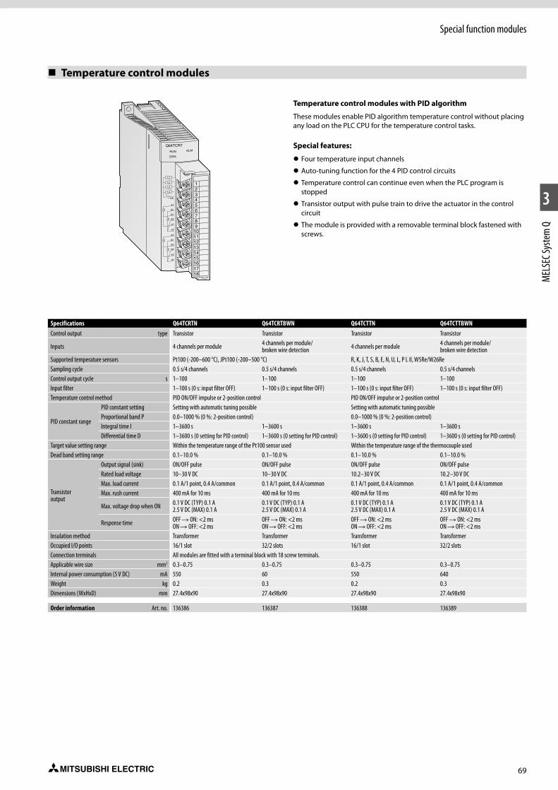
69
Special function modules
1
2
3
MEL
SEC S
yste
m Q
Temperature control modules
A1
B1
B2
b1
b2
NC+ -
A2
L1
L2
L3
L4
A3
B3
B4
b3
b4
A4
RUN ALM
ERR
Q64TCRT
321
456789101112131415161718
Temperature control modules with PID algorithm
These modules enable PID algorithm temperature control without placing any load on the PLC CPU for the temperature control tasks.
Special features:
z Four temperature input channels
z Auto-tuning function for the 4 PID control circuits
z Temperature control can continue even when the PLC program is stopped
z Transistor output with pulse train to drive the actuator in the control circuit
z The module is provided with a removable terminal block fastened with screws.
Specifications Q64TCRTN Q64TCRTBWN Q64TCTTN Q64TCTTBWNControl output type Transistor Transistor Transistor Transistor
Inputs 4 channels per module 4 channels per module/ broken wire detection 4 channels per module 4 channels per module/
broken wire detectionSupported temperature sensors Pt100 (-200–600 °C), JPt100 (-200–500 °C) R, K, J, T, S, B, E, N, U, L, P L II, W5Re/W26ReSampling cycle 0.5 s/4 channels 0.5 s/4 channels 0.5 s/4 channels 0.5 s/4 channelsControl output cycle s 1–100 1–100 1–100 1–100Input filter 1–100 s (0 s: input filter OFF) 1–100 s (0 s: input filter OFF) 1–100 s (0 s: input filter OFF) 1–100 s (0 s: input filter OFF)Temperature control method PID ON/OFF impulse or 2-position control PID ON/OFF impulse or 2-position control
PID constant range
PID constant setting Setting with automatic tuning possible Setting with automatic tuning possibleProportional band P 0.0–1000 % (0 %: 2-position control) 0.0–1000 % (0 %: 2-position control)Integral time I 1–3600 s 1–3600 s 1–3600 s 1–3600 sDifferential time D 1–3600 s (0 setting for PID control) 1–3600 s (0 setting for PID control) 1–3600 s (0 setting for PID control) 1–3600 s (0 setting for PID control)
Target value setting range Within the temperature range of the Pt100 sensor used Within the temperature range of the thermocouple usedDead band setting range 0.1–10.0 % 0.1–10.0 % 0.1–10.0 % 0.1–10.0 %
Transistor output
Output signal (sink) ON/OFF pulse ON/OFF pulse ON/OFF pulse ON/OFF pulseRated load voltage 10–30 V DC 10–30 V DC 10.2–30 V DC 10.2–30 V DCMax. load current 0.1 A/1 point, 0.4 A/common 0.1 A/1 point, 0.4 A/common 0.1 A/1 point, 0.4 A/common 0.1 A/1 point, 0.4 A/commonMax. rush current 400 mA for 10 ms 400 mA for 10 ms 400 mA for 10 ms 400 mA for 10 ms
Max. voltage drop when ON 0.1 V DC (TYP) 0.1 A 2.5 V DC (MAX) 0.1 A
0.1 V DC (TYP) 0.1 A 2.5 V DC (MAX) 0.1 A
0.1 V DC (TYP) 0.1 A 2.5 V DC (MAX) 0.1 A
0.1 V DC (TYP) 0.1 A 2.5 V DC (MAX) 0.1 A
Response time OFF R ON: <2 ms ON R OFF: <2 ms
OFF R ON: <2 ms ON R OFF: <2 ms
OFF R ON: <2 ms ON R OFF: <2 ms
OFF R ON: <2 ms ON R OFF: <2 ms
Insulation method Transformer Transformer Transformer TransformerOccupied I/O points 16/1 slot 32/2 slots 16/1 slot 32/2 slotsConnection terminals All modules are fitted with a terminal block with 18 screw terminals.Applicable wire size mm2 0.3–0.75 0.3–0.75 0.3–0.75 0.3–0.75Internal power consumption (5 V DC) mA 550 60 550 640Weight kg 0.2 0.3 0.2 0.3Dimensions (WxHxD) mm 27.4x98x90 27.4x98x90 27.4x98x90 27.4x98x90
Order information Art. no. 136386 136387 136388 136389

70
Special function modules
1
2
3
MEL
SEC S
yste
m Q
Load cell input module
321
456789101112131415161718
Q61LDRUN
ERR.
ALM
EXC+
S+
EXC-
S-
SIG+
SIG-
NC
NC
NC
NC
NC
NC
NC
NC
NC
NC
SLD
(FG)
Q61LD
The load cell input module Q61LD can connect load cells
directly to MELSEC Q series programmable controllers. External signal converters are no longer required.
Special features:
z An external signal converter is not required. Man-hours and costs are reduced by using a load cell input module that can be connected directly to a programmable contoller.
z The module achieves a highly accurate measurement with steady data conversion speed that guarantees the accuracy of load cells.
z Enhanced convenience with functions like zero offset, two-point calibra-tion and input signal error detection.
Specifications Q61LDAnalog input (load cell output) points 1Analog input (load cell output) mV/V 0.0–3.3
Analog input range (load cell rated output) mV/V
0.0–1.0 0.0–2.0 0.0–3.0
Load cell applied voltage 5 V DC ±5 %, Output current within 60 mA (Four 350 Ω load cells can be connected in parallel.) 6-wire system (Combination use of remote sensing method and ratiometric method) or 4-wire system
Digital output 32-bit signed binary, 0–10 000Gross weight output (Max. weighing output value) 32-bit signed binary, -99999–99999 (Excluding decimal point and unit symbol)
Zero adjustment range mV/V 0.0–3.0Gain adjustment range mV/V 0.3–3.2Resolution 0–10 000Accuracy Nonlineality: within ±0.01 %/FS (Ambient temperature: 25 °C)Conversion speed ms 10Insulation method Photocoupler insulationOccupied I/O points 16External connection system 18-point removable terminal block with screwsApplicable wire size mm2 0.3–0.75Internal power consumption (5 V DC) A 0.48
Weight kg 0.17Dimensions (WxHxD) mm 27.4x98x90
Order information Art. no. 229237
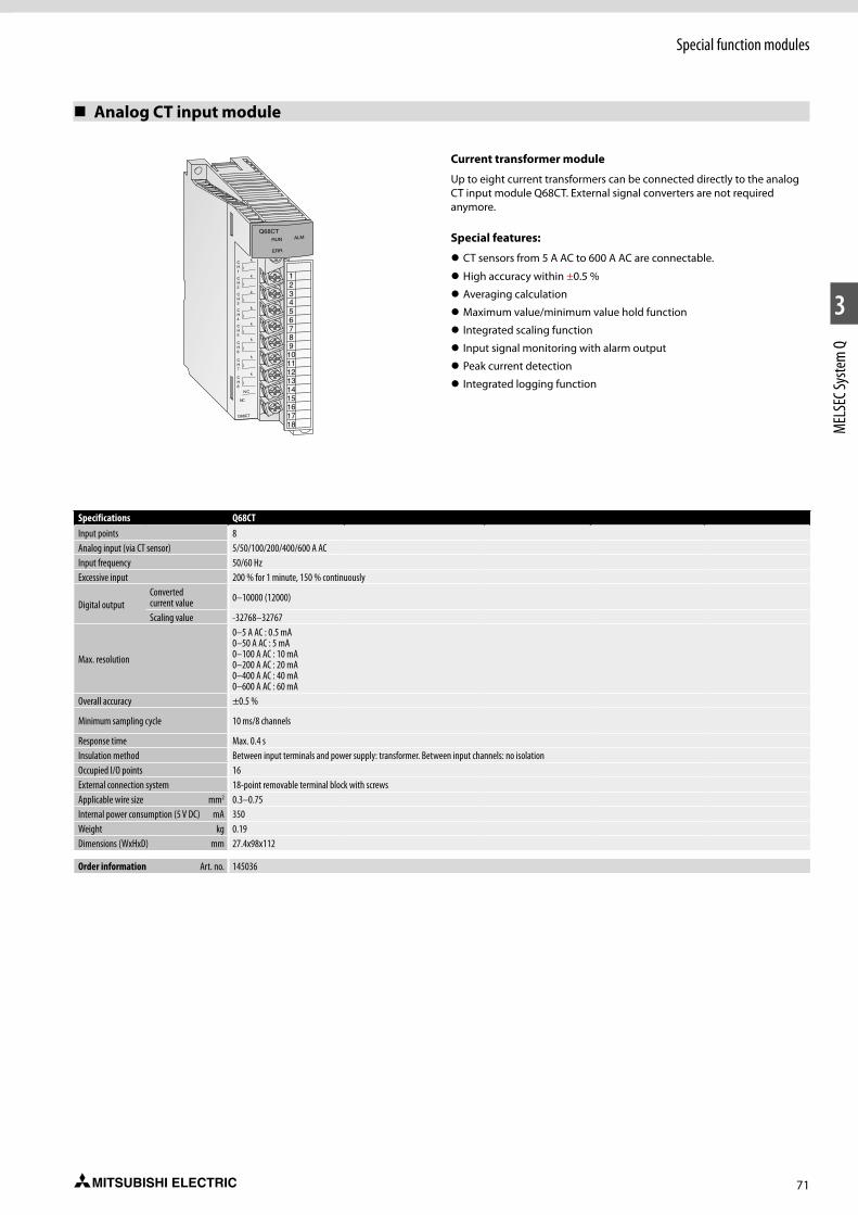
71
Special function modules
1
2
3
MEL
SEC S
yste
m Q
Analog CT input module
321
456789101112131415161718
Q68CT
Q68CT
CH1
CH3
CH2
CH4
CH5
CH7
CH8
CH6
k
k
k
k
k
k
k
l
l
l
l
l
l
l
l
N C
NC
k
ALMRUN
ERR.
Current transformer module
Up to eight current transformers can be connected directly to the analog CT input module Q68CT. External signal converters are not required anymore.
Special features:
z CT sensors from 5 A AC to 600 A AC are connectable.
z High accuracy within ±0.5 %
z Averaging calculation
z Maximum value/minimum value hold function
z Integrated scaling function
z Input signal monitoring with alarm output
z Peak current detection
z Integrated logging function
Specifications Q68CTInput points 8 Analog input (via CT sensor) 5/50/100/200/400/600 A ACInput frequency 50/60 HzExcessive input 200 % for 1 minute, 150 % continuously
Digital outputConverted current value 0–10000 (12000)
Scaling value -32768–32767
Max. resolution
0–5 A AC : 0.5 mA0–50 A AC : 5 mA0–100 A AC : 10 mA0–200 A AC : 20 mA0–400 A AC : 40 mA0–600 A AC : 60 mA
Overall accuracy ±0.5 %
Minimum sampling cycle 10 ms/8 channels
Response time Max. 0.4 sInsulation method Between input terminals and power supply: transformer. Between input channels: no isolationOccupied I/O points 16External connection system 18-point removable terminal block with screwsApplicable wire size mm2 0.3–0.75Internal power consumption (5 V DC) mA 350Weight kg 0.19Dimensions (WxHxD) mm 27.4x98x112
Order information Art. no. 145036
72
Special function modules
1
2
3
MEL
SEC S
yste
m Q
Loop control module
321
456789101112131415161718
Q62HLCRUN
ERR.
ALM
For fast response control
The Q62HLC loop control module uses a continuous proportional PID con-trol format, which features a sampling period of 25 ms for high-accuracy, high-resolution thermocouple inputs, microvoltage inputs, voltage inputs, current inputs and current outputs. These features make the Q62HLC ideal for applications such as rapid temperature increase control, preassure control and flow rate control.
Special features:
z Staggering 25 ms sampling and control update time make the Q62HLC to one of the fastest control module in the market
z Supports sensor types, such as thermocouple, microvoltage, voltage and current input range
z Continuous proportional PID control by 4 to 20 mA current output results in highly stable and accurate control
z Control program profiles can be specified where set values and PID constants are automatically changed at specific times.
z Cascade control can be performed with channel 1 as the master and channel 2 as the slave.
Specifications Q62HLCNumber of input channels 2
Analog input
Thermocouple °C -200–2300 (0.1 °C resolution)Micro voltage mV -100–100 (0.5–10 µV resolution)Voltage V -10–10 (0.05–1 mV resolution)Current mA 0–20 (0.8–1 µA resolution)
Digital output -2000–23000, -10000–10000, -10000–10000, 0–20000Supported thermocouples K, J, T, S, R, N, E, B, PL II, W5re/W26ReMax. conversion speed 25 ms/2 channelsNormal mode rejection ratio 60 dB or more (50/60 Hz)Common mode rejection ratio 120 dB or more (50/60 Hz)Input filter (primary delay digital filter) 0.0–100.0 sSensor compensation value setting -50.00–50.00 %Control method Continuous proportional control
PID constant range
PID constant setting Setting possible by auto-tuningProportional band (P) Thermocouple: 0.1 to full scale °C; micro voltage, voltage, current: 0.1–1000.0 %Integral time (I) s 0.0–3276.7Differential time (D) s 0.0–3276.7
Set value setting range Thermocouple: input range of thermocouple being usedDead band setting range 0.1–10.0 %Occupied I/O points 16Isolation Transformer isolation between the input channels and between the inputs and groundConnection terminals 18-point removable terminal block with screwsApplicable wire size mm2 0.3–0.75External power supply 24 V DC, 70 m AInternal power consumption (5 V DC) mA 270Weight kg 0.25Dimensions (WxHxD) mm 27.4x98x112
Order information Art. no. 200693
73
Special function modules
1
2
3
MEL
SEC S
yste
m Q
High-speed counter modules
High-speed counter with automatic detection of rotation direction
These counter modules detect signals with a frequency which cannot be detected by normal input modules. For example, simple positioning tasks or frequency measurements can be realized.
Special features:
z Input for incremental shaft encoder with automatic forward and reverse detection
z Preset count via external signals or the PLC program with the aid of the PRESET function
z Ring counter function for counting up to a predefined value with auto-matic resetting to the starting value
z Functions such as speed measurement, definition of switching points or periodic counting are available.
z The modules QD62m are provided with a 40-pin connector interface (for suitable connectors, please refer to the chapter “Accessories”).
z The module QD60P8-G is provided with a removable terminal block fastened with screws.
z With the QD64D2, counting at the maximum counting speed of 4 Mpps is possible.
Specifications QD62E QD62 QD62D QD60P8-G QD63P6 QD64D2Counter inputs 2 2 2 8 6 2
Signal levels 5/12/24 V DC (2–5 mA) 5/12/24 V DC (2–5 mA) 5/12/24 V DC (2–5 mA) (RS422A) 5/12/24 V DC 5 V DC (6.4–11.5 mA) EIA standards RS422-A
(differential line driver),Max. counting frequency kHz 200 200 500 (differential) 30 200 4000
Max. counting speed1-phase-input kHz 200 or 100 200 or 100 500 or 200 30 200, 100 or 10 20002-phase-input kHz 200 or 100 200 or 100 500 or 200 — 200, 100 or 10 4000
Counting range32 bits + sign (binary), -2147483648–2147483647
32 bits + sign (binary), -2147483648–2147483647
32 bits + sign (binary), -2147483648–2147483647
16 bits binary: 0–32767 32 bits binary: 0–99999999 32 bits binary: 0–2147483647
32 bits + sign (binary), -2147483648–2147483647
32 bits + sign (binary), -2147483648–2147483647
Counter type All modules are equipped with UP/DOWN preset counter and ring counter function.Moving average function, alarm output and pre-scale function
UP/DOWN preset counter and ring counter function
Addition method, subtraction method, linear counter format, ring counter format, preset counter function, latch counter function
Comparison range 32 bits + sign (binary) 32 bits + sign (binary) 32 bits + sign (binary) 32 bits + sign (binary) 32 bits + sign (binary) 32 bits + sign (binary)
External digital input points
Preset, function start — Preset
Nominal values 5/12/24 V DC (2–5 mA) 5/12/24 V DC (2–5 mA) 5/12/24 V DC (2–5 mA) (RS422A) 5/12/24 V DC 4.5–5.5 V/6.4–11.5 mA 24 V DC, 2–5 mA
External digital output points (coincidence signal)
2 points/channel 12/24 V DC 0.1 A/point, 0.4 A/common (source)
2 points/channel 12/24 V DC 0.5 A/point, 2.0 A/common (sink)
2 points/channel 12/24 V DC 0.5 A/point, 2.0 A/common (sink)
— —2 points/channel 12/24 V DC 0.5 A/point, 2.0 A/common (sink)
Occupied I/O points 16 16 16 32 32 32
Connection terminal 40-pin connector at the front
40-pin connector at the front
40-pin connector at the front
18-point removable termi-nal block with screws 40-pin connector 40-pin connector
Applicable wire size mm2 0.3 0.3 0.3 0.3 – 0.75 0.3 0.3Internal power consumption (5 V DC) mA 330 300 380 580 590 530Weight kg 0.12 0.11 0.12 0.17 0.15 0.16Dimensions (WxHxD) mm 27.4x98x90 27.4x98x90 27.4x98x90 27.4x98x90 27.4x98x90 27.4x98x90
Order information Art. no. 128949 132579 132580 145038 213229 278855
Accessories 40-pin connector and ready to use connection cables > refer to chapter 5

74
Special function modules
1
2
3
MEL
SEC S
yste
m Q
QD65PD2
Ø AØ B
RUN
ERR.
CH1 CH2
QD65PD2
CON 1 CON2
Ø Z
Specifications QD65PD2Counter inputs 2
Signal levelsDC input 5/12/24 V DC (7–10 mA)Differential input Conforms to RS422A
Max. counting frequency
DC input kHz 200Differential input kHz 8000
Counting range 32 bits + sign (binary), -2147483648–2147483647External digital input points 6 phase Z inputs; function start and preset count 6 general purpose inputs External digital output points 8 coincidence outputs, which are activated by comparison of the count value with the user range8 general purpose outputs
Cam switchIntegrated outputs 8Program cycle period 1 ms
PWM outputsOutput frequency DC to 200 kHzDuty ratio Any ratio can be set (resolution: 0.1 µs)
Dimensions (WxHxD) mm 27.4x98x90
Order information Art. no. 245113
High-speed counter/timer module with cam switch function
Due to its high-speed counter inputs, PWM outputs for control DC drives and the integrated cam switching function, the QD65PD2 is well suited for high precision positioning tasks.
Special features:
z Max. counting speed up to 8 MHz
z Pulse measurement function with a resolution of 100 ns
z Precisely control PWM output up to 200 kHz
z The integrated cam switch function reduces the programming effort
z Integrated digital I/Os
z Connection via two 40-pin plug-in connectors with screws
Multi-function counter/timer module

75
Special function modules
1
2
3
MEL
SEC S
yste
m Q
Positioning modules
Specifications QD70P4 QD70P8Number of control axes 4 8 Interpolation —Points per axis 10 (by PLC program or with the positioning software GX Configurator PT)Output signal Pulse chainOutput frequency kHz 1–200 000Positioning method PTP positioning; speed/locus positioning; path control
Positioning
UnitsAbsolute data: -2 147 483 648–2 147 483 647 pulse Incremental method: -2 147 483 648–2 147 483 647 pulse Speed/position switching control: 0–2 147 483 647 pulse
Speed 0–200 000 pulse/sAcceleration/ deceleration processing Automatic, acceleration and deceleration step by step
Acceleration and deceleration time 0–32767 ms
Pulse output type Open collector outputMax. servo motor cable length m 2 2Occupied I/O points 32 32Applicable wire size 0.3 mm2 (with connector A6CON1); 0.2 mm2 (with connector A6CON2)Internal power consumption (5 V DC) mA 550 740External power consumption (24 V DC) mA 65 120Weight kg 0.15 0.17Dimensions (WxHxD) mm 27.4x98x90 27.4x98x90
Order information Art. no. 138328 138329
Accessories 40-pin connector and ready to use connection cables > refer to chapter 5
QD70P4RUN AX1
AX2AX3AX4ERR.
CON1
QD70P4RUN AX1
AX2AX3AX4ERR.
CON1
Multi-axis positioning
The modules are especially designed for systems including multiple axes that do not require any extensive control. The QD70P4 controls up to 4 axes and the QD70P8 up to 8 axes. Since any number of positioning mod-ules can be used the number of axes to be controlled as well is unlimited.
Special features:
z Control of 4 or 8 axes by one module and more than 8 axes by using multiple modules
z Quick start of up to 8 axes simultaneously (0.1 ms per axis after start command from the CPU)
z Various positioning control systems are selectable.
z Easy parametrizing and positional data setup via optionally available positioning software GX Configurator-PT
76
Special function modules
1
2
3
MEL
SEC S
yste
m Q
Specifications QD72P3C3 QD73A1Number of control axes 3 1Interpolation — —
Positioning
Data items 1 per axis 1
Method PTP control: absolute data and/or incremental PTP control: absolute or incremental; speed/position swiching control: incremental
Control range -1073741824–1073741823 pulses -2147483648–2147483647 pulses (32 bit signed binary)Speed 0–100 000 pulse/s 1–4000000 pulse/sAcceleration/ deceleration processing Acceleration and deceleration step by step Automatic, acceleration and deceleration step by step
Acceleration and deceleration time ms 1–5000 2–9999
Start time Positioning control, speed control: 1 ms 1.2 msPulse output method Open collector output Analog output (0–±10 V DC, adjustable to ±5–±10 V DC)Max. output pulse kpps 100 —
Counter function
Number of channels 3 1Count input signal 1-phase input, 2-phase input; 5–24 V DC 2-phase inputCounting speed kpps 100 1000Counting range 31-bit signed binary (-1073741824–1073741823) —
External connection 40-pin connector 15-pin and 9-pin connectorInternal power consumption (5 V DC) A 0.57 0.52Occupied I/O points 32 48Weight kg 0.15 0.2Dimensions (WxHxD) mm 27.4x98x90 55.2x98x90
Order information Art. no. 213230 257759
Accessories 40-pin connector and ready to use connection cables > refer to chapter 5
Positioning modules
QD72P3C3
CON1CON2
CH3 CH2 CH1AX
AB
RUN
ERR.
QD72P3C3
Space efficient positioning
The QD72P3C3 and QD73A1 realize positioning applications with less space requirements.
Special features:
z Minimized space requirement!
z The QD72P3C3 enables the positioning of 3 axes and has 3 integrated counter inputs
z QD73A1 with integrated D/A converter to control servo amplifiers with analog input
z Optimum solution for specific applications!
z Positioning can be controlled by confirming actual movement amount from encoder inputs.
77
Special function modules
1
2
3
MEL
SEC S
yste
m Q
Positioning modules
QD75P2NAX1RUNAX2
ERR.
AX1AX2
Positioning with an open control loop
The modules generate the travel command via a pulse chain. The speed is proportional to the pulse frequency and the distance trav-elled is proportional to the pulse length.
Special features:
z Control of up to four axes with linear interpolation or circular interpolation
z Storage of up to 600 positional data in the flash ROM (no back-up battery necessary)
z Units of travel can be defined in pulses, mm, inches or degrees.
z Configuration and presetting of all 600 positional data is performed via the PLC program or with the aid of the programming software GX Con-figurator QP. This software runs under Windows® 95/98 and Windows® 2000/NT.
Specifications QD75P1N QD75P2N QD75P4NNumber of control axes 1 2 4
Interpolation — 2 axis linear and circular interpolation 2, 3, or 4 axis linear and 2 axis circular interpolation
Points per axis 600 pieces of data with PLC program, 100 pieces of data with GX Configurator QPOutput type Open collector Open collector Open collectorOutput signal Pulse chain Pulse chain Pulse chainOutput frequency kHz max. 4000 max. 4000 max. 4000
Positioning
Method
PTP (Point To Point) control, path control (all of linear, circular, and helical can be set), speed control, speed-position switching control, position-speed switching control
Units
Absolute data: -2 147 483 648–2 147 483 647 pulse -21 4748 364.8–214 748 364.7 µm -21 474.83648–21 474.83647 inch 0–359.99999 degree
Inkremental method: -2 147 483 648–2 147 483 647 pulse -214 748 364.8–214 748 364.7 µm -21 474.83648–21 474.83647 inch -21 474.83648–21 474.83647 degree
Speed/position switching control: 0–2 147 483 647 pulse 0–21 4748 364.7 µm 0–21 474.83647 inch 0–21 474.83647 degree
Speed
1 –1 000 000 pulse/s 0.01 –20 000 000.00 mm/min 0.001–200 000.000 degree/min 0.001–200 000.000 inch/min
Acceleration/deceleration processing Automatic trapezoidal acceleration/deceleration, S-pattern acceleration/decelerationAcceleration anddeceleration time 1–8388608 ms (4 patterns each can be set)Rapid stop decceleration time 1–8388608 ms 1–8388608 ms 1–8388608 ms
Max. length for servo motor cable m 10 10 10Occupied I/O points 32 32 32Internal power consumption (5 V DC) mA 290 300 360Weight kg 0.14 0.14 0.16Dimensions (WxHxD) mm 27.4x98x90 27.4x98x90 27.4x98x90
Order information Art. no. 248389 248390 248391
Accessories 40-pin connector and ready to use connection cables > refer to chapter 5; Programming software: GX Configurator QP, art. no.: 132219
78
Special function modules
1
2
3
MEL
SEC S
yste
m Q
Positioning modules
QD75D1NAX1RUN
ERR.
AX1
Long distance positioning
The modules of the QD75 series are suitable for bridging long distances between module and drive system.
The modules QD75D provide differential outputs.
Special features:
z Control of up to four axes with linear interpolation (QD75D4) or two axes circular interpolation (all modules except QD75D1)
z Storage of up to 600 positional data in the flash ROM (no back-up battery necessary)
z Units of travel can be defined in pulses, mm, inches or degrees.
z Configuration and presetting of all 600 positional data is performed via the PLC program or with the aid of the programming software GX Configurator QP.
Specifications QD75D1N QD75D2N QD75D4NNumber of control axes 1 2 4
Interpolation — 2 axis linear and circular interpolation 2, 3, or 4 axis linear and2 axis circular interpolation
Points per axis 600 pieces of data with PLC program, 100 pieces of data with GX Configurator QPOutput type Differential driver Differential driver Differential driverOutput signal Pulse chain Pulse chain Pulse chainOutput frequency kHz max. 4000 max. 4000 max. 4000
Positioning
Method PTP control: absolute data and/or incremental; speed/position swiching control: incremental; locus/speed control: incremental; path control: absolute data and/or incremental
Units
Absolute data: -2 147 483 648–2 147 483 647 pulse -21 4748 364.8–214 748 364.7 µm -21 474.83648–21 474.83647 inch 0–359.99999 degree
Inkremental method: -2 147 483 648–2 147 483 647 pulse -214 748 364.8–214 748 364.7 µm -21 474.83648–21 474.83647 inch -21 474.83648–21 474.83647 degree
Speed/position switching control: 0–2 147 483 647 pulse 0–21 4748 364.7 µm 0–21 474.83647 inch 0–21 474.83647 degree
Speed
1 –1 000 000 pulse/s 0.01 –20 000 000.00 mm/min 0.001–200 000.000 degree/min 0.001–200 000.000 inch/min
Acceleration/ deceleration processing Automatic trapezoidal or S-pattern acceleration and deceleration or automatic S-pattern acceleration and deceleration
Acceleration and deceleration time
1–8388608 ms (4 patterns, each can be set)
Rapid stop decceleration time 1–8388608 msMax. length for servo motor cable m 10 10 10Occupied I/O points 32 32 32Internal power consumption (5 V DC) mA 430 450 660Weight kg 0.15 0.15 0.16Dimensions (WxHxD) mm 27.4x98x90 27.4x98x90 27.4x98x90
Order information Art. no. 248392 248393 248394
Accessories 40-pin connector and ready to use connection cables > refer to chapter 5; Programming software: GX Configurator QP, art. no.: 132219
79
Special function modules
1
2
3
MEL
SEC S
yste
m Q
Simple Motion modules
Specifications QD77GF4 QD77GF8 QD77GF16 QD77MS2 QD77MS4 QD77MS16Number of controllable axes 4 8 16 2 4 16
Interpolation functions Linear interpolation for up to 4 axes, circular interpolation for 2 axes
2 axes linear and circular interpolation
Linear interpolation for up to 4 axes, circular interpolation for 2 axes
Servo amplifier network CC-Link IE Field CC-Link IE Field CC-Link IE Field SSCNETIII/H SSCNETIII/H SSCNETIII/HServo amplifier MR-J4-GF(-RJ) MR-JE-B/MR-J4(W2/W3)-B over SSCNETIII/HOperation cycle ms 0.888 0.888 0.888 0.888 0.888 0.888
PositioningMethod PTP (Point To Point) control, path control (linear and arc), speed control, speed-position switching control, position-speed switching control,
synchronous control, cam controlAcceleration/deceleration control Trapezoidal acceleration/deceleration, S-curve acceleration/decelerationCompensation Backlash compensation, electronic gear, near pass function
Number of positioning points 600 data/axis (All the data points can be set with the buffer memory.) 600 per axis (can be set with GX Works3 or PLC program)External input signals External devices, like encoder or remote I/O are connected via CC-Link IE Field 1 encoder, A/B phase; 4 digital inputs [DI1–DI4]
Cam function
Storage area cam data 256 kBytesNumber of cams max. 256 (depends on resolution)Resolution per cycle 256/512/1024/2048/4096/8192/16384/32768Stroke resolution -214.7483648 to 214.7483647 (%)
Occupied I/O points 32 32 32 32 32 32Connection terminal 26-pin connector 26-pin connector 26-pin connector 40-pin connector 40-pin connector 40-pin connectorNo. of Simple Motion modules in one system max. 8 max. 8 max. 8 max. 8 max. 8 max. 8Internal power consumption (5 V DC) mA 800 800 800 600 600 750Weight kg 0.26 0.26 0.26 0.15 0.16 0.16Dimensions (WxHxD) mm 27.4x98x115 27.4x98x115 27.4x98x115 27.4x98x90 27.4x98x90 27.4x98x90
Order information Art. no. 297645 297646 269032 248702 248703 248704
Advanced control but simple use as the positioning module
The MELSEC System Q lineup includes Simple Motion modules in addition to the regular positioning modules. Various control functions previously only possible with Motion Controllers, such as speed control, torque control, synchronous control and cam control, are now available with the Simple Motion modules.
These functions can be realized with simple parameter adjustments and via the PLC program.
Special features:
z Various position control modes
z Home position return control
z Advanced synchronous control
z Mark detection
z Speed-torque control (press-fit control)
z Manual control (JOG, inching, or manual pulse generator operation)
z Connection to CC-Link IE Field reduces wiring for QD77GF
80
Special function modules
1
2
3
MEL
SEC S
yste
m Q
Interface modules
Specifications QJ71C24N QJ71C24N-R2 QJ71C24N-R4 QJ71MB91 QJ71MT91
Interface channel 1 RS232 (9-pin Sub-D) RS232 (9-pin Sub-D) RS422/RS485 (screw terminals) RS232 (9-pin Sub-D) Ethernet (RJ45) channel 2 RS422/RS485 (screw terminals) RS232 (9-pin Sub-D) RS422/RS485 (screw terminals) RS422/RS485 (screw terminals) —
Communication mode Full duplex/half duplex Full duplex/half duplex Full duplex/half duplex Full duplex/half duplex —Synchronisation Asynchronous communications Asynchronous communications Asynchronous communications Master/Slave Master/Slave
Data transfer
Rate bit/s50–230400 (channel 1 only) 115200 (channel 1+2 simulta-neously)
50–230400 (channel 1 only) 115200 (channel 1+2 simulta-neously)
50–230400 (channel 1 only) 115200 (channel 1+2 simulta-neously)
300–115200 10 Mbps/100 Mbps
Distance RS232 m 15 15 — 15 200 m, max. segment length: 100 m
Distance RS422/485 m 1200 (if both channels are used) — 1200 (if both channels are used) 1200 —
Network configuration RS232: 1:1 RS485: 1:1; 1:n;n: 1; m:m 1:1 RS232: 1:1
RS485: 1:1; 1:n;n: 1; m:m Master (32 slaves) Slave (242) Master (32 slaves) Slave (242)
Data format 1 start bit, 7 or 8 data bits, 1 or 0 parity bits, 1 or 2 stop bits
1 start bit, 7 or 8 data bits, 1 or 0 parity bits, 1 or 2 stop bits
1 start bit, 7 or 8 data bits, 1 or 0 parity bits, 1 or 2 stop bits Modbus RTU Modbus RTU
Error correction Parity check, checksum Parity check, checksum Parity check, checksum — —DTR/DSR control YES/NO selectable YES/NO selectable — — —X ON/X OFF (DC1/DC3) YES/NO selectable YES/NO selectable YES/NO selectable — —Occupied I/O points 32 32 32 32 32Internal power consumption (5 V DC) mA 310 260 390 310 520Weight kg 0.2 0.2 0.2 0.2 0.11Dimensions (WxHxD) mm 27.4x98x90 27.4x98x90 27.4x98x90 27.4x98x90 27.4x98x90
Order information Art. no. 149500 149501 149502 167757 155603
QJ71C24-R2EXT POWER
CH1
CH2
QJ71C24-R2RUNNEU.
SD
ERR.NEU.
CH2CH1
SDRDRD
Data exchange with peripheral devices
This module enables communication with peripheral devices via a stand-ard RS232 interface. The peripherals are connected point-to-point on a 1:1 basis.
Special features:
z The QJ71C24N provides one RS232 and one RS422/485 interface. The QJ71C24-R2 provides two RS232 interfaces and the QJ71C24N-R4 two RS422/485 interfaces.
z Enables PCs connected to the system to access the full data set of the MELSEC System Q CPU using graphic process supervision or monitoring software
z Integrated flash ROM memory for logging quality, productivity or alarm data that can be printed out when required
z Module and communications status shown by LEDs
z Communications test and monitor function are possible with the soft-ware GX-Configurator UT
z The QJ71MB71 and the QJ71MT91 support the master function of the MODBUS communication.
81
Special function modules
1
2
3
MEL
SEC S
yste
m Q
High-speed communication modules
Specifications QD51-R24 QD51Interfaces 1 x RS422/485, 1 x RS232 2 x RS232Microprocessor V53A (20 MHz) V53A (20 MHz)Number of parallel tasks Max. 2 Max. 2Start conditions for tasks Started by power on, started by the start command from another task, start by an interruption from the PC CPU.
Data transfer Rate bit/s ≤38400 ≤38400Distance m 500 (RS422/485), 15 (RS232C) 15 (RS232C)
Program language AD51H-BASIC AD51H-BASIC
Internal memory
Program memory kbyte 64 x 1 task or 32 x 2 tasks 64 x 1 task or 32 x 2 tasksCommon memory or tasks kbyte 8 8
Data buffer to PLC kbyte 6 6Extension relays 1024 1024Extension data registers 1024 (2 kbyte) 1024 (2 kbyte)
Memory backup capability Provided for common memory, extension relay and extension register. Provided for common memory, extension relay and extension register.Memory for programs Flash memory: 64 kbyte Flash memory: 64 kbyteOccupied I/O points 32 (1 slot) 32 (1 slot)Internal power consumption (5 V DC) mA 310 260Weight kg 0.2 0.2Dimensions (WxHxD) mm 27.4x98x90 27.4x98x90
Order information Art. no. 136385 136384
Accessories For both modules: programming software for PC/AT (MS-DOS): SW1IX-AD51HPE, art. no.: 33102
QD51
CH1RS-232
CH2RS-232
QD51RUNPRG
SD
ERR.P RUN
CH2CH1
SDRDRD
Programmable interface module
This module works through its own program independently of the PLC CPU. Thus, peripherals can be operated or mathematical operations per-formed without imposing an additional load on the PLC CPU. Program-ming is in AD51H-BASIC.
Special features:
z Two RS232C interfaces and one RS422/485 interface
z Two BASIC programs can be operated in parallel (multitasking).
z The tasks can be stored in the module as interpreter programs or in compiled form.
z The integrated Flash ROM is used for storage.
z Online and offline program creation is possible.
z The module and communication status is indicated by means of LEDs.
z Support for plain ASCII data exchange with connected devices such as barcode readers, scales and identification systems
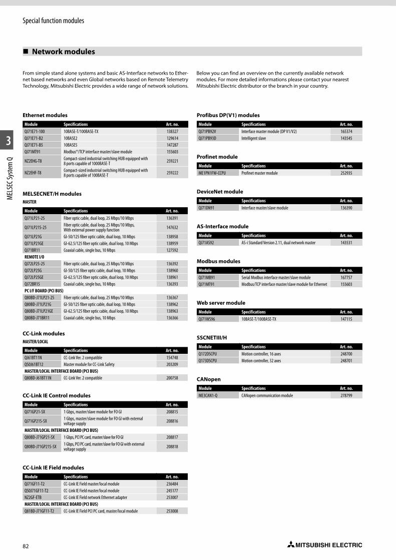
82
Special function modules
1
2
3
MEL
SEC S
yste
m Q
Network modules
From simple stand alone systems and basic AS-Interface networks to Ether-net based networks and even Global networks based on Remote Telemetry Technology, Mitsubishi Electric provides a wide range of network solutions.
Below you can find an overview on the currently available network modules. For more detailed informations please contact your nearest Mitsubishi Electric distributor or the branch in your country.
Ethernet modules
Module Specifications Art. no.QJ71E71-100 10BASE-T/100BASE-TX 138327QJ71E71-B2 10BASE2 129614QJ71E71-B5 10BASE5 147287QJ71MT91 Modbus®/TCP interface master/slave module 155603
NZ2EHG-T8 Compact-sized industrial switching HUB equipped with 8 ports capable of 1000BASE-T 259221
NZ2EHF-T8 Compact-sized industrial switching HUB equipped with 8 ports capable of 100BASE-T 259222
MELSECNET/H modulesMASTER
Module Specifications Art. no.QJ71LP21-25 Fiber optic cable, dual loop, 25 Mbps/10 Mbps 136391
QJ71LP21S-25 Fiber optic cable, dual loop, 25 Mbps/10 Mbps, With external power supply function 147632
QJ71LP21G GI-50/125 fiber optic cable, dual loop, 10 Mbps 138958QJ71LP21GE GI-62.5/125 fiber optic cable, dual loop, 10 Mbps 138959QJ71BR11 Coaxial cable, single bus, 10 Mbps 127592REMOTE I/OQJ72LP25-25 Fiber optic cable, dual loop, 25 Mbps/10 Mbps 136392QJ72LP25G GI-50/125 fiber optic cable, dual loop, 10 Mbps 138960QJ72LP25GE GI-62.5/125 fiber optic cable, dual loop, 10 Mbps 138961QJ72BR15 Coaxial cable, single bus, 10 Mbps 136393PC I/F BOARD (PCI BUS)Q80BD-J71LP21-25 Fiber optic cable, dual loop, 25 Mbps/10 Mbps 136367Q80BD-J71LP21G GI-50/125 fiber optic cable, dual loop, 10 Mbps 138962Q80BD-J71LP21GE GI-62.5/125 fiber optic cable, dual loop, 10 Mbps 138963Q80BD-J71BR11 Coaxial cable, single bus, 10 Mbps 136366
CC-Link modulesMASTER/LOCAL
Module Specifications Art. no.QJ61BT11N CC-Link Ver. 2 compatible 154748QS0J61BT12 Master module for CC-Link Safety 203209MASTER/LOCAL INTERFACE BOARD (PCI BUS)Q80BD-J61BT11N CC-Link Ver. 2 compatible 200758
CC-Link IE Control modules
Module Specifications Art. no.QJ71GP21-SX 1 Gbps, master/slave module for FO GI 208815
QJ71GP21S-SX 1 Gbps, master/slave module for FO GI with external voltage supply 208816
MASTER/LOCAL INTERFACE BOARD (PCI BUS)Q80BD-J71GP21-SX 1 Gbps, PCI PC card, master/slave for FO GI 208817
Q80BD-J71GP21S-SX 1 Gbps, PCI PC card, master/slave for FO GI with external voltage supply 208818
CC-Link IE Field modules
Module Specifications Art. no.QJ71GF11-T2 CC-Link IE Field master/local module 236484QS0J71GF11-T2 CC-Link IE Field master/local module 245177NZ2GF-ETB CC-Link IE Field network Ethernet adapter 253007MASTER/LOCAL INTERFACE BOARD (PCI BUS)Q81BD-J71GF11-T2 CC-Link IE Field PCI PC card, master/local module 253008
Profibus DP(V1) modules
Module Specifications Art. no.QJ71PB92V Interface master module (DP V1/V2) 165374QJ71PB93D Intelligent slave 143545
Profinet module
Module Specifications Art. no.ME1PN1FW-CCPU Profinet master module 252935
DeviceNet module
Module Specifications Art. no.QJ71DN91 Interface master/slave module 136390
AS-Interface module
Module Specifications Art. no.QJ71AS92 AS-i Standard Version 2.11, dual network master 143531
Modbus modules
Module Specifications Art. no.QJ71MB91 Serial Modbus interface master/slave module 167757QJ71MT91 Modbus/TCP interface master/slave module for Ethernet 155603
Web server module
Module Specifications Art. no.QJ71WS96 10BASE-T/100BASE-TX 147115
SSCNETIII/H
Module Specifications Art. no.Q172DSCPU Motion controller, 16 axes 248700Q173DSCPU Motion controller, 32 axes 248701
CANopen
Module Specifications Art. no.ME3CAN1-Q CANopen communication module 278799
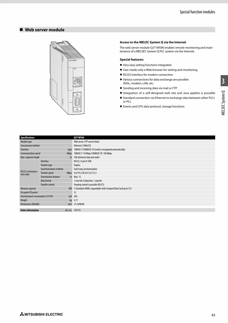
83
Special function modules
1
2
3
MEL
SEC S
yste
m Q
Web server module
Specifications QJ71WS96Module type Web server, FTP server/clientTransmission method Ethernet: CSMA/CDInterface type 10BASE-T/100BASE-TX (mode is recognized automatically)Communication speed Mbps 10BASE-T: 10 Mbps/100BASE-TX: 100 MbpsMax. segment length m 100 (between hub and node)
RS232 communica-tions data
Interface RS232, 9-pin D-SUBTransfer type DuplexSynchronisations method Start/stop synchronisationTransfer speed Mbps 9.6/19.2/38.4/57.6/115.2Transmission distance m Max. 15Data format 1 start bit, 8 data bits, 1 stop bitTransfer control Floating control is possible (RS/CS)
Memory capacity MB 5 (Standard-ROM); expandable with CompactFlash Card up to 512Occupied I/O points 32Internal power consumption (5 V DC) mA 650Weight kg 0.17Dimensions (WxHxD) mm 27.5x98x90
Order information Art. no. 147115
SY.ENC2
QJ71WS96
Access to the MELEC System Q via the Internet
The web server module QJ71WS96 enables remote monitoring and main-tenance of a MELSEC System Q PLC system via the Internet.
Special features:
z Very easy setting functions integrated
z User needs only a Web browser for setting and monitoring.
z RS232 interface for modem connection
z Various connections for data exchange are possible: ADSL, modem, LAN, etc.
z Sending and receiving data via mail or FTP
z Integration of a self-designed web site and Java applets is possible
z Standard connection via Ethernet to exchange data between other PLCs or PCs
z Events and CPU data protocol, storage functions
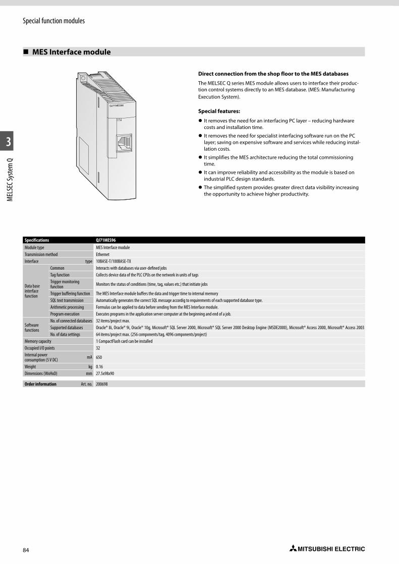
84
Special function modules
1
2
3
MEL
SEC S
yste
m Q
MES Interface module
Specifications QJ71MES96Module type MES Interface moduleTransmission method EthernetInterface type 10BASE-T/100BASE-TX
Data base interface function
Common Interacts with databases via user-defined jobsTag function Collects device data of the PLC CPUs on the network in units of tagsTrigger monitoring function Monitors the status of conditions (time, tag, values etc.) that initiate jobs
Trigger buffering function The MES Interface module buffers the data and trigger time to internal memorySQL text transmission Automatically generates the correct SQL message accordig to requirements of each supported database type.Arithmetic processing Formulas can be applied to data before sending from the MES Interface module.Program execution Executes programs in the application server computer at the beginning and end of a job.
Software functions
No. of connected databases 32 items/project max.Supported databases Oracle® 8i, Oracle® 9i, Oracle® 10g, Microsoft® SQL Server 2000, Microsoft® SQL Server 2000 Desktop Engine (MSDE2000), Microsoft® Access 2000, Microsoft® Access 2003No. of data settings 64 items/project max. (256 components/tag, 4096 components/project)
Memory capacity 1 CompactFlash card can be installedOccupied I/O points 32Internal power consumption (5 V DC) mA 650
Weight kg 0.16Dimensions (WxHxD) mm 27.5x98x90
Order information Art. no. 200698
QJ71MES96
Direct connection from the shop floor to the MES databases
The MELSEC Q series MES module allows users to interface their produc-tion control systems directly to an MES database. (MES: Manufacturing Execution System).
Special features:
z It removes the need for an interfacing PC layer – reducing hardware costs and installation time.
z It removes the need for specialist interfacing software run on the PC layer; saving on expensive software and services while reducing instal-lation costs.
z It simplifies the MES architecture reducing the total commissioning time.
z It can improve reliability and accessibility as the module is based on industrial PLC design standards.
z The simplified system provides greater direct data visibility increasing the opportunity to achieve higher productivity.

85
Special function modules
1
2
3
MEL
SEC S
yste
m Q
Q series C-Application server
The C-Application server is based on the Q series C-Controller platform and with its robust OS has allowed Mitsubishi Electric to make a giant leap forward into the future of cloud connectivity. The C-Application server is based on modern web services and supports all kind of IoT requests. Its strength is to collect information in real time, provide analysis and forwards the results to a variety of cloud systems.
The C-Application server supports:
z Event handler – Asynchronous bi-direction HTTP(S) protocol
z LUA server pages, including LUA virtual machine
z SSL/TLS client/server including SSL certificate
z Raima database, SQLite, MySQL and Redis connectors
z Web services – JSON-RPC, XML-RPC and SOAP
z HTTP(S) client libraries
z Client and server (secure) TCP socket API
z Mail (SMTP) client
Specifications C-Application server for Q12DCCPU-VTransmission type Ethernet, SerialInterface 100BASE-TX, 10BASE-T, RS232Database SQLite3
Function
z QBF and MD library function support z CAS specific functions z HTML5 z Websocket z Lua API z Lua server pages z XML parser z Event handler z REST, AJAX, SOAP, JSON, XML-RPC Web-Services z WebDAV z SMTP z SSL, Shark SSL z PikeHTTP
Weight kg 0.24Dimensions (WxHxD) mm 27.4x98x115
Order information Art. no. 289014
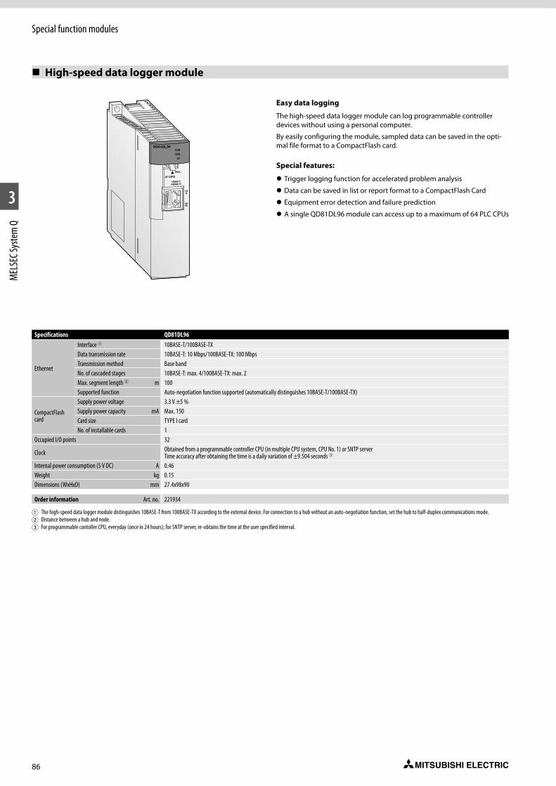
86
Special function modules
1
2
3
MEL
SEC S
yste
m Q
High-speed data logger module
Easy data logging
The high-speed data logger module can log programmable controller devices without using a personal computer.
By easily configuring the module, sampled data can be saved in the opti-mal file format to a CompactFlash card.
Special features:
z Trigger logging function for accelerated problem analysis
z Data can be saved in list or report format to a CompactFlash Card
z Equipment error detection and failure prediction
z A single QD81DL96 module can access up to a maximum of 64 PLC CPUs
Specifications QD81DL96
Ethernet
Interface 1 10BASE-T/100BASE-TXData transmission rate 10BASE-T: 10 Mbps/100BASE-TX: 100 MbpsTransmission method Base bandNo. of cascaded stages 10BASE-T: max. 4/100BASE-TX: max. 2Max. segment length 2 m 100Supported function Auto-negotiation function supported (automatically distinguishes 10BASE-T/100BASE-TX)
CompactFlash card
Supply power voltage 3.3 V ±5 %Supply power capacity mA Max. 150Card size TYPE I cardNo. of installable cards 1
Occupied I/O points 32
Clock Obtained from a programmable controller CPU (in multiple CPU system, CPU No. 1) or SNTP server Time accuracy after obtaining the time is a daily variation of ±9.504 seconds 3
Internal power consumption (5 V DC) A 0.46Weight kg 0.15Dimensions (WxHxD) mm 27.4x98x90
Order information Art. no. 221934
1 The high-speed data logger module distinguishes 10BASE-T from 100BASE-TX according to the external device. For connection to a hub without an auto-negotiation function, set the hub to half-duplex communications mode.2 Distance between a hub and node.3 For programmable contoller CPU, everyday (once in 24 hours); for SNTP server, re-obtains the time at the user specified interval.
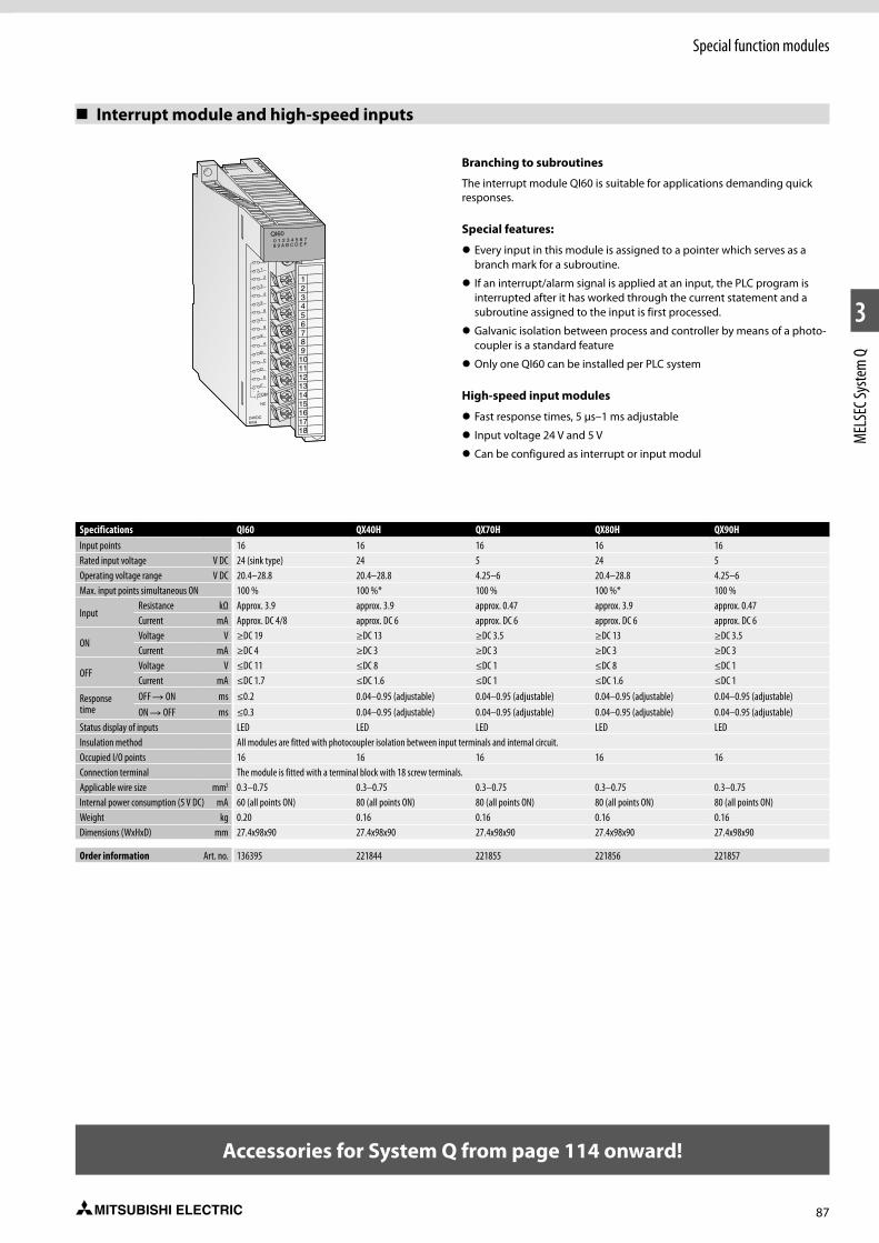
87
Special function modules
1
2
3
MEL
SEC S
yste
m Q
Branching to subroutines
The interrupt module QI60 is suitable for applications demanding quick responses.
Special features:
z Every input in this module is assigned to a pointer which serves as a branch mark for a subroutine.
z If an interrupt/alarm signal is applied at an input, the PLC program is interrupted after it has worked through the current statement and a subroutine assigned to the input is first processed.
z Galvanic isolation between process and controller by means of a photo-coupler is a standard feature
z Only one QI60 can be installed per PLC system
High-speed input modules
z Fast response times, 5 µs–1 ms adjustable
z Input voltage 24 V and 5 V
z Can be configured as interrupt or input modul
Interrupt module and high-speed inputs
321
456789101112131415161718
QI600 1 2 3 4 5 6 78 9 A B C D E F
1
3
5
7
9
B
D
F
2
4
6
8
A
C
E
NC
24VDC6mA
COM+-
Specifications QI60 QX40H QX70H QX80H QX90HInput points 16 16 16 16 16Rated input voltage V DC 24 (sink type) 24 5 24 5Operating voltage range V DC 20.4–28.8 20.4–28.8 4.25–6 20.4–28.8 4.25–6Max. input points simultaneous ON 100 % 100 %* 100 % 100 %* 100 %
InputResistance kΩ Approx. 3.9 approx. 3.9 approx. 0.47 approx. 3.9 approx. 0.47 Current mA Approx. DC 4/8 approx. DC 6 approx. DC 6 approx. DC 6 approx. DC 6
ONVoltage V ≥DC 19 ≥DC 13 ≥DC 3.5 ≥DC 13 ≥DC 3.5Current mA ≥DC 4 ≥DC 3 ≥DC 3 ≥DC 3 ≥DC 3
OFFVoltage V ≤DC 11 ≤DC 8 ≤DC 1 ≤DC 8 ≤DC 1Current mA ≤DC 1.7 ≤DC 1.6 ≤DC 1 ≤DC 1.6 ≤DC 1
Response time
OFF R ON ms ≤0.2 0.04–0.95 (adjustable) 0.04–0.95 (adjustable) 0.04–0.95 (adjustable) 0.04–0.95 (adjustable)ON R OFF ms ≤0.3 0.04–0.95 (adjustable) 0.04–0.95 (adjustable) 0.04–0.95 (adjustable) 0.04–0.95 (adjustable)
Status display of inputs LED LED LED LED LEDInsulation method All modules are fitted with photocoupler isolation between input terminals and internal circuit.Occupied I/O points 16 16 16 16 16Connection terminal The module is fitted with a terminal block with 18 screw terminals.Applicable wire size mm2 0.3–0.75 0.3–0.75 0.3–0.75 0.3–0.75 0.3–0.75Internal power consumption (5 V DC) mA 60 (all points ON) 80 (all points ON) 80 (all points ON) 80 (all points ON) 80 (all points ON)Weight kg 0.20 0.16 0.16 0.16 0.16Dimensions (WxHxD) mm 27.4x98x90 27.4x98x90 27.4x98x90 27.4x98x90 27.4x98x90
Order information Art. no. 136395 221844 221855 221856 221857
Accessories for System Q from page 114 onward!
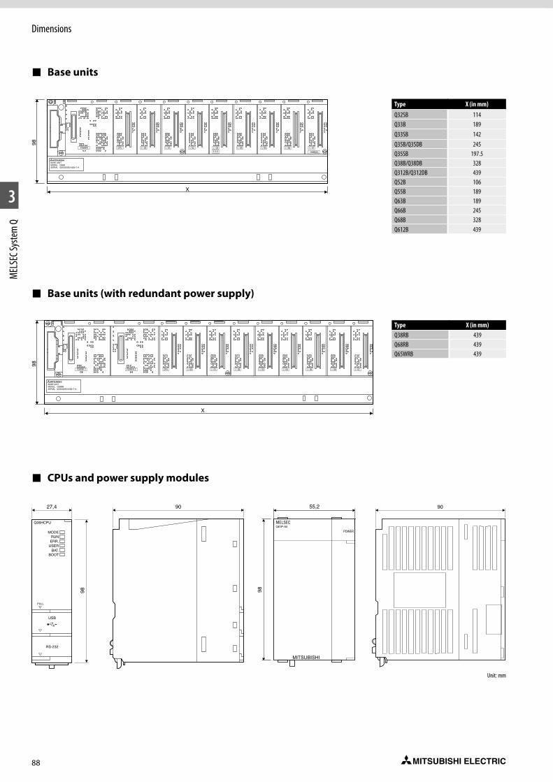
88
1
2
3
MEL
SEC S
yste
m Q
Dimensions
Base units
Base units (with redundant power supply)
CPUs and power supply modules
Type X (in mm)
Q32SB 114Q33B 189Q33SB 142Q35B/Q35DB 245Q35SB 197.5Q38B/Q38DB 328Q312B/Q312DB 439Q52B 106Q55B 189Q63B 189Q66B 245Q68B 328Q612B 439
Type X (in mm)Q38RB 439Q68RB 439Q65WRB 439
Unit: mm

89
Dimensions
1
2
3
MEL
SEC S
yste
m Q
Safety main base unit
Safety CPU and power supply module
Unit: mm
Unit: mm
Type X (in mm)QS034B-E 245
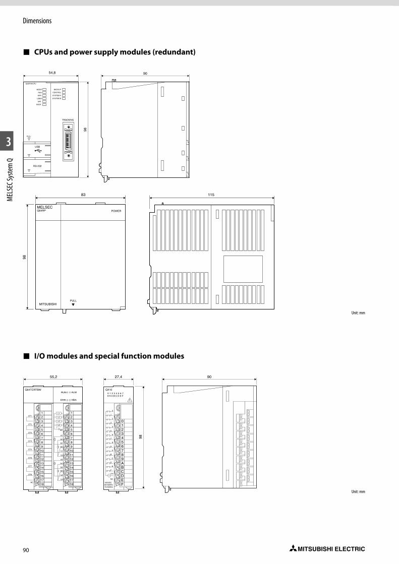
90
Dimensions
1
2
3
MEL
SEC S
yste
m Q
CPUs and power supply modules (redundant)
I/O modules and special function modules
Unit: mm
Unit: mm
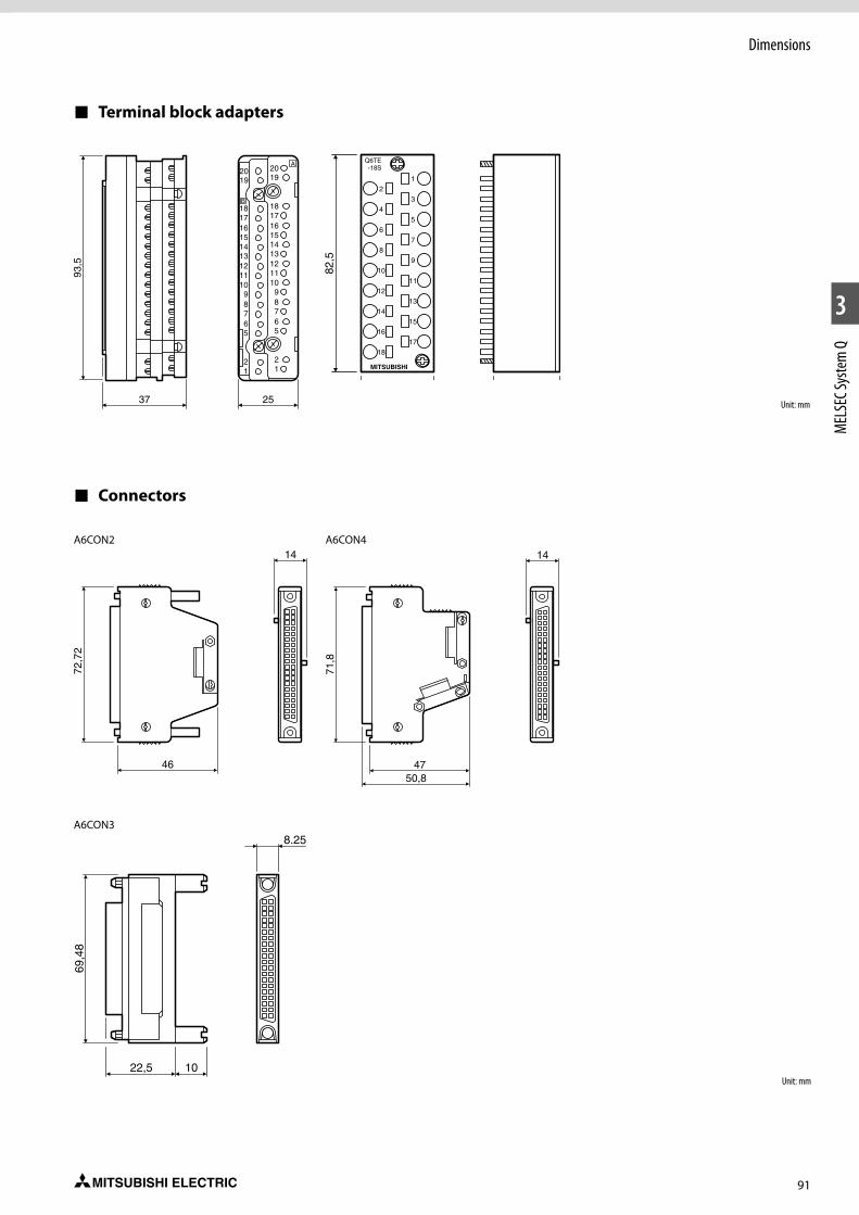
91
Dimensions
1
2
3
MEL
SEC S
yste
m Q
Terminal block adapters
Connectors
A6CON2
A6CON3
A6CON4
Unit: mm
Unit: mm
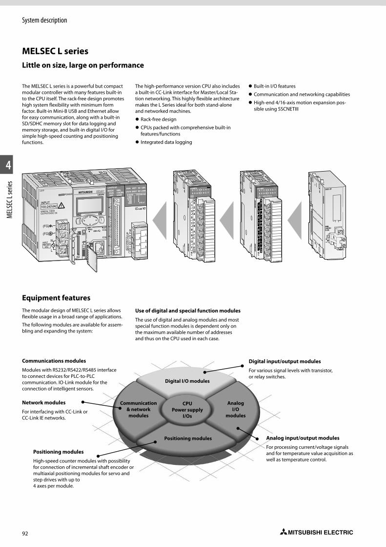
92
1
2
4
MEL
SEC L
serie
sSystem description
The MELSEC L series is a powerful but compact modular controller with many features built-in to the CPU itself. The rack-free design promotes high system flexibility with minimum form factor. Built-in Mini-B USB and Ethernet allow for easy communication, along with a built-in SD/SDHC memory slot for data logging and memory storage, and built-in digital I/O for simple high-speed counting and positioning functions.
The high-performance version CPU also includes a built-in CC-Link interface for Master/Local Sta-tion networking. This highly flexible architecture makes the L Series ideal for both stand-alone and networked machines.
z Rack-free design
z CPUs packed with comprehensive built-in features/functions
z Integrated data logging
z Built-in I/O features
z Communication and networking capabilities
z High-end 4/16-axis motion expansion pos-sible using SSCNETIII
Equipment featuresThe modular design of MELSEC L series allows flexible usage in a broad range of applications.
The following modules are available for assem-bling and expanding the system:
Use of digital and special function modules
The use of digital and analog modules and most special function modules is dependent only on the maximum available number of addresses and thus on the CPU used in each case.
Digital input/output modules
For various signal levels with transistor, or relay switches.
Analog input/output modules
For processing current/voltage signals and for temperature value acquisition as well as temperature control.
Positioning modules
High-speed counter modules with possibility for connection of incremental shaft encoder or multiaxial positioning modules for servo and step drives with up to 4 axes per module.
Communications modules
Modules with RS232/RS422/RS485 interface to connect devices for PLC-to-PLC communication. IO-Link module for the connection of intelligent sensors.
Network modules
For interfacing with CC-Link or CC-Link IE networks.
Digital I/O modules
Analog I/O
modules
Positioning modules
CPU Power supply
I/Os
Communication & network modules
Little on size, large on performance
MELSEC L series
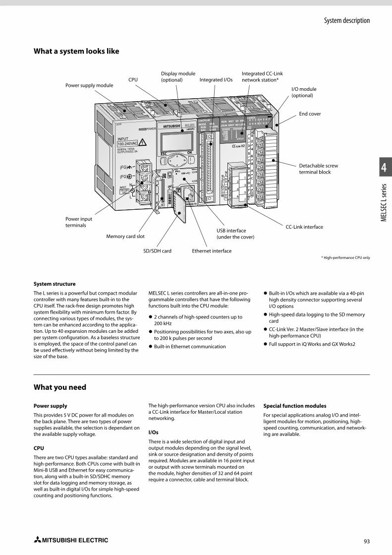
93
System description
1
2
4
MEL
SEC L
serie
s
System structure
The L series is a powerful but compact modular controller with many features built-in to the CPU itself. The rack-free design promotes high system flexibility with minimum form factor. By connecting various types of modules, the sys-tem can be enhanced according to the applica-tion. Up to 40 expansion modules can be added per system configuration. As a baseless structure is employed, the space of the control panel can be used effectively without being limited by the size of the base.
MELSEC L series controllers are all-in-one pro-grammable controllers that have the following functions built into the CPU module:
z 2 channels of high-speed counters up to 200 kHz
z Positioning possibilities for two axes, also up to 200 k pulses per second
z Built-in Ethernet communication
z Built-in I/Os which are available via a 40-pin high density connector supporting several I/O options
z High-speed data logging to the SD memory card
z CC-Link Ver. 2 Master/Slave interface (in the high-performance CPU)
z Full support in iQ Works and GX Works2
What you need
Power supply
This provides 5 V DC power for all modules on the back plane. There are two types of power supplies available, the selection is dependant on the available supply voltage.
CPU
There are two CPU types availabe: standard and high-performance. Both CPUs come with built-in Mini-B USB and Ethernet for easy communica-tion, along with a built-in SD/SDHC memory slot for data logging and memory storage, as well as built-in digital I/Os for simple high-speed counting and positioning functions.
The high-performance version CPU also includes a CC-Link interface for Master/Local station networking.
I/Os
There is a wide selection of digital input and output modules depending on the signal level, sink or source designation and density of points required. Modules are available in 16 point input or output with screw terminals mounted on the module, higher densities of 32 and 64 point require a connector, cable and terminal block.
Special function modules
For special applications analog I/O and intel-ligent modules for motion, positioning, high-speed counting, communication, and network-ing are available.
What a system looks like
Power supply moduleCPU
Display module (optional) Integrated I/Os
Integrated CC-Link network station*
I/O module (optional)
End cover
Detachable screw terminal block
CC-Link interfaceUSB interface (under the cover)
Ethernet interfaceSD/SDH card
Memory card slot
POWER
INPUT
100-240VAC
L61P
50/60Hz 130VA
(FG)
OUTPUT
INPUT100-240
VAC
5VDC 5A
(FG)
N
L
Power input terminals
* High-performance CPU only
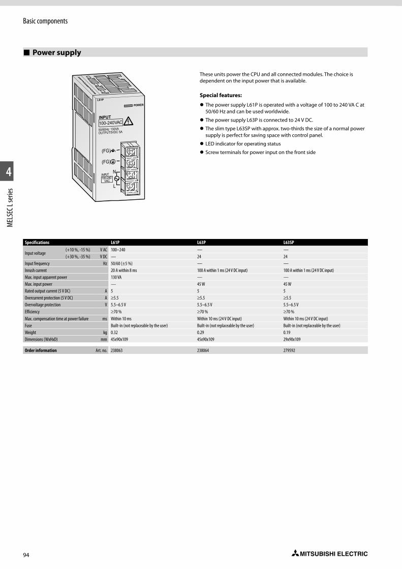
94
1
2
4
MEL
SEC L
serie
sBasic components
Power supply
These units power the CPU and all connected modules. The choice is dependent on the input power that is available.
Special features:
z The power supply L61P is operated with a voltage of 100 to 240 VA C at 50/60 Hz and can be used worldwide.
z The power supply L63P is connected to 24 V DC.
z The slim type L63SP with approx. two-thirds the size of a normal power supply is perfect for saving space with control panel.
z LED indicator for operating status
z Screw terminals for power input on the front side
POWER
INPUT
100-240VAC
L61P
50/60Hz 130VA
(FG)
OUTPUT
INPUT100-240
VAC
5VDC 5A
(FG)
N
L
Specifications L61P L63P L63SP
Input voltage(+10 %, -15 %) V AC 100–240 — —(+30 %, -35 %) V DC — 24 24
Input frequency Hz 50/60 (±5 %) — —Inrush current 20 A within 8 ms 100 A within 1 ms (24 V DC input) 100 A within 1 ms (24 V DC input)Max. input apparent power 130 VA — —Max. input power — 45 W 45 WRated output current (5 V DC) A 5 5 5Overcurrent protection (5 V DC) A ≥5.5 ≥5.5 ≥5.5Overvoltage protection V 5.5–6.5 V 5.5–6.5 V 5.5–6.5 VEfficiency ≥70 % ≥70 % ≥70 %Max. compensation time at power failure ms Within 10 ms Within 10 ms (24 V DC input) Within 10 ms (24 V DC input)Fuse Built-in (not replaceable by the user) Built-in (not replaceable by the user) Built-in (not replaceable by the user)Weight kg 0.32 0.29 0.19Dimensions (WxHxD) mm 45x90x109 45x90x109 29x90x109
Order information Art. no. 238063 238064 279592
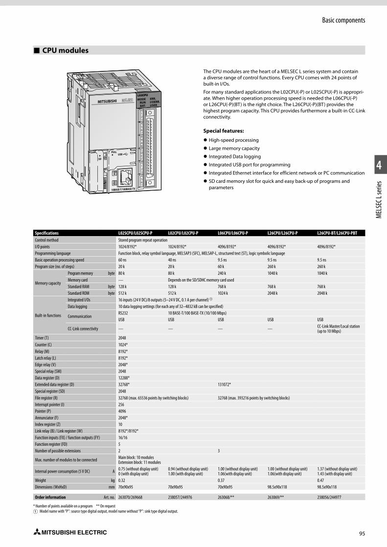
95
Basic components
1
2
4
MEL
SEC L
serie
s
CPU modules
The CPU modules are the heart of a MELSEC L series system and contain a diverse range of control functions. Every CPU comes with 24 points of built-in I/Os.
For many standard applications the L02CPU(-P) or L02SCPU(-P) is appropri-ate. When higher operation processing speed is needed the L06CPU(-P) or L26CPU(-P)(BT) is the right choice. The L26CPU(-P)(BT) provides the highest program capacity. This CPU provides furthermore a built-in CC-Link connectivity.
Special features:
z High-speed processing
z Large memory capacity
z Integrated Data logging
z Integrated USB port for programming
z Integrated Ethernet interface for efficient network or PC communication
z SD card memory slot for quick and easy back-up of programs and parameters
Specifications L02SCPU/L02SCPU-P L02CPU/L02CPU-P L06CPU/L06CPU-P L26CPU/L26CPU-P L26CPU-BT/L26CPU-PBTControl method Stored program repeat operationI/O points 1024/8192* 1024/8192* 4096/8192* 4096/8192* 4096/8192*Programming language Function block, relay symbol language, MELSAP3 (SFC), MELSAP-L, structured text (ST), logic symbolic languageBasic operation processing speed 60 ns 40 ns 9.5 ns 9.5 ns 9.5 nsProgram size (no. of steps) 20 k 20 k 60 k 260 k 260 k
Memory capacity
Program memory byte 80 k 80 k 240 k 1040 k 1040 kMemory card — Depends on the SD/SDHC memory card usedStandard RAM byte 128 k 128 k 768 k 768 k 768 kStandard ROM byte 512 k 512 k 1024 k 2048 k 2048 k
Built-in functions
Integrated I/Os 16 inputs (24 V DC)/8 outputs (5–24 V DC, 0.1 A per channel) a
Data logging 10 data logging settings (for each any of 32–4832 kB can be specified)
CommunicationRS232 10 BASE-T/100 BASE-TX (10/100 Mbps)USB USB USB USB USB
CC-Link connectivity — — — — CC-Link Master/Local station (up to 10 Mbps)
Timer (T) 2048Counter (C) 1024*Relay (M) 8192*Latch relay (L) 8192*Edge relay (V) 2048*Special relay (SM) 2048Data register (D) 12288*Extended data register (D) 32768* 131072*Special register (SD) 2048File register (R) 32768 (max. 65536 points by switching blocks) 32768 (max. 393216 points by switching blocks)Interrupt pointer (I) 256Pointer (P) 4096Annunciator (F) 2048*Index register (Z) 10Link relay (B) / Link register (W) 8192*/8192*Function inputs (FX) / function outputs (FY) 16/16Function register (FD) 5Number of possible extensions 2 3
Max. number of modules to be connected Main block: 10 modules Extension block: 11 modules
Internal power consumption (5 V DC) A 0.75 (without display unit) 0 (with display unit)
0.94 (without display unit) 1.00 (with display unit)
1.00 (without display unit) 1.06(with display unit)
1.00 (without display unit) 1.06(with display unit)
1.37 (without display unit) 1.43 (with display unit)
Weight kg 0.32 0.37 0.47Dimensions (WxHxD) mm 70x90x95 70x90x95 70x90x95 98.5x90x118 98.5x90x118
Order information Art. no. 263070/269668 238057/244976 263068/** 263069/** 238056/244977
* Number of points available on a program ** On request1 Model name with “P”: source type digital output, model name without “P”: sink type digital output.
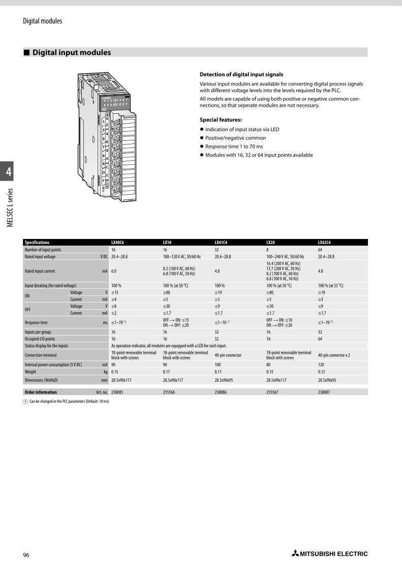
96
Digital modules
1
2
4
MEL
SEC L
serie
s
Digital input modules
Detection of digital input signals
Various input modules are available for converting digital pro cess signals with different voltage levels into the levels required by the PLC.
All models are capable of using both positive or negative common con-nections, so that seperate modules are not necessary.
Special features:
z Indication of input status via LED
z Positive/negative common
z Response time 1 to 70 ms
z Modules with 16, 32 or 64 input points available
Specifications LX40C6 LX10 LX41C4 LX28 LX42C4Number of input points 16 16 32 8 64Rated input voltage V DC 20.4–28.8 100–120 V AC, 50/60 Hz 20.4–28.8 100–240 V AC, 50/60 Hz 20.4–28.8
Rated input current mA 6.0 8.2 (100 V AC, 60 Hz) 6.8 (100 V AC, 50 Hz) 4.0
16.4 (200 V AC, 60 Hz) 13.7 (200 V AC, 50 Hz) 8.2 (100 V AC, 60 Hz) 6.8 (100 V AC, 50 Hz)
4.0
Input derating (for rated voltage) 100 % 100 % (at 50 °C) 100 % 100 % (at 50 °C) 100 % (at 35 °C)
ONVoltage V ≥15 ≥80 ≥19 ≥80 ≥19Current mA ≥4 ≥5 ≥3 ≥5 ≥3
OFFVoltage V ≤8 ≤30 ≤9 ≤30 ≤9Current mA ≤2 ≤1.7 ≤1.7 ≤1.7 ≤1.7
Response time ms ≤1–70 1 OFF R ON: ≤15ON R OFF: ≤20 ≤1–70 1 OFF R ON: ≤10
ON R OFF: ≤20 ≤1–70 1
Inputs per group: 16 16 32 16 32Occupied I/O points 16 16 32 16 64Status display for the inputs As operation indicator, all modules are equipped with a LED for each input.
Connection terminal 18-point removable terminal block with screws
18-point removable terminal block with screws 40-pin connector 18-point removable terminal
block with screws 40-pin connector x 2
Internal power consumption (5 V DC) mA 90 90 100 80 120Weight kg 0.15 0.17 0.11 0.15 0.12
Dimensions (WxHxD) mm 28.5x90x117 28.5x90x117 28.5x90x95 28.5x90x117 28.5x90x95
Order information Art. no. 238085 255566 238086 255567 238087
1 Can be changed in the PLC parameters (Default: 10 ms)
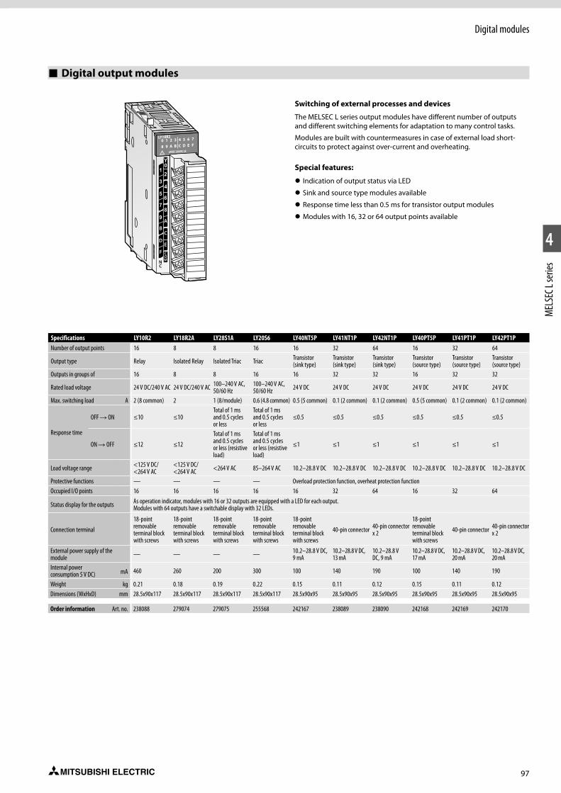
97
Digital modules
1
2
4
MEL
SEC L
serie
s
Digital output modules
Switching of external processes and devices
The MELSEC L series output modules have different number of outputs and different switching elements for adaptation to many control tasks.
Modules are built with countermeasures in case of external load short-circuits to protect against over-current and overheating.
Special features:
z Indication of output status via LED
z Sink and source type modules available
z Response time less than 0.5 ms for transistor output modules
z Modules with 16, 32 or 64 output points available
Specifications LY10R2 LY18R2A LY28S1A LY20S6 LY40NT5P LY41NT1P LY42NT1P LY40PT5P LY41PT1P LY42PT1PNumber of output points 16 8 8 16 16 32 64 16 32 64
Output type Relay Isolated Relay Isolated Triac Triac Transistor (sink type)
Transistor (sink type)
Transistor (sink type)
Transistor (source type)
Transistor (source type)
Transistor (source type)
Outputs in groups of 16 8 8 16 16 32 32 16 32 32
Rated load voltage 24 V DC/240 V AC 24 V DC/240 V AC 100–240 V AC, 50/60 Hz
100–240 V AC, 50/60 Hz 24 V DC 24 V DC 24 V DC 24 V DC 24 V DC 24 V DC
Max. switching load A 2 (8 common) 2 1 (8/module) 0.6 (4.8 common) 0.5 (5 common) 0.1 (2 common) 0.1 (2 common) 0.5 (5 common) 0.1 (2 common) 0.1 (2 common)
Response time
OFF R ON ≤10 ≤10Total of 1 ms and 0.5 cycles or less
Total of 1 ms and 0.5 cycles or less
≤0.5 ≤0.5 ≤0.5 ≤0.5 ≤0.5 ≤0.5
ON R OFF ≤12 ≤12
Total of 1 ms and 0.5 cycles or less (resistive load)
Total of 1 ms and 0.5 cycles or less (resistive load)
≤1 ≤1 ≤1 ≤1 ≤1 ≤1
Load voltage range <125 V DC/ <264 V AC
<125 V DC/<264 V AC <264 V AC 85–264 V AC 10.2–28.8 V DC 10.2–28.8 V DC 10.2–28.8 V DC 10.2–28.8 V DC 10.2–28.8 V DC 10.2–28.8 V DC
Protective functions — — — — Overload protection function, overheat protection functionOccupied I/O points 16 16 16 16 16 32 64 16 32 64
Status display for the outputs As operation indicator, modules with 16 or 32 outputs are equipped with a LED for each output. Modules with 64 outputs have a switchable display with 32 LEDs.
Connection terminal
18-point removable terminal block with screws
18-point removable terminal block with screws
18-point removable terminal block with screws
18-point removable terminal block with screws
18-point removable terminal block with screws
40-pin connector 40-pin connector x 2
18-point removable terminal block with screws
40-pin connector 40-pin connector x 2
External power supply of the module — — — — 10.2–28.8 V DC,
9 mA10.2–28.8 V DC, 13 mA
10.2–28.8 V DC, 9 mA
10.2–28.8 V DC, 17 mA
10.2–28.8 V DC, 20 mA
10.2–28.8 V DC, 20 mA
Internal power consumption 5 V DC) mA 460 260 200 300 100 140 190 100 140 190
Weight kg 0.21 0.18 0.19 0.22 0.15 0.11 0.12 0.15 0.11 0.12Dimensions (WxHxD) mm 28.5x90x117 28.5x90x117 28.5x90x117 28.5x90x117 28.5x90x95 28.5x90x95 28.5x90x95 28.5x90x95 28.5x90x95 28.5x90x95
Order information Art. no. 238088 279074 279075 255568 242167 238089 238090 242168 242169 242170
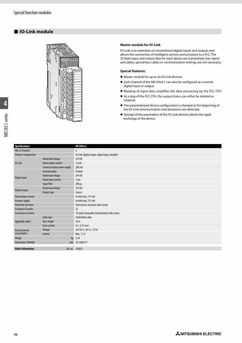
98
Special function modules
1
2
4
MEL
SEC L
serie
s
IO-Link module
Master module for IO-Link
IO-Link is an extension of conventional digital inputs and outputs and allows the connection of intelligent sensors and actuators to a PLC. The 32-byte input and output data for each device are transmitted over stand-ard cables, special bus cables or communication settings are not necessary.
Special features:
z Master module for up to six IO-Link devices
z Each channel of the ME1IOL6-L can also be configured as a normal digital input or output.
z Masking of input data simplifies the data processing by the PLC CPU
z At a stop of the PLC CPU, the output states can either be deleted or retained.
z The parameterized device configuration is checked at the beginning of the IO-Link communication and deviations are detected.
z Storage of the parameters of the IO-Link devices allows the rapid exchange of the device
ME1IOL6-L
24VDC1,7A
Specifications ME1IOL6-LNbr. of channels 6Channel configuration IO-Link, digital output, digital input, disabled
IO-LinkRated load voltage 24 V DCRated output current 15 mASensor/actuator power supply 200 mA
Digital input
Common point PositiveRated load voltage 24 V DCRated input current 5 mAInput filter 200 µs
Digital outputRated load voltage 24 V DCOutput type Source
Rated output current In total max. 215 mAActuator supply In total max. 215 mAProtective functions Overcurrent, overload, short circuitOccupied I/O points 32Connection terminal 18-point removable terminal block with screws
Applicable cablesCable type Unshielded cableMax. lenght 20 mCross-section 0.3–0.75 mm2
External power consumption
Voltage 24 V DC (+20 %, -15 %)Current Max. 1.7 A
Weight kg 0.18Dimensions (WxHxD) mm 28.5x90x117
Order information Art. no. 245825
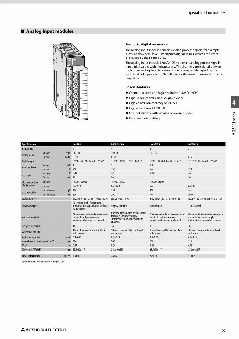
99
Special function modules
1
2
4
MEL
SEC L
serie
s
Analog input modules
Analog to digital conversion
The analog input module converts analog process signals, for example pressure, flow or fill level, linearly into digital values, which are further processed by the L series CPU.
The analog input module L60AD4-2GH converts analog process signals into digital values with high accuracy. The channels are isolated between each other and against the external power supplywith high dielectric withstand voltage for both. This eliminates the need for external isolation amplifiers.
Special features:
z Channel isolated and high resolution (L60AD4-2GH)
z High-speed conversion of 20 µs/channel
z High conversion accuracy of ±0.05 %
z High resolution of 1/20000
z Ensured stability with variable conversion speed
z Easy parameter setting
Specifications L60AD4 L60AD4-2GH L60ADVL8 L60ADIL8Input points 4 4 8 8
Analog inputVoltage V DC -10–10 -10–10 -10–10 —Current mA DC 0–20 0–20 — 0–20
Digital output -20480–20479 (-32768–32767)* -32000–32000 (-32768–32767)* -16384–16383 (-32768–32767)* -8192–8191 (-32768–32767)*
Input resistanceVoltage MΩ 1 1 1.8 —Current Ω 250 250 — 250
Max. inputVoltage V ±15 ±15 ±15 —Current mA 30 30 — 30
I/O characteristics (Digital value)
Voltage -20000–20000 -32000–32000 -16000–16000 —Current 0–20000 0–32000 — 0–8000
Max. resolutionVoltage input µV 200 125 500 —Current input nA 800 500 — 2000
Overall accuracy ±0.2 % (0–55 °C), ±0.1 % (20–30 °C) ±0.05 % (0–55 °C) ±0.2 % (20–30 °C), ±1 % (0–55 °C) ±0.2 % (20–30 °C), ±1 % (0–55 °C)
Conversion speedDepending on the function used: 1 ms/channel, 80 µs/channel (default), 20 µs/channel
40 µs/2 channels 1 ms/channel 1 ms/channel
Insulation methodPhotocoupler isolation between input terminals and power supply. No isolation between the channels.
Photocoupler isolation between input terminals and power supply. Transformer isolation between the channels.
Photocoupler isolation between input terminals and power supply. No isolation between the channels.
Photocoupler isolation between input terminals and power supply. No isolation between the channels.
Occupied I/O points 16 16 16 16
Connection terminal 18-point removable terminal block with screws
18-point removable terminal block with screws
18-point removable terminal block with screws
18-point removable terminal block with screws
Applicable wire size mm2 0.3–0.75 0.3–0.75 0.3–0.75 0.3–0.75Internal power consumption 5 V DC mA 520 760 200 210Weight kg 0.19 0.20 0.20 0.19Dimensions (WxHxD) mm 28.5x90x117 28.5x90x117 28.5x90x117 28.5x90x117
Order information Art. no. 238091 263071 279071 279065
* Value in brackets when using the scaling function
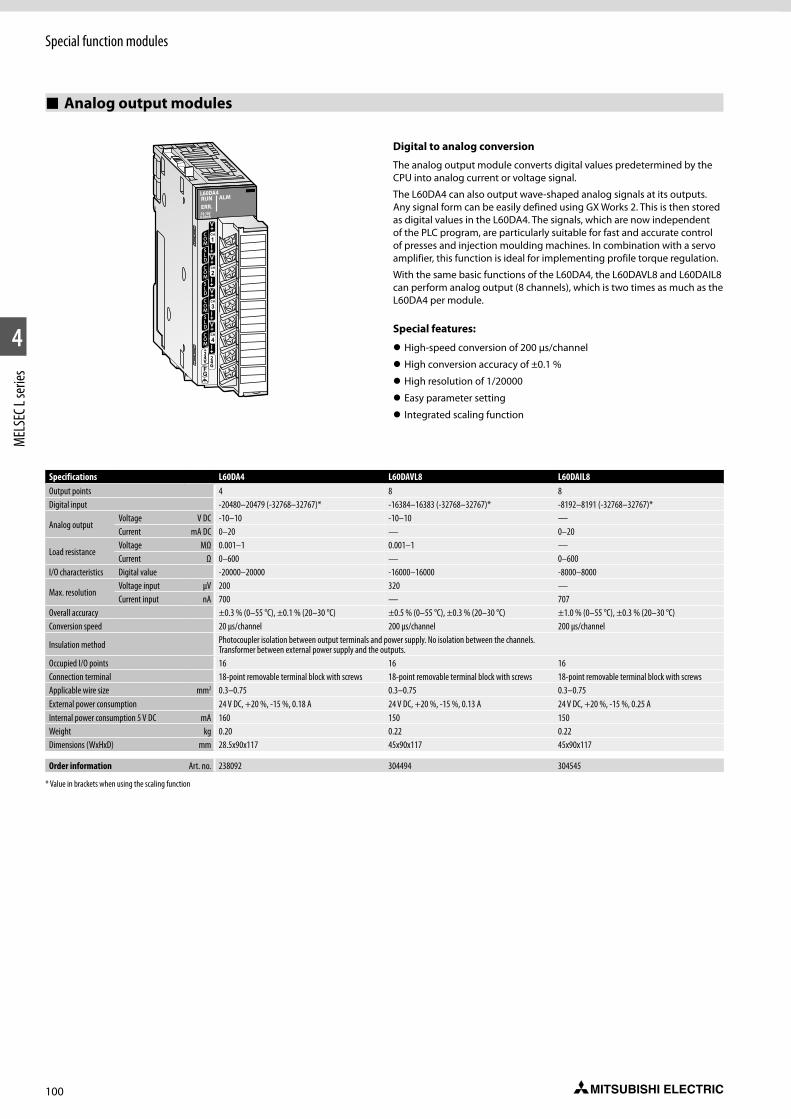
100
Special function modules
1
2
4
MEL
SEC L
serie
s
Analog output modules
Digital to analog conversion
The analog output module converts digital values predetermined by the CPU into analog current or voltage signal.
The L60DA4 can also output wave-shaped analog signals at its outputs. Any signal form can be easily defined using GX Works 2. This is then stored as digital values in the L60DA4. The signals, which are now independent of the PLC program, are particularly suitable for fast and accurate control of presses and injection moulding machines. In combination with a servo amplifier, this function is ideal for implementing profile torque regulation.
With the same basic functions of the L60DA4, the L60DAVL8 and L60DAIL8 can perform analog output (8 channels), which is two times as much as the L60DA4 per module.
Special features:
z High-speed conversion of 200 µs/channel
z High conversion accuracy of ±0.1 %
z High resolution of 1/20000
z Easy parameter setting
z Integrated scaling function
Specifications L60DA4 L60DAVL8 L60DAIL8Output points 4 8 8Digital input -20480–20479 (-32768–32767)* -16384–16383 (-32768–32767)* -8192–8191 (-32768–32767)*
Analog outputVoltage V DC -10–10 -10–10 —Current mA DC 0–20 — 0–20
Load resistanceVoltage MΩ 0.001–1 0.001–1 —Current Ω 0–600 — 0–600
I/O characteristics Digital value -20000–20000 -16000–16000 -8000–8000
Max. resolutionVoltage input µV 200 320 —Current input nA 700 — 707
Overall accuracy ±0.3 % (0–55 °C), ±0.1 % (20–30 °C) ±0.5 % (0–55 °C), ±0.3 % (20–30 °C) ±1.0 % (0–55 °C), ±0.3 % (20–30 °C)Conversion speed 20 µs/channel 200 µs/channel 200 µs/channel
Insulation method Photocoupler isolation between output terminals and power supply. No isolation between the channels. Transformer between external power supply and the outputs.
Occupied I/O points 16 16 16Connection terminal 18-point removable terminal block with screws 18-point removable terminal block with screws 18-point removable terminal block with screwsApplicable wire size mm2 0.3–0.75 0.3–0.75 0.3–0.75External power consumption 24 V DC, +20 %, -15 %, 0.18 A 24 V DC, +20 %, -15 %, 0.13 A 24 V DC, +20 %, -15 %, 0.25 AInternal power consumption 5 V DC mA 160 150 150Weight kg 0.20 0.22 0.22Dimensions (WxHxD) mm 28.5x90x117 45x90x117 45x90x117
Order information Art. no. 238092 304494 304545
* Value in brackets when using the scaling function

101
Special function modules
1
2
4
MEL
SEC L
serie
s
Combined analog input/output module
L60AD2DA2
An analog I/O module has two sets of A/D conversion channels and D/A conversion channels.
Special features
z Scaling function
z Input signal error detection
z Logging function
z Wave output function
z Variable conversion characteristics function + variable arithmetic function
z PID control function
z Easy setting with GX Works3
Specifications L60AD2DA2Input channels 2
Analog inputVoltage V -10–10Current mA 0–20
Input resistanceVoltage MΩ 1Current Ω 250
Max. inputVoltage V ±15Current mA 30
I/O characteristicsVoltage input -16000–16000Current input 12000–12000
Max. resolutionVoltage input µV 333Current input nA 1287
Accuracy ±0.3 % (0–55 °C), ±0.2 % (20–30 °C)
Conversion time
80 µs/channel (logging function/wave output function)100 µs/channel (variable conversion characteristics function)160 µs/channel (variable arithmetic function)200 µs/channel (PID control function)
Output channels 2Digital input -16384–16383
Analog outputVoltage V -10–10Current mA DC 0–20
Load resistanceVoltage output 1 kΩ–1 MΩCurrent output Ω 0–600
I/O characteristicsVoltage output -16000–16000Current output -12000–12000
Max. resolutionVoltage output µV 319
Current output nA 696Accuracy ±0.4 % (0–55 °C), ±0.2 % (20–30 °C)
Max. conversion time
80 µs/channel (logging function/wave output function)100 µs/channel (variable conversion characteristics function)320 µs/2 channels (variable arithmetic function)200 µs/channel (PID control function)
Connection terminal 18-point removable terminal block with screwsOccupied I/O points 16Internal power consumption 5 V DC mA 170Weight kg 0.22Dimensions (WxHxD) mm 28.5x90x117
Order information Art. no. 269673
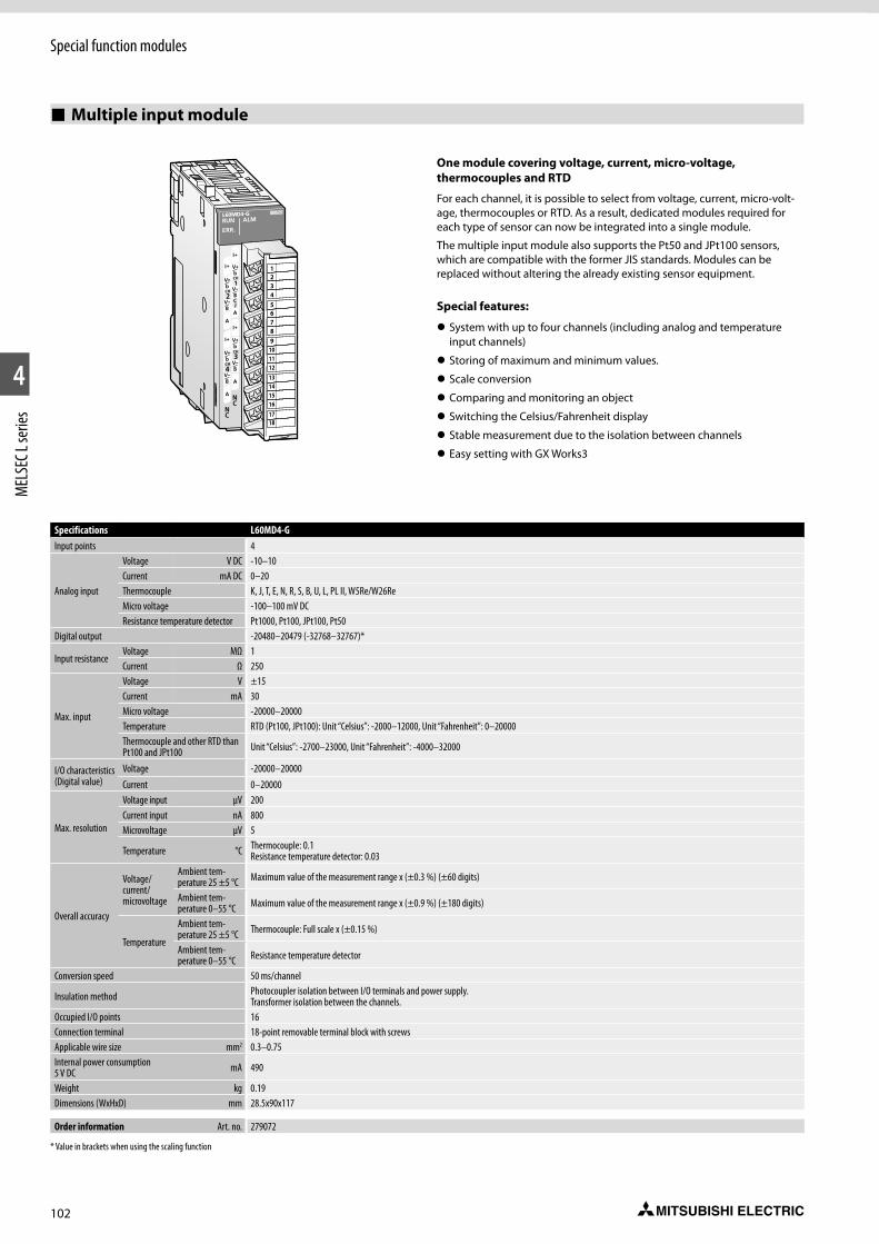
102
Special function modules
1
2
4
MEL
SEC L
serie
s
Multiple input module
One module covering voltage, current, micro-voltage, thermocouples and RTD
For each channel, it is possible to select from voltage, current, micro-volt-age, thermocouples or RTD. As a result, dedicated modules required for each type of sensor can now be integrated into a single module.
The multiple input module also supports the Pt50 and JPt100 sensors, which are compatible with the former JIS standards. Modules can be replaced without altering the already existing sensor equipment.
Special features:
z System with up to four channels (including analog and temperature input channels)
z Storing of maximum and minimum values.
z Scale conversion
z Comparing and monitoring an object
z Switching the Celsius/Fahrenheit display
z Stable measurement due to the isolation between channels
z Easy setting with GX Works3
123456789
101112131415161718
Specifications L60MD4-GInput points 4
Analog input
Voltage V DC -10–10Current mA DC 0–20Thermocouple K, J, T, E, N, R, S, B, U, L, PL II, W5Re/W26ReMicro voltage -100–100 mV DCResistance temperature detector Pt1000, Pt100, JPt100, Pt50
Digital output -20480–20479 (-32768–32767)*
Input resistanceVoltage MΩ 1Current Ω 250
Max. input
Voltage V ±15Current mA 30Micro voltage -20000–20000Temperature RTD (Pt100, JPt100): Unit “Celsius”: -2000–12000, Unit “Fahrenheit”: 0–20000Thermocouple and other RTD than Pt100 and JPt100 Unit “Celsius”: -2700–23000, Unit “Fahrenheit”: -4000–32000
I/O characteristics (Digital value)
Voltage -20000–20000Current 0–20000
Max. resolution
Voltage input µV 200Current input nA 800Microvoltage µV 5
Temperature °C Thermocouple: 0.1Resistance temperature detector: 0.03
Overall accuracy
Voltage/ current/microvoltage
Ambient tem-perature 25 ±5 °C Maximum value of the measurement range x (±0.3 %) (±60 digits)
Ambient tem-perature 0–55 °C Maximum value of the measurement range x (±0.9 %) (±180 digits)
Tempera ture
Ambient tem-perature 25 ±5 °C Thermocouple: Full scale x (±0.15 %)
Ambient tem-perature 0–55 °C Resistance temperature detector
Conversion speed 50 ms/channel
Insulation method Photocoupler isolation between I/O terminals and power supply. Transformer isolation between the channels.
Occupied I/O points 16Connection terminal 18-point removable terminal block with screwsApplicable wire size mm2 0.3–0.75Internal power consumption 5 V DC mA 490
Weight kg 0.19Dimensions (WxHxD) mm 28.5x90x117
Order information Art. no. 279072
* Value in brackets when using the scaling function
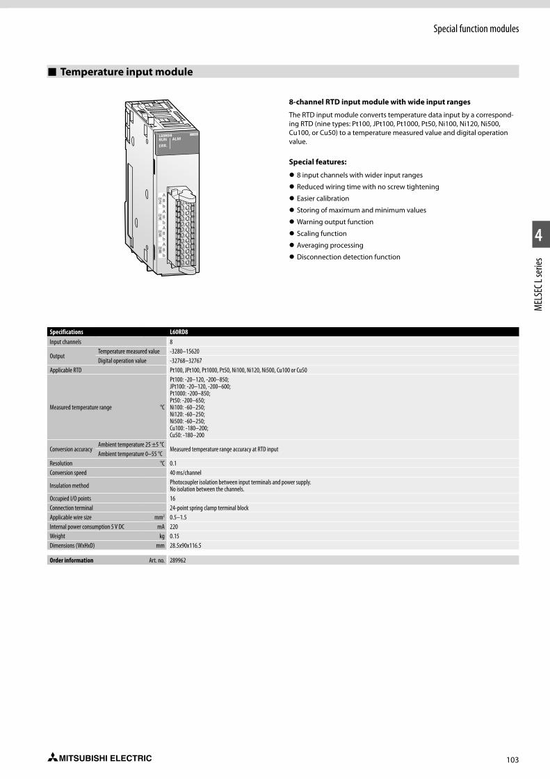
103
Special function modules
1
2
4
MEL
SEC L
serie
s
Temperature input module
8-channel RTD input module with wide input ranges
The RTD input module converts temperature data input by a correspond-ing RTD (nine types: Pt100, JPt100, Pt1000, Pt50, Ni100, Ni120, Ni500, Cu100, or Cu50) to a temperature measured value and digital operation value.
Special features:
z 8 input channels with wider input ranges
z Reduced wiring time with no screw tightening
z Easier calibration
z Storing of maximum and minimum values
z Warning output function
z Scaling function
z Averaging processing
z Disconnection detection function
Specifications L60RD8 Input channels 8
OutputTemperature measured value -3280–15620Digital operation value -32768–32767
Applicable RTD Pt100, JPt100, Pt1000, Pt50, Ni100, Ni120, Ni500, Cu100 or Cu50
Measured temperature range °C
Pt100: -20–120, -200–850; JPt100: -20–120, -200–600; Pt1000: -200–850;Pt50: -200–650;Ni100: -60–250;Ni120: -60–250;Ni500: -60–250;Cu100: -180–200;Cu50: -180–200
Conversion accuracyAmbient temperature 25 ±5 °C
Measured temperature range accuracy at RTD inputAmbient temperature 0–55 °C
Resolution °C 0.1Conversion speed 40 ms/channel
Insulation method Photocoupler isolation between input terminals and power supply. No isolation between the channels.
Occupied I/O points 16Connection terminal 24-point spring clamp terminal blockApplicable wire size mm2 0.5–1.5Internal power consumption 5 V DC mA 220Weight kg 0.15Dimensions (WxHxD) mm 28.5x90x116.5
Order information Art. no. 289962
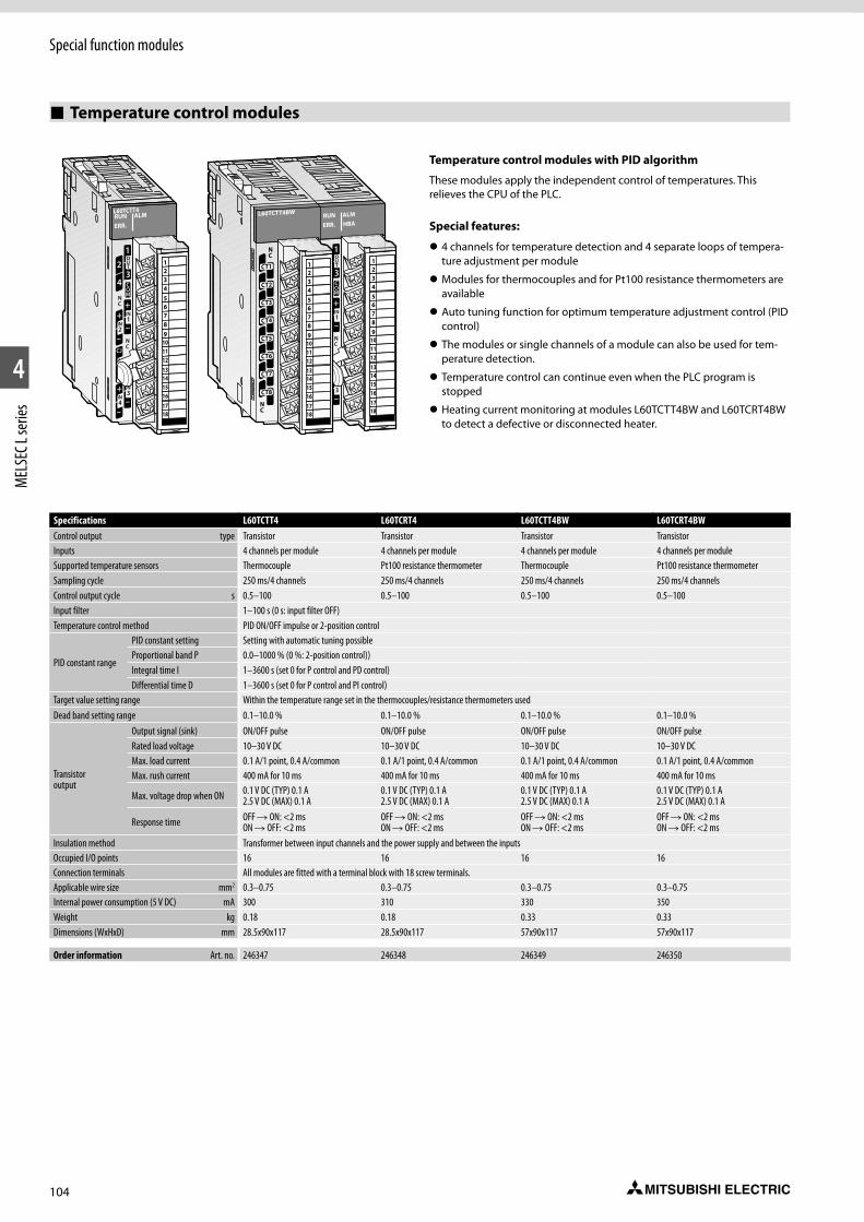
104
Special function modules
1
2
4
MEL
SEC L
serie
s
Temperature control modules
Temperature control modules with PID algorithm
These modules apply the independent control of temperatures. This relieves the CPU of the PLC.
Special features:
z 4 channels for temperature detection and 4 separate loops of tempera-ture adjustment per module
z Modules for thermocouples and for Pt100 resistance thermo meters are available
z Auto tuning function for optimum temperature adjustment control (PID control)
z The modules or single channels of a module can also be used for tem-perature detection.
z Temperature control can continue even when the PLC program is stopped
z Heating current monitoring at modules L60TCTT4BW and L60TCRT4BW to detect a defective or disconnected heater.
Specifications L60TCTT4 L60TCRT4 L60TCTT4BW L60TCRT4BWControl output type Transistor Transistor Transistor TransistorInputs 4 channels per module 4 channels per module 4 channels per module 4 channels per module Supported temperature sensors Thermocouple Pt100 resistance thermometer Thermocouple Pt100 resistance thermometerSampling cycle 250 ms/4 channels 250 ms/4 channels 250 ms/4 channels 250 ms/4 channelsControl output cycle s 0.5–100 0.5–100 0.5–100 0.5–100 Input filter 1–100 s (0 s: input filter OFF)Temperature control method PID ON/OFF impulse or 2-position control
PID constant range
PID constant setting Setting with automatic tuning possibleProportional band P 0.0–1000 % (0 %: 2-position control))Integral time I 1–3600 s (set 0 for P control and PD control)Differential time D 1–3600 s (set 0 for P control and PI control)
Target value setting range Within the temperature range set in the thermocouples/resistance thermometers usedDead band setting range 0.1–10.0 % 0.1–10.0 % 0.1–10.0 % 0.1–10.0 %
Transistor output
Output signal (sink) ON/OFF pulse ON/OFF pulse ON/OFF pulse ON/OFF pulseRated load voltage 10–30 V DC 10–30 V DC 10–30 V DC 10–30 V DCMax. load current 0.1 A/1 point, 0.4 A/common 0.1 A/1 point, 0.4 A/common 0.1 A/1 point, 0.4 A/common 0.1 A/1 point, 0.4 A/commonMax. rush current 400 mA for 10 ms 400 mA for 10 ms 400 mA for 10 ms 400 mA for 10 ms
Max. voltage drop when ON 0.1 V DC (TYP) 0.1 A 2.5 V DC (MAX) 0.1 A
0.1 V DC (TYP) 0.1 A 2.5 V DC (MAX) 0.1 A
0.1 V DC (TYP) 0.1 A 2.5 V DC (MAX) 0.1 A
0.1 V DC (TYP) 0.1 A 2.5 V DC (MAX) 0.1 A
Response time OFF R ON: <2 ms ON R OFF: <2 ms
OFF R ON: <2 ms ON R OFF: <2 ms
OFF R ON: <2 ms ON R OFF: <2 ms
OFF R ON: <2 ms ON R OFF: <2 ms
Insulation method Transformer between input channels and the power supply and between the inputsOccupied I/O points 16 16 16 16Connection terminals All modules are fitted with a terminal block with 18 screw terminals.Applicable wire size mm2 0.3–0.75 0.3–0.75 0.3–0.75 0.3–0.75Internal power consumption (5 V DC) mA 300 310 330 350Weight kg 0.18 0.18 0.33 0.33Dimensions (WxHxD) mm 28.5x90x117 28.5x90x117 57x90x117 57x90x117
Order information Art. no. 246347 246348 246349 246350
HBA
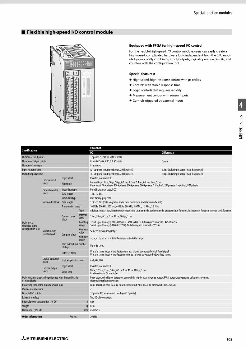
105
Special function modules
1
2
4
MEL
SEC L
serie
s
Flexible high-speed I/O control module
Equipped with FPGA for high-speed I/O control
For the flexible high-speed I/O control module, users can easily create a high-speed, complicated hardware logic independent from the CPU mod-ule by graphically combining input/outputs, logical operation circuits, and counters with the configuration tool.
Special features:
z High-speed, high-response control with µs orders
z Controls with stable response time
z Logic controls that requires rapidity
z Measurement control with sensor inputs
z Controls triggered by external inputs
SpecificationsLD40PD01DC Differential
Number of input points 12 points (5/24 V DC/differential)Number of output points 8 points (5–24 V DC, 0.1 A/point) 6 pointsNumber of interrupts 8 interruptsInput response time ≤1 μs (pulse input speed: max. 200 kpulse/s) ≤1 μs (pulse input speed: max. 8 Mpulse/s)Output response time ≤1 μs (pulse input speed: max. 200 kpulse/s) ≤1 μs (pulse input speed: max. 8 Mpulse/s)
Main blocks (included in the configuration tool)
External input block
Logic select Inverted, not inverted
Filter time General input: 0 μs, 10 μs, 50 μs, 0.1 ms, 0.2 ms, 0.4 ms, 0.6 ms, 1 ms, 5 msPulse input: 10 kpulse/s, 100 kpulse/s, 200 kpulse/s, 500 kpulse/s, 1 Mpulse/s, 2 Mpulse/s, 4 Mpulse/s, 8 Mpulse/s
Parallel encoder block
Input data type Pure binary, gray code, BCDData length 1 bit–12 bits
SSI encoder blockInput data type Pure binary, gray codeData length 1 bit–32 bits (Data length for single turn, multi-turn, and status can be set.)Transmission speed 100 kHz, 200 kHz, 300 kHz, 400 kHz, 500 kHz, 1.0 MHz, 1.5 MHz, 2.0 MHz
Multi function counter block
Counter timer block
Type Addition, subtraction, linear counter mode, ring counter mode, addition mode, preset counter function, latch counter function, internal clock functionInternal clock 25 ns, 50 ns, 0.1 μs, 1 μs, 10 μs, 100 μs, 1 ms
Counting range
32-bit signed binary (-2147483648–2147483647), 32-bit unsigned binary (0–4294967295)16-bit signed binary (-32768–32767), 16-bit unsigned binary (0–65535)
Compare block
Compare value Same as the counting range
Compare mode =, >, <, ≥, ≤, <>, within the range, outside the range
Cam switch block number of steps Up to 16 steps
Set/reset block Uses the signal input to the Set terminal as a trigger to output the High fixed signal.Uses the signal input to the Reset terminal as a trigger to output the Low fixed signal.
Logical operation block Logical operation type AND, OR, XOR
External output block
Logic select Inverted, not inverted
Delay time None, 12.5 ns, 25 ns, 50 ns, 0.1 μs, 1 μs, 10 μs, 100 μs, 1 msCan be set up to 64 multiplies.
Main functions that can be performed with the combination of main blocks
Pulse count, coincidence detection, cam switch, highly-accurate pulse output, PWM output, ratio setting, pulse measurement, electrical interface conversion
Processing time of the main hardware logic Logic operation: min. 87.5 ns, coincidence output: min. 137.5 ns, cam switch: min. 262.5 nsModule size allocation 2Occupied I/O points 32 points (I/O assignment: Intelligent 32 points)External interface Two 40-pin connectorsInternal power consumption (5 V DC) A 0.66Weight kg 0.18Dimensions (WxHxD) mm 45x90x95
Order information Art. no. 296588
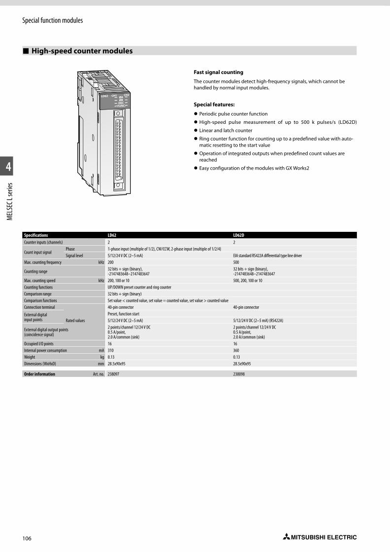
106
Special function modules
1
2
4
MEL
SEC L
serie
s
High-speed counter modules
Fast signal counting
The counter modules detect high-frequency signals, which cannot be handled by normal input modules.
Special features:
z Periodic pulse counter function
z High-speed pulse measurement of up to 500 k pulses/s (LD62D)
z Linear and latch counter
z Ring counter function for counting up to a predefined value with auto-matic resetting to the start value
z Operation of integrated outputs when predefined count values are reached
z Easy configuration of the modules with GX Works2
Specifications LD62 LD62DCounter inputs (channels) 2 2
Count input signalPhase 1-phase input (multiple of 1/2), CW/CCW, 2-phase input (multiple of 1/2/4)Signal level 5/12/24 V DC (2–5 mA) EIA standard RS422A differential type line driver
Max. counting frequency kHz 200 500
Counting range 32 bits + sign (binary), -2147483648–2147483647
32 bits + sign (binary), -2147483648–2147483647
Max. counting speed kHz 200, 100 or 10 500, 200, 100 or 10Counting functions UP/DOWN preset counter and ring counterComparison range 32 bits + sign (binary)Comparison functions Set value < counted value, set value = counted value, set value > counted valueConnection terminal 40-pin connector 40-pin connector
External digital input points
Preset, function startRated values 5/12/24 V DC (2–5 mA) 5/12/24 V DC (2–5 mA) (RS422A)
External digital output points (coincidence signal)
2 points/channel 12/24 V DC 0.5 A/point, 2.0 A/common (sink)
2 points/channel 12/24 V DC 0.5 A/point, 2.0 A/common (sink)
Occupied I/O points 16 16Internal power consumption mA 310 360Weight kg 0.13 0.13Dimensions (WxHxD) mm 28.5x90x95 28.5x90x95
Order information Art. no. 238097 238098
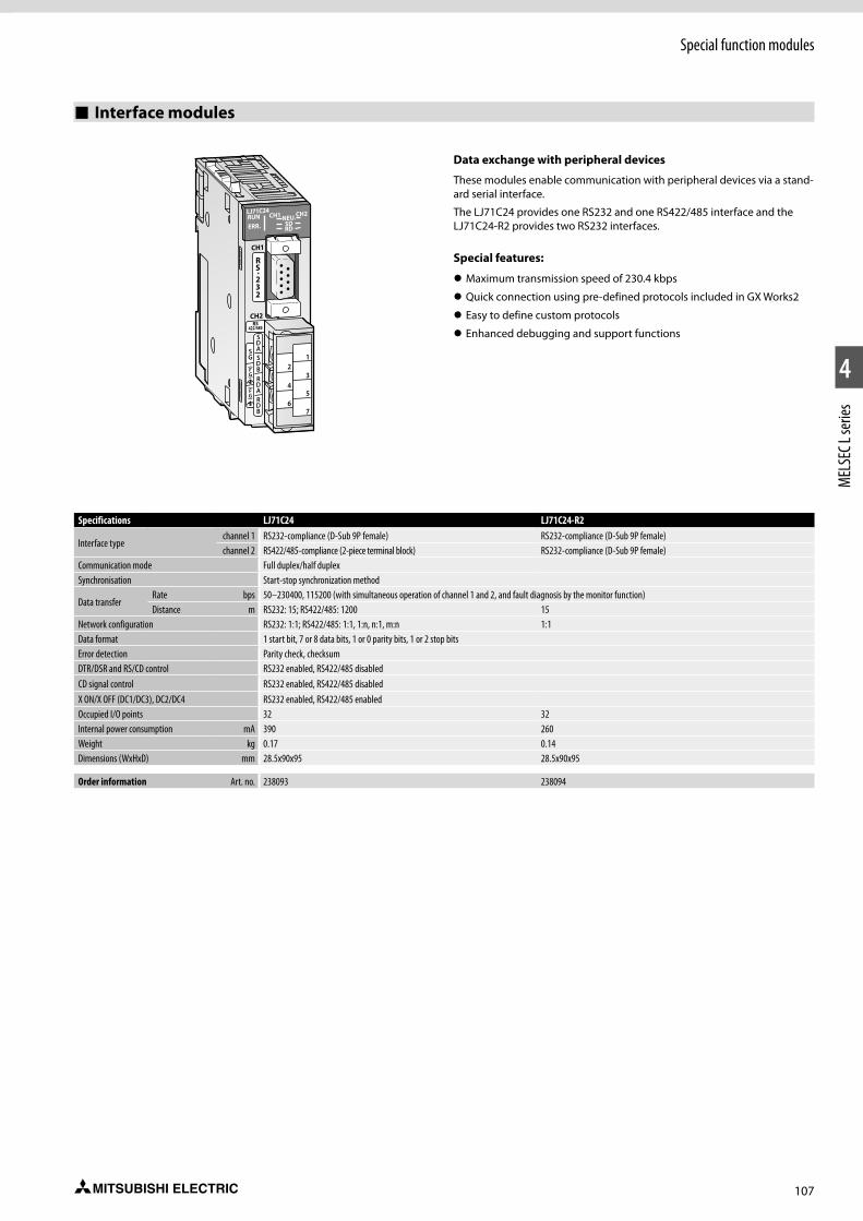
107
Special function modules
1
2
4
MEL
SEC L
serie
s
Interface modules
Data exchange with peripheral devices
These modules enable communication with peripheral devices via a stand-ard serial interface.
The LJ71C24 provides one RS232 and one RS422/485 interface and the LJ71C24-R2 provides two RS232 interfaces.
Special features:
z Maximum transmission speed of 230.4 kbps
z Quick connection using pre-defined protocols included in GX Works2
z Easy to define custom protocols
z Enhanced debugging and support functions
Specifications LJ71C24 LJ71C24-R2
Interface typechannel 1 RS232-compliance (D-Sub 9P female) RS232-compliance (D-Sub 9P female)channel 2 RS422/485-compliance (2-piece terminal block) RS232-compliance (D-Sub 9P female)
Communication mode Full duplex/half duplexSynchronisation Start-stop synchronization method
Data transfer Rate bps 50–230400, 115200 (with simultaneous operation of channel 1 and 2, and fault diagnosis by the monitor function)Distance m RS232: 15; RS422/485: 1200 15
Network configuration RS232: 1:1; RS422/485: 1:1, 1:n, n:1, m:n 1:1Data format 1 start bit, 7 or 8 data bits, 1 or 0 parity bits, 1 or 2 stop bitsError detection Parity check, checksumDTR/DSR and RS/CD control RS232 enabled, RS422/485 disabledCD signal control RS232 enabled, RS422/485 disabledX ON/X OFF (DC1/DC3), DC2/DC4 RS232 enabled, RS422/485 enabledOccupied I/O points 32 32Internal power consumption mA 390 260Weight kg 0.17 0.14Dimensions (WxHxD) mm 28.5x90x95 28.5x90x95
Order information Art. no. 238093 238094

108
Special function modules
1
2
4
MEL
SEC L
serie
s
Positioning modules
Control of high resolution drives
The L series offers two different positioning modules for control of up to four axes.
z Differential output type (LD75D1/2/4)
z Open-collector output type (LD75P1/2/4)
These positioning modules can be used with standard type servo amplifi-ers (Mitsubishi Electric MR-E, MR-J3/MR-J4).
All L series positioning modules can provide functionality such as interpo-lation, speed positioning operation etc.
The open-collector output type module provides positioning with open loop control. The module generates the travel command via the pulse chain. The speed is proportional to the pulse frequency and the distance travelled is proportional to the pulse length.
The modules with differential output can bridge large distances between the module and the drive unit, since this output enables long connection cables.
Special features:
z Up to 600 positioning data per axis
z Maximum output pulse of 200 k pulses/s for LD75P1/2/4 and 4 M puls-es/s for LD75D1/2/4
z High-speed control of high resolution devices such as linear servos and direct drive motors
z Reduced machine vibration by using the optional acceleration/deceler-ation system
z Visualization of positioning module buffer data with customizable graphs
Specifications LD75P1/LD75D1 LD75P2/LD75D2 LD75P4/LD75D4Accessible axes 1 2 4
Output frequency pulse/s — 2-axis linear interpolation, 2-axis circular interpolation
2-/3-/4-axis linear interpolation, 2-axis circular interpolation
Positioning data items per axis 600Output type Open collector/Differential driver Open collector/Differential driver Open collector/Differential driverOutput signal Pulse chain Pulse chain Pulse chain
Positioning
Method PTP (Point To Point) control, path control (both linear and arc can be set), speed control, speed-position switching control, position-speed switching control
Range
Absolute/incremental system:-214 748 364.8–214 748 364.7 µm -21 474.83648–21 474.83647 inch 0–359.99999 degree (absolut); 21 474.83648–21 474.83647 (incremental) -2 147 483 648–2 147 483 647 pulseIn speed-position switching control (INC mode)/position-speed switching control:0–214 748 364.7 µm 0–21 474.83647 inch 0–21 474.83647 degree 0–2 147 483 647 pulse
Speed
1–1 000 000 pulse/s 0.01–20 000 000.00 mm/min 0.001–200 000.000 degree/min 0.001–200 000.000 inch/min
Acceleration/ decleration processing Automatic trapezoidal or S-pattern acceleration and deceleration or automatic S-pattern acceleration and deceleration
Acceleration/ decleration time
1–83 88 608 ms (four patterns can be set for each of acceleration time and deceleration time)
Rapid stop deceleration time 1–8 388 608 ms
Occupied I/O points 32Internal power consumption mA 440/510 480/620 550/760Weight kg 0.18 0.18 0.18Dimensions (WxHxD) mm 45x90x95
Order information Art. no. 251446/251448 251447/251449 238096/238095

109
Special function modules
1
2
4
MEL
SEC L
serie
s
Simple Motion modules
The MELSEC L series lineup includes a Simple Motion module in addition to the regular positioning modules. Various control functions previously only possible with Motion Controllers, such as speed control, torque control, synchronous control and cam control,are now available with the LD77MS module. These functions can be realized with simple parameter adjustments and via the PLC program.
Mark sensors allow use in packaging industry, filling plants, etc., without additional optional modules. A function for automatic calculation of cam data for applications with rotating cutters is implemented – only by setting the length of the product and the synchronisation path. With positioning functions, like linear interpolation (up to 4 axes), circular interpolation (2 axes) and path control it is easy to realize different applications, like X-Y tables, sealing, etc.
Special features:
z Up to 600 positions per axis
z External encoder input for axis synchronisation
z Electronic cam control
z High-speed digital inputs for mark sensors to capture encoder position, motor position etc.
z Parameterization, programming, diagnostics and test operation by GX Works2
z PLCopen function blocks
z Communication between the LD77MS module and servo amplifiers via the high-speed network SSCNETIII/H
LD77MS16RUNERR.
AX 19 10 11 12 13 14 15 16
2 3 4 5 6 7 8
Specifications LD77MS2 LD77MS4 LD77MS16Number of controllable axes 2 4 16
Interpolation functions 2 axes linear and circular interpolation Linear interpolation for up to 4 axes, circular interpolation for 2 axes
Linear interpolation for up to 4 axes, 2 axes linear and circular interpolation
Output type SSCNETIII/H SSCNETIII/H SSCNETIII/HServo amplifier MR-JE-B/MR-J4(W2/W3)-B over SSCNETIII/H MR-JE-B/MR-J4(W2/W3)-B over SSCNETIII/H MR-JE-B/MR-J4(W2/W3)-B over SSCNETIII/HOperation cycle 0.88 ms 0.88 ms 0.88 ms/1.7 ms
Positioning
Method PTP (Point To Point) control, path control (both linear and arc can be set), speed control, speed-position switching control, position-speed switching control, torque control
Acceleration/deceleration control Trapezoidal or S-pattern acceleration and decelerationCompensation Backlash compensation, electronic gear, near pass functionOPR control 5 different methods
Number of positioning points 600 per axis (can be set with GX Works2 or PLC program)
External input signals
Encoder 1 encoder, A/B phases 1 encoder, A/B phases 1 encoder, A/B phasesHigh-speed inputs 4 digital inputs [DI1–DI4] 4 digital inputs [DI1–DI4] 4 digital inputs [DI1–DI4]
Cam function
Storage area cam data 256 kbytes 256 kbytes 256 kbytesNumber of cams Max. 256 (depending on resolution) Max. 256 (depending on resolution) Max. 256 (depending on resolution)Resolution per cycle 256, 512, 1024, 2048, 4096, 8192, 16384, 32768 256, 512, 1024, 2048, 4096, 8192, 16384, 32768 256, 512, 1024, 2048, 4096, 8192, 16384, 32768Stroke resolution 2–16284 2–16284 2–16284
Occupied I/O points 32 32 32No. of Simple Motion modules in one system max. 5 max. 5 max. 5Internal power consumption (5 V DC) mA 550 550 700Weight kg 0.22 0.22 0.22Dimensions (WxHxD) mm 90x45x95 90x45x95 90x45x95
Order information Art. no. 268199 268200 268201
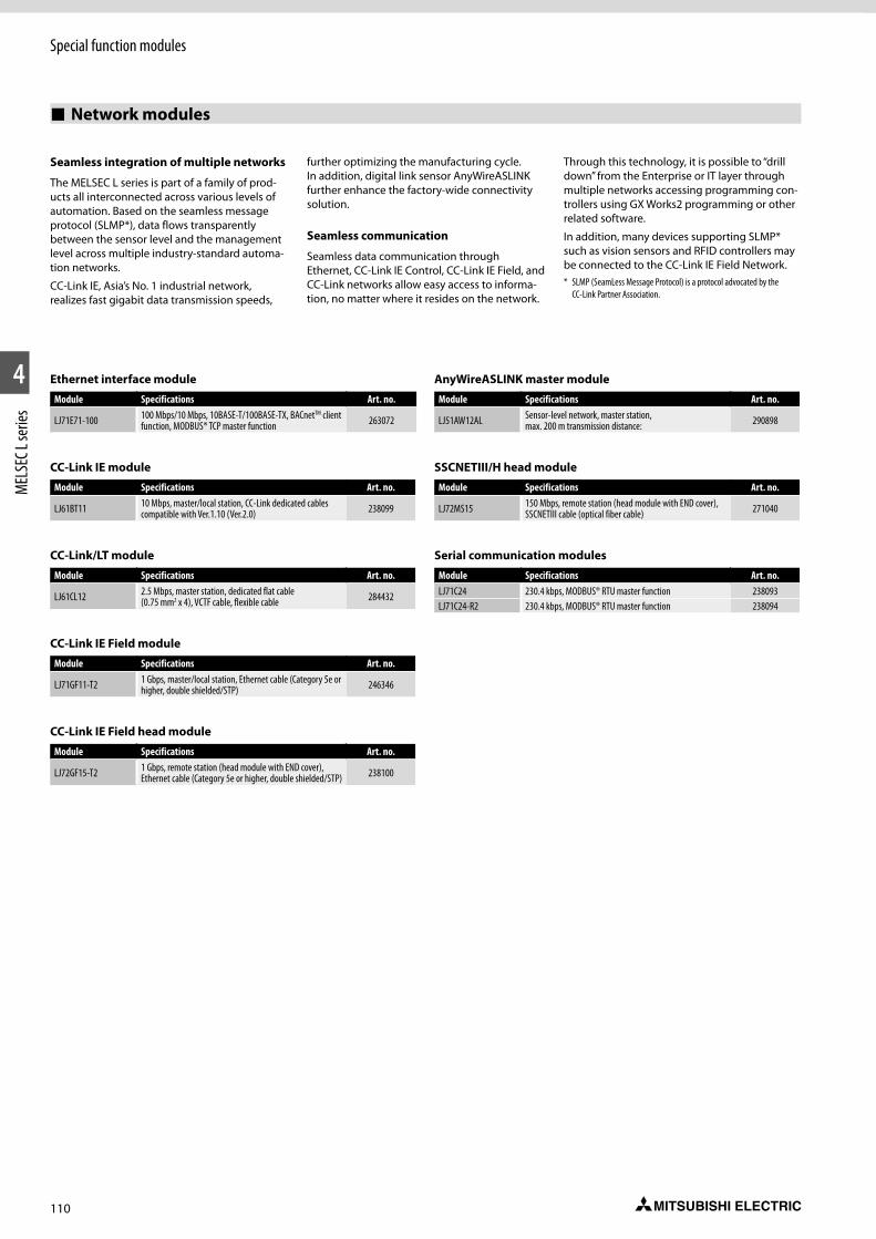
110
Special function modules
1
2
4
MEL
SEC L
serie
s
Network modules
Seamless integration of multiple networks
The MELSEC L series is part of a family of prod-ucts all interconnected across various levels of automation. Based on the seamless message protocol (SLMP*), data flows transparently between the sensor level and the management level across multiple industry-standard automa-tion networks.
CC-Link IE, Asia’s No. 1 industrial network, realizes fast gigabit data transmission speeds,
further optimizing the manufacturing cycle. In addition, digital link sensor AnyWireASLINK further enhance the factory-wide connectivity solution.
Seamless communication
Seamless data communication through Ethernet, CC-Link IE Control, CC-Link IE Field, and CC-Link networks allow easy access to informa-tion, no matter where it resides on the network.
Through this technology, it is possible to “drill down” from the Enterprise or IT layer through multiple networks accessing programming con-trollers using GX Works2 programming or other related software.
In addition, many devices supporting SLMP* such as vision sensors and RFID controllers may be connected to the CC-Link IE Field Network.* SLMP (SeamLess Message Protocol) is a protocol advocated by the
CC-Link Partner Association.
Ethernet interface module
Module Specifications Art. no.
LJ71E71-100 100 Mbps/10 Mbps, 10BASE-T/100BASE-TX, BACnetTM client function, MODBUS® TCP master function 263072
CC-Link IE module
Module Specifications Art. no.
LJ61BT11 10 Mbps, master/local station, CC-Link dedicated cables compatible with Ver.1.10 (Ver.2.0) 238099
CC-Link/LT module
Module Specifications Art. no.
LJ61CL12 2.5 Mbps, master station, dedicated flat cable (0.75 mm2 x 4), VCTF cable, flexible cable 284432
CC-Link IE Field module
Module Specifications Art. no.
LJ71GF11-T2 1 Gbps, master/local station, Ethernet cable (Category 5e or higher, double shielded/STP) 246346
CC-Link IE Field head module
Module Specifications Art. no.
LJ72GF15-T2 1 Gbps, remote station (head module with END cover), Ethernet cable (Category 5e or higher, double shielded/STP) 238100
AnyWireASLINK master module
Module Specifications Art. no.
LJ51AW12AL Sensor-level network, master station, max. 200 m transmission distance: 290898
SSCNETIII/H head module
Module Specifications Art. no.
LJ72MS15 150 Mbps, remote station (head module with END cover), SSCNETIII cable (optical fiber cable) 271040
Serial communication modules
Module Specifications Art. no.LJ71C24 230.4 kbps, MODBUS® RTU master function 238093LJ71C24-R2 230.4 kbps, MODBUS® RTU master function 238094

111
Special function modules
1
2
4
MEL
SEC L
serie
s
Serial communications adapters
RS232 and RS422/485 interface adapters
The L6ADP-R2 provides a RS232 and the L6ADP-R4 a RS422/485 interface for serial communication with the L series PLC.
Specifications L6ADP-R2 L6ADP-R4
Application Serial connection, e.g. GT10 Terminals
Serial connection, e.g. GOT Terminals
Power supply Internally InternallyMax. transfer rate Kpbs 115.2 115.2Occupied I/O points — —Internal power consumption mA 20 150Weight kg 0.10 0.12Dimensions (WxHxD) mm 28.5x90x95 28.5x90x106.5
Order information Art. no. 238059 273657
End cover
END cover with error terminal
This end cover can be used instead of the standard end cover which comes with the CPU in the basic equipment.
The L6EC-ET end cover has a single relay output for error notification.
Specifications L6EC-ET L6EC
Application Error notification via relay output Standard end cover
Output Screw terminal —Max. switching load A 0.5 (24 V DC) —Weight kg 0.11 0.06Dimensions (WxHxD) mm 28.5x90x95 13x90x95
Order information Art. no. 238062 249151
Note: L Series CPU modules are supplied with a standard End Cover L6EC.
Accessories for the L series from page 114 onward!
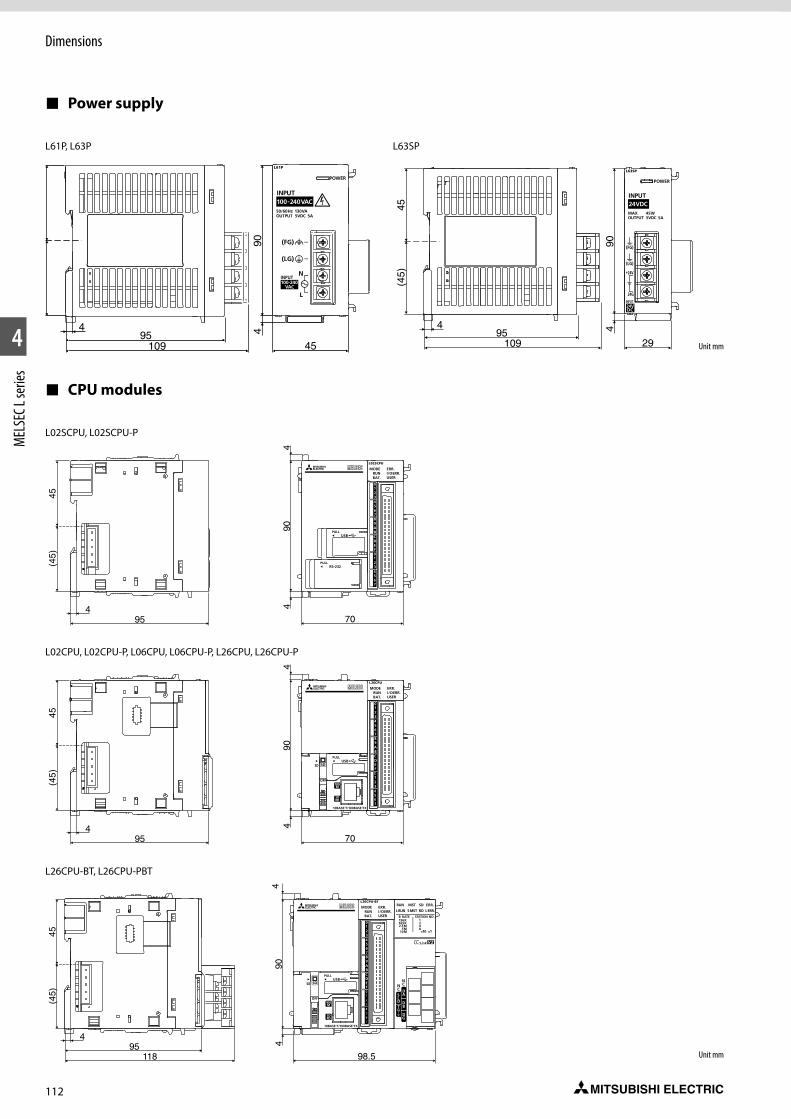
112
1
2
4
MEL
SEC L
serie
sDimensions
CPU modules
954
45(4
5)
70
490
4
4510995
4 490
Unit mm
Unit mm
Power supply
2910995
4 490
45(4
5)
L61P, L63P L63SP
L02CPU, L02CPU-P, L06CPU, L06CPU-P, L26CPU, L26CPU-P
954
45(4
5)
70
490
4
L02SCPU, L02SCPU-P
11895
4
45(4
5)
98.5
490
4
L26CPU-BT, L26CPU-PBT
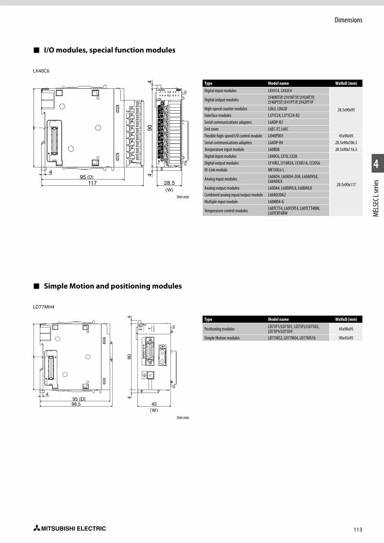
113
Dimensions
1
2
4
MEL
SEC L
serie
s
I/O modules, special function modules
28.511795
4 490
4
Unit mm
Simple Motion and positioning modules
45
490
4
9598.5
4
Type Model name WxHxD (mm)
Digital input modules LX41C4, LX42C4
28.5x90x95
Digital output modules LY40NT5P, LY41NT1P, LY42NT1P, LY40PT5P, LY41PT1P, LY42PT1P
High-speed counter modules LD62, LD62DInterface modules LJ71C24, LJ71C24-R2Serial communications adapters L6ADP-R2End cover L6EC-ET, L6ECFlexible high-speed I/O control module LD40PD01 45x90x95Serial communications adapters L6ADP-R4 28.5x90x106.5Temperature input module L60RD8 28.5x90x116.5Digital input modules LX40C6, LX10, LX28
28.5x90x117
Digital output modules LY10R2, LY18R2A, LY28S1A, LY20S6IO-Link module ME1IOL6-L
Analog input modules L60AD4, L60AD4-2GH, L60ADVL8, L60ADIL8
Analog output modules L60DA4, L60DAVL8, L60DAIL8Combined analog input/output module L60AD2DA2Multiple input module L60MD4-G
Temperature control modules L60TCTT4, L60TCRT4, L60TCTT4BW, L60TCRT4BW
LX40C6
Unit mm
Type Model name WxHxD (mm)
Positioning modules LD75P1/LD75D1, LD75P2/LD75D2, LD75P4/LD75D4 45x90x95
Simple Motion modules LD77MS2, LD77MS4, LD77MS16 90x45x95
LD77MH4
(W)
(D)
(W)
(D)
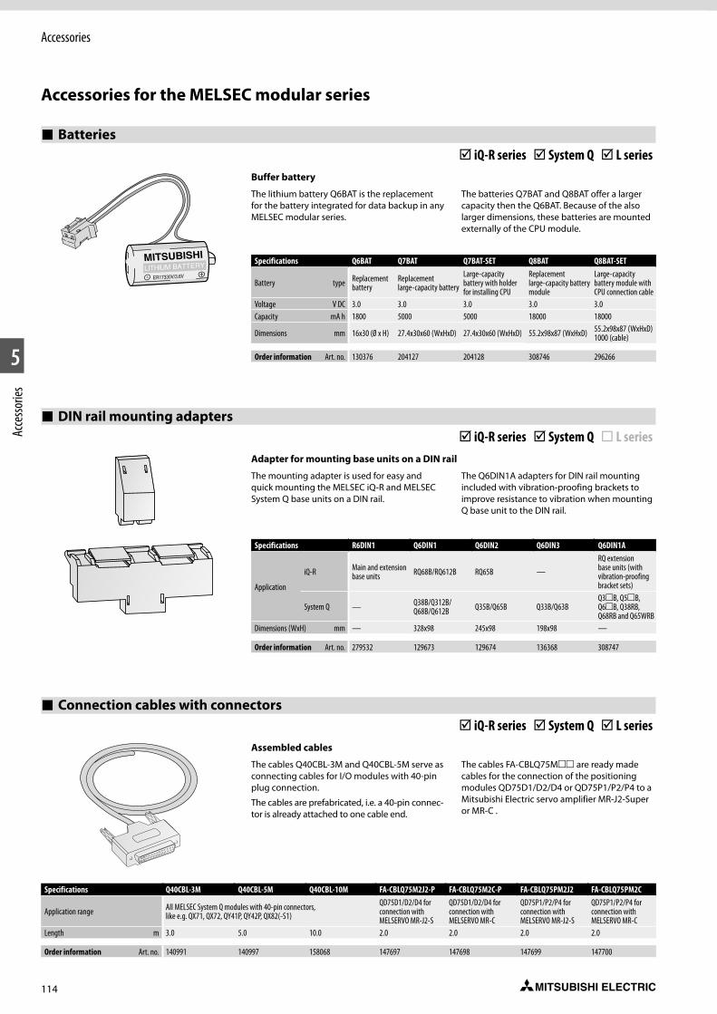
114
Accessories
1
#2
5
Acce
ssorie
s
Accessories for the MELSEC modular series
Batteries þ iQ-R series þ System Q þ L series
Buffer battery
The lithium battery Q6BAT is the replacement for the battery integrated for data backup in any MELSEC modular series.
The batteries Q7BAT and Q8BAT offer a larger capacity then the Q6BAT. Because of the also larger dimensions, these batteries are mounted externally of the CPU module.
Specifications Q6BAT Q7BAT Q7BAT-SET Q8BAT Q8BAT-SET
Battery type Replacement battery
Replacement large-capacity battery
Large-capacity battery with holder for installing CPU
Replacement large-capacity battery module
Large-capacity battery module with CPU connection cable
Voltage V DC 3.0 3.0 3.0 3.0 3.0Capacity mA h 1800 5000 5000 18000 18000
Dimensions mm 16x30 (Ø x H) 27.4x30x60 (WxHxD) 27.4x30x60 (WxHxD) 55.2x98x87 (WxHxD) 55.2x98x87 (WxHxD) 1000 (cable)
Order information Art. no. 130376 204127 204128 308746 296266
DIN rail mounting adapters þ iQ-R series þ System Q ¨ L series
Adapter for mounting base units on a DIN rail
The mounting adapter is used for easy and quick mounting the MELSEC iQ-R and MELSEC System Q base units on a DIN rail.
The Q6DIN1A adapters for DIN rail mounting included with vibration-proofing brackets to improve resistance to vibration when mounting Q base unit to the DIN rail.
Specifications R6DIN1 Q6DIN1 Q6DIN2 Q6DIN3 Q6DIN1A
Application
iQ-R Main and extension base units RQ68B/RQ612B RQ65B —
RQ extension base units (with vibration-proofing bracket sets)
System Q — Q38B/Q312B/Q68B/Q612B Q35B/Q65B Q33B/Q63B
Q3B, Q5B, Q6B, Q38RB, Q68RB and Q65WRB
Dimensions (WxH) mm — 328x98 245x98 198x98 —
Order information Art. no. 279532 129673 129674 136368 308747
Assembled cables
The cables Q40CBL-3M and Q40CBL-5M serve as connecting cables for I/O modules with 40-pin plug connection.
The cables are prefabricated, i.e. a 40-pin connec-tor is already attached to one cable end.
The cables FA-CBLQ75M are ready made cables for the connection of the positioning modules QD75D1/D2/D4 or QD75P1/P2/P4 to a Mitsubishi Electric servo amplifier MR-J2-Super or MR-C .
Connection cables with connectors þ iQ-R series þ System Q þ L series
Specifications Q40CBL-3M Q40CBL-5M Q40CBL-10M FA-CBLQ75M2J2-P FA-CBLQ75M2C-P FA-CBLQ75PM2J2 FA-CBLQ75PM2C
Application range All MELSEC System Q modules with 40-pin connectors, like e.g. QX71, QX72, QY41P, QY42P, QX82(-S1)
QD75D1/D2/D4 for connection with MELSERVO MR-J2-S
QD75D1/D2/D4 for connection with MELSERVO MR-C
QD75P1/P2/P4 for connection with MELSERVO MR-J2-S
QD75P1/P2/P4 for connection with MELSERVO MR-C
Length m 3.0 5.0 10.0 2.0 2.0 2.0 2.0
Order information Art. no. 140991 140997 158068 147697 147698 147699 147700
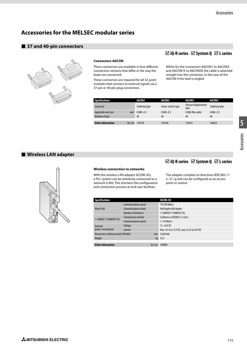
115
Accessories
1
2
5
Acce
ssorie
s
37 and 40-pin connectors þ iQ-R series þ System Q þ L series
Connectors A6CON
These connectors are available in four different connection versions that differ in the way the leads are connected.
These connectors are required for all 32-point modules that connect to external signals via a 37-pin or 40-pin plug connection.
Whilst for the connectors A6CON1 to A6CON3 and A6CON1E to A6CON3E the cable is attached straight into the connector, in the case of the A6CON-4 the lead is angled.
Specifications A6CON1 A6CON2 A6CON3 A6CON4
Connector Soldering type Crimp-contact type Pressure displacement type Soldering type
Applicable wire size mm2 0.088–0.3 0.088–0.3 0.088 (flat cable) 0.088–0.3Number of pins 40 40 40 40
Order information Art. no. 134139 134140 134141 146923
Wireless LAN adapter þ iQ-R series þ System Q þ L series
Wireless connection to networks
With the wireless LAN adapter NZ2WL-EU, a PLC system can be wirelessly connected to a network (LAN). This shortens the configuration and connection process at end-user facilities.
The adapter complies to directives IEEE 802.11 a / b / g and can be configured as an access point or station.
Specifications NZ2WL-EU
Wired LANCommunications speed 10/100 Mbit/sCommunications mode Half duplex/full duplexNumber of interfaces 1 (10BASE-T/100BASE-TX)
1 (10BASE-T/100BASE-TX)Transmission method Conforms to IEEE802.11 a/b/cCommunications speed 1–54 Mbit/s
External power consumption
Voltage 12–24 V DCCurrent Max. 0.4 A at 12 V DC, max. 0.2 A at 24 V DC
Dimensions (without aerial) (WxHxD) mm 25x97x68Weight kg 0.25
Order information Art. no. 249090
Accessories for the MELSEC modular series
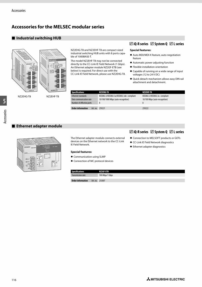
116
1
#2
5
Acce
ssorie
sAccessories
Accessories for the MELSEC modular series
Industrial switching HUB þ iQ-R series þ System Q þ L series
Specifications NZ2EHG-T8 NZ2EHF-T8Ethernet standards IEEE802.3/IEEE802.3u/IEEE802.3ab–compliant IEEE802.3/IEEE802.3u -compliantData communication rate 10/100/1000 Mbps (auto-recognition) 10/100 Mbps (auto-recognition)Number of effective ports 8 8
Order information Art. no. 259221 259222
NZ2EHG-T8 and NZ2EHF-T8 are compact-sized industrial switching HUB units with 8 ports capa-ble of 1000BASE-T.
The model NZ2EHF-T8 may not be connected directly to the CC-Link IE Field Network (1 Gbps). An Ethernet adapter module NZ2GF-ETB (see below) is required. For direct use with the CC-Link IE Field Network, please use NZ2EHG-T8.
Special features:
z Auto MDI/MDI-X feature, auto-negotiation feature
z Automatic power adjusting function
z Flexible installation orientation
z Capable of running on a wide range of input voltages (12 to 24 V DC)
z Quick detach mechanism allows easy DIN rail attachment and detachment.
NZ2EHG-T8 NZ2EHF-T8
Ethernet adapter module þ iQ-R series þ System Q þ L series
Specifications NZ2GF-ETBTransmission rate: 100 Mbps/1 Gbps
Order information Art. no. 253007
The Ethernet adapter module connects external devices on the Ethernet network to the CC-Link IE Field Network.
Special features:
z Communication using SLMP
z Connection of MC protocol devices
z Connection to MELSOFT products or GOTs
z CC-Link IE Field Network diagnostics
z Ethernet adapter diagnosticsPOWER
(FG)
(LG)

117
Accessories
1
2
5
Acce
ssorie
s
MELSEC iQ-R series
SD memory cards þ iQ-R series ¨ System Q ¨ L series
MELSEC iQ-R memory cards
In MELSEC iQ-R CPU modules SD memory card can be used for logging data, troubleshooting device values or as a memory database for recipe storage
Specifications NZ1MEM-2GBSD NZ1MEM-4GBSD NZ1MEM-8GBSD NZ1MEM-16GBSDMemory type SD SDHC SDHC SDHCMemory capacity 2 GB 4 GB 8 GB 16 GB
Order information Art. no. 284966 284967 284968 284969
Extended SRAM cassettes þ iQ-R series ¨ System Q ¨ L series
An optional SRAM cassette enables device/label memory to be increased and doubling up as a hardware security key.
Specifications NZ2MC-1MBS NZ2MC-2MBS NZ2MC-4MBS NZ2MC-8MBS NZ2MC-8MBSE NZ2MC-16MBSMemory type SRAM SRAM SRAM SRAM SRAM SRAMMemory capacity 1 MB 2 MB 4 MB 8 MB 8 MB 16 MB
Order information Art. no. 283684 283683 283682 283583 285495 311472
Connection cables þ iQ-R series ¨ System Q ¨ L series
Specifications RC06B RC12B RC30B RC50BApplication RQ extension base units RQ extension base units RQ extension base units RQ extension base unitsLength m 0.6 1.2 3 5
Order information Art. no. 279528 279529 279530 279521
Connection cable for extension units
These connection cables are used for connect-ing base units to the extension units. They have been cut to the correct length for each application.
When the extension cables are used multiple, the overall distance of the cables should be within 20 m (13.2 m with RQ extension base).
Blank cover modules þ iQ-R series ¨ System Q ¨ L series
The blank cover module is used for dust pre-vention in the space where an I/O module is not mounted (especially the empty slot between modules).
Specifications RG60 QG60Application I/O slots of main and extension base units I/O slots of RQ extension base unitsOccupied I/O points 16 16Weight kg 0.07 0.07Dimensions (WxHxD) mm 27.8x106x110 27.8x106x110
Order information Art. no. 279555 129853

118
Accessories
1
#2
5
Acce
ssorie
s
MELSEC System Q
Dummy module ¨ iQ-R series þ System Q ¨ L series
Place holder and mechanical protection
The dummy module QG60 protects unused slots on the base unit from dust and reserves I/O addresses.
Special features:
z Tough protection of unused slot
z Unified front view
Specifications QG60Occupied I/O points 0–1024 (selectable)Application Used to protect any vacant slot from dust.Current consumption mA —Weight kg 0.07Dimensions (WxHxD) mm 27.4x98x90
Order information Art. no. 129853
ERNT – conversion adapters ¨ iQ-R series þ System Q ¨ L series
AnS series adapters -> MELSEC System Q
These adapters enable a PLC of the MELSEC AnS series to be easily replaced by a MELSEC System Q PLC.
The terminal block adapters enable existing wir-ing for modules of the MELSEC AnS series to be connected to MELSEC System Q modules. The mounting adapters enable a MELSEC System Q base unit to be fitted using the existing fixing holes of the MELSEC AnS series.
Special features:
z No changes to wiring when replacing the PLC
z Time savings and fewer error sources
z Using the existing fixing holes avoids mechanical work in the electrical cabinet.
Item Application Art. no.
ERNT-ASQTXY10 Terminal block A1SX10/A1SY10 to QX10/QY10 249093ERNT-ASQTX40 Terminal block A1SX40(-S1/S2) to QX40(-S1) 249094ERNT-ASQTX80 Terminal block A1SX80(-S1/S2) to QX80 249135ERNT-ASQTY22 Terminal block A1SY22 to QY22 249136ERNT-ASQTY40 Terminal block A1SY40(P) to QY40P 249137ERNT-ASQTY50 Terminal block A1SY50 to QY50 249138ERNT-ASQTY80 Terminal block A1SY80 to QY80 249139ERNT-ASQT64AD Terminal block A1S64AD to Q64AD 249140ERNT-ASQT68AD Terminal block A1S68AD to Q68AD(V/I) 249141ERNT-ASQT62DA Terminal block A1S62DA to Q62DAN 249142ERNT-ASQT68DA Terminal block A1S68DA(V/I) to Q68DA(V/I)N 249143ERNT-ASQB38 Base unit A1S38(H)B to Q38B 249144ERNT-ASQB35 Base unit A1S35B to Q35B 249145ERNT-ASQB33 Base unit A1S33B to Q33B 249146ERNT-ASQB00J Base unit A1SJ(H)CPU(-S3) to Q00(U)JCPU 249147ERNT-ASQB68 Base unit A1S68B to Q68B 249148ERNT-ASQB65 Base unit A1S65B to Q65B 249149ERNT-ASQB55 Base unit A1S55B to Q55B 249150
PCMCIA adapter unit ¨ iQ-R series þ System Q ¨ L series
Memory card adapter
Thememory card adapter Q2MEM-ADP is used for the PCMCIA slot of the PLC for data transferring.
Specifications Q2MEM-ADPFor memory cards type All MELSEC Q memory cards
Order information Art. no. 129650
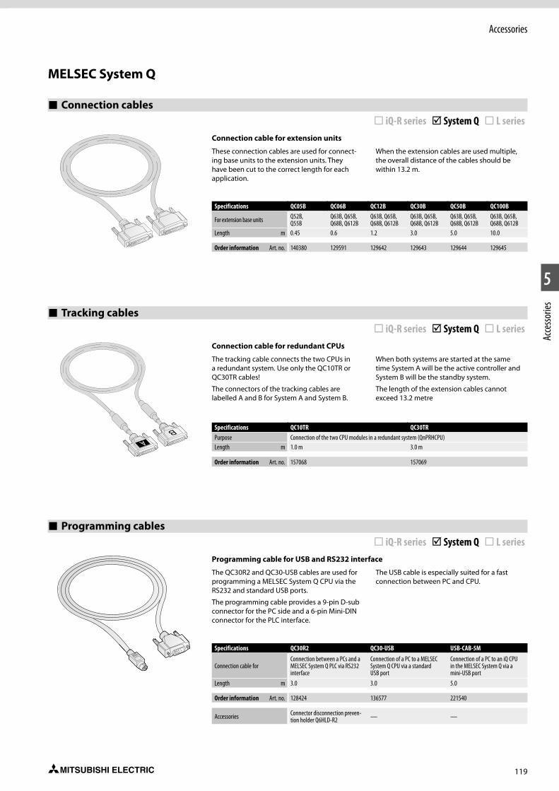
119
Accessories
1
2
5
Acce
ssorie
s
Connection cables ¨ iQ-R series þ System Q ¨ L series
Tracking cables ¨ iQ-R series þ System Q ¨ L series
Specifications QC05B QC06B QC12B QC30B QC50B QC100B
For extension base units Q52B,Q55B
Q63B, Q65B,Q68B, Q612B
Q63B, Q65B,Q68B, Q612B
Q63B, Q65B,Q68B, Q612B
Q63B, Q65B,Q68B, Q612B
Q63B, Q65B,Q68B, Q612B
Length m 0.45 0.6 1.2 3.0 5.0 10.0
Order information Art. no. 140380 129591 129642 129643 129644 129645
Specifications QC10TR QC30TRPurpose Connection of the two CPU modules in a redundant system (QnPRHCPU)Length m 1.0 m 3.0 m
Order information Art. no. 157068 157069
Connection cable for redundant CPUs
The tracking cable connects the two CPUs in a redundant system. Use only the QC10TR or QC30TR cables!
The connectors of the tracking cables are labelled A and B for System A and System B.
When both systems are started at the same time System A will be the active controller and System B will be the standby system.
The length of the extension cables cannot exceed 13.2 metre
Connection cable for extension units
These connection cables are used for connect-ing base units to the extension units. They have been cut to the correct length for each application.
When the extension cables are used multiple, the overall distance of the cables should be within 13.2 m.
Programming cables ¨ iQ-R series þ System Q ¨ L series
Specifications QC30R2 QC30-USB USB-CAB-5M
Connection cable forConnection between a PCs and a MELSEC System Q PLC via RS232 interface
Connection of a PC to a MELSEC System Q CPU via a standard USB port
Connection of a PC to an iQ CPU in the MELSEC System Q via a mini-USB port
Length m 3.0 3.0 5.0
Order information Art. no. 128424 136577 221540
Accessories Connector disconnection preven-tion holder Q6HLD-R2 — —
Programming cable for USB and RS232 interface
The QC30R2 and QC30-USB cables are used for programming a MELSEC System Q CPU via the RS232 and standard USB ports.
The programming cable provides a 9-pin D-sub connector for the PC side and a 6-pin Mini-DIN connector for the PLC interface.
The USB cable is especially suited for a fast connection between PC and CPU.
MELSEC System Q
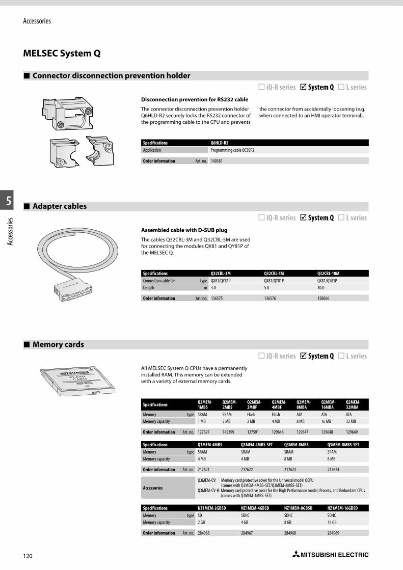
120
Accessories
1
#2
5
Acce
ssorie
s
MELSEC System Q
Connector disconnection prevention holder ¨ iQ-R series þ System Q ¨ L series
Adapter cables ¨ iQ-R series þ System Q ¨ L series
Disconnection prevention for RS232 cable
The connector disconnection prevention holder Q6HLD-R2 securely locks the RS232 connector of the programming cable to the CPU and prevents
the connector from accidentally loosening (e.g. when connected to an HMI operator terminal).
Specifications Q6HLD-R2Application Programming cable QC30R2
Order information Art. no. 140381
Assembled cable with D-SUB plug
The cables Q32CBL-3M and Q32CBL-5M are used for connecting the modules QX81 and QY81P of the MELSEC Q.
Specifications Q32CBL-3M Q32CBL-5M Q32CBL-10MConnection cable for type QX81/QY81P QX81/QY81P QX81/QY81PLength m 3.0 5.0 10.0
Order information Art. no. 136575 136576 158066
Memory cards ¨ iQ-R series þ System Q ¨ L series
All MELSEC System Q CPUs have a permanently installed RAM. This memory can be extended with a variety of external memory cards.
Specifications Q2MEM-1MBS
Q2MEM-2MBS
Q2MEM-2MBF
Q2MEM-4MBF
Q2MEM-8MBA
Q2MEM-16MBA
Q2MEM-32MBA
Memory type SRAM SRAM Flash Flash ATA ATA ATAMemory capacity 1 MB 2 MB 2 MB 4 MB 8 MB 16 MB 32 MB
Order information Art. no. 127627 145399 127591 129646 129647 129648 129649
Specifications Q3MEM-4MBS Q3MEM-4MBS-SET Q3MEM-8MBS Q3MEM-8MBS-SETMemory type SRAM SRAM SRAM SRAMMemory capacity 4 MB 4 MB 8 MB 8 MB
Order information Art. no. 217621 217622 217623 217624
AccessoriesQ3MEM-CV: Memory card protective cover for the Universal model QCPU
(comes with Q3MEM-4MBS-SET/Q3MEM-8MBS-SET)Q3MEM-CV-H: Memory card protective cover for the High Performance model, Process, and Redundant CPUs
(comes with Q3MEM-4MBS-SET)
Specifications NZ1MEM-2GBSD NZ1MEM-4GBSD NZ1MEM-8GBSD NZ1MEM-16GBSDMemory type SD SDHC SDHC SDHCMemory capacity 2 GB 4 GB 8 GB 16 GB
Order information Art. no. 284966 284967 284968 284969
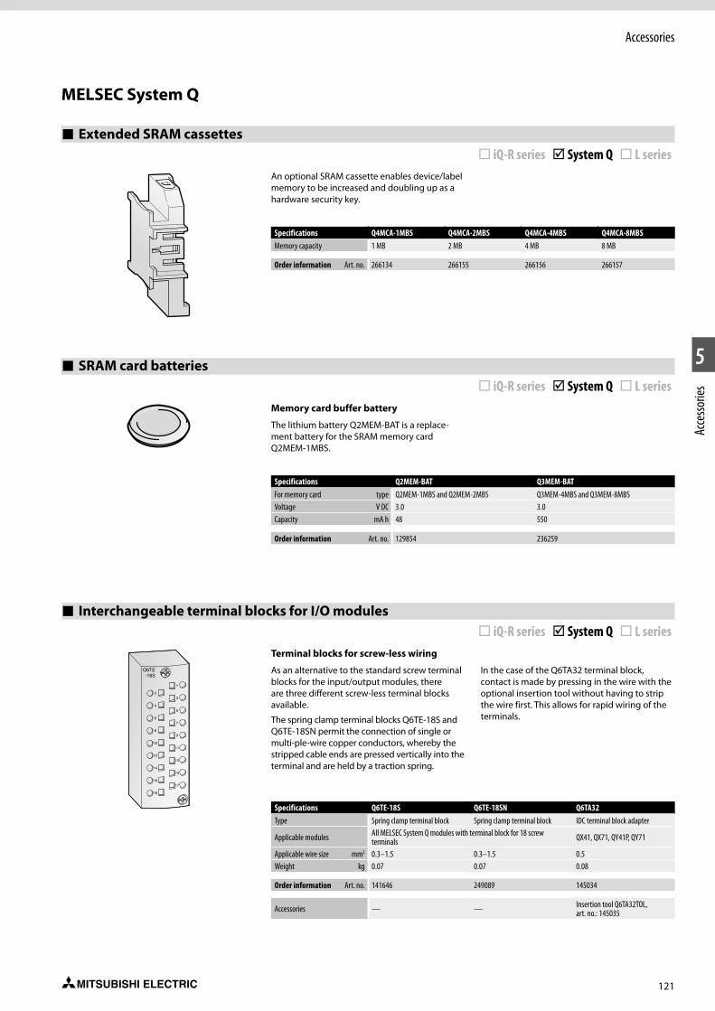
121
Accessories
1
2
5
Acce
ssorie
s
SRAM card batteries ¨ iQ-R series þ System Q ¨ L series
Memory card buffer battery
The lithium battery Q2MEM-BAT is a replace-ment battery for the SRAM memory card Q2MEM-1MBS.
Specifications Q2MEM-BAT Q3MEM-BATFor memory card type Q2MEM-1MBS and Q2MEM-2MBS Q3MEM-4MBS and Q3MEM-8MBSVoltage V DC 3.0 3.0Capacity mA h 48 550
Order information Art. no. 129854 236259
Extended SRAM cassettes ¨ iQ-R series þ System Q ¨ L series
An optional SRAM cassette enables device/label memory to be increased and doubling up as a hardware security key.
Specifications Q4MCA-1MBS Q4MCA-2MBS Q4MCA-4MBS Q4MCA-8MBSMemory capacity 1 MB 2 MB 4 MB 8 MB
Order information Art. no. 266134 266155 266156 266157
Interchangeable terminal blocks for I/O modules ¨ iQ-R series þ System Q ¨ L series
Terminal blocks for screw-less wiring
As an alternative to the standard screw terminal blocks for the input/output modules, there are three different screw-less terminal blocks available.
The spring clamp terminal blocks Q6TE-18S and Q6TE-18SN permit the connection of single or multi-ple-wire copper conductors, whereby the stripped cable ends are pressed vertically into the terminal and are held by a traction spring.
In the case of the Q6TA32 terminal block, contact is made by pressing in the wire with the optional insertion tool without having to strip the wire first. This allows for rapid wiring of the terminals.
Specifications Q6TE-18S Q6TE-18SN Q6TA32Type Spring clamp terminal block Spring clamp terminal block IDC terminal block adapter
Applicable modules All MELSEC System Q modules with terminal block for 18 screw terminals QX41, QX71, QY41P, QY71
Applicable wire size mm2 0.3–1.5 0.3–1.5 0.5Weight kg 0.07 0.07 0.08
Order information Art. no. 141646 249089 145034
Accessories — — Insertion tool Q6TA32TOL, art. no.: 145035
MELSEC System Q
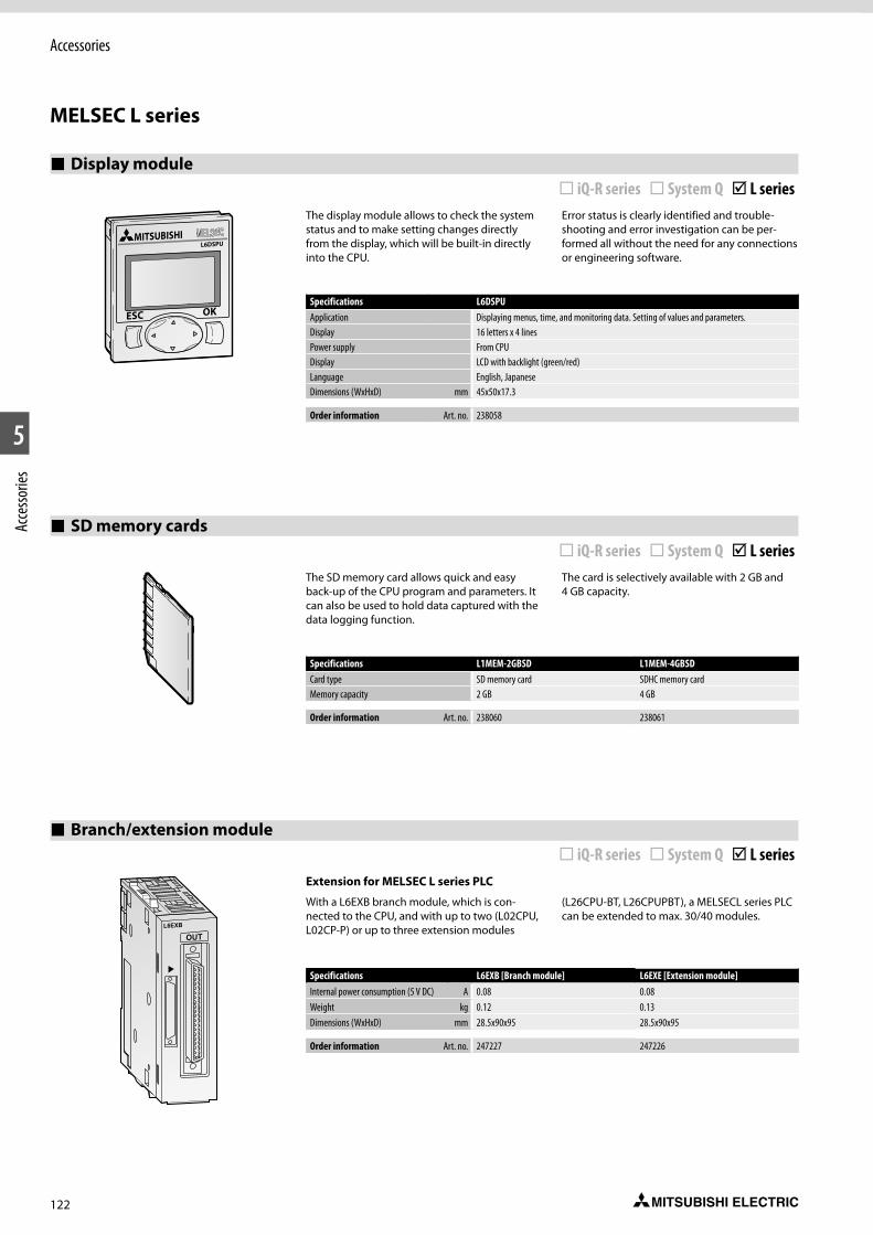
122
Accessories
1
#2
5
Acce
ssorie
s
MELSEC L series
Display module ¨ iQ-R series ¨ System Q þ L series
The display module allows to check the system status and to make setting changes directly from the display, which will be built-in directly into the CPU.
Error status is clearly identified and trouble-shooting and error investigation can be per-formed all without the need for any connections or engineering software.
The SD memory card allows quick and easy back-up of the CPU program and parameters. It can also be used to hold data captured with the data logging function.
The card is selectively available with 2 GB and 4 GB capacity.
Specifications L6DSPUApplication Displaying menus, time, and monitoring data. Setting of values and parameters.Display 16 letters x 4 linesPower supply From CPUDisplay LCD with backlight (green/red)Language English, JapaneseDimensions (WxHxD) mm 45x50x17.3
Order information Art. no. 238058
Specifications L1MEM-2GBSD L1MEM-4GBSDCard type SD memory card SDHC memory cardMemory capacity 2 GB 4 GB
Order information Art. no. 238060 238061
SD memory cards ¨ iQ-R series ¨ System Q þ L series
Branch/extension module ¨ iQ-R series ¨ System Q þ L series
Extension for MELSEC L series PLC
With a L6EXB branch module, which is con-nected to the CPU, and with up to two (L02CPU, L02CP-P) or up to three extension modules
(L26CPU-BT, L26CPUPBT), a MELSECL series PLC can be extended to max. 30/40 modules.
Specifications L6EXB [Branch module] L6EXE [Extension module]Internal power consumption (5 V DC) A 0.08 0.08Weight kg 0.12 0.13Dimensions (WxHxD) mm 28.5x90x95 28.5x90x95
Order information Art. no. 247227 247226

123
Accessories
1
2
5
Acce
ssorie
s
Extension cables ¨ iQ-R series ¨ System Q þ L series
Connection between branch module and extension module
These cables connects a branch module with one or two extension modules.
Specifications LC06E LC10E LC30ECable length m 0.6 1.0 3.0Weight kg 0.19 0.23 0.45
Order information Art. no. 247228 247229 247230
Space module ¨ iQ-R series ¨ System Q þ L series
The space module LG69 is used to secure space for the cables when replacing the AnS/QnAS Series system to the L series system module. Cables can be stored in an area created by a space module, and this space prevents cables from interfering each other.
The space module enables system replacement while reusing the existing wiring, reducing the rewiring work.
Specifications LG69Number of occupied modules The number of occupied modules may vary depending on the modules to be used.Weight kg 0.07Dimensions (WxHxD) mm 16.5x90x95
Order information Art. no. 279073
MELSEC L series
Spring clamp terminal block (push-in type) ¨ iQ-R series ¨ System Q þ L series
The screw terminal block of installed modules can be replaced with a push-in type spring clamp terminal block.
This terminal block type helps to reduce the amount of wiring and maintenance time.
Special features:
z Push-in type for reduced wiring
z Simple to confirm signal integrity
Specifications L6TE-18SType 18-point spring clamp terminal blockApplicable wire size mm2 0.3–1.0 mm2 (22–18 AWG)Dimensions (WxHxD) mm 20x76.8x20
Order information Art. no. 277553

124
Programming
1
#2
6
Prog
ram
ming
MELSOFT – Programming and documentation software for standard personal computers
With the MELSOFT software family Mitsubishi Electric offers efficient software packages help-ing to reduce programming and setup times to a high degree.
The MELSOFT software family provides instant access, direct communications, compatibility, and open exchange of variables.
The MELSOFT family comprises:
z Programming packages like GX Works2 and GX Works3
z Visualization software like for example MAPS
z Network configuration software like for example GX Configurator DP and GX Configurator PN
z Various development software for operator terminals GT Works3 and GT SoftGOT1000
GX Works2 and GX Works3 is recommended as a costeffective beginners package for the MELSEC System Q. This package offers a quick and easy introduction to programming.
For structured programming the IEC 1131 (EN 61131) conform programming software GX IEC Developer is recommended.
iQ Works integrates the functions necessary to manage every part of the system cycle.
System design
The intuitive system configuration diagram allows for the graphic assembly of systems, centralized management of disparate projects and batch configuration of the entire control system.
Programming
Use system labels to seamlessly share device data between GOTs, PLCs and motion controllers. Save the time and hassle of changing device values in each program by using the update system labels feature.
Test and startup
Debug and optimize programs using the simulation functions. Use the included diagnostics and monitoring functions to quickly identify the source of errors.
Operation and maintenance
Speed up the process of commis-sioning, configuring and updating the system by using the batch read feature. Virtually eliminate the confusion associated with system management.
MELSOFT GT Worksis a complete HMI programming, screen creation and maintenance program. In order to reduce the labor required to create detailed and impressive applications, the software’s functionality has been built around the concepts of ease of use, simplifications (without sacrificing functionality) and elegance (in design and screen graphics).
Unified engineering environment: iQ Works
MELSOFT Navigatoris the heart of iQ Works. It enables the effortless design of entire upper-level systems and seamlessly integrates the other MELSOFT programs included with iQ Works. Functions such as system configuration design, batch parameter setting, system labels and batch read all help to reduce TCO.
MELSOFT GX Worksrepresents the next generation in MELSOFT PLC maintenance and programming software. Its functionality has been inherited from both GX and IEC Developer, with imporvements made throughout to increase productivity and drive down engineering costs.
MELSOFT MT Worksis a comprehensive motion CPU maintenance and program desing tool. Its many useful functions, such as intuitive settings, graphical programming and digital oscilloscope, simulator, different Motion OS support, assistance help, to reduce the MT Works2 associated with motion systems.
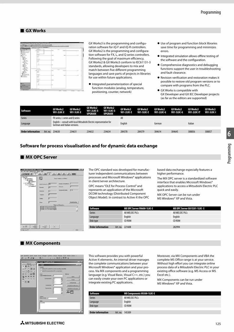
125
Programming
1
2
6
Prog
ram
ming
GX Works3 is the programming and configu-ration software for iQ-F and iQ-R controllers. GX Works2 is the programming and configura-tion software for FX, L, and Q series controllers. Following the goal of maximum efficiency, GX Works2 & GX Works3 conform to IEC61131-3 standards, allowing developers to mix and match between five different programming languages and save parts of projects in libraries for use within future applications.
z Integrated parameterization of special function modules (analog, temperature, positioning, counter, network)
z Use of program and function block libraries save time for programming and minimizes errors.
z Integrated simulation allows offline testing of the software and the configuration.
z Comprehensive diagnostics and debugging functions support the user in troubleshooting and fault clearance.
z Revision verification and restoration makes it possible to restore old program versions or to compare with programs from the PLC.
z GX Works is compatible with GX Developer and GX IEC Developer projects (as far as the editors are supported)
GX Works
Software GX Works2 V01-2L0C-E
GX Works2 V01-5L0C-E
GX Works2 V01-2L0C-E-UPGRADE
GX Works2 V01-5L0C-E-UPGRADE
GX Works3 V01-2LOC-E
GX Works3 V01-5LOC-E
GX Works3 V01-2LOC-G
GX Works3 V01-5LOC-G
GX Works3 V01-2LOC-IT
GX Works3 V01-5LOC-I
Series FX series, L series and Q series All
Language English – consult with local Mitsubishi Electric representative for German and Italian versions. English German Italian
Order information Art. no. 234630 234631 234632 234634 284378 284379 304614 304645 308856 308857
Software for process visualisation and for dynamic data exchange
MX OPC Server
Software MX OPC Server V0600-1L0C-E MX OPC Server UA V201-1LOC- ESeries All MELSEC PLCs All MELSEC PLCsLanguage English EnglishDisk type CD ROM CD ROM
Order information Art. no. 221608 282994
The OPC standard was developed for manufac-turer independent communications between processes and Microsoft Windows® applications in client/server architecture.
OPC means “OLE for Process Control” and represents an application of the Microsoft DCOM technology (Distributed Component Object Model). In contrast to Active-X the OPC
based data exchange especially features a higher performance.
The MX OPC server is a standardized software interface that enables Microsoft Windows® applications to access a Mitsubishi Electric PLC quick and easily.
MX OPC Server can be run under MS Windows® XP and Vista.
Software MX Components V0300-1LOC-ESeries All MELSEC PLCsLanguage EnglishDisk type CD ROM
Order information Art. no. 145309
This software provides you with powerful Active-X elements. An internal driver manages the complete communications between your Microsoft Windows® application and your pro-cess. Via MX components and a programming language (e.g. Visual Basic, Visual C++, etc.) you can easily create your own PC applications or integrate existing PC applications.
Moreover, via MX Components and VBA the complete MS Office range is at your service. Without high effort you can integrate online process data of a Mitsubishi Electric PLC in your existing office software (e.g. MS Access or MS Excel etc.).
MX Components can be run under MS Windows® XP and Vista.
MX Components
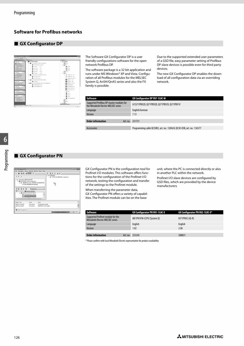
126
Programming
1
#2
6
Prog
ram
ming
Software for Profibus networks
GX Configurator DP
Software GX Configurator DP V07-1L0C-MSupported Profibus DP master modules for the Mitsubishi Electric MELSEC series A1SJ71PB92D, QJ71PB92D, QJ71PB92V, QJ71PB91V
Language English/GermanVersion 7.13
Order information Art. no. 231731
Accessories Programming cable QC30R2, art. no.: 128424; QC30-USB, art. no.: 136577
The Software GX Configurator DP is a user friendly configurations software for the open network Profibus DP.
The software package is a 32 bit application and runs under MS Windows® XP and Vista. Configu-ration of all Profibus modules for the MELSEC System Q, AnSH/QnAS series and also the FX family is possible.
Due to the supported extended user parameters of a GSD file, easy parameter setting of Profibus DP slave devices is possible even for third party devices.
The new GX Configurator DP enables the down-load of all configuration data via an overriding network.
GX Configurator PN
Software GX Configurator PN V01-1L0C-E GX Configurator PN V02-1LOC-E*Supported Profinet module for the Mitsubishi Electric MELSEC series ME1PN1FW-CCPU (System Q) RJ71PN92 (iQ-R)
Language English EnglishVersion 1.02 2.00
Order information Art. no. 255245 308831
* Please confirm with local Mitsubishi Electric representative for product availability
GX Configurator PN is the configuration tool for Profinet I/O modules. This software offers func-tions for the configuration of the Profinet I/O network, testing the configuration and transfer of the settings to the Profinet module.
When transferring the parameter data, GX Configurator PN offers a variety of capabil-ities. The Profinet module can be on the base
unit, where the PC is connected directly or also in another PLC within the network.
Profinet I/O slave devices are configured by GSD files, which are provided by the device manufacturers.

127
Notes
128
Index
AccessoriesMELSEC iQ-R series . . . . . . . . . . . . . . . . . . . . . . . . . . . . . . . . . . . 117MELSEC L series . . . . . . . . . . . . . . . . . . . . . . . . . . . . . . . . . . . . . . 122MELSEC modular series . . . . . . . . . . . . . . . . . . . . . . . . . . . . . . . 116MELSEC System Q . . . . . . . . . . . . . . . . . . . . . . . . . . . . . . . . . . . . 118
MELSEC iQ-R seriesAccessories. . . . . . . . . . . . . . . . . . . . . . . . . . . . . . . . . . . . . . . . . . 114Basic components
Base units . . . . . . . . . . . . . . . . . . . . . . . . . . . . . . . . . . . . . . . . . 17CPU modules . . . . . . . . . . . . . . . . . . . . . . . . . . . . . . . . . . . . . . 19Power supply modules . . . . . . . . . . . . . . . . . . . . . . . . . . . . . . 18
Digital modulesCombined I/O module . . . . . . . . . . . . . . . . . . . . . . . . . . . . . . . 28(High-speed) input modules . . . . . . . . . . . . . . . . . . . . . . . . . 24(High-speed) output modules . . . . . . . . . . . . . . . . . . . . . . . . 26
Dimensions . . . . . . . . . . . . . . . . . . . . . . . . . . . . . . . . . . . . . . . . . . 42Special function modules
Analog modules . . . . . . . . . . . . . . . . . . . . . . . . . . . . . . . . . . . . 29C intelligent function module . . . . . . . . . . . . . . . . . . . . . . . . 41High-speed counter modules . . . . . . . . . . . . . . . . . . . . . . . . . 33High-speed data logger module . . . . . . . . . . . . . . . . . . . . . . 40Interface modules . . . . . . . . . . . . . . . . . . . . . . . . . . . . . . . . . . 36iQ-R C-Application server . . . . . . . . . . . . . . . . . . . . . . . . . . . . 39MES Interface module . . . . . . . . . . . . . . . . . . . . . . . . . . . . . . . 38Network modules . . . . . . . . . . . . . . . . . . . . . . . . . . . . . . . . . . 37Positioning modules . . . . . . . . . . . . . . . . . . . . . . . . . . . . . . . . 34Simple Motion modules . . . . . . . . . . . . . . . . . . . . . . . . . . . . . 35Temperature control modules . . . . . . . . . . . . . . . . . . . . . . . . 32
System description . . . . . . . . . . . . . . . . . . . . . . . . . . . . . . . . . . . . 16
MELSEC L SeriesAccessories. . . . . . . . . . . . . . . . . . . . . . . . . . . . . . . . . . . . . . . . . . 114Basic components
CPU modules . . . . . . . . . . . . . . . . . . . . . . . . . . . . . . . . . . . . . . 95Power supply modules . . . . . . . . . . . . . . . . . . . . . . . . . . . . . . 94
Digital modulesInput modules . . . . . . . . . . . . . . . . . . . . . . . . . . . . . . . . . . . . . 96Output modules . . . . . . . . . . . . . . . . . . . . . . . . . . . . . . . . . . . . 97
Dimensions . . . . . . . . . . . . . . . . . . . . . . . . . . . . . . . . . . . . . . . . . 112Special function modules
Analog modules . . . . . . . . . . . . . . . . . . . . . . . . . . . . . . . . . . . . 99End Cover . . . . . . . . . . . . . . . . . . . . . . . . . . . . . . . . . . . . . . . . 111Flexible high-speed I/O control module . . . . . . . . . . . . . . . 105High-speed counter modules . . . . . . . . . . . . . . . . . . . . . . . . 106Interface modules . . . . . . . . . . . . . . . . . . . . . . . . . . . . . . . . . 107IO-Link module . . . . . . . . . . . . . . . . . . . . . . . . . . . . . . . . . . . . 98Multiple input module . . . . . . . . . . . . . . . . . . . . . . . . . . . . . 102Network modules . . . . . . . . . . . . . . . . . . . . . . . . . . . . . . . . . 110Positioning modules . . . . . . . . . . . . . . . . . . . . . . . . . . . . . . . 108Serial communication adapter. . . . . . . . . . . . . . . . . . . . . . . 111Simple motion modules . . . . . . . . . . . . . . . . . . . . . . . . . . . . 109Temperature control modules . . . . . . . . . . . . . . . . . . . . . . . 104Temperature input module. . . . . . . . . . . . . . . . . . . . . . . . . . 103
System description . . . . . . . . . . . . . . . . . . . . . . . . . . . . . . . . . . . . 92
MELSEC System QAccessories. . . . . . . . . . . . . . . . . . . . . . . . . . . . . . . . . . . . . . . . . . 114Basic components
Base units . . . . . . . . . . . . . . . . . . . . . . . . . . . . . . . . . . . . . . . . . 50CPU modules . . . . . . . . . . . . . . . . . . . . . . . . . . . . . . . . . . . . . . 53Power supply module . . . . . . . . . . . . . . . . . . . . . . . . . . . . . . . 52
Digital modulesInput modules . . . . . . . . . . . . . . . . . . . . . . . . . . . . . . . . . . . . . 60Output modules . . . . . . . . . . . . . . . . . . . . . . . . . . . . . . . . . . . . 62
Dimensions . . . . . . . . . . . . . . . . . . . . . . . . . . . . . . . . . . . . . . . . . . 88Special function modules
Analog CT input module . . . . . . . . . . . . . . . . . . . . . . . . . . . . . 71Analog modules . . . . . . . . . . . . . . . . . . . . . . . . . . . . . . . . . . . . 64High-speed communication modules . . . . . . . . . . . . . . . . . . 81High-speed counter modules . . . . . . . . . . . . . . . . . . . . . . . . . 73High speed data logger module. . . . . . . . . . . . . . . . . . . . . . . 86Interface modules . . . . . . . . . . . . . . . . . . . . . . . . . . . . . . . . . . 80Interrupt module and high-speed inputs . . . . . . . . . . . . . . . 87Load cell module . . . . . . . . . . . . . . . . . . . . . . . . . . . . . . . . . . . 70Loop control module . . . . . . . . . . . . . . . . . . . . . . . . . . . . . . . . 72MES Interface module . . . . . . . . . . . . . . . . . . . . . . . . . . . . . . . 84Multi-function counter/timer module . . . . . . . . . . . . . . . . . 74Network modules . . . . . . . . . . . . . . . . . . . . . . . . . . . . . . . . . . 82Positioning modules . . . . . . . . . . . . . . . . . . . . . . . . . . . . . . . . 75Q series C-Application server . . . . . . . . . . . . . . . . . . . . . . . . . 85Simple Motion modules . . . . . . . . . . . . . . . . . . . . . . . . . . . . . 79Temperature control modules . . . . . . . . . . . . . . . . . . . . . . . . 69Web server module . . . . . . . . . . . . . . . . . . . . . . . . . . . . . . . . . 83
System description . . . . . . . . . . . . . . . . . . . . . . . . . . . . . . . . . . . . 45Automation platform . . . . . . . . . . . . . . . . . . . . . . . . . . . . . . . 45Configuration . . . . . . . . . . . . . . . . . . . . . . . . . . . . . . . . . . . . . . 48Module combinations for multiple CPU system. . . . . . . . . . 49Safety . . . . . . . . . . . . . . . . . . . . . . . . . . . . . . . . . . . . . . . . . . . . 46
Modular PLCsEquipment features . . . . . . . . . . . . . . . . . . . . . . . . . . . . . . . . . . . . 8iQ Platform. . . . . . . . . . . . . . . . . . . . . . . . . . . . . . . . . . . . . . . . . . . . 9Overview . . . . . . . . . . . . . . . . . . . . . . . . . . . . . . . . . . . . . . . . . . . . . 6Special functions
MELSEC iQ-R . . . . . . . . . . . . . . . . . . . . . . . . . . . . . . . . . . . . . . . 10MELSEC L series . . . . . . . . . . . . . . . . . . . . . . . . . . . . . . . . . . . . 14MELSEC System Q. . . . . . . . . . . . . . . . . . . . . . . . . . . . . . . . . . . 12
ProgrammingGX Works . . . . . . . . . . . . . . . . . . . . . . . . . . . . . . . . . . . . . . . . . . . 125iQ Works . . . . . . . . . . . . . . . . . . . . . . . . . . . . . . . . . . . . . . . . . . . . 124MELSOFT Software . . . . . . . . . . . . . . . . . . . . . . . . . . . . . . . . . . . 124Profibus software . . . . . . . . . . . . . . . . . . . . . . . . . . . . . . . . . . . . 126Visualisation software . . . . . . . . . . . . . . . . . . . . . . . . . . . . . . . . 125
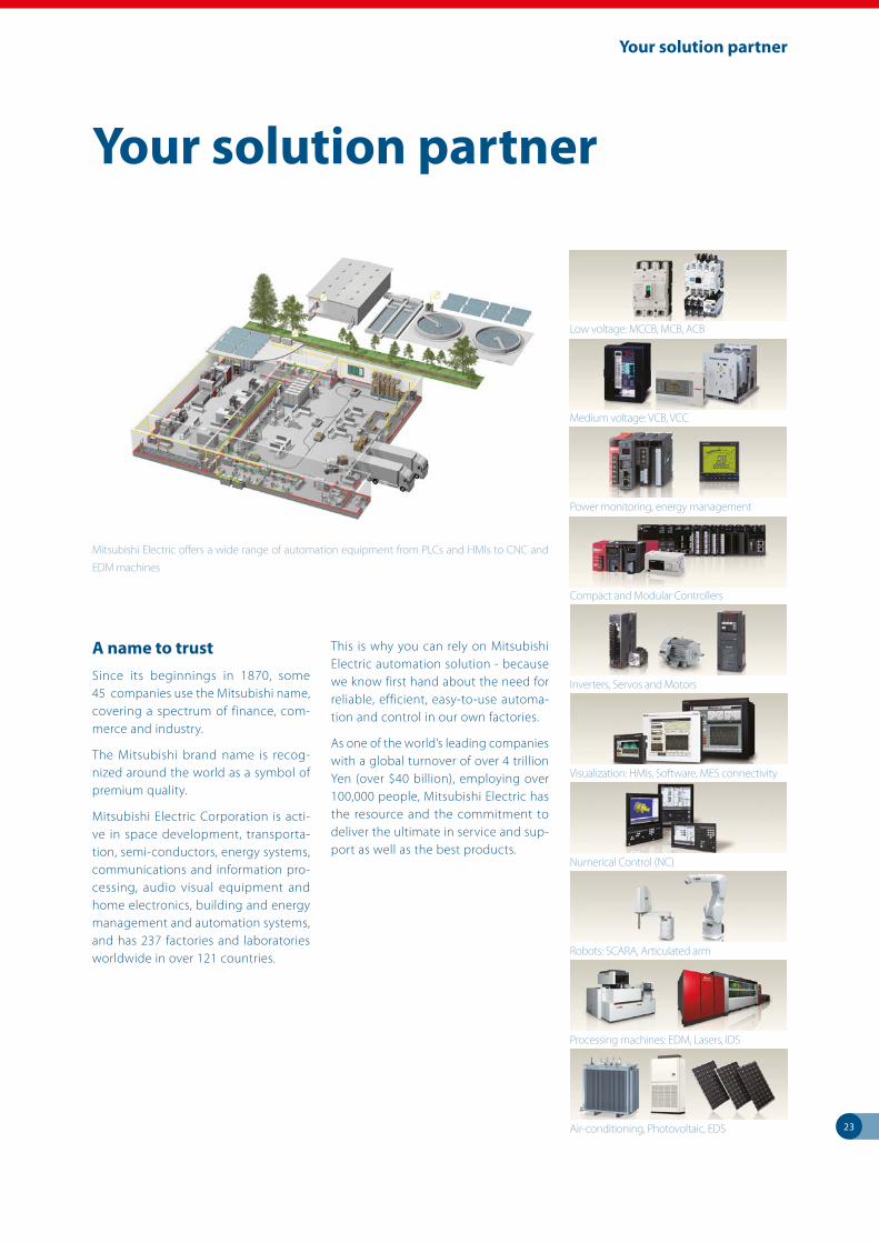
23
Your solution partner
Your solution partner
Low voltage: MCCB, MCB, ACB
Medium voltage: VCB, VCC
Power monitoring, energy management
Compact and Modular Controllers
Inverters, Servos and Motors
Visualization: HMIs, Software, MES connectivity
Numerical Control (NC)
Robots: SCARA, Articulated arm
Processing machines: EDM, Lasers, IDS
Air-conditioning, Photovoltaic, EDS
Mitsubishi Electric offers a wide range of automation equipment from PLCs and HMIs to CNC and
EDM machines
A name to trustSince its beginnings in 1870, some 45 companies use the Mitsubishi name, covering a spectrum of finance, com-merce and industry.
The Mitsubishi brand name is recog-nized around the world as a symbol of premium quality.
Mitsubishi Electric Corporation is acti-ve in space development, transporta-tion, semi-conductors, energy systems, communications and information pro-cessing, audio visual equipment and home electronics, building and energy management and automation systems, and has 237 factories and laboratories worldwide in over 121 countries.
This is why you can rely on Mitsubishi Electric automation solution - because we know first hand about the need for reliable, efficient, easy-to-use automa-tion and control in our own factories.
As one of the world’s leading companies with a global turnover of over 4 trillion Yen (over $40 billion), employing over 100,000 people, Mitsubishi Electric has the resource and the commitment to deliver the ultimate in service and sup-port as well as the best products.
Global Partner. Local Friend.
European Offices
GermanyMitsubishi Electric Europe B.V.Mitsubishi-Electric-Platz 1D-40882 RatingenPhone: +49 (0)2102 / 486-0
Czech Rep.Mitsubishi Electric Europe B.V.Radlická 751/113e Avenir Business ParkCZ-158 00 Praha 5Phone: +420 251 551 470
FranceMitsubishi Electric Europe B.V.25, Boulevard des BouvetsF-92741 Nanterre CedexPhone: +33 (0)1 / 55 68 55 68
IrelandMitsubishi Electric Europe B.V.Westgate Business Park, BallymountIRL-Dublin 24Phone: +353 (0)1 4198800
ItalyMitsubishi Electric Europe B.V.Viale Colleoni 7 Palazzo SirioI-20864 Agrate Brianza (MB)Phone: +39 039 / 60 53 1
NetherlandsMitsubishi Electric Europe B.V.Nijverheidsweg 23CNL-3641RP MijdrechtPhone: +31 (0) 297 250 350
PolandMitsubishi Electric Europe B.V.ul. Krakowska 50PL-32-083 BalicePhone: +48 (0) 12 347 65 00
RussiaMitsubishi Electric (Russia) LLC52, bld. 1 Kosmodamianskaya emb.RU-115054 MoscowPhone: +7 495 / 721 2070
SpainMitsubishi Electric Europe B.V.Carretera de Rubí 76-80 Apdo. 420E-08190 Sant Cugat del Vallés (Barcelona)Phone: +34 (0) 93 / 5653131
SwedenMitsubishi Electric Europe B.V. (Scandinavia) Fjelievägen 8SE-22736 LundPhone: +46 (0) 8 625 10 00
TurkeyMitsubishi Electric Turkey Elektrik Ürünleri A.Ş.Şerifali Mahallesi Nutuk Sokak No:5 TR-34775 Ümraniye-İSTANBUL Phone: +90 (216) 969 25 00
UKMitsubishi Electric Europe B.V.Travellers LaneUK-Hatfield, Herts. AL10 8XBPhone: +44 (0)1707 / 28 87 80
UAEMitsubishi Electric Europe B.V.Dubai Silicon OasisUnited Arab Emirates - DubaiPhone: +971 4 3724716
Representatives
AustriaGEVAWiener Straße 89A-2500 BadenPhone: +43 (0)2252 / 85 55 20
BelarusOOO TECHNIKONProspect Nezavisimosti 177-9BY-220125 MinskPhone: +375 (0)17 / 393 1177
Bosnia and HerzegovinaINEA RBT d.o.o.Stegne 11SI-1000 LjubljanaPhone: +386 (0)1/ 513 8116
BulgariaAKHNATON4, Andrei Ljapchev Blvd., PO Box 21BG-1756 SofiaPhone: +359 (0)2 / 817 6000
CroatiaINEA CRLosinjska 4 aHR-10000 ZagrebPhone: +385 (0)1 / 36 940 - 01/ -02/ -03
Czech RepublicAutoCont C.S. S.R.O.Kafkova 1853/3CZ-702 00 Ostrava 2Phone: +420 595 691 150
DenmarkHANS FØLSGAARD A/STheilgaards Torv 1DK-4600 KøgePhone: +45 4320 8600
EstoniaElectrobit OÜPärnu mnt. 160iEST-11317, TallinnPhone: +372 6518 140
FinlandUTU Automation OyPeltotie 37FIN-28400 UlvilaPhone: +358 (0)207 / 463 500
GreeceUTECO A.B.E.E.5, Mavrogenous Str.GR-18542 PiraeusPhone: +30 (0)211 / 1206-900
HungaryMELTRADE Kft.Fertő utca 14.HU-1107 BudapestPhone: +36 (0)1 / 431-9726
KazakhstanTOO Kazpromavtomatika Ul. Zhambyla 28KAZ-100017 KaragandaPhone: +7 7212 / 50 10 00
LatviaOAK Integrator Products SIA Ritausmas iela 23LV-1058 RigaPhone: +371 67842280
LithuaniaAutomatikos Centras, UAB Neries krantiné 14A-101LT-48397 KaunasPhone: +370 37 262707
MaltaALFATRADE Ltd.99, Paola HillMalta-Paola PLA 1702Phone: +356 (0)21 / 697 816
MoldovaINTEHSIS SRLbld. Traian 23/1MD-2060 KishinevPhone: +373 (0)22 / 66 4242
PortugalFonseca S.A.R. João Francisco do Casal 87/89PT-3801-997 Aveiro, Esgueira Phone: +351 (0)234 / 303 900
RomaniaSirius Trading & ServicesAleea Lacul Morii Nr. 3RO-060841 Bucuresti, Sector 6Phone: +40 (0)21 / 430 40 06
SerbiaINEA SR d.o.o.Ul. Karadjordjeva 12/217SER-11300 SmederevoPhone: +386 (026) 461 54 01
SlovakiaSIMAP SKDolné Pažite 603/97SK-911 06 TrenčínPhone: +421 (0)32 743 04 72
SloveniaINEA RBT d.o.o.Stegne 11SI-1000 LjubljanaPhone: +386 (0)1 / 513 8116
SwitzerlandOMNI RAY AGIm Schörli 5CH-8600 DübendorfPhone: +41 (0)44 / 802 28 80
UkraineCSC- AUTOMATION Ltd.4 B, Yevhenа Sverstyuka Str.UA-02002 KievPhone: +380 (0)44 / 494 33 44
IsraelGIRIT CELADON Ltd.12 H’aomanut StreetIL-42505 NetanyaPhone: +972 (0)9 / 863 39 80
IsraelILAN & GAVISH Ltd.24 Shenkar St., Kiryat ArieIL-49001 Petah-TikvaPhone: +972 (0)3 / 922 18 24
LebanonCEG LIBANCebaco Center/Block A Autostrade DORALebanon-BeirutPhone: +961 (0)1 / 240 445
South AfricaADROIT TECHNOLOGIES20 Waterford Office Park 189 Witkoppen RoadZA-FourwaysPhone: + 27 (0)11 / 658 8100
Mitsubishi Electric Europe B.V.FA - European Business Group Mitsubishi-Electric-Platz 1 D-40882 Ratingen Germany Tel.: +49(0)2102-4860 Fax: +49(0)2102-4861120 [email protected] https://eu3a.mitsubishielectric.com
Art. no. 260570-C Printed April 2017
Version check
Specifications subject to change. All trademarks and copyrights acknowledged.


